
Transient Residual Voltage Analysis During Isolated Operation of a Group of Induction Motor Loads
Upload
khangminh22Category
view
1download
0
A Three-Phase Bidirectional Variable Speed Drive:
An Experimental Validation
for a Three-Phase Induction Motor
Luis Machado1, Tiago J. C. Sousa1, Delfim Pedrosa1,
Vitor Monteiro1, J. G. Pinto1, Joao L. Afonso1
1 Centro ALGORITMI, University of Minho, Campus de Azurém, Guimarães, Portugal [email protected]
Abstract. This paper presents the implementation and subsequent experimental
verification of an electronic variable speed drive (VSD) for driving an induction
motor, which is composed by a three-phase ac-dc converter on the grid-side and by
a three-phase dc-ac converter on the motor-side. With the proposed solution, be-
sides driving the motor, it is possible to mitigate power quality problems on the
grid-side (e.g., current harmonics and power factor) associated with the use of di-
ode-bridge ac-dc converters in the conventional VSDs. Besides, with the proposed
solution, a bidirectional operation is possible, allowing to deliver to the power grid
the energy generated in motor braking processes. As demonstrated along the paper,
with the proposed VSD, it is possible to control the motor speed (including the ro-
tation direction), and the operation with sinusoidal currents and unitary power fac-
tor on the grid-side. A laboratory prototype was developed, permitting to perform
an experimental validation and prove the main functionalities of the VSD.
Keywords: Variable Speed Drive, Active Rectifier, Induction Motor, Regenera-
tive Braking, Power Quality.
1 Introduction
Nowadays, the three-phase induction motor with squirrel cage rotor represents more than
90% of the electric motors used in industry, contributing to more than 60% of industrial
electricity consumption. This situation occurs, not only because the induction motors pre-
sent low acquisition and maintenance costs and great robustness, but mainly due to con-
stant technological evolution and the development of control techniques that have brought
a wider variety of applications [1]-[3].
Conventionally, variable speed drives (VSDs) for induction motors employ a diode
bridge rectifier in order to provide power to the dc-link from the power grid. Although
this type of rectifiers is an economical solution, they contribute to the degradation of
power quality, since they consume currents with high harmonic content that, in turn, cause
distortions in the voltage waveform and low power factor amount of the VSD. Besides,
Luís Machado, Tiago J. C. Sousa, Vítor Monteiro, Delfim Pedrosa, João L. Afonso, “A Three Phase Bidirectional Variable Speed Drive:
An Experimental Validation for a Three Phase Induction Motor”, in Lecture Notes of the Institute for Computer Sciences, Social-Informatics
and Telecommunications Engineering, LNICST, vol. 315 LNICST, pp. 47–57, 2020. DOI: 10.1007/978-3-030-45694-8_4.

2
they do not allow reversing the energy flow, thus rendering the regenerative braking pro-
cess to the power grid impracticable. For power quality improvement, passive or active
filters are frequently installed, meaning additional investment costs [4]. A more recent
solution consists in used active rectifiers [4]. Thus, the passive ac-dc converters have been
replaced by active ac-dc converters, which present the following advantages as attractive
[5],[6]: regulated voltage supply with low ripple to the dc-link; sinusoidal current con-
sumption; maximization of the power factor; and bidirectional power flow, which allows
an effective use of the electrical energy generated in braking or decelerating situations of
the motor, returning it to the power grid instead of being dissipated in a resistor (braking
resistor), or stored in storage elements such as ultracapacitors or batteries [7].
Significant technological advances have emerged in the field of VSDs over the last
few years [1]. This growth has been felt in the market of electric motors, especially as
regards the sale of induction motors, which has increased, and it is thought that it will
continue to increase, not only because of the qualities they have in relation to the dc mo-
tors very used in the past, but mainly because of the evolution of VSDs, which has allowed
the use of these motors in variable speed applications [1].
The paper is structured as follows: Section 2 presents the electrical model of the pro-
posed system under analysis; Section 3 presents the implemented control algorithm for
each of the power converters; Section 4 presents the developed prototype and the obtained
experimental results of the VSD and Section 5 finalizes the paper with the conclusions.
2 Proposed System
This section presents the electrical model of the proposed system under analysis in this
paper. As previously mentioned, a typical topology of a VSD for three-phase induction
motors, usually, has a diode bridge rectifier for interfacing with the power grid, also
known in the literature as a Graetz bridge [8]. As a disadvantage, this type of converter
does not control the input (nor the output) current nor the dc-link voltage (vdc), which is
limited to the peak value of the power grid phase voltages. In this way, the proposed
system suggests the exchange of the passive semiconductors by active semiconductors,
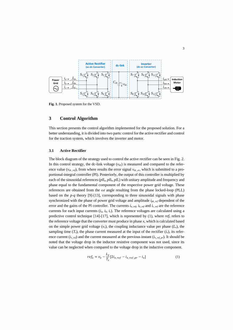
resulting in the electric model of Fig. 1. In this figure, two voltage source converters (ac-
tive rectifier and inverter) can be seen, both with three legs with two insulate gate bipolar
transistors (IGBTs) in each leg. The fact that this topology has only three wires allows to
simplify the solution and reduce the costs related with the addition of a fourth IGBT leg
for the neutral connection or, if it is connected to the midpoint of the dc-link capacitors,
reduce the complexity associated with the voltage regulation in each capacitor terminals.
The converters are connected through a dc-link consisting of a capacitive filter (Cdc),
whose function is to minimize the ripple of the vdc voltage. At the input of the active
rectifier, coupling inductors (La, Lb, Lc) are used to smooth the absorbed currents (ia, ib,
ic). The stator windings of the induction motor were used to smooth the currents at the
output of the inverter (iam, ibm, icm).
3
3 Control Algorithm
This section presents the control algorithm implemented for the proposed solution. For a
better understanding, it is divided into two parts: control for the active rectifier and control
for the traction system, which involves the inverter and motor.
3.1 Active Rectifier
The block diagram of the strategy used to control the active rectifier can be seen in Fig. 2.
In this control strategy, the dc-link voltage (vdc) is measured and compared to the refer-
ence value (vdc_ref), from where results the error signal vdc_er, which is submitted to a pro-
portional-integral controller (PI). Posteriorly, the output of this controller is multiplied by
each of the sinusoidal references (plla, pllb, pllc) with unitary amplitude and frequency and
phase equal to the fundamental component of the respective power grid voltage. These
references are obtained from the ωt angle resulting from the phase locked-loop (PLL)
based on the p-q theory [9]-[13], corresponding to three sinusoidal signals with phase
synchronized with the phase of power grid voltage and amplitude ipk_ref dependent of the
error and the gains of the PI controller. The currents ia_ref, ib_ref and ic_ref are the reference
currents for each input currents (ia, ib, ic). The reference voltages are calculated using a
predictive control technique [14]-[17], which is represented by (1), where refx refers to
the reference voltage that the converter must produce in phase x, which is calculated based
on the simple power grid voltage (vx), the coupling inductance value per phase (Lx), the
sampling time (Ts), the phase current measured at the input of the rectifier (ix), its refer-
ence current (ix_ref) and the current measured at the previous instant (ix_ref_pr). It should be
noted that the voltage drop in the inductor resistive component was not used, since its
value can be neglected when compared to the voltage drop in the inductive component.
𝑟𝑒𝑓𝑥 = 𝑣𝑥 −𝐿𝑥𝑇𝑠[2𝑖𝑥_𝑟𝑒𝑓 − 𝑖𝑥_𝑟𝑒𝑓_𝑝𝑟 − 𝑖𝑥] (1)
Fig. 1. Proposed system for the VSD.
S1 S3
S4
S5
S6
La
Lb
Lc
S2
Active Rectifier(ac-dc Converter)
Power Grid Cdc
dc-link
S7 S9
S10
S11
S12S8
Inverter(dc-ac Converter)
Induction Motor
ia
ib
ic
vdc+
iam
ibm
icm

4
From the reference signals, in order to generate the appropriate duty-cycle of the pulses
to be applied to the gates of the IGBTs, the sinusoidal pulse-width modulation (SPWM)
method was used.
3.2 Motor Control
For the motor control, the closed loop Volts per Hertz control was chosen [18]-[21]. Com-
pared to vector control techniques, it is simpler, more economical and easier to implement
[18]-[21], and is recommended for non-critical applications where good speed and/or
torque performances are not relevant [22].
Fig. 3 shows the designed block diagram of the control loop implementation for the
traction system. As it can be seen, the rotor speed, ωr, is compared with the reference
speed ωr_ref from where, by application of a PI controller, a signal (ωd) is obtained, which
has to be added to the rotor speed in order to obtain the desired synchronous speed (ωs_ref).
Once calculated ωs_ref, and, based on this, calculated fs_ref through a pre-established V/f
ramp, the respective voltage amplitude (vs_ref) that must be applied to each of the stator
windings is obtained by (2). A low-frequency compensation part, an offset voltage V0,
should be included in the voltage/frequency relation.
𝑉𝑠_𝑟𝑒𝑓 =𝑉𝑠
𝑓𝑛𝑜𝑚𝑓𝑠_𝑟𝑒𝑓 + 𝑉0 (2)
Fig. 2. Control diagram for the rectifier stage of the VSD.
Active RectifierPower
Grid
SPWM
vdc
vdc_ref
PIi c_re
f
i b_re
f
i a_re
f vdc_er
refa_r refb_r refc_r
ia
ib
ic
PLL (Based on
p-q Theory)
va vb vc ia ib ic
Predictive Current Control
II
II
II
Dc-
link
Vo
ltag
e C
on
tro
l
ipk_ref
plla
pllb
pllc
ωt
sin(ω
t)
sin(ω
t + 2
40
)
sin(ω
t + 1
20
)
= −
_ − _ _ −
+

5
On the other hand, the integration of ωs_ref results in the signal θref that defines the
frequency of the reference voltages, obtain by (3), that must be synthesized and subse-
quently applied to a modulation technique. As in the control of the active rectifier, the
modulation technique used in the inverter control was SPWM.
𝑣𝑟𝑒𝑓_𝑥 = 𝑉𝑠_𝑟𝑒𝑓𝑠𝑖𝑛(𝜃𝑟𝑒𝑓 − 𝑘𝑥) (3)
4 Experimental Setup and Results
This section presents the obtained experimental results of the developed VSD prototype,
which is shown in Fig. 4. At the top of the prototype, the two power converters can be
seen, implemented with six SKM400GB12V half-bridge IGBT modules from Semikron.
Each half-bridge are driven by a SKHI22AR driver, also from Semikron. For all IGBTs,
a 5 kHz switching frequency is used.
The dc-link, also at the top, is built by a set of capacitors with a total capacitance of
5.5 mF and a maximum voltage of 900 V. Immediately below of the power converters,
can be seen the sensors used to measure the system variables, as well as the dc-link pro-
tections for overvoltages above 900 V. Further down, on the left, it can be seen the control
system platform, based on a TMS320F28335 DSP of Texas Instruments, and, on the right,
can be found the coupling inductors for the active rectifier. At the bottom of the prototype
stands all the necessary logic for the pre-charger system of the dc-link capacitors and the
prototype interface with the power grid.
Fig. 3. Control diagram for the inverter stage of the VSD.
SPWM Inverter
Sx
Sx
vref_x
Vs_ref
Vn
Vs
fn fs
V0
Vs_ref Calculation
θref
vref_x = Vs_ref .sin(θref - kx)
Stator Voltage Calculation
vdc
fs_ref
2π
1
Position Sensor
PI ωr_ref
ωr
ωs_ref ωs
Speed
Calculation
ωs_ref Calculation
Motor
+

6
4.1 Active Rectifier Results
The experimental results concerning the operation of the active rectifier were obtained
based on the scheme of Fig. 5. As it can be seen, the power grid voltage is reduced from
root mean square (rms) value of 230 V to 75 V by using a group of three single-phase
star-connected transformers. In the dc-link, a resistive load (Rload) of 25 Ω was placed in
series with a circuit breaker, it can be connected or disconnected from the dc-link at cer-
tain moment. With this, it was intended to validate the control of the dc-link voltage and
simultaneously the predictive current control. The inductance value (La, Lb, Lc) of each
coupling inductor, the equivalent capacitance value (Ceq) and the equivalent equalization
resistance (Req) of the dc-link are, respectively, 3.5 mH, 5.5 mF and 8.4 kΩ.
With the dc-link voltage regulated at 250 V, at a certain moment, the load of 25 Ω was
connected (Fig. 6 (a)), with an expected drop in dc-link voltage. In steady state, the grid
currents (ia, ib, ic) were obtained in the three phases with amplitude of 17 A, in phase with
Fig. 4. Laboratory prototype of the developed VSD.
Fig. 5. Power circuit used to obtain the experimental results of the VSD active rectifier.
Power Converters
Coupling Inductors
Sensors and dc-link
Protection
ControlSystem Power Grid
Interface
S1
S2
S3
S4
S5
S6
Ceqvdc
+
La
Lb
Lc
ReqPower Grid
np ns
230:75
ia
ib
icRload
EN Load

7
the respective phase-neutral power grid voltages (va, vb, vc) (Fig. 6 (b)). These currents
have a total harmonic distortion (THD) in relation to the fundamental component of 1.6%,
1.4% and 1.7% for phases a, b and c, respectively.
In order to validate the operation of the ac-dc converter as an inverter, a dc-link voltage
of 120 V was fixed with a voltage source. Due to the modulation index used (85%) and
to the available voltage sources, it was necessary to reduce to the power grid voltage,
having been changed to 25 V rms. Results were obtained for peak currents reference of
1 A (Fig. 7 (a)) and 2 A (Fig. 7 (b)). With these results, it was verified that the harmonic
distortion of the currents injected into the power grid is greater when the amplitude of the
currents is smaller, which is expected, considering that the signal-to-noise ratio is lower
in this case.
50 ms/div 10 ms/div
(a) (b)
Fig. 6. Active rectifier operation with a 25 Ω load connected to the dc-link: (a) Transient state
dc-link voltage and power grid currents; (b) Steady state power grid voltages and currents.
5 ms/div 5 ms/div
(a) (b)
Fig. 7. Power grid voltages and currents for the active rectifier operation for a peak current of:
(a) 1 A; (b) 2 A.
icibia
vdc
50 V/div
10 A/div
Rload
connectedia
ib
ic
va
vb
vc
50 V/div
10 A/div
10 A/div
10 A/div
50 V/div
50 V/div
ia
ib
ic
va
vb
vc
0.5 A/div40 V/div
0.5 A/div40 V/div
0.5 A/div40 V/div
ia
ib
ic
va
vb
vc
40 V/div 1 A/div
40 V/div 1 A/div
1 A/div40 V/div

8
4.2 Motor Control Results
The experimental results for the motor control were obtained with a 5.5 kW induction
motor with nominal speed of 920 rpm, 3 pole pairs, voltage, current and nominal torque
of 380 V, 12.3 A and 57.1 Nm, respectively.
In order to carry out the experimental tests, the dc-link was, in a first moment, fed from
the power grid through the diodes of each of the fully controllable semiconductors of the
rectifier stage (Fig. 8). Thus, the grid voltage (75 V rms) was rectified, resulting in a
dc-link voltage close to the peak value of the phase-to-phase voltages, which is slightly
lower due to voltage drops in the coupling inductors, voltage drops on the diodes of the
converter and also due to the equivalent resistance value of 8.4 kΩ on the dc-link which,
although not properly low, is not negligible. It is important to note that the results were
only possible to obtain because it was assumed a voltage Vs (present in equation (2)) ap-
plied to the stator equal to the maximum voltage produced by the converter instead of
considering the motor nominal voltage.
In the first test, the induction motor was subjected to a constant load of 3 Nm at differ-
ent reference speed values (nref) and the experimental result of Fig. 9 (a) was obtained. As
it can be seen, initially, the motor was rotating with a speed (n) of 200 rpm in a given
direction. After about 1 s the direction of rotation was reversed. At this instant, as the
figure shows, the reversal voltage braking was given until the speed is annulled, and the
dc-link voltage was slightly increased. From this speed (0 rpm), the motor accelerated
until reaching the reference speed of 200 rpm, which took place after 2 s. During this
acceleration, as a consequence of the consumed currents (iam, ibm, icm) (about 15 A peak),
the appearance of a sag of approximately 23 V in the dc-link voltage is notorious.
Then, the behavior of the motor with an applied load torque of 5 Nm was tested also
for different rotation speeds. The result obtained is shown in Fig. 9 (b). During the first
two seconds, an oscillation of the motor rotation speed is visible around the reference speed
of 400 rpm. This oscillation tends to decrease as the speed decreases, as it can be seen.
During the speed changes, it is possible to observe the charging of the dc-link capaci-
tors, with a maximum voltage on the dc-link close to 240 V at the transition from 400 rpm
to 350 rpm. Since in these tests a diode bridge rectifier was used, the current cannot flow
Fig. 8. Power circuit used to obtain the experimental results to VSD.
S1
S2
S3
S4
S5
S6
Ceqvdc
+
La
Lb
Lc
Req
S7
S8
S9
S10
S11
S12
Induction Motor
Power Grid
np ns
230:75
ia
ib
ic
iam
ibm
icm

9
to the power grid, so the energy generated by the motor during braking is stored in the
dc-link capacitors.
Posteriorly, the ac-dc converter was placed to function as the active rectifier. At this
stage a load torque of 5 Nm was applied to the motor shaft, and this was carried out at
a rotational speed of 600 rpm, which, after some time, was increased to 800 rpm. After
that, the results of Fig. 10 (a) are presented, where the current absorbed in phase a (ia)
and the respective phase neutral power grid voltage (va) are shown. As can be seen, the
current is in phase with the power grid voltage. It is also possible to see that the distor-
tion of the current at the input of the rectifier (ia) tends to decrease with the increase of
the current, as previously verified in the results obtained for the operation of the ac-dc
converter as inverter.
1 s/div 1 s/div
(a) (b)
Fig. 9. Results obtained in the operation of the motor for a constant load of: (a) 3 Nm; (b) 5 Nm.
20 ms/div 20 ms/div
(a) (b)
Fig. 10. Results obtained for the motor driving a 5 Nm load during: (a) Acceleration from 600 rpm
to 800 rpm; (b) Deceleration from 800 rpm to 600 rpm.
iam ibm icm
n
vdc
nref
10 A/div
200 rpm/div
20 V/div
nref
n
ia ib ic
vdc
5 A/div
50 rpm/div
20 V/div
ia
va
iam ibm icm
vdc
50 V/div 5 A/div
5 A/div
55 V/div
ia
va
iam
ibm icm
vdc
50 V/div 5 A/div
5 A/div
55 V/div

10
Then, in order to analyze the behavior of the system in the event of motor deceleration,
the speed of 800 rpm was reduced again to 600 rpm and the results of Fig. 10 (b) were
obtained. As it can be seen, the current at the input of the rectifier in phase a (ia) has
become in phase opposition with the voltage va, remaining in this situation for about four
power grid cycles. During this time, the current was injected into the power grid, therefore
the ac-dc converter was used as an inverter. Also, for this situation, there was an increase
of the dc-link voltage by about 14% of the voltage set for regulation (250 V).
5 Conclusions
This paper presents an analysis of a variable speed drive (VSD), which makes use of a
three-phase ac-dc power converter to interface with the power grid, and a three-phase
dc-ac converter to drive a three-phase induction motor, both converters sharing a capaci-
tive dc-link. An electrical model of the system was developed and, based on it, a labora-
tory prototype was developed, from which the experimental results presented in this paper
were obtained. These results achieved the objective concerning the experimental valida-
tion of the proposed control algorithms, specifically predictive current control (active rec-
tifier) and closed loop Volts per Hertz control (motor speed control). Thus, it was possible
to verify the capability of the system to compensate power quality problems, in particular,
in relation to the currents consumed on the grid side, which presented sinusoidal wave-
forms, low harmonic content and unitary power factor. In relation to the motor control,
its operation was validated in the traction mode, as well as in the braking mode, returning
the generated energy to the power grid (regenerative braking).
Acknowledgment
This work has been supported by FCT – Fundação para a Ciência e Tecnologia within
the Project Scope: UID/CEC/00319/2019. This work has been supported by the FCT
Project DAIPESEV PTDC/EEI-EEE/30382/2017, and by the FCT Project
QUALITY4POWER PTDC/EEI-EEE/28813/2017.
References
1. A. Almeida, J. Fong, H. Falkner and P. Bertoldi, “Policy options to promote energy efficient
electric motors and drives in the EU”, Renewable and Sustainable Energy Reviews, vol. 74, pp.
1275–1286, Jul., 2017.
2. K. Chavhan and R. Ugale, “Automated test bench for an induction motor using LabVIEW” in
Power Electronics, Intelligent Control and Energy Systems (ICPEICES), IEEE International Con-
ference on, pp. 1–6, Jul., 2016.

11
3. I. Alsofyani and N. Idris, “A review on sensorless techniques for sustainable reliablity and effi-
cient variable frequency drives of induction motors”, Renewable and Sustainable Energy Re-
views, vol. 24, pp. 111–121, Aug., 2013.
4. J. Michalik, V. Smidl, and Z. Peroutka, “Control Approaches of Current-Source Rectifier: Pre-
dictive Control Versus PWM-Based Linear Control”, IEEE International Conference on Power
Eletronics and Drive Systems (PEDS), Dec., 2017.
5. S. Begag, N. Belhaouchet, and L. Rahmani, “Three-phase PWM rectifier with constant switching
frequency”, Journal of Electrical Systems, vol. 5, no. 1, p. 7-12, Nov., 2009.
6. J. Cho, C. Jeong, J. Baek, D. Song, D. Yoo, and C. Won, “High power factor three phase rectifier
for high power density AC/DC conversion applications”, in Applied Power Electronics Confer-
ence and Exposition, vol. 2, pp. 910–915, Mar., 1999.
7. A. Ekstrom and G. Liss, “A Refined HVDC Control System,” IEEE Transactions on Power Ap-
paratus and Systems, vol. PAS-89, no. 5, pp. 723–732, May 1970.
8. R. Saidur, S. Mekhilef, M. Ali, A. Safari, and H. Mohammed, “Applications of variable speed
drive (VSD) in electrical motors energy savings”, Renewable and Sustainable Energy Reviews,
vol. 16, pp. 543–550, Oct., 2011.
9. L. Rolim, D. da Costa, and M. Aredes, “Analysis and software implementation of a robust syn-
chronizing PLL circuit based on the pq theory”, IEEE Transactions on Industrial Electronics, vol.
53, no. 6, pp. 1919–1926, Dec., 2006.
10. T. Thacker, D. Boroyevich, R. Burgos, and F. Wang, “Phase-locked loop noise reduction via
phase detector implementation for single-phase systems”, IEEE Transactions on Industrial Elec-
tronics, vol. 58, no. 6, pp. 2482–2490, Jun., 2011.
11. S. Golestan, M. Monfared, F. Freijedo, and J. Guerrero, “Design and tuning of a modified power-
based PLL for single-phase grid-connected power conditioning systems”, IEEE Transactions on
Power Electronics, vol. 27, no. 8, pp. 3639–3650, Aug., 2012.
12. S. Golestan, J. Guerrero, and J. Vasquez, “Three-phase PLLs: A review of recent advances”,
IEEE Transactions on Power Electronics, vol. 32, no. 3, pp. 1894–1907, Mar., 2017.
13. X. Guo, W. Wu, and H. Gu, “Phase locked loop and synchronization methods for grid-interfaced
converters: a review”, Przeglad Elektrotechniczny, vol. 87, no. 4, pp. 182–187, Jan., 2011.
14. S. Bosch, J. Staiger, and H. Steinhart, “Predictive Current Control for an Active Power Filter with
LCL-Filter”, IEEE Transactions on Industrial Electronics, Jun., 2017.
15. J. Pinto, “Nova Topologia de UPQC sem Transformador para Compensação de Problemas de
Qualidade de Energia Elétrica”, Doctoral thesis, University of Minho, Guimarães, 2011.
16. K. Kumar, P. Michael, J. John, and S. Kumar, “Simulation and comparison of SPWM and
SVPWM control for three phase inverter.”, ARPN Journal of Engineering and Applied Sciences,
vol. 5, no. 7, pp. 61–74, Jul., 2010.
17. V. Bacon, L. Campanhol, and S. Silva, “Análise Comparativa das Técnicas SPWM e SVM Apli-
cadas a um Inversor de Tensão Trifásico”, UNOPAR Científica Ciências Exatas e Tecnológicas,
vol. 10, no. 1, nov., 2015. [Online]. Available in: http://www.pgsskroton.com.br/seer/in-
dex.php/exatas/article/view/508/479. [Accessed: 28-May-2017].
18. K. Tembhekar, “Improvement and analysis of speed control of three phase induction motor drive
including two methods”, in Emerging Trends in Engineering and Technology (ICETET), 2nd
International Conference on, pp. 736–741, 2009.
19. D. Ross, J. Theys, and S. Bowling, “Using the dsPIC30F for Vector Control of an ACIM”, Mi-
crochip Technologies, 2004. [Online]. Disponível em: http://ww1.microchip.com/downlo-
ads/jp/AppNotes/ACIM%20Vector%20Control%2000908a.pdf. [Accessed: 15-Sep-2017].
20. S. Bodkhe and M. Aware, “A variable-speed, sensorless, induction motor drive using DC-link
measurements”, in Industrial Electronics and Applications. 4th IEEE Conference on, pp. 3591–
3596, Jun., 2009.

12
21. H. M. D. Habbi, H. J. Ajeel, and I. I. Ali, “Speed Control of Induction Motor using PI and V/F
Scalar Vector Controllers”, International Journal of Computer Applications, vol. 151, no. 7, Oct.,
2016.
22. I. Alsofyani and N. Idris, “A review on sensorless techniques for sustainable reliablity and effi-
cient variable frequency drives of induction motors”, Renewable and Sustainable Energy Re-
views, vol. 24, pp. 111–121, Aug., 2013.
Copyright © 2022 FDOKUMEN