
Torque Ripple Minimization for Induction Motor Driven by a ...
12
Torque Ripple Minimization for Induction Motor Driven by … 679 JPE 9-5-2 Torque Ripple Minimization for Induction Motor Driven by a Photovoltaic Inverter Yousry Atia † Electronics Research Institute, PV Dept., El-Tahrir St., Dokki, 12311-Giza, Egypt Jizan Technical College, Electrical Engineering Department, Jizan, KSA ABSTRACT The paper presents a new photovoltaic inverter for stand-alone induction motor application. The proposed system is composed of two stages. First stage is for the photovoltaic dc power feeding and second stage is dedicated to the motor-inverter subsystem and control technique. A direct torque control (DTC) with a novel switching strategy for motor torque ripple minimization is introduced. The novel DTC strategy is based on selecting a suitable voltage vector group for motor torque ripple minimization. A three-level voltage source inverter (VSI) is used instead of a two level inverter because the first has more available vectors and lower ripples in the output current and flux than the second, thus it has lower torque ripples. The photovoltaic array and battery bank are sized and the configuration is indicated based on sun-hour methodology. Simulation results show a comparison between three systems; two level VSI with conventional DTC strategy, three level VSI with conventional DTC, and the proposed system that has a novel DTC switching strategy applied to three level VSI. The results show that the proposed system has lower ripples in the current, flux and torque of the motor. Keywords: Photovoltaic inverter, Direct torque control (DTC), Induction motor drive, Two level inverter (2LI), Three level inverter (3LI) 1. Introduction The oil price increased extremely in the last few years, leading to increased attention on the photovoltaic (PV) power as an alternative energy source. In the medium and large scale photovoltaic systems, large scale photovoltaic inverters are used. Many applications of PV stand-alone systems use induction motor as water pumping systems, ventilator systems, and refrigerator systems. These systems are seriously affected by the torque ripples of the motor-inverter systems. Therefore, the inverter output torque quality is a very important element in the motor driven systems. Many corporations that introduce photovoltaic inverters for medium and large scale PV systems suffer from high torque output ripples that reduce the system efficiency and affect the load performance. A three-level inverter with direct torque control technique is one of the best solutions for these drive system problems. Direct torque control technique is an induction motor Manuscript received April 20, 2009; revised July 3, 2009. † Corresponding Author: yousry_atia@ yahoo.com Tel: +202-33310512, Fax: +202-33351631, ERI, Egypt Electrical Engineering Dept., Jizan Technical College, KSA.
-
Upload
khangminh22 -
Category
Documents
-
view
0 -
download
0
Transcript of Torque Ripple Minimization for Induction Motor Driven by a ...
Torque Ripple Minimization for Induction Motor Driven by … 679
JPE 9-5-2
Torque Ripple Minimization for Induction Motor Driven by a Photovoltaic Inverter
Yousry Atia†
Electronics Research Institute, PV Dept., El-Tahrir St., Dokki, 12311-Giza, Egypt Jizan Technical College, Electrical Engineering Department, Jizan, KSA
ABSTRACT
The paper presents a new photovoltaic inverter for stand-alone induction motor application. The proposed system is composed of two stages. First stage is for the photovoltaic dc power feeding and second stage is dedicated to the motor-inverter subsystem and control technique. A direct torque control (DTC) with a novel switching strategy for motor torque ripple minimization is introduced. The novel DTC strategy is based on selecting a suitable voltage vector group for motor torque ripple minimization. A three-level voltage source inverter (VSI) is used instead of a two level inverter because the first has more available vectors and lower ripples in the output current and flux than the second, thus it has lower torque ripples. The photovoltaic array and battery bank are sized and the configuration is indicated based on sun-hour methodology. Simulation results show a comparison between three systems; two level VSI with conventional DTC strategy, three level VSI with conventional DTC, and the proposed system that has a novel DTC switching strategy applied to three level VSI. The results show that the proposed system has lower ripples in the current, flux and torque of the motor.
Keywords: Photovoltaic inverter, Direct torque control (DTC), Induction motor drive, Two level inverter (2LI), Three level inverter (3LI)
1. Introduction
The oil price increased extremely in the last few years, leading to increased attention on the photovoltaic (PV) power as an alternative energy source. In the medium and large scale photovoltaic systems, large scale photovoltaic inverters are used. Many applications of PV stand-alone
systems use induction motor as water pumping systems, ventilator systems, and refrigerator systems. These systems are seriously affected by the torque ripples of the motor-inverter systems. Therefore, the inverter output torque quality is a very important element in the motor driven systems. Many corporations that introduce photovoltaic inverters for medium and large scale PV systems suffer from high torque output ripples that reduce the system efficiency and affect the load performance. A three-level inverter with direct torque control technique is one of the best solutions for these drive system problems.
Direct torque control technique is an induction motor
Manuscript received April 20, 2009; revised July 3, 2009. †Corresponding Author: yousry_atia@ yahoo.com Tel: +202-33310512, Fax: +202-33351631, ERI, Egypt Electrical Engineering Dept., Jizan Technical College, KSA.

680 Journal of Power Electronics, Vol. 9, No. 5, September 2009
control method with high dynamic performance characteristics and it is suitable for encoder-less operation [1]. The inventors of this control technique are I. Takahashi, and M. Depenbrock[2,3]. The (ABB) company is the first corporation to announce the application of DTC in their products[4,5]. Since 1986, many companies tried to improve DTC performance. Application of DTC on a two-level inverter (2-LI) and a three-level inverter (3-LI) gives good performance for induction motor, but it still suffers from high torque ripple in the steady state[6, 7]. This drawback of 2-LI is due to limited vectors (8 vectors only). 3-LI have more vector choices (27 vectors) than 2-LI, thus, the application of DTC on 3-LI promises a better motor performance. In this paper, a novel switching strategy on direct torque control is to improve the output current, flux and torque ripples of the induction motor of a three-level photovoltaic inverter. Also, a comparison between application of DTC on 2-LI and 3-LI with the proposed strategy is carried out. On one hand, the results show improvements in the motor characteristics, torque ripple, current ripples, and flux ripples when using 3-LI with proposed strategy at the same controller and controller parameters. On the other hand, the 3-LI is suitable for higher power ratings and higher voltage applications.
2. Photovoltaic Inverter
The photovoltaic inverter may be a "Line Commutated Inverter" for grid-connected systems, or a "self-commutated Inverter" for stand-alone systems. Off-grid PV systems often use an on-site energy storage, such as batteries, circuitry for battery charging and discharge and dc chopper for voltage step-up, or step down[8]. The battery operation in the PV systems is handled in many references, taking the battery state of charge (SOC) and charge-discharge protection into consideration[9-14].
2.1 The Proposed PV-Inverter System The proposed system is composed of two stages. The
first stage is the PV dc power supply, and the second stage is the three-level inverter with DTC novel strategy to minimize the torque ripple in the induction motor load.
Fig. 1. The first stage of the proposed system; the PV dc-power supply.
The first stage is composed of PV array, storage batteries, charge/discharge controller, dc chopper, high frequency step-up transformer and a rectifier. The PV modules are arranged in configuration in order to feed the batteries with the appropriate voltage and current. The battery bank also is configured to give the system a stable operation at a nearly maximum power point. The charge/ discharge unit is important to protect the batteries from over or under charging. The chopper and high frequency transformer is to step-up the battery operating voltage to a stable and suitable operating voltage on second stage. The block diagram of the first stage is shown in Fig. 1. Sizing of the PV array and batteries is a critical design in the proposed system because the proper design of these items makes the load to operate without power loss and over-custom component.
2.2 PV Stand-alone sizing methodology Part of the process of sizing a stand-alone PV system is
to determine the required number of PV modules and the capacity of the battery bank. Other sizing aspects include wiring, charge controllers, dc chopper, HF transformer, etc., which are beyond the scope of this paper. The sizing is based on a combination of worst-case solar radiation, load consumption and system losses.
The PV array is sized to cover the required load energy all over the system operating period, taking the system component losses and efficiencies into account. The sizing methodology used in this paper is based on the average daily load demand in Ah.
2.3 Sun-hour Methods for PV Array Sizing In this method, the daily module output is estimated by

Torque Ripple Minimization for Induction Motor Driven by … 681 converting the solar radiation data on the plane of array into the equivalent number of sun hours of standard test conditions (STC) of 1 kW/m2 and 25oC [14]. The number of sun hours times the rated module peak power gives an estimation of the average available Ah/day production from the PV array.
2.4 PV Array Sizing The specific output power from solar array depends on
the load required power, efficiencies of the system components and wiring, and load operating periods (day light and eclipse periods). From the energy balance point of view, the amount of average power that must be produced by the solar arrays, Psa could be expressed as [15, 16].
{( * / ) ( * / )} /sa d d d e e e dP P T X P T X T= + (1)
Where: Pd, Pe are the power requirements during daylight
and eclipse , and Xd, Xe are the efficiencies of the paths from the array
to the batteries and from the batteries to the loads, Td , Te are the daylight and eclipse periods of system
operation. By estimating the solar arrays output power (Psa) from
Eq (1), the required area of solar arrays can be estimated.
As shown in Fig. 2, the energy balance equation can be expressed in terms of average quantities of system and component efficiencies and power:
Fig. 2. Energy flow efficiencies of the first stage in the proposed system.
d d e e
d e d
P T P TESA X X X= + (2)
Where;
• ESA Average solar array energy required.
deg 1 3d W w chop tran recX η η η η η η= (3)
Where:
• ηdeg total degradation of solar array • ηW1 line loss from solar array source to charger. • ηW3 line loss from batteries to regulators. • ηchop chopper circuit efficiency. • ηtran HF transformer efficiency. • ηrec rectifier efficiency and
2 e char W batt disX η η η η= (4)
• η B battery watt-hour efficiency • ηchar charging efficiency. • ηdis discharging efficiency. • ηW2 line loss from batteries to bus.
2.5 Battery Sizing The battery size is mainly dependent upon the time
between system operation at eclipse and motor starting period, the load, the allowable depth of discharge (DOD) and the design margin. The battery size in terms of the related capacity can be calculated in Ah from the following relationship[15, 16]:
e eR
D D S
P *TC = X K C Ve
(5)
Where; • CR batteries rated capacity in Ah, • KD design margin (0.9-1.0), • CD the allowable battery depth of discharge
(0.6-0.8), • VS the system voltage in volts.

682 Journal of Power Electronics, Vol. 9, No. 5, September 2009
Fig. 3. Second stage of the proposed system; the Inverter-motor subsystem.
2.6 Second stage of the proposed system The second stage is composed of dc link, a three level
voltage source inverter controlled by direct torque control technique, and induction motor. A novel strategy based on minimizing motor torque ripples is applied to the system. Fig. 3 shows a block diagram of the second stage of the proposed system.
3. Induction Motor Model
The accurate adaptive motor model is also an essential part of the DTC. Motor model estimates the actual torque, stator flux and shaft speed by means of measurements of two motor phase currents and intermediate circuit dc voltage[5].
3.1 Motor Current Equations The motor dynamic model in d-q stationary reference
frame as [17] is:
⎥⎦
⎤⎢⎣
⎡
⎥⎥⎦
⎤
⎢⎢⎣
⎡
⎥⎥⎦
⎤
⎢⎢⎣
⎡⎥⎥
⎦
⎤
⎢⎢
⎣
⎡
⎥⎥⎦
⎤
⎢⎢⎣
⎡
−−
−−
+
−−−−
−
−−−
=
00
0000
0000
1
2
2
1
dsvqsv
sLmLsLmL
mLrLmLrL
D
driqridsiqsi
sLrRrLsLrmLsRsLmLrrLsLrsLrRsLmLrmLsR
mLrRrLmLrrLsRmLr
rLmLrmLrRmLrrLsR
D
driqridsiqsi
p
ωωωω
ωω
ωω
(6)
Where: D = 2mrs LLL − , d, and q subscripts to the
direct and quadrature variables. , , , ,s r s r mR R L L L
are the motor parameters. 3.2 Motor Mechanical Equations The motor electromagnetic torque is expressed as [17]:
( )dsqsqsdse iiPT ψψ −⎟⎠⎞
⎜⎝⎛=
223 (7)
Neglecting friction, the inertia torque will be:
dt
dJP
TT rLe
ω2=−
( )dtTTJ
PLer ∫ −=
2ω (8)
The simulated motor ratings are: 1800 W , 4 poles,
220V, 50Hz, and 1432 rpm, 6 N.m. The parameters of the motor are:
RS= 6.294 Ω, Rr= 3.592 Ω, LS= 0.4808 mH, Lr= 0.4808 mH,
Lm= 0.464 mH, and J = 0.03338 kg.m2
4. DTC Background
DTC is an optimized motor control method for ac drives
where inverter switching directly controls the motor variables: flux and torque. DTC emerged to become a possible alternative to the well-known vector control of induction motors[2–5]. The motor electromechanical torque is given by:
Fig. 4. Block diagram of direct torque control system.

Torque Ripple Minimization for Induction Motor Driven by … 683
DTC is characterized by its simple implementation and a fast dynamic response. Furthermore, the inverter is directly controlled by the algorithm, i.e. the modulation technique for the inverter is not needed[18]. In DTC, the torque and flux are directly controlled by the electromagnetic state of the motor. Compared with field oriented control (FOC), DTC is known to provide fast and robust response for induction motors. However, while offering high dynamic performance, classical DTC produces notable torque, flux, and current ripples, and it operates with a variable inverter switching frequency[6]. The configuration of the DTC is shown in Fig. 4 [19].
( )dsqsqsdse iiPT ψψ −⎟⎠⎞
⎜⎝⎛=
223 (9)
( )s s s sv R i dtψ = −∫ (10)
Where qsdss jψψψ +=
So that by controlling the voltage vector svuur
, the flux
sψ and The motor electromechanical torque eT can be
controlled.
5. Three level Voltage Source Inverter The three-level VSI is described in many publications [7,
20-24]. The three-level Neutral Point Clamped (NPC) voltage source inverter shown in Fig. 5 is the most commonly applied multilevel inverter topology[20]. It has several advantages over two-level VSI since it has greater levels of output voltage, lower dv/dt, less harmonic distortion and lower switching frequencies[20]. The blocking voltage of each switching device is clamped to a fraction of the input voltage level. The dc-link voltage can be raised two times higher than that of the two-level inverter (with the same voltage ratings of switching devices), so that it is considered suitable for high voltage and high power applications.
Fig. 5 shows a NPC-VSI, where (SA1, SA4), (SB1, SB4), (SC1,SC4) are the main switching devices, and (SA2,SA3), (SB2,SB3), (SC2,SC3) are auxiliary switching devices. Diodes (DA1-DC2) clamp the output terminal voltage to the
Fig. 5. Three-level NPC voltage source inverter.
neutral point voltage. Each pair of the auxiliary switching devices (SA3, SA2) is driven complementary to the corresponding pair of the main switching devices (SA1, SA4).
The output pole voltage at a time has one of three possible voltage levels (0,Vdc/2, and Vdc) with respect to the negative side of the DC supply. Also the output line voltage has one of five possible voltage levels (0, Vdc/2, Vdc, -Vdc/2, and -Vdc). Switching states of each phase of the 3-level VSI are listed in Table .
5.1 Available Switching States The switches S1, S2, S3, and S4 in each arm have only
three combination states as follows[21]:
Table 1. Phase switching states of three level inverter.
Arm Switch Vector
Sx
Output Voltage
level S1 S2 S3 S4
State1 1 1 0 0 1 Vdc State2 0 1 1 0 0.5 Vdc/2 State3 0 0 1 1 0 0
So that, each vector in the output contains information
on the switches of the three arms, (SA, SB, and SC) it belongs to {0,0.5,1}
In three-level inverter, there are 27 vectors[20] as shown in Figure 6 as follows: • 3 zero vectors (VZ) of configurations (0,0,0), (1,1,1),
and (0.5,0.5,0.5) • 6 full (large) vectors (Vf) of configurations (1,0,0),
(1,1,0), (0,1,0), (0,1,1), (0,0,1), and (1,0,1).
684 Journal of Power Electronics, Vol. 9, No. 5, September 2009
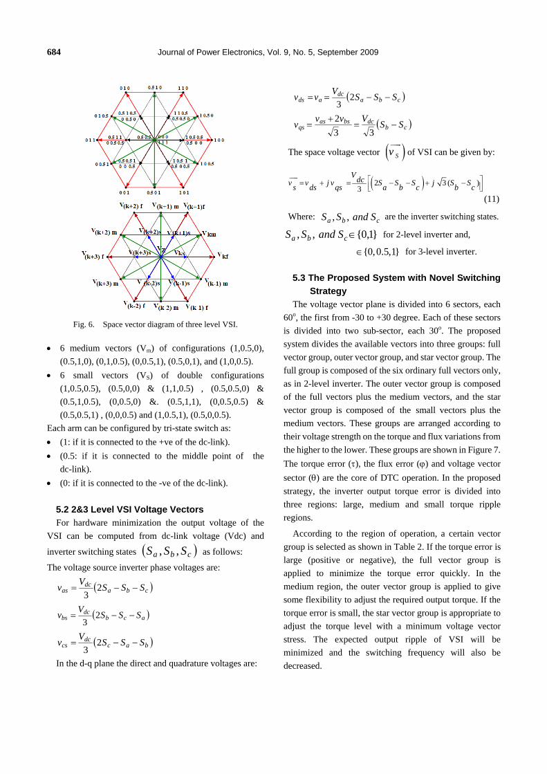
Fig. 6. Space vector diagram of three level VSI.
• 6 medium vectors (Vm) of configurations (1,0.5,0), (0.5,1,0), (0,1,0.5), (0,0.5,1), (0.5,0,1), and (1,0,0.5).
• 6 small vectors (VS) of double configurations (1,0.5,0.5), (0.5,0,0) & (1,1,0.5) , (0.5,0.5,0) & (0.5,1,0.5), (0,0.5,0) &. (0.5,1,1), (0,0.5,0.5) & (0.5,0.5,1) , (0,0,0.5) and (1,0.5,1), (0.5,0,0.5).
Each arm can be configured by tri-state switch as: • (1: if it is connected to the +ve of the dc-link). • (0.5: if it is connected to the middle point of the
dc-link). • (0: if it is connected to the -ve of the dc-link).
5.2 2&3 Level VSI Voltage Vectors For hardware minimization the output voltage of the
VSI can be computed from dc-link voltage (Vdc) and
inverter switching states ( )cba SSS ,, as follows:
The voltage source inverter phase voltages are:
( )cbadc
as SSSVv −−= 23
( )acbdc
bs SSSVv −−= 23
( )bacdc
cs SSSVv −−= 23
In the d-q plane the direct and quadrature voltages are:
( )cbadc
ads SSSVvv −−== 23
( )cbdcbsas
qs SSVvvv −=+
=33
2
The space voltage vector ( )Svuur
of VSI can be given by:
( )2 3 ( )3
Vdcv v j v S S S j S Ss ds qs a b c b c⎡ ⎤= + = − − + −⎢ ⎥⎣ ⎦
uur
(11)
Where: cba SandSS ,, are the inverter switching states.
}1,0{,, ∈cba SandSS for 2-level inverter and,
{0,0.5,1}∈ for 3-level inverter.
5.3 The Proposed System with Novel Switching Strategy
The voltage vector plane is divided into 6 sectors, each 60o, the first from -30 to +30 degree. Each of these sectors is divided into two sub-sector, each 30o. The proposed system divides the available vectors into three groups: full vector group, outer vector group, and star vector group. The full group is composed of the six ordinary full vectors only, as in 2-level inverter. The outer vector group is composed of the full vectors plus the medium vectors, and the star vector group is composed of the small vectors plus the medium vectors. These groups are arranged according to their voltage strength on the torque and flux variations from the higher to the lower. These groups are shown in Figure 7. The torque error (τ), the flux error (ϕ) and voltage vector sector (θ) are the core of DTC operation. In the proposed strategy, the inverter output torque error is divided into three regions: large, medium and small torque ripple regions.
According to the region of operation, a certain vector group is selected as shown in Table 2. If the torque error is large (positive or negative), the full vector group is applied to minimize the torque error quickly. In the medium region, the outer vector group is applied to give some flexibility to adjust the required output torque. If the torque error is small, the star vector group is appropriate to adjust the torque level with a minimum voltage vector stress. The expected output ripple of VSI will be minimized and the switching frequency will also be decreased.

Torque Ripple Minimization for Induction Motor Driven by … 685
Fig. 7. Full, outer and star vector groups.
Table 2. The proposed switching strategy.
Torque Ripple Region Vector group
1 +ve large Full
2 +ve medium Outer
3 +ve small Star
4 -ve small Star
5 -ve medium Outer
6 -ve large Full The small torque error region is defined between 2.5%
and 5% of the full load torque, the medium is between 5% and 10%, and the large is greater than 10%. These values are suggested values and they can be changed according to
the required accuracy of the produced torque. Decreasing these values produces increased switching frequency and switching losses. The flux bang-bang error rang is selected between -10% and +10%. It can also be modified as the torque error. It affects the switching frequency of the VSI inverter.
5.4 The Proposed Switching Strategy The purpose of the proposed switching strategy is to
select the appropriate voltage vector from 27 available vectors in the three-level inverter. The selection is based on the sector number (θ), torque error (τ) and flux error (ϕ). θ takes values from 1 through 6, whereas τ and ϕ take either 0 or 1. The selection between groups depends on the torque error value (ΔT). Tables 3,4,and 5 show the novel switching strategy for full, outer and star vector groups, respectively. The sector (600) is divided into two subsectors (each 300). It is indicated in the table as 1st and 2nd subsectors.
Table 3. Switching strategy for full vector group.
ϕ τ Selected vector (full group)
1st subsector 2nd subsector
0 0 VZ VZ
0 1 V(k+2)f V(k+2)f
1 0 VZ VZ
1 1 V(k+1)f V(k+1)f
Table 4. Switching strategy for outer vector group.
ϕ τ Selected vector (outer group)
1st subsector 2nd subsector
0 0 V(k+3)m V(k-2)f
0 1 V(k+2)f V(k+2)m
1 0 V(k-1)f V(k-1)m
1 1 V(k)m V(k+1)f

686 Journal of Power Electronics, Vol. 9, No. 5, September 2009
Table 5. Switching strategy for star vector group.
ϕ τ Selected vector (star group)
1st subsector 2nd subsector 0 0 V(k+3)m V(k-2)s 0 1 V(k+2)s V(k+2)m 1 0 V(k-1)s V(k-1)m 1 1 V(k)m V(k+1)s
6. The Speed Controller
The speed controller input is the speed error and the rate of error change. The controller output is the torque reference for the DTC. This controller is called classical speed controller (CSC) as described in [25]. The controller equation is:
[ ]( 1) 1* ( ) 2* ( )c k k e k k e k+ = + Δ∫ (12)
Where c is the controller output that represents the
torque reference *T , and k1 and k2 are the scaling factors. e is the speed error, and eΔ is the change in the speed error. Equation 12 is the basic form of the CSC. The controller is used to control the speed of the induction motor in two- and three-level inverters.
7. Simulation Results The proposed DTC switching strategy is applied to the
three-level inverter that drives an induction motor. The output of the system is compared with that of conventional switching strategy for three-level inverter and also with the conventional two-level inverter output. Fig. 8 shows a comparison of the motor output torque for three cases. The higher of the torque ripple in the conventional two-level inverter is the superior.
The torque ripple contents for the conventional DTC for three-level is also better than that of two-level inverter as expected. The torque ripple in the conventional two-Level DTC is about 11.6% , for the conventional DTC strategy applied to the three-level inverter is 8.3% whereas the torque ripple in the proposed system output is only 4.1%, as shown in the figure. Thus, the torque ripple in the
1.20 1.60 2.00 2.40Time (sec)
-4-3-2-10123456789
10
Torq
ue (N
.m)
(a)
1.2 1.6 2.0 2.4Time (sec)
-4-3-2-10123456789
10
Torq
ue (N
.m)
(b)
1.2 1.6 2.0 2.4Time (sec)
-4-3-2-10123456789
10
Torq
ue (N
.m)
(c)
Fig. 8. Torque ripple and torque response comparison in Conventional 2-LI, (b) Conventional 3-LI and
(c) The proposed system.
proposed system is slightly greater than 50% from that of conventional DTC scheme applied to three-level inverter, and about 64% less than that of conventional two-level
Torque Ripple Minimization for Induction Motor Driven by … 687 inverter DTC scheme. The figure also shows the load torque (center line) and the motor electromagnetic torque. The controller follows the load torque demand with minimum overshot in the torque or the speed.
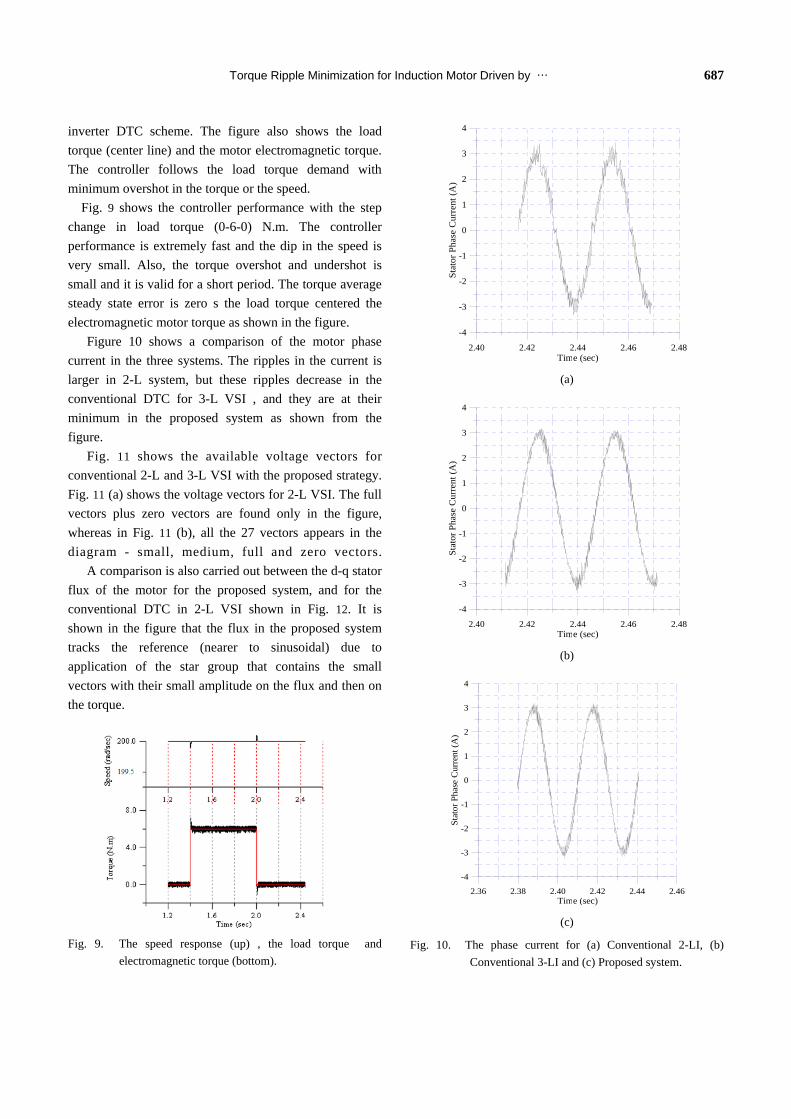
Fig. 9 shows the controller performance with the step change in load torque (0-6-0) N.m. The controller performance is extremely fast and the dip in the speed is very small. Also, the torque overshot and undershot is small and it is valid for a short period. The torque average steady state error is zero s the load torque centered the electromagnetic motor torque as shown in the figure.
Figure 10 shows a comparison of the motor phase current in the three systems. The ripples in the current is larger in 2-L system, but these ripples decrease in the conventional DTC for 3-L VSI , and they are at their minimum in the proposed system as shown from the figure.
Fig. 11 shows the available voltage vectors for conventional 2-L and 3-L VSI with the proposed strategy. Fig. 11 (a) shows the voltage vectors for 2-L VSI. The full vectors plus zero vectors are found only in the figure, whereas in Fig. 11 (b), all the 27 vectors appears in the diagram - small, medium, full and zero vectors.
A comparison is also carried out between the d-q stator flux of the motor for the proposed system, and for the conventional DTC in 2-L VSI shown in Fig. 12. It is shown in the figure that the flux in the proposed system tracks the reference (nearer to sinusoidal) due to application of the star group that contains the small vectors with their small amplitude on the flux and then on the torque.
Fig. 9. The speed response (up) , the load torque and
electromagnetic torque (bottom).
2.40 2.42 2.44 2.46 2.48Time (sec)
-4
-3
-2
-1
0
1
2
3
4
Stat
or P
hase
Cur
rent
(A)
(a)
2.40 2.42 2.44 2.46 2.48Time (sec)
-4
-3
-2
-1
0
1
2
3
4
Stat
or P
hase
Cur
rent
(A)
(b)
2.36 2.38 2.40 2.42 2.44 2.46Time (sec)
-4
-3
-2
-1
0
1
2
3
4
Stat
or P
hase
Cur
rent
(A)
(c)
Fig. 10. The phase current for (a) Conventional 2-LI, (b) Conventional 3-LI and (c) Proposed system.

688 Journal of Power Electronics, Vol. 9, No. 5, September 2009
-400 -200 0 200 400Vds (volt)
-400
-200
0
200
400
Vqs
(vol
t)
(a)
-400 -200 0 200 400Vds (volt)
-400
-200
0
200
400
Vqs
(vol
t)
(b)
Fig. 11. Voltage Vectors For (a) 2-Level VSI (b) 3-Level VSI with proposed Strategy.
2.96 2.97 2.98 2.99 3.00time (sec)
-1.00
-0.50
0.00
0.50
1.00
Psi (
Wb)
(a)
2.96 2.97 2.98 2.99 3.00time (sec)
-1.00
-0.50
0.00
0.50
1.00
Psi (
Wb)
(b)
Fig. 12. d-q Stator Flux for (a) 2_L Inverter (b) 3-L Inverter with proposed strategy.
8. Conclusions
A novel torque ripple minimization technique is
introduced in this paper. The proposed technique is applied to a photovoltaic three level VSI feeds in induction motor as a stand-alone photovoltaic system. The PV array and the battery bank are sized based on sun-hour methodology. The models of the motor, three and two level VSI, are indicated. The various voltage vectors of the three-level VSI are defined and classified into three groups. Each group has its switching strategy that is defined and simulated. Also, an accurate classical speed controller is used to adjust the torque reference for the DTC system. The simulation results show that the proposed system is the superior in torque ripple minimization for motor drive application in PV stand-alone system. Also, they show that the motor torque ripple in the proposed system is slightly greater than 50% from that of conventional DTC scheme applied to three-level VSI, and slightly greater than 64% of conventional DTC scheme applied to two-level VSI.
References [1] A. Purcell, P. Acarnley, "Enhanced Inverter Switching for
Fast Response Direct Torque Control," IEEE Trans. PE, May 2001.
[2] I. Takahashi and T. Noguchi, "A New Quick Response and

Torque Ripple Minimization for Induction Motor Driven by … 689
High Efficiency Control Strategy for the Induction Motor," IEEE Trans. IA, September/October 1986.
[3] M. Depenbrock, "Direct Self-Control of Inverter-fed Induction Machine," IEEE Trans. PE, October 1988.
[4] ABB, "Direct Torque Control – the World's Most Advanced AC Drive Technology," ABB, Finland, Helsinki, Technical guide, No. 1, 1996.
[5] P. Tiitinen, and M. Surandra, "The next generation motor control method, DTC direct torque control," Power Electronics, Drives and Energy Systems for Industrial Growth, 1996., Proceedings of the 1996 International Conference on, Vol.1, January 1996.
[6] Wang Huangang, Xu Wenli,Yang Geng, Li Jian, "Variable-structure torque control of induction motors using space vector modulation," Electrical Engineering (Archiv fur Elektrotechnik) Vol. 87, No. 2, February 2005.
[7] K. Lee; J. Song, I. Choy and J. Yoo ,"Torque ripple reduction in DTC of induction motor driven by three-level inverter with low switching frequency," IEEE Transactions on Power Electronics, Vol. 17, No. 2, March 2002.
[8] Alan Ristow, Miroslav Begovi, Aleksandar Pregelj & Ajeet Rohatgi, “Development of a Methodology for Improving Photovoltaic Inverter Reliability,” IEEE Transactions on IE, Vol. 55, No. 7, July 2008
[9] Cherus, C.D.; Chol, A.M., “Voltage Control in a Battery-Operated Sinusoidal Pulse-Width-Modulated (SPWM) Photovoltaic Inverter,” AFRICON, 1999 IEEE, Vol. 2, 28 September-1 October.
[10] Chee Wei Tan; Green, T.C.; Hernandez-Aramburo, C.A., “A Stochastic Simulation of Battery Sizing for Demand Shifting and Uninterruptible Power Supply Facility,” Power Electronics Specialists Conference, 2007. PESC 2007. IEEE, 17-21 June 2007.
[11] D.P. Jenkins J. Fletcher D. Kane, “Lifetime prediction and sizing of lead–acid batteries for micro generation storage applications,” The Institution of Engineering and Technology 2008, IET Renew. Power Gener., 2008, Vol. 2, No. 3, pp. 191–2008.
[12] O. Sundstr¨om and A. Stefanopoulou, “Optimal Power Split in Fuel Cell Hybrid Electric Vehicle with different Battery Sizes, Drive Cycles, and Objectives,” Proceedings of the 2006 IEEE, International Conference on Control Applications Munich, Germany, October 4-6, 2006.
[13] Monji G. Jaboori, Mohamed M. Saied & Adel A. R. Hanafy, “A Contribution To The Simulation And Design Optimization Of Photovoltaic Systems,” IEEE Transactions on Energy Conversion, Vol. 6, No. 3, September 1991.
[14] IEEE Standards Coordinating Committee 21 on Fuel Cells, Photovoltaics, Dispersed Generation, and Energy Storage,
“IEEE Guide for Array and Battery Sizing in Stand-Alone Photovoltaic (PV) Systems,” Approved 5 December 2007, IEEE-SA Standards Board, IEEE Std 1562™-2007, May 2008.
[15] Imamura M.S., Helm P., and Palz W., “Photovoltaic System Technology, an European Handbook,” British Library, U.K., 1992.
[16] M.Zahran, et al., “Assessment of Earth Remote Sensing Microsatellite Power Subsystem Capability during Detumbling and Nominal Modes,” Journal of Power Electronics, Vol. 6, No. 1, January 2006.
[17] Krause P.C., “Analysis of Electric Machinery,” Mc.Graw-Hill, USA, 1986.
[18] R. Toufouti S. Meziane ,H. Benalla, "Direct Torque Control For Induction Motor Using Intelligent Techniques," Journal of Theoretical and Applied Information Technology, 2007.
[19] Y. Atia, " Enhanced Efficiency Pumping System Operating With Photovoltaic Source,” PhD Thesis, Cairo University, November 2000.
[20] Xavier del Toro Garcia, Antoni Arias, Marcel G. Jayne, Phil A. Witting, M.Vicenç Sala, J. Romeral , “New DTC Control Scheme for Induction Motors fed with a Three-level Inverter, ” AUTOMATIKA, 46(2005) 1–2, 73–81.
[21] Brian A. W. Mauricio B. de R. Correa T. Lipo, “A Three-Level MOSFET Inverter for Low Power Drives,” National Science Center, Engineering Research Center under Award EEC-9731677.
[22] Figarado, S. Bhattacharya, T. Mondal, G. Gopakumar, K. “Three-level inverter scheme with reduced power device count for an induction motor drive with common-mode voltage elimination,” Power Electronics IET, Vol. 1, No. 1, March 2008.
[23] Martins, C.A.; Roboam, X.; Meynard, T.A.; Carvalho, A.S, “Switching frequency imposition and ripple reduction in DTC drives by using a multilevel converter,” IEEE Transactions on PE, Vol. 17, No. 2, March 2002.
[24] Jae Hyeong Seo; Chang Ho Choi; Dong Seok Hyun, “A new simplified space-vector PWM method for three-level inverters,” IEEE Transactions on PE, Vol. 16, No. 4, July 2001.
[25] M. M. Salem, “Classical controller with intelligent properties for speed control of vector controlled induction motor,” Journal of Power Electronics, Vol. 8, No. 3, pp.210-216, 2008.

690 Journal of Power Electronics, Vol. 9, No. 5, September 2009
Yousry Abdel-Gawad Atia was born in Egypt in 1964, received his B.Sc from Menufia Univ. Faculty of Engineering, Shebin-El-Kom in 1987. He was awarded the M.Sc and Ph.D. in 1995 and 2000 respectively from Cairo University, Faculty
of Engineering, Electrical Power and Machines Dept. Currently Dr. Atia is a Researcher at the Electronics Research Institute, Cairo, Egypt. His experience is in the fields of renewable energy, power electronics, drives, electrical machines, system design and control.