Application of Linear Momentum Actuator Disc ... - CiteSeerX

An experimental study on the displacement
characteristics of a magnetic actuator based on
ferrofluid
Alexandru Arcire
Faculty of Electrical Engineering “Gheorghe Asachi”
Technical University of Iasi
Iasi, Romania
Radu Olaru
Faculty of Electrical Engineering “Gheorghe Asachi”
Technical University of Iasi
Iasi, Romania
Abstract—The purpose of this paper is to investigate the
possibilities and means to increase the output displacement of an
actuator with a non-magnetic body levitated in a ferrofluid pre-
magnetized by permanent magnets and to enhance its
displacement characteristic linearity. Numerical simulations led
to a better understanding of the complex processes acting inside
this type of actuator, helping us to develop a more accurate
prototype model. Doubling the number of permanent magnets
and adding magnetic rings led to increasing the output
displacement and improvement of the displacement vs. current
characteristic linearity. The experimental measurements
effectuated on the actuator prototype are in good agreement with
theoretical and simulation results
Keywords—electromagnetic actuator; ferrofluid; permanent
magnets, displacement output
I. INTRODUCTION
Magnetic actuators have important advantages over conventional mechanical drives: simplicity, flexibility and reliability. Most of the magnetic field driven actuators can be classified as electromagnetic, electrodynamic, magnetostrictive, magnetorheologic and ferrofluidic (magnetofluidic). While the first three mentioned have been known for a long time and are widely used, the actuators of the latter two groups gained importance only in the last years.
A ferrofluid or magnetic fluid is a colloidal suspension of small (10 nm, typically) magnetite particles in a carrier liquid. In a non-uniform field the whole fluid responds as a homogeneous magnetic liquid which moves to the region of highest flux. Based on this effect, some actuators use a non-magnetic body immersed in the ferrofluid, the body displacement being controlled by an exterior applied magnetic field. The first type of actuator that uses this principle was described in the year 2000 [1]. A double action actuator was tested as a current to pressure transducer in an electro-pneumatic converter [2]. This principle can be used in controlling the vertical motion of a non-magnetic body. Vertical positioning systems using different actuator configurations with a nonmagnetic body levitated in a ferrofluid are described by Uhlmann et al. [3,4]. Several prototypes of precision positioning systems were developed
and investigated, the influence on velocity and accuracy of positioning being discussed.
A new idea applied for the actuator with nonmagnetic body levitated in ferrofluid consists of the use of two opposed permanent magnets to create a powerful magnetic field gradient in a ferrofluid that contains a nonmagnetic body, whose motion is rigorously and stably controlled by the current in the coil [5]. A numerical analysis of the structure and geometrical and material parameters is performed in [6] in order to investigate the ways to increase the magnetic force produced by the actuator. In this paper an experimental study on the current to displacement characteristics of an actuator similar to that used in [6] is performed.
II. WORKING PRINCIPLE OF THE ACTUATOR
The principle of the double effect actuator, described in [5] and [6] that use a non-magnetic body immersed in a ferrofluid differentially pre-magnetized by two magnets is illustrated in Fig. 1.
Fig. 1. Working principle of the actuator
In a first approximation, the magnetic levitation force may be expressed by the relation:
1 2 02 M IF F F AH H (1)

where IH is the magnetic field produced by the coil which
adds up with the pre-existent magnetic field of the two magnets
MH =1 2M MH H , A is the circular surface area of
nonmagnetic body and is the ferrofluid susceptibility that is
assumed to be constant.
Since the magnetic field produced by the coil is of the form
II kH I where Ik [m-1
] is a coefficient that depends on the
geometry of the coil and the number of coil windings, the final expression for the magnetic force on the non-magnetic body placed at equal distances from the two magnets is:
IAMkF MI02 (2)
where MM HM .
Although Eqs. (1) and (2) may not be used to calculate accurately the value of the magnetic force, they have the advantage of simplicity in expression and interpretation, mentioning the main quantities and how they are involved in generating the force.
It may be concluded that, according to (2), the force produced by the actuator in Fig.1 is directly proportional with the coil current, with the circular disc area and with the initial ferrofluid magnetization. In addition, the force is proportional to the susceptibility of the ferrofluid, eq. (1).
Although the magnetic field generated at any point by one magnet has a non-linear dependence on the distance point – magnet, a linear dependence can be assumed for small displacements Δz of the nonmagnetic body due to the differential effect of the two magnets on the resultant field, so
that MH =
zk z =IH , where
zk is a constant.
III. THE MAGNETIC FIELD INSIDE THE ACTUATOR
As demonstrated in our papers [7] the use of magnetic material enhances the actuator’s output displacement so in order to optimize it we have studied in detail the magnetic field formed by the four magnets (mounted in pairs of two at the distance at of 22 mm). Also it is investigated the influence of doubling number of magnets in compare to the model used in the article mentioned which had only two pre-magnetizing permanent magnets.
The actuator model used in simulations, having four pre-magnetization ring magnets is shown in Fig. 2.
Four different cases have been simulated in Comsol Multiphysics 3.5 software to investigate the influence of using magnetic material with respect to the magnetic field generated by the ring-shaped permanent magnets. Each plot has attached on the left side a color intensity bar, blue on the bottom of the scale being the smallest value and red on top being the biggest value of the magnetic field.
The stationary magnetic 2D field with axial symmetry determined with COMSOL 3.5 is based on the finite element method. The Magnetic Fields interface from the AC/DC module in COMSOL solves the partial differential equation
1 1
0 er B v B J (3)
where B A is the magnetic flux density, A the magnetic
vector potential and Je the externally generated current density. The mesh consisted of approximately 10500 elements with 22000 nodes (degrees of freedom).
Fig. 2. Actuator model with four magnets used in simulations
As the plots shows (Fig. 3-6), the maximum values of the magnetic field, 1.637 T and 1.65 T, data values provided by Comsol are obtained by the configurations in Figs. 5 and 6, respectively, which both have in common the use of magnetic rings, and smaller values for the configurations in Figs. 3 and 4, 1.114 T and 1.122 T, respectively. This is an increase of 67 percent at peak value. The presence of the magnetic rings on the permanent magnet acts as a magnetic field concentrator recording the highest values in the proximity of the outer edge of the rings. The use of magnetic case acts as a magnetic shield, enhancing the effect generated by the presence of magnetic rings and also has a role of mechanical protection.
Fig. 3. Contour view of magnetic field distribution with magnets placed on
container
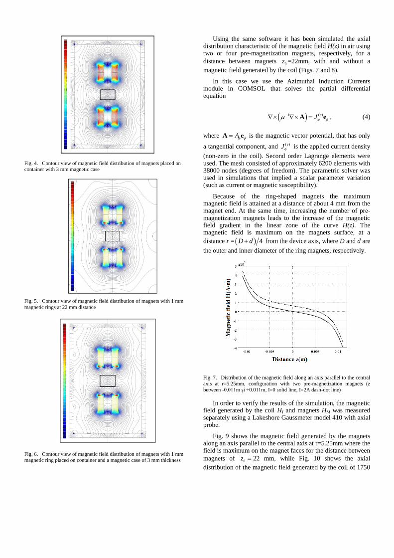
Fig. 4. Contour view of magnetic field distribution of magnets placed on container with 3 mm magnetic case
Fig. 5. Contour view of magnetic field distribution of magnets with 1 mm
magnetic rings at 22 mm distance
Fig. 6. Contour view of magnetic field distribution of magnets with 1 mm magnetic ring placed on container and a magnetic case of 3 mm thickness
Using the same software it has been simulated the axial distribution characteristic of the magnetic field H(z) in air using two or four pre-magnetization magnets, respectively, for a
distance between magnets 0z =22mm, with and without a
magnetic field generated by the coil (Figs. 7 and 8).
In this case we use the Azimuthal Induction Currents module in COMSOL that solves the partial differential equation
1 ( )eJ A e , (4)
where A A e is the magnetic vector potential, that has only
a tangential component, and ( )eJ is the applied current density
(non-zero in the coil). Second order Lagrange elements were used. The mesh consisted of approximately 6200 elements with 38000 nodes (degrees of freedom). The parametric solver was used in simulations that implied a scalar parameter variation (such as current or magnetic susceptibility).
Because of the ring-shaped magnets the maximum magnetic field is attained at a distance of about 4 mm from the magnet end. At the same time, increasing the number of pre-magnetization magnets leads to the increase of the magnetic field gradient in the linear zone of the curve H(z). The magnetic field is maximum on the magnets surface, at a
distance r = 4D d from the device axis, where D and d are
the outer and inner diameter of the ring magnets, respectively.
Fig. 7. Distribution of the magnetic field along an axis parallel to the central
axis at r=5.25mm, configuration with two pre-magnetization magnets (z
between -0.011m şi +0.011m, I=0 solid line, I=2A dash-dot line)
In order to verify the results of the simulation, the magnetic field generated by the coil HI and magnets HM was measured separately using a Lakeshore Gaussmeter model 410 with axial probe.
Fig. 9 shows the magnetic field generated by the magnets along an axis parallel to the central axis at r=5.25mm where the field is maximum on the magnet faces for the distance between
magnets of 0z 22 mm, while Fig. 10 shows the axial
distribution of the magnetic field generated by the coil of 1750

windings of Copper Ø 0.55 mm for a current of 1A and 2A respectively.
Fig. 8. Distribution of the magnetic field along an axis parallel to the central
axis at r=5.25mm, configuration with four pre-magnetization magnets (z between -0.011m şi +0.011m, I=0 solid line, I=2A dash-dot line)
Fig. 9. Magnetic field HM along an axis parallel to the central axis at r=5.25 mm, for two (2M) and four (4M) pre-magnetization magnets
Fig. 10. Axial distribution of the coil magnetic field HI for a current of 1A and
2A
Fig. 11. Distribution of the resulting magnetic field ( HM + HI ) in
configuration with four pre-magnetization magnets (z between -0.011m and
+0.011m) for a current of 2A.
Although the values of the magnetic field generated by the coil was measured axially and the field generated by the magnets was measured along an axis parallel to the central axis at r=5.25mm, it can be seen that the shape of the curve and the resulting field values measured experimentally by adding together magnetic fields HM and HI (Fig. 9 and 10) are close to the results obtained by simulation (Figs. 7 and 8), so it is considered that the experimental (Fig. 11) and simulation results are in good agreement.
IV. ANALYSIS OF DISPLACEMENT DEPENDANCE ON
CURRENT
The actuator schematic with a non-magnetic disc levitated in a ferrofluid pre-magnetized by four permanent magnets is illustrated in Fig. 12. The four ring-shaped permanent magnets mounted in pairs of two, with poles of the same name face to face, are fixed inside the coil casing (frame). In the space between the two magnets is disposed a container which houses a ferrofluid and a nonmagnetic cylinder or disc. The actuator force and the disc displacement are transmitted outside by means of a rod. The prototype contains a coil with 1750 windings of Copper Ø 0.55 mm. The non-magnetic cylinder, made of a polyamide material, has a diameter of 11 mm and a height of 8 mm. The top and bottom ring magnets in Fig. 12 are two pairs of Nd-Fe-B, type R-15-06-06-N magnets (www.supermagnete.de), with the characteristics Ø 15/6 mm,
H= 6 mm, remanent flux density rB = 1.3 T. The ferrofluid
used (Art. FER-02, P196, www.supermagnete.de) is made with hydrocarbons similar to those found in motor oil. The initial
magnetic susceptibility was measured experimentally, i = 1.2,
giving an initial magnetic relative permeability, ri =2.2,
respectively.
Based on the configuration in Fig. 12, experimental results emphasize that doubling the number of magnets (4M) for the same non-magnetic mobile body of 8 mm height and Ø11 mm diameter improves the linearity of the actuator’s displacement characteristics and also increases the stroke of the actuator with almost 20 percent (Fig. 13).

Fig. 12. Basic actuator configuration with nonmagnetic body immersed in a
ferrofluid container
Fig. 13. Displacement vs. current characteristic for two (2M) and four (4M)
premagnetizing magnets
In the experimental procedure it was investigated the effect of using five different heights of the movable non-magnetic cylinder zc = 6, 8, 10, 12 and 14 mm (with the same diameter of 11 mm) in two different configurations of the actuator (with magnetic case and with magnetic rings) on the displacement to current characteristic.
Fig. 14 shows an experimental comparison study of the nonmagnetic body displacement regarding the basic actuator assembly with two pairs of permanent magnets disposed at 22 mm distance (mounted on each ends of the ferrofluid recipient) and using a magnetic case. When is used a magnetic case of 3 mm thickness the increase of the current to displacement slope is maximum 5 percent, but maintains for each nonmagnetic body a good linearity of the displacement characteristic (Fig. 14).
In Fig. 15 we use the same basic configuration as in Fig. 12 but in combination with a pair of two magnetic rings of 1 mm
thick mounted inside the actuator on each magnet, in the space between the magnets and recipient.
Fig. 14. Displacement vs. current characteristic with (c) or without (0)
magnetic case of 3 mm thickness
Fig. 15. Displacement vs. current characteristic with (i) or without (0)
magnetic rings of 1 mm thickness for differet hights of the nonmagnetic body
Analyzing the displacement characteristic for the configuration with magnetic rings in Fig. 15 pinpoints clearly that the maximum stroke was greatly enhanced (about 20 percent more) when comparing to the basic actuator configuration and maintaining a good linearity. In comparison to the values obtained with magnetic case, the ones obtained with magnetic rings are about 15 percent much higher (Fig. 16).
For the mobile nonmagnetic body of 6 mm height the maximum stroke increases from 4,5 to 5,7 mm and for the 8 mm height body increases from 4,1 to 5,1, approximately 20 percent (Fig. 15). All these results are in good agreement with the simulations, that comes to sustain the results obtained at Figs. 3-6, which indicated that an increase in displacement will certainly be obtain, especially the configuration with magnetic rings.

Fig. 16. Displacement vs current characterisitc for the 8 mm height non-
magnetic movable body with magnetic case (c) and magnetic rings (i)
In both configurations adding a magnetic material (magnetic rings or magnetic case) improves the range of the actuator output displacement for the same current fed through the coil while maintaining a very good linearity. From the five nonmagnetic bodies with different heights studied, the best displacement linearity and maximum stroke is obtained by the nonmagnetic mobile body of 6 mm height with magnetic rings of 1 mm thickness.
V. CONCLUSIONS
In this paper an actuator with ferrofluid premagnetized by permanent magnets was studied focusing on optimizing the actuator’s output displacement and the linearity of the displacement vs. current characteristic. Evaluation through simulation and experiment of the magnetic field acting inside this type of actuator led to an increased understanding of the complex processes that takes place in the interior of the actuator which resulted in designing a more accurate actuator
having the highest slope of the current to displacement characteristic.
Doubling the number of magnets led to an increase of the actuator output displacement and an enhanced linearity of the current to displacement characteristic. The use of magnetic material in different configurations (magnetic rings and magnetic case) increases the actuator’s output displacement and maintains a good linearity of the displacement characteristic. Thus, a magnetic case of 3 mm thickness increases the maximum stroke with about 5 percent and magnetic rings mounted on the interior face of the permanent magnets significantly enhance the output displacement of the actuator (about 20 percent) while maintains a good linearity of the actuator displacement characteristic.
REFERENCES
[1] R. Olaru, A. Sălceanu, D. Calarasu, C. Cotae, Magnetic Fluid Actuator, Sensors and Actuators A: Physical, Vol. 81(1-3), pp. 290-293, 2000.
[2] R. Olaru, C. Petrescu, R. Hertanu, Magnetic Actuator with Ferrofluid and Non-Magnetic Disc, International Journal of Applied Electromagnetics and Mechanics, Vol. 32(4), pp. 267-274, 2010.
[3] E. Uhlmann, N. Bayat, Investigations on Ferrofluidic Positioning Systems, Production Engineering, WGP Annals, Vol. XI(2), pp. 195-198, 2004.
[4] E. Uhlmann N. Bayat, High Precision Positioning with Ferrofluids as an Active Medium, CIRP ANNALS-MANUFACTURING TECHNOLOGY, Vol. 55(1), pp. 415-418, 2006.
[5] R. Olaru, C. Petrescu, R. Hertanu, A novel double-action actuator based on ferrofluid and permanent magnets, Journal of Intelligent Material Systems and Structures, Vol. 23(14), pp. 1619-1626, 2012.
[6] R. Olaru, Camelia Petrescu and A. Arcire, Maximizing the magnetic force generated by an actuator with non-magnetic body in a ferrofluid pre-magnetized by permanent magnets, International Review of Electrical Engineering (IREE), Vol. 8(2), pp. 904-911, 2013.
[7] A. Arcire, R. Olaru, C. Petrescu, “Study of the influence of ferromagnetic material on the characteristics of an actuator based on ferrofluid and permanent magnets”, International Conference and Exposition on Electrical and Power Engineering (EPE), 2012, pp. 776 - 780 as doi: 10.1109/ICEPE.2012.6463838as
Copyright © 2022 FDOKUMEN