AN ENHANCED FDTD MODEL FOR COMPLEX LUMPED CIRCUITS
11
Progress In Electromagnetics Research, PIER 76, 485–495, 2007 AN ENHANCED FDTD MODEL FOR COMPLEX LUMPED CIRCUITS S. Q. Xiao, B.-Z. Wang, P. Du, and Z. H. Shao Institute of Applied Physics University of Electronic Science and Technology of China Chengdu 610054, P. R. China Abstract—One of most difficult challenges in simulating hybrid RF systems by finite-difference time-domain (FDTD) method is to construct the models for active and lumped elements. In this article, by combining the circuit equations with an integral transform, an enhanced FDTD method is proposed to model the hybrid lumped network which consists of nonlinear and high order linear elements with arbitrary connections. Based on this model, an active radiation system is analyzed. And it shows the application extension of the traditional FDTD method. 1. INTRODUCTION Finite-difference time-domain (FDTD) method was firstly presented by Yee in 1966 and has been applied to analyze electromagnetic characteristics of various passive microwave and antenna structures [1]. For example, it was successfully used to analyze the guided wave problems [2–5], extract the propagation constant of uniform transmission line [6], study the radiation performance of microwave and millimeter wave antennas [7–11], simulate electromagnetic wave penetration into a complex structure as well as the scattering of the electric large object [12, 13]. Linear lumped circuits and active devices, such as integrated resistor, diode, FET and HEMT, play an important role in microwave integrated circuit (MIC) and microwave monolithic integrated circuit (MMIC). The FDTD method is also expected to be capable of analyzing these lumped and active devices. When the FDTD method is employed in this topic, one of the most difficult challenges is to construct the models for these circuit units. In order to simulate the linear lumped and active devices by the FDTD method, many
Transcript of AN ENHANCED FDTD MODEL FOR COMPLEX LUMPED CIRCUITS
Progress In Electromagnetics Research, PIER 76, 485–495, 2007
AN ENHANCED FDTD MODEL FOR COMPLEXLUMPED CIRCUITS
S. Q. Xiao, B.-Z. Wang, P. Du, and Z. H. Shao
Institute of Applied PhysicsUniversity of Electronic Science and Technology of ChinaChengdu 610054, P. R. China
Abstract—One of most difficult challenges in simulating hybridRF systems by finite-difference time-domain (FDTD) method is toconstruct the models for active and lumped elements. In this article,by combining the circuit equations with an integral transform, anenhanced FDTD method is proposed to model the hybrid lumpednetwork which consists of nonlinear and high order linear elementswith arbitrary connections. Based on this model, an active radiationsystem is analyzed. And it shows the application extension of thetraditional FDTD method.
1. INTRODUCTION
Finite-difference time-domain (FDTD) method was firstly presentedby Yee in 1966 and has been applied to analyze electromagneticcharacteristics of various passive microwave and antenna structures[1]. For example, it was successfully used to analyze the guidedwave problems [2–5], extract the propagation constant of uniformtransmission line [6], study the radiation performance of microwaveand millimeter wave antennas [7–11], simulate electromagnetic wavepenetration into a complex structure as well as the scattering of theelectric large object [12, 13].
Linear lumped circuits and active devices, such as integratedresistor, diode, FET and HEMT, play an important role in microwaveintegrated circuit (MIC) and microwave monolithic integrated circuit(MMIC). The FDTD method is also expected to be capable ofanalyzing these lumped and active devices. When the FDTD methodis employed in this topic, one of the most difficult challenges is toconstruct the models for these circuit units. In order to simulatethe linear lumped and active devices by the FDTD method, many

486 Xiao et al.
efforts have been made. Literature [14] has proposed a FDTD methodfor modeling the linear lumped circuits. The linear lumped networkis described with its impedance in Laplace domain, and then theimpedance is transformed from Laplace domain into Z-domain by thebilinear transformation. Finally, the time domain terminal voltage ofthe linear lumped network required by Yee’s cell can be obtained byusing appropriate digital signal processing techniques. Subsequently,Wu et al. [15] have developed another FDTD model for incorporating ahigh order passive network into FDTD method. In order to obtain anexplicit iteration format a complicated deductive procedure is used inthis model. Shao et al. [16] have present an improved FDTD methodbased on matrix theory for linear lumped circuits. Whereas thesemethods can not address the active and nonlinear circuit issues. Basedon the circuit equations, the authors in [17, 18] have reported a matrixmethod to model the complex lumped and active network. However,it can be seen that this matrix method is inapplicable to model thenetwork with nonlinear and high order linear elements. In this paper,we present an enhanced FDTD method to overcome this challenge anda new matrix technique is built to solve the complex hybrid network.
2. THE BASIC THEORY OF THE ENHANCED FDTDMODEL
2.1. Matrix Technique for the Linear Lumped Network
The frequency dependent impedance of the linear lumped network isdescribed in the integral form of the rational function as [15]
V0(s)I0(s)
=
R∑r=0
ar(1/s)r
M∑m=0
bm(1/s)m
(1)
where s = jω, V0 and I0 are the total voltage and current acrossthe linear lumped network, R and M are the highest order of thenumerator and denominator of the rational function, respectively. Thecoefficients ar and bm are determined by the structure of the linearlumped network.
The formula (1) can be rewritten as
V0(s)M∑
m=0
bm(1/s)m = I0(s)R∑
r=0
ar(1/s)r (2)

Progress In Electromagnetics Research, PIER 76, 2007 487
Utilizing the integral transform relationship between s-domain andtime domain
F (s)/s→∫ t
0f(τ)dτ (3)
Eq. (2) can be transformed into the time domain integral form anddiscretized as follows
b0Vn+10 +
M∑m=1
bmVn+10m = a0I
n+1/20 +
R∑r=1
arIn+1/20r (4)
where V n+101 , . . . , V n+1
0M and In+1/201 , . . . , I
n+1/20R are given by
V n+101 =
∫ (n+1)∆t
0V0(τ)dτ
=∫ n∆t
0V0(τ)dτ +
∫ (n+1)∆t
n∆tV0(τ)dτ
= V n01 + ∆tV n+1
0 (5a)
V n+102 = V n
02 + ∆tV n+101 (5b)
· · ·V n+1
0M = V n0M + ∆tV n+1
0(M−1) (5c)
In+1/201 =
∫ (n+1/2)∆t
0I0(τ)dτ
= In−1/201 + ∆tIn+1/2
0 (6a)
In+1/202 = I
n−1/202 + ∆tIn+1/2
01 (6b)· · ·
In+1/20R = I
n−1/20R + ∆tIn+1/2
0(R−1) (6c)
where ∆t is the time step length. If the medium is linear, lossless andhomogeneous, the electromagnetic fields and current density J can becoupled by the following Maxwell curl equation
ε∂E/∂t = ∇ × H − J (7)
where ε is the permittivity. We can assume that the lumped networkoccupies only one FDTD cell and it is along the x-direction. Accordingto Eq. (7), the relationship between electromagnetic fields and currentI0 at the location of the lumped network can be written as
En+1x = En
x + ∆t/ε (∇ × H)n+1/2x − ∆t/ε · In+1/2
0 /(∆y∆z) (8)

488 Xiao et al.
The local electric field Ex and the terminal voltage V0 of the networksatisfy
V n+10 = En+1
x ∆x (9)where ∆x, ∆y, and ∆z are the spatial step lengths along the x-, y-and z-directions, respectively. In Eqs. (4)–(9), there are (M + R +3) unknowns (En+1
x , V n+10 , V n+1
01 , . . . , V n+10M , I
n+1/20 , I
n+1/201 , . . . , I
n+1/20R )
and (M + R + 3) equations. The system of equations constructed byEqs. (4)–(9) might be written as a matrix format
AB = C0 (10)
where, A is (M + R + 3) × (M + R + 3) coefficient matrix, B is theunknown column vector (En+1
x , V n+10 , V n+1
01 , . . . , V n+10M , I
n+1/20 , I
n+1/201
, . . . , In+1/20R )T , and C0 is the known column vector, respectively. The
matrices A and C0 can be written as
A =
1 0 · · · ∆t/ε/(∆y∆z) 0−∆x 1 0 · · ·
0 −∆t 1 0 · · · 00 0 −∆t 1 0 · · · 0 · · ·
· · ·0 0 · · · −∆t 1 0
0 b0 b1 · · · bM −a0 −a1 · · · −aR
0 0 · · · 0 −∆t 1 0 · · · 00 0 · · · 0 −∆t 1 0 · · ·
· · ·0 · · · 0 −∆t 1
(11)
and
C0 =[En
x +∆tε
(∇×H)n+1/2x 0 V n
01 · · · V n0M 0 I
n−1/201 · · · In−1/2
0R
]T
(12)It is clear that the local electric field on the FDTD cell occupied bythe linear lumped network can be solved very easily by the new matrixtechnique. However, in order to obtain an explicit iteration format acomplicated deductive procedure is used in Literature [15].
2.2. Matrix Technique for the Network with Nonlinear andHigh-order Linear Elements
The complex networks with linear and nonlinear elements have beenextensively used in various microwave circuits and active antenna

Progress In Electromagnetics Research, PIER 76, 2007 489
structures. For instance, diode and FET are frequently used in themicrowave mixer and can be equivalent to a hybrid network withnonlinear sources and linear lumped elements. To model such network,an FDTD model has been presented in [17, 18]. However, if some one-order elements, i.e., R,L or C, are replaced by complex high-orderones in the hybrid network, the method presented in [17, 18] is non-effective. In addition, the introduced matrix technique in Subsection2.1 is only suitable for the linear lumped networks. Therefore, itis necessary to develop an effective method to model the arbitrarycomplex hybrid network. By using Eqs. (2)–(12) in conjunction withKirchhoff’s current law at circuit nodes and Kirchhoff’s voltage law inbranch loop circuits,
∑Ipib
= 0 (13a)∑V q
jl= 0 (13b)
a new matrix technique can be built to solve this bothersome problem.In Eq. (13a), p and ib denote the p-th node and the ib-th branch currentat the p-th node, respectively. In Eq. (13b), q and jl denote the q-th loop circuit and the jl-th element voltage in the q-th loop circuit,respectively. During the analysis, the high order lumped elements areregarded as a circuit subsystem and its impedance Zh can be expressedas
Zh =
X∑x=0
fx(1/s)x
Y∑y=0
gy(1/s)y
(14)
whereX and Y are the highest order of the numerator and denominatorof the rational function, respectively. Based on Eqs. (13)–(14), asystem of nonlinear equations in s-domain can be established forcomplex hybrid network. The system of nonlinear equations needs tobe transformed into time domain using Eq. (3). Then the transforms(5) and (6) are used to discretize the time domain integral expressionswhich exist in this time domain system of nonlinear equations. Finally,combining the system of the discretized equations with Eqs. (8)–(9),a new system of equations, like (10), is constructed. However, unlikethe matrix equation of the linear lumped network, the new matrixequation is the nonlinear one and its coefficient matrix A depends ontime. Its solution can be obtained by Newton-Raphson method. In thefollowing section, we will show an illustrative example to demonstratethe applicability of the proposed approach.
490 Xiao et al.
3. THE APPLICATION OF THE ENHANCED FDTDMODEL
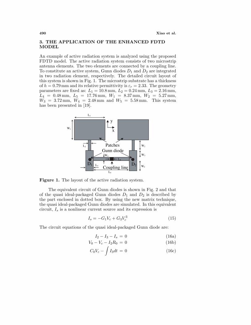
An example of active radiation system is analyzed using the proposedFDTD model. The active radiation system consists of two microstripantenna elements. The two elements are connected by a coupling line.To constitute an active system, Gunn diodes D1 and D2 are integratedin two radiation element, respectively. The detailed circuit layout ofthis system is shown in Fig. 1. The microstrip substrate has a thicknessof h = 0.79 mm and its relative permittivity is εr = 2.33. The geometryparameters are fixed as: L1 = 10.8 mm, L2 = 0.24 mm, L3 = 2.16 mm,L4 = 0.48 mm, L5 = 17.76 mm, W1 = 8.37 mm, W2 = 5.27 mm,W3 = 3.72 mm, W4 = 2.48 mm and W5 = 5.58 mm. This systemhas been presented in [19].
y
x
Patches Gunn diode
Coupling lineD1 D2 W5
W3
W2
L1
W1
L3
L5
W4
L4
L2
Figure 1. The layout of the active radiation system.
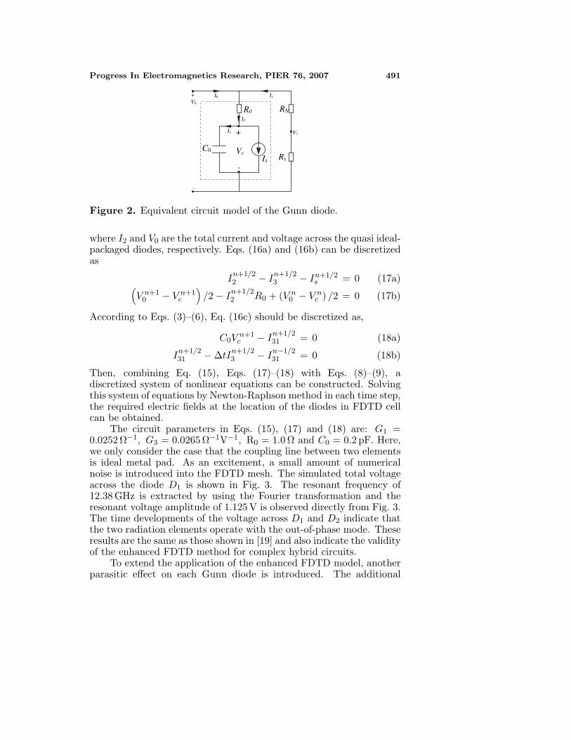
The equivalent circuit of Gunn diodes is shown in Fig. 2 and thatof the quasi ideal-packaged Gunn diodes D1 and D2 is described bythe part enclosed in dotted box. By using the new matrix technique,the quasi ideal-packaged Gunn diodes are simulated. In this equivalentcircuit, Is is a nonlinear current source and its expression is
Is = −G1Vc +G3V3c (15)
The circuit equations of the quasi ideal-packaged Gunn diode are:
I2 − I3 − Is = 0 (16a)V0 − Vc − I2R0 = 0 (16b)
C0Vc −∫I3dt = 0 (16c)
Progress In Electromagnetics Research, PIER 76, 2007 491
R0
C0
Is
+
-
Vc Rs
RN I2
I3
I1 I0 + V0
V1
-
Figure 2. Equivalent circuit model of the Gunn diode.
where I2 and V0 are the total current and voltage across the quasi ideal-packaged diodes, respectively. Eqs. (16a) and (16b) can be discretizedas
In+1/22 − In+1/2
3 − In+1/2s = 0 (17a)(
V n+10 − V n+1
c
)/2 − In+1/2
2 R0 + (V n0 − V n
c ) /2 = 0 (17b)
According to Eqs. (3)–(6), Eq. (16c) should be discretized as,
C0Vn+1c − In+1/2
31 = 0 (18a)
In+1/231 − ∆tIn+1/2
3 − In−1/231 = 0 (18b)
Then, combining Eq. (15), Eqs. (17)–(18) with Eqs. (8)–(9), adiscretized system of nonlinear equations can be constructed. Solvingthis system of equations by Newton-Raphson method in each time step,the required electric fields at the location of the diodes in FDTD cellcan be obtained.
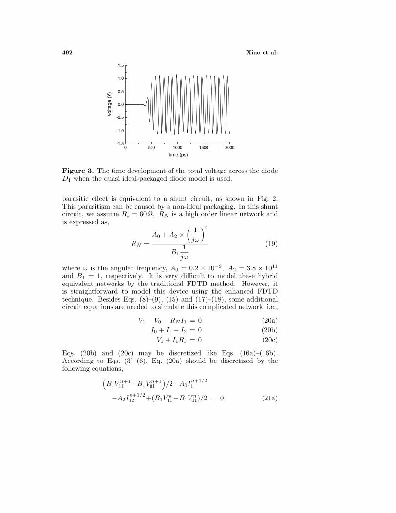
The circuit parameters in Eqs. (15), (17) and (18) are: G1 =0.0252 Ω−1, G3 = 0.0265 Ω−1V−1, R0 = 1.0 Ω and C0 = 0.2 pF. Here,we only consider the case that the coupling line between two elementsis ideal metal pad. As an excitement, a small amount of numericalnoise is introduced into the FDTD mesh. The simulated total voltageacross the diode D1 is shown in Fig. 3. The resonant frequency of12.38 GHz is extracted by using the Fourier transformation and theresonant voltage amplitude of 1.125V is observed directly from Fig. 3.The time developments of the voltage across D1 and D2 indicate thatthe two radiation elements operate with the out-of-phase mode. Theseresults are the same as those shown in [19] and also indicate the validityof the enhanced FDTD method for complex hybrid circuits.
To extend the application of the enhanced FDTD model, anotherparasitic effect on each Gunn diode is introduced. The additional
492 Xiao et al.
0 500 1000 1500 2000-1.5
-1.0
-0.5
0.0
0.5
1.0
1.5
Vol
tage
(V
)
Time (ps)
Figure 3. The time development of the total voltage across the diodeD1 when the quasi ideal-packaged diode model is used.
parasitic effect is equivalent to a shunt circuit, as shown in Fig. 2.This parasitism can be caused by a non-ideal packaging. In this shuntcircuit, we assume Rs = 60 Ω, RN is a high order linear network andis expressed as,
RN =A0 +A2 ×
(1jω
)2
B11jω
(19)
where ω is the angular frequency, A0 = 0.2 × 10⁻⁹, A2 = 3.8 × 10¹¹
and B1 = 1, respectively. It is very difficult to model these hybridequivalent networks by the traditional FDTD method. However, itis straightforward to model this device using the enhanced FDTDtechnique. Besides Eqs. (8)–(9), (15) and (17)–(18), some additionalcircuit equations are needed to simulate this complicated network, i.e.,
V1 − V0 −RNI1 = 0 (20a)I0 + I1 − I2 = 0 (20b)V1 + I1Rs = 0 (20c)
Eqs. (20b) and (20c) may be discretized like Eqs. (16a)–(16b).According to Eqs. (3)–(6), Eq. (20a) should be discretized by thefollowing equations,
(B1V
n+111 −B1V
n+101
)/2−A0I
n+1/21
−A2In+1/212 +(B1V
n11−B1V
n01)/2 = 0 (21a)
Progress In Electromagnetics Research, PIER 76, 2007 493
V n+111 − ∆tV n+1
1 − V n11 = 0 (21b)
V n+101 − ∆tV n+1
0 − V n01 = 0 (21c)
In+1/211 − ∆tIn+1/2
1 − In−1/211 = 0 (21d)
In+1/212 − ∆tIn+1/2
2 − In−1/212 = 0 (21e)
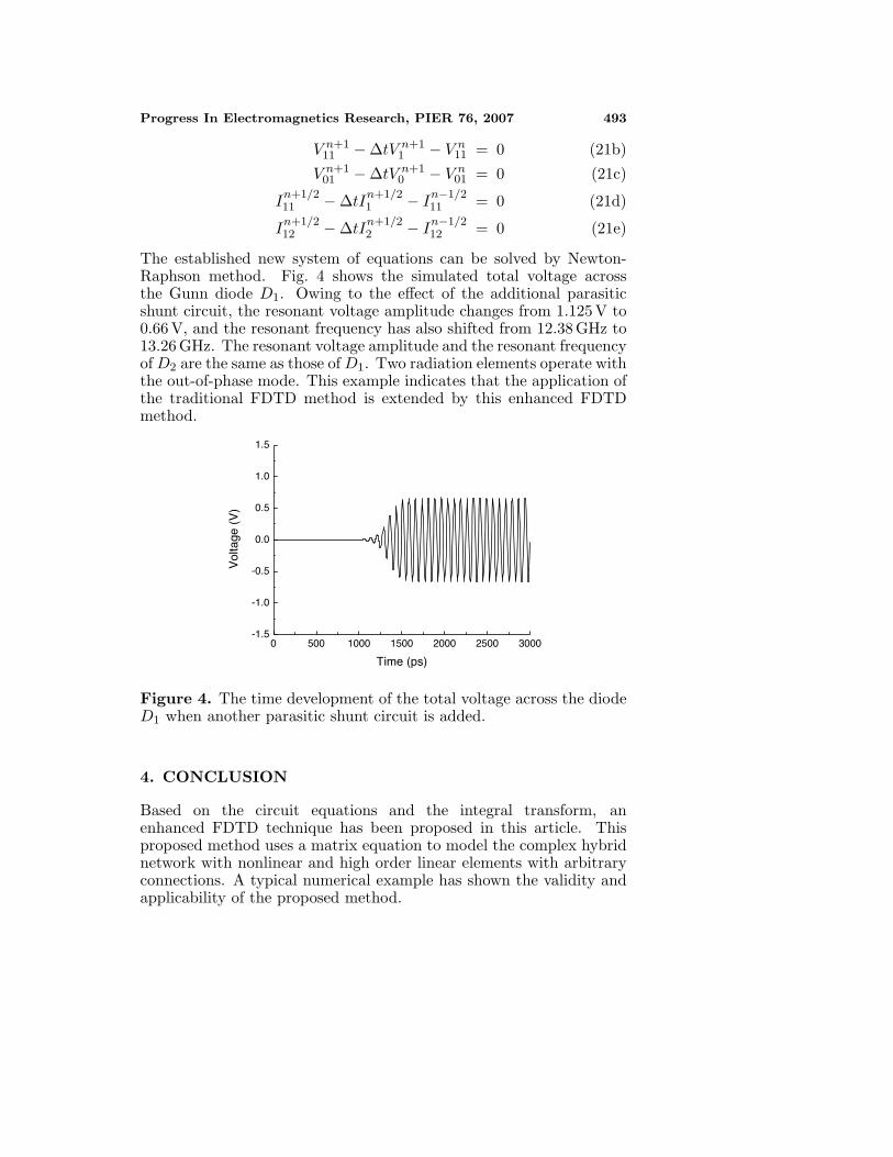
The established new system of equations can be solved by Newton-Raphson method. Fig. 4 shows the simulated total voltage acrossthe Gunn diode D1. Owing to the effect of the additional parasiticshunt circuit, the resonant voltage amplitude changes from 1.125 V to0.66 V, and the resonant frequency has also shifted from 12.38 GHz to13.26 GHz. The resonant voltage amplitude and the resonant frequencyofD2 are the same as those ofD1. Two radiation elements operate withthe out-of-phase mode. This example indicates that the application ofthe traditional FDTD method is extended by this enhanced FDTDmethod.
0 500 1000 1500 2000 2500 3000-1.5
-1.0
-0.5
0.0
0.5
1.0
1.5
Vol
tage
(V
)
Time (ps)
Figure 4. The time development of the total voltage across the diodeD1 when another parasitic shunt circuit is added.
4. CONCLUSION
Based on the circuit equations and the integral transform, anenhanced FDTD technique has been proposed in this article. Thisproposed method uses a matrix equation to model the complex hybridnetwork with nonlinear and high order linear elements with arbitraryconnections. A typical numerical example has shown the validity andapplicability of the proposed method.
494 Xiao et al.
ACKNOWLEDGMENT
This work was supported by the national nature science foundationof China (60501011, 90505001), the Specialized Research Fund for theDoctoral Program of Higher Education of China (No. 20060614005)and the Creative Research Team Program of UESTC.
REFERENCES
1. Taflove, A., Computational Electrodynamics: The finite-differencetime-domain method, Artech House, Boston, 1995.
2. Shao, Z. and W. Hong, “A kind of absorption boundary conditionsfor guided wave problems,” IEEE Trans. Microwave Theory Tech.,Vol. 50, 222–225, 2002.
3. Zhang, Y. and C. Liang, “Analysis of broad wall slots in finitewall thickness waveguide with non-uniform mesh locally conformalFDTD,” Journal of Electromagnetic Waves and Applications,Vol. 17, 1139–1150, 2003.
4. Berenger, J.-P., “Reduction of the angular dispersion of theFDTD method in the earth-ionosphere waveguide,” Journal ofElectromagnetic Waves and Applications, Vol. 17, 1225–1235,2003.
5. Young, J. L. and R. Adams, “Excitation and detection ofwaves in the FDTD analysis of n-port networks,” Progress InElectromagnetics Research, PIER 53, 249–269, 2005.
6. Wang, B.-Z., W. Shao, and Y. Wang, “2-D FDTD method forexact attenuation constant extraction of lossy transmission lines,”IEEE Microwave and Wireless Components Letters, Vol. 14, 289–291, 2004.
7. Zhang, Y., J. Song, and C. H. Liang, “MPI-based parallelizedlocally conformal FDTD for modeling slot antennas and newperiodic structures in microstrip,” Journal of ElectromagneticWaves and Applications, Vol. 18, 1321–1335, 2004.
8. Xiao, S., Z. Shao, M. Fujise, and B.-Z. Wang, “Patternreconfigurable leaky-wave antenna design by FDTD method andFloquet’s theorem,” IEEE Trans. Antennas Propagat., Vol. 53,1845–1848, 2005.
9. Gao, S., L.-W. Li, and A. Sambell, “FDTD analysis of a dual-frequency microstrip patch antenna,” Progress In Electromagnet-ics Research, PIER 54, 155–178, 2005.
10. Zhang, D. W., P. Y. Zhu, and C. H. Liang, “Study onelectromagnetic problems involving combinations of arbitrarily

Progress In Electromagnetics Research, PIER 76, 2007 495
oriented thin-wire antennas and inhomogeneous dielectric objectswith a hybrid MOM-FDTD method,” Journal of ElectromagneticWaves and Applications, Vol. 20, 1519–1533, 2006.
11. Uduwawala, D., “Modeling and investigation of planar parabolicdipoles for GPR applications: a comparison with bow-tie usingFDTD,” Journal of Electromagnetic Waves and Applications,Vol. 20, 227–236, 2006.
12. Golestani-Rad, L., J. Rashed-Mohassel, and M. M. Danaie,“Rigorous analysis of EM-wave penetration into a typical roomusing FDTD method: the transfer function concept,” Journal ofElectromagnetic Waves and Applications, Vol. 20, 913–926, 2006.
13. Gong, Z. and G.-Q. Zhu, “FDTD analysis of an anisotropicallycoated missile,” Progress In Electromagnetics Research, PIER 64,69–80, 2006.
14. Pereda, J. A., F. Alimenti, P. Mezzanotte, L. Roselli, andR. Sorrentino, “A new algorithm for the incorporation of arbitrarylinear lumped networks into FDTD simulators,” IEEE Trans.Microwave Theory Tech., Vol. 47, 943–949, 1999.
15. Wu, T.-L., S.-T. Chen, and Y.-S. Huang, “A novel approach forthe incorporation of arbitrary linear lumped network into FDTDmethod,” IEEE Microwave and Wireless Components Letters,Vol. 14, 74–76, 2004.
16. Shao, Z. and M. Fujise, “An improved FDTD formulation forgeneral linear lumped microwave circuits based on matrix theory,”IEEE Trans. Microwave Theory Tech., Vol. 53, 2261–2266, 2005.
17. Kuo, C.-N., B. Houshmand, and T. Itoh, “Full-wave analysis ofpackage microwave circuits with active and nonlinear devices: anFDTD approach,” IEEE Trans. Microwave Theory Tech., Vol. 45,819–826, 1997.
18. Koh, B. P., I. J. Graddock, P. Urwin-Wright, and C. J. Railton,“FDTD analysis of varactor-tuned patch antenna including devicepackaging effects,” IEE Electronics Letters, Vol. 37, 1494–1495,2001.
19. Thomas, V. A., K.-M. Ling, M. E. Jones, B. Toland, J. Lin, andT. Itoh, “FDTD analysis of an active antenna,” IEEE Microwaveand Guided Wave Letters, Vol. 4, 296–298, 1994.