Fundamentals of Electric Circuits
258
-
Upload
khangminh22 -
Category
Documents
-
view
0 -
download
0
Transcript of Fundamentals of Electric Circuits


محاضرات سلسلة
( 1الدوائر الكهربائية ) ساسيات ا
Fundamentals of Electric Circuits
وشرح إعداد
الدكتور حازم فالح سكيك
غزة –جامعة األزهر
قسم الفيزياء – كلية العلوم

المحتوايت
Basic Concepts ادئ اساسيةمبالوحدة األوىل:
Basic Laws قوانني اساسيةالوحدة الثانية:
Methods of Analysis الدوائرطرق حتليل الوحدة الثالثة:
Circuit Theorems نظريات الدوائرالوحدة الرابعة:
Capacitors and Inductors املكثفات وامللفاتاخلامسة: الوحدة
AC circuits دوائر التيار املرتددالوحدة السادسة:

مفةهوي وساةةةةةةةهاةةةةةةيةهاب اةةووائر اة هرابئية و قرر يتطرق إىل ابئية و مدوائر كهرمقرر يركز اةهن ك سو وريووةهو و، مثة: اةهن ك كوفةةةةةة ة تيةهر واةق انني اةهةهمة م ملةهل اة هراب
رة اة هرابئية ئساةةةةةةةهاةةةةةةيةهاب اح ية: اةةووائر اة هرابئية وم نةهاب اةةواعىل ابةتحةويةو قرر وةاا اة .ورم زوه وكيفي ا صي: اة قهومهاب عىل اةت ايل واةت ازي واة زيو
ثه اخلط ة األوىل ة : من يرريب م درااة اصصةا اةهسواة اة هرابئي واا اة قرر ي ترب او وسواةة اصاصةةهصاب او وسواةة اة ي هارون ن او وسواةة ا هاةة او وسواةة اة وااب
واةطبي وريووه من اةتصصصهاب اةهسواي
اةتيةهر ، واة فةهوي األاةةةةةةةهاةةةةةةية ة هراب مثة: اة ةةةةةةحسة اة هرابئية اة قرر عىل يركز محت ى و إضةةةةهف هاب، واة ةةةةب ، واة قواةقورة اة هرابئي ، واة قهوم ، وفرق اجلهو اة هرابيئ واة هرابيئ
در اجلهو اة هرابئي اةبسةةةيط ، مث: مصةةةهاةووائر إىل ذةك، فه يرشةةةش ةةة : واضةةة م نهاب م نةهاب اةةوارة اة هرابئية ش عالاة اةتيةهر ابة ةةةةةةحسة و، ك ةه يرشةةةةةةاة قةهومةهابمصةةةةةةهدر اةتيةهر وو
وورم زوه
اح يةة: اةةةوارااب مثةة: اةةهن ك سو و مقرر اةةةووائر اة هرابئيةة ويتطرق اةةهن ك إىل ا انني ساةةةهةيب اةتح ي: اة ةةةب ا قيوا و األكث اةووائر ، ابإلضةةةهف إىل رق اح ي: كوفةةة ة تيهر
فرصةةةةةةة ا كةة: ذةةةك وسكث من الل اة قرر و ويقةةو اةتح يةة: اة قةةوي ة ةةووائر اة هرابئيةة وعىل فة : مقه فيوي اهو إىل مسةهعوة اة ت عىل فةط ريق م مسةل محهضةرااب
.واا اةتصصا
، فةننةب حةهأة سوص إىل مقرر اةةووائر اة هرابئية ة ات ن من فه اة اضةةةةةةي اة طرو ة م وا اعو امتالك م رف مسةةةبق و في ا ي م اصصةةةا اةروضةةةيهاب و صةةة صةةةه م ا انني
اة هرابئي ةةةةة : كبو عىل وا ة ووائر ، يث ي ت و فه ك اةبسةةةةةيط اةتفهضةةةةة: واةت هم: .اة اضي
ستتعلم يف هذا المقرر
اة هرابيئ واةتيهر ةةةةةةحس اة هرابئي مث: اة اة هرابئي ،مفهوي وساةةةةةةهاةةةةةةيهاب اةووائر • اة هرابئي واةقورةاجلهو اة هرابيئ وفرق
اة هرابئي ورم زوه اةوائرةم نهاب •ي ن ابسةةةةةةيطهةه إىل دارااب وكيفاألكث ا قيةوا اةةووائر اة هرابئية كيف نت ةهمة: م •
.يسه: اةت هم: م ا انني اح ي: اةوارااب مث: اهن ك سو واهن ك كوف ة تيهر • ر ووائر اة هرابئي واةوارااب ذااب اة سةةةةهساةةةةهةيب اةتح ي: اة ةةةةب واةتح ي: اة قوي ة •
اة غ ط اة ا و واةوارااب ذااب اة قواني اة ت ق ه هوسه اةقي و اة ثفهاب واة فهاب • .دراا واح ي: دوائر اةتيهر اة رتدد •

الكتاب المعتمد للمقرر
Fundamentals of Electric Circuits
fifth edition
Charles K. Alexander | Matthew n. o. Sadiku
رابط تحميل الكتاب
https://drive.google.com/file/d/1s03OpuGKtxLAXcjEtBTFbHOxS5KRt6rn/view

ةها اةسةةةةة سةةةةة من محهضةةةةةرااب اةووائر اة هرابئي ابصعت هد عىل و رشائ اة رض ا احضةةةةة وسعال اة ته
اةراريبني م م أه جل ي اةط ب اةووائر اة هرابئي وا اةسةة سةة اة ت هم من محهضةةرااب كة: محةهضةةةةةةرة من و مصت فة وساةةةةةةةهةيةبةةووائر اة هرابئية ةوة رق ية: ااحامتالك مهةهرااب
و ك ه اك مسةةهئ: ي ي عىل اةي اي محهضةةرااب وا اةوواةةي ةهه رشش عىل اسهة اةفاو اةت نههي ك: و وة من وا اةس س من اة حهضراابونههي ك: محهضرة مرشو م
عىل اةي اي را ط اسلي: اة حهضرااب
https://www.youtube.com/playlist?list=PLoiEx8wAxvXIcc8PXvz-u3n5Cer46Fzz2
ض مه ي يسه عىل فه آم: سك سك ك او اومب أل سهئسه اةواراني من الل واا اة : اة ت ا وااتي ه واا اةفرع من فروع اة رف
والله من وراء القصد
./ حازم فالح سكيكد
غـزة –جامعـة األزهـر
E-mail: [email protected]
www.hazemsakeek.net

نبذة عن المحاضر
سكيك د. حازم فالح
استاذ الفزيايء المشارك بجامعة
غزة – االزهر
معلم أفضل ئزة ل عىل جاحاص
2020عالمي للعام
1998-1993ريزة م اةفرتة -رئين اس اةفاو لهم اصزور
اصزور اة ت اط لهم اةورااهاب وع يو ك ي اةفرتة -مؤان من -1996ريزة
2018-2017واةفرتة 2005
2008-2007و 2000-1998م اةفرتاني ريزة - ع يو اةقب ل واةتسلي: لهم اصزور
2000-1994ريزة م اةفرتة من -موير ا هاب اصيل لهم اصزور
2005-2000ريزة م اةفرتة من -رئين و وة ا س ة أيه اة مهاب لهم اصزور
2021-2020فرتة من ع يو اةتصطيط واجل دة م اة
ومستوى اةفاو اةت ي يو اةفاو اةت ي ي فب مؤان
و ة رتوينكهدي ي اةفاو ة ت ي اصس مؤان
ومؤان مركز اةرتأ اة ي
و رئين احرير مل اةفاو اة صري
اضغط هنا عن السرية الذاتية لمزيد من المعلومات

2019-09-28
1
1
Dr.
Haz
em F
alah
Sak
eek
| w
ww
.haz
emsa
keek
.ne
t|
ww
w.p
hys
icsa
cad
em
y.o
rg
Lecture 0: Introduction
Dr. Hazem Falah Sakeek
Al-Azhar University of Gaza
www.physicsacademy.org
Physics Academy
What is Electricity?
Electricity is the physical flow of electrons, referred to as an electricalcurrent.
2
Dr.
Haz
em F
alah
Sak
eek
| w
ww
.haz
emsa
keek
.ne
t|
ww
w.p
hys
icsa
cad
em
y.o
rg

2019-09-28
2
How Electricity is Generated?Electricity can be generated in three ways:
3
Dr.
Haz
em F
alah
Sak
eek
| w
ww
.haz
emsa
keek
.ne
t|
ww
w.p
hys
icsa
cad
em
y.o
rg
By electro-magnetic conversion, through moving an electric conductor inside a magnetic field, e.g. electric generator.
By chemical reaction, for example in a battery
or fuel cell.
By solid-state conversion for example
solar cell.
(1) (2) (3)
History of Electricity (1)Although people have known aboutelectricity since ancient times, they’veonly been harnessing its power forabout 250 years.
• 1752 Benjamin Franklin proved thatlightning and electricity were thesame.
• 1791, Luigi Galvani published hisdiscovery of bioelectromagnetics,demonstrating that electricity wasthe medium which neurons passedsignals to the muscles.
4
Dr.
Haz
em F
alah
Sak
eek
| w
ww
.haz
emsa
keek
.ne
t|
ww
w.p
hys
icsa
cad
em
y.o
rg

2019-09-28
3
History of Electricity (2)
• 1800 Alessandro Volta's battery,or voltaic pile, made from alternatinglayers of zinc and copper.
• 1820 Hans ChristianOrsted and André-Marie Ampèrediscovered the electromagnetism, theunity of electric and magneticphenomena.
5
Dr.
Haz
em F
alah
Sak
eek
| w
ww
.haz
emsa
keek
.ne
t|
ww
w.p
hys
icsa
cad
em
y.o
rg
History of Electricity (3)
• 1821, British scientist MichaelFaraday discovered the basicprinciples of electricitygeneration.
• 1827 Georg Ohm mathematicallyanalyzed the electrical circuit.
6
Dr.
Haz
em F
alah
Sak
eek
| w
ww
.haz
emsa
keek
.ne
t|
ww
w.p
hys
icsa
cad
em
y.o
rg

2019-09-28
4
History of Electricity (4)
• 1879 Thomas A. Edison, the mostproductive electrical explorer. Heinvented the electric light bulband many other products.
• 1887 Nikola Tesla, a Serbian-American inventor whodiscovered rotating magneticfields.
7
Dr.
Haz
em F
alah
Sak
eek
| w
ww
.haz
emsa
keek
.ne
t|
ww
w.p
hys
icsa
cad
em
y.o
rg
What is Electric Circuit?• Electric circuit, path for transmitting electric current.
• An electric circuit includes a device that gives energy to the chargedparticles constituting the current, such as a battery or a generator;devices that use current, such as lamps, electric motors,or computers; and the connecting wires or transmission lines.
8
Dr.
Haz
em F
alah
Sak
eek
| w
ww
.haz
emsa
keek
.ne
t|
ww
w.p
hys
icsa
cad
em
y.o
rg

2019-09-28
5
Electric Circuit Course Goals
1. To develop an understanding of the fundamentallaws and elements of electric circuits.
2. To learn the energy properties of electricelements and the techniques to measure voltageand current.
3. To understand waveforms, signals, and transient,and steady-state responses of RLC circuits.
4. To develop the ability to apply circuit analysis toDC and AC circuits.
9
Dr.
Haz
em F
alah
Sak
eek
| w
ww
.haz
emsa
keek
.ne
t|
ww
w.p
hys
icsa
cad
em
y.o
rg
Electric Circuit Course Objectives
At the end of this course, students will be able to:
• Identify linear systems and represent those systems inschematic form.
• Apply Kirchhoff's current and voltage laws and Ohm's lawto circuit problems.
• Simplify circuits using series and parallel equivalents andusing Thevenin and Norton equivalents.
• Perform node and loop analyses and set these up instandard matrix format.
• Model first and second order electric systems involvingcapacitors and inductors.
10
Dr.
Haz
em F
alah
Sak
eek
| w
ww
.haz
emsa
keek
.ne
t|
ww
w.p
hys
icsa
cad
em
y.o
rg

2019-09-28
6
Electric Circuit Course Learning Outcomes
1. To be able to understand basic electrical properties.
2. To be able to analyze electrical circuits.
3. To be able to take more advanced courses in circuit analysis.
11
Dr.
Haz
em F
alah
Sak
eek
| w
ww
.haz
emsa
keek
.ne
t|
ww
w.p
hys
icsa
cad
em
y.o
rg
Electric Circuit Course Description
1. Basic Concepts
2. Basic Laws
3. Methods of Analysis
4. Circuit Theorems
5. Capacitors and Inductors
6. Sinusoids and Phasors
12
Dr.
Haz
em F
alah
Sak
eek
| w
ww
.haz
emsa
keek
.ne
t|
ww
w.p
hys
icsa
cad
em
y.o
rg

2019-09-28
7
Electric Circuit Course Outline
Unit 1 Basic Concepts Unit 2 Basic Laws
Systems of Units, Charge and Current, Voltage, Power and Energy, Circuit Elements.
Ohm’s Law, Nodes, Branches, and Loops, Kirchhoff’s Laws, Series Resistors and Voltage Division, Parallel Resistors and Current Division, Wye-Delta Transformations.
Unit 3 Methods of Analysis Unit 4 Circuit Theorems
Nodal Analysis, Nodal Analysis with Voltage Sources, Mesh Analysis, Mesh Analysis with Current Sources.
Superposition, Source Transformation, Thevenin’s Theorem, Norton’s Theorem, Maximum Power Transfer.
13
Dr.
Haz
em F
alah
Sak
eek
| w
ww
.haz
emsa
keek
.ne
t|
ww
w.p
hys
icsa
cad
em
y.o
rg
Electric Circuit Course Outline
14
Dr.
Haz
em F
alah
Sak
eek
| w
ww
.haz
emsa
keek
.ne
t|
ww
w.p
hys
icsa
cad
em
y.o
rg
Unit 5 Capacitors and Inductors Unit 6 AC Circuits: Sinusoids and Phasors
Capacitors, Series and Parallel Capacitors, Inductors, Series and Parallel Inductors
Sinusoids, Phasors, Phasor Relationships for Circuit Elements, Impedance and Admittance, Kirchhoff’s Laws in the Frequency Domain, Impedance Combinations

2019-09-28
8
Electric Circuit Course Evaluation
15
Dr.
Haz
em F
alah
Sak
eek
| w
ww
.haz
emsa
keek
.ne
t|
ww
w.p
hys
icsa
cad
em
y.o
rg
Homework and Quizzes (10%)
Two Midterms (40%)
Final exam (50%)
Text Book
16
Dr.
Haz
em F
alah
Sak
eek
| w
ww
.haz
emsa
keek
.ne
t|
ww
w.p
hys
icsa
cad
em
y.o
rg
Fundamentals of Electric Circuits
Alexander and Sadiku
Fifth edition
https://drive.google.com/open?id=1s03OpuGKtxLAXcjEtBTFbHOxS5KRt6rn
https://bit.ly/2mt8jtb
Link
or

2019-09-28
9
17
Dr.
Haz
em F
alah
Sak
eek
| w
ww
.haz
emsa
keek
.ne
t|
ww
w.p
hys
icsa
cad
em
y.o
rg
منصة أكادميية الفيزياء التعليمية
www.physicsacademy.org

2019-09-28
1
1
Dr.
Haz
em F
alah
Sak
eek
| w
ww
.haz
emsa
keek
.ne
t|
ww
w.p
hys
icsa
cad
em
y.o
rg
Unit: 1 | Lecture: 1
Basic Concepts: Charge and Current
www.physicsacademy.org
Physics Academy
Dr. Hazem Falah Sakeek
Al-Azhar University of Gaza
Basic Concepts
2
Dr.
Haz
em F
alah
Sak
eek
| w
ww
.haz
emsa
keek
.ne
t|
ww
w.p
hys
icsa
cad
em
y.o
rg1.1 Systems of Units
1.2 Electric Charge
1.3 Current
1.4 Voltage
1.5 Power and Energy
1.6 Circuit Elements

2019-09-28
2
Why do we study electric Circuit?
3
Dr.
Haz
em F
alah
Sak
eek
| w
ww
.haz
emsa
keek
.ne
t|
ww
w.p
hys
icsa
cad
em
y.o
rg
• Many branches of electrical engineering, such as power,electric machines, control, electronics, communications, andinstrumentation, are based on electric circuit theory.
• Electric circuits are a good model for the study of energysystems.
• In electrical engineering, we are often interested incommunicating or transferring energy from one point toanother.
An electric circuit is an interconnection of electrical elements
The Purpose of Electric Circuit Course
4
Dr.
Haz
em F
alah
Sak
eek
| w
ww
.haz
emsa
keek
.ne
t|
ww
w.p
hys
icsa
cad
em
y.o
rg
• Our objective in this course is not the study of various uses and applications ofcircuits. Rather, our major concern is the analysis of the circuits.
• By the analysis of a circuit, we mean a study of the behavior of the circuit:How does it respond to a given input? How do the interconnected elementsand devices in the circuit interact?
Simple electric circuit Complicated circuit of a radio transmitter

2019-09-28
3
1.1 System of Units (1)
5
Dr.
Haz
em F
alah
Sak
eek
| w
ww
.haz
emsa
keek
.ne
t|
ww
w.p
hys
icsa
cad
em
y.o
rg
Quantity Basic unit Symbol
Length meter m
Mass kilogram Kg
Time second s
Electric current ampere A
Temperature kelvin K
Luminous intensity candela cd
Six basic units
1.1 System of Units (2)
6
Dr.
Haz
em F
alah
Sak
eek
| w
ww
.haz
emsa
keek
.ne
t|
ww
w.p
hys
icsa
cad
em
y.o
rg
The derived units commonly used in electric circuit theory
Decimal multiples and submultiples of SI units

2019-09-28
4
1.2 Electric Charges
• Charge is an electrical property of theatomic particles of which matterconsists, measured in coulombs (C).
• The charge e on one electron is negativeand equal in magnitude to 1.602 10-19
C which is called as electronic charge.
• The charges that occur in nature areintegral multiples of the electroniccharge.
• The law of conservation of charge statesthat charge can neither be created nordestroyed, only transferred.
7
7
Dr.
Haz
em F
alah
Sak
eek
| w
ww
.haz
emsa
keek
.ne
t|
ww
w.p
hys
icsa
cad
em
y.o
rg
1.3 Current (1)• Electric current is the time rate of
change of charge
• Electric current 𝑖 =𝑑𝑞
𝑑𝑡
• The unit of electric current is ampere(A) which is C/s
1 𝐴 = 1𝐶/𝑠
8
Dr.
Haz
em F
alah
Sak
eek
| w
ww
.haz
emsa
keek
.ne
t|
ww
w.p
hys
icsa
cad
em
y.o
rg
Conducting wire is connected to a battery, the charges are
forced to move; positive charges move in one
direction while negative charges move in the opposite
direction.
2019-09-28
5
1.3 Current (2)
9
Dr.
Haz
em F
alah
Sak
eek
| w
ww
.haz
emsa
keek
.ne
t|
ww
w.p
hys
icsa
cad
em
y.o
rg
A direct current (dc) is a current that remains constant with time.
An alternating current (ac) is a current that varies sinusoidally with time. (reverse direction)
𝑖 =𝑑𝑞
𝑑𝑡
The charge transferred between time 𝑡𝑜 and 𝑡
𝑖 =𝑑𝑞
𝑑𝑡𝑑𝑞 = 𝑖𝑑𝑡 න
𝑡𝑜
𝑡
𝑑𝑞 = න𝑡𝑜
𝑡
𝑖 𝑑𝑡 𝑄 = න𝑡𝑜
𝑡
𝑖 𝑑𝑡⟹ ⟹ ⟹
𝑄 = 𝐼𝑡 𝑄 = න𝑡𝑜
𝑡
𝑖 𝑑𝑡
1.3 Current (3)
10
Dr.
Haz
em F
alah
Sak
eek
| w
ww
.haz
emsa
keek
.ne
t|
ww
w.p
hys
icsa
cad
em
y.o
rg
The direction of current flow isconventionally taken as the direction ofpositive charge movement.
• Current of 5 A may be represented positivelyor negatively as shown in the figure.
• A negative current of −5 A flowing in onedirection is the same as a current of +5 Aflowing in the opposite direction.

2019-09-28
6
Example 1.1
11
11
Dr.
Haz
em F
alah
Sak
eek
| w
ww
.haz
emsa
keek
.ne
t|
ww
w.p
hys
icsa
cad
em
y.o
rg
How much charge is represented by 4,600 electrons?
Solution:
Each electron has −1.602 × 10⁻¹⁹𝐶.
Hence 4,600 electrons will have
−1.602 × 10⁻¹⁹𝐶
𝑒𝑙𝑒𝑐𝑡𝑟𝑜𝑛× 4,600 𝑒𝑙𝑒𝑐𝑡𝑟𝑜𝑛𝑠
= −7.369 × 10⁻¹⁶ 𝐶
Example 2
12
12
Dr.
Haz
em F
alah
Sak
eek
| w
ww
.haz
emsa
keek
.ne
t|
ww
w.p
hys
icsa
cad
em
y.o
rg
A conductor has a constant current of 5 A.
How many electrons pass a fixed point on the conductor in one minute?
Solution
Total no. of charges pass in 1 min is given by
5 A = (5 C/s)(60 s/min) = 300 C/min.
Total no. of electronics pass in 1 min is given
300𝐶/𝑚𝑖𝑛
1.602 × 10⁻¹⁹𝐶/𝑒𝑙𝑒𝑐𝑡𝑟𝑜𝑛
= 1.87 × 10²¹𝑒𝑙𝑒𝑐𝑡𝑟𝑜𝑛/𝑚𝑖𝑛

2019-09-28
7
Example 1.2
13
13
Dr.
Haz
em F
alah
Sak
eek
| w
ww
.haz
emsa
keek
.ne
t|
ww
w.p
hys
icsa
cad
em
y.o
rg
The total charge entering a terminal is given by
𝑞 = 5𝑡 sin 4𝜋 𝑡 (mC)
Calculate the current at 𝑡 = 0.5 (s)
Solution
𝑖 =𝑑𝑞
𝑑𝑡
=𝑑
𝑑𝑡5𝑡 sin 4𝜋 𝑡
ي األولمشتقة الثاني ف+ مشتقة األول في الثاني = دالتين شتقةم
= 5 × sin4𝜋 𝑡 + (4𝜋 cos 4𝜋𝑡 × 5𝑡)
= 5 × sin 4𝜋 𝑡 + (20𝜋 𝑡 cos 4𝜋𝑡)
𝑡 = 0.5 ⟹ 𝑖 = 5 sin 2𝜋 + 10𝜋 cos 2𝜋 ⟹ 𝑖 = 0 + 10𝜋 = 31.42mA
Example 1.3
14
14
Dr.
Haz
em F
alah
Sak
eek
| w
ww
.haz
emsa
keek
.ne
t|
ww
w.p
hys
icsa
cad
em
y.o
rg
Determine the total charge entering a terminal between t=1s and t=2s if the current passing the terminal is
𝑖 = 3𝑡2 − 𝑡 (𝐴)
Solution:
𝑄 = න𝑡𝑜
𝑡
𝑖 𝑑𝑡 𝑄 = න1
2
3𝑡2 − 𝑡 𝑑𝑡
𝑄 = อ𝑡3 −𝑡2
21
2
= 23 −22
2− 13 −
12
2
= 8 − 2 − 1 −1
2= 5.5 (C)

2019-09-28
8
Problems to Solve by yourself
15
15
Dr.
Haz
em F
alah
Sak
eek
| w
ww
.haz
emsa
keek
.ne
t|
ww
w.p
hys
icsa
cad
em
y.o
rg
1. How many coulombs are represented by 6.482×10¹⁷ electrons?
2. A current of 7.4 A flows through a conductor. Calculate how muchcharge passes through any cross-section of the conductor in 20 s.
3. A lightning bolt with 10 kA strikes an object for 15 s. How muchcharge is deposited on the object?
4. The charge flowing in a wire is plotted in Fig. Sketch the corresponding current.

2019-09-28
1
1
Dr.
Haz
em F
alah
Sak
eek
| w
ww
.haz
emsa
keek
.ne
t|
ww
w.p
hys
icsa
cad
em
y.o
rg
Unit: 1 | Lecture: 2
Basic Concepts: Voltage, Power and Energy
www.physicsacademy.org
Physics Academy
Dr. Hazem Falah Sakeek
Al-Azhar University of Gaza
Basic Concepts
2
Dr.
Haz
em F
alah
Sak
eek
| w
ww
.haz
emsa
keek
.ne
t|
ww
w.p
hys
icsa
cad
em
y.o
rg1.1 Systems of Units
1.2 Electric Charge
1.3 Current
1.4 Voltage
1.5 Power and Energy
1.6 Circuit Elements

2019-09-28
2
3
Dr.
Haz
em F
alah
Sak
eek
| w
ww
.haz
emsa
keek
.ne
t|
ww
w.p
hys
icsa
cad
em
y.o
rg
What is the meaning of Potential Difference or Voltage
4
Dr.
Haz
em F
alah
Sak
eek
| w
ww
.haz
emsa
keek
.ne
t|
ww
w.p
hys
icsa
cad
em
y.o
rg
Potential Energy
Force
Kinetic Energy
Battery in circuit create a potential difference
No water flow
Work is done on (2) by force against gravitation
Stored PE is converted to KE
Ball has PE Charge has ePE Stored energy converted to KE

2019-09-28
3
+
+
+
+
+
+
+
+
+
-
-
-
-
-
-
-
-
-5
e-
Force is required to move a charge againstthe electric field.
Voltage (or potential difference) is the energyrequired to move a unit charge through anelement, measured in volts (V).
When force is applied over a distance, work isdone.
Unit of Voltage is volt
Dr.
Haz
em F
alah
Sak
eek
| w
ww
.haz
emsa
keek
.ne
t|
ww
w.p
hys
icsa
cad
em
y.o
rg
1.4 Voltage (1)
𝑣𝑎𝑏 =𝑑𝑤
𝑑𝑞
One volt is the voltage between two pointswhen one joule of energy is used to moveone coulomb of charge from one point tothe other.
1.4 Voltage (2) Voltage Polarity
6
6
Dr.
Haz
em F
alah
Sak
eek
| w
ww
.haz
emsa
keek
.ne
t|
ww
w.p
hys
icsa
cad
em
y.o
rgvab > 0 (+ve) means the potential of a is higher than potential of b.
vab < 0 (−ve) means the potential of a is lower than potential of b.
𝑣𝑎𝑏 = −𝑣𝑏𝑎
Point a is 9 V above point b;
i.e. there is a 9-V voltage drop from a to b
or there is a 9-V voltage rise from b to a
A voltage drop from a to b is equivalent to a voltage rise from b to a.
Voltage, vab, is always across the circuit element or between two
points in a circuit. voltage drop
voltage rise

2019-09-28
4
The unit for work is the newton-meter (N-m) or joule (J).
When a constant force is applied to move an object over a distance, the work is the force times the distance.
Energy is related to work. Energy is the ability to do work. As such, it is measured in the same units as work
7
1.5 Power and Energy (1)
Dr.
Haz
em F
alah
Sak
eek
| w
ww
.haz
emsa
keek
.ne
t|
ww
w.p
hys
icsa
cad
em
y.o
rg
Force
Distance
1.5 Power and Energy (2)
8
8
Dr.
Haz
em F
alah
Sak
eek
| w
ww
.haz
emsa
keek
.ne
t|
ww
w.p
hys
icsa
cad
em
y.o
rg
Power is the time rate of expending or absorbing energy, measured in watts (W).
Mathematical expression 𝑝 =𝑑𝑤
𝑑𝑡
What power is developed if the box is moved in 10 s?
2000 J
10 s
WP
t 200 W
Example: What amount of energy is converted to heat in sliding a box along afloor for 5 meters if the force to move it is 400 N?
W = Fd = (400 N)(5 m) = 2000 J

2019-09-28
5
1.5 Power and Energy (3)
9
9
Dr.
Haz
em F
alah
Sak
eek
| w
ww
.haz
emsa
keek
.ne
t|
ww
w.p
hys
icsa
cad
em
y.o
rg
To relate power and energy to voltage and current,
𝑝 =𝑑𝑤
𝑑𝑡
The power absorbed or supplied by an element is the product of thevoltage across the element and the current through it.
=𝑑𝑤
𝑑𝑞×𝑑𝑞
𝑑𝑡= 𝑣𝑖
𝑑𝑞
𝑑𝑞Multiply the wright hand side by
If the power has a + sign, power is being delivered to or absorbed by the element.
If, the power has a − sign, power is being supplied by the element.
1.5 Power and Energy (4)
10
10
Dr.
Haz
em F
alah
Sak
eek
| w
ww
.haz
emsa
keek
.ne
t|
ww
w.p
hys
icsa
cad
em
y.o
rg
Current direction and voltage polarity play a major role in determining the sign of power.
Passive sign convention
Absorbing Power Supplying Power
Current in the direction of voltage rise, p in -ve
Current in the direction of voltage drop, p is +ve

2019-09-28
6
1.5 Power and Energy (5)
11
11
Dr.
Haz
em F
alah
Sak
eek
| w
ww
.haz
emsa
keek
.ne
t|
ww
w.p
hys
icsa
cad
em
y.o
rg
Current in the direction of voltage
drop
Current in the direction of voltage
drop
Current in the direction of voltage
rise
Current in the direction of voltage
rise
𝑝 = 12𝑤 𝑝 = 12𝑤 𝑝 = −12𝑤 𝑝 = −12𝑤
Element is absorbing power Element is releasing or supplying power
1.5 Power and Energy (6)
12
12
Dr.
Haz
em F
alah
Sak
eek
| w
ww
.haz
emsa
keek
.ne
t|
ww
w.p
hys
icsa
cad
em
y.o
rg
The law of conservation of energy in any electric circuit
0p
Energy is the capacity to do work, measured in joules (J).
Mathematical expression t
t
t
tvidtpdtw
0 0
+ 𝑷𝒐𝒘𝒆𝒓 𝒂𝒃𝒔𝒐𝒓𝒃𝒆𝒅 = − 𝑷𝒐𝒘𝒆𝒓 𝒔𝒖𝒑𝒑𝒍𝒊𝒆𝒅
i.e. the total power supplied to the circuit must balance the total power absorbed.

2019-09-28
7
Example 1.4
13
13
Dr.
Haz
em F
alah
Sak
eek
| w
ww
.haz
emsa
keek
.ne
t|
ww
w.p
hys
icsa
cad
em
y.o
rg
An energy source forces a constant current of 2 A for 10 s to flowthrough a light bulb. If 2.3 kJ is given off in the form of light and heatenergy, calculate the voltage drop across the bulb.
Solution:
The total charge is
The voltage drop is
∆𝑞 = 𝑖∆𝑡 = 2 × 10 = 20 𝐶
𝑣 =∆𝑤
∆𝑞=2.3 × 10³
20= 115 𝑉
Example 1.6
14
14
Dr.
Haz
em F
alah
Sak
eek
| w
ww
.haz
emsa
keek
.ne
t|
ww
w.p
hys
icsa
cad
em
y.o
rg
How much energy does a 100-W electric bulb consume in twohours?
Solution:
𝑤 = 𝑝𝑡 = 100(𝑊) × 2(ℎ) × 60(𝑚𝑖𝑛/ℎ) × 60(𝑠/min)
= 720,000𝐽 = 720𝑘𝐽

2019-09-28
8
Problems to Solve by your self
15
15
Dr.
Haz
em F
alah
Sak
eek
| w
ww
.haz
emsa
keek
.ne
t|
ww
w.p
hys
icsa
cad
em
y.o
rg
1. A rechargeable flashlight battery is capable of delivering 90 mA forabout 12 h. How much charge can it release at that rate? If itsterminal voltage is 1.5 V, how much energy can the batterydeliver?

9/30/2020
1
1
Dr.
Haz
em
Fal
ah S
ake
ek|
ww
w.h
azem
sake
ek.n
et|
ww
w.p
hys
icsa
cad
em
y.o
rg
Unit: 1 | Lecture: 3
Basic Concepts: Circuit Elements
Dr. Hazem Falah Sakeek
Al-Azhar University of Gaza
www.physicsacademy.org
Physics Academy
Basic Concepts
2
Dr.
Haz
em
Fal
ah S
ake
ek|
ww
w.h
azem
sake
ek.
ne
t|
ww
w.p
hys
icsa
cad
em
y.o
rg1.1 Systems of Units
1.2 Electric Charge
1.3 Current
1.4 Voltage
1.5 Power and Energy
1.6 Circuit Elements

9/30/2020
2
1.6 Circuit Elements (Definitions)
3
Dr.
Haz
em
Fal
ah S
ake
ek|
ww
w.h
azem
sake
ek.n
et|
ww
w.p
hys
icsa
cad
em
y.o
rg
An element is the basic building block of an electric circuit.
An electric circuit is simply an interconnection of the elements.
Circuit analysis is the process of determining voltages across(or the currents through) the elements of the circuit.
1.6 Circuit Elements (Elements)
4
Dr.
Haz
em
Fal
ah S
ake
ek|
ww
w.h
azem
sake
ek.
ne
t|
ww
w.p
hys
icsa
cad
em
y.o
rg
Types of Elements
Passive Elements
Not capable of generating energy
resistors, capacitors, and inductors
Active Elements
Capable of generating energy
generators, batteries, and operational amplifiers

9/30/2020
3
1.6 Circuit Elements (Sources)
5
Dr.
Haz
em
Fal
ah S
ake
ek|
ww
w.h
azem
sake
ek.n
et|
ww
w.p
hys
icsa
cad
em
y.o
rg
The most important active elements are voltage or current sources that generally deliver power to the circuit.
Types of Sources
Independent
Voltage Source
Current Source
Dependent
Voltage Source
Current Source
1.6 Circuit Elements (Ideal independent Source)
6
Dr.
Haz
em
Fal
ah S
ake
ek|
ww
w.h
azem
sake
ek.
ne
t|
ww
w.p
hys
icsa
cad
em
y.o
rg
Independent sources
An ideal independent source is an active element that provides aspecified voltage or current that is completely independent of othercircuit elements.
current sourcevoltage source constant voltage (dc)
9/30/2020
4
1.6 Circuit Elements (Ideal independent Voltage Source)
7
Dr.
Haz
em
Fal
ah S
ake
ek|
ww
w.h
azem
sake
ek.n
et|
ww
w.p
hys
icsa
cad
em
y.o
rg
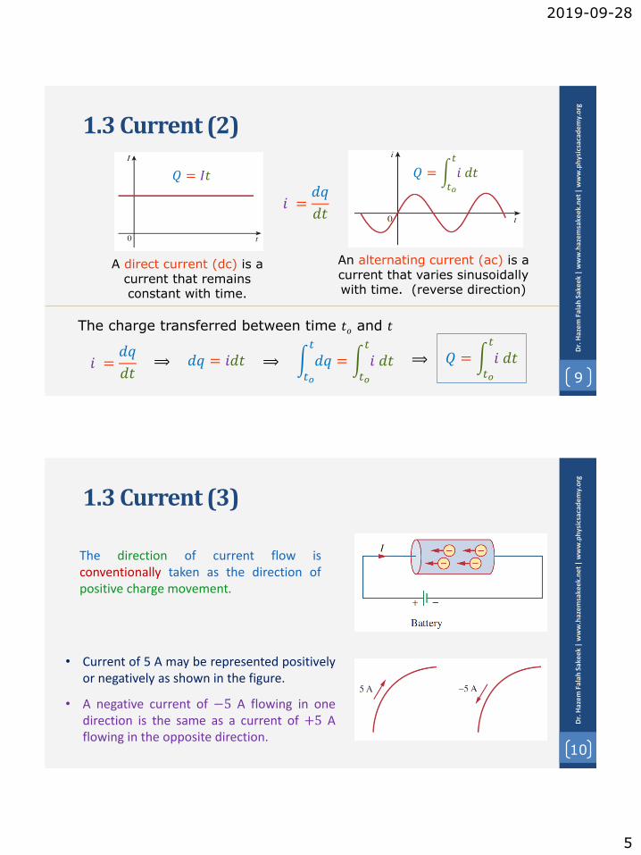
A device which maintains its specified voltage for any loadcurrent that is required.
Voltage source have a specific voltage, but the current dependson the circuit and is determined through analysis.
The Current provided by 12 V source varies in each case.
1.6 Circuit Elements (Ideal & real independent Voltage Source)
8
Dr.
Haz
em
Fal
ah S
ake
ek|
ww
w.h
azem
sake
ek.
ne
t|
ww
w.p
hys
icsa
cad
em
y.o
rg
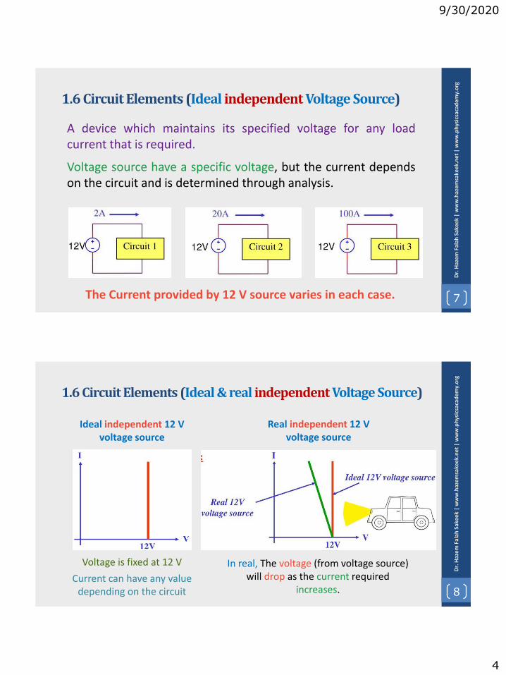
Voltage is fixed at 12 V
Current can have any value depending on the circuit
Ideal independent 12 V voltage source
In real, The voltage (from voltage source) will drop as the current required
increases.
Real independent 12 V voltage source

9/30/2020
5
1.6 Circuit Elements (Ideal independent Current Source)
9
Dr.
Haz
em
Fal
ah S
ake
ek|
ww
w.h
azem
sake
ek.n
et|
ww
w.p
hys
icsa
cad
em
y.o
rg
A device which maintains its specified current for any loadvoltage that is required.
Current source have a specific current, but the voltage dependson the circuit and is determined through analysis.
The voltage provided by 2 A source varies in each case.
1.6 Circuit Elements (Ideal & Real Independent Current Source)
10
Dr.
Haz
em
Fal
ah S
ake
ek|
ww
w.h
azem
sake
ek.
ne
t|
ww
w.p
hys
icsa
cad
em
y.o
rg
Current is fixed at 2 A
Voltage can have any value depending on the circuit
Ideal independent 2 A Current source
In real, The current (from current source) will drop as the voltage
required increases.
Real independent 12 V voltage source
9/30/2020
6
1.6 Circuit Elements (Dependent Source)
11
Dr.
Haz
em
Fal
ah S
ake
ek|
ww
w.h
azem
sake
ek.n
et|
ww
w.p
hys
icsa
cad
em
y.o
rg
Dependent sources
current sourcevoltage source
An ideal dependent source is an active element provides a specifiedvoltage or current that is controlled by another voltage or current.
1.6 Circuit Elements (Dependent Source)
12
Dr.
Haz
em
Fal
ah S
ake
ek|
ww
w.h
azem
sake
ek.
ne
t|
ww
w.p
hys
icsa
cad
em
y.o
rg
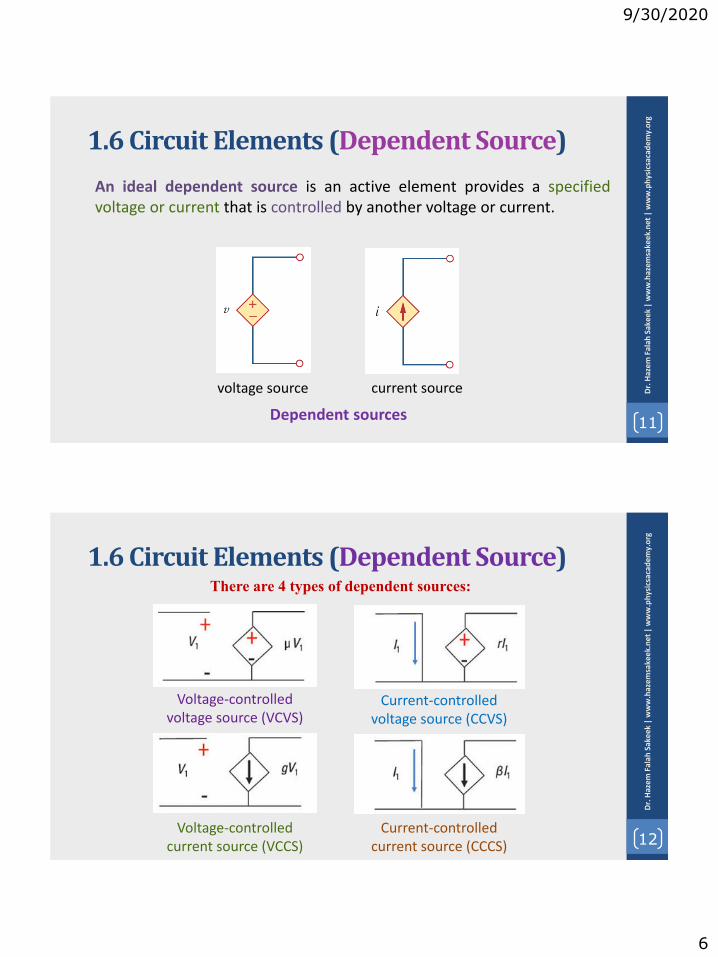
There are 4 types of dependent sources:
Voltage-controlled voltage source (VCVS)
Current-controlled voltage source (CCVS)
Voltage-controlled current source (VCCS)
Current-controlled current source (CCCS)

9/30/2020
7
1.6 Circuit Elements (Dependent Source)
13
Dr.
Haz
em
Fal
ah S
ake
ek|
ww
w.h
azem
sake
ek.n
et|
ww
w.p
hys
icsa
cad
em
y.o
rg
VCVS
VCCS
CCVS
CCCS
Example
14
Dr.
Haz
em
Fal
ah S
ake
ek|
ww
w.h
azem
sake
ek.
ne
t|
ww
w.p
hys
icsa
cad
em
y.o
rg
If 𝑣2 is equal to 3 V Find 𝑉L
𝑉𝐿 = 5𝑣2 = 5 × 3 = 15 𝑉
VCVS

9/30/2020
8
Example
15
Obtain the voltage 𝑣 in the branch shown for i2 = 1A.
15
Dr.
Haz
em
Fal
ah S
ake
ek|
ww
w.h
azem
sake
ek.n
et|
ww
w.p
hys
icsa
cad
em
y.o
rg
𝑣 = 10 + 𝑣𝑥 = 10 + 15 × 1 = 25 𝑉
CCVS
1.6 Circuit Elements (summery)
16
Active Elements Passive Elements
Independentsources
Dependentsources
• A dependent source is an activeelement in which the sourcequantity is controlled by anothervoltage or current.
• They have four different types: VCVS,CCVS, VCCS, CCCS 16
Dr.
Haz
em
Fal
ah S
ake
ek|
ww
w.h
azem
sake
ek.
ne
t|
ww
w.p
hys
icsa
cad
em
y.o
rg
9/30/2020
9
Example 1.7
17
Dr.
Haz
em
Fal
ah S
ake
ek|
ww
w.h
azem
sake
ek.n
et|
ww
w.p
hys
icsa
cad
em
y.o
rg
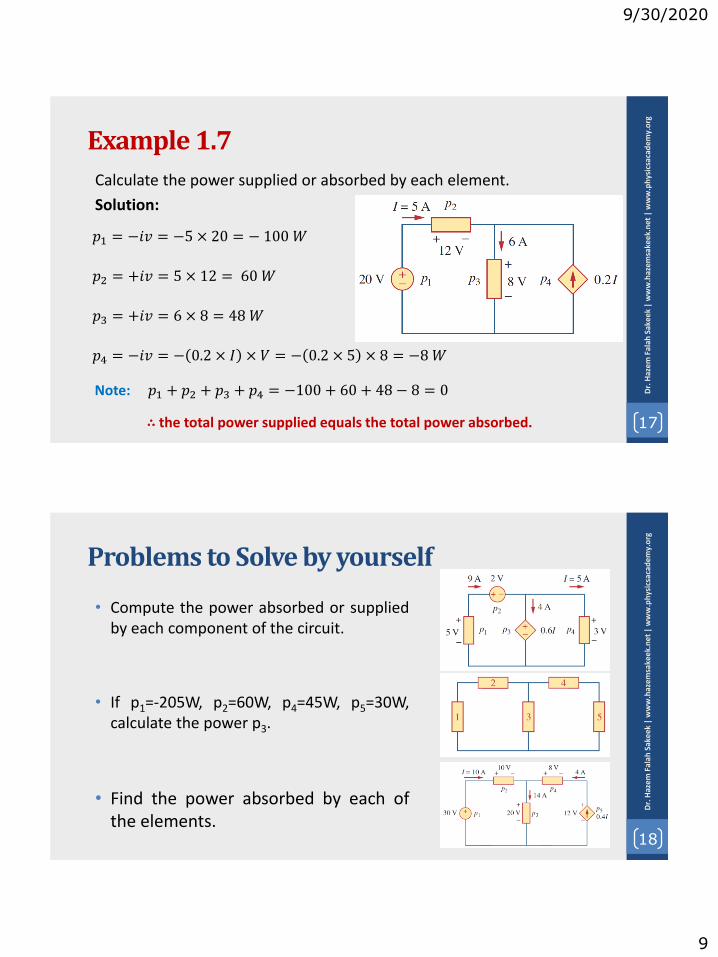
Calculate the power supplied or absorbed by each element.
Solution:
𝑝1 = −𝑖𝑣 = −5 × 20 = − 100 𝑊
𝑝2 = +𝑖𝑣 = 5 × 12 = 60𝑊
𝑝3 = +𝑖𝑣 = 6 × 8 = 48𝑊
𝑝4 = −𝑖𝑣 = − 0.2 × 𝐼 × 𝑉 = − 0.2 × 5 × 8 = −8𝑊
Note: 𝑝1 + 𝑝2 + 𝑝3 + 𝑝4 = −100 + 60 + 48 − 8 = 0
∴ the total power supplied equals the total power absorbed.
Problems to Solve by yourself
18
Dr.
Haz
em
Fal
ah S
ake
ek|
ww
w.h
azem
sake
ek.
ne
t|
ww
w.p
hys
icsa
cad
em
y.o
rg
• Compute the power absorbed or suppliedby each component of the circuit.
• If p1=-205W, p2=60W, p4=45W, p5=30W,calculate the power p3.
• Find the power absorbed by each ofthe elements.

9/30/2020
10
Problems to Solve by yourself
19
Dr.
Haz
em
Fal
ah S
ake
ek|
ww
w.h
azem
sake
ek.n
et|
ww
w.p
hys
icsa
cad
em
y.o
rg
• Find Vo and the power absorbed by each element in the circuit
• Find the power absorbed by each element in the circuit
2019-09-30
1
1
Dr.
Haz
em F
alah
Sak
eek
| w
ww
.haz
emsa
keek
.ne
t|
ww
w.p
hys
icsa
cad
em
y.o
rg
Unit: 2 | Lecture: 4
Basic Laws: Ohms Law
www.physicsacademy.org
Physics Academy
Dr. Hazem Falah Sakeek
Al-Azhar University of Gaza
Basic Laws
2
Dr.
Haz
em F
alah
Sak
eek
| w
ww
.haz
emsa
keek
.ne
t|
ww
w.p
hys
icsa
cad
em
y.o
rg2.1 Ohm’s Law
2.2 Nodes, Branches, and Loops
2.3 Kirchhoff’s Laws
2.4 Series Resistors and Voltage Division
2.5 Parallel Resistors and Current Division
2.6 Wye-Delta Transformations

2019-09-30
2
2.1 Ohm’s Law (resistance)
3
Dr.
Haz
em F
alah
Sak
eek
| w
ww
.haz
emsa
keek
.ne
t|
ww
w.p
hys
icsa
cad
em
y.o
rg
• The ability to resist current, is known as resistance and isrepresented by the symbol R.
• The resistance of any material with a uniform cross-sectionalarea A depends on A and its length 𝑙.
𝑹 = 𝝆𝒍
𝑨
• where 𝝆 is known as the resistivity ofthe material in ohm-meters.
2.1 Ohm’s Law (resistance)
4
Dr.
Haz
em F
alah
Sak
eek
| w
ww
.haz
emsa
keek
.ne
t|
ww
w.p
hys
icsa
cad
em
y.o
rg
Resistivities of common materials

2019-09-30
3
2.1 Ohm’s Law
5
Dr.
Haz
em F
alah
Sak
eek
| w
ww
.haz
emsa
keek
.ne
t|
ww
w.p
hys
icsa
cad
em
y.o
rg
• Ohm’s law states that the voltage 𝑣 across aresistor is directly proportional to the current 𝑖flowing through the resistor.
• Mathematical expression for Ohm’s Law is asfollows:
• R is measured in the unit of ohms, designated Ω.
𝒗 = 𝒊𝑹Georg Simon Ohm
(1787–1854)German physicist
𝑹 =𝒗
𝒊1 Ω = 1 V/A
The resistance R of an element denotes its ability to resist the flow of electric current; it is measured in ohms Ω
2.1 Ohm’s Law (Example)
6
Dr.
Haz
em F
alah
Sak
eek
| w
ww
.haz
emsa
keek
.ne
t|
ww
w.p
hys
icsa
cad
em
y.o
rg
An electric iron draws 2 A at 120 V. Find its resistance.
From Ohm’s law,
𝑅 =𝑣
𝑖=120
2= 60Ω
2019-09-30
4
2.1 Ohm’s Law
7
Dr.
Haz
em F
alah
Sak
eek
| w
ww
.haz
emsa
keek
.ne
t|
ww
w.p
hys
icsa
cad
em
y.o
rg
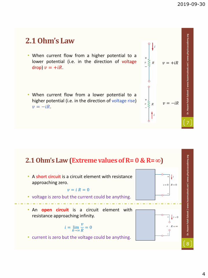
• When current flow from a higher potential to alower potential (i.e. in the direction of voltagedrop) 𝑣 = +𝑖𝑅.
• When current flow from a lower potential to ahigher potential (i.e. in the direction of voltage rise)𝑣 = −𝑖𝑅.
𝑣 = +𝑖𝑅
𝑣 = −𝑖𝑅
2.1 Ohm’s Law (Extreme values of R= 0 & R=)
8
Dr.
Haz
em F
alah
Sak
eek
| w
ww
.haz
emsa
keek
.ne
t|
ww
w.p
hys
icsa
cad
em
y.o
rg
• A short circuit is a circuit element with resistanceapproaching zero.
• voltage is zero but the current could be anything.
• An open circuit is a circuit element withresistance approaching infinity.
• current is zero but the voltage could be anything.
𝑣 = 𝑖 𝑅 = 0
𝑖 = lim𝑅→∞
𝑣
𝑅= 0

2019-09-30
5
2.1 Ohm’s Law (Conductance)
9
Dr.
Haz
em F
alah
Sak
eek
| w
ww
.haz
emsa
keek
.ne
t|
ww
w.p
hys
icsa
cad
em
y.o
rg
• Conductance is the ability of an element to conduct electric current.
• Conductance is the reciprocal of resistance R
• It is measured in mhos (Ʊ) or siemens (S).
𝐺 =1
𝑅=𝑖
𝑣𝑖 = 𝐺𝑣
1 𝑆 = 1 Ʊ = 1 𝐴/𝑉
⟹
2.1 Ohm’s Law (Power Dissipated)
10
Dr.
Haz
em F
alah
Sak
eek
| w
ww
.haz
emsa
keek
.ne
t|
ww
w.p
hys
icsa
cad
em
y.o
rg
• The power dissipated by a resistor can be expressed in terms of R.
• The power dissipated by a resistor can be expressed in terms of G.
𝑝 = 𝑣𝑖 = 𝑖2𝑅 =𝑣2
𝑅
𝑝 = 𝑣𝑖 = 𝑣2𝐺 =𝑖2
𝐺Note:
• The power dissipated in a resistor is a nonlinear function of either current orvoltage.
• Since R and G are positive quantities, the power dissipated in a resistor isalways positive. Thus, a resistor always absorbs power from the circuit. Thisconfirms that a resistor is a passive element, incapable of generating energy.

2019-09-30
6
2.1 Ohm’s Law (Example)
11
Dr.
Haz
em F
alah
Sak
eek
| w
ww
.haz
emsa
keek
.ne
t|
ww
w.p
hys
icsa
cad
em
y.o
rg
In the circuit shown in the Figure, calculate the current i, the conductance G, and the power p.
• The current
• The conductance
• The power
or
or
12
2.2 Network Topology: Branches, Nodes, and Loops
• A branch represents a single element such as a voltage source or a resistor.
• A node is the point of connection between two or more branches.
• A loop is any closed path in a circuit.
• A network with b branches, n nodes, and𝑙 independent loops will satisfy the
fundamental theorem of network topology:
𝒃 = 𝒍 + 𝒏 − 𝟏 Dr.
Haz
em F
alah
Sak
eek
| w
ww
.haz
emsa
keek
.ne
t|
ww
w.p
hys
icsa
cad
em
y.o
rg

2019-09-30
7
13
2.2 Network Topology: Series and Parallel Connection
• Two or more elements are in series if they exclusively share a singlenode and consequently carry the same current.
• Two or more elements are in parallel if they are connected to thesame two nodes and consequently have the same voltage acrossthem.
Dr.
Haz
em F
alah
Sak
eek
| w
ww
.haz
emsa
keek
.ne
t|
ww
w.p
hys
icsa
cad
em
y.o
rg
2.1 Ohm’s Law (Example)
14
Dr.
Haz
em F
alah
Sak
eek
| w
ww
.haz
emsa
keek
.ne
t|
ww
w.p
hys
icsa
cad
em
y.o
rg
Determine the number of branches andnodes in the circuit shown in Fig. Identifywhich elements are in series and whichare in parallel.
Three nodes
Four branches
The 5-Ω resistor is in series with the 10-V voltage source
The 6-resistor is in parallel with the 2-A current source

2019-09-30
8
2.1 Ohm’s Law (Example)
15
Dr.
Haz
em F
alah
Sak
eek
| w
ww
.haz
emsa
keek
.ne
t|
ww
w.p
hys
icsa
cad
em
y.o
rg
How many branches and nodesdoes the circuit in Fig. have? Identifythe elements that are in series andin parallel.
Five branches
Three nodes
The 1-Ω and 2-Ω resistors are in parallel.
The 4-Ω resistor and 10-V source are also in parallel.
Problems to Solve by yourself
16
Dr.
Haz
em F
alah
Sak
eek
| w
ww
.haz
emsa
keek
.ne
t|
ww
w.p
hys
icsa
cad
em
y.o
rg
• For the circuit shown, calculate the voltage v,the conductance G, and the power p.
• Find the hot resistance of a light bulb rated60W, 120 V.
• (a) Calculate current i in the circuit when the switch is in position 1. (b) Find the current when the switch is in position 2.
• A bar of silicon is 4 cm long with a circular cross section. If theresistance of the bar is 240Ω, what is the cross-sectional radius ofthe bar?

2019-09-30
9
Problems to Solve by yourself
17
Dr.
Haz
em F
alah
Sak
eek
| w
ww
.haz
emsa
keek
.ne
t|
ww
w.p
hys
icsa
cad
em
y.o
rg
Determine the number of branches and nodes in the circuit

2019-10-04
1
1
Dr.
Haz
em F
alah
Sak
eek
| w
ww
.haz
emsa
keek
.ne
t|
ww
w.p
hys
icsa
cad
em
y.o
rg
Unit: 2 | Lecture: 5
Basic Laws: Kirchhoff’s Law
www.physicsacademy.org
Physics Academy
Dr. Hazem Falah Sakeek
Al-Azhar University of Gaza
Basic Laws
2
Dr.
Haz
em F
alah
Sak
eek
| w
ww
.haz
emsa
keek
.ne
t|
ww
w.p
hys
icsa
cad
em
y.o
rg2.1 Ohm’s Law
2.2 Nodes, Branches, and Loops
2.3 Kirchhoff’s Laws
2.4 Series Resistors and Voltage Division
2.5 Parallel Resistors and Current Division
2.6 Wye-Delta Transformations

2019-10-04
2
2.1 Kirchhoff’s Laws (KCL)
3
Dr.
Haz
em F
alah
Sak
eek
| w
ww
.haz
emsa
keek
.ne
t|
ww
w.p
hys
icsa
cad
em
y.o
rg
• Kirchhoff’s first law is based on the law of conservationof charge, which requires that the algebraic sum ofcharges within a system cannot change.
• Kirchhoff’s current law (KCL) states that the algebraicsum of currents entering a node is zero.
• where N is the number of branches connected to thenode and n is the nth current entering or leaving thenode.
Gustav Robert
Kirchhoff
(1824–1887)
German physicist
𝑛=1
𝑁
𝑖𝑛 = 0
2.1 Kirchhoff’s Laws (KCL)
4
Dr.
Haz
em F
alah
Sak
eek
| w
ww
.haz
emsa
keek
.ne
t|
ww
w.p
hys
icsa
cad
em
y.o
rg
• Currents entering a node may be regarded as positive, while currents leaving the node may be taken as negative.
𝑖1 + −𝑖2 + 𝑖3 + 𝑖4 + −𝑖5 = 0
𝑖1 + 𝑖3 + 𝑖4 = 𝑖2 + 𝑖5
The sum of the currents entering a node is equal to the sum of the
currents leaving the node.
𝑛=1
𝑁
𝑖𝑛 = 0

2019-10-04
3
2.1 Kirchhoff’s Laws (Combining Current Sources)
5
Dr.
Haz
em F
alah
Sak
eek
| w
ww
.haz
emsa
keek
.ne
t|
ww
w.p
hys
icsa
cad
em
y.o
rg
• The combined or equivalent current source can be found by applyingKCL to node a.
𝐼𝑇 = 𝐼1 − 𝐼2 + 𝐼3
2.1 Kirchhoff’s Laws (KVL)
6
Dr.
Haz
em F
alah
Sak
eek
| w
ww
.haz
emsa
keek
.ne
t|
ww
w.p
hys
icsa
cad
em
y.o
rg
• Kirchhoff’s voltage law (KVL) states that the algebraic sum of all voltages around a closed path or loop is zero.
• where 𝑀 is the number of voltages in the loop and 𝑣𝑚 is the mth voltage.
𝑚=1
𝑀
𝑣𝑚 = 0

2019-10-04
4
2.1 Kirchhoff’s Laws (KVL)
7
Dr.
Haz
em F
alah
Sak
eek
| w
ww
.haz
emsa
keek
.ne
t|
ww
w.p
hys
icsa
cad
em
y.o
rg
KVL can be applied in two ways: by takingeither a clockwise or a counterclockwise triparound the loop. Either way, the algebraicsum of voltages around the loop is zero.
−𝑣1 + 𝑣2 + 𝑣3 − 𝑣4 + 𝑣5 = 0
𝑣2 + 𝑣3 + 𝑣5 = 𝑣1 + 𝑣4
The sign on each voltage is the polarity of the terminal
encountered first as we travel around the loop.Sum of voltage drops = Sum of voltage rises
𝑚=1
𝑀
𝑣𝑚 = 0
2.1 Kirchhoff’s Laws (Combined Voltage Source)
8
Dr.
Haz
em F
alah
Sak
eek
| w
ww
.haz
emsa
keek
.ne
t|
ww
w.p
hys
icsa
cad
em
y.o
rg
• When voltage sources are connected in series, KVL can be applied to obtain the total voltage. The combined voltage is the algebraic sum of the voltages of the individual sources.
𝑉𝑎𝑏 = 𝑉1 + 𝑉2 − 𝑉3

2019-10-04
5
Example 2.5
9
Dr.
Haz
em F
alah
Sak
eek
| w
ww
.haz
emsa
keek
.ne
t|
ww
w.p
hys
icsa
cad
em
y.o
rg
For the circuit in the Figure, find voltages 𝒗1 and 𝒗2.
Solution:
• Assume the current 𝑖 flows through the loop.
• From Ohm’s law
• Applying KVL
• Substituting for 𝑣1 and 𝑣2
𝑣1 = 2𝑖 𝑎𝑛𝑑 𝑣2 = −3𝑖
−20 + 𝑣1 − 𝑣2 = 0
−20 + 2𝑖 + 3𝑖 = 0
𝒗𝟏 = 𝟐𝒊 = 𝟖𝑽 𝑎𝑛𝑑 𝒗𝟐 = −𝟑𝒊 = −𝟏𝟐𝑽
⟹ 5𝑖 = 20 ⟹ 𝒊 = 𝟒𝑨
Example 2.6
10
Dr.
Haz
em F
alah
Sak
eek
| w
ww
.haz
emsa
keek
.ne
t|
ww
w.p
hys
icsa
cad
em
y.o
rg
Determine 𝒗o and 𝒊 in the circuit
Solution:
• Apply KVL around the loop
• Applying Ohm’s law to the 6-Ω resistor gives
• Substituting Eq. (2) into Eq. (1) yields
−12 + 4𝑖 + 2𝑣𝑜 − 4 − 𝑣𝑜 = 0
𝑣𝑜 = −6𝑖
(1)
(2)
−16 + 4𝑖 − 6𝑖 = 0 ⟹ 𝒊 = −𝟖 𝐀
∴ 𝒗𝒐= 𝟒𝟖 𝑽

2019-10-04
6
Example 2.7
11
Dr.
Haz
em F
alah
Sak
eek
| w
ww
.haz
emsa
keek
.ne
t|
ww
w.p
hys
icsa
cad
em
y.o
rg
Find current 𝒊o and voltage 𝒗o in the circuit
Solution:
Applying KCL to node a, we obtain
For the 4Ω resistor, Ohm’s law gives
3 + 0.5𝑖𝑜 = 𝑖𝑜
∴ 𝒊𝒐= 𝟔𝑨
𝒗𝒐 = 𝟒𝒊𝒐 = 𝟐𝟒𝑽
Example 2.8
12
Dr.
Haz
em F
alah
Sak
eek
| w
ww
.haz
emsa
keek
.ne
t|
ww
w.p
hys
icsa
cad
em
y.o
rg
Find currents and voltages in the circuit
Solution:
• From Ohm’s law
• At node a, KCL gives
• Applying KVL to loop 1
𝑣1 = 8𝑖1, 𝑣2 = 3𝑖2, 𝑣3 = 6𝑖3
𝑖1 − 𝑖2 − 𝑖3 = 0
−30 + 𝑣1 + 𝑣2 = 0
−30 + 8𝑖1 + 3𝑖2 = 0 ⟹ 𝑖1 =30 − 3𝑖2
8

2019-10-04
7
Example 2.8
13
Dr.
Haz
em F
alah
Sak
eek
| w
ww
.haz
emsa
keek
.ne
t|
ww
w.p
hys
icsa
cad
em
y.o
rg
Applying KVL to loop 2
−𝑣2 + 𝑣3 = 0 ⟹ 𝑣3 = 𝑣2
6𝑖3 = 3𝑖2
𝑖3 =𝑖22
𝑖1 − 𝑖2 − 𝑖3 = 0 ⟹30 − 3𝑖2
8− 𝑖2 −
𝑖22= 0
𝒊𝟐 = 𝟐𝑨, 𝒊𝟏 = 𝟑𝑨, 𝒊𝟑 = 𝟏𝐀, 𝒗𝟏 = 𝟐𝟒𝑽, 𝒗𝟐 = 𝟔𝑽, 𝒗𝟑 = 𝟔𝑽
Problems to Solve by yourself
14
Dr.
Haz
em F
alah
Sak
eek
| w
ww
.haz
emsa
keek
.ne
t|
ww
w.p
hys
icsa
cad
em
y.o
rg
• Find 𝑣1 and 𝑣2 in the circuit
• Find the currents and voltages
• Find 𝑣o and 𝑖o in the circuit
• Find 𝑉x in the circuit

2019-10-04
8
Problems to Solve by yourself
15
Dr.
Haz
em F
alah
Sak
eek
| w
ww
.haz
emsa
keek
.ne
t|
ww
w.p
hys
icsa
cad
em
y.o
rg
• Calculate 𝑉1 and 𝑉2 in the circuit
• Calculate 𝑣 and 𝑖x in the circuit
• Determine 𝑉o in the circuit
• Determine 𝑖o in the circuit

2019-10-05
1
1
Dr.
Haz
em F
alah
Sak
eek
| w
ww
.haz
emsa
keek
.ne
t|
ww
w.p
hys
icsa
cad
em
y.o
rg
Unit: 2 | Lecture: 6
Basic Laws: Series and Parallel Resistors
www.physicsacademy.org
Physics Academy
Dr. Hazem Falah Sakeek
Al-Azhar University of Gaza
Basic Laws
2
Dr.
Haz
em F
alah
Sak
eek
| w
ww
.haz
emsa
keek
.ne
t|
ww
w.p
hys
icsa
cad
em
y.o
rg2.1 Ohm’s Law
2.2 Nodes, Branches, and Loops
2.3 Kirchhoff’s Laws
2.4 Series Resistors and Voltage Division
2.5 Parallel Resistors and Current Division
2.6 Wye-Delta Transformations

2019-10-05
2
2.5 Series Resistors and Voltage Division (1)
3
Dr.
Haz
em F
alah
Sak
eek
| w
ww
.haz
emsa
keek
.ne
t|
ww
w.p
hys
icsa
cad
em
y.o
rg
The two resistors are in series, since the same current 𝑖 flows in both of them.
𝑣1 = 𝑖𝑅1 𝑣2 = 𝑖𝑅2From Ohm’s law
Apply KVL to the loop −𝑣 + 𝑣1 + 𝑣2 = 0
𝑣 = 𝑣1 + 𝑣2 = 𝑖 𝑅1 + 𝑅2
𝑣 = 𝑖𝑅𝑒𝑞
𝑹𝒆𝒒 = 𝑹𝟏 + 𝑹𝟐
The equivalent resistance of any number of resistors connected in a series is thesum of the individual resistances.
2.5 Series Resistors and Voltage Division (2)
4
Dr.
Haz
em F
alah
Sak
eek
| w
ww
.haz
emsa
keek
.ne
t|
ww
w.p
hys
icsa
cad
em
y.o
rg
Voltage Division: The voltage across each resistor
𝑣1 = 𝑖𝑅1
𝑣2 = 𝑖𝑅2
𝑖 =𝑣
𝑅1 + 𝑅2
𝑣1 =𝑅1
𝑅1 + 𝑅2𝑣 𝑣2 =
𝑅2𝑅1 + 𝑅2
𝑣
Notice that the source voltage 𝑣 is dividedamong the resistors in direct proportion to theirresistances; the larger the resistance, the largerthe voltage drop.

2019-10-05
3
2.6 Parallel Resistors and Current Division (1)
5
Dr.
Haz
em F
alah
Sak
eek
| w
ww
.haz
emsa
keek
.ne
t|
ww
w.p
hys
icsa
cad
em
y.o
rg
Two resistors are connected in parallel andtherefore have the same voltage across them.
From Ohm’s law,
Applying KCL at node 𝑎 gives the total current 𝑖 as
𝑣 = 𝑖1𝑅1 = 𝑖2𝑅2 𝑖1 =𝑣
𝑅1, 𝑖2 =
𝑣
𝑅2or
𝑖 = 𝑖1 + 𝑖2
𝑖 =𝑣
𝑅1+
𝑣
𝑅2= 𝑣
1
𝑅1+
1
𝑅2=
𝑣
𝑅𝑒𝑞
1
𝑅𝑒𝑞=
1
𝑅1+
1
𝑅2
𝑹𝒆𝒒 =𝑹𝟏𝑹𝟐
𝑹𝟏 + 𝑹𝟐
⟹
The equivalent resistance of two parallel resistors is equalto the product of their resistances divided by their sum.
2.6 Parallel Resistors and Current Division (1)
6
Dr.
Haz
em F
alah
Sak
eek
| w
ww
.haz
emsa
keek
.ne
t|
ww
w.p
hys
icsa
cad
em
y.o
rg
Current Division, Given the total current 𝑖entering node 𝑎 in the circuit, how do weobtain current 𝑖1 and 𝑖2?
We know that the equivalent resistor has the same voltage, or
𝑣 = 𝑖𝑅𝑒𝑞 =𝑖𝑅1𝑅2𝑅1 + 𝑅2
𝑖1 =𝑣
𝑅1, 𝑖2 =
𝑣
𝑅2
𝑖1 =𝑅2𝑖
𝑅1 + 𝑅2, 𝑖2 =
𝑅1𝑖
𝑅1 + 𝑅2
The total current 𝑖 is shared by the resistors in inverse proportion to their resistances.
Notice that the larger current flows through the smaller resistance.

2019-10-05
4
2.6 Parallel Resistors (Conductance)
7
Dr.
Haz
em F
alah
Sak
eek
| w
ww
.haz
emsa
keek
.ne
t|
ww
w.p
hys
icsa
cad
em
y.o
rg
It is more convenient to use conductance rather than resistancewhen dealing with resistors in parallel.
The equivalent resistance of N resistors in parallel is
The equivalent conductance of N resistors in parallel is
The equivalent conductance of resistors connected in parallel is thesum of their individual conductance.
2.6 Parallel Resistors (Extreme Cases)
8
Dr.
Haz
em F
alah
Sak
eek
| w
ww
.haz
emsa
keek
.ne
t|
ww
w.p
hys
icsa
cad
em
y.o
rg
Extreme Case (1) R2=0 i.e. R2 is a short circuit
1. The equivalent resistance Req = 0.
2. The entire current flows through the short circuit.
𝑖1 = 0, 𝑖2 = 𝑖
Extreme Case (2) R2=∞ i.e. R2 is an open circuit
1. The equivalent resistance Req = R1.
2. The entire current flows through the path of least resistance.

2019-10-05
5
Example 2.9
9
Dr.
Haz
em F
alah
Sak
eek
| w
ww
.haz
emsa
keek
.ne
t|
ww
w.p
hys
icsa
cad
em
y.o
rg
Find Req for the circuit.
• The 6-Ω and 3-Ω resistors are in parallel
• Also, the 1- Ωand 5-Ω resistors are in series;
• notice that the two 2-Ω resistors are in series,
• This 4-Ω resistor is now in parallel with the 6-Ω resistor
• the three resistors are in series
Example 2.10
10
Dr.
Haz
em F
alah
Sak
eek
| w
ww
.haz
emsa
keek
.ne
t|
ww
w.p
hys
icsa
cad
em
y.o
rg
Calculate the equivalent resistance Rab in the circuit.
• The 3-Ω and 6-Ω resistors are in parallel
• The 12-Ω and 4-Ω resistors are in parallel
• The 1-Ω and 5-Ω resistors are in series

2019-10-05
6
Example 2.10
11
Dr.
Haz
em F
alah
Sak
eek
| w
ww
.haz
emsa
keek
.ne
t|
ww
w.p
hys
icsa
cad
em
y.o
rg
• The 3-Ω in parallel with 6-Ω gives 2-Ω
• This 2-Ω equivalent resistance is now inseries with the 1-Ω resistance to give acombined resistance of 1 Ω + 2Ω = 3Ω.
• The 2-Ω and 3-Ω resistors in parallel.
• The 1.2-Ω resistor is in series with the10-Ω resistor.
Example 2.11
12
Dr.
Haz
em F
alah
Sak
eek
| w
ww
.haz
emsa
keek
.ne
t|
ww
w.p
hys
icsa
cad
em
y.o
rg
Find the equivalent conductance Geq.
The 8-S and 12-S resistors are in parallel, so their conductance is
This 20-S resistor is now in series with 5 S
This is in parallel with the 6-S resistor

2019-10-05
7
Example 2.12
13
Dr.
Haz
em F
alah
Sak
eek
| w
ww
.haz
emsa
keek
.ne
t|
ww
w.p
hys
icsa
cad
em
y.o
rg
Find 𝒊o and 𝒗o in the circuit. Calculate the powerdissipated in the 3-Ω resistor.
The 6-Ω and 3-Ω resistors are in parallel
Apply Ohm’s law
Or apply voltage division,
⟹
Apply Ohm’s law to find 𝑖o
Or apply current division
The power dissipated in the 3-Ω
Example 2.13
14
Dr.
Haz
em F
alah
Sak
eek
| w
ww
.haz
emsa
keek
.ne
t|
ww
w.p
hys
icsa
cad
em
y.o
rg
Determine: (a) the voltage 𝒗o, (b) the powersupplied by the current source, (c) the powerabsorbed by each resistor.
(a) The 6-kΩ and 12-kΩ resistors are in series
Apply the current division technique to find 𝑖1
and 𝑖2

2019-10-05
8
Example 2.13
15
Dr.
Haz
em F
alah
Sak
eek
| w
ww
.haz
emsa
keek
.ne
t|
ww
w.p
hys
icsa
cad
em
y.o
rg
(b) Power supplied by the source is
(c) Power absorbed by the 12-kΩ resistor is
Power absorbed by the 6-kΩ resistor is
Power absorbed by the 9-kΩ resistor is
Notice: that the power supplied equals the power absorbed (1.2 + 0.6 + 3.6 = 5.4 W)
Problems to Solve by yourself
16
Dr.
Haz
em F
alah
Sak
eek
| w
ww
.haz
emsa
keek
.ne
t|
ww
w.p
hys
icsa
cad
em
y.o
rg
(5) Find: (a) 𝑣1 and 𝑣2 (b) the power dissipated inthe 3-kΩ and 20-kΩ resistors, and (c) the powersupplied by the current source.
(4) Find: (a) 𝑣1 and 𝑣2
Also calculate 𝑖1 and 𝑖2
and the power dissipated in the 12-Ω and 40-Ω resistors.
(3) Calculate 𝐺eq
in the circuit.
(2) Find Rab in the circuit.
(1) Find Req in the circuit.
2019-10-05
9
Problems to Solve by yourself
17
Dr.
Haz
em F
alah
Sak
eek
| w
ww
.haz
emsa
keek
.ne
t|
ww
w.p
hys
icsa
cad
em
y.o
rg
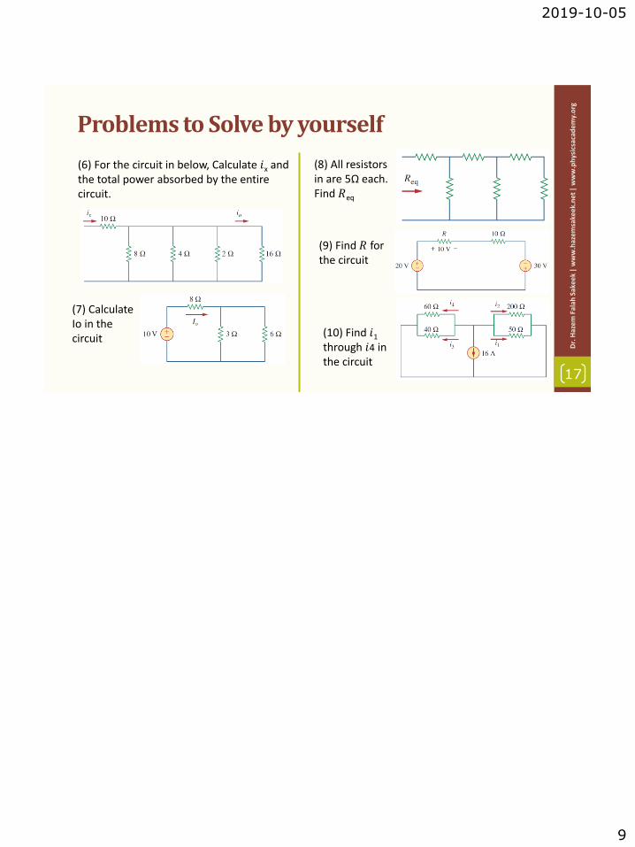
(6) For the circuit in below, Calculate 𝑖x and the total power absorbed by the entire circuit.
(7) Calculate Io in the circuit
(8) All resistors in are 5Ω each. Find 𝑅eq
(9) Find 𝑅 for the circuit
(10) Find 𝑖1
through 𝑖4 in the circuit

2019-10-10
1
1
Dr.
Haz
em F
alah
Sak
eek
| w
ww
.haz
emsa
keek
.ne
t|
ww
w.p
hys
icsa
cad
em
y.o
rg
Unit: 2 | Lecture: 7
Basic Laws: Wye-Delta Transformations
www.physicsacademy.org
Physics Academy
Dr. Hazem Falah Sakeek
Al-Azhar University of Gaza
Basic Laws
2
Dr.
Haz
em F
alah
Sak
eek
| w
ww
.haz
emsa
keek
.ne
t|
ww
w.p
hys
icsa
cad
em
y.o
rg2.1 Ohm’s Law
2.2 Nodes, Branches, and Loops
2.3 Kirchhoff’s Laws
2.4 Series Resistors and Voltage Division
2.5 Parallel Resistors and Current Division
2.6 Wye-Delta Transformations

2019-10-10
2
2.6 Wye-Delta Transformations
3
Dr.
Haz
em F
alah
Sak
eek
| w
ww
.haz
emsa
keek
.ne
t|
ww
w.p
hys
icsa
cad
em
y.o
rg
• Situations often arise in circuit analysis whenthe resistors are neither in parallel nor inseries. For example, the bridge circuit.
• The names Wye and Delta come from theshape of the schematics.
• The transformation allows you to replacethree resistors in a Δ configuration by threeresistors in a Y configuration, and the otherway around.
• Wye-Delta Transformations are used inthree-phase networks, electrical filters, andmatching networks.
2.6 Wye-Delta Transformations
4
Dr.
Haz
em F
alah
Sak
eek
| w
ww
.haz
emsa
keek
.ne
t|
ww
w.p
hys
icsa
cad
em
y.o
rg
Many circuits can be simplified by using three-terminal equivalent networks,such as the (Y) or (T) network and the (∆) or (∏) network.
Notice the different number of nodes in the two configurations.
∆
∏
Y
T
≡ ≡

2019-10-10
3
2.6 Wye-Delta Transformations
5
Dr.
Haz
em F
alah
Sak
eek
| w
ww
.haz
emsa
keek
.ne
t|
ww
w.p
hys
icsa
cad
em
y.o
rg
Transformation of a bridge resistor network, using the Y-Δ transform toeliminate node D, yields an equivalent network that may readily besimplified further.
2.6 Delta to Wye Conversion (1)
6
Dr.
Haz
em F
alah
Sak
eek
| w
ww
.haz
emsa
keek
.ne
t|
ww
w.p
hys
icsa
cad
em
y.o
rg
• Suppose it is more convenient to work with a wye network in a place wherethe circuit contains a delta configuration.
• We superimpose a wye network on the existing delta network and find theequivalent resistances in the wye network.
Superimpose

2019-10-10
4
DeltaWyeTransformations
7
Dr.
Haz
em F
alah
Sak
eek
| w
ww
.haz
emsa
keek
.ne
t|
ww
w.p
hys
icsa
cad
em
y.o
rg
Each resistor in the Y network isthe product of the resistors in thetwo adjacent ∆ branches, dividedby the sum of the three ∆ resistors.
WyeDeltaTransformations
Each resistor in the ∆ network is thesum of all possible products of Yresistors taken two at a time,divided by the opposite Y resistor.
Example 2.14
8
Dr.
Haz
em F
alah
Sak
eek
| w
ww
.haz
emsa
keek
.ne
t|
ww
w.p
hys
icsa
cad
em
y.o
rg
Convert the ∆ network to an equivalent Y network.

2019-10-10
5
Example 2.15
9
Dr.
Haz
em F
alah
Sak
eek
| w
ww
.haz
emsa
keek
.ne
t|
ww
w.p
hys
icsa
cad
em
y.o
rg
Obtain the equivalent resistance𝑹ab for the circuit and use it to findcurrent 𝒊.
We can use wye-delta transformationsas one approach to find a solution.
There are two Y networks and three ∆networks. Transforming just one ofthese will simplify the circuit.
Example 2.15 (1)
10
Dr.
Haz
em F
alah
Sak
eek
| w
ww
.haz
emsa
keek
.ne
t|
ww
w.p
hys
icsa
cad
em
y.o
rg
If we convert the Y network comprising the 𝑅1=10-Ω 𝑅2=20-Ω and 𝑅3=5-Ω resistors,

2019-10-10
6
Example 2.15 (2)
11
Dr.
Haz
em F
alah
Sak
eek
| w
ww
.haz
emsa
keek
.ne
t|
ww
w.p
hys
icsa
cad
em
y.o
rg
Combining the three pairs (30Ω||70Ω), 12.5Ω||17.5Ω), (15Ω||35Ω), we obtain
From equivalent circuit we find,
Then the current 𝑖
Problems to Solve by yourself
12
Dr.
Haz
em F
alah
Sak
eek
| w
ww
.haz
emsa
keek
.ne
t|
ww
w.p
hys
icsa
cad
em
y.o
rg(4) Obtain the Req at the terminals a-b for each of the circuits.
(3) Transform the circuits from ∆ to Y.
(2) ) For the bridge network, find Rab and i.
(1) Transform the wye network to a delta network.
(5) Calculate Io
in the circuit

10/8/2020
1
1
Dr.
Haz
em
Fal
ah S
ake
ek|
ww
w.h
azem
sake
ek.n
et|
ww
w.p
hys
icsa
cad
em
y.o
rg
Unit: 1 | Lecture: 8
Solution of some selected problemElectric Charge, Current, Voltage, Power and
Energy and Circuit Elements
www.physicsacademy.org
Physics Academy
Dr. Hazem Falah Sakeek
Al-Azhar University of Gaza
How many coulombs are represented by 6.482×10¹⁷ electrons?
2
Dr.
Haz
em
Fal
ah S
ake
ek|
ww
w.h
azem
sake
ek.n
et |
ww
w.p
hys
icsa
cad
em
y.o
rgProblems 1.1
The charge of one electron = 1.6×10⁻¹⁹C
The total charge of 6.482×10¹⁷ electrons
= 1.6 × 10−19 × 6.482 × 1017 = 0.103 𝐶
= 103 𝑚𝐶

10/8/2020
2
Determine the current flowing through an element if the charge flow is given by
3
Dr.
Haz
em
Fal
ah S
ake
ek|
ww
w.h
azem
sake
ek.n
et|
ww
w.p
hys
icsa
cad
em
y.o
rgProblems 1.2
(a) 𝒒 𝒕 = 𝟑𝒕 + 𝟖 mC
𝑖 =𝑑𝑞
𝑑𝑡=𝑑 3𝑡 + 8
𝑑𝑡= 3 mA
(b) 𝒒 𝒕 = 𝟖𝒕𝟐 + 𝟒𝒕 − 𝟐 C
𝑖 =𝑑𝑞
𝑑𝑡=𝑑 8𝑡2 + 4𝑡 − 2
𝑑𝑡
= (16𝑡 + 4) mA
(c) 𝒒 𝒕 = 𝟑𝒆−𝒕 − 𝟓𝒆−𝟐𝒕 nC
𝑖 =𝑑𝑞
𝑑𝑡= −3𝑒−𝑡 + 10𝑒−2𝑡 nA
(d) 𝒒 𝒕 = 𝟏𝟎 𝐬𝐢𝐧 𝟏𝟐𝟎𝝅𝒕 pC
𝑖 =𝑑𝑞
𝑑𝑡= 1200𝜋 cos 120𝜋𝑡 pA
(e) 𝒒 𝒕 = 𝟐𝟎𝒆−𝟒𝒕 𝐜𝐨𝐬 𝟓𝟎𝒕 𝜇C
𝑖 =𝑑𝑞
𝑑𝑡= 20𝑒−4𝑡 × (−50sin50𝑡)
+ cos 50𝑡 × −80𝑒−4𝑡
= −1000 sin 50𝑡𝑒−4𝑡
−80 cos 50𝑡𝑒−4𝑡
= −𝑒−4𝑡 1000 sin 50𝑡 + 80 cos 50𝑡 𝜇A
A current of 7.4 A flows through a conductor. Calculate how muchcharge passes through any cross-section of the conductor in 20 s.
4
Dr.
Haz
em
Fal
ah S
ake
ek|
ww
w.h
azem
sake
ek.
ne
t|
ww
w.p
hys
icsa
cad
em
y.o
rgProblems 1.4
𝑖 = 7.4 𝐴 𝑡 = 20𝑠 𝑞 =? ? ?
𝑞 = 𝑖𝑡 = 7.4 × 20 = 148 C

10/8/2020
3
Determine the total charge transferred over the time interval of 0 ≤ 𝑡 ≤ 10 s
when 𝑖 𝑡 =1
2𝑡 A.
5
Dr.
Haz
em
Fal
ah S
ake
ek|
ww
w.h
azem
sake
ek.n
et|
ww
w.p
hys
icsa
cad
em
y.o
rgProblems 1.5
𝑞 = න 𝑖 𝑑𝑡
𝑞 = න0
10
𝑖 𝑑𝑡 = න0
10 1
2𝑡 𝑑𝑡
= อ𝑡2
40
10
= 25 C
The charge entering a certain element is shown in Figure. Find the current at: (a) 𝑡 = 1 ms (b) 𝑡 = 6 ms (c) 𝑡 = 10 ms
6
Dr.
Haz
em
Fal
ah S
ake
ek|
ww
w.h
azem
sake
ek.
ne
t|
ww
w.p
hys
icsa
cad
em
y.o
rgProblems 1.6
(a) 𝒕 = 𝟏 ms
𝑖 =𝑑𝑞
𝑑𝑡=(30 − 0)
(2 − 0)= 15 A
(b) 𝒕 = 𝟔 ms
𝑖 =𝑑𝑞
𝑑𝑡=
0
8 − 2= 0 A
(c) 𝒕 = 𝟏𝟎 ms
𝑖 =𝑑𝑞
𝑑𝑡=(0 − 30)
12 − 8= −7.5 A

10/8/2020
4
The charge flowing in a wire is plotted in Figure. Sketch the corresponding current.
7
Dr.
Haz
em
Fal
ah S
ake
ek|
ww
w.h
azem
sake
ek.n
et|
ww
w.p
hys
icsa
cad
em
y.o
rgProblems 1.7
𝑖 =𝑑𝑞
𝑑𝑡
From 0 to 2 s
𝑖 =(50 − 0)
(2 − 0)𝑖 = 25 𝐴
From 2 to 6 s
𝑖 =(−50 − 50)
(6 − 2)𝑖 = −25 𝐴
From 6 to 8 s
𝑖 =(0 − (−50))
(8 − 6)𝑖 = 25 𝐴
25 𝐴
−25 𝐴
𝑖 = ቐ25 𝐴 0 < 𝑡 < 2−25 𝐴 2 < 𝑡 < 625 𝐴 6 < 𝑡 < 8
8
Dr.
Haz
em
Fal
ah S
ake
ek|
ww
w.h
azem
sake
ek.
ne
t|
ww
w.p
hys
icsa
cad
em
y.o
rgProblems 1.8
The current flowing past a point in a device is shown in Figure. Calculate the total charge through the point.
𝑞 = න 𝑖 𝑑𝑡
𝑞 = 𝑎𝑟𝑒𝑎 𝑢𝑛𝑑𝑒𝑟 𝑡ℎ𝑒 𝑐𝑢𝑟𝑣𝑒
𝑞1 = 𝑎𝑟𝑒𝑎 𝑜𝑓 𝑡𝑟𝑖𝑎𝑛𝑔𝑙𝑒 =1
21 × 10 = 5𝜇𝐶
𝑞2 = 𝑎𝑟𝑒𝑎 𝑜𝑓 𝑟𝑒𝑐𝑡𝑎𝑛𝑔𝑙𝑒 = 10 × 1 = 10𝜇𝐶
𝑞 = 𝑞1 + 𝑞2 = 15𝜇𝐶
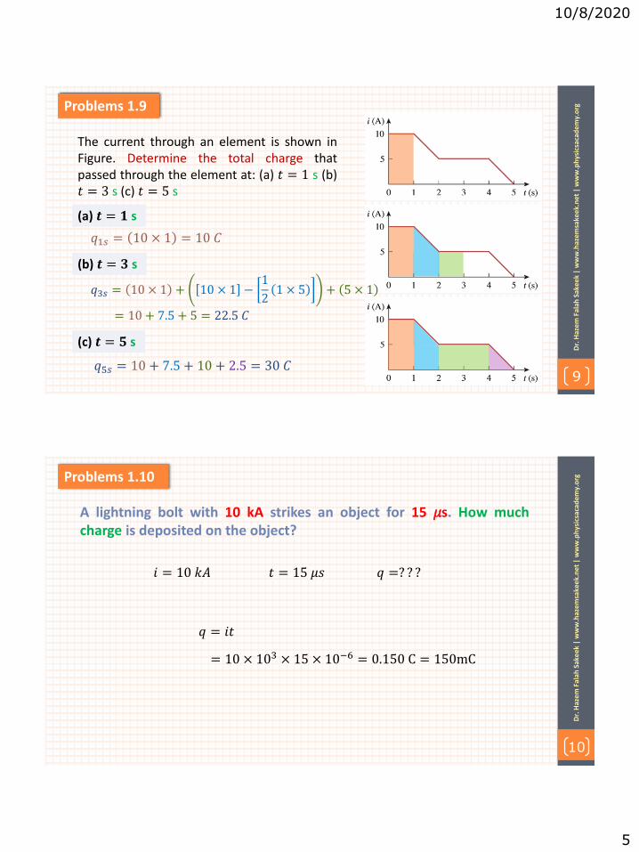
10/8/2020
5
9
Dr.
Haz
em
Fal
ah S
ake
ek|
ww
w.h
azem
sake
ek.n
et|
ww
w.p
hys
icsa
cad
em
y.o
rgProblems 1.9
The current through an element is shown inFigure. Determine the total charge thatpassed through the element at: (a) 𝑡 = 1 s (b)𝑡 = 3 s (c) 𝑡 = 5 s
(a) 𝒕 = 𝟏 s
(b) 𝒕 = 𝟑 s
(c) 𝒕 = 𝟓 s
𝑞1𝑠 = 10 × 1 = 10 𝐶
𝑞3𝑠 = 10 × 1 + 10 × 1 −1
21 × 5 + 5 × 1
𝑞5𝑠 = 10 + 7.5 + 10 + 2.5 = 30 𝐶
= 10 + 7.5 + 5 = 22.5 𝐶
A lightning bolt with 10 kA strikes an object for 15 𝜇s. How muchcharge is deposited on the object?
10
Dr.
Haz
em
Fal
ah S
ake
ek|
ww
w.h
azem
sake
ek.
ne
t|
ww
w.p
hys
icsa
cad
em
y.o
rgProblems 1.10
𝑞 = 𝑖𝑡
= 10 × 103 × 15 × 10−6 = 0.150 C = 150mC
𝑖 = 10 𝑘𝐴 𝑡 = 15 𝜇𝑠 𝑞 =? ? ?

10/8/2020
6
A rechargeable flashlight battery is capable of delivering 90 mA forabout 12 h. How much charge can it release at that rate? If itsterminal voltage is 1.5 V, how much energy can the battery deliver?
11
Dr.
Haz
em
Fal
ah S
ake
ek|
ww
w.h
azem
sake
ek.n
et|
ww
w.p
hys
icsa
cad
em
y.o
rgProblems 1.11
𝑖 = 90 𝑚𝐴 𝑡 = 12 ℎ 𝑣 = 1.5 𝑉 𝑞 =? ? ? 𝐸 =? ? ?
𝑞 = 𝑖𝑡
= 90 × 10−3 × 12 × 60 × 60 = 3,888𝐶 = 3.888 𝑘𝐶
𝐸 = 𝑝𝑡 = 𝑖𝑣 𝑡
= 3,888 × 1.5 = 5,832 𝐽 = 5.832 𝑘𝐽
= 𝑞𝑣
If p1= − 205W, p2=60W, p4=45W,p5=30W, calculate the power p3.
12
Dr.
Haz
em
Fal
ah S
ake
ek|
ww
w.h
azem
sake
ek.
ne
t|
ww
w.p
hys
icsa
cad
em
y.o
rgProblems 1.17
𝑝 = 0
+ 𝑷𝒐𝒘𝒆𝒓 𝒂𝒃𝒔𝒐𝒓𝒃𝒆𝒅 = − 𝑷𝒐𝒘𝒆𝒓 𝒔𝒖𝒑𝒑𝒍𝒊𝒆𝒅
−205 + 60 + 𝑝3 + 45 + 30 = 0
𝑝3 = 205 − 60 − 45 − 30
𝑝3 = 70𝑊 i.e. element 3 absorbs power

10/8/2020
7
Find the power absorbed byeach of the elements.
13
Dr.
Haz
em
Fal
ah S
ake
ek|
ww
w.h
azem
sake
ek.n
et|
ww
w.p
hys
icsa
cad
em
y.o
rgProblems 1.18
𝑝1 = −10 × 30 = −300𝑊
𝑝2 = 10 × 10 = 100𝑊
𝑝3 = 14 × 20 = 280𝑊
𝑝4 = −4 × 8 = −32𝑊
𝑝5 = −4 × 12 = −48𝑊
Find 𝑰 and the power absorbed by each element in the network.
14
Dr.
Haz
em
Fal
ah S
ake
ek|
ww
w.h
azem
sake
ek.
ne
t|
ww
w.p
hys
icsa
cad
em
y.o
rgProblems 1.19
𝐼 = 8 − 2 = 6 𝐴
𝑝8𝐴 = −8 × 9 = −72𝑊
𝑝9𝑉 = 2 × 9 = 18𝑊
𝑝3𝑉 = 6 × 3 = 18𝑊
𝑝6𝑉 = 6 × 6 = 36𝑊

10/8/2020
8
Find Vo and the power absorbedby each element in the circuit.
15
Dr.
Haz
em
Fal
ah S
ake
ek|
ww
w.h
azem
sake
ek.n
et|
ww
w.p
hys
icsa
cad
em
y.o
rgProblems 1.20
𝑝30𝑉 = −6 × 30 = −180 𝑊
𝑝12𝑉 = 6 × 12 = 72𝑊
𝑝28𝑉 = 2 × 28 = 56𝑊
𝑝28𝑉 = 1 × 28 = 28𝑊
𝑝5𝐼𝑜 = −3 × 5𝐼𝑜 = −3 × 5 × 2 = −30𝑊
𝑝 = 0 −180 + 72 + 56 + 28 − 30 + 𝑝𝑜 = 0
𝑝𝑜 = 180 + 30 − 72 − 56 − 28 = 54𝑊
𝑉𝑜 =𝑝𝑜𝐼
𝑉𝑜 =54
3= 18 𝑉

10/17/2019
1
1
Dr.
Haz
em
Fal
ah S
ake
ek
| w
ww
.haz
em
sake
ek.
ne
t |
ww
w.p
hys
icsa
cad
em
y.o
rg
Unit: 2 | Lecture: 9
Solution of some selected problem Ohm’s Law, Kirchhoff’s Laws, Voltage Division,
Current Division and Wye-Delta Transformations
www.physicsacademy.org
Physics Academy
Dr. Hazem Falah Sakeek
Al-Azhar University of Gaza
2
Dr.
Haz
em
Fal
ah S
ake
ek
| w
ww
.haz
em
sake
ek.
ne
t |
ww
w.p
hys
icsa
cad
em
y.o
rg Problems 2.2
Find the hot resistance of a light bulb rated 60W, 120 V.
𝑃 = 60𝑊 𝑣 = 120 𝑉 𝑅 =? ? ?
𝑝 = 𝑣𝑖 = 𝑖2𝑅 =𝑣2
𝑅
𝑝 =𝑣2
𝑅
𝑅 =𝑣2
𝑝 =
120 2
60 = 240 Ω

10/17/2019
2
3
Dr.
Haz
em
Fal
ah S
ake
ek
| w
ww
.haz
em
sake
ek.
ne
t |
ww
w.p
hys
icsa
cad
em
y.o
rg Problems 2.3
A bar of silicon is 4 cm long with a circular cross section. If the resistance of the bar is 240Ω, what is the cross-sectional radius of the bar?
𝑙 = 4 𝑐𝑚 𝑅 = 240Ω 𝜌 = 6.4 × 10²Ω. 𝑚 𝑟 =? ? ?
𝑅 = 𝜌𝑙
𝐴 𝐴 = 𝜌
𝑙
𝑅 𝜋𝑟2 = 𝜌
𝑙
𝑅
𝑟2 = 𝜌𝑙
𝜋𝑅 𝑟2 = 6.4 × 10²
4 × 10−2
𝜋 × 240
𝑟2 = 0.0339 𝑟 = 0.184 𝑚
4
Dr.
Haz
em
Fal
ah S
ake
ek
| w
ww
.haz
em
sake
ek.
ne
t |
ww
w.p
hys
icsa
cad
em
y.o
rg Problems 2.4
(a) Calculate current 𝒊 in the circuit when the switch is in position 1. (b) Find the current 𝒊 when the switch is in position 2.
(a) switch is in position 1
(b) switch is in position 2
𝑖 =𝑣
𝑅=
40
100= 0.4 𝐴
𝑖 =𝑣
𝑅=
40
350= 0.16 𝐴

10/17/2019
3
5
Dr.
Haz
em
Fal
ah S
ake
ek
| w
ww
.haz
em
sake
ek.
ne
t |
ww
w.p
hys
icsa
cad
em
y.o
rg Problems 2.7
Determine the number of branches and nodes in the circuit.
6 branches
4 nodes
6
Dr.
Haz
em
Fal
ah S
ake
ek
| w
ww
.haz
em
sake
ek.
ne
t |
ww
w.p
hys
icsa
cad
em
y.o
rg Problems 2.11
Calculate 𝑽1 and 𝑽2 in the circuit
Applying KVL to the left loop
Applying KVL to the right loop
−𝑉1 + 1 + 5 = 0
𝑉1 = 6 𝑉
−5 + 2 + 𝑉2 = 0
𝑉2 = 3 𝑉

10/17/2019
4
7
Dr.
Haz
em
Fal
ah S
ake
ek
| w
ww
.haz
em
sake
ek.
ne
t |
ww
w.p
hys
icsa
cad
em
y.o
rg Problems 2.15
Calculate 𝒗 and 𝒊x in the circuit
Applying KVL to the left loop
Applying KVL to the right loop
−10 + 𝑣 + 4 = 0
𝑣 = 6 𝑉
−4 + 16 + 3𝑖𝑥 = 0
𝑖𝑥 = −4 𝐴
8
Dr.
Haz
em
Fal
ah S
ake
ek
| w
ww
.haz
em
sake
ek.
ne
t |
ww
w.p
hys
icsa
cad
em
y.o
rg Problems 2.16
Determine 𝑽o in the circuit
Applying KVL to the circuit
−10 + 16 × 𝐼 + 14 × 𝐼 + 25 = 0
30𝐼 − 10 + 25 = 0
𝐼 =10 − 25
30= −0.5 𝐴
Applying KVL to the left loop
−10 + 16𝐼 + 𝑉0 = 0 −10 + 16 × (−0.5) + 𝑉0 = 0
𝑉0 = 18 𝑉

10/17/2019
5
9
Dr.
Haz
em
Fal
ah S
ake
ek
| w
ww
.haz
em
sake
ek.
ne
t |
ww
w.p
hys
icsa
cad
em
y.o
rg Problems 2.20
Determine 𝒊o in the circuit
Applying KVL to the circuit
−54 + 22𝑖𝑜 + 5𝑖𝑜 = 0
𝑖𝑜 =54
27= 2A
10
Dr.
Haz
em
Fal
ah S
ake
ek
| w
ww
.haz
em
sake
ek.
ne
t |
ww
w.p
hys
icsa
cad
em
y.o
rg Problems 2.26
For the circuit 𝒊o =3 A, Calculate 𝒊x and the total power absorbed by the entire circuit.
𝑣16Ω = 𝑖𝑜16 = 3 × 16 = 48 𝑉
𝑣16Ω = 𝑣2Ω= 𝑣4Ω= 𝑣8Ω = 48 𝑉
𝑖2Ω =48
2= 24 𝐴
𝑖4Ω =48
4= 12 𝐴
𝑖8Ω =48
8= 6 𝐴
𝑖𝑥 = 𝑖2Ω+ 𝑖4Ω+ 𝑖8Ω + 𝑖16Ω
𝑖𝑥 = 24+ 12+ 6 + 3 = 45 𝐴
𝑝 = 452 × 10+ 62 × 8+ 122 × 4 + 242 × 2 + 32 × 16
𝑝 = 22,356 𝑊

10/17/2019
6
11
Dr.
Haz
em
Fal
ah S
ake
ek
| w
ww
.haz
em
sake
ek.
ne
t |
ww
w.p
hys
icsa
cad
em
y.o
rg Problems 2.27
Calculate 𝑰o in the circuit
3Ω||6Ω =3 × 6
3 + 6= 2Ω
Applying KVL to the circuit
−10 + 8 × 𝐼𝑜 + 2 × 𝐼𝑜 = 0
𝐼𝑜 =10
8 + 2= 1 𝐴
12
Dr.
Haz
em
Fal
ah S
ake
ek
| w
ww
.haz
em
sake
ek.
ne
t |
ww
w.p
hys
icsa
cad
em
y.o
rg Problems 2.29
All resistors in are 5Ω each. Find 𝑹eq
The last 2 resistor on the left are in series
5 + 5 = 10Ω
10Ω||5Ω =10 × 5
10 + 5= 3.3Ω
3.3Ω in series with 5Ω = 8.3Ω
8.3Ω||5Ω =8.3 × 5
8.3 + 5= 3.1Ω
3.1Ω in series with 5Ω = 8.1Ω = 𝑅𝑒𝑞

10/17/2019
1
1
Dr.
Haz
em
Fal
ah S
ake
ek
| w
ww
.haz
em
sake
ek.
ne
t |
ww
w.p
hys
icsa
cad
em
y.o
rg
Unit: 2 | Lecture: 10
Solution of some selected problem Ohm’s Law, Kirchhoff’s Laws, Voltage Division,
Current Division and Wye-Delta Transformations
www.physicsacademy.org
Physics Academy
Dr. Hazem Falah Sakeek
Al-Azhar University of Gaza
2
Dr.
Haz
em
Fal
ah S
ake
ek
| w
ww
.haz
em
sake
ek.
ne
t |
ww
w.p
hys
icsa
cad
em
y.o
rg Problems 2.25
For the network shown, find the current, voltage, and power associated with the 20-kΩ resistor.
𝑉𝑜 = 5 𝑚𝐴 × 10 𝑘Ω = 50 𝑉
Use current division on the right circuit
𝐼20Ω =5
5 + 20(0.01 × 50) = 0.1 𝐴
𝑉20Ω = 20 × 103 × 0.1 = 2000 𝑉
𝑝20Ω = 0.1 × 2000 = 200 𝑊
To find Vo, use ohm’s law

10/17/2019
2
3
Dr.
Haz
em
Fal
ah S
ake
ek
| w
ww
.haz
em
sake
ek.
ne
t |
ww
w.p
hys
icsa
cad
em
y.o
rg Problems 2.30
Find Req for the circuit
We have 180 Ω and 60 Ω in series and both in parallel with the 60 Ω on the far right of the circuit.
180 + 60 ||60 =240 × 60
240 + 60= 48 Ω
Now the 48 Ω is in series with the 25 Ω
𝑅𝑒𝑞 = 48 + 25 = 73 Ω
4
Dr.
Haz
em
Fal
ah S
ake
ek
| w
ww
.haz
em
sake
ek.
ne
t |
ww
w.p
hys
icsa
cad
em
y.o
rg Problems 2.32
Find 𝒊1 through 𝒊4 in the circuit
Combine resistors in parallel
40Ω||60Ω = 24Ω
200Ω||50Ω = 40Ω
𝑖1 + 𝑖2 =24
24 + 40× (−16) = −6 𝐴
𝑖3 + 𝑖4 =40
24 + 40× (−16) = −10 𝐴
𝑖1 =200
200 + 50× −6 = −4.8 𝐴 𝑖2 =
50
200 + 50× −6 = −1.2 𝐴
Using current division
𝑖3 =60
60 + 40× (−10) = −6 𝐴 𝑖4 =
40
60 + 40× (−10) = −4 𝐴

10/17/2019
3
5
Dr.
Haz
em
Fal
ah S
ake
ek
| w
ww
.haz
em
sake
ek.
ne
t |
ww
w.p
hys
icsa
cad
em
y.o
rg Problems 2.37
Find 𝑹 for the circuit
Applying KVL to the circuit
−20 + 10 + 10 × 𝐼 − 30 = 0
𝐼 =30 − 10 + 20
10= 4 𝐴
𝑅 =𝑉
𝐼=
10
4= 2.5 Ω
6
Dr.
Haz
em
Fal
ah S
ake
ek
| w
ww
.haz
em
sake
ek.
ne
t |
ww
w.p
hys
icsa
cad
em
y.o
rg Problems 2.37
Calculate the equivalent resistance
𝑅1 = 5||20 =5 × 20
25= 4 Ω
𝑅𝑒𝑞 = 4 + 8 = 12 Ω
𝑅1 = 10||40 =10 × 40
50= 8 Ω
𝑅1 = 60| 20 |30
1
𝑅1=
1
60+
1
20+
1
30
1
𝑅1=
6
60 𝑅1 = 10Ω
𝑅𝑒𝑞 = 80 10 + 10 = 80 20 = 16 Ω

10/17/2019
4
7
Dr.
Haz
em
Fal
ah S
ake
ek
| w
ww
.haz
em
sake
ek.
ne
t |
ww
w.p
hys
icsa
cad
em
y.o
rg Problems 2.49
Transform the circuits from ∆ to Y.
𝑅1 = 𝑅2 = 𝑅3 =12 × 12
36= 4 Ω
𝑅1 =30 × 60
100= 18 Ω
𝑅2 =10 × 60
100= 6 Ω
𝑅3 =30 × 10
100= 3Ω
8
Dr.
Haz
em
Fal
ah S
ake
ek
| w
ww
.haz
em
sake
ek.
ne
t |
ww
w.p
hys
icsa
cad
em
y.o
rg Problems 2.51 (a)
Obtain the Req at the terminals a-b for each of the circuits.
Convert the T to ∆ notice that R1=R2=R3
𝑅𝑎 = 𝑅𝑏 = 𝑅𝑐 =
Now simplify the circuit
30Ω||30Ω = 15Ω
30Ω||20Ω = 12Ω
10 × 10 + 10 × 10 + 10 × 10
10= 30Ω
𝑅𝑎𝑏 = 15|| 12 + 12 =15 × 24
39= 9.23Ω

10/17/2019
5
9
Dr.
Haz
em
Fal
ah S
ake
ek
| w
ww
.haz
em
sake
ek.
ne
t |
ww
w.p
hys
icsa
cad
em
y.o
rg Problems 2.51 (b)
Obtain the Req at the terminals a-b for each of the circuits.
Convert the T to ∆
𝑅𝑎 =10 × 20 + 20 × 5 + 5 × 10
10=
350
10= 35Ω 𝑅𝑏 =
350
20= 17.5Ω 𝑅𝑐 =
350
5= 70Ω
30||70 = 21Ω
35||15 = 10.5Ω
𝑅𝑎𝑏 = (25 + 17.5)||(21 + 10.5)
𝑅𝑎𝑏 = (42.5)||(31.5)
𝑅𝑎𝑏 = 36.5Ω
Now simplify the circuit
10
Dr.
Haz
em
Fal
ah S
ake
ek
| w
ww
.haz
em
sake
ek.
ne
t |
ww
w.p
hys
icsa
cad
em
y.o
rg Problems 2.55
Calculate 𝑰o in the circuit
Convert the T to ∆
𝑅𝑎 =10 × 40 + 40 × 20 + 20 × 10
10=
1400
10= 140Ω
𝑅𝑏 =1400
20= 70Ω 𝑅𝑐 =
1400
40= 35Ω
70||70 = 35Ω & 140||60 = 42Ω
𝑅𝑒𝑞 = (35 + 42)|| 35 = 24.1Ω
Now simplify the circuit
𝐼𝑜 =24
24.1= 0.995 𝐴

10/21/2019
1
1
Dr.
Haz
em
Fal
ah S
ake
ek
| w
ww
.haz
em
sake
ek.
ne
t |
ww
w.p
hys
icsa
cad
em
y.o
rg
Unit: 3 | Lecture: 11
Methods of Analysis: Nodal Analysis
www.physicsacademy.org
Physics Academy
Dr. Hazem Falah Sakeek
Al-Azhar University of Gaza
Methods of Analysis
2
Dr.
Haz
em
Fal
ah S
ake
ek
| w
ww
.haz
em
sake
ek.
ne
t |
ww
w.p
hys
icsa
cad
em
y.o
rg
3.1 Introduction
3.2 Nodal analysis
3.3 Nodal analysis with voltage sources
3.4 Mesh analysis
3.5 Mesh analysis with current sources

10/21/2019
2
3.1 Introduction
3
Dr.
Haz
em
Fal
ah S
ake
ek
| w
ww
.haz
em
sake
ek.
ne
t |
ww
w.p
hys
icsa
cad
em
y.o
rg
What are the things which we need to know in order to determine the answers?
If you are given the following circuit, how can we determine (1) the voltage across each resistor, (2) current through each resistor. (3) power generated by each current source, etc.
Things we need to know in solving any resistive circuit with current and voltage sources only:
How should we apply these laws to determine the
answers?
• Kirchhoff’s Current Laws (KCL) • Kirchhoff’s Voltage Laws (KVL) • Ohm’s Law
3.2 Nodal Analysis (1)
4
Dr.
Haz
em
Fal
ah S
ake
ek
| w
ww
.haz
em
sake
ek.
ne
t |
ww
w.p
hys
icsa
cad
em
y.o
rg
It provides a general procedure for analyzing circuits using node voltages as the circuit variables.
Choosing node voltages instead of element voltages reduces the number of equations one must solve simultaneously.
Example 1

10/21/2019
3
3.2 Nodal Analysis (2)
5
Dr.
Haz
em
Fal
ah S
ake
ek
| w
ww
.haz
em
sake
ek.
ne
t |
ww
w.p
hys
icsa
cad
em
y.o
rg
• Steps to determine the node voltages:
1. Select a node as the reference node.
2. Assign voltages 𝑣 1, 𝑣 2,…, 𝑣 n-1 to the remaining n-1 nodes. The voltages are referenced with respect to the reference node.
3. Apply KCL to each of the n-1 non-reference nodes.
4. Use Ohm’s law to express the branch currents in terms of node voltages.
5. Solve the resulting simultaneous equations to obtain the unknown node voltages.
The reference node is commonly called the
ground, since it is assumed to have zero
potential.
3.2 Nodal Analysis (3)
6
Dr.
Haz
em
Fal
ah S
ake
ek
| w
ww
.haz
em
sake
ek.
ne
t |
ww
w.p
hys
icsa
cad
em
y.o
rg
First step we selected a reference node (node 0 with 𝑣 = 0).
Second step we assign voltage designations to nonreference nodes (node 1 with 𝑣 = 𝑣1 and node 2 with 𝑣 = 𝑣2).

10/21/2019
4
3.2 Nodal Analysis (3)
7
Dr.
Haz
em
Fal
ah S
ake
ek
| w
ww
.haz
em
sake
ek.
ne
t |
ww
w.p
hys
icsa
cad
em
y.o
rg
Third step we now add 𝑖1, 𝑖2 and 𝑖3 as the currents through resistors R1, R2 and R3.
At node 1 we apply KCL 𝐼1 = 𝐼2 + 𝑖1 + 𝑖2
At node 2 we apply KCL 𝐼2 + 𝑖2 = 𝑖3
We apply Ohm’s law to express the current in terms of node voltage. (current must always flow from a higher potential to a lower potential).
3.2 Nodal Analysis (4)
8
Dr.
Haz
em
Fal
ah S
ake
ek
| w
ww
.haz
em
sake
ek.
ne
t |
ww
w.p
hys
icsa
cad
em
y.o
rg
𝐼1 = 𝐼2 + 𝑖1 + 𝑖2
𝐼2 + 𝑖2 = 𝑖3
The final step is to solve for the node voltages (see the following examples).
The currents in terms of node voltages are
Substituting in the two KCL equations we get
⟹
&
&
⟹
𝑖1 =𝑣1 − 0
𝑅1 𝑖2 =
𝑣1 − 𝑣2
𝑅2
𝑖3 =𝑣2 − 0
𝑅3
𝐼1 = 𝐼2 +𝑣1
𝑅1+
𝑣1 − 𝑣2
𝑅2
𝐼2 +𝑣1 − 𝑣2
𝑅2=
𝑣2
𝑅3
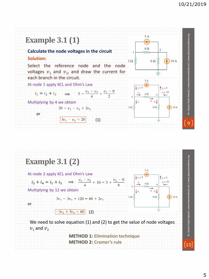
10/21/2019
5
Example 3.1 (1)
9
Dr.
Haz
em
Fal
ah S
ake
ek
| w
ww
.haz
em
sake
ek.
ne
t |
ww
w.p
hys
icsa
cad
em
y.o
rg
Calculate the node voltages in the circuit
Solution:
Select the reference node and the node voltages 𝑣1 and 𝑣2, and draw the current for each branch in the circuit.
At node 1 apply KCL and Ohm’s Law
Multiplying by 4 we obtain
or
⟹
(1)
𝑖1 = 𝑖2 + 𝑖3
Example 3.1 (2)
10
Dr.
Haz
em
Fal
ah S
ake
ek
| w
ww
.haz
em
sake
ek.
ne
t |
ww
w.p
hys
icsa
cad
em
y.o
rg
At node 2 apply KCL and Ohm’s Law
Multiplying by 12 we obtain
or
𝑖2 + 𝑖4 = 𝑖1 + 𝑖5 ⟹
(2)
METHOD 1: Elimination technique METHOD 2: Cramer’s rule
We need to solve equation (1) and (2) to get the value of node voltages 𝑣1 and 𝑣2

10/21/2019
6
Example 3.1 (3)
11
Dr.
Haz
em
Fal
ah S
ake
ek
| w
ww
.haz
em
sake
ek.
ne
t |
ww
w.p
hys
icsa
cad
em
y.o
rg
METHOD 1: Elimination technique
Adding equation (1) and (2) we get
Substituting 𝑣2 = 20 in equation (1) we get
(2)
(1)
If we need the currents, we can calculate them from the values of the nodal voltages.
negative sign show the current flows in the direction opposite to the one assumed.
Example 3.1 (4)
12
Dr.
Haz
em
Fal
ah S
ake
ek
| w
ww
.haz
em
sake
ek.
ne
t |
ww
w.p
hys
icsa
cad
em
y.o
rg
METHOD 2: Cramer’s rule
We need to put Equation (1) and (2) in matrix form as follow
The determinant of the matrix is
(2)
(1)
We now obtain 𝑣1 and 𝑣2
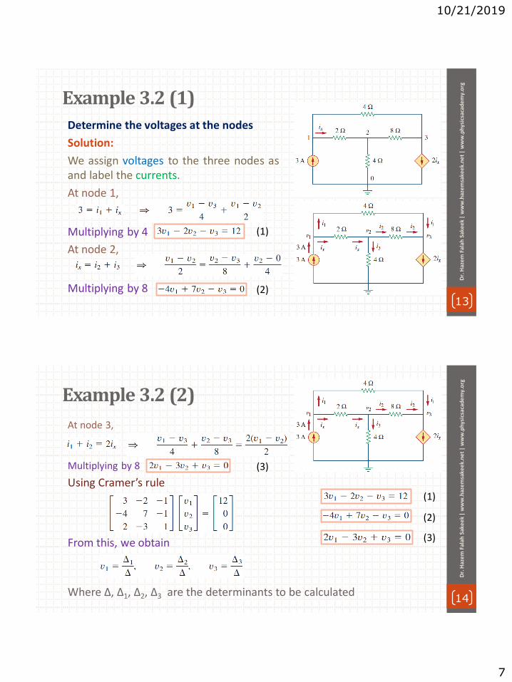
10/21/2019
7
Example 3.2 (1)
13
Dr.
Haz
em
Fal
ah S
ake
ek
| w
ww
.haz
em
sake
ek.
ne
t |
ww
w.p
hys
icsa
cad
em
y.o
rg
Determine the voltages at the nodes
Solution:
We assign voltages to the three nodes as and label the currents.
At node 1,
Multiplying by 4
At node 2,
Multiplying by 8
(2)
(1)
Example 3.2 (2)
14
Dr.
Haz
em
Fal
ah S
ake
ek
| w
ww
.haz
em
sake
ek.
ne
t |
ww
w.p
hys
icsa
cad
em
y.o
rg
At node 3,
Multiplying by 8
Using Cramer’s rule
From this, we obtain
Where ∆, ∆1, ∆2, ∆3 are the determinants to be calculated
(3)
(2)
(1)
(3)

10/21/2019
8
Example 3.2 (3)
15
Dr.
Haz
em
Fal
ah S
ake
ek
| w
ww
.haz
em
sake
ek.
ne
t |
ww
w.p
hys
icsa
cad
em
y.o
rg
Problems to Solve by yourself
16
Dr.
Haz
em
Fal
ah S
ake
ek
| w
ww
.haz
em
sake
ek.
ne
t |
ww
w.p
hys
icsa
cad
em
y.o
rg
(4) Find the currents 𝐼1 through 𝐼4 and the voltage 𝑣o in the circuit.
(3 Obtain the node voltages in the circuit.
(2) ) Find the voltages at the three nonreference nodes in the circuit.
(1) Obtain the node voltages in the circuit.
(5) Find the currents 𝐼1 through 𝐼4 in the circuit.

10/21/2019
1
1
Dr.
Haz
em
Fal
ah S
ake
ek
| w
ww
.haz
em
sake
ek.
ne
t |
ww
w.p
hys
icsa
cad
em
y.o
rg
Unit: 3 | Lecture: 12
Methods of Analysis: Nodal analysis with voltage sources
www.physicsacademy.org
Physics Academy
Dr. Hazem Falah Sakeek
Al-Azhar University of Gaza
Methods of Analysis
2
Dr.
Haz
em
Fal
ah S
ake
ek
| w
ww
.haz
em
sake
ek.
ne
t |
ww
w.p
hys
icsa
cad
em
y.o
rg
3.1 Introduction
3.2 Nodal analysis.
3.3 Nodal analysis with voltage sources.
3.4 Mesh analysis.
3.5 Mesh analysis with current sources.

10/21/2019
2
3.3 Nodal Analysis with Voltage Source (1)
3
Dr.
Haz
em
Fal
ah S
ake
ek
| w
ww
.haz
em
sake
ek.
ne
t |
ww
w.p
hys
icsa
cad
em
y.o
rg
We now consider how voltage sources affect nodal analysis.
• CASE 1 If a voltage source is connected between the reference node and a nonreference node,
• We simply set the voltage at the nonreference node equal to the voltage of the voltage source.
3.3 Nodal Analysis with Voltage Source (2)
4
Dr.
Haz
em
Fal
ah S
ake
ek
| w
ww
.haz
em
sake
ek.
ne
t |
ww
w.p
hys
icsa
cad
em
y.o
rg
• CASE 2 If the voltage source (dependent or independent) is connected between two nonreference nodes, supernode.
nodes 2 and 3 form a supernode A supernode may be regarded as a closed surface enclosing the voltage source and
its two nodes.
A supernode is formed by enclosing a voltage source connected between two non-reference nodes and any elements connected in parallel with it.

10/21/2019
3
3.3 Nodal Analysis with Voltage Source (3)
5
Dr.
Haz
em
Fal
ah S
ake
ek
| w
ww
.haz
em
sake
ek.
ne
t |
ww
w.p
hys
icsa
cad
em
y.o
rg
Basic steps:
1. Take off all voltage sources in supernodes and apply KCL to supernodes.
2. Put voltage sources back to the nodes and apply KVL to relative loops.
Note: supernode requires the application of both KCL and KVL.
or
Example 3.3 (1)
6
Dr.
Haz
em
Fal
ah S
ake
ek
| w
ww
.haz
em
sake
ek.
ne
t |
ww
w.p
hys
icsa
cad
em
y.o
rg
Find the node voltages for the circuit
Solution:
• The supernode contains the 2-V source, nodes 1 and 2, and the 10-Ω resistor.
• Applying KCL to the supernode
(1)

10/21/2019
4
Example 3.3 (2)
7
Dr.
Haz
em
Fal
ah S
ake
ek
| w
ww
.haz
em
sake
ek.
ne
t |
ww
w.p
hys
icsa
cad
em
y.o
rg
Applying KVL to get relationship between 𝑣1 & 𝑣2
From equation (1) and (2) we get
and
(2)
⟹
Example 3.4 (1)
8
Dr.
Haz
em
Fal
ah S
ake
ek
| w
ww
.haz
em
sake
ek.
ne
t |
ww
w.p
hys
icsa
cad
em
y.o
rg
Find the node voltages in the circuit
Solution:
At supernode 1-2 apply KCL
At supernode 3-4 apply KCL
(2)
(1)

10/21/2019
5
Example 3.4 (2)
9
Dr.
Haz
em
Fal
ah S
ake
ek
| w
ww
.haz
em
sake
ek.
ne
t |
ww
w.p
hys
icsa
cad
em
y.o
rg
Apply KVL to the branches involving the voltage sources.
(3)
(4)
and
(5)
For loop 2
But
For loop 3
For loop 1
Example 3.4 (3)
10
Dr.
Haz
em
Fal
ah S
ake
ek
| w
ww
.haz
em
sake
ek.
ne
t |
ww
w.p
hys
icsa
cad
em
y.o
rg
From equation (3) substitute into eqs. (1) & (2), gives
Use eqs. (4), (6), (7) to form a matrix
(4)
(5)
(2)
(1)
(3)
(6)
(6)
(7)

10/21/2019
6
Example 3.4 (3)
11
Dr.
Haz
em
Fal
ah S
ake
ek
| w
ww
.haz
em
sake
ek.
ne
t |
ww
w.p
hys
icsa
cad
em
y.o
rg
(6)
the node voltages Using Cramer’s rule gives
Problems to Solve by yourself
12
Dr.
Haz
em
Fal
ah S
ake
ek
| w
ww
.haz
em
sake
ek.
ne
t |
ww
w.p
hys
icsa
cad
em
y.o
rg
(4) Using nodal analysis, find 𝑣o in the circuit.
(3) Apply nodal analysis to solve for 𝑉x in the circuit.
(2) ) Find 𝑣1, 𝑣2 and 𝑣3 in the circuit.
(1) Find 𝑣 and 𝑖 in the circuit.
(5) Find 𝐼o in the circuit.
(6) Using nodal analysis, determine 𝑉o in the circuit.

10/22/2019
1
1
Dr.
Haz
em
Fal
ah S
ake
ek
| w
ww
.haz
em
sake
ek.
ne
t |
ww
w.p
hys
icsa
cad
em
y.o
rg
Unit: 3 | Lecture: 13
Methods of Analysis: Mesh analysis
www.physicsacademy.org
Physics Academy
Dr. Hazem Falah Sakeek
Al-Azhar University of Gaza
2
Dr.
Haz
em
Fal
ah S
ake
ek
| w
ww
.haz
em
sake
ek.
ne
t |
ww
w.p
hys
icsa
cad
em
y.o
rg
Methods of Analysis
3.1 Introduction
3.2 Nodal analysis.
3.3 Nodal analysis with voltage sources.
3.4 Mesh analysis.
3.5 Mesh analysis with current sources.
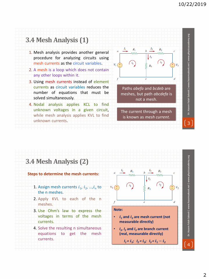
10/22/2019
2
3.4 Mesh Analysis (1)
3
Dr.
Haz
em
Fal
ah S
ake
ek
| w
ww
.haz
em
sake
ek.
ne
t |
ww
w.p
hys
icsa
cad
em
y.o
rg
Paths abefa and bcdeb are meshes, but path abcdefa is
not a mesh.
The current through a mesh is known as mesh current.
1. Mesh analysis provides another general procedure for analyzing circuits using mesh currents as the circuit variables.
2. A mesh is a loop which does not contain any other loops within it.
3. Using mesh currents instead of element currents as circuit variables reduces the number of equations that must be solved simultaneously.
4. Nodal analysis applies KCL to find unknown voltages in a given circuit, while mesh analysis applies KVL to find unknown currents.
3.4 Mesh Analysis (2)
4
Dr.
Haz
em
Fal
ah S
ake
ek
| w
ww
.haz
em
sake
ek.
ne
t |
ww
w.p
hys
icsa
cad
em
y.o
rg
Steps to determine the mesh currents:
1. Assign mesh currents 𝑖1, 𝑖2, …,𝑖n to the n meshes.
2. Apply KVL to each of the n meshes.
3. Use Ohm’s law to express the voltages in terms of the mesh currents.
4. Solve the resulting n simultaneous equations to get the mesh currents.
Note:
• 𝒊1 and 𝒊2 are mesh current (not measurable directly)
• I1, I2 and I3 are branch current (real, measurable directly)
I1 = 𝒊1; I2 = 𝒊2; I3 = 𝒊1 − 𝒊2

10/22/2019
3
3.4 Mesh Analysis (3)
5
Dr.
Haz
em
Fal
ah S
ake
ek
| w
ww
.haz
em
sake
ek.
ne
t |
ww
w.p
hys
icsa
cad
em
y.o
rg
• The first step requires that mesh currents 𝑖1, 𝑖2 are assigned to meshes 1 and 2.
• The second step, we apply KVL to each mesh.
For mesh 1
For mesh 2
• The third step is to solve for the mesh currents.
It is conventional to assume that each mesh current
flows clockwise.
Example 3.5 (1)
6
Dr.
Haz
em
Fal
ah S
ake
ek
| w
ww
.haz
em
sake
ek.
ne
t |
ww
w.p
hys
icsa
cad
em
y.o
rg
Find the branch currents 𝑰1, 𝑰2 and 𝑰3 using mesh analysis.
Solution:
For mesh 1,
or
For mesh 2,
or
(2)
(1)

10/22/2019
4
Example 3.5 (2)
7
Dr.
Haz
em
Fal
ah S
ake
ek
| w
ww
.haz
em
sake
ek.
ne
t |
ww
w.p
hys
icsa
cad
em
y.o
rg
METHOD 1: Using the substitution method, we substitute Eq. (2) into Eq. (1),
From Eq. (2),
Thus,
(1)
(2)
Example 3.5 (3)
8
Dr.
Haz
em
Fal
ah S
ake
ek
| w
ww
.haz
em
sake
ek.
ne
t |
ww
w.p
hys
icsa
cad
em
y.o
rg
METHOD 2: Using Cramer’s rule, from Eq. (2) into Eq. (1),
the determinants
(1)
(2)

10/22/2019
5
Example 3.6 (1)
9
Dr.
Haz
em
Fal
ah S
ake
ek
| w
ww
.haz
em
sake
ek.
ne
t |
ww
w.p
hys
icsa
cad
em
y.o
rg
Use mesh analysis to find 𝑰o the current.
Solution:
For mesh 1
or
For mesh 2
or
For mesh 3
but
or
(1)
(2)
(3)
Example 3.6 (2)
10
Dr.
Haz
em
Fal
ah S
ake
ek
| w
ww
.haz
em
sake
ek.
ne
t |
ww
w.p
hys
icsa
cad
em
y.o
rg
In matrix form
(1)
(2)
(3)

10/22/2019
6
Example 3.6 (3)
11
Dr.
Haz
em
Fal
ah S
ake
ek
| w
ww
.haz
em
sake
ek.
ne
t |
ww
w.p
hys
icsa
cad
em
y.o
rg
We calculate the mesh currents using Cramer’s
rule
Thus,
Problems to Solve by yourself
12
Dr.
Haz
em
Fal
ah S
ake
ek
| w
ww
.haz
em
sake
ek.
ne
t |
ww
w.p
hys
icsa
cad
em
y.o
rg
(4) Apply mesh analysis to find 𝑖.
(3) Use mesh analysis to obtain 𝑖1, 𝑖2 and 𝑖3.
(2) ) Using mesh analysis, find 𝐼o.
(1) Calculate the mesh currents 𝑖1 and 𝑖2.
(5) Calculate the mesh currents 𝑖1 and 𝑖2.

10/30/2019
1
1
Dr.
Haz
em
Fal
ah S
ake
ek
| w
ww
.haz
em
sake
ek.
ne
t |
ww
w.p
hys
icsa
cad
em
y.o
rg
Unit: 3 | Lecture: 14
Methods of Analysis: Mesh analysis with current sources
www.physicsacademy.org
Physics Academy
Dr. Hazem Falah Sakeek
Al-Azhar University of Gaza
2
Dr.
Haz
em
Fal
ah S
ake
ek
| w
ww
.haz
em
sake
ek.
ne
t |
ww
w.p
hys
icsa
cad
em
y.o
rg
Methods of Analysis
3.1 Introduction
3.2 Nodal analysis.
3.3 Nodal analysis with voltage sources.
3.4 Mesh analysis
3.5 Mesh analysis with current sources.

10/30/2019
2
3.5 Mesh Analysis with Current Source (1)
3
Dr.
Haz
em
Fal
ah S
ake
ek
| w
ww
.haz
em
sake
ek.
ne
t |
ww
w.p
hys
icsa
cad
em
y.o
rg
CASE 1 When a current source exists only in one mesh.
We set
𝑖2 = −5 A
The mesh equation for the
other mesh is
Applying mesh analysis to circuits containing current sources (dependent or independent) will reduces the number of equations.
3.5 Mesh Analysis with Current Source (2)
4
Dr.
Haz
em
Fal
ah S
ake
ek
| w
ww
.haz
em
sake
ek.
ne
t |
ww
w.p
hys
icsa
cad
em
y.o
rg
CASE 2 When a current source exists between two meshes
We create a supermesh by excluding the current source and any elements connected in series with it.
Two meshes having a current source in common

10/30/2019
3
3.5 Mesh Analysis with Current Source (3)
5
Dr.
Haz
em
Fal
ah S
ake
ek
| w
ww
.haz
em
sake
ek.
ne
t |
ww
w.p
hys
icsa
cad
em
y.o
rg
A supermesh must satisfy KVL like any other mesh.
Applying KVL to the supermesh in fig. (b)
or
(1)
3.5 Mesh Analysis with Current Source (4)
6
Dr.
Haz
em
Fal
ah S
ake
ek
| w
ww
.haz
em
sake
ek.
ne
t |
ww
w.p
hys
icsa
cad
em
y.o
rg
Apply KCL to a node in the branch where the two meshes intersect, applying KCL to node 0 in Fig. (a).
Solving Eqs. (1) and (2), we get
(2)
(1)
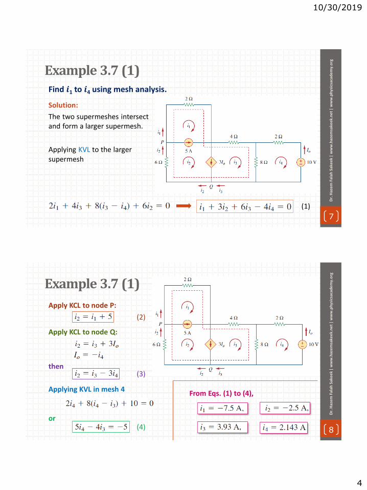
10/30/2019
4
Example 3.7 (1)
7
Dr.
Haz
em
Fal
ah S
ake
ek
| w
ww
.haz
em
sake
ek.
ne
t |
ww
w.p
hys
icsa
cad
em
y.o
rg
Solution:
The two supermeshes intersect and form a larger supermesh.
(1)
Find 𝒊1 to 𝒊4 using mesh analysis.
Applying KVL to the larger supermesh
Example 3.7 (1)
8
Dr.
Haz
em
Fal
ah S
ake
ek
| w
ww
.haz
em
sake
ek.
ne
t |
ww
w.p
hys
icsa
cad
em
y.o
rg
Apply KCL to node P:
Apply KCL to node Q:
then
Applying KVL in mesh 4
or
(2)
(3)
(4)
From Eqs. (1) to (4),

10/30/2019
5
9
To select the method that results in the smaller number of equations. For example:
1. Choose nodal analysis for circuit with fewer nodes than meshes.
2. Choose mesh analysis for circuit with fewer meshes than nodes.
3. Networks that contain many series connected elements, voltage sources, or supermeshes are more suitable for mesh analysis.
4. Networks with parallel-connected elements, current sources, or supernodes are more suitable for nodal analysis.
5. If node voltages are required, it may be expedient to apply nodal analysis. If branch or mesh currents are required, it may be
better to use mesh analysis.
Dr.
Haz
em
Fal
ah S
ake
ek
| w
ww
.haz
em
sake
ek.
ne
t |
ww
w.p
hys
icsa
cad
em
y.o
rg
Problems to Solve by yourself
10
Dr.
Haz
em
Fal
ah S
ake
ek
| w
ww
.haz
em
sake
ek.
ne
t |
ww
w.p
hys
icsa
cad
em
y.o
rg
(4) Use mesh analysis to find 𝑖1, 𝑖2 and 𝑖3
(3) Find 𝑣o and 𝑖o in the circuit.
(2) Use mesh analysis to obtain 𝑖o.
(1) Use mesh analysis to determine 𝑖1, 𝑖2 and 𝑖3
(5) Apply mesh analysis to find 𝑣o.

11/3/2019
1
1
Dr.
Haz
em F
alah
Sak
eek
| w
ww
.haz
emsa
keek
.ne
t|
ww
w.p
hys
icsa
cad
em
y.o
rg
Unit: 3 | Lecture: 15
Solution of some selected problemNodal analysis & Mesh analysis
www.physicsacademy.org
Physics Academy
Dr. Hazem Falah Sakeek
Al-Azhar University of Gaza
Obtain the node voltages in the circuit.
2
Dr.
Haz
em F
alah
Sak
eek
| w
ww
.haz
emsa
keek
.ne
t|
ww
w.p
hys
icsa
cad
em
y.o
rgProblems 3.2
Draw the current direction at each node
Apply KCL at node 1,
0 − 𝑣110
+0 − 𝑣15
= 6 +𝑣1 − 𝑣2
2
−8𝑣1 + 5𝑣2 = 60
3 + 6 +𝑣1 − 𝑣2
2=𝑣2 − 0
4
−2𝑣1 + 3𝑣2 = 36
𝒗𝟏 = 𝟎 𝒗𝟐 = 𝟏𝟐
Apply KCL at node 2,
(1)
(2)
Solve equations (1) & (2)
&
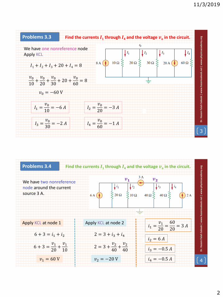
11/3/2019
2
3
Dr.
Haz
em F
alah
Sak
eek
| w
ww
.haz
emsa
keek
.ne
t|
ww
w.p
hys
icsa
cad
em
y.o
rgProblems 3.3 Find the currents 𝑰1 through 𝑰4 and the voltage 𝒗o in the circuit.
We have one nonreference nodeApply KCL
𝑣010
+𝑣020
+𝑣030
+ 20 +𝑣060
= 8
𝐼1+ 𝐼2+ 𝐼3+ 20 + 𝐼4 = 8
𝑣0 = −60 V
𝐼3 =𝑣030
= −2 𝐴
𝐼1 =𝑣010
= −6 𝐴 𝐼2 =𝑣020
= −3 𝐴
𝐼4 =𝑣060
= −1 𝐴
4
Dr.
Haz
em F
alah
Sak
eek
| w
ww
.haz
emsa
keek
.ne
t|
ww
w.p
hys
icsa
cad
em
y.o
rgProblems 3.4 Find the currents 𝑰1 through 𝑰4 and the voltage 𝒗o in the circuit.
We have two nonreference node around the current source 3 A.
Apply KCL at node 1 Apply KCL at node 2
𝒗1 𝒗2
6 + 3 = 𝑖1 + 𝑖2
6 + 3 =𝑣120
+𝑣110
𝑣1 = 60 V
2 = 3 + 𝑖3 + 𝑖4
2 = 3 +𝑣240
+𝑣240
𝑣2 = −20 V
𝑖1 =𝑣120
=60
20= 3 𝐴
𝑖2 = 6 𝐴
𝑖3 = −0.5 𝐴
𝑖4 = −0.5 𝐴

11/3/2019
3
5
Dr.
Haz
em F
alah
Sak
eek
| w
ww
.haz
emsa
keek
.ne
t|
ww
w.p
hys
icsa
cad
em
y.o
rgProblems 3.5 (1) Obtain 𝒗o in the circuit
Apply KCL at node 𝒗o
𝑰0
𝑰2
𝒗0
𝑰1
𝒗1 𝒗2
𝐼1+ 𝐼2+ 𝐼0 = 0
𝑣0 = −4000𝐼0 𝐼0 = −𝑣0
4000
𝑣0 − 𝑣1 = 30
𝑣0 + 2000𝐼1 = 30
∴ 𝐼1=30 − 𝑣02000
𝑣0 − 𝑣2 = 20
𝑣0 + 5000𝐼2 = 20
∴ 𝐼2 =20 − 𝑣05000
but
Notice that
6
Dr.
Haz
em F
alah
Sak
eek
| w
ww
.haz
emsa
keek
.ne
t|
ww
w.p
hys
icsa
cad
em
y.o
rgProblems 3.5 (2)
𝐼1+ 𝐼2+ 𝐼0 = 0
30 − 𝑣02
+20 − 𝑣0
5−𝑣04= 0
10(30 − 𝑣0)
20+4(20 − 𝑣0)
20−5𝑣020
= 0
300 − 10𝑣0 + 80 − 4𝑣0 − 5𝑣0 = 0
380 − 19𝑣0 = 0
𝑣0 = 20 𝑉
𝑰0
𝑰2
𝒗0
𝑰1
𝒗1 𝒗2
𝐼0 = −𝑣0
4000
𝐼1 =30 − 𝑣02000
𝐼2 =20 − 𝑣05000

11/3/2019
4
7
Dr.
Haz
em F
alah
Sak
eek
| w
ww
.haz
emsa
keek
.ne
t|
ww
w.p
hys
icsa
cad
em
y.o
rgProblems 2.7 Apply nodal analysis to solve for 𝑽x in the circuit.
Applying KCL to the circuit
2 = 𝐼1 + 𝐼2 + 0.2𝑉𝑥
𝑰1 𝑰2
2 =𝑉𝑥 − 0
10+𝑉𝑥 − 0
20+ 0.2𝑉𝑥
40 = 2𝑉𝑥 + 𝑉𝑥 + 4𝑉𝑥
𝑉𝑥 =40
7= 5.714 𝑉
𝑽x
8
Dr.
Haz
em F
alah
Sak
eek
| w
ww
.haz
emsa
keek
.ne
t|
ww
w.p
hys
icsa
cad
em
y.o
rgProblems 2.8 Using nodal analysis, find 𝒗o in the circuit.
Applying KCL to the circuit
𝒗1
𝑰2
𝑰1 𝑰3
𝐼1+ 𝐼2+ 𝐼3 = 0
𝑣1 − 0
6 + 4+
𝑣1 − 60 − 0
20+
𝑣1 − 5𝑣0 − 0
20= 0
𝑣110
+𝑣1 − 60
20+𝑣1 − 5𝑣0
20= 0
4𝑣1 − 5𝑣0 = 60
Using voltage divider to replace 𝒗o
𝑣0 =4
4 + 6𝑣1 𝑣1 =
10
4𝑣0
4 ×10
4𝑣0 − 5𝑣0 = 60 𝑣0 =
60
5= 12 𝑉

11/3/2019
5
9
Dr.
Haz
em F
alah
Sak
eek
| w
ww
.haz
emsa
keek
.ne
t|
ww
w.p
hys
icsa
cad
em
y.o
rgProblems 2.10 Find 𝑰o in the circuit.
At node 1
𝒗1 𝒗2𝒗3
𝑣18+ 4 +
𝑣1 − 𝑣31
= 0
At node 2 𝑣2 − 0
2+ 2𝐼0 = 4
At node 3 𝑣1 − 𝑣31
+ 2𝐼0 =𝑣34
But 𝐼0 =𝑣1
8
𝑣22+2𝑣18
= 4
𝑣1 − 𝑣3 +2𝑣18
=𝑣34
9𝑣1 − 8𝑣3 = −32
𝑣1 + 2𝑣2 = 16
5𝑣1 − 5𝑣3 = 0
∴ 𝑣1= 𝑣3
9𝑣1 − 8𝑣1 = −32
(1)
(2)
(3)
𝑣1 = −32 𝑉 ∴ 𝐼0=𝑣18= −4 𝐴
Substitute eqn. (3) in eqn. (1)
10
Dr.
Haz
em F
alah
Sak
eek
| w
ww
.haz
emsa
keek
.ne
t|
ww
w.p
hys
icsa
cad
em
y.o
rgProblems 2.12 Using nodal analysis, determine 𝑽o in the circuit.
𝒗2𝒗1
At node 1𝑣1 − 40
20+𝑣120
+𝑣1 − 𝑣210
= 0
𝑣1 − 40 + 𝑣1 + 2𝑣1 − 2𝑣2 = 0
4𝑣1 − 2𝑣2 = 40 (1)
At node 2𝑣1 − 𝑣210
+ 4𝐼𝑥 =𝑣210
But 𝐼𝑥 =𝑣1
20
𝑣1 − 𝑣2 − 2𝑣1 = 𝑣2
3𝑣1 = 2𝑣2 𝑣1 = 0.666𝑣2 (2)
Substitute eqn. (2) in eqn. (1) 4 × 0.666𝑣2 − 2𝑣2 = 40 𝑉0 = 𝑣2 = 60 𝑉

11/7/2019
1
1
Dr.
Haz
em
Fal
ah S
ake
ek|
ww
w.h
azem
sake
ek.n
et|
ww
w.p
hys
icsa
cad
em
y.o
rg
Unit: 3 | Lecture: 16
Solution of some selected problemNodal analysis & Mesh analysis
www.physicsacademy.org
Physics Academy
Dr. Hazem Falah Sakeek
Al-Azhar University of Gaza
2
Dr.
Haz
em
Fal
ah S
ake
ek|
ww
w.h
azem
sake
ek.
ne
t|
ww
w.p
hys
icsa
cad
em
y.o
rgProblems 3.35 Rework Prob. 3.5 using mesh analysis. Obtain 𝒗o.
Assume that 𝑖1 and 𝑖2 are in mA. We apply mesh analysis.
For mesh 1,
For mesh 2,
2𝑖1 − 30 + 20 + 5𝑖1 − 5𝑖2 = 0
7𝑖1 − 5𝑖2 = 10
5𝑖2 − 5𝑖1 − 20 + 4𝑖2 = 0
−5𝑖1 + 9𝑖2 = 20
(1)
(2)
Solving (1) and (2),
𝑖2 = 5 mA
𝑣0 = 4 kΩ × 5 𝑚𝐴 = 20 v
1
2

11/7/2019
2
3
Dr.
Haz
em
Fal
ah S
ake
ek|
ww
w.h
azem
sake
ek.n
et|
ww
w.p
hys
icsa
cad
em
y.o
rgProblems 3.36 Use mesh analysis to obtain 𝒊1, 𝒊2 and 𝒊3.
−12 + 4𝐼1 + 6𝐼1 − 6𝐼2 = 0
10𝐼1 − 6𝐼2 = 12
(1)
6𝐼2 − 6𝐼1 + 10 + 2𝐼2 = 0
−6𝐼1 + 8𝐼2 = −10
(2)
5𝐼1 − 3𝐼2 = 6
−3𝐼1 + 4𝐼2 = −5
5 −3−3 4
𝐼1𝐼2
=6−5
For mesh 1,
For mesh 2,
∆= 11
∆1= 9
∆2= −7
𝐼1 =9
11= 0.818 𝐴 𝐼2 =
−7
11= −0.636 𝐴
𝑖1 = −𝐼1= −0.818 𝐴
𝑖2 = 𝐼1 − 𝐼2 = 1.454 𝐴
𝑖3 = 𝐼2 = −0.636 𝐴
&
4
Dr.
Haz
em
Fal
ah S
ake
ek|
ww
w.h
azem
sake
ek.
ne
t|
ww
w.p
hys
icsa
cad
em
y.o
rgProblems 3.41(1) Apply mesh analysis to find 𝒊.
For mesh 1,
For mesh 2,
For mesh 3,
−6 + 2𝑖1 − 2𝑖2 + 10𝑖1 = 0
12𝑖1 − 2𝑖2 = 6
6𝑖1 − 𝑖2 = 3 (1)
(2)
4𝑖2 + 2𝑖2 − 2𝑖1 + 𝑖2 − 𝑖3 + 8 = 0
−2𝑖1 + 7𝑖2 − 𝑖3 = −8
−8 + 𝑖3 − 𝑖2 + 6 + 5𝑖3 = 0
−𝑖2 + 6𝑖3 = 2 (3)
At node 0, 𝑖 + 𝑖2 = 𝑖3
𝑖 = 𝑖3 – 𝑖2
3
4

11/7/2019
3
5
Dr.
Haz
em
Fal
ah S
ake
ek|
ww
w.h
azem
sake
ek.n
et|
ww
w.p
hys
icsa
cad
em
y.o
rgProblems 3.41(2) Apply mesh analysis to find 𝒊.
6𝑖1 − 𝑖2 = 3 (1)
(2)−2𝑖1 + 7𝑖2 − 𝑖3 = −8
−𝑖2 + 6𝑖3 = 2 (3)𝑖2 = −1.025 A
𝑖3 = 0.162 A
𝑖 = 𝑖3 − 𝑖2 = 1.187 𝐴
6
Dr.
Haz
em
Fal
ah S
ake
ek|
ww
w.h
azem
sake
ek.
ne
t|
ww
w.p
hys
icsa
cad
em
y.o
rgProblems 3.46 Calculate the mesh currents 𝒊1 and 𝒊2.
For mesh 1,
For mesh 2,
−12 + 3𝑖1 + 8𝑖1 − 8𝑖2 = 0
11𝑖1 − 8𝑖2 = 12 (1)
8𝑖2 − 8𝑖1 + 6𝑖2 + 2𝑣0 = 0
(2)
∵ 𝑣0= 3𝑖1−8𝑖1 + 14𝑖2 + 2 × 3𝑖1= 0
−2𝑖1 + 14𝑖2 = 0
∴ 𝑖1= 7𝑖2
Substitute for 𝑖1 = 7𝑖2 in eqn. (1)s
77𝑖2 − 8𝑖2 = 12
𝑖2 =12
69= 0.174 𝐴
𝑖1 = 7 × 0.174 = 1.217 𝐴
5
6

11/7/2019
4
7
Dr.
Haz
em
Fal
ah S
ake
ek|
ww
w.h
azem
sake
ek.n
et|
ww
w.p
hys
icsa
cad
em
y.o
rgProblems 3.49 Find 𝒗o and 𝒊o in the circuit.
a
For supermesh, 2𝑖1 + 1𝑖1 − 1𝑖3 + 2𝑖2 − 2𝑖3 + 27 = 0
3𝑖1 + 2𝑖2 − 3𝑖3 + 27 = 0 (1)
For mesh 3, 3𝑖3 + 2𝑖3 − 2𝑖2 + 1𝑖3 − 1𝑖1 = 0
−𝑖1 − 2𝑖2 + 6𝑖3 = 0 (2)
Apply KCL at node a 𝑖2 = 𝑖1 + 2𝑖0
but 𝑖0 = −𝑖1
therefore 𝑖2 = −𝑖1 (3)
From eqns. (1) & (2) & (3) we get
𝑖1 = −18 𝐴 𝑖2 = 18 𝐴 𝑖3 = 3 𝐴
∴ 𝑖0= −𝑖1= +18 𝐴
Apply KVL to loop 1 or 2 to find 𝑣0
2𝑖1 + 1𝑖1 − 1𝑖3 + 𝑣0 = 0
𝑣0 = 𝑖3 − 3𝑖1
𝑣0 = 3 − 3 −18
𝑣0 = 57 𝑉
8
Dr.
Haz
em
Fal
ah S
ake
ek|
ww
w.h
azem
sake
ek.
ne
t|
ww
w.p
hys
icsa
cad
em
y.o
rgProblems 3.51 Apply mesh analysis to find 𝒗o.
For mesh 1,
For mesh 2,
For mesh 3,
𝑖1 = 5 𝐴
−40 + 1𝑖2 + 2𝑖2 − 2𝑖1 + 4𝑖2 − 4𝑖3 = 0
7𝑖2 − 4𝑖3 = 50
(1)
(2)
−20 + 4𝑖3 − 4𝑖2 + 8𝑖3 = 0
−4𝑖2 + 12𝑖3 = 20
−𝑖2 + 3𝑖3 = 5 (3)
From eqns. (2) & (3) we get
𝑖2 = 10 𝐴 𝑖3 = 5 𝐴&
𝑣0 = 4 𝑖2 − 𝑖3 = 4 10 − 5 = 20 𝑉
Therefore,
7
8

11/7/2019
5
9
Dr.
Haz
em
Fal
ah S
ake
ek|
ww
w.h
azem
sake
ek.n
et|
ww
w.p
hys
icsa
cad
em
y.o
rgProblems 3.52 Use mesh analysis to find 𝒊1, 𝒊2 and 𝒊3
For mesh 1,
For supermesh,
−12 + 2𝑖1 − 2𝑖2 + 4𝑖1 − 4𝑖3 = 0
6𝑖1 − 2𝑖2 − 4𝑖3 = 12
3𝑖1 − 𝑖2 − 2𝑖3 = 6
2𝑣0 + 4𝑖3 − 4𝑖1 + 2𝑖2 − 2𝑖1 + 8𝑖2 = 0
4 𝑖1 − 4𝑖2 + 4𝑖3 − 6𝑖1 + 10𝑖2 = 0
but 𝑣0 = 2 𝑖1 − 𝑖2
−2 𝑖1 + 6𝑖2 + 4𝑖3 = 0
− 𝑖1 + 3𝑖2 + 2𝑖3 = 0
(1)
(2)
(3)a
Apply KCL at node a 3 + 𝑖2 = 𝑖3
From eqns. (1) & (2) & (3) we get
𝑖1 = 3.5 𝐴 𝑖2 = −0.5 𝐴 𝑖3 = 2.5 𝐴
9

11/13/2019
1
1
Dr.
Haz
em
Fal
ah S
ake
ek|
ww
w.h
azem
sake
ek.n
et|
ww
w.p
hys
icsa
cad
em
y.o
rg
www.physicsacademy.org
Physics Academy
Dr. Hazem Falah Sakeek
Al-Azhar University of Gaza
Unit: 4 | Lecture: 17Circuit Theorems: Linearity Property
Circuit Theorems
2
Dr.
Haz
em
Fal
ah S
ake
ek|
ww
w.h
azem
sake
ek.
ne
t|
ww
w.p
hys
icsa
cad
em
y.o
rg
4.1 Introduction4.2 Linearity Property4.3 Superposition4.4 Source Transformation4.5 Thevenin’s Theorem4.6 Norton’s Theorem4.7 Maximum Power Transfer
1
2

11/13/2019
2
4.1 Introduction
3
Dr.
Haz
em
Fal
ah S
ake
ek|
ww
w.h
azem
sake
ek.n
et|
ww
w.p
hys
icsa
cad
em
y.o
rg
• A major advantage of analyzing circuits usingKirchhoff’s laws as we did in Chapter 3 is thatwe can analyze a circuit without alteringwith its original configuration.
• A major disadvantage of this approach isthat, for a large, complex circuit, tediouscomputation is involved.
• Engineers developed some theorems tosimplify circuit analysis. Such theoremsinclude Thevenin’s and Norton’s theorems.
4.2 Linearity Property (1)
4
Dr.
Haz
em
Fal
ah S
ake
ek|
ww
w.h
azem
sake
ek.
ne
t|
ww
w.p
hys
icsa
cad
em
y.o
rg𝒊𝒐
In the case of voltage source: If 𝑖𝑜 is a linearfunction of 𝑣𝑠, then if we double the voltagewill double the current.
i.e. 2𝑣𝑠 → 2𝑖𝑜
𝒊𝒔 𝒗𝒐
Output = 𝒌 × Input
Where 𝒌 is constant
In the case of current source: If 𝑣𝑜 is a linearfunction of 𝑖𝑠, then if we double the current willdouble the voltage.
i.e. 2𝑖𝑠 → 2𝑣𝑜
Linearity is the property of an element describing a linear relationship betweencause and effect. i.e. output is linearly related (or directly proportional) to its input.
3
4

11/13/2019
3
4.2 Linearity Property (2)
5
Dr.
Haz
em
Fal
ah S
ake
ek|
ww
w.h
azem
sake
ek.n
et|
ww
w.p
hys
icsa
cad
em
y.o
rg
The linearity property is a combination of both the homogeneity (scaling)property and the additivity property.
Additive propertythe response to a sum of inputs isthe sum of the responses to eachinput applied separately.
𝑣 = 𝑖1+ 𝑖2 𝑅→ = 𝑖1𝑅 + 𝑖2𝑅 = 𝑣1+ 𝑣2
Homogeneity propertyIf the input is multiplied by aconstant, then the output ismultiplied by the same constant.
𝑣 = 𝑖 𝑅
→ 𝑘 𝑣 = 𝑘 𝑖 𝑅
A resistor is a linear element because the voltage-current relationshipsatisfies both the homogeneity and the additivity properties.
4.2 Linearity Property (3)
6
Dr.
Haz
em
Fal
ah S
ake
ek|
ww
w.h
azem
sake
ek.
ne
t|
ww
w.p
hys
icsa
cad
em
y.o
rg
Note that the relationship between power and voltage (or current) is nonlinear.
𝑝 = 𝑖2𝑅 =𝑣2
𝑅
Therefore, the theorems covered in this chapter are not applicable to power.
Example:
If single current 𝑖1 flow in R, the power is 𝑝1 = 𝑅𝑖12.
For another current 𝑖2, the power is 𝑝2 = 𝑅𝑖22.
If current 𝑖1+𝑖2 flows through R, the power is
𝑝3 = 𝑅 𝑖1 + 𝑖22 = 𝑅𝑖1
2 + 𝑅𝑖22 + 2𝑅𝑖1𝑖2 ≠ 𝑝1 + 𝑝2
5
6

11/13/2019
4
Example 4.1 (1)
7
Dr.
Haz
em
Fal
ah S
ake
ek|
ww
w.h
azem
sake
ek.n
et|
ww
w.p
hys
icsa
cad
em
y.o
rg
Find 𝑰o when 𝒗s=12 V and 𝒗s = 24 V.
Solution:
Applying KVL to the two loops,
But 𝑣𝑥 = 2𝑖1. Eqn. (2) becomes
Adding Eqs. (1) and (3)
Substituting in Eqn. (1)
(1)
(2)
(3)
When 𝑣s=12 V
When 𝑣s=24 V
Note: when the source value is doubled, 𝐼o doubles.
12𝑖1 − 4𝑖2 + 𝑣𝑠 = 0
−4𝑖1 + 16𝑖2 − 3𝑣𝑥 − 𝑣𝑠 = 0
−10𝑖1 + 16𝑖2 − 𝑣𝑠 = 0
2𝑖1 + 12𝑖2 = 0 ⇒ 𝑖1 = −6𝑖2
−76𝑖2 + 𝑣𝑠 = 0 ⇒ 𝑖2 =𝑣𝑠76
𝐼0 = 𝑖2 =12
76𝐴
𝐼0 = 𝑖2 =24
76𝐴
Example 4.2 (1)
8
Dr.
Haz
em
Fal
ah S
ake
ek|
ww
w.h
azem
sake
ek.
ne
t|
ww
w.p
hys
icsa
cad
em
y.o
rg
Solution:
If 𝑰o =1 A, then
V1 = (3+5) 𝐼o = 8 V
𝐼1 = V1/4 = 2A
Applying KCL at node 1
Applying Ohm’s law to find V2
Applying KCL at node 2
When assuming 𝑰𝟎 = 𝟏 𝑨 gives 𝑰s = 5 AThen the actual source current of 15 A will give 𝑰o =3 A.
Assume 𝑰o =1 A, use linearity to find the actual value of 𝑰o.
𝐼2 = 𝐼1 + 𝐼0 = 3 𝐴
2𝐼2 = 𝑉2 − 𝑉1 ⟹ 2𝐼2 + 𝑉1 = 𝑉2 ⟹ 𝑉2 = 8 + 2 × 3 = 14 𝑉
𝐼3 =𝑉27=14
7= 2 𝐴
⟹ 𝐼4= 𝐼3 + 𝐼2 = 5 𝐴 = 𝐼𝑠
7
8

11/13/2019
5
Problems to Solve by yourself
9
Dr.
Haz
em
Fal
ah S
ake
ek|
ww
w.h
azem
sake
ek.n
et|
ww
w.p
hys
icsa
cad
em
y.o
rg
(3) Calculate the current 𝑖o. What value of input voltage is necessary to make 𝑖o = 5A?
(2) Assume that 𝑉o= 1V and use linearity to calculate the actual value of 𝑉o.
(1) Find 𝑣o when 𝑖s=30 and 𝑖s = 45 A
(4) Use linearity to determine 𝑖o.
9

11/14/2019
1
1
Dr.
Haz
em
Fal
ah S
ake
ek|
ww
w.h
azem
sake
ek.n
et|
ww
w.p
hys
icsa
cad
em
y.o
rg
www.physicsacademy.org
Physics Academy
Dr. Hazem Falah Sakeek
Al-Azhar University of Gaza
Unit: 4 | Lecture: 18Circuit Theorems: Superposition
Circuit Theorems
2
Dr.
Haz
em
Fal
ah S
ake
ek|
ww
w.h
azem
sake
ek.
ne
t|
ww
w.p
hys
icsa
cad
em
y.o
rg
4.1 Introduction4.2 Linearity Property
4.3 Superposition4.4 Source Transformation4.5 Thevenin’s Theorem4.6 Norton’s Theorem4.7 Maximum Power Transfer
1
2

11/14/2019
2
4.3 Superposition (1)
3
Dr.
Haz
em
Fal
ah S
ake
ek|
ww
w.h
azem
sake
ek.n
et|
ww
w.p
hys
icsa
cad
em
y.o
rg
• The idea of superposition depends on the linearity property.
• The principle of superposition helps us to analyze a linear circuit withmore than one independent source by calculating the contribution ofeach independent source separately.
The superposition principle states that the voltage across (orcurrent through) an element in a linear circuit is the algebraic sumof the voltages across (or currents through) that element due toeach independent source acting alone.
4
Dr.
Haz
em
Fal
ah S
ake
ek|
ww
w.h
azem
sake
ek.
ne
t|
ww
w.p
hys
icsa
cad
em
y.o
rg
Steps to Apply Superposition Principle:
1. Turn off all independent sources exceptone source.
2. Find the output (voltage or current) dueto that active source using thetechniques covered in Chapters 2 and3.
3. Repeat step 1 for each of the otherindependent sources.
4. Find the total contribution by addingalgebraically all the contributions dueto the independent sources.
4.3 Superposition (2)
3
4

11/14/2019
3
Example 4.3 (1)
5
Dr.
Haz
em
Fal
ah S
ake
ek|
ww
w.h
azem
sake
ek.n
et|
ww
w.p
hys
icsa
cad
em
y.o
rg
Solution:
We have two sources, so
𝑣 = 𝑣1 + 𝑣2𝑣1 is the contribution due to the 6 V source
𝑣2 is the contribution due to the 3 A source.
To find 𝒗𝟏 we set the current source to 0
Applying KVL to the loop
12𝑖1 − 6 = 0
∴ 𝑖1 = 0.5𝐴
Therefore,
𝑣1 = 4𝑖1 = 2 𝑉
Use the superposition theorem to find 𝒗
6
Dr.
Haz
em
Fal
ah S
ake
ek|
ww
w.h
azem
sake
ek.
ne
t|
ww
w.p
hys
icsa
cad
em
y.o
rg
To find 𝒗𝟐 we set the voltage source to 0
Using current division
Therefore,
𝑣2 = 4𝑖3 = 8 𝑉
𝑣 = 𝑣1 + 𝑣2
𝒗 = 𝟐 + 𝟖 = 𝟏𝟎 𝑽
Example 4.3 (2)
𝑖3 =8
4 + 83 = 2 𝐴
5
6

11/14/2019
4
7
Dr.
Haz
em
Fal
ah S
ake
ek|
ww
w.h
azem
sake
ek.n
et|
ww
w.p
hys
icsa
cad
em
y.o
rg
Solution:
We have current source and voltage source, alsowe have dependent voltage source.
Let
𝑖𝑜 = 𝑖01 + 𝑖02
𝑖01 is the current due to the 4 A source.
𝑖02 is the current due to the 20 V source.
Example 4.4 (1) Use the superposition theorem to find 𝒊𝟎
(1)
8
Dr.
Haz
em
Fal
ah S
ake
ek|
ww
w.h
azem
sake
ek.
ne
t|
ww
w.p
hys
icsa
cad
em
y.o
rg
To obtain 𝑖01, we apply mesh analysis
Loop 1𝑖1 = 4 𝐴
Loop 2−3𝑖1 + 6𝑖2 − 5𝑖01 − 1𝑖3 = 0
Loop 3−5𝑖1 − 1𝑖2 + 5𝑖01 + 10𝑖3 = 0
At node 0𝑖3 + 𝑖01 = 𝑖1
therefore,𝑖3 = 4 − 𝑖01
Substituting Eqs. (2) &(5) into Eqs. (3) &(4)
Example 4.4 (2)
(2)
(3)
(4)
(5)
3𝑖2 − 2𝑖01 = 8
𝑖2 + 5𝑖01 = 20
(6)
(7)
∴ 𝑖01=52
17𝐴 (8)
5𝑖01
𝑖01
7
8

11/14/2019
5
9
Dr.
Haz
em
Fal
ah S
ake
ek|
ww
w.h
azem
sake
ek.n
et|
ww
w.p
hys
icsa
cad
em
y.o
rg
To obtain 𝑖02, we apply mesh analysis
Loop 46𝑖4 − 𝑖5 − 5𝑖02 = 0
Loop 5−𝑖4 + 10𝑖5 + 5𝑖02 − 20 = 0
Note that 𝑖5 = −𝑖02Therefore eqs. (9) & (10) become
6𝑖4 − 4𝑖02 = 0
𝑖4 + 5𝑖02 = −20
Example 4.4 (3)
(9)
(10)
(11)
(12)
∴ 𝑖02= −120
34= −
60
17𝐴 (13)
𝑖𝑜 = 𝑖01 + 𝑖02
𝑖𝑜 =52
17−60
17= −
8
17
𝑖𝑜 = −0.47 𝐴
(1)
5𝑖02
𝑖02
Problems to Solve by yourself
10
Dr.
Haz
em
Fal
ah S
ake
ek|
ww
w.h
azem
sake
ek.
ne
t|
ww
w.p
hys
icsa
cad
em
y.o
rg
(2) Use the superposition principle to find 𝑖oand 𝑣o in the circuit
(1) Using superposition, find Vo in the circuit
(4) Use superposition to find 𝑣o.
9
10

11/9/2019
1
1
Dr.
Haz
em
Fal
ah S
ake
ek|
ww
w.h
azem
sake
ek.n
et|
ww
w.p
hys
icsa
cad
em
y.o
rg
www.physicsacademy.org
Physics Academy
Dr. Hazem Falah Sakeek
Al-Azhar University of Gaza
Unit: 4 | Lecture: 19Circuit Theorems: Source Transformation
Circuit Theorems
2
Dr.
Haz
em
Fal
ah S
ake
ek|
ww
w.h
azem
sake
ek.
ne
t|
ww
w.p
hys
icsa
cad
em
y.o
rg
4.1 Introduction4.2 Linearity Property
4.3 Superposition4.4 Source Transformation4.5 Thevenin’s Theorem4.6 Norton’s Theorem4.7 Maximum Power Transfer
1
2

11/9/2019
2
4.4 Source Transformation (1)
3
Dr.
Haz
em
Fal
ah S
ake
ek|
ww
w.h
azem
sake
ek.n
et|
ww
w.p
hys
icsa
cad
em
y.o
rg
• Source transformation is another tool for simplifying circuits, basedon the concept of equivalence.
• An equivalent circuit is one whose 𝑣-𝑖 characteristics are identicalwith the original circuit.
Source transformation is the process of replacing a voltage sourcevS in series with a resistor R by a current source iS in parallel with aresistor R, or vice versa.
4
Transformation of independent sources
4.4 Source Transformation (2)
Transformation of dependent sources
The arrow of thecurrent source isdirected towardthe positiveterminal of thevoltage source.
The source trans-formation is notpossible whenR = 0 for voltagesource and R = ∞for current source.
Dr.
Haz
em
Fal
ah S
ake
ek|
ww
w.h
azem
sake
ek.
ne
t|
ww
w.p
hys
icsa
cad
em
y.o
rg
3
4

11/9/2019
3
5
The two circuits are equivalent, i.e. they have thesame voltage-current relation at terminals a-b.
4.4 Source Transformation (3)
Dr.
Haz
em
Fal
ah S
ake
ek|
ww
w.h
azem
sake
ek.n
et|
ww
w.p
hys
icsa
cad
em
y.o
rg
If the sources are turned off, the equivalentresistance at terminals a-b in both circuits is R.
When terminals a-b are short-circuited, the short-circuit current flowing from a to b is 𝒊𝒔𝒄 = Τ𝒗𝒔 𝑹 inthe circuit (a) and 𝒊𝒔𝒄 = 𝒊𝒔 for the circuit (b).
Τ𝑣𝑠 𝑅 = 𝑖𝑠
Source transformation requires that
𝒗𝒔 = 𝒊𝒔𝑹 𝒊𝒔 =𝒗𝒔𝑹
or
(a)
(b)
Example 4.6
6
Dr.
Haz
em
Fal
ah S
ake
ek|
ww
w.h
azem
sake
ek.
ne
t|
ww
w.p
hys
icsa
cad
em
y.o
rg
Solution:1. Transform the current and voltage
sources, we get circuit (a).
2. Combining the 2 & 4 = 6
3. Transform the 12 V source in circuit (a) we get circuit (b).
4. Combining the 6 & 3 in parallel and the 2 A & 4 A current source, we get circuit (c).
Applying current division to get
𝑖 =2
2 + 82 = 0.4 𝐴
∴ 𝑣𝑜 = 8 𝑖 = 8 0.4 = 3.2 𝑉
Use source transformation to find 𝒗𝒐
(a)
(b)
(c)
5
6

11/9/2019
4
7
Dr.
Haz
em
Fal
ah S
ake
ek|
ww
w.h
azem
sake
ek.n
et|
ww
w.p
hys
icsa
cad
em
y.o
rg
1. Transform the 6 V source and thedependent current source 0.25𝑣𝑥we get circuit (a).
2. Combining the 2- & 2- inparallel to give 1-, which is inparallel with 3 A current source.
3. Transform the 3 A current sourcein circuit (a) we get circuit (b).
Notice that the terminals for areintact.
Find 𝒗𝒙 using source transformation
Example 4.7 (1)
(a)
(b)
8
Dr.
Haz
em
Fal
ah S
ake
ek|
ww
w.h
azem
sake
ek.
ne
t|
ww
w.p
hys
icsa
cad
em
y.o
rg
Applying KVL−3 + 5𝑖 + 𝑣𝑥 + 18 = 0 (1)
Example 4.7 (2)
Applying KVL to the loop containing only the3-V voltage source and 1 and 𝑣𝑥,we get
−3 + 1𝑖 + 𝑣𝑥 = 0
∴ 𝑣𝑥= 3 − 𝑖 (2)
Substituting Eq. (2) in Eq. (1), we obtain
15 + 5𝑖 + 3 − 𝑖 = 0
∴ 𝑖 = 4.5 𝐴
∴ 𝑣𝑥= 3 − 𝑖 = 7.5 𝑉
7
8

11/9/2019
5
Problems to Solve by yourself
9
Dr.
Haz
em
Fal
ah S
ake
ek|
ww
w.h
azem
sake
ek.n
et|
ww
w.p
hys
icsa
cad
em
y.o
rg
(3) Use source transformation to find the voltage 𝑉𝑥
(2) Use source transformation to find 𝑖.
(1) Use source transformation to reduce the circuit to a single voltage source in series with a single resistor.
(4) Use source transformation to find 𝑖x.
9

11/10/2019
1
1
Dr.
Haz
em
Fal
ah S
ake
ek|
ww
w.h
azem
sake
ek.n
et|
ww
w.p
hys
icsa
cad
em
y.o
rg
www.physicsacademy.org
Physics Academy
Dr. Hazem Falah Sakeek
Al-Azhar University of Gaza
Unit: 4 | Lecture: 20Circuit Theorems: Thevenin’s Theorem
Part 1: No dependent sources
Circuit Theorems
2
Dr.
Haz
em
Fal
ah S
ake
ek|
ww
w.h
azem
sake
ek.
ne
t|
ww
w.p
hys
icsa
cad
em
y.o
rg
4.1 Introducion4.2 Linearity Property
4.3 Superposition4.4 Source Transformation
4.5 Thevenin’s Theorem4.6 Norton’s Theorem4.7 Maximum Power Transfer
1
2

11/10/2019
2
4.5 Thevenin’s Theorem (1)
3
Dr.
Haz
em
Fal
ah S
ake
ek|
ww
w.h
azem
sake
ek.n
et|
ww
w.p
hys
icsa
cad
em
y.o
rg
Thevenin’s theorem states that alinear two-terminal circuit can bereplaced by an equivalent circuitconsisting of a voltage source VTh inseries with a resistor RTh, Original circuit
Thevenin equivalent circuit
Thevenin’s theorem provides a technique by which the fixed part of thecircuit is replaced by an equivalent circuit.
where VTh is the open-circuit voltageat the terminals and RTh is the input orequivalent resistance at the terminalswhen the independent sources areturned off.
4
Dr.
Haz
em
Fal
ah S
ake
ek|
ww
w.h
azem
sake
ek.
ne
t|
ww
w.p
hys
icsa
cad
em
y.o
rg
How to find the Thevenin equivalent voltage VTh?
4.5 Thevenin’s Theorem (2)
Suppose the two circuits (a) & (b) in slide # 3 are equivalent.
Remove the load no current flows, then theopen-circuit voltage across the terminals a-b incircuit (a) must be equal to the voltage sourceVTh in circuit (b).
(a)
(b)
𝑽𝑻𝒉 = 𝑽𝒐𝒄
The open-circuit voltage across the terminals is
3
4

11/10/2019
3
5
Dr.
Haz
em
Fal
ah S
ake
ek|
ww
w.h
azem
sake
ek.n
et|
ww
w.p
hys
icsa
cad
em
y.o
rg
How to find the Thevenin equivalent resistance RTh?
4.5 Thevenin’s Theorem (3)
Suppose the two circuits (a) & (b) in slide # 3 are equivalent.
Remove the load no current flows.
𝑹𝑻𝒉 = 𝑹𝒊𝒏
The input resistance at the terminalswhen the independent sources areturned off is
Turn off all independent sources.
The input resistance of the dead circuit at the terminals in (a) must be equal to (b), refer to circuits in slide # 3.
6
Dr.
Haz
em
Fal
ah S
ake
ek|
ww
w.h
azem
sake
ek.
ne
t|
ww
w.p
hys
icsa
cad
em
y.o
rg
Two Cases to be considered
4.5 Thevenin’s Theorem (4)
CASE 1 If the network has no dependent sources, we turn off allindependent sources. RTh is the input resistance of the network betweenterminals a and b,
𝑹𝑻𝒉 = 𝑹𝒊𝒏
5
6

11/10/2019
4
7
Dr.
Haz
em
Fal
ah S
ake
ek|
ww
w.h
azem
sake
ek.n
et|
ww
w.p
hys
icsa
cad
em
y.o
rg
4.5 Thevenin’s Theorem (5)
CASE 2 If the network has dependent sources, we turn off all independent sources.
𝑹𝑻𝒉 =𝒗𝒐𝒊𝒐
We apply a voltage source 𝑣𝑜 (say 𝑣𝑜 = 1 𝑉) atterminals a and b and determine the resultingcurrent 𝑖𝑜.
Or we may insert a current source 𝑖𝑜 (say 𝑖𝑜 = 1 𝐴) at terminals a-b and find the terminal voltage 𝑣𝑜.
𝑹𝑻𝒉 =𝒗𝒐𝒊𝒐
The two approaches will give the same result.
8
Dr.
Haz
em
Fal
ah S
ake
ek|
ww
w.h
azem
sake
ek.
ne
t|
ww
w.p
hys
icsa
cad
em
y.o
rg
4.5 Thevenin’s Theorem (6)
Thevenin’s theorem is very important in circuit analysis. It helps simplify a circuit.
𝑰𝑳 =𝑽𝑻𝒉
𝑹𝑻𝒉 + 𝑹𝑳
A large circuit may be replaced by a single independent voltage source and a singleresistor. This replacement technique is a powerful tool in circuit design.
A linear circuit with a variable load can be replaced by the Thevenin equivalent.
𝑽𝑳 = 𝑹𝑳𝑰𝑳 =𝑹𝑳
𝑹𝑻𝒉 + 𝑹𝑳𝑽𝑻𝒉
The current 𝑰𝑳 through the load and the voltage𝑽𝑳 across the load are easily determined once theThevenin equivalent of the circuit at the load’sterminals is obtained,
&
7
8
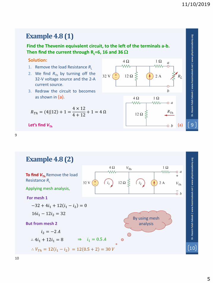
11/10/2019
5
Example 4.8 (1)
9
Dr.
Haz
em
Fal
ah S
ake
ek|
ww
w.h
azem
sake
ek.n
et|
ww
w.p
hys
icsa
cad
em
y.o
rg
Solution:
1. Remove the load Resistance RL
2. We find RTh by turning off the32-V voltage source and the 2-Acurrent source.
3. Redraw the circuit to becomes
as shown in (a).
Find the Thevenin equivalent circuit, to the left of the terminals a-b. Then find the current through RL=6, 16 and 36
𝑅𝑇ℎ = (4| 12 + 1 =4 × 12
4 + 12+ 1 = 4 Ω
Let’s find VTh (a)
10
Dr.
Haz
em
Fal
ah S
ake
ek|
ww
w.h
azem
sake
ek.
ne
t|
ww
w.p
hys
icsa
cad
em
y.o
rg
To find VTh Remove the load Resistance RL
Example 4.8 (2)
Applying mesh analysis,
For mesh 1
−32 + 4𝑖1 + 12 𝑖1 − 𝑖2 = 0
But from mesh 2
∴ 4𝑖1 + 12𝑖1 = 8 ⇒ 𝑖1 = 0.5 𝐴
∴ 𝑉𝑇ℎ = 12 𝑖1 − 𝑖2
𝑖2 = −2 𝐴
By using mesh analysis
16𝑖1 − 12𝑖2 = 32
= 12 0.5 + 2 = 30 𝑉
9
10

11/10/2019
6
11
Dr.
Haz
em
Fal
ah S
ake
ek|
ww
w.h
azem
sake
ek.n
et|
ww
w.p
hys
icsa
cad
em
y.o
rg
To find VTh Remove the load Resistance RL
Example 4.8 (3)
Applying nodal analysis,
(b)
32 − 𝑉𝑇ℎ4
+ 2 =𝑉𝑇ℎ12
96 − 3𝑉𝑇ℎ + 24 = 𝑉𝑇ℎ
⇒ 𝑉𝑇ℎ = 30 𝑉
× 12
Try to use source transformation to find 𝑽𝑻𝒉!
By using nodal analysis
120 = 4𝑉𝑇ℎ
12
Dr.
Haz
em
Fal
ah S
ake
ek|
ww
w.h
azem
sake
ek.
ne
t|
ww
w.p
hys
icsa
cad
em
y.o
rg
To find the current through RL
Example 4.8 (4)
𝑰𝑳 =𝑽𝑻𝒉
𝑹𝑻𝒉 + 𝑹𝑳=
𝟑𝟎
𝟒 + 𝑹𝑳
The Thevenin equivalent circuit
For RL = 6 For RL = 16 For RL = 36
𝐼𝐿 =30
4 + 6= 3 𝐴 𝐼𝐿 =
30
4 + 16= 1.5 𝐴 𝐼𝐿 =
30
4 + 36= 0.75 𝐴
End of part 1
11
12

11/21/2019
1
1
Dr.
Haz
em
Fal
ah S
ake
ek|
ww
w.h
azem
sake
ek.n
et|
ww
w.p
hys
icsa
cad
em
y.o
rg
www.physicsacademy.org
Physics Academy
Dr. Hazem Falah Sakeek
Al-Azhar University of Gaza
Unit: 4 | Lecture: 21Circuit Theorems: Thevenin’s Theorem
Part 2: with dependent sources
Circuit Theorems
2
Dr.
Haz
em
Fal
ah S
ake
ek|
ww
w.h
azem
sake
ek.
ne
t|
ww
w.p
hys
icsa
cad
em
y.o
rg
4.1 Introduction4.2 Linearity Property
4.3 Superposition4.4 Source Transformation
4.5 Thevenin’s Theorem4.6 Norton’s Theorem4.7 Maximum Power Transfer
1
2

11/21/2019
2
3
Dr.
Haz
em
Fal
ah S
ake
ek|
ww
w.h
azem
sake
ek.n
et|
ww
w.p
hys
icsa
cad
em
y.o
rg
4.5 Thevenin’s Theorem
CASE 2 If the network has dependent sources, we turn off all independent sources.
𝑹𝑻𝒉 =𝒗𝒐𝒊𝒐
We apply a voltage source 𝑣𝑜 (say 𝑣𝑜 = 1 𝑉) atterminals a and b and determine the resultingcurrent 𝑖𝑜.
Or we may insert a current source 𝑖𝑜 (say 𝑖𝑜 = 1 𝐴) at terminals a-b and find the terminal voltage 𝑣𝑜.
𝑹𝑻𝒉 =𝒗𝒐𝒊𝒐
The two approaches will give the same result.
4
Dr.
Haz
em
Fal
ah S
ake
ek|
ww
w.h
azem
sake
ek.
ne
t|
ww
w.p
hys
icsa
cad
em
y.o
rg
Find the Thevenin equivalent of the circuit at a-bExample 4.9 (1)
Solution:
1. To find RTh we set the independentsource equal to zero but leave thedependent source alone.
2. We excite the network with a voltagesource connected to the terminals.
3. Set 𝑣o to ease calculation (say 𝑣o=1 V).
4. Redraw the circuit.
5. Our goal is to find the current 𝑖o throughthe terminals, and then obtain RTh
3
4

11/21/2019
3
5
Dr.
Haz
em
Fal
ah S
ake
ek|
ww
w.h
azem
sake
ek.n
et|
ww
w.p
hys
icsa
cad
em
y.o
rgExample 4.9 (2)
Applying mesh analysis to loop 1
Applying mesh analysis to loop 2
Applying mesh analysis to loop 3
−2𝑣𝑥 + 2 𝑖1 − 𝑖2 = 0
4𝑖2 + 2 𝑖2 − 𝑖1 + 6 𝑖2 − 𝑖3 = 0
6 𝑖3 − 𝑖2 + 2𝑖3 + 1 = 0
Also 𝑣𝑥 = −4𝑖2 = 𝑖1 − 𝑖2
∴ 𝑣𝑥= 𝑖1 − 𝑖2
∴ 𝑖1 = −3𝑖2 (1)
(2)
(3)
Solving Eqs. (1), (2) and (3) gives
𝑖3 = −1
6𝐴
but 𝑖𝑜 = −𝑖3 =1
6𝐴
𝑅𝑇ℎ =1 𝑉
𝑖𝑜= 6 Ω
−2𝑖1 + 12𝑖2 − 6𝑖3 = 0
−𝑖1 + 6𝑖2 − 3𝑖3 = 0
−6𝑖2 + 8𝑖3 = −1
6
Dr.
Haz
em
Fal
ah S
ake
ek|
ww
w.h
azem
sake
ek.
ne
t|
ww
w.p
hys
icsa
cad
em
y.o
rg
Example 4.9 (3)
To get VTh apply mesh analysis
𝑖1 = 5 𝐴
−2𝑣𝑥 + 2 𝑖3 − 𝑖2 = 0
∴ 𝑣𝑥 = 𝑖3 − 𝑖2
12𝑖2 − 4𝑖1 − 2𝑖3 = 0
(4)
(5)
(6)Also 𝑣𝑥 = 4 𝑖1 − 𝑖2
(7)
Solving Eqs. (4), (5), (6) and (7) gives
𝑖2 =10
3𝐴
⇒ 𝑉𝑇ℎ = 𝑣𝑜𝑐 = 6𝑖2 = 20 𝑉
loop 1
loop 3
loop 2
5
6

11/21/2019
4
7
Dr.
Haz
em
Fal
ah S
ake
ek|
ww
w.h
azem
sake
ek.n
et|
ww
w.p
hys
icsa
cad
em
y.o
rgExample 4.10 (1)
Determine the Thevenin equivalent circuit
The circuit contains a 2 resistor in parallelwith a 4 resistor. These are, in turn, inparallel with a dependent current source. Itis important to note that there are noindependent sources.
Since we have no independent sources in this circuit, we must excite the circuitexternally. In addition, when you have no independent sources you will not have avalue for VTh you will only have to find RTh.
Excite the circuit with a 1-A current source, and use nodal analysis to calculate vo
8
Dr.
Haz
em
Fal
ah S
ake
ek|
ww
w.h
azem
sake
ek.
ne
t|
ww
w.p
hys
icsa
cad
em
y.o
rgExample 4.10 (2)The nodal equation at a, assuming 𝑖o= 1 A.
2𝑖𝑥 +𝑣𝑜 − 0
4+𝑣𝑜 − 0
2+ −1 = 0
𝑖𝑥 =0 − 𝑣𝑜2
=−𝑣𝑜2
But
∴ 2−𝑣𝑜2
+𝑣𝑜 − 0
4+𝑣𝑜 − 0
2+ −1 = 0
𝑣𝑜 −1 +1
4+1
2= 1
∴ 𝑣𝑜= −4 𝑉
𝑣𝑜 −0.25 = 1
Since 𝑣𝑜 = 1 × 𝑅𝑇ℎ
∴ 𝑅𝑇ℎ=𝑣𝑜1
𝑅𝑇ℎ = −4 Ω
The negative value of the resistancetells us that, the circuit (throughdependent source) is supplying power.
7
8

11/21/2019
5
Problem 4.40 (1)Find the Thevenin equivalent at terminals a-b in the circuit.
9
Dr.
Haz
em
Fal
ah S
ake
ek |
ww
w.h
azem
sake
ek.n
et |
ww
w.p
hys
icsa
cad
em
y.o
rg
To obtain VTh, we apply KVL to the loop.
−70 + 10 + 20 𝐼 + 4𝑉𝑜 = 0
Let R in k and 𝐼 in mA
But 𝑉𝑜 = 10𝐼
−70 + 10 + 20 𝐼 + 4(10𝐼) = 0
70𝐼 = 70
𝐼 = 1 𝑚𝐴
To find VTh apply KVL to the left loop
VTh
−70 + 10𝐼 + 𝑉𝑇ℎ = 0
𝑉𝑇ℎ = 60 𝑉
10
Dr.
Haz
em
Fal
ah S
ake
ek |
ww
w.h
azem
sake
ek.n
et |
ww
w.p
hys
icsa
cad
em
y.o
rg
To obtain RTh, we remove the 70 V source and apply 1 V source at the terminal a-b
−1 + 20𝐼1 + 4𝑉𝑜 = 0
Notice that Vo = -1 V
∴ 𝐼1= 0.25 𝑚𝐴
𝐼2 = 𝐼1 + 𝐼3
𝑅𝑇ℎ =1𝑉
𝐼2=
1𝑉
0.35= 2.857 𝑘Ω
Apply KCL at a𝐼3
𝐼2 = 0.25 +1
10= 0.35 𝑚𝐴
Therefore,
Problem 4.40 (2)
−1 + 20𝐼1 − 4 = 0
9
10

11/21/2019
6
Problems to Solve by yourself
11
Dr.
Haz
em
Fal
ah S
ake
ek|
ww
w.h
azem
sake
ek.n
et|
ww
w.p
hys
icsa
cad
em
y.o
rg
(3) Obtain the Thevenin equivalent at terminals a-b
(2) Apply Thevenin’s theorem to find Vo in thecircuit.
(1) Determine the Thevenin equivalent circuit,as seen by the 5-ohm resistor. Then calculatethe current flowing through the 5-ohm resistor.
(4) Find the Thevenin equivalent at terminals a-b.
11

11/21/2019
1
1
Dr.
Haz
em
Fal
ah S
ake
ek|
ww
w.h
azem
sake
ek.n
et|
ww
w.p
hys
icsa
cad
em
y.o
rg
www.physicsacademy.org
Physics Academy
Dr. Hazem Falah Sakeek
Al-Azhar University of Gaza
Unit: 4 | Lecture: 22Circuit Theorems: Norton’s Theorem
Circuit Theorems
2
Dr.
Haz
em
Fal
ah S
ake
ek|
ww
w.h
azem
sake
ek.
ne
t|
ww
w.p
hys
icsa
cad
em
y.o
rg
4.1 Introduction4.2 Linearity Property
4.3 Superposition4.4 Source Transformation4.5 Thevenin’s Theorem
4.6 Norton’s Theorem4.7 Maximum Power Transfer
1
2

11/21/2019
2
3
Dr.
Haz
em
Fal
ah S
ake
ek|
ww
w.h
azem
sake
ek.n
et|
ww
w.p
hys
icsa
cad
em
y.o
rg
4.6 Norton’s Theorem (1)
Norton’s theorem states that a linear two-terminal circuit can be replaced by anequivalent circuit consisting of a current source IN in parallel with a resistor RN,where IN is the short-circuit current through the terminals and RN is the input orequivalent resistance at the terminals when the independent sources are turnedoff.
𝑹𝑵 = 𝑹𝑻𝒉
The circuit in (a) can be replaced by the one in (b)
(a)
(b)
We are mainly concerned with how to get RN and IN.
From what we know about source transformation,the Thevenin and Norton resistances are equal, sothat
Let’s find Norton current IN.
4
Dr.
Haz
em
Fal
ah S
ake
ek|
ww
w.h
azem
sake
ek.
ne
t|
ww
w.p
hys
icsa
cad
em
y.o
rg
Observe the close relationship between Norton’s and Thevenin’s theorems
𝑰𝑵 =𝑽𝑻𝒉𝑹𝑻𝒉
This is essentially source transformation. For thisreason, source transformation is often calledThevenin-Norton transformation.
4.6 Norton’s Theorem (2)
We determine the short-circuit current flowing from terminal a to b in both circuits
(a)
(b)
(c)
The short-circuit current in (b) is IN.
Since the two circuits are equivalent, then
𝑰𝑵 = 𝑰𝒔𝒄
𝑹𝑵 = 𝑹𝑻𝒉
3
4
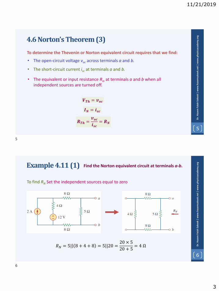
11/21/2019
3
5
Dr.
Haz
em
Fal
ah S
ake
ek|
ww
w.h
azem
sake
ek.n
et|
ww
w.p
hys
icsa
cad
em
y.o
rg
4.6 Norton’s Theorem (3)
To determine the Thevenin or Norton equivalent circuit requires that we find:
• The open-circuit voltage voc across terminals a and b.
𝑹𝑻𝒉 =𝒗𝒐𝒄𝒊𝒔𝒄
= 𝑹𝑵
• The short-circuit current isc at terminals a and b.
• The equivalent or input resistance Rin at terminals a and b when all independent sources are turned off.
𝑽𝑻𝒉 = 𝒗𝒐𝒄
𝑰𝑵 = 𝒊𝒔𝒄
6
Dr.
Haz
em
Fal
ah S
ake
ek|
ww
w.h
azem
sake
ek.
ne
t|
ww
w.p
hys
icsa
cad
em
y.o
rgExample 4.11 (1)
To find RN Set the independent sources equal to zero
𝑅𝑁 = 5| 8 + 4 + 8 = 5 |20 =20 × 5
20 + 5= 4 Ω
Find the Norton equivalent circuit at terminals a-b.
5
6

11/21/2019
4
7
Dr.
Haz
em
Fal
ah S
ake
ek|
ww
w.h
azem
sake
ek.n
et|
ww
w.p
hys
icsa
cad
em
y.o
rgExample 4.11 (2)
Method 1: To find IN, we short-circuit terminals a and b
𝑖1 = 2 𝐴
Applying mesh analysis,
20𝑖2 − 4𝑖1 − 10 = 0
𝒊𝟐 = 𝟏 𝑨 = 𝒊𝒔𝒄 = 𝑰𝑵
From eqns. (1) and (2)
(1)
(2)
8
Dr.
Haz
em
Fal
ah S
ake
ek|
ww
w.h
azem
sake
ek.
ne
t|
ww
w.p
hys
icsa
cad
em
y.o
rgExample 4.11 (3)
Method 2: To find IN, from VTh and RTh
𝑖3 = 2 𝐴
Applying mesh analysis,
25𝑖4 − 4𝑖3 − 12 = 0
𝑣𝑜𝑐 = 𝑉𝑇ℎ = 5𝑖4 = 4 𝑉
From eqns. (3) and (4)
(3)
(4)
𝑖4 = 0.8 𝐴
Hence,
𝑰𝑵 =𝑽𝑻𝒉𝑹𝑻𝒉
𝑰𝑵 =𝟒
𝟒= 𝟏 𝑨
Norton equivalent circuit
7
8

11/21/2019
5
9
Dr.
Haz
em
Fal
ah S
ake
ek|
ww
w.h
azem
sake
ek.n
et|
ww
w.p
hys
icsa
cad
em
y.o
rgExample 4.12 (1) Using Norton’s theorem, find RN and IN of the circuit at a-b
To find RN Set the independent sources equal to zero, and connect a voltage source of vo=1 V to the terminals. We ignore the 4 resistor because it is short-circuited.
Also due to the short circuit, the 5 resistor, the voltage source, and the dependent current source are all in parallel. Hence,
𝑖𝑥 = 0 𝑖𝑜 =1 𝑉
5 Ω= 0.2 𝐴 ∴ 𝑹𝑵=
𝒗𝒐𝒊𝒐
=𝟏
𝟎. 𝟐= 𝟓 𝛀
10
Dr.
Haz
em
Fal
ah S
ake
ek|
ww
w.h
azem
sake
ek.
ne
t|
ww
w.p
hys
icsa
cad
em
y.o
rgExample 4.12 (2)
To find IN we short-circuit terminals a and b and find the current isc
The 4 resistor, the 10-V voltage source, the 5 resistor, and the dependentcurrent source are all in parallel. Hence,
𝑖𝑥 =10
4= 2.5 𝐴
𝑖𝑠𝑐 =10
5+ 2𝑖𝑥 = 2 + 2 2.5 = 7 𝐴 𝑰𝑵 = 𝟕 𝑨At node a, apply KCL
9
10
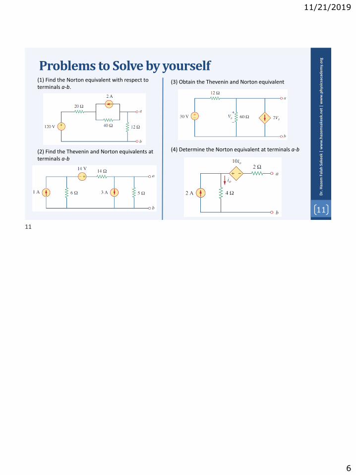
11/21/2019
6
Problems to Solve by yourself
11
Dr.
Haz
em
Fal
ah S
ake
ek|
ww
w.h
azem
sake
ek.n
et|
ww
w.p
hys
icsa
cad
em
y.o
rg
(3) Obtain the Thevenin and Norton equivalent
(2) Find the Thevenin and Norton equivalents atterminals a-b
(1) Find the Norton equivalent with respect to terminals a-b.
(4) Determine the Norton equivalent at terminals a-b
11

11/25/2019
1
1
Dr.
Haz
em
Fal
ah S
ake
ek|
ww
w.h
azem
sake
ek.n
et|
ww
w.p
hys
icsa
cad
em
y.o
rg
www.physicsacademy.org
Physics Academy
Dr. Hazem Falah Sakeek
Al-Azhar University of Gaza
Unit: 4 | Lecture: 23Circuit Theorems: Maximum Power
Transfer
Circuit Theorems
2
Dr.
Haz
em
Fal
ah S
ake
ek|
ww
w.h
azem
sake
ek.
ne
t|
ww
w.p
hys
icsa
cad
em
y.o
rg
4.1 Introduction4.2 Linearity Property
4.3 Superposition4.4 Source Transformation4.5 Thevenin’s Theorem4.6 Norton’s Theorem
4.7 Maximum Power Transfer
1
2

11/25/2019
2
3
Dr.
Haz
em
Fal
ah S
ake
ek|
ww
w.h
azem
sake
ek.n
et|
ww
w.p
hys
icsa
cad
em
y.o
rg
4.8 Maximum Power Transfer (1)
In many practical situations, a circuit is designed to provide power to a load.There are applications in areas such as communications where it is desirable tomaximize the power delivered to a load.
The Thevenin equivalent is useful in finding themaximum power a linear circuit can deliver toa load.
We assume that we can adjust the loadresistance RL.
If the entire circuit is replaced by its Thevenin equivalent except for the load, thepower delivered to the load is
𝑝 = 𝑖2𝑅𝐿 =𝑉𝑇ℎ
𝑅𝑇ℎ + 𝑅𝐿
2
𝑅𝐿 (1)
𝑖 =𝑉𝑇ℎ
𝑅𝑇ℎ + 𝑅𝐿
4
Dr.
Haz
em
Fal
ah S
ake
ek|
ww
w.h
azem
sake
ek.
ne
t|
ww
w.p
hys
icsa
cad
em
y.o
rg
For a given circuit, VTh and RTh are fixed. Byvarying the load resistance the powerdelivered to the load varies as shown in (b)
4.8 Maximum Power Transfer (2)
(b)
(a)
Note from (b) the power is small for small orlarge values RL of but maximum for some valueof RL between 0 and .
We will find that the maximum power occurswhen RL is equal to RTh.
Maximum power is transferred to the loadwhen the load resistance equals the Theveninresistance as seen from the load (RL=RTh).
The power transfer profile with different RL
𝑝 =𝑉𝑇ℎ
𝑅𝑇ℎ + 𝑅𝐿
2
𝑅𝐿 (1)
3
4

11/25/2019
3
5
Dr.
Haz
em
Fal
ah S
ake
ek|
ww
w.h
azem
sake
ek.n
et|
ww
w.p
hys
icsa
cad
em
y.o
rg
To prove the maximum power transfertheorem, we differentiate p with respect to RL
and set the result equal to zero
4.8 Maximum Power Transfer (3)
𝑝 =𝑉𝑇ℎ
𝑅𝑇ℎ + 𝑅𝐿
2
𝑅𝐿
𝑖. 𝑒.𝑑𝑝
𝑑𝑅𝐿= 0
𝑑𝑝
𝑑𝑅𝐿= 𝑉𝑇ℎ
2 𝑑
𝑑𝑅𝐿
𝑅𝐿𝑅𝑇ℎ + 𝑅𝐿
2
𝑑𝑝
𝑑𝑅𝐿= 𝑉𝑇ℎ
2 𝑅𝑇ℎ + 𝑅𝐿2 − 2𝑅𝐿 𝑅𝑇ℎ + 𝑅𝐿𝑅𝑇ℎ + 𝑅𝐿
4
𝑑𝑝
𝑑𝑅𝐿= 𝑉𝑇ℎ
2𝑅𝑇ℎ + 𝑅𝐿 − 2𝑅𝐿𝑅𝑇ℎ + 𝑅𝐿
3= 0
𝑅𝑇ℎ + 𝑅𝐿 − 2𝑅𝐿 = 0
𝑅𝑇ℎ − 𝑅𝐿 = 0
Maximum power transfer takes place when the load resistance RL
equals the Thevenin resistance RTh.
∴ 𝑅𝑇ℎ= 𝑅𝐿 (2)
6
Dr.
Haz
em
Fal
ah S
ake
ek|
ww
w.h
azem
sake
ek.
ne
t|
ww
w.p
hys
icsa
cad
em
y.o
rg
The maximum power transferred is obtained by substituting (2) in (1)
4.8 Maximum Power Transfer (4)
𝒑 =𝑽𝑻𝒉
𝑹𝑻𝒉 + 𝑹𝑳
𝟐
𝑹𝑳 𝑹𝑻𝒉 = 𝑹𝑳 (2)(1)
𝒑𝒎𝒂𝒙 =𝑽𝑻𝒉𝟐
𝟒𝑹𝑳
This equation applies only when RL = RTh
The power transferred at RL ≠ RTh is given by eqn. (1)
5
6

11/25/2019
4
7
Dr.
Haz
em
Fal
ah S
ake
ek|
ww
w.h
azem
sake
ek.n
et|
ww
w.p
hys
icsa
cad
em
y.o
rgExample 4.13 (1)
First we need to find RTh
𝑅𝑇ℎ = 2 + 3 + (6||12)
Find the value of RL for maximumpower transfer in the circuit. Findthe maximum power.
𝑅𝑇ℎ = 5 +6 × 12
6 + 12
We need to find the Theveninresistance RTh and the Theveninvoltage VTh across the terminals a-b.
𝑅𝑇ℎ = 9 Ω
8
Dr.
Haz
em
Fal
ah S
ake
ek|
ww
w.h
azem
sake
ek.
ne
t|
ww
w.p
hys
icsa
cad
em
y.o
rgExample 4.13 (2)
Second we need to find VTh
Applying mesh analysis to (b)
(b)
(a)
−12 + 18𝑖1 − 12𝑖2 = 0
𝑖2 = −2 𝐴But
𝑖1 = −2
3𝐴
Applying KVL around the outer loop to get VTh across terminals a-b,
−12 + 6𝑖1 + 3𝑖2 + 2 0 + 𝑉𝑇ℎ = 0
𝑉𝑇ℎ = 22 𝑉
7
8

11/25/2019
5
9
Dr.
Haz
em
Fal
ah S
ake
ek|
ww
w.h
azem
sake
ek.n
et|
ww
w.p
hys
icsa
cad
em
y.o
rgExample 4.13 (3)
Now we have,
𝑉𝑇ℎ = 22 𝑉
𝑅𝑇ℎ = 9 Ω
For maximum power transfer
𝑅𝐿 = 𝑅𝑇ℎ = 9 Ω
𝑝𝑚𝑎𝑥 =𝑉𝑇ℎ2
4𝑅𝐿
𝑝𝑚𝑎𝑥 =222
4 × 9= 13.44 𝑊
Problems to Solve by yourself
10
Dr.
Haz
em
Fal
ah S
ake
ek|
ww
w.h
azem
sake
ek.
ne
t|
ww
w.p
hys
icsa
cad
em
y.o
rg(3) what resistor connected across terminals will absorbmaximum power from the circuit? What is that power?
(2) Find the maximum power transferred toresistor R.
(1) Find the maximum power that can bedelivered to the resistor R in the circuit
(4) (a) Obtain the Thevenin equivalent at terminals(b) Calculate the current in RL = 8 (c) Find RL for maximum power deliverable to RL(d) Determine that maximum power..
9
10
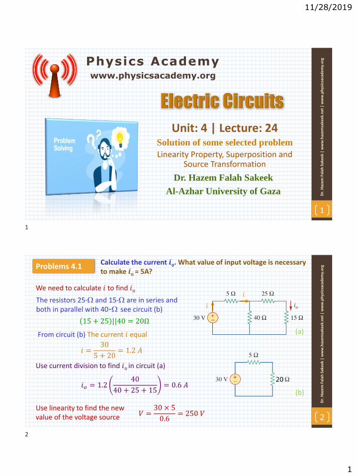
11/28/2019
1
1
Dr.
Haz
em
Fal
ah S
ake
ek|
ww
w.h
azem
sake
ek.n
et|
ww
w.p
hys
icsa
cad
em
y.o
rg
www.physicsacademy.org
Physics Academy
Dr. Hazem Falah Sakeek
Al-Azhar University of Gaza
Unit: 4 | Lecture: 24Solution of some selected problem
Linearity Property, Superposition and Source Transformation
Calculate the current 𝒊o. What value of input voltage is necessary to make 𝒊o = 5A?
2
Dr.
Haz
em
Fal
ah S
ake
ek|
ww
w.h
azem
sake
ek.
ne
t|
ww
w.p
hys
icsa
cad
em
y.o
rgProblems 4.1
𝑖
𝑖We need to calculate 𝑖 to find 𝑖o
The resistors 25- and 15- are in series and both in parallel with 40- see circuit (b)
15 + 25 ||40 = 20Ω
𝑖 =30
5 + 20= 1.2 𝐴
Use current division to find 𝑖o in circuit (a)
𝑖𝑜 = 1.240
40 + 25 + 15= 0.6 𝐴
(b)
Use linearity to find the newvalue of the voltage source 𝑉 =
30 × 5
0.6= 250 𝑉
From circuit (b) The current 𝑖 equal (a)
1
2

11/28/2019
2
Use linearity to determine 𝒊o.
3
Dr.
Haz
em
Fal
ah S
ake
ek|
ww
w.h
azem
sake
ek.n
et|
ww
w.p
hys
icsa
cad
em
y.o
rgProblems 4.4
Assume, 𝑖𝑜 = 1 𝐴 and calculate the value of the current source 𝑖𝑠
Then the voltage across the 6- resistor is 6 V
The current through the 3- resistor is
𝑖3 =6
3= 2 𝐴 𝑖3
𝑖𝑠
𝑖2
The 3- and 6- are in parallel = 2-
𝑖𝑠𝑣𝑜
𝑖2
From circuit (c) the 2- and 2- are in series and the current through them 𝑖2 =3A, then the voltage 𝑣𝑜 = 3 × 4 = 12 𝑉
The current 𝑖1 =12
4= 3 𝐴
Hence, 𝑖𝑠 = 3 + 3 = 6 𝐴
If, 𝑖𝑜 = 1 𝐴 → 𝑖𝑠 = 6 𝐴
𝑖𝑜 = ? 𝐴 → 𝑖𝑠 = 9 𝐴Then 𝑖𝑜 =
1×9
6= 1.5 𝐴
(c)
Using superposition, find Vo in the circuit
4
Dr.
Haz
em
Fal
ah S
ake
ek|
ww
w.h
azem
sake
ek.
ne
t|
ww
w.p
hys
icsa
cad
em
y.o
rgProblems 4.8 (1)
Let 𝑉o = 𝑉1 + 𝑉2
where 𝑉1 and 𝑉2 are due to 9-V and 3-V sources respectively.
To find V1, consider the circuit below.
Apply KCL at node 𝑉1
9 − 𝑉13
=𝑉1
4 + 5+𝑉11
𝑉1 =27
13= 2.0769 𝑉
𝑉1
3
4

11/28/2019
3
Using superposition, find Vo in the circuit
5
Dr.
Haz
em
Fal
ah S
ake
ek|
ww
w.h
azem
sake
ek.n
et|
ww
w.p
hys
icsa
cad
em
y.o
rgProblems 4.8 (2)
To find V2, consider the circuit below.
Apply KCL at node 𝑉2
𝑉24 + 5
+𝑉23=3 − 𝑉21
𝑉2 =27
13= 2.0769 𝑉
𝑉2
𝑉0 = 𝑉1 + 𝑉2 = 4.1538 𝑉
Use the superposition principle to find 𝒊o and 𝒗o
in the circuit
6
Dr.
Haz
em
Fal
ah S
ake
ek|
ww
w.h
azem
sake
ek.
ne
t|
ww
w.p
hys
icsa
cad
em
y.o
rgProblems 4.11 (1)
Let 𝑣𝑜 = 𝑣1 + 𝑣2,
where 𝑣1 and 𝑣2 are due to the 6A and 30V sources.
To find 𝑣1, consider the circuit below.
𝑖1
4𝑖1
𝑣1
𝑣𝑎 𝑣𝑏
At node 𝑣a, 6 =𝑣𝑎40
+𝑣𝑎 − 𝑣𝑏10
At node 𝑣b, 𝑖1 + 4𝑖1 =𝑣𝑏 − 0
20
𝑣𝑏 = 100𝑖1
But 𝑖1 =𝑣𝑎 − 𝑣𝑏10
𝑣𝑏 = 100𝑣𝑎 − 𝑣𝑏10
240 = 5𝑣𝑎 − 4𝑣𝑏 (1)
𝑣𝑏 = 0.909 𝑣𝑎 (2)
Substituting (2) into (1), 5𝑣𝑎– 3.636𝑣𝑎 = 240 𝑣𝑎 = 175.95 𝑉 & 𝑣𝑏 = 159.96 𝑉
However,. 𝑣1 = 𝑣𝑎 – 𝑣𝑏 = 15.99 𝑉
5
6

11/28/2019
4
Use the superposition principle to find 𝑖o and 𝑣oin the circuit
7
Dr.
Haz
em
Fal
ah S
ake
ek|
ww
w.h
azem
sake
ek.n
et|
ww
w.p
hys
icsa
cad
em
y.o
rgProblems 4.11 (2)
(2)
To find 𝑣2, consider the circuit below.
At node 𝑣c,
𝑖2 + 4𝑖2 +−30 − 𝑣𝑐
20= 0
(1)But 𝑖2 =0 − 𝑣𝑐40 + 10
0 − 𝑣𝑐40 + 10
+ 40 − 𝑣𝑐40 + 10
+−30 − 𝑣𝑐
20= 0
5𝑣𝑐50
−30 + 𝑣𝑐20
= 0 𝑣𝑐 = −10 𝑉
𝑣2
𝑣𝑐𝑖2
4𝑖2
∴ 𝑖2=0 − 𝑣𝑐50
=10
50=1
5𝐴
⟹ 𝑣2= 10𝑖2 = 2 𝑉
𝑣0 = 𝑣1 + 𝑣2 = 15.99 + 2 = 17.99 𝑉
& 𝑖0 =𝑣𝑜10
= 1.799 𝐴
Substituting (2) in (1) to find 𝑖2
Use superposition to find 𝒗o.
8
Dr.
Haz
em
Fal
ah S
ake
ek|
ww
w.h
azem
sake
ek.
ne
t|
ww
w.p
hys
icsa
cad
em
y.o
rgProblems 4.13 (1)
Let 𝑣𝑜 = 𝑣1 + 𝑣2+ 𝑣3
To find 𝑣1 consider the circuit below.
Use current division to find 𝑖 through 5
𝑖 = 210
10 + 8 + 5= 0.87 𝐴
𝑣1 = 5 × 0.87 = 4.35 𝑉
𝑣1
Now 𝑣1 can be calculated as follow
7
8

11/28/2019
5
Use superposition to find 𝒗o.
9
Dr.
Haz
em
Fal
ah S
ake
ek|
ww
w.h
azem
sake
ek.n
et|
ww
w.p
hys
icsa
cad
em
y.o
rgProblems 4.13 (2)
To find 𝑣2 consider the circuit below.
𝑣2
Use current division to find 𝑖 through 5
𝑖 = 48
10 + 8 + 5= 1.4 𝐴
𝑣2 = 5 × 1.4 = 6.95 𝑉
Now 𝑣2 can be calculated as follow
𝑣3
To find 𝑣3 consider the circuit below.
Use voltage division to find 𝑣3
𝑣3 = −125
10 + 8 + 5= −2.61 𝑉
Now 𝑣𝑜= 𝑣1 + 𝑣2 + 𝑣3
𝑣𝑜= 4.35 + 6.95 − 2.61= 8.69 𝑉
10
Dr.
Haz
em
Fal
ah S
ake
ek|
ww
w.h
azem
sake
ek.
ne
t|
ww
w.p
hys
icsa
cad
em
y.o
rgProblems 4.20Use source transformation to reduce the circuit to a single voltage source in series with a single resistor.
Transform the 16V source 12V source tocurrent source, we get circuit (a).
(a)
Combine the parallel resistors
1
𝑅𝑒𝑞=
1
10+
1
20+
1
40
1
𝑅𝑒𝑞= 0.1 + 0.05 + 0.025 = 0.175
𝑅𝑒𝑞 = 5.715 Ω
Thus, the circuit is reduced to (b)
(b)
Transform the 4 A source in (b)to voltage source.
9
10

11/28/2019
6
Use source transformation to find 𝒊.
11
Dr.
Haz
em
Fal
ah S
ake
ek|
ww
w.h
azem
sake
ek.n
et|
ww
w.p
hys
icsa
cad
em
y.o
rgProblems 4.22
Transform the 2 A source and 20 V, we get circuit (a).
(a)
Since, we need to find I, we transform only the voltage source as shown in (b)
(b)
Combine the both 10 resistors
10||10=5
Combine the current sources 2 − 1 = 1 𝐴
Use current division to find 𝑖 through 4
𝑖4Ω = 1𝐴5
5 + 4= 0.555 𝐴
12
Dr.
Haz
em
Fal
ah S
ake
ek|
ww
w.h
azem
sake
ek.
ne
t|
ww
w.p
hys
icsa
cad
em
y.o
rgProblems 4.24
(a)
Use source transformation to find the voltage 𝑽𝒙
Transform the two current sources in parallelwith the resistors into their voltage sourceequivalents yield circuit (a),
𝑖
Apply KVL
−40 + 28𝑖 − 30 + 20𝑉𝑥 = 0
28𝑖 + 20𝑉𝑥 = 70
But 𝑉𝑥 = 8𝑖
28𝑖 + 160𝑖 = 70
𝑖 = 0.372 𝐴
𝑉𝑥 = 2.978 𝑉
11
12

11/28/2019
7
Use source transformation to find 𝒊x
13
Dr.
Haz
em
Fal
ah S
ake
ek|
ww
w.h
azem
sake
ek.n
et|
ww
w.p
hys
icsa
cad
em
y.o
rgProblems 4.30
Transform the dependent current source,we get circuit (a)
(a)
Combine the 60 with the 10 andtransform the dependent source again, weget circuit (b)
(b)
Combining 30 and 70 gives 21
Transform the dependent current source, we get circuit (c)
(c)
Applying KVL to the loop gives
45𝑖𝑥 + 2.1𝑖𝑥 − 12 = 0
𝑖𝑥 =12
47.1= 0.254 𝐴
13

11/30/2019
1
1
Dr.
Haz
em
Fal
ah S
ake
ek|
ww
w.h
azem
sake
ek.n
et|
ww
w.p
hys
icsa
cad
em
y.o
rg
www.physicsacademy.org
Physics Academy
Dr. Hazem Falah Sakeek
Al-Azhar University of Gaza
Unit: 4 | Lecture: 25Solution of some selected problem
Thevenin’s Theorem, Norton’s Theorem and Maximum Power Transfer
2
Dr.
Haz
em
Fal
ah S
ake
ek|
ww
w.h
azem
sake
ek.
ne
t|
ww
w.p
hys
icsa
cad
em
y.o
rgProblems 4.33 Determine the Thevenin equivalentcircuit, as seen by the 5- resistor.Then calculate the current flowingthrough the 5- resistor.
Remove the load Resistance 5
Turn off the 4-A current source.
To find RTh
𝑅𝑇ℎ = 10 + 10 = 20 Ω
To find VTh
Remove the load Resistance 5
Apply KCL at node VTh
4 =𝑉𝑇ℎ − 0
10
𝑉𝑇ℎ = 40 V
The current flowing through the 5
𝑰𝟓𝛀 =𝑽𝑻𝒉
𝑹𝑻𝒉 + 𝑹𝑳=
𝟒𝟎
𝟐𝟎 + 𝟓= 𝟏. 𝟔 𝐀
1
2
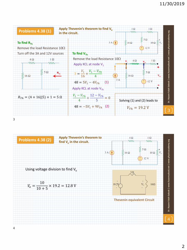
11/30/2019
2
Apply Thevenin’s theorem to find Vo
in the circuit.
3
Dr.
Haz
em
Fal
ah S
ake
ek|
ww
w.h
azem
sake
ek.n
et|
ww
w.p
hys
icsa
cad
em
y.o
rgProblems 4.38 (1)
Remove the load Resistance 10
Turn off the 3A and 12V sources
To find RTh
𝑅𝑇ℎ = (4 + 16||5) + 1 = 5 Ω
To find VTh
Remove the load Resistance 10
Apply KCL at node V1
3 =𝑉116
+𝑉1 − 𝑉𝑇ℎ
4
48 = 5𝑉1 − 4𝑉𝑇ℎ
Apply KCL at node VTh
𝑉1 − 𝑉𝑇ℎ4
+12 − 𝑉𝑇ℎ
5= 0
48 = −5𝑉1 + 9𝑉𝑇ℎ
Solving (1) and (2) leads to
𝑉𝑇ℎ = 19.2 V
(1)
(2)
Apply Thevenin’s theorem to find Vo in the circuit.
4
Dr.
Haz
em
Fal
ah S
ake
ek|
ww
w.h
azem
sake
ek.
ne
t|
ww
w.p
hys
icsa
cad
em
y.o
rgProblems 4.38 (2)
Using voltage division to find Vo
𝑉𝑜 =10
10 + 5× 19.2 = 12.8 V
Thevenin equivalent Circuit
3
4

11/30/2019
3
5
Dr.
Haz
em
Fal
ah S
ake
ek|
ww
w.h
azem
sake
ek.n
et|
ww
w.p
hys
icsa
cad
em
y.o
rgProblems 4.39 Obtain the Thevenin equivalent at a-b
Turn off the 3A and 24V sources
To find RTh
𝑅𝑇ℎ = (10 + 10)||5 + 16 = 20 Ω
To find VTh
Apply KCL at node V1
24 − 𝑉110
+ 3 =𝑉1 − 𝑉210
54 = 2𝑉1 − 𝑉2
𝑉1 − 𝑉210
= 3 +𝑉25
60 = 2𝑉1 − 6𝑉2
(1)
(2)
Solving (1) and (2) leads to
𝑉2 = −1.2 V
Apply KCL at node V2
Apply KVL to find VTh
−𝑉2 + 16 × 3 + 𝑉𝑇ℎ = 0
𝑉𝑇ℎ = − 48 + 1.2
𝑉𝑇ℎ = −49.2 𝑉
30 = 𝑉1 − 3𝑉2
6
Dr.
Haz
em
Fal
ah S
ake
ek|
ww
w.h
azem
sake
ek.
ne
t|
ww
w.p
hys
icsa
cad
em
y.o
rgProblems 4.40 Find the Thevenin equivalent at terminals a-b.
Turn off the 70V source and add 1 V
To find RTh
Notice that 𝑉𝑜 = −1𝑉
−1 + 20𝐼1 + 4𝑉0 = 0
𝐼1 = 0.25 mA
𝐼2 = 𝐼1 +1
10
𝐼2 = 0.35 mA
Apply KCL at node a
𝐼1
𝐼2
Apply KVL
𝑅𝑇ℎ =1𝑉
𝐼2
To find VTh
Apply KVL
−70 + 10 + 20 𝐼 + 4𝑉0 = 0
But 𝑉𝑜 = 10𝐼
70 = 70𝐼 ⟹ 𝐼 = 1 mA
−70 + 10𝐼 + 𝑉𝑇ℎ = 0
𝑉𝑇ℎ = 60 V
𝑅𝑇ℎ =1
0.35 × 10⁻³
𝑅𝑇ℎ = 2.857 𝑘Ω
Apply KVL to the left loop to find VTh
5
6

11/30/2019
4
Find the Norton equivalent with respect to terminals a-b.
7
Dr.
Haz
em
Fal
ah S
ake
ek|
ww
w.h
azem
sake
ek.n
et|
ww
w.p
hys
icsa
cad
em
y.o
rgProblems 4.37
Turn off the 120V and 2 A sources
To find RN
𝑅𝑁 = 12|| 20 + 40 = 10 Ω
To find IN we short circuit terminal a-b
IN
Applying source transformation to the current source yields the circuit below.
Apply KVL
−120 + 80 + 60𝐼𝑁 = 0
𝐼𝑁 = 40/60=0.666 A
8
Dr.
Haz
em
Fal
ah S
ake
ek|
ww
w.h
azem
sake
ek.
ne
t|
ww
w.p
hys
icsa
cad
em
y.o
rgProblems 4.41 Find the Thevenin and Norton equivalents at terminals a-b
Turn off the all sources
To find RTh
𝑅𝑇ℎ = 𝑅𝑁 = 5|| 14 + 6 = 4 Ω
Applying source transformation to the 1-A and 6,
𝑉𝑇ℎ
Apply KCL at node a
6 + 14 − 𝑉𝑇ℎ6 + 14
= 3 +𝑉𝑇ℎ5
𝑉𝑇ℎ = −8 V ⟹ 𝐼𝑁=𝑉𝑇ℎ𝑅𝑇ℎ
=−8
4= −2 A
6 + 14 − 𝑉𝑇ℎ = 60 + 4𝑉𝑇ℎ
7
8

11/30/2019
5
9
Dr.
Haz
em
Fal
ah S
ake
ek|
ww
w.h
azem
sake
ek.n
et|
ww
w.p
hys
icsa
cad
em
y.o
rgProblems 4.47 Obtain the Thevenin and Norton equivalent
Turn off the 30V source and add 1 A at a-b
To find RTh
Apply KCL at node a
1 = 2𝑉𝑥 +𝑉𝑥60
+𝑉𝑥12
𝑉𝑥 =60
126= 0.476 V
𝑅𝑇ℎ =𝑉𝑥1= 0.476
To find VTh
𝑉𝑇ℎ = 𝑉𝑎𝑏 = 𝑉𝑥Apply KCL at node a
30 − 𝑉𝑇ℎ12
=𝑉𝑇ℎ60
+ 2𝑉𝑇ℎ
𝑉𝑇ℎ =150
126= 1.19 V
𝐼𝑁 =𝑉𝑇ℎ𝑅𝑇ℎ
=1.19
0.476= 2.5 A
10
Dr.
Haz
em
Fal
ah S
ake
ek|
ww
w.h
azem
sake
ek.
ne
t|
ww
w.p
hys
icsa
cad
em
y.o
rgProblems 4.48 Determine the Norton equivalent at a-b
Turn off the 2A source and add 1 A at terminal
To find RN
Apply KVL
Note that 𝑖o = 1A
4𝑖𝑜 − 𝑣 + 2𝑖𝑜 − 10𝑖𝑜 = 0
𝑣 = −4 𝑉
𝑅𝑁 =𝑣
1= −4
To find IN, we need to find VTh
𝑉𝑇ℎ
Note that 𝑖o = 2A
𝑉𝑇ℎ = −10𝑖𝑜 + 4𝑖𝑜 = −12 V
𝐼𝑁 =𝑉𝑇ℎ𝑅𝑁
= 3 A
Note that no current flow in the 2
9
10

11/30/2019
6
11
Dr.
Haz
em
Fal
ah S
ake
ek|
ww
w.h
azem
sake
ek.n
et|
ww
w.p
hys
icsa
cad
em
y.o
rgProblems 4.66 Find the maximum power that can bedelivered to the resistor R
Remove the load Resistance R
Turn off all sources.
To find RTh
𝑅𝑇ℎ = 2|| 3 + 5 = 1.6 Ω
To find VTh
Remove the load Resistance R
Use source transformation for the 6 A and 5 we get circuit (b)
(b)
Apply KVL to the full loop
10𝑖 + 30 + 20 + 10 = 0
𝑖 = −6 A
Apply KVL to the upper loop
10 + 2𝑖 + 𝑉𝑇ℎ = 0
𝑉𝑇ℎ = 2V
𝑝𝑚𝑎𝑥 =𝑉𝑇ℎ
2
4𝑅𝑇ℎ=
22
4 × 1.6= 0.625 W
12
Dr.
Haz
em
Fal
ah S
ake
ek|
ww
w.h
azem
sake
ek.
ne
t|
ww
w.p
hys
icsa
cad
em
y.o
rgProblems 4.71 What resistor connected across terminals will absorb maximum powerfrom the circuit? What is that power?
Turn off 8V and add 1 mA at terminal
To find RTh
Let’s the resistance in k and the current in mA
Apply KVL at node a
1 =𝑉𝑎40
+𝑉𝑎 + 120𝑣𝑜
10
40 = 5𝑉𝑎 − 480𝑣𝑜
But 𝑣𝑜 = 0 (no voltage source)
𝑉𝑎 = 8 V ⟹ 𝑅𝑇ℎ= 8 /1 = 8Ω
To find VTh, From the left side of the original circuit
𝑣𝑜 =1
3 + 1× 8 = 2 V
From the right side of the original circuit
𝑉𝑇ℎ =40
10 + 40× −120𝑣𝑜 = −192 V
The required resistance is = Rth=8
𝑝𝑚𝑎𝑥 =𝑉𝑇ℎ
2
4𝑅𝑇ℎ=(−192)2
4 × 8= 1.152 W
11
12

11/30/2019
7
13
Dr.
Haz
em
Fal
ah S
ake
ek|
ww
w.h
azem
sake
ek.n
et|
ww
w.p
hys
icsa
cad
em
y.o
rgProblems 4.72
(a) Obtain the Thevenin equivalent at terminals(b) Calculate the current in RL = 8 (c) Find RL for maximum power deliverable to RL
(d) Determine that maximum power.
Turn off the all sources
To find RTh
𝑅𝑇ℎ = 2 + 4 + 6 = 12 Ω
To find VTh
Remove the load Resistance R
Use source transformation for the 4 A with 2 and 2A with 2 we get circuit (b)
Apply KVL
−𝑉𝑇ℎ + 12 + 8 + 20 = 0
𝑉𝑇ℎ = 40 V
(b)(b) the current in RL = 8
𝑖 = 𝑉𝑇ℎ/(𝑅𝑇ℎ + 𝑅𝐿) = 40/(12 + 8) = 2 A
(c) RL for pmax 𝑅𝐿 = 𝑅𝑇ℎ = 12 Ω
(d) 𝑝𝑚𝑎𝑥 =𝑉𝑇ℎ
2
4𝑅𝑇ℎ=
(40)2
4 × 12= 33.33 W
13

12/29/2019
1
1
Dr.
Haz
em
Fal
ah S
ake
ek
| w
ww
.haz
em
sake
ek.
ne
t|
ww
w.p
hys
icsa
cad
em
y.o
rg
www.physicsacademy.org
Physics Academy
Dr. Hazem Falah Sakeek
Al-Azhar University of Gaza
Unit: 6 | Lecture: 26Capacitors and Inductors: Capacitors
Capacitors and Inductors
2
Dr.
Haz
em
Fal
ah S
ake
ek
| w
ww
.haz
em
sake
ek.
ne
t|
ww
w.p
hys
icsa
cad
em
y.o
rg
6.1 Introduction
6.2 Capacitors
6.3 Series and Parallel Capacitors
6.4 Inductors
6.5 Series and Parallel Inductors
1
2

12/29/2019
2
3
Dr.
Haz
em
Fal
ah S
ake
ek
| w
ww
.haz
em
sake
ek.
ne
t|
ww
w.p
hys
icsa
cad
em
y.o
rg
6.1 Introduction
So far we have limited our studyto resistive circuits.
Unlike resistors, whichdissipate energy, capacitorsand inductors do not dissipatebut store energy.
In contrast to a resistor, whichdissipates energy irreversibly,an inductor or capacitor storesor releases energy (i.e., has amemory).
Inductors
Capacitors
4
Dr.
Haz
em
Fal
ah S
ake
ek
| w
ww
.haz
em
sake
ek.
ne
t|
ww
w.p
hys
icsa
cad
em
y.o
rg
6.2 Capacitors (1)
A capacitor is a passive element designedto store energy in its electric field.
Capacitors are used extensively inelectronics, communications, computers,and power systems. For example, they areused in the tuning circuits of radioreceivers and as dynamic memoryelements in computer systems.
A capacitor consists of two conductingplates separated by an insulator (ordielectric).
In many practical applications, the plates may be aluminum
foil while the dielectric may be air, ceramic, paper, or mica.
3
4

12/29/2019
3
5
Dr.
Haz
em
Fal
ah S
ake
ek
| w
ww
.haz
em
sake
ek.
ne
t|
ww
w.p
hys
icsa
cad
em
y.o
rg
6.2 Capacitors (2)
When a voltage source 𝑣 is connected to thecapacitor, the source deposits a positive charge+ 𝑞 on one plate and a negative charge −𝑞 on theother. The capacitor is said to store the electriccharge. The amount of charge stored, representedby q, is directly proportional to the appliedvoltage so that
𝑞 = 𝐶𝑣
where C, the constant of proportionality, is known as the capacitance of thecapacitor. The unit of capacitance is the farad (F), (1 farad =1 coulomb/volt).
Capacitance is the ratio of the charge on one plate of a capacitor to the voltagedifference between the two plates, measured in farads (F).
6
Dr.
Haz
em
Fal
ah S
ake
ek
| w
ww
.haz
em
sake
ek.
ne
t|
ww
w.p
hys
icsa
cad
em
y.o
rg
6.2 Capacitors (3)The capacitance 𝐶 of a capacitor depends on the physical dimensions of thecapacitor.
𝐶 =𝜖𝐴
𝑑Parallel-plate capacitor
where A is the surface area of each plate, d is the distance between the plates,and 𝜖 is the permittivity of the dielectric material between the plates.
The capacitance depends on:
2. The spacing between the plates—the smaller the spacing,the greater the capacitance.
1. The surface area of the plates—the larger the area, thegreater the capacitance.
3. The permittivity of the material—the higher thepermittivity, the greater the capacitance.
5
6

12/29/2019
4
7
Dr.
Haz
em
Fal
ah S
ake
ek
| w
ww
.haz
em
sake
ek.
ne
t|
ww
w.p
hys
icsa
cad
em
y.o
rg
6.2 Capacitors (4)To obtain the current-voltage relationshipof the capacitor, we take the derivative ofboth sides of the equation
𝑞 = 𝐶𝑣
𝑑𝑞
𝑑𝑡= 𝐶
𝑑𝑣
𝑑𝑡
𝑖 =𝑑𝑞
𝑑𝑡But
𝑖 = 𝐶𝑑𝑣
𝑑𝑡
The current-voltage relationship for acapacitor
Fixed capacitor
Variable capacitor
According to the passive signconvention, if 𝑣 > 0 and 𝑖 > 0 orif 𝑣 < 0 and 𝑖 < 0 the capacitoris being charged, and if 𝑣. 𝑖 < 0the capacitor is discharging.
8
Dr.
Haz
em
Fal
ah S
ake
ek
| w
ww
.haz
em
sake
ek.
ne
t|
ww
w.p
hys
icsa
cad
em
y.o
rg
6.2 Capacitors (5)
The voltage-current relation of the capacitorcan be obtained by integrating both sides of Eq.
𝑖 = 𝐶𝑑𝑣
𝑑𝑡
𝑣 𝑡 =1
𝐶න−∞
𝑡
𝑖 𝜏 𝑑𝜏
𝑣 𝑡 =1
𝐶න𝑡𝑜
𝑡
𝑖 𝜏 𝑑𝜏 + 𝑣 𝑡𝑜
is the voltage across the capacitor at time 𝑡𝑜
𝑣 𝑡𝑜 =𝑞 𝑡𝑜𝐶
Where
Current-voltage relationship of a linear capacitor.
Capacitor voltage depends on the past
history of the capacitor current.
⟹ 𝑑𝑣 =1
𝐶𝑖(𝑡) 𝑑𝑡
7
8

12/29/2019
5
9
Dr.
Haz
em
Fal
ah S
ake
ek
| w
ww
.haz
em
sake
ek.
ne
t|
ww
w.p
hys
icsa
cad
em
y.o
rg
6.2 Capacitors (6)The instantaneous power delivered to the capacitor is
𝑝 = 𝑣𝑖 = 𝐶𝑣𝑑𝑣
𝑑𝑡The energy stored in the capacitor is therefore
𝑤 = න−∞
𝑡
𝑝 𝜏 𝑑𝜏 = 𝐶 න−∞
𝑡
𝑣𝑑𝑣
𝑑𝜏𝑑𝜏 = 𝐶 න
0
𝑣(𝑡)
𝑣 𝑑𝑣
𝑤 =1
2𝐶𝑣2 𝑤 =
𝑞2
2𝐶or
Capacitor voltage depends on the past
history of the capacitor current.
Represents the energy stored in the electric field that exists between the plates of the capacitor.
10
Dr.
Haz
em
Fal
ah S
ake
ek
| w
ww
.haz
em
sake
ek.
ne
t|
ww
w.p
hys
icsa
cad
em
y.o
rg
6.2 Capacitors (7)The word capacitor is derived from this element’s capacity to store energy in an electric field.
(1) A capacitor is an open circuit to dc.
(2) The voltage on a capacitor cannot change abruptly.
(3) The ideal capacitor does not dissipate energy.
(4) A real, nonideal capacitor has a parallel-modelleakage resistance, as high as 100 M and can beneglected for most practical applications.
We should note the following important properties of a capacitor:
abrupt change is not possible
𝑎𝑙𝑙𝑜𝑤𝑒𝑑 𝑛𝑜𝑡 𝑎𝑙𝑙𝑜𝑤𝑒𝑑
9
10

12/29/2019
6
11
Dr.
Haz
em
Fal
ah S
ake
ek
| w
ww
.haz
em
sake
ek.
ne
t|
ww
w.p
hys
icsa
cad
em
y.o
rg
Example 6.1(a) Calculate the charge stored on a 3-pF capacitor with 20 V across it.(b) Find the energy stored in the capacitor.
∵ 𝑞 = 𝐶𝑣
𝑞 = 3 × 10−12 × 20 = 60 × 10−12C = 60 pC
(a)
(b) The energy stored is
∵ 𝑤 =1
2𝐶𝑣2
𝑤 =1
2× 3 × 10−12 × 400 = 600 × 10−12J = 600 pJ
12
Dr.
Haz
em
Fal
ah S
ake
ek
| w
ww
.haz
em
sake
ek.
ne
t|
ww
w.p
hys
icsa
cad
em
y.o
rg
Example 6.2The voltage across a 5 F capacitor is 𝒗(𝒕) = 𝟏𝟎 𝒄𝒐𝒔𝟔𝟎𝟎𝟎𝒕 V. Calculate the current through it.
∵ 𝑖 𝑡 = 𝐶𝑑𝑣
𝑑𝑡
𝑖 𝑡 = 5 × 10⁻⁶𝑑
𝑑𝑡(10 cos6000𝑡)
= −5 × 10−6 × 6000 × 10 sin 6000𝑡
= −0.3 sin 6000𝑡 A
11
12

12/29/2019
7
13
Dr.
Haz
em
Fal
ah S
ake
ek
| w
ww
.haz
em
sake
ek.
ne
t|
ww
w.p
hys
icsa
cad
em
y.o
rg
Example 6.3Determine the voltage across a 2F capacitor if the current through it is𝒊 𝒕 = 𝟔𝒆−𝟑𝟎𝟎𝟎𝒕 𝐦𝐀. Assume that the initial capacitor voltage is zero.
∵ 𝑣 𝑡 =1
𝐶න𝑡𝑜
𝑡
𝑖 𝜏 𝑑𝜏 + 𝑣 𝑡𝑜 and 𝑣 𝑡𝑜 = 0
𝑣 =1
2 × 10⁻⁶න𝑡𝑜
𝑡
6𝑒−3000𝑡 𝑑𝑡 . 10−3
𝑣 =3 × 10³
−3000ቚ𝑒−3000𝑡0
𝑡
𝑣 = 1 − 𝑒−3000𝑡 V
14
Dr.
Haz
em
Fal
ah S
ake
ek
| w
ww
.haz
em
sake
ek.
ne
t|
ww
w.p
hys
icsa
cad
em
y.o
rg
Example 6.5Obtain the energy stored in each capacitor in Figure shown under dc conditions.
Under dc conditions, we replace each capacitor with an open circuit,
The current through the series combination of the 2k and 4k resistors is obtained by current division as
𝑖 =3
3 + 2 + 46 mA = 2 mA
𝑣1 = 2𝑖 = 4 V 𝑣2 = 4𝑖 = 8 V
𝑤1 = 1/2𝐶1𝑣12
𝑤1 = 1/2 2 × 10⁻³ 4 2
𝑤1 = 16 × 10−3 J
𝑤2 = 1/2𝐶2𝑣22
𝑤2 = 1/2 4 × 10⁻³ 8 2
𝑤2 = 128 × 10−3 J
13
14

12/29/2019
8
Problems to Solve by yourself
15
Dr.
Haz
em
Fal
ah S
ake
ek
| w
ww
.haz
em
sake
ek.
ne
t|
ww
w.p
hys
icsa
cad
em
y.o
rg
(3) A voltage of 30𝑒−2000𝑡 V appearsacross a parallel combination of a 100-mF capacitor and a 12 resistor.Calculate the power absorbed by theparallel combination.
(2) A current of 4 sin 4𝑡 A flows through a5-F capacitor.Find the voltage 𝑣(𝑡) across the capacitorgiven that 𝑣 0 = 1 V.
(1) If the voltage across a 7.5-F capacitoris 2𝑡𝑒−3𝑡 V find the current and thepower.
(4) Find the voltage across the capacitors inthe circuit under dc conditions.
15
12/2/2019
1
1
Dr.
Haz
em
Fal
ah S
ake
ek|
ww
w.h
azem
sake
ek.n
et|
ww
w.p
hys
icsa
cad
em
y.o
rg
www.physicsacademy.org
Physics Academy
Dr. Hazem Falah Sakeek
Al-Azhar University of Gaza
Unit: 6 | Lecture: 27Capacitors and Inductors:
Series and Parallel Capacitors
Capacitors and Inductors
2
Dr.
Haz
em
Fal
ah S
ake
ek|
ww
w.h
azem
sake
ek.
ne
t|
ww
w.p
hys
icsa
cad
em
y.o
rg
6.1 Introduction
6.2 Capacitors
6.3 Series and Parallel Capacitors
6.4 Inductors
6.5 Series and Parallel Inductors
1
2

12/2/2019
2
3
Dr.
Haz
em
Fal
ah S
ake
ek|
ww
w.h
azem
sake
ek.n
et|
ww
w.p
hys
icsa
cad
em
y.o
rg
6.3 Series and Parallel CapacitorsTo obtain the equivalent capacitor 𝐶𝑒𝑞 of N capacitors in parallel,
Note that the capacitors have the same voltage 𝑣 across them.
Applying KCL
𝑖 = 𝑖1 + 𝑖2 + 𝑖3 +…..+ 𝑖𝑁
𝑖 = 𝐶1𝑑𝑣
𝑑𝑡+ 𝐶2
𝑑𝑣
𝑑𝑡+ 𝐶3
𝑑𝑣
𝑑𝑡+…..+𝐶𝑁
𝑑𝑣
𝑑𝑡= 𝐶𝑒𝑞
𝑑𝑣
𝑑𝑡
𝐶𝑒𝑞 = 𝐶1 + 𝐶2 + 𝐶3 +⋯+ 𝐶𝑁
Parallel-connected N capacitors
equivalent circuitThe equivalent capacitance of N parallel-connectedcapacitors is the sum of the individual capacitances.
4
Dr.
Haz
em
Fal
ah S
ake
ek|
ww
w.h
azem
sake
ek.
ne
t|
ww
w.p
hys
icsa
cad
em
y.o
rg
6.3 Series and Parallel CapacitorsTo obtain the equivalent capacitor 𝐶𝑒𝑞 of N capacitors in series,
Note that the same current i flows through the capacitors.
Applying KVL
𝑣 = 𝑣1 + 𝑣2 + 𝑣3 +…..+ 𝑣𝑁
1
𝐶𝑒𝑞=
1
𝐶1+
1
𝐶2+1
𝐶3+⋯+
1
𝐶𝑁
Series-connected N capacitors
equivalent circuitThe equivalent capacitance of series capacitors is the reciprocal ofthe sum of the reciprocals of the individual capacitances.
∵ 𝑣𝑘 =1
𝐶𝑘න𝑡𝑜
𝑡
𝑖 𝜏 𝑑𝜏 + 𝑣𝑘 𝑡𝑜
3
4

12/2/2019
3
5
Dr.
Haz
em
Fal
ah S
ake
ek|
ww
w.h
azem
sake
ek.n
et|
ww
w.p
hys
icsa
cad
em
y.o
rg
Example 6.6Find the equivalent capacitance seen between terminals a and b
The 20 F and 5 F capacitors are in series;
This 4 F capacitor is in parallel with the 6 F and 20 F capacitors;
This 30 F capacitor is in series with the 60 F capacitor;
6
Dr.
Haz
em
Fal
ah S
ake
ek|
ww
w.h
azem
sake
ek.
ne
t|
ww
w.p
hys
icsa
cad
em
y.o
rg
Example 6.7 (1)
Find the voltage across each capacitor.
This 60-mF capacitor is in series with the 20-mF and 30-mF capacitors.
40 + 20 = 60 mF
The two capacitors 40 and 20 mF are in parallel
5
6

12/2/2019
4
7
Dr.
Haz
em
Fal
ah S
ake
ek|
ww
w.h
azem
sake
ek.n
et|
ww
w.p
hys
icsa
cad
em
y.o
rg
Example 6.7 (2)
The total charge is
This is the charge on the 20-mF and 30-mF capacitors, because they are in series with the 30-V source.
use KVL to determine
Problems to Solve by yourself
8
Dr.
Haz
em
Fal
ah S
ake
ek|
ww
w.h
azem
sake
ek.
ne
t|
ww
w.p
hys
icsa
cad
em
y.o
rg(3) Determine the equivalent capacitance for each of the circuits.
(2) The equivalent capacitance at terminals a-bin the circuit is 30 F. Calculate the value of C.
(1) Series-connected 20-pF and 60-pFcapacitors are placed in parallel with series-connected 30-pF and 70-pF capacitors.Determine the equivalent capacitance.
7
8

12/2/2019
1
1
Dr.
Haz
em
Fal
ah S
ake
ek|
ww
w.h
azem
sake
ek.n
et|
ww
w.p
hys
icsa
cad
em
y.o
rg
www.physicsacademy.org
Physics Academy
Dr. Hazem Falah Sakeek
Al-Azhar University of Gaza
Unit: 6 | Lecture: 28Capacitors and Inductors: Inductors
Capacitors and Inductors
2
Dr.
Haz
em
Fal
ah S
ake
ek|
ww
w.h
azem
sake
ek.
ne
t|
ww
w.p
hys
icsa
cad
em
y.o
rg
6.1 Introduction
6.2 Capacitors
6.3 Series and Parallel Capacitors
6.4 Inductors
6.5 Series and Parallel Inductors
1
2

12/2/2019
2
3
Dr.
Haz
em
Fal
ah S
ake
ek|
ww
w.h
azem
sake
ek.n
et|
ww
w.p
hys
icsa
cad
em
y.o
rg
6.4 Inductors (1)An inductor is a passive element designedto store energy in its magnetic field.
Inductors are used in power supplies,transformers, radios, TVs, radars, andelectric motors.
Any conductor of electric current hasinductive properties. But in order toenhance the inductive effect, a practicalinductor is usually formed into a cylindricalcoil with many turns of conducting wire.
An inductor consists of a coil of conducting wire.
𝑣 = 𝐿𝑑𝑖
𝑑𝑡where L is the constant of proportionalitycalled the inductance of the inductor. Theunit of inductance is the henry (H),
1 henry equals 1 volt-second per ampere.
Inductance is the property whereby aninductor exhibits opposition to the changeof current flowing through it, measured inhenrys (H).
𝐿 =𝑁2𝜇𝐴
𝑙L for solenoid
where N is the number of turns, 𝑙 is thelength, A is the cross-sectional area, and𝜇 is the permeability of the core.
4
Dr.
Haz
em
Fal
ah S
ake
ek|
ww
w.h
azem
sake
ek.
ne
t|
ww
w.p
hys
icsa
cad
em
y.o
rg
6.4 Inductors (2)
The current-voltage relationship is obtained from Eq.
𝑣 = 𝐿𝑑𝑖
𝑑𝑡
(a) air-core, (b) iron-core, (c) variable iron-core.
Voltage-current relationship of an
inductor
∴ 𝑑𝑖 =1
𝐿𝑣 𝑑𝑡
𝑖 =1
𝐿න−∞
𝑡
𝑣 𝜏 𝑑𝜏
𝑖 =1
𝐿න𝑡𝑜
𝑡
𝑣 𝜏 𝑑𝜏 + 𝑖 𝑡𝑜
Integrating gives
Where 𝑖 𝑡𝑜 is the total current for −∞ < 𝑡 < 𝑡𝑜and 𝑖 −∞ = 0.
3
4

12/2/2019
3
5
Dr.
Haz
em
Fal
ah S
ake
ek|
ww
w.h
azem
sake
ek.n
et|
ww
w.p
hys
icsa
cad
em
y.o
rg
6.4 Inductors (3)
The inductor is designed to store energy in its magnetic field. The power delivered to the inductor is
𝑝 = 𝑣𝑖 = 𝐿𝑑𝑖
𝑑𝑡𝑖
The energy stored in the inductor is therefore
𝑤 = න−∞
𝑡
𝑝 𝜏 𝑑𝜏 = 𝐿න−∞
𝑡 𝑑𝑖
𝑑𝜏𝑖𝑑𝜏 = 𝐿න
−∞
𝑣(𝑡)
𝑖 𝑑𝑖
𝑤 =1
2𝐿𝑖2
=1
2𝐿𝑖2 𝑡 −
1
2𝐿𝑖2 −∞
𝑖 −∞ = 0Since
6
Dr.
Haz
em
Fal
ah S
ake
ek|
ww
w.h
azem
sake
ek.
ne
t|
ww
w.p
hys
icsa
cad
em
y.o
rg
6.4 Inductors (4)
Important properties of an inductor.
The voltage across an inductor is zero when the current is constant. Thus, Aninductor acts like a short circuit to dc.
An important property of the inductor is its opposition to the change in currentflowing through it. The current through an inductor cannot changeinstantaneously
Ideal inductor does not dissipate energy. The energy stored in it can be retrievedat a later time. The inductor takes power from the circuit when storing energy anddelivers power to the circuit when returning previously stored energy.
A practical, nonideal inductor has a significant resistive component.
5
6

12/2/2019
4
7
Dr.
Haz
em
Fal
ah S
ake
ek|
ww
w.h
azem
sake
ek.n
et|
ww
w.p
hys
icsa
cad
em
y.o
rg
Example 6.8
The current through a 0.1-H inductor is 𝑖 𝑡 = 10𝑡 𝑒−5𝑡𝐴. Find the voltage across the inductor and the energy stored in it.
𝑣 = 𝐿𝑑𝑖
𝑑𝑡𝐿 = 0.1 H
𝑣 = 0.1𝑑
𝑑𝑡10𝑡 𝑒−5𝑡
The energy stored is
𝑤 =1
2𝐿𝑖2
8
Dr.
Haz
em
Fal
ah S
ake
ek|
ww
w.h
azem
sake
ek.
ne
t|
ww
w.p
hys
icsa
cad
em
y.o
rg
Example 6.9
Find the current through a 5-H inductor if the voltage across it is
Find the energy stored at 𝑡 = 5 s. Assume 𝑖(𝑣) > 0.
∵ 𝑖 =1
𝐿න𝑡𝑜
𝑡
𝑣 𝜏 𝑑𝜏 + 𝑖 𝑡𝑜 𝐿 = 5 H
The energy stored
7
8

12/2/2019
5
9
Dr.
Haz
em
Fal
ah S
ake
ek|
ww
w.h
azem
sake
ek.n
et|
ww
w.p
hys
icsa
cad
em
y.o
rg
Example 6.10Under dc conditions, find: (a) i, vC, and iL, (b) the energy stored in the capacitor and inductor.
Under dc conditions, we replace the capacitor with an open circuit and
the inductor with a short circuit
The voltage vC is the same as the voltage across the 5
The energy in the capacitor is
The energy in the inductor is
Problems to Solve by yourself
10
Dr.
Haz
em
Fal
ah S
ake
ek|
ww
w.h
azem
sake
ek.
ne
t|
ww
w.p
hys
icsa
cad
em
y.o
rg(4) Find 𝑣𝐶, 𝑖𝐿 and the energy stored in thecapacitor and inductor in the circuit under dcconditions.
(2) An inductor has a linear change incurrent from 50 mA to 100 mA in 2 msand induces a voltage of 160 mV.Calculate the value of the inductor.
(1) The current through a 10-mH inductoris 10e-t/2 A. Find the voltage and thepower at t=3s.
(3) The voltage across a 200-mH inductoris given by 𝑣(𝑡) = 3𝑡2+ 2𝑡 + 4 V for t>0.Determine the current i(t) through theinductor. Assume that i(0)= 1A.
(5) Under steady-state dc conditions, find 𝑖and 𝑣 in the circuit.
9
10

12/30/2019
1
1
Dr.
Haz
em
Fal
ah S
ake
ek
| w
ww
.haz
em
sake
ek.
ne
t|
ww
w.p
hys
icsa
cad
em
y.o
rg
www.physicsacademy.org
Physics Academy
Dr. Hazem Falah Sakeek
Al-Azhar University of Gaza
Unit: 6 | Lecture: 29Capacitors and Inductors:
Series and Parallel Inductors
Capacitors and Inductors
2
Dr.
Haz
em
Fal
ah S
ake
ek
| w
ww
.haz
em
sake
ek.
ne
t|
ww
w.p
hys
icsa
cad
em
y.o
rg
6.1 Introduction
6.2 Capacitors
6.3 Series and Parallel Capacitors
6.4 Inductors
6.5 Series and Parallel Inductors
1
2

12/30/2019
2
3
Dr.
Haz
em
Fal
ah S
ake
ek
| w
ww
.haz
em
sake
ek.
ne
t|
ww
w.p
hys
icsa
cad
em
y.o
rg
6.5 Series and Parallel Inductors (1)
The equivalent inductance of series-connected inductors is the sum of theindividual inductances.
The equivalent inductance of parallelinductors is the reciprocal of the sum of thereciprocals of the individual inductances.
Series-connected inductors Parallel -connected inductors
4
Dr.
Haz
em
Fal
ah S
ake
ek
| w
ww
.haz
em
sake
ek.
ne
t|
ww
w.p
hys
icsa
cad
em
y.o
rg
3
4

12/30/2019
3
5
Dr.
Haz
em
Fal
ah S
ake
ek
| w
ww
.haz
em
sake
ek.
ne
t|
ww
w.p
hys
icsa
cad
em
y.o
rg
Example 6.11 Find the equivalent inductance of the circuit
The 10-H, 12-H, and 20-H inductors are in series; thus, combining them gives a 42-H
This 42-H inductor is in parallel with the 7-H inductor
This 6-H inductor is in series with the 4-H and 8-H inductors
6
Dr.
Haz
em
Fal
ah S
ake
ek
| w
ww
.haz
em
sake
ek.
ne
t|
ww
w.p
hys
icsa
cad
em
y.o
rg
Example 6.12For the circuit 𝑖 𝑡 = 4 2 − 𝑒−10𝑡 mA. If𝑖2 0 = −1 mA. Find (a) i1(0), (b) v(t),v1(t), v2(t), (c) i1(t) and i2(t).
𝑖 𝑡 = 4 2 − 𝑒−10𝑡 mA
𝑖 0 = 4 2 − 1 = 4 mA
Note that 𝑖 = 𝑖1 + 𝑖2
𝑖1 0 = 𝑖 0 − 𝑖2(0) = 4 − −1 = 5 mA
(a)
5
6

12/30/2019
4
7
Dr.
Haz
em
Fal
ah S
ake
ek
| w
ww
.haz
em
sake
ek.
ne
t|
ww
w.p
hys
icsa
cad
em
y.o
rg
Example 6.12For the circuit 𝑖 𝑡 = 4 2 − 𝑒−10𝑡 mA. If𝑖2 0 = −1 mA. Find (a) i1(0), (b) v(t),v1(t), v2(t), (c) i1(t) and i2(t).
(b) The equivalent inductance is
8
Dr.
Haz
em
Fal
ah S
ake
ek
| w
ww
.haz
em
sake
ek.
ne
t|
ww
w.p
hys
icsa
cad
em
y.o
rg
Example 6.12For the circuit 𝑖 𝑡 = 4 2 − 𝑒−10𝑡 mA. If𝑖2 0 = −1 mA. Find (a) i1(0), (b) v(t),v1(t), v2(t), (c) i1(t) and i2(t).
(c) The current i1 is obtained as
7
8

12/30/2019
5
Problems to Solve by yourself
9
Dr.
Haz
em
Fal
ah S
ake
ek
| w
ww
.haz
em
sake
ek.
ne
t|
ww
w.p
hys
icsa
cad
em
y.o
rg
(2) Find Leq at the terminals of the circuit
(1) Determine at terminals a-b of the circuit (3) Consider the circuit. Find: (a) Leq and 𝑖1 𝑡 , 𝑖2 𝑡if 𝑖𝑠 = 3𝑒−𝑡mA (b) 𝑣𝑜 𝑡 , (c) energy stored in the 20-mH inductor at t=1 s.
9

1/2/2020
1
1
Dr.
Haz
em
Fal
ah S
ake
ek
| w
ww
.haz
em
sake
ek.
ne
t|
ww
w.p
hys
icsa
cad
em
y.o
rg
www.physicsacademy.org
Physics Academy
Dr. Hazem Falah Sakeek
Al-Azhar University of Gaza
Unit: 6 | Lecture: 30Solution of some selected problem
Capacitors and Inductors
If the voltage across a 7.5-F capacitor is 𝟐𝒕𝒆−𝟑𝒕 𝐕 find the current and the power.
2
Dr.
Haz
em
Fal
ah S
ake
ek
| w
ww
.haz
em
sake
ek.
ne
t|
ww
w.p
hys
icsa
cad
em
y.o
rgProblems 6.1
𝑖 = 𝐶𝑑𝑣
𝑑𝑡
= 7.5 2𝑒−3𝑡 − 6𝑡𝑒−3𝑡
= 15 1 − 3𝑡 𝑒−3𝑡 A
𝑝 = 𝑣𝑖
= 2𝑡𝑒−3𝑡 × 15 1 − 3𝑡 𝑒−3𝑡
= 30𝑡 1 − 3𝑡 𝑒−6𝑡 W
The current
The power
1
2

1/2/2020
2
A current of 𝟒 𝒔𝒊𝒏𝟒𝒕 𝑨 flows through a 5-F capacitor.Find the voltage 𝒗(𝒕) across the capacitor given that 𝒗 𝟎 = 𝟏 𝐕.
3
Dr.
Haz
em
Fal
ah S
ake
ek
| w
ww
.haz
em
sake
ek.
ne
t|
ww
w.p
hys
icsa
cad
em
y.o
rgProblems 6.4
The voltage 𝒗(𝒕)
𝑣 𝑡 =1
𝐶න𝑡𝑜
𝑡
𝑖 𝜏 𝑑𝜏 + 𝑣 𝑡𝑜
=1
5න0
𝑡
4 𝑠𝑖𝑛 4𝑡 𝑑𝜏 + 1
=4
5ቤ
− cos 4𝑡
40
𝑡
+ 1
= ቚ−0.2 cos 4𝑡0
𝑡+ 1
= −0.2 cos 4𝑡 − (−0.2 cos 0) + 1
= −0.2 cos 4𝑡 + 0.2 + 1
= 1.2 − 0.2 cos 4𝑡 V
A voltage of 𝟑𝟎𝒆−𝟐𝟎𝟎𝟎𝒕 𝐕 appears across a parallel combination of a100-mF capacitor and a 12 resistor. Calculate the power absorbed bythe parallel combination.
4
Dr.
Haz
em
Fal
ah S
ake
ek
| w
ww
.haz
em
sake
ek.
ne
t|
ww
w.p
hys
icsa
cad
em
y.o
rgProblems 6.12
The power 𝑝 = 𝑣𝑖We have the voltage, so we need to find the current through the resistor 𝑖𝑅 and the current in the capacitor 𝑖𝐶.
𝑖𝑅 =𝑣
𝑅=30𝑒−2000𝑡
12= 2.5 𝑒−2000𝑡A
𝑖𝐶 = 𝐶𝑑𝑣
𝑑𝑡= 100 × 10−3
𝑑30𝑒−2000𝑡
𝑑𝑡
= 0.1 × 30 × −2000 𝑒−2000𝑡 = −6000 𝑒−2000𝑡 A
The current 𝑖 = 𝑖𝑅 + 𝑖𝐶 = −5997.5 𝑒−2000𝑡 A
The power 𝑝 = 𝑣𝑖 = −5997.5 𝑒−2000𝑡 × 30𝑒−2000𝑡 = −180 𝑒−4000𝑡 W
3
4

1/2/2020
3
Find the voltage across the capacitors in the circuit under dc conditions.
5
Dr.
Haz
em
Fal
ah S
ake
ek
| w
ww
.haz
em
sake
ek.
ne
t|
ww
w.p
hys
icsa
cad
em
y.o
rgProblems 6.13
𝑖1 𝑖2
𝑖1 =60
40 + 10 + 20= 0.857 A
𝑖2 = 0
𝑣1 = 40 × 𝑖1 = 34.3 V
𝑣2 − 60 + 20𝑖1 = 0
Apply KVL to find 𝑣2
𝑣2 = 42.86 V
Under dc conditions, the circuit is as shown
Series-connected 20-pF and 60-pF capacitors are placed in parallel with series-connected 30-pF and 70-pF capacitors. Determine the equivalent capacitance.
6
Dr.
Haz
em
Fal
ah S
ake
ek
| w
ww
.haz
em
sake
ek.
ne
t|
ww
w.p
hys
icsa
cad
em
y.o
rgProblems 6.14
20 pF is in series with 60pF
30-pF is in series with 70pF
15pF is in parallel with 21pF
=20 × 60
20 + 60= 15 pF
=30 × 70
30 + 70= 21 pF
= 15 + 21 = 36 pF
5
6

1/2/2020
4
The equivalent capacitance at terminals a-b in the circuit is 30 F. Calculate the value of C.
7
Dr.
Haz
em
Fal
ah S
ake
ek
| w
ww
.haz
em
sake
ek.
ne
t|
ww
w.p
hys
icsa
cad
em
y.o
rgProblems 6.16
𝐶𝑒𝑞 = 14 +𝐶 × 80
𝐶 + 80= 30
𝐶 = 20 𝜇𝐹
𝐶 × 80
𝐶 + 80= 16
80𝐶 = 16𝐶 + 1280
64𝐶 = 1280
Determine the equivalent capacitance for each of the circuits.
8
Dr.
Haz
em
Fal
ah S
ake
ek
| w
ww
.haz
em
sake
ek.
ne
t|
ww
w.p
hys
icsa
cad
em
y.o
rgProblems 6.17
4F in series with 12F
=4 × 12
4 + 12= 3 F
3F in parallel with 6F and 3F
= 3 + 6 + 3 = 12 F
4F in series with 12F
𝐶𝑒𝑞 =4 × 12
4 + 12= 3 F
2F in parallel with 4F
= 2 + 4 = 6 F
6F in series with 6F
=6 × 6
6 + 6= 3 F
3F in parallel with 5F
𝐶𝑒𝑞 = 3 + 5 = 8 F
3F in series with 6F
=3 × 6
3 + 6= 2 F
2F in parallel with 4F
= 2 + 4 = 6 F
6F, 2F, and 3F are in series
1
𝐶𝑒𝑞=1
6+1
2+1
3= 1
𝐶𝑒𝑞 = 1F
7
8

1/2/2020
5
The current through a 10-mH inductor is 10e-t/2 A. Find the voltage and the power at t=3s.
9
Dr.
Haz
em
Fal
ah S
ake
ek
| w
ww
.haz
em
sake
ek.
ne
t|
ww
w.p
hys
icsa
cad
em
y.o
rgProblems 6.34
𝑣 = 𝐿𝑑𝑖
𝑑𝑡
𝑣 = 10 × 10−3𝑑 10𝑒−𝑡/2
𝑑𝑡
= 10 × 10−3 × 10 ×−1
2𝑒−𝑡/2
= −50 × 10−3𝑒−𝑡/2
𝑣(3) = −50 × 10−3𝑒−3/2
= −0.011157 V
The voltage The power
𝑝 = 𝑣𝑖
= −50 × 10−3𝑒−𝑡/2 × 10𝑒−𝑡/2
= −500 × 10−3𝑒−𝑡
𝑝(3) = −500 × 10−3𝑒−3
𝑝 3 = −0.025 W
An inductor has a linear change in current from 50 mA to 100 mA in 2 ms and induces a voltage of 160 mV. Calculate the value of the inductor.
10
Dr.
Haz
em
Fal
ah S
ake
ek
| w
ww
.haz
em
sake
ek.
ne
t|
ww
w.p
hys
icsa
cad
em
y.o
rgProblems 6.35
𝑣 = 𝐿𝑑𝑖
𝑑𝑡
𝐿 =𝑣
𝑑𝑖𝑑𝑡
𝐿 =160 × 10−3
100 − 50 10−3
2 × 10⁻³
𝐿 = 6.4 × 10⁻³ H
9
10

1/2/2020
6
The voltage across a 200-mH inductor is given by 𝒗(𝒕) = 𝟑𝒕𝟐+ 𝟐𝒕 + 𝟒 V for t>0. Determinethe current 𝒊(t) through the inductor. Assume that 𝒊(0)= 1A.
11
Dr.
Haz
em
Fal
ah S
ake
ek
| w
ww
.haz
em
sake
ek.
ne
t|
ww
w.p
hys
icsa
cad
em
y.o
rgProblems 6.39
𝑖 =1
𝐿න𝑡𝑜
𝑡
𝑣 𝜏 𝑑𝜏 + 𝑖 𝑡𝑜
𝑖 =1
200 × 10−3න0
𝑡
3𝑡2 + 2𝑡 + 4 𝑑𝜏 + 𝑖 0
𝑖 = 5 ቚ𝑡3 + 𝑡2 + 4𝑡0
𝑡+ 1
𝑖 𝑡 = 5𝑡3 + 5𝑡2 + 20𝑡 + 1 A
Find 𝒗𝑪, 𝒊𝑳 and the energy stored in the capacitor and inductor in the circuit under dc conditions.
12
Dr.
Haz
em
Fal
ah S
ake
ek
| w
ww
.haz
em
sake
ek.
ne
t|
ww
w.p
hys
icsa
cad
em
y.o
rgProblems 6.46
Under dc conditions, the circuit is as shown
Using current division to find 𝑖L
𝑖𝐿 =4
4 + 2× 3 = 2 A
𝑣𝐶 = 0 V
𝑊𝐿 =1
2𝐿 𝑖𝐿
2 =1
2× 0.5 × 22 = 1 J
𝑊𝐶 =1
2𝐶 𝑣𝐶
2 = 0 J
11
12

1/2/2020
7
Under steady-state dc conditions, find 𝒊 and 𝒗 in the circuit.
13
Dr.
Haz
em
Fal
ah S
ake
ek
| w
ww
.haz
em
sake
ek.
ne
t|
ww
w.p
hys
icsa
cad
em
y.o
rgProblems 6.48
Under dc conditions, the circuit is as shown
Using current division to find 𝑖
𝑖 =30
30 + 20× 5 = 3 mA
𝑣 = 20 × 𝑖 = 20 × 3 = 60 V
Determine 𝑳eq at terminals a-b of the circuit
14
Dr.
Haz
em
Fal
ah S
ake
ek
| w
ww
.haz
em
sake
ek.
ne
t|
ww
w.p
hys
icsa
cad
em
y.o
rgProblems 6.51
1
𝐿=
1
60+
1
20+
1
30
1
𝐿=
1
10
𝐿 = 10
𝐿𝑒𝑞 = 10|| 25 + 10
𝐿𝑒𝑞 =10 × 35
10 + 35= 7.778 mH
13
14

1/2/2020
8
Find Leq at the terminals of the circuit
15
Dr.
Haz
em
Fal
ah S
ake
ek
| w
ww
.haz
em
sake
ek.
ne
t|
ww
w.p
hys
icsa
cad
em
y.o
rgProblems 6.53
5 mH is in parallel with 8 mH and 12 mH
= 5|| 8 + 12
=5 × 8 + 12
5 + 8 + 12= 4mH
6 mH is in parallel with 4 mH and 8 mH
= 6|| 4 + 8
=6 × 4 + `8
6 + 4 + 8= 4mH
8 mH is in parallel with 4 mH and 4 mH
= 8|| 4 + 4 = 4mH
6 mH, 10 mH and 4 mH are in series
𝐿𝑒𝑞 = 6 + 10 + 4 = 20 mH
Consider the circuit. Find: (a) 𝑳eq and 𝒊𝟏 𝒕 , 𝒊𝟐 𝒕 if 𝒊𝒔 = 𝟑𝒆−𝒕𝐦𝐀 (b) 𝒗𝒐 𝒕 , (c) energy stored in the 20-mH inductor at t=1 s.
16
Dr.
Haz
em
Fal
ah S
ake
ek
| w
ww
.haz
em
sake
ek.
ne
t|
ww
w.p
hys
icsa
cad
em
y.o
rgProblems 6.61
(a) 𝑳eq
𝐿𝑒𝑞 = 20|| 4 + 6
Using current division to find 𝑖1(t) and 𝑖2(t)
=20 × 10
20 + 10= 6.667 mH
𝑖1(𝑡) =10
10 + 20× 𝑖𝑠 =
1
3× 3𝑒−𝑡 = 𝑒−𝑡 mA
𝑖2(𝑡) =20
10 + 20× 𝑖𝑠 =
2
3× 3𝑒−𝑡 = 2𝑒−𝑡 mA
(b) 𝒗𝒐 𝒕
𝑣𝑜 = 𝐿𝑒𝑞𝑑𝑖𝑠𝑑𝑡
= 6.667 × 10⁻³ −3 × 10⁻³ × 𝑒−𝑡
−20 × 10−6 𝑒−𝑡 V
(c) energy stored in the 20-mH inductor at t=1 s.
𝑊 =1
2𝐿𝑖1
2
=1
2× 20 × 10−3 × 𝑒−2 × 10−6
= 1.353 × 10⁻⁹ J
15
16

12/29/2019
1
1
Dr.
Haz
em
Fal
ah S
ake
ek
| w
ww
.haz
em
sake
ek.
ne
t|
ww
w.p
hys
icsa
cad
em
y.o
rg
www.physicsacademy.org
Physics Academy
Dr. Hazem Falah Sakeek
Al-Azhar University of Gaza
Unit: 9 | Lecture: 31Sinusoids and Phasors
Sinusoids’ features
Sinusoids and Phasors
2
Dr.
Haz
em
Fal
ah S
ake
ek
| w
ww
.haz
em
sake
ek.
ne
t|
ww
w.p
hys
icsa
cad
em
y.o
rg
9.1 Introduction
9.2 Sinusoids’ features
9.3 Phasors
9.4 Phasor relationships for circuit elements
9.5 Impedance and admittance
9.7 Impedance combinations
1
2

12/29/2019
2
3
Dr.
Haz
em
Fal
ah S
ake
ek
| w
ww
.haz
em
sake
ek.
ne
t|
ww
w.p
hys
icsa
cad
em
y.o
rg
9.1 Introduction (1)
AC is more efficient and economical to transmit over long distances,
For the sake of simplicity, our previous analysis has been limited for to dc circuits:those circuits excited by constant or time-invariant sources.
Historically, dc sources were the main means of providing electric power up untilthe late 1800s. At the end of that century, the battle of direct current versusalternating current began.
4
Dr.
Haz
em
Fal
ah S
ake
ek
| w
ww
.haz
em
sake
ek.
ne
t|
ww
w.p
hys
icsa
cad
em
y.o
rg
9.1 Introduction (2)
We now begin the analysis of circuits in whichthe source voltage or current is time-varying.We are interested in sinusoidally time-varyingexcitation, or simply, excitation by a sinusoid.
A sinusoid is a signal that has the form of thesine or cosine function. A sinusoidal currentusually referred to as alternating current (ac).
Such a current reverses at regular time intervalsand has alternately positive and negativevalues. Circuits driven by sinusoidal current orvoltage sources are called ac circuits.
AC Generator
3
4

12/29/2019
3
5
Dr.
Haz
em
Fal
ah S
ake
ek
| w
ww
.haz
em
sake
ek.
ne
t|
ww
w.p
hys
icsa
cad
em
y.o
rg
9.1 Introduction (3)
We are interested in sinusoids for a number of reasons.
(1) Nature itself is characteristically sinusoidal. e.g. sinusoidal variation inthe motion of a pendulum, the vibration of a string, the ripples on theocean surface.
(2) sinusoidal signal is easy to generate and transmit.
(3) Any practical periodic signal can be represented by a sum of sinusoids.
(4) sinusoid is easy to handle mathematically. The derivative and integral of a sinusoid are themselves sinusoids.
For these and other reasons, the sinusoid is an extremely important function incircuit analysis.
6
Dr.
Haz
em
Fal
ah S
ake
ek
| w
ww
.haz
em
sake
ek.
ne
t|
ww
w.p
hys
icsa
cad
em
y.o
rg
9.2 Sinusoids (1)
Consider the sinusoidal voltage
𝑉𝑚 is the amplitude of the sinusoid
𝜔 is the angular frequency in radians/s
𝜔𝑡 is the argument of the sinusoid
It is evident that the sinusoid repeatsitself every T seconds; thus, T iscalled the period of the sinusoid.
𝑇 =2𝜋
𝜔
The sinusoid (a) as a function of its argument and (b) as a function of time.
𝑣 𝑡 = 𝑉𝑚 sin𝜔𝑡
5
6

12/29/2019
4
7
Dr.
Haz
em
Fal
ah S
ake
ek
| w
ww
.haz
em
sake
ek.
ne
t|
ww
w.p
hys
icsa
cad
em
y.o
rg
9.2 Sinusoids (2)
The fact that 𝑣 𝑡 repeats itself every T seconds is shown by replacing 𝑡 by 𝑡 + 𝑇
𝑣 𝑡 = 𝑉𝑚 sin𝜔𝑡
𝑣 𝑡 + 𝑇 = 𝑉𝑚 sin𝜔 𝑡 + 𝑇
= 𝑉𝑚 sin𝜔 𝑡 +2𝜋
𝜔
= 𝑉𝑚 sin 𝜔𝑡 + 2𝜋 = 𝑉𝑚 sin 𝜔𝑡 = 𝑣 𝑡
Hence,
𝑣 𝑡 + 𝑇 = 𝑣 𝑡
A periodic function is one that satisfies 𝑓 𝑡 = 𝑓(𝑡 + 𝑛𝑇), for all t and for all integers n.
𝑇
8
Dr.
Haz
em
Fal
ah S
ake
ek
| w
ww
.haz
em
sake
ek.
ne
t|
ww
w.p
hys
icsa
cad
em
y.o
rg
9.2 Sinusoids (3)
The period T of the periodic function is the time of one complete cycle or thenumber of seconds per cycle.
The reciprocal of this quantity is the number of cycles per second, known as the frequency f of the sinusoid.
𝑓 =1
𝑇
∵ 𝑇 =2𝜋
𝜔
∴ 𝜔 = 2𝜋𝑓 =2𝜋
𝑇
Unit of 𝜔 is in radians per second (rad/s), unit of 𝑓 is in hertz (Hz).
Frequency
Periodic time
Angular frequency
7
8

12/29/2019
5
9
Dr.
Haz
em
Fal
ah S
ake
ek
| w
ww
.haz
em
sake
ek.
ne
t|
ww
w.p
hys
icsa
cad
em
y.o
rg
9.2 Sinusoids (4)Consider a more general expression for the sinusoid,
𝑣 𝑡 = 𝑉𝑚 sin 𝜔𝑡 + 𝜙
where 𝜔𝑡 + 𝜙 is the argument and 𝜙 is the phase.
Two sinusoids with different phases
𝑣1 𝑡 = 𝑉𝑚 sin𝜔𝑡
𝑣2 𝑡 = 𝑉𝑚 sin 𝜔𝑡 + 𝜙
Let
𝑣2 leads 𝑣1 by 𝜙 or 𝑣1 lags 𝑣2 by 𝜙
If 𝜙 ≠ 0 we say that 𝑣1 and 𝑣2 are out of phase.
If 𝜙 = 0 we say that 𝑣1 and 𝑣2 are in phase.
10
Dr.
Haz
em
Fal
ah S
ake
ek
| w
ww
.haz
em
sake
ek.
ne
t|
ww
w.p
hys
icsa
cad
em
y.o
rg
9.2 Sinusoids (5)A sinusoid can be expressed in either sine or cosine form.When comparing two sinusoids, it is suitable to express both as either sine or cosinewith positive amplitudes.
Using these relationships, we can transform a sinusoid from sine form to cosine form or vice versa.
9
10
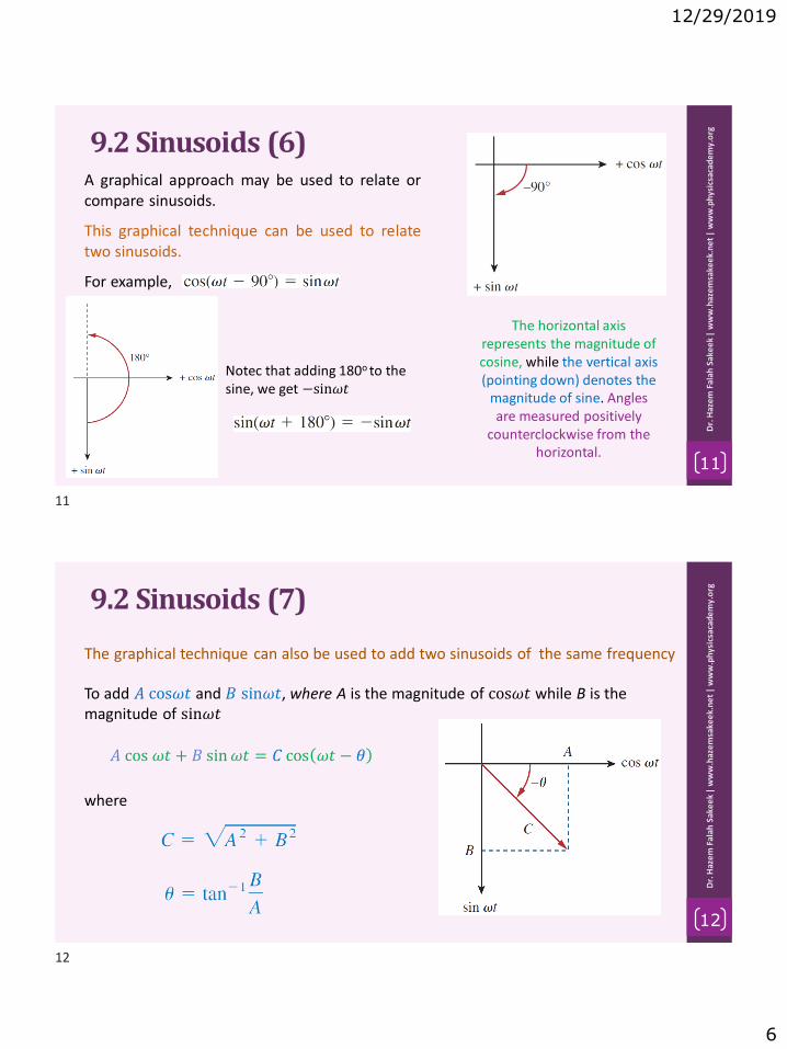
12/29/2019
6
11
Dr.
Haz
em
Fal
ah S
ake
ek
| w
ww
.haz
em
sake
ek.
ne
t|
ww
w.p
hys
icsa
cad
em
y.o
rg
9.2 Sinusoids (6)A graphical approach may be used to relate orcompare sinusoids.
The horizontal axis represents the magnitude of cosine, while the vertical axis (pointing down) denotes the
magnitude of sine. Angles are measured positively
counterclockwise from the horizontal.
This graphical technique can be used to relatetwo sinusoids.
For example,
Notec that adding 180o to the sine, we get −sin𝜔𝑡
12
Dr.
Haz
em
Fal
ah S
ake
ek
| w
ww
.haz
em
sake
ek.
ne
t|
ww
w.p
hys
icsa
cad
em
y.o
rg
9.2 Sinusoids (7)
The graphical technique can also be used to add two sinusoids of the same frequency
To add 𝐴 cos𝜔𝑡 and 𝐵 sin𝜔𝑡, where A is the magnitude of cos𝜔𝑡 while B is the magnitude of sin𝜔𝑡
𝐴 cos 𝜔𝑡 + 𝐵 sin𝜔𝑡 = 𝐶 cos 𝜔𝑡 − 𝜃
where
11
12

12/29/2019
7
13
Dr.
Haz
em
Fal
ah S
ake
ek
| w
ww
.haz
em
sake
ek.
ne
t|
ww
w.p
hys
icsa
cad
em
y.o
rg
9.2 Sinusoids (8)
For example, add 3 cos 𝜔𝑡 and −4 sin𝜔𝑡 using graphical technique.
𝐴 cos 𝜔𝑡 + 𝐵 sin𝜔𝑡 = 𝐶 cos 𝜔𝑡 − 𝜃
3 cos 𝜔𝑡 − 4 sin𝜔𝑡 = ? ? ?
𝐶 = 32 + 42 = 5
𝜃 = tan−1−4
3= −53.1𝑜
3 cos 𝜔𝑡 − 4 sin 𝜔𝑡 = 5 cos(𝜔𝑡 + 53,1𝑜)
14
Dr.
Haz
em
Fal
ah S
ake
ek
| w
ww
.haz
em
sake
ek.
ne
t|
ww
w.p
hys
icsa
cad
em
y.o
rg
Example 9.1
Find the amplitude, phase, period, and frequency of the sinusoid
The amplitude is
The phase is
The angular frequency is
The period
The frequency is
13
14

12/29/2019
8
15
Dr.
Haz
em
Fal
ah S
ake
ek
| w
ww
.haz
em
sake
ek.
ne
t|
ww
w.p
hys
icsa
cad
em
y.o
rg
Example 9.2Calculate the phase angle between 𝑣1 = −10cos 𝜔𝑡 + 50𝑜 and 𝑣2 = 12 sin 𝜔𝑡 − 10𝑜 . State which sinusoid is leading.
METHOD 1: Express 𝑣1 in sine form
𝑣1 = −10 cos 𝜔𝑡 + 50𝑜
𝑣1 = +10 sin 𝜔𝑡 + 50𝑜 − 90𝑜
𝑣1 = +10 sin 𝜔𝑡 − 40𝑜
𝑣1 = +10 sin 𝜔𝑡 − 10𝑜 − 30𝑜
Comparing the two shows that 𝑣1 lags 𝑣2 by 30o
16
Dr.
Haz
em
Fal
ah S
ake
ek
| w
ww
.haz
em
sake
ek.
ne
t|
ww
w.p
hys
icsa
cad
em
y.o
rg
Example 9.2Calculate the phase angle between 𝑣1 = −10cos 𝜔𝑡 + 50𝑜 and 𝑣2 = 12 sin 𝜔𝑡 − 10𝑜 . State which sinusoid is leading.
METHOD 2: use graphical techniques
Comparing the two shows that 𝑣1 lags 𝑣2 by 30o
Consider 𝑣1as −10 cos𝜔𝑡, with phase shift of 50o.
Consider 𝑣2 as 12 sin𝜔𝑡, with phase shift of -10o.
15
16

12/29/2019
9
Problems to Solve by yourself
17
Dr.
Haz
em
Fal
ah S
ake
ek
| w
ww
.haz
em
sake
ek.
ne
t|
ww
w.p
hys
icsa
cad
em
y.o
rg
(3) Given 𝑣1 = 45 sin(𝜔𝑡 + 30𝑜) 𝑉 and 𝑣2= 50 cos(𝜔𝑡 − 30𝑜) 𝑉 , determine thephase angle between the two sinusoidsand which one lags the other.
(1) Given the sinusoidal voltage 𝑣 𝑡 =50 cos(30𝑡 + 10𝑜) find: (a) the amplitude(b) the period T, (c) the frequency f, and(d) v(t) at t=10ms.
(2) Express the following functions incosine form:
(4 For the following pairs of sinusoids,determine which one leads and by howmuch.
(a) 10 sin(𝜔𝑡 + 30𝑜)(b) −9 sin(8𝑡)(c) −20 sin(𝜔𝑡 + 45𝑜)
17

12/29/2019
1
1
Dr.
Haz
em
Fal
ah S
ake
ek
| w
ww
.haz
em
sake
ek.
ne
t|
ww
w.p
hys
icsa
cad
em
y.o
rg
www.physicsacademy.org
Physics Academy
Dr. Hazem Falah Sakeek
Al-Azhar University of Gaza
Unit: 9 | Lecture: 32Sinusoids and Phasors
Phasors
Sinusoids and Phasors
2
Dr.
Haz
em
Fal
ah S
ake
ek
| w
ww
.haz
em
sake
ek.
ne
t|
ww
w.p
hys
icsa
cad
em
y.o
rg
9.1 Introduction
9.2 Sinusoids’ features
9.3 Phasors
9.4 Phasor relationships for circuit elements
9.5 Impedance and admittance
9.7 Impedance combinations
1
2
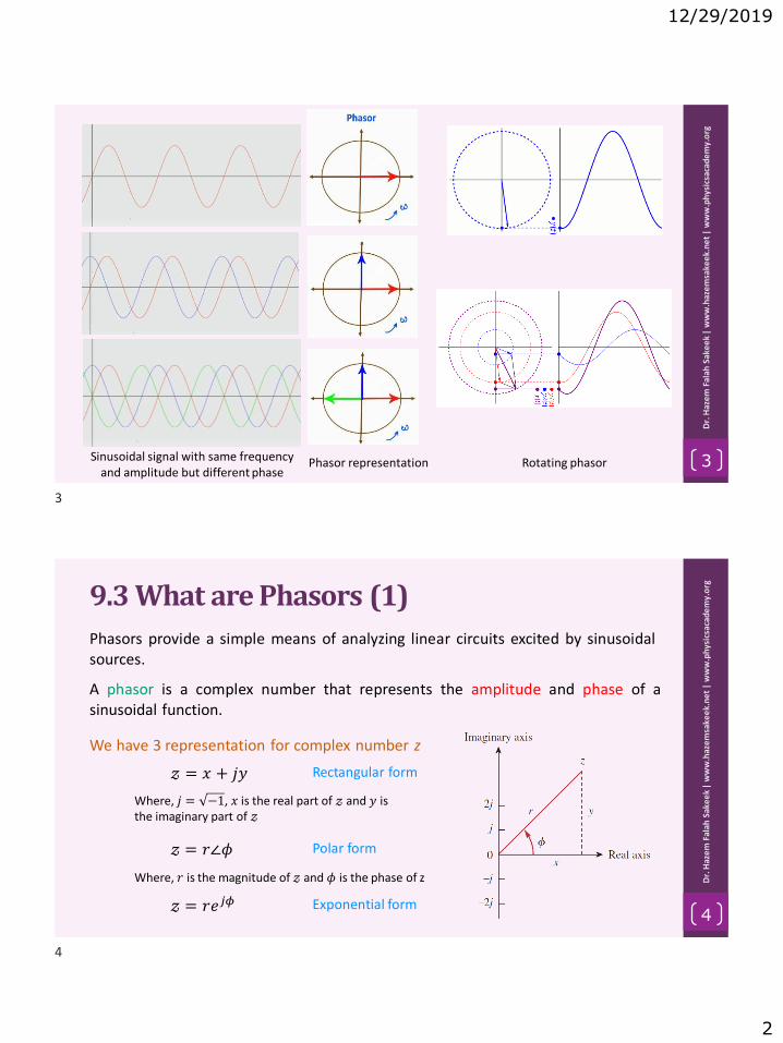
12/29/2019
2
3
Dr.
Haz
em
Fal
ah S
ake
ek
| w
ww
.haz
em
sake
ek.
ne
t|
ww
w.p
hys
icsa
cad
em
y.o
rg
Sinusoidal signal with same frequency and amplitude but different phase
Phasor representation Rotating phasor
4
Dr.
Haz
em
Fal
ah S
ake
ek
| w
ww
.haz
em
sake
ek.
ne
t|
ww
w.p
hys
icsa
cad
em
y.o
rg
9.3 What are Phasors (1)
A phasor is a complex number that represents the amplitude and phase of asinusoidal function.
Phasors provide a simple means of analyzing linear circuits excited by sinusoidalsources.
𝓏 = 𝑥 + 𝑗𝑦
𝓏 = 𝑟∠𝜙
𝓏 = 𝑟𝑒𝑗𝜙
Rectangular form
Polar form
Exponential form
We have 3 representation for complex number z
Where, 𝑗 = −1, 𝑥 is the real part of 𝓏 and 𝑦 is the imaginary part of 𝓏
Where, 𝑟 is the magnitude of 𝓏 and 𝜙 is the phase of z
3
4

12/29/2019
3
5
Dr.
Haz
em
Fal
ah S
ake
ek
| w
ww
.haz
em
sake
ek.
ne
t|
ww
w.p
hys
icsa
cad
em
y.o
rg
9.3 What are Phasors (2)
𝑟 = 𝑥2 + 𝑦2 𝜙 = tan−1𝑦
𝑥
𝑥 = 𝑟 cos𝜙 𝑦 = 𝑟 sin 𝜙
Relationship between rectangular form and polar form
Rectangular polar
polar Rectangular
since, 𝓏 = 𝑥 + 𝑗𝑦
𝓏 = 𝑟 cos 𝜙 + 𝑗𝑟 sin𝜙
𝓏 = 𝑟 cos 𝜙 + 𝑗 sin𝜙
but, 𝑒𝑗𝜙 = cos 𝜙 + 𝑗 sin 𝜙
𝓏 = 𝑟𝑒𝑗𝜙
&
&
6
Dr.
Haz
em
Fal
ah S
ake
ek
| w
ww
.haz
em
sake
ek.
ne
t|
ww
w.p
hys
icsa
cad
em
y.o
rg9.3 Phasors OperationsBasic properties of complex numbers
Addition:
Subtraction:
Multiplication:
Division:
Reciprocal:
Square Root:
Complex Conjugate:
𝓏 = 𝑥 + 𝑗𝑦
𝓏 = 𝑟∠𝜙
𝓏 = 𝑟𝑒𝑗𝜙
𝑟 = 𝑥2 + 𝑦2
𝜙 = tan−1𝑦
𝑥
𝑒𝑗𝜙 = cos𝜙 + 𝑗 sin𝜙
𝑗 = −1
𝑗2 = −1
1
𝑗= −𝑗
cos𝜙 = Re 𝑒𝑗𝜙
sin𝜙 = Im 𝑒𝑗𝜙
Remember
Euler’s identity
5
6
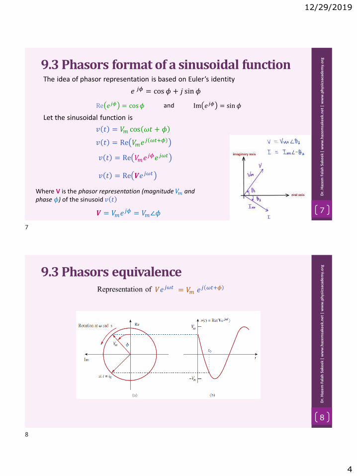
12/29/2019
4
7
Dr.
Haz
em
Fal
ah S
ake
ek
| w
ww
.haz
em
sake
ek.
ne
t|
ww
w.p
hys
icsa
cad
em
y.o
rg
9.3 Phasors format of a sinusoidal function
𝑒 𝑗𝜙 = cos 𝜙 + 𝑗 sin 𝜙
The idea of phasor representation is based on Euler’s identity
Re 𝑒𝑗𝜙 = cos𝜙 Im 𝑒𝑗𝜙 = sin 𝜙
𝑣 𝑡 = 𝑉𝑚 cos 𝜔𝑡 + 𝜙
𝑣 𝑡 = Re 𝑉𝑚𝑒𝑗 𝜔𝑡+𝜙
𝑣 𝑡 = Re 𝑉𝑚𝑒𝑗𝜙𝑒𝑗𝜔𝑡
𝑣 𝑡 = Re 𝑽𝑒𝑗𝜔𝑡
𝑽 = 𝑉𝑚𝑒𝑗𝜙 = 𝑉𝑚∠𝜙
Where V is the phasor representation (magnitude 𝑉𝑚 and phase 𝜙) of the sinusoid 𝑣 𝑡
and
Let the sinusoidal function is
8
Dr.
Haz
em
Fal
ah S
ake
ek
| w
ww
.haz
em
sake
ek.
ne
t|
ww
w.p
hys
icsa
cad
em
y.o
rg
9.3 Phasors equivalenceRepresentation of 𝑉𝑒𝑗𝜔𝑡 = 𝑉𝑚 𝑒𝑗 𝜔𝑡+𝜙
7
8

12/29/2019
5
9
Dr.
Haz
em
Fal
ah S
ake
ek
| w
ww
.haz
em
sake
ek.
ne
t|
ww
w.p
hys
icsa
cad
em
y.o
rg
9.3 Difference between time domain and phasor domain
Time domain representation Phasor domain representation
Tells us the voltage as a function of time Snapshot at t=0
Tells us the magnitude and phase angleTells us the angular frequency
10
Dr.
Haz
em
Fal
ah S
ake
ek
| w
ww
.haz
em
sake
ek.
ne
t|
ww
w.p
hys
icsa
cad
em
y.o
rg
9.3 Phasors of derivative and integral
𝑣 𝑡 = Re 𝑽𝑒𝑗𝜔𝑡 = 𝑉𝑚 cos(𝜔𝑡 + 𝜙)From Eqs.
So that𝑑𝑣
𝑑𝑡= −𝜔𝑉𝑚 sin 𝜔𝑡 + 𝜙 = 𝜔𝑉𝑚 cos 𝜔𝑡 + 𝜙 + 90𝑜
= Re(𝜔𝑉𝑚𝑒𝑗𝜔𝑡𝑒𝑗𝜙𝑒𝑗90) = Re(𝑗𝜔𝑽𝑒𝑗𝜔𝑡)
This shows that the derivative of 𝑣 𝑡 is transformed to the phasor domain as 𝑗𝜔𝑽
The integral of 𝑣 𝑡 is transformed to the phasor domain as 𝑽/𝑗𝜔
9
10

12/29/2019
6
11
Dr.
Haz
em
Fal
ah S
ake
ek
| w
ww
.haz
em
sake
ek.
ne
t|
ww
w.p
hys
icsa
cad
em
y.o
rg
9.3 Phasors
The differences between 𝑣 𝑡 and 𝑽 should be emphasized:
1. 𝑣 𝑡 is the instantaneous or time domain representation, while V is thefrequency or phasor domain representation.
2. 𝑣 𝑡 is time dependent, while V is not.
3. 𝑣 𝑡 is always real with no complex term, while V is generally complex.
Note that: phasor analysis applies only when frequency is constant; it applies inmanipulating two or more sinusoidal signals only if they are of the samefrequency.
12
Dr.
Haz
em
Fal
ah S
ake
ek
| w
ww
.haz
em
sake
ek.
ne
t|
ww
w.p
hys
icsa
cad
em
y.o
rg
ExampleLet 𝑣1 = 50∠60o and 𝑣2 = 30∠ − 50o calculate 𝑣1 + 𝑣2
𝑣1 = 50∠60o = 50 cos 60 + 𝑗 sin 60 = 25 + 𝑗 43.3
𝑣2 = 30∠ − 50o = 30 cos(−50) + 𝑗 sin(−50) = 19.3 − 𝑗 23
𝑣1 + 𝑣2 = 44.3 + 𝑗 20.3
𝑉𝑀 = 44.32 + 20.32 = 48.7
𝜙 = tan−120.3
44.3= 24.6𝑜
𝑣1 + 𝑣2 = 48.7∠24.6𝑜
Solution:
In polar format
11
12

12/29/2019
7
13
Dr.
Haz
em
Fal
ah S
ake
ek
| w
ww
.haz
em
sake
ek.
ne
t|
ww
w.p
hys
icsa
cad
em
y.o
rg
ExampleEvaluate the complex numbers
Solution:
20∠ − 30𝑜 + (4 − 𝑗3)
(4 + 𝑗9)(5 − 𝑗2)
20 cos −30 + 𝑗 sin−30 + (4 − 𝑗3)
20 − 𝑗 8 + 𝑗 45 − 𝑗2 18
=17.3 − 𝑗 10 + (4 − 𝑗3)
38 − 𝑗37
but 𝑗2 = −1
=21.3 − 𝑗 13
38 − 𝑗37
=21.32 + 132∠ tan−1
−1321.3
382 + 372∠ tan−1−3738
=24.95∠ − 31.4𝑜
53.04∠ − 44.2𝑜
= 0.47∠ − 31.4 − (−44.2) = 0.47∠12.8o
14
Dr.
Haz
em
Fal
ah S
ake
ek
| w
ww
.haz
em
sake
ek.
ne
t|
ww
w.p
hys
icsa
cad
em
y.o
rg
Example (1)Let 𝑣1 = −10 sin 𝜔𝑡 − 30𝑜
and 𝑣2 = 20 cos 𝜔𝑡 + 45𝑜 , calculate 𝑣1 + 𝑣2
Solution:
𝑣1 = +10 sin 𝜔𝑡 − 30𝑜 + 180𝑜
We need to convert 𝑣1 to the form 𝑣 = +𝑉𝑚 cos 𝜔𝑡 + 𝜙First convert the –ve sign to +ve by adding 180o
= +10 sin 𝜔𝑡 + 150𝑜
Second convert the sine function to cosine
𝑣1 = +10 cos 𝜔𝑡 + 150𝑜 − 90𝑜 = +10 cos 𝜔𝑡 + 60𝑜
𝑣1 = 10∠60o
𝑣2 = 20∠45o
Write the phasor format of 𝑣1 and 𝑣2
= 10 cos 60 + 𝑗 sin 60 = 5 + 𝑗 8.66
= 20 cos 45 + 𝑗 sin 45 = 14.14 + 𝑗 14.14
𝑣1 + 𝑣2 = 19.14 + 𝑗 22.8
13
14

12/29/2019
8
15
Dr.
Haz
em
Fal
ah S
ake
ek
| w
ww
.haz
em
sake
ek.
ne
t|
ww
w.p
hys
icsa
cad
em
y.o
rg
Example (2)𝑣1 + 𝑣2 = 19.14 + 𝑗 22.8
Convert the answer from phasor domain to time domain
𝑣1 + 𝑣2 = 𝑉𝑀 cos 𝜔𝑡 + 𝜙
𝑉𝑀 = 19.142 + 22.82 = 29.8
𝜙 = tan−122.8
19.14= 50𝑜
𝑣1 + 𝑣2 = 29.8 cos 𝜔𝑡 + 50𝑜
16
Dr.
Haz
em
Fal
ah S
ake
ek
| w
ww
.haz
em
sake
ek.
ne
t|
ww
w.p
hys
icsa
cad
em
y.o
rg
Example 9.7Using the phasor approach, determine the current 𝑖(t)
4𝑖 + 8න 𝑖𝑑𝑡 − 3𝑑𝑖
𝑑𝑡= 50cos(2𝑡 + 75𝑜)
Transform each term in the equation from time domain to phasor domain.
4𝐼 +8𝐼
𝜔𝑗− 3𝐼𝜔𝑗 = 50∠75𝑜
But 𝜔 = 2
4𝐼 +4𝐼
𝑗− 𝑗6𝐼 = 50∠75𝑜
But 1
𝑗= −𝑗
4𝐼 − 𝑗4𝐼 − 𝑗6𝐼 = 50∠75𝑜
I 4 − 𝑗10 = 50∠75𝑜
Convert 4 − 𝑗10 to polar form
15
16

12/29/2019
9
17
Dr.
Haz
em
Fal
ah S
ake
ek
| w
ww
.haz
em
sake
ek.
ne
t|
ww
w.p
hys
icsa
cad
em
y.o
rg
4 − 𝑗10
𝑟 = 42 + 102 = 10.77
𝜙 = tan−1−10
4= −68.2𝑜
Example 9.7
→ 𝑟∠𝜙
I 4 − 𝑗10 = 50∠75𝑜
I 10.77∠ − 68.2𝑜 = 50∠75𝑜
I =50∠75𝑜
10.77∠ − 68.2𝑜
I = 4.64∠143.2𝑜 𝑖 𝑡 = 4.64 cos(2𝑡 + 143.2𝑜)
18
Dr.
Haz
em
Fal
ah S
ake
ek
| w
ww
.haz
em
sake
ek.
ne
t|
ww
w.p
hys
icsa
cad
em
y.o
rg
Practice Problem 9.7Find the voltage 𝑣(𝑡) in a circuit using the phasor approach.
2𝑑𝑣
𝑑𝑡+ 5𝑣 + 10න 𝑣 𝑑𝑡 = 50 cos 5𝑡 − 30𝑜
Transform each term in the equation from time domain to phasor domain.
2𝑉 𝑗𝜔 + 5𝑉 +10𝑉
𝑗𝜔= 50∠ − 30𝑜
But 𝜔 = 5 and 1
𝑗= −𝑗
𝑗10𝑉 + 5𝑉 − 𝑗2𝑉 = 50∠ − 30𝑜
𝑉 5 + 𝑗8 = 50∠ − 30𝑜
𝑟 = 52 + 82 = 9.43
𝜙 = tan−18
5= 58𝑜
5 + 𝑗8 → 𝑟∠𝜙
𝑉 9.43∠58𝑜 = 50∠ − 30𝑜
𝑉 =50∠ − 30𝑜
9.43∠58𝑜= 5.3∠ − 88𝑜
∴ 𝑣 𝑡 = 5.3 cos 5𝑡 − 88𝑜
17
18

12/29/2019
10
Problems to Solve by yourself
19
Dr.
Haz
em
Fal
ah S
ake
ek
| w
ww
.haz
em
sake
ek.
ne
t|
ww
w.p
hys
icsa
cad
em
y.o
rg
(3)
(1) Calculate these complex numbers and express your results in rectangular form:
(2) Find the phasors corresponding to the following signals:
19

12/29/2019
1
1
Dr.
Haz
em
Fal
ah S
ake
ek
| w
ww
.haz
em
sake
ek.
ne
t|
ww
w.p
hys
icsa
cad
em
y.o
rg
www.physicsacademy.org
Physics Academy
Dr. Hazem Falah Sakeek
Al-Azhar University of Gaza
Unit: 9 | Lecture: 33Sinusoids and Phasors
Phasor relationships for circuit elements
Sinusoids and Phasors
2
Dr.
Haz
em
Fal
ah S
ake
ek
| w
ww
.haz
em
sake
ek.
ne
t|
ww
w.p
hys
icsa
cad
em
y.o
rg
9.1 Introduction
9.2 Sinusoids’ features
9.3 Phasors
9.4 Phasor relationships for circuit elements
9.5 Impedance and admittance
9.7 Impedance combinations
1
2

12/29/2019
2
3
Dr.
Haz
em
Fal
ah S
ake
ek
| w
ww
.haz
em
sake
ek.
ne
t|
ww
w.p
hys
icsa
cad
em
y.o
rg
9.4Phasor Relationships for Circuit Elements
Now we know how to represent a voltage or current in the phasor orfrequency domain, how we apply this to circuits involving the passiveelements R, L, and C.
What we need to do is to transform thevoltage-current relationship from thetime domain to the frequency domain foreach element.
4
Dr.
Haz
em
Fal
ah S
ake
ek
| w
ww
.haz
em
sake
ek.
ne
t|
ww
w.p
hys
icsa
cad
em
y.o
rg
9.4Phasor Relationships for Resistor
If the current through a resistor R is
the voltage across it is given by Ohm’s law as
𝑖 = 𝐼𝑚 cos 𝜔𝑡 + 𝜙
𝑣 = 𝑖𝑅 = 𝑅𝐼𝑚 cos 𝜔𝑡 + 𝜙
The phasor form of this voltage is
𝑉 = 𝑅𝐼𝑚 ∠𝜙
But the phasor representation of the current is 𝐼 = 𝐼𝑚 ∠𝜙
𝑉 = 𝑅𝐼
Showing that the voltage-current relation for the resistor in the phasor domain continues to be Ohm’s law, as in the time domain.
Voltage-current relations for a resistor in the: (a) time
domain, (b) frequency domain.
Phasor diagram for the resistor
3
4

12/29/2019
3
5
Dr.
Haz
em
Fal
ah S
ake
ek
| w
ww
.haz
em
sake
ek.
ne
t|
ww
w.p
hys
icsa
cad
em
y.o
rg9.4Phasor Relationships for Inductor
If the current through an inductor L is
𝑖 = 𝐼𝑚 cos 𝜔𝑡 + 𝜙
the voltage across the inductor is
𝑣 = 𝐿𝑑𝑖
𝑑𝑡= −𝜔𝐿𝐼𝑚 sin 𝜔𝑡 + 𝜙
But −sin 𝐴 =cos 𝐴 + 90𝑜
We can write the voltage as
𝑣 = 𝜔𝐿𝐼𝑚 cos 𝜔𝑡 + 𝜙 + 90𝑜
The phasor form of this voltage is
𝑽 = 𝜔𝐿𝐼𝑚 𝑒𝑗(𝜙+90𝑜)
Voltage-current relations for a inductor in the: (a) time
domain, (b) frequency domain.
6
Dr.
Haz
em
Fal
ah S
ake
ek
| w
ww
.haz
em
sake
ek.
ne
t|
ww
w.p
hys
icsa
cad
em
y.o
rg9.4Phasor Relationships for Inductor
The phasor form of this voltage is
𝑽 = 𝜔𝐿𝐼𝑚 𝑒𝑗(𝜙+90𝑜)
𝑽 = 𝜔𝐿𝐼𝑚 𝑒𝑗𝜙𝑒𝑗90𝑜
𝑽 = 𝜔𝐿𝐼𝑚 ∠𝜙 + 90𝑜Phasor diagram for the inductor
I lag V
Showing that the voltage has a magnitude of 𝜔𝐿𝐼𝑚and phase 𝜙 + 90𝑜. The voltage and current are 90o
out of phase. current lags the voltage by 90o.
𝑽 = 𝑗𝜔𝐿𝑰
5
6

12/29/2019
4
7
Dr.
Haz
em
Fal
ah S
ake
ek
| w
ww
.haz
em
sake
ek.
ne
t|
ww
w.p
hys
icsa
cad
em
y.o
rg9.4Phasor Relationships for CapacitorIf the voltage across a capacitor C is
𝑣 = 𝑉𝑚 cos 𝜔𝑡 + 𝜙
the current through the capacitor is
𝑖 = 𝐶𝑑𝑣
𝑑𝑡
By following the same steps as we took for the inductor
𝑰 = 𝑗𝜔𝐶𝑽
𝑽 =𝑰
𝑗𝜔𝐶
Voltage-current relations for a capacitor in the: (a) time
domain, (b) frequency domain.
Phasor diagram for the inductorI lead V
Showing that the voltage and current are 90o out of phase.current leads the voltage by 90o.
8
Dr.
Haz
em
Fal
ah S
ake
ek
| w
ww
.haz
em
sake
ek.
ne
t|
ww
w.p
hys
icsa
cad
em
y.o
rg
Summary of voltage-current relationships
7
8

12/29/2019
5
9
Dr.
Haz
em
Fal
ah S
ake
ek
| w
ww
.haz
em
sake
ek.
ne
t|
ww
w.p
hys
icsa
cad
em
y.o
rg
Example 9.8The voltage 𝑣 = 12 cos 60𝑡 + 45𝑜 is applied to a 0.1-H inductor. Find the steady-state current through the inductor.
For the inductor
𝑽 = 𝑗𝜔𝐿𝑰
𝜔 = 60 𝑟𝑎𝑑/𝑠
𝑽 = 12∠45𝑜 V
𝑰 =𝑽
𝑗𝜔𝐿=
12∠45𝑜
𝑗60 × 0.1=12∠45𝑜
6∠90𝑜= 2∠ − 45𝑜
Converting this to the time domain,
𝑖 𝑡 = 2 cos 60𝑡 − 45𝑜 A
10
Dr.
Haz
em
Fal
ah S
ake
ek
| w
ww
.haz
em
sake
ek.
ne
t|
ww
w.p
hys
icsa
cad
em
y.o
rg
ExampleThe voltage 𝑣 = 20 cos 60𝑡 + 30𝑜 is applied to a 100-F capacitor. Find the steady-state current through the capacitor.
For the capacitor
𝑽 =𝑰
𝑗𝜔𝐶𝜔 = 60 𝑟𝑎𝑑/𝑠
𝑉𝑀 = 20 V
𝜙 = 30𝑜
𝑽 = 20∠30𝑜 V
𝑰 = 𝑽𝑗𝜔𝐶
𝑰 = 20∠30𝑜 (60 × 0.0001)∠90𝑜
𝑰 = 0.12∠120o
Converting this to the time domain,
𝑖 𝑡 = 0.12 cos 60𝑡 + 120𝑜 A
9
10

12/29/2019
6
Problems to Solve by yourself
11
Dr.
Haz
em
Fal
ah S
ake
ek
| w
ww
.haz
em
sake
ek.
ne
t|
ww
w.p
hys
icsa
cad
em
y.o
rg
(1) Determine the current that flows through an 8 resistor connected to a voltagesource 𝑣𝑠 = 110 cos 377𝑡 V
(2) What is the instantaneous voltage across a 2F capacitor when the current through itis 𝑖 = 4 sin 106𝑡 + 25𝑜 A?
(3) A voltage 𝑣 𝑡 = 100 cos 60𝑡 + 20𝑜 V is applied to a parallel combination of aresistor 40k and a 50F capacitor. Find the steady-state currents through the resistorand the capacitor.
(4) A series RLC circuit has R = 80 , L=240 mH, and C = 5 mF. If the input voltage is 𝑣= 10 cos 2𝑡, find the current flowing through the circuit.
(5) A series RL circuit is connected to a 110-V ac source. If the voltage across the resistor is 85 V, find the voltage across the inductor.
11

12/29/2019
1
1
Dr.
Haz
em
Fal
ah S
ake
ek
| w
ww
.haz
em
sake
ek.
ne
t|
ww
w.p
hys
icsa
cad
em
y.o
rg
www.physicsacademy.org
Physics Academy
Dr. Hazem Falah Sakeek
Al-Azhar University of Gaza
Unit: 9 | Lecture: 34Sinusoids and Phasors
Impedance and Admittance
Sinusoids and Phasors
2
Dr.
Haz
em
Fal
ah S
ake
ek
| w
ww
.haz
em
sake
ek.
ne
t|
ww
w.p
hys
icsa
cad
em
y.o
rg
9.1 Introduction
9.2 Sinusoids’ features
9.3 Phasors
9.4 Phasor relationships for circuit elements
9.5 Impedance and admittance
9.7 Impedance combinations
1
2

12/29/2019
2
3
Dr.
Haz
em
Fal
ah S
ake
ek
| w
ww
.haz
em
sake
ek.
ne
t|
ww
w.p
hys
icsa
cad
em
y.o
rg
9.5 Impedance (1)
The voltage-current relations for the three passive elements as
These equations may be written in terms of the ratio of the phasor voltage to the
phasor current as
𝑽 = 𝑅𝑰 𝑽 = 𝑗𝜔𝐿𝑰 𝑽 =𝑰
𝑗𝜔𝐶
𝑽
𝑰= 𝑅
𝑽
𝑰= 𝑗𝜔𝐿
𝑽
𝑰=
1
𝑗𝜔𝐶
Ohm’s law in phasor form for any type of element as
𝒁 =𝑽
𝑰𝑽 = 𝒁𝑰
where Z is a frequency-dependent quantity known as impedance, measured in ohms.
or
resistor inductor capacitor
4
Dr.
Haz
em
Fal
ah S
ake
ek
| w
ww
.haz
em
sake
ek.
ne
t|
ww
w.p
hys
icsa
cad
em
y.o
rg
9.5 Impedance (2)
The impedance Z of a circuit is the ratio of the phasor voltage V to the phasor
current I, measured in ohms ().
Extreme case (1)
When 𝜔 = 0 i.e. for dc sources
𝒁𝑳 = 0 𝒁𝑪 → ∞
confirming that the inductor acts like a short circuit, while the capacitor acts like an open circuit.
Extreme case (2)
When 𝜔 → ∞ i.e. for high frequencies
𝒁𝑳 → ∞ 𝒁𝑪 = 0
indicating that the inductor is an open circuit to high frequencies, while the capacitor is a short circuit.
and
and
3
4

12/29/2019
3
5
Dr.
Haz
em
Fal
ah S
ake
ek
| w
ww
.haz
em
sake
ek.
ne
t|
ww
w.p
hys
icsa
cad
em
y.o
rg
9.5 Impedance (3)
The impedance may be expressed in rectangular form as
𝒁 = 𝑅 + 𝑗𝑋
Where 𝑅 = Re 𝒁 is the resistance and 𝑋 = Im 𝒁 is the reactance
The reactance X may be positive or negative.
Thus, impedance
𝒁 = 𝑅 + 𝑗𝑋
𝒁 = 𝑅 − 𝑗𝑋
is said to be inductive or lagging since currentlags voltage
is capacitive or leading because current leads voltage.
6
Dr.
Haz
em
Fal
ah S
ake
ek
| w
ww
.haz
em
sake
ek.
ne
t|
ww
w.p
hys
icsa
cad
em
y.o
rg
9.5 Impedance (4)
The impedance may also be expressed in polar form as
𝒁 = |𝒁|∠𝜃
Therefore, the impedance is
= |𝒁|∠𝜃𝒁 = 𝑅 + 𝑗𝑋
where
𝒁 = 𝑅2 + 𝑋2 𝜃 = tan−1𝑋
𝑅
and
𝑅 = 𝒁 cos 𝜃 𝑋 = 𝒁 sin 𝜃
5
6

12/29/2019
4
7
Dr.
Haz
em
Fal
ah S
ake
ek
| w
ww
.haz
em
sake
ek.
ne
t|
ww
w.p
hys
icsa
cad
em
y.o
rg
9.5 Admittance (1)
The admittance Y is the reciprocal of impedance, measured in siemens (S).
𝒀 =𝟏
𝒁=
𝑰
𝑽
The admittance Y is the ratio of the phasor current through it to the phasor voltage across it
8
Dr.
Haz
em
Fal
ah S
ake
ek
| w
ww
.haz
em
sake
ek.
ne
t|
ww
w.p
hys
icsa
cad
em
y.o
rg
9.5 Admittance (2)
As a complex quantity the admittance Y may written as
𝒀 = 𝐺 + 𝑗𝐵
Where 𝐺 = Re 𝒀 is the conductance and 𝐵 = Im 𝒀 is the susceptance.
Admittance, conductance, and susceptanceare all expressed in the unit of siemens (or mhos).
7
8

12/29/2019
5
9
Dr.
Haz
em
Fal
ah S
ake
ek
| w
ww
.haz
em
sake
ek.
ne
t|
ww
w.p
hys
icsa
cad
em
y.o
rg
9.5 Admittance (3)Relation between admittance and impedance
𝒀 =𝟏
𝒁
𝒀 = 𝐺 + 𝑗𝐵𝒁 = 𝑅 + 𝑗𝑋
impedance admittance
𝐺 + 𝑗𝐵 =1
𝑅 + 𝑗𝑋
𝐺 + 𝑗𝐵 =1
𝑅 + 𝑗𝑋×𝑅 − 𝑗𝑋
𝑅 − 𝑗𝑋=
𝑅 − 𝑗𝑋
𝑅2 + 𝑋2
Equating the real and imaginary parts gives
𝐺 =𝑅
𝑅2 + 𝑋2𝐵 = −
𝑋
𝑅2 + 𝑋2
showing that 𝐺 ≠ 1/𝑅 as it is in resistive circuits. Of course, if 𝑋 = 0, then 𝐺 = 1/𝑅.
10
Dr.
Haz
em
Fal
ah S
ake
ek
| w
ww
.haz
em
sake
ek.
ne
t|
ww
w.p
hys
icsa
cad
em
y.o
rg
Example 9.9 (1)
Find 𝑣(𝑡) and 𝑖(𝑡) in the circuit
From the voltage source 𝑣𝑠 = 10 cos 4𝑡
𝑉𝑠 = 10∠0
The impedance is
𝒁 = 5 +1
𝑗𝜔𝐶= 5 +
1
𝑗4 × 0.1= 5 − 𝑗2.5
Hence the current
𝑰 =𝑽𝑠
𝒁=
10∠0
5.6∠ − 26.5𝑜
𝑟 = 52 + 2.52 = 5.6
𝜙 = tan−1−2.5
5= −26.57𝑜
5 − 𝑗2.5 → 𝑟∠𝜙
𝑰 = 1.78∠26.57𝑜 A
9
10

12/29/2019
6
11
Dr.
Haz
em
Fal
ah S
ake
ek
| w
ww
.haz
em
sake
ek.
ne
t|
ww
w.p
hys
icsa
cad
em
y.o
rg
Example 9.9 (2)
The voltage across the capacitor is
𝑽 = 𝑰𝒁𝐶 =𝑰
𝑗𝜔𝐶=1.78∠26.57𝑜
𝑗 × 4 × 0.1
=1.78∠26.57𝑜
0.4∠90𝑜
= 4.4∠ − 63.42𝑜 V
Converting I and V to the time domain, we get
𝑖 𝑡 = 1.789 cos 4𝑡 + 26.57𝑜 A
𝑣 𝑡 = 4.47 cos 4𝑡 − 63.43𝑜 V
Notice that i(t) leads v(t) by 90 as expected.
Problems to Solve by yourself
12
Dr.
Haz
em
Fal
ah S
ake
ek
| w
ww
.haz
em
sake
ek.
ne
t|
ww
w.p
hys
icsa
cad
em
y.o
rg
(1) Find current 𝑖 in the circuit when𝑣𝑠 𝑡 = 50 cos200𝑡 V.
(2) Determine the admittance Y for the circuit
(3) Find v(t) in the RLC circuit
(4) If 𝑉𝑜 = 8∠30𝑜 V in the circuit, find Is.
11
12

1/7/2020
1
1
Dr.
Haz
em
Fal
ah S
ake
ek
| w
ww
.haz
em
sake
ek.
ne
t|
ww
w.p
hys
icsa
cad
em
y.o
rg
www.physicsacademy.org
Physics Academy
Dr. Hazem Falah Sakeek
Al-Azhar University of Gaza
Unit: 9 | Lecture: 35Sinusoids and Phasors
Impedance combinations
Sinusoids and Phasors
2
Dr.
Haz
em
Fal
ah S
ake
ek
| w
ww
.haz
em
sake
ek.
ne
t|
ww
w.p
hys
icsa
cad
em
y.o
rg
9.1 Introduction
9.2 Sinusoids’ features
9.3 Phasors
9.4 Phasor relationships for circuit elements
9.5 Impedance and admittance
9.7 Impedance combinations
1
2

1/7/2020
2
3
Dr.
Haz
em
Fal
ah S
ake
ek
| w
ww
.haz
em
sake
ek.
ne
t|
ww
w.p
hys
icsa
cad
em
y.o
rg
9.7 Impedance Combinations (1)
Series-connected impedances
𝒁𝑒𝑞 = 𝒁1 + 𝒁2 +⋯+ 𝒁𝑁
Parallel-connected impedances
1
𝒁𝑒𝑞=
1
𝒁1+
1
𝒁2+⋯+
1
𝒁𝑁
4
Dr.
Haz
em
Fal
ah S
ake
ek
| w
ww
.haz
em
sake
ek.
ne
t|
ww
w.p
hys
icsa
cad
em
y.o
rg
9.7 Impedance Combinations (2)
Voltage-division relationship
𝐼 =𝑉
𝑍1 + 𝑍2
𝑉1 = 𝑍1𝐼 and 𝑉2 = 𝑍2𝐼
𝑉1 =𝑍1
𝑍1 + 𝑍2𝑉
𝑉2 =𝑍2
𝑍1 + 𝑍2𝑉
3
4

1/7/2020
3
5
Dr.
Haz
em
Fal
ah S
ake
ek
| w
ww
.haz
em
sake
ek.
ne
t|
ww
w.p
hys
icsa
cad
em
y.o
rg
9.7 Impedance Combinations (3)
Current-division relationship
𝑉 = 𝐼 𝑍𝑒𝑞
𝑉 = 𝐼1 𝑍1 = 𝐼2 𝑍2
𝐼1 =𝑍2
𝑍1 + 𝑍2𝐼
𝐼2 =𝑍1
𝑍1 + 𝑍2𝐼
= 𝐼𝑍1𝑍2
𝑍1 + 𝑍2
6
Dr.
Haz
em
Fal
ah S
ake
ek
| w
ww
.haz
em
sake
ek.
ne
t|
ww
w.p
hys
icsa
cad
em
y.o
rg9.7 Impedance Combinations (4)
The delta-to-wye and wye-to-delta transformations
𝒀 − ∆ Conversion: ∆ − 𝒀 Conversion:
5
6

1/7/2020
4
7
Dr.
Haz
em
Fal
ah S
ake
ek
| w
ww
.haz
em
sake
ek.
ne
t|
ww
w.p
hys
icsa
cad
em
y.o
rg
Example 9.10 (1)
Find the input impedance of the circuit. Assume that the circuit operates at 𝝎 = 𝟓𝟎 rad/s
Z1 Impedance of the 2-mF capacitor
Z2 Impedance of the 3 resistor in series with the10-mF capacitor
Z3 Impedance of the 0.2-H inductor in series with the 8 resistor
8
Dr.
Haz
em
Fal
ah S
ake
ek
| w
ww
.haz
em
sake
ek.
ne
t|
ww
w.p
hys
icsa
cad
em
y.o
rg
Example 9.10 (2)
The input impedance is
= −𝑗10 +44 + 𝑗14
11 + 𝑗8
= −𝑗10 +44 + 𝑗14
11 + 𝑗8×
11 − 𝑗8
11 − 𝑗8
7
8

1/7/2020
5
9
Dr.
Haz
em
Fal
ah S
ake
ek
| w
ww
.haz
em
sake
ek.
ne
t|
ww
w.p
hys
icsa
cad
em
y.o
rg
Example 9.11 (1)
Determine 𝒗𝒐(𝒕) in the circuit
we must first transform the time domain circuit to the phasor domain
⟹
10 mF ⟹ = −𝑗25 Ω
5 H ⟹
10
Dr.
Haz
em
Fal
ah S
ake
ek
| w
ww
.haz
em
sake
ek.
ne
t|
ww
w.p
hys
icsa
cad
em
y.o
rg
Example 9.11 (2)
Z1 Impedance of the 60- resistor
Z2 Impedance of the parallel combination of the 10-mF capacitor and the 5-H inductor
𝒁1 = 60
By the voltage-division principle
Convert this to the time domain and obtain
=100∠90𝑜
116.6∠59𝑜20∠ − 15𝑜
9
10

1/7/2020
6
Problems to Solve by yourself
11
Dr.
Haz
em
Fal
ah S
ake
ek
| w
ww
.haz
em
sake
ek.
ne
t|
ww
w.p
hys
icsa
cad
em
y.o
rg
(1) At 𝜔 = 337rad/s, find the input impedance of the circuit.
(2) At 𝜔 = 1rad/s, find the input admittanceof the circuit.
(3) Obtain Zin for the circuit
(4) At 𝜔 = 103rad/s find the input admittance of the circuits.
11

1/11/2020
1
1
Dr.
Haz
em
Fal
ah S
ake
ek
| w
ww
.haz
em
sake
ek.
ne
t|
ww
w.p
hys
icsa
cad
em
y.o
rg
www.physicsacademy.org
Physics Academy
Dr. Hazem Falah Sakeek
Al-Azhar University of Gaza
Unit: 9 | Lecture: 36Solution of some selected problem
Sinusoids and PhasorsSinusoids’ features, Phasors, Phasor relationships,
Impedance and admittance
Given the sinusoidal voltage 𝒗 𝒕 = 𝟓𝟎 𝐜𝐨𝐬(𝟑𝟎𝒕 + 𝟏𝟎𝒐) find: (a) the amplitude (b) theperiod T, (c) the frequency f, and (d) v(t) at t=10ms.
2
Dr.
Haz
em
Fal
ah S
ake
ek
| w
ww
.haz
em
sake
ek.
ne
t|
ww
w.p
hys
icsa
cad
em
y.o
rgProblems 9.1
a 𝑉𝑚 = 50 V
b Period 𝑇 =2𝜋
𝜔
c Frequ𝑒𝑛𝑐𝑦 𝑓 =𝜔
2𝜋
d At 𝑡 = 10ms
𝑣(0.01) = 50 cos(0.3 × 180
𝜋+ 10)
𝑣(0.01) = 50 cos(17.2 + 10)
𝑣 0.01 = 44.48 V
𝑣(0.01) = 50 cos(30 × 0.01 rad + 10o)
=2𝜋
30= 0.209 s
=30
2𝜋= 4.775 Hz
1
2

1/11/2020
2
Express the following functions in cosine form:
3
Dr.
Haz
em
Fal
ah S
ake
ek
| w
ww
.haz
em
sake
ek.
ne
t|
ww
w.p
hys
icsa
cad
em
y.o
rgProblems 9.3
(a) 10 sin(ωt + 30o)(b) −9 sin(8t)(c) −20 sin(ωt + 45o)
(a) 10 sin(ωt + 30o)
10 sin(ωt + 30o) = 10 cos(ωt + 30 − 90) = 𝟏𝟎 𝐜𝐨𝐬(𝛚𝐭 − 𝟔𝟎)
b − 9 sin(8t) =𝟗 𝐜𝐨𝐬(𝟖𝐭 + 𝟗𝟎)
c − 20 sin(ωt + 45o) = 20 cos(ωt + 45 + 90) = 𝟐𝟎 𝐜𝐨𝐬(𝛚𝐭 + 𝟏𝟑𝟓)
since, sin θ = cos(𝜃 − 90)
Given 𝒗𝟏 = 𝟒𝟓 𝐬𝐢𝐧(𝝎𝒕 + 𝟑𝟎𝒐) 𝑽 and 𝒗𝟐 = 𝟓𝟎𝒄𝒐𝒔(𝝎𝒕 − 𝟑𝟎𝒐) 𝑽, determine the phase angle between the two sinusoids and which one lags the other.
4
Dr.
Haz
em
Fal
ah S
ake
ek
| w
ww
.haz
em
sake
ek.
ne
t|
ww
w.p
hys
icsa
cad
em
y.o
rgProblems 9.5
𝑣1 = 45 sin(𝜔𝑡 + 30𝑜) = 45 cos(𝜔𝑡 + 30 − 90) = 45 cos(𝜔𝑡 − 60)
𝑣2 = 50 cos(𝜔𝑡 − 30)
This indicates that the phase angle between the two signals is 30o and that v1 lags v2.
𝑣1
𝑣2
3
4

1/11/2020
3
For the following pairs of sinusoids, determine which one leads and by how much.
5
Dr.
Haz
em
Fal
ah S
ake
ek
| w
ww
.haz
em
sake
ek.
ne
t|
ww
w.p
hys
icsa
cad
em
y.o
rgProblems 9.6
𝑖 𝑡 = 4 sin(4𝑡 + 50)
= 4 cos(4𝑡 + 50 − 90)
= 4 cos(4𝑡 − 40)
Thus, 𝑖(t) leads 𝑣(t) by 20o
𝑣2 𝑡 = − cos(377𝑡)
Thus, v2(t) leads v1(t) by 170o
= +cos(377𝑡 + 180)
Calculate these complex numbers and express your results in rectangular form:
6
Dr.
Haz
em
Fal
ah S
ake
ek
| w
ww
.haz
em
sake
ek.
ne
t|
ww
w.p
hys
icsa
cad
em
y.o
rgProblems 9.8
7.5 − 𝑗10 → 𝑟∠𝜙
𝑟 = 7.52 + 102 = 12.5
ϕ = tan−1−10
7.5= −53.13o
4.8∠98.13 → 𝑥 + 𝑗𝑦
6 − 𝑗8 4+ 𝑗2 = 24 − 𝑗32 + 𝑗12 + 16
= 40 − 𝑗20
40 − 𝑗20 → 𝑟∠𝜙
𝑟 = 402 − 202 = 44.72
𝜙 = tan−1−20
40= −26.57𝑜
−10 + 𝑗24 → 𝑟∠𝜙
𝑟 = 102 + 242 = 26
𝜙 = tan−124
−10= 112.62𝑜
=
5
6

1/11/2020
4
Find the phasors corresponding to the following signals:
7
Dr.
Haz
em
Fal
ah S
ake
ek
| w
ww
.haz
em
sake
ek.
ne
t|
ww
w.p
hys
icsa
cad
em
y.o
rgProblems 9.11
𝐕 = 21∠ − 15o
𝐈 = 8∠160o
= 120 cos 10𝑡 − 50o − 90o
= 120 cos 10𝑡 − 140o
𝐕 = 120∠ − 140o
= 60 cos 30𝑡 − 170o
= 60 cos 30𝑡 + 10o − 180o
𝐈 = 60∠ − 170o
Two voltages 𝒗1 and 𝒗2 appear in series so that their sum is 𝒗=𝒗1+𝒗2. If𝒗𝟏 = 𝟏𝟎𝐜𝐨𝐬 𝟓𝟎𝒕 − 𝝅/𝟑 𝐕 and𝒗𝟐 = 𝟏𝟐𝐜𝐨𝐬 𝟓𝟎𝒕 + 𝟑𝟎𝐨 𝐕, find 𝒗.
8
Dr.
Haz
em
Fal
ah S
ake
ek
| w
ww
.haz
em
sake
ek.
ne
t|
ww
w.p
hys
icsa
cad
em
y.o
rgProblems 9.17
𝑣1 = 10cos 50𝑡 − 𝜋/3
𝑣1 = 10cos 50𝑡 − 60𝑜
𝑉1 = 10∠ − 60o
𝑉2 = 12∠ + 30o
𝑉1 + 𝑉2 = 5 − 𝑗8.66+10.392 + 𝑗6
𝑉1 + 𝑉2 = 15.392 − 𝑗2.66
→ 5 − 𝑗8.66
→ 10.392 + 𝑗6
→ 𝑟∠𝜙
𝑟 = 15.3922 + 2.662 = 15.4
𝜙 = tan−1−2.66
15.392= −9.805𝑜
𝑉 = 𝑉1 + 𝑉2 = 15.4∠ − 9.805o
𝑣 = 15.4cos 50𝑡 − 9.805𝑜
7
8

1/11/2020
5
Determine the current that flows through an 8 resistor connected to a voltage source 𝒗𝒔 = 𝟏𝟏𝟎𝒄𝒐𝒔 𝟑𝟕𝟕𝒕 𝐕
9
Dr.
Haz
em
Fal
ah S
ake
ek
| w
ww
.haz
em
sake
ek.
ne
t|
ww
w.p
hys
icsa
cad
em
y.o
rgProblems 9.28
𝑖 𝑡 =𝑣𝑠𝑅
𝑖 𝑡 =110 𝑐𝑜𝑠 377𝑡
8
𝑖 𝑡 = 13.75 𝑐𝑜𝑠 377𝑡
What is the instantaneous voltage across a 2F capacitor when the
current through it is 𝒊 = 𝟒 𝐬𝐢𝐧 𝟏𝟎𝟔𝒕 + 𝟐𝟓𝒐 A?
10
Dr.
Haz
em
Fal
ah S
ake
ek
| w
ww
.haz
em
sake
ek.
ne
t|
ww
w.p
hys
icsa
cad
em
y.o
rgProblems 9.29
Z for the capacitor is given by
𝑽 = 𝑰𝒁
𝒁 =1
𝑗𝜔𝐶
The relation between the voltage and current in phasor form is
=1
𝑗 × 106× 2 × 10−6= −𝑗0.5 Ω
𝑰 = 4∠25o
𝑽 = 𝑰𝒁 = 4∠25o 0.5∠ − 90o = 2∠ − 65o
𝑣 𝑡 = 2 sin 106𝑡 − 65𝑜 V
The instantaneous voltage in time domain
𝒁 = 0.5∠ − 90o
9
10

1/11/2020
6
A voltage 𝒗 𝒕 = 𝟏𝟎𝟎 𝐜𝐨𝐬 𝟔𝟎𝒕 + 𝟐𝟎𝒐 𝐕 is applied to a parallel combination of a resistor 40k and a 50F capacitor. Find the steady-state currents through the resistor and the capacitor.
11
Dr.
Haz
em
Fal
ah S
ake
ek
| w
ww
.haz
em
sake
ek.
ne
t|
ww
w.p
hys
icsa
cad
em
y.o
rgProblems 9.30
R and C are in parallel, they have the same voltage across them.
For the resistor 𝑉 = 𝐼𝑅𝑅
𝐼𝑅 =𝑉
𝑅=100∠20o
40 × 103= 2.5 × 10³∠20o A
𝑖𝑅 = 2.5 × 10³ cos 60𝑡 + 20o A
For the capacitor 𝑖𝑐 = 𝐶𝑑𝑣
𝑑𝑡
𝑖𝑐 = 50 × 10−6𝑑100 𝑐𝑜𝑠 60𝑡 + 20𝑜
𝑑𝑡
𝑖𝑐 = 50 × 10−6 −60 × 100 sin 60𝑡 + 20o
𝑖𝑐 = 0.3 sin 60𝑡 + 20o A
A series RLC circuit has R = 80 , L=240 mH, and C = 5 mF. If theinput voltage is 𝒗 = 𝟏𝟎 𝐜𝐨𝐬 𝟐𝒕, find the current flowing through thecircuit.
12
Dr.
Haz
em
Fal
ah S
ake
ek
| w
ww
.haz
em
sake
ek.
ne
t|
ww
w.p
hys
icsa
cad
em
y.o
rgProblems 9.31
𝐼 =𝑉
𝑍We need to find Zeq for the RLC in series
Z for L = 240 mH → 𝑍𝐿= 𝑗𝜔𝐿 = 𝑗2 × 240 × 10−3 = 𝑗0.48Ω
Z for C = 5 mF → 𝑍𝐶=1
𝑗𝜔𝐶=
1
𝑗2 × 5 × 10−3= −𝑗100Ω
Z for R = 80 → 𝑍𝑅= 80Ω
𝑍𝑒𝑞 = 𝑍𝐿 + 𝑍𝐶 + 𝑍𝑅 = 𝑗0.48 − 𝑗100 + 80 = 80 − 𝑗99.52
𝐼 =10∠0o
127.7∠ − 51.2o
= 127.7∠ − 51.2o
= 0.078∠51.2o
𝑖(𝑡) = 0.078 cos 2𝑡 + 51.2o A
11
12

1/11/2020
7
A series RL circuit is connected to a 110-V ac source. If the voltage across the resistor is 85 V, find the voltage across the inductor.
13
Dr.
Haz
em
Fal
ah S
ake
ek
| w
ww
.haz
em
sake
ek.
ne
t|
ww
w.p
hys
icsa
cad
em
y.o
rgProblems 9.33
In phasor form
𝑉𝑠2 = 𝑉𝑅
2 + 𝑉𝐿2
𝑉𝐿 = 𝑉𝑠2 − 𝑉𝑅
2
= 1002 − 852
𝑉𝐿 = 69.8 V
Find current 𝒊 in the circuit when 𝒗𝒔 𝒕 = 𝟓𝟎 𝐜𝐨𝐬 𝟐𝟎𝟎𝒕 𝐕.
14
Dr.
Haz
em
Fal
ah S
ake
ek
| w
ww
.haz
em
sake
ek.
ne
t|
ww
w.p
hys
icsa
cad
em
y.o
rgProblems 9.35
𝑣𝑠 𝑡 = 50 𝑐𝑜𝑠 200𝑡 → 𝑉𝑠 = 50∠0o 𝜔 = 200
To find the current we need to find the impendence Z
Z for L = 20 mH → 𝑍𝐿= 𝑗𝜔𝐿 = 𝑗200 × 20 × 10−3 = 𝑗4 Ω
Z for C = 5 mF → 𝑍𝐶=1
𝑗𝜔𝐶=
1
𝑗200 × 5 × 10−3= −𝑗 Ω
Z for R = 10
𝑍𝑒𝑞 = 𝑍𝐿 + 𝑍𝐶 + 𝑍𝑅 = 𝑗4 − 𝑗 + 10 = 10 + 𝑗3
= 10.44∠16.7o
𝐼 =𝑉𝑠𝑍𝑒𝑞
=50∠0o
10.44∠16.7o= 4.789∠ − 16.7o
𝑖(𝑡) = 4.789 cos 200𝑡 − 16.7o A
13
14
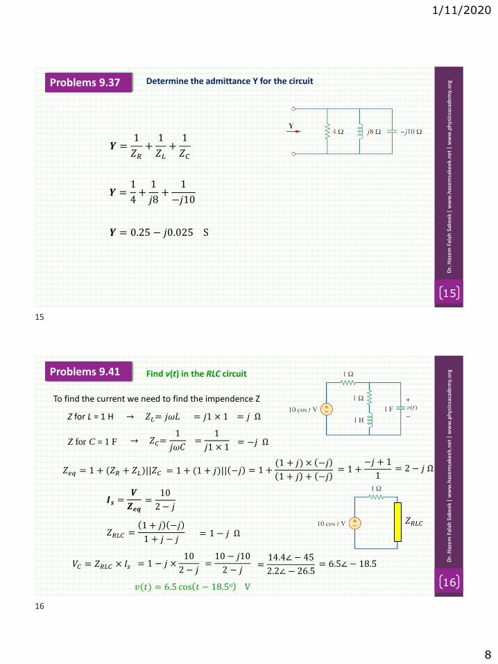
1/11/2020
8
Determine the admittance Y for the circuit
15
Dr.
Haz
em
Fal
ah S
ake
ek
| w
ww
.haz
em
sake
ek.
ne
t|
ww
w.p
hys
icsa
cad
em
y.o
rgProblems 9.37
𝒀 =1
𝑍𝑅+
1
𝑍𝐿+
1
𝑍𝐶
𝒀 =1
4+
1
𝑗8+
1
−𝑗10
𝒀 = 0.25 − 𝑗0.025 S
Find v(t) in the RLC circuit
16
Dr.
Haz
em
Fal
ah S
ake
ek
| w
ww
.haz
em
sake
ek.
ne
t|
ww
w.p
hys
icsa
cad
em
y.o
rgProblems 9.41
To find the current we need to find the impendence Z
Z for L = 1 H → 𝑍𝐿= 𝑗𝜔𝐿 = 𝑗1 × 1 = 𝑗 Ω
Z for C = 1 F → 𝑍𝐶=1
𝑗𝜔𝐶=
1
𝑗1 × 1= −𝑗 Ω
𝑍𝑒𝑞 = 1 + (𝑍𝑅 + 𝑍𝐿)||𝑍𝐶 = 1 + (1 + 𝑗)|| −𝑗 = 1 +(1 + 𝑗) × −𝑗
1 + 𝑗 + −𝑗= 1 +
−𝑗 + 1
1= 2 − 𝑗 Ω
𝑰𝒔 =𝑽
𝒁𝒆𝒒=
10
2 − 𝑗
𝑍𝑅𝐿𝐶 =1 + 𝑗 −𝑗
1 + 𝑗 − 𝑗
𝑍𝑅𝐿𝐶= 1 − 𝑗 Ω
𝑉𝐶 = 𝑍𝑅𝐿𝐶 × 𝐼𝑠 = 1 − 𝑗 ×10
2 − 𝑗=10 − 𝑗10
2 − 𝑗=14.4∠ − 45
2.2∠ − 26.5= 6.5∠ − 18.5
𝑣(𝑡) = 6.5 cos 𝑡 − 18.5o V
15
16

1/11/2020
9
If 𝑽𝒐 = 𝟖∠𝟑𝟎𝒐 V in the circuit, find 𝐈s.
17
Dr.
Haz
em
Fal
ah S
ake
ek
| w
ww
.haz
em
sake
ek.
ne
t|
ww
w.p
hys
icsa
cad
em
y.o
rgProblems 9.52
We begin by simplifying the circuit.
First we replace the parallel inductor and resistor with their series equivalent.
5||𝑗5 =5 × 𝑗5
5 + 𝑗5=
𝑗5
1 + 𝑗=
𝑗5
1 + 𝑗×1 − 𝑗
1 − 𝑗=
𝑗5 + 5
12 + 12= 2.5+ 𝑗2.5 Ω
𝑍2 = −5𝑗 + 2.5 + 𝑗2.5 = 2.5− 𝑗2.5 Ω
𝑍1 = 10 Ω
By current division 𝐼2 =𝑍1
𝑍1 + 𝑍2𝐼𝑠 =
10
12.5 − 𝑗2.5𝐼𝑠 =
4
5 − 𝑗𝐼𝑠
but 𝑉𝑜 = 𝐼2𝑍2
8∠30o =4
5 − 𝑗𝐼𝑠 × (2.5 − 𝑗2.5) =
10 + 𝑗10
5 − 𝑗𝐼𝑠
𝐼𝑠 =8∠30o 5− 𝑗
10 + 𝑗10=
8∠30o 5.1∠− 11.3o
14.14∠45o= 2.88∠−26.3o
At 𝝎 = 𝟑𝟑𝟕𝐫𝐚𝐝/𝐬, find the input impedance of the circuit.
18
Dr.
Haz
em
Fal
ah S
ake
ek
| w
ww
.haz
em
sake
ek.
ne
t|
ww
w.p
hys
icsa
cad
em
y.o
rgProblems 9.56
Z for C = 50 F
→ 𝑍𝐶=1
𝑗𝜔𝐶=
1
𝑗377 × 50 × 10−6= −𝑗53.05
Z for L = 60 mH
→ 𝑍𝐿= 𝑗𝜔𝐿 = 𝑗377 × 60 × 10−3 = 𝑗22.62
𝑍𝑖𝑛 = 12 − 𝑗53.05 + 40||𝑗22.62
𝑍𝑖𝑛 = 12 − 𝑗53.05 +40 × 𝑗22.62
40 + 𝑗22.62
𝑍𝑖𝑛 = 12 − 𝑗53.05 +𝑗904.8
40 + 𝑗22.62×40 − 𝑗22.62
40 − 𝑗22.62
𝑍𝑖𝑛 = 12 − 𝑗53.05 +𝑗36.192 + 20466.5
402+ 22.622= 12 − 𝑗53.05 + 9.7 + 𝑗17.13
= 21.7 − 𝑗35.9
17
18

1/11/2020
10
At 𝝎 = 𝟏𝐫𝐚𝐝/𝐬, find the input admittance of the circuit.
19
Dr.
Haz
em
Fal
ah S
ake
ek
| w
ww
.haz
em
sake
ek.
ne
t|
ww
w.p
hys
icsa
cad
em
y.o
rgProblems 9.57
Z for L = 2 H → 𝑍𝐿= 𝑗𝜔𝐿 = 𝑗2
Z for C = 2 F → 𝑍𝐶=1
𝑗𝜔𝐶=1
𝑗= −𝑗
𝑍𝑖𝑛 = 1 + 𝑗2|| 2 − 𝑗
𝑍𝑖𝑛 = 1 +2 + 𝑗4
2 + 𝑗
= 1 +𝑗2 × 2 − 𝑗
𝑗2 + 2 − 𝑗
= 1 +2 + 𝑗4
2 + 𝑗×2 − 𝑗
2 − 𝑗
= 1 +4 − 𝑗2 + 𝑗8 + 4
4 + 1= 1 +
8 + 𝑗6
5=13 + 𝑗6
5= 2.6 + 𝑗1.2
𝑌𝑖𝑛 =1
𝑍𝑖𝑛=
1
2.6 + 𝑗1.2=
1
2.6 + 𝑗1.2×2.6 − 𝑗1.2
2.6 − 𝑗1.2=
2.6 − 𝑗1.2
6.76 + 1.44= 0.31 − 𝑗0.14 S
Obtain Zin for the circuit
20
Dr.
Haz
em
Fal
ah S
ake
ek
| w
ww
.haz
em
sake
ek.
ne
t|
ww
w.p
hys
icsa
cad
em
y.o
rgProblems 9.60
𝑍𝑖𝑛 = 25 + 𝑗15 + (20 − 𝑗50)|| 30 + 𝑗10
𝑍𝑖𝑛 = 25 + 𝑗15 +(20 − 𝑗50) × 30 + 𝑗10
20 − 𝑗50 + 30 + 𝑗10
𝑍𝑖𝑛 = 25 + 𝑗15 +600 + 𝑗200 − 𝑗1500 + 500
50 − 𝑗40= 25 + 𝑗15 +
1100 − 𝑗1300
50 − 𝑗40
= 25 + 𝑗15 +1100 − 𝑗1300
50 − 𝑗40×50 + 𝑗40
50 + 𝑗40
= 25 + 𝑗15 +55000 + 𝑗44000 − 𝑗65000 + 52000
4100= 25 + 𝑗15 + 26.1 − 𝑗5.1
𝑍𝑖𝑛 = 51.1 + 𝑗9.9
19
20

1/11/2020
11
At 𝝎 = 𝟏𝟎𝟑𝐫𝐚𝐝/𝒔 find the input admittance of the circuits.
21
Dr.
Haz
em
Fal
ah S
ake
ek
| w
ww
.haz
em
sake
ek.
ne
t|
ww
w.p
hys
icsa
cad
em
y.o
rgProblems 9.67
Z for L = 10 mH → 𝑍𝐿= 𝑗𝜔𝐿 = 𝑗103 × 10 × 10−3
Z for C = 20 F → 𝑍𝐶=1
𝑗𝜔𝐶= −𝑗50
= 𝑗10
=1
𝑗103 × 20 × 10−6
Note 30||60 =30×60
30+60= 20
𝑍𝑖𝑛 = −𝑗50 + (20|| 40 + 𝑗10 = −𝑗50 +20 × 40 + 𝑗10
20 + 40 + 𝑗10
𝑍𝑖𝑛 = −𝑗50 +800 + 𝑗200
60 + 𝑗10= −𝑗50 +
824.6∠14o
60.8∠9.46o
= −𝑗50 + 13.5∠4.57o
𝑍𝑖𝑛 = −𝑗50 + 13.5 + 𝑗1.08 = 13.5 − 𝑗48.9
= 50.75∠ − 74.56o
𝑌𝑖𝑛 =1
𝑍𝑖𝑛= 0.0197∠74.56o S
= 0.005 + 𝑗0.019 S
21