Differences between Czochralski Silicon and Float Zone Silicon
Upload
khangminh22Category
view
1download
0
AM389x Sitara™ ARM® Microprocessors(MPUs)Silicon Revisions 2.1, 2.0, 1.1, 1.0
Silicon Errata
Literature Number: SPRZ327HNovember 2010–Revised March 2015

Contents
1 Introduction......................................................................................................................... 41.1 Device and Development Support-Tool Nomenclature ............................................................. 41.2 Package Symbolization and Revision Identification ................................................................. 51.3 ARM Silicon Revision.................................................................................................... 6
2 Revision 2.1 Usage Notes and Known Design Exceptions to Functional Specifications ............... 72.1 Revision 2.1 Usage Notes .............................................................................................. 72.2 Revision 2.1 Known Design Exceptions to Functional Specifications............................................. 9
3 Revision 2.0 Known Design Exceptions to Functional Specifications ....................................... 384 Revision 1.1 Known Design Exceptions to Functional Specifications ....................................... 485 Revision 1.0 Known Design Exceptions to Functional Specifications ....................................... 66Revision History.......................................................................................................................... 68
2 Table of Contents SPRZ327H–November 2010–Revised March 2015Submit Documentation Feedback
Copyright © 2010–2015, Texas Instruments Incorporated

www.ti.com
List of Figures1 Qualified Device Package Symbolization................................................................................. 52 X Device Variant Package Symbolization ................................................................................ 53 ACTVID Signal Active for All Lines of Incoming Data ................................................................. 554 SATA Activity LED Connectivity .......................................................................................... 63
List of Tables1 Identifying Device Revision From Package Symbolization............................................................. 52 JTAG ID Register Variables ................................................................................................ 53 ARM Silicon Revision ....................................................................................................... 64 Revision 2.1 Advisory List .................................................................................................. 95 Revision 2.0 Advisory List................................................................................................. 386 Revision 1.1 Advisory List................................................................................................. 487 Revision 1.0 Advisory List................................................................................................. 66
3SPRZ327H–November 2010–Revised March 2015 List of FiguresSubmit Documentation Feedback
Copyright © 2010–2015, Texas Instruments Incorporated

Silicon ErrataSPRZ327H–November 2010–Revised March 2015
AM389x Sitara™ ARM® Microprocessors (MPUs)Silicon Revisions 2.1, 2.0, 1.1, 1.0
1 IntroductionThis document describes the known exceptions to the functional specifications for the AM389x Sitara ARMProcessors. The updates are applicable to the CYG package. For additional information, see the AM389xSitara™ ARM® Microprocessors (MPUs) data manual (SPRS681).
The advisory numbers in this document may not be sequential. Some advisory numbers may be moved tothe next revision and others may have been removed and documented in the device-specific data manualor peripheral user's guide. When items are moved or deleted, the remaining numbers remain the sameand are not resequenced.
1.1 Device and Development Support-Tool NomenclatureTo designate the stages in the product development cycle, TI assigns prefixes to the part numbers of allprocessors and support tools. Each device has one of three prefixes: X, P, or null (no prefix) (e.g.,AM3894CYG). Texas Instruments recommends two of three possible prefix designators for its supporttools: TMDX and TMDS. These prefixes represent evolutionary stages of product development fromengineering prototypes (TMDX) through fully qualified production devices/tools (TMDS).
Device development evolutionary flow:
X — Experimental device that is not necessarily representative of the final device's electricalspecifications and may not use production assembly flow.
P — Prototype device that is not necessarily the final silicon die and may not necessarily meet finalelectrical specifications.
null — Production version of the silicon die that is fully qualified.
Support tool development evolutionary flow:
TMDX — Development-support product that has not yet completed Texas Instruments internalqualification testing.
TMDS — Fully-qualified development-support product.
X and P devices and TMDX development-support tools are shipped against the following disclaimer:
"Developmental product is intended for internal evaluation purposes."
Production devices and TMDS development-support tools have been characterized fully, and the qualityand reliability of the device have been demonstrated fully. TI's standard warranty applies.
Predictions show that prototype devices (X or P) have a greater failure rate than the standard productiondevices. Texas Instruments recommends that these devices not be used in any production systembecause the expected end-use failure rate still is undefined. Only qualified production devices are to beused.
Sitara, SmartReflex are trademarks of Texas Instruments.ARM, Cortex are registered trademarks of ARM Limited (or its subsidiaries) in the EU and/or elsewhere. All rights reserved.PCI Express, PCIe are registered trademarks of PCI-SIG.All other trademarks are the property of their respective owners.
4 AM389x Sitara™ ARM® Microprocessors (MPUs) Silicon Revisions 2.1, 2.0, SPRZ327H–November 2010–Revised March 20151.1, 1.0 Submit Documentation Feedback
Copyright © 2010–2015, Texas Instruments Incorporated

Lot Trace Code
AM3894CCYG
YMLLLLS
786 CYG
G1Device Revision
120
Lot Trace Code
YMLLLLS G1
786 CYG
X8168X3894CCYG
Device Revision
www.ti.com Introduction
1.2 Package Symbolization and Revision IdentificationFigure 1 shows an example of the AM389x processor qualified device package symbolization. For Xvariants of this device, the symbolization shown in Figure 2 is used. The device revision can be identifiedby the markings on the top of the CYG package; the "C" between the device number and the packageidentifier indicates the device revision (2.1), as noted in the figures.
Table 1 lists the device revisions for the AM389x processor.
Figure 1. Qualified Device Package Symbolization Figure 2. X Device Variant Package Symbolization
Table 1. Identifying Device Revision From Package Symbolization
DEVICE REVISION IDENTIFIER DEVICE REVISION COMMENTSBlank 1.0 Initial device revision
A 1.1 Device revision 1.1B 2.0 Device revision 2.0C 2.1 Device revision 2.1
The VARIANT field of the JTAG ID Register (located at 0x4814 0600) changes between silicon revisions.Table 2 lists the contents of the JTAG ID Register value for each revision of the device. More details onthe JTAG ID Register can be found in the AM389x Sitara™ ARM® Microprocessors (MPUs) data manual(SPRS681).
Table 2. JTAG ID Register Variables
SILICON REVISION JTAG ID REGISTER VALUE0x3B81 E02F2.1 (VARIANT = 0011)0x2B81 E02F2.0 (VARIANT = 0010)0x1B81 E02F1.1 (VARIANT = 0001)0x0B81 E02F1.0 (VARIANT = 0000)
5SPRZ327H–November 2010–Revised March 2015 AM389x Sitara™ ARM® Microprocessors (MPUs) Silicon Revisions 2.1, 2.0,1.1, 1.0Submit Documentation Feedback
Copyright © 2010–2015, Texas Instruments Incorporated

Introduction www.ti.com
1.3 ARM Silicon RevisionEach AM389x silicon revision uses a specific revision of the Cortex®-A8 processor as shown in Table 3.
Table 3. ARM Silicon Revision
ARM CORTEX-A8SILICON REVISION VARIANT/REVISION1.1 (revision A) r3p22.0 (revision B) r3p22.1 (revision C) r3p2
6 AM389x Sitara™ ARM® Microprocessors (MPUs) Silicon Revisions 2.1, 2.0, SPRZ327H–November 2010–Revised March 20151.1, 1.0 Submit Documentation Feedback
Copyright © 2010–2015, Texas Instruments Incorporated

www.ti.com Revision 2.1 Usage Notes and Known Design Exceptions to Functional Specifications
2 Revision 2.1 Usage Notes and Known Design Exceptions to FunctionalSpecificationsThis section describes the usage notes and advisories that apply to revision 2.1 of the AM389x device.
2.1 Revision 2.1 Usage NotesUsage Notes highlight and describe particular situations where the device's behavior may not matchpresumed or documented behavior. This may include behaviors that affect device performance orfunctional correctness. These notes will be incorporated into future documentation updates for the device(such as the device-specific data manual), and the behaviors they describe will not be altered in futuresilicon revisions.
2.1.1 DDR2 and DDR3 Require Software LevelingOn all silicon revisions (except silicon revision 1.0), DDR2 and DDR3 require software leveling to tune thedevice IOs to the timing characteristics of a particular board design. Hardware leveling is not supported onthese devices. For more information on software leveling, see the TMS320DM816x/C6A816x/AM389xDDR3 Initialization With Software Leveling application report (SPRABJ3) or click the following link to viewthe article in the TI Embedded Processors Wiki:http://processors.wiki.ti.com/index.php/DM816x_C6A816x_AM389x_DDR3_Init.
2.1.2 AVS Power Supply RequirementsThe SmartReflex™ driver determines AVS voltage level at the AM389x CVDD power pin required toensure proper operation. Along with the SR Driver, there are AVS power supply requirements for AM389xdevices.• The adaptive voltage scaling (AVS) is required for all AM389x devices.• The AVS voltage must be within ±5% tolerance of the target voltage at all the BGA balls. This includes
overshoot and undershoot due to load changes and broad spectrum AC noise.• The power management IC (PMIC) maximum voltage should be considered as the sum of Vmax, worst
case board DC voltage drop and low frequency regulator output AC ripple.• Voltage remote sense for PMIC must be attached under the AM389x at CVDD and VSS.• CVDD AVS Vmax operating range spec changes from 1.05V to 1.10V. For more detailed information
on the CVDD Vmax voltage, see the AM389x Sitara™ ARM® Microprocessors (MPUs) data manual(SPRS681).
• The PMIC maximum voltage must meet CVDD Vmax requirements depending on a speed grade ofdevices. For more detailed information on the CVDD Vmax voltage, see the AM389x Sitara™ ARM®Microprocessors (MPUs) data manual (SPRS681).
• PMIC layout requirements must also be followed.
For more information on above power supply requirements, click the following link to view the article in theTI Embedded Processors Wiki: http://processors.wiki.ti.com/index.php/DM816x_Design_Resources
2.1.3 Initial Voltage Level Setting of CVDD AVS Rail Power Supplies Usage NoteUsers are required to program their board CVDD AVS supply initial value to 1.00V or 1.05V on the device.The initial CVDD voltage at power-on will be 1.00V or 1.05V nominal and it must transition to AVS targetvalue adjusted by a SR driver. This is required to maintain full power functionality and reliability targetsspecified by TI. For more detailed information on the CVDD Initial Startup voltage, see the AM389xSitara™ ARM® Microprocessors (MPUs) data manual (SPRS681).
7SPRZ327H–November 2010–Revised March 2015 AM389x Sitara™ ARM® Microprocessors (MPUs) Silicon Revisions 2.1, 2.0,1.1, 1.0Submit Documentation Feedback
Copyright © 2010–2015, Texas Instruments Incorporated

Revision 2.1 Usage Notes and Known Design Exceptions to Functional Specifications www.ti.com
2.1.4 PLL Programming Corrected to Operate Modules and Subsystems Within Rated Speed WithoutExceeding the Maximum VCO Limit
The Main PLL configuration example listed in Device Clocking and Flying Adder PLL section in the "ChipLevel Resources" chapter of the AM389x Sitara ARM Microprocessors (MPUs) Technical ReferenceManual (SPRUGX7B) programmed the VCO to operate at 1593 MHz. Since this Main PLL configurationexample did not support USB, customers have been configuring the PLL VCO to operate at 1728 MHz.The maximum rated speed for the PLL VCO is 1600 MHz. The Main PLL configuration in the AM389xSitara ARM Microprocessors (MPUs) Technical Reference Manual (SPRUGX7) has now been revised tooperate the PLL VCO at 1512 MHz so that it is within its rated range. This configuration also supportsUSB operation.
Similarly, PLL configurations which operated the VCO at 1728 MHz were implemented in the EZSDK andRDK example software. Again, this exceeds the maximum rated speed for the PLL VCO at 1600 MHz.Patch files have been created that correctly configure the PLLs to operate within their published ratings.
8 AM389x Sitara™ ARM® Microprocessors (MPUs) Silicon Revisions 2.1, 2.0, SPRZ327H–November 2010–Revised March 20151.1, 1.0 Submit Documentation Feedback
Copyright © 2010–2015, Texas Instruments Incorporated
www.ti.com Revision 2.1 Usage Notes and Known Design Exceptions to Functional Specifications
2.2 Revision 2.1 Known Design Exceptions to Functional SpecificationsTable 4 lists the device revision 2.1 known design exceptions to functional specifications. Advisories arenumbered in the order in which they were added to this document. If the design exceptions are stillapplicable, the advisories move up to the latest silicon revision section. If the design exceptions are nolonger applicable or if the information has been documented elsewhere, those advisories are removed.Therefore, advisory numbering in this section may not be sequential.
Table 4. Revision 2.1 Advisory ListTitle ...................................................................................................................................... Page
Advisory 2.1.1 —Error Interrupt for PCIe EP Mode Not Generated .............................................................. 11Advisory 2.1.16 —Spurious RX_SOP_STARVATION Interrupt on the First CPPI DMA RX Descriptor Following USB
Module Reset................................................................................................................... 12Advisory 2.1.17 —GPMC Uses Bad Generator Polynomial in t=4 BCH Mode (t is Number of Correctable Errors) ....... 12Advisory 2.1.18 —CPGMAC 1-Gbps Mode Does Not Work When EMAC_TXCLK is Not Running ......................... 12Advisory 2.1.19 —Kernel Crashes in Software While Accessing UART RHR Register ....................................... 13Advisory 2.1.20 —DDR3 Hardware Leveling Does Not Function Reliably ...................................................... 14Advisory 2.1.32 —RGB to YUV or YUV to RGB Inline Within HDVPSS VIP May Lead to VIP Path Lockup if DDR
Bandwidth is Overconsumed ................................................................................................ 15Advisory 2.1.33 —When HDVPSS VIP is Configured to Write to Tiled Memory Space, Output Descriptors Generated
Also Write to Tiled Space ..................................................................................................... 15Advisory 2.1.35 —On-Chip HDMI Does Not Operate in 8-/16-Bit Mode......................................................... 16Advisory 2.1.36 —SERDES Transit Signals Pass ESD-CDM Up To ±150 V ................................................... 17Advisory 2.1.39 —Ethernet Boot May Function Unreliably ........................................................................ 18Advisory 2.1.40 —Link Speed Selection for Ethernet Boot is Not According to 802.3 Standard............................. 18Advisory 2.1.41 —PCIe: PCIESS Slave Port Burst Destination Addresses Must be 16-Byte Multiples and 16-Byte
Boundary Aligned .............................................................................................................. 18Advisory 2.1.42 —PCIe: STATUS_COMMAND and SECSTAT Register Status Bits are Incorrect ......................... 19Advisory 2.1.43 —DDR0/DDR1: LPDDR/DDR2/DDR3 Chip Select 1 (DDR[x]_CS[1]) Feature Not Supported ........... 20Advisory 2.1.44 —PCIe Gen2 Mode: PCIESS Corruption of Round-Trip Latency Time and Replay Time Limit Bits
(PL_ACKTIMER Register) .................................................................................................... 20Advisory 2.1.46 —HDVPSS: Enabling nd Disabling the VIP_PARSER Within the HDVPSS VIP in Single-Channel
Capture and Discrete-Sync Modes Can Lead to VIP Overflow.......................................................... 21Advisory 2.1.47 —HDVPSS VOUT[x]_CLK: Does Not Support Positive-Edge Clocking ..................................... 21Advisory 2.1.48 —SIGBUS Fault Under QNX When Accessing Last 48 Bytes of Physical Memory ....................... 22Advisory 2.1.53 —Discrete Sync Capture Mode: When ACTVID Does Not Toggle and VIP Scaler is Used, Output is
Affected ......................................................................................................................... 24Advisory 2.1.54 —VPDMA Line Limit Feature: Descriptor Reports All Fields as Even, but Captures 30 Even and 30
Odd Fields in Memory......................................................................................................... 25Advisory 2.1.55 —VIP Inline Color Space Converter (CSC): In Interlaced Embedded or Discrete Sync Mode,
Descriptor Reports All Fields as Even, but Captures 30 Even and 30 Odd Fields In Memory ...................... 25Advisory 2.1.56 —High-Quality Scaler Does Not Work For Images With Width Smaller Than 34 Pixels ................... 26Advisory 2.1.57 —Simultaneous Display of Internal HDMI and VOUT[1] Not Supported ..................................... 26Advisory 2.1.60 —Occassionally, During Connect/Disconnect and When Line or Width Limit Feature Not Used, Any
Memory Areas Can Be Overwritten ........................................................................................ 26Advisory 2.1.62 —Discrete Sync Interlaced Output Mode: Vertical Sync Output For Odd Fields May Not Correctly
Detect Video Signal............................................................................................................ 26Advisory 2.1.65 —Watchdog Timer (WDT): Watchdog Timer Generates Reset When Enabled For First Time After
Power-On Reset ............................................................................................................... 27
9SPRZ327H–November 2010–Revised March 2015 AM389x Sitara™ ARM® Microprocessors (MPUs) Silicon Revisions 2.1, 2.0,1.1, 1.0Submit Documentation Feedback
Copyright © 2010–2015, Texas Instruments Incorporated

Revision 2.1 Usage Notes and Known Design Exceptions to Functional Specifications www.ti.com
Table 4. Revision 2.1 Advisory List (continued)
Advisory 2.1.66 —PCI Express (PCIe): PCIe Boot Fails When Connected to Some PCs .................................... 27Advisory 2.1.67 —Boot :Ethernet Boot ROM Code Sends an Incorrect Vendor Class identifier in BOOTP Packet ...... 28Advisory 2.1.70 —USB: Attached Non-compliant USB Device that Responds to Spurious Invalid Short Packet May
Lock Up Bus ................................................................................................................... 28Advisory 2.1.72 —ROMCODE: ROM Code Does Not Support Booting From eMMC Devices of Size 4GB or More .... 29Advisory 2.1.76 —UART: Extra Assertion of the FIFO Transmit DMA Request, UARTi_DMA_TX .......................... 30Advisory 2.1.99 —USB: CPU Gets Stale Receive Data From the Data Buffer Located in DDR Memory................... 31Advisory 2.1.100 —USB: In Generic RNDIS CPPI DMA Mode, Receive DMA may Flag Premature Completion Under
Certain Conditions ............................................................................................................. 31Advisory 2.1.101 —USB: Data May be Lost When USB Subsystem is Operating in DMA Mode and More Than One
Endpoint is Transferring Data ............................................................................................... 32Advisory 2.1.102 —USB: DMA Hung up in Frequent Teardowns ................................................................ 32Advisory 2.1.103 —USB: Missed PID and CRC Error Interrupt Causes......................................................... 33Advisory 2.1.104 —USB: CPU Gets Premature TX Transfer Completion Interrupt ............................................ 33Advisory 2.1.105 —SATA: Gen2 Link Fails With Some of GEN3 Devices ..................................................... 34Advisory 2.1.106 — SDIO: SD_SDCD Pin Used as an GPIO Input Affects SDIO Operation ................................ 35Advisory 2.1.107 —McASP to EDMA Synchronization Level Event can be Lost............................................... 36Advisory 2.1.108 —PLL: Maximum Operating Frequencies Reduced for Each Speed Grade Device ...................... 37
10 AM389x Sitara™ ARM® Microprocessors (MPUs) Silicon Revisions 2.1, 2.0, SPRZ327H–November 2010–Revised March 20151.1, 1.0 Submit Documentation Feedback
Copyright © 2010–2015, Texas Instruments Incorporated

www.ti.com Revision 2.1 Usage Notes and Known Design Exceptions to Functional Specifications
Advisory 2.1.1 Error Interrupt for PCIe EP Mode Not Generated
Revision(s) Affected: 2.1, 2.0, 1.1, 1.0
Details: PCI Express® (PCIe®) errors observed on the device configured as endpoint (EP) do notresult in interrupts to the local host (A8). As per the PCIe specification, a non-postedPCIe request from the initiator, which is interpreted as an unsupported request at thecompleter, results in an error indication being sent to the initiator. Currently, the device inEP mode does not generate an interrupt to the local host (A8) on receiving such anerror. The same behavior is applicable for completer abort (CA) errors. This issue onlyimpacts non-posted transactions. Memory writes do not have this issue since they arealways posted.PCIe®
Workaround: Software running on EP should check Received Master Abort and Received TargetAbort bits in the STATUS_COMMAND register status after completing every request thatwould be initiated as a non-posted request over the PCIe link. This is particularlyapplicable to all PCIe reads initiated from A8 on EP.
To be specific, all reads initiated from A8 on EP over PCIe need to be followed by errorstatus checks to ensure the sanity of read data. Note that this is not continuous pollingand the error status should be checked only at the end of transaction. This should notimpact performance in data transfer scenarios where EDMA is used to initiate transfersand the software running on EP relies on DMA completion interrupts.
11SPRZ327H–November 2010–Revised March 2015 AM389x Sitara™ ARM® Microprocessors (MPUs) Silicon Revisions 2.1, 2.0,1.1, 1.0Submit Documentation Feedback
Copyright © 2010–2015, Texas Instruments Incorporated

Revision 2.1 Usage Notes and Known Design Exceptions to Functional Specifications www.ti.com
Advisory 2.1.16 Spurious RX_SOP_STARVATION Interrupt on the First CPPI DMA RX DescriptorFollowing USB Module Reset
Revision(s) Affected: 2.1, 2.0, 1.1, 1.0
Details: A spurious RX_SOP_STARVATION interrupt (bit 0 of IRQ_STATUS_RAW) occurs onthe first CPPI DMA RX descriptor fetch following a USB module reset. This issue is notdependent on the free queue number used or the RX DMA channel number. Thespurious interrupt occurs only after the first CPPI DMA RX descriptor fetch and is notrepeated.
Workaround: The software should ignore only the first RX_SOP_STARVATION interrupt.
Advisory 2.1.17 GPMC Uses Bad Generator Polynomial in t=4 BCH Mode (t is Number ofCorrectable Errors)
Revision(s) Affected: 2.1, 2.0, 1.1, 1.0
Details: In mode t = 4, GPMC uses the wrong generator polynomial (0x14523043AB86A9)instead of a good generator polynomial (0x14523043AB86AB), where bit 1 is incorrect.This results in the following:• On page write, it generates incorrect ECC parity.• On page read, it generates an incorrect syndrome.
Workaround: There is no workaround for this issue. It is recommended to use the NAND flashes thatneed 8-bit or 16-bit ECC.
Advisory 2.1.18 CPGMAC 1-Gbps Mode Does Not Work When EMAC_TXCLK is Not Running
Revision(s) Affected: 2.1, 2.0, 1.1, 1.0
Details: Although EMAC_TXCLK is specific to the 10/100Mbps clock, if it is not running, then the1-Gbps mode does not work.
In Ethernet boot, when the board is powered on, the Ethernet PHY chip auto-negotiatesand establishes a link at either 10/100/1000 Mbps speed. If the link is established at 1Gbps, the Ethernet boot does not work for PHY chips that do not provide theEMAC_TXCLK clock signal. According to the GMII specification, the EMAC_TXCLKsignal is not required to be provided by the PHY for 1-Gbps mode of operation, hencesome of the PHYs may not provide this clock. In these cases, the Ethernet boot fails.
Workaround: Use the PHY chip that outputs the transmit clock to MAC (EMAC_TXCLK pin) (forexample, ET1011C PHY).
Ensure that the PHY does not auto-negotiate to 1 Gbps by default, until boot occurs. Ata later stage, the second-level bootloader or OS driver can enable 1-Gbps mode in thePHY via MDIO and restart auto-negotiation to switch to gigabit mode. A PHY chip mightprovide an input pin to disable/enable 1-Gbps mode by default, which can be overriddenby using MDIO register settings.
Software WorkaroundEMAC requires a clock on EMAC_TXCLK only on initialization.
Enable EMAC as PHY (can be written only via MDIO), then disable auto-negotiation andforce 100-Mbps full-duplex GMII copper mode so that the PHY starts outputting the clockon EMAC_TXCLK. Then restart the EMAC so it is reinitialized while the clock is running.After that, auto-negotiation is enabled by the generic driver and the Ethernet works inboth U-Boot and Linux in all modes.
12 AM389x Sitara™ ARM® Microprocessors (MPUs) Silicon Revisions 2.1, 2.0, SPRZ327H–November 2010–Revised March 20151.1, 1.0 Submit Documentation Feedback
Copyright © 2010–2015, Texas Instruments Incorporated

www.ti.com Revision 2.1 Usage Notes and Known Design Exceptions to Functional Specifications
Advisory 2.1.19 Kernel Crashes in Software While Accessing UART RHR Register
Revision(s) Affected: 2.1, 2.0, 1.1, 1.0
Details: In the software while accessing the UART receive holding register (RHR) register, thekernel crashes. If the RX FIFO is empty before a UART RHR read and the TX FIFO isfull before a UART THR write, an error response results.
Workaround: The software should ensure that the RX FIFO is not empty before reading RHR and theTX FIFO not full before writing to THR.
The RHR read on receive FIFO empty can be avoided as follows:1. Read the UART Line Statue Register (LSR).2. Check to see if the Receiver Data Ready (DR) bit (bit 0) is set to 1.3. If yes, proceed to read RHR, otherwise there is no data to be read and the RHR read
should be skipped.
The THR write on transmit FIFO full can be avoided as follows:1. Read the UART Line Statue Register (LSR).2. Check to see if the Transmit Hold Register Empty (THRE) bit (bit 5) is set to 1.3. If yes, proceed to write to THR, otherwise loop until THRE is set before writing to
THR.4. It may be desirable to implement a few milliseconds timeout for the loop to poll to
avoid long busy waits for THR.
13SPRZ327H–November 2010–Revised March 2015 AM389x Sitara™ ARM® Microprocessors (MPUs) Silicon Revisions 2.1, 2.0,1.1, 1.0Submit Documentation Feedback
Copyright © 2010–2015, Texas Instruments Incorporated

Revision 2.1 Usage Notes and Known Design Exceptions to Functional Specifications www.ti.com
Advisory 2.1.20 DDR3 Hardware Leveling Does Not Function Reliably
Revision(s) Affected: 2.1, 2.0, 1.1, 1.0
Details: In revision 1.0, DDR3 does not function.
In revision 1.1 and later, DDR3 hardware leveling does not function reliably.
Workaround: In revision 1.0, we recommend using DDR2 until the DDR3 issue is fixed in a futurerevision.
In revision 1.1 and later, DDR3 can be used with software leveling. For more details onusing software leveling, see Usage Note, DDR2 and DDR3 Require Software Leveling.
14 AM389x Sitara™ ARM® Microprocessors (MPUs) Silicon Revisions 2.1, 2.0, SPRZ327H–November 2010–Revised March 20151.1, 1.0 Submit Documentation Feedback
Copyright © 2010–2015, Texas Instruments Incorporated

www.ti.com Revision 2.1 Usage Notes and Known Design Exceptions to Functional Specifications
Advisory 2.1.32 RGB to YUV or YUV to RGB Inline Within HDVPSS VIP May Lead to VIP PathLockup if DDR Bandwidth is Overconsumed
Revision(s) Affected: 2.1, 2.0, 1.1
Details: Video capture of RGB data can be converted to YUV data within the HDVPSS VIP. RGBdata is first converted to YUV444 data, then converted to YUV422 data using a 444-to-422 converter. Video capture of YUV422 data can be converted to RGB data within theHDVPSS VIP. YUV422 data is first converted to YUV444 data using a 422-to-444converter, then converted to RGB data. The 422-to-444 converter requires a minimum offour pixels per line or it may lock up. The 444-to-422 converter requires a minimum ofnine pixels per line or it may lock up.
Normal video does not have this few lines per frame, but it is possible that a momentaryDDR bandwidth reduction can cause this lockup to occur. When a lockup occurs, it isalways proceeded by a VIP_PARSER overflow event. This can only happen in single-channel capture modes when RGB is being converted to YUV inline, or YUV is beingconverted to RGB inline. Frequency is dependent on DDR loading. There are 4K bytesof buffering for captured video data. Overflow at the VIP_PARSER, which can lead tothis issue, only occurs if this 4K-byte buffer overflows.
Workaround: Disable and re-enable the VIP port following this sequence:1. Disable the VIP port being used.2. Wait for completion of the current frame capture.3. Put the VIP port being used in reset (bit 23 of port A and port B VIP registers).4. Clean the VPDMA channels that are being used for capture by posting an ABORT
descriptor and waiting for the list completion.5. Bring the VIP port out of reset.6. Start the VIP port.
Advisory 2.1.33 When HDVPSS VIP is Configured to Write to Tiled Memory Space, OutputDescriptors Generated Also Write to Tiled Space
Revision(s) Affected: 2.1, 2.0, 1.1
Details: If HDVPSS VIP is configured to write frame data to tiled memory space, the descriptorsit outputs are also written to tiled space. The descriptor does not overwrite video data.The only issue (if it is an issue) is that the descriptors are written to tiled DDR space.You cannot make HDVPSS VIP write video data to tiled space and the correspondingdescriptors write to nontiled space.
Workaround: The application can read frame height and width from external decoders instead ofdepending on the hardware/driver to provide these values.
15SPRZ327H–November 2010–Revised March 2015 AM389x Sitara™ ARM® Microprocessors (MPUs) Silicon Revisions 2.1, 2.0,1.1, 1.0Submit Documentation Feedback
Copyright © 2010–2015, Texas Instruments Incorporated

Revision 2.1 Usage Notes and Known Design Exceptions to Functional Specifications www.ti.com
Advisory 2.1.35 On-Chip HDMI Does Not Operate in 8-/16-Bit Mode
Revision(s) Affected: 2.1, 2.0, 1.1, 1.0
Details: The HDVPSS VENC_D has 3 x 8-bit data buses [red (R), green (G), blue (B)] thatconnect to both VOUT1 and on-chip HDMI.
In 16-bit output mode, the G bus is used for Y data and the B bus is used for Cb/Crinterleaved data. VOUT1 connects to the G and B buses properly. The on-chip HDMIwrapper/PHY uses the G bus for Y correctly, but it uses the R bus instead of the B busfor Cb/Cr, so the HDMI never receives the Cb/Cr data. The HDMI display shows thewrong colors on the TV in 16-bit mode.
In 8-bit mode, Y as well as Cb/Cr data is sent over the G bus in interleaved format. TheHDMI wrapper expects Y/Cb/Cr data on the G bus. However, HDMI needs to operate at2x pixel clock since Y and C are interleaved on the same 8-bit bus. On-chip HDMI canoperate only at 1x pixel clock; therefore, HDMI cannot operate in 8-bit mode.
On-chip HDMI has no issue to operate in 24-bit mode. This error mainly affects thoseuse cases that want to operate both on-chip HDMI and VOUT1 simultaneously in 8-/16-bit modes to show the same video content.
Workaround: For those use cases that want to operate both on-chip HDMI and VOUT1 simultaneouslyto show the same video content:1. Tie on-chip HDMI with on-chip HD_COMP DAC to show the same video content
simultaneously.2. Connect both an external HDMI transmitter and an external Video DAC to the VOUT0
output to show the same video content simultaneously.
16 AM389x Sitara™ ARM® Microprocessors (MPUs) Silicon Revisions 2.1, 2.0, SPRZ327H–November 2010–Revised March 20151.1, 1.0 Submit Documentation Feedback
Copyright © 2010–2015, Texas Instruments Incorporated

www.ti.com Revision 2.1 Usage Notes and Known Design Exceptions to Functional Specifications
Advisory 2.1.36 SERDES Transit Signals Pass ESD-CDM Up To ±150 V
Revision(s) Affected: 2.1, 2.0, 1.1, 1.0
Details: The device meets all datasheet specifications associated with the SERDES high-speedfunctional pins to a Charged Device Model (CDM) threshold of ±150 V. Due to thesensitive nature of the SERDES high-speed pins, a robust ESD control program thatmandates ESD safe handling methods is highly recommended during assembly and testoperations.
The following is the list of pins that fall into this category:• PCI Express (PCIe) transmit data pins:
– PCIE_TXN0 (AB30)– PCIE_TXP0 (AB31)– PCIE_TXN1 (AB28)– PCIE_TXP1 (Y27)
• Serial ATA (SATA) transmit data pins:– SATA_TXN0 (T31)– SATA_TXP0 (T32)– SATA_TXN1 (U33)– SATA_TXP1 (V33)
Recommendations for ESD Safe HandlingAn electrostatic discharge (ESD) control program is highly recommended for allprocesses that assemble and/or test ESD-sensitive devices. The industry acceptedstandards for ESD control are ANSI/ESD S20.20 (www.esda.org), JESD-625(www.jedec.org) or IEC 61340-5-1 (www.iec.ch). In addition to the guidelines outlined inthe aforementioned ESD control standards, the following additional ESD control methodsare recommended:1. Use of ionization on the printed circuit board (PCB) during assembly.2. Use of grounded, conductive/dissipative suction cups on pick-and-place machines.3. Use of dissipative materials for downholder pins and/or plastic covers as well as two-
stage pogo-pins while performing in-circuit test.4. Use of electrostatic voltmeter to measure voltages close to the IC package during
handling.
17SPRZ327H–November 2010–Revised March 2015 AM389x Sitara™ ARM® Microprocessors (MPUs) Silicon Revisions 2.1, 2.0,1.1, 1.0Submit Documentation Feedback
Copyright © 2010–2015, Texas Instruments Incorporated

Revision 2.1 Usage Notes and Known Design Exceptions to Functional Specifications www.ti.com
Advisory 2.1.39 Ethernet Boot May Function Unreliably
Revision(s) Affected: 2.1, 2.0, 1.1, 1.0
Details: When Ethernet boot mode is selected, and a power-on reset is applied, the ROM checkswhether the link is up. The gigabit PHY on the EVM takes about a second to initialize butthe ROM code waits only for 10 ms to check if the link is up. This causes the ROM totime out before the PHY is completely initialized. This results in the Ethernet boot modefailing. Some PHYs in the market can take up to 5 s to initialize.
Workaround: Use a boot mode where Ethernet follows UART. The UART attempts to boot first, andtimes out in 3 s (as there is nothing connected to the UART). This gives the PHY enoughtime to initialize before the Ethernet boot starts.
Advisory 2.1.40 Link Speed Selection for Ethernet Boot is Not According to 802.3 Standard
Revision(s) Affected: 2.1, 2.0, 1.1, 1.0
Details: The ROM code relies on bit 6 of the control status register to determine whether the linkspeed was auto-negotiated to 1000 MHz or 100 MHz. However, the 802.3 specificationstates that, "it is not necessary for bits 0.6 and 0.13 to reflect the operating speed of thelink when it is read."
While some PHYs update the link speed in these bits correctly, other PHYs do notupdate these bits as it is not mandatory according to the specification.
Workaround: Use PHYs that update bit 6 and 13 of the PHY control register correctly, based on theauto-negotiated link speed. Another option is to always use PHYs whose maximumspeed is the speed of the network; i.e., use only 10/100 PHYs to connects to a 10/100network and a gigabit PHY to connect to a gigabit network, and do not connect a gigabitPHY to a 10/100 network.
Advisory 2.1.41 PCIe: PCIESS Slave Port Burst Destination Addresses Must be 16-Byte Multiplesand 16-Byte Boundary Aligned
Revision(s) Affected: 2.1, 2.0, 1.1, 1.0
Details: EDMA-to-PCIESS slave port write data is corrupted if 16-byte multiples and 16-byteboundary transfer rules are not met. Single-word (4-byte) accesses from any master(including EDMA) are not affected by this issue. Additional clarifications include:• The Cortex-A8 supports only single-word access to the PCIESS and, therefore, any
Cortex-A8 CPU access to the PCIe region does not cause this issue to occur.• The EDMA can perform single-word (4-byte) access by programming ACNT=4. Note:
In this case, the EDMA address must be 16-byte aligned.• If the device DDR is the source and PCIe memory is the destination, then the EDMA
source address need not be aligned, but the EDMA destination address must bealigned.
• If the device DDR is the destination and PCIe memory is the source, then the EDMAdestination and source addresses need not be aligned.
• If this constraint is not met, then the system including the Cortex-A8 CPU may crashin unexpected ways.
Workaround: If the required EDMA 16-byte multiple and boundary rule is not desirable, then single-word accesses must be used.
18 AM389x Sitara™ ARM® Microprocessors (MPUs) Silicon Revisions 2.1, 2.0, SPRZ327H–November 2010–Revised March 20151.1, 1.0 Submit Documentation Feedback
Copyright © 2010–2015, Texas Instruments Incorporated

www.ti.com Revision 2.1 Usage Notes and Known Design Exceptions to Functional Specifications
Advisory 2.1.42 PCIe: STATUS_COMMAND and SECSTAT Register Status Bits are Incorrect
Revision(s) Affected: 2.1, 2.0, 1.1, 1.0
Details: When a non-posted transaction is invoked between a requester (in RC mode) and acompleter and the request packet is rejected by the completer for any reason, thecompleter transmits a completion TLP with an unsupported request as the reason for therejection. This event is designed to be communicated to the user via both the status andcommand (STATUS_COMMAND) and secondary status and IO base/limit (SECSTAT)registers. However, the status bits within these registers are not updated to reflect theevent status.
The "Received Master Abort" bit in the STATUS_COMMAND register and the"RX_MST_ABORT" bit in the SECSTAT register are not asserted when an RC portreceives a "completion with unsupported request completion status".
The "Received Target Abort" bit in the STATUS_COMMAND register and the"RX_TGT_ABORT" bit in the SECSTAT register are not asserted when an RC portreceives a "completion with completer abort status".
Workaround: Once the header portion of the completion transport layer packet (TLP) is parsed andplaced within the PCIe header log registers, software can read the completion statusfield (HEADER_LOG1[bits 23:21]) to determine the captured error condition (forexample, 001b for an unsupported request (UR) completion status and 100b for ancompleter abort (CA) status).
Software should read the completion status and this can be used for error detection.
19SPRZ327H–November 2010–Revised March 2015 AM389x Sitara™ ARM® Microprocessors (MPUs) Silicon Revisions 2.1, 2.0,1.1, 1.0Submit Documentation Feedback
Copyright © 2010–2015, Texas Instruments Incorporated

Revision 2.1 Usage Notes and Known Design Exceptions to Functional Specifications www.ti.com
Advisory 2.1.43 DDR0/DDR1: LPDDR/DDR2/DDR3 Chip Select 1 (DDR[x]_CS[1]) Feature NotSupported
Revision(s) Affected: 2.1, 2.0, 1.1, 1.0
Details: For both DDR0 and DDR1 modules, DDR[x]_CS[1] feature is not supported.
Workaround: Do not use the DDR[x]_CS[1] function. Configure the DDR0/DDR1 peripherals usingDDR[x]_CS[0] only.
Advisory 2.1.44 PCIe Gen2 Mode: PCIESS Corruption of Round-Trip Latency Time and ReplayTime Limit Bits (PL_ACKTIMER Register)
Revision(s) Affected: 2.1, 2.0, 1.1, 1.0
Details: When the PCIe is operating in Gen2 mode (5-Gbps rate per PCIe link in each direction),writing to either of these bits, round trip latency time limit (RND_TRP_LMT) or the replaytime limit (RPLY_LIMT), in the PL_ACKTIMER register causes the value of the bit fieldthat was not being updated to also be modified, corrupting the register contents.
Workaround: Ensure that any updates to either the RND_TRP_LMT or the RPLY_LIMT bits in thePL_ACKTIMER register are made only when the PCIe is operating in Gen1 mode(2.5-Gbps rate per PCIe link in each direction).
20 AM389x Sitara™ ARM® Microprocessors (MPUs) Silicon Revisions 2.1, 2.0, SPRZ327H–November 2010–Revised March 20151.1, 1.0 Submit Documentation Feedback
Copyright © 2010–2015, Texas Instruments Incorporated

www.ti.com Revision 2.1 Usage Notes and Known Design Exceptions to Functional Specifications
Advisory 2.1.46 HDVPSS: Enabling nd Disabling the VIP_PARSER Within the HDVPSS VIP inSingle-Channel Capture and Discrete-Sync Modes Can Lead to VIP Overflow
Revision(s) Affected: 2.1, 2.0, 1.1, 1.0
Details: This occurs only when in single-channel capture and discrete-sync modes.
In discrete-sync or single-channel capture mode, if the VIP_PARSER register within theHDVPSS VIP is disabled and re-enabled, processing elements following theVIP_PARSER register can lock up.
This error could cause the VIP port to lock up and stop capturing any data.
Workaround: Reset the VIP port by following this procedure:1. Disable the VIP port.2. Assert VIP reset in the HDVPSS CLKC register.3. Assert the Async FIFO reset in the VIP parser register.4. Make a list of abort descriptors for all VIP VPDMA channels.5. Post this list and wait for it to complete.6. De-assert the VIP reset in the HDVPSS CLKC register.7. De-assert the Async FIFO reset in the VIP parser register.8. Start the VIP capture port.
Advisory 2.1.47 HDVPSS VOUT[x]_CLK: Does Not Support Positive-Edge Clocking
Revision(s) Affected: 2.1, 2.0, 1.1, 1.0
Details: VOUT data transitions only on the negative (falling) edge of the clock.
The actual VOUT[x]_CLK to data/control delay times are now referenced to the fallingedge and, therefore, timing parameters specified in the device-specific data manual havechanged.
For more detailed information on the timing parameter changes, see the AM389xSitara™ ARM® Microprocessors (MPUs) data manual (SPRS681).
Workaround: There are two options for a workaround:1. The external device connected to the HDVPSS interface can capture data on the
rising edge.2. External logic can be used to invert (or delay) the clock to provide adequate setup
and hold times to meet the requirements of the external device.
21SPRZ327H–November 2010–Revised March 2015 AM389x Sitara™ ARM® Microprocessors (MPUs) Silicon Revisions 2.1, 2.0,1.1, 1.0Submit Documentation Feedback
Copyright © 2010–2015, Texas Instruments Incorporated

Revision 2.1 Usage Notes and Known Design Exceptions to Functional Specifications www.ti.com
Advisory 2.1.48 SIGBUS Fault Under QNX When Accessing Last 48 Bytes of Physical Memory
Revision(s) Affected: 2.1, 2.0, 1.1, 1.0
Details: SIGBUS faults have occurred while running the QNX operating system. If the last 48bytes of physical memory are considered cacheable and an access is made to one ofthe bytes and it generates a cache miss, the subsequent cache line fill would cause aSIGBUS fault or data abort on the access.
Workaround: The data abort can be avoided if the specific cache line fill scenario can be avoided. Thefundamental workaround is to ensure that the software executing on the Cortex-A8 doesnot make a cacheable access at the end of a local interconnect and synchronizationagent (LISA) mapping [for architecture details, see the DMM Functional Descriptionsection of the AM389x Sitara ARM Microprocessors (MPUs) Technical ReferenceManual (SPRUGX7)]. Options include configuring the high-level operating system(HLOS) not recognize to memory at the end of a LISA mapping or making thecumulative effect of the LISA mappings exceed the physical size of external memory, ora combination of both. The solution in workaround 4 is preferred as a general solution forsystems that have less than 2GB of memory. It provides a LISA mapping that wouldexceed the amount of physical memory and it allows the remaining LISA mappings toprecisely reflect actual memory. It also allows HLOS configuration to precisely reflect theactual memory. A variation of mappings that achieves the same effect as workaround 4would be equally preferred. The solution in workaround 2 is required if the system has2GB of memory.1. Ensure that the last MMU page of a LISA mapping is uncacheable.
This capability cannot be readily ensured by the HLOS since an application istypically free to allocate memory and declare it cacheable. A customized memorymanager would be required. This solution could cover the entire 2-GB physicalmemory address space for DDR2/3 less the reserved MMU page(s).
2. Ensure the last MMU page size of memory in a LISA mapping is reserved fromthe HLOS.An HLOS provides a means for defining the location and size of all physical memory.Subsequently, the HLOS can be configured not to recognize a block of memory atthe end of physical memory; therefore, a cache line access cannot be made to it. Ifthe LISA mapping covers the entire physical memory, it will exceed the physical sizerecognized by the HLOS. The smallest block of memory that can be withheld shouldbe aligned on an MMU page boundary. The smallest MMU page for the Cortex-A8 is4KB.Note: The HLOS must ensure that an MMU mapping can never be made to thereserved space. This solution could cover the entire 2-GB physical memory addressspace for DDR2/3 less any reserved blocks of memory.Example: For 64 MB of physical memory, the last 4K bytes are withheld from theHLOS memory manager. The LISA mappings will cover the actual physical memory.
3. Configure the LISA mapping to a size larger than the underlying physicalmemory.If using 64M bytes of physical memory, then configure the LISA mapping for 128Mbytes but only allow the HLOS to recognize/access the actual 64M bytes of physicalmemory. If the access is not to actual physical memory it is in error and the MMUwould have to ensure that the access is caught and an exception issued. Thissolution can only cover up to 2GB less 128MB of physical memory.Example: For two EMIFs with 64MB of memory on each to be configured as tworegions at 0x80000000 and 0xC0000000:• MAP_0 and _1 value would be 0x80300100 (128MB at 0x80000000).• MAP_2 and _3 value would be 0xC0300200 (128MB at 0xC0000000).The HLOS only recognizes 64MB at both 0x80000000 and 0xC0000000.
22 AM389x Sitara™ ARM® Microprocessors (MPUs) Silicon Revisions 2.1, 2.0, SPRZ327H–November 2010–Revised March 20151.1, 1.0 Submit Documentation Feedback
Copyright © 2010–2015, Texas Instruments Incorporated

www.ti.com Revision 2.1 Usage Notes and Known Design Exceptions to Functional Specifications
4. Configure the lowest level LISA mapping (MAP_0) to cover the entire DDR2/3external address range and force the EMIF to generate a legal data abort.Higher-level LISA mappings will accurately describe actual physical memory whilethe lowest level mapping (MAP_0) will exceed the size of all physical memory andpreclude the data abort scenario. MAP_0 will cover the full 2-GB space and directsany access to a reserved space within the EMIF. The DMM will first map an accessaccording to MAP_1, _2 or _3 settings. These higher-level mappings only coveractual physical memory. If the access is not to actual physical memory it is in errorand MAP_0 will cover it and map it to a reserved space in the EMIF which willgenerate a data abort. A data abort on an access to nonexistent memory is a legalfault and will generate an exception to the HLOS. This solution could cover a physicalmemory address space of 2GB less 128MB.Example: For two EMIFs with 64MB of memory on each to be configured as tworegions at 0x80000000 and 0xC0000000:• MAP_0 value would be 0x80720100.• MAP_1 value would be 0x80200100 (64MB at 0x80000000).• MAP_2 and _3 value would be 0xC0200200 (64MB at 0xC0000000).The HLOS only recognizes 64MB at both 0x80000000 and 0xC0000000.
23SPRZ327H–November 2010–Revised March 2015 AM389x Sitara™ ARM® Microprocessors (MPUs) Silicon Revisions 2.1, 2.0,1.1, 1.0Submit Documentation Feedback
Copyright © 2010–2015, Texas Instruments Incorporated

Revision 2.1 Usage Notes and Known Design Exceptions to Functional Specifications www.ti.com
Advisory 2.1.53 Discrete Sync Capture Mode: When ACTVID Does Not Toggle and VIP Scaler isUsed, Output is Affected
Revision(s) Affected: 2.1, 2.0
Details: This discrete sync mode (ACTVID not toggling during blanking) was added to revision2.0. In this mode, the capture port does not send the end of frame condition to thedownstream modules until the start of the next frame. To the downstream modules, thisappears as an end-of-frame condition immediately followed by a start-of-frame condition.
The VIP scaler resets itself on every frame that is passed through it. The reset beginswhen it receives the end-of-frame condition, and continues for ~2 lines due to its internalpipeline. While in this state, it stops requesting data from the capture port. The captureport has a very small FIFO to buffer data (32 pixels), which means that this FIFOoverflows at the start of every frame when the capture port is in discrete sync mode andthe VIP scaler is being used.
When the capture port is in the overflow state, it does not send pixel data to the scaler,so the scaler receives a short line at the beginning of each frame. The scaler generatesa rectangular output regardless of the input data being fed to it. Because the first line isshort, the beginning of the next line starts at the end of the first line, and this continuesfor the rest of the frame.
Depending on exactly what the capture port frequency is set to, an even or odd numberof pixels could be dropped from the first line. Since the input source is YUV422, if thenumber of pixels dropped is odd, the Cb and Cr components of the video get swapped,resulting in color corruption.
Workaround:• Use the discrete sync video mode where ACTVID toggles during blanking.• If this mode is unavailable, use either the VIP_PARSER trimmer function to trim the
last line from the captured video, or use the VIP scaler trimmer function to trim thelast line from the captured video:– Using the trim function creates a separation between the end-of-frame condition
and start-of-frame condition from the capture port, allowing the scaler tosuccessfully reset.
– If the VIP port is configured to capture a single stream and send only thedownscaled version to memory, then either the VIP_PARSER or VIP scalertrimmer can be used. Because the scaler is reducing the number of vertical linesdue to downscaling, trimming the last line has a negligible effect on the output.
– If the VIP port is configured to capture a single stream and se nd both adownscaled and non-scaled version to memory, then use the VIP scaler trimmer.If the VIP_PARSER trimmer is used, then the non-scaled output will have one linemissing, which may be undesirable.
24 AM389x Sitara™ ARM® Microprocessors (MPUs) Silicon Revisions 2.1, 2.0, SPRZ327H–November 2010–Revised March 20151.1, 1.0 Submit Documentation Feedback
Copyright © 2010–2015, Texas Instruments Incorporated

www.ti.com Revision 2.1 Usage Notes and Known Design Exceptions to Functional Specifications
Advisory 2.1.54 VPDMA Line Limit Feature: Descriptor Reports All Fields as Even, but Captures 30Even and 30 Odd Fields in Memory
Revision(s) Affected: 2.1, 2.0, 1.1, 1.0
Details: The VPDMA input descriptor can be set to only capture a specific height and width ofinput. This is typically used to keep random captured data that is too large fromcorrupting adjacent memory regions.
If this feature is used, the input video source is interlaced, and the size of the incomingvideo is larger than what was set, the field ID reported in the output descriptor fromVPDMA is 0 for all fields that are larger than the specified height/width settings.
Workaround:• If larger video is coming in than what the VPDMA was configured for, it is difficult to
know if this is a software programming mistake or some other problem.• The field ID (FID) of each input field is captured in the VIP_PARSER capture port. If
software believes the source is interlaced and receives two fields with the same FID,it can query the VIP_PARSER to determine the correct FID. After one such check, itcan auto-toggle the FID, or continue to check the VIP_PARSER.
Advisory 2.1.55 VIP Inline Color Space Converter (CSC): In Interlaced Embedded or Discrete SyncMode, Descriptor Reports All Fields as Even, but Captures 30 Even and 30 OddFields In Memory
Revision(s) Affected: 2.1, 2.0, 1.1, 1.0
Details: The CSC does not pass the field ID information correctly to the VPDMA. If the CSC isbeing used, the FID reported to the VPDMA and thus in the output descriptor is always0. The CSC would be used to either:1. convert interlaced RGB capture data (not a common format) to interlaced YUV422 or
YUV420 format (not a common capture type)or
2. convert interlaced YUV422 capture data to interlaced RGB format (not a commonformat).
Workaround: The FID of each input field is captured in the VIP_PARSER capture port. If softwarebelieves the source is interlaced and receives two fields with the same FID, it can querythe VIP_PARSER to determine the correct FID. After one such check, it can auto-togglethe FID, or continue to check the VIP_PARSER.
25SPRZ327H–November 2010–Revised March 2015 AM389x Sitara™ ARM® Microprocessors (MPUs) Silicon Revisions 2.1, 2.0,1.1, 1.0Submit Documentation Feedback
Copyright © 2010–2015, Texas Instruments Incorporated

Revision 2.1 Usage Notes and Known Design Exceptions to Functional Specifications www.ti.com
Advisory 2.1.56 High-Quality Scaler Does Not Work For Images With Width Smaller Than 34 Pixels
Revision(s) Affected: 2.1, 2.0, 1.1, 1.0
Details: The high-quality scaler in the high-quality de-interlace path requires a minimum linewidth of 34 pixels to operate properly. If it is less than 34 pixels, it locks up.
Workaround: Ensure memory-to-memory or memory-to-display paths that use the high-quality scalerhave a line width greater than 34 pixels.
Advisory 2.1.57 Simultaneous Display of Internal HDMI and VOUT[1] Not Supported
Revision(s) Affected: 2.1, 2.0, 1.1, 1.0
Details: The same video encoder within the HDVPSS drives both the internal HDMI and theVOUT[1] output. HDVPSS is not properly connected to the internal HDMI when theHDVPSS video encoder is configured in YUV422 mode.
Because VOUT[1] is only pinned out as 16 bits, YUV422 is the only output mode itsupports.
Because of the connection problem, it is not possible to drive 422 data from HDVPSS toboth the internal HDMI and VOUT[1] at the same time.
RGB or YUV444 works properly between HDVPSS and the internal HDMI.
Workaround: Use VOUT[0] to simultaneously show the same contents as the internal HDMI.
Advisory 2.1.60 Occassionally, During Connect/Disconnect and When Line or Width Limit FeatureNot Used, Any Memory Areas Can Be Overwritten
Revision(s) Affected: 2.1, 2.0, 1.1, 1.0
Details: When connect/disconnect events occur, it is possible for any size frame to be capturedby HDVPSS VIP. If the captured frame is corrupted by the connect/disconnect eventsuch that a very long or very wide frame is captured, and the VPDMA maximumwidth/maximum height feature is not used (set to unlimited), memory areas outside ofthose allocated by software can be written to.
If adjacent memory areas are program code, this can cause random behavior dependingon exactly what is written.
Workaround: Ensure the VPDMA maximum width/maximum height values are set to something otherthan unlimited. However, the maximum size to which these can be set is 1920x1080.
Advisory 2.1.62 Discrete Sync Interlaced Output Mode: Vertical Sync Output For Odd Fields MayNot Correctly Detect Video Signal
Revision(s) Affected: 2.1, 2.0, 1.1, 1.0
Details: In discrete sync interlaced output mode, the HDVPSS Video Encoder (VENC) outputsthe vertical sync (VS) pulse at the end of every field output, just like in progressiveformat. VS is supposed to be output in the middle of the last line for the odd field ininterlaced format.
Because it is not positioned correctly, some devices connected when the VENC is in thisformat cannot detect the video signal correctly.
Workaround: For any interlaced video output, use embedded sync output mode.
26 AM389x Sitara™ ARM® Microprocessors (MPUs) Silicon Revisions 2.1, 2.0, SPRZ327H–November 2010–Revised March 20151.1, 1.0 Submit Documentation Feedback
Copyright © 2010–2015, Texas Instruments Incorporated

www.ti.com Revision 2.1 Usage Notes and Known Design Exceptions to Functional Specifications
Advisory 2.1.65 Watchdog Timer (WDT): Watchdog Timer Generates Reset When Enabled For FirstTime After Power-On Reset
Revision(s) Affected: 2.1, 2.0
Details: As per device specification, the WDT default timeout is 2 ms. The ROM code that runsafter a warm reset takes longer than 2 ms to execute. The WDT is stopped, by default,at reset time and the ROM code does not use the WDT functionality. Enabling the WDTcan be done by writing to the control module register by writing WPOPDISABLE=0 in theCONTROL_SEC_CTRL register. Once the WDT is enabled, it issues a reset in 2 ms.
On reset, the ROM code executes again and this time as WPOPDISABLE=0, thewatchdog is stopped. The application code can upload a new value into the watchdogand start it again.
Workaround: The reset happens only the first time the WDT is enabled after power-on reset. TheWDT must be enabled once early on in the boot process, so that the system restartsagain. The same WDT configuration code is run once more, and then works normally.This way the impact to boot time is minimized. If the WDT is initialized later by theoperating system, a reset occurs immediately and then the whole system has to rebootitself, causing unwanted side effects.
Advisory 2.1.66 PCI Express (PCIe): PCIe Boot Fails When Connected to Some PCs
Revision(s) Affected: 2.1, 2.0, 1.1, 1.0
Details: The ROM code cannot handle hot-reset or disable-link packets. It has been observed onsome motherboards on some slots, that the PC BIOS issues hot-reset or disable-linktransactions on the PCIe bus. When the device sees these transactions, the PCIecontroller gets reset automatically.
This reset causes the PCIe controller to lose the configuration that was programmed byROM and, as a result, the PCIe boot does not complete. This issue is seen only wheninterfacing with some PCs. It is not seen when one device acting as root complex tries toboot another device acting as endpoint.
Workaround: If possible, use another slot on the PC. If it is not possible to change slots, do not usePCIe boot. Boot from a SPI flash and the code running from the SPI flash can configurethe PCIe and also handle reconfiguring the PCIe controller when a hot reset or disablelink is detected.
27SPRZ327H–November 2010–Revised March 2015 AM389x Sitara™ ARM® Microprocessors (MPUs) Silicon Revisions 2.1, 2.0,1.1, 1.0Submit Documentation Feedback
Copyright © 2010–2015, Texas Instruments Incorporated

Revision 2.1 Usage Notes and Known Design Exceptions to Functional Specifications www.ti.com
Advisory 2.1.67 Boot :Ethernet Boot ROM Code Sends an Incorrect Vendor Class identifier inBOOTP Packet
Revision(s) Affected: 2.1, 2.0
Details: When using Ethernet boot, the device ROM code should send a BOOTP request with aunique identifier to distinguish itself from other devices on the same network. Instead,the ROM code sends the same identifier, "DM814x ROM v1.0", for all devices (i.e.,DM812x, DM814x, AM387x, DM816x, AM389x, and AM335x, etc.); hence, the downloadhost attempting to bootstrap the devices can no longer determine which device isrequesting the code to be downloaded. Applications using the DM812x, DM814x,AM387x, DM816x, AM389x, AM335x, DM38x, DM813x, DM810x, and DMVA3/4 devicescannot coexist in the same network if they are booted from Ethernet.
Workaround: None.
For some applications, it might be necessary to uniquely identify and service BOOTPpackets from a client. The recommended approach to uniquely identify clients is to usethe MAC address. Every device comes with a unique MAC address. A list of MACaddresses and the device type can be made available to the host in advance, so that thehost can take device-specific action when it receives a BOOTP packet from a MACaddress on the Host's list.
Advisory 2.1.70 USB: Attached Non-compliant USB Device that Responds to Spurious InvalidShort Packet May Lock Up Bus
Revision(s) Affected: 2.1, 2.0, 1.1, 1.0
Details: The integrated USB PHY (analog transceiver) has a timing error that turns on its receivertoo early and occasionally detects the end of its own transmit data as receive data. Thiscauses the USB controller to transmit an invalid short packet. Normally this invalid shortpacket would be ignored by the attached USB device and the data transmission wouldcontinue as expected.
At least one mass storage class USB device has been found to be non-compliant to theUSB specification, by responding to this packet. This non-compliant response (NACK) tothe invalid short packet violates USB protocol and causes the bus to hang. Poor signalintegrity of the differential signal pair used to connect the attached USB device maycontribute to this issue. Impedance discontinuities and mismatched terminations on thedifferential signal pair may cause reflections to propagate longer than expected, whichallows the transceiver to detect these reflections of its own transmit data as receive data.
Workaround: There is no workaround for this issue.
To prevent an unexpected response to any invalid short packets, attach only USBdevices that are compliant with the USB specification. To minimize reflections, it is alsorecommended that the USB DP and DM signals are routed as a 90-Ω differential pairtransmission line with minimum impedance discontinuities and proper terminations.
28 AM389x Sitara™ ARM® Microprocessors (MPUs) Silicon Revisions 2.1, 2.0, SPRZ327H–November 2010–Revised March 20151.1, 1.0 Submit Documentation Feedback
Copyright © 2010–2015, Texas Instruments Incorporated

www.ti.com Revision 2.1 Usage Notes and Known Design Exceptions to Functional Specifications
Advisory 2.1.72 ROMCODE: ROM Code Does Not Support Booting From eMMC Devices of Size4GB or More
Revision(s) Affected: 2.1
Details: During eMMC initialization, the ROM code queries the card for operating conditions byissuing CMD1 with ARG = 0. The fixed pattern response expected from the MMC card, ifthe card capacity is greater than 4GB in size, is 0x40FF 8080. As stipulated in Section7.4.2, Operating voltage range validation, of the JEDEC Embedded MultiMediaCard(e·MMC) industry standard (JESD84-A441).
eMMC devices currently available in the market only adhere to Section 7.4.3, Accessmode validation (higher than 2GB of densities), and do not adhere to Section 7.4.2,Operating voltage range validation, of the JEDEC eMMC standard. When the ROM codeissues a CMD1 with ARG = 0, current eMMC devices respond with a fixed pattern of0x00FF 8080, even if the eMMC card capacity is of 4GB or more. Because of this, theinitialization fails.
Workaround: There are two workarounds for this issue:1. If use cases permit, use an MMC device which is less that 4GB in size.2. If capacity of 4GB or more is needed, use eSD instead of eMMC.
29SPRZ327H–November 2010–Revised March 2015 AM389x Sitara™ ARM® Microprocessors (MPUs) Silicon Revisions 2.1, 2.0,1.1, 1.0Submit Documentation Feedback
Copyright © 2010–2015, Texas Instruments Incorporated

Revision 2.1 Usage Notes and Known Design Exceptions to Functional Specifications www.ti.com
Advisory 2.1.76 UART: Extra Assertion of the FIFO Transmit DMA Request, UARTi_DMA_TX
Revision(s) Affected: 2.1
Details: When the UART transmit FIFO reaches 64, a TX_fifo_full signal is asserted. The UARTTX_fifo_full signal is asserted asynchronously to the dma_request signal which isgenerated in the OCP clock domain. If a FIFO full condition is allowed, it is possible thatan extra dma_request pulse can occur resulting in a TX sync error.
Workaround: This issue can be avoided by keeping the sum of the TX_THRESHOLD andTRIGGER_LEVEL ≤ 63 or 1 less than the FIFO size. If this TX_THRESHOLD sumcondition is met, the transmit FIFO will not become full and the extra dma_request pulsewill not occur.
TX_THRESHOLD + TRIGGER_LEVEL ≤ 63 (1 less than the FIFO size)
UART Registers RequiredUART OFFESETUART REGISTER REGISTER DESCRITPION ADDRESS
EFR Enhanced Feature Register 8hLCR Line Control Register and Register Portal ChMCR Modem Control Register 10h
SPR/TLR Trigger Level Register 1ChSCR Supplementary Control Register 40h
MDR3 Mode Definition Register 3 80hTXDMA TX_DMA_THRESHOLD Register 84h
Example setup for TX_THRESHOLD + TRIGGER_LEVEL = 63:Set LCR[7:0] = BFh // Enable EFR register accessSet EFR[4] = 1 //Set ENHANCEDEN bit to enable writing toMCR register
Set LCR[7:0] = 00h // Enable FCR register accessSet SCR[6] = 1 // Set TXTRIGGRANU1 bit to set TX triggerlevel granularity to 1Set MCR[6] = 1 // Enable TLR register accessSet TLR[3:0] =0 and FCR[5:4] = 1 // Set Trigger Level to 1Set MDR3[2] = 1 // Set to enable TX DMA thresholdsettingSet TXDMA[5:0] = 3Eh // Set TX_THRESHOLD = 62
30 AM389x Sitara™ ARM® Microprocessors (MPUs) Silicon Revisions 2.1, 2.0, SPRZ327H–November 2010–Revised March 20151.1, 1.0 Submit Documentation Feedback
Copyright © 2010–2015, Texas Instruments Incorporated

www.ti.com Revision 2.1 Usage Notes and Known Design Exceptions to Functional Specifications
Advisory 2.1.99 USB: CPU Gets Stale Receive Data From the Data Buffer Located in DDR Memory
Revision(s) Affected: 2.1, 2.0, 1.1, 1.0
Details: When the CPPI DMA completes a receive data transaction it posts a write to the RXdata buffer located in memory, posts a write to update the descriptor located in memory,and raises an interrupt to the CPU. When the system load is high and the write is to theDDR, the posted writes to the DDR may not be complete before the CPU receives theinterrupt. In this case, the CPU would fetch stale receive data from the RX data bufferlocated in the DDR.
Workaround: Initialize the datalength descriptor field to zero. The CPPI DMA updates this field, afterthe completion of an RX DMA operation, with the actual number of bytes received. Toensure the DMA operation is completed, the software should poll this field (in the ISR orin a deferred call context), until it becomes a non-zero value to ensure that the databuffer has been updated with the actual data. The descriptor buffer write is posted afterthe data buffer write, so waiting for the descriptor field to be updated ensures the databuffer has been updated.
Advisory 2.1.100 USB: In Generic RNDIS CPPI DMA Mode, Receive DMA may Flag PrematureCompletion Under Certain Conditions
Revision(s) Affected: 2.1, 2.0, 1.1, 1.0
Details: In generic RNDIS CPPI DMA mode, when a short packet is detected on a certainendpoint, the DMA incorrectly broadcasts the same status to all other RX endpoints inprogress. This may result in premature completion of the other RX endpoint descriptorsleading to missed data.
Workaround: There are two workarounds for this issue:1. Do not use generic RNDIS CPPI DMA Mode.2. If using generic RNDIS CPPI DMA mode, the workaround involves monitoring
transfer data size before and after the transfer. On receiving the DMA completioninterrupt for a particular endpoint, if software detects that all the data as per theoriginal transfer size has not been received yet, then place a new request for theremaining data.
31SPRZ327H–November 2010–Revised March 2015 AM389x Sitara™ ARM® Microprocessors (MPUs) Silicon Revisions 2.1, 2.0,1.1, 1.0Submit Documentation Feedback
Copyright © 2010–2015, Texas Instruments Incorporated

Revision 2.1 Usage Notes and Known Design Exceptions to Functional Specifications www.ti.com
Advisory 2.1.101 USB: Data May be Lost When USB Subsystem is Operating in DMA Mode andMore Than One Endpoint is Transferring Data
Revision(s) Affected: 2.1, 2.0, 1.1, 1.0
Details: In generic RNDIS mode, data loss may occur due to a USB data toggle synchronizationerror that occurs when an internal data toggle counter is erroneously reset from theDATA1 state to the DATA0 state while the USB subsystem is actively receiving datafrom more than one endpoint. The erroneous reset of the data toggle counter occursbecause the associated logic in the USB subsystem DMA contains an error that doesnot support the correct data toggle update with data transfers from multiple endpoints. Ifthe DATA1 state is erroneously reset to the DATA0 state immediately following a USBtransaction in which the PID is DATA0, the transmitter and receiver becomedesynchronized. This data toggle synchronization error causes the receiver, per the USBspecification, to silently discard the non-synchronized packet, which causes the Packetand any data contain therein to be lost.
NOTE: For more information related to the definition of DATA0 and DATA1 PIDsand functional requirements of data toggle synchronization, see sections8.4.4 and 8.6 of the Universal Serial Bus Specification Revision 2.0.
Workaround:• Operating in USB host mode -
– Option 1: The workaround involves detecting and correcting the data togglemismatch by software after receiving each USB packet. In order to implement thisworkaround, the CPPI4.1 DMA must be configured to operate in transparentmode; generic RNDIS mode cannot be used. Software must save the previousdata toggle value then compare the current data toggle value and the saved valueto detect a data toggle mismatch. If a synchronization error is detected, it must becorrected by simultaneously writing 1b to the data toggle write enable(DATATOGWREN) and data toggle (DATATOG) bits in the respective RXCSRregisters. Since software is constantly monitoring the DATAx state as part of thisworkaround, this can potentially have a performance impact. However, the exactimplications on the performance will have to be evaluated in a given systemcontext.
– Option 2: Assign each stream to a different Endpoint. In this mode multiple EPs(max 16) can be used, as long as there is one-stream-to-one-Endpointcommunication. Operating in transparent mode is not required.
• Operating in USB device mode - DO NOT use RNDIS mode
Advisory 2.1.102 USB: DMA Hung up in Frequent Teardowns
Revision(s) Affected: 2.1, 2.0, 1.1, 1.0
Details: DMA may potentially hang up if a teardown is initiated by software while the endpoint isstill active.
Workaround: The following software sequence must be followed BEFORE initiating teardown:1. Clear the DMAEN bit in the RXCSR register.2. Wait for 250 µs
32 AM389x Sitara™ ARM® Microprocessors (MPUs) Silicon Revisions 2.1, 2.0, SPRZ327H–November 2010–Revised March 20151.1, 1.0 Submit Documentation Feedback
Copyright © 2010–2015, Texas Instruments Incorporated

www.ti.com Revision 2.1 Usage Notes and Known Design Exceptions to Functional Specifications
Advisory 2.1.103 USB: Missed PID and CRC Error Interrupt Causes
Revision(s) Affected: 2.1, 2.0, 1.1, 1.0
Details: During isochronous receive transfers, the DMA clears PID and CRC errors before theCPU can read the error status bits.
The error will manifest itself as a phantom interrupt to the CPU since the source ofinterrupt shall be cleared by the DMA before the CPU sees it.
Workaround: During isochronous transfers, ignore error interrupts with no error bits set.
Advisory 2.1.104 USB: CPU Gets Premature TX Transfer Completion Interrupt
Revision(s) Affected: 2.1, 2.0, 1.1, 1.0
Details: TX transfer completion interrupt from the CPPI DMA is asserted when the DMA copiestransmit data into the intermediate CPPI FIFO rather than waiting until the datatransmission has completed (sent over the wire). This causes the application to get falsenotification on status (success) when in reality there can be an error (like NAK timeout).
This results in the following undesirable events:• The CPU must handle additional error interrupts that may occur after data is sent on
the wire.• The application could allocate the same hardware endpoint used in the previous
transfer to begin a new transfer to another device while that specific hardwareendpoint is still transmitting valid data because the DMA copied the data into theintermediate CPPI FIFO and returned prematurely. In this case, valid data from theprevious transfer could be truncated.
Workaround: In the DMA TX completion ISR (actually in a deferred call context), the completion statusand corresponding endpoints should be held until the TXCSR indicates FIFO emptystatus then status is returned to the application.
33SPRZ327H–November 2010–Revised March 2015 AM389x Sitara™ ARM® Microprocessors (MPUs) Silicon Revisions 2.1, 2.0,1.1, 1.0Submit Documentation Feedback
Copyright © 2010–2015, Texas Instruments Incorporated

Revision 2.1 Usage Notes and Known Design Exceptions to Functional Specifications www.ti.com
Advisory 2.1.105 SATA: Gen2 Link Fails With Some of GEN3 Devices
Revision(s) Affected: 2.1, 2.0, 1.1, 1.0
Details: When connecting a SATA GEN3 – capable target [ for example, a Hard Drive (HDD) orSolid State Drive (SSD)] to a device with a SATA Host subsystem (after power-up orreset), the speed negotiation fails connecting at GEN2 speed between the two devicesbut a link is established at GEN1 speed. It will take some time to finish a link connectionwhen it fails the speed negotiation. This interoperability issue can be seen with some ofthe AM389x devices.
Note: This issue does not apply to Target devices with maximum speed capability ofGEN2 or GEN1 speed.
Workaround: Use GEN2 or GEN1 maximum speed drives to avoid the issue or use GEN3 drives withjumper restricting capabilities to restrict the speed to GEN2.
34 AM389x Sitara™ ARM® Microprocessors (MPUs) Silicon Revisions 2.1, 2.0, SPRZ327H–November 2010–Revised March 20151.1, 1.0 Submit Documentation Feedback
Copyright © 2010–2015, Texas Instruments Incorporated

www.ti.com Revision 2.1 Usage Notes and Known Design Exceptions to Functional Specifications
Advisory 2.1.106 SDIO: SD_SDCD Pin Used as an GPIO Input Affects SDIO Operation
Revision(s) Affected: 2.1, 2.0, 1.1, 1.0
Details: When the SD Card Detect Input (SD_SDCD) terminal function is configured as a GPIOinput via pin multiplexing control, even though the peripheral function selected is GPIO,external stimulus on this IO is not blocked from getting into the SDIO module. Thereforetransitions on the SD_SDCD pin impact the SDIO functional system, this can cause theSDIO system to hang unexpectedly.
Workaround: There is no workaround for this issue.
Whenever the SDIO interface is used, the SD_SDCD pin must either be used as a SDIOCard Detect input or it must be held at a constant input level. It cannot be used as aGPIO input or output. The pin-mux control for the SD_SDCD pin must select the SDIOCard Detect input mode when the SDIO module is in use to prevent unexpectedbehavior.
Whenever the SDIO interface is not used, the SD_SCDC pin can be left unconnectedand the internal pulldown resistor will hold it low. If any track or circuitry is attached tothe SD_SDCD pin when unused, the SD_SDCD pin should be held static low by a weakpulldown resistor (for example, 10-kΩ) to ground. It can also be driven static low bylogic.
35SPRZ327H–November 2010–Revised March 2015 AM389x Sitara™ ARM® Microprocessors (MPUs) Silicon Revisions 2.1, 2.0,1.1, 1.0Submit Documentation Feedback
Copyright © 2010–2015, Texas Instruments Incorporated

Revision 2.1 Usage Notes and Known Design Exceptions to Functional Specifications www.ti.com
Advisory 2.1.107 McASP to EDMA Synchronization Level Event can be Lost
Revision(s) Affected: 2.1, 2.0, 1.1, 1.0
Details: The McASP FIFO events to the EDMA can be lost depending on the timing between theMcASP side activity and the EDMA side activity. The problem is most likely to occur in aheavily loaded system which can cause the EDMA latency to increase and potentially hitthe problematic timing window. When an event is lost, the McASP FIFO RX path willoverflow or the TX path will underflow. Software intervention is required to recover fromthis condition.
The issue results due to a state machine boundary condition in the McASP FIFO logic.In normal operation, when “Threshold” (set by the RNUMEVT and WNUMEVT bit fieldsin the McASP RFIFOCTL register) words of data are read/written by the EDMA then theprevious event would be cleared. Similarly, when “Threshold” words of data arewritten/read from the pins, a new event should be set. If these two conditions occur atthe same exact time (within a 2 cycle window), then there is a conflict in the set/clearlogic and the event is cleared but is not re-asserted to the EDMA.
Workaround: Since the McASP is a real-time peripheral, any loss of data due to underflow/overflowshould be avoided by eliminating the possibility of EDMA read/write completing at thesame time as a new McASP Event.
Software should configure the system to:1. Maximize time until the deadline for the McASP FIFO.2. Minimize EDMA service time for McASP related transfers.
In order to maximize time until deadline, the RNUMEVT and WNUMEVT should be set tothe largest multiple of “number of serializers active” that is, ≤ 32 words. Since the FIFOis 64-Words deep, this which gives the maximum time to avoid the boundary condition.
In order to minimize EDMA service time for McASP related transfers multiple options arepossible. For example, McASP buffers can be placed in OCMCRAM (since on-chipmemories provide a more deterministic and lower latency path compared to DDRmemory) In addition, a dedicated Queue/TC can be allocated to McASP transfers. Atminimum, care should be taken to avoid any long transfers on the same Queue/TC toavoid head-of-line blocking latency.
36 AM389x Sitara™ ARM® Microprocessors (MPUs) Silicon Revisions 2.1, 2.0, SPRZ327H–November 2010–Revised March 20151.1, 1.0 Submit Documentation Feedback
Copyright © 2010–2015, Texas Instruments Incorporated

www.ti.com Revision 2.1 Usage Notes and Known Design Exceptions to Functional Specifications
Advisory 2.1.108 PLL: Maximum Operating Frequencies Reduced for Each Speed Grade Device
Revision(s) Affected: 2.1, 2.0, 1.1, 1.0
Details: In order to comply with the maximum operating frequency imposed by the PLL, themaximum frequency limits for the main modules and subsystems have been correctedfrom the previously provided values. These modules include the ARM Cortex-A8, andHDVICP2, as well as other processing subsystems.
The maximum operating frequencies are limited by the PLL configuration as well as theperiod jitter created by the chosen PLL settings. These limits were stated correctly in thePLLs and SYSCLKs sections of previous data manual (revision E and earlier) but notreflected clearly throughout the rest of the documentation suite. The PLLs and SYSCLKssections have now been updated to contain more explanation and the tables now clearlyreflect the maximum operating frequencies that comply with PLL design specifications.
Operation of any modules or subsystem with a clock that violates the maximumoperating frequency may lead to unpredictable results.
Workaround: There is no workaround for devices that are operated above the rated performancespecifications.
The software must be modified to program the PLLs such that the maximum operatingfrequency is not violated for any module or subsystem.
For more detailed information on the maximum operating frequencies for all of themodules and subsystems and the associated SYSCLKs, see the PLLs and SYSCLKssections of the AM389x Sitara™ ARM® Microprocessors (MPUs) data manual(SPRS681). Additional explanation and PLL programming examples for each speedgrade can be found in the Device Clocking and Flying Adder PLL section in the "ChipLevel Resources" chapter of the AM389x Sitara™ ARM® Microprocessors (MPUs)Technical Reference Manual (SPRUGX7).
The EZSDK and RDK example software previously available contains PLL configurationsthat operate some modules and subsystems above their rated speed. Patch files havebeen created that correctly configure the PLLs to operate all modules and subsystemswithin their published ratings.
37SPRZ327H–November 2010–Revised March 2015 AM389x Sitara™ ARM® Microprocessors (MPUs) Silicon Revisions 2.1, 2.0,1.1, 1.0Submit Documentation Feedback
Copyright © 2010–2015, Texas Instruments Incorporated

Revision 2.0 Known Design Exceptions to Functional Specifications www.ti.com
3 Revision 2.0 Known Design Exceptions to Functional SpecificationsTable 5 lists the device revision 2.0 known design exceptions to functional specifications. Advisories arenumbered in the order in which they were added to this document. If the design exceptions are stillapplicable, the advisories move up to the latest silicon revision section. If the design exceptions are nolonger applicable or if the information has been documented elsewhere, those advisories are removed.Therefore, advisory numbering in this section may not be sequential.
Table 5. Revision 2.0 Advisory ListTitle ...................................................................................................................................... Page
Advisory 2.0.2 —VIP Parser Output FIFO Overflow Bit is Set/VIP Port Locks Up When Capture is Run With OtherDrivers (e.g., SC, Display) .................................................................................................... 39
Advisory 2.0.29 —Occasionally, Video Frame Data is Not Written When Performing Video Capture Using HDVPSSVIP in Multichannel Mode..................................................................................................... 40
Advisory 2.0.30 —Occasionally, Video Frame Data Descriptor is Not Written Back When Performing Video CaptureUsing HDVPSS VIP ........................................................................................................... 41
Advisory 2.0.52 —Field ID Repeat Occurs in Multichannel Applications Along With Reduced Frame Rate After SomePeriod of Time.................................................................................................................. 42
Advisory 2.0.58 —HDVPSS VIP Reset Sequence is Occasionally Unsuccessful if VPDMA is Writing OutputDescriptors For VIP Captured Data ........................................................................................ 43
Advisory 2.0.59 —Occasionally, Chip Lockup Occurs When HDVPSS VIP is Performing Single-Channel Capture,Sending Tiled Data to DDR and Connect/Disconnect Events are Occurring .......................................... 43
Advisory 2.0.61 —In Single-Channel Capture, VIP Path Locks Up After 12-14 Hours With Good Pixel Data WhichCan Lead To Luma/Chroma Tearing For 420 Capture, Requiring VIP Reset ......................................... 44
Advisory 2.0.63 —HDVPSS VIP Single-Channel Capture Using Tiled Output Can Lead To VIP Lockup ifConnect/Disconnect Events Occur .......................................................................................... 44
Advisory 2.0.64 —SATA: Link Establishment Fails With SATA GEN3 Capable Targets...................................... 45Advisory 2.0.68 —Continuous Writes From Cortex-A8 Occasionally Starve Other Requestors for DDR Bandwidth...... 47
38 AM389x Sitara™ ARM® Microprocessors (MPUs) Silicon Revisions 2.1, 2.0, SPRZ327H–November 2010–Revised March 20151.1, 1.0 Submit Documentation Feedback
Copyright © 2010–2015, Texas Instruments Incorporated

www.ti.com Revision 2.0 Known Design Exceptions to Functional Specifications
Advisory 2.0.2 VIP Parser Output FIFO Overflow Bit is Set/VIP Port Locks Up When Capture isRun With Other Drivers (e.g., SC, Display)
Revision(s) Affected: 2.0, 1.1, 1.0
Details: When running capture with other HDVPSS drivers such as SC and Display, the VIPparser port sometimes gets locked or hung up and the output FIFO overflow bit in theVIP parser gets set (in the VINx_PARSER FIQ Status register).
This condition occurs when the VPDMA inbound and outbound descriptor priority forCapture, SC, or Display and other drivers is set to 0 (highest priority). Due to this issue,capture data does not get written to DDR memory because the capture VPDMA stallsand causes the output FIFO to become full. Once the output FIFO becomes full, theVPDMA drops the request to the VIP parser and causes the VIP port to lock up.
Workaround:1. Detect VIP overflow using the FIQ_STATUS register in the VIP parser.2. Stop the VIP port.3. Keep the VIP port in reset.4. Program abort descriptors for all VIP VPDMA channels.5. Take VIP out of reset.6. Start the VIP capture port.
All of the above steps are taken care of in the driver via IOCTLs:• IOCTL_VPS_CAPT_CHECK_OVERFLOW (step 1)• IOCTL_VPS_CAPT_RESET_AND_RESTART(steps 2-6)
This resets both Port A and Port B for that VIP instance. All the VIP blocks includingCSC, SC, CHR_DS for that VIP instance are reset.
Ensure that no module is being accessed in that VIP instance while performing the VIPreset, either in M2M path or capture path, when this API is called.
To minimize VIP overflows, the descriptor priority for VIP data should be set to 0(highest), and all other descriptor priorities should be non-0. In addition, the list numberon which the VIP capture list is running should be the lowest numbered list (list 0).
39SPRZ327H–November 2010–Revised March 2015 AM389x Sitara™ ARM® Microprocessors (MPUs) Silicon Revisions 2.1, 2.0,1.1, 1.0Submit Documentation Feedback
Copyright © 2010–2015, Texas Instruments Incorporated

Revision 2.0 Known Design Exceptions to Functional Specifications www.ti.com
Advisory 2.0.29 Occasionally, Video Frame Data is Not Written When Performing Video CaptureUsing HDVPSS VIP in Multichannel Mode
Revision(s) Affected: 2.0, 1.1
Details: When capturing a video frame using the HDVPSS VIP port, a data descriptor isprogrammed to the VPDMA. A data descriptor must be programmed for every frame thatneeds to be captured. Occasionally, even though a data descriptor is programmed to theVPDMA, the frame data may not get written to the DDR memory. This is seen in thepixel multiplexed mode of the capture for a 16-channel D1 case.
The frequency of occurrence of this issue averages about one frame per channel in 24hours. The frequency of this issue depends on the amount of loading that is present inthe HDVPSS. This issue has not been seen in single-channel mode operation of the VIPport.
An additional cause of video frame drop is found in revision 2.0 which results in oneframe per channel being dropped every 30 minutes.
Workaround: Currently, there is no known workaround, but to detect this error, the HDVPSS driverscan be programmed to put a 32-bit pattern at line 10 of the data buffer.• If this 32-bit word is overwritten, then it is assumed that a frame was captured and
the frame is returned to the user application.• If this 32-bit word is not overwritten, then its assumed that a frame was not captured
and the frame is not returned to the user application but, instead, submitted again tocapture a subsequent frame.
This mechanism is used for all capture modes by the driver, except when outputting totiled memory. The driver takes cache operations when using this logic. There is noimpact to the CPU load due to this logic. The number of missing frames can bedetermined by calling FVID2 IOCTL IOCTL_VPS_CAPT_PRINT_ADV_STATISTICS,which prints the information to the console.
For revision 2.0, use VPDMA firmware revision 1B2.
40 AM389x Sitara™ ARM® Microprocessors (MPUs) Silicon Revisions 2.1, 2.0, SPRZ327H–November 2010–Revised March 20151.1, 1.0 Submit Documentation Feedback
Copyright © 2010–2015, Texas Instruments Incorporated

www.ti.com Revision 2.0 Known Design Exceptions to Functional Specifications
Advisory 2.0.30 Occasionally, Video Frame Data Descriptor is Not Written Back When PerformingVideo Capture Using HDVPSS VIP
Revision(s) Affected: 2.0, 1.1
Details: When capturing a video frame using the HDVPSS VIP port, a data descriptor isprogrammed to the VPDMA. A data descriptor must be programmed for every frame thatneeds to be captured. The VPDMA outputs this data descriptor to a driver-specifiedlocation in memory. The software driver uses this written back descriptor to getinformation about the current capture frame such as field ID, frame width, and frameheight. Occasionally, it is seen that this descriptor is not written back to the memoryeven though the frame data itself is written to memory. This is seen in all modes ofcapture involving the HDVPSS VIP.
The frequency of occurrence of this issue averages about two descriptor write backmisses per channel in one minute. The frequency of this issue depends on the amountof loading that is present in the HDVPSS.
An additional cause of descriptor drop is found in revision 2.0 in multichannel (pixel orline mux) mode which results in one output descriptor per channel not being writtenevery 30 minutes.
Workaround: The written back descriptor is used only for informational purposes and does not affectthe capture process itself. When the descriptor is not written back, the driver takes thefollowing action:• The frame width and frame height is read as the same as the last frame that was
captured.• If the user-specified expected input is of a progressive type, then the field ID is read
as the same as the last frame field ID.• If the user-specified expected input is of an interlaced type, then the field ID is read
as the inverse of the last frame field ID.
Unless there was a change in the external source at the precise moment of thedescriptor write back miss, this information is valid. If precise accuracy of frame widthand height is important, then users are advised to use additional separate means, suchas querying the external video decoder, to determine the frame width and frame heightof the incoming frame.
41SPRZ327H–November 2010–Revised March 2015 AM389x Sitara™ ARM® Microprocessors (MPUs) Silicon Revisions 2.1, 2.0,1.1, 1.0Submit Documentation Feedback
Copyright © 2010–2015, Texas Instruments Incorporated

Revision 2.0 Known Design Exceptions to Functional Specifications www.ti.com
Advisory 2.0.52 Field ID Repeat Occurs in Multichannel Applications Along With Reduced FrameRate After Some Period of Time
Revision(s) Affected: 2.0
Details: During multichannel capture, if a new capture descriptor is loaded to the VIP capturechannel just as the capture channel receives an end of frame from the external videosource, and at the same time another client (memory to memory, display or capture)starts a line, ends a line or ends a frame, the VIP capture channel does not receive thenew capture descriptor. The capture descriptor is sent correctly to another internalVPDMA module which software reads to determine if the descriptor has been accepted.
VIP capture channels hold a current descriptor and a shadow descriptor. The descriptorthat is lost is the shadow descriptor.
When the current descriptor is completed, the client believes it does not have theshadow (next) descriptor, so that frame capture is dropped. Software believes it hasloaded two descriptors, so this results in software thinking there are two descriptorsloaded in the channel, but the client always has only one, leading to every other framebeing dropped.
Workaround: Use VPDMA firmware revision 1B2. This firmware essentially causes the descriptors tobe written twice to the VIP capture channels. If the channel has two descriptors, theadditional descriptor load is ignored.
When the above described event occurs, there one frame is dropped; but after that, allframes are captured, rather than every other frame.
42 AM389x Sitara™ ARM® Microprocessors (MPUs) Silicon Revisions 2.1, 2.0, SPRZ327H–November 2010–Revised March 20151.1, 1.0 Submit Documentation Feedback
Copyright © 2010–2015, Texas Instruments Incorporated

www.ti.com Revision 2.0 Known Design Exceptions to Functional Specifications
Advisory 2.0.58 HDVPSS VIP Reset Sequence is Occasionally Unsuccessful if VPDMA is WritingOutput Descriptors For VIP Captured Data
Revision(s) Affected: 2.0, 1.1, 1.0
Details: The HDVPSS VIP reset sequence involves aborting the VIP clients within the VPDMA toreset them. Two registers in each client which should be reset on abort were not. Thesetwo registers are associated with the writing of the output descriptors from the HDVPSSVIP.
If any descriptor being used for VIP capture has the write descriptor bit set, and a VIPoverflow occurs which requires reset on a frame that is writing a descriptor, andimmediately after the reset is performed and a DDR-induced stall occurs during the firstframe captured, the HDVPSS VPDMA hangs. Only a hard reset of the entire DSS canbe performed to clear this hang.
A stall on the first frame after reset can only occur if the first frame after the reset isperformed is sent to DDR. If the first frame after reset completes without stall to the endof frame, the two registers get set to the proper state.
Workaround: The first frame captured after completion of the VIP reset sequence should have boththe drop data and write descriptor bits set, which keeps the contents of that frame fromgoing to DDR, thus avoiding the potential stall condition.
Advisory 2.0.59 Occasionally, Chip Lockup Occurs When HDVPSS VIP is Performing Single-Channel Capture, Sending Tiled Data to DDR and Connect/Disconnect Events areOccurring
Revision(s) Affected: 2.0
Details: In tiled mode, the VPDMA VIP client multiplies the captured line width by either 2 or 4(depending on tiled container size), and then a downstream CDMA module divides thisby 2 or 4. An issue causes the VIP client to load the tiled mode status of the nextdescriptor before the complete frame is sent. If the next descriptor is not tiled, thiscauses the client to think it is not tiled, and if the captured width is less than either 2 or 4128 byte words, the CDMA divides this number, producing a 0, which is sent as the OCPburst size, resulting in chip lockup disconnect.
The above condition can only occur under three circumstances:1. The HDVPSS VIP scaler is scaling to a line width where the modulo 128 of the width
is less than 2 or 4 bytes (depending on container size).2. Connect/disconnect events are occurring such that line widths getting to the HDVPSS
VPDMA VIP clients can have a width that matches the above condition.3. Frame sizes are less than the sampling period of the descriptor pacing period.
Normally, it is assumed that the sampling period is 2x of the frame period, but whenreceiving shorter frames caused by connect/disconnect, this is not true.
Workaround: Always keep the mode bit the same for all descriptors. If the software wants to changefrom tiled to non-tiled or non-tiled to tiled, then it must abort the client and give newdescriptors with the new mode bit. If performing tiled transfers and drop data bit is set,the mode bit must be set. In this case the descriptor address must be converted to atiled address and not use the normal L3 memory map.
43SPRZ327H–November 2010–Revised March 2015 AM389x Sitara™ ARM® Microprocessors (MPUs) Silicon Revisions 2.1, 2.0,1.1, 1.0Submit Documentation Feedback
Copyright © 2010–2015, Texas Instruments Incorporated

Revision 2.0 Known Design Exceptions to Functional Specifications www.ti.com
Advisory 2.0.61 In Single-Channel Capture, VIP Path Locks Up After 12-14 Hours With Good PixelData Which Can Lead To Luma/Chroma Tearing For 420 Capture, Requiring VIPReset
Revision(s) Affected: 2.0
Details: During single-channel capture, if a new capture descriptor is loaded to the VIP capturechannel just as the capture channel receives an end of frame from the external videosource, and at the same time another client (memory to memory, display, or capture)starts a line, ends a line or ends a frame, the VIP capture channel does not receive thenew capture descriptor. The capture descriptor is sent correctly to another internalVPDMA module which software reads to determine if the descriptor has been accepted.
VIP capture channels hold a current descriptor and a shadow descriptor. The descriptorthat is lost is the shadow descriptor. When the current descriptor is completed, the clientlocks up, leading to VIP overflow.
If the output format is selected as 420 (CHR_DS used), the luma and chromacomponents are sent to two separate clients. Either of these clients can reach this lock-up condition, which can lead to one of the clients capturing a frame of either luma orchroma, and the other locking up. This can lead to one luma or one chroma framegetting lost, but only when the lockup and resulting overflow occurs.
The actual time to event is determined by the amount of activity going on within theHDVPSS. 12-14 hours is with four camera sources being captured in 420 format, alongwith other memory-to-memory operations. The time to overflow is longer if fewer sourcesare being captured.
Workaround: Use the VIP reset sequence when this event occurs. This results in 2-3 frames beingdropped on the channel where the lockup occurs.
Advisory 2.0.63 HDVPSS VIP Single-Channel Capture Using Tiled Output Can Lead To VIP Lockupif Connect/Disconnect Events Occur
Revision(s) Affected: 2.0
Details: When HDVPSS VIP is configured to output tiled mode, the VPDMA has to line buffereither two or four lines (depending on container size) of data to perform the tilingoperation. The VPDMA assumes all lines have the same length. When aconnect/disconnect events occur, any line can have any length. If the last of the set oflines (last of two or last of four) is either short or long compared to the previous lines, theVPDMA gets into a hung state, resulting in VIP overflow.
Workaround: Use the VIP reset sequence to clear the overflow. This will result in 2-3 frames lost onthe channel where the event occurred.
44 AM389x Sitara™ ARM® Microprocessors (MPUs) Silicon Revisions 2.1, 2.0, SPRZ327H–November 2010–Revised March 20151.1, 1.0 Submit Documentation Feedback
Copyright © 2010–2015, Texas Instruments Incorporated

www.ti.com Revision 2.0 Known Design Exceptions to Functional Specifications
Advisory 2.0.64 SATA: Link Establishment Fails With SATA GEN3 Capable Targets
Revision(s) Affected: 2.0
Details: When connecting a SATA GEN3 capable target, for example a Hard Disk Drive (HDD),to a device with a SATA Host Subsystem (after power-up or reset) the speed negotiationfails between the two devices and no link is established.
Two different types of failure behaviors with the same results have been observed:
Losing Synchronization:The Target (Device) always starts the speed negotiation at the highest speed supported,in this case GEN3, by sending an ALIGNp primitive data pattern to the Host SATAsubsystem. The Host SATA subsystem sends a continuous D10.2 Tone at GEN1 speed(1.5 GBits/sec) and should ideally remain at this state until the Host recognizes theTargets' ALIGNp primitive data pattern [at GEN2 or GEN1 but not GEN3 speed]. Whilethe Target (Device) is still at GEN3, due to aliasing, etc., the Host SATA subsystemfalsely responds back to the Device with an ALIGNp primitive data pattern at a differentspeed (GEN2 speed). The Host completes the speed negotiation at GEN2 speed andtransitions to a logical IDLE state (Non-ALIGNp primitive SYNCp) before the Target(Device) timeout period expires (54.6 µs). Once the timeout period expires for GEN3speed, the Target (Device) starts sending an ALIGNp primitive data pattern at GEN2speed, expecting an ALIGNp primitive data pattern from the Host which never happensbecause the Host is in a logical IDLE state at GEN2 speed. Another timeout periodexpires because the target (Device) did not receive the ALIGNp primitive data pattern atGEN2 speed. This forces the Target (Device) to drop its speed from GEN2 to GEN1 andattempt to establish a link at GEN1 speed. The Host still remains in a logical IDLE stateat GEN2 speed. After the final timeout period expires, the Target (Device) requests aRESET (by sending COMINIT signal) to restart the link establishment process with theHost. This new link establishment results in the same outcome with the Host and Targetalways being out of sync.
Unknown State/Lock-up:The Target (Device) always starts the speed negotiation at the highest speed supported,in this case GEN3, by sending an ALIGNp primitive data pattern to the Host SATAsubsystem. The Host SATA subsystem sends a continuous D10.2 Tone at GEN1 speed(1.5 GBits/sec) and ideally should remains at this state until the Host recognizes theTargets' ALIGNp primitive data pattern [at GEN2 or GEN1 but not GEN3 speed]. Whilethe Target (Device) is still at GEN3, due to aliasing, etc., the Host SATA subsystemfalsely responds back to the Target (Device) with an ALIGNp primitive data pattern at adifferent speed (GEN2 speed) and remains at this state (sending the GEN2 ALIGNpprimitive). The Target (Device) times out (54.6 µs) and starts sending an ALIGNpprimitive data pattern at GEN2 speed. Target (Device) now recognizes the Host GEN2ALIGNp primitive data pattern and responds with a logical IDLE state (Non-ALIGNpprimitive SYNCp) completing the link establishment from the Target (Device)perspective. However, the Host is stuck in an unknown state sending GEN2 ALIGNpprimitive and never completes the link establishment. Both the Host and Target (Device)remain at this state until a higher Host SATA Controller application (User S/W) performsa Reset.
Note: This issue does not apply to Target devices with maximum speed capability ofGEN2 or GEN1 speed.
45SPRZ327H–November 2010–Revised March 2015 AM389x Sitara™ ARM® Microprocessors (MPUs) Silicon Revisions 2.1, 2.0,1.1, 1.0Submit Documentation Feedback
Copyright © 2010–2015, Texas Instruments Incorporated

Revision 2.0 Known Design Exceptions to Functional Specifications www.ti.com
Workaround(s):• Use GEN2 or GEN1 maximum speed drives to avoid the issue
or• Use GEN3 drives with jumper restricting capabilities to restrict the speed to GEN2
or• The Host Application S/W can continually perform Port resets to restart the link
establishment eventually succeeding in establishing a link. Note: This is not apreferred method because an excessive amount of resets might be required toestablishment the link.
46 AM389x Sitara™ ARM® Microprocessors (MPUs) Silicon Revisions 2.1, 2.0, SPRZ327H–November 2010–Revised March 20151.1, 1.0 Submit Documentation Feedback
Copyright © 2010–2015, Texas Instruments Incorporated
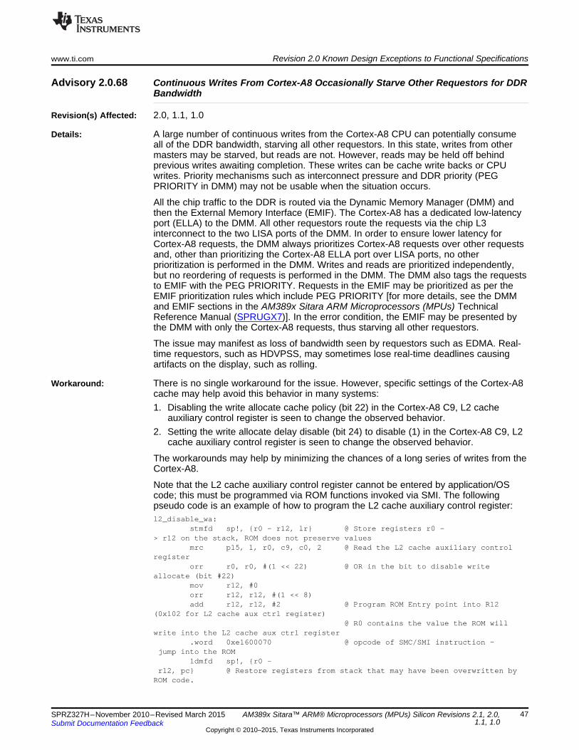
www.ti.com Revision 2.0 Known Design Exceptions to Functional Specifications
Advisory 2.0.68 Continuous Writes From Cortex-A8 Occasionally Starve Other Requestors for DDRBandwidth
Revision(s) Affected: 2.0, 1.1, 1.0
Details: A large number of continuous writes from the Cortex-A8 CPU can potentially consumeall of the DDR bandwidth, starving all other requestors. In this state, writes from othermasters may be starved, but reads are not. However, reads may be held off behindprevious writes awaiting completion. These writes can be cache write backs or CPUwrites. Priority mechanisms such as interconnect pressure and DDR priority (PEGPRIORITY in DMM) may not be usable when the situation occurs.
All the chip traffic to the DDR is routed via the Dynamic Memory Manager (DMM) andthen the External Memory Interface (EMIF). The Cortex-A8 has a dedicated low-latencyport (ELLA) to the DMM. All other requestors route the requests via the chip L3interconnect to the two LISA ports of the DMM. In order to ensure lower latency forCortex-A8 requests, the DMM always prioritizes Cortex-A8 requests over other requestsand, other than prioritizing the Cortex-A8 ELLA port over LISA ports, no otherprioritization is performed in the DMM. Writes and reads are prioritized independently,but no reordering of requests is performed in the DMM. The DMM also tags the requeststo EMIF with the PEG PRIORITY. Requests in the EMIF may be prioritized as per theEMIF prioritization rules which include PEG PRIORITY [for more details, see the DMMand EMIF sections in the AM389x Sitara ARM Microprocessors (MPUs) TechnicalReference Manual (SPRUGX7)]. In the error condition, the EMIF may be presented bythe DMM with only the Cortex-A8 requests, thus starving all other requestors.
The issue may manifest as loss of bandwidth seen by requestors such as EDMA. Real-time requestors, such as HDVPSS, may sometimes lose real-time deadlines causingartifacts on the display, such as rolling.
Workaround: There is no single workaround for the issue. However, specific settings of the Cortex-A8cache may help avoid this behavior in many systems:1. Disabling the write allocate cache policy (bit 22) in the Cortex-A8 C9, L2 cache
auxiliary control register is seen to change the observed behavior.2. Setting the write allocate delay disable (bit 24) to disable (1) in the Cortex-A8 C9, L2
cache auxiliary control register is seen to change the observed behavior.
The workarounds may help by minimizing the chances of a long series of writes from theCortex-A8.
Note that the L2 cache auxiliary control register cannot be entered by application/OScode; this must be programmed via ROM functions invoked via SMI. The followingpseudo code is an example of how to program the L2 cache auxiliary control register:l2_disable_wa:
stmfd sp!, r0 - r12, lr @ Store registers r0 -> r12 on the stack, ROM does not preserve values
mrc p15, 1, r0, c9, c0, 2 @ Read the L2 cache auxiliary controlregister
orr r0, r0, #(1 << 22) @ OR in the bit to disable writeallocate (bit #22)
mov r12, #0orr r12, r12, #(1 << 8)add r12, r12, #2 @ Program ROM Entry point into R12
(0x102 for L2 cache aux ctrl register)@ R0 contains the value the ROM will
write into the L2 cache aux ctrl register.word 0xe1600070 @ opcode of SMC/SMI instruction -
jump into the ROMldmfd sp!, r0 -
r12, pc @ Restore registers from stack that may have been overwritten byROM code.
47SPRZ327H–November 2010–Revised March 2015 AM389x Sitara™ ARM® Microprocessors (MPUs) Silicon Revisions 2.1, 2.0,1.1, 1.0Submit Documentation Feedback
Copyright © 2010–2015, Texas Instruments Incorporated
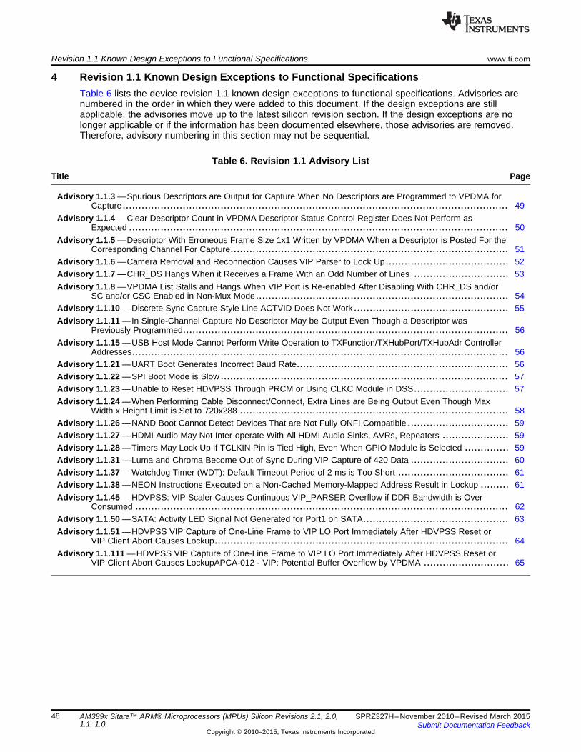
Revision 1.1 Known Design Exceptions to Functional Specifications www.ti.com
4 Revision 1.1 Known Design Exceptions to Functional SpecificationsTable 6 lists the device revision 1.1 known design exceptions to functional specifications. Advisories arenumbered in the order in which they were added to this document. If the design exceptions are stillapplicable, the advisories move up to the latest silicon revision section. If the design exceptions are nolonger applicable or if the information has been documented elsewhere, those advisories are removed.Therefore, advisory numbering in this section may not be sequential.
Table 6. Revision 1.1 Advisory ListTitle ...................................................................................................................................... Page
Advisory 1.1.3 —Spurious Descriptors are Output for Capture When No Descriptors are Programmed to VPDMA forCapture.......................................................................................................................... 49
Advisory 1.1.4 —Clear Descriptor Count in VPDMA Descriptor Status Control Register Does Not Perform asExpected ........................................................................................................................ 50
Advisory 1.1.5 —Descriptor With Erroneous Frame Size 1x1 Written by VPDMA When a Descriptor is Posted For theCorresponding Channel For Capture........................................................................................ 51
Advisory 1.1.6 —Camera Removal and Reconnection Causes VIP Parser to Lock Up....................................... 52Advisory 1.1.7 —CHR_DS Hangs When it Receives a Frame With an Odd Number of Lines .............................. 53Advisory 1.1.8 —VPDMA List Stalls and Hangs When VIP Port is Re-enabled After Disabling With CHR_DS and/or
SC and/or CSC Enabled in Non-Mux Mode................................................................................ 54Advisory 1.1.10 —Discrete Sync Capture Style Line ACTVID Does Not Work ................................................. 55Advisory 1.1.11 —In Single-Channel Capture No Descriptor May be Output Even Though a Descriptor was
Previously Programmed....................................................................................................... 56Advisory 1.1.15 —USB Host Mode Cannot Perform Write Operation to TXFunction/TXHubPort/TXHubAdr Controller
Addresses....................................................................................................................... 56Advisory 1.1.21 —UART Boot Generates Incorrect Baud Rate................................................................... 56Advisory 1.1.22 —SPI Boot Mode is Slow ........................................................................................... 57Advisory 1.1.23 —Unable to Reset HDVPSS Through PRCM or Using CLKC Module in DSS.............................. 57Advisory 1.1.24 —When Performing Cable Disconnect/Connect, Extra Lines are Being Output Even Though Max
Width x Height Limit is Set to 720x288 ..................................................................................... 58Advisory 1.1.26 —NAND Boot Cannot Detect Devices That are Not Fully ONFI Compatible ................................ 59Advisory 1.1.27 —HDMI Audio May Not Inter-operate With All HDMI Audio Sinks, AVRs, Repeaters ..................... 59Advisory 1.1.28 —Timers May Lock Up if TCLKIN Pin is Tied High, Even When GPIO Module is Selected .............. 59Advisory 1.1.31 —Luma and Chroma Become Out of Sync During VIP Capture of 420 Data ............................... 60Advisory 1.1.37 —Watchdog Timer (WDT): Default Timeout Period of 2 ms is Too Short ................................... 61Advisory 1.1.38 —NEON Instructions Executed on a Non-Cached Memory-Mapped Address Result in Lockup ......... 61Advisory 1.1.45 —HDVPSS: VIP Scaler Causes Continuous VIP_PARSER Overflow if DDR Bandwidth is Over
Consumed ...................................................................................................................... 62Advisory 1.1.50 —SATA: Activity LED Signal Not Generated for Port1 on SATA.............................................. 63Advisory 1.1.51 —HDVPSS VIP Capture of One-Line Frame to VIP LO Port Immediately After HDVPSS Reset or
VIP Client Abort Causes Lockup............................................................................................. 64Advisory 1.1.111 —HDVPSS VIP Capture of One-Line Frame to VIP LO Port Immediately After HDVPSS Reset or
VIP Client Abort Causes LockupAPCA-012 - VIP: Potential Buffer Overflow by VPDMA ........................... 65
48 AM389x Sitara™ ARM® Microprocessors (MPUs) Silicon Revisions 2.1, 2.0, SPRZ327H–November 2010–Revised March 20151.1, 1.0 Submit Documentation Feedback
Copyright © 2010–2015, Texas Instruments Incorporated

www.ti.com Revision 1.1 Known Design Exceptions to Functional Specifications
Advisory 1.1.3 Spurious Descriptors are Output for Capture When No Descriptors areProgrammed to VPDMA for Capture
Revision(s) Affected: 1.1, 1.0
Details: The Capture driver works as follows:• A list is programmed with two data descriptors for every capture channel.• When a frame for given channel is captured, the frame data goes to the buffer
address programmed in the descriptor and the programmed descriptor is written backto a specific memory location.
• The software then checks the specific memory location and, for every descriptor thatis written in this memory location, it re-programs a new data descriptor.
When software does not program a descriptor, the expectation is that any new framedata arriving for that channel should be dropped and when software does not program adescriptor, there should be no descriptor output to the memory.
However when the software does not program a descriptor for a channel, the new framedata gets dropped since there is no descriptor and, therefore, no buffer address tooutput this data. But, the VPDMA generates a spurious descriptor and writes it tomemory.
The spurious descriptor that gets written out has the following properties:• The width x height reported in the descriptor is 1x1.• The buffer address in the descriptor is same as the last received descriptor.
Workaround:1. Ensure that spurious descriptors do not occur; i.e., make sure a capture VPDMA
channel is never starved of descriptors. A capture VPDMA channel can be starved ofdescriptors in the following scenarios:• When the CPU is halted due to breakpoints.• When the CPU is halted due to a Code Composer Studio (CCStudio) printf.• When a high-priority task or ISR continuously consumes CPU MHz for more than
1 frame or field interval.2. Thus, once a capture is started, the software should not perform any CCStudio printf
(the software can perform a UART printf since the UART printf does not block theCPU).• Do not set any breakpoints.• The capture driver thread should be the highest priority.
3. If, after the above, spurious descriptors (that meet the above-described properties;i.e., 1x1 size and buffer address equals previously received descriptor bufferaddress), do not re-submit a new descriptor for this received descriptor since it is aspurious descriptor.
49SPRZ327H–November 2010–Revised March 2015 AM389x Sitara™ ARM® Microprocessors (MPUs) Silicon Revisions 2.1, 2.0,1.1, 1.0Submit Documentation Feedback
Copyright © 2010–2015, Texas Instruments Incorporated

Revision 1.1 Known Design Exceptions to Functional Specifications www.ti.com
Advisory 1.1.4 Clear Descriptor Count in VPDMA Descriptor Status Control Register Does NotPerform as Expected
Revision(s) Affected: 1.1, 1.0
Details: The Capture driver working mechanism is briefly explained in Advisory 1.1.3. In addition:• Every few milliseconds, the capture driver software:
– Examines this memory location for received descriptors.– Replaces the memory location with new descriptors.– Re-submits the new list of descriptors to the VPDMA.
• While capture is checking the received descriptors, new descriptors could begenerated and, in order to make sure no descriptors output by VPDMA are missed,the capture driver sets the clear descriptor count bit in the VPDMA Descriptor StatusControl register.
• This bit performs the following:– Switches the descriptor writing to a new memory location.– Tells the software, via the last descriptors written field in the Descriptor Status
Control register, how many descriptors were received at the instant the cleardescriptor count bit was set.
However, when the clear descriptor count bit is set, sometimes some descriptors werenever written to memory. Due to this issue, the software does not replace thosedescriptors causing frame-rate drops for those channels.
Workaround:• Do not use the clear descriptor count bit. Instead, use the Current Descriptor register
in the VPDMA to keep track of how many descriptors were written since last check.• The Descriptors Top and Descriptors Bottom registers are programmed to write the
received descriptors in a circular manner in the buffer that starts at Descriptors Topand ends at Descriptors Bottom.
• The descriptor received at any given time is the current descriptor (the value of thecurrent descriptor in the previous check). The software takes care to handlewraparound when reading descriptors in a circular manner.
50 AM389x Sitara™ ARM® Microprocessors (MPUs) Silicon Revisions 2.1, 2.0, SPRZ327H–November 2010–Revised March 20151.1, 1.0 Submit Documentation Feedback
Copyright © 2010–2015, Texas Instruments Incorporated

www.ti.com Revision 1.1 Known Design Exceptions to Functional Specifications
Advisory 1.1.5 Descriptor With Erroneous Frame Size 1x1 Written by VPDMA When a Descriptoris Posted For the Corresponding Channel For Capture
Revision(s) Affected: 1.1, 1.0
Details: The Capture driver working mechanism is briefly explained in Advisory 1.1.3.
Sometimes, the VPDMA outputs descriptors that report the incorrect frame size 1x1even though the descriptors were programmed to the VPDMA. Here the frame data,itself, is written to the correct programmed memory address.
The erroneous descriptor that gets written out has the following properties:• The width x height reported in the descriptor is 1x1.• The buffer address in the descriptor is the correct buffer address for the current
frame.
Workaround: Detect this condition based on the above described properties of the descriptor andreplace the received descriptors as usual.
51SPRZ327H–November 2010–Revised March 2015 AM389x Sitara™ ARM® Microprocessors (MPUs) Silicon Revisions 2.1, 2.0,1.1, 1.0Submit Documentation Feedback
Copyright © 2010–2015, Texas Instruments Incorporated

Revision 1.1 Known Design Exceptions to Functional Specifications www.ti.com
Advisory 1.1.6 Camera Removal and Reconnection Causes VIP Parser to Lock Up
Revision(s) Affected: 1.1, 1.0
Details: If the camera is removed and reconnected while capture is running, then the VIP parserlocks up and causes the capture driver to hang up.
This issue occurs because when the camera is removed or reconnected, the F-bit andV-bit transitions are not consistent. For example, the V-bit transitions to a new frameevery few lines and, thus, causes many short frames to be received at the VIP portwhich causes the VIP port to lock.
In the multichannel case, the internal hardware FIFO that is used for capture is commonfor all channels at a given port. So if one channel is removed or reconnected, the wholeFIFO at the VIP port locks up and causes all channels at that port to lock up.
Workaround: For multichannel case, with TVP5158:• Operate TVP5158 in pixel-mux mode.• Load TVP5158 firmware patch v2.1.21 or above.• Disable fast lock detect:
– TVP5158 REG_FV_CTRL = 0x06.• Disable auto-switch mode; i.e., be in force NTSC or force PAL mode:
– TVP5158 REG_VID_STD_SELECT = 0x1 (NTSC) or 0x2 (PAL).• Always decode F and V bits from line count (TVP5146 compatible):
– TVP5158 REG_FV_DEC_CTRL = 0x03.• TVP5158 REG_OP_MODE_CTRL = 0.
The above workaround does not work with the TVP5158 in line mux mode and is notspecified to work with non-TVP5158 multichannel video decoders.
For single-channel case:• The software should detect cable removal by querying the external video decoder.• When sync loss is detected, the VIP port should be stopped.• When the cable is reconnected, the software should:
– Perform a VIP reset sequence, as mentioned in Advisory 1.1.8.– Start the VIP port.
52 AM389x Sitara™ ARM® Microprocessors (MPUs) Silicon Revisions 2.1, 2.0, SPRZ327H–November 2010–Revised March 20151.1, 1.0 Submit Documentation Feedback
Copyright © 2010–2015, Texas Instruments Incorporated

www.ti.com Revision 1.1 Known Design Exceptions to Functional Specifications
Advisory 1.1.7 CHR_DS Hangs When it Receives a Frame With an Odd Number of Lines
Revision(s) Affected: 1.1, 1.0
Details: When CHR_DS receives a frame with an odd number of lines and then an EOF signal, ithangs up waiting for the even numbered line to arrive.
When using CHR_DS in memory-to-memory mode this is not an issue, since usersoftware can ensure that CHR_DS always receives an even number of lines. However,when CHR_DS is used in capture path, this cannot be ensured.
Workaround: To resolve this issue:1. Ensure that the external video decoder always gives even number of lines.2. If Step 1 cannot be ensured, then use the SC to trim the input to an even number of
lines and then send the lines to CHR_DS.3. If Steps 1 and 2 cannot be performed (because SC is used in some other path), then
do not use CHR_DS and use either YUV422S or YUV422I output mode.
If CHR_DS locks up, you can recover it by using the VIP reset sequence mentioned inAdvisory 1.1.8.
This issue could also occur when the cable is disconnected. In this situation, refer to theworkaround in Advisory 1.1.6 for single-channel case.
53SPRZ327H–November 2010–Revised March 2015 AM389x Sitara™ ARM® Microprocessors (MPUs) Silicon Revisions 2.1, 2.0,1.1, 1.0Submit Documentation Feedback
Copyright © 2010–2015, Texas Instruments Incorporated

Revision 1.1 Known Design Exceptions to Functional Specifications www.ti.com
Advisory 1.1.8 VPDMA List Stalls and Hangs When VIP Port is Re-enabled After Disabling WithCHR_DS and/or SC and/or CSC Enabled in Non-Mux Mode
Revision(s) Affected: 1.1, 1.0
Details: When capturing in non-mux mode with CHR_DS and/or SC and/or CSC enabled in thecapture path, the capture runs correctly for the first run.
If capture is stopped by disabling the VIP port and then capture is started again withCHR_DS and/or SC and/or CSC in the path, then the VPDMA list for capture stalls andhangs up, causing the capture driver to hang up as well.
This is applicable for both embedded-sync mode as well as discrete-sync mode, exceptthat in discrete-sync mode the hang occurs on the first run.
Workaround: For 8-/16-bit, YUV422 embedded-sync mode:1. Disable the VIP port.2. Assert VIP reset in the HDVPSS CLKC register.3. Assert the Async FIFO reset in the VIP parser register.4. Make a list of abort descriptors for all VIP VPDMA channels.5. Post this list and wait for it to complete.6. De-assert the VIP reset in the HDVPSS CLKC register.7. De-assert the Async FIFO reset in the VIP parser register.
For 8/16/24-bit discrete-sync mode, in addition to the above workaround, the followingadditional sequence of descriptor programming must be performed in order to usediscrete-sync mode with CSC, SC, and CHR_DS. For the first list that is posted whendiscrete-sync mode is started, perform the following:1. To the list, add a data descriptor such that video data from the VIP parser goes
directly to VPDMA, with DROP_DATA = 1, WRITE_DESC = 0 in the data descriptor(e.g., PORTB_RGB VPDMA channel).
2. To the list, add a sync-on-client descriptor with the VPDMA channel as the one set inthe above data descriptor (e.g., PORTB_RGB VPDMA channel and event = EOF).
3. To the list, add a configuration descriptor with the actual required VIP mux settingswhich enables CHR_DS, CSC, and SC.
4. To the list, add the actual data descriptors as before (e.g., YUV420 output datadescriptors).
5. Program the VIP mux such that data from the VIP parser goes directly to VPDMA.6. Enable the VIP port so that data starts flowing.7. Post the list that is prepared above.8. The list stalls until it receives an end of frame. In the blanking period, the
configuration descriptor programs the mux to use the CSC, SC, and CHR_DS andthen capture continues as usual.
54 AM389x Sitara™ ARM® Microprocessors (MPUs) Silicon Revisions 2.1, 2.0, SPRZ327H–November 2010–Revised March 20151.1, 1.0 Submit Documentation Feedback
Copyright © 2010–2015, Texas Instruments Incorporated

Hsync
Vsync
ACTVID
VerticalBlanking
Active datawritten tomemory
www.ti.com Revision 1.1 Known Design Exceptions to Functional Specifications
Advisory 1.1.10 Discrete Sync Capture Style Line ACTVID Does Not Work
Revision(s) Affected: 1.1, 1.0
Details: The VIP port supports a discrete sync capture mode where the ACTVID signal is used todetermine the active region of the video and then the VPDMA writes this active videoframe to memory. However, with some external video decoders, this mode does notwork by default.
Workaround: The VIP parser requires that the ACTVID signal is active for all lines of the incomingdata, including the vertical blanking region. The vertical blanking region, itself, is notwritten to memory by the VPDMA. Figure 3 illustrates this.
Figure 3. ACTVID Signal Active for All Lines of Incoming Data
55SPRZ327H–November 2010–Revised March 2015 AM389x Sitara™ ARM® Microprocessors (MPUs) Silicon Revisions 2.1, 2.0,1.1, 1.0Submit Documentation Feedback
Copyright © 2010–2015, Texas Instruments Incorporated

Revision 1.1 Known Design Exceptions to Functional Specifications www.ti.com
Advisory 1.1.11 In Single-Channel Capture No Descriptor May be Output Even Though a Descriptorwas Previously Programmed
Revision(s) Affected: 1.1, 1.0
Details: The Capture driver working mechanism is briefly explained in Advisory 1.1.3.
In single-channel non-mux mode, sometimes, even though a descriptor is programmed,it is not output to memory even though the frame itself is captured. Due to this issue, thesoftware does not reprogram a descriptor for that VIP port and the capture frame ratedrops.
Workaround: Program a dummy descriptor on one of the VPDMA MULT_SRCx channels for the port,even though no data is received on that channel. This always causes the VPDMA tooutput a descriptor to memory for the channel on which data is being received. In thiscase, Advisory 1.1.5 is also applicable.
Advisory 1.1.15 USB Host Mode Cannot Perform Write Operation toTXFunction/TXHubPort/TXHubAdr Controller Addresses
Revision(s) Affected: 1.1, 1.0
Details: The USB controller does not support devices connected through a hub when operatingas USB host. Due to this, writing to the TXHubPort/TXHubAdr results in the write beingignored.
Workaround: There is no workaround for this issue.
Advisory 1.1.21 UART Boot Generates Incorrect Baud Rate
Revision(s) Affected: 1.1, 1.0
Details: The UART boot mode is not functional on the device due to generating incorrect baudrate. This occurs because the ROM code puts the DDR PLL in bypass instead of lockingit. As a result, the UART module gets an input clock of 13.5 MHz. Therefore, the UARToperates at 32452 baud. The expected baud rate in 115200.
Workaround: Use a host that can support the generated baud rate (32452 baud).
NOTE: Some PCs do not allow a non-standard baud rate to be set. On suchPCs, there is no workaround.
56 AM389x Sitara™ ARM® Microprocessors (MPUs) Silicon Revisions 2.1, 2.0, SPRZ327H–November 2010–Revised March 20151.1, 1.0 Submit Documentation Feedback
Copyright © 2010–2015, Texas Instruments Incorporated

www.ti.com Revision 1.1 Known Design Exceptions to Functional Specifications
Advisory 1.1.22 SPI Boot Mode is Slow
Revision(s) Affected: 1.1, 1.0
Details: SPI boot mode works at a lower speed than specified.
Workaround: There is no workaround for this issue.
Advisory 1.1.23 Unable to Reset HDVPSS Through PRCM or Using CLKC Module in DSS
Revision(s) Affected: 1.1
Details: The VPDMA is not being reset by the CLKC module although the CLKC module isresetting other modules.
Workaround: There is no workaround for this issue.
57SPRZ327H–November 2010–Revised March 2015 AM389x Sitara™ ARM® Microprocessors (MPUs) Silicon Revisions 2.1, 2.0,1.1, 1.0Submit Documentation Feedback
Copyright © 2010–2015, Texas Instruments Incorporated

Revision 1.1 Known Design Exceptions to Functional Specifications www.ti.com
Advisory 1.1.24 When Performing Cable Disconnect/Connect, Extra Lines are Being Output EvenThough Max Width x Height Limit is Set to 720x288
Revision(s) Affected: 1.1
Details: When performing cable disconnect/reconnect with capture, the frames being sent by thevideo decoder can be of non-fixed size. If the incoming frame height is greater than 2x ofthe maximum expected frame height that is set in the VPDMA, then the VPDMAparameter to apply the max frame height does not take effect. This results in extra linesoverflowing the allocate buffer in DDR memory.
This issue affects modes of capture, such as non-multiplexed mode, multiplexed modes,discrete sync mode, embedded sync mode, and 8/16/24-bit capture modes.
ExamplesIf the VPDMA max height is set to 288 and an incoming frame of height 500 lines isreceived:
Since 500 < 2 x 288, the extra (500 - 288 = 212) lines do not overflow the allocatedmemory buffer in DDR memory.
If the VPDMA max height is set to 288 and an incoming frame of height 600 lines isreceive:
Since 600 > 2 x 288, the extra (600 - (2 x 288) = 24) lines overflow the allocatedmemory buffer in DDR memory.
If the VPDMA max height is set to 288 and an incoming frame of height 1000 lines isreceive:
Since 1000 > 2 x 288, the extra (1000 - (2 x 288) = 424) lines overflow the allocatedmemory buffer in DDR memory.
Workaround:1. Ensure that, in no circumstance, the video decoder outputs > 2x max expected
height.2. If option 1 cannot be ensured, then, in the case of non-multiplexed capture, use SC
in the capture path to crop the height.3. If workaround 1 cannot be ensured and workaround 2 does not apply, then
characterize the max number of lines that can be received from the video decoder bysetting max height as unlimited and allocate extra buffer space in memory.
In TVP5158, specifically, it has been observed that frames of max height up to 2100lines have been received; therefore, it is important to ensure that when a channel bufferis allocated, an extra 2100 lines are allocated at the end of the buffer.
ExampleFor a given channel, 6 buffers of size 720x288x2 bytes may be allocated; therefore, acontiguous memory of 720x288x2x6 + 720x2100x2 should be allocated. When memoryis allocated this way, then during the cable disconnect/connect when the channel bufferoverflows, it either overflows into its own channel buffer memory or in the extra 2100lines of the buffer that was allocated at the end of the sixth buffer. This ensures thatother channel data and/or code sections are not corrupted. For a 16-channel TVP5158system, this means an extra 720x2100x2x16 bytes = 47MB of space is needed toaccommodate the extra lines.
These workarounds need to be applied for other video decoders as well.
Note that this extra DDR buffer allocation needs to be handled in the application. TheHDVPSS drivers do not allocate any buffer memory.
58 AM389x Sitara™ ARM® Microprocessors (MPUs) Silicon Revisions 2.1, 2.0, SPRZ327H–November 2010–Revised March 20151.1, 1.0 Submit Documentation Feedback
Copyright © 2010–2015, Texas Instruments Incorporated

www.ti.com Revision 1.1 Known Design Exceptions to Functional Specifications
Advisory 1.1.26 NAND Boot Cannot Detect Devices That are Not Fully ONFI Compatible
Revision(s) Affected: 1.1, 1.0
Details: Some NAND flashes are not fully ONFI compatible. Specifically, in these flashes, theparameter pages do not contain the ONFI signature and the contents of the parameterpage is not valid. This results in the following:• NAND flash geometry is identified incorrectly.• NAND boot fails.
Workaround: Choose a NAND flash that is fully ONFI compatible (i.e., the parameter page has anONFI signature) or use NAND I2C boot, where the NAND geometry is read from an I2CEEPROM.
Advisory 1.1.27 HDMI Audio May Not Inter-operate With All HDMI Audio Sinks, AVRs, Repeaters
Revision(s) Affected: 1.1, 1.0
Details: The HDMI sends excessive ACR packets which leads to inter-operation issues and toCTS interval compliancy failures. This may cause the device HDMI audio not to inter-operate with all types of HDMI receivers, AVRs or repeaters.
Workaround: Currently, there is no workaround for this issue.
Advisory 1.1.28 Timers May Lock Up if TCLKIN Pin is Tied High, Even When GPIO Module isSelected
Revision(s) Affected: 1.1, 1.0
Details: Timers may sometimes lock up if the TCLKIN pin is tied high, even when the GPIOmodule is selected. If the TCLKIN pin is tied high (is not toggling/does not come to 0),TIMERs may lock up and may not be usable. This happens even if the TCLKIN pin is notselected by the pin control registers. The locks may be seen randomly on power up; i.e.,it may be observed that some timers lock up and some do not.
Workaround: The TCLKIN pin must be driven to 0 on the board.
59SPRZ327H–November 2010–Revised March 2015 AM389x Sitara™ ARM® Microprocessors (MPUs) Silicon Revisions 2.1, 2.0,1.1, 1.0Submit Documentation Feedback
Copyright © 2010–2015, Texas Instruments Incorporated

Revision 1.1 Known Design Exceptions to Functional Specifications www.ti.com
Advisory 1.1.31 Luma and Chroma Become Out of Sync During VIP Capture of 420 Data
Revision(s) Affected: 1.1
Details: When capturing a video frame using the HDVPSS VIP port, a data descriptor isprogrammed to the VPDMA. For 420 data, two data descriptors must be programmed forevery frame that needs to be captured; one for the luma channel and one for the chromachannel. Occasionally, even though a data descriptor is programmed to the VPDMA, theframe data and descriptor for either luma or chroma may not get written to the DDRmemory. This results in either luma or chroma data for the same frame to become out ofsync with each other. This is seen in 420 capture, single-channel capture modesinvolving the HDVPSS VIP.
The frequency of occurrence of this issue averages about one frame, of either luma orchroma, missed per hour. The frequency of this issue depends on the amount of loadingthat is present in the HDVPSS.
Workaround: The driver checks for both luma and chroma writing by VPDMA to DDR and returns thebuffer only when both are written. If the VPDMA has not written one of the luma orchroma data, the driver resubmits the descriptor to VPDMA after a few milliseconds.Most of the time, the VPDMA succeeds on resubmission.
If the second submission also fails, the driver clears the VPDMA channels in that captureinstance using abort descriptors and the VPDMA recovers after that. This can cause,worst case, one frame loss versus 2-3 frames if a full VIP reset is used.
60 AM389x Sitara™ ARM® Microprocessors (MPUs) Silicon Revisions 2.1, 2.0, SPRZ327H–November 2010–Revised March 20151.1, 1.0 Submit Documentation Feedback
Copyright © 2010–2015, Texas Instruments Incorporated

www.ti.com Revision 1.1 Known Design Exceptions to Functional Specifications
Advisory 1.1.37 Watchdog Timer (WDT): Default Timeout Period of 2 ms is Too Short
Revision(s) Affected: 1.1, 1.0
Details: As per device specification, the WDT default timeout is 2 ms. The ROM code that runsafter a warm reset takes longer than 2 ms to execute. The WDT is disabled, by default,at reset time and the ROM code does not use the WDT functionality. Enabling the WDTcan be done by writing to the control module register so that it is made available to usein the application. Once the WDT is enabled, the Timer starts ticking and before itreaches the 2-ms timeout period, the application software can modify the timeout value.However, once the WDT expires and issues a warm reset to the system, the WDTcounter starts again with default timeout value of 2 ms. The time application softwaregains control only after the ROM execution. By this time, the WDT expires because the2-ms timeout period is too short. This results in repeated WDT timeout resets within theinterval of 2 ms. Application software cannot gain the system control after the first WDTtimeout triggered warm reset. Regardless of any timeout value that may have beenprovided in software, the timeout value always reverts to 2 ms after a warm reset.
Workaround: A hardware workaround is to connect the WDT reset out to the POR input of the device.This loop on the board ensures that every time the WDT sends out a reset, the devicereceives a POR reset, which keeps the WDT in a frozen state. Application code canenable the WDT.
Advisory 1.1.38 NEON Instructions Executed on a Non-Cached Memory-Mapped Address Result inLockup
Revision(s) Affected: 1.1, 1.0
Details: The AXI2OCP bridge causes device lockup when a NEON instruction is issued with loadaddress targeting area of virtual memory mapped as strongly ordered or device type inthe MMU. Cortex-A8 NEON™ instructions resulting in an ARLEN=0xf executed on amemory-mapped address that is not in the cache causes a hang condition. The AXIprotocol (v1.0) specification allows the burst length, ARLEN[3:0], to be up to 16 datatransfers long. The counter in AXI2OCP that maintains the count of the narrow bursttransactions should compare five bits to properly track the maximum case of ARLEN[3:0]= 4’h0Fh (i.e.,16 transactions), but the comparator looks at the four LSBs instead of allfive bits. This effectively leads the AXI2OCP to incorrectly signal the read responsecompletion. The RLAST is never asserted and, therefore, the read burst is never cleanlycompleted. Once the AXI2OCP accepts the maximum number of outstanding requestsfor the ARID in question, the AXI bus hangs.
Workaround: Any of the following workarounds is an acceptable solution:• Disable the compiler from using NEON instructions. The assumption is that majority
of the software that uses NEON instructions is either hand-coded or from intrinsiclibrary functions. Auto-detection of vectorizable code from the compiler is lessprevalent.
• Avoid NEON SIMD element load instructions (VLD: i.e., VLDn.<size> D0-D3 [RX])to strongly ordered, device, or non-cacheable memory.
• NEON SIMD element load data accesses, if used, should only be done to data that isspecified to exist in the A8 L1 or L2 caches, via use of the PLD instruction. Thiswould avoid having to require any AXI read channel transactions to load data.
61SPRZ327H–November 2010–Revised March 2015 AM389x Sitara™ ARM® Microprocessors (MPUs) Silicon Revisions 2.1, 2.0,1.1, 1.0Submit Documentation Feedback
Copyright © 2010–2015, Texas Instruments Incorporated

Revision 1.1 Known Design Exceptions to Functional Specifications www.ti.com
Advisory 1.1.45 HDVPSS: VIP Scaler Causes Continuous VIP_PARSER Overflow if DDR Bandwidthis Over Consumed
Revision(s) Affected: 1.1, 1.0
Details: This only occurs in single-channel capture cases where the VIP scaler is being used.
If the HDVPSS VIP scaler is being used to downscale external video inline with theVIP_PARSER and there is a momentary DDR bandwidth reduction that causes anoverflow of the VIP_PARSER, the VIP scaler becomes out of sync with the externalvideo, resulting in continuous overflows, garbled resulting video, but no lockups.
The VIP scaler is programmed with an input height/width and output height/width. If theactual input does not match the programmed input values, the design still tries to createthe programmed output height/width. While it is "making up" the output for the missinginput, it stops requesting data from upstream.
If the 4k-byte buffer for holding captured video data in the HDVPSS VPDMA becomesfull due to DDR bandwidth restrictions (cannot get data out fast enough), this causes anoverflow at the VIP_PARSER. This results in the VIP_PARSER dropping lines/pixelswhile it is in the overflow state. This results in a frame going to the VIP scaler which issmaller than the programmed size.
The VIP scaler detects the input is the wrong size, stops requesting data, and startsmaking up data for what is missing. External video data continues to come in, butbecause the VIP scaler has stopped requesting data, it causes another overflow of theVIP_PARSER.
While the VIP scaler is making up the missing data, it is running as fast as it can, andbecomes out of sync with external video coming into the VIP_PARSER. The extraoverflow it creates makes the next frame lose lines/pixels too, and this continues on.
The overflow could cause distortions on the data captured by the VIP port.
Workaround: Reset the VIP port by following this procedure:1. Disable the VIP port.2. Assert VIP reset in the HDVPSS CLKC register.3. Assert the Async FIFO reset in the VIP parser register.4. Make a list of abort descriptors for all VIP VPDMA channels.5. Post this list and wait for it to complete.6. De-assert the VIP reset in the HDVPSS CLKC register.7. De-assert the Async FIFO reset in the VIP parser register.8. Start the VIP capture port.
62 AM389x Sitara™ ARM® Microprocessors (MPUs) Silicon Revisions 2.1, 2.0, SPRZ327H–November 2010–Revised March 20151.1, 1.0 Submit Documentation Feedback
Copyright © 2010–2015, Texas Instruments Incorporated

GP1[31]/SATA_ACT1_LED
J33
GP1[30]/SATA_ACT0_LED
J32
Unconnected
SATA Subsystem
ACT0_LED
ACT1_LED
Revision 1.x
GP1[31]/SATA_ACT0_LED
J33
GP1[30]/SATA_ACT1_LED
J32
SATA Subsystem
ACT0_LED
ACT1_LED
Revision 2.0
www.ti.com Revision 1.1 Known Design Exceptions to Functional Specifications
Advisory 1.1.50 SATA: Activity LED Signal Not Generated for Port1 on SATA
Revision(s) Affected: 1.1, 1.0
Details: Due to a connectivity issue, SATA_ACT0_LED and SATA_ACT1_LED ports are mappedto the internal Port0 of the device SATA module. The SATA Activity LED signal is notgenerated for Port1.
Workaround: There is no workaround for this issue.
This issue is corrected on revision 2.0, but with the output pins reversed.SATA_ACT1_LED is mapped to pin J32 and SATA_ACT0_LED to pin J33 (seeFigure 4).
Figure 4. SATA Activity LED Connectivity
63SPRZ327H–November 2010–Revised March 2015 AM389x Sitara™ ARM® Microprocessors (MPUs) Silicon Revisions 2.1, 2.0,1.1, 1.0Submit Documentation Feedback
Copyright © 2010–2015, Texas Instruments Incorporated

Revision 1.1 Known Design Exceptions to Functional Specifications www.ti.com
Advisory 1.1.51 HDVPSS VIP Capture of One-Line Frame to VIP LO Port Immediately After HDVPSSReset or VIP Client Abort Causes Lockup
Revision(s) Affected: 1.1, 1.0
Details: As data is captured from the HDVPSS VIP to the VPDMA, it is broken into 128-bytesegments for transfer to DDR. At the end of each line a remainder for the line iscalculated, sent as a DDR transfer, and then the address incremented by the line stride.The VPDMA VIP LO port clients incorrectly send the previous line's remainder as thesize of the last transfer of a line instead of the current line. If the line captured by the VIPLO port clients is one line, it uses the last remainder calculated from the previous frame.
If a VIP LO port client abort is performed, or immediately after reset, and a one-lineframe goes to the VIP LO port clients as the first or second frame, the reset value of theremainder calculation registers is sent as the burst, and the reset value is 0. Theremainder registers are ping-ponged and there are two per channel. This can occur inmultichannel or single-channel configurations.
In the multichannel case, any camera source that sends a one-line frame can cause thisto occur.
In a single-channel configuration, the VIP LO port captures luma and chromacomponents separately. If either component has one line immediately after reset, thiscan occur. This means if the CHR_DS module is used to convert 422 data to 420, a two-or three-line captured frame can also cause this condition, because the chromacomponent for a two- or three-line frame is downsampled to one line.
Workaround: For single-channel cases, the HDVPSS VIP scaler can be used to keep single lineframes from reaching the VPDMA. The VIP scaler always generates the output size it isprogrammed to, regardless of the input. So long as the scaler is not set to output oneline (or two or three if the output is going to be 420), this problem does not occur.
For multichannel cases, the source creating the multichannel input must ensure thatone-line frames cannot come in. Occassionally, and only during connect/disconnectwhen a line or width limit feature is not used, any memory areas can be overwritten(memory corruption/memory flashthrough).
64 AM389x Sitara™ ARM® Microprocessors (MPUs) Silicon Revisions 2.1, 2.0, SPRZ327H–November 2010–Revised March 20151.1, 1.0 Submit Documentation Feedback
Copyright © 2010–2015, Texas Instruments Incorporated

www.ti.com Revision 1.1 Known Design Exceptions to Functional Specifications
Advisory 1.1.111 HDVPSS VIP Capture of One-Line Frame to VIP LO Port Immediately After HDVPSSReset or VIP Client Abort Causes LockupAPCA-012 - VIP: Potential BufferOverflow by VPDMA
Revision(s) Affected: 1.1, 1.0
Details: VPDMA can accept two outbound descriptors – current and shadow descriptors. Thismeans the VPDMA can consume two buffers for capture operation.
When the number of descriptors with the VPDMA underflows (becomes 0 or only onedescriptor is provided to VPDMA) while capture is in progress, there is a corner conditionin the VPDMA which can sometimes generate 2 descriptors without the softwareproviding the descriptors to VPDMA.
The issue is related to how the VPDMA shifts data from the shadow register to thecurrent register. When using only one descriptor, it should always load into the currentdescriptor but there are cases where the descriptor would load into the current descriptorand the shadow descriptor. Hence extra descriptors are generated.
When this condition happens and if the VIP parser keeps capturing data, this can lead tocorruption of the previously provided buffers by the software because of the extragenerated descriptor.
Two types of corruption can occur:1. If the VIP parser generates the same size frame as previous frames, then the content
of the previous buffer will be overwritten by the VPDMA while the software owns thebuffer. This can corrupt the buffer within the limit of the buffer size.
2. If the VIP generates different size frames (as can happen in weak signal orconnect/disconnect cases), the VPDMA can corrupt the buffer content beyond thelimit of the allocated buffer (buffer overwrite).
To avoid this buffer overwrite and/or corruption, the software should adhere to the belowmentioned workaround.
Workaround: To overcome this buffer corruption the following workarounds are recommended.1. The software driver should ensure that the VPDMA descriptors don’t underflow by
giving new descriptors to VPDMA for every descriptor completed by VPDMA i.e. forevery frame captured.(a) Capture Start:
In case of starting the capture, the driver should always provide two descriptors tothe VPDMA and then enable the VIP parser.
(b) Capture in Progress:When capture is in progress, for every frame captured, the driver should provide anew descriptor to the VPDMA.If no new frames (buffers) are available for programming, then the driver can setthe drop data bit of the descriptor and provide a dummy buffer address. This willensure that VPDMA descriptor doesn’t underflow even when there are no buffersto program.
(c) Capture Stop:While stopping capture, the driver should abort all the current and shadowdescriptors for a particular channel by programming the abort channel descriptorto the VPDMA. This will ensure that the VPDMA will stop further data capture andsince the driver is not providing any more descriptors to the VPDMA, the alreadyprovided descriptors don’t get consumed and result in descriptor underflow.
2. To ensure that the VPDMA doesn’t overwrite the buffers beyond the expected framesize, VPDMA line limit feature of the descriptor can be used to limit the max amountof data that the VPDMA will capture.If the frame captured is less that the available limit sizes, then the software shouldallocate the buffer equal to the nearest max limit size.
65SPRZ327H–November 2010–Revised March 2015 AM389x Sitara™ ARM® Microprocessors (MPUs) Silicon Revisions 2.1, 2.0,1.1, 1.0Submit Documentation Feedback
Copyright © 2010–2015, Texas Instruments Incorporated

Revision 1.0 Known Design Exceptions to Functional Specifications www.ti.com
5 Revision 1.0 Known Design Exceptions to Functional SpecificationsTable 7 lists the device revision 1.0 known design exceptions to functional specifications. Advisories arenumbered in the order in which they were added to this document. If the design exceptions are stillapplicable, the advisories move up to the latest silicon revision section. If the design exceptions are nolonger applicable or if the information has been documented elsewhere, those advisories are removed.Therefore, advisory numbering in this section may not be sequential.
Table 7. Revision 1.0 Advisory ListTitle ...................................................................................................................................... Page
Advisory 1.0.9 —Noise Filter (NSF) Outputting Frames of 64x32 Though Input Data is of Larger Size .................... 67Advisory 1.0.14 —When Using HDMI Port, HD_VENC_D_CLK Needs to be Doubled for Normal Operation ............. 67
66 AM389x Sitara™ ARM® Microprocessors (MPUs) Silicon Revisions 2.1, 2.0, SPRZ327H–November 2010–Revised March 20151.1, 1.0 Submit Documentation Feedback
Copyright © 2010–2015, Texas Instruments Incorporated

www.ti.com Revision 1.0 Known Design Exceptions to Functional Specifications
Advisory 1.0.9 Noise Filter (NSF) Outputting Frames of 64x32 Though Input Data is of Larger Size
Revision(s) Affected: 1.0
Details: When the noise filter (NSF) is used along with capture and display after a few frames ofexecution, the NSF starts outputting frames of size 64x32, even though the input size islarger.
Workaround: Use the noise filter in external bypass mode.
Advisory 1.0.14 When Using HDMI Port, HD_VENC_D_CLK Needs to be Doubled for NormalOperation
Revision(s) Affected: 1.0
Details: HD VENC_D (DVO1) and HDMI should operate with the same pixel clock frequencysince HD VENC_D supplies the video and control signals for HDMI.
The pixel clock selector (pixel clock for HDMI and HD VENC_D 1X clock),HD_VENC_D_CLK1X_SELECT, always selects HD_VENC_D_CLK / 2. This ensuresthat HD_VENC_D_CLK is always divided by 2; e.g., if the desired display is a resolutionof 720p60, the HD_VENC_D_CLK would be 74.25 MHz. Since the pixel clock selectoralways selects HD_VENC_D_CLK / 2, the HDMI and HD VENC_D pixel clock would be37.125 MHz.
Workaround: Clock HD_VENC_D_CLK at twice the required pixel clock and configure HD VENC_D touse 1X input; e.g., in the above example HD_VENC_D_CLK should be clocked at 148.5MHz.
HDMI and HD VENC_D have been verified for HD_VENC_D_CLK input up to 297 MHzfor 1080p60 resolution.
67SPRZ327H–November 2010–Revised March 2015 AM389x Sitara™ ARM® Microprocessors (MPUs) Silicon Revisions 2.1, 2.0,1.1, 1.0Submit Documentation Feedback
Copyright © 2010–2015, Texas Instruments Incorporated

Revision History www.ti.com
Revision History
Changes from February 19, 2014 to March 6, 2015 (from G Revision (February 2014) to H Revision)...................... Page
• Global: Updated/Changed title of document to AM389x Sitara™ ARM® Microprocessors (MPUs) ........................... 4• Global: Updated/Changed the device-specific Data Manual (DM) references .................................................... 4• Global: Updated/Changed the device-specific Technical Reference Manual (TRM) references .............................. 4• Global: Updated/Changed the words "guarantee" and "guaranteed" to "ensure" or "ensured" or "specified", were
applicable. .................................................................................................................................. 4• Added "CVDD AVS Vmax operating range ..." bullet to Section 2.1.2, AVS Power Supply Requirements Usage Note.... 7• Updated/Changed CVDD nominal value from "1.10" to "1.05" V in Section 2.1.3, Initial Voltage Level Setting of CVDD
AVS Rail Power Supplies Usage Note ................................................................................................. 7• Added Section 2.1.4, PLL Programming Corrected to Operate Modules and Subsystems Within Rated Speed Without
Exceeding the Maximum VCO Limit Usage Note ..................................................................................... 8• Updated/Changed sentence structure in workaround Advisory 2.1.1, Error Interrupt for PCIe EP Mode Not Generated . 11• Moved Advisory 2.1.20, DDR3 Hardware Leveling Does Not Function Reliably................................................ 14• Updated/Changed Advisory 2.1.20, DDR3 Hardware Leveling Does Not Function Reliably .................................. 14• Updated/Changed Advisory 2.1.67, Ethernet Boot Mode Sends BOOTP Identifier Similar to DM814x ..................... 28• Updated/Changed Advisory 2.1.99, USB: CPU Gets Stale Receive Data From the Data Buffer Located in DDR
Memory.................................................................................................................................... 31• Updated/Changed Advisory 2.1.100, USB: In Generic RNDIS CPPI DMA Mode, Receive DMA may Flag Premature
Completion Under Certain Conditions ................................................................................................ 31• Updated/Changed Advisory 2.1.101, USB: Data May be Lost When USB Subsystem is Operating in DMA Mode and More
Than One Endpoint is Transferring Data ............................................................................................ 32• Updated/Changed Advisory 2.1.102, USB: DMA Hung up in Frequent Teardowns ............................................ 32• Added a Workaround to Advisory 2.1.103, USB: Missed PID and CRC Error Interrupt Causes.............................. 33• Updated/Changed Workaround Advisory 2.1.104, USB: CPU gets Premature TX Transfer Completion Interrupt ......... 33• Added Advisory 2.1.105, SATA: Gen2 lLnk Fails With Some of GEN3 Devices Interrupt ..................................... 34• Added Advisory 2.1.106, SDIO: SD_SDCD Pin Used as an GPIO Input Affects SDIO Operation .......................... 35• Added Advisory 2.1.107, McASP to EDMA Synchronization Level Event can be Lost ........................................ 36• Added Advisory 2.1.108, Maximum Operating Frequencies Reduced for Each Speed Grade Device ...................... 37• Deleted Revision 2.0 Advisories moved to Revision 2.1, duplicate ............................................................... 38• Added Advisory 1.1.111, HDVPSS VIP Capture of One-Line Frame to VIP LO Port Immediately After HDVPSS Reset or
VIP Client Abort Causes LockupAPCA-012 - VIP: Potential Buffer Overflow by VPDMA ..................................... 65
68 Revision History SPRZ327H–November 2010–Revised March 2015Submit Documentation Feedback
Copyright © 2010–2015, Texas Instruments Incorporated

IMPORTANT NOTICE
Texas Instruments Incorporated and its subsidiaries (TI) reserve the right to make corrections, enhancements, improvements and otherchanges to its semiconductor products and services per JESD46, latest issue, and to discontinue any product or service per JESD48, latestissue. Buyers should obtain the latest relevant information before placing orders and should verify that such information is current andcomplete. All semiconductor products (also referred to herein as “components”) are sold subject to TI’s terms and conditions of salesupplied at the time of order acknowledgment.TI warrants performance of its components to the specifications applicable at the time of sale, in accordance with the warranty in TI’s termsand conditions of sale of semiconductor products. Testing and other quality control techniques are used to the extent TI deems necessaryto support this warranty. Except where mandated by applicable law, testing of all parameters of each component is not necessarilyperformed.TI assumes no liability for applications assistance or the design of Buyers’ products. Buyers are responsible for their products andapplications using TI components. To minimize the risks associated with Buyers’ products and applications, Buyers should provideadequate design and operating safeguards.TI does not warrant or represent that any license, either express or implied, is granted under any patent right, copyright, mask work right, orother intellectual property right relating to any combination, machine, or process in which TI components or services are used. Informationpublished by TI regarding third-party products or services does not constitute a license to use such products or services or a warranty orendorsement thereof. Use of such information may require a license from a third party under the patents or other intellectual property of thethird party, or a license from TI under the patents or other intellectual property of TI.Reproduction of significant portions of TI information in TI data books or data sheets is permissible only if reproduction is without alterationand is accompanied by all associated warranties, conditions, limitations, and notices. TI is not responsible or liable for such altereddocumentation. Information of third parties may be subject to additional restrictions.Resale of TI components or services with statements different from or beyond the parameters stated by TI for that component or servicevoids all express and any implied warranties for the associated TI component or service and is an unfair and deceptive business practice.TI is not responsible or liable for any such statements.Buyer acknowledges and agrees that it is solely responsible for compliance with all legal, regulatory and safety-related requirementsconcerning its products, and any use of TI components in its applications, notwithstanding any applications-related information or supportthat may be provided by TI. Buyer represents and agrees that it has all the necessary expertise to create and implement safeguards whichanticipate dangerous consequences of failures, monitor failures and their consequences, lessen the likelihood of failures that might causeharm and take appropriate remedial actions. Buyer will fully indemnify TI and its representatives against any damages arising out of the useof any TI components in safety-critical applications.In some cases, TI components may be promoted specifically to facilitate safety-related applications. With such components, TI’s goal is tohelp enable customers to design and create their own end-product solutions that meet applicable functional safety standards andrequirements. Nonetheless, such components are subject to these terms.No TI components are authorized for use in FDA Class III (or similar life-critical medical equipment) unless authorized officers of the partieshave executed a special agreement specifically governing such use.Only those TI components which TI has specifically designated as military grade or “enhanced plastic” are designed and intended for use inmilitary/aerospace applications or environments. Buyer acknowledges and agrees that any military or aerospace use of TI componentswhich have not been so designated is solely at the Buyer's risk, and that Buyer is solely responsible for compliance with all legal andregulatory requirements in connection with such use.TI has specifically designated certain components as meeting ISO/TS16949 requirements, mainly for automotive use. In any case of use ofnon-designated products, TI will not be responsible for any failure to meet ISO/TS16949.
Products ApplicationsAudio www.ti.com/audio Automotive and Transportation www.ti.com/automotiveAmplifiers amplifier.ti.com Communications and Telecom www.ti.com/communicationsData Converters dataconverter.ti.com Computers and Peripherals www.ti.com/computersDLP® Products www.dlp.com Consumer Electronics www.ti.com/consumer-appsDSP dsp.ti.com Energy and Lighting www.ti.com/energyClocks and Timers www.ti.com/clocks Industrial www.ti.com/industrialInterface interface.ti.com Medical www.ti.com/medicalLogic logic.ti.com Security www.ti.com/securityPower Mgmt power.ti.com Space, Avionics and Defense www.ti.com/space-avionics-defenseMicrocontrollers microcontroller.ti.com Video and Imaging www.ti.com/videoRFID www.ti-rfid.comOMAP Applications Processors www.ti.com/omap TI E2E Community e2e.ti.comWireless Connectivity www.ti.com/wirelessconnectivity
Mailing Address: Texas Instruments, Post Office Box 655303, Dallas, Texas 75265Copyright © 2015, Texas Instruments Incorporated
Copyright © 2022 FDOKUMEN