Advanced Technologies for Response Modification of Hospital Buildings
19
77 Research Objectives The objective of this research is to develop a better understanding of the applications of advanced technologies to protect critical facilities from the effects of earthquakes. A broad range of advanced technologies are under investigation, from those close to implementation to others that require long-term investigation. Results from these analytical and experi- mental studies will be used in fragility studies to probabilistically quantify the relative merits and potential benefits of implementing these technolo- gies. Eventually, the results will be quantified and included in decision support methodologies that integrate both engineering and social science aspects. Advanced Technologies for Response Modification of Hospital Buildings by Michel Bruneau (Coordinating Author), Andrei M. Reinhorn, Amjad Aref, Sarah L. Billington, Michael C. Constantinou, George C. Lee and Andrew S. Whittaker Michel Bruneau, Professor, Andrei Reinhorn, Profes- sor, Amjad Aref, Assistant Professor, Michael Constantinou, Professor and Chair, George C. Lee, Samuel P. Capen Professor of Engineering, Andrew Whittaker, Associate Pro- fessor, S. Viti, Visiting Re- searcher and Professor (from the University of Florence, Italy), Mai Tong, Senior Research Scientist, Department of Civil, Struc- tural and Environmental Engineering, University at Buffalo Sarah Billington, Assistant Professor, and Tong-Seok Han, Post Doctoral Re- searcher, Department of Civil and Environmental Engineering, Cornell Uni- versity National Science Foundation, Earthquake Engineering Research Centers Program R etrofitting hospitals using advanced technologies can make it pos- sible to meet or exceed the high level of performance expected of these facilities following an earthquake.The initial expense of these tech- nologies may be high, but increased implementation based on sustained research efforts is expected to reduce costs in the future to the point where they will be the same or less than conventional retrofitting tech- niques. MCEER’s diversified research activities investigate a broad range of ad- vanced technologies, from some near to implementation with a high prob- ability of acceptance, to those requiring long-term investigation with high potential payoff.Together, these technologies provide the necessary diver- sity to tackle complex loss reduction problems, and the flexibility required to rapidly adjust the research directions when data collected from new earthquakes suddenly changes perceptions and long held beliefs about what constitutes acceptable solutions. A first approach strives to provide satisfactory seismic performance by introducing discrete control devices. The intent is to provide the highest level of control without the need for repairs or replacements following a major earthquake. Because there is not yet a consensus on how this can be best achieved, other new technologies are being developed to modify the existing solutions, enhance their effectiveness, provide better overall con- trol, and ensure fail-safe mechanisms. Such new technologies must be ag- gressively investigated as they may provide the best solution, in some Research Team continued on page 2
-
Upload
independent -
Category
Documents
-
view
2 -
download
0
Transcript of Advanced Technologies for Response Modification of Hospital Buildings

77
Research Objectives
The objective of this research is to develop a better understanding ofthe applications of advanced technologies to protect critical facilities fromthe effects of earthquakes. A broad range of advanced technologies areunder investigation, from those close to implementation to others thatrequire long-term investigation. Results from these analytical and experi-mental studies will be used in fragility studies to probabilistically quantifythe relative merits and potential benefits of implementing these technolo-gies. Eventually, the results will be quantified and included in decisionsupport methodologies that integrate both engineering and social scienceaspects.
Advanced Technologies for ResponseModification of Hospital Buildings
by Michel Bruneau (Coordinating Author), Andrei M. Reinhorn, Amjad Aref, Sarah L. Billington,Michael C. Constantinou, George C. Lee and Andrew S. Whittaker
Michel Bruneau, Professor,Andrei Reinhorn, Profes-sor, Amjad Aref, AssistantProfessor, MichaelConstantinou, Professorand Chair, George C. Lee,Samuel P. Capen Professorof Engineering, AndrewWhittaker, Associate Pro-fessor, S. Viti, Visiting Re-searcher and Professor(from the University ofFlorence, Italy), Mai Tong,Senior Research Scientist,Department of Civil, Struc-tural and EnvironmentalEngineering, University atBuffalo
Sarah Billington, AssistantProfessor, and Tong-SeokHan, Post Doctoral Re-searcher, Department ofCivil and EnvironmentalEngineering, Cornell Uni-versity
National Science Foundation,Earthquake EngineeringResearch Centers Program
Retrofitting hospitals using advanced technologies can make it pos- sible to meet or exceed the high level of performance expected of
these facilities following an earthquake. The initial expense of these tech-nologies may be high, but increased implementation based on sustainedresearch efforts is expected to reduce costs in the future to the pointwhere they will be the same or less than conventional retrofitting tech-niques.
MCEER’s diversified research activities investigate a broad range of ad-vanced technologies, from some near to implementation with a high prob-ability of acceptance, to those requiring long-term investigation with highpotential payoff. Together, these technologies provide the necessary diver-sity to tackle complex loss reduction problems, and the flexibility requiredto rapidly adjust the research directions when data collected from newearthquakes suddenly changes perceptions and long held beliefs aboutwhat constitutes acceptable solutions.
A first approach strives to provide satisfactory seismic performance byintroducing discrete control devices. The intent is to provide the highestlevel of control without the need for repairs or replacements following amajor earthquake. Because there is not yet a consensus on how this can bebest achieved, other new technologies are being developed to modify theexisting solutions, enhance their effectiveness, provide better overall con-trol, and ensure fail-safe mechanisms. Such new technologies must be ag-gressively investigated as they may provide the best solution, in some
Research Teamcontinued on page 2

78
instances the only solution, toachieve the high level of seismicperformance sought for criticalbuildings in regions of high seismic-ity.
A second approach focuses onthe use of infill panels. These maybe particularly suitable in regionswhere the implementation of ad-vanced devices is less probable, dueto lack of earthquake awareness, orto engineer preference for material-based solutions over device-basedapproaches (for various reasons).All the infill systems studied holdthe promise that they could beimplemented (among many pos-sible solutions) without reinforcingthe beams and columns in an exist-ing building. This makes them par-ticularly interesting solutions forhospital retrofit for two reasons.First, they would greatly reduce thecost of retrofits, and second andmore importantly, recognizing thathospitals undergo frequent re-orga-nization of floor space usage, theseinfills could be moved just like thenon-structural partitions theywould replace (although not as eas-ily and likely not without some in-put from an engineer). While this isan ultimate goal, it is important torecognize that other more general
studies are required prior to estab-lishing and validating this full-port-ability concept; it remains, howeverthe ideal to be pursued.
Research work on both theseapproaches is facilitated by the useof a demonstration hospital. Thedemonstration hospital serves as astandard mathematical model forMCEER researchers to integratework on characterization and ret-rofit of structural and non-struc-tural components and systems.Development of the models wasjust recently completed. Therefore,some of the seismic retrofit strate-gies summarized in this paper wereaccomplished without the benefitof these models. However, in futurephases of this research, the demon-stration hospital will serve to assessthe effectiveness of the new pro-posed strategies both in enhancingseismic performance of the struc-tural systems, and assessing theiradequacy in providing greater lev-els of protection to the non-struc-tural elements, equipments, andcontents. Details of the models aredescribed in the next subsection,followed by descriptions of specificretrofit strategies under investiga-tion.
Design engDesign engDesign engDesign engDesign engineerineerineerineerineers and rs and rs and rs and rs and researesearesearesearesearcccccherherherherhers can use the tecs can use the tecs can use the tecs can use the tecs can use the technologhnologhnologhnologhnologiesiesiesiesiesinininininvvvvvestigated and deestigated and deestigated and deestigated and deestigated and devvvvveloped in this reloped in this reloped in this reloped in this reloped in this researesearesearesearesearccccch to imprh to imprh to imprh to imprh to improoooovvvvve thee thee thee thee theseismic rseismic rseismic rseismic rseismic resilience of cresilience of cresilience of cresilience of cresilience of critical fitical fitical fitical fitical facilities.acilities.acilities.acilities.acilities. Results will be integ Results will be integ Results will be integ Results will be integ Results will be integrrrrratedatedatedatedatedinto a decision supporinto a decision supporinto a decision supporinto a decision supporinto a decision support methodologt methodologt methodologt methodologt methodology to aid hospital adminis-y to aid hospital adminis-y to aid hospital adminis-y to aid hospital adminis-y to aid hospital adminis-trtrtrtrtratoratoratoratorators in selecting the most apprs in selecting the most apprs in selecting the most apprs in selecting the most apprs in selecting the most appropropropropropriate striate striate striate striate strengthening tecengthening tecengthening tecengthening tecengthening tech-h-h-h-h-niques fniques fniques fniques fniques for their specifor their specifor their specifor their specifor their specific situation,ic situation,ic situation,ic situation,ic situation, to assess loss of perf to assess loss of perf to assess loss of perf to assess loss of perf to assess loss of perfororororormance/mance/mance/mance/mance/capacapacapacapacapabilities and time to rbilities and time to rbilities and time to rbilities and time to rbilities and time to recoecoecoecoecovvvvverererereryyyyy,,,,, and to deter and to deter and to deter and to deter and to determine cost/ben-mine cost/ben-mine cost/ben-mine cost/ben-mine cost/ben-efefefefefit of using these tecit of using these tecit of using these tecit of using these tecit of using these technologhnologhnologhnologhnologies.ies.ies.ies.ies. The demonstrThe demonstrThe demonstrThe demonstrThe demonstration hospitalation hospitalation hospitalation hospitalation hospitalcan be used as a baseline analcan be used as a baseline analcan be used as a baseline analcan be used as a baseline analcan be used as a baseline analytical tool in underytical tool in underytical tool in underytical tool in underytical tool in undergggggrrrrraduate andaduate andaduate andaduate andaduate andgggggrrrrraduate couraduate couraduate couraduate couraduate courses in earses in earses in earses in earses in earthquakthquakthquakthquakthquake enge enge enge enge engineerineerineerineerineering.ing.ing.ing.ing.
Graduate Students: Jeffrey Berman, Ph.D. Can-
didate, Woo-Young Jung,Ph.D. Candidate, Wei Liu,Ph.D. Graduate (now withWeidlinger Associates, NewYork), A. Natali Sigaher,Ph.D. Candidate, DarrenVian, Ph.D. Candidate,Michael Astrella, M.S.Student, Hiram Badillo,M.S. Student and TsungYuan Yang, M.S. Student,Department of Civil, Struc-tural and EnvironmentalEngineering, University atBuffalo
Keith Kesner, Ph.D. Candi-date, Cornell University

79Advanced Technologies for Response Modification of Hospital Buildings
SummariesPrevious
Summaries2000-2001:Vian et al.,http://mceer.buffalo.edu/publications/resaccom/0001/rpa_pdfs/08bruneau4.pdf
Constantinou et al.,http://mceer.buffalo.edu/publications/resaccom/0001/rpa_pdfs/10Lee-ketter-2.pdf
Lee et al.,http://mceer.buffalo.edu/publications/resaccom/0001/rpa_pdfs/12lee-hosp_graphics.pdf.
1999-2000:Shinozuka et al.,http://mceer.buffalo.edu/publications/resaccom/9900/Chapter2.pdf
1997-1999:Reinhorn et al.,http://mceer.buffalo.edu/publications/resaccom/9799/Ch3reinh.pdf
Lee et al., http://mceer.buffalo.edu/publications/resaccom/9799/Ch4lee.pdf
MCEER DemonstrationHospital
The MCEER Demonstration Hos-pital is an existing facility in the SanFernando Valley in Southern Cali-fornia. The hospital facility was con-structed in the early 1970’s to meetthe seismic requirements of the1970 Uniform Building Code(ICBO, 1970). For the intended pur-pose of the demonstration hospi-tals, the framing system of theexisting facility was modifiedslightly to a rectangular plan pro-file and the penthouse was elimi-nated. The vertical shafts in thebuilding for mechanical and verti-cal transportation systems werereplaced by typical floor framing.The resulting building is termedWest Coast 1970s (or WC70).
The Uniform Building Code(UBC) was used for seismic designin California from the late 1920’suntil the 2000 International Build-ing Code was introduced in 2001.In the late 1960’s, the UniformBuilding Code was substantially re-vised. Limits on allowable displace-ments in buildings were introducedin the 1964 edition of the UBC. Thischange led to substantial increasesin the required elastic lateral stiff-ness, and subsequently the lateralstrength, of moment-frame build-ings such as the existing facility. Assuch, the stiffness and strength of1970’s moment-frame constructionare significantly greater than thoseconstructed in the 1960’s. To enableinvestigators tasked with develop-ing retrofit strategies for structuralcomponents and systems to pre-pare solutions for weak and flex-ible buildings similar to thoseconstructed on the West Coast inthe 1960’s, the authors developeda framing system that complied
with the gravity-load and seismic re-quirements of the 1964 UniformBuilding Code. That framing systemwas designed for the same gravityloads as those used for the designof the existing facility. The resultingframing system is termed WestCoast 1960’s (or WC60).
Medical facilities on the WestCoast have been designed for earth-quake effects for more than 60years. Such effects were not consid-ered in the design of East Coastmedical facilities until the 1990’s.As such, there is a large inventoryof medical facilities on the EastCoast that have minimal resistanceto earthquake effects. To facilitatethe preparation of retrofit strategiesfor a typical (vulnerable) 1970’sEast Coast medical facility, beamand column sizes for the third fram-ing system were developed to com-ply with the requirements of the1970 Building Code of New York.This code had no seismic designrequirements, and framing systemsthat complied with the Code weredesigned for gravity and wind loadsonly. The framing system was de-signed for the same gravity loads asWC70 and WC60. The resultingframing system is termed East Coast1970’s (or EC70).
Mathematical models of the threebuildings have been developed onone or more analysis platforms:SAP2000NL, IDARC, and OpenSees.
■ Figure 1. Isometric View of the Hospital Building Framing

80
Figure 1 is an isometric view of theframing of the hospital facility.
The three mathematical modelswere analyzed to establish themodel frequency and fundamentalperiod in each direction. The fun-damental periods in the longitudi-nal and transverse directions forWC70, WC60, and EC60 are (0.87sec., 0.82 sec.), (1.76 sec., 1.86 sec.),and (2.06 sec., 2.05 sec.), respec-tively. Approximately 85% of thetotal mass participated in thesemodes, in the two principal direc-tions of the building.
Nonlinear static analysis andsimple plastic analysis was under-taken to establish the maximumlateral strength of the three build-ings. Sample results are shown inFigure 2 for the three buildingsunder lateral loading in the trans-verse direction, for nonlinear staticanalysis (curves denoted WC70,WC60 and EC70) and plastic analy-sis (horizontal lines denoted 6040kips, 1560 kips and 964 kips). Plas-tic analysis predicts the ultimate lat-eral strength of the frames well forWC70 and WC60.
Structural RetrofitStrategies
Concepts considered by MCEERresearchers are presented in the fol-lowing sections, with brief descrip-tions of progress to date andpotential advantages.
Steel Infills
The seismic retrofit of existingbuildings is a difficult task due tomany factors, such as, the cost ofclosing the building for the dura-tion of the retrofit work or havingto heavily reinforce existing fram-ing due to the increased demandsthe retrofit strategy may place onit. Light-gauge steel plate shearwalls could provide engineers withan effective option for the seismicretrofit of older buildings. The con-cept is to create a system that isstrong enough to resist the neces-sary seismic forces and yet lightenough to keep the existing struc-tural elements from needing rein-forcement. Additionally, if thesesystems could be installed quicklyand eliminate the need to disruptthe occupants of existing struc-tures, they would be even moredesirable, especially in the contextof a hospital retrofit.
Steel plate shear infills are pro-posed to achieve these goals. Thesecan be designed to buckle in shearand form a diagonal tension field.Subsequent yielding of the infill intension provides the opportunity todissipate seismic energy.
A design procedure for steel plateshear walls based on the plasticanalysis of an accepted analyticalmodel developed by Thorburn etal., 1983 and Timler and Kulak, 1983was created. The analytical modelrepresents the steel plate shear wall
■ Figure 2. Base Shear Versus Roof Displacement Relationships for WC70, WC60,and EC60
6040 kips
WC 70
WC 60
EC 70
7000
6000
5000
4000
3000
2000
1000
00 0.2 0.4 0.6 0.8 1 1.2 1.4 1.6 1.8 2
Roof Displacement (feet)
Bas
e S
hear
(ki
ps)
1560 kips
964 kips

81Advanced Technologies for Response Modification of Hospital Buildings
using a series of inclined, tensiononly, strips. The design procedureinvolves the selection of the infillthickness at a given story using:
tV
F Ls s
Y
=2
2 2
Wsin a (1)
where Vs is the story shear, Fy is theinfill yield stress, L is the bay width,Ws is the system overstrength fac-tor, and a is the angle of inclinationof the tension field with respect tovertical. Details regarding this de-sign procedure can be found inBerman and Bruneau, 2003.
Using the MCEER DemonstrationHospital, two different types oflight-gauge steel plate shear wallprototypes were designed as seis-mic retrofit alternatives (Berman,2002). The first type used a 20gauge (1.0 mm or 0.0396 in.) flatinfill plate of steel (at the first floor)and the second used a corrugatedinfill, type B steel deck, of 22 gauge(0.75 mm or 0.0295 in) material.These thicknesses were found as-suming that one bay of every grav-ity frame line in the north-south
direction of the demonstration hos-pital would receive an infill.
Using these infill thicknesses,three light-gauge steel plate shearwall test specimens were designed.The first two, specimens F1 and F2,used the flat plates with differentconnections to the boundary frame.F1 made use of an industrialstrength epoxy, while F2 used awelded connection. Figure 3 showsspecimen F1 prior to testing. Athird specimen, C1, was fabricatedusing the corrugated infill of typeB steel deck with an epoxy connec-tion to the boundary frame. Figure4 shows specimen C1 prior to test-ing.
Specimen F1 suffered a failure ofthe epoxy connection prior toyielding of the infill and therefore,did not dissipate a significantamount of energy. Specimen C1was tested successfully to a dis-placement ductility of three priorto significant strength degradation.The hysteresis curves for specimenC1 are shown in Figure 5. Due tothe corrugated profile of specimenC1, local buckling developed whenthe corrugations were in compres-
■ Figure 3. Specimen F1 Prior to Testing ■ Figure 4. Specimen C1 Prior to Testing
The seismic retrofit technolo-gies and response modifica-tion methods investigated inthis effort will be incorpo-rated into integrated decisionsupport systems under devel-opment by Alesch, Dargush,Grigoriu, Petak and vonWinterfeldt.
82
■ Figure 6. Fracture of Infill for Specimen C1
-3.0 -2.0 -1.0 0.0 1.0 2.0 3.0Drift (%)
-600
-400
-200
0
200
400
600
Base
Shear
(kN
)
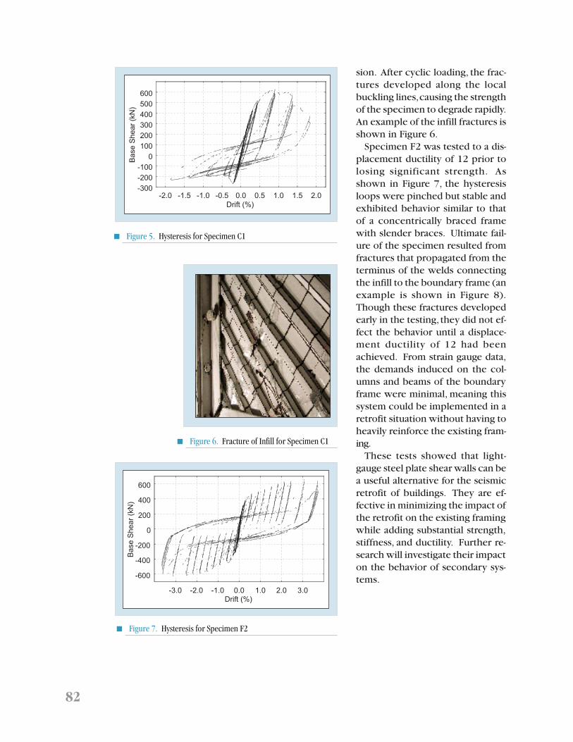
■ Figure 7. Hysteresis for Specimen F2
sion. After cyclic loading, the frac-tures developed along the localbuckling lines, causing the strengthof the specimen to degrade rapidly.An example of the infill fractures isshown in Figure 6.
Specimen F2 was tested to a dis-placement ductility of 12 prior tolosing significant strength. Asshown in Figure 7, the hysteresisloops were pinched but stable andexhibited behavior similar to thatof a concentrically braced framewith slender braces. Ultimate fail-ure of the specimen resulted fromfractures that propagated from theterminus of the welds connectingthe infill to the boundary frame (anexample is shown in Figure 8).Though these fractures developedearly in the testing, they did not ef-fect the behavior until a displace-ment ductility of 12 had beenachieved. From strain gauge data,the demands induced on the col-umns and beams of the boundaryframe were minimal, meaning thissystem could be implemented in aretrofit situation without having toheavily reinforce the existing fram-ing.
These tests showed that light-gauge steel plate shear walls can bea useful alternative for the seismicretrofit of buildings. They are ef-fective in minimizing the impact ofthe retrofit on the existing framingwhile adding substantial strength,stiffness, and ductility. Further re-search will investigate their impacton the behavior of secondary sys-tems.
■ Figure 5. Hysteresis for Specimen C1
-2.0 -1.5 -1.0 -0.5 0.0 0.5 1.0 1.5 2.0
Drift (%)
-300
-200
-100
0
100
200
300
400
500
600
Base
Shear
(kN
)

83Advanced Technologies for Response Modification of Hospital Buildings
Advanced Composite Infills
The following sections describethe conceptual designs of threeinfill panels that have been investi-gated analytically and experimen-tally to assess their performance asseismic retrofitting strategies.
Multi-layer PMC Infill PanelA multi-layer system is introduced
as a main concept to increase en-ergy dissipation and stiffness ofsteel frames. This multi-layer systemallows in-plane shear deformationand, therefore, sliding along specificlayers to take place upon loadingthe frame. The panel is tailored to
Top
Outer Panel (Outer shell)Inner Panel (Core & Core shell) Visco-elastic layer(Honeycomb Style)
CoreOuter shell
Visco-elastic Honeycomb layerCore shell
Top view
(a) Design (b) Test Set-up
■ Figure 9. Configuration of the Multi-layer PMC Infill Panel System
experience damage at specific lay-ers, thereby energy dissipation willbe produced within the infill panelwhen these layers exhibit in-planeshear deformations. As shown inFigure 9, the conceptual design ofthe polymer matrix composite(PMC) infill panel system consistsof three panels forming the entirewall thickness: first, an inner panelcomposed of a core material andcore shell; second, outer panels thatconsist of outer shells at both sidesof the inner panel; and third, visco–elastic honeycomb layers at the in-terface between these two panels.The role of the inner panel is toincrease structural rigidity. In turn,the outer panels are designed totransfer applied lateral force to thevisco–elastic honeycomb layers aswell as to resist large contact forcesat the interface with the steel col-umns. Upon testing, this multi-layerinfill provided significant stiffnessenhancements and moderate en-ergy dissipation. However, the inter-face layers can be designed to meetspecific drift limitations, or to pro-vide damping via the damage intro-duced at the interface layers.
■ Figure 8. Fracture at 3.5% Drift forSpecimen F2

84
Multi–panel Infill PanelA multi–panel PMC infill panel is
designed to have higher damping,by introducing a combination of3M visco-elastic solid and poly-meric honeycomb materials. Thissystem provides significant damp-ing for seismic protection of build-ings. This multi-panel PMC infill wallcomprises two separate compo-nents as shown in Figure 10. A sand-wich design is considered as theinfill panel to reduce the weight,sound, and vibration as well as toimprove the structural rigidity ofthe composite panel, and the damp-ing panels are designed to exhibitshear deformation at the interfacelayers between fiber reinforcedpolymer (FRP) plates by the rela-tive motion of the top and bottombeams. As such, the geometry of thedamping panels is designed to havethree PMC laminates, and the damp-ing materials are located at the in-terface between them. In this case,the interaction of this system withthe steel frame produces both stiff-ness and damping following differ-ent drift values. By designing the
proper vertical interface layers, thissystem can dissipate seismic exci-tations. The design parametersalong with simplified analysis toolsare available for the designer to tai-lor the panels to achieve the desireddamping characteristics.
Multi-Box Infill PanelLight and flexible building sys-
tems often require specific designfeatures for limiting earthquakedamage. With the same mechanicalconcept used in the multi–panelsystem, a tube–type infill structureis designed to have three PMC boxpanels as shown in Figure 11. In thiscase, significant increase in thedamping of a steel frame may beexpected by larger damping area atthe interface between the box pan-els. The significant advantage of thissystem is that it provides energy dis-sipation without adding any signifi-cant stiffness to the steel frame.Thus, by minimizing the stiffnessassociated with this infill panel,semi-rigidly connected frames andsimilar classes of frames will notexhibit failure at the column-beam
■ Figure 10. Configuration of the Multi-Panel Infill System
An-Cor Industrial Plastics
Armstrong World Industries
Enidine, Inc.
Kuraray Company, Ltd. Japan
Office of Statewide HealthPlanning & Development(OSHPD)
Sumitomo 3M LTD, Japan
B
Top connection
A
Bottom connection
Verticalinterfacelayer
(a) Design (b) Test Set-up

85Advanced Technologies for Response Modification of Hospital Buildings
connection because this infill isflexible and does not attract signifi-cant forces at the joints. The mainemphasis here is to provide the re-quired damping without impartingany adverse damage to the joints ofthe structural system. Moreover,because these box panels may bedesigned not to fill the entire spacebetween the columns, interrup-tions to the floor plan can be mini-mized.
Precast Infill Panels Made withEngineered CementitiousComposite Materials
An infill system that utilizes engi-neered cementitious compositesmaterials (ECC) is being developedfor the protection of critical struc-tures. The ECC materials, used inlieu of traditional building materi-als, are advantageous due to theirpseudo-strain hardening responsein tension (Figure 12(a)) (Li, 1998and Li and Leung, 1992). This duc-tile response results in greateramounts of energy dissipation insteel reinforced ECC structural ap-
plications when compared to tra-ditional reinforced concrete mate-rials (Fischer and Li, 2002). The infillsystem under development utilizesprecast ECC infill panels withbolted, pre-tensioned connectionsbetween the infill panels and atconnections to the existing struc-ture. Additional details of the re-search are presented in Kesner,2003.
The primary (non-structural) ad-vantage of the proposed infill sys-tem lies in the inherent flexibilityof the system’s use and ease of in-stallation. The use of bolted con-nections allows for the easyremoval or relocation of infill pan-els in response to changes in facil-ity use. The two-piece infill sectionsallow for installation in an existingframe with minimal equipment andinterference with ongoing facilityuse. Additional flexibility in use isprovided by the ability of partiallyinfilled frames to increase thestrength, stiffness and energy dissi-pation of a structural frame. Partialframe infills minimize the impactthe retrofit has on the existing
■ Figure 11. Configuration of the Multi-Box Infill Panel System
78.0 82.0
22.00 0.400.40
(a) Design (b) Test Set-up

86
0.0
1.0
2.0
0.00 0.01 0.02 0.03 0.04
Tensile Strain
Te
nsi
leS
tre
ss(M
Pa
)
(a)
Actuator
Stro
ngco
lum
n
Reaction beam
DFRCC Panel
Existing frameBolted connection to frame
Actuator
Stro
ngco
lum
n
Reaction beam
DFRCC Panel
Existing frameBolted connection to frame
(b)0.0
1.0
2.0
0.00 0.01 0.02 0.03 0.04
Tensile Strain
Te
nsi
leS
tre
ss(M
Pa
)
(a)0.0
1.0
2.0
0.00 0.01 0.02 0.03 0.04
Tensile Strain
Te
nsi
leS
tre
ss(M
Pa
)
(a)
Actuator
Stro
ngco
lum
n
Reaction beam
DFRCC Panel
Existing frameBolted connection to frame
Actuator
Stro
ngco
lum
n
Reaction beam
DFRCC Panel
Existing frameBolted connection to frame
(b)
Actuator
Stro
ngco
lum
n
Reaction beam
DFRCC Panel
Existing frameBolted connection to frame
Actuator
Stro
ngco
lum
n
Reaction beam
DFRCC Panel
Existing frameBolted connection to frame
Existing frameBolted connection to frame
(b)
(a) Typical Tensile Response of ECCMaterials
(b) Schematic Representation of ECC Infill Systemand Experimental Set-up
structure and on existing second-ary systems.
To evaluate the beam-type infillsystem, panel connection tests andlarge-scale infill panel tests wereconducted (Kesner, 2003). Thepanel connection tests identifiedappropriate levels of boltpretensioning for the retrofit con-nections as well as slip coefficientsuseful for design. The infill paneltests were conducted as singlepanel tests (Figure 12(b)) with eachtested panel representing one halfof a beam-type infill section. Theeffect of different ECC mix designs,alternate reinforcement details andtwo different panel shapes on cy-clic response of the panel was ex-amined. Each panel was subjectedto symmetric cyclic loading to in-
creasing drift levels. Load-displace-ment response, the amount of en-ergy dissipated by the panels,cracking behavior, and panel failuremechanisms were of particular im-portance for the testing. Figure 13compares the load-drift response ofan ECC panel with welded wire fab-ric reinforcement (WWF), an ECCpanel with WWF and a single de-formed reinforcing bar on the pe-rimeter of the panel, and a concretepanel with WWF and a deformedperimeter bar. The perimeter barclearly adds strength and energydissipation capacity to the panels.The ECC panels showed clear ad-vantages over the concrete panel interms of increased strength, driftcapacity, and energy dissipation.The enhanced performance of theECC is a consequence of the strainhardening of the ECC in tension incombination with mild reinforce-ment. Further details of the experi-mental program and results aregiven in Kesner, 2003.
To examine the response of thebeam-type infill system in steelframed structures, a series of finiteelement analyses were performed.The goal of the analyses was toverify the ability of an infilled frameto satisfy performance limits forcritical structures as presented inFEMA 273, 1999. Various analyses
ECC with WWF
ECC with WWF andperimeter bar
Concrete with perimeter bar
% Drift
App
lied
Load
(kN
)
60
40
20
-40
-60
-5% -3% 1% 3% 5%
■ Figure 13. Selected Experimental Results of Single-Panels
■ Figure 12. ECC Infill System

87Advanced Technologies for Response Modification of Hospital Buildings
were conducted to examine theeffect of the infill addition on thestrength and stiffness of the frame,to examine load distributionthrough the panels, and to deter-mine if infill additions resulted inlocalized yielding in the frames thatthey are retrofitting. A constitutivemodel for ECC did not exist and wastherefore developed and imple-mented for this research (Han et al.,2002). Details of the analyses aregiven in Kesner, 2003.
The simulation results indicatedthat the beam-type infill panel sys-tems could significantly increasethe strength and stiffness of theframe, as well as the energy dissi-pation during cyclic loadings. Typi-cal simulation results are shown inFigure 14. The variation in frameresponse when different numbersof infill sections are used demon-strates the variety of solutions andstrength/stiffness options this ret-rofitting system offers. Yielding inthe frame occurred at similar lev-els (all in the base of the frame)whether there was an infill systemin place or not. This indicates thatthe infill addition can simulta-neously protect the frames and in-crease stiffness. Additional analysesshowed that a panel geometry thattapers toward the center of thebeam-type infill gives a similar re-sponse as the rectangular panelswhile using less material (Kesner,2003). Tapered panels allow foreven more flexibility in the use ofthis system in terms of having moreoptions for existing non-structuralcomponents to “penetrate” the baywhere the infill is placed.
Based upon the results of the ex-periments and numerical simula-tions, the concept of precast ECCinfill panels appears viable. Thelaboratory testing of the ECC infill
Bare Frame2 Beam-type Infills4 Beam-type Infills6 Beam-type Infills
% Drift
App
lied
Load
(kN
)
1200
800
400
-1.25% -0.75% 0.25% 0.75% 1.25%
-400
-800
-1200
■ Figure 14. Simulated Load-Drift Response from a Bare SteelFrame and Frames with ECC Infill Panels
panels demonstrated the strength,stiffness and energy dissipation lev-els that can be obtained from suchinfill panels. The panel strength anddrift capacity can be tailoredthrough variations in panel rein-forcement, ECC material and panelgeometry. The simulation resultsindicated that a variety of levels ofincreased strength, stiffness andenergy dissipation are possible withvarious amounts of beam-typeinfills. The increase in strength, stiff-ness and energy dissipation of theECC infilled frames can be achievedwith minimal impact on the use ofthe existing structure.
Global Retrofit of Structures byWeakening and Damping
A new procedure for global ret-rofit of existing structures sub-jected to seismic excitation isproposed. The main features of thisprocedure are to reduce maximumacceleration and associated forcesin buildings by reducing theirstrength (weakening). The globalweakening retrofit, which takes theopposite approach from conven-tional retrofitting procedures, is

88
particularly suitable for buildingsthat have overstressed componentsand foundation supports or weakbrittle components. Moreover, suchretrofit may protect secondary sys-tems sensitive to high accelerations.However, by weakening the struc-ture, large deformations are ex-pected. By adding supplementaldamping devices, it is possible tocontrol the deformation to bewithin desirable limits. A structureretrofitted with this strategy willhave, therefore, a reduction in boththe acceleration response and de-formations, depending on theamount of additional damping in-troduced. An illustration of theabove strategy is performed byevaluating the inelastic response ofthe structure through a spectralprocedure, modified to fit struc-tures with additional damping. Theresults are compared with a dy-namic nonlinear analysis. Bothmethods show that the retrofit so-lution is feasible and simplifiedtechniques can be used for evalua-tion.
Conventionally, seismic perfor-mance can be improved by bothincreasing the strength and ductil-
ity capacity of the structure, or bydecreasing the level of excitation.In this retrofit strategy, bothstrength capacity and demand arereduced as well as the deformationresponse and ductility demands.The process is done in two differ-ent steps (see Figure 15). The firststep consists of weakening thestructure, which leads to a decreasein strength capacity and with it, adecrease in the acceleration de-mand. This is also associated withan increase in the ductility demand.The second step consists of addingviscous damping to reduce the duc-tility demand (see Figure 15).
The structural “weakening” canbe easily obtained by releasing se-lected connections in the structure.The properties of the modified con-nections depend on the materialsand the construction practices usedin the building. In this paper, it issuggested to replace selected fixedconnections with hinges by releas-ing the bolts or strategically remov-ing welds. The enhancement ofdamping can be achieved by add-ing structural braces with built-indevices such as viscoelastic, fluidviscous, friction devices or
■ Figure 15. Strength Reduction and Damping Enhancement
First Step Second Step Final Result
Strength Reduction(Weakening)
DampingEnhancement
Weakening+
Damping
Displacements, D
Original
Strengthening
Softening
Bas
e
She
ar,
V
Displacements, D
OriginalEnhancedDamping
Ba
se
Sh
ear
, V
Displacements, D
Original
EnhancedDamping
Weakened
Bas
e
She
ar,
V
(a) Change Accelerations (Smaller)and Displacements (Bigger) and
Vice Versa
(b) Change Displacementsbut not Accelerations
(Reactions)
(c) Reduction both inAccelerations and
Displacements
Bas
e S
hear
,V
Bas
e S
hear
,V
Bas
e S
hear
,V

89Advanced Technologies for Response Modification of Hospital Buildings
unbonded braces (Reinhorn et al.,1995 and Constantinou et al.,1998).
To illustrate the retrofitting tech-nique, the four-story steel framestructure from the MCEER demon-stration hospital (shown in Figure1) is evaluated. The evaluation ofthe structure’s response is per-formed using an inelastic spectralanalysis, based on approximatedinelastic design spectra (Reinhorn,1997). This analytical procedure,used for undamped or lightlydamped structures (Ramirez et al.,2000), was modified for highlydamped structures. The results ob-tained for the spectral inelastic re-sponse and those provided by aninelastic dynamic analysis show thesame characteristics for the modi-fied structure. The seismic excita-tion is derived according to FEMA273 and with the information pro-vided by NSHMP (National SeismicHazard Mapping Program) for thehospital’s location. Three probabili-ties of occurrence, 10%, 5% and 2%in 50 years, are assumed in thisstudy, corresponding to a PGA of0.50 g, 0.63 g and 0.77g, respec-tively. The influence of the retro-
fit method is shown in Figure 16.The base shear is reduced by weak-ening, while the displacements arereduced by added damping. Fig-ure 17 illustrates the influence oflow vs. high damping. The robust-ness of the response should benoted, i.e., the maximum force/ac-celeration response is almost thesame, independent of the hazardlevel. At the same time, the displace-ment is bounded to smaller valuesthan in the original structure.
While this is work in progress, itis clear from the above evaluationthat this retrofit strategy can glo-bally affect the structural system un-dergoing inelastic deformations inreducing both accelerations anddisplacements. The reduction ofdisplacements leads to a reductionin the global damage inflicted to thestructure. The reduction in accel-erations can affect the functional-ity of the non-structuralcomponents and of the equipment,thus improving the resilience of thehospital in case of severe earth-quakes. Performance targets anddesign criteria may be developed,along with practical, implemen-table construction solutions.
■ Figure 16. Performance of Weakened-Damped Structure Evaluated by Spectral Method and Time Analysis
Top Displacements
0
100
200
300
400
500
600
700
original weaken damping = 0.5 damping = 1.0
To
pD
isp
lacem
en
ts(m
m)
Nonlinear Dynamic Analysis
Spectral Analysis
Base Shear
0
5000
10000
15000
20000
original weaken damping = 0.5 damping = 1.0
Ba
se
Sh
ea
r(k
N)
Nonlinear Dynamic Analysis
Spectral Analysis
ECC Technology Network:www.engineeredcomposites.com

90
■ Figure 17. Performance of Damped-Weakened Retrofitted Structure for Different Hazards
C=0.5 kN/mm/sec - (10% in 50 Years)
0.00
0.50
1.00
1.50
2.00
0 100 200 300 400 500
Spectral Displacement (mm)
Elastic Spectral DemandDamped Elastic Spectral DemandDamped Inelastic SpectrumSpectral Capacity
Sp
ec
tra
lA
cc
ele
rati
on
(/g
)
10%
C=1.0 kN/mm/sec - (10% in 50 Years)
0.00
0.50
1.00
1.50
2.00
0 100 200 300 400 500
Spectral Displacement (mm)
Elastic Spectral DemandDamped Elastic Spetral DemandDamped Inelastic Spectral DemandSpectral Capacity
Sp
ec
tra
lA
cc
ele
rati
on
(/g
)
10%
C=0.5 kN/mm/sec - (2% in 50 Years)
0.00
0.50
1.00
1.50
2.00
0 100 200 300 400 500
Spectral Displacement (mm)
Elastic Spectral DemandDamped Elastic spectral DemandDamped Inelastic Demand SpectraSpectral Capacity
Sp
ec
tra
lA
cc
ele
rati
on
(/g
)
5%C=0.5 kN/mm/sec - (5% in 50 Years)
0.00
0.50
1.00
1.50
2.00
0 100 200 300 400 500
Spectral Displacement (mm)
Elastic Spectral DemandDamped Elastic Spcetral DemandDamped Inelastic Spectral DemandSpectral Demand
Sp
ectr
al A
ccel
erat
ion
(/g
)
2%
C=1.0 kN/mm/sec - (2% in 50 Years)
0.00
0.50
1.00
1.50
2.00
0 100 200 300 400 500
Spectral Displacement (mm)
Elastic Spectral DemandDamped Elastic spectral DemandDamped Inelastic Spectral DemandSpectral Capacity
Sp
ec
tra
lA
cc
ele
rati
on
(/g
)
2%
(a) Slightly Damped Structure
(b) Highly Damped Structure
C=1.0 kN/mm/sec - (5% in 50 Years)
0.00
0.50
1.00
1.50
2.00
0 100 200 300 400 500
Spectral Displacement (mm)
Elastic Spectral DemandDamped Elastic Spetral DemandDamped Inelastic Spectral DemandSpectral Capacity
Sp
ec
tra
lA
cc
ele
rati
on
(/g
)
5%

91Advanced Technologies for Response Modification of Hospital Buildings
Semi-Active ResponseModification Systems –Combined RSPM and PassiveDamping Hybrid ControlSystem
RSPM (Real-time Structural Pa-rameter Modification) is a semi-ac-tive nonlinear control system forreducing structural seismic re-sponses. Figure 18 illustrates howthe combined system works. Thesystem includes a passive damperand a controlled stiffness unit. Thepassive damper is always engagedto dissipate energy, but the stiffnessunit is connected or disconnectedbased on a pre-set threshold. It isdisconnected initially until a re-sponse threshold value—termedthe open distance, is reached. If therelative displacement (the absolutevalue) becomes larger than theopen distance, the stiffness unit isengaged to control the response. If,at any instant, the displacement (ab-solute value) becomes smaller thanthe threshold, the RSPM stiffnessunit is disconnected. The semi-ac-tive control mechanism is activatedonly when the stiffness unit is con-nected. The devices are normallycombined as a pair of tension andcompression units working as apush-and-pull set.
The internal semi-active controlof the stiffness unit is based onmaximized accumulation and re-moval of energy. In the simple caseof a linear stiffness unit, the con-trol force is governed by
R t tk S t S t t t t
i
d d d i i i= =- < £Ï
ÌÓ +
+0 1
1( ( ) ( ))(2)
where Sd is the net stroke from thelast controlled switching point; ti isthe ith control point at which a
switching command is executedand the device force is released.
The hybrid system has been ana-lyzed through an existing buildingwith a potential pounding problem(Lee et al., 2002). The math-sciencebuilding of the University of Cali-fornia at Los Angeles (UCLA) is aseven-story moment resistant steelframe structure. One seismic haz-ard is possible collision of the build-ing with an adjacent building, the“Math-science addition.” The gap inthe north-south direction betweenthese two buildings is only sixinches. The combined RSPM andpassive damping devices are con-sidered between the roofs of thetwo buildings to reduce the roofdisplacement response. Another re-quirement is to reduce the accel-eration response level. For thispurpose, a pure damping devicemay be more effective in reducingacceleration. Therefore, the RSPMand damping device are combinedto take advantage of their respec-tive strengths.
In a simple lumped mass modelcomparison, Figure 19 shows theresponse levels under ‘LA’ earth-quake with RSPM or with only lin-ear viscous damping control. Theresponse reduction effects of thecontrol systems are normalized asthe percentage of the controlledresponse over the non-controlledresponse level. A lower curve im-plies a better response reduction
Damper
Open distance, RSPM Stiffness
■ Figure 18. Combined RSPM and Passive DampingHybrid Control System

92
effect. As shown in the figure, thepassive damping devices will be-come less effective as the structuralyielding (ductility demand) in-creases. This is primarily due to theincreased energy dissipation fromthe structural ductility and a slowervelocity response increase rate. Inthe nonlinear structural responses,as a trade off effect of structuralmember yielding, the displacementresponse will typically grow at afaster rate than the velocity andacceleration responses. Under sucha condition, the displacement-basedRSPM control illustrates a clear ad-vantage over the velocity-based pas-sive dampers.
In summary, semi-active controlstrategies may be able to provide alarger control capability for seismicinduced structural response reduc-tion. In particular, they are betterable to balance the difficult struc-tural control requirements, such aslimiting acceleration levels and con-trolling story responses, thus reduc-ing structural response in bothelastic and inelastic ranges.
Dampers
MCEER investigators have madeimportant contributions to the de-velopment of existing guidelines orspecifications for structures withdamping systems: FEMA 273/274Guidelines for the Seismic Reha-bilitation of Buildings, publishedin 1998, FEMA 356 Prestandardand Commentary for the SeismicRehabilitation of Buildings,NEHRP 2000 Provisions for Seis-mic Regulations for New Build-ings, published in 2001 and NEHRP2003 Provisions for Seismic Regu-lations for New Buildings, to bepublished in 2004.
While the technical basis for themethods of analysis and design ofbuildings with damping systems inFEMA 273/274/356 and 2000NEHRP were primarily developedat MCEER prior to 2000, the lack ofverification studies prevented thesemethods from gaining the designprofessional acceptance needed tomove the procedures into modelcodes and standards.
MCEER researchers, under thedirection of Technical Subcommit-tee 12 of the Building Seismic SafetyCouncil, have completed and pub-lished verification studies that dem-onstrate the validity of theMCEER-developed methods ofanalysis and design (Ramirez et al.,2001, 2002a, 2002b, and to appear;Whittaker et al., to appear). Basedon this work, these methods havereached Chapter status in the 2003NEHRP Provisions and have beenaccepted for inclusion in ASCE Stan-dard 7-05, Minimum Design Loadsfor Buildings and Other Struc-tures, that is scheduled for publica-tion in 2005. All future buildingcodes, starting with the next editionof the International Building Code,
0 2 4 6 8 10 12 14 160.3
0.4
0.5
0.6
0.7
0.8
0.9
1linear viscous10% stif RSPM20% stif RSPM30% stif RSPM
Ductility demand
Dis
plac
emen
t red
uctio
n %
■ Figure 19. Comparison of Response Levels

93Advanced Technologies for Response Modification of Hospital Buildings
will refer to the ASCE Standard formethods of analysis and design.
The evaluation and verificationstudies performed at MCEER in-cluded studies of numerous mod-els of structures with dampingsystems and several three-story andsix-story multistory steel buildingswith damping systems. However,all studies concentrated on seismicexcitations with far-field, and stiffsoil or rock characteristics. Theverification studies were extendedwith MCEER funding in 2002-2003to include near-field and soft soilexcitations. These additional stud-ies have just been completed. Theresults demonstrate that the devel-oped methods of analysis and de-sign are also appropriate andaccurate for near-field and soft soilseismic excitations.
Finally, MCEER researchers havecompleted, published and patented(see Sigaher and Constantinou,2003 and Constantinou, 2002)work on the Scissor-Jack SeismicEnergy Dissipation System. The firstapplication of this new technologyis pending following the call forbids on the Cyprus Olympic Com-mittee Building, a six-story rein-forced concrete building with 52scissor-jack-damper assemblies.
Next Steps andConclusions
The research projects describedin this paper are just one compo-nent of MCEER’s integrated re-search plan. Successful executionof this plan depends on close inter-action between various tasks. First,reliable seismic time-histories rep-resentative for eastern NorthAmerica, and their associated levelof reliability, must be developed to
complement the available westernNorth America suites of earthquakerecords (Papageorgiou, 2001). Theresulting seismic input feeds di-rectly into the fragility studies aswell as the geotechnical, structuraland non-structural evaluation andretrofit research tasks.
Second, seismic evaluation andretrofit of structural systems inter-acts in a close manner with fragil-ity curve development, providingnew retrofit schemes based on ad-vanced technologies that can beused in the fragility studies toprobabilistically quantify the rela-tive merits and potential benefits ofalternative retrofit schemes. The fra-gility studies also return to theevaluation and retrofit studies valu-able information on seismic perfor-mance that can be used to focus theseismic retrofit research activities.A similar interdependency exists forthe research on non-structural sys-tems, to an even greater degree.Fragility studies, enhanced throughinteraction with evaluation and ret-rofit studies, provide key informa-tion to develop reliable cost-benefitanalysis decision tools. Researchdependency also exists, in a veryclose interactive loop, betweencost-benefit analyses and socialstudies on implementation and in-centives, as both rely on eachother’s data to converge to a respec-tive solution.
The development of decision sup-port methodologies that can inte-grate both the engineering andsocial science aspects needed toachieve quantification of resilienceis a key research activity that tiesall of these tasks together. Theseactivities are described in an an-other paper in this Volume.
An important subsequent task incontinuation of the research activi-

94
ties reported in this paper will beresearch on response modificationdevices and strategies to protectnon-structural systems. The objec-tives will be to investigate how vari-ous types of response modificationstrategies can help modify floorresponses (maximum displace-ments, velocities, and accelera-
Acknowledgments
This research was primarily supported by the Earthquake Engineering Research CentersProgram of the National Science Foundation, under award number EEC-9701471 tothe Multidisciplinary Center for Earthquake Engineering Research. This support isgratefully acknowledged.
References
Berman, J., (2003), Experimental Investigation of Light-Gauge Steel Plate Shear Wallsfor the Seismic Retrofit of Buildings, MCEER-03-0001, Multidisciplinary Center forEarthquake Engineering Research, University at Buffalo.
Berman, J. and Bruneau, M., (2003), “Plastic Analysis and Design of Steel Plate ShearWalls,” Journal of Structural Engineering, ASCE (in press).
Constantinou, M.C., (2002), Highly Effective Energy Dissipation Apparatus, inventor:Michael C. Constantinou, assignee: Research Foundation of State University of NewYork, United States Patent 6,438,905, issued August 28, 2002.
Constantinou, M.C., Soong, T.T. and Dargush, G.F., (1998), Passive Energy DissipationSystems for Structural Design and Retrofit, MCEER-98-MN01, Multidisciplinary Centerfor Earthquake Engineering Research, University at Buffalo.
FEMA-273, (1999), NEHRP Guidelines for Seismic Retrofit of Buildings, FederalEmergency Management Agency, Washington, DC.
Fischer, G. and Li, V.C., (2002), “Effect Of Matrix Ductility On Tension Stiffening Behaviorof Steel Reinforced Engineered Cementitious Composites,” ACI Structural Journal,Vol. 99, No. 1, pp. 104-111.
Han, T.S., Feenstra, P.H. and Billington, S.L., (2002), “Simulation of Highly Ductile Fiber-Reinforced Cement-based Composites,” ACI Structural Journal, accepted forpublication, November.
Kesner, K.E., (2003), Development of Engineered Cementitious Composite Materialsfor Seismic Retrofit and Strengthening Applications, Ph.D. Dissertation, CornellUniversity, 337 pp.
Lee, G.C., Tong, M., Wu, Y. H., Hwang, S. and Hart, G., (2002), “Application of a Semi-Active Seismic Protective System in an Existing Building in Los Angeles,” Proceedings,7NCEE, Boston, MA, July 21-25, 2002.
tions). This will allow limits to beestablished within which structuralretrofit solutions can (or cannot)provide adequate seismic protec-tion to non-retrofitted non-struc-tural equipment, and to determinethe type of floor responses that canbe controlled with these variousstructural retrofit strategies.

95Advanced Technologies for Response Modification of Hospital Buildings
References (Cont’d)
Li, V.C., (1998), “Engineered Cementitious Composites – Tailored Composites ThroughMicromechanical Modeling,” Fiber Reinforced Concrete: Present and the Future, N.Banthia, A. Bentur, and A. Mufti, eds., Canadian Society for Civil Engineering, Montreal,pp. 64-97.
Li, V.C. and Leung, C., (1992), “Steady-State and Multiple Cracking of Short Random FiberComposites,” Journal of Engineering Mechanics, Vol. 118, No. 11, pp. 2246-2264.
Papageorgiou, A.S., Halldorsson, B. and Dong, G., (2001), “Earthquake Motion Input andIts Dissemination Via the Internet,” Research Progress and Accomplishments: 2000-2001, MCEER-01-SP01, Multidisciplinary Center for Earthquake Engineering Research,University at Buffalo.
Ramirez, O.M., Constantinou, M.C., Kircher, C.A., Whittaker, A.S., Johnson M.W. andGomez, J.D., (2000), Development and Evaluation of Simplified Procedures forAnalysis and Design of Buildings with Passive Energy Dissipation Systems,Technical Report MCEER-00-0010, Multidisciplinary Center for EarthquakeEngineering Research, University at Buffalo, December.
Ramirez, O.M., Constantinou, M.C., Kircher, C.A., Whittaker, A.S., Johnson, M.W., Gomez,J.D. and C.Z. Chrysostomou, (2001), Development and Evaluation of SimplifiedProcedures for Analysis and Design of Buildings with Passive Energy DissipationSystems, Technical Report MCEER-00-0010, Revision 1, Multidisciplinary Center forEarthquake Engineering Research, University at Buffalo, November.
Ramirez, O.M., Constantinou, M.C., Gomez, J., Whittaker, A.S. and Chrysostomou, C.Z.,(2002a), Evaluation of Simplified Methods of Analysis of Yielding Structures withDamping Systems,” Earthquake Spectra, Vol. 18, No. 3, pp. 501-530.
Ramirez, O.M., Constantinou, M.C., Whittaker, A.S., Kircher, C.A. and Chrysostomou, C.Z.,(2002b), “Elastic and Inelastic Seismic Response of Buildings with Damping Systems,”Earthquake Spectra, Vol. 18, No. 3, Aug. 2002, pp. 531-547.
Ramirez, O.M., Constantinou, M.C., Whittaker, A.S., Kircher, C.A., Johnson, M.W. andChrysostomou, C.Z., (to appear), “Validation of 2000 NEHRP Provisions EquivalentLateral Force and Modal Analysis Procedures for Buildings with Damping Systems,”Earthquake Spectra.
Reinhorn, A., (1997), “Inelastic analysis technique in seismic evaluation,” Proceedingsof the International Workshop on Seismic Design Methodologies for the nextGeneration of Codes, Bled/Slovenia, June 24-27.
Reinhorn, A., Li, C. and Constantinou, M.C., (1995), Experimental and AnalyticalInvestigation of Seismic Retrofit of Structures with Supplemental Damping: Part1 – Fluid Viscous Damping Devices, NCEER-95-0001, National Center for EarthquakeEngineering Research, University at Buffalo.
Sigaher, A.N. and Constantinou, M.C., (2003), “Scissor Jack Damper Engergy DissipationSystem,” Earthquake Spectra, Vol.19, No.1, Feb. 2003, pp. 133-158.
Thorburn, L.J., Kulak, G.L., and Montgomery, C.J., (1983), Analysis of Steel Plate ShearWalls, Structural Engineering Report No. 107, Department of Civil Engineering,University of Alberta, Edmonton, Alberta, Canada.
Timler, P.A. and Kulak, G.L., (1983), Experimental Study of Steel Plate Shear Walls,Structural Engineering Report No. 114, Department of Civil Engineering, Universityof Alberta, Edmonton, Alberta, Canada.
Whittaker, A.S., Constantinou, M.C., Ramirez, O.M., Johnson, M.W. and Chrysostomou,C.Z., (to appear), “Equivalent Lateral Force and Modal Analysis Procedures of the2000 NEHRP Provisions for Buildings with Damping Systems,” Earthquake Spectra.