
Major Modification - FCC
16
1. KNKA442 - 179B - Major Mod - 120131 TOPEKA SMSA LIMITED PARTNERSHIP (KNKA442) Topeka KS CMA 179B FCC Form 601 Attachment 1 Major Modification DEMONSTRATION OF APPLICANT'S QUALIFICATIONS Pursuant to Section 22.107(a), TOPEKA SMSA LIMITED PARTNERSHIP ("Applicant"), a subsidiary of AT&T Inc. ("AT&T"), is qualified to hold Commission licenses, as has previously been determined. Pursuant to Section 1.919, Applicant relies on the current FCC Form 602 of Applicant, AT&T, or AT&T Mobility, LLC. PUBLIC INTEREST STATEMENT As required by Section 22.107(b), Applicant, the B-block cellular licensee in the Topeka KS CMA (179B), herein proposes to add, modify and/or delete cell sites, as detailed in the attached Schedule Ds. No sites involve any environmental action requiring FCC approval. Taken together, these sites improve coverage within the CMA, providing increased capacity and continued high quality cellular service. Accordingly, the public interest, convenience, and necessity will be served by grant of this application. OPERATION OF FACILITY As required pursuant to Section 22.107(d), the existing facilities will operate in compliance with all rules governing the Public Mobile service. EXISTING CGSA DETERMINATION The existing Cellular Geographic Service Area ("CGSA") shown on the attached map was derived from the most-recent CGSA submission filed with the Commission for this Call Sign. CGSA REVISIONS The revisions proposed in this application expand Applicant’s CGSA within the CMA the expanded CGSA includes areas adjacent to existing coverage and includes areas less than 50 square miles currently being served on a secondary basis where the Applicant is now seeking protection The alterations to the CGSA proposed in this application are depicted in the attached map provided in accordance with Section 22.929(c). Because the application expands the existing CGSA, it has been designated a Phase II application. The service area boundaries for the sites in this application were developed in accordance with Section 22.911(a). The engineering calculations use a minimum of 98' HAAT, per FCC Rule 22.911(a)(3), and 0.1 Watt or 27 db less than maximum ERP, per FCC Rule 22.911(a)(4). Site specific information is provided below and polar antenna radiation patterns are appended hereto. Applicant acknowledges that grant of this application does not convey the right to interference protection for the service area other than the defined CGSA. SAB EXTENSION AGREEMENTS This application includes SAB extensions into one or more adjacent CGSAs. Applicant or its affiliate is either the licensee of the adjacent CGSAs into which the SAB extends, and therefore no written SAB extension agreement is required, or Applicant has the required written SAB extension agreement in its files. ADMINISTRATIVE INFORMATION This application is for primary status for sites detailed in the Schedule Ds. The five-year build out period for all markets involved has expired. TECHNICAL INFORMATION Pursuant to Section 22.953(a)(3), the radial distance from the cell-transmitting antenna to its SAB has been calculated in accordance with Section 22.911(a). FULL-SIZE 1:500,000 SCALE MAP & REDUCED 8.5” X 11” MAP In accordance with Sections 22.929(c) and 22.953(a)(2), attached to this exhibit is a reduced 8.5” x 11” map, which includes the existing 32 dBu contours of the new sites. The full-scale copy of the system map, as required by Sections 22.929(c) and 22.953(a)(1), will be filed manually under separate cover. [1] See Applications of AT&T Inc. and Cellco Partnership d/b/a Verizon Wireless, For Consent to Assign or Transfer Control of Licenses and Authorizations and Modify a Spectrum Leasing Arrangement, WT Docket No. 09-104, Memorandum Opinion and Order, 25 FCC Rcd 8704 (2010). Page 1 of 15
-
Upload
khangminh22 -
Category
Documents
-
view
5 -
download
0
Transcript of Major Modification - FCC
1. KNKA442 - 179B - Major Mod - 120131TOPEKA SMSA LIMITED PARTNERSHIP (KNKA442)
Topeka KS CMA 179B FCC Form 601 Attachment 1
Major Modification DEMONSTRATION OF APPLICANT'S QUALIFICATIONS Pursuant to Section 22.107(a), TOPEKA SMSA LIMITED PARTNERSHIP ("Applicant"), a subsidiary of AT&T Inc. ("AT&T"), is qualified to hold Commission licenses, as has previously been determined. Pursuant to Section 1.919, Applicant relies on the current FCC Form 602 of Applicant, AT&T, or AT&T Mobility, LLC. PUBLIC INTEREST STATEMENT As required by Section 22.107(b), Applicant, the B-block cellular licensee in the Topeka KS CMA (179B), herein proposes to add, modify and/or delete cell sites, as detailed in the attached Schedule Ds. No sites involve any environmental action requiring FCC approval. Taken together, these sites improve coverage within the CMA, providing increased capacity and continued high quality cellular service. Accordingly, the public interest, convenience, and necessity will be served by grant of this application. OPERATION OF FACILITY As required pursuant to Section 22.107(d), the existing facilities will operate in compliance with all rules governing the Public Mobile service. EXISTING CGSA DETERMINATION The existing Cellular Geographic Service Area ("CGSA") shown on the attached map was derived from the most-recent CGSA submission filed with the Commission for this Call Sign. CGSA REVISIONS The revisions proposed in this application expand Applicant’s CGSA
within the CMA
the expanded CGSA includes areas adjacent to existing coverage
and includes areas less than 50 square miles currently being served on a secondary basis where the Applicant is now seeking protection The alterations to the CGSA proposed in this application are depicted in the attached map provided in accordance with Section 22.929(c). Because the application expands the existing CGSA, it has been designated a Phase II application. The service area boundaries for the sites in this application were developed in accordance with Section 22.911(a). The engineering calculations use a minimum of 98' HAAT, per FCC Rule 22.911(a)(3), and 0.1 Watt or 27 db less than maximum ERP, per FCC Rule 22.911(a)(4). Site specific information is provided below and polar antenna radiation patterns are appended hereto. Applicant acknowledges that grant of this application does not convey the right to interference protection for the service area other than the defined CGSA. SAB EXTENSION AGREEMENTS This application includes SAB extensions into one or more adjacent CGSAs. Applicant or its affiliate is either the licensee of the adjacent CGSAs into which the SAB extends, and therefore no written SAB extension agreement is required, or Applicant has the required written SAB extension agreement in its files. ADMINISTRATIVE INFORMATION This application is for primary status for sites detailed in the Schedule Ds. The five-year build out period for all markets involved has expired. TECHNICAL INFORMATION Pursuant to Section 22.953(a)(3), the radial distance from the cell-transmitting antenna to its SAB has been calculated in accordance with Section 22.911(a). FULL-SIZE 1:500,000 SCALE MAP & REDUCED 8.5” X 11” MAP In accordance with Sections 22.929(c) and 22.953(a)(2), attached to this exhibit is a reduced 8.5” x 11” map, which includes the existing 32 dBu contours of the new sites. The full-scale copy of the system map, as required by Sections 22.929(c) and 22.953(a)(1), will be filed manually under separate cover. [1] See Applications of AT&T Inc. and Cellco Partnership d/b/a Verizon Wireless, For Consent to Assign or Transfer Control of Licenses and Authorizations and Modify a Spectrum Leasing Arrangement, WT Docket No. 09-104, Memorandum Opinion and Order, 25 FCC Rcd 8704 (2010).
Page 1 of 15

TOPEKA SMSA LIMITED PARTNERSHIP (KNKA442) Topeka KS CMA 179B
FCC Form 601 Attachment 1
Site information
Sit
e N
am
e
TX
UL
S L
ocati
on
Nu
mb
er
UL
S L
ocati
on
Acti
on
(A
/M/D
)
Lati
tud
e
Lo
ng
itu
de
(P)r
op
osed
or
(E)x
isti
ng
Sit
e
UL
S A
nte
nn
a
Nu
mb
er
UL
S A
nte
nn
a
Acti
on
(A
/M/D
)
Max E
RP
(W
att
s)
Rad
Cen
terl
ine
(m)
Tip
Heig
ht
(m)
An
ten
na D
ata
Sh
eet
Ref
Site Location Data Site Antenna Specific Data
Lyndon KS40071 8 M 38-38-19.0 N 95-42-41.0 W E 1 M 169.9 85.4 86.8 7775
KS40072 2 M 354.9 85.4 86.8 7775
KS40073 3 M 354.9 85.4 86.8 7775
Toplaw KS41541 17 M 39-01-09.6 N 95-30-10.7 W E 1 M 195.0 61 62.4 7775
KS41542 2 M 398.3 61 62.4 7775
KS41543 3 M 195.0 61 62.4 7775
Carbondale KS41551 2 M 38-45-28.4 N 95-42-38.7 W E 1 M 107.1 122.9 123.9 800-10122
KS41552 2 M 107.1 122.9 123.9 800-10122
KS41553 3 M 229.1 122.9 123.9 800-10122
Perry Lake KS41561 3 M 39-11-17.5 N 95-19-40.2 W E 1 M 138.1 123.5 124.8 800-10123
KS41562 2 M 331.3 123.5 124.8 800-10123
KS41563 3 M 138.1 123.5 124.8 800-10123
Valencia KS41601 7 M 39-02-48.4 N 95-52-48.7 W E 1 M 218.9 55.2 56.5 800-10123
KS41602 2 M 218.9 55.2 56.5 800-10123
KS41603 3 M 218.9 55.2 56.5 800-10123
Kaw Valley KS41661 6 M 39-02-50.8 N 95-48-51.6 W E 1 M 478.8 61 62.4 742266
KS41662 2 M 478.8 61 62.4 742266
KS41663 3 M 478.8 61 62.4 742266
Rossville KS41801 11 M 39-08-42.0 N 95-55-37.7 W E 1 M 154.9 58.8 59.8 800-10122
KS41803 2 M 288.5 58.8 59.8 742-265
Overbrook KS45211 12 M 38-46-59.9 N 95-30-12.4 W E 1 M 169.9 93.3 94.5 X6517A-X6519A
KS45212 2 M 309.2 90.5 91.4 P65-16-XLH-RR
KS45213 3 M 169.9 90.5 91.7 X6517A-X6519A
Rock Creek KS45231 13 M 39-15-57.6 N 95-31-20.5 W E 1 M 182.0 76.2 77.4 X6517A-X6519A
KS45232 2 M 182.0 76.2 77.4 X6517A-X6519A
KS45233 3 M 182.0 76.2 77.4 X6517A-X6519A
Meriden KS45681 15 M 39-10-24.7 N 95-33-38.1 W E 1 M 331.3 77.4 78.3 P65-16-XLH-RR
KS45682 2 M 186.4 77.4 78.6 X6517A-X6519A
KS45683 3 M 186.4 77.4 78.6 X6517A-X6519A
Nortonville KS46642 16 M 39-25-05.8 N 95-20-17.5 W E 1 M 354.9 57.9 58.9 800-10122
KS46643 2 M 467.8 57.9 58.9 800-10122
Auburn AWS KS62271 A 38-52-06.0 N 95-49-38.0 W E 1 A 416.9 76.2 77.5 800-10123
KS62273 2 A 371.7 76.2 77.5 800-10123
Page 2 of 15

Table of Contents
KNKA442 - 179B - Major Mod - 120131 1X6517A-X6519A 3742-265 5800-10122 7800-10123 97775 11742266 13P65-16-XLH-RR 15

2. X6517A-X6519ADualBand 824-896/1850-1990 MHz
Issue 1006 - © 2006 JAYBEAM Wireless reserves the right to modify or amend any antenna or specification without prior notice. 164
w w w. j a y b e a m w i r e l e s s . c o m
DPX065X25M200X-Pol / 65° Az16.8 dBi / 18.8 dBi
Adjustable Electrical Tilt
Reference X6517A-X6519A
Electrical SpecificationsFrequency: 824 - 896 MHz 1850 - 1990 MHzGain: 16.8 dBi (14.7 dBd) 18.8 dBi (16.7 dBd)Input Impedance: 50 ohmsVSWR: <1.4:1Polarization: ±45°Electrical Downtilt: 0° - 8° Adjustable Electrical Tilt 0° - 6° Adjustable Electrical TiltIn Band Isolation: >25 dB >30 dBInter Band Isolation: >30 dBAzimuth Beamwidth: 65°Elevation Beamwidth: 8.5° 4.0°1st Upper Sidelobe: <-15 dB1st Null: >-20 dB typicalFront to Back Ratio: >25 dBIntermodulation: <-150 dBc for 2 x 20W carriersInput Power: 2 x 500W 2 x 250WInput Connector Type / Location: 4 x 7/16-DIN Female / BottomOperating Temperature: -40°F (-40°C) to +140°F (+60°C)
Mechanical SpecificationsSurvival Wind Speed: 125 mph (200 km/h; 56 m/s)Wind Loads (100mph; 160km/h; 45m/s): Front: 206 lbf (917 N) Side: 94 lbf (419 N)Antenna Weight and Dims (LxWxD): 47 lbs (21.4 kg) 93.5 x 12.7 x 5.8 in (2375 x 323 x 147 mm)
Mounting Kit OptionsPole Mounting Kit: MKS04P01 Weight: 6.4 lbs (2.9 kg)Scissor Tilt Mounting Kit: MKS04T03 Weight: 9.0 lbs (4.1 kg)
Unicell OptionsFor use inside Unicell Modules: UNX20-25Azimuth Swivel / Elevation Tilt: Fixed Az / Fixed ElRequired Mounting Kit: UNX20-RAM
Bottom View:
DU
AL
BA
ND
Rear View:
Variable Mounting Points(Refer to installation instructions for
recommended spacing.)
850 MHzLocking Tilt
Adjustment Lever
1900 MHzLocking Tilt
Adjustment Lever
Connector ID label onrear of antenna.
Connector IDLabel
Page 3 of 15

DualBand 824-896/1850-1990 MHz
Issue 1006 - © 2006 JAYBEAM Wireless reserves the right to modify or amend any antenna or specification without prior notice. 165
w w w. j a y b e a m w i r e l e s s . c o m
Typical Patterns - DPX065X25M200
Azimuth Pattern
824-896 MHz
Elevation Pattern 8°Elevation Pattern 6°Elevation Pattern 4°
Elevation Pattern 2°Elevation Pattern 0°
Elevation Pattern 2° Elevation Pattern 4°
Azimuth Pattern Elevation Pattern 0°
Elevation Pattern 6°
1850-1990 MHz
DU
AL
BA
ND
Page 4 of 15

3. 742-265
Kathrein Inc., Scala Division Post Office Box 4580 Medford, OR 97501 (USA) Phone: (541) 779-6500 Fax: (541) 779-3991Email: [email protected] Internet: www.kathrein-scala.com
General specifications: Frequency range 824–960 MHz
1710–2180 MHz
Impedance 50 ohms
VSWR <1.5:1
Intermodulation (2x20w) IM3:< -150 dBc
Polarization +45° and -45°
Connector 4 x 7-16 DIN female
Isolation intrasystem >30 dB intersystem >50 dB (824–960 // 1710–2180 MHz) typ.
Weight 48.5 lb (22 kg)
Dimensions 75.4 x 10.3 x 5.5 inches (1916 x 262 x 139 mm)
Equivalent flat plate area 6.16 ft2 (0.572 m2)
Wind survival rating* 120 mph (200 kph)
Shipping dimensions 87.2 x 11.9 x 7.6 inches (2215 x 302 x 192 mm)
Shipping weight 59.5 lb (27 kg)
Mounting Fixed mount options are available for 2 to 4.6 inch (50 to 115 mm) OD masts.
See reverse for order information.
* Mechanical design is based on environmental conditions as stipulated in EIA-222-F (June 1996) and/or ETS 300 019-1-4 which include the static mechanical load imposed on an antenna by wind at maximum velocity. See the Engineering Section of the catalog for further details.
10634-J 936.3218/a
742 265
65° Dualband Directional Antenna
Horizontal pattern±45°- polarization
Vertical pattern±45°- polarization
0°–6° electrical downtilt
Vertical pattern±45°- polarization
0.5°–9.5° electrical downtilt
Horizontal pattern±45°- polarization
824–960 MHz
1710–2180 MHz
Kathrein’s dual band antennas are ready for 3G applications, covering all existing wireless bands as well as all spectrum under consideration for future systems, AMPS, PCS and 3G/UMTS. These cross-polarized antennas offer diversity operation in the same space as a conventional 800 MHz antenna, and are mountable on our compact sector brackets.
• Wide band operation.
• Exceptional intermodulation characteristics.
• Remote control ready.
• Various gain, beamwidth and downtilt ranges.
• AISG compatible.
• High strength pultruded fiberglass radome.
Specifications: 824–894 MHz 880–960 MHz 1710–1880 MHz 1850–1990 MHz 1920–2180 MHzGain 15.5 dBi 16 dBi 17.8 dBi 18.2 dBi 18.3 dBi
Front-to-back ratio >27 dB (co-polar) >25 dB (co-polar) >25 dB (co-polar) >25 dB (co-polar) >25 dB (co-polar)
Maximum input power per input 500 watts (at 50°C) 500 watts (at 50°C) 250 watts (at 50°C) 250 watts (at 50°C) 250 watts (at 50°C) total power 1000 watts (at 50°C) 500 watts (at 50°C)
+45° and -45° polarization 68° (half-power) 65° (half-power) 67° (half-power) 65° (half-power) 63° (half-power) horizontal beamwidth
+45° and -45° polarization 10.5° (half-power) 10° (half-power) 5.2° (half-power) 5° (half-power) 4.9° (half-power) vertical beamwidth
Electrical downtilt 0.5°–9.5° 0.5°–9.5° 0°–6° 0°–6° 0°–6° continuously adjustable
Sidelobe suppression for 0.5° 5° 9.5° T 0.5° 5° 9.5° T 0° 3° 6° T 0° 3° 6° T 0° 3° 6° T first sidelobe above horizon 15 15 15 dB 15 17 19 dB 14 15 15 dB 18 17 17 dB 17 17 16 dB
Cross polar ratio Main direction 0° 20 dB (typical) 20 dB (typical) 16 dB (typical) 18 dB (typical) 18 dB (typical) Sector ±60° >10 dB >10 dB >10 dB >10 dB >10 dB
Page 5 of 15

Kathrein Inc., Scala Division Post Office Box 4580 Medford, OR 97501 (USA) Phone: (541) 779-6500 Fax: (541) 779-3991Email: [email protected] Internet: www.kathrein-scala.com
All specifications are subject to change without notice. The latest specifications are available at www.kathrein-scala.com.
2.625 inches ± 0.125(68 mm ± 4)
Profile PA2
Order Information:Model Description
742 265 Antenna with 7-16 DIN connectors
742 265
65° Dualband Directional Antenna
10.3 inches(262 mm)
77.4 inches(1967 mm)
75.4 inches(1916 mm)
79 inches(2007 mm)
5.5 inches(139 mm)
Mounting Options:Model Description
2 x 738 546 Mounting Kit for 2 to 4.6 inch (50 to 115 mm) OD mast.
742 033 Three-panel Sector Mounting Kit (120 deg. ea.) for 4.5 inch (114.3 mm mm) OD steel mast.
742 034 Three-panel Sector Mounting Kit (120 deg. ea.) for 5.5 inch (139.7 mm mm) OD steel mast.
850 10013 Tilt Mount Kit 0–11 Degrees downtilt angle.
2 x 738 546 Mounting Kit
35 mmM6
64 mmM8
Page 6 of 15
4. 800-10122
Kathrein Inc., Scala Division Post Office Box 4580 Medford, OR 97501 (USA) Phone: (541) 779-6500 Fax: (541) 779-3991Email: [email protected] Internet: www.kathrein-scala.com
* Mechanical design is based on environmental conditions as stipulated in EIA-222-F (June 1996) and/or ETS 300 019-1-4 which include the static mechanical load imposed on an antenna by wind at maximum velocity. See the Engineering Section of the catalog for further details.
General specifications: Frequency range 806–960 MHz
1710–2180 MHz
Impedance 50 ohms
VSWR <1.5:1
Intermodulation (2x20w) IM3:< -150 dBc
Polarization +45° and -45°
Connector 4 x 7-16 DIN female (long neck)
Isolation intrasystem >30 dB intersystem >45 dB (806–960 // 1710–2180 MHz)
Weight 59.5 lb (27 kg)
Dimensions 75.5 x 10.3 x 5.9 inches (1917 x 262 x 149 mm)
Equivalent flat plate area 6.16 ft2 (0.572 m2)
Wind survival rating* 120 mph (200 kph)
Shipping dimensions 88.5 x 12 x 8 inches (2249 x 304 x 204 mm)
Shipping weight 66.1 lb (30 kg)
Mounting Fixed mount options are available for 2 to 4.6 inch (50 to 115 mm) OD masts.
See reverse for order information.
10726-E936.2900/b
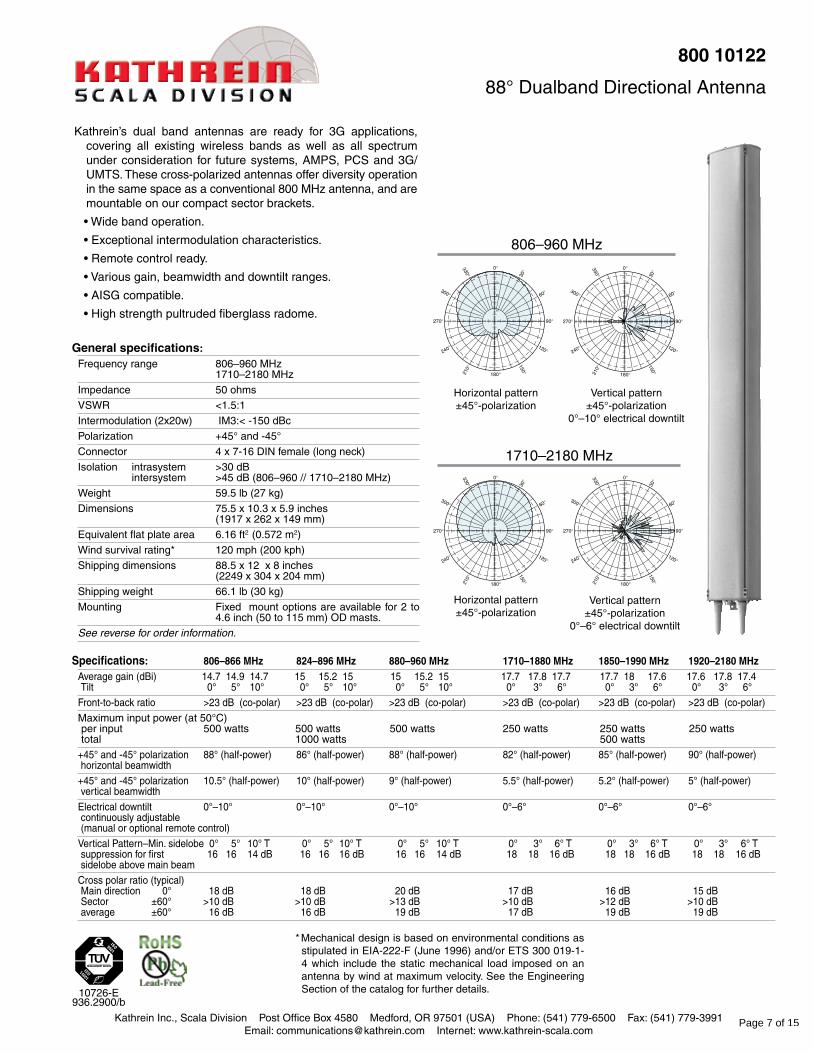
800 10122
88° Dualband Directional Antenna
Kathrein’s dual band antennas are ready for 3G applications, covering all existing wireless bands as well as all spectrum under consideration for future systems, AMPS, PCS and 3G/UMTS. These cross-polarized antennas offer diversity operation in the same space as a conventional 800 MHz antenna, and are mountable on our compact sector brackets.
• Wide band operation.
• Exceptional intermodulation characteristics.
• Remote control ready.
• Various gain, beamwidth and downtilt ranges.
• AISG compatible.
• High strength pultruded fiberglass radome.
806–960 MHz
1710–2180 MHz
Horizontal pattern ±45°-polarization
Horizontal pattern ±45°-polarization
Vertical pattern ±45°-polarization
0°–10° electrical downtilt
Vertical pattern ±45°-polarization
0°–6° electrical downtilt
Specifications: 806–866 MHz 824–896 MHz 880–960 MHz 1710–1880 MHz 1850–1990 MHz 1920–2180 MHz Average gain (dBi) 14.7 14.9 14.7 15 15.2 15 15 15.2 15 17.7 17.8 17.7 17.7 18 17.6 17.6 17.8 17.4 Tilt 0° 5° 10° 0° 5° 10° 0° 5° 10° 0° 3° 6° 0° 3° 6° 0° 3° 6°
Front-to-back ratio >23 dB (co-polar) >23 dB (co-polar) >23 dB (co-polar) >23 dB (co-polar) >23 dB (co-polar) >23 dB (co-polar)
Maximum input power (at 50°C) per input 500 watts 500 watts 500 watts 250 watts 250 watts 250 watts total 1000 watts 500 watts
+45° and -45° polarization 88° (half-power) 86° (half-power) 88° (half-power) 82° (half-power) 85° (half-power) 90° (half-power) horizontal beamwidth
+45° and -45° polarization 10.5° (half-power) 10° (half-power) 9° (half-power) 5.5° (half-power) 5.2° (half-power) 5° (half-power) vertical beamwidth
Electrical downtilt 0°–10° 0°–10° 0°–10° 0°–6° 0°–6° 0°–6° continuously adjustable (manual or optional remote control)
Vertical Pattern–Min. sidelobe 0° 5° 10° T 0° 5° 10° T 0° 5° 10° T 0° 3° 6° T 0° 3° 6° T 0° 3° 6° T suppression for first 16 16 14 dB 16 16 16 dB 16 16 14 dB 18 18 16 dB 18 18 16 dB 18 18 16 dB sidelobe above main beam
Cross polar ratio (typical) Main direction 0° 18 dB 18 dB 20 dB 17 dB 16 dB 15 dB Sector ±60° >10 dB >10 dB >13 dB >10 dB >12 dB >10 dB average ±60° 16 dB 16 dB 19 dB 17 dB 19 dB 19 dB
Page 7 of 15
All specifications are subject to change without notice. The latest specifications are available at www.kathrein-scala.com.
Kathrein Inc., Scala Division Post Office Box 4580 Medford, OR 97501 (USA) Phone: (541) 779-6500 Fax: (541) 779-3991Email: [email protected] Internet: www.kathrein-scala.com
Order Information:Model Description
800 10122 Antenna with 7/16 DIN connectors
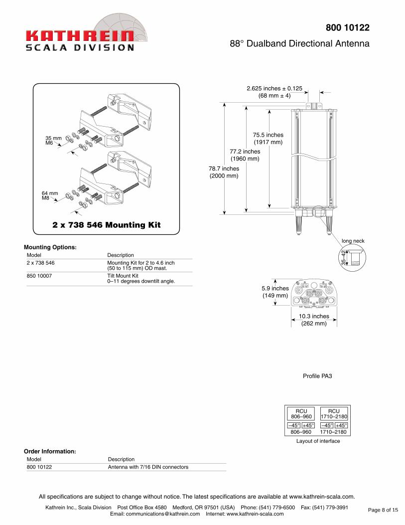
800 10122
88° Dualband Directional Antenna
long neck
35–4
2
2 x 738 546 Mounting Kit
Mounting Options:Model Description
2 x 738 546 Mounting Kit for 2 to 4.6 inch (50 to 115 mm) OD mast.
850 10007 Tilt Mount Kit 0–11 degrees downtilt angle.
10.3 inches(262 mm)
78.7 inches(2000 mm)
75.5 inches(1917 mm)
77.2 inches(1960 mm)
5.9 inches(149 mm)
2.625 inches ± 0.125(68 mm ± 4)
35 mmM6
64 mmM8
Profile PA3
Page 8 of 15

5. 800-10123
Kathrein Inc., Scala Division Post Office Box 4580 Medford, OR 97501 (USA) Phone: (541) 779-6500 Fax: (541) 779-3991Email: [email protected] Internet: www.kathrein-scala.com
Specifications: 806–866MHz 824–896MHz 880–960MHz 1710–1880MHz 1850–1990MHz 1920–2180MHzAverage gain (dBi) 16.1 16.2 16.1 16.3 16.4 16.3 16.5 16.6 16.5 17.8 17.7 17.4 18 17.9 17.4 17.9 17.8 17.3 Tilt 0° 4° 7° 0° 4° 7° 0° 4° 7° 0° 3° 6° 0° 3° 6° 0° 3° 6°
Front-to-back ratio >25 dB (co-polar) >25 dB (co-polar) >25 dB (co-polar) >23 dB (co-polar) >23 dB (co-polar) >23 dB (co-polar)
+45° and -45° polarization 86° (half-power) 86° (half-power) 86° (half-power) 84° (half-power) 85° (half-power) 88° (half-power) horizontal beamwidth
+45° and -45° polarization 7.3° (half-power) 7.2° (half-power) 6.9° (half-power) 4.8° (half-power) 4.5° (half-power) 4.2° (half-power) vertical beamwidth
Electrical downtilt 0.5°–7° 0.5°–7° 0.5°–7° 0°–6° 0°–6° 0°–6° continuously adjustable (manual or optional remote control)
Vertical Pattern–Min. sidelobe 0° 4° 7° T 0° 4° 7° T 0° 4° 7° T 0° 3° 6° T 0° 3° 6° T 0° 3° 6° T suppression for first 15 14 14 dB 15 14 14 dB 15 14 15 dB 18 17 16 dB 18 17 17 dB 18 16 17 dB sidelobe above main beam
Cross polar ratio (typical) Main direction 0° 18 dB 18 dB 20 dB 16 dB 16 dB 15 dB Sector ±60° >10 dB >10 dB >13 dB >10 dB >12 dB >10 dB average ±60° 16 dB 16 dB 19 dB 16 dB 17 dB 18 dB
Maximum input power 806–960 MHz 1710–2180 MHz per input (at 50°C) 500 watts 250 watts total (at 50°C) 1000 watts 500 watts
* Mechanical design is based on environmental conditions as stipulated in EIA-222-F (June 1996) and/or ETS 300 019-1-4 which include the static mechanical load imposed on an antenna by wind at maximum velocity. See the Engineering Section of the catalog for further details.
Generalspecifications:Frequency range 806–960 MHz
1710–2180 MHz
Impedance 50 ohms
VSWR <1.5:1
Intermodulation (2x20w) IM3: <-150 dBc
Polarization +45° and -45°
Connector 4 x 7-16 DIN female (long neck)
Isolation intrasystem >30 dB intersystem >45 dB (806 –960 // 1710–2180 MHz)
Weight 72.8 lb (33 kg)
Dimensions 103.7 x 10.3 x 5.9 inches (2635 x 262 x 149 mm)
Equivalent flat plate area 8.27 ft2 (0.768 m2)
Wind survival rating* 120 mph (200 kph)
Shipping dimensions 116.8 x 12 x 8 inches (2966 x 304 x 204 mm)
Shipping weight 86 lb (39 kg)
Mounting Fixed and tilt mount options are available for 2 to 4.6 inch (50 to 115 mm) OD masts.
See reverse for order information.
10777-C936.2809/e
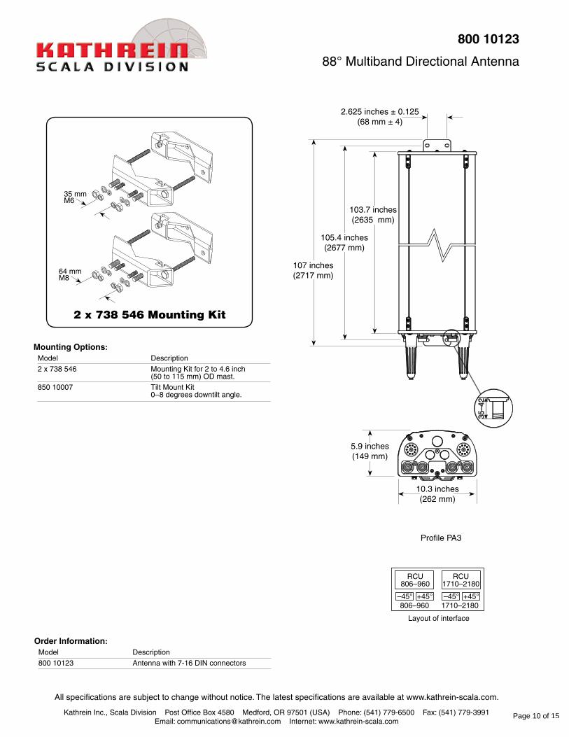
80010123
88° Multiband Directional Antenna
Kathrein’s dual band antennas are ready for 3G applications, covering all existing wireless bands as well as all spectrum under consideration for future systems, AMPS, PCS and 3G/UMTS. These cross-polarized antennas offer diversity operation in the same space as a conventional 800 MHz antenna, and are mountable on our compact sector brackets.
• Wide band operation.
• Exceptional intermodulation characteristics.
• Remote control ready.
• Various gain, beamwidth and downtilt ranges.
• AISG compatible.
• High strength pultruded fiberglass radome.
1710–2180 MHz
Horizontal pattern ±45°-polarization
Horizontal pattern ±45°-polarization
Vertical pattern ±45°-polarization
0.5°–7° electrical downtilt
Vertical pattern ±45°-polarization
0°–6° electrical downtilt
806–960 MHz0
30
60
90
120
150
180210
240
270
300
330 3
10
20
30
0
30
60
90
120
150
180210
240
270
300
330 3
10
20
30
0
30
60
90
120
150
180210
240
270
300
330 3
10
20
30
0
30
60
90
120
150
180210
240
270
300
330 3
10
20
30
Page 9 of 15
All specifications are subject to change without notice. The latest specifications are available at www.kathrein-scala.com.
Kathrein Inc., Scala Division Post Office Box 4580 Medford, OR 97501 (USA) Phone: (541) 779-6500 Fax: (541) 779-3991Email: [email protected] Internet: www.kathrein-scala.com
35–4
2
2 x 738 546 Mounting Kit
MountingOptions:Model Description
2 x 738 546 Mounting Kit for 2 to 4.6 inch (50 to 115 mm) OD mast.
850 10007 Tilt Mount Kit 0–8 degrees downtilt angle.
OrderInformation:Model Description
800 10123 Antenna with 7-16 DIN connectors
10.3 inches(262 mm)
107 inches(2717 mm)
103.7 inches(2635 mm)
80010123
88° Multiband Directional Antenna
105.4 inches(2677 mm)
5.9 inches(149 mm)
RCU806–960
806–960 1710–2180
RCU1710–2180
Layout of interface
–45° +45° –45° +45°
2.625 inches ± 0.125(68 mm ± 4)
35 mmM6
64 mmM8
Profile PA3
Page 10 of 15

6. 7775
90° 2.6 m RET Antenna
Part Number:RA21.7775.00
Horizontal Beamwidth: 90o
Gain: 17 / 17 dBi14.9 / 14.9 dBd
Electrical Downtilt: AdjustableConnector Type: 7/16 DIN female
824-
896/1
850-
1990
MHz
Dual Band Antenna
Key Benefits
• Excellent multi-band capabilities
• Polarization purity makes good diversity gain
• Excellent pattern performance and high gain over frequency
• High passive intermodulation performance
• Light, slim and robust design
The Powerwave dual band dual polarized broadband antenna has individual adjustable electrical downtilt per band (upgradeable to Remote Electrical Tilt (RET). Four connector ports allow separate tilts on each frequency band and ensure the use of diversity concepts. The phase shifter technology, based on a patented sliding dielectric, minimizes intermodulation distortion and maximizes efficiency. The slant +/- 45° dual polarization system provides the independent fading signals needed for achieving top-quality coverage via diversity concepts. The Powerwave Broadband antenna design is based on a patented stacked aperture-coupled patch technology, which provides high isolation performance and a wide VSWR bandwidth. The antennas have superior radiation patterns due to a unique reflector design which provides a very small variation of the –3dB horizontal beam width over the frequency band as well as a high front-to-back ratio.
Page 11 of 15
D03
1-08
472
Rev
. A Corporate HeadquartersPowerwave Technologies, Inc. 1801 East St. Andrew PlaceSanta Ana, CA 92705 USA
Tel: 714-466-1000Fax: 714-466-5800 www.powerwave.com
Main European OfficeAntennvägen 6SE-187 80 TäbySwedenTel: +46 8 540 822 00Fax: +46 8 540 823 40
©Copyright 2006, Powerwave Technologies, Inc. All Rights reserved. Powerwave, Powerwave Technologies, The Power in Wireless and the Powerwave logo are registered trademarks of Powerwave Technologies, Inc.
Main Asia-Pacific Office23 F Tai Yau Building181 Johnston RoadWanchai, Hong KongTel: +852 2512 6123Fax: +852 2575 4860
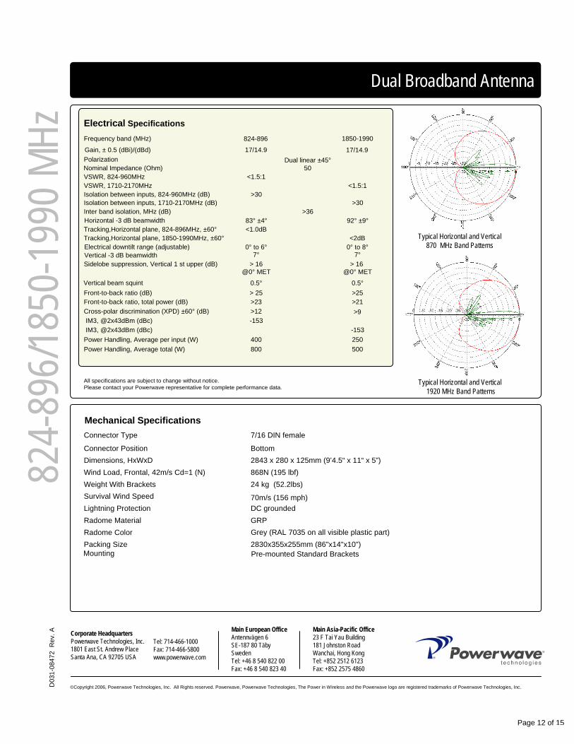
24 kg (52.2lbs) Weight With Brackets
2830x355x255mm (86"x14"x10")Packing SizeRadome Color
GRPRadome MaterialDC groundedLightning Protection70m/s (156 mph)Survival Wind Speed
868N (195 lbf)Wind Load, Frontal, 42m/s Cd=1 (N)2843 x 280 x 125mm (9’4.5“ x 11“ x 5”)Dimensions, HxWxDBottomConnector Position
7/16 DIN femaleConnector Type
Dual Broadband Antenna
Electrical SpecificationsFrequency band (MHz) 824-896 1850-1990
Gain, ± 0.5 (dBi)/(dBd) 17/14.9 17/14.9Polarization Dual linear ±45°Nominal Impedance (Ohm) 50VSWR, 824-960MHz <1.5:1VSWR, 1710-2170MHz <1.5:1Isolation between inputs, 824-960MHz (dB) >30Isolation between inputs, 1710-2170MHz (dB) >30Inter band isolation, MHz (dB) >36Horizontal -3 dB beamwidth 83° ±4° 92° ±9°Tracking,Horizontal plane, 824-896MHz, ±60° <1.0dBTracking,Horizontal plane, 1850-1990MHz, ±60° <2dBElectrical downtilt range (adjustable) 0° to 6° 0° to 8°Vertical -3 dB beamwidth 7° 7°Sidelobe suppression, Vertical 1 st upper (dB) > 16 > 16
@0° MET @0° MET
Vertical beam squint 0.5° 0.5°Front-to-back ratio (dB) > 25 >25Front-to-back ratio, total power (dB) >23 >21Cross-polar discrimination (XPD) ±60° (dB) >12IM3, @2x43dBm (dBc) -153IM3, @2x43dBm (dBc) -153
Power Handling, Average per input (W) 400 250Power Handling, Average total (W) 800 500
All specifications are subject to change without notice. Please contact your Powerwave representative for complete performance data.
Mechanical Specifications
Typical Horizontal and Vertical 870 MHz Band Patterns
Typical Horizontal and Vertical1920 MHz Band Patterns
Grey (RAL 7035 on all visible plastic part)
Pre-mounted Standard BracketsMounting
824-
896/1
850-
1990
MHz
>9
Page 12 of 15

7. 742266
Kathrein Inc., Scala Division Post Office Box 4580 Medford, OR 97501 (USA) Phone: (541) 779-6500 Fax: (541) 779-3991Email: [email protected] Internet: www.kathrein-scala.com
Kathrein’s dual band antennas are ready for 3G applications, covering all existing wireless bands as well as all spectrum under consideration for future systems, AMPS, PCS and 3G/UMTS. These cross-polarized antennas offer diversity operation in the same space as a conventional 800 MHz antenna, and are mountable on our compact sector brackets.
• Wide band operation.
• Exceptional intermodulation characteristics.
• Remote control ready.
• Various gain, beamwidth and downtilt ranges.
• AISG compatible.
• High strength pultruded fiberglass radome.
General specifications: Frequency range 824–960 MHz
1710–2180 MHz
VSWR <1.5:1
Impedance 50 ohms
Intermodulation (2x20w) IM3: <-150dBc
Polarization +45° and -45°
Connector 4 x 7-16 DIN female (long neck)
Isolation intrasystem >30 dB intersystem >50 dB (824–960 // 1710–2180 MHz)
Weight 59.5 lb (27 kg)
Dimensions 99.1 x 10.3 x 5.5 inches (2516 x 262 x 139 mm)
Equivalent flat plate area 8.27 ft2 (0.768 m2)
Wind survival rating* 120 mph (200 kph)
Shipping dimensions 110.8 x 11.9 x 7.8 inches (2815 x 302 x 192 mm)
Shipping weight 75 lb (34 kg)
Mounting Fixed and tilt mount options are available for 2 to 4.6 inch (50 to 115 mm) OD masts.
See reverse for order information.
Horizontal pattern±45°- polarization
Vertical pattern±45°- polarization
0°–6° electrical downtilt
Vertical pattern±45°- polarization
0.5°–7° electrical downtilt
Horizontal pattern±45°- polarization
* Mechanical design is based on environmental conditions as stipulated in EIA-222-F (June 1996) and/or ETS 300 019-1-4 which include the static mechanical load imposed on an antenna by wind at maximum velocity. See the Engineering Section of the catalog for further details.
824–960 MHz
1710–2180 MHz
10635-K 936.3219/b
742 266
65° Dualband Directional Antenna
Specifications: 824–894 MHz 880–960 MHz 1710–1880 MHz 1850–1990 MHz 1900–2180 MHzGain 16.5 dBi 17 dBi 17.8 dBi 18.2 dBi 18.3 dBi
Front-to-back ratio >28 dB (co-polar) >28 dB (co-polar) >25 dB (co-polar) >25 dB (co-polar) >25 dB (co-polar)
Maximum input power per input 500 watts (at 50°C) 500 watts (at 50°C) 250 watts (at 50°C) 250 watts (at 50°C) 250 watts (at 50°C) total power 1000 watts (at 50°C) 500 watts (at 50°C)
+45° and -45° polarization 68° (half-power) 65° (half-power) 67° (half-power) 65° (half-power) 62° (half-power) horizontal beamwidth
+45° and -45° polarization 7.3° (half-power) 7° (half-power) 5.2° (half-power) 5° (half-power) 4.7° (half-power) vertical beamwidth
Electrical downtilt 0.5°–7° 0.5°–7° 0°–6° 0°–6° 0°–6° continuously adjustable
Sidelobe suppression for 0.5° 4° 7° T 0.5° 4° 7° T 0° 3° 6° T 0° 3° 6° T 0° 3° 6° T first sidelobe above horizon 14 14 14 dB 16 16 16 dB 13 13 13 dB 16 15 14 dB 15 15 15 dB
Cross polar ratio Main direction 0° 20 dB (typical) 20 dB (typical) 17 dB (typical) 18 dB (typical) 18 dB (typical) Sector ±60° >10 dB >10 dB >10 dB >10 dB >10 dB
Page 13 of 15

Kathrein Inc., Scala Division Post Office Box 4580 Medford, OR 97501 (USA) Phone: (541) 779-6500 Fax: (541) 779-3991Email: [email protected] Internet: www.kathrein-scala.com
All specifications are subject to change without notice. The latest specifications are available at www.kathrein-scala.com.
long neck
35–4
2
10.3 inches(262 mm)
102.6 inches(2607 mm)
99.1 inches(2516 mm)
5.5 inches(139 mm)
Order Information:Model Description
742 266 Antenna with 7-16 DIN connectors
742 266
65° Dualband Directional Antenna
101.1 inches(2567 mm)
2.625 inches ± 0.125(68 mm ± 4)
Mounting Options:Model Description
2 x 738 546 Mounting Kit for 2 to 4.6 inch (50 to 115 mm) OD mast.
742 033 Three-panel Sector Mounting Kit (120 deg. ea.) for 4.5 inch (114.3 mm mm) OD steel mast.
742 034 Three-panel Sector Mounting Kit (120 deg. ea.) for 5.5 inch (139.7 mm mm) OD steel mast.
850 10007 Tilt Mount Kit 0–8 Degrees downtilt angle.
2 x 738 546 Mounting Kit
35 mmM6
64 mmM8
Page 14 of 15

8. P65-16-XLH-RRDual Broadband AntennasP65-16-XLH-RR
ANTENNA PATTERNS*
*All specifications subject to change without notice. Please contact your Powerwave representative for complete performance data.
For detailed patterns visit http://www.powerwave.com/rpa/.
Frequency range (MHz) 698-894 1710-2170
Vertical beam squint (°) < 0.8 < 0.5
Front to back ratio (dB) >24 > 30
Tracking, horizontal plane ±60° (dB) < 2 < 2
Isolation between inputs (dB) > 30 > 30
Inter band Isolation (dB) > 40 > 40
IM3, 2xTx@43dBm (dBc) -153 -153
Power handling, average per input (W) 500 250
Cross polar discrimination (XPD) ±60° (dB) > 10 > 10
Front to back ratio, total power (dB)
Cross polar discrimination (XPD) 0° (dB) > 15 > 15
Polarization Dual Linear +/- 45 Dual Linear +/- 45
Nominal Impedance (Ω) 50 50
Gain (dBi/dBd) 13.5/11.4 14.0/11.9 15.5/13.4 16.7/14.6 17.0/14.9
Side lobe suppression, vertical 1st upper (dB) > 16 > 16
Frequency band (MHz) 698-806 806-894 1710-1880 1850-1990 1900-2170
Electrical down tilt (°) 2 to 10 0 to 10
Power handling, average total (W) 1000 500
Vertical beam width, -3 dB (°) 14.7 6.8
VSWR < 1.4:1 < 1.4:1
Horizontal beam width, -3 dB (°) 73 65 63 57 52
ELECTRICAL SPECIFICATIONS*
GAIN (dBi/dBd): 14/11.9 17/14.9
TILT: 2-10, 0-10
LENGTH: 72”
POLARIZATION: Dual linear ±45°
FREQUENCY (MHz): 698-894, 1710-2170
HORIZONTAL BEAM WIDTH (°): 65, 65
Operating Temperature -40C to +60C
Radome material PVC, IP55
Survival wind speed, mph (m/s) 150 (67)
Lightning protection DC Ground
Shipping weight, lbs (kg) 75 (34)
RET iRET AISGv1.1, MET and AISGv2.0
Packet size, HxWxD, in (mm) 87” x 16” x 10” (2225 x 400 x 225)
Radome colour Light Grey
Brackets 7256.00, 7454.00, 2210.00
Connector position Bottom
Dimensions, HxWxD, in (mm) 72” x 12” x 6” (1829 x 305 x 152)
Maximum operational wind speed, mph (m/s) 100 (45)
Connector 4 X 7/16 DIN Female, IP67
Weight, without brackets, lbs (kg) 53 (24)Wind load, frontal/lateral/rear side 42 m/s Cd=1.0 (N) 1380
Mounting Pre-mounted Tilt Brackets
Weight, with brackets, lbs (kg) 64 (29)
MECHANICAL SPECIFICATIONS*
© Copyright 2009 Powerwave Technologies, Inc. All rights reserved.
POWERWAVE Dual Broadband Antennas
Page 15 of 15
pc089x
Stamp