Advanced Computer Networking - IS MUNI
93
1. Introduction – Recapitulation of assumed knowledge PA191: Advanced Computer Networking Eva Hladk´ a Slides by: Tom´ aˇ s Rebok Faculty of Informatics Masaryk University Autumn 2014 Eva Hladk´ a (FI MU) 1. Recapitulation of assumed knowledge Autumn 2014 1 / 93
-
Upload
khangminh22 -
Category
Documents
-
view
0 -
download
0
Transcript of Advanced Computer Networking - IS MUNI

1. Introduction – Recapitulation of assumed knowledge
PA191: Advanced Computer Networking
Eva Hladka
Slides by: Tomas Rebok
Faculty of Informatics Masaryk University
Autumn 2014
Eva Hladka (FI MU) 1. Recapitulation of assumed knowledge Autumn 2014 1 / 93

Course Introduction
Course Organization
attending the lectures is optional
the knowledge acquired during PB156 course or in book J. KuroseComputer networking is assumed
course materials will be published on the course webpage (more orless in time ;-) )
assessment methodology:
final exam (written form)no priority questions on the exams
course literature:
slides, RFCs, . . .literature being announced in relevant course parts
Eva Hladka (FI MU) 1. Recapitulation of assumed knowledge Autumn 2014 2 / 93

Course Introduction
Course Overview
the course goal:
to provide an advanced insight into the area of computer networks andtheir applications
discussed topics:
advanced IPv6 functionalitiesadvanced routing mechanismsQoS in computer networksad-hoc/sensor networkspeer-to-peer networks/systemsmobile servicesetc.
Eva Hladka (FI MU) 1. Recapitulation of assumed knowledge Autumn 2014 3 / 93

Lecture overview
Recapitulation of assumed knowledge
Recapitulation of assumed knowledge
Eva Hladka (FI MU) 1. Recapitulation of assumed knowledge Autumn 2014 4 / 93

Lecture overview
Lecture overview
1 Course Introduction
2 Lecture overview
3 IntroductionComputer Networks in GeneralNetwork ProtocolsStandardization
4 Network ModelsISO/OSI ModelISO/OSI vs. TCP/IP Model
5 TCP/IP ModelL1 – Physical LayerL2 – Data Link LayerL3 – Network LayerL4 – Transport LayerL7 – Application Layer
Eva Hladka (FI MU) 1. Recapitulation of assumed knowledge Autumn 2014 5 / 93

Introduction Computer Networks in General
Lecture overview
1 Course Introduction
2 Lecture overview
3 IntroductionComputer Networks in GeneralNetwork ProtocolsStandardization
4 Network ModelsISO/OSI ModelISO/OSI vs. TCP/IP Model
5 TCP/IP ModelL1 – Physical LayerL2 – Data Link LayerL3 – Network LayerL4 – Transport LayerL7 – Application Layer
Eva Hladka (FI MU) 1. Recapitulation of assumed knowledge Autumn 2014 6 / 93

Introduction Computer Networks in General
Computer NetworksIntroduction
a group of computers and devices interconnected by communicationschannels that facilitate communications among users and allows usersto share resources
can be used for various purposes:
facilitating communications (in various ways – text, speech, video, etc.)sharing hardwaresharing files, data, and informationsharing software
fundamental characteristics:
Delivery – the system must deliver data to the correct destinationAccuracy – the system must deliver data accuratelyTimeliness – the system must deliver data in a timely manner
Eva Hladka (FI MU) 1. Recapitulation of assumed knowledge Autumn 2014 7 / 93

Introduction Computer Networks in General
Computer NetworksIdeal vs. Real Networks
Ideal Networks
transparent forusers/applications
just end-to-end characteristics
unlimited throughput
no losses
no delay/latency and jitter
keeps packet ordering
data cannot be corrupted
Real Networks
have internal structure whichinfluences data transmission
limited throughput
(sometimes) data losses
(sometimes) variabledelay/latency and jitter
(sometimes) do not keep packetordering
data can be corrupted
Eva Hladka (FI MU) 1. Recapitulation of assumed knowledge Autumn 2014 8 / 93

Introduction Computer Networks in General
Computer NetworksRequired features
efficiency – efficient/maximal use of available throughput
fairness – the same approach to all the data flows (having the samepriority)
decentralised management
fast convergence when adapting to a new state
multiplexing/demultiplexing
reliability
data flow control – a protection in order to avoid network’s (networkdevices’) and hosts’ congestion
Eva Hladka (FI MU) 1. Recapitulation of assumed knowledge Autumn 2014 9 / 93

Introduction Computer Networks in General
Computer NetworksBasic Approaches I.
connection-oriented networks (circuit switching networks)a connection (called a circuit) is set up between two devices, which isused for the whole communicationinformation about the nature of the circuit is maintained by thenetwork – a state has to be maintainedcircuit may either be a fixed one or created on an “as-needed” basiseasy (more or less automatic) implementation of the QoSe.g., the regular telephone system
connection-less (state-less) networks (packet switching networks)no specific path is used for data transfer – the data is chopped up intosmall pieces (called packets) and sent over the network
packets can be routed, combined or fragmentedon the receiving end the data is read from the packets andre-assembled into the form of the original datano state has to be maintainedvery hard implementation of the QoS (best-effort service)e.g., the Internet
Eva Hladka (FI MU) 1. Recapitulation of assumed knowledge Autumn 2014 10 / 93

Introduction Computer Networks in General
Computer NetworksBasic Approaches II.
connection-oriented network
connection-less network
Eva Hladka (FI MU) 1. Recapitulation of assumed knowledge Autumn 2014 11 / 93
Introduction Network Protocols
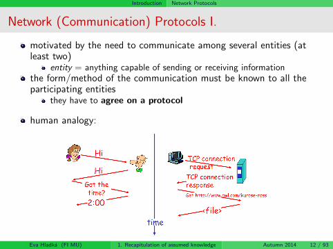
Network (Communication) Protocols I.
motivated by the need to communicate among several entities (atleast two)
entity = anything capable of sending or receiving informationthe form/method of the communication must be known to all theparticipating entities
they have to agree on a protocol
human analogy:
Eva Hladka (FI MU) 1. Recapitulation of assumed knowledge Autumn 2014 12 / 93

Introduction Network Protocols
Network (Communication) Protocols II.
the protocol defines “What” the subject of communication is, “How”the communication has to behave and “When” does it behavethey define:
syntax = structure/format of data (the order in which they arepresented)semantics = refers to the meaning of each section of bits (how shoulda particular pattern to be interpreted)timing = when data should be sent and how fast they can be sent
examples of network protocols:UDP, TCP, IP, IPv6, SSL, TLS, SNMP, HTTP, FTP, SSH, Aloha,CSMA/CD, . . .
Network Protocol
Network Protocol is a set of rules that defines the format and the order ofmessages exchanged among two or more communicating entities, as well as theactions performed during sending/receiving that messages.
Eva Hladka (FI MU) 1. Recapitulation of assumed knowledge Autumn 2014 13 / 93
Introduction Standardization
Standardization
definition of norms/standards describing various actions, activities,forms/methods of communication, etc. (not only in IT)
main goals:
qualitysecuritycompatibilityinteroperabilityportability
standards fall into two categories:
de facto – standards that have not been approved by an organizedbody but have been adopted as standards through widespread use(they are often established originally by manufacturers)de jure – standards legislated by an officially recognized body
standard IT organizations:
ISO, ITU-T, ANSI, IEEE, IETF (RFCs), IEC, etc.
Eva Hladka (FI MU) 1. Recapitulation of assumed knowledge Autumn 2014 14 / 93

Network Models
Lecture overview
1 Course Introduction
2 Lecture overview
3 IntroductionComputer Networks in GeneralNetwork ProtocolsStandardization
4 Network ModelsISO/OSI ModelISO/OSI vs. TCP/IP Model
5 TCP/IP ModelL1 – Physical LayerL2 – Data Link LayerL3 – Network LayerL4 – Transport LayerL7 – Application Layer
Eva Hladka (FI MU) 1. Recapitulation of assumed knowledge Autumn 2014 15 / 93

Network Models ISO/OSI Model
ISO/OSI Model I.
7-layer model proposed by OSI organization in order to ensurecompatibility and interoperability of communication systemsdeveloped by various vendors
the purpose of layered architecture:each layer is responsible for particular functionality
it adds some control information to the data in order to do its job
each layer communicates just with its neighbours
each layer uses the services provided by the lower layer and provides itsservices to the higher layerthe functionality is isolated in the particular layer (once a layerchanges, just the neighbouring layers have to adapt to such a change)
logically, the communication is performed just between peer layers;physically, the communication traverses all the lower layersthe layers are just an abstraction – the real implementations are moreor less different
7 layers not widely accepted ⇒ TCP/IP model
Eva Hladka (FI MU) 1. Recapitulation of assumed knowledge Autumn 2014 16 / 93

Network Models ISO/OSI Model
ISO/OSI Model II.
Eva Hladka (FI MU) 1. Recapitulation of assumed knowledge Autumn 2014 17 / 93

Network Models ISO/OSI vs. TCP/IP Model
ISO/OSI Model vs. TCP/IP Model
Eva Hladka (FI MU) 1. Recapitulation of assumed knowledge Autumn 2014 18 / 93

Network Models ISO/OSI vs. TCP/IP Model
TCP/IP Hourglass Model
Eva Hladka (FI MU) 1. Recapitulation of assumed knowledge Autumn 2014 19 / 93

TCP/IP Model
Lecture overview
1 Course Introduction
2 Lecture overview
3 IntroductionComputer Networks in GeneralNetwork ProtocolsStandardization
4 Network ModelsISO/OSI ModelISO/OSI vs. TCP/IP Model
5 TCP/IP ModelL1 – Physical LayerL2 – Data Link LayerL3 – Network LayerL4 – Transport LayerL7 – Application Layer
Eva Hladka (FI MU) 1. Recapitulation of assumed knowledge Autumn 2014 20 / 93

TCP/IP Model L1 – Physical Layer
L1 – Physical LayerIntroduction I.
Physical Layer:provides the functionality for an interaction with transmission mediaprovides services for the Data Link Layer
the Data Link Layer passes/obtains data to/from the Physical Layer inthe form of 0s and 1s organized into framesthe Physical Layer transforms the streams of bits (from frames) intosignals spread through the transmission media
controls the transmission media; for example, decides about:
sending/receiving the data (signals)data transformation (coding) into signalsthe number of logical channels simultaneously transferring data fromvarious sources
Eva Hladka (FI MU) 1. Recapitulation of assumed knowledge Autumn 2014 21 / 93

TCP/IP Model L1 – Physical Layer
L1 – Physical LayerIntroduction II.
the main goal: to ensure a transmission of bits (= the content ofpassed frames) between sender and receiver
several standards (RS-232-C, CCITT V.24, CCITT X.21, IEEE 802.x)defining electrical, mechanical, functional, and proceduralcharacteristics of interfaces used for connecting various transmissionmedia and devices, e.g.:
parameters of the transmitted signals, their meaning and timingmutual relationships of control and state signalsconnectors’ wiringand many many others
Eva Hladka (FI MU) 1. Recapitulation of assumed knowledge Autumn 2014 22 / 93

TCP/IP Model L1 – Physical Layer
Figure: Position of the Physical Layer.
Eva Hladka (FI MU) 1. Recapitulation of assumed knowledge Autumn 2014 23 / 93
TCP/IP Model L1 – Physical Layer
L1 – Physical LayerServices
Bit-to-Signal Transformation
representing the bits by a signal – electromagnetic energy that canpropagate through medium
Bit-Rate Control
the number of bits sent per second
Bit Synchronization
the timing of the bit transfer (synchronization of the bits by providingclocking mechanisms that control both sender and receiver)
Multiplexing
the process of dividing a link (physical medium) into logical channelsfor better efficiency
Circuit Switching
circuit switching is usually a function of the physical layer(packet switching is an issue of the data link layer)
Eva Hladka (FI MU) 1. Recapitulation of assumed knowledge Autumn 2014 24 / 93
TCP/IP Model L1 – Physical Layer
L1 – Physical LayerSignals
data is transferred (via transmission media) in the form of(electromagnetic) signals
the data have to be converted into the signals
signal = a function of time representing changes of physical(electromagnetic) characteristics of the transmission media
data that have to be transferred (0s and 1s) – digital (binary)
signals spread through the transmission media – analog or digital
some media suitable for both analog and digital transmission – wiredmedia (coaxial cable, twisted pair), optical fibresome media suitable just for analog transmission – ether (air)
Eva Hladka (FI MU) 1. Recapitulation of assumed knowledge Autumn 2014 25 / 93

TCP/IP Model L1 – Physical Layer
L1 – Physical LayerTransmission Media
provide an environment for the functionality of physical layer
basic distinction:guided (wired) media
provide a conduit from one device to anothertwisted pair (LANs, up to 10 Gbps), coaxial cable, optical fibre(backbones, hundreds of Gbps), etc.
unguided (wire-less) media
transfer an electromagnetic wave without the use of physical conductorthe signals are broadcasted (spread) via ether (air, vacuum, water, etc.)radio signals, microwave signals, infrared signals, etc.
for details see PV183: Computer Networks Technology
Eva Hladka (FI MU) 1. Recapitulation of assumed knowledge Autumn 2014 26 / 93

TCP/IP Model L1 – Physical Layer
L1 – Physical LayerMultiplexing
multiplexing – a technique of sharing an available bandwidth byconcurrent communication channels
the goal is to maximize the utilization of the mediaapplied especially for optical fibres and non-wired media
for analog signals:Frequency-Division Multiplexing (FDM)Wave-Division Multiplexing (WDM)
for digital signals:Time-Division Multiplexing (TDM)
Eva Hladka (FI MU) 1. Recapitulation of assumed knowledge Autumn 2014 27 / 93

TCP/IP Model L1 – Physical Layer
L1 – Physical LayerResume
ensures the transmission of particular bits (0s and 1s) between thesender and receivertransferred bits are transcoded into the form of signals spread throughthe transmission media
the use of analog signals requires a modulationthe use of digital signals requires a transcoding
especially because of synchronization problems
for the transmission, both wired (twisted pair, optical fibre, etc.) ornon-wired (ether) media can be used
each of them is suitable for different conditionsthe technique of sharing a single media by concurrent transmissions iscalled multiplexing
further information:PB156: Computer Networks (doc. Hladka)PV169: Communication Systems Basics (doc. Staudek)PV183: Computer Networks Technology (dr. Pelikan)
Eva Hladka (FI MU) 1. Recapitulation of assumed knowledge Autumn 2014 28 / 93

TCP/IP Model L2 – Data Link Layer
L2 – Data Link LayerIntroduction
Data Link Layer:receives packets (being passed from the Network Layer) and transformsthem into framesin cooperation with the Physical layer ensures the transmission offrames between communicating devices interconnected with a (shared)transmission media
i.e., just the local (inside a segment) delivery (LAN)
ensures the transmission reliability between these devicesensures the flow control in order to avoid receiver congestioncontrols the access of the devices to shared media (Medium AccessControl)
Eva Hladka (FI MU) 1. Recapitulation of assumed knowledge Autumn 2014 29 / 93

TCP/IP Model L2 – Data Link Layer
L2 – Data Link LayerServices
Framingthe incoming packets (being passed from the Network Layer) areencapsulated into frames
Addressingprovides the addresses of physical layer entities – physical/MAC addressesframes contain source and destination addresses of communicating entities
Error Controlit’s not possible to eliminate the errors occurring on the physical layerL2 layer ensures the required level of reliability of the data link (errordetection and correction)
Flow Controlprevents the receiver congestionstop-and-wait mechanism, sliding-window mechanism, . . .
Medium Access Control – MACnecessary in environments, where the transmission media is shared by severalentitieseliminates collisions caused by multiple (concurrent) transmissions
Eva Hladka (FI MU) 1. Recapitulation of assumed knowledge Autumn 2014 30 / 93
TCP/IP Model L2 – Data Link Layer
L2 – Data Link LayerError Control
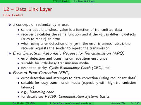
a concept of redundancy is usedsender adds bits whose value is a function of transmitted datareceiver calculates the same function and if the values differ, it detects(tries to repair) an errorwhen using error detection only (or if the error is unrepairable), thereceiver requests the sender to repeat the transmission
Error Detection, Automatic Request for Retransmission (ARQ)error detection and transmission repetition ensurancesuitable for little-lossy transmission mediaeven/odd parity, Cyclic Redundancy Check (CRC), etc.
Forward Error Correction (FEC)error detection and attempts to data correction (using redundant data)suitable for lossy transmission media (especially with high transmissionlatency)e.g., Hamming codefor details see PV169: Communication Systems Basics
Eva Hladka (FI MU) 1. Recapitulation of assumed knowledge Autumn 2014 31 / 93

TCP/IP Model L2 – Data Link Layer
L2 – Data Link LayerMedium Access Control (MAC)
the functionality responsible for coordination of multiple devices’access to shared transmission media
The goal: the elimination of collisions caused by concurrenttransmissions (emissions)
i.e., concurrent transmissions to a shared transmission environment
medium access protocols:
random-access protocols – Aloha, CSMA/CD, CSMA/CAcontrolled-access protocols – based on reservations, polling, tokens, etc.channelization protocols (multiplex-oriented access) – FDMA, TDMA,etc.
Eva Hladka (FI MU) 1. Recapitulation of assumed knowledge Autumn 2014 32 / 93

TCP/IP Model L2 – Data Link Layer
L2 – Data Link LayerL2 Networks I.
local area networks (LANs)a systematic topology for simple networks
bus, circle, star, tree, mesh, etc.
wider networks are composed by interconnecting simple topologies(local area networks)
common L2 interconnection devices:bridge
transparent network interconnection (all the traffic passes the bridge)separates shared media (collisions do not pass the bridge)
switch
≈ multi-port bridge
Eva Hladka (FI MU) 1. Recapitulation of assumed knowledge Autumn 2014 33 / 93

TCP/IP Model L2 – Data Link Layer
L2 – Data Link LayerL2 Networks II.
based on MAC addresses
Backward Learning Algorithm – the bridge “learns” the locations ofnetwork stations (nodes) by listening on the media (observing thesource addresses)the frames are switched based on the receiver address
characteristics:it’s possible to create networks with loops (cycles)
Distributed Spanning Tree Algorithm for the spanning tree calculationis used
not suitable for large networks
switch tables grow with the number of stations – low convergence
Eva Hladka (FI MU) 1. Recapitulation of assumed knowledge Autumn 2014 34 / 93

TCP/IP Model L2 – Data Link Layer
L2 – Data Link LayerDistributed Spanning Tree Algorithm I.
the algorithm goal: to disable (disuse) some bridges’ ports (in orderto prevent loops)
every bridge sends periodical reports<own address, root bridge address, currently known cost of the path tothe root bridge>
once a bridge receives a report from its neighbour, it adapts its ideaabout the “best” path:
it prefers the root with lower addressit prefers lower path costsin the case of same paths’ costs it prefers lower address
mechanism:root bridge selection (the lowest address)sequential growth of the treethe “best” paths found define the active bridges’ portsthe other ports are disabled
Eva Hladka (FI MU) 1. Recapitulation of assumed knowledge Autumn 2014 35 / 93

TCP/IP Model L2 – Data Link Layer
L2 – Data Link LayerDistributed Spanning Tree Algorithm II.
root bridge selection phaseonce started, all the bridges claim themselves as Root Bridges (and reportthis to the others)each of them sends its report via all its portsbased on this information, the root bridge is selected (the lowest address)
root ports selection phaseeach bridge chooses its Root Port – the port with the lowest path cost to theRoot Bridgeif two ports have the same costs, the one with lower Port ID is selected. Theother is disabled (it becomes non-designated) in order to prevent loops
active/inactive ports selection phaseRoot Bridge sets all its ports as active (Designated)the bridges communicate via all the links, which do not contain Root Ports,and try to determine the one with the lowest Bridge ID. Once the one isselected, it sets its corresponding port as active; the other disables its port.
see the animation: http:
//frakira.fi.muni.cz/~jeronimo/vyuka/Cisco-spanning_tree.swfEva Hladka (FI MU) 1. Recapitulation of assumed knowledge Autumn 2014 36 / 93

TCP/IP Model L2 – Data Link Layer
L2 – Data Link LayerResume
ensures the transmission of frames between two communicating devices(determined by their MAC addresses) interconnected via shared transmissionmedia
ensuring the reliability of the transferpreventing the receiver from the congestionusing the medium access control (MAC protocols)
L2 networks (LANs):(usually) bus, circle, and star topologiesthe essential devices for building wider area networks are bridges and switchesBackward Learning Algorithm to determine stations’ location (necessary forframes’ switching)Spanning Tree Algorithm is used for spanning tree determination
further information:PV169: Communication Systems Basics (doc. Staudek)PV183: Computer Networks Technology (dr. Pelikan)graph algorithms – PB165: Graphs and Networks (prof. Matyska, doc.Hladka, doc. Rudova)
Eva Hladka (FI MU) 1. Recapitulation of assumed knowledge Autumn 2014 37 / 93

TCP/IP Model L3 – Network Layer
L3 – Network LayerIntroduction
Network Layer:provides services for the Transport Layer:
receives segments from the Transport Layer and transforms them intopacketsin cooperation with the Data Link Layer ensures the packets’transmission between communicating nodes (even between differentLANs)
logically joins independent LAN networks
the upper layers are provided with an illusion of just a single wide-areanetwork (WAN)
allows unique identification (addressing) of every host/device on theInternetensures routing of passing packetsin cooperation with the Data Link Layer associates the L3-addresseswith the L2/MAC-addresses (and vice versa)further services: multicast
Eva Hladka (FI MU) 1. Recapitulation of assumed knowledge Autumn 2014 38 / 93

TCP/IP Model L3 – Network Layer
Figure: Position of the Network Layer.
Eva Hladka (FI MU) 1. Recapitulation of assumed knowledge Autumn 2014 39 / 93

TCP/IP Model L3 – Network Layer
L3 – Network LayerServices I.
Internetworkinglogical gluing of heterogeneous physical networks together to look likea single network (from the upper layers’ point of view)
by such an interconnection, an internetwork (shortly internet) is created
an illusion of a uniform environment provided by a single wide-areanetwork
Packetizingreceived segments are transformed into packets
Fragmentinga technique to solve the problem of heterogeneous MTUs – when adatagram is larger than the MTU of the network over which it must besent, it is divided into smaller fragments which are each sent separately
Addressingthe entity addresses used on the network layer – so-called IP addresses,unique throughout the whole networkpackets contain source and destination addresses of communicatingentities
Eva Hladka (FI MU) 1. Recapitulation of assumed knowledge Autumn 2014 40 / 93

TCP/IP Model L3 – Network Layer
L3 – Network LayerServices II.
Address Resolution
ARP, RARP protocols
Routing
the process of selecting paths in a network along which to send networktraffic from a source to a particular destination
Control Messaging
providing basic information about unavailability to deliver a packet,about a network/host state, etc. – ICMP protocol
Eva Hladka (FI MU) 1. Recapitulation of assumed knowledge Autumn 2014 41 / 93

TCP/IP Model L3 – Network Layer
L3 – Network LayerAddressing
a requirement to uniquely identify every host/device connected to theInternet
a necessity to systematic address assignment
in order to simplify the routing process
every device/interface is assigned an Internet address (IP address)
IPv4 address (32 bits) vs. IPv6 address (128 bits)
Eva Hladka (FI MU) 1. Recapitulation of assumed knowledge Autumn 2014 42 / 93

TCP/IP Model L3 – Network Layer
L3 – Network LayerIPv4 Addresses – types
Unicast Address – an identification of a single network interface
identification of a single sender/receiver
Broadcast Address – in this case, the data are sent to all the hosts onthe particular LAN (“all-hosts broadcast”)
the source address of such datagrams (sender identification) is unicastaddress
Multicast Address – used for an identification of a group of receivers(network interfaces) who applied for the data
routers send such data to all the group membersthe source address of such datagrams (sender identification) is unicastaddress
Eva Hladka (FI MU) 1. Recapitulation of assumed knowledge Autumn 2014 43 / 93

TCP/IP Model L3 – Network Layer
L3 – Network LayerIPv6 Addresses
addresses used by the IPv6 protocol (see later)
(currently) final solution of IP address space shortageIPv6 address has 128 bits (= 16 Bytes):
2128 of possible addresses (≈ 3× 1038 addresses ⇒ ≈ 5× 1028
addresses for every human on the Earth)a hexadecimal notation instead of decadic notation (in pairs of bytesseparated by “:”)
Eva Hladka (FI MU) 1. Recapitulation of assumed knowledge Autumn 2014 44 / 93

TCP/IP Model L3 – Network Layer
L3 – Network LayerIPv6 Addresses – address abbreviation
Leading zeros might be omitted in every group:0074 might be written as 74, 000F as F , . . .3210 cannot be abbreviated!
Consecutive groups of zeros might be omitted:and replaced by the “::” symboljust a single sequence of zero groups might be abbreviated!
Eva Hladka (FI MU) 1. Recapitulation of assumed knowledge Autumn 2014 45 / 93
TCP/IP Model L3 – Network Layer
L3 – Network LayerIPv6 Addresses – types
Unicast Address – same as in IPv4 (an identification of a singlenetwork interface)
Multicast Address – same as in IPv4 (used for addressing a group ofreceivers)
the data are delivered to all members of the particular groupsprefix ff00::/8
Anycast Address – a newbie
identifies a group of receivers like multicastbut the data are delivered just to a single member of such a group (theclosest one)
IPv4 broadcast addresses are not used in IPv6
they were substituted by particular multicast groups (e.g., a group ofall hosts/routers on the particular LAN)
Eva Hladka (FI MU) 1. Recapitulation of assumed knowledge Autumn 2014 46 / 93

TCP/IP Model L3 – Network Layer
L3 – Network LayerInternet Protocol (IP) I.
the most widespread network layer protocolensures data (in pieces called datagrams) delivery, even through anintermediate nodes (called routers) – host-to-host delivery
hosts/interfaces are identified by their IP addressesuses datagram approach to packet switching, the communication isconnectionless⇒ routing
provides an unreliable (so-called best-effort) servicesupplemented by a set of supporting protocols (ICMP, ARP, RARP,IGMP)
used for nonstandard situations treatment, a distribution of informationnecessary for correct routing, L2 identification of network interfaces(MAC addresses), etc.
proposed and standardized in two versions:
Internet Protocol version 4 (IPv4) – 1981, RFC 791Internet Protocol version 6 (IPv6) – 1998, RFC 2460
Eva Hladka (FI MU) 1. Recapitulation of assumed knowledge Autumn 2014 47 / 93

TCP/IP Model L3 – Network Layer
L3 – Network LayerInternet Protocol (IP) II.
Supplementary protocols:
Eva Hladka (FI MU) 1. Recapitulation of assumed knowledge Autumn 2014 48 / 93
TCP/IP Model L3 – Network Layer
L3 – Network LayerIPv4 Datagram
Eva Hladka (FI MU) 1. Recapitulation of assumed knowledge Autumn 2014 49 / 93

TCP/IP Model L3 – Network Layer
L3 – Network LayerIPv4 Datagram II.
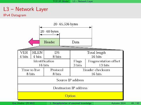
Version (VER) – IP protocol version
Header length (HLEN) – the length of IP datagram header (in 4B words)
because of the Option field, which makes the length of the headervariable
Differentiated services (DS) or Type of service (TOS) – defines the class of the
datagram for quality-of-service (QoS) purposes
necessary for a distinction of “important” (control datagrams, real-timedata) and “less important” datagrams
Total length – the length of the whole IP IP datagram (in B)
max. 216 − 1 = 65535 bytesIdentification, Flags, Offset – fields used for fragmentation
Time to live (TTL) – used to control the maximum number of hops (router)
visited by the datagramthe sending nodes stores a number in this field (≈ 2× the biggest number ofhops between any two hosts in the network)each router decrements this number by 1if this value equals to zero (TTL = 0), the datagram is discardedthe purpose is to prevent a datagram from becoming an errant
Eva Hladka (FI MU) 1. Recapitulation of assumed knowledge Autumn 2014 50 / 93

TCP/IP Model L3 – Network Layer
L3 – Network LayerIPv4 Datagram III.
Protocol – higher-level protocol identificationspecifies the final destination protocol to which the IP datagram shouldbe delivered
this value helps in multiplexing/demultiplexing process
the identifiers are specified by IANA organization
e.g., 1 = ICMP, 2 = IGMP, 6 = TCP, 17 = UDP, etc.see http://www.iana.org/assignments/protocol-numbers
Eva Hladka (FI MU) 1. Recapitulation of assumed knowledge Autumn 2014 51 / 93

TCP/IP Model L3 – Network Layer
L3 – Network LayerIPv4 Datagram IV.
Header checksum – the checksum of the IP headerdata are not included
data checksums are provided by the L4-level (Transport Layer)
the main reason for distinction:
the checksums have to be recomputed on every router the datagramvisits because of header changes (e.g., TTL field)⇒ computing the checksum from the header only is simpler = theprocessing is faster
Source IP address, Destination IP address – 32-bit IPv4 addressidentifying sender/receiver
Options – optional part of IP datagrams, used especially for networktesting and debugging
Data – the data being transferred
Eva Hladka (FI MU) 1. Recapitulation of assumed knowledge Autumn 2014 52 / 93

TCP/IP Model L3 – Network Layer
L3 – Network LayerInternet Control Message Protocol (ICMP) I.
IP protocol provides unreliable (best-effort) servicewithout any mechanism to inform the sender about errors arisen duringdata deliverywithout any mechanism for network state testing
Internet Control Message Protocol (ICMP)RFC 792a supplementary protocol for IP protocolprovides information about errors arsed during data deliveryprovides basic information about the network state
message examples:Destination unreachable – “Destination” is a protocol, port, host, ornetworkTime exceeded – an information about TTL expiration or when allfragments that make up a message do not arrive at the destinationhost within a certain time limitEcho request/reply – a request for reply
Eva Hladka (FI MU) 1. Recapitulation of assumed knowledge Autumn 2014 53 / 93

TCP/IP Model L3 – Network Layer
L3 – Network LayerInternet Control Message Protocol (ICMP) II.
ICMP Encapsulation:
Eva Hladka (FI MU) 1. Recapitulation of assumed knowledge Autumn 2014 54 / 93

TCP/IP Model L3 – Network Layer
L3 – Network LayerIP Protocol version 6 (IPv6) – main features
larger address space – 128-bit IPv6 address, 2128 of unique addresses
better (simpler) header format – basic 40B header containing just themost important information
allowance for extensions – via so-called extension headers
Support for real-time transfers – flows’ tagging, flows’ priorities
Support for more security – data authentication, encryption, andintegrity support
Mobility support – via so-called home agents
Device autoconfiguration support – statefull and statelessautoconfiguration
Eva Hladka (FI MU) 1. Recapitulation of assumed knowledge Autumn 2014 55 / 93

TCP/IP Model L3 – Network Layer
L3 – Network LayerIPv6 Datagram – basic header I.
fixed (40B) header lengthchecksum, options, and fragmenting information are not included in basicheader any more
options and fragmenting information available via extension headerschecksum removed without any compensation (ensured on L2 and L4)
Eva Hladka (FI MU) 1. Recapitulation of assumed knowledge Autumn 2014 56 / 93

TCP/IP Model L3 – Network Layer
L3 – Network LayerIPv6 Datagram – basic header II.
Version (VER) – version number of the IP (currently 6)
Priority (PRI), also Traffic Class – datagram priority with respect totraffic congestion
Flow label – designed to provide special handling for a particular flowof data
not widely used yet
Payload length – the total length of the IP datagram excluding thebase header
Next header – defines the header that follows the base header in thedatagram (extension header or transport header)
Hop limit – ≈ TTL in IPv4
Source/Destination address – IPv6 address of source/destinationnode
Eva Hladka (FI MU) 1. Recapitulation of assumed knowledge Autumn 2014 57 / 93

TCP/IP Model L3 – Network Layer
L3 – Network LayerIPv6 Datagram – extension headers
several extension headers have been defined
e.g., Hop-By-Hop Options, Routing, Fragment, Encapsulating Security Payload,Authentication Header, etc.Eva Hladka (FI MU) 1. Recapitulation of assumed knowledge Autumn 2014 58 / 93

TCP/IP Model L3 – Network Layer
L3 – Network LayerICMPv6
ICMP protocol version 6 (ICMPv6)
based on same mechanisms as the ICMPv4moreover, includes the functionality of ARP and IGMP protocols
using so-called Neighbour Discovery protocol working in cooperationwith ICMPv6
Eva Hladka (FI MU) 1. Recapitulation of assumed knowledge Autumn 2014 59 / 93

TCP/IP Model L3 – Network Layer
L3 – Network LayerRouting
Routing = the process of finding a path in the network between twocommunicating nodes
the route/path has to satisfy certain constraintsinfluenced by several factors:
static ones: network topologydynamic ones: network load
Eva Hladka (FI MU) 1. Recapitulation of assumed knowledge Autumn 2014 60 / 93

TCP/IP Model L3 – Network Layer
L3 – Network LayerThe Global View Problem
the global knowledge of network topology is problematic
it’s very difficult to acquire itif yet acquired, it’s not actual any moreit has to be locally relevant
a local view of network topology represents a routing table
the difference between local and global knowledge can lead to:
cycles/loops (i.e., black holes)oscillation (load adaptability)
Eva Hladka (FI MU) 1. Recapitulation of assumed knowledge Autumn 2014 61 / 93

TCP/IP Model L3 – Network Layer
L3 – Network LayerRouting – the goal
the main goal of routing is:to find optimal paths
the optimality criterion is a metric – a cost assigned for passingthrough a network
to deliver a data packet to its receiver
the routing usually does not deal with the whole packet paththe router deals with just a single step – to whom should be theparticular packet forwarded
somebody “closer” to the recipientso-called hop-by-hop principle
the next router then decides, what to further do with the receivedpacket
Eva Hladka (FI MU) 1. Recapitulation of assumed knowledge Autumn 2014 62 / 93

TCP/IP Model L3 – Network Layer
L3 – Network LayerRouting – basic approaches
The basic approaches divide based on the routing tablecreation/maintenance:
static (non-adaptive)
manually (by hand) edited recordssuitable for a static topology and smaller networks
dynamic (adaptive) – these respond to network changes
complex (usually distributed) algorithmse.g.:
centralized – a centre controls the whole routingisolated – every node on its owndistributed – nodes’ cooperation
Eva Hladka (FI MU) 1. Recapitulation of assumed knowledge Autumn 2014 63 / 93

TCP/IP Model L3 – Network Layer
L3 – Network LayerRouting – mathematical view
the routing can be seen as a problem of graph theorya network can be represented by a graph, where:
nodes represent routers (identified by their IP addresses)edges represent routers’ interconnection (a data link)edges’ value = the communication costthe goal: to find paths having minimal costs between any two nodes inthe network
Eva Hladka (FI MU) 1. Recapitulation of assumed knowledge Autumn 2014 64 / 93

TCP/IP Model L3 – Network Layer
L3 – Network LayerRouting – routing algorithms’ required features
Required features of any routing algorithm:
accuracy
simplicity
effectivity and scalability
to minimize an amount of control information (≈ 5% of the wholetraffic!)to minimize routing tables’ sizes
robustness and stability
a distributed algorithm is necessary
fairness
optimality
“What should be treated as the best path?”
Eva Hladka (FI MU) 1. Recapitulation of assumed knowledge Autumn 2014 65 / 93

TCP/IP Model L3 – Network Layer
L3 – Network LayerRouting – basic approaches to distributed routing
Basic approaches to distributed routing:
Distance Vector (DV) – Bellman-Ford algorithm
the neighboring routers periodically (or when the topology changes)exchange complete copies of their routing tablesbased on the content of received updates, a router updates itsinformation and increments its distance vector number
a metric indicating the number of hops in the network
i.e., “all pieces of information about the network just to my neighbors”
Link State (LS)
the routers periodically exchange information about states of the links,to which they are directly connectedthey maintain complete information about the network topology –every router is aware of all the other routers in the networkonce acquired, the Dijkstra algorithm is used for shortest pathscomputationi.e., “information about just my neighbors to everyone”
Eva Hladka (FI MU) 1. Recapitulation of assumed knowledge Autumn 2014 66 / 93

TCP/IP Model L3 – Network Layer
L3 – Network LayerDistance Vector – RIP protocol
the principal actor of DV routingRIPv1 (RFC 1058)RIPv2 (RFC 1723) – adds several features (e.g., an authentication ofrouting information)
the networks are identified using the CIDR mechanismthe number of hops is used as a metric
transfer of a packet between two neighboring routers = 1 hopinfinity = 16
⇒ the RIP cannot be used for networks with minimal amount of hopsbetween any two routers > 15
the routers send the information periodically every 30 secondstriggered updates when a state of a link changestimeout 180s (detection of connection errors)
usage:suitable for small networks and stable linksnot advisable for redundant networks
Eva Hladka (FI MU) 1. Recapitulation of assumed knowledge Autumn 2014 67 / 93

TCP/IP Model L3 – Network Layer
L3 – Network LayerLink State – OSPF protocol
Open Shortest Path First
currently the mostly used LS protocol
metric: cost
a number (in the range between 1 and 65535) assigned to each router’snetwork interfacethe lower the number is, the better the link/path is (i.e., will bepreferred)by default, every interface is automatically assigned a cost derived fromthe link’s throughput
cost = 100000000/bandwidth (bw in bps)might be manually edited
extensions:
message authenticationrouting areas – next layer of hierarchyload-balancing – more links/paths with the same cost
Eva Hladka (FI MU) 1. Recapitulation of assumed knowledge Autumn 2014 68 / 93

TCP/IP Model L3 – Network Layer
L3 – Network LayerRouting – Link State vs. Distance Vector
Link State
Complexity:every node has to know the cost of everylink in the network ⇒ O(nE) messagesonce a link state changes, the change hasto be propagated to every node
Speed of convergence:
O(n2) alg., sends O(nE) messagessustains from oscillations
Robustness:wrongly functional/compromised routerspreads wrong information just about thelinks it is directly connected toevery router computes routing tables onits own ⇒ separated from routinginformation propagation ⇒ a form ofrobustness
Usage:suitable for large networks
Distance Vector
Complexity:once a link state changes, the change hasto be propagated just to the closestneighbors; it is further propagated just incases, when the changed state leads to achange in the current shortest paths tree
Speed of convergence:may converge more slowly than LSproblems with routing loops/cycles,count-to-infinity problem
Robustness:bad computation is spread through thenetwork ⇒ may lead to a “confusion” ofother routers (bad routing tables)
Usage:suitable just for smaller networks
Eva Hladka (FI MU) 1. Recapitulation of assumed knowledge Autumn 2014 69 / 93

TCP/IP Model L3 – Network Layer
L3 – Network LayerAutonomous Systems
the goal of Internet’s division into Autonomous Systems isa reduction of routing overhead
simpler routing tables, a reduction of exchanged information, etc.a simplification of the whole network management
particular internets are managed by various institutions/organizations
autonomous systems = domainsa 16bit identifier is assigned to every AS/domain
Autonomous System Number (ASN) – RFC 1930assigned by ICANN (Internet Corporation For Assigned Names andNumbers)
correspond to administrative domainsnetworks and routers inside a single AS are managed by a singleorganization/institutione.g., CESNET, PASNET, . . .
a distinction according to the way an AS is connected to the Internet:Stub ASMultihomed ASTransit AS
Eva Hladka (FI MU) 1. Recapitulation of assumed knowledge Autumn 2014 70 / 93

TCP/IP Model L3 – Network Layer
L3 – Network LayerAutonomous Systems – routing
separated routing because of scalability reasons:interior routing
routing inside an ASunder the full control of AS’s administrator(s)the primary goal is the performanceso-called Interior Gateway Protocols (IGP) (e.g., RIP, OSPF)
exterior routingrouting among ASsthe primary goal is the support of defined policies and scalabilityso-called Exterior Gateway Protocols (EGP) (e.g., EGP, BGP-4)
a cooperation of interior and exterior routing protocols is necessary
Eva Hladka (FI MU) 1. Recapitulation of assumed knowledge Autumn 2014 71 / 93

TCP/IP Model L3 – Network Layer
L3 – Network LayerAutonomous Systems – exterior routing (BGP)
Border Gateway Protocol
currently version 4 (BGP-4)
proposed due to Internet’s grow and demands on complex topologiessupport
supports redundant topologies, deals with loops/cycles
employs so-called Path Vector routing
not only paths’ costs, but the full descriptions of the whole paths areexchanged
allows a definition of routing rules (policies)
makes use of the fully reliable TCP protocol
uses CIDR for paths’ aggregation
Eva Hladka (FI MU) 1. Recapitulation of assumed knowledge Autumn 2014 72 / 93

TCP/IP Model L3 – Network Layer
L3 – Network LayerIP Multicast
A classical solution of group communication in the network:
Just a single data copy goes every network link
A feature of the network (hop-by-hop service, no end-to-end service)
Non-reliable delivery (best effort, UDP, group address)
Spread wideness restricted by TTL (Time To Live) field of packets
How to identify a group?
⇒ multicast IP address
IPv4: class D (224.0.0.0 – 239.255.255.255)IPv6: prefix ff00::/8
Two basic approaches to multicast routing:
Source Based Tree
Shared Tree (Core Based Tree)
Eva Hladka (FI MU) 1. Recapitulation of assumed knowledge Autumn 2014 73 / 93

TCP/IP Model L3 – Network Layer
L3 – Network LayerIP Multicast – Source Based Tree vs. Core Based Tree
Source Based Tree Core Based Tree
Top-down activity (from theconstituent)
Periodic broadcast
Cutting the subtrees with no clients
Wideness restriction – TTL
Suitable for closely located groups
Drawbacks: overhead, flooding bybroadcasts
Protocols: DVMRP (RIP), MOSPF(OSPF), PIM–DM
A core is established – ensured bymeeting points (MPs)
A client contacts a MP
Down-top activity (from thereceiver)
Reduces broadcast −→ betterscalability
Drawback: a dependence on thecore availability
Protocols: CBT, PIM–SM
Eva Hladka (FI MU) 1. Recapitulation of assumed knowledge Autumn 2014 74 / 93
TCP/IP Model L4 – Transport Layer
L4 – Transport LayerIntroduction
Transport Layer:
provides its services to the Application Layer:obtains data coming from sending application and transforms theminto segmentsreceived segments delivers to the destination application
in cooperation with the network layer ensures data (segments)delivery between communicating applications/processes
providing transmission reliability, if requiredprovides them with a logical communication channel
an illusion of direct physical interconnection
so-called process-to-process delivery
the lowest layer providing so-called end-to-end servicesthe headers generated on the sender’s side are interpreted “only” onthe receiver’s sidethe transport layer data are seen by routers as a payload of transmittedpackets
Eva Hladka (FI MU) 1. Recapitulation of assumed knowledge Autumn 2014 75 / 93

TCP/IP Model L4 – Transport Layer
Figure: Position of the Transport Layer.
Eva Hladka (FI MU) 1. Recapitulation of assumed knowledge Autumn 2014 76 / 93

TCP/IP Model L4 – Transport Layer
L4 – Transport LayerServices
Packetizingthe data provided by an application are transformed into packets (having atransport header added)
Connection Controlconnection-oriented and connectionless services
Addressingthe addresses of transport layer entities (= network applications/services) –so-called portsthe packets contain source and destination ports (an identification of sourceand destination application)
an application is uniquely identified in the network by the pairIP address:port
Connection ReliabilityFlow Control and Error Control
provided on the node-to-node principle by lower layers, L4 provides iton the end-to-end principle
ensures a reliability over best-effort service (IP)
Congestion Control and Quality of Service (QoS) ensurance
Eva Hladka (FI MU) 1. Recapitulation of assumed knowledge Autumn 2014 77 / 93
TCP/IP Model L4 – Transport Layer
L4 – Transport LayerAddressing – ports
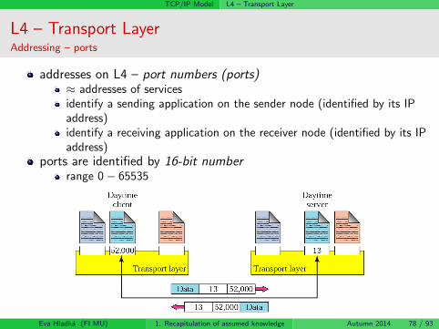
addresses on L4 – port numbers (ports)≈ addresses of servicesidentify a sending application on the sender node (identified by its IPaddress)identify a receiving application on the receiver node (identified by its IPaddress)
ports are identified by 16-bit numberrange 0− 65535
Eva Hladka (FI MU) 1. Recapitulation of assumed knowledge Autumn 2014 78 / 93

TCP/IP Model L4 – Transport Layer
L4 – Transport LayerConnection-oriented vs. Connection-less Services
Connection-oriented services
prior to the transmission, a connection is established (and maintainedduring the whole transmission)
packets are numbered
their delivery/undelivery is explicitly acknowledged
Connection-less services
packets are sent to the destination application without any connectionbeing established
packets are not numbered (⇒ they aren’t acknowledged)
might be lost, delayed, delivered out-of-order, etc.
Eva Hladka (FI MU) 1. Recapitulation of assumed knowledge Autumn 2014 79 / 93

TCP/IP Model L4 – Transport Layer
L4 – Transport LayerUser Datagram Protocol (UDP)
User Datagram Protocol (UDP)
the simplest transport protocol providing a connection-less and unreliableservice
provides best-effort serviceenriches the IP layer services just by process-to-process communication and simpleerror controlif a reliability has to be ensured, it must be provided by the application
main features: simplicity, minimal overheadno connection establishment/maintenance necessity (brings a delay in the beginningof the transmission)no necessity to maintain state information by the communicating nodessmall/simple header
selected applications:processes requiring just a simple “request – reply” communication (e.g., the DNS(Domain Name Service))processes/protocols with internal flow and error control (e.g., TFTP (Trivial FileTransport Protocol))real-time transfersmulticast transfers
Eva Hladka (FI MU) 1. Recapitulation of assumed knowledge Autumn 2014 80 / 93
TCP/IP Model L4 – Transport Layer
L4 – Transport LayerUDP header
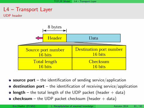
source port – the identification of sending service/application
destination port – the identification of receiving service/application
length – the total length of the UDP packet (header + data)
checksum – the UDP packet checksum (header + data)
Eva Hladka (FI MU) 1. Recapitulation of assumed knowledge Autumn 2014 81 / 93

TCP/IP Model L4 – Transport Layer
L4 – Transport LayerTransmission Control Protocol (TCP)
Transmission Control Protocol (TCP)transport protocol providing connection-oriented and fully reliable service
if possible, the data sent by the sender will be received by the receiver – completeand in the right orderin comparison with the UDP protocol, the TCP is byte-stream oriented (UDP workswith blocks of data)
prior to a communication, a connection has to be established betweensender and receiver
so-called three-way handshake taking place prior to the communication ensures theexchange of all necessary information
the connection is distinguishable just on the end nodes (end-to-end service)
the routers are not aware about the connections
an established connection might be used for fully duplex communication
the control data are enclosed in the backward data (so-calledpiggybacking)
just point-to-point connections are supported
the communication among more peers (a-la multicast) is not supported
multiplexing/demultiplexing and error control same as in the UDP
Eva Hladka (FI MU) 1. Recapitulation of assumed knowledge Autumn 2014 82 / 93
TCP/IP Model L4 – Transport Layer
L4 – Transport LayerTCP header I.
Eva Hladka (FI MU) 1. Recapitulation of assumed knowledge Autumn 2014 83 / 93
TCP/IP Model L4 – Transport Layer
L4 – Transport LayerTCP header II.
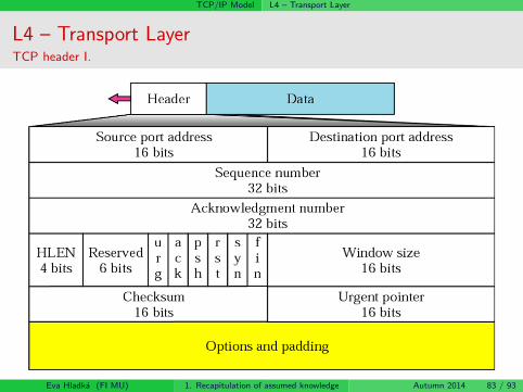
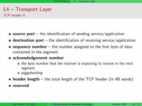
source port – the identification of sending service/application
destination port – the identification of receiving service/application
sequence number – the number assigned to the first byte of datacontained in the segment
acknowledgement numberthe byte number that the receiver is expecting to receive in the nextsegmentpiggybacking
header length – the total length of the TCP header (in 4B words)
reserved
Eva Hladka (FI MU) 1. Recapitulation of assumed knowledge Autumn 2014 84 / 93

TCP/IP Model L4 – Transport Layer
L4 – Transport LayerTCP header III.
control – 6 control bits identifying various control information
window size – the size of the window that the other party mustmaintain
used for the Flow Control service (see the next slide)
checksum – the checksum of the TCP segment (header + data)
urgent pointer – used when the segment contains urgent data(out-of-order delivery)
options
Eva Hladka (FI MU) 1. Recapitulation of assumed knowledge Autumn 2014 85 / 93

TCP/IP Model L4 – Transport Layer
L4 – Transport LayerFlow Control vs. Congestion Control I.
TCP controls the amount of sent data in such a way, that:
protects the receiver from being congested = Flow Control
protects the network from being congested = Congestion Control
The amount of data allowed to be sent to the network is defined by:
the receiver’s window size (flow control)
by the size of so-called congestion window (congestion control)
maintained on the sender side
the amount of data allowed to be sent to the network – limited by thelower value of both parameters
Eva Hladka (FI MU) 1. Recapitulation of assumed knowledge Autumn 2014 86 / 93

TCP/IP Model L4 – Transport Layer
L4 – Transport LayerFlow Control vs. Congestion Control II.
Eva Hladka (FI MU) 1. Recapitulation of assumed knowledge Autumn 2014 87 / 93

TCP/IP Model L4 – Transport Layer
L4 – Transport LayerResume
ensures the communication of particular applications
providing an optional reliability ensuranceUDP protocol for fast, but non-reliable packet transmission
just the error control (using checksums) is provided
TCP protocol for fully-reliable byte-stream transmission
the transmission reliability ensured by repeated sending (ARQmechanisms)provides a mechanism for flow control (receiver protection from acongestion) – explicit information provided by the receiverprovides a mechanism for congestion control (network protection froma congestion) – an estimation of available throughput (AIMDmechanism)
further information:
PB156: Computer Networks (doc. Hladka)PV183: Computer Networks Technology (dr. Pelikan)
Eva Hladka (FI MU) 1. Recapitulation of assumed knowledge Autumn 2014 88 / 93

TCP/IP Model L7 – Application Layer
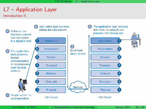
L7 – Application LayerIntroduction I.
Application Layer:
provides services to users:application programs specific for a particular purpose
e.g., electronic mail, WWW, DNS, etc. etc.
applications = the main reason for computer networks existence
comprises network applications/programs and application protocolsapplication protocols (HTTP, SMTP, etc.) are parts of networkapplications (web, email)
they are not applications on their ownthe protocols define a form of communication between communicatingapplications
application protocols define:
types of messages, which the applications exchange (request/response)messages’ syntaxmessages’ semantics (a semantics of particular fields)rules, when and how the messages are exchanged
Eva Hladka (FI MU) 1. Recapitulation of assumed knowledge Autumn 2014 89 / 93
TCP/IP Model L7 – Application Layer
L7 – Application LayerIntroduction II.
Eva Hladka (FI MU) 1. Recapitulation of assumed knowledge Autumn 2014 90 / 93

TCP/IP Model L7 – Application Layer
L7 – Application LayerBasic Application Classification/Distinction
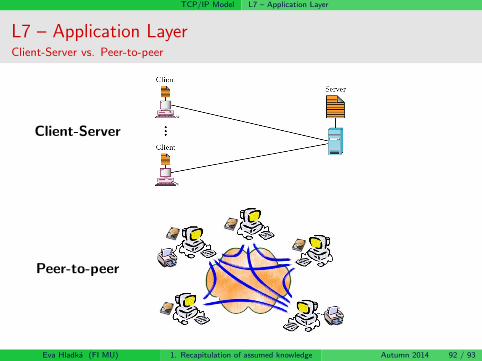
According to employed communication model:
Client-Server model
Thin vs. Fat clients
Peer-to-peer model
According to the way of accessing the information:
pull model – the data transfer is initiated by a client
push model – the data transfer is initiated by a server
According to the demands on the computer network:
applications with low demands on the computer network
applications with high demands on the computer network
Eva Hladka (FI MU) 1. Recapitulation of assumed knowledge Autumn 2014 91 / 93
TCP/IP Model L7 – Application Layer
L7 – Application LayerClient-Server vs. Peer-to-peer
Client-Server
Peer-to-peer
Eva Hladka (FI MU) 1. Recapitulation of assumed knowledge Autumn 2014 92 / 93

TCP/IP Model L7 – Application Layer
L7 – Application LayerResume
provides services to usersacts as an interface between users and computer network
the applications can be distincted according to various criteriaclient/server vs. peer-to-peer, pull vs. push model, demands on thecomputer network, etc.
examples of Internet’s fundamental applications and applicationprotocols:
name service (DNS)World-Wide-Web (HTTP)electronic email (SMTP)file transfer (FTP)multimedia transmissions (RTP/RTCP)
further information:PB156: Computer Networks (doc. Hladka)PV160: Net-centric computing II. (prof. Matyska)PV188: Principles of Multimedia Processing and Transport (doc.Hladka, dr. Liska, Ing. Siler)etc.Eva Hladka (FI MU) 1. Recapitulation of assumed knowledge Autumn 2014 93 / 93


![3. Advanced Routing Mechanisms [10pt]PA191 - IS MUNI](https://static.fdokumen.com/doc/165x107/6332ce284d54c8e1f9079371/3-advanced-routing-mechanisms-10ptpa191-is-muni.jpg)