Addendum-3-Contract-41-Phosphorus-Removal-and-Filtration ...
133
1 pw:\392039-RVRSA CONTRACT 41 DESIGN PHOSP\Bidding\Addenda\Addendum #3\Addendum-3_11-5-20.doc ROCKAWAY VALLEY REGIONAL SEWERAGE AUTHORITY MORRIS COUNTY, NEW JERSEY PHOSPHORUS REMOVAL AND FILTRATION FACILITIES CONTRACT NO. 41 NEW JERSEY STATE LOAN PROJECT NO. S340821-08 ADDENDUM #3 (133 Pages) Issued By: Mott MacDonald 111 Wood Avenue South Iselin, NJ 08830-4112 November 5, 2020 To All Concerned: The original documents for the above-referenced contract are herein changed and clarified as noted in this Addendum #3. THIS ADDENDUM #3 SHALL BECOME PART OF THE CONTRACT DOCUMENTS AND IS TO BE ATTACHED THERETO. Bidders are required to email a completed copy of the attached “Acknowledgement of Receipt of Changes to Bid Document Form” to each of the individuals listed below, upon receipt of this addendum, in order to provide confirmation of receipt of this addendum (Addendum #3): 1) JoAnn Mondsini email: [email protected] 2) Robert Bocchino email: [email protected] 3) Janice Fox email: [email protected] 4) Christopher Wohlleb email: [email protected]
-
Upload
khangminh22 -
Category
Documents
-
view
3 -
download
0
Transcript of Addendum-3-Contract-41-Phosphorus-Removal-and-Filtration ...
1 pw:\392039-RVRSA CONTRACT 41 DESIGN PHOSP\Bidding\Addenda\Addendum #3\Addendum-3_11-5-20.doc
ROCKAWAY VALLEY REGIONAL SEWERAGE AUTHORITY MORRIS COUNTY, NEW JERSEY
PHOSPHORUS REMOVAL AND FILTRATION FACILITIES CONTRACT NO. 41
NEW JERSEY STATE LOAN PROJECT NO. S340821-08
ADDENDUM #3
(133 Pages)
Issued By:
Mott MacDonald 111 Wood Avenue South
Iselin, NJ 08830-4112
November 5, 2020 To All Concerned: The original documents for the above-referenced contract are herein changed and clarified as noted in this Addendum #3. THIS ADDENDUM #3 SHALL BECOME PART OF THE CONTRACT DOCUMENTS AND IS TO BE ATTACHED THERETO.
Bidders are required to email a completed copy of the attached “Acknowledgement of Receipt of Changes to Bid Document Form” to each of the individuals listed below, upon receipt of this addendum, in order to provide confirmation of receipt of this addendum (Addendum #3):
1) JoAnn Mondsini email: [email protected] 2) Robert Bocchino email: [email protected] 3) Janice Fox email: [email protected] 4) Christopher Wohlleb email: [email protected]
2 pw:\392039-RVRSA CONTRACT 41 DESIGN PHOSP\Bidding\Addenda\Addendum #3\Addendum-3_11-5-20.doc
ACKNOWLEDGMENT OF RECEIPT OF CHANGES TO BID DOCUMENT FORM
ROCKAWAY VALLEY REGIONAL SEWERAGE AUTHORITY (Name of Local Contracting Unit)
PHOSPHORUS REMOVAL AND FILTRATION FACILITIES CONTRACT NO. 41 (Name of Construction/Public Works Project) (Project or Bid Number) The undersigned bidder hereby acknowledges receipt of the following notices, revisions, or addenda to the bid advertisement, specifications or bid documents. Local Unit Reference Number How Received Date Received
Or Title of Addendum/Revision (mail, fax, Pick-up, etc.)
Addendum #3 _____________ ______________ Acknowledgement by Bidder: Name of Bidder: Signature: Printed Name and Title: Date:
3 pw:\392039-RVRSA CONTRACT 41 DESIGN PHOSP\Bidding\Addenda\Addendum #3\Addendum-3_11-5-20.doc
RESPONSES TO QUESTIONS SUBMITTED BY PLANHOLDERS The following are responses to questions, pertaining to the above referenced project, that were submitted to the Rockaway Valley Regional Sewerage Authority (RVRSA) and received by the October 13, 2020 deadline for submission of request for interpretations, as noted in the Information for Bidders section of the Contract Documents.
Q1. Question #1: Plan Page – C-04 “Existing Pavement to be restored is quantified as 51,948 SF”. Which detail or specification describes that work.
RESPONSE:
• Refer to “Pavement Detail” on Drawing Number C-29 of the Contract Drawings.
• Refer to Section 2700 “Pavement, Sidewalk and Curbing” of the Technical Specifications. Q2. Question #2: Chemical Tank Question – On drawing page PR-01 it shows 2 ea.
10,000gallon tanks, and 1 ea. 500 gallon. The specs mention a 275 gallon tank which I could not locate, which has incorrect dimensions in the spec. Can you provide me a direction here? Please provide the appropriate drawing numbers if the ones attached are not correct. I assume by the specifications language that they are double wall HDPLE tanks. Further Section 11003, #2.02-3 of the specification states the design shall be for Specific Gravity 1.5, or 1.9. Which should it be?
RESPONSE:
• Refer to Item #S5 under the SPECIFICATIONS header in Addendum #3. Q3. Question #3: Upon review of drawing C-10 (Civil Site Utility Piping Plan), it shows a new
6” fire water service w/ hydrant to be installed off an existing 8” water service. At this juncture, it is noted that an 8” x 6” tee w/ 6” gate valve is to be installed. As such, I’m under the impression that the 8” existing main can be shut-down (turned-off) for the new “tee” to be cut-into the main. Is it feasible (& we’re allowed to) shut-down this 8” water main while the new 6” fire water service is installed. Otherwise we can proceed with a wet tap installation for the new 6” fire water service (which will come at an additional cost), however the drawing does not appear to indicate that a wet tap installation is the preferred method for this new 6” fire water service.
RESPONSE:
• Refer to Item #D1 under the DRAWINGS header in Addendum #3. Q4. Question #4: Also regarding the proposed fire hydrant, Drawing C-27 (Construction
Details Sheet 7 of 9) shows a detail for the proposed hydrant with a note next to the hydrant that states “Match Existing RVRSA Fire Hydrant Model”. Is it possible to obtain the model of the fire hydrant(s) currently on-site in an effort to obtain an accurate cost?
RESPONSE:
• Refer to Item #D3 under the DRAWINGS header in Addendum #3.
4 pw:\392039-RVRSA CONTRACT 41 DESIGN PHOSP\Bidding\Addenda\Addendum #3\Addendum-3_11-5-20.doc
Q5. Question #5: Specification Section 08952 Fiberglass Sandwich Panel Assemblies – where is this located?
RESPONSE:
• The fiberglass sandwich panel assembles, as specified in Section 08952 – “Fiberglass Sandwich Panel Assemblies” of the Technical Specifications, are the building windows that are identified as Window Types 2 and 3 on Drawing Number A-07 of the Contract Drawings.
Q6. Question #6: Section 07811 Sprayed Fire – Resistive Materials – where is this located?
RESPONSE:
• The “Sprayed Fire – Resistive Materials”, as specified in Section 07811 of the Technical Specifications, are not required for this project.
Q7. Question #7: Is there a geotechnical report? I saw logs and boring locations, but not a
report.
RESPONSE:
• No geotechnical report is available for this project. Q8. Question #8: PR-1 shows a 66x66x24 CCFRP Tee for the Ammonium sulfate; PR-2 shows
a 66x66x36 CCFRP closed Tee…; PR-12 shows a 66” closed tee with 45” manufactured riser. Which detail is correct?
RESPONSE:
• Refer to Items #D8, #D9, and #D15 under the DRAWINGS header in Addendum #3. Q9. Question #9: Per Specification 15030 – 4 2.04 A.4 “buried Butterfly valves are to be
mechanical joint.” Per Hobas – Megalugs should not be used to connect butterfly valves to Hobas CCFRP pipe. Per Hobas – a Flanged connection could be used. Should Flanged Butterfly Valves and Flanged connection be used for buried Service in this application?
RESPONSE:
• Exterior buried valves that are larger than 48 inches in diameter shall be provided with flanged ends. Exterior buried butterfly valves that are 48 inches in diameter and smaller shall be provided with mechanical joint ends.
• Refer to Item #S7 under the SPECIFICATIONS header in Addendum #3 for further information pertaining to the requirements for connecting the butterfly valves to the CCFRPM pipe.
Q10. Question #10: Drip Legs are shown on piping that does not appear to have a carrier pipe.
Please confirm the intention.
RESPONSE:
• Refer to Items #D5 and #D6 under the DRAWINGS header in Addendum #3.
5 pw:\392039-RVRSA CONTRACT 41 DESIGN PHOSP\Bidding\Addenda\Addendum #3\Addendum-3_11-5-20.doc
Q11. Question #11: Is there a specification for the Dry Disconnects at the Chem Feed Fill locations?
RESPONSE:
• Refer to Items #D5, #D6, and #D10 under the DRAWINGS header in Addendum #3.
Q12. Question #12: The Detail for Davit Bracket Detail on pr-11 calls out “New Portable Davit
Crane Thern Model 5124M1 Gal.” Is that to be provided by the Contractor?
RESPONSE:
• Yes, the new portable davit crane is to be furnished and installed by the Contractor under this project.
• Refer to Item #D12 under the DRAWINGS header in Addendum #3. Q13. Question #13: The specifications regarding frequency of testing are open to a great
amount of interpretation. We request that the testing be changed to a “unit price per test” or that we are given a “testing frequency.” For example, 1 test per every 800 cubic yards.
RESPONSE:
• Refer to Item #S1 and #S2 under the SPECIFICATIONS header in Addendum #3. Q14. Question #14: There does not appear to be specifications for the (3) Backwash Effluent
Pump VFD’s. Please confirm.
RESPONSE:
• Refer to Item #S15 under the SPECIFICATIONS header in Addendum #3. Q15. Question #15: I have reviewed the specifications. Drawing E-17 Clearly shows ABB VFD
details, (typical for 3 Backwash pumps). Drawing E-04 Clearly shows these VFD’s mounted in the equipment room in the new building. However, no written specifications for these VFD’s are apparent. Can you direct me to the written specifications for the VFD’s? If you are in agreement with me that there are in fact no written specifications provide for the VFD’s , would it be prudent to send an RFI to the engineer to request VFD written specifications be provided in an addendum?
RESPONSE:
• Refer to Item #S15 under the SPECIFICATIONS header in Addendum #3. Q16. Question #16: Are there any requirements for housekeeping pads under the chemical
storage tanks?
RESPONSE:
• Refer to Item #D10 under the DRAWINGS header in Addendum #3.
6 pw:\392039-RVRSA CONTRACT 41 DESIGN PHOSP\Bidding\Addenda\Addendum #3\Addendum-3_11-5-20.doc
Q17. Question #17: It appears that there are (2) Sauereisen “lining systems” required at the Secondary Containment (StormTrap) Unit. Are these “lining systems” also required at the Stormwater Detention System or just this “Secondary Containment (StormTrap) Unit?
RESPONSE:
• The interior protective lining system, as specified in Section 10104 of the Technical Specifications, is only required for the Secondary Containment System. The interior protective lining system is not required for the Stormwater Detention System.
Q18. Question #18: There is a “Detail D” shown on C-26 & another detail just to the right, which shows a profile/section of the StormTrap unit with the following note: “Geomembrane: Solmax-GSE ultraflex smooth surfaced black geomembrane, LLDPE series, as manufactured by The Solmax-GSE Lining Technology LLC, or equal.” “Linear low-density polyethylene (LLDPE) geomembrane waterproofing wrap of system.” Which detail are we to follow? Detail “D” or the aforementioned detail? Is it a combination of both? Does the Solmax-GSE Geomembrane take the place of the “Pond Liner” shown on Detail “D”?
RESPONSE:
• All of the waterproofing details, as shown on Drawing Number C-26 of the Contract Drawings, are applicable to this project.
• Refer to Item #D2 under the DRAWINGS header in Addendum #3 for further information. Q19. Question #19: Is there a louver specification or named manufacturer?
RESPONSE:
• Specifications for the louvers are provided in Section 08919 – “Fixed Louvers” of the Technical Specifications.
Q20. Question #20: Is there a louver motor specification or named manufacturer?
RESPONSE:
• Specifications for motorized damper actuators are provided in Section 15910 – “Instrumentation and Control Devices – HVAC” of the Technical Specifications.
Q21. Question #21: Who/what is the concentric flue box manufacturer, model or spec?
RESPONSE:
• Refer to Item #D17 under the DRAWINGS header in Addendum #3. Q22. Question #22: Please be advised that the eyewash model # spec’d is no longer
manufactured.
RESPONSE:
• Mott MacDonald has contacted the local manufacturer’s representative for the specified Bradley Model S19314FSS Combination Eyewash / Shower and we have been advised that the specified equipment is still available from the manufacturer.
7 pw:\392039-RVRSA CONTRACT 41 DESIGN PHOSP\Bidding\Addenda\Addendum #3\Addendum-3_11-5-20.doc
Q23. Question #23: On the Upper level plan drawing E-03 there is a symbol shown that is a “M” in a box. These are located inside by three exterior doorways. This symbol is not shown on any of the symbol lists except on the Mechanical drawings as a damper motor. There is no damper motor shown on the Mechanical drawings at these locations. Please clarify what this symbol is supposed to be. On Drawing E-08 the fire alarm riser diagram shows three pull stations as a circle with a “P” in it. This symbol is not shown on the drawing. Are these the same device that is shown in question #1 above?
RESPONSE:
• Refer to Item #D21 under the DRAWINGS header in Addendum #3. Q24. Question #24: The Cable and raceway schedule on drawings E-18 & E-19 provides us
with a conduit and wire size but does not provide us with the type of conduit to use for each feeder or circuit, ie GRS, PVCC or PVC. Please clarify which type of conduit is to be used for each item on the feeder schedules.
RESPONSE:
• Refer to Item #D31 under the DRAWINGS header in Addendum #3. Q25. Question #25: Please clarify which room/areas are considered to be corrosive and
required to utilize PVC coated galvanized rigid conduit (PVCC) and which rooms/areas are to utilize standard galvanized Rigid Steel conduit (RGRS).
RESPONSE:
• Refer to Item #D31 under the DRAWINGS header in Addendum #3. Q26. Question #26: Is EMT conduit suitable for use the control room?
RESPONSE:
• No, EMT conduit is not suitable for use in the Equipment (control) Room, in the new Filtration Building.
• Refer to Item #D31 under the DRAWINGS header in Addendum #3 for further information.
Q27. Question #27: On the upper level power plan drawing E-03 there are 2 duplex receptacles
in the chemical storage room, if this is a corrosive area, what type of receptacle and switches should we use? Please provide a detail and catalog number.
RESPONSE:
• Refer to Item #D21 under the DRAWINGS header in Addendum #3. Q28. Question #28: On the upper level plan E-03 there is a Nema 3R red strobe light which
connects to breaker 29 directly in panel LP, what controls this strobe light?
RESPONSE:
• Strobe light is continuously illuminated. No controls are required.
• Refer to Item #D21 under the DRAWINGS header in Addendum #3.
8 pw:\392039-RVRSA CONTRACT 41 DESIGN PHOSP\Bidding\Addenda\Addendum #3\Addendum-3_11-5-20.doc
Q29. Question #29: On the upper level plan E-03 every smoke detector has an “A” next to the
fire alarm symbol on the drawing, what does this signify?
RESPONSE:
• Refer to Item #D21 under the DRAWINGS header in Addendum #3.
Q30. Question #30: On the upper level plan E-03 there are 2 – 3 way switches but no switch by
the door on the far right of the plan on the northeast side. The National Electrical Code (NEC) requires a means of illumination where you enter an area. Should a 4-way switch be added at this location?
RESPONSE:
• Refer to Item #D21 under the DRAWINGS header in Addendum #3. Q31. Question #31: The fiber optic cables that are shown on drawing E-02 that run from the
main control building to the Chemical building and then to the new filter building are not shown on the feeder schedules on drawings E-18 and E-19. Please provide us with a specification on the required fiber optic cables.
RESPONSE:
• Specifications for the required fiber optic (F.O.) cable are provided in Section 16420 – “Enclosed Controllers” of the Technical Specifications on pages 16420-24 and 16420-25.
Q32. Question #32: Please indicate any area(s) of work that are classified (Class 1 Div. 1 or
Div.2 etc.) per the NEC.
RESPONSE:
• Refer to Item #D32 under the DRAWINGS header in Addendum #3. Q33. Question #33: Is MCC #13 new or existing (it has a doted perimeter line).
RESPONSE:
• Yes, MCC #13 is new and is to be furnished and installed by the Contractor under this project.
• Refer to Item #D23 under the DRAWINGS header in Addendum #3. Q34. Question #34: What is the scope of electrical demolition if any?
RESPONSE:
• In general, the electrical improvements included in this project are associated with new construction. The Contractor is to provide all labor, materials and equipment required to complete all demolition work that is necessary to facilitate the work that is included under this Contract.
9 pw:\392039-RVRSA CONTRACT 41 DESIGN PHOSP\Bidding\Addenda\Addendum #3\Addendum-3_11-5-20.doc
Q35. Question #35: Please confirm that ALL conduits "outside" the electrical room shall be
PVC coated GRS.
RESPONSE:
• Refer to Item #D31 under the DRAWINGS header in Addendum #3.
Q36. Question #36: Based on the Contract Documents it appears contaminated soils are
expected (non-hazardous and hazardous). Allowance items (Item #1b – 1g) have been provided however they appear to be dedicated to soil testing and additional costs. The necessary soil disposal work to be included under Item 1 seems to be unclassified or left to each contractor’s discretion however pursuant to the Local Public Contract Laws that is not allowed but rather a bid line item must be provided by the CONTRACTING UNIT. Please provide an allowance item for all soil disposal to be utilized for quantification and payment once waste characterization is determined.
RESPONSE:
• New Jersey Local Public Contracts Law does not require that a line item be provided in the Bid for disposal of non-contaminated soils. Allowance items have been provided in the Bid for “Additional Costs for Transportation and Disposal of Non-Hazardous Contaminated Soil”; and for “Additional Costs for Transportation and Disposal of Hazardous Contaminated Soil”
Q37. Question #37: The soil borings indicate groundwater at drastically different elevations
(B1 – El. 197.0, B2 - El. 207.5, B3 – El. 206.0). Are there additional borings since the provided borings are very inconsistent?
RESPONSE:
• No additional boring logs are available. Q38. Question #38: Please confirm the magnitude of groundwater to be expected including
allowed discharge point, means of treatment and disposal requirements.
RESPONSE:
• The Contractor is alerted to the fact that the boring information and lab testing results, as included in the Appendix of the Contract Documents, are not intended to be a part of the Contract Documents and are included in the Appendix strictly for the Contractor's convenience. In considering the results of the test borings and lab testing, it shall be understood by the Contractor that they represent the sole judgment of the soil boring contractor and testing lab as to the character of the material and subsurface conditions and that neither the Owner nor its Engineer guarantees that the character of the underground material will be even approximately as reported by the soil boring contractor or as indicated in the lab testing results. Intending bidders should make any additional investigations deemed necessary.
Q39. Question #39: Please explain the relevance of Attachment A located in Spec Section 02310.
RESPONSE:
• Fill and backfill materials that are to be provided for this project shall comply with the Standards referenced in Section 2310 – “Fill and Backfill Materials” Part 1.04 “References”, of the Technical Specifications. The Contractor is to provide the analytical
10 pw:\392039-RVRSA CONTRACT 41 DESIGN PHOSP\Bidding\Addenda\Addendum #3\Addendum-3_11-5-20.doc
results for the material generated at the quarry as part of their shop drawing submission to demonstrate that the proposed materials conform with the referenced standards and Attachment A in Section 2310, of the Technical Specifications.
Q40. Question #40: Please clarify the required coatings on the project. In particular, Spec Section 10104 calls for a coating which appears to be required on the stormwater management structures however the Contract Drawings indicate an HDPE geomembrane to “wrap” the structures. Which is required?
RESPONSE:
• The interior protective lining system, as specified in Section 10104 of the Technical Specifications, is only required for the Secondary Containment System. The interior protective lining system is not required for the Stormwater Detention System.
• The exterior Linear Low-Density Polyethylene (LLDPE) Geomembrane waterproofing system, as illustrated in the waterproofing details on Drawing Number C-26 of the Contract Drawings and as specified in Section 2725 of the Technical Specifications, is required for both the Secondary Containment System and the Stormwater Detention System.
Q41. Question #41: Is there a preferred SCADA integrator for the project?
RESPONSE:
• Refer to Item #S17 under the SPECIFICATIONS header in Addendum #3. Q42. Question #42: Please provide more information on the proposed natural gas line. There
is very minimal information on the plan sheets and there does not seem to be a spec section.
RESPONSE:
• Refer to Drawing Numbers C-10, PR-11, M-8, M-9, M-10, M-11, M-12, M-13, and M-14 of the Contract Drawings.
• Refer to Item #S11 under the SPECIFICATIONS header in Addendum #3. Q43. Question #43: Plan Sheet C-02 defines “Pavement Restoration” however there is no
detail explaining the work; are we to estimate 2” milling and paving in these designated areas?
RESPONSE:
• Refer to “Pavement Detail” on Drawing Number C-29 of the Contract Drawings.
• Refer to Section 2700 “Pavement, Sidewalk and Curbing” of the Technical Specifications.
Q44. Question #44: Plan Sheet PR-02 mentions a 4” PVC to DIP compression coupling which
is confusing considering they mention a 10” DIP line where a 4” PVC drain line is actually running. Is this a typo? Trying to connect 4” PVC to 4” DIP? Plans do not mention pipe material after compression coupling but mention it comes from lower level drain in PEMB. Please clarify.
RESPONSE:
• 4” diameter SCH 80 PVC pipe is to be provided to convey flows from the lower level drains in the new disc filter building to the wet well at the new backwash sludge pump
11 pw:\392039-RVRSA CONTRACT 41 DESIGN PHOSP\Bidding\Addenda\Addendum #3\Addendum-3_11-5-20.doc
station. The 4” SCH 80 PVC pipe shall be connected to the 4” cast iron pipe stub at the building
• Refer to Item #D9 under the DRAWINGS header in Addendum #3.
Q45. Question #45: Drawing E-17 Clearly shows ABB VFD details, (typical for 3 Backwash
pumps). Drawing E-04 Clearly shows these VFD’s mounted in the equipment room in the new building. However, no written specifications for these VFD’s are apparent. Can you direct me to the written specifications for the VFD’s?
RESPONSE:
• Refer to Item #S15 under the SPECIFICATIONS header in Addendum #3. Q46. Question #46: On the drawings it shows 2 ea. 10,000 gallon tanks, and 1 ea. 500 gallon.
The specs mention a 275 gallon tank which I could not locate which has incorrect dimensions in the spec. Can you clarify? Spec section 11003-2.02-3 of the specification states the design shall be for Specific Gravity S.G. 1.5, or 1.9. Which SG should it be?
RESPONSE:
• Refer to Item #S5 under the SPECIFICATIONS header in Addendum #3. Q47. Comment #1: Per Specification Section 11001-2.04.F.1.c, there are only two ACS Local
Control Panels one for Discfilters 1 & 2 and one for Discfilters 3 & 4. The drawings referenced (DWG E-10 & E-18) appear to refer to four ACS receptacles. Please note Circuit P-DF2-12 needs to include control wiring to ACS LCP shown on the very left of the drawing. Please note Circuit P-DF4-12 needs to include control wiring to ACS LCP shown wired to Discfilter 3 LCP.
RESPONSE:
• Refer to Item #S4 under the SPECIFICATIONS header in Addendum #3. Q48. Comment #2: The referenced drawings (DWG E-11) states the Discfilter Local Control
Panels will have Control Logix PLCs. Per Specification Section 11001-2.04.H.11, they will include the Allen Bradley Micro850. Please modify for correctness to show the Micro850.
RESPONSE:
• Refer to Item #S4 under the SPECIFICATIONS header in Addendum #3. Q49. Comment #3: (DWG S-03) Please note the anchors for the filters will be spaced
differently on each end of the filter due to the bypass pipe. On the bypass side, anchors will be spaced at 3’-1 11/16” and on the effluent end the spacing will be 6’ 3 3/8”…
RESPONSE:
• Refer to Item #D16 under the DRAWINGS header in Addendum #3.
12 pw:\392039-RVRSA CONTRACT 41 DESIGN PHOSP\Bidding\Addenda\Addendum #3\Addendum-3_11-5-20.doc
SPECIFICATIONS
The original Specifications for the above-referenced contract are herein changed and clarified as noted below:
S1. SCOPE OF CONTRACT
• DELETE: The following under “Sub-Items SC1.00b-g Testing, Transportation and Disposal of Contaminated Soil”
o Environmental sampling and testing. The Contractor shall be responsible for the collection of initial environmental samples and for analytical testing of the samples in the area of the project to determine if contaminants are present. Initial samples shall be collected at the time of test pitting and prior to the start of construction. Initial sampling and testing will be paid for at the lump sum price bid under Item 1b. Soil samples shall be collected by the Contractor’s environmental consultant and analyzed by a NJDEP-certified laboratory to characterize soils for potential contamination. Laboratory analyses of the soil samples shall be completed using an NJDEP-certified laboratory. Target Compound List/Target Analyte List (TCL/TAL) and Extractable Petroleum Hydrocarbons (EPH) Category 2 analysis shall be conducted on all samples.
• INSERT: Under “Sub-Items SC1.00b-g Testing, Transportation and Disposal of Contaminated Soil”
o Environmental sampling and testing. The Contractor shall be responsible for the collection of initial environmental samples and for analytical testing of the samples in the areas of the project to determine if contaminants are present. Initial samples shall be collected at the time of test pitting and prior to the start of construction. A minimum of twenty (20) initial soil samples are to be collected and analyzed from the various locations where soil excavation is to be performed under this project. Initial sampling and testing will be paid for at the lump sum price bid under Item 1b. Soil samples shall be collected by the Contractor’s environmental consultant and analyzed by a NJDEP-certified laboratory to characterize soils for potential contamination. Laboratory analyses of the soil samples shall be completed using an NJDEP-certified laboratory. Target Compound List/Target Analyte List (TCL/TAL) and Extractable Petroleum Hydrocarbons (EPH) Category 2 analysis shall be conducted on all samples.
• DELETE: The following under “Sub-Items SC1.00b-g Testing, Transportation and Disposal of Contaminated Soil”
o Should the results of the initial testing detect any soil contamination or if areas of suspected contamination are identified during excavation and construction, the Contractor will be required to stockpile soils for the purpose of soil testing and characterization, as required for disposal. Sampling and testing of excavated / stockpiled soils that are suspected of being contaminated or for which initial test results have detected contamination will be paid for at the lump sum bid under Item 1c. Laboratory testing criteria and sampling frequency shall be in accordance with the requirements of the disposal facility. The Contractor shall provide a sampling plan to the engineer for approval prior to implementation. Sample results shall be forwarded to the Engineer immediately upon receipt.
• INSERT: Under “Sub-Items SC1.00b-g Testing, Transportation and Disposal of Contaminated Soil”
o The Contractor is required to stockpile all excavated soils for the purpose of soil testing and characterization, as required for disposal of the excavated soils. Soils removed from areas that are suspected of contamination, or for which the initial sampling detected contamination, shall be segregated into separate piles on this basis of the location from which the soil was removed and based upon the type of contamination that is suspected. A minimum of twenty (20) soil samples are to be collected and analyzed from the various excavated soil stockpiles. The
13 pw:\392039-RVRSA CONTRACT 41 DESIGN PHOSP\Bidding\Addenda\Addendum #3\Addendum-3_11-5-20.doc
results of the lab testing shall be used by the Contractor to determine whether the stockpiled soils are “clean” (uncontaminated) or contaminated. Sampling and testing of excavated / stockpiled soils for the purpose of waste classification and characterization (uncontaminated or contaminated) will be paid for at the lump sum price bid under Bid Item 1c. Laboratory testing criteria and sampling frequency shall be in accordance with the requirements of the Contractor’s proposed disposal facilities. The Contractor shall provide a sampling plan to the engineer for approval prior to implementation. Sample results shall be forwarded to the Engineer immediately upon receipt. All costs for transportation and disposal of non-contaminated excavated soils that are removed as part of this project, shall be included in the lump sum price bid under Bid Item 1a. Additional costs associated with transportation and disposal of contaminated soils and hazardous contaminated soils will be paid for under the allowance items provided at Bid Items 1f an 1g depending upon whether the soil is characterized as non-hazardous contaminated material or hazardous contaminated material.
S2. SECTION 2215 – ENVIRONMENTAL SOIL SAMPLING
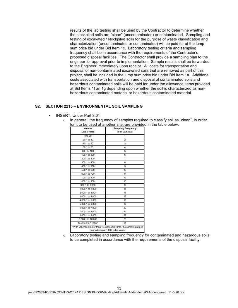
• INSERT: Under Part 3.01 o In general, the frequency of samples required to classify soil as “clean”, in order
for it to be used at another site, are provided in the table below. Volume Sampling Frequency
(Cubic Yards) (# of Samples)
0 to 20 1
20.1 to 40 2
40.1 to 60 3
60.1 to 80 4
80.1 to 100 5
100.1 to 200 6
200.1 to 300 7
300.1 to 400 8
400.1 to 500 9
500.1 to 600 10
600.1 to 700 11
700.1 to 800 12
800.1 to 900 13
900.1 to 1,000 14
1,000.1 to 2,000 15
2,000.1 to 3,000 16
3,000.1 to 4,000 17
4,000.1 to 5,000 18
5,000.1 to 6,000 19
6,000.1 to 7,000 20
7,000.1 to 8,000 21
8,000.1 to 9,000 22
9,000.1 to 10,000 23
10,000.1 to 11,000* 24
* With volumes greater than 10,000 cubic yards, the sampling rate is
1 per additional 1,000 cubic yards.
o Laboratory testing and sampling frequency for contaminated and hazardous soils to be completed in accordance with the requirements of the disposal facility.
14 pw:\392039-RVRSA CONTRACT 41 DESIGN PHOSP\Bidding\Addenda\Addendum #3\Addendum-3_11-5-20.doc
S3. The attached specification SECTION 08800 – GLAZING shall become a part of the Contract Documents. The “Glazing” specifications are for the 10’-0” x 4’-0” building windows that are identified as Window Type 1 on Drawing Number A-07 of the Contract Drawings. The Type 1 window, that is required for this project, is located in the wall between the Equipment Room (102) and the Process Equipment Room (101), as noted on Drawing Number A-02 of the Contract Drawings and as shown in “Building Section 2” on Drawing Number A-06 of the Contract Drawings.
S4. SECTION 11001 – AUTOMATIC DISC FILTER EQUIPMENT
• DELETE: Part 2.04 F. 1c. o There shall be two ACS local control panels mounted near the Discfilters, one for
Discfilters 1 and 2, one for Discfilter 3 and 4. Each ACS local control panel shall include a receptacle to allow an electrical cable from the pump on the mobile trolley to be connected. A starter within each control panel shall be wired to the receptacle. Each panel shall be a NEMA 4X Stainless Steel enclosure. The power feed shall be 480VAC, 60HZ, 3 phase, control voltage shall be 120VAC, 60HZ, 1 phase. Field wiring will be required between the ACS local control panels and the Discfilter local control panels. Field wiring shall be done by the Contractor.
• INSERT: Under Part 2.04 F. 1c. o There shall be control panels mounted near the Discfilters. Each panel shall be a
NEMA 4X Stainless Steel enclosure. The power feed shall be 480VAC, 60HZ, 3 phase, control voltage shall be 120VAC, 60HZ, 1 phase. Field wiring will be required between the ACS local control panels and the Discfilter control panels. Field wiring shall be done by the Contractor.
o Each Discfilter’s Control Panel shall include the motor starter for the ACS pump. Each Discfilter shall have a control panel consisting of the ACS pump power disconnect switch with auxiliary contact block and receptacle/plug for the ACS pump. Each panel will be powered from the ACS pump motor starter with 480VAC.
• DELETE: Part 2.04 F. 1d. o Each ACS Local Control Panel shall allow the operator initiation from start/stop
pushbuttons and selector switches on the front. Once initiated, the system must provide for media cleaning while being fully automated from the Discfilter Local Control Panel. System must provide spray application of chemical to the filter media and may not depend on use of "soak" or "bath" techniques for media cleaning. Equipment manufacturer must demonstrate that the system has been designed and implemented in previous Discfilter installations for chemical cleaning. The ACS and controls shall be provided by the Discfilter equipment supplier.
• INSERT: Under Part 2.04 F. 1d. o Each Discfilter shall be provided with a separate control panel with a key
operated "Jog-Auto-Maintenance" switch, ACS start/stop pushbuttons, E-Stop. Each panel will be powered with 120VAC from each Discfilter panel. When the switch is in "Auto", the Discfilter will operate normally. When the Operator wants to perform a cleaning, the switch will need to be in the "Maintenance" position.
• DELETE: Part 2.04 H. 1. o The disc filter operation shall be managed by an automated control system. The
automatic control will be designed around an Allen Bradley Micro850 Programmable Logic Controller.
• INSERT: Part 2.04 H. 1. o The disc filter operation shall be managed by an automated control system. The
automatic control will be designed around an Allen Bradley Control Logix Programmable Logic Controller.
15 pw:\392039-RVRSA CONTRACT 41 DESIGN PHOSP\Bidding\Addenda\Addendum #3\Addendum-3_11-5-20.doc
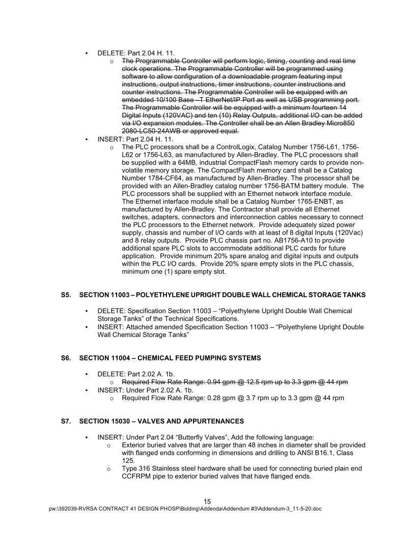
• DELETE: Part 2.04 H. 11. o The Programmable Controller will perform logic, timing, counting and real time
clock operations. The Programmable Controller will be programmed using software to allow configuration of a downloadable program featuring input instructions, output instructions, timer instructions, counter instructions and counter instructions. The Programmable Controller will be equipped with an embedded 10/100 Base –T EtherNet/IP Port as well as USB programming port. The Programmable Controller will be equipped with a minimum fourteen 14 Digital Inputs (120VAC) and ten (10) Relay Outputs, additional I/O can be added via I/O expansion modules. The Controller shall be an Allen Bradley Micro850 2080-LC50-24AWB or approved equal.
• INSERT: Part 2.04 H. 11. o The PLC processors shall be a ControlLogix, Catalog Number 1756-L61, 1756-
L62 or 1756-L63, as manufactured by Allen-Bradley. The PLC processors shall be supplied with a 64MB, industrial CompactFlash memory cards to provide non-volatile memory storage. The CompactFlash memory card shall be a Catalog Number 1784-CF64, as manufactured by Allen-Bradley. The processor shall be provided with an Allen-Bradley catalog number 1756-BATM battery module. The PLC processors shall be supplied with an Ethernet network interface module. The Ethernet interface module shall be a Catalog Number 1765-ENBT, as manufactured by Allen-Bradley. The Contractor shall provide all Ethernet switches, adapters, connectors and interconnection cables necessary to connect the PLC processors to the Ethernet network. Provide adequately sized power supply, chassis and number of I/O cards with at least of 8 digital Inputs (120Vac) and 8 relay outputs. Provide PLC chassis part no. AB1756-A10 to provide additional spare PLC slots to accommodate additional PLC cards for future application. Provide minimum 20% spare analog and digital inputs and outputs within the PLC I/O cards. Provide 20% spare empty slots in the PLC chassis, minimum one (1) spare empty slot.
S5. SECTION 11003 – POLYETHYLENE UPRIGHT DOUBLE WALL CHEMICAL STORAGE TANKS
• DELETE: Specification Section 11003 – “Polyethylene Upright Double Wall Chemical Storage Tanks” of the Technical Specifications.
• INSERT: Attached amended Specification Section 11003 – “Polyethylene Upright Double Wall Chemical Storage Tanks”
S6. SECTION 11004 – CHEMICAL FEED PUMPING SYSTEMS
• DELETE: Part 2.02 A. 1b. o Required Flow Rate Range: 0.94 gpm @ 12.5 rpm up to 3.3 gpm @ 44 rpm
• INSERT: Under Part 2.02 A. 1b. o Required Flow Rate Range: 0.28 gpm @ 3.7 rpm up to 3.3 gpm @ 44 rpm
S7. SECTION 15030 – VALVES AND APPURTENANCES
• INSERT: Under Part 2.04 “Butterfly Valves”, Add the following language: o Exterior buried valves that are larger than 48 inches in diameter shall be provided
with flanged ends conforming in dimensions and drilling to ANSI B16.1, Class 125.
o Type 316 Stainless steel hardware shall be used for connecting buried plain end CCFRPM pipe to exterior buried valves that have flanged ends.
16 pw:\392039-RVRSA CONTRACT 41 DESIGN PHOSP\Bidding\Addenda\Addendum #3\Addendum-3_11-5-20.doc
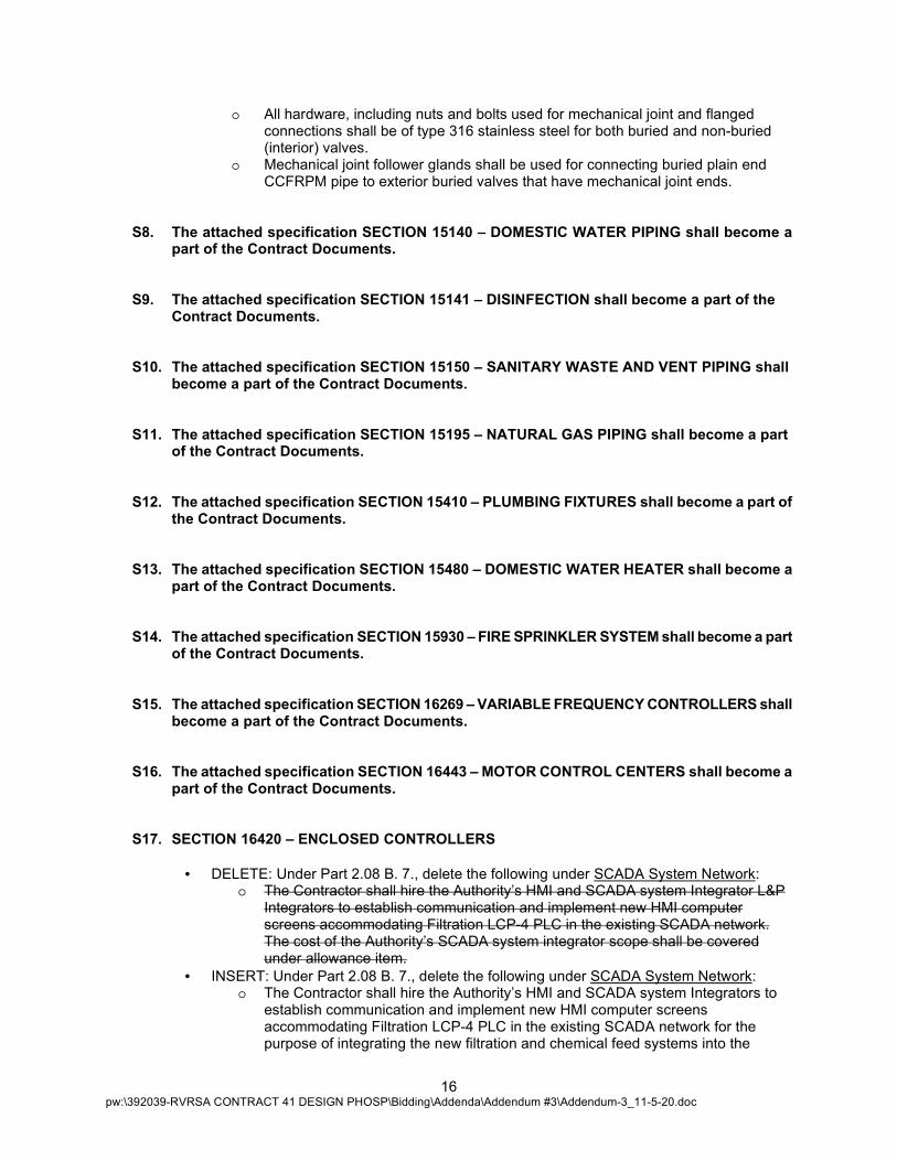
o All hardware, including nuts and bolts used for mechanical joint and flanged connections shall be of type 316 stainless steel for both buried and non-buried (interior) valves.
o Mechanical joint follower glands shall be used for connecting buried plain end CCFRPM pipe to exterior buried valves that have mechanical joint ends.
S8. The attached specification SECTION 15140 – DOMESTIC WATER PIPING shall become a part of the Contract Documents.
S9. The attached specification SECTION 15141 – DISINFECTION shall become a part of the Contract Documents.
S10. The attached specification SECTION 15150 – SANITARY WASTE AND VENT PIPING shall become a part of the Contract Documents.
S11. The attached specification SECTION 15195 – NATURAL GAS PIPING shall become a part of the Contract Documents.
S12. The attached specification SECTION 15410 – PLUMBING FIXTURES shall become a part of the Contract Documents.
S13. The attached specification SECTION 15480 – DOMESTIC WATER HEATER shall become a part of the Contract Documents.
S14. The attached specification SECTION 15930 – FIRE SPRINKLER SYSTEM shall become a part of the Contract Documents.
S15. The attached specification SECTION 16269 – VARIABLE FREQUENCY CONTROLLERS shall become a part of the Contract Documents.
S16. The attached specification SECTION 16443 – MOTOR CONTROL CENTERS shall become a part of the Contract Documents.
S17. SECTION 16420 – ENCLOSED CONTROLLERS
• DELETE: Under Part 2.08 B. 7., delete the following under SCADA System Network: o The Contractor shall hire the Authority’s HMI and SCADA system Integrator L&P
Integrators to establish communication and implement new HMI computer screens accommodating Filtration LCP-4 PLC in the existing SCADA network. The cost of the Authority’s SCADA system integrator scope shall be covered under allowance item.
• INSERT: Under Part 2.08 B. 7., delete the following under SCADA System Network: o The Contractor shall hire the Authority’s HMI and SCADA system Integrators to
establish communication and implement new HMI computer screens accommodating Filtration LCP-4 PLC in the existing SCADA network for the purpose of integrating the new filtration and chemical feed systems into the
17 pw:\392039-RVRSA CONTRACT 41 DESIGN PHOSP\Bidding\Addenda\Addendum #3\Addendum-3_11-5-20.doc
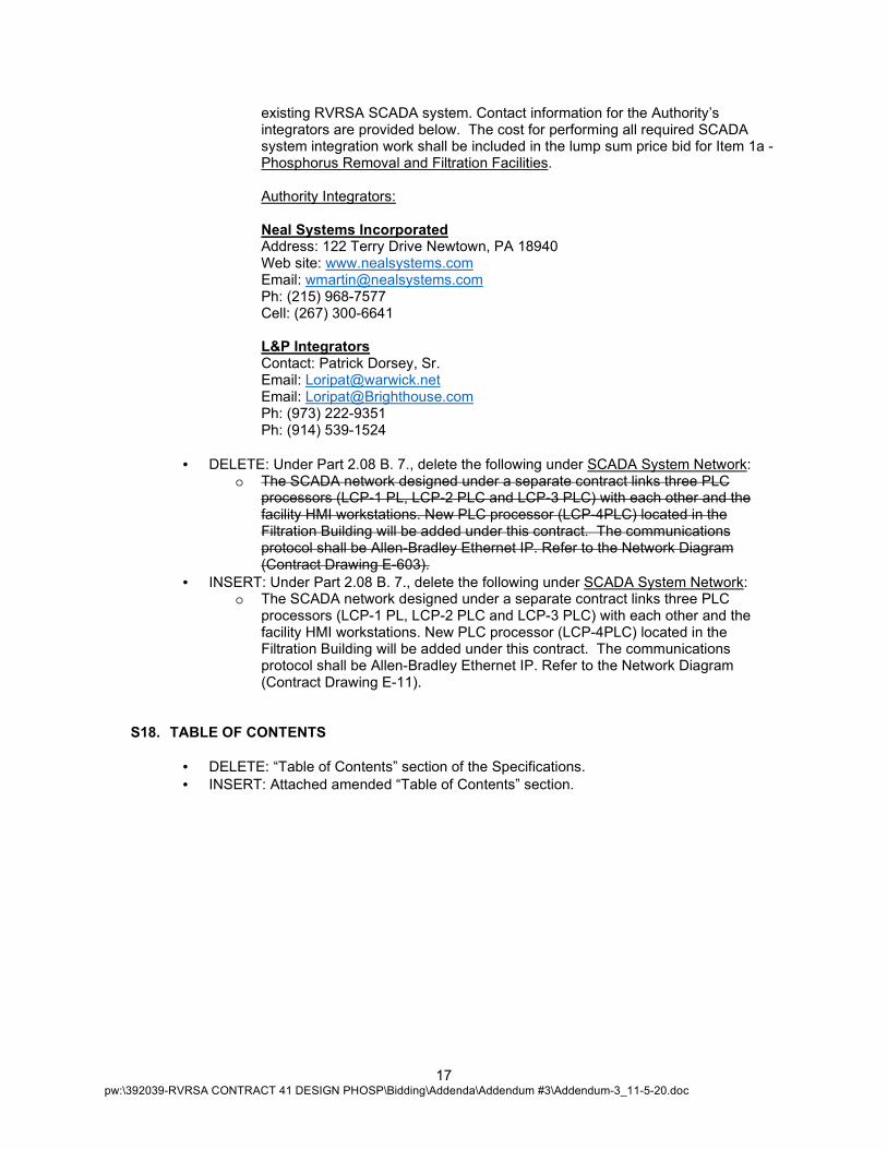
existing RVRSA SCADA system. Contact information for the Authority’s integrators are provided below. The cost for performing all required SCADA system integration work shall be included in the lump sum price bid for Item 1a - Phosphorus Removal and Filtration Facilities.
Authority Integrators: Neal Systems Incorporated Address: 122 Terry Drive Newtown, PA 18940 Web site: www.nealsystems.com Email: [email protected] Ph: (215) 968-7577 Cell: (267) 300-6641
L&P Integrators Contact: Patrick Dorsey, Sr. Email: [email protected] Email: [email protected] Ph: (973) 222-9351 Ph: (914) 539-1524
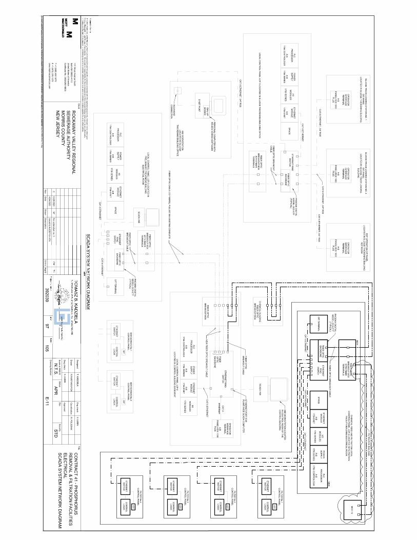
• DELETE: Under Part 2.08 B. 7., delete the following under SCADA System Network: o The SCADA network designed under a separate contract links three PLC
processors (LCP-1 PL, LCP-2 PLC and LCP-3 PLC) with each other and the facility HMI workstations. New PLC processor (LCP-4PLC) located in the Filtration Building will be added under this contract. The communications protocol shall be Allen-Bradley Ethernet IP. Refer to the Network Diagram (Contract Drawing E-603).
• INSERT: Under Part 2.08 B. 7., delete the following under SCADA System Network: o The SCADA network designed under a separate contract links three PLC
processors (LCP-1 PL, LCP-2 PLC and LCP-3 PLC) with each other and the facility HMI workstations. New PLC processor (LCP-4PLC) located in the Filtration Building will be added under this contract. The communications protocol shall be Allen-Bradley Ethernet IP. Refer to the Network Diagram (Contract Drawing E-11).
S18. TABLE OF CONTENTS
• DELETE: “Table of Contents” section of the Specifications.
• INSERT: Attached amended “Table of Contents” section.
18 pw:\392039-RVRSA CONTRACT 41 DESIGN PHOSP\Bidding\Addenda\Addendum #3\Addendum-3_11-5-20.doc
DRAWINGS
The original Drawings for the above-referenced contract are herein changed and clarified as noted below:
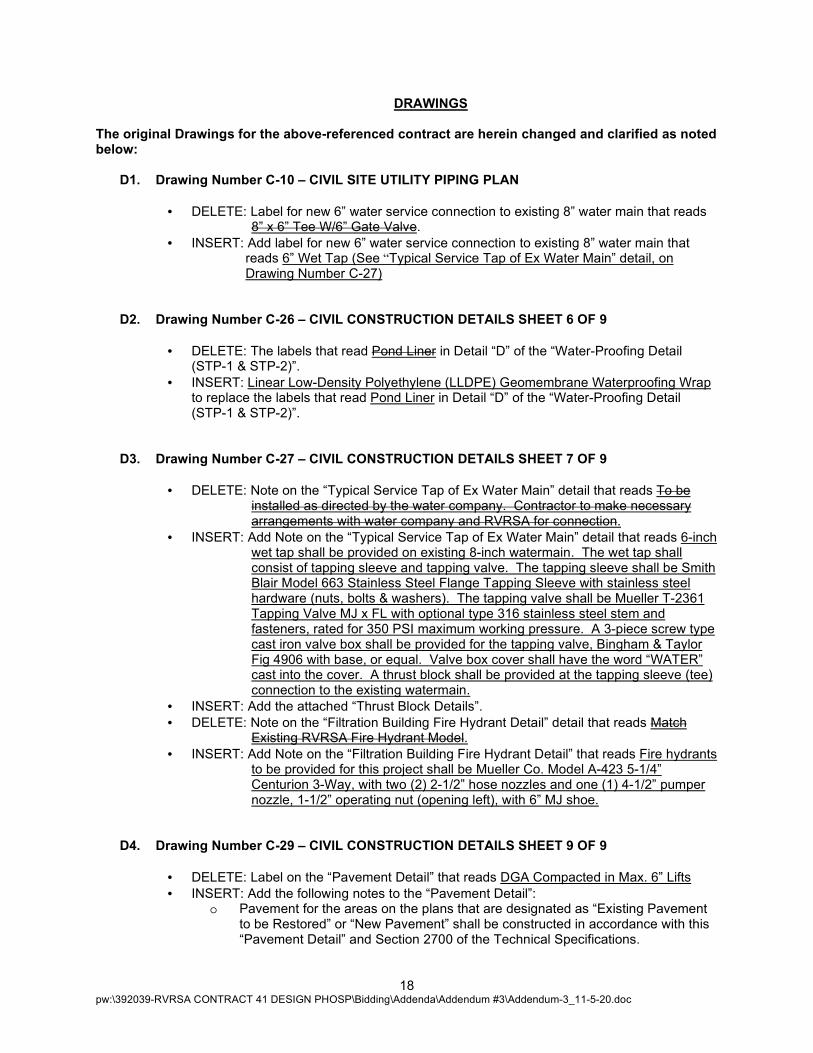
D1. Drawing Number C-10 – CIVIL SITE UTILITY PIPING PLAN
• DELETE: Label for new 6” water service connection to existing 8” water main that reads 8” x 6” Tee W/6” Gate Valve.
• INSERT: Add label for new 6” water service connection to existing 8” water main that reads 6” Wet Tap (See “Typical Service Tap of Ex Water Main” detail, on Drawing Number C-27)
D2. Drawing Number C-26 – CIVIL CONSTRUCTION DETAILS SHEET 6 OF 9
• DELETE: The labels that read Pond Liner in Detail “D” of the “Water-Proofing Detail (STP-1 & STP-2)”.
• INSERT: Linear Low-Density Polyethylene (LLDPE) Geomembrane Waterproofing Wrap to replace the labels that read Pond Liner in Detail “D” of the “Water-Proofing Detail (STP-1 & STP-2)”.
D3. Drawing Number C-27 – CIVIL CONSTRUCTION DETAILS SHEET 7 OF 9
• DELETE: Note on the “Typical Service Tap of Ex Water Main” detail that reads To be installed as directed by the water company. Contractor to make necessary arrangements with water company and RVRSA for connection.
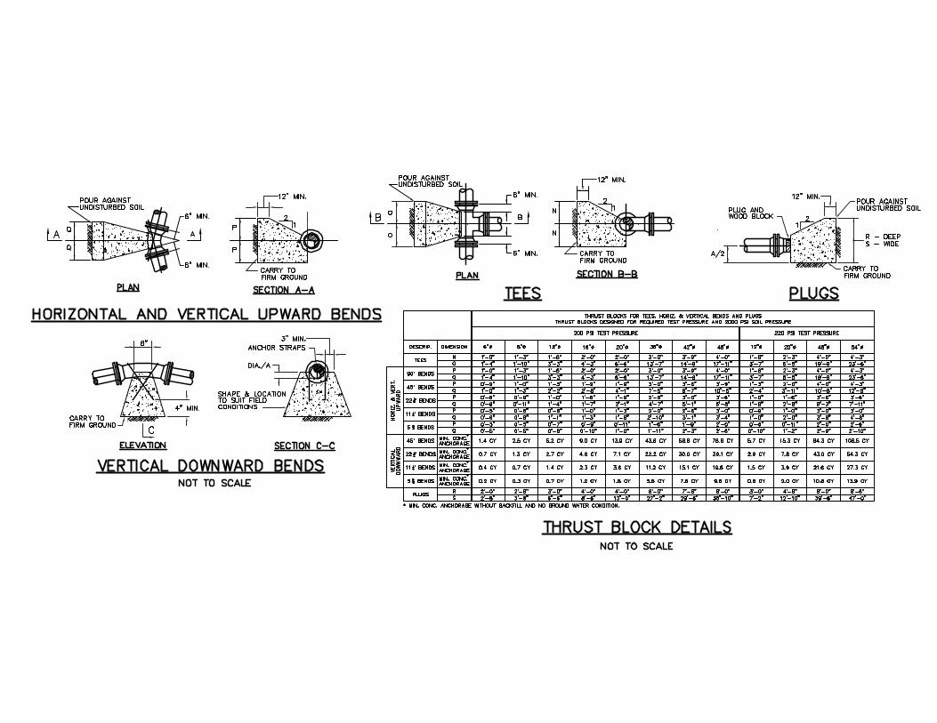
• INSERT: Add Note on the “Typical Service Tap of Ex Water Main” detail that reads 6-inch wet tap shall be provided on existing 8-inch watermain. The wet tap shall consist of tapping sleeve and tapping valve. The tapping sleeve shall be Smith Blair Model 663 Stainless Steel Flange Tapping Sleeve with stainless steel hardware (nuts, bolts & washers). The tapping valve shall be Mueller T-2361 Tapping Valve MJ x FL with optional type 316 stainless steel stem and fasteners, rated for 350 PSI maximum working pressure. A 3-piece screw type cast iron valve box shall be provided for the tapping valve, Bingham & Taylor Fig 4906 with base, or equal. Valve box cover shall have the word “WATER” cast into the cover. A thrust block shall be provided at the tapping sleeve (tee) connection to the existing watermain.
• INSERT: Add the attached “Thrust Block Details”.
• DELETE: Note on the “Filtration Building Fire Hydrant Detail” detail that reads Match Existing RVRSA Fire Hydrant Model.
• INSERT: Add Note on the “Filtration Building Fire Hydrant Detail” that reads Fire hydrants to be provided for this project shall be Mueller Co. Model A-423 5-1/4” Centurion 3-Way, with two (2) 2-1/2” hose nozzles and one (1) 4-1/2” pumper nozzle, 1-1/2” operating nut (opening left), with 6” MJ shoe.
D4. Drawing Number C-29 – CIVIL CONSTRUCTION DETAILS SHEET 9 OF 9
• DELETE: Label on the “Pavement Detail” that reads DGA Compacted in Max. 6” Lifts
• INSERT: Add the following notes to the “Pavement Detail”: o Pavement for the areas on the plans that are designated as “Existing Pavement
to be Restored” or “New Pavement” shall be constructed in accordance with this “Pavement Detail” and Section 2700 of the Technical Specifications.
19 pw:\392039-RVRSA CONTRACT 41 DESIGN PHOSP\Bidding\Addenda\Addendum #3\Addendum-3_11-5-20.doc
o Pavement subgrade shall consist of a minimum of one (1') foot thick layer of Class "G" compacted fills and six (6) inches of compacted quarry process road stone, compacted in max. 6” lifts.
• INSERT: Add the following note to the “Gravel Driveway Detail”: o All areas on the plans that are designated for installation of “New Gravel
Access/Cover” shall be in accordance with the “Gravel Driveway Detail”
D5. Drawing Number PI-02 – PROCESS AND INSTRUMENTATION DIAGRAMS ALUM FEED & FILTRATION
• DELETE: Drip Leg (with Leak Detector) that is shown on 2” SCH 80 CPVC (Suction) line from the Alum Storage Tanks.
• INSERT: Add Drip Leg (with Leak Detector) to 6” SCH 80 CPVC Containment Pipe (Carrier), on discharge side of pumps, at low point in Chemical Storage Room.
• DELETE: 2” Dry Disconnect on both fill lines for the Alum Storage Tanks.
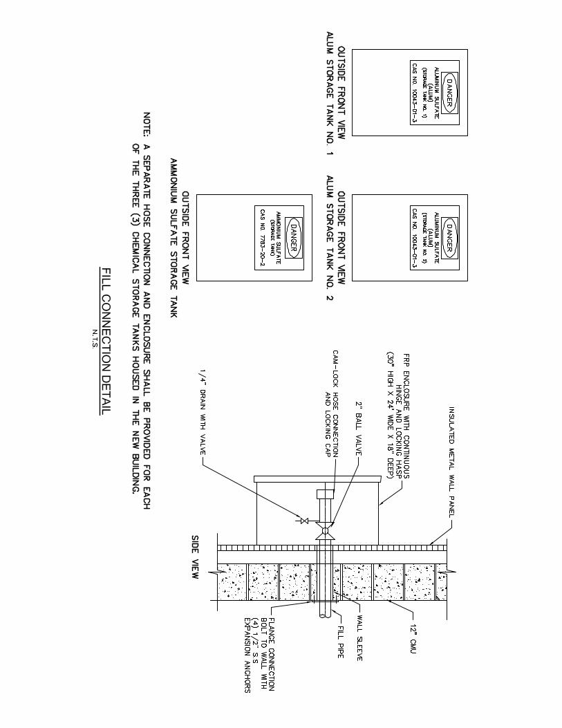
• INSERT: Add the following labels on both fill lines for the Alum Storage Tanks: o Provide 2” Hose Connection in accordance with the “Fill Connection Detail”
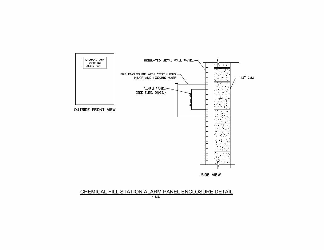
provided under Addendum #3. A separate hose connection and enclosure shall be provided for each of the two Alum storage tank fill lines. A separate enclosure shall also be provided to house the Chemical Fill Station Alarm Panel shown on Drawing Number E-14 of the Contract Drawings, in accordance with the “Chemical Fill Station Alarm Panel Enclosure Detail” provided under Addendum #3. All enclosures shall be mounted on exterior of new prefabricated steel building.
o The ball valves, at the fill points for the Alum storage tanks, shall be installed at a location that is accessible during filling.
• INSERT: Add the attached “Fill Connection Detail”.
• INSERT: Add the attached “Chemical Fill Station Alarm Panel Enclosure Detail”.
• DELETE: Interconnection between 2” SCH 80 CPVC pressure relief valve discharge pipe and 2” SCH 80 CPVC Alum tank fill pipe at Alum Storage Tank No.2.
• INSERT: Extend 2” SCH 80 CPVC pressure relief valve discharge pipe and connect this pipe separately into Alum Storage Tank No.2.
• DELTE: The two (2) ball valves that are located on 2” SCH 80 CPVC pressure relief valve discharge pipe.
D6. Drawing Number PI-03 – PROCESS AND INSTRUMENTATION DIAGRAMS AMMONIUM SULFATE AND GENERAL FEED DETAILS
• DELETE: Drip Leg (with Leak Detector) that is shown on 1” SCH 80 CPVC (Suction) line from the Ammonium Sulfate Storage Tanks.
• DELETE: Drip Leg (with Leak Detector) that is shown on tubing, on discharge side of pumps.
• INSERT: Add Drip Leg (with Leak Detector) to 1-1/2” SCH 80 CPVC Containment Pipe (Carrier), on discharge side of pumps, at low point near pump skid.
• INSERT: Add Drip Leg (with Leak Detector) to 1-1/2” SCH 80 CPVC Containment Pipe (Carrier), on discharge side of pumps, at low point in the Process Equipment (Filter) Room just before the line exists through the building wall.
• DELETE: 1” Dry Disconnect on fill line for the Ammonium Sulfate Storage Tank.
• INSERT: Add the following labels on fill line for the Ammonium Sulfate Storage Tank: o Provide 2” Hose Connection in accordance with “Fill Connection Detail” provided
under Addendum #3. A separate hose connection and enclosure shall be provided for the Ammonium Sulfate storage tank fill line. A separate enclosure shall also be provided to house the Chemical Fill Station Alarm Panel shown on
20 pw:\392039-RVRSA CONTRACT 41 DESIGN PHOSP\Bidding\Addenda\Addendum #3\Addendum-3_11-5-20.doc
Drawing Number E-14 of the Contract Drawings, in accordance with the “Chemical Fill Station Alarm Panel Enclosure Detail” provided under Addendum #3. All enclosures shall be mounted on exterior of new prefabricated steel building.
o The ball valves, at the fill points for the Ammonium Sulfate tanks, shall be installed at a location that is accessible during filling.
• DELETE: Label that reads: 1” SCH 80 CPVC (Fill) on fill line for the Ammonium Sulfate Storage Tank.
• INSERT: Add the following labels on fill line for the Ammonium Sulfate Storage Tank: o 2” SCH 80 CPVC (Fill). (The fill line for the Ammonium Sulfate Storage Tank
shall be 2” diameter SCH 80 CPVC)
D7. Drawing Number PI-04 – PROCESS AND INSTRUMENTATION DIAGRAMS FILTRATION WITH BACKWASH
• DELETE: Valve “Size” (60 Inch) for Valves with I.D. numbers “DFI-5” and “DFE-5”, in the table entitled “Valve Schedule – Filtration Facilities”.
• INSERT: 66 Inch in “Size” column for Valves with I.D. numbers “DFI-5” and “DFE-5”, in the table entitled “Valve Schedule – Filtration Facilities”.
D8. Drawing Number PR-01 – PROCESS OVERALL FILTER UNIT PROCESS PLAN
• DELETE: Label for new Ammonium Sulfate manhole that reads 66” x 66” x 24” CCFRPM Tee For Ammonium Sulfate Dosing.
• INSERT: Add label for new Ammonium Sulfate manhole that reads Ammonium Sulfate Chemical Feed Dosing Manhole (See Detail provided under Addendum #3)
D9. Drawing Number PR-02 – PROCESS LOWER LEVEL PLAN
• DELETE: Label for new Ammonium Sulfate manhole that reads 66” x 66” x 36” Closed Tee with Ammonium Feed.
• INSERT: Add label for new Ammonium Sulfate manhole that reads Ammonium Sulfate Chemical Feed Dosing Manhole (See Detail provided under Addendum #3)
• DELETE: Label for the new 4” pipe from the lower level drains in the new disc filter building that reads 4” DIP to PVC Compressions Coupling
• INSERT: Add label that reads Provide Fernco shielded coupling, or equal, with stainless steel shear ring for connecting 4” DIP to 4” SCH 80 PVC to replace label that reads 4” DIP to PVC Compressions Coupling, (as deleted in the comment above).
• DELETE: Label for the new 4” pipe from the lower level drains in the new disc filter building that reads 10” DIP
• INSERT: Add label for new 4” pipe from the lower level drains in the new disc filter building that reads 4” SCH 80 PVC to wet well of backwash sludge pump station. Refer to Drawing Number PR-01 for routing, to replace label that reads 10” DIP, (as deleted in the comment above).
D10. Drawing Number PR-05 – PROCESS CHEMICAL STORAGE PLAN & SECTIONS
• INSERT: Add the following note: o Provide 4-inch high housekeeping pad beneath each of the three (3) new
chemical storage tanks. Housekeeping pad should extend a minimum of 3
21 pw:\392039-RVRSA CONTRACT 41 DESIGN PHOSP\Bidding\Addenda\Addendum #3\Addendum-3_11-5-20.doc
inches beyond the bolt circle of the tank’s anchor bolt holes, around the entire perimeter of the tank. Housekeeping pad shall be in accordance with the “Equipment Pad Detail” provided Drawing Number S-10 of the Contract Drawings.
• DELETE: All references to Dry Disconnects on fill lines for the Alum Storage Tanks and Ammonium Sulfate Storage Tank shall be deleted.
• INSERT: Add the following label for the Alum Storage Tanks fill lines and Ammonium Sulfate Storage Tank fill line:
o Provide Hose Connections in accordance with the “Fill Connection Detail” provided under Addendum #3.
• DELETE: All references to 1” SCH 80 CPVC on fill line for the Ammonium Sulfate Storage Tank.
• INSERT: Amend the labels on fill line for the Ammonium Sulfate Storage Tank to require that the fill line shall be 2” diameter SCH 80 CPVC.
D11. General Comment that pertains to all drawings:
• The finished floor elevation in the Chemical Storage Room is herein lowered from elevation 208’-10” to elevation 208’-6”. All impacted drawings are herein modified to reflect this change. Slab and wall thicknesses shall remain the same, as noted on the Structural (S) drawings. This change is required to account a loss in the volume of the containment area, that will result from the installation of the housekeeping pads beneath the three (3) chemical storage tanks.
D12. Drawing Number PR-06 – PROCESS BACKWASH SLUDGE PUMP STATION MECHANICAL PLAN
• INSERT: Add the following note: o In addition to the pedestal base, a new portable davit crane shall also be
furnished and installed under this project. The new portable davit crane shall be Thern Inc. Model 5124M1GAL, or equal, as noted in the “Davit Bracket Detail” on Drawing Number PR-11. The new portable davit crane shall be provided with a zinc-plated spur gear hand winch with brake for load control, and 316 stainless steel wire rope assembly with 316 stainless steel eye hook. Wire rope shall be of an appropriate length to facilitate installation and removal of the pumping equipment. Wire rope shall be a minimum of 45-foot in length. The Contractor shall be required to confirm that the hoist and wire rope are suitably sized, as necessary, for lifting and lowering the new submersible pumps, after submittals for the submersible pumps have been approved.
D13. Drawing Number PR-09 – PROCESS FILTRATION EXTERIOR PIPING PLAN
• DELETE: Label for new Ammonium Sulfate manhole that reads 66” x 66” with Riser CCFRPM to Connected Ammonium Sulfate Feed.
• INSERT: Add label for new Ammonium Sulfate manhole that reads Ammonium Sulfate Chemical Feed Dosing Manhole (See Detail provided under Addendum #3)
• INSERT: Add the following note: o CCFRPM piping that is to be connected to flanged butterfly valves shall be
provided fiberglass reinforced polymer flanges that are compatible with the ANSI flanges on the butterfly valves.
22 pw:\392039-RVRSA CONTRACT 41 DESIGN PHOSP\Bidding\Addenda\Addendum #3\Addendum-3_11-5-20.doc
D14. Drawing Number PR-10 – PROCESS FILTRATION EXTERIOR PIPING SECTIONS
• DELETE: Label for new Ammonium Sulfate manhole, in Section - 3 “Effluent Elevation Change Section”, that reads New 66” x 66” x 36” CCFRPM Closed Tee Ammonium Tee Manhole.
• INSERT: Add label for new Ammonium Sulfate manhole that reads Ammonium Sulfate Chemical Feed Dosing Manhole (See Detail provided under Addendum #3)
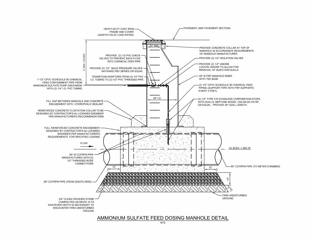
D15. Drawing Number PR-12 – PROCESS CONSTRUCTION DETAILS SHEET 2 OF 2
• DELETE: “Ammonium Sulfate Feed Dosing Manhole Detail”.
• INSERT: Add the attached, amended “Ammonium Sulfate Feed Dosing Manhole Detail”.
D16. Drawing Number S-03 – STRUCTURAL FOUNDATION PLAN
• INSERT: Add the following note: o Mounting and anchoring of the disc filter equipment shall comply with all of the
manufacturer’s recommendations and requirements for the approved disc filter equipment.
D17. Drawing Number M-02 – MECHANICAL HVAC FLOOR PLAN
• INSERT: Add the following note: o The concentric flue box shall be provided by unit heater manufacturer.
D18. Electrical (E) Drawings – General Comment pertains to all Electrical (E) drawings
• Pilot light lens colors shall be as follows for all electrical controllers: o Green colored lens – shall signify “Running” o Red colored lens – shall signify “Alarm”
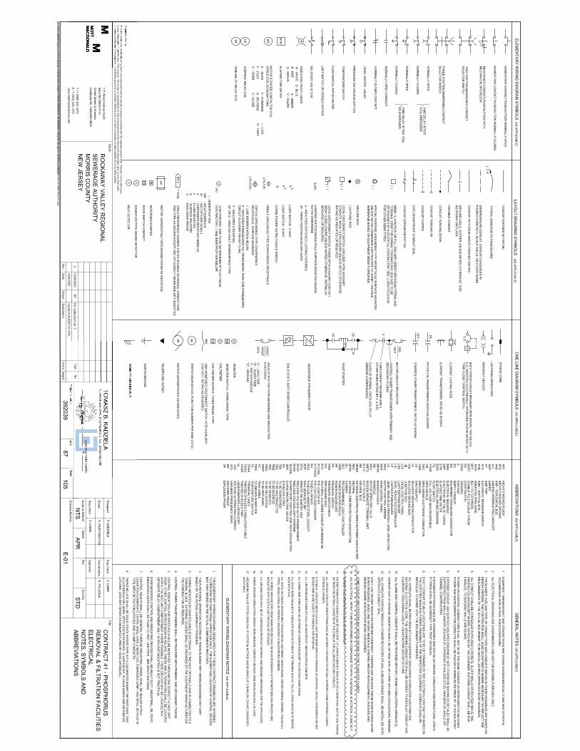
D19. Drawing Number E-01 – ELECTRICAL NOTES, SYMBOLS AND ABBREVIATIONS
• DELETE: Drawing Number E-01 – “ELECTRICAL NOTES, SYMBOLS AND ABBREVIATIONS” of the Contract Drawings.
• INSERT: Attached amended Drawing Number E-01 – “ELECTRICAL NOTES, SYMBOLS AND ABBREVIATIONS”. Revisions to drawing have been clouded.
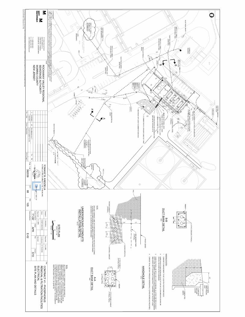
D20. Drawing Number E-02 – ELECTRICAL SITE PLAN AND DETAILS
• DELETE: Drawing Number E-02 – “ELECTRICAL SITE PLAN AND DETAILS” of the Contract Drawings.
• INSERT: Attached amended Drawing Number E-02 – “ELECTRICAL SITE PLAN AND DETAILS”. Revisions to drawing have been clouded.
23 pw:\392039-RVRSA CONTRACT 41 DESIGN PHOSP\Bidding\Addenda\Addendum #3\Addendum-3_11-5-20.doc
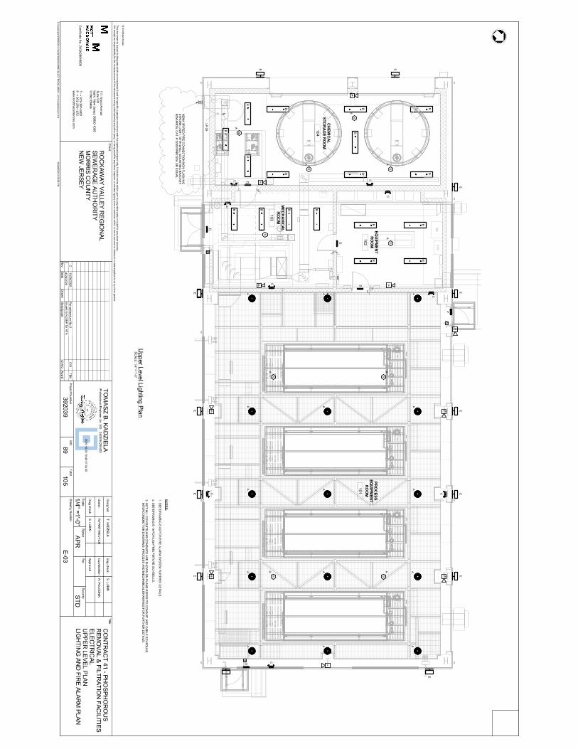
D21. Drawing Number E-03 – ELECTRICAL UPPER LEVEL PLAN LIGHTING AND FIRE ALARM PLAN
• DELETE: Drawing Number E-03 – “ELECTRICAL UPPER LEVEL PLAN LIGHTING AND FIRE ALARM PLAN” of the Contract Drawings.
• INSERT: Attached amended Drawing Number E-03 – “ELECTRICAL UPPER LEVEL PLAN LIGHTING AND FIRE ALARM PLAN”. Revisions to drawing have been clouded.
The following revisions are in addition to the revisions that are shown on the attached revised plan sheet:
• DELETE: The letter “M” in the square symbols that are located by the three (3) exterior doorways of the new filtration building, in the “Upper Level Lighting Plan”.
• INSERT: The letter “P” to replace the letter “M” in the square symbols that are located by the three (3) exterior doorways of the new filtration building, in the “Upper Level Lighting Plan”.
• The letter “P” in the square symbols shall stand for fire alarm system pull station. The correct symbol for the fire alarm pull station (the letter “P” in a box) is shown in the “Fire Alarm Riser Diagram” on Drawing E-08 of the Contract Drawings.
• INSERT: Add the following note: o The receptacles and switches in the Chemical Storage Room of the new
Filtration Building shall have PVC boxes with neoprene cover plates.
• INSERT: Add the following note: o The red strobe light, located on the Southeast exterior wall of the new
prefabricated steel building, shall be non-flashing and continuously illuminated to identify the location of the fire hydrant water connection, per local fire department requirements. The red strobe light shall be positioned above the fire department connection (FDC) that is located near the Southern corner of the Chemical Storage Room as shown in the “Fire Protection Floor Plan” on Drawing M-17 of the Contract Drawings.
• DELETE: The letter “A” that is located next to the hexagon-shaped symbols that contain the letter “S” (which designate the smoke detectors) in the “Upper Level Lighting Plan”. The Letter “A” was added to the smoke detector symbol in error.
• INSERT: A 4-way switch should be added near the door located on the Northeast side of the new Filtration Building, in the interior of the building. For reference this door is designated as Door Number 103 on Drawing Number A-02 of the Contract Drawings.
D22. Drawing Number E-04 – ELECTRICAL UPPER LEVEL PLAN POWER PLAN
• The chemical fill station alarm panel that is shown at the West corner of the new prefabricated steel building shall be relocated near the South corner of the new building so that it is adjacent to the fill points for the Alum and Ammonium Sulfate storage tanks.
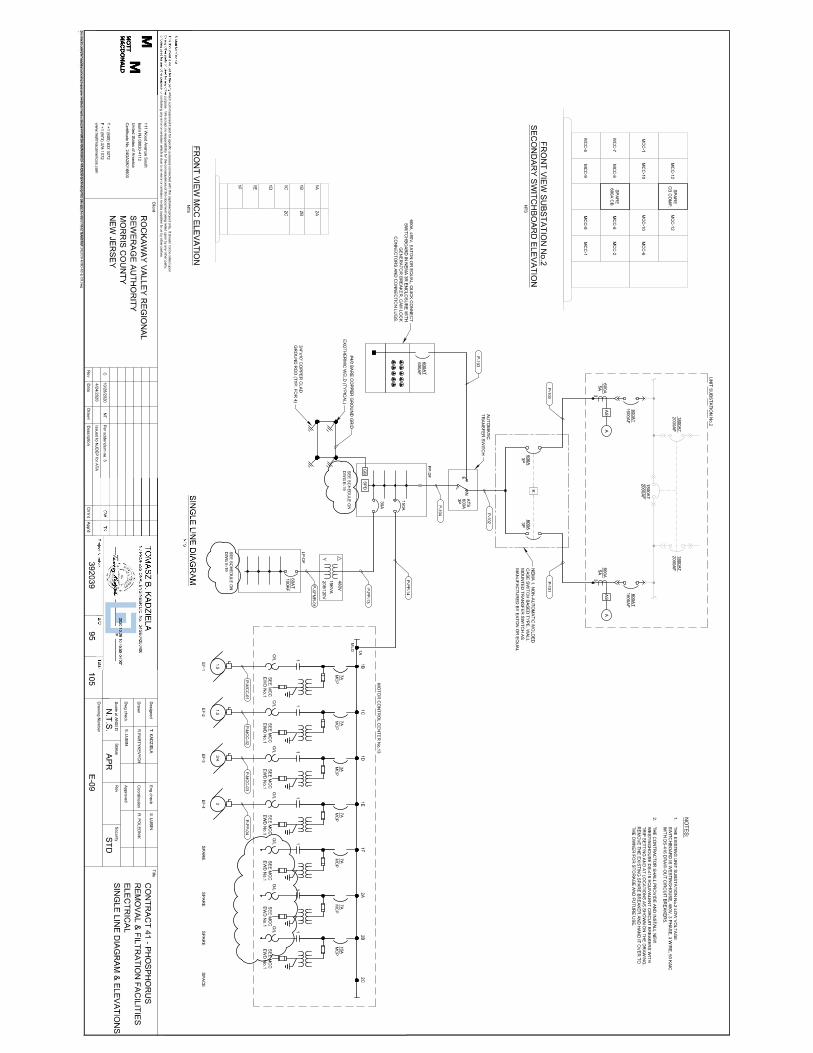
D23. Drawing Number E-09 – ELECTRICAL SINGLE LINE DIAGRAM & ELEVATIONS
• DELETE: Drawing Number E-09 – “ELECTRICAL SINGLE LINE DIAGRAM & ELEVATIONS” of the Contract Drawings.
• INSERT: Attached amended Drawing Number E-09 – “ELECTRICAL SINGLE LINE DIAGRAM & ELEVATIONS”. Revisions to drawing have been clouded.
24 pw:\392039-RVRSA CONTRACT 41 DESIGN PHOSP\Bidding\Addenda\Addendum #3\Addendum-3_11-5-20.doc
The following revision is in addition to the revisions that are shown on the attached revised plan sheet:
• INSERT: “New” in front of the Motor Control Center No. 13. (MCC #13 is new and is to be furnished and installed under this project.)
D24. Drawing Number E-11 – ELECTRICAL SCADA SYSTEM NETWORK DIAGRAM
• DELETE: Drawing Number E-11 – “ELECTRICAL SCADA SYSTEM NETWORK DIAGRAM” of the Contract Drawings.
• INSERT: Attached amended Drawing Number E-11 – “ELECTRICAL SCADA SYSTEM NETWORK DIAGRAM”. Revisions to drawing have been clouded.
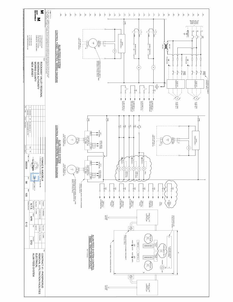
D25. Drawing Number E-12 – ELECTRICAL ALUM FEED SYSTEM
• DELETE: Drawing Number E-12 – “ELECTRICAL ALUM FEED SYSTEM” of the Contract Drawings.
• INSERT: Attached amended Drawing Number E-12 – “ELECTRICAL ALUM FEED SYSTEM”. Revisions to drawing have been clouded.
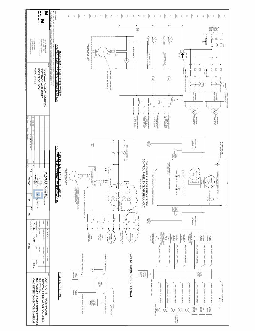
D26. Drawing Number E-13 – ELECTRICAL AMMONIUM SULFATE FEED SYSTEM & HVAC
INTERCONNECTION DIAGRAM
• DELETE: Drawing Number E-13 – “ELECTRICAL AMMONIUM SULFATE FEED SYSTEM & HVAC INTERCONNECTION DIAGRAM” of the Contract Drawings.
• INSERT: Attached amended Drawing Number E-13 – “ELECTRICAL AMMONIUM SULFATE FEED SYSTEM & HVAC INTERCONNECTION DIAGRAM”. Revisions to drawing have been clouded.
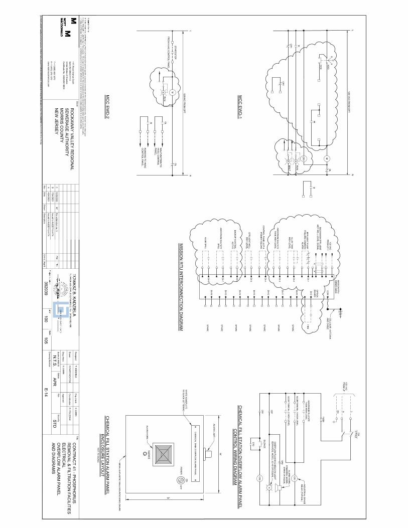
D27. Drawing Number E-14 – ELECTRICAL OVERFLOW ALARM PANEL AND DIAGRAMS
• DELETE: Drawing Number E-14 – “ELECTRICAL OVERFLOW ALARM PANEL AND DIAGRAMS” of the Contract Drawings.
• INSERT: Attached amended Drawing Number E-14 – “ELECTRICAL OVERFLOW ALARM PANEL AND DIAGRAMS”. Revisions to drawing have been clouded.
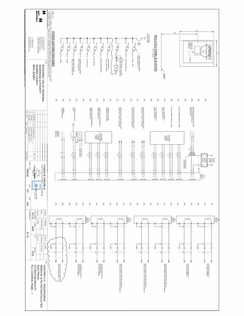
D28. Drawing Number E-15 – ELECTRICAL FILTRATION FACILITY PLC CONTROL PANEL – 1
• DELETE: Drawing Number E-15 – “ELECTRICAL FILTRATION FACILITY PLC CONTROL PANEL - 1” of the Contract Drawings.
• INSERT: Attached amended Drawing Number E-15 – “ELECTRICAL FILTRATION FACILITY PLC CONTROL PANEL - 1”. Revisions to drawing have been clouded.
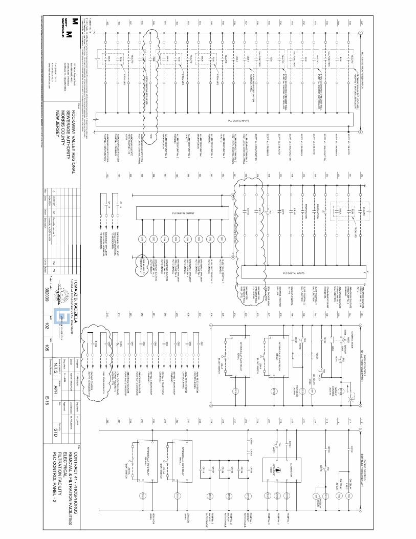
D29. Drawing Number E-16 – ELECTRICAL FILTRATION FACILITY PLC CONTROL PANEL – 2
• DELETE: Drawing Number E-16 – “ELECTRICAL FILTRATION FACILITY PLC CONTROL PANEL - 2” of the Contract Drawings.
• INSERT: Attached amended Drawing Number E-16 – “ELECTRICAL FILTRATION FACILITY PLC CONTROL PANEL - 2”. Revisions to drawing have been clouded.
25 pw:\392039-RVRSA CONTRACT 41 DESIGN PHOSP\Bidding\Addenda\Addendum #3\Addendum-3_11-5-20.doc
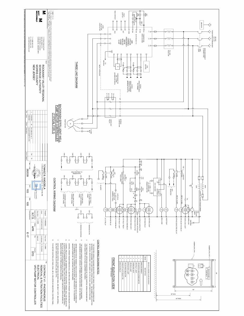
D30. Drawing Number E-17 – ELECTRICAL VFD PUMP MOTOR CONTROLLER
• DELETE: Drawing Number E-17 – “ELECTRICAL VFD PUMP MOTOR CONTROLLER” of the Contract Drawings.
• INSERT: Attached amended Drawing Number E-17 – “ELECTRICAL VFD PUMP MOTOR CONTROLLER”. Revisions to drawing have been clouded.
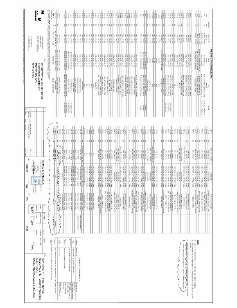
D31. Drawing Number E-18 – ELECTRICAL CABLE AND RACEWAY SCHEDULE
• DELETE: Drawing Number E-18 – “ELECTRICAL CABLE AND RACEWAY SCHEDULE” of the Contract Drawings.
• INSERT: Attached amended Drawing Number E-18 – “ELECTRICAL CABLE AND RACEWAY SCHEDULE”. Revisions to drawing have been clouded.
The following revisions are in addition to the revisions that are shown on the attached revised plan sheet:
• DELETE: Note 3 that reads All conduits shall be PVC coated RGS, except for underground conduits and conduits within the electrical room, which shall be RGS.
• INSERT: Add note to replace Note 3 that reads as follows: o PVC coated rigid galvanized steel conduit shall be provided in all areas of the
project, with the exception of the Mechanical Room and Equipment (Electrical) Room, which are located in the new Filtration Building. Locations where PVC coated rigid galvanized steel conduit are required include outside locations, and locations in the Process Equipment Room and Chemical Storage Room of the new Filtration Building. Rigid galvanized steel conduit shall be used in the Mechanical Room and Equipment (Electrical) Room, in the new Filtration Building. Rigid galvanized steel conduit shall also be used in underground concrete encased duct banks. This note shall govern over all other requirements for conduit material type as referenced in the Contract Drawings and Technical Specifications.
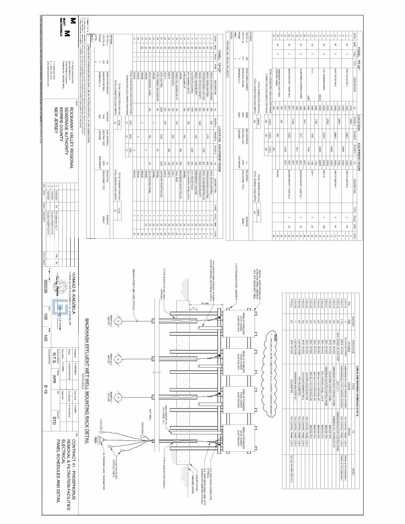
D32. Drawing Number E-19 – ELECTRICAL PANEL SCHEDULES AND DETAIL
• DELETE: Drawing Number E-19 – “ELECTRICAL PANEL SCHEDULES AND DETAIL” of the Contract Drawings.
• INSERT: Attached amended Drawing Number E-19 – “ELECTRICAL PANEL SCHEDULES AND DETAIL”. Revisions to drawing have been clouded.
The following revision is in addition to the revisions that are shown on the attached revised plan sheet:
• INSERT: Add note that reads as follows: o The Backwash Sludge Pump Station is a Class 1 Div. 1 hazardous location, as
such all equipment to be provided at the pump station shall be designed based National Electrical Code (NEC) requirements for Class 1 Div. 1 hazardous location.

-i-
497F 01-2019-F pw:\392039-RVRSA CONTRACT 41 DESIGN PHOSP\Design\Documents\Specifications\1 Front End\03-TOC-B - REV1.doc (Rev. 31)
Table of Contents
Description Page No.
ROCKAWAY VALLEY REGIONAL SEWERAGE AUTHORITY MORRIS COUNTY, NEW JERSEY
PHOSPHORUS REMOVAL AND FILTRATION FACILITIES
NEW JERSEY STATE LOAN PROJECT NO. S340821-08 CONTRACT NO. 41
Table of Contents
Description Page No.
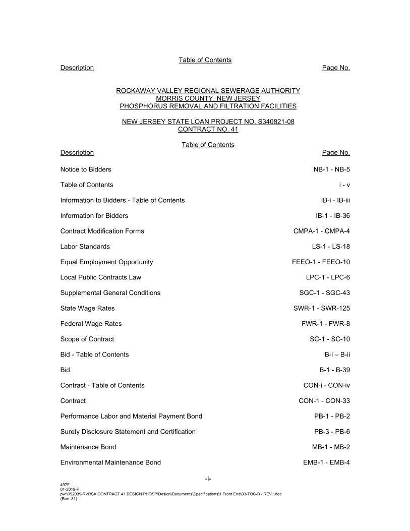
Notice to Bidders NB-1 - NB-5 Table of Contents i - v Information to Bidders - Table of Contents IB-i - IB-iii Information for Bidders IB-1 - IB-36 Contract Modification Forms CMPA-1 - CMPA-4 Labor Standards LS-1 - LS-18 Equal Employment Opportunity FEEO-1 - FEEO-10 Local Public Contracts Law LPC-1 - LPC-6
Supplemental General Conditions SGC-1 - SGC-43 State Wage Rates SWR-1 - SWR-125 Federal Wage Rates FWR-1 - FWR-8 Scope of Contract SC-1 - SC-10 Bid - Table of Contents B-i – B-ii Bid B-1 - B-39 Contract - Table of Contents CON-i - CON-iv Contract CON-1 - CON-33 Performance Labor and Material Payment Bond PB-1 - PB-2 Surety Disclosure Statement and Certification PB-3 - PB-6 Maintenance Bond MB-1 - MB-2 Environmental Maintenance Bond EMB-1 - EMB-4
-ii-
497F 01-2019-F pw:\392039-RVRSA CONTRACT 41 DESIGN PHOSP\Design\Documents\Specifications\1 Front End\03-TOC-B - REV1.doc (Rev. 31)
Table of Contents
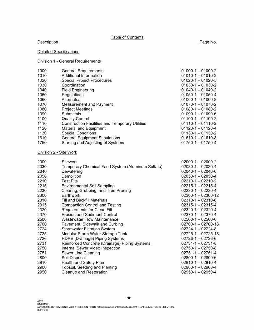
Description Page No. Detailed Specifications Division 1 - General Requirements 1000 General Requirements 01000-1 – 01000-2 1010 Additional Information 01010-1 – 01010-2 1020 Special Project Procedures 01020-1 – 01020-5 1030 Coordination 01030-1 – 01030-2 1040 Field Engineering 01040-1 – 01040-2 1050 Regulations 01050-1 – 01050-4 1060 Alternates 01060-1 – 01060-2 1070 Measurement and Payment 01070-1 – 01070-2 1080 Project Meetings 01080-1 – 01080-2 1090 Submittals 01090-1 – 01090-6 1100 Quality Control 01100-1 – 01100-2 1110 Construction Facilities and Temporary Utilities 01110-1 – 01110-2 1120 Material and Equipment 01120-1 – 01120-4 1130 Special Conditions 01130-1 – 01130-2 1610 General Equipment Stipulations 01610-1 – 01610-8 1750 Starting and Adjusting of Systems 01750-1 – 01750-4 Division 2 - Site Work 2000 Sitework 02000-1 – 02000-2 2030 Temporary Chemical Feed System (Aluminum Sulfate) 02030-1 – 02030-4 2040 Dewatering 02040-1 – 02040-6 2050 Demolition 02050-1 – 02050-4 2210 Test Pits 02210-1 – 02210-2 2215 Environmental Soil Sampling 02215-1 – 02215-4 2230 Clearing, Grubbing, and Tree Pruning 02230-1 – 02230-4 2300 Earthwork 02300-1 – 02300-12 2310 Fill and Backfill Materials 02310-1 – 02310-8 2315 Compaction Control and Testing 02315-1 – 02315-4 2320 Requirements for Clean Fill 02320-1 – 02320-4 2370 Erosion and Sediment Control 02370-1 – 02370-4 2500 Wastewater Flow Maintenance 02500-1 – 02500-6 2700 Pavement, Sidewalk and Curbing 02700-1 – 02700-18 2724 Stormwater Filtration System 02724-1 – 02724-8 2725 Modular Storm Water Storage Tank 02725-1 – 02725-18 2726 HDPE (Drainage) Piping Systems 02726-1 – 02726-6 2731 Reinforced Concrete (Drainage) Piping Systems 02731-1 – 02731-8 2750 Internal Sewer Video Inspection 02750-1 – 02750-8 2751 Sewer Line Cleaning 02751-1 – 02751-4 2800 Soil Disposal 02800-1 – 02800-6 2810 Health and Safety Plan 02810-1 – 02810-4 2900 Topsoil, Seeding and Planting 02900-1 – 02900-4 2950 Cleanup and Restoration 02950-1 – 02950-4
-iii-
497F 01-2019-F pw:\392039-RVRSA CONTRACT 41 DESIGN PHOSP\Design\Documents\Specifications\1 Front End\03-TOC-B - REV1.doc (Rev. 31)
Table of Contents
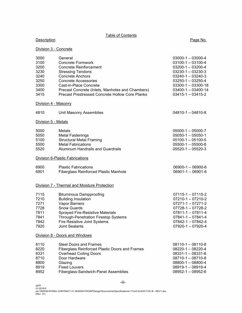
Description Page No. Division 3 - Concrete 3000 General 03000-1 – 03000-4 3100 Concrete Formwork 03100-1 – 03100-4 3200 Concrete Reinforcement 03200-1 – 03200-4 3230 Stressing Tendons 03230-1 – 03230-3 3240 Concrete Anchors 03240-1 – 03240-3 3250 Concrete Accessories 03250-1 – 03250-4 3300 Cast-in-Place Concrete 03300-1 – 03300-18 3400 Precast Concrete (Inlets, Manholes and Chambers) 03400-1 – 03400-14 3415 Precast Prestressed Concrete Hollow Core Planks 03415-1 – 03415-2 Division 4 - Masonry 4810 Unit Masonry Assemblies 04810-1 – 04810-8 Division 5 - Metals 5000 Metals 05000-1 – 05000-7 5050 Metal Fastenings 05050-1 – 05050-1 5100 Structural Metal Framing 05100-1 – 05100-5 5500 Metal Fabrications 05500-1 – 05500-8 5520 Aluminum Handrails and Guardrails 05520-1 – 05520-3 Division 6-Plastic Fabrications 6900 Plastic Fabrications 06900-1 – 06900-6 6901 Fiberglass Reinforced Plastic Manhole 06901-1 – 06901-6 Division 7 - Thermal and Moisture Protection 7115 Bituminous Dampproofing 07115-1 – 07115-2 7210 Building Insulation 07210-1 – 07210-2 7271 Vapor Barriers 07271-1 – 07271-2 7728 Snow Guards 07728-1 – 07728-2 7811 Sprayed Fire-Resistive Materials 07811-1 – 07811-4 7841 Through-Penetration Firestop Systems 07841-1 – 07841-4 7842 Fire Resistive Joint Systems 07842-1 – 07842-4 7920 Joint Sealants 07920-1 – 07920-4 Division 8 - Doors and Windows 8110 Steel Doors and Frames 08110-1 – 08110-8 8220 Fiberglass Reinforced Plastic Doors and Frames 08220-1 – 08220-4 8331 Overhead Coiling Doors 08331-1 – 08331-6 8710 Door Hardware 08710-1 – 08710-8 8800 Glazing 08800-1 – 08800-4 8919 Fixed Louvers 08919-1 – 08919-4 8952 Fiberglass-Sandwich-Panel Assemblies 08952-1 – 08952-6
-iv-
497F 01-2019-F pw:\392039-RVRSA CONTRACT 41 DESIGN PHOSP\Design\Documents\Specifications\1 Front End\03-TOC-B - REV1.doc (Rev. 31)
Table of Contents
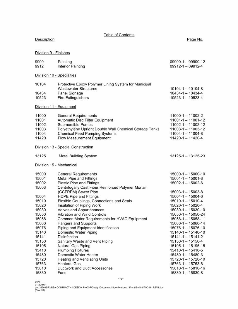
Description Page No. Division 9 - Finishes 9900 Painting 09900-1 – 09900-12 9912 Interior Painting 09912-1 – 09912-4 Division 10 - Specialties 10104 Protective Epoxy Polymer Lining System for Municipal Wastewater Structures 10104-1 – 10104-8 10434 Panel Signage 10434-1 – 10434-4 10523 Fire Extinguishers 10523-1 – 10523-4 Division 11 - Equipment 11000 General Requirements 11000-1 – 11002-2 11001 Automatic Disc Filter Equipment 11001-1 – 11001-12 11002 Submersible Pumps 11002-1 – 11002-12 11003 Polyethylene Upright Double Wall Chemical Storage Tanks 11003-1 – 11003-12 11004 Chemical Feed Pumping Systems 11004-1 – 11004-8 11420 Flow Measurement Equipment 11420-1 – 11420-4 Division 13 - Special Construction 13125 Metal Building System 13125-1 – 13125-23 Division 15 - Mechanical 15000 General Requirements 15000-1 – 15000-10 15001 Metal Pipe and Fittings 15001-1 – 15001-8 15002 Plastic Pipe and Fittings 15002-1 – 15002-6 15003 Centrifugally Cast Fiber Reinforced Polymer Mortar (CCFRPM) Sewer Pipe 15003-1 – 15003-8 15004 HDPE Pipe and Fittings 15004-1 – 15004-6 15010 Flexible Couplings, Connections and Seals 15010-1 – 15010-4 15020 Insulation of Piping Work 15020-1 – 15020-4 15030 Valves and Appurtenances 15030-1 – 15030-10 15050 Vibration and Wind Controls 15050-1 – 15050-24 15058 Common Motor Requirements for HVAC Equipment 15058-1 – 15058-11 15060 Hangers and Supports 15060-1 – 15060-14 15076 Piping and Equipment Identification 15076-1 – 15076-10 15140 Domestic Water Piping 15140-1 – 15140-10 15141 Disinfection 15141-1 – 15141-2 15150 Sanitary Waste and Vent Piping 15150-1 – 15150-4 15195 Natural Gas Piping 15195-1 – 15195-15 15410 Plumbing Fixtures 15410-1 – 15410-5 15480 Domestic Water Heater 15480-1 – 15480-3 15720 Heating and Ventilating Units 15720-1 – 15720-10 15763 Heaters, Gas 15763-1 – 15763-8 15810 Ductwork and Duct Accessories 15810-1 – 15810-16 15830 Fans 15830-1 – 15830-8
-v-
497F 01-2019-F pw:\392039-RVRSA CONTRACT 41 DESIGN PHOSP\Design\Documents\Specifications\1 Front End\03-TOC-B - REV1.doc (Rev. 31)
Table of Contents
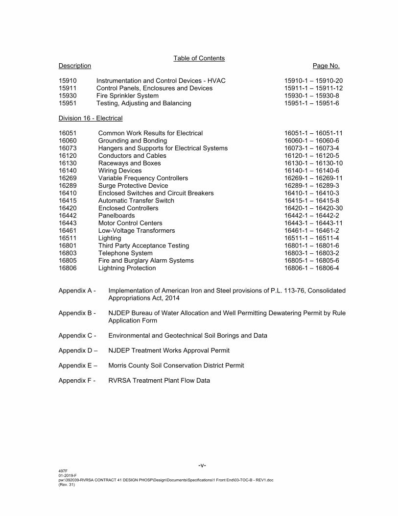
Description Page No. 15910 Instrumentation and Control Devices - HVAC 15910-1 – 15910-20 15911 Control Panels, Enclosures and Devices 15911-1 – 15911-12 15930 Fire Sprinkler System 15930-1 – 15930-8 15951 Testing, Adjusting and Balancing 15951-1 – 15951-6 Division 16 - Electrical 16051 Common Work Results for Electrical 16051-1 – 16051-11 16060 Grounding and Bonding 16060-1 – 16060-6 16073 Hangers and Supports for Electrical Systems 16073-1 – 16073-4 16120 Conductors and Cables 16120-1 – 16120-5 16130 Raceways and Boxes 16130-1 – 16130-10 16140 Wiring Devices 16140-1 – 16140-6 16269 Variable Frequency Controllers 16269-1 – 16269-11 16289 Surge Protective Device 16289-1 – 16289-3 16410 Enclosed Switches and Circuit Breakers 16410-1 – 16410-3 16415 Automatic Transfer Switch 16415-1 – 16415-8 16420 Enclosed Controllers 16420-1 – 16420-30 16442 Panelboards 16442-1 – 16442-2 16443 Motor Control Centers 16443-1 – 16443-11 16461 Low-Voltage Transformers 16461-1 – 16461-2 16511 Lighting 16511-1 – 16511-4 16801 Third Party Acceptance Testing 16801-1 – 16801-6 16803 Telephone System 16803-1 – 16803-2 16805 Fire and Burglary Alarm Systems 16805-1 – 16805-6 16806 Lightning Protection 16806-1 – 16806-4 Appendix A - Implementation of American Iron and Steel provisions of P.L. 113-76, Consolidated
Appropriations Act, 2014 Appendix B - NJDEP Bureau of Water Allocation and Well Permitting Dewatering Permit by Rule
Application Form Appendix C - Environmental and Geotechnical Soil Borings and Data Appendix D – NJDEP Treatment Works Approval Permit Appendix E – Morris County Soil Conservation District Permit Appendix F - RVRSA Treatment Plant Flow Data
08800 - 1
SECTION 08800
GLAZING
PART 1 - GENERAL
1.1 SUMMARY
A. Section includes:
1. Glass for interior borrowed lites. 2. Glazing sealants and accessories.
1.2 COORDINATION
A. Coordinate glazing channel dimensions to provide necessary bite on glass, minimum edge and face clearances, and adequate sealant thicknesses, with reasonable tolerances.
B. Related Requirements: Section 08110 – Steel Doors and Frames.
1. Comply with hollow metal frame manufacturer’s written instructions for the setting and installation of glazed panels within hollow metal frames.
1.3 ACTION SUBMITTALS
A. Product Data: For each type of product.
B. Glass Samples: For each type of glass product other than clear monolithic vision glass; 12 inches square.
C. Glazing Schedule: List glass types and thicknesses for each size opening and location. Use same designations indicated on Drawings.
D. Delegated-Design Submittal: For glass indicated to comply with performance requirements and design criteria, including analysis data signed and sealed by the qualified professional engineer responsible for their preparation.
1.4 INFORMATIONAL SUBMITTALS
A. Preconstruction adhesion and compatibility test report.
1.5 QUALITY ASSURANCE
A. Sealant Testing Agency Qualifications: An independent testing agency qualified according to ASTM C 1021 to conduct the testing indicated.
08800 - 2
PART 2 - PRODUCTS
2.1 MANUFACTURERS
A. JE Burkowitz – Pedricktown NJ - 800 257 7827
B. Pilkington North America – Toledo, Ohio – 419 247 4517
C. Vitro Architectural Glass – Pittsburgh, Pennsylvania - 1 855 887 6457
2.2 PERFORMANCE REQUIREMENTS
A. Delegated Design: Engage a qualified professional engineer, as defined in Section 014000 "Quality Requirements," to design glazing.
B. Safety Glazing: Where safety glazing is indicated, provide glazing that complies with 16 CFR 1201, Category II.
2.3 GLASS PRODUCTS, GENERAL
A. Glazing Publications: Comply with published recommendations of glass product manufacturers and organizations below unless more stringent requirements are indicated. See these publications for glazing terms not otherwise defined in this Section or in referenced standards.
1. GANA Publications: Glazing Manual."
B. Safety Glazing Labeling: Where safety glazing is indicated, permanently mark glazing with certification label of the SGCC Label shall indicate manufacturer's name, type of glass, thickness, and safety glazing standard with which glass complies.
C. Strength: Where fully tempered float glass is indicated, provide fully tempered float glass.
2.4 GLASS PRODUCTS
A. Fully Tempered Float Glass: ASTM C 1048, Kind FT (fully tempered), Condition A (uncoated) unless otherwise indicated, Type I, Class 1 (clear) or Class 2 (tinted) as indicated, Quality-Q3.
2.5 GLAZING SEALANTS
A. General:
1. Compatibility: Compatible with one another and with other materials they contact, including glass products, seals of insulating-glass units, and glazing channel substrates, under conditions of service and application, as demonstrated by sealant manufacturer based on testing and field experience.
2. Suitability: Comply with sealant and glass manufacturers' written instructions for selecting glazing sealants suitable for applications indicated and for conditions existing at time of installation.
3. Colors of Exposed Glazing Sealants: As selected by Architect from manufacturer's full range.
08800 - 3
B. Glazing Sealant: Neutral-curing silicone glazing sealant complying with ASTM C 920, Type S, Grade NS, Class 100/50, Use NT.
2.6 MISCELLANEOUS GLAZING MATERIALS
A. Cleaners, Primers, and Sealers: Types recommended by sealant or gasket manufacturer.
B. Setting Blocks: Elastomeric material with a Shore, Type A durometer hardness of 85, plus or minus 5.
C. Spacers: Elastomeric blocks or continuous extrusions of hardness required by glass manufacturer to maintain glass lites in place for installation indicated.
D. Edge Blocks: Elastomeric material of hardness needed to limit glass lateral movement (side walking).
PART 3 - EXECUTION
3.1 GLAZING, GENERAL
A. Comply with combined written instructions of manufacturers of glass, sealants, gaskets, and other glazing materials, unless more stringent requirements are indicated, including those in referenced glazing publications.
B. Protect glass edges from damage during handling and installation. Remove damaged glass from Project site and legally dispose of off Project site. Damaged glass includes glass with edge damage or other imperfections that, when installed, could weaken glass, impair performance, or impair appearance.
C. Install setting blocks in sill rabbets, sized and located to comply with referenced glazing publications, unless otherwise required by glass manufacturer. Set blocks in thin course of compatible sealant suitable for heel bead.
D. Do not exceed edge pressures stipulated by glass manufacturers for installing glass lites.
E. Provide spacers for glass lites where length plus width is larger than 50 inches.
F. Provide edge blocking where indicated or needed to prevent glass lites from moving sideways in glazing channel, as recommended in writing by glass manufacturer and according to requirements in referenced glazing publications.
3.2 GASKET GLAZING (DRY)
A. Cut compression gaskets to lengths recommended by gasket manufacturer to fit openings exactly, with allowance for stretch during installation.
B. Insert soft compression gasket between glass and frame or fixed stop so it is securely in place with joints miter cut and bonded together at corners.
C. Installation with Drive-in Wedge Gaskets: Center glass lites in openings on setting blocks, and press firmly against soft compression gasket by inserting dense compression gaskets formed
08800 - 4
and installed to lock in place against faces of removable stops. Start gasket applications at corners and work toward centers of openings. Compress gaskets to produce a weathertight seal without developing bending stresses in glass. Seal gasket joints with sealant recommended by gasket manufacturer.
D. Installation with Pressure-Glazing Stops: Center glass lites in openings on setting blocks, and press firmly against soft compression gasket. Install dense compression gaskets and pressure-glazing stops, applying pressure uniformly to compression gaskets. Compress gaskets to produce a weathertight seal without developing bending stresses in glass. Seal gasket joints with sealant recommended by gasket manufacturer.
E. Install gaskets so they protrude past face of glazing stops.
3.3 CLEANING AND PROTECTION
A. Immediately after installation remove nonpermanent labels and clean surfaces.
B. Protect glass from contact with contaminating substances resulting from construction operations. Examine glass surfaces adjacent to or below exterior concrete and other masonry surfaces at frequent intervals during construction, but not less than once a month, for buildup of dirt, scum, alkaline deposits, or stains.
1. If, despite such protection, contaminating substances do come into contact with glass, remove substances immediately as recommended in writing by glass manufacturer. Remove and replace glass that cannot be cleaned without damage to coatings.
C. Remove and replace glass that is damaged during construction period.
3.4 MONOLITHIC GLASS SCHEDULE
A. Glass Type : Clear fully tempered float glass.
1. Minimum Thickness: 3/8”.2. Safety glazing required.
11003-1 pw:\392039-RVRSA CONTRACT 41 DESIGN PHOSP\Design\Documents\Specifications\Div 11\11003-Chemical Storage Tanks - REV 1.doc
SECTION 11003
POLYETHYLENE UPRIGHT DOUBLE WALL CHEMICAL STORAGE TANKS
PART 1 – GENERAL
1.01 WORK INCLUDED
A. 10,000-GALLON Under the lump sum bid, the Contractor shall supply two (2) 10,000 gallon (12’ dia. x 19’ high) flat bottom, domed top, vertical high-density linear polyethylene (HDLPE) dual containment bulk aluminum based liquid chemical storage tanks with the following features:
• One (1) 18” manway (top)
• One (1) 4” vent connection (top)
• One (1) 2” fill connection(top)
• One (1) 2” discharge connection (bottom)
• One (1) 2” empty bulkhead fitting for ultrasonic level indicator (top)
• One (1) 2” spare connection (top)
• One (1) 2” site glass connection (bottom)
• One (1) 2” overflow connection (top-side)
• Reverse level indicator
• Seismic Restraint System
B. 500-GALLON Under the lump sum bid, the Contractor shall supply one (1) 500 gallon (4.5’ dia. x 6.5’ high) flat bottom, domed top, vertical high-density linear polyethylene (HDLPE) dual containment bulk ammonium sulfate based liquid chemical storage tank with the following features:
• One (1) 14” manway (top)
• One (1) 2” vent connection (top)
• One (1) 2” fill connection(top)
• One (1) 2” discharge connection (bottom)
• One (1) 2” spare connection (top)
• Reverse level indicator
• Seismic Restraint System
1.02 DESCRIPTION Chemical storage tanks shall be upright, double wall, flat bottom storage tank assemblies. The assembly consists of one cylindrical inner primary tank and one blended form octagonal outer secondary tank. Each tank is molded in one-piece seamless construction by rotational molding. The tanks are designed for above-ground, vertical installation and are capable of containing chemicals at atmospheric pressure. The assembly shall be designed to prevent rainwater from entering the containment tank. The design shall allow direct primary tank base retention for up to seismic conditions per IBC code requirements. The containment tank shall be designed to hold a minimum of 115% of the normal fill capacity of the primary tank.
11003-2 pw:\392039-RVRSA CONTRACT 41 DESIGN PHOSP\Design\Documents\Specifications\Div 11\11003-Chemical Storage Tanks - REV 1.doc
1.03 SUBMITTALS
A. Submit in accordance with Section 01090, copies of all materials required to establish compliance with this Section. The cost of preparing required submittals shall be not compensated separately and should be included in the lump sum price, which will be paid with delivery of the equipment to Owner’s property. Submittals shall include at least the following information:
1. Service Conditions: Chemical environment and temperature.
2. Statement that fabrication shall be in accordance with ASTM D 1998, where applicable.
3. Sizing, dimensions and description of the fittings and accessories for each tank that are to be supplied by the tank manufacturer.
4. Layouts and assembly schedules for each tank identifying the location and elevation from the bottom of the tank for all connections and appurtenances supplied by the tank manufacturer.
5. Complete description and product cut sheets of all equipment being supplied including capacity, size, performance, and materials
6. Descriptive literature, bulletins, and/or catalogs of the equipment.
7. A complete bill of materials.
8. The weight of each component.
9. Printed copy of the warranty to be provided.
10. Resin - A copy of the resin data sheet from the resin manufacturer for the tank is to
be supplied and the tank manufacturer is to certify that it will be the resin used in the manufacture of the tank. Verification NSF 61 listing for the resin is required.
11. Wall thickness - Prior to the manufacture of the tank the designed wall thickness audit is to be supplied based upon 600 psi hoop stress (ASTM D 1998) @ 100 degrees F. (Note: See 7.1.2 for chemicals being stored above 100 degrees F)
12. Tank restraint – Drawings and calculations for the system are to be provided. Note: Wet stamped or site specific drawings and calculations may be required.
13. Supporting information on fittings and accessories to be supplied; heat system, insulation, mastic coating, etc.
14. Technical Manuals: The tank manufacturer’s “Guideline for Use & Installation” is to be submitted for review.
15. Installation certificate: Once installed the installer is to certify that the tank system has been installed according to the tank manufacturer’s Guidelines for Use & Installation.
16. Manufacturer Qualifications: The manufacturer is to have rotationally molded polyethylene tanks based upon ASTM D 1998 utilizing Type II resins for the last 5 years.
17. Factory Test Report: Upon completion of the tank the manufacturer’s inspection report is to be supplied for each tank.
11003-3 pw:\392039-RVRSA CONTRACT 41 DESIGN PHOSP\Design\Documents\Specifications\Div 11\11003-Chemical Storage Tanks - REV 1.doc
a. Verification of wall thickness (See 1.04 D 3) b. Impact test (See 1.04 D 1) c. Hydrostatic test (See 1.04 D 4) d. Verification of fitting placement (See 1.04 C 3) e. Visual inspection (See 1.04 D 5) f. Verification of materials
1.04 QUALITY ASSURANCE
A. Applicable Standards: 1. ARM (Association of Rotational Molders) Standards: Low Temperature Impact
Resistance (Falling Dart Test Procedure)
2. ANSI Standards: B-16.5 Pipe Flanges and Flanged Fittings
3. OSHA Standards: 29 CFR 1910.106 Occupational Safety and Health Administration, Flammable and Combustible Liquids
4. UBC CODE: Uniform Building Code 2006 Edition
5. IBC CODE: International Building Code 2009 Edition
6. CBC Code: California Building Code 2010 Edition
7. 2.8 NSF/ANSI Standard 61 – Drinking Water System Components (Type II resin)
8. 40 CFR-264.193
9. ASTM (American Society for Testing and Materials) Standards:
D618 Conditioning Plastics and Electrical Insulating Materials for Testing
D638 Tensile Properties of Plastics
D790 Flexural Properties of Unreinforced and Reinforced Plastics and Electrical Insulating Materials
D883 Definitions of Terms Relating to Plastics
D1505 Density of Plastics by the Density-Gradient Technique
D1525 Test Method for Vicat Softening Temperature of Plastics
D1693 Test Method for Environmental Stress-Cracking of Ethylene Plastics
D1998 Standard Specification for Polyethylene Upright Storage Tanks
D2765 Degree of Crosslinking in Crosslinked Ethylene Plastics as Determined by Solvent Extraction
D2837 Method for Obtaining Hydrostatic Design Basis for Thermoplastic Pipe Materials
D3892 Practice for Packaging/Packing of Plastics
F412 Definitions of Terms Relating to Plastic Piping Systems
NSF/ANSI Standard 61 – Drinking Water System Components (Type II resin)
11003-4 pw:\392039-RVRSA CONTRACT 41 DESIGN PHOSP\Design\Documents\Specifications\Div 11\11003-Chemical Storage Tanks - REV 1.doc
B. The tanks of the same material furnished under this Section shall be supplied by a manufacturer who has been regularly engaged in the design and manufacturing of rotationally molded polyethylene chemical storage tanks using high density linear polyethylene tanks for over ten years.
C. Dimensions and Tolerances
1. All dimensions will be taken with the tank in the vertical position, unfilled. Tank dimensions will represent the exterior measurements.
2. The tolerance for the outside diameter, including out of roundness, shall be per ASTM D1998.
3. The tolerance for fitting placements shall be +/- 0.5 in. in elevation and 2 degrees
radial at ambient temperature.
D. Test Methods – Test specimens shall be taken from fitting locations
1. Low Temperature Impact Test
a. Test specimens shall be conditioned at (- 40) degrees Fahrenheit for a minimum of 2 hours.
b. The test specimens shall be impacted in accordance with the standard testing methods as found in ASTM D1998. Test specimens < ½” thickness shall be tested at 100 ft. lb. Test specimens > ½” thickness shall be tested at 200 ft. lb.
2. Ultrasonic Tank Thickness Test
a. All tanks 2000 gallons or larger shall be measured for tank wall thickness at
6”, 1ft., 2ft. and 3ft. on the tank sidewall height at 0° and 180° around the tank circumference with 0° being the tank manway and going counter-clockwise per ANSI standard drafting specifications. The manufacturer shall provide a copy of this test report during the shop drawing submission. All tanks shall meet design thickness requirements and tolerances.
b. Tanks smaller than 2000 gallons are only periodically measured at the start of a production run or after any design changes. Customers can place an order for tank wall
3. Hydrostatic Water Test
a. The hydrostatic water test shall consist of filling the primary tank to brim full capacity for a minimum of four hours and conducting a visual inspection for leaks. Contractor shall include the cost of the test in his lump sum bid.
4. Workmanship
a. The finished tank wall shall be free, as commercially practicable, of visual defects such as foreign inclusions, air bubbles, pinholes, pimples, crazing, cracking and delaminations that will impair the serviceability of the vessel. Fine bubbles are acceptable with Type II tanks to the degree in which they do not interfere with proper fusion of the resin melt.
b. All cut edges where openings are cut into the tanks shall be trimmed smooth.
11003-5 pw:\392039-RVRSA CONTRACT 41 DESIGN PHOSP\Design\Documents\Specifications\Div 11\11003-Chemical Storage Tanks - REV 1.doc
1.05 DELIVERY, STORAGE, AND HANDLING
A. The tanks shall be marked to identify the product, date (month and year) of manufacture,
capacity, and serial number. The tank shall be shipped with a 3 of 9, HRI bar code label containing tank description, manufacturing order number, part number, serial number, manufacturer, and date.
B. All fittings that do not interfere with tank shipment shall be installed unless otherwise specified. Fittings and accessories that interfere with tank shipment or could be broken during shipment are shipped separately.
C. All equipment delivered to the site shall be stored as specified in accordance with the manufacturer’s instructions.
D. All tank fitting attachments shall be equipped with flexible couplers or other movement provisions provided by the tank customer. The tank will deflect based upon tank loading, chemical temperature and storage time duration. Tank piping flexible couplers shall be designed to allow 4 percent design movement. Movement shall be considered to occur both outward in tank radius and downward in fitting elevation from the neutral tank fitting placement.
1.06 WARRANTY
A. The Equipment shall materially conform to the description in this Specification and the Contract Documentation and shall be free from defects in material and workmanship. Warranty periods are 3 years from final project completion.
1.07 MAINTENANCE
A. Maintenance Service: Furnish all special tools and appliances necessary to service, repair and adjust the equipment. Furnish one set of special tools required for complete assembly or disassembly of disc filter system components, together with a neat metal box (or boxes) for the same. The tool kit shall be sufficiently complete to permit normal repair and maintenance of all equipment furnished under this project.
B. Properly bound and label all extra materials for easy identification without opening the packaging. Mark or tag special tools and include a list of the tools and a description of their use with the operation and maintenance data. Provide special tools in an appropriate storage case.
PART 2 – PRODUCTS
2.01 MANUFACTURERS
A. The tank manufacturer shall be Snyder Industries, Inc., or equal.
B. All tank attachments and connections are to be provided by the tank manufacturer.
C. Tank to be Type II, HDLPE.
11003-6 pw:\392039-RVRSA CONTRACT 41 DESIGN PHOSP\Design\Documents\Specifications\Div 11\11003-Chemical Storage Tanks - REV 1.doc
2.02 DESIGN CRITERIA
A. The minimum required wall thickness of the cylindrical shell at any fluid level shall be determined by the following equation, but shall not be less than 0.187 in. thick.
T = P x O.D./2 SD = 0.433 x S.G. x H x O.D./2 SD T = wall thickness SD = hydrostatic design stress, PSI P = pressure (.433 x S.G. x H), PSI H = fluid head, ft. S.G. = specific gravity, g/cm^3 O.D. = outside diameter, in.
1. The hydrostatic design stress shall be determined by multiplying the hydrostatic design basis, determined by ASTM D2837 using rotationally molded samples, with a service factor selected for the application. The hydrostatic design stress is 600 PSI at 73 degrees Fahrenheit for Type II materials. In accordance with the formula in A, the tank shall have a stratiform (tapered wall thickness) wall.
2. The hydrostatic design stress shall be derated for service above 100 degrees Fahrenheit and for mechanical loading of the tank.
3. The standard design specific gravity shall be 1.9.
B. The minimum required wall thickness for the cylinder straight shell must be sufficient to support its own weight in an upright position without any external support. Secondary containment tanks shall be designed per SII standard containment thickness requirements. The secondary containment shall be configured to allow shipment of the primary tank inside of the secondary tank. The shipment shall be done without the aid of additional spacer blocks which can be lost during shipment causing tank damage.
C. The top head must be integrally molded with the cylinder shell. The minimum thickness of the top head shall be equal to the top of the straight wall. The primary tank top shall be configured to prevent rain water from entering the secondary containment tank. The top head of tanks with 550 or more gallons of capacity shall be designed to provide a minimum of 1300 square inches of flat area for fitting locations. The primary tank shall be keyed to the secondary tank preventing primary tank rotation. The secondary containment shall have 115% of the normal fill capacity of the primary tank.
D. Tanks with 550 or more gallons of capacity shall have a minimum of 3 lifting lugs integrally molded into the top head. The lifting lugs shall be designed to allow erection of empty primary and secondary tanks. Tanks shall be capable of being lifted into position as a unit (primary and secondary tanks).
E. The tank shall be designed to provide a minimum of 4 tie-down lugs integrally molded into the top head. The tie-down lugs shall be designed to allow tank retention in wind and seismic loading situations without tank damage. The primary/secondary tank unit shall be configured to allow direct primary tank base retention for seismic load conditions. The base retention unit shall be anchor bolted to an appropriate structure and not require additional spacer blocks. Refer to section 12.0 for tank tie-down accessories.
11003-7 pw:\392039-RVRSA CONTRACT 41 DESIGN PHOSP\Design\Documents\Specifications\Div 11\11003-Chemical Storage Tanks - REV 1.doc
2.03 MATERIALS AND EQUIPMENT
A. Resin Classification 1. Chemical compatibility shall be according to the following chemical resistance guides:
Compass Publications - Pruett, Kenneth M., “Chemical Resistance Guide for Plastics” Pruett, Kenneth M., “Chemical Resistance Guide for Metals and Alloys” Pruett, Kenneth M., “Chemical Resistance Guide for Elastomers III” These references shall be considered as general guidelines only. In many cases, combinations of these chemicals are used in such a way that only the customer (by testing molded product samples) can make a determination in regards to acceptability.
2. The material used shall be virgin polyethylene resin as compounded and certified by
the manufacturer. The tanks shall be made from high density linear polyethylene (HDLPE) resin as manufactured by ExxonMobil Chemical, or resin of equal physical and chemical properties.
3. All polyethylene resin material shall contain a minimum of a U.V. 15 stabilizer as
compounded by the resin manufacturer. Pigments may be added at the purchaser's request, but shall not exceed 0.25% (dry blended) of the total weight.
4. Mechanical Properties of tank material: Type II (HDLPE)
PROPERTY ASTM VALUE
Density (Resin) D1550 0.941-0.950 g/cc
Tensile (Yield Stress 2"/min)
D638
2800 - 3500 PSI
Elongation at Break (2"/min.)
D638
>1000%
ESCR (100% Igepal, Cond. A, F50)
D1693
>500 hours
ESCR (10% Igepal, Cond. A, F50)
D1693
40 - 48 hours
Flexural Modulus 1% Secant
D790B
130,000 – 145,000 PSI
B. Tank Fittings (Nozzles) 1. Threaded Bulkhead
a. Threaded bulkhead fittings are available for above liquid installation
depending on the tank diameter and the placement of the fitting in the tank. Fittings must be placed away from tank knuckle radius' and flange lines. Consult SII for placement questions. The maximum allowable size for bulkhead fittings placed on a curved cylindrical section of tanks 48 in. to 142 in. in diameter is 2 inch. Tank wall thickness must be considered for bulkhead fitting placement. The maximum wall thickness for each fitting size is shown below.
11003-8 pw:\392039-RVRSA CONTRACT 41 DESIGN PHOSP\Design\Documents\Specifications\Div 11\11003-Chemical Storage Tanks - REV 1.doc
Fitting Size Maximum Wall Thickness
1/2 in. 2 in.
3/4 in. 2 in.
1 in. 2 in.
1 1/4 in. 2 in.
1 1/2 in. 2 in.
2 in. 2 in.
3 in. 2.125 in. (Flat Surface Only)
b. The bulkhead fittings shall be constructed of PVC. Gaskets shall be a
minimum of 1/4" thickness and constructed of 41-50 durometer EPDM.
2. Fittings - Bolted Double 150 lb. Flange Fittings
a. Bolted double flange fittings are available for below liquid level installation for sizes 2 in. through 4 in. depending on the placement of the fitting in the tank. Fittings must be placed away from tank knuckle radius' and flange lines. Consult the manufacturer for placement coordination and shop drawing indications. Bolted double flange fittings provide the best strength and sealing characteristics of any tank fitting available. Allowable fittings sizes based on tank diameter for curved surfaces are shown below.
Tank Diameter Maximum Bolted Fitting
Size Allowable
48 in. - 86 in. 3 in. 90 in. - 102 in. 6 in.
120 in. - 142 in. 8 in.
The bolted double flange fittings shall allow tank wall thickness up to 2 1/2 in.
b. The bolted double flange fitting shall be constructed with 2 ea. 150 lb. flanges, 2 ea. 150 lb. flange gaskets, and the correct number and size of all-thread bolts for the flange specified by the flange manufacturer. The flanges shall be constructed of PVC Type I, Grade I, or other specified material. Gaskets shall be a minimum of 1/4" thickness and constructed of 41-50 durometer EPDM. There shall be a minimum of 4 ea. full thread bolts. The bolts may have gasketed flanged metal heads or bolt heads encapsulated in Type II polyethylene material. The encapsulated bolt shall be designed to prevent metal exposure to the liquid in the tank and prevent bolt rotation during installation. The polyethylene encapsulation shall fully cover the bolt head and a minimum of 1/4" of the threads closest to the bolt head. The polyethylene shall be color coded to distinguish bolt material (white - 316 S.S., yellow - Hastelloy C276, green - Titanium). Each encapsulated bolt shall have a gasket to provide a sealing surface against the inner flange.
c. Standard orientation of bolted double flange fittings shall have bolt holes straddling the principal centerline of the tank in accordance with ANSI/ASME B-16.5 unless otherwise specified.
3. Fittings - Bolted Stainless Steel Fittings
a. Bolted stainless steel fittings are available for below liquid level installation depending on the tank diameter and the placement of the fitting in the tank. Fittings must be placed away from tank knuckle radius' and flange lines.
11003-9 pw:\392039-RVRSA CONTRACT 41 DESIGN PHOSP\Design\Documents\Specifications\Div 11\11003-Chemical Storage Tanks - REV 1.doc
Consult SII for placement questions. Allowable fittings sizes based on tank diameter for curved surfaces are shown below. Tank Diameter Maximum Bolted Fitting Size Allowable 48 in. 3 in. 64 in. - 142 in. 4 in. The bolted stainless steel fittings shall allow tank wall thickness up to 2 1/2 in.
4. Fittings – Unified Fitting Outlet (UFOTM)
a. The UFO shall provide a flexible containment seal between the inner primary tank and the outer secondary containment tank. This fitting outlet when used in combination with fittings as per sections 9.2 and 9.3 provides access for connecting piping to the inner primary tank while maintaining containment integrity between the inner primary tank and the outer secondary containment tank. This fitting outlet may be used for 2, 3, and 4 in. fitting sizes.
b. The fitting outlet shall consist of 1 ea. flexible polyethylene containment boot, 1 ea. appropriate fitting gasket, 1 ea. UFO gasket, 1 ea. solid 304 stainless steel UFO flange, 1 ea. split 304 stainless steel UFO flange, and 12 ea. 3/8 in. 304 stainless steel bolt assemblies. Gaskets shall be a minimum of 1/4" thickness and constructed of 41-50 durometer EPDM.
5. Vents
a. Each tank must be properly vented for the type of material and flow rates expected. Vents must comply with OSHA 1910.106 (f) (2) (iii) or other accepted standard. All tanks must be vented for atmospheric pressure as well as any pressure created by filling and emptying the tank. Some applications may require a sealed tank with a vent line going to a scrubber system for proper chemical safety. Venting equipment should be sized to limit pressure or vacuum in the tank to a maximum of 1/2" of water column (0.02 psi). U-Vents are offered in sizes from 1 in. to 6 in. with or without mesh insect screening. U-Vents with mesh screening may require additional sizing due to reduced air-flow rates. Consult the manufacturer for necessary venting and placement information.
b. All u-vents shall be constructed of PVC or other specified materials.
c. When a tank is being filled from a pressurized tanker truck or rail car steps need to be taken to avoid pressurizing the tank. The tank may require a secondary surge protection lid to avoid any pressure build up. The surge protection lid is to be a 14” or 18” hinged and be design that it is self-closing.
6. Flange Adapters
a. Flange adapters may be purchased as optional equipment to adapt threaded or socket fitting outlets to 150 lb. flange connections for connection to piping system components. Flange adapters are available in PVC, CPVC or other specified materials. Flange adapter construction shall utilize schedule 80 components in sizes ranging from ¾” to 8” depending on material required.
7. Fittings - Self-Aligning Threaded Bulkhead
11003-10 pw:\392039-RVRSA CONTRACT 41 DESIGN PHOSP\Design\Documents\Specifications\Div 11\11003-Chemical Storage Tanks - REV 1.doc
a. Self-Aligning fittings are available for installation in vapor phase applications
on curved surfaces depending on the spherical dome radius and the placement of the fitting on the tank dome. Fittings must be placed away from tank radius’. Consult SII for placement questions. The maximum allowable size for self-aligning fittings placed on a spherical section of the tank is shown below.
Tank Diameter Maximum Fitting Size Allowable
45 in. – 48 in. 2 in.
64 in. – 142 in. 3 in.
Tank thickness and fitting angle may need to be considered for self-aligning fitting placement. The maximum thickness and installation angles for each fitting size are shown below. Fitting Size Maximum Angle Maximum Thickness 1 in. 27 degrees 1.000 in. 2 in. 25 degrees 0.750 in. 3 in. 20 degrees 1.000 in.
b. The self-aligning fittings shall be constructed of PVC or CPVC. Gaskets shall be a minimum of 1/4" thickness and constructed of 41-50 durometer EPDM.
8. Flexible Connections
a. All tank fitting attachments shall be equipped with flexible couplers or other movement provisions provided by the tank customer. The tank will deflect based upon tank loading, chemical temperature and storage time duration. Tank piping flexible couplers shall be designed to allow 4% design movement. Movement shall be considered to occur both outward in tank radius and downward in fitting elevation from the neutral tank fitting placement.
b. The flexible connection is to be manufactured of the same material as the tank or a compatible material approved by the project engineer. If an elastomer flexible connection is used control bolts are required if recommended by the manufacturer. The flexible connection is to be designed for a minimum of 4% movement. The flexible connection is to be designed with 150# flange connections to allow for attachment to the tank and the piping system. The flexible connection is to be attached as close as possible to the tank to reduce stress.
C. Tank Attachments 1. Ultrasonic Level Indicator - The ultrasonic enclosure is to be an all plastic design with
a NEMA 4X rating. The ultrasonic transducer is to have a 12” dead band and beam with a 20 ft range. The connection to the tank is to be 2” NPT. The ultrasonic level indicator shall provide a visual display of liquid level in the tank showing gallonage in measurement of hundreds of gallons along with 4-20 mA output for other alarm or control systems as well as four independent contacts capable of handling 10 amps each. Each contact can be programmed to operate in different opening and closing methods (7 modes). Contacts can be used to control pumps, valves, alarms, etc.
11003-11 pw:\392039-RVRSA CONTRACT 41 DESIGN PHOSP\Design\Documents\Specifications\Div 11\11003-Chemical Storage Tanks - REV 1.doc
2. Leak Detector Unit - The leak detector unit shall consist of a proximity sensor, a welded 2 in. fpt connection, a 2 in. bung plug with a ¾ in strain relief, and an indicator box. The sensor is placed in the interstitial space between the primary and secondary tanks approximately 1 in. above the tank bottom. The indicator box shall be NEMA 4 rated and factory pre-wired for 110 VAC power. All connections shall be labeled to prevent errors in field installation. The indicator box will show a green light when power is on and the sensor is not detecting a liquid. The light is a push to test light allowing the operator to test for power outage or malfunction. If the green light goes out there are two possibilities. The green light does not come on when the button is pushed. This would indicate a lack of power to the unit or the light bulb is burned out. If the green light comes on when pushed, then a possible leak condition is indicated.
3. Sight Level Gage - The sight level gage shall be constructed of flexible PE or PVC tubing to allow for tank contraction and expansion due to loading and temperature changes. The level gage shall be connected to the tank at the top of the tank with 1ea. appropriate 3/4" fitting as described in section and to a tee off of the drain / transition fitting. Each fitting can have valves installed for isolation or drainage purposes.
4. Manway – Manway shall be an 18” (10,000 gallon), 14” (500 gallon)
5. Internal Down Pipe - All internal down pipes shall be supported at 5 ft. maximum intervals
D. Tank Accessories 1. Ladders
a. Ladders shall be constructed of FRP.
b. Safety cages shall be provided with ladders and comply with all applicable OSHA standards.
c. All ladders shall be designed to meet applicable OSHA standards. Reference: OSHA 2206; 1910.27; fixed ladders.
d. Ladders must be mounted to the tank to allow for tank expansion and contraction due to temperature and loading changes. All top ladder mounts shall be connected to integrally molded in attachment lugs that allow for tank movement due to temperature and loading changes.
PART 3 – EXECUTION
3.01 GENERAL
A. Contractor shall install the tanks per the Equipment Manufacturer’s directions and the drawings. The Contractor will provide all supports and anchoring required to install the tanks. The plumbing/interconnecting piping, and monitoring equipment shall be provided by the Contractor as detailed on the drawings and specifications. The Equipment Manufacturer will provide adequate crating and protection of the tanks for shipment to the project site. Installation instructions will be provided that specifically outline installation of the tanks. Lifting instructions will be provided to assist the Contractor.

11003-12 pw:\392039-RVRSA CONTRACT 41 DESIGN PHOSP\Design\Documents\Specifications\Div 11\11003-Chemical Storage Tanks - REV 1.doc
END OF SECTION
15140-1
SECTION 15140
DOMESTIC WATER PIPING PART 1 GENERAL 1.01 SECTION INCLUDES
A. The contractor shall furnish and install domestic water pipe, fittings, valves, accessories, specialties as shown, specified, or required for a complete installation and satisfactory operation. Provide pipe and fittings of new materials, protected from dirt, moisture, and mechanical damage.
1.02 REFERENCES
A. ASSE 1010 - Water Hammer Arresters
B. ASSE 1011 - Hose Connection Vacuum Breakers
C. ASSE 1012 - Backflow Preventers with Immediate Atmospheric Vent
D. ASSE 1013 - Backflow Preventers, Reduced Pressure Principle
E. AWWA C510 - Double Check Valve Backflow Prevention Assembly
F. AWWA C511 - Reduced Pressure Principle Backflow Prevention Assembly
G. PD1WH201 - Water Hammer Arresters H. ASTM B42 - Seamless Copper Pipe I ASTM B8 8 - Seamless Copper Water Tube J. ASTM B16.18 - Cast Copper Alloy Solder Joint Pressure Fittings K. ASTM B16.22 - Wrought Copper and Copper Alloy Solder Joint Pressure Fittings L. National Standard Plumbing Code, 2018 1.03 SUBMITTALS
A. Provide submittals, including the following, in conformity with Division 1 specifications.
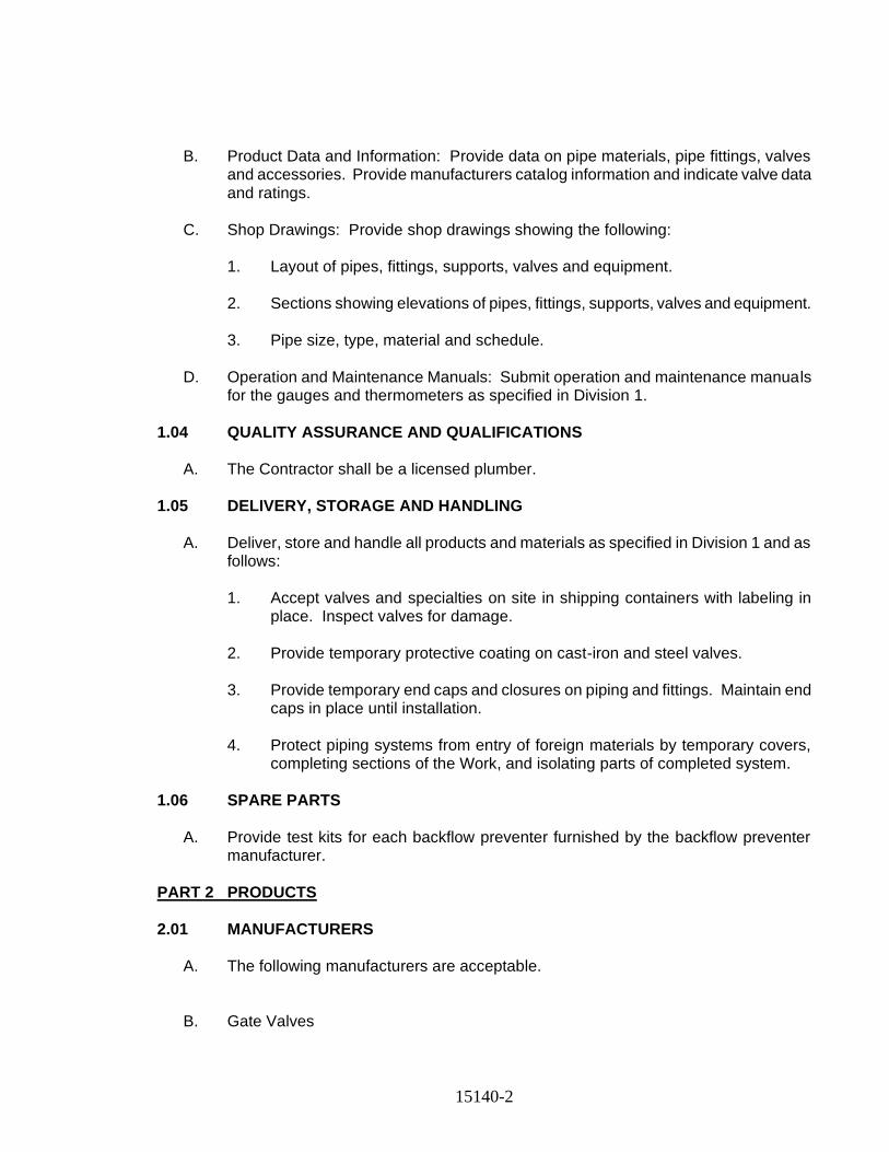
15140-2
B. Product Data and Information: Provide data on pipe materials, pipe fittings, valves and accessories. Provide manufacturers catalog information and indicate valve data and ratings.
C. Shop Drawings: Provide shop drawings showing the following:
1. Layout of pipes, fittings, supports, valves and equipment.
2. Sections showing elevations of pipes, fittings, supports, valves and equipment.
3. Pipe size, type, material and schedule.
D. Operation and Maintenance Manuals: Submit operation and maintenance manuals
for the gauges and thermometers as specified in Division 1. 1.04 QUALITY ASSURANCE AND QUALIFICATIONS
A. The Contractor shall be a licensed plumber. 1.05 DELIVERY, STORAGE AND HANDLING
A. Deliver, store and handle all products and materials as specified in Division 1 and as follows:
1. Accept valves and specialties on site in shipping containers with labeling in
place. Inspect valves for damage.
2. Provide temporary protective coating on cast-iron and steel valves.
3. Provide temporary end caps and closures on piping and fittings. Maintain end caps in place until installation.
4. Protect piping systems from entry of foreign materials by temporary covers,
completing sections of the Work, and isolating parts of completed system. 1.06 SPARE PARTS
A. Provide test kits for each backflow preventer furnished by the backflow preventer manufacturer.
PART 2 PRODUCTS 2.01 MANUFACTURERS
A. The following manufacturers are acceptable. B. Gate Valves
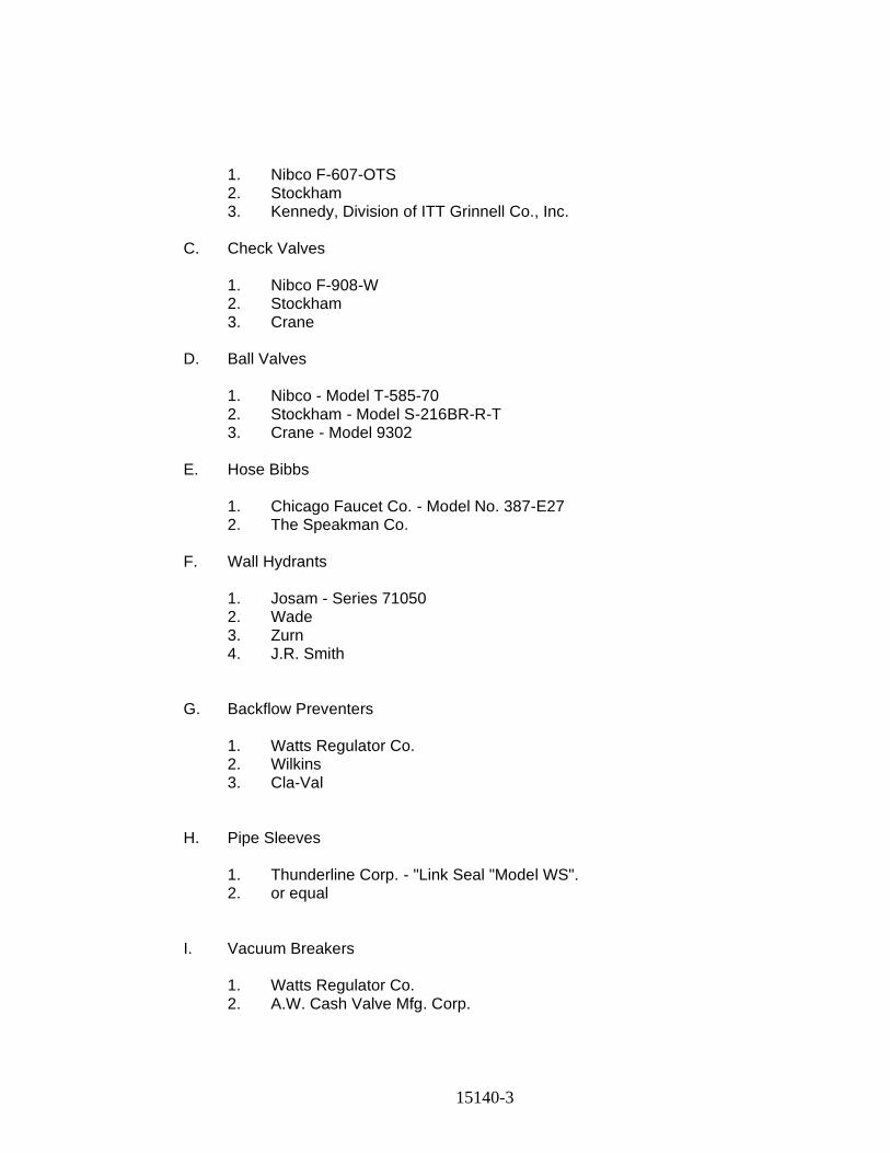
15140-3
1. Nibco F-607-OTS 2. Stockham 3. Kennedy, Division of ITT Grinnell Co., Inc.
C. Check Valves
1. Nibco F-908-W 2. Stockham 3. Crane
D. Ball Valves
1. Nibco - Model T-585-70 2. Stockham - Model S-216BR-R-T 3. Crane - Model 9302
E. Hose Bibbs
1. Chicago Faucet Co. - Model No. 387-E27 2. The Speakman Co.
F. Wall Hydrants
1. Josam - Series 71050 2. Wade 3. Zurn 4. J.R. Smith
G. Backflow Preventers
1. Watts Regulator Co. 2. Wilkins 3. Cla-Val
H. Pipe Sleeves
1. Thunderline Corp. - "Link Seal "Model WS". 2. or equal
I. Vacuum Breakers
1. Watts Regulator Co. 2. A.W. Cash Valve Mfg. Corp.
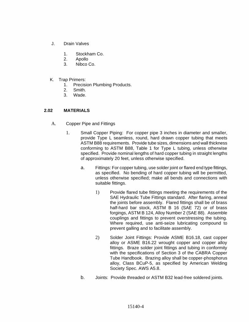
15140-4
J. Drain Valves
1. Stockham Co. 2. Apollo 3. Nibco Co.
K. Trap Primers: 1. Precision Plumbing Products. 2. Smith. 3. Wade.
2.02 MATERIALS
A. Copper Pipe and Fittings
1. Small Copper Piping: For copper pipe 3 inches in diameter and smaller, provide Type L seamless, round, hard drawn copper tubing that meets ASTM B88 requirements. Provide tube sizes, dimensions and wall thickness conforming to ASTM B88, Table 1 for Type L tubing, unless otherwise specified. Provide nominal lengths of hard copper tubing in straight lengths of approximately 20 feet, unless otherwise specified.
a. Fittings: For copper tubing, use solder joint or flared end type fittings, as specified. No bending of hard copper tubing will be permitted, unless otherwise specified; make all bends and connections with suitable fittings.
1) Provide flared tube fittings meeting the requirements of the SAE Hydraulic Tube Fittings standard. After flaring, anneal the joints before assembly. Flared fittings shall be of brass half-hard bar stock, ASTM B 16 (SAE 72) or of brass forgings, ASTM B 124, Alloy Number 2 (SAE 88). Assemble couplings and fittings to prevent overstressing the tubing. Where required, use anti-seize lubricating compound to prevent galling and to facilitate assembly.
2) Solder Joint Fittings: Provide ASME B16.18, cast copper alloy or ASME B16.22 wrought copper and copper alloy fittings. Braze solder joint fittings and tubing in conformity with the specifications of Section 3 of the CABRA Copper Tube Handbook. Brazing alloy shall be copper-phosphorus alloy, Class BCuP-5, as specified by American Welding Society Spec. AWS A5.8.
b. Joints: Provide threaded or ASTM B32 lead-free soldered joints.
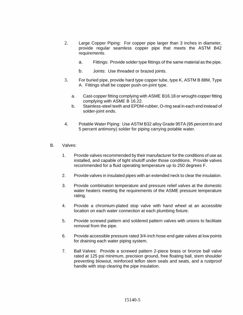
15140-5
2. Large Copper Piping: For copper pipe larger than 3 inches in diameter, provide regular seamless copper pipe that meets the ASTM B42 requirements.
a. Fittings: Provide solder type fittings of the same material as the pipe.
b. Joints: Use threaded or brazed joints.
3. For buried pipe, provide hard type copper tube, type K, ASTM B 88M, Type A. Fittings shall be copper push-on-joint type.
a. Cast-copper fitting complying with ASME B16.18 or wrought-copper fitting complying with ASME B 16.22.
b. Stainless-steel teeth and EPDM-rubber, O-ring seal in each end instead of solder-joint ends.
4. Potable Water Piping: Use ASTM B32 alloy Grade 95TA (95 percent tin and 5 percent antimony) solder for piping carrying potable water.
B. Valves:
1. Provide valves recommended by their manufacturer for the conditions of use as installed, and capable of tight shutoff under those conditions. Provide valves recommended for a fluid operating temperature up to 250 degrees F.
2. Provide valves in insulated pipes with an extended neck to clear the insulation.
3. Provide combination temperature and pressure relief valves at the domestic
water heaters meeting the requirements of the ASME pressure temperature rating.
4. Provide a chromium-plated stop valve with hand wheel at an accessible
location on each water connection at each plumbing fixture. 5. Provide screwed pattern and soldered pattern valves with unions to facilitate
removal from the pipe.
6. Provide accessible pressure rated 3/4-inch hose-end gate valves at low points for draining each water piping system.
7. Ball Valves: Provide a screwed pattern 2-piece brass or bronze ball valve
rated at 125 psi minimum, precision ground, free floating ball, stem shoulder preventing blowout, reinforced teflon stem seals and seats, and a rustproof handle with stop clearing the pipe insulation.
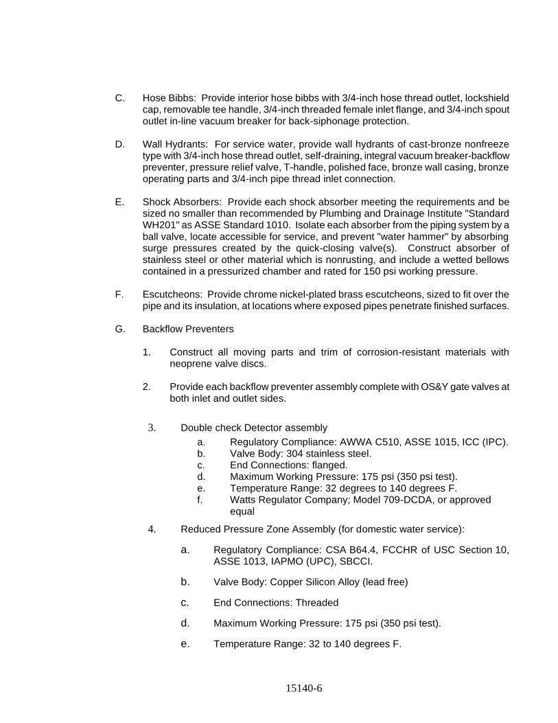
15140-6
C. Hose Bibbs: Provide interior hose bibbs with 3/4-inch hose thread outlet, lockshield cap, removable tee handle, 3/4-inch threaded female inlet flange, and 3/4-inch spout outlet in-line vacuum breaker for back-siphonage protection.
D. Wall Hydrants: For service water, provide wall hydrants of cast-bronze nonfreeze
type with 3/4-inch hose thread outlet, self-draining, integral vacuum breaker-backflow preventer, pressure relief valve, T-handle, polished face, bronze wall casing, bronze operating parts and 3/4-inch pipe thread inlet connection.
E. Shock Absorbers: Provide each shock absorber meeting the requirements and be
sized no smaller than recommended by Plumbing and Drainage Institute "Standard WH201" as ASSE Standard 1010. Isolate each absorber from the piping system by a ball valve, locate accessible for service, and prevent "water hammer" by absorbing surge pressures created by the quick-closing valve(s). Construct absorber of stainless steel or other material which is nonrusting, and include a wetted bellows contained in a pressurized chamber and rated for 150 psi working pressure.
F. Escutcheons: Provide chrome nickel-plated brass escutcheons, sized to fit over the
pipe and its insulation, at locations where exposed pipes penetrate finished surfaces. G. Backflow Preventers
1. Construct all moving parts and trim of corrosion-resistant materials with
neoprene valve discs.
2. Provide each backflow preventer assembly complete with OS&Y gate valves at both inlet and outlet sides.
3. Double check Detector assembly
a. Regulatory Compliance: AWWA C510, ASSE 1015, ICC (IPC). b. Valve Body: 304 stainless steel. c. End Connections: flanged. d. Maximum Working Pressure: 175 psi (350 psi test). e. Temperature Range: 32 degrees to 140 degrees F. f. Watts Regulator Company; Model 709-DCDA, or approved
equal
4. Reduced Pressure Zone Assembly (for domestic water service):
a. Regulatory Compliance: CSA B64.4, FCCHR of USC Section 10, ASSE 1013, IAPMO (UPC), SBCCI.
b. Valve Body: Copper Silicon Alloy (lead free)
c. End Connections: Threaded
d. Maximum Working Pressure: 175 psi (350 psi test).
e. Temperature Range: 32 to 140 degrees F.
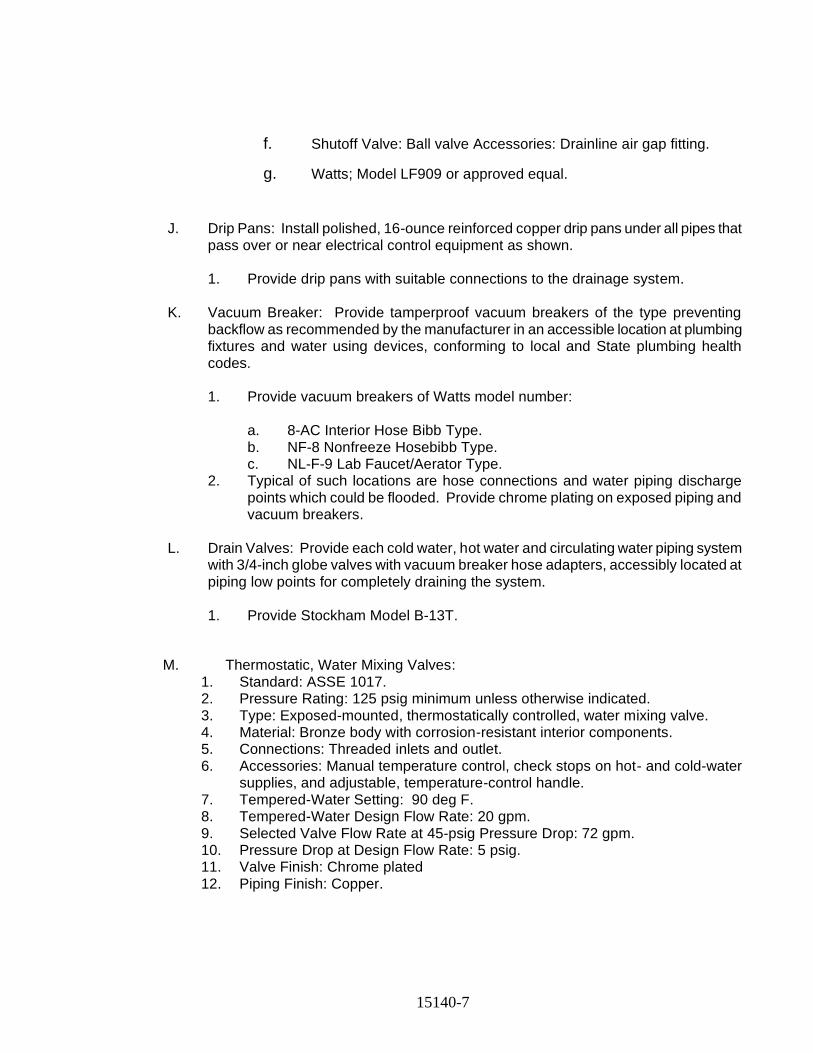
15140-7
f. Shutoff Valve: Ball valve Accessories: Drainline air gap fitting.
g. Watts; Model LF909 or approved equal.
J. Drip Pans: Install polished, 16-ounce reinforced copper drip pans under all pipes that pass over or near electrical control equipment as shown.
1. Provide drip pans with suitable connections to the drainage system.
K. Vacuum Breaker: Provide tamperproof vacuum breakers of the type preventing
backflow as recommended by the manufacturer in an accessible location at plumbing fixtures and water using devices, conforming to local and State plumbing health codes.
1. Provide vacuum breakers of Watts model number:
a. 8-AC Interior Hose Bibb Type. b. NF-8 Nonfreeze Hosebibb Type. c. NL-F-9 Lab Faucet/Aerator Type.
2. Typical of such locations are hose connections and water piping discharge points which could be flooded. Provide chrome plating on exposed piping and vacuum breakers.
L. Drain Valves: Provide each cold water, hot water and circulating water piping system
with 3/4-inch globe valves with vacuum breaker hose adapters, accessibly located at piping low points for completely draining the system.
1. Provide Stockham Model B-13T.
M. Thermostatic, Water Mixing Valves: 1. Standard: ASSE 1017. 2. Pressure Rating: 125 psig minimum unless otherwise indicated. 3. Type: Exposed-mounted, thermostatically controlled, water mixing valve. 4. Material: Bronze body with corrosion-resistant interior components. 5. Connections: Threaded inlets and outlet. 6. Accessories: Manual temperature control, check stops on hot- and cold-water
supplies, and adjustable, temperature-control handle. 7. Tempered-Water Setting: 90 deg F. 8. Tempered-Water Design Flow Rate: 20 gpm. 9. Selected Valve Flow Rate at 45-psig Pressure Drop: 72 gpm. 10. Pressure Drop at Design Flow Rate: 5 psig. 11. Valve Finish: Chrome plated 12. Piping Finish: Copper.

15140-8
N. Plumbing Specialties: 1. Water Hammer Arresters:
a. Materials: ASSE 1010 certified, Type L copper tube, HHPP piston with two lubricated EPDM O-rings, FDA approved lubricant, rolled piston stop, wrought copper male thread adapter.
b. Manufacturer and Product: Sioux Chief Mfg. Co., Inc.; Series 650 and 660.
2. TP-1, Trap Priming Valve: a. Materials: Cast bronze, line pressure drop activated,
antisiphon port, 1/2-inch connection. b. Manufacturer and Product: Precision Plumbing Products, Inc.;
Model P-1 trap priming valve and Model DU-4, distribution unit.
3. ETP-1, Automatic Trap Priming System: a. Materials: Preset 24-hour clock, manual override switch,
solenoid valve, 3/4-inch connection, calibrated water distribution manifold, water hammer arrester, and wall-mounted steel cabinet with access door.
b. Power: 120V, single-phase. c. Manifold outlet quantity as required. d. Manufacturer and Product: Precision Plumbing Products, Inc.;
Prime-Time Model PT. 4. Pressure/Temperature Relief Valve:
a. Materials: ASME/AGA rated, bronze body construction, vacuum relief valve vent in drain, backup emergency safety fuse plug, tamper-resistant bonnet screws, test lever, short thermostat, and automatic reseating.
b. Manufacturer and Product: Watts Industries, Inc.; Series 40. 5. Pressure Gauge:
a. Materials: 3-1/2-inch gauge size, 0 to 160 psi range, steel case, glass crystal, brass movement, and 1/3-inch NPT lower connection.
b. Manufacturer and Product: Ashcroft Dresser Instrument Division, Dresser Industries, Inc.; Type 1008.
6. Thermometer: a. Materials: Adjustable angle, red reading mercury type with
9-inch case and 30 degrees F to 180 degrees F range, 3-1/2-inch aluminum stem, and separate NPT brass thermowell.
b. Manufacturer and Product: H.O. Trerice Co.; Model A005.
PART 3 EXECUTION 3.01 INSTALLATION
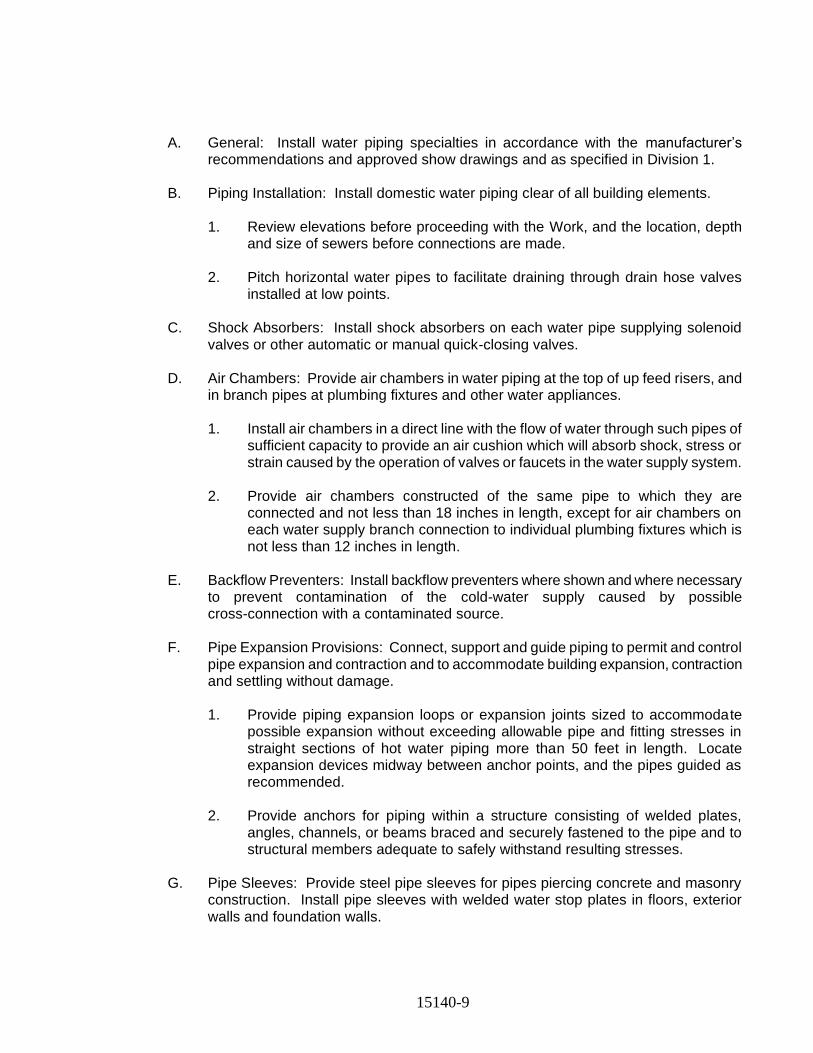
15140-9
A. General: Install water piping specialties in accordance with the manufacturer’s recommendations and approved show drawings and as specified in Division 1.
B. Piping Installation: Install domestic water piping clear of all building elements.
1. Review elevations before proceeding with the Work, and the location, depth
and size of sewers before connections are made.
2. Pitch horizontal water pipes to facilitate draining through drain hose valves installed at low points.
C. Shock Absorbers: Install shock absorbers on each water pipe supplying solenoid
valves or other automatic or manual quick-closing valves.
D. Air Chambers: Provide air chambers in water piping at the top of up feed risers, and in branch pipes at plumbing fixtures and other water appliances.
1. Install air chambers in a direct line with the flow of water through such pipes of
sufficient capacity to provide an air cushion which will absorb shock, stress or strain caused by the operation of valves or faucets in the water supply system.
2. Provide air chambers constructed of the same pipe to which they are
connected and not less than 18 inches in length, except for air chambers on each water supply branch connection to individual plumbing fixtures which is not less than 12 inches in length.
E. Backflow Preventers: Install backflow preventers where shown and where necessary
to prevent contamination of the cold-water supply caused by possible cross-connection with a contaminated source.
F. Pipe Expansion Provisions: Connect, support and guide piping to permit and control
pipe expansion and contraction and to accommodate building expansion, contraction and settling without damage.
1. Provide piping expansion loops or expansion joints sized to accommodate
possible expansion without exceeding allowable pipe and fitting stresses in straight sections of hot water piping more than 50 feet in length. Locate expansion devices midway between anchor points, and the pipes guided as recommended.
2. Provide anchors for piping within a structure consisting of welded plates,
angles, channels, or beams braced and securely fastened to the pipe and to structural members adequate to safely withstand resulting stresses.
G. Pipe Sleeves: Provide steel pipe sleeves for pipes piercing concrete and masonry
construction. Install pipe sleeves with welded water stop plates in floors, exterior walls and foundation walls.
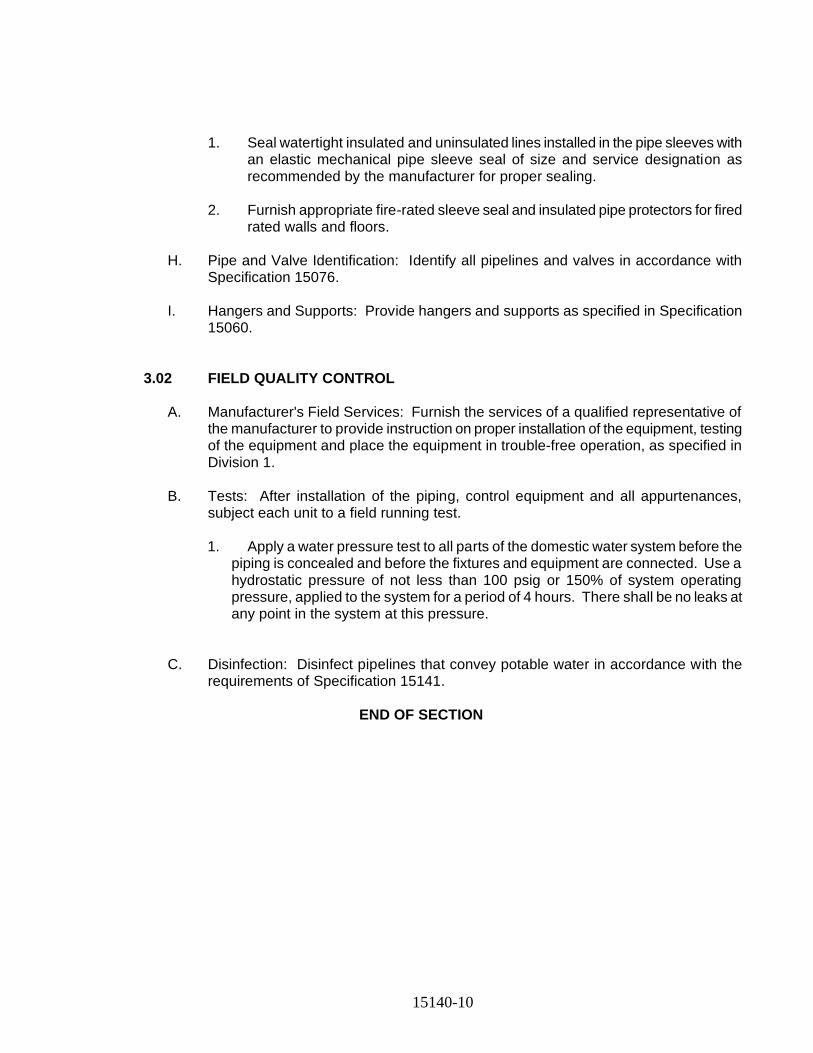
15140-10
1. Seal watertight insulated and uninsulated lines installed in the pipe sleeves with an elastic mechanical pipe sleeve seal of size and service designation as recommended by the manufacturer for proper sealing.
2. Furnish appropriate fire-rated sleeve seal and insulated pipe protectors for fired
rated walls and floors.
H. Pipe and Valve Identification: Identify all pipelines and valves in accordance with Specification 15076.
I. Hangers and Supports: Provide hangers and supports as specified in Specification
15060. 3.02 FIELD QUALITY CONTROL
A. Manufacturer's Field Services: Furnish the services of a qualified representative of the manufacturer to provide instruction on proper installation of the equipment, testing of the equipment and place the equipment in trouble-free operation, as specified in Division 1.
B. Tests: After installation of the piping, control equipment and all appurtenances,
subject each unit to a field running test.
1. Apply a water pressure test to all parts of the domestic water system before the piping is concealed and before the fixtures and equipment are connected. Use a hydrostatic pressure of not less than 100 psig or 150% of system operating pressure, applied to the system for a period of 4 hours. There shall be no leaks at any point in the system at this pressure.
C. Disinfection: Disinfect pipelines that convey potable water in accordance with the
requirements of Specification 15141. END OF SECTION
15141-1
SECTION 15141
DISINFECTION
PART 1 - GENERAL
1.01 SECTIONS INCLUDES
A. Drawing and general provisions of the Contract, including general and Supplementary Conditions and Division 01 Specification Sections, apply to this section.
1.02 SUMMARY
A. Disinfection of all pipelines, conduits, pumps, tanks, structures, and equipment which are to store, handle or carry potable water. All labor, chlorine and equipment, including taps, corporation stops, temporary pumps, hoses, miscellaneous piping and other items necessary to perform the work, shall be furnished and installed by the Contractor, and removed after completion of the disinfection procedure.
B. REFERENCES
1. AWWA C651 - Disinfecting Water Mains
2. AWWA C652 - Disinfection of Water-Storage Facilities
3. International Plumbing Code
1.03 QUALITY ASSURANCE
A. Disinfection shall be in accordance with AWWA C651 for water mains and AWWA C652 for water storage facilities and equipment, except as modified herein. Disinfection procedures for new water mains and water storage facilities shall also conform to the requirements of the International Plumbing Code, Section 610 “Disinfection of Potable Water System” and Section 606.5.4.5 “Installation of the Building Water Distribution System - Cleaning or Painting" respectively, except as modified herein.
PART 2 PRODUCTS (NOT USED)
15141-2
PART 3 EXECUTION
3.01 PIPELINES
A. Pumps, hydrants, and other water handling equipment items that are part of the potable water distribution system shall be disinfected in the same manner as described herein for the pipelines.
B. Pipelines shall first be flushed with clean water. Disinfection shall be accomplished by the Continuous Feed Method, as specified in AWWA C651, using sodium hypochlorite solution.
C. Water-chlorine solution with a concentration not less than 50 mg/l of available chlorine shall then be added at one end of the section being disinfected and discharged at the far end. The water-chlorine solution shall be added until the water coming from each downstream blowoff has a residual of not less than 25 mg/l of chlorine.
D. The pipelines shall then be closed and the solution allowed to remain in the lines for at least 24 hours. The chlorine residual in the pipeline shall then be rechecked. If the free chlorine residual is less than 10 mg/l after 24 hours, the procedure shall be repeated until the free chlorine residual after 24 hours is 10 mg/l or greater.
E. After the 24-hour holding period, the pipelines and equipment shall be thoroughly flushed and filled with clean water. Flushing water shall not be permitted to enter existing water mains.
F. Flushing water shall not be discharged to sanitary or storm sewers without permission of local authority. Where necessary, Federal, State and local regulatory agencies shall be contacted to determine special provisions for the disposal of heavily chlorinated water.
G. When new potable water pipelines are to be connected to an existing water distribution system, the connecting piping shall be disinfected and tested in accordance with the procedure set forth in Section 9.1 or Section 9.2, as applicable, of AWWA C651.
3.02 WATER SUPPLY
A. The Contractor shall provide all necessary apparatus to convey the water to the point of use and perform the disinfection procedure
3.03 VERIFICATION OF DISINFECTION
A. After the completion of disinfection, bacteriological samples shall be taken by the Contractor and tested at a certified laboratory. Samples shall be taken as required by the Department of Health. The test reports shall be submitted to the Engineer for review and approval. If the samples are not satisfactory, the entire disinfection procedure shall be repeated at the expense of the Contractor until satisfactory samples are obtained.
END OF SECTION
15150-1
SECTION 15150
SANITARY WASTE AND VENT PIPING
PART 1 - GENERAL
1.01 SECTION INCLUDES
A. This section includes furnishing and installing sanitary waste and vent pipe, fittings, accessories, specialties as shown, specified or required for a complete installation and satisfactory operation. Provide pipe and fittings of new materials, protected from dirt, moisture and mechanical damage.
1.02 REFERENCES
A. ASME A112.1 - Floor Drains
B. National Standard Plumbing Code
1.03 SUBMITTALS
A. General: Provide submittals, including the following, in conformity with Article 4 of the General Conditions.
B. Product Data and Information: Provide data on pipe materials, pipe fittings, valves and accessories.
C. Shop Drawings: Provide shop drawings showing the following:
1. Layout drawings of pipes, fittings, supports, and equipment.
2. Sections showing elevations of pipes, fittings, supports, valves and equipment.
3. Pipe size, type, material and schedule.
1.04 QUALITY ASSURANCE AND QUALIFICATIONS
A. The Contractor shall be a New Jersey State licensed master plumber.
1.05 DELIVERY, STORAGE AND HANDLING
A. Deliver, store and handle all products and materials as specified in Division 1 and as follows:
1. Provide temporary end caps and closures on piping and fittings. Maintain end caps in place until installation.
2. Protect piping systems from entry of foreign materials by temporary covers, completing sections of the Work, and isolating parts of completed system.
PART 2 - PRODUCTS
2.01 MANUFACTURERS
A. The following manufacturers are acceptable. Equivalent products of other manufacturers may be submitted for approval.
B. Pipe Sleeves
15150-2
1. Thunderline Corp. - "Link Seal "Model WS".
2. or approved equal
C. Cast iron soil pipe and fittings shall be as manufactured by the following or approved equal.
1. U.S. Pipe and Foundry Co., Birmingham, AL.
2. Tyler Pipe Industries, Tyler, TX.
3. Charlotte Pipe and Foundry, Charlotte, NC.
2.02 MATERIALS
A. Pipe, Tubing and Fittings:
1. Pipe and Fittings: Buried soil pipe and fittings shall be cast iron, service weight, hub and spigot meeting the requirements of ASTM A74. Above ground soil pipe shall be hubless cast iron pipe and fittings meeting the requirements of CISPI 301. Hubless pipe and fittings shall not be used for buried pipe. Refer to pipe schedules on the Contract Drawings.
a. Protective Coatings: Interior protective coatings (linings) and exterior protective coatings for pipe and fittings in the finished work shall be as follows and as indicated in the piping schedules.
2. Interior bituminous lining shall be in accordance with AWWA C151.
3. Pipe and fittings not exposed in the finished work, or if the pipe schedules indicate that the pipe exterior is to have a bituminous coating, the pipe shall be coated in accordance with the requirements of AWWA C151.
4. Piping shall be painted in accordance with the requirements in the Div. 9 Painting Specification.
5. Joints: Neoprene gasket, compression type joints shall be in accordance with ASTM C564 for hub and spigot pipe. Hubless couplings for hubless pipe, shall be composed of a stainless steel shield, clamp assembly and an elastomeric sealing sleeve conforming to CISPI 310.
B. Escutcheons: Provide chrome nickel-plated brass escutcheons, sized to fit over the pipe and its insulation, at locations where exposed pipes penetrate finished surfaces.
C. Cleanouts: Provide cleanouts meeting the following requirements.
1. Floor Cleanouts in Finished Rooms: Provide floor cleanouts in finished rooms with an adjustable cast-iron floor cleanout installed flush with finished floor, with cutoff sections, brass internal plug, satin finish nickel alloy top, and with secured cover.
a. J.R. Smith Mfg. Co., Figure No. 4429.
2. Floor Cleanouts in Unfinished Rooms: Provide floor cleanouts in unfinished rooms with a satin finish brass top, and secured heavy-duty brass cover.
a. J.R. Smith Mfg. Co., Figure No. 4221-S
3. Cleanouts on Exposed Piping: On exposed risers and horizontal piping provide cleanouts with cast-brass, with countersunk, iron pipe size male threaded plug.
4. Cleanouts on Concealed Piping: On concealed piping provide cleanouts with cast-brass, countersunk, with stainless steel round access cover plate secured to plug with countersunk screw.
a. J.R. Smith Mfg. Co., Figure No. 4531-S
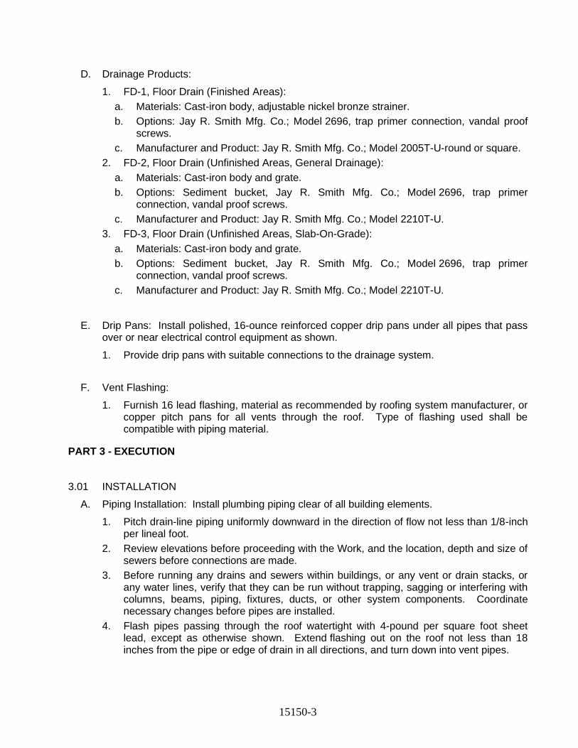
15150-3
D. Drainage Products:
1. FD-1, Floor Drain (Finished Areas):
a. Materials: Cast-iron body, adjustable nickel bronze strainer.
b. Options: Jay R. Smith Mfg. Co.; Model 2696, trap primer connection, vandal proof screws.
c. Manufacturer and Product: Jay R. Smith Mfg. Co.; Model 2005T-U-round or square.
2. FD-2, Floor Drain (Unfinished Areas, General Drainage):
a. Materials: Cast-iron body and grate.
b. Options: Sediment bucket, Jay R. Smith Mfg. Co.; Model 2696, trap primer connection, vandal proof screws.
c. Manufacturer and Product: Jay R. Smith Mfg. Co.; Model 2210T-U.
3. FD-3, Floor Drain (Unfinished Areas, Slab-On-Grade):
a. Materials: Cast-iron body and grate.
b. Options: Sediment bucket, Jay R. Smith Mfg. Co.; Model 2696, trap primer connection, vandal proof screws.
c. Manufacturer and Product: Jay R. Smith Mfg. Co.; Model 2210T-U.
E. Drip Pans: Install polished, 16-ounce reinforced copper drip pans under all pipes that pass over or near electrical control equipment as shown.
1. Provide drip pans with suitable connections to the drainage system.
F. Vent Flashing:
1. Furnish 16 lead flashing, material as recommended by roofing system manufacturer, or copper pitch pans for all vents through the roof. Type of flashing used shall be compatible with piping material.
PART 3 - EXECUTION
3.01 INSTALLATION
A. Piping Installation: Install plumbing piping clear of all building elements.
1. Pitch drain-line piping uniformly downward in the direction of flow not less than 1/8-inch per lineal foot.
2. Review elevations before proceeding with the Work, and the location, depth and size of sewers before connections are made.
3. Before running any drains and sewers within buildings, or any vent or drain stacks, or any water lines, verify that they can be run without trapping, sagging or interfering with columns, beams, piping, fixtures, ducts, or other system components. Coordinate necessary changes before pipes are installed.
4. Flash pipes passing through the roof watertight with 4-pound per square foot sheet lead, except as otherwise shown. Extend flashing out on the roof not less than 18 inches from the pipe or edge of drain in all directions, and turn down into vent pipes.
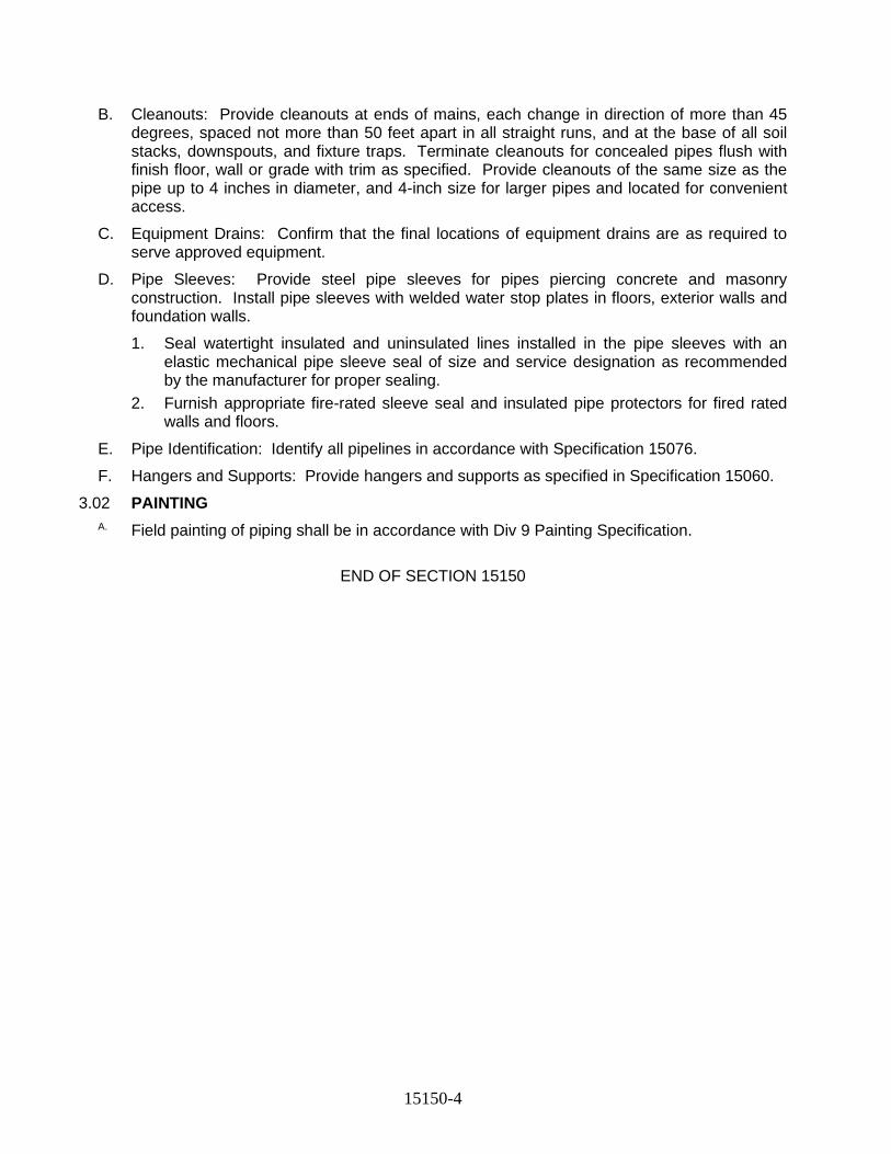
15150-4
B. Cleanouts: Provide cleanouts at ends of mains, each change in direction of more than 45 degrees, spaced not more than 50 feet apart in all straight runs, and at the base of all soil stacks, downspouts, and fixture traps. Terminate cleanouts for concealed pipes flush with finish floor, wall or grade with trim as specified. Provide cleanouts of the same size as the pipe up to 4 inches in diameter, and 4-inch size for larger pipes and located for convenient access.
C. Equipment Drains: Confirm that the final locations of equipment drains are as required to serve approved equipment.
D. Pipe Sleeves: Provide steel pipe sleeves for pipes piercing concrete and masonry construction. Install pipe sleeves with welded water stop plates in floors, exterior walls and foundation walls.
1. Seal watertight insulated and uninsulated lines installed in the pipe sleeves with an elastic mechanical pipe sleeve seal of size and service designation as recommended by the manufacturer for proper sealing.
2. Furnish appropriate fire-rated sleeve seal and insulated pipe protectors for fired rated walls and floors.
E. Pipe Identification: Identify all pipelines in accordance with Specification 15076.
F. Hangers and Supports: Provide hangers and supports as specified in Specification 15060.
3.02 PAINTING
A. Field painting of piping shall be in accordance with Div 9 Painting Specification.
END OF SECTION 15150
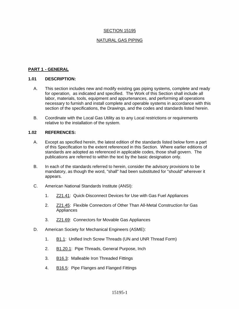
15195-1
SECTION 15195
NATURAL GAS PIPING
PART 1 - GENERAL
1.01 DESCRIPTION:
A. This section includes new and modify existing gas piping systems, complete and ready for operation, as indicated and specified. The Work of this Section shall include all labor, materials, tools, equipment and appurtenances, and performing all operations necessary to furnish and install complete and operable systems in accordance with this section of the specifications, the Drawings, and the codes and standards listed herein.
B. Coordinate with the Local Gas Utility as to any Local restrictions or requirements relative to the installation of the system.
1.02 REFERENCES:
A. Except as specified herein, the latest edition of the standards listed below form a part of this Specification to the extent referenced in this Section. Where earlier editions of standards are adopted as referenced in applicable codes, those shall govern. The publications are referred to within the text by the basic designation only.
B. In each of the standards referred to herein, consider the advisory provisions to be mandatory, as though the word, "shall" had been substituted for "should" wherever it appears.
C. American National Standards Institute (ANSI):
1. Z21.41: Quick-Disconnect Devices for Use with Gas Fuel Appliances
2. Z21.45: Flexible Connectors of Other Than All-Metal Construction for Gas Appliances
3. Z21.69: Connectors for Movable Gas Appliances
D. American Society for Mechanical Engineers (ASME):
1. B1.1: Unified Inch Screw Threads (UN and UNR Thread Form)
2. B1.20.1: Pipe Threads, General Purpose, Inch
3. B16.3: Malleable Iron Threaded Fittings
4. B16.5: Pipe Flanges and Flanged Fittings
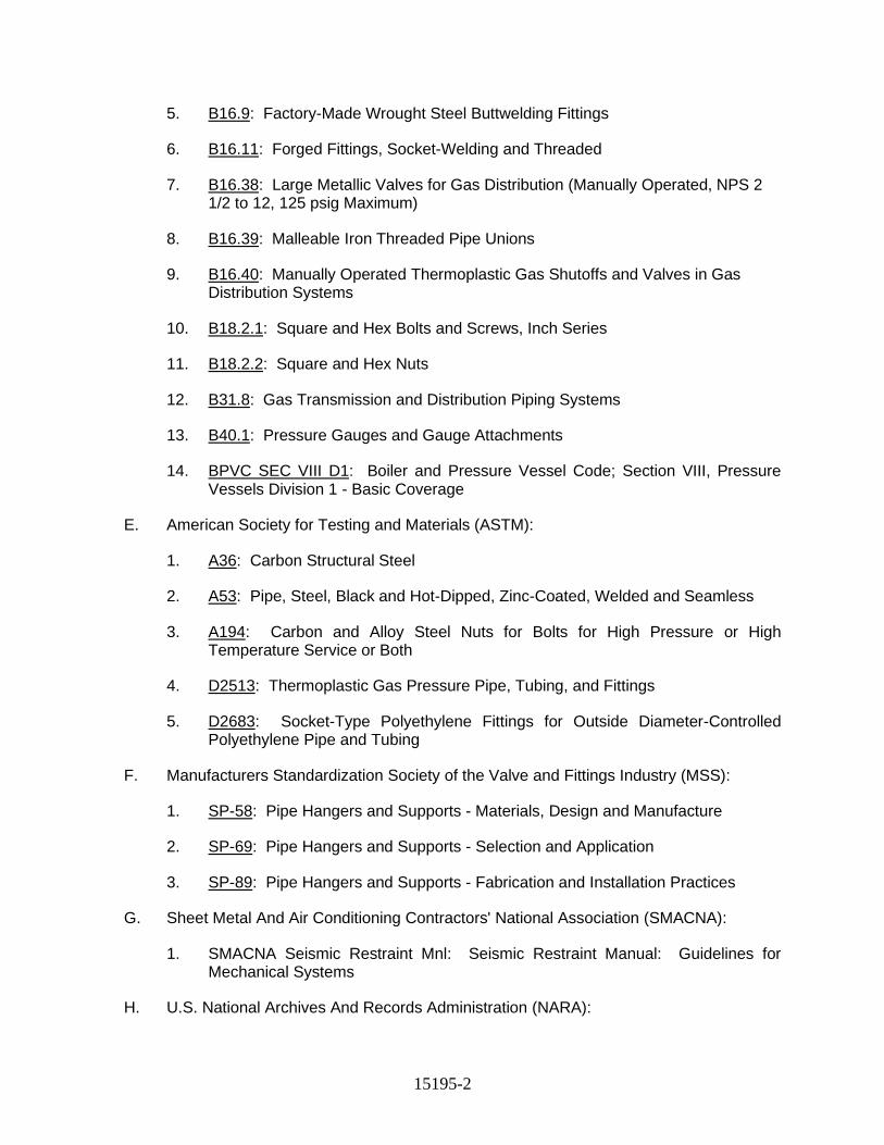
15195-2
5. B16.9: Factory-Made Wrought Steel Buttwelding Fittings
6. B16.11: Forged Fittings, Socket-Welding and Threaded
7. B16.38: Large Metallic Valves for Gas Distribution (Manually Operated, NPS 2 1/2 to 12, 125 psig Maximum)
8. B16.39: Malleable Iron Threaded Pipe Unions
9. B16.40: Manually Operated Thermoplastic Gas Shutoffs and Valves in Gas Distribution Systems
10. B18.2.1: Square and Hex Bolts and Screws, Inch Series
11. B18.2.2: Square and Hex Nuts
12. B31.8: Gas Transmission and Distribution Piping Systems
13. B40.1: Pressure Gauges and Gauge Attachments
14. BPVC SEC VIII D1: Boiler and Pressure Vessel Code; Section VIII, Pressure Vessels Division 1 - Basic Coverage
E. American Society for Testing and Materials (ASTM):
1. A36: Carbon Structural Steel
2. A53: Pipe, Steel, Black and Hot-Dipped, Zinc-Coated, Welded and Seamless
3. A194: Carbon and Alloy Steel Nuts for Bolts for High Pressure or High Temperature Service or Both
4. D2513: Thermoplastic Gas Pressure Pipe, Tubing, and Fittings
5. D2683: Socket-Type Polyethylene Fittings for Outside Diameter-Controlled Polyethylene Pipe and Tubing
F. Manufacturers Standardization Society of the Valve and Fittings Industry (MSS):
1. SP-58: Pipe Hangers and Supports - Materials, Design and Manufacture
2. SP-69: Pipe Hangers and Supports - Selection and Application
3. SP-89: Pipe Hangers and Supports - Fabrication and Installation Practices
G. Sheet Metal And Air Conditioning Contractors' National Association (SMACNA):
1. SMACNA Seismic Restraint Mnl: Seismic Restraint Manual: Guidelines for Mechanical Systems
H. U.S. National Archives And Records Administration (NARA):
15195-3
1. 49 CFR 192: Transportation of Natural and Other Gas by Pipeline: Minimum Federal Safety Standards
1.03 SUBMITTALS:
A. Submit the following:
1. Product Data - Annotate descriptive data to show the specific manufacturer, model, type, size, capacity, options, etc. of each item.
a. Pipe and fittings
b. Warning and identification tape
c. Valves
d. Gas equipment connectors
e. Regulators
f. Pipe hangers and supports
2. Certification - Submit documentation certifying completion of the following items in compliance with this Section.
a. Metal welding inspection
b. PE fusion welding inspection
c. Piping pressure tests
d. System purging
3. Certificates and Licenses - Prepare as specified in this section.
a. Qualifications of Installer
b. Qualifications of Construction Supervisor
4. Manufacturer's Instructions: Submit manufacturer's installation instructions and manufacturer's visual joint appearance chart.
a. PE pipe and fittings
5. Operation and Maintenance Manuals -
a. Valves
b. Regulators
15195-4
1.04 QUALITY CONTROL:
A. Provide in accordance with Division 1 specifications.
B. Qualifications of Installer
1. Prior to installation, submit data showing the name and license of the installing contractor and that he has successfully installed systems of the same type and design as specified herein. Data shall include names and locations of at least two installations of such systems. Indicate type and design of each system and certify that each system has performed satisfactorily in the manner intended for not less than 18 months. The installing contractor shall be licensed to perform applicable gas piping systems installation in the state in which the project is located.
2. Qualifications of Welders: Piping shall be welded in accordance with qualified procedures using performance qualified welders and welding operators. The Authority Having Jurisdiction shall be notified 24 hours in advance of any required testing and the tests shall be performed at the work site. The welder or welding operator shall apply his assigned symbol near each weld he makes as a permanent record. Prior to installation, submit data for acceptance showing the name and certification of each welder and welding operator to be used on the project. Submit each welder's identification symbols, assigned number, or letter, used to identify work of the welder. Welders making defective welds after passing a qualification test shall be given requalification test and, upon failing to pass this test, shall not be permitted to work on this Contract.
a. Steel Welder's Qualifications: Comply with ASME B31.8. Each steel welder shall have a copy of a certified ASME B31.8 qualification test report. Conduct a qualification test for each welder and submit results for acceptance.
b. PE Welder's Qualifications: Supervising and installing personnel shall be trained by a PE pipe manufacturer's sponsored course of not less than one week duration, or present proof satisfactory to the Engineer that personnel are currently working in the installation of PE gas distribution lines. Conduct a qualification test for each welder and submit results for acceptance.
c. Safety Standards: 49 CFR 192.
C. Qualifications of Construction Supervisor: Provide a Construction Supervisor with a minimum of 5 years of experience in fuel gas piping construction supervision who shall be responsible for the installation of the Work of this Section of the Specifications. The Construction Supervisor shall be licensed to perform applicable fuel gas piping systems supervision in the state in which the project is located. Prior to installation, submit data for acceptance showing the name and license of the Construction Supervisor.
15195-5
1.05 DELIVERY, STORAGE AND HANDLING:
A. Provide in accordance with Division 1 specifications.
B. Shipping:
1. All equipment, material and spare parts shall be shipped, stored, handled and installed in such a manner as not to degrade quality, serviceability, or appearance. Equipment and material warranties shall not be voided by actions of the Contractor.
C. Receiving:
1. All equipment, material and spare parts shall be delivered to the site in original packages or containers bearing the manufacturer's labels and product identification.
2. Inspect for damage and correctness, and inventory items, upon delivery to site.
3. Store and safeguard equipment, material and spare parts in accordance with manufacturer's recommendations.
1.06 COOPERATION AND COORDINATION WITH OTHER TRADES:
A. Work shall be performed in cooperation with other trades on the project and so scheduled as to allow efficient completion of the project. Materials and equipment shall be installed as fast as conditions will permit, and installed promptly when and as directed.
B. Furnish to all other trades advance information on location and size of all concrete pads, chases, frames, boxes, sleeves, and openings needed for the Work, and also furnish layout information and shop drawings necessary to permit other trades affected by the Work to install their work properly coordinated and without delay.
C. Where there is evidence that Work installed interferes with the work of other Sections, assist in working out space conditions to make satisfactory adjustments.
D. With the acceptance of the Engineer and without extra cost, make reasonable modifications in Work specified under this Section of the Specifications required to coordinate with normal structural interference's, or for proper execution of specified work.
E. If work is installed before coordinated with other trades so as to cause interference with the work of such trades, make all necessary changes in Work under this Section of the Specifications at no additional cost.
F. Protect all materials and work of other trades from damage that may be caused by the Work required under this Section of the Specifications and be responsible for repairing any damages caused by such work without any additional cost.
15195-6
G. Follow Drawings in layout work. Check Drawings of, and coordinate with, other trades to verify special provisions, installation requirements and spaces in which Work provided under this Section of the Specifications will be installed. Maintain maximum headroom or space conditions at all points. Where headroom or space conditions appear inadequate, notify the Engineer before proceeding.
1.07 CODES, PERMITS AND FEES:
A. Except for additional requirements as specified or indicated under the Work of this Section, materials, workmanship and equipment shall conform to the governing edition of the following regulations, and agency requirements.
1. State and Local Building Codes including,
2. Local Fire Department
3. Local Gas Utility
4. Occupational Safety and Health Administration (OSHA)
5. Any other local codes or requirements of Authorities Having Jurisdiction.
B. Pay for all fees and give all notices, file all plans, obtain all permits and licenses, and obtain all necessary approvals from Authorities Having Jurisdiction. Deliver all certificates of inspection to the Authorities Having Jurisdiction. No work shall be covered before examination and approval by Authorities Having Jurisdiction. Replace imperfect or condemned work to conform to inspectional requirements, satisfactory to the Engineer and Authorities Having Jurisdiction without extra cost. If Work is covered before inspection and acceptance, pay costs of uncovering and reinstalling the covering, whether it meets contract requirements or not.
PART 2 - PRODUCTS
2.01 GENERAL:
A. Branch piping to appliances or equipment shall be at least as large as the inlets thereof.
2.02 PIPE AND FITTINGS:
A. Buried Piping:
1. Pipe: Polyethylene (PE) ASTM D 2513, 100 psig working pressure, Standard Dimension Ratio (SDR), the ratio of pipe diameter to wall thickness, 11.5 maximum.
2. Socket Fittings: ASTM D 2683.
3. Butt-Fusion Fittings: ASTM D 2513, molded.
15195-7
4. Buried Utility Warning and Identification Tape
a. Provide detectable aluminum-foil plastic-backed tape or detectable magnetic plastic tape manufactured specifically for warning and identification of buried piping. Tape shall be detectable by an electronic detection instrument. Provide tape in rolls, 3 inch minimum width, color-coded yellow for natural gas, with warning and identification imprinted in bold black letters continuously and repeatedly over entire tape length. Warning and identification shall be "CAUTION BURIED GAS PIPING BELOW" or similar wording. Use permanent code and letter coloring unaffected by moisture and other substances contained in trench backfill material. Refer to Section 02210 for details.
5. Casing:
a. Where indicated at crossings, provide ASTM A53, galvanized pipe, Schedule 40, with extruded polyethylene coating.
B. Aboveground Piping:
1. Pipe: Black steel, ASTM A 53, Type E or F, Grade A or B, Schedule 40, threaded ends for sizes 2-1/2 inches and smaller; otherwise, plain end beveled for butt welding.
2. Threaded Fittings: ASME B16.3, black malleable iron, Class 150.
3. Butt-Welding Fittings: ASME B16.9, Schedule 40, with backing rings of compatible material.
4. Unions: ASME B16.39, black malleable iron.
5. Pipe Thread Paste or Tape: Antiseize and sealant paste or tape of polytetrafluoroethylene (PTFE).
6. Welding Filler Metal: ASME B31.8.
C. Risers:
1. Manufacturer's standard anodeless riser, transition from plastic to steel pipe with 7 to 12 mil thick epoxy coating. Use swaged gas-tight construction with O-ring seals, metal insert, and protective sleeve. Provide remote bolt-on or bracket or wall-mounted riser supports.
2.03 VALVES, BURIED:
A. Shutoff Valves:
1. PE ball or plug valves, ASME B16.40 and ASTM D 2513, Class C materials (PE 2306 or PE 3406), strength rating of Class 4 location with class factor of 0.20, and SDR matching PE pipe dimensions and working pressure.
15195-8
B. Valve Boxes:
1. Provide street valve box with cast-iron cover and two-piece 5 1/4 inch shaft-slip valve box extension. Cast the word "Gas" into the box cover. Use valve box for areas as follows:
a. Roads and Traffic Areas: Heavy duty, cast iron cover.
b. Other Areas: Standard duty, concrete cover.
2.04 VALVES, ABOVE GROUND:
A. Provide lockable valves where located outdoors and where otherwise indicated.
B. Shutoff Valves, Sizes Larger Than 2 Inch.
1. Cast-iron body plug valve in accordance with ASME B16.38, nonlubricated, wedge-mechanism or tapered lift plug, and flanged ends.
C. Shutoff Valves, Sizes 2 Inch and Smaller
1. Steel body plug valve in accordance with ANSI B16.33, straightway, taper plug, regular pattern with a port opening at least equal to the internal pipe area or round port full bore pattern, non-lubricated, PTFE packing, flat or square head stem with lever operator, 125 psig rating, threaded ends.
2.05 GAS EQUIPMENT CONNECTORS:
A. All gas equipment connectors shall be AGA-approved.
1. Flexible Connectors: ANSI Z21.45 and approved for use in Maryland.
2. Quick Disconnect Couplings: ANSI Z21.41.
3. Semi-Rigid Tubing and Fittings: ANSI Z21.69.
2.06 REGULATORS:
A. AGA-approved, self-contained with spring-loaded diaphragm pressure regulating valve and atmospheric vent, corrosion resistant construction, pressure operating range as required for the pressure reduction indicated, volume capacity not less than indicated, threaded ends for sizes 2 inch and smaller, otherwise flanged. Regulators shall have corrosion resistant factory painted finish. Regulators shall be designed for the gas used.
2.07 PRESSURE GAUGES:
A. Pressure gages shall be ASME B40.1, liquid filled, 1 percent accuracy or better, with bronze bourdon tube and steel or brass case.
15195-9
B. Gages shall have a minimum 2-1/2 inch diameter face. Dial gradations reading in PSI and shall be such that the normal operating pressure of the system is within middle 1/3 of scale range.
C. Gages shall be equipped with a ball valve shutoff and snubber.
2.08 PIPE HANGERS AND SUPPORTS:
A. Provide MSS SP-58 and MSS SP-69, Type 1 with adjustable type steel support rods, except as specified or indicated otherwise. Attach to steel bar joists with MSS SP-58, Type 19 or 23 C-clamps and retaining straps. Attach to Steel W or S beams with Type 21, 28, 29, or 30 clamps. Attach to steel angles, vertical web steel channels, horizontal web steel channel and wood with drilled hole on centerline and double nut and washer. Attach to concrete with Type 18 insert or drilled expansion anchor.
B. Hangers and supports shall be factory-painted steel, and rods and fasteners shall be series 300 stainless steel.
C. Provide in accordance with section 15060 - Hangers and Supports for Piping and Equipment.
2.09 SUPPLEMENTARY STEEL AND CHANNELS:
A. Provide all supplementary steel and factory fabricated channels required for proper installation, mounting and support of all equipment and systems provided under this Section.
B. Channels and supplementary steel shall be of sufficient strength and size to allow only a minimum deflection in conformance with the manufacturer's requirements for the specific loading on the system installed herein.
C. All supplementary steel shall be ASTM A36 factory-formed standard mill finished structural shapes. Channels shall be steel. Supplementary steel assemblies shall be painted after fabrication, and channels shall be factory painted.
2.10 PIPE SLEEVES:
A. Sleeves in Masonry and Concrete Walls, and Floors: Standard weight ductile-iron or cast-iron pipe sleeves. Sleeves available from the manufacturer of mechanically adjustable segmented elastomeric seals shall be permitted subject to acceptance by the Engineer. Provide minimum 2 inch high waterstop for sleeves in exterior walls and floors.
B. Sleeves in Non-Masonry or Non-Concrete Walls, and Floors: Aluminum sheet, 19 gage minimum thickness.Mechanically Adjustable Segmented Elastomeric Seals: Seals shall have EPDM seal elements and series 300 stainless steel hardware.
PART 3 - EXECUTION
15195-10
3.01 PREPARATION:
A. Arrange for permits, inspections, and tests, in accordance with applicable State and local codes, at the contractor's expense. Verify all measurements at job site.
B. Avoid interferences with other trades.
3.02 INSTALLATION:
A. Installation, workmanship, inspection and testing shall be in accordance with the specified Fuel Gas Code with the additions specified herein. Install piping straight and true to bear evenly on hangers and supports. Keep the interior and ends of new piping and existing piping affected by the Work thoroughly cleaned of water and foreign matter. Keep piping systems clean during installation by means of plugs or other accepted methods. When work is not in progress, securely close open ends of piping to prevent entry of water and foreign matter. Inspect piping before placing into position.
B. Piping shall not be permitted in Electrical Rooms and stairwells.
C. Piping and other apparatus shall not be installed in such a manner so as to interfere with the full swing of doors, movement of personnel and equipment, and access to other equipment.
D. Make provisions for pipe expansion and contraction with suitable anchors and offsets, expansion joints, or expansion loops. Make provisions in buried piping for differential settlement. Install piping to allow freedom of movement in all planes without imposing undue stress on any section of the main piping, branch piping, equipment and structure.
E. Piping: Cut pipe to actual dimensions and assemble to prevent residual stress. Provide supply connections entering the building as indicated. Within buildings, run piping parallel to structure lines and conceal in finished spaces. Terminate each vertical supply pipe to burner or appliance with tee, nipple and cap to form a sediment trap. To supply multiple items of gas-burning equipment, provide manifold with inlet connections at both ends.
1. Cleanliness
a. Clean inside of pipe and fittings before installation. Blow lines clear using 80 to 100 psig clean dry compressed air. Rap steel lines sharply along entire pipe length before blowing clear.
2. Buried Polyethylene (PE) Piping:
a. Provide totally PE piping. Buried piping shall not be permitted under any building and/or structure. Terminate buried piping not more than 6 inches above grade. Prior to installation, obtain printed instructions and technical assistance in proper installation techniques from pipe manufacturer. When joining new PE pipe to existing pipe line, ascertain when procedural changes in the fusion process is necessary to attain optimum bonding.
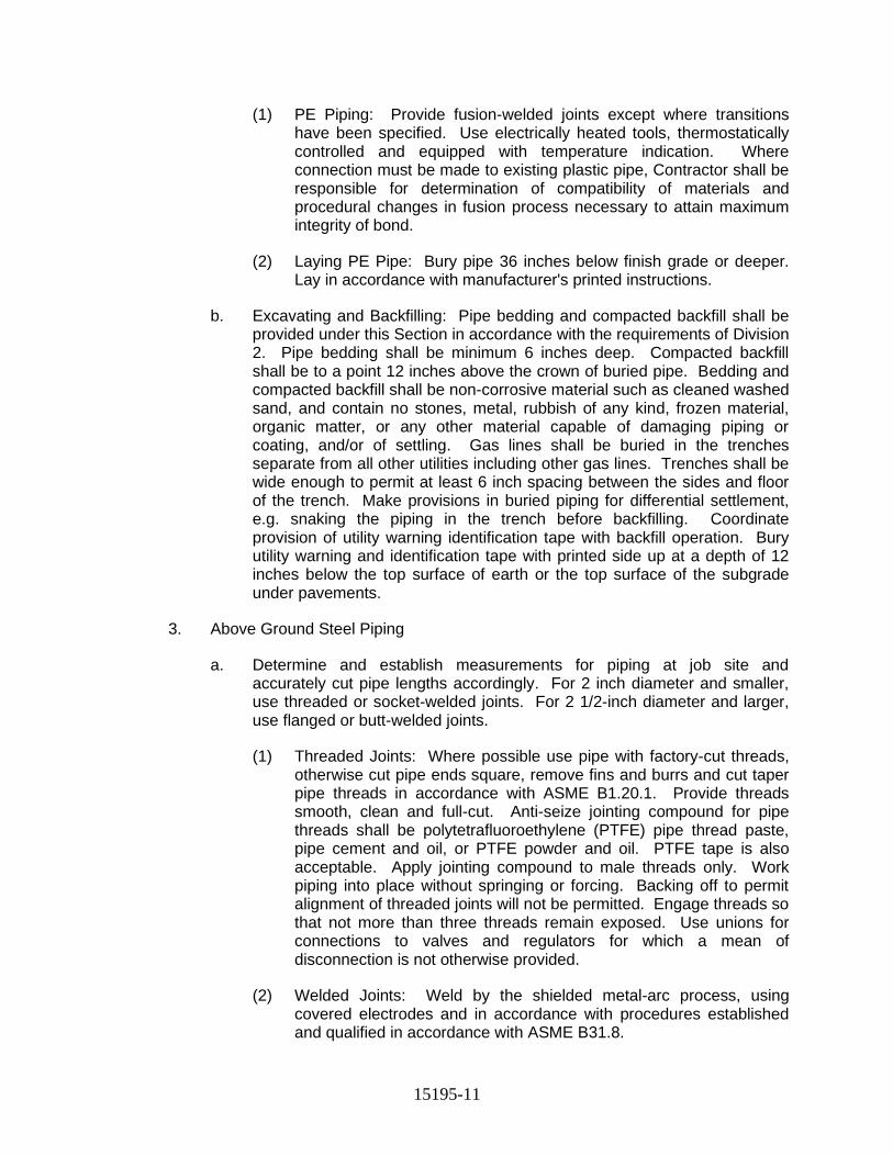
15195-11
(1) PE Piping: Provide fusion-welded joints except where transitions have been specified. Use electrically heated tools, thermostatically controlled and equipped with temperature indication. Where connection must be made to existing plastic pipe, Contractor shall be responsible for determination of compatibility of materials and procedural changes in fusion process necessary to attain maximum integrity of bond.
(2) Laying PE Pipe: Bury pipe 36 inches below finish grade or deeper. Lay in accordance with manufacturer's printed instructions.
b. Excavating and Backfilling: Pipe bedding and compacted backfill shall be provided under this Section in accordance with the requirements of Division 2. Pipe bedding shall be minimum 6 inches deep. Compacted backfill shall be to a point 12 inches above the crown of buried pipe. Bedding and compacted backfill shall be non-corrosive material such as cleaned washed sand, and contain no stones, metal, rubbish of any kind, frozen material, organic matter, or any other material capable of damaging piping or coating, and/or of settling. Gas lines shall be buried in the trenches separate from all other utilities including other gas lines. Trenches shall be wide enough to permit at least 6 inch spacing between the sides and floor of the trench. Make provisions in buried piping for differential settlement, e.g. snaking the piping in the trench before backfilling. Coordinate provision of utility warning identification tape with backfill operation. Bury utility warning and identification tape with printed side up at a depth of 12 inches below the top surface of earth or the top surface of the subgrade under pavements.
3. Above Ground Steel Piping
a. Determine and establish measurements for piping at job site and accurately cut pipe lengths accordingly. For 2 inch diameter and smaller, use threaded or socket-welded joints. For 2 1/2-inch diameter and larger, use flanged or butt-welded joints.
(1) Threaded Joints: Where possible use pipe with factory-cut threads, otherwise cut pipe ends square, remove fins and burrs and cut taper pipe threads in accordance with ASME B1.20.1. Provide threads smooth, clean and full-cut. Anti-seize jointing compound for pipe threads shall be polytetrafluoroethylene (PTFE) pipe thread paste, pipe cement and oil, or PTFE powder and oil. PTFE tape is also acceptable. Apply jointing compound to male threads only. Work piping into place without springing or forcing. Backing off to permit alignment of threaded joints will not be permitted. Engage threads so that not more than three threads remain exposed. Use unions for connections to valves and regulators for which a mean of disconnection is not otherwise provided.
(2) Welded Joints: Weld by the shielded metal-arc process, using covered electrodes and in accordance with procedures established and qualified in accordance with ASME B31.8.
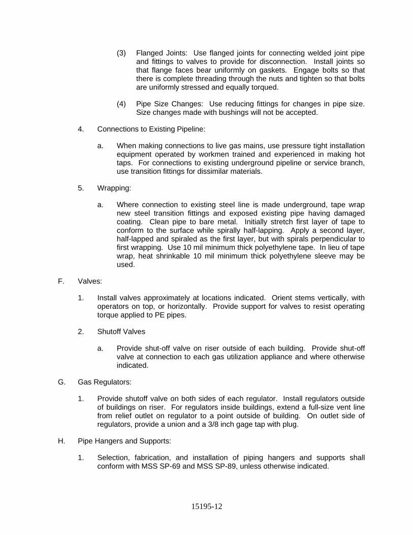
15195-12
(3) Flanged Joints: Use flanged joints for connecting welded joint pipe and fittings to valves to provide for disconnection. Install joints so that flange faces bear uniformly on gaskets. Engage bolts so that there is complete threading through the nuts and tighten so that bolts are uniformly stressed and equally torqued.
(4) Pipe Size Changes: Use reducing fittings for changes in pipe size. Size changes made with bushings will not be accepted.
4. Connections to Existing Pipeline:
a. When making connections to live gas mains, use pressure tight installation equipment operated by workmen trained and experienced in making hot taps. For connections to existing underground pipeline or service branch, use transition fittings for dissimilar materials.
5. Wrapping:
a. Where connection to existing steel line is made underground, tape wrap new steel transition fittings and exposed existing pipe having damaged coating. Clean pipe to bare metal. Initially stretch first layer of tape to conform to the surface while spirally half-lapping. Apply a second layer, half-lapped and spiraled as the first layer, but with spirals perpendicular to first wrapping. Use 10 mil minimum thick polyethylene tape. In lieu of tape wrap, heat shrinkable 10 mil minimum thick polyethylene sleeve may be used.
F. Valves:
1. Install valves approximately at locations indicated. Orient stems vertically, with operators on top, or horizontally. Provide support for valves to resist operating torque applied to PE pipes.
2. Shutoff Valves
a. Provide shut-off valve on riser outside of each building. Provide shut-off valve at connection to each gas utilization appliance and where otherwise indicated.
G. Gas Regulators:
1. Provide shutoff valve on both sides of each regulator. Install regulators outside of buildings on riser. For regulators inside buildings, extend a full-size vent line from relief outlet on regulator to a point outside of building. On outlet side of regulators, provide a union and a 3/8 inch gage tap with plug.
H. Pipe Hangers and Supports:
1. Selection, fabrication, and installation of piping hangers and supports shall conform with MSS SP-69 and MSS SP-89, unless otherwise indicated.
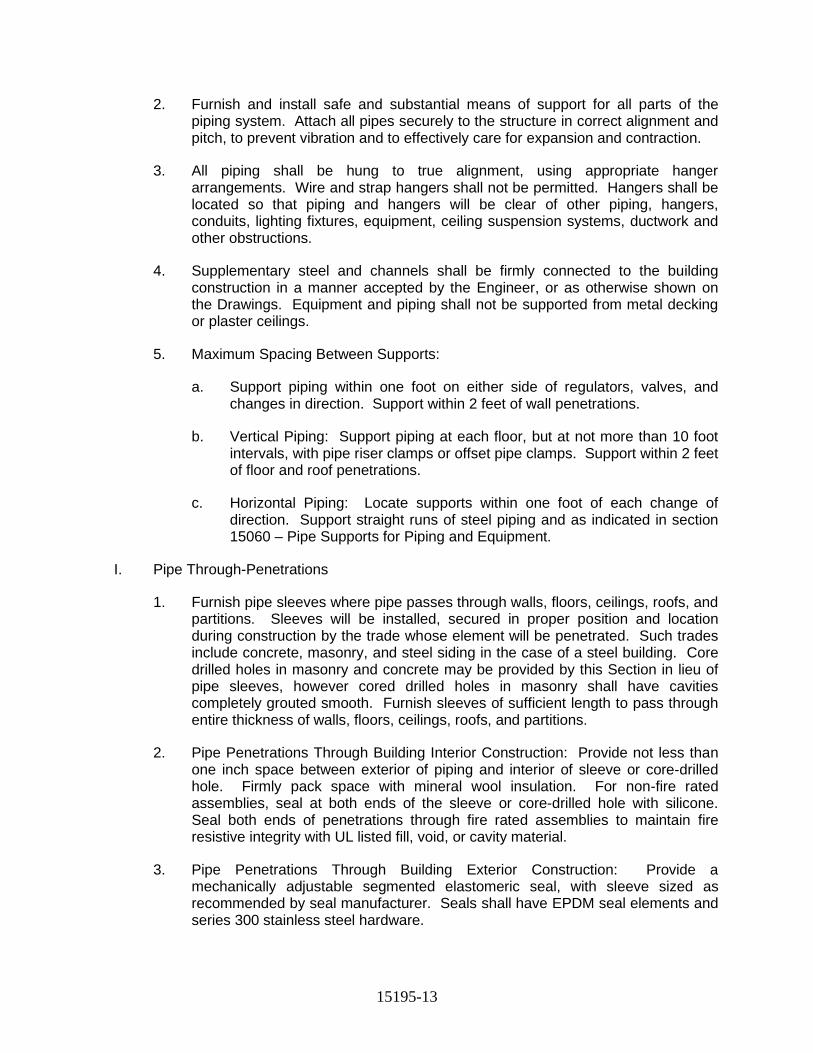
15195-13
2. Furnish and install safe and substantial means of support for all parts of the piping system. Attach all pipes securely to the structure in correct alignment and pitch, to prevent vibration and to effectively care for expansion and contraction.
3. All piping shall be hung to true alignment, using appropriate hanger arrangements. Wire and strap hangers shall not be permitted. Hangers shall be located so that piping and hangers will be clear of other piping, hangers, conduits, lighting fixtures, equipment, ceiling suspension systems, ductwork and other obstructions.
4. Supplementary steel and channels shall be firmly connected to the building construction in a manner accepted by the Engineer, or as otherwise shown on the Drawings. Equipment and piping shall not be supported from metal decking or plaster ceilings.
5. Maximum Spacing Between Supports:
a. Support piping within one foot on either side of regulators, valves, and changes in direction. Support within 2 feet of wall penetrations.
b. Vertical Piping: Support piping at each floor, but at not more than 10 foot intervals, with pipe riser clamps or offset pipe clamps. Support within 2 feet of floor and roof penetrations.
c. Horizontal Piping: Locate supports within one foot of each change of direction. Support straight runs of steel piping and as indicated in section 15060 – Pipe Supports for Piping and Equipment.
I. Pipe Through-Penetrations
1. Furnish pipe sleeves where pipe passes through walls, floors, ceilings, roofs, and partitions. Sleeves will be installed, secured in proper position and location during construction by the trade whose element will be penetrated. Such trades include concrete, masonry, and steel siding in the case of a steel building. Core drilled holes in masonry and concrete may be provided by this Section in lieu of pipe sleeves, however cored drilled holes in masonry shall have cavities completely grouted smooth. Furnish sleeves of sufficient length to pass through entire thickness of walls, floors, ceilings, roofs, and partitions.
2. Pipe Penetrations Through Building Interior Construction: Provide not less than one inch space between exterior of piping and interior of sleeve or core-drilled hole. Firmly pack space with mineral wool insulation. For non-fire rated assemblies, seal at both ends of the sleeve or core-drilled hole with silicone. Seal both ends of penetrations through fire rated assemblies to maintain fire resistive integrity with UL listed fill, void, or cavity material.
3. Pipe Penetrations Through Building Exterior Construction: Provide a mechanically adjustable segmented elastomeric seal, with sleeve sized as recommended by seal manufacturer. Seals shall have EPDM seal elements and series 300 stainless steel hardware.
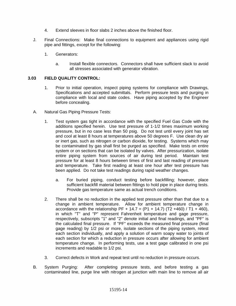
15195-14
4. Extend sleeves in floor slabs 2 inches above the finished floor.
J. Final Connections: Make final connections to equipment and appliances using rigid pipe and fittings, except for the following:
1. Generators:
a. Install flexible connectors. Connectors shall have sufficient slack to avoid all stresses associated with generator vibration.
3.03 FIELD QUALITY CONTROL:
1. Prior to initial operation, inspect piping systems for compliance with Drawings, Specifications and accepted submittals. Perform pressure tests and purging in compliance with local and state codes. Have piping accepted by the Engineer before concealing.
A. Natural Gas Piping Pressure Tests:
1. Test system gas tight in accordance with the specified Fuel Gas Code with the additions specified herein. Use test pressure of 1-1/2 times maximum working pressure, but in no case less than 50 psig. Do not test until every joint has set and cool at least 8 hours at temperatures above 50 degrees F. Use clean dry air or inert gas, such as nitrogen or carbon dioxide, for testing. Systems which may be contaminated by gas shall first be purged as specified. Make tests on entire system or on sections that can be isolated by valves. After pressurization, isolate entire piping system from sources of air during test period. Maintain test pressure for at least 8 hours between times of first and last reading of pressure and temperature. Take first reading at least one hour after test pressure has been applied. Do not take test readings during rapid weather changes.
a. For buried piping, conduct testing before backfilling; however, place sufficient backfill material between fittings to hold pipe in place during tests. Provide gas temperature same as actual trench conditions.
2. There shall be no reduction in the applied test pressure other than that due to a change in ambient temperature. Allow for ambient temperature change in accordance with the relationship PF + 14.7 = (P1 + 14.7) (T2 +460) / T1 + 460), in which "T" and "P" represent Fahrenheit temperature and gage pressure, respectively, subscripts "1" and "2" denote initial and final readings, and "PF" is the calculated final pressure. If "PF" exceeds the measured final pressure (final gage reading) by 1/2 psi or more, isolate sections of the piping system, retest each section individually, and apply a solution of warm soapy water to joints of each section for which a reduction in pressure occurs after allowing for ambient temperature change. In performing tests, use a test gage calibrated in one psi increments and readable to 1/2 psi.
3. Correct defects in Work and repeat test until no reduction in pressure occurs.
B. System Purging: After completing pressure tests, and before testing a gas contaminated line, purge line with nitrogen at junction with main line to remove all air
15195-15
and gas. Clean completed line by attaching a test pilot fixture at capped stub-in line at building location and let gas flow until test pilot ignites. Procedures shall conform to the specified Fuel Gas Code.
CAUTION
Failure to purge may result in explosion within line when air-to-gas is at correct mixture.
3.04 MANUFACTURERS INSTRUCTIONS:
A. Obtain instructions from the manufacturer for the proper method of installation and connection of the equipment that is to be installed. Obtain all information that is necessary to facilitate the Work and to complete the project.
3.05 PAINTING:
A. Field painting of above ground gas piping shall be provided in accordance with Div 9 specifications.
B. Field touch up all damaged factory or shop applied coatings for material and equipment furnished under this Section in accordance with the manufacturer's recommendation.
C. Provide painting of the following.
1. Supplementary steel in all aboveground locations. Color of finish coat shall match color of structure to which attached.
2. Pipe, fittings and valves in all aboveground locations. Color of finish coat shall be in accordance with Div 9 specifications.
D. Do not apply any field painting, including field touch-up, until after installation and testing is completed and system accepted.
END OF SECTION
15410-1
SECTION 15410
PLUMBING FIXTURES
PART 1 GENERAL
1.01 REFERENCES
A. The following is a list of standards that may be referenced in this section: 1. American Society of Mechanical Engineers (ASME). 2. American Society of Sanitary Engineering (ASSE): 1010, Performance
Requirements for Water Hammer Arresters. 3. Plumbing and Drainage Institute (PDI):
a. Code Guide 302 and Glossary of Industry Terms. b. WH-201, Water Hammer Arrester Standard.
4. Underwriters Laboratories Inc. (UL).
1.02 SUBMITTALS
A. Make submittals to the Engineer in accordance with Division 1 specifications.
B. Action Submittals: Catalog information and rough-in dimensions for plumbing fixtures, products, and specialties.
1.03 REGULATORY REQUIREMENTS
A. Comply with local and state requirements.
PART 2 PRODUCTS
2.01 MANUFACTURERS
A. Emergency Showers and Eyewashes: 1. Haws. 2. Western. 3. Guardian.
B. Plumbing Specialties: 1. Shock Arresters:
a. Smith. b. Sioux Chief. c. Precision Plumbing Products.
2. Pressure/Temperature Relief Valves: a. Cash-Acme b. Kunkle Valve. c. Watts
3. Pressure Gauges: a. Ashcroft.
15410-2
b. Marsh. c. Marshalltown.
4. Thermometers: a. Trerice. b. Weksler.
2.02 GENERAL
A. Fixture Trim: Provide plumbing fixture trim where applicable on fixtures.
B. Plumbing Fixtures: Indicated by fixture as shown on Drawings.
C. Plumbing Specialties: where applicable or as shown on Drawings.
D. Exposed fixture connections and piping shall be polished chrome-plated.
2.03 MATERIALS
A. Safety Equipment: 1. EES, Safety Shower/Eyewash Combination (All Stainless Steel):
a. Model: Bradley; Model S19314FSS b. Shower: Stainless steel deluge. c. Eyewash: Stainless steel aerated eye/face wash and stainless-
steel bowl. d. Valve: Stay open. e. Support: Freestanding, 1-1/4-inch stainless steel pipe standard,
stanchion, and floor flange. f. Alarms: Magnetically operated proximity switches and remote-
mounted strobe light.
B. Fixtures 1. Service Sink
a. Service Sinks: Enameled, cast iron, trap standard mounted. 1) Fixture:
a) Standard: ASME A112.19.1. b) Type: Service sink with back. c) Back: Two faucet holes. d) Nominal Size: 20 by 24 inches e) Color: White. f) Mounting: NPS 3 P-trap standard with grid strainer
inlet, cleanout, and floor flange. g) Rim Guard: On front and sides.
2) Faucet: exposed yolk wall mount utility type with vacuum breaker and stops in shank
3) Support: wall hanger 4) Mounting Height: Standard.
C. Plumbing Specialties: 1. Water Hammer Arresters:
15410-3
a. Materials: ASSE 1010 certified, Type L copper tube, HHPP piston with two lubricated EPDM O-rings, FDA approved lubricant, rolled piston stop, wrought copper male thread adapter.
b. Manufacturer and Product: Sioux Chief Mfg. Co., Inc.; Series 650 and 660.
2. Pressure/Temperature Relief Valve: a. Materials: ASME/AGA rated, bronze body construction, vacuum
relief valve vent in drain, backup emergency safety fuse plug, tamper-resistant bonnet screws, test lever, short thermostat, and automatic reseating.
b. Manufacturer and Product: Watts Industries, Inc.; Series 40. 3. Pressure Gauge:
a. Materials: 3-1/2-inch gauge size, 0 to 160 psi range, steel case, glass crystal, brass movement, and 1/3-inch NPT lower connection.
b. Manufacturer and Product: Ashcroft Dresser Instrument Division, Dresser Industries, Inc.; Type 1008.
4. Thermometer: a. Materials: Adjustable angle, red reading mercury type with 9-inch
case and 30 degrees F to 180 degrees F range, 3-1/2-inch aluminum stem, and separate NPT brass thermowell.
b. Manufacturer and Product: H.O. Trerice Co.; Model A005.
D.
PART 3 EXECUTION
3.01 PREPARATION
A. Drawings do not attempt to show exact details of fixtures. Changes in locations of fixtures, advisable in opinion of Contractor, shall be submitted to Engineer for review before proceeding with the Work.
3.02 INSTALLATION
A. Plumbing Fixtures, Mounting Heights: 1. Standard rough-in catalogued heights, unless shown otherwise on
Drawings. 2. Caulk fixtures in contact with finished walls with waterproof, white,
nonhardening sealant which will not crack, shrink, or change color with age.
B. Exact fixture location and mounting arrangement shall be as indicated on elevations and details as shown on Drawings.
C. Unless noted otherwise and as a minimum, fixtures shall be supported as indicated in PDI Code Guide 302.
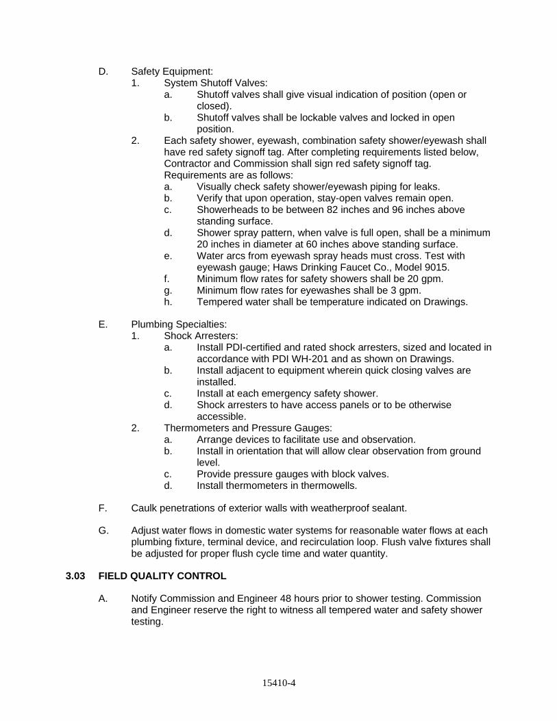
15410-4
D. Safety Equipment: 1. System Shutoff Valves:
a. Shutoff valves shall give visual indication of position (open or closed).
b. Shutoff valves shall be lockable valves and locked in open position.
2. Each safety shower, eyewash, combination safety shower/eyewash shall have red safety signoff tag. After completing requirements listed below, Contractor and Commission shall sign red safety signoff tag. Requirements are as follows: a. Visually check safety shower/eyewash piping for leaks. b. Verify that upon operation, stay-open valves remain open. c. Showerheads to be between 82 inches and 96 inches above
standing surface. d. Shower spray pattern, when valve is full open, shall be a minimum
20 inches in diameter at 60 inches above standing surface. e. Water arcs from eyewash spray heads must cross. Test with
eyewash gauge; Haws Drinking Faucet Co., Model 9015. f. Minimum flow rates for safety showers shall be 20 gpm. g. Minimum flow rates for eyewashes shall be 3 gpm. h. Tempered water shall be temperature indicated on Drawings.
E. Plumbing Specialties: 1. Shock Arresters:
a. Install PDI-certified and rated shock arresters, sized and located in accordance with PDI WH-201 and as shown on Drawings.
b. Install adjacent to equipment wherein quick closing valves are installed.
c. Install at each emergency safety shower. d. Shock arresters to have access panels or to be otherwise
accessible. 2. Thermometers and Pressure Gauges:
a. Arrange devices to facilitate use and observation. b. Install in orientation that will allow clear observation from ground
level. c. Provide pressure gauges with block valves. d. Install thermometers in thermowells.
F. Caulk penetrations of exterior walls with weatherproof sealant.
G. Adjust water flows in domestic water systems for reasonable water flows at each plumbing fixture, terminal device, and recirculation loop. Flush valve fixtures shall be adjusted for proper flush cycle time and water quantity.
3.03 FIELD QUALITY CONTROL
A. Notify Commission and Engineer 48 hours prior to shower testing. Commission and Engineer reserve the right to witness all tempered water and safety shower testing.
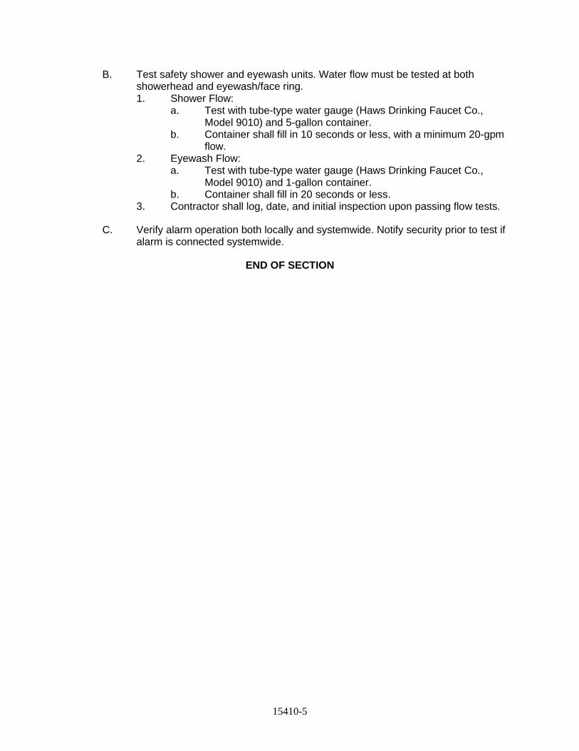
15410-5
B. Test safety shower and eyewash units. Water flow must be tested at both showerhead and eyewash/face ring. 1. Shower Flow:
a. Test with tube-type water gauge (Haws Drinking Faucet Co., Model 9010) and 5-gallon container.
b. Container shall fill in 10 seconds or less, with a minimum 20-gpm flow.
2. Eyewash Flow: a. Test with tube-type water gauge (Haws Drinking Faucet Co.,
Model 9010) and 1-gallon container. b. Container shall fill in 20 seconds or less.
3. Contractor shall log, date, and initial inspection upon passing flow tests.
C. Verify alarm operation both locally and systemwide. Notify security prior to test if alarm is connected systemwide.
END OF SECTION
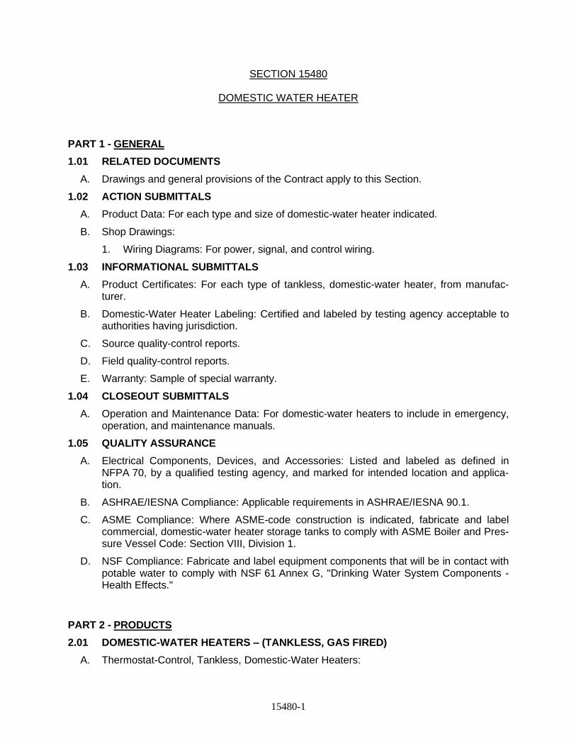
15480-1
SECTION 15480
DOMESTIC WATER HEATER
PART 1 - GENERAL
1.01 RELATED DOCUMENTS
A. Drawings and general provisions of the Contract apply to this Section.
1.02 ACTION SUBMITTALS
A. Product Data: For each type and size of domestic-water heater indicated.
B. Shop Drawings:
1. Wiring Diagrams: For power, signal, and control wiring.
1.03 INFORMATIONAL SUBMITTALS
A. Product Certificates: For each type of tankless, domestic-water heater, from manufac-turer.
B. Domestic-Water Heater Labeling: Certified and labeled by testing agency acceptable to authorities having jurisdiction.
C. Source quality-control reports.
D. Field quality-control reports.
E. Warranty: Sample of special warranty.
1.04 CLOSEOUT SUBMITTALS
A. Operation and Maintenance Data: For domestic-water heaters to include in emergency, operation, and maintenance manuals.
1.05 QUALITY ASSURANCE
A. Electrical Components, Devices, and Accessories: Listed and labeled as defined in NFPA 70, by a qualified testing agency, and marked for intended location and applica-tion.
B. ASHRAE/IESNA Compliance: Applicable requirements in ASHRAE/IESNA 90.1.
C. ASME Compliance: Where ASME-code construction is indicated, fabricate and label commercial, domestic-water heater storage tanks to comply with ASME Boiler and Pres-sure Vessel Code: Section VIII, Division 1.
D. NSF Compliance: Fabricate and label equipment components that will be in contact with potable water to comply with NSF 61 Annex G, "Drinking Water System Components - Health Effects."
PART 2 - PRODUCTS
2.01 DOMESTIC-WATER HEATERS – (TANKLESS, GAS FIRED)
A. Thermostat-Control, Tankless, Domestic-Water Heaters:
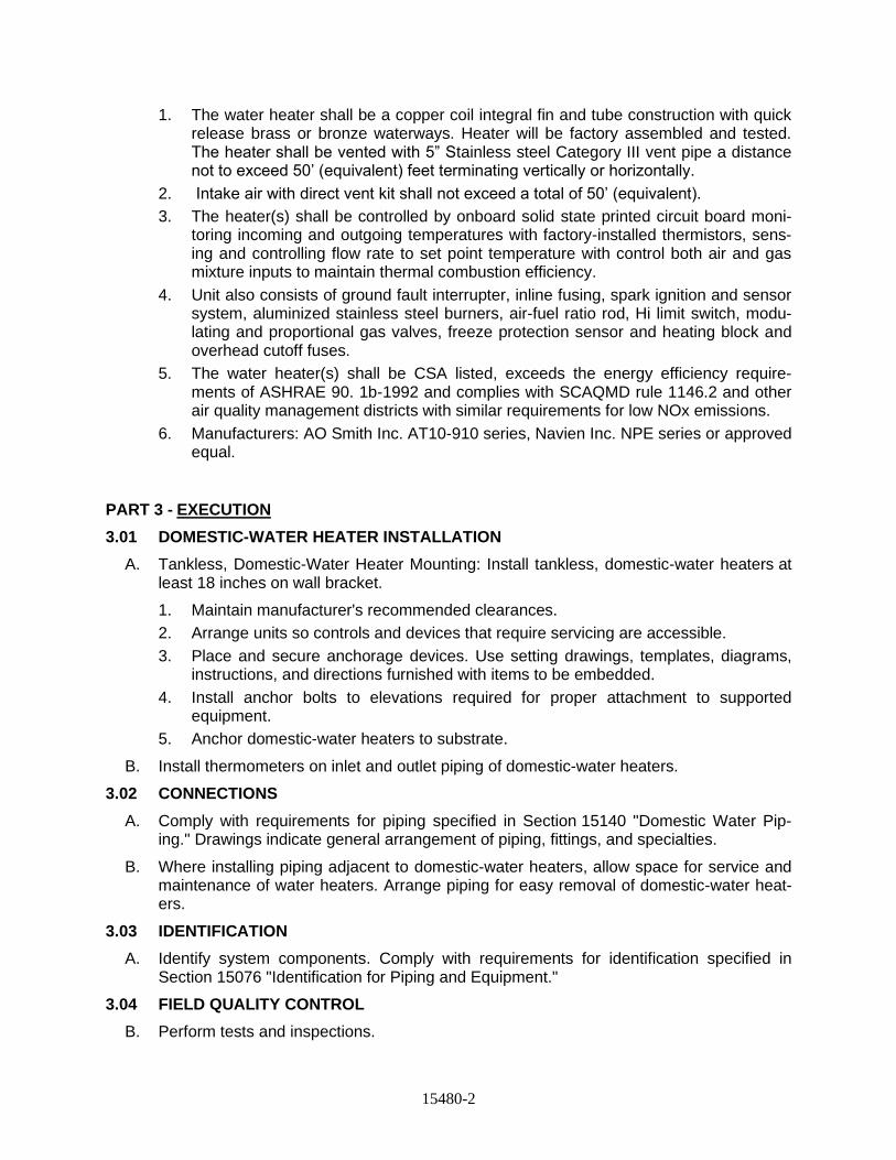
15480-2
1. The water heater shall be a copper coil integral fin and tube construction with quick release brass or bronze waterways. Heater will be factory assembled and tested. The heater shall be vented with 5” Stainless steel Category III vent pipe a distance not to exceed 50’ (equivalent) feet terminating vertically or horizontally.
2. Intake air with direct vent kit shall not exceed a total of 50’ (equivalent).
3. The heater(s) shall be controlled by onboard solid state printed circuit board moni-toring incoming and outgoing temperatures with factory-installed thermistors, sens-ing and controlling flow rate to set point temperature with control both air and gas mixture inputs to maintain thermal combustion efficiency.
4. Unit also consists of ground fault interrupter, inline fusing, spark ignition and sensor system, aluminized stainless steel burners, air-fuel ratio rod, Hi limit switch, modu-lating and proportional gas valves, freeze protection sensor and heating block and overhead cutoff fuses.
5. The water heater(s) shall be CSA listed, exceeds the energy efficiency require-ments of ASHRAE 90. 1b-1992 and complies with SCAQMD rule 1146.2 and other air quality management districts with similar requirements for low NOx emissions.
6. Manufacturers: AO Smith Inc. AT10-910 series, Navien Inc. NPE series or approved equal.
PART 3 - EXECUTION
3.01 DOMESTIC-WATER HEATER INSTALLATION
A. Tankless, Domestic-Water Heater Mounting: Install tankless, domestic-water heaters at least 18 inches on wall bracket.
1. Maintain manufacturer's recommended clearances.
2. Arrange units so controls and devices that require servicing are accessible.
3. Place and secure anchorage devices. Use setting drawings, templates, diagrams, instructions, and directions furnished with items to be embedded.
4. Install anchor bolts to elevations required for proper attachment to supported equipment.
5. Anchor domestic-water heaters to substrate.
B. Install thermometers on inlet and outlet piping of domestic-water heaters.
3.02 CONNECTIONS
A. Comply with requirements for piping specified in Section 15140 "Domestic Water Pip-ing." Drawings indicate general arrangement of piping, fittings, and specialties.
B. Where installing piping adjacent to domestic-water heaters, allow space for service and maintenance of water heaters. Arrange piping for easy removal of domestic-water heat-ers.
3.03 IDENTIFICATION
A. Identify system components. Comply with requirements for identification specified in Section 15076 "Identification for Piping and Equipment."
3.04 FIELD QUALITY CONTROL
B. Perform tests and inspections.
15480-3
1. Manufacturer's Field Service: Engage a factory-authorized service representative to inspect components, assemblies, and equipment installations, including connec-tions, and to assist in testing.
2. Leak Test: After installation, charge system and test for leaks. Repair leaks and re-test until no leaks exist.
3. Operational Test: After electrical circuitry has been energized, start units to confirm proper operation.
4. Test and adjust controls and safeties. Replace damaged and malfunctioning con-trols and equipment.
C. Prepare the test and inspection reports.
END OF SECTION
15930-1
SECTION 15930
FIRE SPRINKLER SYSTEM
PART 1 - GENERAL
1.01 SECTION INCLUDES
A. This section includes pipe materials, fittings, valves, sprinkler heads, fire dept. connections.
1. Provide wet-pipe automatic sprinkler systems as shown.
2. Provide sprinkler systems to be automatically fire responsive and installed to accommodate building structure and equipment.
3. Sprinkler systems shown are intended to show basic requirements. Quantity, size and location of sprinkler heads shown, and size and location of branch feeder piping, is not to be regarded as absolute. Provide additional sprinkler heads where necessary to give adequate protection for concealed areas, spaces adjacent to beams, columns and ducts, and to other areas in protected spaces where sprinkler coverage may be fully or partially obstructed.
4. Provide fire protection systems complete in all respects complying with provisions of the National Fire Protection Association (NFPA) Standards, local codes and ordinances, requirements specified herein. Resolve conflicting requirements by meeting the more stringent requirement in each case.
5. Provide an angle or globe valve in properly sized main drain piped to acceptable drain location for use in system flow tests.
6. Provide all equipment and devices listed or approved for their intended service by Underwriters' Laboratory, Factory Mutual.
B. All conduit and wiring from alarm valves and devices and sprinkler devices (tamper switches, flow switches, pressure switches, etc.) to fire alarm panels shall be furnished and installed in Contract.
1.02 RELATED SECTIONS
A. Specification 15076 - Piping and Equipment Identification
1.03 REFERENCES
A. ASME B16.3 - Malleable-Iron Threaded Fittings, Class 150 and 300
B. ASME B16.4 - Cast-Iron Threaded Fittings, Class 125 and 250
C. ASTM A 53 - Pipe, Steel, Black and Hot-Dipped, Zinc-Coated Welded and Seamless
D. ASTM A 795 - Black and Hot-Dipped Zinc-Coated (Galvanized) Welded and Seamless Steel Pipe for Fire Protection Use
E. NFPA 13 - Standard for the Installation of Sprinkler Systems
15930-2
F. FM - Approval Guide
G. UL - Fire Protection Equipment Directory
H. AISI - American Iron and Steel Institute
1.04 SUBMITTALS
A. General: Provide submittals, including the following, in conformity with the General Conditions.
B. Shop Drawings: Submit complete layout of working drawings, indicating pipe materials used, fittings, supports, and floor and wall penetration seals. Indicate weights, mounting, and support details.
1. Provide manufacturers catalog data for piping, fittings, valves, sprinkler heads, fire department connections, flow detection and alarm devices, and gauges.
2. Delegated-Design Submittal: The Contractor shall have his working drawings and hydraulic calculations prepared, signed and sealed by a NJ Professional Engineer. Submit for review working plans of the installation to the Engineer showing layout of all areas with automatic sprinkler protection, showing proposed location of sprinkler heads with respect to lights, diffusers, ceiling grid, framing members, etc. Data on these working plans shall include, but not be limited to the following: size of all piping; method of anchoring or hanging pipe lines; location and type of valves; position, type and temperature ratings of sprinkler heads, zone valves, stand pipes, and detectors; material and equipment list indicating manufacturers' names and types; structural, mechanical, electrical and architectural coordinating information; hydraulic calculations and the various other items pertinent to the complete installation of the systems. After approval from the Engineer, working plans, hydraulic calculations, specifications, etc., shall also be submitted for approval to the local authorities for plan approval and permits.
3. Operations and Maintenance Manuals:
a. Submit under provision of Division 1 - General Requirements.
1.05 QUALITY ASSURANCE
A. Codes: Perform Work to meet following codes:
1. Sprinkler System - NFPA 13 2. Valves - Bear UL or FM Label or Marking
B. Permits: Contractor shall obtain and pay for all required permits, fees, inspections and approvals by authorities having jurisdiction.
C. Except as modified herein, conform to the required and advisory provisions of the NJ Building Code and NFPA 13 (whichever is the most stringent) for design, equipment materials, installation, workmanship, examination, inspection, and testing. Include all materials, accessories, and equipment inside and outside the building for each system to be complete and ready for use. Design and provide each system to accommodate blind spaces, piping, electrical equipment, ductwork, and other construction and equipment in accordance with detailed drawings submitted for approval. Locate sprinkler heads in a
15930-3
consistent pattern with ceiling grid, lights, and supply air diffusers. Provide devices and equipment for fire protection service of a make or type which is UL listed or FM approved for use in sprinkler systems.
D. The Contractor shall provide complete, new sprinkler fire protection water service connections complete with UL listed and FM approved reduced pressure principle backflow preventer assembly, alarm valve, water motor gong, fire department siamese connection, sprinkler heads, flow switches, piping, hangers, test connections and all appurtenances. It shall be understood that the final design of the sprinkler fire protection systems, including, but not limited to, the arrangement, hydraulic calculations, size and location of risers, feed mains, cross mains, test connections, branch lines and drains, and the location, spacing, number and types of heads or nozzles shall be the responsibility of the Contractor and shall conform with the requirements of the, local Authorities, Standards and Codes listed in these specifications. The Contractor shall be responsible for procuring approval from the local fire department and building department.
1.06 DELIVERY, STORAGE AND HANDLING
A. General: Deliver, store and handle all products and materials as specified in Division 1 and as follows:
1. Deliver and store valves in shipping containers with labels in place.
2. Provide temporary protective coating on cast-iron and steel valves.
3. Provide end caps and closures on piping and fittings.
B. Acceptance: Accept equipment on-site in factory packaging and inspect for damage.
PART 2 - PRODUCTS
2.01 MANUFACTURERS
A. The following manufacturers are acceptable. Equivalent products of other manufacturers may be submitted for approval.
B. Gate Valves
1. Nibco F-607-0TS
2. Stockham
3. Kennedy Va., Division of ITT Grinnell Co., Inc.
C. Swing Check Valves
1. Nibco F-908-W
2. Stockham
3. Kennedy Va., Division of ITT Grinnell Co., Inc.
D. Riser Check Valves
1. Reliable Model G
15930-4
2. Viking EasyPac Riser Manifold Assembly
3. Victaulic
E. Grooved Mechanical Couplings
1. Victaulic
2. Approved eual
F. Sprinkler Heads
1. Viking Corp.
2. Reliable Automatic Sprinkler Co., Inc.
3. Approved equal
G. Water Flow Switches
1. Notifier - Series WFD
2. Potter
3. System Sensor
H. Tamper Switches
1. Notifier - Series OSY2
2. Potter
3. System Sensor
I. Wall Siamese
1. Croker 6010 series
2. Potter-Roemer
3. Star
J. Pipe Couplings
1. Victaulic – Firelock
2. Or approved equal
2.02 PIPE AND FITTINGS
A. Comply with NFPA 13 for pipe and fittings.
1. Install fire protection piping in accordance with National Fire Protection Association Standards.
2. Provide seemless carbon steel pipe complying with ASTM A795 or A53.
3. Piping 2” and smaller shall be schedule 40 with screwed joints and fittings.
4. Piping 2 1/2” and larger shall be schedule schedule 40 joined by roll groove type couplings.
15930-5
B. Screwed Fittings:
1. Screwed fittings 2-inches and smaller shall be malleable iron flat band fittings, ASME B16.3, 125 pounds. Malleable iron shall conform to the requirements of ASTM A197.
2. All threads shall be clean cut and smooth conforming to the American Standard for Pipe Threads, ASME B1.1. Fittings shall be with right and/or left hand threads as required.
3. Unions and railroad unions and union elbows and tees shall be malleable iron fitted with brass to iron seats unless otherwise specified.
C. Groove type couplings and fittings:
1. Couplings shall be FM approved for fire protection.
2. Housing: Ductile iron conforming to ASTM A-536, grade 65-45-12.
3. Coupling gasket: Grade “E” EPDM type A Vic-plus gasket system
4. Bolts/nuts: heat treated plated carbon steel, meeting the physical and chemical requirements of ASTM A-449 and physical requirements of ASTM A-183.
5. Fittings shall be ductile iron conforming to ASTM A-536, grade 65-45-12
2.03 VALVES
A. General: Provide gate, check, globe and angle valves UL listed and FM approved for fire protection service.
1. Valves open when their handwheel is turned counterclockwise.
2. Valves 2-inch size and smaller: Provide screwed pattern bronze construction valve with union bonnet and rising stem.
3. Valves 2-1/2 inches and larger: Provide valves of grooved pattern iron bodies with bronze trim, bolted bonnets, outside screw and yoke, and rising stem.
4. Provide valves of same type from same manufacturer.
B. Gate Valves: Provide gate valves in piping to isolate each major item of equipment and, in general, to isolate each floor and each major portion of system.
C. Check Valves: Provide check valves of the horizontal, single disc, swing type designed with full pipe diameter water passage. Provide check valves having bronze renewable seat ring, disc, and hinge bushing and pins.
2.04 SPRINKLER HEADS
A. General: Provide upright or pendent type sprinklers as shown or specified. Use pendent type sprinklers in finished areas, with chrome or nickel plated finish.
15930-6
B. Temperature Rating: Provide sprinklers for dry- and wet-pipe systems having fusible element of standard temperature rating, unless otherwise specified or approved.
C. Deflectors: Provide sprinklers with suitable water deflectors giving uniform circular distribution pattern, unless otherwise required. Provide sprinklers of all types from common manufacturer.
D. Extra Heads: Provide wall-mounted cabinet, housing minimum of six extra sprinkler heads and sprinkler wrench. Extra sprinkler heads shall include two of all types used.
2.05 SIAMESE CONNECTION
A. General: Provide and install one or more siamese connections where shown.
B. Type: Provide siamese of freestanding sidewalk type or of flush-mounted wall type, as shown.
C. Size: All siamese connections are 2 1/2" x 2 1/2" x 4", except as noted, with polished brass finish and branded with the legend "AUTOSPKR" or as appropriate. Furnish siamese connections with polished brass caps and chains.
D. Threads: Provide hose threads conforming to local fire department requirements.
E. Check Valves: Provide and install approved check valve and automatic ball-drip valve at each siamese connection.
2.06 GAUGES
A. General: Provide Bourdon-tube type pressure gauge with 4-l/2-inch minimum diameter case, suitable for 250 psig maximum pressure with markings in 5 psi increments.
2.07 WATER FLOW DETECTION AND ALARM
A. Provide vane-type water flow switch for each wet sprinkler system.
1. Provide flow switch on system side of control valve. Provide flow switches of dual SPDT switches/Form C contacts type with contacts rated for at least 10 amps on 115-volt, 60 hertz, single-phase service. Provide flow switches having either electric or mechanical retarding device to prevent false alarms upon normally occurring supply pressure surges.
2. Alarm check valve incorporating integral flow alarm switch and retarding chamber are acceptable for flow detection provided its switch characteristics meet those stated for the vane-type switch specified above.
B. Water Flow Alarm: Each water flow switch, upon sensing water flow, initiates signal actuating l0-inch electric alarm bell, mounted outside building at approved location.
1. Provide weatherproof alarm bell with suitable guard and weatherproof back box. Keep unused flow detector contacts available for other specified alarm functions.
2.08 TAMPER SWITCHES
15930-7
A. Description: Provide tamper switches with dual SPDT contacts at control valves and the DCDA gate valves. Locate switches so as not to interfere with normal valve operation. Provide tamper switch in weatherproof die-cast housing with conduit inlet and valve attachment. Provide switch mechanism 120-volt ac and entire installed assembly tamper resistant.
2.09 IDENTIFICATION SIGNS
A. Provide sprinkler system identification signs in accordance with the NFPA 13, and Specification 15076.
2.10 RISER CHECK VALVE
A. Provide for wet pipe sprinkler system a riser check valve with trim package.
B. Riser Check valve shall be a FM Approved spring-loaded check valve having a rated working pressure of 250 psi and factory hydrostatic tested to a pressure of 500 psi. Valve body casting shall be gray iron per ASTM-A48 Class 30A, containing a bronze seat and stainless-steel clapper per ASTM A240 with rubber gasket and EPDM rubber facing seal. End connections to be grooved by grooved per ANSI/AWWA C606. The riser check valve shall be factory tapped for 1-1/4” main drain and ½” plugged NPT system connection with additional ¼” supply connections. All parts of the clapper assembly to consist of stainless steel. Check valve shall be capable of holding air pressure in the system without the use of priming water. Trim components shall consist of a 1-1/4” bronze angle valve main drain connection, and a 300-psi pressure gauge connection with 3-way bronze globe valve located on both the upstream and downstream side of the riser check.
PART 3 - EXECUTION
3.01 PREPARATION
A. Remove scale and foreign material, from inside and outside piping before assembly.
3.02 INSTALLATION
A. General: Install equipment in accordance with the manufacturer's recommendations and approved shop drawings and as specified in Division 1.
1. Obtain Fire Department approvals of sprinkler system shop drawings and all local authorities having jurisdiction.
2. Provide alarm check valve assembly at sprinkler system water source connection.
3. Locate fire department connection with sufficient clearance from walls, obstructions or adjacent siamese connections to allow full swing of fire department wrench handle.
4. Provide drains piped to and discharging into floor drains.
5. Install baffles between sprinkler heads spaced less than 6 feet apart.
6. Install pre-action valves to water source and test system. For all leaks replace any leaking sprinkler heads. Tighten or replace joint connector.
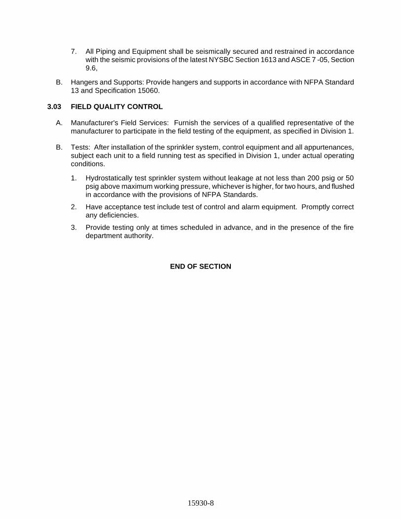
15930-8
7. All Piping and Equipment shall be seismically secured and restrained in accordance with the seismic provisions of the latest NYSBC Section 1613 and ASCE 7 -05, Section 9.6,
B. Hangers and Supports: Provide hangers and supports in accordance with NFPA Standard 13 and Specification 15060.
3.03 FIELD QUALITY CONTROL
A. Manufacturer's Field Services: Furnish the services of a qualified representative of the manufacturer to participate in the field testing of the equipment, as specified in Division 1.
B. Tests: After installation of the sprinkler system, control equipment and all appurtenances, subject each unit to a field running test as specified in Division 1, under actual operating conditions.
1. Hydrostatically test sprinkler system without leakage at not less than 200 psig or 50 psig above maximum working pressure, whichever is higher, for two hours, and flushed in accordance with the provisions of NFPA Standards.
2. Have acceptance test include test of control and alarm equipment. Promptly correct any deficiencies.
3. Provide testing only at times scheduled in advance, and in the presence of the fire department authority.
END OF SECTION
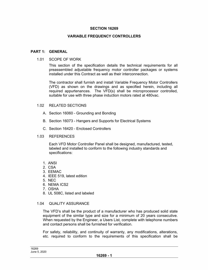
16269 June 5, 2020
16269 - 1
SECTION 16269
VARIABLE FREQUENCY CONTROLLERS
PART 1: GENERAL
1.01 SCOPE OF WORK
This section of the specification details the technical requirements for all preassembled adjustable frequency motor controller packages or systems installed under this Contract as well as their interconnection.
The contractor shall furnish and install Variable Frequency Motor Controllers (VFD) as shown on the drawings and as specified herein, including all required appurtenances. The VFD(s) shall be microprocessor controlled, suitable for use with three phase induction motors rated at 480vac.
1.02 RELATED SECTIONS
A. Section 16060 - Grounding and Bonding
B. Section 16073 - Hangers and Supports for Electrical Systems
C. Section 16420 - Enclosed Controllers
1.03 REFERENCES
Each VFD Motor Controller Panel shall be designed, manufactured, tested, labeled and installed to conform to the following industry standards and specifications:
1. ANSI 2. CSA 3. EEMAC 4. IEEE 519, latest edition 5. NEC 6. NEMA ICS2 7. OSHA 8. UL 508C, listed and labeled
1.04 QUALITY ASSURANCE
The VFD’s shall be the product of a manufacturer who has produced solid state equipment of the similar type and size for a minimum of 20 years consecutive. When requested by the Engineer, a Users List, complete with telephone numbers and contact persons shall be furnished for verification.
For safety, reliability, and continuity of warranty, any modifications, alterations, etc. required to conform to the requirements of this specification shall be
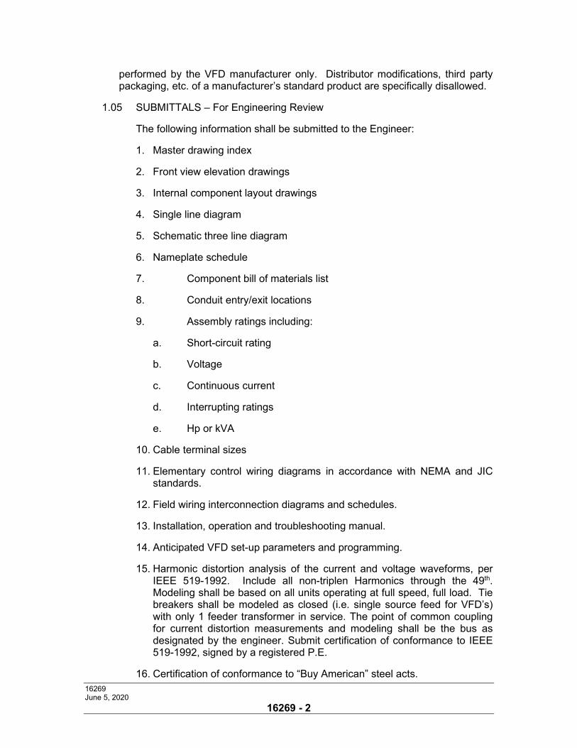
16269 June 5, 2020
16269 - 2
performed by the VFD manufacturer only. Distributor modifications, third party packaging, etc. of a manufacturer’s standard product are specifically disallowed.
1.05 SUBMITTALS – For Engineering Review
The following information shall be submitted to the Engineer:
1. Master drawing index
2. Front view elevation drawings
3. Internal component layout drawings
4. Single line diagram
5. Schematic three line diagram
6. Nameplate schedule
7. Component bill of materials list
8. Conduit entry/exit locations
9. Assembly ratings including:
a. Short-circuit rating
b. Voltage
c. Continuous current
d. Interrupting ratings
e. Hp or kVA
10. Cable terminal sizes
11. Elementary control wiring diagrams in accordance with NEMA and JIC standards.
12. Field wiring interconnection diagrams and schedules.
13. Installation, operation and troubleshooting manual.
14. Anticipated VFD set-up parameters and programming.
15. Harmonic distortion analysis of the current and voltage waveforms, per IEEE 519-1992. Include all non-triplen Harmonics through the 49th. Modeling shall be based on all units operating at full speed, full load. Tie breakers shall be modeled as closed (i.e. single source feed for VFD’s) with only 1 feeder transformer in service. The point of common coupling for current distortion measurements and modeling shall be the bus as designated by the engineer. Submit certification of conformance to IEEE 519-1992, signed by a registered P.E.
16. Certification of conformance to “Buy American” steel acts.
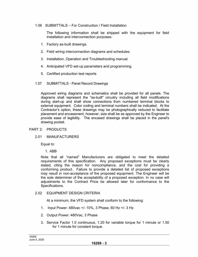
16269 June 5, 2020
16269 - 3
1.06 SUBMITTALS – For Construction / Field Installation
The following information shall be shipped with the equipment for field installation and interconnection purposes:
1. Factory as-built drawings.
2. Field wiring interconnection diagrams and schedules.
3. Installation, Operation and Troubleshooting manual.
4. Anticipated VFD set-up parameters and programming.
5. Certified production test reports
1.07 SUBMITTALS - Panel Record Drawings
Approved wiring diagrams and schematics shall be provided for all panels. The diagrams shall represent the "as-built" circuitry including all field modifications during start-up and shall show connections from numbered terminal blocks to external equipment. Color coding and terminal numbers shall be indicated. At the Contractor’s option, these drawings may be photographically reduced to facilitate placement and encasement, however, size shall be as approved by the Engineer to provide ease of legibility. The encased drawings shall be placed in the panel's drawing pocket.
PART 2: PRODUCTS
2.01 MANUFACTURERS
Equal to:
1. ABB
Note that all “named” Manufacturers are obligated to meet the detailed requirements of this specification. Any proposed exceptions must be clearly stated, citing the reason for noncompliance, and the cost for providing a conforming product. Failure to provide a detailed list of proposed exceptions may result in non-acceptance of the proposed equipment. The Engineer will be the sole determiner of the acceptability of a proposed exception. In no case will adjustments to the Contract Price be allowed later for conformance to the Specifications.
2.02 EQUIPMENT DESIGN CRITERIA
At a minimum, the VFD system shall conform to the following:
1. Input Power: 480vac +/- 10%, 3 Phase, 60 Hz +/- 3 Hz.
2. Output Power: 480Vac, 3 Phase
3. Service Factor 1.0 continuous, 1.20 for variable torque for 1 minute or 1.50 for 1 minute for constant torque.
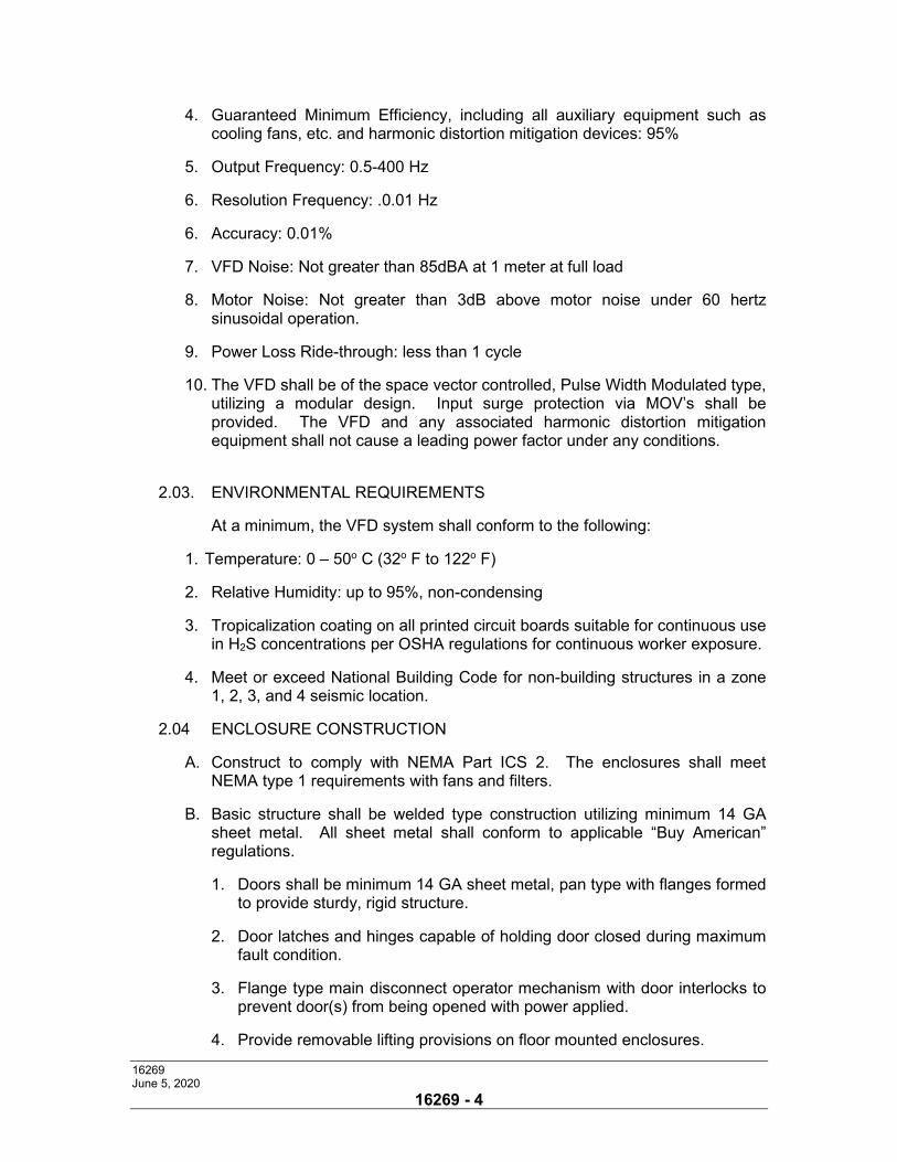
16269 June 5, 2020
16269 - 4
4. Guaranteed Minimum Efficiency, including all auxiliary equipment such as cooling fans, etc. and harmonic distortion mitigation devices: 95%
5. Output Frequency: 0.5-400 Hz
6. Resolution Frequency: .0.01 Hz
6. Accuracy: 0.01%
7. VFD Noise: Not greater than 85dBA at 1 meter at full load
8. Motor Noise: Not greater than 3dB above motor noise under 60 hertz sinusoidal operation.
9. Power Loss Ride-through: less than 1 cycle
10. The VFD shall be of the space vector controlled, Pulse Width Modulated type, utilizing a modular design. Input surge protection via MOV’s shall be provided. The VFD and any associated harmonic distortion mitigation equipment shall not cause a leading power factor under any conditions.
2.03. ENVIRONMENTAL REQUIREMENTS
At a minimum, the VFD system shall conform to the following:
1. Temperature: 0 – 50o C (32o F to 122o F)
2. Relative Humidity: up to 95%, non-condensing
3. Tropicalization coating on all printed circuit boards suitable for continuous use in H2S concentrations per OSHA regulations for continuous worker exposure.
4. Meet or exceed National Building Code for non-building structures in a zone 1, 2, 3, and 4 seismic location.
2.04 ENCLOSURE CONSTRUCTION
A. Construct to comply with NEMA Part ICS 2. The enclosures shall meet NEMA type 1 requirements with fans and filters.
B. Basic structure shall be welded type construction utilizing minimum 14 GA sheet metal. All sheet metal shall conform to applicable “Buy American” regulations.
1. Doors shall be minimum 14 GA sheet metal, pan type with flanges formed to provide sturdy, rigid structure.
2. Door latches and hinges capable of holding door closed during maximum fault condition.
3. Flange type main disconnect operator mechanism with door interlocks to prevent door(s) from being opened with power applied.
4. Provide removable lifting provisions on floor mounted enclosures.
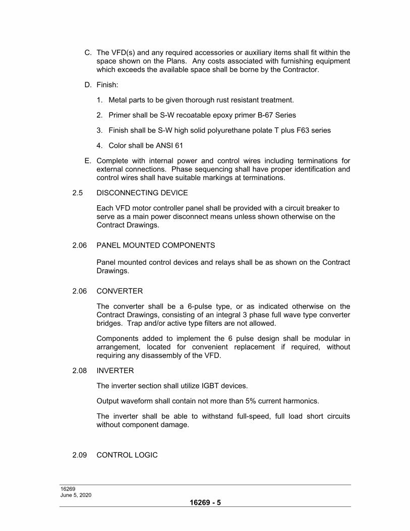
16269 June 5, 2020
16269 - 5
C. The VFD(s) and any required accessories or auxiliary items shall fit within the space shown on the Plans. Any costs associated with furnishing equipment which exceeds the available space shall be borne by the Contractor.
D. Finish:
1. Metal parts to be given thorough rust resistant treatment.
2. Primer shall be S-W recoatable epoxy primer B-67 Series
3. Finish shall be S-W high solid polyurethane polate T plus F63 series
4. Color shall be ANSI 61
E. Complete with internal power and control wires including terminations for external connections. Phase sequencing shall have proper identification and control wires shall have suitable markings at terminations.
2.5 DISCONNECTING DEVICE
Each VFD motor controller panel shall be provided with a circuit breaker to serve as a main power disconnect means unless shown otherwise on the Contract Drawings.
2.06 PANEL MOUNTED COMPONENTS
Panel mounted control devices and relays shall be as shown on the Contract Drawings.
2.06 CONVERTER
The converter shall be a 6-pulse type, or as indicated otherwise on the Contract Drawings, consisting of an integral 3 phase full wave type converter bridges. Trap and/or active type filters are not allowed.
Components added to implement the 6 pulse design shall be modular in arrangement, located for convenient replacement if required, without requiring any disassembly of the VFD.
2.08 INVERTER
The inverter section shall utilize IGBT devices.
Output waveform shall contain not more than 5% current harmonics.
The inverter shall be able to withstand full-speed, full load short circuits without component damage.
2.09 CONTROL LOGIC
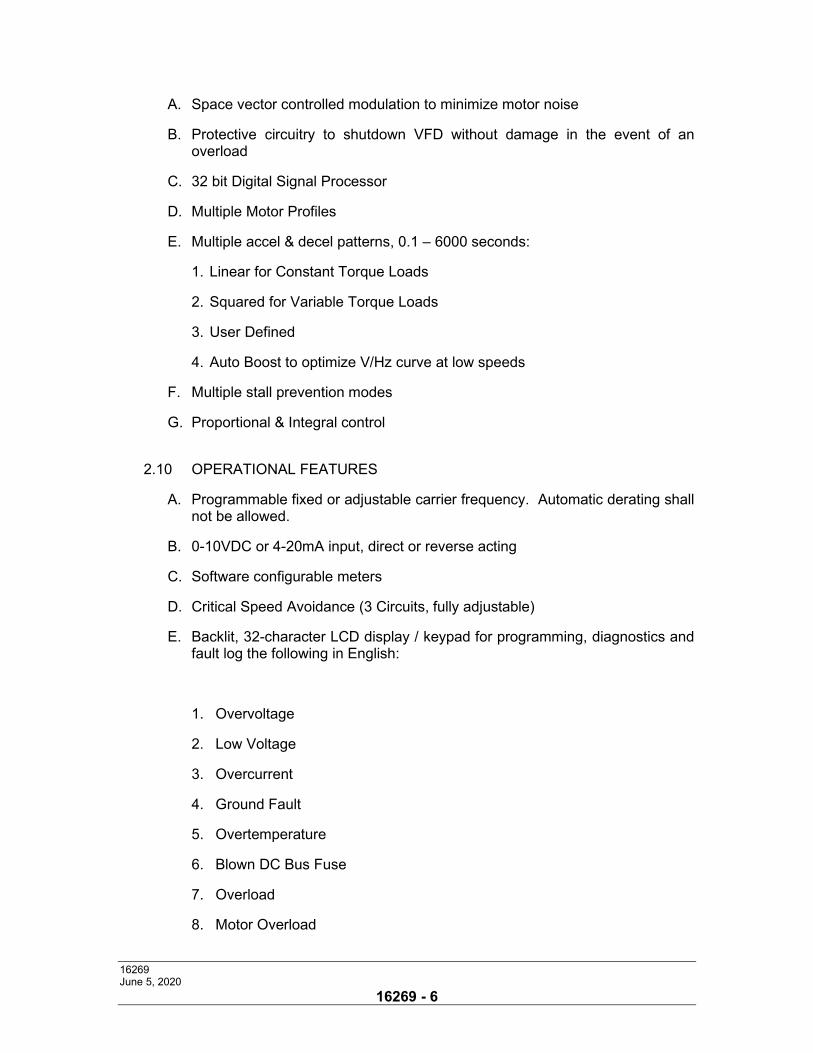
16269 June 5, 2020
16269 - 6
A. Space vector controlled modulation to minimize motor noise
B. Protective circuitry to shutdown VFD without damage in the event of an overload
C. 32 bit Digital Signal Processor
D. Multiple Motor Profiles
E. Multiple accel & decel patterns, 0.1 – 6000 seconds:
1. Linear for Constant Torque Loads
2. Squared for Variable Torque Loads
3. User Defined
4. Auto Boost to optimize V/Hz curve at low speeds
F. Multiple stall prevention modes
G. Proportional & Integral control
2.10 OPERATIONAL FEATURES
A. Programmable fixed or adjustable carrier frequency. Automatic derating shall not be allowed.
B. 0-10VDC or 4-20mA input, direct or reverse acting
C. Software configurable meters
D. Critical Speed Avoidance (3 Circuits, fully adjustable)
E. Backlit, 32-character LCD display / keypad for programming, diagnostics and fault log the following in English:
1. Overvoltage
2. Low Voltage
3. Overcurrent
4. Ground Fault
5. Overtemperature
6. Blown DC Bus Fuse
7. Overload
8. Motor Overload
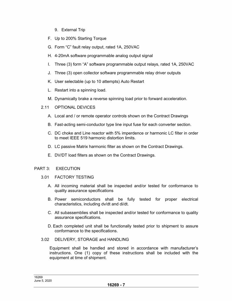
16269 June 5, 2020
16269 - 7
9. External Trip
F. Up to 200% Starting Torque
G. Form “C” fault relay output, rated 1A, 250VAC
H. 4-20mA software programmable analog output signal
I. Three (3) form “A” software programmable output relays, rated 1A, 250VAC
J. Three (3) open collector software programmable relay driver outputs
K. User selectable (up to 10 attempts) Auto Restart
L. Restart into a spinning load.
M. Dynamically brake a reverse spinning load prior to forward acceleration.
2.11 OPTIONAL DEVICES
A. Local and / or remote operator controls shown on the Contract Drawings
B. Fast-acting semi-conductor type line input fuse for each converter section.
C. DC choke and Line reactor with 5% imperdence or harmonic LC filter in order to meet IEEE 519 harmonic distortion limits.
D. LC passive Matrix harmonic filter as shown on the Contract Drawings.
E. DV/DT load filters as shown on the Contract Drawings.
PART 3: EXECUTION
3.01 FACTORY TESTING
A. All incoming material shall be inspected and/or tested for conformance to quality assurance specifications
B. Power semiconductors shall be fully tested for proper electrical characteristics, including dv/dt and di/dt.
C. All subassemblies shall be inspected and/or tested for conformance to quality assurance specifications.
D. Each completed unit shall be functionally tested prior to shipment to assure conformance to the specifications.
3.02 DELIVERY, STORAGE and HANDLING
Equipment shall be handled and stored in accordance with manufacturer’s instructions. One (1) copy of these instructions shall be included with the equipment at time of shipment.
16269 June 5, 2020
16269 - 8
Shipping groups shall be designed to be shipped by truck. Indoor groups shall be bolted to skids. Breakers and accessories shall be packaged and shipped separately.
The assembled VFD system enclosure sections shall be equipped to be handled by crane. Where cranes are not available, the equipment shall be suitable for skidding in place on rollers using jacks to raise and lower the groups as coordinated by the Contractor.
Equipment being stored prior to installation shall be stored so as to maintain the equipment in a clean and dry condition. If stored outdoors, indoor gear shall be covered and heated. Outdoor equipment shall be heated.
3.03 FIELD INSTALLATION
The Contractor shall install equipment only when conditions of temperature and/or moisture can be maintained within limits of manufacturer's recommendations. Equipment cabinets may be installed at any stage of construction, provided openings are suitably protected to prevent entrance of water and foreign materials. The Contractor shall rig apparatus into place and set level and true in locations shown on the Drawings. After apparatus is set, remove lifting eyes and jacks, and deliver to Owner for his future use. Plug any shipping holes. The Contractor shall restore all factory finishes damaged in transit or installation, clean all exterior surfaces, vacuum clean interior spaces, remove all foreign material and keep space free from water and continuously heated after installation. All field wiring between the equipment and control panels shall be furnished and interconnected as required. All electrical connections to terminal strips shall be made with compression type terminals. Conduit entrances to all panels and devices shall be sealed, after wire installation, to prevent condensation/moisture from entering the panel or device. Conduit entrances into field mounted panels and devices shall be made with threaded gasketed hubs from the bottom unless specifically approved by the equipment manufacturer and Engineer. All signal, control and power wire runs shall be continuous from point to point. Where wires must be joined, only terminal strips shall be used. All wires carrying current not controlled by the main disconnect of the panel, shall be yellow in color. Yellow wire shall not be used for any other purpose except as a phase marker for 480 VAC. All wiring and piping shall be horizontal or vertical runs and groups of wires to common points shall be neatly harnessed and adequately supported. Wiring shall be run to one side of numbered terminal blocks mounted on the inside of the enclosures. The layout of the panel shall ensure the separation of internal and external wiring. All wires are to be identified at both ends by tubular sleeve type markers with numbering as shown on reviewed submittal drawings.
16269 June 5, 2020
16269 - 9
3.04 FIELD QUALITY CONTROL
The Contractor shall provide the services of a qualified factory-trained manufacturer’s representative to assist the Contractor in installation and start-up of the equipment specified under this section. The manufacturer’s representative shall provide technical direction and assistance to the Contractor in general assembly of the equipment, connections and adjustments, and testing of the assembly and components contained herein.
The manufacturer’s representative shall provide inspection of the final installation. The manufacturer’s representative shall perform site start-up and functional checkout of the VFD(s) including all components and subcomponents. Upon completion of the manufacturer's start-up and checkout, the manufacturer shall demonstrate to the customer all the automated sequences of operation as specified herein.
The contractor shall furnish the services and equipment to measure Voltage and Current distortion levels under actual full load operating conditions to verify harmonic distortion is within the limits of Table 10-3 of IEEE519-1992. AFD(s) which individually (or in total) exceed the cited limitations for individual (or total) harmonic distortion limitations shall be modified in the field as required at no expense to the Owner in order to effect compliance. If equipment is modified, site harmonic testing shall be repeated at no extra cost to the Owner.
The Contractor shall provide a minimum of six (6) copies of the manufacturer’s field start-up report.
3.05 MANUFACTURER'S CERTIFICATION
A qualified factory-trained manufacturer's representative shall certify in writing that the equipment has been installed, adjusted and tested in accordance with the manufacturer's recommendations.
The Contractor shall provide a minimum of six (6) copies of the manufacturer's representative's certification.
3.06 FIELD TESTING, ADJUSTMENTS AND TUNING
The Contractor shall furnish the services of a qualified control panel manufacturer's technician to start-up, shakedown and calibrate each control panel. This technician shall be scheduled for these services on the same days as the representatives of the process equipment when necessary. The Contractor shall notify the Engineer stating the installation is ready for testing ten (10) days prior to running of field test. All field testing shall be performed in the presence of the Engineer or his representative. All VFD(s) parameters and other control relays shall be set in the field by a qualified representative of the manufacturer retained by the Contractor. The
technician shall record all final calibration setpoints, field testing data and opera-tional information. A complete, type written report shall be submitted to the Engineer for review. Final settings, including factory default values for all system
16269 June 5, 2020
16269 - 10
adjustments shall be documented with the as-built record drawings in O and M Manuals.
3.07 OPERATIONS AND MAINTENANCE MANUALS
The Contractor shall provide six (6) copies of Operator’s Manuals (O & M Manuals). The manuals shall include complete instructions covering the operation, maintenance and troubleshooting of the equipment. Each control panel shall be provided with an individually bound Operations and Maintenance (O&M) Manual, assembled by the designated Control System Supplier. Each manual shall be bound in a three ring type (or similar) binder and divided into tab separated chapters as follows:
A. Control Panel Identification - indicating manufacturer, supplier, installer and
servicer information.
B. As-built Record Drawings - reflecting field revisions made during startup commissioning and tuning. Drawing should include scaled interior and exterior elevation views and JIC formatted ladder logic diagrams (i.e. similar to approved shop drawings).
C. A listing of Programming and Calibration Setpoints for each field adjustable
device. Timing relay setpoints maybe shown on the ladder logic diagrams near that relay coil.
D. Complete Bill of Materials schedule indicating each subcomponent and device
used for assemble that panel. Each component part should be detailed with a part identification number, manufacturer name, manufacturer catalog number and quantity used. Each component shall be cross-referenced numbered to the appropriate tab in the Bill of Materials Manual.
E. Manufacturer specification cut sheets and installation/operation manuals of
major or unique subcomponents (i.e. backlit annunciator, microprocessor controllers, telemetry dialer, adjustable frequency controller, etc.).
F. Manufacturer specification cut sheets and installation/operation manuals, where
appropriate, of common or minor subcomponents shall be provided in a separately bound binder identified as “Bill of Materials - Miscellaneous Components”. This binder shall be divided into tab-separated chapters for each individual component with a numbered cross-reference to the Bill of Materials schedule in each control panel O & M Manual.
The factory (as-built) drawings shall be corrected to incorporate all changes made following manufacturing and during installation interconnection, debugging, tuning and commissioning. These drawings shall be provided in electronic format (.pdf or .dwg).
Equipment installation, operation and maintenance manuals shall be provided with each assembly shipped and shall include instruction leaflets, instruction
16269 June 5, 2020
16269 - 11
bulletins, renewal parts lists where applicable, for the complete assembly and each major component. These manuals shall be provided in electronic format (.pdf or .doc). One copy of these manuals shall be provided to the engineer prior to delivery of the equipment to the job site in addition to the manuals provided to the owner following commissioning of the equipment.
3.08 OPERATOR TRAINING
Upon successful completion of a demonstration of the automated sequences of operation by the manufacturer and acceptance by the engineer the manufacturer shall provide a "hands-on" training course for the customer's operating personnel which shall cover the following topics:
1. Overall System Description and Theory of Operation
2. Automatic Operation
3. Manual Operation
4. Safeties and Control Relaying
5. Recommended System Check Lists and Log Sheets
6. Recommended Preventive Maintenance
The training course shall be for up to eight (8) owner’s representatives (including the design engineer and an assistant design engineer) for 2 normal workdays at the jobsite location. The course shall consist of two (2) separate two (2) day workshops.
The training course shall be conducted by a manufacturer’s qualified representative. The training program shall include instructions on the completed system assembly.
3.09 SPARE PARTS
A complete set of spare parts shall be provided. Spare parts shall include, but not be limited to:
1. One of each type and size of control fuse
2. Three of each type and size of power fuse
3. Manufacturer recommended spare parts.
5. One complete set of Inverter (Output) Power Semiconductor devices
Spare parts shall be available from Stocking Distributors. Include the names, addresses and telephone numbers of at least 3 stocking distributors with the bid.
END OF SECTION
16443-1 C:\pwworking\hmm\water_wastewater\woh35175\d0538353\16443t.doc
October 29, 2020
SECTION 16443
MOTOR CONTROL CENTERS
PART 1: GENERAL
1.01 SCOPE
The contractor shall furnish and install, at the locations shown on the Contract Drawings, as specified or as directed, Motor Control Center(s) (MCC) and all required control devices, complete with shop drawings, operation and maintenance manuals, and other appurtenances, and furnish all labor, supervision, materials, appurtenances, tools and ancillary services as required for a complete and operable installation in accordance with the requirements of the Contract Documents.
1.02 SUBMITTALS
Shop drawings and Manufacturer's literature outlining locations and completely detailing the components to be used shall be submitted for approval prior to their fabrication and well in advance of any MCC work. The Contractor shall submit six (6) sets of detailed shop drawings as specified elsewhere. The shop drawing submittals shall include:
1. Complete assemblies, including electrical components, connection
details, torque requirements as well as a complete list of parts with full identification.
2. Outline drawings indicating overall dimension, weights, locations of
devices on the panel, cable entrances and reference tables to other drawings furnished.
3. One line diagrams showing all ratings and main connections.
4. Complete assembly drawings showing elevations and section views of
each non-identical unit.
5. Foundation plan drawings showing locations of channel sills, anchor bolts, and conduit and grounding entrances.
6. Complete three line diagrams showing all controls and instruments,
including terminal wiring designations. 7. Structure drawings showing available space for all conduit and cable
connections.
8. Schematic (elementary) control diagrams.
16443-2 C:\pwworking\hmm\water_wastewater\woh35175\d0538353\16443t.doc
October 29, 2020
9. Complete point to point wiring diagrams.
10. Family of time-current characteristic curves for all types of trip devices
furnished.
11. A tabulation of circuit breaker settings required to provide complete selective coordination with all upstream and down stream short circuit, ground fault, overcurrent, and overload devices.
12. Bills of material of all equipment, devices, components, and nameplates, which shall include complete descriptions, ratings, and locations.
13. A complete list of all spare parts recommended as owner stock items.
1.03 QUALITY ASSURANCE
A. Factory Inspection
The entire MCC will go through a quality inspection before shipment. This inspection will include:
1. Physical inspection of:
a. Structure b. Electrical conductors, including:
i. Bussing ii. General wiring iii. Units
2. Electrical tests
a. i. Power circuit phasing ii. Control circuit wiring iii. Instrument transformers iv. Meters v. Ground fault system vi. Device electrical operation
b. AC dielectric tests shall be made of: i. Power circuit ii. Control circuits
3. Markings/labels, include:
a. Instructional type b Underwriters Laboratory (UL)
16443-3 C:\pwworking\hmm\water_wastewater\woh35175\d0538353\16443t.doc
October 29, 2020
c. Inspector's stamps
The manufacturer will use integral quality control checks throughout the manufacturing process to ensure the correctness of the MCC.
PART 2: PRODUCTS
2.01 GENERAL
1. The manufacturer of the MCC shall be the manufacturer of the major com-
ponents within the assembly, including circuit breakers. 2.02 ACCEPTABLE MANUFACTURERS
A. Square D Model 6
B. Cutler Hammer Freedom Series
C. Siemens Model 95
2.03 RATINGS
Each MCC shall be 480V, 3-phase, 3-wire, 60Hz. Wiring shall be NEMA Class II, Type B, SIS with sleeve wire markers at both ends. The MCC shall conform to Underwriters Laboratory (UL) 845, current revision, the latest version of the National Electrical Code, and NEMA ICS 2. Each entire MCC line up shall be U.L. labeled by the manufacturer at the factory. The MCC frame, bracing, enclosure and installation method(s) shall be rated for the seismic forces published for the job site.
2.04 CONSTRUCTION
A. GENERAL Steel material will comply with UL845.
The MCC shall consist of one or more vertical sections of heavy gauge steel bolted together to form a rigid, freestanding assembly. A removable 10 gauge structural steel lifting angle shall be mounted full width of the MCC lineup at the top. Removable 10-gauge bottom channel sills shall be mounted front, back rear and sides of the vertical sections, extending the full perimeter around the line up. Vertical sections shall have structural support members formed from a minimum
16443-4 C:\pwworking\hmm\water_wastewater\woh35175\d0538353\16443t.doc
October 29, 2020
of 13-gauge hot rolled steel. Internal reinforcement structural parts shall be of 12-gauge steel to provide a strong, rigid assembly. The entire assembly shall be constructed and packaged to withstand all stresses included in transit and during installation.
All steel parts shall be provided with UL listed acrylic baked enamel paint finish, except plated parts used for ground connections. All painted parts shall be undergo a multistage treatment process, followed by the finishing paint coat.
Pretreatment shall include:
1. hot alkaline cleaner to remove grease and oil 2. iron phosphate treatment to improve adhesion and corrosion resistance 3. non-chrome sealer to enhance corrosion resistance
The paint shall be applied using an electro-deposition process to ensure a uniform paint coat with high adhesion.
The standard paint finish shall be able to pass at lease 300 hours of salt spray per ASTM B117 with less than ⅛″ loss of paint from a scribed line.
Paint color shall be #49 medium light grey per ANSI standard Z55.1-1967.
Structures shall be totally enclosed, dead-front, free standing assemblies. Structures will be capable of being bolted together to form a single assembly.
The overall height of the MCC shall not exceed 90″ (excluding base channel). Base channels of 1.5 inches in height shall be removable. The total width of one section will be 20 inches or as shown otherwise.
Structures shall be industrial duty NEMA type 12.
Each 20-inch wide standard section shall have all necessary hardware and bussing for modular plug-in units to be added and moved around. All unused space shall be covered by hinged blank doors and equipped with modular plug-in units for future use where applicable.
Each section shall include a top plate. Top and bottom plates shall be removable to ease the cutting of conduit entry openings.
B. WIREWAYS
Structures shall contain a horizontal wireway at the top of each sections and a horizontal wireway at the bottom of each section. These wireways shall run the full length of motor control center to allow room for power and control cable to connect between units in different sections.
16443-5 C:\pwworking\hmm\water_wastewater\woh35175\d0538353\16443t.doc
October 29, 2020
A vertical wireway shall be provided in each MCC section that accepts modular plug-in units. The vertical wireway shall connect with both the top and bottom horizontal wireway. The vertical wireway shall be 4″ wide minimum, with a separate hinged door. Access to the wireways shall not require opening control unit doors. Structures that house a single, full section control unit are not required to have vertical wireways. Those control units must open directly into the MCC horizontal wireways.
C. BUSSINGS
All power bussing and splice connections shall be isolated from the unit compartments and the wireways. The horizontal bus shall be mounted onto a molded glass-filled polyester support assembly that braces the bus against the forces generated during a short circuit. The horizontal bus shall be isolated from the top horizontal wireway by a grounded steel barrier. This barrier shall be removable to allow access to the bus and connections for maintenance.
The vertical bus shall be housed in a modular glass-filled polyester support that provides bus insulation and braces the bus against the forces generated during a short circuit. These supports shall have openings every 3″ for unit stab-on connections. Each opening shall include a manual shutter to close off the stab opening. These shutters shall be attached to the structure so that when they are removed (to allow a stab connection), they are retained in the structure. The shutters must be readily accessible for use if a plug-in unit is removed from the MCC.
All bussing and connectors shall be silver-plated copper.
The main horizontal bus shall be rated for the continuous amperes as shown on the Contract Drawings and shall extend the full length of the MCC. Bus ratings shall be based on 65ºC maximum temperature rise in a 40ºC ambient. Provisions shall be provided for splicing additional sections onto either end of the MCC.
The horizontal bus splice bars shall be preassembled into a captive bus stack which can be easily installed into the end of the MCC power bus to allow installation of additional sections. The main bus splice shall use four bolts, two on each side of the bus split, for each phase. The splice bolts shall secure to self clenching nuts installed in the bus assembly. It shall be possible to maintain any bus connection with a single tool. "Nut and Bolt" bus connections to the power bus are not permitted.
Each section that accepts plug-in units must include a vertical bus for distributing power from the main bus to the individual plug-in starter units. Empty modular plug-in buckets with bus stabs shall be provided in all unused or space cubicles. This vertical bus shall be of the same material and plating as the main horizontal bus. The vertical bus shall be connected directly to the horizontal bus stack
16443-6 C:\pwworking\hmm\water_wastewater\woh35175\d0538353\16443t.doc
October 29, 2020
without the use of risers or other intervening connectors. It shall be possible to maintain the vertical-to-horizontal bus connection with a single tool. "Nut and bolt" bus connections to the power bus shall not be permitted. When a back-to -back unit arrangement is used, separate vertical bus shall be provided for both the front and rear units.
A tin-plated copper ground bus shall be provided; the bar must run the entire length of the MCC. The ground bus shall be 0.25″ x 1.0″ and be rated for 300 amps. A compression lug shall be provided in the MCC for a 4/0-250 MCM ground cable. The ground bus shall be provided with (6)-0.38″ holes for each vertical section to accept customer supplied ground lugs for any loads requiring a ground conductor.
Each vertical section shall have a vertical ground bus that is connected to the horizontal ground bus. This vertical ground bus shall be installed so that the plug-in units engage the ground bus prior to engagement of the power stabs, and shall disengage only after the power stabs are disconnected upon removal of the plug-in unit.
The power bus system shall be braced to withstand a short circuit current of 65,000 RMS amperes minimum at 480 VAC. Circuit breakers shall have a minimum interrupting capacity of 65,000 amps RMS at 480 VAC.
D. UNIT STAB CONNECTION
Units with circuit breaker disconnects through 250A frame and fusible switch disconnects through 200A shall connect to the vertical bus through a spring reinforced stab-on connector. Units with larger disconnects shall be connected directly to the main horizontal bus with appropriately sized cable or riser bus. Stabs on all plug-in units shall be solidly bused to the unit disconnect. Cabled stab assemblies are not permitted. All conducting parts on the line side of the unit disconnect shall be shrouded by a suitable insulating material to prevent accidental contact with those parts. Unit mounting shelves shall include hanger brackets to support the unit weight during installation and removal. All plug-on units shall use a twinhandle camming lever located at the top of the bucket to rack in and out the plug-on unit. The cam lever shall work in conjunction with the hanger brackets to ensure positive stab alignment. Empty modular plug-in buckets with bus stabs shall be provided in all unused or space cubicles.
E. UNIT DISCONNECTS
16443-7 C:\pwworking\hmm\water_wastewater\woh35175\d0538353\16443t.doc
October 29, 2020
A cast metal handle operator shall be provided on each disconnect. With the unit stabs engaged into the vertical phase bus and the unit door closed, the handle mechanism shall allow complete “ON/OFF” control of the unit disconnect with clear indication of the disconnect's status. All circuit breaker operators shall include a separate “TRIPPED” position to clearly indicate a circuit breaker trip condition. It shall be possible to reset a tripped circuit breaker without opening the control unit door. A mechanical interlock shall prevent an operator from opening the unit door when the disconnect is in the “ON” position. Another mechanical interlock shall prevent an operator from placing the disconnect in the “ON” position while the unit door is open. It shall be possible for authorized personnel to defeat these interlocks. A non-defeatable interlock shall be provided between the handle operator and the cam lever to prevent installing or removing a plug-on unit unless the disconnect is in the “OFF” position. The plug-in unit shall have a grounded stab-on connector which engages the vertical ground bus prior to, and releases after, the power bus stab-on connectors. All non-plug-on units shall use a fixed position type operating mechanism which allows complete ON/OFF control of the unit disconnect with the clear indication of the disconnect's status. All circuit breaker operators shall include a separate “tripped” position. A mechanical interlock shall prevent an operator from opening the unit door when the disconnect is in the ON position. Another mechanical interlock shall prevent an operator from placing the disconnect in the ON position while the unit door is open. Provisions shall be provided for locking all disconnects in the “OFF” position with up to three padlocks. Handle mechanisms shall be located on the left side to encourage operators to stand to the left of the unit being switched.
F. COMBINATION STARTERS
Each combination starter shall use a thermal-magnetic or instantaneous type molded case circuit breaker as the unit disconnect as indicated on the contract drawings. Instantaneous trip, magnetic only motor circuit protector type breakers may be utilized as approved by the Engineer. All breakers shall have a short cir-cuit interrupting capacity of 65,000 amps RMS at 480 VAC or as indicated otherwise on the Contract Drawings. All starters shall use NEMA rated contractors (NEMA size 1 minimum). The overload relays shall be solid state type and provide proper protection for T-Frame and U-Frame motors and shall meet NEMA Class 10 tripping
16443-8 C:\pwworking\hmm\water_wastewater\woh35175\d0538353\16443t.doc
October 29, 2020
characteristics. Overload relays shall be NEMA Class 20 or 30 where indicated or directed by the Engineer. The overload relays shall trip within the NEMA defined timing range under locked rotor condition and shall be designed to provide phase failure, phase unbalance and ground fault protection. They shall be ambient compensated and shall include an isolated Form-C contacts. Overload trip indication shall be provided. The relays shall be factory inspected and calibrated so that a minimum acceptance accuracy level of + 5% is main-tained. The relays shall have a field adjustable tripping current range of approximately 3 to 1. When provided, control circuit transformers shall include two primary fuses and one secondary fuse (in the non-grounded secondary conductor). The transformer shall be sized to accommodate the contactor(s) and all connected control circuit loads. When a unit control circuit transformer is not provided, the disconnect will include an electrical interlock for disconnection of externally powered control circuits. Auxiliary control circuit interlocks shall be provided where indicated. Auxiliary interlocks shall be field-convertible to normally open or normally closed operation. NEMA Size 1-4 starters shall be mounted adjacent to the wireway so that power wiring (motor leads) can connect directly to the starter terminals without the use of interposing terminals. Larger starters shall be arranged so that power wiring may exist through the bottom of the starter cubicle without entering the vertical wireway. All starter units shall be provided with unit control terminal blocks.
G. CIRCUIT BREAKERS
Main and feeder protective devices shall be thermal-magnetic type molded case breakers with frame and trip ratings as shown on the Contract Drawings. Motor branch circuit protective devices shall be instantaneous type molded case breakers with trip ratings as shown on the Contract Drawings. All circuit breakers shall have a short circuit interrupting capacity of 65,000 amp RMS at 480 VAC or as indicated otherwise on the Contract Drawings. Devices shall be automatically and/or manually operated. Molded case circuit breakers shall provide complete circuit overcurrent protection by having inverse time and instantaneous tripping characteristics, and where applicable shall be current limiting. Circuit breakers shall be operated by a toggle-type handle and shall have a quick-make, quick-break over-current switching mechanism that is mechanically trip free. Automatic tripping of the breakers shall be clearly indicated by handle
16443-9 C:\pwworking\hmm\water_wastewater\woh35175\d0538353\16443t.doc
October 29, 2020
position. Contacts shall be non--welding silver alloy and arc extinction shall be accomplished by means of DE-ION arc chutes. Circuit breakers interrupting capacities shall be as indicated on the drawings or as specified hereinafter. Circuit breakers shall be thermal-magnetic trip with inverse time current characteristics. Breakers shall have trip rating plugs with ratings as indicated on the Contract Drawings. Rating plugs shall be interlocked so they are interchangeable between frames and interlocked such that a breaker cannot be latched with the rating plug removed. Trip units shall have adjustable short time setting with a fixed instantaneous override for circuit protection. Main breakers shall be provided with additional short delay trip time adjustment for increased system coordination. Supply limiters or current limiting mechanisms, if required.
H. ADJUSTABLE FREQUENCY DRIVES
The MCC shall include adjustable frequency drives as indicated on the Contract Drawings. The drives shall be as specified in Section 16269 of these Specifications.
I. CIRCUIT BREAKER PANELBOARD
The MCC shall include a circuit breaker panelboard as shown on the Contract Drawings. The panelboard shall be as specified in Section 16442 of these specifications.
J. DRY TYPE TRANSFORMERS
The MCC shall include a dry type transformer as shown on the Contract Drawings. The transformer shall be as specified in Section 16461 of these specifications.
K. TERMINAL BLOCKS
Terminal blocks shall be the pull-apart type rated at 20 amps. All current carrying parts shall be tin-plated. Terminals shall be accessible from inside the unit when the unit door is opened. Terminal blocks shall be track-mounted with the stationary portion of the block secured to the unit divider located below each unit. The stationary portion will be used for field connections and will remain attached to the cubicle when the unit is removed. The terminals used for field connections shall be angled outward to that they can be wired without removing the unit or any of its components. The unit saddle, or bucket, shall be formed so that the unit can be removed without disturbing the stationary portion of the terminal
16443-10 C:\pwworking\hmm\water_wastewater\woh35175\d0538353\16443t.doc
October 29, 2020
blocks or any of the field control wiring. The removable portion of the terminal blocks shall be used for the unit wiring (factory connections).
L. NAMEPLATES
Nameplates shall be engraved phenolic nameplates for each MCC and unit com-partment. They shall be white background with black letter, measuring a minimum of 1.5 inches high x 6 inches wide total outside dimensions. Lettering shall measure 0.5 inches high. Nameplates shall be attached with stainless steel sheet metal screws.
M. CONTROL AND PILOT DEVICES
Multiple function indicator and operator-indicator devices shall be oil tight, modular, square shape, uniform size and shall be “Coordinated Manual Controls” (CMC) as manufactured by Microswitch Division of Honeywell or equal. They shall be complete with cover plates, custom legend plates and color inserts and contact blocks. Indication assemblies shall be transformer type with 1 watt, 6 VAC lamps and shall be lit for the selected function.
Single function switches and control devices shall be of NEMA 4X, oil/water tight construction, and provided with adequate legend plates. Indication lights for status, running, malfunction, alarm and other functions shall be of NEMA 4X oil/water tight construction. Lights shall be press to test, transformer type and complete with 1 watt, 6 VAC lamps.
PART 3: EXECUTION
3.01 INSTALLATION
The Contractor shall install equipment only when conditions of temperature and/or moisture are within limits of manufacturer's recommendations. The Contractor shall rig apparatus into place and set level and true in locations shown on the drawings. After apparatus is set, remove lifting eyes and jacks, and deliver to Owner for his future use. The Contractor shall restore all factory finishes damaged in transit or installation, clean all exterior surfaces, vacuum clean interior spaces, remove all foreign material and keep equipment area free from water and continuously heated after installation.
3.02 DELIVERY, STORAGE AND HANDLING
16443-11 C:\pwworking\hmm\water_wastewater\woh35175\d0538353\16443t.doc
October 29, 2020
The Contractor shall receive, store and properly protect all equipment from the elements to prevent corrosion or damage to component parts. The Contractor shall energize space heaters or make provisions to keep equipment dry.
3.03 FIELD ADJUSTMENTS AND TESTING
The Contractor shall notify the Engineer stating the installation as ready for testing ten (10) days prior to the running of the specified field tests. All field testing shall be performed in the presence of the Engineer or his representative. The Contractor shall furnish a qualified technician for start-up service and field testing of the equipment. The Contractor's technician shall record all test data including insulation resistance, amperes, volts, setpoint values, etc. The Contractor shall submit a complete typewritten report of the field tests conducted, including tabulation of data, to the Engineer. See the Electrical Testing section of these specifications for additional requirements.
3.04 SPARE PARTS
The Contractor shall provide all spare parts recommended by the manufac-turer as normal owner stock items. As a minimum, parts shall include:
control relays -10% (minimum 1) of each type, range and ampacity fuses -10% (minimum 1) of each type, range and ampacity lights -10% (minimum 1 sleeve) of each type, range and ampacity
3.05 OPERATOR’S MANUALS
The Contractor shall provide six (6) copies of Operator's Manuals (O&M Manuals). The manuals shall include complete instructions covering the operation, maintenance and troubleshooting of the equipment.
3.06 OPERATOR TRAINING
The Contractor shall provide two (2) four (4) hour instruction and training period by manufacturer's personnel on the operation, maintenance and troubleshooting of the equipment.
*END OF SECTION*