AD 422274 - DTIC
245
UNCLASSIFIED AD 422274 DEFENSE DOCUMENTATION CENTER FOR SCIENTIFIC AND TECHNICAL INFORMATION CAMERON STATION, ALEXANDRIA. VIRGINIA UNCLASSIFIED
-
Upload
khangminh22 -
Category
Documents
-
view
2 -
download
0
Transcript of AD 422274 - DTIC

UNCLASSIFIED
AD 422274
DEFENSE DOCUMENTATION CENTERFOR
SCIENTIFIC AND TECHNICAL INFORMATION
CAMERON STATION, ALEXANDRIA. VIRGINIA
UNCLASSIFIED

NOTICE: When government or other dravings, speci-fications or other data are used for any purposeother than in connection with a definitely relatedgovernment procurement operation, the U. S.Government thereby incurs no responsibility nor anyobligation whatsoever; and the fact that the Govern-ment may have fozmlated., furnished., or in any waysupplied the said drawings, specifications, or otherdata is not to be regarded by implication or other-wise as in any manner licensing the holder or anyother person or corporatijn, or conveying any rightsor permission to manufacture, use or sell anypatented invention that may in any way be relatedthereto.

* f -
4 0 /
/
- A 3I - -V -
IILi,
,,
0~ S
r Ct U 22
)CU' £
Cr

UNIVERSITY OF CINCINNATI
COLLEGE OF DESIGN. ARCHITECTURE. AND ART
CINCINNATI 21, OHIO
November 11, 1963
Defense DocLuentation Center
Cameron StationAlexandria, Virginia
Gentlemen:
SUBJECT: Request for photo copies of report,
Enclosed you will find a copy of the report, "LunarShelter Concepts", originally printed by the Air Force AeroPropulsion Lab at Wright-Patterson Air Force Base and covering
a collaborative design project undertaken by two departuentsof the College of Design, Architecture, and Art at the Univer-sity of Cincinnati.
Requests for copies of the report have exceeded our sup-ply and that of the Aero Propulsion Lab. At the Lab's direction,
we are forwarding this copy to you with the request that photo
copies be made. We will refer future requests for copies toyou.
Very truly yours,
•J ;
James M. Alexander, Jr. L1Professor of Design
Head, Department of Industrial Design
JMA : jpc

Preface
The Flight Accessories Laboratory, Aeronautical Systems Division, wishesto extend its sincere appreciation to the Applied Arts College of theUniversity of Cincinnati for their organization of this Lunar Shelter ResearchProgram. Special appreciation is given to Dean !. Pickering, Dean E. Ketchum,Mr. R. Deshon, Mr. K. Merkel, and Mr. J. Alexander who weie mainly responsiblefor the undertakint of this effort. Considering the time interval for thisresearch problem, the results are considered exceptional. It is hoped thatthe University of Cincinnati and other Universities will initiate othersimilar studies. The Flight Accessories Laboratory also wishes to extendits sincere appreciation to Aeromedical Laboratory and Fli&nt DynamicsLaboratory for assistance in the organization of the design program require-mnts.
Further appreciation is expressed by Mr. F. Forbes and ir. A. Vasiloffto Lt/Col L. Winebrenner, Chief, Flight Accessories Laboratory; Mr. L.Hildebrandt, Technical Director, Flight Accessories Laboratory; Mr. H. Amli,Chief, Support Techniques Branch; Mr. R. Gafvert, Assistant Chief, SupportTechniques Branch; Mr. J. Tackis, Chief, Logistics, Maintenance and SupportTechniques Section and Mr. C. Martel, Chief, Liquid Propellant and GasServicing Techniques Section for their stimulation, interest, and advice inthis collaborative effort.
DT ,
TISIA El

Table of~ Contents
PagePreface . . . . * * * * * * * * * * * * * *
Introduction. * * ** * . . . . . . . . . . . . . ... . . . . . . . . 1Lunar Shelter Program a . . . . a . . . . . . 4Problem21. .. .... . . . . ............ . . . . . . . . . . . . 35
Problem62 . . . . ................. . . . . . . . . . . . . . . 35 *
Problem 3 . . . . . . . . . . . . . . . . . . . 48 .* . *. 5
Problem 11. .. .. .... . . . . . . . . . . . . . . . . . . 207
Problem 12. . . . . . . . *.........* o * . . * . * 228
Probem 3 .. .. . . .. .. .. . . . 22

nRQDCLTION
Background: in January 1962 contact was initially made between Flight
Accessories Laboratory personnel and the officials of the University of
Cincinnati, College of Applied Arts, to discuss the feasibility of the
University undertaking an unfunded student design study of a Lunar Shelter.
It was aereed that such a study, although not an official Air Force Program,
would mutually benefit the University and the Air Force. The Flight
Accessories Laboratory agreed to submit a list of Lunar Shelter requlre-
ments and assumptions to the University. This p..ram, shown in the follow-
ing section, created Euide lines for the student. This problem was officially
assigned to the fourth year architecta and the third and fourth year indus-
trial design students of the University for a period of seven weeks.
Approximately sixty students were divided into thirteen teams to participate
in this design Program. Thd students utilized the first week doing a
literature survey. The remaining six weeks were spent on the solution of
the problem and the final Presentation. The personnel of the Flight
Accessories Laboratory made three visits to the University during the
problem's assiEznent, two of which were for guidance, and the final visit
was for the final critique and grading of the student teams.
The students' final solution to the problem is represented in this report
by both graphic and written materiel, As some of the student teams pre-
sented their final solution with the use of 3 in slides and models, it was
necessary to eliminate some of the slides to keep this report to a minimu,
volume.

Purpose: Tne main intent of this report is to disseminate the thirteen
solutions of the Lunar Shelter design problem; however, the solutions uon-
tained in this report do not necessarily reflect the technical position
of the Air Force. The reports are published as presented by the students,
and contain no comtnents or critiques by the U. S. Air Force.
Scope: The solutions to the lunar shelter design problem contained in this
manuscript are limited to a general design philosophy, general floor plan
arrangements and general details. Since the designs were done by upper
class students in the Department of Architecture and Industrial Design, the
problem was initiated and completed in a period of seven consecutive weeks,
and it was impossible for the solutions to be very detailed.
Assumptions: Several assumptions were made foi the students. These were in
the areas of requirements for radiation shielding, lunar environment, and
power supply. It was assumed that ten feet of lunar dust would be adequate
for shielding purposes. It should be realized that this figure is an average
of many sources ranging from a few feet to a hundied feet of lunar dust.
Further, the students were given an option to use other materials using d
simplified approach. The students were also given a wide choice of
structural techniques to use, such as airmat, expandable honeycomb, and
foaming techniqueb, although it is recognized that some of these techniques
are at this time beyond the state of the art, It was felt, however, that
some of these technicues would be feasible by the 1970 time period. The
environmPrnt of the moon was taken from many sources, but again it has been
standardized for the benefit of the student. A solar collector was chosen
as a power supply, but it is realized that an atomic reactor could also

be utilized in actual practice. Luring the lunar night the power would be
supplied by either battery or an Auxiliary Power Unit (AFU). These
assumptions were made to allow the student to spend trie majority of time
on actual design rather than aecidinC on power supply, radiation protection
required, etc. The actual program guidance and assumptions as given to the
student appears in the next section.
Lunar Shelter Proram
1 G';
Current rissilc ano epk.ce enrphasia ino.icete that successful lsncin s cnthe moon wil- come .itnin tit next 5 - 10 year period. 'ht.n man is landedon the moon, facilities r,.ust be lrovicec for the jroper shelter Jf personnelan( raiantenance of equipment. 5he desiLning of' a shelter to caeet the harshenvironment of' thc noon prcsrits many problms. Not only must the Ehelterp.ovide protecticn against vacuum, radietion, meteoroid,, tempertureextrei.:es, an6 ctner conuiticns, lut the ability of th*. personnel to fabri-catc and erect the shelter cn the moon in a minimu. of' time must be considered.
The technical ieasitilit , of F lunci shelter has been established byprevious Air -iorce studies. These shelters will. compln:ent c manned lunarease, which is irnicated will be established in the 1970 time period.AlthouLh" thL moon's environ.ental conditions are not thoroughly known,enough data is available to allo-w a preliminary concept to be outline&.As most kno .,ledpe is LeineL about the r,,oon's environment, a more directtype of' perman.nt .uner base could be desifned. However, since clear cutsolutions to protle;s now do not exist, and since the. k.me p~rioa ofinvetiUator, is critica, the oesi~n concepts4 ms be utilized willbe those thet can be inve~ti.etec- an adaptec lh s minimum of time.
A thick wslled concrete ariu steel structure would be ideal for p idinga shlt,- on the moon. However, weight limitationL on tht transportation ofsuch articles, ano tht hazaraous, unsuitabl. environment foi constiuction,make it impracticl to consider this type of structure at the present time.kurthc, any shelter and/or equipment nuust be Tscka@;ed in , manr:er tha willbe coripatable with a booster rocket. Assembly or construction of complicatedfacilities are unttesiblc in a vacuum. Present presuried spEce suits make
complicated space assemblies unf'esible. ProbLbly Ffter tiie first base isset up undriounc facilities woulo be constructed, howeve,., there is aspecific requirem;ent 'or a shelter that can be transported to the moon orextrate.rrestrial bocies in either prefbriLcateo modules and/or expendable
structural moo ules.
The architects and industrial oeciners 01 today should beccme familiarwith requirementb of space architecture or scientists and engineers will bethe architects and designers of the future.
2. LUNAJi I IHOINMNT ASSUIMTIONS:
a. Atmosphere, for all practical purposes~consider it to be a hardvacuum.
b. Temperature rn 0 Ls -2_O 0F in Lunar shadow, +22LOF in sun light.c. Lunar day 14 days lonE, lunar night 11 days.d. Surface conaitions, most areas of the moon are covered with at
least ix inches oi line dust particles.
4

e. Terrain, mountains, plains and craters.
r. Seismic effects, not critical.g. Lunar surface material is not a radiological hazard.h. Water, although there may be ice deposits. It is assumed that
there is no water on or below the surface of the moon.i. Radiation protection. It is assumed that ten feet of lunar dust
wili. protect the crew and equipment from solar and cosmic radiation.
J. Gravity. One-sixth that of earth.k. Mbon personnel capable of working outside in space suit, but time
must be held to minimum.
3. *-ILTER REQUIRWNTS:
a. Crew, nine men. (3 working, 3 off duty, 3 sleeping)b. Thirty day mission.a. 243 cubic feet of refrigeration equipment and food storage required.
50 cubic feet of the 243 is food storage.d. Water. 250 gallon for 6rin-ing, cooking, etc., 100 gallon for non-
potable systems.e. Power supply 10 iM (Provide by a solar collector). Solar collector
is 40 feet in diameter parabolic reflector# See sketch for schematicof equipment necessary for operation.
CAP ?INT
f. Sleeping area for three (3) men. 2 Emergency bunks for sickness, etc.
g. Recreation area or areas for 3-4 men,h. Bathroom facilities, shower, lavatory, and water closet.i. Work area or areas-Communications, Biological Lab., Lunar mineral
analysis Lab., Reconnaisance Lab., and Mlti-purpose Lab* area.J. Noise reduction, noise producing equipment should be isolated and/
or accoustical treatment integrated into the design to eliminate
noises.
5

k. Careful consideration shoulu be [iven to eolcx celection.1. Lighting rcquirenmenta 1,0 foot candles.m. An airlock or airlocks should I:c an inteiatl part ot th design.n. All dccr openin : o wineccv will hove lEaL> radius corners.o. Atr.csphere 10 psia.p. 2.nvironca.ntel (ontrol: air ccnciticneis, LehumiciliGLs, o( r
filters... Temperbture control tec'niL,-:e are aa rollows:
Case 1. If shelter is covered with Lune! cust, Ltc. pl.ce radiatorsaway from snelier in a per.r .n.nt shedo, arec to rtdiate excess licat and placeblack bory in sun lilht area for tiermal aLsorption. However, fcr this caselittle if any t>~a~el absorptioti is requireu.
Case 2. If shelter ij not ccveled, all surftces fecin6 the sunwoul. have glossy white type Cf coatinL, whil surface fec:nb lunar terreinwould hav . a polisheL rold or aluminum type coating. 'his wcula need to beaccomplishec by mn-vable lens because tie sun woulc rovt with reLpect to theshelter, There woulL 1'. several black booie: ccve-,L by vnetitn typ blindslocated on th, cork an6 li(at side o the sielter for the purposes ofabaorbinL or radieting theirml energy.
Case 3. If sielter not coveled, co,_t entire .terior cif structurewith polisiec aluminum and locate black bociis as in Case 2.
r, Shelter end equipment bhoulQ be in e launch packege of 11+ feetdiameter by 5.5 feet long.
a. Shelter unL equipm.nt not to wFi h =,orc t.-en 21,00C lbs.t. Shelter should bi e sily erectec inc. .ill be erected duiinp
lunar night. (Lqual to full moon niLbt cin earth)u. Shelter shoulc. be easily e;.pondec by accin ot er riodules..v. Possible methcds of protectinL a crew fros radiatior c-re as lollows;
Case 1. Cover thi entire surface wilh ten feet of lunar dust.
Cae 2. Design structure as a 6ouble wall contaiiher C:.d fillspace with ten feet of lunar dust or equivalent.
Case 3. Design a double wall structure with possibly two feetof lunar dust between walls ano desin into the structure L storm cellarin the center with &n eight foot wall of lunar dust or equivalent.
Case 4. Other mrteriels such vs water, plastic foeT.., steel, ltLL,etc. may be used in place of lunar dust. The thickness of theve materialsvaries inversely as dcnsity of lunar dust (100 lb./cu. ft.) over densityof desired radiation material. Example for water density (62.5 lb./cu. ft.100/62.5 = x/10, where x e-ual number of feet oa water required).
w. Ultra Violet rediaticn can be stopped by a thin layer of' metallicfoil.
6

4. CURRENT SMTER COMEPT:
a. Prefabricated Iydule. The concept is based on the use of prefabri-cated cylinarical tanks boosted to the moon. These tanks would bepart of the lunar booster's final stage. The advantae of thisconcept is that current construction techniques can be employed,that the launch package is compatable with the booster and that thelife support equipment is already inside the mocule. The main dis-advantage is that assembly of the individual modules must still beaccomplished in a lunar environment.
b. Inflatable-Goodyear Aircraft Co. has developed an expandablestructure called "Airmat., This concept is based on a pressurizedenvelope that will retain its shape by internal pressure. Shapeother than circular can be meintained by usine light weight crosshairs between the two skins. The main disadvantage of this approachis that puncture results in a structural failure.
c. Foamed in Place Structures. Here a light weight balloon structureis inflated as a form. Then polyurethane foam is allowed to foamover this form. After the foam is hardened, the structure is self-supporting without interna3 pressure. The main disadvantage ofthis concept is that it will weigh about .5-6 times as much asinflatable concepts.
d. Expandable Honeycomb. This is based on fabricating the structurefrom a flexible honeycomb core and outer skins. After arrival onthe =on, the package is inflated and rigidized by plasticizer boiloff, ultra violet cross linking or vaporized catalysis. This conceptwould weigh about 1.5 as much as inflatable concepts, but would notrequire internal air pressure for structural integrity.
e. Unfurlable. These concepts are based on unfolding links and/ortelescoping links. These concepts would weigh about 2-3 times asmuch as inflatable concepts. The main disadvantages are mechanicalproblems in joints and high weight penalty.
a. Lunar dust or rubble exists to depth of 6 inches at shelter site,and the site area is approximately level.
b. A manned controlled lunar traversing device. capable of moving rubbleand having manipulator techniques, shall be available at time ofshelter landing.
6. D F14 SOLTIOS INCL MEt
a. Floor plan or plans.b. Cross Section or Sections.a. One exterior perspective (color)d. Two interior perspectives (color)e. Elevationsf. Perspectives, plans, etc. of interior furnishings (kitchen console,
furniture, etc.) (color)
7

g. Model(s) optionalh. Drawings of structure, equipment, etc., in packaged condition,
assembly or exploded diagrams, etc., ao necessary to explainconcept adequately.
i. Two-Three typed pages cescribing concept as per format issued byinstructor.
7. RS ARCHs as assigned by instructor
8. PRFS "TATICN OF MARCH DME: 1 p.m., June 25, 1962
9, PRESENTATION OF DFSIGN SOLUTIONS DUE: 1 p.m., July 30, 1962
8

LUNAR SHELTER CONCEPT S
BYt
Dennis Scott Malone Arch., '64
James Daniel Spinnenwebor Arch,,, '64
Howard Edwin Fischer Inid, Des, 163
David Ralph Moehring Id. Des. '64

DESIGN PHILOSOPHY
The concept of this team. is baosd cn fioir b. c .c.' :
first, the siructure should arrive on the moon in as fully
a completed stage as possible; second, whatever erection
techniques required on the lunar surface should be as simple
as possible; third, the shelter as an entity should function
as a precision machine with a minimum of human attendance;
fourth, the structural capabilities of the transporting
cylinder should be utilized to their fullest.
Therefore, this concept involves a basically completed shelter
before it actually lands on the moon. The mechanics of trans-
forming the cylinder into working and living space are simple
and can be accomplished in a ashirt-Eleeve3 environment.
Very little timeuand effort are involved in these processes,
thus enabling the crew to proceed with their various tasks:
soon after arrival.
PAOKAGE & EREOTION TECHNIQUES
Due to the relatively short time involved and the adverse
working conditions, a system as fully automatic and efficient
as possible is desirable. The process of transforming a 14' x 3'
cylinder fully packed with equipment into a working-living
space is very simple. The bulk of static equipment requiring
no supervision (storage facilities, etc.) is located in
10

movable 'pods' within the transporting cylinder.
When the shelter is on the lunar surface, the pods are
moved to the exterior of the shell, thus opening the interior
for working and living space. The pods are automatically
actuated, pressurized and tested before the crew actually
arrives. In case of malfunction or meteorite hit, the 'podsu
can be easily withdrawn into the shell for emergency repairs.
The bottom pods, extending to 16 feet each, will serve as a
3-point stabilizer for final leveling of the shelter. En-
closed within the leveling pods are emevgency supplies with
which the crew will be able to 'sit out' solar flares,
meterorite bombardments, and other similar crises.
inflatable membrane
hydraulic leveliar, 2/ pod I
\' I
crushable pack
DETAIL OF I STABILIZER AT--ASE OF SHELTER
11

STRUCTURES AND MATERIALS
The construction of the shelter walls shall be double wall
with honeycomb between. The thicker walls on the outside will
furnish protection from meteorites. The honeycomb will
provide insulation both thermally and acoustically. The
thinner walls on the inside form the primary pressure shell.
These three layers, in conjunction with various masses of
equipment around the perimeter, are to supply adequate
protection from ordinary radiation.
Equipment housed within the Npods' will be enclosed in an
inflatable structure with the capability of being rigid and
providing thermal insulation.
Floors will be aluminum plate, sandwich honeycomb construction.
Ceilings will be lumenescent panels and will provide 40
footcandles.
Interior walls are to be truss-like in character with access
panels to equipment and storage units. This will provide
lateral stability to the whole structure. Communication and
observation domes will be an inflatable, transparent, polar-
ized material.
ENVIRONMENTAL PROTECTION
Basically the shelter is enclosed within the cylindrical
package. The shelter stands in a vertical position and
12

is divided into five levels. The entire cylindrical shell is
double wall construction with insulation between, providing
for protection from extreme heat and cold and for protection
from meteorites.
Each level and equipment pod is independent of the others at
all times ozaotduring passage from one level to another.
This allows repairs to be made in one area without disrupting
activities in another area. Airlocks and decontamination
chamber Is located in the bottom level to isolate the remainder
of the shelter from noisy and possibly hazardous radiological
conditions. Protection from solar flare radiation is provided
in two lunar-dust covered Npods' at the surface level. Stored
within these are emergency water, food and medical supplies.
INTEROR FURNISHINGS AND EQUIPMENT INTEGRATION
Sleeping facilities consist of nylon webbing mounted between
two horizontal bare which unroll from a fixed end located
in each 'pod' on the sleeping level. These can be rolled up
and the area utilized for changing clothes or hygienic activ-
ities0
Tables and work surfaces fold down from walls, exposing various
storage facilities and equipment related to each area. When
closed they provide a smooth wall surface. All eouipment is
fully integrated into the walls of the shelter or within the
pods. Hence, nothing will need to be moved about by the crew.
12

Chairs are to be foamed in place over wire mesh frame
preformed to the contour of the chair. Cushions will be
foam rubber. Color selections on all equipment is discussed
in the plan analyses.
STATI STICAL INFORMATION
Launch package 5390 cu. ft.
Shelter expanded and erected 10568 cu. ft.
Storage
Electronic & communications equipment 280 cu. ft.Heat exchanger and food storage 14o cu. ft.,Refrigeration and food storage 243 cu. ft.Non-potable water and waste disposal 210 cu. ft.Odor filters and air-conditioning 150 cu, ft.Excercising equipment 22 cu. ft.BiAlogical lab equipment 210 cu. ft.Mineral analysis lab equipment 210 cu. ft.Multi-purpose lab equipment 210 ou. ft.Batteries 210 cu. ft.Oxygen and water storage 210 oue ft.Oxygen and water storage 210 cu. ft.Mechanical core 430 cu. ft.Storm cellar and emergency equipment 350 cu. ft.Exploration equipment and space suit 319 cu. ft.StorageMisc. other fixed equipment 870 cu. ft.
4274 cu. ft.
Working and living area 6294 cu. ft.
Average ceiling height of 6.85' 918 sq, ft.
Area per crew member 102 sq. ft.
14

explorationequipsen
general storage pumps, filter., purifier.02 storage, OOP-02
SERVIOE LEVEL I
This the lowest level, when erected will contain three basicelementat air-looks, atorm cellars, and miscelluncous hleavymechanical equipment. Adjacent to thoi air-1oc'-s ;..re provideddecontamination facilities as well ac ex;.-lor:atiori ecuai,:neritstorage and hot materials lif~t to the anayci lborntoriosabove,
The storm cellars will contain emergency food, wuater mrd -ur-vival equipment which will be used in time o'- ex:cess rol:!rradiation, and similar crises. This area is b to *,e t'lesick. bay as any injured men -;ould have to be novcd -,o t'isarea.
The colors used arc dull gold atid ,ello-.-tnn. Tnes-e colorcwere selected to provide a -;.arm, receptive t.~r.iceasopposed to the desolate barr(,ness o!' the lun 'r 2u12.rlce.
15

LABORAMQ±Y LEVEL 2
On this level are located thIe bulk of laboratory Ct!id analysisequipment. It is located immirediately above the air-locklevel. This allows efficient access from lab to lunar sur-face. Rock samples, etc., can be easily transported to thelab without disturbinrg other work areas. In conjuntion w;iththis function, a shielded lift for heavy and/or radiologicallyhazardous materials is provided.
Electronic and chemical te-Wti' tuilts are vithin the pods andin the perimeter stora-e units oi' the snell. Fold-down worksurfaces are employed on this levcl r-Aso, :-,ikinv; possiblea versatility of work space.
Dark olive green and pales gray-green are the colors used onthis floor to minimize eyestrain and provide a non-offensivebackground for concentrated work.
Storar:.
LAA
shieldd li6

storage
ebed
-clothig storage
mechaical
ca re
PLAN1/4 .l'.0'
SLEEPING LEVEL 3
On this level are located the facilities for sleeping andpersonal hygiene,
The three smaller spaces within the whole area provide arelative degree of privacy for each of the three men occupyingthis area at any one time. Privacy is further accomplishedby a folding screen which shields out stray light, soundand other minor annoyances.
Included in each "berth" are storage facilities for each ofthe nine men. Also included is a fingertip control panel forindividual temperature control, lighting levels, etc. Pro-vided here also is storage space for personal items, suchas books, pictures and souvenirs.
The colors in this area should be restfl and conducive tosleep. Hence the selection of dark gray-blue for quietnessand dulled turquoise to provide some degree of warmth.
17
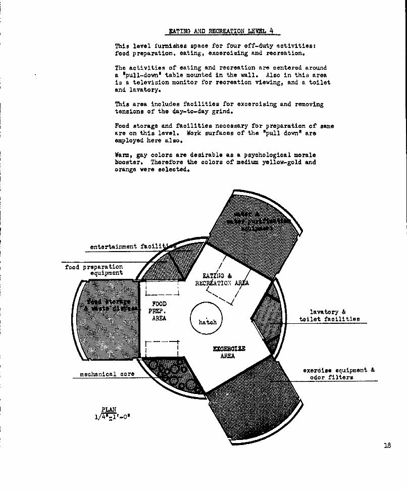
EATING A4D REOREATION LEVEL 4
This level furnishes space for four off-duty activities:food preparation, eating, exoeroising and recreation.
The activities of eating and recreation are centered arounda "pull-down' table mounted in the wall. Also in this areais a television monitor for recreation viewing, and a toiletand lavatory.
This area includes facilities for excercising and removingtensions of the day-to-day grind.
Food storage and facilities necessary for preparation of sameare on this level. Work surfaces of the "pull down' areemployed here also.
Warm, gay colors are desirable as a psychological moralebooster. Therefore the colors of medium yellow-gold andorange were selected,
entertainment fa
food prparation/equipment EATZNG &
PPMP. lavatory &.AREA hathtoilet facilities
AREA
mechaics.exerise equipment &mechaicalcoreodor filters
PLANT: '0

aomputers&
T leetrin ootefor solar olleoor a"elocaATteN
one of tepod. ...MIORING
mechanical 0ore
COMNIOATIONS AND OBSERVATION LEVEL5
This level being located in the uppermost section of theshelter will provide for all communications and electronicoperations. It will also provide for limited observationvia inflatable# polarized *bubbles* and telescoping seats.
Three stations are provided thus duties of a monotonousnature can be easily exchanged.
Controls and operating mechanisms for the solar collectormounted immediately above the oommnionlations and observationlevel are located in this area. The heat exchanger andturbin6 associated with the solar collector are located inone of the pods.
Dark, non-refleotive colors are most suited to monitoringelectronic equipment; thus the selection of flat black anddark, olive green was made.
19

THEORETICAL ADVANTAGES OF THIS CONCEPT
1. Elimination of time-consuming and complicated assemblyof shelter.
2. Automatic expansion, pressuriation and testing of shelter
prior to occupancy by crew.
5. Automatic and efficient leveling procedure.
4. Complete segregation between area, each acting as an air-tight compartment.
5. Oomplete utilization of transporting package.
6. Minimum site preparation
7. No excavation necessary.
8. Readily adaptable for future expansion of up to a 54-manexpedition.
9 Easily contracted and moved to another site.
10. Relatively easy effecting of emergency repairs.
20

21

,=22

23

24

iIEIiSLI ?.25

26

44
'77Z7

I

IZ9

q4I
30

31

32

!I
1A!f
Ito:

77- lk
, .
- 4 1

LUNAR SHELTER CONCEPTS
byThomas W. Berkhouse, Ind. Des. 163Frank E. Conboy, Ind. Des. '64Philip J. Franz, Arch. '64garnet S. Hoffmann, Arch. '64
1. DESIGN PHILOSOPHY
The concept of the lunar shelter is bssed on expandable
prefabricated structural module units of housing. After these
individual units have expanded, the micro-encapsulated foam
reactants, which have been made to adhere to the inflatpble
structure, are activated by melting away the capsule covering.
It would seem wasteful to spend valupble time assemblin7
a complicated shelter when time could otherwise be utilized
for accomplishing the proposed mission. Therefore, a simple
lunar shelter erected in s minimum of time and work is an
integral part of this design philosophy. The high cost per
pound for this shelter dictated the possible use of all parts
of the rocket ship.
Another phase of our concept was to provide for conditions
as close to those on earth as possible. As opoosed to the
buried shelter where man cannot relate himself to te exterior
form, this lunar shelter with its four individucl, definable
shapes provides this important relationship of experiencing
the external as well as the internal space as man does on earth.

2. PACKAGE AND ERECTION TECHNIQUES
The package techniques employed are designed to contain
the four huts in the hull of the space ship along with the
solar reflector, supplies and eouipment necessary to sustain
life in and around the shelter. A unique packaging feature
is that the four shelter huts are able to fold to a height of
38 inches each and still have all the eouipment contained within
the hut thus eliminating the job of transporting furnishings and
equipment into the hut after expansion.
The first step toward complete erection of the shelter
is to remove the nose from the space ship and lift the four
huts out of the space ship hull with the lunar roving vehicle.
After the retro-rockets hove been removed, the huts Pre "plugged"
into the hull of the ship. The next step is to remove the
solar collector and drop the movable sides of the upper 23 feet
of the space ship hull, thus forming the protective ceiling
over the huts.
The huts are expanded by internal air pressure and then
foamed in place.
The space left between the structural members (space ship
hull) is filled with balloon-shaped foam.
After everything is in place, lunar dust is piled on top
of the roof. A lunar "stockade" is formed around the huts to
afford protection from radiation and micrometeorites. The
height of the lunar dust "stockade" walls and the ceiling line
determine the angle of light and radiation permitted into the
stockade.
36

3. STRUCTURES AND MATERIALS
The structure in the individual expandable huts is first
provided by interior sir pressure and then by activated hard-
ened foam.
The 34 inch bases of the huts are of a double wall construction
of the same type as used in the space ship h'll, while the upper
inflatable membrane is covered with micro-incapsulated foam
reactants. After the huts are positioned in place and inflated,
the capsules are melted away and the foaming action is initiated.
The structure in the ceiling oovering of the stockade
is made up of ribs of the space ship hull. At landing time
these ribs form the upper 23 feet of the shell of the space
ship hull. After the huts are in place, these ribs fall away
on hinges at the lower ends. These ribs are held in a near-
horizontal position by tension rings, and the voids left between
the ribs are filled with balloon-shaped foam. The lower 12 foot
portion serves ap the central structural column for the umbrella-
type stockade ceiling.
Lunar dust is used as a protective covering on the roof
of the stockade and by forming walls around the lunar shelter.
4. FlOOR PIAN ANALYSIS
The lunar shelter is composed of sn outer stockade wall
which provides for a protected exterior space surroundina the
huts. The reecon for this space is to allow the men to exper-
ience the shape of the hut and relate themselves to both the
exterior ns well as tl9 interior of the shelter.
37

The shelter pror[er is entered throug~h the center core of
the lower 12 feet of the space ship hull. By entering the
central core, one first steps into an airlock which contqins
a shower to aid in decontamination of the space man's suit. The
central core also contains storare compartments for lunar
probing equipment and suits.
In the 5 feet 6 inch space above the central core, is posi-
tioned the central water supply system and mechanical enuipment.
From the central core one may enter any one of the four
individual room huts. By placing different activities of lunar
shelter life in different room huts, a condition as nepr to earth
living has been provided. Each room hut contnins its own air
supply.
One hut contains food preparation equipment as well as dry
food and refrigerated food storage. Another hut contains
recreational and conference facilities while another contains
the laboratory equipment. The fourth hut contains the sleeping
and infirmiry facilities along with personal clothing and
toilet facilities.
The solar collector is centrally-mounted over the lunar
shelter.
5. ENVIRONMENTAL PROTECTION
Environmental protection is achieved through a series of
lunar dust snd foam layers on the different shelter parts.
The outermost protection is the lunar dust stockade walls.
The umbrella roof of the shelter is made up of 5 feet of lunar
dust, 2 feet of foam and structural ribs of the expanded space
ship hull.
38

The lunar huts themselves offer additional protection
with their structural foam skin.
6. INTERIOR FURNISHINGS AND EQUIPMENT INTEGRATION
All furnishings and equipment will be packaged in their
places of use. All furnishings in the huts will be built in
and expanded into -!sce when the huts are expnnded. During
flight these furnishings will be packaged in the 30 Inchs of
uncollapsable hut.
7. STATISTICAL INFORMATION
Areas and Volumes
Unexpanded Hut - 156 sa.ft. - 467 cu.ft.Expanded Hut - 156 sq.ft. - 1250 cu.ft.Central Core - 175 sq.ft. - 1400 cu.ft.Mechanical Equipment - 175 sq.ft. - 960 cu.ft.
Lunar dust required to build stockade - 47,760 cu.ft.
8. THEORETICAL ADVANTAGES OF THIS CONCEPT
The advanta es of this concept are simplicity in assemblinT
high ratio of volume to package volume of built-in eouipment
and furnishinq, and the personal relationship of the exterior
to the interior shape by the individual.

7' 1
CEE=D=
4o

41

342

I
42A

mll
U
Id-C6 Ukuw
43

1. ~
92 ,~;1~w
~~1~
~
_ I
-~ I
LL
~L.I?
-I
~ ~' I-ICI- --
~ LUaU~
2~~wL'I~ ~ -
1I~*
Vp
44

La
T"X"
45

46

4

LUNAR 3HI!LTER CONCE~PTS
by: Do Baum, Howard (Ind. Des. '63)
Vlells, John (Arch. '64)
Wyler, John (Arch. '64)
Telton, Robert (Arch. f64)
48

DESIGN PHILOSOPHY
The approach to design was based upon certain critical,
but fundamenta, criteria. This shelter had to be a
self-contained unit for nine men for thirty days, with
the ability to satisfy both physical and mental desires.
Due to the conditions of launching a vehicle out of
earthts gravity through the cold voids of space onto
the lunar surface, it became necessary to conceive
a shelter both structurally sound and light in weight, and
with the ability of functioning as a shelter on dropping
to the moonts surface. For these reasons, the package
casing will be the structural units with the whole
shelter being opened automatically, producing a fixed
environment into which the men can escape.
In doing this we made certain necessary assumptions;
'whic,in the future will have to be proven before
this concept could become functional. The first and
most necessary is that the men, the lunar vehicle,
and the shelter will arrive in different rockets but
will land in very close proximity to each other.
PACKAGE AND ERECTION TECHNIQUE
The rocket will be sent directly from earth with
a lunar package thirty-five feet in length by fourteen
.fe:e six inches in diameter. The upper five feet will
house pod rockets with adjustable legs capable of securing
the rockets in the vertical position. This upper portion
49

contains the solar reflector, heat transfer equipment,
communications equipment, and television cameras.
This tower-like structure will also act as a gantry
for lowering the thirty foot shelter( with the aid of
the lunar vehicle) into the appropriate horizontal position
in a hole produced by explosives fired from the descending
rocket. At placement the package would automatically
be split open, separating into equal halves ready for
habitation. Leg-like structures will then level the
shelter in preparation for covering with lunar substance.
All cables and lines would be already connected to the
gantry. This whole procedure would take a minimum amount
of time saving the men for more useful research.
STRUCTURES AND MATERIALS
The lunar shelter is to be completely prepackaged,
supplied, and built on earth using the capsule shell
of the package as the structural members. This shell will
be filament-wound asbestos-phenolics. The cyl! trical
shell will fuse into equal halves using silcone -
idfsulics to separate the sections nine feet apart,
with solid insulated folding partitions expanding
simultaneously with the division of the shells Suarapteeing
always an earth-type environment within the station.
50

FLOOR PLAN ANALYSIS
The layout selected is based upon the necessity for
individuality of function. The shelter therefore has been
sectionalized, helping to ensure safety measures to the
adjoining areas. The two-floor arrangement produces the
most efficient uses of the existing cubic footage.
On entering the shelter, it is necessary to pass
tnrough the air looks and adjoining dressing area, then
into the circulation area where the control and communication
console and the elevator are located. The upper level is
assigned to work and research, while the lower contains
the living and sleeping area4 This creates an atmosphere
commensurable with one's proclivity to earth.
ENVIRONi'4,-TAL PROTECTION
Due to the tremendous environmental difficulties, it
became necessary to shield the shelter from direct contact
with the outside. This shield is basically designed to
protect against radioactivity, but also provides protection
against meterorite bombardment. The shield is based upon
using lunar materials rather than having to carry materials
from earth. The solution most reasonably derived is to
place the shelter below grade insuring a constant temperature,
and, after covering, yielding protection against radio-
activity and meterorite.
INTERIOR FURNISHINGS AND EQUIPMENT INTEGRATION
All interior equipment is prepacked and ready for use
before leaving earth. The equipment has been arranged
51

to afford accoustical isolation of each function. Extraneous
noises therefore will be reduced to a bare minimum. All
furniture selected is light weight, folding, and with the
capability for multi-purpose use. All sitting areas wil.
be aluminum frame with nylon webbing and magnetic legs
for greater stability. Color selectim has been pointed
toward insuring high mental stability. Besides this,
each man's equipment will be individually colored. The
over-all appearance of the interior will be bright with
a multitude of colors.
STATISTICAL INFORMATION
DESCRIPTION AREA VOLU1E
Upper LevelAir lock 24 sq. ft. 150 cu. ft.Changing area
(including spacesuit 1 so, ft,. 575 Cu. ft.storage) .
Exterior equipment storage 25 sq. ft. 150 cu. ft.Thermal control equipment 70 cu. ft.
Circulation area 63 sq. ft. 430 cu. ft.Elevator 25 sq. ft.Control panel 49 sq. ft. 275 cu. ft.Emergency power 90 cu. ft.Laboratory 350 sq. ft. 2100 cu. ft..
(including benches)
Lower LevelSleeping area
(including storageand beds) 150 sq. ft. 1125 cu. ft.
Air storage (two) 250 cu. ft. eachCirculation 63 sq. ft. 450 cu. ft.Elevator 25 sq. ft.Toilet area 25 sq. ft. 175 cu. ft.
52

Waste purification equipment 125 cu. ft.Air purification equipment 125 cu. ft.
Living area 110 sq.ft. q25 cu. ft.Food storage and preparation 200 cu.ft.First aid and study area 25 sq. ft. 175 cu. ft.Recreation eqiiipment ,and storage 27 sq. ft. 175 cu. zt.Air storage 150 cu. ft.Water storage 150 cu. ft.
THEORETICAL ADVANTAGES OF THIS CONCEPT
This concept has many advantages over the more
idealistic presentations normally associated with
space research. Here are just a few of this concept's
more pronounced advantages: (1) It yields a high percent-
age of efficierM of over-all volume-to-package weight.
(Every portion of the lunar package is utilized).
(2) it is rather easy to increase volume with a minimal
increase in weight. (3) The packa-e is "self-constructing"
(decreasing building time immensely because everything
is prepackaged, self-sealing, and ready to use on opening).
(4) It also would be very easy to design a colony around
this space shelter by merely connecting entrance tubes
to a multi-shelter air lock.
The simplicity of design, construction and
circulation all illustrate the reason that this concept
Is essentially the most advantageous for the first
lunar shelter.
53

I X T I ft 10 ft V I w D E 9A UN W E tS W LE V LEA YI Lt 0N
L~~~~~~~~., A
54

P',~
AMY":S
14", P~
1, 0~
~~W A-'
55

aP k
00
56

al 4
Vt
.101i11-
~I' - 'I * A'57

-44
UPP ER LE VEL PLA N
58

-VA..
. I
59
r-7ALI
11OW j,;
;i
V6
74

IN
.77
MMI
A'

LUNAR SHELTER CONCEPT
Gene Brethauer Architecture '64Lee Coburn Architecture '64Mike Proffltt Ind. Design '64Stan Waechter Ind. Design '16
DESIGN PHILOSOPHY
The mission, of which this shelter is a vital
part, to establish a manned exploratory base of op-
erations on the Moon will be subject to hazards and
harsh demands indigenous to space travel and Moon en-
vironment and will, therefore, tax heavily the minds
and bodies of the crew.
We feel this taxation must be balanced by use of
a shelter on the Moon providing adequate, at least,
food, rest, work and recreation to restore and maintain
the physical condition of the men during the mission
and for the return trip to Earth.
Our objeotives then, were to design an easily
erected, compact and yet spacious, complete and
reasonably comfortable shelter.
PACKAGE AND ERECTION TECHNI4UES
Our solution took shape as a self-contained, semi
self-erecting unit requiring virtually no manual labor
for exterior set-up and very little for the interior.
62

LUNAR SHELTER CONCEPT
Upon arrival, the Moon vehicle using a portable
crane will remove the shelter package from it'm booster
rocket and transport it to the erection site, Then;
i.Remote controlled latches release the storage
compartments forming the upper missile body
2.The floor sections forming the lower missile
body are released by explosive bolts and swung
downward exposing the inflatable shelter.
5.Canned "atmosphere" shapes the inflatable section
of the shelter, followed by introduction of gasses
into the wall cavities of same activating and
rigidizing the foaming plastic placed there during
manufacture. Noxious gasses resulting from the
chemical reaction are vented to the outside via
small vent holes provided in the outer skin.
4.The umbrella-like solar reflector may then be
raised to the top of the elevator-airlock shaft
freeing the elevator capsule for use.
The shelter may now be entered and work may progress
inside as well as outside (in the space of approx. one hour)
5.The exterior of the shelter is now covered by
ten feet of Lunar dust by use of the Lunar vehicle.
The unfolding of the solar reflector completes
the setup and the shelter may swing into operation.
63

LUNAR SHELTER CONCEPT
STRUCTURE AND MATERIALS
Since the entire structure is prefrabricated, there
is nothing for the crew to construct on the Moon site
save the remote shelters which are strictly optional.
The central core assembly is basically an aluminum.
space-frame covered with an aluminum skin - the spaces
between uprights being filled with polyurethane foam.
for rigidity and insulation. The elevator capsule and
solar reflector base have their outside diameters coated
with "Teflon" to prevent sticking in the center shaft
before air is introduced to provide a bearing cushion.
Utilizing the inherent structural strength of
plastic foam as applied to a dome shape, the inflatable
portion of the shelter is constructed as a sandwich-
that is, it consists of two layers of flexible skin
spaced apart by cross hairs 'a la Goodyear "Airmat".
The cavity between skins is filled by the foam as
it expands. The foam material is laminated to the insides
of the skins during assembly.
This construction allows increased space without
proportionate increases in weight.
With the shelter inflated, gas is introduced to the
wall cavity via tubes built Into the wall, and the chem-
ical reaction expands and rigidizes the foam making the
64

LUNAR SHELTER CONCEPT
structure self-supporting and able to support the loaa
of Lunar dust to be placed upon it.
The central core supports the remainder of the shel-
ter including the solar generating unit and reflector.
FLOOR PLAN ANALYSIS
By creating a centralized circulation area, a log-
ical. room configuration developed. From this area, all
rooms are eaiily and readily accessible.
Water and food storage is located near the greatest
need.
Airlock doors slide to the side to avoid being hit
by the descending elevator capsule.
ENVIRONMENTAL PROTECTION
Site conditions;
1. An existing crater may be used.
2. A depression may be made by explosives or
by the Lunar vehicle.
.3. The shelter may be erected on a flat open
site.
In all three cases the shelter would be covered
with ten feet of Lunar dust for radiological and
meteoroid protection.
65

LUNAR .RELT7\ C4.'CEPT
Protection at the top of tre elevator shaft is
achieved by thick shielding within the solar reflec-
tor base and by shielding in the walls of the entrance
cone.
Additional protection is available to field work-
ers in the form of emergency shelters constructed (as
&n option) from the storage comoartioents from the upper
section of the shelter package.
INTERIOR FURNISHINGS AND EQUIPMENT INTEGRATION
The majority of the interior furnishings will be
pre-positioned during prefrabricaton and will be of
construction similar to the inflatable walls- namely
plastic foam -and are actuated by a special gas inject-
ion machine.
A number of moveable furniture pieces of similar
construction are also used.
Additional prefrabridated units for cooking, re-
frigeration, etc., are small and easily carried to
position in the rooms. The main refrigeration unit is
built into the central core above the bottom floor and
functions also as an air purification device. It is
accessible from the elevator shaft should repair be
necessary.
Adequate facilities are provided for bathroom,
lab., sleeping and recreation (music, reading, gym-
nastics ) and meditation.
66

LUNAR SHELTER CONCEPT
THEORETICAL ADVANTAGES
Easy rapid set-up of this shelter will allow the
crew to establish operations very quickly and with a
positive minimum of exposure to the hostile Lunar en-
vironment.
The livability of this shelter will promote a
continued high level of moral and physical fitness
with a correspondingly high degree of efficiency in
evidence in the performance of the crew.
The obvious advantages of prefrabricated airlock,
air-tight doors, plumbing system, etc., coupled with
excellent strength and acoustical properties of the
foam plastic dome (not to mention the spaciousness)
are some or the merits of this concept.
STATISTICAL TUhIZTTON
Dome height (inside) ........... Max. 131-O1,9in, 81-011
Circulation area ............ ......78 sq. ft.Physical Exercise area...........i0 " "
Recreation area .................. O " Chapel area............ .......... .18 " "
Laboratory area ............ .... 98"Sleeping area .................... 105 " "
First Aid area. ........ . ......... .98 IKitchen area ..................... 130 If
Bath area ......................... 36 I f .5torage area ..... ................... 40 " "
TOTAL AREA 1043 sq. ft.
67

68

fIMPI,,
69

70

VI 1 14 Ll4 10S1*A
7 WAL7L VAMO 21 I.P14G P*nn'l 2? FIR1~1 71064114I P)U P -LA4 &0 V r- ... 0 .hs,
M o. PWtib I'lT E-)9 109 IltWiuG u,,
7 CN VFLL [ L 2
0 OM . cA . Z!)
If P2.o.~~oco aPLA 5?~ lapo *#Lv )tA.Io~ ,r 4
8 .3i A- t9 Az . t, v A? .......,~ "i f 0 I ~ 0 0 ~ l04 310
r 4" 7to~~o . L IAIII L .
r,-. .fim 31 w,.v ',71

lw' R.10. w
Hoow-" To lZiLciv, &.V04MLV C>uw
IeAl-r V-,
T
LK NAL 64 0r-'Sl[: C px To V Cuu
TypiorAL

IWLO. WAL
73

-2
LU a; :z~LJ
9 l 1
\> '-W 2L O
211: aofl L
7. LL a ll
44

Llw12 b
I bc L- --
K] fLi
m 75

AN 4,dj~t iLAT
16

_ -. ....
77

jj
C MMUIJICTCI5 I jL 0C,( Y UN Miwml- AMIL05I%
78

779

LUNAR SHELTER CONCEPTS
H. Goerke, Ind. Des. , '64
H. Rominger, Arch., '64
J. Buchman, Ind.Des. , '63
J. Helgeson, Arch. , '64
J. Blackwood, Arch., '64
1. DESIGN PHILOSOPHY
The philosophy involved in designing a lunar shelter is little
different than the philosophy involved in designing an earth
structure. Lunar design is, however, much more limited.
We are forced to reproduce the earth's atmosphere, provide
for servicing; or in other words, build a self-sufficient struc-
ture in a completely alien environment.
We have attempted to make our shelter a pleasing living space
and at the same time a compact, highly functional structure.
We have attempted to present a design solution which is func-
tional psychologically as well as mechanically.
80

2. PACKAGE & ERECTION TECHNIQUES
The structure is packaged within the required cylindrical volume:
length of 35 feet, diameter of 14 feet. The package itself is split
longitudinally into halves and utilized as an entry canopy at the
two air locks. The exterior equipment is packaged within a second
cylinder that is 4 feet in diameter and 22 feet in length. The cy-
linder fits through the central air lock and is anchored to one of the
expandable entrance tube doors.
Steps in process of erection:
a. The package is lowered from the rocket and
positioned on a relatively smooth area by the
vehicle.
b. The exterior package is removed by the vehicle
and placed near by.
c. The cylinder is hydraulically leveled.
d. The shelter is then expanded as follows:
(1) Cylinder is depressurized.
(2) Entry tubes and bottom of the cylinder
are released.
(3) The shelter is repressurized slowly
and allowed to expand. The exterior
81

equipment is pulled forward in one
tube as the shelter expands.
(4) The shelter is depressurized.
(5) The floor is allowed to solidify,
and the exterior equipment cylinder
is removed by the vehicle.
e. The canopies are erected, and the conduit is laid
for the exterior equipment.
f. The exterior equipment is erected, and the
shelter is covered with lunar dust.
g. The interior furnishings and panels are put in
place.
3. STRUCTURE & MATERIALS
The structure is essentially mechanical. The hinged joints
would be under atmospheric conditions at times of expansion and
then released in order to rigidize.
The interior panels are to be 3 inches thick porcelain enamel
panels, perforated and insulated.
The floor is two layers of flexible plastic, reinforced with cables
and foamed in place plastic between the two layers. The cables
82

would also act as spacers, insuring the proper degree of expansion.
The exterior walls would be at least double thickness cavity walls
to provide for perimeter heating and cooling.
The structure is made up of 3 transverse frames stabilized by the
end air locks, the exterior skin and the floor.
4. FLOOR PLAN ANALYSIS
Structure and packaging have dictated to a great extent the layout
of the plan. The living area of the structure has five major areas.
The recreation area has the least necessity for built-in equipment,
therefore, it is centrally located. All major equipment is built
into the wall and ceiling cavities. The other four spaces (kitchen,
sleeping, toilet and sick bay) relegate themselves to their posi-
tions due to their size. The primary air lock and the lab areas
are adjacent, thereby placing the maintenance and scientific as-
pects of the shelter in one area. A secondary recreation and exercise
area is included in the lab section in order to isolate potentially
noisy activities. The acoustically-treated partition walls and re-
silient flooring system should decrease the transmission of sound
and vibration to an acceptable level. The panels would act in the same
manner to stop reverberation.
B3

5. ENVIRONMENTAL PROTECTION
The structure is covered with 10 feet of lnar dust to protect the
men and ship from meteorites and harmful amounts of solar
radiation.
The structure maintains an atmospheric pressure of 10 psi.
The air is dehumidified, filtered, deodorized, regenerated and
then recirculated.
Temperature is maintained by radiating excess heat (black body)
during the day cycle and utilization of the energy stored by the
solar collector during the night cycle.
The shelter is divided into two airtight sections, each capable
of maintaining pressure and temperature until repairs could be
made. Each section is serviced by an exterior air lock. Water,
air, etc. are compartmented so that a failure of any one com-
partment would not seriously affect the total supply. Extra space
suits are stored in the top cavity of the emergency airlock for repair
work. The airlocks act as decontamination points.
6. INTERIOR FURNISHINGS & EQUIPMENT TNTEGATICN
All interior furnishings, with the exception of a few chairs, are
built into the walls. The panels fit against the exterior walls
during flight and can be easily folded out after expansion of the structure.
84

The mechanical equipment is built into the ceiling cavities. All
generators, compressors, etc. , are to be suspension-mounted
to decrease vibration. Tables and couches fold or slide out of the
panels and walls.
7. STATISTICAL INFORMATION
a. Volume and area by section:
Laboratory #1 760 cu. 39 sq.
Laboratory #2 760 cu. 39 sq.
Main Recreation 1,010 cu. 112 sq.
Secondary Recreation 810 cu. 90 sq.
Kitchen 600 cu. 4Z sq.
Toilet 350 cu, 12 sq.
Sleeping 600 cu. 42 sq.
Sick Bay 350 cu. 14 sq.
Ceiling (Mechanical Equipment) 1,085 cu. - sq.
Area for Exterior Gear 360 cu. 40 sq.
Air Locks (Mechanical Equipment) 672 cu.I - sq.'
Extra Space Suit Storage 224 cu. - sq.
Passage and Decontamination 236 cu. 32 sq.
TOTAL 6,635 cu.' 464 sq.

b. Major Equipment Included:
(I) Water storage and system for reprocessing
wash water, system for heating and cooling
water and system for recovering water from
waste.
(2) Air storage and system for purification,
circulating, deodorizing, regenerating,
heating, cooling, compressing, and main-
taining the proper pressure of atmosphere.
(3) Storage batteries and solar collector to
provide energy. Electrical system to ser-
vice stove, refrigerator, lights, radio, etc.
(4) Heating and cooling system.
8. THEORETICAL ADVANTAGES OF THIS CONCEPT
a. The structure requires no intricate exterior assembling.
b. The structure is compact, requiring a minimum amount of
power, and atmosphere.
c. This concept could be used as a module by attaching
similar shelters (groups of 4) at the expandable entry
tube.
86

1-4
IX
~'a mm .. wk
111: ~ ~ c mu JillV4" 87AL&Ye r

SH14LTER OPLONIN
O~tNING88

5dJILT. tN r~9uvp.
SUILT.INq)5-PA M
5ECTION 1-1- SEC-TI.O) Z-Z!
CVL&lZ 1R.W6 bNZI4 CQ5
--------- I~ -4 5 ~ A H
su iL-F , 4I~e ia e utirtA
S(ATa TOSWTI
1-~gt C. E LJLP
_____ ___ -1 4LD
A6~uLP. tLcxr.v
PACKAGING1/8 SCALE 89

9 V
4% '1 ~ *' 2 ~a*
-A 1 1 , 4
a- U,
~ 4: Sta .~, %.e
90

p.91

9Z

93

Al
4,WAwl
-1w 7
94

95

LI
96

97

98
A
99

100

101

MM OZ

103

104

LUNAR SHELTER CONCEPTTeam #7
1. David G. Heclanan I.D. 632. Chang G. Kim Arch 643. Martin H. Pitstick I,,D. 654. Robert Turner Arch 64
I. DESIGN PHILOSOPHY
In order to make clear the concept, a few assumptions
will be made:
1. 6" minimum of lunar dust and rubble on the surface
of the moon.
2. Atmosphere consists of a hard vacuum.
3. Temperature varies from -250OF to /225OF in a per-
iod of 4 hours or more.
4. Water as such will not exist.
5. Lunar dust and rubble will not be a radiological
hazard.
6. Assume 10' of dust for maximum protection and 2
feet of dust for normal nrotection.
7. Men will be capable of working outside for a per-
iod of not more than 3 hours.
8. Assume that the space-ship will be launched from
a manned space base.
9. Assume that the Lunar Rubble will easily suppart
the weight of two units without undue settling of
dust.
Criteria for Design
The shelter -uust be nrotected f rom materials and radi-
ation. In case of ouncture, the shelter must provide
adequate Drotection from total decompression. The
shelter must provide for the socialogical and phycho-
logical needs of the men. The shelter must be easily
expanded in order to include more units.
105

Our team decided that it would be most advantageous
to use a module as the basic unit of the shelter. In
this way, the shelter could most easily be expanded.
In using separate units, adequate sound nrotection
could be achieved without the use of mechanical de-
vices.
The erection of the units should be done (for the most
part) by automation. The men would assist only in a
minor capacl.ty. The idea of phyohological well-beirg
will be greatly reinforced through the use of windows;
thereby, connecting the interior of the capsule with
the exterior. This, of course, €ould most easily be
done if the units were not covered with 101 of dust.
II. PACKAGE AID ERECTION TECHNIQUES
A cargo sbip will land on the moon after being launched
from the space station. The units themselves will have
been packaged into 4 nrimary packages: The first pack-
age will contain the 3 lower units and the access tube.
The second package will contain the two upper units.
The third package will contain the solar batteries.
The last package will contain the solar unit, and black
body radiators for heat dissipation.
106

The packages will be (ronped by means of a winch.
Each unit will be attached one to the other with a
medianioally operated detonating couple. The deton-
ator will be set off by means of rip cord attached to
the side of the packages. When the cargo ship lands
on the moon, the rover will unlatch a bottom hatch
of rocket allowing the packages to be dropped by means
of an operating panel in one leg of the ship. The
weight of the packages will cause the winch to unwind.
(see board #1)
As the bundles hit ground, a crew member will detonate
the couples. The rover will pick up the packages and
carry them to a pre-nlanned point. By means of the
rover the packages will be pulled apart.a4.,.d the units
will begin to inf.ate. By the time the rover has
pulled the units apart, they will have become fully
inflated and dropped into position for sealing. (see
slides) The right hand unit will be attached to cen-
ter unit by means of a hinge in the floor. The left
unit will be attached to main unit by means of a hinge
at the top of door. The main access tunnel will be
hinged to the top of air lock door. When the honeycomb
walls are injected with carbon dioxide, a rigidizing
action will go into effect. The skins will bond
to the exoandable honeycomb by means of an encapsulated
epoxy resin plastielser.
107

The sealing action will be as follows: The rover will
exert an upward pressure at the base of the right unit;
thereby, causing a vacuum welded seal at door and in
the floor. At this time all necessary mechnical con-
nections for air, water, power, and corrmunications will
be made (see detail d4, board P). Moon rover will
now nroceed to doar hinge between center and left units.
By exerting iipward pull at hook above hinge a vacuum,
welded seal at door frame and in the floor will take
place. The main tunnel will be attached in same man-
ner, and droped into -osition to seal. Lower units
are now ready to be occupied. The moon rover will now
start the covering operation.
Men inside center unit will now actuate the expansion
and rigidizing p)rocess in the vertical access tube.
By this time the second bundle will have been separ-
ated from winch and be ready to be nositioned on pile
of dust above lower units. The rover will null up-
ward unit .)ackagc apart oentering it ovr access tube.
Connecting air lock of the uner units will be inte-
grally attached to the recreation unit and hinged at
the top of the door at the laboratory unit. After
uper units have been properly positioned over the
access tube, the sealing operation will commence as
108

follows:
Exerting uiward pull above d-)or at laboratory unit
will cause hinges in floor and Coor to seal.
Note: By this time the upper units will have been
fully inflated and ready for the main sealing operation.
By means of contact pressure-, an encapsulated epoxy
resin plasticizer will j oceed to bond the outer skins
of units together (see board #8, detail #6). A foamed-
in-place tube will form a seal between the upper units
and the access tube and upper emergency air lock. Ac-
cess tube and air lock will now be ready 15r service.
Connection of mechanical equipment will be done by
crew members at the top of the access tube. (see board
8 detail #8).
Note: See board #8, detail 45) for vacuum-welded seal
at door.
As soon as connections have been made, the upper unit
will be ready for occupation. The rover will have by
this time completed a two foot layer of dust, above the
floor line of the upper units. (see board #7 also
board #8 detail #2), ksee detail #1 for walls of lower
units). The rover will fill the 2 foot space between
walls of urper units with dust. By this time the last
bundle will have been lowered and disconnected from
winch. The rover will unrackage and set up foamed-
in-place 40 ft. diameter solar collector and attached
generator, and set up the black body radiators. Radio
109

antenna will be part of solar collecter. The sampl~s
buckets will be left in rocket. This completes the
moon shelter erection.
Time required will be aproximately 5 hours. The s amples
buckets will be foamed up around a nile of samples
and hoisted into khe base of rocket. Power for winch
will come from the solar generator. A rocket in this
case will serve as a cargo ship in that it will trans-
port the shelter to the moon, and carry back samples
to the space base for further study.
III.STRUCTURE AND MATERIALS
As has been mentioned before, our design concept em-
ploys modular units. The material for walls will be
expandable honeycomb attached to skins by means of
an epoxy resin plasticizer. The floors of the units
will be prefabricated on earth and serve as protection
at the tops and bottoms of the bundles during the flight.
Floors will be made of a 5 inch styrofoam sandwiched
between 2-12 gauge sheets of aluminum. "T" bars 3 feet
on center will further strengthen the floors, At the
time of fabrication, all interior walls, fittings, and
all mechanical units will be fastened to the flocrs.
Shelves other than base cabinets will
110

be attached to the walls. Wall skins at these noints
will be reinforced. Interior walls will be secured
to floor and to ceiling. When being fabricated the
exterior skins will be nulled down ovei, the
equipment and fastened to floor by means of a clamping
bar, (see board f 8, detail #1 and 2)
The outer skins of upper units will be coated with a
white aluminized finish. This coating will reflect
most of the solar heat radiation. The two foot fill
space will act as further insilating protection against
the severe Lunor temperature variations. The units,
by means of access tunnels, can be positioned in a
number of different ways. (see board #6)
We chose the vertical s lution due to the fact that
less area of dust had to be gathered in order to give
adequate Drotection. There will be a 2" clearance
between the top of the vertical access tube and seal-
ing slot of the unpor units to allow for settling
(see board #8 detail #8)
The upper units will be equipped *th adjustable
18" in diameter double pane oolarized windows. In
the event of a solar flair, all windows will Immediately
rotate to black position.
The mouth of the main tunnel will be protected by
an eight foot high mound of dust.
1)1l

IV. FLOOR PLAN ANALYSIS
A Lte1lon is called to boards #2 & 4.
The lower units will contain all necessary equip-
ment in order to sustain life in case of an emer-
gency. The unitq are nlanned so that privacy from
noise and human activity will be shlelded from the
sleeoing area. Also contained in the sleeping
units will be the toilet, lavatory and shower.
In case of sickness, one of the sleeping areas will
serve as an emergency sick bay. ( see board #3 )
The center unit will contain the major mechanical
equipment facilities: air rejuvenation & power sup-
ly, emergency communication systems, and waste re-
juvenatL on and disoosal equipment. Decontamination
and the main space suit storage area is connected
with the entrance of the air lock. This area will
be the :.ivot point for all circulation. The Kitchen
Unit will contain oxygen and water storage. This unit
will also contain tools for minor repairs, as well as
food prenaration and facilities for food storage.
The two upoer units will be used for the laboratory
group and recreation ai~ea. The windows in the labo-
ratory area could be used for observation of the lunor
surface, and observation of the earth and other planets.
liz

Notice that all equipment is placed around the units
allowing maximum circulation space in the center.
Just across the airlock is the recreation area. We
have allowed more space here because we thought that
this would be the area where the men could relax. It
could also be a place where one can do a mild 5 rm of
exercise in order to keep physically fit for the at-
mosphere of earth. As many as 6 persons might use
this area at a time. The recreation unit can be used
to show movies, read books, and play mildly active
games.
Windows are also nrovided here, not so much for obser-
vation, but as a visible connection with the moon.
This is necessary in order to keep up morale and pre-
vent a fear of a cave-like existence.
V. ENVIRONMENTAL PROTECTION
In order to keep the pressure up in the units, a pro-
cedure had to be planned into the shelter. The re-
suit was a series of pressure tight doors connecting
the units. These doore must be closed at all times.
Therefore, all doors except the vertical access hatch
will have automatic closing devices.
1.3

In case one of the upper units is punctured by a small
meteorite~it will normally be stopped by the dust blanket.
If the meteorite passes through the blanket, then the
dust will tend to keep the air pressure from dropning
rapidly, allowing personnel a fighting chance of eva-
cuating the unit.
If, however, a large meteorite happensto puncture the
unit, then at least the other units will remain irtact.
Puncturing the access tube will isolate the men in
the upper units, but the men below could enter the
access tube at the top emergency air lock and repair
the tube.
The most disastrous case would be if both of the
access tube and center unit were knocked out. All
of the units would be sealed off from each other.
In this case an alarm will sound in the sleeping unit.
These men will put on the three or four spare space
suits, depressurize the unit, and make the necessary
repairs. For this purpose there will be four spare
space suitsin the sleeping unit.
114

VI. INTERIOR FURNISHINGS AND EQUIPMENT
At the time of fabrication on earth, all equipment
will be bolted to the floors. The furnishings will
also be integrally built as I rt of the units. Only
the round table in the kitchen unit plus the collap-
sible stools in the mechanical equipment unit and
laboratory unit will be left loose.
All of the units will have individual air supply and
return ducts to the air rejuvenation center. This
will greatly decrease the possibility of total
decompression in all units at the same time. Heat
will be dissipated through the black body radiatc s
located just beyond the comtlex.
Power and water will alm be supplied to evry unit
through ducts, and conduits in the floor (see board#8
detail #4)
Air pressure panelsand alarms will be located in every
unit. In case of an emergenc, one will only have
to observe the panel in order to locate the stricken
area. All shelves and interior walls will be burg
from the interior walls of the shells. (see board #3)
Communications panels will also be located in every
unit.
The color scheme will be beige with spot colc' sceents.I15

Variable moods can be created through the use of light-
ing. Incandescent lighting will be used throughout.
Colors will be gold, white, pink, and blue. Intensi-
ties will vary from zero foot candles to a maximum
of forty foot candles. Lights will either be lmcated
in the top of equipment, or in metal troughs around the
perimeter of the units. All lighting will be indirect.
(For multi purnose table in recreation unit see board 0)
VII. STATISTICAL INFORMATION
Area
One Unit 154 Ft. 2
Five Units 770 Ft.2
Cubage 5,9O0 Ft.3
Total Weight 3680#.
Food Preparation 14 Ft.2
Recreation Area 154 Flt.I!
T:ilet 14 "
Shower 30 "
Tools 6 "
Comnnunication 8 "
Labs. 40 "
Space Suit 16 "
Decontamination )4n "
Air-lock 30
Batteries 8 "

VIII. TI!EOiRETICAL ADVANTAGES OF THIS CONCEPT.
The advantagos of this conceot are many. We
shall compare this method with that of using the
14 x 35 cansule.
In the first place, the ship which carries the
shelter to the moon can also be used for a re-
turn trip. Naturally some samples of the lunar
materials samples, as well as the result of many
experiments, will want to be returned to the
earth for further study. Using this concept, the
cargo will return to the space station and be
transferred to an earthbound ship.
Only 1 3/4 acres of dust will be needed to cover
the base. This is less than 2/3 of the dust re-
quired for a capsule structure. The entire struc-
ture will weigh only 4000 nounds, allowing 1000
lbs. for mare much needed equipment.
Erection time should be about the same as for the
capsule. Total usable area is 770 square feet,
much more than can be achieved from the capsule
method.
Finally, the psychological advantage of this con-
cept could mean the difference between a level-
headed crew, and a group of irritable individuals.
117

FN 74-
iL
ISwam"
' a l;7

LLJ>
VI (A
ILI.3 -,0 U 7 :r (Li- U0 L ul _jo 4:() LijL Lu .: bUJ ju; . 0 :r :r
A 'nZ<
In
r -------
otj
z ul 0
U
LU
WE 0lu l4eo >- Z LN LLJ _4L5
ZeLLLUI, D-
V)crJwx 0! lu
Dw Ujtfftr L) :j'o0,080"- uw<
U In* 't ;K U)IL i 0 1 tow

I
,i v v-4 : 7447,
1, P
0 J X,
, 7L,
7. 0 X
man
1 .77
7t-
ui*
2Z
' 7

- r ~ ~ n~77
.........

-............. ....
42

TTZ

7F
INN
C"y
mm mum-
CITA
91h
jr
IZ4

rz z IDOT
-ulZu 'aJin01
Aiat .4
jffp va ...........
J12 t2 ol4, ZP,
Ego
V;,
OtL
it J
0 ta
> -UJ
7 riW: 7
Ol:ol
luto :dl. w >:
wJan
AN-5 W-7-4 ., 3z al v ,aj -io 140 0 -L A L
le -Cvoz VJ3 , ZL-0- jQ z bl
L- -RO z0 42 0
Uj
lu Z Y:ac 0 alCf. 0 A,
LU .1 0x IL 0 Z 4u A!01 t 0i I 1 11 .:r. 0 lu 20- Z:j2'.6 0. ano:
4wo og -di v 01L IL if IL00. A 2 .,A'z 3z-,
vI m .0 -
Luull AO

77 ' 7U
bA
inru
IL 94
IP.
'ad
41
4k-001
6c, 6,
O d-A Milli"
IW
izc,

- - - - - -"- --- -
4127

128

I Z9

130

131

I 3Z

133

,+,~ .A +
r+
Ac..
'134

1 3

136

1137

138

11 3
iri
139

LUNAR SHELTER CONCEPTS
Ronald Batterson, Arih. '64.Larry Blaekman, Arsh. 164John Buloroft, Ind. Dese,64William Dushek, Arch. 164
DESIGN PHILOSOPH!
The main points of our design philosophy are
listed below in outline form:
* The shelter should be crected in the shortestpossible time with minimal labor by the crew,
* Theore should be as few moving parts in theactual erection of the shelter as possible.
* All materials and equipment transported to thesoon should be utilized to their fullest capacity.
* Due to the harsh environment of the moon andother umknown factors# the shelter shouldprovide as large a safety factor as possible.
* The design solution reached by our team is to becompatible with existing technology and be ableto be implemented in the itmodimte future.
* The shelter should ountain 4 built in aystea forsurvival if part of it is duAged.
*F For better irculation and environmental somfortpthe shelter's components should be on one level,
PACKAGE & ERECTION TECHNIQUES
The shelter is composed primarily of the capsule
in which it is transported to the moon. All equipment
and materials to be used are in place, thus there is a
140

-2-
minimal amount of labor required from the orew.
Erection technique is as follows:
* The capsule is lowered to a horizontal positionby the Moon Traversing Vehicle,
* A panel on each side of the shelter is removed(these -serve an Black Body Radiators)# and anairmat room extends on each side. (Expansionpowered by high pressure air In capsule.)
* An airzmat entrance tunnel and the solar reflector
are added.
* All airmat structures are stabilized by foam.
* Entire shelter Is then covered with lunarrubble to a depth of ton feet.
STRUCTURES & XATERIA1S
No radieal mate rlals are proposed. ihelter as
eonelvied can be built primarily with, *off the shelf"
hardware. Typical A1rraft/Roeket construction Is to
be used as main body of shelter. Aimat i,1 be used
for auxiliary appendages* Lunar rubble will be used
as protection against radiation and meteorites.
F7OOR PLAN ANALYMS
The shelter Is divided Into three main a&reas:
laboratory, sleepin/peorsonal hygiene and recreation/
eating. The floor plan has been designed to allow
141.

-3-
access to any area oe' the exterior of the shelter
without passing through another area. Through a
system of hatches, each area is a separate entity
and, in event of the loss of pressure in one areap
the other two would not be affected. Also, each
area has access to space suits and emergency exits.
Noisy equipment has been separated from sleeping and
oommunioation areas.
ENVIRONME-NTAL PROTECTION
The shelter is covered with ten feet of rubble.
This should be quite sufficient protection against
all known environmental problems.
INTERIOR FURNISiINGS & UIPFYIOT INTIERATION
All equipment will be built into the capsule.
The core wills between the labs and sleeping and
recreation areas will serve both areas. All
mechanical and electrical equipment is built into
the periphery ar~eas cf the shelter, thus utilizing
all space to the utmost. All equipment and furnishings
will be designed to stand shocks of blast off and landing
of capsule. The entrance chamber adjacent to the airlock
will be used as a preparation area for men and equipment
leaving the shelter environment.
14Z

-4-
STATISTICAL INORMATION
AIRBAS AND CUBAGE,
AREA SIZE Sa.?T. CU.FT.
Entrance chamber 8'x91x8' 72 576
Air look 8'x3'tZ' 24 192
Recreation 12x16'x8 ' 192 1536
Sleeping 12'x16'x8' 192 1536
Lab 8,xl6'x8' 128 1024
Lab 3'x3*'xB' 10 80
Totals 618 494
LUNAR MUBLE ONT SHELTER
46,000 cu. ft.
92,000 sq. ft.
2.1 Aores
THEORETICAL ADVANTAGES O0 THIS CONCEPT
* Complete use of oapsule. No extraneous materialcarried to build a shelter*
* No relocation of equipment; everything mountedin place and ready to use.
* Erection simple and fast* Labor is minimal asexpansion of capsule is handled by interior airpressures
* All movement between areas is on a horisontal plane.
* Shelter is stil able to Notion and esoaor d in the even a of pressur
r o her mishap in any of the areas.
o Shelter can be built utilizing present daytechnology and materials.
143

AV4
7M4

I1 2 11
I&It
145

LIgnT
-14

147
------ ------

14

44.
149

NX
150

WV, A
151

. V154

153

154

...... .....
155

156

,lot.
R157

158

LUNAR SHELTER CONCEPT
Designers: Donald W. Anernan - Arch. t64James J. H-oetker - I. D. '64J. Douglas Riehi - Arch. '64Chester H. Wolgamot 1 . D. '63
159

DESIGN PHILOSOPHY
The basic philosophy and design concept was to create
structure that would serve as a lunar shelter for a complement of nine men
for a period of thirty days. This concept was to embody and fulfill the
requirements set fo:rth in the Project Program with the emphasis on ease of
erection, maximum use of spaces conceived, and minimum requirement of
weight.
In meeting these requirements, we proceeded to create an
environment that not only met the functional needs of the mission, but also the
emotional and psychological needs of the men who are to function under the
adverse atmospheric conditions of the moon.
PACKAGE AND ERECTION TECHNIQUE
In the packaged state the expandable airmat is compressed
in the recess provided in the shell. Center floor, ceiling and wall panels are
stored in the recreation area. Sanitation package is in food preparation area,
and furniture and supplies are in remaining areas.
The final stage of the missile will consist of the lunar shelter
and a pod of landing or retro-rockets, circling the moon in an orbit determined
by the crew upon their landing. The shelter will then be guided in and landed
in a vertical position on legs telescoping from the rocket pod.
16o

One crewman. will leave the space ship and enter the
traversing vehicle which has also previously landed. He will then lower
the shelter using magnetic clamps as illustrated on Board Number 1. Once
the capsule is on its side, the vehicle will raise one half of the cylinder, fire
the explosive bolts holding the two sections together and, utilizing the air
pressure inside, allow the two to separate. Hydraulic jacks acting in reverse
will drain, allowing the separation process to proceed in a slow controlled
manner. The fluid in the jacks (water) will drain into the water system for
future use.
The airmat is stretched tight, jacks are locked in place and
foam is activated forming a rigid shell. The shelter is then lowered and ready
for entry.
Three crew members will remove the solar collector unit
from the shelter and mount it on the retro-pod, which was severed from the
capsule and returned to a level position.
While the collector is being erected, fellow crewmen, who
have removed their spacesuits, are proceeding to install floorpanels, place
the shower and lavatory unit, erect the dismantled walls and ceiling sections,
unpack furniture and provisions and proceed to the purpose of the mission.
Elapsed time for set down of shelter to shirt-sleeve
atmospheric occupancy, 1-2 hours.
161

STRUCTURE AND MATERIAL
The lunar shelter consists basically of two components:
a metal cylinder that separates longitudinally upon landing, and a polyurethane
foam airmat that stretches between the two sections to form the airtight outer
shell. The metal cylinder consists of an outer and inner skin welded to
Airframe sections that carry radially around the cylinder.
The walls, floors and ceilings inside the shelter are sandwich
sections made up of aluminum skins with a high density polyurethane foam,
Edges are reinforced with channels of needed load-bearing capacity, and the
floor sections have a soft vinyl coating.
FLOOR PLAN ANALYSIS
The overall design concept may be visualized as six major
functioning areas: Embarcation, Working, Recreation, Sleeping, Mechanical
Equipment and Air Circulation. Each area has been located according to its
related need for access and sound-conditioning. Exemplary of this is the location
of both the mechanical equipment and air circulation areas which are separated
from the living quarters by sound-deadening material in the floor and ceiling
panels, and the location of the high noise level labs and communications ar"-
away from the sleeping facilities.
ENVIRONMENT AND PROTECTION
The climatic environment in the capsule approaches that of
the earth's atmosphere in that humidity, temperature and air composition are
set for the ideal human requirements.
162

For psychological purposes, a cool color scheme was chosen
for the shelter. Many variances in color and hues may, however, be achieved
through the use of luminescent panels controlled by rheostat.
Protection for this environment from solar radiation is
accomplished by a covering of 10 feet of lunar dust over the capsule. Entry
into the shelter is made through a tunnel attached to the airlock and set at
an angle to the structure so that direct horizontal bombardment of this radiation
is impossible. Further protection is achieved by incorporating into the design
a double hull to decrease the possibility of rupture.
INTERIOR FURNISHING AND EQUIPMENT INTEGRATION
The shell of the structure functions not only as protection, but
also as the structural system from which all stationary interior furnishings are
mounted. In doing so, interior partitions become essentially non-load bearing
and thus are held to a minimum in thickness and weight. All equipment that
will be used in experiments and daily functions will be stored on the main level,
labs will be self-contained units, and all remaining equipment will be on the
lower level.
163

STATISTICAL INFORMATION
Area Square Feet Cubic Feet
Infirmary 58 464
Food dispensary 65 520
Recreation 145 1,160
Sleeping 58 464
Toilet 32 Z56
Circulation 50 400
Dressing 4Z Z56
Tools and Back Packs 24 192
Communication 45 360
Laboratory 73 584
Space Suit Storage 49 39Z
Decontamination Area Z4 192
Airlock 22 154
Mechanical Equipment Area 418
Storage 476
Equipment Service 1, 120
Duct Work 630
Batteries 68
Total 687 8,106
164

THEORETICAL ADVANTAGES OF CONCEPT
The major advantages of the concept are: use of the launch
cylinder as the shelter permitting almost immediate occupancy, separation of
noise levels to insure quiet areas and the integration into the design of a
double-hulled structure to further decrease the possibility of rupture.
165

(~I 12 o.i
i IT;
166

5
K. r.J;y I
U
I
I
-~ -~-~
F'U * Ii
I I
i I
Ii 1U ' I
- 5 U*1 I. Uji ~ I ! ~
U
- U V-
1I I a -U -
L~ U* 2
U I-LI LIU
167

m-
ca
C-
IJ
LLI
caa
0 m00
W ------ 0
_______168

4191
* -a
169

C3
'ha
170

,444
*171

O, /
LI
172

WNRSHELTER OONCEPTS
Lawrenoe L. Fabbre ............... ndu al Design '64
Ronald J. Kreinbrink ........ Ardhtecture '64
John S. Madzula .................. Architecture '64
H. Patrick Thornton Jr. .......... Industrial Design '64

The moon is a large, essentially spherical body which moves in
a slightly elliptical orbit around the earth. Its mean distance
from the earth is 238,857 miles, and it takes 27.3 days to
revolve once about earth. Daring this revolution, it turns exactly
once on its own axis so that it always presents the same side to
earth. We can actually see from earth 59% of its surface.
Its diameter is 2160 miles, approximately 1/4th that of earth,
but its mass is only 1/81 that of of earth; thus its density is
only .61 times that of earth or about 280 pounds per cubic foot.
From this we derive that the gravitational attraction at the moon's
surface is only 1/6th that on the earth's surface.
The environment of a building on the moon differs markedly
from its environment on earth. The moon has no observable
atmosphere. There is no haze, dloud formations, rains, or snow. The
structure is either bathed in intense sunshine or looks upon
stari, black space. The moor4 having no absorbing atmosphere can
feel tiie full force of the suns rays and become extremely hot on
one side while the other side will have qpickly radiated its heat
into space and become exceedingly cold. Any sturcture placed on
the moon must be able to withstand these extreme temperatures and
especially the tremendous temperature gradients.
The ultraviolet radiation, normally absorbed by the earth's
atmosphere, will be sufficiently intense to render panes of glass
or plastic useless as windows.
The moon is continually bombarded by particular matter:
174

Cosmic rays, charged particles, and meMir particles. Extra-
trrrestial materials exist in three forms: inter.planetary dust
which forms the zodiacal light, debris from comets or meteors,
and lastly meteorites. Micrometeorite particles occur in stoeh
at a great velocity which prove dangerous to any exposed structure.
We assume the following:
1. That the location of the building on the moon will be
fixed.
2. That the building will be constructed from materials
brought from earth.
3. That it will be a permanent-type building in the sense
that it will be occupied on a continuing basis for
several years.
Because the gravitational force is only 1/6 as great as that
of earth, a whole new field of design is opened up. It is as
if we had an exceedingly high-strength, light-weight construction
material. The reduction in gravity will influence the convective
flow of air and the rate of flow of liquids downhill. These
changes are likely to become important in our heating, power, water,
sewage, and ventilating system.
On the moon we will be able to play gravitational forces
against the air pressure forces, achieving some kind of equi3.ib-
rium which may gain us an advantage, Broad expanses of curved
structures can be used, but the whole must be held together by
some means so that the air pressure within the structure will not
blow the unit apart.
Rapid, intense heating and sudden, severe cooling present
difficult design problems. The parts of the structure becoming
175

shaded will immediately become very cold, while those in the sun
will remain heated to a high temperature. To control this heat
we feel that the method of covering the structure with existing
lunar material plus having the outer skin of the structure a high-
ly reflective material, such as a foil. The black and white bodies
which will be used to absorb and give off heat respectively,will be
connented directly with our heating and ventilating systems.
The bombardment of meteoric matter is serious but will be..
dealt with by our covering of the structure with t'he lunar material.
Assuming that the moon's surface is sufficiently solid, it
will provide mormal support for the building.
We feel that the shape of our units most efficientXy uses
the package space, module approach, area sealing devices, expand-
able approach, automatic errection, maximum safety, simplified
mechanical equipment operation and controlled noise areas.
Our philosophic ideas here explained will be further discussed
under the folloing topics.
2. PACKAGE AND ERECTION TECHNIQUES
In the packaged state each unit is supported separately.
This enables the ship to control the position of its payload;
also it insures that no one unit supports any more than its on
weight under acceleration.
The method of packaging the ship sonsists of sliding each
unit down vertical tracks to a position where it will be locked
automatically and be supported individually. Upon the completion
of packing, the nose cone is set in place. The unpacking process
is the reverse by use of the traversing vehicle.
176

Erection of the units shall take place near the perimeter of a
small crater, The site shall be graded level by the vehicle and
the air lift hole shall be excavated by the vehicle before the
air lock unit is positioned. The first unit to be positioned is
the air lock unit with the mechanical and unit connectors hinged
at its base. When removed from the ship, ';he units shall automat-
ically expand vertically and lock into position. The remaining
four units are positioned and connected to the air lock and each
other by the mechanical and unit connectors. The air lock is the
first unit to be expanded horizontally. This enables the removal
of the expandable solar collector, generator, and white and black
bodies, for their erection. The prime interest is the operation of
the mechanical equipment for the function of all units before
their final expansion.
Inflation of the air mat structure follows the operation of
mechanical equipment. This enables correct alignment and check for
air leaks in all units. The air mat and rigid panels are then
rigidized from within by actuation of pellets of expandable foam.
Upon rigidizing of all unit; a structure of stabilized lunar
material shall be poured over entire complex by the traversing
vehicle. The vehicle shall be capable of stahalizing the lunar
material with foam and ejecting this material to a depth suf-
ficient to aid the support of the remaining cover material.
The total covering shall consist of approximately 2 feet of sta.
tlized lunar material and 8 feet of existing lunar material.
During the covering process,part of the team will be in the
complex placing floor sections over the expanded area, positioning
177

equipment, wall sections, and furniture. This erection process
can be handled in stages to enable work and eat / sleep cycles
to begin.
3. STRUCMUS AND MATERIALS
The main structural component for each unit shall be a central
core or wall between rigid floor and ceiling. Additional strut.-
t=e shall be provided by a layer of stabilized lunar material.
The structural materials are broken into two main categories.
First is the rigid material which is molded and fabricated of
a high strength, light weight material. Secondthe expandable
material will consist of an integration of air mat and expandable
foam reactants inside the air mat.
We feel that this combination achieves the rigid and light
weight properties needed in this structure.
4. M W_ ANALYSIS
A. Circulation is definite and direct to each unit*
B. Each space is designed to be coordinated with its specific use.
C. Each unit space is so designed as to afford maximum efficiency
and usage.
D. Relief from unit to unit is afforded by a common passage.
E. Mechanical equipment is isolated from the quiqt areas.
5. VIROMNUL PROTECTION
A. Protection is obtained from 10 feet of lunar dust over th. complex.
B. Decontamination chamber is located in the air lock shaft,
which affords complex and lunar surface contamination protection.
C. Air lock unit affords dual decontamination protection in emer-
gency.
178

D. Pressure suits and fire extinguishors are packed in each unit
6. INRIOR FURNISHINGS AND EQUIPMENT INTEGRATION
Interior furnishings shall be disassembled in packaged state.
Frames and cushions of seating units shall be separate components.
Frames telescope horizontally so as to occupy less area in packaged
state. Frames to be constructed of aluminun tubing,and cushions
will be molded foam shells covered with foam rubber and vinyl.
Work area will have lab working surfaced in place in packed units,
and component table surfaces fold or slide out of permenent unit.
All mechanical functioning equipment is contained in mechanical
unit which feeds air, water and electricity, to all other units.
Mechanical unit also contains maintenance work area and tools.
Lab unit contains all equipment needed for lunar Rtudy work,
All of this equipment is packaged within the unit.
The eating and recreation unit houses all equipment neces-
sary for food preparation and recreation.
The sleep, dress, and hygiene area houses clothing locker
units, sleeping surfaces, linen, and medical supplies.
The air~ack unit,while packaged, stores solar collector and
generator. After expansion, this unit will house space suit
storage.
All equipment to be used in different units is packaged
directly in that unit and need not be moved after expansion and
setup of interiors takes place.
. STATISTIOS
Entire Area
a. 1310 sq. ft.
b. 10,480 cu. ft.
179

1. Air Lock
a. 262 sq. ft.
b. 2,096 cu. ft.
2. Mechanical Equipment
a* 262 sq. ft.
b. 2,096 cu. ft.
3. Lab Area
a. 262 sq. ft.
b. 2,096 cu ft.
4. Rest, Dreasing and Hygiene
a. 262 sq. ft.
b. 2,096 cu. ft.
5. Eating
a. 88 sq. ft.
b. 699 ou.ft.
recreation
a. 174 sq. ft.
b. 1399 cu. ft.
8. THEORETICAL ADVANTAGIS OF THIS ONEZZ
The advantages of our concept begin with the shape of our
units. They conform to the lunar package readily along with their
adaptability to modular construction and efficient future expan-
sion.
In their packaged state, they house all equipment needed in
expanded, functioning stata. Expansion of units Is almost com-
pletely automatic. The units expand vertically upon removal from
the space ship. After they are positioned by mechanical and unit
connectors, the horizontal expansion is done by inflation and
180

actuation of foam. This we feel to be an efficient method occupying
a short period of tims. Covering the entire complex with stabil-
ized lunar material adds strength to our structure, and actually
becomes an integrated structural member. After this material is
in place, the rest of the covering process can be done in stages.
By covering our complex,,we feel we can achieve the maximum pro-
tection from great radiation and micro-meteorite storms. The only
vulnerable spot in our entire complex is the outer hatch which
heads into our air lock unit. A safety factor is provided here
in the lower hatch. Also, each unit becomes an air-tight compart-
ment whereby, if one component is damaged,it can be sealed off from
the rest of the units. Little structural damage is expected.
NBwever, due to the placement of the complex under 10 feet of
lunar material, the outer hatch on the airlock unit is so designed
that our transversing vehicle may be parked directly over it and
access to and from it can be achieved without having a pressur-
ized space suit on. The vehicle will be in this position whenever
it is not in use to give added protection to upper hatch. We
feel that protection from the lunar environment and ouick escape
factors have now been provided.
Each unit of the complex is designed to carry out a specific
function or functions. Each unit is accessible thru a hallway
in the outer air lock unit. Noise producing units have been
separated from areas of rest and recreation.
The Physical change of passing from one unit to another through
this hallway provides for a psychological change. Though the man
is entering another similarly outer shaped unit, he is not aware
of this because of interior treatment of space and color. Also
181

because the exterior is not visible, his awareness to shape of
units is minimized. Another psychological consideration is achieved
by covering the structure and providing a feeling that it can-
not be punctured.
Food becomes an important psychological consideration because
of its ability to relate to the earths environment. Food will be
packaged so that the individual may choose his own menu. Preparation
will merely mean plugging each packaged meal into a water and heat
receptAole, It can be eaten from this same package and any left-
overs will remain in package and be replaced in refri.:erator
where it will be chemically treatedthe origminal packafge now
becomes the waste package.
Recreation is also an important consideration, We have
provided an area for both reading / listening types and physical
type. This area can be used for either or both types of recrea-
tione Physical recreation is important because it is the method
by which the individual can attain bis physical fitness need.
Some predetermined schedule of exercise will be provided to insure
proper fitness.
Each unit will be communicable by an intercom system. The
work-lab unit will have a television monitor as part of its com-
munication equipment. This monitor will give a picture of thP
entire area around the shelter. Lighting will also be provided
outside so that during the lunar night a constnnt obselvance of the
surrounding area can be made.
Consideration has been given in our concept to future expan-
sion. As this unit will be a permanent structure, other
units can be directly attached to the originol units i kcing a
182

growing complex. Food storage, air tanks, water, and clothing
storage units are so designed that they may replaced in the
future ( i.e. at the end of each team's stay on the noon).
Checked against available research material, we feel that this concept
is a feasible solution to man's lunar environmental needs.
183

LUNARSHELTER FBRKRE IN BRINK
MADZULATHORNTON
184

I -i
SITE PLAN
SCALE- 1"-20'
PACKAGED SHELTER

MECH . EQUIP UNIT 1.1WATER (BTORAOEa PUMP)
2. HEATING3
3.WORK B9NCM.TOOL STORAGE
4. AIR SUPPLY 2
5, ELECTRICAL SOURCE3S.R&PRIGERATION zoUIRTPLOOR SECTIONS 4. WORK UNIT
t END UNITC
S.PLOOR SECTIONS
4.CHMR
a &WORN SURFACE$
SIWOON DOWNWALL UNITS
AIRLOCK UNIT 2.I.LIFT4 k
2.AIRLOCK DOOR3.CONTROL PANEL4. GENERATOR
5.SOLAR COLLECTOR
& ADD. COLI.EOOR STRUCTURE
7. INNER MATCH5
S.WALL PANELS
S FLOOR SECTIONS 5. EAT-RECREATION
I. FOOD STORAGE7 2,7005 PREP.
4 3.RSO. EQUIP,4*CHAIRS
3 ~S.CAL WNITS
5 L TAMLSLEEP-HYGIENE 3. 7. FLOOR SECTIONS
UNIT 5S.STORAft
SHOWER2. LAVATORTYZ' WATER CLOSETSC L 1/" 1'04.WA8TE REFRID
5, CLOTHING STORAGES.END WALL CASINE TO
7.oSUD
S OCHSOLE
S. WALL PANELS
10FORSECTIONS SET-UP PLAN
V86

FIRST STAGE ___
SECOND STAGE
, IIIII
THIRD STGEFURH STG

A -1-
ATER
REFROERAT
CATINS LUNARMINERAL
ELEC ANALYSISLAB
WORK BENCH
mULT I-PURPOSE
LAB
RECCAILAB
COMMUNICATWOLAB am
LAB
AIRLOCK
STORA01
RECREATION
EATINQ
CRISIS RECREATION
MEDICAL MATH
SLEEP SCALE 1/4"- V-0"
A
EXP; DED PLAN

MAIP-IffhIRM UNIT MEHC.L ,ouwwmr4
*LOO N IT
SECTION A - A
FODC.NflftATIN UNIT wo-L"M IT
SECTION 8- 6
SCALE 1/4"o I-Om
SECTIONS
189

1. RIOh) PANELL
9. AIR SUPPLY
S. LIGHTING
4. EXPANDABLE MATERIAL WIIHIN AIRMAT
5. REFLECTIVE SURFACE
S DOOR JAMB DETAIL
7. EPOXY SEAED JAMB
A. FLOOR CURB
I. UNIT 11MECHANICAL EQUIP. CONNECTOR
10, FLOOR SECTION
11. RIGID FLOOR
It, AIR RETURN
I&. MECHANICAL EQUIP. SUPPLY IS RETURN LINES
14. ELECTRICAL OUTLET
STRUCTURAL DETAIL
190

LISIAR ATIAILLUNMAR MATMRAL
pg MATCHS
AIR ~~LOCK8WITDTI
DO191

4
i
192

193

429

LUNAR SHELTER CONCEPTS
CARL N. ELLIOTT ARCH. 1964WILLIAM R. HOES IND. DES. 1964DENNIS L. REINKE ARCH. 1964SALLIE E. WIEGAND IND. DES. 1963
DESIGN PHILOSOPHY
The team has used the 14 X 35 ft. cylinder as the living quarters.
It is broken down into five separate cylinders with four of these 8'-0"
high for the living and working quarters and one 3'-0" high containing
the power unit. The four main cylinders are unstacked, butted together,
and connected with an X-shaped rubber hallway. The power unit is cen-
tered over the top of the walkway connection and portects this area
from lunar dust. It too is connected to the rubber hallway so that the
unit can be serviced easily from below. The entire shelter is then
covered with ten feet of lunar dust. The solar reflector is a
Goodyear Inflatable Airmat which is self-rigidizing after erection.
PACKAGE AND ERECTION TECHNIQUES
The cylinders are stacked top to bottom in the following order:
Sleeping and Bath Area, Kitchen-Recreation Area, Main Laboratory Area,
Air Lock and Secondarr Laboratory Unit, and the Power Unit. This
arrangement puts the heaviest units on the bottom of the main cylinder
and will be quite stable in landing.
The individual cylinders are loosened from each other by explo-
sive bolts. The top row blows first and the top unit is lifted off
with a crane attachment on the earth moving vehicle. Then the next
row of bolts blows off and the second unit is removed and set tangent
to the first. After the third one is set ii place, the inside equip-
195

ment that has to beremoved for use outside is taken care of. The
rubber walkway is fastened to the three doors and the fourth cylinder
is attached to it from inside the shelter. The power unit is lifted
on top and also sealed to the inner hallway. The shelter can now be
pressurized as soon as the power is turned on. The telescoping tunnels
are connected to the airlocks, and the entire structure is covered with
ten feet of lunar dust.
STRUURES AND MATIA S
Cylinder -- double steel wall, two inch air space on side walls, four
inch space between ceiling layers and three inch space under floors.
Interior floors -- cork tile
Interior walls -- acoustical board
Solar reflector -- self-rigidizing Goodyear Airmat
FLOOR PLAN ANALYSIS
The shelter has four separate circular floor areas or rooms:
1. The air lock, decontamination equipment, space suit storage, and
the mineral and biological labs are in the first cylinder. These
particula.' lab areas were placed near the entrance since they will
deal with materials brought in from outside.
2. The bath and sleeping areas are in another room. There are three
bunks for sleeping and two for emergency sickness. These areas can be
isolated if necessary and are completely sound-conditioned.
3. The kitchen and recreation facillities have been grouped in a third
room, It has been left open in the center while the rest of the areas
are lairly well filled.
196

4. The other labs and communication equipment have been placed In
the fourth cylinder. Each has been assigned to a certain section of
the circular work unit attached to the outside wal. An erergency
airlock has been provided for use in the event of a failure in the main
MiMOMN& PROTECION
The shelter will be covered with ten feet of lunar dust. This
will protect from all radiation, the extreme heat and cold, and meteoroida.
Black bodies and radiators will be placed around the structure outside.
There will be 10psi atmosphere inside the shelter. An airlock, decon-
tamination chamber, emergency a lock and a completely equipped first
aid area are built into the design.
INFO 1FPi;SBINGS &kNr EQUIPME NT EATION
11he bathrnm, sleeping and first aid ai'eas ave all in one unit.
There are nine lockers,one for each man, in the main sleeping axea.
A drawer is at the bottom of each for shoes. Smaller drawers are
provided in the middle. The two large compartitints in each locker are
covered with plastic doors which slide up and down 'n tracks in the
sae manner as a roll top desk. The three bunks au- made of I Af
aluminum tubing covered with nylon netting and are permanently fastened
down. This area is painted light green. In the sick bay there are
two bunks of the same type which can be folded against the wall and a
TV nurse unit at the foot of each. Medical supplies and surgical
instruments are kept in storage space along the wall and under the
197

bunks. This area is blue-green as in the bathroom. It and the other
bedroom can be shut off from the bath by folding doors.
The bath fixtures are molded in one piece of plastic. On the wall
opposite the fixtures is a large mirror which helps add size to the
room,. Under the mirror are folding benches and above it, a folding
shelf. Ample storage space has been provided around the walls for
soap, towels, bedding, shaving supplies, etc. The shower works on water
vapor and has a blower unit for drying without the use of towels.
There is also a mall blower for drying the hands. The fixtures are
located under the power unit for easy access to the water supply.
Water is reclaimed by a heater evaporation process after having been
forced back up to the power unit with compressed air. The solid waste
is sent up to the solar reflector and burned.
The main lab area has counter space around the wall. In the center
of the room is a table which contains an automatic mapping device for
spotting the location of lunar explorers. It is lighted from under-
neath. Hanging down from the ceiling above the table are television
screens which connect to cameras outside the shelter, the sick bay,
and the space station. The counter areas are green to be easy on the
eyes. The communications center is located in this lab area. An
emergency airlock has been provided for safe exit and entrance in case
the other one should fail. In normal times it is used for storage.
Other modules may be connected at this point. The ceilings are vaulted
to make the equipment easy to reach.
The mineral and biological labs are located in the cylinder with
198

the airlock equipment. They were put near the entrance as they will
deal with materials brought in from the outside. The counter top and
storage space in this lab is arranged in the same manner as the main
one. In the other half of the room is the air lock for three men and
a decontxmination chamber for one man at a time. The air look walls
are formed by the tanks of air used to increase and decrease the
pressure. Space suits are stored sidewards in racks along the wall
which slide out Into the room. Storage space has been provided for
shoes, helmets and tools to be used outisde. There is a central
dividing, sealing wall which acts as an analysis device for lunar
minerals. The lab area is reddishbrown, the dressing area is off
white and the air look is blue-green.
The kitchen and recreation area are in the fourth room. The
freezer has vertical sliding racks which operate in the same manner as
the space suit storage unit. The meals are pre-packaged in boxes which
are put into the high-frequency infr.red oven. After heating, the
halves of the box are opened and used as the plate. The canned and
de1 drated items are then added to the plate. The plates and cans are
disposed of through a pneumatic tube and burned in the incinerator
under the reflector. The men can eat sitting on bar stools at the
counter top or at a round table in the room. There are three bar
stools and six chairs plus one lounge chair. The recreation area
has been provided with exercise equipment, table games, hi-fi, movies,
books, radio and TV (if a Telstar arrangement can be provided for the
mOon).
199
All rooms have these things in comons Cork tile of different
shades is used on the floor to deaden noise. All blank wall space
is covered with sound reducing board. Electroluminescent panels
which cover the ceiling eliminate annoying shadows on work surfaces.
We are specifying disposable clothing, bedding, and towels for the
inhabitants of the shelter so as to eliminate the problem of washing
clothes and for protection against radiation. Radiant heating is pro-
vided in the floors. Ventilation comes through the louvered access
door to the power unit.
The top power unit contains the refrigeration equipment, oxygen
and other gasses, electrical panels which slide out, odor filters,
dbhumidifiers., hot water heater, pumps, etc. The bottom six inches
contains the wiring, pipes and other conduits neeuary for hoo up
to the living quarters.
STA==TISCAL
Floor area per uxit 154 sq. ft.Cubage per unit 1232 ou. ft.Sleeping, first aid area 77 sq. ft.Bathroom 77 sq. ft.Total lab areas 214 sq. ft.Total work areas 308 sq. ft.Total living areas 308 sq. ft.Living plus work areas 616 sq. ft.Outside ceiling height 8 ft. 0 in.Inside ceiling height 7 ft. 5 in.6entral hall 5 ft. 10 in sq. or app 36 sq. ft. or
288 cu. ft.Power unit 3 ft. 0 in. high, 154 sq. ft.,,462 ou.ft.
200

= =Ig &W = OF M§QNCP
The team first started with the concept of a remotely controlled
automatic foaming machine which foamed shelters in place. Another
concept was to lay the cylinder horizontally and expand one or both
sides. We finally analyzed the actual cylinder itself and found that,
while it was not what could be termed luxurious, it had sufficient
room for living and working space for nine men for thirty days.
The simplest solution would have been to lay the cylinder on its
side and have no assembly problems. However, it would have been diff-
icult to tip the package over into this position since it lands verti.
cally. Also it was hard to utilize the floor and ceiling areas
efficiently. The curved walls and ceilings lessen the amount of usable
area in a two floor concept, and the one floor model bad too much waste
storage space. Making a four or five floor shelter within the vertical
cylinder had other disadvantages. It would be almost impossible to
cover it with dust. It would be very inconvenient to have to keep
climbing up and down and exctz ly hard to remove the equipment to be
used outside.
Our concept givs the same floor area as the latter idea but puts
it all on one floor level. The ceilings are an even height all over the
room and the power unit is compact and out of the way but can be serviced
easily. Connecting the cylinders by a central walkway rather than at
the two points of tangency prevents the rooms from becoming hallways
of traffic that would disrupt the activity within the room. There are
also only half as many door openings to seal. All of the inside
equipment is already in place and in working order.
201

022

203

v &
VIA
204

205

C T. -, -7.711
M.6
4W
206

'JNAR SHELTER CONCEPTS
by
John Jappen Arch. 1964
Edwin Schlesselman Ind. Des. 1963
Roy Skarl, Jr. Arch. 1964
Larry Whitaker Ind. Des. 1964
DESIGN PHILOSOPHY
Our concept is based upon satisfying basic minimum shelter require-
ments. This dictates the use of the capsule itself as the shelter.
Use of the capsule will result in a minimum requirement of human
and mechanical effort to erect a suitable shelter. Also, a minimum
of living space will be provided which, though adequate, must be
efficiently organized. We feel that such an approach is justified
by several factors: First, the lunar environment makes any type of
elaborate construction infeasible and undesirable, both from a human
and a mechanical standpoint. This holds particularly true for the
first mission which is exploratory in nature. A large, permanent
base could be established later using a modular complex of these
units.
Finally, experimentation and comparison with similar situations,
(Submarines, Polar exploration, etc.), has shown that such a shelter
is a practical and sound solution for a short term mission such as
this one.
207

PACK"AGE AND ERECTION TECHNIQUES
Most of the equipment and furnishings will be permanently secured
in place prior to launching. The solar collector and heat exchanger
will be collapsed and secured to the floor in the lab area. All of
the other equipment remains in place after landing. The capsule
will be lowered into a horizontal position by using the lower half
of the rocket as a supporting and lowering device. The moon trav-
ersing device will support une end of the capsule as the other end
is lowered hydraulically along tracks on the side of the rocket.
Supporting "feet" will then be projected electrically until the
capsule is level and stabilized. The ends will telescope out by
means of building up the atmospheric pressure inside and seal on
contact ',ith a flange around the inner shell. When the capsule is
in its final extended position, a corrugated, high-strength metal
tunnel 15 feet in length will be fitted to both ends of the capsule.
With the tunnels in place and all exterior connections complete,
the entire capsule is covered with 10 feet of lunar dust.
STRUCTURE AND MATERIAL
Exterior walls, floors, and ceilings are of a double-walled sandwich
type construction with a 3/8" outer skin, a 1/8" inner layer with
a 3" airspace between. This space contains a reinforcing core of
light metal and insulation. Two bulkheads of like construction are
provided for structural and rigidizing strength. The interior is
spray-coated with vinyl for acoustical and decorative properties.
This will eliminate the unpleasant sensation of living in a steel
tank.
208

FIOR PLAN ANALYSIS
The floor plan was designed for mximum efficiency withi the limited,
but adequate, space provided.
Although the areas are in close proximity, each area is isolated from
the others for the reduction of noise and for separating the men in
one area from the other.
The lab area has been designed for the use of three men, but in case
of an emergency the area may be increased by the addition of a table
in the area.
A maximum amount of flexibility has been designed in the recreation
area to provide for a variety of activities. By means of screens,
different sections may be isolated for reading, etc.
The door dividing the lab area from the recreation area may be used
as a screen for motion pictures.
Circulation in the sleeping area is limited mainly to allowing access
to the auxiliary air lock and to the bunks and clothing storage.
ENVIRONMENTAL PROTECTION
Complete protection is provided by 10 feet of lunar dust. Additional
protection from radiation will be obtained from the capsule itself.
lVTBRIOR FMISHI AND EQUMM
Recreation and food area:
Food center (freezer, refrigerator, preparation center, water)
collapsible tablecouchdesk-tablebook, film, and reading shelvesconsole and storage units
record playermovie projectorgame equipment
209

Lab area:Communications centerbiological, mineral analysisrecon labmulti-purpose labstorage units
Sleeping area:5 bunks (2 auxiliary)storage units
Lavatory:showerwash basin (formed plastic)water closet (formed plastic)
STATISTICAL INFORMATION
Sleeping area:60 sq. ft. (approx.)420 cu. ft. (approx.)
Work area:
900 cu. &Pti. x
Air locks:78 sq. ft. (approx.) each780 cu. ft. (approx.) each
Recreation area:192 sq. ft. (approx.)1440 cu. ft. (approx.)
Bathroom:40 sq. ft. (approx.)280 cu. ft. (approx.)
Total length expanded: 49 ft.diameter: 14 ft.
Total area: 646 sq. ft. (approx.)4600 cu. ft. (approx.)
w/o air locks: 3040 cu. ft. (approx.)
210

THEORETICAL ADVANTAGES OF CONCEPT
The main advantage has been previously outlined: minimum effort needed
for erection. In addition, the unit is self-contained and no moving
of equipment is necessary. The telescoping ends provide for an air
lock and emergency unit apart from the living area. All phases of the
erection are mechanically accomplished. There is no dependence on foam
or other materials.
By positioning the unit horizontally, the unit has stability and elimi-
nates the need for ladders or other means of vertical transportation.
Thus, ve have no loss of floor space, and far less lunar dust is required
for protection.
211

Eli
2.12

"'3 '%~iJL
to ~ (~
all- I
(VAL u 2
WF)-
~ Iti
I'~I I' 213

i! ji 4al)'
214

4I -. %%
***k

LUNAR SHELRM CONCEPTS
ROYDEN T. SCHENZ ARCH. '6+
WILLIAM B. HICKS ARCH. '64
RONALD N. HYDE IND. DES. 16.
WILLIAM D. SEIPLE IND. DES. 063
DESIGN PLOSOPH
Rapid assembly of living space and the creation of a
friendly environment will be essential when the nine as-
tronauts arrive at their destination, The creation of
work and relaxation quarters compatible with familiam asso-
ciations give them a, sense of security on which to rely in
order to accomplish the magnificent goals toward which
they aspire.
EACKAECToN )HQUES
The packaging of the Lunar Shelter living unit st.ruc-
ture is accomplished within the designated 14 x 35 foot
capsules but the nose cone will also be utilized.
The capsule will be lowered to the ground by one of
two ways:
(1) The tractor will pile up dust & rubble to the
level of the capsule. A balloon will be inflat-
ed around the capsule, which is then guided down
the hill by the tractor. The balloon is deflat-
ed and the assembly of the living quarters com-
216

menced.
(2) The rocket motor and fuel tank unit is detached
from the portion of the booster to which the
landing struts arA attached. The landing struts
are then folded to bring the capsule within a
few feet of the surface of the moon. The trac-
tor then lowers the capsule to the ground.
Following the location of the capsule on the desired
site, the tractor breaks the bonding seal, pneumatic jacks
built into the structure are utilized to transform the cap-
sule itself into the airtight living unit.
The unit is presswrized and started functioning.
The out-units (solar collector, black body radiators,
etc.) are removed from capsule and connected by foamed
tubing to living unit. The living unit is covered by ten
(10) feet of lunar dust and rubble. It is now ready for
occupancy.
STDUCTURES AI
A. The outer shell of living unit will be the same as
the space craft (sheet metal sandwich).
B. The inner membrane, which is sealed to prevent
infiltration of lunar environment, is silicone
plastic (flexible at -300 F.).
C. The exterior piping and living unit access tunnel are
foamed tubing.
D. The solar collector is an inflated structure.
217

STRUCTUM~ M1.2D MATERIALS (Cont d)
B. Interior walls are air-mat which is pre-positioned
and bonded to ceilings.
F. Interio ceilings are ound ab. orbing.
FLOOR PAN ANALYSI8
A. The linear wall treatment is familiar and functional.
B. A ceiling of seven (7) foot minimum height helps alle-
viate any claustrophobic tendencies..
C. All floov space is usable. Minimum circulation.
,NUMNMETAL PRO TEC ION
A. Inner membrane of tough, flexible pawtic. Completely
sealed except for airlock and equipment "plug-ins."
B6 Strong metal skin supported by:
(1) Air-mat walls.
(2) Triangulated metal sandwich panels at ends.
(3) Looked pneumatic jacks.
C. Long access tunnel from outside to airlock.
D. Hound of rubble or crater rim shielding entrance to
access tunnel.
E. Deoc, tamination shower in inner airlock chamber.
F. Isolated space suit storage and entrance chamber.
G. Ten (10) feet of lunar dust over entire structure.
INTERIOI FURNISHINGS AND EQUIP IENT INTEGATION
A. Mechanical equipment
218

INTMIOR FURNISHINGS AND EQUIPMF1NT INTEGRATION (Cont'd)
(1) Air purifying, conditioning equipment.
(2) Oxygen regenerating equipment.
(3) Heat exchanga equipment.
(4) Power oquipment.
(5) WAter purification equipment.
B. Airlock equipment
(1) Space suit storage.
(2) Double chamber airlock.
(3) Deontamination shower (in inner sirlock).
(4) Air compressor.
C. Laboratory equipment
(1) Geological (4) Radiological
(2) Biological (5) Photographic
(3) Astronomic (6) Logistics & Records
D. Communications equipment
(1) Television (3) Long distance radio (moon to earth)
(2) Radar (4) Field survey team radio
E. Isolation equipment
(1) Two (2) bunks
(2) Medical and first-aid equipment
F. Bathroom equipment
(1) Water closet (3) Sink
(2) Shower (4) Personal storage
G. Sleeping room equipment
(1) Three (3) bunks
(2.) Personal storage
219

INTERIOR FURNISHINGS AN EQ IMT. INTEGRkTION (COont 'd)
H. Recreation and kitchen
(1) Food storage and refrigeration
(2) Cooking unit
(a) oven (a) Disposa~l
(b) Sink Wd Kitchen utensil storage
(3) Eating table wi';h flour chairs
(4) Reoreation equipment
(a) Two (2) tables with chairs
(b) Reading materials, movie & tape recording
equipment
(c) Storage unit
(5i) Chart board
STATISTICAL INOR-MATION Sq Ft. Cu. Ft.
A. Airlock (inner chamber) -------------- 22 123.8
(outer chamnber) 1.2 73-5
B. Space suit storage------------------ 99 937.8
C. Mechanical equipment----------------- 81. 791.1
D. Communications---------------------- 72.5 507.5
Ej Laboratory area (total) -------------- 120 11.55.0
F. Food storage (mcl. refrigeration) 32 2 4.5
G09 Recreation area --------------------- 244 2691.1
H. Bath-------------------------------- 62.8 522.6
J. Sleeping ----------------------------- 45.5 367.3
1K. Isolation --------------------------- 50 1+85.2
220

STATISTICAL INFOiIIMAJ2ION Sq. Ft. CuI. Ft .
L.- Floor ara--------- ------- 852
M. Ar'ea at maximum interior width ------- 9014.25 ---
N . Interior -volume ----------- - -------- 8281. 33
THEO)RETICAL ADVANTAGES OF CONCEPT
A. Rapid assembly.
B. Utilization of entire capsule and nose-cone.
C. High strength shell and support.
D. No possible direct-line radiation hazard.
Z. Maximum utilization of wall space.
F. All floor space usable (minimum circulation).
G. Familiar type interior environment.
H. Easy access due to horizontal airlock.
J. Double safety airlock to prevent jammning.
K. Minimum amount of moving parts for erection.

K4
jj~ I
-1
(u 1 1 1 Jj\i -
.~1 .1~.J I'~
-*i
'ij) 1
t2.~ .7:>
'I
21
.. %- \
I -~
\\ ~*~\
I\~ ~*
5% ~ b. )

~
K]4'
.1
4, VN
N.
K3 A
\ ~A
II -.
I/I
f//
(~P~
ZZ3

iii
ZZ4

-4-
I~o UI11
C~m
225

a ' f l~ 4a
.
let.,
I226

Z 7

LUNAR SHELTER CO1CEPTS
by:
Gary Leoniew3.cz Arch. '64
RoGer Short Arch. '64
GeorGe Smith Ind. Dos. '63
Larry Vanover Ind. Des, '64
University of Cincinnati
College of DesiGn,Architecture and Art
29 July 1962

PHILO3OPHY
Our philsophy Is compo,;ed of three basic 1rinci!:le:
A. Organic ,-rowtt,The spaces eminate from the core area assegments of an orande radi.-tu from a centralnucleus.
B. The inflatable balloon.The balloon is a determininE factor in theconcept by reason of the nature and limita..tions inherent in working with the balloonas the structural basis of the problem.
C. Airlock.The airlock's import to the lunar basecommunity and the importance of its locationin relation to the shelter led to a degreeof prominence in the design solution.
PACKAGE AND ERECTLON TECHNIC$:
PACKAGING:
Our package consists of two basic units, the shelter
unit and solar collector. Their heights would permit
use of a thirty foot cylinder, the units would be
positioned in the cylinder so that the colleotor is
in the top over the shelter unit.
In our solution the heavy equipment is located in the
stebesite. Care is given in the location of equipment
so that a balance Is achieved which would prevent
spinning clue to an off-center load.
The basic steps in unloading of the shelter are:
1. A hole is blasted by a shot fro:z the cylinderjust prior to loading.
2. Legs are lowered from the cylinder.
22C

PACKAGE AND ERECTION TECHNICS: (cont.)
3. The cylind'er lands, and the bottom dropsaway.
4. The shelter is lowered to the machine by anInternal skeletal disparr:er.
5. The solar collhctor is lowered onto thedisparger by m\eans of an internal hoist,then iq lowered in turn to the machiae.
ERECTION:
Erect.on of the shelter is outlined by the following
steps:
A. Sheltor unit is lowered into hole by machine.
B. Hydraulic jaokn raise the shelter properfrom the stebes (sub-terrain emer- oncy base)to te Crade level (',pprox. ten foet).
C. The inner balloon is inflated while the holeis beinC filledC in.
D. Catalyst is released into the inner balloonwhich contains partially-catalizoc foam plastic.
E. The plastic foam s and expands within theinner balloon until the pre-doter:inod li,,Aits1i,'xosod by croas hairs are reached, givingthe des,-ired cross-ooctio i.
F. The structuru is now habitable, and :icn :-.aynow enter to set up the ouuipmont.
STRUCTURES A2D ",ATERIALS:
The strength of the structure Is '.eveloped froi- the
rigid foam p L.fstic sholl. Thiis foaming is allowed
to f'lo'., int the ihollow- w,-\llz of ;tebesite forxminc a
bond betwoon the L)lloon a nK the core. The shelter
i; al-,o jiven A.b.bility by the cteboe below the :ra.
230

jTRU-J2UiE_! AU1'D 'bITRIAL3: (c ont .)
T*.-e shell Is coimposcd of an outer sh~in vwith a . :,tallic
co~tn~,an inner sl-in of plastic, and a f'17i-i bet-
wee'n the two of rir-id foam:patc The observation
dome is of Fotocera!-, c. hirgh otrornGth clazo p.rod*uct.
FLOOR PLAEU .IUALYSI 3:
The basi!2- f or our r1annin, is the assum~ption that there
would be no intej-ration of the three shifts: worikinc,
slcepin-, a,:nd leisure. Th-is as. ;uo--: tion permits rela-
UionshI,.._ th:. .t ziI:;-ht be objectionable und'er a diff~erent
sot of con, 1 itO.4os.
Entry to the The11lter is made throuC-h the steoesite,
which contain,- thae airlock', a-:id suit storacje. Above
the stebesite is the main area of the shelter, contain-
inZ thie 1.wor!2,in.. and livinG -!paces.
3elow the stebesite is the stebes. This would be used
by the nine men durinC solar flares. As more teams are
sent, the stebes would become a core for access to the
additional underground bases. In that case tnie shelter
could become a common entry for several underGround
bases radiatinG from the stebes,
An observation dome Is incorporated into our design
to allow scientific-astronomical observations to be
made during the lunar night without leavine the shelter.
Durine the lunar day a shutter-like apparatus would
231

FLOOR PLU ANALYSIS: (cont.)
close and protect the work area below.
ENVIRONMENTAL PROTECTION:
There are three major elements against which protec-
tion must be provided at the lunar base:
1. Temperature
2. Radiation
3. Meteoroids
As protection against both temperature and average
lunar radiation, the shell of our shelter is composed
of a rigid foamed plastic. This protection would be
insufficient during a solar flare so, as a safeguard,
an emergenoy shelter is buried ten feet below the
luna.r surface. The water ,upply for the lunar base
is stored in thie stebes. Emer6ency rations also are
placed in the stebes. Meteoroids are protected against
by the shell.
INTERIOR FURNI;HINGS AND EQUIPMENT INTEGLTION:
Many of the furnishings are incorporated into the
shltor itself, as the flowinL; quality of the foaming
plastic would allow be-nchoc, tables, etc. to be forined
as intejral parts of the structure. Integration of
equipment is also achieved by prodctor,-inod uom;iart-
ments in the 5tructuro into which 5pscific Modular
units are installed. 3ne of our fur'ohlnjs will be
232

conn Li'uted oif Ulic 1paclklni contaInaoix of7 mlucollaneou '.
Color ..,ould be Introdluced t iruj to oquipmeint and
clothin,-, the intorior apaCOs bein,' neutrnl In color.
Fur iothinCf3 ure hold to a minii-mm 'by providim- for
only the three mani toamne for oach function.
Utilitiea are al,.o Incorporatea into the &Itructure.
Fluninuwill )e trawwiittod by floxible tubinjr incorp-
oratQd Into the foam t'las-tic irvior Oal utletsi In
L1h0 oullin, q ,,.1.12 accomodato f Ixturon to .rovItie the
necoeary 40.ie. of lit*.ht,
STATI .3TICAL, XNFQ0UiATI0N:
Room Sciuare, FootaL~q Cubic, _Ekoarc
Laooratory 300 2400
Recreation 160 1280
Emergeccy SleepinC 90 560
Sleeping 180 1440
Toilets 60 480
Shower 30 240
Research StoraGe 30 240
Food Storage 40 320
Food Preparation 50 400
Eating 100 800
Stebesite 115 920
233

3TATISTICAL INFOR14ATION: (cont.)
Room 13quare foota~pe Cubic Footage
Stebes 115 920
Total 1250 Sq.ft 10,000 cu.ft.
THEORETICAL ADVANTAGES OF THI3 CONCEPT:
A. Rapid erection time.
B. Lack of involvement.
C. Adequate protection without a covering of lunardust.
D. Observation dome will allow scientifio surveysto be made from within the structure,
234

235

U'w
04
04
as
lN
at4.g
Al
Sr
23

237

238