CD10 • CD10/AD • CD12 • CD12/AD
55
Ozone Systems Installation & Operation Manual CD10 • CD10/AD • CD12 • CD12/AD Corona Discharge Ozone Generators Tested and certified by WQA to NSF/ANSI 50 as a component only. ClearWater Tech Integrated Ozone Systems 850-E Capitolio Way, San Luis Obispo, Ca 93401 • 805-549-9724 • Fax: 805-549-0306 • E-mail: [email protected] • www.cwtozone.com Copyright © 2012 - ClearWater Tech, LLC • Reproduction of any kind is prohibited • LIT221 • REV101012
-
Upload
khangminh22 -
Category
Documents
-
view
0 -
download
0
Transcript of CD10 • CD10/AD • CD12 • CD12/AD

Ozone Systems
Installation & Operation Manual
CD10 • CD10/AD • CD12 • CD12/AD Corona Discharge Ozone Generators
Tested and certified by WQA to NSF/ANSI 50 as a
component only.
ClearWater Tech Integrated Ozone Systems
850-E Capitolio Way, San Luis Obispo, Ca 93401 • 805-549-9724 • Fax: 805-549-0306 • E-mail: [email protected] • www.cwtozone.com Copyright © 2012 - ClearWater Tech, LLC • Reproduction of any kind is prohibited • LIT221 • REV101012

-1-
O3 INTRODUCTION
This Installation and Operation Manual is written to assist in the installation, operation and maintenance of ozone delivery systems manufactured by ClearWater Tech, LLC. This equipment has been designed using the most modern materials and technology available. Please read this manual carefully and in its entirety before proceeding with any installation, operation or maintenance procedure associated with this equipment. Failure to follow these instructions could result in personal injury, damage to the equipment or reduced product performance.
In an ongoing effort to improve reliability and operating efficiency, ClearWater Tech may find it necessary to make changes to its products. Therefore, the information contained in this manual may not conform in every respect to earlier versions of ClearWater Tech ozone system found in the field. If you have any questions, please contact your ClearWater Tech dealer or the ClearWater Tech service department.

-2-
TABLE OF CONTENTS Overview ............................................................................................................................. 3 Safety Information ............................................................................................................. 4 Theory of Operation/Product Description ...................................................................... 6 Figure 1 – Complete Ozone System ................................................................................ 6 Installation Procedures – Getting Started ....................................................................... 9 Installation Procedures – Plumbing ............................................................................... 10 Figure 2 – Side stream Plumbing Installation Diagram .............................................. 12 Figure 3 – Full Flow Plumbing Installation Diagram ................................................. 12 Figure 4 – Contact Column Installation Diagram ....................................................... 13 Figure 5 – Contact Column Exploded View ................................................................. 13 Installation Procedures – Electrical ............................................................................... 14 Figure 6 – External Loop Electrical Interface ............................................................. 16 Installation Procedures – Pneumatic ............................................................................. 17 Figure 7 – Hook-Up: Air preparation system to ozone generator ............................... 17 Figure 8 – Oxygen Concentrator .................................................................................. 18 Figure 9 – Vacuum Break Detail .................................................................................. 20 Figure 10 – Ozone Destruct System Detail .................................................................. 21 Start-Up and Calibration ................................................................................................ 22 Figure 11 – Ozone Generator LED Display ................................................................ 24 Figure 12 – Pneumatic Operation Parameters ............................................................ 25 Maintenance ..................................................................................................................... 26 Figure 13 – Ozone Generator Cooling Fan Assembly ................................................. 27 Figure 14 – CD10/AD and CD12/AD Heat Regenerative Air Dryer ........................... 32 Figure 15 – 1” Reaction Chamber – Exploded View ................................................... 33 Troubleshooting ............................................................................................................... 34 Appendix A – Specifications ........................................................................................... 38 Appendix B – Parts List .................................................................................................. 44 Appendix C – Maintenance Kit ...................................................................................... 46 Appendix D – Logic Schematics ..................................................................................... 48 Appendix F – Warranty Information ............................................................................ 52

-3-
O2 +
Electrical Field
O1 = O3
O2 +
O1 = O3
Oxygen (O2) Ozone (O2)
OVERVIEW How Ozone In Generated Ozone is generated by exposing oxygen molecules (O2) in an air stream to a controlled, high energy electrical field. As the air stream passes through the electrical field produced inside the ozone generator, some oxygen molecules are split, forming single oxygen atoms (O1). These oxygen atoms then recombine with other oxygen molecules in the air stream, forming ozone (O3) Properties of Ozone Ozone is the most powerful oxidizer available that can be safely used in water treatment1. It is used to treat drinking water, bottled water, swimming pool water, waste water, food and beverage processing water, and in many other applications. Ozone is effective in performing the following: • Disinfection – Bacterial disinfection,
inactivation of viruses and cysts.
• Oxidation of Inorganics – Precipitates, iron, manganese, sulfides nitrides and organically-bound heavy metals
• Oxidation of Organics – Including organics causing color, taste, and odor problems. Some detergents and pesticides, phenols, VOCs, turbidity control and micro-floccuity control and micro-flocculation of soluble organics.
Benefits of Ozone Use
• Ozone is generated on site – no transportation or storage is required
• The most powerful oxidizer commercially available – very effective for disinfection and oxidation without handling problems.
• Ozone creates no potentially harmful by-products (such as THMs) – the only by-product is oxygen.
• Ozone leaves no telltale taste or odor.
1 Water Quality Association, “Ozone for POU, POE and Small Water System Water Treatment Applications,” Lisle, IL, 1999
Molecular Weight 48
Odor Readily detectable at concentrations above 0.02 ppm in air
Color Bluish in ozone generator cell, but ozone/air mixture exiting generator is invisible – even at high ozone concentrations.
Gas Density: 2.144 grams/liter at 32°F (Approximately 150% that of oxygen).
Solubility Only partially soluble in water, but about 10-20 times more soluble than oxygen (at 68°F).

-4-
Safety Information Safety Warnings Two aspects of ClearWater Tech ozone generators represent potential dangers – ozone gas and high voltage electricity. OZONE GAS – WARNING: HIGH CONCENTRATIONS OF OZONE GAS ARE
DANGEROUS TO HUMANS. LOW CONCENTRATIONS CAN CAUSE IRRITATION TO THE EYES, THROAT AND RESPIRATORY SYSTEM.
The ClearWater Tech CD10 and CD12 Series corona discharge ozone generators are designed to operate under a vacuum condition. While safety precautions have been taken, entering the equipment area should be avoided if ozone gas is detected. Ozone has a very distinctive odor and is detectable at very low concentrations (0.02 ppm), which is far below OSHA’s maximum permissible exposure level of 0.1 ppm. HIGH VOLTAGE – WARNING: CLEARWATER TECH OZONE GENERATORS
OPERATE AT HIGH VOLTAGE. DO NOT TAMPER WITH OR DELIBERATELY BYPASS THE COVER OR SAFETY SWITCHES BUILT INTO THE OZONE GENERATOR UNLESS INSTRUCTED TO DO SO BY THIS MANUAL. IF CONTACT IS MADE WITH OPERATING HIGH VOLTAGE COMPONENTS, ELECTRIC SHOCK WILL OCCUR.
ClearWater Tech corona discharge ozone generators take line voltage and convert it DC current. A high voltage transformer then boosts the voltage. While each ozone generator has a cover safety switch and other safety interlocks, proper care must be used by a qualified electrician when making any internal adjustments or performing any maintenance procedures.

Safety Information
-5-
IMPORTANT SAFETY INSTRUCTIONS When installing and using this electrical equipment, basic safety precautions should always be followed, including the following:
1. READ AND FOLLOW ALL INSTRUCTIONS. 2. Connect to a grounded, grounding type receptacle only.
3. Do not bury cord.
4. Warning – To reduce the risk of electrical shock, replace damaged cord immediately.
5. Install at least 5ft from tub water using nonmetallic plumbing. Install ozone generator no less than 1 ft above the maximum water level to prevent water from contacting electrical equipment. Install in accordance with the installation instructions.
6. Warning: Short term inhalation of high concentration of ozone and long term inhalation of low concentrations of ozone can cause serious harmful physiological effects. Do not inhale gas produced by this device.
7. Warning: For indoor use only. This unit is not intended for outdoor use. 8. A wire connector is provided on this unit to connect a minimum 8 AWG (8.4 mm2) solid copper
conductor between this unit and any metal equipment, metal enclosures of electrical equipment, metal water pipe, or conduit within 5 feet (1.5m) of the unit.
9. All field-installed metal components such as rails, ladders, drains or other similar hardware within 3 meters of the spa or hot tub shall be bonded to the equipment grounding bus with copper conductors not smaller than No. 6 AWG.
10. All electrical connections should be made by a licensed, qualified electrician. 11. Before attempting any electrical connections, be sure all power is off at the main circuit breaker. 12. The electrical supply for this product must include a suitably rated switch or circuit breaker to open all
ungrounded supply conductors to comply with Section 422-20 of the National Electrical Code, ANSI/NFPA 70-1987. The disconnecting means must be readily accessible to the operator(s) but installed at least five feet from any open body of water.
13. The System should be sized appropriately for its intended use by a qualified professional familiar with the application. This equipment must be validated by the manufacturer for its intended use; failure to do so may void the warranty.
14. Install check valves and a vacuum break to prevent water from contacting the electrical equipment.
15. SAVE THESE INSTRUCTIONS.

-6-
Theory of Operation/Product Description ClearWater Tech ozone systems are designed for safe, effective use in a variety of water treatment applications. The CD10, CD10/AD, and CD12 ozone generators have been tested and certified by the Water Quality Association according to NSF/ANSI 50. Each complete, integrated system may include the components required for reliable, efficient ozone production and can be divided into four general segments: Complete Ozone System Figure 1 Air preparation system Ozone generator Ozone injection/contacting Ozone destruct Air Preparation System ClearWater Tech corona discharge ozone generators require a source of clean, dry, oil-free, oxygen-enriched or dry air for effective ozone production. To meet that need, ClearWater Tech can provide any one of three types of air preparation systems.
• The first type combines pressure swing adsorption (PSA) oxygen technology with oil-less compressor to increase the concentration of oxygen and reduce the moisture content in the feed gas (the air supplied to the ozone generator). This substantially improves the output capability of the ozone generator and prevents premature failure of key internal components. These air preparation systems deliver 90%+/-3% oxygen purity at -100°F dew point and at very low pneumatic pressures, minimizing noise and reducing compressor wear. The PSA system is rated with a continuous duty cycle in conditions up to 90% relative humidity non-condensing.
Ozone Destruct Unit
Ozone Destruct System Optional
Water Flow Booster Pump
Ozone Injector
Vacuum Break
Air Preparation Ozone Generator
Option 1
Option 2
Off Gas Vent
Contact Vessel
Ball Valve
Water Trap
Shown: ClearWater Tech CD10 or CD12 with OXS80 (Option 1) and CD10/AD or CD12/AD (Option 2) Ozone System

Theory of Operation/Product Description
-7-
• The second type is low pressure swing adsorption (LPSA) dry air technology which operates in the same way as the PSA oxygen system but only delivers 20% oxygen purity at -60 to -90˚F dew point. The LPSA system is rated with a continuous duty cycle in conditions up to 90% relative humidity non-condensing.
• The third type is a heat regenerative dry air system. The heat regenerative system operates via a vacuum which draws in ambient air and dries it to a -10 to -20˚F dew point at 20% oxygen purity. The CD10/AD and CD12/AD (“AD” represents Air Dryer) incorporate a heat regenerative air dryer system, rated with a duty cycle of no more than 10 hours of operation in a 24 hour period in conditions up to 75% relative humidity non-condensing. Due to the operation of the internal air dryer, continuous power must be applied to the CD10/AD and CD12/AD for proper operation. As the ambient air travels through the dryer chambers the sieve material inside traps the moisture from the air and allows the oxygen to pass to the ozone reaction chamber. The heat, generated by the heating rods inside the dryer chamber, then evaporates the moisture that has been trapped in the sieve and expels off the top of the sieve bed. The two dryer chambers and attached 3-way solenoid valve operate on a timed cycle. Dryer chamber 1 heats first evaporating moisture for 1-1/2 hours, while the solenoid is energized allowing the vacuum from the venturi to draw air flow through dryer chamber 2. During this time the “AIR PREP” LED will flash and “DRYER 1” LED will be illuminated continuously. After the 1-1/2 hours there is a 1/2 hour cool down period, power to dryer chamber 1 will be discontinued, correspondingly “DRYER 1” LED will not be illuminated. Note: The “AIR PREP” LED will remain flashing throughout the cycle. After the cool down period dryer chamber 2 will heat and the solenoid valve will de-energize, allowing vacuum from the venturi to draw air flow through dryer chamber 1. During this time the “AIR PREP” LED will flash and “DRYER 2” LED will be illuminated continuously. After 1-1/2 hours there is a 1/2 hour cool down period when power to dryer chamber 2 will be discontinued; correspondingly, “DRYER 2” LED will not be illuminated. After this 1/2 hour cool down, the air dryer cycle will repeat.
If “Plant Air” feed gas is to be used in place of a ClearWater Tech air preparation system, the same air quality standards must be met to achieve the ozone output and longevity of the ozone generator. A pounds per square inch (PSI) regulator must be installed when using plant air feed gas. This regulator must be set to a maximum of 5 PSI.
The type of air preparation will effect ozone production in grams per hour and, more importantly, ozone concentration - also known as “percent by weight.” Since ozone is produced with oxygen, the greater the percent of oxygen that enters the ozone generator, producing more grams per hour and concentration of ozone. Since a PSA oxygen concentrator has an oxygen output that is nearly four and a half times greater than a standard air dryer, it will yield the highest grams per hour with the highest concentrations. Greater ozone concentration equates to higher solubility of the ozone gas in solution, which will yield a greater oxidation potential.
Ozone Generator The feed gas produced by the either the PSA or LPSA air preparation system is supplied to the ClearWater Tech ozone generator at a maximum pressure of 5 pounds per square inch (PSI). Note: If a heat regenerative air dryer is used the feed gas will be at drawn through the ozone generator under vacuum. An external air flow meter and vacuum gauge is recommended to be used to control and monitor the air flow and vacuum through the ozone generator. At this point, the feed gas is drawn through the ozone generator by the vacuum created at the ozone injector rather than by the pressure from the air preparation system compressors.
As the feed gas enters the thermally-protected reaction chambers inside the ozone generator, some of the oxygen molecules are split while passing through the high voltage electrical field (the “corona”), forming single oxygen atoms (O1). These oxygen atoms then recombine with other oxygen molecules in the air stream, forming ozone.
Depending on the application, the ClearWater Tech ozone generator may be interlocked with an oxidation reduction potential (ORP) or parts per million (PPM) controller, pressure switch flow switch, timer, or circulation

Theory of Operation/Product Description
-8-
pump. Many safety features are also built in, including main power fuses, thermal protection, cover safety switch, and back flow prevention.
Ozone Injection/Contacting The ozone injector serves two purposes. One, it creates the vacuum required to safely draw the ozone gas from the ozone generator and two, it provides a means by which the ozone gas can become dissolved in water. A very dynamic injection process is required to effectively dissolve ozone in water.
ClearWater Tech injection systems use only Mazzei® injectors for maximum mass transfer efficiency. The injector produces a cavitation effect, enabling the ozone gas to join the water stream in the form of extremely tiny bubbles. These bubbles must be as small as possible in order to increase the ratio of bubble surface area to the amount of ozone entering the water.
Depending on the application and the water treatment goals, a ClearWater Tech contacting system may also be required. Some oxidation reactions take place so quickly that they are limited only by the rate at which the ozone is dissolved in the water. Other reactions, such as disinfection, may require that proper ozone residual be maintained for a specific amount of time. A correctly sized contact vessel is used for this purpose.
Ozone Destruct The ClearWater Tech off-gas destruct systems consist of two components: the ozone destruct unit (a heated chamber filled with manganese dioxide and copper oxide) and a water trap. Used in conjunction with a ClearWater Tech off gas vent, the ozone destruct system is an effective way to vent the contact vessel(s) when it is impractical to send the off gas to atmosphere or reintroduce it to the water.
-9-
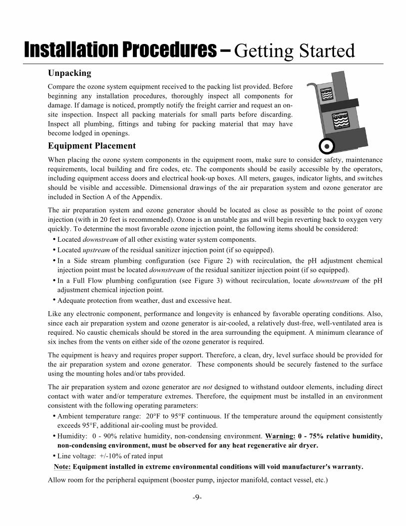
Installation Procedures – Getting Started Unpacking Compare the ozone system equipment received to the packing list provided. Before beginning any installation procedures, thoroughly inspect all components for damage. If damage is noticed, promptly notify the freight carrier and request an on-site inspection. Inspect all packing materials for small parts before discarding. Inspect all plumbing, fittings and tubing for packing material that may have become lodged in openings.
Equipment PlacementWhen placing the ozone system components in the equipment room, make sure to consider safety, maintenance requirements, local building and fire codes, etc. The components should be easily accessible by the operators, including equipment access doors and electrical hook-up boxes. All meters, gauges, indicator lights, and switches should be visible and accessible. Dimensional drawings of the air preparation system and ozone generator are included in Section A of the Appendix.
The air preparation system and ozone generator should be located as close as possible to the point of ozone injection (with in 20 feet is recommended). Ozone is an unstable gas and will begin reverting back to oxygen very quickly. To determine the most favorable ozone injection point, the following items should be considered: • Located downstream of all other existing water system components. • Located upstream of the residual sanitizer injection point (if so equipped). • In a Side stream plumbing configuration (see Figure 2) with recirculation, the pH adjustment chemical
injection point must be located downstream of the residual sanitizer injection point (if so equipped). • In a Full Flow plumbing configuration (see Figure 3) without recirculation, locate downstream of the pH
adjustment chemical injection point. • Adequate protection from weather, dust and excessive heat.
Like any electronic component, performance and longevity is enhanced by favorable operating conditions. Also, since each air preparation system and ozone generator is air-cooled, a relatively dust-free, well-ventilated area is required. No caustic chemicals should be stored in the area surrounding the equipment. A minimum clearance of six inches from the vents on either side of the ozone generator is required.
The equipment is heavy and requires proper support. Therefore, a clean, dry, level surface should be provided for the air preparation system and ozone generator. These components should be securely fastened to the surface using the mounting holes and/or tabs provided.
The air preparation system and ozone generator are not designed to withstand outdoor elements, including direct contact with water and/or temperature extremes. Therefore, the equipment must be installed in an environment consistent with the following operating parameters: • Ambient temperature range: 20°F to 95°F continuous. If the temperature around the equipment consistently
exceeds 95°F, additional air-cooling must be provided. • Humidity: 0 - 90% relative humidity, non-condensing environment. Warning: 0 - 75% relative humidity,
non-condensing environment, must be observed for any heat regenerative air dryer. • Line voltage: +/-10% of rated input Note: Equipment installed in extreme environmental conditions will void manufacturer's warranty.
Allow room for the peripheral equipment (booster pump, injector manifold, contact vessel, etc.)

-10-
Installation Procedures – Plumbing The ozone system should be plumbed using either a side stream or full flow configuration. The side stream loop method takes a portion of the water from the main flow (see Figure 2) and diverts it into a side stream downstream of the filter (if so equipped). Ozone is introduced into the side stream water and is allowed contact time with the water before it is returned to the main flow at a point downstream of all other equipment (heaters, solar panels, etc., if so equipped) in the circulation system. A
booster pump is usually employed to compensate for the flow restriction caused by the side stream loop and the injector manifold. If a halogen-type residual sanitizer is utilized, its injection point should be as far downstream as possible from the point at which the side stream water returns to the main flow. In a full flow configuration, the same system components are usually involved and appear in the same order with respect to the direction of flow. However, all the water in the main flow is allowed contact time with the ozone (see Figure 3). A booster pump may be necessary to maintain proper flow requirements. If employed, the booster pump is located upstream of the point at which the ozone injector manifold is installed.
NOTES:
• Adequate use of unions and isolation valves is strongly recommended to facilitate maintenance and repairs
• Use Schedule 80 PVC for all pluming connections wherever possible. Pluming size requirements are dictated by the water flow characteristics of the system.
• Make sure to use proper plumbing
practices and secure all plumbing and system equipment according to local codes.
• Ozone is a powerful oxidizer and will degrade certain materials. Use ozone-compatible plumbing materials for section(s) of the system that will come in contact with ozone dissolved in water. The following is a list of the materials that are compatible with ozone:
• PVC • Stainless Steel (300 Series) • CPVC • Viton • Kynar • EPDM • Teflon • Concrete
• Depending on the application, other components (psi gauge, flow meter, etc.) may be installed to assist in monitoring system parameters.
Step 1: Arrange the ozone system equipment (booster pump, injector and contact vessel) according to
mechanical print or as dictated by equipment layout and serviceability considerations. Do not secure booster pump(s) and contact vessel to housekeeping pads at this point. Dry fit plumbing as appropriate to insure proper fit and location before making permanent connections.
Step 2: Install a tee or plumbing saddle into the main water line after the filter (if so equipped) and before the flow diversion mechanism. The purpose of the mechanism is to restrict water flow so water is diverted into the side stream (see Figure 2). If such a mechanism is not present in the system (such as a heater bypass valve, etc.), it will require installation of a valve (butterfly, gate or ball) or a flow controller.
Step 3: Plumb a line from the tee or plumbing saddle to the booster pump. For serviceability of the equipment in the side stream loop, be sure to install an isolation valve between the tee or saddle and the booster pump.
Step 4: Plumb from the booster pump to the injector manifold. Make sure to note the correct direction of flow, indicated by a blue arrow on the inlet side of the manifold body. The check valve assembly is strapped to the manifold using wire ties. Remove the assembly; using Teflon® tape, install it onto the top opening of the injector.

Installation Procedures - Plumbing
-11-
Step 5: Plumb from the injector manifold to the inlet side of the contact vessel. To reduce possible backpressure to the injector, minimize the number of elbows between the injector manifold and contact vessel. The contact vessel is a specified size, determined by water flow requirements. ClearWater Tech contact columns and the 30, 40, 80, and 120-gallon contact tanks have inlet and outlet fittings on the bottom of the vessel(s) and are designated with arrows showing the direction of flow. Note: The inlet and outlet arrows on the contact tanks are under the base of the tank. The inlet on the 264, 463 and 850-gallon tanks is located at the top with the outlet at the bottom.
Step 6: Using a tee or plumbing saddle, plumb from the outlet of the contact vessel back into the main water line. For serviceability of the equipment in the side stream loop, be sure to install an isolation valve between the outlet fitting on the contact vessel and before returning to the main water line.
Step 7: Secure the booster pump and contact vessel to solid mounting surfaces using appropriate hardware and according to local codes. If installing a ClearWater Tech contact column, use a ClearWater Tech contact column mounting kit and install according to the instructions below. If installing a contact tank, secure to a solid horizontal surface using mounting flange or feet
Step 8: Install the contact vessel venting system into the top of the vessel. If using the ClearWater Tech contact column, the vent kit supplied includes fittings, a control valve and Teflon® tubing. The contact tank venting system includes an air relief valve, fittings and a length of Teflon® tubing. Depending on conditions, the vented gas may be directed to an ozone destruct system, to atmosphere or to the low-pressure side of the water system. Note: Do not direct the tubing to the suction side of any pump in the system.
Contact Column Installation (if so equipped) Step 1: Make sure the following hardware items are included in the contact column mounting kit: • 'L' bracket • Unistrut bar • 1/2” concrete anchors • Protective end cap • 6” clamp assembly • Mounting hardware
Step 2: Mark the two holes for mounting the 'L' bracket to the wall (see Figure 4). The bracket should be located so that the 6” clamp assembly will be approximately 12” from the top of the contact column. Drill a 1/2” hole at each of the marks, about 3 1/2” deep. Insert a concrete anchor into each hole with the threaded end facing outward. Slip the 'L' bracket over the threaded ends of the anchors, followed by a washer for each anchor. Secure the bracket to the wall by threading a nut onto each anchor and tightening.
Step 3: Cut the unistrut bar to the desired length and attach it to the 'L' bracket using hardware provided.
Step 4: Slip the two sides of the 6” clamp into the unistrut bar and then around the contact column. Tighten the retaining bolt, securing the contact column to the unistrut bar.
Step 5: Slip the protective end cap over the exposed end of the unistrut bar.

Installation Procedures - Plumbing
-12-
Side stream Plumbing Installation Diagram Figure 2
Full Flow Plumbing Installation Diagram Figure 3
Flow Diversion Mechanism
Filter Isolation Valve
Booster Pump
Ozone Injector
Bypass Valve
Contact Vessel
Isolation Valve
Booster Pump
Isolation Valve
Service Loop
Isolation Valve
Isolation Valve Ozone Injector
Bypass Valve
Contact Vessel

Installation Procedures - Plumbing
-13-
6” Clamp Assembly with bolt & nut
Unistrut (cut to length)
Unistrut Protective End Cap
Bolts, nuts & washers (2 ea)
“L” Bracket
Concrete Anchors with nuts &
washers (2 ea)
Column
Column Flange
Flange Bolts & Washers (8
ea)
Diffuser
Riser Tube
Gasket
Flange Nuts & Washers (8 ea)
Base Flange
Base
Contact Column Installation Diagram Figure 4
Contact Column Exploded View Figure 5

Installation Procedures - Electrical
-14-
Installation Procedures – Electrical The CD10 and CD12 Series ozone generators are equipped with universal regulated power supplies that accept an input voltage from 90-250VAC at 47-63Hz, single phase (1ø). ClearWater Tech has an assortment of IEC cords for various voltage requirements and outlet configurations, for use around the world. All possible pre wiring has been completed at the factory. Logic schematics have been provided in the Appendix, Section D.
NOTES:
• All electrical connections should be made by a licensed, qualified electrician. All local, state and national codes must be observed.
• Make sure all power is off at the main circuit breaker before making any electrical connections.
• The CD10/AD and CD12/AD must be energized by a constant unswitched power source for proper operation of the on-board heat regenerative dry air system.
• The air flow of the CD10/AD and CD12/AD must not be drawn through the unit for more than 10 hours in a 24 hour period for proper operation of the on-board air dryer.
Step 1: Conforming to all local, state and national electrical codes, ground the ozone generator to a true earth ground. Use solid copper bonding wire (usually #6 AWG) from the copper-bonding lug located on the bottom of the ozone generator to the grounding point.
Step 2: Main Power: Plug in the IEC end of the power cord to the power entry module located at the bottom of the ozone generator. The other end can be plugged into any main power source with input voltage from 90 to 250 VAC at 47 to 63 Hz, single phase. Note: The CD10/AD and CD12/AD must be energized by a constant unswitched power source.
Step 3: External Loop (EXT LOOP): The external loop, noted on the front cover LED display as “EXT LOOP”, is a true dry contact interface. Note: The term ‘dry contact’ means that this loop does not supply output nor except input voltages. Warning: Supplying voltage to the external loop will cause damage to the ozone generator and void warranty. Under normal operation the external loop will effectively interrupt the ozone output, when the loop has lost continuity, this will also illuminate the “EXT LOOP” LED and turn off the “Ozone Output” LED’s on the front cover. Note: When the external loop has lost continuity main power to the ozone generator will remain “ON” giving power to the cooling fan and the internal air dryer of the CD10/AD and CD12/AD. When continuity is present through the external loop ozone, output will continue. This continuity will effectively turn “OFF” the “EXT LOOP” LED and will again illuminate the “Ozone Output” LED’s.
The external loop, a removable two-position plug with a white 18AWG wire located at the bottom panel of the ozone generator (see Appendix, Section A), can be interfaced to any control device, i.e. pressure switch, vacuum switch, flow switch, float switch, ORP controller, PPM controller, or timer. To interface a control device to the external loop, cut the white 18AWG wire in half. Connect the control device to each leg of the external loop. Note: External Loop control devices supplied by ClearWater Tech may come equipped with a two-position male connector ready to be plugged into the female two-position connector mounted to the chassis of the ozone generator. If the control device used supplies
CD10 and CD12 Series Power Consumption Input Voltage 90-250VAC 47-63Hz CD10 1.1 - 0.7 amps CD10/AD 2.2 - 1.1 amps CD12 1.7 – 1.0 amps CD12/AD 3.2 - 1.6 amps
Installation Procedures - Electrical
-15-
an output voltage a single pole single throw (SPST) normally open relay may be used to create a dry contact interface (see Figure 6). Note: Attached to the white 18 AWG external loop is a warning, “THIS CONNECTION IS A DRY CONTACT ONLY, DO NOT APPLY VOLTAGE”.
Step 4: Ozone Output Control: The CD10 and CD12 Series ozone generators are equipped with two options for controlling the ozone output. The first is a manual 0-100% ozone output control and the second option is a remote 4-20mA control signal. The manual ozone output control knob and remote 4-20mA control leads (orange and purple), are located at the bottom of the ozone generator (see Appendix, Section A).
1. Manual Ozone Output Control: Turning the control knob counterclockwise will decrease the ozone output to down 0%, while turning the knob clockwise will increase the ozone output up to 100%. The percent of ozone output is indicated by the “Ozone Output” LEDs on the front of the ozone generator, with each LED representing 10% output (see Figure 11).
2. Remote 4-20mA Control: A 4-20mA control signal to the ozone generator may be used to control the ozone generator output. The ozone generator will automatically sense the 4-20mA input signal and override the setting of the manual ozone output control. Based on the 4-20mA signal, ozone output will increase or decrease: 4mA = 0% ozone output, 20mA = 100% ozone output. The percent of ozone output is indicated by the “Ozone Output” LEDs on the front of the ozone generator, with each LED representing 10% output (see Figure 11). Note: If the remote 4-20mA signal fails or is missing, the system will default to the manual ozone output setting. Check and adjust the manual ozone output control knob to avoid over-ozonation. Step 1: Mount the 4-20mA controller to a suitable vertical surface according to the installation
manual supplied with the controller. Step 2: Wire the #22 AWG orange “positive” (+) lead from the ozone generator to the 4-20mA
controller according to the manual supplied with the controller. Step 3: Wire the #22 AWG purple “negative” (-) lead from the ozone generator to the 4-20mA
controller according to the manual supplied with the controller. Step 4: Complete the required programming and calibration steps as outlined in the installation
manual supplied with the 4-20mA controller.
Step 5: Air Preparation System Power - CD10 and CD12 only: 120VAC systems only: if a PSA oxygen concentrator LPSA dry air system is used, plug power cord into main power. 240VAC systems only: if a PSA oxygen concentrator or LPSA dry air system is used, the power cord must be hard wired to the main power source (Black-L1, White-L2 and Green-Ground). Notes: The prescribed air flow must be set to “atmospheric pressure” on either the PSA oxygen concentrator or LPSA dry air system prior to use. Follow Step 4 of the “Start-up & Calibration” section. Warnings: Failure to calibrate may lead to premature failure of the air preparation systems. Vacuum must be interrupted if the air prep system is not “ON.” Failure to do so will damage the air prep system. Air Preparation System - CD10/AD and CD12/AD only: The air dryer of the CD10/AD and CD12/AD is powered by the main power of the unit.

Installation Procedures - Electrical
-16-
External Loop Electrical Interface Figure 6
120 VAC Signal
L1
N
Power from OPR, PPM, pump or timer
120V Coil
Interface Relay
External Loop
240 VAC Signal
L1
N
Power from OPR, PPM, pump or timer
240V Coil
Interface Relay
External Loop

-17-
Installation Procedures – Pneumatic This section outlines the steps required to complete the ozone system pneumatic hook-ups. The system components include the air preparation system, ozone generator, vacuum break, and ozone injector manifold (see Figure 7). The air preparation system provides the ozone generator with a source of oil-free oxygen-enriched air (90% +/- 3% oxygen purity at -100˚F dew point) or dry air (20% oxygen purity). The air is drawn from the ozone generator (where ozone is produced from the oxygen in the air stream) and through the vacuum break by the suction created at the ozone injector manifold.
Hook-Up: Air preparation system to ozone generator Figure 7 PSA Oxygen Concentrator or LPSA Dry Air - CD10 or CD12 only: Step 1: Teflon® tape and attach brass barb provided to the PSA oxygen concentrator or LPSA dry air outlet, if
needed.
Step 2: Air Flow Gauge Assembly: Mount the standard cubic feet per hour (SCFH)/vacuum gauge assembly to the ozone generator (ordered separately), following the installation instructions provided with the gauge assembly.
Step 3: Using a suitable length of 3/8” braided tubing attach tubing to the barb located at the oxygen concentrator or LPSA air dryer, then attach the other end of the tubing to the SCFH/vacuum gauge assembly. Secure the tubing to the fittings with the hose clamps provided.
Water Flow Booster Pump
Ozone Injector
Vacuum Break
Air Preparation Ozone Generator
Option 1
Option 2
Ozone Out
Shown: ClearWater Tech CD10 or CD12 with OXU80 (Option 1) and CD10/AD or CD12/AD (Option 2)
Air Prep In

Installation Procedures – Pneumatic
-18-
Sieve Bed
Compressor Inlet Filter
Hour Meter
Power Indicator Light
Solenoid Valve
SCFH Air Flow Meter and Adjustment Valve
Compressor
Oxygen Outlet
Main Power Cord
Shown: Aerous 15 Shown: Aerous 15 (Cover Removed)
AD40 - Heat Regenerative Dry Air - CD10 or CD12 only: Follow the installation procedures according to the Installation and Operation Manual provided with the AD40.
Heat Regenerative Dry Air - CD10/AD and CD12/AD only: The CD10/AD and CD12/AD ozone generator (“AD” represents Air Dryer) has been pneumatically pre-plumbed at the factory with an internal heat regenerative air dryer to provide simplicity of a “plug and play” ozone system. The CD10/AD is also equipped with an internal moisture-indicating cartridge, which is visible through the view window on the right side of the CD10/AD. This indicating cartridge is used as a reference to indicate the quality of dry air. If the air dryer is not operating properly the silica will turn from blue and white in color to all white. See Troubleshooting Guide. The CD10/AD and CD12/AD are also equipped with an “External Air Prep Loop,” which can be used to interface the SCFH/vacuum gauge assembly by following the installation instructions provided with the gauge assembly. This is the only necessary pneumatic connection. The air flow of the CD10/AD and CD12/AD must not be drawn through the unit for more than 10 hours in a 24 hour period.
The CD10/AD and CD12/AD must be powered up for 24 hours prior to system start-up (no air flow should be drawn through the system by the ozone injection manifold). This sieve material in the heat regenerative air dryer must be evaporated of any moisture that has accumulated. Notes: If this step is not completed premature failure of the heat regenerative air dryer system will occur. During this time the external loop connector may be removed so that the ozone reaction chamber will not have power to it.
Oxygen Concentrator Figure 8

Installation Procedures – Pneumatic
-19-
Hook-Ups: Ozone generator-to-vacuum break & vacuum break-to-injector manifold The ClearWater Tech vacuum break provides a positive atmospheric “break” between the ozone injector manifold and the ozone generator, preventing water from flowing back into the ozone generator should the venturi check valve fail. Under normal operating conditions, the vacuum break's flapper valve (see Figure 9) is closed, allowing the vacuum created by the venturi to draw the output gas from the ozone generator. If the check valve at the venturi begins to leak or fails completely, vacuum is interrupted and water will flow toward the ozone generator. With the vacuum break properly installed between the venturi and the ozone generator, the water will flow down the riser tube (away from the ozone generator) and out to drain, protecting the ozone generator from potential water damage.
Step 1: Select a suitable vertical surface that is accessible and in close proximity to both the ozone generator and the ozone injector manifold.
Step 2: Install the two Clic® mounting clamps provided onto the vertical surface so that the vacuum break is in a vertical position and the drain holes are below the level of the ozone generators ozone outlet fitting. One clamp should be located so it fits around the Riser Tube Elbow, and the other so it fits around the bottom of the Lower Tee, (see Figure 9).
Step 3: Remove the Fill Port Cap located on top of the Riser Tube and fill the Riser Tube with clean water (no particulate matter) to "Fill Level" line (see Figure 9).
Step 4: Re-install the Fill Port Cap, using pliers or a wrench to tighten. Note: Do not over- tighten as damage to PVC fittings may occur.
Step 5: Install the check valve with compression fitting (located in the parts kit or attached to the ozone generator with a wire tie) into the stainless steel ozone outlet located at the bottom of the ozone generator.
Step 6: Connect one end of a suitable length of Teflon® ozone delivery line to the fittings installed into the ozone outlets (see Step 5 above). Attach the other end of the Teflon® delivery line to the fitting threaded into the Upper Tee. As an additional backflow prevention measure, loop this length of tubing as high as is practical between the two connection points.
Step 7: Connect one end of a second length of Teflon® delivery line to the fitting threaded into the Lower Tee. Attach the other end of the delivery line to the fitting located on top of the check valve assembly, which was installed at the injector manifold.
Step 8: Adjustments to the valve on the ozone injector manifold will be necessary. These steps are covered in Chapter 7, “Start-up and Calibration Procedures.”

Installation Procedures – Pneumatic
-20-
Vacuum Break Detail Figure 9 Hook-Up: Contact vessel-to-ozone destruct system (if so equipped) The ClearWater Tech ozone off-gas destruct system consists of two components: the ozone destruct unit (a heated chamber filled with manganese dioxide and copper oxide) and a water trap. Used in conjunction with the ClearWater Tech off-gas vent, this two-stage ozone destruct system is an efficient way to properly vent the ozone system contact vessel (see Figure 10).
NOTES:• The ozone destruct unit must have constant
power to function properly. Make sure it is plugged into an unswitched 120VAC outlet or wired to unswitched 240VAC power. Once up to temperature, the unit will remain warm to the touch.
• It is normal for small amounts of water to drain from the water trap, so it must be plumbed to waste appropriately
Step 1: Select a suitable vertical surface adjacent to the ozone system contact vessel. Using the Clic® mounting clamps provided, mount the water trap to the surface. Step 2: Using the mounting tabs, mount the ozone destruct unit adjacent to the water trap.
Step 3: Using Teflon® tape, install the small ball valve into the opening (at the tee or inlet) of the water trap. Using Teflon® tape, install the thread-by-compression fitting provided into the small ball valve.
Step 4: Using the compression fitting, attach one end of a suitable length of the Teflon® tubing to the compression fitting on top of the contact vessel (the fitting is threaded directly into the cap of the contact column and is threaded into the off-gas vent on the top of a contact tank). Attach the other end of the tubing to the inlet of the small ball valve (see Step 3 above) in the water trap.
Step 5: Using the compression fitting provided, attach another suitable length of Teflon® tubing to the fitting on top of the water trap. Attach the other end of the tubing to the inlet compression fitting on the bottom of the ozone destruct unit.
Ozone Output
Ozone Generator
Ozone Flow
Fill Port Cap
Upper Tee
Lower Tee
Mounting Clamp Locations
Fill Level
Riser Elbow
Riser Tube
Drain Holes
Drain Barb
Flapper Valve Injector Manifold
Ozone Flow

Installation Procedures – Pneumatic
-21-
Step 6: Attach a suitable length of braided tubing to the fitting on the bottom of the water trap. Terminate the other end to appropriate waste or drain.
Step 7: Plug the ozone destruct unit into an unswitched 120VAC outlet or wire to unswitched 240VAC power and allow it to warm up. Warning: The destruct unit will be warm to the touch when in operation.
Ozone Destruct System Detail Figure 10
Ozone Destruct Unit Use Unswitched Continuous Power
Off Gas Vent
Contact Vessel
Ball Valve
Water Trap
To Waste
Teflon Tubing

-22-
Start-Up and Calibration The previous sections of this manual have involved comparatively static procedures: making electrical and pneumatic connections, fitting pipe, etc. This section involves the dynamic process of starting up and balancing the components of the ozone system, including initiating water flow, making air and water flow adjustments, etc.
Maximum performance and reliability is achieved when the prescribed air flow is maintained at the ozone generator while the system is operating under a slight vacuum (measured in inches of mercury, or “in.Hg”). Air from the air preparation system is flowing toward the ozone generator under pressure, and from the ozone generator under vacuum (created by the ozone injector manifold). The change from pressure to vacuum occurs at the SCFH/vacuum gauge assembly mounted to the CD10 or CD12. Note: If an external heat regenerative dry air system, CD10/AD, or the CD12/AD is used, the air flow will be completely dependant upon the vacuum draw of the ozone injector manifold. If the vacuum level is too high but air flow levels are correct, opening the ball valve on the injector manifold(s) slightly will decrease the vacuum by increasing the amount of water flowing through the bypass of the ozone injector manifold. Similarly, if the vacuum level is too low, closing the ball valve on the injector manifold(s) slightly will increase the vacuum.
Air Preparation System, Ozone Generator & Ozone Injector Step 1: Make sure all isolation valves in the ozone water system are open (Figures 2 or 3 show recommended
isolation valve locations).
Step 2: Start up hydraulics. Allow the water system to reach hydraulic equilibrium (contact vessel(s) full, off-gas vent(s) operating, etc.) and observe for plumbing leaks. Note: Water flow must be established through the main water pump and the ozone system booster pump (if so equipped).
Step 3: Close the ball valve on the injector manifold about half way.
Step 4: Make sure electrical power to all ozone system electrical components is on. The main power switch of the air preparation system must be in the “ON” position, if so equipped (see Figure 8).
PSA Oxygen Concentrator and LPSA Dry Air: Systems must be set to “atmospheric pressure” prior to full start up of the system. Disconnect the oxygen delivery line from each oxygen concentrator (if delivery has already been attached). Step 1: Check to make sure the compressor of the PSA or LPSA air preparation system is operating.Step 2: Using the air flow gauge adjustment valve on the PSA or LPSA air preparation system (see
Figure 8), adjust the air flow according to the “air prep system air flow” specifications (see Figure 12).
Note: When the system is under normal operation, the air flow will drop from the initial setting due to the air preparation system being under back pressure. DO NOT READJUST THE AIR FLOW GAUGE ADJUSTMENT VALVE.
CD10/AD and CD12/AD: Unit must be powered up for 24 hours prior to system start-up (no air flow should be drawn through the system by the ozone injection manifold until this step has been completed). The sieve material in the heat regenerative air dryer must be evaporated of any moisture that has accumulated. If the external loop has been removed during this step, replace external loop. Note: If this step is not completed premature failure of the heat regenerative air dryer system may occur.
Start-Up and Calibration
-23-
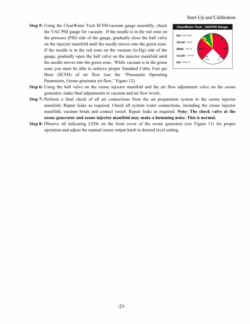
Step 5: Using the ClearWater Tech SCFH/vacuum gauge assembly, check the VAC/PSI gauge for vacuum. If the needle is in the red zone on the pressure (PSI) side of the gauge, gradually close the ball valve on the injector manifold until the needle moves into the green zone. If the needle is in the red zone on the vacuum (in.Hg) side of the gauge, gradually open the ball valve on the injector manifold until the needle moves into the green zone. While vacuum is in the green zone you must be able to achieve proper Standard Cubic Feet per Hour (SCFH) of air flow (see the “Pneumatic Operating Parameters, Ozone generator air flow,” Figure 12).
Step 6: Using the ball valve on the ozone injector manifold and the air flow adjustment valve on the ozone generator, make final adjustments to vacuum and air flow levels.
Step 7: Perform a final check of all air connections from the air preparation system to the ozone injector manifold. Repair leaks as required. Check all system water connections, including the ozone injector manifold, vacuum break and contact vessel. Repair leaks as required. Note: The check valve at the ozone generator and ozone injector manifold may make a humming noise. This is normal.
Step 8: Observe all indicating LEDs on the front cover of the ozone generator (see Figure 11) for proper operation and adjust the manual ozone output knob to desired level setting.

Start-Up and Calibration
-24-
Ozone Generator LED Display Figure 11
LED Function CD10 CD10/AD CD12 CD12/AD OZONE
OUTPUT The ten LEDs represent 0-100%, minimum to maximum ozone output. Each LED is equal to 10% output. These LEDs can be adjusted with the manual output control knob located at the bottom of the ozone generator or automatically with a remote 4-20mA control signal.
POWER Main Power is “ON” to the ozone generator, when LED is illuminated.
HV DRIVE
Power is being sent to the high voltage drive board, when the LED is illuminated.
EXT LOOP
The External Loop has continuity through it when the LED is not illuminated, which indicates ozone is being produced. The External Loop does not have continuity, when the LED is illuminated, which indicates no ozone production.
HIGH TEMP
The High Temp LED will not be illuminated during normal operation. If the ozone generator’s internal temperature is in excess of 150˚F the High Temp LED will illuminate, which will also discontinue ozone production.
AIR PREP
CD10/AD and CD12/AD Only: The Dryer Timer LED will flash continuously during normal operation and indicates that the dryer timer cycle is operating correctly.
DRYER 1 CD10/AD and CD12/AD Only: DRYER 1 LED will be illuminated when dryer chamber #1 is heating.
DRYER 2 CD10/AD and CD12/AD Only: DRYER 2 LED will be illuminated when dryer chamber #2 is heating.
Note: There is a 30 minute period where Dryer #1 and Dryer #2 are off. This is normal. The dryers are in a cool down phase before switching.
MIN
MAX
OZONE OUTPUT
POWER
HV DRIVE
EXT LOOP
HI TEMP
EXT LOOP
MIN
MAX
OZONE OUTPUT
POWER
HV DRIVE
HI TEMP
AIR PREP
DRYER 1
DRYER 2
MIN
MAX
OZONE OUTPUT
POWER
HV DRIVE 1
EXT LOOP
HI TEMP 1
HV DRIVE 2
EXT LOOP
HI TEMP 2
MIN
MAX
OZONE OUTPUT
POWER
HV DRIVE 1
HI TEMP 1
HV DRIVE 2
HI TEMP 2
EXT LOOP
AIR PREP
DRYER 1
DRYER 2

Start-Up and Calibration
-25-
Vacuum Break Check the water level in the vacuum break, making sure it is above the flapper valve (see Figure 9). If water is not pressing downward on the flapper valve it will open, causing a loss of vacuum. The water level in the vacuum break should remain static with no air bubble movement. A loss of vacuum means ozone cannot be drawn through the vacuum break, which in turn can cause an ozone leak (see Troubleshooting Guide).
Ozone Destruct System Adjust the small ball valve at the tee of the water trap (see Figure 10) so that only a small amount of water is “spitting” into the trap. This will indicate that the contact vessel is full and only a very small amount of water is allowed to escape. Do not close this valve completely. Doing so may cause back pressure on the contact vessel and injection manifold, which will cause a loss of vacuum (see Troubleshooting Guide).
Pneumatic Operating Parameters Figure 12
CD10 Operating Range Optimum Air prep system air flow Ozone generator air flow Vacuum gauge
3 to 4 SCFH 3 to 4 SCFH -3 to -8 in Hg
4 SCFH 4 SCFH -5 in Hg
CD10/AD Operating Range Optimum Ozone generator air flow Vacuum gauge
3 to 4 SCFH -3 to -8 in Hg
4 SCFH -5 in Hg
CD12 Operating Range Optimum Air prep system air flow Ozone generator air flow Vacuum gauge
6 to 8 SCFH 6 to 8 SCFH -3 to -8 in Hg
8 SCFH 8 SCFH -5 in Hg
CD10/AD Operating Range Optimum Ozone generator air flow Vacuum gauge
6 to 8 SCFH -3 to -8 in Hg
8 SCFH -5 in Hg

-26-
Maintenance Maintenance of the ozone system is critical to its longevity and operating efficiency. While all system components are built to provide years of reliable service with minimum maintenance, following the procedures outlined below is strongly recommended.
All maintenance procedures have been segmented by interval: daily, monthly, semi-annual and annual. Daily procedures involve quick visual checks for changes in normal operating
conditions. Monthly, semi-annual and annual procedures include cleaning and/or replacement of certain critical parts.
NOTES: • The ozone generator warranty states that it
“does not extend to any product or part which has been damaged or rendered defective as a result of use of parts not sold by ClearWater Tech, or service or unit modification not authorized by ClearWater Tech.” Please contact your ClearWater Tech dealer if you have any questions about any maintenance procedure before you begin that procedure.
• CAUTION: Observe all common safety practices and review the “Safety Warnings and Instructions” (Chapter 2) before attempting any maintenance procedure that requires the use of tools and/or shutting down the ozone system.
Daily Procedures Air Preparation System • Power Switch: Check the power switch on the air preparation system (if so equipped), or inline particulate filter
inside the ozone generator (see Appendix A). Note: The air prep system must always have main power when vacuum is being drawn through the ozone system.
• Indicator Cartridge: Inspect the air preparation system indicator cartridge (if so equipped). A change in the blue crystals to light pink or white in color indicates the presence of moisture in the feed gas coming from the air preparation system. If such a change is observed, refer to the Troubleshooting Guide.
• Air Flow: Check the air flow gauge on the air preparation system (see Figure 8). Make sure the air flow is within the SCFH range shown on the “Air prep system air flow” line of the “Pneumatic Operating Parameters” chart (Figure 12). Adjust if necessary by following Step 4 of the “Start-Up & Calibration” section.
Ozone Generator • Indicator Lights: Check the indicator lights on the ozone generator. (see Figure 11 for Ozone Generator LED
Display function) • Air Flow: Check the SCFH/vacuum gauge assembly attached to the ozone generator. Make sure air flow is
within the SCFH range shown on the “Ozone generator air flow” line of the “Pneumatic Operating Parameters” (see Figure 12). Adjust if necessary by following Step 5-6 of the “Start-Up & Calibration” section.
• Vacuum: Check the SCFH/vacuum gauge assembly attached to the ozone generator. Make sure pressure is within then range shown on the “Pressure” line of the “Pneumatic Operating Parameters” chart (see Figure 12). Adjust if necessary by following Step 5-6 of the “Start-Up & Calibration” section.

Maintenance
-27-
Vacuum Break • Water Level: Check the water level in the vacuum break. Make sure it is up to the fill line. Fill as required by
removing the threaded fitting on top of the riser tube until water is up to the fill level in the riser tube (see Figure 9).
Injection Manifold • Check valve: Inspect the Teflon ozone delivery line that runs between the vacuum break and the check valve
assembly on the suction port of the ozone injector manifold. If water is observed in the delivery line near the check valve assembly, the check valve has failed. See Troubleshooting Guide.
Ozone Destruct System • Water Trap: Check water trap for excessive water. It should be no more than half full. If excessive water is
observed, see Troubleshooting Guide. • Ozone Destruct Unit: Check to make sure the power indicator light located on the right side of the unit is
illuminated. Note: Unit must be plugged into an unswitched outlet. Cover of unit will be warm to the touch.
Monthly Procedures Air Preparation System • Cooling Fan Operation: Check to make sure the cooling fan mounted on the side panel of the air preparation
system is operating. If not, refer to the Troubleshooting Guide. • Cover Filter: Check the cover filter element mounted on the side of the air preparation system and clean as
required. Operating conditions in the equipment area will dictate the frequency required for this procedure. Remove the filter element and clean with soap and water, drying them completely before re-installing.
Ozone Generator • Cooling Fan Operation: Check to make sure the cooling fan mounted on the bottom panel of the ozone
generator is operating. If not, refer to the Troubleshooting Guide. • Cooling Fan Filters: Check the cooling fan filter element mounted on the fan assembly located at the bottom
panel of the ozone generator and clean as required. Operating conditions in the equipment area will dictate the frequency required for this procedure. Remove the filter element and clean with soap and water, drying them completely before re-installing (see Figure 13).
Booster Pump(s) • Strainer Baskets: Check and clean the strainer basket in the booster pump (if so equipped) as required.
Ozone Generator Cooling Fan Assembly Figure 13
Fan
Ozone Generator Bottom Panel
Finger Guard
Fan Filter Element
Fan Filter Grill

Maintenance
-28-
System Shutdown Procedures CAUTION: The ozone generator operates at high voltages. Follow these steps carefully before performing
any semi-annual or annual maintenance procedures.
Step 1: Turn off power to any peripheral system hydraulic components and air prep system. Step 2: Turn the Main Power switch on the ozone generator to the “OFF” position. The LED display on the front
cover should not be illuminated. Step 3: Disconnect the power to the ozone system either at the service disconnect box (if so equipped) or main
circuit breaker.
Semi-Annual Procedures CAUTION: Follow system shutdown procedures (outlined above) before performing any of the following
steps.
Air Preparation System • Air Inlet Filter, PSA Oxygen Concentrator or LPSA Dry Air - Replace the air compressor inlet filter on the air
preparation system module (see Figure 8). Note: Manufacturers' recommended replacement interval is 4,000 hours of operation. Operating conditions in the equipment area will dictate the required frequency of this procedure.
Annual Procedures CAUTION: Follow system shutdown procedures before performing any of the following steps.
Air Preparation System • Compressors, PSA Oxygen Concentrator or LPSA Dry Air: Following the procedures outlined in the
compressor rebuild kit, rebuild the two compressor heads on each air preparation system module. Note: Manufacturers' recommended interval is 5,000 to 12,000 hours of operation. Compressor performance and/or operating conditions in the equipment area will dictate the required frequency of this procedure.
• Air Dryer: CD10/AD and CD12/AD only: Replace sieve material according to the steps outlined below (see Figure 14). Note: You will need to remove the unit from the wall in order to pour out the media. Allow the air dryer chambers to cool completely and read all steps before continuing. Step 1: Straighten out the ends of the dryer chambers using pliers. Step 2: Using a snap ring tool, remove the top snap rings. Step 3: Remove the top screens; the o-ring pick is handy for this. The bottom snap ring may be left
remaining within the air dryer chambers. Step 4: Turn the ozone generator over to pour the old sieve material from the dryer chambers and dispose.
Note: When removing the sieve material, be sure not to discard the bottom screens. Step 5: Re-seat/Re-install the bottom screens. Note: The heater rod must be put through the center of the
bottom screens. Step 6: Fill chamber with new sieve material to 3/4” to 1” below the top of the dryer chambers. You will
have more media than needed. Step 7: Re-install the top screens. Step 8: Using a snap ring tool, place the top snap rings snug against the top screen. Step 9: Bend the ends of the dryer chambers in-ward for added retention of the sieve material (optional). Step 10: The ozone generator must be turned on for 24 hours prior to system start-up to eliminate any moisture
trapped in the new sieve material.

Maintenance
-29-
Indicating Media Replacement (CD10/AD only)
Step 1: Using wrench, loosen and disconnect the compression fitting located at the top of the indicating media chamber.
Step 2: With a flat-head screwdriver, unlock the two gray clamps securing the indicating media chamber. Step 3: Pull the chamber free of the clamps, the chamber will only be held within the unit by the bottom cap.
Rotate the chamber downwards to position the bottom cap to be at the top of the chamber. Step 4: Secure the bottom cap with channel lock pliers and turn the chamber counter-clockwise to unscrew it.
Be mindful to not spill the indicating media. Step 5: Remove the indicating chamber from the unit, remove the interior screen and dispose of the media. Step 6: Remove the Teflon tape from the bottom cap’s threads and re-tape the threads with 2-3 wraps. Step 7: Refill the indicating chamber with new blue and white indicating crystals. You will have more media
than needed. Step 8: Replace the interior screen and reinstall the chamber following steps 1 through 4 in reverse order.
Ozone Generators
• Cooling Filters: Clean or replace the cooling fan filter elements as required. • Inline Particulate Filter: Replace the inline particulate filter. • Reaction Chambers: Remove and disassemble the reaction chamber according to the steps outlined below (see
Figure 15). Check the chamber interior and dielectric tube for oil, dirt or moisture.
Reaction Chamber Removal and Disassembly
Note: Read through all the steps before disassembling the reaction chamber. Step 1: Make sure all power to the ozone generator has been disconnected according to the “System Shutdown
Procedures” outlined above. Step 2: Disconnect the high voltage lead from the reaction chamber(s). Step 3: Disconnect the tubing connections on both ends of the reaction chamber(s). Step 4: Remove the 4 nuts securing each chamber and remove the reaction chamber from ozone generator. Step 5: Make note or mark the position of the end caps and their elbow fittings on the reaction chambers, during
re-assembly the end caps will need to return to original positions. Note: The orientation of the end caps and the chamber itself is different between the two CD12 chambers.
Step 6: Remove retaining screws and washers from the two end caps (3 each). Step 7: Using a gentle back-and-forth twisting motion, remove the non-high voltage end cap (the one without
the high voltage attachment screw) from the heat sink/cathode assembly. A flat-head screwdriver may be used to gently pry the end cap off, as long as equal pressure is applied to each side of the end cap.
Step 8: Remove the high voltage end cap and dielectric from the heat sink/cathode assembly. Step 9: The high voltage end cap can be removed by holding the glass and turning the end cap counter-
clockwise approximately 6 turns. Pull the end cap off the glass. Push the contact brush out of the dielectric glass. A screwdriver can be used to push the brush, and pliers to pull it out once the opposing end is exposed.
Step 10: Inspect the dielectric, end caps and cathode for breakage, corrosion or debris; then follow the assembly and re-installation steps below.

Maintenance
-30-
Reaction Chamber Assembly and Re-installation: Step 1: Remove o-rings from end caps, clean the dielectric glass, end caps and interior of the stainless steel
cathode cylinder. Use denatured alcohol, shop towels to clean and be sure to remove all old o-ring debris. A 1” ball hone can be used to clean the major debris out of the cathode if there is heavy buildup.
Step 2: Prepare the end caps for re-assembly by replacing the o-rings. Thread the hex brush adapter nut, with contact brush attached, onto the end of the high voltage end cap (cap with the high voltage attachment screw) center screw. Re-tape the threads of the elbow fittings if needed.
Step 3: Using a gentle twisting motion, press the non-high voltage end cap onto the heat sink/cathode assembly until flush with the heat sink cooling fins. Turn the end cap to the correct orientation.
Step 4: Slide the three end cap retaining screws with washers through the holes in the non-high voltage end cap, aligning them with the heat sink screw bosses. Thread screws into screw bosses until heads are snug against the end cap.
Step 5: Next we focus on assembling the rest of the subcomponents, before installing them into the reaction chamber. Slowly insert the brush (installed onto the high voltage end cap) into the dielectric glass. Note: Go slowly in order to prevent or minimize bending the center wire of the brush during this procedure. It is normal for the bristles to bend flat against the dielectric glass. Fully seat the dielectric glass into the high voltage end cap. Clean the glass with denatured alcohol once more, and do not retouch the glass without re-cleaning.
Step 6: Hold the reaction chamber upright on a flat surface, empty high voltage side up. Grasp the high voltage end cap and lower the glass into the reaction chamber. Press directly downwards on the high voltage end cap to fully seat the dielectric assembly; the end caps should be flush with the heat sink cooling fins. Turn the end cap to the correct orientation.
Step 8: Slide the three end cap retaining screws with washers through the holes in the end cap, aligning them with the heat sink screw bosses. Thread screws into screw bosses until heads are snug against the end cap.
Step 9: Re-install the complete reaction chamber assembly into the ozone generator by securing the reaction chamber to its mounts, securing delivery line and connecting the high voltage insulated wire.
Vacuum Break • Cleaning: Disconnect ozone delivery lines. Remove the vacuum break from mounting clamps. Disconnect the
overflow tube from flapper valve, open flapper and clean the seat with a soft cloth. Remove riser tube threaded fitting and flush riser tube with water. Re-assemble and re-install vacuum break, making sure to add water to correct level (see Figure 9).
Injector Manifold • Check Valve: Replace the check valve located at the ozone injection manifold. Note: Because the system is in
the shutdown mode, no vacuum is present at the injector. Therefore, it is normal for some water to be flowing from the injector during this procedure.

Maintenance
-31-
Contact Vessel • Cleaning, Contact Column only: Inspect the diffuser slots at the top of the contact column riser tube. If they are
clear, no further maintenance is required. If the slots are fouled, disassemble the column and clean as required, following the steps outlined below (see Figure 5).
Step 1: Make sure the isolation valves before and after the contact column(s) are closed. Step 2: Disconnect the vent line from the top of the contact column(s). Step 3: Remove the bolts in the 6” base flange. Step 4: Remove the column, lifting it over the interior riser tube. Step 5: Remove and clean the diffuser. Step 6: Inspect the flange gasket and replace if necessary. Step 7: Reassemble the contact column and attach vent lines.
Ozone Destruct System • Off-Gas Vent: Disconnect tubing from top of off-gas vent and remove vent from contact vessel. Disassemble
vent and clean inside thoroughly. The float assembly maybe disassembled cleaned, making sure all ports and orifices are clean and free of debris. Clean O-rings or replace as required. Re-assemble and mount vent onto the contact vessel
• Ozone Destruct Unit: Under normal operating conditions, this unit may require no annual maintenance. However, if a strong odor of ozone can be detected in the air immediately surrounding the unit, the catalyst may require replacement. Follow the directions included with the ozone destruct rebuild kit.

Maintenance
-32-
CD10/AD and CD12/AD Heat Regenerative Air Dryer Figure 14
Top Dryer Chamber
Bottom Dryer Heater Rod (2 Position White)
Dry Air Outlet
Top Dryer Heater Rod (2 Position, Red)
Solenoid Valve
Solenoid Valve Connector
(3 Position, Red)
Bottom Screen
Sieve Material (Not Shown)
Heater Rod
Bottom Dryer Chamber
Bottom Snap Ring Top Screen
Top Snap Ring

Maintenance
-33-
1” Reaction Chamber - Exploded View Figure 15
Ozone Outlet Fitting
Bottom End Cap and O-rings
Heat Sink and Cathode
Glass Dielectric
End Cap Retaining Screws and Washers
Contact Brush
High Voltage End Cap and O-Rings
Brush Adapter Nut
High Voltage Terminal
Oxygen Inlet Fitting

-34-
Troubleshooting Air Preparation – PSA Oxygen Concentrator or LPSA Dry Air Problem/Symptom Possible Cause Solution Unit not operating -No power to system
-Power switch in “OFF” position -Insufficient vacuum through ozone generator (if vacuum switch is equipped with system)
-Incorrect wiring
-Check main power to unit -Turn switch to “ON” position -Adjust injector -See “Start-Up & Calibration – Step 5” -See “Installation Procedures – Electrical”
Low air flow or no air flow -Flow meter out of adjustment -Fouled compressor inlet filter -Compressor not functioning
-Adjust flow meter -See “Start-Up & Calibration – Step 4” -Replace inlet filter -Rebuild of replace as required
Compressor pressure relief valve making noise
-Excessive backpressure in system -Pinching tubing -Compressor not functioning -Sieve bed (ATF) not functioning
-Inspect check valves for proper operation & replace as required
-Replace tubing -Rebuild or replace as required -Replace as required
Indicator cartridge desiccant has changed from blue & white to all pink or white
-Moisture has entered air prep system -Check & tighten fittings -Rebuild/replace all compressor(s) or sieve bed as required
-Replace indicating desiccant Unit is making excessive noise
-Shipping damage -Fan blocked -Packaging material not removed
-Located damage and repair/replace parts -Clear Obstructions -Remove packaging material
Air Preparation – Heat Regenerative Dry Air (CD10/AD and CD12/AD Only) Problem/Symptom Possible Cause Solution Air Prep LED not flashing -Air dryer board not functioning -Replace air dryer board Dryer 1 or 2 LED not illuminated
-Air dryer board not functioning -Dryer 1 LED will not illuminate when Dryer 2 LED is illuminated
-Dryer 1 is in cool down mode -Dryer 2 LED will not illuminate when Dryer 1 LED is illuminated
-Dryer 2 LED is in cool down mode
-Replace air dryer board -See “Theory of Operation and Product Description - Air Preparation System”
-See “Ozone Generator LED Display, Figure 11”
Dryer chamber(s) not heating
-Heating element not functioning -Replace Heating element
Indicating desiccant cartridge has changed from blue & white to all pink or white. Moisture has entered air prep system.
-Unit does not have constant power -Excessive air flow -Excessive duty cycle -Excessive relative humidity -Solenoid valve not operating -Air dryer board not functioning
-Unit must have constant power -Adjust flow meter See “Start-Up & Calibration – Step 5” -Duty cycle must not exceed 10 hours in a 24 hour period
-Relative humidity must not exceed 75% -Replace solenoid valve -Replace air dryer board

Troubleshooting
-35-
Ozone Generator Problem/Symptom Possible Cause Solution LED display is not illuminated
-No power to unit -Main power switch is in the “OFF” position
-Blown fuse(s) -Incorrect wiring -LED display board ribbon cable is disconnected from output control board
-Check circuit breakers -Turn switch to the “ON” positioning -Replace fuse(s) -See “Installation Procedures – Electrical” -Connect ribbon cable (be sure all of the pins are properly inserted into the output control board)
‘Main Power’ LED is not illuminated, but all other LED’s are illuminated
-LED display board is inoperable -Replace LED display board
Circuit breaker trips -Incorrect wiring -Circuit breaker amperage does not match draw
-Unit flooded with water
-See “Installation Procedures-Electrical” -Replace with correct circuit breaker -Assess damage, correct cause and rebuild as required
‘HV Drive’ LED is not illuminated
-No power to the high voltage drive board -Check board to be sure it is attached securely to the mother board
-Bad high voltage drive board, replace as required
‘External Loop’ LED is illuminated
-The external loop does not have continuity
-See “Installation Procedures – Electrical, Step 3” for function
‘Ozone Output’ LED’s are not illuminated
-The manual 0-100% output potentiometer is set to 0% output
-Remote 4-20mA controller is sending a 4mA signal, which will indicated 0% output
-Adjust potentiometer clock wise to desired set point
-No solution required, controller will adjust LED’s automatically
‘Hi Temp’ LED illuminated -Unit is overheating -Check fan for proper operation and clean fan filter
-Check operating temperature -See “Installation Procedures – Getting Started, Equipment Placement”
Internal Mother Board ‘Power’ LED not illuminated
-No power to mother board -Inoperable mother board -Blown mother board fuse
-See “Installation Procedures – Electrical” -Replacement Mother Board -Replace fuse
Receive an electrical shock upon touching the unit
-Incorrect wiring -Unit not grounded -Unit flooded with water
-See “Installation Procedures-Electrical” -Ground unit according to local codes -Assess damage, correct cause and rebuild as required
Fan not operating -Debris caught in fan -Fan inoperable
-Remove debris -Replace fan
Low air flow or no air flow -Air prep system not operating properly -Fouled inline filter -Air leak
-See “Start Up & Calibration-Step 4” -Change inline filter -Check all fittings, tighten as required

Troubleshooting
-36-
Ozone Generator Problem/Symptom Possible Cause Solution Low air flow or no air flow -Air prep system not operating properly
-Fouled inline filter -Air leak
-See “Start Up & Calibration-Step 4” -Change inline filter -Check all fittings, tighten as required
Low vacuum -Hydraulics/Pneumatics out of adjustment -Defective check valve(s) -No water in vacuum break -Defective O-ring seals in reaction chamber(s)
-Loose internal fittings -Defective dielectrics
-See “Start-Up & Calibration” -Back wash filter (if so equipped), look for obstruction through the ozone loop.
-Replace check valves -Fill vacuum break with water – See “Start-Up & Calibration – Vacuum Break”
-Check & Replace as required -Check all fittings, tighten as required -Check & replace as required
High vacuum -Hydraulics/Pneumatics out of adjustment -Change in hydraulics – excessive water flow through ozone injector
-See “Start-Up & Calibration” -See “Start-Up & Calibration”
Unit flooded with water -Defective check valve(s) -No vacuum break -Vacuum break flapper valve stuck Hydraulics out of adjustment
-Assess damage, repair as required, replace check valve(s)
-Repair unit as required and install Vacuum break
-See “Maintenance Procedures-Annual, Vacuum Break”
-See “Start-Up & Calibration” Ozone small detected from or near ozone generator
-Insufficient vacuum at venturi -Loose internal fittings -Defective O-ring seals in reaction chamber(s)
-Defective dielectrics
-Adjust injector See “Start-Up & Calibration” -Check all fittings, tighten as required -Check & replace as required -Check & replace as required
Ozone Injector/Contacting Problem/Symptom Possible Cause Solution Water backflow past injector check valve(s)
-Defective check valve(s) -Replace check valve(s)
Water bubbling in vacuum break
-Insufficient vacuum at venturi -Debris on seat of vacuum break flapper valve
-See “Start-Up & Calibration” -See “Maintenance Procedures –Annual, Vacuum Break”
No vacuum at venturi inlet port
-Ozone injector out of adjustment -Low water flow through ozone injector -Back pressure in hydraulic line -Booster pump not functioning properly
-See “Start-Up & Calibration” -Check for obstructions upstream of ozone injector
-Check for obstructions downstream of ozone injector
-Check booster pump (contact dealer) Ozone smell detected around vacuum break or ozone injector
-Insufficient vacuum at venturi -Loose fittings
-See “Start-Up & Calibration” -Check all, tighten as required

Troubleshooting
-37-
Ozone Destruct Problem/Symptom Possible Cause Solution Excessive water in water trap
-Failed off gas vent -Failed spring check valve in water trap
Back pressure on drain line
-Clean vent or replace as required -Replace water trap -Remove back pressure
Ozone destruct unit not operating
-No power to unit -Switch not “ON” -Fuse blown -Incorrect wiring connections
-Check main power to unit -Turn switch to “ON” position -Replace fuse -See “Installation Procedures-Electrical”
Ozone destruct unit trips circuit breaker
-Incorrect wiring -Incorrect circuit breaker -Water break flow into unit
-See “Installation Procedures-Electrical” -Replace with correct circuit breaker -Assess damage and rebuild as needed
Ozone destruct indicator lights not on
-Lamp burned out -Switch not “ON” -Blown fuse -Incorrect wiring
-Replace lamp -Turn switch to “ON” position -Replace fuse -See “Installation Procedures-Electrical
Receive an electrical shock from ozone destruct
-Incorrect wiring -Unit not grounded -Unit flooded with water
-See “Installation Procedures-Electrical” -Ground unit according to local codes -Assess damage, correct cause and rebuild as required

-38-
Appendix A – Specifications Air Preparation System (Aerous 15 Shown)
Air Prep System Specifications Oxygen Output/SCFH
Aerous 8 19.75” H x 11.89” W x 13.75” D
68 lbs (with cover) 90% (+/-3%) @ 8 SCFH, 10 PSI
Aerous 15 20.50” H x 12.64” W x 15.10” D
75 lbs (with cover) 90% (+/-3%) @ 15 SCFH, 10
PSI
Compressor Inlet Filter Hour Meter
Power Indicator Light SCFH Air Flow Meter and
Adjustment Valve Main Power Cord
Oxygen Outlet
Sieve Beds
Solenoid Valves
Compressor
Control Board

Appendix A - Specifications
-39-
Air Preparation System (Workhorse 12C Shown)
Air Prep System Specifications Oxygen Output/SCFH
OXS80 (Workhorse 8C) 15.5” H x 17” W x 16” D
45 lbs (with cover) 90% (+/-3%) @ 8 SCFH
PDA20 (LPSA20) 15.5” H x 17” W x 16” D
45 lbs (with cover) 20% (+/-3%) @ 20 SCFH
SCFH Air Flow Meter and Adjustment Valve
Fan Oxygen Outlet
Cover Filter Main Power Cord
Hour Meter
Compressor Inlet Filter Compressor Cooling Coil
ATF

Appendix A - Specifications
-40-

Appendix A - Specifications
-41-
CD10
Shown: ClearWater Tech CD10 Ozone Generator (Wire harness omitted for clarity)
OZONE GENERATOR SPECIFICATIONS OZONE OUTPUT/SCFH
CD10 19” h x 9” w x 5” d, 9.5 lbs 1.3 g/h, 1% @ 4 SCFH, Dry Air 4 g/h, 3% @ 4 SCFH, Oxygen
Mounting Hole Measurement 14” h x 11” w
LED Display Board (Under Cover)
High Voltage Transformer
Reaction Chamber
High Voltage Drive Board
Board Retainer Bracket
Control Board
Main Mother Board
Inline Particulate Filter
Cover Safety Switch
External Loop
Remote 4-20mA Control Leads
Air Prep Inlet
Manual Ozone Output Adjustment Knob
Remote 4-20mA Connector
Fuse Carrier
External Loop Connector
Ozone Outlet and Check Valve
Bonding/Ground Lug
Fan and Fan Filter
Power Entry Module – OFF/ON Switch, Cord Input, Fuse Carrier

Appendix A - Specifications
-42-
CD10/AD
Shown: ClearWater Tech CD10/AD Ozone Generator (Wire harness omitted for clarity)
OZONE GENERATOR SPECIFICATIONS OZONE OUTPUT/SCFH
CD10/AD 19” h x 11.5” w x 5” d, 14.5 lbs 1.3 g/h, 1% @ 4 SCFH
Mounting Hole Measurement 13” h x 13.5” w
LED Display Board (Under Cover)
High Voltage Transformer
Reaction Chamber
High Voltage Drive Board
Board Retainer Bracket
Control Board
Main Mother Board
Inline Particulate Filter (Under indicating
cartridge)
Air Dryer (#1 Front, #2 back) and solenoid valve
Indicating Desiccant Cartridge
Cover Safety Switch
External Loop
Remote 4-20mA Control Leads
Bonding/Ground Lug
Fuse Carrier
External Air Prep Loop
Manual Ozone Output Adjustment Knob
Remote 4-20mA Connector
External Loop Connector
Ozone Outlet and Check Valve Fan and Fan Filter
Power Entry Module – OFF/ON Switch, Cord Input

Appendix A - Specifications
-43-
CD12 Shown: ClearWater Tech CD12 Ozone Generator (Wire harness omitted for clarity)
OZONE GENERATOR SPECIFICATIONS OZONE OUTPUT/SCFH CD12 21.5” h x 11.5” w x 5” d, 14.5 lbs 3 g/h, 1% @ 8 SCFH, Dry Air
8 g/h, 3% @ 8 SCFH, Oxygen
Mounting Bracket Measurement 15.5” h x 13.5” w
LED Display Board (Under Cover)
High Voltage Transformer
Reaction Chambers
High Voltage Drive Boards
Board Retainer Bracket
Output Control Board
Inline Particulate Filter
Main Mother Board
Cover Safety Switch
External Loop
Remote 4-20mA Control Leads
Air Prep Inlet
Manual Ozone Output Adjustment Knob
Remote 4-20mA Connector
External Loop Connector
Ozone Outlet and Check Valve
Fuse Carrier
Power Entry Module – OFF/ON Switch, Cord Input
Bonding/Ground Lug
Fan and Fan Filter

Appendix A - Specifications
-44-
CD12/AD Shown: ClearWater Tech CD12/AD Ozone Generator (Wire harness omitted for clarity)
OZONE GENERATOR SPECIFICATIONS OZONE OUTPUT/SCFH
CD12/AD 22”h x 13.5”w x 8.25”d, 20 lbs 2.6 g/h, 1% @ 8 SCFH
Mounting Bracket Measurement Z-Bar Mount
LED Display Board (Under Cover)
High Voltage Transformer
Reaction Chambers
High Voltage Drive Boards
Board Retainer Bracket
Control Board
Air Dryer/ Solenoid Valve
Inline Particulate Filter
Main Mother Board
Remote 4-20mA Control Leads
Cover Safety Switch
External Loop
Manual Ozone Output Adjustment Knob
Fuse Carrier
Ozone Outlet and Check Valve
Power Entry Module – OFF/ON Switch, Cord Input
External Air Prep Loop
Remote 4-20mA Connector
Bonding/Ground Lug
External Loop Connector
Fan and Fan Filter

-45-
Appendix B – Parts List SeaQual Air Preparation System OSX80 and LPSA20
Description Part Number Compressor Inlet Filter OXS350 Enclosure Filter OXS370 Compressor Rebuild Kit OXS356 Pressure Relief Valve OXS362 Compressor Vibration Mount OXS366 Indicating Desiccant Refill (if so equipped) DES16
Aerous 8 Air Preparation System OXU80
Description Part Number Enclosure Filter OXU350 Compressor Inlet Filter OXU370 Pressure Relief Valve OXS362 Sieve Bed (Single) Aerous 8 OXU375 Solenoid Valve OXU379 Control Board Aerous 8 120V OXU372 Control Board Aerous 8 220/240V OXU386 Replacement Compressor 120V OXU373 Replacement Compressor 220/240V OXU374
Air Preparation System – CD10/AD and CD12/AD
Description Part Number Complete Air Dryer Assembly – CD10/AD ADP100 Complete Air Dryer Assembly – CD12/AD ADP203 Air Dryer Heating Rod ADP20 Solenoid Valve, 3-way, 24VDC SV220 Indicating Desiccant Refill DES16 Dryer Sieve Desiccant Refill – CD10/AD DES12 Indicating Desiccant Cartridge Screen – CD10/AD SCN20 Dryer Media Screen – CD10/AD SCN30 Dryer Media Screen – CD12/AD SCN40 Dryer Media Retaining Ring – CD10/AD HW137 Dryer Media Retaining Ring – CD12/AD HRR187 Dryer Chamber Retaining Spring – CD10/AD SPG110 Dryer Chamber Retaining Spring – CD12/AD SPG100

Appendix B – Parts List
-46-
Ozone Generator Description Part Number Reaction Chamber – Complete CD10, CD10/AD RCC17 Reaction Chamber – Complete CD12 Left, CD12/AD Top, CD12/AD Bottom RCC18 Reaction Chamber – Complete CD12 Right RCC19 Dielectric Anode Assembly, 1” (Glass, Brush and Brush Adapter) RCC76SA Non-High Voltage End Cap (Bottom) RCC57 High Voltage End Cap (Top) RCC53 O-ring Set ORS50 Mother Board CCA1325SA Air Dryer Board – CD10/AD ELPC5020SA Air Dryer/Control Board – CD12/AD CCA1232SA Air Dryer/Control Board – CD12/AD Independent Control CCA1377SA 4-20mA Interface Board – CD10, CD12, CD10/AD ELPC5031SA LED Display Board – CD12/AD CCA1350SA LED Display Board – CD10 ELPC5054SA LED Display Board – CD10/AD ELPC5050SA LED Display Board – CD12 ELPC5052SA High Voltage Drive Board – CD10, CD10/AD, CD12, CD12/AD ELPC5040SA High Voltage Drive Board – CD12/AD Independent Control CCA1149SA High Voltage Drive Board – CD12, CD12/AD, CD12/AD Independent Control ELPC5042SA Complete Board Set – CD10 ELPC5064SA Complete Board Set – CD10/AD ELPC5060SA Complete Board Set – CD12 ELPC5062SA Complete Board Set – CD12/AD ELPC5066SA High Voltage Transformer – CD10, CD10/AD ELTR100 High Voltage Transformer – CD12, CD12/AD ELTR105 Check Valve – 1/4fpt X 1/4mpt CKV22 Cooling Fan FA47 Cooling Fan Filter FA40 Inline Particulate Filter FLT34 Fuse, Bussmann MDL-5 – 5 amp, 250VAC Slow Blow, Main Power FUS20 Fuse, Littlefuse 239003 – 3amp, 250VAC Slow Blow, Mother Board – HDO3-I FUS15

-47-
Appendix C – Maintenance Kit ASP80 – Maintenance Kit – OXS80 Sequal Air Prep Part Number Quantity Description
OXS350 1 Oxygen Concentrator – Replacement Compressor Inlet Filter OXS356 1 Oxygen Concentrator – Compressor Rebuild Kit OXS360 1 Oxygen Concentrator – Compressor Pressure Relief Valve OXS370 1 Oxygen Concentrator – Cover Filter
ASP86 – Maintenance Kit – LPSA20 Sequal Air Prep Part Number Quantity Description
OXS350 1 Oxygen Concentrator – Replacement Compressor Inlet Filter OXS356 1 Oxygen Concentrator – Compressor Rebuild Kit OXS360 1 Oxygen Concentrator – Compressor Pressure Relief Valve OXS370 1 Oxygen Concentrator – Cover Filter
ASP70A – Maintenance Kit – Aerous 8 Air Prep Part Number Quantity Description
OXU350 1 Oxygen Concentrator – Replacement Enclosure Filter OXU370 1 Oxygen Concentrator – Replacement Compressor Inlet Filter
ASP111B – Maintenance Kit – CD10 Part Number Quantity Description
FA40 1 Filter – Cooling Fan Filter FLT34 1 Filter – Inline Particulate Filter ORS50 1 O-Ring Set CKV22 1 Check Valve – 1/4fpt X 1/4mpt CKV21 1 Check Valve – 1/4fpt X 1/4 fpt FUS20 5 Fuse, Bussmann MDL-5 – 5 amp, 250VAD Slow Blow, Main Power FUS15 1 Fuse, 3A, 250VAC Slow Blow, 5X20mm
ASP110B – Maintenance Kit – CD10/AD Part Number Quantity Description
FA40 1 Filter – Cooling Fan Filter FLT34 1 Filter – Inline Particulate Filter ORS50 1 O-Ring Set CKV22 1 Check Valve – 1/4fpt X 1/4mpt CKV21 1 Check Valve – 1/4fpt X 1/4 fpt DES16 1 Indicating Desiccant Refill DES12 1 Dryer Sieve Desiccant Refill FUS20 5 Fuse, Bussmann MDL-5 – 5 amp, 250VAD Slow Blow, Main Power FUS15 1 Fuse, 3A, 250VAC Slow Blow, 5X20mm

Appendix C – Maintenance Kit
-48-

Appendix C – Maintenance Kit
-49-
ASP112 – Maintenance Kit – CD12 Part Number Quantity Description
FA40 1 Filter – Cooling Fan Filter FLT34 1 Filter – Inline Particulate Filter ORS50 2 O-Ring Set CKV22 1 Check Valve – 1/4fpt X 1/4mpt CKV21 1 Check Valve – 1/4fpt X 1/4 fpt FUS20 5 Fuse, Bussmann MDL-5 – 5 amp, 250VAD Slow Blow, Main Power FUS15 1 Fuse, 3A, 250VAC Slow Blow, 5X20mm
ASP115A – Maintenance Kit – CD12/AD Part Number Quantity Description
FA40 1 Filter – Cooling Fan Filter FLT34 1 Filter – Inline Particulate Filter ORS50 2 O-Ring Set CKV22 1 Check Valve – 1/4fpt X 1/4mpt CKV21 1 Check Valve – 1/4fpt X 1/4 fpt DES12 1 Dryer Sieve Desiccant Refill FUS20 5 Fuse, Bussmann MDL-5 – 5 amp, 250VAD Slow Blow, Main Power FUS15 1 Fuse, 3A, 250VAC Slow Blow, 5X20mm

-50-
Appendix D – Logic Schematics CD10
G L2/N L1
Power Entry Module
Cover Safety Switch
0 V
DC
5 V
DC
12 V
DC
24 V
DC
100
VD
C
Manual Ozone Output Control
External Loop
Control Board
LED Display Board
Mother Board
Fuse
Fan
High Voltage Board
High Voltage Transformer
Reaction Chamber
Remote 4-20mA Ozone Output Control
Shown: Electrical Schematic CD10 Line Side

Appendix D – Logic Schematics
-51-
CD10/AD
G L2/N L1
Power Entry Module
Cover Safety Switch
0 V
DC
5 V
DC
12 V
DC
24 V
DC
100
VD
C
Manual Ozone Output Control
External Loop
Control Board
LED Display Board
Mother Board
Fuse
Fan
High Voltage Board
High Voltage Transformer
Reaction Chamber
Remote 4-20mA Ozone Output Control
Solenoid Valve
Dryer #1
Dryer #2
0 V
DC
Shown: Electrical Schematic CD10/AD Line Side

Appendix D – Logic Schematics
-52-
CD12
G L2/N L1
Power Entry Module
Cover Safety Switch
0 V
DC
5 V
DC
12 V
DC
24 V
DC
100
VD
C
Manual Ozone Output Control
External Loop
Control Board
LED Display Board
Mother Board
Fuse
Fan
High Voltage Board 1
High Voltage Transformer 1
Reaction Chamber 1
Remote 4-20mA Ozone Output Control
0 V
DC
High Voltage
Board 2
High Voltage Transformer 2
Reaction Chamber 2 Shown:
Electrical Schematic CD12 Line Side

Appendix D – Logic Schematics
-53-
CD12/AD
G L2/N L1
Power Entry Module
Cover Safety Switch
0 V
DC
5 V
DC
12 V
DC
24 V
DC
100
VD
C
Manual Ozone Output Control
External Loop
Control Board
LED Display Board
Mother Board
Fuse
Fan
High Voltage Board 1
High Voltage Transformer 1
Reaction Chamber 1
Remote 4-20mA Ozone Output Control
Solenoid Valve
Dryer #1
Dryer #2
0 V
DC
High Voltage
Board 2
High Voltage Transformer 2
Reaction Chamber 2
Shown: Electrical Schematic CD12/AD Line Side

-54-
Appendix E – Warranty Information ClearWater Tech, LLC. Limited Three-Year Warranty
Summary of the Warranty ClearWater Tech, LLC (“CWT”) makes every effort to assure that its products meet high quality and durability standards and warrants the products it manufactures against defects in materials and workmanship for a period of three (3) years, commencing on the date of original shipment from CWT, with the following exceptions: 1) The warranty period shall begin on the installation date if the installation is performed within 90 days of the original shipment from CWT; 2) The warranty period shall begin on the date of the bill of sale to the end user if the installation date is more 90 days after the original shipment date. To validate the warranty, a warranty card, accompanied by a copy of the bill of sale, must be returned to CWT and must include the following information: • End user name • Complete address, including telephone number • Date installed
• Complete model and serial number information • Name of company from which the unit was purchased
Repairs and replacement parts provided under this warranty shall carry only the unexpired portion of this warranty or 90 days, whichever is longer.
Items Excluded from the Warranty This warranty does not extend to any product and/or part from which the factory assigned serial number has been removed or which has been damaged or rendered defective as a result of: • An accident, misuse, alteration or abuse • An act of God such as flood, earthquake, hurricane,
lightning or other disaster resulting only from the forces of nature
• Normal wear and tear • Operation outside the usage parameters stated in the
product user’s manual
• Use of parts not sold by CWT • Service or unit modification not authorized by CWT • Check valve/solenoid valve failure • Damage which may occur during shipping • Failure to meet service requirements as outlined in the I &
O manual
Obtaining Service Under the Warranty Any product and/or part not performing satisfactorily may be returned to CWT for evaluation. A Return Goods Authorization (RGA) number must first be obtained by either calling or writing your local authorized dealer, distributor or CWT direct, prior to shipping the product. The problem experienced with the product and/or part must be clearly described. The RGA number must appear prominently on the exterior of the shipped box(es). The product and/or part must be packaged either in its original packing material or in comparable and suitable packing material, if the original is not available. You are responsible for paying shipping charges to CWT and for any damages to the product and/or part that may occur during shipment. It is recommended that you insure the shipment for the amount you originally paid for the product and/or part.
If, after the product and/or part is returned prepaid and evaluated by CWT, it proves to be defective while under warranty, CWT will, at its election, either repair or replace the defective product and/or part and will return ship at lowest cost transportation prepaid to you except for shipments going outside the 50 states of the United States of America. If upon inspection, it is determined that there is no defect or that the damage to the product and/or part resulted from causes not within the scope of this limited warranty, then you must bear the cost of repair or replacement of damaged product and/or part and all return freight charges. Any unauthorized attempt by the end user to repair CWT manufactured products without prior permission shall void any and all warranties. For service, contact your authorized dealer or distributor or CWT direct at (805) 549-9724.
Exclusive Warranty There is no other expressed warranty on CWT products and/or parts. Neither this warranty, nor any other warranty, expressed or implied, including any implied warranties or merchantability of fitness, shall extend beyond the warranty period. Some states do not allow limitation on how long an implied warranty lasts, so that the above limitation or exclusion may not apply to you.
Disclaimer of Incidental and Consequential Damages No responsibility is assumed for any incidental or consequential damages; this includes any damage to another product or products resulting from such a defect. Some states do not allow the exclusion or limitation of incidental or consequential damages, so that above limitation or exclusion may not apply to you.
Legal Remedies of Purchaser This warranty gives you specific legal rights and you may also have other rights, which vary from state to state.
THIS STATEMENT OF WARRANTY SUPERSEDES ALL OTHERS PROVIDED TO YOU AT ANY PRIOR TIME.