ad-755 116 state of the art survey on holography and ... - DTIC
111
... -v ./-.r w^^äjsji^sJ'" AD-755 116 STATE OF THE ART SURVEY ON HOLOGRAPHY AND MICROWAVES IN NONDESTRUCTIVE TESTING Robert C. Grubinskas Army Materials and mechanics Research Center Watertown, Massachusetts September 1972 DISTRIBUTED BY: KTffl National Technical Information Service U. S. DEPARTMENT OF COMMERCE 5285 Port Royal Road, Springfield Va. 22151
-
Upload
khangminh22 -
Category
Documents
-
view
1 -
download
0
Transcript of ad-755 116 state of the art survey on holography and ... - DTIC

... -v ■ ./-.r w^^äjsji^sJ'"
AD-755 116
STATE OF THE ART SURVEY ON HOLOGRAPHY AND MICROWAVES IN NONDESTRUCTIVE TESTING
Robert C. Grubinskas
Army Materials and mechanics Research Center Watertown, Massachusetts
September 1972
DISTRIBUTED BY:
KTffl National Technical Information Service U. S. DEPARTMENT OF COMMERCE 5285 Port Royal Road, Springfield Va. 22151

:tm
AMMRC MS 72-9 AD
• i
I STATE OF THE
HO LOG
HN NO
»ft 4 1> - /// o ilii HI I ROBEM
MATERUiU IfflUFACTUR TESTIN^ TECHNOLOGY
it||Y ON
September 197?
Approved for public release; distribution unlimited. Reproduced by
NATIONAL TECHNICAL INFORMATION SERVICE
US Department of Commerce* Springfield VA 22151
ARMY MATERIALS AND MECHANICS RESEARCH CENTER Watertown, Massachusetts 02172
^ -■>A
rf

I —WWWI——ü
1" JWERI&i \i
int nnntcM $,
to>. --si a JE;...-.UM J.._......„....
n ~ •«'jüBiiK/irauiftin
Bit., i.ili. tsi/99WL
A\
The finding« in this report «re not to be construed •■ •n official Otpsrtaent of the Amy position, unless so designated by other authorised docuaents.
Mention of any trade naaes or aanufacturera in this report shall not be construed aa advertising nor as an official indorsement or approval of such products or coapaniea by the United Statea Government.
<«
DISPOSITIO« IISTMICTIONS
DMU-OV tkU rtport *••• it is «e loaf" aaaaa«. Do sot mar» it to tka orif faator.
/

·•·
THIS DOCUMENT IS BEST QUALITY AVAILABLE. THE COPY
FURNISHED TO DTIC CONTAINED
A SIGNIFICANT NUMBER OF
PAGES WHICH DO NOT
REPRODUCE LEGIBLYo

UNCLASSIFIED Security Classification Ü
DOCUMENT CONTROL DATA R&D (Security cfaagificafion of title, body of abstract and indexing annotation must be entered when the overall report Is ctmsaUled)
I. ORIGINATING ACTIVITY (Corporate author)
Army Materials and Mechanics Research Center Watertown, Massachusetts 02172
2a. REPORT SECURITY CLASSIFICATION
Unclassified 26. GROUP
3. REPORT TiTLE
STATE OF THE ART SURVEY ON HOLOGRAPHY AND MICROWAVES IN NONDESTRUCTIVE TESTING
4. DESCRIPTIVE NOTES (Type of report and Inclusive dates)
5 AUTHOR(S) (First name, middle Initial, TösTneme)
Robert C. Grubinskas
6- REPORT DATE
September 1972 Sa. CONTRACT OR GRANT NO.
•>. PROJECT NO. PEMA
'•AMCMS Code 4931.OM.6350-XO51116
d.
7t. TOTAL NO. OF PAGES 76. NO. OF REFS
JJrfT JO*! I 740 sa. ORIGINATOR'S REPORT KUMBEHil
AMMRC MS 72-9
16. OTHER REPORT NOIS) (Any other numbers Owl may 6* a«eljn»rf :hls report)
10. DISTRIBUTION STATEMENT
Approved for public release; distribution unlimited.
II. SUPPLEMENTARY NOTES 12. SPONSORING MILITARY ACTIVITY
U. S. Army Materiel Command Washington, D. C. 20315
13. ABSTRACT
The object of this monograph is to trace the evolution of relatively new nonde- structive testing techniques arising from the vigorously active fields of holography and microwaves. Highlighted areas include the description of existing techniques and a discussion of their capabilities and limitations. Receiving primary emphasis are the applications of thes^ techniques to the evaluation of materials, structures, and end items for quality assurance purposes. An extensive reference and bibliographical section has also been included to increase the usefulness of this document and to provide a launching point for further study. (Author)
§#fallf of Illustrations in ti)A document may be better ^Vftudied «n mlcrotiohi,
t^^> DD I MOV at 1473 OIMIITI »OR «NMV US«. UNCLASSIFIED
Security Classification

UNCLASSIFIED Security Classification
KEY WORDS
Nondestructive tests Reviews Holography Microwaves Resolution Materials tests Interferometers Reflectometers Vibration Stress analysis
S-4
ROLE WT
UNCLASSIFIED Security Classification
MJW*?- V—Bim i *m •i-tnnu^m
AMMRC MS 72-9
STATE OF THE ART SURVEY ON HOLOGRAPHY AND MICROWAVES IN NONDESTRUCTIVE TESTING * ;\K
Monograph by
ROBERTO. GRUBINSKAS
September 1972
Approved for public release; distribution unlimited.
MATERIALS MANUFACTURING AND TESTING TECHNOLOGY DIVISION
ARMY MATERIALS AND MECHANICS RESEARCH CENTER Watertown, Massachusetts 02172
?'£■
\
Dy'A Project M716350 PEMA AMCMS Code 4931.OM.6350-XO51116 Materials Testing Technology
Presented at the 13th International Meeting of the Technical Cooperation Program's Working Panel 4, Sub-Group P, Evaluation Methods for Materials and Materials in Structures, in Anaheim California, 20-29 April 1971.
[ ARMY MATERIALS AND MECHANICS RESEARCH CENTER
STATE OF THE ART SURVEY ON HOLOGRAPHY AND MICROWAVES IN NONDESTRUCTIVE TESTING
ABSTRACT I 5
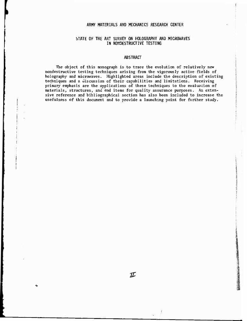
The object of this monograph is to trace the evolution of relatively new nondestructive testing techniques arising from the vigorously active fields of holography and microwaves. Highlighted areas include the description of existing techniques and a discussion of their capabilities and limitations. Receiving primary emphasis are the applications of these techniques to the evaluation of materials, structures, and end items for quality assurance purposes. An exten- sive reference and bibliographical section has also been included to increase the usefulness of this document and to provide a launching point for further study.
!
&

FOREWORD
This report was prepared under a project entitled State of the Art Survey on Holography and Microwave Technologies in Nondestructive Testing. This work was performed under the auspices of the U. S. Army Materiel Command's Materials Testing Technology Program, Department of Army Project Number M716350, AMCMS Code Number 4931.OM.6350. This work, which spanned the time interval from October 1970 to March 1972, was conducted with the twofold purpose of (1) contributing to the support of the overall effectiveness of the Army's Quality Assurance Program and (2) providing inputö to the Technical Cooperation Program as under- taken by Sub-Group P on Materials, Working Panel 4, on Evaluation Methods for Materials and Materials in Structures.
The author wishes to acknowledge and to express his gratitude to the follow- ing individuals and/or concerns for the provision of illustrative material: To Mr. Paul G. Lingenfelder formerly with the Naval Electronics Laboratory Center, San Diego, California, for the use of Table II, Figures 2, 3, and 10 to 26; to GCO, Inc., Plymouth, Michigan, for the use of Figures 28, 30, 31, 33 to 42, and 50; to Dr. Alexander Hammer, U. S. Army Weapons Command, Research and Engineering Directorate, Rock Island, Illinois, for the use of Figures 29, 44, 48, and 49; to Mr. Harry L. Ceccon, U. S. Department of Transportation, Transportation Systems Center, Cambridge, Massachusetts, for the use of Figure 32; to Dr. Charles M. Vest, University of Michigan, Ann Arbor, Michigan, for the use of Figures 43 and 45 to 47; to Mr. Robert Aprahamian, TRW Systems Group, Redondo Beach, California, for the use of Figures 51 and 52; to Mr. Byron B. Brenden, Holosonics, Inc., Richland, Washington, for the use of Figures 54 to 67; to Miss Theresa M. Lavelle, Frankford Arsenal, Philadelphia, Pennsylvania, for the use of Figures 70 to 76 and 79 to 83; and finally, to Mr. Lester Feinstein, NASA Ames Research Center, Moffett Field, California, for the use of Figures 84 to 87.
m

CONTENTS
Page
ABSTRACT
FOREWORD iii
INTRODUCTION 1
HOLOGRAPHY: GENERAL 1
OPTICAL HOLOGRAPHY 6
ACOUSTICAL HOLOGRAPHY 8
ELECTRON HOLOGRAPHY .... 11
HOLOGRAPHY SUMMARY 11
MICROWAVES 11
SAFETY 16
REFERENCES/BIBLIOGRAPHY 17
LITERATURE CITED . 71
BIBLIOGRAPHY 98
JZ

INTRODUCTION
Concurrent literature searches were performed on the subjects of Holographic and Microwave Nondestructive Testing. This work, which spanned the time interval from October 1970 to March 1972, was conducted from the standpoint of assessing the applicability of these technologies toward the evaluation of materials, struc- tures, and end items for quality assurance purposes. The description of existing techniques, their capabilities and limitations, and their adaptation to materials evaluation in both laboratory and industrial environments represent the substance of this monograph.
To supplement the examination of pertinent books and periodicals, literature searches were initiated and performed by the DoD Nondestructive Testing Informa- tion Analysis Center, the U. S. Army Foreign Science and Technology Center, The National Technical Information Service, and the NASA Scientific and Technical Information Facility. Additional information was also obtained through personal contacts with researchers and equipment manufacturers.
The work was performed under the auspices of the U. S. Army Materiel Com- mand's Materials Testing Technology Program with the twofold purpose of (1) con- tributing to the support of the overall effectiveness of the Army's Quality Assurance Program and (2) providing inputs to the Technical Cooperation Program as undertaken by Sub-Group P on Materials, Working Panel 4, on Evaluation Methods for Materials and Materials in Structures.1»2 These latter inputs, which have been combined and substantially amplified, form the basis of this monograph.
HOLOGRAPHY: GENERAL
Holography is a relatively new method of visualization possessing many unique characteristics of scientific importance. It is a fascinating and rapidly expand- ing field which is currently undergoing a metamorphosis from the function of being an academic curiosity to the function of assuming a prominent position as an established and widely applied technology. Because of the enormous activity and significant advancements which have been made in holography within the past decade, the following discussion will, of necessity, be very abbreviated and restricted in scope to only those aspects of holography that specifically relate to the nondestructive testing of materials. The extent of this productivity is directly reflected in the number of currently available Holographical Bibliogra- phies and Surveys.3-15 In addition, several references are available to the reader who may desire to further acquaint himself with the origin and subsequent development of this field from a historical viewpoint.16"18
To begin, it would be best, out of considerations of completeness and reader comprehension, to initially discuss what is meant by the term holography in a broad sense, and subsequently, in a more comprehensive sense. Generally speak- ing, holography is basically a technology which deals with a method of storage for use with any type of wave motion — be it electromagnetic in nature such as light waves, or nonelectromagnetic in nature such as acoustical waves — in which both the amplitude and phase of the wave motion can be captured and conveniently released at any later period. Because all of the information about the shape of an object is embodied in the complex wave of radiation which emanates from it

when it is suitably illuminated, the holographic process allows one to record this shape in permanent form in the hologram. Thus, at any later time, the shape can be regenerated and used as a sort of three-dimensional template against which any slight deviations in the geometry of the object can be compared.
More specifically, holography is a method for producing three-dimensional images of coherently illuminated objects by means of wavefront reconstruction and involves the use of highly intense, coherent, and monochromatic waves or beams.* It is a two-step technique, involving the processes of construction and reconstruction wherein some incident wavefrontt is recorded and subsequently reconstructed at a later time independently of its original source. For such a reconstruction to be possible, all of the information about the incident wave- front must be recorded; namely, its frequency, amplitude, and phase. As the fre- quency in a holographic system is a constant, being specified by the coherent wave source, the problem arises as to how the amplitude and phase information may be recorded simultaneously and ail-inclusively. Since most of the existing recording devices are square-law detectors, the amplitude is readily recordable, but the phase is not. The manner in which the phase is rendered recordable is, in actuality, the essence of holography.
For many years since its conception, progress in holography was severely hampered due to the lack of radiation sources possessing the necessary degrees of intensity, monochromaticity, and coherency. With respect to coherency, the term is used to describe in a quantitative way the preservation of the uniformity of phase between corresponding points of the wavetrain along and orthogonal to the direction of wave propagation, or, more generally, between two or more points located on either the same or different wavefronts within the wavetrain. These constraints were overcome in large part with the advent of the laser and its eventual application to the holographic process. The degree of the proliferation which has also occurred in the field of laser technology is manifested by the large number of commercially available lasers as is shown in the literature- referenced chart of Figure l.19-60 in this figure and the ones to follow, the citation of pertinent literature references will occur at applicable sites within the structure of the chart.
In the construction process, which is illustrated for the optical holographic case in Figure 2, a known and reproducible reference wave is allowed to combine and interfere with an unknown and complex wave, usually referred to as the signal or object beam, that has been either transmitted through or reflected from some object of interest to produce the incident wavefront. Because both of these waves have been derived from the same source via division of either wavefront or amplitude, they are mutually coherent and combine to produce an interference fringe field corresponding to the sum of their complex amplitudes. The terms division of amplitude and division of wavefront are used to designate the manner in which two beams may be derived from a single source. In the division of
*The terms waves and beams are synonymous and will, hereafter, be used interchangeably throughout this monograph.
tit should be noted that in holographic parlance, the term wavefront is used to denote the instantaneous state of the two interfering beams on some two- dimensional surface such as a recording medium. This usage is in contrast to the conventional context where the term wavefront is usod to signify a uniphase surface.

amplitude method (illustrated in Figure 1), the entire cross section of the beam is intercepted by a suitable optical component such as a beam-splitting reflector to produce two outgoing beams from one incoming beam by means of partial reflec- tion and transmission. In the division of wavefront method, only a fraction of the beam cross section is intercepted by a suitable optical component, such as a prism, to produce a phase shift or slight change in direction of only that por- tion of the intercepted beam while the remainder of the beam continues undeviated along the direction of beam propagation. (The division of wavefront method is illustrated in slightly modified form in Figure 17, where the modification con- sists of transmitting the hitherto undeviated portion of the beam through a two- dimensional object such as a photographic transparency.)
In the fringe field produced by the interaction of the signal and reference beams, the fringe spacing is modulated or varied by the phase differences exist- ing between the two waves. Therefore, the interference pattern embodying this fringe field is essentially a phase-modulated amplitude distribution whose square can then be recorded by a conventional square-law detector, such as a photographic emulsion placed within the region of interference. The recording is called a hologram. The angle between the signal and reference beams, labeled 6 in Fig- ure 2, is usually referred to as the shear angle. The magnitude of the shear angle and the wavelength of the light used, in turn, determine the orientation and spacing of the fringes comprising the recorded interference pattern. The angle <J> between the reference beam and the photographic plate is an additional parameter, which, in combination with the other two, influences the resolution requirements of the recording medium.
In the reconstruction process, which is illustrated in Figure 3, the holo- gram is used as a diffraction grating. When it is illuminated with the reference beam, three beams emerge — a zero order or undeflected beam and two first-order diffracted beams. The diffracted beams produce the real and virtual images of the object to complete the holographic process. In Figure 3, only the first- order diffracted beam which yields the virtual image has been shown, the other two beams having been omitted from the figure for the sake of clarity. If the original object is three-dimensional, then the virtual image is a genuine three- dimensional replica of the object possessing both parallax and depth of focus. The real image, on the other hand, is pseudoscopic or depth-inverted in appearance. Hence, the virtual image — also referred to as the true, primary, or nonpseudo- soopio image — is the one which is of primary interest in practical applications of holography.
Although optical holographic techniques have been the most extensively used to date, holograph^ need not be limited to visible light. Here lies the key to th^ great potential of this technique for nondestructive testing. Holography can, in principle, be performed with any wave radiation encompassed within the entire electromagnetic spectrum; with particulate radiation, such as neutrons and electrons which possess wave-equivalent properties; and finally, with non- electromagnetic radiation such as acoustical waves. The present and future holo- graphic techniques applicable to nondestructive testing are indicated in Figure 4. As can be seen from the figure, the only techniques presently available for prac- tical exploitation are those of optical, acoustical, and electron holography.

Since the interference pattern produced by the interaction of a beam scat- tered from the object of interest and the coherent reference beam must be faith- fully replicated during the construction process, the selection of a suitable holographic recording material for a particular application is of utmost import- ance. For optical holography, the diverse spatial variations in light intensity constituting the interference pattern are recorded indirectly through the cor- responding changes in the physical properties of the material comprising the recording medium. In order to be effectual, the affected physical properties must be capable of interacting with the reconstruction beam, in the second step of the holographic process, to produce the desired image of the object. In gen- eral, the interference patterns are usually preserved on or within the recording medium in the form of either an optical density or phase-shift pattern. In the optical density pattern, the recording material is classified as being absorptive, an'i the stored interference pattern, the hologram, behaves as a density grating which diffracts light by modulating the intensity of the incident reference beam. In the phase-shift pattern, the recording material is classified as being nonab- sorptive, phase-only, or more commonly as just phase. Unlike absorptive materials, holograms formed using phase materials possess uniform optical densities and be- have as phase gratings which diffract light by means of phase shifts produced by localized variations in the thickness and/or refractive index of the recording medium. In many actual cases, both amplitude and phase variations are present in the same hologram.
Some of the conventional and unconventional materials which have been used for holographic recording purposes are depicted in Figure 5. As can be seen from the figure, these materials divide into the two major categories of absorptive and pnase. It should be noted that photographic emulsions, the most commonly used materials, which are basically absorptive can be transformed into phase materials through suitable bleaching and processing techniques. For most of these materials, the recording process is permanent and irreversible. In contrast, certain other materials, such as the photochromies and electro-optic crystals, are erasable, and hence are reusable. Holograms can be further classified accord- ing to type, as shown in Figure 6, as being initially either plane/single-lay er/ thin or as volume/thick; secondarily, as being either absorptive or phase; and thirdly, as being either transmissive or reflective. Generally speaking, the terms plane, single-layer, or thin are used to designate those holograms wherein the interference pattern is recorded as a two-dimensional spatial grating on the surface of the recording medium or in a medium whose thickness is small as com- pared to the wavelength of the wave radiation being used to create it. Included in the thin hologram category is the surface relief hologram where the fringes comprising the interference field are recorded as surface deformations of the recording material. Likewise, the terms volume or thick are used to designate those holograms wherein the interference pattern is recorded as a three- dimensional spatial grating within the volume of the recording medium whose thickness is many times greater than the wavelength of the illumination source. The resultant volume hologram is composed of planes of varying density or index of refraction. Maximum diffraction efficiency is achieved during the reconstruc- tion process when the Bragg condition for reflection is satisfied for discrete values of reference beam angles of incidence and layer spacing. Additional de- tailed information concerning holographic recording materials and hologram clas- sifications can be found in the literature references cited in Figures 5 and 6.
/
i i i i*
-■ ■*-. .1 füfsrf! «B-'-W'lfc* :**S^*'^4?!Si»*i-«5*fÄ»«t»'tBiii,'*
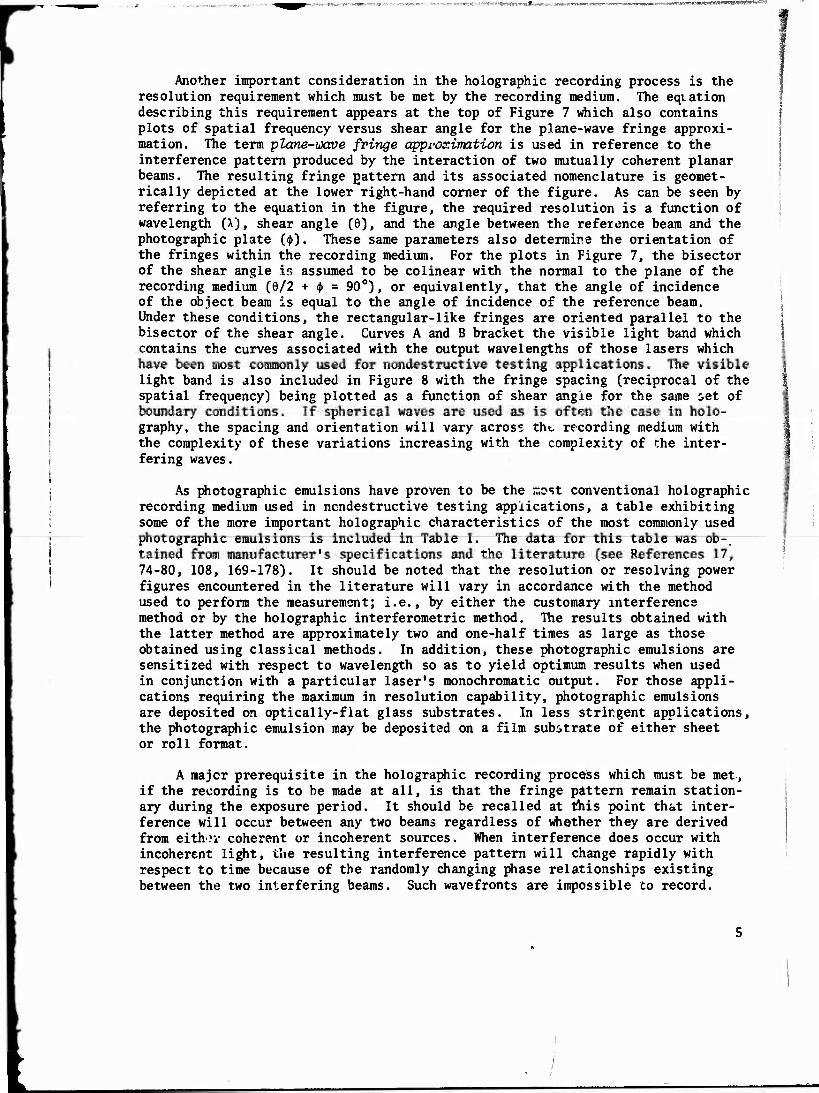
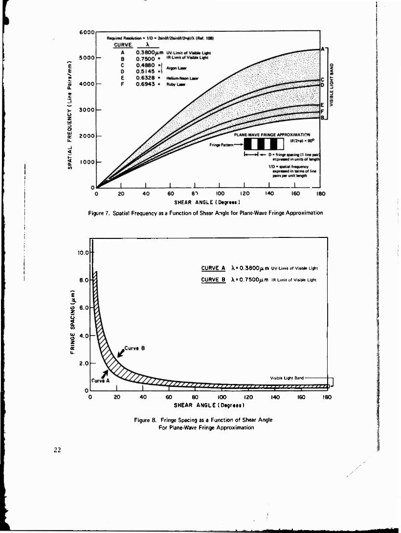
Another important consideration in the holographic recording process is the resolution requirement which must be met by the recording medium. The equation describing this requirement appears at the top of Figure 7 which also contains plots of spatial frequency versus shear angle for the plane-wave fringe approxi- mation. The term plane-wave fringe approximation is used in reference to the interference pattern produced by the interaction of two mutually coherent planar beams. The resulting fringe pattern and its associated nomenclature is geomet- rically depicted at the lower right-hand corner of the figure. As can be seen by referring to the equation in the figure, the required resolution is a function of wavelength (A), shear angle (0), and the angle between the reference beam and the photographic plate (<(>). These same parameters also determine the orientation of the fringes within the recording medium. For the plots in Figure 7, the bisector of the shear angle is assumed to be colinear with the normal to the plane of the recording medium (6/2 + <J> = 90°), or equivalently, that the angle of incidence of the object beam is equal to the angle of incidence of the reference beam. Under these conditions, the rectangular-like fringes are oriented parallel to the bisector of the shear angle. Curves A and B bracket the visible light band which contains the curves associated with the output wavelengths of those lasers which have been most commonly used for nondestructive testing applications. The visible light band is also included in Figure 8 with the fringe spacing (reciprocal of the spatial frequency) being plotted as a function of shear angle for the same set of boundary conditions. If spherical waves are used as is often the case in holo- graphy, the spacing and orientation will vary across the recording medium with the complexity of these variations increasing with the complexity of the inter- fering waves.
As photographic emulsions have proven to be the most conventional holographic recording medium used in nondestructive testing applications, a table exhibiting some of the more important holographic characteristics of the most commonly used photographic emulsions is included in Table I. The data for this table was ob- tained from manufacturer's specifications and the literature (see References 17, 74-80, 108, 169-178). It should be noted that the resolution or resolving power figures encountered in the literature will vary in accordance with the method used to perform the measurement; i.e., by either the customary interference method or by the holographic interferometric method. The results obtained with the latter method are approximately two and one-half times as large as those obtained using classical methods. In addition, these photographic emulsions are sensitized with respect to wavelength so as to yield optimum results when used in conjunction with a particular laser's monochromatic output. For those appli- cations requiring the maximum in resolution capability, photographic emulsions are deposited on optically-flat glass substrates. In less strirgent applications, the photographic emulsion may be deposited on a film substrate of either sheet or roll format.
A major prerequisite in the holographic recording process which must be met, if the recording is to be made at all, is that the fringe pattern remain station- ary during the exposure period. It should be recalled at this point that inter- ference will occur between any two beams regardless of whether they are derived from either coherent or incoherent sources. When interference does occur with incoherent light, the resulting interference pattern will change rapidly with respect to time because of the randomly changing phase relationships existing between the two interfering beams. Such wavefronts are impossible to record.
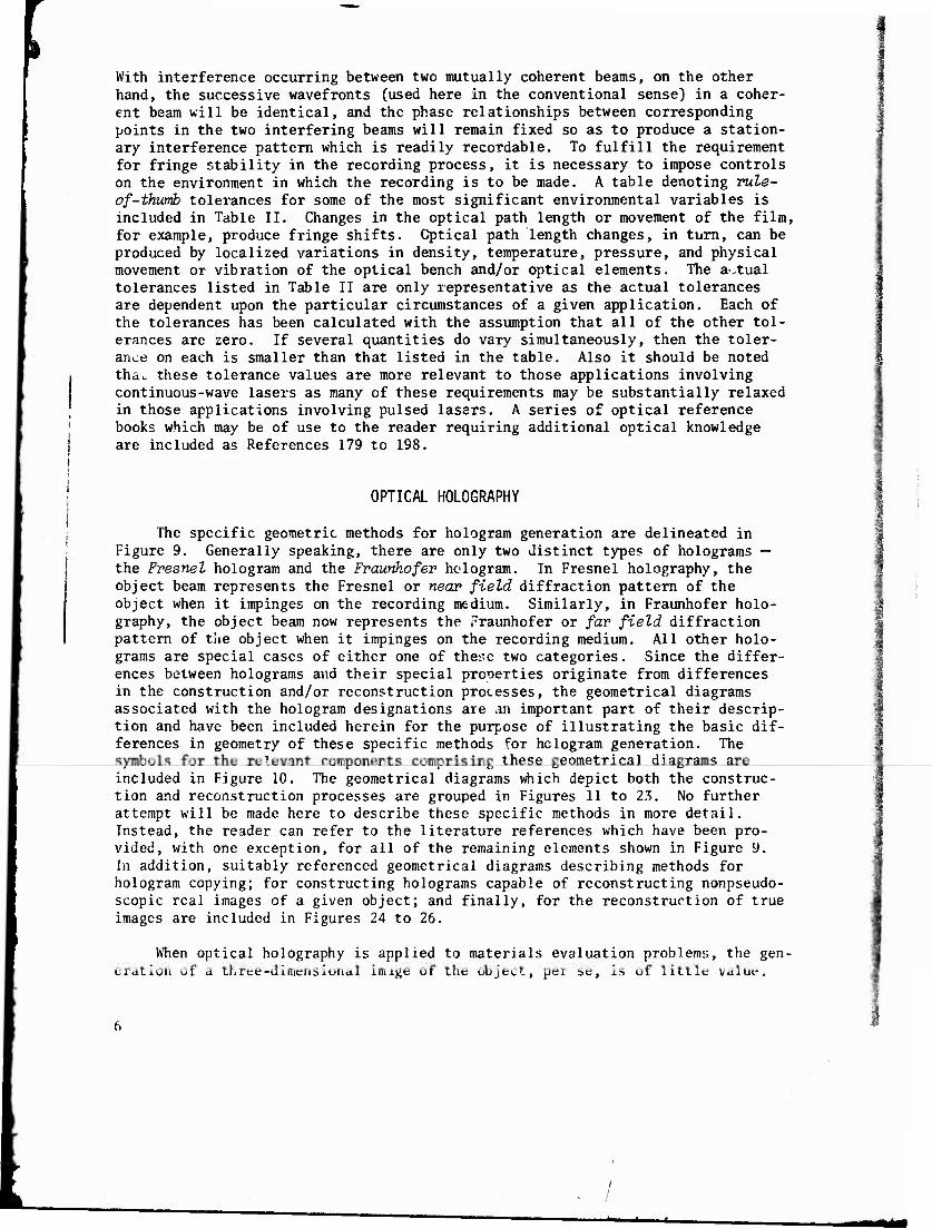
With interference occurring between two mutually coherent beams, on the other hand, the successive wavefronts (used here in the conventional sense) in a coher- ent beam will be identical, and the phase relationships between corresponding points in the two interfering beams will remain fixed so as to produce a station- ary interference pattern which is readily recordable. To fulfill the requirement for fringe stability in the recording process, it is necessary to impose controls on the environment in which the recording is to be made. A table denoting rule- of-thwmb tolerances for some of the most significant environmental variables is included in Table II. Changes in the optical path length or movement of the film, for example, produce fringe shifts. Optical path length changes, in turn, can be produced by localized variations in density, temperature, pressure, and physical movement or vibration of the optical bench and/or optical elements. The actual tolerances listed in Table II are only representative as the actual tolerances are dependent upon the particular circumstances of a given application. Each of the tolerances has been calculated with the assumption that all of the other tol- erances are zero. If several quantities do vary simultaneously, then the toler- ance on each is smaller than that listed in the table. Also it should be noted tha^ these tolerance values are more relevant to those applications involving continuous-wave lasers as many of these requirements may be substantially relaxed in those applications involving pulsed lasers. A series of optical reference books which may be of use to the reader requiring additional optical knowledge are included as References 179 to 198.
:
OPTICAL HOLOGRAPHY
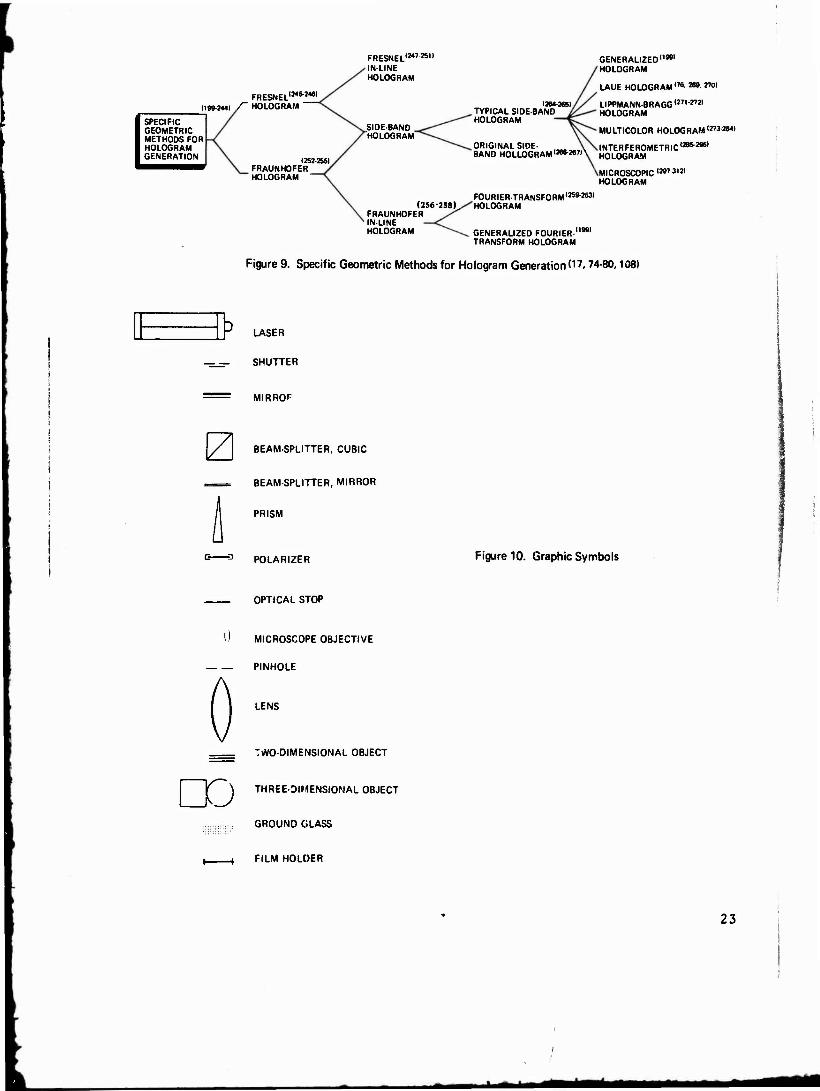
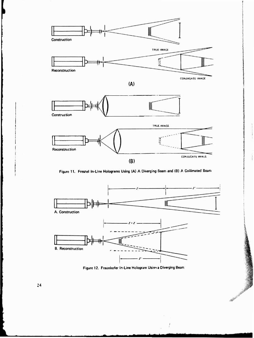
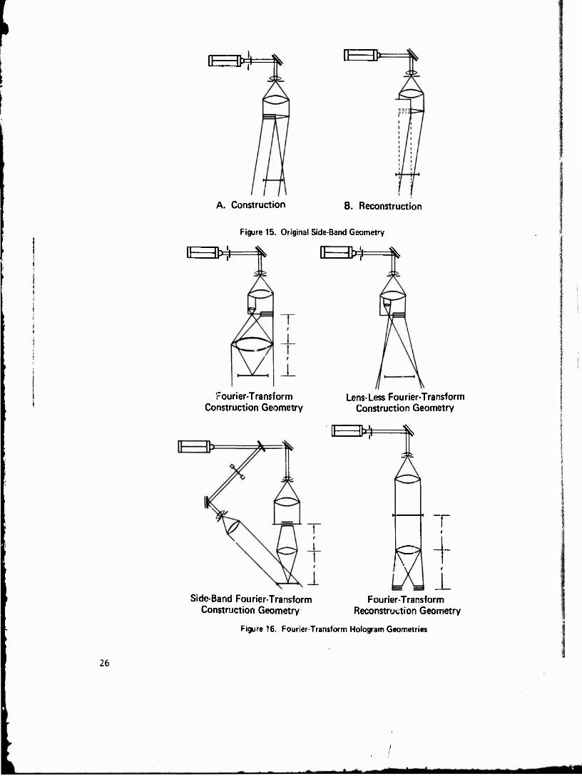
The specific geometric methods for hologram generation are delineated in Figure 9. Generally speaking, there are only two distinct types of holograms — the Fvesnel hologram and the Fraunhofer hologram. In Fresnel holography, the object beam represents the Fresnel or near field diffraction pattern of the object when it impinges on the recording medium. Similarly, in Fraunhofer holo- graphy, the object beam now represents the Fraunhofer or far field diffraction pattern of the object when it impinges on the recording medium. All other holo- grams are special cases of either one of these two categories. Since the differ- ences between holograms and their special properties originate from differences in the construction and/or reconstruction processes, the geometrical diagrams associated with the hologram designations are an important part of their descrip- tion and have been included herein for the purpose of illustrating the basic dif- ferences in geometry of these specific methods for hologram generation. The symbols for the relevant components comprising these geometrical diagrams are included in Figure 10. The geometrical diagrams which depict both the construc- tion and reconstruction processes are grouped in Figures 11 to 23. No further attempt will be made here to describe these specific methods in more detail. Instead, the reader can refer to the literature references which have been pro- vided, with one exception, for all of the remaining elements shown in Figure 9. In addition, suitably referenced geometrical diagrams describing methods for hologram copying; for constructing holograms capable of reconstructing nonpseudo- scopic real images of a given object; and finally, for the reconstruction of true images are included in Figures 24 to 26.
When optical holography is applied to materials evaluation problems, the gen- eration of a three-dimensional imige of the object, per se, is of little value.

Furthermore, for opaque materials, optical holography is strictly limited to sur- face observations. Hence, if this technique is to be used for nondestructive testing purposes, supplementary means have to be employed to either stress or impart energy into the test object so as to faithfully produce surface manifesta- tions of the parameter of interest. It is at this juncture that the technique of holographic interferometry plays a significant role.
As in the conventional optical case, holographic interferometric measure- ments can be made with great accuracy, i.e., to within a fraction of the wave- length of the light being used. Whereas conventional interferometry is usually restricted to the examination of objects possessing highly polished surfaces and simple shapes, holographic interferometry is not. It can be used to examine three-dimensional surfaces of arbitrary shape and surface conditions. Additional points of contrast are as follows. Conventional interferometry must be performed in real time; requires a critical alignment of optical components; and yields a two-dimensional fringe-field readout. Holographic interferometry, on the other hand, can be performed in either real time or at two different times; does not require precise alignment of optical components (except for real-time applica- tions); and yields a three-dimensional fringe-field readout. Because of the three-dimensionality of the hologram reconstruction, a complex object can be interferometrically examined from many different perspectives, wherein the angle of view is limited by only the physical size of the hologram. Thus, a single hologram reconstruction is equivalent to a multiplicity of conventional inter- ferometric observations.
The techniques of holographic interferometry, which are depicted in Fig- ure 27, can be reduced to two basic categories: time lapse and real time. In the time-lapse approach, advantage is made of the fact that more than one holo- gram may be made on the same recording medium. Examples of this approach include:
Double Exposure or Differential Technique involves the recording of two holograms — one of the object in its natural or undisturbed state, and the other of the object in some changed or disturbed state. In the reconstruction process, the two recorded object beams interfere with one another to produce a fringe field wherein the contour and spacing describe the changes that occurred between the two exposures.
Multiple Exposure or Stroboscopic Technique involves the multiple recording of certain predetermined positions of an object in periodic motion, usually at the positive and negative amplitudes of vibration. In the reconstruction process, fringes of high contrar.t are produced that enable the measurement of high ampli- tudes of vibration. By appropriately timing the light pulses, the phase rela- tionships of the antinodes may also be obtained.
Continuous Exposure or Time-Average Technique is an extension of the double and multiple exposure methods to the limiting case involving the recording of a continuum or infinite number of exposures of an object in periodic motion. Because the holographic exposure time is usually much greater than the period of object motion, the hologram is a record of the time-averaged irradiance distribu- tion at the hologram plane. In the reconstruction process, an infinite number of images, corresponding to the previously recorded infinite number of object positions, are produced and interfere with one another. In the resulting fringe

field, the bright fringes correspond to nodal regions (i.e., regions of zero or very small amplitudes of vibration) and dark fringes to antinodal regions (i.e., legions of large amplitudes of vibration). By employing appropriate fringe anal- ysis techniques, the amplitudes of vibration for each point on the object's sur- face may be determined. Because the fringe contrast decreases as the amplitude of motion increases, the displacement amplitudes amenable to analysis by this method cannot be too great.
In the real-time approach, a hologram is first made of the object in its natural or undisturbed state. The hologram is then reconstructed and precisely repositioned so that the virtual image is exactly superimposed upon the object. Thereupon, the object is disturbed in either a static or dynamic manner. With the hologram being used as an observation window, it is possible to observe the resulting interference pattern produced by the interaction of the recorded object beam (also referred to as the stored or frozen beam) with a modified, real-time object beam (sometimes referred to as the live beam). With this method, it is possible to observe differential, stroboscopic, and time-averaged fields. For time-varying fringe fields, the time averaging is performed by the observer's ey .
Holographic interferometry has been successfully used as a noncontacting tool for strain and vibration studies, depth-contour mappings, and transient/ dynamic phenomena analyses. In the area of nondestructive testing, holographic interferometry has been used to detect and locate disbonds within honeycomb- sandwich structures; disbonds between steel cylinder and diffusion-bonded aluminum cladding; flaws within either passenger car or aircraft tires; cracks in pr~;~ctile bodies; and also to separate hollow turbine blades according to wall thickness. Holographic interferometry has also been used for monitoring stress corrosion cracking and for the determination of Young's modulus.for glass. Complete holographic test systems are presently commercially avai^ .ble from approximately twelve manufacturers, while the necessary components required to custom build a system are available from a multitude of sources. The overall price of a laboratory test system varies in direct accordance with the sophisti- cation, capabilities, and object size and spans the price range of $1,500 to $25,000. Highly specialized industrial holographic analyzers are also available at proportionately higher prices. Photographic examples of holographic testing systems and materials evaluation applications can be found in Figures 28 to 52. These photogiaphs are augmented by either self-explanatory or annotated captions* so as to obviate the need for any further prolonged discussion here in the body of the text. As for the interferometric results, it should be noted that the greater the fringe density, the greater is the surface deformation which pro- duced it.
ACOUSTICAL HOLOGRAPHY
Acoustical holography is another endeavor which has been vigorously pursued for nondestructive testing purposes, since sound, unlike light, is capable of penetrating opaque objects. Acoustical holography, like optical holography, is a two-step technique involving the processes of acoustical hologram construction and reconstruction. In the construction process, the acoustical hologram may be
*In these captions, the frequently used designation Holographic Nondestructive Testing appears in abbreviated form as HNDT.

■v
formed either directly by the interference of an acoustical object beam with an acoustical reference beam in the acoustical domain, or indirectly via the inter- action of a piezoelectrically detected acoustical object beam with an electron- ically simulated reference beam. With respect to the reconstruction process which must occur in the optical domain in order to be seen, the particular method involved will be the determining factor as to whether the reconstruction process occurs coincidentdlly with or ensuing tc the process of construction. The speci- fic methods used for acoustical hologram generation are depicted in Figure 53. In addition, representative geometrical diagrams portraying these methods have also been included as integral supplements in Figures 54 to 60 and 64 as the differences between these methods stem predominantly from differences in the geometrical arrangements of the components used to construct the acoustical holograms. As can be seen from Figure 53, the various techniques developed thus far fall into two general categories; namely, real-time and raster-scanning. For the most part, acoustical analogs of existing optical holographic methods have been employed wherein the acoustical portion of the system is submerged in a liquid medium, usually water, and the electro-optical portion required for readout purposes is situated externally to the liquid tank. Although higher acoustical frequencies have been used in specialized instances, the majority of work, for practical testing applications, has been performed in the 1-10 MHz frequency range.
Real-Time Acoustical Holography: In the construction process, the acousti- cal hologram is formed on a liquid surface as a relief pattern of variable height. The simplified surface conditions and equations associated with this approach are included in Figure 54. A basic liquid-surface system for acoustical holography is shown in Figure 55. This figure is augmented by Figures 56 and 57 which illus- trate the physical nature of the liquid surface relief pattern — the acoustical hologram — and the types of readout obtainable with this method. It should be noted that the technique shown in Figures 56 and 57 preceded in time the one illustrated in Figure 55, and hence did not incorporate improvements such as the use of the small isolation tank and acoustical lenses. The relief pattern is produced by the interference effects of two interacting beams of either continu- ous or pulsed ultrasound — one which has been transmitted through the test object, the dbg eat beam, and the other, the reference beam, which has been directly transmitted to the liquid surface. Reconstruction of this acoustically formed hologram occurs simultaneously for all practical purposes and is accomplished by reflecting light, incident from above, from the surface. A spatial filter is used to achieve a separation of the resulting diffracted light into components for viewing and recording purposes. Because all of the liquid surface elements comprising the acoustical hologram vre formed at the same instant, the reconstruc- tion process can be accomplished in quasi real-time. This important characteris- tic enables test objects undergoing examination to be continuously moved and rotated for defect enhancement purposes and the resulting dynamically changing images to be recorded by appropriate auxiliary instrumentation. The use of acous- tical lenses results in the further enhancement of image quality and permits the interrogation in depth of preselected subsurface layers of test object material. For this method, the maximum obtainable acoustical field of view to date is of the order of five and one-half inches. Finally, this method is presently re- stricted in the acoustical domain to the application of the through-transmission mode and is, for the most part, subject to the attendant limitations of this particular technique.

Raster-Soanning Acoustical Holography: This method of acoustical holography can be further subdivided into two basic approaches — electronic raster scanning and mechanical raster scanning as in Figure 53. In this method, energy must be transformed initially from acoustical to electronic, and subsequently from elec- tronic to light. In the construction process, ultrasonic fields which have been either transmitted through or reflected from the test object are sensed by piezo- electric detectors. These detectors may be of relatively moderate surface area, such as those that are used as receiver faceplates for electronically-scanned ultrason'-c image converter tubes, or they may be of the point-receiver type, such as those that are used in mechanical raster-scanning systems. The manner in which an acoustical hologram is constructed by the mechanical raster-scanning technique is illustrated in Figure 58. By detecting ultrasonic fields of interest using piezoelectric means, the requirement for effecting the interaction of the object and reference beams to produce interference may be accomplished in either the acoustical or electronic domains. For the acoustical domain option, a real acous- tical reference beam is used, while for the electronic domain option, a simulated electronic reference beam is used to interfere with the electronic signal derived from the piezoelectrically-transformed acoustical object beam. Upon achieving interference, the resulting electronic data is appropriately processed and used to modulate the intensity of either a point light source, the electron beam of a television display monitor or of an oscilloscope, or the writing element (single- turn wire helix) of a facsimile recorder. For the electronic raster-scanning systems, the electron beams of both the ultrasonic image converter tube and the television display monitor are in synchronization with one another, while for the mechanical raster-scanning systems, the point light source or the oscilloscope electron beam is scanned in synchronization with the piezoelectric receiver. The end result is the generation of an optical transparency which serves as the hologram (the optical equivalent to the acoustical hologram) for reconstruction in the optical domain. An example of a mechanical raster-scanning approach employing an electronically-obtained simulated reference beam for acoustical hologram construction is the synthetic aperture method wherein the object beam for the electronic domain is piezoelectrically derived from only a single scan- ning transducer, usually of the focused variety, being operated ir. the pulse-echo mode. With this method, it is possible to obtain, within limits, depth-indicative acoustical holograms of subsurface layers of the isonofied test object. Addi- tional examples of mechanical raster-scanning methods, as per Figure 53, are included in Figures 59 and 60. Examples of raster-scanned acoustical holograms are shown in Figures 61 to 63, and the subsequent reconstruction process is depicted in Figure 64.
In terms of reduction to practice, both the real-time and raster-scanning acoustical holographic methods are capable of achieving the resolution expected on the basis of the wavelength and hologram aperture used. While mechanical raster-scanning methods are two-step processes, the real-time liquid surface method is essentially a one-step process — the processes of hologram construction and reconstruction occurring almost simultaneously. In addition, while it is possible to generate acoustical holog~' • with commercially available equipment employing the electronic raster-scanning method, the only complete acoustical holographic systems designed specifically for materials evaluation applications available to date employ either the inherently simple real-time liquid surface, or synthetic aperture mechanical raster-scanning methods. The cost of complete systems such as these is presently of the order of $40,000.
10

Regarding practical nondestructive testing applications,619~639 much of the developmental work was performed with laboratory-type test specimens. However, the real-time liquid surface method is currently being applied to detect delamina- tions and inclusions in graphite-epoxy and boron-epoxy lamina; debonds in metal- nonmetal and metal-metal structures including honeycomb-sandwich panels; voids in diffusion-bonded structures; and fatigue cracks in steel. Acoustical holography, like acoustical imaging, provides optimum test results using objects possessing simple surface geometries. Objects possessing complex surface geometries still constitute significant impediments to the more widespread application of this technique. However, efforts are now being made to mitigate these impediments through the development and application of cylindrical and mosaic-type acoustical transducers. Several representative examples of results obtained using methods of liquid-surface acoustical holography are shown in Figures 65 to 67.
ELECTRON HOLOGRAPHY
Only a few pertinent comments will be made at this time concerning the remaining holographic technique, electron holography, for the sake of complete- ness. Although electron microscopy has become one of the most important tools of modern day science, electron holography has within the short time span of twenty years caught up with electron microscopy as an imaging method. This accomplishment was made possible by a significant breakthrough made in 1968 by a group of Japanese scientists.107 Electron holography now has a resolution equiv- alent to that obtainable with electron raicroscopy. As for utilization, the spe- cific application is the ultimate determining factor as to which of these two methods should be used. In certain instances, electron holography would be preferable, while for others, the method of choice would be electron microscopy.
HOLOGRAPHY SUMMARY
In summary, holography has undergone a rebirth and maturation during the decade of the sixties. Further advancements remain to be made in the areas of the development of new and improved coherent sources of radiation; the develop- ment of new and improved holographic recording materials exhibiting increased sensitivity, higher resolution, faster speed, greater dimensional stability, more faithful reproducibility of multicolor scenes, and reusable capabilities; the development of improved fringe interpretation techniques; the development of improved techniques for increasing the range of variation in sensitivity of holo- graphic interferometric methods; and, finally, the improvement and .simplification of the reconstruction process involving the suppression of image granularity and the utilization of limited coherent white light sources. The ultimate success of holography as a practical scientific tool will be directly dependent upon the contributions derived from the continuing explorations of world-wide research and the attainments of further progress in areas of current application.
MICROWAVES
Microwaves are a form of electromagnetic radiation comprising a not-too- rigidly defined frequency band of 0.225 to 100 gigahertz (1 GHz - 109 Hz) and a
11

corresponding wavelength band in free space of 133.3 to 0.3000 centimeters. In the electromagnetic spectrum, the microwave frequency band is bounded by the lower frequency radiosvave band on the one hand, and by the higher frequency infra- red band on the other. The microwave frequency bands are delineated in Figure 68. In certain respects, microwaves beiiave like light waves in that they travel in straight lines, reflect, refract, diffract, interfere, and scatter according to the laws of optics. Differences in behavior do arise due to differences in wave- length — microwaves typically possessing wavelengths some one hundred thousand times larger than light. As a direct consequence, microwaves tend to interact with objects and materials on a macroscopic scale and light on a microscopic scale. Unlike light, microwaves are capable of penetrating most nonmetallic materials and structures, reflecting and scattering from internal boundaries, and interacting with the molecules of materials. Although its significance as a ma- terials testing method was recognized in the early 1950*s, microwave technology was not extensively put into practice as a nondestructive testing tool until the 1960's. This advancement was made possible by the advent of more adequate equip- ment for the generation and measurement of microwave energy.
To date, all microwave techniques have employed either continuous-wave or frequency-modulated modes of radiation, as the problems associated with the reduction-to-practice of pulse reflection techniques similar to those used in ultrasonic testing are quite formidable. Ar. insight into these problems can be obtained by merely considering the distance that a microwave pulse would occupy in free space. Since the velocity of propagation of electromagnetic radiation is 3 x io° meters per second, a 1-microsecond pulse would occupy 300 meters in
I space, a 1-nanosecond (10-9 second) pulse 30 centimeters, and a 10-picosecond j (10-11 second) pulse 0.3 centimeter. Thus, with present day technological know-
how the attainment of a bona fide range resolution capability for flaw detection purposes in microwave nondestructive testing, although highly desirable, is a
| physical impossibility. Whereas magnetrons, klystrons, traveling wave tubes, i paramagnetic oscillators, and molecular oscillators may all be used for the gen- t eration of microwaves, it has been the klystron which has proven to be the work- ' horse of microwave nondestructive testing. In materials testing applications,
shorter wavelength radiations spanning the wavelength interval of 0.5 to 20 cen- timeters (1.5 to 60 GHz) have been employed in order to achieve improvements in defect-size resolution.
When microwaves penetrate a nonelectrically conducting material, they are influenced by only three parameters of the material — two electromagnetic, the dielectric constant and the loss tangent, and one geometric, the shape and dimen- sions of the material. The dielectric constant, also referred to as the permit- tivity, is in actuality a frequency-dependent parameter that is a measure of the amount of electrostatic energy that can be stored per unit volume of material when a unit voltage is applied and, as a consequence, is intimately associated witli the polarization characteristics of the material. Polarization always occurs to some degree whenever microwaves penetrate dielectric materials, since electri- cal charge within the material is displaced due to the influence of the electric field associated with the microwaves. The other electromagnetic materials prop- erty, the loss tangent, is a measure of the amount of power which is lost as heat whenever a dielectric material is subjected to a high frequency electromagnetic field. Both the dielectric constant and loss tangent are functions of material composition, structure, homogeneity, orientation, moisture content, and other
12

similar factors. These relationships lead to a number of interesting practical microwave nondestructive testing applications. As for the shape and dimensions of the material, if the surface geometry is too irregular, the physical extent too small, or the thickness too great, then deleterious effects, such a.~ undesir- able surface reflections, objectionable edge effects, a distortion of beam direc- tivity, and excessive self-absorption by the material of microwave energy, may be encountered.
The specific geometric methods that have thus far been employed in micro- wave nondestructive testing are illustrated in Figure 69 and include:
Transmission where microwave energy passing through the material is accord- ingly modified by the internal condition of the material.
Reflection where the microwave energy reflected from either the surface or from within the material is correspondingly modified by either the surface or internal condition of the material.
Scattering where microwave energy penetrating the material is randomly reflected and/or diffracted by scattering centers, such as cracks, voids, inclu- sions, and foreign material, situated within the parent material.
Interferometry where two or more sets of microwave wavetrains simultaneously traveling in either the same or opposite directions naturally interfere with one another as in the classical case, or where two sets of microwave wavetrains are deliberately made to interact with one another to produce interference as in the holographic case.
Block diagrams of the equipment associated with the specific geometric microwave methods are included in Figures 70 to 76.
Microwave signal data displays for nondestructive testing applications are shown in Figure 77. In certain established test approaches, the amplitude and/ or phase of a microwave signal is measured and/or monitored using either meters, oscilloscopes, or recorders. In more sophisticated test approaches, a spectral analysis is performed on the detected microwave signal to yield additional inform- ation concerning flaw parameters and physical properties. As in other nondestruc- tive testing techniques, methods are available for displaying the data in pictorial form in an attempt to yield perceptible defect profiles and simplify the interpretation of microwave test results. These methods include:
Field Scanning where a microwave field is probed with a scanning pickup horn moving in synchronization with an intensity-modulated writing element of the recording instrumentation, such as the single-turn wire helix of a facsimile recorder or the electron beam of an oscilloscope. The end result is a plan view display of the cross section of the microwave field containing variations in con- trast which are in direct proportion to the strength of the detected signal.
Cholester-ic Liquid Crystals where a mapping of the entire microwave field, or a large fraction thereof, is obtained in color with liquid crystals by their ability, upon exposure, to convert the microwave energy absorbed as heat into a temperature-dependent wavelength readout. Because of the nonunifortuities inherent
r.
13
» —- ■■ mm*

within the microwave field, the surface of a cholesteric liquid crystal detec- tor — a thin layer of liquid crystals deposited on a t'.iin black substrate — will be differentially heated in direct accordance with the variations of intensity of the microwave field to yield a color pattern, representing the desired mapping. The color change is reversible with respect to temperature and may be effected over a narrow and variable temperature range.
Photographic Emulsions where a microwave-field mapping is obtained in either black-and-white or color by using appropriately prepared photographic films as sensing elements. As with the cholesteric liquid crystal method, the differen- tial heating effects associated with the microwavt field are relied upon to pro- duce the thermal gradients required for the recording, which in this case is irreversible. The film is usually subjected to an initial and incomplete expo- sure to uniform illumination with light, coated with a thin film of developer, and then placed into the microwave field to undergo further development. Because the rate of development of a photographic emulsion is temperature-dependent, those regions of the film that are exposed to more intense microwave radiation will experience greater heating effects and will consequently develop more rapidly than those regions exposed to less intense levels of microwave radiation. When the exposure is completed, the degree of darkness within the recording will vary in direct accordance with the intensity of the microwave field.
Holography where the visualization of a highly frequency-stable microwave field is accomplished through a two-step method involving the processes of con- struction and reconstruction. In the construction process, a known and reproduc- ible microwave beam is allowed to combine and deliberately interfere with an unknown, mutually coherent, and complex microwave beam. The known beam is refer- red to as the reference beam, the unknown beam is referred to as the object beam and is derived from the same microwave source. The resulting interference pattern is then recorded using a suitable recording medium. When a real microwave refer- ence beam is employed to create interference in the microwave domain, recording media exhibiting temperature-sensitive characteristics such as cholesteric liquid crystals and carbon-impregnated paraffin have been found to be satisfactory. For this type of approach, the construction process is completed by generating an optical transparency of the microwave hologram, where the optical transparency is in actuality an optical hologram. The necessity of effecting a hologram translation from the microwave to the optical domain can be obviated by using an alternative approach. In this case, an electronically simulated microwave refer- ence beam is allowed to interfere with an electronically transformed object beam derived from a probe being used to scan the microwave field of interest. The resultant signal created by the interference, now occurring in the electronic domain, is used to modulate the intensity of a point light source moving across a photographic plate in synchronization with the probe. The end result is the pro- duction of a single optically scanned hologram containing extraneous information in the form of a recorded, raster-scanned, line pattern. In the reconstruction process, coherent light from a laser is used to illuminate the optical hologram to yield an image of the object. Because the wavelength of the laser light is of the order of 10"5 times smaller than that of the microwave radiation, the reconstructed image is reduced by the same ratio and necessitates the use of an auxiliary optical system for viewing purposes. The reduction in image size also substantially diminishes the three-dimensional aspects normally associated with reconstructed holographic images. The techniques of holographic interftrometry
14
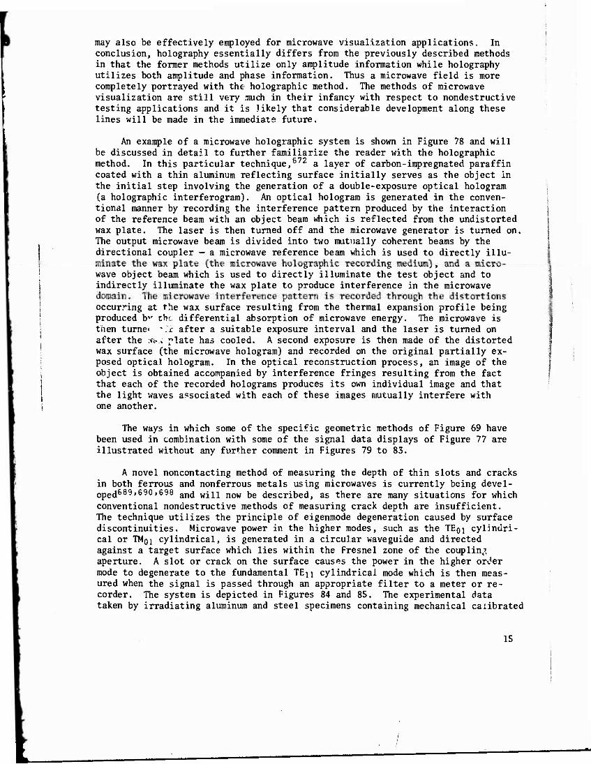
may also be effectively employed for microwave visualization applications. In conclusion, holography essentially differs from the previously described methods in that the former methods utilize only amplitude information while holography utilizes both amplitude and phase information. Thus a microwave field is more completely portrayed with the holographic method. The methods of microwave visualization are still very mich in their infancy with respect to nondestructive testing applications and it is likely that considerable development along these lines will be made in the immediate future.
An example of a microwave holographic system is shown in Figure 78 and will be discussed in detail to further familiarize the reader with the holographic method. In this particular technique,672 a layer of carbon-impregnated paraffin coated with a thin aluminum reflecting surface initially serves as the object in the initial step involving the generation of a double-exposure optical hologram (a holographic interferogram). An optical hologram is generated in the conven- tional manner by recording the interference pattern produced by the interaction of the reference beam with an object beam which is reflected from the undistorted wax plate. The laser is then turned off and the microwave generator is turned on. The output microwave beam is divided into two mutually coherent beams by the directional coupler — a microwave reference beam which is used to directly illu- minate the wax plate (the microwave holographic recording medium), and a micro- wave object beam which is used to directly illuminate the test object and to indirectly illuminate the wax plate to produce interference in the microwave domain. The microwave interference pattern is recorded through the distortions occurring at the wax surface resulting from the thermal expansion profile being produced bv the differential absorption of microwave energy. The microwave is then turne< *.r after a suitable exposure interval and the laser is turned on after the *.« plate has cooled. A second exposure is then made of the distorted wax surface (the microwave hologram) and recorded on the original partially ex- posed optical hologram. In the optical reconstruction process, an image of the object is obtained accompanied by interference fringes resulting from the fact that each of the recorded holograms produces its own individual image and that the light waves associated with each of these images mutually interfere with one another.
The ways in which some of the specific geometric methods of Figure 69 have been used in combination with some of the signal data displays of Figure 77 are illustrated without any further comment in Figures 79 to 83.
A novel noncontacting method of measuring the depth of thin slots and cracks in both ferrous and nonferrous metals using microwaves is currently being devel- oped689'690'698 and will now be described, as there are many situations for which conventional nondestructive methods of measuring crack depth are insufficient. The technique utilizes the principle of eigenmode degeneration caused by surface discontinuities. Microwave power in the higher modes, such as the TEQI cylindri- cal or TMQI cylindrical, is generated in a circular waveguide and directed against a target surface which lies within the Fresnel zone of the coupling aperture. A slot or crack on the surface causes the power in the higher order mode to degenerate to the fundamental TEJJ cylindrical mode which is then meas- ured when the signal is passed through an appropriate filter to a meter or re- corder. The system is depicted in Figures 84 and 85. The experimental data taken by irradiating aluminum and steel specimens containing mechanical calibrated
15

slots with either TE0i or TM01 cylindrical modes are shown in Figures 86 and 87. In both cases, the signal amplitude was referenced to the signal strength pro- duced by the deepest slot irradiated with the TE01 mode. The uncertainty band in these figures arises from the lack of a good calibration procedure.
Microwave nondestructive testing techniques have been successfully used as a noncontacting tool for the detection of flaws such as inclusions, voids, and delaminations within nonmetallic structures; the measurement of contour, eccen- tricity, motion, and displacement involving either metallic or nonmetallic parts; the measurement of the thickness of coatings of one nonmetallic material over another or of a nonmetallic coating on a metal; the measurement of thickness of materials and structures bounded by parallel surfaces; the measurement of the degree of cure of plastic materials; the determination of moisture content of materials; the determination of the orientation of both metallic and nonme- tallic fibers in fiber-reinforced nonmetallic materials; and the direct meas- urement of the dielectric constant and loss tangent, just to mention a few applications.673"737 In spite of these impressive capabilities, microwave non- destructive testing is still handicapped by the following inadequacies; analysis of data can be difficult if more than one influencing variable is present; pre- cise positioning of components is necessary to minimize interference effects; high frequencies which yield greater resolution are also more severely influenced by minor variations in materials properties; no standardized procedures are available for testing purposes; and finally, the method is still being explored and developed. Complete microwave nondestructive testing systems are currently commercially available from three manufacturers while the necessary components required to custom build a system are available from a multitude of sources. The overall price of a laboratory test system varies in direct accordance with the sophistication, capabilities, and accessories required and spans the price range of $2,000 to $25,000.
SAFETY
This technical monograph will now be concluded with a few remarks on the subject of safety. Generally speaking, whenever new technologies are introduced into recognized fields of endeavor, questions inevitably avise concerning the existence or nonexistence of safety hazards. The specific parallel in the case of this monograph is the introduction and reduction-to-practice of the relatively new technologies of holography and microwaves in the established field of non- destructive testing. For the most part, the hazards associated with the partic- ular form of radiation are those which are of utmost concern. Once a safety hazard is recognized, adequate protective measures are taken to prevent unneces- sary exposure of personnel to injurious levels of radiative intensity. In order to control the intensity of radiation, it is first necessary to place controls on the source of radiation. Once this is done, maximum permissible levels of exposure have to be determined. Other corrective actions involve the medical surveillance of personnel; the use of protective devices; the registration, supervision, and control of the radiation source; and finally, the reporting of accidents.
For optical holography, the effects of laser radiation are essentially the same as light generated by more conventional ultraviolet, infrared, and visible
16 „f

■vv-'j-w-üv:."-?-*"^.1*'' ?
light sources. The unique biological implications attributed to laser radiation are generally those resulting from the highly intense and characteristic mono- chromatic nature of laser light. Several of the existing regulative documents pertaining to holographic safety538_5'*1,7't0 are extremely interesting and should be read by anyone who becomes involved in holography. As for acoustical holo- graphy and microwaves, the output levels of the radiation sources, as used in nondestructive testing applications, are sufficiently low, and consequently do not pose any radiation hazards' to personnel. In contrast, for microwave applica- tions involving radar and communications systems, the power output capabilities of microwave generators are substantial and effective precautions are necessary. AS for microwave safety, the reader is referred to the two representative publi- cations included in the Reference/Bibliography Section of this monograph for additional reading.738"739
REFERENCES/BIBLIOGRAPHY
Attempts have been made, wherever possible, to facilitate the acquisition of reports and certain literature publications through the inclusion of accession numbers. On the /hole, the accession number will be prefixed by either of three designations —AD, N, or A. Documents possessing accession numbers prefixed by AD or N are available at a nominal cost from the National Technical Information Service (NTIP), Springfield, Virginia 22151, while those with the A prefix are available from the Technical Information Service, American Institute of Aeronau- tics and Astronautics, Inc., 750 Third Avenue, New York, New York 10017. Cer- tain other documents may also be obtained from the Superintendent of Documents, U. S. Government Printing Office (GPO), Washington, D. C. 20402.
17

Photographic Emulsions Resolution Lines/mm
Emulsion Thickness (pm) Exposure ergs/cm2 Glass Film
Kodak 649 F >3,000 17 6 1,000
High-Resolution Plates )3,000 9 6 SO-243 500 4 2 | High-Contrast Copy 250 7
AGFA-Gevaert Scientia
8E56, 8F.70, 8E75 3,000 6 200 10E70, 10E75 2,800 7 5 50 j
14E56, 14E70, 14E75 2,800 6 14C70, 14C75 1,500 4 3
llford
HE-NEI > 1,500 10 5 Polaroid
55P/N
Table I. PROPERTIES OF PHOTOGRAPHIC EMULSIONS USP.D IN HOLOGRAPHY
TO PRODUCE EITHER ABSORPTIVE OR PHASE HOLOGRAMS U7,74-80,108,169-1781
Variable Tolerance
Film movement 0/8* Path-length change {D/8)cos(0/2}** Local pressure change 0.05 mm Hg Local temperature change 0.31°F Optical element movement 0.05/im
*D = fringe spacing
"0 = shear angle
Table II. TABLE OF TOLERANCES« 199)
18
id^BM ^M*

KRYPTON
-CARBON MONOXIDE
HELIUM-CADMIUM
NEODYMIUM DOPED. YTTRIUM-ALUMINUM-GARNET
NEODYMIUM DOPED. CALCIUM TUNOSTATE
ERBIUM-DOPED GLASS
ADOLINIUM-DOPED CLASS
HOLMIUMDOfED GLASS
YTTERBIUMDOPE0 GLASS
'Denotes those type;, of lasers that have been most commonly used for holographic nondes- tructive testing applications.
Figure 1. Types of Lasers
LASER SHUTTER
MIRROR
BEAMSPUTTER
£3 POLARIZER
HOH
REFERENCE HE AW
Figure 2. Hologram Construction
19

LASER
MIRROR
Bf:AM-SPLITTER
MIRROR
PINHOLE
RECONSTRUCTED BEAM
OBSERVER
Figure 3. Hologram Reconstruction
HOLOGRAPHIC TECHNIQUES APPLICABLE TO NDT
r NEUTRON HOLOGRAPHY <61)
/ / r X-RAY HOLOGRAPHY (6371)
/,' // /-ULTRAVIOLET HOLOGRAPHY <7273>
^^-OPTICAL HOLOGRAPHY (74"81' 268)
Present Future — — —
j^- INFRARED HOLOGRAPHY*82 83)
^MICROWAVE HOLOGRAPHY*84981
•ACOUSTICAL HOLOGRAPHY199 102)
ELECTRON HOLOGRAPHY*103 107)
Figure 4. Present and Future Holographic Techniques Applicable to Nondestructive Testing
20
' ■ ■ ■J ^

HOLOGRAPHIC RECORDING
I MATERIALS
ABSORPTIVE
HASE
PHOTOGRAPHIC EMULSIONS
PHOTOCHROMIC MATERIALS
PHOTOGRAPHIC EMULSIONS
PHOTOPOLYMER MATERIALS
THERMOPLASTIC MATERIALS
DICHROMATED GELATIN
ELECTRO-OPTIC CRYSTALS
FERROMAGNETIC FILMS
Figure 5. Holographic Recording Materials,17-74"80-108151'
PLANE SINGLE LAYER THIN
I TYPES OF HOLOGRAMS
ABSORPTIVE — TRANSMISSIVE
[VOLUME [THICK
PHASE
ABSORPTIVE <
-TRANSMISSIVE
REFLECTIVE
TRANSMISSIVE.
TWO-DIMENSIONAL RECORDING OF INTERFERENCE PATTERN
REFLECTIVE ^ \ THREE-DIMENSIONAL ^^ARECORDING OF
INTERFERENCE PATTERN
PHASE
-TRANSMISSIVE
REFLECTIVE
Figure 6. Types of Holograms <17'74*'108-152-168>
21
rin^H
E E
o a. c T«
>- o z ui
o UJ K
< a.
6000
5000 -
4000 -
3000
2000 -
1000 -
60 8"> 100 120
SHEAR ANGLE (Degree«)
Figure 7. Spatial Frequency as a Function of Shear Angle for Plane-Wave Fringe Approximation
10.0 ■
e.o
E
o z
I <n Mi (9
6.0
4.0-
2.0
A CURVE A X ■ 0.3800/1 m UVLimit of Visible Light
CURVE B X « 0.7500/itn IR Limit of Visible Light
Visible Light Band-
ZZjgzzzgag >' > f' > t f f t,f a / ayJ
60 80 100 120
SHEAR ANGLE (Degrees)
140 160 180
22
Figure 8. Fringe Spacing as a Function of Shear Angle For Plane-Wave Fringe Approximation
/
FRESNEL124*™ (199-2441 / HOLOGRAM
SPECIFIC GEOMETRIC METHODS FOR HOLOGRAM GENERATION
(252-2551 FRAUNHOFER HOLOGRAM
FRESNEL124725" IN-LINE HOLOGRAM
SIDEBAND HOLOGRAM
(256-258) FRAUNHOFER IN-LINE HOLOGRAM
1264-2651 TYPICAL SIDE-BAND HOLOGRAM
ORIGINAL SIDE- BAND HOLLOGRAM12«6-287^
GENERALIZED11*91
HOLOGRAM
LAUE HOLOGRAM176' *••J701
LIPPMANN-BRAGG <27'-272> HOLOGRAM
MULTICOLOR HOLOGRAM1"*»«'
INTERFEROMETRIC128"981
HOLOGRAM
MICROSCOPIC <»73'" HOLOGRAM
FOURIER-TRANSFORM'25»-2831
HOLOGRAM
GENERALIZED FOURIER-"991
TRANSFORM HOLOGRAM
Figure 9. Specific Geometric Methods for Hologram Generation'17.74-80,108)
LASER
—„— SHUTTER
== MIRROF
BEAMSPLITTER, CUBIC
BEAM-SPLITTER, MIRROR
PRISM
G 3 POLARIZER Figure 10. Graphic Symbols
OPTICAL STOP
MICROSCOPE OBJECTIVE
PINHOLE
LENS
^^ T»VO-DIMENSIONAL OBJECT
I K~*\ THREE-DIMENSIONAL OBJECT
GROUND GLASS
. | FILM HOLDER
23
mmtmih
24
Reconstruction
CONJUGATE IMAGE
(A)
* r Construction
TRUE IMAGE
5=< Reconstruction
(B) CONJUGATE IMAGE
Figure 11. Fresnel In-Line Holograms Using (A) A Diverging Beam and (B) A Collimated Beam
Figure 12. Fraunhofer In Line Hologram Usinn a Diverging Beam
a^mm^a^m^m ^MM ^—k

A. Construction
^=4 B. Reconstruction
CONJUGATE IMAGE
TRUE IMAGE
Figure 13. Fraunhofer In-Line Hologram Using a Collimated Beam
A. Construction B. Reconstruction
Figure 14. Typical Side-Band Geometry
25
A.^^
E3H*=^ [^3>
A. Construction B. Reconstruction
Figure 15. Original Side-Band Geometry
BW»=*
Fourier-Transform Construction Geometry
0Btt=%
Lens-Less Fourier-Transform Construction Geometry
E3'li V
&
' T
Side-Band Fourier-Transform Construction Geometry
Fourier-Transform Reconstruction Geometry
Figure 16. Fourier-Transform Hologram Geometries
26
■ — riMiH*

A. Construction
OBSERVER
B. Reconstruction
Figure 17. Generalized Fourier-Transform Geometry
A. Construction
N OBSERVE«
B. Reconstruction
Figure 18. Generalized Hologram Geometry
27
AiMAM tm^tBmtmmmmmm

£ s
A. Construction
B. Reconstruction
Figure 19. Lippman-Bragg Geometry
B. Reconstruction
Figure 20. Multicolor Geometry
28
/ /

\
Q PRIMARY IMAGE
(^ RED-GREEN IMAGE *
Q) RED-BLUE IMAGE
Q GREEN-RED IMAGE
(b) BLUE RED iMAGE
@ GREEN-BLUE IMAGE
Q\ BLUE-GREEN IMAGE
♦ (FIRST C( .OR DESIGNATES THE ILLUMINATING LIGHT, SEJOND COLOR DESIGNATES THE SET OF RECORDED FRINGES WITH WHICH IT INTERACTS)
Figure 21. Positions of Ghost Images in the Reconstruction of a Multicolor Hologram
A. Construction
^- MICROSCOPE AND ^ OBSERVER
B. Reconstruction
Figure 22. Geometry for Holographic Microscopy
29
m

ACTUAL LENS SUPERIMPOSED WITH TRUE IMAGE OF LENS
A. Construction
I MICROSCOPE AND OBSERVER
B. Reconstruction
Figure 23. Holographic Microscopy with a Collecting Lens
Figure 24. Hologram Copying Geometry<313-316'
30

(^3>
A. First Construction
Pseudoscopic Real Image
B. Second Construction
1
Observer
Nonpseudoscopic Real Image
Second Hologram
C. Final Reconstruction
Figure 25. A Method of Constructing a Hologram Which Will Reconstruct a Nonpseudoscopic Real Image of a Given Object 1317-319)
31
i i tarn

Shutter
fc Laser
^ ' \ Reconstructed Optical Stop
Mirror
Beam-Splitter
Mirror
Microscope Objective
Observer
Observer
*-aser Microscope Objective
Reconstructed Image
Hologram
Figure 26. Reconstruction of the True Image: (A) Virtual Case; (B> Real Case
32
rit^teMO^MMi iMM

^
1320-328) ,
TECHNIQUES OF HOLOGRAPHIC INTERFEROMETRY
REAL TIME-
^-TIME-LAPSE
SINGLE "EXPOSURE'
DOUBLE /"EXPOSURE"
DIFFERENTIAL
STROBOSCOPIC
■TIME-AVERAGE
DIFFERENTIAL
t MULTIPLE EXPOSURE"
CONTINUOUS EXPOSURE
-STROBOSCOPIC
-TIME AVERAGE
CONTOUR13703821
/MAPPING
/ STRESS1383428' //"ANALYSIS
1/ VIBRATIONAL142*4521
(32*369) /^"ANALYSIS .APPLICAT.ONS^NONDESTRUCT|VE(453.5,8,
\ TESTING
\ TRANSIENTl519S37!
^-PHENOMENA ANALYSIS
Figure 27. Techniques and Applications of Holographic Interferometry'17,74"80'
Amazing accuracy, sensitivity to surface displacements of as little as 12 microinches, and versatility combine to make a laboratory- model holographic interferometer a powerful new tool for researchers, designers, and quality-assurance engineers in many fields. Among its established capabilities are nondestructive detection of subsurface discontinuities in many kinds of materials, vibration analysis, contour mapping, and displacement measurements.
Figure 26, Commercial Laboratory-Model Holographic Interferometer 19-066-198/AMC-71
33

Figure 29. Holographic Analysis Equipment 19-066-375/ AMC-71
Figure 30. Commercial Holographic Transducer Analyzer 19-066-186/AMC-71
A powerful tool for design and quality control of acoustic transducers, the GCO series 2000 Holographic Transducer Analyzer can be used to: display head-flexure modes, measure displacement over entire vibrating surface, identify resonant frequencies; locate separations in rubber-to-metal bonds, reveal subsurface defects in rubber gaskets, etc.
34
- ■*- ^M

i
Subsurface defects in honeycomb-sandwich structures are located with accuracy, reliability, and speed on this holographic analyzer. This model can test a contoured or flat panel up to 25 square feet in projected surface area in 40 minutes or less. A choice of thermal, vibration, pressure, or vacuum stressing may be applied. Both the real-time view and the corresponding permanent record are interpreted directly, with the size, shape, and location of the defect clearly superimposed in the natural position on the image of the test panel.
Figure 31. Commercial Holographic Honeycomb Panel Analyzer 19-066-189/AMC-71
35
*mä

\
The GCO Model PT-12 Holographic Tire Analyzer, shown above, employs the principle of time-lapse, double-exposure, holographic interferometry. The analyzer is capable of inspecting tires ranging in size from a minimum of 12 inches rim diameter to a maximum of 45 inches outside diameter at a rate of better than 12 tires per hour when auxiliary semi- automatic options are employed. The inspection procedure consists of producing a double-exposure hologram of each quadrant of the inner walls of the tire undergoing examination. The first exposure is made of the tire in its initial state of stress - the tire having been mechanically pre-spread at the beads - and the second exposure is made following the application of a slight vacuum. Defect anomalies are manifested by minute changes in the inner-wall topography occurring as a result of the pressure differential existing between the unvented tire defects and the evacuated tire testing chamber.
Figure 32. Commercial Holographic Tire Analyzer
36
mtmm

The GCO Model 4158 Holographic Tire Analyzer can analyze pneumatic tires of up to 33 inches in diameter and up to 12 inches wide. The analyzer consists of a pneumatic, servo controlled, vibration isolation system ana surface plate; a tire holding and stressing fixture; and a holographic interferometer including a helium-neon laser. This model can conveniently and completely analyze three or four tires an hour for all subsurface separations and construction features. The tire holder indexes to four equal positions, and each hologram analyzes the tread and both sidewalls of the tire simultaneously.
Figure 33. Commercial Holographic Tire Analyzer
57
«krf.

Figure 34. HNDT-Passenger Car Tire 19-065-193/AMC-71
Both sidewalls and the treads are simultaneously analyzed for all hidden separations and structural features by the GCO Model 4158 Holographic NDT tire analyzer. This holo- graphic interferogram of an 8.25 x 14, four-ply tire dramatically reveals a shoulder separation between the liner and the first ply plus a separation between the first and second plies in the tread region. These flaws were brought out by natural creep, after inflation to 50 psi, and double-exposure holographic (three-dimensional) interferometry.
Figure 35. HNDT-Aircraft Tire 19-066-197/AMC-V1
Vacuum/memory stressing and double-exposure holographic interferometry were used for nondestructive testing of this ?5 x 6.75/18-PR aircraft tire. Separations were (clockwise from top) at first-wire turnup (1/2-inch deep), sidewall (0 15-inch deep), and second-wire tumvp (0.4- to 0.5-inch deep).
58
Mi

Double exposure holographic interferometry and mild thermal stressing clearly and reliably revealed unbonds between a steel cylinder and diffusion-bonded aluminum cladding.
Figure 36. HNDT-Steel Cylinder with Diffusion-Bonded Cladding
59

I
All four programmed flaws (each 2 inches square) in this honeycomb-sandwich panel were sharply outlined by vacuum stressing and double-exposure holography with a pressure reduction between exposures. The quarter-inch aluminum honeycomb was bonded between boron-epoxy skins (with 0.04-inch-thick titanium doubter between the core and the far skin). The second defect from the right was caused by crushed core. The others were missing adhesive (from left to right): between far skin and doubler, between doubler and core, and between core and near (10-oly) skin.
Figure 37. HNDT-Honeycomb-Sandwich Panel
19-066-19?/AMC-71
Qebonds as small as 1 /4-inch in diameter were readily detected by double exposure ho'' yaphy of a rubber-to-aluminum laminate. A uniform vacuum was applied to the test panel, and the rubber continued to "creep" ■ it was returned to atmosphenc pressure. The resulting differential movement in each debond region was clearly revealed in the hologram as a series of concentric circles.
Figure 38. HNDT-Rubber-toAluminum Laminate
19-066-196/AMC-71
40

In a titanium honeycomb-sandwich panel, three debonds were detected by *mal stressing and
real-time holographic interferometry.
Figure 39. HNDT-Titanium Honeycomb-Sandwich Panel
19-066-187/AMC-71
41
- •- — -*

A figure-eight fringe anomaly around two cells below the center of this photograph reveals a single-cell-wall disbond between these cells in a diffusion-bonded, titanium, honeycomb-sandwich structure. This vivid delineation of individual honeycomb-core cells and the lone flaw was pro- duced by real-time holographic interferometry and internal-pressure stressing of the panel (whose cells interconnect). The completely nondestructive test required only a few minutes on a GCO Model 3378 Holographic Sandwich-Structure Analyzer.
Figure 40. HNDT-Diffusion-Bonded Titanium Honeycomb-Sandwich Structure 19-066-191/AMC-71
42

An aluminum honeycomb sandwich panel, with two debonds between skin and core, was non destructively analyzed by holographic methods: vacuum stressing (300 mm of mercury) in real time (leitj and acoustic vibration stressing (31.5 kHz) and time-average holography (right).
Figure 41. HNDT-Aluminum Honeycomb-Sandwich Panel
19066195/AMC-71
43
^ - —

An aluminum honeycomb-sandwich structure with a T-extrusion was mildly stressed by heat. This realtime holographic interferogram reveals two debonds under the Tsection, one between the T section and the skin, and the other between the skin and honeycomb core. Flaws such as these ran be located even when there are no air gaps between the debonded pjrts.
Figure 42. HNDT-Aluminum Honeycomb Structure with a T-Extrusion
19-066-188/AMC-71
44
. _ -. _~ -■■ MM AattM ritfB* 1mk

Figure 43. HNDT-Rubber-to-Metal Laminate: Holographic Interferometric Results of a 0.065-Inch Rubber-to-Metal Laminate with Programmed Voids Using a Heat Stressing Method. 19-066-376/AMC-71
r -
V .
■4 L ' i 1. » ' .
p ' mS&k-- • S[*>*v " pa, ■*:.,; - , v ■ '■"'', * ,■:"'■ • * l m A;-. _/•' * ■ "*"** '■•-"' £* ' ■■ '■•""
* i
*
i \
w
't
1
\ ' * V
1 || Voids
WbÜS^^^B-, k3 E3 1 #0'
l«i
Figure 44. HNDT-Aluminum Honeycomb Panel: Fringe Perturbation Due to a 1-1/2 Inch Square Debond in a Honeycomb Panel. 19-066-373/AMC-71
45
m I

Figure 45. HNDT-Aluminum Honeycomb Panel: Holographic Interferometric Results Obtained Using Two Different Object-Loading Methods: (A) Vibration Technique (B) Vacuum Technique
19-066-465/AMC-71
Figure 46. HNDT-Aluminum Honeycomb Panel: Holographic Interferometric Results Depicting Areas of Disbond Using Vacuum-Loading Technique: (A) 1.5-Inch Defect (B) 2-Inch Defect. A Higher Vacuum and Optical Magnification was
Used to Produce Interferogram (A).
19-066-466/AMC-71
46

Figure 47. HNDT-Detection of Radial Microcracks in High-Strength Aircraft Structural Steel 19-066-378/AMC-71
Figure 48. HNDT-Crack Detection in a 175MM Projectile: Interferometric Hologram Reconstruction of a 175MM Projectile with a Crack Near Fuse Plug.
19-066-377/AMC-71
47
-- -■*- «k*i MM *m

Figure 49. HNDT-Vibrational Analysis of a Metal Plate Vibrating at 1.775 KHZ
19-066-374/AMC-71
48
tMi MMÜ

0° 60c 120° 180°
Examples of the use of holographic interferometry for vibration analysis: the upper row of photos of time-average holograms of a vibrating plate (1,2 mode) show the effect of varying the phase of reference-wave phase shift. The lower pictures of time-average holograms of a vibrating cylinder show modal patterns that are highly symmetrical (left) and unsymmetrical (right).
Figure 50. HNDT-Vibrational Analysis of a Metal Plate and Cylinder
19-066-1LÖ/AMC-71
49
. ——»—»——-

HTTTT I Mt fcjUkl In
(a)
(c) NDT of aluminum core, aluminum facesheets honeycomb panel. Flaws were introduced by removing the core from the front facesheets with a drill from the rear of the panel. A propagating transverse wave was caused to propagate by impacting the panel from the rear with a spherical pendulum.
(a) Top view of panel showing the core (b) Front view of the honeycomb panel (c) Holographic interferogram showing the defects in the panel,
50
Figure 51. HNDT-Aluminum Honeycomb Panel: Pulsed Holographic Nondestructive Testing
19-066-1256/AMC-71
ü —i ■«—^»~i- MMHWi

.
a. Hollow Turbine Blade b. Interferogram of an Accept- able Wall Thickness Turbine Blade. Peak Deflection 195 finches.
c. Interferogram of an Exces- sively Thick Wall Turbine Blade. Peak Deflection 175 finches.
Nondestructive testing of hollow turbine blade using the technique of double exposure holographic interferometry. A change of 2 psi internal pressurization was'introduced between exposures.
Figure 52. HNDT-Hollow Turbine Blade Seperation
19-066-1257/AMC-71
51
- -" m^±

(542-588) „REAL TIME
.RASTER SCANNING
LIQUID«58*598» .SURFACE DEFORMATION
REAL .REFERENCE BEAM
ELECTRON SCAN ELECTRONIC (SSSPJL OF PIEZOELECTRIC
RECEIVER
FIXED SOURCE SCANNING RECEIVER
1604-618) MECHANICAL
SCANNING SOURCE FIXED RECEIVER
SIMULTANEOUS SOURCE - RECEIVER SCANNING
SYNTHETIC APERTURE
REAL REFERENCE BEAM
SIMULATED REFERENCE BEAM
SIMULATED REFERENCE BEAM
Figure 53. Specific Geometric Methods for Acoustical Hologram Generation
1. Ideal Geometry: -£"J»i!SL& A A
2. d<
3. h
2 sin (
tc 2«2',f2iin2e
(7 * Surface Tension)
4. h - -£L 0 9PC
5. Sin 60 ^j»"9
Acosff
6. Diffracted Light Amplitude:
X COSÖ
7. Operating Criteria: UUHz) sin 0*0.233
Reconstruction Beam
Reference Beam Object Beam <~1)
Acoustical Parameters /Wavelength A\ / Velocity C j I Intensity I I \ Frequency \J
Figure 54. Liquid Surface Acoustical Holography. Simplified Surface Conditions and Equations
52
<^^fe

REFERENCE BEAM
ACOUSTIC TRANSDUCER
SOURCE
VIEWING OPTICS
SPATIAL FILTER
MAIN TANK
OBJECT
ACOUSTIC TRANSDUCER
Figure 55. Acoustical Holography Basic Liquid Surface System
53
- ■■■- *— — -——<M

IMAGE OF LIQUID SURFACE
Figure 56. Method of Recording a Liquid Surface Hologram 19-066-520/AMC-71
LAMP
SPATIAL FILTER
«mxjj
OBJECT
0> OBJECTIVE EYEPIECE
LENSES T. V. MONITOR
SIGNAL GENERATOR
54
Fic,ure 57. Acoustical Real-Time Holography Using a Liquid Surface 19-0bS-519/AMC-71
— - — tm ^^HHMAflHM

B Cos ut BA(x.y) CosdMx.yl
Oscillator [ I (
B Cos wt
10 MHz
3 R.F. Power Amplifier
Illuminating Source
Transducer
EA(x.y) Cos (a»t + 0(x.y)
R.F. Amplifier
'Objects
0. C. Signal Processe' "low Pass Filfe'"1
Gain Clipping Avg. Level
-•Modulating Signal
Jo C. R.T./ or Bulb
i Scanning
Mechanism Motor Control
Projection of Hologram Aperture Hologram Aperture
(Defined by Area Scanned)
Figure 58. Acoustical Hologram Construction by Means of Mechanical Raster-Scanning Technique
PHASE DETECTION AMPLIFIER
O.C. LEVEL SET LIGHT ''ODULATOR
REFERENCE SIGNAL
OBJECT
R.F. SOURCE
PHASE DETECTION AMPLIFIER
O.C. LEVEL SET LIGHT MODULATOR
¥—
REFERENCE SIGNAL
—■+**
FIXED TRANSDUCER (SIGNAL)
OBJECT
R. F. SOURCE
POINT TRANSDUCER
ISOURCEI
FIXED SOURCE-SCANNING RECEIVER SCANNING SOURCE-FIXED RECEIVER
Figure 59. Acoustical Holography: Reciprocal Receiver or Source Scanning
55
I
ttt nig

SIGNAL PROCESSER
R.F. SOURCE
OBJECT
TWO POINT •TRANSDUCERS (SOURCE AND
RECEIVER)
SIGNAL PROCESSER
PLANE TRANSDUCER
50URCEI
POINT TRANSDUCES (RECEIVER)
OBJECT
R.F. SOURCE
Coincident Source and Receiver Plane Source Point Receiver
Figure 60. Acoustical Holography: Simultaneous Source-Receiver Scanning
r -. i
•• »•-■•«
i; I:
' • *•••• •• • ^•••••■« *• « MOT»** • * »■• • • -•# •
ivlViW^VU
$Mi
■ * ; * 1
/if?//
Figure 61. Examples of Scanned Acoustical Holograms
.
56 #*
- ■ i

Normal (Receiver Scanning)
Aperture: 4.2 x 5.3 cm @ 32 1/cm
Frequency: 10 MHz
Simultaneous Scanning (Coincides! Source and Receiver)
Figure 62. Comparison of Normal and Simultaneous Scanned Holograms
(TRANSDUCERS FIXED, OBJECT SCANNED)
Hologram Reconstruction Image "Off Axis"
Aperature: 4.2 x 5.3 cm @ 32 1/cm
Frequency. 10MHz
Object: 1.6 x 2.4 cm, 13 cm from Hologram and "On Axis" of Aperture
Figure 63. Plane Source-Point Receiver Simultaneous Scanned Hologram and Reconstruction
57
M — «MM«
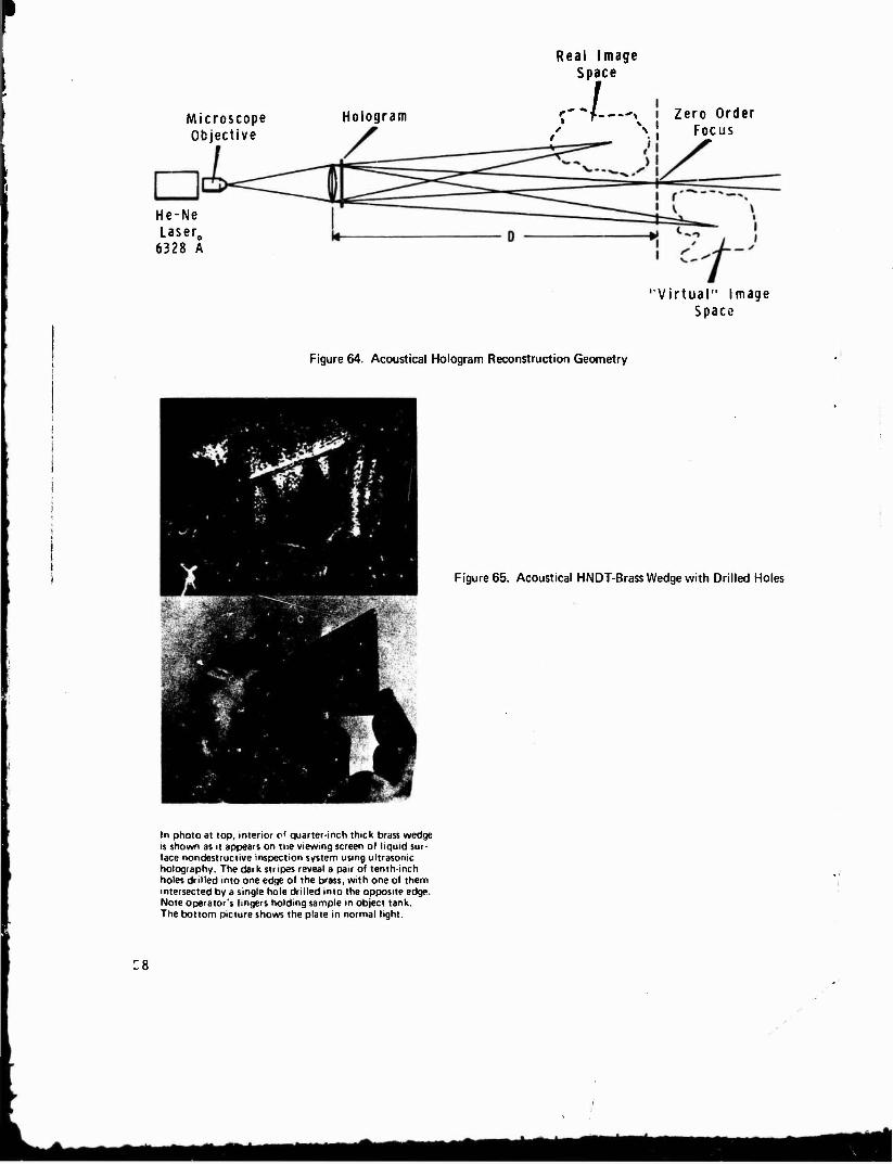
Real Image Space
Microscope Objective
Hologram r" "f -^ I Zero Order * \\ Focus
He-Ne Laser0
6328 A
"Virtual" Image Space
Figure 64. Acoustical Hologram Reconstruction Geometry
Figure 65. Acoustical HNDT-Brass Wedge with Drilled Holes
In photo at top, interior c' quarter-inch thick brass wedge is shown as it appears on the viewing screen of liquid sur- face nondestructive inspection system using ultrasonic holography. The dark stripes reveal a pair of tenth-inch holes drilled into one edge of the brass, with one of them intersected by a single hole drilled into the opposite edge. Note operator's fingers holding sample in object tank. The bottom picture shows the plate in normal light.
:8

MAJOR FLAWS
Figure 66. Acoustical HNDT Image of Flaws in 1/2-Inch Stainless Steel Butt Weld.
19-066-519/AMC-71
59

TYPICAL NON-DESTRUCTIVE TESTS Examples of the non-destructive testing capabilities of the
Ultrasonic Imager. The unit is equally effective with ceramics»
nonbonds and composites.
INTERNAL VOIDS IN PLASTICS
Photo shows high strength, high
temperature plastic block.
Block is 0.400" thick.
REAL-TIME IMAGE
HONEYCOMB STRUCTURE
Imaged at 5 MHz.
Boron Epoxy . ■„ 0.030'
Aluminum Honeycomb 0.50"
Fiberglass 0.040'
REAL-TIME IMAGE
PLASTIC BLOCK
Smallest hole 1s 0.0145" in
diameter, yet Is clearly
visible.
Imaged at 5MHz.
60
Figure 67. Other Examples of Acoustical HNDT
— •■ «aMMma

Mem) t(GHz) Subband Subband f(GHz) X(cm) Subband
133.3 0.225 76.9 0.394
76.9 0.390 64.5 0.465 58.8 0.510 41.4 0.725 38.4 0 780 33.3 0.900 31.6 0.950 26.1 1.150 22.2 1.350 20.7 1.450 19.3 1.550
19.3 1.55 18.3 1.65 16.2 1.85 15.0 2.00 12.5 2.40 11.5 2.60 11.1 2.70 10.3 2.90 9.67 3.10 8.32 3 40 8.10 370 7.69 3.90 7.14 4 20 5.77 5 20
((GHz) A(cm)
Figure 68. Microwave Frequency Bands' '
(641-665)
SPECIFIC GEOMETRIC METHODS FOR MICROWAVE NDT
TRANSMISSION
REFLECTION
<
DIRECTIONAL COUPLER
MAGIC TEE
SCATTERING
^CLASSICAL
-INTERFEROMETRY-/
•36.0 0.834 38.0 0.790 -40.0 -42.0
0.750 0.715
44.0 0.682 46.0 0.652
-46.0 -48.0 -50.0 -62.0 -54.0 -56.0
0.652 0.625 0.600 0.577 C.556 0.536
56.0 100.0
-0.536 -0.300
SINGLE HORN
DUAL HORN
■HOLOGRAPHIC
Figure 69. Specific Geometric Methods for Microwave Nondestructive Testing
61
*a

o.c METER
MILLIVAC- 17 B
POWER SUPPLY
H.P 715 A
TUNED DETECTOR
[HP X456-B
KLYSTRON VA-6312
ISOLATOR UNILINE L88-96
—IATTENUATOR H.P. X382-A
20 DB COUPLER H.P. 1070
-< SAMPLE
DC METER
MILLIVAC- 17 B
r TUNED
OETECTOR KP- X485-B
Figure 70. Block Diagram of Microwave Transmission Method
D. C. METER
OR
RECORDER
DETECTOR
OIRECTIONAL COUPLER
TRANSMITTER ISOLATOR Vi_ ,'~"*x
■^1 SAMPLE J
^ '
NOTE: BY REPLACING THE TRANSMITTER BY A SWEEP OSCILLATOR .SWEEP TECHNIQUE
CAN BE USED
Figure 71. Microwave Directional Coupler Reflection Technique
62
/
■- ■- J^MMli ^■^ i-—mgmm^

TRANSMITTED REFLECTED
o.e. METER MV I7B
DC. METER MV 178
POWER SUPPLY
HP. 7I5A TUNED
DETECTOR HP. X48M
TUNED DETECTOR H.P. X456-6
SAMPLE
Y KLYSTRON
VA-6312 ISOLATOR UNILINE
ATTENUATOR POLYTECHNIC
«926
2008 DUAL
DIRECTIONAL COUPLER NARD-1030
1 L88-96
Figure 72. Block Diagram of Microwave Reflection Method
F.M. TEST SET
BENDIX RADIO« 5
ATTENUATOR POLYTECNIC
# 191
SLIDING SHORT 23 VI
SPERRY MICROLINE
ATTENUATOR POLYTECHNIC tt 191
TUNED DETECTOR MICROLINE
#359
UG 1078/U
CCAG
DC. METER
MILLIVAC-I7B
Figure 73. Block Diagram for Microwave "Magic Tee" Reflection Method
63

TRANSMITTER ISOLATOR
ATTENUATOR PHASE
SHIFTER
H DETECTOR
OSCILLOSCOPE (USED FOR
SWEEP TECHNIQUES)
I ATTENUATOR —
FACSIMILE MACHINE USED FOR
GLASS CYLINDER)
JL
j S
Ki K p
L E
CHART RECORDER (USED FOR ALL OTHER C- W
TECHNIQUES)
Figure 74. Microwave Dual Horn Technique
POWER SUPPLY
H.P. 715 A
KLYSTRON VA 6312
ISOLATOR UNILINE L88-96
ATTENUATOR H.R X382A
o.e. METER
MILL I VAC I7B
TUNED DETECTOR KP X4B5-B
WARD A #1070 lODB DIRECTIONAL
COUPLER <
D. C.METER M>LUVAC-|7B
TUNED DETECTOR
HP. X48B-B
A SAMPLE
64
Figure 75. Block Diagram of Microwave Scattering Method
■MMAMT,
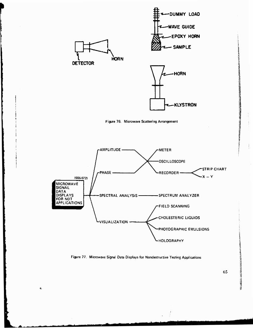
I HORN DETECTOR
:±*—DUMMY LOAD
WAVE GUIDE
EPOXY HORN
SAMPLE
\ U.—HORN
•KLYSTRON
Figure 76. Microwave Scattering Arrangement
(666672)
IMICROWAVE SIGNAL
I DATA DISPLAYS FOR NDT APPLICATIONS
-AMPLITUDE
-PHASE
-SPECTRAL ANALYSIS
-VISUALIZATION
STRIP CHART
X - Y
•SPECTRUM ANALYZER
FIELD SCANNING
CHOLESTERIC LIQUIDS
PHOTOGRAPHIC EMULSIONS
HOLOGRAPHY
Figure 77. Microwave Signal Data Displays for Nondestructive Testing Applications
65
•k_^MMa«MI

Microwave Obiect Beam
iPin Hole
|V ~M Beamsplitter
■O Polarizer
Microwave Generator
Figure 78. Microwave Hologram Construction and Reconstruction Processes
66
Figure 79. Calibration Curve for Transmitted Microwave Energy Versus Thickness of Plastic Cards
- ■- - •- — ' mtmk

Thickness Measurement AX F = 9.626 x 10⁹ CPS
60 65
Figure 80. Calibration Curve for Reflected Microwave Energy Versus Thickness of Plastic Cards
S UJ 100%-5 -o
E £
5%
Epon 815 with Catalyst "D"
25 50 Time (Min)
Degree of Cure
75 100
Figure 81. Curve of Transmitted Energy Versus Degree of Cure
67
Mfe

Time (Sec)
Figure 82. Microwave Scan of Filament-Wound Plastic Sample with Area of Unbond
u V c
W
V
£ Cfl
C «J u H
1 1 ,1
K A 1 -\7 V L s\
\ V \ 1 Position of Sample
NOTE: Microwave frequency was swept from 27.8 to 40 GHz at a rate of 100 sweeps/sec. The sample was scanned at the rate of 1 inch per 10 sec, so the values on the graph are averages for the frequency range.
Figure 83. Microwave Scan of Urethane Foam Sample Containing a 1/4-Inch Hole
68
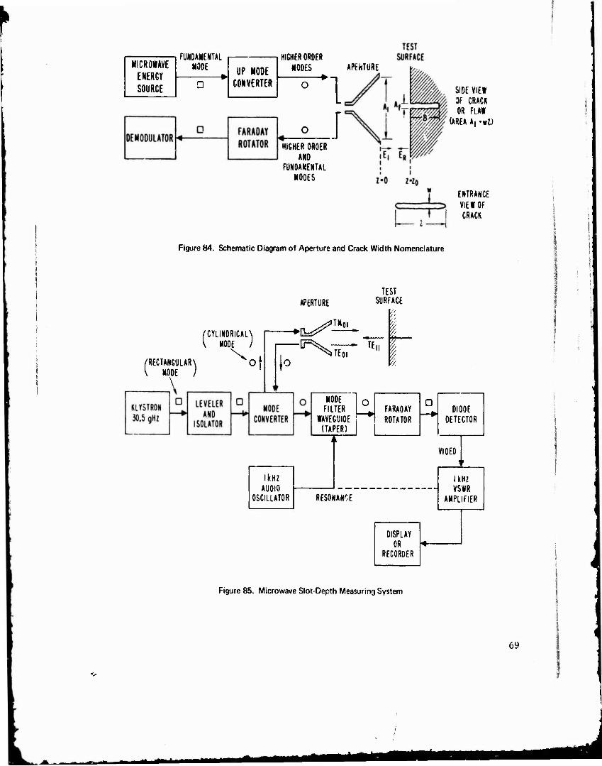
MICROWAVE ENERGY SOURCE
FUNDAMENTAL MODE UP NODE
CONVERTER
HI6HER ORDER NODES APEHTURE r—^n
HIGHER ORDER AND
FUNDAMENTAL NODES
SIDE VIEW OF CRACK OR FLAW
(AREA A, •»!)
ENTRANCE VIEW OF CRACK
Figure 84. Schematic Diagram of Aperture and Crack Width Nomenclature
APERTURE TEST
SURFACE
/CYLINDRICAL^ \ MODE I
/RECTANGULAR \ of V MODE ) I«
IE, T!" I
MODE | 0 FILTER
WAVEGUIDE (TAPER)
i kHz AUDIO
OSCILLATOR RESONANCE
FARADAY ROTATOR
D —► DIODE
OETECTOR
VIDEO •
1 kHz VSWR
AMPLIFIER
DISPLAY OR
RECORDER
Figure 85. Microwave Slot-Depth Measuring System
69
L ^«a *■

60
50
40 - o
Ss 30
&. oo 20
10 -
Jfr^Sfcr
/SPECIMEN APERTUREN \ SEPARATION = 5 mm /
2.0 2.5 3.0 3.5 GROOVE DEPTH, mm
Figure 86. Signal Strength Versus Experimental Slot-Depth for Aluminum
60
50
_ 40
LU "^
1— UJ 30 </> Q_
<E Z _l o o ?<) i^>
10
0
/SPECIMEN APERTURE \ SEPARATION = 5 mm
CYLINDRICAL TM01
CYLINDRICAL TEoi
.5 1.0 1.5 2.0 2.5 3.0 3.5 4.0 4.5 5.0 GROOVE DEPTH, mm
70
Figure 87. Signal Strength Versus Experimental Slot-Depth for Steel
ateM^B *Mtt

LITERATURE CITED
1. GRUBINSKAS, R. C. "Holography - Comment on the State-of-the-Art". The Technical Cooperation Program, Minutes of the Thirteenth Meeting of Working Panel 4, Sub-Group P, Evaluation Methods for Materials and Materials in Structures, TTCP P4 Document P4/13M/71, Appendix 9, 1971. Also published as TTCP P4 Docu- ment P4/US/1/71, April 1971.
2. GRUBINSKAS, R. C. "Microwave Nondestructive Testing - Comment on the State-of-the Art". The Technical Cooperation Program, Minutes of the Thirteenth Meeting of Working Panel 4, Sub-Group P, Evaluation Methods for Materials and Materials in Structures, TTCP P4 Document P4/13M/71, Appendix 11, 1971. Also published as TTCP P4 Document P4/US/2/71.
3. BATES, M. "Applications and Technology of Holography II". Southern Methodist University Industrial Information Services, Science Library Search, IIS Search 774, March 23, 1971.
4. KALLARD, T., ed. Holography State-of-the-Art Review - 1970. Optosonic Press, New York, 1970.
5. KISATSKY, P., BARBARISI, M., and FASANO, J. "A Survey of Potential Applications of Holography at Picatinny Arsenal". Picatinny Laser Study Group, 1 February 1970.
6. LATTA, J. N. "A Classified Bibliography on Holography and Related Fields (First Half)". J. Soc. Motion Picture Television Engrs., v. 77, no. 4, April 1968, p. 422-458.
7. LATTA, J. N. "A Classified Bibliography on Holography and Related Fields (Second Half)". J. Soc. Motion Picture Television Engrs., v. 77, no. 5, May 1968, P. 540-580.
8. MORGAN, R. "A Selected Bibliographic Guide to Conference Papers on Nondestructive Testing, 1955-1967". Atomic Energy Research Establishment, Harwell, England, Document AERE-Bib-164/NDT-27, December 1968.
9. PERALTA, B. C. "State-of-the-Art Study on Holography". Remote Area Conflict Information Center, Battelle Memorial Institute Report, BAT-171-51, 25 August 1966, AD 803 381 L.
10. "Application of Holography in Evaluation of Materials, Structures, and Nondestructive Testing". NASA Scientific and Technical Information Facility, 29 January 1971, Parts I and II, NASA Literature Search No. 14066.
11. "Holography". A DDC Bibliography, Defense Documentation Center, DDC-TAS-70-15-I, v. 1, May 1970, AD 704 950.
12. "Holography". A DDC Bibliography, Defense Documentation Center, DDC-TAS-70-15-II, v. 2, May 1970, AD 868 800.
13. "Holography". (Secret Report). A DDC Bibliography, Defense Documentation Center, DDC-TAS-70-1S-III, v. 3, May 1970, AD 508 850.
14. "Report Bibliography - Holography (U)". Defense Documentation Center, Defense Supply Agency, Cameron Station, Alexandria, Virginia, November 1970, Search Control No. 049915.
15. "Report Bibliography - Nondestructive Testing (U)". Defense Documentation Center for Scientific and Technical Information, Cameron Station, Alexandria, Virginia, January 1971, Search Control No. 053625.
16. GABOR, D. "Holography, Past, Present and Future". SPIE Seminar Proceedings, v. 25, 1971, p. 129-134.
17. KLEIN, H. A. Holography. Lippincott, New York, 1970.
18. KIRKPATRICK, P. "History of Holography". SPIE Seminar Proceedings, v. 15, 1968, p. 9-12.
19. The Optical Industry and Systems Directory: 1970-1971, 17 ed., Optical Publishing Co., Inc., Pittsfield, Massachusetts, 1970.
20. The Optical Industry and Systems Directory: 1971-1972, 18th ed., Optical Publishing Co., Inc., Pittsfield, Massachusetts, 1971.
21. Laser Focus Buyer's Guide: 1971. Advanced Technology Publications, Inc., Newtonville, Massachusetts, 1971.
22. Laser Focus Buyer's Guide: 1972. Advanced Technology Publications, Inc., Newtonville, Massachusetts, 1972.
23. "Lasers and Masers - A Continuing Bibliography with Indexes". NASA Scientific and Technical Information Division, NASA SP-7009(03), June 1968.
24. ALEKSOFF, C. C. "Gas Lasers as Sources for Holography". Appl. Opt., v. 6, 1967, p. 2192.
25. ALEKSOFF, C. C. "Multi-Mode Lasers in Interferometry and Holography". University of Michigan Technical Report, No. 1673-47-T, May 1970.
26. ANSLEY, D. A., and SIEBERT, L. "Coherent Pulse Laser Holography". SPIE Seminar Proceedings, v. 15, 1968, p. 127-131.
?7. BARBER, H. P. "Coherence - Length Extension of He-Ne Lasers for Holography". J. Opt. Soc. Am., v. 57, no. 4, 1967, p. 574.
71
— • m

28.
29,
30.
7.1.
32.
33.
34.
35.
36.
37.
38.
39.
40.
41.
42.
43.
44.
45.
46.
47.
48.
49.
50.
51.
52.
53.
54.
55.
56.
57.
58.
59.
60.
61.
62.
63.
64.
BARBER, H. P. "Coherence - Length Extension of He-Ne Users". Appl. Opt., v. 7, no. 3, 1968, p. SS9-S61.
BIRNBAUM, G. Optical Masers. Academic Press, New York, 1964.
BLOOM, A. L. "Properties of Laser Resonators Giving Uniphase Nave Fronts". Spectra-Physics Laser Technical Bulletin, no. 2, August 1963.
BLOOM, A. L. "Noise in Lasers and Laser Detectors" March 1965.
Spectra-Physics Laser Technical Bulletin, no. 4,
BLOOM, A. L. Gas Users. Wiley, New York, 1968.
BROTHERTON, M. Masers and Lasers: How They Work, What They Do. McGraw-Hill, New York, 1964.
BROWN, R. Users: Tools of Modern Technology. Doubleday, New York, 1968.
BROWN, R. Lasers - A Survey of Their Performance and Applications. Business Books Limited, London, 1969.
CHANG, W. S. C, ed. Lasers and Applications. The Ohio State University, Columbus, SR-27, 1963.
DUTTON, D., GIVENS, M. P., and HOPKINS, R. E. "Some Demonstration Experiments in Optics Using a Gas Laser". Spectra-Physics User Technical Bulletin, no. 3, October 1963.
GOODMAN, J. W., et al. "Laser Applications (Six Papers Originally Prepared for WESCON 1965)". Stanford University Technical Report, 2303-2/SU-SEL-65-07S, September 1965, AD 473 549.
GRAYSON, D. L., and WEISS, S. J, "User Imaging Techniques". Naval Avionics Facility, Indianapolis, Indiana, Technical Report, NAFI TR-1615, December 1970.
GREGOR, E. "Recent Improvements in Pulsed Ruby Users for Holography". SPIE Seminar Proceedings, v. 25, 1971, p. 93-98.
HARVEY, A. F. Coherent Light. Wiley-Interscience, New York, 1970.
HEARD, H. G., ed. Laser Parameter Measurements Handbook. Wiley, New York, 1968.
INGALLS, A. L. "Coherence and Resolution". Air Force Avionics Laboratory, AFAL TR 67-264, November 1967.
INNES, D. J., and BLOOM, A. L. "Design of Optical Systems for Use With Laser Beams". Spectra-Physics Laser Technical Bulletin, no. 5, August 1966.
ITZKAN, I., KNUDSEN, K., and VAHER, E. "A Single Frequency Argon Ion Laser for Holographic Applications". SPIE Seminar Proceedings, v. IS, 1968, p. 155-158.
KOCK, W. E. "Fundamentals of Users". Optical Spectra, v. 3, no. 2, March-April 1969, p. 65-74.
K0CK, W. E. Lasers and Holography. Doubleday, New York, 1968.
LENGYEL, B. A. Lasers■ Wiley, New York, 1962.
LENGYEL, B. A. Introduction to Laser Physics. Wiley, New York, 1966.
LYTEL, A. ABC's of Lasers and Masers. Howard W. Sams, Photofact Publication UL-2, 1965.
MARSHAL, S. L., ed. Laser Technology and Applications. McGraw-Hill, New York, 1968.
MERCER, G. N. "Gas Lasers for Holography". SPIE Seminar Proceedings, v. 15, 1969, p. 49-53.
PATEK, K. Lasers. Iliffe, London, 1967.
PIKE, C. A. Users and Masers. Howard W. Sams, New York, 1968.
REMPEL, R. C. "Optical Properties of Laser as Compared to Conventional Radiators". Spectra-Physics Laser Technical Bulletin, no. 1, June 1963.
ROSS, D. Lasers, Light Amplifiers and Oscillators. Academic Press, New York, 1969.
ROSS, M. Laser Receivers. Wiley, New York, 1966.
TOMIYASU, K. The Laser Literature: An Annotated Guide. Plenum Press, New York, 1968.
SINCLAIR, D. C. "Scanning Spherical-Mirror Interferometers for the Analysis of Laser Mode Structure". Spectra-Physics Laser Technical Bulletin, no. 6, April 1968.
VanPELT, W. F., et al. "Laser Fundamentals and Experiments". Bureau of Radiological Health/ Southwestern Radiological Health Laboratory Report, BRH/SWRHI. 70-1, May 1970.
"Nondestructive Evaluation". National Materials Advisory Board Report, NMAB-252, June 1969, p. V-5ff.
SHARPE, R. S., ed. Research Techniques in Nondestructive Testing. Academic Press, New York, 1970.
BAEZ, A. V. "Study in Diffraction Microscopy with Special Reference to X-Rays". J. Opt. Soc. Am., v. 42, 1952, p. 756.
EAGLESFIELD, C. C. "Resolution of X-Ray Microscopy by Hologram". Electronics Letters, v. 1, 1965, p. 181.
72

65. EL-SUM, H. M. A., and BAEZ, A. V. "Preliminary Experiments on X-Ray Microscopy by Reconstructed » ive Fronts". Phys. Rev., v. 99, no. 3, 19SS, p. 624.
66. HAINE, M. E., and MULVEY, T. "Diffraction Miroscopy with X-Rays". N?ture, v. 170, 1952, p. 202.
67. KASAHARA, T., and KIMURA, Y. "Stereo-Radiography Using Holographic Techniques". Japan. J. Appl. Phys., v. 8, no. 1, January 1969, p. 124-125, A69-20178.
68. MULSON, J. P., and POLEYN, R. F. "Sequential Stereo Holography with Application to X-Rays". Naval Training Device Center Technical Report, NAUTRADEVCEN IH-160, May 1969, AD 854 598.
69. REDMAN, J. D., IVOLTON, W. P., and SHUTTLEWORTH, E. "Use of Holography to Make Truly Three-Dimen .ional X-Ray Images". Nature, v. 220, no. 5162, October 5, 1968, p. 58-60.
70. SACCOCIO, E. J. "Application of Lloyd's Mirror to X-Ray Holography". J. Opt. Soc. Am., v. 57, 10. 7, 1967, p. 966.
71. WINTHROP, J. TV, and WORTHINGTON, C. R. "X-Ray Microscopy by Successive Fourier Transformation* . Phys. Letters, v. 15, 1965, p. 124.
72. RIECK, H. "Holographic Small Particle Analysis by Ultraviolet Ruby Laser Light" in The Engineering Uses of Holography, E. R. Robertson, and J. M. Harvey, ed., Cambridge University Press, London, 1970, p. 261-266.
73. WUERKER, R. F., HEFLINGER, L. 0., and BRI0NES, R. H. "Holographic Interferometry with Ultravio et Light". Appl. Phys. Utters, v. 12, no. 9, 1968, p. 302-303.
74. CAULFIELD, H. J., and LU, S. The Applications of Holography. Wiley-Interscience, New York, 1970.
75. COLLIER, R. J., BURCKHARDT, C. B., and LIN, L. H. Optical Holography. Academic Press, New York, May 1971.
76. DeVELIS, J. B., and REYNOLDS, G. O. Theory and Applications of Holography. Addison-Wesley, Re.ding, Massachusetts, 1967.
77. KIEMLE, H., and ROSS, D. Introduction to the Technology of Holography. Akademische Verlagsgesel'lschaft, Frankfurt am Main, 1969, (in German). Also available in a translated version Introduction to Holographic Techniques, Plenum Press, New York, 1971.
78. SMITH, H. M. Principles of Holography. Wiley-Interscience, New York, 1969.
79. STROKE, G. W. An Introduction to Coherent Optics and Holography, 1st ed., Academic Press, New York, 1966.
80. STROKE, G. W. An Introduction to Coherent Optics and Holography, 2d ed., Academic Press, New York, 1S69.
81. REDMAN, J. D. "Holography" in Non-Destructive Testing, H- B. Egerton, ed., Oxford University Press, London, 1969.
82. EL-SUM, H. M. A. "Infrared Image Formation by Reconstructed Wave Fronts". J. Opt. Soc. Am., v. 49, 1959, p. 505-506.
83. LOWENTHAL, S., et al. "Holography at Ten Micrometers". Compt. Revd. Acad. Sei., Paris, v. 266B, 1968, p. 1363.
84. AOKI, Y. "Microwave Holograms and Optical Reconstruction". Appl. Opt., v. 6, no. 11, 1967, p 1:143-1946.
85. AOKI, Y. "Microwave Holography by a Two-Beam Interference Method". Proc. IEEE, v. 56, 1968, p. 1402.
86. AUGUSTINE, C. F., and KOCK, W. E. "Microwave Holograms Using Liquid Crystal Displays". Proc. IEEE, v. 57, no. 3, March 1969, p. 354-355.
87. DOOLEY, R. P. "X-Band Holography". Proc. IEEE, v. 53, no. 11, 1965, p. 1733-1735.
88. DUFFY, D. E. "Optical Reconstruction from Microwave Holograms". J. Opt. Soc. Am., v. 56, no. 6, 1966, p. 832.
89. FRANKLIN, P. "Microwave Holography Stirs New Interest". Microwaves, v. 7, no. 6, 1968, p. 14-16.
90. HORTON, M. C. "Microwave Coherent Optics". Bendix Tech. Journal, v. 2, Summer 19o9, p. 8-14, A70-1041S.
91. JOHNSON, K. R. "Centimeter Wave Holography". SPIE Sei.inar Proceedings, v. 15, 1968, p. 171-172.
92. KOCK, W. E., and HARVEY, F. K. "A Photographic Method for Displaying Sound Wave and Microwave Space Fattems". Bell System Tech. J. , v. 30, no. 3, 1951, p. 564-587.
93. KOCK, W. E. "Side-Looking Radar Holography, and Doppler-Free Coherent Radar", proc. IELE, v. 56, no. 2, 1968, p. 238-239.
94. LEITH, E. N., et al. "Coherent Optical Techniques for Radar Data Processing". J. Opt. Soc. Am., v. So, no. 10, 1966, p. 1419.
95. MITTRA, R. "Aspects of Microwave Holography". Electronic Communicator, July 1967, p. 11-12.
73
»
— — •* •^aa

96. STROKE, G. W. "Optical Imaging Systems Achieving Aperture Synthesis by Fourier-Transform Holography". Phys. Letters, v. 28A, 1968, p. 251.
97. TRirOLES, G. "Visible and Mic »ave Holography Using an Inclined Reference Beam". J. Opt. Soc. Am., v. 56, 1966, p. 1414.
98. TRICOLES, G., and ROPE, E. L. "Reconstructions of Visible Images from Reduced Scale Replicas of Micro- wave Holograms". J. Opt. Sec. Am., v. 57, 1967, p. 97.
99. HILDEBRAND, B. P., and BRENDEN, B. B. An Introduction to Acoustical Holography. Plenum Press, New York, 1972.
100. METHERELL, A. F., EL-SUM, H. M. A., and LARMORE, L., ed. Acoustical Holography. Pieman Press, New York, v. 1, 1969.
101. METHERELL, A. F., and LARMORE, L., ed. Acoustical Holography. Plenum Press, New York, v. 2, 1970.
102. METHERELL, A. F., and LARMORE, L., ed. Acoustical Holography. Plenum Press, New York, v. 3, 1971.
103. GABOR, D. "Diffraction Microscopy". J. Appl. Phvs., v. 19, :J48, p. 1191, and Research, v. 4, 1951, p. 107.
104. GABOR, D. "Microscopy by Reconstructed Wavefronts: I and II". Proc. Roy. Soc, v. 197A, 1949, p. 454, and v. 64B, 1951, p. 449.
105. HAINE, M. F.., and DYSON, J. "Modification of Gabor's Proposed Diffraction Microscope". Nature, v. 166, 1950, p. 315.
? 106. HAINE, M. E., and MULVEY, T. "Formation of the Diffraction Image with Electrons in the Gabor Diffraction j Microscope". J. Opt. Soc. Am., v. 42, 1952, p. 763.
107. TONOMURA, A., et al. "Optical Reconstruction of Image from Fraunhofer Electron-Hologram". Japan. J. j Appl. Phys., v. 7, no. 3, March 1968, p. 295.
j 108. SHULMAN, A. R. Optical Data Processing. Wiley-Interscience, New York, 1970.
109. ANDERSON, L. K. "High Capacity Holographic Optical Memory". Microwaves/Laser Technology, v. 9, no. 3, ! March 1970, p. 62-66.
110. NORMAN, S. L. "Holography in Unconventional Materials". Optical Spectra, v. 4, no. 10, November 1970, f' p. 26-30.
i 111. URBACH, J. C., and MEIER, R. W. "Holographic Recording Materials". SPIE Seminar Proceedings, v. 15, ; 1968, p. 55-73.
112. URBACH, J. C. "Advances in Hologram Recording Materials". SPIE Sem'.nar Proceedings, v. 25, 1971, | p. 17-42.
! 113. BIEDERMANN, K. "Attempts to Increase the Holographic Exposure Index of Photographic. Materials". Appl. I Opt., v. 10, 1971, p. 584. 1 114. FALCONER, D. G. "Role of > e Photographic Process in Holography". Phot. Sei. Eng., v. 10, no. 3, 1966,
p. 133-139.
115. FRIESEM, A. A., and ZELENKA, J. S. "Effects of Film Nonlinearities in Holography". Appl. Opt., v. 6, no. 10, 1967, p. 1755-1759.
116. FRY, A. G. "Resolving Power of Photographic Emulsions". J. Opt. Soc. Am., v. 53, no. 3, 1963, p. 368-374.
117. GOODMAN, J. W., and KNIGHT, G. R. "Effects of Film Nonlinearities on tfavefront Reconstruction Images of Diffuse Objects". J. Opt. Soc. Am., v. 58, no. 9, 1968, p. 1276-1283.
118. LaMACCHIA, J. T., and BJOrtKHOLM, J. E. "Resolution of Pulsed Laser Ho.'ograms". Appl. Phys. Letters, v. 12, 1968, p. 45.
119. NASSENSTEIN, H., et al. "An Investigation of the Properties of Photographic Materials for Holography" in The Engineering Uses of Holography, E. R. Robertson, and J. M. Harvey, ed., Cambridge University Press, London, 1970, p. 25-43.
120. PRENEL, J. P. "Study of the Linearity of Response of a Holographic Photosensitive Emulsion". Optics and Laser Technology, v. 3, no. 3, August 1971, p. 157-161.
121. VanLIGTEN, R. F. "Influence of Photographic Film on Wavefront Reconstruction: I and II". J. Opt. Soc. Am., v. 56, 1966, p. 1 and 1009.
122. VILKOMERSON, D. H. R. "Measurements of the Noise Spectral Power Density of Photosensitive Materials at High Spatial Frequencies". Appl Opt., v. 9, no. 9, September 1970, p. 2080-2087, A70-40812.
123. WOLFE, R. N., MARCHAND, E. W., and DePALMA, J. J. "Determination of the Modulation Transfer Function of Photographic Emulsions from Physical Measurements". J. Opt. Soc. Am., v. 58, no. 9, 1968, p. 1245-1256
74

124. "Holography - Plate or Film Negatives". Laser Focus, v. 1, no. 20, 1965, p. 4.
125. ARAIUO, R. J. "Kinetics of Bleaching of Photochromic Glass". Appl. Opt., v. 7, no. 5, 1968, p. 781-786.
126. BALDWIN, W. J. "Determination of the Information Storage Capacity of Photochromic Glass with Holo- graphy". Appl. Opt., v. 6, no. 8, 1967, p. 142Ö.
127. BARDOS, A., KALMAN, G., and KEARNEY, R. "Holographic Color Map Storage". Carson Laboratories, Inc., Final Report, Naval Air Systems Command, Contract No. N00019-68-C-0097, January 1969, AD 857 293.
128. FRIESEM, A. A., and WALKER, J. L. "Photochromic Materials in Holography". J. Opt. Soc. Am., v. 58, 1968, p. 730.
129. KIRK, J. P. "Hologram oa Photochromic Glass". Appl. Opt., v. 5, October 1966, p. 1684-1685.
130. MEGLA, G. K. "Optical Properties and Applications of Photochromic Glass". Appl. Opt., v. 5. no. 6, 1966, p. 945-960.
131. SHAJENKO, P. "Experiments on Storage of Multiple Images i;i Colored Crystals". Rome Air Development Center Technical Report, 67-257, June 1967.
132. TAUBER, A. S., and MYERS, W. C. "Photochromic Micro-Images". Proc. Ann. Meet. Nat. Microfilm Assoc, v. 11, 1962, p. 256.
133. BURCKHARDT, C. B., and DOHERTY, E. T. "A Bleach Process for High-Efficiency Low-Noise Holograms". Appl. Opt., v. 8, 1969, p. 2479.
134. CHANG, M., and GEORGE, N. "Holographic Dielectric Grating: Theory and Practice". Appl. Opt., v. 9, 1970, p. 713.
135. GUPT0N, J. A., Jr. "Processing Holographic Film for Maximum Resolution". Laser Focus, v. 5, no. 9, May 1969, p. 56.
136. KOGELNICK, H. "Reconstructing Response and Efficiency of Hologram Gratings" in Modern Optics, Polytechnic Press, New York, 1967, p. 605. ~ "
137. LATTA, J. N. "The Bleaching of Holographic Diffractio .atings for Maximum Efficiency". Appl. Opt., v. 7, 1968, p. 2409.
138. LIN, L. H. "Hologram Formation in Hardened Dichromated Gelatin Films". App. Opt., v. 8, 1969, p. 903.
139. McMAHON, D. H. "Holographic Microfilm". Laser Focus, v. 6, no. 10, October 1970, p. 34-37.
140. McMAHON, D. H., and FRANKLIN, A. R. "Efficient High Quality R-10 Bleached Holographic Diffraction Gratings". Appl. Opt., v. 8, 1969, p. 1927.
141. McMAHON, D. H., and MAL0NEY, W. T. "Measurements of the Stability of Bleached Photographic Phase Holograms". Appl. Opt., v. 9, 1970, p. 1363.
142. RUSS0, V., and S0LTINI, S. "Bleached Holograms". Appl. Opt., v. 7, no. 1, 1968, p. 202.
143. SHERIDON, N. K. "Production of Blazed Holograms". Appl. Phys. Letters, v. 12, no. 9, 1968, p. 316-318.
144. STETSON, K. A. "Di/fraction from Surface Ripple of Aluminized Photographic Emulsions". J. Opt. Soc. Am., v. So, 1966, p. 542.
145. UPATNIEKS, J., and LEONARD, C. "Diffraction Efficiency of Bleached Photographically Recorded Inter- ference Patterns". Appl. Opt., v. 8, 1969, p. 85.
146. "Reversal Bleach Process for Producing Phase Holograms on Kodak Spectroscopic Plates, Type 649-F". Eastman Kodak Data Release Bulletin.
147. JENNLY, J. A. "Recent De/elopments in Photopolymer Holography". SPIE Seminar Proceedings, v. 25, 1971, p. 105-110.
148. GLENN, W. E. "Thermoplastic Recording". J. Appl. Phys., v. 30, no. 12, 1959, p. 1870-1873.
149. URBACH, J. C., and MEIER, R. W. "Characteristics of Thermoplastic Xerographic Holograms". J. Opt. Soc. Am., v. 56, 1966, p. 537.
150. SHANKOFF, T. A. "Phase Holograms in Dichromated Gelatin". Appl. Opt., v. 7, no. 10, 1968, p.2101-2105.
151. PLOSS, R. S. "A Review of Electro-Optics Materials, Methods, and Uses". Optical Spectra, v. 3, no. 1, January-February 1969, p. 63-67.
152. BERGSTEIN, L., and KERMISCH, D. "Image Storage and Reconstruction in Volume Holography". J. Opt. Soc. Am., v. 58, 1968, p. 730, and Proc. Symp. Modern Optics, New York, March 22-24, 1967, Polytechnic Press, v. 17, Microwave Research Institute Symposia Series.
153. ÖURT0N, G. T., et al. "Laser-Hologram Multicolor Moving Map Display System". RCA Advanced Technology Laboratories, Final Report, November 197Ü, AD 877 633.
154. FRIESEM, A. A. "Holograms on Thick Emulsions". Appl. Phys. Letters, v. 7, 1965, p. 102-103.
75

155.
156.
157.
158.
159.
160.
161.
162.
163.
164.
165.
166.
167.
168.
169.
170.
171.
172.
173.
174.
175.
176.
177.
178.
179.
180.
181.
182.
183.
184.
185.
186.
187.
188.
189.
FRIESEM, A. A., KOZMA, A., and ADAMS, G. F. "Investigation of hologram Recording Parameters". J. Opt. Soc. Am., v. 56, 1966, p. 1449.
FRIESEM, A. A. "Three-Dimensional Recording Media in Holography". University of Michigan Technical Report, No. 1673-16-T/1118-50-T, August 1969, AD 858 661.
GABOR, D., and STROKE, G. W. "The Theory of Deep Holograms". Proc. Roy. Soc, London, Ser. A, v. 304, no. 1478, 1968, p. 275-289.
GEORGE, N. "Full View Holograms". Optics Communications, v. 1, no. 9, April 1970, p. 457-459, AD 716 276.
GEORGE, N. "Reflection-Transmission Full-View Holograms". Air Force Office of Scientific Research Technical Report, AF0SR 70-2826TR, July 1970, AD 716 571.
JEONG, T. H., RUDOLF, P., and LUCKETT, A. "360° Holography". J. Opt. Soc. Am., v. 56, 1966, p. 1263-1264.
JEONG, T. IS. "360° HolograDhy Without Lens, Mirror, or Beam Splitter", no. 4, 1967, p. 574.
J. Opt. Soc. An., v. 57,
J. Opt. Soc. Am., v. 57,
Appl. Opt., v. 5, no. 8,
n.o. 2, 1967,
JEONG, T. I!. "Cylindrical Holography and Some Proposed Applications", no. 11, 1967, p. 1396-1398.
KOGELNIK, H. "Hologram Efficiency and Response". Microwaves, v. 6, no. 11, 1967, p. 68-73.
KOZMA, A. "Hologram Recording in Thin Emulsions". Air Force Avionics Laboratory Technical Report, AFAL-TR-69-362, March 1970, AD 866 091.
LEITH, E. N., MASSEY, N., and MARKS, J. "Holographic Recording on Three-Dimensional Media". J. Opt. Soc. Am., v. 56, 1966, p. 536.
LEITH, E. N., et al. "Holographic Data Storage in Three-Dimensional Media". August 1966, p. 1303-1311.
MARCHANT, M., and KNIGHT, D. "Multiple Recording of Hologram". Optica Acta. v. 14, p. 199-201
UPATNIEKS. J., et Hi. "A Study of Hologram Recording and Applications". Air Force Avionics Laboratory Interim Technical Report, AFAL-TR-70-74, July 1970, AD 872-279.
"Fundamentals and Applications of Optical Data Processing and Holography". University of Michigan, v. 1 and v. 2, 1970. Material Content for an Intensive Short Course, #7029, given July 20-31, 1970.
"Characteristics of Kodak Plates for Scientific and Technical Applications". Eastman Kodak Technical Information Bulletin.
"Kodak Materials for Holography". Eastman Kodak Data Release Bulletin.
"Kodak Plates and Films for Science and Industry". Eastman Kodak Publication P-9, 1967.
T.JiCSKA, S. A. "Characteristics of the Agfa-Gevaert Type 10E70 Holographic Film". Appl. Opt., v. 7, no. 11, 1968, p. 2312-2314.
"Scientific Photography". Agfa-Gevaert Technical Information Bulletin, October 1967.
"Photographic Materials for Holography". /gfa-Gevaert Technical Information Bulletin, August 19b9.
"Scientific Photography - Scientia 10E56". , ofa-Gevaert Technical Information Bulletin, April 1970.
"Ilford Holographic Plate He-Ne/1". Ilford Technical Information Sheet R43.1.
"Spectral Response and Sensitometric Data for Pol.roid Land Black and White Films". Polaroid Technical Information Bulletin, September 1968.
BORN, M., and WOLF, E. Principles of Optics, 2d re . ed., Pergamon Press, New York, 1964.
BROWN, E. B. Modem Optics. Reinhold, New York, 1965.
F0WLES, G. R. Introduction to Modem Optics. Holt, Rinehart and Winston, New York, 1968.
FRANCOS', M. Diffraction: Coherence in Optics. Pergamon Press, New York, 1966.
FRUNGEL, F. High Speed Pulso Technology. Academic Press, New York, v. 2, 1965.
GARBUNY, M. Optical Physics. Academic Press, New York, 1965.
GOODMAN, J. W. Introduction to Fou.-~r Optics. McGraw-Hill, New York, 1968.
HARDY, A. C, and PEF.R1N, F. H. The Principles of Optics. McGraw-Hill, New York, 1932.
JENKINS, F. A., and WHITE, H. E. Fundamentals of Optics, 3d ed., McGraw-Hill, New York, 1957.
LIPSON, S. G., and LIPS0N, H. Optical Physics. Cambridge University Press, London, 1969.
ROSSI, B. Optics. Addison-Wesley, Reading, Massachusetts, 1957.
76

190.
191.
192.
193.
194.
195.
196.
197.
198.
199.
200.
2C1.
202.
203.
204.
205.
206.
207.
208.
209.
210.
211.
212.
213.
214.
215.
216.
217.
218.
SEARS, F. W. Optics, 3d ed., Addison-Wesley, Reading, Massachusetts, 1949.
SHULMAN. A. R. "Principles of Optical Data Processing for Engineers". NASA TR R-327, May 1970.
SOMMERFELD, A. Optics. Academic Press, New York, 1954.
STONE, J. M. Radiation and Optics. McGraw-Hill, New York, 1963.
THEOCARIS, P. S. Moire Fringes in Strain Analysis. Pergamon Press, New York, 1969.
TOLANSKY, S. Multiple-Beam Interferometry of Surfaces and Films. Oxford University Press, London, 1948.
WEBB, R. H. Elementary Wave Optics. Academic Press, New York, 1969.
Proceedings of the Symposium on Modern Optics. Microwave Research I», 'itute Symposia Series, v. 17, Polytechnic Press, New York, 1967.
RCA Electro-Optics Handbook. RCA/Commercial Engineering, Harrison, New Jersey.
LINGENFELDER, P. G. "Holography Manual - Compilation of Laboratory Techniques Commonly Used in the Construction of Holograms Including Refinements Developed at NELC". Naval Electronics Laboratory Center, Technical Document 47, January 1969, AD 854 550.
ABRAMS0N, N. "The 'Holo-Diagram', a Practical Device for the Making and the Evaluation of Holograms" in The Engineering Uses of Holography, E. R. Robertson, and J. M. Harvey, ed., Cambridge University Press, London, 1970, p. 45-56.
APRAHAMIAN, R. "Some Useful Equations Used in the Field of Holography". TRW Report, AM 70-2, 28 January 1970.
J. Opt. Soc. Am. CARTER, W. H., and DOUGAL, A. A. "Field Range and Resolution in Holography", v. 56, 1966, p. 1754.
CHAMPAGNE, E. B. "A Study of Aberrations in Holography". J. Opt. Soc. Am., v. 57, no. 4, 1967, p. 560.
CHAMPAGNE, E. B. "Nonparaxial Imaging, Magnification, and Aberration Properties in Holography". J. Opt. Soc. Am., v. 57, no. 1, 1967, p. 51-55.
CHAMPAGNE, E. B. "A Qualitative and Quantitative Study of Holographic Imaging". Air Force Avionics Laboratory Technical Report, AFAL-TR-67-107, July 1967.
COCHRANE, G. D. "Techniques for the Production and Use of Very Large and Very Small Holograms". Optical Spectra, v. 1, no. 1, January 1967, p. 35.
DeVELIS, J. B., and REYNOLDS, G. 0. "Magnification Limitations in Holography". J. Opt. Soc. Am., v. 56, 1966, p. 1414A.
DIAMOND, F. I. "Magnification and Resolution in Wavefront Reconstruction". J. Opt. Soc. Am., v. 57, no. 4, 1967, p. 503-508.
GABOR, D., KOCK, W. E., and STROKE, G. W. "Holography". Science, v. 173, July 2, 1971, p. 11-23.
GEORGE, N., McCRICKERD, J. T., and CHANG, M. M. T. "Scaling and Resolution of Scenic Holographic Stereograms". SPIE Seminar Proceedings, v. 15 1368, p. 161-165.
HAINES, K. A., and BRUMM, D. B. "A Technique for Bandwidth Reduction in Holographic Systems". Proc. IEEE, v. 55, no. 8, 1967, p. 1512-1513.
LEHMANN, M. "Holography, Technique, and Practice" in The Engineering Uses of Holography, E. R. Robertson, and J. M. Harvey, ed., Cambridge University Press, London, 1970, p. 1-24.
LEITH, E. N., et al. "Investigation of Hologram Techniques". University of Michigan, 1st Interim Engineering Report, No. 7421-7-P, December 1965, AD 4/6 267.
LEITH, E. N., et al. "Investigation of Hologram Techniques". Engineering Report, No. 7421-22-P, July 196f, AD 486 489.
LEITH, E. N., et al. "Investigation of Hologram Techniques". Engineering Report, No. 7421-29-P, December 1966, AD 804 105.
LEITH, E. N., and HAINES, K. A. "Investigation of Hologram Techniques". University of Michigan Techiical Report, No. 7421-32-F, Final Report, July 1967, AD 817-984. (Air Force Avionics Laboratory Report, AFAL TR-67-141).
LEITH, H. N., et al. "Investigation of Hologram Techniques". University of Michigan, 4th Interim Technics! Report, No. 7421-38-P, January 1968, A0 826-135. (Air Force Avionics Laboratory Report, AFAL TR-67-324).
LEITH, E N., et al. "Investigation oi Hologram Techniques". University of Michigan Technical Report, No. 74?' 53■■(■", Final Report, June 1968, AD 834 872. (Air Force Avionics Laboratory Report, AFAL TK-68-83).
University of Michigan, 2d Interim
Universitv of M'chigan, 3d Inteiim
77
219. LEITH, E. N., et al. "Investigation of Hologram Techniques". University of Michigan, Interim Tech- nical Report, No. 1673-17-P, April 1969, AD 851 062
220. LEITH, E. N., et al. "Investigation of Hologram Techniques". University of Michigan, Interim Tech- nical Report, No. 1673-27-P, July 1969, AD 856 738. (Air Force Avionics Laboratory Report, AFAL TR-69-179.)
221. MEIER, R. W. "Magnification and Third-Order Aberrations in Holography". J. Opt. Soc. Am., v. 55, no. 8, 1965, p. 987-992.
222. MEIER, R. W. "Aberrations and Symmetry Properties of Holographic lD._ges". J. Opt. Soc. Am., v. 55, 1965, p. 1566.
223. MEIER, R. W. "Depth of Focus and Depth of Field in Holography". J. Opt. Soc. Am., v. 55, no. !2, 1965, p. 1693-1694.
224. MEIER, R. W. "Cardinal Points and the Novel Imaging Properties of a Holographic System". J. Opt. Soc. Am., v. 56, no. 2, 1966, p. 219-223.
225. MEIER, R. W. "Holographic Image Types and Their Aberrations". J. Opt. Soc. Am., v. 56, 1966, p. 1448.
226. MEIER, R. W. "Optical Properties of Holographic Images". J. Opt. Soc. Am., v. 57, no. 7, 1967, p. 895-900.
227. NEUMANN, D. B. "Geometrical Relationships Between the Original Object and the Two Images of a Holo- gram Reconstruction". J. Opt. Soc. Am., v. 56, no. 7, 1966, p. 858-861.
228. PARRENT, G. B., and REYNOLDS, G. 0. "Space-Bandwidth Theorem for Holograms". J. Opt. Soc. Am., v. 56, 1966, p. 1400.
229. REYNOLDS, G. 0. "Magnification Limitations in Holography". J. Opt. Soc. Am,, v. 56, 1966, p. 1414.
230. REYNOLDS, G. 0., and DeVELIS, J. B. "Hologram Coherence Effects". Trans. IEEE, v. AP-15, 1967, p. 41.
231. ROSE, H. W. "Effect of Carrier Frequency on Quality of Reconstructed Wavefronts". J. Opt. Soc. Am., v. 55, 1965, p. 1565A.
232. SHEWELL, J. R. "Beam Ratios in Holography". J. Opt. Soc. Am., v. 57, no. 4, 1967, p. 560.
233. UPATNIEKS, J., and LEITH, E. N. "Lensless Three-Dimensional Photography by Wavefront Reconstruction". J. Opt. Soc. Am., v. 54, 1964, p. 579-580.
234. UPATNIEKS, J. "Improvement of Microimage Quality in Holography and Other Coherent Optical Systems". J. Opt. Soc. Am., v. 56, 1966, p. 1448.
235. UPATNIEKS, J. "Improvement of Two-Dimensional Imc^e Qualit/ in Coherent Optical Systems". Appl. Opt., v. 6, no. 11, 1967, p. 1905-1910.
236. UPATNIEKS, J. "Reduction of Spatial Frequencies in Holograms Without Decreasing the Field of View". J. Opt. Soc. Am., v. 58, no. 4, 1968, p. 589-590.
237. UPATNIEKS, J. "Principles and Properties of Hologram Photography" in Current Developments in Optics, W. Benson, and M. A. Whitcomb, ed., Armed Forces - NRC Committee on Vision, Washington, D. C., 1968, p. 35-42, AD 673 425.
238. WENDER, D. C. "Unique Properties of Holographic Images". Optical Spectra, v. 4, no. 9, October 1970, p. 22-25.
239. K0ZMA, A. "Incoherent Holography". J. Opt. Soc. Am., v. 58, 1968, p. 722.
240. LURIE, M. "Holography with Partially Coherent Light". J. Opt. Soc. Am., v. 56, no. 10, 1966, p. 1415.
241. MANDEL, L. "Wavefront Reconstruction with Light of Finite Coherence Length". J. Opt. Soc. Am , v. 56, no. 11, November 1966, p. 16jv. 1637.
242. PETERS, P. J. "Incoherent Holograms with Mercury Light Source". Appl. Phys. Letters, v. 8, 1966, p. 209-210.
243. STROKE, G. W., and RESTRICK, R. C. "Holography with Spatially Noncoherent Light". Appl. Phys. Letters, v. 7, 1965, p. 229.
244. WILMOT, D. W., SCHINELL2R, E. R., and HEUMAN, R. W. "Hologram Illumina*; "> with a Flashlight". Proc. IEEE, v. 54, 1966, p. 690-691.
245. ARMSTRONG, J. "Fresnel Holograms: Their Imaging Properties and Aberrations". IBM J. Res f, Dev., v. 9, 1965, p. 171-178.
246. C0CHRAN, G. "New Method of Making Fresnel Transforms with Noncoherent Light". J. Opt. Soc. Am., v. 56, 1966, p. 1513.
247. GABOR, D. "A New Microscopic Principle". Nature, v. 161, May 15, 1948, p. 777-778.
248. CAB0R, D. "Microsc^y by Reconstructed Wavefronts". Proc. Roy. Soc, London, Series A: Mathematical and Physical Sciences, v. A197, July 7, 1949, p. 454-486.
78
249. GABOR, D. "Microscopy by Reconstructed Wavefronts: II". Proc. Phys. Soc, London, Section B: Atomic and Molecular Physics, v. B64, June 1, 1951, p. 449-469.
250. GABOR, D. "Holography or the "Whole Picture*". New Scientist, v. 29, 1966, p. 74-78.
251. KIRKPATRICK, P., and EL-SUM, H. M. A. "Image Formation by Reconstructed Wavefronts: I, Physical Principals and Methods of Refinement". J. Opt. Soc. Am., v. 46, 1956, p. 825-831.
252. ASAKl'RA, T. "Diffuse Illumination in Two-Beam Fraunhofer Holography and Spatiai Filtering Effect". Japan. J. Appl. Phys., v. 7, no. 6, 1968, p. 625-633.
253. BELZ, R. A. "Resolution Limits of Fraunhofer Holography". Arnold Engineering Development Center Report, AEDC-TR-70-23, May 1970, AD 706 403.
254. DOTSON, W. P., Jr. "The Effect of Object Motion in Fraunhofer Holography with Application to Velocity Measurements". NASA Technical Note, NASA TN D-5515, November 1969.
255. THOMPSON, B. J. "Fraunhofer Holography". SPIE Seminar Proceedings, v. 15, 1968, p. 25-39.
256. PARRENT, G. B., and THOMPSON, B. J. "On the Fraunhofer (Far-Field) Diffraction Patterns of Opaque and Transparent Objects with Coherent Background", Optica Acta, v. 11, July 1964, p. 183-193.
257. DeVELIS, J. B., PARRENT, G. B., and THOMPSON, B. J. "Image Reconstruction with Fraunhofer Holograms". J. Opt. Soc. Am., v. 56, no. 4, 1966, p. 423-427; J. Opt. Soc. Am., v. 54, 1964, p. 1407-1408.
258. THOMPSON, B. J., et al. "A Readout Technique for the Laser Fog Disdrometer". J. Appl. Meterology, i v. 5, 1966, p. 343-348.
259. STROKE, G. W., and FALCONER, D. G. "Lensless Fourier-Transform Method for Optical Holography". Appl. j Phys. Letters, v. 6, 1965, p. 201.
; 260. STROKE, G. W., et al. "Optical Image Synthesis (Complex Amplitude Addition and Subtraction) by Holographic Fourier Transformation". Appl. Phys. Letters, v. 18, no. 2, 1965, p. 116-118.
261. STROKE, G. W., et al. "Three-Dimensional Holography with 'Lensless' Fourier-Transform Holograms and j Coarse P/N Polaroid Film". J. Opt. Soc. Am., v. 55, no. 10, 1965, p. 1327-1328.
262. i>7R0KE, G. W. "Fourier-Transform Holography". SPIE Seminar Proceedings, v. 15, 1968, p. 21-23. i ( 263. VANDER LUGT, A. "Signal Detection by Complex Spatial Filtering". IEEE Trans: Information Theory, ■ v. 1T-10, April 1964, p. 139-145.
264. LEITH, E. N., and UPATNIEKS, J. "Wavefront Reconstruction with Continuous-Tone Objects". J. Opt. Soc. Am., v. 53, no. 12, 1963, p. 1377-1381.
265. LEITH, E. N., and UPATNIEKS, J. "Wavefront Reconstruction with Diffused Illumination and Three- | Dimensional Objects". J. Opt. Soc. Am., v. 54, no. 11, ÜS4, p. 1295-1301.
| 266. LEITH, E. N., and UPATNIEKS, J. "Reconstructed Wavefronts and Communication Theory". J. Opt. Soc. | Am., v. 52, no. 10, 1962, p. 1123-1130.
2'7. L0HMANN, A. "Optical Single-Sideband Transmission Applied to the Gabor Microscope". Optica Acta, v. 3. 1956, p. 97.
268. 0STR0VSKIY, Yu. I. "Holography". NASA Technical Translation No. F-706, May 1972. Translation of "Golografiya". "Nauka" Press, Leningrad Branch, Leningrad, 1970.
269. LEITH, E. N., et al. "Holographic Data Storage in Three-Dimensional Media". Appl. Opt., v. 5, August 1966, p. 1303-1311.
270. VanHEERDEN, P. J. "Theory of Optical Information Storage in Solids". Appl. Opt., v. 2, April 1963, p. 393-400.
271. STROKE, G. W., and LABEYRiE, A. E. "White-Light Reconstruction of Holograph]c Images Using the Lippmann-Bragg Diffraction Effect". Phys. Letters, v. 20, March 1, 1966, p. 368-370.
272. LIPPMANN, M. G. "On the Theory of the Photography of Single and Multiple Colors by the Interference Method". Grumman Research Department Translation TR-59, November 1970, AD 877 811.
273. COLLIER, R. J. "Techniques for Recording Color Holograms on Two-Dimensional Media". J. Opt. Soc. Am., v. 56, 1966, p. 1449.
274. COLLIER, R. J. "Multicolor Imaging from Holograms Formed on Two-Dimensional Media". Appl. Opt., v. 6, no. 6, 1967, p. 1091-1095.
275. FRIESEM, A. A., and FEDOROWICZ, R. J. "Recent Advances in Multicolor Wavefront Reconstruction". Appl. Opt., v. 5, no. 6, June 1966, p. 1085-1086.
276. FR12SEM, A. A., and FEDOROWICZ, R. J. "Multicolor Wavefront Reconstruction". Appl. Opt., v, 6, no. 3, March 1967, p. 529-536.
277. FRIESEM, A. A., and (FEDOROWICZ^ FREDRICKS, R. J. "Multicolor Hclogr.pnv". SPIE Seminar Proceedings, v. 15, 1968, p. 41-48.
79

278. HORVATH, V. V. "An Introduction to Multicolor Holography". General Electric Co. Laboratory Report, No. 67-C-356, September 1967, N68-21438 (NTIS).
279. LIN, L. H., et al. "Multicolor Holographic Image Reconstruction with White-Light Illumination", bell System Tech. J., v. 45, 1966. p. 659-660.
280. LIN, L. H., and LoüIANCO, C. V. "Experimental Techniques in Making Multicolor White-Light Reconstructed Holograms". Appl. Opt., v. 6, no. 7, 1967, p. 1255-1258.
281. MANDEL, L. "Color Imagery by Wavefront Reconstruction". J. Opt. Soc. Am., v. 55, no. 12, 1965, p. 1697-1698.
282. MAROM, E. "Color Imagery by Wavefront Reconstruction". J. Opt. Soc. Am., v. 57, no. 1, 1967, p. 101-102.
283. PENNINGTON, K. S., and LIN, L. H. "Multicolor Wavefront Reconstruction". Appl. Phys. Letters, v. 7, August 1, 1965, p. 56-57.
284. UPATNIEKS, J., MARKS, J., and FEDEROWICZ, R. "Color Holograms for White-Light Reconstruction". Appl. Phys. Letters, v. 8, no. II, 1966, p. 286-287.
285. ALEKSOFF, C. C. "Temporally Modulated Holography". Appl. Opt., v. 10, 1971, p. 1329.
j 286. BERGGREN, R. "Analysis of lnterferograms". Optical Spectra, v. 4, no. 11, December 1970, p. 22-25.
i 287. BURCH, J. M., et al. "Dual - and Multiple-Be?m Interferometry by Wavefront Reconstruction". Nature, | v. 209, ,.%6, p. 1015.
288. CHAMPAGNE, E.., and KERSCH, L. "Control of Holographic Interferometric Fringe Patterns". J. Opt. Soc. | Am., v. 59, 1969, p. 1S35A.
' 289. HAINES, K. A., and HILDEBRAND, B. P. "Interferometric Measurements on Diffuse Surfaces by Holographic j Techniques". IEEE Trans: Instrumentation and Measurement, v. 1M-15, December 1966, p. 149-161.
290. NEUMANN, D. B., and ROSE, H. W. "Improvement of Recorded Holographic Fringes by Feedback Control". j Appl. Opt., v. 6, no. 6, June 1967, p. 1097-1104.
291. ROSE, H. W., and PRUETT, H. D. "Stabilization of Holographic Fringes by FM Feedback". Appl. Opt., i v. , no. 1, January 1968, p. 87-89.
i 292. STETSON, K. A., and POWELL, R. L. "Hologram Interferometry". J. Opt. Soc. Am., v. 56. no. 9, 1966, p. 1161-1166.
293. STETSON, K. A. "A Rigorous Treatment of the Fringes of Hologram Interferometry". Optik, v. 29, j 1969, p. 386. ; 294. TANNER, L. il. "A Study of Fringe Clarity in Laser Interferometry and Holography". J. Sei. Jnstr. , ' Series 2, v. 1, 1968, p. 517.
295. TSURUTA, T. , SHI0TAKE, N., and IfOH, Y. "Hologram Interferometry Using Two Reference Beams". Japan. J. Appl. Phys., v. 7. no. 9, September 1968, p. 1092-1190.
296. TSUR'JTA, T. , SHIOTAKE, N. , and ITOH, Y. 'Formation and Localization of Holographically Produced Interference Fringes". Optica Acta, v. 16, 1969, p. 72?.
297. ANDERSON, W. L. "Problems in Coherent Light Microscopy". SPIE Seminar Proceedings, v. 15, 1968, p. 159-160.
298. CARTI R, W. H., and DOUGAL, A. A. "Studies of Cohe'ent Laser Illumination in Microscopy and Micro- holography". J. Quantum Electronics IEEE, 1966, QE-2, p. 44.
299. CARTER, W. H., and DOUGAL. A. A. "Methods and Characteristics of Gas Laser Illumination in Microscopy". University of Texas, Laboratories for Electronics and Related Science Research, Technical Report No. 13, January 4, 1966, AD 489 331.
300. COX, M. E. "Closeup or Holographic Microscopy". Laser Focus, v. 7, no. 2, February 1971, p. 41-13.
301. GABOR, 0., and GOSS, W. P, "Interference Microscope with Total wavefront Reconstruction". J. Opt. Soc. Am., v. 56, no. 7, 1966, p. 849-858.
302. KNOX, C. "Holographic Microscopy as a Technique for Recording Dynamic Microscopic Subjects". Science (Washington), v. 153, 1966, p. 989-990.
303. LAWT0N, K. C. , and VanUGTEN, R. F. "Oepth of Imaged vclun« in Hig'., Magnification Holographic Micro- $ A scopy". SPIE Seminar Proceedings, v. 25, 1971, p. 209-211.
304. LEITH, E. N., and UPATNIEKS, J. "Microscopy by Wavefront Reconstruction". J. Opt. Soc. Am., v. 55, no. 5, 1965, p. 569-570.
305. LEITH, E. N., et al. "Hologram Microscopy and Lens Aberration Compensation by the Use of Holograms". J. Opt. Soc. Am., v. 55, 1965, p. 595.
80
1

306. LEITH, E. N., et al. "Microscopy by Wavefront Reconstruction". J. Opt. Soc. Am., v. 55, no. 8, 1965, p. 981-986.
307. HAGILL, P. J. "Applications of a Holographic Interference Microscope". J. Appl. Phys,, v. 39, no. 10, 1968, p. 4717-4725.
308. PISTOL'KORS, A, A. "Theory of the Holographic Microscope". So\iet Physics - Doklady, v. 12, no. 10, 1968, p. 966-968.
309. SNOW, K. "An Application of Holography to Microscopy". Appl. Opt., v. 7, no. 3, 1968, p. 549-554.
310. VanLIGTEN, R. F., and OSTERBERG, H. "Holographic Microscopy". Nature, v. 211, July 16, 1966, p. 282-283, and J. Opt. Soc. AB., V. 57, no. 4, 1967, p. 564.
311. VanLIGTEN, R. F, "Holographic Microscopy". SPIE Seminar Proceedings, v. 15, 1968, p. 75-9S.
312. VanLIGTEN, R, F. "Holographic Microscopy for the Determination of Failure Mechanisms in Monolithic Circuits". NASA, CR-1394, July 1969, Document No. N69-31958.
313. BRUMM, D. B. "Copying Hologrnms", Appl. Opt , v. 5, no. 12, December 1966, p. 1946-1947.
314. HARRIS, F. S., Jr., et al. "Copying Holograms". Appl. Opt., v. S, no. 4, April 1966, p. 665-666.
315. LAJJDRY, J. "The Effect of Two Hologram-Copying Parameters on the Quality of Copies". Appl. Opt., v. 6, no. 11, 1967, p. 1947-1956.
316. ROSE, H. W. "Resolution of Images Reconstructed from Copied Holograms". J. Opt. Soc. Am., v. 56, 1966, p. 542.
317. COLLIER, R. J. "Formation and Inversion of Pseudoscopic Images". J. Opt. Soc. Am., v. 58, 1968, p. 722.
318. DEVANEY, A. J., and GRAULING, C. R. "A Technique for Obtaining a Nonpseudoscopic Real Image from Holograms". Appl. Phys. Letters, v. 11, no. 9, 1967, p. 289-291. I
319. ROTZ, F. B., and FRIESEM; A. A. "Holograms with Nonpseudoscopic Real Images". Appl. Phys. Letters, v. 8, no. 6, 1966, p. 146-148.
320. HAINES, K. "The Analysis and Application of Hologram Interferpmetry". University of Michigan, Technical Report No. 7421-25-T, January 1967, AD 805 169.
321. HEFLINGER, L. 0., WUERKER, R. F., and BROOKS, R. E. "Holographic Interferometry". J. Appl. Phys., v. 37, no. 2, 1966, p. 642-649.
322. HILDEBRAND, B. P. "The Role of Coherence Theory in Holography with Application to Measurement" in The Engineering Uses of Holography, E. R. Robertson and J. M. Harvey, eds., Cambridge University Press, London, 1970, p. 401-433.
323. WUERKER, R. If. "Holographic Interferometry". SPIE Seminar Proceedings, v. 25, 1971, p. 225-238.
324. BALLARD, G. S, "Double-Exposure Holographic Interferometer with Separate Reference Beams". J. Appl. Phys., v. 39, no. 10, 1968, p. 4846-4848.
325. HEFLINGER, L. 0., WUERKER, R. F., and BROOKS, R. E. "Double-Exposure Holographic Interferometry". Bull. Am. Phys. Soc, v. 10, no. 9, 1965, p. 1187.
326. ARCHBOLD, E., and ENNOS, A. E. "Observation of Surface Vibration Modes by Stroboscopic Hologram Interferometry". Nature, v. 217, no. 5123, March 9, 1968, p. 942-943.
S27. SHAJENKQ, P., and JOHNSON, C, D. "Application of Stroboscopic Technique to Holographic Interferometry". USN Journal of Underwater Acoustics, v. 18, no. 4, October 1968, p. 577-582.
328. BIEDERMANN, K., and MOLIN, N. E. "Combining Hypersensitization and Rapid In-Situ Processing for Time-Average Hologram Interferometry". J. Phys. E. (Sei. Instrum.), to be published.
329. BARREKETTE, E. S., et al., eds. Applications of Holography, Plenum Press, New York, 1971.
330. B0HN, J. R., and GOTTENBERG, W. G. "Holography for Materials Response Measurements". Symposium on Advanced Experimental Techniques in the Mechanics of Materials, sponsored by the Air Force Office of Scientific Research and Southwest Research Institute, San Antonio, Texas, September 9-11, 1970.
331. BRADFORD, W. R. "Holographic Measuring Techniques" in The Engineering Uses of Holography, E. R. Robertson and J. M. Harvey, eds., Cambridge University Press, London, 1970, p. 57-75.
332. BRANDT, G. B. "Laser Techniques for Application to Surface Topography and Roughness Measurements". Westinghouse Research Laboratories, Technical Report WERL-H0LOG-1, December 18, 1967.
333. BRANDT, G, B. "Techniques and Applications of Holography". Electro-Technology, April 1968, p. 53-72.
334. BRENDEN, B. B., and HILD^BRAND, B. P. "The Potential of Holography for Irradiated Materials Examination". Proceedings 'if the 16th Conference on Remote Systems Technology, 1969, p. 289-293.
335. BROOKS, R, E. "Scientific Applications of Holography" in Current Developments in Optics, W. Benson and M. A. Whitcomb, eds., Armed Forces — NRC Committee on Vision, Washington, D. C. 1968, p. 56-66.
81

336. BROOKS, R. E., and HEFLINGER, L. 0. "Moire Gauging Using Optical Interference Patterns". Appl. Opt., v. 8, 1969, p. 935.
337. CANFIELD, L. D. "Application of Holographic Techniques". Lockheed Company, Report No. LR-22283, December 1968, AD 857 890L.
338. CHEN, J. C., and BADIN, R. "Holographic Interferometry Application to Shell Structures". Jet Propulsion Lab. Space Programs Summary 37-64, v. 3, p. 101-106.
339. DENBY, D., and BUTTERS, J. "Holography as in Engineering Tool". New Scientist, v. 45, February 26, 1970, p. 394-396, A70-24198.
340. DOSANJH, D. S., ed. Modern Optical Methods in Gas Dynamic Research, Plenum Press, 1971.
341. DUDDERAR, T. D., and 0'REGAN, R. 0. "Laser Holography and Interferometry in Materials Research". Materials Research and Standards, v. 11, no. 9, September 1971, p. 8-15.
342. ENN0S, A. E. "Holographic Techniques in Engineering Metrology". Symposium Proceedings of the Institution of Mechanical Engineers, London, England, November 19-20, 1968, p. 5-12, A69-4023S.
343. GABOR, D. "Ho'ograms as Optical Elements". J. Opt. Soc. Am., v. 57, no. 4, 1967, p. 562.
344. GOODMAN, J. W. "Present and Future Applications of Holography" in Current Developments in Optics, W. Benson and M. A. Whitcomb, eds., Armed Forces — NRC Committee on Vision, Washington, D. C, 1968, p. 43-56, AD 673 425.
345. GOODMAN, J. W. "Systems Applications of Holography". bPIE Seminar Proceedings, v. 15, 1968, p. 147-152.
I 346. GOODMAN, J. W., et al. "Holographic Imagery Through Atmospheric Inhomogeneities". NASA SP-193, 1969, p. 123-127.
347. GOTTENBERG, W. G. "Some Applications of Holographic Interferometry". Experimental Mechanics, September 1968, p. 405-410.
j 348. BRANDT, G. B. "Hologram-Moire Interferometry for Transparent Objects". Appl. Opt., j v. 6, no. 9, 1967, p. 1535-1540.
349. HAINES, K. A., and HILDEBRAND, B. P. "Surface Deformation Measurement Using the Wavefront i ReconstructJ.L.. ^chnique". Appl. Opt., v. 5, no. 4, April 1966, p. 595-602.
350. HAINES, K. A., and HILDEBRAND, B. P. "Interferometric Measurements on Diffuse Surfaces by ! Holographic Techniques". IEEE Transactions on Instrumentation and Measurement, v. IM-15, no. 14, ; December 1966, p. 149-161. I
351. HANNES, H. "Interferometric Measurements on Phase Structures for Holography". Optik, v. 26, no. 4, 1967/1968, p. 363-380.
352. HANSLER, R. L. "Application of Holographic Interferometry to the Comparison of Highly Polished I Reflecting Surfaces". Appl. Opt., v. 7, no. 4, 1968, p. 711-712.
j 353. HOLDS, J. H. "Aeronautical Applications of Holographic Interferometry". Thesis, United States j Naval Postgraduate School, June 1967, AD 816 056.
354. HUSSMAN, E. K. "A Holographic Interferometer for Measuring Radiation Energy Deposition Profiles in Transparent Liquids". Appl. Opt., v. 10, no. 1, January 1971, p. 182-186.
355. LUXM00RE, A. R., and HOUSE, C, "A Combined Lens Hologram System for Observing Moire Fringes" in The Engineering Uses of Holography, E. R. Robertson and J. M. Harvey, eds., Cambridge University Press, London, 1970, p. 435-448.
356. MATTHEWS, B. J. "Measurement of Fine Particulate in Pollution Control". SPIE Seminar Proceedings, v. 25, 1971, p. 157-168.
357. MAYER, G. M., and JOHNSON, C. D. "Underwater Holographic Measurement of Mutual Coupling Effects in Sonar Transducer Arrays". Naval Underwater Systems Center, Report No. NL-3002, 7 July 1970, AD 874 535.
358. McFEE, R. H. "Holographic Observation of Crystal Growth from the Melt". McDonnell Douglas, Research Communication 101, May 1969, AD 690 081.
359. OSTER, G. "Holography as a Moire Phenomenon". Proc. Symp. Modern Opt., New York, March 22-24, 1967, p. 541-551.
360. PASTOR, J. "Kilography and Moire". Proc. 1st Electro-Optical Systems Design Conference, New York, September 16-18, 1969, p. 243-247, A70-33149.
361. POWELL, R. L., Der HOVANESIAN, J., Jid BRICIC, V. "Hologram Interferometry with Birefringent Objects" in The Engineering Uses of Holography, E. R. Robertson and J. M. Harvey, eds., Cambridge University Press, London, 1970, p. 201-224?
82

362. RIBBENS, K. B. "Interferometric Surface Roughness Measurement". Appl. Opt., v. S, November 1969, p. 2173.
363. ROBERTSON, E. R., and HARVEY, J. M., eds. The Engineering Uses of Holography, Cambridge University Press, 1970.
364. SHOFNER, F. M., et al. "Recording Fluid Velocity Fields Holographically". SPIE Seminar Proceedings, v. 15, 1968, p. 167-170.
365. THOMPSON, B. J. "Particle Size Examination" in The Engineering Uses of Holography, E. R. Robertson and J. M. Harvey, eds., Cambridge University Press, London, 1970, p. 249-259.
366. TANNER, L. H. "Scope and Limitations of Three-Dimensional Holography of Phase Objects". J. Sei. Instrum., v. 44, 1967, p. 1011.
367. WILLIAMS, D. D. "Holography for Electrochemical Studies: Concentration Gradients". U. S. Army Electronics Command, Technical Report ECOM-3167, August 1967.
368. WILLIAMS, J. R., and NORDEN, B. N. "Analysis of Optical Component Movement by Holographic Interferometry". NASA TMX-2227, March 1971.
369. "Holographic Instrumentation Applications". NASA SP-248, 13-14 January 11*70.
370. HAINES, K. A., and HILDEBRAND, B. P. "Contour Generation by Wavefror.l Reconstruction". Phys. Letters, v. 19, no. 1, 1965, p. 10-11.
371. HEFLINGER, L. 0., and WUERKER, R. F. "Holographic Contouring via Multifrequency Lasers". Appl. Phys. Letters, v. 15, no. 1, July 1, 1969, p. 28-30.
372. HILDEBRAND, B. P., and HAINES, K. A. "The Generation of Three-Dimensional Contour Maps by Wavefront Reconstruction". Phys. Letters, v. 21, no. 4, June 1, 1966, p. 422-423.
373. HILDEBRAND, B. P., and HAINES, K. A. "Multiple-Wavelength and Multiple-Source Holography Applied to Contour Generation". J. Opt. Soc. Am., v. 57, no. 2, February 1967, p. 155-162.
374. HILDEBRAND, B. P. "A General Analysis of Contour Holography". University of Michigan, Kaport No. 7421-35-T, February 1968, AD 828 931.
375. TSURUTA, T., et al. "Holographic Generation of Contour Map of Diffusely Reflecting Surface by Using Immersion Method". Japanese Journal of Applied Physics, v. 6, May 1967, p. 661-662.
376. VARNER, J. R., and ZELENKA, J. S. "New Developments in Contour Holography". J. Opt. Soc. Am., v. 58, 1968, p. 723.
377. VARNER, J. R. "Holographic Contouring: Alternatives and Applications". SPIE Seminar Proceedings, v. 25, 1971, p. 239-248.
378. VARNER, J. R. "Holographic Contouring Techniques Applicable to Mechanical Testing". Materials Research and Standards, v. 11, no. 9, September 1971, p. 31-35.
379. VARNER, J. R. "Simplified Multiple-Frequency Holographic Contouring". Appl. Opt., v. 10, 1971, p. 212.
380. ZELENKA, J. S. "Multiple-Wavelength Holography for the Formation of Contcis". USN Journal of Underwater Acoustics, v. 18, no. i, October 1968, p. 597-604, AD 683 855.
381. ZELENKA, J. S., and VARNER, J. R. "Multiple-Index Contouring". Appl. Opt., v. 8, 1969, p. 1431.
382. ZELENKA, J. S., and VARNER, J. R. "A New Method for Generating Depth Contours Holographically." Appl. Opt., v. 7, 1968, p. 2107.
383. ALEKSANDROV, E. B., and BRONCH-BRUEVICH, A. M. "Investigation of Surface Strains by the Hologram Technique". Soviet Physics-Technical Physics, v. 12, no. 2, August 1967, p. 253-265.
384. APRAHAMIAN, R., and EVEhSEN, D. A. "Applications of Holography to Applied Mechanics". TRW Report AM 70-3, February 12, 1970.
385. APRAHAMIAN, R., et al. "An Analytical and Experimental Study of Stresse* ir. Turbine Blades Using Holographic Interferometry". TRW Report AM 71-5, Final Report, July 23, 1971.
336. BOONE, P., and VERBIEST, R. "Application of Hologram Interferometry to Plate Deformation and Translation Measurements". Optica Acta, v. 16, no. 5, 1969, p. 555-567, A70-13945.
387. BRINS0N, H. F. "New Aspects of Photoplasticity". Paper No. 1670 presented at the 1970 Society for Experimental Stress Analysis Spring Meeting, Huntsville, Alabama, May 19-22, 1970, A70-J231<*.
388. BURCHETT, 0. J., THEIS, J. D., and CURLEE, R. M. "Failure of Some Carbon-Carbon Cylinders Under Hoop Stress". Sandia Laboratories Report No. SC-TM-69-123, March 1969.
389. BURCHETT, 0. J., and IRWIN, J. L. "Holographic Inspection of the Deformation Patterns of Carbon- Carbon Cylinders Under Load". Sandia Laboratories Report No. SC-DR-69-281, April 1970.
83

390. BUTTERS, J. N. "Lasers ill the Visualization of Surface Strain and Vibrations". Proceedings Institution of Mechanical Engineers, v. 183, pt. 3D, 1968, p. 67-74, A69-40244.
391. BUTTERS, J. N. "Application of Holography to Instrument Diaphragm Deformations and Associated Topic:" in The Engineering Uses of Holography, E. R. Robertson and J. M. Harvey, eds., Cambridge University Press, London, 1970, p. 151-172.
392. CHAU, H. H. M. "Holographic Interferometer for Isopachic Stress Analysis". The Review of Scientific Instruments, v. 39, no. 12, December 1968, p. 1789-1792.
393. CHUANG, K. C. "Application of the Optical Correlation Measurement to Detection of Fatigue Damage". Materials Evaluation, v. 26, no. 6, June 1968, p. 116-119.
3S4. CHUANG, K. C, and MUELLER, R. K. "Detection of Strain by Coherent Optical Techniques". Materials Evaluation, v. 27, no. 4, April 1969, p. 76-78.
395. CHUANG, K. C, and MAROM, E. M. "Feasibility of Using Optical Correlation Technique for Detecting Impending Fatigue Failure". U. S. Army Aviation Materiel Laboratories, Technical Report 69-19, April 1969, AD 690 216.
396. CLARK, J. A., and DURELLI, A. J. "Development of Experimental Stress Analysis Methods to Determine Stresses and Strains in Solid Propellant Grains. A Modified Method of Holographic Interferometry for Static and Dynamic Photoelasticity". Catholic University of America, Report No. 18, April 1969, AD 688 148.
397. Der H0VANES1AN, J., BRICIC, V., and POWELL, R. L. "A New Experimental Stress-Optic Method: Stress- I Holo-Interferometry". Experimental Mechanics, v. 8, August 1968, p. 362-368.. A68-36277.
398. Der HOVANESIAN, J. "Application of Photoholoelasticity to Frozen Two-Dimensional Models with Extensions to Three-Dimensional Analysis". Strain, v. 5, 1969, p. 84-88, A69-31110.
399. Der HOVANESIAN, J. "New Applications of Holography to Thermoelastic Studies". Conference j Proceedings of the Institution of Mechanical Engineers, Cambridge, England, April 6-10, 1970,
p. 149-156, A70-25592.
i 400. Der HOVANESIAN, J., and VARNER, J. "Methods for Determining the Bending Moments in Normally Loaned Thin Plates by Hologram Interferometry" in The Engineering Uses of Holography, E. R. Robertson and
[ J. M. Harvey, eds., Cambridge University Press, London, 1970, p. 173-1R4.
401. DHIR, S. K., and PETERSON, H. A. "Holog.- phic Applications in Stress Analysis". Naval Ship Research j and Development Center, Technical Report 3627, March 1971, AD 721 115.
j 402. DUDDERAR, T. D., and O'REGAN, R. "Holographic Interferometry in Materials Research and Fracture Mechanics". Symposium on Advanced Experimental Techniques in the Mechanics of Materials, sponsored by the Air Force Office of Scientific Research and Southwest Research Institute, San Antonio, Texas,
| September 9-11, 1970.
403. ENNOS, A. E. "Measurements of In-Plane Surface Strain by Hologram Interferometry". J. Sei. Instrum., Series 2, v. 1, 1968, p. 731.
404. F0URNEY, M. E. "Application of Holography to Photoelasticity". Exp. Mech., v. 8, no. 1, January 1968, p. 33-38, A68-15259.
405. F0URNEY, M. E., WAGGONER, A. P., and MATE, K. V. "Recording Polarization Effects via Holography". J. Opt. Soc. Am., v. 58, no. S, 1968, p. 701-702.
406. TOURNEY, M. E., and MATE, K. V. "Further Application of Holography to Photoelasticity". Exp. Mech., v. 10, no. 5, 1970, p. 177.
407. F0URNEY, M. E. "Holographic Photoelasticity: The Modernization of an Old Tool". Materials Research and Standards, v. II, ro. 9, September 1971, p. 22-25.
408. HANSCHE, B, D. "The Application of Holometry to Deformation Analysis of Spheres". Sandia Laboratories Report No. SC-,')C-71-0S30, to be published.
409. LEADBETTER, I. K., and ALLAN, T. "Holographic Examination of the Pre-Buckling Behavior of Axially Loaded Cylinders" in The Engineering Uses of Holography, E. R. Robertson and J. M. Harvey, eds., Cambridge University t'ress London, 1970, p. 185-200.
410. LOISEAU, H. "Recent Advances in Photoe'.astic Stress Analysis - Separation of the Main Stresses and Automation of Measurements". Paper presented at the 4th International Conference on Stress Analysis, Cambridge, England, April 7-10, 1970, (in French), A70-31809.
411. MAG1LL, P. J., and YOUNG, T. "Detection of Strain in Evaporated Films by Wavefront Reconstruction". J. Vacuum Sei. Technol., v. 4, no. 1, 1967, p. 47-48.
412. MAROM, L., and MUELLER, R- K. "Optical Correlation for Impending Fatigue Failure Detection". Symposium on Advanced Experiment?.! Techniques in the Mechanics of Materials, September 1970.
413. MAROM, E. "Fatigue Detection Using Holographic Techniques" in The Engineering Uses of Holography, E. R. Robertson and J. M. Harvey, eds., Cambridge University Press, London, 1970, p. 237-248.
84

414. MURPHY, C. G., BURCHETT, 0. J., and MATTHEWS, C. W. "Hoiometric Deformation Measurement on Carbon- Carbon Biaxial Test Specimens". Sandia Laboratories Report No. SC-DC-71-4327, to be published.
415. O'REGAN, R., and DUDDERAR, T. D. "A New Holographic Interferometer for Stress Analysis". Exp. Mech., v. 11, no. 6, 1971, p. 241.
416. RATNER, G. H. "Holographic Interferometric Fringe Analysis and Measurements of Controlled Surface Displacements". Master's Thesis, Air Force Inst. of Tech., Wright-Patterson Air Force Base, Ohio School of Engineering, June 1970, AD 874 653.
417. SAMPSON, R. C. "Holographic Interferometry Applications in Experimental Mechanics". Society for Experimental Stress Analysis, Fall Meeting, Houston, Texas, October 14-17, 1969, A70-12959.
418. SAMPSON, R. C. "Hologr&phrc-Interferometry Applications in Experimental Mechanics". Exp. Mech., August 1970, p. 313-320.
419. SANFORD, R. J., and DURELLI, A. J. "Interpretation of Fringes in Stress-Holo-Interferometry". Exp. Mech., v. 11, no. 4, 1971, p. 161.
420. SCIAMMARELLA, C. A., et al. "Moire-Holographic Technique for Three-Dimensional Analysis". J. Appl. Mech.. v. 37, March 1970, p. 180-185, A70-26487.
421. SHIBAYAMA, K., and UCHIYAMA, H. "Measurement of Three-Dimensional Displacements by Hologram Interferometry". Appl. Opt., v. 10, nc. 9, September 1971, p. 2150-2154.
422. S0LLID, J. E. "Holographic Interferometry Applied to Measurements of Small Static Displacements of Diffusely Reflecting Surfaces". Appl. Opt., v. 8, no. 8, August 1969, p. 1587.
423. S0LLID, J. E. "A Comparison of Out-of-Plane Deformation and In-Plane Translation Measurements Made with Holographic Interferometry". SPIE Seminar Proceedings, v. 25, 1971, p. 171-176.
424. SURGET, J. "Application of Holographic Interferometry for Studying the Deformations of Transparent Bodies", (in French), A70-37209.
425. VIEN0T, J. C., et al. "Hologram Interferometry: Surface Displacement Fringe Analysis as an Approach to the Study of Mechanical Strains and Other Applications to the Determination of Anisotropy in Transparent Objects" in The Engineering Uses of Holography, E. R. Robertson and J. M. Harvey, eds., Cambridge University Press, London, 1970, p. 133-150.
426. WILSHAW, T. R. "A Review of Special Techniques for Measuring Plastic Strain". AGARD Report 569, January 14, 1970, AD 698 829.
427. WILSON, A. D., et al. "Holographic and Analytic Study of a Semi-Clamped Rectangular Plate Supported by Struts". 1970 Spring Meeting, Society for Experimental Stress Analysis, Huntsville, Alabama, May 19-22, 1970, SESA 'jper 1650, A70-32331.
428. "Holographic Stress Analysis", NASA Tech. Brief 70-10123.
429. APRAHAMIAN, R., and EVENSEN, D. A. "Applications of Holography to Dynamics: High-Frequency Vibrations of Beams". J. Appl. Mech., June 1970, p. 287-291.
430. ARCHBOLD, E., and ENNOS, A. E. "Techniques of Hologram Interferometry for Engineering Ins^-Xtion and Vibration Analysis" in The Engineering Uses of Holography, E. R. Robertson and J. M. Harvey, eds., Cambridge University Press, London, 1970, p. 381-396.
431. BRANDT, G. B. "Practical Holography for Vibration Studies". Optical Spectra, v. 4, no. 9, October 1970, p. 26-31.
432. Der HOVANESIAN, J., and HUNG, Y. Y. "Moire Contour-Sum Contour-Difference, and Vibration Analysis of Arbitrary Objects". Appl. Opt., v. 10, no. 12, December 1971, p. 2734-2738.
433. EVENSEN, D. A., and APRAHAMIAN, R. "Applications of Holography to Vibrations, Transient Response, and Wave Propagation". TRW Report AM 70-11, May 25, 1970.
434. GRAHAM, T. S. "The Measurement of Vibration Modes for the Mart Contract Using Holographic Interferometry". General Dynamics/Electric Boat Division Task 4.1.4a, Mart Report No. 53, May 1970, AD 877 887.
435. GRANT, R. M. "General Evaluation of Sonar Transducers by Average Time Holographic Interferometry". J. Acoust. Soc. Am., v. 42, no. 5, 1967, p. 1218.
436. GRANT, R. M., and STROKE, G. W. "The Theory cf Holographic Interferometry and its Application to Sonar Transducers". USN Journal of Underwater Acoustics, v. 18, no. 4, October 1968, p. 523-661, AD 683 853.
437. GRIFFITHS, I). J. "Application of Holographic Interferometry to Analysis of Sinusoidally-Excited Acoust h: Transducers". Thesis in Naval Postgraduate School, December 1969, AD 708 391.
438. IIAZELL, C. R., 1.1 EM, S. Ü., and OLSON, M. D. "Real-Time llolograhic "ibration Analysis of Engineering Structural Components". SPIE Seminar Proceedings, v. 25, 1971, p. 177-182
85

439. HOCKLEY, B. S., and HILL, R. J. "Vibration and Strain Analysis by Means of Holography". Aircraft Engineering, v. 41, May 1969, p. 6-11, 16, A69-39960.
440. HOCKLEY, B. S., et al. "Vibration and Strain Analysis by Means of Holography". Paper presented at the 9th International Conference on Aeronautics, Paris, France, June 2-4, 1969, A69-33351.
441. HOCKLEY, B. S., and BUTTERS, J. N. "Ho* graphy as a Routine Method of Vibration Analysis". J. Mech. Engineering Science, v. 12, no. 1, 1970, p. 37-47.
442. MASSEY, G. A. "A Laser Instrument for Vibration Measurement". Optical Spectra, v. 3, no. 1, January-February 1969, p. 49-54.
443. MONAHAN, M. A., and BROMLEY, K. "Vibration Analysis by Holographic and Conventional Interferometry". Naval Electronics Laboratory, NELC Report 1513, 8 September 1967, AD 663 271.
444. MOORE, G. C. "Navships Transducer Measurement Needs Relative to Holography Techniques". USN Journal of Underwater Acoustics, v. 18, no. 4, October 1968, p. 457-459, AD 683 851.
445. NEUMANN, D. B., et al. "Holographic Technique for Determining the Phase of "ibrating Objects". Appl. Opt., v. 9, 1970, p. 1357.
446. POWELL, R. L., and STETSON, K. A. "Interferometric Vibration by Wavefront Reconstruction". J. Opt. Soc. Am., v. 55, no. 12, December 1965, p. 1593-1598.
447. STETSON, K. A., and POWELL, R. L. "Interferometric Hologram Evaluation and Real Time Vibration Analysis of Diffuse Objects". J. Opt. Soc. Am., v. 55, no. 12, December 1965, p. 1694-1695.
448. POWELL, R. L. "The Measurement of Vibration by Holography" in The Engineering Uses of Holography, E. R. Robertson and J. M. Harvey, eds., Cambridge University Press, London, 1970, p. 333-345.
449. STETSON, K. A. "Vibration Measurement by Holography" in The Engineering Uses of Holography, E. R. Robertson and J. M. Harvey, eds., Cambridge University Press, London, 1970, p. 307-331.
450. WADDELL, P., and KENNEDY, W. "Vibration Studies of Engineering Components by Time-Averaged Holograms" in The Engineering Uses of Holography, F. R. Robertson and J. M. Harvey, eds., Cambridge University Press, London, 1970, p. i47-354.
451. WALL, M. R. "The Form of Holographic Vibration Fringes" in The Engineering Uses of Holography, E. R. Robertson and J. M. Harvey, eds., Cambridge University Press, London, 1970, p. 355-380.
452. Z0NKHIEV, M. A. "Amplitude-Phase Holograms of Vibration Patterns". Soviet Physics-Acoustics, v. 16, no. 2, October-December 1970, p. 209-212.
453. ROGERS, G. L. "When to Use Holography November 1970, p. 20-23.
454. "Holography —Expanding New NDT Discipline". Quality Management 5 Engineering, v. 11, no. 2, February 1972, p. 20-23.
455. "How Holography is Used for Nondestructive Testing". Optical Spectra, v. 4, no. 10, November 1970, p. 24-25.
456. ALWANG, W. G., BURR, R., and CAVANAUCH, L. A. "Holographic Measurement of Compressor Blade, Turbine Blade and Airframe Panel Vibration Distribution". Int. Automotive Engineering Congress, Detroit, Michigan, January 13-17, 1969, SAE Publication 690265.
457. ALWANG, W. G., et al. "Some Applications of Holographic Interferometry to Analysis of the Vibrational Response of Turbine Engine Components". Proceedings of the First Electro-Optical Systems Design Conference, New York, N. Y., September 16-18, 1969, p. 79-94.
458. APRAHAMIAN, R., and BHUTA, P. G. "Holographic and Acousto-Optical Imaging Nondestructive Testing Techniques". TRW Report AM 70-12, August 12, 1970.
459. ARAVE, A. E., and STANLEY, M. L. "NDT Holographic Techniques to Determine the Swage Joint Tightness of the ATR Fuel Elements". Materials Evaluation, v. 29, no. 11, November 1971, p. 259-264.
460. ARCHBOLD, E., BURQI, J. M., and ENNOS, A. E. "The Application of Holography to the Comparison of Cylinder Bores". J. Sei. Instrum., v. 44, no. 7, 1967, p. 489-494.
461. BAKER, L. R. "Automatic Gauging Using Transform Optics" in The Engineering Uses of Holography, E. R. Robertson and J. M. Harvey, eds., Cambridge University Press, London, 1970, p. 469-482.
462. BARNES, W. P. "Laser Applications in Optical Component Testing". Electro-Optical Systems Design, v. 2, no. 4, April 1970, p. 38-55.
463. BARNES, W. P. "Transverse Deflections of a 45-Inch-Diameter, Lightweight Mirror Blank: Experiment and Theory". NASA SP-233, 1970, p. 287-290.
464. BEESLEY, M. J. "A Potential Application of Holography to Microcircuit Manufacture" in The Engineering Uses of Holography, E. R. Robertson and J. M. Harvey, eds., Cambridge University Press, London, 1970, p. 503-516.
and When Not to". Optical Spectra, v. 4, no. 10,
4
86
J

465. BOHN, J. R. "Materials Testing Using Holography". TRW Systems, ilaterials Engineering Laboratory, Report No. 0-1/2210, undated.
466. BHUTA, P. G., and APRAHAMIAN, R. "Pulsed Laser Holographic and Acousto-Optical Imaging Nondestructive Testing of Composite Structures". TRW Report No. AM-70-7, April 3, 1970.
467. BROWN, G. M., GRANT, R. M., and McCAUGHEY, W. A. "Holographic Nondestructive Testing (HNDT, of Aircraft Materials". Proc. 15th Nat. Symp. of Aerospace Material and Process Engineers, Los Angele";, Calif., April 29 to May 1, 1969, p. 913-922, A69-35576.
468. BRUNER, R. C, and KRUMME, J. B. "Holographic Interferometry Techniques for Evaluation of Adhesive Bonded Structures". Proc. 6th International Conference on Nondestructive Testing, Hanover, W. Germany, June 1-5, 1970, p. 127-138, A70-45754.
469. BURCH, J. M. "The Application of Lasers in Production Engineering". Prod. Eng., v. 44, 1965, p. 431.
470. BURCH, J. M., and COOK, R. W. "A New Method for Comparing a Diffusely Reflecting Component Against a Holographically Recorded Master Shape" in The Engineering Uses of Holography, E. R. Robertson and i J. M. Harvey, eds., Cambridge University Press, London, 1970, p. 449-467.
471. BURCHETT, 0. J., and IRWIN, J. L. "Laser Holograph of Carbon Composite Structures". Proc. 10th Annual Symp. Am. Soc. of Mech. Eng., Albuquerque, New Mexico, January 29-30, 1970, p. 235-252, A70-39212. I
f 472. BURCHETT, 0. J. "Analysis Techniques for the Inspection of Structures by Holographic Interferometry". I
Materials Evaluation, v. 30, no. 2, February J972, p. 25ff. I
473. CARRIKER, R. C. "Inspection of Pressurized Turbine Blades by Interferometric Holography". United Aircraft Research Labs., E. Hartford, Conn., Report UAR-H18, January 1969.
474. ERF, R. K., AAS, H. G., and WATERS, J. P. "Bond Inspection by Dynamic Time-Average Interferometric Holography of Ultrasonically Excited Plates". J. Acoust. Soc. Am., v. 47, no. 4, pt. 1, 1970, p. 968-969.
475. ERF, R. K., et al. "Nondestructive Holographic Techniques for Structures Inspection". United Aircraft Research Labs., E. Hartford, Conn., First Semiannual Interim Technical Report L99/2(8-6, January 1972.
476. ERICKS0N, K. E. "Holograhic Method of Monitoring the Performance of a Large Telescope Mirror". NASA SP-233, 1970, p. 311-314.
477. FRIESEM, A. A., and VEST, C. M. "Detection of Micro-Fractures by Holographic Interferometry". Appl. Opt., v. 8, no. 6, 1969, p. 1253-1254.
478. GELLERT, R. I., HOLDEN, M. T., and POND, C. R. "The Application of Holographic Interferomelry to Nondestructive Testing". Am. Soc. for NDT, Symp. on NDT of Welds and Materials Joining, Los Angeles, Calif., March 11-13, 1968, Paper, A68-23205.
479. GRANT, R. M., and BROWN, G. M. "Holographic Nondestructive Testing (HNDT)". Materials Evaluation, v. 27, no. 4, April 1969, p. 79-84.
480. GRANT, R. M., and STONE, L. S. "Holographic Nondestructive Testing (HNDT)". Proc. 6th International Conference on Nondestructive Testing, Hanover, W. Germany, June 1-5, 1970, ICNT Report No. M14, p. 139-150, A70-45755.
481. AAS, H. G., ERF, R. K., and WATERS, J. P. "Investigation to Determine the Feasibility of Employing Lasero Beam Holography for the Detectioi and Characterization of Bond Defects in Composite Material Structures". NASA Contract Report No. 111836, Final Report, February 1971, NTIS No. N71-177S7.
482. HAGEMAIER, D. J. "Nondestructive Testing Methods for Materials Evaluation". Materials Evaluation, v. 28, no. 6, June 1970, p. 25A-26A.
483. HAGEMAIER, D. J. "Applications tor Specialized Nondestructive Testing Methods". Metal Progress, v. 100, no. 2, August 1971, p. 67-75.
484. HARRIS, W. J., and CLAUSS, F. J. "Inspecting Bonded Structures by Laser Holography". Metal Progress, v. 100, no. 2, August 1971, p. 63-6*.
4SS. HILDEBRAND, B. P., HAINES, K. A., and LARKIN, R. "Holography as a Tool in the Testing of Large Aperture Optics". Appl. Opt., v. 6, no. 7, July 1967, p. 1267-1269.
486. HOLLSTEIN, M. "Holography -A Nondestructive Method of Materials Testing". Dornier-Post, January 2, 1971, p. 49-53.
487. IVLRSEN, R. J., and McGARVEY, J. W. "Holographic Interferometry -Techniques and Applications". U. S. Army Weapons Commard, WECOM Report 69-116, June 1069, AD 691 131.
488. IVERSEN, R. J., McGARVEY, J. W., and GARDNER, L. B. "Ho.ographic Nondestructive Testing of Rubber-ia- Metal Bonds". Proc. 18th Defensi Conference on Nondestructive Testing, October 1969, p. 79-82.
489. IVERSEN, R. J., McGARVEY, J. W., and GARDNER, L. B. "Holographic Inspection of Laminate Bonds". U. S. Army Weapons Command, 1970, AD 713 545.
87

490. IVERSEN, R. J., Mc"<ARVEY, J. K., and SCHULZ, R. D. "Applications of Holography to Component Testing". U. S. Any Weapons Command, WECOM TR-RE-70-1S7, June 1970, AD 709 603.
491. JENKINS, k. «., and McIIWAIN, M. C. "Holographic Analysis of Printed Circuit Boards". Materials Evaluation, v. 29, no. 9, September 1971, p. 199ff.
492. JOHNSON, C. D., and LeBLANC, C. L. "Interferoaetric Holography Techniques Applicable to Sonar Transducer Investigations". Navy Underwater Sound Laboratory, Report No. USL 876, 11 April 1968, AD 834 277.
493. KERSCH, L. A. "Adve:i»*d Concepts of Holographic Nondestructive Testing". Materials Evaluation, v. 29, no. 6, June 1971, p. 125-129, 140.
494. KIEMLE, H. "Holographic Micro-Images for Industrial Applications" in The Engineering Uses of Holography, E. R Robertson and J. M. Harvey, eds., Cambridge University Press, London, 19707 p. 517-330.
495. LAVERY, A. L. "Nondestructive Tire Testing Studies". U. S. Department of Transportation Technology Directorate, Cambridge, Mass., Report dated February 1S72.
496. LEITH, E. N. "Investigation of Holographic Testing Techniques". University of Michigan, First Semiannual Technical Report No. 2420-5-P, August 1960, AD 857 061.
497. LEITH, E. N., and VEST, C. M. "Investigation of Holographic Testing Techniques". University of Michigan, Second Semiannual Technical Report No. 2420-9-P, April 1970, AD 70S 220.
I 498. LEITH, E. N., and VEST, C. M. "Investigation of Holographic Testing Techniques". University of
i Michigan, Third Semiannual Technical Report No. 2420-12-P, September 1970, AD 87S 043.
499. LEITH, E. J., and VEST, C. M. "Investigation of Holographic Testing Techniques". University of Michigan, Fourth Semiannual Technical Report No. 2420-21-P, February 1971, AD 718 386.
500. VEST, C. M., et al. "Investigation of Holographic Testing Techniques". University of Michigan Report No. 24200-26-F, Final Report, August 1971, AD 734 408.
501. MASUMURA, A., and MATSUKAWA, M. "Holographic Interferometry for Testing Homogeneity of Large j Optical Glass Blanks". Optics and Laser Technology, v. 3, no. 1, February 1971, p. 36-40.
; 502. MINASSIAN, A. S. "Holography Applications in Quality Assurance". Trans, of the 21st Annual Tech. Conf., Am. Soc. for Quality Control, Chicago, 111., May 31 to June 2, 1967, p. 201-206, A67-30405.
503. MORSE, G., KNOELL, A., and BADIN, R. "Holography Application Study to Pressure Vessel Flaw j Detection". JPL Space Programs Summary 37-64, v. 3, p. 100-101.
j 504. MUELLER, R. K. "Holography for Nondestructive Testing". Bendix Research Laboratories, j Southfield, Michigan; private communication.
505. POND, C. R., HOLDEN, M. T., and GELLERT, R. I. "The Application of Holographic Interferometry to Nondestructive Testing". Am. Soc. for NDT, Symp. on NDT of Welds and Materials Joining, Los Angeles, Calif., March 11-13, 1968, paper, A68-23205.
506. REDMAN, J. D. "Holographic Visual Displays". Nondestructive Testing, v. 1, no. 6, November 1968, p. 360-362.
507. R0SZHART, T. V., PEARSON, D. J., and B0HN, J. R. "Holographic Characterization of Ceramics-Part I". TRW Systems Group Report, Contract N00019-69-C-0228, February 16, 1971, AD 727 160.
508. R0SZHART, T. V., and BOHN, J. R. "Holographic Characterization of Ceramics-Part II". TRW Systems Group Report, Contract N00019-70-C-0136, July 15, 1971, AD 729 699.
509. SAMPSON, R. C. "Structural Measurements with Holographic Interferometry". Materials Research and Standards, v. 11, no. 9, September 1971, p. 26-31.
510. TAKAHASHI, N., and SUGIYAMA, S. "Toyota Tries Fiber Holography". Laser Focus, v. 7, no. 3, March 1971, p. 29.
511. VEST, C. M. "Holographic Interferoraetry in Material Testing". Symp. on Advanced Experimental Techniques in the Mechanics of Materials, September 1970, Preprint, Session IV.
512. VEST, C. M., McKAGUE, E. L., Jr., and FRIESEM, A. A. "Holographic Detection of Microcracks". J. Basic Eng. (ASME), v. 93, 1971, p. 237.
513. WATERS, J. P., AAS, H. G., and ERF, R. K. "Investigation of Applying Interferometric Holography to Turbine Blade Stress Analysis". United Aircraft Report No. J990798-13, February 1970, AD 702 420.
514. WAY, F. C. "Determination of the Performance of Holographic Nondestructive Testing Systems". Pratt 6 Whitney Aircraft, Florida Res. 6 Dev. Ctr, West Palm Beach, Florida, October 9, 1970, GPO 70-297, A70-43520.
515. WAY, F. C. "Determination of the Performance of Holographic Nondestructive Testing Systems". Materials Evaluation, v. 29, no. 7, July 1971, p. 148ff.
88
516. NELLS, D. R. "MIT of Sandwich Structures by Holographic Icierferoaetry". Materials Evaluation, v. 27, no. 11, Noveaber 1969. p. 225-231.
517. WISWALL, C. E.. and MAXWELL. S. J. "Optimizing Pulsed Laser Holographic Nondestructive Testing". Appl. Opt., v. 9, no. 7, July 1970. p. 1724-1725.
518. "GCO Model PT-12 Holographic Tire Analyzer". GOO, Inc., Ann A or, Michigan, Descriptive Brochure.
519. APRAHAMIAN, R., et al. "Application of Pulsed Holographic Interferometry to the Measurement of Propagating Transverse Waves in Beans". Proc. Soc. for Experimental Stress Analysis, v. 28, no. 2, July 1971, p. 309-314.
520. APRAHAMIAN, R-, et al. "Holographic Study of Propagating Transverse Haves in Plates". Proc. Soc. for Experimental Stress Analysis, v. 28, no. 2, August 1971, p. 357-362.
521. GATES, J. H., and HALL, R. G. "The Measurement of Transient Disturbances by Holography with Pulsed Lasers" in The Engineering Uses of Holography, E. R. Robertson and J. M. Harvey, eds., Cambridge University Press, London, 1970, p. 115-132.
522. HIRTH, A., SMIGIELSKI, P., and STIMPFLING, A. "Use of Holography for Visualization of the Wake of Projectiles in Hypersonic Flight at Mach 6". Optics and Laser Technology, v. 3, no. 4, Noveaber 1971, p. 195-199.
523. LU, S., HEMSTREET, H. W., and CAULFIELD, H. J. '"jiography of Moving Objects". Phys. Letters, v. 25A, no. 4, 1967, p. 294-295.
524. KURTZ, R. L., and LOH, H. Y. "A Holographic Systea That Records Front-Surface Detail of s Scene Moving at High Velocity". NASA Technical Report R-380, January 1972.
525. LURIE, M. "Holography of Moving Objects: Measurement of Smal Displacements". J. Opt. Soc. /i., v. 57, no. 4, 1967, p. 573-575.
526. MAGILL, P. J., and WILSON, A. D. "Holographic Detection of Motion of Semiconductor Devices". Proc. IEEE, v. 55, no. 11, 1967, p. 2032-2033.
527. MATULKA, R. D. "The Application of Holographic Interferometry to the Determination of Asymmetric Three-Dimensional Density Fields in Free Jet Flow". United States Naval Postgraduate School Thesis, June 1970, AD 714 610.
528. NEUMANN, D. B. "The Effect of Scene Motion on Holography". Doctoral Thesis, Ohio State University, Columbus, Air Force Avionics Laboratory Report, September 1967, AD 826 306.
529. NEUMANN, D. B. "Holography of Moving Scenes". J. Opt. Soc. Am., v. 58, no. 4, April 1968, p. 447-454.
530. NEUMANN, D. B. "Moving Object Holography with Unblurred images of Normal Brightness". SP1E Seminar Proceedings, v. 15, 1968, p. 123-126.
531. R0SZHART, T. V., PEARSON, D. J., and BOHN, J. R. "Pulsed Ruby Holographic Instrumentation for Mate- rials Testing and Research". Materials Research and Standards, v. 11, no. 9, September 1971, p. 36ff.
532. RUFF, B. "Pulsed Laser Holography". Optical Spectra, v. 1, no. 1, January 1967, p. <»8-S0.
533. TERNEAUD, ;.., and BUGES, J. C. "Pulsed Laser Holography". SP1E Seminar Proceedings, v. 15, 1968, p. 105-110.
534. WUERKER, R. F., HcFLINGER, L. 0., and ZIVI, S. M. "Holographic Interferometry and Pulsed Laser Holography". SPIE Seminar Proceedings, v. 15, 1968, p. 97-104.
535. WUERKER, R. F. "Pulsed Laser Holography". Air Force Avionics Laboratory, Technical Report AFAL-TR-68-371, January 1969, AD 847 493.
536. WUERKER, R. F., and HEFLINGER, L. 0. "Pulsed Laser Holography" in The Engineering Uses of Holography, E. R. Robertson and J. M. Harvey, eds., Cambridge University Press, London, 1970, p. 99-114.
537. ZIVI, S. M., and HUMBERSTONE, G. H. "Ruby Laser Holography as Ballistic Range Instrumentation". TRK Systems Group Report R-1973, January 1970, AD 877 560.
538. SETTER, L. R., et al. "Regulations, Standards, and Guides for Microwaves, Ultraviolet Radiation, and Radiation from Lasers and Television Receivers —An Annotated Bibliography". Public Health Service Publication No. 999-RH-35, April 1969.
539. "Control of Hazards to HeaUh from Laser Radiation". Department of the Army Technical Bulletin TB MED 279/Department of the Navy Publication NAVMED P-5052-35, 24 February 1969.
340. "Laser Safety". U. S. Army Materiel Command, Regulation No. 385-29, 21 April 1970.
541. "Rules and Regulations Relative to the Use of Laser Systems, P vices or Equipment to Control the Hazards of Laser Rays or Beams". The Commonwealth of Mass., üt^t. of Public Health, adopted under the provisions of Sec. 51, Chap. Ill, General Laws as inserted by Chap. 560, Acts of 1968, adopted September 15, 1970.
89
/

542. Vjii. T., et si. "Scund Karr "tologrm js*A Optic.*: Becanstrartiaa'. Proc. «S£. T. SS. *»- 9. 196?. p. 1622-1623.
543. AOKI. t. Three-Maes» aoeal Icforgatiot ?-.-~r»pr is afc Acoustic So'ograaT- Ap*l. Opt., v. 7. so. ?. 196B. p. 1402-3103.
544. AOCI, Y. ""Acitatacaj Hoie-rraas and Optical Boroestraft.«:"" ia Acoajstical Holoaraafrr. *. ?. Metier*::. H. M. A. IS-Sat. aad t. Lar-nore. «is., fleas«, »nest. «*ew Tort. v. ]. 1949, p. 223-247.
34S. AOKI. T. ""Higher-Order Images frao Gra-ieg-Like Acoustical Mblofrcots aad Their ütaltielexiag aad Multicolor Applications" ia Acoustical joalofragfey. A. ~. Mrtnerell aad L. Lararre. eis.. Plenua Press. Maw Tork. v. 2, 1970. p. SOS-347.
546. BCYE8, A. L.. et at. "Toaputer Reconstruction of Iat$rs fron Ultrasonic Holograms'" ia Acoustical Holography, A. F. Nethmll aad t. Laraore. eds.. Pieeat Press, 'S«* Tori. v. 2. 1970. p. 25J-225.
547. aREVDEX, B. B. "A Coapariscn of Aco-jstical Holography Methods". Bat teile Kcrthwest Laboratory, Technical Beport BKM.-SA-1S17, Xover..,<r 20. 1967.
548. 3REMJEX, B. B. "A Coaparison of Acoustical Holography MethcJs" ia Acoustical Holography. A. F. Metherell, H. M. A. El-Sat. mi L. Uracre. eds.. Plenua Press, \e* Tort. v. 1, 1969. p. 57-71.
549. SEEXDEX, B. B. "Recent Oevelopnents in Acoustical laaging". Materials Research and Standards, v. 11, no. 9, Septeaber 1971, p. 16ff.
! 550. CRAM, L. A., and ROSSITER, I. 0. "long-Havelength Holography and Visucl Reproduciion Methods"* in
Acoustical Holography, A. F. Metherell and I. laraore, eds., Plenua Press, HEM York, v. 2. 1970. p. 349-351.
551. EL-SUM. H. M. A. "Acoustic Holography". STSE Sea-inar Proceedings, v. 15, 1966. p. 137-146.
| S52. EL-SUM, H. N. A. "Progress in Acoustical Holography' in Acoustical Holography. A. F. Mrthercll and L. Laraore, eds., Plenua Press, Neu. York, v. 2, 1970, p. 7-22.
553. FEHR, U. "Holography of Infrasound as Observed fron Natural am* Artificial Sources" in Acoustical Holography, A. F. Metherell and L. Laraore, eds., Plenua Press. New York, v 2, 1970, p. 243-250.
i 554. GRANT, R. M. "Underwater Holography". J. Opt. Soc. Aa., v. 56, 1966, p. 1142.
555. GREEN, P. S., et al. "Underwater Acoustic laaging". Lockheed Research Laboratory, Technical Report 4-17-67-5, June 29, 1967, AD 656 091.
556. GREEN, P. S. "Methods of Acoustic Visualization". International Journal of Nondestructive Testing, v. 1, no. 1, June 1969, p. 1-27.
557. FISCHER, M. K., and ZAMBUTO, M. ''Optical Holograhic Detection of Ultrasonic Haves" in Acoustical i Hoiography, A. F. Metherell, ed., Plenua Press. New York, v. 3, 1971, p. 349-362.
558. GRAHAM, T% S. "A New Method for Studying Acoustic Radiation Using Long-havelength Acoustical Holograph/" in Acoustical Holography, A. F. Metherell and L. Laraore, eds., Plenua Press, Sew York, v. 2, 1970, p. 3S3-355.
559. GREGUSS, P. "Techniques and Information Content of Sonoholograas". J. Photogr. Sei., v. 14 1966, p. 329-332.
560. GREGUSS, P. "Possibility and Limitations in Sonoholography''. J. Acoust. Soc. Am., v. 42, no. 5, 1967, p. 1186.
561. GREGUSS, P. "Acoustical Filtering With Holograp'iically Matched Spatial Filters" in Acoustical Holography, A. F. Metherell, H. M. A. El-Sum, and L. Laraore, eds., Plenum Press, New York, v. 1, 1969, p. 257-265.
562. HALSTEAD, J. "Ultrasound Holography". Ultrasonics, v. 6, no. 2, April 1968, p. 79-87.
563. HOLT, D., and WATRASIEWICZ, 8. M. "Optimum Receiver Arrays for Acoustical Holography" in The Engineering Uses of Holography, E. R. Robertson and J. M. Harvey, eds., Cambridge University Press, Press, London, 1970, p. 5.>i-538.
564. K0RPEL, A. "Acoustic Imaging and Holography". IEEE Spectral, v. 5, no. 10, October 1968, p. 45-52.
565. K0RPEL, A., and DESMARES, P. "Rapid Sampling of Acoustic Holograms by Laser-Scanning Techniques". J. Acoust. Soc. Am., v. 45, no. 4, April 1969, p. 881-884.
56f. K0RPEL, A., and KESSLER, L. W. "Acoustical Holography by Optically Sampling a Sound Field in Bulk" in Acoustical Holography, A. F. Metherell and L. Larmore, eds., Plenum Press, New York, v. 2, 19~0, p. 105-116.
567. LAFFERTY, A. J., and STEPHENS, R. W. "The Pohlman Cell as a Means of Producing Acoustic Holograms". Optics and Laser Technology, v. 3, no. 4, November 1971, p. 232-233.
568. MacANALLY, R. B., and YEH, C. "Acoustic Imaging by Holography". University of California Report UCLA-6S-48, August 1969 (Doctoral Thesis), AD 694 035.
90

H. 0. K. "Vtase 9istartiaa» tar :« Soniiaear tffects in ae Acoastic Field" ia Acoustical
575.
! 576.
577.
5 S78.
579.
580.
581.
5*2.
583.
i 584.
585.
586.
587.
588.
589.
»blggfe, *- F- »Ami!. H- "~ A. 11 -Saw. ni L. Laraore. e&-. »Jesu« rrcu, V» Tot». T. 1. 1»». f. S1--201.
57t. ajajUBI. 0. K. "Ik «be theory of Acoustical teagisg'* ia Ac—ttial 5»JSEfa.. *- f- Nrtkt,t,! * L. Unm, cd».. Jataoa. ?Tr><. *BK Ysr*. v. 2. 19TO. a. 23-37.
571. WATS. K. C-. UMK, 6. ■-. and »am. 0. C. "Zatcractcar. of ligfct and Ultrasonic Surface »V.-«*"". i. «coast. Soc. to-, T. 42. no. 6. 196?. p. 12S5-125?.
572. NEimEIX. A. F.. et «1. Tntroourtion to Acoustical Hal Of tapfer"". 1. Acoust. Soc. IT., T. 42. ma. 4. 1967. p. 735-742.
S~3. NEI8BEU.. A. F. The Helatire laportaace of Phase and *n*jJstude ia Acoustical Holography" ia Acoustical aolograafcT. A. F. Metberell. S. N. A. El-Sun. and L. Laraore. eds.. Plenua Press. Ma» York. v. 1. 1969. p. 203-22
574. SCtHBELL, A. F.. S?!X*S. S.. »J »ISA. E. J. "Teaporal Sefere=ce Acoustical Hologranhr-. Appl. Opt., v. », ao. I. August 1969. p. 1543-1550.
WJETHEkFXL, A. F. "Acoustical Holograph»-". Scientific Anerican. v. 221. no. 4, October 1969. p. 36-44.
«ETHEREti. A. T. "Instraneatation of Acoustical holography". Proc.. Instruaeat Soc. An.. 16th Int. Aerospace las'.runcntatioo Sync., Seattle. Washington, «ay 11-13. 1970. p. 108-110. A70-37887.
NEIHSbcIX, A. F.. SP!KAK, 5.. and PISA. E. J. "Teaporal Reference Acoustical Holography" in Acoustical Holography. A. F. Hetherel: and L. Lamore. eds.. Plenum Press. Ken York. 1970. p. 69-85.
WEIHOELL, A. F. "The Present Status of Acoustical Holography". SPIE Seminar Proceedings, v. 2S. 1971. p. 137-147.
WELLES, St. I., MAROM, E.. and FftlTZLSt. D. "Some Problem Associated with Optical Inage Fomation fron Acoustic Holograas". Appl. Opt., v. 8. no. 8. August 1969. p. 1537-1542.
NBMAX, D. R. "XDT Applications of a Pulsed Laser Schlieren Systea". Battelle Northwest Laboratory. Technical Report BHHL-SA-345». March 1971.
REDMAN, J. P., et al. 'Holographic Display of Data fron Ultrasonic Scanning". Ultrasonics, v. 7. no. 1. January 1969. p. 26-29.
SICfcE, J. "Acoustic Holography Kithout Deaagnification". IEEE Transactions «s Sonics and Ultrasonics, v. SU-18, April 1971. p. 86-89.
THURSTOSc, F. L. "Holographic Iaaging with Ultrasound". J. Accust. Soc. Aa., v. 42, no. 5, 196;, p. 1148.
THURSTONE, F. L., and SHERWOOD, A. K. "Threc-Diaensional Visualization Using Acoustical Fields" in Acoustical Holography, A. F. Hetherell, ed., Plenua Press, Xew York, v. 3, 1971, p. 317-331.
ÜVDE, C, LANDRY, C. J., and DeSOUZA, A, A. "Acoustical Transparencies for Optical Isaging and Ultrasonic Diffraction" in Acoustical Holography, A. F. Hetherell, H. M. A. El-Sua, and L. Lamore, eds., Pienua Press, New York, v. 1, 1969, p. 1S9-172.
WHITMAN, R. L. "Acoustic Kolograa Foraation with a Frequency Shifted Reference Beaa". Appl. Opt., v. 9, no. 6, June 1970, p. 1375-1378.
YOUNG, J. D., and WOLFE, J. E. "A Sew Recording Technique for Acoustic Holography". Appl. Phys. Letters, v. 11, no. 9, 1567, p. 294-296.
"Acoustic Holograas". Ultrasonics, v. 7, no. 4- October 1969, p. 219.
BRENDEN, B. B., and H0EGGER, D. R. "Acoustical Holography with Real-Tine Color Translation" in Acoustical Holography, A. F. Hetherell and L. Laraore, eds., Plenua Press, New York, v. 2, 1970, p. 289-293.
590. FARRAH, H. R., MAROH, E., and MUELLER, R. K. "An Underwater Viewing Systea Using Sound Holography" in Acoustical Holography, A. F. Hetherell and L. Laraore, eds-, Plenua Press, New York, v. 2, 1970, p. 173-183.
591. GREEN, P. S. "Acoustic Holography with the Liquid Surface Relief Conversion Method". Lockheed Missiles and Space Company; Technical Report LMSC Report 6-77-67-42, September 1967.
592. GREEN, P. S. "A New Liquid-Surface-Relief Method of Acoustic Image Conversion" in Acoustical Holography, A. F. Hetherell, ed., Plenua Press, New York, v. 3, 1971, p. 173-187.
593. KEATING, P. N. "The Effect of Interfering Ultrasonic Waves in Fluids on a Surface". Bendix Corporation, undated.
594. MUELLER, R. K., and SHERIDON, N. K. "Sound Holograas and Optical Reconstruction". Appl. Phys. Letters, v. 9, no. 9, November 1, 1966, p. 328-329.
91
\
595. MUELLER, R. K., and KEATING, P. N. "The Liquid-Gas Interface as a Recording Medium for Acoustical Holography" in Acoustical Holography. A. F. Netherell. H. M. A. El-Sun, and L. Laraore, eds.. Plenum Press. Mew York, v. 1, 1969, p. 49-55.
596. SHERIDON, N. K. "Thin Liquid Layers for the Detection and Amplification of Ultrasonic Interference Patterns" in Acoustical Holography. A. F. Netherell and L. Laraore, eds.. Plenum Press, New York, v. 2, 1970, p. 27S-2M.
597. SMITH, R. B.. and BRENDEK, b. B. "Refineaents and Variations in Liquid Surface and Scanned Ultra- sound Holography". Battelle Northwest Laboratory, Technical Report BNM.-SA-1972, Septenber 1968.
S9S. SMITH, R. B., and BRENDEK, B. B. "Refineaents and Variation« in Liquid Surface and Scanned Ultrasound Holography". Ultrasonics, v. 7, no. 2, April 19u9, p. 125-126.
599. BOUTIN, H., and MUELLER, R. K. "Real-Tine Display of Sound Holograas by KDP Modulation of a Coherent Light Source". J. Acoust. Soc. «a., v. 42. no. 5, 1967, p. 1169.
UN). FRITZLER, D., HAMM, E., and MUELLER, R. K. Tlltrasonic Holography via the Ultrasonic Camera- in Acoustical Holography, A. F. Netherell, H. N. A. El-Sun and L. Laraore, eds., Plenun Press, he» York, v. 1, 1969, p. 249-255.
601. GONTZ, G. G. "Sound Holograph Real-Tine Display Tube". The Bendix Corporation Report No. 4601, August 1968, AD 680 251.
602. NAR0N, E., FRITZLER. D.. and MUELLER, R. K. "Ultrasonic Holography by Electronic Scanning of a Piezoelectric Cryst.-l". Appl. Phys. Letters, v. 12, no. 2, January IS, 1968, p. 26-28.
603. MUELLER, R. K., MARCH, E., and FRITZLER, D. "Electronic Simulation of a Variable Inclination Reference for Acoustic Holography via the Ultrasonic Camera". Appl. Phys. Letters, v. 12, no. 11, J-Jie 1, 1968, p. 394-395.
604. C0U.INS, H. D., et al. "Imaging Flaws in Metallic Objects Using a Time-Gated Ultrasonic Scanned Holography Technique". Battelle Northwest Laboratory, Technical Report BNKL-Y-80115, January 1970.
605. FARR, J. B. "Acoustical Holography Experiments Using Digital Processing" in Acoustical Holography, A. F. Netherell and L. Laraore, eds-, Plenum Press, New York, v. 2, 1970, p. 22S-242.
606. KREUZER, J. L. "Ultrasonic Three-Dimensional Imaging Using Holographic Techniques". Proc. Symp. on Modern Optics, New York, March 22-24, 1967, p. 91-108.
607. KREUZER, J. L. "Ultrasonic Three-Dimeiu.onal Imaging Using Holographic Techniques". Arm/ Materials and Mechanics Research Center, Technical Report AMRA CR 66-J2F, 31 March 1967, AD 650 224.
608. KREUZER, J. L. "A Synthetic Aperture Coherent Imaging Technique" in Acoustical Holography, A. F. Netherell, ed.. Plenum Press, New York. v. 3, 1971, p. 287-315.
609. NASSEY, G. A. "Acoustic Holography in Air with an Electronic Reference". Proc. IEEE, v. 55, 1967, p. 1115-1117.
610. NETHERELL, A. F. "Rr^rence Naves in Synthesized Acoustical Holograms". J. Acoust. Soc. Am., v. 42, no. 5, 1967, ,>. 1169.
611. HETHEREL!., A. F. and EL-SUM, H. M. A. "Simulated Reference in a Coarsely Sary leO Acoustical Hologram". Appi. Phys. Letters, v. 11, no. 1, 1967, p. 20-22.
612. NETHERELL, A. F. "Acoustical Holography with a Single Stationary Point Detector" in The Engineering Uses of Holography, E. R. Robertson and J. N. Harvey, eds., Cambridge University Press, London, 1970, p. S39-S49.
613. NEELEY, U. I. "Source Scanning Holography". Phys. Letters (Netherlands), v. 282, no. 7, January 13, 1969, p. 475-476.
614. PISA, E. J., SPINAK, S., and NETHERELL, A. F. "Color Acoustical Holography" in Acoustical Holography, A. F. Netherell and L. Larmore, eds., Plenum Press, New York, v. 2, 1970, p. 295-303.
615. PRESTON, K., Jr., and KREUZER, J. L. "Ultrasonic Imaging Using a Synthetic Holographic Technique". Appl. Phys. Letters, v. 10, no. 5, March 1, 1967, p. 150-152.
616. PRESTON, K., Jr. "Synthetic Aperture Acoustic Imaging". Proc. Soc. of Photographic Scientists and Engineers Seminar. New York, April 2S-26, 1968, p. 105-111.
617. SMITH, R. B. "Ultrasonic Imaging Using a Scanned Hologram Method". Battelle Northwest Lab. Report, BNWL-SA-1362, for presentation at the 1967 IEEE Ultrasonics Symp., Vancouver, B.C., Canada, October 4-6, 1967; also NTIS Document PB 182292.
618. SMITH, J. M., and MOODY, N. F. "Application of Fourier Transforms in Assessing the Performance of ar Ultrasonic Holography System" in Acoustical Holography, A. F. Metherell, H M. A. El-Sum, and L. Laraore, eds., Plenum Press, New York, v. 1, 1969, p. 97-112.
619. ALDRIDGE, E. E., CURE, A. B., and SHEPHERD, D. A. "Exploring the Use of Ultrasonic Holography in Nondestructive Testing". Proc. 1969 Ultrasonics for Industry Conf., London, October 7-8, 1969. p. 60-62, A70-10882.
92 *

620.
621.
622.
623.
624.
62S.
626.
627.
628.
629.
630.
631.
632.
633.
634.
63S.
636.
637.
638.
639.
640.
641.
642.
643.
ALORIDGE, E. E., CLARE, A. B., and SHEPHERD, 0. A. "Utrasonic Holography in Nondestructive Testing" in Acoustical Holography, A. F. Metherell, ed., Plenum Press, New York, v. 3, 1971, p. 129-145.
ARNDT, K. R., and KREUZER, J. L. "Investigation of the Application o* Coherent Acoustic Imaging to Nondestructive Testing". Army Materials and Mechanics Research Center, AMMRC CR 70-14, April 1970, AD 711 085.
BRENDEN, B. B. "Acoustical Holography as a Tool for Nondestructive Testing". Materials Evaluation, v. 27, no. 6, June 1969, p. 140-144.
CLEMENTS, H. "Nondestructive Testing Evaluation of Graphite Epoxy Composites ar.d Adhesive Bonded AluKinua Structures Employing Acoustical Holography" in Acoustical Holography, A. F. Metherell, ed., Plenum Press, New York, v. 3, 1971, p. 147-1S8.
COLLINS, H. D., and KORLTON, D. C. "Investigation of Acoustic Holography for Visualization of Flaws in Thick-Walled Pressure Vessels'". Southwest Research Institute Project 17-2440, Biannual Progress Report No. 5 (September 1, 1970 to March 1, 1971), May 28, 1971.
DAU, G. J., et al. "Evaluation of Acoustical Holography for the Inspection of Pressure Vessel Sections". Southwest Research Institute Project 17-2440, Biannual Progress Report No. 6 (March 1 to September 1, 1971), January 7, 1972.
FARRELL, A. J. "Consideration of Acoustic Holography for Nondestructive Testing Applications". Dept. of Supply, Australian Defence Scientific Service, Aeronautics Res. Labs. Instrument Note 72, January 1970, AD 873 099.
GOODWIN, L. E., and LOVETT, R. S. "Ultrasonic Holography in Nondestructive Testing". Proc. 9th Reliability and Maintainability Conf., Detroit, Michigan, July 20-22, 1970, p. 211-220, A70-3S8;9„
GREENE, D. C. "Use of Acoustical Holography for the Imaging of Sources of Radiated Acoustic Energy". J. Acous. Soc. Am., v. 46, no. 1, part 1, 1969, p. 44-45.
HILDEBRAND, B. P. "Acoustic Holography for Nuclear Instrumentation". Battelle Northwest Laboratory, Technical Report BNKL-SA-2017, November 6, 1968.
HOLT, D., and COLDRICK, J. R. "Acoustical Holography and its Applications". Ultrasonics, v. 7, no. 4, October 1969, p. 240-245.
KREUZER, J. L. "Ultrasonic Holography for Nondestructive Testing". Materials Evaluation, v. 26, no. 10, October 1968, p. 197-203.
KREUZER, J. L. "Ultrasonic Holographic Imaging in Solids". Army Materials and Mechanics Research Center, AMMRC CR 69-05 (F), 30 September 1969, AD 695 674.
KREUZER, J. L., and VOGEL, P. E. "Acoustic Holographic Techniques for Nondestructive Testing" in Acoustical Holography, A. F. Metherell, H. M. A. El-Sum, and L. Larmore, eds., Plenum Press, New York, v. 1, 1969, p. 73-95.
PATTERSON, M. L. "Acoustical Holography Applied to Moving Systems", .''aval Missile Center TP-70-39, 25 May 1970, AD 869 689.
PENN, W. A., and CHOVAN, J. L. "The Application of Holographic Concepts to Sonar" in Acoustical Holography, A. F. Metherell and L. Larmore, eds., Plenum Press, New York, v. 2, 1970, p. l35~Tf2,
PRESTON, K., et al. "Investigation of the Application of Coherent Acoustic Imaging to Non- destructive Testing". Perkin-Elmer Engineering Report No. 9668, June 27, 1969, AD 859 318,
THURSTONE, F. L. "Acoustical Imaging of Biological Tissue — Holography and Direct Imaging" in Acoustical Holography, A. F. Metherell and L. Larmore, eds., Plenum Press, New York, v. 2, 1970, p. 265-274.
SKINT, J. B., GODBOLD, N. H., and YEE, B. G. W. "Application of Acoustical Holography to Raw Detection". General Dynamics, Convair Aerospace Division, Report No. ERR-FW-1146, January 27, 1971.
SKINT, J. B., YEE, G. B., and GODBOLD, N. H. "Application of Acoustical Holography to Flaw Detection" in Acoustical Holography, A. F. Metherell, ed., Plenum Press, New York, v. 3, 1971, p. 159-171.
"Microwave Band Designations" in Reference Data for Radio Engineers, 5th ed., Howard K. Sams, New York, 1968, p. 1-3.
CRIBBS, R. W., LAMB, B. L., and LUCIAN, A. D. "Development of Microwave NDT Inspection Techniques for Large Solid-Propellant Rocket Motors". Aeroject-General Corp., Final Report, 0948 Phase I, Contract NAS 7-367, 31 December 1965, X66 19530
CRiBBS, R. K. "Microwaves in Nondestructive Testing". Proc. Aerospace - AFMAL Conference on NDT of Plastic/Composite Structures, Dayton, Ohio, March 18-20, 1969, paper No. 4, AD 708 146.
DEAN, D. S. "Mi .rowaves for Materials Inspection - An Introduction". Nondestructive Testing, v. 1, no. 1, August 1967, p. 19-24.
93
-
akagmBaaBMa»afc>ato

644. DEAN, D. S. "Microwave Techniques". Proc. British Scientific Instrument Research Assn. Conference, East Bourne, England, May 6-7, 1969, p. 8-13, A70-I1395.
645. HARVEY, A. F. Microwave Engineering. Acadeuic Press, New York, 1963.
646. HOCHSCHILD, R. "Application of Microwaves in Nondestructive Testing". Nondestructive Testing, v. 21, no. 2, March-April 1963, p. 11S-120.
647. HOCHSCHILD, R. "Principles and Applications of Microwaves in Materials Testing". Microwave Instruments Co. Bulletin 1000, October 1964.
348. HOCHSCHILD, R. "Microwave Nondestructive Testing in One (Not-So-Easy) Lesson". Materials Evaluation, v. 26, no. 1, January 1968, p. 35A-42A.
649. JACOBY, M. H. "The Use of Standard Microwave Coamunications Test Equipment for Nondestructive Testing". Paper presented at the 1970 National Spring Conference of the Am. Soc. for Nondestructive Testing, Los Angeles, California, March 9-12, 1970.
650. LANCE, A. L. Introduction to Microwave Theory and Measurements. McGraw-Hill, New York, 1964.
651. LAVELLE, T. M. "Microwave Nondestructive Testing". Minutes of the 15th Annual DOD Conference on Nondestructive Testing, Boston, Massachusetts, October 4-6, 1966, p. 57-67, AD 649 692.
652. LAVELLE, T. M., LEHMAN, J. T., and LATSHAW, D. "Microwave Techniques as Applied to Nondestructive Testing of Nonmetallic Materials". Frankford Arsenal Technical Report, FA TR T67-9-1, March 1967, AD 652 268.
653. LAVELLE, T. M. "Microwave in Nondestructive Testing". Am. Soc. for Nondestructive Testing, Am. Soc. for Metals, and Am. Soc. of Tool Mfg. Engineers, sponsored by 4th Annual Nestern Metals and Tool Conference and Exposition, Los Angeles, California, March 13-17, 1967, A67-23014.
654. LAVELLE, T. M. "Microwaves in Nondestructive Testing". Materials Evaluation, v. 25, no. 11, November 1967, p. 254-258.
655. OWSTON, C. N. "Application of Microwaves to Nondestructive Testing". British Journal of NDT, v. 11, no. 2, June 1969, p. 26-30.
656. LYTEL, A. Microwave Test and Measurement Techniques. Howard W. Sams, Photofact Publication MIL-1, Indianapolis, Indiana, 1964.
657. NICHOLS, L., EDWARDS, R., and KRAHN, H. J. "Millimeter-Wave Generators". Electro-Technology, v. 74, no. 3, September 1964, p. 65-84.
658. SIKHER, M., and FOX, J. Handbook of Microwave Measurements, 3d ed., 3 vols., Polytechnic Press of the Polytechnic Institute of Brooklyn, New York, 1963.
659. WIND, M., and RAPAPORT, H. ed. Handbook of Microwave Measurements, 2 vols. Polytechnic Press of the Polytechnic Institute of Brooklyn, New York, 1955.
660. WORT, D. J. "Microwave Interferometry as an NDT Method of Measuring Dynamic Clearances". Nondestructive Testing, v. 4, no. 6, December 1971, p. 380-381.
661. "Application of Microwaves in Evaluation of Materials, Structures, and Nondestructive Testing: Parts I and II". NASA Scientific and Technical Information Division, 29 January 1971, NASA Literature Search No. 14085.
662. "Generation and Transmission of Microwave Energy". Department of the Army Technical Manual, TM 11-673, June 1953.
663. "Microwave Inspection Applications Guide". National Aeronautics and Space Administration, Contracts NAS 7-367 and 7-544, Prepared by the Aeroje -General Corp., 1969, N70-16400.
664. "Quality Assurance: Guidance to Nondestructive Testing Techniques". U. S. Army Materiel Command Pamphlet, AMCP 702-10, April 1970.
665. "Quality Assurance: Guide to Specifying NDT in Materiel Life Cycle Applications1'. U. S. Army Materiel Command Pamphlet, AMCP 702-11, September 1970.
666. DEAN, D. S., and KERRIDGE, L. A. "Microwave Techniques" in Research Techniques in Nondestructive Testing, R. S. Sharpe, ed., Academic Press, New York, 1970, p. 417-441.
667. CRIBBS, R. W. "The Uses of Swep* Frequency Microwaves". Nondestructive Testing, Novenfcer 1969, p. 248-250.
668. IIZUKA, K. "A Method for Photographing Microwave with a Polaroid Fi.m". Harvard University, Div. of Eng. and Appl. Phys., Technical Report No. 558, March 1968, AD 667 729.
669. JACOBS, H., et al. "Conversion of Millimeter-Wave Images into Visible Displays". J. Opt. Soc. Am., v. 5«, no. 2, February 1968, p. 246-2S3, AD 672 291
670. PLUNKETT, J. C., and SELTZER, D. D. "Physical Property Evaluation of Composite Materials Using Swept Frequency Microwave Techniques". Proc. 6th Int. Conference on Nondestructive Testing, Hanover, W. Germany, June 1-5, 1970, p. 147-161, A70-45705.
94

674.
675.
676.
■ 677.
678.
1 679. 1
j 680.
681.
682. !
683.
j 684.
685.
686.
687.
688.
689.
671. "Development of Liquid Crystal Microwave Power Density Meter". Jendix Res. Labs., PB 191 396, Hay 1970. U. S. Dept. H. 2. W. Publication BRH/DEP 70-8.
672. IIZUKA, K. "Microwave Holography Maps Surface Expansion". Microwaves/Laser Technology, v. 9, no. !1, November 1970, p. 26.
673. ADAMS, D. K. "The Application of Microwave Techniques to Nondestructive Testing of Filament-Wound Plastics and Other Die»ectric Media". Proc. Air Force Materials Laboratory/AB. Soc for Testing and Materials Test Methods Symp., Dayton, Ohio, September 21-23, 1966. Air Force Materials Laboratory Technical Report, AFML-TR-66-274, p. 60S-637, AD 801 547.
ALEXANDER, F. G. "Doppler Radar fcr Measuring Irregularities in Rolled Sheet Material". IEEE Trans, on Industrial Electronics, v. IE-10, no. 1, May 1963, p. 83-84.
BALDERSON, H. L. "Incipient Failure Detection: Some Usable Techniques for Detecting Incipient Failures". Boeing Co. Report, No. D2-113029-1, October 1968, AD 842 621.
BALLARD, D. W. "New Frontiers for Nondestructive Testing in the Nuclear Age". Paper prepared for presentation at the IAEA Symposium on Nondestructive Testing in Nuclear Technology, Bucharest, Romania, May 17-21, 1965, N66-18760.
BALLARD, S. W. "Nondestructive Testing". Industrial Research, v. 7, October 1965, p. 68-72, A66-10864.
BILLETER, T R., BROWN, D. P., and SPEAR, W. G. "Microwave Techniques for Measuring High Temperatures and Coolant Impurities". Nuclear Applications, v. 6, January 1969, p. 73-80.
BOTSC0, R. J. "Nondestructive Testing of Plastics with Microwaves". Plastics Design and Processing, Parts 1 and 2, November 1968, p. 1-4 and December 1968, p. 5-9.
BOTSC0, R. J. "Nondestructive Testing of Plastics with Microwaves". Materials Evaluation, v. 27, no. 6, Jime 1969, p. 2SA-32A.
BONDEN, W. J., and DRAYER, D. W. "Evaluation of Filament Wound cpoxy Composites". Sandis Corporation Livermore Laboratory Technical Report, SCL-CR-66-154, February 1967.
BRANDON, W. W., Jr. "Applications of Microwaves in the Nondestructive Testing of Solid Propellants". Rohm S Haas Co. Technical Report, No. 5-53, November 2, 1964, AD 609 982.
BRIDGES, J. E., et al. "Turbine Engine Compressor Blade Checkout". Air Force Aero Propulsion Labor- arory Technical Report, AFAPL-TR-67-59, June 1967.
BUSSEY, H. E., and GRAY, J. E. "Measurement and Standardization of Dielectric Samples". IRE Transactions on Instrumentation, v. 1-11, no. 3-4, December 1962, p. 162-165.
C0FIELD, R. E. "Thickness Measurements by Nondestructive Testing Methods". Union Carbide Corp. Report, No. Y-1535, June 21, 1966.
COURTNEY, W. E. "Analysis and Evaluation of a Method of Measuring the Corplex Permittivity and Perme- ability of Microwave Insulators". IEEE Trans., v. MTT-18, no. 8, August 1970, p. 476-485, AD 714 470.
ECKERT, T. E., and LAMB, B. L. "Development of Microwave NDT Inspection Techniques for Large Solid- Propellant Rocket Motors". Aerojet-General Corp., Sacramento, California, Final Report, 1117, June 1969, N70-18459.
EPSTEIN, G. "Nondestructive Test Methods for Reinforced Plastic/Composite Materials". Space and Missile Systems Organization Technical Report, SAMS0-TR-69-78, 3 February 1969, AD 686 466.
FEINSTE'N, L., and HRUBY, R. J. "Surface-Crack Detection by Microwave Methods". Proc. 6th Symp. on Nondestructive Evaluation of Aerospace and Weaspons Systems Components and Materials, San Antonio, Texas, April 17-19, 1967, p. 92-106.
690. FEINSTEIN, L., and HRUBY, R. J. "Microwave Detection of Surface Cracks on Metals". Am. Inst. of Aeronautics and Astronautics/Am. Soc. of Mechanical Engineers. 9th Structures, Structural Dynamics, and Materials Conference, Palm Springs, California, April 1-3, 3968, AIAA Paper No. 68-321.
691. FOWLER, K. A., and HATCH, H. P. "Detection of Voids and Inhomogeneities in Fiber Glass Reinforced Plastics by Microwave and Beta-Ray Backscatter Techniques". Springfield Armory Technical Report, SA TR-19-1519, 20 May 1966, AD 644 419.
692. FRANK, L. M., and KUBiAK, E. J. "Nondestructive Methods Development for the Evaluation of Film and Ultrathin Shiet Materials". Air Force Materials Laboratory Technical Report, AFML-TR-67-276, March 1968, AD 832 035.
693. GIANGRANDE., R. V. "Microwave Inspection Techniques for Determining Ablative Shield Thickness and Ceramic Materials Properties". Army Materials and Mechanics Research Center, AMRA TR 65-31, December 1965, AD 629 908.
69<J. GODDING, R. G., and BIRD, D. "An Apparatus for Continuous Measurement of Water Content of Foundary Sands". BCIRA Journal, v. 11, no. 5, September 1963, p. 641-661.
95
695.
696.
697.
698.
699.
700.
701.
702.
703.
704.
705.
706.
707.
708.
709.
710.
711.
712.
713.
714.
715.
716.
717.
GREEN, D. T. "Application of Microwaves to the Measurement of Solid Propellant Burning Rates and to Nondestructive Testing". Rocket Propulsion Estabishment, Mescott, Technical Memoradnum 514, March 1968, AD 873 320.
HENDRON, J. A., et al. "Corona and Microwave Methods for the Detection of Voids in Glass-Epoxy Structures". Materials Evaluation, v. 22, no. 7, July 1964, p. 311-314.
HOWARD, D. D., THOMAS, N. A., and LICITRA, M. C. "Microwave Monitoring of Sea Mater Contamination of Navy Fuel Oils". Naval Research Laboratory Technical Report, NkL 6552, June 21, 1967, AD 655 819.
HRUBY, R. J., and FEINSTEIN, I. "A Novel Nondestructive, Noncontacting Method of Measuring the Depth of Thin Slits and Cracks in Metals". Review of Scientific Tnstruments, v. 41, no. 5, May 1970, p. 679-683.
K0VALEV, V. P., and KUZNETSOV, M. G. "Application of Radio Naves in Flaw Detection". Defectoscopy, no. 5, September-October JS»6S, p. 383-387.
KUBIAK, E., HOSEK, R., xid LICHODZIEJEWSKI, W. "Development of Nondestructive Testing Methods for the Evaluation of Thin and Ultrathin ?9ieet Materials". Air Force Materials Laboratory Technical Report, AFML-TR-66-304, February 1967, AD 813 860.
LAVELLE, T. M. "Microwave Inspection of Nonmetallic Production Samples". Frankford Arsenal Technical Report, FA TR T68-11-1, September 1968, AD 843 557L.
LAVOIE, R. J. "Nondestructive Testing". Machine Design, A69-41S29.
41. Scptesisor 4, 1969, p. 122-13S,
LEONARD, J. D., and STROPKI, G. T. "Utilization of Microwave Frequencies for Quality Control and Nondestructive Testing of Dielectric Components". Proc. and Annual Symp. on Nondestructive Testing of Aircraft and Missile Components, San Antonio, Texas, February 14-16, 1961, p. 31-39.
LEONARD, J. D., and STROPKI, G. T. "Quality Control and Nondestructive Testing of Dielectric Components Using the Microwave Thickness Guage". Froc. 7th Symp. on Electromagnetic Windows, v. 5, Ohio State University, Columbus, Ohio, June 2-4, 1964, A65-11107, AD 605 393.
LEWIS, M. F. "Recent Developments in Microwave Ultrasonics". Ultrasonics, v. 8, no. 1, January 1970, p. 24-25.
LIEBERMAN, P., NAGUMO, G., and MILLER, D. A. "Development of Microwave System for Particle and Shock Velocity Measurement Using a Piezoresistive Dielectric Waveguide". Defense Atomic Support Agency Technical Report, DASA 2335, October 1969, AD 861 566.
LIEBMAN, M. E., BRANMAN, S., and LUCIAN, A. D. "The Nondestructive Testing of Filament Wound Containers". Proc. 4th Annual Symp. on Nondestructive Testing of Aircraft and Missle Components, San Antonio, Texas, February 26-28, 1963, p. 139-151.
.LUCIAN, A. D. "Microwave Techniques for Solid Propellant Rocket Motor Inspection". Aerojet-General Corp., Sacramento, California, PRA/SA - Navy/I.MSC, 24 November 1964.
J.UCIAN, A. D., and STANDART, M. W. "Application of Sonic and Microwav: Inspections to Composite Nonmetallic Structures". Proc. Aerospace - AFMAI. Conference on NOT of Plastic/Composite Structures, Dayton, Ohio, March 18-20, 1969, Paper no. 5, AD 708 146.
MAGID, M. "Accurate Microwave Component Testing". Electro-Technology, v. 76, no. 4, October 1965,. p. 42-49.
MAGID, M. "Precision Determination of the Dielectric Properties .of Nonmagnetic High-Loss Microwave Materials". IEEE Trans, on Instrumentation and Measurement, v. IM-17, no. 4, December 1968, p. 291-29S, A69-26047.
McMASTER, R. C. "Finding Malfunctions Before They Happen". Electronics, v. 37, no. 29, November 16, 1964, p. 75-81.
OAKS, A. E. "Microwave Studies of Bonding". General Electric Technical Information Series, Report No. 68SD208, April 1968.
OSB0RN, J. R., BURICK, R. J., and HO, P. Y. "Continuous Measurement of Solid Propellant Burning Rates". Purdue University Jet Propulsion Center Report No. 1-65-2, February 1965, AD 616 098.
PLUNKETT, J. C. "Physical Property Evaluation of Composite Materials Using Fresnel Optical Principles in the Microwave Region". Proc. Aerospace - AFMAL Conference on NDT of Plastic/Composite Structures, Dayton, Ohio, March 18-20, 1969, Paper No. 8.
PRINE, D. W. "Detection of Small Inhomogeneities in Non-Metals with Microwaves". Paper presented at the 1966 National Spring Conference of the Am. Soc. for Nondestructive Testing, Los Angeles, California, March 7-10, 1966.
PRINE, D. W. "Evaluation of Small Discontinuities in Non-Metals with Microwaves". Proc. 5th Int. Conference on Nondestructive Testing, Canada, 1967, p. 441-445.
96
718. PROUDFOOT, E. A. "Feasibility of Nondestructive Evaluation of SiC Properties". AVCO Corp. Space Systems Division Report, AVSSD-0144-66-RR, July 1966.
719. RINGLUiD, R., BECK, B., and KIRK, K. "Simplified Determination of Dielectric Constants Applicable to Microwave Absorbers". Kerne Air Development Center Technical Documentary Report, No. RADC TDR-63-241, June 1963, AD 417 231.
720. ROCKONITZ, M., and HcGUIRE, L. J. "A Microwave Technique for the Detection of Voids in Honeycombed Ablative Materials". Materials Evaluation, v. 24, no. 2, February 1966, p. 105-108.
721. SMITH, A. B., and DAMON, R. N. "A Bibliography of Microwave Ultrasonics". IEEE Trans, on Sonics and Ultrasonics, v. SU-17, no. 2, April 1970, p. 86-111.
722. STANDART, M. W., et al. "Development of Microwave NOT Inspection Techniques for Large Solid Propellant Rocket Motors". Aerojet-Genei-sl Corp., Sacramento, California, Contract NAS 7-544, Final Report, 1117, 15 June 1969.
723. STINEBRING, k. C., and HARRISON, R. H. "Nondestructive Testing of Rocket Components Using Microwaves and Low-Frequency Ultrasonics". Materials Evaluation, v. 23, no. 1., January 1965, p. 17-23.
724. TANG, H. K. "Microwave Inspection of Ablative Cord-Clad Missile Shell". Paper presented at the 1964 Spring National Convention of the Am. Soc. for Nondestructive Testing, Los Angeles, California, March 16-19, 1964.
725. THOMAS, A. S., and THOMAS, E. M. "Measurement of Complex Permittivity and Permeability". Air Force Materials Laboratory Technical Report, AFML-TR-70-87, September 1970, AD 877 164.
726. WALKER, B. E., Jr., EWING, C. T., and MILLER, R. R. "Nondestructive Testing for Void Content in Glass- Filament-Wound Composites". Naval Research Laboratory Report, NRL 6775, 4 October 1968, AD 679 573.
727. WALKER, C. W. "Applications of Microwaves in Nondestructive Testing". Proc. of the Symp. on the Nondestructive Testing of Wood, Madison, Wisconsin, October 7-9, 1963. Forest Products Laboratory Report, FPL-040, March 1964, AD 434 81F.
728. WATSON, A. "The Nondestructive Measurement of Water Content by the Microwave Absorption Method". British Building Research Station, CIB Bulletin, v. 3, 1960, p. 15-16.
729. WATSON, A. "Measurement and Control of Moisture Content by Microwave Absorption". British Building Research Station Current Papers, Research Series 3, 1963.
730. WEBER, A. H., Jr., et al. "Radome Thickness Gage". Electronics, June 20, 1958.
731. ZURBRICK, J. R., and CHIKLIS, C. K. "Development of Nondestructive Methods for the Evaluation of Organic Non-Metallic Materials". Air Force Materials Laboratory Technical Report, AFML-TR-65-267, October 1965.
732. ZURBRICK, J. R. "Development of Nondestructive Methcds for the Quantitative Evaluation of Glass- Reinforced Plastics". Air Force Materials Laboratory Technical Report, AFML-TR-66-269, March 1967.
733. "Evaluation of Void Content in Epoxy-Glass Filament Wound Materials by Microwave Tests". U. S. Naval Applied Science Laboratory, Lab. Project 6188-1, Technical Memorandum no. 1, May 18, 1965, AD 615 308.
734. "Microwaves in the Iron and Steel Industry". Nondestructive Testing, v. 1, no. 3, February 1968, p. 134.
735. "Microwave Testing Eliminates Defects in Bowling Balls". Magnafacts, v. 15, no. 3, Summer 1967, p. 4-5.
736. "Standard Methods of Test for A-C Loss Characteristics and Dielectric Constant (Permittivity) of Solid Electrical Insulating Materials". ASTM Designation: D 150-68.
737. "Tentative Method of Test for Complex Permittivity (Dielectric Constant) of Solid Electrical Insulating Materials at Microwave Frequencies and Temperatures to 1650 C". ASTM Designation: D2S20-66T.
738. "Control of Hazards to Health from Microwave Radiation". Department of the Army Technical Bulletin, TB MED 270/Department of the Air Force Manual, AFM 161-7.
739. SCOTT, J. "Is Today's Standard for Microwave Radiation Safe for Humans?" Microwaves, v. 10, no. 1, January 1971, p. 9-14.
740. "Luser Hazards and Safety". Defense Documentation Conter Bibliography, August 1971, p. 131, AD 729 830.
97

BIBLIOGRAPHY
1. ARONSON, R. "What Good is Holography?" Machine Design, v. 4!, January 23, 1969, p. 26ff.
2. BENNETT, S. J., and GATES, J. W. C. "Holography of Diffusely Reflecting Objects Using a Double Focus Lens' . Nature, v. 221, March 29, 1969, p. 1234-1235.
3. BRANDT, G. B. "Hologram Projection on Curved Image Planes". Experimental Mechanics, v. 9, March 1969, p. 142-144, A69-25653.
4. BROOKS, R. E. "New Dimension for Interferometry". Electronics, May IS, 1967, p. 88-93.
5. BROWN, B. R., and LOHMANN, A. W. "Computer Generated Holograms" in The Engineering Uses of Holography, P. R. Robertson and J. M. Harvey, eds., Cambridge University Press, London, 1970, p. 77-97.
6. BRYNGDAHL, 0. "Polarizing Holography". J. Opt. Soc. Am., v. 57, 1967, p. 545.
7. BURCH, J. M. "Laser Speckle Metrology". SPIE Seminar Proceedings, v. 25, 1971, p. 149-156. ]
8. BUTTERS, J. N. "Laser Holography and Speckle Patterns in Engineering Metrology". Symposium on Advanced Experimental Techniques in the Mechanics of Materials, San Antonio, Texas, September 9-10, 1970.
9. BUTTERS, J. N., and LEENDERTZ, J. A. "Speckle Pattern and Holographic Techniques in Engineering Metrology". Optics and Laser Technology, v. 3, no. 1, February 1971, p. 26-30.
10. CARCEL, J. T., et al. "Simplification of Holographic Procedures". Appl. Opt., v. 5, no. 7, July 1966, | p. 1199-1201, AD 658 522. \
11. CARTER, W. H. "Computational Reconstruction of Scattering Objects from Holograms". J. Opt. Soc. Am., j v. 60, no. 3, 1970, p. 306-314.
12. CHANG, M. M. T. "Holographic Dielectric Gratings: Theory and Practice". Air Force Office of j Scientific Research, Technical Report AF0SR 69-2141TR, May 1969, AD 696 577. I !
13. CLOSE, D. H. "High Resolution Portable Holocamera". SPIE Seminar Proceedings, v. 25, 1971, p. 99-103.
j 14. COLLIER, R. J. "Holography and Integral Photography". Physics Today, v. 21, no. 7, July 1968, p. 54-63.
15. DENBY, D. "A Holographic Interferometer Comparable With an In-Line Reference Field Laser Speckle I Interferometer". Optics and Laser Technology, v. 3, no. 4, November 1971, p. 220-222.
16. ELLIS, G. W. "Holomicrography: Transformation of Image During Reconstruction a Posteriori". Science, v. 154, December 2, 1966, p. 1195-1197.
17. EL-SUM, H. M. A., and KIRKPATRICK, P. "Microscopy by Reconstructed Wave-Fronts". Phys. Rev., i v. 85, 1952, p. 763.
: 18. EL-SUM, H. M. A. "Uses for Holograms". Science and Technology, no. 71, November 1967, p. 50-59.
! 19. FARMER, W. M., BURGESS, K. S., and TROLINGER, J. D. "Holocamera for Examination of Water Droplets in a Large High Altitude Test Cell". Arnold Engineering Development, Technical Report AEDC-TR-70-181, December 1970, AD 715 916.
20. FELBER, C. K., and MASSIALAS, F. G. "Design Features of Holographic Apparatus". Materials Research and Standards, v. 11, no. 9, September 1971, p. 19-21.
21. FELEPPA, E. "Image Contrast Arising from Specimen Motion in Holographic Imagery". SPIE Seminar Proceedings, v. 25, 1971, p. 203-207.
22. FERNELIUS, N., and TOME, C. "Vibration-Analysis Studies Using Changes of Laser Speckle". J. Opt. Soc. Am., v. 61, 1971, p. 566.
23. GABOR, D. "Diffraction Microscopy". J. Appl. Phys., v. 19, 1948, p. 1191.
24. GABOR, D. "Diffractioi Microscopy". Res. Appl. in Industry, v. 4, 1951, p. 107-112.
25. GABOR, D. "Character Recognition by Holography". Nature, v 208, no. 5009, 1965, p. 422-423.
26. GABOR, D., et al. "Reconstruction of Phase Objects by Holograpny". Nature, v. 208, no. 5016, 1965, p. 1159-1162.
27. GABOR, D. "Progress in Microscopy by Reconstructed Wavefronts". Proceedings of the NBS Semi- centennial Symposium on Electron Physics, NBS Circular 527, 1954, p. 237-245.
28. GABOR, D. "Holography and Communications". Proc. Symp. on Generalized Networks, New York, 1966.
29. GABOR, D. "Wavefront Reconstruction or Holography". Physik, b. 1, v. 22, no. 6, 1966, p. 256-265; v. 22, no. 9, 1966, p. 303-307.
30. GABOR, D. "Holography - The Reconstruction of Wavefronts". Electronics and Power, v. 12, 1966, p. 230-234.
31. GABOR, D. "Holography: Photography Without Lenses in Three Dimensions". J. Roy. Soc. Arts, v. 115, 1967, p. 246-259.
98

32.
33.
34.
35.
36.
37.
38.
39.
40.
41.
42.
43,
44.
4:i.
46.
'17.
48.
49.
50.
51.
52.
53.
54.
55.
56.
57.
58.
59.
60.
61.
62.
GIVENS, M. P. "Introduction to Holography". Am. J. Physics, v. 35, no. 11, 1967, p. 1056-1064.
GOODMAN, J. W. "Wavefront-Reconstruction Imaging Through Random Media". Appl. Phys. Letters, v. 8, 1966, p. 311.
GOODMAN, J. W. "Applications of Holography". J. Opt. Soc. Am., v. 56, 1966, p. 1413.
GOODMAN, J. W., et al. 'Techniques for Long-Range Holographic Isaging". Air Force Avionics Laboratory, Technical Report AFAL-TR-68-261, September 1968, AD 843 518.
GOODMAN, J. W. "Techniques for Long-Range Holographic Imaging". Air Force Avionics Laboratory, Technical Report AFAL-TR-68-373 (Final Report), October 1968, AD 850 568.
GREBOWSKY, G. J. "Elimination of Coherent Noise in a Coherent Light Imaging System". Goddard Space Flight Center Report No. X-521-70-76, March 1970.
GREGUSS, P. "Bicholography". SPIE Seminar Proceedings, v. 25, 1971, p. 55-83.
HANSLER, R. L. "A Holographic Foucault Knife-Edge Test for Optical Elements of Arbitrary Design" Appl. Opt., v. 7, no. 9, 1968, p. 1863-1864.
J. Opt. Soc. Am., v. 59, no. 1, HILDEBRAND, B. P., and HAINES, K. A. "Holography by Scanning". January 1969, p. 1-6.
HOCKLEY, B. S., and BUTTERS, J. N. "Coherent Photography (Holography) as an Aid to Engineering Design". J. Photographic Sei., v. 18, 1970, p. 16-22.
HOOD, J. M., Jr. "Diffraction Effects and Coherent Images of Photographically Produced Phase Objects". Naval Electronics Laboratory Center, Technical Document 56, 20 May 1969, AD 855 763.
JE0NG, T. H. "Holography Comes Out of the Cellar". Optical Spectra;, v. 2, no. 6, November- December 1968, p. 58-65. \
KRZYZK0WSKI, P. F., and PUCILOWSKI, J. J. "A Technique for Dissecting and Recording Holographic Information". U. S. Army Electronics Command, Technical Report ECOM-3177, September 1969.
LaMACCHIA, J. T. "Holographic Optical Memories — Promise and Problems". SPIE Seminar Proceedings, v. 25, 1971, p. 51-53.
LANDRY, J. "Coffee-Table Holography". J. Opt. Soc. Am., v. 56, no. 8, 1966, p. 1133.
LANZL, F., MAGER, H. J., and WAIDELICH, W. "Holographic Decoding of Three-Dimensional Objects". Optics and Laser Technology, v. 3, no. 2, May 1971, p. 83-85.
LEBEYRIE, A., and FLAMAND, J. "Diffraction Gratings Through Holography". Optical Spectra, v. 3, no. 6, November-December 1969, p. 50-54.
LEITH, E. N., and UPATNIEKS, J. "New Techniques in Wavefront Reconstruction". J. Opt. Soc. Am., v. 51, 1961, p. 1469.
LEITH, E. N., and UPATNIEKS, J. "Wavefront Reconstruction With Continuous-Tone Transparencies". J. Opt. Soc, Am., v. 53, no. 3, 1963, p. 522.
LEITH, E. N. "The Hologram Technique and Potential Applications". University of Michigan, Technical Report No. 6815-1-F, June 1965, AD 469 650.
LEITH, E. N., et al. "Hologram Visual Displays". Laser Focus, v. 1, no. 21, 1965, p. 15-19; J. of the SMPTE, v. 75, no. 4, 1966, p. 323-326.
LEITH, E. N. "Photography by Laser". Scientific American, v. 212, no. 6, 1965, p. 24-35.
LEITH, E. N., and UPATNIEKS, J. "Wavefront Reconstruction Photography". Physics Today, v. 18, no. 8, August 1965, p. 26-3?.
LEITH, E. N. "Holography's Practical Dimension". Electronics, v. 25, July 1966, p. 88-94.
LEITH, E. N. "Holography-Lensless 3-D Photography". Industrial Research, August 1966, p. 40-43.
LEITH, E. N., and UPATNIEKS, J. "Imagery with Pseudo-Randomly Diffused Coherent Illumination". Appl. Opt., v. 7, October 1968, p. 2085.
LEITH, E. N.f and UPATNIEKS, J. "Modern Holography". SPIE Seminar Proceedings, v. 15, 1968, p. 13-19.
LEITH, E. N., and UPATNIEKS, J. "Holography at the Crossroads". Optical Spectra, v. 4, no. 9, October 1970, p. 21.
LEITH, E. N. "New Techniques in Holography". SPIE Seminar Proceedings, v. 25, 1971, p. 13-16.
LOHMAN, A. W. "How to Make Computer Holograms". SPIE Seminar Proceedings, v. 25, 1971, p. 43-49.
LOWE, M. A. "Four-Dimensional Recording Using Synchronous Pulsed Holography" in The Engineering Uses of Holography, E. R. Robertson and J. M. Harvey, eds., Cambridge University Press, London, 1970, p. 495-501.
99

63. LU, S. "Generatina Multiple Images for Integrated Circuits by Fourier - Trensfom HologratU", Electron Devices Meeting, Washington, October 1967.
64. LURIE, M. "Verification of Holographic Measurement of Three Types of Motion" in The Enaineerina Uses of Hologrnph~:, E. R. Robertson, and J, M. Harvey, ed., Cambridge University Press, LOndon, 1970 p. 391-39§.
65. MAR OM, E. , nnci FRITZLnR, D. "Holographic Image Formation in the Presence of Lenses". J. Opt. Soc. Am., v. 57, no. 4, 1967, p. 559.
66. McCRICKERD, J. T. "The Holographic Stereogram". Air Force Office of Scientific Research 'l'echnical Report, AFOSR 69-2143 TR, May 1969, AD 696 580.
67. McDERMOTT, J, "Fi.tally, A Practical Application for Holography". Electronic Design, v. 17, no. 4, February 15, 1969, p. 25-32.
68. McDERMOTT, J. "Holography, No Longer a Novelty, Looks for Consumer Application". Electronic Design, v. 19, no. 7, April 1, 1971, p. 24-26,
!>9. MIKAELYAN, A. L. "State-of-the-Art and Prospects of the Development of Hologl':tphy". Radiotekhnika, v. 25, no. 10, 1970, p. 3-12. (Tran~l~t~d by M. D. Friedman, Lockhead Missiles and Space Company, Sunn~vale, California, 1971), AD 719 855,
70. MOHON, W. N., ALONSO, J., Jr., and RODEMANN, A. H. "Polarization Effects in Holography". Nanl Training Device Center Technical Note, TN-9, February 1970, AD 874 638.
71. MORROW, H. E., and DESSEL, N. F. "Three-Dimensional Holography". Navy Electronics Laboratory Report,·· NEL-1403, September 1966, AD 643 165.
72. PENNINGTON, K. S. "Advances in Holography". Scientific American, v. 218, no. 2, 1968, p. 40-48.
73. PIPAN, c. A. "Alignment of a Spatial Filtering System". Optical Spectra, v. 2, no. 6, NovemberDecember 1968, p. 50-56.
74. REDMAN, J. D. "Novel Applications of Holography". J •. Sci. Instr., v. 1, Series 2, 1968, p. 821-822.
75. REYNOLDS, G. 0., YANSEN, D. E., and ZUCKERMAN, J. L. "Time Varying Random Media Compensation with Holography". SPIE Seminar Proceedings, v. 25, 1971, p. 183-190.
76. ROBERT, A. "The Application of Poincare's Sphere to Precision Ellipsometry" in The Engineering Uses of Holography, E. R. Robertson, and J. M. Harvey, ed., Cambridge Univer~ity Press, London, 1970, p. 225-236.
77. ROGERS, G. L. "l'hase-Contrast Holograms". J. Opt. Soc. Am., v. 55, 1965, p. 1181.
78. ROSE, H. W. , and CHAMPAGNE, E. B. "Diffraction-Pattern Photography". Air Force Systems Command Re!! cnrch and Tcchnol og)" Briefs, v. 4, no. 4, April 1966, p. 5-12.
79. ~OSE, H. W., WILLIAMSON, T. L., and COLLINS, S. A., Jr. "Polarizcttion Effects in Holography". Appl. Opt. , Fall 1970.
80. S~RODINSKIY, A., and SOROKO, L. M. "Progress in ·Holography". Uspekhi Golografii, n. 5, 1970, p. 1-48. Foreign Technology Division, WP-AFB, Ohio, Document FTD-HC-23-338-71, 9 September 1971.
81. STETSON, K. A., and SINGH, K. "Measurement of Signal-to-Noise Ratio in Hologram Reconstructions by Vibration Interferograms". Optics and Laser Technology, v. 3, no. 2, M11y 1971, p. 104-108.
82. STONG, c. L. "How to Make Holograms and Experiment with Them or with Ready-Made Holograms". Scientific lunerican, v. 216, no. 2, February 1967, p. 122-128.
83. STORY, J. B., et al. "Schlieren Photographs from Holograms". J. Appl. Phys., v. 37, no. S, April 1966, p. 2183-2184.
84. STROKE, G. W. "Lensless Photograpl'v". Int. Scienr.<l anci Technology, no. 41, May 1965, p. 52-60.
85. STROKE, G. w., et nl. "!land-Held Holography". J. Opt. Soc, Am., v. 57, January 1967, p. 110.
86. STROKE, G. w. "Holography Steps Into New Fields". Scientific Research, v. 2, no. 9, September 1967, p. 41-48.
87. STROKE, G. w. "Holographic Image Df>blurring". Optical Spectra, v. 4. no. 10, November 1970, p. 31-32.
88. n-:m~PSON, B. J. "Holography - A Commercial Future?" Electro-Optical Systems Design, v. 2. no. 1, J,)!lUQry 1970, p. 32-34.
89. TSURUTA, T., and ITOH, Y. "Image Correction_~sing Holography". Appl. Opt.~. 7, 1968, p. 2139.
90. TSUZUKI, y. , HIROSE, Y., and IIJIMA, K. "Holographic Observation of the Parametrically Excited Vibrational Mode of an X-Cut Quartz Plate". Proc. IEEE, v. 56, 1968, p. 1229.
'Jl. TURUKIIANO, B. G., and TURUKHANO, N. "Interferometric Control of Holographic Mountings". Soviet Physics - Ttchnical Physics, v. 13, no. 4, October 1968, p. 566·567.
02. UPATNIEKS, J., VANDER LUGT, A., and LEITH, E. N. "Correction of Lens Aberrations by Means of Holograms". Appl, Opt., v. 5,1066, p. 589,
100
i
I I
I
93. UPATNIEKS, J., VANDER LUCT, A., and LEITH, E. N. "Correction of Lens Aberrations by Means of Holograms". Appl. Opt., v. 5, no. 4, 1966, p. 589-S93.
94. VANDER LUCT» A. "Optical Processing". SPIE Seminar Proceedings, v. 25, 1971, p. 117-124.
95. WASIELEWSKI, J. E. "Optical Spatial Filter Analysis". Rone Air Development Center, RADC-TR-70-69, Hay 1970, AD 871 156.
96. HATKINS, M. C. "Introduction to Holography". Office of Aerospace Research Report, OAR 68-0015, 18 April 1969, AD 685 400.
97. WOLF, E. "Three-Dimensional Structure Determination of Semi-Transparent Objects from Holographic Data". Optics Communications, v. 1, no. 1, September-October 1969, p. 153-156, A70-13647.
98. YU, F. T. S., and MORRISON, J. P. "A Theoretical and Experimental Technique of the Optimum Holographic Process". SPIE Seminar Proceedings, v. 25, 1971, p. 87-92.
99. YURA, H. J. "Holography in a Spatially Inhomogeneous Medium". The Rand Corporation, June 1970, AD 708 911.
100. "A 'Body by Fisher' Hologram Goes on Display in Nev York". Optical Spectra, v. 2, no. 6, November- December 1968, p. 92-93.
101. "Holography Becoming Practical Experimental Tool". Scientific Research, v. 1, no. 3, March 1966.
102. "Holography: The Reality and the Illusion". Electronic Design, Special Report, v. 17, no. 11, May 24, 1969.
103. "More on Holographic Movies". Laser Focus, v. 1, September 15, 1965, p. 5-6.
104. "Holographic News Letter No. 1". Union Carbide Corporation, Korad department, August 1970. 1GS. "Holographic News Letter No. 2". Union Carbide Corporation, Korad Department, December 1970.
101
%