
Een nieuwe commentaar op de documenten van het Tweede Vaticaans Concilie: deel 4
Upload
khangminh22Category
view
1download
0
INHOUDSOPGAVE
Vergunningaanvraag Windpark Cluster Nuon 1
1. Aanbiedingsbrief
2. Notitie Toelichting op de bijlagen
3. Aanvraagformulier Omgevingsloket
4. Bijlage 1: Toelichting op de aanvraag
i. Bijlage 1: Tekeningen van het Windpark
ii. Bijlage 2: Informatiepakketen aangevraagde windturbines
iii. Bijlage 3: Onderzoek naar akoestiek en slagschaduw
iv. Bijlage 4: Onderzoek naar externe veiligheid
v. Bijlage 5: Het milieueffectrapportage Windpark Wieringermeer (separate bijlage)
5. Aanvulling op de aanvraag

PRINCIPE FUNDERING


119.325+Ref.120.000+
119.500+ 119.500+
V112 3.3 ACCIONA AW116/3000
3.210-
0.325+
2.550-
V112 3.3
2.435-
1.500+
Nordex N117
1.100+
2.020-
Gemiddelde maaiveld
3.000+
2.600-
Senvion 3.2. M114
Alstom ECO 110 Siemens SWT-3.0-113 Enercon E-101 GE
1.750-
3.100-2.020-
3.000-
Alstom ECO 110
0.100-
3.020-
Siemens SWT-3.0-113
1.200-
0.200+
Enercon E-101
1.300-
GE
0.1.150-
0.900+0.150+Gemiddelde maaiveld
1.100-
1.500+0.900+
1.500+
0.200-
1.500+
0.400-
1.500-
0.400-
Gamesa
1.500+
Gamesa
3.265
(NOT CONTROLLED) (NOT CONTROLLED)
0.435-
2.830+
98.320+
115.000+
90.000+
99.200+
91.900+
116.900+
100.900+
98.920+
Ref.120.000+
93.000+
95.860+
Enercon E-101
A 2014-06-05 E.B FDECB 2014-06-24 E.B FDECCD
R:\F
DE\P
roject
en\P
7000
584
Windp
ark
Wierin
germ
eer
- Do
ornb
os\0
4. E
nginee
ring\
4.5
Bouw
kund
e Civiel\a
utoc
ad\d
ossier
s\179b
\3.11
2.179_
blad
1.dwg
4-7-
2014
11:5
3:33
3.112.1791
-
Windpark WieringermeerHoogte's Fundaties en Turbines
1:250 mm 15 PPD
717 B 06 FDEC hr. Doornbos P70005874
2014-06-02 E.B FDEC
AC2012 EEBC
Detail A
Geen aanpassing Geen aanpassing
Opmerking:Maaiveld per lijn te bepalen
VERTROUWELIJK
Geen aanpassing
Detail AEnercon E-101schaal 1 : 50
0.900+
1.300-
Gemiddelde Maaiveld
1.500+

E: Fundatiebreedte max. 22000 (22.00 m1)
1700
1000
3200maaiveld 50
0
Bovenkant fundatie
BA
D
C: Opstort
C2: Opstort Senvion anchorcage 3000 mm
A: max.: 500B: max.: 1000
A + B = mv tot aan bovenkantfundatie: max.: 1500 mm
Heipalen
mmmm
VERTROUWELIJK
Opmerking:
Diepte en hoogte fundatie afhankelijk van grondonderzoek en
type windturbine (definitieve fundatieontwerp).
Indicatieve fundatie
Maaiveldhoogte t.p.v. windturbine.

ACCIONA AW116


18-11-2013 18-11-2013 18-11-2013

08-04-2013 08-04-2013 08-04-2013

03-04-2013 04-04-2013 04-04-2013

CALCULATION REPORT Doc.: LC_FL_2CTP1
Rev.: E
LOAD CALCULATION-FOUNDATION LOADS AW 116/3000 IEC-IIA – TH120 –
AW56.7
Page: 1 of 19
Rev. Date Description of the revision
“A” 06/2011 Initial report
“B” 02/2012 Envelope 2CTP1, 2CTP2 and 2CTP1-BT. Extreme Loads and Soil Dynamics Requirements Updated.
“C” 02/2012 Design conditions update. Anchoring prestressing cable – foundation design condition included.
“D” 03/2012 Joint at 0m detail – External Prestressing tendon anchor definition (Annex A). Safety Factors included in Load Tables
“E” 03/2012 Drawing DI0021 updated (diameter of tendons axis position)
Done PAM
Reviewed EAL
Approved MNP
© 2012 ACCIONA WINDPOWER S.A. All rights reserved
LOAD CALCULATION
FOUNDATION LOADS
2CTP1, 2CTP2 and 2CTP1-BT
AW 116/3000 IEC-IIA –TH120 – AW56.7
60Hz, 50Hz and Cold Climate
09-03-2012 09-03-2012 09-03-2012

CALCULATION REPORT Doc.: LC_FL_2CTP1
Rev.: E
LOAD CALCULATION-FOUNDATION LOADS AW 116/3000 IEC-IIA – TH120 –
AW56.7
Page: 2 of 19
0 INDEX
1 INTRODUCTION ................................................................................................................ 3
2 TOTAL HUB HEIGHT ........................................................................................................ 4
3 LOADS AT TOWER BASE ................................................................................................ 5
3.1 MAXIMUM EXTREME LOADS .................................................................................... 5
3.2 MAXIMUM OPERATIONAL LOADS ............................................................................ 6
3.3 MAXIMUM NO GAPPING LOADS ............................................................................... 7
3.4 FATIGUE LOADS ........................................................................................................ 8
3.4.1 RAINFLOW-COUNTS .......................................................................................... 8
3.4.2 DAMAGE EQUIVALENT LOADS ......................................................................... 9
4 REQUIREMENTS OF THE SOIL FOR THE FOUNDATION ............................................ 13
4.1 SETTLEMENT ........................................................................................................... 13
4.2 SOIL DYNAMICS REQUIREMENTS ......................................................................... 14
5 DESIGN CONDITIONS .................................................................................................... 15
5.1 CONNECTION TOWER-FOUNDATION ................................................................... 15
5.2 GENERAL FOUNDATION REQUIREMENTS ........................................................... 16
5.3 EARTHING SYSTEM ................................................................................................ 17
5.4 FLOOD LEVEL .......................................................................................................... 17
ANNEX A. DI0021 – TH120 FOR TURBINE AW3000. TH CONNECTION WITH
FOUNDATION ......................................................................................................................... 18

CALCULATION REPORT Doc.: LC_FL_2CTP1
Rev.: E
LOAD CALCULATION-FOUNDATION LOADS AW 116/3000 IEC-IIA – TH120 –
AW56.7
Page: 3 of 19
1 INTRODUCTION
In the present report, foundation loads to extreme and fatigue calculations for AW 116/3000 IEC-IIa –
120M concrete Tower – AW56.7 are shown. The loads envelope of the cases 2CTP1, 2CTP2 and
2CTP1-BT have been considered. This means AW 116/3000 IEC-IIa –TH120m – AW56.7 60Hz, 50Hz
and Cold Climate.
In addition, it includes the requirements when analyzing the appearance of the ground gap in the
foundation design. Finally, the minimum dynamic soil requirements and design conditions of the
connection tower-foundation, foundation layout, earthing system and flood level are specified.

CALCULATION REPORT Doc.: LC_FL_2CTP1
Rev.: E
LOAD CALCULATION-FOUNDATION LOADS AW 116/3000 IEC-IIA – TH120 –
AW56.7
Page: 4 of 19
2 TOTAL HUB HEIGHT
The total hub height of the AW 116/3000 IEC-IIa –120m concrete Tower – AW56.7 is 120.0m. The total
hub height is measured from the top of the foundation to the hub center.
Figure 1: Scheme of the total hub height.
Ht=120m

CALCULATION REPORT Doc.: LC_FL_2CTP1
Rev.: E
LOAD CALCULATION-FOUNDATION LOADS AW 116/3000 IEC-IIA – TH120 –
AW56.7
Page: 5 of 19
3 LOADS AT TOWER BASE
Loads have been calculated according to IEC 61400 ed 2 and GL2003 regulations.
3.1 MAXIMUM EXTREME LOADS
The following table shows the loads, which are found in the base of tower by the extreme load cases.
The table loads INCLUDES safety factors (S.F.) for each load case (Fz also includes the safety
factor). Safety factors are different depending on the load case as specified in the next table. The loads
have already been increased by their corresponding safety factor.
Load case S.F.
Included in loads
Mx (kN·m) My (kN·m) Mxy (kN·m) Mz (kN·m) Fx (kN) Fy (kN) Fxy (kN) Fz (kN)
Mx Max 6.1j 1.35 141954 46698 149437 4836.5 745 -1509.3 1683.1 -17154
Mx Min 6.1a 1.35 -142582 49810 151031 -3335.8 826.3 1510.3 1721.6 -17270
My Max 1.5v3 1.35 1866.6 133464 133477 -2211.6 1377.1 33.1 1377.5 -17378
My Min 1.5v2 1.35 -25141 -137200 139485 -6406.5 -1135.5 300.1 1174.5 -17251
Mxy Max 6.1a 1.35 -142011 51415 151031 -3396.5 852.2 1514.7 1738 -17282
Mxy Min 8.1ea1 1.35 -3.9 -7.95 8.86 401.8 74 6.98 74.3 -19324
Mz Max 1.5x2 1.35 -8994.3 179.2 8996.1 8186.1 195.3 129.2 234.2 -17307
Mz Min 2.2e 1.10 -15284 -51541 53760 -10211 -421.7 158.3 450.5 -14081
Fx Max 6.1j 1.35 81880 108441 135882 3086.2 1427.1 -878.4 1675.7 -17231
Fx Min 1.5v2 1.35 -26106 -136469 138943 -6286.6 -1139.2 326.1 1184.9 -17249
Fy Max 6.1f 1.35 -141637 30134 144808 -3998.7 596.7 1588.4 1696.7 -17317
Fy Min 6.1j 1.35 141943 48929 150140 4875.6 776 -1513.6 1700.9 -17143
Fxy Max 6.1g 1.35 -130988 66743 147011 -3114.9 1032.6 1411.3 1748.8 -17135
Fxy Min 1.5e1 1.35 -219.7 -9111 9113.7 245.9 -0.92 0.34 0.98 -17378
Fz Max 7.1s31 1.35 22385 32298 39297 -602.5 465.4 -306.2 557.1 -13878
Fz Min 8.1ua7 1.35 -397.8 -33989 33992 -37.9 -368.3 3.76 368.3 -19394
Table 1: Extreme Load Cases.
Figure 2: Coordinate system for the foundation.

CALCULATION REPORT Doc.: LC_FL_2CTP1
Rev.: E
LOAD CALCULATION-FOUNDATION LOADS AW 116/3000 IEC-IIA – TH120 –
AW56.7
Page: 6 of 19
3.2 MAXIMUM OPERATIONAL LOADS
The next table presents the maximum operational loads of the wind turbine. These loads occur when
the turbine is working under normal circumstances.
Safety factor INCLUDED in this table. The loads have already been increased by their corresponding
safety factor.
Load case S.F.
Included in loads
Mx (kN·m) My (kN·m) Mxy (kN·m) Mz (kN·m) Fx (kN) Fy (kN) Fxy (kN) Fz (kN)
Mx Max 6.4b 1.00
41704 14014 43996 1129.1 265.4 -418.0 495.1 -12730
Mx Min 6.4b 1.00 -35823 11042 37486 -1259.6 184.5 350.5 396.1 -12810
My Max 1.2p 1.00 3690.3 68536 68635 2002.2 638.5 -2.64 638.5 -12918
My Min 2.3a 1.00 9396.7 -52206 53045 -1271.9 -420.3 -159.1 449.4 -12853
Mxy Max 1.2p 1.00 3690.3 68536 68635 2002.2 638.5 -2.64 638.5 -12918
Mxy Min 1.2b 1.00 105.0 -73.6 128.2 448.2 12.4 -0.18 12.4 -12888
Mz Max 2.3b 1.00 1041.8 -3090.0 3260.9 6969.4 104.2 -60.0 120.2 -12793
Mz Min 2.3b 1.00 6408.8 -26491 27255 -7256.1 -128.8 -134.1 185.9 -12820
Fx Max 2.3b 1.00 8613.3 43262 44111 -5598.6 678.4 -140.6 692.8 -12913
Fx Min 2.3b 1.00 2680.8 -52172 52241 1147.8 -577.1 23.4 577.6 -12812
Fy Max 6.4b 1.00 -35516 11103 37211 -1222.0 184.9 352.6 398.2 -12812
Fy Min 6.4b 1.00 39772 18414 43828 775.9 320.0 -422.2 529.8 -12754
Fxy Max 2.3b 1.00 8613.3 43262 44111 -5598.6 678.4 -140.6 692.8 -12913
Fxy Min 6.4a 1.00 -146.6 -4017.2 4019.9 -0.68 0.016 -0.019 0.025 -12875
Fz Max 6.4b 1.00 -8585.0 12210 14926 264.5 204.8 77.7 219.0 -12665
Fz Min 1.2aa 1.00 5361.8 34557 34971 944.7 378.9 -41.9 381.2 -12991
Table 2: Operational loads

CALCULATION REPORT Doc.: LC_FL_2CTP1
Rev.: E
LOAD CALCULATION-FOUNDATION LOADS AW 116/3000 IEC-IIA – TH120 –
AW56.7
Page: 7 of 19
3.3 MAXIMUM NO GAPPING LOADS
The next table presents the maximum no gapping loads without turbulence according to GL2003
requirements.
Safety factor INCLUDED in this table. The loads have already been increased by their corresponding
safety factor.
Load case S.F.
Included in loads
Mx (kN·m) My (kN·m) Mxy (kN·m) Mz (kN·m) Fx (kN) Fy (kN) Fxy (kN) Fz (kN)
Mx Max dlc4.1c 1.00 8142.8 25226 26507 -1549.8 273.3 -55.1 278.8 -12858
Mx Min dlc4.1c 1.00 -5148.7 15935 16746 799.4 260.2 49.3 264.8 -12824
My Max dlc1.0b 1.00 5197.6 58271 58502 463.3 515.7 -23.2 516.2 -12911
My Min dlc4.1b 1.00 657.9 -33139 33146 -696.6 -245.8 -0.03 245.8 -12850
Mxy Max dlc1.0b 1.00 5228.3 58271 58505 462.4 516.6 -24.9 517.2 -12910
Mxy Min dlc4.1a 1.00 199.6 74.6 213.1 84.5 26.9 -2.92 27.1 -12876
Mz Max dlc4.1c 1.00 1526.2 1497.9 2138.4 1230.4 69.9 -9.96 70.6 -12816
Mz Min dlc4.1c 1.00 2777.7 -14924 15181 -2930.2 -53.4 -20.9 57.3 -12807
Fx Max dlc1.0b 1.00 5228.3 58271 58505 462.4 516.6 -24.9 517.2 -12910
Fx Min dlc4.1b 1.00 672.2 -33044 33051 -683.3 -246.9 -0.58 246.9 -12850
Fy Max dlc4.1c 1.00 -5125.2 16618 17390 698.7 267.3 50.2 272 -12822
Fy Min dlc4.1c 1.00 8132 24933 26225 -1581.9 267.3 -55.2 272.9 -12859
Fxy Max dlc1.0b 1.00 5228.3 58271 58505 462.4 516.6 -24.9 517.2 -12910
Fxy Min dlc4.1b 1.00 -52.9 -4373.5 4373.8 -27.5 -0.092 0.14 0.17 -12865
Fz Max dlc4.1c 1.00 -1714.6 5468.8 5731.3 -978 118.6 11.8 119.1 -12792
Fz Min dlc1.0b 1.00 1405.5 55075 55093 741.7 479.8 13.3 480 -12925
Table 3: No Gapping Load Cases.
With these loads, gap between foundation and ground is not allowed.
CALCULATION REPORT Doc.: LC_FL_2CTP1
Rev.: E
LOAD CALCULATION-FOUNDATION LOADS AW 116/3000 IEC-IIA – TH120 –
AW56.7
Page: 8 of 19
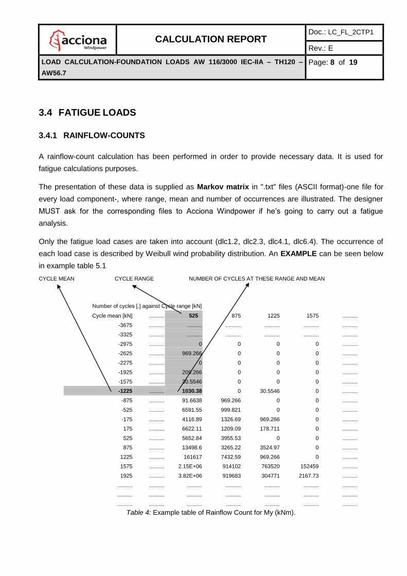
3.4 FATIGUE LOADS
3.4.1 RAINFLOW-COUNTS
A rainflow-count calculation has been performed in order to provide necessary data. It is used for
fatigue calculations purposes.
The presentation of these data is supplied as Markov matrix in ".txt" files (ASCII format)-one file for
every load component-, where range, mean and number of occurrences are illustrated. The designer
MUST ask for the corresponding files to Acciona Windpower if he’s going to carry out a fatigue
analysis.
Only the fatigue load cases are taken into account (dlc1.2, dlc2.3, dlc4.1, dlc6.4). The occurrence of
each load case is described by Weibull wind probability distribution. An EXAMPLE can be seen below
in example table 5.1
CYCLE MEAN CYCLE RANGE NUMBER OF CYCLES AT THESE RANGE AND MEAN
Number of cycles [.] against Cycle range [kN]
Cycle mean [kN] .......... 525 875 1225 1575 ..........
-3675 .......... .......... .......... .......... .......... ..........
-3325 .......... .......... .......... .......... .......... ..........
-2975 .......... 0 0 0 0 ..........
-2625 .......... 969.266 0 0 0 ..........
-2275 .......... 0 0 0 0 ..........
-1925 .......... 209.266 0 0 0 ..........
-1575 .......... 30.5546 0 0 0 ..........
-1225 .......... 1030.38 0 30.5546 0 ..........
-875 .......... 91.6638 969.266 0 0 ..........
-525 .......... 6591.55 999.821 0 0 ..........
-175 .......... 4116.89 1326.69 969.266 0 ..........
175 .......... 6622.11 1209.09 178.711 0 ..........
525 .......... 5652.84 3955.53 0 0 ..........
875 .......... 13498.6 3265.22 3524.97 0 ..........
1225 .......... 161617 7432.59 969.266 0 ..........
1575 .......... 2.15E+06 914102 763520 152459 ..........
1925 .......... 3.82E+06 919683 304771 2167.73 ..........
.......... .......... .......... .......... .......... .......... ..........
.......... .......... .......... .......... .......... .......... ..........
.......... .......... .......... .......... .......... .......... ..........
Table 4: Example table of Rainflow Count for My (kNm).

CALCULATION REPORT Doc.: LC_FL_2CTP1
Rev.: E
LOAD CALCULATION-FOUNDATION LOADS AW 116/3000 IEC-IIA – TH120 –
AW56.7
Page: 9 of 19
Time
Range
Figure 3: Range and mean definition
3.4.2 DAMAGE EQUIVALENT LOADS
Damage equivalent loads are used to equate the fatigue damage represented by RFCC data to that
caused by a single stress range repeating at a single frequency. The method is based on the Miner’s
rule. The damage equivalent stress is given by the following formula:
m i
m
i
NN
nLL
where LN is the equivalent stress for N cycles
Li is the stress range bin i.
ni is the number of rain flow cycles at stress range bin i.
m is the negative inverse of the slope on the material’s Wöhler curve (m is also
referred to as the S-N curve slope).
N is the number of cycle repetitions in the turbine lifetime.
The S-N curve slope (m) used here is 4 (steel), and 9 (composite), and its constant for every number of
cycles -there is no knee number-.
The stress Li depends upon the geometry of the structure considered. It is assumed that stress is
proportional to load, therefore it is quite acceptable to use load instead of stress in the above equation.
Mean
Load

CALCULATION REPORT Doc.: LC_FL_2CTP1
Rev.: E
LOAD CALCULATION-FOUNDATION LOADS AW 116/3000 IEC-IIA – TH120 –
AW56.7
Page: 10 of 19
For simplicity, Li and ni have been derived from the one-dimensional table with no correction to account
for the fatigue damage due to mean stresses.
The equivalent loads (in kNm and kN) are presented overleaf for each load component assuming 107
cycles in the turbine lifetime of 20 years. The values are given separately for each wind speed case as
well as the integrated load. The value for each case represents the relative damage due to that
particular case. This has the advantage of allowing the damage due to each case to be compared.
Inv
ers
e
SN
S
lop
e
dlc
1.2
a
dlc
1.2
b
dlc
1.2
c
dlc
1.2
d
dlc
1.2
e
dlc
1.2
f
dlc
1.2
g
dlc
1.2
h
dlc
1.2
i
dlc
1.2
j
dlc
1.2
k
.......
dlc
6.4
a
dlc
6.4
b
dlc
6.4
c
dlc
6.4
d
To
tal
3 451 450 449 932 977 799 760 887 796 1249 1143 ...... 273 3914 2937 1280 6452
4 500 504 500 969 1020 828 807 938 835 1290 1178 ...... 245 4853 4296 2331 6484
5 545 552 547 1013 1068 864 869 1002 884 1347 1228 ...... 247 5651 5502 3408 6973
6 585 595 589 1056 1115 900 938 1071 935 1409 1282 ...... 259 6349 6573 4448 7598
7 622 634 627 1097 1161 935 1008 1139 986 1472 1336 ...... 272 6968 7530 5427 8262
8 656 669 662 1135 1204 970 1075 1205 1033 1533 1390 ...... 286 7521 8393 6340 8927
9 688 700 693 1169 1244 1002 1139 1267 1078 1591 1441 ...... 298 8017 9176 7186 9575
10 717 729 723 1201 1282 1033 1196 1325 1120 1646 1490 ...... 310 8464 9891 7969 10197
Table 5: Lifetime rainflow cycle counts table definition
Tables 6 to 11 present the lifetime rainflow cycle counts from which the damage equivalent loads have
been derived at tower base:
m i
m
i
N
nLMean
Load Case LN

CALCULATION REPORT Doc.: LC_FL_2CTP1
Rev.: E
LOAD CALCULATION-FOUNDATION LOADS AW 116/3000 IEC-IIA – TH120 –
AW56.7
Page: 11 of 19
Inve
rse
SN
Slo
pe
[-]
dlc
1.2
a
dlc
1.2
aa
dlc
1.2
ab
dlc
1.2
ac
dlc
1.2
ad
dlc
1.2
ae
dlc
1.2
af
dlc
1.2
ag
dlc
1.2
b
dlc
1.2
c
dlc
1.2
d
dlc
1.2
e
dlc
1.2
f
dlc
1.2
g
dlc
1.2
h
dlc
1.2
i
dlc
1.2
j
dlc
1.2
k
dlc
1.2
l
dlc
1.2
m
dlc
1.2
n
dlc
1.2
o
dlc
1.2
p
dlc
1.2
q
dlc
1.2
r
dlc
1.2
s
dlc
1.2
t
dlc
1.2
u
dlc
1.2
v
dlc
1.2
w
dlc
1.2
x
dlc
1.2
y
dlc
1.2
z
dlc
2.3
a
dlc
2.3
b
dlc
4.1
a
dlc
4.1
b
dlc
4.1
c
dlc
6.4
a
dlc
6.4
b
To
tal
3 2021 3924 3812 3770 3762 4119 4188 3998 2037 1933 2466 2453 2376 3253 3315 3347 4209 4012 4275 5050 4690 4459 4898 4862 4870 4632 4704 4724 4171 4385 4505 4063 3958 793 1586 624 412 692 867 10361 14881
4 2152 5175 5396 5342 5317 6314 6457 6197 2222 2084 2618 2584 2522 3377 3473 3495 4458 4227 4487 5467 5069 4814 5455 5452 5523 5354 5456 5501 5137 5420 5597 5371 5223 1712 3278 847 795 1370 841 15138 16487
5 2304 6312 6804 6741 6706 8358 8592 8326 2438 2257 2795 2732 2705 3549 3698 3682 4749 4485 4740 5885 5436 5157 5981 6032 6176 5990 6120 6188 5993 6328 6574 6534 6347 2756 5191 1026 1207 2102 875 19314 19741
6 2469 7357 8054 7982 7945 10243 10581 10363 2671 2440 2979 2878 2900 3732 3953 3879 5044 4747 5000 6291 5776 5475 6482 6614 6827 6569 6719 6802 6777 7140 7461 7573 7355 3810 7155 1172 1610 2819 924 22974 23137
7 2641 8320 9165 9086 9056 11986 12428 12290 2906 2626 3162 3017 3097 3910 4216 4075 5326 4998 5254 6682 6085 5767 6959 7192 7466 7103 7266 7352 7507 7874 8268 8504 8261 4818 9074 1293 1988 3491 976 26220 26292
8 2812 9207 10157 10074 10054 13600 14139 14088 3131 2806 3339 3146 3288 4077 4473 4265 5588 5232 5495 7055 6367 6033 7408 7753 8074 7596 7765 7846 8190 8539 9003 9336 9076 5758 10896 1394 2334 4104 1026 29130 29166
9 2975 10018 11045 10961 10953 15093 15718 15747 3338 2975 3506 3266 3467 4231 4714 4444 5827 5446 5721 7406 6624 6275 7828 8282 8639 8052 8218 8289 8824 9142 9670 10080 9810 6623 12595 1480 2647 4659 1073 31763 31782
10 3127 10760 11844 11761 11765 16471 17168 17264 3524 3129 3660 3376 3632 4371 4935 4611 6044 5639 5931 7733 6857 6495 8215 8770 9155 8470 8630 8687 9407 9689 10276 10745 10471 7415 14164 1553 2929 5158 1118 34161 34171
Table 6: Lifetime Weighted Equivalent Loads: Tower Mx, Tower station height= 0m (1.E+07 cycles)
Inve
rse
SN
Slo
pe
[-]
dlc
1.2
a
dlc
1.2
aa
dlc
1.2
ab
dlc
1.2
ac
dlc
1.2
ad
dlc
1.2
ae
dlc
1.2
af
dlc
1.2
ag
dlc
1.2
b
dlc
1.2
c
dlc
1.2
d
dlc
1.2
e
dlc
1.2
f
dlc
1.2
g
dlc
1.2
h
dlc
1.2
i
dlc
1.2
j
dlc
1.2
k
dlc
1.2
l
dlc
1.2
m
dlc
1.2
n
dlc
1.2
o
dlc
1.2
p
dlc
1.2
q
dlc
1.2
r
dlc
1.2
s
dlc
1.2
t
dlc
1.2
u
dlc
1.2
v
dlc
1.2
w
dlc
1.2
x
dlc
1.2
y
dlc
1.2
z
dlc
2.3
a
dlc
2.3
b
dlc
4.1
a
dlc
4.1
b
dlc
4.1
c
dlc
6.4
a
dlc
6.4
b
To
tal
3 10591 8272 7488 7352 7391 6842 6561 6534 10552 10533 11507 11519 11484 14498 14641 14556 13555 13618 13695 12990 13085 12549 11857 11991 12091 10378 10326 10338 9443 9193 9173 8822 8532 3147 4353 5273 4256 2895 997 4676 36005
4 12507 10851 10481 10269 10287 10309 9877 9843 12351 12248 13645 13436 13419 18393 18630 18755 16713 16893 16827 15713 15798 14954 14737 14790 14857 12512 12484 12592 11657 11302 11233 11699 11234 7726 8812 8154 9151 5451 839 6897 34068
5 14946 13139 13148 12869 12831 13487 12937 12879 14658 14432 16116 15727 15748 22427 22728 23023 20058 20362 20128 18479 18610 17416 17814 17753 17763 14588 14606 14862 13665 13212 13045 14284 13654 13268 13604 10899 14502 8176 756 8918 35120
6 17389 15163 15509 15172 15051 16349 15726 15623 16999 16660 18453 17955 17999 26018 26375 26783 23105 23499 23136 20927 21154 19626 20736 20554 20490 16510 16579 17015 15494 14946 14634 16580 15811 19029 18294 13337 19713 10860 706 10774 36883
7 19577 16954 17603 17215 16991 18920 18264 18105 19117 18690 20507 19945 19996 29085 29500 29981 25757 26218 25766 23016 23368 21538 23374 23084 22936 18243 18361 18989 17163 16520 16034 18606 17728 24621 22708 15442 24547 13389 672 12496 38793
8 21466 18544 19465 19031 18695 21231 20577 20357 20953 20460 22272 21670 21720 31690 32159 32693 28045 28557 28042 24798 25282 23185 25710 25331 25095 19789 19953 20769 18686 17949 17275 20391 19429 29868 26790 17248 28935 15713 648 14099 40745
9 23083 19961 21127 20651 20200 23318 22688 22408 22528 21986 23788 23158 23201 33912 34432 35005 30020 30575 30014 26330 26948 24613 27765 27315 26996 21165 21369 22363 20072 19246 18384 21966 20941 34712 30540 18800 32883 17822 629 15586 42766
10 24472 21231 22616 22102 21536 25208 24619 24283 23883 23301 25096 24444 24480 35824 36387 36993 31734 32324 31728 27662 28406 25861 29572 29066 28671 22389 22631 23789 21333 20421 19382 23360 22289 39146 33977 20144 36427 19724 615 16961 44912
Table 7: Lifetime Weighted Equivalent Loads: Tower My, Tower station height= 0m (1.E+07 cycles)
Inve
rse
SN
Slo
pe
[-]
dlc
1.2
a
dlc
1.2
aa
dlc
1.2
ab
dlc
1.2
ac
dlc
1.2
ad
dlc
1.2
ae
dlc
1.2
af
dlc
1.2
ag
dlc
1.2
b
dlc
1.2
c
dlc
1.2
d
dlc
1.2
e
dlc
1.2
f
dlc
1.2
g
dlc
1.2
h
dlc
1.2
i
dlc
1.2
j
dlc
1.2
k
dlc
1.2
l
dlc
1.2
m
dlc
1.2
n
dlc
1.2
o
dlc
1.2
p
dlc
1.2
q
dlc
1.2
r
dlc
1.2
s
dlc
1.2
t
dlc
1.2
u
dlc
1.2
v
dlc
1.2
w
dlc
1.2
x
dlc
1.2
y
dlc
1.2
z
dlc
2.3
a
dlc
2.3
b
dlc
4.1
a
dlc
4.1
b
dlc
4.1
c
dlc
6.4
a
dlc
6.4
b
To
tal
3 926 1263 1047 1035 1037 858 859 866 949 955 1049 1063 1049 1399 1398 1344 1731 1683 1667 1805 1837 1824 1755 1771 1781 1649 1629 1632 1404 1434 1449 1264 1257 115 553 58.1 78.5 289 134 462 4591
4 975 1648 1481 1456 1454 1296 1292 1300 1002 1000 1097 1111 1092 1479 1479 1410 1816 1762 1729 1961 2005 2006 1946 1962 1987 1921 1889 1883 1699 1740 1765 1669 1652 229 1167 90.8 163 500 109 651 3997
5 1037 2001 1899 1857 1850 1717 1704 1713 1068 1055 1165 1177 1155 1590 1591 1509 1937 1880 1827 2155 2210 2227 2147 2157 2198 2190 2144 2126 1964 2015 2053 2053 2021 356 1859 122 257 718 97.0 827 3883
6 1103 2327 2297 2235 2221 2110 2086 2096 1139 1113 1237 1248 1224 1706 1710 1620 2068 2010 1936 2362 2424 2457 2346 2346 2401 2449 2390 2357 2204 2267 2314 2417 2366 483 2556 149 349 931 89.5 992 3958
7 1168 2626 2669 2586 2564 2472 2436 2446 1209 1171 1306 1318 1295 1817 1825 1731 2198 2139 2043 2563 2630 2676 2535 2523 2589 2690 2620 2571 2422 2496 2550 2757 2686 606 3221 173 435 1134 84.6 1144 4134
8 1229 2898 3012 2910 2878 2801 2753 2762 1276 1227 1370 1383 1362 1918 1931 1836 2318 2259 2143 2749 2821 2876 2709 2685 2759 2909 2830 2766 2619 2704 2761 3070 2978 723 3841 193 512 1323 81.0 1283 4391
9 1286 3145 3327 3207 3164 3100 3039 3046 1337 1278 1427 1443 1424 2008 2029 1933 2428 2368 2234 2918 2993 3056 2867 2833 2912 3106 3019 2941 2798 2894 2951 3357 3245 831 4412 211 582 1496 78.3 1410 4718
10 1338 3369 3615 3478 3425 3372 3298 3302 1393 1326 1477 1498 1480 2089 2117 2022 2527 2465 2315 3070 3148 3216 3010 2966 3050 3282 3188 3097 2961 3068 3123 3618 3488 930 4935 226 645 1653 76.3 1525 5096
Table 8: Lifetime Weighted Equivalent Loads: Tower Mz, Tower station height= 0m (1.E+07 cycles)

CALCULATION REPORT Doc.: LC_FL_2CTP1
Rev.: E
LOAD CALCULATION-FOUNDATION LOADS AW 116/3000 IEC-IIA – TH120 –
AW56.7
Page: 12 of 19
Inve
rse
SN
Slo
pe
[-]
dlc
1.2
a
dlc
1.2
aa
dlc
1.2
ab
dlc
1.2
ac
dlc
1.2
ad
dlc
1.2
ae
dlc
1.2
af
dlc
1.2
ag
dlc
1.2
b
dlc
1.2
c
dlc
1.2
d
dlc
1.2
e
dlc
1.2
f
dlc
1.2
g
dlc
1.2
h
dlc
1.2
i
dlc
1.2
j
dlc
1.2
k
dlc
1.2
l
dlc
1.2
m
dlc
1.2
n
dlc
1.2
o
dlc
1.2
p
dlc
1.2
q
dlc
1.2
r
dlc
1.2
s
dlc
1.2
t
dlc
1.2
u
dlc
1.2
v
dlc
1.2
w
dlc
1.2
x
dlc
1.2
y
dlc
1.2
z
dlc
2.3
a
dlc
2.3
b
dlc
4.1
a
dlc
4.1
b
dlc
4.1
c
dlc
6.4
a
dlc
6.4
b
To
tal
3 149 138 122 121 122 107 103 102 148 147 157 158 158 192 196 195 197 199 199 204 206 202 190 195 196 176 176 177 162 161 160 147 143 28.5 59.7 47.9 35.7 32.9 10.8 56.6 544
4 157 167 159 158 159 152 146 143 156 155 165 163 162 204 208 209 206 206 207 210 211 208 201 206 208 191 191 193 184 183 180 180 174 68.2 118 72.1 76.5 58.1 9.01 83.2 446
5 173 191 191 190 191 192 184 180 171 170 182 176 175 228 231 237 226 223 225 223 224 220 217 221 225 205 206 209 204 203 199 210 201 117 181 95.1 121 82.9 8.24 108 418
6 193 213 218 219 220 227 218 213 189 189 202 192 190 255 257 268 251 246 246 238 239 235 234 240 244 220 222 227 222 221 214 236 225 167 242 116 165 106 8.01 133 414
7 213 232 243 245 245 259 250 243 208 208 221 208 206 280 283 297 275 269 268 253 256 250 252 259 264 233 236 244 239 237 229 260 247 216 300 134 205 127 8.17 156 422
8 232 249 265 269 268 288 280 269 226 227 239 222 221 303 305 323 298 290 288 268 272 264 270 277 283 246 250 260 254 253 241 282 266 262 352 150 242 147 8.56 179 435
9 248 264 284 290 289 314 308 293 243 243 255 236 234 324 325 345 318 309 305 281 286 276 286 295 301 258 263 275 268 267 252 302 284 305 401 163 275 164 9.02 200 454
10 263 278 301 310 308 337 334 314 257 257 269 248 247 341 342 364 336 325 321 293 300 288 302 311 318 270 275 288 281 281 263 321 300 344 445 175 305 180 9.46 219 478
Table 9: Lifetime Weighted Equivalent Loads: Tower Fx, Tower station height= 0m (1.E+07 cycles)
Inve
rse
SN
Slo
pe
[-]
dlc
1.2
a
dlc
1.2
aa
dlc
1.2
ab
dlc
1.2
ac
dlc
1.2
ad
dlc
1.2
ae
dlc
1.2
af
dlc
1.2
ag
dlc
1.2
b
dlc
1.2
c
dlc
1.2
d
dlc
1.2
e
dlc
1.2
f
dlc
1.2
g
dlc
1.2
h
dlc
1.2
i
dlc
1.2
j
dlc
1.2
k
dlc
1.2
l
dlc
1.2
m
dlc
1.2
n
dlc
1.2
o
dlc
1.2
p
dlc
1.2
q
dlc
1.2
r
dlc
1.2
s
dlc
1.2
t
dlc
1.2
u
dlc
1.2
v
dlc
1.2
w
dlc
1.2
x
dlc
1.2
y
dlc
1.2
z
dlc
2.3
a
dlc
2.3
b
dlc
4.1
a
dlc
4.1
b
dlc
4.1
c
dlc
6.4
a
dlc
6.4
b
To
tal
3 28.5 59.6 52.1 52.2 52.6 52.8 54.3 53.2 29.5 25.2 34.4 34.1 33.4 52.4 51.1 48.9 63.3 63.2 66.6 74.1 70.4 66.4 74.0 72.1 72.0 70.7 71.5 72.5 63.7 66.4 69.2 59.6 59.6 15.0 20.9 6.36 3.81 6.57 10.3 110 204
4 30.9 73.9 70.2 70.6 71.1 77.9 80.4 78.6 32.4 26.5 35.2 34.7 33.8 53.0 50.9 48.6 63.4 63.3 66.3 76.6 72.4 68.1 78.9 76.7 77.1 77.7 78.8 80.0 73.9 77.3 80.9 74.3 74.0 32.5 42.3 8.75 6.85 12.4 9.80 159 194
5 33.6 86.5 86.4 87.2 87.6 101 105 103 35.7 28.3 36.6 35.9 35.0 54.8 52.0 49.7 65.1 65.2 67.6 80.4 75.6 70.8 84.3 81.6 82.7 84.3 85.6 87.1 82.9 86.9 91.5 87.4 86.6 52.3 66.3 10.7 9.89 18.4 9.88 202 214
6 36.4 98.0 101 102 103 122 127 126 38.8 30.1 38.2 37.2 36.4 57.0 53.6 51.2 67.4 67.7 69.3 84.7 79.1 73.7 90.0 86.5 88.4 90.5 92.0 93.8 91.1 95.7 101 99.4 98.0 72.5 90.7 12.5 12.7 24.3 10.1 239 244
7 38.9 109 114 116 116 142 147 147 41.6 31.9 39.8 38.5 37.9 59.2 55.5 53.0 70.0 70.7 71.2 89.3 82.6 76.6 95.9 91.3 93.9 96.3 97.9 100 98.6 104 111 110 108 91.8 115 13.9 15.3 29.8 10.4 271 274
8 41.2 118 126 129 129 160 166 167 44.1 33.7 41.3 39.7 39.4 61.3 57.3 54.7 72.7 73.7 73.1 94.0 86.0 79.5 102 95.9 99.2 102 104 106 106 111 120 120 118 110 137 15.2 17.6 34.8 10.7 300 301
9 43.3 127 137 140 140 177 184 185 46.3 35.3 42.7 40.8 40.8 63.3 59.1 56.4 75.3 76.8 75.0 98.5 89.4 82.3 107 100 104 107 109 111 112 118 129 129 126 126 158 16.3 19.7 39.3 11.0 326 327
10 45.2 136 147 151 151 192 200 203 48.2 36.8 44.0 41.8 42.2 65.1 60.9 57.9 77.8 79.7 76.8 103 92.5 84.9 113 105 109 112 114 116 118 124 137 137 133 142 178 17.3 21.6 43.4 11.4 349 350
Table 10: Lifetime Weighted Equivalent Loads: Tower Fy, Tower station height= 0m (1.E+07 cycles)
Inve
rse
SN
Slo
pe
[-]
dlc
1.2
a
dlc
1.2
aa
dlc
1.2
ab
dlc
1.2
ac
dlc
1.2
ad
dlc
1.2
ae
dlc
1.2
af
dlc
1.2
ag
dlc
1.2
b
dlc
1.2
c
dlc
1.2
d
dlc
1.2
e
dlc
1.2
f
dlc
1.2
g
dlc
1.2
h
dlc
1.2
i
dlc
1.2
j
dlc
1.2
k
dlc
1.2
l
dlc
1.2
m
dlc
1.2
n
dlc
1.2
o
dlc
1.2
p
dlc
1.2
q
dlc
1.2
r
dlc
1.2
s
dlc
1.2
t
dlc
1.2
u
dlc
1.2
v
dlc
1.2
w
dlc
1.2
x
dlc
1.2
y
dlc
1.2
z
dlc
2.3
a
dlc
2.3
b
dlc
4.1
a
dlc
4.1
b
dlc
4.1
c
dlc
6.4
a
dlc
6.4
b
To
tal
3 24.6 47.6 37.8 36.7 35.8 32.9 31.4 30.4 24.9 20.2 28.3 28.5 28.6 49.6 46.6 41.2 60.1 57.2 61.2 66.1 63.8 61.6 65.9 64.9 64.2 61.9 62.7 63.0 52.6 53.9 54.6 46.4 46.7 3.84 9.50 4.91 3.60 4.41 3.76 21.4 164
4 27.3 57.7 48.9 47.4 46.3 45.8 43.7 42.2 27.6 20.6 28.4 28.3 28.6 49.4 45.7 40.0 58.7 55.9 59.7 66.4 63.5 61.8 68.3 66.9 66.2 66.4 67.4 67.4 59.9 61.2 61.8 55.9 56.3 8.33 19.9 8.01 7.66 8.68 3.24 33.7 134
5 30.3 66.6 58.6 56.8 55.6 57.0 54.6 52.8 30.5 21.8 29.4 29.1 29.6 51.0 46.7 40.5 59.7 56.6 60.3 68.6 65.0 63.8 71.6 69.9 69.3 70.9 72.1 71.7 66.5 67.6 68.1 64.1 64.5 13.8 32.3 10.8 12.1 13.3 3.27 45.7 123
6 33.0 74.8 67.4 65.3 64.2 67.0 64.2 62.5 33.1 23.1 30.7 30.2 31.0 53.1 48.2 41.6 61.5 58.3 61.7 71.8 67.2 66.7 75.0 73.2 72.7 75.0 76.6 75.8 72.5 73.5 73.7 71.5 71.9 19.6 45.3 13.3 16.5 17.9 3.57 57.0 120
7 35.4 82.5 75.6 73.1 72.0 76.0 72.9 71.3 35.3 24.5 32.1 31.4 32.5 55.3 49.9 43.1 63.8 60.4 63.3 75.5 69.9 70.0 78.6 76.6 76.2 79.0 81.0 79.6 78.0 78.8 78.9 78.4 78.6 25.3 58.2 15.4 20.5 22.2 3.91 67.2 120
8 37.4 89.9 83.1 80.3 79.3 84.0 80.7 79.3 37.2 25.7 33.6 32.6 34.0 57.6 51.6 44.7 66.2 62.6 64.9 79.5 72.7 73.6 82.0 80.1 79.7 82.8 85.1 83.3 83.0 83.7 83.8 84.9 84.9 30.7 70.4 17.2 24.2 26.1 4.23 76.5 121
9 39.2 96.8 90.2 86.9 86.0 91.3 87.8 86.8 38.9 26.9 35.0 33.9 35.5 59.7 53.2 46.3 68.6 64.9 66.6 83.4 75.6 77.1 85.4 83.5 83.1 86.3 89.1 86.8 87.6 88.2 88.2 91.0 90.8 35.6 81.7 18.8 27.5 29.7 4.50 84.8 124
10 40.7 103 96.7 93.0 92.2 97.9 94.3 93.5 40.3 27.9 36.4 35.0 36.9 61.8 54.7 47.8 70.9 67.1 68.1 87.3 78.5 80.6 88.5 86.8 86.2 89.6 92.8 90.0 91.8 92.4 92.3 96.7 96.2 40.2 92.1 20.1 30.5 32.9 4.73 92.3 127
Table 11: Lifetime Weighted Equivalent Loads: Tower Fz, Tower station height= 0m (1.E+07 cycles)

CALCULATION REPORT Doc.: LC_FL_2CTP1
Rev.: E
LOAD CALCULATION-FOUNDATION LOADS AW 116/3000 IEC-IIA – TH120 –
AW56.7
Page: 13 of 19
4 REQUIREMENTS OF THE SOIL FOR THE FOUNDATION
It must be ensured that foundation soil properties comply with the assumptions made in the
static and dynamic calculations for the tower’s design. This requirement is given for an ordinary
slab foundation.
For sites where they have poor soil conditions, the use of pile foundations could be an option.
In connection with the settlement analysis it should be distinguished between immediate elastic
and time dependent consolidation settlements. Calculations should provide information on the
tolerance or variability in the settlement calculation. In this way, each soil layer contributing to
the foundation settlement and stiffness must be thoroughly investigated. The depth to be
investigated should at least equal the largest base dimension of the structure. The soil borings
are to extend to at least this depth.
4.1 SETTLEMENT
To ensure the suitable behavior of the tower during operation, a maximum foundation inclination
of 3mm/m is permissible. This value refers to the uneven settling due to constant load (dead
weight) and not to an inclination during operation as a result of the external moments. The
inclination occurring due to dead weight must be demonstrated by means of an adequate
analysis.

CALCULATION REPORT Doc.: LC_FL_2CTP1
Rev.: E
LOAD CALCULATION-FOUNDATION LOADS AW 116/3000 IEC-IIA – TH120 –
AW56.7
Page: 14 of 19
4.2 SOIL DYNAMICS REQUIREMENTS
Particular attention needs to be paid to the requirements with regard to soil dynamics, since the
wind turbines are structures that are subject to strong dynamic loads and stresses. It must be
taken into account that the load excitation is not a static event but a dynamic one (excitation
frequencies <5Hz.).
It’s very important to avoid the interaction of the soil and foundation dynamics with the rest of
the turbine. To comply with this need the dynamic soil stiffness for AW 116 /3000 IEC-IIa –
T120H, AW56.7 must have a minimum value of:
Dynamic rotational spring stiffness of foundation equal or bigger to: Kθx = Kθy = 2.9·1011 (N·m/rad).

CALCULATION REPORT Doc.: LC_FL_2CTP1
Rev.: E
LOAD CALCULATION-FOUNDATION LOADS AW 116/3000 IEC-IIA – TH120 –
AW56.7
Page: 15 of 19
5 DESIGN CONDITIONS
The foundation design to develop will take into account the following conditions:
5.1 CONNECTION TOWER-FOUNDATION
Acciona Windpower will design the connection between the foundation and the tower. The
designer must request to AW the foundation assembly requirements.
In case of the concrete tower, the connection between the tower and the foundation is done
through several corrugated sheaths and a system of prestressing tendons as shown in next
figure.
Next plot shows the distribution of the External Prestressing tendons and the anchor system
used.
Figure 4: Detail of the anchoring prestressing tendons at the tower foundation.
This drawing is contained in DI0021 of Acciona Windpower and it is attached as an annex in
this report. See Annex A at the end of the report.

CALCULATION REPORT Doc.: LC_FL_2CTP1
Rev.: E
LOAD CALCULATION-FOUNDATION LOADS AW 116/3000 IEC-IIA – TH120 –
AW56.7
Page: 16 of 19
The designer of the foundation must take into account the forces due to the anchoring of the
prestressing cable. The foundation have to be design to resist 6 punctual loads of 3333 kN
each. These loads consist of 6 prestressing groups, as shown in the previous figure.
5.2 GENERAL FOUNDATION REQUIREMENTS
The requirements for the foundation are collected in General Document DG200336 of Acciona
Windpower. This General Document includes the design of a General Foundation, Concrete
Ground Floor, selected backfill and preassembly slabs for concrete tower erection.
The design could vary depending on the particular soil.
Figure 5: Scheme of the Backfill, according to DG200336
The previous issues are civil work competences. Their correct implementation following AW’s
indications is needed for erecting the concrete tower.

CALCULATION REPORT Doc.: LC_FL_2CTP1
Rev.: E
LOAD CALCULATION-FOUNDATION LOADS AW 116/3000 IEC-IIA – TH120 –
AW56.7
Page: 17 of 19
5.3 EARTHING SYSTEM
The earthing system consists of two parts: the general earthing system and the earthing system
for each wind turbine, which is connected to the general system.
The final topology of an earthing system depends on the location of the W.F., since it depends
on the characteristics of the ground (electric resistivity, homogeneity, stratification, etc.) and on
the current regulation where the wind turbine is assembled.
The designer must include on the foundation drawings the earthing system sketch according to
AW specifications and drawings.
After all, the earthing system resistance must be less than 10Ω;
The AW documents show an example of the earthing system execution. the earthing system
configuration depends on the current and local regulation where the wind turbine is assembled.
The earthing system for each wind turbine must be connected to the general earthing system of
the wind farm with 50mm2 copper.
The foundation drawings will have to take into account the holes for the wind farm general
wiring installation.
5.4 FLOOD LEVEL
In order to avoid the water accumulation over the tower base level or into the pedestal catchpit,
the design and the construction of the foundation, of the assembly platform and of the site
access must assure that the flood level is under the top pedestal level. For it, the designer must
study the flood risk and design the drainage necessary of the different elements (foundation,
assembly platform and site access).

CALCULATION REPORT Doc.: LC_FL_2CTP1
Rev.: E
LOAD CALCULATION-FOUNDATION LOADS AW 116/3000 IEC-IIA – TH120 –
AW56.7
Page: 18 of 19
ANNEX A. DI0021 – TH120 FOR TURBINE AW3000. TH
CONNECTION WITH FOUNDATION


DOCUMENTOS GENERALES
GENERAL DOCUMENTATION
Doc.: DG200297
Rev.: D
REQUERIMIENTOS TÉCNICOS DE LA CIMENTACIÓN AW3000
AW3000 FOUNDATION TECHNICAL REQUIREMENTS P. 1 / 12
Rev Fecha Date
Descripción de la revisión Description of the revision
“A” “A" 24/02/12 Elaboración / First edition
“B” 10/08/12 Modificaciones generales. Se ha concretado más en las acometidas eléctricas / General modifications. Electrical connections has been specified more
“C” 08/10/13 Modificado material hormigón del pedestal y valor capacidad portante del terreno / Pedestal concrete material and soil requirement value modified.
“D” 21/11/13 Se elimina referencia a los LC_FL’s / Reference to LC_FL’s removed
“E”
Realizado / Done Revisado / Reviewed Aprobado / Approved
En caso de duda prevalecerá la versión en castellano/ In case of doubt, the Spanish version shall prevail. © 2013 ACCIONA WINDPOWER S.A. Todos los derechos reservados / All rights reserved
AW3000
19-11-2013 21-11-2013 22-11-2013

DOCUMENTOS GENERALES
GENERAL DOCUMENTATION
Doc.: DG200297
Rev.: D
REQUERIMIENTOS TÉCNICOS DE LA CIMENTACIÓN AW3000
AW3000 FOUNDATION TECHNICAL REQUIREMENTS P. 2 / 12
1. INTRODUCCIÓN
En el presente documento se describen las
características generales de la cimentación para la
máquina AW3000 y se indican especificaciones
técnicas requeridas por Acciona Windpower para
realizar su diseño.
2. GENERALIDADES
Existen distintos modelos de aerogenerador
AW3000 en función de la clase del emplazamiento
y el tipo de torre y su altura. Estos parámetros
definen inicialmente el diseño de la cimentación de
la turbina, sin embargo existen otros muchos
aspectos a tener en cuenta relacionados con las
características particulares encontradas en campo.
En el presente documento se pretende aportar una
descripción técnica general para la cimentación de
la máquina AW3000.
3. TIPOS DE ZAPATAS
Las turbinas eólicas se encuentran sujetas a
fuertes cargas dinámicas y estáticas, y la zapata es
el elemento fundamental que sirve de soporte
estructural para toda la máquina. Evita el vuelco y
el hundimiento, recibiendo todas las cargas desde
la torre realizando el soporte mecánico.
El aerogenerador AW3000 puede ir montado
sobre 2 tipos de torres distintas: de acero o de
hormigón. De esta forma, para que la torre y la
cimentación trabajen de manera solidaria debe de
adaptarse la zapata a cada tipo de estructura.
1. INTRODUCTION
This document provides a general overview of the
foundation characteristics for the AW3000 and
references certain technical specifications from
Acciona Windpower required for designing the
applicable foundation.
2. GENERAL INFORMATION
Acciona Windpower offers the AW3000 with
different hub heights and rotor options, and the
foundation design will vary according to these
different product variants. In addition, the design
will be further defined by the actual site conditions
of each turbine. The intent of this document is to
provide a general technical description of the
foundations for the AW3000 platform.
3. FOUNDATION TYPES
Wind turbines are exposed to high dynamic and
static loads, and the principal means of support for
the machine is the foundation. It avoids overturning
or subsidence, as it is the mechanical support for all
the loads coming from the tower.
The AW3000 wind turbine can be assembled on
two different types of towers: steel or concrete.
Correspondingly, there are two different foundation
types for each of these options:

DOCUMENTOS GENERALES
GENERAL DOCUMENTATION
Doc.: DG200297
Rev.: D
REQUERIMIENTOS TÉCNICOS DE LA CIMENTACIÓN AW3000
AW3000 FOUNDATION TECHNICAL REQUIREMENTS P. 3 / 12
Existen por lo tanto 2 tipos de zapatas para los 2
tipos de torres posibles:
3.1. Zapata para la torre de acero
La unión de la torre a la cimentación se realiza
mediante una corona formada por una doble hilera
concéntrica de pernos, embebida en una zapata de
hormigón armado. Dicha doble hilera de pernos
sobresale por la parte superior de la zapata para
atornillarla al primer tramo de torre.
De manera general la zapata será de forma
octogonal, y el esquema de la misma junto con la
armadura cortante correspondiente a la torre de
acero se muestran a continuación:
3.1. Steel tower slab
The union of the tower to the foundation is
achieved by means of a ring with two concentric
rows of studs, which is embedded inside a
reinforced concrete slab. That double ring of studs
protrudes from the upper side of the slab to tension
to the tower.
Generally, the slab will be octagonal, and a
generic diagram of the slab with the shear
reinforcement related to the steel tower is shown
below:
Zapata para torre de acero / Slab for Steel tower
En estas zapatas generalmente nos encontramos
con más armadura y menos hormigón de lo que
hay en las zapatas para torres de hormigón. Para la
nivelación con el primer tramo de la torre, el
mortero de nivelación es sustituido por la brida
superior de la cimentación. Así mismo, el carrete de
There is typically more steel and less concrete than
the concrete tower foundation. For the leveling with
the first tower section, the grout is replaced with the
upper foundation flange. Similarly, the foundation
stud ring of the slab is shown below:

DOCUMENTOS GENERALES
GENERAL DOCUMENTATION
Doc.: DG200297
Rev.: D
REQUERIMIENTOS TÉCNICOS DE LA CIMENTACIÓN AW3000
AW3000 FOUNDATION TECHNICAL REQUIREMENTS P. 4 / 12
pernos localizado en la zapata se muestra a
continuación:
3.2. Zapata para la torre de hormigón
La torre de hormigón es una estructura
compuesta por elementos prefabricados llamados
dovelas. Estas se unen a la cimentación mediante
la introducción de las barras que sobresalen de las
dovelas del primer tramo en unas vainas
localizadas en la zapata. Posteriormente se
rellenan dichas vainas con mortero y se procede a
la realización del anillo de cimentación, ambos con
mortero de alta resistencia, para su unión final.
De la zapata también sobresalen las barras para
realizar el post-tensado de la torre una vez estén la
torre y la nacelle montadas.
El esquema general de la zapata correspondiente
a la torre de hormigón y el de la unión torre-zapata
en las vainas puede verse en las siguientes figuras:
3.2. Concrete tower slab
The concrete tower is a structure consisting of
precast concrete elements called keystones. These
first section keystones are joined to the foundation by
inserting its outstanding bars into the slab sheaths.
These sheaths are filled with mortar. For the final
assembly, the foundation mortar is created.
Also, 6 groups of four bolts protrude from the slab
for the tower post-tensioning once the tower and the
nacelle are assembled.
A generic diagram of the slab for concrete tower
and the tower-slab union at the sheath is shown in
the following pictures:

DOCUMENTOS GENERALES
GENERAL DOCUMENTATION
Doc.: DG200297
Rev.: D
REQUERIMIENTOS TÉCNICOS DE LA CIMENTACIÓN AW3000
AW3000 FOUNDATION TECHNICAL REQUIREMENTS P. 5 / 12
Zapata para torre de hormigón con detalle de las vainas y los pernos post-tensado / Slab for concrete tower with the sheaths and post
tension anchoring bolts detailed
El premontaje de la torre se realiza en una serie
de losas donde se irán dejando los tramos para su
levantamiento. Las losas se podrían colocar de 2
maneras: radialmente alrededor de la torre, o en
línea recta una tras otra. A continuación se muestra
un esquema general del relleno y las losas de
premontaje:
The keystone pre-assembly takes place next to the
wind turbine foundation on concrete slabs as shown
in the diagrams below. The slabs could be placed by
2 ways: radially around the tower, or in line.

DOCUMENTOS GENERALES
GENERAL DOCUMENTATION
Doc.: DG200297
Rev.: D
REQUERIMIENTOS TÉCNICOS DE LA CIMENTACIÓN AW3000
AW3000 FOUNDATION TECHNICAL REQUIREMENTS P. 6 / 12
4. PUESTA A TIERRA
El diseño de la puesta a tierra del aerogenerador
AW3000 debe asegurar la protección completa de
la máquina. Para dicha protección existen dos
partes en el sistema de red de tierras: una toma de
red general para todo el parque eólico (a través de
un cable de cobre desnudo de 50 mm2), y la toma
de tierras de cada turbina en particular que irá
unida a la red general.
Los sistemas de protección contra rayos y puesta
a tierra están diseñados y certificados conforme a
la norma Germanicher Lloyd Guideline for the
classification of Windturbines (Edition 2003 with
suplement 2004) Rules and Guidelines IV –
Industrial Services, Part 1. En el documento
DG200233 se ha hace una explicación más
detallada de los requerimientos de protección
contra rayos y puesta a tierra.
4. GROUNDING
The AW3000 grounding design should assure the
complete protection of the machine from Electrical
Over-Voltages. This target is achieved by using a
general grounding grid for the collection system (with
a copper cable of 50 mm2), and an individual
grounding grid for each wind turbine, which should all
be connected to the collection system grounding grid.
The grounding system is designed and certified
according to Germanicher Lloyd Gudeline for the
classification of Windturbines (Edition 2003 with
suplement 2004) Rules and Guidelines IV – Industrial
Services, Part 1. A more detailed explanation of the
lightning and grounding requirements can be found in
specification DG200233.

DOCUMENTOS GENERALES
GENERAL DOCUMENTATION
Doc.: DG200297
Rev.: D
REQUERIMIENTOS TÉCNICOS DE LA CIMENTACIÓN AW3000
AW3000 FOUNDATION TECHNICAL REQUIREMENTS P. 7 / 12
La puesta a tierra depende de la resistividad del
terreno y puede verse afectada por normativas
locales. A modo de ejemplo, el sistema se
compone de un primer rombo de pletinas de acero
galvanizado que se coloca antes de empezar a
poner la armadura y la corona de pernos (en el
caso de la torre de acero) y del que sobresalen
prolongaciones centrales por encima de la parte
superior de la zapata y que van unidas al sistema
de tierras de la torre y de la red general del parque.
The grounding system depends on soil resistivity
and can be affected by local regulations. As an
example, this system below consists in a rhombus
with galvanized steel flanges, that is installed before
laying the mesh reinforcement and the bolt crown (for
steel tower), with central extensions above the higher
side of the slab and connected to the general
grounding grid and the tower grounding grid.
La otra parte de la puesta a tierra consiste en una
serie de anillos de cobre al nivel de la parte
superior de la zapata una vez esté ya hormigonada,
y alrededor de la acera sobre la superficie de la
zahorra a 1 metro del aerogenerador. De esta
manera se garantiza la equipotencialidad en la
zona de influencia de la turbina.
The other part of the grounding system are
concentric rings on the top side of the slab after
ending the concreting, and around the graded
aggregate surface of 1 meter from the turbine tower.
Thus, the equipotentiality on the turbine influence
zone is secured.

DOCUMENTOS GENERALES
GENERAL DOCUMENTATION
Doc.: DG200297
Rev.: D
REQUERIMIENTOS TÉCNICOS DE LA CIMENTACIÓN AW3000
AW3000 FOUNDATION TECHNICAL REQUIREMENTS P. 8 / 12
Se debe garantizar que este sistema de tierras
posea una resistencia mínima igual o inferior a 10
Ω. En la siguiente figura se muestra una vista en
planta del sistema:
It must be assured that the grounding termination
shall have an equal or lower resistance than 10 Ω. In
the figure below the grounding system can be seen:
5. ACOMETIDAS ELÉCTRICAS
Es importante en el diseño de la cimentación
tener en cuenta la distribución de los cables de
potencia y de control de la máquina. La red de
cables para la conexión eléctrica irá introducida a
través del interior de la zapata para acabar
sobresaliendo por la arqueta inferior de la torre. En
5. ELECTRICAL CONNECTIONS
It is important to take into account the layout of the
control and power cables for the foundation design.
Cable grid for electrical connection will be guided
through the foundation to the central collection box.
A more detailed explanation of the electrical
interfaces can be found in specification DG200311.

DOCUMENTOS GENERALES
GENERAL DOCUMENTATION
Doc.: DG200297
Rev.: D
REQUERIMIENTOS TÉCNICOS DE LA CIMENTACIÓN AW3000
AW3000 FOUNDATION TECHNICAL REQUIREMENTS P. 9 / 12
el documento DG200311 se hace una explicación
más detallada del interfaz eléctrico.
La turbina puede ir conectada a través de 3
cables unipolares o uno tripolar, y en función del
tipo de torre los cables y los tubos que los
contienen pueden variar.
En el caso de emplear cables unipolares, el de
mayor tamaño es de 630mm2 sección, e irá a
través de la zapata de la siguiente manera:
Torre de hormigón
Los 3 cables unipolares conducidos a
través de un tubo de 200mm de diámetro.
Torre de acero
Los 3 unipolares irán cada uno en 3
tubos de 90mm de diámetro, y deberán
atravesar el carrete de pernos por el
mismo par de pernos para evitar campos
eléctricos inducidos.
En el caso de emplear cable tripolar, el cable
más grande considerado constará de 3x400 mm2
de sección, con un radio de curvatura muy grande
de 2000mm aprox.
En este caso será necesario un diseño especial
de la cimentación debido a que la acometida
eléctrica a través de la zapata es más complicada.
Torre de hormigón
El tripolar 3x400mm2
irá a través de un tubo
de 200mm de diámetro. El acceso del tubo
debería hacerse por debajo de la zapata
debido al radio de curvatura del cable.
The turbine can be connected with three-conductor
cable or just one single-conductor cable, and the
different tower types can accommodate the cables of
varying size as follows.
In case of single-conductor cables, the largest
considered has 630mm2 of section and will be
guided by the slab:
Concrete tower
The 3 single-conductor cables will be
guided with 1 conduit of 200mm diameter.
Steel tower
The 3 single-conductor cables will be
guided with 3 conduits of 90mm diameter,
and will get into the stud ring between the
same couple of bolts to prevent the induction
of magnetic fields.
In case of three-conductor type cable, the
largest considered is 3x400mm2 of section, with a big
bending radius of 2000mm approx.
A special foundation design will be necessary,
because the electrical connection through the
foundation is more complicated.
Concrete tower
The 3x400mm2
cable will be guide with 1
conduit of 200mm diameter. The conduit should
be guided from the bottom because of the big
bending radius.

DOCUMENTOS GENERALES
GENERAL DOCUMENTATION
Doc.: DG200297
Rev.: D
REQUERIMIENTOS TÉCNICOS DE LA CIMENTACIÓN AW3000
AW3000 FOUNDATION TECHNICAL REQUIREMENTS P. 10 / 12
Torre de acero
En este caso, no hay suficiente espacio
entre los pernos del carrete de la zapata
como para que pueda pasar el cable a
través de ellos. Así que hay 2 opciones:
- Intruducir el cable tripolar a través
de un tubo de 200m de diámetro
por debajo de la zapata.
- Introducir el tubo normalmente a
través de la zapata y bifurcar el
cable antes de llegar al carrete de
pernos.
Estas dimensiones de tubos son válidas también
para los cables equivalentes de la métrica AWG.
Steel tower
In this case, the steel tower wind
generators have less space between
foundation studs, and the conduit does not fit
between them. So there are 2 options:
- Guide the three-conductor cable with 1
conduit of 200mm from the slab bottom.
- Guide the conduit through the
foundation and divide the three-
conductor before the stud ring.
These conduit dimensions are valid for the
equivalent cables of AWG metric.
Los cables de toma de tierras y de potencia de la
máquina irán en un tritubo de 50mm de diámetro.
En emplazamientos donde se den condiciones de
inundación, debido a que la cota del terreno
circundante es mayor, los tubos irán sellados para
impedir el acceso del agua a los mismos.
6. CARACTERÍSTICAS DE LOS MATERIALES
La zapata debe ser capaz de soportar las cargas
estáticas y dinámicas calculadas en el diseño de la
torre al igual que el terreno debe de poder soportar
toda la estructura. En función de esto, se diseña la
zapata de unas dimensiones y con unos materiales
determinados.
Los requerimientos de cargas de Acciona
Windpower para la cimentación vienen
The grounding and the power cables will be guided
with three conduits of 50mm of diameter.
In locations with a high flooding probability, due to
the higher elevation of the terrain all around, the
conduits need to be sealed to prevent water access.
6. MATERIAL CHARACTERISTICS
The slab must be able to support the static and
dynamic loads estimated during the tower design and
the soil must be able to support the structure.
Consequently, the slab is designed with specific
materials and dimensions particular to the site.
Acciona Windpower's foundation loads requirements are
specified in the corresponding foundation load reports.

DOCUMENTOS GENERALES
GENERAL DOCUMENTATION
Doc.: DG200297
Rev.: D
REQUERIMIENTOS TÉCNICOS DE LA CIMENTACIÓN AW3000
AW3000 FOUNDATION TECHNICAL REQUIREMENTS P. 11 / 12
especificados en los correspondientes informes de
cargas de cimentación.
6.1 Materiales de la zapata
Los materiales de los que se compone la
zapata de la máquina AW3000 deben tener
de manera general las siguientes
características (tanto para la torre de acero
como para la de hormigón):
6.1 Slab materials
The slab materials for AW3000 shall have
the following characteristics (for steel tower
and concrete tower):
Hormigón / Concrete:
Hormigón del pedestal / Pedestal concrete HA-30/F/40/IIa
Hormigón de zapatas / Slab concrete HA-30/F/40/IIa
Hormigón de limpieza / Cleaning concrete HL-150/C/TM
Acero / Steel:
Acero pasivo / Reinforcing steel B-500S
Acero chapas / Plate steel
Brida superior para montaje / Upper flange (assembly template) S355 JR
Brida inferior / Lower flange
6.2 Características del terreno
Al igual que la zapata, es importante
cerciorarse de que el terreno es capaz de
resistir el conjunto de cargas transmitidas
al mismo. Para ello inicialmente se debe
realizar un estudio geotécnico donde se
detalle fundamentalmente los aspectos que
se detallan debajo. En el caso de que
Acciona Windpower diseñe una
cimentación para el cliente, el documento
DG200076 explica estos requerimientos
con mayor detalle:
- Referencia al marco geológico
6.2 Soil characteristics
It is important to ensure that the soil is able
to support the full loads transmitted from the
tower. A geotechnical study is required
taking into consideration the following
aspects. In the case of Acciona Windpower
designing a foundation for a customer, the
specification DG200076 explains these
requirements in more detail:
- Reference to the geological conditions

DOCUMENTOS GENERALES
GENERAL DOCUMENTATION
Doc.: DG200297
Rev.: D
REQUERIMIENTOS TÉCNICOS DE LA CIMENTACIÓN AW3000
AW3000 FOUNDATION TECHNICAL REQUIREMENTS P. 12 / 12
- Las características geotécnicas
- Condiciones hidrogeológicas
- Condiciones de inundación
- Estabilidad del terreno en el entorno
- Estudios sísmicos
- Agresividad del terreno al hormigón
- Resistividad
- Capacidad portante del terreno
Se establece como norma general una
capacidad portante de 3kg/cm2. Y por otro
lado debe poseer una resistencia eléctrica
máxima de 10 Ω para proteger a la
máquina.
En lugares donde las condiciones del
terreno sean muy pobres (zonas
inundables), el empleo de cimentación
pilotada puede subsanar problemas.
- Geotechnical characteristics
- Hydro-geological conditions
- Flood level conditions
- Slope stability analysis
- Seismic studies
- Aggressiveness
- Resistivity
- Soil-bearing capacity
The general soil requirement must be
3kg/cm2. And also, the soil must have a
maximum resistivity of 10 Ω to ensure the
protection of the turbine.
When the characteristics of the soil are too
poor to provide the necessary stiffness (as at
flooded areas) soil remediation, aggregate
piers, or piles may be required.


INSTALLATION / INSTALACIÓN :
A 1 A 2 A 3 Ref Proveedor Ref PDM
1YAW BEARING GREASE/ GRASA
RODAMIENTO YAWShell Rhodina BBZ 01-05-14 02-10-08
YAW BEARING / Rodamiento
Yaw
2BLADE BEARING GREASE /
GRASA RODAMIENTO PALAKluberplex Bem 41-141. 01-05-14
BLADE BEARING /
Rodamiento Pala
3
LOW SHAFT BEARING AND
PITCH CYLINDER COUPLING
GREASE / GRASA RODAMIENTO
EJE LENTO Y RÓTULA CILINDRO
PITCH
LGWM 1. Shell 01-05-14 22-03-06
LOW SPEED SHAFT AND
PITCH CYLINDER COUPLING
/ Eje Lento y Rótula cilindro
Pitch
4 YAW PINION GEAR GREASE /
GRASA DIENTES CORONA YAWCEPLATTYN BL. 01-05-14 03-04-09
YAW PINION GEAR /
Dientes Corona Yaw
5GEARBOX OIL / ACEITE
MULTIPLICADORAMOBILGEAR SHC XMP. 01-05-14 02-01-06 GEARBOX / Multiplicadora
6 SILICONE / SILICONA SIKAFLEX 11FC+ 01-02-08 SIKA, S.A. - 01-05-14 01-09-04SEALING + STICKING /
Sellado + PegadoNO N.A.
7HYDRAYLIC GROUP OIL /
ACEITE GRUPO HIDRÁULICOVESTA HV-32 01-05-14 01-07-03
HYDRAULIC GROUP / Grupo
Hidráulico
8GEAR GREASE / GRASA
REDUCTORASShell Morlina S4B 01-05-14 Gear / Reductoras
9
GENERATOR BEARING GREASE /
GRASA RODAMIENTO
GENERADOR
Beslux Liplex M-1-2S 01-05-14 25-10-05GENERATOR BEARING /
Rodamiento Generador
10LITHIUM GREASE (LADDER) /
GRASA LITIO (ESCALERA)Molykote G4500. 01-05-14 11-04-12
LADDER PINIONS / Piñones
escalera
11 AEROSOL SPRAY FT WX2100 Cytonix Corporation 01-05-14 Sensor FT
12HOIST LUBRIFIANT / SPRAY
LUBRICANTE POLIPASTOVERKOL CADENAS 01-05-14 01-07-07
Hoist chain lubrifiant /
Lubricación cadena
polipasto
13 NITROGEN / NITRÓGENO 01-05-14ELECTRICAL SYSTEM /
Sistema eléctrico (Celdas)
14 SOLVENT / DISOLVENTE Disolvente Universal 01-02-08 ALP PINTURAS, S.A. 1263 01-05-14 22-06-09NACELLE & HUB CLEANING
/ Limpieza nacelle y bujeYES / SI X
HARMFUL /
NOCIVO
STORE BETWEEN 5ºC AND 40ºC
/ Almacenar entre 5ºC y 40ºC
15ANTIFREEZE /
ANTICONGELANTEAntifrogen N (Clariant)52.5% v/v. Suministros Buelna 01-05-14 10-04-13 Ground
Mezcla: 52,5% Antifrogen
N (Clariant) y 47,5% agua
destilada
1012373y
1012373_2.
16 PAINT / PINTURA Pintura normalizada Ral Spray 01-02-08 PRODUCTOS QUIMICOS FM 2005L 1950 01-05-14 01-02-12 MARKING PAINT / Pintura
para señalizaciónYES / SI X X
STORE BETWEEN 5ºC AND 40ºC
/ Almacenar entre 5ºC y 40ºC
17 PAINT / PINTURA Zinco Spray Talken 01-02-08 TALKEN COLOR 1950 01-05-14 31-07-12
PROTECTION MECHANIZED
SURFACES / Protección de
superficies mecanizadas
YES / SI X X X N.A.
18 GLUE / PEGAMENTO LOCTITE 2701 01-05-14 08-10-12
19 GLUE / PEGAMENTO Loctite 542 01-02-08 LOCTITE - 01-05-14 21-06-12 < 1 L.PIPES SEALING / Sellador
de tuberíasYES / SI
DAMAGING /
NOCIVO
STORE BETWEEN 8ºC AND 21ºC
/Almacenar entre 8ºC y 21ªC
20 GLUE / PEGAMENTO LOCTITE 7850 01-02-08 LOCTITE - 01-05-14 08-07-10 < 1 L.Degreasant /
DesengrasanteNO N.A.
21CONCRETE TOWER CABLES GREASE / GRASA TENDONDES TORRES HORMIGÓNGrease as described on ETA-05/0123 DYWIDAG 01-05-14
CONCRETE TOWER CABLES
/ Tendones Postesado torres
hormigón
INVENTORY OF CHEMICAL SUBSTANCES / INVENTARIO DE SUSTANCIAS QUÍMICAS
AW 3000
WIND FARM / PARQUE EÓLICO
NºCommon Name / Nombre
común
Purchase
Code /
Cód.
Compras
Trade Name / Nombre comercial
Mutual Soc.
eval. Date /
Fecha eval.
Mutua
Flammable /
InflamableManufacturer / Fabricante Nº UN
Registrat
ion Date
/ Fecha
alta
Termina
tion
Date /
Fecha
baja
Safety Data
File (SDF)
Date / Fecha
Ficha de
Datos de
Seguridad
Storage place / Lugar
de almacenamiento
Toxic /
Tóxico
Corrosive /
Corrosivo
Irritant /
Irritante
Compress
ion Gas?
/ ¿Gas a
presión?
Storage Safety Remarks /
Observaciones de seguridad para
almacenamiento
Average
Quantity
/
Cantidad
Media
Use / Utilización
ACTIVITIES/TECHNOLOGIES
ACTIVIDADES/TECNOLOGÍASSafety Yellow
Sheet (SYS) /
Hoja Amarilla de
Seguridad (HAS)
Hazardous? /
¿Peligroso?


ALSTOM ECO 110


CONFIDENTIAL DOCUMENT
RENEWABLE POWER WIND
Alstom Renovables España, S.L.
Roc Boronat, 78. 08005 Barcelona, Spain
Phone: +34 932 257 600
Fax: +34 932 210 939
www.power.alstom.com
TECHNICAL DESCRIPTION
DST-0650 Rev. 02
TITLE: ECO 100/110 – T90 ANCHOR BOLTS – FOUNDATION DESCRIPTION
Author: Checked by: Approved by:
A. Ortiz C. Freitas J. Boyra
REVISIONS
Rev. Date Author
00 15/03/2013 AO
01 10/10/2013 AO
02 19/11/2013 KB
PROPRIETARY INFORMATION OF ALSTOM
The information contained herein is ALSTOM proprietary information and has been disclosed in confidence.
Any use, disclosure or reproduction of this information without ALSTOM’s written permission is a violation of
ALSTOM’s right. Unpublished work. © ALSTOM 2013. All rights reserved.
© ALSTOM 2013. All rights reserved. Information contained in this document is indicative only. No representation
or warranty is given or should be relied on that it is complete or correct or will apply to any particular project. This
will depend on the technical and commercial circumstances. It is provided without liability and is subject to change
without notice. Reproduction, use or disclosure to third parties, without express written authority, is strictly
prohibited.
Copyright © 2013 ALSTOM. All rights reserved. ALSTOM and the logo ALSTOM and its variations are trademarks
and service trademarks of ALSTOM. Any other names mentioned are the property of their respective owners.
FRM-0966-EN_R07

2 / 4
DST-0650 Rev. 02
ECO 100/110 – T90 ANCHOR BOLTS – FOUNDATION DESCRIPTION
Copyright © 2013 ALSTOM. All rights reserved.
CONFIDENTIAL DOCUMENT
TABLE OF CONTENTS
1. Aim .................................................................... 2
2. Scope ................................................................. 2
3. Foundation description....................................... 3
1. AIM
This specification is a technical description of the
general configuration of the standard foundation of
ALSTOM wind turbines.
2. SCOPE
WTWTWTWT
50
Hz
50
Hz
50
Hz
50
Hz
60
Hz
60
Hz
60
Hz
60
Hz
RemarksRemarksRemarksRemarks
ECO74 --
ECO80 CII --
ECO80 CIII --
ECO80 2.0 --
ECO86 --
ECO100 T90m tower with anchor bolts
ECO110 T90m tower with anchor bolts
ECO122 --
HAL150 --

3 ECO 100/110 – T90 ANCHOR BOLTS – FOUNDATION DESCRIPTION
DST-0650 Rev. 02
Copyright © 2013 ALSTOM. All rights reserved.
CONFIDENTIAL DOCUMENT
3. FOUNDATION DESCRIPTION
The ALSTOM foundation design is a standard
foundation design suitable for a range of different
soils.
The standard foundation is made of an octagonal slab
with variable depth of reinforced concrete and an
octagonal pedestal of reinforced concrete where the
connection to the tower is made through anchor
bolts. It is manufactured in situ, below the natural soil
level and its configuration uses the filling soil weight
over the slab to contribute to stabilize the wind
turbine.
If the foundation design is made by the Client,
ALSTOM will supply the design requirements such as
the loads at tower base, connection details or earthing
system.
In order to avoid issues during the service life in the
wind turbine, the foundation shall be able to carry the
loads at tower base, keep the stiffness at tower base
and fulfil ALSTOM requirements and local standards.
Fig. 1- Standard foundation for ECO 100/110 T90m with anchor bolts.

4 / 4
DST-0650 Rev. 02
ECO 100/110 – T90 ANCHOR BOLTS – FOUNDATION DESCRIPTION
Copyright © 2013 ALSTOM. All rights reserved.
CONFIDENTIAL DOCUMENT
GENERAL SPECIFICATIONS
Slab concrete (C30/37) 475 m3
Pedestal concrete (C40/50) 15 m3
Levelling concrete (C20/25) 27 m3
Reinforcement (S500) Approx. 33 000 kg
Excavation 1 195 m3 1)
Backfill 710 m3 1)
ANCHOR BOLTS
Quantity 2 rows of 76 bolts
Quality 10.9
Type M36 ISO 898-1
Total length 3 000 mm
HIGH STRENGTH GROUT
Minimum comp. strength 80 MPa
EMBEDDED FLANGE
Interior diameter 3 850 mm
Exterior diameter 4 530 mm
Thickness 50 mm
Quality S355
TEMPLATE FLANGE
Interior diameter 3 890 mm
Exterior diameter 4 490 mm
Thickness 30 mm
Quality S355
Table 1- General specifications. 1) Approximate volume calculated
considering a relation 2/1 in slope walls.
The standard foundation design presented is only
applicable when the soil fulfils the following
conditions:
• Maximum characteristic design soil
pressure: 250 kN/m2 at point of resultant
load (no partial safety factors included).
• Maximum characteristic design peak
pressure: 312 kN/m2 (no partial safety
factors included).
• Maximum ground water level up to the
bottom of the foundation.
• Minimum dynamic rotational stiffness
values in the range indicated in
foundations loads report.

General Tower bolts re-tightening12x750 gr Grease Unimoly Plus
General Nacelle Frame Re-Tightening I12x750 gr Grease Unimoly Plus
General Crane inspection 750 ml Brugarolas Beslux Camin 150WR (spray)
General Nacelle Frame Re-Tightening II12x750 gr Grease Unimoly Plus
Drive Train Gearbox Oil replacement 385 l Mobilgear SHC XMP 320. Contact with spare parts management
Drive Train Rotor bearings inspection and greasing25000 gr KLÜBER ISOFLEX TOPAS L 152.
Drive Train HSS coupling retightening. KTR RADEX-N 22012x750 gr Grease Unimoly Plus
Drive Train LSS re-tightening12x750 gr Grease Unimoly Plus
System Activity Quantity Units
Type of Grease and oil can change for CCV or DCV.
More detailed information in preventive manual

General Tower bolts re-tightening12x750 gr Grease Unimoly Plus
System Activity Quantity Units
Type of Grease and oil can change for CCV or DCV.
More detailed information in preventive manual
Drive Train Gearbox General Inspection and oil test12x750 gr Grease Unimoly Plus
Blades Blade re-tightening12x750 gr Grease Unimoly Plus
Yaw System Gear oil substitution 11 l MOBIL SHC XMP 320
Yaw System Yaw re-tightening12x750 gr Grease Unimoly Plus
Yaw System Gliding track greasing 3 l KLÜBER Staburags NBU 12 Altemp
Yaw System Radial guide track greasing 3 l KLÜBER Staburags NBU 12 Altemp
Yaw System Yaw crown and pinnions greasing 1000 gr KLÜBERPLEX AG 11-462

General Tower bolts re-tightening12x750 gr Grease Unimoly Plus
System Activity Quantity Units
Type of Grease and oil can change for CCV or DCV.
More detailed information in preventive manual
Yaw System Brake pads substitution600 gr Lubricant Grease Kluber Duotempi PMY 45
Park Brake Park brake re-tightening12x750 gr Grease Unimoly Plus
Hydraulic System Oil inspection200 l Klüber-Summit HYSYN FG32 (Qty required 20L)
Generator Automatic grease feeding system inspection. BEKA-MAX OC-125000
1000
gr
grKlüber BEM 41-132 (qty needed 2kg)
Generator Bearing manual greasing25000
1000
gr
grKlüber BEM 41-132 (qty needed 2kg)
Generator Generator re-tightening12x750 gr Grease Unimoly Plus
Generator Cooling system. Accumulator pressure inspection 5 l Antifreeze coolant (water-glycol 50-50 mixture) (10 l aprox)

General Tower bolts re-tightening12x750 gr Grease Unimoly Plus
System Activity Quantity Units
Type of Grease and oil can change for CCV or DCV.
More detailed information in preventive manual
Generator Cooling system coolant Substitution 5 l Antifreeze coolant (water-glycol 50-50 mixture)
Ground Line & Lightning protection Lightning protection inspection 400 ml
Conductive grease Zn -based. Zorel-Zn grease (spray)
small brush
carbon brush
Ground Line & Lightning protection Earth conductor inspection 400 ml Conductive grease Zn -based. Zorel-Zn grease (spray)
Pitch System General inspection 750 gr Grease Unimoly plus
Pitch System Gear oil substitution
208
20
l
l
MOBIL SHC XMP 460
MOBIL SHC XMP 460
Pitch System Pitch re-tightening12x750 gr Grease Unimoly Plus
Pitch System Crown grease refill 5
1
Kg
Kg
KLÜBERPLEX AG 11-462 Quantity: 1kg aprox. / LPS 3

General Tower bolts re-tightening12x750 gr Grease Unimoly Plus
System Activity Quantity Units
Type of Grease and oil can change for CCV or DCV.
More detailed information in preventive manual
Pitch System Bearing grease refill 170 Kg RHODINA BBZ. Re-greasing: 1560 cm3/blade
Pitch System Crown and Bearing greasing 5 Kg KLÜBERPLEX AG 11-462 Quantity: 1kg aprox. / LPS 3
Transformer Cooling medium 1500 liters MIDEL7131 - biodegradable synthetic ester
Converter Cooling system coolant replacement50
-
l
-
Antifreeze coolant (water-glycol 50-50 mixture) (Converteam)
Monoetylene Glycol (WWSEG) Luzar Organic 42% P/P

ENERCON E101


Gewichte und Abmessungen Weight and Dimensions
E-101/BF/97/17/01 WRD/Konstruktion
WRD/Design
Erstellt / compiled: Held, M./2011-10-17 Freigegeben / approved: Pollmann, F. / 2011-10-18
D0160916-1 Seite / page 1 von / of 1
© C
opyr
ight
EN
ER
CO
N G
mbH
. Alle
Rec
hte
vorb
ehal
ten
Gesamthöhe ab Gelände 149,50 m
Total height above TOP Ground
Nabenhöhe ab Gelände 99,00 m
Hub height above TOP Ground
Turmhöhe ab Fundamentoberkante 96,69 m
Tower height above TOP Foundation
Bauart / Design Stahl / Fertigteilbetonturm
Steel / precast concrete tower
Windzone (DIBt) WZ III / WZ4 GK I1
WTC (IEC 61400-1) WTC IIA1
Anzahl der Sektionen / Number of sections 3 Stahl / steel
14 Beton / concrete
Länge Doben Dunten Gewicht
length diamtop diambottom weight
m m m t
Sektion 1 / 22,345
3,218 3,770 ca. 49
section 1 3,4443
Sektion 2 / 19,585 3,770 4,300 ca. 50
section 2
Sektion 3 / 3,800 4,300 4,390 ca. 23
section 3
Betonsektionen / 50,960 4,410 6,802 ca. 730
concrete sections
Gesamtgewicht Turm / total weight tower ca. 852
1 Typenprüfung vorhanden / Certification Report available 2 Typenprüfung in Arbeit / Certification Report in process
3 Flanschaußendurchmesser / outside flange diameter


Aral Degol BG 460
SAFETY DATA SHEET
Product name
Conforms to Regulation (EC) No. 1907/2006 (REACH), Annex II - Germany
1.1 Product identifier
1.3 Details of the supplier of the safety data sheet
Liquid.Product type
E-mail address [email protected]
1.2 Relevant identified uses of the substance or mixture and uses advised against
SECTION 1: Identification of the substance/mixture and of the company/undertaking
Product code 456206-DE04
1.4 Emergency telephone number
EMERGENCY TELEPHONE NUMBER
Carechem:+44 (0) 1235 239 670 (24 hours)
Supplier BP Europa SEGeschäftsbereich IndustrieschmierstoffeErkelenzer Straße 20D-41179 MönchengladbachGermany
Telefon: +49 (0) 2161 909 30Telefax: +49 (0) 2161 909 400
Aral AGGeschäftsbereich SchmierstoffeÜberseeallee 1D-20457 Hamburg
Customer Service Center / Environmental Protection / Product Safety: +49 (0)40 639-52288
SDS no. 456206
Use of the substance/mixture
Gear lubricant For specific application advice see appropriate Technical Data Sheet or consult our company representative.
See sections 11 and 12 for more detailed information on health effects and symptoms and environmental hazards.
Classification according to Regulation (EC) No. 1272/2008 [CLP/GHS]
SECTION 2: Hazards identification2.1 Classification of the substance or mixture
Product definition Mixture
Classification according to Directive 1999/45/EC [DPD]
The product is not classified as dangerous according to Directive 1999/45/EC and its amendments.
2.2 Label elements
Signal word
Hazard statements
Prevention
Precautionary statements
Response
Storage
Disposal
No signal word.
No known significant effects or critical hazards.
Not applicable.
Not applicable.
Not applicable.
Not applicable.
Supplemental label elements
Safety data sheet available on request.
Not classified.
Product name
Version 3
Aral Degol BG 460 Page: 1/9456206-DE04Product code
Date of issue 21 March 2014 Format Germany Language ENGLISH
(Germany)

Conforms to Regulation (EC) No. 1907/2006 (REACH), Annex II - Germany
SECTION 2: Hazards identification
Other hazards which do not result in classification
Defatting to the skin.
Containers to be fitted with child-resistant fastenings
Not applicable.
Tactile warning of danger Not applicable.
Special packaging requirements
2.3 Other hazards
Substance/mixture Mixture
SECTION 3: Composition/information on ingredients
This product does not contain any hazardous ingredients at or above regulated thresholds.
Highly refined base oil (IP 346 DMSO extract < 3%). Proprietary performance additives.
Do not induce vomiting unless directed to do so by medical personnel. Get medical attention if symptoms occur.
In case of contact, immediately flush eyes with plenty of water for at least 15 minutes. Eyelids should be held away from the eyeball to ensure thorough rinsing. Check for and remove any contact lenses. Get medical attention.
4.1 Description of first aid measures
If inhaled, remove to fresh air. Get medical attention if symptoms appear.
Notes to physician Treatment should in general be symptomatic and directed to relieving any effects.
Ingestion
Inhalation
Eye contact
Protection of first-aiders No action shall be taken involving any personal risk or without suitable training.
SECTION 4: First aid measures
4.2 Most important symptoms and effects, both acute and delayed
4.3 Indication of any immediate medical attention and special treatment needed
Skin contact Wash skin thoroughly with soap and water or use recognised skin cleanser. Remove contaminated clothing and shoes. Wash clothing before reuse. Clean shoes thoroughly before reuse. Get medical attention if irritation develops.
See Section 11 for more detailed information on health effects and symptoms.
Promptly isolate the scene by removing all persons from the vicinity of the incident if there is a fire. No action shall be taken involving any personal risk or without suitable training.
Hazardous combustion products
Hazards from the substance or mixture
Combustion products may include the following:carbon oxides (CO, CO2) (carbon monoxide, carbon dioxide)
In a fire or if heated, a pressure increase will occur and the container may burst.
Fire-fighters should wear appropriate protective equipment and self-contained breathing apparatus (SCBA) with a full face-piece operated in positive pressure mode. Clothing for fire-fighters (including helmets, protective boots and gloves) conforming to European standard EN 469 will provide a basic level of protection for chemical incidents.
Special protective equipment for fire-fighters
In case of fire, use foam, dry chemical or carbon dioxide extinguisher or spray.
5.1 Extinguishing media
Do not use water jet.
Suitable extinguishing media
Unsuitable extinguishing media
SECTION 5: Firefighting measures
5.2 Special hazards arising from the substance or mixture
5.3 Advice for firefighters
Special precautions for fire-fighters
Product name
Version 3
Aral Degol BG 460 Page: 2/9456206-DE04Product code
Date of issue 21 March 2014 Format Germany Language ENGLISH
(Germany)

Conforms to Regulation (EC) No. 1907/2006 (REACH), Annex II - Germany
6.2 Environmental precautions
Stop leak if without risk. Move containers from spill area. Prevent entry into sewers, water courses, basements or confined areas. Contain and collect spillage with non-combustible,absorbent material e.g. sand, earth, vermiculite or diatomaceous earth and place in container for disposal according to local regulations. Dispose of via a licensed waste disposal contractor.
Avoid dispersal of spilt material and runoff and contact with soil, waterways, drains and sewers.Inform the relevant authorities if the product has caused environmental pollution (sewers,waterways, soil or air).
Large spill
Stop leak if without risk. Move containers from spill area. Absorb with an inert material and place in an appropriate waste disposal container. Dispose of via a licensed waste disposal contractor.
Small spill
6.3 Methods and materials for containment and cleaning up
SECTION 6: Accidental release measures6.1 Personal precautions, protective equipment and emergency procedures
For non-emergency personnel
For emergency responders
6.4 Reference to other sections
See Section 1 for emergency contact information.See Section 5 for firefighting measures.See Section 8 for information on appropriate personal protective equipment.See Section 12 for environmental precautions.See Section 13 for additional waste treatment information.
No action shall be taken involving any personal risk or without suitable training. Evacuate surrounding areas. Keep unnecessary and unprotected personnel from entering. Do not touch or walk through spilt material. Floors may be slippery; use care to avoid falling. Put on appropriate personal protective equipment.
If specialised clothing is required to deal with the spillage, take note of any information in Section 8 on suitable and unsuitable materials. See also the information in "For non-emergency personnel".
Store in accordance with local regulations. Store in a dry, cool and well-ventilated area, away from incompatible materials (see Section 10). Keep away from heat and direct sunlight. Keep container tightly closed and sealed until ready for use. Containers that have been opened must be carefully resealed and kept upright to prevent leakage. Store and use only in equipment/containers designed for use with this product. Do not store in unlabelled containers.
SECTION 7: Handling and storage7.1 Precautions for safe handling
Protective measures
Advice on general occupational hygiene
7.2 Conditions for safe storage, including any incompatibilities
7.3 Specific end use(s)
Recommendations
Put on appropriate personal protective equipment.
Eating, drinking and smoking should be prohibited in areas where this material is handled,stored and processed. Wash thoroughly after handling. Remove contaminated clothing and protective equipment before entering eating areas. See also Section 8 for additional information on hygiene measures.
Germany - Storage code 10
Not suitable Prolonged exposure to elevated temperature.
See section 1.2 and Exposure scenarios in annex, if applicable.
No exposure limit value known.
Recommended monitoring procedures
If this product contains ingredients with exposure limits, personal, workplace atmosphere or biological monitoring may be required to determine the effectiveness of the ventilation or other control measures and/or the necessity to use respiratory protective equipment. Reference should be made to monitoring standards, such as the following: European Standard EN 689 (Workplace atmospheres - Guidance for the assessment of exposure by inhalation to chemical agents for comparison with limit values and measurement strategy) European Standard EN 14042 (Workplace atmospheres - Guide for the application and use of procedures for the assessment of exposure to chemical and biological agents) European Standard EN 482 (Workplace atmospheres - General requirements for the performance of procedures for the measurement of chemical agents) Reference to national guidance documents for methods for the determination of hazardous substances will also be required.
SECTION 8: Exposure controls/personal protection8.1 Control parameters
Derived No Effect Level
Occupational exposure limits
Product name
Version 3
Aral Degol BG 460 Page: 3/9456206-DE04Product code
Date of issue 21 March 2014 Format Germany Language ENGLISH
(Germany)

Conforms to Regulation (EC) No. 1907/2006 (REACH), Annex II - Germany
SECTION 8: Exposure controls/personal protection
Hand protection
Respiratory protective equipment is not normally required where there is adequate natural or local exhaust ventilation to control exposure.In case of insufficient ventilation, wear suitable respiratory equipment.The correct choice of respiratory protection depends upon the chemicals being handled, the conditions of work and use, and the condition of the respiratory equipment. Safety procedures should be developed for each intended application. Respiratory protection equipment should therefore be chosen in consultation with the supplier/manufacturer and with a full assessment of the working conditions.
General Information:
Because specific work environments and material handling practices vary, safety procedures should be developed for each intended application. The correct choice of protective gloves depends upon the chemicals being handled, and the conditions of work and use. Most gloves provide protection for only a limited time before they must be discarded and replaced (even the best chemically resistant gloves will break down after repeated chemical exposures).
Gloves should be chosen in consultation with the supplier / manufacturer and taking account of a full assessment of the working conditions.
Recommended: Nitrile gloves.Breakthrough time:
Breakthrough time data are generated by glove manufacturers under laboratory test conditions and represent how long a glove can be expected to provide effective permeation resistance. It is important when following breakthrough time recommendations that actual workplace conditions are taken into account. Always consult with your glove supplier for up-to-date technical information on breakthrough times for the recommended glove type.Our recommendations on the selection of gloves are as follows:
Continuous contact:
Gloves with a minimum breakthrough time of 240 minutes, or >480 minutes if suitable gloves can be obtained.If suitable gloves are not available to offer that level of protection, gloves with shorter breakthrough times may be acceptable as long as appropriate glove maintenance and replacement regimes are determined and adhered to.
Short-term / splash protection:
Recommended breakthrough times as above.It is recognised that for short-term, transient exposures, gloves with shorter breakthrough times may commonly be used. Therefore, appropriate maintenance and replacement regimes must be determined and rigorously followed.
Glove Thickness:
Safety glasses with side shields.Eye/face protection
Respiratory protection
Skin protection
Appropriate engineering controls
Provide exhaust ventilation or other engineering controls to keep the relevant airborne concentrations below their respective occupational exposure limits.All activities involving chemicals should be assessed for their risks to health, to ensure exposures are adequately controlled. Personal protective equipment should only be considered after other forms of control measures (e.g. engineering controls) have been suitably evaluated.Personal protective equipment should conform to appropriate standards, be suitable for use, be kept in good condition and properly maintained.Your supplier of personal protective equipment should be consulted for advice on selection and appropriate standards. For further information contact your national organisation for standards.The final choice of protective equipment will depend upon a risk assessment. It is important to ensure that all items of personal protective equipment are compatible.
Wash hands, forearms and face thoroughly after handling chemical products, before eating,smoking and using the lavatory and at the end of the working period. Ensure that eyewash stations and safety showers are close to the workstation location.
8.2 Exposure controls
Hygiene measures
No DNELs/DMELs available.
Predicted No Effect Concentration
No PNECs available
Individual protection measures
Product name
Version 3
Aral Degol BG 460 Page: 4/9456206-DE04Product code
Date of issue 21 March 2014 Format Germany Language ENGLISH
(Germany)

Conforms to Regulation (EC) No. 1907/2006 (REACH), Annex II - Germany
SECTION 8: Exposure controls/personal protection
For general applications, we recommend gloves with a thickness typically greater than 0.35 mm.
It should be emphasised that glove thickness is not necessarily a good predictor of glove resistance to a specific chemical, as the permeation efficiency of the glove will be dependent on the exact composition of the glove material. Therefore, glove selection should also be based on consideration of the task requirements and knowledge of breakthrough times.Glove thickness may also vary depending on the glove manufacturer, the glove type and the glove model. Therefore, the manufacturers’ technical data should always be taken into account to ensure selection of the most appropriate glove for the task.
Note: Depending on the activity being conducted, gloves of varying thickness may be required for specific tasks. For example:
• Thinner gloves (down to 0.1 mm or less) may be required where a high degree of manual dexterity is needed. However, these gloves are only likely to give short duration protection and would normally be just for single use applications, then disposed of.
• Thicker gloves (up to 3 mm or more) may be required where there is a mechanical (as well as a chemical) risk i.e. where there is abrasion or puncture potential.
Use of protective clothing is good industrial practice.Personal protective equipment for the body should be selected based on the task being performed and the risks involved and should be approved by a specialist before handling this product.Cotton or polyester/cotton overalls will only provide protection against light superficial contamination that will not soak through to the skin. Overalls should be laundered on a regular basis. When the risk of skin exposure is high (e.g. when cleaning up spillages or if there is a risk of splashing) then chemical resistant aprons and/or impervious chemical suits and boots will be required.
Environmental exposure controls
Emissions from ventilation or work process equipment should be checked to ensure they comply with the requirements of environmental protection legislation. In some cases, fume scrubbers, filters or engineering modifications to the process equipment will be necessary to reduce emissions to acceptable levels.
Skin and body
Not available.
Physical state
Melting point/freezing point
Initial boiling point and boiling range
Vapour pressure
Relative density
Vapour density
Liquid.
Not available.
Not available.
Not available.
Not available.
Oily.Odour
pH
Brown.Colour
Evaporation rate Not available.
Auto-ignition temperature
Flash point
Not available.
Open cup: 305°C (581°F) [Cleveland.]
Not available.
Not available.
Not available.
Not available.Odour threshold
Partition coefficient: n-octanol/water
Upper/lower flammability or explosive limits
9.1 Information on basic physical and chemical properties
Appearance
Decomposition temperature Not available.
SECTION 9: Physical and chemical properties
Flammability (solid, gas) Not available.
Pour point -12 °C
Density <1000 kg/m³ (<1 g/cm³) at 15°C
Solubility(ies) insoluble in water.
Product name
Version 3
Aral Degol BG 460 Page: 5/9456206-DE04Product code
Date of issue 21 March 2014 Format Germany Language ENGLISH
(Germany)

Conforms to Regulation (EC) No. 1907/2006 (REACH), Annex II - Germany
SECTION 9: Physical and chemical properties
Not available.
Viscosity Kinematic: 460 mm2/s (460 cSt) at 40°CKinematic: 29.3 mm2/s (29.3 cSt) at 100°C
Explosive properties
Not available.Oxidising properties
9.2 Other information
No additional information.
10.6 Hazardous decomposition products
10.4 Conditions to avoid Avoid all possible sources of ignition (spark or flame).
Under normal conditions of storage and use, hazardous decomposition products should not be produced.
The product is stable.10.2 Chemical stability
10.5 Incompatible materials
10.3 Possibility of hazardous reactions
Under normal conditions of storage and use, hazardous reactions will not occur.Under normal conditions of storage and use, hazardous polymerisation will not occur.
SECTION 10: Stability and reactivity10.1 Reactivity No specific test data available for this product. Refer to Conditions to avoid and Incompatible
materials for additional information.
Reactive or incompatible with the following materials: oxidising materials.
Potential chronic health effects
Potential acute health effects
Inhalation Vapour inhalation under ambient conditions is not normally a problem due to low vapour pressure.
No known significant effects or critical hazards.Ingestion
Skin contact Defatting to the skin. May cause skin dryness and irritation.
No known significant effects or critical hazards.Eye contact
No known significant effects or critical hazards.General
No known significant effects or critical hazards.Carcinogenicity
No known significant effects or critical hazards.Mutagenicity
Developmental effects No known significant effects or critical hazards.
Symptoms related to the physical, chemical and toxicological characteristics
Skin contact
Ingestion
Inhalation May be harmful by inhalation if exposure to vapour, mists or fumes resulting from thermal decomposition products occurs.
No specific data.
Adverse symptoms may include the following:irritationdrynesscracking
Eye contact No specific data.
Routes of entry anticipated: Dermal, Inhalation.
SECTION 11: Toxicological information11.1 Information on toxicological effects
Acute toxicity estimates
Not available.
Route ATE value
Information on the likely routes of exposure
Delayed and immediate effects and also chronic effects from short and long term exposure
Inhalation
Ingestion
Skin contact
Eye contact
Overexposure to the inhalation of airborne droplets or aerosols may cause irritation of the respiratory tract.
Ingestion of large quantities may cause nausea and diarrhoea.
Prolonged or repeated contact can defat the skin and lead to irritation and/or dermatitis.
Potential risk of transient stinging or redness if accidental eye contact occurs.
Product name
Version 3
Aral Degol BG 460 Page: 6/9456206-DE04Product code
Date of issue 21 March 2014 Format Germany Language ENGLISH
(Germany)

Conforms to Regulation (EC) No. 1907/2006 (REACH), Annex II - Germany
SECTION 11: Toxicological informationFertility effects No known significant effects or critical hazards.
Mobility Spillages may penetrate the soil causing ground water contamination.
12.3 Bioaccumulative potential
12.6 Other adverse effects
12.1 Toxicity
12.2 Persistence and degradability
PBT Not applicable.
vPvB Not applicable.
SECTION 12: Ecological information
12.4 Mobility in soil
Soil/water partition coefficient (KOC)
Not available.
12.5 Results of PBT and vPvB assessment
Expected to be biodegradable.
This product is not expected to bioaccumulate through food chains in the environment.
Spills may form a film on water surfaces causing physical damage to organisms. Oxygen transfer could also be impaired.
Other ecological information
Environmental hazards Not classified as dangerous
European waste catalogue (EWC)
Yes.Hazardous waste
Where possible, arrange for product to be recycled. Dispose of via an authorised person/licensed waste disposal contractor in accordance with local regulations.
Methods of disposal
SECTION 13: Disposal considerations13.1 Waste treatment methods
Product
Packaging
Waste code Waste designation
Methods of disposal
Waste code European waste catalogue (EWC)
Special precautions
13 02 05* mineral-based non-chlorinated engine, gear and lubricating oils
15 01 10* packaging containing residues of or contaminated by dangerous substances
Where possible, arrange for product to be recycled. Dispose of via an authorised person/licensed waste disposal contractor in accordance with local regulations.
This material and its container must be disposed of in a safe way. Empty containers or liners may retain some product residues. Avoid dispersal of spilt material and runoff and contact with soil, waterways, drains and sewers.
However, deviation from the intended use and/or the presence of any potential contaminants may require an alternative waste disposal code to be assigned by the end user.
-
-
-
-
-
Not regulated.
--
-
Not regulated.Not regulated. Not regulated.
SECTION 14: Transport information
ADR/RID IMDG IATA
14.1 UN number
14.2 UN proper shipping name
14.3 Transport hazard class(es)
ADN
Product name
Version 3
Aral Degol BG 460 Page: 7/9456206-DE04Product code
Date of issue 21 March 2014 Format Germany Language ENGLISH
(Germany)

Conforms to Regulation (EC) No. 1907/2006 (REACH), Annex II - Germany
SECTION 14: Transport information- -- -
- - - -
14.4 Packing group
Additional information
14.5 Environmental hazards
No. No. No. No.
14.6 Special precautions for user
Not available.
National regulations
Other regulations
1 Appendix No. 4Hazard class for water
Not applicable.Annex XVII - Restrictions on the manufacture,placing on the market and use of certain dangerous substances,mixtures and articles
REACH Status The company, as identified in Section 1, sells this product in the EU in compliance with the current requirements of REACH.
SECTION 15: Regulatory information15.1 Safety, health and environmental regulations/legislation specific for the substance or mixture
EU Regulation (EC) No. 1907/2006 (REACH)
Annex XIV - List of substances subject to authorisation
15.2 Chemical Safety Assessment
This product contains substances for which Chemical Safety Assessments are still required.
Substances of very high concern
None of the components are listed.
All components are listed or exempted.
All components are listed or exempted.
All components are listed or exempted.
All components are listed or exempted.
All components are listed or exempted.
All components are listed or exempted.
All components are listed or exempted.
United States inventory (TSCA 8b)
Australia inventory (AICS)
Canada inventory
China inventory (IECSC)
Japan inventory (ENCS)
Korea inventory (KECI)
Philippines inventory (PICCS)
(classified according VwVwS)
SECTION 16: Other informationAbbreviations and acronyms ADN = European Provisions concerning the International Carriage of Dangerous Goods by
Inland WaterwayADR = The European Agreement concerning the International Carriage of Dangerous Goods by RoadATE = Acute Toxicity EstimateBCF = Bioconcentration FactorCAS = Chemical Abstracts ServiceCLP = Classification, Labelling and Packaging Regulation [Regulation (EC) No. 1272/2008]CSA = Chemical Safety AssessmentCSR = Chemical Safety ReportDMEL = Derived Minimal Effect LevelDNEL = Derived No Effect LevelDPD = Dangerous Preparations Directive [1999/45/EC]DSD = Dangerous Substances Directive [67/548/EEC]EINECS = European Inventory of Existing Commercial chemical SubstancesES = Exposure ScenarioEUH statement = CLP-specific Hazard statementEWC = European Waste Catalogue
Product name
Version 3
Aral Degol BG 460 Page: 8/9456206-DE04Product code
Date of issue 21 March 2014 Format Germany Language ENGLISH
(Germany)

Conforms to Regulation (EC) No. 1907/2006 (REACH), Annex II - Germany
SECTION 16: Other information
Date of issue/ Date of revision
Notice to reader
Date of previous issue
GHS = Globally Harmonized System of Classification and Labelling of ChemicalsIATA = International Air Transport AssociationIBC = Intermediate Bulk ContainerIMDG = International Maritime Dangerous GoodsLogPow = logarithm of the octanol/water partition coefficientMARPOL 73/78 = International Convention for the Prevention of Pollution From Ships, 1973 as modified by the Protocol of 1978. ("Marpol" = marine pollution)OECD = Organisation for Economic Co-operation and DevelopmentPBT = Persistent, Bioaccumulative and ToxicPNEC = Predicted No Effect ConcentrationRID = The Regulations concerning the International Carriage of Dangerous Goods by RailRRN = REACH Registration NumberSADT = Self-Accelerating Decomposition TemperatureSVHC = Substances of Very High ConcernSTOT-RE = Specific Target Organ Toxicity - Repeated ExposureSTOT-SE = Specific Target Organ Toxicity - Single ExposureTWA = Time weighted averageUN = United NationsUVCB = Complex hydrocarbon substanceVOC = Volatile Organic CompoundvPvB = Very Persistent and Very Bioaccumulative
All reasonably practicable steps have been taken to ensure this data sheet and the health, safety and environmental information contained in it is accurate as of the date specified below. No warranty or representation, express or implied is made as to the accuracy or completeness of the data and information in this data sheet.
The data and advice given apply when the product is sold for the stated application or applications. You should not use the product other than for the stated application or applications without seeking advice from us.
It is the user’s obligation to evaluate and use this product safely and to comply with all applicable laws and regulations. The BP Group shall not be responsible for any damage or injury resulting from use, other than the stated product use of the material,from any failure to adhere to recommendations, or from any hazards inherent in the nature of the material. Purchasers of the product for supply to a third party for use at work, have a duty to take all necessary steps to ensure that any person handling or using the product is provided with the information in this sheet. Employers have a duty to tell employees and others who may be affected of any hazards described in this sheet and of any precautions that should be taken.
History
Product StewardshipPrepared by
Indicates information that has changed from previously issued version.
21/03/2014.
03/10/2013.
Not applicable.Full text of abbreviated R phrases
Full text of classifications [DSD/DPD]
Not applicable.
Full text of abbreviated H statements
Full text of classifications [CLP/GHS]
Not applicable.
Not applicable.
Product name
Version 3
Aral Degol BG 460 Page: 9/9456206-DE04Product code
Date of issue 21 March 2014 Format Germany Language ENGLISH
(Germany)

SAFETY DATA SHEET according to Regulation (EC) No. 1907/2006
0893 106 1 - HHS 2000 150ML
Version 4.0 Revision Date 28.04.2014 Date of last issue: 03.11.2013 Date of first issue: 03.11.2010
Print Date 30.04.2014 CH / EN
1 / 20
SECTION 1: Identification of the substance/mixture and of the company/undertaking
1.1 Product identifier
Commercial Product Name : HHS 2000 150ML
Product code : 0893 106 1 MSDS-Identcode : 10033261
1.2 Relevant identified uses of the substance or mixture and uses advised against
Use of the Substance/Mixture : Anti-friction agent and lubricant
1.3 Details of the supplier of the safety data sheet
Company : Würth AG Dornwydenweg 11 4144 Arlesheim Switzerland
Telephone : +41 (0)61 705 91 11 Telefax : +41 (0)61 705 97 97 Responsible/issuing person : E-mail address: [email protected]
1.4 Emergency telephone number
Information center for poisoning Swiss Toxicological Information Centre, Zurich (STIC, Tox-center, 24h) :145 from foreign country : +41 44 251 51 51
SECTION 2: Hazards identification
2.1 Classification of the substance or mixture
Classification (REGULATION (EC) No 1272/2008)
Aerosols, Category 1 H222: Extremely flammable aerosol. H229: Pressurised container: May burst if heated. Skin irritation, Category 2 H315: Causes skin irritation. Specific target organ toxicity - single expo-sure, Category 3
H336: May cause drowsiness or dizziness.
Chronic aquatic toxicity, Category 2 H411: Toxic to aquatic life with long lasting effects.
Classification (67/548/EEC, 1999/45/EC)
Extremely flammable R12: Extremely flammable. Irritant R38: Irritating to skin.
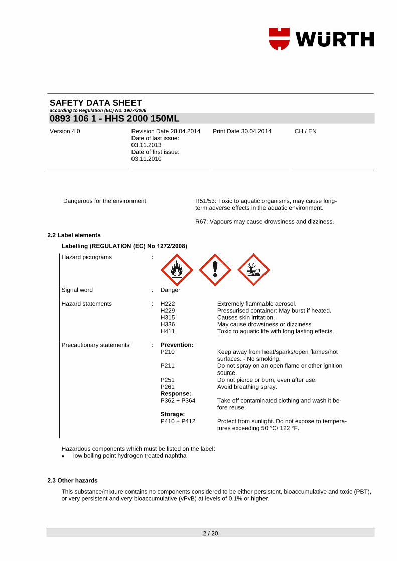
SAFETY DATA SHEET according to Regulation (EC) No. 1907/2006
0893 106 1 - HHS 2000 150ML
Version 4.0 Revision Date 28.04.2014 Date of last issue: 03.11.2013 Date of first issue: 03.11.2010
Print Date 30.04.2014 CH / EN
2 / 20
Dangerous for the environment R51/53: Toxic to aquatic organisms, may cause long-
term adverse effects in the aquatic environment. R67: Vapours may cause drowsiness and dizziness.
2.2 Label elements
Labelling (REGULATION (EC) No 1272/2008)
Hazard pictograms :
Signal word
: Danger
Hazard statements
: H222 Extremely flammable aerosol. H229 Pressurised container: May burst if heated. H315 Causes skin irritation. H336 May cause drowsiness or dizziness. H411 Toxic to aquatic life with long lasting effects.
Precautionary statements
: Prevention:
P210 Keep away from heat/sparks/open flames/hot surfaces. - No smoking.
P211 Do not spray on an open flame or other ignition source.
P251 Do not pierce or burn, even after use. P261 Avoid breathing spray. Response:
P362 + P364 Take off contaminated clothing and wash it be-fore reuse.
Storage:
P410 + P412 Protect from sunlight. Do not expose to tempera-tures exceeding 50 °C/ 122 °F.
Hazardous components which must be listed on the label:
low boiling point hydrogen treated naphtha
2.3 Other hazards
This substance/mixture contains no components considered to be either persistent, bioaccumulative and toxic (PBT), or very persistent and very bioaccumulative (vPvB) at levels of 0.1% or higher.

SAFETY DATA SHEET according to Regulation (EC) No. 1907/2006
0893 106 1 - HHS 2000 150ML
Version 4.0 Revision Date 28.04.2014 Date of last issue: 03.11.2013 Date of first issue: 03.11.2010
Print Date 30.04.2014 CH / EN
3 / 20
SECTION 3: Composition/information on ingredients
3.2 Mixtures
Hazardous components
Chemical Name CAS-No. Classification (67/548/EEC)
Classification (1272/2008/EC)
Concentration [%] EC-No.
Registration number
low boiling point hydrogen treated naphtha
64742-49-0
265-151-9
F; R11 Xi; R38 N; R51/53 Xn; R65 R67
Flam. Liq. 2; H225 Skin Irrit. 2; H315 STOT SE 3; H336 Asp. Tox. 1; H304 Aquatic Chronic 2; H411
>= 35 - < 40
isobutane 75-28-5
200-857-2
F+; R12
Flam. Gas 1; H220
>= 25 - < 35
propane 74-98-6
200-827-9
F+; R12
Flam. Gas 1; H220
>= 3 - < 5
n-hexane 110-54-3
203-777-6
F; R11 Repr.Cat.3; R62 Xn; R48/20-R65 Xi; R38 R67 N; R51-R53
Flam. Liq. 2; H225 Skin Irrit. 2; H315 Repr. 2; H361f STOT SE 3; H336 STOT RE 2; H373 Asp. Tox. 1; H304 Aquatic Chronic 2; H411
>= 1,5 - < 2
butane 106-97-8
203-448-7
F+; R12
Flam. Gas 1; H220 Press. Gas Liquefied gas; H280
>= 1,5 - < 2
For the full text of the R-phrases mentioned in this Section, see Section 16. For the full text of the H-Statements mentioned in this Section, see Section 16.
SECTION 4: First aid measures
4.1 Description of first aid measures

SAFETY DATA SHEET according to Regulation (EC) No. 1907/2006
0893 106 1 - HHS 2000 150ML
Version 4.0 Revision Date 28.04.2014 Date of last issue: 03.11.2013 Date of first issue: 03.11.2010
Print Date 30.04.2014 CH / EN
4 / 20
General advice
: If you feel unwell, seek medical advice (show the label where possi-ble). First aider needs to protect himself. Move out of dangerous area. Never give anything by mouth to an unconscious person. Take off contaminated clothing and shoes immediately.
If inhaled
: If breathed in, move person into fresh air. In the case of inhalation of aerosol/mist consult a physician if necessary. Keep patient warm and at rest. If not breathing, give artificial respiration. If breathing is diffi-cult, give oxygen.
In case of skin contact
: In case of contact, immediately flush skin with soap and plenty of water. Do NOT use solvents or thinners. If skin irritation persists, call a physician. Wash off with polyethylene glycol and afterwards with plenty of water.
In case of eye contact
: Protect unharmed eye. If easy to do, remove contact lens, if worn. In the case of contact with eyes, rinse immediately with plenty of water and seek medical advice.
If swallowed
: If swallowed, seek medical advice immediately and show this con-tainer or label. If swallowed, DO NOT induce vomiting. If a person vomits when lying on his back, place him in the recovery position.
4.2 Most important symptoms and effects, both acute and delayed
No data available
4.3 Indication of any immediate medical attention and special treatment needed
No data available
SECTION 5: Firefighting measures
5.1 Extinguishing media
Suitable extinguishing media : Dry powder, Foam, Carbon dioxide (CO2), Water mist Unsuitable extinguishing media : High volume water jet
5.2 Special hazards arising from the substance or mixture
Specific hazards during firefight-ing
: Do not use a solid water stream as it may scatter and spread fire. Hazardous decomposition products may be formed under fire condi-tions (see section 10). Exposure to decomposition products may be a hazard to health.
5.3 Advice for firefighters

SAFETY DATA SHEET according to Regulation (EC) No. 1907/2006
0893 106 1 - HHS 2000 150ML
Version 4.0 Revision Date 28.04.2014 Date of last issue: 03.11.2013 Date of first issue: 03.11.2010
Print Date 30.04.2014 CH / EN
5 / 20
Special protective equipment for firefighters
: In the event of fire, wear self-contained breathing apparatus. Use personal protective equipment.
Further information : Standard procedure for chemical fires. Use extinguishing measures
that are appropriate to local circumstances and the surrounding envi-ronment. In the event of fire and/or explosion do not breathe fumes. Use water spray to cool unopened containers. Collect contaminated fire extinguishing water separately. This must not be discharged into drains. Fire residues and contaminated fire extinguishing water must be disposed of in accordance with local regulations. If the tempera-ture rises there is danger of the vessels bursting due to the high vapor pressure.
SECTION 6: Accidental release measures
6.1 Personal precautions, protective equipment and emergency procedures
Refer to protective measures listed in sections 7 and 8. Use personal protective equipment. Remove all sources of ignition. Avoid contact with skin and eyes. Ensure adequate ventilation, especially in confined areas. Contaminated surfaces will be extremely slippery. Immediately evacuate personnel to safe areas. Avoid inhalation of vapour or mist. Beware of vapours accumulating to form explosive concentrations. Vapours can accumulate in low areas.
6.2 Environmental precautions
Do not flush into surface water or sanitary sewer system. Prevent further leakage or spillage if safe to do so. If the product contaminates rivers and lakes or drains inform respective authorities. Avoid release to the environment. Refer to special instructions/ Safety data sheets.
6.3 Methods and materials for containment and cleaning up
Contain and collect spillage with non-combustible absorbent material, (e.g. sand, earth, diatomaceous earth, vermicu-lite) and place in container for disposal according to local / national regulations. Clean contaminated surface tho-roughly.
6.4 Reference to other sections
see chapter: 7, 8, 11, 12 and 13
SECTION 7: Handling and storage
7.1 Precautions for safe handling

SAFETY DATA SHEET according to Regulation (EC) No. 1907/2006
0893 106 1 - HHS 2000 150ML
Version 4.0 Revision Date 28.04.2014 Date of last issue: 03.11.2013 Date of first issue: 03.11.2010
Print Date 30.04.2014 CH / EN
6 / 20
Advice on safe handling : For personal protection see section 8. Limit the stocks at work place. Use only in well-ventilated areas. Do not breathe vapours or spray mist. Avoid contact with skin and eyes. Do not spray on a naked flame or any incandescent material. Prevent the creation of flamma-ble or explosive concentrations of vapour in air and avoid vapour concentration higher than the occupational exposure limits. Take precautionary measures against static discharges. Use appropriate container to avoid environmental contamination. Do not carry cloths that have come into contact with the product in your clothing.
Advice on protection against fire and explosion
: Normal measures for preventive fire protection. Vapours are heavier than air and may spread along floors. Vapours may form explosive mixtures with air. Keep away from heat and sources of ignition. Do not smoke. No sparking tools should be used. Electrical equipment should be protected to the appropriate standard.
Dust explosion class : Not applicable
7.2 Conditions for safe storage, including any incompatibilities
Requirements for storage areas and containers
: Store in original container. BEWARE: Aerosol is pressurized. Keep away from heat. Keep away from direct sunlight. Do not open by force or throw into fire even after use. Do not spray on flames or red-hot objects. Keep containers tightly closed in a cool, well-ventilated place. Please observe the storage instructions for aerosols!
Advice on common storage : Keep away from food, drink and animal feedingstuffs. Do not store
together with oxidizing and self-igniting products. Other data : No decomposition if stored and applied as directed.
7.3 Specific end use(s)
No data available
SECTION 8: Exposure controls/personal protection
8.1 Control parameters
Components CAS-No. Control parameters Basis Update
isobutane 75-28-5 TWA: 1.900 mg/m3, 800 ppm STEL: 7.200 mg/m3, 3.200 ppm
CH SUVA 2013-01-01

SAFETY DATA SHEET according to Regulation (EC) No. 1907/2006
0893 106 1 - HHS 2000 150ML
Version 4.0 Revision Date 28.04.2014 Date of last issue: 03.11.2013 Date of first issue: 03.11.2010
Print Date 30.04.2014 CH / EN
7 / 20
Components CAS-No. Control parameters Basis Update
propane 74-98-6 TWA: 1.800 mg/m3, 1.000 ppm NIOSH, STEL: 7.200 mg/m3, 4.000 ppm NIOSH,
CH SUVA 2013-01-01
n-hexane 110-54-3 TWA: 180 mg/m3, 50 ppm H, RF3, NIOSH, SSc, STEL: 1.440 mg/m3, 400 ppm H, RF3, NIOSH, SSc,
CH SUVA 2013-01-01
butane 106-97-8 TWA: 1.900 mg/m3, 800 ppm STEL: 7.200 mg/m3, 3.200 ppm
CH SUVA 2013-01-01
Components CAS-No. Control parameters Basis Update
n-hexane 110-54-3 TWA: 72 mg/m3, 20 ppm
2006/15/EC 2006-02-09
Other information on limit values: see chapter 16
8.2 Exposure controls
Engineering measures
Provide sufficient air exchange and/or exhaust in work rooms.
Personal protective equipment
Respiratory protection : When workers are facing concentrations above the exposure limit they must use appropriate certified respirators. Product contains low-boiling liquids. Respiratory protective equip-ment must be air supplied respirators.
Respirator with filter type AX
Hand protection
Material : Nitrile rubber Glove thickness : 0,45 mm Break through time: : 480 min
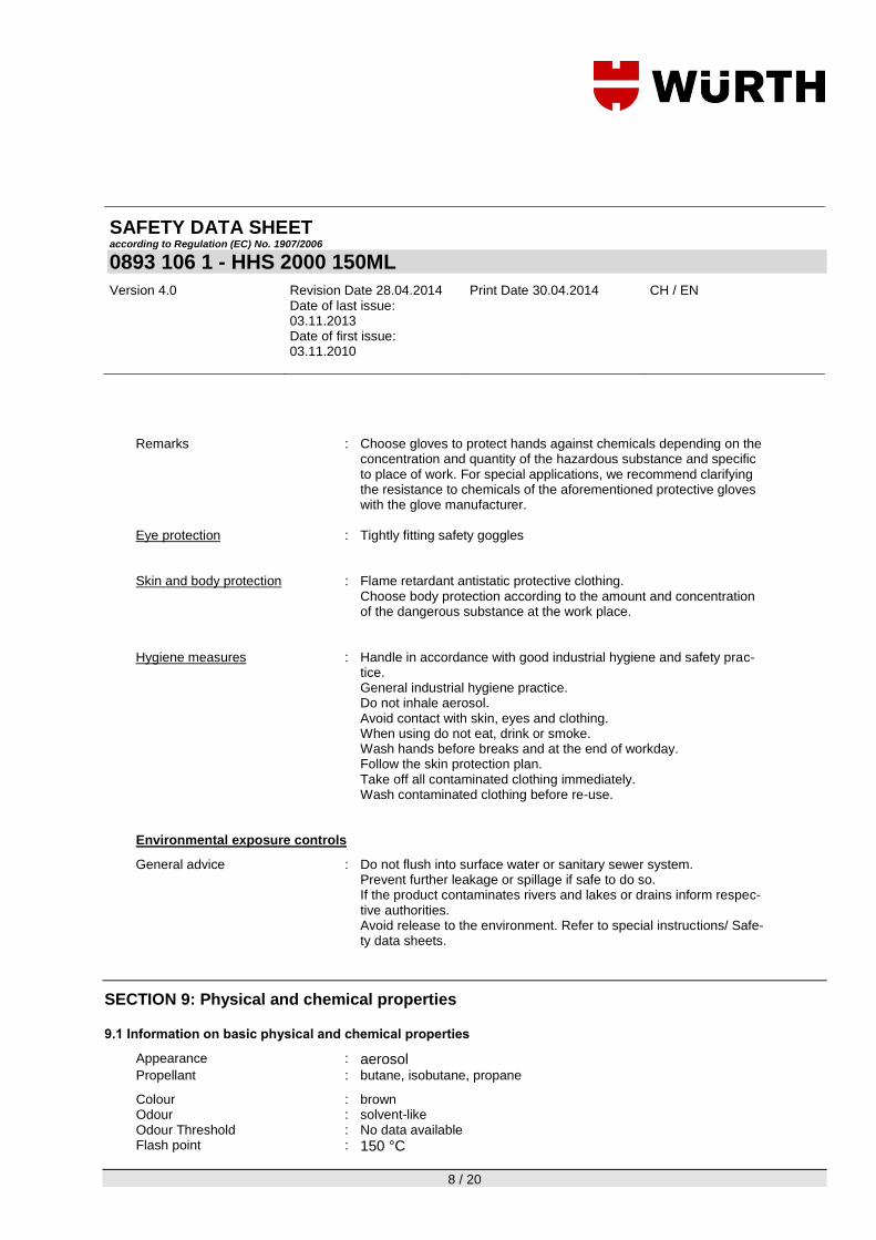
SAFETY DATA SHEET according to Regulation (EC) No. 1907/2006
0893 106 1 - HHS 2000 150ML
Version 4.0 Revision Date 28.04.2014 Date of last issue: 03.11.2013 Date of first issue: 03.11.2010
Print Date 30.04.2014 CH / EN
8 / 20
Remarks : Choose gloves to protect hands against chemicals depending on the
concentration and quantity of the hazardous substance and specific to place of work. For special applications, we recommend clarifying the resistance to chemicals of the aforementioned protective gloves with the glove manufacturer.
Eye protection : Tightly fitting safety goggles
Skin and body protection : Flame retardant antistatic protective clothing.
Choose body protection according to the amount and concentration of the dangerous substance at the work place.
Hygiene measures : Handle in accordance with good industrial hygiene and safety prac-
tice. General industrial hygiene practice. Do not inhale aerosol. Avoid contact with skin, eyes and clothing. When using do not eat, drink or smoke. Wash hands before breaks and at the end of workday. Follow the skin protection plan. Take off all contaminated clothing immediately. Wash contaminated clothing before re-use.
Environmental exposure controls
General advice : Do not flush into surface water or sanitary sewer system. Prevent further leakage or spillage if safe to do so. If the product contaminates rivers and lakes or drains inform respec-tive authorities. Avoid release to the environment. Refer to special instructions/ Safe-ty data sheets.
SECTION 9: Physical and chemical properties
9.1 Information on basic physical and chemical properties
Appearance : aerosol Propellant : butane, isobutane, propane
Colour : brown Odour : solvent-like Odour Threshold : No data available Flash point : 150 °C

SAFETY DATA SHEET according to Regulation (EC) No. 1907/2006
0893 106 1 - HHS 2000 150ML
Version 4.0 Revision Date 28.04.2014 Date of last issue: 03.11.2013 Date of first issue: 03.11.2010
Print Date 30.04.2014 CH / EN
9 / 20
Active ingredient Ignition temperature : ca. 350 °C
Thermal decomposition
: No data available
Lower explosion limit : 1,8 %(V)
Upper explosion limit : 11,2 %(V)
Explosive properties : No data available Flammability : solid / gaseous: Extremely flammable aerosol.
Oxidizing properties : No data available Auto-ignition temperature : No data available Burning number : No data available Molecular weight : No data available pH : Not applicable Boiling point/boiling range : No data available Vapour pressure : No data available Density : 0,742 g/cm3
Active ingredient Bulk density : No data available Water solubility : insoluble
Partition coefficient: n-octanol/water
: No data available
Solubility in other solvents : No data available Viscosity, dynamic : No data available Viscosity, kinematic : No data available Flow time : No data available Impact sensitivity : No data available Relative vapour density : No data available Surface tension : No data available Evaporation rate : No data available Minimum ignition energy : No data available Acid number : No data available Refraction index : No data available Miscibility in water : No data available Solvent separation test : No data available
9.2 Other information
None known.

SAFETY DATA SHEET according to Regulation (EC) No. 1907/2006
0893 106 1 - HHS 2000 150ML
Version 4.0 Revision Date 28.04.2014 Date of last issue: 03.11.2013 Date of first issue: 03.11.2010
Print Date 30.04.2014 CH / EN
10 / 20
SECTION 10: Stability and reactivity
10.1 Reactivity
No data available
10.2 Chemical stability
The product is chemically stable.
10.3 Possibility of hazardous reactions
Stability : No decomposition if stored and applied as directed. Vapours may form explosive mixtures with air. If the temperature rises there is danger of the vessels bursting due to the high vapor pressure.
10.4 Conditions to avoid
Heat, flames and sparks.
10.5 Incompatible materials
Materials to avoid : Avoid contact with other chemicals.
10.6 Hazardous decomposition products
Hazardous decomposition prod-ucts
: Build-up of dangerous/toxic fumes possible in cases of fire/high tem-perature.
Build-up of dangerous/toxic fumes possible in cases of fire/high tem-perature.
SECTION 11: Toxicological information
11.1 Information on toxicological effects
Acute toxicity
Acute oral toxicity: n-hexane
: LD50 Rat: ca. 16 g/kg Method: OECD Test Guideline 401
Acute inhalation toxicity: isobutane
: LC50 Mouse, male: 1.237 mg/l Test atmosphere: gas

SAFETY DATA SHEET according to Regulation (EC) No. 1907/2006
0893 106 1 - HHS 2000 150ML
Version 4.0 Revision Date 28.04.2014 Date of last issue: 03.11.2013 Date of first issue: 03.11.2010
Print Date 30.04.2014 CH / EN
11 / 20
Exposure time: 120 min
n-hexane
: LC50 : 259,354 mg/l, 73860 ppm Test atmosphere: vapour Exposure time: 4 h Method: OECD Test Guideline 403
butane
: LC50 Mouse, males: 1.237 mg/l, 520400 ppm Test atmosphere: gas Exposure time: 2 h
Acute dermal toxicity: n-hexane
: LD50 Rabbit, males: > 3.350 mg/kg Method: OECD Test Guideline 402
Acute toxicity (other routes of administration): No data available Skin corrosion/irritation
low boiling point hydrogen treated naphtha
: Severe skin irritation
n-hexane
: Species: Rabbit irritating Method: OECD Test Guideline 404
Serious eye damage/eye irritation
n-hexane
: Species: Rabbit No eye irritation Method: OECD Test Guideline 405
Respiratory or skin sensitisation
Sensitisation: n-hexane
: Test Method: LLNA Species: Mouse Result: Does not cause skin sensitisation. Method: OECD Test Guideline 429
Germ cell mutagenicity
Genotoxicity in vitro: isobutane : Type: Mutagenicity (Escherichia coli - reverse mutation assay)

SAFETY DATA SHEET according to Regulation (EC) No. 1907/2006
0893 106 1 - HHS 2000 150ML
Version 4.0 Revision Date 28.04.2014 Date of last issue: 03.11.2013 Date of first issue: 03.11.2010
Print Date 30.04.2014 CH / EN
12 / 20
with and without metabolic activation Result: negative Method: OECD Test Guideline 471
n-hexane
: Type: Mutagenicity (Salmonella typhimurium - reverse mutation as-say) with and without metabolic activation Result: negative Method: OECD Test Guideline 471
butane
: Test species: Human lymphocytes with and without metabolic activation Result: negative Method: OECD Test Guideline 473
Genotoxicity in vivo: n-hexane
: Test species: Mouse Sex: males Application Route: inhalation (vapour) Exposure duration: 8 w Dose: 0 - 400 ppm Result: negative
butane
: Type: In vivo micronucleus test Test species: Rat Sex: male and female Application Route: inhalation (gas) Exposure duration: 13 w Dose: 0 - 10000 ppm Result: negative Method: OECD Test Guideline 474
Carcinogenicity
Remarks low boiling point hydrogen treated naphtha
: Carcinogenicity: Classified based on benzene content < 0.1% (Regulation (EC) 1272/2008, Annex VI, Part 3, Note P) Mutagenicity: Classified based on benzene content < 0.1% (Regulation (EC) 1272/2008, Annex VI, Part 3, Note P)
isobutane
: Mutagenicity: Tests on bacterial or mammalian cell cultures did not show mutagen-ic effects.

SAFETY DATA SHEET according to Regulation (EC) No. 1907/2006
0893 106 1 - HHS 2000 150ML
Version 4.0 Revision Date 28.04.2014 Date of last issue: 03.11.2013 Date of first issue: 03.11.2010
Print Date 30.04.2014 CH / EN
13 / 20
Reproductive toxicity
isobutane
: Note: No toxicity to reproduction
n-hexane
: Note: Suspected human reproductive toxicant
Note: Suspected of damaging fertility.
Teratogenicity
No data available STOT - single exposure
low boiling point hydrogen treated naphtha
: May cause drowsiness or dizziness.
n-hexane
: May cause drowsiness or dizziness.
STOT - repeated exposure
n-hexane
: May cause damage to organs through prolonged or repeated expo-sure.
butane
: NOAEL: Rat, male and female: 21,394 mg/l, 9000 ppm Application Route: Inhalation Exposure time: 28 d Dose: 0 - 9000 ppm
Aspiration hazard
Aspiration toxicity low boiling point hydrogen treated naphtha
: May be fatal if swallowed and enters airways.
n-hexane
: May be fatal if swallowed and enters airways.
Neurological effects
No data available Toxicology Assessment
Toxicology, Metabolism, Distribution No data available Acute effects No data available
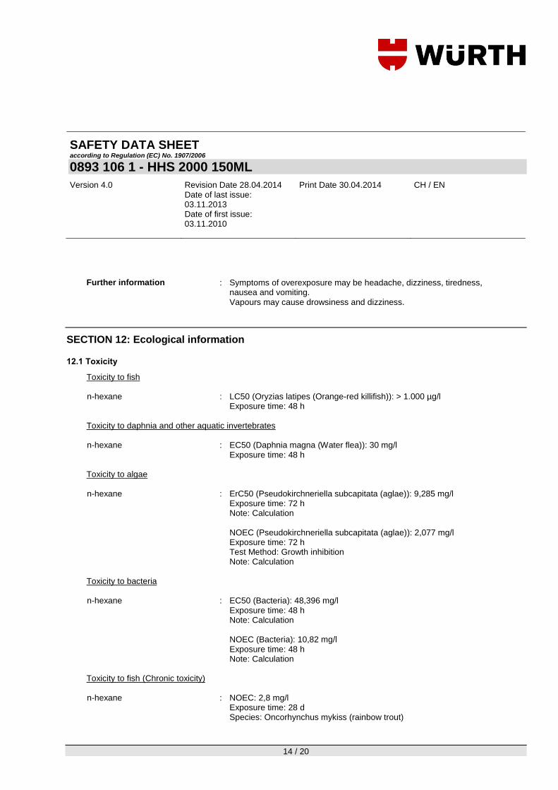
SAFETY DATA SHEET according to Regulation (EC) No. 1907/2006
0893 106 1 - HHS 2000 150ML
Version 4.0 Revision Date 28.04.2014 Date of last issue: 03.11.2013 Date of first issue: 03.11.2010
Print Date 30.04.2014 CH / EN
14 / 20
Further information
: Symptoms of overexposure may be headache, dizziness, tiredness, nausea and vomiting. Vapours may cause drowsiness and dizziness.
SECTION 12: Ecological information
12.1 Toxicity
Toxicity to fish n-hexane
: LC50 (Oryzias latipes (Orange-red killifish)): > 1.000 µg/l Exposure time: 48 h
Toxicity to daphnia and other aquatic invertebrates n-hexane : EC50 (Daphnia magna (Water flea)): 30 mg/l
Exposure time: 48 h
Toxicity to algae n-hexane
: ErC50 (Pseudokirchneriella subcapitata (aglae)): 9,285 mg/l Exposure time: 72 h Note: Calculation
NOEC (Pseudokirchneriella subcapitata (aglae)): 2,077 mg/l Exposure time: 72 h Test Method: Growth inhibition Note: Calculation
Toxicity to bacteria n-hexane
: EC50 (Bacteria): 48,396 mg/l Exposure time: 48 h Note: Calculation
NOEC (Bacteria): 10,82 mg/l Exposure time: 48 h Note: Calculation
Toxicity to fish (Chronic toxicity) n-hexane
: NOEC: 2,8 mg/l Exposure time: 28 d Species: Oncorhynchus mykiss (rainbow trout)

SAFETY DATA SHEET according to Regulation (EC) No. 1907/2006
0893 106 1 - HHS 2000 150ML
Version 4.0 Revision Date 28.04.2014 Date of last issue: 03.11.2013 Date of first issue: 03.11.2010
Print Date 30.04.2014 CH / EN
15 / 20
Toxicity to daphnia and other aquatic invertebrates (Chronic toxicity) n-hexane
: NOEC: 4,888 mg/l Exposure time: 21 d Species: Daphnia magna (Water flea)
Ecotoxicology Assessment
Acute aquatic toxicity low boiling point hydrogen treated naphtha
: Toxic to aquatic life.
n-hexane : Toxic to aquatic life.
Chronic aquatic toxicity low boiling point hydrogen treated naphtha
: Toxic to aquatic life with long lasting effects.
n-hexane
: Toxic to aquatic life with long lasting effects.
12.2 Persistence and degradability
Biodegradability isobutane
: Result: Readily biodegradable.
n-hexane
: Concentration: 100 mg/l Result: Readily biodegradable. Biodegradation: 81 % Exposure time: 28 d Method: OECD Test Guideline 301F
butane
: Concentration: 61,2 mg/l Result: Readily biodegradable. Biodegradation: 100 % Exposure time: 26,4 d
12.3 Bioaccumulative potential
No data available
12.4 Mobility in soil
No data available

SAFETY DATA SHEET according to Regulation (EC) No. 1907/2006
0893 106 1 - HHS 2000 150ML
Version 4.0 Revision Date 28.04.2014 Date of last issue: 03.11.2013 Date of first issue: 03.11.2010
Print Date 30.04.2014 CH / EN
16 / 20
12.5 Results of PBT and vPvB assessment
This substance/mixture contains no components considered to be either persistent, bioaccumulative and toxic (PBT), or very persistent and very bioaccumulative (vPvB) at levels of 0.1% or higher.
12.6 Other adverse effects
Additional ecological information
: The product should not be allowed to enter drains, water courses or the soil.
SECTION 13: Disposal considerations
13.1 Waste treatment methods
Advice on disposal and packag-ing
: Disposal: In accordance with local and national regulations. Do not empty into drains; dispose of this material and its container in a safe way. This material and its container must be disposed of as hazardous waste. Waste codes should be assigned by the user based on the applica-tion for which the product was used.
The following Waste Codes are only suggestions: Waste Code (EWC) : Waste Key (unused product):
160504, gases in pressure containers (including halons) containing dangerous substances Waste key (used product): 160504, gases in pressure containers (including halons) containing dangerous substances
Disposal of uncleaned packag-ing
: Waste key (uncleaned packaging): 150110, packaging containing residues of or contaminated by dan-gerous substances Note: Empty containers should be taken to an approved waste han-dling site for recycling or disposal. Do not burn, or use a cutting torch on, the empty drum. Please ensure aerosol cans are sprayed com-pletely empty (including propellant) Containers that have not been emptied in compliance with regulations are regarded as hazardous waste. Dispose of as unused product.
SECTION 14: Transport information
14.1 UN number
ADN : 1950 ADR : 1950

SAFETY DATA SHEET according to Regulation (EC) No. 1907/2006
0893 106 1 - HHS 2000 150ML
Version 4.0 Revision Date 28.04.2014 Date of last issue: 03.11.2013 Date of first issue: 03.11.2010
Print Date 30.04.2014 CH / EN
17 / 20
RID : 1950 IMDG : 1950 IATA : 1950
14.2 Proper shipping name
ADN : AEROSOLS ADR : AEROSOLS RID : AEROSOLS IMDG : AEROSOLS (naphtha (petroleum), hydrotreated light) IATA : AEROSOLS, FLAMMABLE
14.3 Transport hazard class(es)
ADN : 2 ADR : 2 RID : 2 IMDG : 2.1 IATA : 2.1
14.4 Packing group
ADN Classification Code : 5F Labels : 2.1
ADR Classification Code : 5F Labels : 2.1 Limited quantity : 1,00 L Tunnel restriction code : (D)
RID Classification Code : 5F Hazard Identification Number : 23 Labels : 2.1 Limited quantity : 1,00 L
IMDG Labels : 2.1 EmS Number : F-D, S-U
IATA Packing instruction (cargo air-craft)
: 203
Packing instruction (passenger aircraft)
: 203
Packing instruction (LQ) : Y203 Labels : 2.1
14.5 Environmental hazards
ADN

SAFETY DATA SHEET according to Regulation (EC) No. 1907/2006
0893 106 1 - HHS 2000 150ML
Version 4.0 Revision Date 28.04.2014 Date of last issue: 03.11.2013 Date of first issue: 03.11.2010
Print Date 30.04.2014 CH / EN
18 / 20
ADN
Environmentally hazardous :
no
ADR
Environmentally hazardous :
yes
RID
Environmentally hazardous :
yes
IMDG
Marine pollutant :
yes
IATA
Environmentally hazardous :
no
14.6 Special precautions for user
see chapter: 6, 7 and 8
14.7 Transport in bulk according to Annex II of MARPOL 73/78 and the IBC Code
Not applicable for product as supplied.
SECTION 15: Regulatory information
15.1 Safety, health and environmental regulations/legislation specific for the substance or mixture
Seveso II - Directive 2003/105/EC amending Council Directive 96/82/EC on the con-trol of major-accident hazards involving dangerous substances
: Update: Quantity 1 Quantity 2
Extremely flammable 10 t 50 t Update: Dangerous for the environ-
ment 200 t 500 t
Update: Petroleum products: (a) gaso-
lines and naphthas, (b) kero-senes (including jet fuels), (c) gas oils (including diesel fuels, home heating oils and gas oil blending streams)
2.500 t 25.000 t
Further information
: Reserved for industrial and professional use.
15.2 Chemical Safety Assessment
No data available

SAFETY DATA SHEET according to Regulation (EC) No. 1907/2006
0893 106 1 - HHS 2000 150ML
Version 4.0 Revision Date 28.04.2014 Date of last issue: 03.11.2013 Date of first issue: 03.11.2010
Print Date 30.04.2014 CH / EN
19 / 20
SECTION 16: Other information
Full text of R-phrases referred to under sections 2 and 3
R11 Highly flammable. R12 Extremely flammable. R38 Irritating to skin. R48/20 Harmful: danger of serious damage to health by prolonged exposure through
inhalation. R51 Toxic to aquatic organisms. R51/53 Toxic to aquatic organisms, may cause long-term adverse effects in the aquatic
environment. R53 May cause long-term adverse effects in the aquatic environment. R62 Possible risk of impaired fertility. R65 Harmful: may cause lung damage if swallowed. R67 Vapours may cause drowsiness and dizziness.
Full text of H-Statements referred to under sections 2 and 3.
H220 Extremely flammable gas. H222 Extremely flammable aerosol. H225 Highly flammable liquid and vapour. H229 Pressurised container: May burst if heated. H280 Contains gas under pressure; may explode if heated. H304 May be fatal if swallowed and enters airways. H315 Causes skin irritation. H336 May cause drowsiness or dizziness. H361f Suspected of damaging fertility. H373 May cause damage to organs through prolonged or repeated exposure. H411 Toxic to aquatic life with long lasting effects.
Other information
H Toxic by skin resorption possible; Substances, which are easily absored through the skin, can give by additional skin resoption a substancial higher risk compared to only inhalation by the airways.
NIOSH National Institute for Occupational Safety and Health RF3 Contains substances which possibly affects the fertility of humans. SSc Harm to the unborn child is not to be expected when the OEL-value is respected
The information provided in this Safety Data Sheet is correct to the best of our knowledge, information and belief at the date of its publication. The information given is designed only as a guidance for safe handling, use, processing, storage, transportation, disposal and release and is not to be considered a warranty or quality specifi-cation. The information relates only to the specific material designated and may not be valid for such material used in combination with any other materials or in any process, unless specified in the text.

SAFETY DATA SHEET according to Regulation (EC) No. 1907/2006
0893 106 1 - HHS 2000 150ML
Version 4.0 Revision Date 28.04.2014 Date of last issue: 03.11.2013 Date of first issue: 03.11.2010
Print Date 30.04.2014 CH / EN
20 / 20
Prepared by : SAP Business Compliance Services GmbH
Birlenbacher Str. 19 D-57078 Siegen
Germany Telephone: +49-(0)271-88072-0 Ref.: WIAG00001684

Klüberplex AG 11-461
SAFETY DATA SHEET
Product name
Klüberplex AG 11-461
Conforms to Regulation (EC) No. 1907/2006 (REACH), Annex II - United Kingdom (UK)
:
1.1 Product identifier
1.3 Details of the supplier of the safety data sheet
e-mail address of personresponsible for this SDS
: Material Compliance Management E-Mail: [email protected]
1.2 Relevant identified uses of the substance or mixture and uses advised against
SECTION 1: Identification of the substance/mixture and of the company/undertaking
National contact
1.4 Emergency telephone number
Supplier
Emergency telephonenumber (with hours ofoperation)
: 0049 (0) 897876-700 (24hrs)
KLÜBER LUBRICATION MÜNCHEN KGGeisenhausenerstrasse 7D-81379 MünchenTel: +49 (0) 897876-0Fax: +49 (0) 897876-333
Not applicable.
Product code : 039213
Product description : Grease
Date of printing : 2012-04-02. Date of issue2012-04-02
Classification Not classified.:
See Section 11 for more detailed information on health effects and symptoms.
Classification according to Regulation (EC) No. 1272/2008 [CLP/GHS]
Percentage of the mixture consisting of ingredient(s) of unknown toxicity: 8%
Percentage of the mixture consisting of ingredient(s) of unknown hazards to theaquatic environment: 10.2%
SECTION 2: Hazards identification
2.1 Classification of the substance or mixture
Product definition : Mixture
See Section 16 for the full text of the R phrases or H statements declared above.
Classification according to Directive 1999/45/EC [DPD]
The product is not classified as dangerous according to Directive 1999/45/EC and its amendments.
Ingredients of unknowntoxicity
:
Ingredients of unknownecotoxicity
:
2.2 Label elements
Hazard pictograms :
Signal word :
Hazard statements :
Prevention :
Precautionary statements
Response :
Storage :
Disposal :
No signal word.
No known significant effects or critical hazards.
Not applicable.
Not applicable.
Not applicable.
Not applicable.
Not classified.
Version : 1/112

Klüberplex AG 11-461
Conforms to Regulation (EC) No. 1907/2006 (REACH), Annex II - United Kingdom (UK)
SECTION 2: Hazards identification
:Other hazards which donot result in classification
Not available.
Supplemental labelelements
Containers to be fittedwith child-resistantfastenings
Not applicable.
Tactile warning of danger Not applicable.
:
:
: Contains N-alkylated benzotriazole. May produce an allergic reaction. Safety datasheet available for professional user on request.
Special packaging requirements
Hazardous ingredients :
2.3 Other hazards
Additional warning phrases : Not available.
Substance/mixture Mixture
Occupational exposure limits, if available, are listed in Section 8.
:
Identifiers 67/548/EECProduct/ingredientname
There are no additional ingredients present which, within the current knowledge of the supplier and in theconcentrations applicable, are classified as hazardous to health or the environment and hence require reporting in thissection.
SECTION 3: Composition/information on ingredients
Naphthenic acids, zincsalts
EC: 234-409-2CAS: 12001-85-3
1-5 Xi; R36 Eye Irrit. 2, H319 [1]
Benzenamine, N-phenyl-, reactionproducts with 2,4,4-trimethylpentene
EC: 270-128-1CAS: 68411-46-1
0.25-2.5
R52/53 Aquatic Chronic 3,H412
[1]
N-alkylatedbenzotriazole
CAS: 94270-86-7 0.1-0.25
Xi; R38R43N; R51/53
Skin Irrit. 2, H315Skin Sens. 1, H317Aquatic Chronic 2,H411
[1]
See Section 16 forthe full text of the R-phrases declaredabove.
%
Type
Regulation (EC) No.1272/2008 [CLP]
Classification
See Section 16 for thefull text of the Hstatements declaredabove.
[1] Substance classified with a health or environmental hazard[2] Substance with a workplace exposure limit[3] Substance meets the criteria for PBT according to Regulation (EC) No. 1907/2006, Annex XIII[4] Substance meets the criteria for vPvB according to Regulation (EC) No. 1907/2006, Annex XIII
Type
Description mineral oil ester oil aluminium complex soap solid lubricant:
Immediately flush eyes with plenty of water, occasionally lifting the upper and lowereyelids. Check for and remove any contact lenses. Get medical attention if irritationoccurs.
4.1 Description of first aid measures
Remove victim to fresh air and keep at rest in a position comfortable for breathing.Get medical attention if symptoms occur. In case of inhalation of decompositionproducts in a fire, symptoms may be delayed. The exposed person may need to bekept under medical surveillance for 48 hours.
Inhalation
Eye contact
:
:
SECTION 4: First aid measures
Version : 2/112

Klüberplex AG 11-461
Conforms to Regulation (EC) No. 1907/2006 (REACH), Annex II - United Kingdom (UK)
SECTION 4: First aid measures
Wash out mouth with water. Remove victim to fresh air and keep at rest in a positioncomfortable for breathing. If material has been swallowed and the exposed personis conscious, give small quantities of water to drink. Do not induce vomiting unlessdirected to do so by medical personnel. Get medical attention if symptoms occur.
Skin contact Flush contaminated skin with plenty of water. Remove contaminated clothing andshoes. Get medical attention if symptoms occur.
Notes to physician In case of inhalation of decomposition products in a fire, symptoms may be delayed.The exposed person may need to be kept under medical surveillance for 48 hours.
Ingestion
:
:
:
Specific treatments
Protection of first-aiders : No action shall be taken involving any personal risk or without suitable training.
4.2 Most important symptoms and effects, both acute and delayed
Potential acute health effects
Inhalation : Exposure to decomposition products may cause a health hazard. Serious effectsmay be delayed following exposure.
No known significant effects or critical hazards.:Ingestion
Skin contact : No known significant effects or critical hazards.
No known significant effects or critical hazards.:Eye contact
Over-exposure signs/symptoms
Skin contact
Ingestion
Inhalation No specific data.
No specific data.
No specific data.
:
:
:
Eye contact : No specific data.
4.3 Indication of any immediate medical attention and special treatment needed
No specific treatment.:
Promptly isolate the scene by removing all persons from the vicinity of the incident ifthere is a fire. No action shall be taken involving any personal risk or without suitabletraining.
Hazardous combustionproducts
Hazards from thesubstance or mixture
Decomposition products may include the following materials:carbon dioxidecarbon monoxidenitrogen oxidessulfur oxidesmetal oxide/oxides
In a fire or if heated, a pressure increase will occur and the container may burst.
Fire-fighters should wear appropriate protective equipment and self-containedbreathing apparatus (SCBA) with a full face-piece operated in positive pressuremode. Clothing for fire-fighters (including helmets, protective boots and gloves)conforming to European standard EN 469 will provide a basic level of protection forchemical incidents.
Special protectiveequipment for fire-fighters
Use an extinguishing agent suitable for the surrounding fire.
5.1 Extinguishing media
:
:
:
None known.
Suitable extinguishingmedia
:
Unsuitable extinguishingmedia
:
SECTION 5: Firefighting measures
5.2 Special hazards arising from the substance or mixture
5.3 Advice for firefighters
Special precautions forfire-fighters
:
Version : 3/112

Klüberplex AG 11-461
Conforms to Regulation (EC) No. 1907/2006 (REACH), Annex II - United Kingdom (UK)
6.2 Environmentalprecautions
Stop leak if without risk. Move containers from spill area. Prevent entry into sewers,water courses, basements or confined areas. Wash spillages into an effluenttreatment plant or proceed as follows. Contain and collect spillage with non-combustible, absorbent material e.g. sand, earth, vermiculite or diatomaceous earthand place in container for disposal according to local regulations (see section 13).Dispose of via a licensed waste disposal contractor. Note: see section 1 foremergency contact information and section 13 for waste disposal.
Avoid dispersal of spilt material and runoff and contact with soil, waterways, drainsand sewers. Inform the relevant authorities if the product has caused environmentalpollution (sewers, waterways, soil or air).
Large spill :
Stop leak if without risk. Move containers from spill area. Dilute with water and mopup if water-soluble. Alternatively, or if water-insoluble, absorb with an inert drymaterial and place in an appropriate waste disposal container. Dispose of via alicensed waste disposal contractor.
Small spill :
6.3 Methods and materials for containment and cleaning up
SECTION 6: Accidental release measures
6.1 Personal precautions, protective equipment and emergency procedures
For non-emergencypersonnel
:
For emergency responders :
6.4 Reference to othersections
See Section 1 for emergency contact information.See Section 8 for information on appropriate personal protective equipment.See Section 13 for additional waste treatment information.
No action shall be taken involving any personal risk or without suitable training.Evacuate surrounding areas. Keep unnecessary and unprotected personnel fromentering. Do not touch or walk through spilt material. Put on appropriate personalprotective equipment.
If specialised clothing is required to deal with the spillage, take note of anyinformation in Section 8 on suitable and unsuitable materials. See also theinformation in "For non-emergency personnel".
:
:
Store in accordance with local regulations. Store in original container protected fromdirect sunlight in a dry, cool and well-ventilated area, away from incompatiblematerials (see section 10) and food and drink. Keep container tightly closed andsealed until ready for use. Containers that have been opened must be carefullyresealed and kept upright to prevent leakage. Do not store in unlabelled containers.Use appropriate containment to avoid environmental contamination.
SECTION 7: Handling and storage
The information in this section contains generic advice and guidance. The list of Identified Uses in Section 1 should beconsulted for any available use-specific information provided in the Exposure Scenario(s).
7.1 Precautions for safe handling
Protective measures :
Advice on generaloccupational hygiene
:
7.2 Conditions for safestorage, including anyincompatibilities
7.3 Specific end use(s)
Recommendations :
:Industrial sector specificsolutions
Not available.
Not available.
Put on appropriate personal protective equipment (see Section 8).
Eating, drinking and smoking should be prohibited in areas where this material ishandled, stored and processed. Workers should wash hands and face beforeeating, drinking and smoking. Remove contaminated clothing and protectiveequipment before entering eating areas. See also Section 8 for additionalinformation on hygiene measures.
:
Version : 4/112

Klüberplex AG 11-461
Conforms to Regulation (EC) No. 1907/2006 (REACH), Annex II - United Kingdom (UK)
Recommended monitoringprocedures
Occupational exposure limits
If this product contains ingredients with exposure limits, personal, workplaceatmosphere or biological monitoring may be required to determine the effectivenessof the ventilation or other control measures and/or the necessity to use respiratoryprotective equipment. Reference should be made to European Standard EN 689 formethods for the assessment of exposure by inhalation to chemical agents andnational guidance documents for methods for the determination of hazardoussubstances.
Hand protection
Use a properly fitted, air-purifying or air-fed respirator complying with an approvedstandard if a risk assessment indicates this is necessary. Respirator selection mustbe based on known or anticipated exposure levels, the hazards of the product andthe safe working limits of the selected respirator.
Chemical-resistant, impervious gloves complying with an approved standard shouldbe worn at all times when handling chemical products if a risk assessment indicatesthis is necessary.
Safety eyewear complying with an approved standard should be used when a riskassessment indicates this is necessary to avoid exposure to liquid splashes, mists,gases or dusts.
Eye/face protection
Respiratory protection :
:
:
:
No exposure limit value known.
Skin protection
Personal protective equipment for the body should be selected based on the taskbeing performed and the risks involved and should be approved by a specialistbefore handling this product.
:
Environmental exposurecontrols
: Emissions from ventilation or work process equipment should be checked to ensurethey comply with the requirements of environmental protection legislation. In somecases, fume scrubbers, filters or engineering modifications to the processequipment will be necessary to reduce emissions to acceptable levels.
Appropriate engineeringcontrols
: No special ventilation requirements. Good general ventilation should be sufficient tocontrol worker exposure to airborne contaminants. If this product containsingredients with exposure limits, use process enclosures, local exhaust ventilation orother engineering controls to keep worker exposure below any recommended orstatutory limits.
Wash hands, forearms and face thoroughly after handling chemical products, beforeeating, smoking and using the lavatory and at the end of the working period.Appropriate techniques should be used to remove potentially contaminated clothing.Wash contaminated clothing before reusing. Ensure that eyewash stations andsafety showers are close to the workstation location.
8.2 Exposure controls
Hygiene measures :
No DELs available.
Predicted effect concentrations
No PECs available.
SECTION 8: Exposure controls/personal protection
The information in this section contains generic advice and guidance. The list of Identified Uses in Section 1 should beconsulted for any available use-specific information provided in the Exposure Scenario(s).
8.1 Control parameters
Derived effect levels
Individual protection measures
Body protection :
Other skin protection Appropriate footwear and any additional skin protection measures should beselected based on the task being performed and the risks involved and should beapproved by a specialist before handling this product.
Version : 5/112

Klüberplex AG 11-461
Conforms to Regulation (EC) No. 1907/2006 (REACH), Annex II - United Kingdom (UK)
Not available.
Melting point/freezing point
Initial boiling point and boilingrange
Vapour pressure
Solubility(ies)
Not available.
Not available.
Insoluble in the following materials: cold water and hot water.
Characteristic.Odour
pH
White.Colour
Auto-ignition temperature
Flash point
Not available.
Not applicable.
Not available.
Not available.
Not available.
Not applicable.
Viscosity Not available.
Partition coefficient: n-octanol/water
Upper/lower flammability orexplosive limits
Explosive properties
:
:
:
:
:
:
:
:
:
:
:
:
:
Not available.Oxidising properties :
9.1 Information on basic physical and chemical properties
Appearance
9.2 Other information
Burning time Not applicable.
Burning rate Not applicable.
:
:
Decomposition temperature : Not available.
SECTION 9: Physical and chemical properties
Flammability (solid, gas) : Not available.
No additional information.
Density : 1.07 g/cm3 [20°C]
Bulk Density : Not available.
Paste.:Physical state
10.6 Hazardousdecomposition products
10.4 Conditions to avoid No specific data.
Under normal conditions of storage and use, hazardous decomposition productsshould not be produced.
The product is stable.10.2 Chemical stability
No specific data.
:
:
:
10.5 Incompatible materials :
10.3 Possibility ofhazardous reactions
: Under normal conditions of storage and use, hazardous reactions will not occur.
SECTION 10: Stability and reactivity
10.1 Reactivity : No specific test data related to reactivity available for this product or its ingredients.
Acute toxicity
Product/ingredient name Result Species Dose Exposure
SECTION 11: Toxicological information
11.1 Information on toxicological effects
Version : 6/112

Klüberplex AG 11-461
Conforms to Regulation (EC) No. 1907/2006 (REACH), Annex II - United Kingdom (UK)
SECTION 11: Toxicological information
Potential acute health effects
Inhalation : Exposure to decomposition products may cause a health hazard. Serious effectsmay be delayed following exposure.
No known significant effects or critical hazards.:Ingestion
Skin contact : No known significant effects or critical hazards.
No known significant effects or critical hazards.:Eye contact
Residual oils (petroleum),hydrotreated
LD50 Dermal Rat >5000 mg/kg -
LD50 Oral Rat >5000 mg/kg -Distillates (petroleum),hydrotreated heavyparaffinic
LD50 Dermal Rabbit >2000 mg/kg -
LD50 Oral Rat >5000 mg/kg -Naphthenic acids, zinc salts LC50 Inhalation Vapour Rat >25200 mg/m3 4 hours
LD50 Dermal Rabbit >2 g/kg -LD50 Oral Rat 4920 mg/kg -
Benzenamine, N-phenyl-,reaction products with 2,4,4-trimethylpentene
LD50 Dermal Rat >2000 mg/kg -
LD50 Oral Rat >5000 mg/kg -
Conclusion/Summary : Not available.
Carcinogenicity
Conclusion/Summary : Not available.
Mutagenicity
Conclusion/Summary : Not available.
Teratogenicity
Conclusion/Summary : Not available.
Reproductive toxicity
Conclusion/Summary : Not available.
Symptoms related to the physical, chemical and toxicological characteristics
Skin contact
Ingestion
Inhalation No specific data.
No specific data.
No specific data.
:
:
:
Eye contact : No specific data.
Irritation/Corrosion
Naphthenic acids, zinc salts Eyes - Moderate irritant Rabbit - - -Skin - Mild irritant Rabbit - - -
Product/ingredient name Result Score Exposure Observation
Conclusion/Summary : Not available.
Sensitiser
Conclusion/Summary : Not available.
Species
Not available.
Acute toxicity estimates
Not available.
Specific target organ toxicity (single exposure)
Specific target organ toxicity (repeated exposure)
Aspiration hazard
Information on the likelyroutes of exposure
:
Delayed and immediate effects and also chronic effects from short and long term exposure
Short term exposure
Not available.
Not available.
Not available.
Version : 7/112

Klüberplex AG 11-461
Conforms to Regulation (EC) No. 1907/2006 (REACH), Annex II - United Kingdom (UK)
SECTION 11: Toxicological information
Potential chronic health effects
No known significant effects or critical hazards.General :
No known significant effects or critical hazards.Carcinogenicity :
No known significant effects or critical hazards.Mutagenicity :
No known significant effects or critical hazards.Teratogenicity :
Not available.
Conclusion/Summary : Not available.
Developmental effects : No known significant effects or critical hazards.
Fertility effects : No known significant effects or critical hazards.
Long term exposure
Potential immediateeffects
Potential delayed effects :
:
Potential immediateeffects
Potential delayed effects :
:
Other information :
Not available.
Not available.
Not available.
Not available.
Not available.
Mobility Not available.:
12.3 Bioaccumulative potential
12.6 Other adverse effects No known significant effects or critical hazards.
Not available.
12.1 Toxicity
Residual oils (petroleum),hydrotreated
Acute EC50 >10000 mg/l Daphnia 48 hours
Acute IC50 >1000 mg/l Algae 96 hoursAcute LC50 1000 to 5000 mg/l Fish 96 hoursChronic NOEC >5000 mg/l Fish 96 hours
Distillates (petroleum),hydrotreated heavy paraffinic
Acute LC50 >100 mg/l Fresh water Fish - Pimephales promelas 96 hours
Product/ingredient name SpeciesResult Exposure
Conclusion/Summary : Not available.
12.2 Persistence and degradability
Conclusion/Summary : Not available.
PBT : Not applicable.
vPvB : Not applicable.
SECTION 12: Ecological information
12.4 Mobility in soil
Soil/water partitioncoefficient (KOC)
Not available.:
12.5 Results of PBT and vPvB assessment
:
Version : 8/112

Klüberplex AG 11-461
Conforms to Regulation (EC) No. 1907/2006 (REACH), Annex II - United Kingdom (UK)
Within the present knowledge of the supplier, this product is not regarded ashazardous waste, as defined by EU Directive 91/689/EEC.
Hazardous waste :
The generation of waste should be avoided or minimised wherever possible.Significant quantities of waste product residues should not be disposed of via thefoul sewer but processed in a suitable effluent treatment plant. Dispose of surplusand non-recyclable products via a licensed waste disposal contractor. Disposal ofthis product, solutions and any by-products should at all times comply with therequirements of environmental protection and waste disposal legislation and anyregional local authority requirements.
:Methods of disposal
SECTION 13: Disposal considerations
The information in this section contains generic advice and guidance. The list of Identified Uses in Section 1 should beconsulted for any available use-specific information provided in the Exposure Scenario(s).
13.1 Waste treatment methods
Product
Packaging
Methods of disposal :
Special precautions :
The generation of waste should be avoided or minimised wherever possible. Wastepackaging should be recycled. Incineration or landfill should only be consideredwhen recycling is not feasible.
This material and its container must be disposed of in a safe way. Empty containersor liners may retain some product residues. Avoid dispersal of spilt material andrunoff and contact with soil, waterways, drains and sewers.
-
-
-
-
Not regulated.
-
-
Not regulated. Not regulated.
- - -
SECTION 14: Transport information
ADR/RID IMDG IATA
14.1 UN number
14.2 UN propershipping name
14.3 Transporthazard class(es)
14.4 Packinggroup
Additionalinformation
14.5Environmentalhazards
14.6 Specialprecautions foruser
14.7 Transport in bulkaccording to Annex II ofMARPOL 73/78 and the IBCCode
No. No. No.
Not available. Not available. Not available.
: Not available.
- - -
SECTION 15: Regulatory information
15.1 Safety, health and environmental regulations/legislation specific for the substance or mixture
EU Regulation (EC) No. 1907/2006 (REACH)
Annex XIV - List of substances subject to authorisation
Substances of very high concern
None of the components are listed.
Version : 9/112

Klüberplex AG 11-461
Conforms to Regulation (EC) No. 1907/2006 (REACH), Annex II - United Kingdom (UK)
SECTION 15: Regulatory information
Other EU regulations
Not applicable.Annex XVII - Restrictionson the manufacture,placing on the market anduse of certain dangeroussubstances, mixtures andarticles
:
Europe inventory : Not determined.
Black List Chemicals : Not listed
Priority List Chemicals : Not listed
Integrated pollutionprevention and controllist (IPPC) - Air
: Not listed
Integrated pollutionprevention and controllist (IPPC) - Water
: Not listed
Chemical WeaponsConvention List Schedule IChemicals
: Not listed
Chemical WeaponsConvention List Schedule IIChemicals
: Not listed
Chemical WeaponsConvention List Schedule IIIChemicals
: Not listed
International regulations
15.2 Chemical SafetyAssessment
This product contains substances for which Chemical Safety Assessments are stillrequired.
:
R36- Irritating to eyes.R38- Irritating to skin.R43- May cause sensitisation by skin contact.R51/53- Toxic to aquatic organisms, may cause long-term adverse effects in theaquatic environment.R52/53- Harmful to aquatic organisms, may cause long-term adverse effects in theaquatic environment.
:Full text of abbreviated Rphrases
Indicates information that has changed from previously issued version.
SECTION 16: Other information
Full text of abbreviated Hstatements
:
Abbreviations andacronyms
: ATE = Acute Toxicity EstimateCLP = Classification, Labelling and Packaging Regulation [Regulation (EC) No.1272/2008]DNEL = Derived No Effect LevelEUH statement = CLP-specific Hazard statementPNEC = Predicted No Effect ConcentrationRRN = REACH Registration Number
Procedure used to derive the classification according to Regulation (EC) No. 1272/2008 [CLP/GHS]
Classification Justification
Not classified.
Full text of classifications[CLP/GHS]
:
H315 Causes skin irritation.H317 May cause an allergic skin reaction.H319 Causes serious eye irritation.H411 Toxic to aquatic life with long lasting effects.H412 Harmful to aquatic life with long lasting effects.
Aquatic Chronic 2, H411 AQUATIC TOXICITY (CHRONIC) - Category 2Aquatic Chronic 3, H412 AQUATIC TOXICITY (CHRONIC) - Category 3Eye Irrit. 2, H319 SERIOUS EYE DAMAGE/ EYE IRRITATION - Category 2Skin Irrit. 2, H315 SKIN CORROSION/IRRITATION - Category 2Skin Sens. 1, H317 SKIN SENSITIZATION - Category 1
Version : 10/112

Klüberplex AG 11-461
Conforms to Regulation (EC) No. 1907/2006 (REACH), Annex II - United Kingdom (UK)
SECTION 16: Other information
2012-04-02.Date of printing
Date of issue
This safety datasheet applies only to products originally packaged and labelled by KLÜBER LUBRICATION.The information contained therein is protected by copyright and must not be reproduced or amended withoutthe express written approval of KLÜBER LUBRICATION. This document may be passed on only to the extentrequired by law. Any dissemination of our safety datasheets (e.g. as a document for download from theInternet) beyond this legally required extent is not permitted without express written consent.KLÜBER LUBRICATION provides its customers with amended safety datasheets as prescribed by law. Thecustomer is responsible for passing on safety datasheets and any amendments contained therein to its owncustomers, employees and other users of the product. KLÜBER LUBRICATION provides no guarantee thatsafety datasheets received by users from third parties are up-to-date.All information and instructions in this safety datasheets were compiled to the best of our knowledge and arebased on the information available to us. The data provided are intended to describe the product in relation tothe required safety measures; they are neither an assurance of characteristics nor a guarantee of the product'ssuitability for particular applications and do not justify any contractual legal relationships.
Notice to reader
Date of previous issue
:
:
:
Xi - IrritantN - Dangerous for the environment
:Full text of classifications[DSD/DPD]
2012-04-02
2011-10-05.
Version : 2
Prepared by Material Compliance Management+49 (0) 89 7876 1564
:
Version : 11/112

Klüberplex BEM 41-141
SAFETY DATA SHEET
Product name
Klüberplex BEM 41-141
Conforms to Regulation (EC) No. 1907/2006 (REACH), Annex II - United Kingdom (UK)
:
1.1 Product identifier
1.3 Details of the supplier of the safety data sheet
e-mail address of personresponsible for this SDS
: Material Compliance Management E-Mail: [email protected]
1.2 Relevant identified uses of the substance or mixture and uses advised against
SECTION 1: Identification of the substance/mixture and of the company/undertaking
National contact
1.4 Emergency telephone number
Supplier
Emergency telephonenumber (with hours ofoperation)
: 0049 (0) 897876-700 (24hrs)
KLÜBER LUBRICATION MÜNCHEN KGGeisenhausenerstrasse 7D-81379 MünchenTel: +49 (0) 897876-0Fax: +49 (0) 897876-333
Not applicable.
Product code : 020320
Product description : Grease
Date of printing : 2011-07-11. Date of issue2011-07-11
Classification Not classified.:
See Section 11 for more detailed information on health effects and symptoms.
Classification according to Regulation (EC) No. 1272/2008 [CLP/GHS]
Percentage of the mixture consisting of ingredient(s) of unknown toxicity: 4.2%
Percentage of the mixture consisting of ingredient(s) of unknown hazards to theaquatic environment: 2.2%
SECTION 2: Hazards identification
2.1 Classification of the substance or mixture
Product definition : Mixture
See Section 16 for the full text of the R phrases or H statements declared above.
Classification according to Directive 1999/45/EC [DPD]
The product is not classified as dangerous according to Directive 1999/45/EC and its amendments.
Ingredients of unknowntoxicity
:
Ingredients of unknownecotoxicity
:
2.2 Label elements
Hazard pictograms :
Signal word :
Hazard statements :
Prevention :
Precautionary statements
Response :
Storage :
Disposal :
No signal word.
No known significant effects or critical hazards.
Not applicable.
Not applicable.
Not applicable.
Not applicable.
Not classified.
Version : 1/101

Klüberplex BEM 41-141
Conforms to Regulation (EC) No. 1907/2006 (REACH), Annex II - United Kingdom (UK)
SECTION 2: Hazards identification
:Other hazards which donot result in classification
Not available.
Supplemental labelelements
Containers to be fittedwith child-resistantfastenings
Not applicable.
Tactile warning of danger Not applicable.
:
:
: Safety data sheet available for professional user on request.
Special packaging requirements
Hazardous ingredients :
2.3 Other hazards
Additional warning phrases : Not available.
Substance/mixture Mixture:
SECTION 3: Composition/information on ingredients
[1] Substance classified with a health or environmental hazard[2] Substance with a workplace exposure limit[3] Substance meets the criteria for PBT according to Regulation (EC) No. 1907/2006, Annex XIII[4] Substance meets the criteria for vPvB according to Regulation (EC) No. 1907/2006, Annex XIII
TypeDescription Synthetic hydrocarbon oil mineral oil special lithium soap:
Wash out mouth with water. Remove victim to fresh air and keep at rest in a positioncomfortable for breathing. If material has been swallowed and the exposed personis conscious, give small quantities of water to drink. Do not induce vomiting unlessdirected to do so by medical personnel. Get medical attention if symptoms occur.
Skin contact
Immediately flush eyes with plenty of water, occasionally lifting the upper and lowereyelids. Check for and remove any contact lenses. Get medical attention if irritationoccurs.
Flush contaminated skin with plenty of water. Remove contaminated clothing andshoes. Get medical attention if symptoms occur.
4.1 Description of first aid measures
Remove victim to fresh air and keep at rest in a position comfortable for breathing.Get medical attention if symptoms occur.
Notes to physician Treat symptomatically. Contact poison treatment specialist immediately if largequantities have been ingested or inhaled.
Ingestion
Inhalation
Eye contact
:
:
:
:
:
Specific treatments
Protection of first-aiders : No action shall be taken involving any personal risk or without suitable training.
SECTION 4: First aid measures
4.2 Most important symptoms and effects, both acute and delayed
Potential acute health effects
Inhalation : No known significant effects or critical hazards.
No known significant effects or critical hazards.:Ingestion
Skin contact : No known significant effects or critical hazards.
No known significant effects or critical hazards.:Eye contact
Over-exposure signs/symptoms
Skin contact
Ingestion
Inhalation No specific data.
No specific data.
No specific data.
:
:
:
Eye contact : No specific data.
4.3 Indication of any immediate medical attention and special treatment needed
No specific treatment.:
Version : 2/101

Klüberplex BEM 41-141
Conforms to Regulation (EC) No. 1907/2006 (REACH), Annex II - United Kingdom (UK)
Promptly isolate the scene by removing all persons from the vicinity of the incident ifthere is a fire. No action shall be taken involving any personal risk or without suitabletraining.
Hazardous combustionproducts
Hazards from thesubstance or mixture
Decomposition products may include the following materials:carbon dioxidecarbon monoxidemetal oxide/oxides
In a fire or if heated, a pressure increase will occur and the container may burst.
Fire-fighters should wear appropriate protective equipment and self-containedbreathing apparatus (SCBA) with a full face-piece operated in positive pressuremode. Clothing for fire-fighters (including helmets, protective boots and gloves)conforming to European standard EN 469 will provide a basic level of protection forchemical incidents.
Special protectiveequipment for fire-fighters
Use an extinguishing agent suitable for the surrounding fire.
5.1 Extinguishing media
:
:
:
None known.
Suitable extinguishingmedia
:
Unsuitable extinguishingmedia
:
SECTION 5: Firefighting measures
5.2 Special hazards arising from the substance or mixture
5.3 Advice for firefighters
Special precautions forfire-fighters
:
6.2 Environmentalprecautions
Stop leak if without risk. Move containers from spill area. Prevent entry into sewers,water courses, basements or confined areas. Wash spillages into an effluenttreatment plant or proceed as follows. Contain and collect spillage with non-combustible, absorbent material e.g. sand, earth, vermiculite or diatomaceous earthand place in container for disposal according to local regulations (see section 13).Dispose of via a licensed waste disposal contractor. Note: see section 1 foremergency contact information and section 13 for waste disposal.
Avoid dispersal of spilt material and runoff and contact with soil, waterways, drainsand sewers. Inform the relevant authorities if the product has caused environmentalpollution (sewers, waterways, soil or air).
Large spill :
Stop leak if without risk. Move containers from spill area. Dilute with water and mopup if water-soluble. Alternatively, or if water-insoluble, absorb with an inert drymaterial and place in an appropriate waste disposal container. Dispose of via alicensed waste disposal contractor.
Small spill :
6.3 Methods and materials for containment and cleaning up
SECTION 6: Accidental release measures
6.1 Personal precautions, protective equipment and emergency procedures
For non-emergencypersonnel
:
For emergency responders :
6.4 Reference to othersections
See Section 1 for emergency contact information.See Section 8 for information on appropriate personal protective equipment.See Section 13 for additional waste treatment information.
No action shall be taken involving any personal risk or without suitable training.Evacuate surrounding areas. Keep unnecessary and unprotected personnel fromentering. Do not touch or walk through spilt material. Put on appropriate personalprotective equipment.
If specialised clothing is required to deal with the spillage, take note of anyinformation in Section 8 on suitable and unsuitable materials. See also theinformation in "For non-emergency personnel".
:
:
Version : 3/101

Klüberplex BEM 41-141
Conforms to Regulation (EC) No. 1907/2006 (REACH), Annex II - United Kingdom (UK)
Store in accordance with local regulations. Store in original container protected fromdirect sunlight in a dry, cool and well-ventilated area, away from incompatiblematerials (see section 10) and food and drink. Keep container tightly closed andsealed until ready for use. Containers that have been opened must be carefullyresealed and kept upright to prevent leakage. Do not store in unlabelled containers.Use appropriate containment to avoid environmental contamination.
SECTION 7: Handling and storage
The information in this section contains generic advice and guidance. The list of Identified Uses in Section 1 should beconsulted for any available use-specific information provided in the Exposure Scenario(s).
7.1 Precautions for safe handling
Protective measures :
Advice on generaloccupational hygiene
:
7.2 Conditions for safestorage, including anyincompatibilities
7.3 Specific end use(s)
Recommendations :
:Industrial sector specificsolutions
Not available.
Not available.
Put on appropriate personal protective equipment (see Section 8).
Eating, drinking and smoking should be prohibited in areas where this material ishandled, stored and processed. Workers should wash hands and face beforeeating, drinking and smoking. Remove contaminated clothing and protectiveequipment before entering eating areas. See also Section 8 for additionalinformation on hygiene measures.
:
Recommended monitoringprocedures
Occupational exposure limits
If this product contains ingredients with exposure limits, personal, workplaceatmosphere or biological monitoring may be required to determine the effectivenessof the ventilation or other control measures and/or the necessity to use respiratoryprotective equipment. Reference should be made to European Standard EN 689 formethods for the assessment of exposure by inhalation to chemical agents andnational guidance documents for methods for the determination of hazardoussubstances.
Safety eyewear complying with an approved standard should be used when a riskassessment indicates this is necessary to avoid exposure to liquid splashes, mists,gases or dusts.
Eye/face protection :
:
No exposure limit value known.
Skin protection
Appropriate engineeringcontrols
: No special ventilation requirements. Good general ventilation should be sufficient tocontrol worker exposure to airborne contaminants. If this product containsingredients with exposure limits, use process enclosures, local exhaust ventilation orother engineering controls to keep worker exposure below any recommended orstatutory limits.
Wash hands, forearms and face thoroughly after handling chemical products, beforeeating, smoking and using the lavatory and at the end of the working period.Appropriate techniques should be used to remove potentially contaminated clothing.Wash contaminated clothing before reusing. Ensure that eyewash stations andsafety showers are close to the workstation location.
8.2 Exposure controls
Hygiene measures :
No DELs available.
Predicted effect concentrations
No PECs available.
SECTION 8: Exposure controls/personal protection
The information in this section contains generic advice and guidance. The list of Identified Uses in Section 1 should beconsulted for any available use-specific information provided in the Exposure Scenario(s).
8.1 Control parameters
Derived effect levels
Individual protection measures
Version : 4/101

Klüberplex BEM 41-141
Conforms to Regulation (EC) No. 1907/2006 (REACH), Annex II - United Kingdom (UK)
SECTION 8: Exposure controls/personal protection
Hand protection
Use a properly fitted, air-purifying or air-fed respirator complying with an approvedstandard if a risk assessment indicates this is necessary. Respirator selection mustbe based on known or anticipated exposure levels, the hazards of the product andthe safe working limits of the selected respirator.
Chemical-resistant, impervious gloves complying with an approved standard shouldbe worn at all times when handling chemical products if a risk assessment indicatesthis is necessary.
Respiratory protection :
:
Personal protective equipment for the body should be selected based on the taskbeing performed and the risks involved and should be approved by a specialistbefore handling this product.
:
Environmental exposurecontrols
: Emissions from ventilation or work process equipment should be checked to ensurethey comply with the requirements of environmental protection legislation. In somecases, fume scrubbers, filters or engineering modifications to the processequipment will be necessary to reduce emissions to acceptable levels.
Body protection :
Other skin protection Appropriate footwear and any additional skin protection measures should beselected based on the task being performed and the risks involved and should beapproved by a specialist before handling this product.
Not available.
Melting point/freezing point
Initial boiling point and boilingrange
Vapour pressure
Solubility(ies)
Not available.
Not available.
Insoluble in the following materials: cold water and hot water.
Characteristic.Odour
pH
Yellow.Colour
Auto-ignition temperature
Flash point
Not available.
Not applicable.
Not available.
Not available.
Not available.
Not available.
Viscosity Not available.
Partition coefficient: n-octanol/water
Upper/lower flammability orexplosive limits
Explosive properties
:
:
:
:
:
:
:
:
:
:
:
:
:
Not available.Oxidising properties :
9.1 Information on basic physical and chemical properties
Appearance
9.2 Other information
Burning time Not applicable.
Burning rate Not applicable.
:
:
Decomposition temperature : Not available.
SECTION 9: Physical and chemical properties
Flammability (solid, gas) : Not available.
No additional information.
Density : 0.88 g/cm3 [20°C]
Bulk Density : Not available.
Paste.:Physical state
The product is stable.10.2 Chemical stability :
10.3 Possibility ofhazardous reactions
: Under normal conditions of storage and use, hazardous reactions will not occur.
SECTION 10: Stability and reactivity
10.1 Reactivity : No specific test data related to reactivity available for this product or its ingredients.
Version : 5/101

Klüberplex BEM 41-141
Conforms to Regulation (EC) No. 1907/2006 (REACH), Annex II - United Kingdom (UK)
SECTION 10: Stability and reactivity
10.6 Hazardousdecomposition products
10.4 Conditions to avoid No specific data.
Under normal conditions of storage and use, hazardous decomposition productsshould not be produced.
No specific data.
:
:
10.5 Incompatible materials :
Potential acute health effects
Inhalation : No known significant effects or critical hazards.
No known significant effects or critical hazards.:Ingestion
Skin contact : No known significant effects or critical hazards.
No known significant effects or critical hazards.:Eye contact
Acute toxicity
Residual oils (petroleum),hydrotreated
LD50 Dermal Rat >5000 mg/kg -
LD50 Oral Rat >5000 mg/kg -
Product/ingredient name Result Species Dose Exposure
Conclusion/Summary : Not available.
Carcinogenicity
Conclusion/Summary : Not available.
Mutagenicity
Conclusion/Summary : Not available.
Teratogenicity
Conclusion/Summary : Not available.
Reproductive toxicity
Conclusion/Summary : Not available.
Symptoms related to the physical, chemical and toxicological characteristics
Skin contact
Ingestion
Inhalation No specific data.
No specific data.
No specific data.
:
:
:
Eye contact : No specific data.
Irritation/Corrosion
Conclusion/Summary : Not available.
Sensitiser
Conclusion/Summary : Not available.
Not available.
SECTION 11: Toxicological information
11.1 Information on toxicological effects
Acute toxicity estimates
Not available.
Specific target organ toxicity (single exposure)
Specific target organ toxicity (repeated exposure)
Aspiration hazard
Information on the likelyroutes of exposure
:
Delayed and immediate effects and also chronic effects from short and long term exposure
Short term exposure
Not available.
Not available.
Not available.
Version : 6/101
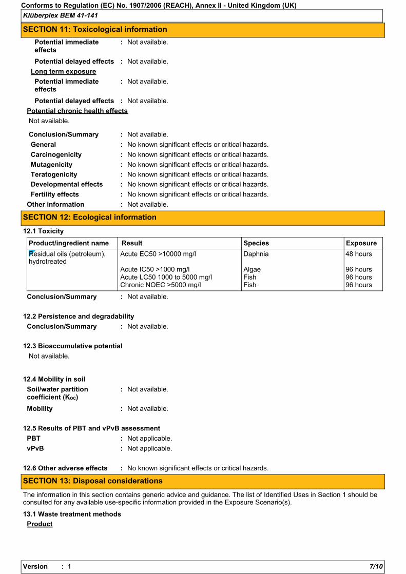
Klüberplex BEM 41-141
Conforms to Regulation (EC) No. 1907/2006 (REACH), Annex II - United Kingdom (UK)
SECTION 11: Toxicological information
Potential chronic health effects
No known significant effects or critical hazards.General :
No known significant effects or critical hazards.Carcinogenicity :
No known significant effects or critical hazards.Mutagenicity :
No known significant effects or critical hazards.Teratogenicity :
Not available.
Conclusion/Summary : Not available.
Developmental effects : No known significant effects or critical hazards.
Fertility effects : No known significant effects or critical hazards.
Long term exposure
Potential immediateeffects
Potential delayed effects :
:
Potential immediateeffects
Potential delayed effects :
:
Other information :
Not available.
Not available.
Not available.
Not available.
Not available.
Mobility Not available.:
12.3 Bioaccumulative potential
12.6 Other adverse effects No known significant effects or critical hazards.
Not available.
12.1 Toxicity
Residual oils (petroleum),hydrotreated
Acute EC50 >10000 mg/l Daphnia 48 hours
Acute IC50 >1000 mg/l Algae 96 hoursAcute LC50 1000 to 5000 mg/l Fish 96 hoursChronic NOEC >5000 mg/l Fish 96 hours
Product/ingredient name SpeciesResult Exposure
Conclusion/Summary : Not available.
12.2 Persistence and degradability
Conclusion/Summary : Not available.
PBT : Not applicable.
vPvB : Not applicable.
SECTION 12: Ecological information
12.4 Mobility in soil
Soil/water partitioncoefficient (KOC)
Not available.:
12.5 Results of PBT and vPvB assessment
:
SECTION 13: Disposal considerations
The information in this section contains generic advice and guidance. The list of Identified Uses in Section 1 should beconsulted for any available use-specific information provided in the Exposure Scenario(s).
13.1 Waste treatment methods
Product
Version : 7/101

Klüberplex BEM 41-141
Conforms to Regulation (EC) No. 1907/2006 (REACH), Annex II - United Kingdom (UK)
SECTION 13: Disposal considerations
Within the present knowledge of the supplier, this product is not regarded ashazardous waste, as defined by EU Directive 91/689/EEC.
Hazardous waste :
The generation of waste should be avoided or minimised wherever possible.Significant quantities of waste product residues should not be disposed of via thefoul sewer but processed in a suitable effluent treatment plant. Dispose of surplusand non-recyclable products via a licensed waste disposal contractor. Disposal ofthis product, solutions and any by-products should at all times comply with therequirements of environmental protection and waste disposal legislation and anyregional local authority requirements.
:Methods of disposal
Packaging
Methods of disposal :
Special precautions :
The generation of waste should be avoided or minimised wherever possible. Wastepackaging should be recycled. Incineration or landfill should only be consideredwhen recycling is not feasible.
This material and its container must be disposed of in a safe way. Empty containersor liners may retain some product residues. Avoid dispersal of spilt material andrunoff and contact with soil, waterways, drains and sewers.
-
-
-
-
Not regulated.
-
-
Not regulated. Not regulated.
- - -
SECTION 14: Transport information
ADR/RID IMDG IATA
14.1 UN number
14.2 UN propershipping name
14.3 Transporthazard class(es)
14.4 Packinggroup
Additionalinformation
14.5Environmentalhazards
14.6 Specialprecautions foruser
14.7 Transport in bulkaccording to Annex II ofMARPOL 73/78 and the IBCCode
No. No. No.
Not available. Not available. Not available.
: Not available.
- - -
Not applicable.Annex XVII - Restrictionson the manufacture,placing on the market anduse of certain dangeroussubstances, mixtures andarticles
:
SECTION 15: Regulatory information
15.1 Safety, health and environmental regulations/legislation specific for the substance or mixture
EU Regulation (EC) No. 1907/2006 (REACH)
Annex XIV - List of substances subject to authorisation
Substances of very high concern
None of the components are listed.
Version : 8/101

Klüberplex BEM 41-141
Conforms to Regulation (EC) No. 1907/2006 (REACH), Annex II - United Kingdom (UK)
SECTION 15: Regulatory information
Other EU regulations
Europe inventory : Not determined.
Black List Chemicals : Not listed
Priority List Chemicals : Not listed
Integrated pollutionprevention and controllist (IPPC) - Air
: Not listed
Integrated pollutionprevention and controllist (IPPC) - Water
: Not listed
Chemical WeaponsConvention List Schedule IChemicals
: Not listed
Chemical WeaponsConvention List Schedule IIChemicals
: Not listed
Chemical WeaponsConvention List Schedule IIIChemicals
: Not listed
International regulations
15.2 Chemical SafetyAssessment
This product contains substances for which Chemical Safety Assessments are stillrequired.
:
2011-07-11.Date of printing
Date of issue
Notice to reader
Date of previous issue
:
:
:
Not applicable.:Full text of abbreviated Rphrases
Not applicable.:Full text of classifications[DSD/DPD]
Indicates information that has changed from previously issued version.
2011-07-11
2011-07-11.
SECTION 16: Other information
Full text of abbreviated Hstatements
:
Abbreviations andacronyms
: ATE = Acute Toxicity EstimateCLP = Classification, Labelling and Packaging Regulation [Regulation (EC) No.1272/2008]DNEL = Derived No Effect LevelEUH statement = CLP-specific Hazard statementPNEC = Predicted No Effect ConcentrationRRN = REACH Registration Number
Procedure used to derive the classification according to Regulation (EC) No. 1272/2008 [CLP/GHS]
Classification Justification
Not classified.
Full text of classifications[CLP/GHS]
:
Not applicable.
Not applicable.
Version : 1
Prepared by Material Compliance Management+49 (0) 89 7876 1564
:
Version : 9/101

Klüberplex BEM 41-141
Conforms to Regulation (EC) No. 1907/2006 (REACH), Annex II - United Kingdom (UK)
SECTION 16: Other information
This safety datasheet applies only to products originally packaged and labelled by KLÜBER LUBRICATION.The information contained therein is protected by copyright and must not be reproduced or amended withoutthe express written approval of KLÜBER LUBRICATION. This document may be passed on only to the extentrequired by law. Any dissemination of our safety datasheets (e.g. as a document for download from theInternet) beyond this legally required extent is not permitted without express written consent.KLÜBER LUBRICATION provides its customers with amended safety datasheets as prescribed by law. Thecustomer is responsible for passing on safety datasheets and any amendments contained therein to its owncustomers, employees and other users of the product. KLÜBER LUBRICATION provides no guarantee thatsafety datasheets received by users from third parties are up-to-date.All information and instructions in this safety datasheets were compiled to the best of our knowledge and arebased on the information available to us. The data provided are intended to describe the product in relation tothe required safety measures; they are neither an assurance of characteristics nor a guarantee of the product'ssuitability for particular applications and do not justify any contractual legal relationships.
Version : 10/101

Product Name: MOBIL SHC 632
Revision Date: 11 May 2012 Page 1 of 9 ______________________________________________________________________________________________________________________
MATERIAL SAFETY DATA SHEET
SECTION 1 PRODUCT AND COMPANY IDENTIFICATION PRODUCT
Product Name: MOBIL SHC 632 Product Description: Synthetic Base Stocks and Additives Product Code: 201560500560, 602987-00, 970854 Intended Use: Circulating/gear oil
COMPANY IDENTIFICATION
Supplier: EXXON MOBIL CORPORATION 3225 GALLOWS RD. FAIRFAX, VA. 22037 USA
24 Hour Health Emergency 609-737-4411 Transportation Emergency Phone 800-424-9300 ExxonMobil Transportation No. 281-834-3296 Product Technical Information 800-662-4525, 800-947-9147 MSDS Internet Address http://www.exxon.com, http://www.mobil.com
SECTION 2 COMPOSITION / INFORMATION ON INGREDIENTS No Reportable Hazardous Substance(s) or Complex Substance(s).
SECTION 3 HAZARDS IDENTIFICATION This material is not considered to be hazardous according to regulatory guidelines (see (M)SDS Section 15).
POTENTIAL HEALTH EFFECTS
Low order of toxicity. Excessive exposure may result in eye, skin, or respiratory irritation. High-pressure injection under skin may cause serious damage.
NFPA Hazard ID: Health: 0 Flammability: 1 Reactivity: 0 HMIS Hazard ID: Health: 0 Flammability: 1 Reactivity: 0 NOTE: This material should not be used for any other purpose than the intended use in Section 1 without expert advice. Health studies have shown that chemical exposure may cause potential human health risks which may vary from person to person.
SECTION 4 FIRST AID MEASURES
INHALATION
Remove from further exposure. For those providing assistance, avoid exposure to yourself or others. Use

Product Name: MOBIL SHC 632
Revision Date: 11 May 2012 Page 2 of 9 ______________________________________________________________________________________________________________________
adequate respiratory protection. If respiratory irritation, dizziness, nausea, or unconsciousness occurs, seek immediate medical assistance. If breathing has stopped, assist ventilation with a mechanical device or use mouth-to-mouth resuscitation.
SKIN CONTACT
Wash contact areas with soap and water. If product is injected into or under the skin, or into any part of the body, regardless of the appearance of the wound or its size, the individual should be evaluated immediately by a physician as a surgical emergency. Even though initial symptoms from high pressure injection may be minimal or absent, early surgical treatment within the first few hours may significantly reduce the ultimate extent of injury.
EYE CONTACT
Flush thoroughly with water. If irritation occurs, get medical assistance. INGESTION
First aid is normally not required. Seek medical attention if discomfort occurs.
SECTION 5 FIRE FIGHTING MEASURES
EXTINGUISHING MEDIA
Appropriate Extinguishing Media: Use water fog, foam, dry chemical or carbon dioxide (CO2) to extinguish flames. Inappropriate Extinguishing Media: Straight Streams of Water
FIRE FIGHTING
Fire Fighting Instructions: Evacuate area. Prevent runoff from fire control or dilution from entering streams, sewers, or drinking water supply. Firefighters should use standard protective equipment and in enclosed spaces, self-contained breathing apparatus (SCBA). Use water spray to cool fire exposed surfaces and to protect personnel. Hazardous Combustion Products: Smoke, Fume, Aldehydes, Sulfur oxides, Incomplete combustion products, Oxides of carbon
FLAMMABILITY PROPERTIES
Flash Point [Method]: >210°C (410°F) [ASTM D-92] Flammable Limits (Approximate volume % in air): LEL: 0.9 UEL: 7.0 Autoignition Temperature: N/D
SECTION 6 ACCIDENTAL RELEASE MEASURES
NOTIFICATION PROCEDURES
In the event of a spill or accidental release, notify relevant authorities in accordance with all applicable regulations. US regulations require reporting releases of this material to the environment which exceed the applicable reportable quantity or oil spills which could reach any waterway including intermittent dry creeks. The National Response Center can be reached at (800)424-8802.

Product Name: MOBIL SHC 632
Revision Date: 11 May 2012 Page 3 of 9 ______________________________________________________________________________________________________________________
PROTECTIVE MEASURES Avoid contact with spilled material. See Section 5 for fire fighting information. See the Hazard Identification Section for Significant Hazards. See Section 4 for First Aid Advice. See Section 8 for advice on the minimum requirements for personal protective equipment. Additional protective measures may be necessary, depending on the specific circumstances and/or the expert judgment of the emergency responders.
SPILL MANAGEMENT Land Spill: Stop leak if you can do it without risk. Recover by pumping or with suitable absorbent. Water Spill: Stop leak if you can do it without risk. Confine the spill immediately with booms. Warn other shipping. Remove from the surface by skimming or with suitable absorbents. Seek the advice of a specialist before using dispersants. Water spill and land spill recommendations are based on the most likely spill scenario for this material; however, geographic conditions, wind, temperature, (and in the case of a water spill) wave and current direction and speed may greatly influence the appropriate action to be taken. For this reason, local experts should be consulted. Note: Local regulations may prescribe or limit action to be taken.
ENVIRONMENTAL PRECAUTIONS
Large Spills: Dike far ahead of liquid spill for later recovery and disposal. Prevent entry into waterways, sewers, basements or confined areas.
SECTION 7 HANDLING AND STORAGE
HANDLING
Prevent small spills and leakage to avoid slip hazard. Material can accumulate static charges which may cause an electrical spark (ignition source). When the material is handled in bulk, an electrical spark could ignite any flammable vapors from liquids or residues that may be present (e.g., during switch-loading operations). Use proper bonding and/or ground procedures. However, bonding and grounds may not eliminate the hazard from static accumulation. Consult local applicable standards for guidance. Additional references include American Petroleum Institute 2003 (Protection Against Ignitions Arising out of Static, Lightning and Stray Currents) or National Fire Protection Agency 77 (Recommended Practice on Static Electricity) or CENELEC CLC/TR 50404 (Electrostatics - Code of practice for the avoidance of hazards due to static electricity). Static Accumulator: This material is a static accumulator.
STORAGE
The container choice, for example storage vessel, may effect static accumulation and dissipation. Do not store in open or unlabelled containers.
SECTION 8 EXPOSURE CONTROLS / PERSONAL PROTECTION
Exposure limits/standards for materials that can be formed when handling this product: When mists/aerosols can occur the following are recommended: 5 mg/m³ - ACGIH TLV (inhalable fraction), 5 mg/m³ - OSHA PEL.

Product Name: MOBIL SHC 632
Revision Date: 11 May 2012 Page 4 of 9 ______________________________________________________________________________________________________________________
NOTE: Limits/standards shown for guidance only. Follow applicable regulations. ENGINEERING CONTROLS
The level of protection and types of controls necessary will vary depending upon potential exposure conditions. Control measures to consider:
No special requirements under ordinary conditions of use and with adequate ventilation.
PERSONAL PROTECTION
Personal protective equipment selections vary based on potential exposure conditions such as applications, handling practices, concentration and ventilation. Information on the selection of protective equipment for use with this material, as provided below, is based upon intended, normal usage.
Respiratory Protection: If engineering controls do not maintain airborne contaminant concentrations at a level which is adequate to protect worker health, an approved respirator may be appropriate. Respirator selection, use, and maintenance must be in accordance with regulatory requirements, if applicable. Types of respirators to be considered for this material include:
No special requirements under ordinary conditions of use and with adequate ventilation.
For high airborne concentrations, use an approved supplied-air respirator, operated in positive pressure mode. Supplied air respirators with an escape bottle may be appropriate when oxygen levels are inadequate, gas/vapor warning properties are poor, or if air purifying filter capacity/rating may be exceeded. Hand Protection: Any specific glove information provided is based on published literature and glove manufacturer data. Glove suitability and breakthrough time will differ depending on the specific use conditions. Contact the glove manufacturer for specific advice on glove selection and breakthrough times for your use conditions. Inspect and replace worn or damaged gloves. The types of gloves to be considered for this material include:
No protection is ordinarily required under normal conditions of use. Eye Protection: If contact is likely, safety glasses with side shields are recommended. Skin and Body Protection: Any specific clothing information provided is based on published literature or manufacturer data. The types of clothing to be considered for this material include:
No skin protection is ordinarily required under normal conditions of use. In accordance with good industrial hygiene practices, precautions should be taken to avoid skin contact.
Specific Hygiene Measures: Always observe good personal hygiene measures, such as washing after handling the material and before eating, drinking, and/or smoking. Routinely wash work clothing and protective equipment to remove contaminants. Discard contaminated clothing and footwear that cannot be cleaned. Practice good housekeeping.
ENVIRONMENTAL CONTROLS
Comply with applicable environmental regulations limiting discharge to air, water and soil. Protect the environment by applying appropriate control measures to prevent or limit emissions.
SECTION 9 PHYSICAL AND CHEMICAL PROPERTIES
Note: Physical and chemical properties are provided for safety, health and environmental considerations only

Product Name: MOBIL SHC 632
Revision Date: 11 May 2012 Page 5 of 9 ______________________________________________________________________________________________________________________
and may not fully represent product specifications. Contact the Supplier for additional information. GENERAL INFORMATION
Physical State: Liquid
Color: Orange
Odor: Characteristic
Odor Threshold: N/D
IMPORTANT HEALTH, SAFETY, AND ENVIRONMENTAL INFORMATION
Relative Density (at 15 °C): 0.867 Flash Point [Method]: >210°C (410°F) [ASTM D-92] Flammable Limits (Approximate volume % in air): LEL: 0.9 UEL: 7.0
Autoignition Temperature: N/D
Boiling Point / Range: > 316°C (600°F) Vapor Density (Air = 1): > 2 at 101 kPa
Vapor Pressure: < 0.013 kPa (0.1 mm Hg) at 20 °C
Evaporation Rate (n-butyl acetate = 1): N/D
pH: N/A
Log Pow (n-Octanol/Water Partition Coefficient): > 3.5 Solubility in Water: Negligible
Viscosity: 320 cSt (320 mm2/sec) at 40 °C | 38 cSt (38 mm2/sec) at 100°C Oxidizing Properties: See Hazards Identification Section.
OTHER INFORMATION
Freezing Point: N/D Melting Point: N/A Pour Point: -33°C (-27°F)
SECTION 10 STABILITY AND REACTIVITY
STABILITY: Material is stable under normal conditions. CONDITIONS TO AVOID: Excessive heat. High energy sources of ignition. MATERIALS TO AVOID: Strong oxidizers
HAZARDOUS DECOMPOSITION PRODUCTS: Material does not decompose at ambient temperatures. HAZARDOUS POLYMERIZATION: Will not occur.
SECTION 11 TOXICOLOGICAL INFORMATION
ACUTE TOXICITY
Route of Exposure Conclusion / Remarks
Inhalation
Toxicity (Rat): LC50 > 5000 mg/m3 Minimally Toxic. Based on test data for structurally similar materials.
Irritation: No end point data. Negligible hazard at ambient/normal handling temperatures. Based on assessment of the components.
Ingestion

Product Name: MOBIL SHC 632
Revision Date: 11 May 2012 Page 6 of 9 ______________________________________________________________________________________________________________________
Toxicity (Rat): LD50 > 5000 mg/kg Minimally Toxic. Based on test data for structurally similar materials.
Skin
Toxicity (Rabbit): LD50 > 5000 mg/kg Minimally Toxic. Based on test data for structurally similar materials.
Irritation (Rabbit): Data available. Negligible irritation to skin at ambient temperatures. Based on test data for structurally similar materials.
Eye
Irritation (Rabbit): Data available. May cause mild, short-lasting discomfort to eyes. Based on test data for structurally similar materials.
CHRONIC/OTHER EFFECTS
Contains: Synthetic base oils: Not expected to cause significant health effects under conditions of normal use, based on laboratory studies with the same or similar materials. Not mutagenic or genotoxic. Not sensitizing in test animals and humans.
Additional information is available by request. The following ingredients are cited on the lists below: None.
--REGULATORY LISTS SEARCHED--
1 = NTP CARC 3 = IARC 1 5 = IARC 2B
2 = NTP SUS 4 = IARC 2A 6 = OSHA CARC
SECTION 12 ECOLOGICAL INFORMATION
The information given is based on data available for the material, the components of the material, and similar materials. ECOTOXICITY Material -- Not expected to be harmful to aquatic organisms. Material -- Not expected to demonstrate chronic toxicity to aquatic organisms. MOBILITY Base oil component -- Low solubility and floats and is expected to migrate from water to the land.
Expected to partition to sediment and wastewater solids.
SECTION 13 DISPOSAL CONSIDERATIONS

Product Name: MOBIL SHC 632
Revision Date: 11 May 2012 Page 7 of 9 ______________________________________________________________________________________________________________________
Disposal recommendations based on material as supplied. Disposal must be in accordance with current applicable laws and regulations, and material characteristics at time of disposal.
DISPOSAL RECOMMENDATIONS
Product is suitable for burning in an enclosed controlled burner for fuel value or disposal by supervised incineration at very high temperatures to prevent formation of undesirable combustion products. Protect the environment. Dispose of used oil at designated sites. Minimize skin contact. Do not mix used oils with solvents, brake fluids or coolants.
REGULATORY DISPOSAL INFORMATION
RCRA Information: The unused product, in our opinion, is not specifically listed by the EPA as a hazardous waste (40 CFR, Part 261D), nor is it formulated to contain materials which are listed as hazardous wastes. It does not exhibit the hazardous characteristics of ignitability, corrositivity or reactivity and is not formulated with contaminants as determined by the Toxicity Characteristic Leaching Procedure (TCLP). However, used product may be regulated.
Empty Container Warning Empty Container Warning (where applicable): Empty containers may contain residue and can be dangerous. Do not attempt to refill or clean containers without proper instructions. Empty drums should be completely drained and safely stored until appropriately reconditioned or disposed. Empty containers should be taken for recycling, recovery, or disposal through suitably qualified or licensed contractor and in accordance with governmental regulations. DO NOT PRESSURISE, CUT, WELD, BRAZE, SOLDER, DRILL, GRIND, OR EXPOSE SUCH CONTAINERS TO HEAT, FLAME, SPARKS, STATIC ELECTRICITY, OR OTHER SOURCES OF IGNITION. THEY MAY EXPLODE AND CAUSE INJURY OR DEATH.
SECTION 14 TRANSPORT INFORMATION
LAND (DOT): Not Regulated for Land Transport
LAND (TDG): Not Regulated for Land Transport
SEA (IMDG): Not Regulated for Sea Transport according to IMDG-Code
AIR (IATA): Not Regulated for Air Transport
SECTION 15 REGULATORY INFORMATION
OSHA HAZARD COMMUNICATION STANDARD: When used for its intended purposes, this material is not classified as hazardous in accordance with OSHA 29 CFR 1910.1200. Complies with the following national/regional chemical inventory requirements:: TSCA Special Cases:
Inventory Status
AICS Restrictions Apply
ELINCS Restrictions Apply
KECI Restrictions Apply

Product Name: MOBIL SHC 632
Revision Date: 11 May 2012 Page 8 of 9 ______________________________________________________________________________________________________________________
EPCRA: This material contains no extremely hazardous substances. SARA (311/312) REPORTABLE HAZARD CATEGORIES: None. SARA (313) TOXIC RELEASE INVENTORY: This material contains no chemicals subject to the supplier notification requirements of the SARA 313 Toxic Release Program. The following ingredients are cited on the lists below:
Chemical Name CAS Number List Citations
PHENOL, 4,4-METHYLENEBIS(2,6-BIS(1,1-DIMETHYLETHYL)-
118-82-1 5
--REGULATORY LISTS SEARCHED-- 1 = ACGIH ALL 6 = TSCA 5a2 11 = CA P65 REPRO 16 = MN RTK 2 = ACGIH A1 7 = TSCA 5e 12 = CA RTK 17 = NJ RTK 3 = ACGIH A2 8 = TSCA 6 13 = IL RTK 18 = PA RTK 4 = OSHA Z 9 = TSCA 12b 14 = LA RTK 19 = RI RTK 5 = TSCA 4 10 = CA P65 CARC 15 = MI 293 Code key: CARC=Carcinogen; REPRO=Reproductive
SECTION 16 OTHER INFORMATION
N/D = Not determined, N/A = Not applicable THIS SAFETY DATA SHEET CONTAINS THE FOLLOWING REVISIONS: Revision Changes: Section 13: Disposal Considerations - Disposal Recommendations was modified. Section 01: Product Code was modified. Section 10 Stability and Reactivity - Header was modified. Section 13: Disposal Recommendations - Note was modified. Section 09: Phys/Chem Properties Note was modified. Section 09: Boiling Point C(F) was modified. Section 09: Pour Point C(F) was modified. Section 08: Comply with applicable regulations phrase was modified. Section 08: Personal Protection was modified. Section 09: Vapor Pressure was modified. Section 07: Handling and Storage - Handling was modified. Section 07: Handling and Storage - Storage Phrases was modified. Section 06: Accidental Release - Spill Management - Water was modified. Section 09: Relative Density - Header was modified. Section 09: Flash Point C(F) was modified. Section 09: Viscosity was modified. Section 09: Viscosity was modified. Section 14: Sea (IMDG) - Header was modified. Section 14: Air (IATA) - Header was modified.

Product Name: MOBIL SHC 632
Revision Date: 11 May 2012 Page 9 of 9 ______________________________________________________________________________________________________________________
Section 14: LAND (TDG) - Header was modified. Section 14: LAND (DOT) - Header was modified. Section 15: List Citation Table - Header was modified. Section 14: LAND (DOT) - Default was modified. Section 14: LAND (TDG) Default was modified. Section 14: Sea (IMDG) - Default was modified. Section 14: Air (IATA) - Default was modified. Section 15: National Chemical Inventory Listing - Header was modified. Section 15: National Chemical Inventory Listing was modified. Section 08: Exposure limits/standards was modified. Section 15: Special Cases Table was modified. Hazard Identification: OSHA - May be Hazardous Statement was modified. Section 09: Oxidizing Properties was modified. Section 06: Protective Measures was added. Section 06: Accidental Release - Protective Measures - Header was added. Section 09: DMSO IP was deleted. Section 09: DMSO IP - Header was deleted. ------------------------------------------------------------------------------------------------------- ---------------------------------------------- ----------------------------------------------------------------------------------------------------------------------------- ------------------------ The information and recommendations contained herein are, to the best of ExxonMobil's knowledge and belief, accurate and reliable as of the date issued. You can contact ExxonMobil to insure that this document is the most current available from ExxonMobil. The information and recommendations are offered for the user's consideration and examination. It is the user's responsibility to satisfy itself that the product is suitable for the intended use. If buyer repackages this product, it is the user's responsibility to insure proper health, safety and other necessary information is included with and/or on the container. Appropriate warnings and safe-handling procedures should be provided to handlers and users. Alteration of this document is strictly prohibited. Except to the extent required by law, re-publication or retransmission of this document, in whole or in part, is not permitted. The term, "ExxonMobil" is used for convenience, and may include any one or more of ExxonMobil Chemical Company, Exxon Mobil Corporation, or any affiliates in which they directly or indirectly hold any interest. ----------------------------------------------------------------------------------------------------------------------------- ------------------------ Internal Use Only
MHC: 0B, 0B, 0, 0, 0, 0 PPEC: A
DGN: 2007973XUS (1013491) ----------------------------------------------------------------------------------------------------------------------------- ------------------------ Copyright 2002 Exxon Mobil Corporation, All rights reserved

Product Name: MOBILGEAR OGL 461 Revision Date: 20 Dec 2012 Page 1 of 13 _____________________________________________________________________________________________________________________
SAFETY DATA SHEET SECTION 1 IDENTIFICATION OF THE SUBSTANCE / MIXTURE AND OF THE
COMPANY / UNDERTAKING
As of the revision date above, this (M)SDS meets the regulations in the United Kingdom & Ireland. 1.1. PRODUCT IDENTIFIER
Product Name: MOBILGEAR OGL 461 Product Description: Base Oil and Additives Product Code: 201560402040, 406246, 610030-60
1.2. RELEVANT IDENTIFIED USES OF THE SUBSTANCE OR MIXTURE AND USES ADVISED AGAINST
Intended Use: Grease Uses advised against: None unless specified elsewhere in this SDS. 1.3. DETAILS OF THE SUPPLIER OF THE SAFETY DATA SHEET
Supplier: EXXONMOBIL LUBRICANTS & SPECIALTIES EUROPE, A DIVISION OF EXXONMOBIL PETROLEUM & CHEMICAL, BVBA (EMPC) POLDERDIJKWEG B-2030 Antwerpen Belgium
E-Mail: [email protected] Supplier / Registrant: (BE) 32 35433111
1.4. EMERGENCY TELEPHONE NUMBER
24 Hour Environmental / Health Emergency Telephone:
(UK) 01372 222 000 / (IRELAND) 44 1372 222 000
SECTION 2 HAZARDS IDENTIFICATION 2.1. CLASSIFICATION OF SUBSTANCE OR MIXTURE Classification according to EU Directive 67/548/EEC / 1999/45 EC Not Classified

Product Name: MOBILGEAR OGL 461 Revision Date: 20 Dec 2012 Page 2 of 13 _____________________________________________________________________________________________________________________
2.2. LABEL ELEMENTS Not regulated according to EU Directive 67/548/EEC / 1999/45 EC
. . Contains: ZINC SULPHONATE May produce an allergic reaction.
2.3. OTHER HAZARDS PHYSICAL / CHEMICAL HAZARDS
No significant hazards. HEALTH HAZARDS
Excessive exposure may result in eye, skin, or respiratory irritation. High-pressure injection under skin may cause serious damage.
ENVIRONMENTAL HAZARDS
No significant hazards. Material does not meet the criteria for PBT or vPvB in accordance with REACH Annex XIII.
NOTE: This material should not be used for any other purpose than the intended use in Section 1 without expert
advice. Health studies have shown that chemical exposure may cause potential human health risks which may vary from person to person.
SECTION 3 COMPOSITION / INFORMATION ON INGREDIENTS 3.1. SUBSTANCES Not Applicable. This material is regulated as a mixture. 3.2. MIXTURES This material is defined as a mixture. Reportable hazardous substance(s) complying with the classification criteria and/or with an exposure limit (OEL) Name CAS# EC# Registration# Concentration* GHS/CLP
classification GRAPHITE 7782-42-5 231-955-3 NE 5 - 10% OEL SULFURIZED OLEFIN Confidential NE 1 - 5% [Aquatic Acute 3 H402],
Aquatic Chronic 3 H412, [Flam. Liq. 4 H227]
ZINC DINONYLNAPHTHALENE SULPHONATE
28016-00-4 248-778-2 NE 0.1 - 1% Skin Irrit. 2 H315, Eye Irrit. 2 H319, Skin Sens. 1 H317
ZINC DITHIOPHOSPHATE 68649-42-3 272-028-3 NE 1 - 2.5% Skin Irrit. 2 H315, Eye Dam. 1 H318, [Aquatic Acute 2 H401], Aquatic Chronic 2 H411
Note - any classification in brackets is a GHS building block that was not adopted by the EU in the CLP regulation (No 1272/2008)

Product Name: MOBILGEAR OGL 461 Revision Date: 20 Dec 2012 Page 3 of 13 _____________________________________________________________________________________________________________________
and therefore is not applicable in the EU or in non-EU countries which have implemented the CLP regulation and is shown for informational purposes only.
Name CAS# EC# Registration#
Concentration* DSD Symbols/Risk Phrases
GRAPHITE 7782-42-5 231-955-3 NE 5 - 10% OELSULFURIZED OLEFIN Confidential NE 1 - 5% R52/53
ZINC DITHIOPHOSPHATE 68649-42-3 272-028-3 NE 1 - 2.5% Xi;R38, Xi;R41, N;R51/53
* All concentrations are percent by weight unless ingredient is a gas. Gas concentrations are in percent by volume. Note: See (M)SDS Section 16 for full text of the R-Phrases. See (M)SDS Section 16 for full text of hazard statements. SECTION 4 FIRST AID MEASURES 4.1. DESCRIPTION OF FIRST AID MEASURES INHALATION
Under normal conditions of intended use, this material is not expected to be an inhalation hazard. SKIN CONTACT
Wash contact areas with soap and water. If product is injected into or under the skin, or into any part of the body, regardless of the appearance of the wound or its size, the individual should be evaluated immediately by a physician as a surgical emergency. Even though initial symptoms from high pressure injection may be minimal or absent, early surgical treatment within the first few hours may significantly reduce the ultimate extent of injury.
EYE CONTACT
Flush thoroughly with water. If irritation occurs, get medical assistance. INGESTION
First aid is normally not required. Seek medical attention if discomfort occurs. 4.2. MOST IMPORTANT SYMPTOMS AND EFFECTS, BOTH ACUTE AND DELAYED
Local necrosis as evidenced by delayed onset of pain and tissue damage a few hours after injection. 4.3. INDICATION OF ANY IMMEDIATE MEDICAL ATTENTION AND SPECIAL TREATMENT NEEDED
The need to have special means for providing specific and immediate medical treatment available in the workplace is not expected.
SECTION 5 FIRE FIGHTING MEASURES 5.1. EXTINGUISHING MEDIA
Suitable Extinguishing Media: Use water fog, foam, dry chemical or carbon dioxide (CO2) to extinguish flames.

Product Name: MOBILGEAR OGL 461 Revision Date: 20 Dec 2012 Page 4 of 13 _____________________________________________________________________________________________________________________
Unsuitable Extinguishing Media: Straight streams of water
5.2. SPECIAL HAZARDS ARISING FROM THE SUBSTANCE OR MIXTURE
Hazardous Combustion Products: Smoke, Fume, Aldehydes, Sulphur oxides, Incomplete combustion products, Oxides of carbon
5.3. ADVICE FOR FIRE FIGHTERS
Fire Fighting Instructions: Evacuate area. Prevent run-off from fire control or dilution from entering streams, sewers or drinking water supply. Fire-fighters should use standard protective equipment and in enclosed spaces, self-contained breathing apparatus (SCBA). Use water spray to cool fire exposed surfaces and to protect personnel.
FLAMMABILITY PROPERTIES
Flash Point [Method]: >204°C (400°F) [EST. FOR OIL, ASTM D-92 (COC)] Upper/Lower Flammable Limits (Approximate volume % in air): UEL: No data available LEL: No data available Autoignition Temperature: No data available
SECTION 6 ACCIDENTAL RELEASE MEASURES 6.1. PERSONAL PRECAUTIONS, PROTECTIVE EQUIPMENT AND EMERGENCY PROCEDURES
NOTIFICATION PROCEDURES
In the event of a spill or accidental release, notify relevant authorities in accordance with all applicable regulations.
PROTECTIVE MEASURES
Avoid contact with spilled material. See Section 5 for fire fighting information. See the Hazard Identification Section for Significant Hazards. See Section 4 for First Aid Advice. See Section 8 for advice on the minimum requirements for personal protective equipment. Additional protective measures may be necessary, depending on the specific circumstances and/or the expert judgment of the emergency responders. For emergency responders: Respiratory protection: respiratory protection will be necessary only in special cases, e.g., formation of mists. Half-face or full-face respirator with filter(s) for dust/organic vapor or Self Contained Breathing Apparatus (SCBA) can be used depending on the size of spill and potential level of exposure. If the exposure cannot be completely characterized or an oxygen deficient atmosphere is possible or anticipated, SCBA is recommended. Work gloves that are resistant to hydrocarbons are recommended. Gloves made of polyvinyl acetate (PVA) are not water-resistant and are not suitable for emergency use. Chemical goggles are recommended if splashes or contact with eyes is possible. Small spills: normal antistatic work clothes are usually adequate. Large spills: full body suit of chemical resistant, antistatic material is recommended.
6.2. ENVIRONMENTAL PRECAUTIONS Prevent entry into waterways, sewers, basements or confined areas.
6.3. METHODS AND MATERIAL FOR CONTAINMENT AND CLEANING UP Land Spill: Scrape up spilled material with shovels into a suitable container for recycle or disposal. Water Spill: Stop leak if you can do so without risk. Confine the spill immediately with booms. Warn other

Product Name: MOBILGEAR OGL 461 Revision Date: 20 Dec 2012 Page 5 of 13 _____________________________________________________________________________________________________________________
shipping. Skim from surface Water spill and land spill recommendations are based on the most likely spill scenario for this material; however, geographic conditions, wind, temperature, (and in the case of a water spill) wave and current direction and speed may greatly influence the appropriate action to be taken. For this reason, local experts should be consulted. Note: Local regulations may prescribe or limit action to be taken.
6.4. REFERENCES TO OTHER SECTIONS See Sections 8 and 13. SECTION 7 HANDLING AND STORAGE 7.1. PRECAUTIONS FOR SAFE HANDLING
Prevent small spills and leakage to avoid slip hazard. Static Accumulator: This material is not a static accumulator.
7.2. CONDITIONS FOR SAFE STORAGE, INCLUDING ANY INCOMPATIBILITIES
Do not store in open or unlabelled containers.
7.3. SPECIFIC END USES: Section 1 informs about identified end-uses. No industrial or sector specific guidance available. SECTION 8 EXPOSURE CONTROLS / PERSONAL PROTECTION 8.1. CONTROL PARAMETERS EXPOSURE LIMIT VALUES Exposure limits/standards (Note: Exposure limits are not additive) Substance Name Form Limit/Standard Note Source GRAPHITE
Inhalable dust.
TWA 10 mg/m3 UK EH40
GRAPHITE Respirable dust.
TWA 4 mg/m3 UK EH40
GRAPHITE Respirable fraction.
TWA 2 mg/m3 ACGIH
UK EH40 Workplace Exposure Limits. Exposure limits for use with Control of Substances Hazardous to Health Regulations 2002 (as amended) Note: Information about recommended monitoring procedures can be obtained from the relevant agency(ies)/institute(s):
UK Health and Safety Executive (HSE)
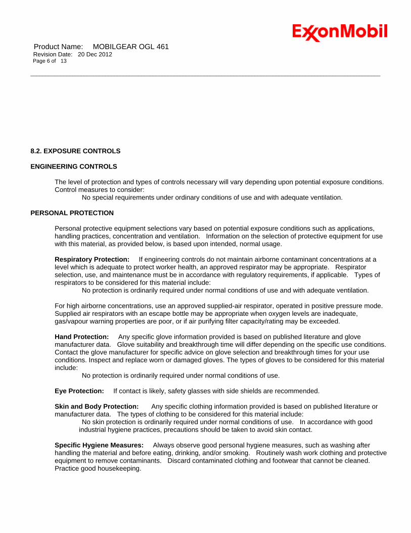
Product Name: MOBILGEAR OGL 461 Revision Date: 20 Dec 2012 Page 6 of 13 _____________________________________________________________________________________________________________________
8.2. EXPOSURE CONTROLS ENGINEERING CONTROLS
The level of protection and types of controls necessary will vary depending upon potential exposure conditions. Control measures to consider:
No special requirements under ordinary conditions of use and with adequate ventilation.
PERSONAL PROTECTION Personal protective equipment selections vary based on potential exposure conditions such as applications, handling practices, concentration and ventilation. Information on the selection of protective equipment for use with this material, as provided below, is based upon intended, normal usage. Respiratory Protection: If engineering controls do not maintain airborne contaminant concentrations at a level which is adequate to protect worker health, an approved respirator may be appropriate. Respirator selection, use, and maintenance must be in accordance with regulatory requirements, if applicable. Types of respirators to be considered for this material include:
No protection is ordinarily required under normal conditions of use and with adequate ventilation. For high airborne concentrations, use an approved supplied-air respirator, operated in positive pressure mode. Supplied air respirators with an escape bottle may be appropriate when oxygen levels are inadequate, gas/vapour warning properties are poor, or if air purifying filter capacity/rating may be exceeded. Hand Protection: Any specific glove information provided is based on published literature and glove manufacturer data. Glove suitability and breakthrough time will differ depending on the specific use conditions. Contact the glove manufacturer for specific advice on glove selection and breakthrough times for your use conditions. Inspect and replace worn or damaged gloves. The types of gloves to be considered for this material include:
No protection is ordinarily required under normal conditions of use. Eye Protection: If contact is likely, safety glasses with side shields are recommended. Skin and Body Protection: Any specific clothing information provided is based on published literature or manufacturer data. The types of clothing to be considered for this material include:
No skin protection is ordinarily required under normal conditions of use. In accordance with good industrial hygiene practices, precautions should be taken to avoid skin contact.
Specific Hygiene Measures: Always observe good personal hygiene measures, such as washing after handling the material and before eating, drinking, and/or smoking. Routinely wash work clothing and protective equipment to remove contaminants. Discard contaminated clothing and footwear that cannot be cleaned. Practice good housekeeping.

Product Name: MOBILGEAR OGL 461 Revision Date: 20 Dec 2012 Page 7 of 13 _____________________________________________________________________________________________________________________
ENVIRONMENTAL CONTROLS
Comply with applicable environmental regulations limiting discharge to air, water and soil. Protect the environment by applying appropriate control measures to prevent or limit emissions.
SECTION 9 PHYSICAL AND CHEMICAL PROPERTIES Note: Physical and chemical properties are provided for safety, health and environmental considerations only and may not fully represent product specifications. Contact the Supplier for additional information. 9.1. INFORMATION ON BASIC PHYSICAL AND CHEMICAL PROPERTIES
Physical State: Solid Form: Semi-fluid Colour: Black Odour: Characteristic Odour Threshold: No data available pH: Not technically feasible Melting Point: No data available Freezing Point: No data available Initial Boiling Point / and Boiling Range: > 316°C (600°F) [Estimated] Flash Point [Method]: >204°C (400°F) [EST. FOR OIL, ASTM D-92 (COC)] Evaporation Rate (n-butyl acetate = 1): No data available Flammability (Solid, Gas): [test method unavailable] Upper/Lower Flammable Limits (Approximate volume % in air): UEL: No data available LEL: No data available Vapour Pressure: < 0.013 kPa (0.1 mm Hg) at 20 °C [Estimated] Vapour Density (Air = 1): No data available Relative Density (at 15 °C): 0.95 [test method unavailable] Solubility(ies): water Negligible Partition coefficient (n-Octanol/Water Partition Coefficient): > 3.5 [Estimated] Autoignition Temperature: No data available Decomposition Temperature: No data available Viscosity: 460 cSt (460 mm2/sec) at 40ºC | 30 cSt (30 mm2/sec) at 100°C [test method unavailable] Explosive Properties: None Oxidizing Properties: None
9.2. OTHER INFORMATION
DMSO Extract (mineral oil only), IP-346: < 3 %wt
NOTE: Most physical properties above are for the oil component in the material.

Product Name: MOBILGEAR OGL 461 Revision Date: 20 Dec 2012 Page 8 of 13 _____________________________________________________________________________________________________________________
SECTION 10 STABILITY AND REACTIVITY 10.1. REACTIVITY: See sub-sections below. 10.2. CHEMICAL STABILITY: Material is stable under normal conditions. 10.3. POSSIBILITY OF HAZARDOUS REACTIONS: Hazardous polymerization will not occur. 10.4. CONDITIONS TO AVOID: Excessive heat. High energy sources of ignition. 10.5. INCOMPATIBLE MATERIALS: Strong oxidisers 10.6. HAZARDOUS DECOMPOSITION PRODUCTS: Material does not decompose at ambient temperatures. SECTION 11 TOXICOLOGICAL INFORMATION 11.1. INFORMATION ON TOXICOLOGICAL EFFECTS Hazard Class Conclusion / Remarks Inhalation Acute Toxicity: No end point data for material.
Minimally Toxic. Based on assessment of the components.
Irritation: No end point data for material. Negligible hazard at ambient/normal handling temperatures. Based on assessment of the components.
Ingestion Acute Toxicity: No end point data for material.
Minimally Toxic. Based on assessment of the components.
Skin Acute Toxicity: No end point data for material.
Minimally Toxic. Based on assessment of the components.
Skin Corrosion/Irritation: No end point data for material.
Negligible irritation to skin at ambient temperatures. Based on assessment of the components.
Eye Serious Eye Damage/Irritation: No end point data for material.
May cause mild, short-lasting discomfort to eyes. Based on assessment of the components.
Sensitisation Respiratory Sensitization: No end point data for material.
Not expected to be a respiratory sensitizer.
Skin Sensitization: No end point data for material.
Not expected to be a skin sensitizer. Based on assessment of the components.
Aspiration: Data available. Not expected to be an aspiration hazard. Based on physico-chemical properties of the material.
Germ Cell Mutagenicity: No end point data for material.
Not expected to be a germ cell mutagen. Based on assessment of the components.
Carcinogenicity: No end point data for material.
Not expected to cause cancer. Based on assessment of the components.
Reproductive Toxicity: No end point data for material.
Not expected to be a reproductive toxicant. Based on assessment of the components.
Lactation: No end point data for material. Not expected to cause harm to breast-fed children. Specific Target Organ Toxicity (STOT) Single Exposure: No end point data for Not expected to cause organ damage from a single exposure.

Product Name: MOBILGEAR OGL 461 Revision Date: 20 Dec 2012 Page 9 of 13 _____________________________________________________________________________________________________________________
material. Repeated Exposure: No end point data for material.
Not expected to cause organ damage from prolonged or repeated exposure. Based on assessment of the components.
TOXICITY FOR SUBSTANCES
NAME ACUTE TOXICITYZINC DITHIOPHOSPHATE Dermal Lethality: LD50 > 2000 mg/kg (Rabbit); Oral Lethality: LD50
> 2000 mg/kg (Rat) OTHER INFORMATION Contains: Base oil severely refined: Not carcinogenic in animal studies. Representative material passes IP-346, Modified Ames test, and/or other screening tests. Dermal and inhalation studies showed minimal effects; lung non-specific infiltration of immune cells, oil deposition and minimal granuloma formation. Not sensitising in test animals. Graphite: May contain crystalline silica. Certain grades have produced lung tumours in animal studies and also exposed humans. Airborne exposure to high concentrations have resulted in pneumoconiosis in humans. Additional information is available by request. SECTION 12 ECOLOGICAL INFORMATION The information given is based on data available for the material, the components of the material, and similar materials. 12.1. TOXICITY Material -- Not expected to be harmful to aquatic organisms. 12.2. PERSISTENCE AND DEGRADABILITY Biodegradation: Base oil component -- Expected to be inherently biodegradable 12.3. BIOACCUMULATIVE POTENTIAL Base oil component -- Has the potential to bioaccumulate, however metabolism or physical properties may
reduce the bioconcentration or limit bioavailability. 12.4. MOBILITY IN SOIL Base oil component -- Low solubility and floats and is expected to migrate from water to the land.
Expected to partition to sediment and wastewater solids. 12.5. PERSISTENCE, BIOACCUMULATION AND TOXICITY FOR SUBSTANCE(S) This product is not, or does not contain, a substance that is a PBT or a vPvB. 12.6. OTHER ADVERSE EFFECTS No adverse effects are expected.

Product Name: MOBILGEAR OGL 461 Revision Date: 20 Dec 2012 Page 10 of 13 _____________________________________________________________________________________________________________________
SECTION 13 DISPOSAL CONSIDERATIONS Disposal recommendations based on material as supplied. Disposal must be in accordance with current applicable laws and regulations, and material characteristics at time of disposal. 13.1. WASTE TREATMENT METHODS
Product is suitable for burning in an enclosed controlled burner for fuel value or disposal by supervised incineration at very high temperatures to prevent formation of undesirable combustion products.
REGULATORY DISPOSAL INFORMATION European Waste Code: 12 01 12* NOTE: These codes are assigned based upon the most common uses for this material and may not reflect contaminants resulting from actual use. Waste producers need to assess the actual process used when generating the waste and its contaminants in order to assign the proper waste disposal code(s). This material is considered as hazardous waste pursuant to Directive 91/689/EEC on hazardous waste, and subject to the provisions of that Directive unless Article 1(5) of that Directive applies.
Empty Container Warning Empty Container Warning (where applicable): Empty containers may contain residue and can be dangerous. Do not attempt to refill or clean containers without proper instructions. Empty drums should be completely drained and safely stored until appropriately reconditioned or disposed. Empty containers should be taken for recycling, recovery, or disposal through suitably qualified or licensed contractor and in accordance with governmental regulations. DO NOT PRESSURISE, CUT, WELD, BRAZE, SOLDER, DRILL, GRIND, OR EXPOSE SUCH CONTAINERS TO HEAT, FLAME, SPARKS, STATIC ELECTRICITY, OR OTHER SOURCES OF IGNITION. THEY MAY EXPLODE AND CAUSE INJURY OR DEATH. SECTION 14 TRANSPORT INFORMATION LAND (ADR/RID): 14.1-14.6 Not Regulated for Land Transport
INLAND WATERWAYS (ADNR/ADN): 14.1-14.6 Not Regulated for Inland Waterways Transport
SEA (IMDG): 14.1-14.6 Not Regulated for Sea Transport according to IMDG-Code
SEA (MARPOL 73/78 Convention - Annex II): 14.7. Transport in bulk according to Annex II of MARPOL 73/78 and the IBC Code Not classified according to Annex II
AIR (IATA): 14.1-14.6 Not Regulated for Air Transport

Product Name: MOBILGEAR OGL 461 Revision Date: 20 Dec 2012 Page 11 of 13 _____________________________________________________________________________________________________________________
SECTION 15 REGULATORY INFORMATION REGULATORY STATUS AND APPLICABLE LAWS AND REGULATIONS
Complies with the following national/regional chemical inventory requirements: AICS, IECSC, PICCS, TSCA Special Cases:
Inventory Status ENCS Restrictions Apply NDSL Restrictions Apply
15.1. SAFETY, HEALTH AND ENVIRONMENTAL REGULATIONS/LEGISLATION SPECIFIC FOR THE SUBSTANCE OR MIXTURE
Applicable EU Directives and Regulations: 1907/2006 [... on the Registration, Evaluation, Authorisation and Restriction of Chemicals ... and amendments thereto] 689/2008/EC [....concerning the export and import of dangerous substances and amendments thereto] 1272/2008 [on classification, labelling and packaging of substances and mixtures.. and amendments thereto] Refer to the relevant EU/national regulation for details of any actions or restrictions required by the above Regulation(s)/Directive(s).
15.2. CHEMICAL SAFETY ASSESSMENT REACH Information: A Chemical Safety Assessment has been carried out for one or more substances present in the material. SECTION 16 OTHER INFORMATION REFERENCES: Sources of information used in preparing this SDS included one or more of the following: results from in house or supplier toxicology studies, CONCAWE Product Dossiers, publications from other trade associations, such as the EU Hydrocarbon Solvents REACH Consortium, U.S. HPV Program Robust Summaries, the EU IUCLID Data Base, U.S. NTP publications, and other sources, as appropriate.

Product Name: MOBILGEAR OGL 461 Revision Date: 20 Dec 2012 Page 12 of 13 _____________________________________________________________________________________________________________________
List of abbreviations and acronyms that could be (but not necessarily are) used in this safety data sheet: Acronym Full text N/A Not applicable N/D Not determined NE Not established VOC Volatile Organic Compound AICS Australian Inventory of Chemical Substances AIHA WEEL American Industrial Hygiene Association Workplace Environmental Exposure Limits ASTM ASTM International, originally known as the American Society for Testing and Materials (ASTM) DSL Domestic Substance List (Canada) EINECS European Inventory of Existing Commercial Substances ELINCS European List of Notified Chemical Substances ENCS Existing and new Chemical Substances (Japanese inventory) IECSC Inventory of Existing Chemical Substances in China KECI Korean Existing Chemicals Inventory NDSL Non-Domestic Substances List (Canada) NZIoC New Zealand Inventory of Chemicals PICCS Philippine Inventory of Chemicals and Chemical Substances TLV Threshold Limit Value (American Conference of Governmental Industrial Hygienists) TSCA Toxic Substances Control Act (U.S. inventory) UVCB Substances of Unknown or Variable composition, Complex reaction products or Biological materialsLC Lethal Concentration LD Lethal Dose LL Lethal Loading EC Effective Concentration EL Effective Loading NOEC No Observable Effect Concentration NOELR No Observable Effect Loading Rate KEY TO THE RISK CODES CONTAINED IN SECTION 2 AND 3 OF THIS DOCUMENT (for information only): R38; Irritating to skin. R41; Risk of serious damage to eyes. R51/53; Toxic to aquatic organisms, may cause long-term adverse effects in the aquatic environment. R52/53; Harmful to aquatic organisms, may cause long-term adverse effects in the aquatic environment. KEY TO THE H-CODES CONTAINED IN SECTION 3 OF THIS DOCUMENT (for information only): [Flam. Liq. 4 H227]: Combustible liquid; Flammable Liquid, Cat 4 Skin Irrit. 2 H315: Causes skin irritation; Skin Corr/Irritation, Cat 2 Skin Sens. 1 H317: May cause allergic skin reaction; Skin Sensitization, Cat 1 Eye Dam. 1 H318: Causes serious eye damage; Serious Eye Damage/Irr, Cat 1 Eye Irrit. 2 H319: Causes serious eye irritation; Serious Eye Damage/Irr, Cat 2 [Aquatic Acute 2 H401]: Toxic to aquatic life; Acute Env Tox, Cat 2 [Aquatic Acute 3 H402]: Harmful to aquatic life; Acute Env Tox, Cat 3 Aquatic Chronic 2 H411: Toxic to aquatic life with long lasting effects; Chronic Env Tox, Cat 2 Aquatic Chronic 3 H412: Harmful to aquatic life with long lasting effects; Chronic Env Tox, Cat 3 THIS SAFETY DATA SHEET CONTAINS THE FOLLOWING REVISIONS: Revision Changes: Section 11: Other Health Effects Header was modified. Section 11: Other Health Effects was deleted. -----------------------------------------------------------------------------------------------------------------------------------------------------

Product Name: MOBILGEAR OGL 461 Revision Date: 20 Dec 2012 Page 13 of 13 _____________________________________________________________________________________________________________________
The information and recommendations contained herein are, to the best of ExxonMobil's knowledge and belief, accurate and reliable as of the date issued. You can contact ExxonMobil to insure that this document is the most current available from ExxonMobil. The information and recommendations are offered for the user's consideration and examination. It is the user's responsibility to satisfy itself that the product is suitable for the intended use. If buyer repackages this product, it is the user's responsibility to insure proper health, safety and other necessary information is included with and/or on the container. Appropriate warnings and safe-handling procedures should be provided to handlers and users. Alteration of this document is strictly prohibited. Except to the extent required by law, re-publication or retransmission of this document, in whole or in part, is not permitted. The term, "ExxonMobil" is used for convenience, and may include any one or more of ExxonMobil Chemical Company, Exxon Mobil Corporation, or any affiliates in which they directly or indirectly hold any interest. ----------------------------------------------------------------------------------------------------------------------------------------------------- Internal Use Only
MHC: 0B, 0B, 0, 0, 0, 0 PPEC: A DGN: 2008935XGB (550304)-----------------------------------------------------------------------------------------------------------------------------------------------------
ANNEX Annex not required for this material.

Nytro Taurus
SAFETY DATA SHEET
Product name
Nytro TaurusConforms to Regulation (EC) No. 1907/2006 (REACH), Annex II
1.1 Product identifier
1.3 Details of the supplier of the safety data sheet
Liquid.Product type
Product description Insulating oil
1.2 Identified uses
Manufacture of substance- IndustrialDistribution of substance- IndustrialFormulation and (re)packing of substances and mixtures- IndustrialUse as functional fluids e.g. cable oils, transfer oils, coolants, insulators, refrigerants, hydraulic fluids in industrialequipment including maintenance and related material transfers.Use as functional fluids e.g. cable oils, transfer oils, coolants, insulators, refrigerants, hydraulic fluids in professionalequipment including maintenance and related material transfers.
Identified uses
SECTION 1: Identification of the substance/mixture and of the company/undertaking
1.4 Emergency telephone number
National advisory body/Poison Centre
Telephone number
Hours of operation
+44 (0) 1235 239 670
24 hour service
e-mail address of personresponsible for this SDS
Nynas ABP.O. Box 10700SE-121 29 StockholmSWEDEN+46 8 602 12 00www.nynas.com
Not classified.
SECTION 2: Hazards identification2.1 Classification of the substance or mixture
Product definition Mixture
Classification according to Directive 1999/45/EC [DPD]
The product is not classified as dangerous according to Directive 1999/45/EC and its amendments.
2.2 Label elements
Hazard symbol or symbols
Safety phrases Not applicable.
This product is not classified according to EU legislation.Risk phrases
Indication of danger
2.3 Other hazards
Substance meets the criteriafor PBT according toRegulation (EC) No.1907/2006, Annex XIII
No.
Substance meets the criteriafor vPvB according toRegulation (EC) No.1907/2006, Annex XIII
No.
Date of issue/Date of revision 1/102012-12-11.

Nytro Taurus
Conforms to Regulation (EC) No. 1907/2006 (REACH), Annex II
Substance/mixture Mixture
Identifiers 67/548/EECProduct/ingredientname
SECTION 3: Composition/information on ingredients
Distillates (petroleum),hydrotreated lightnaphthenic
REACH #: 01-2119480375-34EC: 265-156-6CAS: 64742-53-6Index: 649-466-00-2
60 - 80 Not classified. Asp. Tox. 1, H304 [2]
Distillates (petroleum),hydrotreated lightparaffinic
REACH #: 01-2119487077-29EC: 265-158-7CAS: 64742-55-8Index: 649-468-00-3
20 - 40 Not classified. Asp. Tox. 1, H304 [2]
Lubricating oils(petroleum), C20-50,hydrotreated neutraloil-based
REACH #: 01-2119474889-13EC: 276-738-4CAS: 72623-87-1Index: 649-438-00-5
0 - 30 Not classified. Asp. Tox. 1, H304 [2]
Lubricating oils(petroleum), C15-30,hydrotreated neutraloil-based
REACH #: 01-2119474878-16EC: 276-737-9CAS: 72623-86-0Index: 649-482-00-X
0 - 30 Not classified. Asp. Tox. 1, H304 -
Distillates (petroleum),solvent-refined lightnaphthenic
REACH #: 01-2119480374-36EC: 265-098-1CAS: 64741-97-5Index: 649-458-00-9
0 - 5 Not classified. Asp. Tox. 1, H304 [2]
Distillates (petroleum),solvent-refined heavynaphthenic
REACH #: 01-2119483621-38EC: 265-097-6CAS: 64741-96-4Index: 649-457-00-3
0 - 5 Not classified. Asp. Tox. 1, H304 [2]
% TypeRegulation (EC) No.1272/2008 [CLP]
Classification
See Section 16 for thefull text of the Hstatements declaredabove.
[1] Substance classified with a health or environmental hazard[2] Substance with a workplace exposure limit[3] Substance meets the criteria for PBT according to Regulation (EC) No. 1907/2006, Annex XIII[4] Substance meets the criteria for vPvB according to Regulation (EC) No. 1907/2006, Annex XIII
Type
Annex I Nota L applies to the base oil(s) in this product. Nota L - The classification as a carcinogen need not apply if itcan be shown that the substance contains less than 3 % DMSO extract as measured by IP 346.
Rinse cautiously with water for several minutes. Remove contact lenses, if presentand easy to do. Continue rinsing. If irritation, blurred vision or swelling occurs andpersists, obtain medical advice from a specialist.
4.1 Description of first aid measures
If breathing is difficult, remove victim to fresh air and keep at rest in a positioncomfortable for breathing. If casualty is unconscious and: If not breathing, ifbreathing is irregular or if respiratory arrest occurs, provide artificial respiration oroxygen by trained personnel. Immediately obtain specialist medical assessment andtreatment for the casualty.
Inhalation
Eye contact
SECTION 4: First aid measures
Date of issue/Date of revision 2/102012-12-11.

Nytro Taurus
Conforms to Regulation (EC) No. 1907/2006 (REACH), Annex II
SECTION 4: First aid measures
Always assume that aspiration has occurred. Do not induce vomiting as there is highrisk of aspiration. Never give anything by mouth to an unconscious person. Seekprofessional medical attention or send the casualty to a hospital. Do not wait forsymptoms to develop.
Skin contact Remove contaminated clothing and shoes. Wash with soap and water. Handle withcare and dispose of in a safe manner. Seek medical attention if skin irritation,swelling or redness develops and persists.
Accidental high pressure injection through the skin requires immediate medicalattention. Do not wait for symptoms to develop.
Notes to physician Due to low viscosity there is a risk of aspiration if the product enters the lungs.Ingestion (swallowing) of this material may result in an altered state ofconsciousness and loss of coordination. Treat symptomatically.
Ingestion
Protection of first-aiders No action shall be taken involving any personal risk or without suitable training.Before attempting to rescue casualties, isolate area from all potential sources ofignition including disconnecting electrical supply. Ensure adequate ventilation andcheck that a safe, breathable atmosphere is present before entry into confinedspaces.
4.2 Most important symptoms and effects, both acute and delayed
Potential acute health effects
Inhalation Inhalation of vapours may cause headache, nausea, vomiting and an altered state ofconsciousness.
If viscosity <20,5 cSt, risk of aspiration. Aspiration hazard if swallowed. Can enterlungs and cause damage. Ingestion (swallowing) of this material may result in analtered state of consciousness and loss of coordination.
Ingestion
Skin contact No known significant effects or critical hazards.
Eye contact may cause redness and transient pain.Eye contact
4.3 Indication of any immediate medical attention and special treatment needed
Promptly isolate the scene by removing all persons from the vicinity of the incident ifthere is a fire. No action shall be taken involving any personal risk or without suitabletraining.
Hazardous combustionproducts
Hazards from the substanceor mixture
Incomplete combustion is likely to give rise to a complex mixture of airborne solidand liquid particulates, gases, including carbon monoxide, H2S, SOx (sulfur oxides)or sulfuric acid and unidentified organic and inorganic compounds.
In a fire or if heated, a pressure increase will occur and the container may burst. Thissubstance will float and can be reignited on surface water.
Fire-fighters should wear appropriate protective equipment and self-containedbreathing apparatus (SCBA) with a full face-piece operated in positive pressuremode.
Special protective equipmentfor fire-fighters
Use dry chemical, CO2, water spray (fog) or foam.
5.1 Extinguishing media
Do not use direct water jets on the burning product; they could cause splattering andspread the fire. Simultaneous use of foam and water on the same surface is to beavoided as water destroys the foam.
Suitable extinguishing media
Unsuitable extinguishingmedia
SECTION 5: Firefighting measures
5.2 Special hazards arising from the substance or mixture
5.3 Advice for firefighters
Special precautions for fire-fighters
Date of issue/Date of revision 3/102012-12-11.

Nytro Taurus
Conforms to Regulation (EC) No. 1907/2006 (REACH), Annex II
6.2 Environmental precautions
Large spillages may be cautiously covered with foam, if available, to limit vapourcloud formation. Do not use water jet. When inside buildings or confined spaces,ensure adequate ventilation. Transfer collected product and other contaminatedmaterials to suitable containers for recovery or safe disposal.
Prevent product from entering sewers, rivers or other bodies of water. If necessarydike the product with dry earth, sand or similar non-combustible materials. In case ofsoil contamination, remove contaminated soil and treat in accordance with localregulations. In case of small spillages in closed waters (i.e. ports), contain productwith floating barriers or other equipment. Collect spilled product by absorbing withspecific floating absorbents.
If possible, large spillages in open waters should be contained with floating barriersor other mechanical means. If this is not possible, control the spreading of thespillage, and collect the product by skimming or other suitable mechanical means.The use of dispersants should be advised by an expert, and, if required, approved bylocal authorities.
Large spill
Stop leak if without risk. Absorb spilled product with suitable non-combustiblematerials.
Small spill
6.3 Methods and materials for containment and cleaning up
SECTION 6: Accidental release measures6.1 Personal precautions, protective equipment and emergency procedures
For non-emergency personnel
For emergency responders
6.4 Reference to othersections
See Section 1 for emergency contact information.See Section 8 for information on appropriate personal protective equipment.See Section 13 for additional waste treatment information.
Keep non-involved personnel away from the area of spillage. Alert emergencypersonnel. Except in case of small spillages, the feasibility of any actions shouldalways be assessed and advised, if possible, by a trained, competent person incharge of managing the emergency. Stop leak if safe to do so. Avoid direct contactwith the product. Stay upwind/keep distance from source. In case of large spillages,alert occupants in downwind areas.
Eliminate all ignition sources if safe to do so. Spillages of limited amounts ofproduct, especially in the open air when vapours will be usually quickly dispersed,are dynamic situations, which will presumably limit the exposure to dangerousconcentrations.
Note : recommended measures are based on the most likely spillage scenarios forthis material; however, local conditions (wind, air temperature, wave/current directionand speed) may significantly influence the choice of appropriate actions. For thisreason, local experts should be consulted when necessary. Local regulations mayalso prescribe or limit actions to be taken.
Small spillages: normal antistatic working clothes are usually adequate.
Large spillages: full body suit of chemically resistant and thermal resistant materialshould be used. Work gloves providing adequate chemical resistance, specifically toaromatic hydrocarbons. Note : gloves made of PVA are not water-resistant, and arenot suitable for emergency use. Safety helmet, antistatic non-skid safety shoes orboots. Goggles and /or face shield, if splashes or contact with eyes is possible oranticipated.
Respiratory protection : A half or full-face respirator with filter(s) for organic vapours(and when applicable for H2S) a Self Contained Breathing Apparatus (SCBA) can beused according to the extent of spill and predictable amount of exposure. If thesituation cannot be completely assessed, or if an oxygen deficiency is possible, onlySCBA’s should be used.
Date of issue/Date of revision 4/102012-12-11.

Nytro Taurus
Conforms to Regulation (EC) No. 1907/2006 (REACH), Annex II
Storage area layout, tank design, equipment and operating procedures must complywith the relevant European, national or local legislation. Storage installations shouldbe designed with adequate bunds in case of leaks or spills. Cleaning, inspection andmaintenance of internal structure of storage tanks must be done only by properlyequipped and qualified personnel as defined by national, local or companyregulations.
Store separately from oxidising agents.
Recommended materials for containers, or container linings use mild steel, stainlesssteel. Not suitable : Some synthetic materials may be unsuitable for containers orcontainer linings depending on the material specification and intended use.Compatibility should be checked with the manufacturer.
Keep only in the original container or in a suitable container for this kind of product.Keep containers tightly closed and properly labelled. Protect from sunlight. Emptycontainers may contain harmful, flammable/combustible or explosive residue orvapours. Do not cut, grind, drill, weld, reuse or dispose of containers unlessadequate precautions are taken against these hazards.
SECTION 7: Handling and storageThe information in this section contains generic advice and guidance. The list of Identified Uses in Section 1 should beconsulted for any available use-specific information provided in the Exposure Scenario(s).
7.1 Precautions for safe handling
Protective measures
Advice on generaloccupational hygiene
7.2 Conditions for safestorage, including anyincompatibilities
Do not ingest. Avoid contact with skin. Avoid breathing fume/mist. Use personalprotective equipment as required.
Prevent the risk of slipping. Take precautionary measures against static discharge.Avoid splash filling of bulk volumes when handling hot liquid product.
Note: see section 8 for personal protective equipment and section 13 for wastedisposal.
Ensure that proper housekeeping measures are in place. Contaminated materialsshould not be allowed to accumulate in the workplaces and should never be keptinside the pockets. Eating, drinking and smoking should be prohibited in areas wherethis material is handled, stored and processed. Wash hands thoroughly afterhandling. Change contaminated clothes at the end of working shift.
General information Obtain special instructions before use. Keep away from heat/sparks/open flames/hotsurfaces. - No smoking. Use and store only outdoors or in a well-ventilated area.
Avoid release to the environment.
Recommended monitoringprocedures
Occupational exposure limits
If this product contains ingredients with exposure limits, personal, workplaceatmosphere or biological monitoring may be required to determine the effectivenessof the ventilation or other control measures and/or the necessity to use respiratoryprotective equipment. Reference should be made to European Standard EN 689 formethods for the assessment of exposure by inhalation to chemical agents andnational guidance documents for methods for the determination of hazardoussubstances.
SECTION 8: Exposure controls/personal protectionThe information in this section contains generic advice and guidance. The list of Identified Uses in Section 1 should beconsulted for any available use-specific information provided in the Exposure Scenario(s).
8.1 Control parameters
Oil mist AFS 2005:17 (Sweden, 12/2010).TWA: 1 mg/m³ 8 hour(s). Form: mist and fume
STEL: 3 mg/m³ 15 minute(s). Form: mist and fume
Product/ingredient name Exposure limit values
Date of issue/Date of revision 5/102012-12-11.

Nytro Taurus
Conforms to Regulation (EC) No. 1907/2006 (REACH), Annex II
SECTION 8: Exposure controls/personal protection
Hand protection
Respirator selection must be based on known or anticipated exposure levels, thehazards of the product and the safe working limits of the selected respirator. Use aproperly fitted, particulate filter respirator complying with an approved standard if arisk assessment indicates this is necessary.
Wear oil-resistant protective gloves (e.g. nitril rubber). PVC gloves. Neoprenegloves.
If potential exists for splashing, use goggles.Eye/face protection
Respiratory protection
Skin protection
Wear protective clothing if there is a risk of skin contact. Change contaminatedclothes at the end of working shift.
Environmental exposurecontrols
Emissions from ventilation or work process equipment should be checked to ensurethey comply with the requirements of environmental protection legislation. In somecases, fume scrubbers, filters or engineering modifications to the processequipment will be necessary to reduce emissions to acceptable levels.
Appropriate engineeringcontrols
Mechanical ventilation and local exhaust will reduce exposure via the air. Use oilresistant material in construction of handling equipment. Store under recommendedconditions and if heated, temperature control equipment should be used to avoidoverheating.
Wash hands, forearms and face thoroughly after handling chemical products, beforeeating, smoking and using the lavatory and at the end of the working period. Ensurethat eyewash stations and safety showers are close to the workstation location.Wash contaminated clothing before reuse.
8.2 Exposure controls
Hygiene measures
Individual protection measures
Body protection
Other skin protection Appropriate footwear and any additional skin protection measures should beselected based on the task being performed and the risks involved and should beapproved by a specialist before handling this product.
Product/ingredient name Exposure Value Population Effects
Derived effect levels
Type
Predicted effect concentrations
No PECs available.
>250°C
Physical state
Melting point/freezing point
Initial boiling point and boilingrange
Vapour pressure
Density
Vapour density
Solubility(ies)
Liquid.
-48°C
0,87 g/cm3 [15°C]
Not available.
160 Pa @ 100 °C
Insoluble in water.
Odourless/Light petroleum.Odour
pH
Light yellowColour
Evaporation rate Not available.
Flash point Closed cup: >140°C [Pensky-Martens.]
Not available.
Not applicable.
Not available.Odour threshold
Upper/lower flammability orexplosive limits
9.1 Information on basic physical and chemical properties
Appearance
SECTION 9: Physical and chemical properties
Flammability (solid, gas) Not available.
Date of issue/Date of revision 6/102012-12-11.

Nytro Taurus
Conforms to Regulation (EC) No. 1907/2006 (REACH), Annex II
SECTION 9: Physical and chemical properties
Auto-ignition temperature >270°C
Not available.
Not available.
Viscosity Kinematic (40°C): 0,1 cm2/s (10 cSt)
Partition coefficient: n-octanol/water
Explosive properties
Not available.Oxidising properties
Decomposition temperature 280°C
DMSO extractable compounds forbase oil substance(s) according toIP346
< 3%
10.6 Hazardousdecomposition products
10.4 Conditions to avoid Oxidising agent.
Under normal conditions of storage and use, hazardous decomposition productsshould not be produced. Incomplete combustion is likely to give rise to a complexmixture of airborne solid and liquid particulates, gases, including carbon monoxide,H2S, SOx (sulfur oxides) or sulfuric acid and unidentified organic and inorganiccompounds.
Stable under normal conditions.10.2 Chemical stability
Keep away from extreme heat and oxidizing agents.10.5 Incompatible materials
10.3 Possibility of hazardousreactions
Under normal conditions of storage and use, hazardous reactions will not occur.Incomplete combustion is likely to give rise to a complex mixture of airborne solidand liquid particulates, gases, including carbon monoxide, H2S, SOx (sulfur oxides)or sulfuric acid and unidentified organic and inorganic compounds.
SECTION 10: Stability and reactivity10.1 Reactivity No specific test data related to reactivity available for this product or its ingredients.
Acute toxicity
SECTION 11: Toxicological information11.1 Information on toxicological effects
Product/ingredient name Result Species Dose Exposure
Distillate (petroleum), hydrotreated lightnaphthenic
LC50 Inhalation Dusts andmists
Rat >5,53 mg/l 4 hours
LD50 Dermal Rabbit >2000mg/kg
-
LD50 Oral Rat >5000mg/kg
-
LD50 Oral Rat >5000mg/kg
-
Distillate (petroleum), Hydrotreated LightParaffinic
LC50 Inhalation Dusts andmists
Rat >5,53 mg/l 4 hours
LD50 Dermal Rabbit >2000mg/kg
-
LD50 Oral Rat >5000mg/kg
-
Distillates (petroleum), solvent-refined lightnaphthenic
LD50 Dermal Rabbit >5000mg/kg
-
LD50 Oral Rat >5000mg/kg
-
Distillates (petroleum), solvent-refined heavynaphthenic
LC50 Inhalation Dusts andmists
Rat >5,53 mg/l 4 hours
LD50 Dermal Rabbit >2000mg/kg
-
LD50 Oral Rat >5000mg/kg
-
LD50 Oral Rat >5000 -
Date of issue/Date of revision 7/102012-12-11.
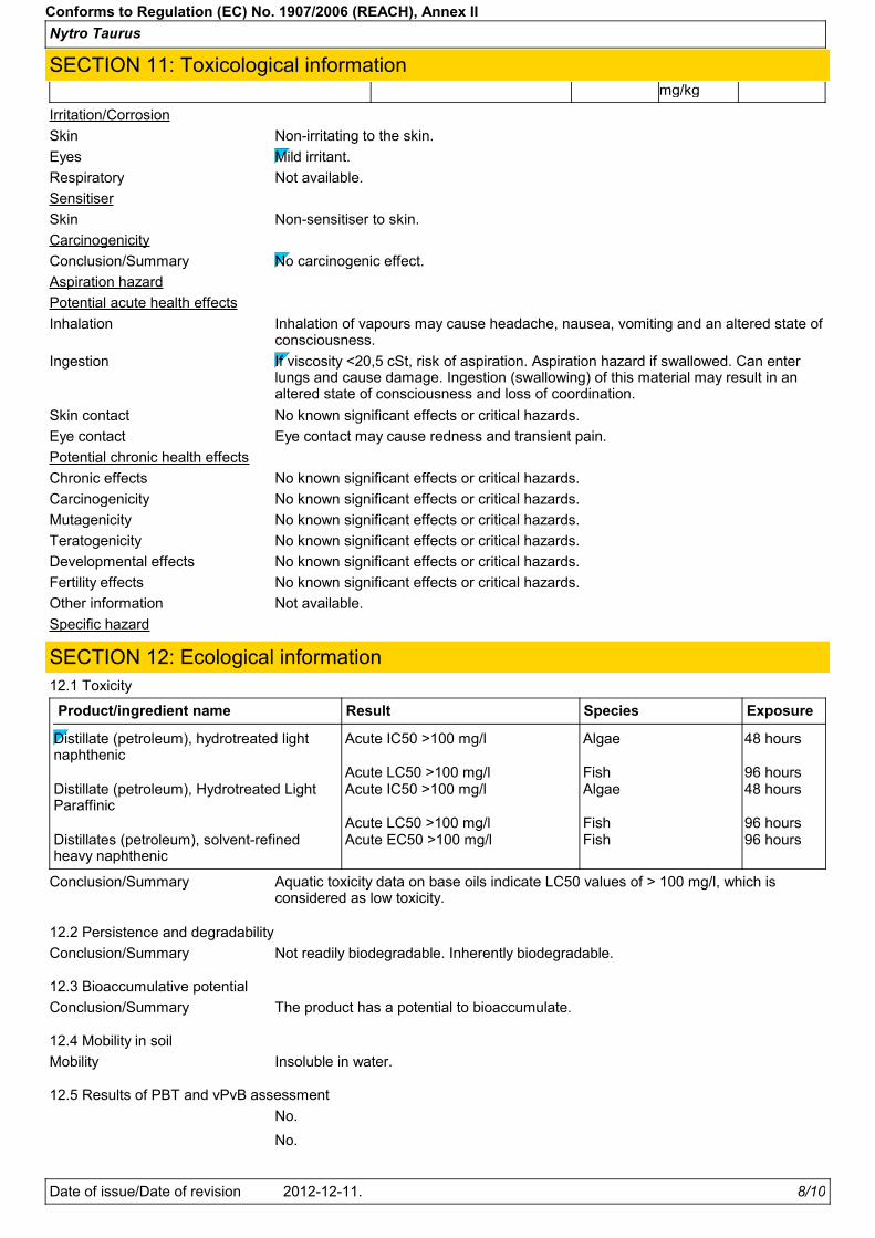
Nytro Taurus
Conforms to Regulation (EC) No. 1907/2006 (REACH), Annex II
SECTION 11: Toxicological information
Potential chronic health effects
Potential acute health effects
Inhalation Inhalation of vapours may cause headache, nausea, vomiting and an altered state ofconsciousness.
If viscosity <20,5 cSt, risk of aspiration. Aspiration hazard if swallowed. Can enterlungs and cause damage. Ingestion (swallowing) of this material may result in analtered state of consciousness and loss of coordination.
Ingestion
Skin contact No known significant effects or critical hazards.
Eye contact may cause redness and transient pain.Eye contact
No known significant effects or critical hazards.Chronic effects
No known significant effects or critical hazards.Carcinogenicity
No known significant effects or critical hazards.Mutagenicity
No known significant effects or critical hazards.Teratogenicity
Carcinogenicity
Conclusion/Summary No carcinogenic effect.
Developmental effects No known significant effects or critical hazards.
Fertility effects No known significant effects or critical hazards.
Irritation/Corrosion
Skin Non-irritating to the skin.
Eyes Mild irritant.
Respiratory Not available.
Sensitiser
Skin Non-sensitiser to skin.
Aspiration hazard
Other information Not available.
Specific hazard
mg/kg
Mobility Insoluble in water.
12.3 Bioaccumulative potential
12.1 Toxicity
Distillate (petroleum), hydrotreated lightnaphthenic
Acute IC50 >100 mg/l Algae 48 hours
Acute LC50 >100 mg/l Fish 96 hoursDistillate (petroleum), Hydrotreated LightParaffinic
Acute IC50 >100 mg/l Algae 48 hours
Acute LC50 >100 mg/l Fish 96 hoursDistillates (petroleum), solvent-refinedheavy naphthenic
Acute EC50 >100 mg/l Fish 96 hours
Product/ingredient name SpeciesResult Exposure
Conclusion/Summary Aquatic toxicity data on base oils indicate LC50 values of > 100 mg/l, which isconsidered as low toxicity.
12.2 Persistence and degradability
Conclusion/Summary Not readily biodegradable. Inherently biodegradable.
No.
No.
SECTION 12: Ecological information
12.4 Mobility in soil
12.5 Results of PBT and vPvB assessment
Conclusion/Summary The product has a potential to bioaccumulate.
Date of issue/Date of revision 8/102012-12-11.

Nytro Taurus
Conforms to Regulation (EC) No. 1907/2006 (REACH), Annex II
SECTION 12: Ecological information12.6 Other adverse effects Spills may form a film on water surfaces causing physical damage to organisms.
Oxygen transfer could also be impaired.
Within the present knowledge of the supplier, this product is not regarded ashazardous waste, as defined by EU Directive 91/689/EEC.
Hazardous waste
Where possible (e.g. in the absence of relevant contamination), recycling of usedsubstance is feasible and recommended. This substance can be burned orincinerated, subject to national/local authorizations, relevant contamination limits,safety regulations and air quality legislation. Contaminated or waste substance (notdirectly recyclable): Disposal can be carried out directly, or by delivery to qualifiedwaste handlers. National legislation may identify a specific organization, and/orprescribe composition limits and methods for recovery or disposal.
Methods of disposal
SECTION 13: Disposal considerationsThe information in this section contains generic advice and guidance. The list of Identified Uses in Section 1 should beconsulted for any available use-specific information provided in the Exposure Scenario(s).
13.1 Waste treatment methods
Product
Packaging
Methods of disposal
Special precautions
The generation of waste should be avoided or minimised wherever possible. Wastepackaging should be recycled. Incineration or landfill should only be consideredwhen recycling is not feasible.
SECTION 14: Transport informationInternational transport regulations
This product is not regulated for carriage according to ADR/RID, ADN, IMDG, ICAO/IATA.
Other EU regulations
Not applicable.Annex XVII - Restrictions onthe manufacture, placing onthe market and use of certaindangerous substances,mixtures and articles
Europe inventory All components are listed or exempted.
SECTION 15: Regulatory information15.1 Safety, health and environmental regulations/legislation specific for the substance or mixture
EU Regulation (EC) No. 1907/2006 (REACH)
Annex XIV - List of substances subject to authorisation
15.2 Chemical SafetyAssessment
This product contains substances for which Chemical Safety Assessments are stillrequired.
Substances of very high concern
None of the components are listed.
Revision comments Not available.
Indicates information that has changed from previously issued version.
SECTION 16: Other information
Abbreviations and acronyms ATE = Acute Toxicity EstimateCLP = Classification, Labelling and Packaging Regulation [Regulation (EC) No.1272/2008]DNEL = Derived No Effect LevelEUH statement = CLP-specific Hazard statementPNEC = Predicted No Effect ConcentrationRRN = REACH Registration Number
Classification according to Regulation (EC) No. 1272/2008 [CLP/GHS]Asp. Tox. 1, H304
Date of issue/Date of revision 9/102012-12-11.

Nytro Taurus
Conforms to Regulation (EC) No. 1907/2006 (REACH), Annex II
SECTION 16: Other information
2012-12-14.Date of printing
Date of issue/ Date of revision
Version
To the best of our knowledge, the information contained herein is accurate. However, neither the above-namedsupplier, nor any of its subsidiaries, assumes any liability whatsoever for the accuracy or completeness of theinformation contained herein.Final determination of suitability of any material is the sole responsibility of the user. All materials may present unknownhazards and should be used with caution. Although certain hazards are described herein, we cannot guarantee thatthese are the only hazards that exist.
Notice to reader
Date of previous issue
Not applicable.Full text of abbreviated Rphrases
Full text of classifications[DSD/DPD]
Not applicable.
2012-12-11.
2011-02-28.
3
Full text of abbreviated Hstatements
Procedure used to derive the classification according to Regulation (EC) No. 1272/2008 [CLP/GHS]
Classification Justification
Asp. Tox. 1, H304 Calculation method
Full text of classifications[CLP/GHS]
H304 May be fatal if swallowed and enters airways.
Asp. Tox. 1, H304 ASPIRATION HAZARD - Category 1
Date of issue/Date of revision 10/102012-12-11.

TECTROL CLP 220
Safety Data Sheet
Product code: 1058231Print date: 15.04.2014 Page 1 of 7
BayWa AG München
according to Regulation (EC) No 1907/2006
SECTION 1: Identification of the substance/mixture and of the company/undertaking
TECTROL CLP 220
1.1. Product identifier
1.2. Relevant identified uses of the substance or mixture and uses advised against
Use of the substance/mixture
mineral oil.
1.3. Details of the supplier of the safety data sheet
BayWa AG MünchenCompany name:
Arabellastr. 4Street:
D-81925 MünchenPlace:
Telephone: +49 (0) 89 288511-766 Telefax:+49 (0) 89 9212-3219
e-mail: [email protected]
Giftnotruf München (DE;EN) +49 (0) 89 192401.4. Emergency telephone
number:
SECTION 2: Hazards identification
2.1. Classification of the substance or mixture
This mixture is not classified as hazardous according to Directive 1999/45/EC.
According to EC directives or the corresponding national regulations the product does not have to be
labelled. Data arise from reference works and literature.
2.2. Label elements
Sicherheitsdatenblatt auf Anfrage für berufsmäßige Verwender erhältlich.
Special labelling of certain mixtures
Additional advice on labelling
The product is classified and labelled according to EC directives or corresponding national laws.
PBT
not applicable
vPvB
not applicable
2.3. Other hazards
SECTION 3: Composition/information on ingredients
3.2. Mixtures
mineral oil. AdditiveChemical characterization
Hazardous components
GHS classification
Quantity
ClassificationCAS No
REACH No
Index No
EC No Chemical name
0,1-1 %Petroleumdestillat
Xn - Harmful, N - Dangerous for the environment R51-53-65-66
Full text of R and H phrases: see Section 16.
Revision date: 20.02.2014 GB - EN

TECTROL CLP 220
Safety Data Sheet
Product code: 1058231Print date: 15.04.2014 Page 2 of 7
BayWa AG München
according to Regulation (EC) No 1907/2006
SECTION 4: First aid measures
4.1. Description of first aid measures
Take off immediately all contaminated clothing, including underwear and shoes .
Do not put any product-impregnated cleaning rags into your trouser pockets.
General information
Provide fresh air.
After inhalation
After contact with skin, wash immediately with plenty of water and soap. Change contaminated
clothing. After cleaning apply high-fat content skin care cream.
After contact with skin
In case of contact with eyes, rinse immediately with plenty of flowing water for 10 to 15 minutes holding
eyelids apart. Subsequently consult an ophthalmologist.
After contact with eyes
If accidentally swallowed rinse the mouth with plenty of water (only if the person is conscious) and
obtain immediate medical attention. Do NOT induce vomiting. Call a physician immediately.
After ingestion
4.2. Most important symptoms and effects, both acute and delayed
In all cases of doubt, or when symptoms persist, seek medical advice.
4.3. Indication of any immediate medical attention and special treatment needed
No information available.
SECTION 5: Firefighting measures
5.1. Extinguishing media
Carbon dioxide (CO2). Extinguishing powder. alcohol resistant foam. Water with tenside additive.
Co-ordinate fire-fighting measures to the fire surroundings.
Suitable extinguishing media
High power water jet.
Unsuitable extinguishing media
5.2. Special hazards arising from the substance or mixture
No information available.
Protective respiration apparatus not using surrounding air (breathing apparatus) (DIN EN
133).Contaminated fire-fighting water must be collected separately. Dispose of waste according to
applicable legislation.
5.3. Advice for firefighters
SECTION 6: Accidental release measures
Special danger of slipping by leaking/spilling product. Keep away from sources of ignition. - No
smoking. Avoid contact with skin and eyes. Ensure adequate ventilation of the storage area.
6.1. Personal precautions, protective equipment and emergency procedures
Do not allow to enter into surface water or drains. In case of gas escape or of entry into waterways, soil
or drains, inform the responsible authorities. Do not allow to enter into soil/subsoil.
6.2. Environmental precautions
Absorb with liquid-binding material (e.g. sand, diatomaceous earth, acid- or universal binding agents).
Treat the recovered material as prescribed in the section on waste disposal .
6.3. Methods and material for containment and cleaning up
This article doesn't contain dangerous substances or preparations intended to be released under
normal or reasonably foreseeable conditions of use.
6.4. Reference to other sections
Revision date: 20.02.2014 GB - EN
TECTROL CLP 220
Safety Data Sheet
Product code: 1058231Print date: 15.04.2014 Page 3 of 7
BayWa AG München
according to Regulation (EC) No 1907/2006
SECTION 7: Handling and storage
7.1. Precautions for safe handling
No special measures are necessary.
Advice on safe handling
Keep away from heat.
Advice on protection against fire and explosion
Avoid contact with skin and eyes. Generation/formation of mist Keep away from sources of ignition. -
No smoking. Wash hands before breaks and after work. Notice the directions for use on the label. Take
precautionary measures against static discharge.
Further information on handling
7.2. Conditions for safe storage, including any incompatibilities
Keep the packing dry and well sealed to prevent contamination and absorbtion of humidity. Store
packaging and ignitable materials separately.
Requirements for storage rooms and vessels
Keep away from food, drink and animal feeding stuffs.
Advice on storage compatibility
Protect against: UV-radiation/sunlight. frost.
Further information on storage conditions
7.3. Specific end use(s)
Observe technical data sheet.
SECTION 8: Exposure controls/personal protection
8.1. Control parameters
refer to chapter 7. No further action is necessary.
Additional advice on limit values
8.2. Exposure controls
After contact with skin, wash immediately with plenty of water and soap. When using do not eat, drink,
smoke, sniff. Prolonged/repetitive skin contact may cause skin defattening or dermatitis.
Do not put any product-impregnated cleaning rags into your trouser pockets.
Protective and hygiene measures
Tightly sealed safety glasses. DIN EN 166
Eye/face protection
Tested protective gloves are to be worn: DIN EN 374
Duration of wearing with permanent contact: 480 min
Suitable material: NBR (Nitrile rubber).
Thickness of glove material: 0,7 mm.
Unsuitable material: Leather articles
Wearing time with occasional contact (splashes): 30 min.
Suitable material: NBR (Nitrile rubber).
Thickness of glove material: 0,4 mm
Unsuitable material: Butyl rubber. NR (Natural rubber (Caoutchouc), Natural latex).
Protect skin by using skin protective cream.
Hand protection
Wear suitable protective clothing. Remove contaminated, saturated clothing immediately.
Skin protection
No special measures are necessary.
Respiratory protection
Revision date: 20.02.2014 GB - EN

TECTROL CLP 220
Safety Data Sheet
Product code: 1058231Print date: 15.04.2014 Page 4 of 7
BayWa AG München
according to Regulation (EC) No 1907/2006
Do not allow to enter into surface water or drains. See chapter 7. No additional measures necessary.
Environmental exposure controls
brown
liquidPhysical state:
Colour:
9.1. Information on basic physical and chemical properties
SECTION 9: Physical and chemical properties
characteristicOdour:
Test method
Changes in the physical state
not determinedPour point: DIN ISO 3016
DIN ISO 2592260 °CFlash point:
not explosive.
Explosive properties
Density (at 15 °C): 0,896 g/cm³ DIN 51757
Water solubility: not miscible
Viscosity / kinematic:
(at 40 °C)
DIN 51562220 mm²/s
9.2. Other information
No information available.
SECTION 10: Stability and reactivity
10.1. Reactivity
No information available.
10.2. Chemical stability
No information available.
10.3. Possibility of hazardous reactions
No known hazardous reactions.
No information available.
10.4. Conditions to avoid
No information available.
10.5. Incompatible materials
No known hazardous decomposition products.
10.6. Hazardous decomposition products
SECTION 11: Toxicological information
11.1. Information on toxicological effects
Toxicocinetics, metabolism and distribution
No data available
Irritation and corrosivity
Irritant effect on the skin: No known symptoms to date.
Irritant effect on the eye: No known symptoms to date.
Sensitising effects
not sensitising.
STOT-single exposure
No information available.
Revision date: 20.02.2014 GB - EN

TECTROL CLP 220
Safety Data Sheet
Product code: 1058231Print date: 15.04.2014 Page 5 of 7
BayWa AG München
according to Regulation (EC) No 1907/2006
Severe effects after repeated or prolonged exposure
No information available.
Aspiration hazard
No information available.
There is no requirement for the product to be specially labelled according to EC directives or the
corresponding national laws.
Additional information on tests
SECTION 12: Ecological information
12.1. Toxicity
No information available. The classification was carried out according to the calculation method of the
Preparations Directive (1999/45/EC).
12.2. Persistence and degradability
No information available.
12.3. Bioaccumulative potential
No information available.
No information available.
12.4. Mobility in soil
12.5. Results of PBT and vPvB assessment
PBT
not applicable
vPvB
not applicable
The preparation is not dangerous in the sense of Directive 1999/45/EC.
12.6. Other adverse effects
slightly hazardous to water (WGK 1) Do not allow to enter into surface water or drains.
Do not allow to enter into surface water or drains.
Further information
SECTION 13: Disposal considerations
13.1. Waste treatment methods
Advice on disposal
This material and its container must be disposed of in a safe way.
Collect in closed and suitable containers for disposal.
Observe mixture permissions according to "Altölverordnung (Waste oil directive)". Dispose of waste
according to "Kreislaufwirtschafts- und Abfallgesetz (KrW-/AbfG)".
Waste disposal number of waste from residues/unused products
130205 OIL WASTES AND WASTES OF LIQUID FUELS (except edible oils, and those in chapters 05, 12 and
19); waste engine, gear and lubricating oils; mineral-based non-chlorinated engine, gear and lubricating
oils
Classified as hazardous waste.
Waste disposal number of used product
OIL WASTES AND WASTES OF LIQUID FUELS (except edible oils, and those in chapters 05, 12 and
19); waste engine, gear and lubricating oils; mineral-based non-chlorinated engine, gear and lubricating
oils
Classified as hazardous waste.
130205
Waste disposal number of contaminated packaging
WASTE PACKAGING; ABSORBENTS, WIPING CLOTHS, FILTER MATERIALS AND PROTECTIVE
CLOTHING NOT OTHERWISE SPECIFIED; packaging (including separately collected municipal
packaging waste); plastic packaging
150102
Revision date: 20.02.2014 GB - EN

TECTROL CLP 220
Safety Data Sheet
Product code: 1058231Print date: 15.04.2014 Page 6 of 7
BayWa AG München
according to Regulation (EC) No 1907/2006
Non-contaminated packages may be recycled. Dispose of this material and its container to hazardous
or special waste collection point.
Contaminated packaging
SECTION 14: Transport information
Land transport (ADR/RID)
14.1. UN number: Not a hazardous material with respect to these transportation regulations.
Not a hazardous material with respect to these transportation regulations.
Other applicable information (land transport)
Inland waterways transport (ADN)
Not a hazardous material with respect to these transportation regulations.
Other applicable information (inland waterways transport)
Marine transport (IMDG)
Not a hazardous material with respect to these transportation regulations.
Other applicable information (marine transport)
Air transport (ICAO)
Not a hazardous material with respect to these transportation regulations.
Other applicable information (air transport)
14.5. Environmental hazards
noENVIRONMENTALLY HAZARDOUS:
14.6. Special precautions for user
Protect containers against damage. Keep container tightly closed and dry.
14.7. Transport in bulk according to Annex II of MARPOL73/78 and the IBC Code
not applicable
Not a hazardous material with respect to these transportation regulations.
Other applicable information
SECTION 15: Regulatory information
15.1. Safety, health and environmental regulations/legislation specific for the substance or mixture
EU regulatory information
Additional information
No marking required according to 1999/45/EC, appendix V B, No. 9.
National regulatory information
1 - slightly water contaminatingWater contaminating class (D):
15.2. Chemical safety assessment
For this substance a chemical safety assessment has not been carried out.
SECTION 16: Other information
Full text of R phrases referred to under Sections 2 and 3
51 Toxic to aquatic organisms.
53 May cause long-term adverse effects in the aquatic environment.
65 Harmful: may cause lung damage if swallowed.
66 Repeated exposure may cause skin dryness or cracking.
The above information describes exclusively the safety requirements of the product and is based on
our present-day knowledge. The information is intended to give you advice about the safe handling of
Further Information
Revision date: 20.02.2014 GB - EN

TECTROL CLP 220
Safety Data Sheet
Product code: 1058231Print date: 15.04.2014 Page 7 of 7
BayWa AG München
according to Regulation (EC) No 1907/2006
the product named in this safety data sheet, for storage, processing, transport and disposal. The
information cannot be transferred to other products. In the case of mixing the product with other
products or in the case of processing, the information on this safety data sheet is not necessarily valid
for the new made-up material.
(The data for the hazardous ingredients were taken respectively from the last version of the sub-contractor's safety
data sheet.)
Revision date: 20.02.2014 GB - EN

Product Name: UNIREX N 2
Revision Date: 09 Apr 2013 Page 1 of 9 ______________________________________________________________________________________________________________________
MATERIAL SAFETY DATA SHEET
SECTION 1 PRODUCT AND COMPANY IDENTIFICATION PRODUCT
Product Name: UNIREX N 2 Product Description: Base Oil and Additives Product Code: 2015A0207220, 644351-00, 97N713 Intended Use: Grease
COMPANY IDENTIFICATION
Supplier: EXXON MOBIL CORPORATION 3225 GALLOWS RD. FAIRFAX, VA. 22037 USA
24 Hour Health Emergency 609-737-4411 Transportation Emergency Phone 800-424-9300 ExxonMobil Transportation No. 281-834-3296 Product Technical Information 800-662-4525, 800-947-9147 MSDS Internet Address http://www.exxon.com, http://www.mobil.com
SECTION 2 COMPOSITION / INFORMATION ON INGREDIENTS No Reportable Hazardous Substance(s) or Complex Substance(s).
SECTION 3 HAZARDS IDENTIFICATION This material is not considered to be hazardous according to regulatory guidelines (see (M)SDS Section 15).
POTENTIAL HEALTH EFFECTS
Excessive exposure may result in eye, skin, or respiratory irritation. High-pressure injection under skin may cause serious damage.
NFPA Hazard ID: Health: 0 Flammability: 1 Reactivity: 0 HMIS Hazard ID: Health: 0 Flammability: 1 Reactivity: 0 NOTE: This material should not be used for any other purpose than the intended use in Section 1 without expert advice. Health studies have shown that chemical exposure may cause potential human health risks which may vary from person to person.
SECTION 4 FIRST AID MEASURES
INHALATION
Under normal conditions of intended use, this material is not expected to be an inhalation hazard.

Product Name: UNIREX N 2
Revision Date: 09 Apr 2013 Page 2 of 9 ______________________________________________________________________________________________________________________
SKIN CONTACT
Wash contact areas with soap and water. If product is injected into or under the skin, or into any part of the body, regardless of the appearance of the wound or its size, the individual should be evaluated immediately by a physician as a surgical emergency. Even though initial symptoms from high pressure injection may be minimal or absent, early surgical treatment within the first few hours may significantly reduce the ultimate extent of injury.
EYE CONTACT
Flush thoroughly with water. If irritation occurs, get medical assistance. INGESTION
First aid is normally not required. Seek medical attention if discomfort occurs.
SECTION 5 FIRE FIGHTING MEASURES
EXTINGUISHING MEDIA
Appropriate Extinguishing Media: Use water fog, foam, dry chemical or carbon dioxide (CO2) to extinguish flames. Inappropriate Extinguishing Media: Straight Streams of Water
FIRE FIGHTING
Fire Fighting Instructions: Evacuate area. Prevent runoff from fire control or dilution from entering streams, sewers, or drinking water supply. Firefighters should use standard protective equipment and in enclosed spaces, self-contained breathing apparatus (SCBA). Use water spray to cool fire exposed surfaces and to protect personnel. Hazardous Combustion Products: Smoke, Fume, Aldehydes, Sulfur oxides, Incomplete combustion products, Oxides of carbon
FLAMMABILITY PROPERTIES
Flash Point [Method]: >200°C (392°F) [EST. FOR OIL, ASTM D-92 (COC)] Flammable Limits (Approximate volume % in air): LEL: N/D UEL: N/D Autoignition Temperature: N/D
SECTION 6 ACCIDENTAL RELEASE MEASURES
NOTIFICATION PROCEDURES
In the event of a spill or accidental release, notify relevant authorities in accordance with all applicable regulations. US regulations require reporting releases of this material to the environment which exceed the applicable reportable quantity or oil spills which could reach any waterway including intermittent dry creeks. The National Response Center can be reached at (800)424-8802.
PROTECTIVE MEASURES
Avoid contact with spilled material. See Section 5 for fire fighting information. See the Hazard Identification Section for Significant Hazards. See Section 4 for First Aid Advice. See Section 8 for advice on the minimum

Product Name: UNIREX N 2
Revision Date: 09 Apr 2013 Page 3 of 9 ______________________________________________________________________________________________________________________
requirements for personal protective equipment. Additional protective measures may be necessary, depending on the specific circumstances and/or the expert judgment of the emergency responders. For emergency responders: Respiratory protection: respiratory protection will be necessary only in special cases, e.g., formation of mists. Half-face or full-face respirator with filter(s) for dust/organic vapor or Self Contained Breathing Apparatus (SCBA) can be used depending on the size of spill and potential level of exposure. If the exposure cannot be completely characterized or an oxygen deficient atmosphere is possible or anticipated, SCBA is recommended. Work gloves that are resistant to hydrocarbons are recommended. Gloves made of polyvinyl acetate (PVA) are not water-resistant and are not suitable for emergency use. Chemical goggles are recommended if splashes or contact with eyes is possible. Small spills: normal antistatic work clothes are usually adequate. Large spills: full body suit of chemical resistant, antistatic material is recommended.
SPILL MANAGEMENT Land Spill: Scrape up spilled material with shovels into a suitable container for recycle or disposal. Water Spill: Stop leak if you can do it without risk. Confine the spill immediately with booms. Warn other shipping. Skim from surface. Water spill and land spill recommendations are based on the most likely spill scenario for this material; however, geographic conditions, wind, temperature, (and in the case of a water spill) wave and current direction and speed may greatly influence the appropriate action to be taken. For this reason, local experts should be consulted. Note: Local regulations may prescribe or limit action to be taken.
ENVIRONMENTAL PRECAUTIONS
Prevent entry into waterways, sewers, basements or confined areas.
SECTION 7 HANDLING AND STORAGE
HANDLING
Prevent small spills and leakage to avoid slip hazard. Static Accumulator: This material is not a static accumulator.
STORAGE
Do not store in open or unlabelled containers. Keep away from incompatible materials.
SECTION 8 EXPOSURE CONTROLS / PERSONAL PROTECTION
NOTE: Limits/standards shown for guidance only. Follow applicable regulations. ENGINEERING CONTROLS
The level of protection and types of controls necessary will vary depending upon potential exposure conditions. Control measures to consider:

Product Name: UNIREX N 2
Revision Date: 09 Apr 2013 Page 4 of 9 ______________________________________________________________________________________________________________________
No special requirements under ordinary conditions of use and with adequate ventilation.
PERSONAL PROTECTION
Personal protective equipment selections vary based on potential exposure conditions such as applications, handling practices, concentration and ventilation. Information on the selection of protective equipment for use with this material, as provided below, is based upon intended, normal usage.
Respiratory Protection: If engineering controls do not maintain airborne contaminant concentrations at a level which is adequate to protect worker health, an approved respirator may be appropriate. Respirator selection, use, and maintenance must be in accordance with regulatory requirements, if applicable. Types of respirators to be considered for this material include:
No protection is ordinarily required under normal conditions of use and with adequate ventilation. For high airborne concentrations, use an approved supplied-air respirator, operated in positive pressure mode. Supplied air respirators with an escape bottle may be appropriate when oxygen levels are inadequate, gas/vapor warning properties are poor, or if air purifying filter capacity/rating may be exceeded. Hand Protection: Any specific glove information provided is based on published literature and glove manufacturer data. Glove suitability and breakthrough time will differ depending on the specific use conditions. Contact the glove manufacturer for specific advice on glove selection and breakthrough times for your use conditions. Inspect and replace worn or damaged gloves. The types of gloves to be considered for this material include:
No protection is ordinarily required under normal conditions of use. Eye Protection: If contact is likely, safety glasses with side shields are recommended. Skin and Body Protection: Any specific clothing information provided is based on published literature or manufacturer data. The types of clothing to be considered for this material include:
No skin protection is ordinarily required under normal conditions of use. In accordance with good industrial hygiene practices, precautions should be taken to avoid skin contact.
Specific Hygiene Measures: Always observe good personal hygiene measures, such as washing after handling the material and before eating, drinking, and/or smoking. Routinely wash work clothing and protective equipment to remove contaminants. Discard contaminated clothing and footwear that cannot be cleaned. Practice good housekeeping.
ENVIRONMENTAL CONTROLS
Comply with applicable environmental regulations limiting discharge to air, water and soil. Protect the environment by applying appropriate control measures to prevent or limit emissions.
SECTION 9 PHYSICAL AND CHEMICAL PROPERTIES
Note: Physical and chemical properties are provided for safety, health and environmental considerations only and may not fully represent product specifications. Contact the Supplier for additional information. GENERAL INFORMATION
Physical State: Solid Form: Semi-fluid
Color: Green

Product Name: UNIREX N 2
Revision Date: 09 Apr 2013 Page 5 of 9 ______________________________________________________________________________________________________________________
Odor: Characteristic
Odor Threshold: N/D
IMPORTANT HEALTH, SAFETY, AND ENVIRONMENTAL INFORMATION
Relative Density (at 15 °C): 0.93 Flash Point [Method]: >200°C (392°F) [EST. FOR OIL, ASTM D-92 (COC)] Flammable Limits (Approximate volume % in air): LEL: N/D UEL: N/D
Autoignition Temperature: N/D
Boiling Point / Range: N/D
Vapor Density (Air = 1): N/D
Vapor Pressure: < 0.013 kPa (0.1 mm Hg) at 20 °C [Estimated] Evaporation Rate (n-butyl acetate = 1): N/D
pH: N/A
Log Pow (n-Octanol/Water Partition Coefficient): N/D Solubility in Water: Negligible
Viscosity: 113 cSt (113 mm2/sec) at 40 °C [Base oil] Oxidizing Properties: See Hazards Identification Section.
OTHER INFORMATION
Freezing Point: N/D Melting Point: >219°C (426°F) DMSO Extract (mineral oil only), IP-346: < 3 %wt Decomposition Temperature: N/D NOTE: Most physical properties above are for the oil component in the material.
SECTION 10 STABILITY AND REACTIVITY
STABILITY: Material is stable under normal conditions. CONDITIONS TO AVOID: Excessive heat. High energy sources of ignition. MATERIALS TO AVOID: Strong oxidizers
HAZARDOUS DECOMPOSITION PRODUCTS: Material does not decompose at ambient temperatures. HAZARDOUS POLYMERIZATION: Will not occur.
SECTION 11 TOXICOLOGICAL INFORMATION
ACUTE TOXICITY
Route of Exposure Conclusion / Remarks
Inhalation
Toxicity: No end point data for material. Minimally Toxic. Based on assessment of the components.
Irritation: No end point data for material. Negligible hazard at ambient/normal handling temperatures. Based on assessment of the components.
Ingestion
Toxicity: No end point data for material. Minimally Toxic. Based on assessment of the components.

Product Name: UNIREX N 2
Revision Date: 09 Apr 2013 Page 6 of 9 ______________________________________________________________________________________________________________________
Skin
Toxicity: No end point data for material. Minimally Toxic. Based on assessment of the components.
Irritation: No end point data for material. Negligible irritation to skin at ambient temperatures. Based on assessment of the components.
Eye
Irritation: No end point data for material. May cause mild, short-lasting discomfort to eyes. Based on assessment of the components.
CHRONIC/OTHER EFFECTS For the product itself:
Component concentrations in this formulation would not be expected to cause skin sensitization, based on tests of the components or similar formulations. Contains: Base oil severely refined: Not carcinogenic in animal studies. Representative material passes IP-346, Modified Ames test, and/or other screening tests. Dermal and inhalation studies showed minimal effects; lung non-specific infiltration of immune cells, oil deposition and minimal granuloma formation. Not sensitizing in test animals.
The following ingredients are cited on the lists below: None.
--REGULATORY LISTS SEARCHED--
1 = NTP CARC 3 = IARC 1 5 = IARC 2B
2 = NTP SUS 4 = IARC 2A 6 = OSHA CARC
SECTION 12 ECOLOGICAL INFORMATION
The information given is based on data available for the material, the components of the material, and similar materials. ECOTOXICITY Material -- Not expected to be harmful to aquatic organisms. MOBILITY Base oil component -- Low solubility and floats and is expected to migrate from water to the land.
Expected to partition to sediment and wastewater solids.
PERSISTENCE AND DEGRADABILITY
Biodegradation: Base oil component -- Expected to be inherently biodegradable
BIOACCUMULATION POTENTIAL Base oil component -- Has the potential to bioaccumulate, however metabolism or physical properties may
reduce the bioconcentration or limit bioavailability.

Product Name: UNIREX N 2
Revision Date: 09 Apr 2013 Page 7 of 9 ______________________________________________________________________________________________________________________
SECTION 13 DISPOSAL CONSIDERATIONS
Disposal recommendations based on material as supplied. Disposal must be in accordance with current applicable laws and regulations, and material characteristics at time of disposal.
DISPOSAL RECOMMENDATIONS
Product is suitable for burning in an enclosed controlled burner for fuel value or disposal by supervised incineration at very high temperatures to prevent formation of undesirable combustion products.
REGULATORY DISPOSAL INFORMATION
RCRA Information: Disposal of unused product may be subject to RCRA regulations (40 CFR 261). Disposal of the used product may also be regulated due to ignitability, corrosivity, reactivity or toxicity as determined by the Toxicity Characteristic Leaching Procedure (TCLP). Potential RCRA characteristics: TCLP (BARIUM)
Empty Container Warning Empty Container Warning (where applicable): Empty containers may contain residue and can be dangerous. Do not attempt to refill or clean containers without proper instructions. Empty drums should be completely drained and safely stored until appropriately reconditioned or disposed. Empty containers should be taken for recycling, recovery, or disposal through suitably qualified or licensed contractor and in accordance with governmental regulations. DO NOT PRESSURISE, CUT, WELD, BRAZE, SOLDER, DRILL, GRIND, OR EXPOSE SUCH CONTAINERS TO HEAT, FLAME, SPARKS, STATIC ELECTRICITY, OR OTHER SOURCES OF IGNITION. THEY MAY EXPLODE AND CAUSE INJURY OR DEATH.
SECTION 14 TRANSPORT INFORMATION
LAND (DOT): Not Regulated for Land Transport
LAND (TDG): Not Regulated for Land Transport
SEA (IMDG): Not Regulated for Sea Transport according to IMDG-Code
AIR (IATA): Not Regulated for Air Transport
SECTION 15 REGULATORY INFORMATION
OSHA HAZARD COMMUNICATION STANDARD: When used for its intended purposes, this material is not classified as hazardous in accordance with OSHA 29 CFR 1910.1200. Complies with the following national/regional chemical inventory requirements: DSL, IECSC, TSCA Special Cases:
Inventory Status
KECI Restrictions Apply

Product Name: UNIREX N 2
Revision Date: 09 Apr 2013 Page 8 of 9 ______________________________________________________________________________________________________________________
EPCRA SECTION 302: This material contains no extremely hazardous substances. SARA (311/312) REPORTABLE HAZARD CATEGORIES: None. SARA (313) TOXIC RELEASE INVENTORY: This material contains no chemicals subject to the supplier notification requirements of the SARA 313 Toxic Release Program. The following ingredients are cited on the lists below: None.
--REGULATORY LISTS SEARCHED-- 1 = ACGIH ALL 6 = TSCA 5a2 11 = CA P65 REPRO 16 = MN RTK 2 = ACGIH A1 7 = TSCA 5e 12 = CA RTK 17 = NJ RTK 3 = ACGIH A2 8 = TSCA 6 13 = IL RTK 18 = PA RTK 4 = OSHA Z 9 = TSCA 12b 14 = LA RTK 19 = RI RTK 5 = TSCA 4 10 = CA P65 CARC 15 = MI 293 Code key: CARC=Carcinogen; REPRO=Reproductive
SECTION 16 OTHER INFORMATION
N/D = Not determined, N/A = Not applicable THIS SAFETY DATA SHEET CONTAINS THE FOLLOWING REVISIONS: Revision Changes: Section 04: First Aid Inhalation - Header was modified. Section 09: Vapor Pressure was added. Section 06: Protective Measures was added. Section 06: Accidental Release - Protective Measures - Header was added. Section 09: Phys/Chem Properties Note was modified. Section 09: Physical State was modified. Section 09: Color was modified. Section 09: Evaporation Rate - Header was modified. Section 08: Comply with applicable regulations phrase was modified. Section 09: Vapor Pressure was modified. Section 07: Handling and Storage - Storage Phrases was modified. Hazard Identification: Health Hazards was modified. Section 11: Dermal Lethality Test Data was modified. Section 11: Dermal Lethality Test Comment was modified. Section 11: Oral Lethality Test Data was modified. Section 11: Inhalation Lethality Test Data was modified. Section 11: Dermal Irritation Test Data was modified. Section 11: Eye Irritation Test Data was modified. Section 11: Oral Lethality Test Comment was modified. Section 11: Inhalation Irritation Test Data was modified. Section 05: Hazardous Combustion Products was modified. Section 06: Accidental Release - Spill Management - Water was modified.

Product Name: UNIREX N 2
Revision Date: 09 Apr 2013 Page 9 of 9 ______________________________________________________________________________________________________________________
Section 09: Relative Density - Header was modified. Section 09: Flash Point C(F) was modified. Section 09: Viscosity was modified. Section 14: Sea (IMDG) - Header was modified. Section 14: Air (IATA) - Header was modified. Section 14: LAND (TDG) - Header was modified. Section 14: LAND (DOT) - Header was modified. Section 15: Chemical Name - Header was deleted. Section 15: CAS Number - Header was deleted. Section 15: List Citations - Header was deleted. Section 15: List Citations Table was deleted. Section 15: List Citation Table - Header was modified. Section 14: LAND (DOT) - Default was modified. Section 14: LAND (TDG) Default was modified. Section 14: Sea (IMDG) - Default was modified. Section 14: Air (IATA) - Default was modified. Section 15: National Chemical Inventory Listing - Header was modified. Section 15: National Chemical Inventory Listing was modified. Section 15: Community RTK - Header was modified. Section 11: Additional Health Information was modified. Section 09: Melting Point C(F) was modified. Section 15: Special Cases Table was modified. Section 09: Decomposition Temperature was added. Section 09: Decomposition Temp - Header was added. Section 09: Oxidizing Properties was modified. Section 01: Company Contact Methods Sorted by Priority was modified. Section 04: First Aid Ingestion - Header was modified. ----------------------------------------------------------------------------------------------------------------------------- ------------------------ ------------------------------------------------------------------------------------------------------------------------------- ---------------------- The information and recommendations contained herein are, to the best of ExxonMobil's knowledge and belief, accurate and reliable as of the date issued. You can contact ExxonMobil to insure that this document is the most current available from ExxonMobil. The information and recommendations are offered for the user's consideration and examination. It is the user's responsibility to satisfy itself that the product is suitable for the intended use. If buyer repackages this product, it is the user's responsibility to insure proper health, safety and other necessary information is included with and/or on the container. Appropriate warnings and safe-handling procedures should be provided to handlers and users. Alteration of this document is strictly prohibited. Except to the extent required by law, re-publication or retransmission of this document, in whole or in part, is not permitted. The term, "ExxonMobil" is used for convenience, and may include any one or more of ExxonMobil Chemical Company, Exxon Mobil Corporation, or any affiliates in which they directly or indirectly hold any interest. ---------------------------------------------------------------------------------------------------------------------------------------------- ------- Internal Use Only
MHC: 0B, 0B, 0, 0, 0, 0 PPEC: A
DGN: 2031341XUS (553418) ----------------------------------------------------------------------------------------------------------------------------- ------------------------ Copyright 2002 Exxon Mobil Corporation, All rights reserved

GAMESA G114


ENGINEERING COORDINATION MEMORANDUM (ECM)
CODE (CÓDIGO): F08-01-ECM269 DATE (FECHA): 10/10/2010
FROM (DE): UMN TO (A): IBD PROGRAMA: F08-01
FAX: --- FAX: --- FOCAL POINT: UMEZQUIRIZ
PHONE (TEL): --- PHONE (TEL): --- CC: ---
SUBJECT (ASUNTO):
Design information for the G114 CII T93 foundation
Page 1 of 3 PTD-TEC-002-R06 Edition 1
1. SCOPE
The scope of the document is to provide design information of the T93 foundation for G114 CII valid for quotation and commercial purposes.
2. BARS CAGE
Consists on 128 (64 x 2) M39 bars (2500mm length)
The upper template is as follows:

ENGINEERING COORDINATION MEMORANDUM (ECM)
CODE (CÓDIGO): F08-01-ECM269 DATE (FECHA): 10/10/2010
FROM (DE): UMN TO (A): IBD PROGRAMA: F08-01
FAX: --- FAX: --- FOCAL POINT: UMEZQUIRIZ
PHONE (TEL): --- PHONE (TEL): --- CC: ---
SUBJECT (ASUNTO):
Design information for the G114 CII T93 foundation
Page 2 of 3 PTD-TEC-002-R06 Edition 1
∅ext = 4530mm
∅int =3930mm
Thickness = 30mm Weight = 891kg Material: S235JR (EN10025-3)
The lower template is as follows:
∅ext = 4590mm
∅int =3870mm
Thickness = 50mm Weight = 1.798kg
Material: S355J2+N (EN10025-3)
∅4530
∅3930
∅4590
∅3870

ENGINEERING COORDINATION MEMORANDUM (ECM)
CODE (CÓDIGO): F08-01-ECM269 DATE (FECHA): 10/10/2010
FROM (DE): UMN TO (A): IBD PROGRAMA: F08-01
FAX: --- FAX: --- FOCAL POINT: UMEZQUIRIZ
PHONE (TEL): --- PHONE (TEL): --- CC: ---
SUBJECT (ASUNTO):
Design information for the G114 CII T93 foundation
Page 3 of 3 PTD-TEC-002-R06 Edition 1
3. VARIABLE EDGE INVERTED FOUNDATION
The general foundation dimensions are as follows:
• ∅slab = 18.5m
• ∅ped = 5.5m
• Hout = 0.5m
• Hin = 2.2m • Hped = 0.5m • Concrete: 357m3
• Steel reinforcement: 42Tn
The values included here have to be considered as a reference for a standard wind farm. The final
design will be adapted to the particular geotechnical properties.
SEC. UNITS DESCRIPTION
· Un. Clearing: Topsoil removal included, and storage in selected area for that purpose close to wind farm, for later use in
revegetation or transport to landfill.
· Un. Excavation: Extracted material transport for use as refill or in case of excess, shipping to landfill.
· Un. Embankment: Transport includes the necessary material from excavation or loan.
· Un. Refilled with compaction: Mechanically tamped in layers of 30cm maximum thickness until a density of 95% PM.
Included the wetting, even before compacting.
1.1 FOUNDATION Φ21 m
1.1.1 Earthworks
1.1.1.1 683.49 m2 Terrain clearance and cleanning for foundation esplanade. Execution according to PG-3
1.1.1.2 1,661.71 m3 Rock terrain excavation by means of breaking hammer 100%
1.1.1.3 1.108.79 m3 Partial filling with excavation product. Extended and compacted until 1.8T/m3 density by means of mechanical devices
and 30cm max. layer with wetting.
1.1.2 Foundation
1.1.2.1 43.37 m3 Cleanning concrete: 20N/mm2 resistance (max. arid: 30mm)
1.1.2.2 509.54 m3 HA-30/F/20/IIA+H concrete (max. arid 20mm). Mixed in concrete factory and filled by pump. Application and vibration
according EHE
1.1.2.3 - HA-50/F/20/IIA+Hconcrete (max. arid 20mm). Mixed in concrete factory and filled by pump. Application and vibration
according EHE
1.1.2.4 48.07 m2 Metallic one side curved formwork. Totally assembled
1.1.2.5 - m2 Metallic one side plane formwork. Totally assembled
1.1.2.6 56,710.00 Kg 500MPa passive reinforcement; cut, bent, and assembled. Spacers included. Additional quantity of 7% due to clippings
1.1.2.5 1.00 Un Extraordinay devices for concrete pumping and curing in extreme temperature conditions.
1.1.3 Various
1.1.3.1 1.00 Un Manufacturing and delivery of levelling system
1.1.3.2 1.00 Un Manufacturing and delivery of post-tensioned bars
1.1.3.3 1.00 Un Manufacturing and delivery of anchoring flanges
1.1.3.4 0.63 Un Masterflow 9300 or similar high resistance and low retraction grout (application included).
1.1.3.5 1.00 Un Electrical canalizations: PVC ducts (d=200mm and d=90mm for power cables and optic fiber) protected by 10cm of HM-
15 concrete. Assembled and sealed with 50kg/cm3 polyurethane foam.
1.1.3.6 1.00 Un WTG external earthing connection (cooper cable not included)
1.1.3.7 1.00 Un
NOTES: (some units scope):

Confidentiality: 3 / CLIENT INFORMATION
Code: GD176868-en Rev: 0
Date: 17/01/13 Page 1 of 5
GENERAL CHARACTERISTICS MANUAL
Type of Documentation: Title: Approval process:
Electronic: PDM Flow + Translation
Product Author: YURROZ
Deliverable: Revised: JEJGUERRERO
S12
G114 2.5MW IIA DESIGN LOADS AND
INTERFACE DEFINITION Approved: IRS
The present document, its content, its appendices and/or amendments (the "Document") have been created by Gamesa Corporación Tecnológica, S.A. ("Gamesa") for information purposes only. They contain private information referring to Gamesa and/or its subsidiaries (the "Company"), and are addressed exclusively to its recipients. Consequently, it may not be disclosed, published or distributed, in whole or in part, without prior written consent from Gamesa, and must include specific reference to Gamesa’s intellectual property rights in all cases. The entire contents of this Document, including any texts, images, brand names, logos, color combinations or any other element, its structure and design, the selection of the materials herein and the manner in which they are presented are protected by both industrial and intellectual property rights belonging to Gamesa, and must be respected by both the recipient and addressee of the present Document. In particular, but without any limitation to the general obligation to maintain its confidentiality, any reproduction is strictly prohibited, except for private use. Any transformation, distribution, public communication, dissemination to any third party, and in a general sense, any other form of exploitation by any means, of all or any part of the contents of this Document, its design or the selection of the materials included in it and the manner in which they are presented is also strictly forbidden.
ICA-TEC-001-R06 (en) Edition 1
TABLE OF CONTENTS
1. PURPOSE ..................................................................................................................................... 2
2. SCOPE ......................................................................................................................................... 2
3. G114-2.5MW T93M IEC IIA FOUNDATION LOADS............................................................................. 2 3.1. DESIGN LOADS.................................................................................................................... 2 3.2. COORDINATE SYSTEM.......................................................................................................... 2 3.3. EXTREME LOADS ................................................................................................................. 3 3.4. FATIGUE LOADS .................................................................................................................. 3 3.5. LOADS FOR GAP VERIFICATION ............................................................................................ 3 3.6. ROTATIONAL STIFFNESS ...................................................................................................... 4 3.7. INTERFACES........................................................................................................................ 4
RECORD OF CHANGES
Rev. Date Author Description
0 17/01/13 YURROZ Initial version

Confidentiality: 3 / CLIENT INFORMATION
Code: GD176868-en Rev: 0
GENERAL CHARACTERISTICS MANUAL Date: 17/01/13 Page 2 of 5
Title: G114 2.5MW IIA DESIGN LOADS AND INTERFACE DEFINITION
ICA-TEC-001-R06 (en) Edition 1
1. PURPOSE
This document presents the foundation loads as well as the minimum rotational stiffness required for the design of the Gamesa G114 2.5MW foundations. Additionally, the interface with the wind turbine is also defined.
2. SCOPE
Applicable to foundations for all the G114 wind turbines included in the table below:
Hub height IEC IIA
93 m X
Table 1: Scope of applicability
Prior to the design of the foundation, the foundation engineer shall check that he is in possession of the latest version of this document and all the documents referred to herein.
3. G114-2.5MW T93M IEC IIA FOUNDATION LOADS
3.1. DESIGN LOADS
The foundation loads needed for the design of the G114-2.5MW T93m IIA foundations are shown below. The loads shown below are valid as long as the site has been classified according to standard IEC-61400-1 and there are no seismic or typhoon requirements. 3.2. COORDINATE SYSTEM
The coordinate system used for the extreme loads, fatigue loads, and the gap loads is shown in the Figure 1.
Figure 1: coordinate system

Confidentiality: 3 / CLIENT INFORMATION
Code: GD176868-en Rev: 0
GENERAL CHARACTERISTICS MANUAL Date: 17/01/13 Page 3 of 5
Title: G114 2.5MW IIA DESIGN LOADS AND INTERFACE DEFINITION
ICA-TEC-001-R06 (en) Edition 1
3.3. EXTREME LOADS
Unfactored extreme loads for the design of the G114-2.5MW T93m IIA foundations are shown in Table 2. The foundation designer shall apply the safety factors according to the Codes and Regulations applicable to the design of the foundation.
Fx Fy Fz Mx My Mz Mxy Load Case
Safety factor kN kN kN kNm kNm kNm kNm
dlc22kp_5 1 -1118.52 -38.1643 -3723.83 3515.136 -106784 -819.689 106670.4
Table 2: G114-2.5MW T93m IIA extreme loads at the base of the tower. Unfactored loads.
The minimum safety factor to be applied in all cases will be as defined in the IEC 61400-1 standard for each load case. Table 3 provides factored extreme loads for G114-2.5MW T93m IIA foundations.
Fx Fy Fz Mx My Mz Mxy Load Case
Safety
factor kN kN kN kNm kNm kNm kNm
dlc22kp_5 1.1 -1230.37 -41.9808 -4096.22 3866.649 -117463 -901.658 117337.4 Table 3: G114-2.5MW T93m IIA extreme loads at the base of the tower. Factored loads.
The loads provided by Gamesa as “Extreme Loads” in this section are the maximum static loads for the specific wind turbine calculated according to IEC 61400 or DIBt standard for each site class. These loads must not be combined with any other type of load. They include the dynamic behavior of the structure and correspond to the most unfavorable case at the base of the wind turbine among the different load cases, according to IEC 61400 or DIBt. Therefore, the loads provided by Gamesa as “Extreme Loads” are directly the foundation design loads. They shall not be divided or combined with any other load 3.4. FATIGUE LOADS
The equivalent fatigue loads for the design of the G114-2.5MW T93m IIA foundations are provided in Table 4. They have been calculated for 107 cycles:
m FX [kN] FY [kN] FZ [kN] MX [kNm] MY [kNm] MZ [kNm]
Tower Bottom 4 378.4525 185.3096 150.914 10685.44 25464.91 4434.141
Tower Bottom 7 425.3256 220.2182 201.8251 13325.63 37320.9 4488.102
Table 4: G114-2.5MW T93m IIA equivalent fatigue loads at the base of the tower.
In the above table, the “m” values correspond to the Wöhler gradient, which has a value of 4 for steel and 7 for reinforced concrete. Table 5 shows the mean fatigue loads for the design of the G114-2.5MW T93m IIA foundations:
Fx( KN) Fy (kN) Fz (kN) Mx (kNm) My (kNm) Mz (kNm)
228.3552 -6.7115 -4216 2125.066 18978.94 114.6571
Table 5: G114-2.5MW T93m IIA mean fatigue loads at the base of the tower
3.5. LOADS FOR GAP VERIFICATION
IMPORTANT NOTE: Checking the foundations under operational loads to test whether there is a gap between the footing and the ground is necessary for countries where such verification is required. The designer is responsible for taking into account the local considerations of the country where the foundation is to be installed.

Confidentiality: 3 / CLIENT INFORMATION
Code: GD176868-en Rev: 0
GENERAL CHARACTERISTICS MANUAL Date: 17/01/13 Page 4 of 5
Title: G114 2.5MW IIA DESIGN LOADS AND INTERFACE DEFINITION
ICA-TEC-001-R06 (en) Edition 1
The following tables show the gap loads for the G114-2.5MW T93m IIA wind turbine:
Fx Fy Fz Mx My Mz Mxy Load Case Load
kN kN kN kNm kNm kNm kNm
dlc10a 1 374.8788 -13.95 -4234.84 2776.939 33279.88 508.3978 33346.26
Table 6: G114-2.5MW T93m IIA gap loads at he base of the tower according to DIN1054, case 1
Fx Fy Fz Mx My Mz Mxy
Load Case Load kN kN kN kNm kNm kNm kNm
dlc81ab5 1 -58.1688 -183.014 -4173.52 16234.01 -9444.9 478.3138 16567.56
Table 7: G114-2.5MW T93m IIA gap loads at he base of the tower according to DIN1054, case 2
Fx Fy Fz Mx My Mz Mxy
Load Case Load kN kN kN kNm kNm kNm kNm
dlc22kp_5 1 -1118.52 -38.1643 -3723.83 3515.136 -106784 -819.689 106670.4
Table 8: G114-2.5MW T93m IIA gap loads at he base of the tower according to DIN1054, case 3.
3.6. ROTATIONAL STIFFNESS
The foundation shall meet the rotational stiffness requirements specified by Gamesa for each wind turbine, so that the turbine operates correctly at the natural frequency of the entire unit. If this condition is not met, the loads provided by Gamesa for the design of the foundation will no longer be valid. In the case of pile foundations, Gamesa will supply the minimum foundation horizontal stiffness value to be guaranteed in the design. The value for G114-2.5MW T93m IIA is shown in Table 9:
Tower height 93m IIA
Rotational stiffness of the foundation 5.945E+10 Nm/rad
Table 9: G114-2.5MW T93m IIA minimum rotational stiffness
3.7. INTERFACES
The post-tensioned bolts system shall be fully defined in the diagrams and the following documents must be provided: a) Assembly specifications, including the leveling process and its control. b) The system shall be compatible with the tower bottom flange c) Material specifications, including catalogues of the commercial parts where required. The maximum acceptable difference in level for the G9x turbines welded section is 6 mm. If the difference in level is greater, proceed as indicated in section 7.1 of the document EQ209006. The entrance door to the tower shall be placed facing against prevailing winds in order to prevent the direction of the wind from slamming the door shut, with the subsequent possibility of injuries to operators. The welding axis of the first tower section shell ring is 90º (clockwise) with regard to the entrance door.

Confidentiality: 3 / CLIENT INFORMATION
Code: GD176868-en Rev: 0
GENERAL CHARACTERISTICS MANUAL Date: 17/01/13 Page 5 of 5
Title: G114 2.5MW IIA DESIGN LOADS AND INTERFACE DEFINITION
ICA-TEC-001-R06 (en) Edition 1
Figure 2: position of the welded foundation section

GENERAL ELECTRIC 3.2-103


ENGINEERING COORDINATION MEMORANDUM (ECM)
CODE (CÓDIGO): F08-01-ECM269 DATE (FECHA): 10/10/2010
FROM (DE): UMN TO (A): IBD PROGRAMA: F08-01
FAX: --- FAX: --- FOCAL POINT: UMEZQUIRIZ
PHONE (TEL): --- PHONE (TEL): --- CC: ---
SUBJECT (ASUNTO):
Design information for the G114 CII T93 foundation
Page 1 of 3 PTD-TEC-002-R06 Edition 1
1. SCOPE
The scope of the document is to provide design information of the T93 foundation for G114 CII valid for quotation and commercial purposes.
2. BARS CAGE
Consists on 128 (64 x 2) M39 bars (2500mm length)
The upper template is as follows:

ENGINEERING COORDINATION MEMORANDUM (ECM)
CODE (CÓDIGO): F08-01-ECM269 DATE (FECHA): 10/10/2010
FROM (DE): UMN TO (A): IBD PROGRAMA: F08-01
FAX: --- FAX: --- FOCAL POINT: UMEZQUIRIZ
PHONE (TEL): --- PHONE (TEL): --- CC: ---
SUBJECT (ASUNTO):
Design information for the G114 CII T93 foundation
Page 2 of 3 PTD-TEC-002-R06 Edition 1
∅ext = 4530mm
∅int =3930mm
Thickness = 30mm Weight = 891kg Material: S235JR (EN10025-3)
The lower template is as follows:
∅ext = 4590mm
∅int =3870mm
Thickness = 50mm Weight = 1.798kg
Material: S355J2+N (EN10025-3)
∅4530
∅3930
∅4590
∅3870

ENGINEERING COORDINATION MEMORANDUM (ECM)
CODE (CÓDIGO): F08-01-ECM269 DATE (FECHA): 10/10/2010
FROM (DE): UMN TO (A): IBD PROGRAMA: F08-01
FAX: --- FAX: --- FOCAL POINT: UMEZQUIRIZ
PHONE (TEL): --- PHONE (TEL): --- CC: ---
SUBJECT (ASUNTO):
Design information for the G114 CII T93 foundation
Page 3 of 3 PTD-TEC-002-R06 Edition 1
3. VARIABLE EDGE INVERTED FOUNDATION
The general foundation dimensions are as follows:
• ∅slab = 18.5m
• ∅ped = 5.5m
• Hout = 0.5m
• Hin = 2.2m • Hped = 0.5m • Concrete: 357m3
• Steel reinforcement: 42Tn
The values included here have to be considered as a reference for a standard wind farm. The final
design will be adapted to the particular geotechnical properties.
SEC. UNITS DESCRIPTION
· Un. Clearing: Topsoil removal included, and storage in selected area for that purpose close to wind farm, for later use in
revegetation or transport to landfill.
· Un. Excavation: Extracted material transport for use as refill or in case of excess, shipping to landfill.
· Un. Embankment: Transport includes the necessary material from excavation or loan.
· Un. Refilled with compaction: Mechanically tamped in layers of 30cm maximum thickness until a density of 95% PM.
Included the wetting, even before compacting.
1.1 FOUNDATION Φ21 m
1.1.1 Earthworks
1.1.1.1 683.49 m2 Terrain clearance and cleanning for foundation esplanade. Execution according to PG-3
1.1.1.2 1,661.71 m3 Rock terrain excavation by means of breaking hammer 100%
1.1.1.3 1.108.79 m3 Partial filling with excavation product. Extended and compacted until 1.8T/m3 density by means of mechanical devices
and 30cm max. layer with wetting.
1.1.2 Foundation
1.1.2.1 43.37 m3 Cleanning concrete: 20N/mm2 resistance (max. arid: 30mm)
1.1.2.2 509.54 m3 HA-30/F/20/IIA+H concrete (max. arid 20mm). Mixed in concrete factory and filled by pump. Application and vibration
according EHE
1.1.2.3 - HA-50/F/20/IIA+Hconcrete (max. arid 20mm). Mixed in concrete factory and filled by pump. Application and vibration
according EHE
1.1.2.4 48.07 m2 Metallic one side curved formwork. Totally assembled
1.1.2.5 - m2 Metallic one side plane formwork. Totally assembled
1.1.2.6 56,710.00 Kg 500MPa passive reinforcement; cut, bent, and assembled. Spacers included. Additional quantity of 7% due to clippings
1.1.2.5 1.00 Un Extraordinay devices for concrete pumping and curing in extreme temperature conditions.
1.1.3 Various
1.1.3.1 1.00 Un Manufacturing and delivery of levelling system
1.1.3.2 1.00 Un Manufacturing and delivery of post-tensioned bars
1.1.3.3 1.00 Un Manufacturing and delivery of anchoring flanges
1.1.3.4 0.63 Un Masterflow 9300 or similar high resistance and low retraction grout (application included).
1.1.3.5 1.00 Un Electrical canalizations: PVC ducts (d=200mm and d=90mm for power cables and optic fiber) protected by 10cm of HM-
15 concrete. Assembled and sealed with 50kg/cm3 polyurethane foam.
1.1.3.6 1.00 Un WTG external earthing connection (cooper cable not included)
1.1.3.7 1.00 Un
NOTES: (some units scope):
GE Power & Water Technical Specification g
CONFIDENTIAL – GE Proprietary Information
DO NOT COPY without written consent from GE Power & Water. UNCONTROLLED when printed or submitted electronically. ©2013 GE Power & Water. All rights reserved
Page 1 / 65 Spec # 109W4732 Originator 204012213 Revision -
TMPL0001 Master Specification Template Rev. (G)
Technical Specification Wind Turbine Generator Systems
All Types
Information on the Design, Detailing and Execu-tion of the Foundation for the Wind Turbine
Generator System

GE Power & Water g
CONFIDENTIAL – GE Proprietary Information
DO NOT COPY without written consent from GE Power & Water. UNCONTROLLED when printed or submitted electronically. ©2013 GE Power & Water. All rights reserved
Page 2 / 65 Spec # 109W4732 Originator 204012213 Revision -
TMPL0001 Master Specification Template Rev. (G)
Copyright and patent rights This document is to be treated confidentially. It may only be made accessible to authorized persons. It may only be
made available to third parties with the expressed written consent of GE.
This document is copyrighted within the meaning of the Copyright Act. The transmission and reproduction of the docu-
ments, also in extracts, as well as the exploitation and communication of the contents are not allowed without express
written consent. Contraventions are liable to prosecution and compensation for damage. We reserve all rights for the
exercise of commercial patent rights.
Change List
Rev. Date (y/m/d)/ Author
Affected Pages
Change
- 2013-07-15/
204012213 All New document as per ECR3038487-W89AD

GE Power & Water g
CONFIDENTIAL – GE Proprietary Information
DO NOT COPY without written consent from GE Power & Water. UNCONTROLLED when printed or submitted electronically. ©2013 GE Power & Water. All rights reserved
Page 3 / 65 Spec # 109W4732 Originator 204012213 Revision -
TMPL0001 Master Specification Template Rev. (G)
Table of Contents
Change List ......................................................................................................................................................................................................................................................... 2
Table of Contents............................................................................................................................................................................................................................................ 3
List of Figures .................................................................................................................................................................................................................................................... 5
List of Tables ...................................................................................................................................................................................................................................................... 6
Preliminary Remarks .................................................................................................................................................................................................................................... 7
1 General / Introduction .................................................................................................................................................................................................................... 7
2 Applicable Documents / Order of Precedence ............................................................................................................................................................... 7
3 Scope-of-Supply ................................................................................................................................................................................................................................ 7
Section I and II Clause Applicability ..................................................................................................................................................................................................... 8
Section I – Mandatory Requirements ...............................................................................................................................................................................................10
1 Codes and Standards ...................................................................................................................................................................................................................10
1.1 General ............................................................................................................................................................................................................................................10
2 Foundation Structural Design .................................................................................................................................................................................................10
2.1 General ............................................................................................................................................................................................................................................10
2.2 Extreme Loads............................................................................................................................................................................................................................10
2.3 Fatigue Loads .............................................................................................................................................................................................................................10
2.3.5 Grout Joint Fatigue Strength ................................................................................................................................................................... 10
2.3.6 Mono-Pier Foundation Fatigue Strength .......................................................................................................................................... 10
2.3.7 Deep Driven Piling Fatigue Strength ................................................................................................................................................... 11
2.5 Tower Inclination Load ..........................................................................................................................................................................................................11
3 Foundation Performance ...........................................................................................................................................................................................................11
3.1 Ground Water Level / Buoyancy .....................................................................................................................................................................................11
3.2 Foundation Dynamic Stiffness .........................................................................................................................................................................................11
3.3 Maximum Allowed Settlement and Inclination ......................................................................................................................................................11
3.4 Foundation Lift-Off, Overturning, Sliding, Shear Failure and Pile Tension .............................................................................................11
4 Foundation Interface Detailing ...............................................................................................................................................................................................11
4.1 Tower Foundation Interface Configuration ..............................................................................................................................................................11
4.2 Foundation Anchor Bolts .....................................................................................................................................................................................................14
4.2.1 Foundation Anchor Bolt Size ................................................................................................................................................................... 14
4.2.2 Foundation Anchor Bolt Material .......................................................................................................................................................... 14
4.2.3 Foundation Anchor Bolt Fabrication ................................................................................................................................................... 15
4.2.4 Foundation Anchor Bolt Corrosion Protection ............................................................................................................................... 15
4.2.5 Foundation Anchor Bolt Conduits / Sleeves .................................................................................................................................... 15
4.2.6 Foundation Anchor Bolt Thread Protection ..................................................................................................................................... 15
4.2.7 Embedded Anchor Ring ............................................................................................................................................................................. 15
4.2.8 Foundation Drawing Anchor Bolt Requirements .......................................................................................................................... 15
4.3 Grouted Joint ..............................................................................................................................................................................................................................16
4.5 Electrical Conduits ...................................................................................................................................................................................................................17
4.5.1 General ................................................................................................................................................................................................................ 17
4.5.2 Conduit Arrangement: 50 hz / 60 hz 1.X Series Wind Turbine with External Step-up Transformer ................. 17
4.5.3 Conduit Arrangement: 50 hz / 60 hz 2.X Series Wind Turbine .............................................................................................. 17
4.6 Tower Access Stair ...................................................................................................................................................................................................................22
4.7 Grounding System ...................................................................................................................................................................................................................24
4.7.1 General ................................................................................................................................................................................................................ 24
4.7.2 Ground / Earth Resistance ....................................................................................................................................................................... 24
4.7.3 Materials ............................................................................................................................................................................................................. 24
4.7.4 Grounding Arrangements ......................................................................................................................................................................... 24
4.7.4.1 Grounding Arrangement: 50 hz 1.X Series Wind Turbines ......................................................................................... 25
4.7.4.2 Grounding Arrangement: 60 hz 1.X Series Wind Turbine ........................................................................................... 26
4.7.4.3 Grounding Arrangement: 50 hz / 60 hz 2.X Series Wind Turbine ........................................................................... 28
4.7.4.4 External-to-Tower Transformer Grounding ........................................................................................................................ 29
4.8 Resistance Verification and Resistance Improvements ...................................................................................................................................30

GE Power & Water g
CONFIDENTIAL – GE Proprietary Information
DO NOT COPY without written consent from GE Power & Water. UNCONTROLLED when printed or submitted electronically. ©2013 GE Power & Water. All rights reserved
Page 4 / 65 Spec # 109W4732 Originator 204012213 Revision -
TMPL0001 Master Specification Template Rev. (G)
Section II – Supplemental Information ............................................................................................................................................................................................31
1 Codes and Standards ...................................................................................................................................................................................................................31
1.1 General ............................................................................................................................................................................................................................................31
2 Foundation Structural Design .................................................................................................................................................................................................31
2.1 General ............................................................................................................................................................................................................................................31
2.2 Extreme Loads............................................................................................................................................................................................................................31
2.3 Fatigue Loads .............................................................................................................................................................................................................................32
2.3.1 Markov Matrix.................................................................................................................................................................................................. 32
2.3.2 Fatigue Load Spectra .................................................................................................................................................................................. 32
2.3.3 Combination of Fatigue Load Effects ................................................................................................................................................. 33
2.3.4 Fatigue Design Calculation ...................................................................................................................................................................... 33
2.3.5 Grout Joint Fatigue Strength ................................................................................................................................................................... 35
2.3.6 Mono-Pier Foundation Fatigue Strength .......................................................................................................................................... 35
2.4 Seismic Loads .............................................................................................................................................................................................................................36
3 Foundation Performance ...........................................................................................................................................................................................................36
3.2 Foundation Dynamic Stiffness .........................................................................................................................................................................................36
3.4 Foundation Lift-Off, Overturning, Sliding and Shear Failure ..........................................................................................................................36
4 Foundation Interface Detailing ...............................................................................................................................................................................................37
4.1.1 T-Flange Tower with Anchor Bolt Cage ............................................................................................................................................. 37
4.1.2 Adapter Anchor System ............................................................................................................................................................................. 37
4.2 Foundation Anchor Bolts .....................................................................................................................................................................................................38
4.2.2 Foundation Anchor Bolt Material .......................................................................................................................................................... 38
4.2.4 Foundation Anchor Bolt Corrosion Protection ............................................................................................................................... 39
4.3 Grouted Joint ..............................................................................................................................................................................................................................39
4.4 Tower Drain Pipe .......................................................................................................................................................................................................................39
4.5 Electrical Conduits ...................................................................................................................................................................................................................40
4.5.1 General ................................................................................................................................................................................................................ 40
4.7 Grounding System ...................................................................................................................................................................................................................40
4.7.1 General ................................................................................................................................................................................................................ 40
4.8 Resistance Verification and Resistance Improvements ...................................................................................................................................40
4.9 Concrete Pedestal / Grout Joint Waterproofing ....................................................................................................................................................41
4.10 Part 4 References ...............................................................................................................................................................................................................41
5 Geotechnical Design .....................................................................................................................................................................................................................42
5.1 General ............................................................................................................................................................................................................................................42
5.2 Soil investigation .......................................................................................................................................................................................................................42
5.3 Soil dynamic properties required by the foundation designer .....................................................................................................................42
5.4 Preliminary loads for soil investigation .......................................................................................................................................................................44
5.5 Settlement Criteria ...................................................................................................................................................................................................................44
5.6 Stiffness requirements ..........................................................................................................................................................................................................45
5.7 Conversion Formulas .............................................................................................................................................................................................................46
5.7.1 Raft Foundation Spring Constants ....................................................................................................................................................... 46
5.7.2 Stiffness of an Octagonal Spread Foundation ............................................................................................................................... 47
5.7.3 Stiffness of a Pole Type Foundation .................................................................................................................................................... 48
5.8 Groundwater and Dewatering Requirements ........................................................................................................................................................55
5.9 Soil Chemistry Tests ................................................................................................................................................................................................................55
5.10 Excavation Criteria ............................................................................................................................................................................................................56
5.10.1 Lean Concrete Layer ............................................................................................................................................................................. 56
5.10.2 Deep Piling .................................................................................................................................................................................................. 56
5.10.3 Caisson or pole type foundation ..................................................................................................................................................... 56
5.11 Backfill Criteria .....................................................................................................................................................................................................................57
5.12 Rainwater Run-off Protection.....................................................................................................................................................................................57
5.13 Part 5 References ...............................................................................................................................................................................................................58
6 Foundation Construction ...........................................................................................................................................................................................................59
6.1 Typical Construction Requirements ..............................................................................................................................................................................59

GE Power & Water g
CONFIDENTIAL – GE Proprietary Information
DO NOT COPY without written consent from GE Power & Water. UNCONTROLLED when printed or submitted electronically. ©2013 GE Power & Water. All rights reserved
Page 5 / 65 Spec # 109W4732 Originator 204012213 Revision -
TMPL0001 Master Specification Template Rev. (G)
6.2 Quality Assurance / Quality Control (QA/QC) ...........................................................................................................................................................59
Checklist .............................................................................................................................................................................................................................................................64
List of Figures
Figure 1 T-Flange Tower with Anchor Bolt Cage System ...................................................................................................................................................12
Figure 2 Tower Base Ring / Adaptor Anchor System ............................................................................................................................................................13
Figure 3 Anchor Bolt Embedded Length .......................................................................................................................................................................................14
Figure 4 Typical Anchor Bolt Permanent Cap ............................................................................................................................................................................15
Figure 5 Plan Detail, 1.x Series with 5 x 125mm Power Cable Conduits ..................................................................................................................18
Figure 6 Plan Detail, 1.x Series with 5 x 100mm Power Cable Conduits ...................................................................................................................19
Figure 7 Plan Detail, 1.x Series with 7 x 100mm Power Cable Conduits ...................................................................................................................20
Figure 8 Plan Detail, Conduits for a 2.x Series with External Transformer ...............................................................................................................21
Figure 9 Plan Detail, Conduits for a 2.x Series with Internal Transformer .................................................................................................................21
Figure 10 1.X Series Tower Access Stairs Interface Dimensions ....................................................................................................................................22
Figure 11 2.X Series Tower Access Stairs Interface Dimensions - 75m, 85m, 98.3m and 110m Hub Heights ..................................23
Figure 12 Ground Connection – Cable to Cable (Tee) Mechanical and Exothermic Options ........................................................................25
Figure 13 50 hz 1.x Wind Turbine Grounding Elevation View (all dimensions are in mm) ............................................................................26
Figure 14 60 hz 1.x Wind Turbine Grounding Plan Arrangement ..................................................................................................................................27
Figure 15 60 hz 1.x Wind Turbine Grounding Elevation View ..........................................................................................................................................27
Figure 16 2.x Series Grounding Elevation View (all dimensions are in mm)..........................................................................................................28
Figure 17 Elevation View of External Pad Mount Transformer Grounding – Turbine Located at End of Turbine String .............29
Figure 18 Elevation View of External Pad Mount Transformer Grounding – Turbine Located Along Turbine String.....................29
Figure 19 Load Cycle Widths / Oscillations about Mean Value ......................................................................................................................................33
Figure 20 Damage Calculation per Material S-N Curve ......................................................................................................................................................34
Figure 21 Damage Contribution Calculation for Each Group of ∆’s ............................................................................................................................34
Figure 22 Summing individual damages ......................................................................................................................................................................................35
Figure 23 Tower T-Flange Foundation Interface Detailing ................................................................................................................................................37
Figure 24 Adapter Anchor System Foundation Interface Detailing .............................................................................................................................38
Figure 25 Typical Tower Grout Joint Configurations .............................................................................................................................................................39
Figure 26 Foundation Pedestal Sealing .........................................................................................................................................................................................41
Figure 27 Simplified Analysis Model.................................................................................................................................................................................................45
Figure 28 Complete model, the combined stiffness- tower and foundation .........................................................................................................49
Figure 29 Model for a normal spread (raft) or pilecap foundation................................................................................................................................50
Figure 30 Nonlinear springs for long pile and a short rigid pile ......................................................................................................................................50
Figure 31 Model for short pile type foundation- decompose into two separate models ...............................................................................51
Figure 32 Coordinate System ..............................................................................................................................................................................................................52
Figure 33 Stiffness terms in stiffness matrix provided by the foundation ...............................................................................................................52
Figure 34 For case where the axial stiffness is deleted .......................................................................................................................................................52
Figure 35 Pile Head Fixity Cases ........................................................................................................................................................................................................53
Figure 36 Example curves relating stiffness terms for a short lateral pile foundation ....................................................................................55
Figure 37 Drainage Plans for Raft and Pile Type Foundations ........................................................................................................................................58
Figure 38 Examples of poor tower grout joint construction .............................................................................................................................................61
Figure 39 Example of broken foundation anchor bolts .......................................................................................................................................................62
Figure 40 Example of uneven installed foundation anchor bolts..................................................................................................................................62
Figure 41 Example of anchor bolts with insufficient projection .....................................................................................................................................63
Figure 42 Example of non-plum anchor bolts ...........................................................................................................................................................................63
Figure 43 Example of anchor bolts not properly protected from contamination / dirt ...................................................................................63

GE Power & Water g
CONFIDENTIAL – GE Proprietary Information
DO NOT COPY without written consent from GE Power & Water. UNCONTROLLED when printed or submitted electronically. ©2013 GE Power & Water. All rights reserved
Page 6 / 65 Spec # 109W4732 Originator 204012213 Revision -
TMPL0001 Master Specification Template Rev. (G)
List of Tables
Table 1 50 hz 1.x Turbine Grounding Leads ................................................................................................................................................................................25
Table 2 60 hz 1.x Turbine Grounding Leads ................................................................................................................................................................................26
Table 3 50 / 60 hz 2.x Turbine Grounding Leads ......................................................................................................................................................................28
Table 4 Representative Partial Safety Factors for Fatigue Assessment ....................................................................................................................32
Table 5 Spring Constants for Spread Foundations .................................................................................................................................................................46

GE Power & Water g
CONFIDENTIAL – GE Proprietary Information
DO NOT COPY without written consent from GE Power & Water. UNCONTROLLED when printed or submitted electronically. ©2013 GE Power & Water. All rights reserved
Page 7 / 65 Spec # 109W4732 Originator 204012213 Revision -
TMPL0001 Master Specification Template Rev. (G)
Preliminary Remarks
1 General / Introduction
This document highlights important aspects of the wind turbine foundation for the Buyer’s action or consideration.
As it is assumed that the Buyer is familiar with the design of wind turbine foundations, this document is not all inclusive,
and the Buyer may need to consider other design aspects to insure adequate strength, stability, stiffness and longevity
of the foundation.
2 Applicable Documents / Order of Precedence
The following are the foundation related documents provided to the Buyer, and are listed in the order of precedence.
The document “Load specification for the Foundation of the Wind Turbine Generator System” is specific to a turbine
model, as delineated by the turbine series, MW rating, rotor diameter, nominal hub height, and possibly other factors
such as weather rating. This document is referred to herein as the Foundation Load Specification. The Buyer should
confirm that the Buyer is using the most recent applicable Foundation Load Specification, prior to finalizing the founda-
tion design and issuing the For-Construction foundation drawings.
Document 1.x 2.x
Load Specification for the Foundation of the Wind Turbine Generator Sys-
tem X X
Information on the Design, Detailing and Execution of the Foundation for
the Wind Turbine Generator System X X
Customer Information for the Installation of the Anchor Bolt Assembly in
the Wind Turbine Foundation X X
Customer Information for the Anchor Bolt System - 2.X Series X
3 Scope-of-Supply
This document does not specify foundation interface hardware scope-of-supply responsibility between the Buyer and
Seller. Refer to the Contract for the scope-of-supply responsibility.

GE Power & Water g
CONFIDENTIAL – GE Proprietary Information
DO NOT COPY without written consent from GE Power & Water. UNCONTROLLED when printed or submitted electronically. ©2013 GE Power & Water. All rights reserved
Page 8 / 65 Spec # 109W4732 Originator 204012213 Revision -
TMPL0001 Master Specification Template Rev. (G)
Section I and II Clause Applicability This document is divided into two parts. Section I contains mandatory requirements that the Buyer is expected to com-
ply with. Section II contains supplemental information for the Buyer’s consideration, and is for informative purposes
only. The clauses in Section I and Section II are numbered to correspond to one another. However, not all clauses in
Section I will have supplementary information in Section II, and vice versa. The following table tabulates the clause ap-
plicability in Section I and Section II.
Clause Clause Title Section I
Mandatory Requirements
Section II Supplemental Information
1.0 Codes and Standards X X
1.1 General X X
2.0 Foundation Structural Design X X
2.1 General X X
2.2 Extreme Loads X X
2.3 Fatigue Loads X X
2.3.1 Markov Matrix X
2.3.2 Fatigue Load Spectra X
2.3.3 Combination of Fatigue Load Effects X
2.3.4 Fatigue Design Calculation X
2.3.5 Grout Joint Fatigue Strength X X
2.3.6 Mono-Pier Foundation Fatigue Strength X X
2.3.7 Deep Driven Piling Fatigue Strength X
2.4 Seismic X
2.5 Tower Inclination Load X
3.0 Foundation Performance X X
3.1 Ground Water Level / Buoyancy X
3.2 Foundation Dynamic Stiffness X X
3.3 Maximum Allowed Settlement and Inclination X
3.4 Foundation Lift-Off, Overturning, Sliding, Shear
Failure and Pile Tension X X
4.0 Foundation Interface Detailing X X
4.1 Tower Foundation Interface Configuration X
4.1.1 T-Flange Tower with Anchor Bolt Cage X
4.1.2 Adapter Anchor System X
4.2 Foundation Anchor Bolts X
4.2.1 Foundation Anchor Size X
4.2.2 Foundation Anchor Material X X
4.2.3 Foundation Anchor Fabrication X
4.2.4 Foundation Anchor Corrosion Protection X X
4.2.5 Foundation Anchor Conduits / Sleeves X
4.2.6 Foundation Anchor Thread Protection X
4.2.7 Embedded Anchor Ring X
4.2.8 Foundation Drawing Anchor Bolt Requirements X
4.3 Grouted Joint X X
4.4 Tower Drain Pipe X
4.5 Electrical Conduits X X

GE Power & Water g
CONFIDENTIAL – GE Proprietary Information
DO NOT COPY without written consent from GE Power & Water. UNCONTROLLED when printed or submitted electronically. ©2013 GE Power & Water. All rights reserved
Page 9 / 65 Spec # 109W4732 Originator 204012213 Revision -
TMPL0001 Master Specification Template Rev. (G)
Clause Clause Title Section I
Mandatory Requirements
Section II Supplemental Information
4.5.1 General X X
4.5.2 Conduit Arrangement: 50 hz / 60 hz 1.X Series
Wind Turbine with External Step-up Transformer X
4.5.3 Conduit Arrangement: 50 hz / 60 hz 2.X Series
Wind Turbine X
4.6 Tower Access Stairs X
4.7 Grounding System X X
4.7.1 General X X
4.7.2 Ground / Earth Resistance X
4.7.3 Materials X
4.7.4 Grounding Arrangements X
4.7.4.1 Grounding Arrangement: 50 hz 1.X Series Wind
Turbine X
4.7.4.2 Grounding Arrangement: 60 hz 1.X Series Wind
Turbine X
4.7.4.3 Grounding Arrangement: 50 hz / 60hz 2.X Series
Wind Turbine X
4.7.4.4 External-to-Tower Transformer Grounding X
4.8 Resistance Verification and Resistance Improve-
ments X X
4.9 Concrete Pedestal / Grout Joint Waterproofing X
4.10 Part 4 References X
5.0 Geotechnical Design X
5.1 General X
5.2 Soil investigation X
5.3 Soil dynamic properties required by the founda-
tion designer X
5.4 Preliminary Loads for Soil Investigation X
5.5 Settlement Criteria X
5.6 Stiffness Requirements X
5.7 Conversion Formulas X
5.7.1 Raft Foundation Spring Constants X
5.7.2 Stiffness of an Octagonal Spread Foundation X
5.7.3 Stiffness of a Pole Type Foundation X
5.8 Groundwater and Dewatering Requirements X
5.9 Soil Chemistry Tests X
5.10 Evacuation Criteria X
5.10.1 Lean Concrete Layer X
5.10.2 Deep Piling X
5.10.3 Caisson or pole type foundation X
5.11 Backfill Criteria X
5.12 Rainwater Run-off Protection X
5.13 Part 5 References X
6.0 Foundation Construction X
6.1 Typical Construction Requirements X
6.2 Quality Assurance / Quality Control X

GE Power & Water g
CONFIDENTIAL – GE Proprietary Information
DO NOT COPY without written consent from GE Power & Water. UNCONTROLLED when printed or submitted electronically. ©2013 GE Power & Water. All rights reserved
Page 10 / 65 Spec # 109W4732 Originator 204012213 Revision -
TMPL0001 Master Specification Template Rev. (G)
Section I – Mandatory Requirements
1 Codes and Standards
1.1 General
The Buyer is responsible for insuring that the wind turbine foundation meets all of the relevant Codes and Standards
applicable to the project site.
2 Foundation Structural Design
2.1 General
The Foundation Load Specification may include a number of different load cases for a particular turbine model that are
differentiated by a turbine specific detail such as the blade manufacturer. In such situations, all of the load cases must
be considered in the foundation design unless otherwise directed by the Seller. One exception is if the Foundation Load
Specification provides load cases for both Standard Weather (SW) and Cold Weather Extreme (CWE) rated turbines. Un-
less otherwise specified in the Foundation Load Specification, SW turbines need only consider the SW extreme and fa-
tigue loads, whereas CWE rated turbines must consider both the SW and CWE extreme and fatigue load cases. This is
regardless of whether the CWE rated turbine is installed in CWE site.
2.2 Extreme Loads
The foundation loads in the Foundation Load Specification are provided with, and without, partial load factors. The
foundation designer is ultimately responsible for the selection of the appropriate partial load factors as per the govern-
ing design standard for the project site.
2.3 Fatigue Loads
The Foundation Load Specification includes the high-cycle fatigue load data for the wind turbine design life cyclic oper-
ating loads. The fatigue loading of all foundation elements must be fully considered by the Buyer in accordance with
the applicable codes and standards and industry recognized practices, and considering the full design life of the wind
farm (20 years minimum).
2.3.5 Grout Joint Fatigue Strength
The grouted joint at the foundation interface of the tower base flange shall be designed for the fatigue loading considering
the full design life of the wind farm (20 years minimum). Refer to the fatigue load spectra or Markov Matrices in the project
specific load specification for the fatigue loading that must be considered.
2.3.6 Mono-Pier Foundation Fatigue Strength
For all mono-pier foundations (also referred to as short pole type, caissons, bored piles or the proprietary design Patrick
and Henderson Tensionless Pier), the fatigue strength of the foundation concrete (in compression), the anchor bolts, and
any steel reinforcement shall be verified as able to resist the fatigue loads. For foundations that contain a cementitious
grout slurry around the foundation, this material shall also be designed for the applied fatigue loading.

GE Power & Water g
CONFIDENTIAL – GE Proprietary Information
DO NOT COPY without written consent from GE Power & Water. UNCONTROLLED when printed or submitted electronically. ©2013 GE Power & Water. All rights reserved
Page 11 / 65 Spec # 109W4732 Originator 204012213 Revision -
TMPL0001 Master Specification Template Rev. (G)
2.3.7 Deep Driven Piling Fatigue Strength
The required fatigue strength of any deep driven piling shall consider both the fatigue damage incurred during pile driving, plus the fatigue damage incurred over the wind turbine operational life, as per the fatigue loads in the turbine load specifi-cation.
2.5 Tower Inclination Load
The Foundation Load Specification specifies an additional moment that the foundation designer must consider to act
on the upper surface of the foundation, to account for tower inclination resulting from uneven foundation settlement
and installation tolerances. This moment is additive to the Mr moment specified in the Foundation Load Specification
load cases. Unless otherwise indicated, this additional moment is unfactored, and the appropriate load factor / safety
factor to the load case to which it is being considered with must be applied.
3 Foundation Performance
3.1 Ground Water Level / Buoyancy
The ground water level and corresponding buoyancy effect must be accounted for in the foundation design, and must
consider the highest possible level of ground water as per the site geotechnical report.
3.2 Foundation Dynamic Stiffness
The foundation must provide the minimum dynamic stiffness specified in the Foundation Load Specification.
3.3 Maximum Allowed Settlement and Inclination
The foundation inclination and vertical settlement must not exceed the limits specified in the Foundation Load Specifi-
cation. The Buyer’s analysis must consider both immediate and long-term foundation settlement, and anticipated vari-
ation of soil properties across the foundation. However, the Buyer’s analysis need only consider the gravity load due to
the mass of the wind turbine and foundation. Wind turbine operational and extreme loads do not need to be consid-
ered in the Buyer’s analysis.
3.4 Foundation Lift-Off, Overturning, Sliding, Shear Failure and Pile Tension
The foundation must be checked for lift-off, overturning, sliding and pile tension, as applicable, and the underlying soil
checked for shear failure, as per the GE Foundation Load Specification and GL Guidelines.
4 Foundation Interface Detailing
4.1 Tower Foundation Interface Configuration
A T-flange tower with an anchor bolt cage (see Figure 1), or an adapter anchor system (see Figure 2), are the typical
foundation anchorage configurations used for a GE wind turbine tubular tower. Both are similar with regards to the
embedded anchorage, but differ in installation. The Foundation Load Specification details the applicable foundation
anchorage configuration.

GE Power & Water g
CONFIDENTIAL – GE Proprietary Information
DO NOT COPY without written consent from GE Power & Water. UNCONTROLLED when printed or submitted electronically. ©2013 GE Power & Water. All rights reserved
Page 12 / 65 Spec # 109W4732 Originator 204012213 Revision -
TMPL0001 Master Specification Template Rev. (G)
Figure 1 T-Flange Tower with Anchor Bolt Cage System
pre-assembled anchor cage being
set on foundation base mat
anchor cage surrounded by foundation
reinforcement
anchor cage after foundation concrete
placement
lower tower section secured to anchor cage foundation after soil
backfill

GE Power & Water g
CONFIDENTIAL – GE Proprietary Information
DO NOT COPY without written consent from GE Power & Water. UNCONTROLLED when printed or submitted electronically. ©2013 GE Power & Water. All rights reserved
Page 13 / 65 Spec # 109W4732 Originator 204012213 Revision -
TMPL0001 Master Specification Template Rev. (G)
1.0
2.0
3.0
4.0
5.0
6.0
7.0
8.0
9.0
Figure 2 Tower Base Ring / Adaptor Anchor System
Tower base ring portion of the tower, and the soon-to-be-embedded anchor bolt system. The tower base ring is being used as a template to maintain proper position of the anchor bolt system during the concrete placement. The tower base ring to anchor bolt system connection is a “T-flange” with an inner and outer set of anchor bolts.
Tower base ring after foundation concrete placement. Temporary support structure will be removed after concrete cure. The lower tower section will connect to the tower base ring with an “L-flange” and a single inner set of attachment bolts.
tower base ring
anchor bolt system
temporary support structure (note: design shown consists of a removable upper section and a sacrificial lower section. The lower sec-tion can also be used to support the foundation reinforcing)
foundation leveling slab

GE Power & Water g
CONFIDENTIAL – GE Proprietary Information
DO NOT COPY without written consent from GE Power & Water. UNCONTROLLED when printed or submitted electronically. ©2013 GE Power & Water. All rights reserved
Page 14 / 65 Spec # 109W4732 Originator 204012213 Revision -
TMPL0001 Master Specification Template Rev. (G)
4.2 Foundation Anchor Bolts
The provisions of Section 4.2 are applicable to wind turbine projects for which the anchor bolts are supplied by the Buy-
er. Also refer to the document ” Customer Information for the Installation of the Anchor Bolt Assembly in the Wind Tur-
bine Foundation” for both the 1.x and 2.x Series wind turbines, and the document “Customer Information for the Anchor
Bolt System” for 2.x Series wind turbines
4.2.1 Foundation Anchor Bolt Size
Refer to the wind turbine specific Load Specification document for the nominal anchor bolt diameter and quantity. The
foundation designer is responsible for determining the embedded length of the anchor bolts, and the minimum anchor bolt
projection above the top of the flange of the tower base or tower base ring.
The anchor bolt embedded length will be dependent on the foundation design. A common practice is that the embedded
length be sufficient to extend the anchorage to near the upper surface of the bottom reinforcing mat (see Figure 3). The
anchor bolt minimum projection length must consider any necessary engagement length for the anchor bolt pre-
tensioning tooling.
Figure 3 Anchor Bolt Embedded Length
4.2.2 Foundation Anchor Bolt Material
The foundation designer is responsible for selecting the foundation anchor bolt material, given the tensile and shear loads
calculated from the GE provided foundation loads, plus the anchor bolt installation pre-stress, site specific considerations
(for example, corrosion allowance), and the bolt geometry (for example, undersized shanks).
For projects for which the wind turbine is required to have cold weather extreme (CWE) design provisions, the foundation
anchor bolts must have a minimum Charpy value of 27 Joules at -40°C. (Note: in some cases, a CWE rated turbine may be
supplied, but the site may not necessarily require a CWE rated turbine. In such cases, it is not necessary for the anchor
bolts to meet this Charpy requirement)

GE Power & Water g
CONFIDENTIAL – GE Proprietary Information
DO NOT COPY without written consent from GE Power & Water. UNCONTROLLED when printed or submitted electronically. ©2013 GE Power & Water. All rights reserved
Page 15 / 65 Spec # 109W4732 Originator 204012213 Revision -
TMPL0001 Master Specification Template Rev. (G)
4.2.3 Foundation Anchor Bolt Fabrication
All foundation anchor bolts shall have mechanically cold rolled threads; cut threads are not allowed.
4.2.4 Foundation Anchor Bolt Corrosion Protection
Corrosion protection shall be provided over the entire length of the foundation anchor bolts. The corrosion protection shall
have a design life commensurate with the wind farm design life (typically 20 years).
4.2.5 Foundation Anchor Bolt Conduits / Sleeves
Conduits or rigid anchor bolt sleeves must be provided to ensure that the embedded potion of the foundation anchor
bolt does not become bonded or adhered to the foundation concrete, and that the anchor bolt is free to elongate over
the entire length. The anchor bolt conduits / sleeves must be suitably sealed and protected during construction to pre-
vent the egress of water.
4.2.6 Foundation Anchor Bolt Thread Protection
A provision such as tape or protective caps shall be provided on the threads of the foundation anchor bolts to protect
the threads from contamination during the concrete and grout placement. Additionally, all foundation anchor bolts are
to be provided with a permanent plastic cap to cover the nut and bolt projection after installation tightening. The plas-
tic cap must have integral seals to preclude the ingress of water (see Figure 4), and must have a mechanism to physi-
cally secure the cap (e.g., screwed on the bolt thread).
Figure 4 Typical Anchor Bolt Permanent Cap
4.2.7 Embedded Anchor Ring
The width and thickness of the embedded anchor ring must be based on specific calculation for the site-specific foun-
dation design, and with due consideration to the uplift force in the anchor bolts.
4.2.8 Foundation Drawing Anchor Bolt Requirements
The foundation drawings prepared by the Buyer must include the following requirements for the foundation anchor bolts, as a minimum: - the size and the length of the foundation anchor bolts, including the minimum length of the cold rolled thread if not fully
threaded, and any other special requirements such as full diameter shank
- the foundation anchor bolt specification / material grade
- the type / quantity / grade / specification for the washers and nuts
- installation pre-tension force and amount of elongation
- detailed bolt tensioning program (how the bolts are to be tensioned, and frequency of inspection)
- the compressive strength of the grout that must be achieved before the anchor bolts can be fully tensioned

GE Power & Water g
CONFIDENTIAL – GE Proprietary Information
DO NOT COPY without written consent from GE Power & Water. UNCONTROLLED when printed or submitted electronically. ©2013 GE Power & Water. All rights reserved
Page 16 / 65 Spec # 109W4732 Originator 204012213 Revision -
TMPL0001 Master Specification Template Rev. (G)
4.3 Grouted Joint
The grout at the tower-to-foundation interface must provide complete contact with the entire surface area of tower base
flange, with no voids or cavities.
For the tower-to-foundation interface grouted joint,, the foundation designer shall:
- Provide the grout joint dimensions (width and depth) that are commensurate with the type of grout
- Provide a detailed grouting specification which will list approved manufacturer(s), requirements to prepare the joint for
grouting, grout mixing, grouting procedure and the grout curing requirements. The grout specification will also list the
requirements for samples of grout to be taken by the contractor for testing by the owner’s testing representative.
- Determine the grout and underlying foundation concrete strengths required for each construction stage, and for all
wind turbine design load cases. This includes, but is not limited to: anchor bolt pre-tensioning, erection of the first tow-
er section, erection of second tower section, erection of the whole tower, erection of the complete turbine, and com-
mencing of wind turbine operation. All design load cases provided in the Foundation Load Specification, including all
extreme, fatigue and other load cases, shall be rigorously checked in the design of the foundation and grout joint, and
in the determination of grout / concrete strength.
- Specify the hardware and methods for leveling the tower base section. This must consider the loads and stresses on
the foundation concrete and tower base flange from dead weight and potential wind loads. This includes specifying
the minimum size and locations of shims, and acceptable shim materials
- Determine and specify on the foundation construction documents the curing time and the grout compressive strength
required before the anchor bolts can be tensioned.
The foundation designer must consider the following:
- If a mid-tower section is to be set on the base prior to grout cure and anchor bolt tensioning, the associated dead
weights and potential wind loads for that configuration must be considered.
- No tensioning of the anchor bolts is allowed while the tower is supported on leveling devices (The anchor bolt nuts may
be snugged down to the flange with 135N-m of torque to constrain the tower while resting on leveling devices)
- Under no circumstances may a third tower section be erected prior to grout cure and tensioning of the anchor bolts

GE Power & Water g
CONFIDENTIAL – GE Proprietary Information
DO NOT COPY without written consent from GE Power & Water. UNCONTROLLED when printed or submitted electronically. ©2013 GE Power & Water. All rights reserved
Page 17 / 65 Spec # 109W4732 Originator 204012213 Revision -
TMPL0001 Master Specification Template Rev. (G)
4.5 Electrical Conduits
4.5.1 General
The Buyer has to provide sufficient electrical conduits in the foundation for the power and control cables. As the required
quantity and diameter of the conduits can vary depending on a number of factors including the park configuration, the
thickness of the power and control cables, and voltage levels, it is the Buyer’s responsibility to ensure that an appropriate
number of appropriately sized conduits are provided for proper installation of the power and control cables.
The conduits must be protected against sagging, floating-up, and other movement during the concrete placement, and
the conduit ends must be sealed to prevent the ingress of water, concrete or debris. All conduit couplings must be com-
pletely watertight. The conduits must be oriented vertically where the conduits emerge from the foundation concrete on
the inside of the tower.
Consult with the engineer-of-record should reinforcement steel need to be shifted to install the electrical conduits. Unless
explicitly approved by the engineer-of-record, no reinforcement steel shall be cut, or be tack-welded to, to assist in the in-
stallation of the electrical conduits
4.5.2 Conduit Arrangement: 50 hz / 60 hz 1.X Series Wind Turbine with External Step-up Transformer
Buyer to provide a minimum of five (5) 125mm (5 inch) diameter PVC conduits for tinned copper power cable (5 x 400 mm2
[750 kcmil] per phase), running from the low voltage distribution cabinet of the pad-mounted transformer to the power
distribution cabinet interface inside the turbine tower. See Figure 5.
As an alternative, Buyer to provide a minimum of five (5) 100mm (4 inch) diameter PVC conduits for tinned copper power
cable (5 x 400 mm2 [750 kcmil] per phase), running from the low voltage distribution cabinet of the pad-mounted trans-
former to the power distribution cabinet interface inside the turbine tower. See Figure 6.
As an alternative, Buyer to provide a minimum of five (5) 125mm (5 inch) diameter PVC conduits for aluminum power cable
(5 x 500 mm2 [1000 kcmil] per phase), running from the low voltage distribution cabinet of the pad-mounted transformer to
the power distribution cabinet interface inside the turbine tower. See Figure 5.
As an alternative, Buyer to provide a minimum of seven (7) 100mm (4 inch) diameter PVC conduits for aluminum power
cable (7 x 400 mm2 [750 kcmil] per phase), running from the low voltage distribution cabinet of the pad-mounted trans-
former to the power distribution cabinet interface inside the turbine tower. See Figure 7.
In addition to the power cable conduits, Buyer to provide one (1) 100mm (4 inch) conduit and one (1) 60mm (2.5 inch) con-
duit for communication and control cables as shown in Figure 5, Figure 6 and Figure 7.
4.5.3 Conduit Arrangement: 50 hz / 60 hz 2.X Series Wind Turbine
For turbines with an external-to-the-tower step-up transformer, Buyer to provide a minimum of ten (10) 125mm (5 inch)
diameter PVC conduits for the power and control cables as shown in Figure 8. For turbines with an internal step-up trans-
former, Buyer to provide to provide a minimum of seven (7) 125mm (5 inch) diameter PVC conduits for the power and con-
trol cables as shown in Figure 9.

GE Power & Water g
CONFIDENTIAL – GE Proprietary Information
DO NOT COPY without written consent from GE Power & Water. UNCONTROLLED when printed or submitted electronically. ©2013 GE Power & Water. All rights reserved
Page 18 / 65 Spec # 109W4732 Originator 204012213 Revision -
TMPL0001 Master Specification Template Rev. (G)
Figure 5 Plan Detail, 1.x Series with 5 x 125mm Power Cable Conduits

GE Power & Water g
CONFIDENTIAL – GE Proprietary Information
DO NOT COPY without written consent from GE Power & Water. UNCONTROLLED when printed or submitted electronically. ©2013 GE Power & Water. All rights reserved
Page 19 / 65 Spec # 109W4732 Originator 204012213 Revision -
TMPL0001 Master Specification Template Rev. (G)
Figure 6 Plan Detail, 1.x Series with 5 x 100mm Power Cable Conduits

GE Power & Water g
CONFIDENTIAL – GE Proprietary Information
DO NOT COPY without written consent from GE Power & Water. UNCONTROLLED when printed or submitted electronically. ©2013 GE Power & Water. All rights reserved
Page 20 / 65 Spec # 109W4732 Originator 204012213 Revision -
TMPL0001 Master Specification Template Rev. (G)
Figure 7 Plan Detail, 1.x Series with 7 x 100mm Power Cable Conduits

GE Power & Water g
CONFIDENTIAL – GE Proprietary Information
DO NOT COPY without written consent from GE Power & Water. UNCONTROLLED when printed or submitted electronically. ©2013 GE Power & Water. All rights reserved
Page 21 / 65 Spec # 109W4732 Originator 204012213 Revision -
TMPL0001 Master Specification Template Rev. (G)
Figure 8 Plan Detail, Conduits for a 2.x Series with External Transformer
Figure 9 Plan Detail, Conduits for a 2.x Series with Internal Transformer
Control cable harness shall be routed through the indicated conduit (closest to the tower door) to preclude crossing of LV power cables and control cables. The control cable harness must be connected to the MCC (Master Controller Cabinet), located at the 8 o'clock position
TOWER DOOR

GE Power & Water g
CONFIDENTIAL – GE Proprietary Information
DO NOT COPY without written consent from GE Power & Water. UNCONTROLLED when printed or submitted electronically. ©2013 GE Power & Water. All rights reserved
Page 22 / 65 Spec # 109W4732 Originator 204012213 Revision -
TMPL0001 Master Specification Template Rev. (G)
4.6 Tower Access Stair
Buyer to provide a suitable support surface for the base of the GE supplied tower access stair. Refer to
Figure 10 and Figure 11 respectively, for the stairs interface dimensions for the 1.x series wind turbines, and the 75m,
85m, 98.3m and 110m hub height 2x series turbines, respectively.
Figure 10 1.X Series Tower Access Stairs Interface Dimensions
1250 mm
110 mm
2015 mm
150 mm
157 mm

GE Power & Water g
CONFIDENTIAL – GE Proprietary Information
DO NOT COPY without written consent from GE Power & Water. UNCONTROLLED when printed or submitted electronically. ©2013 GE Power & Water. All rights reserved
Page 23 / 65 Spec # 109W4732 Originator 204012213 Revision -
TMPL0001 Master Specification Template Rev. (G)
Figure 11 2.X Series Tower Access Stairs Interface Dimensions - 75m, 85m, 98.3m and 110m Hub Heights

GE Power & Water g
CONFIDENTIAL – GE Proprietary Information
DO NOT COPY without written consent from GE Power & Water. UNCONTROLLED when printed or submitted electronically. ©2013 GE Power & Water. All rights reserved
Page 24 / 65 Spec # 109W4732 Originator 204012213 Revision -
TMPL0001 Master Specification Template Rev. (G)
4.7 Grounding System
4.7.1 General
The provisions herein are intended for general system information, and are the minimum requirements for grounding of GE supplied items. The Buyer is responsible for the grounding design and installation requirements, and must encom-pass the minimum requirements herein.
The grounding system consists of ground ring conductors that limit the step and touch potential for personnel, and the ground rods that maintain a low ground resistance. The grounding system shall be designed to meet the following min-imum requirements:
- All equipment and structures must be properly grounded, and an adequate earth ground grid installed, as necessary to provide for personnel safety, and safe operation of the equipment
- Proper equipment grounding for lightning and surge protection
- All specific country, state and local requirements (i.e. NEC and NESC) shall be adhered to in the grounding design, construction and installation
- In locations where adopted, the National Electrical Code (NEC) requirements shall be met and step touch potential limits shall be per the requirements of the National Electrical Safety Code (NESC)
- Local soil conditions and resistivity must be considered in the installation of the grounding system for the individual turbine site as well as for the area surrounding a group of turbines within an interconnected system.
4.7.2 Ground / Earth Resistance
The grounding system must provide a ground / earth resistance of <= 10 Ohm Local Earth. See IEC 61400-24 and IEC
62305-3 Chapter 5.4.
If the resistance is above 10 Ohm, install an additional ground ring around the foundation (refer to Paragraph 4.8). If the
resistance remains above 10 Ohm after adding the additional grounding, a step voltage calculation with a risk analysis
needs to be done.
4.7.3 Materials
Grounding materials shall follow the project site local construction norms, and be of tinned stranded copper conductor
(cable), or alternatively, steel strips.
All steel strips shall have a minimum cross sectional area of 100mm², and either be 3.5 mm by 30 mm rectangular steel
bars, or of circular shape.
4.7.4 Grounding Arrangements
Grounding connections are not to be connected to any anchor cages / anchor rods, or embedded steel plates.
Connection shall be by bolted or exothermic connectors as per Figure 12; welded connections are unacceptable.
For the grounding arrangement plan and elevation views shown in the Figures herein, the following system can be used
as long as all national electrical standards are followed.
• The grounding ring embedded in the wind turbine foundation concrete will be 120 mm2 [250 kcmil] bare copper ca-
ble or galvanized steel strips.
• The terminal lugs and the grounding ring in the soil will be 120 mm2 [250 kcmil] bare copper cable or stainless steel
strips.

GE Power & Water g
CONFIDENTIAL – GE Proprietary Information
DO NOT COPY without written consent from GE Power & Water. UNCONTROLLED when printed or submitted electronically. ©2013 GE Power & Water. All rights reserved
Page 25 / 65 Spec # 109W4732 Originator 204012213 Revision -
TMPL0001 Master Specification Template Rev. (G)
Refer to Figure 13, Figure 14, Figure 15 and Figure 16 for detailing of the inner and outer grounding rings. For the inner
grounding ring, the typical detailing is to install the grounding ring on top of the bottom layer of steel reinforcing, and
mechanically attach at a minimum of four (4) locations. The diameter of the inner grounding ring needs to be large
enough so that the inner grounding ring is within 1.0 meter (39 inches) of the outer face(s) of the foundation perimeter.
Locate the outer grounding ring at approximately 0.25 meters (10 inches) from the outer edge of the foundation at an
installation depth of 1.0 meter (39 inches) below the top of grade. Where indicated, six (6) driven grounding rods equally
spaced around the outer grounding ring is recommended; should never install less than four (4) grounding rods.
Figure 12 Ground Connection – Cable to Cable (Tee) Mechanical and Exothermic Options
4.7.4.1 Grounding Arrangement: 50 hz 1.X Series Wind Turbines
Provide a total of 5 grounding leads coming into the wind turbine tower. Table 1 shows the lead names and connec-
tions. Number and label the leads as shown in Table 1 and Figure 13 below.
Designator Description Connects to Special Requirements
PES1 Lead number 1 Grounding ring embedded in-
side the foundation
PES2 Lead number 2 Grounding ring embedded in-
side the foundation
PES3 Lead number 3 Grounding ring located outside
of the foundation
Grounding lead to be completely isolated from contacting the foundation concrete and reinforcement by routing within em-bedded PVC conduit with a diameter of approximately 50 mm. Protect conduit ends against concrete entering.
PES4 Lead number 4 Grounding ring located outside
of the foundation
PES5 Lead number 5 Pad mount transformer
Table 1 50 hz 1.x Turbine Grounding Leads

GE Power & Water g
CONFIDENTIAL – GE Proprietary Information
DO NOT COPY without written consent from GE Power & Water. UNCONTROLLED when printed or submitted electronically. ©2013 GE Power & Water. All rights reserved
Page 26 / 65 Spec # 109W4732 Originator 204012213 Revision -
TMPL0001 Master Specification Template Rev. (G)
Figure 13 50 hz 1.x Wind Turbine Grounding Elevation View (all dimensions are in mm)
4.7.4.2 Grounding Arrangement: 60 hz 1.X Series Wind Turbine
Provide a total of 6 grounding leads coming into the wind turbine tower. Table 2 shows the lead names and connec-
tions. Number and label the leads as shown in Figure 14 and Figure 15. Note that in addition to the (6) grounding leads,
the figures also show the grounding strip between the outer grounding ring and the transformer grounding (grounding
strip 5), and the two grounding strips between the tower flange and the ESS platform (grounding strips 8 and 9).
Designator Description Connects to Special Requirements
PES1 Lead Number 1 Grounding ring embedded
inside the foundation
PES2 Lead Number 2 Grounding ring embedded
inside the foundation
PES3 Lead Number 3 Grounding ring embedded
inside the foundation
PES4 Lead Number 4 Grounding ring embedded
inside the foundation
PES6 Lead Number 6 Grounding ring located out-
side of the foundation
Grounding lead to be completely isolat-ed from contacting the foundation con-crete and reinforcement by routing with-in embedded PVC conduit with a diame-ter of approximately 50 mm. Protect conduit ends against concrete entering.
PES7 Lead Number 7 Grounding ring located out-
side of the foundation
Table 2 60 hz 1.x Turbine Grounding Leads
PES

GE Power & Water g
CONFIDENTIAL – GE Proprietary Information
DO NOT COPY without written consent from GE Power & Water. UNCONTROLLED when printed or submitted electronically. ©2013 GE Power & Water. All rights reserved
Page 27 / 65 Spec # 109W4732 Originator 204012213 Revision -
TMPL0001 Master Specification Template Rev. (G)
Figure 14 60 hz 1.x Wind Turbine Grounding Plan Arrangement
(2) 250 kcmil copper cables from the tower flange to the ESS Bus Bar
Tower Wall
(4) 250 kcmil bare copper cables connect the inside grounding ring to the tower flange.
Top of soil
(4) 250 kcmil bare copper cables connect the outside grounding ring to the inside copper ring.
(6) GroundingRods bonded tothe outside grounding ring
GroundingRod
ESS platform
Inside Grounding Ring
Outside Grounding Ring
Rebar mechanically bolted to the bottom reinforcing steel mat of the foundation (not CAD Welded)
(2) 250 kcmil copper cables from the DTA Platform to the outer ring (inside PVC duct)
(1) 250 kcmil bare copper cable to the grounding rods at transform
Concrete foundation
ESS Bus Bar
SECTION B-B
Figure 15 60 hz 1.x Wind Turbine Grounding Elevation View

GE Power & Water g
CONFIDENTIAL – GE Proprietary Information
DO NOT COPY without written consent from GE Power & Water. UNCONTROLLED when printed or submitted electronically. ©2013 GE Power & Water. All rights reserved
Page 28 / 65 Spec # 109W4732 Originator 204012213 Revision -
TMPL0001 Master Specification Template Rev. (G)
4.7.4.3 Grounding Arrangement: 50 hz / 60 hz 2.X Series Wind Turbine
Provide a total of 5 grounding leads coming into the wind turbine tower. Table 3 shows the lead names and connec-
tions. Number and label the leads as shown in Figure 16.
Designator Description Connects to Special Requirements
PES1 Lead number 1 Grounding ring embedded in-
side the foundation
PES2 Lead number 2 Grounding ring embedded in-
side the foundation
PES3 Lead number 3 Grounding ring located outside
of the foundation
Grounding lead to be completely isolated from contacting the foundation concrete and reinforcement by routing within em-bedded PVC conduit with a diameter of approximately 50 mm. Protect conduit ends against concrete entering.
PES4 Lead number 4 Grounding ring located outside
of the foundation
PES5 Lead number 5 Pad mount transformer
Table 3 50 / 60 hz 2.x Turbine Grounding Leads
Figure 16 2.x Series Grounding Elevation View (all dimensions are in mm)

GE Power & Water g
CONFIDENTIAL – GE Proprietary Information
DO NOT COPY without written consent from GE Power & Water. UNCONTROLLED when printed or submitted electronically. ©2013 GE Power & Water. All rights reserved
Page 29 / 65 Spec # 109W4732 Originator 204012213 Revision -
TMPL0001 Master Specification Template Rev. (G)
4.7.4.4 External-to-Tower Transformer Grounding
The transformer XO terminal is connected through the grounding pad at the low voltage compartment by means of bare
copper cable, which is connected to two ground electrodes located adjacent to the transformer pad. The bare copper
cable is to be completely isolated from contacting the transformer foundation concrete and reinforcement by routing
within embedded PVC conduit. Refer to Figure 17 and Figure 18. The two ground electrodes are connected to the turbine
foundation outer grounding ring by a 120 mm2 [250 kcmil] bare copper cable.
Figure 17 Elevation View of External Pad Mount Transformer Grounding – Turbine Located at End of Turbine String
Figure 18 Elevation View of External Pad Mount Transformer Grounding – Turbine Located Along Turbine String

GE Power & Water g
CONFIDENTIAL – GE Proprietary Information
DO NOT COPY without written consent from GE Power & Water. UNCONTROLLED when printed or submitted electronically. ©2013 GE Power & Water. All rights reserved
Page 30 / 65 Spec # 109W4732 Originator 204012213 Revision -
TMPL0001 Master Specification Template Rev. (G)
4.8 Resistance Verification and Resistance Improvements
The ground resistance should be measured upon completion of installation of the ground system. Measured ground re-
sistance must be less than 10 ohms (Ω) to ensure personnel and operation safety. If the ground/earth resistance is not less
than 10 ohms, the grounding system shall be improved by adding additional ground rods spaced equally around the pe-
rimeter of the grounding ring, and located no closer than 1.83m (6 feet) apart, until the resistance is less than 10 ohms (Ω).
The electrode shall be installed such that at least 2.44 m (8 feet) of length is in contact with the soil. Grounding resistance
measurements should be recorded in the contractor checklist documentation. Note - The resistance is measured with the
cables not connected to the high voltage side of the transformer so that only the local grounding is measured and not
counting any from any other collector cables.

GE Power & Water g
CONFIDENTIAL – GE Proprietary Information
DO NOT COPY without written consent from GE Power & Water. UNCONTROLLED when printed or submitted electronically. ©2013 GE Power & Water. All rights reserved
Page 31 / 65 Spec # 109W4732 Originator 204012213 Revision -
TMPL0001 Master Specification Template Rev. (G)
Section II – Supplemental Information
1 Codes and Standards
1.1 General
The wind turbine foundation information provided by GE is not aligned to any specific Code or Standard, but does con-
sider the Codes and Standards commonly used for wind turbine foundation design. This includes those of:
- GL (Germanischer Lloyd Rules and Guidelines 2003, Regulation for the Certification of Wind Energy Conversion
Systems- Vol. IV- Non-Marine Technology, Part 1 – Wind Energy, Hamburg, Germany)
- IEC (International Electrotechnical Commission Standard 61400-1 second edition 1999- 02 Wind Turbine Gen-
erator Systems Part 1 Safety Requirements, Geneva, Switzerland)
- ASCE/AWEA RP2011, Recommended Practice for Compliance of Large On-land Wind Turbine Support Struc-
tures
2 Foundation Structural Design
2.1 General
A wind turbine imposes high dynamic loads on the foundation. This requires special consideration in the foundation
design, especially with regards to fatigue loading.
The wind turbine foundation loads provided by GE are from the results of dynamic simulations performed in accordance
with IEC 61400-1 and GL requirements and guidelines. Foundation loads are provided for both the extreme load design
cases, and fatigue loads. The foundation loads are turbine-specific, and the applicable loads to consider in the founda-
tion design are dependent on the characteristics of the turbine, including the wind classification, turbine tower type and
height, blade type, etc.
Unless stated otherwise in the turbine-specific Load Specification, the foundation loads are assumed to act at the bot-
tom-most flange of the tower assembly, i.e., at the interface between the tower flange and foundation grout for an an-
chor bolt cage connection, and at the interface between the adapter flange and foundation grout for an adapter an-
chor system.
2.2 Extreme Loads
The GE foundation load tables contain the controlling load cases from the IEC-61400 design load cases (DLC). The loads
include all of the elements of the indicated DLC acting simultaneously, i.e., the loads are not provided in their separate
elements of dead, live, operational, etc.
The foundation loads are provided with, and without, partial load factors. Unless indicated otherwise in the turbine-
specific Load Specification document, a single partial load factor is used for each DLC, following the practice of IEC
61400-1. For the ultimate limit state design of the foundation, the factored loads used by the foundation designer
should not be less than the factored loads in the GE Load Specification document. In the specific case of reinforced
concrete design per ACI 318, refer to ASCE/AWEA RP2011. The resulting load combinations should not use less than [1.4
x (GE Load Specification unfactored loads)] for the strength design of the concrete and reinforcing when considering
overturning and resisting load factors combined, along with the normal material strength reduction factors (φ) specified
in ACI 318.

GE Power & Water g
CONFIDENTIAL – GE Proprietary Information
DO NOT COPY without written consent from GE Power & Water. UNCONTROLLED when printed or submitted electronically. ©2013 GE Power & Water. All rights reserved
Page 32 / 65 Spec # 109W4732 Originator 204012213 Revision -
TMPL0001 Master Specification Template Rev. (G)
2.3 Fatigue Loads
The wind turbine foundation is subject to fatigue loading from a number of sources, including wind field turbulence,
blade-tower passing, and operational activities such as starting, stopping and nacelle yawing. The foundation load
specification typically provides the wind turbine fatigue load data in two formats: Markov Matrices, and Fatigue Load
Spectra. The two formats are described in more detail below. In general, the Markov Matrices provide a more accurate
and comprehensive way to analyse the foundation for fatigue. Both the Markov Matrices and Fatigue Load Spectra are
available in electronic media form. In addition, the Fatigue Load Spectra is typically provided in graphical form in the
WTGS load specification document.
For reinforced concrete, the reinforcing and concrete should be designed for fatigue using the CEB-FIP Model Code 1990
published by Comité Euro-International du Béton, as recommended by the 2003 Germanischer Lloyd Rules and Guidelines.
Other concrete design codes such as German Standard DIN 1045-1, and American Concrete Institute ACI 215R, do not
consider the high number of load cycles associated with a wind turbine, and therefore should not be used.
The partial safety factor on the GE provided fatigue loads is 1.0 (γF = 1). Additional partial safety factors need to be applied
as per the Code or Standard being used. Refer to Table 4 for general information. Note that the applicable partial safety
factors must be applied before the damages are calculated.
CEB-FIP Model Code 1990 IEC 61400-1 GL 2003
γF x γSd Effect 1.0 x 1.1 = 1.1 ≥ 1.0 x 1.15 = 1.15
(Component Class 2) 1.0 x 1.1 = 1.1
Concrete γC 1.5 ≥ 1.1 1.5
γF x γSd x γC 1.65 ≥ 1.265 1.65
Reinforcement γS 1.15 ≥ 1.1 1.15
γF x γSd x γS 1.265 ≥ 1.265 1.265
Table 4 Representative Partial Safety Factors for Fatigue Assessment
2.3.1 Markov Matrix
A Markov Matrix is provided for each applicable foundation load (My, Fx, etc.). The Markov Matrix is a listing of load cy-
cles, and provides the following (3) data points for each load cycle: the mean load, the variation about that mean load,
and the number of cycles associated with that mean load and variation. Since the Markov Matrix provides both the
total variation in load and the associated mean load value, the Markov Matrices should be used for all fatigue analysis
that require the mean stress level to be considered, e.g., concrete fatigue analysis.
2.3.2 Fatigue Load Spectra
A Foundation Load Spectra is provided for each foundation load (My, Fx, etc.). The Fatigue Load Spectra is calculated for a
single mean value of the foundation loads. This mean value is listed in the wind turbine Load Specification, and is typically
the value of the foundation loads at the rated wind speed. The resulting Fatigue Load Spectra is assumed to be repre-
sentative of cyclic loading the wind turbine will be subject to over the considered design life of the wind turbine (typically 20
years). However, since the Fatigue Load Spectra is based on a given constant mean load value, the Fatigue Load Spectra
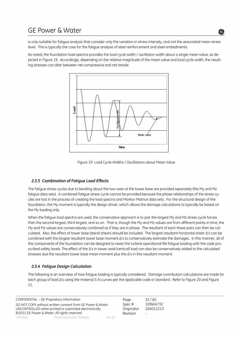
GE Power & Water g
CONFIDENTIAL – GE Proprietary Information
DO NOT COPY without written consent from GE Power & Water. UNCONTROLLED when printed or submitted electronically. ©2013 GE Power & Water. All rights reserved
Page 33 / 65 Spec # 109W4732 Originator 204012213 Revision -
TMPL0001 Master Specification Template Rev. (G)
is only suitable for fatigue analysis that consider only the variation in stress intensity, and not the associated mean stress
level. This is typically the case for the fatigue analysis of steel reinforcement and steel embedments.
As noted, the foundation load spectra provides the load cycle width / oscillation width about a single mean value, as de-
picted in Figure 19. Accordingly, depending on the relative magnitude of the mean value and load cycle width, the result-
ing stresses can alter between net compressive and net tensile.
Figure 19 Load Cycle Widths / Oscillations about Mean Value
2.3.3 Combination of Fatigue Load Effects
The fatigue stress cycles due to bending about the two axes at the tower base are provided separately (the My and Mz
fatigue data sets). A combined fatigue stress cycle cannot be provided because the phase relationships of the stress cy-
cles are lost in the process of creating the load spectra and Markov Matrice data sets. For the structural design of the
foundation, the My moment is typically the design driver, which allows the damage calculations to typically be based on
the My loading only.
When the fatigue load spectra are used, the conservative approach is to pair the largest My and Mz stress cycle forces,
then the second largest, third largest, and so on. That is, though the My and Mz values are from different points in time, the
My and Mz values are conservatively combined as if they are in phase. The resultant of each these pairs can then be cal-
culated. Also, the effect of tower base lateral shears should be included. The largest resultant horizontal shear ∆’s can be
combined with the largest resultant tower base moment ∆’s to conservatively estimate the damages. In this manner, all of
the components of the foundation can be designed to resist the turbine operational life fatigue loading with the code pro-
scribed safety levels. The effect of the ∆’s in tower axial (vertical) load can also be conservatively added to the calculated
stresses due the resultant tower base mean moment plus the ∆’s in this resultant moment.
2.3.4 Fatigue Design Calculation
The following is an overview of how fatigue loading is typically considered. Damage contribution calculations are made for
each group of load ∆’s using the material S-N curves per the applicable code or standard. Refer to Figure 20 and Figure
21.
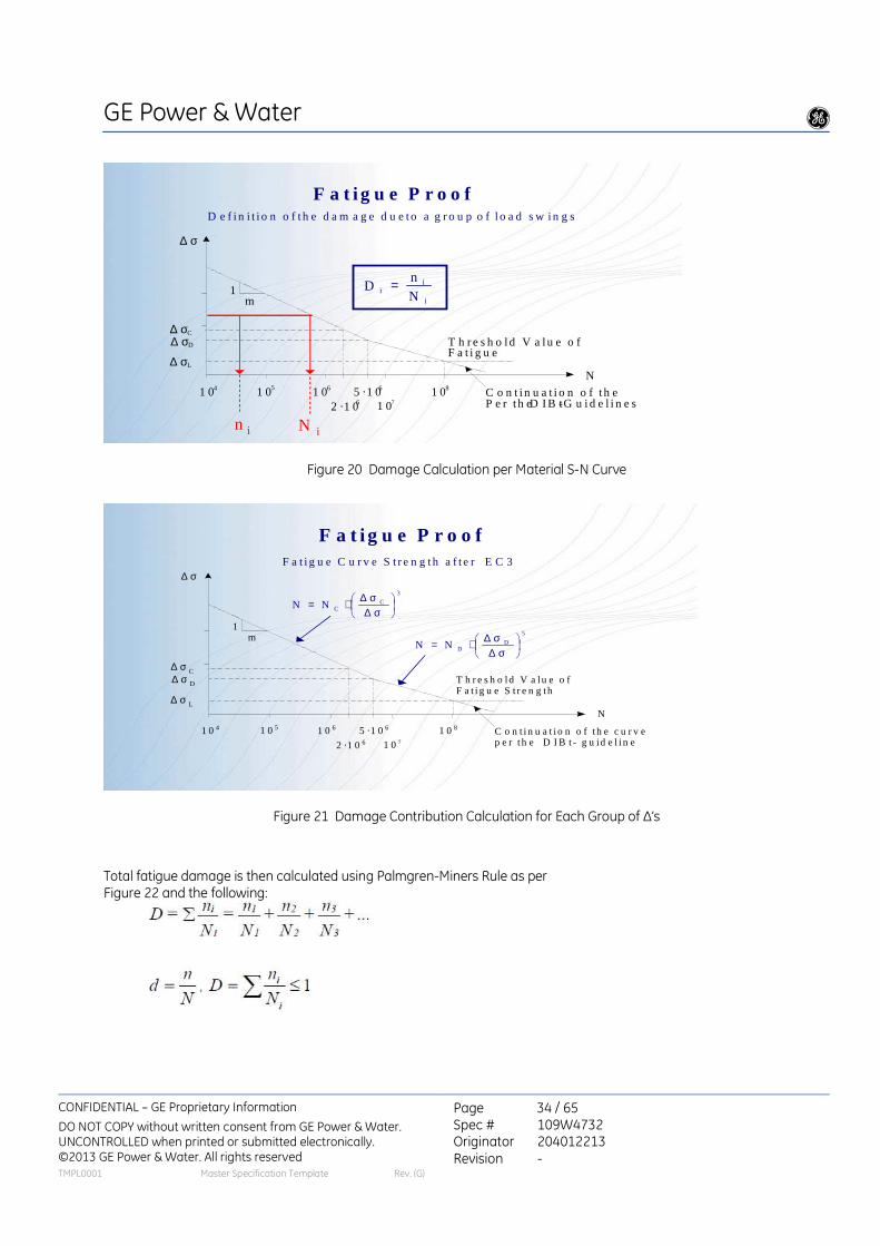
GE Power & Water g
CONFIDENTIAL – GE Proprietary Information
DO NOT COPY without written consent from GE Power & Water. UNCONTROLLED when printed or submitted electronically. ©2013 GE Power & Water. All rights reserved
Page 34 / 65 Spec # 109W4732 Originator 204012213 Revision -
TMPL0001 Master Specification Template Rev. (G)
F a t i g u e P r o o f
∆ σ D
2 ·1 0 6 1 0 7 1 0 8 5 ·1 0 6
1 m
N
∆ σ
1 0 6 1 0 4 1 0 5
∆ σ C
∆ σ L
T h r e s h o ld V a lu e o f t h e F a t i g u e s t r e n g t h
C o n t in u a t i o n o f t h e c u r v e P e r th e D IB t - G u i d e l i n e s
D e f in i t i o n o f t h e d a m a g e d u e t o a g r o u p o f l o a d s w in g s
n i N i
i
i i N
n D =
Figure 20 Damage Calculation per Material S-N Curve
F a t i g u e P r o o f
∆ σ D
2 ·1 06 1 07
1 085 ·1 06
1m
N
∆ σ
1 061 04 1 05
∆ σ C
∆ σ L
T h r e s h o ld V a lu e o fF a t i g u e S t r e n g th
C o n t in u a t io n o f th e c u r v ep e r th e D I B t - g u id e l i n e
F a t i g u e C u r v e S t r e n g th a f t e r E C 3
3
CCNN
σ∆σ∆⋅=
5
DDNN
σ∆σ∆⋅=
Figure 21 Damage Contribution Calculation for Each Group of ∆’s
Total fatigue damage is then calculated using Palmgren-Miners Rule as per Figure 22 and the following:

GE Power & Water g
CONFIDENTIAL – GE Proprietary Information
DO NOT COPY without written consent from GE Power & Water. UNCONTROLLED when printed or submitted electronically. ©2013 GE Power & Water. All rights reserved
Page 35 / 65 Spec # 109W4732 Originator 204012213 Revision -
TMPL0001 Master Specification Template Rev. (G)
F a t ig u e P r o o fF a t ig u e C a lc u la t io n a fte r th e p ro c e d u re o f E u ro c o d e 3 u sin g th e m e th o do f P a lm g re n /M in e r fo r n o n p e r io d ic lo a d c yc le s :
D a m a g e S u m :
w ith n i : n u m b e r o f te n s io n sw in g s o f a n in te n s ity le v e l e x pec te d in 2 0 ye a r l i fe tim e o f m a ch in e ∆ σ
Ν i: n u m b e r o f te n s io n sw in g s th a t w o u ld lea d to fa i lu re a t th a t p a r t ic u la r in te n s i ty le v e l (a m o u n t o f s tre ss sw in g o r d e lta )∆ σ
0,1N
nD
i
i ≤= ∑
Figure 22 Summing individual damages
This general method of estimating the fatigue loads is outlined in Danish Energy Agency “Recommendation for Technical
Approval of Offshore Wind Turbines”[5], as follows: “In practice, it is not allowed to calculate the response of the structure
over its entire lifetime, time step after time step. Thus, a number of load cases are selected which, in conjunction, are as-
sumed to result in the same level of certainty as the actual load event. For this purpose, the load is usually thought to be
decomposed into a (current) mean value (in the case of wind this corresponds to the mean load of V10 min) with a pertur-
bation around this. This decomposition is applicable to both time simulation and quasi-static observations.”
For wind turbine concrete foundations, the reinforcing and concrete are typically designed for fatigue using the CEB-FIP
Model Code 1990 Design Code published by Comite Euro-International Du Beton. This is referred to as MC1990 in this doc-
ument. This fatigue method is also per DAfStb booklet 439. Note that the 2003 Germanischer Lloyd Rules and Guidelines
(GL) also require use of MC 1990 (Chapter 5, Page 5-15, section 5.4.2.2)
2.3.5 Grout Joint Fatigue Strength
The required fatigue strength of the grout joint at the foundation interface of the tower base flange is project specific, as
per the fatigue load spectra or Markov Matrices in the project specific load specification. It is recommended that the min-
imum section modulus and minimum bearing area of the grout joint be determined based on the extreme loads. The fa-
tigue load assessment should consider the net area of the grout at the interface with the tower base flange. Moreover, the
net area at this interface should deduct the area of the anchor sleeves.
2.3.6 Mono-Pier Foundation Fatigue Strength
For all mono-pier foundations (also referred to as short pole type, caissons, bored piles or the proprietary design Patrick
and Henderson Tensionless Pier), fatigue design should be as per the CEB-FIP Model Code 1990 Design Code.

GE Power & Water g
CONFIDENTIAL – GE Proprietary Information
DO NOT COPY without written consent from GE Power & Water. UNCONTROLLED when printed or submitted electronically. ©2013 GE Power & Water. All rights reserved
Page 36 / 65 Spec # 109W4732 Originator 204012213 Revision -
TMPL0001 Master Specification Template Rev. (G)
2.4 Seismic Loads
Seismic resistance is not a standard design requirement in IEC 61400-1. Moreover, any necessary seismic resistance for
a site is dependent on site-specific factors including the mapped ground acceleration, soil profile and the provisions of
the local Building or Seismic Code. Accordingly, seismic loads are typically not included by GE in the wind turbine specif-
ic Load Specification.
For sites where the level of seismicity may be high enough to control certain aspects of the foundation design, GE can
provide site specific seismic loads upon request, subject to GE being provided with all of the relevant information need-
ed to develop the earthquake loads, including, the applicable code, ground accelerations, soil types, facility importance,
etc. Such sites should be identified by the Customer during the project development phase so that GE can confirm the
seismic adequacy of the applicable wind turbine model, and to insure that the GE calculated site-specific seismic loads
are available to the foundation designer early in the project execution phase.
3 Foundation Performance
3.2 Foundation Dynamic Stiffness
Wind turbines are subject to strong dynamic loadings. Accordingly, the dynamic properties of the overall wind turbine
structural system (i.e., the foundation, tower, drive train, and rotor) are critical.
The Foundation Load Specification specifies the minimum acceptable foundation stiffness that is required to ensure
that the total wind turbine system will have the minimum fundamental eigenfrequency assumed by GE in the wind tur-
bine design. This specified minimum acceptable foundation stiffness may be dependent on the foundation type. Note
that there is no upper limit on the foundation stiffness, since as part of the wind turbine design, GE confirms that the
wind turbine is acceptable assuming the foundation to be completely rigid.
3.4 Foundation Lift-Off, Overturning, Sliding and Shear Failure
National or Industry Codes and Standards may apply for stability verification of the foundation. It is recommended that
the foundation to comply with the Germanischer Lloyd Wind Energie GmbH IV Rules and Guidelines Edition 2003, 6.7.6.3
Part (3) and Part (4). This means 100% contact area between the foundation and soil during normal operational loading,
and for the extreme loads case, a contact area at least up to the foundation centerline (50% contact). The Foundation
Load Specification provides the applicable load cases for which the foundation should maintain 100% and 50% contact.
For overturning stability, the safety factor against the calculated overturning moment must never be less than 1.50,
based on the safety factor being applied to the unfactored service loads. The calculated overturning moment must in-
clude the moment due to the resultant of the tower base shear, multiplied by the foundation height. This check is for
safety factor against overturning about the ‘toe’ of the foundation and against soil failure in shear.
For foundation sliding checks, the safety factor must be at least 1.50. The effect of the tower base torsional moment
about the vertical axis of the tower must be included in this check against lateral forces. For spread foundations, con-
sidering only the resistance due to friction between the subgrade and bottom of the foundation is typically sufficient to
confirm sufficient resistance to sliding. For deep piled foundations, all of the lateral forces are to be resisted by the pil-
ing; friction between the bottom of the foundation and subgrade shall not be considered.

GE Power & Water g
CONFIDENTIAL – GE Proprietary Information
DO NOT COPY without written consent from GE Power & Water. UNCONTROLLED when printed or submitted electronically. ©2013 GE Power & Water. All rights reserved
Page 37 / 65 Spec # 109W4732 Originator 204012213 Revision -
TMPL0001 Master Specification Template Rev. (G)
4 Foundation Interface Detailing
4.1.1 T-Flange Tower with Anchor Bolt Cage
With a T-flange tower, the wind turbine tower is bolted to an embedded anchor bolt cage via a T-shape bolting flange,
with a grout joint between the T-shape bolting flange and the foundation. Refer to Figure 23 for the detailing of the T-
flange foundation interface.
Figure 23 Tower T-Flange Foundation Interface Detailing
4.1.2 Adapter Anchor System
The adapter anchor system is comprised of an embedded anchor bolt assembly and a tower base ring. The tower base
ring has a bolted T-flange connection with the embedded anchor bolt cage, a grout joint between the T-flange and the
foundation concrete, and a L-flange bolted connection with the tower. Refer to Figure 24 for the foundation interface
detailing of the adapter anchor system. With this system, the tower base ring may also be used as a fixture to maintain
proper anchor bolt alignment during the foundation concrete placement.
tower base flange (T flange)
**
nominal grade / ground elevation
turbine hub-height elevation
datum of GE provided foundation loads
* GE specified dimension ** Buyer specified dimension
anchor cage anchor bolts
*
* **
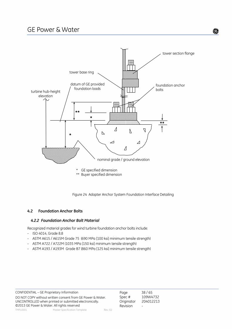
GE Power & Water g
CONFIDENTIAL – GE Proprietary Information
DO NOT COPY without written consent from GE Power & Water. UNCONTROLLED when printed or submitted electronically. ©2013 GE Power & Water. All rights reserved
Page 38 / 65 Spec # 109W4732 Originator 204012213 Revision -
TMPL0001 Master Specification Template Rev. (G)
Figure 24 Adapter Anchor System Foundation Interface Detailing
4.2 Foundation Anchor Bolts
4.2.2 Foundation Anchor Bolt Material
Recognized material grades for wind turbine foundation anchor bolts include:
- ISO 4014, Grade 8.8
- ASTM A615 / A615M Grade 75 (690 MPa [100 ksi] minimum tensile strength)
- ASTM A722 / A722M (1035 MPa [150 ksi] minimum tensile strength)
- ASTM A193 / A193M Grade B7 (860 MPa [125 ksi] minimum tensile strength)
tower section flange
*
nominal grade / ground elevation
turbine hub-height elevation
datum of GE provided foundation loads
tower base ring
foundation anchor bolts
* GE specified dimension ** Buyer specified dimension
** *
**

GE Power & Water g
CONFIDENTIAL – GE Proprietary Information
DO NOT COPY without written consent from GE Power & Water. UNCONTROLLED when printed or submitted electronically. ©2013 GE Power & Water. All rights reserved
Page 39 / 65 Spec # 109W4732 Originator 204012213 Revision -
TMPL0001 Master Specification Template Rev. (G)
4.2.4 Foundation Anchor Bolt Corrosion Protection
Recognized foundation anchor bolt corrosion protection methods include:
- 75 µm to 100 µm [3 to 4 mils] of Hot Dip Galvanizing per ASTM A153. Caution: for high-strength steel anchor bolts, the
provisions of ASTM A193 shall be followed to avoid embrittlement.
- Fusion bonded epoxy coating in accordance with ASTM 934 or ASTM A775. Coating thickness of 180 µm to 305 µm [7 to
12 mils]
- Wrapping with a petrolatum base fabric tape ( e.g., Densyl Tape, by Denso North America, 1.15 mm [46 mil] average
thickness, or equivalent product)
4.3 Grouted Joint
Figure 25 depicts two typical grout joint configurations. The grout joint configuration is determined by the foundation de-
signer.
It is recommended that the Foundation Engineer of Record (FEOR) prepare, seal and submit, to the owner of Wind Farm
and kept as record, the calculations and construction details on how the base of the tower is to be supported both during
construction and permanently, and show that the construction and permanent loads are transmitted safely without any
damage to the steel tower base flange, anchor bolts or foundation.
Prior to tensioning the anchors, the grout strength should be proven by testing to be as specified by the foundation de-
signer. The test results should be based on the average result of 3 cubes (prisms).
Figure 25 Typical Tower Grout Joint Configurations
4.4 Tower Drain Pipe
Buyer should provide a single 70 mm (2.5 in) nominal diameter PVC pipe in the foundation inside the tower for drainage.
The surface of the foundation inside the tower should be sloped towards the drainpipe, and the end of the drain pipe
should be flush with the top surface of the foundation and in an accessible, location given the arrangement of equip-
ment in the down-tower.

GE Power & Water g
CONFIDENTIAL – GE Proprietary Information
DO NOT COPY without written consent from GE Power & Water. UNCONTROLLED when printed or submitted electronically. ©2013 GE Power & Water. All rights reserved
Page 40 / 65 Spec # 109W4732 Originator 204012213 Revision -
TMPL0001 Master Specification Template Rev. (G)
4.5 Electrical Conduits
4.5.1 General
Electrical conduits should slope downward at 2 degrees or more toward the outside of the foundation. Unless otherwise
indicated, the electrical conduits should be trimmed to within 8 cm (3 in) of the top of the concrete surface. The conduit
elements should be connected using 15° bends only (unless full 90° bend elements or flexible conduit is used). Larger
bends such as 30° elements should not be used. (A 90° bend is comprised of 6 x 15° bends.) Follow all the bending radius
requirements of the power cables.
The electrical conduits bushings can cause problems during power cable installation when the bushings are not installed
in the correct direction. To preclude this, start the conduit installation with a bushing facing away from the foundation. For
gravity type spread foundations, provide a coupling at the face of the foundation for the electrical conduits.
4.7 Grounding System
4.7.1 General
Guidance for the design of grounding (earthing) can be found in Reference [4-1] in Section 6, Page 34. The grounding
design should meet the provisions of Reference [4-2] in Section 6, Page 34.
4.8 Resistance Verification and Resistance Improvements
The following methods can be used to assist in lowering the grounding/earth resistance to 10 ohms or less:
LYNCOLE XIT Grounding: Provides a chemical ground rod that consists of hollow copper tubing with a chemical grounding
rod inserted into piping. The chemical seeps into the ground providing substantial adherence with the soil to give a re-
sistance of 1 ohm.
PowerFill (Clay)/PowerSet (Rocks/Sand): Utilize carbon-based additive “calcined petroleum coke” to protect copper from
corroding. It creates a positive, low-resistance, electrical connection between grounding system and the earth. In high-
resistivity soils, Powerfill can be used to produce acceptable grounding impedance with reasonable size. Drill earth hole to
the desired depth, suspend ground rod in center of hole to be filled and pour Powerfill up to the desired level.
Eritech Chemical Ground Electrodes provide a low-impedance ground in locations of high soil resistivity. Together with
Ground Enhancing Material (GEM) as backfill, the system is intended to dissipate lightning energy and other dangerous
electrical fault currents, in sandy or rocky soil conditions. UL & cUL Listed to UL467 and CSA C22.2 No. 41 respectively.
GE is open to discussions of customer options for methods to reduce grounding resistance where assistance is required
due to land masses of high resistivity.

GE Power & Water g
CONFIDENTIAL – GE Proprietary Information
DO NOT COPY without written consent from GE Power & Water. UNCONTROLLED when printed or submitted electronically. ©2013 GE Power & Water. All rights reserved
Page 41 / 65 Spec # 109W4732 Originator 204012213 Revision -
TMPL0001 Master Specification Template Rev. (G)
4.9 Concrete Pedestal / Grout Joint Waterproofing
After tower installation is complete, consideration should be given to sealing the pedestal concrete top and the grout
joint with a waterproofing material, e.g., a resin impregnated membrane as shown in Figure 26.
Figure 26 Foundation Pedestal Sealing
4.10 Part 4 References
[4-1] IEC Technical Report TR 61400-24 first edition 2002 Wind turbine generator systems- Part 24: Lightning Protection,
Ref. # IEC/TR 61400-24:2002(E).
[4-2] Germanischer Lloyd Wind Energie GmbH (GL) Guidelines for the Certification of Wind Turbines Edition 2003, sec-
tion 8.9 Lightning Protection and all the standards referenced in its section 8.9.1. This includes IEC 61024-1-1 (1993-09)
“Protection of Structures against lightning- Part 1: General Principles”.
sealing

GE Power & Water g
CONFIDENTIAL – GE Proprietary Information
DO NOT COPY without written consent from GE Power & Water. UNCONTROLLED when printed or submitted electronically. ©2013 GE Power & Water. All rights reserved
Page 42 / 65 Spec # 109W4732 Originator 204012213 Revision -
TMPL0001 Master Specification Template Rev. (G)
5 Geotechnical Design
5.1 General
The foundation soil properties must be consistent with the assumptions made in GE’s static and dynamic calculations of
the wind turbine, and must be accurately quantified to ensure proper foundation design. The information provided in this
section is for reference only, and the geotechnical engineer is fully responsible for determining and carrying-out the exam-
inations needed to define the parameters that are critical in confirming the strength, stability and stiffness of the wind tur-
bine foundation.
5.2 Soil investigation
A site-specific soil investigation (geotechnical investigation) report is expected to be commissioned by the Buyer for all pro-
jects.
A minimum of one boring or cone penetration test (CPT) is recommended at each turbine foundation location. For sites
with appreciable variation in soil properties, additional borings should be made around the perimeter of each foundation
footprint. The exact number and location of borings should be determined based on discussions with a geotechnical en-
gineer knowledgeable about the local soil conditions. Each soil layer contributing to the foundation settlement and stiff-
ness must be thoroughly investigated.
For gravity foundations, all borings should extend to at least as deep as the largest lateral dimension of the foundation.
For mon-pier type foundations (also referred to as short pole type, caissons, bored piles or the proprietary design Patrick
and Henderson Tensionless Pier), the borings should extend to at least 2 meters below the bottom of the planned shaft
foundation excavation. For deep pile type foundations (foundations on multiple driven or augured piling), boring depths
will be based on the pile type and the site soil properties. The structural engineer should provide preliminary maximum pile
reactions to the geotechnical engineer in order to reach a mutual decision on an economical pile type. Based on this pile
type and reaction, the geotechnical engineer should make a recommendation regarding boring depths.
The project geotechnical report should address bearing capacity, differential soil settlements, consolidation settlements
and recommendations for preventing surcharge soil erosion due to storm water drainage from the wind turbine tower and
nacelle. Moreover, the report should address potential degradation of the soil or rock due to cyclic loading from the wind
turbine, over the full turbine operational life. The Foundation Load Specification provides fatigue load spectra and Markov
Matrices that define the load cycles and magnitudes that should be considered in this degradation assessment.
5.3 Soil dynamic properties required by the foundation designer
The total stiffness of the wind turbine system is a function of the tower stiffness, the foundation stiffness, and the stiffness
of the underlying soil. The soil stiffness is a function of the subgrade soil properties. Accordingly, the geotechnical engi-
neer must conservatively establish the properties of the subgrade soil in order to ensure that the overall wind turbine sys-
tem stiffness is accurately defined.
GE Power & Water g
CONFIDENTIAL – GE Proprietary Information
DO NOT COPY without written consent from GE Power & Water. UNCONTROLLED when printed or submitted electronically. ©2013 GE Power & Water. All rights reserved
Page 43 / 65 Spec # 109W4732 Originator 204012213 Revision -
TMPL0001 Master Specification Template Rev. (G)
The foundation designer requires the following values:
• Gd [MN/m²] - dynamic shear modulus
• ρ [kg/m³] - soil density [t/m³]; the moist density of natural soil, in case of water saturation including the water
filling the pore volume, is introduced as density
• ν - Poisson’s ratio
These parameters can be used to calculate static and dynamic coefficients of compressibility. Soil parameters are required
to calculate the stiffness of each layer of the subgrade. These stiffness calculations may be based on formulas included
later in this document (for shallow gravity raft foundations) or through the use of computer software if required.
Formulas for different soil/ foundation conditions are available in texts such Chapter 8 of Reference [5-1]. Other example
sources of information on soil dynamics are References [5-2] , [5-3] and Principles of Soil Dynamics, by B.M. Das
The dynamic soil properties of the subsurface should be established by geophysical testing methods. These include field
methods that focus on the low-strain tests that are not large enough to induce significant non-linear non-elastic stress
strain behaviour, they include: seismic refraction and reflection, suspension logging, steady-state vibration, down-hole,
seismic cross-hole, spectral analysis of surface waves, and seismic CPT. These special tests can be used to determine Gd
and Poisson’s ratio. They should be performed by a qualified geologist and included in the final report when the soil proper-
ties cannot be conservatively classified.
All soil layers that influence settlement and the stiffness of the foundation must be investigated. Generally CPT are recom-
mended since they give a continuous record of the data properties with depth. For SPT (standard penetration test) the
sampling intervals should not be in excess of 1 to 1.5m in the upper layers or any possibly weak layers.
When calculating foundation stiffness the selection of the shear modulus of the soil (G) will be based on a reduction from
the initial shear modulus of very small strains (Go). It will be appropriate for the amount of strain level that will be experi-
enced at the loading condition under consideration. This is based on the strain in the soil due to the full operating power
production tower base moment loading and based on the geometry and dimensions of the foundation used (spread foun-
dation, type pole type, etc).
If shear strain = γ, the factor for reduced allowable shear modulus =
The level of the strain in the soil due to the applied tower base load can be many times greater than the strain level used for a normal rotating machine foundation such as a large motor. For clays this might be a strain level of 0.001 or larger, for G (γ) in wind turbine foundation applications. This is equal to 0.1%. So the shear modulus at small strain level Go is reduced based on the type of soil and the anticipated level of strain of based on the subgrade and the foundation size.
G (γ) Go

GE Power & Water g
CONFIDENTIAL – GE Proprietary Information
DO NOT COPY without written consent from GE Power & Water. UNCONTROLLED when printed or submitted electronically. ©2013 GE Power & Water. All rights reserved
Page 44 / 65 Spec # 109W4732 Originator 204012213 Revision -
TMPL0001 Master Specification Template Rev. (G)
5.4 Preliminary loads for soil investigation
General Electric supplies the foundation loads to the project foundation engineer. The foundation engineer then provides a
first initial estimate of the foundation footprint size and magnitudes of the design loads at the base of the foundation to
the project geotechnical engineer. The soil properties used for calculations must be applicable for the foundation’s final
geometry, the General Electric supplied loads and the site’s actual soils. The final assumed static and dynamic properties of
the soil supporting the final foundation size will be stated in a project geotechnical report issued by the geotechnical engi-
neer to the project foundation engineer and the project Owner. The report must confirm all assumptions on soil properties
made in the foundation size calculations.
5.5 Settlement Criteria
The settlement analysis should distinguish between immediate elastic settlements and time-dependent consolidation set-
tlements. The analysis should provide information on the tolerance or variability in the settlement calculations.
The actual bearing area under the foundation should be used when considering settlement and bearing capacities, that is
the area based on considering the eccentricity (e) of the vertical reaction (V) on the foundation. Typically this would be a
smaller oval shaped area offset from the center on foundation with its center point eccentricity distance (e) based on the
amount of tower base moment (M), where e = M/V. Refer to Section 8.3 of DNV/Riso 2002.
For the tower, a foundation inclination of 3mm/m due to foundation differential settlement is permissible. This differential
settlement limit is that from the uniform dead load, and the variation in soil properties across the foundation footprint, and
must be demonstrated by the foundation designer by adequate analysis. The inclination during turbine operation as a
result of the extreme or operational loads need not be considered in this 3mm/m limit. The dynamic analysis of the tur-
bine accounts for the additional rotations of the foundation due to the operational and extreme loads. This analysis is
based on the foundation providing the minimum rotational stiffness specified in the Foundation Load Specification.
Uniform foundation vertical settlement from the combined mass of the turbine and foundation will normally not control
the design, given the more restrictive requirements on rotational stiffness, and the low magnitude of the gravity loads as
compared to the operational overturning moment loads. Nonetheless, the geotechnical engineer should confirm that the
vertical long-term settlement resulting from the combined gravity weight of the turbine and foundation is less than 20mm.
For projects with raft (spread) foundations in the United States and Canada, the safety factor on the extreme unfactored
loads should never be less than 2.0 for soil shear failure considerations (typical values are 3.0 for normal operating and
fatigue loads and 2.26 on extreme loads). This is based on the weakest failure curve through the soil, which can lead to
overturning. The geotechnical engineer has the final responsibility for determining the minimum safety factor.
For single pole type lateral pile systems (monopile or similar), the size of the foundation will typically be dictated by the lim-
its on allowable deflections and rotations, nonetheless, failure of the pile itself is still checked.

GE Power & Water g
CONFIDENTIAL – GE Proprietary Information
DO NOT COPY without written consent from GE Power & Water. UNCONTROLLED when printed or submitted electronically. ©2013 GE Power & Water. All rights reserved
Page 45 / 65 Spec # 109W4732 Originator 204012213 Revision -
TMPL0001 Master Specification Template Rev. (G)
5.6 Stiffness requirements
Wind turbines are structures that are subject to strong dynamic stresses. Dynamic system properties, in particular the
natural frequencies of the overall system consisting of the foundation, tower, machine head and rotor, are therefore of
particular importance for proper load determination. In the wind turbine design assessment, the foundation and underly-
ing soil is not regarded as a rigid restraint, but is modeled by approximation using equivalent springs (torsion and linear
springs), which are each dependent on soil properties. Refer to Figure 27.
Figure 27 Simplified Analysis Model
Given this, the foundation must provide the minimum stiffness levels assumed in the wind turbine design, in order to insure that the total system has the minimum fundamental eigenfrequency considered in the wind turbine design.. Refer to the Foundation Load Specification for the minimum stiffness that is required of the foundation. Note that it is not possible for the foundation to be too stiff because the wind turbine design is also evaluated with the assumption that the base of the tower is 100% fixed for all rotations and translations.

GE Power & Water g
CONFIDENTIAL – GE Proprietary Information
DO NOT COPY without written consent from GE Power & Water. UNCONTROLLED when printed or submitted electronically. ©2013 GE Power & Water. All rights reserved
Page 46 / 65 Spec # 109W4732 Originator 204012213 Revision -
TMPL0001 Master Specification Template Rev. (G)
5.7 Conversion Formulas
When using data obtained from literature, attention must be paid whether one is dealing with the modulus of stiffness [ES]
or with the Young’s modulus of elasticity [E]. At larger Poisson’s ratios in particular, the two values differ significantly.
ES represents the coefficient of compressibility or constrained modulus, that is, the ratio of stress to strain for one-
dimensional loading (the plane wave modulus and it is the inverse of the coefficient of volume compression). English texts
often represent this parameter with the symbol M [MN/m²].
The conversion is the same for static and dynamic values, except dynamic parameters additionally receive the index d.
When consulting tables, it must be taken into account that the dynamic modulus of elasticity exceeds the static modulus
of elasticity by a factor of 2 (non-cohesive soils) to 30 (cohesive soils)! The use of the following equations is based on the
assumption of an elastic half space model to verify that the required foundation resistance to rotations and translations
has been met. Additionally, the equations only apply to isotropic soils; not highly layered site soils.
Calculation of modulus of stiffness from the modulus of elasticity: Calculation of shear modulus from the modulus of stiffness: Calculation of shear modulus from the modulus of elasticity:
5.7.1 Raft Foundation Spring Constants
For a spread gravity raft type foundation (the equations are from References [5-4] and [5-5]):
Tower Base Spring Stiffness Term
Equivalent Radius for Rectangular Foundations
(with dimensions 2a x 2b)
Horizontal Stiffness
(horizontal translation)
Rotational Stiffness
(rocking)
Table 5 Spring Constants for Spread Foundations

GE Power & Water g
CONFIDENTIAL – GE Proprietary Information
DO NOT COPY without written consent from GE Power & Water. UNCONTROLLED when printed or submitted electronically. ©2013 GE Power & Water. All rights reserved
Page 47 / 65 Spec # 109W4732 Originator 204012213 Revision -
TMPL0001 Master Specification Template Rev. (G)
5.7.2 Stiffness of an Octagonal Spread Foundation
For the case of the rotational stiffness for an octagonal shaped foundation- assume use of a rigid circular footing resting
on the surface of a semi-infinite elastic body where:
A = footprint area of proposed octagonal foundation [m²]
G = shear modulus of the soil [MN/m²]
Gd = shear modulus at very low strain amplitude (dynamic shear modulus) [MN/m²]
E = Young’s modulus [MN/m²]
Ed = Young’s modulus for dynamic case [MN/m²]
Es = coefficient of compressibility or constrained [MN/m²]
Esd = dynamic case value of Es [MN/m²]
ρ = mass density of the soil (in the unit system typically used in the USA, this is the soil unit weight / accelera-
tion of gravity)
ν = Poisson’s ratio [-]
rO = radius of circular footing [m]
d = cross sectional width across straight sides of octagon shaped foundation [m]
vS = shear wave velocity [m/s]
vP = compressional wave velocity [m/s]
kϕ = required rotational stiffness of foundation in [MN m/rad] as specified in the Foundation Load Specification
The relationship between [Es] and [E] is given in Section 5.7
For a rigid circular footing the equivalent rocking mode spring is given as follows, assuming no contribution from any em-
bedment coefficients:
As per Section 5.7:
Where geophysical methods are used to measure in place shear and compression wave velocities:
The value of dynamic constrained modulus [Esd] may be much higher than the static modulus [Es] depending on soil type.
See interaction charts in the literature. Based on these relationships the structural engineer can prepare a chart based on
the expected geometry of the foundation showing the minimum values of [Esd] and [Gd] required to meet the stiffness cri-
teria specified in the Foundation Load Specification for resistance against foundation rocking. This chart can be filled in for

GE Power & Water g
CONFIDENTIAL – GE Proprietary Information
DO NOT COPY without written consent from GE Power & Water. UNCONTROLLED when printed or submitted electronically. ©2013 GE Power & Water. All rights reserved
Page 48 / 65 Spec # 109W4732 Originator 204012213 Revision -
TMPL0001 Master Specification Template Rev. (G)
all values of ν from 0.30, 0.31, 0.32, and so on through ν = 0.47. For each ν value, the corresponding value of [Esd] and [Gd]
is shown. The geotechnical engineer can then verify if the site conditions are better than the chart values. For example:
If the width across an octagonal foundation is d, then the area of this foundation is:
A = 2 * tan(22.5) * d2
For a circular foundation to have the same footprint area, the foundation radius is:
rO =
Rewriting previous equations:
So for an octagon foundation on isotropic soils:
Where rO is the radius of an equivalent circle that has the same area as the octagon foundation. Based on this term for
[Esd] and relationship to [Gd], the chart can be prepared listing [Esd] and [Gd] for each value of ν from 0.30 through 0.47.
5.7.3 Stiffness of a Pole Type Foundation
This section only applies to pole type foundations. Pole type foundations are also referred to as mono-pier, caissons, bored
piles or the proprietary design Patrick and Henderson Tensionless Pier. Requirements are given for stiffness at the tower-
foundation interface and serviceability limits on foundation motion at the ground line surface. This section can also apply
where the distance from tower base flange to the point of zero rotation is large. For example, for a very tall raft foundation
or for a multiple pile type foundation with a large height.
The Foundation Load Specification specifies the stiffness requirements for typical raft (mat or spread) foundations, or con-
crete pile cap plus deep driven pile type foundations. If a different foundation system such as a pole type foundation is
used instead, the foundation designer must provide a foundation that still maintains the same equivalent total system fre-
quency (tower plus foundation). More specifically, the foundation system must provide a stiffness at the tower base that
still produces a complete system eigenfrequency that is sufficiently high enough to be adequately removed from the ma-
chine operational exciting frequencies. Meeting the minimum stiffness values specified in the Foundation Load Specifica-
tion insures that the tower eigenfrequency remains in the correct range. Moreover, a foundation that is too ‘soft’ creates a
total combined system frequency that is too low, which changes the tower extreme and fatigue load cases. The tower
extreme and fatigue loads are calculated based on spread or pile cap systems, which have a point of rotation close to the
base of the tower (at the base of a typical foundation). If the foundation rotates about a much lower point, it then acts as
an extension to the actual tower. Mono-pier type foundation systems always move the effective point of foundation rota-
tion down further from the tower base than a normal thickness spread or raft foundation.

GE Power & Water g
CONFIDENTIAL – GE Proprietary Information
DO NOT COPY without written consent from GE Power & Water. UNCONTROLLED when printed or submitted electronically. ©2013 GE Power & Water. All rights reserved
Page 49 / 65 Spec # 109W4732 Originator 204012213 Revision -
TMPL0001 Master Specification Template Rev. (G)
Figure 28 Complete model, the combined stiffness- tower and foundation
Pole type foundations behave as laterally loaded short piles. The stiffness against horizontal displacement and rotation of
the foundation is nonlinear due to the nonlinear nature of the soil stiffness. The nonlinear lateral soil resistance curves for
the specific soils at the site, and any variation in depth, are to be used to analyze the foundation stiffness for the operating
and extreme loads. Geotechnical data such as the soil unit weight and friction angle, the un-drained cohesive strength,
the soil strain parameter E50, and the soil p-y curves and t-z curves are needed for the nonlinear lateral pile analysis.
The cyclic nature of the wind turbine loading will significantly lower the resistance provided by some surrounding materials
on short embedded pole type foundations. The design allowables for the soils or rock surrounding the foundation must be
accordingly reduced. Moreover, when considering the cyclic load effects on the soil and other elements, the actual level of
soil strain during the operational loads is to be used. The evaluation is to consider the number and magnitude of the load
cycles specified in the Foundation Load Specification Load Spectra and Markov Matrices.
In summary, for this type of short pole foundations, the foundation designer will provide a foundation that satisfies the re-
placement general stiffness terms as specified in the Foundation Load Specification, and as calculated at the top of the
monopile head (interface to the tower base). This equivalent top-of-pile-head stiffness matrix includes the on-diagonal
and off-diagonal stiffness terms. The stiffness used for the P-Y and T-Z curves will be based on the tower base moment
and shear loads occurring during rated wind speed turbine operation, which is DLC 1.1 given in the table “Load Case for
Check Against Tension Loading in the Piles”, in the Foundation Load Specification.

GE Power & Water g
CONFIDENTIAL – GE Proprietary Information
DO NOT COPY without written consent from GE Power & Water. UNCONTROLLED when printed or submitted electronically. ©2013 GE Power & Water. All rights reserved
Page 50 / 65 Spec # 109W4732 Originator 204012213 Revision -
TMPL0001 Master Specification Template Rev. (G)
Figure 29 Model for a normal spread (raft) or pilecap foundation
Figure 30 Nonlinear springs for long pile and a short rigid pile

GE Power & Water g
CONFIDENTIAL – GE Proprietary Information
DO NOT COPY without written consent from GE Power & Water. UNCONTROLLED when printed or submitted electronically. ©2013 GE Power & Water. All rights reserved
Page 51 / 65 Spec # 109W4732 Originator 204012213 Revision -
TMPL0001 Master Specification Template Rev. (G)
Figure 14: Nonlinear springs for long pile and a short rigid pile
Figure 31 Model for short pile type foundation- decompose into two separate models
If the model is separated at the base of foundation and top of pile head in order to enable separate design of the tower
and the foundation, consider that there will always be a slope to the top of the pile and a horizontal displacement as de-
picted in Figure 31. For a spread foundation model, a simple horizontal spring and rotational spring should be adequate.
For a pole foundation system, the springs are nonlinear (soil strain rates increase with increasing level of load). The
amount of spring stiffness at the level of normal operational loading is considered. When a short pile is used then the fol-
lowing occurs (see Figure 31 for deflected shape showing θ and ∆)
Force [F] = (stiffness) x (displacement) = [K] [∆]

GE Power & Water g
CONFIDENTIAL – GE Proprietary Information
DO NOT COPY without written consent from GE Power & Water. UNCONTROLLED when printed or submitted electronically. ©2013 GE Power & Water. All rights reserved
Page 52 / 65 Spec # 109W4732 Originator 204012213 Revision -
TMPL0001 Master Specification Template Rev. (G)
Figure 32 Coordinate System
First, write the relationships for a planar problem (since soil properties are normally the same in both directions, one can
extend relationships to a 3 dimensional solution if a 6X6 matrix is used for x, y, z directions).
Figure 33 Stiffness terms in stiffness matrix provided by the foundation
Since the pure axial spring stiffness will not change the fundamental frequency for lateral motion of the nacelle (fo flex), the
vertical x direction can be dropped, producing a 2x2 matrix.
Figure 34 For case where the axial stiffness is deleted

GE Power & Water g
CONFIDENTIAL – GE Proprietary Information
DO NOT COPY without written consent from GE Power & Water. UNCONTROLLED when printed or submitted electronically. ©2013 GE Power & Water. All rights reserved
Page 53 / 65 Spec # 109W4732 Originator 204012213 Revision -
TMPL0001 Master Specification Template Rev. (G)
K11 = axial stiffness provided by the foundation in (KN/m) = = unit of force applied in vertical x direction per unit
displacement in vertical x direction. Not required for the planar problem only interested in the fundamental frequency of
the tower for lateral motion of the nacelle.
K22 = pure lateral translation stiffness provided by the foundation in (KN/m) = = unit of force applied in horizon-
tal y direction per unit displacement in horizontal y direction
K33 = rotational stiffness provided by the foundation in (KN-m/rad) = = unit of moment M applied about the z
axis per unit of rotation Θ about this z axis that this moment produces
Not shown on Figure 32 but occurring at the same time are the following two parameters: K23 = = unit of force applied in the horizontal y direction per unit of rotation Θ about the z axis (KN/rad) K32 = = unit of moment M applied about the z axis per unit of displacement in the horizontal y direction (KN-m/ m) When a unit lateral load is applied to the top of foundation, the resistance offered by the foundation is resolved into two
componentss which sum together for the total stiffness. The unit horizontal load will create a horizontal displacement uy
and a rotation in the pile of amount θz at the top of pilehead. The pile offers resistance to both motions.
Based on the previous relationships:
Figure 35 Pile Head Fixity Cases
CASE I CASE II

GE Power & Water g
CONFIDENTIAL – GE Proprietary Information
DO NOT COPY without written consent from GE Power & Water. UNCONTROLLED when printed or submitted electronically. ©2013 GE Power & Water. All rights reserved
Page 54 / 65 Spec # 109W4732 Originator 204012213 Revision -
TMPL0001 Master Specification Template Rev. (G)
Note that in both expressions the off-diagonal term is opposite in sign from the normal on-diagonal term. So the off-
diagonal stiffness term always acts in the negative direction. This requires the pure horizontal stiffness to need to be of a
higher value in order to limit uy. The off-diagonal term in the second expression likewise requires the value of the pure on-
diagonal rotational stiffness to need to be higher in order to limit pile head rotation or slope (θz).
Use Case I to find the value of the term K23 = . Set the pile head horizontal displacement uy = 0, that is, the top of
pile head is free for rotation only (simple support). Apply a unit moment M, and use a nonlinear analysis of the soil layers to
solve for the value of horizontal reaction H that will result. Also find the rotation value θz that this unit load produces. Then
K23 = -H/ θz and K33= M/ θz
Use Case II to find the value of the term K32 = . Set the pile head rotation as 100% fixed (θz = 0), that is, the top of
pile head is free for horizontal translation uy only. Apply a unit lateral load P and use a nonlinear analysis of the soil layers
to solve for the value of rotational moment M that will be carried by the fixity of the top of pile for rotation θz. Also find the
horizontal translation value uy that this unit moment produces. Then K32 = M / uy and K22 = H / uy.
By the geometry and statics, the values of K23 and K32 must be equal and opposite. There is a coupling between these
two off-diagonal terms of the total stiffness..
With F = [K] [∆] use direct inversion to solve the problem for the values of displacement. This matrix arithmetic will result in: The terms and are the two equal off-diagonal terms. Set = = (the off-diagonal stiffness terms) Set = and = and ∆ = uy and The denominator of the expressions for uy and θz must always be greater than 0, or: This expression should always be verified as true for the combination of terms used. Also note that the numerator of the
expression for uy is the total displacement at the top of the pile. As the off-diagonal stiffness value is reduced, the eigen-
frequency of the system will be lowered.
To satisfy the required total stiffness at the tower/foundation interface, curves relating and

GE Power & Water g
CONFIDENTIAL – GE Proprietary Information
DO NOT COPY without written consent from GE Power & Water. UNCONTROLLED when printed or submitted electronically. ©2013 GE Power & Water. All rights reserved
Page 55 / 65 Spec # 109W4732 Originator 204012213 Revision -
TMPL0001 Master Specification Template Rev. (G)
for a fixed minimum value of have to be evaluated. An example curve is presented in Figure 36.
Figure 36 Example curves relating stiffness terms for a short lateral pile foundation
5.8 Groundwater and Dewatering Requirements
Foundation excavation dewatering due to high ground water levels, presence of water bearing strata, or impermeable
materials (rock, clays, etc.) must be considered as required by specific site conditions. Where excavation is made below the
ground water level, a dewatering system shall be installed with sufficient capacity to maintain ground water elevation at
not less than 1 m (3 ft) below the working surface of the excavation. Discharge from the dewatering system shall be in ac-
cordance with applicable regulations and permits.
5.9 Soil Chemistry Tests
The chemistry of the soil should be checked at three levels to determine if sulfate resistant cement will be required for con-
crete foundations. Also test for soil pH, water-soluble sulfate in the soil and groundwater, and water-soluble chlorides.

GE Power & Water g
CONFIDENTIAL – GE Proprietary Information
DO NOT COPY without written consent from GE Power & Water. UNCONTROLLED when printed or submitted electronically. ©2013 GE Power & Water. All rights reserved
Page 56 / 65 Spec # 109W4732 Originator 204012213 Revision -
TMPL0001 Master Specification Template Rev. (G)
5.10 Excavation Criteria
Excavations should be maintained and protected against earth collapse from natural causes or subsequent construction
work. Excavations should have stable slopes (typically 3 horizontal to 1 vertical), as appropriate, to meet local soil condi-
tions and local safety codes and regulations. The length of time foundation excavations are left open needs to be mini-
mized at sites subject to heavy rains or erosion of evacuations sides.
After the foundation has been excavated to the bearing level, but prior to commencing with the foundation construction,
the Buyer’s geotechnical engineer is to verify that the soil conditions at the bottom of the excavation are consistent with
the assumptions in the project geotechnical report. If the soil conditions are deemed to be inadequate, then the geotech-
nical representative should direct the contractor on the measures needed to provide an adequate subgrade. One such
measure is additional excavation, and replacement of some of the existing materials with new-engineered materials. Lo-
cally soft or yielding areas shall be excavated and replaced with compacted backfill as required. Bearing grades should be
cleaned and kept dry prior to placing the concrete.
5.10.1 Lean Concrete Layer
The Constructor should use a lean concrete layer to improve the excavation work surface. This layer should be placed as
soon as possible after the excavation is complete to protect the subgrade bearing capacity from damage (against hard
rains for instance). The thickness of the lean concrete layer depends on the ground stiffness. Typical thickness is approxi-
mately 100mm. The lean concrete layer must be level and of a uniform thickness. This allows for support of reinforcement
chairs and insures proper clearances of the reinforcing bars. Also, the foundation drawings should specify a thickened
layer of concrete or a small square foundation at the landing location for the posts that are used to support the turbine
embedded anchor cage prior to the foundation concrete placement. This thickened layer or small square foundation must
be sufficient to safely bear the weight of the concentrated dead load without incurring settlement. Uneven settlements
under the temporary support posts must be avoided since may require re-levelling of the turbine foundation anchor cage,
which is difficult to do after the reinforcement has been placed.
5.10.2 Deep Piling
For foundations that rely on driven deep piling, the geotechnical engineer should verify that the subgrade at the base of
the excavation can support the weight of the uncured new concrete. This engineer is to advise if additional measures are
required to carry this plastic concrete weight without excessive deformations of the subgrade. This should be coordinated
with the structural engineer for the foundations.
5.10.3 Caisson or pole type foundation
For caisson or pole type foundations (Patrick and Henderson Tensionless Pier or similar) blasting of rock to create the exca-
vation is prohibited. Rock excavation will have to be conducted with hydraulic excavators, hydraulic hoe ram or hammer
excavator, track hoe or other mechanical equipment.

GE Power & Water g
CONFIDENTIAL – GE Proprietary Information
DO NOT COPY without written consent from GE Power & Water. UNCONTROLLED when printed or submitted electronically. ©2013 GE Power & Water. All rights reserved
Page 57 / 65 Spec # 109W4732 Originator 204012213 Revision -
TMPL0001 Master Specification Template Rev. (G)
5.11 Backfill Criteria
The foundation drawings are to clearly state the minimum in-place unit weight for any backfill used for overturning
stability. The project geotechnical report should indicate if the site excavated material is suitable for backfill, and list any
requirements for improving the excavated material as applicable. If off-site material is required, the report should list the
testing and installation requirements. Moreover, the project geotechnical report, the project construction specifications or
the project drawings are to give the compaction requirements for the fill and backfill material.
The backfill soil must be tested after it has been placed and compacted to confirm that this minimum unit weight has been
provided. During this testing verification, the unit weight of the compacted material must not be overestimated in order to
avoid changes during the construction phase.
United States
Material used as load bearing structural fill should be compacted to a least a minimum of 95% of the maximum dry densi-
ty as determined by ASTM D1557 (modified Proctor) or equal. The natural moisture content of the material shall not devi-
ate more than 2 percent of optimum. Material used as non-load bearing backfill shall be compacted to a minimum of
90% of ASTM D1557 or equal. Natural moisture content of material shall not deviate more than 3 percent of optimum.
Consult the project specific excavation and backfill specification to insure final requirements are not greater. These re-
quirements for structural fill and backfill minimum density also apply to the soils below the exterior transformer foundation
(if applicable). Settlement of the transformer pad towards the turbine is to be precluded. The surface of the transformer
pads should be checked for levelness prior to site demobilization, and any pads for which settlement towards the tower is
detected should be corrected.
5.12 Rainwater Run-off Protection
The foundation must have suitable provisions to account for rainstorm run-offs, including the run-off of rainwater from the
surface area of the wind turbine hub, nacelle and tower. Such provisions include providing a crushed stone drainage ring
around the perimeter of the foundation pedestal, and a drainage pipe to carry the rainwater to the outer perimeter of the
foundation; all sized for a 10-year storm event. See Figure 37.
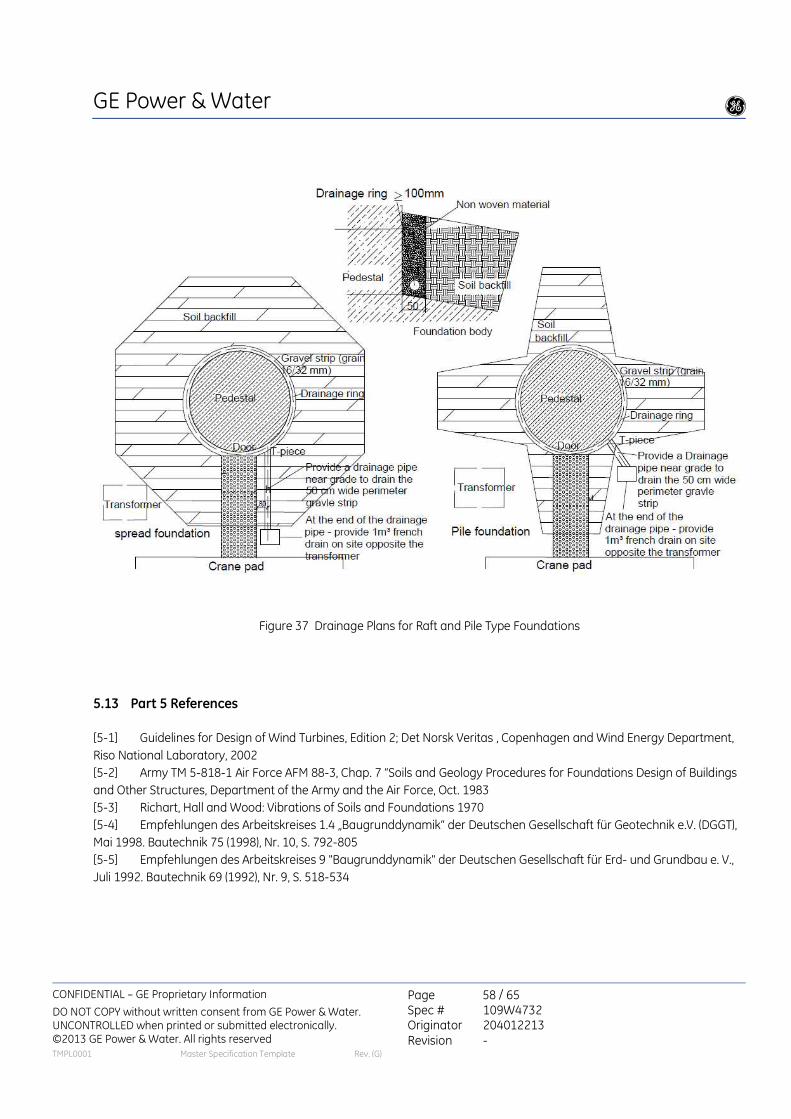
GE Power & Water g
CONFIDENTIAL – GE Proprietary Information
DO NOT COPY without written consent from GE Power & Water. UNCONTROLLED when printed or submitted electronically. ©2013 GE Power & Water. All rights reserved
Page 58 / 65 Spec # 109W4732 Originator 204012213 Revision -
TMPL0001 Master Specification Template Rev. (G)
Figure 37 Drainage Plans for Raft and Pile Type Foundations
5.13 Part 5 References
[5-1] Guidelines for Design of Wind Turbines, Edition 2; Det Norsk Veritas , Copenhagen and Wind Energy Department,
Riso National Laboratory, 2002
[5-2] Army TM 5-818-1 Air Force AFM 88-3, Chap. 7 “Soils and Geology Procedures for Foundations Design of Buildings
and Other Structures, Department of the Army and the Air Force, Oct. 1983
[5-3] Richart, Hall and Wood: Vibrations of Soils and Foundations 1970
[5-4] Empfehlungen des Arbeitskreises 1.4 „Baugrunddynamik“ der Deutschen Gesellschaft für Geotechnik e.V. (DGGT),
Mai 1998. Bautechnik 75 (1998), Nr. 10, S. 792-805
[5-5] Empfehlungen des Arbeitskreises 9 "Baugrunddynamik" der Deutschen Gesellschaft für Erd- und Grundbau e. V.,
Juli 1992. Bautechnik 69 (1992), Nr. 9, S. 518-534

GE Power & Water g
CONFIDENTIAL – GE Proprietary Information
DO NOT COPY without written consent from GE Power & Water. UNCONTROLLED when printed or submitted electronically. ©2013 GE Power & Water. All rights reserved
Page 59 / 65 Spec # 109W4732 Originator 204012213 Revision -
TMPL0001 Master Specification Template Rev. (G)
6 Foundation Construction
6.1 Typical Construction Requirements
The following is an outline of typical construction requirements:
Pre-Construction
• Obtain the site geotechnical investigation report, including the parameters needed to define the site seismicity as per
the governing code
• Obtain the site soil properties for the grounding design (resistivity), and develop the site specific grounding layout / con-
struction drawings
• Site Quality Control – overseen by an independent civil engineering inspection firm (qualified, certified). Their task is to
control and document the quality of the construction works, the construction drawings and other project specifications.
The quality manager must be competent in civil engineering (foundations) and independent from the construction
company.
• Develop construction schedule
• Implement any required soil improvement measures
• Installation of driven foundation piling (if required)
• Have construction site discussions with the project owner and construction contractor, including reviewing the method
for installing and supporting the wind turbine foundation anchor cage during the concrete placement
Start of foundation construction
• Installation of the blinding layer lean concrete
• Approval of reinforcement placement by the Buyer’s site engineer prior to the concrete placement
• Verify with the foundation engineer (or the responsible concrete technologist) the final concrete mix design composi-
tion, and the project requirements for curing and curing materials (concrete after- treatments)
• Verify provisions for test cubes or cylinders, and monitoring testing
• Monitor curing and after treatment of the foundation (in accordance with the type of concrete)
• Review the design of grout joint between the tower bottom section and foundation concrete (geometry, type of grout,
etc.), and monitor the grout placement including testing of grout test cubes / cylinders for verification of the grout ulti-
mate compressive strength
6.2 Quality Assurance / Quality Control (QA/QC)
Construction QA/QC is the responsibility of the Buyer. Proper supervision is critical in order for the foundations to meet
the intended service life. Proper supervision should be provided for all inspections, testing and record keeping of the
foundation construction. All applicable National and Local standards that address construction quality are expected to
be adhered to. The Buyer is responsible for providing to the Contractor the complete specifications for all necessary
activities including reinforced concrete construction, grouting, excavation and backfilling, surveying, and clearing and
grubbing.

GE Power & Water g
CONFIDENTIAL – GE Proprietary Information
DO NOT COPY without written consent from GE Power & Water. UNCONTROLLED when printed or submitted electronically. ©2013 GE Power & Water. All rights reserved
Page 60 / 65 Spec # 109W4732 Originator 204012213 Revision -
TMPL0001 Master Specification Template Rev. (G)
Recommended QA/QC actions include:
• Use of an independent testing agency (certified and/or qualified) for testing the concrete cubes / cylinders
• Use of a competent concrete production facility and supplier
• Drafting a design mix report including all additives and admixtures
• Securing cement certificates and mill test reports
• Use of aggregate laboratory tests for mechanical and chemical properties of aggregates
• Use of a review and approval process for reinforcing bar shop drawings (where these type drawings are used for
fabrication)
• Production concrete testing including all additives and admixtures
• Securing of delivery tickets recording batching information for truck-delivered concrete
• Observation of the concrete placement, and confirming adherence to the relevant standards and specifications (for
example, dwell time between concrete placements, fall height of the concrete)
Specific items of note are:
• The design and construction of the tower base flange grout joint has to be done with high care considering the high
amount of fatigue loading. Figure 38 depicts the outcome of a poor grout joint design / construction
• For pre-stressed anchor bolts, the correct amount of pretension must be applied, and the anchor bolt must not be
bonded to the concrete along the entire embedded length, otherwise bolt breakage may occur as illustrated in Fig-
ure 39
• The anchor bolt tensioning device may require a minimum engagement length of threads above the anchor bolt nut,
and prior to the concrete placement, the anchor bolt placement should be verified as providing this minimum en-
gagement length
• Anchor bolts must be plumb and centered in the tower base flange holes for proper tensioning
• The anchor bolts and the tower / tower base ring need to be protected during the concrete placement and construc-
tion of the grout joint. Lack of proper protection may require extensive cleaning of the parts or proper pretension
may not be achieved and tensioning tooling may be damaged
• The foundation must be properly cured, including suitable after-treatments, to minimize foundation cracking
• The foundation electrical conduits should be confirmed as having suitable provisions such as dry animal repellent to
prevent rodents from entering the turbine through the foundation

GE Power & Water g
CONFIDENTIAL – GE Proprietary Information
DO NOT COPY without written consent from GE Power & Water. UNCONTROLLED when printed or submitted electronically. ©2013 GE Power & Water. All rights reserved
Page 61 / 65 Spec # 109W4732 Originator 204012213 Revision -
TMPL0001 Master Specification Template Rev. (G)
Figure 38 Examples of poor tower grout joint construction

GE Power & Water g
CONFIDENTIAL – GE Proprietary Information
DO NOT COPY without written consent from GE Power & Water. UNCONTROLLED when printed or submitted electronically. ©2013 GE Power & Water. All rights reserved
Page 62 / 65 Spec # 109W4732 Originator 204012213 Revision -
TMPL0001 Master Specification Template Rev. (G)
Figure 39 Example of broken foundation anchor bolts
Figure 40 Example of uneven installed foundation anchor bolts

GE Power & Water g
CONFIDENTIAL – GE Proprietary Information
DO NOT COPY without written consent from GE Power & Water. UNCONTROLLED when printed or submitted electronically. ©2013 GE Power & Water. All rights reserved
Page 63 / 65 Spec # 109W4732 Originator 204012213 Revision -
TMPL0001 Master Specification Template Rev. (G)
Figure 41 Example of anchor bolts with insufficient projection
Figure 42 Example of non-plum anchor bolts
Figure 43 Example of anchor bolts not properly protected from contamination / dirt

GE Power & Water g
CONFIDENTIAL – GE Proprietary Information
DO NOT COPY without written consent from GE Power & Water. UNCONTROLLED when printed or submitted electronically. ©2013 GE Power & Water. All rights reserved
Page 64 / 65 Spec # 109W4732 Originator 204012213 Revision -
TMPL0001 Master Specification Template Rev. (G)
Checklist
This checklist itemizes some of the more important criteria. This checklist should not in any way be considered an ex-
haustive listing.
Clause Preliminary
Remarks Item
2.0
The Foundation Load Specification being referenced for the turbine founda-
tion loads is for the turbine model under consideration, e.g., correct hub
height, rotor diameter, MW rating, etc.
3.0 Contract scope-of-supply is clearly understood
Clause Section
I
Section
II Item
1.1 X Foundation design and calculations comply with applicable local and National
code and regulations
2.2 X Selection and use of partial load factors is in accordance with governing de-
sign standard
2.2 X Ultimate limit state of the concrete under and above the embedded anchor ring calculated and confirmed
2.2 X Ultimate limit state of the vertical reinforcement surrounding the anchor cage calculated and confirmed
2.2 X Ultimate limit state of all reinforcements bars calculated and confirmed
2.2
3.4 X
Soil pressures (mean value and edge pressure) are within design allowables
for appropriate load cases
2.3 X All foundation elements are designed for operational life fatigue loads includ-
ing the concrete, reinforcement and anchor bolts / anchor cage
2.3.5 X Grout joint is designed for operational life fatigue loads
2.5 X Tower inclination moment has been included in the foundation load calcula-
tions
3.1 X Foundation design accounts for buoyancy effects as applicable
3.2 X Foundation provides the minimum required dynamic stiffness
3.3 X Calculated foundation inclination and vertical settlement are within limits
3.4 X No foundation lift-off
3.4 X No excessive foundation overturning
3.4 X No foundation sliding
3.4 X No soil shear failure
4.2.1 X Anchor bolt diameter is as per the Foundation Load Specification
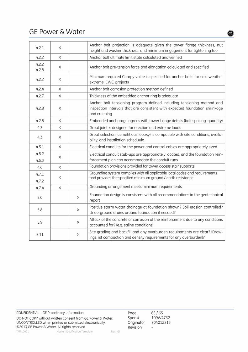
GE Power & Water g
CONFIDENTIAL – GE Proprietary Information
DO NOT COPY without written consent from GE Power & Water. UNCONTROLLED when printed or submitted electronically. ©2013 GE Power & Water. All rights reserved
Page 65 / 65 Spec # 109W4732 Originator 204012213 Revision -
TMPL0001 Master Specification Template Rev. (G)
4.2.1 X Anchor bolt projection is adequate given the tower flange thickness, nut
height and washer thickness, and minimum engagement for tightening tool
4.2.2 X Anchor bolt ultimate limit state calculated and verified
4.2.2
4.2.8 X Anchor bolt pre-tension force and elongation calculated and specified
4.2.2 X Minimum required Charpy value is specified for anchor bolts for cold weather
extreme (CWE) projects
4.2.4 X Anchor bolt corrosion protection method defined
4.2.7 X Thickness of the embedded anchor ring is adequate
4.2.8 X
Anchor bolt tensioning program defined including tensioning method and
inspection intervals that are consistent with expected foundation shrinkage
and creeping
4.2.8 X Embedded anchorage agrees with tower flange details (bolt spacing, quantity)
4.3 X Grout joint is designed for erection and extreme loads
4.3 X Grout selection (cemetitious, epoxy) is compatible with site conditions, availa-
bility, and installation scheduule
4.5.1 X Electrical conduits for the power and control cables are appropriately sized
4.5.2
4.5.3 X
Electrical conduit stub-ups are appropriately located, and the foundation rein-
forcement plan can accommodate the conduit runs
4.6 X Foundation provisions provided for tower access stair supports
4.7.1
4.7.2 X
Grounding system complies with all applicable local codes and requirements and provides the specified minimum ground / earth resistance
4.7.4 X Grounding arrangement meets minimum requirements
5.0 X Foundation design is consistent with all recommendations in the geotechnical
report
5.8 X Positive storm water drainage at foundation shown? Soil erosion controlled?
Underground drains around foundation if needed?
5.9 X Attack of the concrete or corrosion of the reinforcement due to any conditions
accounted for? (e.g. saline conditions)
5.11 X Site grading and backfill and any overburden requirements are clear? (Draw-
ings list compaction and density requirements for any overburden)?

Place of use Designation Use Quantity
Class of
hazardous
material
Converter Cooling Circuit
(Ideally replaced by non-harmful P44)
Glysantin® G05® Coolant 200 L at 50% with water
Xn (Harmful)
Slipring hub cleaning Cleaner, Spray Cleaner (Weicon)
Manufacture of
electrical
equipment
500mL/machine
N
(Environmentally
hazardous)
Yaw & brake HPU MOBIL DTE 25 Hydraulic fluid 20 L Non-hazardous
Generator
UNIREX N 3
(ajouter kluberplex
dem 41 (GREASE
BEM 41-132
KLUEBERPLEX)
Grease
Top up grease
quantity per
year: 800g = 2
cartridges
N
Blades & Yaw
Bearings (Not used
in EU)
MOBILITH SHC 460 Grease
Initial charge:
approx. 2.2kg
per yaw motor
Relubricating
quantity per
yaw motor:
0.2kg
--> total per
turbine: 0.2kg x
4 yaw motors =
0.8 kg
Non-hazardous
Pitch and yaw Drive MOBIL SHC
220/460/630
Circulation/gear
oil
25 L / yaw è
100 L Non-hazardous
Main bearing FAG Arcanol
LOAD400 Lubricant
10 kg tank + in
the bearings Non-hazardous
Pitch teeth CEPLATTYN BL Lubricant Apply by hand
200g / blade Non-hazardous
Pitch & yaw bearing STABYL EOS E 2 Lubricant
grease
5kg tank + in
the bearings Non-hazardous
Minimal and
solidified, service Loctite 243 Adhesive 1 drop per bolt N, Xi (irritating)

actions only during
significant
mechanical
disassembly, not
before year 8
Minimal and
solidified, service
actions only during
significant
mechanical
disassembly, not
before year 8
Loctite 586 Adhesive 1 drop per bolt Xn
Minimal and
solidified, service
actions only during
significant
mechanical
disassembly, not
before year 8
Loctite 640 Adhesive 1 drop per bolt Xi
Generator bearings Klüberplex BEM 41-
141 Lubricant
4 kg tank + in
the bearings Non-hazardous
Pitch drive
LIEBHERR
SPEZIALFETT 1026
LS
Grease 0,1 kg for the 3
pitch bearings Non-hazardous
Maintenance
cleaning HM Classico
Industrial
purifier
0.1 L / WTG at
10%
Xi, R43
(sensitizing),
R52/53
(Environmentally
hazardous)
A film over the blade
studs OKS 221 Lubrifiant
Very little Spray, only
(respray when changing blade
before tightening)
Xi, F+ (extremely
flammable), N
Slip ring hub
cleaning SRB4E
Cleaning
solvent for
Magnetic
Heads, Printed
Circuit,
Soldering Flows
0.5 L / WTG /
maintenance
F (easily
flammable)

NORDEX N117


Format: A3
Blatt/sheet: 1/4
Dokumentennummer/ document number:
K0801_041624_IN_R01
Datum/ Date: 22.01.2013
Nordex N 117/3000
Variante Trafo im Turm/ variant internal
transformer
Nabenhöhe/ Hub heigth: 120 m +1,10 m
3,91 m
11
8,0
m
12
0,0
m
17
8,4
m
14,54 m
A=10.715 m²
116,8 m
Diese Darstellung ist nicht maßstabsgerecht
This image is not according scale
Maßstab/scale: 10 m
3,5° + 2 m
+0,0
4,38 m

Format: A3
Blatt/sheet: 2/4
Dokumentennummer/ document number:
K0801_041624_IN_R01
Datum/ Date: 22.01.2013
Nordex N 117/3000
Variante Trafo im Turm/ variant internal
transformer
Nabenhöhe/ Hub heigth: 120 m
117,8 m

Format: A3
Blatt/sheet: 3/4 Dokumentennummer/ document number:
K0801_041624_IN_R01
Datum/ Date: 22.01.2013
Nordex N 117/3000
Variante Trafo außerhalb Turm/ variant
external transformer
Nabenhöhe/ Hub heigth: 120 m
3,91 m
11
8,0
m 1
20
,0 m
17
8,4
m
14,54 m
A=10.715 m²
116,8 m
Diese Darstellung ist nicht maßstabserecht
This image is not according scale
Maßstab/scale: 10 m
3,5° + 2 m
Diese Darstellung ist nicht maßstabserecht
This image is not according scale
+1,10 m
+0,0
4,38 m
Diese Darstellung ist nicht maßstabsgerecht
This image is not according scale

Format: A3
Blatt/sheet: 4/4 Dokumentennummer/ document number:
K0801_041624_IN_R01
Datum/ Date: 22.01.2013
Nordex N 117/3000
Variante Trafo außerhalb Turm/ variant
external transformer
Nabenhöhe/ Hub heigth: 120 m
117,8 m

2013 by Nordex Energy GmbH
Sales document
Wind turbine class K08 delta
Type: N117/3000
Technical description
K0801_041798_EN
Revision 01 / 2013-01-18
- Translation of the original sales document - This document is a translation from German. In case of doubt, the German text shall prevail.
Document is published in electronic form.
Signed original at Nordex Energy GmbH, Department Central Engineering.

2013 by Nordex Energy GmbH
Technical modifications
This document was created with utmost care, taking into account the currently applicable standards.
However, due to continuous development, the figures, functional steps and technical data are subject to change without prior notice.
Copyright
Copyright 2013 by Nordex Energy GmbH.
This document including its presentation and content is the intellectual property of Nordex Energy GmbH.
Any disclosure, duplication or translation of this document or parts thereof in printed, handwritten or electronic form without the explicit approval of Nordex Energy GmbH is explicitly prohibited.
All rights reserved.
Contact details
For questions relating to this documentation please contact:
Nordex Energy GmbH
Langenhorner Chaussee 600
22419 Hamburg
Germany
http://www.nordex-online.com

Table of Contents Revision 01 / 2013-01-18
K0801_041798_EN Page 3 of 15
1. Set-up................................................................................................................... 4
1.1 Tower .................................................................................................................... 4
1.2 Rotor ..................................................................................................................... 6
1.3 Nacelle .................................................................................................................. 6
1.4 Auxiliary systems .................................................................................................. 8
2. Functional principle.......................................................................................... 10
3. Technical data ................................................................................................... 11
4. Revision index................................................................................................... 15

Revision 01 / 2013-01-18 Sales document
Page 4 of 15 K0801_041798_EN Tower
1. Set-up
The Nordex N117/3000 wind turbine is a speed-variable wind turbine with a rotor diameter of 116.8 m and a nominal power of 3000 kW. This wind turbine is designed for 50 Hz or 60 Hz. The wind turbine is designed for class 2a in accordance with IEC 61400-1.
The wind turbine Nordex N117/3000 is made up of the following main components:
Rotor, consisting of rotor hub, three rotor blades and the pitch system
Nacelle with drive train, generator and yaw system
Tubular tower or hybrid tower with foundation
Medium-voltage transformer (MV transformer) and medium-voltage switchgear (MV switchgear)
1.1 Tower
The Nordex N117/3000 is erected on tubular steel towers or hybrid towers for different rotor hub heights and wind zones.
The tubular steel tower is a cylindrical tower. The top section is conical. Depending on the hub height, it consists of four to seven tower sections.
Corrosion protection of the tubular steel tower is ensured by a tower surface coating system according to ISO 12944.
A service lift, the vertical ladder with fall protection system as well as resting and working platforms inside the tower allow for a weather-protected ascent to the nacelle.
The Nordex N117/3000 turbine may be erected on a hybrid tower, too. The bottom part of the hybrid tower consists of a concrete tower and the top part of a tubular steel tower with two sections.
The foundation depends on the ground conditions at the intended site. An anchor cage is imbedded in the foundation for anchoring the tower. Tower and anchor cage are screwed together.
In the standard version, the tower base only accommodates the switch cabinet. The switch cabinet contains important components of the electronic controls, turbine PC, frequency converter, main switch, fuses and outputs to the transformer and to the generator.
The frequency converter is equipped with a water cooling system. The water which was heated in the frequency converter is cooled in a water/air heat exchanger. It is located at the outside close to the tower door.
The MV transformer and MV switchgear are located in a separate transformer substation near the wind turbine.

Sales document Revision 01 / 2013-01-18
Tower K0801_041798_EN Page 5 of 15
Fig. 1 Sectional view of the tower base, standard version
1 Soil backfill
2 Tower anchoring
3 Stairs
4 Tower door
5 Ventilation/cooling
6 Power cables
7 2nd Tower platform
8 Switch cabinet
9 1st Tower platform
10 Transformer substation
As an option, the MV transformer and MV switchgear can also be installed in the tower base. In this case, the components are arranged in the tower base on three different levels:
The MV transformer on the foundation
The MV switchgear on the 1st tower platform
The switch cabinet with frequency converter on the 2nd tower platform
In the case of a separate transformer substation, the MV transformer is usually designed as an oil transformer. If the transformer is installed inside the tower, a dry-type transformer is used.

Revision 01 / 2013-01-18 Sales document
Page 6 of 15 K0801_041798_EN Rotor
1.2 Rotor
The rotor consists of the rotor hub with three pitch bearings and three pitch drives for blade adjustment as well as three rotor blades.
The rotor hub has a modular design. The base frame of the rotor hub is made up of a stiff cast structure. Onto this element pitch bearing and rotor blade are mounted. The rotor hub is covered with the spinner which enables the direct access from the nacelle into the rotor hub.
The rotor blades are made of high-quality glass-reinforced and carbon-fiber reinforced plastics. Each rotor blade is equipped with a highly effective lightning protection system.
In accordance with the guidelines IEC TS 61400-23 and GL IV-1 (2400) the rotor blade is statically and dynamically tested with loads that were even beyond standard design requirements.
The pitch system serves to adjust the pitch angle of the rotor blades set by the control system. For each individual rotor blade, the pitch system comprises an electromagnetic drive with 3-phase motor, planetary gear and drive pinion, as well as a control unit with frequency converter and emergency power supply. Power supply and signal transfer are realized through a slip ring assembly located in the nacelle.
1.3 Nacelle
The nacelle contains essential mechanical and electronic components of the wind turbine. The nacelle is mounted on the tower in rotating bearings.
The rotor shaft is mounted on the rotor bearing in the nacelle. In the rotor bearing a mechanical rotor lock is integrated used to securely lock the rotor.
The gearbox increases the rotor speed until it reaches the speed required for the generator.
The bearings and gearings are continuously lubricated with cooled oil. A 2-stage pump enables the oil circulation. A combined filter element with integrated coarse and fine filter removes solids. The control system monitors the level of contamination of the filter elements (differential pressure measurement). Optionally, an additional offline filtration can be installed (super fine-mesh filter 5 µm).
The gear oil used for lubrication also serves as a gearbox cooling. The temperatures of the gearbox bearings and the oil are continually monitored. When the optimum operating temperature is not reached yet, a thermal bypass shorts the circuit and conducts the gear oil back to the gearbox. If the optimum working temperature of the gear oil is exceeded it is cooled down.
The gearbox cooling is achieved with an oil/water cooler with stepped cooling capacity. The cooler is installed directly at the gearbox. The heated cooling water is recooled together with the cooling water of the generator in a passive cooler on the roof of the nacelle.
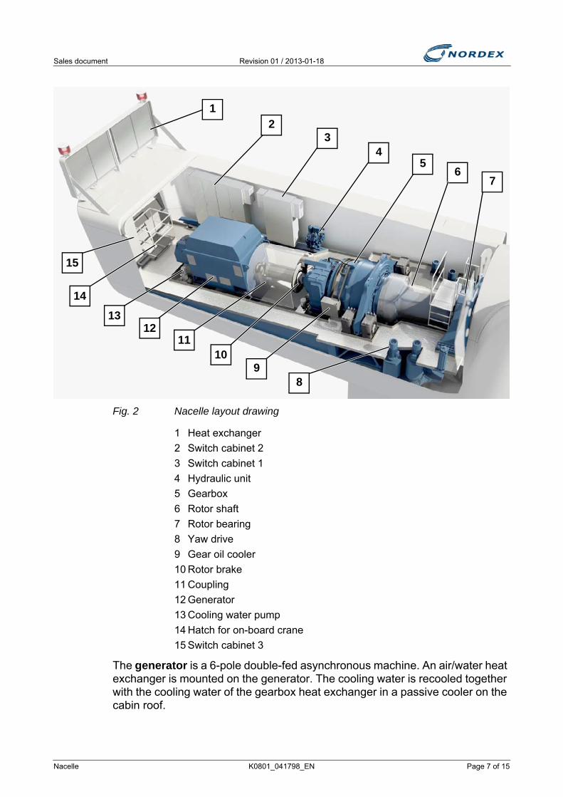
Sales document Revision 01 / 2013-01-18
Nacelle K0801_041798_EN Page 7 of 15
Fig. 2 Nacelle layout drawing
1 Heat exchanger
2 Switch cabinet 2
3 Switch cabinet 1
4 Hydraulic unit
5 Gearbox
6 Rotor shaft
7 Rotor bearing
8 Yaw drive
9 Gear oil cooler
10 Rotor brake
11 Coupling
12 Generator
13 Cooling water pump
14 Hatch for on-board crane
15 Switch cabinet 3
The generator is a 6-pole double-fed asynchronous machine. An air/water heat exchanger is mounted on the generator. The cooling water is recooled together with the cooling water of the gearbox heat exchanger in a passive cooler on the cabin roof.
1
32
4
6
8
7
9
5
15
14
1312
11
10

Revision 01 / 2013-01-18 Sales document
Page 8 of 15 K0801_041798_EN Auxiliary systems
The mechanical rotor brake supports the aerodynamic braking effect of the rotor blades as soon as the speed falls below a defined value and finally stops the rotor. The aerodynamic braking effect of the rotor is achieved by adjusting the rotor blades perpendicular towards the rotation direction. The rotor brake consists of a brake caliper which acts on the brake disk mounted behind the gearbox.
The yaw drives optimally rotate the nacelle into the wind. The four yaw drives are located on the machine frame in the nacelle. A yaw drive consists of an electric motor, multi-stage planetary gear and drive pinion. The drive pinions mesh with the external teeth of the yaw bearing.
If positioned properly the nacelle is locked by means of a electric brake system. It consists of several brake calipers which are fastened to the machine frame and act on a brake disk. In addition, the electric motors of the yaw drives are equipped with an electrically actuated holding brake.
Fig. 3 Components of the yaw system
1 Machine frame
2 Yaw drives in mesh with yaw bearing teeth
3 Yaw bearing
4 Brake caliper
The hydraulic unit provides the oil pressure for the operation of the rotor brake and the yaw brakes.
1.4 Auxiliary systems
An automatic lubrication unit is provided for each rotor bearing, generator bearing, pitch gearing, pitch races and yaw gearing.
The switch cabinets in the rotor hub, in the nacelle and in the tower base of the wind turbine are equipped with air conditioning units.
2
3
41

Sales document Revision 01 / 2013-01-18
Auxiliary systems K0801_041798_EN Page 9 of 15
Gearbox, generator and hydraulic unit are equipped with heaters.
A chain hoist is installed in the nacelle which is used for lifting tools, components and other work materials from the ground into the nacelle. A second, movable overhead crane is used for carrying the materials within the nacelle.

Revision 01 / 2013-01-18 Sales document
Page 10 of 15 K0801_041798_EN Auxiliary systems
2. Functional principle
The turbine operates automatically. A programmable logic controller (PLC) continuously monitors the operating parameters using various sensors, compares the actual values with the corresponding setpoints and issues the required control signals to the WT components. The operating parameters are defined by Nordex and adapted to the individual site.
When there is no wind the WT remains in idle mode. Only various auxiliary systems, such as heating and gear lubrication, and the PLC, which monitors the data from the wind measuring system, are operational. All other systems are switched off and do not use any power. The rotor idles.
When the cut-in wind speed is reached, the wind turbine changes to the mode 'Ready for operation'. Now all systems are tested, the nacelle aligns to the wind and the rotor blades turn into the wind. When a certain speed is reached, the generator is connected to the grid and the WT produces electricity.
At low wind speeds the WT operates in part-load operation. In the course of this the rotor blades remain fully turned into the wind (pitch angle 0°). The power produced by the WT depends on the wind speed.
When the nominal wind speed is reached, the WT switches over to the nominal load range. If the wind speed continues to increase, the speed control changes the rotor blade angle so that the rotor speed and thus the power output of the WT remain constant.
The yaw system ensures that the nacelle is always optimally aligned to the wind. To this end, two separate wind measuring systems located at the height of the hub measure the wind direction. Only one wind measuring system is required for control system, while the second monitors the first and takes over in case the first system fails. If the measured wind direction varies too greatly from the alignment of the nacelle, the nacelle is yawed into the wind.
The conversion of the wind energy absorbed from the rotor to electrical energy is achieved using a double-fed asynchronous generator with slip ring rotor. Its stator is directly and its rotor via a specially controlled frequency converter connected to the MV transformer. This offers a significant advantage enabling the generator to be operated in a defined speed range near its synchronous speed.
If certain parameters concerning turbine safety are exceeded, the WT will cut out immediately, e.g. if the cut-out wind speed is exceeded. Depending on the cause of the cut-out, various braking programs are triggered. In the case of external causes, such as excessive wind speeds or grid failure, the rotor is softly braked by means of rotor blade adjustment.

Sales document Revision 01 / 2013-01-18
Auxiliary systems K0801_041798_EN Page 11 of 15
3. Technical data
* At installation altitudes above 1000 m, the nominal power can be achieved up to the defined temperature ranges.
Climatic design data of the standard version
Design temperature Standard -20 °C…+50 °C
CCV -40 °C…+50 °CHCV -20 °C…+50 °C
Operating temperature range -20 °C … +40 °C
Operating temperature range CCV -30 °C … +40 °C
Operating temperature range HCV -20 °C … +45 °C
StopStandard -20 °C, restart at .-18 °C
CCV -30 °C, restart at -28 °CHCV -20 °C, restart at .-18 °C
Max. height above MSL 2000 m*
Certificate According to IEC 61400-1
Design
Type3-blade rotor with horizontal axis
Up-wind turbine
Power control Active single blade adjustment
Nominal power 3000 kW
Nominal power starting at wind speeds of(at air density of 1.225 kg/m3)
Approx. 12 m/s
Operating speed range of the rotor 8.0...14.1 rpm
Nominal speed 12.6 rpm
Cut-in wind speed Approx. 3 m/s
Cut-out wind speed 25 m/s
Cut-back-in wind speed 22 m/s
Calculated service life 20 years
Towers
Hub height 91 m 120 m 141 m
Name R91 R120 PH141
Wind class DIBt 3/IEC 2a DIBt 2/IEC 2a DIBt 2/IEC 3a
Number of tower sections 4 7 2 (+ concrete tower)

Revision 01 / 2013-01-18 Sales document
Page 12 of 15 K0801_041798_EN Auxiliary systems
Rotor
Rotor diameter 116.8 m
Swept area 10715 m2
Nominal power/area 280 W/m2
Rotor shaft inclination angle 5°
Blade cone angle 3.5°
Rotor blade
MaterialGlass-reinforced and carbon-fiberreinforced
plastics
Total length 57.3 m
Total weight per blade Approx. 10.6 t
Rotor shaft/rotor bearing
Type Forged hollow shaft
Material 42CrMo4 or 34CrNiMo6
Bearing type Spherical roller bearing
LubricationContinuous and automatic with lubricating
grease
Rotor bearing housing material EN-GJS-400-18U-LT
Gearbox
Type Multi-stage planetary gear + spur gear
Gear ratio50 Hz: i=92 ± 1%
60 Hz: i=111 ± 1%
Lubrication Forced-feed lubrication
Oil type VG 320
Max. oil temperature 75 °C
Oil change Change, if required
Electrical system
Nominal power PnG 3000 kW
Nominal voltage 3 x AC 660 V ± 10%
Nominal current InG at SnG 3240 A

Sales document Revision 01 / 2013-01-18
Auxiliary systems K0801_041798_EN Page 13 of 15
Nominal apparent power SnG at PnG 3333 kVA
Power factor at PnG
1.00 as default setting0.9 underexcited (inductive) up to
0.9 overexcited (capacitive) possible
Frequency 50 or 60 Hz
NOTE
The nominal power is subject to system-specific tolerances. During nominal power, they are ±100 kW. Practice has shown that negative deviations occur rarely and in most cases are <25 kW. For the precise compliance with external power specifications the nominal power of the single wind turbine may be parameterized accordingly. Alternatively, the wind farm can be parameterized accordingly using the Wind Farm Portal®.
Generator
Degree of protection IP 54 (slip ring box IP 23)
Nominal power 3090 kW
Nominal voltage 660 V
Frequency 50 or 60 Hz
Speed range50 Hz: 700 … 1300 rpm 60 Hz: 840 … 1560 rpm
Poles 6
Weight Approx. 10.6 t
Gearbox cooling and filtration
Type
1. Cooling circuit: Oil circuit with oil/water heat exchanger and thermal bypass2. Cooling circuit: Water/air together with generator cooling
FilterCoarse filter 50 µm
Fine-mesh filter 10 µm
Offline filter (optional) 5 µm
Generator cooling
Type Water circuit with water/air heat exchanger
Cooling water pump50 Hz: 1.3 kW60 Hz: 1.1 kW
Electrical system

Revision 01 / 2013-01-18 Sales document
Page 14 of 15 K0801_041798_EN Auxiliary systems
Flow rate Approx. 70 l/min
Coolant Water/glycol-based coolant
Converter cooling
TypeWater circuit with water/air heat exchanger
and thermal bypass
Coolant Water/glycol-based coolant
Pitch System
Pitch bearing Double-row four-point contact bearing
Lubrication of the gearing Automatic lubrication unit with grease
Drive3-phase motor incl. spring-actuated brake
and multi-stage planetary gear
Emergency power supply Lead-acid batteries
Hydraulic system
Hydraulic oil VG 32
Oil quantity Approx. 20 l
Thermal protection Integrated PT100
Yaw drive
Motor Asynchronous motor
Gearbox 4-stage planetary gear
Number of drives 4
Lubrication Oil, ISO VG 150
Yaw speed Approx. 0.5 °/s
Generator cooling

Sales document Revision 01 / 2013-01-18
K0801_041798_EN Page 15 of 15
4. Revision index
Rev. Date Modification AST Author
01 2013-01-18 New 7592 R. Simon

Nordex Energy GmbH
Langenhorner Chaussee 600
22419 Hamburg
Germany
http://www.nordex-online.com

K0801_041843_EN Revision 01, 2013-01-22 1 / 32
Transport, access roads and crane
requirements
Nordex N100/3300, N117/3000
Version delta
This document is a translation from German. In case of doubt, the German text shall prevail.
Nordex Energy GmbH, Langenhorner Chaussee 600, 22419 Hamburg, Germany All rights reserved. Observe protection notice ISO 16016.

Transport, access roads and crane requirements
K0801_041843_EN Revision 01, 2013-01-22 2 / 32
Table of contents
1 Basic information .................................................................................................. 3
2 Weights, dimensions and handling instructions ................................................. 4
2.1 Nacelle .................................................................................................................... 4
2.2 Drive train ................................................................................................................ 5
2.3 Rotor hub ................................................................................................................. 5
2.4 Rotor blade .............................................................................................................. 6
2.5 Weights of components on crane hook .................................................................... 7
2.6 Transport frames ..................................................................................................... 8
2.7 Towers N100/3300 ................................................................................................ 10
2.8 N117/3000 towers .................................................................................................. 11
2.9 Anchor cage .......................................................................................................... 12
3 Requirements for the access roads ................................................................... 14
3.1 Loads ..................................................................................................................... 14
3.2 Slopes and vertical radii ......................................................................................... 15
3.2.1 Slopes ................................................................................................................... 15
3.3 Clearance profile on a straight route ...................................................................... 16
3.4 Bends, opportunities to turn, and funnel lanes ....................................................... 16
3.4.1 Bends .................................................................................................................... 16
3.4.2 Opportunity to turn and funnel lanes ...................................................................... 19
3.4.3 Road construction .................................................................................................. 20
3.4.4 Passing places ...................................................................................................... 21
3.4.5 Storage areas and site office ................................................................................. 22
3.4.6 Quality assurance, access roads and crane hardstanding areas ........................... 23
3.5 Public roads ........................................................................................................... 23
4 Crane requirements ............................................................................................. 23
5 Crane hardstanding area ..................................................................................... 24

Transport, access roads and crane requirements
K0801_041843_EN Revision 01, 2013-01-22 3 / 32
1 Basic information
This document contains the basics for planning of the road construction and infrastructure of wind
farms for the wind turbine class K08 delta (N100 and N117 with the respective hub heights).
Furthermore component dimensions for the design of transport equipment and cranes are
included.
The planning parameters in this document are given as minimum requirements and may vary
depending on the project.
Detailed information on the infrastructure planning is project-specific and must be agreed to with
all persons involved prior to project start.
Each project location must be analyzed and planned correspondingly with regard to its local and
general safety regulations. In this context, the safety of persons and material is given top priority.
Deviations to the below specifications must be agreed to with Nordex beforehand.
We expressly point out that all values must be regarded as standard values only.
Further instructions for transport can be requested from Nordex.
The layout of access roads and hardstanding areas depends on the transportation and
erection method.
- The design must be modified for each individual erection site.
- Depending on the erection site different variants are possible.
- Transport weights may also vary with the erection site.
The exact design of access roads, crane hardstanding areas and assembly areas must
be agreed to
with Nordex prior to starting the erection work!
Improper design or layout of access roads and crane hardstanding areas may cause
considerably higher logistics and erection costs at a later stage.

Transport, access roads and crane requirements
K0801_041843_EN Revision 01, 2013-01-22 4 / 32
2 Weights, dimensions and handling instructions
2.1 Nacelle
Drive train, rotor hub and further exterior assemblies (obstacle lights, wind sensors, lightning
arrester, etc.) are not assembled for nacelle transport.
The transport frame for the nacelle consists of 4 single supports. They can be used for twist lock
fastening (see chapter 2.6). Otherwise, anti-slip mats must be used for transport.
The nacelle must only be placed on compacted ground or on crane mats.
Fig. 1: Nacelle (view from the left) with transport supports
Fig. 2: Nacelle (front view) with transport supports
The coordinates of the center of gravity of the nacelle are determined without considering the
drive train and the transport support.
12700
40
00
4300
2400
2572

Transport, access roads and crane requirements
K0801_041843_EN Revision 01, 2013-01-22 5 / 32
2.2 Drive train
Fig. 3: Drive train on transport frame
For the rear section of the gearbox a wooden cladding is planned. This cladding is included in the
overall length.
2.3 Rotor hub
Fig. 4: Rotor hub on transport frame
The rotor hub is delivered on a separable transport frame.
Anti-slip mats must be used for transport.
2784 approx. 6200
29
67
3190
2066
4654
3000
5312
39
70

Transport, access roads and crane requirements
K0801_041843_EN Revision 01, 2013-01-22 6 / 32
2.4 Rotor blade
Each rotor blade is delivered on two transport frames using a trailer. One of the transport frames
is fastened to the blade root, the other one to the support point.
In addition to center of gravity and support point the drawing shows the defined points where the
webbing slings can be attached. The blade must only be lifted at these points as they are
reinforced in these areas.
Fig. 5: Rotor
blade
Rotor blade LM48.8 NR50 NR58.5
A
Lifting point root
0.8
0.3
0.3
C
Center of gravity
14.5
14.3
15.6
E Lifting point SA 34 32 38
F Support point 35 34 40
G Lifting point SA - 37 43
H Length 48.8 48.8 57.3
I Transport height 2.9…3.9 3.2…4.1 3.1…3.6
J Transport width 2.9…3.1 2.5…3.9 2.5…3.7
Fig. 6 Transport dimensions
Rotor blade
All dimensions in meters [m] SA: Star assembly SBA: Single blade assembly
I
J

Transport, access roads and crane requirements
K0801_041843_EN Revision 01, 2013-01-22 7 / 32
2.5 Weights of components on crane hook
A) Weights for transport (with transport frame)
Nacelle
Height (without exterior assemblies) 4.00 m
Width 4.30 m
Length 12.70 m
Weight of "empty" nacelle (without rotor shaft, gearbox)
Approx. 60 t
Weight of drive train only (rotor shaft, gearbox)
59.3 -61.3
Rotor hub Ø 100 Ø 117
Weight Approx. 31.5 t Approx. 31.5 t
Dimensions L x W x H 4.65 m x 5.31 m x 3.97 m (overall spinner dimensions)
Rotor blade
Length incl. blade bolts
without blade bolts
49 m
48.7 m
57.6 m
57.3 m
Weight per blade
(varies depending on the manufacturer and the method of transportation)
Max. 11.9 t 11.2 t
Switch cabinet (Bottombox)
Dimensions L x W x H 2.2 m x 1.2 m x 2 m
Weight Approx. 2.9 t
B) Weights for erection (without transport frame)
Nacelle
Height (without exterior assemblies) 4.00 m
Width 4.30 m
Length 12.70 m
Weight of "empty" nacelle (without rotor shaft, gearbox)
Approx. 58.7 t
Weight of drive train only (rotor shaft, gearbox)
56.7 t ... 58.7 t
Weight of complete nacelle (without rotor)
Approx. 115.5 t
Rotor hub Ø 100 Ø 117
Weight Approx. 30 t Approx. 30 t
Rotor blade
Dimensions as specified above, under A)
Weight per blade
(varies depending on the manufacturer)
Max. 11.4 t
10.7 t
Complete rotor Max. 64.2 t Approx. 62.1 t

Transport, access roads and crane requirements
K0801_041843_EN Revision 01, 2013-01-22 8 / 32
Switch cabinet (Bottombox)
As specified above, under A)
Transformer
With the transformer installed in the tower the transformer substation is omitted.
Individual components per wind turbine:
Transformer Approx. 8.9 t, L x W x H: 2.6 x 1.3 x 2.54 m
Medium-voltage switchgear Max. 1.5 t, L x W x H: 2.0 x 1.0 x 2.0 m
Transformer substation
The transformer substation and wind turbine must not be erected at the same time.
For exact dimensions and weights refer to the manufacturer: Dimensions and weights also vary within a wind farm depending on equipment and project scope.
The following values can be found:
Length 3.3 to 7.0 m
Width 2.5 to 3.0 m
Height 2.7 to 3.9 m
Weight (incl. transformer, etc.) 15 to 31 t
2.6 Transport frames
Transport frame Weight
Nacelle transport frame Approx. 1.25 t
Transport frame – drive train Approx. 2.6 t
Hub transport frame Approx. 1.5 t
Transport frame – rotor blade (root/tip)
Depending on method of transportation
Approx. 150-400 kg/50-600 kg
Transport cross beams – switch cabinet Approx. 100 kg (transport cross beams are expected to remain installed at the switch cabinet)
Nacelle transport frame
Front bearing surface: 400 x 400 mm
Rear bearing surface: 500 x 400 mm
Load per front support: 18 t
Load per rear support: 12 t
The screws for fastening the nacelle are part of the transport supports and must be returned
together with the transport supports to Nordex.

Transport, access roads and crane requirements
K0801_041843_EN Revision 01, 2013-01-22 9 / 32
Transport frame – drive train
Fig. 7: Transport frame – drive train
The supports for the gearbox supports are removable. The transport frames for the drive train can
be stacked up to 4 for return transport.
The supports for the gearbox supports, including their fastening screws, are part of the transport
frame and must be returned together with the transport frame to Nordex.
A transport frame with a width of < 2.45 m is currently being developed.
Hub transport frame
The transport frame can be stacked and screwed together for return transport.
500
2066
3000
720
75
5
3680
Fig. 8: Hub transport frame
The round wood plate must also be returned if it is not damaged.
4390
2710
13
57
6907 2
22
7
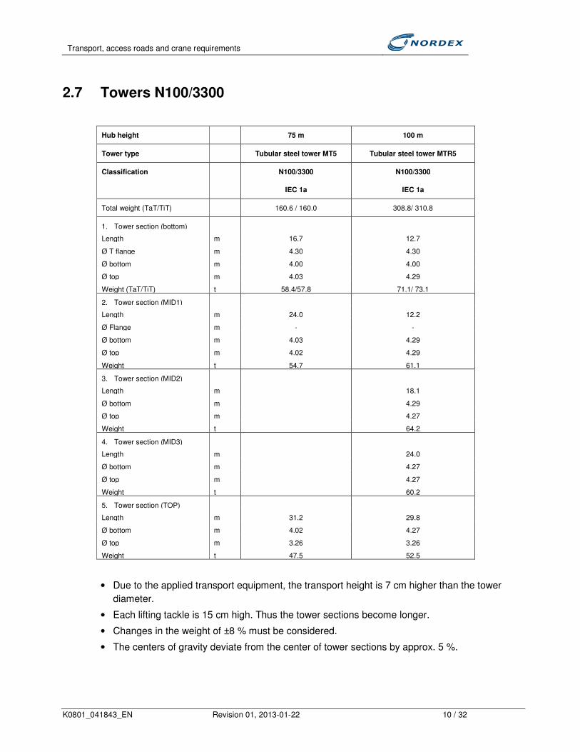
Transport, access roads and crane requirements
K0801_041843_EN Revision 01, 2013-01-22 10 / 32
2.7 Towers N100/3300
Hub height 75 m 100 m
Tower type Tubular steel tower MT5 Tubular steel tower MTR5
Classification N100/3300
IEC 1a
N100/3300
IEC 1a
Total weight (TaT/TiT) 160.6 / 160.0 308.8/ 310.8
1. Tower section (bottom)
Length m 16.7 12.7
Ø T flange m 4.30 4.30
Ø bottom m 4.00 4.00
Ø top m 4.03 4.29
Weight (TaT/TiT) t 58.4/57.8 71.1/ 73.1
2. Tower section (MID1)
Length m 24.0 12.2
Ø Flange m - -
Ø bottom m 4.03 4.29
Ø top m 4.02 4.29
Weight t 54.7 61.1
3. Tower section (MID2)
Length m 18.1
Ø bottom m 4.29
Ø top m 4.27
Weight t 64.2
4. Tower section (MID3)
Length m 24.0
Ø bottom m 4.27
Ø top m 4.27
Weight t 60.2
5. Tower section (TOP)
Length m 31.2 29.8
Ø bottom m 4.02 4.27
Ø top m 3.26 3.26
Weight t 47.5 52.5
• Due to the applied transport equipment, the transport height is 7 cm higher than the tower
diameter.
• Each lifting tackle is 15 cm high. Thus the tower sections become longer.
• Changes in the weight of ±8 % must be considered.
• The centers of gravity deviate from the center of tower sections by approx. 5 %.

Transport, access roads and crane requirements
K0801_041843_EN Revision 01, 2013-01-22 11 / 32
2.8 N117/3000 towers
Hub height 91 m 120 m 141 m
Tower type Tubular steel tower Tubular steel tower MT5 Hybrid tower PH141
Classification N117/3000 N117/3000 N117/3000
Total weight (TaT/TiT) 216.1/ 216.6 466.5/ 466.7 102.1
1. Tower section
Length m 13.8 9.1 23.00
Ø T flange m 4.30 4.30 -
Ø bottom m 4.00 4.07 4.29
Ø top m 4.03 4.30 4.29
Weight (TaT/TiT) t 57.5/ 58.0 69.5 / 69.7 48.5
2. Tower section (MID1)
Length m 18.1 9.3
Ø bottom m 4.03 4.30
Ø top m 4.02 4.30
Weight t 54.5 69.9
3. Tower section (MID2)
Length m 24.0 9.3
Ø bottom m 4.02 -
Ø top m 4.02 4.29
Weight t 52.5 68.1
4. Tower section (MID3)
Length m 12.2
Ø bottom m 4.28
Ø top m 4.28
Weight t 68.2
5. Tower section (MID4)
Length m 17.1
Ø bottom m 4.26
Ø top m 4.26
Weight t 69.9
6. Tower section (MID5)
Length m 25
Ø bottom m 4.26
Ø top m 4.25
Weight t 63.7
7. Tower section (TOP)
Length m 32.0 35.00 35.00
Ø bottom m 4.02 4.23 4.29
Ø top m 3.26 3.26 3.26
Weight t 51.2 57.2 53.6
• Due to the applied transport equipment, the transport height is 7 cm higher than the tower
diameter.
• Each lifting tackle is 15 cm high. Thus the tower sections become longer.

Transport, access roads and crane requirements
K0801_041843_EN Revision 01, 2013-01-22 12 / 32
• Changes in the weight of ±8 % must be considered.
• The centers of gravity deviate from the center of tower sections by approx. 5 %.
2.9 Anchor cage
Nordex delivers modular anchor cages which vary in dimensions and weights. The anchor cages
are always delivered as an assembly set. The anchor cage is assembled on site by the
responsible construction company. Nordex offers against extra payments to deliver the anchor
cages already pre-assembled to the construction site (this is not possible for the anchor cages of
the N100 R100 and N117 R120).
Special permission is required for the transportation of pre-assembled anchor cages. This may
result in lead times of up to 6 weeks depending on the country.
An N100 R75 and N117 R91 anchor cage is made up of the following parts:
WT Name Parts Thicknes
s Dimensions
Maximum Weight
Maximum
N100 R75 N100 R91
Load-spreading plate
2 77 mm Outside ∅ 4500 mm Approx. 3.7 t
Anchor plate 2 70 mm Outside ∅ 4460 mm Approx. 3.1 t
Anchor bolts 160 M42 L = 3071 mm Approx. 5.4 t
Washers, nuts and other small parts Approx. 0.5 t
The complete anchor cage, including transport equipment, weighs approx. 12.6 t.
Fig. 9: Anchor cage with 2x80 bolts Fig. 10: Anchor cage 2x100 bolts (N100 R100)

Transport, access roads and crane requirements
K0801_041843_EN Revision 01, 2013-01-22 13 / 32
The anchor cage N100 R100 consists of the following parts:
WT Name Parts Thicknes
s Dimensions
Maximum Weight
Maximum total
N100 R100
Load-spreading plate
4 160 mm Outside ∅ 4720 mm Approx. 11 t
Anchor plate 4 100 mm Outside ∅ 4550 mm Approx. 5.2 t
Anchor bolts 200 M42 L = 3190 mm Approx. 7.0 t
Washers, nuts and other small parts Approx. 0.5 t
The complete anchor cage, including transport equipment, weighs approx. 23,7t and is quartered
The anchor cage N117 R120 consists of the following parts:
WT Name Parts Thicknes
s Dimensions
Maximum Weight
Maximum total
N117 R120
Load-spreading plate 1
Load-spreading plate 2
4 4
120 mm 120 mm
Outside ∅ 4500 mm
Outside ∅ 4770 mm
Approx. 5.6 t Approx. 8.8 t
Anchor plate 4 120 mm Outside ∅ 4650 mm Approx. 7.4 t
Anchor bolts 200 M42 L = 3794 mm Approx. 8.3 t
Washers, nuts and other small parts Approx. 0.5 t
These values represent the current status of development and may vary slightly.
The complete anchor cage assembly set, including transport equipment, weighs approx. 30.6 t
and is quartered.
The weights may vary slightly depending on the tower.

Transport, access roads and crane requirements
K0801_041843_EN Revision 01, 2013-01-22 14 / 32
3 Requirements for the access roads
In general, the ordering party is responsible for the planning of the wind farm infrastructure on the
basis of the requirements stipulated in this document. In order to prevent subsequent problems
during transport and erection work, the planning must be agreed to with Nordex prior to starting
the construction. The infrastructure planning must contain at least the following information:
• WT sites
• Access roads planning, including the longitudinal profile with slopes and vertical radii, cross
profile and bend radii
• Turning and passing places
• Crane hardstanding areas regarding foundation and WT site
To avoid problems during the erection of the wind turbine, the following minimum requirements
for the access roads must be met under normal ground conditions:
3.1 Loads
The access roads for each wind turbine must be capable of supporting the following loads:
Vehicles per wind turbine
- Approx. 50 to 100 concrete and construction vehicles, up to 220 vehicles for hybrid towers
- Approx. 15 to 40 heavy trucks for crane erection (depending on the hub height)
- Approx. 8 to 13 heavy trucks with turbine components
(2 to 7 for tower sections, 3 for rotor blades, 3 for nacelle, rotor hub and drive train, 2 for
switch cabinet (Bottombox), small parts and erection container)
- Maximum truck length 62 m rotor blade transport and 49 m tower transport
- Required clearance height for public roads ≥ 4.50 m,
from construction site access 5.00 m to 6.00 m (depending on the method of transport and
local conditions)
- Different types of construction vehicles
Weight of vehicles
- Max. load per axle: approx. 12 t
- Max. overall weight: approx. 165 t

Transport, access roads and crane requirements
K0801_041843_EN Revision 01, 2013-01-22 15 / 32
3.2 Slopes and vertical radii
3.2.1 Slopes
If the surfaces meet the descriptions in Chapter 3.5, slopes of approx. 8 % must not be exceeded
at any rate. If there are slopes exceeding 8 %, Nordex must always be consulted.
Against reimbursement of the extra costs, additional tractor units can be used so that slightly
steeper slopes can be handled and under the provision of a suitable surface condition. As the
length of the entire tractor unit becomes larger this must be considered in road construction
planning, especially in terms of bend radii.
Slopes of up to 8 % can only be accomplished when driving forward. In the case the transports
can only manage the slope driving backwards, partly depending on the site-specific conditions,
the maximum inclination must not exceed 1.5 % (without additional tractor units). On these road
sections, the road foundation must be taken into account (see Chapter 3.5) as the traction is
completely shifted to the front axle of the tractor unit. An adapted design and/or the use of other
materials for road construction may be required for the relevant sections.
The lateral tilt must not be greater than 2 %.
Depending on the season and the weather the requirements for slopes may vary so that
additional tractor units or vehicles for braking must be used.
3.2.2 Vertical radii
The radii (vertical) for peaks and valleys must not be lower than R375 m. Over a length of 30.0 m
(largest center distance) the difference in height between two points must not be lower than
0.30 m.
If the required minimum radii can be hardly achieved or not at all due to associated construction
measures an on-site inspection must be carried out to discuss possible alternatives such as other
routes or transport methods.
Fig. 11: Vertical radius
N100 N117
WT type Rmin [m] N100 350 N117 375

Transport, access roads and crane requirements
K0801_041843_EN Revision 01, 2013-01-22 16 / 32
3.3 Clearance profile on a straight route
For all hub heights
H Clearance height Approx. 4.50-6.00 m (depending on transport method)
W Clearance width 5.00 m (Concrete hybrid towers: 6.00 m)
The clearance on public roads normally has a height of approx. 4.5 m due to bridges. On the
access roads to the construction site a clearance height of 5 m to 6 m* and a clearance width of
at least 5 m must be ensured depending on the project or location. For concrete hybrid towers a
clearance width of at least 6 m must be ensured to enable the transport of prefabricated concrete
elements.
*If it is not possible to adopt the method of transport employed for the route to the construction
site access to the internal access roads due to local conditions (topography, roadway
arrangement, obstacles) components may be reloaded to other means of transport, if required, to
enable the delivery to the crane hardstanding area. The crane capacities needed for such
purposes and the width of the reloading area near or inside the construction site must be agreed
on with Nordex in advance. A corresponding transport, reloading, and storage concept must be
prepared considering the local conditions and the feasibility of measures to be taken.
Fig. 12: Clearance profile
3.4 Bends, opportunities to turn, and funnel lanes
3.4.1 Bends
The following sketches exemplarily illustrate the space required for the rotor blade in a bend:

Transport, access roads and crane requirements
K0801_041843_EN Revision 01, 2013-01-22 17 / 32
Fig. 13: Minimum required extension 70° bend N100 (left and right turn)
Fig. 14: Minimum required extension 90° bend N100 (left and right turn)
Fig. 15: Minimum required extension 120° bend N100 (left and right turn)

Transport, access roads and crane requirements
K0801_041843_EN Revision 01, 2013-01-22 18 / 32
Fig. 16: Minimum required extension 70° bend N117 (left and right turn)
Fig. 14: Minimum required extension 90° bend N117 (left and right turn)
Fig. 15: Minimum required extension 120° bend N117 (left and right turn)

Transport, access roads and crane requirements
K0801_041843_EN Revision 01, 2013-01-22 19 / 32
The continuous lines depict the travel of the truck. The dashed lines mark the areas covered by
the vehicle and the rotor blade. The outer area covered is determined by the length of the rotor
blade protruding at the rear.
The covered area (dashed) must be free of all obstacles, i.e. trees, streetlights, buildings, masts,
etc. This area must be max. 20 cm above the paved level of the accessible road.
The construction of bends to be accessed backwards must enable the respective turbine types to
travel the whole covered radii specified in chapter 3.4. due to the maximum turn angle of the rear-
wheels of less than 70 %. The capacity of the vehicles deployed normally matches the loads that
must be moved. The deployment of additional tractors and/or other vehicles, however, cannot be
excluded due to local conditions. Since in case of pushing other forces act on the vehicle and its
load and the trajectory within the lane cannot be influenced damages to the road surface on
construction site may occur. These damages must be repaired immediately , respectively before
other heavy loads pass through.
The exact values depend on the vehicles used and the individual local situation.
The maximum slope or incline in bend radii/bend areas is < 2 %. A bend with slope/incline shall
be constructed in a manner that the road surface is on an even level to protect the components
from hitting the ground. The area that lay 50 m around the peak is the bend area and must be
constructed as an even surface.
3.4.2 Opportunity to turn and funnel lanes
Depending on the size of project and the access situation double lanes enabling the vehicles to
turn shall be constructed at strategic and central crossroads or preferably at access points to
single turbines.
These double lanes shall enable the vehicles to turn and to leave the construction site forward.
The lanes shall be located at strategic crossroads to avoid reversing over a distance of 500 m
because these movements consume too much time and may negatively affect the traffic on
construction site or the erection process.
The dimensions of the funnel lanes derive from the length of the components (refer to Chapter
2.4) with 5 m to be added to serve as manoeuvring space = width of the lane, the bend radii must
be considered as specified below. The width of the smallest place (front side) is < 4.5 m. If a
funnel lane shall be used as a parking place for more than 1 vehicle the lane must be broadened
by another lane of 4.5 m width per vehicle. In junction areas the turning lanes shall always be
adjacent , not opposite to one another. Depending on the location it should be considered if four
lanes are required or do making sense in junction areas.

Transport, access roads and crane requirements
K0801_041843_EN Revision 01, 2013-01-22 20 / 32
Fig. 14: Opportunity to turn and funnel lanes
3.4.3 Road construction
In principle, the access roads shall be planned to enable a secure transport for the respective
wind turbine type and to achieve the load-carrying capacities described in chapter 3.1. For that
purpose, the site-specific ground conditions must be taken into account. Planning and execution
shall be adjusted accordingly. The structure described below serves only for illustration and does
not excuse the ordering party from a project-specific design and planning.
Fig. 15: Cross-section of the access road (example)
• Instead of gravel, base and top layer may be made of broken bricks or concrete (free of other
demolition waste).
• All layers and the subsoil must be compacted using proper machinery to allow for heavy loads
• Even road surface
• Proper drainage for all access roads must be ensured (cross slope of 1 to 2 %).
Proper water transport (e.g., in the lateral trenches or under access road junctions) must be
3. Top layer compacted, ballast, 15-25 cm
2. Base layer compacted, gravel, 15-30 cm
1. Bed compacted, 30-100 cm
Geomembrane as separation layer
30-100 cm
Min. 4.5 m
Subsoil
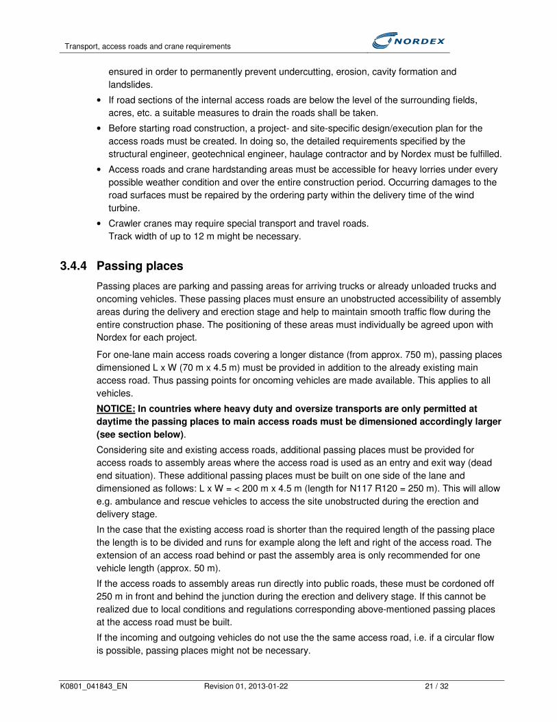
Transport, access roads and crane requirements
K0801_041843_EN Revision 01, 2013-01-22 21 / 32
ensured in order to permanently prevent undercutting, erosion, cavity formation and
landslides.
• If road sections of the internal access roads are below the level of the surrounding fields,
acres, etc. a suitable measures to drain the roads shall be taken.
• Before starting road construction, a project- and site-specific design/execution plan for the
access roads must be created. In doing so, the detailed requirements specified by the
structural engineer, geotechnical engineer, haulage contractor and by Nordex must be fulfilled.
• Access roads and crane hardstanding areas must be accessible for heavy lorries under every
possible weather condition and over the entire construction period. Occurring damages to the
road surfaces must be repaired by the ordering party within the delivery time of the wind
turbine.
• Crawler cranes may require special transport and travel roads.
Track width of up to 12 m might be necessary.
3.4.4 Passing places
Passing places are parking and passing areas for arriving trucks or already unloaded trucks and
oncoming vehicles. These passing places must ensure an unobstructed accessibility of assembly
areas during the delivery and erection stage and help to maintain smooth traffic flow during the
entire construction phase. The positioning of these areas must individually be agreed upon with
Nordex for each project.
For one-lane main access roads covering a longer distance (from approx. 750 m), passing places
dimensioned L x W (70 m x 4.5 m) must be provided in addition to the already existing main
access road. Thus passing points for oncoming vehicles are made available. This applies to all
vehicles.
NOTICE: In countries where heavy duty and oversize transports are only permitted at
daytime the passing places to main access roads must be dimensioned accordingly larger
(see section below).
Considering site and existing access roads, additional passing places must be provided for
access roads to assembly areas where the access road is used as an entry and exit way (dead
end situation). These additional passing places must be built on one side of the lane and
dimensioned as follows: L x W = < 200 m x 4.5 m (length for N117 R120 = 250 m). This will allow
e.g. ambulance and rescue vehicles to access the site unobstructed during the erection and
delivery stage.
In the case that the existing access road is shorter than the required length of the passing place
the length is to be divided and runs for example along the left and right of the access road. The
extension of an access road behind or past the assembly area is only recommended for one
vehicle length (approx. 50 m).
If the access roads to assembly areas run directly into public roads, these must be cordoned off
250 m in front and behind the junction during the erection and delivery stage. If this cannot be
realized due to local conditions and regulations corresponding above-mentioned passing places
at the access road must be built.
If the incoming and outgoing vehicles do not use the the same access road, i.e. if a circular flow
is possible, passing places might not be necessary.

Transport, access roads and crane requirements
K0801_041843_EN Revision 01, 2013-01-22 22 / 32
Fig. 16: Examples of a passing place
3.4.5 Storage areas and site office
The following sketch shows a general presentation of a Nordex site office which must be
designed project-specific:
Fig. 17: Nordex site office (example)
The ordering party has provided an area of approx 1200 m² in order to accommodate the
following equipment and accessories:
• Nordex office 20 ft container
• Office for responsible company 20 ft container
• Office for meetings 20 ft container
• Generator with drip tray
• Recycling
• Free space for material on EUR pallets (14 m x 2.5 m)
• Rest room
• Free space for material (fenced: 14 m x 2.5 m)
• 4x 20 ft material container (2x for material / 1x for cables in order to store material in dry and heatable place)
• Parking lots for passenger cars

Transport, access roads and crane requirements
K0801_041843_EN Revision 01, 2013-01-22 23 / 32
3.4.6 Quality assurance, access roads and crane hardstanding areas
The ordering party is responsible to carry out the following minimum and required quality checks
for the design of access roads and crane hardstanding areas depending on the type and
composition of the earthwork materials. The check results must be submitted to Nordex at the
latest 4 weeks before delivery starts:
Quality checks Minimum
number/comme
nts
Degree of compaction (Dpr) according to DIN 18127 of the access roads
in layers (bed, base layer, top layer)
1 test (every 500
m)
Degree of compaction (Dpr) according to DIN 18127 of the crane
hardstanding areas in layers (bed, base layer, top layer)
4 tests (per crane
hardstanding
area)
Static plate load test according to DIN 18134 of the access roads in
layers (bed, base layer, top layer)
3 tests (every
5000 m²)
Static plate load test according to DIN 18134 of the crane hardstanding
areas in layers (bed, base layer, top layer)
2 tests (per crane
hardstanding
area)
The results of all tests must be documented in full. This must be done in a professional manner
and illustrated with tables and diagrams and submitted to Nordex. The testing points are to be
presented in the diagrams including positions and heights. The soil profile of access roads and
crane hardstanding areas also require neat presentation.
3.5 Public roads
In general, the ordering party is responsible for the access roads from the destination port or the
freeway exit to the construction site. The ordering party is also in charge of planning, obtaining
permission and executing necessary constructive measures.
Here, Nordex can be of support when creating feasibility tests and listing required constructive
measures. Depending on the complexity of the access roads, it may be necessary to perform a
"dummy run" prior to starting the heavy duty transports.
4 Crane requirements
One main crane and, at least, one auxiliary crane are required for the wind turbine erection. The
auxiliary crane must be able to change its position several times before, during and after the wind
turbine erection.
• The required hook height is:
- Hub height + 10 m (e.g. N100 R100: 110 m)
- Exception: N117 R120: Hub height + 20 m (e.g. N117 R120: 140 m)

Transport, access roads and crane requirements
K0801_041843_EN Revision 01, 2013-01-22 24 / 32
• Main crane radius min. 15 to 30 m (depending on crane type)
• Auxiliary crane radius min. 6 to 12 m (depending on crane type)
Hub height 75 m 91 m 100 m 120 m 141 m Main crane - Maximum hook load - Maximum hook load at hub height
67.0 t 58.0 t
72.3 t 60.0 t
73.7 t 61.0 t
58.0 t 58.0 t
61.0 t 61.0 t
Auxiliary crane Required hook load
35 t
30 t
40 t
30 t
30 t
5 Crane hardstanding area
The crane hardstanding area must be planned and laid out according to the site-specific
conditions and the planned crane positions.
The crane hardstanding area must withstand the soil pressure of the crane outriggers. The soil
pressure depends on the maximum weight of the components and the size of the crane used
(mobile crane, crawler crane) and must be at least 250 kN/m².
The crane hardstanding area must be level across the entire surface:
- Maximum inclination for wind turbines with a hub height up to 100 m: ≤ 1 %
- Maximum inclination for wind turbines with a hub height of 100 m and higher: 0%
The crane hardstanding areas must be planned in such a way that the height difference between hardstanding area and
foundation top edge must not be greater than 1.1 m.
The erection and working area of the crane must be free of obstacles which might impair the
erection and operation of the crane (see following drawings). The length of the rotor blades and
the space for the star assembly must be considered for crane operation.
The transformer substation must not be placed on the crane hardstanding area or the assembly
area of the crane jib.
To prevent dirt from entering the wind turbine, access to foundation and the ground must be
compacted and covered with gravel to ensure a dry and clean surface.
An approx. 2 m wide walkable working area must be provided directly around the foundation.
The nacelle must only be placed on the crane hardstanding area or on the crane mats.
A long erection area is required for assembling the crane jib of lattice cranes. The length amounts
to:
- Hub height + 10 m
- For N117 R120: Hub height +20 m
The auxiliary crane must be free to move parallel to the entire length of the crane jib.
Crane hardstanding areas of 10 x 10 m each must be provided at the third points of the assembly
area (see following drawings).

Transport, access roads and crane requirements
K0801_041843_EN Revision 01, 2013-01-22 25 / 32
Examples
• Example 1 shows a crane hardstanding area for wind turbines up to 80 m hub height and with
just-in-time delivery. Higher transport costs are generally to be expected for this variant. The
final layout for the specific site must be planned after the site has been inspected.
• Example 1a shows the hardstanding area for wind turbines with tower heights of up to 80 m
and with a storage area for the delivery of turbine components including tower sections and
blades. The final layout for the specific site must be planned after the site has been inspected.
• Example 2 shows a crane hardstanding area for wind turbines up to 100 m tower height and
with just-in-time delivery. Higher transport costs are generally to be expected for this variant.
The final layout for the specific site must be planned after the site has been inspected.
• Example 2a shows the hardstanding area for wind turbines with tower heights of up to 100 m
and with a storage area for the delivery of turbine components including tower sections and
blades. The final layout for the specific site must be planned after the site has been inspected.
• Example 3 shows a crane hardstanding area for a N117, R120 and with just-in-time delivery.
Higher transport costs are generally to be expected for this variant. The final layout for the
specific site must be planned after the site has been inspected.
• Example 3a shows the hardstanding area for a N117, R120 with a storage area for the
delivery of turbine components including tower sections and blades. The final layout for the
specific site must be planned after the site has been inspected.
• Example 4 shows the hardstanding area for wind turbines with concrete hybrid tower (PH 141)
and with optional storage area for the delivery of turbine components including tower sections
and blades. The final layout for the specific site must be planned after the site has been
inspected.
In addition to the examples shown above, a clear assembly area for the rotor (star assembly) is
also required. This area depends on the local conditions and therefore Nordex has to be
consulted before any action is taken. Space for at least 2 Nordex erection containers must be
provided (for power generator and tools).
Further space must be provided for one Nordex material container for temporary material
storage, garbage containers, staff containers, construction vehicles, etc.
The access roads to the wind turbine must always be kept free for ambulance and rescue
vehicles.

Transport, access roads and crane requirements
K0801_041843_EN Revision 01, 2013-01-22 26 / 32
Example 1: Crane hardstanding area for WT up to 80 m hub height with just-in-time delivery

Transport, access roads and crane requirements
K0801_041843_EN Revision 01, 2013-01-22 27 / 32
Example 1a: Crane hardstanding area for WTs up to 80 m hub height with storage areas for delivery

Transport, access roads and crane requirements
K0801_041843_EN Revision 01, 2013-01-22 28 / 32
Example 2: Crane hardstanding area for WT up to 100 m hub height with just-in-time delivery

Transport, access roads and crane requirements
K0801_041843_EN Revision 01, 2013-01-22 29 / 32
Example 2a: Crane hardstanding area for WTs up to 100 m hub height with storage areas for delivery

Transport, access roads and crane requirements
K0801_041843_EN Revision 01, 2013-01-22 30 / 32
Example 3: Crane hardstanding area for N117 R120 with just-in-time delivery

Transport, access roads and crane requirements
K0801_041843_EN Revision 01, 2013-01-22 31 / 32
Example 3a: Crane hardstanding area for N117 R120 with storage area

Transport, access roads and crane requirements
K0801_041843_EN Revision 01, 2013-01-22 32 / 32
Example 4: Crane hardstanding area for WTs with concrete hybrid tower (PH141) with optional storage
area for delivery

HaskoningDHV Nederland B.V.
Calculations N117
The foundation shape has been determined based on the soil properties, loads and ground water level. Both the
internal forces and external forces have been calculated using Finite Element Method software DIANA, which has
been developed by TNO. Several calculation sheets have been made by Royal HaskoningDHV in order to facilitate
the highly automated design process. The leading input and output sheets of the calculations that lead to a
proximate rebar configuration have been added to this memo. A calculation of the foundations rotational stiffness
shows that it could be critical to reach the value which has been stated in the load document. In the design 28 piles
are required based on bearing capacity. It could however be required to add more piles to full fill the rotational
stiffness criteria or use a higher concrete class for the piles.
Figure 1: Foundation design for N117 wind turbine
Foundation shape Tapered circular
Diameter 17.5 meter
Thickness Center: 2,60 meter
Edge: 1,40 meter
Pedestal height 0,52 meter
Volume
495 m3
Reinforcement
59000 kg (excluding cutting losses) 120 kg/m3
3000 kg (estimated cutting losses)
62000 kg (including estimated cutting losses) 125 kg/m3
Lowering at anchors 175 mm
Blinding layer Minimal thickness: 100 mm
Lowering 150 mm at anchor section includes rebar # 8-150
Soil cover Very limited
Number of piles 28 (inclined outwards 10:1)
Pile type Cast-in place full displacement screw pile with temporary steel casing and grout injection
(Dutch Fundex type or similar)
Table 1: Properties for N117 turbine foundation
LW-AF20130441 14 March 2013
Client confidential - 4 -

K0801_041837_EN Revision 00, 2013-02-07 1 / 5
Lubricants, coolants, transformer oil and
measures against accidental leakage
Nordex N100/3300, N117/3000
Version delta
Nordex Energy GmbH, Langenhorner Chaussee 600, 22419 Hamburg, Germany All rights reserved. Observe protection notice ISO 16016.
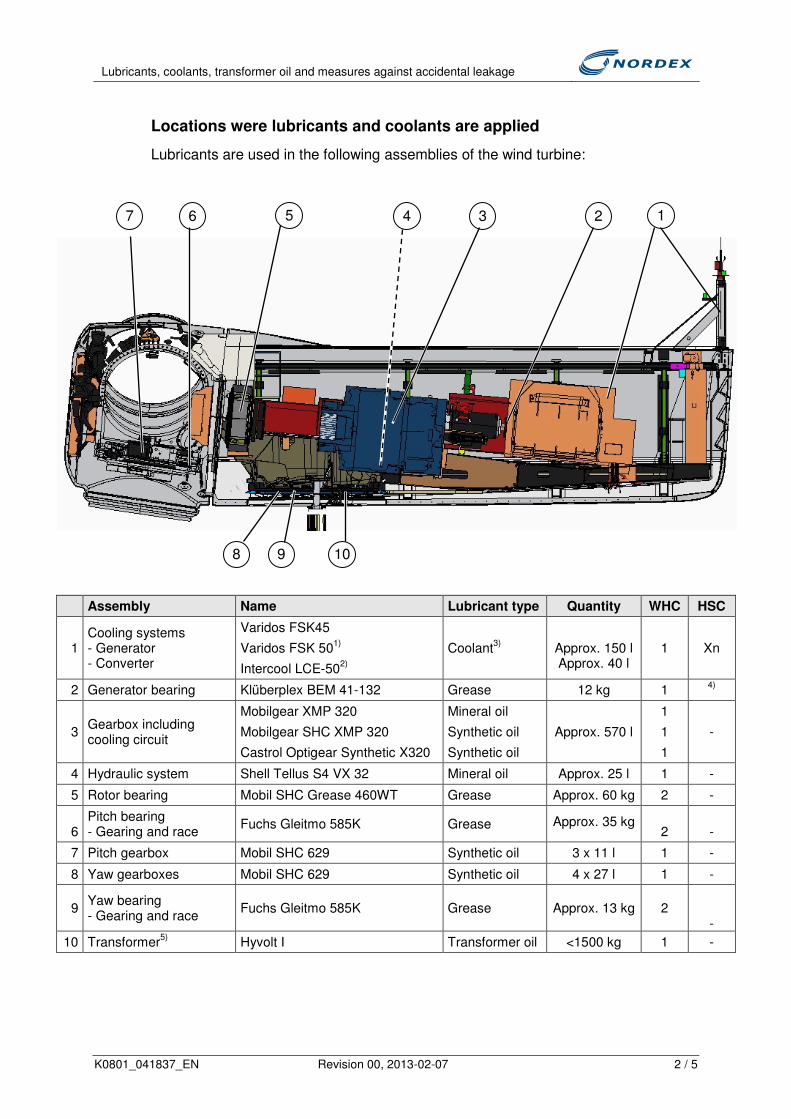
Lubricants, coolants, transformer oil and measures against accidental leakage
K0801_041837_EN Revision 00, 2013-02-07 2 / 5
Locations were lubricants and coolants are applied
Lubricants are used in the following assemblies of the wind turbine:
Assembly Name Lubricant type Quantity WHC HSC
1 Cooling systems - Generator - Converter
Varidos FSK45
Varidos FSK 501)
Intercool LCE-502)
Coolant3)
Approx. 150 l Approx. 40 l
1 Xn
2 Generator bearing Klüberplex BEM 41-132 Grease 12 kg 1 4)
3 Gearbox including cooling circuit
Mobilgear XMP 320
Mobilgear SHC XMP 320
Castrol Optigear Synthetic X320
Mineral oil
Synthetic oil
Synthetic oil
Approx. 570 l
1
1
1
-
4 Hydraulic system Shell Tellus S4 VX 32 Mineral oil Approx. 25 l 1 -
5 Rotor bearing Mobil SHC Grease 460WT Grease Approx. 60 kg 2 -
6
Pitch bearing - Gearing and race
Fuchs Gleitmo 585K Grease Approx. 35 kg 2
-
7 Pitch gearbox Mobil SHC 629 Synthetic oil 3 x 11 l 1 -
8 Yaw gearboxes Mobil SHC 629 Synthetic oil 4 x 27 l 1 -
9 Yaw bearing - Gearing and race
Fuchs Gleitmo 585K Grease Approx. 13 kg 2
-
10 Transformer5)
Hyvolt I Transformer oil <1500 kg 1 -
1
2
3
4
5
6
7
8
9
10

Lubricants, coolants, transformer oil and measures against accidental leakage
K0801_041837_EN Revision 00, 2013-02-07 3 / 5
WHC: Water hazard class
HSC: Hazardous substance class
Xn: Harmful
1) Coolant for Cold climate version (CCV)
2) Coolant only for USA
The hazardousness of chemical substances is classified differently in the
USA.
According to HMIS, this coolant has the classification: 1 / 0 / 0 / B
(HMIS = Hazardous materials identification system)
3) See below "Coolant"
4) "-" EU label not required
5) Only applicable to external transformer, if provided by Nordex
For all lubricants safety datasheets are available according to Directive 91/155/EEC.
Design measures against leakage of lubricants and coolants
• Pitch gearboxes
The pitch gearboxes are located in the rotor hub and turn along with the rotor. A
sealing system effectively prevents the gear oil from escaping. In case of
accidental leakage, the oil remains within the rotor hub and will not escape from
the access hatch due to the shape and inclination of the hub.
• Yaw bearing
The races and gearings of the yaw bearing are lubricated with grease. The
sealing system prevents the grease from escaping. If there is too much grease
in the bearings it escapes inside the hub and remains there.
In case of accidental leakage, the grease remains within the rotor hub and will
not escape from the access hatch due to the shape and inclination of the hub.
• Rotor bearing
Grease regularly emerges from the labyrinth seals of the rotor bearing during
operation and runs directly into two grease drip trays (capacity approx. 10 or
25 l). These are cleaned regularly during maintenance.
• Gearbox
The gearbox has non-abrasive, wear-free sealing systems at both, input and
output shaft. In case of accidental leakage, the oil is collected by the nacelle
housing or by the oil-proof upper tower platform.
• Generator bearing
The generator bearings are lubricated with grease and are equipped with a
highly effective sealing system. This effectively prevents lubricant from

Lubricants, coolants, transformer oil and measures against accidental leakage
K0801_041837_EN Revision 00, 2013-02-07 4 / 5
escaping. If the sealing system fails the grease remains within the nacelle and is
correctly disposed of during maintenance.
• Hydraulic unit
The hydraulic unit is equipped with a highly effective sealing system which
prevents oil from escaping. If the sealing system is damaged, the oil remains
within the nacelle.
• Yaw gearboxes
The yaw gearboxes are equipped with a sealing system which prevents oil from
escaping. If the sealing system is damaged, the oil remains within the nacelle.
• Yaw bearing
The races of the yaw bearing are lubricated with grease. The sealing system
prevents the grease from escaping. If there is too much grease in the bearing it
escapes to the external gearing.
The external gearing is lubricated with a non-drip adhesive grease.
Underneath the external gearing any escaping grease is collected in the nacelle
housing where it can be removed.
• Nacelle housing
The nacelle housing will collect any escaping fluids which the provided grease
drip trays are not able to collect. The bottom sections of the nacelle housing are
tray-shaped. All pipes are laid above these trays.
• Tower
The top tower platform is designed as an oil-proof drip tray. The drip tray has a
capacity of at least 630 liters.
• Transformer (if provided by Nordex)
External transformer: The transformer is located outside the wind turbine in a
separate transformer substation. Normally the transformer oil is not changed
during the entire service life. In case accidental leakage, the oil is collected in a
drip tray made of oil-impermeable concrete under the transformer. A certificate
of the concrete's impermeability can be requested from Nordex.
Transformer inside tower: The transformer is located on the tower foundation. It
is installed in an separated area. A dry-type transformer is used which operates
without oil.
• Coolant
The cooling system of the generator and the converter work fully independently
from each other. The pressure of the cooling systems is constantly monitored
during operation. A pressure drop is immediately reported via the operation
control.
The coolant is a mixture of an antifreeze liquid and water.

Lubricants, coolants, transformer oil and measures against accidental leakage
K0801_041837_EN Revision 00, 2013-02-07 5 / 5
Maintenance
The above-mentioned systems, which contain lubricants or coolants, are checked
for leaks during the periodic maintenance works. Any leaks are eliminated. All drip
trays are inspected at regular intervals during maintenance and emptied if
necessary.
Changing the gear oil
During scheduled maintenance an oil sample is taken from the gearbox and
analyzed in a laboratory. The oil is changed if necessary, depending on the result of
the oil sample analysis, or if the maximum operating time is reached.
Waste disposal
All lubricants and coolants must be disposed of by certified specialist waste
management companies from the region upon presentation of proof and in
accordance with local laws and guidelines.

SENVION 3.2M114


7500
2150
4150Outer Dimensions:hight: 2,150 mwidth: 4,150 mlength: 7,500 m
Gross weight: approx. 0,9 mtonsNet weight: approx. 1,0 mTons
alle Angaben in mmevery data in mm
REpower 3.X M
8765
F
E
D
C
B
A
4321
1 2 3 4 5 6 7 8
F
E
D
C
B
A
Weitergabe sowie Vervielfältigungdieses Dokuments, Verwertung undMitteilung seines Inhalts sindverboten, soweit nicht ausdrücklichgestattet. Zuwiderhandlungenverpflichten zu Schadenersatz.Alle Rechte für den Fall derPatent-, Gebrauchsmuster- oderGeschmacksmustereintragungvorbehalten.
The reproduction, distribution andutilization of this document as wellas the communication of itscontents to others without explicidauthorization is prohibited.Offenders will be held liable forthe payment of damages. All rightsreserved in the event of the grantof a patent, utility model or design.
PDM Dok ID
A3
Plot:
Stückzahl proAnlage/ No. ofPieces per Turbine:
.
..
A. Trede05.10.2009
T. Sebon05.10.2009
J. Lütjen05.10.2009
. .1:50
WEC REpowerWEA REpower
nacelle hood - transport documentGondelhaube - Transport Dokument
AD-3.1-GP.MA.02-D
P:\Products\03_01_REpower_3XM\GesamtProjekt\Mass_Abmessg_Transp_Schwerpkt\Doku_Zeichnung\D-3.1-GP.MA.02-D..
1/1
05.10.2009
ToleranceDIN ISO 8015
DIN ISO 2768-mHH
DIN ISO13715
+-
Schutzvermerk DIN ISO 16016
Protection Mark DIN ISO 16016SAP-No.: Pos.-Nr.: (Ers.d. / repl.by:)(Ers.f. / repl.for:)
REpower Systems AG- Entwicklungszentrum -
Hollesenstraße 15D-24768 Rendsburg
Phone: +49 - 4331 - 131390Fax. No: +49 - 4331 - 13139999
Unterbennung / subtitle
DIN-Blatt/DIN-Sheet
Datum/date
be strictly observed!Indicated Specification has to zwingend zu beachten!Angegebene Spezifikation ist
freigegeben/released:
geprüft / checked:
gezeichnet / drawn:
Version / Revision
Workflow Status
Zeichnungsnummer / Drawing Number
Benennung / Title
Werkstoff / Material:
Name/name
Gewicht / Weight:Maßstab / Scale:
EDP NO.
Blatt/Sheet

3910
5047 3632250
13075
1200
450
800
180250 22
0
383
1586
2xM48 at each sideof the main frame
2000
940
2626
1100
4200 10
0
forward transport direction
alle Angaben in mmevery data in mm
Outer Dimensions:hight: 3,910 mwidth: 4,200 mlength: 13,075 m
Gross weight: approx. 61,5 mtonsNet weight: approx. 60 mTons
REpower 3.X M
The two transport frames are each equipped with 4Lashing points. In front of the main frame, screwedlashing points can be mounted by a M48 thread. Twotimes in total.Lash point breaking load is about 200 kN, thatequals 100 kN lashing force.
C 16001 05.10.2009 Massen und Abmessungen aktualisiert / weights and dimensions updated J. Lütjen T. Sebon A. Trede
B 13254 02.09.2008 aktuelles WEA design / actual WEC design J. Lütjen T. Sebon A. Trede
Ver./rev.
Änd.Nr.
Datum/date Änderung / modification bearbeitet/
processedgeprüft/checked
Freigabe/released
8765
F
E
D
C
B
A
4321
1 2 3 4 5 6 7 8
F
E
D
C
B
A
Weitergabe sowie Vervielfältigungdieses Dokuments, Verwertung undMitteilung seines Inhalts sindverboten, soweit nicht ausdrücklichgestattet. Zuwiderhandlungenverpflichten zu Schadenersatz.Alle Rechte für den Fall derPatent-, Gebrauchsmuster- oderGeschmacksmustereintragungvorbehalten.
The reproduction, distribution andutilization of this document as wellas the communication of itscontents to others without explicidauthorization is prohibited.Offenders will be held liable forthe payment of damages. All rightsreserved in the event of the grantof a patent, utility model or design.
PDM Dok ID
A3
Plot:
Stückzahl proAnlage/ No. ofPieces per Turbine:
.
..
A. Trede03.03.2008
Schwerdtfeger03.03.2008
J. Lütjen03.03.2008
. .1:100
WEC REpowerWEA REpower nacelle - transport documentGondel Transport Dokument
CD-3.1-GP.MA.02-B
P:\Products\03_01_REpower_3XM\GesamtProjekt\Mass_Abmessg_Transp_Schwerpkt\Doku_Zeichnung\D-3.1-GP.MA.02-B..
1/2
05.10.2009
ToleranceDIN ISO 8015
DIN ISO 2768-mHH
DIN ISO13715
+-
Schutzvermerk DIN ISO 16016
Protection Mark DIN ISO 16016SAP-No.: Pos.-Nr.: (Ers.d. / repl.by:)(Ers.f. / repl.for:)
REpower Systems AG- Entwicklungszentrum -
Hollesenstraße 15D-24768 Rendsburg
Phone: +49 - 4331 - 131390Fax. No: +49 - 4331 - 13139999
Unterbennung / subtitle
DIN-Blatt/DIN-Sheet
Datum/date
be strictly observed!Indicated Specification has to zwingend zu beachten!Angegebene Spezifikation ist
freigegeben/released:
geprüft / checked:
gezeichnet / drawn:
Version / Revision
Workflow Status
Zeichnungsnummer / Drawing Number
Benennung / Title
Werkstoff / Material:
Name/name
Gewicht / Weight:Maßstab / Scale:
EDP NO.
Blatt/Sheet

Dokument-Nr./ Document-No.:
V-1.1-FG.OO.OO-A-J
Verfasser / Author
REpower Systems AGAlbert-Betz-Str. 10-24783 OsterronfeldTel.: +49-4331-13139-0Fax: +49-4331-13139-999
Erstellt:Prepared by:
GeprOft:Checked by:
Freigabe:Released by:
Bernd Frost----~
Stephan Schafer
~~
REpower Wind Turbine
Datum / Date:
2011-05-27
Seiten / Pages:
28
Ausfertigung /Issue:
D Original I OriginalD Reg. Exemplar Nr I Reg. Copy No.:_D Kopie (nicht erfasst) I Copy (not registered)
Status:
DEntwurf I DraftDEntwurf zur externen PrUfung I Draft for
external checkD freigegebene Fassung I released Version
Klassifikation / Classification:
D streng vertraulich I strictly confidentialD intern I internal[gI kundenvertraulich I Customer confidentialD offentlich I public
Anderungsdienst / QM document control:
D ja I yesD nein I noD begrenzt bis I limited until:
General Specification for the Design ofOnshore Foundations
Schutzvermerk ISO 16016: Weitergabe sowie Vervielfaltigung dieses Dokuments, Verwertung und Mitteilung seines Inhalts sind verboten, soweit nichtausdrUcklich gestattet. Zuwiderhandlungen verpflichten zu Schadenersatz. AlleRechte fUr den Fall der Patent-, Gebrauchsmuster- oder Geschmacksmustereintragung vorbehalten.
Protection mark ISO 16016: The reproduction, distribution and utilization of thisdocument as well as the communication of its contents to others without explicitauthorization is prohibited. Offenders will be held liable for the payment of damages. All rights reserved in the event of the grant of a patent, utility model ordesign.

General Specification for the Design of Onshore Foundations
Dokumenten-Nr. / Document-No.: V-1.1-FG.00.00-A-J Page 2 of 28 Stand / Issue: 2011-05-27
Schutzvermerk ISO 16016 beachten / Protection Mark ISO 16016 to be attended Streng Vertraulich / Strictly Confidental
Der deutsche Text ist maßgebend! / The German Text is Authoritative! Änderungsverzeichnis / Change Index:
Revision Ausgabe-datum / Date of issue
Aus-tausch-seiten / Replaced pages
Änderungen / Modifications
A 2006-03-20 - Erstausgabe / First Issue B 2006-03-23 all C 2007-08-28 all D 2008-01-21 all E 2008-07-14 all F 2008-10-14 all G 2009-12-18 all
H 2010-06-07 p.24, p.26-27
General requirements for 3.XM @ 96.50 to 100 m hh; External Tower Stair Section added
I 2011-01-11 -- Section 4.4 added; Section 5.1 to 5.3 modified; Section 5.7; modified; Section 7.1 modified
J 2011-05-27 -- Section 5 modified; Minimum values for the REpower MM100 added; Section 4.4.1: detailed definition “compacted”
Zugehörige aktuelle Dokumente dieser Unterlage / Other Applicable Documents
Bezeichnung / Designation Dokumenten-Nr. / Document No.
Revisions-Nr. Ausgabedatum / Date of issue
Anlagen / Annex:
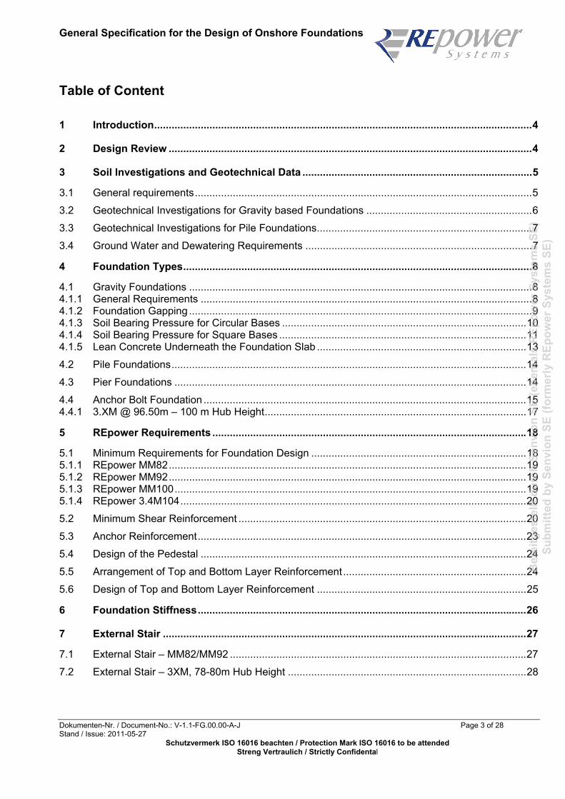
General Specification for the Design of Onshore Foundations
Dokumenten-Nr. / Document-No.: V-1.1-FG.00.00-A-J Page 3 of 28 Stand / Issue: 2011-05-27
Schutzvermerk ISO 16016 beachten / Protection Mark ISO 16016 to be attended Streng Vertraulich / Strictly Confidental
Table of Content
1 Introduction..................................................................................................................................4
2 Design Review .............................................................................................................................4
3 Soil Investigations and Geotechnical Data ...............................................................................5
3.1 General requirements....................................................................................................................5 3.2 Geotechnical Investigations for Gravity based Foundations .........................................................6 3.3 Geotechnical Investigations for Pile Foundations..........................................................................7 3.4 Ground Water and Dewatering Requirements ..............................................................................7
4 Foundation Types........................................................................................................................8
4.1 Gravity Foundations ......................................................................................................................8 4.1.1 General Requirements ..................................................................................................................8 4.1.2 Foundation Gapping ......................................................................................................................9 4.1.3 Soil Bearing Pressure for Circular Bases ....................................................................................10 4.1.4 Soil Bearing Pressure for Square Bases .....................................................................................11 4.1.5 Lean Concrete Underneath the Foundation Slab ........................................................................13 4.2 Pile Foundations..........................................................................................................................14 4.3 Pier Foundations .........................................................................................................................14 4.4 Anchor Bolt Foundation ...............................................................................................................15 4.4.1 3.XM @ 96.50m – 100 m Hub Height..........................................................................................17
5 REpower Requirements ............................................................................................................18
5.1 Minimum Requirements for Foundation Design ..........................................................................18 5.1.1 REpower MM82...........................................................................................................................19 5.1.2 REpower MM92...........................................................................................................................19 5.1.3 REpower MM100.........................................................................................................................19 5.1.4 REpower 3.4M104.......................................................................................................................20 5.2 Minimum Shear Reinforcement ...................................................................................................20 5.3 Anchor Reinforcement.................................................................................................................23 5.4 Design of the Pedestal ................................................................................................................24 5.5 Arrangement of Top and Bottom Layer Reinforcement...............................................................24 5.6 Design of Top and Bottom Layer Reinforcement ........................................................................25
6 Foundation Stiffness.................................................................................................................26
7 External Stair .............................................................................................................................27
7.1 External Stair – MM82/MM92 ......................................................................................................27 7.2 External Stair – 3XM, 78-80m Hub Height ..................................................................................28

General Specification for the Design of Onshore Foundations
Dokumenten-Nr. / Document-No.: V-1.1-FG.00.00-A-J Page 4 of 28 Stand / Issue: 2011-05-27
Schutzvermerk ISO 16016 beachten / Protection Mark ISO 16016 to be attended Streng Vertraulich / Strictly Confidental
1 Introduction
The design of foundations for REpower wind turbines has to be carried out based on the REpower load specification. National requirements and standards have also be taken into account. The design of the embedded steel can is carried out by REpower. EUROCODES shall be applied preferably if recognised in that particular country.
2 Design Review
REpower is entitled to do a design-review. However REpower does not accept responsibility as a result of the design review. If the foundation design does not meet REpower’s requirements the design has to be revised. These are the standard documents to be submitted for the design-review:
− Report on Ground Investigation
− General arrangement drawing of the foundation
− Reinforcement Drawings
− Bar Schedule
− Work Instructions
− Design-Report
Technical documentation should be in German and/or English. Other languages can be exceptionally accepted . This information shall be found on the drawings:
− Turbine (e. g. MM82 or 3.XM), hub height, name of the project / site
− Allowable groundwater level for the foundation
− Material properties for concrete and reinforcement steel (yield strength, ultimate strength etc.)
− Demands on the subsoil (allowable bearing pressure etc.)
To advance the projects, consulting-engineers should be able to communicate in English and/or in German.

General Specification for the Design of Onshore Foundations
Dokumenten-Nr. / Document-No.: V-1.1-FG.00.00-A-J Page 5 of 28 Stand / Issue: 2011-05-27
Schutzvermerk ISO 16016 beachten / Protection Mark ISO 16016 to be attended Streng Vertraulich / Strictly Confidental
3 Soil Investigations and Geotechnical Data
3.1 General requirements
Soil investigations should provide all necessary data for a detailed design of a specific foundation structure at a specific location. Soil investigations may be divided into the following parts:
− Geological studies
− Geophysical surveys
− Geotechnical investigations
A geological study should be based on information about the geological history of the area where the wind turbine is to be installed. The purpose of the study is to establish a basis for selection of methods and extent of the site investigation.
A geophysical survey can be used to extend the localised information from single borings and in-situ testing in order to get an understanding of the soil stratification within a given area. Such a survey can provide guidelines for selection of a suitable foundation site within the area, if not already decided. Geophysical surveys are carried out by means of seismic methods.
A geotechnical investigation consists of:
− soil sampling for laboratory testing
− in-situ testing of soil
Soil investigations should be adjusted to the geotechnical design methods used. The field and laboratory investigations should establish the detailed soil stratigraphy across the site, thus providing the following types of geotechnical data for all important soil layers:
− data for classification and description of the soil, such as
unit weight of sample
unit weight of solid particle
water content
liquid and plastic limits
grain size distribution
− parameters required for a detailed and complete foundation design, such as
permeability tests
consolidation tests
− static tests for determination of characteristic shear strength parameters such as friction angle φ for sand and undrained shear strength cu for clay (triaxial tests and direct simple shear tests)
− cyclic tests for determination of strength and stiffness parameters (triaxial tests, direct simple shear tests and resonant column tests)

General Specification for the Design of Onshore Foundations
Dokumenten-Nr. / Document-No.: V-1.1-FG.00.00-A-J Page 6 of 28 Stand / Issue: 2011-05-27
Schutzvermerk ISO 16016 beachten / Protection Mark ISO 16016 to be attended Streng Vertraulich / Strictly Confidental
Sampling can be carried out with and without drilling. The cone penetration test (CPT) and various vane tests form the most commonly used in-situ testing methods. Results from such in-situ tests can be used to interpret parameters such as the undrained shear strength of clay. The extent to which the various types of in-situ tests and laboratory tests are required depends much on the foundation type in question, for example, whether it is a piled foundation or a gravity-based foundation. This geotechnical report should contain sufficient information about the site and its soils, e.g. in terms of soil strength and deformation properties, to allow for design of the foundation with respect to:
− bearing capacity
− stability against sliding
− settlements
− foundation stiffness
− need for and possibility of drainage
− static and dynamic coefficients of compressibility
− sensitivity to dynamic loading
− highest possible groundwater table
− seismic activity
The geotechnical report is further required to contain identification of soil type at foundation level.
3.2 Geotechnical Investigations for Gravity based Foundations
Regarding gravity-based foundations, an extensive investigation of the shallow soil deposits should be undertaken. This investigation should cover soil deposits up to a depth, which is deeper than the depth of any possible critical shear surface. Further, all soil layers influenced by the structure in terms of settlement should be thoroughly investigated. This also has to be done for all soil layers contributing to the foundation stiffness. The foundation stiffness is of importance for the design of the structure supported by the foundation. The depth to be covered by the thorough investigation should at least equal the largest base dimension of the structure. The extent of shallow borings with sampling should be determined on the basis of the type and size of structure as well as on general knowledge about the soil conditions in the area considered for installation. Emphasis should be given to the upper layers and potentially weaker layers further down. It is recommended that the sampling interval is not in excess of 1.0-1.5 m. Shallow CPTs distributed across the installation area should be carried out in addition to the borings. The number of CPTs depend on the soil conditions and on the type and size of structure. If the soil conditions are very irregular across the foundation site, the number of CPTs will have to be increased. The shallow CPTs should provide continuous graphs from the soil surface up to the maximum depth of interest. Special tests such as plate loading tests, pressuremeter tests and shear wave velocity measurements should be considered where relevant.

General Specification for the Design of Onshore Foundations
Dokumenten-Nr. / Document-No.: V-1.1-FG.00.00-A-J Page 7 of 28 Stand / Issue: 2011-05-27
Schutzvermerk ISO 16016 beachten / Protection Mark ISO 16016 to be attended Streng Vertraulich / Strictly Confidental
3.3 Geotechnical Investigations for Pile Foundations
For lateral pile analysis, shallow cone penetration tests should be carried out from the surface to 20-30m depth. In addition, shallow borings with sampling should be considered for better determination of characteristics of the individual layers identified by the cone penetration tests. It is recommended that the sampling interval is not in excess of 1.0-1.5m. As regards axial pile analysis, at least one down-the-hole CPT boring should be carried out to give a continuous CPT profile. Moreover, one nearby boring with sampling should be carried out for the axial pile capacity analysis. The minimum depth should be the anticipated penetration of the pile plus a zone of influence sufficient for evaluation of the risk of punch-through failure. The sampling interval should be determined from the CPT results, but is recommended not to exceed 3 m. Special attention should be paid when potential end bearing layers or other dense layers are found. Here, additional CPTs and sampling should be carried out in order to determine the thickness and lateral extension of such layers within the area considered for the foundation.
3.4 Ground Water and Dewatering Requirements
The geotechnical engineer of record has to determine the maximum ground water level on site. The encountered ground water level has to be clearly stated together with the ground profile.
During the construction phase of the proposed foundation, it might be necessary to dewater the construction site temporarily. REpower won’t accept foundation designs considering a permanent dewatering during the operational life-span of the WTG. For the structural foundation design, buoyancy and hydrostatic effects have to be considered, if applicable. Lowering the groundwater level by wells and ducts may not be taken into account for the design of the overall stability. If the natural ground water level is higher than the base, buoyancy has to be considered even if there is area drainage.

General Specification for the Design of Onshore Foundations
Dokumenten-Nr. / Document-No.: V-1.1-FG.00.00-A-J Page 8 of 28 Stand / Issue: 2011-05-27
Schutzvermerk ISO 16016 beachten / Protection Mark ISO 16016 to be attended Streng Vertraulich / Strictly Confidental
4 Foundation Types
4.1 Gravity Foundations 4.1.1 General Requirements
For economical reasons, gravity foundations should preferably be designed with a circular base. Octagonal or polygonal (n ≥ 8) bases are also acceptable. To simplify the analysis of polygonal bases, a circular base with an equal area may be modelled as well. To improve the stiffness of the foundation it is recommended to arrange a layer of ballast on top of the foundation slab.
The design shall include the following key elements:
− Overall stability assessments taking into account the ground water level
− Reinforced concrete design
− Fatigue analysis for the reinforcement and the concrete
Depending on the design of the embedded steel can provided by REpower, the foundation should be engineered as follows:
For US projects only: Due to patent reasons the version 1 general arrangement of the above figure is not allowed to be used in connection with an embedded steel can the USA.

General Specification for the Design of Onshore Foundations
Dokumenten-Nr. / Document-No.: V-1.1-FG.00.00-A-J Page 9 of 28 Stand / Issue: 2011-05-27
Schutzvermerk ISO 16016 beachten / Protection Mark ISO 16016 to be attended Streng Vertraulich / Strictly Confidental
4.1.2 Foundation Gapping
No inactive area at the base of a gravity foundation is admissible for the tower moment specified by REpower. No safety factors have to be applied. It has to be proven that the excentricity of the total vertical load (turbine, foundation slab, pedestal, ballast etc.) due to the tower moment is
e < R / 4 for circular bases
e < a / 6 for square bases with tower moment parallel to edges
e < a / 8.485 for square bases with tower moment in 45° direction to edges
For unscaled ultimate loads (γF = 1.0) not more than 50% of the base may be without compression. No safety factors have to be applied. It has to be proven that the resultant of all forces (tower moment, turbine, foundation slab, pedestal, ballast) is within a circle
e < 0.59 * R for circular bases
e < a / 3 for square bases

General Specification for the Design of Onshore Foundations
Dokumenten-Nr. / Document-No.: V-1.1-FG.00.00-A-J Page 10 of 28 Stand / Issue: 2011-05-27
Schutzvermerk ISO 16016 beachten / Protection Mark ISO 16016 to be attended Streng Vertraulich / Strictly Confidental
4.1.3 Soil Bearing Pressure for Circular Bases
The bearing pressure beneath a circular base has to be calculated as follows
− Ultimate bearing pressure at the edge of the foundation for characteristic loads
Fz = resultant of all vertical forces ( turbine, tower, foundation, ballast etc.)
e = M / Fz excentricity
K = coefficient according to the graph below
σmax = K * Fz / (π* R2) soil pressure at the edge
1.0
1.5
2.0
2.5
3.0
3.5
4.0
4.5
5.0
0.10
0.15
0.20
0.25
0.30
0.35
0.40
0.45
0.50
0.55
0.60
e/r
K
− Ultimate averaged bearing pressure for characteristic loads as shown in the sketch
α = 2 * arccos(e / R) (included angle of sector circle)
Aeff = R2 * (α - sin α) (area with constant pressure)
σm = Fz / Aeff

General Specification for the Design of Onshore Foundations
Dokumenten-Nr. / Document-No.: V-1.1-FG.00.00-A-J Page 11 of 28 Stand / Issue: 2011-05-27
Schutzvermerk ISO 16016 beachten / Protection Mark ISO 16016 to be attended Streng Vertraulich / Strictly Confidental
4.1.4 Soil Bearing Pressure for Square Bases
The bearing pressure beneath a square base has to be calculated as follows:
− Ultimate bearing pressure at the edge of the foundation for the characteristic loads
Fz = resultant of all vertical forces ( turbine, tower, foundation, ballast etc.)
e = M / Fz excentricity
K = coefficient according to the graph below
σmax = K * Fz / a² soil pressure at the edge of the foundation
foundations w ith a square base
0.00
1 .00
2 .00
3 .00
4 .00
5 .00
6 .00
0.00
0.02
0.04
0.06
0.08
0.10
0.12
0.14
0.16
0.18
0.20
0.22
0.24
0.26
0.28
0.30
0.32
0.34
0.36
e /a
K
para lle l 45°

General Specification for the Design of Onshore Foundations
Dokumenten-Nr. / Document-No.: V-1.1-FG.00.00-A-J Page 12 of 28 Stand / Issue: 2011-05-27
Schutzvermerk ISO 16016 beachten / Protection Mark ISO 16016 to be attended Streng Vertraulich / Strictly Confidental
− Ultimate averaged bearing pressure for characteristic loads as shown in the sketch (90° direction):
Aeff = a2 - 2 * a * e area with constant pressure
σm = Fz / Aeff
− Ultimate averaged bearing pressure for the characteristic loads as shown in the sketch (45° direc-tion):
Aeff = (a – e* 20.50)2 area with constant pressure
σm = Fz / Aeff

General Specification for the Design of Onshore Foundations
Dokumenten-Nr. / Document-No.: V-1.1-FG.00.00-A-J Page 13 of 28 Stand / Issue: 2011-05-27
Schutzvermerk ISO 16016 beachten / Protection Mark ISO 16016 to be attended Streng Vertraulich / Strictly Confidental
4.1.5 Lean Concrete Underneath the Foundation Slab
If the ground conditions do not allow to set up a gravity foundation directly on the natural soil, poor soil may be exchanged by lean concrete or engineering backfill. The backfill has to be arranged in a conical way:
For US projects only: Due to patent reasons no reinforced sub bases or lean concrete layers are allowed to be used on site in the USA. The embedded steel can has to be placed on a non-reinforced sub base layer. It is required to use a minimum of 100mm lean concrete to support the levelling legs of the embedded steel can.

General Specification for the Design of Onshore Foundations
Dokumenten-Nr. / Document-No.: V-1.1-FG.00.00-A-J Page 14 of 28 Stand / Issue: 2011-05-27
Schutzvermerk ISO 16016 beachten / Protection Mark ISO 16016 to be attended Streng Vertraulich / Strictly Confidental
4.2 Pile Foundations
If the ground conditions do not permit gravity foundations, piled foundations are required. The piles have to absorb the axial forces due to the tower moment and dead loads as well as the horizontal forces due to torsion and lateral forces. It is recommended to use raked piles. REpower exclusively accepts reinforced concrete piles. Steel piles and wooden piles are not admissible. Reinforcement cages for the piles may not be welded, even spot welding is not admissible because the performance of the pile regarding to fatigue would decrease dramatically.
4.3 Pier Foundations
A pier foundation is neither a gravity foundation nor a piled foundation. A pier foundation can be referred to as a caisson, a mono-pile with a large diameter. The proprietary name is “Patrick & Henderson” foundation.
For pier foundations the centre of rotation is located at a lower height indication compared with gravity foundations or piled foundations. If the point of rotation is placed too low, the pier foundation acts like an extension of the tower, which affects the natural eigenfrequencies of the tower-foundation system. The engineer of record has to assure, that the tower-foundation system does not become softer than the minimum dynamic rotational stiffness specified by REpower!
Among other things the design of a pier foundation has to include the following elements:
− Verification of the rotational and lateral stiffness at a reference height indication as specified by REpower. If the centre of rotation is at a lower height indication than specified by REpower, the complete system (nacelle, tower and foundation) has to be taken into consideration.
− Overall stability
− Structural design of the foundation body
− Fatigue analysis for the reinforcement and/or anchor bars as well as for the concrete
For pier foundations (caisson, Patrick & Henderson, and similar) excavating using explosives is prohibited. Where necessary, a hydraulic excavator or other applicable devices shall be used instead. Especially for P&H-Foundations the excavation method may not degrade the texture of the in-situ soil/rock. The engineer of record has to propose a suitable method for excavation works.

General Specification for the Design of Onshore Foundations
Dokumenten-Nr. / Document-No.: V-1.1-FG.00.00-A-J Page 15 of 28 Stand / Issue: 2011-05-27
Schutzvermerk ISO 16016 beachten / Protection Mark ISO 16016 to be attended Streng Vertraulich / Strictly Confidental
4.4 Anchor Bolt Foundation
A tubular steel tower of a REpower wind turbine may be designed to be connected to the foundation with an anchor cage. The proposed anchor cage consists of an embedment ring as well as an inner and outer ring of holding down bolts fixed to the embedment ring with threads. The bolts will be pre-stressed after erection of the bottom tower segment.
REpower accepts the following two principle positions of the embedment ring. The following figure does not represent a complete structural drawing. It only shows basic parts of a proposed foundation design.
Option A: The embedment ring is placed below the bottom reinforcement. In that case no anchor reinforcement around the holding down bolts is needed.
Option B: The embedment ring is placed above the bottom reinforcement. In that case anchor reinforcement around the holding down bolts is required. The anchor reinforcement has to be in accordance with the stated design approach in section 5.3 on page 23. A sufficient anchor length on the tension site of the anchor reinforcement has to be assured.
The number of bolts, the mean diameter of the inner & outer bolt ring as well as the proposed bolt diameter can be found on the tubular steel tower drawing.

General Specification for the Design of Onshore Foundations
Dokumenten-Nr. / Document-No.: V-1.1-FG.00.00-A-J Page 16 of 28 Stand / Issue: 2011-05-27
Schutzvermerk ISO 16016 beachten / Protection Mark ISO 16016 to be attended Streng Vertraulich / Strictly Confidental
The following general requirements have to be taken into account:
− A suitable long term corrosion protection of the bolts has to be assured. The bolts have to be pro-tected against corrosion for the proposed design life of 20yrs.
− Concrete is sensible to creeping and shrinkage effects. The foundation engineer generally speci-fies the pre-tension force of the bolts. The pre-tension force shall be checked periodically after ini-tial pre-tension of the bolts. The foundation engineer has to clearly state after what time frame the pre-tension force has to be adjusted.
− It has to be assured that water, grout or concrete does not come into contact with the holding down bolts. Typically a high temperature (HT) tube is used to prevent contact between concrete, grout and water. A heat shrinkage tube seals the HT tube at both ends. See figure below:
1. HT tube avoiding contact between concrete and bolt
2. Heat shrinkage tube for sealing
3. Threaded bolt end
1
2 3

General Specification for the Design of Onshore Foundations
Dokumenten-Nr. / Document-No.: V-1.1-FG.00.00-A-J Page 17 of 28 Stand / Issue: 2011-05-27
Schutzvermerk ISO 16016 beachten / Protection Mark ISO 16016 to be attended Streng Vertraulich / Strictly Confidental
4.4.1 3.XM @ 96.50m – 100 m Hub Height
REpower’s wind turbine 3.XM @ 96.5 m – 100 m hub height shall be arranged with a pre-stressed concrete pedestal. The bolt cage as well as the template for the erection of the bolt cage is provided by REpower. Therefore the design of each foundation shall be based on REpower’s standard foundation design which will be provided on demand. Only country-specific inevitable modifications are permitted. The general arrangement shall comply with the sketch below:

General Specification for the Design of Onshore Foundations
Dokumenten-Nr. / Document-No.: V-1.1-FG.00.00-A-J Page 18 of 28 Stand / Issue: 2011-05-27
Schutzvermerk ISO 16016 beachten / Protection Mark ISO 16016 to be attended Streng Vertraulich / Strictly Confidental
5 REpower Requirements
To assure a proper foundation design REpower specifies the following minimum requirements. These requirements are structural requirements as well as geometrical and requirements regarding the proposed concrete class. Nevertheless for the foundation design local codes and standards have to be considered.
5.1 Minimum Requirements for Foundation Design
Each of the following sections do contain a table stating the minimum requirements, that have to be considered for the foundation design:
− Hub Height [m]: Range or single value for the hub height.
− Wind Class: Proposed wind class of a specific location.
− Concrete Volume [m3]: Minimum values for concrete volume. The column differentiates between gravity foundations without buoyancy and pile foundations with buoyancy effects. For squared foun-dations values have to be increased by 10%.
− Reinforcements Steel [t]: Minimum values for reinforcement steel. The column differentiates be-tween gravity foundations without buoyancy and pile foundations with buoyancy effects. For squared foundations values have to be increased by 10%.
− Slab Thickness h [mm]: That column states the minimum thickness of the foundation slab itself. The given values are valid for foundations with an embedded steel can as well as if an anchor cage is supposed to be used for the tower – foundation connection. The blinding layer may not be taken into account.

General Specification for the Design of Onshore Foundations
Dokumenten-Nr. / Document-No.: V-1.1-FG.00.00-A-J Page 19 of 28 Stand / Issue: 2011-05-27
Schutzvermerk ISO 16016 beachten / Protection Mark ISO 16016 to be attended Streng Vertraulich / Strictly Confidental
− Concrete Class: In that column the minimum concrete class around the embedded flange is stated. The concrete class is based on Eurocode 2 nomenclature. If the Eurocode 2 is not applica-ble in an particular country, the chosen concrete compressive strength fck shall be equivalent.
5.1.1 REpower MM82
Concrete Volume [m3] Reinforcement Steel [t] Slab Thickness h Hub
Height
[m]
Wind Class Gravity Found.
without buoyancy Pile Found. with
buoyancy Gravity Found.
without buoyancy Pile Found. with
buoyancy [mm]
ConcreteClass
59 IEC1a, 2a & IEC S-Class 213 186 23.5 27.5 1,500 C35/45
69 IEC1a, 2a & IEC S-Class 244 212 27.0 31.0 1,650 C35/45
69 IEC CCV 265 229 30.0 33.5 1,750 C35/45
78-80 IEC2a, IEC S-Class 291 250 33.5 36.0 1,900 C35/45
80 IEC CCV 297 263 34.0 30.0 2,000 C35/45
100 IEC 3a 350 293 40.0 42.0 2,200 C35/45
5.1.2 REpower MM92
Concrete Volume [m3] Reinforcement Steel [t] Slab Thickness h Hub
Height
[m]
Wind Class Gravity Found.
without buoyancy Pile Found. with
buoyancy Gravity Found.
without buoyancy Pile Found. with
buoyancy [mm]
ConcreteClass
68.5 IEC2a 241 209 27.0 30.5 1,700 C35/45
78-80 IEC2a 286 244 33.0 35.0 1,950 C35/45
80 IEC CCV 299 265 34.0 35.0 2,000 C35/45
98-100 IEC2a & 3a 355 293 41.0 41.5 2,250 C35/45
5.1.3 REpower MM100
Concrete Volume [m3] Reinforcement Steel [t] Slab Thickness h Hub
Height
[m]
Wind Class Gravity Found.
without buoyancy Pile Found. with
buoyancy Gravity Found.
without buoyancy Pile Found. with
buoyancy [mm]
ConcreteClass
78-80 IEC2a 290 250 33.0 35.0 2,000

General Specification for the Design of Onshore Foundations
Dokumenten-Nr. / Document-No.: V-1.1-FG.00.00-A-J Page 20 of 28 Stand / Issue: 2011-05-27
Schutzvermerk ISO 16016 beachten / Protection Mark ISO 16016 to be attended Streng Vertraulich / Strictly Confidental
5.1.4 REpower 3.4M104 Concrete Volume [m3] Reinforcement Steel [t] Slab Thickness
h Hub Height
[m]
Wind Class Gravity Found.
without buoyancy Pile Found. with
buoyancy Gravity Found.
without buoyancy Pile Found. with
buoyancy [mm]
ConcreteClass
78-80 IEC2a 353 299 42.0 42.0 2,300 C35/45
93 IEC1b 433 433 46.5 46.5 2,500 C35/45
96.5-100 IEC2a 450 450 47.5 47.5 2,500 (*)
(*) Anchor cage design: C50/60 below the tower base flange; C30/37 around the embedded ring flange at the bottom of the anchor cage.
5.2 Minimum Shear Reinforcement
REpower specifies a minimum shear reinforcement depending on the shear forces in the foundation slab. Furthermore local codes and standards have to be considered. Regardless of REpower’s requirement, the adequacy of the shear reinforcement has to be proven by the designer. Shear reinforcement shall embrace the bottom layer of reinforcement as well as the top layer of reinforcement.

General Specification for the Design of Onshore Foundations
Dokumenten-Nr. / Document-No.: V-1.1-FG.00.00-A-J Page 21 of 28 Stand / Issue: 2011-05-27
Schutzvermerk ISO 16016 beachten / Protection Mark ISO 16016 to be attended Streng Vertraulich / Strictly Confidental
(Concrete: C30/37) VEd [KN/m] (γ incl.)
d ↓ 200 400 600 800 1000 1200 1400 1600 1800 2000 2200 2400 2600 2800 3000
[cm] [cm²/m²
] [cm²/m²
] [cm²/m²] [cm²/m²] [cm²/m²] [cm²/m²] [cm²/m²] [cm²/m²] [cm²/m²] [cm²/m²] [cm²/m²] [cm²/m²] [cm²/m²] [cm²/m²] [cm²/m²]
100 0.00 3.41 5.11 6.81 8.52 11.26 15.52 19.78 24.04 28.30 32.56 36.82 41.08 45.34 49.60 110 0.00 3.10 4.65 6.20 7.74 9.29 12.81 16.68 20.56 24.43 28.30 32.17 36.05 39.92 43.79 120 0.00 2.84 4.26 5.68 7.10 8.52 10.55 14.10 17.65 21.20 24.75 28.30 31.85 35.40 38.95 130 0.00 2.62 3.93 5.24 6.55 7.86 9.17 11.92 15.20 18.47 21.75 25.02 28.30 31.58 34.85 140 0.00 2.43 3.65 4.87 6.08 7.30 8.52 10.05 13.09 16.13 19.17 22.22 25.26 28.30 31.34 150 0.00 2.27 3.41 4.54 5.68 6.81 7.95 9.09 11.26 14.10 16.94 19.78 22.62 25.46 28.30 160 0.00 2.13 3.19 4.26 5.32 6.39 7.45 8.52 9.67 12.33 14.99 17.65 20.31 22.98 25.64 170 0.00 2.00 3.01 4.01 5.01 6.01 7.02 8.02 9.02 10.76 13.27 15.77 18.28 20.78 23.29 180 0.00 1.89 2.84 3.79 4.73 5.68 6.63 7.57 8.52 9.47 11.74 14.10 16.47 18.84 21.20 190 0.00 1.79 2.69 3.59 4.48 5.38 6.28 7.17 8.07 8.97 10.37 12.61 14.85 17.09 19.33 200 0.00 1.70 2.56 3.41 4.26 5.11 5.96 6.81 7.67 8.52 9.37 11.26 13.39 15.52 17.65 210 0.00 1.62 2.43 3.25 4.06 4.87 5.68 6.49 7.30 8.11 8.92 10.05 12.08 14.10 16.13 220 0.00 0.00 2.32 3.10 3.87 4.65 5.42 6.20 6.97 7.74 8.52 9.29 10.88 12.81 14.75 230 0.00 0.00 2.22 2.96 3.70 4.44 5.19 5.93 6.67 7.41 8.15 8.89 9.78 11.63 13.49 240 0.00 0.00 2.13 2.84 3.55 4.26 4.97 5.68 6.39 7.10 7.81 8.52 9.23 10.55 12.33 250 0.00 0.00 2.04 2.73 3.41 4.09 4.77 5.45 6.13 6.81 7.50 8.18 8.86 9.56 11.26
(Concrete: C30/37) VEd [KN/m] (γ incl.)
d ↓ 320
0
3400 3600 3800 4000 4200 4400 4600 4800 5000 5200 5400 5600 5800 6000
[cm] [cm²/m²] [cm²/m²] [cm²/m²] [cm²/m²] [cm²/m²] [cm²/m²] [cm²/m²] [cm²/m²] [cm²/m²] [cm²/m²] [cm²/m²] [cm²/m²] [cm²/m²] [cm²/m²] [cm²/m²]
100 53.86 58.12 62.38 66.63 70.89 75.15 79.41 83.67 87.93 92.19 96.45 100.71 104.97 109.23 113.49110 47.66 51.53 55.41 59.28 63.15 67.02 70.89 74.77 78.64 82.51 86.38 90.25 94.13 98.00 101.87120 42.50 46.05 49.60 53.15 56.70 60.25 63.79 67.34 70.89 74.44 77.99 81.54 85.09 88.64 92.19 130 38.13 41.41 44.68 47.96 51.24 54.51 57.79 61.06 64.34 67.62 70.89 74.17 77.45 80.72 84.00 140 34.39 37.43 40.47 43.51 46.55 49.60 52.64 55.68 58.72 61.77 64.81 67.85 70.89 73.94 76.98 150 31.14 33.98 36.82 39.66 42.50 45.34 48.18 51.02 53.86 56.70 59.54 62.38 65.21 68.05 70.89 160 28.30 30.96 33.63 36.29 38.95 41.61 44.27 46.94 49.60 52.26 54.92 57.58 60.25 62.91 65.57 170 25.80 28.30 30.81 33.31 35.82 38.32 40.83 43.33 45.84 48.34 50.85 53.36 55.86 58.37 60.87 180 23.57 25.93 28.30 30.67 33.03 35.40 37.77 40.13 42.50 44.86 47.23 49.60 51.96 54.33 56.70 190 21.58 23.82 26.06 28.30 30.54 32.78 35.03 37.27 39.51 41.75 43.99 46.23 48.48 50.72 52.96 200 19.78 21.91 24.04 26.17 28.30 30.43 32.56 34.69 36.82 38.95 41.08 43.21 45.34 47.47 49.60 210 18.16 20.19 22.22 24.24 26.27 28.30 30.33 32.36 34.39 36.41 38.44 40.47 42.50 44.53 46.55 220 16.68 18.62 20.56 22.49 24.43 26.36 28.30 30.24 32.17 34.11 36.05 37.98 39.92 41.85 43.79 230 15.34 17.19 19.04 20.89 22.75 24.60 26.45 28.30 30.15 32.00 33.86 35.71 37.56 39.41 41.26 240 14.10 15.88 17.65 19.43 21.20 22.98 24.75 26.53 28.30 30.08 31.85 33.63 35.40 37.17 38.95 250 12.97 14.67 16.38 18.08 19.78 21.49 23.19 24.89 26.60 28.30 30.00 31.71 33.41 35.12 36.82
Example: VEd = 3000 KN/m d = 180 cm as,req = 21.20 cm²/m²

General Specification for the Design of Onshore Foundations
Dokumenten-Nr. / Document-No.: V-1.1-FG.00.00-A-J Page 22 of 28 Stand / Issue: 2011-05-27
Schutzvermerk ISO 16016 beachten / Protection Mark ISO 16016 to be attended Streng Vertraulich / Strictly Confidental
(Concrete: C35/45) VEd [KN/m] (γ incl.)
d ↓ 200 400 600 800 1000 1200 1400 1600 1800 2000 2200 2400 2600 2800 3000
[cm] [cm²/m²
] [cm²/m²
] [cm²/m²] [cm²/m²] [cm²/m²] [cm²/m²] [cm²/m²] [cm²/m²] [cm²/m²] [cm²/m²] [cm²/m²] [cm²/m²] [cm²/m²] [cm²/m²] [cm²/m²]
100 0.00 3.41 5.11 6.81 8.52 10.51 14.77 19.03 23.29 27.55 31.81 36.07 40.33 44.58 48.84 110 0.00 3.10 4.65 6.20 7.74 9.29 12.06 15.93 19.80 23.68 27.55 31.42 35.29 39.16 43.04 120 0.00 2.84 4.26 5.68 7.10 8.52 9.94 13.35 16.90 20.45 24.00 27.55 31.10 34.65 38.20 130 0.00 2.62 3.93 5.24 6.55 7.86 9.17 11.17 14.44 17.72 20.99 24.27 27.55 30.82 34.10 140 0.00 0.00 3.65 4.87 6.08 7.30 8.52 9.74 12.34 15.38 18.42 21.46 24.51 27.55 30.59 150 0.00 0.00 3.41 4.54 5.68 6.81 7.95 9.09 10.51 13.35 16.19 19.03 21.87 24.71 27.55 160 0.00 0.00 3.19 4.26 5.32 6.39 7.45 8.52 9.58 11.58 14.24 16.90 19.56 22.22 24.89 170 0.00 0.00 3.01 4.01 5.01 6.01 7.02 8.02 9.02 10.02 12.51 15.02 17.53 20.03 22.54 180 0.00 0.00 2.84 3.79 4.73 5.68 6.63 7.57 8.52 9.47 10.98 13.35 15.72 18.08 20.45 190 0.00 0.00 2.69 3.59 4.48 5.38 6.28 7.17 8.07 8.97 9.86 11.86 14.10 16.34 18.58 200 0.00 0.00 2.56 3.41 4.26 5.11 5.96 6.81 7.67 8.52 9.37 10.51 12.64 14.77 16.90 210 0.00 0.00 2.43 3.25 4.06 4.87 5.68 6.49 7.30 8.11 8.92 9.74 11.32 13.35 15.38 220 0.00 0.00 2.32 3.10 3.87 4.65 5.42 6.20 6.97 7.74 8.52 9.29 10.12 12.06 14.00 230 0.00 0.00 2.22 2.96 3.70 4.44 5.19 5.93 6.67 7.41 8.15 8.89 9.63 10.88 12.73 240 0.00 0.00 2.13 2.84 3.55 4.26 4.97 5.68 6.39 7.10 7.81 8.52 9.23 9.94 11.58 250 0.00 0.00 2.04 2.73 3.41 4.09 4.77 5.45 6.13 6.81 7.50 8.18 8.86 9.54 10.51
(Concrete: C35/45) VEd [KN/m] (γ incl.)
d ↓ 3200 3400 3600 3800 4000 4200 4400 4600 4800 5000 5200 5400 5600 5800 6000[cm] [cm²/m²] [cm²/m²] [cm²/m²] [cm²/m²] [cm²/m²] [cm²/m²] [cm²/m²] [cm²/m²] [cm²/m²] [cm²/m²] [cm²/m²] [cm²/m²] [cm²/m²] [cm²/m²] [cm²/m²]
100 53.10 57.36 61.62 65.88 70.14 74.40 78.66 82.92 87.18 91.44 95.70 99.95 104.21 108.47 112.73110 46.91 50.78 54.65 58.52 62.40 66.27 70.14 74.01 77.88 81.76 85.63 89.50 93.37 97.24 101.12120 41.75 45.29 48.84 52.39 55.94 59.49 63.04 66.59 70.14 73.69 77.24 80.79 84.34 87.89 91.44 130 37.38 40.65 43.93 47.21 50.48 53.76 57.03 60.31 63.59 66.86 70.14 73.42 76.69 79.97 83.25 140 33.63 36.67 39.72 42.76 45.80 48.84 51.89 54.93 57.97 61.01 64.06 67.10 70.14 73.18 76.22 150 30.39 33.23 36.07 38.91 41.75 44.58 47.42 50.26 53.10 55.94 58.78 61.62 64.46 67.30 70.14 160 27.55 30.21 32.87 35.53 38.20 40.86 43.52 46.18 48.84 51.51 54.17 56.83 59.49 62.15 64.82 170 25.04 27.55 30.05 32.56 35.06 37.57 40.07 42.58 45.09 47.59 50.10 52.60 55.11 57.61 60.12 180 22.81 25.18 27.55 29.91 32.28 34.65 37.01 39.38 41.75 44.11 46.48 48.84 51.21 53.58 55.94 190 20.82 23.06 25.31 27.55 29.79 32.03 34.27 36.51 38.76 41.00 43.24 45.48 47.72 49.96 52.21 200 19.03 21.16 23.29 25.42 27.55 29.68 31.81 33.94 36.07 38.20 40.33 42.45 44.58 46.71 48.84 210 17.41 19.43 21.46 23.49 25.52 27.55 29.58 31.60 33.63 35.66 37.69 39.72 41.75 43.77 45.80 220 15.93 17.87 19.80 21.74 23.68 25.61 27.55 29.48 31.42 33.36 35.29 37.23 39.16 41.10 43.04 230 14.58 16.44 18.29 20.14 21.99 23.84 25.70 27.55 29.40 31.25 33.10 34.95 36.81 38.66 40.51 240 13.35 15.12 16.90 18.67 20.45 22.22 24.00 25.77 27.55 29.32 31.10 32.87 34.65 36.42 38.20 250 12.21 13.92 15.62 17.33 19.03 20.73 22.44 24.14 25.84 27.55 29.25 30.95 32.66 34.36 36.07
Example: VEd = 3000 KN/m d = 180 cm as,req = 20.45 cm²/m²

General Specification for the Design of Onshore Foundations
Dokumenten-Nr. / Document-No.: V-1.1-FG.00.00-A-J Page 23 of 28 Stand / Issue: 2011-05-27
Schutzvermerk ISO 16016 beachten / Protection Mark ISO 16016 to be attended Streng Vertraulich / Strictly Confidental
5.3 Anchor Reinforcement
The embedded steel can is tied back to the foundation slab by anchor reinforcement. Bars within a section of 70 cm may only be taken into account. Regardless of REpower’s requirement, the adequacy of the anchor reinforcement subjected to fatigue as well as to ultimate loads has to by proven by the designer.
REpower requirement:
− Mres = resultant tower moment incl. safety factor
− Fz = vertical load of the tower reduced by safety factor γ = 0.90
− D = Diameter of the tower
− F = 4 * Mres / D - Fz force to be covered by anchor reinforcement around the circumference

General Specification for the Design of Onshore Foundations
Dokumenten-Nr. / Document-No.: V-1.1-FG.00.00-A-J Page 24 of 28 Stand / Issue: 2011-05-27
Schutzvermerk ISO 16016 beachten / Protection Mark ISO 16016 to be attended Streng Vertraulich / Strictly Confidental
5.4 Design of the Pedestal
To avoid cracking of the pedestal REpower specifies a minimum reinforcement according to the sketch below:
5.5 Arrangement of Top and Bottom Layer Reinforcement
The top and the bottom layer of reinforcement should preferably be arranged in an unseparated way. If the required length of the bars is not available, the overlap joint should be designed according to the sketch below. Overlap joints have to be placed staggered. Placing them in one line is not permissible. It should be avoided to arrange overlaps in the area of high bending moments in the foundation slab. Regardless of REpower’s requirement, the adequacy of the arrangement of reinforcement subjected to fatigue as well as ultimate loads has to by proven by the designer.
Where overlap joints can’t be avoided the overlap length shall be not less than 45 times the diameter of the reinforcement bars.
Welded or manually connected rebars do have a significantly reduced fatigue strength. Therefore no manual connection of rebars are permitted.

General Specification for the Design of Onshore Foundations
Dokumenten-Nr. / Document-No.: V-1.1-FG.00.00-A-J Page 25 of 28 Stand / Issue: 2011-05-27
Schutzvermerk ISO 16016 beachten / Protection Mark ISO 16016 to be attended Streng Vertraulich / Strictly Confidental
5.6 Design of Top and Bottom Layer Reinforcement
The top and the bottom layer of reinforcement has to be designed by means of the finite-element-method taking into account the stiffness of the soil. The curve of moments has to be enveloped by the resistance. Averaging the curve of moments is not admissible.

General Specification for the Design of Onshore Foundations
Dokumenten-Nr. / Document-No.: V-1.1-FG.00.00-A-J Page 26 of 28 Stand / Issue: 2011-05-27
Schutzvermerk ISO 16016 beachten / Protection Mark ISO 16016 to be attended Streng Vertraulich / Strictly Confidental
6 Foundation Stiffness
REpower specifies minimum dynamic foundation stiffness (kϕ,dyn and kxy,dyn) in order to ensure that the overall system natural frequency stays above the main excitation loads. This requirement enables REpower to demonstrate that fatigue life will be acceptable since the foundation stiffness has been assumed in the turbine fatigue simulations. Furthermore REpower specifies statical foundation stiffness (kϕ,stat) to ensure stability and to limit moments from second order theory.
θϕ
ϕMk dyn
dyn,
,=
yxFk dynyx
dynyx ,,,
,, Δ=
θϕ
ϕMk stat
stat,
,=
− kϕ,dyn : dynamic rotational stiffness of the foundation
− kxy,dyn : dynamic horizontal stiffness of the foundation
− kϕ,stat : statical rotational stiffness of the foundation
− θ: rotation at reference height
− Δx,y: horizontal displacement at reference height
− Mϕ,dyn : resultant dynamic moment at reference height
− Mϕ,stat : resultant statical moment at reference height
− Fxy,dyn : resultant horizontal force at reference height
For circular gravity bases dynamic foundation stiffness is calculated using a rigid footing on elastic half-space formulation:
2
23
,, )1()1()21(*
34
νννν
ϕ −⋅+−−
⋅=rEK dynsdyn
r: radius of the base ES,dyn: dynamic module of compressibility ν: Poisson’s ratio
For squared gravity bases dynamic foundation stiffness is calculated using a rigid footing on elastic half-space formulation:
2
23
,, )1()1()21(**2*
νννν
ϕ −⋅+−−
=aEK dynsdyn
a: half side length ES,dyn: dynamic module of compressibility ν: Poisson’s ratio
In the estimation of foundation stiffness at the design stage, sufficient allowance should be made for ground variability across the site. Regardless of this requirement, the rotational stiffness of the foundation shall be proven by the designer using adequate equations.

General Specification for the Design of Onshore Foundations
Dokumenten-Nr. / Document-No.: V-1.1-FG.00.00-A-J Page 27 of 28 Stand / Issue: 2011-05-27
Schutzvermerk ISO 16016 beachten / Protection Mark ISO 16016 to be attended Streng Vertraulich / Strictly Confidental
7 External Stair
Each turbine can be entered by an external tower stair. As a rigid support a proper stair base support has to be provided. The rigid stair base support shall be set up on site. The needed dimensions of the support area are depicted in this section. The support area has to be made of a concrete slab, flagstones or any other suitable support material. The stair base can be levelled within ±50mm up and downwards.
7.1 External Stair – MM82/MM92
Depending on the turbine configuration the distance Lx varies. The information regarding the turbine configuration will be provided be the project management. The stair base support has to be provided in front of the proposed tower door.
Distance Lx [mm]
ETS (External Transformator) ITS (Internal Transformator)
2700 3800
The height hbase depends on the hub height of the turbine. The following listing states the height of the stair base depending on the configuration and hub height of a specific turbine in relation to the top of the embedment can.
hbase for ETS [mm] hbase for ITS [mm]
MM-Series, Hub height = 59m 710 720
MM-Series, Hub height > 59m 610 660

General Specification for the Design of Onshore Foundations
Dokumenten-Nr. / Document-No.: V-1.1-FG.00.00-A-J Page 28 of 28 Stand / Issue: 2011-05-27
Schutzvermerk ISO 16016 beachten / Protection Mark ISO 16016 to be attended Streng Vertraulich / Strictly Confidental
7.2 External Stair – 3XM, 78-80m Hub Height
For this specific turbine the height hbase in relation to the top of the embedment can is given below:
− 3XM – 80m hub height: hbase = 800mm
The distance Lx and the distance Ly for the 80m hub height is given below:
− Distance Lx = 1600mm
− Distance Ly = 4500mm

Wind turbine
REpower 3.XM
Lubricants and measures
against leaks caused by accidents
Document no. (version):
D-3.1-GP.00.01-A-EN (D)
Author
REpower Systems SE Albert-Betz-Str. 1 D-24783 Osterrönfeld Phone: +49-4331-13139-0 Fax: +49-4331-13139-999
Original document: German
Prepared: Gunnar Sienknecht
Reviewed: Jan Lütjen
Approved: Rainer Rieckenberg
Translated: Service provider
Date:
2013-02-22
Pages:
8
Document type: Original Reg. copy no.:___ Copy (unregistered) Status: Draft Draft for external review Approved version
Classification: Strictly confidential Internal Customer confidential Public
Updating service: Yes No Limited until: _________ = <ALT> 0168, = <ALT> 0254
Protective note ISO 16016: The reproduction, distribution and utilization of this document, as well as the communication of its contents to others without explicit authorization, is prohibited. Offenders will be held liable for the payment of damages. All rights reserved in the event of the granting of a patent, utility model, or registered design.

Wind turbine REpower 3.XM Lubricants and measures against leaks caused by accidents
Change history:
Ver
sio
n
Issu
e d
ate
Rep
lace
d
pag
es
Changes
A 2008-01-31 First edition B 2009-04-14 All New identification for 3.XM
New lubrication grease for generator bearing lubrication C 2012-10-16 All Types of grease / separation of German/English / content revision D 2013-02-22 All Water hazard class adjusted
Related documents:
Name Document no.
Please ask the REpower Systems SE Document Management department for the most current versions of the respective related documents. The German description will apply in case of doubt.
Document no.: D-3.1-GP.00.01-A-EN Version D Page 2 Last updated: 2013-02-22 – Observe protective note ISO 16016 –

Wind turbine REpower 3.XM Lubricants and measures against leaks caused by accidents
Lubricants and measures against leaks caused by accidents
3.XM
Table of contents:
1 List of lubricants ........................................................................................................ 4 2 Design measures to prevent lubricant from escaping ........................................... 6
2.1 Blade pitch gearbox......................................................................................... 6 2.2 Blade adjustment bearing................................................................................ 6 2.3 Rotor bearing................................................................................................... 6 2.4 Gearbox........................................................................................................... 6 2.5 Generator bearing ........................................................................................... 7 2.6 Hydraulic system ............................................................................................. 7 2.7 Yaw gearbox.................................................................................................... 7 2.8 Yaw bearing..................................................................................................... 7
3 Maintenance and oil change ..................................................................................... 7 3.1 Maintenance .................................................................................................... 7 3.2 Oil change ....................................................................................................... 8 3.3 Disposal........................................................................................................... 8
Document no.: D-3.1-GP.00.01-A-EN Version D Page 3 Last updated: 2013-02-22 – Observe protective note ISO 16016 –

Wind turbine REpower 3.XM Lubricants and measures against leaks caused by accidents
1 List of lubricants
10, 121 4, 12
6, 7 8, 9 2
5
No. Location Type Brand Quantity WHC* HSC*
1 Gearbox
Synthetic oil
Mobil SHC XMP 320 or Castrol Optigear SYN A320
≈580 l
1 2
- -
2 Yaw gearbox
Synthetic oil
Mobil SHC XMP 150 or Mobil SHC Gear 150
≈20 l
≈20 l
1
2
-
-
3 Hydraulic system
Hydraulic oil
Fuchs ECO-HYD S plus (NCV)
Shell Tellus Arctic 32 (CCV) ≈20 l ≈20 l
1 2
- -
4 Main bearing
Lubrication grease
Fuchs Lubritech Stabyl EOS E2 ≈135 kg
1
-
5 Generator bearing
Lubrication grease
Klüberplex BEM 41-132 ≈11 kg 1 -
Document no.: D-3.1-GP.00.01-A-EN Version D Page 4 Last updated: 2013-02-22 – Observe protective note ISO 16016 –

Wind turbine REpower 3.XM Lubricants and measures against leaks caused by accidents
6 Yaw – bearing
Lubrication grease
Fuchs Lubritech Gleitmo 585K ≈17 kg 2 -
7 Yaw – gearing
Lubrication grease
OKS 495 or Fuchs Lubritech Gleitmo 585K
≈1 kg ≈1 kg
1 2
- -
8 Rotor blade – bearing
Lubrication grease
Fuchs Lubritech Gleitmo 585K ≈3x10 kg +15 kg
2 -
9 Blade bearing
– gearing
Lubrication grease
OKS 495 or Fuchs Lubritech Gleitmo 585K
≈3x1 kg ≈3x1 kg
1 2
- -
10 Blade pitch gearbox
Synthetic oil
Mobil SHC XMP 150 or Mobil SHC Gear 150
3×7.5 l
3×7.5 l
1
2
-
-
11 Blade pitch gearb.
seal
Lubrication grease
Fuchs Lubritech Stabyl EOS E2 <1 kg
1
-
12 Rotor lock,
door hinges, etc.
Lubrication grease
Fuchs Lubritech Stabyl EOS E2 <1 kg
1
-
* - WHC = water hazard class (- = not applicable because insoluble solid substance)
** - HSC = hazardous substances class (- = not applicable)
Safety data sheets in accordance with directive 91/155/EEC are available for all lubricants
Document no.: D-3.1-GP.00.01-A-EN Version D Page 5 Last updated: 2013-02-22 – Observe protective note ISO 16016 –

Wind turbine REpower 3.XM Lubricants and measures against leaks caused by accidents
2 Design measures to prevent lubricant from escaping
The following design measures can prevent leakage as a cause for escaping lubricant:
2.1 Blade pitch gearbox The blade pitch gearboxes are arranged along the cast element of the rotor hub and rotate with the rotor. A double sealing system effectively prevents the discharge of the gear oil. If there is leakage, the oil remains inside the rotor hub, the spinner or the rotor blades. The corresponding sump capacity is adequate for the relatively low oil quantity.
2.2 Blade adjustment bearing The tracks of the bearings are lubricated with lubrication grease. The sealing system effectively prevents the discharge of the lubrication grease Used lubrication grease expelled from the tracks will be collected in lubrication grease collection bottles that are mounted on the inner bearing ring. The grease collection bottles are emptied during maintenance. If the bottles are too full and lubrication grease is discharged, the sealing system ensures the lubrication grease remains inside the rotor hub enclosure. If the external sealing system of the blade bearing fails, the discharged lubrication grease will be collected by the rotor blade rain deflector. The rain deflector and the deflector on the rotor hub enclosure form an effective labyrinth, both against penetrating rainwater and against discharged lubrication greases from the pitch bearing. The blade bearing gearing is lubricated with an adherent lubrication grease. This adherent lubrication grease is highly viscous and non-drip. Clumpy flaking of the adhesive lubricant from the gearing is not possible. In addition, the blade bearing gearing is covered to prevent access. Any leakage will remain inside this cover.
2.3 Rotor bearing During operation, lubrication grease escapes from the labyrinth seals of the rotor bearing. This lubrication grease will be collected directly below the bearing, in a lubrication grease pan integrated in the main frame. Aluminum sheet inserts provide the necessary sealing of the integrated grease pan. The grease pan is regularly emptied during maintenance and the discharged lubrication grease is disposed of properly.
2.4 Gearbox The gearbox features non-abrasive, i.e. wear-free, sealing systems on the drive shaft and output shaft. If leakages occur on the gearbox, the discharged will be immediately collected in an oil pan that is integrated in the nacelle. In addition, the top platform of the tower is designed to function as an oil pan. To this end, the platform is welded oil-tight with an 80 mm high, circular edge. The threaded joint holes are sealed. This effectively prevents the oil from continuing to enter the tower interior.
Document no.: D-3.1-GP.00.01-A-EN Version D Page 6 Last updated: 2013-02-22 – Observe protective note ISO 16016 –

Wind turbine REpower 3.XM Lubricants and measures against leaks caused by accidents
2.5 Generator bearing The lubricated generator bearings are equipped with a non-contact sealing system based on the labyrinth principle. This sealing system effectively prevents uncontrolled discharge of the lubricant. Used, excess lubrication grease will be collected in the designated containers. The collection containers will be emptied during maintenance.
2.6 Hydraulic system The hydraulic unit is located in the nacelle. An oil pan is positioned directly below the unit for any lingering leaks or discharged hydraulic oil.
2.7 Yaw gearbox The oil-filled gearboxes for the yaw system feature a complex sealing system on the input and output shafts. The drives are located within the nacelle enclosure. If oil escapes as the result of damage, this oil will be collected by a circular coaming mounted on the nacelle enclosure.
2.8 Yaw bearing The tracks of the bearing are lubricated with lubrication grease. The selected sealing system ensures that excess lubrication grease is discharged outward toward the gearing. The yaw bearing gearing is lubricated with an adherent lubrication grease. This lubrication grease is highly viscous and non-drip. Clumpy flaking of the lubrication grease from the gearing is not possible. To collect lubrication grease discharged from the yaw bearing sealing system, a continuous coaming ring is mounted below the yaw bearing gearing. These lubrication grease collection channels will be regularly emptied during maintenanc.
3 Maintenance and oil change
3.1 Maintenance The lubrication grease collection pans are checked at regular intervals during maintenance and emptied as required (see "Disposal" section). Required quantities of lubrications grease and hydraulic oil are lifted into the nacelle using a chain hoist. Document no.: D-3.1-GP.00.01-A-EN Version D Page 7 Last updated: 2013-02-22 – Observe protective note ISO 16016 –

Wind turbine REpower 3.XM Lubricants and measures against leaks caused by accidents
Document no.: D-3.1-GP.00.01-A-EN Version D Page 8 Last updated: 2013-02-22 – Observe protective note ISO 16016 –
3.2 Oil change Lubricants are not stocked on site at the wind turbine. Oil is not refilled. During the scheduled maintenance an oil sample is taken from the gearbox and inspected in a laboratory. An oil change is only carried out if necessary depending on the result of the oil sample inspection. The oil change is carried out by a service company. For draining and refilling the oil, a hose is attached between the tanker and the gearbox.
3.3 Disposal Lubricant is disposed of by approved, specialist firms in the region using a tracking form procedure.


SIEMENS SWT3.2-113


Hub height
Rotor diameter
Total height
Sca
le:S
heet S
ize:
1 / 1
Pag
e Nr.:
This do
cum
ent m
ust no
t be c
opie
d or mad
e availa
ble to a
nythird
party
witho
ut our w
ritten p
ermiss
ion.
The
con
tents m
ust b
e used
only as
agree
d with
us.
Bre
ach of the
abo
ve w
ill caus
e lega
l action.
Sie
me
ns W
ind P
ow
er A
/S
Sie
me
ns Win
d Po
we
r A/S
ISO
Re
stricted
A3
1:7
50
SW
T-3
.2-1
13 1
15 H
H
Bo
rup
vej 1
6 D
K-7330 B
randeT
el. +
45
9942 2222
Meter
To
tal h
eight*
17
1,5
Hu
b h
eight
11
5R
oto
r diam
eter1
13
* Incl. 2
00
mm
ele
vate
d fo
undation and groutingT
he tower bottom
flange d
iame
ter will be betw
een4
.5m an
d 4.8m depen
ding on the final tow
erd
esign.
Pre
limina
ry

Generic flat foundation design, SWT-3.0-113, 115m NH, IEC2B
Dokument-ID: E R WP EN-40-0000-7046-02André Frank / 2013.01.23
Restricted
Siemens Wind Power A/S © 2011. Alle Rechte vorbehalten.
SWT-3.0-113, 115,0m_EFD_IEC2B_Rev 1_en.doc 1 / 2
SWT-3.2-113, 115 m hubheight, IEC2B Generic foundation design without buoyancy Use only for the cost inquiry! Subject to change! Basic data
size note value unit Concrete (C30/35, C45/55) Ca. 614 [m³] Steel (BST500S) Ca. 67940 [kg] Density, surcharge: Min. 18,0 [kN / m³] Groundwater Under foundation base Foundation shape round Outer diameter 19,5 [m] Plate down- grade (1 : 5,2) 10,9 [°]
Sketch
flat foundation
GOK
0,00; 0,10
3,00; 0,10
3,00; -0,40
9,75; -1,70
9,75; -3,10
10,25; -3,30
13,55; 0,0010,75; 0,0010,75; 0,00
-3,10
-4,00
-3,00
-2,00
-1,00
0,00
1,00
2,00
0 1 2 3 4 5 6 7 8 9 10 11 12 13 14
Soil requirements
size comment value unit Edge pressure App. 275 [kN / m²] Mean pressure App. 197 [kN / m²] Base friction angle (against gliding) App. 15 [°] Es,dyn app. 120 [MN / m²] Misalligment after 20 years 0,25 [°] Reference is made to: DIBt 2004 Richtlinie für Windkraftanlagen
Source for foundation loads: SWT-30-113, 115.0m Tubular, Foundation loads for preliminary use only rev00 - 20130121.pdf

Generic flat foundation design, SWT-3.2-113, 115m NH, IEC2B
Dokument-ID: E R WP EN-40-0000-7046-02André Frank / 2013.01.23
Strictly confidental
Siemens Wind Power A/S © 2011. Alle Rechte vorbehalten.
SWT-3.0-113, 115,0m_EFD_IEC2B_Rev 1_en.doc 2 / 2
Bill of quantities 1 – Site equipment Amount Unit
1.1 Site equipment Delivery and removal of equipment, incl. safeguards during civil works 1 pcs
1.2 Dewatering system According to geotechnical report 1 pcs
2 – Earthwork
2.1 Top soil App. 30cm, exposing, casting at site and later on leveling according foundation 173 [ m² ]
2.2 Excavation Excavating, storing at side, later on backfilling around the foundation. 1478 [ m³ ]
2.2a Excavation (as before) Displacing within the area, no dump fees 1478 [ m³ ]
2.3 Fine level Building into 330 [ m² ]
2.4 Soil improvement According geotechnical report 1 pcs
3 - Foundation
3.1 Subbase App. 10cm, C20/25, building into, incl. film as underlayer. 330 [ m² ]
3.2 Formwork As lost formwork. 95 [ m² ]
3.3 Foundation concrete C30/37 or C45/55, building into according soil conditions, in certain circumstances with several layers. 614 [ m³ ]
3.4 Foundation basket Delivered as single elements, carrying into excavation by crane, assembling, leveling and safeguarding. 1 pcs
3.5 Reinforcement steel BST 500S / D=10 - 28 mm, supplying, cutting, bending and laying. 67940 [ kg ]
3.6 Cable ducts (eg. Kabuflex) d=125mm, supplying and building into according cable duct system. (power cables and communication) 200 rm
3.7 Cable ducts d=40mm, supplying and building into according cable duct system. (earthing and drainage) 20 rm
3.8 Mortar grouting Between foundation socket and bottom flange, immediately after tower erection., Material: C90/105 z.B. Pagel V1/160 1 pcs
3.9 Gravel path App.. 2,00m width, from crane floor space to tower door 1 pcs
3.9 Finishing work Finishing soil surface after tower erection. 1 pcs
4 - Others
4.1 Prooving cubes Manufacturing and testing general

Substances Hazardous to Water, SWT-3.2-113, Wieringermeer
Document ID: E W ON CSM COE-40-NL00078/80-7248-002014.05.12Restricted
Siemens corporate proprietary information
Siemens Wind Power A/S © All Rights Reserved 2014
1 / 1SWT-3.2-113 Specification Hazardous Substances, Wieringermeer rev 0.doc
Substances Hazardous to Water SWT-3.2-113 Windpark Wieringermeer Siemens has designed the wind turbines SWT-3.2-113 in such a way as to avoid any environmental impact due to a leakage of a fluid in the turbine. This document describes the provisions made in the design of these wind turbines to inhibit any leakage of a substance hazardous to water and to prevent any negative impact on the environment if a leakage were to occur. Hydraulic system The hydraulic system is used for the pitch control of the rotor blades and brake. Its components are placed both in the nacelle and the hub; the main pump unit with the hydraulic oil reservoir is installed in the nacelle. The volume of the reservoir in the main system is 130 liter. The tank has a low-level indicator with a threshold of 80 liters, so that the turbine is stopped when 50 liter (130-80) oil is missing. If there is damage in the reservoir up to 130 l can be leaked from the pump system in the nacelle; if there is damage on any of the remaining parts of the system, up to 50 liters (130-80) can be leaked. In case of a leak in the hydraulic system in the nacelle, the hydraulic oil is collected in the lower part of the canopy. The capacity of the collection system in the canopy is more than 300 liter; this volume fully covers the needs for collection of all liquids in the nacelle. The hydraulic system in the hub contains at 90 liter (max. capacity of the pitch accumulators). The oil is mainly contained in the three pitch accumulators and pitch cylinders. The capacity is evenly divided between the three independent pitch systems (one per blade, each containing 30 liter). Due to the fact that the pitch system is designed with three independent systems, the maximum oil amount that can be leaked at a single incident is 80 liters (130-80+30), which represents the total volumetric oil content in one of the pitch systems and the oil supplied from the main pump system before the low level sensor stops the turbine. Oil collecting in the hub is utilized by the use of oil absorbing material with a minimum capacity of 80 liters and this volume fully covers the needs for collection of all liquids in the hub. Yaw system Each wind turbine has eight yaw gears (ten as an option). Each of the eight yaw gears contains 8.6 l of gear oil. In case of an oil leak in the yaw gear, the oil is collected in the lower part of the canopy. The capacity of the collection system in the canopy is more than 300 liter; this volume fully covers the needs for collection of all liquids in the nacelle. Transformer (optional) Wind turbines equipped with a power transformer inside the tower hold an aluminum tank that is mounted below the rack supporting the transformer. The tank is able to contain all potentially leaking oil from the transformer, being more than 1000 liter. The top edges of the tank are furnished with a collar that seals tightly to the bottom side of the rack.

MIDEL® 7131
Greater Environmental Protection
June 2013 Page 1 of 2
Greater Environmental Protection
Companies are under increasing
pressure to ensure their activities cause
as little damage as possible to the
environment. A call for change is evident
from the introduction of strict governing
standards and legislation designed to
encourage best practice and punish the
neglect of our communities.
Companies with progressive thinking
have realised that as well as helping to
save the planet, they can also benefit
from the positive PR and cost advantages
associated using ‘greener options’.
MIDEL 7131 has been proven to be non-
toxic and readily biodegradable, and as
such is an environmentally friendly
alternative to mineral oil and silicone
liquid. MIDEL 7131’s classification as
non-water hazardous by UBA further
supports this assertion.
Biodegradation
Biodegradation is the process by which
organic substances degrade and become
harmlessly absorbed by the environment.
The biodegradation of MIDEL 7131 has
been assessed by an accredited
laboratory using a standard test method
developed by the Organization for
Economic Cooperation and Development
(OECD), a worldwide standard-setting
body.
Method
Tests for biodegradation use micro-
organisms, of the type present in
wastewater treatment plants. These
organisms are put into glass jars with the
test compound for 28 days.
Measurements are taken of the oxygen
consumed, or carbon dioxide produced,
to determine the biodegradation
percentage.
Results
Figure 1 demonstrates that MIDEL 7131
achieved 10% degradation by day 3 and
10 days later it was 71% degraded. On
the 28th day MIDEL 7131 reached 89%
degradation, putting it comfortably in the
Readily Biodegradable OECD and the
Fully Biodegradable IEC 61039
categories.
MIDEL 7131 will not biodegrade in a
transformer. This is due to the fact that
the conditions within the transformer are
too hot and dry to sustain microbial life.
Comparative independent studies
examining the biodegradation of mineral
oil and silicone liquid show a stark
contrast to the environmentally friendly
MIDEL 7131.
In Figure 2, the graph clearly
demonstrates that neither of MIDEL
7131’s counterparts managed to achieve
even a 10% level of degradation at the
end of the 28 day test period. Therefore
MIDEL 7131’s excellent biodegradable
properties make it the sensible solution
for use in a transformer.
Figure 1 - Biodegradation of MIDEL 7131
0
10
20
30
40
50
60
70
80
90
100
0.0 5.0 10.0 15.0 20.0 25.0 30.0
Time (Days)
% B
iod
eg
rad
ati
on
10 Days
10%
71%
OECD 301 F Manometric Respirometry
Figure 2 - Biodegradation of Mineral Oil and Silicone Liquid
0
10
20
30
40
50
60
70
80
90
100
0.0 5.0 10.0 15.0 20.0 25.0 30.0
Time (Days)
% B
iod
eg
rad
ati
on
Mineral Oil
Silicone Liquid
OECD 301 D Closed Bottle Test

MIDEL® 7131
Greater Environmental Protection
June 2013 Page 2 of 2
UBA Water Hazard Classification
Germany’s central environmental
authority, Umwelt Bundes Amt (UBA),
evaluates chemicals and provides them
with ratings, either as non-water
hazardous (nwg) or one of three hazard
levels.
The UBA classification is based on the
biodegradability of the chemical
combined with the potential effect on
aquatic life. The classification for various
transformer fluids is shown in the Table 1.
MIDEL 7131 is classified as non-water
hazardous, while silicone liquid and
mineral oils do present some hazard and
therefore require extra containment
measures incurring further costs.
Effect on Aquatic Life
In addition to the importance of
biodegradability, it is favourable if a
transformer fluid does not represent a
hazard to the ecosystem. In extreme
concentration levels of 1000mg/l it has
been demonstrated that MIDEL 7131 will
have no ill effects on aquatic life in the
event of a spillage into a watercourse.
Wastewater
Biological sewage treatment plants use
'activated' or microbially active sludge to
break down organic matter within
sewage. Contaminating chemicals can
destroy these micro-organisms and a
total cessation of the sewage treatment
process may result. This is a very costly
and time consuming problem for the
sewage treatment industry.
Tests carried out by the global chemical
company, BASF; demonstrate that
MIDEL 7131 has no effect on the
respiratory inhibition of activated sludge
even at very high concentrations of up to
1000mg/l. The conclusion is that MIDEL
7131 does not represent a risk to
biological treatment plants.
Advantages of Using Biodegradable
MIDEL 7131
Local regulations and insurance
companies usually determine the
containment requirements for
transformers. Over the years it has
become more common for insurance
companies to identify reduced
containment requirements for
transformers containing safer alternatives
to mineral oils.
Table 1 - Common Test Parameters and Guidance Limits
Fluid CAS Number UBA Classification
MIDEL 7131 68424-31-7 nwg
Silicone Liquid 63148-62-9 1
Mineral Oils Variety 1

VESTAS V112

Copyright © 2022 FDOKUMEN