
A Sliding Mode Observer Based Sensorless Vector Control of ...
Upload
independentCategory
view
1download
0
IEEE TRANSACTIONS ON INDUSTRIAL ELECTRONICS, VOL. 54, NO. 4, AUGUST 2007 1853
A VHDL Holistic Modeling Approach and FPGAImplementation of a Digital Sensorless Induction
Motor Control SchemeMarcian N. Cirstea, Senior Member, IEEE, and Andrei Dinu, Member, IEEE
Abstract—This paper presents a sensorless neural-network-based induction motor control scheme, developed by followinga holistic approach to electronic system modeling and controllerdesign. The method uses Very-high-speed integrated circuitsHardware Description Language (VHDL), allowing the engineer-ing system’s functional description to be combined with a detaileddigital controller design, which is then implemented into a field-programmable gate array (FPGA). The VHDL description ofthe hardware-implemented neural networks is automatically gen-erated by C++ programs, in an adaptable architecture, appro-priate to low-dynamic systems such as fans and pumps. Thecomplete system performance is investigated by simulation andvalidated experimentally. This approach provides advantages suchas a unique modeling and evaluation environment for completepower electronic systems, the same environment is used for thedigital controller design and compact FPGA rapid prototyping,fast design development, short time to market, a CAD platformindependent model, and reusability of the model/design.
Index Terms—Control systems, field-programmable gate arrays(FPGA), induction motor drives, modeling, neural networks.
I. INTRODUCTION
THE FAST progress of very large scale integration (VLSI)technology and electronic design automation (EDA) tech-
niques in recent years has created the opportunity for the devel-opment of complex and compact high-performance controllersfor power electronic systems. Currently, the engineer is usingmodern EDA tools to create, simulate, and verify a design,and without committing to hardware, can quickly evaluatecomplex systems with high confidence in the “right first time”correct operation of the final product. The proposed approachextends the traditional use of hardware description languagesfor VLSI digital circuits design, in particular, Very-high-speedintegrated circuits Hardware Description Language (VHDL)[1], to encompass the holistic modeling of power electronicsystems, including modern fuzzy and neural controllers [2].The outcome is a design environment that allows all aspects ofthe system to be considered simultaneously, thus maximizingoperational performance in order to achieve high efficiency
Manuscript received May 1, 2006; revised April 11, 2007.M. N. Cirstea is with Anglia Ruskin University, Cambridge CB1 1PT, U.K.
(e-mail: [email protected]).A. Dinu is with Goodrich Corporation, Birmingham B28 8LN, U.K. (e-mail:
[email protected]).Color versions of one or more of the figures in this paper are available online
at http://ieeexplore.ieee.org.Digital Object Identifier 10.1109/TIE.2007.898286
and power quality. Successful innovation often means a de-sign achieving a desirable cluster of characteristics, subject tocertain constrains, and holistic modeling of complex technicalsystems can constitute the first step toward novel designs ofhigh performance.
The innovative research was carried out on an induction-motor drive, combining the classic structure of a pulsewidth-modulation (PWM) inverter with a neural network controllerbased on a state-space observer. The widespread industrial useof induction motors has been stimulated over the years bytheir relative cheapness, low maintenance, and high reliability.Thus, a large number of induction-motor control strategieshave been researched/developed [3]–[5]. The best solutions usePWM techniques based on the concept of voltage space vectors[6]–[8], as these methods are capable of producing a high-output current response with speed and low harmonic distor-tion. The control in induction motor variable-speed drives [9],[10] often requires accurate control of the motor currents, whichis normally achieved by using a voltage-source inverter [11],[12]. The induction motor current control techniques given inthe literature [10] include the following: 1) feedback controlusing ramp comparison with PWM (using classical comparisonbetween a triangular waveform and a sinewave); 2) hystere-sis control; and 3) predictive control. The main drawback of1) is the slow current response. Hysteresis current control usesa set of three hysteresis controllers, each included in a separatefeedback loop and acting independently. The arrangement of-fers a fast control method using simple hardware resources, butthe main disadvantage is that the variable switching frequencydepends on the load parameters, and this affects the inverterefficiency and reliability, given that overrated power transistorsneed to be used. Predictive current controllers perform betterthan hysteresis controllers by anticipating the future currentresponse of the load as a function of the inverter voltage andselecting the optimal inverter output in accordance with thereference current, also generating less ripple currents. Thisapproach is used to minimize the current harmonic contentand the switching frequency or to improve the transient re-sponse. A combination of both approaches is possible [6],which has the advantage of relatively simple implementationbut is not optimal given two assumptions: 1) that the motor-stator resistance is negligible and 2) that the estimated internalvoltage vector can only have six discrete positions. The PWMinverter losses can be reduced if two equivalent inverter states(1, 1, 1) and (0, 0, 0) are generated selectively, depending on
0278-0046/$25.00 © 2007 IEEE

1854 IEEE TRANSACTIONS ON INDUSTRIAL ELECTRONICS, VOL. 54, NO. 4, AUGUST 2007
the previous state [7]. This principle can be integrated in thepredictive current controller and improves the overall quality ofthe control system.
This paper presents an improved current control algorithmcompared to that proposed in the study in [6], that does notignore the stator resistance R and incorporates an online induc-tance estimator [8], thus allowing a more accurate calculationof the internal voltage e and the application of the current-control strategy to electrical motors with non-negligible statorresistance. The drive system was tested by simulation andlaboratory experiments. The results presented prove that thecontrol strategy is appropriate for applications where fast speedchanges are not required (fans, pumps) and validate the VHDLmodeling/field-programmable gate arrays (FPGAs) prototypingapproach.
II. DESIGN APPROACH
Traditionally, mathematical models have been developed toevaluate the functionality of global engineering systems. How-ever, the practical development of each part of the system needsthen to be separately addressed. This often involves the use ofdifferent software platforms, the design itself being developedin a different environment. Recent advances in CAD havebrought the functional description of design and practical hard-ware implementation closer. VHDL enables the underpinningmathematical description and the electronic design implemen-tation to be simultaneously addressed in a unique environment,supported by most major CAD platforms. Complex power-electronic systems, with elements such as internal combus-tion engines, electric motors, generators, power converters,and a variety of control systems, can be modeled using thisapproach [18].
The benefits of holistic modeling include the following:1) potential to deal with increased system complexity by eval-uating its behavior at an early design stage and simultaneousinclusion in the design of various control strategies; 2) a modelthat can deal with nonlinearity using artificial intelligence; and3) it provides a unique platform for investigating differentsystem topologies. VHDL offers added advantages: 1) the useof the same CAD platform for system’s functional modelingand the controller design; 2) neural networks/fuzzy logic canbe easily hardware implemented using automated processes;3) fast implementation and relatively short time to market fornew designs; and 4) reusable design modules are obtained.
Simulation results are valuable to check the model behavior,but on many occasions, it is the hardware validation thatprovides significant information before the decision is takento invest in an application-specific integrated circuit (ASIC).The cheapest and fastest way to validate a VHDL code isvia a prototype board containing reprogrammable devicessuch as FPGAs. Advantages offered are as follows: 1) it canensure an error-free design before permanent silicon (ASIC)implementation, shortening the time to correct design problemsand 2) it allows the use of the prototype board for the hardwaretesting of other system components. The general benefits ofholistic modeling, combined with the advantages of VHDL andFPGAs, enable new complex and fast neural/fuzzy controllers
to be modeled, simulated, and implemented with efficient useof resource [19], [20].
A promising paradigm in modern control theory, neural con-trol, was developed to provide an adequate framework to dealwith mathematically complex problems, input data imprecision,and incompletely defined systems. An induction-motor con-troller that combines a predictive PWM current control strategywith the neural approach is analyzed; the method avoids part ofthe calculations used by classical vector control. Novel aspectsin the controller design include the automatic generation ofthe VHDL neural hardware code, dependent on the desiredcontrol precision, using C++ programs, following the generalprocedure outlined in [2, pp. 167–172]; a versatile reusablecontrol module is obtained.
III. MODELED SYSTEM
The complete system to be modeled is illustrated in Fig. 1.The controller operation is based upon a symmetrical three-phase equivalent circuit of the induction motor, containing aresistor R, an inductor L, and a voltage source e on each phase.The main assumptions made are as follows: 1) the induction-motor drive does not require fast speed changes (low dynamicrequirements); 2) the resistance of the induction-motor rotor isconstant; and 3) magnetic saturation is not taken into consider-ation. These assumptions, therefore, impose some applicationconstraints to this strategy. The relation between current andvoltages can be written in space-vector terms as
u(t) = Ri(t) + Ldi(t)dt
+ e(t). (1)
The parameters can be determined based on the stator-coordinates space-vector motor model [17]
L =LsLr − L2
m
Lr
R =Rs
e =Lm
Lr[−Rri
sr + jωer (Lri
sr + Lmiss)]
u =u s
i = i s.
(2)
The controller includes neural networks and classical digitalcircuits. Tier0 generates a space vector of constant amplitude,which rotates with the angular speed required by the statorcurrent vector. Tier1 multiplies the space vector generated byTier0 with the reference amplitude of the current space vector.Tier2 contains the hardware-implemented neural network thatgenerates the PWM switching pattern and the neural inductanceestimator circuit. The output Tier3 is the speed controller. Italso generates the control signals for the transistors in the PWMinverter.
The development of the system model, based on the diagramin Fig. 1, is further presented in this paper. The speed and cur-rent control loops are shown in Fig. 2(a), the “Speed Controller”block is further shown in Fig. 2(b) [“E_syn” is calculated on thebasis of the currents and voltages fed into the speed controller
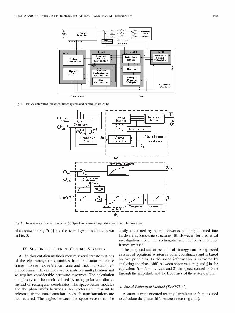
CIRSTEA AND DINU: VHDL HOLISTIC MODELING APPROACH AND FPGA IMPLEMENTATION 1855
Fig. 1. FPGA-controlled induction motor system and controller structure.
Fig. 2. Induction motor control scheme. (a) Speed and current loops. (b) Speed controller functions.
block shown in Fig. 2(a)], and the overall system setup is shownin Fig. 3.
IV. SENSORLESS CURRENT CONTROL STRATEGY
All field-orientation methods require several transformationsof the electromagnetic quantities from the stator referenceframe into the flux reference frame and back into stator ref-erence frame. This implies vector matrices multiplication andso requires considerable hardware resources. The calculationcomplexity can be much reduced by using polar coordinatesinstead of rectangular coordinates. The space-vector modulesand the phase shifts between space vectors are invariant toreference frame transformations, so such transformations arenot required. The angles between the space vectors can be
easily calculated by neural networks and implemented intohardware as logic-gate structures [8]. However, for theoreticalinvestigations, both the rectangular and the polar referenceframes are used.
The proposed sensorless control strategy can be expressedas a set of equations written in polar coordinates and is basedon two principles: 1) the speed information is extracted byanalyzing the phase shift between space vectors e and i in theequivalent R − L − e circuit and 2) the speed control is donethrough the amplitude and the frequency of the stator current.
A. Speed-Estimation Method (Tier0/Tier1)
A stator-current-oriented rectangular reference frame is usedto calculate the phase shift between vectors e and i.

1856 IEEE TRANSACTIONS ON INDUSTRIAL ELECTRONICS, VOL. 54, NO. 4, AUGUST 2007
Fig. 3. Overall system setup.
The reference frame is rotating with synchronous speed, andthe stator current lies along its real axis. Thus, the stator-currentvector i s becomes the real quantity Is. The general induction-motor space-vector model in the synchronous rotating referenceframe is
usyns =RsIs +
dΨsyns
dt+ jωesΨsyn
s
0 =Rrisynr +
dΨsynr
dt+ j(ωes − ωer) ·Ψsyn
r
Ψsyns =LsIs + Lmisyn
r
Ψsynr =Lri
synr + LmIs
(3)
while the equation governing the rotor current vector is
disynr
dt+
(Rr
Lr+ jωslp
)isynr = −Lm
Lr·(
jωslpIs +dIs
dt
).
(4)
The quantity “ωslp” in (4) is the slip angular frequency andrepresents the difference between the stator electrical angularfrequency ωes and the rotor electrical angular frequency ωer.The relation between the slip angular frequency and the rotorspeed is described by
ωr =ωes − ωslp
p= ωs − ωslp
p(5)
where p is the number of magnetic pole pairs. In steady-stateoperation, the motor currents are sinusoidal and have constantfrequency, thus space-vector circular trajectories
isynr =
−jωslpLmIs
Rr + jωslpLr. (6)
The internal voltage vector esyn is determined by substituting(6) in (2). In the steady state this yields
Reesyn =ωesωslpLmLrRrIs
R2r + ω2
slpL2r
· Lm
Lr
Imesyn =ωesLmR2
rIs
R2r + ω2
slpL2r
· Lm
Lr.
(7)
The slip angular frequency depends linearly on the real-to-imaginary ratio, as indicated by
cot (arg(esyn)− arg(isyn)) =ReesynImesyn =
ωslpLr
Rr. (8)
The argument difference between the two vectors is indepen-dent of the reference frame, so the steady-state slip angularfrequency is calculated in the stator reference frame
ωslp = cot [arg(es)− arg (iss)] ·Rr
Lr. (9)
B. Speed-Control Algorithm (Tier3)
The new control method aims to simultaneously fulfill twointerrelated tasks, achieved by the slip-control loop and by thespeed-control loop, respectively: 1) keep the steady-state slipconstant: ωslp = Ωslp by controlling the stator-current ampli-tude Is, 2) control the stator electrical angular frequency ωes sothat the rotor speed ωr follows reference ωref .1) Slip-Control Loop: For a given stator-current amplitude
Is, vector esyn locus in the complex plane is a pair of circles(Reesyn)2 + (Imesyn − R)2 = R2
R = L2m
2Lr· |ωes| · Is.
(10)
Each quadrant in Fig. 4 corresponds to a combination of thestator angular frequency sign and the slip angular frequencysign. The stator angular frequency is positive in quadrants Iand II, and negative in III and IV. The circles are tangential tothe real axis in the origin of the reference frame. For each quad-rant, there is one reference slip angular frequency Ωslp. Thereferences Ωslp1, Ωslp2, Ωslp3, and Ωslp4 have equal absolutevalues but different signs. Calculations can be reduced to onequadrant due to diagram symmetry. Through transformation,the real and imaginary parts of vector esyn are replaced withtheir absolute values. The result is an equivalent voltage vectoralways situated in the first quadrant
E syneqv = |Reesyn|+ j · |Imesyn| . (11)
To maintain a constant slip angular frequency, the anglebetween the equivalent voltage vector and the stator current
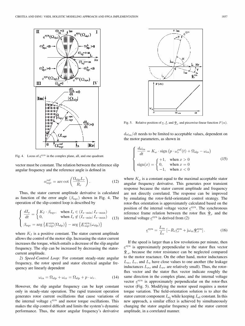
CIRSTEA AND DINU: VHDL HOLISTIC MODELING APPROACH AND FPGA IMPLEMENTATION 1857
Fig. 4. Locus of esyn in the complex plane, all, and one quadrant.
vector must be constant. The relation between the reference slipangular frequency and the reference angle is defined in
αrefeqv = arc cot
(ΩslpLr
Rr
). (12)
Thus, the stator current amplitude derivative is calculatedas function of the error angle (βeqv) shown in Fig. 4. Theoperation of the slip-control loop is described by
dIs
dt=
KI · βeqv, when Is ∈ (Is−min; Is−max)0, when Is ∈ (Is−min; Is−max)
βeqv = argE syn
eqv(Ωslp) − arg
E syn
eqv(ωslp) (13)
where KI is a positive constant. The stator current amplitudeallows the control of the motor slip. Increasing the stator currentincreases the torque, which entails a decrease of the slip angularfrequency. The slip can be increased by decreasing the stator-current amplitude.2) Speed-Control Loop: For constant steady-state angular
frequency, the rotor speed and stator electrical angular fre-quency are linearly dependent
ωes = Ωslp + ωer = Ωslp + p · ωr. (14)
However, the slip angular frequency can be kept constantonly in steady-state operation. The rapid transient operationgenerates rotor current oscillations that cause variations ofthe internal voltage esyn and motor torque oscillations. Thismakes the slip control difficult and limits the system’s dynamicperformance. Thus, the stator angular frequency’s derivative
Fig. 5. Relative position of e, I , and Ψr and piecewise-linear function F (α).
dωes/dt needs to be limited to acceptable values, dependent onthe motor parameters, as shown in
dωes
dt= Kω · sign (
p · ωrefr (t) + Ωslp − ωes
)
sign(x) =
+1, when x > 00, when x = 0−1, when x < 0
(15)
where Kω is a constant equal to the maximal acceptable statorangular frequency derivative. This generates poor transientresponse because the stator current amplitude and frequencyare not directly correlated. The response can be improvedby emulating the rotor-field-orientated control strategy. Therotor-flux orientation is approximately calculated based on theposition of the internal voltage vector esyn. The synchronousreference frame relation between the rotor flux Ψr and theinternal voltage esyn is derived from (2)
esyn =Lm
Lr[−Rri
synr + jωerΨsyn
r ] . (16)
If the speed is larger than a few revolutions per minute, thenesyn is approximately perpendicular to the stator flux vectorΨ s, because the rotor resistance can be neglected comparedto the motor reactance. On the other hand, motor inductancesLm, Lr, and Ls have close values to one another (the leakageinductances Lσs and Lσr are relatively small). Thus, the rotor-flux vector and the stator flux vector indicate roughly thesame direction in the complex plane, and the internal voltagevector esyn is approximately perpendicular on the rotor-fluxvector (Fig. 5). Modifying the motor speed requires a motortorque variation. The field-orientation solution is to alter thestator current component Isq while keeping Isd constant. In thisnew approach, a similar effect is achieved by simultaneouslychanging the stator angular frequency and the stator currentamplitude, in a correlated manner.

1858 IEEE TRANSACTIONS ON INDUSTRIAL ELECTRONICS, VOL. 54, NO. 4, AUGUST 2007
If γ is the angle between the rotor flux and the stator current,then the two stator current components are
isd = Is · cos γisq = Is · sin γ.
(17)
The derivative disd/dt must be null during the motor speedchange, and therefore, the variation of the stator current am-plitude depends on γ according to (19), which is derivedfrom (18). Equation (17) demonstrates that the stator currentcomponent isq increases with Is. However, any variation ofIs must be related to the derivative dγ/dt in accordance withcondition (19)
disddt
=dIs
dtcos γ − Is sin γ · dγ
dt= 0
disqdt
=dIs
dtsin γ + Is cos γ · dγ
dt
(18)
dIs
dt= Is · tan γ · dγ
dt(19)
dIs
dt=
diqs
dt· tan γ
tan γ · sin γ + cos γ. (20)
The angle γ in Fig. 5 depends on the rotor current vector Ir,which is the solution of (4). It can be demonstrated that chang-ing Is causes only small variations of angle γ. On the otherhand, a slip angular frequency change ∆ωslp induces a transientduring which the angle γ undergoes significant oscillations thatend with the final value of γ corresponding to the final slipangular frequency. The final γ increases with the increase offinal ωslp. In conclusion, the motor can be accelerated by in-creasing Isq, which is controlled by increasing both Is and ωes.The stator current amplitude must satisfy conditions (19) and(20). Therefore, dIs/dt needs to be correlated with γ, whichdepends on the stator angular frequency derivative dωes/dt.Good system behavior, resembling the results obtained with therotor-field-oriented vector control strategy, can be obtained ifdωes/dt is a function of Is and angle γ (or alternatively of angleαeqv) as in
dωes
dt= sign
(p · ωref
r (t) + Ωslp − ωes
) · F (Is, αeqv)
F (Is, αeqv) > 0.(21)
Function F is nonlinear and mathematically complex. Forefficient hardware implementation, a compromise must befound between mathematical complexity, system’s dynamicperformance, and available hardware resources (FPGA size).Equation (22) gives a solution suitable for small FPGAs: apiecewise linear function F , independent of the stator currentbut depending on αeqv (Fig. 5). K1, K2, and αmin are positiveconstants, whose optimal values depend on motor parameters.The initial control solution (15) is, therefore, a particular case of(22), with K1 = 0 and K2 = Kω . This speed-control approach
requires that vector e has an acceptable amplitude to allow thecalculation of the angle α
dωes
dt=
sign
(p · ωref
r (t) + Ωslp− ωes
)·(K1χeqv + K2), when χeqv >0
sign(p · ωref
r (t) + Ωslp − ωes
)·K2, when χeqv≤0
χeqv = αeqv − αmin.(22)
As shown by (10), the amplitude of the internal load voltageis proportional to the stator angular frequency ωes and to thestator current amplitude Is. According to the presented controlalgorithm, the stator angular frequency ωes is strictly positiveat zero rotor speed because it equals the reference slip angularfrequency (ωes = Ωslp). The control precision at low speeddepends on the load torque. The precision is higher at hightorque, because the stator current increases with the torque andthat increases amplitude of e. However, experiments show thatthis control does not work well below 200 r/min.
C. Neural Current Controller (Tier2)
The neural control process includes two main functions: thePWM switching pattern generation and the load inductanceestimation. These are presented next.1) PWM Switching-Pattern Generator: If the sampling
process is considered, then (1) becomes
u(k) = Ri(k) +L
Ts[i(k)− i(k − 1)] + e(k). (23)
A noninductive load voltage vector V 1 can be defined as sumof the resistive voltage and the internal voltage
V 1(k) = Ri(k) + e(k). (24)
This can be calculated by a state-space observer, using (23) as
V 1(k) = u(k)− L
Ts[i(k)− i(k − 1)] = u(k)− L
Ts∆i ref .
(25)
The neural PWM generator produces the optimum transistorswitching pattern to ensure adequate inverter output voltages,which maintain the required load currents. The load voltage iscalculated so that at the end of the period the current will equalthe reference one
u ref(k + 1) =Ri(k) +L
Ts[i ref(k + 1)− i(k)] + e(k) (26)
u ref(k + 1) =V 1 +L
Ts[i ref(k + 1)− i(k)] . (27)
The PWM inverter can generate seven different output volt-ages and only six of them are not null. The result in (27) iscompared to these voltages, and one of them must be selectedas the most appropriate one.
The selection process can be described in geometrical termsas in Fig. 6. The current error vector ∆iref
must have its originon the vertex of the noninductive voltage vector. Under these
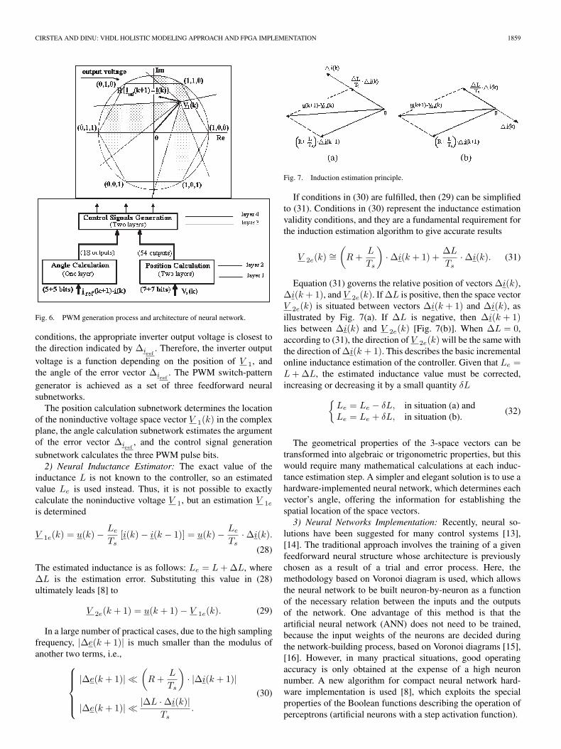
CIRSTEA AND DINU: VHDL HOLISTIC MODELING APPROACH AND FPGA IMPLEMENTATION 1859
Fig. 6. PWM generation process and architecture of neural network.
conditions, the appropriate inverter output voltage is closest tothe direction indicated by ∆iref
. Therefore, the inverter outputvoltage is a function depending on the position of V 1, andthe angle of the error vector ∆iref
. The PWM switch-patterngenerator is achieved as a set of three feedforward neuralsubnetworks.
The position calculation subnetwork determines the locationof the noninductive voltage space vector V 1(k) in the complexplane, the angle calculation subnetwork estimates the argumentof the error vector ∆iref
, and the control signal generationsubnetwork calculates the three PWM pulse bits.2) Neural Inductance Estimator: The exact value of the
inductance L is not known to the controller, so an estimatedvalue Le is used instead. Thus, it is not possible to exactlycalculate the noninductive voltage V 1, but an estimation V 1e
is determined
V 1e(k) = u(k)− Le
Ts[i(k)− i(k − 1)] = u(k)− Le
Ts·∆i(k).
(28)
The estimated inductance is as follows: Le = L +∆L, where∆L is the estimation error. Substituting this value in (28)ultimately leads [8] to
V 2e(k + 1) = u(k + 1)− V 1e(k). (29)
In a large number of practical cases, due to the high samplingfrequency, |∆e(k + 1)| is much smaller than the modulus ofanother two terms, i.e.,
|∆e(k + 1)|
(R +
L
Ts
)· |∆i(k + 1)|
|∆e(k + 1)| |∆L ·∆i(k)|Ts
.
(30)
Fig. 7. Induction estimation principle.
If conditions in (30) are fulfilled, then (29) can be simplifiedto (31). Conditions in (30) represent the inductance estimationvalidity conditions, and they are a fundamental requirement forthe induction estimation algorithm to give accurate results
V 2e(k) ∼=(
R +L
Ts
)·∆i(k + 1) +
∆L
Ts·∆i(k). (31)
Equation (31) governs the relative position of vectors ∆i(k),∆i(k + 1), and V 2e(k). If ∆L is positive, then the space vectorV 2e(k) is situated between vectors ∆i(k + 1) and ∆i(k), asillustrated by Fig. 7(a). If ∆L is negative, then ∆i(k + 1)lies between ∆i(k) and V 2e(k) [Fig. 7(b)]. When ∆L = 0,according to (31), the direction of V 2e(k) will be the same withthe direction of ∆i(k + 1). This describes the basic incrementalonline inductance estimation of the controller. Given that Le =L +∆L, the estimated inductance value must be corrected,increasing or decreasing it by a small quantity δL
Le = Le − δL, in situation (a) andLe = Le + δL, in situation (b).
(32)
The geometrical properties of the 3-space vectors can betransformed into algebraic or trigonometric properties, but thiswould require many mathematical calculations at each induc-tance estimation step. A simpler and elegant solution is to use ahardware-implemented neural network, which determines eachvector’s angle, offering the information for establishing thespatial location of the space vectors.3) Neural Networks Implementation: Recently, neural so-
lutions have been suggested for many control systems [13],[14]. The traditional approach involves the training of a givenfeedforward neural structure whose architecture is previouslychosen as a result of a trial and error process. Here, themethodology based on Voronoi diagram is used, which allowsthe neural network to be built neuron-by-neuron as a functionof the necessary relation between the inputs and the outputsof the network. One advantage of this method is that theartificial neural network (ANN) does not need to be trained,because the input weights of the neurons are decided duringthe network-building process, based on Voronoi diagrams [15],[16]. However, in many practical situations, good operatingaccuracy is only obtained at the expense of a high neuronnumber. A new algorithm for compact neural network hard-ware implementation is used [8], which exploits the specialproperties of the Boolean functions describing the operation ofperceptrons (artificial neurons with a step activation function).

1860 IEEE TRANSACTIONS ON INDUSTRIAL ELECTRONICS, VOL. 54, NO. 4, AUGUST 2007
Fig. 8. Digital neural model to gate structure conversion example.
The algorithm contains three main steps: the digitization ofthe ANN mathematical model, the conversion of the digitizedmodel into a logic-gate structure (illustrated in Fig. 8), andfinally, the hardware optimization by elimination of redundantlogic gates. A set of C++ programs has been developed, basedon the presented algorithm. The programs generate an opti-mized VHDL model of the ANN implementation. This strat-egy bridges the gap between the ANN design and simulationsoftware (such as specialized ANN MATLAB Toolbox) andthe software packages used in hardware design (ModelSim,Xilinx ISE). Although the method is directly applicable only toneural networks, which is composed of neurons with step acti-vation functions, it can also be extended to sigmoidal activationfunctions.
For a better understanding of the implementation algorithm,an example is presented in Fig. 8. The neuron has A = 12input weights and a positive threshold level. Thus, the weightsare sorted in descending order and a recursive implementationprocedure is initiated [8]. The first three weights in the orderedarray are larger than the threshold level so that inputs 4, 7,and 1 will drive an OR gate alongside with the subneurons builton the basis of terminal groups Gt(4), Gt(5), and Gt(6). Ter-minal groups Gt(7) through Gt(11) are not taken into accountbecause their group weights do not surpass the threshold level.Terminal group Gt(4 + 1) = Gt(5) has Z = 0 critical weightsand several noncritical weights so that a Z + 2 = 2-input AND
gate is used.A set of three C++ programs that automatically generate
the netlist description of the implementation, optimize thenetlist, and generate the VHDL model of the final circuit are(Fig. 9): CONV_NET.CPP, OPTIM.CPP, and VHDL_TR.CPP.The three ANNs described by ANGLES.CPP, REGIONS.CPP,and CTRL.CPP are the constituent parts of a more complexfeed-forward ANN, which generates the PWM switching pat-tern for a power inverter. The neural PWM generator operatessuch as to minimize the current ripple in the load of the powerinverter when the load has an inductive character.
Fig. 9. Neural PWM generator design programs and their interconnections.
The complex plane has been divided up into triangularVoronoi cells which correspond with certain approximate mod-ulus and argument values that require special decisions tobe taken by the PWM generator. The conversion process ismonitored by a master program that controls the user interfaceand calls all the six specialized programs in the correct order.This allows the user to control the main parameters of the neuralnetworks to be generated:
1) number of triangular Voronoi cells;2) number of sectors used to divide the 360 interval when
analyzing the argument of ∆i;3) number of bits used to code the components of the two
complex input quantities ∆i and V nL;4) maximum fan-in for the logic gate of the VHDL model.
Several combinations of the above parameters have beentried, and the solution generating an optimal performance–complexity ratio has been adopted. The same number of bitswas used, being successively given values 4, 5, and 6, to check
CIRSTEA AND DINU: VHDL HOLISTIC MODELING APPROACH AND FPGA IMPLEMENTATION 1861
the effect on the number of gates. The effect is shown asfollows:
Nb = 4 Nb = 5 Nb = 6Angle subnetwork 252 gates 378 gates 408 gatesPosition subnetwork 132 gates 242 gates 343 gatesControl subnetwork 709 gates 709 gates 709 gates
The number of gates in the Control Subnetwork is alwaysthe same, as it depends on the number of Voronoi cells inthe previous two subnetworks but not on the number of bitsused to represent the voltage and the current. The chosenimplementation solution uses five input bits to code eachanalog input, as a compromise between complexity (size ofnetwork in number of gates) and precision. The 360 interval isdivided into 36 sectors, and the complex plane is divided into54 triangular Voronoi cells. The initial netlist description of thefirst subnetwork contained 568 logic gates arranged on 11 gatelayers. After the optimization stage, the netlist contained242 gates (representing 42.6% of the initial gate count). Theinitial and final numbers of gates for the second subnetworkare 660 and 378, which means a compression to 57.27%.This subnetwork has been implemented by a logic-gatestructure with 14 layers. On the other hand, the control-signalgeneration subnetwork has been optimized from 1329 to709 gates resulting in a compression of only 23.43%. Thecorresponding hardware implementation contains six layers oflogic gates. Thus, the total number of gates in the optimizedneural implementation is 1329. The longest path from inputs tooutputs passes through 14 + 6 = 20 layers of logic gates.
A new implementation approach, based on the adjustment ofthe balance between the number of neurons and the operationalaccuracy of the network, was briefly presented. This involvesthe construction of the network neuron by neuron instead oftraining a feed-forward neural network defined by a fixedarchitecture. The construction method, following the algorithmin the study in [2, pp. 77–98], is a simplified version of themethod in the study in [15] and is based on Voronoi diagramsfor neural networks with binary outputs [16]. A set of C++programs generates the mathematical description of the neuralnetworks and transforms them into VHDL models. They allowthe user to modify the main parameters of the neural networksto be generated: the number of triangular Voronoi cells, thenumber of sectors used to divide the 360 interval, the numberof bits used for the codification of each input quantity, and themaximum logic gate fan-in.
V. BEHAVIORAL VHDL SYSTEM SIMULATION
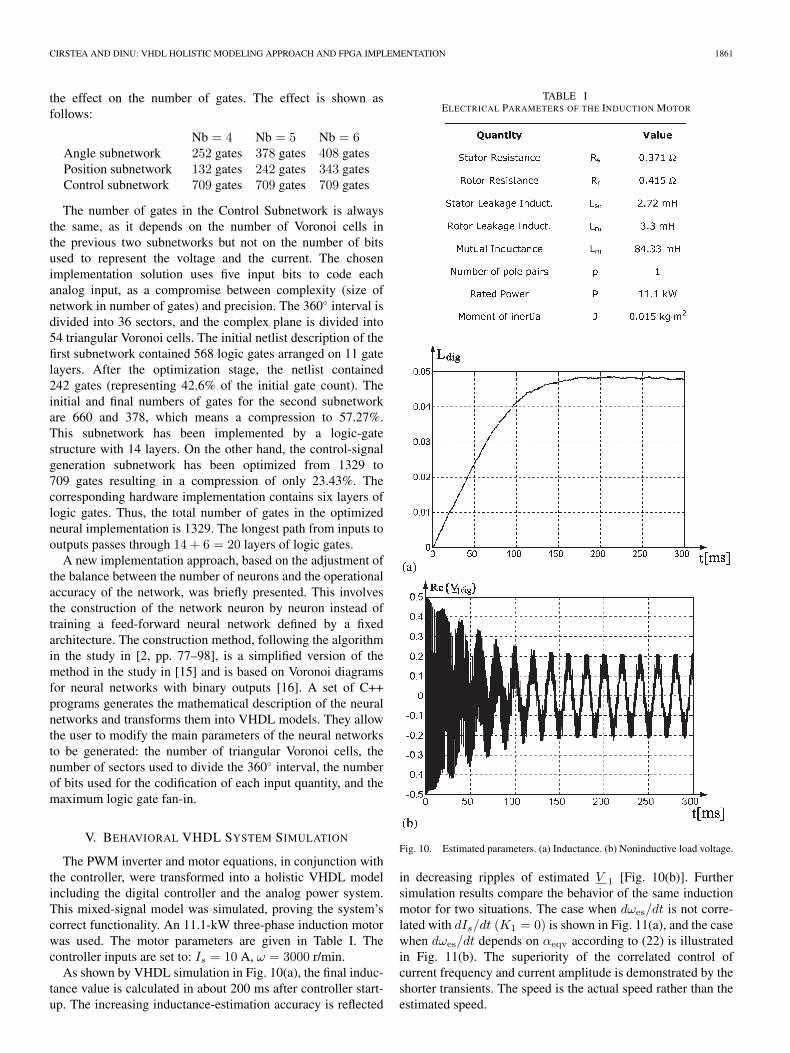
The PWM inverter and motor equations, in conjunction withthe controller, were transformed into a holistic VHDL modelincluding the digital controller and the analog power system.This mixed-signal model was simulated, proving the system’scorrect functionality. An 11.1-kW three-phase induction motorwas used. The motor parameters are given in Table I. Thecontroller inputs are set to: Is = 10 A, ω = 3000 r/min.
As shown by VHDL simulation in Fig. 10(a), the final induc-tance value is calculated in about 200 ms after controller start-up. The increasing inductance-estimation accuracy is reflected
TABLE IELECTRICAL PARAMETERS OF THE INDUCTION MOTOR
Fig. 10. Estimated parameters. (a) Inductance. (b) Noninductive load voltage.
in decreasing ripples of estimated V 1 [Fig. 10(b)]. Furthersimulation results compare the behavior of the same inductionmotor for two situations. The case when dωes/dt is not corre-lated with dIs/dt (K1 = 0) is shown in Fig. 11(a), and the casewhen dωes/dt depends on αeqv according to (22) is illustratedin Fig. 11(b). The superiority of the correlated control ofcurrent frequency and current amplitude is demonstrated by theshorter transients. The speed is the actual speed rather than theestimated speed.

1862 IEEE TRANSACTIONS ON INDUSTRIAL ELECTRONICS, VOL. 54, NO. 4, AUGUST 2007
Fig. 11. Speed variation for (a) K1 = 0, K2 > 0 and (b) K1 > 0, K2 > 0.
Fig. 12. Load current space vector.
The slow motor deceleration in Fig. 11(a) is due to theattempt to “force” the system to generate a dynamic responsebeyond its limits. This can be eliminated by using a slightlysmaller value for K2. In Fig. 11(b), the controller automaticallyfinds the optimal average acceleration by calculating dωes/dtas in (22). Faster transients may be obtained if F depends bothon Is and αeqv. The attenuated speed oscillations cannot beeliminated unless K1 is small—not practical, transient responseworsens with K1 decreasing.
Fig. 12 illustrates the behavior of the VHDL simulated-load-current space vector, which has an expected shape. Simula-tions were attempted for gradually lower speeds, and thus,
the limitation of the applicability of the control strategy hasbeen determined. The system does not work adequately atfrequencies below 4 Hz (240 r/min), because the back emf istoo small, leading to unacceptably high calculation errors evenduring steady-state operation. Experimental tests attempted atlower speeds confirmed this limitation, therefore, this papercould not include results at speeds near zero.
VI. CONTROLLER FPGA IMPLEMENTATION AND TESTING
The silicon area required by the speed controller dependson its complexity, which affects the system’s dynamic per-formance. The control system can be implemented either insmall FPGAs (low dynamics) or in large chips (for goodtransient response). The sample controller was implementedinto a Xilinx XC4010XL FPGA. Testing was performed asfollows: 1) timing simulation and 2) oscilloscope test of theFPGA mounted on an XS40 test board. The Xilinx synthesistool analyzes the abstract VHDL model and generates an opti-mized implementation file (bit stream) in accordance with theapplication requirements and the structural details of the targetchip. The software allows optimization for speed or for com-plexity (area); the synthesis was done using area optimization(minimum silicon).
Timing analysis was then performed to check propagationdelays. The implemented controller correctly generated thePWM pulses for the power inverter. The test proved the correctoperation of the novel neural PWM controller. Experimentaltesting in conjunction with the 11.1-kW three-phase inductionmotor followed, to validate the system’s model and the controlstrategy. Experimental tests were carried out with the controllerimplemented in the Xilinx XC4010XL FPGA and the 11.1-kWthree-phase induction motor (specification in Section V). Thespeed/torque behavior of the drive was investigated. Fig. 13(a)illustrates the natural motor startup with load, when the torqueis proportional with the speed. The speed transient responselasts for approximately 0.75 s, matching closely the simu-lated startup profile, then the motor speed stays constant at3000 r/min.
Fig. 13(b) shows the motor transient response to a fastvariation of the torque. Initially, the rapid increase of the torquecauses the motor to slow, and this leads to an increase ofthe motor slip above the imposed value. Therefore, the slip-compensation mechanism, included in the FPGA controller,increases the motor current, boosting the active torque, andreducing the slip. As a consequence, the speed is brought backup to the desired value after approximately 0.8 s.
Fig. 14 illustrates the controlled-torque characteristic versusthe natural one, plotted using experimental measurements. Theimprovement in maintaining constant speed for variable-loadtorque is easily noticeable, proving high performance of theneural-controlled drive for low-dynamic applications.
The authors are aware that more comprehensive tests can beperformed. However, the purpose of the content of this paperwas to present the novel methodology applied to this control-system design and to present a set of results that validatethe approach taken and confirm the correct operation of thecontroller. Within these limits, the authors consider that they

CIRSTEA AND DINU: VHDL HOLISTIC MODELING APPROACH AND FPGA IMPLEMENTATION 1863
Fig. 13. Speed Control. (a) Startup with load. (b) Speed control at torque step.
Fig. 14. Controlled versus natural torque characteristic.
have achieved their objective. The holistic modeling/designapproach used in this paper can be summarized as follows.
1) The mathematical evaluation of the system using VHDLbehavioral simulation. The holistic model, at this abstractstage, includes the following: the control system, thepower converter, and the induction motor, allows theintegrated simulation of these elements in the same envi-ronment (ModelSim). This has allowed the optimizationof the control functions and has enabled the creationof a testing environment early in the controller-designprocess. The motor is modeled as a VHDL entity with thephase voltages and the load torque as input ports, while
the phase currents and the rotor speed are the output ports.The motor equations are integrated using Euler’s methodwith a step of 50 ns.
2) At the next stage, the optimized VHDL controller codecan be directly implemented in a variety of “targettechnologies,” the actual physical devices in which thecontroller design is placed. The “target” can be 1) anyCPLD or FPGA—reprogrammable devices, for which theconfiguration is lost when power is switched off, or it canbe permanently configured into a ROM that reconfiguresthe FPGA at any power-up instance or 2) any ASIC—permanently configured chips of different speeds andcomplexity, customized to application.
3) Once the target device is chosen, and the respectiveelectronic library, containing full details of the physicaldevice, is used, the control circuit design contains fullphysical data, including exact signal timing (propagationdelays). This allows another verification of the controller,before any investment is made in physical hardwaretesting.
4) At the next stage, when the designer is pleased with theperformance of the control circuit, the actual download-ing into the physical device is being performed, enablingphysical signals to be tested with an oscilloscope. Theactual chip that was used for physical testing was a XilinxFPGA. The downloading was done simply through astandard parallel cable, connected to the parallel interfaceof the computer and the input of the development board.
An important advantage illustrated by the design presentedis that all the stages described above were performed withinthe same EDA environment, enabling: 1) holistic modelingand optimization; 2) controller virtual timing analysis; and3) easy hardware prototyping on an FPGA development plat-form, allowing experimental testing of the controller.
VII. CONCLUSION
A novel neural induction motor current and speed controlstrategy has been developed, which benefits from reduced num-ber of calculations over classical field-orientation approaches,leading to a low complexity and easy to implement sensorlessdigital controller. The current control strategy can be appliedto a range of power electronic systems and drives. A par-ticular example of an induction motor control application isinvestigated, and the results presented show efficient onlineinductance estimation and sensorless induction motor speedcontrol. The controller was designed using VHDL, in a man-ner that facilitates control over the hardware implementationcomplexity, and was implemented into a Xilinx FPGA. Theneural architecture, which is generated by C++ programs, givesadditional flexibility.
A compact reliable low-complexity reusable digital con-troller design is achieved, allowing rapid prototyping of thedrive via FPGA controller implementation. This offers a cost-effective solution for industrial applications that do not havehigh dynamic requirements. Experimental results confirmed theefficacy of the controller.

1864 IEEE TRANSACTIONS ON INDUSTRIAL ELECTRONICS, VOL. 54, NO. 4, AUGUST 2007
REFERENCES
[1] D. L. Perry, VHDL, 3rd ed. New York: McGraw-Hill, 2002.[2] M. N. Cirstea, A. Dinu, J. Khor, and M. McCormick, Neural and Fuzzy
Logic Control of Drives and Power Systems. Oxford, U.K.: Elsevier,2002.
[3] M. Rodic and K. Jezernik, “Speed-sensrless sliding-mode torquecontrol of an induction motor,” IEEE Trans. Ind. Electron., vol. 49, no. 1,pp. 87–95, Feb. 2002.
[4] L. Harnefors, M. Jansson, R. Ottersten, and K. Pietilainen, “Unified sen-sorless vector control of synchronous and induction motors,” IEEE Trans.Ind. Electron., vol. 50, no. 1, pp. 153–160, Feb. 2003.
[5] M. Comanescu and L. Xu, “An improved flux observer based on PLLfrequency estimator for sensorless vector control of induction motors,”IEEE Trans. Ind. Electron., vol. 53, no. 1, pp. 50–56, Feb. 2006.
[6] S. Nabae, M. Ogasawara, and H. Akagi, “A new control scheme forcurrent controlled PWM inverters,” IEEE Trans. Ind. Appl., vol. IA-22,no. 4, pp. 697–701, Jul./Aug. 1986.
[7] J. Catala I Lopez, L. Romeral, A. Arias, and E. Aldabas, “Novel fuzzyadaptive induction motor drive,” IEEE Trans. Ind. Electron., vol. 53, no. 4,pp. 1170–1178, Jun. 2006.
[8] A. Dinu, “FPGA neural controller for three phase sensorless inductionmotor drive systems,” Ph.D. dissertation, De Montfort Univ., Leicester,U.K., 2000.
[9] B. K. Bose, Power Electronics and Motor Drives—Advances and Trends.New York: Academic, 2006.
[10] M. P. Kazmierkowski, R. Krishnan, F. Blaabjerg, and J. D. Irwin, Controlin Power Electronics: Selected Problems. New York: Academic, 2002.
[11] M. Boussak and K. Jarray, “A high-performance sensorless indirect sta-tor flux orientation control of induction motor drive,” IEEE Trans. Ind.Electron., vol. 53, no. 1, pp. 41–49, Feb. 2006.
[12] Y. Y. Tzou and H. J. Hsu, “FPGA realization of space-vector PWM controlIC for three-phase PWM inverters,” IEEE Trans. Power Electron., vol. 12,no. 6, pp. 953–963, Nov. 1997.
[13] C.-Y. Huang, T.-C. Chen, and C.-L. Huang, “Robust control of inductionmotor with a neural-network load torque estimator and a neural-networkidentification,” IEEE Trans. Ind. Electron., vol. 46, no. 5, pp. 990–998,Oct. 1999.
[14] F.-J. Lin and P.-H. Shen, “Robust fuzzy neural network sliding-modecontrol for two-axis motion control system,” IEEE Trans. Ind. Electron.,vol. 53, no. 4, pp. 1209–1225, Aug. 2006.
[15] B. K. Bose and A. K. Garga, “Neural network design using Voronoidiagrams,” IEEE Trans. Neural Netw., vol. 4, no. 5, pp. 778–787,Sep. 1993.
[16] A. Okabe, B. Boots, K. Sugihara, and S. N. Chiu, Spatial Tessellations—Concepts and Applications of Voronoi Diagrams, 2nd ed. Hoboken, NJ:Wiley, 2000.
[17] P. Vas, “Sensorless vector and direct torque control,” in Monographsin Electrical and Electronic Engineering. London, U.K.: Oxford Univ.Press, 1998.
[18] M. F. Castoldi and M. L. Aguiar, “Simulation of DTC strategy in VHDLcode for induction motor control,” in Proc. Int. Symp. Ind. Electron.,Montreal, QC, Canada, 2006, pp. 2248–2253.
[19] Z. Zhou, T. Li, T. Takahahi, and E. Ho, “Design of a universal space vectorPWM controller based on FPGA,” in Proc. Appl. Power Electron. Conf.,2004, vol. 3, pp. 1698–1702.
[20] D. Zhang, H. Li, and S. Y. Foo, “A simplified FPGA implementa-tion of neural network algorithms integrated with stochastic theory forpower electronics applications,” in Proc. IEEE IECON, Raleigh, NC,2005, pp. 1018–1024.
Marcian N. Cirstea (M’97–SM’04) received thedegree in electrical engineering from TransilvaniaUniversity of Brasov, Brasov, Romania, in 1990, andthe Ph.D. degree from Nottingham Trent University,Nottingham, U.K., in 1996.
He is currently Head of the Design and Tech-nology Department at Anglia Ruskin University,Cambridge, U.K. He had previously been with DeMontfort University, Leicester, U.K., and Transilva-nia University of Brasov. He has published severaltechnical books and about 95 peer-reviewed papers.
His research focus is on digital circuit design, control systems for powerelectronics, holistic modeling of electronic systems, field-programmable gatearrays (FPGAs), and application-specific integrated circuit design. He hasdelivered five international courses/tutorials on very-high-speed integrated cir-cuits hardware description language digital controller design applied to powerelectronic systems modeling and FPGA controller prototyping.
Prof. Cirstea is Founder and Chairman of the Technical Committee onElectronic Systems on Chip of the IEEE Industrial Electronics Society, amember of the Institution of Engineering and Technology (IET) and a CharteredEngineer in the U.K. He is also a Referee for Elsevier, IEEE TRANSACTIONS,and the IET Proceedings, and an Associate Editor of the IEEE TRANSACTIONS
ON INDUSTRIAL ELECTRONICS. Three of his IEEE conference papers havereceived awards.
Andrei Dinu (M’05) received the B.Eng. and M.Sc.degrees in electrical engineering from TransilvaniaUniversity of Brasov, Brasov, Romania, in 1995 and1996, respectively, and the Ph.D. degree in electricaland electronic engineering from De Montfort Uni-versity, Leicester, U.K., in 2000, with a thesis con-cerning the sensorless control of induction motorsusing hardware-implemented neural networks.
He was appointed as a Lecturer at De MontfortUniversity, where he conducted research in the fieldof electrical drives control until 2003 when he moved
to industry. He was a Design Engineer at Datalink Electronics, Loughborough,U.K., and in 2004, he was with Goodrich Corporation as a Control SystemsEngineer. He is the coauthor of two books and author of over 25 refereedscientific papers. He is currently involved in R&D projects carried out inBirmingham, U.K., by the Electromagnetic Systems Technical Centre ofGoodrich Corporation.
Dr. Dinu is a member of the Institution of Engineering and Technology andof the IEEE Industrial Electronics Society. He was the recipient of the ABBaward through one of his IEEE conference papers.
Copyright © 2022 FDOKUMEN