Self-force calculations with matched expansions and quasinormal mode sums
Upload
khangminh22Category
view
3download
0
�����������������
Citation: Lu, L.; Gao, M. A Truncated
Matched Filter Method for
Interrupted Sampling Repeater
Jamming Suppression Based on
Jamming Reconstruction. Remote
Sens. 2022, 14, 97. https://doi.org/
10.3390/rs14010097
Academic Editors: Mi Wang,
Hanwen Yu, Jianlai Chen and
Ying Zhu
Received: 4 December 2021
Accepted: 23 December 2021
Published: 25 December 2021
Publisher’s Note: MDPI stays neutral
with regard to jurisdictional claims in
published maps and institutional affil-
iations.
Copyright: © 2020 by the authors.
Licensee MDPI, Basel, Switzerland.
This article is an open access article
distributed under the terms and
conditions of the Creative Commons
Attribution (CC BY) license (https://
creativecommons.org/licenses/by/
4.0/).
remote sensing
Article
A Truncated Matched Filter Method for Interrupted SamplingRepeater Jamming Suppression Based on Jamming Reconstruction
Lu Lu * and Meiguo Gao
School of Information and Electronics, Beijing Institute of Technology, Beijing 100081, China;[email protected]* Correspondence: [email protected]
Abstract: Interrupted sampling repeater jamming (ISRJ) is becoming more widely used in electroniccountermeasures (ECM), thanks to the development of digital radio frequency memory (DRFM).Radar electronic counter-countermeasure (ECCM) is much more difficult when the jamming signalis coherent with the emitted signal. Due to the intermittent transmission feature of ISRJ, the energyaccumulation of jamming on the matched filter shows a ‘ladder’ characteristic, whereas the real targetsignal is continuous. As a consequence, the time delay and distribution of the jamming slice can beobtained based on searching the truncated-matched-filter (TMF) matrix. That is composed of pulsecompression (PC) results under matched filters with different lengths. Based on the above theory,this paper proposes a truncated matched filter method by the reconstruction of jamming slices tosuppress ISRJ of linear frequency modulation (LFM) radars. The numerical simulations indicate theeffectiveness of the proposed method and validate the theoretical analysis.
Keywords: interrupted sampling repeater jamming (ISRJ); interference suppression; truncatedmatched filter; jamming reconstruction; radar electronic counter-countermeasure (ECCM)
1. Introduction
In recent years, Digital Radio Frequency Memory (DRFM) has been gaining wideacceptance in the field of electronic countermeasure (ECM) and expanding the potentialjamming patterns. A great deal of jamming produced by DRFM is coherent with the signalemitted by the victim radar since the jamming process involves intercepting, storing, andretransmitting data from the radar. Jamming techniques, such as interrupted samplingrepeater jamming (ISRJ) [1,2], derived from DRFM, can produce a significant amount offalse targets which will seriously affect the target detection of victim radars.
The ISRJ is usually composed of signal sampling, storing and repeating which can beachieved by DRFM. The DRFM firstly samples a slice of signal transmitted by the victimradar and then retransmits the slice with different ways. According to the retransmittingscheme, ISRJ can be divided as interrupted sampling and direct repeater jamming (IS-DRJ) [1], interrupted sampling and periodic repeater jamming (ISPRJ) [3], and interruptedsampling and cyclic repeater jamming (ISCRJ) [4]. The main difference between ISDRJand ISPRJ is the retransmitting times of the slice. After sampling from the victim radar,ISDRJ immediately retransmits the slice once, and ISPRJ repeats the slice several times.Unlike ISDRJ and ISRRJ, ISCRJ repeats the current sampling signal and all the previousjamming slices.
Furthermore, many researchers have studied ISRJ’s performance and proposed im-proved interference tactics [2,5–7]. The interrupted-sampling and nonuniform periodicrepeater jamming (ISNPRJ) [6] retransmits the sampled signal with different delay andachieves multiple false targets jamming. There is now a new type of ISRJ based on amulti-waveform modulation [7] that compensates for the lack of periodicity of a single typeof ISRJ. In order to solve the problem that false targets usually lag behind real targets, amodulation-based ISRJ method [8] is proposed to generate preceding targets.
Remote Sens. 2022, 14, 97. https://doi.org/10.3390/rs14010097 https://www.mdpi.com/journal/remotesensing

Remote Sens. 2022, 14, 97 2 of 14
In contrast, a large number of ECCM technologies against ISRJ have been proposed [9–17],which can be roughly categorized into 2 classes: transmitting schemes and echo signalprocessing schemes.
Transmitting schemes adjust waveform actively to suppress ISRJ. By estimating theISRJ parameters, the transmitter can generate the optimized waveform orthogonal tojamming signals [18]. The false targets are deduced directly after pulse compression. Atime-frequency random coded (TFRC) method [19] in the multi-carrier phased-coded(MCPC) signal is designed to reduce the correlation between radar echo and ISRJ. For ISRJdiscontinuity in phase, Hanbali and Kastantin [12] add a linear phase into the emittedsignal to counter the approach of active echo cancellation based on ISRJ.
Echo signal processing schemes are another major class of ISRJ suppression method,which can also be subdivided into two categories: filtering methods and signal recoverymethods.
The filtering methods are designed to filter out the interference from echo signals.ISRJ usually transmits with much higher energy than the echo signal in order to achieveeffective interference. The energy function detection and band-pass filtering (EFDBP) [20]method exploited the energy difference to extract signal without jamming and design filterssuppressing side lobes. The energy difference is also be reflected in the time-frequency(TF) domain. Thus, a ’max-TF’ function (MaxTF) [21] was proposed to design a filter in theTF domain directly to suppress jamming signals. The Sliding-Truncation Matched Filter(STMF) method [22] analyzed the difference between the real target signals and jammingsignals in the TF domain. By truncating and sliding the matched filter, the jammingparameters can be extracted and estimated. Information entropy is another method todistinguish real target signal and jamming signal. Ref. [20] utilized the difference ininformation entropy between the real target signal and the interfering signal after singularvalue decomposition (SVD) to design a band-pass filter.
Alternatively, a lot of research studies today have attempted to employ compressedsensing (CS) to recover the real target signal directly from the jammed signal [23–25]. Thereal target signal in time domain extracted by the energy function can be utilized as akind of compressed data [24]. LFM signals are sparse in the spectrum after differentialbeat processing, so a linear relationship between the echo signal and the spectrum canbe established. The real target signal was recovered with some common sparse recoveryalgorithms, such as orthogonal matching pursuit (OMP). Ref. [26] considered the noiseeffect and improved the interference rejection performance of the compressed sensingalgorithm at low signal-to-noise ratio by introducing Bayesian compress sensing (BCS). Ithas been suggested that some researchers utilize fractional Fourier transforms (FRFT) tofind methods to suppress jamming for the aggregation characteristic of LFM signals in thefractional domain [27–29].
Transmitting schemes can achieve better interference suppression due to the jointtransmitting waveform design. However, it is not possible to design waveforms for onlyone type of interference in practical situations. It makes more sense to suppress interferenceby echo signal processing. Nevertheless, the conventional echo signal processing methodshave poor interference suppression at low signal-to-noise ratios (SNR) because they usuallyutilized only part of the unjammed echo signal.
This study creatively proposes a truncated matched filter method based on the recon-struction of jamming slices to improve the ISRJ suppression performance. This methodutilizes information from jamming signals, whose amplitude is higher than that of thereal target signal. This allows for more accurate reconstruction and is suitable for lowSNR regimes. The two main factors used to reconstruct the jamming slices are the delaytime of jamming signal and the jamming slice segment corresponding to that. The methodconstructs a search matrix composed of pulse compression results under the matched filterswith different lengths. At the peak position of the PC result using the full-length filter, theladder characteristic in the filter length domain is effective to extract the jamming slice. Inaddition, the peak position can be thought as the delay time of the jamming signal corre-sponding to the reference signal. The method has improved the suppression performance

Remote Sens. 2022, 14, 97 3 of 14
and keep the jamming-free signal as much as possible. It shows a great efficiency underhigh jamming-to-signal ratios (JSR) and low SNR circumstances.
The remainder of this paper is arranged as follows. In Section 2, the model of radarsignal and the mechanism of ISRJ are described. In Section 3, the truncated matchedfilter method is detailed as instructed, including building truncated matched filter matrix,extracting jamming slice, and reconstructing jamming slices. In Section 4, simulation resultsare presented to validate the proposed method. Finally, the conclusions are drawn inSection 5.
2. Signal Model2.1. Signal Model of LFM Radar
The normalized LFM continuous signal in a transmitting cycle can be expressed as:
s(t) = ej2π( f0t+0.5kt2), t ∈ [0, T], (1)
where f0 is the carrier frequency; T is the period of the emitted signal; k = B/T representsthe frequency modulation slope, of which B stands for the bandwidth. The carrier frequencyof the signal can be neglected since it doesn’t affect the deductions in this study. So, it canbe simplified as:
s(t) = ejπk t2, t ∈ [0, T]. (2)
The echo signal of scattering point model is formulated below [29].
x(t) =K
∑i=1
Ais(t− τi) + n(t)
=K
∑i=1
Aiejπk(t−τi)2+ n(t),
(3)
where Ai and τi represent the amplitude and time delay of the i-th scattering point, respec-tively; K is the number of the scattering points. Without loss of generality, it is common toassume the target as a single scattering point model [28]. Thus, the echo signal of the targetcan be expressed as follows:
x(t) = Asejπ(t−τs)2+ n(t), t ∈ [0, T], (4)
where As is the amplitude of the target; τs is the time delay. τs = 2Rs/c, where c representsthe speed of light, and Rs is the distance between the target and the radar.
2.2. Mechanism of ISRJ
Figure 1 shows the mechanism of ISRJ. Since the three types of ISRJ are all based onretransmitting the sampling slice, ISRJ can be thought as a linear combination of severaljamming slices. For this paper, firstly, we build the model of a slice, which can be expressedas follows.
sJ(t) = AJrect(
t− uTI
)ejπk(t−u′)2
, (5)
rect(t′) ={
1, 0 ≤ t′ ≤ 10, otherwise
(6)
where AJ is the amplitude of the jamming signal; rect(t′) is a standard rectangular windowfunction with pulse width 1 and initial location 0; u and TI are the delay and width of thejamming slice; u′ is the delay of the jamming slice relative to the initial signal emitted bythe victim radar.

Remote Sens. 2022, 14, 97 4 of 14
1 2 3 4 5 6 7 8 9 101 2 3 4 5 6 7 8 9 10
S1 T1 S3 T3 S5 T5 S7 T7 S9 T9S1 T1 S3 T3 S5 T5 S7 T7 S9 T9
S1 T1 T1 T1 S5 T5 T5 T5 S9 T9S1 T1 T1 T1 S5 T5 T5 T5 S9 T9
S1 T1 S3 S3 T1 S6 T6 T3 T1 S10S1 T1 S3 S3 T1 S6 T6 T3 T1 S10
Radar
signal
ISDRJ
ISPRJ
ISCRJ
Sample slices
Retransmission
slices
Figure 1. Mechanism of ISRJ.
Construct the matched filter for the transmitted signal, which is expressed as:
h(t) = s∗(−t) = e−jπkt2, t ∈ [0, T], (7)
where ∗ represents conjugation operator. Thus, the output of the match filter for a jammingslice can be written as:
SMF(t) = sJ(t)⊗ h(t)
=∫ ∞
−∞rect
(v− u
TI
)ejπk(v−u′)2
· e−jπk(t−v)2dv
= AJejπk(
u′2−t2)
·∫ ∞
−∞rect
(v− u
TI
)e−j2πk(u′−t)vdv,
(8)
where ⊗ stands for the convolution operator.According to the Fourier transform pairs:
rect(
tτ
)↔ TISa
(ωτ
2
), f (t− u)↔ F(ω)e−jωu, (9)
where Sa(x) = sin(x)/x, the integral part of the formula can be thought as the Fouriertransform of the rectangular window function rect[(v− u)/TI ], when ω is set to 2πk(u′− t)Thus, the last part of (8) can be written as:

Remote Sens. 2022, 14, 97 5 of 14
∫ ∞
−∞rect
(v− u
TI
)e−j2πk(u′−t)vdv
= TISa(
2πk(u′ − t)2
TI
)e−j2πk(u′−t)u.
(10)
Therefore, the output of the match filter for a jamming slice can be summarized as:
SMF(t) =AJ T ISa(
2πk(u′ − t)2
TI
)· ejπk(u′2−t2)e−j2πk(u′−t)u.
(11)
It is obvious that the peaks will appear if each part of the formula gets the maximum valueand that will be achieved when t is set to u′.
3. Truncated Matched Filter for ISRJ Suppression
Based on the above signal model, this paper proposes a truncated matched filtermethod to suppress ISRJ interference. Firstly, we generate a series of matched filters whoselength change from 0 to the full length L. The full length means the length of the matchedfilter is the same as the received signal. After that, we can get a two-dimensional matrixcomposed of the pulse compression results under truncated matched filters with differentlengths of window. The m × k matrix R is named as TMF matrix, where m representsthe delay time, and k is the window length. By searching the rising edge in the windowlength dimension of the peak position in the delay dimension, the position and width of thejamming slice can be obtained and used to restructure the jamming slice. At last, subtractthe jamming signal from the received signal to realize ISRJ Suppression.
3.1. Truncated Matched Filter
In the first place, we truncate the full-length matched filter into different lengths to getthe truncated matched filter:
h(t, Tw) = rect(
tTw
)· e−jπkt2
. (12)
The output of the matched filter, which is also called a pulse compression (PC) result, isformulated as follows:
STMF(t, Tw)
= sJ(t)⊗ h(t, Tw)
= AJejπk(u′2−t2)
·∫ ∞
−∞rect
(v− u
TI
)· rect
(t− vTw
)e−j2πk(u′−t)vdv.
(13)
Since the product result of two rectangular window functions is still a rectangular windowfunction, combine them as:
g(v, Tw) = rect(
v− uTI
)rect
(t− vTw
)= rect
(v− u
T0
),
(14)
where u is the delay of the new rectangular window function; T0 is the overlapping timeperiod of the matched filter and the jamming slice, which is corresponding to u and TI .Based on the derivation in Section 2, we can set ω = 2πk(u′ − t) and make use of theFourier transform pairs to get the result:

Remote Sens. 2022, 14, 97 6 of 14
STMF(t, Tw) =AJ T0Sa(
2πk(u′ − t)2
T0
)· ejπk(u′2−t2)e−j2πk(u′−t)u.
(15)
Obviously, the PC result of a jamming slice will get the maximum value when t = u′,and the amplitude of the peak position can be expressed as:
STMF(u′, Tw
)= AJ T0. (16)
Considering that the delay of the truncated matched filter is the same as the transmittedsignal, the overlapping time T0 is just determined by the length of the filter. So, give theformula of the maximum value as a piecewise function:
STMF(u′) =
0, t ∈ [0, τ0]
AJ(Tw − τ0), t ∈ (τ0, τ0 + TI ] ,AJ Tw, t ∈ (τ0 + TI , T]
(17)
where τ0 represents the time when the filter and the jamming slice start overlapping. Inextreme cases, the maximum value will be simplified into two parts when τ0 = 0 orτ0 + TI = T. It can be concluded from the Formula (17) that the maximum value versusthe length presents a ladder characteristic. There is no overlapping part between the filterand the jamming slice, and the PC result equals to 0 until the length of the filter reachesthe starting time of the jamming slice. The PC result will increase as the overlapping partincreases. When the jamming slice is completely covered by the matched filter, it willachieve the maximum value. After that, the increasing length will not influence that, andthe PC result will maintain the value without changing.
The PC result between the matched filter and the target signal can be written as:
Ss(t)= x(t)⊗ h(t, Tw)
=∫ ∞
−∞Asejπk(v−τs) · rect
(t− vTw
)e−jπk(t−v)2
dv
= Asejπk(τs2−t2)
·∫ ∞
−∞rect
(t− vTw
)e−j2πk(τs−t)vdv
= AsTwSa(
2πk(τs − t)2
Tw
)· ejπk(τs
2−t2)e−j2πk(τs−t)v.
(18)
Similarly, the amplitude of the peak position can be formulated as:
Ss(τs) = AsTw. (19)
It is different with the jamming slice that the maximum value of the PC result generatedby the target signal shows a linear increase relationship with the length of the matched filter.In contrast, the PC result of the jamming slice contains at least one period with constantvalue, which is called as a ladder characteristic. Despite the fact that a lot of peaks will bedetected when the echo signal is jammed by ISRJ, we take advantage of this to distinguishwhether the peak is caused by the jamming slice or the real target signal.
The TF representation and PC results under different matched filters are depicted inFigure 2. For a better view of the TF features of the target signals and jamming signals,we use the ISDRJ as an example, and related parameters are set as Table 1. Figure 2a isthe TF energy distribution images. From Figure 2b, the PC result of jamming signal is farhigher than the real target signal, and it is difficult to distinguish them. However, we can

Remote Sens. 2022, 14, 97 7 of 14
find in Figure 2c that the interrupted emitting of ISDRJ makes the PC results show theladder characteristic, along with the change of the length of matched filter. Figure 2d is theTMF matrix.
60
40
0
20
40
60
Figure 2. Comparison of different characters between real target signal and jamming signal. (a) TheTF analysis; (b) the pulse compression results filtered with the full-length matched filter; (c) the pulsecompression results versus the lengths of matched filters; (d) the TMF matrix.
Table 1. Simulation parameters.
Parameter Symbol Unit Value
Signal-to-noise ratio SNR dB 0Jamming-to-signal ratio JSR dB 15
Radar signal cycle T µs 10Radar signal band width B MHz 100
Radar receiver complex sampling frequency fs MHz 150Target location R0 m 200
Main false target location RJ m 678ISRJsampling pulse width TI µs 1
Pulse repetition interval of ISPRJ TISPRJ µs 2Slice number of ISPRJ NISPRJ 3

Remote Sens. 2022, 14, 97 8 of 14
3.2. Extraction and Reconstruction of Jamming Slice
The ‘ladder’ characteristic and the TMF matrix facilitate the extraction and reconstruc-tion of jamming slices. Firstly, the PC result filtered by the full-length matched filter will bedetected by Constant False Alarm Rate (CFAR) detectors:
Pmax(t0) = Γ{STMF(t, T)}, (20)
where t0 = {t1, t2, . . . , tn} represents the time of n targets detected; Γ{·} denotes the CFARdetection operator. Noise and the side lobe of the jamming slice will make the edge of therising part jitter, which will result in the inaccuracy of the edge determination. Therefore,some centroid estimation methods can be applied to the PC results based on Reference [30].So that we can get the all targets, including false targets and the real target, for the i-th peak,the PC results can be extracted, along with the filter length domain, to get the max-peakfunction Pmax(Tw)
Pi,max(Tw) = STMF(ti, Tw). (21)
The steps of extracting jamming slice are described below.Step 1: Differentiate the max-peak function Pi,max(Tw) and get P′i,max(Tw).Step 2: Determine a threshold γ0 to extract the jamming slice function c(Tw). Since
PC result jammed by ISRJ will show the ladder characteristic which is demonstrated inSection 3.1, the differential of the max-peak function can extract the rising part. Accordingto (16) and (17), the threshold can be set as:
γ0 =max[Pi,max(Tw)]
T, (22)
where T can be replaced as the number of sample points in the discrete form. Then, c(Tw)can be written as
c(Tw) =
{1, Pi,max(Tw) > γ0,0, Pi,max(Tw) ≤ γ0,
(23)
where c(Tw) equals to 1 means the end of the filter coincides with the jamming slice. c(Tw)represents the jamming slice that produces the i-th peak in Pmax(t0). Therefore, we canrewrite c(Tw) as
c(t) ={
1, Pi,max(Tw) > γ0,0, Pi,max(Tw) ≤ γ0,
(24)
which represents the jamming segments in terms of the peak position. The jamming slicecan be divided into multiple continuous segments.
Step 3: Assume that the signal sequence detected at the radar receiver is x = [x1, x2, . . . , xn]T
and the transmitting signal sequence is s = [s1, s2, . . . , sn]T . Then, select the p-th piece
of continuous jamming slice jp =[sl , sl+1, . . . , sl+Q
]T , where l and Q are the number ofstarting point and the length of jamming slice, respectively. M points around the start andend position of each segment also need to be searched in order to reduce the influence ofnoise. Thus, the expanded jamming slice can be expressed as:
j′p =[sl−M+1, sl−M, . . . , sl , sl+1, . . . ,
sl+Q, sl+Q+1, . . . , sl+Q+M−1]T .
(25)
If i in {l −M + 1, l −M, . . . , l + Q + M− 1} exceeds the length of the local referencecode signal, set i = i− N. If i ≤ 0, set i = i + N. In addition, the p-th piece of echo signal isformulated as:
x′p =[xl−M+1, xl−M, . . . , xl , sl+1, . . . ,
xl+Q, xl+Q+1, . . . , xl+Q+M−1]T .
(26)

Remote Sens. 2022, 14, 97 9 of 14
Construct the searching matrix Kp as:
Kp =[k(1,1)p , k(2,1)
p , . . . , k(M,1)p , k(1,2)
p , k(2,2)p , . . . ,
k(M,2)p , . . . , k(M,M)
p ]T(27)
where
k(i,q)p =
1Q + 2M− i− q + 2
[01×(i−1), xl+i−1,
xl+i, . . . , xl+Q+2M−q, 01×(q−1)]T .(28)
i = 1, 2, . . . , M and q = 1, 2, . . . , M. 0 is the zero matrix.Step 4: The reconstructed signal most similar to the jamming slice will be picked out
by the minimum remaining energy criterion. For each tow in the searching matrix Kp,
caculate the remaining energy criterion R(i,q)p as follows:
R(i,q)p = ‖x′p −
k(i,q)p x′p
||k(i,q)p ||2
k(i,q)p ‖2. (29)
Select the row with the minimum R(i,q)p and the reconstructed jamming slice jc can be
expressed as:
jc =k(imin,qmin)
p x′p
||k(imin,qmin)p ||2
k(imin,qmin)p . (30)
Step 5: Repeat step 3 and 4 until all the jamming slices have been reconstructed.The specific algorithm is described in Algorithm 1.
Algorithm 1: Truncated Matched Filter Method for jamming slice extraction.
Input: The max-peak function Pi,max(Tw), the transmitting cycle time T, echosignal s(t)
Output: The reconstructed jamming signal j(t)1. Differentiate Pi,max(Tw) and obtain P′i,max(Tw);2. Determine γ0 according to Equation (22) and obtain c(t) by
Equations (23) and (24);3. Calculate the searching matrix Kp according to Equation (27).4. Calculate and select the minimum remaining energy criterion. Reconstruct the
jamming slice with Equation (30).5. If all the jamming slices are reconstructed, stop the reconstruction and output
the signal without jamming; otherwise back to 3.
To summarize, the jamming suppression method is composed of four stages, as shownin Figure 3. Firstly, we extract signals by the truncated matched filters with variable lengthsfrom the received signal and get a two-dimensional matrix. Secondly, jamming slice andparameters are detected from the matrix. Then, we can reconstruct the jamming slice withthe parameters. Finally, the interference suppressed signal can be obtained by subtractingthe jamming slices from the jammed signal.

Remote Sens. 2022, 14, 97 10 of 14
Variable Length
Truncation
Matched Filter
Received Signal
Jamming Slice and
Parameters
Detection
Jamming Slice
Reconstruction
Jamming
Suppression
Interference
Suppressed Signal
Figure 3. Flow chart of interference suppression.
4. Simulation4.1. Interference Suppression Based on TMF
As shown in (2), the transmitting signal is assumed as LFM signal. Based on thejamming model in Section 2, related parameters are set as Table 1.
The echo signal in time domain and the pulse compression results before and aftersuppression are all shown in Figures 4–6. As demonstrated in the figures, the three jammingtypes show different features in the PC results. ISDRJ retransmits the sampled signal atonce, making the same delay of each repeat period. As a result, there will be only onemaster false target with high amplitude. ISPRJ is similar with ISDRJ. Since it will repeatthe sampled signal with several times, the number of master false targets equals to therepeating times in a repeating period. Unlike ISDRJ and ISPRJ, ISCRJ repeats the currentjamming slice and the previous jamming slice. The current jamming slice in each repeatingperiod generates a false target at the same position. Under that circumstance, the PC resultof ISCRJ is composed of a main false target with high amplitude and numerous multiplesecondary false targets. All the three pulse compression results after TMF interferencesuppression are almost entirely composed of the real target without any false one whichproves the effectiveness of this method.
0 5 10
Time( s)
(a)
10
5
0
5
10
Am
pli
tude
0 0.5 1 1.5
Range(km)
(b)
0
0.5
1
Norm
aliz
ed A
mpli
tude
0 0.5 1 1.5
Range(km)
(c)
0
0.5
1
Norm
aliz
ed A
mpli
tude
Real Target
Real TargetFalse Targets
Figure 4. Simulation results of TMF for ISDRJ. (a) The echo signal with ISDRJ; (b) pulse compressionof the echo signal; (c) pulse compression of echo signal after TMF.

Remote Sens. 2022, 14, 97 11 of 14
0 5 10
Time( s)
(a)
10
5
0
5
10
Am
pli
tude
0 0.5 1 1.5
Range(km)
(b)
0
0.5
1
Norm
aliz
ed A
mpli
tude
0 0.5 1 1.5
Range(km)
(c)
0
0.5
1
Norm
aliz
ed A
mpli
tude
Real Target
False TargetsReal Target
Figure 5. Simulation results of TMF for ISPRJ. (a) The echo signal with ISPRJ; (b) pulse compressionof the echo signal; (c) pulse compression of echo signal after TMF.
0 5 10
Time( s)
(a)
10
5
0
5
10
Am
pli
tude
0 0.5 1 1.5
Range(km)
(b)
0
0.5
1N
orm
aliz
ed A
mpli
tude
0 0.5 1 1.5
Range(km)
(c)
0
0.5
1
Norm
aliz
ed A
mpli
tude
False TargetsReal Target Real Target
Figure 6. Simulation results of TMF for ISCRJ. (a) The echo signal with ISCRJ; (b) pulse compressionof the echo signal; (c) pulse compression of echo signal after TMF.
4.2. Monte-Carlo Simulations and Results
We utilized the probability of target detection as evaluation criteria.The probability of target detection is the rate of radar detecting targets in PC results,
which can be calculated asPd = Nd/Ntotal, (31)
where Pd represents the probability of target detection; Ntotal is the total number of PCresults, and Nd targets are detected by radar.
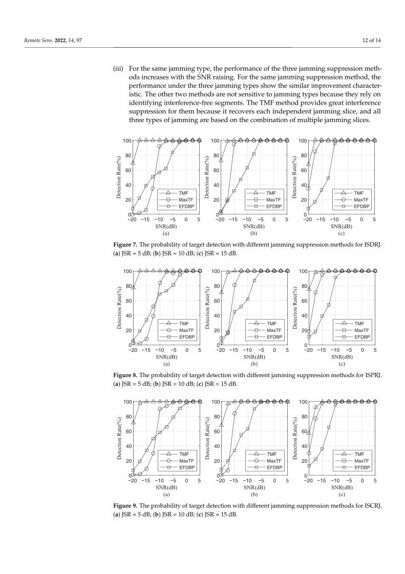
Figures 7–9 are the probability of target detection curve after the jamming suppressionwith three jamming types and three jamming suppression methods, where 1000 times ofMonte Carlo simulation are performed on each SNR and JSR. From the probability of targetdetection curve, it can be seen that:
(i) Under the three jamming suppression methods, the probability of target detection willimprove with the increase of SNR and JSR. The reason is that, when SNR and JSR rise, thedistinction between jamming and true target signals becomes increasingly clear, whichmakes it easier to extract interference-free segments for MaxTF and EFDBP methods.In the TMF method, higher SNR and JSR mean higher jamming-noise ratio (JNR) andbetter recovery of jamming signals, which improves interference suppression.
(ii) The TMF method shows better performance in lower SNR and JSR compared withother methods. The other two methods rely on the extraction of interference-freesegments, whereas their extraction performance in the low SNR and JSR regimes ispoor. In addition, the TMF method is to recover jamming signals directly. When theSNR and JSR are low, the JNR is still high enough to ensure the recovery of jammingsignals, resulting in a greater interference suppression effect.
Remote Sens. 2022, 14, 97 12 of 14
(iii) For the same jamming type, the performance of the three jamming suppression meth-ods increases with the SNR raising. For the same jamming suppression method, theperformance under the three jamming types show the similar improvement character-istic. The other two methods are not sensitive to jamming types because they rely onidentifying interference-free segments. The TMF method provides great interferencesuppression for them because it recovers each independent jamming slice, and allthree types of jamming are based on the combination of multiple jamming slices.
20 5
SNR(dB)
(a)
0
20
40
60
80
100
Det
ecti
on
Rat
e(%
)
TMF
MaxTF
EFDBP
SNR(dB)
(b)
0
20
40
60
80
100
Det
ecti
on
Rat
e(%
)
TMF
MaxTF
EFDBP
SNR(dB)
(c)
0
20
40
60
80
100
Det
ecti
on
Rat
e(%
)
TMF
MaxTF
EFDBP
15 10 5 0 20 515 10 5 0 20 515 10 5 0
Figure 7. The probability of target detection with different jamming suppression methods for ISDRJ.(a) JSR = 5 dB; (b) JSR = 10 dB; (c) JSR = 15 dB.
SNR(dB)
(a)
0
20
40
60
80
100
Det
ecti
on
Rat
e(%
)
TMF
MaxTF
EFDBP
SNR(dB)
(b)
0
20
40
60
80
100
Det
ecti
on
Rat
e(%
)
TMF
MaxTF
EFDBP
SNR(dB)
(c)
0
20
40
60
80
100
Det
ecti
on
Rat
e(%
)
TMF
MaxTF
EFDBP
20 515 10 5 0 20 515 10 5 0 20 515 10 5 0
Figure 8. The probability of target detection with different jamming suppression methods for ISPRJ.(a) JSR = 5 dB; (b) JSR = 10 dB; (c) JSR = 15 dB.
SNR(dB)
(a)
0
20
40
60
80
100
Det
ecti
on
Rat
e(%
)
TMF
MaxTF
EFDBP
SNR(dB)
(b)
0
20
40
60
80
100
Det
ecti
on
Rat
e(%
)
TMF
MaxTF
EFDBP
SNR(dB)
(c)
0
20
40
60
80
100
Det
ecti
on
Rat
e(%
)
TMF
MaxTF
EFDBP
20 515 10 5 0 20 515 10 5 0 20 515 10 5 0
Figure 9. The probability of target detection with different jamming suppression methods for ISCRJ.(a) JSR = 5 dB; (b) JSR = 10 dB; (c) JSR = 15 dB.

Remote Sens. 2022, 14, 97 13 of 14
5. Conclusions
ISRJ has gradually become the most significant factor on detecting, tracking, andrecognizing targets of radar. Many ECCM approaches have been proposed against ISRJ.However, they show poor performance in low SNR regimes, whether in detection rate andjamming-free signal segments extraction. Besides, most ECCM techniques need to detector recognize whether the jamming exists, and they can only be employed in the presenceof ISRJ.
Based on the study of ISRJ principle, this paper proposed a TMF-based ISRJ interfer-ence suppression method to surmount these shortcomings. It automatically and accuratelyextracts and reconstructs jamming slices, which can greatly keep the signal of real targets.By subtracting the jamming slices from the jammed signal, we can get the integral jamming-free signal, almost without information loss. Mathematical derivation and simulationsverified the effectiveness of the method. This method performs better in detection rateand the ability of interference suppression, especially in low SNR regimes. However, theproposed method is computationally intensive because it consumes a lot of resources inconstructing the search matrix. Further research studies will be carried out on reducing thecomputation and working in a more complex real environment.
Author Contributions: Conceptualization, M.G.; Formal analysis, L.L.; Investigation, L.L.; Methodol-ogy, L.L.; Validation, L.L.; Writing—original draft, L.L.; Writing—review & editing, M.G. All authorshave read and agreed to the published version of the manuscript.
Funding: This work was supported by the National Natural Science Foundation of China underGrant 62071041 and 61701554, Shanghai Aerospace and Technology Innovation Foundation, China,under Grant SAST-2020078.
Institutional Review Board Statement: Not applicable.
Informed Consent Statement: Not applicable.
Data Availability Statement: The data presented in this study are available on request from thecorresponding author.
Conflicts of Interest: The authors declare no conflict of interest.
References1. Wang, X.; Liu, J.; Zhang, W.; Fu, Q.; Liu, Z.; Xie, X. Mathematic principles of interrupted-sampling repeater jamming (ISRJ). Sci.
China Ser. F Inf. Sci. 2007, 50, 113–123. [CrossRef]2. Feng, D.; Xu, L.; Pan, X.; Wang, X. Jamming wideband radar using interrupted-sampling repeater. IEEE Trans. Aerosp. Electron.
Syst. 2017, 53, 1341–1354. [CrossRef]3. Liu, Z.; Wang, X.S.; Liu, J.C.; Wang, G.; Xiao, S. Jamming technique of interrupted-sampling and periodic repeater based on
digital radio frequency memory. Acta Armamentarii 2008, 29, 405–410.4. Zhong, L. Jamming Technique for Countering LFM Pulse Compression Radar Based on Digital Radio Frequency Memory. Ph.D.
Dissertation, National University of Defense Technology, Changsha, China, 2006.5. Li, H.; Zhao, G.; Yang, Y.; Gao, H. The performance analysis of multi-false target jamming of part copying Radar pulse. Electron.
Inf. Warf. Technol. 2010, 25, 39–44.6. Yang-rui, Z.; Yun-jie, L.; Man-ling, L.; Mei-guo, G.; Xiong-jun, F. Suppress Jamming Technique of Multiple False Targets on
Interrupted-Sampling and Non-Uniform Periodic Repeater. Acta Electron. Sin. 2016, 44, 46–53. [CrossRef]7. Ping, Z.; Qingsheng, Z.; Yanbin, L.; Nan, H.; Wenqing, X. Intermittent Sampling Repeater Jamming Technique Based on
Multi-waveform Modulation. Mod. Radar 2020, 42, 77–83. 89. [CrossRef]8. Li, C.Z.; Su, W.M.; Gu, H.; Ma, C.; Chen, J.L. Improved interrupted sampling repeater jamming based on DRFM. In Proceedings
of the 2014 IEEE International Conference on Signal Processing, Communications and Computing (ICSPCC), Guilin, China, 5–8August 2014; pp. 254–257.
9. Jianzhong, Z.; Heqiang, M.; Shuliang, W.; Yanbing, L.; Hongwei, G. Anti-Intermittent Sampling Repeater Jamming Method Basedon LFM Segmented Pulse Compression. J. Electron. Inf. Technol. 2019, 41, 1712–1720. [CrossRef]
10. Zhou, C.; Liu, Q.; Chen, X. Parameter estimation and suppression for DRFM-based interrupted sampling repeater jammer. IETRadar Sonar Navig. 2018, 12, 56–63. [CrossRef]
11. Xiong, W.; Zhang, G.; Liu, W. Efficient filter design against interrupted sampling repeater jamming for wideband radar. EURASIPJ. Adv. Signal Process. 2017, 2017, 1–12. [CrossRef]

Remote Sens. 2022, 14, 97 14 of 14
12. Hanbali, S.B.S.; Kastantin, R. Technique to counter active echo cancellation of self-protection ISRJ. Electron. Lett. 2017, 53, 680–681.[CrossRef]
13. Zhou, K.; Li, D.; Quan, S.; Liu, T.; Su, Y.; He, F. SAR Waveform and Mismatched Filter Design for Countering Interrupted-SamplingRepeater Jamming. IEEE Trans. Geosci. Remote Sens. 2021. [CrossRef]
14. Yu, M.; Dong, S.; Duan, X.; Liu, S. A novel interference suppression method for interrupted sampling repeater jamming based onsingular spectrum entropy function. Sensors 2019, 19, 136. [CrossRef] [PubMed]
15. Zhou, K.; Li, D.; Su, Y.; Liu, T. Joint design of transmit waveform and mismatch filter in the presence of interrupted samplingrepeater jamming. IEEE Signal Process. Lett. 2020, 27, 1610–1614. [CrossRef]
16. Hanbali, S.B.S. Technique to counter improved active echo cancellation based on ISRJ with frequency shifting. IEEE Sens. D 2019,19, 9194–9199. [CrossRef]
17. Zhang, J.; Zhou, C. Interrupted Sampling Repeater Jamming Suppression Method based on Hybrid Modulated Radar Signal. InProceedings of the 2019 IEEE International Conference on Signal, Information and Data Processing (ICSIDP), Chongqing, China,11–13 December 2019; pp. 1–4.
18. Zhou, C.; Liu, F.; Liu, Q. An adaptive transmitting scheme for interrupted sampling repeater jamming suppression. Sensors 2017,17, 2480. [CrossRef]
19. Li, J.; Luo, X.; Duan, X.; Wang, W.; Ou, J. A Novel Radar Waveform Design for Anti-Interrupted Sampling Repeater Jamming viaTime-Frequency Random Coded Method. Prog. Electromagn. Res. M 2020, 98, 89–99. [CrossRef]
20. Mu-yao, Y.; Sheng-bo, D.; Xiang-yu, D. An Interference Suppression Algorithm of Multiple False Targets for Pulse Doppler Radar.J. Signal Process. 2017, 33, 1578–1584. [CrossRef]
21. Chen, J.; Wu, W.; Xu, S.; Chen, Z.; Zou, J. Band pass filter design against interrupted-sampling repeater jamming based ontime-frequency analysis. IET Radar Sonar Navig. 2019, 13, 1646–1654. [CrossRef]
22. Chao, Z.; Quan-hua, L.; Tao, Z. Research on DRFM Repeater Jamming Recognition. J. Signal Process. 2017, 33, 911–917. [CrossRef]23. Wei, Y.; Lu, Z.; Yuan, G.; Fang, Z.; Huang, Y. Sparsity adaptive matching pursuit detection algorithm based on compressed
sensing for radar signals. Sensors 2017, 17, 1120. [CrossRef]24. Hui, Y.; Chunyang, W.; Lei, A.; Xin, L. ECCM scheme against interrupted-sampling repeater jamming based on compressed
sensing signal reconstruction. Syst. Eng. Electron. 2018, 40, 717–725. [CrossRef]25. Zhao, Y.; Gini, F.; Greco, M.; Tang, B. Radar ECCM based on phase-aid distributed compressive sensing. Signal Image Video
Process. 2018, 12, 1497–1504. [CrossRef]26. Huan, S.; Dai, G.; Luo, G.; Ai, S. Bayesian compress sensing based countermeasure scheme against the interrupted sampling
repeater jamming. Sensors 2019, 19, 3279. [CrossRef]27. Yang, Z.; Chaoxuan, S.; Zhuangzhi, H.; Ning, H.; Hui, X. Fractional Fourier Transform and Compressed Sensing Adaptive
Countering Smeared Spectrum Jamming. J. Electron. Inf. Technol. 2019, 41, 1047–1054. [CrossRef]28. Zhang, L.; Wang, G.; Zhang, X.; Li, S.; Xin, T. Interrupted-sampling repeater jamming adaptive suppression algorithm based on
fractional dictionary. Syst. Eng. Electron. 2020, 42, 1439–1448. [CrossRef]29. Fang, B.; Huang, G.; Gao, J. Sub-Nyquist sampling and reconstruction model of LFM signals based on blind compressed sensing
in FRFT domain. Circuits Syst. Signal Process. 2015, 34, 419–439. [CrossRef]30. Tuncay, P.; Kartal, M. A new method for Doppler centroid estimation based on block processing. In Proceedings of the 2013 6th
IEEE International Conference on Recent Advances in Space Technologies (RAST), Istanbul, Turkey, 12–14 June 2013; pp. 417–420.
Copyright © 2022 FDOKUMEN