A Study on Seismic Behavior of Piled Raft Foundation for Oil ...
10
INTERNATIONAL SOCIETY FOR SOIL MECHANICS AND GEOTECHNICAL ENGINEERING This paper was downloaded from the Online Library of the International Society for Soil Mechanics and Geotechnical Engineering (ISSMGE). The library is available here: https://www.issmge.org/publications/online-library This is an open-access database that archives thousands of papers published under the Auspices of the ISSMGE and maintained by the Innovation and Development Committee of ISSMGE.
-
Upload
khangminh22 -
Category
Documents
-
view
4 -
download
0
Transcript of A Study on Seismic Behavior of Piled Raft Foundation for Oil ...
INTERNATIONAL SOCIETY FOR
SOIL MECHANICS AND
GEOTECHNICAL ENGINEERING
This paper was downloaded from the Online Library of the International Society for Soil Mechanics and Geotechnical Engineering (ISSMGE). The library is available here:
https://www.issmge.org/publications/online-library
This is an open-access database that archives thousands of papers published under the Auspices of the ISSMGE and maintained by the Innovation and Development Committee of ISSMGE.
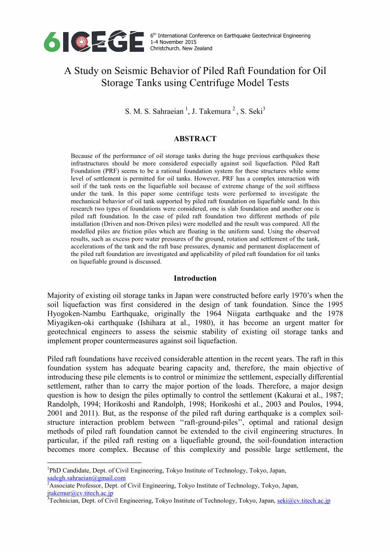
6th International Conference on Earthquake Geotechnical Engineering 1-4 November 2015 Christchurch, New Zealand
A Study on Seismic Behavior of Piled Raft Foundation for Oil
Storage Tanks using Centrifuge Model Tests
S. M. S. Sahraeian 1
, J. Takemura 2
, S. Seki3
ABSTRACT
Because of the performance of oil storage tanks during the huge previous earthquakes these
infrastructures should be more considered especially against soil liquefaction. Piled Raft
Foundation (PRF) seems to be a rational foundation system for these structures while some
level of settlement is permitted for oil tanks. However, PRF has a complex interaction with
soil if the tank rests on the liquefiable soil because of extreme change of the soil stiffness
under the tank. In this paper some centrifuge tests were performed to investigate the
mechanical behavior of oil tank supported by piled raft foundation on liquefiable sand. In this
research two types of foundations were considered, one is slab foundation and another one is
piled raft foundation. In the case of piled raft foundation two different methods of pile
installation (Driven and non-Driven piles) were modelled and the result was compared. All the
modelled piles are friction piles which are floating in the uniform sand. Using the observed
results, such as excess pore water pressures of the ground, rotation and settlement of the tank,
accelerations of the tank and the raft base pressures, dynamic and permanent displacement of
the piled raft foundation are investigated and applicability of piled raft foundation for oil tanks
on liquefiable ground is discussed.
Introduction
Majority of existing oil storage tanks in Japan were constructed before early 1970’s when the
soil liquefaction was first considered in the design of tank foundation. Since the 1995
Hyogoken-Nambu Earthquake, originally the 1964 Niigata earthquake and the 1978
Miyagiken-oki earthquake (Ishihara at al., 1980), it has become an urgent matter for
geotechnical engineers to assess the seismic stability of existing oil storage tanks and
implement proper countermeasures against soil liquefaction.
Piled raft foundations have received considerable attention in the recent years. The raft in this
foundation system has adequate bearing capacity and, therefore, the main objective of
introducing these pile elements is to control or minimize the settlement, especially differential
settlement, rather than to carry the major portion of the loads. Therefore, a major design
question is how to design the piles optimally to control the settlement (Kakurai et al., 1987;
Randolph, 1994; Horikoshi and Randolph, 1998; Horikoshi et al., 2003 and Poulos, 1994,
2001 and 2011). But, as the response of the piled raft during earthquake is a complex soil-
structure interaction problem between ‘‘raft-ground-piles’’, optimal and rational design
methods of piled raft foundation cannot be extended to the civil engineering structures. In
particular, if the piled raft resting on a liquefiable ground, the soil-foundation interaction
becomes more complex. Because of this complexity and possible large settlement, the
1PhD Candidate, Dept. of Civil Engineering, Tokyo Institute of Technology, Tokyo, Japan,
[email protected] 2Associate Professor, Dept. of Civil Engineering, Tokyo Institute of Technology, Tokyo, Japan,
[email protected] 3Technician, Dept. of Civil Engineering, Tokyo Institute of Technology, Tokyo, Japan, [email protected]
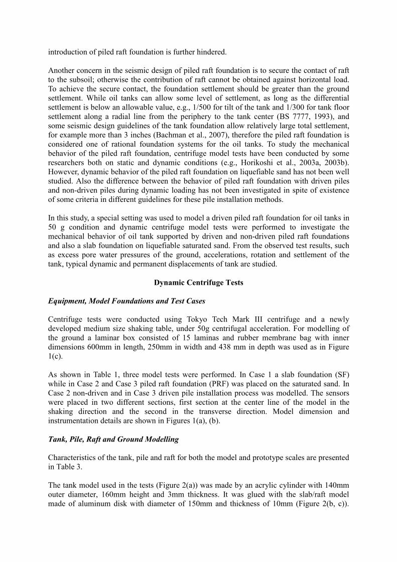
introduction of piled raft foundation is further hindered.
Another concern in the seismic design of piled raft foundation is to secure the contact of raft
to the subsoil; otherwise the contribution of raft cannot be obtained against horizontal load.
To achieve the secure contact, the foundation settlement should be greater than the ground
settlement. While oil tanks can allow some level of settlement, as long as the differential
settlement is below an allowable value, e.g., 1/500 for tilt of the tank and 1/300 for tank floor
settlement along a radial line from the periphery to the tank center (BS 7777, 1993), and
some seismic design guidelines of the tank foundation allow relatively large total settlement,
for example more than 3 inches (Bachman et al., 2007), therefore the piled raft foundation is
considered one of rational foundation systems for the oil tanks. To study the mechanical
behavior of the piled raft foundation, centrifuge model tests have been conducted by some
researchers both on static and dynamic conditions (e.g., Horikoshi et al., 2003a, 2003b).
However, dynamic behavior of the piled raft foundation on liquefiable sand has not been well
studied. Also the difference between the behavior of piled raft foundation with driven piles
and non-driven piles during dynamic loading has not been investigated in spite of existence
of some criteria in different guidelines for these pile installation methods.
In this study, a special setting was used to model a driven piled raft foundation for oil tanks in
50 g condition and dynamic centrifuge model tests were performed to investigate the
mechanical behavior of oil tank supported by driven and non-driven piled raft foundations
and also a slab foundation on liquefiable saturated sand. From the observed test results, such
as excess pore water pressures of the ground, accelerations, rotation and settlement of the
tank, typical dynamic and permanent displacements of tank are studied.
Dynamic Centrifuge Tests
Equipment, Model Foundations and Test Cases
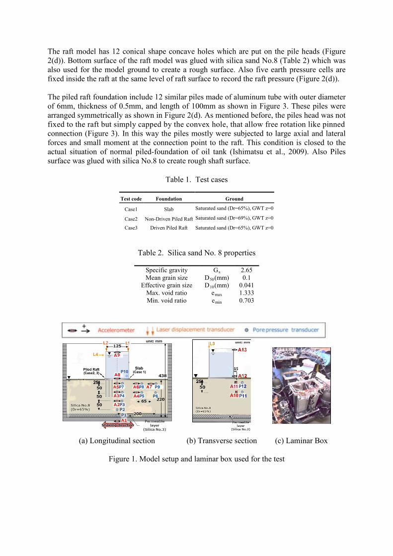
Centrifuge tests were conducted using Tokyo Tech Mark III centrifuge and a newly
developed medium size shaking table, under 50g centrifugal acceleration. For modelling of
the ground a laminar box consisted of 15 laminas and rubber membrane bag with inner
dimensions 600mm in length, 250mm in width and 438 mm in depth was used as in Figure
1(c).
As shown in Table 1, three model tests were performed. In Case 1 a slab foundation (SF)
while in Case 2 and Case 3 piled raft foundation (PRF) was placed on the saturated sand. In
Case 2 non-driven and in Case 3 driven pile installation process was modelled. The sensors
were placed in two different sections, first section at the center line of the model in the
shaking direction and the second in the transverse direction. Model dimension and
instrumentation details are shown in Figures 1(a), (b).
Tank, Pile, Raft and Ground Modelling
Characteristics of the tank, pile and raft for both the model and prototype scales are presented
in Table 3.
The tank model used in the tests (Figure 2(a)) was made by an acrylic cylinder with 140mm
outer diameter, 160mm height and 3mm thickness. It was glued with the slab/raft model
made of aluminum disk with diameter of 150mm and thickness of 10mm (Figure 2(b, c)).
The raft model has 12 conical shape concave holes which are put on the pile heads (Figure
2(d)). Bottom surface of the raft model was glued with silica sand No.8 (Table 2) which was
also used for the model ground to create a rough surface. Also five earth pressure cells are
fixed inside the raft at the same level of raft surface to record the raft pressure (Figure 2(d)).
The piled raft foundation include 12 similar piles made of aluminum tube with outer diameter
of 6mm, thickness of 0.5mm, and length of 100mm as shown in Figure 3. These piles were
arranged symmetrically as shown in Figure 2(d). As mentioned before, the piles head was not
fixed to the raft but simply capped by the convex hole, that allow free rotation like pinned
connection (Figure 3). In this way the piles mostly were subjected to large axial and lateral
forces and small moment at the connection point to the raft. This condition is closed to the
actual situation of normal piled-foundation of oil tank (Ishimatsu et al., 2009). Also Piles
surface was glued with silica No.8 to create rough shaft surface.
Table 1. Test cases
Test code Foundation Ground
Case1 Slab Saturated sand (Dr=65%), GWT z=0
Case2 Non-Driven Piled Raft Saturated sand (Dr=69%), GWT z=0
Case3 Driven Piled Raft Saturated sand (Dr=65%), GWT z=0
Table 2. Silica sand No. 8 properties
Specific gravity Gs 2.65
Mean grain size D50(mm) 0.1
Effective grain size D10(mm) 0.041
Max. void ratio emax 1.333
Min. void ratio emin 0.703
(a) Longitudinal section (b) Transverse section (c) Laminar Box
Figure 1. Model setup and laminar box used for the test
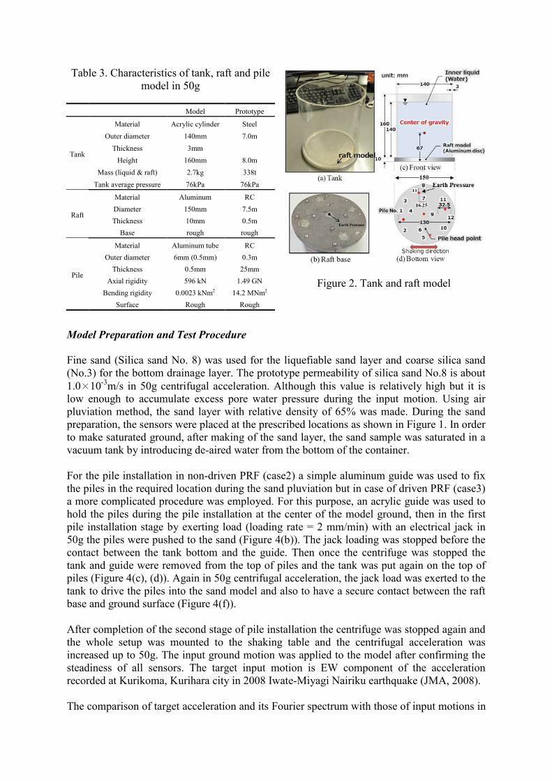
Figure 2. Tank and raft model
Model Preparation and Test Procedure
Fine sand (Silica sand No. 8) was used for the liquefiable sand layer and coarse silica sand
(No.3) for the bottom drainage layer. The prototype permeability of silica sand No.8 is about
1.0×10⁻³
m/s in 50g centrifugal acceleration. Although this value is relatively high but it is
low enough to accumulate excess pore water pressure during the input motion. Using air
pluviation method, the sand layer with relative density of 65% was made. During the sand
preparation, the sensors were placed at the prescribed locations as shown in Figure 1. In order
to make saturated ground, after making of the sand layer, the sand sample was saturated in a
vacuum tank by introducing de-aired water from the bottom of the container.
For the pile installation in non-driven PRF (case2) a simple aluminum guide was used to fix
the piles in the required location during the sand pluviation but in case of driven PRF (case3)
a more complicated procedure was employed. For this purpose, an acrylic guide was used to
hold the piles during the pile installation at the center of the model ground, then in the first
pile installation stage by exerting load (loading rate = 2 mm/min) with an electrical jack in
50g the piles were pushed to the sand (Figure 4(b)). The jack loading was stopped before the
contact between the tank bottom and the guide. Then once the centrifuge was stopped the
tank and guide were removed from the top of piles and the tank was put again on the top of
piles (Figure 4(c), (d)). Again in 50g centrifugal acceleration, the jack load was exerted to the
tank to drive the piles into the sand model and also to have a secure contact between the raft
base and ground surface (Figure 4(f)).
After completion of the second stage of pile installation the centrifuge was stopped again and
the whole setup was mounted to the shaking table and the centrifugal acceleration was
increased up to 50g. The input ground motion was applied to the model after confirming the
steadiness of all sensors. The target input motion is EW component of the acceleration
recorded at Kurikoma, Kurihara city in 2008 Iwate-Miyagi Nairiku earthquake (JMA, 2008).
The comparison of target acceleration and its Fourier spectrum with those of input motions in
Table 3. Characteristics of tank, raft and pile
model in 50g
Model Prototype
Tank
Material Acrylic cylinder Steel
Outer diameter 140mm 7.0m
Thickness 3mm
Height 160mm 8.0m
Mass (liquid & raft) 2.7kg 338t
Tank average pressure 76kPa 76kPa
Raft
Material Aluminum RC
Diameter 150mm 7.5m
Thickness 10mm 0.5m
Base rough rough
Pile
Material Aluminum tube RC
Outer diameter 6mm (0.5mm) 0.3m
Thickness 0.5mm 25mm
Axial rigidity 596 kN 1.49 GN
Bending rigidity 0.0023 kNm2 14.2 MNm2
Surface Rough Rough
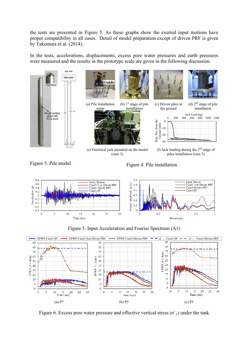
the tests are presented in Figure 5. As these graphs show the exerted input motions have
proper compatibility in all cases. Detail of model preparation except of driven PRF is given
by Takemura et al. (2014).
In the tests, accelerations, displacements, excess pore water pressures and earth pressures
were measured and the results in the prototype scale are given in the following discussion.
Figure 3. Pile model
Figure 5. Input Acceleration and Fourier Spectrum (A1)
EPWP-Case1-SF EPWP-Case2-Non Driven PRF EPWP-Case3-Driven PRF σ`v - Case1-SF σ`v - Case3-Driven PRF
(a) P7 (b) P5 (c) P3
Figure 6. Excess pore water pressure and effective vertical stress (σ`v) under the tank
(a) Pile installation
setup
(b) 1st stage of pile
installation
(c) Driven piles in
the ground
(d) 2nd stage of pile
installation
(e) Electrical jack mounted on the model
(case 3)
(f) Jack loading during the 2nd stage of
piles installation (case 3)
Figure 4. Pile installation
-30
-20
-10
0
0 200 400 600 800 1000 1200
Rel
a. P
os.
fro
m t
he
Gro
und
(m
m)
Jack Load (kg)
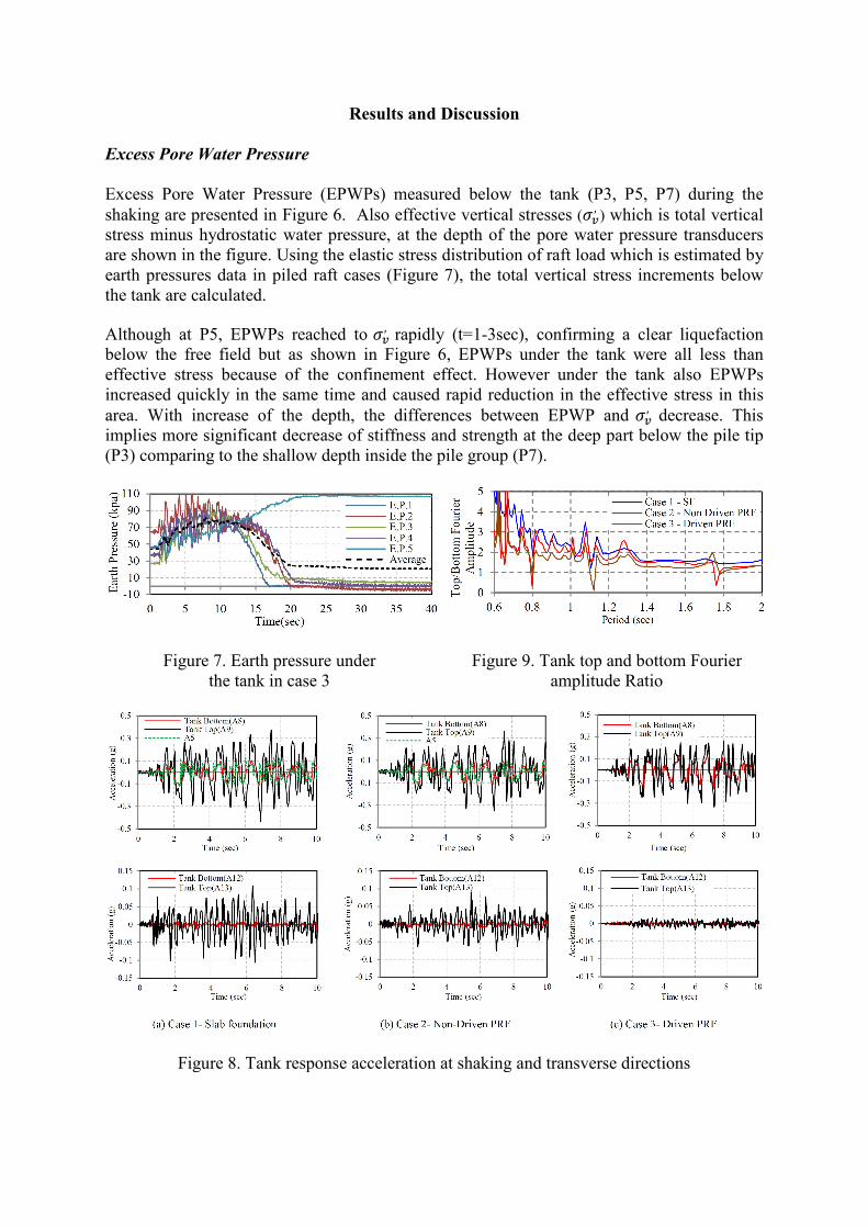
Results and Discussion
Excess Pore Water Pressure
Excess Pore Water Pressure (EPWPs) measured below the tank (P3, P5, P7) during the
shaking are presented in Figure 6. Also effective vertical stresses (𝜎𝜎𝑣𝑣, ) which is total vertical
stress minus hydrostatic water pressure, at the depth of the pore water pressure transducers
are shown in the figure. Using the elastic stress distribution of raft load which is estimated by
earth pressures data in piled raft cases (Figure 7), the total vertical stress increments below
the tank are calculated.
Although at P5, EPWPs reached to 𝜎𝜎𝑣𝑣, rapidly (t=1-3sec), confirming a clear liquefaction
below the free field but as shown in Figure 6, EPWPs under the tank were all less than
effective stress because of the confinement effect. However under the tank also EPWPs
increased quickly in the same time and caused rapid reduction in the effective stress in this
area. With increase of the depth, the differences between EPWP and 𝜎𝜎𝑣𝑣, decrease. This
implies more significant decrease of stiffness and strength at the deep part below the pile tip
(P3) comparing to the shallow depth inside the pile group (P7).
Figure 7. Earth pressure under
the tank in case 3
Figure 9. Tank top and bottom Fourier
amplitude Ratio
Figure 8. Tank response acceleration at shaking and transverse directions
In the build-up period (rapid increase of EPWPs), increase of EPWP is slower in Case 1 in
the shallow part (P7) because of more load from the slab in this case. However after the
shake, EPWPs dissipated more rapid in piled raft cases (Cases 2 and 3) especially in the
shallow part (P7) where piles located. Obviously the reason is more confinement effect by the
pile group in these cases. The reason for faster EPWP dissipation in case 2 is unintentional
higher soil relative density (about 4%) during making the ground model.
Tank Response, Settlement and Rotation
Accelerations at top and bottom of the tank in shaking direction (A8, A9), transverse
direction (A12, A13) and in the ground just beneath the tank (A5) are shown in Figure 8. In
Case 3, A5 was not recorded. After rapid increase of EPWP, a large difference between the
tank top and bottom accelerations was appeared especially in Case 1 with slab foundation.
The main reason is reduction in foundation stiffness while the water pressure fluctuation in
the tank is negligible based on P10 result. The ratio of Fourier amplitude at tank top and
bottom is presented in Figure 9. As Figures 8 and 9 shows, the piled raft foundation is
effective in reducing the rocking motion not only in the shaking direction but also in the
transverse direction especially in Case 3 with driven piled raft foundation.
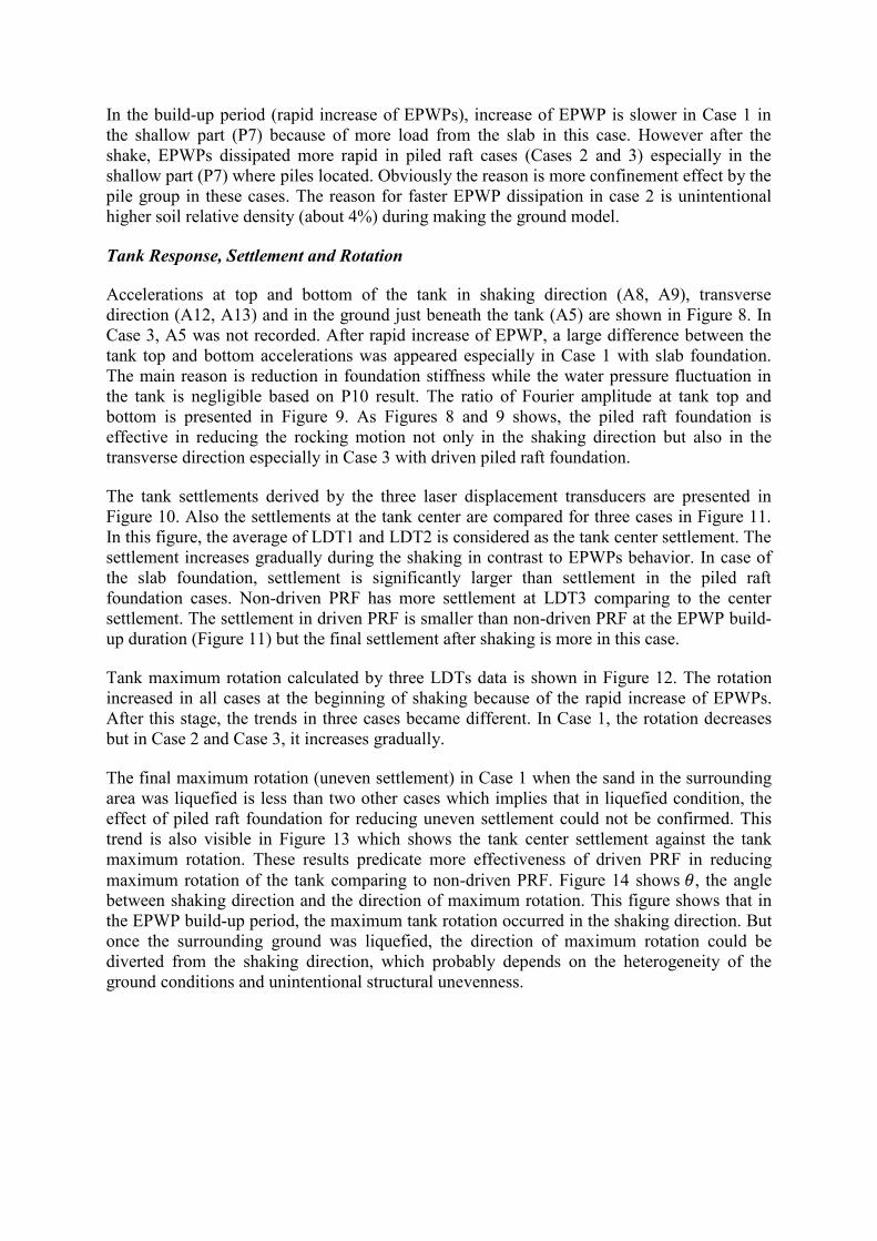
The tank settlements derived by the three laser displacement transducers are presented in
Figure 10. Also the settlements at the tank center are compared for three cases in Figure 11.
In this figure, the average of LDT1 and LDT2 is considered as the tank center settlement. The
settlement increases gradually during the shaking in contrast to EPWPs behavior. In case of
the slab foundation, settlement is significantly larger than settlement in the piled raft
foundation cases. Non-driven PRF has more settlement at LDT3 comparing to the center
settlement. The settlement in driven PRF is smaller than non-driven PRF at the EPWP build-
up duration (Figure 11) but the final settlement after shaking is more in this case.
Tank maximum rotation calculated by three LDTs data is shown in Figure 12. The rotation
increased in all cases at the beginning of shaking because of the rapid increase of EPWPs.
After this stage, the trends in three cases became different. In Case 1, the rotation decreases
but in Case 2 and Case 3, it increases gradually.
The final maximum rotation (uneven settlement) in Case 1 when the sand in the surrounding
area was liquefied is less than two other cases which implies that in liquefied condition, the
effect of piled raft foundation for reducing uneven settlement could not be confirmed. This
trend is also visible in Figure 13 which shows the tank center settlement against the tank
maximum rotation. These results predicate more effectiveness of driven PRF in reducing
maximum rotation of the tank comparing to non-driven PRF. Figure 14 shows 𝜃𝜃, the angle
between shaking direction and the direction of maximum rotation. This figure shows that in
the EPWP build-up period, the maximum tank rotation occurred in the shaking direction. But
once the surrounding ground was liquefied, the direction of maximum rotation could be
diverted from the shaking direction, which probably depends on the heterogeneity of the
ground conditions and unintentional structural unevenness.
(a) Case 1 – Slab foundation (b) Case 2 – Non Driven PRF (c) Case 3 – Driven PRF
Figure 10. Tank Settlement
Figure 11. Tank center settlement
Figure 12. Tank maximum rotation
Figure 13. Tank max. rotation
vs tank center settlement
Figure 14. 𝜃𝜃 at maximum rotation
direction
Figure 15. Tank top
view and 𝜃𝜃 direction
Conclusions
From the dynamic centrifuge model tests on slab and piled raft foundation of oil storage tank
resting on thick loose saturated sand, the following conclusions were derived.
1. Although the EPWP beneath the tank were much less than the initial effective stress, it
rapidly increased and became constant values. The time of getting the constant value is
almost same as the time in which sand in the surrounding area became liquefied.
2. Piled raft foundation was effective in reducing not only total settlement but also rocking
motion. The driven PRF has better operation in reducing the rocking motion furthermore
it could reduce the maximum rotation of tank comparing to non-driven PRF.
3. In the EPWP build-up period, the PRF could have better performance in reducing the
uneven settlement compared to the slab foundation, especially for the foundation with
driven piles. However, once the sand in the surrounding area was liquefied, the effect of
PRF in reducing the uneven settlement could not be confirmed.
4. In the early stage of shaking during the pore pressure build-up period, the maximum tank
rotation occurred in the shaking direction. But once the surrounding ground was liquefied,
it’s direction could be diverted from the shaking direction, which probably depends on
-300
-250
-200
-150
-100
-50
0
0 5 10 15 20 25 30S
ettl
emen
t (m
m)
Time (sec)
LDT 1
LDT 2
LDT 3
-300
-250
-200
-150
-100
-50
0
0 5 10 15 20 25 30
Set
tlem
ent
(mm
)
Time (sec)
LDT 1
LDT 2
LDT 3
-300
-250
-200
-150
-100
-50
0
0 5 10 15 20 25 30
Set
tlem
ent
(mm
)
Time (sec)
LDT 1
LDT 2
LDT 3
-300
-250
-200
-150
-100
-50
0
0 5 10 15 20 25 30
Tan
k C
ente
r S
ett.
(mm
)
Time(Sec)
Case1-SFCase2-Non Driven PRFCase3-Driven PRF
0
0.002
0.004
0.006
0.008
0 5 10 15 20 25 30
Max
. R
ota
tion (
rad)
Time (sec)
Case1-SFCase2-Non Driven PRFCase3-Driven PRF
0
0.001
0.002
0.003
0.004
0.005
0.006
0.007
0.008
-300-250-200-150-100-500
Max
imu
m R
ota
tio
n (
rad)
Tank Center Settlement (mm)
Case1Case2Case3
0
50
100
150
200
250
300
350
400
0 5 10 15 20 25 30
Ѳ a
t M
ax.
Ro
tati
on D
ir.
(rad
)
Time (sec)
Case1-SFCase2-Non Driven PRFCase3-Driven PRF
the heterogeneity of the ground conditions and unenviable structural unevenness.
The number of piles in the piled raft model was relatively less compared to the actual tank
foundation. Besides the ground condition in the centrifuge model was so loose against the
input shaking motion. Therefore the piled raft model with more piles and higher liquefaction
resistance of the ground can be main concerns for the further study.
References
Bachman R, Nyman D, Bhushan K, Leyendecker E V, Lister L. Seismic design guidelines and data submittal requirements for LNG facilities. Federal Energy Regulatory Commission: Washington D.C, 2007.
BS 7777. Flat-bottomed, vertical, cylindrical storage tanks for low temperature service. 1, 1993.
Horikoshi K, Randolph M F. A contribution to optimum design of piled rafts. Geotechnique 1998; 48 (3): 301-317.
Horikoshi K, Matsumoto T, Hashizume Y, Watanabe T, Fukuyama H. Performance of piled raft foundations subjected to static horizontal loads. Int. Jour. of Physical Modelling in Geotechnics 2003a; 3(2): 37-50.
Horikoshi K, Matsumoto T, Hashizume Y, Watanabe T, Performance of piled raft foundations subjected to dynamic loading. Int. Jour. of Physical Modelling in Geotechnics 2003b; 3(2): 51-62.
Ishihara S, Kawase Y, Nakajima M. Liquefaction characteristics of sand deposits at an oil tank site during the 1978 Miyagiken-oki Earthquake. Soils and Foundations 1980; 20 (2): 97-111.
Ishimatsu S, Yagi T, Yoshimi T, Takemura J. Filed observation of pile behavior during the liquid level variation in an oil tank. Kisoko 2009, 37 (10):76-79.
JMA (Japan Meteorological Agency (2008)). http://www. seisvol.kishou.go.jp/eq/kyoshin/jishin/080614_iwate-miyagi/index.html.
Kakurai M, Yamashita K, Tomono M. Settlement behavior of piled raft foundation on soft ground. Proc. 8th ARCSMFE 1987; 1: 373-376.
Poulos H G, Alternative design strategies for piled raft foundation. Proc. 3rd International Conference Deep Foundation Practice 1994; 239-244.
Poulos H G, Piled raft foundations: design and applications. Geotechnique 2001;51(2):95-113.
Poulos H G, Small J C, Chow H. Piled raft foundations for tall building. Geotechnical Engineering Journal of
the SEAGS & AGSSEA 2011;42(2): 78-84.
Randolph M F. Design methods for pile groups and piled rafts. Proc. 13th ICSMGE 1994; 5: 61-82.
Takemura J, Yamada M, Seki S. Dynamic response and settlement behavior of piled raft foundation of oil
storage tank. Proc. 8th inter. con. on physical modelling in Geotechnique 2014; 1: 613-619.