A spatiotemporal extension for dealing with moving objects with extent in Oracle 11g
11
A spatiotemporal extension for dealing with moving objects with extent in Oracle 11g Luís Matos IEETA – University of Aveiro Campus Universitário de Santiago 3810–193 Aveiro, Portugal [email protected] José Moreira IEETA/DETI – University of Aveiro Campus Universitário de Santiago 3810–193 Aveiro, Portugal [email protected] Alexandre Carvalho INESC/DEI – University of Porto, Campus da FEUP R. Dr. Roberto Frias, 378 4200–465 Porto, Portugal alexandre.carvalho@ inescporto.pt ABSTRACT This paper deals with the design and implementation of a data model and operations for dealing with continuously changing spa- tial data in Oracle 11g object-relational DBMS. The data model relies on abstract data types but we introduce modifications to the internal structure of the spatiotemporal data representations pro- posed in the literature, to reduce storage requirements and to en- able the reuse of data during the execution of queries. We show how to implement spatiotemporal operations relying on the spa- tial functions released by the underlying DBMS and how to use the alternative data representations to reduce the volume of tem- porary data created in the evaluation of spatiotemporal operations. We also demonstrate how to use the proposed data types and op- erations for storage and manipulation of moving objects data using SQL. Finally, we discuss on the advantages and disadvantages of the proposed solutions. 1 Categories and Subject Descriptors H.2.8 [Database management]: Database applications—Spatial databases and GIS; H.2.3.3 [Database management]: Languages— query languages General Terms Spatiotemporal data management Keywords data models and query languages, object-relational databases, spa- tiotemporal data, moving objects 1. INTRODUCTION Research on spatiotemporal databases focuses on the efficient rep- resentation, management and querying of spatial information that changes over time. The properties describing spatial information may change discretely or continuously over time. The former as- sumes that the values of spatial properties change instantaneously 1 This work is based on an earlier work: SAC ’12 Pro- ceedings of the 2012 ACM Symposium on Applied Com- puting, Copyright 2012 ACM 978-1-4503-0857-1/12/03. http://doi.acm.org/10.1145/2245276.2245280. at certain time instants, hence the values of those properties be- tween consecutive changes are constant. The latter describes the values of spatial properties as continuous functions of time. Some authors claim that discrete changes can be modeled as a specializa- tion of continuous changes by using trivial constant functions [5, 16]. The most well-known data models and query languages to deal with spatiotemporal information are based on constraint databases [6] and Abstract Data Types (ADT) [7, 5]. The constraint databases data model [6] is very specialized and its transposition into re- lational or object-relational database management systems (OR- DBMS), the current commercial database standards, would be barely feasible [3]. On the other hand, the representation of ADT can be smoothly integrated into ORDBMS. This approach has been used to develop a spatiotemporal extension implemented on the top of Secondo, an academic and research database prototype [12, 4], but it has not been fully implemented on ORDBMS. There have been many attempts in recent years to develop domain- specific spatiotemporal extensions on the top of ORDBMS such as Oracle, Postgres or DB2, for a diversity of fields of application. The implementation of such extensions is an arduous task and the spa- tiotemporal support that is provided by most proposals is limited and oriented towards the requirements of the applications they are intended for. These observations indicate that the management of spatiotemporal information in standard DBMS is an important is- sue and that the release of generic spatiotemporal extensions would be an important advance in many domains of knowledge. This work focuses on the design and implementation of spatiotem- poral data types and algorithms for dealing with continuously chang- ing spatial data on ORDBMS. The data model is based on ADT, but we also introduce modifications to the representation of moving re- gions proposed in [7, 5] to reduce memory requirements in storage and in the size of the intermediate data structures created during the evaluation of spatiotemporal operations. We present several algorithms to implement the spatiotemporal operations (projection, predicates and clipping) relying on the spatial features of the under- lying DBMS that are not covered in previous spatiotemporal exten- sions for ORDBMS. We also discuss the merits and the weaknesses of data representations and the algorithms that we propose, and we identify open issues for future research. The remainder of this paper is organized as follows: section 2 pre- sents a brief research overview on spatiotemporal databases, fo- cusing on data models and languages suitable for implementation on ORDBMS; section 3 defines our data model for the represen- tation of spatiotemporal data; section 4 presents a selected set of algorithms for the implementation of the most representative spa- APPLIED COMPUTING REVIEW VOL. 12, NO. 2 7
Transcript of A spatiotemporal extension for dealing with moving objects with extent in Oracle 11g

A spatiotemporal extension for dealing with movingobjects with extent in Oracle 11g
Luís Matos
IEETA – University of Aveiro
Campus Universitário de
Santiago
3810–193 Aveiro, Portugal
José Moreira
IEETA/DETI – University of
Aveiro
Campus Universitário de
Santiago
3810–193 Aveiro, Portugal
Alexandre Carvalho
INESC/DEI – University of
Porto, Campus da FEUP
R. Dr. Roberto Frias, 378
4200–465 Porto, Portugal
alexandre.carvalho@
inescporto.pt
ABSTRACT
This paper deals with the design and implementation of a datamodel and operations for dealing with continuously changing spa-tial data in Oracle 11g object-relational DBMS. The data modelrelies on abstract data types but we introduce modifications to theinternal structure of the spatiotemporal data representations pro-posed in the literature, to reduce storage requirements and to en-able the reuse of data during the execution of queries. We showhow to implement spatiotemporal operations relying on the spa-tial functions released by the underlying DBMS and how to usethe alternative data representations to reduce the volume of tem-porary data created in the evaluation of spatiotemporal operations.We also demonstrate how to use the proposed data types and op-erations for storage and manipulation of moving objects data usingSQL. Finally, we discuss on the advantages and disadvantages ofthe proposed solutions.1
Categories and Subject Descriptors
H.2.8 [Database management]: Database applications—Spatialdatabases and GIS; H.2.3.3 [Database management]: Languages—query languages
General Terms
Spatiotemporal data management
Keywords
data models and query languages, object-relational databases, spa-tiotemporal data, moving objects
1. INTRODUCTION
Research on spatiotemporal databases focuses on the e�cient rep-resentation, management and querying of spatial information thatchanges over time. The properties describing spatial informationmay change discretely or continuously over time. The former as-sumes that the values of spatial properties change instantaneously
1This work is based on an earlier work: SAC ’12 Pro-ceedings of the 2012 ACM Symposium on Applied Com-puting, Copyright 2012 ACM 978-1-4503-0857-1/12/03.http://doi.acm.org/10.1145/2245276.2245280.
at certain time instants, hence the values of those properties be-tween consecutive changes are constant. The latter describes thevalues of spatial properties as continuous functions of time. Someauthors claim that discrete changes can be modeled as a specializa-tion of continuous changes by using trivial constant functions [5,16].
The most well-known data models and query languages to deal withspatiotemporal information are based on constraint databases [6]and Abstract Data Types (ADT) [7, 5]. The constraint databasesdata model [6] is very specialized and its transposition into re-lational or object-relational database management systems (OR-DBMS), the current commercial database standards, would be barelyfeasible [3]. On the other hand, the representation of ADT can besmoothly integrated into ORDBMS. This approach has been usedto develop a spatiotemporal extension implemented on the top ofSecondo, an academic and research database prototype [12, 4], butit has not been fully implemented on ORDBMS.
There have been many attempts in recent years to develop domain-specific spatiotemporal extensions on the top of ORDBMS such asOracle, Postgres or DB2, for a diversity of fields of application. Theimplementation of such extensions is an arduous task and the spa-tiotemporal support that is provided by most proposals is limitedand oriented towards the requirements of the applications they areintended for. These observations indicate that the management ofspatiotemporal information in standard DBMS is an important is-sue and that the release of generic spatiotemporal extensions wouldbe an important advance in many domains of knowledge.
This work focuses on the design and implementation of spatiotem-poral data types and algorithms for dealing with continuously chang-ing spatial data on ORDBMS. The data model is based on ADT, butwe also introduce modifications to the representation of moving re-gions proposed in [7, 5] to reduce memory requirements in storageand in the size of the intermediate data structures created duringthe evaluation of spatiotemporal operations. We present severalalgorithms to implement the spatiotemporal operations (projection,predicates and clipping) relying on the spatial features of the under-lying DBMS that are not covered in previous spatiotemporal exten-sions for ORDBMS. We also discuss the merits and the weaknessesof data representations and the algorithms that we propose, and weidentify open issues for future research.
The remainder of this paper is organized as follows: section 2 pre-sents a brief research overview on spatiotemporal databases, fo-cusing on data models and languages suitable for implementationon ORDBMS; section 3 defines our data model for the represen-tation of spatiotemporal data; section 4 presents a selected set ofalgorithms for the implementation of the most representative spa-
APPLIED COMPUTING REVIEW VOL. 12, NO. 2 7

tiotemporal operations in databases; section 5 demonstrates howto store and query moving objects’ data using our Oracle 11g spa-tiotemporal extension; section 6 discusses the solutions proposedin this paper and compares them with related works; section 7 con-cludes and presents guidelines for future research.
2. SPATIOTEMPORAL DATABASES
We will consider that a spatiotemporal object, also referred to asmoving object, is a spatial object that may change its position orshape continuously over time [7].
2.1 Spatiotemporal database architectures
There are three main architectural approaches for representation oftime and space in databases: layered, monolithic and extensibleapproaches [1].
Layered architectures implement advanced features in a layer thatresides on top of an o↵-the-shelf DBMS. Applications which re-quire these advanced features communicate with the DBMS throughthe layer interface. The main advantage of this approach is to pro-vide very fast development of new features but, due to a clear sep-aration of the layer from the DBMS core, transaction managementand query optimization are only guaranteed for the DBMS level [2].
Monolithic architectures overcome these problems, since every spe-cific feature and service is provided directly by the DBMS kernel.Yet, this architecture carries a daunting task which is the implemen-tation process [11].
Extensible architectures try to combine the best from previous ar-chitectures: the support for application-specific or domain-specificfeatures is placed within the DBMS but outside of its core. Gen-erally, this is only possible if the DBMS supports the developmentof extensions. Extensible architectures can benefit from the sup-port for transaction management, indexing, and query optimization.Moreover, the development of an extension is less complex than thedevelopment of new functions inside the DBMS kernel.
2.2 Data models and languages
A moving object m can be defined as a triple (S , I, f ) where S ⇢ R2
denotes the geometry of a spatial object, I ⇢ R is a time intervaland f : R2 ⇥ R ! R2 is a continuous function defining a transfor-mation, i.e., the changes in the position or geometry of S during I.The semantics of an atomic moving object is mOb ject = {(x, y, t) 2R2⇥R |(9x0)(9y0)((x0, y0) 2 S ^ t 2 I^(x, y) = f (x0, y0, t))} [3]. Themost common classes of geometries for spatial objects are point,line and region, but there is no commonly accepted definition orterminology in the literature. The continuous function f enablesthe representation of translations, scaling and transformations inthe geometry (deformation) of the moving objects. The representa-tion of complex transformations, such as, splitting or merging mov-ing objects, may also be an important feature in some applications.For a systematic approach on handling changes in spatiotemporalphenomena, refer to [8].
The most well-known approach for the representation of spatiotem-poral data in databases uses Abstract Data Types (ADT) [7]. Thepaper proposes an abstract data model, where complex data typesare constructed from simpler data types. This is a particularly in-
teresting approach for implementation on extensible database ar-chitectures. It defines Base data types (int, real, string and bool),Spatial data types (point, points, line and region) and a temporaldata type (instant). The type constructor range(↵) produces typeswhose values are finite sets of pairwise disjoint intervals over theBase type ↵. The type constructor moving(↵) produces temporaltypes whose values are functions from time over the domain of↵ 2 Base [ S patial. The most important are moving(point) andmoving(region).
The discrete data model [5] proposes a sliced representation, wheremoving values are represented as an ordered collection of slices(units). Each unit represents the evolution of a spatial object dur-ing a time interval by a linear function. Moving point and movingsegment are fixed size units, while moving region is a variable sizeunit. A moving segment unit is defined by a pair of moving pointsunits and a moving region unit is defined as a set of moving seg-ments units. The signatures, the semantics and the algorithms forthe implementation of a large set of spatiotemporal operations us-ing this data model are presented in [12].
In [17] it is proposed an SQL extension for the management of spa-tiotemporal data where time and spatial data are defined in terms ofspatial quanta. The representation of the quanta is isomorphic tonatural numbers. The formalization of the data model and opera-tions is elegant and compact but this framework was designed todeal only with discrete changes in time and space.
2.3 Spatiotemporal ORDBMS
Current ORDBMS are extensible architectures that enable develop-ing extensions for dealing with complex data types, which can besmoothly attached to the database and manipulated via SQL. No-table examples are the spatial extensions for dealing with geograph-ical information, such as, Oracle Spatial, DB2 Spatial extender orPostGIS.
Hermes is an extension developed on Oracle to deal with discretelyor continuously changing spatial data [16]. The spatial data typesand operations arise from Oracle Spatial and the temporal datatypes are implemented using the TAU Temporal Literal library [13].This extension provides a large variety of moving data types, in-cluding moving points, moving lines and moving regions. Themoving segments that connect the vertices of moving lines or mov-ing regions can be straight lines or arcs. It also includes data typesfor moving regions with holes and moving collections to model col-lections of objects of any moving data type. The movement of theobjects can be modeled using linear, polynomial of first and sec-ond degree, square root of polynomial of second degree or constantfunctions. It includes a set of spatiotemporal operations to dealwith moving points in location-based services applications [16, 14].However, it only presents a limited number of algorithms to imple-ment spatiotemporal operations for the other moving types. Fordetails on the implementation of these works we recommend read-ing the technical report [15].
The SpatioTemporal Object Cartridge (STOC) is also an extensiondeveloped on Oracle for the management of discretely or continu-ously changing spatial data. This extension delivers data types torepresent continuously changing moving points [9]. Moving rect-angles and discretely changing moving lines are covered in [18].The so-called spatial object-relational operations on moving datatypes return a moving string, denoting the spatial relationship be-tween the objects, or a moving number for distances. In [10], the
APPLIED COMPUTING REVIEW VOL. 12, NO. 2 8

authors present a similar extension for dealing with objects movingin a three-dimensional space (e.g., aircrafts) that is oriented towardsthe implementation of applications in defense simulation.
There are several works on dealing only with discretely changingspatiotemporal data. In opposition with previous works, classifiedas extensible architectures, these proposals usually follow a layeredapproach and in many cases are special purpose developments ori-ented towards the requirements of specific domains of applications,such as, environment applications (e.g., bio-diversity or land usageapplications), crime analysis or travel behavior. However, the man-agement of discretely changing spatial data is out of the scope ofthis paper.
3. SPATIOTEMPORAL DATA REPRESEN-TATION
This work focuses on the representation, manipulation and query-ing of moving objects, i.e., spatial objects that may change positionor shape continuously over time, on ORDBMS. The aim is to pro-vide a spatiotemporal extension for developing applications dealingwith current and past information about moving objects, via SQL.The extension is based on the ADT approach proposed in [7, 5] andwas developed and tested on Oracle 11g ORDBMS and Oracle11gSpatial.
We have chosen to preserve the same representation of Oracle Spa-tial sdo_geometry type and use variable-size arrays to define thevertices of moving regions. Nevertheless, we have decided to usenested tables to represent the collections of units in moving ob-jects’ representations, because these structures are easier to updateand the number of elements is not predetermined. They can be bothstored in database tables and manipulated using SQL. In the follow-ing definitions we will use [· · · ] to denote variable-size arrays andh· · · i to denote nested tables.
3.1 Data definitions
We map the base and the spatial data types directly into Oracle 11gnative and Oracle11g Spatial data types.
Definition 1. A real and an int are mapped into the Oracle’snumber data type. An instant is mapped into the Oracle’s date datatype.
Definition 2. A time interval denotes a period of time betweentwo time instants:
interval ⌘ {(begin, end) | begin, end 2 instant ^ begin end}
The type sdo_geometry in Oracle 11g Spatial is a container forstoring primitive geometries such as points, lines and polygons,and complex geometries composed of collections of primitive ones.The edges of lines and polygons can be straight lines as circulararcs. The elements in a collection of a complex geometry may beof di↵erent types.
Definition 3. The spatial types point, line, and region are mappedinto Oracle’s Spatial sdo_geometry type.
We also need to store and manipulate multidimensional values,such as, the position or the speed vector of a moving point. We havejust recognized that sdo_geometry is adequate to handle multidi-mensional values, but it has a complex structure: the representationof a simple value such as a point, requires storing its coordinates,as well as the kind of geometry and layer’s information. Hence, forpractical reasons, we have included in our framework a data typefor dealing with multidimensional values.
Definition 4. An nValue is two-dimensional value
nValue ⌘ {(x, y) | x, y 2 real}
Definition 5. A set of time intervals is an ordered collection ofpairwise disjoint time intervals:
intervalS et ⌘ {hti | t 2 interval ^ (tn.end tn+1.begin)}
Definition 6. A moving point is an ordered collection of unitscomposed by a time interval t, the position v of the moving pointat t.begin and a variability function vv describing the movement ofthe point during t.
mPoint ⌘ { ht, v, vvi | t 2 interval ^ v, vv 2 nValue ^
(tn.end tn+1.begin) ^ a)
(tn+1.begin � tn.end ⇠t ) b)
vn+1.x � (vn.x + vvn.x · (tn.end � tn.begin)) ⇠s ^
vn+1.y � (vn.y + vvn.y · (tn.end � tn.begin)) ⇠s) }
Condition a) ensures that the time intervals are pairwise disjointand so, a moving point cannot have two di↵erent positions at thesame time. vv is a linear function of time that returns the positionof a moving point for any t 2 t:
(x0, y0) = (v.x + vv.x · t, v.y + vv.y · t)
Condition b) validates the position of a moving point in consecutivetime intervals. ⇠t and ⇠s are constants denoting a temporal and aspatial precision. This means that when two times intervals t1 andt2 are close (or touch) in time, the position of a moving point at theend of the first one (t1) must be close (or equal) to its position at thebegining of the second one (t2).
The internal structure of our moving region data type introducesseveral modifications relatively to the data representations proposedin [7, 5, 14]. These are also discussed in section 6.
To start with, we need the following auxiliary data types:
mPointId ⌘ {(id,mp) | id 2 int ^ mp 2 mPoint },denoting a uniquely identified moving point and
mPointIdS et ⌘ �⇥pid
⇤ | pid 2 mPointId ,
denoting a collection of moving points identifiers such that i , j)pidi , pid j. Let us also consider that for any mp 2 mPoint ands 2 mPointS etId,
APPLIED COMPUTING REVIEW VOL. 12, NO. 2 9

mp.DtE⌘|mp|[
n=1
(mpn.t) and s.⇥pid
⇤ ⌘|s|[
i=1
(si.pid)
denote the collection of all time intervals in a moving point’s rep-resentation and the collection of all moving points identifiers in acollection of moving points, respectively.
Definition 7. A moving region is an ordered collection of unitscomposed by a time interval (t) and a set of the moving points iden-tifiers defining its geometry.
mRegion ⌘ { ht, si | t 2 interval ^ s 2 mPointS et ^
(tn.end tn+1.begin) ^ |s| � 3 ^
8si 2 s ( si.pid.mp.DtE\ this.t = this.t ) }
The time intervals must not overlap and the set of moving pointsmust hold three points, at least. The last condition ensures thata moving region’s unit cannot hold moving points whose positionis undefined during any instant within its temporal domain. It isassumed that the region is always closed, i.e., the last moving pointis implicitly connected to the first one.
It is important to point out that the units in an mRegion and theunits of the mPoints defining its vertices are independent. Thus,it is possible to update a mPoint and keep the corresponding mRe-gion unchanged. Indeed, it is only necessary to insert a new unitin a mRegion when the number of moving points defining its shapechanges. This allows minimizing the costs of updates, reducing thesize of the data structures and improving the performance of theoperations dealing with moving regions.
We also use a single-typed table to store the moving points definingthe geometry of all moving regions in a database table. Hence,these moving points may be shared by several moving regions.
We will consider that a mValue is a specialization of mPoint andrepresents one or two-dimensional moving values, time is a gen-eralization of instant, interval and intervalSet, and a mObject is ageneralization of mPoint and mRegion. These definitions are onlyused to support the representation of the signatures of the opera-tions in more compacted forms and they do not have any impact onthe expressiveness of the data model.
4. SPATIOTEMPORAL ALGORITHMS
This section presents the algorithms for the implementation of themain spatiotemporal operations, namely, projections, predicates andclipping. Due to space restrictions, we only present the algorithmsthat illustrate better the main issues raised by the implementationof these operations.
As the current version of the data model does not include a datatype for the representation of multiple moving regions, the spatialclipping algorithms can only operate with convex shapes. This en-sures that the intersection of two moving regions returns always asingle moving region.
The implementation of operations dealing with temporal or numer-ical features of moving objects is, in most cases, straightforward. In
the following, we will just introduce their signatures and present abrief description of them. However, the operations dealing with thespatial features of moving objects are more complex and we willpresent the main steps of the algorithms to implement them. Thegeneral strategy that we use to implement these operations has two(for projections and predicates) or three main steps (for clipping):
1. Transform a moving object into spatial (sdo_geometry) ob-jects
2. Perform spatial operations using Oracle11g Spatial functions
3. Assemble the results into a moving object
In the following algorithms these steps will be tagged using thenotation [#x].
4.1 Projections
Projections are operations with the signature mOb ject ! ↵, where↵ stands for intervalS et, mValue or spatial.
The values of ↵ may be standard projections, e.g., the temporalunits (! intervalS et) or the speed (! mValue) in a moving ob-ject’s representation.
A spatial projection gives the footprint of a moving object. Hence,the spatial projection of a moving point mp is a line obtained asfollows:
initialize r := null | r 2 line;
for each un 2 mp:
(1) [#1] get pb := un.v;
(2) [#1] compute pe := un.v + un.vv ⇥ un.t.end;
(3) [#2] add pb, pe to r;
loop;
return r;
This algorithm performs a simple scan of the units un in mp, com-putes, for each iteration, the corresponding starting and the endingpositions (1, 2), and adds the line segment formed by these twopoints into the result r (3).
The following algorithm computes the spatial projection of a mov-ing region mr during a single unit un 2 mr. The result is a region.
initialize r := null | r 2 region;
for each pair si, si+1 ⇢ un. [s]:(1) [#1] mpa := si.pid.mp; mpb := si+1.pid.mp;
(2) [#1] compute xa := projection mpa during un.t;(3) [#1] compute xb := projection mpb during un.t;(4) [#1] create region rr from xa, xb,mpa,mpb;
(5) [#2] compute r := r [ rr;
loop;
(6) [#1] compute rra := projection un at un.t.begin;
(7) [#1] compute rrb := projection un at un.t.end;
(8) [#2] compute r := r [ rra [ rrb;
return r;
(the loop must include the pair of moving points slast , s1)
The first iteration in the loop is depicted in Figure 1 (left side). Thedashed lines are the projections of the moving points 1 and 2 ob-tained in (2, 3). These statements are a temporal clipping operation(see section 4.3), to obtain a moving point representation for theinterval of interest, followed by a spatial projection. The region ingray, created in (4, 5), gives the space covered by the first segmentduring un.t. Notice that this segment, defined by moving points 1
APPLIED COMPUTING REVIEW VOL. 12, NO. 2 10

and 2, starts as a ’point’. The region in the middle gives the spacecovered by the second segment (moving points 2 and 3), and soon. The result is the union of the regions computed during the loopiterations (5) with the projections of un at un.t.begin (initial shape)and at un.t.end (final shape) of the moving region (6, 7, 8).
Figure 1: Projection of a moving region object.
The process can be repeated for all temporal units represented ina moving region and the result is the union of all regions obtainedduring the process.
4.2 Predicates
Predicates are operations that return the values true or false. Thesignature is mOb ject ⇥ ↵ ! boolean, where ↵ stands for time,number, mValue, spatial or mOb ject.
The predicates having a second argument of a non-moving datatype, are implemented through a projection followed by a numeri-cal, temporal or spatial operation provided by the underlying data-base system.
The algorithm below shows how to compute an intersection predi-cate between a moving m and a static spatial object g.
(1) [#1] compute x := spatial projection of m;
(2) [#2] compute r = x \ g;
if (r is null) return f alse; else return true;
Figure 2 illustrates the intersection between a moving point (leftside) or a moving region (right side) with a static spatial object, butthe algorithms to compute other topological, directional or distancebased predicates, are similar.
Static geometry
Moving point projection
Moving region projection
Figure 2: Spatial predicates.However, to test if two moving regions, mr1 and mr2, intersect weneed a di↵erent solution.
for each t 2 (mr1.hti \ mr2.hti) with step �t:(1) [#1] compute x1 := projection of mr1 at t;(2) [#1] compute x2 := projection of mr2 at t;(3) [#2] compute x = x1 \ x2;
if (x is not null) return true;
loop;
return f alse;
Notice that the value of t defined in the loop is isomorphic to realnumbers and so, its implementation is not straightforward. To dealwith this issue, we make a discretization of the temporal dimensionusing a temporal quantum (�t). The quantum gives the incrementof t between iterations. The statements inside the loop test whetherthe spatial projections (1,2) of the two moving regions at time �tintersect (3). When so, the algorithm finishes and the predicateyields true. If the projections of the two regions never intersect,then the algorithm yields false.
4.3 Clipping
Clipping operations enable filtering spatiotemporal values accord-ing to a given criteria. The result is a subset of the initial spa-tiotemporal value for which the criteria holds. The signatures aremoving ⇥ instant ! spatial and moving ⇥ ↵ ! moving, where ↵stands for intervalS et, number, spatial or mOb ject.
The clipping of a moving object at a time instant is a special casebecause the result is a static object: a point or a region. The algo-rithms are easy to implement and we skip their presentation in thispaper.
It is important to notice that if mr is a moving region, then mr. [s]holds the identification of moving points rather than their inter-nal representations. Hence, copying or splitting an unit un 2 mrrequires inserting new records into the nested table of moving re-gions, but the shared nested table of moving points keeps unchanged,saving space.
The following algorithm implements the clipping of a moving pointmp by a static region g using an intersection relationship, as de-picted in (Figure 3, top).
initialize r := null | r 2 mPoint;for each un 2 mp:
(1) [#1] compute x1 := project un during t;(2) [#2] compute x2 := x1 \ g;
(3) [#2] if (x2 ✓ g) add un to r;
(4) [#2] elseif (x2 \ g) add (clip un \ g) to r;
return r;
ID1
ID2
ID3
ID4
ID5
ID1
ID2
ID3
ID4
ID5
ID4'ID1'
tbegin tbegin + !t
1, 2
2
3
3'
1,2
3'4'
4'
4 4
3
3'4'
21
3'4'
1Figure 3: Clipping: moving point (above) or a moving region(below) with a region.
This algorithm performs a spatial projection for each unit un in mp(1) and checks for interactions with g (2): If the projection (a line)is inside g (3) then un is added to the result; if it partially overlaps(intersects) g (4) then the algorithm computes the point(s) wherethey intersect, recalculates the boundaries of un.t, updates un.v, ifrequired, and adds the clipped unit to the result; otherwise, un isdiscarded.
APPLIED COMPUTING REVIEW VOL. 12, NO. 2 11

Figure 3 (bottom part) depicts a clipping operation using two mov-ing regions, mr1 and mr2. The result is another moving region rrepresenting the spatial intersection of mr1 and mr2 across time.
initialize r := null | r 2 mRegion;
for each t 2 (mr1.hti) with step �t:(1) [#1] get u1 := un 2 mr1 | un.t �2 t(2) [#1] get u2 := un 2 mr2 | un.t �2 t(3) [#1] compute x1 := project u1 at t;(4) [#1] compute x2 := project u2 at t;(5) [#2] if (x1 \ x2)(6) [#3] append x1 \ x2 into r;
loop;
return r;
This solution is also based on a discretization of the temporal di-mension using a temporal quantum �t. It computes the projectionsof the two moving regions at regular time instants (1, 2) and evalu-ates the spatial relationship between them (3). If there is no inter-action, the algorithm advances to the next step in the loop. If oneof the projections is inside the other projection (4, 5, 6), then thevertices of the corresponding moving region are appended to the re-sult. Otherwise, the vertices in the intersection may correspond tomoving points (black dots) from m1 or m2, or Steiner points (whitedots in Figure 4). A Steiner point is an extra vertex that is not amember of the input geometries.
Figure 4: Intersection of two moving regions at t � �t and t.
The following example shows a general case, where the verticesdefining the geometry correspond to the projection of moving points(black dots) from mr1 (mp1, mp2, mp3, mp4 and mp5) or mr2 (mp6,mp7 and mp8), Steiner points (white dots) or cloned points (graydots). A Steiner point is an extra vertex that is not a member of theinput geometries. The cloned points are explained below.
The procedure to convert the intersections in two consecutive snap-shots into a moving object requires finding the siblings in the twogeometries (Figure 5).
Figure 5: Find siblings at t � �t and t.
The siblings of the moving points in both geometries are obvious(see the solid lines connecting m1, m2, m5, m6 and m7). To find thesiblings of the points in the arrays mp6 through mp1 the algorithm
1) assigns an index value to each position in the arrays of A and Band 2) decides the pairs of siblings using a linear transformation:sibling(idxx) = round
⇣ |y||x| ⇥ idxx
⌘, where |y| stands for the length
of the array with fewer elements (three elements in A) and |x| thelength of the other array (five elements in B). Hence, s2 and mp1have two siblings each and must be cloned. The same procedureholds for the points in the arrays mp5 through mp6. The movingpoints mp3 and mp4 just vanish during the elapsed time �t and donot need any special treatment.
Notice that: 1) the arrays are circular (the last index connects withthe first one); 2) if an intersection has only Steiner points, it isnecessary to choose artificially a reference point to start with thefinding siblings step. In the latter case, we use a simple heuristicrule: the siblings are the upper (or upper left, if ties occur) pointsin the two geometries.
The steps after finding the siblings are:
• Create new moving points for the clones discovered in previ-ous step.
• Calculate the variability functions for the pairs holding Steinerpoints and clones. This is a simple formula, as the algorithmholds the position of two points (pair of siblings) and �t.
• Compare the array of moving points identifications in the lastunit of r with the arrays of moving points identifications justcreated using the following criteria:
1. The arrays have the same length.2. The moving points with a direct match (the solid lines)
have the same indexes in both arrays.
When these two conditions hold, it is enough to update theupper bound of the time interval in the last unit of r. This isa coalescing operation. Otherwise, it is necessary to insert anew unit into r.
• Compare the variability functions of the pairs holding Steinerpoints with the corresponding moving points (by array posi-tioning) in the last unit of r, and insert new units into themoving points where the variability functions do not match.
Notice that, as our data model allows sharing the moving pointsthat define the vertices of moving regions, it is only necessary tocreate new moving points for the clones. The other moving pointsare shared with those in the input moving regions.
For simplicity, exceptions such as the initializations or the process-ing of the first iteration in the loop are omitted.
The algorithm to implement a clipping operation using a movingpoint and a static region is similar. The main di↵erences are: thesecond projection (2, 4) is not required and the points in the ver-tices of the static region must be cloned and converted into movingpoints where all parameters in the variability function are zero.
5. QUERY LANGUAGE
This paper presents an extension for dealing with moving objectsthat may change position or location continuously over time (e.g.,icebergs) in an Oracle 11g database. We are currently working ontools for semi-automated extraction of spatial objects with complex
APPLIED COMPUTING REVIEW VOL. 12, NO. 2 12

shapes from a sequence of satellite or aerial images, but in this pa-per, for demonstration purposes, we will use some simple generatedmoving objects.
5.1 Creating the data model
Figure 6 depicts the spatial transformations of a moving object dur-ing a time interval. The numbers in the vertices of the polygonsrepresent the identifiers of each moving point.
0 5 10 15 20 25 30 350
2
4
6
8
10
12
14
16
18
20
5
5
6
2 1
3
4
12
3
4 3 6
12
4
5
5
6
6
Figure 6: A simple moving region.
This figure puts in evidence that the number of vertices delimit-ing the moving object’s shape between two consecutive snapshots(satellite or aerial images) may di↵er. Indeed, they probably willdi↵er when dealing with real-world objects. In those cases, forinstance, to represent the transition from the pentagon in the firstsnapshot to the hexagon in the second one, it is required to add anextra moving point into the initial shape. In this example we choseto clone the moving point in vertex one. As each moving point hasits own movement analytical formula, each one may move towardsa di↵erent vertex at the ending shape. Notice that the choice of theinitial location for the extra moving points has a major impact onthe intermediate shapes of the moving objects. This issue is relatedwith the quality of data representations and is out of the scope ofthis paper. Similarly, the transition from the hexagon in the secondsnapshot to the rectangle in the third snapshot has two pairs of mov-ing points that converge to the same vertices and so one of them ineach pair should be deleted from the moving region’s topology atthe end of the transition.
In the following, we demonstrate how to create such moving regionusing the spatiotemporal extension proposed in this paper. First, itis required to create a table to store the moving objects’ data (Fig-ure 7). For simplicity, the table has only two attributes: a numericobject identifier and a nested table to store the objects’ movement.The nested table is indexed by NESTED_TABLE_ID and the start-Date of the time interval of each unit. There is one nested table permoving object.
CREATE TABLE MovingObjectsmovingObjectId NUMBER PRIMARY KEY,objectMovement MRegionUnitTable)
NESTED TABLE objectMovement STORE AS objectRoute( PRIMARY KEY (NESTED_TABLE_ID, ti.startDate)ORGANIZATION INDEX );
Figure 7: SQL command to create the moving objects table.
It is also necessary to create a shared table to store the movingpoints defining the vertices of all objects in the moving regionstable. As the SQL statements to create these tables are similar toprevious ones, they are omitted.
Figure 8 shows how to insert a moving point into the shared table.
INSERT INTO MPointTable VALUES( MPoint (1, PointArray (
Point(6.0, 19.0), Point(15.5, 14.33), Point(30.0, 8.0) ),DateArray (
TO_DATE( ’01-01-2012 15:00:00’,’DD-MM-YYYY HH24:MI:SS’),
TO_DATE( ’01-01-2012 15:02:00’,’DD-MM-YYYY HH24:MI:SS’),
TO_DATE( ’01-01-2012 15:04:00’,’DD-MM-YYYY HH24:MI:SS’)
))
);
Figure 8: SQL command to insert a moving point into the mov-ing points table.
The attributes are a moving point identifier, a PointArray with thecoordinates of the moving point and a DateArray that contains theinstants where the observations were taken. The number of ele-ments in PointArray and DateArray must be the same. The MPointconstructor performs all operations required to insert the movingpoint into the shared table, including the creation of motion unitsdefined by a time interval, the coordinates of the moving objectat the beginning of the time interval and a variability function de-scribing the movement of the point during that time interval. Thisprocedure must be repeated for all moving points needed to repre-sent the topology of the moving object.
INSERT INTO MovingObjects VALUES( 15, MRegionUnitTable (
MRegionUnit( TimeInterval(TO_DATE( ’01-01-2012 15:00:00’,
’DD-MM-YYYY HH24:MI:SS’),TO_DATE( ’01-01-2012 15:02:00’,
’DD-MM-YYYY HH24:MI:SS’)),NumberArray(1, 3, 4, 5, 6)
),MRegionUnit( TimeInterval(
TO_DATE( ’01-01-2012 15:02:00’,’DD-MM-YYYY HH24:MI:SS’),
TO_DATE( ’01-01-2012 15:04:00’,’DD-MM-YYYY HH24:MI:SS’)),
NumberArray(1, 2, 3, 4, 5, 6),),MRegionUnit( TimeInterval(
TO_DATE( ’01-01-2012 15:04:00’,’DD-MM-YYYY HH24:MI:SS’),
null),NumberArray(1, 2, 3, 4, 5, 6)
))
);
Figure 9: SQL command to insert a moving object into the da-tabase.
The moving objects data is stored as a sequence of MRegionsUnitsdefined by a time interval and a set of moving point identifiers thatwere previously inserted into the shared table (Figure. 9).
APPLIED COMPUTING REVIEW VOL. 12, NO. 2 13

The whole representation of the moving region is shown in Fig-ure 10.
Figure 10: DB representation of a moving object.
The moving object with identification 15 has only three units (see|1|). The first is a moving pentagon, the second is a moving hexagonand the last one is an open unit that must be completed when a newsnapshot with the most recent location and shape of the movingobject will be available. All moving points defining the vertices ofthe moving region (mRegion) are stored into a single table (see |2|)and so, they may be shared. Each moving point has its own internalrepresentation (see |3|) and the number of units of the moving pointsdefining the moving region is independent. Hence, it is possible toadd new units into the representation of the moving point with id =1 (nested table |3|) and keep the representation in nested table |1|unchanged. In fact, it is only necessary to insert a new unit into thenested table |1| when the number of the vertices (moving points)changes (e.g., the transformation of the pentagon into hexagon).
5.2 Query operations
Having described the data model supporting the moving objectsrepresentation, this section presents three queries to demonstratethe main spatiotemporal operations developed in this work.
The query in (Figure 11) retrieves the spatial projection of themoving region defined in previous examples.
The Select statement retrieves the whole movement of moving re-gion 15 and stores the values in mrut. Then, the function movRe-gion2SDO performs a spatial projection (see 4.1) and returns thefootprint of the moving region. Notice that sdo is a static spatialvalue of SDO_GEOMETRY data type2. The result of this operationis the lighter region depicted in Figure 12.
The second query, listed in Figure 13, retrieves the identification
2SDO_GEOMETRY is the Oracle 11g Spatial Data Option datatype for representing generic polygons (regions)
DECLAREmrut MRegionUnitTable;sdo SDO_GEOMETRY;
BEGINSELECT objectMovementINTO mrutFROM MovingObjectsWHERE movingObjectId = 15;
sdo :=MOV_SPT.movRegion2SDO(mrut);END;
Figure 11: A spatial projection.
Figure 12: The projection of the moving region in Figure 6 anda static rectangle.
of the moving objects that intersect a rectangle with coordinates{(23,1), (23,5), (27,5), (27,1)}, as depicted also in Figure 12.
SELECT movingObjectIdFROM MovingObjectsWHERE MOV_SPT.intersectSdoGeom (
objectMovement,MOV_SPT.pointArray2SDOPolygon (
PointArray ( Point(23,1), Point(23,5),Point(27,5), Point(27,1)
))
);
Figure 13: SQL command to select the moving regions that in-tersect a static region.
The intersectSdoGeom is a predicate (see 4.2) that receives a mov-ing region (objectMovement) and a static region (the rectangle givenby PointArray(. . . )) as arguments and returns true if they intersectat any time instant. The pointArray2SDOPolygon function trans-forms a set of points into a SDO_GEOMETRY value. As the mov-ing objects table in this example has only one moving region andthe movement of that region intersects the rectangle, then the resultof this query is 15.
The last example (Figure 14) is a clipping operation (see 4.3) of amoving point and a static region.
The operation clippingSDOGeom receives a moving point and astatic region, and returns another moving point composed by theparts of the initial moving point that intersect the static region. Inthis query it is assumed that the moving point with the identifier
APPLIED COMPUTING REVIEW VOL. 12, NO. 2 14

SELECT MOV_SPT.clippingSDOGeom (MPoint(mpId, mov),MOV_SPT.pointArray2SDOPolygon (
PointArray ( Point(4,2), Point(4,6),Point(10,6), Point(12,8), Point(12, 2)
))
FROM MPointTableWHERE mpId = 7;
Figure 14: SQL command showing a clipping operation.
7 was previously inserted into the MPointTable (see 5.1 for an ex-ample on how to insert values into a moving points table). Thisoperation is depicted in figure 15.
0 5 10 150
1
2
3
4
5
6
7
8
9
10
(12, 6)
(8, 4)
(6, 5)
(3, 3)
(10, 8)
(14, 9)
(12, 6)
(12, 2)(4, 2)
(4, 6)
(4, 11/3)
(11.5, 6.5)
Steiner point
Steiner point
Figure 15: The result of the spatial clipping operation.
6. DISCUSSION
The spatiotemporal extension presented in this paper is based onADT. The representation of a moving point is similar to the orig-inal proposal [7, 5], which also has been followed in subsequentworks [14, 16, 4, 10, 9, 18]. The representation of moving regionsintroduces the following modifications to previous works:
• The shape of a moving region is defined by an ordered col-lection of moving points, rather than moving segments. Thismeans that in previous works, each vertex defining the ge-ometry of a moving region is represented twice. Therefore,it is necessary to assure that they are always connected, i.e.,the position of the ending moving point in a moving segmentis the same as the position of the starting moving point in thenext moving segment, along time; otherwise, the geometryof the moving region is invalid. This representation enablesusing circular arcs in [16]. In [5] it is claimed that it helpson the implementation of the plane sweep technique in geo-metric operations.
• The units representing the spatiotemporal behavior of a mov-ing region are loosely coupled with the units of the movingpoints that define its geometry. This design choice allowsreducing the number of units in a moving region represen-
tation, improving storage and memory requirements and de-creasing the costs of update operations.
• The moving points that define the geometry of moving re-gions have unique identifiers and may be used in multiplemoving regions. This means that the regions that move to-gether may share the moving points in common, avoidingdata duplication, and, more important, the moving regionsresulting from spatiotemporal operations, e.g., clipping, mayshare the moving points that they have in common with theinput moving regions.
We use two main approaches to develop the algorithms that imple-ment the spatiotemporal operations:
• The general approach considers that any spatiotemporal op-eration can be implemented as a sequence of spatial oper-ations over snapshots (projections) of the moving objects.This approach is simple to implement and it is orthogonalto the kinds of variability functions (linear, quadratic, etc.)that we use. The performance and the precision of the resultsare obviously dependent on the temporal quantum used. Themain di�culty is to assemble the results of the spatial oper-ations for each snapshot, back into a moving data type (justfor clipping operations with moving regions). We have in-troduced a simple method to perform a sort of morphing be-tween pairs of regions in consecutive snapshots, but the map-ping of the sibling points is not perfect: 1) side e↵ects mayoccur during small periods of time in the neighbourhood ofthe transitions, i.e., when adding or removing vertices in theresulting moving region; 2) the paths of the moving pointsmay cross resulting in non-realistic shapes; and 3) the num-ber of units created is not optimal due to those side e↵ects.This issue requires further investigation.
• In some spatiotemporal operations, we use directly move-ment formulas to compute the geometry of the regions cov-ered by a moving object and then execute spatial operations.In opposition to the previous one, this approach can only beused to implement some operations.
These issues have not been covered in other spatiotemporal exten-sions implemented on ORDBMS. The Hermes implementation [14]has focused on the operations for dealing with moving points forlocation-based services. The technical report [15] presents algo-rithms to compute the spatial projection of moving regions at agiven time instant and the projection of a moving line made ofstraight-line segments whose moving points move linearly, duringa time interval. The algorithms to compute predicates and clippingoperations are not covered. The solutions presented in [18] focuson moving points and moving rectangles.
In [12], the authors present a comprehensive list of algorithms forthe implementation of spatiotemporal operations, including predi-cates, projections, set operators and clipping, on the Secondo da-tabase prototype. These special-purpose solutions are full imple-mentations and so they can be optimized as a whole, while our so-lutions can only be optimized in parts. However, these algorithmsare harder to implement and they can only deal with movementsdescribed by linear functions. The utilization of other kinds ofvariability functions implies a significant reformulation of the al-gorithms.
APPLIED COMPUTING REVIEW VOL. 12, NO. 2 15
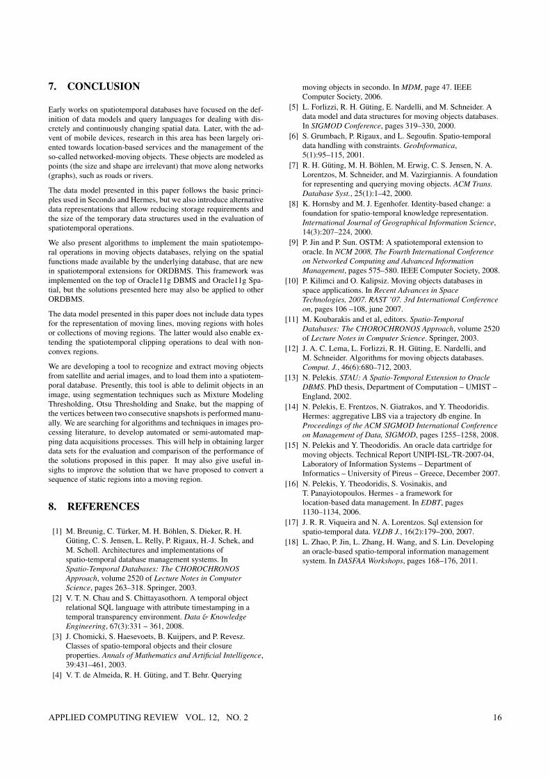
7. CONCLUSION
Early works on spatiotemporal databases have focused on the def-inition of data models and query languages for dealing with dis-cretely and continuously changing spatial data. Later, with the ad-vent of mobile devices, research in this area has been largely ori-ented towards location-based services and the management of theso-called networked-moving objects. These objects are modeled aspoints (the size and shape are irrelevant) that move along networks(graphs), such as roads or rivers.
The data model presented in this paper follows the basic princi-ples used in Secondo and Hermes, but we also introduce alternativedata representations that allow reducing storage requirements andthe size of the temporary data structures used in the evaluation ofspatiotemporal operations.
We also present algorithms to implement the main spatiotempo-ral operations in moving objects databases, relying on the spatialfunctions made available by the underlying database, that are newin spatiotemporal extensions for ORDBMS. This framework wasimplemented on the top of Oracle11g DBMS and Oracle11g Spa-tial, but the solutions presented here may also be applied to otherORDBMS.
The data model presented in this paper does not include data typesfor the representation of moving lines, moving regions with holesor collections of moving regions. The latter would also enable ex-tending the spatiotemporal clipping operations to deal with non-convex regions.
We are developing a tool to recognize and extract moving objectsfrom satellite and aerial images, and to load them into a spatiotem-poral database. Presently, this tool is able to delimit objects in animage, using segmentation techniques such as Mixture ModelingThresholding, Otsu Thresholding and Snake, but the mapping ofthe vertices between two consecutive snapshots is performed manu-ally. We are searching for algorithms and techniques in images pro-cessing literature, to develop automated or semi-automated map-ping data acquisitions processes. This will help in obtaining largerdata sets for the evaluation and comparison of the performance ofthe solutions proposed in this paper. It may also give useful in-sighs to improve the solution that we have proposed to convert asequence of static regions into a moving region.
8. REFERENCES
[1] M. Breunig, C. Türker, M. H. Böhlen, S. Dieker, R. H.Güting, C. S. Jensen, L. Relly, P. Rigaux, H.-J. Schek, andM. Scholl. Architectures and implementations ofspatio-temporal database management systems. InSpatio-Temporal Databases: The CHOROCHRONOSApproach, volume 2520 of Lecture Notes in ComputerScience, pages 263–318. Springer, 2003.
[2] V. T. N. Chau and S. Chittayasothorn. A temporal objectrelational SQL language with attribute timestamping in atemporal transparency environment. Data & KnowledgeEngineering, 67(3):331 – 361, 2008.
[3] J. Chomicki, S. Haesevoets, B. Kuijpers, and P. Revesz.Classes of spatio-temporal objects and their closureproperties. Annals of Mathematics and Artificial Intelligence,39:431–461, 2003.
[4] V. T. de Almeida, R. H. Güting, and T. Behr. Querying
moving objects in secondo. In MDM, page 47. IEEEComputer Society, 2006.
[5] L. Forlizzi, R. H. Güting, E. Nardelli, and M. Schneider. Adata model and data structures for moving objects databases.In SIGMOD Conference, pages 319–330, 2000.
[6] S. Grumbach, P. Rigaux, and L. Segoufin. Spatio-temporaldata handling with constraints. GeoInformatica,5(1):95–115, 2001.
[7] R. H. Güting, M. H. Böhlen, M. Erwig, C. S. Jensen, N. A.Lorentzos, M. Schneider, and M. Vazirgiannis. A foundationfor representing and querying moving objects. ACM Trans.Database Syst., 25(1):1–42, 2000.
[8] K. Hornsby and M. J. Egenhofer. Identity-based change: afoundation for spatio-temporal knowledge representation.International Journal of Geographical Information Science,14(3):207–224, 2000.
[9] P. Jin and P. Sun. OSTM: A spatiotemporal extension tooracle. In NCM 2008, The Fourth International Conferenceon Networked Computing and Advanced InformationManagement, pages 575–580. IEEE Computer Society, 2008.
[10] P. Kilimci and O. Kalipsiz. Moving objects databases inspace applications. In Recent Advances in SpaceTechnologies, 2007. RAST ’07. 3rd International Conferenceon, pages 106 –108, june 2007.
[11] M. Koubarakis and et al, editors. Spatio-TemporalDatabases: The CHOROCHRONOS Approach, volume 2520of Lecture Notes in Computer Science. Springer, 2003.
[12] J. A. C. Lema, L. Forlizzi, R. H. Güting, E. Nardelli, andM. Schneider. Algorithms for moving objects databases.Comput. J., 46(6):680–712, 2003.
[13] N. Pelekis. STAU: A Spatio-Temporal Extension to OracleDBMS. PhD thesis, Department of Computation – UMIST –England, 2002.
[14] N. Pelekis, E. Frentzos, N. Giatrakos, and Y. Theodoridis.Hermes: aggregative LBS via a trajectory db engine. InProceedings of the ACM SIGMOD International Conferenceon Management of Data, SIGMOD, pages 1255–1258, 2008.
[15] N. Pelekis and Y. Theodoridis. An oracle data cartridge formoving objects. Technical Report UNIPI-ISL-TR-2007-04,Laboratory of Information Systems – Department ofInformatics – University of Pireus – Greece, December 2007.
[16] N. Pelekis, Y. Theodoridis, S. Vosinakis, andT. Panayiotopoulos. Hermes - a framework forlocation-based data management. In EDBT, pages1130–1134, 2006.
[17] J. R. R. Viqueira and N. A. Lorentzos. Sql extension forspatio-temporal data. VLDB J., 16(2):179–200, 2007.
[18] L. Zhao, P. Jin, L. Zhang, H. Wang, and S. Lin. Developingan oracle-based spatio-temporal information managementsystem. In DASFAA Workshops, pages 168–176, 2011.
APPLIED COMPUTING REVIEW VOL. 12, NO. 2 16

ABOUT THE AUTHORS:
Luís Miguel de Oliveira Matos was born in Caracas, Venezuela, in January 1985. He received his M.S. degree in computer and telematics engineering from University of Aveiro, Portugal, in July 2009. He is enrolled in the MAP-i Doctoral Programme. Currently, he is working at the Signal Processing Laboratory of Institute of Electronics and Telematics Engineering of Aveiro (IEETA) which is associated with the Department of Electronics, Telecommunications and Informatics (DETI) of University of Aveiro. His main research interests are biomedical and data compression and image/video coding. He has also worked in spatiotemporal databases management systems. Luís Matos can be contacted at [email protected].
José Moreira received his Ph.D. in Computer Science and Networks from the École Nationale Supérieure des Télécommunications de Paris (France) and the Faculdade de Engenharia da Universidade do Porto (Portugal) in 2001. He is currently an Assistant Professor at the Department of Electronics, Telecommunications and Informatics of the Universidade de Aveiro and a researcher at IEETA, a non-profit R&D institute affiliated to the same university. His main research interests cover spatiotemporal database systems and Geographical Information Systems. He is also interested on Semantic web and spatiotemporal data mining.
Alexandre Valle de Carvalho is an auxiliar professor at the Computer Engineering Department of Faculdade de Engenharia, University of Porto. He is also a senior researcher at INESC Porto. Currently his main research interests are on spatio-temporal data management and retrieval and spatio-temporal information visualization.
APPLIED COMPUTING REVIEW VOL. 12, NO. 2 17