
A Simulation of Minuteman Trajectories - University of ...
20
1 A Simulation of Minuteman Trajectories Keith Baylor
-
Upload
khangminh22 -
Category
Documents
-
view
1 -
download
0
Transcript of A Simulation of Minuteman Trajectories - University of ...
1
A Simulation of Minuteman
Trajectories
Keith Baylor
dkarl
Typewritten Text
Appendix 12

2
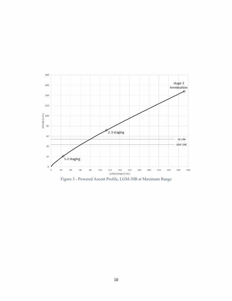
I. COMPLETE FLIGHT OF MINUTEMAN I (LGM-30B)1 A nominal trajectory profile for the Minuteman IB on a maximum-range flight is shown in Figure 1. This is a true-scale drawing, with data on the key events listed in Table 1. A similar trajectory is depicted in Figure 2, which is a “view from space” of a somewhat shorter-range flight (4600 nautical miles, from the 510th SMS to a non-specific target). Both figures are useful in portraying the very long free-flight phase as opposed to the comparatively short powered ascent and re-entry segments. Once two launch votes were in place and any time-on-target delays had run out, the ground programming entered terminal countdown (TCD). TCD’s principal events were heralded by the closing of the Safety Control Switch (SCS) at about T-20 seconds. Activation of the missile’s onboard batteries occurred at T-14 seconds, followed closely by release of the suspension system’s grip on the 1-2 interstage. At T-10 seconds, the Stage I nozzles were commanded to move and monitored for proper response. At T-6 seconds, the command was issued to blow the closure door. The handoff from the ground program to the Operational Flight Program (OFP) occurred in the midst of TCD, with the final tasks being to command Stage I Ignition to the Thiokol M55A1 and release the guidance set umbilical cable. At liftoff, the missile’s motion pulled the Stage I umbilical free and triggered the indication of “missile away” to the launch control center. Owing to its high thrust-to-weight ratio, the missile fairly leaped out of the launch tube, reaching nearly 60 mph as the Stage I nozzles cleared the TE pylons. It climbed vertically for only three seconds before pitching over in line with the target azimuth. The bird reached Mach 1 a mere sixteen seconds after liftoff and passed through maximum dynamic pressure at 36 seconds. By 45 seconds, it had entered the hypersonic regime at Mach 5, and at 50 seconds surpassed the typical operating altitude of the SR-71. Stage I acceleration peaked at 7.7 g’s and then dropped sharply, initiating the 1-2 staging event one minute into the flight. The 1-2 interstage was severed laterally at Stage I burnout, such that the lower 15 inches remained with Stage I, leaving the larger portion of the interstage still affixed to Stage II. About 18 seconds into Stage II burn, the interstage was blown apart longitudinally into four pieces (this approach eliminates the possibility of the stages colliding, which can occur if the interstage is completely discarded all at once). By 92 seconds, the Stage II-driven stack had climbed past the 264,000-foot altitude mark used by the Air Force to recognize pilots as astronauts, and 12 seconds later flew beyond the Karman Line demarking the “edge of space.” Stage II acceleration peaked at 5.7 g’s and then dropped sharply, initiating the 2-3 staging event. The 2-3 interstage separation occurred in a manner similar to the 1-2, and the stack began Stage III flight. The flight program was actively solving for the thrust termination and RV injection point, and issued RV mechanical disconnect when it determined that the injection point was about 1.5 seconds away. The OFP then entered fine countdown and issued thrust termination when the velocity to be gained equaled zero. Thrust termination was achieved by explosively opening four vent ports in the Stage III motor case, abruptly reducing the combustion chamber pressure to zero. This simultaneously extinguished the propellant burn and provided a slight

3
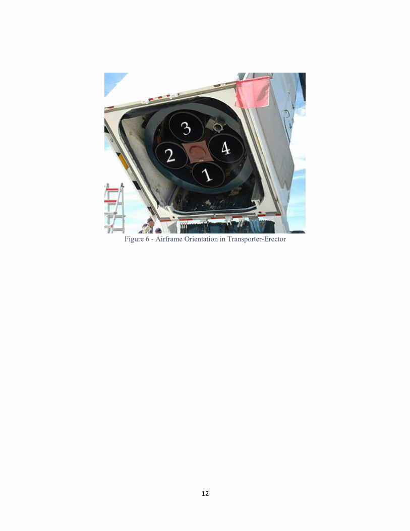
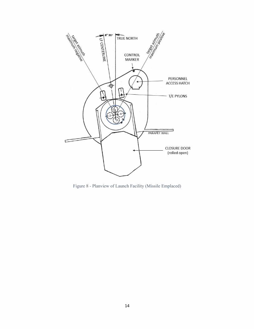
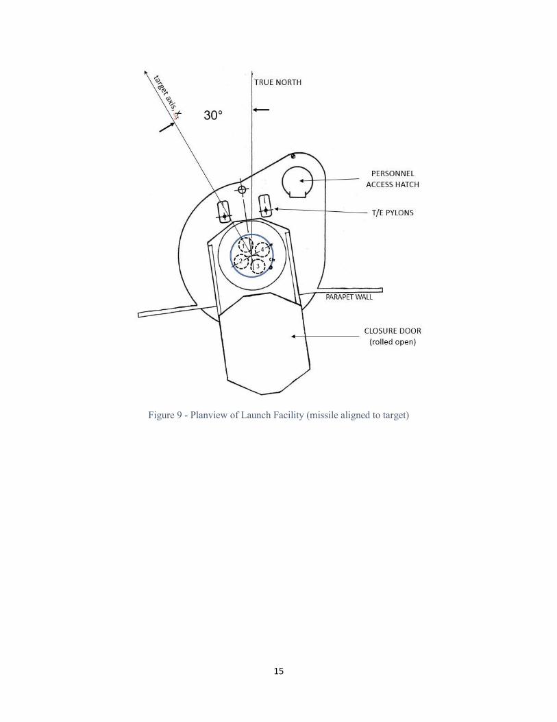
measure of deceleration to Stage III. For the maximum range trajectory, this occurred 181 seconds after liftoff; for shorter range targets, it was slightly earlier. The flight program performed a series of safety checks and issued pre-arming signals within a quarter-second of thrust termination, culminating in the RV electrical disconnect command. In conjunction with the slight deceleration of Stage III, separation springs in the RV mechanical system pushed the RV away from the NS10 guidance set. From this point - 272 nautical miles downrange from the LF, and an altitude of 148 nautical miles - the Mk11 began its long ballistic toss through space. Figure 3 gives a profile view of the powered ascent path that delivered the RV to this release point. Figure 4 shows the acceleration and velocity values as they occur up to RV release.2 Having only a slightly different velocity vector, Stage III and the guidance set followed the RV fairly closely throughout the long toss. Those Minuteman IBs that were fitted with the Mk11A operated differently, having a spacer containing small rocket motors mounted atop the guidance set. Three to five seconds after electrical disconnect, a tumbler motor fired perpendicular to the Stage III centerline, imparting a rotation rate to the Stage III/NS10 assembly. Following another programmed time interval, a retro motor was fired. This sequence generated an almost unpredictable change in the flight path and thus randomized the position of Stage III relative to the Mk11A, reducing the problem of the third stage serving as a radar beacon for the target’s defenses.3 After separation, at a time established by the RV’s arming & fusing/attitude control (AF/AC) assembly, the RV was pitched down to the orientation needed for re-entry and then spun up to promote stability. Two pitch motors and two spin motors at the base of the RV accomplished this task. The pitch attitude varied with range, but was typically straight down (90 degrees below local horizontal) or even pointed slightly back toward the LF, at the point of RV release (see again Figure 1). The long ballistic free-flight peaked at 886 nautical miles altitude, roughly halfway to the target. Re-entry began just over 35 minutes after launch, when the RV had descended to about 500,000 feet. Final arming sequences occurred at this point, but details of these functions remain classified. A closer look at the missile’s airframe axes and orientations is helpful in understanding the events of the flight. Despite its bullet-like appearance, it does have a “right-left-top-bottom” arrangement, as seen in Figure 5. The centerline through the length of the whole stack is the roll, or Xb, axis. Using numbers for each of the first stage nozzles allows for description of the other principal axes. Passing through nozzles 2 and 4 is the pitch (Yb) axis, while the yaw (Zb) axis passes through nozzles 1 and 3. The several arrows in Figure 5 indicate the positive direction for each axis and for rotation about that axis. The roll (Xb) axis is positive in the direction of the re-entry vehicle and is directed straight up along the local vertical when the bird is in the launch facility. The pitch (Yb) axis is positive toward the right (designated by nozzle 4) and is directed toward the east (or nearly so)

4
with the missile in the LF. The yaw axis (Zb) is positive toward the bottom (as marked by nozzle 1) and is directed north (or nearly so) when the missile is emplaced in the LF. As viewed from the rear of the missile, a clockwise roll is positive, and a turn toward the right is positive yaw. Pitch is defined as positive when the stack tips over from vertical, in the direction of nozzle 1. Lowering the T/E is a positive pitch maneuver (see Figure 6). The orientation scheme as it appears from beneath Stage I is offered in more detail at Figure 7. Taking a look at all this geometry from directly above the LF yields the view in Figure 8. The missile is depicted aligned with the LF centerline, as though it has just been emplaced by a missile handling team. Note that the site centerline is skewed 8.5° counterclockwise from true north; this applies for operational sites but the LFs at Vandenberg are “turned” roughly 45° in the same direction. Note also the target azimuth lines; all likely targets lie between these lines that are about 30° off true north in both directions. Following emplacement, the missile must be properly indexed. For Minuteman II and III, this meant matching the yaw (Zb) axis with true north, and the nozzles ended up in a diamond arrangement with #1 at the top of the view in Figure 7. However, for Minuteman I, the indexing process meant pointing #1 at the target, aligning the yaw (Zb) axis with the pre-selected target azimuth. Assuming a target that was well to the northwest, the arrangement shown in Figure 9 emerges. With the missile’s airframe axes and orientations now all in place, another look at the nominal trajectory is in order. The powered ascent consists of four phases: vertical climb, pitchover, gravity turn, and steer to burnout. The vertical climb segment uses all available thrust to overcome gravity and clear the vicinity of the launch pad. If necessary, a roll maneuver is executed to get the yaw axis aligned on the required launch azimuth. Minuteman IA was capable of striking only the target to which it was aligned, so no roll occurred with an A-missile. The B-missile picked up the capability to reach one alternate target, provided that target was no more than 10 degrees either way of the primary target; therefore, Minuteman IB executed a roll only if the alternate target was selected. For Minuteman II and III, a roll maneuver always occurred (unless the target azimuth was 0° true north). Although mighty impressive to witness, vertical climb is not at all the most effective nor efficient way to get into an orbital or sub-orbital path. The velocity vector at Stage III burnout needs to be horizontal (or nearly so), and as the missile’s velocity increases in magnitude, more and more energy is required to change the direction of that velocity. It is therefore desirable to get the missile out of the vertical climb as soon as possible. This is accomplished by a controlled pitchover. The timing of the pitchover depends on the thrust-to-weight ratio, since there must always be enough thrust in the vertical to overcome gravity. With its thrust-to-weight ratio just short of three, Minuteman is able to do so very quickly and, indeed, nominal pitchover is at three seconds into the flight, less than 400 feet off the ground. Videos can be found that depict the missile pitching over before it clears its own exhaust plume.
5
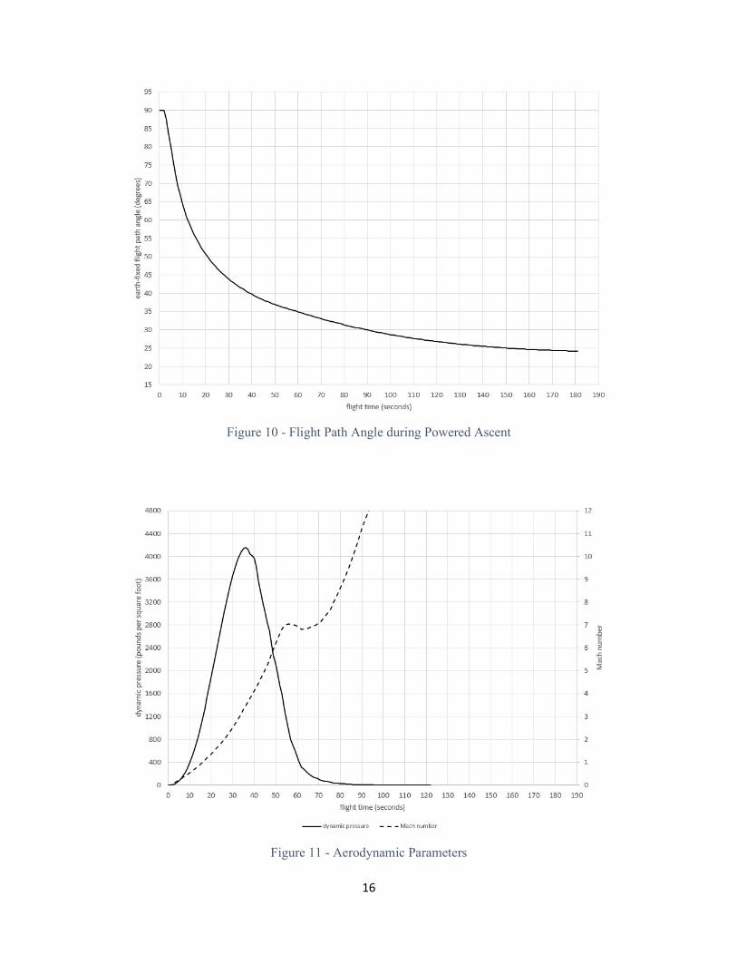
Pitchover is accomplished by briefly kicking nozzles 2 and 4 into a large positive deflection (again reference Figure 5), tipping the whole stack over in the direction of the target axis and, in the process, initiating the gravity turn. With the missile off-vertical, the Stage I nozzles are centered up and gravity alone is used to turn the velocity vector. The effects of the pitchover and gravity turn are illustrated in Figure 10. Flight path angle is the angle between the missile’s path (velocity vector) and the local horizontal. At launch, it is 90°; i.e., straight up. Pitchover is marked by the sharp corner in the trace on the plot, and the rapidly decreasing values show the gravity turn taking place; the missile is essentially being allowed to fall over. The actual pitch angle - above or below the horizon - of the missile’s airframe is not necessarily the same as the flight path angle, and the difference between them is called the angle-of-attack. During periods of high dynamic pressure (see Figure 11), even small angles of attack produce aerodynamic sideloading on the bird, which can render the airframe asunder. Yaw angles out of the target plane can do the same. Ergo, during Stage I flight, the primary active control inputs are those needed to keep the angle-of-attack (and yaw angles) at zero. The control inputs are not used to turn the velocity vector but only to maintain alignment of the airframe with the velocity vector. Keeping the angle-of-attack as close to zero as possible is the function of attitude control, which is always running closed-loop. Any external disturbances which alter the actual flight path are left uncorrected until the dynamic pressure is greatly reduced. Once the missile is in the far upper reaches of the atmosphere, the direction of the velocity vector can be controlled without introducing serious sideloading. Closed loop guidance can be engaged. Since the stable platform has been running since launch, it can indicate the missile’s current velocity and position. These data are compared to those needed at burnout, and the flight computer generates corrections. If using the Delta Guidance scheme, the flight program will seek to correct all the way back to the original trajectory. If using Explicit Guidance, the flight program will continuously calculate a new trajectory to reach the required burnout state. If external disturbances during open-loop guidance have been small, the new trajectory will be not greatly different from the original nominal flight path. If the disturbances are large, it is very difficult to correct to the original trajectory, but determining a new path in real-time is extremely calculation-intensive. Hence, Delta was the earlier approach, yielding to Explicit later. Whether Delta or Explicit, it is during this last phase that the missile airframe may not be aligned with the flight path angle. If Stage I performance was above nominal, the bird may now be at a higher altitude than necessary; if so, the guidance set may command a nose-down (positive pitch) attitude to steer back toward the required RV release point. If west winds blew it to the right of the target plane, the guidance set may command a nose-left (negative yaw) attitude to get back on course. Most likely, there is a combination of these commands, all while the bird is flying with nozzle #1 on its “earthside” and nozzle #3 on the side up toward space.

6
The nominal release point for the Minuteman IB on a maximum range trajectory was 272 nautical miles downrange from the LF, at an altitude of 148 nautical miles with velocity at 22,659 feet per second (15,450 mph). The flight path was angled at 24.2° above the local horizontal. The symmetry of the ballistic flight path dictates that the re-entry will occur at roughly the same angle, but below the horizontal; thus, the RV was pitched well down not long after release. Refer again to Figure 1 to visualize why the RV is pitched down at such a large angle.
II. MAXIMUM RANGE PERFORMANCE OF OTHER VARIANTS
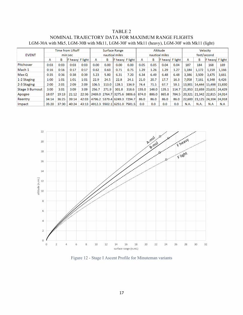
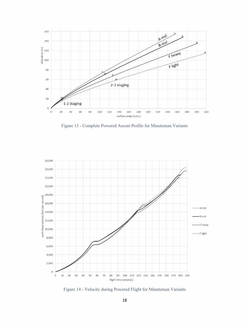
Flight performance of the Minuteman ICBM was improved with each variant. Key parameters from maximum range trajectories for the A, B, and F (with two different payloads) are listed in Table 2, but the effects are easier to see in the plots that follow. The expression “F heavy” here refers to the Minuteman II fitted with penetration aids; “F light” indicates the Minuteman II with lightweight spacer in place of the penaids. The trajectory profile during Stage I burn is shown in Figure 12; the small squares along the flight path indicate the 1-2 staging event. The additional propellant in the Thiokol M55A1 can be seen in that the B-missile gets a little further along than the A does. Conversely, that same stage labors under the increased weight of the Minuteman II stack and does not proceed as far along the trajectory. Figure 13 depicts the complete powered ascent profile (staging again indicated by small squares). Most evident in this plot is the performance of Aerojet’s SR19 second stage in the Minuteman II over the earlier M56A1. Despite the 1-2 staging handicap noted in Figure 12 for the F-missile, the improved Stage II drives it some 20 miles further downrange. The SR19’s advantage can also be seen in the velocity curves in Figure 14: although 1-2 staging occurs at a slower speed for Minuteman II, its superior second stage overtakes the Minuteman I variants and is running some 1500 feet/second faster at 2-3 staging. III. TRAJECTORIES AT LESS THAN MAXIMUM RANGE
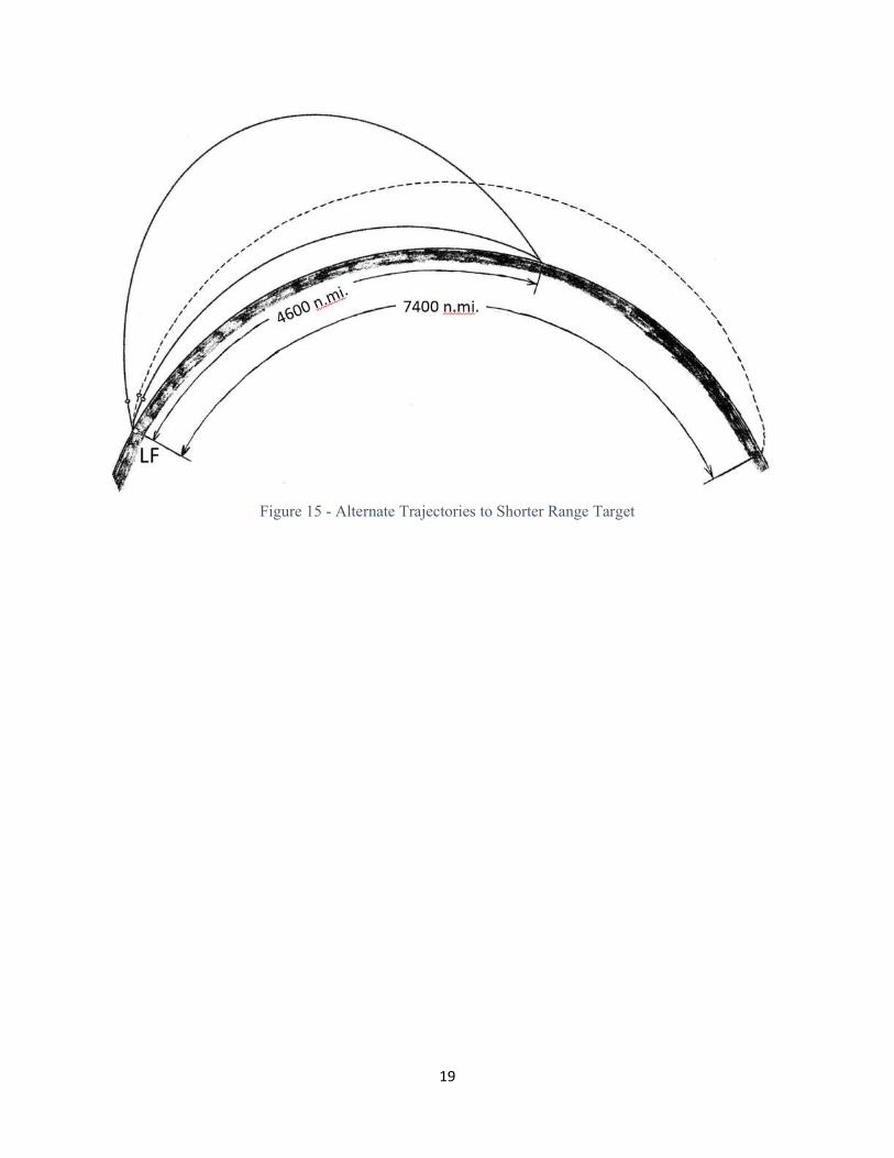
For any ICBM to reach its maximum range, there is uniquely one trajectory; for any lesser range, there are two solutions for getting there: a high path and a low path. The Minuteman II OTP allowed for selection of these via an input field called either "Shape 1" or "Shape 2". The Minuteman III OTP added a substantial degree of refinement in that it had an input parameter for reentry angle, reflecting the capability of the PBV. The angle had to be reasonable for a high or low approach, but could be varied somewhat.
7
Figure 15 shows these two trajectories for a Minuteman II striking a target at 4600 nm, overlaid against a trajectory out toward max range. The long-range flight is represented by the broken line. Peak altitude on this route is about 650 nm. Apogee on the high toss is 1552 nm, and 282 nm on the low flat path, but the paramount factors on this are the time-of-flight and the reentry angle. The high toss reaches the target not quite 45 minutes after liftoff and arrives on a flight path angle of 40° below the local horizontal. An RV delivered via the low path requires only 24 minutes to arrive and comes skimming in at 10°. IV. COMPARISION TO EARLIER ICBMs
Quite possibly the greatest distinction between Minuteman and its predecessors, insofar as flight performance goes, was in thrust-to-weight ratio (T:W). For Minuteman, this value was about twice that of the liquid-fueled missiles, and was manifested principally in the first few seconds of flight. The earlier ICBMs lifted off slowly and spent much more time in vertical climb. The Atlas (D, E or F) lifted off with thrust-to-weight of about 1.45:1. Within 15 to 18 seconds of vertical ascent, it had reached about 1.6:1 and commenced pitchover, with altitude typically 2500 feet and velocity 300 feet per second. For Titan I, thrust-to-weight ratio of 1.35:1 at liftoff improved to 1.55 at pitchover, but took some 24 seconds to get there (propellant burn rate rather less than other ICBMs). Pitchover typically at 3800 feet altitude and 345 feet per second velocity. The Titan II lifted off with T:W of only 1.3, but pitched over within 15 seconds or so, its thrust-to-weight having reached just over 1.4. Sturdiness of airframe as compared to Atlas likely permitted pitchover at this ratio. Altitude 1320 feet. Velocity 180 feet per second. A second major distinction between Minuteman and the Atlas/Titan systems was orbital capability. The Titan II put all of NASA’s 8000-pound Gemini spacecraft into earth orbit, and the Atlas D did the same for Mercury (4000 pounds). Certainly of note in this regard was Project SCORE, wherein an Atlas B flew its entire bad self into orbit. But for Minuteman, the conventional wisdom has always been that “it cannot reach orbit.” While it is true that the flight programs were probably never designed to steer to orbit, the raw flight performance was there, albeit on a limited level. The LGM-30B had sufficient performance to put 30 pounds into low earth orbit (the A-missile did indeed fall short entirely). Minuteman II could loft nearly 400 pounds to orbit, and was later used very effectively as the basis for Orbital Sciences Corporation’s Minotaur launch vehicle, wherein it put 1000+ pounds into low earth orbit.
8
Figure 1 - Nominal Trajectory Profile, LGM-30B at Maximum Range
(showing also pitch attitude of RV after release)
TABLE 1 MINUTEMAN I (LGM-30B) NOMINAL TRAJECTORY - MAXIMUM RANGE (5500
NAUTICAL MILES)

9
Figure 2 - Trajectory Profile, LGM-30B at 4600 nm Range
10
Figure 3 - Powered Ascent Profile, LGM-30B at Maximum Range

11
Figure 4 - Acceleration and Velocity during Powered Ascent
Figure 5 - Missile Body Axes and Directions
12
Figure 6 - Airframe Orientation in Transporter-Erector

13
Figure 7 - Orientation of Components and Axes, as viewed looking up from beneath missile
14
Figure 8 - Planview of Launch Facility (Missile Emplaced)
15
Figure 9 - Planview of Launch Facility (missile aligned to target)
16
Figure 10 - Flight Path Angle during Powered Ascent
Figure 11 - Aerodynamic Parameters
17
TABLE 2 NOMINAL TRAJECTORY DATA FOR MAXIMUM RANGE FLIGHTS
LGM-30A with Mk5, LGM-30B with Mk11, LGM-30F with Mk11 (heavy), LGM-30F with Mk11 (light)
Figure 12 - Stage I Ascent Profile for Minuteman variants
18
Figure 13 - Complete Powered Ascent Profile for Minuteman Variants
Figure 14 - Velocity during Powered Flight for Minuteman Variants
19
Figure 15 - Alternate Trajectories to Shorter Range Target
20
Endnotes 1. All data and plots in this appendix on Minuteman flight performance were obtained from a trajectory simulation prepared expressly for this book by Keith Baylor. Baylor was an ICBM Trajectory Engineer at HQ SAC (1984-1988) and OIC of Tech Engineering at Whiteman (1989-1992). (a) The simulation assumes a non-rotating spherical Earth having a uniform gravity field and a diameter of 6880 nautical miles. The simulation uses the 1959 ARDC model atmosphere. Targets were assumed to be at sea level. Given these constraints, the simulation is utterly useless for actual targeting, but quite serviceable for in-plane analysis of flight parameters and the effects of changing payload weights, launch site elevation, rocket motor performance, etc. (b) Minuteman motor performance was obtained from Rocket Propulsion Elements, George Sutton and Donald Ross (John Wiley & Sons, 1976) pages 356-357; and from Preludes to U.S. Space-Launch Vehicle Technology, J.D. Hunley (University Press of Florida, 2008) pages 319-320, 325, and 328. 2. The general sequence of flight events is from Student Study Guide, Minuteman Weapon System Familiarization: Flight Control Group, (Chanute Technical Training Center, Chanute Air Force Base, Illinois, 18 May 1964), 8-9. 3. “Reentry Vehicle Development leading to the Minuteman Avco Mark 5 and 11,” David K. Stumpf, Air Power History, Fall 2017.