Guidance for monitoring enclosed landfill gas flares, LFTGN05
Upload
khangminh22Category
view
0download
0
A Practical Guide to Landfill Management
in Pacific Island Countries and Territories
- How to improve your waste disposal facility and its operation
in an economical and effective way -
Volume-1: Inland-based waste disposal
(2nd Edition)


A Practical Guide to Landfill Management in Pacific Island Countries and Territories
________________________________
Volume-1: Inland-based waste disposal (2nd Edition)
March 2010

ii
SPREP Library/IRC Cataloguing-in-Publication Data A practical guide to landfill management in Pacific island countries and territories : Volume 1 – Inland-based waste disposal. Apia, Samoa : SPREP, 2010. iv, 69 p. : ill. ; 29 cm. ISBN: 978-982-04-0398-7 1.Landfill management - Oceania. 2. Waste Management – Oceania. 3. Source reduction - Oceania. 4. Waste disposal in the ground - Oceania. 5. Refuse and refuse disposal - Oceania. I. Secretariat of the Pacific Regional Environment Programme (SPREP). II. Japan International Cooperation Agency (JICA). III. Title 363.728 This guideline was produced with the assistance of JICA. SPREP P O Box 240 Apia, Samoa Ph: (685) 21929 Fax: (685) 20231 Email: [email protected] Website: www.sprep.org © SPREP 2010 The Secretariat of the Pacific Regional Environment Programme authorizes the reproduction of this material, whole or in part, provided appropriate acknowledgement is given.

iii
Foreword
Solid waste management is an environmental priority for most islands in the Pacific. Unfortunately, lack of recycling and reduction initiatives, poor waste collection systems, open dumpsites, and environmental pollution are still common in many countries in the region. Despite this general outlook, there are a number of positive changes being made to improve waste management policies and practices in Pacific Island Countries and Territories (PICTs), including improvement of collection systems, implementation of container deposit schemes, and the upgrading and construction of sanitary landfills. This practical guide to landfill management is an important example of positive change. It draws on the experience of Japan, the country that has developed the Fukuoka type semi-aerobic landfill and has facilitated the construction and upgrading of several dumpsites into Fukuoka-type landfills in Palau, Samoa, and Vanuatu, as well as other countries in Asia. This varied experience has enriched the development of this guideline, which provides practical, useful tips and invaluable guidance to waste practitioners in PICTs. As the name of this guide indicates, it is a practical document which can be followed step-by-step to improve the management of landfills. But it is more than that. It is also a useful tool for waste practitioners to build their capacity through self-learning. It is my sincere hope that you find this guideline useful, and that you take advantage of the opportunities it represents. A lot of experience and hard work has gone into the preparation of this document, but our work does not stop there. SPREP members are calling for more resources to be dedicated to waste management, and we stand ready to answer that call through continued partnership with partners such as JICA, and through future solid waste management initiatives with other partners. In closing, I refer to the acronym ‘NIMBY’ - Not in My Backyard - which has been used in this guideline. Typically, NIMBY describes the public’s attitude towards waste disposal facilities, but let us now apply it to ourselves as waste practitioners. Let us no longer allow poor waste disposal and poor waste management to take place in our backyard. I entreat you to use this guideline and take whatever further action is necessary to ensure sound, practical, and sustainable waste management practices in your ‘backyards’. David Sheppard Director Secretariat of the Pacific Regional Environment Programme

iv
Acknowledgements The following individuals are gratefully acknowledged for their valuable contributions: Mr. Shiro AMANO, Japan International Cooperation Agency (author and editor) Dr. Frank Griffin, (reviewer, former Pollution Prevention and Waste Management Adviser,
SPREP) Ms. Esther Richards, Solid Waste Officer, SPREP (reviewer and editor) Dr. Bruce W. GRAHAM, Graham Environmental Consulting Ltd (reviewer, former
Coordinator, Pollution Prevention and Waste Management, SPREP) Dr. Yasushi MATSUFUJI, Fukuoka University (resource person) Dr. Hisashi OGAWA, World Health Organization Regional Office for Western Pacific
(reviewer) Dr. Kunitoshi SAKURAI, University of Okinawa (resource person) Mr. Takeo TASHIRO, Fukuoka City (resource person, former JICA Expert) Mr. Hiromi HIRONAKA (resource person, former JICA Expert) Mr. Yoshikuni EGUCHI, Taisei Kanri Kaihatsu Corporation (resource person, former JICA
Expert) This book contains a number of pictures and materials provided by experts involved with JICA projects in such countries as Samoa, Palau, Vanuatu, Fiji and others worldwide. The Secretariat of the Pacific Regional Environment Programme would like to express its appreciation to all the institutions and individuals who have provided information to share their experience in this book.

v
Table of Contents
Foreword .............................................................................................ii
Acknowledgements ...........................................................................iv
Chapter 1.............................................................................................1
INTRODUCTION................................................................................1
1.1 Background ........................................................................................... 1
1.2 Pacific Features .................................................................................... 1
1.3 Waste dumps: old issue and new problem......................................... 2
Chapter 2.............................................................................................4
LANDFILL AS A RUBBISH BIN .........................................................4
2.1 Open dumping as a state of mess....................................................... 4
2.2 Important function of landfills ............................................................. 5
2.3 Sanitary landfill as a solution .............................................................. 6
Chapter 3.............................................................................................9
BASIC CONCEPT OF SEMI-AEROBIC LANDFILL ..............................9
3.1 Aerobic Decomposition........................................................................ 9
3.2 Leachate Collection and Supply of Air.............................................. 10
3.3 Leachate Quality ................................................................................. 11
3.4 Emission of Landfill Gases and Global Warming ............................ 12
Chapter 4...........................................................................................13
IMPROVING EXISTING LANDFILL FACILITIES ..............................13
4.1 STEP 1: Review and Assessment of Existing Conditions............... 14
4.2 STEP 2: Development of Solution Options....................................... 16
4.3 STEP 3: Detail Planning and Design ................................................. 18
4.4 STEP 4: Implementation of Improvement Plan................................. 40
Chapter 5...........................................................................................41
IMPROVING LANDFILL OPERATION ..............................................41
5.1 Landfill Method ................................................................................... 41
5.2 Cell Construction ................................................................................ 42
5.3 Order of Landfilling............................................................................. 42
vi
5.4 Spreading and Compaction ............................................................... 42
5.5 Working (Tipping) Face ...................................................................... 45
5.6 Cover Material and Disposal Operation ............................................ 45
5.7 Leachate Management........................................................................ 47
5.8 Maintenance of Facilities.................................................................... 48
5.9 Environmental Management .............................................................. 53
5.10 Social Considerations ........................................................................ 56
5.11 Occupational Health and Safety ........................................................ 57
Chapter 6...........................................................................................58
Key to Successful Landfill Management .......................................58
Glossary of Terms.............................................................................59
References........................................................................................65
APPENDIX-1: Flow of Upgrading Work .............................................66
APPENDIX-2: Review of Landfill Methods ........................................67

1
CHAPTER 1 INTRODUCTION
This book is primarily targeted at solid waste officers in Pacific island countries and territories (PICTs) who may have little background in engineering and construction. The objective of this guide is to help those users understand the concept of a landfill and its operation. Also demonstrated are economical and effective ways to upgrade/improve an existing facility, which can be applied to most landfills in PICTs. This book focuses on inland-based waste disposal and does not include landfilling at coastlines, lagoons or wetlands where a different method needs to be developed and applied. 1.1 Background For small island countries in the Pacific region, waste management has become a major concern with the potential to cause negative impacts on national development activities, including tourism and trade, food supplies, public health and the environment. The generation and disposal of wastes has direct and indirect linkages to economic development. Waste materials represent a loss of money and opportunity, in terms of added cost of management and lost potential as a reusable resource. Poorly managed wastes can have negative effects on tourism, by jeopardising the image of “Pacific Paradise” promoted by most PICTs, and by association with health warnings about infectious and vector-borne diseases. There is the potential for contamination of food supplies, which can have impacts on local markets or revenue from export crops. There are numerous health and environmental hazards that arise when wastes are poorly managed and disposed of. Conversely, the benefits from good waste management can include reduced raw material costs, enhancement of the tourism experience, and reduced health-care costs. Effective measures now will also avoid the need for expensive clean-up operations in the future. 1.2 Pacific Features In PICTs, there are some common features that are quite different from those of industrialized countries. Such features include, but are not limited to, the following:
- Geographical isolation - Fragility of the island environment - Limited natural resources - Heavy reliance on imported goods - Lack of industries other than tourism, agriculture or fisheries
On top of these, rapid population growth, high population densities in urban areas and changes in lifestyle are also commonly observed in most PICTs. The combined effects of imported goods and increasing economic development will contribute to the generation of solid wastes. As a result, the volumes and diversity of solid wastes are increasing. Solid waste management is particularly important for small islands because of their limited land space. Geographical isolation and small local markets make it more difficult to recycle
2
products economically. Waste dumping into lagoons and coastal areas is a major threat to clean environments. Even in high-island countries, improperly managed dumpsites are posing serious risks to public health. The reduction of solid waste and its safe disposal is one of the common and crucial issues for the Pacific region. 1.3 Waste dumps: old issue and new problem A waste dump is a place where people have thrown rubbish away. In ancient times, our ancestors ate shellfish and threw shells away somewhere near their residence. That place, in other words a shell heap (midden), became the first dumpsite in the history of human beings. Our ancestors disposed only things that were of no use, but we, considered as more “advanced,” often dispose of things which are still quite usable and have value. Because most materials do not vanish immediately, we have to keep them somewhere even if we do not need them any more. There used to be few materials that did not degrade naturally. When a banana skin was thrown away, for example, it would degrade quickly and became a part of nature. Many artificial materials are available now to make our life convenient. Unfortunately, most of them do not easily decompose and will stay as they are for a long time. When materials are thrown away and left uncovered, they will start decomposing and generate bad smells, and act as a breeding ground for flies, mosquitoes and other vectors. Those wastes that do not easily decompose remain scattered as they are. Some light materials will fly away under strong winds. Scavenging can also serve to spread the waste around. Uncontrolled open burning can also add to the nuisance impacts and potential health risks. This overall situation is called open dumping and poses significant environmental and health risks to the public and the surrounding environment. It is a common and typical problem in PICTs. We all generate waste. Some types of waste, such as organic matter (e.g. plants and leaves), decompose easily and quickly but others do not and remain as they are for many years. There was no word describing waste in the Pacific a long time ago because people utilised the natural resources very well and did not waste them. As artificial materials are produced to make our life more convenient, people tend to forget the importance of saving resources. The idea of mass production and mass consumption contributes to mass disposal of waste. Materials become waste if nobody wants to use them. There are, however, many things that can be re-used or recycled. Materials you throw away may be valuable to others. People can pick up materials and utilise them before they are disposed of at the dump. In order to do this, we need to segregate the materials and collect them separately from other wastes. Diverting waste from going to the landfill with proper recycling activities can significantly save the life of the landfill. Waste is sometimes referred to as a mirror that reflects our society. In other words, the degree of civilisation or development can be judged from the amount or quality of wasted

3
materials. If this applies to a small island country in the Pacific, what can we see in the mirror now? What will our grandchildren see in the future? The answer very much depends on the quality of our life and the management of waste. As the society matures, so does waste management. To forward the clean and safe environment to our future generations, let’s think about what we can do now and start working from today on.

- 4 -
CHAPTER 2 LANDFILL AS A RUBBISH BIN
In this chapter, you will understand the difference between an open dump and a sanitary landfill and will learn an important concept of “landfill as a rubbish bin” as the first step. 2.1 Open dumping as a state of mess
Open dumping creates a lot of problems, not only to the surrounding environment but more critically to public health and safety as illustrated below: No soil cover – It allows for flies, mosquitoes and other vectors to breed, generates unpleasant smells and is a potential fire hazard. There may be a high disease risk for the nearby residents. It also attracts human and animal scavengers to the dumpsite to look for food and useful materials. No leachate collection/control – Where there is no proper control of leachate, it sometimes overflows to the plantations or farms downstream and will damage crops. Leachate also seeps into the ground and may pollute the groundwater that is one of the most important sources of drinking water in Pacific islands. No drainage – Surface water quickly accumulates at lower locations and deteriorates the site conditions. Runoff water damages the road surface as well as slopes if there is no drainage facility. Any surface/runoff water entering the area where waste is deposited will end up as leachate. Poor access – When the access road is in poor condition, collection vehicles cannot reach the tipping area and may therefore offload the waste in a disorganised way alongside the access road. This sometimes blocks the road and makes it even more difficult for following vehicles to find the proper place to unload the waste. Landfill operation and maintenance will also be hampered by the poor access. Open to scavenging – Scavenging activities by people and animals to look for food and valuable materials not only disrupt the landfill operation but are considered very dangerous
WWhhaatt iiss ooppeenn dduummppiinngg?? As you see in the previous chapter, open dumping is a state where loads of rubbish are dumped and left uncontrolled in an open space with such conditions as:
- no soil cover, - no leachate collection/control, - no drainage, - poor access to the tipping area, especially in a wet season, - open to scavenging, - uncontrolled open burning.

- 5 -
to the scavengers themselves. In some countries, for example, health-care waste from hospitals and medical institutions is mixed with solid waste and is disposed of at the same dumpsite. Such waste contains needles, syringes and infectious materials and is harmful to the people on site. Uncontrolled open burning – Exposed rubbish easily catches fire whether this is a deliberate act or not. Uncontrolled open burning is potentially hazardous and dangerous to the surrounding community and the environment as well as landfill workers. Once a fire breaks out, it sometimes requires weeks to extinguish. Visual impacts – The visual offence caused by open dumping contributes to the NIMBY (Not-In-My-Back-Yard) syndrome and can adversely affect tourism which is one of the most important sources of income for many Pacific islands.
Photo- 1: Typical Open Dumps in PICTs 2.2 Important function of landfills
WWhhaatt iiss aa llaannddffiillll??
A landfill, also known as a dump or rubbish dump (and historically as a midden), is a site for the disposal of waste materials by burial and is the oldest form of waste treatment. Historically, landfills have been the most common methods of organised waste disposal and remain so in many places around the world. (Wikipedia, http://en.wikipedia.org/wiki/Landfill)

- 6 -
A landfill is like a big rubbish bin. Imagine a life without a rubbish bin at home. Let’s suppose you live in a small room and generate waste every day. You most probably will start throwing your rubbish at one of four corners of your room. If one corner is filled up with rubbish, you will continue throwing the rubbish at the next corner and will go on to the next until all the four corners are filled up. The rubbish will invade your space and you will be eventually buried in it. The story above teaches you two important lessons. One lesson is that you need to reduce rubbish as much as possible so as to save the space of your room. The other is that a rubbish bin must be placed to keep your room clean and neat. A rubbish bin clearly demarcates inside and outside, retains rubbish horizontally and vertically and is structurally stable. A landfill is of no difference except for its size and location.
Photo- 2: Rubbish Bin and Landfill
2.3 Sanitary landfill as a solution A simple rubbish bin can solve some of the problems of waste disposal, but that is not enough. If you want to make your life safer and cleaner, waste should be properly disposed of and contained safely for a long period of time. A landfill is the physical facility used for disposing of waste onto or into the land in a controlled manner. A sanitary landfill is a landfill where waste is disposed of without causing a nuisance to the environment and public health and safety.
- 7 -
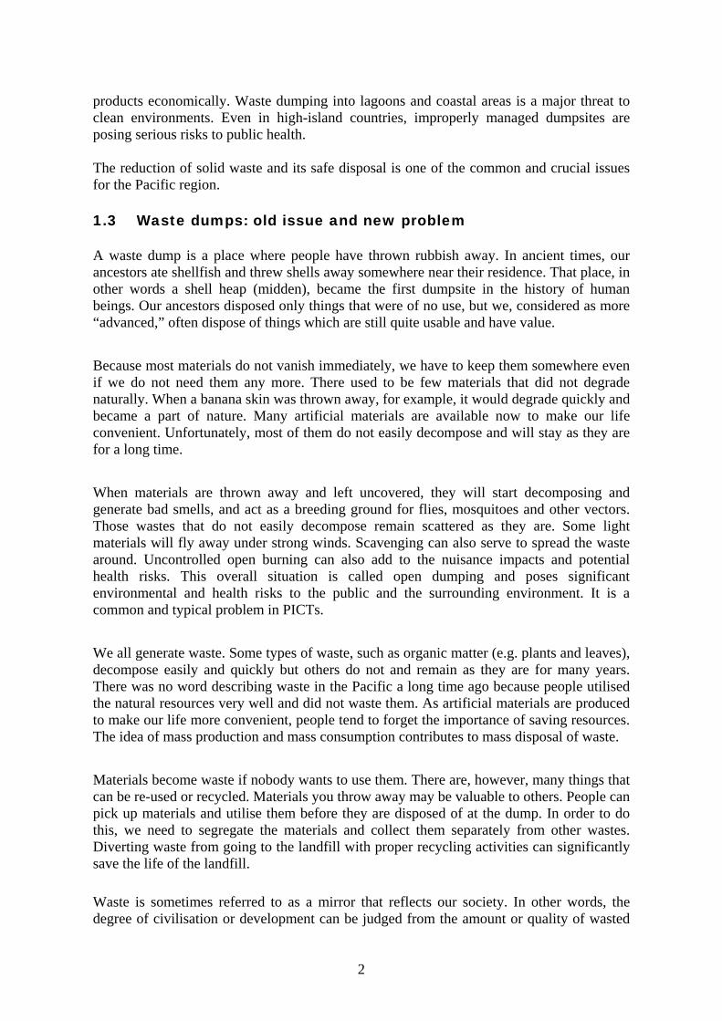
Photo-3 shows the physical changes of Tafaigata Landfill in Samoa from the state of open dumping to a sanitary landfill for the past years.
Photo- 3: Transition of Open Dump to Sanitary Landfill (Tafaigata Landfill, Samoa) (Arrows show the same location as the original access road.)
1. November 2002 (Open dump) 2. February 2003 (Under rehabilitation) 3. February 2006 (Re-circulation system working) 4. August 2009 (Extension of future disposal area)
(Adapted from Reference 9: Richards, E., Solid Waste Management in Pacific Island Countries and Territories, 2009)
The other photos are also illustrating how the state of open dumping is improved in M-dock Landfill in Koror, Palau (Photo-4) and Bouffa Landfill in Port Vila, Vanuatu (Photo-5).
WWhhaatt iiss aa ssaanniittaarryy llaannddffiillll??
A sanitary landfill can be explained as follows: 1. A method of disposing waste by spreading it in layers covered with soil or other
inert materials to control generation of vermin, vectors and odors so that any adverse environmental and health impacts will be minimized
2. A site used for, or reclaimed by, such method
1 2
3 4

- 8 -
Photo- 4: Transition of Open Dump to Sanitary Landfill (M-dock Landfill, Palau) 1. 1970s (Open dump) 2. August 2006 (Under rehabilitation) 3. February 2008 (After rehabilitation)
Photo- 5: Transition of Open Dump to Sanitary Landfill (Bouffa Landfill, Vanuatu) 1 & 2: Before rehabilitation (2006) 3: After rehabilitation (2008)
1 2
3
1 2
3
- 9 -
CHAPTER 3 BASIC CONCEPT OF SEMI-AEROBIC LANDFILL
In this chapter, you will learn the basic concept of the semi-aerobic landfill system and how it works as one of methods for sanitary landfill.
A semi-aerobic landfill is a landfill where waste goes through a decomposition process in the presence of oxygen. This type of landfilling method has several advantages including reduction in the amount of landfill gas and faster stabilisation of the waste landfilled. 3.1 Aerobic Decomposition Organic substances in municipal solid waste, such as carbohydrates and fats, are broken down by an aerobic metabolic process (in the presence of oxygen) into fatty acids and alcohol. This process works in the same way as animals and plants utilise respiration. In addition, after organic nitrogen has been oxidized into ammonia, it is stabilised by being changed into nitrite-nitrogen or nitrate-nitrogen by the action of nitrite-oxidizing bacteria.
Aerobic decomposition of solid waste is generally faster than anaerobic decomposition and its end products are simple and non-odorous substances such as carbon dioxide, water and nitric acid. Anaerobic decomposition produces pollutants with high BOD (Biochemical Oxygen Demand) such as fatty acids, inflammable gases such as methane, and odorous gases such as hydrogen sulphide (H2S), sulphurous oxides (SOx) and nitrous oxides (NOx). A particular type of semi-aerobic landfill was developed as a joint project of Fukuoka City and Fukuoka University. Staff at the university undertook research over three years in the early 1970s which showed that decomposition and therefore stabilisation of waste in a landfill increases when oxygen is present due to a greater level of microbial activity. Additionally, the quality of leachate was improved at a much faster rate, and the generation of methane, hydrogen sulphide and other gases was reduced significantly. The semi-aerobic landfill method was first tested at Shin-Kamata Landfill with close collaboration between Fukuoka University and Fukuoka City in 1975. After proving its positive effect on the environment, it was officially accepted in Japan as the ‘Semi-aerobic Landfill Method (Fukuoka Method)’ and was adopted as a national standard technology for solid waste disposal by the Ministry of Health and Welfare.
((QQ)) WWhhaatt iiss tthhee ooppppoossiittee mmeetthhoodd ttoo tthhee aaeerroobbiicc mmeetthhoodd??
(A) It is called anaerobic method that works in the absence of oxygen.
((QQ)) WWhhaatt iiss tthhee SSeemmii--aaeerroobbiicc llaannddffiillll ssyysstteemm?? (A) It is the system that utilises an aerobic metabolic process as much as possible to
break down solid waste at a landfill.

- 10 -
3.2 Leachate Collection and Supply of Air
Leachate is collected and drained to a leachate retention pond through collection pipes with properly sized holes, which are laid in graded rocks. As the outlet of the main leachate collection pipe is always open to air, fresh air is drawn into the waste layers. This process introduces an aerobic condition around the pipes. Since leachate is removed as quickly as it forms, the inside waste layers have lower water content. Also as the leachate level is kept low, the chance of groundwater contamination is reduced. In a semi-aerobic landfill, the leachate collection system consists of a central pipe (main collection pipe) with branch pipes on either side of it laid at a suitable spacing. Each pipe has many holes with approximate diameters of 1 inch, cut through the pipe to allow leachate to enter and air to go into the waste layer. The pipes are placed in graded rock (10~25 cm in diameter) and laid with a slope to allow easier collection of leachate. The main collection pipe ends in an open leachate retention pond. The pipes are designed and laid so that only one-third of the section is filled with leachate, leaving the rest of the space for air to flow. At each intersection of the main collection pipe with the branch pipes and at the end of each branch pipe, vertical gas ventilation pipes are installed. Those gas venting pipes with punched holes are enclosed in used drums filled with graded rocks. See Chapter 4 for more details.
The heat produced by microbial activity in the semi-aerobic landfill causes the temperature inside the landfill to rise. Convection currents generated by the temperature difference between the waste layer and the outside air make it possible for air to enter the waste layers through the main collection pipe (Fukuoka City Environmental Bureau,1999), refer to Figure 1.
((QQ)) WWhhyy aarree tthhee ttwwoo ttyyppeess ooff ppiippee iimmppoorrttaanntt??
(A) Because those pipes act like blood vessels that convey oxygen (air) and discharge leachate from the body (waste layers).
((QQ)) WWhhaatt aarree tthhee ttwwoo iimmppoorrttaanntt ppiippeess iinn tthhee sseemmii--aaeerroobbiicc llaannddffiillll ssyysstteemm??
(A).Leachate collection pipes and gas venting pipes

- 11 -
Figure- 1: Diagram of a semi-aerobic landfill (Reference 2: Fukuoka City Environmental Bureau, 1999)
The leachate collection pipes offer a number of advantages:
a) Leachate is drained out as quickly as possible, preventing it from fouling in the waste material and making it easier for fresh air to enter. This assists aerobic conditions in the waste layers.
b) By creating aerobic conditions, microbial activity is enhanced and the decomposition of waste is increased.
c) By laying the collection pipes in the rocks, the collection pipes are protected from clogging (blockage of the pipes from dirt) and damage during operation.
d) By quickly draining out the leachate, there is reduced pressure caused by water on the bottom ground/liner, leading to a reduced risk of leachate seepage.
3.3 Leachate Quality The quality of leachate improves significantly and more rapidly than in anaerobic landfills so that treatment costs for leachate may be markedly reduced, refer Figure 2. Stabilisation of the landfill is much faster which means that:
- generation of methane is reduced, thus contributes to prevention of global warming, and
- settlement of the landfill ceases in a shorter period of time, making it possible to return the completed landfill site to other uses.

- 12 -
The overall effectiveness of semi-aerobic landfills depends on the ability to continuously monitor various performance parameters such as quality of leachate (BOD, COD, pH, colour, suspended solid, etc.), gases, settlement, etc.
-
Figure- 2: A comparison of landfill type and change in leachate BOD over time
(Reference 2: Fukuoka City Environmental Bureau, 1999) 3.4 Emission of Landfill Gases and Global Warming Gases generated from landfills include carbon dioxide (CO2), methane (CH4), ammonia (NH3), hydrogen sulphide (H2S) and others. Carbon dioxide and methane are known as greenhouse gases that contribute to global warming. It is well known that decomposition under the aerobic condition generates much less methane than that of under the anaerobic condition. Reduction of methane generation employing the semi-aerobic landfill method is desired since methane is contributing to global warming 21 times as much as carbon dioxide. A study indicates that a semi-aerobic landfill can reduce the effect of greenhouse gases from the landfill by as much as 40 percent, compared to an anaerobic landfill.
((QQ)) WWhhaatt aarree tthhee bbeenneeffiittss ooff uussiinngg tthhee sseemmii--aaeerroobbiicc llaannddffiillll mmeetthhoodd??
(A) Decomposition of organic waste is a lot faster than that of anaerobic system
Quality of leachate improves Offensive odour disappears Generation of methane gas decreases Locally available or wasted materials can be utilised to reduce cost Life-cycle cost is less expensive than that of anaerobic system Technology is simple and easy to maintain, if the concept is fully understood
- 13 -
CHAPTER 4 IMPROVING EXISTING LANDFILL FACILITIES
In a situation that an existing landfill has become an ugly open dump, people generally want to close or abandon the facility and ask for a new clean landfill. It is however apparent that the new landfill will soon become another messy open dump. The reason is that the capacity to properly manage a landfill has not yet been increased or developed. Without increasing your ability to manage the existing landfill, you will never be successful in managing the new one, however clean it may be at the beginning. It is therefore strongly advised that the construction of a new landfill be postponed, even if you have financial resources, until such time you acquire enough knowledge and experience on how to properly manage landfills through the process of upgrading, operating and maintaining your existing landfill.
Improvement
of Landfills
Rehabilitation ofExisting Landfills
Continuous use after
rehabilitation
Safe Closure
Construction of
New Landfills
Day-to-day operation
and maintenance
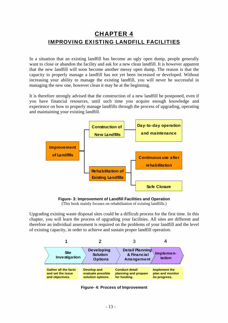
Figure- 3: Improvement of Landfill Facilities and Operation (This book mainly focuses on rehabilitation of existing landfills.)
Upgrading existing waste disposal sites could be a difficult process for the first time. In this chapter, you will learn the process of upgrading your facilities. All sites are different and therefore an individual assessment is required on the problems of your landfill and the level of existing capacity, in order to achieve and sustain proper landfill operation.
Implemen-tation
4
Implemen-tation
Implemen-tation
4
Gather all the facts and set the issue and objectives.
Develop and evaluate possible solution options.
Conduct detail planning and prepare for funding.
Implement the plan and monitor its progress.
SiteInvestigation
1
SiteInvestigation
SiteInvestigation
1
DevelopingSolutionOptions
2
DevelopingSolutionOptions
DevelopingSolutionOptions
2
Detail Planning& Financial
Arrangement
Detail Planning& Financial
Arrangement
3
Figure- 4: Process of Improvement

- 14 -
4.1 STEP 1: Review and Assessment of Existing Conditions When you plan to upgrade the existing landfill, the first task you need to do is to investigate the existing conditions of your landfill. Such investigations include, but are not limited to, the following: - topography in and around the landfill - geology/hydrogeology of the site - meteorological data near the site - existing operation and maintenance from technical and financial aspects - apparent and latent problems associated with the landfill
Site Investigation
DevelopingSolutionOptions
Detail Planning & Financial
ArrangementImplementation
Site Investigation
DevelopingSolutionOptions
Detail Planning & Financial
ArrangementImplementation
Topography& Geology
DisposalOperation
IdentifyProblems
Environmental& Social Study
Topography& Geology
DisposalOperation
IdentifyProblems
Environmental& Social Study
Figure- 5: Step 1. Site Investigation To obtain the topography information, a topographical survey needs to be conducted. Topographical drawings allow you to estimate the total area of landfill, the area and volume of existing waste deposits, the area and location of rainwater or surface water accumulation, and the available space for future waste disposal, etc. The drawings are also very useful when you make a plan to improve your landfill facility.
Photo- 6: Site Investigation (Exploratory Boring and Topography Survey) It is recommended, if your budget allows, that exploratory bore holes be drilled at several locations, both upstream and downstream. The purpose of drilling is to investigate the

- 15 -
geological and hydrogeological features of the site. The bored holes are also used as monitoring wells to check the quality of groundwater, and to see if any contamination from the landfill is taking place. Meteorological data such as average precipitation, temperature, and sunlight hours will be used to estimate the amount of leachate generation (and potential evaporation) so that an appropriate volume of the retention pond is determined. It is however worth emphasising that the size of the leachate retention pond depends heavily on the intensity of rainfall in the rainy season and the treatment capacity or method of leachate treatment. It is not economical to determine the capacity/size of the retention pond based only on the calculation of rainfall in wet season. One of the prime objectives for upgrading the waste disposal facility is to reduce adverse impacts on the surrounding environment and public health. Therefore, you should carefully observe and analyse the existing conditions and operations to identify problems both apparent and latent as shown in Table-1.
Table- 1: Checklist for Health and Environmental Impacts at a Landfill
Severity of Impact Problem Areas Not Present Minor Severe
Fly breeding Rodents and vermin Offensive odour Smoke from open burning Contamination of surface water with leachate
Contamination of groundwater with leachate
Fire hazard caused by open burning Dust from landfill operation Noise from landfill operation Visual impact Human and animal scavenging
(Adapted from Reference 16: Guides for Municipal Solid Waste Management in Pacific Island Countries, WHO Western Pacific Region, 1996)
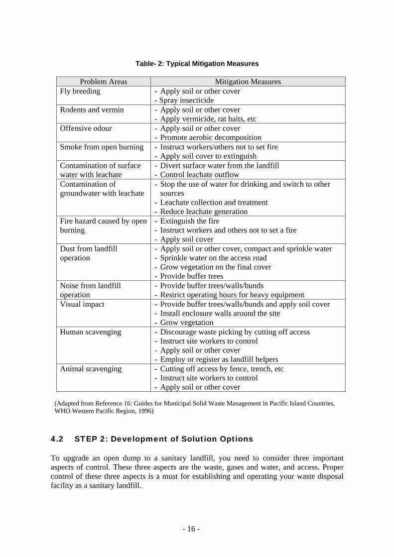
Identified problems in Table-1 need to be corrected accordingly. Table-2 shows typical mitigation measures to be taken to reduce the impact of each problem area. According to the severity of the impact, some of the above measures should be taken into consideration in the plan that you will make for upgrading the landfill facility and its operation.
- 16 -
Table- 2: Typical Mitigation Measures
Problem Areas Mitigation Measures
Fly breeding
- Apply soil or other cover - Spray insecticide
Rodents and vermin
- Apply soil or other cover - Apply vermicide, rat baits, etc
Offensive odour
- Apply soil or other cover - Promote aerobic decomposition
Smoke from open burning
- Instruct workers/others not to set fire - Apply soil cover to extinguish
Contamination of surface water with leachate
- Divert surface water from the landfill - Control leachate outflow
Contamination of groundwater with leachate
- Stop the use of water for drinking and switch to other sources
- Leachate collection and treatment - Reduce leachate generation
Fire hazard caused by open burning
- Extinguish the fire - Instruct workers and others not to set a fire - Apply soil cover
Dust from landfill operation
- Apply soil or other cover, compact and sprinkle water - Sprinkle water on the access road - Grow vegetation on the final cover - Provide buffer trees
Noise from landfill operation
- Provide buffer trees/walls/bunds - Restrict operating hours for heavy equipment
Visual impact
- Provide buffer trees/walls/bunds and apply soil cover - Install enclosure walls around the site - Grow vegetation
Human scavenging
- Discourage waste picking by cutting off access - Instruct site workers to control - Apply soil or other cover - Employ or register as landfill helpers
Animal scavenging - Cutting off access by fence, trench, etc - Instruct site workers to control - Apply soil or other cover
(Adapted from Reference 16: Guides for Municipal Solid Waste Management in Pacific Island Countries, WHO Western Pacific Region, 1996)
4.2 STEP 2: Development of Solution Options To upgrade an open dump to a sanitary landfill, you need to consider three important aspects of control. These three aspects are the waste, gases and water, and access. Proper control of these three aspects is a must for establishing and operating your waste disposal facility as a sanitary landfill.

- 17 -
Site Investigation
DevelopingSolutionOptions
Detail Planning & Financial
ArrangementImplementation
Site Investigation
DevelopingSolutionOptions
Detail Planning & Financial
ArrangementImplementation
Control ofWaste
Control ofWater/Gases
Control ofAccess
Additional Facility
Control ofWaste
Control ofWater/Gases
Control ofAccess
Additional Facility
Figure- 6: Step 2. Development of Solution Options
Control of waste – This could be done by establishing a physical boundary just like a rubbish bin. The waste should be safely contained in an orderly fashion. Deposited waste should be covered with soil or other suitable materials to eliminate fly breeding and odour emissions from the waste. The first important thing you need to do is to take control of rubbish. If funding allows, it is better to install a weighbridge to measure the incoming waste so that you can utilise such data for fee collection/payment and for planning of remaining life of the landfill. Control of water and gases – Gases are generated as by-products of the natural decomposition process occurring at a landfill. Such gases include methane (CH4), carbon dioxide (CO2), nitrogen (N2), hydrogen sulphide (H2S), ammonia (NH3) etc. Methane and carbon dioxide are the two principal gases generated from the anaerobic decomposition of biodegradable organic waste. Some of these gases may cause fires and/or explosions at landfills. Landfill gases need to be controlled to prevent unwanted movement into the atmosphere so that any accidents can be avoided. Water control has two targets, one for surface water and the other for leachate. The control of surface and storm water can prevent water from entering the landfill and as a result it contributes to reducing the amount of leachate. The control of leachate is essential for preventing pollution and protecting groundwater quality since leachate may percolate through the underlying soil. The idea of control over leachate is to collect and drain leachate as quickly as possible from the disposal area and keep it in a retention pond. It is much easier to control leachate when it is confined to one location. Control of access – The control of access means the securing and proper maintenance of an access road and the restriction of unauthorised entry to a landfill. The access road needs to be constructed and maintained to allow all-weather tipping. This means that the road leading up to the dumping area can be driven on even during a heavy wet season. Unauthorised entry of vehicles and people may lead to illegal waste dumping, fires and vandalism of landfill facilities. It also allows uncontrolled scavenging at the tipping area. In
- 18 -
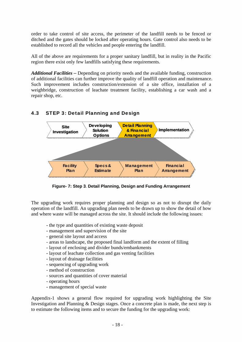
order to take control of site access, the perimeter of the landfill needs to be fenced or ditched and the gates should be locked after operating hours. Gate control also needs to be established to record all the vehicles and people entering the landfill. All of the above are requirements for a proper sanitary landfill, but in reality in the Pacific region there exist only few landfills satisfying these requirements. Additional Facilities – Depending on priority needs and the available funding, construction of additional facilities can further improve the quality of landfill operation and maintenance. Such improvement includes construction/extension of a site office, installation of a weighbridge, construction of leachate treatment facility, establishing a car wash and a repair shop, etc. 4.3 STEP 3: Detail Planning and Design
Site Investigation
DevelopingSolutionOptions
Detail Planning & Financial
ArrangementImplementation
Site Investigation
DevelopingSolutionOptions
Detail Planning & Financial
ArrangementImplementation
Facility Plan
ManagementPlan
Specs &Estimate
FinancialArrangement
Facility Plan
ManagementPlan
Specs &Estimate
FinancialArrangement
Figure- 7: Step 3. Detail Planning, Design and Funding Arrangement
The upgrading work requires proper planning and design so as not to disrupt the daily operation of the landfill. An upgrading plan needs to be drawn up to show the detail of how and where waste will be managed across the site. It should include the following issues: - the type and quantities of existing waste deposit - management and supervision of the site - general site layout and access - areas to landscape, the proposed final landform and the extent of filling - layout of enclosing and divider bunds/embankments - layout of leachate collection and gas venting facilities - layout of drainage facilities - sequencing of upgrading work - method of construction - sources and quantities of cover material - operating hours - management of special waste
Appendix-1 shows a general flow required for upgrading work highlighting the Site Investigation and Planning & Design stages. Once a concrete plan is made, the next step is to estimate the following items and to secure the funding for the upgrading work:

- 19 -
- quantity survey (volume of various work) - required resources (manpower, materials and construction equipment) - construction schedule - construction cost Depending on the magnitude of the upgrading work, planning/design work may be better undertaken by an experienced consultant or engineer. If your financial resource is very limited, you can minimize the cost by reducing the scope of upgrading work, such as downsizing the upgrading area, eliminating lower priority work items, downgrading the material specifications or splitting the work into several phases. You do not have to improve everything at once. In order to sustain the proper operation, incremental improvement or sectional-phased improvement is strongly recommended. 4.3.1 Facility Plan (1) Access Road Access to the disposal area is often a problem in most countries in the Pacific region. The access road needs to be suitable to allow all-weather tipping. This means that the road leading up to the dumping area can be driven on, even in times of heavy rain. There are three parts to the access road. The first one is from the public road to the front gate of the landfill. The second access road is from the front gate to the disposal area. The last access is inside the disposal area to the tipping face. The first two of the access roads described should be considered as permanent. These roads need to be properly graded and compacted and are better paved if funding allows. To keep the access road in a dry and usable condition as much as possible, proper sectional and longitudinal gradients as well as side ditches have to be provided. The access road must have enough width to allow vehicles to pass each other safely. The third stage of the access road, inside the disposal area, is considered as temporary. Temporary roads inside the disposal area sometimes are required to be established on the buried waste and need to be shifted from one location to another as the tipping face moves. The construction of a new access road is illustrated in the following photos:
Photo- 7: Clearing Photo- 8: Grading

- 20 -
Photo-7 shows the clearing of bush areas for the construction of a new access road. Clearing is done employing heavy construction equipment such as bulldozers and backhoes. Rough and preliminary grading of the ground is also done during clearing. After clearing, grading of the ground is carried out. Grading of the ground is usually done using a grader as seen in Photo-8. If the ground is very soft at some locations, the soil should be replaced with good material that will provide a firmer base.
Photo- 9: Compaction & Gravel Paving Photo- 10: Paved Access Road Proper compaction is required, as shown in Photo-9, to make the ground strong enough for the passage of heavy equipment. If funding allows, it is recommended that the access road be paved with gravel (and asphalt). Pavement increases the durability of the access road and reduces the frequency of maintenance. Photo-10 shows the condition after gravel paving.
Photo- 11: Side Ditch with Curb Stone Photo- 12: Side Ditch with Road
Crossing Culvert
Photo-11 shows the side ditches installed along the access road with curb stones painted in yellow. Side ditches and a road crossing culvert are shown in Photo-12. The function of access roads is often underestimated, but they are extremely important for proper operation and maintenance, not only of the landfill but for other facilities as well. Access roads should provide secure access to the operational parts of the site at all times. Since the upgrading work should not hamper the daily landfilling operation, additional access or diversion roads to and from the tipping face may be required during the upgrading work.

- 21 -
(2) Drainage Facility The purpose of installing a drainage facility is to reduce the amount of surface water running into and/or over the landfill area. Depending on the topography of the landfill area and its surroundings, rainfall builds up as surface water and may flow into the landfill area. The volume of rainfall and subsequent surface water is usually much higher than the volume of leachate generated within the landfill site. If a substantial amount of surface water goes into the waste disposal area, the amount of leachate will significantly increase and therefore exceed the capacity of the facilities to collect, retain and treat. In order to avoid such situations, it is necessary to separate the surface water and prevent it from entering the waste disposal area. Water is typically diverted by constructing embankments or perimeter drains on the uphill side of the landfill away from the disposal areas. Attention needs to be given to preventing erosion when constructing water diversion works. The surface water drainage facility can be classified into the following categories Perimeter drain - The perimeter drain facility collects rainwater from outside areas of the landfill and prevents the surface water from running into the landfill disposal area. The perimeter drain leads the surface water to a downstream storm water reservoir. The perimeter drain will also collect the surface water from inside the disposal area once the site is filled up and the final soil cover is installed. Perimeter drains not only divert the surface water from the landfill area, but have another function to prevent animals and unauthorised people from trespassing on the landfill.
Photo- 13: Perimeter Drain Excavation
Landfill surface drain – Landfill surface drains are installed to drain the runoff water from the landfill surface after application of the final cover soil. Surface drains are dug to the required gradient (commonly 2 to 3%) on the fully compacted final cover layer. The rate of ground settlement is high at the early stage after the site is filled up. Therefore, it is recommended that simple drains such as an open ditch be installed temporarily until the settlement of the ground (final soil cover) comes to an end. Once the settlement is nearly complete, a concrete-based ditch may be constructed as permanent structure. Upstream diversion channel – Upstream diversion channels are required in cases where the catchment areas of both the landfill site and the outside areas are too large and the capacity of perimeter drains is considered insufficient for the surface water from the surrounding

- 22 -
areas. Photos 14 and 15 show installation of upstream diversion pipes.
Photo- 14: Excavation of Trench Photo- 15: Diversion Pipe Setting (3) Physical Boundary (Waste Retaining Facility) In general, an open dump has no physical boundary to retain rubbish. A physical boundary is a structure that retains rubbish inside the “rubbish bin”. The physical boundary can be an embankment/bund, trench, terrace or depression that clearly demarcates the waste disposal site and is structurally stable. There are basically three methods to establish a physical boundary depending on the conditions at the site. Such methods include the trench method, area method and depression method. Trench Method - The trench method is most suited where the surrounding ground is quite flat and the water table is reasonably deep. The soil excavated for trenches gives on-site cover soil. To start the process, a portion of the trench or small area is excavated and the soil removed is placed to form an embankment at the end of the trench. The trench itself forms a physical boundary or retaining facility. Wastes are placed in the trench, spread out and compacted. Cover soil used for the day’s operation is obtained by excavating another trench next to this filled trench, or continuing the trench that is being filled. The width and depth of a trench or small fill area should be determined depending on the amount of waste to be disposed of, the available area, level of water table, etc. Area Method - The area method is most suited when the slope of the land is not suitable for trench excavations. The method is suitable for sites where the land is flat and the water table is high. Embankment/bunds (typically 2-3m high) are constructed around the disposal area to form a physical boundary and to support the waste for compaction. To form embankments/bunds, old decomposed waste can be used as the core of the bund and covered with soil. In this method, cover material has to be obtained and transported from nearby land or from borrow pits, if surplus soil is not available on site. Old deposited waste or decomposed organic waste can be used for daily and intermediate cover. Depression Method - The depression method is suited for areas where natural or artificial depressions exist. Examples of depressions include canyons, borrow pits, and quarries that naturally form a physical boundary. Terraces may need to be cut into the ground level to

- 23 -
allow wastes to be deposited safely as equipment may not be able to operate in the depression if the slope is too high. In order to reduce the amount of surface water running in to the depression (disposal area), it is strongly recommended that proper drainage be excavated/installed along the surrounding areas. Depending on the site conditions, you can take one of the above methods to form a physical boundary that can retain rubbish. In the area method, enclosing bunds are the physical structure that retains rubbish inside. Divider bunds are installed when you further divide the disposal area into smaller sections so that it will be easier for you to manage landfilling operations. In order to save soil materials, enclosing and divider bunds are constructed using old waste deposits from the existing landfill that has been decomposed and become like soil. The surface of the bunds is compacted and covered with soil. Structurally it is better to use soil materials for embankments, but with the use of old deposited waste, you can save soil materials significantly. In many countries in the Pacific, soil materials are sometimes scarce or expensive to obtain. In order to protect the surface from erosion, the top and the outside slope should be vegetated with grass. Photo-16 demonstrates the sequence of construction process at a landfill.
Photo- 16: Sequence of Enclosing Bunds Construction 1. Dozing and mounting old deposited waste 2. Embanking enclosing bunds 3. Embanking divider bund 4. Covering bunds with soil
1 2
3 4

- 24 -
(4) Leachate Control Facility The function of a leachate collection facility is to quickly collect and drain the leachate to a leachate retention pond. It is important to minimise the amount of leachate to be generated and remove it from the waste layers as quickly as possible so that there will be little trapped leachate in the landfill site. This ensures that the water pressure acting on the bottom of the landfill is kept minimal so as to reduce the risk of seepage of leachate into the ground. In the semi-aerobic landfill system, the leachate collection facility also serves to naturally supply fresh air into the waste layers and subsequently enhances the entire gas venting processes. The typical leachate collection system consists of a liner at the base of the waste to prevent the leachate from migrating to groundwater, pipes overlaying the liner to collect the leachate and drain the liquid to a retention pond where leachate can be treated or pumped and fed back into the landfill through the vertical gas venting pipes as illustrated in section 4.3.1(6).
If a landfill site is unable to treat the leachate then attempts should be focussed on reducing the quantity of leachate generated (through drainage management, refer section 4.3.1(2)) and the toxicity of contaminants contained within the leachate by diverting hazardous wastes from landfill and by reducing the organic content of the waste by encouraging composting. The layout for leachate collection pipes can be designed considering the topography of the landfill site and landfilling method as shown in Figure-8.
Straight Line Pattern Fishbone Pattern Ladder Pattern
(Arrows indicate the flow of leachate.)
Figure- 8: Layout for Leachate Collection Pipes
(Adapted from Reference 5: Japan Municipal Association for Waste Management, Guidelines for Design and Operation of Waste Disposal Sites, 1989)
For the straight line pattern, pipes are laid out linearly and where the disposal area is very wide, several sets of straight pipes can be installed in parallel.
- 25 -
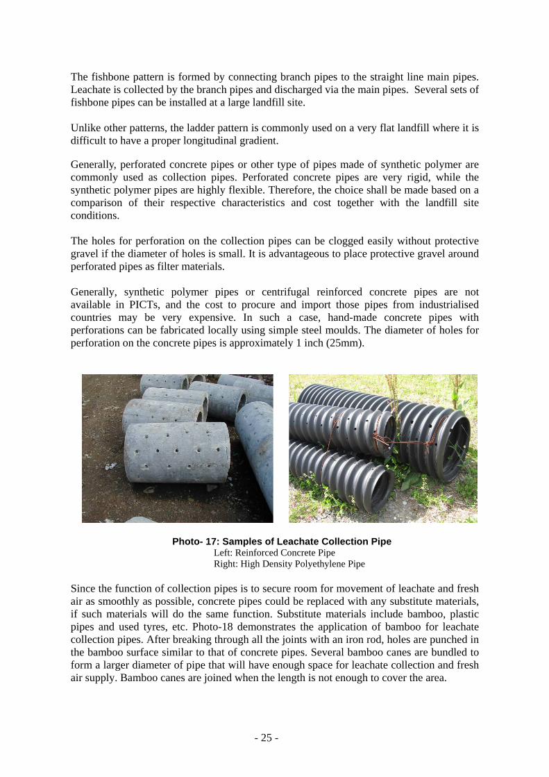
The fishbone pattern is formed by connecting branch pipes to the straight line main pipes. Leachate is collected by the branch pipes and discharged via the main pipes. Several sets of fishbone pipes can be installed at a large landfill site. Unlike other patterns, the ladder pattern is commonly used on a very flat landfill where it is difficult to have a proper longitudinal gradient. Generally, perforated concrete pipes or other type of pipes made of synthetic polymer are commonly used as collection pipes. Perforated concrete pipes are very rigid, while the synthetic polymer pipes are highly flexible. Therefore, the choice shall be made based on a comparison of their respective characteristics and cost together with the landfill site conditions. The holes for perforation on the collection pipes can be clogged easily without protective gravel if the diameter of holes is small. It is advantageous to place protective gravel around perforated pipes as filter materials. Generally, synthetic polymer pipes or centrifugal reinforced concrete pipes are not available in PICTs, and the cost to procure and import those pipes from industrialised countries may be very expensive. In such a case, hand-made concrete pipes with perforations can be fabricated locally using simple steel moulds. The diameter of holes for perforation on the concrete pipes is approximately 1 inch (25mm).
Photo- 17: Samples of Leachate Collection Pipe Left: Reinforced Concrete Pipe Right: High Density Polyethylene Pipe
Since the function of collection pipes is to secure room for movement of leachate and fresh air as smoothly as possible, concrete pipes could be replaced with any substitute materials, if such materials will do the same function. Substitute materials include bamboo, plastic pipes and used tyres, etc. Photo-18 demonstrates the application of bamboo for leachate collection pipes. After breaking through all the joints with an iron rod, holes are punched in the bamboo surface similar to that of concrete pipes. Several bamboo canes are bundled to form a larger diameter of pipe that will have enough space for leachate collection and fresh air supply. Bamboo canes are joined when the length is not enough to cover the area.

- 26 -
Photo- 18: Bamboos as Substitute Material for Pipes 1. Breaking through bamboo joints using an iron rod 2. Drilling holes 3. Jointing bamboo Canes 4. Bundling bamboo Canes
Where the deposited waste layer is shallow, the ground is easily exposed in order to install pipes. The ground needs to be graded with proper gradients so that leachate naturally flows into the pipes. A typical design of a leachate collection facility is shown in Figure-9. The leachate collection pipes should be covered with a gravel/rock layer that protects the pipes from being damaged by heavy landfill equipment. The gravel/rock layer also prevents leachate pipes from being clogged with the deposit of dirt or other small particles.
Minimum 3D
Minimum 3D
Protective material
h: Minimum height 50 cm for main pipe 30 cm for branch pipe
D
Base material
h
Figure- 9: Typical Design for Leachate Collection Facility (Cross Section)
1 2
3 4

- 27 -
There is no synthetic geo-membrane to prevent leachate from seeping into the ground, unlike the modern design concept. The first reason is that the installation of synthetic liners significantly increases the total construction cost. Therefore few countries in the Pacific can afford it. Secondly, the synthetic liners are easily damaged during the construction and the early stage of landfilling operations without experienced landfill operators. This again many countries in the Pacific cannot afford. The third reason is that it is also technically difficult to install liners in the waste deposited area if the waste layer is deep. In addition to the reasons above, leachate percolation to the subsurface ground can be minimised by draining out the leachate from the disposal area as quickly as possible.
Photo- 19: Concrete Pipe Setting Photo-19 demonstrates the installation of concrete pipes (main pipe) to collect leachate in the renewed disposal area where deposited waste has been cleared. After installing the main collection pipes, the bottom of the trench is cemented to prevent erosion and seepage. (See Photo-20) This work is not a must but is an additional measure to reinforce the facility. Both main and branch pipes then are covered with protective gravel/rock material as shown below. The gravel/rock must be well sifted or screened to have appropriate sizes so that dust, powder or small materials are excluded.
Photo- 20: Installation of Pipes and Protective Gravel Layer Where the waste layer is very deep, it is not practical or cost effective to remove all the waste deposit in the area in order to install the pipes. In such a situation, trenches need to be excavated with enough width and depth to install the pipes as shown in Photo-21.

- 28 -
Photo- 21: Excavation of Trench at Deep Waste Layer Excavation for leachate collection pipes should be carefully designed to have a proper longitudinal gradient so that collected leachate will flow naturally to the downstream end of the pipes. Over-excavation at some locations may result in accumulation of leachate and the formation of puddles in the waste layer. Where the water table is high, the bottom of the pipes should be above the water table. If the bottom of the excavated trench is very soft and cannot withstand the weight of pipes, ground-supporting measures need to be taken.
Photo- 22: Installation of Leachate Collection Facility in Deep Waste Layer 1. Installation of pipes using a crane 2. & 3. Protective gravel filling using a crane
4. Condition two months after trenches backfilled with waste and covered with soil
1 2
3 4

- 29 -
Numbers 1 through 3 in Photo-22 show the installation of pipes and a protective gravel layer using a crane and a large bucket in deep excavated trenches where the waste deposit is thick. Number 4 shows the state of the disposal area two months after the deep trenches were backfilled with waste and the area was covered with soil. Grass has naturally grown on the ground. There is no nuisance from offensive odour, flies and vermin, or fires once the waste deposit is covered with soil. As shown in Table-2, there are also other typical corrective measures. Among other measures proposed in Table-2, even simple soil cover can solve a lot of problems. Therefore, periodic soil cover is a must to keep your landfill in a sanitary condition. The leachate generated in the disposal area naturally flows into the collection pipe and is led to a leachate retention pond established somewhere downstream. The leachate retention pond is the place where collected leachate is retained and treated. Leachate in the disposal area needs to be drained out as quickly as possible through the collection pipes to the retention pond so that you can control leachate at one place. Number 1 in Photo-23 shows a leachate retention pond under construction. An excavated pond will be appropriate if the ground is a clay material and expected to have low permeability. It is better to install a synthetic liner in the retention pond to reduce the risk of leachate seepage into the subsurface ground, if funds allow this.
Photo- 23: Leachate Retention Pond 1. Excavation and compaction 2. Synthetic geo-membrane sheet installed
At the leachate retention pond, you can treat leachate employing various methods depending on your budget and available resources. Some of the economical treatment methods are explained in section 4.3.1(6). Figure-10 shows the layout of a leachate and gas control facility. It also clearly shows the physical boundaries, just like a large rubbish bin.
1 2

- 30 -
Figure- 10: Example of Leachate and Gas Control Facility at a Landfill
(5) Gas Venting Facility The main function of a gas venting facility is to release the gases generated from the landfill layers as soon as possible before they create environmental impacts on surrounding areas. It also accelerates the stabilization process of the landfill under the semi-aerobic system. The gas venting facility needs to be planned and designed to suit these purposes. Typically, a gas venting facility for a semi-aerobic landfill system consists of horizontal and vertical/inclined gas venting pipes. A vertical gas venting pipe is installed on top of a connection pit. A connection pit is used to connect the main leachate collection pipes and branch pipes. A sample of a connection pit is shown in Photo-24. In this case, the connection pit is made of concrete that is placed in-situ using formwork. Since the function of the connection pit is to connect pipes and secure space for air to move in and out freely, you can form a connection pit using other materials such as cement blocks, bricks, wood, used drums, used tyres, mounds of gravel/rock material, etc. It is not necessarily squared or walled.
Photo- 24: Pipe Connection Pit

- 31 -
Photo-25 demonstrates installation of an in-situ concrete connection pit in deep waste layer. Pipes and connection pits are installed in the excavated trenches.
Photo- 25: Installation (in-situ concrete) of Connection Pit in Deep Waste Layer Photo-26 shows how a vertical gas venting pipe is installed on the pipe connection pit. The vertical gas venting system consists of gas venting pipes (PVC pipe is used in the Photo), protective casing (used oil drums are used), and gravel-fill between pipes and casing. The connection pit has a cover to support the weight of the gravel-filled drums, and gas venting pipes. Both gas venting pipes and used drums are punched with holes to let air and gases move in and out. The cover (support for the gas venting facility) should be strong enough to support the protective gravel/rock material placed over the top.
Photo- 26: Vertical Gas Venting Pipe installed on Pipe Connection Pit Left: Installed condition Middle & Right: Excavated condition 5 years later
The vertical gas venting pipes (including drums and gravel) are extended upwards as the waste layers are piled up. Photo-27 shows the condition of the extended gas venting facility in the area where waste is already filled up to a certain height. It is suggested that the surrounding area about 2m from the vertical gas venting facility be mounded at least 30 cm higher than the ground level so that runoff water does not enter the gas venting facility, taking ground settlement into consideration. Any direct water inflow into the vertical gas venting facility will increase the amount of leachate at the retention pond. It is likely that the immediate area surrounding vertical venting pipes more rapidly decomposes and therefore some settlement is expected.
- 32 -
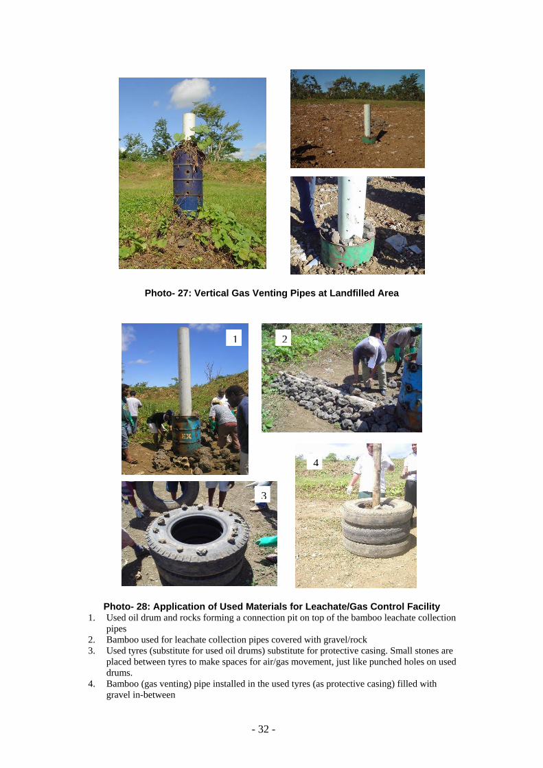
Photo- 27: Vertical Gas Venting Pipes at Landfilled Area
Photo- 28: Application of Used Materials for Leachate/Gas Control Facility 1. Used oil drum and rocks forming a connection pit on top of the bamboo leachate collection
pipes 2. Bamboo used for leachate collection pipes covered with gravel/rock 3. Used tyres (substitute for used oil drums) substitute for protective casing. Small stones are
placed between tyres to make spaces for air/gas movement, just like punched holes on used drums.
4. Bamboo (gas venting) pipe installed in the used tyres (as protective casing) filled with gravel in-between
1 2
3
4

- 33 -
As you can see in Photo-28 and Photo-29, used/wasted materials can be utilised to substitute for expensive materials. It is therefore very important for you to understand the functions of each facility of the landfill. You do not have to apply or stick to advanced engineering designs or specifications. You can choose any designs and materials that will do the same function as required for a specific facility, depending on affordability or availability.
Photo- 29: Different Types of Vertical Gas Venting Facility to Enlarge the Aerobic Zone
around the Pipe 1&2: Used tyres with plastic containers as a substitute for gravel 3: Used tyres and bamboo sticks with gravel (Adapted from Reference No. 4) 4: Triple used drums with rocks 5: Bamboo cage with gravel (Leachate re-circulation Facility)
The function of filter materials around the gas venting pipes is to enlarge the aerobic zone around the pipes so that exchange of gases and fresh air is promoted. Think always about what the appropriate technology means to you in terms of technical, financial, social and institutional aspects. As you increase your capacity, the appropriate technology will also be upgraded. (6) Leachate Treatment The quality of leachate can be improved through recirculation. The leachate recirculation in semi-aerobic landfills returns leachate to the landfill to quicken the purification (treatment) of the leachate. In aerated landfills, there is a rapid reduction of organic components (i.e. BOD) and a slow reduction in nitrogen components. In recirculating landfills, there is a
1 2 3
4 5
- 34 -
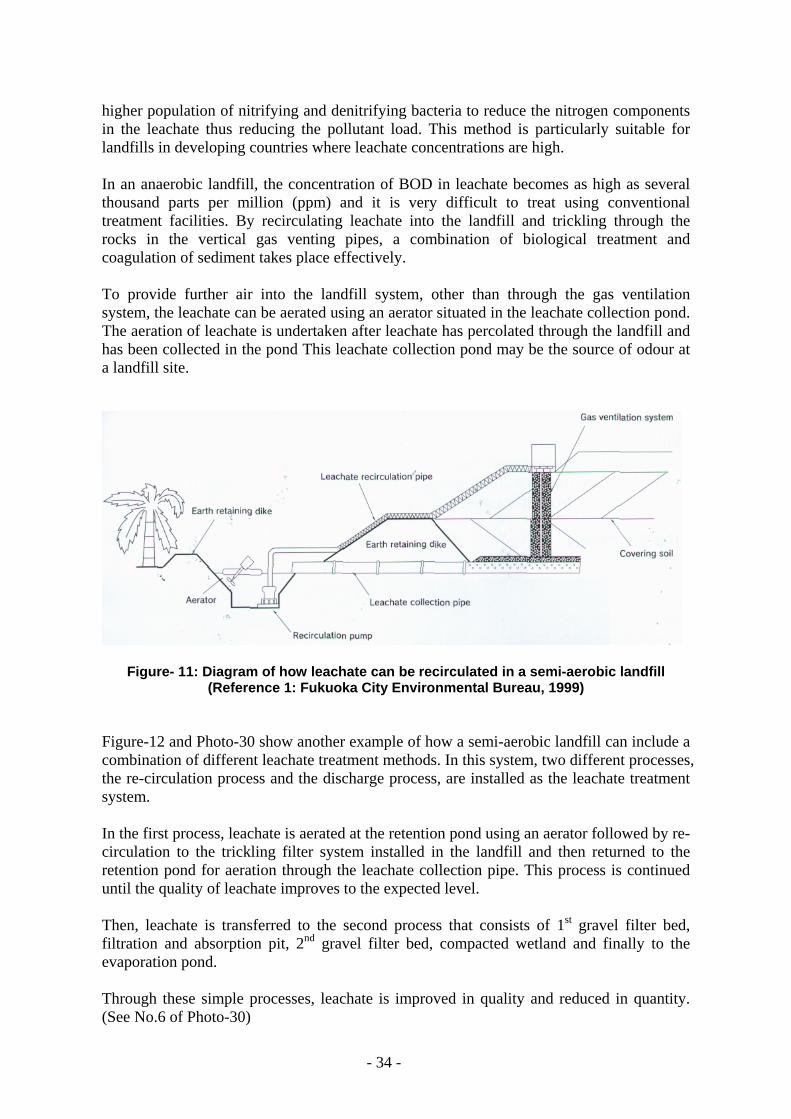
higher population of nitrifying and denitrifying bacteria to reduce the nitrogen components in the leachate thus reducing the pollutant load. This method is particularly suitable for landfills in developing countries where leachate concentrations are high. In an anaerobic landfill, the concentration of BOD in leachate becomes as high as several thousand parts per million (ppm) and it is very difficult to treat using conventional treatment facilities. By recirculating leachate into the landfill and trickling through the rocks in the vertical gas venting pipes, a combination of biological treatment and coagulation of sediment takes place effectively. To provide further air into the landfill system, other than through the gas ventilation system, the leachate can be aerated using an aerator situated in the leachate collection pond. The aeration of leachate is undertaken after leachate has percolated through the landfill and has been collected in the pond This leachate collection pond may be the source of odour at a landfill site.
Figure- 11: Diagram of how leachate can be recirculated in a semi-aerobic landfill
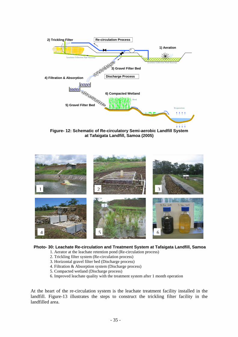
(Reference 1: Fukuoka City Environmental Bureau, 1999) Figure-12 and Photo-30 show another example of how a semi-aerobic landfill can include a combination of different leachate treatment methods. In this system, two different processes, the re-circulation process and the discharge process, are installed as the leachate treatment system. In the first process, leachate is aerated at the retention pond using an aerator followed by re-circulation to the trickling filter system installed in the landfill and then returned to the retention pond for aeration through the leachate collection pipe. This process is continued until the quality of leachate improves to the expected level. Then, leachate is transferred to the second process that consists of 1st gravel filter bed, filtration and absorption pit, 2nd gravel filter bed, compacted wetland and finally to the evaporation pond. Through these simple processes, leachate is improved in quality and reduced in quantity. (See No.6 of Photo-30)
- 35 -
P1) Aeration
Leachate Collection Pipe (Existing)
Leachate Collection Pond (Existing)
Evaporation
Discharge Process
Re-circulation Process
6) Compacted Wetland
3) Gravel Filter Bed
4) Filtration & Absorption
Reed
2) Trickling Filter
5) Gravel Filter Bed
Figure- 12: Schematic of Re-circulatory Semi-aerobic Landfill System
at Tafaigata Landfill, Samoa (2005)
Photo- 30: Leachate Re-circulation and Treatment System at Tafaigata Landfill, Samoa 1. Aerator at the leachate retention pond (Re-circulation process) 2. Trickling filter system (Re-circulation process) 3. Horizontal gravel filter bed (Discharge process) 4. Filtration & Absorption system (Discharge process) 5. Compacted wetland (Discharge process) 6. Improved leachate quality with the treatment system after 1 month operation
At the heart of the re-circulation system is the leachate treatment facility installed in the landfill. Figure-13 illustrates the steps to construct the trickling filter facility in the landfilled area.
1 2 3
4 5 6

- 36 -
3~5 m
1~1.5 m
Additional pipes
Air Air
Figure- 13: Construction of Leachate Re-circulation Facility in the Waste Layer 1. Excavation/preparation around the main vertical gas venting
pipe for treatment layers (3~5m x 1~1.5m deep) 2. Installation of four (4) additional gas venting pipes around
the main vertical gas venting pipe 3. Installation of multiple treatment layers that consist of two
stone layers with the coconut husk layer in the middle 4. Installation of leachate re-circulation system/pipe
Photo-31 illustrates different applications of leachate treatment/re-circulation system (trickling filter type) constructed in a similar way to Figure-13.
Photo- 31: Various types of Treatment System (Trickling Filter) for Re-circulation Left: Tafaigata Landfill, Samoa Right: Sisdol Landfill, Nepal
1 2
3 4

- 37 -
There are ample possibilities to improve leachate quality, employing various methods such as leachate recirculation, aeration at the retention pond, simple coagulation and sedimentation, filtration and absorption, etc. (7) Site Security and Access Control Site access needs to be controlled to prevent unauthorised intruders and dumping. The front gate needs to be lockable and secure, with enough fencing to prevent unauthorised access. Unauthorised intruders also include scavengers, which is a common occurrence at many dumpsites across the South Pacific region. To minimise site access, a fence needs to be located around the perimeter of the site, with sufficient height and quality to prevent intruders. The site fence may need to be monitored periodically to identify and repair any damage or holes that may be deliberately cut in the fence.
Photo- 32: Gate house Photo- 33: Sign Board at the Gate
Personnel need to be employed so that there is continual site supervision. The responsibility of employed staff is to ensure that there is no unauthorised dumping (discussed in following sections) and to ensure the rules of the dump are adhered to. A gatehouse or shelter for staff will need to be constructed and access to warm water, soap, potable water and other basic sanitation facilities needs to be provided. Staff should be trained on how site access is to be controlled and how users should be directed across the waste disposal site.
Restricted tipping hours must be introduced and the hours should only cover the time that members of staff are employed on site. The initial introduction of restricted tipping hours may create opposition if the public has previously enjoyed tipping at any time of the day and it may cause dumping in other locations across the island. Public education and awareness activities may be required and should focus on anti-littering campaigns. The community and
Photo- 34: Sign Boards on Access Road

- 38 -
site users need to be educated on why controls are necessary and the benefits to public health should be promoted. If the entrance or gatehouse area is some distance away from the disposal area, clear signage to direct users of the site to the designated waste disposal area should be used. Vehicle movement needs to be monitored to ensure that the signage is effective and users are locating the tipping face easily. Photo-34 illustrates samples of sign boards on the access road, showing directions in both English and local language. 4.3.2 Design Specifications and Cost Estimate The next step after you have planned how you would like to improve the landfill is to determine design specifications such as dimensions of structures, types of materials, capacity of equipment to be installed, etc.
• Design & Specifications: Determine the design and specifications of the facilities or work to be carried out. This will significantly affect the cost of work items. In other words, the total cost will be cut down by reviewing the design and specifications of expensive work items if the total cost exceeds your budget.
• Quantity Survey: Calculate the quantities of required work, such as volume of work, materials to be used, man-hours and equipment for installation.
• Cost Estimate: Estimate the cost for each work and calculate the total cost. • Time Scheduling: Develop the sequence of work and estimate the duration of each
work and calculate the total time schedule.
Table- 3 Example of Cost Items
Description of Work Unit Quantity Unit Cost ($)
Amount ($) Remarks/Specifications
1 Site Topography Survey ha 2 Plan & Design lot 1.0 3 Access Road M width, thickness 4 Site Preparation ha 5 Gate no dimensions, type of material 6 Fence lin. m dimensions, type of material 7 Gate House no square meter, type of materials 8 Bund/dike Construction lin. m dimensions of structure, type of
material 9 Soil Cover Application m2 thickness, type of materials 10 Leachate Collection System
(main) m diameter, type of materials
11 Leachate Collection System (branch)
m diameter, type of materials
12 Gas Venting System (vertical) m diameter, type of materials 13 Gas Venting System (horizontal) m diameter, type of materials 14 Leachate Retention Pond m3 dimension of pond, type of liner 15 Leachate Circulation System no type of equipment, capacity 16 Leachate Oxidation System no depth, type & diameter of pipe 17 Groundwater Monitoring Well no dimensions 18 Drainages (open ditch) lin. m capacity 19 Weigh Bridge set No.1 – No.19 Sub total Overhead & Other Expenses lot 1.0
Total Amount

- 39 -
4.3.3 Management Plan An overall landfill management plan includes such items as a daily operation plan, monthly plan (short-term), annual plan (mid-term) and closure plan (long-term). Control of Solid Waste Flow – It is imperative for proper solid waste management that the flow of solid waste be well understood and controlled. The waste flow provides you with a whole picture of waste including amount of generation, collection, recycle and final disposal. In case of final disposal at a landfill, it is possible to control incoming waste by setting up operating days and hours, strict gate control and boundary patrol against unauthorised trespassing or illegal dumping. Record-keeping of incoming waste is also very important on such items as type of waste, amount of waste, location of deposition, time and date. In order to have accurate records, installation of a weighbridge should be considered as an option. Landfill Operation – A sequence of daily landfill operation mainly consists of receiving waste at the gate, guiding collection and other trucks to designated tipping face, unloading waste, spreading and compaction of waste and covering soil. In addition, from time to time, extension of leachate collection pipes or gas venting pipes, diversion of access road, constructing additional retaining bunds, intermediate or final soil cover, etc. is required. On a long-term basis, establishing a schedule/sequence of landfilling and securing required resources for the operation is essential. See Chapter 5 for more details.
Facility Maintenance - Landfill facility includes waste retaining facility, leachate retention pond, leachate re-circulation facility, leachate collection facility, gas venting facility, site drainage facility, and others. In order to make the landfill function, proper maintenance of various facilities needs to be carried out on a daily basis. For a landfill employing the semi-aerobic system, leachate collection and gas venting facilities are the two most important facilities to let the system work well. See Chapter 5 for more details. Environmental Monitoring – The objective of environmental monitoring is to make sure there is no hazardous effect generated from the landfill. If any possible hazard is observed, remedial measures should be taken according to the level of threat to environment and public health. Such monitoring includes leachate, groundwater, surface-water, landfill gases, temperature of waste layer (through gas venting pipe) as well as open air, precipitation, settlement of waste layer, water level of leachate retention pond, etc. 4.3.4 Financial Arrangement Ideally, solid waste management in PICTs should be self-sustained financially. Technical sustainability is strongly dependent on financial stability and vice versa. In order to sustain solid waste management operation including upgrading of existing landfills, an institutional approach needs to be introduced for securing financial resources as suggested below: Annual Institutional Budget - Annual institutional budget is always insufficient in most PICTs, especially for work involving major construction work. Therefore, the first priority for the annual budget is to focus on carrying out day-to day operation as properly as possible. If the upgrading work is minimal, you may be able to squeeze the annual budget for the work.
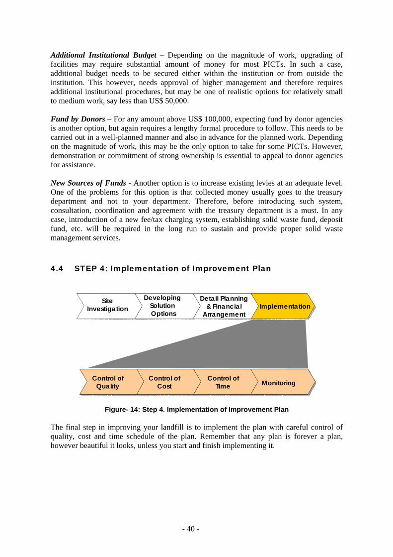
- 40 -
Additional Institutional Budget – Depending on the magnitude of work, upgrading of facilities may require substantial amount of money for most PICTs. In such a case, additional budget needs to be secured either within the institution or from outside the institution. This however, needs approval of higher management and therefore requires additional institutional procedures, but may be one of realistic options for relatively small to medium work, say less than US$ 50,000. Fund by Donors – For any amount above US$ 100,000, expecting fund by donor agencies is another option, but again requires a lengthy formal procedure to follow. This needs to be carried out in a well-planned manner and also in advance for the planned work. Depending on the magnitude of work, this may be the only option to take for some PICTs. However, demonstration or commitment of strong ownership is essential to appeal to donor agencies for assistance. New Sources of Funds - Another option is to increase existing levies at an adequate level. One of the problems for this option is that collected money usually goes to the treasury department and not to your department. Therefore, before introducing such system, consultation, coordination and agreement with the treasury department is a must. In any case, introduction of a new fee/tax charging system, establishing solid waste fund, deposit fund, etc. will be required in the long run to sustain and provide proper solid waste management services. 4.4 STEP 4: Implementation of Improvement Plan
Site Investigation
DevelopingSolutionOptions
Detail Planning & Financial
ArrangementImplementation
Control ofQuality
Control ofCost
Control ofTime Monitoring
Control ofQuality
Control ofCost
Control ofTime Monitoring
Figure- 14: Step 4. Implementation of Improvement Plan The final step in improving your landfill is to implement the plan with careful control of quality, cost and time schedule of the plan. Remember that any plan is forever a plan, however beautiful it looks, unless you start and finish implementing it.

- 41 -
CHAPTER 5 IMPROVING LANDFILL OPERATION
You have learned in the previous chapters how to improve your landfill facility. Upgrading an existing landfill facility may be a difficult task for you, but a real challenge is whether or not you can sustain the proper operation and maintenance after the landfill facility is upgraded. In this respect, physical upgrading work is relatively easy, compared to proper daily operation. You can improve the facility overnight. However, you have to continue the operation at the landfill for many years in a sound and controlled manner. Landfilling work includes the methods of landfilling, spreading and compaction, cover requirements and access roads. These items must be considered carefully before undertaking landfilling work as there is a close relationship among them. In order to sustain proper operation and maintenance of the landfill, it is required to develop an operation & maintenance plan. In the majority of landfill sites across the Pacific, either the national or municipal government will be responsible for the management and operation of the landfill. Due to this, the relevant government agency should take ownership of the operation and maintenance plan at an early stage and be very familiar with its contents. It will be more beneficial if most, if not all, of the operating and management practices are developed by the responsible body.
Photo- 35: Improved Operation (right) as Compared to Previous Operation (left) 5.1 Landfill Method Appropriate numbers and quality of staff need to be employed to supervise dumping in the disposal area. The staff at the tipping face should ensure that users are not dumping in other areas across the site and only in the designated disposal area. On small dumpsites the responsibility for site access at the entrance, and supervision of dumping, may be more practically undertaken by the same staff member. This is only feasible if the entrance and the tipping face are within a short walking distance. The disposal area should be kept as small as possible and clearly defined. The area can be defined with the use of soil bunds or excavated trenches.

- 42 -
5.2 Cell Construction A cell is a unit of landfilled space or area including cover material that is developed during one operating period. Ideally one operating period is one day, but in reality in the Pacific islands, it varies from several days, a week, or even a month, depending on the availability of landfill equipment and cover materials. Sandwich Method - Waste is placed horizontally in layers for the sandwich method and is useful for filling in narrow valleys. Cell Method - An amount of solid waste is covered with soil in cells. This method is the most popular method of filling. The amount of solid waste deposited during one operating period (usually one day) determines the size of each cell. As each cell is an independent filling area covered with soil, each cell acts as a firewall to minimize the spread of any underground landfill fires. Dumping Method - This method involves rubbish trucks simply dumping solid waste into the landfill site. As the solid waste is not compacted, the landfill base is weak and negative impacts such as bad odour and harmful vectors may develop. Due to these problems it is not recommended for a method of landfilling. 5.3 Order of Landfilling Landfilling on a waste site can be either of two ways: towards a downstream direction, or, toward upstream direction. Landfilling from uphill downwards allows easy access to the tipping face via the already landfilled area. However, sliding of the landfilled layer may occur if the landfilled slope is steep, and especially during periods of heavy rain. In contrast, landfilling from downhill upwards gives reduced access to the tipping face but reduced risks of slippage. 5.4 Spreading and Compaction Method - Spreading and compaction can be performed two ways, pushing down or pushing up the slope by the compaction equipment (bulldozer, loader, and landfill compactor). It is easier to push solid waste into a uniform thickness if spreading uphill and better compaction is achieved. If pushing solid waste down the slope, the waste at the base of the slope tends to be thicker. The spreading and compaction of the waste has a direct influence over the capacity and stabilisation of the landfill. If low compaction is achieved the landfill site will last a shorter period of time than that if high compaction is attained. When pushing solid waste, waste should be spread thinly out in layers of about 30 to 50cm. The layer should be made as uniform as possible. Between each layer, the compacting equipment needs to make regular passes over the waste layer. The layers should make a lift of about 2 metres with a maximum of 3 metres. A slope gradient of 3:1 (about 20 degrees) is recommended for pushing up (compacting) the slope.

- 43 -
Push-down Method Push-up Method
Figure- 15: Method of Spreading and Compaction
(In both cases, the direction of landfilling is from left to right as shown.)
Landfill Equipment - Landfill equipment should be carefully selected to suit the conditions for your landfill. A number of factors need to be considered. Such factors include type of waste, amount of daily incoming waste, site characteristics, weather conditions throughout the year, etc.
Landfill Compactor Bulldozer Excavator/backhoe Wheel-mounted Loader
Photo- 36: Typical Equipment used for Landfills
Typical problems with landfill equipment include breakdown from wear and tear, entanglement of wires or metal pieces caught in moving parts, loss of hydraulic pressure, or clogging of the radiator mesh due to dust and dirt. Therefore it is important that a regular service schedule for preventive maintenance for the equipment be followed. The activities that require the use of heavy equipment include:
1. grading and maintaining site access roads, 2. excavation of disposal areas, 3. excavation and loading of soil for cover, and, 4. spreading, compacting and covering the deposited waste.
The equipment that can be used to undertake these activities includes bulldozers, multipurpose utility loaders, wheel-mounted loaders, landfill compactors, graders, backhoes etc. Refer to Table 4 for details of how landfill equipment can be used.
Waste layer
Cover soil
Waste layer
Cover soil

- 44 -
Table- 4: Features of Landfill Equipment
Equipment Advantages Disadvantages Landfill compactor - very effective in compacting
and crushing rubbish - good mobility
- ineffective in soft ground - very expensive - limited availability
Bulldozer - effective in spreading and transporting waste in a short distance
- suitable for compaction - effective in covering of waste
with soil - available in most countries
- ineffective for excavating soil
Backhoe - effective in excavation and loading of waste/soil
- available in most countries - can be utilised for multi-
purpose
- ineffective for compacting waste/soil
Wheel-tractor-mounted loader (Front-end Loader)
- effective in loading rubbish and soil
- high mobility
- ineffective for: o excavation o compacting waste/soil o maintaining access roads
Multipurpose Loader/Excavator (Backhoe Loader)
- can undertake most tasks (excavation, soil application, waste handling)
- high mobility
- ineffective in compaction - unsuitable for excavating
some soils (i.e. hard clay)
Grader - effective in grading and maintaining site access roads
- high mobility
- unsuitable for waste spreading, transporting waste
It is necessary, when selecting equipment, to ensure that:
1. maintenance parts and servicing are available 2. operators can effectively use the equipment 3. compaction efficiency is considered (which will affect the landfill life)
Taking into account conditions such as the amount of incoming waste, type of waste and availability of equipment, then landfill equipment with small capacities will be sufficient in most landfills in PICTs. For instance, a small bulldozer, say 7~10 ton, is enough for handling 200 tons of waste per day. It should be also considered to share (or borrow) the equipment as much as possible with other government departments to reduce the number of machinery, if exclusive use at the landfill is not possible. A storage shed should also be included so that maintenance for the equipment can be located on site. In PICTs in the past, donors provided many different types of equipment without any specific regard for standardisation or consideration for what could easily be maintained in country. Since standardisation of equipment is very important for the ease of operation and maintenance, the recipient country should discuss the type of equipment to be provided in advance of any agreement with donor agencies.

- 45 -
5.5 Working (Tipping) Face The working face of a landfill should be kept as small as possible. The advantages of maintaining a small face include less litter as there is less waste exposed to the wind, better control of scavengers, less leachate generation as there is less rainwater entry and, covering and compacting waste can be undertaken more efficiently. Amount of soil cover is also minimised. A large landfill should not extend its tipping face any greater than 30m by 50m, whilst smaller operations should aim for a 20m by 20m area. During the wet season, efforts should be taken to minimise the tipping face size as much as possible as this will help to reduce the amount of surface water penetrating the waste to produce leachate. The working face can be increased during the dry season to a wider area.
Photo- 37: Working Face Left: waste is compacted in a relatively small area Right: waste is spread over wide area without boundary
5.6 Cover Material and Disposal Operation Necessity of Cover Material - To maintain sanitary conditions the waste needs to be covered on a regular basis. The frequency of covering will be dependant on a number of factors, such as weather conditions, type of waste being landfilled, or availability of landfill equipment and cover materials. Covering at small landfill sites can be done manually, but at larger sites, equipment will need to be obtained to undertake spreading, compaction and covering of the deposited waste. Cover material needs to be identified and sourced, preferably on-site, or else from a borrow pit nearby. Cover material ideally should consist of inert, non-combustible, dry and dense material. Once the material has been spread and compacted over the waste, then it should prevent pests and vermin from accessing the waste, minimise rainwater infiltration, prevent litter migration and provide a stable platform for tipping vehicles. The placement of soil over solid waste also reduces the fire risk and the covered waste becomes an effective firewall. Suitable cover material could include soil, sand, crushed rock, crushed coral rock, ash, decomposed waste from another part of the site, demolition waste, sawdust and garden
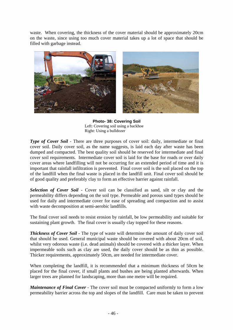
- 46 -
waste. When covering, the thickness of the cover material should be approximately 20cm on the waste, since using too much cover material takes up a lot of space that should be filled with garbage instead.
Photo- 38: Covering Soil Left: Covering soil using a backhoe Right: Using a bulldozer
Type of Cover Soil - There are three purposes of cover soil: daily, intermediate or final cover soil. Daily cover soil, as the name suggests, is laid each day after waste has been dumped and compacted. The best quality soil should be reserved for intermediate and final cover soil requirements. Intermediate cover soil is laid for the base for roads or over daily cover areas where landfilling will not be occurring for an extended period of time and it is important that rainfall infiltration is prevented. Final cover soil is the soil placed on the top of the landfill when the final waste is placed in the landfill unit. Final cover soil should be of good quality and preferably clay to form an effective barrier against rainfall. Selection of Cover Soil - Cover soil can be classified as sand, silt or clay and the permeability differs depending on the soil type. Permeable and porous sand types should be used for daily and intermediate cover for ease of spreading and compaction and to assist with waste decomposition at semi-aerobic landfills. The final cover soil needs to resist erosion by rainfall, be low permeability and suitable for sustaining plant growth. The final cover is usually clay topped for these reasons. Thickness of Cover Soil - The type of waste will determine the amount of daily cover soil that should be used. General municipal waste should be covered with about 20cm of soil, whilst very odorous waste (i.e. dead animals) should be covered with a thicker layer. When impermeable soils such as clay are used, the daily cover should be as thin as possible. Thicker requirements, approximately 50cm, are needed for intermediate cover. When completing the landfill, it is recommended that a minimum thickness of 50cm be placed for the final cover, if small plants and bushes are being planted afterwards. When larger trees are planned for landscaping, more than one metre will be required. Maintenance of Final Cover - The cover soil must be compacted uniformly to form a low permeability barrier across the top and slopes of the landfill. Care must be taken to prevent

- 47 -
the cover being eroded by rain water. The top of the cover should have a slope of 2-3% so that rainfall does not pond, and the side slopes should have a gradient of 20-30 degrees. Waste decomposes over time, causing settlement of the landfill and subsidence. This subsidence can cause cracking and sinking of the cover, as well as the formation of potholes. This can result in leachate volume increases, gas leakage, erosion of the cover soil and landslides. During the following years after installation of the final cover, it should be inspected regularly for defects. Any areas of settlement should be filled in and repaired. At large and deep landfills, settlement can occur for up to 30 years after closure. 5.7 Leachate Management Leachate management includes avoidance, collection, removal, treatment, disposal and monitoring of leachate generated in the landfill. A programme to regularly inspect and monitor leachate management needs to be developed and implemented. Leachate should be treated to the extent that it does not pose a health hazard, before it is discharged to public water such as streams, rivers, wetlands or the ocean. Normally, leachate treatment is a very costly exercise employing sophisticated systems in the industrialised countries since leachate contains various chemicals and heavy metals in those countries. Generally speaking, leachate from landfills in the PICTs, however, does not contain hazardous chemicals or heavy metals and is basically derived from organic waste. Therefore simple and economical treatment methods indicated in chapter 4 will work well. The quality of leachate should be tested periodically to see if there is any significant change in quality over time. Monitoring leachate quality also keeps you informed of the effectiveness of the treatment operation. The water level at the leachate retention pond needs to be monitored to ensure it is kept below the outlet of the collection pipe so that fresh air is naturally provided into the pipe at all times. Through the leachate re-circulation process, as shown in chapter 4 (6), the amount of leachate in the retention pond can be significantly reduce by evaporation. Some examples of failure in controlling the water level of leachate are shown in the Photo below.
Photo- 39: Submerged leachate pipe outlet (example of bad practice) (Adapted from Reference No. 4)

- 48 -
5.8 Maintenance of Facilities In order to maintain proper operations, landfill facilities must be regularly inspected and kept in a good condition. Facilities to be maintained include access roads, landfill slopes, drainage, and leachate collection and the gas venting facility. Access Roads - Access roads at landfills usually have a short lifespan. There are two types of roads which should be considered, trunk roads and branch access roads. The trunk roads are those roads that exist on site for a number of years, while the branch access roads to the tipping face will usually only be used for a matter of months. The road should be designed according to the size of vehicle and their speed, and geography of the land. Other considerations include safety measures such as guard rails to prevent traffic from falling down steep slopes that inevitably exist at many landfill sites and also reinforcements to prevent slippage from slope failure. Diversion of water should be considered carefully across the whole site and drainage around the road network is also important.
Photo- 40: Example of Site Access Road (Bouffa Landfill, Vanuatu) Construction of Slope - The landfill slope is formed from the deposited waste and the exterior soil placed around the outside. It is the slope which the final form of the landfill will take and should be carefully considered as it may restrict the final usage of the site if not chosen wisely. The slope should fit in with the terrain in the area and soil characteristics of the landfill site. The earth bund is the final soil cover on a landfilled slope. Progressively building the bund as the landfill progresses is the ideal method of construction. Therefore as each layer of the landfill is placed (approximately 2 to 3 metres high), the next layer of the bund should be constructed. When the new bund is built on the underlaying landfill layers, a minimum setback of 1~2 m is recommended for every lift of 2~3 m. Even at a large landfill site, one lift should not exceed 5 m. As the landfill slope is usually built on a landfill layer, the stability of the slope is greatly dependent on the compaction and stability of the underlying landfill layers. Consult with engineers if you plan to install more than 3 lifts or 6 m high.
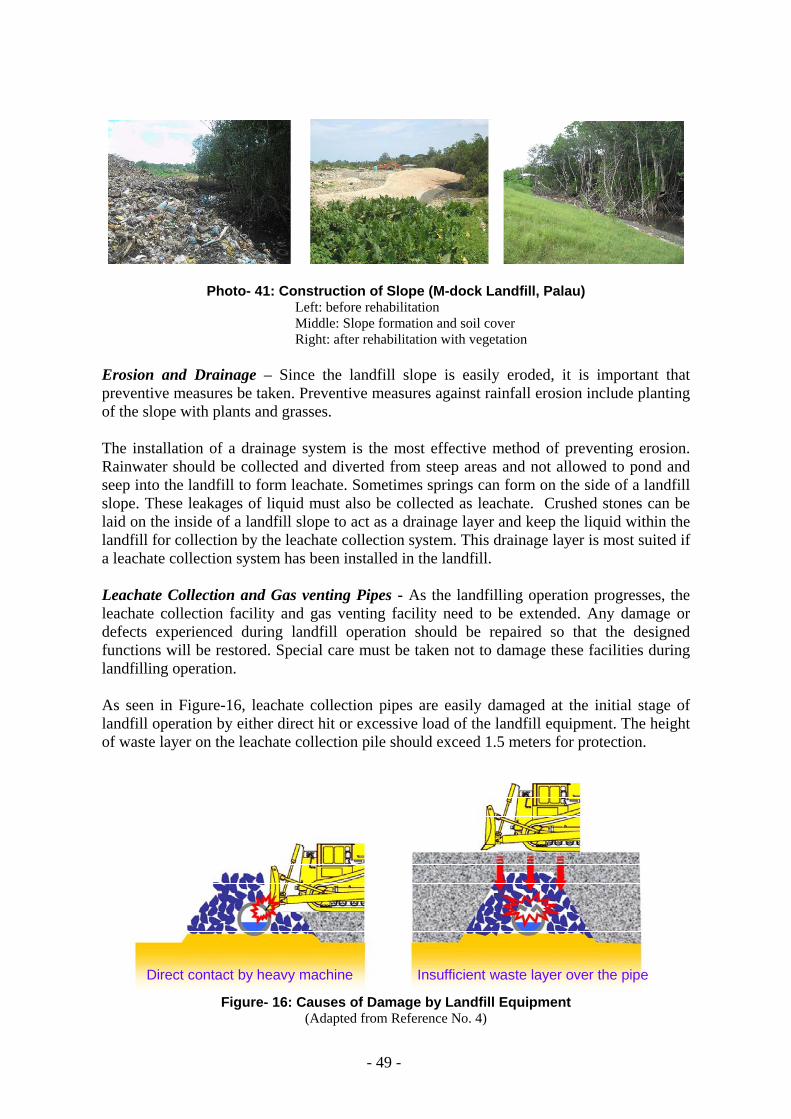
- 49 -
Photo- 41: Construction of Slope (M-dock Landfill, Palau) Left: before rehabilitation Middle: Slope formation and soil cover Right: after rehabilitation with vegetation
Erosion and Drainage – Since the landfill slope is easily eroded, it is important that preventive measures be taken. Preventive measures against rainfall erosion include planting of the slope with plants and grasses. The installation of a drainage system is the most effective method of preventing erosion. Rainwater should be collected and diverted from steep areas and not allowed to pond and seep into the landfill to form leachate. Sometimes springs can form on the side of a landfill slope. These leakages of liquid must also be collected as leachate. Crushed stones can be laid on the inside of a landfill slope to act as a drainage layer and keep the liquid within the landfill for collection by the leachate collection system. This drainage layer is most suited if a leachate collection system has been installed in the landfill. Leachate Collection and Gas venting Pipes - As the landfilling operation progresses, the leachate collection facility and gas venting facility need to be extended. Any damage or defects experienced during landfill operation should be repaired so that the designed functions will be restored. Special care must be taken not to damage these facilities during landfilling operation. As seen in Figure-16, leachate collection pipes are easily damaged at the initial stage of landfill operation by either direct hit or excessive load of the landfill equipment. The height of waste layer on the leachate collection pile should exceed 1.5 meters for protection.
Direct contact by heavy machine Insufficient waste layer over the pipeDirect contact by heavy machine Insufficient waste layer over the pipe
Figure- 16: Causes of Damage by Landfill Equipment (Adapted from Reference No. 4)

- 50 -
Photo- 42: Damaged Leachate Collection Pipes
Photo- 43 Clogged Leachate Collection Pipes Left: Normal condition Right: Clogged with plastic waste
Photo- 44: Clogged Vertical Gas Venting Pipes (The protective filter materials around the gas venting pipe are buried with waste and cover soil, thus soil and waste penetrated into the gas venting pipe and clogged it.)
Photos 42, 43 and 44 illustrate the damage or malfunction of leachate collection pipes and gas venting pipes. Because the leachate collection pipes are laid on the bottom, it will be

- 51 -
extremely difficult to repair them after waste is deposited and piled up high. Therefore careful operation must be carried out especially at the initial stage of landfilling and at the point where leachate collection pipes and gas venting pipes are installed.
When you observe or discover damage to the leachate collection facility or the gas venting facility, it is better to fix it as quickly as possible before the waste layer is further piled up. The following photos explain how to repair damaged pipes.
Photo- 45: Sequence of Remediation of Damaged Gas Venting Facility on the Connection Pit 1. Excavate around the damaged gas venting facility. 2. Remove the gas venting pipe and the support (previously iron rods were used) on the
connection pit. 3. Clean inside the connection pit. 4. Install a strong support on the pit and place stones around. A big used tire with steel rim
(yellow circle) reinforced by 2 inches steel pipes underneath (on the connection pit) is used as the support in this case since the previous support was collapsed due to the heavy load of the facility.
5 & 6. Install a new gas venting pipe and used drums on the support and fill the drums with stones.
7. Backfill around the gas venting facility with fresh waste and compact it. 8. Install another set of drums with stones around the pipe to extend the gas venting facility. 9. Continue the processes 7 and 8 up to the designated height.
1 2 3
4 5 6
7 8 9

- 52 -
As the waste layer becomes deeper (higher), additional gas venting facility as well as leachate collection facility should be installed in the waste layer if the final depth (height) of the waste layer will exceed more than 20m. (See Figures 17 and 18)
Figure- 17: Installation of Additional Gas Venting Facility in Deep Waste Layer (Adapted from Reference No. 4)
GasGas venting pipe
Air flow direction
Additional leachate collection pipe
Retaining facility
Leachate collection pipeLeachate retention pond
GasGas venting pipe
Air flow direction
Additional leachate collection pipe
Retaining facility
Leachate collection pipeLeachate retention pond
Figure- 18: Installation of Additional Leachate Collection Pipes in Deep Waste Layer (Adapted from Reference No. 4)
(Additional horizontal leachate collection pipes can also provide fresh air into the waste layers.)

- 53 -
5.9 Environmental Management Landfills are sometimes referred to as a typical NIMBY facility. The reason for this is that people suffer many nuisances caused by the landfills. Appropriate measures can minimise the nuisances as illustrated below (also refer to Tables 1 & 2, Section 4.1 Review and Assessment of Existing Conditions). Odour - Odour is sometimes very difficult to manage at a landfill site. All sites will generate odour to some extent and it will generally be worse in wet, hot weather. Some measures which can be taken include:
- immediate covering of highly odorous waste - regular covering of waste - ensure the tipping face does not pond water - encourage residents to store waste in a dry condition (so that when waste reaches
the landfill it is not as odorous), - maintain buffer zones around the landfill site (to minimise impacts on neighbouring
sites)
Dust - Dust control measures at a landfill site typically include wetting down of dirt roads with a water truck. Regular rounds of the roads will need to be made by the water truck, particularly in periods of very dry weather. Water can be sourced from on-site surface-water ponds or basins.
Fire and Smoke - Fires should be minimised at landfill sites as burning rubbish can generate poisonous gases and be an environmental and health risk. The type of control measures typically considered includes:
- regular soil cover to minimise risk of fires - developing a fire management plan including maintenance of an effective fire break
around the perimeter of the site, and, - developing emergency procedures for minor and major fires, including soil cover,
water spray, excavation of trench, etc.
Photo- 46: Examples of Fire Incident at Landfills Left: M-dock Landfill, Palau (2004) Right: Lami Landfill, Fiji (2006)
It is therefore important to have good compaction of waste in daily operation in order to prevent the fire from spreading.

- 54 -
For chronic smouldering in the waste layer, additional installation of a number of independent-type gas venting facility with proper cover soil will be very effective as shown in Photo-47.
Photo- 47: Installation of additional independent gas venting facility Left: Excavation of trench (1.5 m deep) Middle: Installation of additional gas venting facility Right: Compaction and soil cover
The following figures explain the mechanism of fire and how it is put out by installing additional independent gas venting facilities.
Waste Layer
CH4
CH4
CH4
CH4
CH4
O2
O2
O2
O2
Smoke SmokeMechanism of Fire
Waste Layer
CH4
CH4
CH4
CH4
CH4
O2
O2
O2
O2
Smoke Smoke
Cover Soil
Waste Layer
CH4
CH4
CH4
CH4
CH4
O2
O2
Cover Soil
Figure- 19: Fire Fighting Measure for Chronic Smoulders
Where the waste layer is in an anaerobic condition (absence of oxygen), methane is generated and contained in the waste layer. When oxygen penetrates into the waste layer from the ground, the concentration of methane enters a certain range (5–15 %) and catches
1 2
3

- 55 -
fire naturally by chance or by deliberate ignition. In an anaerobic landfill, the fire continues consuming flammable materials (buried waste) in the waste layer. (See No. 1 of Figure-19) By installing a number of additional gas venting facility with soil cover, quick discharge of methane is promoted and supply of oxygen from the ground is minimised. (See No.2 of Figure-19) When much methane has been released in the air, the fire (smoulder) gradually becomes suppressed. (See No. 3 of Figure19)
Noise - Noise control can include the restriction of opening hours to certain times. Noise barriers can be constructed, either soil berms or maintaining a buffer zone with trees. Surface Water Quality - Landfill sites typically have a lot of exposed surfaces in which stormwater can become a significant source of sedimentation. A sedimentation basin or other soil erosion and sediment control measures may be useful so that water can be collected and sediments be allowed to settle from the water prior to discharge from the site. Any measures constructed will need regular maintenance, particular after heavy rainfalls. Stormwater that has travelled across the site may become contaminated. If surface waters are contaminated, they may need to be directed for treatment along with the leachate (if a leachate treatment process is in place). Visual Impact - Improvement of a landfill site can contribute to reducing the NIMBY syndrome against rubbish dumps. Effort should be made to try to keep waste from view of the public employing such measures as building a buffer zone with trees, constructing bunds, installing wooden or galvanised walls or fences, etc. This can reduce some of the potential impacts of landfill operations such as noise, dust and odour. Even simple regular covering of soil over rubbish can significantly reduce the eyesore potential.
Photo- 48: Waste Dumps vicinity of Residential Area Public Health and Environmental Monitoring - Public health and environmental monitoring can provide an indication of the severity of impacts at the waste disposal site and how effective control measures are in reducing the impacts.

- 56 -
Monitoring the aquifer(s) below a landfill site will provide an indication of how effective the leachate collection system is operating. Groundwater wells should be installed upstream and downstream of the landfill so that regional concentrations (background values) can be monitored and compared to downstream values. Groundwater monitoring is quite expensive so the wells should be chosen with care and for optimum benefit. Groundwater and surface water quality should be monitored on a quarterly (every 3 months) or bi-annual (every 6 months) frequency. It is important to account for seasonal variations in the groundwater monitoring program. In addition, the water level at the leachate retention pond needs to be monitored so that any overflow of leachate or plugging of the outlet of leachate collection pipe is avoided. Gas monitoring needs to be conducted where there is potential of gases to accumulate in high concentrations, such as the outlets of gas venting pipes. Regular monitoring of landfill gases will enable you to see if the semi-aerobic system is functioning. It must be emphasised that measuring gases is utmost important when entering a deep pit or excavated place in order to avoid any accident caused by deficiency of oxygen. There also needs to be a mechanism for reporting and responding to complaints and problem monitoring results. Results should be reported on a regular basis to the responsible body so that decisions can be made to minimise and manage any outstanding issues. 5.10 Social Considerations At a landfill you will often see unauthorised people roaming around the tipping face. Those people are called waste-pickers who collect recyclables or valuable materials. They sometimes disrupt the landfill operation and vandalise landfill facility, if you try to remove them from the landfill area without their consent. It has become more and more important to give consideration to social aspect of solid waste management. Indeed, waste-pickers are a diligent workforce from the stand point of recycling waste. It is not quite a good solution to remove them from the circle of solid waste management. Rather, you will be better off if you can come up with an idea to keep them in the system of waste management. Such an idea may be employing them as registered landfill workers, setting up a separate waste segregation point, or providing training for other skills, etc.
Photo- 49: Waste-pickers at landfill

- 57 -
5.11 Occupational Health and Safety Occupational health and safety with landfill operation generally consists of the aspects such as site traffic, landfill operation, and landfill staff/workers including visitors from outside.
Site Traffic – In general, no official traffic regulations are enforced in the landfill area in PICTs. It is however necessary to establish site specific rules and training program so that safety of both traffic and site workers is ensured and efficiency of site operation is improved. Traffic rules and regulations should include travelling routes, speed limits, traffic signboards, information boards, etc. Both English and local language should be used in the signboards to avoid misunderstanding. Landfill Operation – Special care must be taken at the tipping face, on the access road and possibly in other areas since heavy landfill equipment and collection trucks are moving around. Site workers need to provide guidance to truck drivers and equipment operators to avoid any direct contact or falling into a gap. When working in a deep pit or excavated location, prepare for deficiency of oxygen or existence of hazardous/inflammable gases. Establishment of a health and safety plan and on-site training for landfill operation is essential in order to avoid accidents and damage of facilities. Because the landfill operation is to backfill the space with waste (and soil cover) from the bottom, the most important facilities, such as leachate collection pipes and gas venting pipes, will be buried under waste when the first layer is filled up. Therefore, in-house and on-site training is essential for new site staff as well as operators to let them understand functions of various facilities and proper landfill operation in order to prevent any damage caused by operational carelessness.
Photo- 50: On-site Training Staff, Workers and Visitors – Proper safety gear can prevent site workers from injuries on site. Such safety gear includes hard hat, goggle, gloves, safety shoes/boots, safety vest, etc. In the landfill area, at least proper shoes must be worn on-site at all time. All visitors to the landfill site must register themselves at the gate and those who are not familiar with the site should be escorted by site staff.
- 58 -
CHAPTER 6 KEY TO SUCCESSFUL LANDFILL MANAGEMENT
Behavioural Change – from NATO to ABT NATO and ABT are the two special acronyms Professor Matsufuji at Fukuoka University (“Mr. Landfill”) sometimes refers to. NATO stands for “No Action, Talk Only,” while ABT stands for “Action Before Talking” that emphasises the importance of taking actions. Excessive studies, meetings and discussions are very common in the Pacific islands (and may apply to many other countries) to come up with “strategies, action plans, recommendations, suggestions,” or whatever you name it. Those plans, however, have rarely been implemented. Even if they are very attractive or look perfect, they will be forever an excellent strategy or plan stacked on the desk unless they are implemented. You have enough numbers of plans and reports on what should be done to improve your waste management. What you really need is to take one step forward to implement a plan which is within your control. You must be action-oriented. Incremental Improvement and Appropriate Technology Most of the plans recommended or suggested by consultants are far beyond your capacity in terms of finances and technology. In other words, they are unrealistic or impractical. You should always bear in mind what an appropriate technology means to you. That is, a technology suitable for sustaining the operation for a particular country, municipality, organisation or community, judging primarily from financial and technical considerations. Appropriate technology does not necessarily mean advanced or sophisticated technology and it differs from one country to another depending on the level of capacity of the individual country. Capacity includes technical, financial, social and institutional aspects and will increase as the country develops. Therefore an appropriate technology for you will be upgraded accordingly as your capacity increases. You should improve or increase your capacity step by step. Focus More on Developing Capacity rather than Facility People always dream for a brand new facility and equipment and ask donors to provide it. As is often the case with solid waste management in the PICTs, the government tries to close the messy open dump and construct a new disposal site. Even if you open a new clean landfill, you will be surprised to see how soon the new landfill becomes another messy open dump. Without increasing your ability to manage the existing landfill, you will never be successful in managing the new one. It is therefore strongly advised that capacity building/development be much more important than facility building. You should first acquire enough knowledge and experience on how to properly manage landfills through the process of upgrading, operating and maintaining the existing landfill. Your organisation should be committed to sustaining proper operation by providing enough resources, placing higher priority on solid waste management than ever. Remember that you are the one responsible for the landfill, not anybody else. Like the catch copy of NiKe, “just do it!”

- 59 -
GLOSSARY OF TERMS
Aeration (aerator) Mechanical equipment that has a spinning facility which adds air (oxygen) to the water.
Aerobic A biochemical process or environmental condition occurring in the presence of oxygen.
Aerobic decomposition
The natural breakdown of organic matter requiring oxygen and water. Anaerobic
A biochemical process or environmental condition occurring in the absence of oxygen.
Anaerobic decomposition The natural breakdown of organic matter requiring water but not oxygen.
Appropriate technology
A technology that is suitable for sustaining the operation for a particular country, municipality, organisation or community, judging primarily from financial and technical considerations. Appropriate technology does not necessarily mean advanced or sophisticated technology and differs from one country to another depending on the level of capacity of the individual country. Capacity includes technical, financial, social and institutional aspects and will increase as the country develops.
Biodegradable material An organic material that can be broken down or converted to simpler, more stable compounds by micro-organisms. Most organic wastes such as foods, yard waste and paper are biodegradable.
BOD Acronym for “Biochemical Oxygen Demand” that refers to the content of biodegradable organic matter in water, expressed as the amount of oxygen required by the micro-organisms for carrying out the degradation process during a specified period of time, usually 5 days. It is an indirect measure of the amount of organic matter present in water. This parameter is used primarily to estimate the organic content, and thus the potential level of pollution, in natural water and wastewater.
Buffer zone A neutral area established between a landfill and neighbouring community that minimises and mitigates the impact of problems from the landfill such as odour, vectors, smoke, eyesore, etc.

- 60 -
Cell A basic unit by which a landfill is developed during one operating period. It is the general area/space where incoming waste is disposed, spread, compacted, and covered with soil.
COD
Acronym for “Chemical Oxygen Demand” that refers to the equivalent amount of oxygen required to oxidise organic and inorganic substances in water treated with oxidant chemicals.
Compactor Any power-driven mechanical equipment designed to compress and thereby reduce the volume of waste.
Composting The controlled biological decomposition of organic matter under aerobic conditions. Composting has a variety of methods including windrows, static piles and enclosed containers. In most PICTs, the proportion of biodegradable waste ranges from 50-70 % (by weight) of municipal solid waste.
Decomposition
The breakdown of organic matters by bacterial, chemical, or thermal means.
Denitrification The anoxic biological conversion of nitrate to nitrogen gas. It occurs naturally in surface waters low in oxygen and can be engineered in wastewater treatment systems.
Disposal
The final handling of solid waste, following collection, intermediate processing, or incineration. Disposal most often means placement of wastes in a dump or a landfill.
Diversion rate The proportion of waste material diverted for recycling, composting, or reuse and away from landfilling or incineration.
Fukuoka Method
A particular type of semi-aerobic landfill system developed as a joint effort by Fukuoka City and Fukuoka University. It utilises natural decomposition processes under aerobic conditions so that greater microbial activity is promoted and therefore faster stabilization of waste is obtained.
Hydraulic conductivity A measurement of how fast water can pass through the pores of soil. If the number is large, it is likely that leachate easily seeps into the ground and may contaminate the groundwater. (See also permeability)
Hydrogen sulphide (H2S) A flammable, highly poisonous gas having an unpleasant odour that is produced from the reduction of sulphates in sulphur containing organic materials.

- 61 -
Landfill A term used for a waste disposal area that has environmental controls, in contrast to the term ‘dump’ which has no controls. Landfills are areas designed to contain waste. In most industrialised countries, the specifications by which a landfill is built will vary based on the type of waste to accept, and in accordance with the laws and regulations of the specific country.
Landfill Gas
By-product of the natural decomposition process occurring at a landfill, including methane (CH4), carbon dioxide (CO2), nitrogen (N2), hydrogen sulphide (H2S), ammonia (NH3) etc. Some of these gases may cause fires and explosions at landfills.
Leachate Liquid that has drained through the solid waste in the landfill. Sources of leachate may be precipitation, surface water runoff and the moisture squeezed from the waste. Leachate contains a variety of pollutants including organic pollutants and heavy metals. Since leachate may include potentially harmful materials, leachate can contaminate both groundwater and surface water.
Leachate pond A pond or tank constructed at a landfill to receive the leachate from the area. Usually the pond is designed to provide some treatment of the leachate, by allowing settlement of solids or by aeration to promote biological processes.
Liner
A protective layer, made of soil and/or synthetic materials, installed along the bottom and sides of a landfill to prevent or reduce the flow of leachate into the environment.
Manual landfill
A landfill in which most operations are carried out without the use of mechanized equipment.
Metabolic The chemical processes occurring within a living cell or organism that are necessary for the maintenance of life.
Methane (CH4)
An odorless, colorless, flammable, explosive gas that can be produced by anaerobic decomposition of solid waste at landfills. Methane is one of the greenhouse gasses (GHGs) that contributes to global warming.
Municipal solid waste
All solid waste, except industrial and agricultural wastes, generated from residential households, commercial and business establishments, institutional facilities and municipal services. Municipal solid waste may include construction and demolition debris and other special wastes that may enter the municipal waste stream. Generally excludes hazardous wastes.

- 62 -
NIMBY Acronym for “Not in My Backyard” to express opposition of residents to siting a waste facility close to their homes.
Nitrification The biological oxidation of ammonia and ammonium sequentially to nitrite and then nitrate. It occurs naturally in surface waters, and can be engineered in wastewater treatment systems. The purpose of nitrification in wastewater treatment systems is a reduction in the oxygen demand resulting from the ammonia.
Open dump
An unplanned state of landfill, typically with no leachate control, no access control, no soil cover, no management, uncontrolled open burning and many waste pickers.
Organic waste Waste containing carbon, including paper, plastics, wood, food wastes, and yard wastes. In practice in MSWM, the term is often used in a more restricted sense to mean material that is more directly derived from plant or animal sources, and which can generally be decomposed by microorganisms.
Oxidation
The addition of oxygen, removal of hydrogen, or the removal of electrons from an element or compound.
Permeability
A measure of how well water moves through soil. It is typically expressed as centimeters per second.
pH An expression of the intensity of the alkaline or acidic strength of water. Values range from 0-14, where 0 is most acid, 14 most alkaline, and 7 neutral.
Pollutant Any substance that contaminates soil, water, or the atmosphere. Putrescible waste
Any organic matter that can become rotten and decay subject to biological and chemical decomposition.
Runoff
The water that flows overland to lakes or streams during and shortly after a precipitation event.
Sanitary landfill
An engineered method of disposing solid waste on land in a manner that protects human health and the environment. Standard specifications include sound siting, extensive site preparation, proper leachate and gas management and monitoring, compaction, daily and final cover, complete access control, and record-keeping.

- 63 -
In this book, however, a sanitary landfill does not necessarily mean an engineered or technically advanced waste disposal facility.
Scavenging
Uncontrolled separation or removal of recyclable and reusable materials. Material scavenging may take place at landfills, the curb sides or transfer stations. Animal scavenging is also common at most open dumps.
Scavenger (waste-picker)
A person who illegally removes materials, typically from a landfill. Also referred to as a waste-picker in a more appropriate expression.
Semi-aerobic
Only partially aerobic i.e. some of the processes occurring will be in the presence of oxygen.
Settlement The volume decrease and compaction of waste layers in a landfill experienced during organic waste decomposition. Settlement takes place over many years after waste is deposited.
Special wastes
Wastes that are considered to be outside the scope of municipal solid waste, but must often be dealt with by municipal authorities. Special wastes include household hazardous waste, medical/health-care waste, construction and demolition debris, debris generated by natural disasters, car bodies, tyres, oils, batteries, sewage sludge, etc.
Stabilisation
The process that a landfill undergoes to become stable. During the stabilisation process, there are environmental releases such as leachate production and gas emissions. It may take as many as thirty years for a landfill to be completely stabilised after closure.
Subsidence Another word for settlement, see settlement.
Tipping fee A fee for unloading or dumping waste at a landfill.
Trickling filter
A simple biological wastewater treatment process where a microbial film is attached to non-moving rock or plastic media. Wastewater is sprayed over rocks or plastic media covered with micro-organisms. Trickling filters are designed to allow wastewater to contact with air so that degradation of organic matter occurs by the action of the micro-organisms. In a re-circulating semi-aerobic landfill system, this process takes place when leachate is returned and trickled through gravels filled around the vertical gas venting pipe.

- 64 -
Vectors Organisms that carry disease-causing pathogens. Rodents, flies, and birds are the main vectors at a landfill that spread pathogens beyond the landfill site.
Waste characterisation study An analysis of samples from a waste stream to determine its composition. Also referred to as “waste audit.”
Waste picker A person who picks out recyclable materials from mixed waste, usually on a street or at a landfill site.
Wetland An area that is regularly wet or flooded and has a water table that stands at or above the land surface for at least part of the year.
Working face The area of the landfill where waste is currently being deposited. Also known as the “tipping face.”
Yard waste Leaves, grass clippings and other natural organic matters discarded from yards and gardens.

- 65 -
REFERENCES 1. AMANO, S.: JICA’s Assistance in the Field of Solid Waste Management in
Developing Countries – Application of Semi-aerobic Landfill Method, Kankyo Gijutsu Kaishi, 2010 (in Japanese)
2. Fukuoka City Environmental Bureau: The Fukuoka Method, What is the semi-aerobic landfill?, 1999
3. Japan International Cooperation Agency: Supporting Capacity Development for Solid Waste Management in Developing Countries, 2005
4. Japan International Cooperation Agency: Caution for Application of “Fukuoka Method” (Semi-aerobic Landfill Technology), 2007
5. Japan Municipal Association for Waste Management: Guidelines for Design and Operation of Waste Disposal Sites, 1989 (in Japanese)
6. Matsufuji, Y.: Design and Operation of Sanitary Landfill, JICA, 1990 7. Matsufuji, Y.: Technical Guidelines on Sanitary Landfill, JICA, 1990 8. Ministry of Natural Resources and Environment, Independent State of Samoa: Manual
of Operation & Maintenance for Tafaigata Landfill Site in Samoa (Draft), 2009 9. Richards, E.: Solid Waste Management in Pacific Islands and Territories (Draft), 2009 10. Sakurai, K.: Improvement of Solid Waste Management in Developing Countries, JICA,
1990 11. SPREP: Pacific Regional Solid Waste Management Strategy 2010-2015, 2009 12. TACHIFUJI A. and HIRATA O.: The Challenge of Overseas Technology Transfer
Based on the Semi-aerobic Landfill System (Fukuoka Method), Journal of the Japan Society of Material Recycles and Waste Management, Vol. 20 No. 6, 2009 (in Japanese)
13. TANAKA, N.: Environmentally Safe Disposal of Waste - Facility Construction and Management, Gihoudou, 2000 (in Japanese)
14. Tchobanoglous, G., H. Theisen, and S. Vigil: Integrated Solid Waste Management, McGraw-Hill, Inc., 1993
15. World Health Organization, Western Pacific Region: Controlled Solid Waste Landfill in Nuku’alofa, Tonga – Healthy Islands, Document Series, No. 8, 1997
16. World Health Organization, Western Pacific Region: Guide for Municipal Solid Waste Management in Pacific Island Countries, Healthy Cities – Healthy Islands, Document Series, No. 6, 1996
17. World Health Organization: Safe Management of Waste from Health-care Activities, 1999
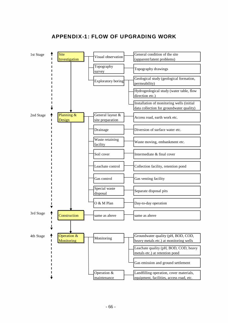
- 66 -
APPENDIX-1: FLOW OF UPGRADING WORK
1st Stage Site
Investigation Visual observation General condition of the site(apparent/latent problems)
Topographysurvey Topography drawings
Exploratory boring Geological study (geological formation,permeability)
Hydrogeological study (water table, flowdirection etc.)
Installation of monitoring wells (initialdata collection for groundwater quality)
2nd Stage Planning &Design
General layout &site preparation Access road, earth work etc.
Drainage Diversion of surface water etc.
Waste retainingfacility
Waste moving, embankment etc.
Soil cover Intermediate & final cover
Leachate control Collection facility, retention pond
Gas control Gas venting facility
Special wastedisposal Separate disposal pits
O & M Plan Day-to-day operation
3rd Stage Construction same as above same as above
4th Stage Operation &Monitoring Monitoring Groundwater quality (pH, BOD, COD,
heavy metals etc.) at monitoring wells
Leachate quality (pH, BOD, COD, heavymetals etc.) at retention pond
Gas emission and ground settlement
Operation &maintenance
Landfilling operation, cover materials,equipment, facilities, access road, etc.

- 67 -
APPENDIX-2: REVIEW OF LANDFILL METHODS
Improvement of Improvement of Waste Disposal System Waste Disposal System
using Semiusing Semi--aerobic aerobic Landfill MethodLandfill Method
What is a landfill?What is a landfill?
A landfill, also known as a dump or rubbish dump (and historically as a midden), is a site for the disposal of waste materials by burial and is the oldest form of waste treatment. Historically, landfills have been the most common methods of organisedwaste disposal and remain so in many places around the world. (Wikipedia)
Role/functions of landfillsRole/functions of landfills
Provide sufficient space for disposing wasteContain the buried waste until it goes back to the nature with no environmental pollutionProduce a safe reclaimed land after closure
A sanitary landfill is an engineered means of disposing of waste. In a sanitary landfill, waste is spread in layers on a piece of property, usually on marginal or submarginalland. The objective is to spread the layers and then compact them tightly, greatly reducing the volume of the waste. The waste is then covered by soil.(source: http://www.answers.com/topic/sanitary-landfill)
Sanitary Landfill Sanitary Landfill Definition (1)Definition (1)
method of controlled disposal of refuse on land. The method was introduced in England in 1912 (where it is called controlled tipping) and involves natural fermentation brought about by microorganisms. Usually the refuse is deposited in shallow layers, compacted, and covered within 24 hours with earth or other chemically inert material to form an effective seal. Mechanical equipment such as a bulldozer is used to grade, compact, and cover the refuse. The method often is employed to reclaim otherwise useless land, i.e., to fill declivities to levels convenient for building or park and other public purposes. (source: http://www.britannica.com/EBchecked/topic/522463/sanitary-landfill)
Sanitary LandfillSanitary LandfillDefinition (2)Definition (2)
The disposal of garbage by spreading it in layers covered with soil or ashes to a depth sufficient to control rats, flies, and odors.
(source: McGraw-Hill Dictionary of Scientific & Technical Terms, 6E, Copyright © 2003 by The McGraw-Hill Companies, Inc.)
Sanitary Landfill Sanitary Landfill Definition (3)Definition (3)
1. A method of disposing garbage by spreadingit in layers covered with soil or other inert materials to control generation of vermin, vectors and odors so that any adverse environmental and health impacts will be minimized.
2. A site used for or reclaimed by such method.
Whatever the definitions are, Whatever the definitions are, sanitary landfill, in this sanitary landfill, in this book,book, is: is:
Classification of LandfillsClassification of Landfills
(By Dr. M. Hanashima, 1981)

- 68 -
Type-I: Anaerobic Landfill
(Open Dumping)
Leachate
Solid WasteSolid waste
Type-II: Anaerobic Sanitary Landfill
Leachate
Solid Waste
Type-III: Improved Anaerobic
Sanitary Landfill
Leachate
PitLeachateCollection Pipe
Solid Waste
LeachateCollection Pipe
Type-IV: Semi-aerobic Landfill
Leachate Collection System
Leachate Collection Pipe
Solid Waste
Pit forpumping
Leachate
runoff drainage
Type-V: Aerobic Landfill
Pits for pumping
Solid Waste
Blower
LeachateLeachate Collection System
runoff drainage
Air supply pipes
Advantages/disadvantagesAdvantages/disadvantages
LowHighHighV. Aerobic
LowLow to Medium
MediumIV. Semi-aerobic
MediumLow to Medium
MediumIII. Improved Anaerobic (Sanitary)
MediumLowLowII. Anaerobic (Sanitary)
HighLowLowI. Anaerobic
Negative Impact to Environment or Public Health
Maintenance Cost
Construction Cost
Type
Review ofReview ofSemiSemi--aerobic Landfill Methodaerobic Landfill Method
(Type(Type--IV)IV)
Q1: Q1: What is the SemiWhat is the Semi--aerobic aerobic
landfill system?landfill system?
A1: It is the system that utilizes an
aerobic metabolic process as much as possible to break down
solid waste at a landfill.

- 69 -
Q2: Q2:
What are the two important pipes What are the two important pipes in the semiin the semi--aerobic landfill system?aerobic landfill system?
A2:Leachate collection pipesGas venting pipes
Q3: Q3:
Why are they important?Why are they important?
A3:Because those pipes act like blood vessels that convey oxygen (air) and discharge leachate from the body (waste layers).
Q4: Q4:
What is the opposite method to What is the opposite method to aerobic method?aerobic method?
A4:Anaerobic method that works
under anaerobic condition
Q5: Q5:
What are the benefits of using the What are the benefits of using the semisemi--aerobic landfill method?aerobic landfill method?
A5:Decomposition of organic waste is a lot faster than that of anaerobic system.Quality of leachate improves.Offensive odor disappears.Generation of methane gas decreases.Life-cycle cost is less expensive.
Function of PipesFunction of Pipes
Applications of Applications of
SemiSemi--aerobic Landfill Methodaerobic Landfill Method--Failed casesFailed cases--
1.Damage or Clogging of gas venting pipes by landfill operation
2. Damage to leachate collection pipes by landfill operation
3. Clogging of leachate collection pipes
4. Submerged outlet of the leacgatecollection pipe
How can you avoid these failures?How can you avoid these failures?
Appropriate designLandfill operation manuals/procedureCareful operation at the initial stage Careful landfilling near the pipesPeriodical monitoringSwift remediationTraining for site operators/workers
Copyright © 2022 FDOKUMEN