LANDFILL GAS MANAGEMENT SYSTEM - Barton County
389
PROJECT MANUAL PHASE IV CELL CONSTRUCTION BARTON COUNTY SANITARY LANDFILL BARTON COUNTY, KANSAS SCS Project Number 27219346.01 January 2020 Prepared For: Barton County Sanitary Landfill 350 Northeast 30 th Road Great Bend, Kansas
-
Upload
khangminh22 -
Category
Documents
-
view
0 -
download
0
Transcript of LANDFILL GAS MANAGEMENT SYSTEM - Barton County

PROJECT MANUAL PHASE IV CELL CONSTRUCTION
BARTON COUNTY SANITARY LANDFILL BARTON COUNTY, KANSAS
SCS Project Number 27219346.01 January 2020
Prepared For: Barton County Sanitary Landfill
350 Northeast 30th Road Great Bend, Kansas

Barton County TOC-1
TABLE OF CONTENTS
PHASE IV CELL CONSTRUCTION BARTON COUNTY SANITARY LANDFILL
January 2020
INVITATION TO BID INSTRUCTIONS TO BIDDERS BID FORM SAMPLE BID BOND SAMPLE AGREEMENT FORM SAMPLE PERFORMANCE BOND SAMPLE PAYMENT BOND GENERAL CONDITIONS SUPPLEMENTARY CONDITIONS CONSTRUCTION QUALITY ASSURANCE (CQA) PLAN TECHNICAL SPECIFICATONS: DIVISION 1 GENERAL REQUIREMENTS
SECTION 01010 Scope of Work SECTION 01110 Measurement and Payment SECTION 01120 General Provisions and Definitions SECTION 01130 Special Provisions SECTION 01210 Unit Prices SECTION 01310 Project Management and Coordination SECTION 01320 Project Meetings SECTION 01340 Submittals SECTION 01350 Environmental Protection SECTION 01400 Quality Assurance and Control Services SECTION 01510 Temporary Facilities and Controls SECTION 01620 Security SECTION 01710 Construction Layout and Surveying SECTION 01720 Contract Closeout Procedures
DIVISION 2 SITE WORK
SECTION 02150 Site Clearing & Grubbing SECTION 02230 Granular Drainage Material SECTION 02240 Earthwork SECTION 02241 Compacted Soil Liner

Barton County TOC-2
SECTION 02250 Geotextile SECTION 02300 Geosynthetic Drainage Composite SECTION 02600 HDPE Geomembrane SECTION 02900 Seeding, Fertilizing, Mulching
DIVISION 3 THROUGH 14 NOT USED DIVISION 15 MECHANICAL
SECTION 15010 HDPE Piping SECTION 15020 PVC
DIVISION 16 AND 17 NOT USED
PHASE IV CELL CONSTRUCTION DRAWINGS

INVITATION TO BID

INVITATION TO BID Date: January 23, 2020 Re: Phase IV Cell Construction Barton County Sanitary Landfill Ladies and Gentlemen: You are invited to prepare a bid for the Phase IV Cell Construction (approximately 6.3 acres), at the Barton County Sanitary Landfill near Great Bend, Kansas. The scope of work for this project, which is described in the enclosed bid package, generally consists of earthwork and composite landfill liner installation for the Phase IV cell. The bottom liner system includes the following layers from bottom to top: 2-feet thick compacted earthen liner, 60-mil high density polyethylene liner, geosynthetic drainage composite consisting of 0.2 inch drainage net with 6.0 ounce per square yard non-woven geotextile heat bonded to both sides on side slopes and bonded on a single side on the cell bottom, and 1-foot thick sand protection / drainage layer. The project also includes installing perforated leachate collection piping, gas vents and constructing storm water run-on and run-off controls for the cell. It is expected that work for this project will be completed by October 31, 2020. Please prepare your bid in accordance with the instructions included in the Bid Package. One (1) copy of the completed Bid Package must be submitted and delivered no later than 1:30 P.M. Central Standard Time on February 28, 2020 to the following address:
Donna Zimmerman Barton County Clerk
1400 Main Street, Room 202 Great Bend, Kansas 67530
Phone (620) 793-1835 Fax (620) 793-1990
Please identify submitted Bid Package by labeling shipping packaging with the title “Phase IV Bid.” Bids received after 1:30 P.M. on the specified date will not be considered. The bids will be publicly opened at 1:30 P.M. on February 28, 2020 at the Barton County Courthouse. Upon complete review and evaluation of the submitted bids, Barton County will notify the successful bidder and issue a Notice-of-Award. Barton County reserves the right to reject any or all bids. It is the contractor’s responsibility to have read and understood all

Barton County, Kansas Phase IV Cell Construction Invitation to Bid Page 2
terms and conditions stated in this document. The successful bidder will be required to sign a contractual agreement as shown in this document. Any modifications and/or exceptions to the agreement as shown must accompany the bid response. Barton County will issue a notice to proceed after receiving the executed agreement, insurance certificates, bonds, and any other applicable documents. A mandatory pre-bid meeting will be held at 3:00 P.M. on February 13, 2020 at the Barton County Landfill, 350 NE 30th Rd, Great Bend, Kansas. A landfill site visit will occur immediately prior to the meeting at 2 P.M.. All bidders are encouraged to visit the site prior to bidding. Additional visits to the site may be coordinated by contacting Mr. Phil Hathcock, Solid Waste Manager at (620) 793-1898. Site visits must be completed at least three business days prior to the bid opening date. If you have any questions or comments concerning this project, please call Bret Clements with SCS Engineers at (913) 749-0711 or Phil Hathcock with Barton County at (620) 793-1898. Your interest in this work is appreciated, and Barton County looks forward to receiving your company’s bid.
Very truly yours, Barton County, Kansas

INSTRUCTIONS TO BIDDERS

INSTRUCTIONS TO BIDDERS
PHASE IV CELL CONSTRUCTION BARTON COUNTY SANITARTY LANDFILL
JANUARY 2020
ARTICLE 1 - DEFINED TERMS
1.01 Terms used in these Instructions to Bidders have the meanings indicated in the General Conditions and Supplementary Conditions. Additional terms used in these Instructions to Bidders have the meanings indicated below:
A. Issuing Office--The office from which the Bidding Documents are to be issued and where the bidding procedures are to be administered. The Bidding Documents are to be issued from the Engineer’s office:
SCS Engineers
8575 W 110th St., Suite 100 Overland Park, Kansas 66210
(913) 749-0711
ARTICLE 2 - COPIES OF BIDDING DOCUMENTS
2.01 One complete set of the Bidding Documents may be obtained from the Issuing Office. 2.02 Complete sets of Bidding Documents shall be used in preparing Bids; neither Owner nor Engineer assumes any responsibility for errors or misinterpretations resulting from the use of incomplete sets of Bidding Documents. 2.03 Owner and Engineer, in making copies of Bidding Documents available on the above terms, do so only for the purpose of obtaining Bids for the Work and do not confer a license or grant for any other use.
ARTICLE 3 - QUALIFICATIONS OF BIDDERS
3.01 To demonstrate Bidder’s qualifications to perform the Work, within five days of Owner’s request, Bidder shall submit written evidence such as financial data, previous experience, present commitments, and such other data as may be called for by the Owner to assess the Bidder’s qualifications to perform the Work. 3.02 Bidder, acting as General Contractor, shall have previous experience installing low permeability soil liner systems to specifications requiring hydraulic conductivity of 1 x 10⁻⁷ centimeters per second (cm/sec) or less; use of equipment designed to kneed and remold clay soils; and adjusting in-place soil moisture content of soil obtained from the borrow source or after soil is placed, as needed, to adhere to project moisture and density specifications. Bidder shall have successfully completed construction of at least two composite liner systems (Subtitle D landfill or wastewater lagoon). Along with Form C: Statement of Bidders Qualifications list a minimum of at least two recently completed composite liner construction projects including the following information: Project Name, Owner, Project Description, Location, Contract Value, Completion Date, Contact Phone Number. 3.03 The manufacturer of the HDPE liner material shall have at least five (5) years of continuous experience in manufacturing of polyethylene geomembrane and/or experience totaling 10,000,000 square feet of manufactured polyethylene geomembrane. The material must meet all requirements contained within Section 02600 of the Technical Specifications. The Bidder shall provide the following written information as part of the Bid:
A. A certificate from the manufacturer confirming that the manufacturer has at least five (5) years of continuous experience in the manufacture of polyethylene geomembrane materials and has manufactured at least 10,000,000 square feet of such material during that period.
3.04 The installation contractor shall be the manufacturer or an approved installer trained to install the manufacturer’s geomembrane. The Installer shall perform the installation under the constant direction of a field installation supervisor who shall remain on site and be responsible, throughout the liner installation, for liner layout,

seaming, testing, repairs, and all other activities. The field Installation supervisor shall have installed or supervised the installation of a minimum of 2,000,000 square feet of polyethylene geomembrane. Seaming shall be performed under the direction of a master seamer who has seamed a minimum of 2,000,000 square feet of polyethylene geomembrane, using the same type of seaming apparatus specified for this project. The field supervisor and/or master seamer shall be present whenever seaming is performed. The Bidder shall provide the following written information as part of the Bid:
A. A list of completed facilities, totaling a minimum of 2,000,000 square feet for which the installer has installed polyethylene geomembrane. For each installation, the following information shall be provided:
• Name and purpose of facility, location, and date of installation. • Name of owner, design engineer, manufacturer, and name and telephone number of contact at the
facility who can discuss the project. • Thickness and quantity of the installed geomembrane.
B. Resume of the field installation supervisor and master seamer confirming that each has supervised the
installation of and/or seamed a minimum of 2,000,000 square feet of polethylene geomembrane liner.
ARTICLE 4 - EXAMINATION OF BIDDING DOCUMENTS, OTHER RELATED DATA, AND SITE 4.01 Subsurface and Physical Conditions
A. The Supplementary Conditions identify:
1. Those reports of explorations and tests of subsurface conditions at or contiguous to the Site that Engineer has used in preparing the Bidding Documents.
B. Copies of reports and drawings referenced in Paragraph 4.01.A will be made available by Owner to any Bidder on request. Those reports and drawings are not part of the Contract Documents, but the “technical data” contained therein upon which Bidder is entitled to rely as provided in Paragraph 4.02 of the General Conditions has been identified and established in Paragraph 4.02 of the Supplementary Conditions. Bidder is responsible for any interpretation or conclusion Bidder draws from any “technical data” or any other data, interpretations, opinions or information contained in such reports or shown or indicated in such drawings. 4.02 Underground Facilities A. Information and data shown or indicated in the Bidding Documents with respect to existing Underground Facilities at or contiguous to the Site is based upon information and data furnished to Owner and Engineer by owners of such Underground Facilities, including Owner, or others. 4.03 Provisions concerning responsibilities for the adequacy of data furnished to prospective Bidders with respect to subsurface conditions, other physical conditions and Underground Facilities, and possible changes in the Bidding Documents due to differing or unanticipated conditions appear in Paragraphs 4.02, 4.03, and 4.04 of the General Conditions. Provisions concerning responsibilities for the adequacy of data furnished to prospective Bidders with respect to a Hazardous Environmental Condition at the Site, if any, and possible changes in the Contract Documents due to any Hazardous Environmental Condition uncovered or revealed at the Site which was not shown or indicated in the Drawings or Specifications or identified in the Contract Documents to be within the scope of the Work appear in Paragraph 4.06 of the General Conditions. 4.04 On request, Owner will provide Bidder access to the Site to conduct such examinations, investigations, explorations, tests, and studies as Bidder deems necessary for submission of a Bid. Bidder shall fill all holes and clean up and restore the Site to its former condition upon completion of such explorations, investigations, tests, and studies. Bidder shall comply with all applicable Laws and Regulations relative to excavation and utility locates. 4.05 It is the responsibility of each Bidder before submitting a Bid to: A. examine and carefully study the Bidding Documents, the other related data identified in the Bidding Documents, and any Addenda;

B. visit the Site and become familiar with and satisfy Bidder as to the general, local, and Site conditions that may affect cost, progress, and performance of the Work; C. become familiar with and satisfy Bidder as to all federal, state, and local Laws and Regulations that may affect cost, progress, and performance of the Work; D. carefully study all: (1) reports of explorations and tests of subsurface conditions at or contiguous to the Site and all drawings of physical conditions in or relating to existing surface or subsurface structures at or contiguous to the Site (except Underground Facilities) which have been identified in the Supplementary Conditions as provided in Paragraph 4.02 of the General Conditions, and (2) reports and drawings of Hazardous Environmental Conditions at the Site which have been identified in the Supplementary Conditions as provided in Paragraph 4.06 of the General Conditions; E. obtain and carefully study (or accept consequences of not doing so) all additional or supplementary examinations, investigations, explorations, tests, studies, and data concerning conditions (surface, subsurface, and Underground Facilities) at or contiguous to the Site which may affect cost, progress, or performance of the Work or which relate to any aspect of the means, methods, techniques, sequences, and procedures of construction to be employed by Bidder, including applying any specific means, methods, techniques, sequences, and procedures of construction expressly required by the Bidding Documents, and safety precautions and programs incident thereto; F. agree at the time of submitting its Bid that no further examinations, investigations, explorations, tests, studies, or data are necessary for the determination of its Bid for performance of the Work at the price(s) bid and within the times and in accordance with the other terms and conditions of the Bidding Documents; G. become aware of the general nature of the work to be performed by Owner and others at the Site that relates to the Work as indicated in the Bidding Documents; H. correlate the information known to Bidder, information and observations obtained from visits to the Site, reports and drawings identified in the Bidding Documents, and all additional examinations, investigations, explorations, tests, studies, and data with the Bidding Documents; I. promptly give Engineer written notice of all conflicts, errors, ambiguities, or discrepancies that Bidder discovers in the Bidding Documents and confirm that the written resolution thereof by Engineer is acceptable to Bidder; and J. determine that the Bidding Documents are generally sufficient to indicate and convey understanding of all terms and conditions for the performance of the Work. 4.06 The submission of a Bid will constitute an incontrovertible representation by Bidder that Bidder has complied with every requirement of this Article 4, that without exception the Bid is premised upon performing and furnishing the Work required by the Bidding Documents and applying any specific means, methods, techniques, sequences, and procedures of construction that may be shown or indicated or expressly required by the Bidding Documents, that Bidder has given Engineer written notice of all conflicts, errors, ambiguities, and discrepancies that Bidder has discovered in the Bidding Documents and the written resolutions thereof by Engineer are acceptable to Bidder, and that the Bidding Documents are generally sufficient to indicate and convey understanding of all terms and conditions for performing and furnishing the Work.
ARTICLE 5 - PRE-BID CONFERENCE 5.01 A mandatory pre-bid conference will be held on February 13, 2020 at 3:00 p.m. local time at the Barton County Courthouse. Representatives of Owner and Engineer will be present to discuss the Project. Bidders are required to attend and participate in the conference. Engineer will transmit to all prospective Bidders of record such Addenda as Engineer considers necessary in response to questions arising at the conference. Oral statements may not be relied upon and will not be binding or legally effective.

ARTICLE 6 - SITE AND OTHER AREAS
6.01 The Site is identified in the Bidding Documents. Easements for permanent structures or permanent changes in existing facilities are to be obtained and paid for by Owner unless otherwise provided in the Bidding Documents. All additional lands and access thereto required for temporary construction facilities, construction equipment, or storage of materials and equipment to be incorporated in the Work are to be obtained and paid for by Contractor. 6.02 Soil materials to be used to complete the Phase IV Cell are located on-site and have been pre-qualified for their use in specific portions of the project. Soil materials to be used in the construction of the cell subgrade and 24-inch low permeability liner will be obtained from specific on-site stockpiles, or the cell excavation, as depicted on the project plans and/or as directed by the Engineer. To prevent unnecessary stockpiling and multiple handling of soil materials the sequencing of project construction must be well planned and closely monitored. Rock has not been encountered in previous cell construction or in any of the numerous on-site groundwater wells that have been drilled to depths exceeding 70 feet below ground surface. Rock is not expected to be encountered during this project. 6.03 A pond located directly north of the landfill on Barton County property may be used for construction purposes. However, no guarantee as to the quantity or existence of water in the pond is made. If water is available in the pond, it may be used by the contractor for this project in accordance with the Owner’s constraints. Any repairs necessary to return temporary haul roads or fencing to their original condition are the responsibility of the Contractor at no additional cost to the Owner. Historically, contractors have obtained potable water from the Barton County Community College located west of the landfill on NE 30 Road. Typically, irrigation pipe is laid in the ditch along NE 30 Road to transport water to the job site.
ARTICLE 7 - INTERPRETATIONS AND ADDENDA 7.01 All questions about the meaning or intent of the Bidding Documents are to be submitted to Engineer in writing. Interpretations or clarifications considered necessary by Engineer in response to such questions will be issued by Addenda mailed or delivered to all parties recorded by Engineer as having received the Bidding Documents. Questions received less than ten days prior to the date for opening of Bids may not be answered. Only questions answered by Addenda will be binding. Oral and other interpretations or clarifications will be without legal effect. 7.02 Addenda may be issued to clarify, correct, or change the Bidding Documents as deemed advisable by Owner or Engineer.
ARTICLE 8 - BID SECURITY 8.01 A Bid must be accompanied by Bid security made payable to Owner in an amount of 5% percent of Bidder’s maximum Bid price and in the form of a certified check or bank money order or a Bid bond (on the form attached) issued by a surety meeting the requirements of Paragraphs 5.01 and 5.02 of the General Conditions. 8.02 The Bid security of the Successful Bidder will be retained until such Bidder has executed the Contract Documents, furnished the required contract security and met the other conditions of the Notice of Award, whereupon the Bid security will be returned. If the Successful Bidder fails to execute and deliver the Contract Documents and furnish the required contract security within 15 days after the Notice of Award, Owner may annul the Notice of Award and the Bid security of that Bidder will be forfeited. The Bid security of other Bidders whom Owner believes to have a reasonable chance of receiving the award may be retained by Owner until the earlier of seven days after the Effective Date of the Agreement or 61 days after the Bid opening, whereupon Bid security furnished by such Bidders will be returned. 8.03 Bid security of other Bidders whom Owner believes do not have a reasonable chance of receiving the award will be returned within seven days after the Bid opening.

ARTICLE 9 - CONTRACT TIMES
9.01 The number of days within which, or the dates by which the Work is to be substantially completed and ready for final payment are set forth in the Agreement.
ARTICLE 10 - LIQUIDATED DAMAGES 10.01 Provisions for liquidated damages are set forth in the Agreement.
ARTICLE 11 - SUBSTITUTE AND “OR-EQUAL” ITEMS 11.01 The Contract, if awarded, will be on the basis of materials and equipment specified or described in the Bidding Documents without consideration of possible substitute or “or-equal” items. Whenever it is specified or described in the Bidding Documents that a substitute or “or-equal” item of material or equipment may be furnished or used by Contractor if acceptable to Engineer, application for such acceptance will not be considered by Engineer until after the Effective Date of the Agreement.
ARTICLE 12 - SUBCONTRACTORS, SUPPLIERS, AND OTHERS 12.01 The names, addresses, telephone numbers, and proposed work items and amount of all subcontractors the bidder expects to use in performing the work under this proposal shall be furnished with the bid proposal. If no subcontractors are expected to be used, a statement to that effect must accompany bid. After the bid opening, the successful bidder may not substitute any of the subcontractors identified in the bid, except with the approval of the Owner and for good cause shown. The availability of another subcontractor at a lower cost to the general contractor after the general contractor’s bid has been accepted by the Owner shall not constitute good cause for such substitution. If Owner or Engineer, after due investigation, has reasonable objection to any proposed Subcontractor, Supplier, individual, or entity, Owner may, before the Notice of Award is given, request apparent Successful Bidder to submit a substitute without an increase in the Bid. 12.02 If apparent Successful Bidder declines to make any such substitution, Owner may award the Contract to the next lowest Bidder that proposes to use acceptable Subcontractors, Suppliers, individuals, or entities. Declining to make requested substitutions will not constitute grounds for forfeiture of the Bid security of any Bidder. Any Subcontractor, Supplier, individual, or entity so listed and against which Owner or Engineer makes no written objection prior to the giving of the Notice of Award will be deemed acceptable to Owner and Engineer subject to revocation of such acceptance after the Effective Date of the Agreement as provided in Paragraph 6.06 of the General Conditions. 12.03 Contractor shall not be required to employ any Subcontractor, Supplier, individual, or entity against whom Contractor has reasonable objection.
ARTICLE 13 - PREPARATION OF BID 13.01 The Bid Form is included with the Bidding Documents. Additional copies may be obtained from the Owner. 13.02 All blanks on the Bid Form shall be completed by printing in ink or by typewriter and the Bid signed in ink. Erasures or alterations shall be initialed in ink by the person signing the Bid Form. A Bid price shall be indicated for each Bid item listed therein, or the words “No Bid,” “No Change,” or “Not Applicable” entered.
13.03 A Bid by a corporation shall be executed in the corporate name by the president or a vice-president or other corporate officer accompanied by evidence of authority to sign. The corporate seal shall be affixed and attested by the secretary or an assistant secretary. The corporate address and state of incorporation shall be shown below the signature.
13.04 A Bid by a partnership shall be executed in the partnership name and signed by a partner (whose title must appear under the signature), accompanied by evidence of authority to sign. The official address of the partnership shall be shown below the signature. 13.05 A Bid by a limited liability company shall be executed in the name of the firm by a member and accompanied by evidence of authority to sign. The state of formation of the firm and the official address of the firm shall be shown below the signature. 13.06 A Bid by an individual shall show the Bidder’s name and official address. 13.07 A Bid by a joint venture shall be executed by each joint venturer in the manner indicated on the Bid Form. The official address of the joint venture shall be shown below the signature. 13.08 All names shall be typed or printed in ink below the signatures. 13.09 The Bid shall contain an acknowledgment of receipt of all Addenda, the numbers of which shall be filled in on the Bid Form. 13.10 The address and telephone number for communications regarding the Bid shall be shown. 13.11 The Bid shall contain evidence of Bidder’s authority and qualification to do business in the state where the Project is located or covenant to obtain such qualification prior to award of the Contract. Bidder’s state contractor license number, if any, shall also be shown on the Bid Form. 13.12 Items required to be submitted with bid:
1. Bid Form 2. Form A: List of Proposed Subcontractors and Vendors 3. Form B: Construction Plant and Equipment List 4. Form C: Statement of Bidders Qualifications 5. Bid security payable to Barton County, Kansas in an amount of five (5) percent of Bidder’s maximum Bid
Price. See attached Sample Bid Bond form. 13.13 Items required to be submitted for award of contract:
1. Signed Agreement 2. Insurance Certificates 3. Performance Bond 4. Payment Bond
ARTICLE 14 - BASIS OF BID; COMPARISON OF BIDS
14.01 Unit Price A. Bidders shall submit a Bid on a unit price basis for each item of Work listed in the Bid schedule. B. The total of all estimated prices will be the sum of the products of the estimated quantity of each item and the corresponding unit price. The final quantities and Contract Price will be determined in accordance with Paragraph 11.03 of the General Conditions. C. Discrepancies between the multiplication of units of Work and unit prices will be resolved in favor of the unit prices. Discrepancies between the indicated sum of any column of figures and the correct sum thereof will be resolved in favor of the correct sum. Discrepancies between words and figures will be resolved in favor of the words. 14.02 The Bid price shall include such amounts as the Bidder deems proper for overhead and profit on account of cash allowances, if any, named in the Contract Documents as provided in Paragraph 11.02 of the General Conditions. 14.03 Bid prices will be compared after adjusting for differences in the time designated by Bidders for Substantial Completion. The adjusting amount will be determined at the rate set forth in the Contract Documents for liquidated damages for failing to achieve Substantial Completion for each day before or after the desired date appearing in Article 9.

ARTICLE 15 - SUBMITTAL OF BID
15.01 A Bid shall be submitted no later than the date and time prescribed and at the place indicated in the Invitation to Bid and shall be enclosed in an opaque sealed envelope plainly marked with the Project title , the name and address of Bidder, and shall be accompanied by other required documents. If a Bid is sent by mail or other delivery system, the sealed envelope containing the Bid shall be enclosed in a separate envelope plainly marked on the outside with the notation “BID ENCLOSED.” A mailed Bid shall be addressed to:
Donna Zimmerman Barton County Clerk
1400 Main Street, Room 202 Great Bend, Kansas 67530
Phone (620) 793-1835 Fax (620) 793-1990
ARTICLE 16 - MODIFICATION AND WITHDRAWAL OF BID 16.01 A Bid may be modified or withdrawn by an appropriate document duly executed in the manner that a Bid must be executed and delivered to the place where Bids are to be submitted prior to the date and time for the opening of Bids. 16.02 If within 24 hours after Bids are opened, any Bidder files a duly signed written notice with Owner and promptly thereafter demonstrates to the reasonable satisfaction of Owner that there was a material and substantial mistake in the preparation of its Bid, that Bidder may withdraw its Bid, and the Bid security will be returned. Thereafter, if the Work is rebid, that Bidder will be disqualified from further bidding on the Work.
ARTICLE 17 - OPENING OF BIDS 17.01 Bids will be opened at the time and place indicated in the Advertisement or Invitation to Bid and, unless obviously non-responsive, read aloud publicly. An abstract of the amounts of the base Bids and major alternates, if any, will be made available to Bidders after the opening of Bids.
ARTICLE 18 - BIDS TO REMAIN SUBJECT TO ACCEPTANCE 18.01 All Bids will remain subject to acceptance for the period of time stated in the Bid Form, but Owner may, in its sole discretion, release any Bid prior to the end of this period.
ARTICLE 19 – EVALUATION OF BIDS AND AWARD OF CONTRACT 19.01 Owner reserves the right to reject any or all Bids, including without limitation, nonconforming, nonresponsive, unbalanced, or conditional Bids. Owner further reserves the right to reject the Bid of any Bidder whom it finds, after reasonable inquiry and evaluation, to not be responsible. Owner may also reject the Bid of any Bidder if Owner believes that it would not be in the best interest of the Project to make an award to that Bidder. Owner also reserves the right to waive all informalities not involving price, time, or changes in the Work and to negotiate contract terms with the Successful Bidder. 19.02 More than one Bid for the same Work from an individual or entity under the same or different names will not be considered. Reasonable grounds for believing that any Bidder has an interest in more than one Bid for the Work may be cause for disqualification of that Bidder and the rejection of all Bids in which that Bidder has an interest. 19.03 In evaluating Bids, Owner will consider whether or not the Bids comply with the prescribed requirements, and such alternates, unit prices and other data, as may be requested in the Bid Form or prior to the Notice of Award.
19.04 In evaluating Bidders, Owner will consider the qualifications of Bidders and may consider the qualifications and experience of Subcontractors, Suppliers, and other individuals or entities proposed for those portions of the Work for which the identity of Subcontractors, Suppliers, and other individuals or entities must be submitted as provided in the Supplementary Conditions. 19.05 Owner may conduct such investigations as Owner deems necessary to establish the responsibility, qualifications, and financial ability of Bidders, proposed Subcontractors, Suppliers, individuals, or entities to perform the Work in accordance with the Contract Documents. 19.06 If the Contract is to be awarded, Owner will award the Contract to the Bidder whose Bid is in the best interests of the Project.
ARTICLE 20 - INSURANCE 20.01 Article 5 of the General Conditions, as modified by the Supplementary Conditions, sets forth Owner’s requirements as to insurance. When the Successful Bidder delivers the executed Agreement to Owner, it shall be accompanied by such insurance certificates. 20.02 The successful bidder shall deliver to Barton County no later than fifteen (15) days after award of Contract, but in any event prior to execution of the Contract by Barton County and prior to commencing work on the site, certificates of insurance attesting to the fact that the policies of insurance required elsewhere in the Contract Documents have been obtained.
ARTICLE 21 - SIGNING OF AGREEMENT 21.01 When Owner gives a Notice of Award to the Successful Bidder, it shall be accompanied by the required number of unsigned counterparts of the Agreement with the other Contract Documents which are identified in the Agreement as attached thereto. Within 15 days thereafter, Successful Bidder shall sign and deliver the required number of counterparts of the Agreement and attached documents to Owner. Within ten days thereafter, Owner shall deliver one fully signed counterpart to Successful Bidder with a complete set of the Drawings with appropriate identification.
ARTICLE 22 - SALES AND USE TAXES 22.01 Owner is exempt from Kansas state sales and use taxes on materials and equipment to be incorporated in the Work. The Exemption number will be provided after awarding the contract. Said taxes shall not be included in the Bid.

BID FORM

BID FORM
PHASE IV CELL CONSTRUCTION BARTON COUNTY SANITARY LANDFILL
TABLE OF ARTICLES
Article Article No.
Bid Recipient ............................................................................................................................................... 1
Bidder's Acknowledgements ........................................................................................................................ 2
Bidder's Representations .............................................................................................................................. 3
Further Representations ............................................................................................................................... 4
Basis of Bid .................................................................................................................................................. 5
Time of Completion ..................................................................................................................................... 6
Attachments to this Bid ............................................................................................................................... 7
Defined Terms ............................................................................................................................................. 8
Bid Submittal ............................................................................................................................................... 9

ARTICLE 1 – BID RECIPIENT
1.01 This Bid is submitted to:
Barton County Clerk 1400 Main Street, Room 202 Great Bend, Kansas 67530
2.01 The undersigned Bidder proposes and agrees, if this Bid is accepted, to enter into an Agreement with Owner in the form included in the Bidding Documents to perform all Work as specified or indicated in the Bidding Documents for the prices and within the times indicated in this Bid and in accordance with the other terms and conditions of the Bidding Documents.
ARTICLE 2 – BIDDER'S ACKNOWLEDGEMENTS
3.01 Bidder accepts all of the terms and conditions of the Instructions to Bidders, including without limitation those dealing with the disposition of Bid security. This Bid will remain subject to acceptance for 60 days after the Bid opening, or for such longer period of time that Bidder may agree to in writing upon request of Owner.
ARTICLE 3 – BIDDER'S REPRESENTATIONS
4.01 In submitting this Bid, Bidder represents that:
A. Bidder has examined and carefully studied the Bidding Documents, the other related data identified in the Bidding Documents, and the following Addenda, receipt of which is hereby acknowledged.
Addendum No. Addendum Date
B. Bidder has visited the Site and become familiar with and is satisfied as to the general, local and Site conditions that may affect cost, progress, and performance of the Work.
C. Bidder is familiar with and is satisfied as to all federal, state and local Laws and Regulations that may affect cost, progress and performance of the Work.
D. Bidder has carefully studied all: (1) reports of explorations and tests of subsurface conditions at or contiguous to the Site and all drawings of physical conditions in or relating to existing surface or subsurface structures at or contiguous to the Site (except Underground Facilities) which have been identified in SC-4.02.
E. Bidder has obtained and carefully studied (or accepts the consequences for not doing so) all additional or supplementary examinations, investigations, explorations, tests, studies and data concerning conditions (surface, subsurface and Underground Facilities) at or contiguous to the Site which may affect cost, progress, or performance of the Work or which relate to any aspect of the means, methods, techniques, sequences, and procedures of construction to be employed by Bidder, including applying the specific means, methods, techniques, sequences, and procedures of construction expressly required by the Bidding Documents to be employed by Bidder, and safety precautions and programs incident thereto.

F. Bidder does not consider that any further examinations, investigations, explorations, tests, studies, or data are necessary for the determination of this Bid for performance of the Work at the price(s) bid and within the times and in accordance with the other terms and conditions of the Bidding Documents.
G. Bidder is aware of the general nature of work to be performed by Owner and others at the Site that relates to the Work as indicated in the Bidding Documents.
H. Bidder has correlated the information known to Bidder, information and observations obtained from visits to the Site, reports and drawings identified in the Bidding Documents, and all additional examinations, investigations, explorations, tests, studies, and data with the Bidding Documents.
I. Bidder has given Engineer written notice of all conflicts, errors, ambiguities, or discrepancies that Bidder has discovered in the Bidding Documents, and the written resolution thereof by Engineer is acceptable to Bidder.
J. The Bidding Documents are generally sufficient to indicate and convey understanding of all terms and conditions for the performance of the Work for which this Bid is submitted.
K. Bidder will submit written evidence of its authority to do business in the state where the Project is located not later than the date of its execution of the Agreement.
ARTICLE 4 – FURTHER REPRESENTATIONS
5.01 Bidder further represents that:
A. this Bid is genuine and not made in the interest of or on behalf of any undisclosed individual or entity and is not submitted in conformity with any agreement or rules of any group, association, organization or corporation;
B. Bidder has not directly or indirectly induced or solicited any other Bidder to submit a false or sham Bid;
C. Bidder has not solicited or induced any individual or entity to refrain from bidding; and
D. Bidder has not sought by collusion to obtain for itself any advantage over any other Bidder or over Owner.
ARTICLE 5 – BASIS OF BID
6.01 Bidder will complete the Work in accordance with the Contract Documents for the following price(s):

Barton County SCS Engineers
Item No. Item Description
Estimated Subtotal
1 Mobilization / Demobilization 1 LS /LS
2 Excavate Soil to Subgrade Elevations 73,700 CY /CY
3 Compacted Fill 160 CY /CY
4 Construct 2-foot Thick Compacted Soil Liner 272,360 SF /SF
5 Excavate and Backfill Anchor Trench 630 LF /LF
6 Provide and Install 60 mil Textured Geomembrane 61,265 SF /SF
7 Provide and Install 60 mil Smooth Geomembrane 211,095 SF /SF
8 Provide and Install Double Sided Geocomposite 61,265 SF /SF
9 Provide and Install Single Sided Geocomposite 211,095 SF /SF
10Provide and Install Leachate Collection Piping and Drainage Gravel 445 LF /LF
11 Install 12-inch Thick Sand Drainage Layer 272,360 SF /SF
12 Provide and Install Perimeter Gas Vents 2 EA /EA
13Provide and Install Temporary Storm Water Diversion Berm 1,495 LF /LF
14 Provide and Install Temporary Liner Termination Berm 865 LF /LF
15 Seeding and Mulching 8 AC /AC
Total- -
Notes:1.
2.
3. All quantities are based on the engineer's estimate; it is the contractor's responsibility to verify all quantities prior to bidding.
BID FORMBarton County Sanitary Landfill
Phase IV Construction
Estimated Quantity Unit Price
This worksheet is used to make your cost proposal. Where quantities are not given, CONTRACTORS shall calculate their own. Geomembrane and geocomposite include material to construct the cell within the Cell limits. These estimates do not include any allowance for terminatino berm, storm water diversion berm, anchor trench, waste or material overlapped in seams.

Unit Prices have been computed in accordance with Paragraph 11.03.B of the General Conditions.
Bidder acknowledges that estimated quantities are not guaranteed, and are solely for the purpose of comparison of Bids, and final payment for all Unit Price Bid items will be based on actual quantities, determined as provided in the Contract Documents.
ARTICLE 6 – TIME OF COMPLETION
7.01 Bidder agrees that the Work will be substantially complete within 60 calendar days after the date when the
Contract Times commence to run as provided in Paragraph 2.03 of the General Conditions, and will be completed and ready for final payment in accordance with Paragraph 14.07.B of the General Conditions within 90 calendar days after the date when the Contract Times commence to run.
7.02 Bidder accepts the provisions of the Agreement as to liquidated damages in the event of failure to complete the Work within the Contract Times.
ARTICLE 7 – ATTACHMENTS TO THIS BID
8.01 The following documents are attached to and made a condition of this Bid:
A. List of Proposed Subcontractors and Vendors
B. Construction Plant and Equipment List
C. Required Bidder Qualification Statement with Supporting Data
ARTICLE 8 – BID SUBMITTAL
9.01 This Bid submitted by:
Corporation Name: State of Incorporation:
Type (General Business, Professional, Service, Limited Liability): By: (Signature -- attach evidence of authority to sign) Name (typed or printed): Title: Attest: (CORPORATE SEAL) Date of Authorization to do business in Kansas is / / .

CONTRACTOR:______________________________________
FORM A. LIST OF PROPOSED SUBCONTRACTORS AND VENDORS
Bidder proposes to employ the following subcontractors in performance of the work, as well as vendors who will furnish major components, materials and equipment. If no subcontractors or purchases are anticipated, then the word “None” will so indicate.
Name & Address of Subcontractor or Vendor
Description of Work to be Subcontracted or Items Purchased
Percentage of Total Value of Work to be Subcontracted (%)______________________

CONTRACTOR:______________________________________
FORM B. CONSTRUCTION PLANT AND EQUIPMENT LIST
Contractor shall submit a complete list of construction plant and equipment to be used on the site, providing the information requested below. The maintained hourly rental rates shall include all maintenance and fuel, and shall be used for changes and extra work where Lump Sum Prices do not apply. EQUIPMENT TYPE
QTY ON SITE
DATE SCHEDULED ON SITE
MAINTAINED HOURLY RATE* W/O OPERATOR
MAINTAINED HOURLY RATE* W/ OPERATOR

CONTRACTOR:______________________________________
FORM C. STATEMENT OF BIDDER’S QUALIFICATIONS All questions must be answered and the data given must be clear and comprehensive. This statement must be notarized. If necessary, questions may be answered on separate attached sheets. The bidder may submit any additional information he so desires. 1. Name of bidder________________________________________________________________ 2. Permanent main office address____________________________________________________ 3. When organized________________________________________________________________ 4. If a corporation, where incorporated_________________________________________________ 5. How many years have you been engaged in construction under your present firm name or trade
name?________________________________________________________________________ 6. General character of work performed by you__________________________________________ 7. List the more important contracts recently completed by you, stating approximate gross cost for each, and
the month and year completed_____________________________________________________________________ _____________________________________________________________________________
8. Contracts on hand: (Schedule these, showing gross amount of each contract and the respective anticipated
dates of completion.)___________________________________________________ _____________________________________________________________________________
9. Have you ever failed to complete any work awarded to you? If so, where and why?__________
_____________________________________________________________________________ 10. Have you ever been put on liquidated damages on any contract awarded to you? If so, where and
why?_________________________________________________________________________ 11. Have you ever defaulted on a contract? If so, where and why?___________________________
_____________________________________________________________________________ 12. Has your firm ever engaged in litigation for the settlement of claims or disputes arising out of a construction
contract? If so, give particulars._________________________________________ _____________________________________________________________________________
13. List your major equipment available for Public Works Projects___________________________
_____________________________________________________________________________ 14. To what extent would you expect to employ subcontractors?_____________________________
_____________________________________________________________________________ 15. Experience in construction work similar in importance to Public Works Projects_______________
_____________________________________________________________________________
16. Background and experience for the principal members of your organization, including the officers_______________________________________________________________________
17. Give bank reference_____________________________________________________________

18. Will you, upon request, fill out a detailed financial statement and furnish any other information that may be required by Barton County? _____________________________________________________________________________
19. The undersigned hereby authorizes and requests any person, firm, or corporation to furnish any information
requested by Barton County in verification of the recitals comprising this Statement of Bidder’s Qualifications.
Dated at________________________________ this___________day of ________________, 20______ ______________________________________ Name of Bidder By____________________________________ Title___________________________________ State of _________________________) ) SS County of________________________) ______________________________________________, being duly sworn, deposes and says that he is _________________________________________________________________________________ of (TITLE) ____________________________________________________________________________________ and that the answers to the foregoing questions and all statements therein contained are true and correct. Subscribed and sworn to before me this __________________ day of _____________________, 20___. ________________________________ Notary Public My commission expires:_____________________________ *Includes fuel, lubricants, repair parts and service, maintenance labor, applicable taxes, overhead and profit.

SAMPLE BID BOND

SAMPLE BID BOND
Any singular reference to Bidder, Surety, Owner, or other party shall be considered plural where applicable.
BIDDER (Name and Address): SURETY (Name and Address of Principal Place of Business): OWNER (Name and Address):
Barton County, Kansas 1400 Main Street Great Bend, Kansas 67530
BID Bid Due Date: Project (Brief Description Including Location): BOND Bond Number: Date (Not later than Bid due date):
Penal sum (Words) (Figures) Surety and Bidder, intending to be legally bound hereby, subject to the terms printed on the reverse side hereof, do each cause this Bid Bond to be duly executed on its behalf by its authorized officer, agent, or representative. BIDDER SURETY
(Seal) (Seal) Bidder's Name and Corporate Seal Surety’s Name and Corporate Seal By: By: Signature and Title Signature and Title
(Attach Power of Attorney)
Attest: Attest: Signature and Title Signature and Title Note: Above addresses are to be used for giving required notice.

1. Bidder and Surety, jointly and severally, bind themselves, their heirs, executors, administrators, successors and assigns to pay to Owner upon default of Bidder the penal sum set forth on the face of this Bond. Payment of the penal sum is the extent of Surety’s liability. 2. Default of Bidder shall occur upon the failure of Bidder to deliver within the time required by the Bidding Documents (or any extension thereof agreed to in writing by Owner) the executed Agreement required by the Bidding Documents and any performance and payment bonds required by the Bidding Documents. 3. This obligation shall be null and void if:
3.1. Owner accepts Bidder's Bid and Bidder delivers within the time required by the Bidding Documents (or any extension thereof agreed to in writing by Owner) the executed Agreement required by the Bidding Documents and any performance and payment bonds required by the Bidding Documents, or
3.2. All Bids are rejected by Owner, or 3.3. Owner fails to issue a Notice of Award to Bidder
within the time specified in the Bidding Documents (or any extension thereof agreed to in writing by Bidder and, if applicable, consented to by Surety when required by Paragraph 5 hereof).
4. Payment under this Bond will be due and payable upon default by Bidder and within 30 calendar days after receipt by Bidder and Surety of written notice of default from Owner, which notice will be given with reasonable promptness, identifying this Bond and the Project and including a statement of the amount due. 5. Surety waives notice of any and all defenses based on or arising out of any time extension to issue Notice of Award agreed to in writing by Owner and Bidder, provided that the total time for issuing Notice of Award including extensions shall not in the aggregate exceed 120 days from Bid due date without Surety's written consent. 6. No suit or action shall be commenced under this Bond prior to 30 calendar days after the notice of default required in Paragraph 4 above is received by Bidder and Surety and in no case later than one year after Bid due date.
7. Any suit or action under this Bond shall be commenced only in a court of competent jurisdiction located in the state in which the Project is located. 8. Notices required hereunder shall be in writing and sent to Bidder and Surety at their respective addresses shown on the face of this Bond. Such notices may be sent by personal delivery, commercial courier, or by United States Registered or Certified Mail, return receipt requested, postage pre-paid, and shall be deemed to be effective upon receipt by the party concerned. 9. Surety shall cause to be attached to this Bond a current and effective Power of Attorney evidencing the authority of the officer, agent, or representative who executed this Bond on behalf of Surety to execute, seal, and deliver such Bond and bind the Surety thereby. 10. This Bond is intended to conform to all applicable statutory requirements. Any applicable requirement of any applicable statute that has been omitted from this Bond shall be deemed to be included herein as if set forth at length. If any provision of this Bond conflicts with any applicable statute, then the provision of said statute shall govern and the remainder of this Bond that is not in conflict therewith shall continue in full force and effect. 11. The term "Bid" as used herein includes a Bid, offer, or proposal as applicable.

SAMPLE AGREEMENT FORM

SAMPLE AGREEMENT FORM PHASE IV CELL CONSTRUCTION
BARTON COUNTY SANITARY LANDFILL THIS AGREEMENT is by and between Barton County, Kansas (Owner) and (Contractor). Owner and Contractor, in consideration of the mutual covenants set forth herein, agree as follows: ARTICLE 1 - WORK 1.01 Contractor shall complete all Work as specified or indicated in the Contract Documents. The Work is generally described as follows: Constructing and installing erosion control measures, clearing and grubbing the site including stripping and stockpiling topsoil and clay, and excavating and placing compacted fill to achieve subgrade elevations. Constructing a landfill liner system, which includes the following layers from bottom to top: 2-feet thick compacted earthen liner, 60-mil high density polyethylene liner, geosynthetic drainage composite consisting of 0.2 inch drainage net with 6.0 ounce per square yard non-woven geotextile heat bonded to both sides on side slopes and bonded on a single side on the cell bottom, and 1-foot thick sand protection / drainage layer. The project also includes installing perforated leachate collection piping and constructing storm water run-on and run-off controls for the cell. ARTICLE 2 - THE PROJECT 2.01 The Project for which the Work under the Contract Documents may be the whole or only a part is generally described as follows: The overall project consists of constructing a 6.25 acre composite lined landfill cell. The cell consists of a liner system leachate collection system, and storm water controls. ARTICLE 3 - ENGINEER 3.01 The project was designed by SCS Engineers under contract with Barton County, Kansas the landfill Owner. ARTICLE 4 - CONTRACT TIMES 4.01 Time of the Essence
A. All time limits for Milestones, if any, Substantial Completion, and completion and readiness for final payment as stated in the Contract Documents are of the essence of the Contract. 4.02 Days to Achieve Substantial Completion and Final Payment
A. The Work will be substantially completed within 60 calendar days after the date when the Contract Times commence to run as provided in Paragraph 2.03 of the General Conditions, and completed and ready for final payment in accordance with Paragraph 14.07 of the General Conditions within 90 days after the date when the Contract Times commence to run. 4.03 Liquidated Damages
A. Contractor and Owner recognize that time is of the essence of this Agreement and that Owner will suffer financial loss if the Work is not completed within the times specified in Paragraph 4.02 above, plus any extensions thereof allowed in accordance with Article 12 of the General Conditions. The parties also recognize the delays, expense, and difficulties

involved in proving in a legal or arbitration proceeding the actual loss suffered by Owner if the Work is not completed on time. Accordingly, instead of requiring any such proof, Owner and Contractor agree that as liquidated damages for delay (but not as a penalty), Contractor shall pay Owner $1500 for each calendar day that expires after the time specified in Paragraph 4.02 for Substantial Completion until the Work is substantially complete. After Substantial Completion, if Contractor shall neglect, refuse, or fail to complete the remaining Work within the Contract Time or any proper extension thereof granted by Owner, Contractor shall pay Owner $1500 for each calendar day that expires after the time specified in Paragraph 4.02 for completion and readiness for final payment until the Work is completed and ready for final payment. ARTICLE 5 - CONTRACT PRICE 5.01 Owner shall pay Contractor for completion of the Work in accordance with the Contract Documents an amount in current funds equal to the sum of the amounts determined pursuant to Paragraphs 5.01.A, 5.01.B, and 5.01.C below:
All specific cash allowances are included in the above price and have been computed in accordance with paragraph 11.02 of the General Conditions.
A. For all Unit Price Work, an amount equal to the sum of the established unit price for each separately identified item of Unit Price Work times the estimated quantity of that item as indicated in this paragraph 5.01.B:
As provided in Paragraph 11.03 of the General Conditions, estimated quantities are not guaranteed, and determinations of actual quantities and classifications are to be made by Engineer as provided in Paragraph 9.07 of the General Conditions. Unit prices have been computed as provided in Paragraph 11.03 of the General Conditions.
UNIT PRICE WORK
Item No.
Description
Unit
Estimated Quantity
Unit Price
Estimated
TOTAL OF ALL ESTIMATED PRICES $ (words) (numerals)
ARTICLE 6 - PAYMENT PROCEDURES 6.01 Submittal and Processing of Payments
A. Contractor shall submit Applications for Payment in accordance with Article 14 of the General Conditions. Applications for Payment will be processed by Engineer as provided in the General Conditions.
B. Where the quantity of any single pay item in this Contract is an estimated quantity and where the actual quantity of
such pay item varies more than twenty percent (20%) above or below the estimated quantity stated in this Contract, an equitable adjustment in the Contract price shall be made upon demand of either party. The equitable adjustment shall be based upon any increase or decrease in costs due solely to the variation above one hundred twenty percent (120%) or below eighty percent (80%) of the estimated quantity. If the quantity variation is such as to cause an increase in the time necessary for completion, Barton County shall, upon receipt of a written request for an extension of time within 10 (ten) days from the beginning of such delay, or within such further period of time which may be granted by Barton County prior to the date of final settlement of the Contract, ascertain the facts and make such adjustment for extending the completion date as in its judgment the findings justify. 6.02 Progress Payments; Retainage
A. Owner shall make progress payments on account of the Contract Price on the basis of Contractor’s Applications for Payment within two weeks of approval during performance of the Work as provided in Paragraphs 6.02.A.1 and 6.02.A.2 below. All such payments will be measured by the schedule of values established as provided in Paragraph 2.07.A of the

General Conditions (and in the case of Unit Price Work based on the number of units completed) or, in the event there is no schedule of values, as provided in the General Requirements:
1. Prior to Substantial Completion, progress payments will be made in an amount equal to the percentage indicated below but, in each case, less the aggregate of payments previously made and less such amounts as Engineer may determine or Owner may withhold, including but not limited to liquidated damages, in accordance with Paragraph 14.02 of the General Conditions:
a. Ninety (90) percent of Work completed (with the balance being retainage).
b. Ninety (90) percent of cost of materials and equipment not incorporated in the Work (with the balance being
retainage).
2. Upon Substantial Completion, Owner shall pay an amount sufficient to increase total payments to Contractor to Ninety-five (95) percent of the Work completed (with the balance being retainage), less such amounts as Engineer shall determine in accordance with Paragraph 14.02.B.5 of the General Conditions and less Ninety-five (95) percent of Engineer’s estimate of the value of Work to be completed or corrected as shown on the tentative list of items to be completed or corrected attached to the certificate of Substantial Completion.
6.03 Final Payment
A. Upon final completion and acceptance of the Work in accordance with Paragraph 14.07 of the General Conditions, Owner shall pay the remainder of the Contract Price as recommended by Engineer as provided in said Paragraph 14.07. ARTICLE 7 - INTEREST 7.01 All moneys not paid when due as provided in Article 14 of the General Conditions shall bear interest at the rate of five (5) percent per annum. ARTICLE 8 – CONTRACTOR’S REPRESENTATIONS 8.01 In order to induce Owner to enter into this Agreement Contractor makes the following representations:
A. Contractor has examined and carefully studied the Contract Documents and the other related data identified in the Bidding Documents.
B. Contractor has visited the Site and become familiar with and is satisfied as to the general, local, and Site conditions that may affect cost, progress, and performance of the Work.
C. Contractor is familiar with and is satisfied as to all federal, state, and local Laws and Regulations that may affect cost, progress, and performance of the Work.
D. Contractor has carefully studied all: (1) reports of explorations and tests of subsurface conditions at or contiguous to the Site and all drawings of physical conditions in or relating to existing surface or subsurface structures at or contiguous to the Site (except Underground Facilities) which have been identified in the Supplementary Conditions as provided in Paragraph 4.02 of the General Conditions and (2) reports and drawings of a Hazardous Environmental Condition, if any, at the Site which has been identified in the Supplementary Conditions as provided in Paragraph 4.06 of the General Conditions.
E. Contractor has obtained and carefully studied (or assumes responsibility for doing so) all additional or supplementary examinations, investigations, explorations, tests, studies, and data concerning conditions (surface, subsurface, and Underground Facilities) at or contiguous to the Site which may affect cost, progress, or performance of the Work or which relate to any aspect of the means, methods, techniques, sequences, and procedures of construction to be employed by Contractor, including any specific means, methods, techniques, sequences, and procedures of construction expressly required by the Bidding Documents, and safety precautions and programs incident thereto.
F. Contractor does not consider that any further examinations, investigations, explorations, tests, studies, or data are necessary for the performance of the Work at the Contract Price, within the Contract Times, and in accordance with the other terms and conditions of the Contract Documents.

G. Contractor is aware of the general nature of work to be performed by Owner and others at the Site that relates to the Work as indicated in the Contract Documents.
H. Contractor has correlated the information known to Contractor, information and observations obtained from visits to the Site, reports and drawings identified in the Contract Documents, and all additional examinations, investigations, explorations, tests, studies, and data with the Contract Documents.
I. Contractor has given Engineer written notice of all conflicts, errors, ambiguities, or discrepancies that Contractor has discovered in the Contract Documents, and the written resolution thereof by Engineer is acceptable to Contractor.
J. The Contract Documents are generally sufficient to indicate and convey understanding of all terms and conditions for performance and furnishing of the Work. ARTICLE 9 - CONTRACT DOCUMENTS 9.01 Contents
A. The Contract Documents consist of the following:
1. Invitation to Bid 2. Instructions to Bidders 3. Bid Form 4. Bid Bond 5. Agreement Form 6. Performance Bond 7. Payment Bond 8. General Conditions 9. Supplementary Conditions 10. Scope of Work and Specifications as listed in the table of contents of the Project Manual 11. Construction Quality Assurance Plan 12. Drawings consisting of sheets with each sheet bearing the following general title: [or] the Drawings
listed on attached sheet index.
13. Addenda (numbers to , inclusive).
14. Exhibits to this Agreement (enumerated as follows):
a. Contractor’s Bid (pages to , inclusive).
b. Documentation submitted by Contractor prior to Notice of Award (pages to , inclusive).
11. The following which may be delivered or issued on or after the Effective Date of the Agreement and are not attached hereto:
a. Notice to Proceed (pages to , inclusive).
b. Work Change Directives.
c. Change Order(s).

B. The documents listed in Paragraph 9.01.A are attached to this Agreement (except as expressly noted otherwise above).
C. There are no Contract Documents other than those listed above in this Article 9.
D. The Contract Documents may only be amended, modified, or supplemented as provided in Paragraph 3.04 of the
General Conditions. ARTICLE 10 - MISCELLANEOUS 10.01 Terms
A. Terms used in this Agreement will have the meanings stated in the General Conditions and the Supplementary Conditions. 10.02 Assignment of Contract
A. No assignment by a party hereto of any rights under or interests in the Contract will be binding on another party hereto without the written consent of the party sought to be bound; and, specifically but without limitation, moneys that may become due and moneys that are due may not be assigned without such consent (except to the extent that the effect of this restriction may be limited by law), and unless specifically stated to the contrary in any written consent to an assignment, no assignment will release or discharge the assignor from any duty or responsibility under the Contract Documents. 10.03 Successors and Assigns
A. Owner and Contractor each binds itself, its partners, successors, assigns, and legal representatives to the other party hereto, its partners, successors, assigns, and legal representatives in respect to all covenants, agreements, and obligations contained in the Contract Documents. 10.04 Severability
A. Any provision or part of the Contract Documents held to be void or unenforceable under any Law or Regulation shall be deemed stricken, and all remaining provisions shall continue to be valid and binding upon Owner and Contractor, who agree that the Contract Documents shall be reformed to replace such stricken provision or part thereof with a valid and enforceable provision that comes as close as possible to expressing the intention of the stricken provision. 10.05 Jurisdiction
A. This agreement and every question airising hereunder shall be construed or determined according to the laws of the State of Kansas. Should any part of this agreement be adjudicated, venue shall be proper only in the District Court of Barton County, Kansas.

IN WITNESS WHEREOF, Owner and Contractor have signed this Agreement in duplicate. One counterpart each has been delivered to Owner and Contractor. All portions of the Contract Documents have been signed or identified by Owner and Contractor or on their behalf. This Agreement will be effective on , (which is the Effective Date of the Agreement). OWNER: CONTRACTOR: By: By: Title: Title:
[CORPORATE SEAL] [CORPORATE SEAL] Attest: Attest: Title: Title: Address for giving notices: Address for giving notices: License No.: (If Owner is a corporation, attach evidence of authority to sign. If Owner is a public body, attach evidence of authority to sign and resolution or other documents authorizing execution of Owner-Contractor Agreement.)
(Where applicable)
Agent for service or process: (If Contractor is a corporation or a partnership, attach evidence
of authority to sign.)

SAMPLE PERFORMANCE BOND

SAMPLE PERFORMANCE BOND
Any singular reference to Contractor, Surety, Owner, or other party shall be considered plural where applicable. CONTRACTOR (Name and Address): SURETY (Name and Address of Principal Place of Business): OWNER (Name and Address): Barton County, Kansas
Barton County, Kansas 1400 Main Street Great Bend, Kansas 67530
CONTRACT Date: Amount: Description (Name and Location): Barton County, Kansas Barton County Sanitary Landfill Phase IV Cell Construction
350 Northeast 30th Road Great Bend, Kansas 67530
BOND Bond Number: Date (Not earlier than Contract Date): Amount (Not to be less than contract amount): Modifications to this Bond Form: Surety and Contractor, intending to be legally bound hereby, subject to the terms printed on the reverse side hereof, do each cause this Performance Bond to be duly executed on its behalf by its authorized officer, agent, or representative.
CONTRACTOR AS PRINCIPAL SURETY Company: Signature: (Seal) (Seal) Name and Title: Surety’s Name and Corporate Seal By: Signature and Title (Attach Power of Attorney) (Space is provided below for signatures of additional parties, if required.)
Attest: Signature and Title CONTRACTOR AS PRINCIPAL SURETY Company: Signature: (Seal) (Seal) Name and Title: Surety’s Name and Corporate Seal By: Signature and Title (Attach Power of Attorney) Attest: Signature and Title:

1. Contractor and Surety, jointly and severally, bind themselves, their heirs, executors, administrators, successors, and assigns to Owner for the performance of the Contract, which is incorporated herein by reference. 2. If Contractor performs the Contract, Surety and Contractor have no obligation under this Bond, except to participate in conferences as provided in Paragraph 3.1. 3. If there is no Owner Default, Surety's obligation under this Bond shall arise after:
3.1. Owner has notified Contractor and Surety, at the addresses described in Paragraph 10 below, that Owner is considering declaring a Contractor Default and has requested and attempted to arrange a conference with Contractor and Surety to be held not later than 15 days after receipt of such notice to discuss methods of performing the Contract. If Owner, Contractor and Surety agree, Contractor shall be allowed a reasonable time to perform the Contract, but such an agreement shall not waive Owner's right, if any, subsequently to declare a Contractor Default; and
3.2. Owner has declared a Contractor Default and formally terminated
Contractor's right to complete the Contract. Such Contractor Default shall not be declared earlier than 20 days after Contractor and Surety have received notice as provided in Paragraph 3.1; and
3.3. Owner has agreed to pay the Balance of the Contract Price to:
1. Surety in accordance with the terms of the Contract;
2. Another contractor selected pursuant to Paragraph 4.3 to perform the
Contract. 4. When Owner has satisfied the conditions of Paragraph 3, Surety shall promptly and at Surety's expense take one of the following actions:
4.1. Arrange for Contractor, with consent of Owner, to perform and complete the Contract; or
4.2. Undertake to perform and complete the Contract itself, through its agents
or through independent contractors; or
4.3. Obtain bids or negotiated proposals from qualified contractors acceptable to Owner for a contract for performance and completion of the Contract, arrange for a contract to be prepared for execution by Owner and Contractor selected with Owner's concurrence, to be secured with performance and payment bonds executed by a qualified surety equivalent to the bonds issued on the Contract, and pay to Owner the amount of damages as described in Paragraph 6 in excess of the Balance of the Contract Price incurred by Owner resulting from Contractor Default; or
4.4. Waive its right to perform and complete, arrange for completion, or obtain
a new contractor and with reasonable promptness under the circumstances:
1. After investigation, determine the amount for which it may be liable to Owner and, as soon as practicable after the amount is determined, tender payment therefor to Owner; or
2. Deny liability in whole or in part and notify Owner citing reasons
therefor. 5. If Surety does not proceed as provided in Paragraph 4 with reasonable promptness, Surety shall be deemed to be in default on this Bond 15 days after receipt of an additional written notice from Owner to Surety demanding that Surety perform its obligations under this Bond, and Owner shall be entitled to enforce any remedy available to Owner. If Surety proceeds as provided in Paragraph 4.4, and Owner refuses the payment tendered or Surety has denied liability, in whole or in part, without further notice Owner shall be entitled to enforce any remedy available to Owner.
6. After Owner has terminated Contractor's right to complete the Contract, and if Surety elects to act under Paragraph 4.1, 4.2, or 4.3 above, then the responsibilities of Surety to Owner shall not be greater than those of Contractor under the Contract, and the responsibilities of Owner to Surety shall not be greater than those of Owner under the Contract. To a limit of the amount of this Bond, but subject to commitment by Owner of the Balance of the Contract Price to mitigation of costs and damages on the Contract, Surety is obligated without duplication for:
6.1. The responsibilities of Contractor for correction of defective Work and completion of the Contract;
6.2. Additional legal, design professional, and delay costs resulting from
Contractor's Default, and resulting from the actions or failure to act of Surety under Paragraph 4; and
6.3. Liquidated damages, or if no liquidated damages are specified in the
Contract, actual damages caused by delayed performance or non-performance of Contractor.
7. Surety shall not be liable to Owner or others for obligations of Contractor that are unrelated to the Contract, and the Balance of the Contract Price shall not be reduced or set off on account of any such unrelated obligations. No right of action shall accrue on this Bond to any person or entity other than Owner or its heirs, executors, administrators, or successors. 8. Surety hereby waives notice of any change, including changes of time, to Contract or to related subcontracts, purchase orders, and other obligations. 9. Any proceeding, legal or equitable, under this Bond may be instituted in any court of competent jurisdiction in the location in which the Work or part of the Work is located and shall be instituted within two years after Contractor Default or within two years after Contractor ceased working or within two years after Surety refuses or fails to perform its obligations under this Bond, whichever occurs first. If the provisions of this paragraph are void or prohibited by law, the minimum period of limitation available to sureties as a defense in the jurisdiction of the suit shall be applicable. 10. Notice to Surety, Owner, or Contractor shall be mailed or delivered to the address shown on the signature page. 11. When this Bond has been furnished to comply with a statutory requirement in the location where the Contract was to be performed, any provision in this Bond conflicting with said statutory requirement shall be deemed deleted herefrom and provisions conforming to such statutory requirement shall be deemed incorporated herein. The intent is that this Bond shall be construed as a statutory bond and not as a common law bond. 12. Definitions.
12.1 Balance of the Contract Price: The total amount payable by Owner to Contractor under the Contract after all proper adjustments have been made, including allowance to Contractor of any amounts received or to be received by Owner in settlement of insurance or other Claims for damages to which Contractor is entitled, reduced by all valid and proper payments made to or on behalf of Contractor under the Contract.
12.2. Contract: The agreement between Owner and Contractor identified on the
signature page, including all Contract Documents and changes thereto.
12.3. Contractor Default: Failure of Contractor, which has neither been remedied nor waived, to perform or otherwise to comply with the terms of the Contract.
12.4. Owner Default: Failure of Owner, which has neither been remedied nor
waived, to pay Contractor as required by the Contract or to perform and complete or comply with the other terms thereof.
FOR INFORMATION ONLY – Name, Address and Telephone Surety Agency or Broker Owner’s Respresentative (engineer or other party)

SAMPLE PAYMENT BOND

SAMPLE PAYMENT BOND
Any singular reference to Contractor, Surety, Owner, or other party shall be considered plural where applicable. CONTRACTOR (Name and Address): SURETY (Name and Address of Principal Place of Business): OWNER (Name and Address): Barton County, Kansas
Barton County, Kansas 1400 Main Street Great Bend, Kansas 67530
CONTRACT Date: Amount: Description (Name and Location): Barton County, Kansas Barton County Sanitary Landfill Phase IV Cell Construction
350 Northeast 30th Road Great Bend, Kansas 67530
BOND Bond Number: Date (Not earlier than Contract Date): Amount (Not to be less than contract amount): Modifications to this Bond Form: Surety and Contractor, intending to be legally bound hereby, subject to the terms printed on the reverse side hereof, do each cause this Payment Bond to be duly executed on its behalf by its authorized officer, agent, or representative.
CONTRACTOR AS PRINCIPAL SURETY Company: Signature: (Seal) (Seal) Name and Title: Surety’s Name and Corporate Seal By: Signature and Title (Attach Power of Attorney) (Space is provided below for signatures of additional parties, if required.)
Attest: Signature and Title CONTRACTOR AS PRINCIPAL SURETY Company: Signature: (Seal) (Seal) Name and Title: Surety’s Name and Corporate Seal By: Signature and Title (Attach Power of Attorney) Attest: Signature and Title:

1. Contractor and Surety, jointly and severally, bind themselves, their heirs, executors, administrators, successors, and assigns to Owner to pay for labor, materials, and equipment furnished by Claimants for use in the performance of the Contract, which is incorporated herein by reference. 2. With respect to Owner, this obligation shall be null and void if Contractor:
2.1. Promptly makes payment, directly or indirectly, for all sums due Claimants, and
2.2. Defends, indemnifies, and holds harmless Owner from all claims,
demands, liens, or suits alleging non-payment by Contractor by any person or entity who furnished labor, materials, or equipment for use in the performance of the Contract, provided Owner has promptly notified Contractor and Surety (at the addresses described in Paragraph 12) of any claims, demands, liens, or suits and tendered defense of such claims, demands, liens, or suits to Contractor and Surety, and provided there is no Owner Default.
3. With respect to Claimants, this obligation shall be null and void if Contractor promptly makes payment, directly or indirectly, for all sums due. 4. Surety shall have no obligation to Claimants under this Bond until:
4.1. Claimants who are employed by or have a direct contract with Contractor have given notice to Surety (at the addresses described in Paragraph 12) and sent a copy, or notice thereof, to Owner, stating that a claim is being made under this Bond and, with substantial accuracy, the amount of the claim.
4.2. Claimants who do not have a direct contract with Contractor:
1. Have furnished written notice to Contractor and sent a copy, or
notice thereof, to Owner, within 90 days after having last performed labor or last furnished materials or equipment included in the claim stating, with substantial accuracy, the amount of the claim and the name of the party to whom the materials or equipment were furnished or supplied, or for whom the labor was done or performed; and
2. Have either received a rejection in whole or in part from Contractor,
or not received within 30 days of furnishing the above notice any communication from Contractor by which Contractor had indicated the claim will be paid directly or indirectly; and
3. Not having been paid within the above 30 days, have sent a written
notice to Surety and sent a copy, or notice thereof, to Owner, stating that a claim is being made under this Bond and enclosing a copy of the previous written notice furnished to Contractor.
5. If a notice by a Claimant required by Paragraph 4 is provided by Owner to Contractor or to Surety, that is sufficient compliance. 6. When a Claimant has satisfied the conditions of Paragraph 4, the Surety shall promptly and at Surety's expense take the following actions:
6.1. Send an answer to that Claimant, with a copy to Owner, within 45 days after receipt of the claim, stating the amounts that are undisputed and the basis for challenging any amounts that are disputed.
6.2. Pay or arrange for payment of any undisputed amounts.
7. Surety's total obligation shall not exceed the amount of this Bond, and the amount of this Bond shall be credited for any payments made in good faith by Surety.
8. Amounts owed by Owner to Contractor under the Contract shall be used for the performance of the Contract and to satisfy claims, if any, under any performance bond. By Contractor furnishing and Owner accepting this Bond, they agree that all funds earned by Contractor in the performance of the Contract are dedicated to satisfy obligations of Contractor and Surety under this Bond, subject to Owner's priority to use the funds for the completion of the Work. 9. Surety shall not be liable to Owner, Claimants, or others for obligations of Contractor that are unrelated to the Contract. Owner shall not be liable for payment of any costs or expenses of any Claimant under this Bond, and shall have under this Bond no obligations to make payments to, give notices on behalf of, or otherwise have obligations to Claimants under this Bond. 10. Surety hereby waives notice of any change, including changes of time, to the Contract or to related Subcontracts, purchase orders and other obligations. 11. No suit or action shall be commenced by a Claimant under this Bond other than in a court of competent jurisdiction in the location in which the Work or part of the Work is located or after the expiration of one year from the date (1) on which the Claimant gave the notice required by Paragraph 4.1 or Paragraph 4.2.3, or (2) on which the last labor or service was performed by anyone or the last materials or equipment were furnished by anyone under the Construction Contract, whichever of (1) or (2) first occurs. If the provisions of this paragraph are void or prohibited by law, the minimum period of limitation available to sureties as a defense in the jurisdiction of the suit shall be applicable. 12. Notice to Surety, Owner, or Contractor shall be mailed or delivered to the addresses shown on the signature page. Actual receipt of notice by Surety, Owner, or Contractor, however accomplished, shall be sufficient compliance as of the date received at the address shown on the signature page. 13. When this Bond has been furnished to comply with a statutory requirement in the location where the Contract was to be performed, any provision in this Bond conflicting with said statutory requirement shall be deemed deleted herefrom and provisions conforming to such statutory requirement shall be deemed incorporated herein. The intent is that this Bond shall be construed as a statutory Bond and not as a common law bond. 14. Upon request of any person or entity appearing to be a potential beneficiary of this Bond, Contractor shall promptly furnish a copy of this Bond or shall permit a copy to be made. 15. DEFINITIONS
15.1. Claimant: An individual or entity having a direct contract with Contractor, or with a first-tier subcontractor of Contractor, to furnish labor, materials, or equipment for use in the performance of the Contract. The intent of this Bond shall be to include without limitation in the terms "labor, materials or equipment" that part of water, gas, power, light, heat, oil, gasoline, telephone service, or rental equipment used in the Contract, architectural and engineering services required for performance of the Work of Contractor and Contractor's Subcontractors, and all other items for which a mechanic's lien may be asserted in the jurisdiction where the labor, materials, or equipment were furnished.
15.2. Contract: The agreement between Owner and Contractor identified on
the signature page, including all Contract Documents and changes thereto.
15.3. Owner Default: Failure of Owner, which has neither been remedied nor
waived, to pay Contractor as required by the Contract or to perform and complete or comply with the other terms thereof.
FOR INFORMATION ONLY – Name, Address and Telephone Surety Agency or Broker: Owner’s Representative (engineer or other party):

GENERAL CONDITIONS

00700 - 1
GENERAL CONDITIONS
PHASE IV CELL CONSTRUCTION BARTON COUNTY SANITARY LANDFILL
JANUARY 2020
GENERAL CONDITIONS
ARTICLE 1 - DEFINITIONS AND TERMINOLOGY 1.01 Defined Terms A. Wherever used in the Bidding Requirements or Contract Documents and printed with initial capital letters, the terms listed below will have the meanings indicated which are applicable to both the singular and plural thereof. In addition to terms specifically defined, terms with initial capital letters in the Contract Documents include references to identified articles and paragraphs, and the titles of other documents or forms. 1. Addenda--Written or graphic instruments issued prior to the opening of Bids which clarify, correct, or change the Bidding Requirements or the proposed Contract Documents. 2. Agreement--The written instrument which is evidence of the agreement between Owner and Contractor covering the Work. 3. Application for Payment--The form acceptable to Engineer which is to be used by Contractor during the course of the Work in requesting progress or final payments and which is to be accompanied by such supporting documentation as is required by the Contract Documents. 4. Asbestos--Any material that contains more than one percent asbestos and is friable or is releasing asbestos fibers into the air above current action levels established by the United States Occupational Safety and Health Administration. 5. Bid--The offer or proposal of a Bidder submitted on the prescribed form setting forth the prices for the Work to be performed. 6. Bidder--The individual or entity who submits a Bid directly to Owner. 7. Bidding Documents--The Bidding Requirements and the proposed Contract Documents (including all Addenda). 8. Bidding Requirements--The Advertisement or Invitation to Bid, Instructions to Bidders, bid security of acceptable form, if any, and the Bid Form with any supplements.
9. Change Order--A document recommended by Engineer which is signed by Contractor and Owner and authorizes an addition, deletion, or revision in the Work or an adjustment in the Contract Price or the Contract Times, issued on or after the Effective Date of the Agreement. 10. Claim--A demand or assertion by Owner or Contractor seeking an adjustment of Contract Price or Contract Times, or both, or other relief with respect to the terms of the Contract. A demand for money or services by a third party is not a Claim. 11. Contract--The entire and integrated written agreement between the Owner and Contractor concerning the Work. The Contract supersedes prior negotiations, representations, or agreements, whether written or oral. 12. Contract Documents-- Those items so designated in the Agreement. Only printed or hard copies of the items listed in the Agreement are Contract Documents. Approved Shop Drawings, other Contractor’s submittals, and the reports and drawings of subsurface and physical conditions are not Contract Documents. 13. Contract Price--The moneys payable by Owner to Contractor for completion of the Work in accordance with the Contract Documents as stated in the Agreement (subject to the provisions of Paragraph 11.03 in the case of Unit Price Work). 14. Contract Times--The number of days or the dates stated in the Agreement to: (i) achieve Milestones, if any, (ii) achieve Substantial Completion; and (iii) com-plete the Work so that it is ready for final payment as evidenced by Engineer’s written recommendation of final payment. 15. Contractor--The individual or entity with whom Owner has entered into the Agreement. 16. Cost of the Work--See Paragraph 11.01.A for definition. 17. Drawings--That part of the Contract Documents prepared or approved by Engineer which graphically shows the scope, extent, and character of the Work to be performed by Contractor. Shop Drawings and other Contractor submittals are not Drawings as so defined. 18. Effective Date of the Agreement--The date indicated in the Agreement on which it becomes effective, but if no such date is indicated, it means the date on

00700 - 2
which the Agreement is signed and delivered by the last of the two parties to sign and deliver. 19. Engineer--The individual or entity named as such in the Agreement. 20. Field Order--A written order issued by Engineer which requires minor changes in the Work but which does not involve a change in the Contract Price or the Contract Times. 21. General Requirements--Sections of Division 1 of the Specifications. The General Requirements pertain to all sections of the Specifications. 22. Hazardous Environmental Condition--The presence at the Site of Asbestos, PCBs, Petroleum, Hazardous Waste, or Radioactive Material in such quantities or circumstances that may present a substantial danger to persons or property exposed thereto in connection with the Work. 23. Hazardous Waste--The term Hazardous Waste shall have the meaning provided in Section 1004 of the Solid Waste Disposal Act (42 USC Section 6903) as amended from time to time. 24. Laws and Regulations; Laws or Regulations--Any and all applicable laws, rules, regulations, ordinanc-es, codes, and orders of any and all governmental bodies, agencies, authorities, and courts having jurisdiction. 25. Liens--Charges, security interests, or encumbrances upon Project funds, real property, or personal property. 26. Milestone--A principal event specified in the Contract Documents relating to an intermediate comple-tion date or time prior to Substantial Completion of all the Work. 27. Notice of Award--The written notice by Owner to the Successful Bidder stating that upon timely compliance by the Successful Bidder with the conditions precedent listed therein, Owner will sign and deliver the Agreement. 28. Notice to Proceed--A written notice given by Owner to Contractor fixing the date on which the Con-tract Times will commence to run and on which Contractor shall start to perform the Work under the Contract Documents. 29. Owner--The individual or entity with whom Contractor has entered into the Agreement and for whom the Work is to be performed. 30. PCBs--Polychlorinated biphenyls. 31. Petroleum--Petroleum, including crude oil or any fraction thereof which is liquid at standard conditions of temperature and pressure (60 degrees Fahrenheit and
14.7 pounds per square inch absolute), such as oil, petroleum, fuel oil, oil sludge, oil refuse, gasoline, kerosene, and oil mixed with other non-Hazardous Waste and crude oils. 32. Progress Schedule--A schedule, prepared and maintained by Contractor, describing the sequence and duration of the activities comprising the Contractor’s plan to accomplish the Work within the Contract Times. 33. Project--The total construction of which the Work to be performed under the Contract Documents may be the whole, or a part. 34. Project Manual--The bound documentary information prepared for bidding and constructing the Work. A listing of the contents of the Project Manual, which may be bound in one or more volumes, is contained in the table(s) of contents. 35. Radioactive Material--Source, special nucle-ar, or byproduct material as defined by the Atomic Energy Act of 1954 (42 USC Section 2011 et seq.) as amended from time to time. 36. Related Entity -- An officer, director, partner, employee, agent, consultant, or subcontractor. 37. Resident Project Representative--The autho-rized representative of Engineer who may be assigned to the Site or any part thereof. 38. Samples--Physical examples of materials, equipment, or workmanship that are representative of some portion of the Work and which establish the standards by which such portion of the Work will be judged. 39. Schedule of Submittals--A schedule, prepared and maintained by Contractor, of required submittals and the time requirements to support scheduled performance of related construction activities. 40. Schedule of Values--A schedule, prepared and maintained by Contractor, allocating portions of the Contract Price to various portions of the Work and used as the basis for reviewing Contractor’s Applications for Payment. 41. Shop Drawings--All drawings, diagrams, illustrations, schedules, and other data or information which are specifically prepared or assembled by or for Contractor and submitted by Contractor to illustrate some portion of the Work. 42. Site--Lands or areas indicated in the Contract Documents as being furnished by Owner upon which the Work is to be performed, including rights-of-way and easements for access thereto, and such other lands furnished by Owner which are designated for the use of Contractor.

00700 - 3
43. Specifications--That part of the Contract Documents consisting of written requirements for materials, equipment, systems, standards and workmanship as applied to the Work, and certain administrative requirements and procedural matters applicable thereto. 44. Subcontractor--An individual or entity having a direct contract with Contractor or with any other Subcontractor for the performance of a part of the Work at the Site. 45. Substantial Completion--The time at which the Work (or a specified part thereof) has progressed to the point where, in the opinion of Engineer, the Work (or a specified part thereof) is sufficiently complete, in accordance with the Contract Documents, so that the Work (or a specified part thereof) can be utilized for the purposes for which it is intended. The terms “substantially complete” and “substantially completed” as applied to all or part of the Work refer to Substantial Completion thereof. 46. Successful Bidder--The Bidder submitting a responsive Bid to whom Owner makes an award. 47. Supplementary Conditions--That part of the Contract Documents which amends or supplements these General Conditions. 48. Supplier--A manufacturer, fabricator, suppli-er, distributor, materialman, or vendor having a direct contract with Contractor or with any Subcontractor to furnish materials or equipment to be incorporated in the Work by Contractor or any Subcontractor. 49. Underground Facilities--All underground pipelines, conduits, ducts, cables, wires, manholes, vaults, tanks, tunnels, or other such facilities or attachments, and any encasements containing such facilities, including those that convey electricity, gases, steam, liquid petroleum products, telephone or other communications, cable television, water, wastewater, storm water, other liquids or chemicals, or traffic or other control systems. 50. Unit Price Work--Work to be paid for on the basis of unit prices. 51. Work--The entire construction or the various separately identifiable parts thereof required to be provided under the Contract Documents. Work includes and is the result of performing or providing all labor, services, and documentation necessary to produce such construction, and furnishing, installing, and incorporating all materials and equipment into such construction, all as required by the Contract Documents. 52. Work Change Directive--A written statement to Contractor issued on or after the Effective Date of the Agreement and signed by Owner and recommended by Engineer ordering an addition, deletion, or revision in the Work, or responding to differing or unforeseen subsurface
or physical conditions under which the Work is to be performed or to emergencies. A Work Change Directive will not change the Contract Price or the Contract Times but is evidence that the parties expect that the change ordered or documented by a Work Change Directive will be incorporated in a subsequently issued Change Order following negotiations by the parties as to its effect, if any, on the Contract Price or Contract Times. 1.02 Terminology A. The following words or terms are not defined but, when used in the Bidding Requirements or Contract Documents, have the following meaning. B. Intent of Certain Terms or Adjectives 1. The Contract Documents include the terms “as allowed,” “as approved,” “as ordered”, “as directed” or terms of like effect or import to authorize an exercise of professional judgment by Engineer. In addition, the adjectives “reasonable,” “suitable,” “acceptable,” “proper,” “satisfactory,” or adjectives of like effect or import are used to describe an action or determination of Engineer as to the Work. It is intended that such exercise of professional judgment, action or determination will be solely to evaluate, in general, the Work for compliance with the requirements of and information in the Contract Documents and conformance with the design concept of the completed Project as a functioning whole as shown or indicated in the Contract Documents (unless there is a specific statement indicating otherwise). The use of any such term or adjective is not intended to and shall not be effective to assign to Engineer any duty or authority to supervise or direct the performance of the Work or any duty or authority to undertake responsibility contrary to the provisions of Paragraph 9.09 or any other provision of the Contract Documents. C. Day 1. The word “day” means a calendar day of 24 hours measured from midnight to the next midnight. D. Defective 1. The word “defective,” when modifying the word “Work,” refers to Work that is unsatisfactory, faulty, or deficient in that it:
a. does not conform to the Contract Documents, or b. does not meet the requirements of any applicable inspection, reference standard, test, or approval referred to in the Contract Documents, or c. has been damaged prior to Engineer’s -recommendation of final payment (unless responsibility for the protection thereof has been

00700 - 4
assumed by Owner at Substantial Completion in accordance with Paragraph 14.04 or 14.05).
E. Furnish, Install, Perform, Provide 1. The word “furnish,” when used in connection with services, materials, or equipment, shall mean to supply and deliver said services, materials, or equipment to the Site (or some other specified location) ready for use or installation and in usable or operable condition. 2. The word “install,” when used in connection with services, materials, or equipment, shall mean to put into use or place in final position said services, materials, or equipment complete and ready for intended use. 3. The words “perform” or “provide,” when used in connection with services, materials, or equipment, shall mean to furnish and install said services, materials, or equipment complete and ready for intended use. 4. When “furnish,” “install,” “perform,” or “pro-vide” is not used in connection with services, materials, or equipment in a context clearly requiring an obligation of Contractor, “provide” is implied. F. Unless stated otherwise in the Contract Docu-ments, words or phrases which have a well-known technical or construction industry or trade meaning are used in the Contract Documents in accordance with such recognized meaning. ARTICLE 2 - PRELIMINARY MATTERS 2.01 Delivery of Bonds and Evidence of Insurance A. When Contractor delivers the executed counterparts of the Agreement to Owner, Contractor shall also deliver to Owner such bonds as Contractor may be required to furnish. B. Evidence of Insurance: Before any Work at the Site is started, Contractor and Owner shall each deliver to the other, with copies to each additional insured identified in the Supplementary Conditions, certificates of insurance (and other evidence of insurance which either of them or any additional insured may reasonably request) which Contractor and Owner respectively are required to purchase and maintain in accordance with Article 5. 2.02 Copies of Documents A. Owner shall furnish to Contractor up to ten printed or hard copies of the Drawings and Project Manual. Additional copies will be furnished upon request at the cost of reproduction. 2.03 Commencement of Contract Times; Notice to Proceed
A. The Contract Times will commence to run on the thirtieth day after the Effective Date of the Agreement or, if a Notice to Proceed is given, on the day indicated in the Notice to Proceed. A Notice to Proceed may be given at any time within 30 days after the Effective Date of the Agreement. In no event will the Contract Times com-mence to run later than the sixtieth day after the day of Bid opening or the thirtieth day after the Effective Date of the Agreement, whichever date is earlier. 2.04 Starting the Work A. Contractor shall start to perform the Work on the date when the Contract Times commence to run. No Work shall be done at the Site prior to the date on which the Contract Times commence to run. 2.05 Before Starting Construction A. Preliminary Schedules: Within 10 days after the Effective Date of the Agreement (unless otherwise specified in the General Requirements), Contractor shall submit to Engineer for timely review: 1. a preliminary Progress Schedule; indicating the times (numbers of days or dates) for starting and completing the various stages of the Work, including any Milestones specified in the Contract Documents; 2. a preliminary Schedule of Submittals; and 3. a preliminary Schedule of Values for all of the Work which includes quantities and prices of items which when added together equal the Contract Price and subdi-vides the Work into component parts in sufficient detail to serve as the basis for progress payments during performance of the Work. Such prices will include an appropriate amount of overhead and profit applicable to each item of Work. 2.06 Preconstruction Conference A. Before any Work at the Site is started, a conference attended by Owner, Contractor, Engineer, and others as appropriate will be held to establish a working understanding among the parties as to the Work and to discuss the schedules referred to in Paragraph 2.05.A, procedures for handling Shop Drawings and other submittals, processing Applications for Payment, and maintaining required records. 2.07 Initial Acceptance of Schedules A. At least 10 days before submission of the first Application for Payment a conference attended by Contractor, Engineer, and others as appropriate will be held to review for acceptability to Engineer as provided below the schedules submitted in accordance with Paragraph 2.05.A. Contractor shall have an additional 10 days to make corrections and adjustments and to complete and resubmit the schedules. No progress payment shall be

00700 - 5
made to Contractor until acceptable schedules are submitted to Engineer. 1. The Progress Schedule will be acceptable to Engineer if it provides an orderly progression of the Work to completion within the Contract Times. Such acceptance will not impose on Engineer responsibility for the Progress Schedule, for sequencing, scheduling, or progress of the Work nor interfere with or relieve Contractor from Contractor’s full responsibility therefor. 2. Contractor’s Schedule of Submittals will be acceptable to Engineer if it provides a workable arrangement for reviewing and processing the required submittals. 3. Contractor’s Schedule of Values will be acceptable to Engineer as to form and substance if it provides a reasonable allocation of the Contract Price to component parts of the Work. ARTICLE 3 - CONTRACT DOCUMENTS: INTENT, AMENDING, REUSE 3.01 Intent A. The Contract Documents are complementary; what is required by one is as binding as if required by all. B. It is the intent of the Contract Documents to describe a functionally complete Project (or part thereof) to be constructed in accordance with the Contract Docu-ments. Any labor, documentation, services, materials, or equipment that may reasonably be inferred from the Contract Documents or from prevailing custom or trade usage as being required to produce the intended result will be provided whether or not specifically called for at no additional cost to Owner. C. Clarifications and interpretations of the Contract Documents shall be issued by Engineer as provided in Article 9. 3.02 Reference Standards A. Standards, Specifications, Codes, Laws, and Regulations 1. Reference to standards, specifications, manuals, or codes of any technical society, organization, or association, or to Laws or Regulations, whether such reference be specific or by implication, shall mean the standard, specification, manual, code, or Laws or Regula-tions in effect at the time of opening of Bids (or on the Effective Date of the Agreement if there were no Bids), except as may be otherwise specifically stated in the Contract Documents. 2. No provision of any such standard, specification, manual or code, or any instruction of a
Supplier shall be effective to change the duties or responsibilities of Owner, Contractor, or Engineer, or any of their subcontractors, consultants, agents, or employees from those set forth in the Contract Documents. No such provision or instruction shall be effective to assign to Owner, or Engineer, or any of, their Related Entities, any duty or authority to supervise or direct the performance of the Work or any duty or authority to undertake respon-sibility inconsistent with the provisions of the Contract Documents. 3.03 Reporting and Resolving Discrepancies A. Reporting Discrepancies 1. Contractor’s Review of Contract Documents Before Starting Work: Before undertaking each part of the Work, Contractor shall carefully study and compare the Contract Documents and check and verify pertinent figures therein and all applicable field measurements. Contractor shall promptly report in writing to Engineer any conflict, error, ambiguity, or discrepancy which Contractor may discover and shall obtain a written interpretation or clarification from Engineer before proceeding with any Work affected thereby. 2. Contractor’s Review of Contract Documents During Performance of Work: If, during the performance of the Work, Contractor discovers any conflict, error, ambiguity, or discrepancy within the Contract Documents or between the Contract Documents and any provision of any Law or Regulation applicable to the performance of the Work or of any standard, specification, manual or code, or of any instruction of any Supplier, Contractor shall promptly report it to Engineer in writing. Contractor shall not proceed with the Work affected thereby (except in an emergency as required by Paragraph 6.16.A) until an amendment or supplement to the Contract Documents has been issued by one of the methods indicated in Paragraph 3.04. 3. Contractor shall not be liable to Owner or Engineer for failure to report any conflict, error, ambigu-ity, or discrepancy in the Contract Documents unless Contractor knew or reasonably should have known thereof. B. Resolving Discrepancies 1. Except as may be otherwise specifically stated in the Contract Documents, the provisions of the Contract Documents shall take precedence in resolving any conflict, error, ambiguity, or discrepancy between the provisions of the Contract Documents and:
a. the provisions of any standard, specification, manual, code, or instruction (whether or not specifically incorporated by reference in the Contract Documents); or b. the provisions of any Laws or Regulations applicable to the performance of the Work
00700 - 6
(unless such an interpretation of the provisions of the Contract Documents would result in viola-tion of such Law or Regulation).
3.04 Amending and Supplementing Contract Documents A. The Contract Documents may be amended to provide for additions, deletions, and revisions in the Work or to modify the terms and conditions thereof by either a Change Order or a Work Change Directive. B. The requirements of the Contract Documents may be supplemented, and minor variations and deviations in the Work may be authorized, by one or more of the following ways: 1. A Field Order; 2. Engineer’s approval of a Shop Drawing or Sample; (Subject to the provisions of Paragraph 6.17.D.3); or 3. Engineer’s written interpretation or clarification. 3.05 Reuse of Documents A. Contractor and any Subcontractor or Supplier or other individual or entity performing or furnishing all of the Work under a direct or indirect contract with Contractor, shall not: 1. have or acquire any title to or ownership rights in any of the Drawings, Specifications, or other documents (or copies of any thereof) prepared by or bearing the seal of Engineer or Engineer’s consultants, including electronic media editions; or 2. reuse any of such Drawings, Specifications, other documents, or copies thereof on extensions of the Project or any other project without written consent of Owner and Engineer and specific written verification or adaption by Engineer. B. The prohibition of this Paragraph 3.05 will survive final payment, or termination of the Contract. Nothing herein shall preclude Contractor from retaining copies of the Contract Documents for record purposes. 3.06 Electronic Data A. Copies of data furnished by Owner or Engineer to Contractor or Contractor to Owner or Engineer that may be relied upon are limited to the printed copies (also known as hard copies). Files in electronic media format of text, data, graphics, or other types are furnished only for the convenience of the receiving party. Any conclusion or information obtained or derived from such electronic files will be at the user’s sole risk. If there is a discrepancy between the electronic files and the hard copies, the hard copies govern.
B. Because data stored in electronic media format can deteriorate or be modified inadvertently or otherwise without authorization of the data’s creator, the party receiving electronic files agrees that it will perform acceptance tests or procedures within 60 days, after which the receiving party shall be deemed to have accepted the data thus transferred. Any errors detected within the 60-day acceptance period will be corrected by the transferring party.. C. When transferring documents in electronic media format, the transferring party makes no representations as to long term compatibility, usability, or readability of documents resulting from the use of software application packages, operating systems, or computer hardware differing from those used by the data’s creator. ARTICLE 4 - AVAILABILITY OF LANDS; SUBSURFACE AND PHYSICAL CONDITIONS; HAZARDOUS ENVIRONMENTAL CONDITIONS; REFERENCE POINTS 4.01 Availability of Lands A. Owner shall furnish the Site. Owner shall notify Contractor of any encumbrances or restrictions not of general application but specifically related to use of the Site with which Contractor must comply in performing the Work. Owner will obtain in a timely manner and pay for easements for permanent structures or permanent changes in existing facilities. If Contractor and Owner are unable to agree on entitlement to or on the amount or extent, if any, of any adjustment in the Contract Price or Contract Times, or both, as a result of any delay in Owner’s furnishing the Site or a part thereof, Contractor may make a Claim therefor as provided in Paragraph 10.05. B. Upon reasonable written request, Owner shall furnish Contractor with a current statement of record legal title and legal description of the lands upon which the Work is to be performed and Owner’s interest therein as necessary for giving notice of or filing a mechanic's or construction lien against such lands in accordance with applicable Laws and Regulations. C. Contractor shall provide for all additional lands and access thereto that may be required for temporary construction facilities or storage of materials and equipment. 4.02 Subsurface and Physical Conditions A. Reports and Drawings: The Supplementary Conditions identify: 1. those reports of explorations and tests of subsurface conditions at or contiguous to the Site that

00700 - 7
Engineer has used in preparing the Contract Documents; and 2. those drawings of physical conditions in or relating to existing surface or subsurface structures at or contiguous to the Site (except Underground Facilities) that Engineer has used in preparing the Contract Documents. B. Limited Reliance by Contractor on Technical Data Authorized: Contractor may rely upon the general accuracy of the “technical data” contained in such reports and drawings, but such reports and drawings are not Contract Documents. Such “technical data” is identified in the Supplementary Conditions. Except for such reliance on such “technical data,” Contractor may not rely upon or make any claim against Owner or Engineer, or any of their Related Entities with respect to: 1. the completeness of such reports and drawings for Contractor’s purposes, including, but not limited to, any aspects of the means, methods, techniques, sequences, and procedures of construction to be employed by Contractor, and safety precautions and programs incident thereto; or 2. other data, interpretations, opinions, and information contained in such reports or shown or indicated in such drawings; or 3. any Contractor interpretation of or conclusion drawn from any "technical data" or any such other data, interpretations, opinions, or information. 4.03 Differing Subsurface or Physical Conditions A. Notice: If Contractor believes that any subsur-face or physical condition at or contiguous to the Site that is uncovered or revealed either: 1. is of such a nature as to establish that any “technical data” on which Contractor is entitled to rely as provided in Paragraph 4.02 is materially inaccurate; or 2. is of such a nature as to require a change in the Contract Documents; or 3. differs materially from that shown or indicated in the Contract Documents; or 4. is of an unusual nature, and differs materially from conditions ordinarily encountered and generally recognized as inherent in work of the character provided for in the Contract Documents; then Contractor shall, promptly after becoming aware thereof and before further disturbing the subsurface or physical conditions or performing any Work in connec-tion therewith (except in an emergency as required by Paragraph 6.16.A), notify Owner and Engineer in writing about such condition. Contractor shall not further disturb such condition or perform any Work in connection
therewith (except as aforesaid) until receipt of written order to do so. B. Engineer’s Review: After receipt of written notice as required by Paragraph 4.03.A, Engineer will promptly review the pertinent condition, determine the necessity of Owner's obtaining additional exploration or tests with respect thereto, and advise Owner in writing (with a copy to Contractor) of Engineer’s findings and conclusions. C. Possible Price and Times Adjustments 1. The Contract Price or the Contract Times, or both, will be equitably adjusted to the extent that the existence of such differing subsurface or physical condition causes an increase or decrease in Contractor’s cost of, or time required for, performance of the Work; subject, however, to the following:
a. such condition must meet any one or more of the categories described in Paragraph 4.03.A; and b. with respect to Work that is paid for on a Unit Price Basis, any adjustment in Contract Price will be subject to the provisions of Paragraphs 9.07 and 11.03.
2. Contractor shall not be entitled to any adjustment in the Contract Price or Contract Times if:
a. Contractor knew of the existence of such conditions at the time Contractor made a final commitment to Owner with respect to Contract Price and Contract Times by the submission of a Bid or becoming bound under a negotiated contract; or b. the existence of such condition could reasonably have been discovered or revealed as a result of any examination, investigation, explo-ration, test, or study of the Site and contiguous areas required by the Bidding Requirements or Contract Documents to be conducted by or for Contractor prior to Contractor's making such final commitment; or c. Contractor failed to give the written notice as required by Paragraph 4.03.A.
3. If Owner and Contractor are unable to agree on entitlement to or on the amount or extent, if any, of any adjustment in the Contract Price or Contract Times, or both, a Claim may be made therefor as provided in Paragraph 10.05. However, Owner and Engineer, and any of their Related Entities shall not be liable to Contractor for any claims, costs, losses, or damages (including but not limited to all fees and charges of engineers, architects, attorneys, and other professionals and all court or arbitration or other dispute resolution costs) sustained by

00700 - 8
Contractor on or in connection with any other project or anticipated project. 4.04 Underground Facilities A. Shown or Indicated: The information and data shown or indicated in the Contract Documents with respect to existing Underground Facilities at or contiguous to the Site is based on information and data furnished to Owner or Engineer by the owners of such Underground Facilities, including Owner, or by others. Unless it is otherwise expressly provided in the Sup-plementary Conditions: 1. Owner and Engineer shall not be responsible for the accuracy or completeness of any such information or data; and 2. the cost of all of the following will be included in the Contract Price, and Contractor shall have full responsibility for:
a. reviewing and checking all such information and data, b. locating all Underground Facilities shown or indicated in the Contract Documents, c. coordination of the Work with the owners of such Underground Facilities, including Owner, during construction, and d. the safety and protection of all such Under-ground Facilities and repairing any damage thereto resulting from the Work.
B. Not Shown or Indicated 1. If an Underground Facility is uncovered or revealed at or contiguous to the Site which was not shown or indicated, or not shown or indicated with reasonable accuracy in the Contract Documents, Contractor shall, promptly after becoming aware thereof and before further disturbing conditions affected thereby or performing any Work in connection therewith (except in an emergency as required by Paragraph 6.16.A), identify the owner of such Underground Facility and give written notice to that owner and to Owner and Engineer. Engineer will promptly review the Underground Facility and determine the extent, if any, to which a change is required in the Contract Documents to reflect and document the consequences of the existence or location of the Under-ground Facility. During such time, Contractor shall be responsible for the safety and protection of such Underground Facility. 2. If Engineer concludes that a change in the Contract Documents is required, a Work Change Directive or a Change Order will be issued to reflect and document such consequences. An equitable adjustment shall be made in the Contract Price or Contract Times, or both, to the extent that they are attributable to the
existence or location of any Underground Facility that was not shown or indicated or not shown or indicated with reasonable accuracy in the Contract Documents and that Contractor did not know of and could not reasonably have been expected to be aware of or to have anticipated. If Owner and Contractor are unable to agree on entitlement to or on the amount or extent, if any, of any such adjustment in Contract Price or Contract Times, Owner or Contractor may make a Claim therefor as provided in Paragraph 10.05. 4.05 Reference Points A. Owner shall provide engineering surveys to establish reference points for construction which in Engineer’s judgment are necessary to enable Contractor to proceed with the Work. Contractor shall be responsible for laying out the Work, shall protect and preserve the established reference points and property monuments, and shall make no changes or relocations without the prior written approval of Owner. Contractor shall report to Engineer whenever any reference point or property monument is lost or destroyed or requires relocation because of necessary changes in grades or locations, and shall be responsible for the accurate replacement or relocation of such reference points or property monuments by professionally qualified personnel. 4.06 Hazardous Environmental Condition at Site A. Reports and Drawings: Reference is made to the Supplementary Conditions for the identification of those reports and drawings relating to a Hazardous Environmental Condition identified at the Site, if any, that have been utilized by the Engineer in the preparation of the Contract Documents. B. Limited Reliance by Contractor on Technical Data Authorized: Contractor may rely upon the general accuracy of the “technical data” contained in such reports and drawings, but such reports and drawings are not Contract Documents. Such “technical data” is identified in the Supplementary Conditions. Except for such reliance on such “technical data,” Contractor may not rely upon or make any claim against Owner or Engineer, or any of their Related Entities with respect to: 1. the completeness of such reports and drawings for Contractor’s purposes, including, but not limited to, any aspects of the means, methods, techniques, sequences and procedures of construction to be employed by Contractor and safety precautions and programs incident thereto; or 2. other data, interpretations, opinions and information contained in such reports or shown or indicated in such drawings; or 3. any Contractor interpretation of or conclusion drawn from any “technical data” or any such other data, interpretations, opinions or information.

00700 - 9
C. Contractor shall not be responsible for any Hazardous Environmental Condition uncovered or re-vealed at the Site which was not shown or indicated in Drawings or Specifications or identified in the Contract Documents to be within the scope of the Work. Contractor shall be responsible for a Hazardous Environmental Condition created with any materials brought to the Site by Contractor, Subcontractors, Suppliers, or anyone else for whom Contractor is responsible. D. If Contractor encounters a Hazardous Environmental Condition or if Contractor or anyone for whom Contractor is responsible creates a Hazardous Environmental Condition, Contractor shall immediately: (i) secure or otherwise isolate such condition; (ii) stop all Work in connection with such condition and in any area affected thereby (except in an emergency as required by Paragraph 6.16.A); and (iii) notify Owner and Engineer (and promptly thereafter confirm such notice in writing). Owner shall promptly consult with Engineer concerning the necessity for Owner to retain a qualified expert to evaluate such condition or take corrective action, if any. E. Contractor shall not be required to resume Work in connection with such condition or in any affected area until after Owner has obtained any required permits related thereto and delivered to Contractor written notice: (i) specifying that such condition and any affected area is or has been rendered safe for the resumption of Work; or (ii) specifying any special conditions under which such Work may be resumed safely. If Owner and Contractor cannot agree as to entitlement to or on the amount or extent, if any, of any adjustment in Contract Price or Contract Times, or both, as a result of such Work stop-page or such special conditions under which Work is agreed to be resumed by Contractor, either party may make a Claim therefor as provided in Paragraph 10.05. F. If after receipt of such written notice Contractor does not agree to resume such Work based on a reasonable belief it is unsafe, or does not agree to resume such Work under such special conditions, then Owner may order the portion of the Work that is in the area affected by such condition to be deleted from the Work. If Owner and Contractor cannot agree as to entitlement to or on the amount or extent, if any, of an adjustment in Contract Price or Contract Times as a result of deleting such portion of the Work, then either party may make a Claim therefor as provided in Paragraph 10.05. Owner may have such deleted portion of the Work performed by Owner’s own forces or others in accordance with Article 7. G. To the fullest extent permitted by Laws and Regulations, Owner shall indemnify and hold harmless Contractor, Subcontractors, and Engineer, and the officers, directors, partners, employees, agents, consultants, and subcontractors of each and any of them from and against all claims, costs, losses, and damages (including but not limited to all fees and charges of engineers, architects, attorneys, and other professionals
and all court or arbitration or other dispute resolution costs) arising out of or relating to a Hazardous Environmental Condition, provided that such Hazardous Environmental Condition: (i) was not shown or indicated in the Drawings or Specifications or identified in the Contract Documents to be included within the scope of the Work, and (ii) was not created by Contractor or by anyone for whom Contractor is responsible. Nothing in this Paragraph 4.06. G shall obligate Owner to indemnify any individual or entity from and against the conse-quences of that individual’s or entity’s own negligence. H. To the fullest extent permitted by Laws and Regulations, Contractor shall indemnify and hold harmless Owner and Engineer, and the officers, directors, partners, employees, agents, consultants, and subcontractors of each and any of them from and against all claims, costs, losses, and damages (including but not limited to all fees and charges of engineers, architects, attorneys, and other professionals and all court or arbitration or other dispute resolution costs) arising out of or relating to a Hazardous Environmental Condition created by Contractor or by anyone for whom Contractor is responsible. Nothing in this Paragraph 4.06.H shall obligate Contractor to indemnify any individual or entity from and against the consequences of that individual’s or entity’s own negligence. I. The provisions of Paragraphs 4.02, 4.03, and 4.04 do not apply to a Hazardous Environmental Condition uncovered or revealed at the Site. ARTICLE 5 - BONDS AND INSURANCE 5.01 Performance, Payment, and Other Bonds A. Contractor shall furnish performance and payment bonds, each in an amount at least equal to the Contract Price as security for the faithful performance and payment of all of Contractor’s obligations under the Contract Documents. These bonds shall remain in effect until one year after the date when final payment becomes due or until completion of the correction period specified in Paragraph 13.07, whichever is later, except as provided otherwise by Laws or Regulations or by the Contract Documents. Contractor shall also furnish such other bonds as are required by the Contract Documents. B. All bonds shall be in the form prescribed by the Contract Documents except as provided otherwise by Laws or Regulations, and shall be executed by such sureties as are named in the current list of “Companies Holding Certificates of Authority as Acceptable Sureties on Federal Bonds and as Acceptable Reinsuring Compa-nies” as published in Circular 570 (amended) by the Financial Management Service, Surety Bond Branch, U.S. Department of the Treasury. All bonds signed by an agent must be accompanied by a certified copy of the agent’s authority to act.

00700 - 10
C. If the surety on any bond furnished by Contractor is declared bankrupt or becomes insolvent or its right to do business is terminated in any state where any part of the Project is located or it ceases to meet the requirements of Paragraph 5.01.B, Contractor shall promptly notify Owner and Engineer and shall, within 20 days after the event giving rise to such notification, provide another bond and surety, both of which shall comply with the requirements of Paragraphs 5.01.B and 5.02. 5.02 Licensed Sureties and Insurers A. All bonds and insurance required by the Contract Documents to be purchased and maintained by Owner or Contractor shall be obtained from surety or insurance companies that are duly licensed or authorized in the jurisdiction in which the Project is located to issue bonds or insurance policies for the limits and coverages so required. Such surety and insurance companies shall also meet such additional requirements and qualifications as may be provided in the Supplementary Conditions. 5.03 Certificates of Insurance A. Contractor shall deliver to Owner, with copies to each additional insured identified in the Supplementary Conditions, certificates of insurance (and other evidence of insurance requested by Owner or any other additional insured) which Contractor is required to purchase and maintain. B. Owner shall deliver to Contractor, with copies to each additional insured identified in the Supplementary Conditions, certificates of insurance (and other evidence of insurance requested by Contractor or any other additional insured) which Owner is required to purchase and maintain. 5.04 Contractor’s Liability Insurance A. Contractor shall purchase and maintain such liability and other insurance as is appropriate for the Work being performed and as will provide protection from claims set forth below which may arise out of or result from Contractor’s performance of the Work and Contractor’s other obligations under the Contract Documents, whether it is to be performed by Contractor, any Subcontractor or Supplier, or by anyone directly or indirectly employed by any of them to perform any of the Work, or by anyone for whose acts any of them may be liable: 1. claims under workers’ compensation, disability benefits, and other similar employee benefit acts; 2. claims for damages because of bodily injury, occupational sickness or disease, or death of Contractor’s employees;
3. claims for damages because of bodily injury, sickness or disease, or death of any person other than Contractor’s employees; 4. claims for damages insured by reasonably available personal injury liability coverage which are sus-tained:
a. by any person as a result of an offense directly or indirectly related to the employment of such person by Contractor, or b. by any other person for any other reason;
5. claims for damages, other than to the Work itself, because of injury to or destruction of tangible property wherever located, including loss of use resulting therefrom; and 6. claims for damages because of bodily injury or death of any person or property damage arising out of the ownership, maintenance or use of any motor vehicle. B. The policies of insurance required by this Paragraph 5.04 shall: 1. with respect to insurance required by Paragraphs 5.04.A.3 through 5.04.A.6 inclusive, include as additional insured (subject to any customary exclusion regarding professional liability) Owner and Engineer, and any other individuals or entities identified in the Supple-mentary Conditions, all of whom shall be listed as addi-tional insureds, and include coverage for the respective officers, directors, partners, employees, agents, consultants and subcontractors of each and any of all such additional insureds, and the insurance afforded to these additional insureds shall provide primary coverage for all claims covered thereby; 2. include at least the specific coverages and be written for not less than the limits of liability provided in the Supplementary Conditions or required by Laws or Regulations, whichever is greater; 3. include completed operations insurance; 4. include contractual liability insurance covering Contractor’s indemnity obligations under Paragraphs 6.11 and 6.20; 5. contain a provision or endorsement that the coverage afforded will not be canceled, materially changed or renewal refused until at least 30 days prior written notice has been given to Owner and Contractor and to each other additional insured identified in the Supplementary Conditions to whom a certificate of insurance has been issued (and the certificates of insurance furnished by the Contractor pursuant to Paragraph 5.03 will so provide); 6. remain in effect at least until final payment and at all times thereafter when Contractor may be

00700 - 11
correcting, removing, or replacing defective Work in accordance with Paragraph 13.07; and 7. with respect to completed operations insur-ance, and any insurance coverage written on a claims-made basis, remain in effect for at least two years after final payment.
a. Contractor shall furnish Owner and each other additional insured identified in the Supple-mentary Conditions, to whom a certificate of insurance has been issued, evidence satisfactory to Owner and any such additional insured of continuation of such insurance at final payment and one year thereafter.
5.05 Owner’s Liability Insurance A. In addition to the insurance required to be provided by Contractor under Paragraph 5.04, Owner, at Owner’s option, may purchase and maintain at Owner’s expense Owner’s own liability insurance as will protect Owner against claims which may arise from operations under the Contract Documents. 5.06 Property Insurance A. Unless otherwise provided in the Supple-mentary Conditions, Owner shall purchase and maintain property insurance upon the Work at the Site in the amount of the full replacement cost thereof (subject to such deductible amounts as may be provided in the Supplementary Conditions or required by Laws and Regulations). This insurance shall: 1. include the interests of Owner, Contractor, Subcontractors, and Engineer, and any other individuals or entities identified in the Supplementary Conditions, and the officers, directors, partners, employees, agents, consultants and subcontractors of each and any of them, each of whom is deemed to have an insurable interest and shall be listed as an insured or additional insured; 2. be written on a Builder’s Risk “all-risk” or open peril or special causes of loss policy form that shall at least include insurance for physical loss or damage to the Work, temporary buildings, false work, and materials and equipment in transit, and shall insure against at least the following perils or causes of loss: fire, lightning, extended coverage, theft, vandalism and malicious mischief, earthquake, collapse, debris removal, demolition occasioned by enforcement of Laws and Regulations, water damage, (other than caused by flood) and such other perils or causes of loss as may be specifi-cally required by the Supplementary Conditions; 3. include expenses incurred in the repair or replacement of any insured property (including but not limited to fees and charges of engineers and architects); 4. cover materials and equipment stored at the Site or at another location that was agreed to in writing by
Owner prior to being incorporated in the Work, provided that such materials and equipment have been included in an Application for Payment recommended by Engineer; 5. allow for partial utilization of the Work by Owner; 6. include testing and startup; and 7. be maintained in effect until final payment is made unless otherwise agreed to in writing by Owner, Contractor, and Engineer with 30 days written notice to each other additional insured to whom a certificate of insurance has been issued. B. Owner shall purchase and maintain such boiler and machinery insurance or additional property insurance as may be required by the Supplementary Conditions or Laws and Regulations which will include the interests of Owner, Contractor, Subcontractors, and Engineer, and any other individuals or entities identified in the Supplementary Conditions, and the officers, directors, partners, employees, agents, consultants and subcontractors of each and any of them, each of whom is deemed to have an insurable interest and shall be listed as an insured or additional insured. C. All the policies of insurance (and the certifi-cates or other evidence thereof) required to be purchased and maintained in accordance with Paragraph 5.06 will contain a provision or endorsement that the coverage afforded will not be canceled or materially changed or renewal refused until at least 30 days prior written notice has been given to Owner and Contractor and to each other additional insured to whom a certificate of insurance has been issued and will contain waiver provisions in accor-dance with Paragraph 5.07. D. Owner shall not be responsible for purchasing and maintaining any property insurance specified in this Paragraph 5.06 to protect the interests of Contractor, Subcontractors, or others in the Work to the extent of any deductible amounts that are identified in the Supple-mentary Conditions. The risk of loss within such identified deductible amount will be borne by Contractor, Subcontractors, or others suffering any such loss, and if any of them wishes property insurance coverage within the limits of such amounts, each may purchase and maintain it at the purchaser’s own expense. E. If Contractor requests in writing that other special insurance be included in the property insurance policies provided under Paragraph 5.06, Owner shall, if possible, include such insurance, and the cost thereof will be charged to Contractor by appropriate Change Order. Prior to commencement of the Work at the Site, Owner shall in writing advise Contractor whether or not such other insurance has been procured by Owner.

00700 - 12
5.07 Waiver of Rights A. Owner and Contractor intend that all policies purchased in accordance with Paragraph 5.06 will protect Owner, Contractor, Subcontractors, and Engineer, and all other individuals or entities identified in the Supple-mentary Conditions to be listed as insureds or additional insureds (and the officers, directors, partners, employees, agents, consultants and subcontractors of each and any of them) in such policies and will provide primary coverage for all losses and damages caused by the perils or causes of loss covered thereby. All such policies shall contain provisions to the effect that in the event of payment of any loss or damage the insurers will have no rights of recovery against any of the insureds or additional insureds thereunder. Owner and Contractor waive all rights against each other and their respective officers, directors, partners, employees, agents, consultants and subcontractors of each and any of them for all losses and damages caused by, arising out of or resulting from any of the perils or causes of loss covered by such policies and any other property insurance applicable to the Work; and, in addition, waive all such rights against Subcontractors, and Engineer, and all other individuals or entities identified in the Supplementary Conditions to be listed as insured or additional insured (and the officers, directors, partners, employees, agents, consultants and subcontractors of each and any of them) under such policies for losses and damages so caused. None of the above waivers shall extend to the rights that any party making such waiver may have to the proceeds of insurance held by Owner as trustee or otherwise payable under any policy so issued. B. Owner waives all rights against Contractor, Subcontractors, and Engineer, and the officers, directors, partners, employees, agents, consultants and subcontractors of each and any of them for: 1. loss due to business interruption, loss of use, or other consequential loss extending beyond direct physical loss or damage to Owner’s property or the Work caused by, arising out of, or resulting from fire or other perils whether or not insured by Owner; and 2. loss or damage to the completed Project or part thereof caused by, arising out of, or resulting from fire or other insured peril or cause of loss covered by any property insurance maintained on the completed Project or part thereof by Owner during partial utilization pursuant to Paragraph 14.05, after Substantial Completion pursuant to Paragraph 14.04, or after final payment pursuant to Paragraph 14.07. C. Any insurance policy maintained by Owner covering any loss, damage or consequential loss referred to in Paragraph 5.07.B shall contain provisions to the effect that in the event of payment of any such loss, damage, or consequential loss, the insurers will have no rights of recovery against Contractor, Subcontractors, or Engineer, and the officers, directors, partners, employees,
agents, consultants and subcontractors of each and any of them. 5.08 Receipt and Application of Insurance Proceeds A. Any insured loss under the policies of insurance required by Paragraph 5.06 will be adjusted with Owner and made payable to Owner as fiduciary for the insureds, as their interests may appear, subject to the requirements of any applicable mortgage clause and of Paragraph 5.08.B. Owner shall deposit in a separate account any money so received and shall distribute it in accordance with such agreement as the parties in interest may reach. If no other special agreement is reached, the damaged Work shall be repaired or replaced, the moneys so received applied on account thereof, and the Work and the cost thereof covered by an appropriate Change Order . B. Owner as fiduciary shall have power to adjust and settle any loss with the insurers unless one of the parties in interest shall object in writing within 15 days after the occurrence of loss to Owner’s exercise of this power. If such objection be made, Owner as fiduciary shall make settlement with the insurers in accordance with such agreement as the parties in interest may reach. If no such agreement among the parties in interest is reached, Owner as fiduciary shall adjust and settle the loss with the insurers and, if required in writing by any party in interest, Owner as fiduciary shall give bond for the proper performance of such duties. 5.09 Acceptance of Bonds and Insurance; Option to Replace A. If either Owner or Contractor has any objection to the coverage afforded by or other provisions of the bonds or insurance required to be purchased and maintained by the other party in accordance with Article 5 on the basis of non-conformance with the Contract Documents, the objecting party shall so notify the other party in writing within 10 days after receipt of the certificates (or other evidence requested) required by Paragraph 2.01.B. Owner and Contractor shall each provide to the other such additional information in respect of insurance provided as the other may reasonably request. If either party does not purchase or maintain all of the bonds and insurance required of such party by the Contract Documents, such party shall notify the other party in writing of such failure to purchase prior to the start of the Work, or of such failure to maintain prior to any change in the required coverage. Without prejudice to any other right or remedy, the other party may elect to obtain equivalent bonds or insurance to protect such other party's interests at the expense of the party who was required to provide such coverage, and a Change Order shall be issued to adjust the Contract Price accordingly. 5.10 Partial Utilization, Acknowledgment of Property Insurer A. If Owner finds it necessary to occupy or use a portion or portions of the Work prior to Substantial

00700 - 13
Completion of all the Work as provided in Paragraph 14.05, no such use or occupancy shall commence before the insurers providing the property insurance pursuant to Paragraph 5.06 have acknowledged notice thereof and in writing effected any changes in coverage necessitated thereby. The insurers providing the property insurance shall consent by endorsement on the policy or policies, but the property insurance shall not be canceled or permitted to lapse on account of any such partial use or occupancy. ARTICLE 6 - CONTRACTOR’S RESPONSIBILITIES 6.01 Supervision and Superintendence A. Contractor shall supervise, inspect, and direct the Work competently and efficiently, devoting such attention thereto and applying such skills and expertise as may be necessary to perform the Work in accordance with the Contract Documents. Contractor shall be solely responsible for the means, methods, techniques, sequences, and procedures of construction. Contractor shall not be responsible for the negligence of Owner or Engineer in the design or specification of a specific means, method, technique, sequence, or procedure of construction which is shown or indicated in and expressly required by the Contract Documents. B. At all times during the progress of the Work, Contractor shall assign a competent resident superin-tendent who shall not be replaced without written notice to Owner and Engineer except under extraordinary circumstances. The superintendent will be Contractor’s representative at the Site and shall have authority to act on behalf of Contractor. All communications given to or received from the superintendent shall be binding on Contractor. 6.02 Labor; Working Hours A. Contractor shall provide competent, suitably qualified personnel to survey and lay out the Work and perform construction as required by the Contract Docu-ments. Contractor shall at all times maintain good disci-pline and order at the Site. B. Except as otherwise required for the safety or protection of persons or the Work or property at the Site or adjacent thereto, and except as otherwise stated in the Contract Documents, all Work at the Site shall be performed during regular working hours. Contractor will not permit the performance of Work on a Saturday, Sunday, or any legal holiday without Owner’s written consent (which will not be unreasonably withheld) given after prior written notice to Engineer. 6.03 Services, Materials, and Equipment A. Unless otherwise specified in the Contract Documents, Contractor shall provide and assume full
responsibility for all services, materials, equipment, labor, transportation, construction equipment and machinery, tools, appliances, fuel, power, light, heat, telephone, water, sanitary facilities, temporary facilities, and all other facilities and incidentals necessary for the performance, testing, start-up, and completion of the Work. B. All materials and equipment incorporated into the Work shall be as specified or, if not specified, shall be of good quality and new, except as otherwise provided in the Contract Documents. All special warranties and guarantees required by the Specifications shall expressly run to the benefit of Owner. If required by Engineer, Contractor shall furnish satisfactory evidence (including reports of required tests) as to the source, kind, and quality of materials and equipment. C. All materials and equipment shall be stored, applied, installed, connected, erected, protected, used, cleaned, and conditioned in accordance with instructions of the applicable Supplier, except as otherwise may be provided in the Contract Documents. 6.04 Progress Schedule A. Contractor shall adhere to the Progress Schedule established in accordance with Paragraph 2.07 as it may be adjusted from time to time as provided below. 1. Contractor shall submit to Engineer for acceptance (to the extent indicated in Paragraph 2.07) proposed adjustments in the Progress Schedule that will not result in changing the Contract Times. Such adjust-ments will comply with any provisions of the General Re-quirements applicable thereto. 2. Proposed adjustments in the Progress Schedule that will change the Contract Times shall be submitted in accordance with the requirements of Article 12. Adjustments in Contract Times may only be made by a Change Order. 6.05 Substitutes and “Or-Equals” A. Whenever an item of material or equipment is specified or described in the Contract Documents by using the name of a proprietary item or the name of a particular Supplier, the specification or description is intended to establish the type, function, appearance, and quality required. Unless the specification or description contains or is followed by words reading that no like, equivalent, or “or-equal” item or no substitution is permitted, other items of material or equipment or material or equipment of other Suppliers may be submitted to Engineer for review under the circumstances described below. 1. “Or-Equal” Items: If in Engineer’s sole discretion an item of material or equipment proposed by Contractor is functionally equal to that named and sufficiently similar so that no change in related Work will

00700 - 14
be required, it may be considered by Engineer as an “or-equal” item, in which case review and approval of the proposed item may, in Engineer’s sole discretion, be accomplished without compliance with some or all of the requirements for approval of proposed substitute items. For the purposes of this Paragraph 6.05.A.1, a proposed item of material or equipment will be considered functionally equal to an item so named if:
a. in the exercise of reasonable judgment Engineer determines that:
1) it is at least equal in materials of construction, quality, durability, appearance, strength, and design characteristics; 2) it will reliably perform at least equally well the function and achieve the results imposed by the design concept of the completed Project as a functioning whole, 3) it has a proven record of performance and availability of responsive service; and
b. Contractor certifies that, if approved and incorporated into the Work:
1) there will be no increase in cost to the Owner or increase in Contract Times, and 2) it will conform substantially to the detailed requirements of the item named in the Contract Documents.
2. Substitute Items
a. If in Engineer’s sole discretion an item of material or equipment proposed by Contractor does not qualify as an “or-equal” item under Paragraph 6.05.A.1, it will be considered a proposed substitute item. b. Contractor shall submit sufficient information as provided below to allow Engineer to determine that the item of material or equipment proposed is essentially equivalent to that named and an acceptable substitute therefor. Requests for review of proposed substitute items of material or equipment will not be accepted by Engineer from anyone other than Contractor. c. The requirements for review by Engineer will be as set forth in Paragraph 6.05.A.2.d, as supplemented in the General Requirements and as Engineer may decide is appropriate under the circumstances. d. Contractor shall make written application to Engineer for review of a proposed substitute item of material or equipment that Contractor seeks to furnish or use. The application:
1) shall certify that the proposed substi-tute item will:
a) perform adequately the functions and achieve the results called for by the general design, b) be similar in substance to that specified, and c) be suited to the same use as that specified;
2) will state:
a) the extent, if any, to which the use of the proposed substitute item will preju-dice Contractor’s achievement of Substantial Completion on time; b) whether or not use of the proposed substitute item in the Work will require a change in any of the Contract Docu-ments (or in the provisions of any other direct contract with Owner for other work on the Project) to adapt the design to the proposed substitute item; and c) whether or not incorporation or use of the proposed substitute item in con-nection with the Work is subject to payment of any license fee or royalty;
3) will identify:
a) all variations of the proposed substitute item from that specified , and b) available engineering, sales, maintenance, repair, and replacement services;
4) and shall contain an itemized esti-mate of all costs or credits that will result directly or indirectly from use of such substitute item, including costs of redesign and claims of other contractors affected by any resulting change,
B. Substitute Construction Methods or Proce-dures: If a specific means, method, technique, sequence, or procedure of construction is expressly required by the Contract Documents, Contractor may furnish or utilize a substitute means, method, technique, sequence, or procedure of construction approved by Engineer. Contractor shall submit sufficient information to allow Engineer, in Engineer’s sole discretion, to determine that the substitute proposed is equivalent to that expressly called for by the Contract Documents. The requirements for review by Engineer will be similar to those provided in Paragraph 6.05.A.2.

00700 - 15
C. Engineer’s Evaluation: Engineer will be allowed a reasonable time within which to evaluate each proposal or submittal made pursuant to Paragraphs 6.05.A and 6.05.B. Engineer may require Contractor to furnish additional data about the proposed substitute item. Engineer will be the sole judge of acceptability. No “or equal” or substitute will be ordered, installed or utilized until Engineer’s review is complete, which will be evidenced by either a Change Order for a substitute or an approved Shop Drawing for an “or equal.” Engineer will advise Contractor in writing of any negative determination. D. Special Guarantee: Owner may require Contractor to furnish at Contractor’s expense a special performance guarantee or other surety with respect to any substitute. E. Engineer’s Cost Reimbursement: Engineer will record Engineer’s costs in evaluating a substitute proposed or submitted by Contractor pursuant to Paragraphs 6.05.A.2 and 6.05.B Whether or not Engineer approves a substitute item so proposed or submitted by Contractor, Contractor shall reimburse Owner for the charges of Engineer for evaluating each such proposed substitute. Contractor shall also reimburse Owner for the charges of Engineer for making changes in the Contract Documents (or in the provisions of any other direct contract with Owner) resulting from the acceptance of each proposed substitute. F. Contractor’s Expense: Contractor shall provide all data in support of any proposed substitute or “or-equal” at Contractor’s expense. 6.06 Concerning Subcontractors, Suppliers, and Others A. Contractor shall not employ any Subcon-tractor, Supplier, or other individual or entity (including those acceptable to Owner as indicated in Paragraph 6.06.B), whether initially or as a replacement, against whom Owner may have reasonable objection. Contractor shall not be required to employ any Subcontractor, Supplier, or other individual or entity to furnish or perform any of the Work against whom Contractor has reasonable objection. B. If the Supplementary Conditions require the identity of certain Subcontractors, Suppliers, or other individuals or entities to be submitted to Owner in advance for acceptance by Owner by a specified date prior to the Effective Date of the Agreement, and if Contractor has submitted a list thereof in accordance with the Supplementary Conditions, Owner’s acceptance (either in writing or by failing to make written objection thereto by the date indicated for acceptance or objection in the Bidding Documents or the Contract Documents) of any such Subcontractor, Supplier, or other individual or entity so identified may be revoked on the basis of reason-able objection after due investigation. Contractor shall submit an acceptable replacement for the rejected
Subcontractor, Supplier, or other individual or entity, and the Contract Price will be adjusted by the difference in the cost occasioned by such replacement, and an appropriate Change Order will be issued . No acceptance by Owner of any such Subcontractor, Supplier, or other individual or entity, whether initially or as a replacement, shall consti-tute a waiver of any right of Owner or Engineer to reject defective Work. C. Contractor shall be fully responsible to Owner and Engineer for all acts and omissions of the Subcontractors, Suppliers, and other individuals or entities performing or furnishing any of the Work just as Contractor is responsible for Contractor’s own acts and omissions. Nothing in the Contract Documents: 1. shall create for the benefit of any such Subcontractor, Supplier, or other individual or entity any contractual relationship between Owner or Engineer and any such Subcontractor, Supplier or other individual or entity, nor 2. shall anything in the Contract Documents create any obligation on the part of Owner or Engineer to pay or to see to the payment of any moneys due any such Subcontractor, Supplier, or other individual or entity except as may otherwise be required by Laws and Regulations. D. Contractor shall be solely responsible for scheduling and coordinating the Work of Subcontractors, Suppliers, and other individuals or entities performing or furnishing any of the Work under a direct or indirect contract with Contractor. E. Contractor shall require all Subcontractors, Suppliers, and such other individuals or entities per-forming or furnishing any of the Work to communicate with Engineer through Contractor. F. The divisions and sections of the Specifica-tions and the identifications of any Drawings shall not control Contractor in dividing the Work among Subcon-tractors or Suppliers or delineating the Work to be performed by any specific trade. G. All Work performed for Contractor by a Subcontractor or Supplier will be pursuant to an appro-priate agreement between Contractor and the Subcontractor or Supplier which specifically binds the Subcontractor or Supplier to the applicable terms and conditions of the Contract Documents for the benefit of Owner and Engineer. Whenever any such agreement is with a Subcontractor or Supplier who is listed as an additional insured on the property insurance provided in Paragraph 5.06, the agreement between the Contractor and the Subcontractor or Supplier will contain provisions whereby the Subcontractor or Supplier waives all rights against Owner, Contractor, and Engineer,, and all other individuals or entities identified in the Supplementary Conditions to be listed as insureds or additional insureds (and the officers, directors, partners, employees, agents,
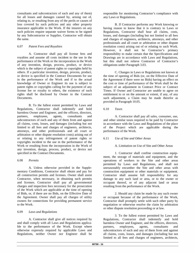
00700 - 16
consultants and subcontractors of each and any of them) for all losses and damages caused by, arising out of, relating to, or resulting from any of the perils or causes of loss covered by such policies and any other property insurance applicable to the Work. If the insurers on any such policies require separate waiver forms to be signed by any Subcontractor or Supplier, Contractor will obtain the same. 6.07 Patent Fees and Royalties A. Contractor shall pay all license fees and royalties and assume all costs incident to the use in the performance of the Work or the incorporation in the Work of any invention, design, process, product, or device which is the subject of patent rights or copyrights held by others. If a particular invention, design, process, product, or device is specified in the Contract Documents for use in the performance of the Work and if to the actual knowledge of Owner or Engineer its use is subject to patent rights or copyrights calling for the payment of any license fee or royalty to others, the existence of such rights shall be disclosed by Owner in the Contract Documents. B. To the fullest extent permitted by Laws and Regulations, Contractor shall indemnify and hold harmless Owner and Engineer, and the officers, directors, partners, employees, agents, consultants and subcontractors of each and any of them from and against all claims, costs, losses, and damages (including but not limited to all fees and charges of engineers, architects, attorneys, and other professionals and all court or arbitration or other dispute resolution costs) arising out of or relating to any infringement of patent rights or copyrights incident to the use in the performance of the Work or resulting from the incorporation in the Work of any invention, design, process, product, or device not specified in the Contract Documents. 6.08 Permits A. Unless otherwise provided in the Supple-mentary Conditions, Contractor shall obtain and pay for all construction permits and licenses. Owner shall assist Contractor, when necessary, in obtaining such permits and licenses. Contractor shall pay all governmental charges and inspection fees necessary for the prosecution of the Work which are applicable at the time of opening of Bids, or, if there are no Bids, on the Effective Date of the Agreement. Owner shall pay all charges of utility owners for connections for providing permanent service to the Work. 6.09 Laws and Regulations A. Contractor shall give all notices required by and shall comply with all Laws and Regulations applica-ble to the performance of the Work. Except where otherwise expressly required by applicable Laws and Regulations, neither Owner nor Engineer shall be
responsible for monitoring Contractor’s compliance with any Laws or Regulations. B. If Contractor performs any Work knowing or having reason to know that it is contrary to Laws or Regulations, Contractor shall bear all claims, costs, losses, and damages (including but not limited to all fees and charges of engineers, architects, attorneys, and other professionals and all court or arbitration or other dispute resolution costs) arising out of or relating to such Work. However, it shall not be Contractor’s primary responsibility to make certain that the Specifications and Drawings are in accordance with Laws and Regulations, but this shall not relieve Contractor of Contractor’s obligations under Paragraph 3.03. C. Changes in Laws or Regulations not known at the time of opening of Bids (or, on the Effective Date of the Agreement if there were no Bids) having an effect on the cost or time of performance of the Work shall be the subject of an adjustment in Contract Price or Contract Times. If Owner and Contractor are unable to agree on entitlement to or on the amount or extent, if any, of any such adjustment, a Claim may be made therefor as provided in Paragraph 10.05. 6.10 Taxes A. Contractor shall pay all sales, consumer, use, and other similar taxes required to be paid by Contractor in accordance with the Laws and Regulations of the place of the Project which are applicable during the performance of the Work. 6.11 Use of Site and Other Areas A. Limitation on Use of Site and Other Areas 1. Contractor shall confine construction equip-ment, the storage of materials and equipment, and the operations of workers to the Site and other areas permitted by Laws and Regulations, and shall not unreasonably encumber the Site and other areas with construction equipment or other materials or equipment. Contractor shall assume full responsibility for any damage to any such land or area, or to the owner or occupant thereof, or of any adjacent land or areas resulting from the performance of the Work. 2. Should any claim be made by any such owner or occupant because of the performance of the Work, Contractor shall promptly settle with such other party by negotiation or otherwise resolve the claim by arbitration or other dispute resolution proceeding or at law. 3. To the fullest extent permitted by Laws and Regulations, Contractor shall indemnify and hold harmless Owner and Engineer, and the officers, directors, partners, employees, agents, consultants and subcontractors of each and any of them from and against all claims, costs, losses, and damages (including but not limited to all fees and charges of engineers, architects,

00700 - 17
attorneys, and other professionals and all court or arbitration or other dispute resolution costs) arising out of or relating to any claim or action, legal or equitable, brought by any such owner or occupant against Owner, Engineer, or any other party indemnified hereunder to the extent caused by or based upon Contractor's performance of the Work. B. Removal of Debris During Performance of the Work: During the progress of the Work Contractor shall keep the Site and other areas free from accumulations of waste materials, rubbish, and other debris. Removal and disposal of such waste materials, rubbish, and other debris shall conform to applicable Laws and Regulations. C. Cleaning: Prior to Substantial Completion of the Work Contractor shall clean the Site and the Work and make it ready for utilization by Owner. At the com-pletion of the Work Contractor shall remove from the Site all tools, appliances, construction equipment and machinery, and surplus materials and shall restore to original condition all property not designated for alteration by the Contract Documents. D. Loading Structures: Contractor shall not load nor permit any part of any structure to be loaded in any manner that will endanger the structure, nor shall Contractor subject any part of the Work or adjacent property to stresses or pressures that will endanger it. 6.12 Record Documents A. Contractor shall maintain in a safe place at the Site one record copy of all Drawings, Specifications, Addenda, Change Orders, Work Change Directives, Field Orders, and written interpretations and clarifications in good order and annotated to show changes made during construction. These record documents together with all approved Samples and a counterpart of all approved Shop Drawings will be available to Engineer for reference. Upon completion of the Work, these record documents, Samples, and Shop Drawings will be delivered to Engi-neer for Owner. 6.13 Safety and Protection A. Contractor shall be solely responsible for initiating, maintaining and supervising all safety precau-tions and programs in connection with the Work. Contractor shall take all necessary precautions for the safety of, and shall provide the necessary protection to prevent damage, injury or loss to: 1. all persons on the Site or who may be affected by the Work; 2. all the Work and materials and equipment to be incorporated therein, whether in storage on or off the Site; and 3. other property at the Site or adjacent thereto, including trees, shrubs, lawns, walks, pavements,
roadways, structures, utilities, and Underground Facilities not designated for removal, relocation, or replacement in the course of construction. B. Contractor shall comply with all applicable Laws and Regulations relating to the safety of persons or property, or to the protection of persons or property from damage, injury, or loss; and shall erect and maintain all necessary safeguards for such safety and protection. Contractor shall notify owners of adjacent property and of Underground Facilities and other utility owners when prosecution of the Work may affect them, and shall cooperate with them in the protection, removal, relocation, and replacement of their property. C. All damage, injury, or loss to any property referred to in Paragraph 6.13.A.2 or 6.13.A.3 caused, directly or indirectly, in whole or in part, by Contractor, any Subcontractor, Supplier, or any other individual or entity directly or indirectly employed by any of them to perform any of the Work, or anyone for whose acts any of them may be liable, shall be remedied by Contractor (except damage or loss attributable to the fault of Draw-ings or Specifications or to the acts or omissions of Owner or Engineer or , or anyone employed by any of them, or anyone for whose acts any of them may be liable, and not attributable, directly or indirectly, in whole or in part, to the fault or negligence of Contractor or any Subcontractor, Supplier, or other individual or entity directly or indirectly employed by any of them). D. Contractor’s duties and responsibilities for safety and for protection of the Work shall continue until such time as all the Work is completed and Engineer has issued a notice to Owner and Contractor in accordance with Paragraph 14.07.B that the Work is acceptable (except as otherwise expressly provided in connection with Substantial Completion). 6.14 Safety Representative A. Contractor shall designate a qualified and experienced safety representative at the Site whose duties and responsibilities shall be the prevention of accidents and the maintaining and supervising of safety precautions and programs. 6.15 Hazard Communication Programs A. Contractor shall be responsible for coordi-nating any exchange of material safety data sheets or other hazard communication information required to be made available to or exchanged between or among employers at the Site in accordance with Laws or Regulations. 6.16 Emergencies A. In emergencies affecting the safety or protec-tion of persons or the Work or property at the Site or adjacent thereto, Contractor is obligated to act to prevent threatened damage, injury, or loss. Contractor shall give

00700 - 18
Engineer prompt written notice if Contractor believes that any significant changes in the Work or variations from the Contract Documents have been caused thereby or are required as a result thereof. If Engineer determines that a change in the Contract Documents is required because of the action taken by Contractor in response to such an emergency, a Work Change Directive or Change Order will be issued. 6.17 Shop Drawings and Samples A. Contractor shall submit Shop Drawings and Samples to Engineer for review and approval in accor-dance with the acceptable Schedule of Submittals (as required by Paragraph 2.07). Each submittal will be identified as Engineer may require. 1. Shop Drawings
a. Submit number of copies specified in the General Requirements. b. Data shown on the Shop Drawings will be complete with respect to quantities, dimensions, specified performance and design criteria, materials, and similar data to show Engineer the services, materials, and equipment Contractor proposes to provide and to enable Engineer to review the information for the limited purposes required by Paragraph 6.17.D.
2. Samples: Contractor shall also submit Samples to Engineer for review and approval in accor-dance with the acceptable schedule of Shop Drawings and Sample submittals.
a. Submit number of Samples specified in the Specifications. b. Clearly identify each Sample as to material, Supplier, pertinent data such as catalog numbers, the use for which intended and other data as Engineer may require to enable Engineer to review the submittal for the limited purposes required by Paragraph 6.17.D.
B. Where a Shop Drawing or Sample is required by the Contract Documents or the Schedule of Submittals , any related Work performed prior to Engineer’s review and approval of the pertinent submittal will be at the sole expense and responsibility of Contractor. C. Submittal Procedures 1. Before submitting each Shop Drawing or Sample, Contractor shall have determined and verified:
a. all field measurements, quantities, dimensions, specified performance and design criteria, installation requirements, materials, catalog numbers, and similar information with respect thereto;
b. the suitability of all materials with respect to intended use, fabrication, shipping, handling, storage, assembly, and installation pertaining to the performance of the Work; c. all information relative to Contractor’s responsibilities for means, methods, techniques, sequences, and procedures of construction, and safety precautions and programs incident thereto; and d. shall also have reviewed and coordinated each Shop Drawing or Sample with other Shop Drawings and Samples and with the requirements of the Work and the Contract Documents.
2. Each submittal shall bear a stamp or specific written certification that Contractor has satisfied Contractor’s obligations under the Contract Documents with respect to Contractor’s review and approval of that submittal. 3. With each submittal, Contractor shall give Engineer specific written notice of any variations, that the Shop Drawing or Sample may have from the requirements of the Contract Documents. This notice shall be both a written communication separate from the Shop Drawing’s or Sample Submittal; and, in addition, by a specific notation made on each Shop Drawing or Sample submit-ted to Engineer for review and approval of each such variation. D. Engineer’s Review 1. Engineer will provide timely review of Shop Drawings and Samples in accordance with the Schedule of Submittals acceptable to Engineer. Engineer’s review and approval will be only to determine if the items covered by the submittals will, after installation or incorporation in the Work, conform to the information given in the Contract Documents and be compatible with the design concept of the completed Project as a functioning whole as indicated by the Contract Docu-ments. 2. Engineer’s review and approval will not extend to means, methods, techniques, sequences, or procedures of construction (except where a particular means, method, technique, sequence, or procedure of con-struction is specifically and expressly called for by the Contract Documents) or to safety precautions or programs incident thereto. The review and approval of a separate item as such will not indicate approval of the assembly in which the item functions. 3. Engineer’s review and approval shall not relieve Contractor from responsibility for any variation from the requirements of the Contract Documents unless Contractor has complied with the requirements of Paragraph 6.17.C.3 and Engineer has given written

00700 - 19
approval of each such variation by specific written notation thereof incorporated in or accompanying the Shop Drawing or Sample. Engineer’s review and approval shall not relieve Contractor from responsibility for complying with the requirements of Paragraph 6.17.C.1. E. Resubmittal Procedures 1. Contractor shall make corrections required by Engineer and shall return the required number of cor-rected copies of Shop Drawings and submit, as required, new Samples for review and approval. Contractor shall direct specific attention in writing to revisions other than the corrections called for by Engineer on previous submittals. 6.18 Continuing the Work A. Contractor shall carry on the Work and adhere to the Progress Schedule during all disputes or disagreements with Owner. No Work shall be delayed or postponed pending resolution of any disputes or disagreements, except as permitted by Paragraph 15.04 or as Owner and Contractor may otherwise agree in writing. 6.19 Contractor’s General Warranty and Guarantee A. Contractor warrants and guarantees to Owner that all Work will be in accordance with the Contract Documents and will not be defective. Engineer and its Related Entities shall be entitled to rely on representation of Contractor’s warranty and guarantee. B. Contractor’s warranty and guarantee hereunder excludes defects or damage caused by: 1. abuse, modification, or improper maintenance or operation by persons other than Contractor, Sub-contractors, Suppliers, or any other individual or entity for whom Contractor is responsible; or 2. normal wear and tear under normal usage. C. Contractor’s obligation to perform and complete the Work in accordance with the Contract Documents shall be absolute. None of the following will constitute an acceptance of Work that is not in accordance with the Contract Documents or a release of Contractor’s obligation to perform the Work in accordance with the Contract Documents: 1. observations by Engineer; 2. recommendation by Engineer or payment by Owner of any progress or final payment; 3. the issuance of a certificate of Substantial Completion by Engineer or any payment related thereto by Owner;
4. use or occupancy of the Work or any part thereof by Owner; 5. any review and approval of a Shop Drawing or Sample submittal or the issuance of a notice of acceptabil-ity by Engineer; 6. any inspection, test, or approval by others; or 7. any correction of defective Work by Owner. 6.20 Indemnification A. To the fullest extent permitted by Laws and Regulations, Contractor shall indemnify and hold harmless Owner and Engineer, and the officers, directors, partners, employees, agents, consultants and subcontractors of each and any of them from and against all claims, costs, losses, and damages (including but not limited to all fees and charges of engineers, architects, attorneys, and other professionals and all court or arbitration or other dispute resolution costs) arising out of or relating to the performance of the Work, provided that any such claim, cost, loss, or damage is attributable to bodily injury, sickness, disease, or death, or to injury to or destruction of tangible property (other than the Work itself), including the loss of use resulting therefrom but only to the extent caused by any negligent act or omission of Contractor, any Subcontractor, any Supplier, or any individual or entity directly or indirectly employed by any of them to perform any of the Work or anyone for whose acts any of them may be liable . B. In any and all claims against Owner or Engineer or any of their respective consultants, agents, officers, directors, partners, or employees by any employ-ee (or the survivor or personal representative of such employee) of Contractor, any Subcontractor, any Supplier, or any individual or entity directly or indirectly employed by any of them to perform any of the Work, or anyone for whose acts any of them may be liable, the indemnification obligation under Paragraph 6.20.A shall not be limited in any way by any limitation on the amount or type of damages, compensation, or benefits payable by or for Contractor or any such Subcontractor, Supplier, or other individual or entity under workers’ compensation acts, disability benefit acts, or other employee benefit acts. C. The indemnification obligations of Contractor under Paragraph 6.20.A shall not extend to the liability of Engineer and Engineer’s officers, directors, partners, employees, agents, consultants and subcontractors arising out of: 1. the preparation or approval of, or the failure to prepare or approve, maps, Drawings, opinions, reports, surveys, Change Orders, designs, or Specifications; or

00700 - 20
2. giving directions or instructions, or failing to give them, if that is the primary cause of the injury or damage. 6.21 Delegation of Professional Design Services A. Contractor will not be required to provide professional design services unless such services are specifically required by the Contract Documents for a portion of the Work or unless such services are required to carry out Contractor’s responsibilities for construction means, methods, techniques, sequences and procedures. Contractor shall not be required to provide professional services in violation of applicable law. B. If professional design services or certifications by a design professional related to systems, materials or equipment are specifically required of Contractor by the Contract Documents, Owner and Engineer will specify all performance and design criteria that such services must satisfy. Contractor shall cause such services or certifications to be provided by a properly licensed professional, whose signature and seal shall appear on all drawings, calculations, specifications, certifications, Shop Drawings and other submittals prepared by such professional. Shop Drawings and other submittals related to the Work designed or certified by such professional, if prepared by others, shall bear such professional’s written approval when submitted to Engineer. C. Owner and Engineer shall be entitled to rely upon the adequacy, accuracy and completeness of the services, certifications or approvals performed by such design professionals, provided Owner and Engineer have specified to Contractor all performance and design criteria that such services must satisfy. D. Pursuant to this Paragraph 6.21, Engineer’s review and approval of design calculations and design drawings will be only for the limited purpose of checking for conformance with performance and design criteria given and the design concept expressed in the Contract Documents. Engineer’s review and approval of Shop Drawings and other submittals (except design calculations and design drawings) will be only for the purpose stated in Paragraph 6.17.D.1. E. Contractor shall not be responsible for the adequacy of the performance or design criteria required by the Contract Documents. ARTICLE 7 - OTHER WORK AT THE SITE 7.01 Related Work at Site A. Owner may perform other work related to the Project at the Site with Owner’s employees, or via other direct contracts therefor, or have other work performed by
utility owners. If such other work is not noted in the Con-tract Documents, then: 1. written notice thereof will be given to Contractor prior to starting any such other work; and 2. if Owner and Contractor are unable to agree on entitlement to or on the amount or extent, if any, of any adjustment in the Contract Price or Contract Times that should be allowed as a result of such other work, a Claim may be made therefor as provided in Paragraph 10.05. B. Contractor shall afford each other contractor who is a party to such a direct contract, each utility owner and Owner, if Owner is performing other work with Owner’s employees, proper and safe access to the Site, a reasonable opportunity for the introduction and storage of materials and equipment and the execution of such other work, and shall properly coordinate the Work with theirs. Contractor shall do all cutting, fitting, and patching of the Work that may be required to properly connect or otherwise make its several parts come together and properly integrate with such other work. Contractor shall not endanger any work of others by cutting, excavating, or otherwise altering their work and will only cut or alter their work with the written consent of Engineer and the others whose work will be affected. The duties and responsibilities of Contractor under this Paragraph are for the benefit of such utility owners and other contractors to the extent that there are comparable provisions for the benefit of Contractor in said direct contracts between Owner and such utility owners and other contractors. C. If the proper execution or results of any part of Contractor’s Work depends upon work performed by others under this Article 7, Contractor shall inspect such other work and promptly report to Engineer in writing any delays, defects, or deficiencies in such other work that render it unavailable or unsuitable for the proper execution and results of Contractor’s Work. Contractor’s failure to so report will constitute an acceptance of such other work as fit and proper for integration with Contractor’s Work except for latent defects and deficiencies in such other work. 7.02 Coordination A. If Owner intends to contract with others for the performance of other work on the Project at the Site, the following will be set forth in Supplementary Condi-tions: 1. the individual or entity who will have authority and responsibility for coordination of the activities among the various contractors will be identified; 2. the specific matters to be covered by such authority and responsibility will be itemized; and

00700 - 21
3. the extent of such authority and responsibili-ties will be provided. B. Unless otherwise provided in the Supplementary Conditions, Owner shall have sole authority and responsibility for such coordination. 7.03 Legal Relationships A. Paragraphs 7.01.A and 7.02 are not applicable for utilities not under the control of Owner. B. Each other direct contract of Owner under Paragraph 7.01.A shall provide that the other contractor is liable to Owner and Contractor for the reasonable direct delay and disruption costs incurred by Contractor as a result of the other contractor’s actions or inactions. C. Contractor shall be liable to Owner and any other contractor for the reasonable direct delay and disruption costs incurred by such other contractor as a result of Contractor’s action or inactions. ARTICLE 8 - OWNER’S RESPONSIBILITIES 8.01 Communications to Contractor A. Except as otherwise provided in these General Conditions, Owner shall issue all communications to Contractor through Engineer. 8.02 Replacement of Engineer A. In case of termination of the employment of Engineer, Owner shall appoint an engineer to whom Contractor makes no reasonable objection, whose status under the Contract Documents shall be that of the former Engineer. 8.03 Furnish Data A. Owner shall promptly furnish the data required of Owner under the Contract Documents. 8.04 Pay When Due A. Owner shall make payments to Contractor when they are due as provided in Paragraphs 14.02.C and 14.07.C. 8.05 Lands and Easements; Reports and Tests A. Owner’s duties in respect of providing lands and easements and providing engineering surveys to establish reference points are set forth in Paragraphs 4.01 and 4.05. Paragraph 4.02 refers to Owner’s identifying and making available to Contractor copies of reports of explorations and tests of subsurface conditions and drawings of physical conditions in or relating to existing surface or subsurface structures at or contiguous to the
Site that have been utilized by Engineer in preparing the Contract Documents. 8.06 Insurance A. Owner’s responsibilities, if any, in respect to purchasing and maintaining liability and property insur-ance are set forth in Article 5. 8.07 Change Orders A. Owner is obligated to execute Change Orders as indicated in Paragraph 10.03. 8.08 Inspections, Tests, and Approvals A. Owner’s responsibility in respect to certain inspections, tests, and approvals is set forth in Paragraph 13.03.B. 8.09 Limitations on Owner’s Responsibilities A. The Owner shall not supervise, direct, or have control or authority over, nor be responsible for, Contractor’s means, methods, techniques, sequences, or procedures of construction, or the safety precautions and programs incident thereto, or for any failure of Contractor to comply with Laws and Regulations applicable to the performance of the Work. Owner will not be responsible for Contractor’s failure to perform the Work in accordance with the Contract Documents. 8.10 Undisclosed Hazardous Environmental Condition A. Owner’s responsibility in respect to an undis-closed Hazardous Environmental Condition is set forth in Paragraph 4.06. 8.11 Evidence of Financial Arrangements A. If and to the extent Owner has agreed to furnish Contractor reasonable evidence that financial arrangements have been made to satisfy Owner’s obligations under the Contract Documents, Owner’s responsibility in respect thereof will be as set forth in the Supplementary Conditions. ARTICLE 9 - ENGINEER’S STATUS DURING CONSTRUCTION 9.01 Owner’s Representative A. Engineer will be Owner’s representative during the construction period. The duties and responsi-bilities and the limitations of authority of Engineer as Owner’s representative during construction are set forth in the Contract Documents and will not be changed without written consent of Owner and Engineer.

00700 - 22
9.02 Visits to Site A. Engineer will make visits to the Site at inter-vals appropriate to the various stages of construction as Engineer deems necessary in order to observe as an experienced and qualified design professional the progress that has been made and the quality of the various aspects of Contractor’s executed Work. Based on information obtained during such visits and observations, Engineer, for the benefit of Owner, will determine, in general, if the Work is proceeding in accordance with the Contract Documents. Engineer will not be required to make exhaustive or continuous inspections on the Site to check the quality or quantity of the Work. Engineer’s efforts will be directed toward providing for Owner a greater degree of confidence that the completed Work will conform generally to the Contract Documents. On the basis of such visits and observations, Engineer will keep Owner informed of the progress of the Work and will endeavor to guard Owner against defective Work. B. Engineer’s visits and observations are subject to all the limitations on Engineer’s authority and responsibility set forth in Paragraph 9.09. Particularly, but without limitation, during or as a result of Engineer's visits or observations of Contractor's Work Engineer will not supervise, direct, control, or have authority over or be responsible for Contractor’s means, methods, techniques, sequences, or procedures of construction, or the safety precautions and programs incident thereto, or for any failure of Contractor to comply with Laws and Regulations applicable to the performance of the Work. 9.03 Project Representative A. If Owner and Engineer agree, Engineer will furnish a Resident Project Representative to assist Engineer in providing more extensive observation of the Work. The authority and responsibilities of any such Resident Project Representative and assistants will be as provided in the Supplementary Conditions, and limitations on the responsibilities thereof will be as provided in Paragraph 9.09. If Owner designates another representative or agent to represent Owner at the Site who is not Engineer’s consultant, agent or employee, the responsibilities and authority and limitations thereon of such other individual or entity will be as provided in the Supplementary Conditions. 9.04 Authorized Variations in Work A. Engineer may authorize minor variations in the Work from the requirements of the Contract Documents which do not involve an adjustment in the Contract Price or the Contract Times and are compatible with the design concept of the completed Project as a functioning whole as indicated by the Contract Docu-ments. These may be accomplished by a Field Order and will be binding on Owner and also on Contractor, who shall perform the Work involved promptly. If Owner or Contractor believes that a Field Order justifies an adjustment in the Contract Price or Contract Times, or
both, and the parties are unable to agree on entitlement to or on the amount or extent, if any, of any such adjustment , a Claim may be made therefor as provided in Paragraph 10.05. 9.05 Rejecting Defective Work A. Engineer will have authority to reject Work which Engineer believes to be defective, or that Engineer believes will not produce a completed Project that conforms to the Contract Documents or that will prejudice the integrity of the design concept of the completed Project as a functioning whole as indicated by the Contract Documents. Engineer will also have authority to require special inspection or testing of the Work as provided in Paragraph 13.04, whether or not the Work is fabricated, installed, or completed. 9.06 Shop Drawings, Change Orders and Payments A. In connection with Engineer’s authority, and limitations thereof, as to Shop Drawings and Samples, see Paragraph 6.17. B. In connection with Engineer’s authority, and limitations thereof, as to design calculations and design drawings submitted in response to a delegation of professional design services, if any, see Paragraph 6.21. C. In connection with Engineer’s authority as to Change Orders, see Articles 10, 11, and 12. D. In connection with Engineer’s authority as to Applications for Payment, see Article 14. 9.07 Determinations for Unit Price Work A. Engineer will determine the actual quantities and classifications of Unit Price Work performed by Contractor. Engineer will review with Contractor the Engineer’s preliminary determinations on such matters before rendering a written decision thereon (by recommendation of an Application for Payment or otherwise). Engineer’s written decision thereon will be final and binding (except as modified by Engineer to reflect changed factual conditions or more accurate data) upon Owner and Contractor, subject to the provisions of Paragraph 10.05. 9.08 Decisions on Requirements of Contract Documents and Acceptability of Work A. Engineer will be the initial interpreter of the requirements of the Contract Documents and judge of the acceptability of the Work thereunder. All matters in question and other matters between Owner and Contractor arising prior to the date final payment is due relating to the acceptability of the Work, and the interpretation of the requirements of the Contract Documents pertaining to the performance of the Work, will be referred initially to Engineer in writing within 30 days of the event giving rise to the question

00700 - 23
B. Engineer will, with reasonable promptness, render a written decision on the issue referred. If Owner or Contractor believe that any such decision entitles them to an adjustment in the Contract Price or Contract Times or both, a Claim may be made under Paragraph 10.05. The date of Engineer’s decision shall be the date of the event giving rise to the issues referenced for the purposes of Paragraph 10.05.B. C. Engineer’s written decision on the issue referred will be final and binding on Owner and Contractor, subject to the provisions of Paragraph 10.05. D. When functioning as interpreter and judge under this Paragraph 9.08, Engineer will not show partiality to Owner or Contractor and will not be liable in connection with any interpretation or decision rendered in good faith in such capacity. 9.09 Limitations on Engineer’s Authority and Responsibilities A. Neither Engineer’s authority or responsibility under this Article 9 or under any other provision of the Contract Documents nor any decision made by Engineer in good faith either to exercise or not exercise such authority or responsibility or the undertaking, exercise, or performance of any authority or responsibility by Engineer shall create, impose, or give rise to any duty in contract, tort, or otherwise owed by Engineer to Contractor, any Subcontractor, any Supplier, any other individual or entity, or to any surety for or employee or agent of any of them. B. Engineer will not supervise, direct, control, or have authority over or be responsible for Contractor’s means, methods, techniques, sequences, or procedures of construction, or the safety precautions and programs incident thereto, or for any failure of Contractor to comply with Laws and Regulations applicable to the performance of the Work. Engineer will not be respon-sible for Contractor’s failure to perform the Work in accordance with the Contract Documents. C. Engineer will not be responsible for the acts or omissions of Contractor or of any Subcontractor, any Supplier, or of any other individual or entity performing any of the Work. D. Engineer’s review of the final Application for Payment and accompanying documentation and all maintenance and operating instructions, schedules, guarantees, bonds, certificates of inspection, tests and approvals, and other documentation required to be delivered by Paragraph 14.07.A will only be to determine generally that their content complies with the require-ments of, and in the case of certificates of inspections, tests, and approvals that the results certified indicate compliance with the Contract Documents.
E. The limitations upon authority and responsi-bility set forth in this Paragraph 9.09 shall also apply to, the Resident Project Representative, if any, and assistants, if any. ARTICLE 10 - CHANGES IN THE WORK; CLAIMS 10.01 Authorized Changes in the Work A. Without invalidating the Contract and without notice to any surety, Owner may, at any time or from time to time, order additions, deletions, or revisions in the Work by a Change Order, or a Work Change Directive. Upon receipt of any such document, Contractor shall promptly proceed with the Work involved which will be performed under the applicable conditions of the Contract Documents (except as otherwise specifically provided). B. If Owner and Contractor are unable to agree on entitlement to, or on the amount or extent, if any, of an adjustment in the Contract Price or Contract Times, or both, that should be allowed as a result of a Work Change Directive, a Claim may be made therefor as provided in Paragraph 10.05. 10.02 Unauthorized Changes in the Work A.Contractor shall not be entitled to an increase in the Contract Price or an extension of the Contract Times with respect to any work performed that is not required by the Contract Documents as amended, modified, or supplemented as provided in Paragraph 3.04, except in the case of an emergency as provided in Paragraph 6.16 or in the case of uncovering Work as provided in Paragraph 13.04.B. 10.03 Execution of Change Orders A. Owner and Contractor shall execute appropri-ate Change Orders recommended by Engineer covering: 1. changes in the Work which are: (i) ordered by Owner pursuant to Paragraph 10.01.A, (ii) required because of acceptance of defective Work under Paragraph 13.08.A or Owner’s correction of defective Work under Paragraph 13.09, or (iii) agreed to by the parties; 2. changes in the Contract Price or Contract Times which are agreed to by the parties, including any undisputed sum or amount of time for Work actually performed in accordance with a Work Change Directive; and 3. changes in the Contract Price or Contract Times which embody the substance of any written decision rendered by Engineer pursuant to Paragraph 10.05; provided that, in lieu of executing any such Change Order, an appeal may be taken from any such decision in accordance with the provisions of the Contract Documents and applicable Laws and Regulations, but

00700 - 24
during any such appeal, Contractor shall carry on the Work and adhere to the Progress Schedule as provided in Paragraph 6.18.A. 10.04 Notification to Surety A. If notice of any change affecting the general scope of the Work or the provisions of the Contract Documents (including, but not limited to, Contract Price or Contract Times) is required by the provisions of any bond to be given to a surety, the giving of any such notice will be Contractor’s responsibility. The amount of each applicable bond will be adjusted to reflect the effect of any such change. 10.05 Claims A. Engineer’s Decision Required: All Claims, except those waived pursuant to Paragraph 14.09, shall be referred to the Engineer for decision. A decision by Engineer shall be required as a condition precedent to any exercise by Owner or Contractor of any rights or remedies either may otherwise have under the Contract Documents or by Laws and Regulations in respect of such Claims. B. Notice: Written notice stating the general nature of each Claim, shall be delivered by the claimant to Engineer and the other party to the Contract promptly (but in no event later than 30 days) after the start of the event giving rise thereto. The responsibility to substantiate a Claim shall rest with the party making the Claim. Notice of the amount or extent of the Claim, with supporting data shall be delivered to the Engineer and the other party to the Contract within 60 days after the start of such event (unless Engineer allows additional time for claimant to submit additional or more accurate data in support of such Claim). A Claim for an adjustment in Contract Price shall be prepared in accordance with the provisions of Paragraph 12.01.B. A Claim for an adjustment in Contract Time shall be prepared in accordance with the provisions of Paragraph 12.02.B. Each Claim shall be accompanied by claimant's written statement that the adjustment claimed is the entire adjustment to which the claimant believes it is entitled as a result of said event. The opposing party shall submit any response to Engineer and the claimant within 30 days after receipt of the claimant’s last submittal (unless Engineer allows additional time). C. Engineer’s Action: Engineer will review each Claim and, within 30 days after receipt of the last submittal of the claimant or the last submittal of the opposing party, if any, take one of the following actions in writing: 1. deny the Claim in whole or in part, 2. approve the Claim, or 3. notify the parties that the Engineer is unable to resolve the Claim if, in the Engineer’s sole discretion, it would be inappropriate for the Engineer to do so. For
purposes of further resolution of the Claim, such notice shall be deemed a denial. D. In the event that Engineer does not take action on a Claim within said 30 days, the Claim shall be deemed denied. E. Engineer’s written action under Paragraph 10.05.C or denial pursuant to Paragraphs 10.05.C.3 or 10.05.D will be final and binding upon Owner and Contractor, unless Owner or Contractor invoke the dispute resolution procedure set forth in Article 16 within 30 days of such action or denial. F. No Claim for an adjustment in Contract Price or Contract Times will be valid if not submitted in accordance with this Paragraph 10.05. ARTICLE 11 - COST OF THE WORK; ALLOWANCES; UNIT PRICE WORK 11.01 Cost of the Work A. Costs Included: The term Cost of the Work means the sum of all costs, except those excluded in Paragraph 11.01.B, necessarily incurred and paid by Contractor in the proper performance of the Work. When the value of any Work covered by a Change Order or when a Claim for an adjustment in Contract Price is determined on the basis of Cost of the Work, the costs to be reimbursed to Contractor will be only those additional or incremental costs required because of the change in the Work or because of the event giving rise to the Claim. Except as otherwise may be agreed to in writing by Owner, such costs shall be in amounts no higher than those prevailing in the locality of the Project, shall include only the following items, and shall not include any of the costs itemized in Paragraph 11.01.B. 1. Payroll costs for employees in the direct employ of Contractor in the performance of the Work under schedules of job classifications agreed upon by Owner and Contractor. Such employees shall include, without limitation, superintendents, foremen, and other personnel employed full time at the Site. Payroll costs for employees not employed full time on the Work shall be apportioned on the basis of their time spent on the Work. Payroll costs shall include, but not be limited to, salaries and wages plus the cost of fringe benefits, which shall include social security contributions, unemployment, excise, and payroll taxes, workers’ compensation, health and retirement benefits, bonuses, sick leave, vacation and holiday pay applicable thereto. The expenses of performing Work outside of regular working hours, on Saturday, Sunday, or legal holidays, shall be included in the above to the extent authorized by Owner. 2. Cost of all materials and equipment furnished and incorporated in the Work, including costs of transportation and storage thereof, and Suppliers’ field

00700 - 25
services required in connection therewith. All cash discounts shall accrue to Contractor unless Owner deposits funds with Contractor with which to make pay-ments, in which case the cash discounts shall accrue to Owner. All trade discounts, rebates and refunds and returns from sale of surplus materials and equipment shall accrue to Owner, and Contractor shall make provisions so that they may be obtained. 3. Payments made by Contractor to Subcontractors for Work performed by Subcontractors. If required by Owner, Contractor shall obtain competitive bids from subcontractors acceptable to Owner and Contractor and shall deliver such bids to Owner, who will then determine, with the advice of Engineer, which bids, if any, will be acceptable. If any subcontract provides that the Subcontractor is to be paid on the basis of Cost of the Work plus a fee, the Subcontractor’s Cost of the Work and fee shall be determined in the same manner as Contractor’s Cost of the Work and fee as provided in this Paragraph 11.01. 4. Costs of special consultants (including but not limited to Engineers, architects, testing laboratories, surveyors, attorneys, and accountants) employed for services specifically related to the Work. 5. Supplemental costs including the following:
a. The proportion of necessary transportation, travel, and subsistence expenses of Contractor’s employees incurred in discharge of duties connected with the Work. b. Cost, including transportation and mainte-nance, of all materials, supplies, equipment, machinery, appliances, office, and temporary facilities at the Site, and hand tools not owned by the workers, which are consumed in the perfor-mance of the Work, and cost, less market value, of such items used but not consumed which remain the property of Contractor. c. Rentals of all construction equipment and machinery, and the parts thereof whether rented from Contractor or others in accordance with rental agreements approved by Owner with the advice of Engineer, and the costs of transportation, loading, unloading, assembly, dismantling, and removal thereof. All such costs shall be in accordance with the terms of said rental agreements. The rental of any such equip-ment, machinery, or parts shall cease when the use thereof is no longer necessary for the Work. d. Sales, consumer, use, and other similar taxes related to the Work, and for which Contractor is liable, imposed by Laws and Regulations. e. Deposits lost for causes other than negligence of Contractor, any Subcontractor, or anyone directly or indirectly employed by any of them or
for whose acts any of them may be liable, and royalty payments and fees for permits and licenses. f. Losses and damages (and related expenses) caused by damage to the Work, not compensated by insurance or otherwise, sustained by Contractor in connection with the performance of the Work (except losses and damages within the deductible amounts of property insurance established in accordance with Paragraph 5.06.D), provided such losses and damages have resulted from causes other than the negligence of Contractor, any Subcontractor, or anyone directly or indirectly employed by any of them or for whose acts any of them may be liable. Such losses shall include settlements made with the written consent and approval of Owner. No such losses, damages, and expenses shall be included in the Cost of the Work for the purpose of determining Contractor’s fee. g. The cost of utilities, fuel, and sanitary facilities at the Site. h. Minor expenses such as telegrams, long distance telephone calls, telephone service at the Site, expresses, and similar petty cash items in connection with the Work. i. The costs of premiums for all bonds and insurance Contractor is required by the Contract Documents to purchase and maintain.
B. Costs Excluded: The term Cost of the Work shall not include any of the following items: 1. Payroll costs and other compensation of Contractor’s officers, executives, principals (of partnerships and sole proprietorships), general managers, safety managers, engineers, architects, estimators, attor-neys, auditors, accountants, purchasing and contracting agents, expediters, timekeepers, clerks, and other personnel employed by Contractor, whether at the Site or in Contractor’s principal or branch office for general administration of the Work and not specifically included in the agreed upon schedule of job classifications referred to in Paragraph 11.01.A.1 or specifically covered by Paragraph 11.01.A.4, all of which are to be considered administrative costs covered by the Contractor’s fee. 2. Expenses of Contractor’s principal and branch offices other than Contractor’s office at the Site. 3. Any part of Contractor’s capital expenses, including interest on Contractor’s capital employed for the Work and charges against Contractor for delinquent payments. 4. Costs due to the negligence of Contractor, any Subcontractor, or anyone directly or indirectly employed by any of them or for whose acts any of them may be

00700 - 26
liable, including but not limited to, the correction of defective Work, disposal of materials or equipment wrongly supplied, and making good any damage to property. 5. Other overhead or general expense costs of any kind and the costs of any item not specifically and expressly included in Paragraphs 11.01.A and 11.01.B. C. Contractor’s Fee: When all the Work is performed on the basis of cost-plus, Contractor’s fee shall be determined as set forth in the Agreement. When the value of any Work covered by a Change Order or when a Claim for an adjustment in Contract Price is determined on the basis of Cost of the Work, Contractor’s fee shall be determined as set forth in Paragraph 12.01.C. D. Documentation: Whenever the Cost of the Work for any purpose is to be determined pursuant to Paragraphs 11.01.A and 11.01.B, Contractor will establish and maintain records thereof in accordance with generally accepted accounting practices and submit in a form acceptable to Engineer an itemized cost breakdown together with supporting data. 11.02 Allowances A. It is understood that Contractor has included in the Contract Price all allowances so named in the Contract Documents and shall cause the Work so covered to be performed for such sums and by such persons or entities as may be acceptable to Owner and Engineer. B. Cash Allowances 1. Contractor agrees that:
a. the cash allowances include the cost to Contractor (less any applicable trade discounts) of materials and equipment required by the allowances to be delivered at the Site, and all applicable taxes; and b. Contractor’s costs for unloading and handling on the Site, labor, installation , overhead, profit, and other expenses contemplated for the cash allowances have been included in the Contract Price and not in the allowances, and no demand for additional payment on account of any of the foregoing will be valid.
C. Contingency Allowance
1. Contractor agrees that a contingency allowance, if any, is for the sole use of Owner to cover unanticipated costs. D. Prior to final payment, an appropriate Change Order will be issued as recommended by Engineer to reflect actual amounts due Contractor on account of Work covered by allowances, and the Contract Price shall be correspondingly adjusted.
11.03 Unit Price Work A. Where the Contract Documents provide that all or part of the Work is to be Unit Price Work, initially the Contract Price will be deemed to include for all Unit Price Work an amount equal to the sum of the unit price for each separately identified item of Unit Price Work times the estimated quantity of each item as indicated in the Agreement. B. The estimated quantities of items of Unit Price Work are not guaranteed and are solely for the purpose of comparison of Bids and determining an initial Contract Price. Determinations of the actual quantities and classifications of Unit Price Work performed by Contractor will be made by Engineer subject to the provisions of Paragraph 9.07. C. Each unit price will be deemed to include an amount considered by Contractor to be adequate to cover Contractor’s overhead and profit for each separately identified item. D. Owner or Contractor may make a Claim for an adjustment in the Contract Price in accordance with Paragraph 10.05 if: 1. the quantity of any item of Unit Price Work performed by Contractor differs materially and signifi-cantly from the estimated quantity of such item indicated in the Agreement; and 2. there is no corresponding adjustment with respect any other item of Work; and 3. Contractor believes that Contractor is entitled to an increase in Contract Price as a result of having incurred additional expense or Owner believes that Owner is entitled to a decrease in Contract Price and the parties are unable to agree as to the amount of any such increase or decrease. ARTICLE 12 - CHANGE OF CONTRACT PRICE; CHANGE OF CONTRACT TIMES 12.01 Change of Contract Price A. The Contract Price may only be changed by a Change Order. Any Claim for an adjustment in the Contract Price shall be based on written notice submitted by the party making the Claim to the Engineer and the other party to the Contract in accordance with the provisions of Paragraph 10.05. B. The value of any Work covered by a Change Order or of any Claim for an adjustment in the Contract Price will be determined as follows:

00700 - 27
1. where the Work involved is covered by unit prices contained in the Contract Documents, by applica-tion of such unit prices to the quantities of the items involved (subject to the provisions of Paragraph 11.03); or 2. where the Work involved is not covered by unit prices contained in the Contract Documents, by a mutually agreed lump sum (which may include an allowance for overhead and profit not necessarily in accordance with Paragraph 12.01.C.2); or 3. where the Work involved is not covered by unit prices contained in the Contract Documents and agreement to a lump sum is not reached under Paragraph 12.01.B.2, on the basis of the Cost of the Work (determined as provided in Paragraph 11.01) plus a Contractor’s fee for overhead and profit (determined as provided in Paragraph 12.01.C). C. Contractor’s Fee: The Contractor’s fee for overhead and profit shall be determined as follows: 1. a mutually acceptable fixed fee; or 2. if a fixed fee is not agreed upon, then a fee based on the following percentages of the various portions of the Cost of the Work:
a. for costs incurred under Paragraphs 11.01.A.1 and 11.01.A.2, the Contractor’s fee shall be 15 percent; b. for costs incurred under Paragraph 11.01.A.3, the Contractor’s fee shall be five percent; c. where one or more tiers of subcontracts are on the basis of Cost of the Work plus a fee and no fixed fee is agreed upon, the intent of Paragraph 12.01.C.2.a is that the Subcontractor who actually performs the Work, at whatever tier, will be paid a fee of 15 percent of the costs incurred by such Subcontractor under Paragraphs 11.01.A.1 and 11.01.A.2 and that any higher tier Subcontractor and Contractor will each be paid a fee of five percent of the amount paid to the next lower tier Subcontractor; d. no fee shall be payable on the basis of costs itemized under Paragraphs 11.01.A.4, 11.01.A.5, and 11.01.B; e. the amount of credit to be allowed by Contractor to Owner for any change which results in a net decrease in cost will be the amount of the actual net decrease in cost plus a deduction in Contractor’s fee by an amount equal to five percent of such net decrease; and f. when both additions and credits are involved in any one change, the adjustment in Contractor’s fee shall be computed on the basis
of the net change in accordance with Paragraphs 12.01.C.2.a through 12.01.C.2.e, inclusive.
12.02 Change of Contract Times A. The Contract Times may only be changed by a Change Order. Any Claim for an adjustment in the Contract Times shall be based on written notice submitted by the party making the Claim to the Engineer and the other party to the Contract in accordance with the provisions of Paragraph 10.05. B. Any adjustment of the Contract Times covered by a Change Order or any Claim for an adjustment in the Contract Times will be determined in accordance with the provisions of this Article 12. 12.03 Delays A. Where Contractor is prevented from completing any part of the Work within the Contract Times due to delay beyond the control of Contractor, the Contract Times will be extended in an amount equal to the time lost due to such delay if a Claim is made therefor as provided in Paragraph 12.02.A. Delays beyond the control of Contractor shall include, but not be limited to, acts or neglect by Owner, acts or neglect of utility owners or other contractors performing other work as contemplat-ed by Article 7, fires, floods, epidemics, abnormal weather conditions, or acts of God. B. If Owner, Engineer, or other contractors or utility owners performing other work for Owner as contemplated by Article 7, or anyone for whom Owner is responsible, delays, disrupts, or interferes with the performance or progress of the Work, then Contractor shall be entitled to an equitable adjustment in the Contract Price or the Contract Times , or both. Contractor’s entitlement to an adjustment of the Contract Times is conditioned on such adjustment being essential to Contractor’s ability to complete the Work within the Contract Times. C If Contractor is delayed in the performance or progress of the Work by fire, flood, epidemic, abnormal weather conditions, acts of God, acts or failures to act of utility owners not under the control of Owner, or other causes not the fault of and beyond control of Owner and Contractor, then Contractor shall be entitled to an equitable adjustment in Contract Times, if such adjustment is essential to Contractor’s ability to complete the Work within the Contract Times. Such an adjustment shall be Contractor’s sole and exclusive remedy for the delays described in this Paragraph 12.03.C. D. Owner, Engineer and the Related Entities of each of them shall not be liable to Contractor for any claims, costs, losses, or damages (including but not limited to all fees and charges of Engineers, architects, attorneys, and other professionals and all court or arbitration or other dispute resolution costs) sustained by

00700 - 28
Contractor on or in connection with any other project or anticipated project. E. Contractor shall not be entitled to an adjustment in Contract Price or Contract Times for delays within the control of Contractor. Delays attributable to and within the control of a Subcontractor or Supplier shall be deemed to be delays within the control of Contractor. ARTICLE 13 - TESTS AND INSPECTIONS; CORRECTION, REMOVAL OR ACCEPTANCE OF DEFECTIVE WORK 13.01 Notice of Defects A. Prompt notice of all defective Work of which Owner or Engineer has actual knowledge will be given to Contractor. All defective Work may be rejected, corrected, or accepted as provided in this Article 13. 13.02 Access to Work A. Owner, Engineer, their consultants and other representatives and personnel of Owner, independent testing laboratories, and governmental agencies with jurisdictional interests will have access to the Site and the Work at reasonable times for their observation, inspecting, and testing. Contractor shall provide them proper and safe conditions for such access and advise them of Contractor’s Site safety procedures and programs so that they may comply therewith as applicable. 13.03 Tests and Inspections A. Contractor shall give Engineer timely notice of readiness of the Work for all required inspections, tests, or approvals and shall cooperate with inspection and testing personnel to facilitate required inspections or tests. B. Owner shall employ and pay for the services of an independent testing laboratory to perform all inspections, tests, or approvals required by the Contract Documents except: 1. for inspections, tests, or approvals covered by Paragraphs 13.03.C and 13.03.D below; 2. that costs incurred in connection with tests or inspections conducted pursuant to Paragraph 13.04.B shall be paid as provided in said Paragraph 13.04.C; and 3. as otherwise specifically provided in the Con-tract Documents. C. If Laws or Regulations of any public body having jurisdiction require any Work (or part thereof) specifically to be inspected, tested, or approved by an employee or other representative of such public body, Contractor shall assume full responsibility for arranging and obtaining such inspections, tests, or approvals, pay all
costs in connection therewith, and furnish Engineer the required certificates of inspection or approval. D. Contractor shall be responsible for arranging and obtaining and shall pay all costs in connection with any inspections, tests, or approvals required for Owner’s and Engineer’s acceptance of materials or equipment to be incorporated in the Work; or acceptance of materials, mix designs, or equipment submitted for approval prior to Contractor’s purchase thereof for incorporation in the Work. Such inspections, tests, or approvals shall be performed by organizations acceptable to Owner and Engineer. E. If any Work (or the work of others) that is to be inspected, tested, or approved is covered by Contractor without written concurrence of Engineer, it must, if requested by Engineer, be uncovered for observation. F. Uncovering Work as provided in Paragraph 13.03.E shall be at Contractor’s expense unless Contractor has given Engineer timely notice of Contractor’s intention to cover the same and Engineer has not acted with reasonable promptness in response to such notice. 13.04 Uncovering Work A. If any Work is covered contrary to the written request of Engineer, it must, if requested by Engineer, be uncovered for Engineer’s observation and replaced at Contractor’s expense. B. If Engineer considers it necessary or advisable that covered Work be observed by Engineer or inspected or tested by others, Contractor, at Engineer’s request, shall uncover, expose, or otherwise make available for observation, inspection, or testing as Engineer may require, that portion of the Work in question, furnishing all necessary labor, material, and equipment. C. If it is found that the uncovered Work is defective, Contractor shall pay all claims, costs, losses, and damages (including but not limited to all fees and charges of engineers, architects, attorneys, and other professionals and all court or arbitration or other dispute resolution costs) arising out of or relating to such uncovering, exposure, observation, inspection, and testing, and of satisfactory replacement or reconstruction (including but not limited to all costs of repair or replacement of work of others); and Owner shall be entitled to an appropriate decrease in the Contract Price. If the parties are unable to agree as to the amount thereof, Owner may make a Claim therefor as provided in Paragraph 10.05. D. If, the uncovered Work is not found to be defective, Contractor shall be allowed an increase in the Contract Price or an extension of the Contract Times, or both, directly attributable to such uncovering, exposure, observation, inspection, testing, replacement, and reconstruction. If the parties are unable to agree as to the

00700 - 29
amount or extent thereof, Contractor may make a Claim therefor as provided in Paragraph 10.05. 13.05 Owner May Stop the Work A. If the Work is defective, or Contractor fails to supply sufficient skilled workers or suitable materials or equipment, or fails to perform the Work in such a way that the completed Work will conform to the Contract Documents, Owner may order Contractor to stop the Work, or any portion thereof, until the cause for such order has been eliminated; however, this right of Owner to stop the Work shall not give rise to any duty on the part of Owner to exercise this right for the benefit of Contractor, any Subcontractor, any Supplier, any other individual or entity, or any surety for, or employee or agent of any of them. 13.06 Correction or Removal of Defective Work A. Promptly after receipt of notice, Contractor shall correct all defective Work, whether or not fabricated, installed, or completed, or, if the Work has been rejected by Engineer, remove it from the Project and replace it with Work that is not defective. Contractor shall pay all claims, costs, losses, and damages (including but not limited to all fees and charges of engineers, architects, attorneys, and other professionals and all court or arbitration or other dispute resolution costs) arising out of or relating to such correction or removal (including but not limited to all costs of repair or replacement of work of others). B. When correcting defective Work under the terms of this Paragraph 13.06 or Paragraph 13.07, Contractor shall take no action that would void or otherwise impair Owner’s special warranty and guarantee, if any, on said Work. 13.07 Correction Period A. If within one year after the date of Substantial Completion (or such longer period of time as may be prescribed by the terms of any applicable special guarantee required by the Contract Documents) or by any specific provision of the Contract Documents, any Work is found to be defective, or if the repair of any damages to the land or areas made available for Contractor’s use by Owner or permitted by Laws and Regulations as contemplated in Paragraph 6.11.A is found to be defective, Contractor shall promptly, without cost to Owner and in accordance with Owner’s written instructions: 1. repair such defective land or areas; or 2. correct such defective Work; or 3. if the defective Work has been rejected by Owner, remove it from the Project and replace it with Work that is not defective, and
4. satisfactorily correct or repair or remove and replace any damage to other Work, to the work of others or other land or areas resulting therefrom. B. If Contractor does not promptly comply with the terms of Owner’s written instructions, or in an emergency where delay would cause serious risk of loss or damage, Owner may have the defective Work corrected or repaired or may have the rejected Work re-moved and replaced. All claims, costs, losses, and damages (including but not limited to all fees and charges of engineers, architects, attorneys, and other professionals and all court or arbitration or other dispute resolution costs) arising out of or relating to such correction or repair or such removal and replacement (including but not limited to all costs of repair or replacement of work of others) will be paid by Contractor. C. In special circumstances where a particular item of equipment is placed in continuous service before Substantial Completion of all the Work, the correction period for that item may start to run from an earlier date if so provided in the Specifications . D. Where defective Work (and damage to other Work resulting therefrom) has been corrected or removed and replaced under this Paragraph 13.07, the correction period hereunder with respect to such Work will be extended for an additional period of one year after such correction or removal and replacement has been satisfactorily completed. E. Contractor’s obligations under this Paragraph 13.07 are in addition to any other obligation or warranty. The provisions of this Paragraph 13.07 shall not be construed as a substitute for or a waiver of the provisions of any applicable statute of limitation or repose. 13.08 Acceptance of Defective Work A. If, instead of requiring correction or removal and replacement of defective Work, Owner (and, prior to Engineer’s recommendation of final payment, Engineer) prefers to accept it, Owner may do so. Contractor shall pay all claims, costs, losses, and damages (including but not limited to all fees and charges of engineers, architects, attorneys, and other professionals and all court or arbitration or other dispute resolution costs) attributable to Owner’s evaluation of and determination to accept such defective Work (such costs to be approved by Engineer as to reasonableness) and the diminished value of the Work to the extent not otherwise paid by Contractor pursuant to this sentence. If any such acceptance occurs prior to Engineer’s recommendation of final payment, a Change Order will be issued incorporating the necessary revisions in the Contract Documents with respect to the Work, and Owner shall be entitled to an appropriate decrease in the Contract Price, reflecting the diminished value of Work so accepted. If the parties are unable to agree as to the amount thereof, Owner may make a Claim therefor as provided in Paragraph 10.05. If the acceptance occurs

00700 - 30
after such recommendation, an appropriate amount will be paid by Contractor to Owner. 13.09 Owner May Correct Defective Work A. If Contractor fails within a reasonable time after written notice from Engineer to correct defective Work or to remove and replace rejected Work as required by Engineer in accordance with Paragraph 13.06.A, or if Contractor fails to perform the Work in accordance with the Contract Documents, or if Contractor fails to comply with any other provision of the Contract Documents, Owner may, after seven days written notice to Contractor, correct or remedy any such deficiency. B. In exercising the rights and remedies under this Paragraph 13.09, Owner shall proceed expeditiously. In connection with such corrective or remedial action, Owner may exclude Contractor from all or part of the Site, take possession of all or part of the Work and suspend Contractor’s services related thereto, take posses-sion of Contractor’s tools, appliances, construction equipment and machinery at the Site, and incorporate in the Work all materials and equipment stored at the Site or for which Owner has paid Contractor but which are stored elsewhere. Contractor shall allow Owner, Owner’s representatives, agents and employees, Owner’s other contractors, and Engineer and Engineer’s consultants access to the Site to enable Owner to exercise the rights and remedies under this Paragraph. C. All claims, costs, losses, and damages (including but not limited to all fees and charges of engineers, architects, attorneys, and other professionals and all court or arbitration or other dispute resolution costs) incurred or sustained by Owner in exercising the rights and remedies under this Paragraph 13.09 will be charged against Contractor, and a Change Order will be issued incorporating the necessary revisions in the Contract Documents with respect to the Work; and Owner shall be entitled to an appropriate decrease in the Contract Price. If the parties are unable to agree as to the amount of the adjustment, Owner may make a Claim therefor as provided in Paragraph 10.05. Such claims, costs, losses and damages will include but not be limited to all costs of repair, or replacement of work of others destroyed or damaged by correction, removal, or replacement of Contractor’s defective Work. D. Contractor shall not be allowed an extension of the Contract Times because of any delay in the performance of the Work attributable to the exercise by Owner of Owner’s rights and remedies under this Paragraph 13.09.
ARTICLE 14 - PAYMENTS TO CONTRACTOR AND COMPLETION 14.01 Schedule of Values A. The Schedule of Values established as provid-ed in Paragraph 2.07.A will serve as the basis for progress payments and will be incorporated into a form of Applica-tion for Payment acceptable to Engineer. Progress payments on account of Unit Price Work will be based on the number of units completed. 14.02 Progress Payments A. Applications for Payments 1. At least 20 days before the date established in the Agreement for each progress payment (but not more often than once a month), Contractor shall submit to Engineer for review an Application for Payment filled out and signed by Contractor covering the Work completed as of the date of the Application and accompanied by such supporting documentation as is required by the Contract Documents. If payment is requested on the basis of materials and equipment not incorporated in the Work but delivered and suitably stored at the Site or at another location agreed to in writing, the Application for Payment shall also be accompanied by a bill of sale, invoice, or other documentation warranting that Owner has received the materials and equipment free and clear of all Liens and evidence that the materials and equipment are covered by appropriate property insurance or other arrangements to protect Owner’s interest therein, all of which must be satisfactory to Owner. 2. Beginning with the second Application for Payment, each Application shall include an affidavit of Contractor stating that all previous progress payments received on account of the Work have been applied on account to discharge Contractor’s legitimate obligations associated with prior Applications for Payment. 3. The amount of retainage with respect to progress payments will be as stipulated in the Agreement. B. Review of Applications 1. Engineer will, within 10 days after receipt of each Application for Payment, either indicate in writing a recommendation of payment and present the Application to Owner or return the Application to Contractor indicating in writing Engineer’s reasons for refusing to recommend payment. In the latter case, Contractor may make the necessary corrections and resubmit the Application. 2. Engineer’s recommendation of any payment requested in an Application for Payment will constitute a representation by Engineer to Owner, based on Engineer’s observations on the Site of the executed Work as an experienced and qualified design professional and on

00700 - 31
Engineer's review of the Application for Payment and the accompanying data and schedules, that to the best of Engineer’s knowledge, information and belief:
a. the Work has progressed to the point indicat-ed; b. the quality of the Work is generally in accor-dance with the Contract Documents (subject to an evaluation of the Work as a functioning whole prior to or upon Substantial Completion, to the results of any subsequent tests called for in the Contract Documents, to a final determination of quantities and classifications for Unit Price Work under Paragraph 9.07, and to any other qualifications stated in the recommendation); and c. the conditions precedent to Contractor’s being entitled to such payment appear to have been fulfilled in so far as it is Engineer’s responsibility to observe the Work.
3. By recommending any such payment Engineer will not thereby be deemed to have represented that:
a. inspections made to check the quality or the quantity of the Work as it has been performed have been exhaustive, extended to every aspect of the Work in progress, or involved detailed inspections of the Work beyond the responsi-bilities specifically assigned to Engineer in the Contract Documents; or b. that there may not be other matters or issues between the parties that might entitle Contractor to be paid additionally by Owner or entitle Owner to withhold payment to Contractor.
4. Neither Engineer’s review of Contractor’s Work for the purposes of recommending payments nor Engineer’s recommendation of any payment, including final payment, will impose responsibility on Engineer:
a. to supervise, direct, or control the Work, or b. for the means, methods, techniques, sequences, or procedures of construction, or the safety precautions and programs incident thereto, or c. for Contractor’s failure to comply with Laws and Regulations applicable to Contractor’s performance of the Work, or d. to make any examination to ascertain how or for what purposes Contractor has used the moneys paid on account of the Contract Price, or e. to determine that title to any of the Work, materials, or equipment has passed to Owner free and clear of any Liens.
5. Engineer may refuse to recommend the whole or any part of any payment if, in Engineer’s opinion, it would be incorrect to make the representations to Owner stated in Paragraph 14.02.B.2. Engineer may also refuse to recommend any such payment or, because of subse-quently discovered evidence or the results of subsequent inspections or tests, revise or revoke any such payment recommendation previously made, to such extent as may be necessary in Engineer’s opinion to protect Owner from loss because:
a. the Work is defective, or completed Work has been damaged, requiring correction or replace-ment; b. the Contract Price has been reduced by Change Orders; c. Owner has been required to correct defective Work or complete Work in accordance with Paragraph 13.09; or d. Engineer has actual knowledge of the occurrence of any of the events enumerated in Paragraph 15.02.A.
C. Payment Becomes Due 1. Ten days after presentation of the Application for Payment to Owner with Engineer’s recommendation, the amount recommended will (subject to the provisions of Paragraph 14.02.D) become due, and when due will be paid by Owner to Contractor. D. Reduction in Payment 1. Owner may refuse to make payment of the full amount recommended by Engineer because:
a. claims have been made against Owner on account of Contractor’s performance or furnish-ing of the Work; b. Liens have been filed in connection with the Work, except where Contractor has delivered a specific bond satisfactory to Owner to secure the satisfaction and discharge of such Liens; c. there are other items entitling Owner to a set-off against the amount recommended; or d. Owner has actual knowledge of the occurrence of any of the events enumerated in Paragraphs 14.02.B.5.a through 14.02.B.5.c or Paragraph 15.02.A.
2. If Owner refuses to make payment of the full amount recommended by Engineer, Owner will give Contractor immediate written notice (with a copy to Engineer) stating the reasons for such action and promptly pay Contractor any amount remaining after deduction of the amount so withheld. Owner shall promptly pay

00700 - 32
Contractor the amount so withheld, or any adjustment thereto agreed to by Owner and Contractor, when Contractor corrects to Owner’s satisfaction the reasons for such action. 3. If it is subsequently determined that Owner’s refusal of payment was not justified, the amount wrongfully withheld shall be treated as an amount due as determined by Paragraph 14.02.C.1. 14.03 Contractor’s Warranty of Title A. Contractor warrants and guarantees that title to all Work, materials, and equipment covered by any Application for Payment, whether incorporated in the Project or not, will pass to Owner no later than the time of payment free and clear of all Liens. 14.04 Substantial Completion A. When Contractor considers the entire Work ready for its intended use Contractor shall notify Owner and Engineer in writing that the entire Work is substantially complete (except for items specifically listed by Contractor as incomplete) and request that Engineer issue a certificate of Substantial Completion. B. Promptly after Contractor’s notification, , Owner, Contractor, and Engineer shall make an inspection of the Work to determine the status of completion. If Engineer does not consider the Work substantially complete, Engineer will notify Contractor in writing giving the reasons therefor. C. If Engineer considers the Work substantially complete, Engineer will deliver to Owner a tentative certificate of Substantial Completion which shall fix the date of Substantial Completion. There shall be attached to the certificate a tentative list of items to be completed or corrected before final payment. Owner shall have seven days after receipt of the tentative certificate during which to make written objection to Engineer as to any provisions of the certificate or attached list. If, after considering such objections, Engineer concludes that the Work is not substantially complete, Engineer will within 14 days after submission of the tentative certificate to Owner notify Contractor in writing, stating the reasons therefor. If, after consideration of Owner’s objections, Engineer considers the Work substantially complete, Engineer will within said 14 days execute and deliver to Owner and Contractor a definitive certificate of Substantial Completion (with a revised tentative list of items to be completed or correct-ed) reflecting such changes from the tentative certificate as Engineer believes justified after consideration of any objections from Owner. D. At the time of delivery of the tentative certificate of Substantial Completion, Engineer will deliver to Owner and Contractor a written recommen-dation as to division of responsibilities pending final payment between Owner and Contractor with respect to security, operation, safety, and protection of the Work,
maintenance, heat, utilities, insurance, and warranties and guarantees. Unless Owner and Contractor agree otherwise in writing and so inform Engineer in writing prior to Engineer’s issuing the definitive certificate of Substantial Completion, Engineer’s aforesaid recommendation will be binding on Owner and Contractor until final payment. E. Owner shall have the right to exclude Contractor from the Site after the date of Substantial Completion subject to allowing Contractor reasonable access to complete or correct items on the tentative list. 14.05 Partial Utilization A. Prior to Substantial Completion of all the Work, Owner may use or occupy any substantially completed part of the Work which has specifically been identified in the Contract Documents, or which Owner, Engineer, and Contractor agree constitutes a separately functioning and usable part of the Work that can be used by Owner for its intended purpose without significant interference with Contractor’s performance of the remainder of the Work, subject to the following condi-tions. 1. Owner at any time may request Contractor in writing to permit Owner to use or occupy any such part of the Work which Owner believes to be ready for its intended use and substantially complete. If and when Contractor agrees that such part of the Work is substantially complete, Contractor will certify to Owner and Engineer that such part of the Work is substantially complete and request Engineer to issue a certificate of Substantial Completion for that part of the Work. 2. Contractor at any time may notify Owner and Engineer in writing that Contractor considers any such part of the Work ready for its intended use and substan-tially complete and request Engineer to issue a certificate of Substantial Completion for that part of the Work. 3. Within a reasonable time after either such request, Owner, Contractor, and Engineer shall make an inspection of that part of the Work to determine its status of completion. If Engineer does not consider that part of the Work to be substantially complete, Engineer will notify Owner and Contractor in writing giving the reasons therefor. If Engineer considers that part of the Work to be substantially complete, the provisions of Paragraph 14.04 will apply with respect to certification of Substantial Completion of that part of the Work and the division of responsibility in respect thereof and access thereto. 4. No use or occupancy or separate operation of part of the Work may occur prior to compliance with the requirements of Paragraph 5.10 regarding property insurance. 14.06 Final Inspection A. Upon written notice from Contractor that the entire Work or an agreed portion thereof is complete,

00700 - 33
Engineer will promptly make a final inspection with Owner and Contractor and will notify Contractor in writing of all particulars in which this inspection reveals that the Work is incomplete or defective. Contractor shall immediately take such measures as are necessary to complete such Work or remedy such deficiencies. 14.07 Final Payment A. Application for Payment 1. After Contractor has, in the opinion of Engineer, satisfactorily completed all corrections identified during the final inspection and has delivered, in accordance with the Contract Documents, all maintenance and operating instructions, schedules, guarantees, bonds, certificates or other evidence of insurance certificates of inspection, marked-up record documents (as provided in Paragraph 6.12), and other documents, Contractor may make application for final payment following the procedure for progress payments. 2. The final Application for Payment shall be accompanied (except as previously delivered) by:
a. all documentation called for in the Contract Documents, including but not limited to the evidence of insurance required by Paragraph 5.04.B.7; b. consent of the surety, if any, to final payment; c. a list of all Claims against Owner that Contractor believes are unsettled; and d. complete and legally effective releases or waivers (satisfactory to Owner) of all Lien rights arising out of or Liens filed in connection with the Work.
3. In lieu of the releases or waivers of Liens specified in Paragraph 14.07.A.2 and as approved by Owner, Contractor may furnish receipts or releases in full and an affidavit of Contractor that: (i) the releases and receipts include all labor, services, material, and equipment for which a Lien could be filed; and (ii) all payrolls, material and equipment bills, and other indebtedness connected with the Work for which Owner or Owner's property might in any way be responsible have been paid or otherwise satisfied. If any Subcontractor or Supplier fails to furnish such a release or receipt in full, Contractor may furnish a bond or other collateral satisfactory to Owner to indemnify Owner against any Lien. B. Engineer’s Review of Application and Acceptance 1. If, on the basis of Engineer’s observation of the Work during construction and final inspection, and Engineer’s review of the final Application for Payment and accompanying documentation as required by the
Contract Documents, Engineer is satisfied that the Work has been completed and Contractor’s other obligations under the Contract Documents have been fulfilled, Engineer will, within ten days after receipt of the final Application for Payment, indicate in writing Engineer’s recommendation of payment and present the Application for Payment to Owner for payment. At the same time Engineer will also give written notice to Owner and Contractor that the Work is acceptable subject to the provisions of Paragraph 14.09. Otherwise, Engineer will return the Application for Payment to Contractor, indicat-ing in writing the reasons for refusing to recommend final payment, in which case Contractor shall make the necessary corrections and resubmit the Application for Payment. C. Payment Becomes Due 1. Thirty days after the presentation to Owner of the Application for Payment and accompanying docu-mentation, the amount recommended by Engineer, less any sum Owner is entitled to set off against Engineer’s recommendation, including but not limited to liquidated damages, will become due and , will be paid by Owner to Contractor. 14.08 Final Completion Delayed A. If, through no fault of Contractor, final completion of the Work is significantly delayed, and if Engineer so confirms, Owner shall, upon receipt of Contractor’s final Application for Payment (for Work fully completed and accepted) and recommendation of Engineer, and without terminating the Contract, make payment of the balance due for that portion of the Work fully completed and accepted. If the remaining balance to be held by Owner for Work not fully completed or corrected is less than the retainage stipulated in the Agreement, and if bonds have been furnished as required in Paragraph 5.01, the written consent of the surety to the payment of the balance due for that portion of the Work fully completed and accepted shall be submitted by Contractor to Engineer with the Application for such payment. Such payment shall be made under the terms and conditions governing final payment, except that it shall not constitute a waiver of Claims. 14.09 Waiver of Claims A. The making and acceptance of final payment will constitute: 1. a waiver of all Claims by Owner against Contractor, except Claims arising from unsettled Liens, from defective Work appearing after final inspection pursuant to Paragraph 14.06, from failure to comply with the Contract Documents or the terms of any special guarantees specified therein, or from Contractor’s continuing obligations under the Contract Documents; and

00700 - 34
2. a waiver of all Claims by Contractor against Owner other than those previously made in accordance with the requirements herein and expressly acknowledged by Owner in writing as still unsettled. ARTICLE 15 - SUSPENSION OF WORK AND TERMINATION 15.01 Owner May Suspend Work A. At any time and without cause, Owner may suspend the Work or any portion thereof for a period of not more than 90 consecutive days by notice in writing to Contractor and Engineer which will fix the date on which Work will be resumed. Contractor shall resume the Work on the date so fixed. Contractor shall be granted an adjust-ment in the Contract Price or an extension of the Contract Times, or both, directly attributable to any such suspension if Contractor makes a Claim therefor as provided in Paragraph 10.05. 15.02 Owner May Terminate for Cause A. The occurrence of any one or more of the following events will justify termination for cause: 1. Contractor’s persistent failure to perform the Work in accordance with the Contract Documents (including, but not limited to, failure to supply sufficient skilled workers or suitable materials or equipment or failure to adhere to the Progress Schedule established under Paragraph 2.07 as adjusted from time to time pursuant to Paragraph 6.04); 2. Contractor’s disregard of Laws or Regulations of any public body having jurisdiction; 3. Contractor’s disregard of the authority of Engineer; or 4. Contractor’s violation in any substantial way of any provisions of the Contract Documents. B. If one or more of the events identified in Paragraph 15.02.A occur, Owner may, after giving Contractor (and surety ) seven days written notice of its intent to terminate the services of Contractor: 1. exclude Contractor from the Site, and take possession of the Work and of all Contractor’s tools, appliances, construction equipment, and machinery at the Site, and use the same to the full extent they could be used by Contractor (without liability to Contractor for trespass or conversion), 2. incorporate in the Work all materials and equipment stored at the Site or for which Owner has paid Contractor but which are stored elsewhere, and
3. complete the Work as Owner may deem expedient. C. If Owner proceeds as provided in Paragraph 15.02.B, Contractor shall not be entitled to receive any further payment until the Work is completed. If the unpaid balance of the Contract Price exceeds all claims, costs, losses, and damages (including but not limited to all fees and charges of engineers, architects, attorneys, and other professionals and all court or arbitration or other dispute resolution costs) sustained by Owner arising out of or relating to completing the Work, such excess will be paid to Contractor. If such claims, costs, losses, and damages exceed such unpaid balance, Contractor shall pay the difference to Owner. Such claims, costs, losses, and damages incurred by Owner will be reviewed by Engineer as to their reasonableness and, when so approved by Engineer, incorporated in a Change Order. When exercising any rights or remedies under this Paragraph Owner shall not be required to obtain the lowest price for the Work performed. D. Notwithstanding Paragraphs 15.02.B and 15.02.C, Contractor’s services will not be terminated if Contractor begins within seven days of receipt of notice of intent to terminate to correct its failure to perform and proceeds diligently to cure such failure within no more than 30 days of receipt of said notice. E. Where Contractor’s services have been so terminated by Owner, the termination will not affect any rights or remedies of Owner against Contractor then existing or which may thereafter accrue. Any retention or payment of moneys due Contractor by Owner will not release Contractor from liability. F. If and to the extent that Contractor has provided a performance bond under the provisions of Paragraph 5.01.A, the termination procedures of that bond shall supersede the provisions of Paragraphs 15.02.B, and 15.02.C. 15.03 Owner May Terminate For Convenience A. Upon seven days written notice to Contractor and Engineer, Owner may, without cause and without prejudice to any other right or remedy of Owner, terminate the Contract. In such case, Contractor shall be paid for (without duplication of any items): 1. completed and acceptable Work executed in accordance with the Contract Documents prior to the effective date of termination, including fair and reasonable sums for overhead and profit on such Work; 2. expenses sustained prior to the effective date of termination in performing services and furnishing labor, materials, or equipment as required by the Contract Documents in connection with uncompleted Work, plus fair and reasonable sums for overhead and profit on such expenses;

00700 - 35
3. all claims, costs, losses, and damages (including but not limited to all fees and charges of engineers, architects, attorneys, and other professionals and all court or arbitration or other dispute resolution costs) incurred in settlement of terminated contracts with Subcontractors, Suppliers, and others; and 4. reasonable expenses directly attributable to termination. B. Contractor shall not be paid on account of loss of anticipated profits or revenue or other economic loss arising out of or resulting from such termination. 15.04 Contractor May Stop Work or Terminate A. If, through no act or fault of Contractor, (i) the Work is suspended for more than 90 consecutive days by Owner or under an order of court or other public authority, or (ii) Engineer fails to act on any Application for Payment within 30 days after it is submitted, or (iii) Owner fails for 30 days to pay Contractor any sum finally determined to be due, then Contractor may, upon seven days written notice to Owner and Engineer, and provided Owner or Engineer do not remedy such suspension or failure within that time, terminate the Contract and recover from Owner payment on the same terms as provided in Paragraph 15.03. B. In lieu of terminating the Contract and without prejudice to any other right or remedy, if Engineer has failed to act on an Application for Payment within 30 days after it is submitted, or Owner has failed for 30 days to pay Contractor any sum finally determined to be due, Contractor may, seven days after written notice to Owner and Engineer, stop the Work until payment is made of all such amounts due Contractor, including interest thereon. The provisions of this Paragraph 15.04 are not intended to preclude Contractor from making a Claim under Paragraph 10.05 for an adjustment in Contract Price or Contract Times or otherwise for expenses or damage directly attributable to Contractor’s stopping the Work as permitted by this Paragraph. ARTICLE 16 - DISPUTE RESOLUTION 16.01 Methods and Procedures A. Either Owner or Contractor may request mediation of any Claim submitted to Engineer for a decision under Paragraph 10.05 before such decision becomes final and binding. The mediation will be governed by the Construction Industry Mediation Rules of the American Arbitration Association in effect as of the Effective Date of the Agreement. The request for mediation shall be submitted in writing to the American Arbitration Association and the other party to the Contract. Timely submission of the request shall stay the effect of Paragraph 10.05.E.
B. Owner and Contractor shall participate in the mediation process in good faith. The process shall be concluded within 60 days of filing of the request. The date of termination of the mediation shall be determined by application of the mediation rules referenced above. C. If the Claim is not resolved by mediation, Engineer’s action under Paragraph 10.05.C or a denial pursuant to Paragraphs 10.05.C.3 or 10.05.D shall become final and binding 30 days after termination of the mediation unless, within that time period, Owner or Contractor: 1. elects in writing to invoke any dispute resolution process provided for in the Supplementary Conditions, or 2. agrees with the other party to submit the Claim to another dispute resolution process, or 3. gives written notice to the other party of their intent to submit the Claim to a court of competent jurisdiction. ARTICLE 17 - MISCELLANEOUS 17.01 Giving Notice A. Whenever any provision of the Contract Documents requires the giving of written notice, it will be deemed to have been validly given if: 1. delivered in person to the individual or to a member of the firm or to an officer of the corporation for whom it is intended, or 2. delivered at or sent by registered or certified mail, postage prepaid, to the last business address known to the giver of the notice. 17.02 Computation of Times A. When any period of time is referred to in the Contract Documents by days, it will be computed to exclude the first and include the last day of such period. If the last day of any such period falls on a Saturday or Sunday or on a day made a legal holiday by the law of the applicable jurisdiction, such day will be omitted from the computation. 17.03 Cumulative Remedies A. The duties and obligations imposed by these General Conditions and the rights and remedies available hereunder to the parties hereto are in addition to, and are not to be construed in any way as a limitation of, any rights and remedies available to any or all of them which are otherwise imposed or available by Laws or Regula-tions, by special warranty or guarantee, or by other provisions of the Contract Documents. The provisions of

00700 - 36
this Paragraph will be as effective as if repeated specifically in the Contract Documents in connection with each particular duty, obligation, right, and remedy to which they apply. 17.04 Survival of Obligations A. All representations, indemnifications, warran-ties, and guarantees made in, required by, or given in accordance with the Contract Documents, as well as all continuing obligations indicated in the Contract Docu-ments, will survive final payment, completion, and
acceptance of the Work or termination or completion of the Contract or termination of the services of Contractor. 17.05 Controlling Law A. This Contract is to be governed by the law of the state in which the Project is located. 17.06 Headings
A. Article and paragraph headings are inserted for convenience only and do not constitute parts of these General Conditions.

SUPPLEMENTARY CONDITIONS

SUPPLEMENTARY CONDITIONS
PHASE IV CELL CONSTRUCTION BARTON COUNTY SANITARY LANDFILL
JANUARY 2020 SC-4.02 Add the following new paragraph(s) immediately after Paragraph 4.02.B: C. In the preparation of Drawings and Specifications, Engineer relied upon the following drawings of physical conditions in or relating to existing surface and subsurface structures (except Underground Facilities) which are at or contiguous to the Site:
1. Drawings dated November 2001, of Barton County Sanitary Lateral Expansion, prepared by Terracon Consultants, Inc., Lenexa, Ks., entitled: “Permit Modifications & Operations Plan, Subtitle D Lateral Expansion”, Terracon project number 50997110D, consisting of 16 sheets.
2. Permit modification application prepared by SCS Engineers, October 2016; Amended March 2018. Including Valley Fill Expansion design drawings sealed by Nathan Hamm, Kansas Licensed Professional Engineer on July 17, 2018.
SC-5.03 Add the following new paragraphs immediately after Paragraph 5.03.B: C. Failure of Owner to demand such certificates or other evidence of full compliance with these insurance requirements or failure of Owner to identify a deficiency from evidence provided shall not be construed as a waiver of Contractor’s obligation to maintain such insurance. D. By requiring such insurance and insurance limits herein, Owner does not represent that coverage and limits will necessarily be adequate to protect Contractor, and such coverage and limits shall not be deemed as a limitation on Contractor’s liability under the indemnities granted to Owner in the Contract Documents. SC-5.04 Add the following new paragraph immediately after Paragraph 5.04.B: C. The limits of liability for the insurance required by Paragraph 5.04 of the General Conditions shall provide coverage for not less than the following amounts or greater where required by Laws and Regulations: 1. Workers’ Compensation, and related coverages under Paragraphs 5.04.A.1 and A.2 of the General Conditions: a. State: Statutory b. Applicable Federal (e.g.,Longshoreman’s): Statutory c. Employer’s Liability: $500,000 Contractor’s General Liability under Paragraphs 5.04.A.3 through A.6 of the General Conditions which shall include completed operations and product liability coverages and eliminate the exclusion with respect to property under the care, custody and control of Contractor: a. General Aggregate $1,000,000 b. Products - Completed Operations Aggregate $1,000,000 c. Personal and Advertising Injury $1,000,000

d. Each Occurrence (Bodily Injury and Property Damage) $1,000,000 e. Property Damage liability insurance will provide Explosion, Collapse, and Under-ground coverages where applicable. f. Excess or Umbrella Liability 1) General Aggregate $1,000,000 2) Each Occurrence $1,000,000 3. Automobile Liability under Paragraph 5.04.A.6 of the General Conditions: a. Bodily Injury: Each person $1,000,000 Each Accident $1,000,000 b. Property Damage: Each Accident $1,000,000 c. Combined Single Limit of $1,000,000 4. The Contractual Liability coverage required by Paragraph 5.04.B.4 of the General Conditions shall provide coverage for not less than the following amounts: a. Bodily Injury: Each Accident $1,000,000 Annual Aggregate $1,000,000 b. Property Damage: $1,000,000 Each Accident $1,000,000 Annual Aggregate $1,000,000 5. The following entities are to be listed as additional insureds on the Contractor’s policies. Barton County, Kansas SCS Engineers SC-5.06 Delete Section 5.06 in its entirety, the Owner does not intend to purchase “Builder’s Risk” insurance for this project. SC-6.06 Add a new paragraph immediately after Paragraph 6.06.G: H. Owner or Engineer may furnish to any Subcontractor or Supplier, to the extent practicable, information about amounts paid to Contractor on account of Work performed for Contractor by a particular Subcontractor or Supplier. SC-6.10 Add a new paragraph immediately after Paragraph 6.10.A: B. Owner is exempt from payment of sales and compensating use taxes of the State and of cities and counties thereof on all materials to be incorporated into the Work. 1. Owner will furnish the required certificates of tax exemption to Contractor for use in the purchase of supplies and materials to be incorporated into the Work.

2. Owner’s exemption does not apply to construction tools, machinery, equipment, or other property purchased by or leased by Contractor, or to supplies or materials not incorporated into the Work. SC-6.17 Add the following new paragraphs immediately after Paragraph 6.17.E: F. Contractor shall furnish required submittals with sufficient information and accuracy in order to obtain required approval of an item with no more than three submittals. Engineer will record Engineer’s time for reviewing subsequent submittals of Shop Drawings, samples or other items requiring approval and Contractor shall reimburse Owner for Engineer’s charges for such time. G. In the event that Contractor requests a substitution for a previously approved item, Contractor shall reimburse Owner for Engineer’s charges for such time unless the need for such substitution is beyond the control of Contractor. SC-7.04 Claims Between Contractors A. Should Contractor cause damage to the work or property of any other contractor at the Site, or should any claim arising out of Contractor’s performance of the Work at the Site be made by any other contractor against Contractor, Owner, Engineer, or the construction coordinator, Contractor shall promptly attempt to settle with such other contractor by agreement, or to otherwise resolve the dispute by arbitration or at law. B. Contractor shall, to the fullest extent permitted by Laws and Regulations, indemnify and hold harmless Owner, Engineer, the construction coordinator and the officers, directors, partners, employees, agents and other consultants and subcontractors of each and any of them from and against all claims, costs, losses and damages (including, but not limited to, fees and charges of engineers, architects, attorneys, and other professionals and court and arbitration costs) arising directly, indirectly or consequentially out of any action, legal or equitable, brought by any other contractor against Owner, Engineer, Engineer’s Consultants, or the construction coordinator to the extent said claim is based on or arises out of Contractor’s performance of the Work. Should another contractor cause damage to the Work or property of Contractor or should the performance of work by any other contractor at the Site give rise to any other Claim, Contractor shall not institute any action, legal or equitable, against Owner, Engineer, or the construction coordinator or permit any action against any of them to be maintained and continued in its name or for its benefit in any court or before any arbiter which seeks to impose liability on or to recover damages from Owner, Engineer, or the construction coordinator on account of any such damage or Claim. C. If Contractor is delayed at any time in performing or furnishing Work by any act or neglect of another contractor, and Owner and Contractor are unable to agree as to the extent of any adjustment in Contract Times attributable thereto, Contractor may make a Claim for an extension of times in accordance with Article 12. An extension of the Contract Times shall be Contractor’s exclusive remedy with respect to Owner, Engineer, and construction coordinator for any delay, disruption, interference, or hindrance caused by any other contractor. This paragraph does not prevent recovery from Owner, Engineer, or construction coordinator for activities that are their respective responsibilities. SC-14.06 Add the following new paragraph immediately after Paragraph 14.06.A. B. Prior to the application for final payment by the Contractor, the Contractor shall obtain and deliver in duplicate to the Owner, through the Engineer, a notarized Waiver and Release of Lien, in the form attached hereto, from all manufacturers, materialmen, subcontractors, and other furnishing services and/or materials for the project. These documents shall be accompanied by a contractor’s Certificate, in the form attached hereto, signed and notarized by the Contractor, or his legal representative, certifying that all persons providing labor have been paid in accordance with wage rates applicable to the Project, and listing names of all suppliers, materialmen, subcontractors, and others providing goods and/or services for the Project SC-16.02 Jurisdiction A. This agreement and every question arising hereunder shall be construed or determined according to the laws of the State of Kansas. Should any part of this agreement be adjudicated, venue shall be proper only in the District Court of Barton County, Kansas.

WAIVER AND RELEASE OF LIEN WHEREAS, the undersigned, (Name of manufacturer, Materialman, or Subcontractor) has furnished to the following: (Name of Contractor) for use in the construction of (Kind of Material & Services Furnished) Project – Phase IV Cell Construction belonging to Barton County . NOW, THEREFORE, the undersigned, (Name of Manufacturer, Materialman, or , for and in consideration of $ Subcontractor) and other good and valuable consideration, the receipt whereof is hereby acknowledged, do(es) hereby waive and release any and all liens or right to or claim of lien, on the above-described project and premises, under any law, common or statutory, on account of labor or materials, or both, heretofore or hereafter furnished by the undersigned to or for the account of said: for said Project. Given under my (our) hand(s) and seal(s) this day of , 20 . (Name of Manufacturer, Materialman, or Subcontractor) By: President, Vice President, Partner or Owner, or, if signed by other than one of the foregoing, accompanied by Power of Attorney, signed by one of the foregoing in favor of the Signer. (Use designation applicable)

CERTIFICATE OF CONTRACTOR certifies that he is the (Title) of of (Name of Contractor) (Address) , the Contractor, in a Contract dated , 20 , entered into between the Contractor and Barton County, the Owner for the construction project; and that he is legally authorized to and does make this certificate on behalf of said Contractor. The undersigned, further certifies; (1) that all persons who have provided labor for the above-named Project, have been paid in full, and (2) that the names of suppliers, materialmen, subcontractors and others providing materials and/or services for the Project, and the kind or kinds of materials and/or services so provided are listed and attached hereto; and that a Waiver and Release of Lien executed by each and all suppliers, materialmen, subcontractors and others providing materials and/or services has been obtained and delivered to the Owner.

CONSTRUCTION QUALITY ASSURANCE (CQA) PLAN
3166bhc
Pencil

CONSTRUCTION QUALITY ASSURANCE (CQA) PLAN
BARTON COUNTY SAN ITARY LANDF I L L
GREAT BEND , KANSAS KDHE PERMIT NO. 103
Prepared for:
Barton County, Kansas 1200 Main, Room108
Great Bend, Kansas 67530
Prepared by:
S C S E N G I N E E R S 7311 West 130th Street, Suite 100
Overland Park, KS 66213
October 2016 Revision v1.1 March 2016
File No. 27215101.00
Offices Nationwide www.scsengineers.com
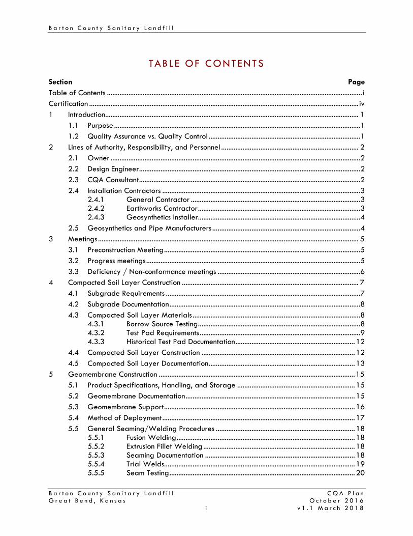
B a r t o n C o u n t y S a n i t a r y L a n d f i l l
B a r t o n C o u n t y S a n i t a r y L a n d f i l l C Q A P l a n G r e a t B e n d , K a n s a s O c t o b e r 2 0 1 6 i v 1 . 1 M a r c h 2 0 1 8
TABLE OF CONTENTS
Section Page Table of Contents ............................................................................................................................................... i Certification ....................................................................................................................................................... iv 1 Introduction .............................................................................................................................................. 1
1.1 Purpose .......................................................................................................................................... 1 1.2 Quality Assurance vs. Quality Control ..................................................................................... 1
2 Lines of Authority, Responsibility, and Personnel ............................................................................. 2 2.1 Owner ............................................................................................................................................ 2 2.2 Design Engineer ............................................................................................................................ 2 2.3 CQA Consultant ............................................................................................................................ 2 2.4 Installation Contractors ............................................................................................................... 3
2.4.1 General Contractor ............................................................................................... 3 2.4.2 Earthworks Contractor ........................................................................................... 3 2.4.3 Geosynthetics Installer........................................................................................... 4
2.5 Geosynthetics and Pipe Manufacturers ................................................................................... 4 3 Meetings .................................................................................................................................................. 5
3.1 Preconstruction Meeting .............................................................................................................. 5 3.2 Progress meetings ........................................................................................................................ 5 3.3 Deficiency / Non-conformance meetings ................................................................................ 6
4 Compacted Soil Layer Construction ................................................................................................... 7 4.1 Subgrade Requirements ............................................................................................................. 7 4.2 Subgrade Documentation ........................................................................................................... 8 4.3 Compacted Soil Layer Materials .............................................................................................. 8
4.3.1 Borrow Source Testing ........................................................................................... 8 4.3.2 Test Pad Requirements .......................................................................................... 9 4.3.3 Historical Test Pad Documentation ................................................................... 12
4.4 Compacted Soil Layer Construction ...................................................................................... 12 4.5 Compacted Soil Layer Documentation .................................................................................. 13
5 Geomembrane Construction .............................................................................................................. 15 5.1 Product Specifications, Handling, and Storage .................................................................. 15 5.2 Geomembrane Documentation ............................................................................................... 15 5.3 Geomembrane Support ........................................................................................................... 16 5.4 Method of Deployment ............................................................................................................ 17 5.5 General Seaming/Welding Procedures .............................................................................. 18
5.5.1 Fusion Welding .................................................................................................... 18 5.5.2 Extrusion Fillet Welding ..................................................................................... 18 5.5.3 Seaming Documentation .................................................................................... 18 5.5.4 Trial Welds........................................................................................................... 19 5.5.5 Seam Testing ........................................................................................................ 20

B a r t o n C o u n t y S a n i t a r y L a n d f i l l
B a r t o n C o u n t y S a n i t a r y L a n d f i l l C Q A P l a n G r e a t B e n d , K a n s a s O c t o b e r 2 0 1 6 i i v 1 . 1 M a r c h 2 0 1 8
5.6 Repairs ........................................................................................................................................ 21 6 Geosynthetics Construction ................................................................................................................. 22
6.1 Product Specifications, Handling, and Storage .................................................................. 22 6.1.1 Geocomposite Specifications ............................................................................ 23 6.1.2 Geotextile Specifications .................................................................................. 24 6.1.3 Geosynthetic Clay Liner (GCL) Specifications ............................................... 25 6.1.4 Geogrid Specifications ...................................................................................... 26
6.2 Geosynthetic Documentation ................................................................................................... 26 6.3 Geosynthetic Installation .......................................................................................................... 27
6.3.1 Geocomposite Installation ................................................................................. 27 6.3.2 Geotextile Installation ........................................................................................ 28 6.3.3 Geosynthetic Clay Liner (GCL) Installation ..................................................... 28 6.3.4 Geogrid Installation ............................................................................................ 29
7 Leachate Collection System Construction ......................................................................................... 30 7.1 Leachate Collection Pipes ........................................................................................................ 30 7.2 Sand Protection / Drainage Layer ........................................................................................ 30 7.3 Clean Drainage Gravel ........................................................................................................... 31
8 Miscellaneous Items Construction ....................................................................................................... 33 8.1 Silty Clay Layer (ET Final Cover System) ............................................................................. 33 8.2 Vegetative Support Layer (Final Cover Systems) ............................................................... 33
9 Surveying............................................................................................................................................... 34 10 Documentation ...................................................................................................................................... 35
10.1 Daily Record Keeping ................................................................................................... 35 10.2 Photo Documentation ..................................................................................................... 35 10.3 Construction Deficiencies ............................................................................................... 35 10.4 Design and Specification Clarifications or Modifications ....................................... 36
11 CQA Report and Certification .......................................................................................................... 37

B a r t o n C o u n t y S a n i t a r y L a n d f i l l
B a r t o n C o u n t y S a n i t a r y L a n d f i l l C Q A P l a n G r e a t B e n d , K a n s a s O c t o b e r 2 0 1 6 i i i v 1 . 1 M a r c h 2 0 1 8
L i s t o f T a b l e s Table 1: Structural Fill Testing Requirements .............................................................................................. 7 Table 2: Borrow Source Pre-Construction Testing ..................................................................................... 9 Table 3: Test Pad Compacted Soil Layer Testing Frequencies and Requirements ........................... 11 Table 4: Compacted Soil Layer Construction Testing ............................................................................. 12 Table 5: Geocomposite Requirements ....................................................................................................... 23 Table 6: Non-woven Geotextile Requirements ........................................................................................ 24 Table 7: GCL Requirements ......................................................................................................................... 25 Table 8: Biaxial Geogrid Requirements ................................................................................................... 26 Table 9: Sand Protection/Drainage Layer Testing Requirements ........................................................ 31 Table 10: Clean Drainage Gravel Testing Requirements ..................................................................... 32 Table 11: Vertical Surveying Requirements and Tolerances ................................................................ 34 A p p e n d i c e s Appendix A Excerpt from EPA Technical Guidance Document:
QA and QC for Waste Containment Facilities Appendix B Copies of GRI Specifications
B1: GRI GM13 - HDPE Geomembrane B2: GRI GM17 - LLDPE Geomembrane B3: GRI GM19 - Geomembrane Seams B4: GRI GT13(a) - Geotextile as Separation Layer
B5: GRI GCL3 - Geosynthetic Clay Liner Appendix C Example CQA Forms Meeting Record Daily Field Activities report Nuclear Density Gauge Test Record Material Inventory Record Seam/Non-Destructive Test Record Non-Destructive Test Record Destructive Test Record Repair Record Trial Weld Record Appendix D 2011 Test Pad Summary Report

B a r t o n C o u n t y S a n i t a r y L a n d f i l l
B a r t o n C o u n t y S a n i t a r y L a n d f i l l C Q A P l a n G r e a t B e n d , K a n s a s O c t o b e r 2 0 1 6 i v v 1 . 1 M a r c h 2 0 1 8
CERT I F ICAT ION
This Construction Quality Assurance (CQA) Plan has been prepared for the Barton County Sanitary Landfill located in Great Bend, Kansas owned and operated by Barton County, Kansas. This CQA Plan generally follows the requirements of the Kansas Administrative Regulations (KAR) for municipal solid waste and construction and demolition landfills and was prepared in accordance with generally accepted industry standards and the local engineering standard of care. Nathan A. Hamm, P.E.
KS License No. 17474 SCS Engineers Vice President / Project Director

B a r t o n C o u n t y S a n i t a r y L a n d f i l l
B a r t o n C o u n t y S a n i t a r y L a n d f i l l C Q A P l a n G r e a t B e n d , K a n s a s O c t o b e r 2 0 1 6 1 v 1 . 1 M a r c h 2 0 1 8
1 INTRODUCT ION
1 . 1 P U R P O S E
This Construction Quality Assurance (CQA) Plan is part of the 2016 Barton County Sanitary Landfill (BCSL) Permit Modification Application submitted to the Kansas Department of Health and Environment (KDHE) Bureau of Waste Management (BWM). The purpose of this CQA Plan is to meet the Construction Quality Assurance requirements included in the Kansas Administrative Regulations, Title 28, Article 29 (K.A.R. 28-29).
This plan is intended to guide construction quality assurance documentation and testing activities to demonstrate that the constructed landfill bottom liner, final cover, leachate management system, and other support infrastructure meet applicable regulations and permit requirements.
1 . 2 Q U A L I T Y A S S U R A N C E V S . Q U A L I T Y C O N T R O L
This CQA Plan addresses construction quality assurance (CQA), not quality control (QC). This CQA Plan is independent of the QC programs conducted by the Manufacturers and Contractors. The intent of the CQA Plan is to provide instruction for independent third party verification and testing in order to demonstrate the Contractors have met their obligations to supply and install Facility construction components according to the permit, construction plans, and specifications. QC is provided by the Manufacturers and Contractors and refers only to those actions taken to ensure the materials and workmanship meet project requirements. Construction Quality Control (CQC) will be addressed in the construction plans and specifications or a separate plan (as needed) and will be handled by the Contractor. Additional CQA activities may be required with the project specifications.

B a r t o n C o u n t y S a n i t a r y L a n d f i l l
B a r t o n C o u n t y S a n i t a r y L a n d f i l l C Q A P l a n G r e a t B e n d , K a n s a s O c t o b e r 2 0 1 6 2 v 1 . 1 M a r c h 2 0 1 8
2 L INES OF AUTHOR ITY, RESPONS IB I L I TY, AND PERSONNEL
This section provides and defines the responsibilities and qualifications for personnel referenced in this CQA Plan.
2 . 1 O W N E R
The Owner is Barton County, Kansas. In this CQA Plan, reference to the Owner may also refer to the Facility’s operator or permit holder if not Barton County, Kansas.
2 . 2 D E S I G N E N G I N E E R
The Design Engineer, also referred to as “Designer,” is the individual or firm responsible for the design and preparation of the project construction plans and specifications. The Design Engineer is responsible for approving the design and specification changes or clarifications necessary during construction. The Design Engineer may be associated with the CQA Consultant or be an independent entity.
2 . 3 C Q A C O N S U L T A N T
The CQA Consultant is the firm retained by the Owner to perform CQA services for construction projects at the Facility. The CQA Consultant and its employees will be an independent party and shall not be affiliated with the Owner or Contractors. The Consultant includes the CQA Engineer and the CQA Monitor(s) who work under his/her direction.
The CQA Engineer must be a registered Professional Engineer (PE) in the State of Kansas and will be responsible for ensuring the CQA Monitors are adequately instructed on proper performance of CQA tasks. The CQA Engineer will also be the person responsible for the CQA Report and Certification, discussed further in Section 11. CQA Monitors are the individuals responsible for performing the day-to-day onsite quality assurance tasks outlined in this plan and must be present during main work activities. The CQA Monitors will have the appropriate level of qualifications and experience for the items being constructed. The CQA Consultant’s duties include the following:
• Review design plans, specifications, and related guidance documents; • Review Contractor submittals for compliance with the CQA Plan requirements and make
appropriate recommendations for other submittals; • Review Manufacturer’s quality control documentation for materials; • Observe material delivery, unloading, and storage; • Observe and document material placement; • Observe and document repair operations; • Schedule and coordinate CQA inspection activities;

B a r t o n C o u n t y S a n i t a r y L a n d f i l l
B a r t o n C o u n t y S a n i t a r y L a n d f i l l C Q A P l a n G r e a t B e n d , K a n s a s O c t o b e r 2 0 1 6 3 v 1 . 1 M a r c h 2 0 1 8
• Verify the Manufacturer's and Contractor's QC plans are in general compliance with the CQA Plan;
• Coordinate CQA activities to verify testing and documentation are complete, accurate, and in accordance with the design plans, specifications, and related guidance documents;
• Assure testing equipment used and tests performed are conducted according to this CQA Plan and industry standards;
• Perform, observe, document, and report test results as required; • Document deviations from design plans, specifications, and related guidance documents;
and • Document and report deficiencies not corrected to the satisfaction of the CQA Monitor
and the CQA Engineer. CQA personnel will be allocated to the site to monitor construction based on the number of major construction activities being performed or separate crews constructing major items on each work day. Major items include:
• Structural fill placement (as required); • Subgrade preparation activities including proof-rolling; • Compacted soil layer construction in bottom liner and final cover systems; • Geosynthetics installation; • Leachate collection system installation (as required); • Silty clay layer and vegetative support layer installation for applicable final cover
systems. 2 . 4 I N S T A L L A T I O N C O N T R A C T O R S
The following section details the typical Installation Contractors, also referred to as “Contractor(s)” to be used in construction of the Facility’s liner, final cover system, and leachate collection system. Construction activities at the Facility may utilize various combinations of these Contractors.
2 . 4 . 1 G e n e r a l C o n t r a c t o r
The General Contractor is responsible for the construction project as a whole and CQC. The General Contractor may also be the Earthworks Contractor and may subcontract the Geosynthetics Installer(s) and/or Earthworks Contractor. The General Contractor may be affiliated with the Owner. 2 . 4 . 2 E a r t h w o r k s C o n t r a c t o r
The Earthworks Contractor is responsible for proper delivery and placement of earthwork, applicable leachate collection system, and storm water components as outlined in the design plans and specifications. The Earthworks Contractor may also install or subcontract leachate collection system or other components of the Facility. The Earthwork Contractor may subcontract the Geosynthetics Installer(s) and may also be affiliated with the Owner.
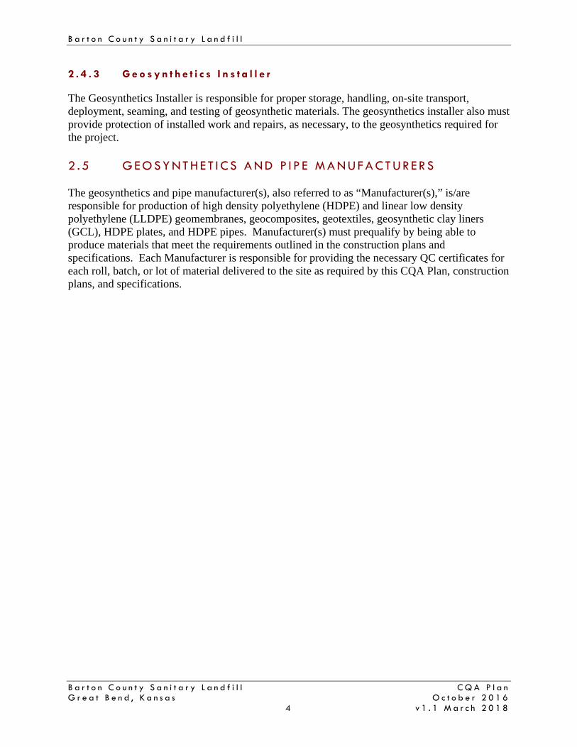
B a r t o n C o u n t y S a n i t a r y L a n d f i l l
B a r t o n C o u n t y S a n i t a r y L a n d f i l l C Q A P l a n G r e a t B e n d , K a n s a s O c t o b e r 2 0 1 6 4 v 1 . 1 M a r c h 2 0 1 8
2 . 4 . 3 G e o s y n t h e t i c s I n s t a l l e r
The Geosynthetics Installer is responsible for proper storage, handling, on-site transport, deployment, seaming, and testing of geosynthetic materials. The geosynthetics installer also must provide protection of installed work and repairs, as necessary, to the geosynthetics required for the project. 2 . 5 G E O S Y N T H E T I C S A N D P I P E M A N U F A C T U R E R S
The geosynthetics and pipe manufacturer(s), also referred to as “Manufacturer(s),” is/are responsible for production of high density polyethylene (HDPE) and linear low density polyethylene (LLDPE) geomembranes, geocomposites, geotextiles, geosynthetic clay liners (GCL), HDPE plates, and HDPE pipes. Manufacturer(s) must prequalify by being able to produce materials that meet the requirements outlined in the construction plans and specifications. Each Manufacturer is responsible for providing the necessary QC certificates for each roll, batch, or lot of material delivered to the site as required by this CQA Plan, construction plans, and specifications.

B a r t o n C o u n t y S a n i t a r y L a n d f i l l
B a r t o n C o u n t y S a n i t a r y L a n d f i l l C Q A P l a n G r e a t B e n d , K a n s a s O c t o b e r 2 0 1 6 5 v 1 . 1 M a r c h 2 0 1 8
3 MEET INGS
This section describes the types and obligations for various meetings during the construction process. Meeting documentation forms, such as the one in Appendix C, may be used if desired.
3 . 1 P R E C O N S T R U C T I O N M E E T I N G
A preconstruction meeting will be held at the Facility prior to the start of construction. Representatives from the Owner, Design Engineer, CQA Consultant, and Contractor(s) should attend the preconstruction meeting. The purpose of the pre-construction meeting is to:
• Provide each organization with relevant CQA documentation and supporting information;
• Review the project construction plans, specifications, CQA Plan, and other pertinent documents as necessary;
• Define the responsibilities of each party; • Define lines of communication and authority; • Review work area safety protocol; • Review method of documentation, testing procedures, and reporting inspection data; • Establish testing protocols and procedures for correcting and documenting
construction deficiencies; • Discuss changes that may be needed to ensure construction will meet or exceed the
minimum requirements of design; • Conduct a site inspection to discuss work areas, work plans, adverse weather
procedures, stockpiling, laydown areas, access roads, haul roads, and related items; and
• Review the project schedule.
This meeting will be documented by the CQA Consultant and copies of meeting minutes distributed to all parties.
3 . 2 P R O G R E S S M E E T I N G S
Progress meetings are informal and will be held as necessary but generally daily either before the start of work or at the completion of work. At a minimum, this meeting will be attended by the CQA Monitor and the Contractor(s). The purpose of this meeting is to:
• Review scheduled work activities; • Review the previous day's activities; • Review and discuss problems; and • Review test data.
Documentation of these informal progress meetings may or may not be retained. Documentation deemed notable by the CQA Consultant will be recorded by the CQA Monitor and kept with the Daily Field Activities Report (see example form in Appendix C) or other daily record keeping documentation as discussed in Section 10.1.

B a r t o n C o u n t y S a n i t a r y L a n d f i l l
B a r t o n C o u n t y S a n i t a r y L a n d f i l l C Q A P l a n G r e a t B e n d , K a n s a s O c t o b e r 2 0 1 6 6 v 1 . 1 M a r c h 2 0 1 8
3 . 3 D E F I C I E N C Y / N O N - C O N F O R M A N C E M E E T I N G S
Special meetings will be held, as needed, to discuss potential problems or deficiencies. At a minimum, these meetings will be attended by the CQA Monitor and the Contractor(s). If the problem relates to a design issue, the Design Engineer should also attend. The purpose of the meeting is to:
• Review deficiency / non-conformance item(s); • Discuss resolution options; • Determine course for correction; and • Notify and coordinate with appropriate parties.
The results of this meeting will be documented by the CQA Consultant. Brief discussion is required in the CQA Report and Certification (see Section 11).

B a r t o n C o u n t y S a n i t a r y L a n d f i l l
B a r t o n C o u n t y S a n i t a r y L a n d f i l l C Q A P l a n G r e a t B e n d , K a n s a s O c t o b e r 2 0 1 6 7 v 1 . 1 M a r c h 2 0 1 8
4 COMPACTED SOI L LAYER CONSTRUCT ION
The following sections describe anticipated compacted soil layer CQA activities. A CQA Report and Certification will be submitted to the KDHE BWM after construction of each cell, phase, or portion of liner or final cover system is complete as discussed in Section 11. Documentation requirements specific to the compacted soil layer construction are discussed below.
4 . 1 S U B G R A D E R E Q U I R E M E N T S
Immediately underneath the compacted soil layer is referred to as subgrade and must be suitable for the applicable construction activities. In a base liner system, the subgrade is typically the limit of excavation or soil fill necessary to reach appropriate construction elevations. Where the base liner overlaps onto the pre-Subtitle D MSW and C&D landfill, the subgrade will be the top of the intermediate cover. In final cover systems, subgrade may represent the top of daily or intermediate cover, or other fill material necessary to reach design elevations. In either the case of the base liner or final cover construction, the CQA Monitor will observe and test structural fill as outlined on Table 1 below.
Table 1: Structural Fill Testing Requirements
Test Test Method Frequency Results
Conformance Testing1
Soil classification ASTM D 2487 1 per material type
Verify adequacy for subgrade requirements
Particle-size analysis ASTM D 422 1 per 5,000 cy or one per material type
(fill only) Atterberg limits ASTM D 4318
Proctor Compaction Curve
ASTM D 698 / ASTM D 1557
1 per 5,000 cy with at least 1 per soil type
Construction Testing
In-place moisture content using nuclear method ASTM D 6938 For fill:
1 per 10,000 ft2 per lift 2
As specified by Design Engineer
In-place density using nuclear method (for fill only)
ASTM D 6938 ≥95% standard Proctor
Lift thickness Observation Periodic oversight2, must verify final lift
As specified by Design Engineer
Note: cy = cubic yard; ft2 = square feet 1. Pre-construction testing may be performed in addition to conformance testing on structural fill or other
subgrade materials. Frequency and test determination will be at the discretion of the Owner and CQA Consultant.
2. At the discretion of Design Engineer. The CQA Consultant will observe the subgrade to determine if it consists of competent material and is free of trees, stumps, boulders, and debris. The surface of the subgrade shall be graded to provide a smooth, workable surface on which to construct the liner. A proof roll will be conducted to identify soft spots in the subgrade. Soft spots shall be excavated and replaced with structural fill or otherwise stabilized to meet project requirements.

B a r t o n C o u n t y S a n i t a r y L a n d f i l l
B a r t o n C o u n t y S a n i t a r y L a n d f i l l C Q A P l a n G r e a t B e n d , K a n s a s O c t o b e r 2 0 1 6 8 v 1 . 1 M a r c h 2 0 1 8
4 . 2 S U B G R A D E D O C U M E N T A T I O N
Documentation for prepared subgrade installation generally includes the following information:
• Date, project name, location and weather data; • A reduced-scale plan showing work areas and test locations (if applicable); • Descriptions of ongoing construction (if applicable); • Summary of test results, samples taken, and their location (if applicable); • Test equipment calibration (if applicable); • Loose lift thickness observation (if applicable); • Type and configuration of compaction equipment (if applicable); • Visual inspection of materials to document they are uniform and as specified in the
design (soil type, clod size, deleterious materials, etc.); • Visual inspection of the stability of the subgrade (i.e., proof-rolling observation); • List of equipment used for the day’s construction activities; and • Name of CQA Monitor.
Subgrade testing will be conducted at the discretion of the Owner, Design Engineer, and/or CQA Consultant. Surveying requirements are discussed in Section 9. 4 . 3 C O M P A C T E D S O I L L A Y E R M A T E R I A L S
This section summarizes requirements for soil materials to be used in the compacted soil layer. The compacted soil layer is a component of the base liner system (Subtitle D MSW landfill) and the final cover system (prescriptive cover). The required hydraulic conductivity of the compacted soil layer material after placement shall be less than, or equal to, 1x10⁻⁷ centimeters per second (cm/sec) for the base liner system and 1x10⁻⁵ cm/sec for the prescriptive final cover system. Compacted soil layer construction should not begin until borrow source testing and/or the test pad construction have been completed, as necessary, to determine the material type and placement requirements. Note that for areas of liner which require a geogrid installation, the geogrid will be installed on the prepared subgrade directly underneath the compacted soil layer. Geogrid CQA requirements are discussed in Section 6. 4 . 3 . 1 B o r r o w S o u r c e T e s t i n g
The soil desired to be used as the compacted soil layer must be placed at appropriate moisture contents and dry densities which result in hydraulic conductivities (ASTM D 5084) no greater than 1x10⁻⁷ cm/sec for base liner system or 1x10⁻⁵ cm/sec for the prescriptive final cover system. The acceptable range of moisture contents and dry densities at which the material can be placed

B a r t o n C o u n t y S a n i t a r y L a n d f i l l
B a r t o n C o u n t y S a n i t a r y L a n d f i l l C Q A P l a n G r e a t B e n d , K a n s a s O c t o b e r 2 0 1 6 9 v 1 . 1 M a r c h 2 0 1 8
will be determined in general accordance with the procedure to determine the Acceptability Zone as discussed in Technical Guidance Document: “Quality Assurance and Quality Control for Waste Containment Facilities”, EPA/600/R-93/182, September 1993 (see Section 2.1.4.5 of the referenced document, excerpt included in Appendix A). An Acceptability Zone should be drawn to encompass the data points representing test results meeting or exceeding the design criteria. Generally, the moisture contents and dry densities will be determined using standard compaction (ASTM D 698) and/or modified compaction (ASTM D 1557) at the discretion of the CQA Engineer. In addition to the compaction and permeability testing, identification or index testing will be performed on the soil in accordance with the criteria shown on Table 2.
Table 2: Borrow Source Pre-Construction Testing
Test Test Method Frequency
Soil classification ASTM D 2487
1 per 10,000 cy with at least 1 per soil type
Particle-size analysis with hydrometer ASTM D 422
Atterberg limits ASTM D 4318
Proctor compaction curve ASTM D 698 / ASTM D 1557
Hydraulic conductivity ASTM D 5084 As needed to develop acceptable placement
zone Note: cy = cubic yard
The compacted soil layer’s Acceptability Zone will be used for soil placement specifications to construct compacted soil layers. Once the Acceptability Zone has been established and approved for a particular borrow source, it will not be necessary to perform the Acceptability Zone testing program again for materials meeting the identification and index criteria. Prior to starting construction, future soil from the same borrow source will be subjected to soil classification (ASTM D 2487) Atterberg Limits testing (ASTM D 4318) and particle-size analysis (ASTM D 422). These test results will be evaluated for each potential compacted soil liner material and compared to the material represented by the established Acceptability Zone. If, in the opinion of the CQA Consultant, the proposed soil is substantially different from previously established material, then a new Acceptability Zone will be developed. 4 . 3 . 2 T e s t P a d R e q u i r e m e n t s
Test pads are constructed to verify the preconstruction testing results, including density, moisture content, and hydraulic conductivity can be achieved in the field. After a test pad has been constructed and shown to meet the requirements of the CQA Plan, additional test pads will not be required as long as the materials and methods of placement are similar to the previously constructed test pad.

B a r t o n C o u n t y S a n i t a r y L a n d f i l l
B a r t o n C o u n t y S a n i t a r y L a n d f i l l C Q A P l a n G r e a t B e n d , K a n s a s O c t o b e r 2 0 1 6 1 0 v 1 . 1 M a r c h 2 0 1 8
Test pads are intended for use only with compacted soil layer in the base liner construction (Subtitle D MSW Landfill liner system), not with the compacted soil layer in the prescriptive final cover system. A test pad will be constructed when the CQA Engineer determines one is needed such as if a new borrow material without a previously approved placement zone is proposed for the project; construction equipment is significantly changed; or construction practices are significantly changed. The test pad, if deemed necessary, should be constructed prior to construction of the compacted soil layer. It is intended that the test pad be completed prior to beginning construction of the liner itself to verify adequate methods and material, although compacted soil layer construction may overlap. The test pad will be constructed on a relatively flat area (similar to the floor of a cell) in or near the construction project area. The test pad may be constructed within the area of the liner and may be incorporated into the compacted soil layer portion of the liner system using a stair-step construction method to tie into the adjacent liner areas. The test pad must be maintained in acceptable condition while the remainder of the liner is under construction if it is within the area of the construction project’s liner system. Test Pad Construction The minimum thickness of the test pad shall be 36 inches. Two-Stage Infiltration testing will require a minimum thickness of 2.5 feet or 30 inches. The minimum surface area for the test pad shall be 5,000 square feet (sf) or an area large enough to accommodate proper operation of the construction equipment (i.e., allow the equipment to reach operating speed), whichever is greater. The Earthworks Contractor will place and compact each lift with a thickness of approximately six (6) inches after compaction. Each lift will be thoroughly and uniformly compacted to the density and moisture content determined necessary to achieve the required 1x10⁻⁷ cm/sec hydraulic conductivity. Each lift will be incorporated into the previous lift by techniques such as scarifying and using compaction equipment capable of penetrating the thickness of the compacted lift. Visible debris, roots, and angular or sharp rocks larger than two (2) inches in diameter will be removed from the test pad. Frozen soil will not be allowed for construction of the test pad. The test pad will be protected from detrimental climatic effects during construction by performing the following:
• Re-compact soil lifts where the integrity is adversely affected by weather to the extent that the requirements of the CQA Plan are not met; and
• Provide measures so the test pad is protected from desiccation or deterioration by covering the test pad, applying moisture, or other appropriate methods.
Test Pad Construction Oversight The CQA Consultant will provide oversight of test pad construction to document the construction procedures and test results.

B a r t o n C o u n t y S a n i t a r y L a n d f i l l
B a r t o n C o u n t y S a n i t a r y L a n d f i l l C Q A P l a n G r e a t B e n d , K a n s a s O c t o b e r 2 0 1 6 1 1 v 1 . 1 M a r c h 2 0 1 8
The CQA Consultant will document the following items or activities: • Type and size of compaction equipment used and the number of passes made to achieve
the required density; • Method of surface preparation for each lift of soil; • Method of reducing clod size, if required; • Method of adjusting soil moisture content, if required; • Method of controlling desiccation, if required; • Thickness of each lift after compaction; • Density and moisture content for each soil lift • Constructed test pad dimensions, and; • Results of hydraulic conductivity testing.
Test Pad Field Verification The CQA Consultant will perform or direct test pad testing as indicated in Table 3, below.
Table 3: Test Pad Compacted Soil Layer Testing Frequencies and Requirements
Parameter Specification Test Method Construction Frequency
Compacted Lift Thickness
As specified by the design engineer Observation Continuous
In-Place Moisture Content
Within Acceptability Zone
ASTM D 6938 / ASTM D 4643 with one ASTM D 2216 for every 10 of
other methods
4 per lift min.
In-Place Density Within Acceptability Zone
ASTM D 6938 / ASTM D 2937 / ASTM D 1566 /
ASTM D 2167 4 per lift min.
Hydraulic Conductivity (undisturbed
samples)
k≤1x10⁻⁷ cm/sec (bottom liner) or 1x10⁻⁵ cm/sec (final cover)
ASTM D 6391 4 two stage tests per test pad
If the test pad is significantly larger than 5,000 sf, the test frequency will be increased proportionately. Holes created by in-place testing will be filled with granular bentonite and/or low permeability soil depending on which method is appropriate for the hole. The hydraulic conductivity of the test pad will be determined using the procedure described in ASTM D 6391, Standard Test Method for Field Measurement of Hydraulic Conductivity Limits of Porous Materials Using Two Stages of Infiltration from a Borehole, which is commonly referred to as the Boutwell Test. A minimum of four (4) determinations will be made on each completed test pad; i.e., testing is not done on individual lifts as the test pad is constructed. If test results show passing results at the conclusion of Stage 1, Stage 2 will not be required. Once a material has been proven by this method to produce a hydraulic conductivity of 1x10⁻⁷ cm/sec or less, that material will not require additional test pad construction or Boutwell testing when used for future liner construction, provided the CQA Engineer certifies that similar materials and construction procedures are being followed.

B a r t o n C o u n t y S a n i t a r y L a n d f i l l
B a r t o n C o u n t y S a n i t a r y L a n d f i l l C Q A P l a n G r e a t B e n d , K a n s a s O c t o b e r 2 0 1 6 1 2 v 1 . 1 M a r c h 2 0 1 8
4 . 3 . 3 H i s t o r i c a l T e s t P a d D o c u m e n t a t i o n
In May 2011 two test pads were constructed using “Middle” and “Lower” Horizon soils. These materials showed a hydraulic conductivity averaging 7.62x10⁻⁸ cm/sec and 5.19x10⁻⁸ cm/sec, respectively. If preconstruction testing of the soil liner shows the material is similar to either soil then another test pad will not be required. However, if testing shows that the materials are not consistent, then a test pad will be required to show the material can reach the required 1x10⁻⁷ cm/sec permeability in the field. See Appendix D for the approved 2011 Test Pad Summary Report. 4 . 4 C O M P A C T E D S O I L L A Y E R C O N S T R U C T I O N
Compacted Soil Layer Testing Table 4 describes the required soil testing and testing frequencies to confirm soil used for construction is consistent with soil used to develop the Acceptability Zone and/or used in the Test Pad. The construction tests (moisture and density) will be performed to verify the material is placed within the appropriate soil Acceptability Zone and the requisite hydraulic conductivity is achieved.
Table 4: Compacted Soil Layer Construction Testing
Test Test Method Frequency Results
Conformance Testing
Soil classification ASTM D 2487
1 per 5,000 cy with at least 1 per soil type
Consistent with pre-construction testing
discussed in Table 2
Particle-size analysis with hydrometer ASTM D 422
Atterberg limits ASTM D 4318
Proctor compaction curve ASTM D 698 / ASTM D 1557
1 per 10,000 cy with at least 1 per soil type
Hydraulic conductivity ASTM D 5084 If needed, at CQA Consultant’s discretion
k ≤ 1x10⁻⁷ cm/sec for base liner system and k ≤ 1x10⁻⁵ cm/sec for prescriptive final cover
Construction Testing
In-place moisture content using nuclear method ASTM D 6938
1 per 10,000 ft2 per lift Within Acceptability Zone discussed in Section 4.3 In-place density
using nuclear method ASTM D 6938
Lift thickness Observation Continuous oversight while
compacted soil layer construction is occurring
As specified by Design Engineer
Note: cy = cubic yard; ft2 = square feet; cm/sec = centimeters per second
Laboratory test reports will indicate the type of test, method of testing and condition, preparation, and orientation of each sample. Field tests should reference the locations where the tests were conducted and where samples were collected.

B a r t o n C o u n t y S a n i t a r y L a n d f i l l
B a r t o n C o u n t y S a n i t a r y L a n d f i l l C Q A P l a n G r e a t B e n d , K a n s a s O c t o b e r 2 0 1 6 1 3 v 1 . 1 M a r c h 2 0 1 8
Nuclear density gauges will be calibrated at the frequency required by the manufacturer and checked on a daily basis. Density by drive cylinder (ASTM D 2937) and moisture content by oven (ASTM D2216) or by microwave (ASTM D 4643) may be conducted on the liner to verify the density gauge is in proper working order. These tests will be conducted at the discretion of the CQA Consultant. Compacted Soil Layer Construction Procedures The upper six inches of the subgrade surface on which the compacted soil layer is to be placed shall be compacted to density firm condition suitable to provide a stable platform for subsequent layer compaction. In constructing the compacted soil layer, the surface on which the lift will be placed shall be proof-rolled and scarified to a depth of at least one inch. See Section 4.1 for additional information regarding subgrade requirements. Each lift of the compacted soil layer shall be placed loose and shall be compacted to designated thickness (specified by Design Engineer) or less by the use of a sheepsfoot roller. The compactor shall be equipped with feet that fully penetrate the loose lift of soil. Rocks, cobbles, roots, and other foreign objects over 2 inches in diameter will be removed from the area. Placement of frozen soil, or additional lifts of soil onto frozen in-place liner material, shall be prohibited. If the compacted soil layer borrow material is frozen, it must thaw completely before use in the construction. In the event of freezing or frost on constructed lifts of compacted soil layers, the material shall be scarified and allowed to thaw, and re-worked to the observed depth of frost penetration (based on the CQA Consultant's observation), prior to placing additional lifts of soil. After the soil layer is compacted, it shall be smooth rolled and protected from desiccation cracking, frost damage or other sources of degradation. If the compacted soil layer requires repair or replacement, a description of the repair will be placed in the CQA Report and Certification. During compacted soil layer construction, the CQA Monitor will observe and document installation procedures and lift thicknesses. After the compacted soil layer is completed, a control survey will be performed on a 100-foot by 100-foot grid and grade breaks to verify the compacted soil layer thickness. Refer to Section 9 for additional surveying information. 4 . 5 C O M P A C T E D S O I L L A Y E R D O C U M E N T A T I O N
CQA documentation for compacted soil layer construction generally includes the following, surveying requirements are discussed in Section 9:
• Date, project name, location and weather data; • A reduced-scale plan showing work areas and test locations, if applicable; • Descriptions of ongoing construction, if applicable; • Summary of test results and samples taken; • Test equipment calibration data; • Loose lift thickness observation;

B a r t o n C o u n t y S a n i t a r y L a n d f i l l
B a r t o n C o u n t y S a n i t a r y L a n d f i l l C Q A P l a n G r e a t B e n d , K a n s a s O c t o b e r 2 0 1 6 1 4 v 1 . 1 M a r c h 2 0 1 8
• Description of type and configuration of construction equipment, if applicable; • Visual inspection of materials to document they are uniform and as specified in the
design (color, texture, clods, deleterious materials, uniformity of moisture content, etc.); and
• Name of CQA Monitor.

B a r t o n C o u n t y S a n i t a r y L a n d f i l l
B a r t o n C o u n t y S a n i t a r y L a n d f i l l C Q A P l a n G r e a t B e n d , K a n s a s O c t o b e r 2 0 1 6 1 5 v 1 . 1 M a r c h 2 0 1 8
5 GEOMEMBRANE CONSTRUCT ION
This section summarizes CQA activities to be performed for the geomembranes to be used as a component of the base liner and prescriptive final cover systems. 5 . 1 P R O D U C T S P E C I F I C A T I O N S , H A N D L I N G , A N D S T O R A G E
The geomembranes used in the base liner system and prescriptive final cover system for the project shall conform to the minimum specifications detailed in current versions of GRI GM 13 (for HDPE geomembrane) and GRI GM 17 (for LLDPE geomembrane) for resin and geomembrane components, copies of which are included in Appendix B. Prior to shipment, the CQA Consultant will be provided with the Manufacturer’s QC documentation and certification for each lot of resin and each roll of geomembrane to be shipped and used for construction. The geomembrane shall be manufactured of first-quality resin and shall be compounded and manufactured specifically for the purpose intended. The CQA Consultant shall obtain and review the Manufacturer’s QC reports for conformance with project specifications. The geomembrane material shall be free of holes, blisters, undispersed raw materials, or signs of contamination by foreign matter. Defects shall be repaired in accordance with the Manufacturer's recommendations. The geomembrane material shall be handled in a manner which will:
• Avoid or minimize damage by such activities as handling, traffic, smoking, and use of equipment and tools;
• Prevent scratching or crimping of panels during unrolling; • Prevent damage of the underlying soil liner or final cover components; • Prevent uplifting of in-place panels by wind; and • Minimize the wrinkles and compensate (distribute across cell, avoid wrinkles at seams)
for those that cannot be prevented. 5 . 2 G E O M E M B R A N E D O C U M E N T A T I O N
Each Manufacturer is responsible for providing the necessary QC certificates for each roll, batch, or lot of material delivered to the site. The geomembrane must meet the requirements listed in the current versions of GRI GM 13 (HDPE) and GRI GM 17 (LLDPE) for both textured and smooth geomembrane, as applicable. Copies of the QC certifications will be included with the CQA Report and Certification. Prior to geomembrane installation, the Geosynthetics Installer will provide a signed form to the CQA Consultant stating the constructed surface immediately underlying the geomembrane is adequate as discussed in Section 5.3.

B a r t o n C o u n t y S a n i t a r y L a n d f i l l
B a r t o n C o u n t y S a n i t a r y L a n d f i l l C Q A P l a n G r e a t B e n d , K a n s a s O c t o b e r 2 0 1 6 1 6 v 1 . 1 M a r c h 2 0 1 8
The CQA Consultant shall log in rolls of geomembrane material that arrives on site and review the Manufacturer’s QC certification documentation. Each roll shall be documented on a Material Inventory Log similar to the one found in Appendix C. Storage of geomembrane material shall be done in a manner that reasonably protects the material from puncture, denting, deformation of rolls, and other damaging situations prior to its deployment. Ultra violet (UV) sensitive geosynthetics should be stored in undamaged opaque coverings and protected from standing water during storage. In general, geomembrane observation includes documenting the following information:
• Date, project name, contractor, location, and weather data; • Identification of panel number, roll number, and panel placement; • Welder and equipment identification; • Location and identification of repairs and date of repair; • Operating temperatures of welding equipment; • Length measurements for geomembrane panel and repairs; • Seam overlap and verification of seaming documentation tests (including results) at all
seam and repair locations; and • Name of the CQA Monitor.
The following includes information is required in the CQA Report and Certification for geomembrane:
• Manufacturer’s QC certificates for each geomembrane roll used in construction; • Surface acceptance form provided by the Geosynthetics Installer for the layer
immediately underlying the geomembrane; • Material inventory logs (example in Appendix C); • Documentation of geomembrane observation and forms (examples in Appendix C)
including: o Seam/non-destructive Test Record, o Non-destructive Test Record, o Destructive Test Record, o Repair Record, and o Trail Weld Record;
• Panel placement map; and • Laboratory testing results for destructive tests.
5 . 3 G E O M E M B R A N E S U P P O R T
Surfaces to be lined with geomembrane shall:
• Be smooth and free of debris and angular or sharp rocks; • Be smooth-rolled and shall not contain protrusions of stones, clods, rocks, or debris that
are large enough to damage the liner; and

B a r t o n C o u n t y S a n i t a r y L a n d f i l l
B a r t o n C o u n t y S a n i t a r y L a n d f i l l C Q A P l a n G r e a t B e n d , K a n s a s O c t o b e r 2 0 1 6 1 7 v 1 . 1 M a r c h 2 0 1 8
• Not have sudden, sharp, or abrupt changes in grade. The Geosynthetics Installer shall be responsible for providing a signed surface acceptance form for the constructed surface immediately underlying the geomembrane to the CQA Consultant for inclusion in the CQA Report and Certification. These forms should be completed on a daily basis covering that day’s installation progress. The Geosynthetics Installer and/or Contractor shall protect the surface underlying the geomembrane from desiccation, flooding, and freezing. Protection, if required, may consist of a thin, plastic protective cover, or other material as approved by the CQA Engineer, installed over the completed underlying surface until such time as the placement of geomembrane begins. The thin, plastic protective cover would only be used as a short-term (i.e., overnight, over a weekend, or a couple days of inclement weather) measure to protect the compacted soil layer surface until the geomembrane is deployed. It shall not be used for long-term frost protection over winter. Geomembrane deployment shall be performed as soon as possible after completion of the compacted soil layer. Longer-term exposure situations may require placement of additional protective soil. Underlying surfaces found to have significant desiccation cracking, swelling, heaving, or other similar conditions, shall be replaced or reworked to remove the defects. The geomembrane shall be installed in direct and uniform contact with the underlying compacted soil layer. 5 . 4 M E T H O D O F D E P L O Y M E N T
The general method of deployment for the geomembrane panels are outlined below:
1. The method and equipment used to deploy the panels must not damage the geomembrane or the supporting surface.
2. No personnel working on the geomembrane will wear shoes that may damage the geomembrane liner or engage in actions that could result in damage to the liner.
3. Adequate temporary anchoring (i.e., sandbags or other approved anchorage) that will not damage the geomembrane will be placed to prevent uplift of the geomembrane by wind.
4. The geomembrane will be deployed in a manner to minimize wrinkles. 5. Any area of a panel observed and noted as damaged (torn, twisted, punctured, or
crimped) will be marked and repaired or replaced. Any repaired panels will be approved by the CQA Monitor and noted on the information forms.
6. Bridging or stressed conditions in the geomembrane should be minimized. Proper slack allowance for shrinkage should be provided during installation and before the placement of overlying components.
7. Panels shall have a minimum 4-inch finished overlap or as required by the manufacturer. Seams shall be oriented parallel to the line of maximum slope, i.e., orientation should generally be in line with the downward grade of the liner system and horizontal seams shall not be allowed on side slopes.
8. Seams on side slopes shall be installed at 45-degree angle to the slope. In corners and odd-shaped geometric locations, the number of field seams will be minimized and every

B a r t o n C o u n t y S a n i t a r y L a n d f i l l
B a r t o n C o u n t y S a n i t a r y L a n d f i l l C Q A P l a n G r e a t B e n d , K a n s a s O c t o b e r 2 0 1 6 1 8 v 1 . 1 M a r c h 2 0 1 8
effort shall be made to maximize the panel size. No “T” joints will be closer than 10 feet to the toe of the slope.
9. Objects such as pipes, gas vents, manholes, sumps, or other objects which may penetrate the liner shall be connected to the liner material in such a way that prevents leakage and unnecessary stresses.
5 . 5 G E N E R A L S E A M I N G / W E L D I N G P R O C E D U R E S
5 . 5 . 1 F u s i o n W e l d i n g
1. Seaming shall extend to the outside edge of panels to be placed in the anchor trench. 2. While welding a seam, monitor and maintain the proper overlap. 3. Align wrinkles at the seam overlap to allow welding through the wrinkle. 4. “Fishmouths” or wrinkles at seam overlaps, which cannot be welded through, will be cut
along the ridge in order to achieve a flat overlap. The cut “fishmouth” or wrinkle will be heat-tacked flat and extruded or patched with an oval or round patch of the same geomembrane material extending a minimum of three inches beyond the cut.
5. Prior to welding cross/butt seams, the top and bottom overlaps of intersecting fusion welded seams will be trimmed six inches. Intersecting extrusion fillet-welded seams will be ground to flatten the extrusion bead prior to welding butt seams.
6. All “T” joints produced as a result of cross/butt seams will be extrusion fillet welded. The overlap on each “leg” of the “T” joint will be trimmed back six inches. Grind three inches minimum on each of the three legs of the “T,” and extrusion weld the area prepared by grinding.
7. Clean the seam area prior to seaming to provide an area that is clean and free of moisture, dust, dirt, or debris.
5 . 5 . 2 E x t r u s i o n F i l l e t W e l d i n g
1. Whenever possible, pre-bevel extrusion welded seams prior to heat-tacking into place. 2. Overlap geomembrane a minimum of four inches. 3. Using a hot-air source, temporarily bond the panels of geomembrane to be welded, taking
care not to damage the geomembrane. 4. Clean the seam area prior to seaming to provide an area that is clean and free of moisture,
dust, dirt, and debris. 5. Prior to welding but within one hour of the welding operation, grind seam overlap in a
manner that does not damage the geomembrane. Grind marks should be covered with extrudate whenever possible. Grinding should not extend more than one-quarter inch past the edge of the area covered by the extrudate during welding.
5 . 5 . 3 S e a m i n g D o c u m e n t a t i o n
The following seaming information will be documented:
• Date and time, • Weather conditions, • Panel number,

B a r t o n C o u n t y S a n i t a r y L a n d f i l l
B a r t o n C o u n t y S a n i t a r y L a n d f i l l C Q A P l a n G r e a t B e n d , K a n s a s O c t o b e r 2 0 1 6 1 9 v 1 . 1 M a r c h 2 0 1 8
• Seam number, • Seam length, • Welder technician ID, • Machine number, • Temperature setting, and • Seam testing results.
Personnel performing seaming operations shall be trained in the operation of the specific seaming equipment being used. The installation contractor shall provide direct supervision of the seaming operations. Welding technicians (personnel performing the seaming operations) will mark the following information on the liner with permanent markers at the start of seaming operations:
• Date and time, • Welding technician ID, • Machine number, and • Machine operating temperature and speed.
A panel layout drawing will be prepared to show locations of seams, samples cut for destructive testing, and repairs. The panel layout drawing will be included in the CQA Report and Certification at the CQA Consultant’s discretion. 5 . 5 . 4 T r i a l W e l d s
Trial welds for fusion and extrusion welds will be conducted:
• Prior to each seaming period, • Every five hours, • As weather conditions dictate, or • If welding problems are suspected and at the discretion of CQA Monitor.
Trial welds shall be performed under the same conditions encountered during actual seaming. Once qualified by a passing trial weld, welding technicians shall not change parameters (temperature, speed, etc.) without performing another trial weld.
1. Trial welds shall be made by joining two pieces of geomembrane that are at least six inches in width. Trial welds for fusion welds shall be a minimum of five feet long, and extrusion weld trial seams shall be a minimum of four feet long.
2. Samples shall consist of five one-inch-wide specimens, one from the middle of the seam and two that are each one foot from each end of the test seam. Specimens shall be obtained using a one-inch die cutter. The specimens shall then be tested in peel (three specimens) and sheer (two specimens) using a field tensiometer capable of 500 pound tensile force.
3. For a trial weld to be considered acceptable, all specimens must meet the following criteria: a. They must exhibit film tearing bond (FTB).

B a r t o n C o u n t y S a n i t a r y L a n d f i l l
B a r t o n C o u n t y S a n i t a r y L a n d f i l l C Q A P l a n G r e a t B e n d , K a n s a s O c t o b e r 2 0 1 6 2 0 v 1 . 1 M a r c h 2 0 1 8
b. They must meet or exceed the minimum strength values shown in GRI GM 19 for appropriate geomembrane type and seam. If any specimen should fail, the entire procedure will be repeated.
c. In the case of double track fusion welded seams, both welds must pass to be considered acceptable.
d. If repeat tests utilizing reasonable sets of welding parameters also fail, the seaming apparatus will not be accepted and will not be used for seaming until the deficiencies are corrected and a passing test seam is achieved.
e. Trial Weld Documentation: The installation contractor will record date, time, operator, machine number, ambient and operating temperatures, speed setting, peel values, shear values, and pass/fail designation. A log of recorded test values will be maintained and will become part of the record documents for the installation.
f. In the event that non-complying seam test strips are encountered, the welding machine will be taken out of service until a passing trial weld is obtained, and additional peel specimens will be taken to localize the flaw.
5 . 5 . 5 S e a m T e s t i n g
Seam testing is categorized as non-destructive and destructive. Non-destructive tests shall be performed over the full length of field seams. Testing shall be by vacuum (for extrusion welds) or pressure (for double fusion welds). Vacuum tests (ASTM D 5641) will induce a pressure of 5 pounds per square inch (psi) and must hold the pressure for 10 seconds. Pressure tests (ASTM D 5820) will induce a pressure of 30 psi to 35 psi and hold the pressure for 5 minutes with a loss of no more than 2 psi. Destructive samples of seams shall be collected approximately once every 500 feet of seam per seam type (extrusion or double fusion) for both field and laboratory destructive testing. A minimum of 1 destructive sample shall be taken on repairs, or at the discretion of the CQA Engineer. Each destruct seam sample will have five specimens for field testing and five specimens for laboratory testing. The following laboratory tests will be performed on each destructive seam sample:
• Shear test by method ASTM D4437 (Mod. NSF 54) or equivalent thereof; and • Peel test by method ASTM D4437 (Mod. NSF 54) or equivalent thereof.
Required seam strength values and locus of failure of destructive samples will be compared to the seam strength and related properties of geomembrane seams as discussed in current GRI GM 19 specifications (Appendix B) for the appropriate geomembrane type and seam. Result of field seam testing samples will be recorded. Holes in the geomembrane resulting from destructive seam sampling shall be repaired and tested in accordance with this section.

B a r t o n C o u n t y S a n i t a r y L a n d f i l l
B a r t o n C o u n t y S a n i t a r y L a n d f i l l C Q A P l a n G r e a t B e n d , K a n s a s O c t o b e r 2 0 1 6 2 1 v 1 . 1 M a r c h 2 0 1 8
5 . 6 R E P A I R S
a. Any portion of the geomembrane or geomembrane seam showing a flaw or having a destructive or non-destructive test in noncompliance will be repaired and nondestructively tested.
b. Repair holes larger than one-quarter inch with a patch; repair smaller holes by extrusion cap welding.
c. Grind and clean the surface to be patched. Remove no more than 10 percent of the thickness.
d. Patches shall have rounded corners or be oval in shape, made of the same geomembrane, and extend a minimum of six inches beyond the edge of the defects. Patches shall be of the same compound and thickness as the geomembrane specified. Patches shall have their top edges beveled with an angle grinder prior to placement on the geomembrane. Patches will be applied using approved methods only.
e. Each repair will be nondestructively tested, except when the CQA Engineer requires a destructive seam sample obtained from a repaired seam. Repairs that pass the nondestructive test will be taken as an indication of an adequate repair. Failed tests indicate that the repair must be repeated and retested until passing test results are achieved.
f. All acceptable seams will be bounded by two locations from which passing tests have been taken.

B a r t o n C o u n t y S a n i t a r y L a n d f i l l
B a r t o n C o u n t y S a n i t a r y L a n d f i l l C Q A P l a n G r e a t B e n d , K a n s a s O c t o b e r 2 0 1 6 2 2 v 1 . 1 M a r c h 2 0 1 8
6 GEOSYNTHET ICS CONSTRUCT ION
This section discusses geosynthetics, except for geomembrane discussed in Section 5. Geosynthetics will be used in various components of the landfill base liner, leachate collection system, and/or prescriptive final cover system. The following geosynthetics are discussed:
• Geosynthetic Drainage Composite (Geocomposite), • Geotextile, • Geosynthetic clay liner (GCL), and • Geogrids.
6 . 1 P R O D U C T S P E C I F I C A T I O N S , H A N D L I N G , A N D S T O R A G E
Geosynthetics are to be installed in accordance with the approved permit documents, project specifications, and Manufacturer’s installation instructions. Care shall be used during delivery and construction to ensure geosynthetic materials are not damaged.
Geosynthetics are manufactured in varying lengths and widths depending on the selected weight and type of geosynthetic. Prior to shipment, the CQA Consultant will be provided with Manufacturer’s QC documentation and certification for each roll of geosynthetic to be shipped and used for construction. The geosynthetics shall be manufactured of first-quality materials and shall be compounded and manufactured specifically for the purposed intended.
The CQA Consultant shall obtain and review the Manufacturer’s QC reports for conformance with project specifications. Geosynthetics will conform to product specifications discussed in the applicable subsections 6.1.1 through 6.1.4.
The CQA Monitor will verify the following:
• Equipment used to unload the rolls will not damage the geosynthetics • Care is used in unloading • The following Manufacturer-supplied information has been received and approved:
o Manufacturer’s name o Product information, including a written statement and test results indicating that
product has been tested and meets or exceeds product specification requirements o Roll number o Batch or lot number o Roll dimensions
• The geosynthetics are stored in a manner that reasonably protects the material from damage, deformation, and contaminants prior to its deployment. Storage requirements may vary based on the type of geosynthetic such as the following:
o Geosynthetic rolls are labeled and covered to minimize contact with dirt and contaminants;
o Geosynthetics are protected from standing water; o UV sensitive geosynthetics are stored in undamaged opaque coverings/packaging
resistant to photodegradation

B a r t o n C o u n t y S a n i t a r y L a n d f i l l
B a r t o n C o u n t y S a n i t a r y L a n d f i l l C Q A P l a n G r e a t B e n d , K a n s a s O c t o b e r 2 0 1 6 2 3 v 1 . 1 M a r c h 2 0 1 8
o GCL shall not to be exposed to storm water or hydrated prior to complete installation discussed in Section 6.3.3.
o Other requirements as specified by the Manufacturer(s). Any damaged or defective rolls will be rejected and removed from the site or stored at a location, separate from accepted rolls, designated by the Owner. At the discretion of the Owner and CQA Consultant, geosynthetic rolls may be selected for conformance sampling by a third party (independent of the Manufacture, Contractor, and Owner) to verify adequacy of the Manufacturer’s product and/or confirm proper handling and storage. 6 . 1 . 1 G e o c o m p o s i t e S p e c i f i c a t i o n s
Geocomposite is installed on top of the geomembrane in the base liner system and prescriptive final cover system as shown in the Permit Drawings. The geocomposite is a 0.2-inch bi-planar drainage net with 6.0 ounce per square yard non-woven geotextile heat bonded to one side for cell floor or both sides for use on the side slopes and prescriptive final cover system. Table 5 below specifies the typical manufacturer’s values for the geocomposite.
Table 5: Geocomposite Requirements
Test Test Method Manufacturer’s QC Frequency (approximate)
Typical Values1 200-mil
Geocomposite (combined system)
Transmissivity2 ASTM D4716-01 1 per 540,000 ft2 Single Sided: ≥1x10⁻⁴ m2/sec
Double Sided: ≥1x10⁻³ m2/sec
Ply Adhesion ASTM D413 or GRI GC7 1 per 100,000 ft2 1.0 lb/in
Geonet (individual component)
Thickness ASTM D5199 1 per 50,000 ft2 ≥200 mil
Transmissivity ASTM D4716 1 per 500,000 ft2 As needed to meet geocomposite transmissivity
Density ASTM D1505 1 per 50,000 ft2 0.94 g/cm3
Tensile Strength (MD) ASTM D7179 1 per 50,000 ft2 45 lb/in Carbon Black
Content ASTM D4218 1 per 50,000 ft2 2.0%
Geotextile (individual component)
Mass per Unit Area ASTM D5261 1 per 100,000 ft2 6 oz/sy Grab Tensile
Strength ASTM D4632 1 per 100,000 ft2 160 lb
Grab Elongation ASTM D4632 1 per 100,000 ft2 50% CBR Puncture
Strength ASTM D6241 1 per 540,000 ft2 435 lb

B a r t o n C o u n t y S a n i t a r y L a n d f i l l
B a r t o n C o u n t y S a n i t a r y L a n d f i l l C Q A P l a n G r e a t B e n d , K a n s a s O c t o b e r 2 0 1 6 2 4 v 1 . 1 M a r c h 2 0 1 8
Trapezoidal Tear Strength ASTM D4533 1 per 100,000 ft2 65 lb
Apparent Opening Size (AOS) ASTM D4751 1 per 540,000 ft2 0.212 mm
(70 US sieve) Permittivity ASTM D4491 1 per 540,000 ft2 1.5 / sec
Water Flow Rate ASTM D4491 1 per 540,000 ft2 110 gpm/ft2
UV Resistance ASTM D4355-07 1 per 540,000 ft2 70% Note:
1. Specifications based off of typical values for Manufacturer’s double sided non-woven geocomposite. 2. Transmissivity values are pertinent to the design and function of the leachate collection system and should be based on
the engineering design. See Engineering Report for further discussion. 6 . 1 . 2 G e o t e x t i l e S p e c i f i c a t i o n s
Geotextile is used as a separation layer for various components with the landfill. Two primary types of geotextile, 6 ounce per square yard and 8 ounce per square yard, are used for these applications as designated in the Permit Drawings. Both types of geotextiles are used as separation layers to help prevent finer particles from entering into larger particle pore spaces. Table 6 below lists the requirements from GRI GT13(a) for Class 3 geotextile materials. A full copy of the GRI GT13(a) is included in Appendix B.
Table 6: Non-woven Geotextile Requirements
Test Test Method Manufacturer’s QC Frequency (approximate)
Required Values1 6 oz/sy
(separation layer)
Required Values1 8 oz/sy
(separation layer) Mass per Unit
Area 2 ASTM D 5261 100,000 ft2 6 oz/sy 8 oz/sy
Grab Tensile Strength 2 ASTM D 4632 100,000 ft2 113 lb 113 lb
Grab Tensile Elongation 2 ASTM D 4632 100,000 ft2 50% 50%
Trapezoidal Tear Strength 2 ASTM D 4533 100,000 ft2 41 lb 41 lb
CBR Puncture Strength 2 ASTM D6241 500,000 ft2 230 lb 230 lb
Permittivity 2 ASTM D 4491 100,000 ft2 0.02 / sec 0.02 / sec Apparent Opening
Size (AOS) 3 ASTM D 4751 500,000 ft2 0.024 in 0.024 in
UV Stability/ UV Resistance 4, 5 ASTM D 7238 Per formulation Minimum 50% Minimum 50%
Notes: 1. GRI GT13(a) for Class 3 material properties ≥50% elongation (non-woven) for additional information. 2. Values are minimum average roll values (MARV) 3. Values are minimum average value 4. Values are minimum values 5. Evaluation to be on 50 mm (2.0-inch) strip tensile specimens after 500 hours light exposure.

B a r t o n C o u n t y S a n i t a r y L a n d f i l l
B a r t o n C o u n t y S a n i t a r y L a n d f i l l C Q A P l a n G r e a t B e n d , K a n s a s O c t o b e r 2 0 1 6 2 5 v 1 . 1 M a r c h 2 0 1 8
6 . 1 . 3 G e o s y n t h e t i c C l a y L i n e r ( G C L ) S p e c i f i c a t i o n s
The GCL shall be formulated and manufactured from geotextiles and high-swelling, contaminant-resistant sodium bentonite. The GCL shall be manufactured by the mechanical bonding of the needle-punch process to enhance the internal friction characteristics of the GCL and to maintain the integrity of the GCL under hydration. No glues or adhesives shall be used in lieu of the needle-punch process.
Table 7: GCL Requirements
Test Test Method Manufacturer’s QC Frequency (approximate)
Typical Values1 Needle-punched reinforced
GCL with
GCL (combined system) Bentonite,
Mass per Unit Area 2 ASTM D5993 1 per 40,000 ft2 0.75 lb/ft2 MARV
Tensile Strength 3 ASTM D6768 1 per 40,000 ft2 45 lb/in MARV
Peel Strength ASTM D6469 ASTM D4632 4 1 per 40,000 ft2 3.5 lb/in MARV
21 lb MARV Hydraulic
Conductivity 5 ASTM D5887 1 per week 5x10⁻⁹ cm/sec maximum
Index Flux ASTM D5887 1 per week 1x10⁻⁸ m3/m2/sec maximum Internal Shear
Strength 6 ASTM D6243 Periodically 500 psf typical
Geotextile (individual component) Cap Nonwoven,
Mass per Unit Area ASTM D5261 1 per 200,000 ft2 6.0 oz/sy MARV
Carrier Scrim Nonwoven,
Mass Per Unit Area ASTM D5261 1 per 200,000 ft2 6.0 oz/sy MARV
Bentonite (individual component)
Swell Index ASTM D5890 1 per 100,000 lb 24 mL/2 g minimum
Moisture Content ASTM D4643 1 per 100,000 lb 12% maximum
Fluid Loss ASTM D5891 1 per 100,000 lb 18 mL maximum Note:
1. Specifications based off of typical values for Manufacturer’s double sided non-woven geocomposite. 2. MARV = minimum average roll value 3. At 0% moisture content 4. Modified to use 4-inch wide grip, maximum peak of five specimens averaged in machine direction. 5. Deaired, deionized water at 5 psi maximum effective confining stress and 2 psi head pressure. 6. Typical peak value for specimen hydrated for 24 hours and sheared under a 200 psf normal stress.

B a r t o n C o u n t y S a n i t a r y L a n d f i l l
B a r t o n C o u n t y S a n i t a r y L a n d f i l l C Q A P l a n G r e a t B e n d , K a n s a s O c t o b e r 2 0 1 6 2 6 v 1 . 1 M a r c h 2 0 1 8
6 . 1 . 4 G e o g r i d S p e c i f i c a t i o n s
Biaxial geogrid is to be used where the MSW landfill side slope overlaps onto the C&D landfill. The geogrid is to be installed on top of the prepared surface under the compacted soil layer in the designated areas. The product specified is a Tensar BX4100 geogrid or equivalent; Table 8 below outlines the minimum product specifications. Manufacturer’s QC documentation frequency will be specified by the Manufacturer.
Table 8: Biaxial Geogrid Requirements
Test Test Method MD Required Values1
XMD Required Values
Aperture Dimensions (nominal dimensions)
33 mm 1.3 in.)
33 mm (1.3 in.)
Minimum Rib Thickness
(nominal dimensions)
0.76 mm (0.03 in)
0.76 mm (0.03 in)
Tensile Strength (at 2% Strain) ASTM D6637-10 4.0 kN/m
(270 lb/ft) 5.5 kN/m (380 lb/ft)
Tensile Strength (at 5% Strain) ASTM D6637-10 8.0 kN/m
(550 lb/ft) 10.5 kN/m (720 lb/ft)
Ultimate Tensile Strength ASTM D6637-10 12.8 kN/m
(880 lb/ft) 13.5 kN/m (920 lb/ft)
Junction Efficiency ASTM D7737-11
or GRI-GG2-05
93%
Flexural Stiffness ASTM D7748-12
or ASTM D5732-01
250,000 mg-cm
Aperture Stability
GRI GG9 US Army Corps
Engineers Methodology for Torsional Rigidity
0.28 m-N/deg
Resistance to Installation Damage
ASTM D5818 and ASTM D6637
90%SC, 83% SW, 70% GP
Resistance to Long Term Degradation EPA 9090 100%
Resistance to UV Degradation
ASTM D4355-05 for 500 hours 100%
6 . 2 G E O S Y N T H E T I C D O C U M E N T A T I O N
The CQA Consultant shall document the following for the geosynthetics:
• Review the Manufacturer’s QC certification documentation. • Log-in rolls of geosynthetic material that arrive on site; each roll shall be documented on
a Material Inventory Log similar to that found in Appendix C with other like geosynthetics.

B a r t o n C o u n t y S a n i t a r y L a n d f i l l
B a r t o n C o u n t y S a n i t a r y L a n d f i l l C Q A P l a n G r e a t B e n d , K a n s a s O c t o b e r 2 0 1 6 2 7 v 1 . 1 M a r c h 2 0 1 8
• Confirm storage of geosynthetic material is done in a manner that reasonably protects the material from puncture, denting, deformation of rolls, and other damaging situations prior to its deployment. Geosynthetics shall be protected from standing water and UV sensitive geosynthetics should be stored in undamaged opaque coverings.
• Photo documentation of geosynthetic installation and repair procedures should be included in the final CQA Report.
6 . 3 G E O S Y N T H E T I C I N S T A L L A T I O N
6 . 3 . 1 G e o c o m p o s i t e I n s t a l l a t i o n
In general, the geocomposite shall be installed according to the Manufacturer’s specifications. At a minimum, the following guidelines shall be followed:
• Deployed geocomposite shall be weighted at its edges during times of excessive wind; • Geocomposite to be deployed on slopes shall first be anchored and rolled down the slope
in a controlled manner; • Geocomposite shall not be deployed horizontally across slopes unless approved by the
Design Engineer; • Care shall be taken when cutting geocomposite in place to not cut or damage other
associated geosynthetic materials; • Care shall be taken to avoid trapping rocks or other sharp objects between geocomposite
and geomembrane layers; and, • Tears or rips in the geotextile portion of the geocomposite shall be patched with like
geotextile material.
Adjacent geocomposite rolls shall be joined according to project specifications and Manufacturer’s instructions. At a minimum the following procedures shall be followed:
• Tears or rips in geotextile portion of the geocomposite shall be patched with like geotextile material; geotextiles may be sewn or fusion welded in accordance with the Manufacturer’s instructions
• Adjacent edges of the geonet along the length of the geocomposite roll shall be placed with the edges of each geonet butted against each other.
• The adjacent edges shall be joined by tying the geonet structure with plastic (not metal) cable ties spaced every 5 feet along the roll length.
• Adjacent edges of the geotextile component will be joined by seaming. Heat lystering can be used when seaming is not possible due to panel configuration.
• Adjoining geocomposite rolls (end to end) across the roll width should be shingled down in the direction of the slope, with the geonet portion of the top overlapping the geonet portion of the bottom geocomposite a minimum of 12 inches across the roll width.
• Where the geocomposite is anchored in an anchor trench, the geonet portion should be tied every 6 inches along the geocomposite edges.

B a r t o n C o u n t y S a n i t a r y L a n d f i l l
B a r t o n C o u n t y S a n i t a r y L a n d f i l l C Q A P l a n G r e a t B e n d , K a n s a s O c t o b e r 2 0 1 6 2 8 v 1 . 1 M a r c h 2 0 1 8
6 . 3 . 2 G e o t e x t i l e I n s t a l l a t i o n
In general, the geotextile shall be installed according to the Manufacturer’s specifications. At a minimum, the following guidelines shall be followed:
• Deployed geotextile shall be weighted at its edges during times of excessive wind; • Care shall be taken when cutting geotextile in place to not cut or damage other associated
geosynthetic materials; • Care shall be taken to avoid trapping rocks or other sharp objects between geotextile and
geomembrane layers; • Geotextile should overlap 6 to 12 inches or in accordance with Manufacturer’s
instructions. • Adjacent edges will be joined by sewing seams. Heat lystering may be used when
seaming is not possible due to the panel configuration or as indicated in design plans and specifications.
• Tears or rips in geotextile materials shall be patched with like geotextile material; geotextiles may be sewn or fusion welded in accordance with the Manufacturer’s instructions.
6 . 3 . 3 G e o s y n t h e t i c C l a y L i n e r ( G C L ) I n s t a l l a t i o n
In general, the geotextile shall be installed according to the Manufacturer’s specifications. At a minimum, the following guidelines shall be followed:
• Contacting surfaces shall be clean and clear of dirt or native soil. • GCL edges will be pulled tight during placement to maximize contact and to smooth out
wrinkles or creases. • GCL overlaps shall be the minimum required by the Manufacturer and verified by the
CQA Monitor. • If required by the Manufacturer, the seams shall be augmented with granular bentonite.
If granular bentonite is required for seaming, it shall be applied in accordance with manufacturer’s specifications. Accessory bentonite shall be of the same type as the material within the GCL material itself. Adhesives may be used on seams to keep panels in contact during geomembrane placement and backfill operations.
• The Contractor shall only work on an area that can be completed in one working day. Completion shall be defined as the full installation of the GCL and placement and seaming of the overlying geomembrane.
• Large rips or tears in the GCL shall be repaired by completely exposing the affected areas, removing foreign objects or soil, and then placing a patch over the defect. The patch shall have a minimum overlap of 12 inches on edges. Accessory bentonite shall be placed between the patch and the repaired material at a rate of one-quarter (1/4) pound per lineal foot or edge. The above procedures shall also be implements in the event a rip or tear occurs on a sloped surface. In this instance, the edges of the patch shall be fastened to the main panel of the liner with construction adhesive in addition to the bentonite-enhanced seam.

B a r t o n C o u n t y S a n i t a r y L a n d f i l l
B a r t o n C o u n t y S a n i t a r y L a n d f i l l C Q A P l a n G r e a t B e n d , K a n s a s O c t o b e r 2 0 1 6 2 9 v 1 . 1 M a r c h 2 0 1 8
• Any GCL which becomes hydrated prior to covering with geomembrane liner material will be replaced.
6 . 3 . 4 G e o g r i d I n s t a l l a t i o n
In general, the geogrid shall be installed according to the Manufacturer’s specifications. At a minimum, the following guidelines shall be followed:
• Prior to installation of the geogrid, the subgrade (which may consist of a prepared intermediate cover) will be prepared in accordance with Sections 4.1 and 4.2. The geogrid will be installed directly on top of this prepared subgrade.
• Geogrid to be deployed on slopes shall first be anchored and rolled longitudinal up/down slope in a controlled manner, shingling with an overlap of at least 12 inches or in accordance with Manufacturer’s recommendations, to reduce the potential for damage by equipment when spreading soil. Geogrid shall not be deployed horizontally across slopes unless approved by the Design Engineer;
• Geogrid will be aligned and pulled taut to remove wrinkles and laydown slack with hand tension. Ensure the geogrid is installed flat without curling or warping, and stays flat when spreading soil on top of the geogrid. Do not allow waves in geogrid to occur or remain when pushing soil on top of geogrid.
• Overlap geogrid rolls along sides and edges at least 12 inches or in accordance with Manufacturer’s recommendations.
• Tie edges of geogrid, when required by manufacturer. • Cut and overlap geogrid if needed to accommodate curves or immovable protrusions. • Care shall be taken when cutting geogrid in place to not cut or damage other associated
geosynthetic materials; • If an area of geogrid becomes damaged, remove overlying soil (if covered) to expose the
damaged geogrid. Place a geogrid patch over the damaged area and extend 3 feet beyond the damaged area in all direction.
Once the geogrid is placed, soil will be placed on top of the geogrid. This soil will be for the compacted soil liner (discussed in Section 4). Care will be taken during soil placement to not damage the geogrid or create waves/wrinkles. Advancement of soil on the geogrid should be done in accordance with the Manufacturer’s instructions with appropriate equipment.

B a r t o n C o u n t y S a n i t a r y L a n d f i l l
B a r t o n C o u n t y S a n i t a r y L a n d f i l l C Q A P l a n G r e a t B e n d , K a n s a s O c t o b e r 2 0 1 6 3 0 v 1 . 1 M a r c h 2 0 1 8
7 L EACHATE COLLECT ION SYSTEM CONSTRUCT ION
A leachate collection system shall be constructed to convey leachate to the leachate storage location. The leachate collection system will consist of a sand protection/drainage layer over a geocomposite drainage layer. The geocomposite drainage layer is installed over the base geomembrane liner surface. The leachate collection system is drained by a network of perforated collection pipes which will be encapsulated in 2-inch clean gravel then wrapped with a geotextile separation layer (filter layer). The perforated collection pipes drain to the landfill sump where it is pumped to the storage tanks or recirculated into the landfill. The geocomposite drainage layer and the geotextile separation layer components of the leachate collection system are discussed in Section 6. The leachate collection pies, sand protection / drainage layer, and clean drainage gravel are discussed in the following subsections. 7 . 1 L E A C H A T E C O L L E C T I O N P I P E S
The leachate collection, conveyance, and cleanout pipes will be constructed per the Permit Drawings. Pipe material will be the diameter specified in the Engineering Report and Permit Drawings and will at a minimum be SDR 11 HDPE with a PE Standard Designation Code in the 3000 series (PE3XXX). The collection pipes within the landfill cell shall be encapsulated in a 2-inch clean gravel to protect the pipe and prevent clogging. The aggregate surrounding the pipe will be wrapped in a geotextile to reduce disposition of the finer particles to the porous space of the aggregate. The CQA Report and Certification (Section 11) will document the locations and elevations of leachate pipes to the nearest 0.01 feet at least every 100 feet along the pipes and at grade breaks in accordance with surveying discussed in Section 9. Pertinent components or junctions will also be recorded. 7 . 2 S A N D P R O T E C T I O N / D R A I N A G E L A Y E R
Sand will be used as a protection / drainage layer in the liner system as part of the leachate collection system. The sand will be tested and meet the requirements in Table 9 below. Sand placement and spreading techniques must minimize the potential for damage to the underlying geomembrane liner and geosynthetics. Specifically, sand will be placed by advancing it in fingers across the underlying geosynthetics. Low ground pressure equipment (≤ 5psi) such as a light-weight, wide-tracked dozer will be used for spreading the sand. Haul trucks delivering sand to the cell shall access the cell via a “road” of sand with a minimum thickness of 3 feet. When placing the sand, sharp turning motions by vehicles or equipment shall not be made in order to reduce the potential for damage to the geosynthetics. During sand protection/drainage layer installation, periodic visits to the site will be made by the CQA Monitor to observe and document installation procedures. Before and after sand placement, a control survey will be performed on a 100-foot grid which verifies the thickness of the constructed layer in accordance with Section 9.

B a r t o n C o u n t y S a n i t a r y L a n d f i l l
B a r t o n C o u n t y S a n i t a r y L a n d f i l l C Q A P l a n G r e a t B e n d , K a n s a s O c t o b e r 2 0 1 6 3 1 v 1 . 1 M a r c h 2 0 1 8
Table 9: Sand Protection/Drainage Layer Testing Requirements
Test Test Method Frequency Results
Pre-Construction Testing*
Particle Size Analysis ASTM D 422 1 per 5,000 cy with at least one per aggregate type and source
Sand: ≥ 95% passing 1/2-inch Sieve ≤ 30% passing #30 Sieve ≤ 5% passing #200 Sieve**
Permeability ASTM D 2434 ≥1x10⁻² cm/sec
Carbonate Content ASTM D 2434 1 per aggregate type and source Less than 20%
Conformance Testing
Particle-size analysis ASTM D 422 1 per 5,000 cy with
at least one per aggregate type and
source
Sand: ≥ 95% passing 1/2-inch Sieve ≤ 30% passing #30 Sieve ≤ 5% passing #200 Sieve**
Permeability ASTM D 2434 ≥1x10⁻² cm/sec
Carbonate Content ASTM D 2434 1 per aggregate type and source Less than 20%
* At discretion of Owner, Design Engineer, and CQA Consultant ** Fines are considered materials passing the US Sieve No. 200 (0.074 mm)
7 . 3 C L E A N D R A I N A G E G R A V E L
Aggregate, in the form of 2-inch clean drainage gravel will be used as the leachate collection system pipe cover and inside the sumps as shown on the Permit Drawings. The aggregate will be tested at the rates shown on Table 10 based on cubic yards of material. The aggregate must exhibit, at a minimum, the results shown on Table 10 below. Aggregate placement techniques and equipment must minimize the potential for damage to the underlying geomembrane and geosynthetics. Low ground pressure equipment (≤ 5 psi) such as a wide-tracked dozer will be used for spreading the aggregate. Haul trucks delivering aggregate to the construction area shall access the phase via a “road” of sand or other bearing material with a minimum thickness of five feet. When placing the material, sharp turning motions by vehicles or equipment shall not be made in order to prevent grinding of material into the geosynthetics. Equipment will not drive over unburied pipes and shall minimize driving over shallowly buried pipes. Aggregate will be placed over the pipes and components without damage or movement to the pipes. Geosynthetics will be placed over the gravel as mentioned in Section 6.1 and shown in the Permit Drawings. During aggregate installation, periodic visits to the site will be made by the CQA Monitor to observe and document installation procedures. Before and after aggregate placement, a control

B a r t o n C o u n t y S a n i t a r y L a n d f i l l
B a r t o n C o u n t y S a n i t a r y L a n d f i l l C Q A P l a n G r e a t B e n d , K a n s a s O c t o b e r 2 0 1 6 3 2 v 1 . 1 M a r c h 2 0 1 8
survey will be performed on a 100-foot grid which verifies the thickness of the constructed layer as discussed in Section 9.
Table 10: Clean Drainage Gravel Testing Requirements
Test Test Method Frequency Results
Pre-Construction Testing*
Particle Size Analysis ASTM D 422 1 per 2,000 cy with at least one per aggregate type and source
2-inch clean drainage gravel: ≥ 95% passing 3-inch Sieve ≤ 10% passing 1-inch Sieve ≤ 5% passing #200 Sieve**
Permeability ASTM D 2434 ≥1 cm/sec
Conformance Testing
Particle-size analysis ASTM D 422 1 per 2,000 cy with at
least one per aggregate type and
source
2-inch clean drainage gravel: ≥ 95% passing 3-inch Sieve ≤ 10% passing 1-inch Sieve ≤ 5% passing #200 Sieve**
Permeability ASTM D 2434 ≥1 cm/sec
* At discretion of Owner, Design Engineer, and CQA Consultant ** Fines are considered materials passing the US Sieve No. 200 (0.074 mm)

B a r t o n C o u n t y S a n i t a r y L a n d f i l l
B a r t o n C o u n t y S a n i t a r y L a n d f i l l C Q A P l a n G r e a t B e n d , K a n s a s O c t o b e r 2 0 1 6 3 3 v 1 . 1 M a r c h 2 0 1 8
8 MISCEL LANEOUS I T EMS CONSTRUCT ION
Miscellaneous items also requiring CQA documentation include soils for layers in the final cover systems. This section discusses CQA requirements for these items.
8 . 1 S I L T Y C L A Y L A Y E R ( E T F I N A L C O V E R S Y S T E M )
A 3-foot minimum thick silty clay layer will be constructed on top of the minimum 1-foot thick intermediate cover as part of the ET final cover system. The silty clay layer will consist of fine particle soil materials such as silty clay, which meets the intent of the Permit Drawings.
During silty clay layer installation, periodic visits to the site will be made by the CQA Monitor to observe and document installation procedures. After silty clay layer placement, a control survey will be performed on the 100-foot by 100-foot grid and grade breaks to verify the thickness. Refer to Section 9 for additional surveying information.
8 . 2 V E G E T A T I V E S U P P O R T L A Y E R ( F I N A L C O V E R S Y S T E M S )
A vegetative support layer will support vegetation for the final cover system. For the prescriptive final cover system, the vegetative support layer will be a minimum of 24 inches thick placed over the geosynthetic drainage composite. For the ET final cover system, the vegetative support layer will be a minimum 12 inches thick placed over the silty clay layer.
Nutrient testing will be completed on this soil, as needed, to demonstrate soil is suitable for sustaining the specified vegetation. Nutrients may be incorporated into the soil as required. The vegetative support layer will be vegetated in accordance with the Facility’s Closure and Post-Closure Plan.
Placement/spreading techniques must minimize the potential for damage to the underlying geosynthetics (prescriptive final cover) or silty clay layer (ET final cover). Specifically, vegetative support layer material will be placed by advancing it upslope across the underlying geosynthetics or silty clay layer. Low ground pressure equipment (≤ 5 psi) such as a wide tracked dozer will be used for spreading the material. When placing the material, sharp turning motions by vehicles or equipment shall not be made in order to prevent grinding of materials into the geosynthetics or excessively compacting the silty clay layer.
During vegetative support layer installation, periodic visits to the site will be made by the CQA Monitor to observe and document installation procedures. After vegetative support layer placement, a control survey will be performed on the 100-foot by 100-foot grid and grade breaks to verify the layer thickness. Refer to Section 9 for additional surveying information.

B a r t o n C o u n t y S a n i t a r y L a n d f i l l
B a r t o n C o u n t y S a n i t a r y L a n d f i l l C Q A P l a n G r e a t B e n d , K a n s a s O c t o b e r 2 0 1 6 3 4 v 1 . 1 M a r c h 2 0 1 8
9 SURVEY ING
All surveying shall be performed under the direction of a Kansas licensed land surveyor or Professional Engineer as appropriate. Record / as-built drawings and data shall include a seal indicating the land surveyor or engineer responsible for the survey. The survey drawings and information will be presented in the CQA Report and Certification. Surveying will verify minimum layer thicknesses are achieved. Surveying will also be performed to verify and document the locations of critical landfill components. Critical landfill components to be measured and included on as-built drawings include, but are not limited to landfill cell boundaries, anchor trenches, termination berms, leachate collection system piping, sumps, and structures. Allowable horizontal survey tolerances will be plus or minus (±) 0.50 feet of the design plans on a frequency consistent with the vertical surveying requirements. The horizontal tolerance may be reduced to less than 0.5 feet at the discretion of the CQA Engineer in order to verify appropriate vertical tolerances are met. Allowable vertical survey requirement and tolerances are shown on Table 11. Surveys will be performed on a maximum 100-foot by 100-foot grid with additional locations for the top and toe of slopes and at grade breaks.
Table 11: Vertical Surveying Requirements and Tolerances Description Survey Frequency Requirement Tolerance1
Top of Subgrade2 100-foot by 100-foot grid; top and toe of slopes; grade breaks Design elevations +0.00 to -0.20 feet
Top of Compacted Soil Layer
100-foot by 100-foot grid; top and toe of slopes; grade breaks
MSW Cell Liner System3: At least 24 inches thick +0.20 to -0.00 feet
MSW Side Slope Liner System3: At least 12 inches thick +0.20 to -0.00 feet
Prescriptive Final Cover System: At least 18 inches thick +0.20 to -0.00 feet
Top of Sand Protection/ Drainage Layer
100-foot by 100-foot grid; top and toe of slopes; grade breaks
MSW Liner Systems3: At least 12 inches thick +0.20 to -0.00 feet
Top of Silty Clay Layer
100-foot by 100-foot grid; top and toe of slopes; grade breaks
ET Final Cover System: At least 3.0 feet thick +0.20 to -0.00 feet
Top of Vegetative Support Layer
100-foot by 100-foot grid; top and toe of slopes; grade breaks
Prescriptive Final Cover System: At least 24 inches thick +0.20 to -0.00 feet ET Final Cover System: At Least 12 inches thick
Clean drainage gravel
Survey top and bottom Use 100-foot by 100-foot grid, top and toe of slopes, grade breaks, and/or frequency for pipes, as applicable
Design elevations +0.20 to -0.00 feet
Pipes Top of pipe every 100 feet, beginning and end, grade breaks, and turns
Design elevations; must maintain proper drainage direction and may not exceed minimum or maximum slopes indicated in design plans
+0.20 to -0.20 feet
1 Tolerance is plus (+), minus (-), or plus or minus (±) indicated feet of design coordinates and elevations. 2 The when the subgrade is the top of intermediate cover and a minimum thickness is specified, the thickness will be
verified as discussed in Table 2. 3 Subtitle D MSW Landfill only, not required for C&D Landfill.

B a r t o n C o u n t y S a n i t a r y L a n d f i l l
B a r t o n C o u n t y S a n i t a r y L a n d f i l l C Q A P l a n G r e a t B e n d , K a n s a s O c t o b e r 2 0 1 6 3 5 v 1 . 1 M a r c h 2 0 1 8
10 DOCUMENTAT ION
An effective CQA program depends on thorough monitoring of construction activities. This is most effectively accomplished by observation and documentation during major phases of construction. In addition to component specific documentation requirements discussed in Sections 3 through 9, the following also apply:
• Daily record-keeping including recording observations; • Photographic records; • Construction deficiencies and resolutions; and • Construction design plan and specification clarifications or modifications.
This documentation will be compiled into a CQA Report and Certification which will be submitted to the KDHE BWM. See Section 11 for additional information. 1 0 . 1 D A I L Y R E C O R D K E E P I N G
Daily items to be recorded will consist of field notes, observations, and testing data sheets. Field notes and observations will include the adequacy of work performed and reporting of construction problems and resolutions. This information will be submitted on a regular basis to the CQA Engineer for review. Daily recordkeeping may be kept on a form such as the Daily Field Activities Report form included in Appendix C. 1 0 . 2 P H O T O D O C U M E N T A T I O N
Each major phase of construction will be documented with photos. Photographs should be identified by location and direction of view (when applicable), subject description, date, and name of the person taking the photograph. 1 0 . 3 C O N S T R U C T I O N D E F I C I E N C I E S
When construction deficiencies are discovered, the CQA Monitor will determine the nature and extent of the deficiency and notify the Contractor. If unsatisfactory test results identify a deficiency, additional tests may be performed to define the extent of the deficient area. The Contractor shall correct the deficiency to the satisfaction of the CQA Monitor. If unable to correct the problem, the CQA Monitor will notify the CQA Engineer who will assist during the problem resolution. If the solution involves a design revision, the Design Engineer shall also be contacted. The corrected deficiency will be retested and/or approved before additional related work is performed by the Contractor. Retests and related documentation will be recorded by the CQA Monitor and included in the CQA Report and Certification (Section 11).

B a r t o n C o u n t y S a n i t a r y L a n d f i l l
B a r t o n C o u n t y S a n i t a r y L a n d f i l l C Q A P l a n G r e a t B e n d , K a n s a s O c t o b e r 2 0 1 6 3 6 v 1 . 1 M a r c h 2 0 1 8
1 0 . 4 D E S I G N A N D S P E C I F I C A T I O N C L A R I F I C A T I O N S O R M O D I F I C A T I O N S
During construction, the need to address design changes may arise. In such cases, the CQA Monitor will notify the CQA Engineer who will notify the Design Engineer. Significant design changes will only be made with written agreement from the CQA Engineer and Design Engineer and with approval from the KDHE BWM.

B a r t o n C o u n t y S a n i t a r y L a n d f i l l
B a r t o n C o u n t y S a n i t a r y L a n d f i l l C Q A P l a n G r e a t B e n d , K a n s a s O c t o b e r 2 0 1 6 3 7 v 1 . 1 M a r c h 2 0 1 8
11 CQA REPORT AND CERT I F ICAT ION
At the completion of the project, the CQA Consultant will submit to KDHE BWM a CQA Report and Certification. This CQA Report and Certification will certify the work has been performed in general accordance with the permit drawings, construction drawings, CQA Plan, and applicable KDHE regulations. The CQA report will contain the following information:
• Summary of construction activities; • Observation and test data sheets; • Sampling, testing locations, and test results from the laboratory and field tests; • Test calculations; • Area (acres) and capacity (yd3) of the newly constructed area; • Documentation for component specific information (discussed in applicable component
Sections 3 through 8) • A description of significant construction problems and the resolution of these problems; • Deviations from the CQA Plan, project construction plans and specifications, or permit; • Describe changes to the permitted design and the justification for these changes; • Record drawings and/or as-builts (2 full-size sets) which accurately locate items
including the extent and thickness of appropriate layers; and • Certification by a professional engineer registered in the State of Kansas.
The CQA Report and Certification will be submitted to KDHE BWM for approval. For newly constructed landfill cells, waste will not be disposed into areas with newly constructed liner until approval is received from the KDHE BWM. Closure of an area, phase, or cell, is not considered closed until approved by KDHE BWM.

APPENDIX A
Excerpt from EPA Technical Guidance Document:
QA and QC for Waste Containment Facilities

EPAl600/R·93/182September 1993
Technical Guidance Document:
QUALITY ASSURANCE AND QUALITY CONTROLFOR WASTE CONTAINMENT FACILITIES
by
David E. DanielUniversity of Texas at Austin
Department of Civil EngineeringAustin, Texas 78712
and
Robert M. KoernerGeosynthetic Research Institute
West Wing, Rush Building No. 10Philadelphia, Pennsylvania 19104
Cooperative Agreement No. CR-815546-01-0
Project Officer
David A. CarsonRisk Reduction Engineering Laboratory
Office of Research and DevelopmentU.S. Environmental Protection Agency
Cincinnati, Ohio 45268
RISK REDUCTION ENGINEERING LABORATORYOFFICE OF RESEARCH AND DEVELOPMENT
U.S. ENVIRONMENTAL PROTECTION AGENCYCINCINNATI, OHIO 45268
@ Printed on ReCYCled Paper

DISCLAIMER
The information in the document has been funded wholly or in part by the United StatesEnvironmental Protection Agency under assistance agreementnumber CR-81SS46-01-0. It hasbeen subject to the Agency's peer and administrative review and has been approved for publicationas a U.S. EPA document. Mention of trade names or commercial products does not constituteendorsement or recommendation for use.
This document contains numerous references to various procedures for performing tests aspart of the process of quality control and quality assurance. Standards published by the AmericanSociety for Testing and Materials (ASTM) are referenced wherever possible because ASTMprocedures represent consensus standards. Other testing procedures referenced in this documentwere generally developed by an individual or a small group of individuals and, therefore, do notrepresent consensus standards. The mention of non-consensus standards does not constitute theirendorsement.
The reader is cautioned against using this document for the direct preparation of sitespecific quality assurance plans or related documents without giving proper consideration to thesite- and project-specific requirements. To do so would ignore the educational context of theaccompanying text, innovations made since the. publication of the document, and the prevailingunique and site-specific aspects of all waste containment facilities.
ii

is fitted to the three compaction data points and the optimum water content and maximum dry unitweight are determined from the equation of the best-fit parabola. This technique is significantlymore time consuming than the one-point compaction testbut offers 1) a standard ASTM procedureand 2) greater reliability and repeatability in estimated Wopt and 'Yd,max. ' ,
2.1.4.5 Recommended Procedure for Developinll Water Content-Density Specification
One of the most important aspects of CQC and CQA' for soil liners is documentation of thewater content and dry unit weight of the soil immediately after compaction. Historically,themethod used to specify water content and dry unit weight has been based upon, experience withstructural fill. Design engineers often require that soil liners be compacted within a specified rangeof water content and to a minimum dry unit weight. The "Acceptable Zone" shown in Fig. 2.5represents the zone of acceptable water content/dry unit weight combinations that is oftenprescribed. The shape of the Acceptable Zone shown in Fig. 2.5 evolved empirically fromconstruction practices applied to roadway bases, structural fills, embankments, and earthen dams.The specification is based primarily upon the need' to achieve a minimum dry unit w~ight foradequate strength and limited compressibility. As discussed by Mundell and Bailey (1985),Boutwell and Hedges (1989), and Daniel and Benson (1990), this rp,ethod of specifying watercontent and dry unit weight isnot necessarily the best method for compacted soil liners.,
'Yd,max
PYd,max
Zero Air Voids Curve
Acceptable Zone
Wopt
Molding Water Content (w)
Figure 2.5 - Fonn ofWater Content-Dry Unit Weight Specification Often Used in the Past
30

',' The recommended approach is intended to ens~ th~t the soil l~er~ill be compacted to awater content and dry unit weight that will lead to low hy4raulic conductivity and adequateengirieeringperfomiance with respect to 'other considerarions, ¢.g., shear stre,ngth. Rationalspecification of water content/dry unit weight criteria should be based upon test data developed foreach particular,soiI., Field test da~ wouldl?e,1?,e~ter.than laboratorydata,;but,the,qos~~fdeterminingcompaction criteria in the 'field through a series of test sections would almost always be prohibitive.Beca~se .the compactiv~ effort willvary in the field, a 10gicaLappro.ach is to !ielect severalcompactive efforts in the laboratory that span the range of cQmpactive effort that might beanticipated in the field.. If thi~ ,is ,done, the water co~tent/dry unit 'Ydg~t Criterion that evolves~ould be expected .to apply to any reasonable compac~Ye effort. . ... ''j' . '
. For most earthwork projects, mOdified Procto;eff';rt represents. areasonabl~' uppe~ limit onthe. compactive effort likely to be delivere4 to the soil in the field. Standard compactipn effort'(ASTM 0-698) likely represents a medium compactive effort. It is,conc,eivable that s,oilin,some~ocations will be~compacted with an effot;t ,less than th~t,of standard proctor qompaction. Areasonable IQwer limit. of compactive energy is, the "reduce(! COplpl;l.ction" procedure in whichstandard compaction procedures (ASTM'D-698) are followed except that, only 15 drops of the
"hammer perlift.are usedinstead of t~e usual 25 drops. The reduced compactic?'~ p!ocedure is thesame as the 15 blow compaction test described by the U.S. Army Corps of Engineers (1970). Thereduced compactive effort is expected to correspond to a reasonable minimum level of compactiveenergy for a typical soil liner or cover. Other compaction methods; e.g., kneading compaction,could be used. The key is to span the range of compactive effort expected in the field withlaboratory compaction procedures.
One satisfactory approach is as follows:
1. Prepare and compact soil in the labOratory with modified, standard, and reducedcompaction procedures to develop compaction curves as shown in Fig. 2.6a. Makesure that the soil preparation procedures are appropriate; factors such as clod sizereduction may influence the results (Benson and Daniel, 1990). Other compactionprocedures can be used ifthey better simulate field compaction and span the rangeof compactive effort expected in the field. Also, as few as two compactionprocedures can be used if field construction procedures make either the lowest orhighest compactive energy irrelevant. ' '. "
2. The comp~cted specimens should b.e permeated, e.g., per ASTM 0-5084. Careshould be taken to ensure that permeation procedures are correct, with importantdetails such as degree of saturation and effective confining stress carefully selected.The measured hydraulic.conductivity should be plotted as a function of moldingwater content as shown i11 Fig. 2.6b.
3. As shown in Fig. 2.6c, the dry unit weight/water content points should be replotted, with different SYmbols, used to~epres,ent c,ompacted specimens that had hydraulic"... conductivities greater than the maximum acceptable value and specimens with
hydraulic conductivities less than or equal to the maximum acceptable value. An"Acceptable Zone" should be drawn to encompass the data points representing testresults meeting or exceeding the design criteria. Some judgment is usuallynecessary in constructing the Acceptable Zone from the data points. Statisticalcriteria (e.g., Boutwell and Hedges, 1989) may be introduced at this stage.
'31
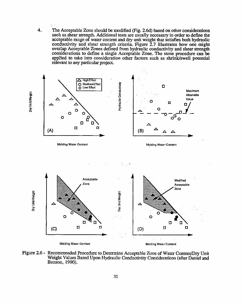
" .4. The Acceptable Zone should be modified (Fig. 2.6d) based on other considerations
such as shear strength. Additional tests are usually necessary in order to define theacceptable range of water content and dry.unit weight that satisfies both hydraulicconductivity and shear strength criteria. Figure 2.7 illustrates how one mightoverlap Acceptable Zones defined from hydraulic conductivity and shear strengthconsiderations to define a single Acceptable Zone. The same procedure can beapplied to take into consideration other factors such as shrink/swell potentialrelevant to any particular project.
MaximumAllowable
Vaue
[]
(8)lJo
(A)
~'so'."0::>
i"l'c:8
~ ,g.-.:
~§ ..0.. "l'
~>.
0::I: ..0..
Molding Water Content Molding Wate r Content
lJ
Modified
Acceptable
Zone
oo
o
(D)lJ
Acceptable
Zone
o
o
(C)
Molding Water Content Molding Wate r Content
Figure 2.6 - Recommended Procedure to Determine Acceptable Zone of Water Content/Dry UnitWeight Values Based Upon Hydraulic Conductivity Considerations (after DaiIiel andBenson, 1990). .
32

,Acceptable Zone
Based on Hydraulic
Conductivity Criterion
Acceptable Zone
,Based on Shear
Strength Criterion
Overall Acceptable Zone
Based on All Criteria
Molding Water Content
Figure 2.7 - Acceptable Zone of Water Content!Dry Unit Weights Detennined by SuperposingHydraulic Conductivity and Shear Strength Data (after Daniel and Benson, 1990).
, ' '
The same general procedure just outlined may also be used for soil-bentonite mixtures.However, to keep: the scope of testing reasonable, the required amount of bentonite should bedetermined before the main part of the testing program is initiated. The recommended procedurefor soil-bentonite mi~es may be summarized as follows: '
1.
.'"
.. ",,', 2~,
The type, grade, and gradation of bentonite that will be used should be determined.This process usually involves estimating costs from several potential suppliers. Asufficient quantity of the bentonite likely to be used for the project should beobtained aIlcl te~ted to characterize the bentonite (characterization tests are discussedlater).
, ,
A, representative sample'of the 'soil to which the bentonite will be added should beobtained." ' ' , ,
33

3. Batches of soil-bentonite mixtures should be prepared by blending in bentonite atseveral percentages, e.g., 2%, 4%, 6%, 8%, and 10% bentonite. Bentonite contentis defmed as the weight or mass of bentonite divided by the weight or mass of soilmixed with bentonite. For instance, if 5 kg of bentonite are mixed with 100 kg ofsoil, the bentonite content is 5%. Some people use the gross weight of bentoniterather than oven dry weight. Since air-dry bentonite usually contains 10% to 15%hygroscopic water by weight, the use of oven-dry, air-dry, or damp weight canmake a difference in the percentage. Similarly, the weight of soil may be defined aseither moist or dry (air- or oven-dry) weight. The contractor would rather workwith total (moist) weights since the materials used in forming a soil-bentonite blenddo contain some water. However, the engineering characteristics are controlled bythe relative amounts of dry materials. A dry-weight basis is generallyrecommended for definition of bentonite content, but CQC and CQA personnelmust recognize that the project specifications mayor may not be on a dry-weightbasis.
4. Develop compaction curves for each soil-bentonite mixture prepared from Step 3using the method of compaction appropriate to the project, e.g., ASTM D-698 orASTM D-1557.
5. Compact samples at 2% wet of optimum for each percentage of bentonite using thesame compaction procedure employed in Step 4.
6. Permeate the soils prepared from Step 5 using ASTM D-5084 or some otherappropriate test method. Graph hydraulic conductivity versus percentage ofbentonite.
7. Decide how much bentonite to use based on the minimum required amountdetermined from Step 6. The minimum amount of bentonite used in the fieldshould always be greater than the minimum amount suggested by laboratory testsbecause mixing in the field is usually not as thorough as in the laboratory.Typically, the amount of bentonite used in the field is one to four percentage pointsgreater than the minimum percent bentonite indicated by laboratory tests.
8. A master batch of material should be prepared by mixing bentonite with arepresentative sample of soil at the average bentonite content expected in the field.The procedures described earlier for determining the Acceptable Zone of watercontent and dry unit weight are then applied to the master batch.
2.1.5 Test Pads
Test pads are sometimes constructed and tested prior to construction of the full-scalecompacted soil liner. The test pad simulates conditions at the time of construction of the soil liner.If conditions change, e.g~, as a result of emplacement of waste materials over the liner, theproperties of the liner will change in ways that are not normally simulated in a test pad. Theobjectives of a test pad should be as follows:
1. To verify that the materials and methods of construction will produce a compactedsoil liner that meets the hydraulic conductivity objectives defined for a project,hydraulic conductivity should be measured with techniques that will characterize thelarge-scale hydraulic conductivity and identify any construction defects that cannotbe observed with small-scale laboratory hydraulic conductivity tests.
34

APPENDIX B
Copies of GRI Specifications
B1: GRI GM13 – HDPE Geomembrane
B2: GRI GM17 – LLDPE Geomembrane
B3: GRI GM19 – Geomembrane Seams
B4: GRI GT13(a) – Geotextile as Separation Layer
B5: GRI GCL3 – Geosynthetic Clay Liner
Note: Copies included are current as of the date of this plan.
Please refer to most current GRI Specifications for possible updates.
http://www.geosynthetic-institute.org/specifications.htm

B1: GRI GM13 – HDPE Geomembrane

GM13 - 1 of 11 Revision 14: 1/6/16
Revision 14: January 6, 2016
Revision schedule on pg. 11
GRI Test Method GM13*
Standard Specification for
“Test Methods, Test Properties and Testing Frequency for
High Density Polyethylene (HDPE) Smooth and Textured Geomembranes”
This specification was developed by the Geosynthetic Research Institute (GRI), with the
cooperation of the member organizations for general use by the public. It is completely optional
in this regard and can be superseded by other existing or new specifications on the subject matter
in whole or in part. Neither GRI, the Geosynthetic Institute, nor any of its related institutes,
warrant or indemnifies any materials produced according to this specification either at this time
or in the future.
1. Scope
1.1 This specification covers high density polyethylene (HDPE) geomembranes with a
formulated sheet density of 0.940 g/ml, or higher, in the thickness range of 0.75
mm (30 mils) to 3.0 mm (120 mils). Both smooth and textured geomembrane
surfaces are included.
1.2 This specification sets forth a set of minimum, physical, mechanical and chemical
properties that must be met, or exceeded by the geomembrane being manufactured.
In a few cases a range is specified.
1.3 In the context of quality systems and management, this specification represents
manufacturing quality control (MQC).
Note 1: Manufacturing quality control represents those actions taken by a
manufacturer to ensure that the product represents the stated
objective and properties set forth in this specification.
1.4 This standard specification is intended to ensure good quality and performance of
HDPE geomembranes in general applications, but is possibly not adequate for the
complete specification in a specific situation. Additional tests, or more restrictive
*This GRI standard is developed by the Geosynthetic Research Institute through consultation and review by the
member organizations. This specification will be reviewed at least every 2-years, or on an as-required basis. In this
regard it is subject to change at any time. The most recent revision date is the effective version.
Copyright © 1997, 1998, 1999, 2000, 2003, 2006, 2013 Geosynthetic Institute
All rights reserved
Geosynthetic Institute
475 Kedron Avenue
Folsom, PA 19033-1208 USA
TEL (610) 522-8440
FAX (610) 522-8441
GSI
GRI
GII
GAI
GEI
GCI

GM13 - 2 of 11 Revision 14: 1/6/16
values for test indicated, may be necessary under conditions of a particular
application.
Note 2: For information on installation techniques, users of this standard are
referred to the geosynthetics literature, which is abundant on the
subject.
2. Referenced Documents
2.1 ASTM Standards
D 792 Specific Gravity (Relative Density) and Density of Plastics by
Displacement
D 1004 Test Method for Initial Tear Resistance of Plastics Film and Sheeting
D 1238 Test Method for Flow Rates of Thermoplastics by Extrusion Plastometer
D 1505 Test Method for Density of Plastics by the Density-Gradient Technique
D 1603 Test Method for Carbon Black in Olefin Plastics
D 3895 Test Method for Oxidative Induction Time of Polyolefins by Thermal
Analysis
D 4218 Test Method for Determination of Carbon Black Content in
Polyethylene Compounds by the Muffle-Furnace Technique
D 4833 Test Method for Index Puncture Resistance of Geotextiles,
Geomembranes and Related Products
D 5199 Test Method for Measuring Nominal Thickness of Geotextiles and
Geomembranes
D 5397 Procedure to Perform a Single Point Notched Constant Tensile Load –
(SP-NCTL) Test: Appendix
D 5596 Test Method for Microscopic Evaluation of the Dispersion of Carbon
Black in Polyolefin Geosynthetics
D 5721 Practice for Air-Oven Aging of Polyolefin Geomembranes
D 5885 Test method for Oxidative Induction Time of Polyolefin Geosynthetics
by High Pressure Differential Scanning Calorimetry
D 5994 Test Method for Measuring the Core Thickness of Textured
Geomembranes
D 6370 Standard Test Method for Rubber-Compositional Analysis by
Thermogravimetry (TGA)
D 6693 Test Method for Determining Tensile Properties of Nonreinforced
Polyethylene and Nonreinforced Flexible Polypropylene Geomembranes
D 7238 Test Method for Effect of Exposure of Unreinforced Polyolefin
Geomembrane Using Fluorescent UV Condensation Apparatus
D 7466 Test Method for Measuring the Asperity Height of Textured
Geomembranes
2.2 GRI Standards
GM10 Specification for the Stress Crack Resistance of Geomembrane Sheet

GM13 - 3 of 11 Revision 14: 1/6/16
2.3 U. S. Environmental Protection Agency Technical Guidance Document "Quality
Control Assurance and Quality Control for Waste Containment Facilities,"
EPA/600/R-93/182, September 1993, 305 pgs.
3. Definitions
Manufacturing Quality Control (MQC) - A planned system of inspections that is used to
directly monitor and control the manufacture of a material which is factory originated.
MQC is normally performed by the manufacturer of geosynthetic materials and is
necessary to ensure minimum (or maximum) specified values in the manufactured
product. MQC refers to measures taken by the manufacturer to determine compliance
with the requirements for materials and workmanship as stated in certification documents
and contract specifications.
ref. EPA/600/R-93/182
Manufacturing Quality Assurance (MQA) - A planned system of activities that provides
assurance that the materials were constructed as specified in the certification documents
and contract specifications. MQA includes manufacturing facility inspections,
verifications, audits and evaluation of the raw materials (resins and additives) and
geosynthetic products to assess the quality of the manufactured materials. MQA refers to
measures taken by the MQA organization to determine if the manufacturer is in
compliance with the product certification and contract specifications for the project.
ref. EPA/600/R-93/182
Formulation, n - The mixture of a unique combination of ingredients identified by type,
properties and quantity. For HDPE polyethylene geomembranes, a formulation is
defined as the exact percentages and types of resin(s), additives and carbon black.
4. Material Classification and Formulation
4.1 This specification covers high density polyethylene geomembranes with a
formulated sheet density of 0.940 g/ml, or higher. Density can be measured by
ASTM D1505 or ASTM D792. If the latter, Method B is recommended.
4.2 The polyethylene resin from which the geomembrane is made will generally be in
the density range of 0.932 g/ml or higher, and have a melt index value per ASTM
D1238 of less than 1.0 g/10 min.
4.3 The resin shall be virgin material with no more than 10% rework. If rework is
used, it must be a similar HDPE as the parent material.
4.4 No post consumer resin (PCR) of any type shall be added to the formulation.

GM13 - 4 of 11 Revision 14: 1/6/16
5. Physical, Mechanical and Chemical Property Requirements
5.1 The geomembrane shall conform to the test property requirements prescribed in
Tables 1 and 2. Table 1 is for smooth HDPE geomembranes and Table 2 is for
single and double sided textured HDPE geomembranes. Each of the tables are
given in English and SI (metric) units. The conversion from English to SI
(metric) is soft.
Note 3: The tensile strength properties in this specification were originally
based on ASTM D 638 which uses a laboratory testing temperature
of 23C 2C. Since ASTM Committee D35 on Geosynthetics
adopted ASTM D 6693 (in place of D 638), this GRI Specification
followed accordingly. The difference is that D 6693 uses a testing
temperature of 21C 2C. The numeric values of strength and
elongation were not changed in this specification. If a dispute
arises in this regard, the original temperature of 23C 2C should
be utilized for testing purposes.
Note 4: There are several tests often included in other HDPE specifications
which are omitted from this standard because they are outdated,
irrelevant or generate information that is not necessary to evaluate
on a routine MQC basis. The following tests have been purposely
omitted:
Volatile Loss Water Absorption
Dimensional Stability Ozone Resistance
Coeff. of Linear Expansion Modulus of Elasticity
Resistance to Soil Burial Hydrostatic Resistance
Low Temperature Impact Tensile Impact
ESCR Test (D 1693) Field Seam Strength
Wide Width Tensile Multi-Axial Burst
Water Vapor Transmission Various Toxicity Tests
Note 5: There are several tests which are included in this standard (that are
not customarily required in other HDPE specifications) because
they are relevant and important in the context of current
manufacturing processes. The following tests have been purposely
added:
Oxidative Induction Time
Oven Aging
Ultraviolet Resistance
Asperity Height of Textured Sheet (see Note 6)

GM13 - 5 of 11 Revision 14: 1/6/16
Note 6: The minimum average value of asperity height does not represent
an expected value of interface shear strength. Shear strength
associated with geomembranes is both site-specific and product-
specific and should be determined by direct shear testing using
ASTM D5321/ASTM D6243 as prescribed. This testing should be
included in the particular site’s CQA conformance testing protocol
for the geosynthetic materials involved, or formally waived by the
Design Engineer, with concurrence from the Owner prior to the
deployment of the geosynthetic materials.
Note 7: There are other tests in this standard, focused on a particular
property, which are updated to current standards. The following
are in this category:
Thickness of Textured Sheet
Puncture Resistance
Stress Crack Resistance
Carbon Black Dispersion (In the viewing and subsequent
quantitative interpretation of ASTM D 5596 only near
spherical agglomerates shall be included in the assessment).
5.2 The values listed in the tables of this specification are to be interpreted according
to the designated test method. In this respect they are neither minimum average
roll values (MARV) nor maximum average roll values (MaxARV).
5.3 The properties of the HDPE geomembrane shall be tested at the minimum
frequencies shown in Tables 1 and 2. If the specific manufacturer's quality
control guide is more stringent and is certified accordingly, it must be followed in
like manner.
Note 8: This specification is focused on manufacturing quality control
(MQC). Conformance testing and manufacturing quality assurance
(MQA) testing are at the discretion of the purchaser and/or quality
assurance engineer, respectively.
6. Workmanship and Appearance
6.1 Smooth geomembrane shall have good appearance qualities. It shall be free from
such defects that would affect the specified properties of the geomembrane.
6.2 Textured geomembrane shall generally have uniform texturing appearance. It
shall be free from agglomerated texturing material and such defects that would
affect the specified properties of the geomembrane.
6.3 General manufacturing procedures shall be performed in accordance with the
manufacturer's internal quality control guide and/or documents.

GM13 - 6 of 11 Revision 14: 1/6/16
7. MQC Sampling
7.1 Sampling shall be in accordance with the specific test methods listed in Tables 1
and 2. If no sampling protocol is stipulated in the particular test method, then test
specimens shall be taken evenly spaced across the entire roll width.
7.2 The number of tests shall be in accordance with the appropriate test methods
listed in Tables 1 and 2.
7.3 The average of the test results should be calculated per the particular standard
cited and compared to the minimum value listed in these tables, hence the values
listed are the minimum average values and are designated as "min. ave."
8. MQC Retest and Rejection
8.1 If the results of any test do not conform to the requirements of this specification,
retesting to determine conformance or rejection should be done in accordance
with the manufacturing protocol as set forth in the manufacturer's quality manual.
9. Packaging and Marketing
9.1 The geomembrane shall be rolled onto a substantial core or core segments and
held firm by dedicated straps/slings, or other suitable means. The rolls must be
adequate for safe transportation to the point of delivery, unless otherwise
specified in the contract or order.
10. Certification
10.1 Upon request of the purchaser in the contract or order, a manufacturer's
certification that the material was manufactured and tested in accordance with this
specification, together with a report of the test results, shall be furnished at the
time of shipment.

GM13 - 7 of 11 Revision 14: 1/6/16
Table 1(a) – High Density Polyethylene (HDPE) Geomembrane -Smooth
Properties Test Test Value Testing Frequency
Method 30 mils 40 mils 50 mils 60 mils 80 mils 100 mils 120 mils (minimum)
Thickness (min. ave.) D5199 nom. Nom. Nom. Nom. Nom. Nom. Nom. Per roll
lowest individual of 10 values -10% -10% -10% -10% -10% -10% -10%
Formulated Density mg/l (min.) D 1505/D 792 0.940 g/cc 0.940 g/cc 0.940 g/cc 0.940 g/cc 0.940 g/cc 0.940 g/cc 0.940 g/cc 200,000 lb
Tensile Properties (1) (min. ave.)
yield strength
break strength
yield elongation
break elongation
D 6693
Type IV
63 lb/in.
114 lb/in.
12%
700%
84 lb/in.
152 lb/in.
12%
700%
105 lb/in.
190 lb/in.
12%
700%
126 lb/in.
228 lb/in.
12%
700%
168 lb/in.
304 lb/in.
12%
700%
210 lb/in.
380 lb/in.
12%
700%
252 lb/in.
456 lb/in.
12%
700%
20,000 lb
Tear Resistance (min. ave.) D 1004 21 lb 28 lb 35 lb 42 lb 56 lb 70 lb 84 lb 45,000 lb
Puncture Resistance (min. ave.) D 4833 54 lb 72 lb 90 lb 108 lb 144 lb 180 lb 216 lb 45,000 lb
Stress Crack Resistance (2) D5397
(App.)
500 hr. 500 hr. 500 hr. 500 hr. 500 hr. 500 hr. 500 hr. per GRI-GM10
Carbon Black Content (range) D 4218 (3) 2.0-3.0% 2.0-3.0% 2.0-3.0% 2.0-3.0% 2.0-3.0% 2.0-3.0% 2.0-3.0% 20,000 lb
Carbon Black Dispersion D 5596 note (4) note (4) note (4) note (4) note (4) note (4) note (4) 45,000 lb
Oxidative Induction Time (OIT) (min. ave.) (5)
(a) Standard OIT
— or —
(b) High Pressure OIT
D 3895
D 5885
100 min.
400 min.
100 min.
400 min.
100 min.
400 min.
100 min.
400 min.
100 min.
400 min.
100 min.
400 min.
100 min.
400 min.
200,000 lb
Oven Aging at 85°C (5), (6) D 5721
(a) Standard OIT (min. ave.) - % retained after 90 days
— or —
(b) High Pressure OIT (min. ave.) - % retained after 90 days
D 3895
D 5885
55%
80%
55%
80%
55%
80%
55%
80%
55%
80%
55%
80%
55%
80%
per each
formulation
UV Resistance (7) D 7238
(a) Standard OIT (min. ave.)
— or —
(b) High Pressure OIT (min. ave.) - % retained after 1600 hrs (9)
D 3895
D 5885
N.R. (8)
50%
N.R. (8)
50%
N.R. (8)
50%
N.R. (8)
50%
N.R. (8)
50%
N.R. (8)
50%
N.R. (8)
50%
per each
formulation
(1) Machine direction (MD) and cross machine direction (XMD) average values should be on the basis of 5 test specimens each direction.
Yield elongation is calculated using a gage length of 1.3 inches
Break elongation is calculated using a gage length of 2.0 in.
(2) The yield stress used to calculate the applied load for the SP-NCTL test should be the manufacturer’s mean value via MQC testing.
(3) Other methods such as D 1603 (tube furnace) or D 6370 (TGA) are acceptable if an appropriate correlation to D 4218 (muffle furnace) can be established.
(4) Carbon black dispersion (only near spherical agglomerates) for 10 different views:
9 in Categories 1 or 2 and 1 in Category 3
(5) The manufacturer has the option to select either one of the OIT methods listed to evaluate the antioxidant content in the geomembrane.
(6) It is also recommended to evaluate samples at 30 and 60 days to compare with the 90 day response.
(7) The condition of the test should be 20 hr. UV cycle at 75C followed by 4 hr. condensation at 60C.
(8) Not recommended since the high temperature of the Std-OIT test produces an unrealistic result for some of the antioxidants in the UV exposed samples.
(9) UV resistance is based on percent retained value regardless of the original HP-OIT value.
ENGLISH UNITS

GM13 - 8 of 11 Revision 14: 1/6/16
Table 1(b) – High Density Polyethylene (HPDE) Geomembrane - Smooth
Properties Test Test Value Testing Frequency
Method 0.75 mm 1.00 mm 1.25 mm 1.50 mm 2.00 mm 2.50 mm 3.00 mm (minimum)
Thickness - mils (min. ave.) D5199 nom. (mil) nom. (mil) nom. (mil) nom. (mil) nom. (mil) nom. (mil) nom. (mil) per roll
lowest individual of 10 values -10% -10% -10% -10% -10% -10% -10%
Formulated Density (min.) D 1505/D 792 0.940 g/cc 0.940 g/cc 0.940 g/cc 0.940 g/cc 0.940 g/cc 0.940 g/cc 0.940 g/cc 90,000 kg
Tensile Properties (1) (min. ave.)
yield strength
break strength
yield elongation
break elongation
D 6693
Type IV
11 kN/m
20 kN/m
12%
700%
15 kN/m
27 kN/m
12%
700%
18 kN/m
33 kN/m
12%
700%
22 kN/m
40 kN/m
12%
700%
29 kN/m
53 kN/m
12%
700%
37 kN/m
67 kN/m
12%
700%
44 kN/m
80 kN/m
12%
700%
9,000 kg
Tear Resistance (min. ave.) D 1004 93 N 125 N 156 N 187 N 249 N 311 N 374 N 20,000 kg
Puncture Resistance (min. ave.) D 4833 240 N 320 N 400 N 480 N 640 N 800 N 960 N 20,000 kg
Stress Crack Resistance (2) D 5397 500 hr. 500 hr. 500 hr. 500 hr. 500 hr. 500 hr. 500 hr. per GRI GM-10
(App.)
Carbon Black Content - % D 4218 (3) 2.0-3.0% 2.0-3.0% 2.0-3.0% 2.0-3.0% 2.0-3.0% 2.0-3.0% 2.0-3.0% 9,000 kg
Carbon Black Dispersion D 5596 note (4) note (4) note (4) note (4) note (4) note (4) note (4) 20,000 kg
Oxidative Induction Time (OIT) (min. ave.) (5)
(a) Standard OIT
— or —
(b) High Pressure OIT
D 3895
D 5885
100 min.
400 min.
100 min.
400 min.
100 min.
400 min.
100 min.
400 min.
100 min.
400 min.
100 min.
400 min.
100 min.
400 min.
90,000 kg
Oven Aging at 85°C (5), (6) D 5721
(a) Standard OIT (min. ave.) - % retained after 90 days
— or —
(b) High Pressure OIT (min. ave.) - % retained after 90 days
D 3895
D 5885
55%
80%
55%
80%
55%
80%
55%
80%
55%
80%
55%
80%
55%
80%
per each
formulation
UV Resistance (7) D 7238
(a) Standard OIT (min. ave.)
— or —
(b) High Pressure OIT (min. ave.) - % retained after 1600 hrs (9)
D 3895
D 5885
N. R. (8)
50%
N.R. (8)
50%
N.R. (8)
50%
N.R. (8)
50%
N.R. (8)
50%
N.R. (8)
50%
N.R. (8)
50%
per each
formulation
(1) Machine direction (MD) and cross machine direction (XMD) average values should be on the basis of 5 test specimens each direction
Yield elongation is calculated using a gage length of 33 mm
Break elongation is calculated using a gage length of 50 mm
(2) The yield stress used to calculate the applied load for the SP-NCTL test should be the manufacturer’s mean value via MQC testing.
(3) Other methods such as D 1603 (tube furnace) or D 6370 (TGA) are acceptable if an appropriate correlation to D 4218 (muffle furnace) can be established.
(4) Carbon black dispersion (only near spherical agglomerates) for 10 different views:
9 in Categories 1 or 2 and 1 in Category 3
(5) The manufacturer has the option to select either one of the OIT methods listed to evaluate the antioxidant content in the geomembrane.
(6) It is also recommended to evaluate samples at 30 and 60 days to compare with the 90 day response.
(7) The condition of the test should be 20 hr. UV cycle at 75C followed by 4 hr. condensation at 60C.
(8) Not recommended since the high temperature of the Std-OIT test produces an unrealistic result for some of the antioxidants in the UV exposed samples.
(9) UV resistance is based on percent retained value regardless of the original HP-OIT value.
SI (METRIC) UNITS

GM13 - 9 of 11 Revision 14: 1/6/16
Table 2(a) – High Density Polyethylene (HDPE) Geomembrane - Textured
Properties Test
Method
Test Value Testing
Frequency
30 mils 40 mils 50 mils 60 mils 80 mils 100 mils 120 mils (minimum)
Thickness mils (min. ave.)
lowest individual for 8 out of 10 values
lowest individual for any of the 10 values
D 5994 nom. (-5%) -10%
-15%
nom. (-5%) -10%
-15%
nom. (-5%) -10%
-15%
nom. (-5%) -10%
-15%
nom. (-5%) -10%
-15%
nom. (-5%) -10%
-15%
nom. (-5%) -10%
-15%
per roll
Asperity Height mils (min. ave.) D 7466 16 mil 16 mil 16 mil 16 mil 16 mil 16 mil 16 mil every 2nd roll (1)
Formulated Density (min. ave.) D 1505/D 792 0.940 g/cc 0.940 g/cc 0.940 g/cc 0.940 g/cc 0.940 g/cc 0.940 g/cc 0.940 g/cc 200,000 lb
Tensile Properties (min. ave.) (2)
yield strength
break strength
yield elongation
break elongation
D 6693 Type IV
63 lb/in.
45 lb/in. 12%
100%
84 lb/in.
60 lb/in. 12%
100%
105 lb/in.
75 lb/in. 12%
100%
126 lb/in.
90 lb/in. 12%
100%
168 lb/in.
120 lb/in. 12%
100%
210 lb/in.
150 lb/in. 12%
100%
252 lb/in.
180 lb/in. 12%
100%
20,000 lb
Tear Resistance (min. ave.) D 1004 21 lb 28 lb 35 lb 42 lb 56 lb 70 lb 84 lb 45,000 lb
Puncture Resistance (min. ave.) D 4833 45 lb 60 lb 75 lb 90 lb 120 lb 150 lb 180 lb 45,000 lb
Stress Crack Resistance (3) D 5397
(App.)
500 hr. 500 hr. 500 hr. 500 hr. 500 hr. 500 hr. 500 hr. per GRI GM10
Carbon Black Content (range) D 4218 (4) 2.0-3.0 % 2.0-3.0 % 2.0-3.0 % 2.0-3.0 % 2.0-3.0 % 2.0-3.0 % 2.0-3.0 % 20,000 lb
Carbon Black Dispersion D 5596 note (5) note (5) note (5) note (5) note (5) note (5) note (5) 45,000 lb
Oxidative Induction Time (OIT) (min. ave.) (6)
(a) Standard OIT
— or — (b) High Pressure OIT
D 3895
D 5885
100 min.
400 min.
100 min.
400 min.
100 min.
400 min.
100 min.
400 min.
100 min.
400 min.
100 min.
400 min.
100 min.
400 min.
200,000 lb
Oven Aging at 85°C (6), (7) D 5721
(a) Standard OIT (min. ave.) - % retained after 90 days
— or — (b) High Pressure OIT (min. ave.) - % retained after 90 days
D 3895
D 5885
55%
80%
55%
80%
55%
80%
55%
80%
55%
80%
55%
80%
55%
80%
per each
formulation
UV Resistance (8) D 7238 (a) Standard OIT (min. ave.)
— or —
(b) High Pressure OIT (min. ave.) - % retained after 1600 hrs (10)
D 3895
D 5885
N.R. (9)
50%
N.R. (9)
50%
N.R. (9)
50%
N.R. (9)
50%
N.R. (9)
50%
N.R. (9)
50%
N.R. (9)
50%
per each
formulation
(1) Alternate the measurement side for double sided textured sheet
(2) Machine direction (MD) and cross machine direction (XMD) average values should be on the basis of 5 test specimens each direction. Yield elongation is calculated using a gage length of 1.3 inches
Break elongation is calculated using a gage length of 2.0 inches
(3) P-NCTL test is not appropriate for testing geomembranes with textured or irregular rough surfaces. Test should be conducted on smooth edges of textured rolls or on smooth sheets made from the same formulation as
being used for the textured sheet materials.
The yield stress used to calculate the applied load for the SP-NCTL test should be the manufacturer’s mean value via MQC testing.
(4) Other methods such as D 1603 (tube furnace) or D 6370 (TGA) are acceptable if an appropriate correlation to D 4218 (muffle furnace) can be established. (5) Carbon black dispersion (only near spherical agglomerates) for 10 different views:
9 in Categories 1 or 2 and 1 in Category 3
(6) The manufacturer has the option to select either one of the OIT methods listed to evaluate the antioxidant content in the geomembrane. (7) It is also recommended to evaluate samples at 30 and 60 days to compare with the 90 day response.
(8) The condition of the test should be 20 hr. UV cycle at 75C followed by 4 hr. condensation at 60C.
(9) Not recommended since the high temperature of the Std-OIT test produces an unrealistic result for some of the antioxidants in the UV exposed samples. (10) UV resistance is based on percent retained value regardless of the original HP-OIT value.
ENGLISH UNITS

GM13 - 10 of 11 Revision 14: 1/6/16
Table 2(b) – High Density Polyethylene (HDPE) Geomembrane - Textured
Properties Test Method
Test Value Testing Frequency
0.75 mm 1.00 mm 1.25 mm 1.50 mm 2.00 mm 2.50 mm 3.00 mm (minimum)
Thickness mils (min. ave.)
lowest individual for 8 out of 10 values
lowest individual for any of the 10 values
D 5994 nom. (-5%)
-10%
-15%
nom. (-5%)
-10%
-15%
nom. (-5%)
-10%
-15%
nom. (-5%)
-10%
-15%
nom. (-5%)
-10%
-15%
nom. (-5%)
-10%
-15%
nom. (-5%)
-10%
-15%
per roll
Asperity Height mils (min. ave.) D 7466 0.40 mm 0.40 mm 0.40 mm 0.40 mm 0.40 mm 0.40 mm 0.40 mm every 2nd roll (1)
Formulated Density (min. ave.) D 1505/D 792 0.940 g/cc 0.940 g/cc 0.940 g/cc 0.940 g/cc 0.940 g/cc 0.940 g/cc 0.940 g/cc 90,000 kg
Tensile Properties (min. ave.) (2)
yield strength
break strength
yield elongation
break elongation
D 6693
Type IV
11 kN/m
8 kN/m 12%
100%
15 kN/m
10 kN/m 12%
100%
18 kN/m
13 kN/m 12%
100%
22 kN/m
16 kN/m 12%
100%
29 kN/m
21 kN/m 12%
100%
37 kN/m
26 kN/m 12%
100%
44 kN/m
32 kN/m 12%
100%
9,000 kg
Tear Resistance (min. ave.) D 1004 93 N 125 N 156 N 187 N 249 N 311 N 374 N 20,000 kg
Puncture Resistance (min. ave.) D 4833 200N 267 N 333 N 400 N 534 N 667 N 800 N 20,000 kg
Stress Crack Resistance (3) D 5397 (App.)
500 hr. 500 hr. 500 hr. 500 hr. 500 hr. 500 hr. 500 hr. per GRI GM10
Carbon Black Content (range) D 4218 (4) 2.0-3.0 % 2.0-3.0 % 2.0-3.0 % 2.0-3.0 % 2.0-3.0 % 2.0-3.0 % 2.0-3.0 % 9,000 kg
Carbon Black Dispersion D 5596 note (5) note (5) note (5) note (5) note (5) note (5) note (5) 20,000 kg
Oxidative Induction Time (OIT) (min. ave.) (6)
(a) Standard OIT — or —
(b) High Pressure OIT
D 3895
D 5885
100 min.
400 min.
100 min.
400 min.
100 min.
400 min.
100 min.
400 min.
100 min.
400 min.
100 min.
400 min.
100 min.
400 min.
90,000 kg
Oven Aging at 85°C (6), (7) D 5721
(a) Standard OIT (min. ave.) - % retained after 90 days
— or —
(b) High Pressure OIT (min. ave.) - % retained after 90 days
D 3895
D 5885
55%
80%
55%
80%
55%
80%
55%
80%
55%
80%
55%
80%
55%
80%
per each
formulation
UV Resistance (8) D 7238
(a) Standard OIT (min. ave.)
— or — (b) High Pressure OIT (min. ave.) - % retained after 1600 hrs (10)
D 3895
D 5885
N.R. (9)
50%
N.R. (9)
50%
N.R. (9)
50%
N.R. (9)
50%
N.R. (9)
50%
N.R. (9)
50%
N.R. (9)
50%
per each
formulation
(1) Alternate the measurement side for double sided textured sheet (2) Machine direction (MD) and cross machine direction (XMD) average values should be on the basis of 5 test specimens each direction.
Yield elongation is calculated using a gage length of 33 mm
Break elongation is calculated using a gage length of 50 mm (3) The SP-NCTL test is not appropriate for testing geomembranes with textured or irregular rough surfaces. Test should be conducted on smooth edges of textured rolls or on smooth sheets made from the same
formulation as being used for the textured sheet materials.
The yield stress used to calculate the applied load for the SP-NCTL test should be the manufacturer’s mean value via MQC testing.
(4) Other methods such as D 1603 (tube furnace) or D 6370 (TGA) are acceptable if an appropriate correlation to D 4218 (muffle furnace) can be established.
(5) Carbon black dispersion (only near spherical agglomerates) for 10 different views:
9 in Categories 1 or 2 and 1 in Category 3 (6) The manufacturer has the option to select either one of the OIT methods listed to evaluate the antioxidant content in the geomembrane.
(7) It is also recommended to evaluate samples at 30 and 60 days to compare with the 90 day response.
(8) The condition of the test should be 20 hr. UV cycle at 75C followed by 4 hr. condensation at 60C. (9) Not recommended since the high temperature of the Std-OIT test produces an unrealistic result for some of the antioxidants in the UV exposed samples.
(10) UV resistance is based on percent retained value regardless of the original HP-OIT value.
SI (METRIC UNITS)
GM13 - 11 of 11 Revision 14: 1/6/16
Adoption and Revision Schedule
for
HDPE Specification per GRI-GM13
“Test Methods, Test Properties, Testing Frequency for
High Density Polyethylene (HDPE) Smooth and Textured Geomembranes”
Adopted: June 17, 1997
Revision 1: November 20, 1998; changed CB dispersion from allowing 2 views
to be in Category 3 to requiring all 10 views to be in Category 1 or 2.
Also reduced UV percent retained from 60% to 50%.
Revision 2: April 29, 1999: added to Note 5 after the listing of Carbon Black
Dispersion the following: “(In the viewing and subsequent
quantitative interpretation of ASTM D5596 only near spherical
agglomerates shall be included in the assessment)” and to Note (4)
in the property tables.
Revision 3: June 28, 2000: added a new Section 5.2 that the numeric table values
are neither MARV or MaxARV. They are to be interpreted per the
the designated test method.
Revision 4: December 13, 2000: added one Category 3 is allowed for carbon
black dispersion. Also, unified terminology to “strength” and
“elongation”.
Revision 5: May 15, 2003: Increased minimum acceptable stress crack resistance
time from 200 hrs to 300 hrs.
Revision 6: June 23, 2003: Adopted ASTM D 6693, in place of ASTM D 638, for
tensile strength testing. Also, added Note 2.
Revision 7: February 20, 2006: Added Note 6 on Asperity Height clarification
with respect to shear strength.
Revision 8: Removed recommended warranty from specification.
Revision 9: June 1, 2009: Replaced GRI-GM12 test for asperity height of
textured geomembranes with ASTM D 7466.
Revision 10 April 11, 2011: Added alternative carbon black content test methods
Revision 11 December 13, 2012: Replaced GRI-GM11 with the equivalent ASTM
D 7238.
Revision 12 November 14, 2014: Increased minimum acceptable stress crack
resistance time from 300 to 500 hours. Also, increased asperity height
of textured sheet from 10 to 16 mils (0.25 to 0.40 mm).
Revision 13 November 4, 2015: Removed Footnote (1) on asperity height from tables.
Revision 14 January 6, 2016: Removed Trouser Tear from Note 5.

B2: GRI GM17 – LLDPE Geomembrane

GM17 - 1 of 11 Rev. 12: 11/4/15
Revision 12: November 4, 2015
Revision schedule on pg. 11
GRI Test Method GM17*
Standard Specification for
“Test Methods, Test Properties and Testing Frequency for
Linear Low Density Polyethylene (LLDPE) Smooth and Textured Geomembranes”
This specification was developed by the Geosynthetic Research Institute (GRI), with the
cooperation of the member organizations for general use by the public. It is completely optional
in this regard and can be superseded by other existing or new specifications on the subject matter
in whole or in part. Neither GRI, the Geosynthetic Institute, nor any of its related institutes,
warrant or indemnifies any materials produced according to this specification either at this time
or in the future.
1. Scope
1.1 This specification covers linear low density polyethylene (LLDPE) geomembranes
with a formulated sheet density of 0.939 g/ml, or lower, in the thickness range of
0.50 mm (20 mils) to 3.0 mm (120 mils). Both smooth and textured geomembrane
surfaces are included.
1.2 This specification sets forth a set of minimum, maximum, or range of physical,
mechanical and endurance properties that must be met, or exceeded by the
geomembrane being manufactured.
1.3 In the context of quality systems and management, this specification represents
manufacturing quality control (MQC).
Note 1: Manufacturing quality control represents those actions taken by a
manufacturer to ensure that the product represents the stated
objective and properties set forth in this specification.
*This GRI standard is developed by the Geosynthetic Research Institute through consultation and review by the
member organizations. This specification will be reviewed at least every 2-years, or on an as-required basis. In this
regard it is subject to change at any time. The most recent revision date is the effective version. Copyright © 2000, 2003, 2006, 2013 Geosynthetic Institute
All rights reserved
Geosynthetic Institute
475 Kedron Avenue
Folsom, PA 19033-1208 USA
TEL (610) 522-8440
FAX (610) 522-8441
GSI
GRI
GII
GAI
GEI
GCI

GM17 - 2 of 11 Rev. 12: 11/4/15
1.4 This standard specification is intended to ensure good uniform quality LLDPE
geomembranes for use in general applications.
Note 2: Additional tests, or more restrictive values for the tests indicated,
may be necessary under conditions of a particular application. In
this situation, interactions with the manufacturers are required.
Note 3: For information on installation techniques, users of this standard
are referred to the geosynthetics literature, which is abundant on
the subject.
2. Referenced Documents
2.1 ASTM Standards
D 792 Specific Gravity (Relative Density) and Density of Plastics by
Displacement
D 1004 Test Method for Initial Tear Resistance of Plastics Film and Sheeting
D 1238 Test Method for Flow Rates of Thermoplastics by Extrusion Plastometer
D 1505 Test Method for Density of Plastics by the Density-Gradient Technique
D 1603 Test Method for Carbon Black in Olefin Plastics
D 3895 Test Method for Oxidative Induction Time of Polyolefins by Thermal
Analysis
D 4218 Test Method for Determination of Carbon Black Content in
Polyethylene Compounds by the Muffle-Furnace Technique
D 4833 Test Method for Index Puncture Resistance of Geotextiles,
Geomembranes and Related Products
D 5199 Test Method for Measuring Nominal Thickness of Geotextiles and
Geomembranes
D 5323 Practice for Determination of 2% Secant Modulus for Polyethylene
Geomembranes
D 5596 Test Method for Microscopic Evaluation of the Dispersion of Carbon
Black in Polyolefin Geosynthetics
D 5617 Test Method for Multi-Axial Tension Test for Geosynthetics
D 5721 Practice for Air-Oven Aging of Polyolefin Geomembranes
D 5885 Test method for Oxidative Induction Time of Polyolefin Geosynthetics
by High Pressure Differential Scanning Calorimetry
D 5994 Test Method for Measuring the Core Thickness of Textured
Geomembranes
D 6370 Standard Test Method for Rubber-Compositional Analysis by
Thermogravimetry (TGA)
D 6693 Test Method for Determining Tensile Properties of Nonreinforced
Polyethylene and Nonreinforced Flexible Polypropylene Geomembranes
D 7238 Test Method for Effect of Exposure of Unreinforced Polyolefin
Geomembrane Using Fluorescent Condensation Device

GM17 - 3 of 11 Rev. 12: 11/4/15
D 7466 Test Method for Measuring the Asperity Height of Textured
Geomembranes
2.2 U. S. Environmental Protection Agency Technical Guidance Document "Quality
Control Assurance and Quality Control for Waste Containment Facilities,"
EPA/600/R-93/182, September 1993, 305 pgs.
3. Definitions
Manufacturing Quality Control (MQC) - A planned system of inspections that is used to directly
monitor and control the manufacture of a material which is factory originated. MQC is normally
performed by the manufacturer of geosynthetic materials and is necessary to ensure minimum (or
maximum) specified values in the manufactured product. MQC refers to measures taken by the
manufacturer to determine compliance with the requirements for materials and workmanship as
stated in certification documents and contract specifications.
ref. EPA/600/R-93/182
Manufacturing Quality Assurance (MQA) - A planned system of activities that provides
assurance that the materials were constructed as specified in the certification documents and
contract specifications. MQA includes manufacturing facility inspections, verifications, audits
and evaluation of the raw materials (resins and additives) and geosynthetic products to assess the
quality of the manufactured materials. MQA refers to measures taken by the MQA organization
to determine if the manufacturer is in compliance with the product certification and contract
specifications for the project.
ref. EPA/600/R-93/182
Linear Low Density Polyethylene (LLDPE), n – A ethylene/-olefin copolymer having a linear
molecular structure. The comonomers used to produce the resin can include 1-butene, 1-hexene,
1-octene or 4-methyl-1-pentene. LLDPE resins have a natural density in the range of 0.915 to
0.926 g/ml (ref. Pate, T. J. Chapter 29 in Handbook of Plastic Materials and Technology, I.I.
Rubin Ed., Wiley, 1990).
Formulation, n - The mixture of a unique combination of ingredients identified by type,
properties and quantity. For linear low density polyethylene geomembranes, a formulation is
defined as the exact percentages and types of resin(s), additives and carbon black.
4. Material Classification and Formulation
4.1 This specification covers linear low density polyethylene geomembranes with a
formulated sheet density of 0.939 g/ml, or lower. Density can be measured by
ASTM D1505 or ASTM D792. If the latter, Method B is recommended.
4.2 The polyethylene resin from which the geomembrane is made will generally be in
the density range of 0.926 g/ml or lower, and have a melt index value per ASTM
D1238 of less than 1.0 g/10 min. This refers to the natural, i.e., nonformulated,
resin.

GM17 - 4 of 11 Rev. 12: 11/4/15
4.3 The resin shall be virgin material with no more than 10% rework. If rework is
used, it must be of the same formulation (or other approved formulation) as the
parent material.
4.4 No post consumer resin (PCR) of any type shall be added to the formulation.
5. Physical, Mechanical and Chemical Property Requirements
5.1 The geomembrane shall conform to the test property requirements prescribed in
Tables 1 and 2. Table 1 is for smooth LLDPE geomembranes and Table 2 is for
single and double sided textured LLDPE geomembranes. Each of the tables are
given in English and SI (metric) units. The conversion from English to SI
(metric) is “soft”. It is to be understood that the tables refer to the latest revision
of the referenced test methods and practices.
Note 4: The tensile strength properties in this specification were originally
based on ASTM D 638 which uses a laboratory testing temperature
of 23C 2C. Since ASTM Committee D35 on Geosynthetics
adopted ASTM D 6693 (in place of D 638), this GRI Specification
followed accordingly. The difference is that D 6693 uses a testing
temperature of 21C 2C. The numeric values of strength and
elongation were not changed in this specification. If a dispute
arises in this regard, the original temperature of 23C 2C should
be utilized for testing purposes.
Note 5: There are several tests sometimes included in other LLDPE
geomembrane specifications which are omitted from this standard
because they are outdated, irrelevant or generate information that is
not necessary to evaluate on a routine MQC basis. The following
tests have been purposely omitted:
Volatile Loss Solvent Vapor Transmission
Dimensional Stability Water Absorption
Coeff. of Linear Expansion Ozone Resistance
Resistance to Soil Burial Hydrostatic Resistance
Low Temperature Impact Tensile Impact
ESCR Test (D 1693 and D 5397) Small Scale Burst
Wide Width Tensile Various Toxicity Tests
Water Vapor Transmission Field Seam Strength
Note 6: There are several tests which are included in this standard (that are
not customarily required in other LLDPE geomembrane
specifications) because they are relevant and important in the
context of current manufacturing processes. The following tests
have been purposely added:
Oxidative Induction Time

GM17 - 5 of 11 Rev. 12: 11/4/15
Oven Aging
Ultraviolet Resistance
Asperity Height of Textured Sheet
Note 7: There are other tests in this standard, focused on a particular
property, which are updated to current standards. The following
are in this category:
Thickness of Textured Sheet
Tensile Properties, incl. 2% Secant Modulus
Puncture Resistance
Axi-Symmetric Break Resistance Strain
Carbon Black Dispersion (In the viewing and subsequent
quantitative interpretation of ASTM D 5596 only near
spherical agglomerates shall be included in the
assessment).
Note 8: The minimum average value of asperity height does not represent
an expected value of interface shear strength. Shear strength
associated with geomembranes is both site-specific and product-
specific and should be determined by direct shear testing using
ASTM D5321/ASTM D6243 as prescribed. This testing should be
included in the particular site’s CQA conformance testing protocol
for the geosynthetic materials involved, or formally waived by the
Design Engineer, with concurrence from the Owner prior to the
deployment of the geosynthetic materials.
5.2 The values listed in the tables of this specification are to be interpreted according
to the designated test method. In this respect they are neither minimum average
roll values (MARV) nor maximum average roll values (MaxARV).
5.3 The various properties of the LLDPE geomembrane shall be tested at the
minimum frequencies shown in Tables 1 and 2. If the specific manufacturer's
quality control guide is more stringent, it must be followed in like manner.
Note 9: This specification is focused on manufacturing quality control
(MQC). Conformance testing and manufacturing quality assurance
(MQA) testing are at the discretion of the purchaser and/or quality
assurance engineer, respectively. Communication and interaction
with the manufacturer is strongly suggested.
6. Workmanship and Appearance
6.1 Smooth geomembrane shall have good appearance qualities. It shall be free from
such defects that would affect the specified properties and hydraulic integrity of
the geomembrane.

GM17 - 6 of 11 Rev. 12: 11/4/15
6.2 Textured geomembrane shall generally have uniform texturing appearance. It
shall be free from such defects that would affect the specified properties and
hydraulic integrity of the geomembrane.
6.3 General manufacturing procedures shall be performed in accordance with the
manufacturer's internal quality control guide and/or documents.
7. MQC Sampling
7.1 Sampling shall be in accordance with the specific test methods listed in Tables 1
and 2. If no sampling protocol is stipulated in the particular test method, then test
specimens shall be taken evenly spaced across the entire roll width.
7.2 The number of tests shall be in accordance with the appropriate test methods
listed in Tables 1 and 2.
7.3 The average of the test results should be calculated per the particular standard
cited and compared to the minimum value listed in these tables, hence the values
listed are the minimum average values and are designated as "min. ave."
8. MQC Retest and Rejection
8.1 If the results of any test do not conform to the requirements of this specification,
retesting to determine conformance or rejection should be done in accordance
with the manufacturing protocol as set forth in the manufacturer's quality manual.
9. Packaging and Marketing
9.1 The geomembrane shall be rolled onto a substantial core or core segments and
held firm by dedicated straps/slings, or other suitable means. The rolls must be
adequate for safe transportation to the point of delivery, unless otherwise
specified in the contract or order.
9.2 Marking of the geomembrane rolls shall be done in accordance with the
manufacturers accepted procedure as set forth in their quality manual.
10. Certification
10.1 Upon request of the purchaser in the contract or order, a manufacturer's
certification that the material was manufactured and tested in accordance with this
specification, together with a report of the test results, shall be furnished at the
time of shipment.

GM17 - 7 of 11 Rev. 12: 11/4/15
Table 1(a) – Linear Low Density Polyethylene (LLDPE) Geomembrane
(SMOOTH)
Properties Test Test Value Testing Frequency
Method 20 mils 30 mils 40 mils 50 mils 60 mils 80 mils 100 mils 120 mils (minimum)
Thickness - mils (min. ave.) D5199 nom. nom. nom. nom. nom. nom. nom. nom. per roll
lowest individual of 10 values -10% -10% -10% -10% -10% -10% -10% -10%
Density g/ml (max.) D 1505/D 792 0.939 0.939 0.939 0.939 0.939 0.939 0.939 0.939 200,00 lb
Tensile Properties (1) (min. ave.)
break strength - lb/in.
break elongation - %
D 6693
Type IV
76
800
114
800
152
800
190
800
228
800
304
800
380
800
456
800
20,000 lb
2% Modulus – lb/in. (max.) D 5323 1200 1800 2400 3000 3600 4800 6000 7200 per formulation
Tear Resistance - lb (min. ave.) D 1004 11 16 22 27 33 44 55 66 45,000 lb
Puncture Resistance - lb (min. ave.) D 4833 28 42 56 70 84 112 140 168 45,000 lb
Axi-Symmetric Break Resistance Strain - % (min.) D 5617 30 30 30 30 30 30 30 30 per formulation
Carbon Black Content - % D 4218 (2) 2.0-3.0 2.0-3.0 2.0-3.0 2.0-3.0 2.0-3.0 2.0-3.0 2.0-3.0 2.0-3.0 45,000 lb
Carbon Black Dispersion D 5596 note (3) note (3) note (3) note (3) note (3) note (3) note (3) note (3) 45,000 lb
Oxidative Induction Time (OIT) (4)
(a) Standard OIT (min. ave.)
— or —
(b) High Pressure OIT (min. ave.)
D 3895
D 5885
100
400
100
400
100
400
100
400
100
400
100
400
100
400
100
400
200,000 lb
Oven Aging at 85°C (5) D 5721
(a) Standard OIT (min. ave.) - % retained after 90 days
— or —
(b) High Pressure OIT (min. ave.) - % retained after 90 days
D 3895
D 5885
35
60
35
60
35
60
35
60
35
60
35
60
35
60
35
60
per formulation
UV Resistance (6) D 7238
(a) Standard OIT (min. ave.)
— or —
(b) High Pressure OIT (min. ave.) -
% retained after 1600 hrs (8)
D 3895
D 5885
N. R. (7)
35
N.R. (7)
35
N.R. (7)
35
N.R. (7)
35
N.R. (7)
35
N.R. (7)
35
N.R. (7)
35
N.R. (7)
35
per formulation
(1) Machine direction (MD) and cross machine direction (XMD) average values should be on the basis of 5 test specimens each direction.
Break elongation is calculated using a gage length of 2.0 in. at 2.0 in./min.
(2) Other methods such as D 1603 (tube furnace) or D 6370 (TGA) are acceptable if an appropriate correlation to D 4218 (muffle furnace) can be established.
(3) Carbon black dispersion (only near spherical agglomerates) for 10 different views:
9 in Categories 1 or 2 and 1 in Category 3
(4) The manufacturer has the option to select either one of the OIT methods listed to evaluate the antioxidant content in the geomembrane.
(5) It is also recommended to evaluate samples at 30 and 60 days to compare with the 90 day response.
(6) The condition of the test should be 20 hr. UV cycle at 75C followed by 4 hr. condensation at 60C.
(7) Not recommended since the high temperature of the Std-OIT test produces an unrealistic result for some of the antioxidants in the UV exposed samples.
(8) UV resistance is based on percent retained value regardless of the original HP-OIT value.
English Units

GM17 - 8 of 11 Rev. 12: 11/4/15
Table 1(b) – Linear Low Density Polyethylene (LLDPE) Geomembrane
(SMOOTH)
Properties Test Test Value Testing Frequency
Method 0.50 mm 0.75 mm 1.0 mm 1.25 mm 1.50 mm 2.00 mm 2.5 mm 3.0 mm (minimum)
Thickness - mm (min. ave.) D5199 nom. nom. nom. nom. nom. nom. nom. nom. per roll
lowest individual of 10 values -10% -10% -10% -10% -10% -10% -10% -10%
Density g/ml (max.) D 1505/D 792 0.939 0.939 0.939 0.939 0.939 0.939 0.939 0.939 90,000 kg
Tensile Properties (1) (min. ave.)
break strength – N/mm
break elongation - %
D 6693
Type IV
13
800
20
800
27
800
33
800
40
800
53
800
66
800
80
800
9,000 kg
2% Modulus – N/mm (max.) D 5323 210 315 420 520 630 840 1050 1260 per formulation
Tear Resistance - N (min. ave.) D 1004 50 70 100 120 150 200 250 300 20,000 kg
Puncture Resistance - N (min. ave.) D 4833 120 190 250 310 370 500 620 750 20,000 kg
Axi-Symmetric Break Resistance Strain - % (min.) D 5617 30 30 30 30 30 30 30 30 per formulation
Carbon Black Content - % D 4218 (3) 2.0-3.0 2.0-3.0 2.0-3.0 2.0-3.0 2.0-3.0 2.0-3.0 2.0-3.0 2.0-3.0 20,000 kg
Carbon Black Dispersion D 5596 note (3) note (3) note (3) note (3) note (3) note (3) note (3) note (3) 20,000 kg
Oxidative Induction Time (OIT) (4)
(c) Standard OIT (min. ave.)
— or —
(d) High Pressure OIT (min. ave.)
D 3895
D 5885
100
400
100
400
100
400
100
400
100
400
100
400
100
400
100
400
90,000 kg
Oven Aging at 85°C (5) D 5721
(a) Standard OIT (min. ave.) - % retained after 90 days
— or —
(b) High Pressure OIT (min. ave.) - % retained after 90 days
D 3895
D 5885
35
60
35
60
35
60
35
60
35
60
35
60
35
60
35
60
per formulation
UV Resistance (6) D 7238
(a) Standard OIT (min. ave.)
— or —
(b) High Pressure OIT (min. ave.) -
% retained after 1600 hrs (8)
D 3895
D 5885
N. R. (7)
35
N.R. (7)
35
N.R. (7)
35
N.R. (7)
35
N.R. (7)
35
N.R. (7)
35
N.R. (7)
35
N.R. (7)
35
per formulation
(1) Machine direction (MD) and cross machine direction (XMD) average values should be on the basis of 5 test specimens each direction.
Break elongation is calculated using a gage length of 50 mm at 50 mm/min.
(2) Other methods such as D 1603 (tube furnace) or D 6370 (TGA) are acceptable if an appropriate correlation to D 4218 (muffle furnace) can be established.
(3) Carbon black dispersion (only near spherical agglomerates) for 10 different views:
9 in Categories 1 or 2 and 1 in Category 3
(4) The manufacturer has the option to select either one of the OIT methods listed to evaluate the antioxidant content in the geomembrane.
(5) It is also recommended to evaluate samples at 30 and 60 days to compare with the 90 day response.
(6) The condition of the test should be 20 hr. UV cycle at 75C followed by 4 hr. condensation at 60C.
(7) Not recommended since the high temperature of the Std-OIT test produces an unrealistic result for some of the antioxidants in the UV exposed samples.
(8) UV resistance is based on percent retained value regardless of the original HP-OIT value.
SI (Metric) Units

GM17 - 9 of 11 Rev. 12: 11/4/15
Table 2(a) – Linear Low Density Polyethylene (LLDPE) Geomembrane
(TEXTURED)
Properties Test Method
Test Value Testing Frequency
20 mils 30 mils 40 mils 50 mils 60 mils 80 mils 100 mils 120 mils (minimum)
Thickness mils (min. ave.)
lowest individual for 8 out of 10 values
lowest individual for any of the 10 values
D 5994 nom. (-5%)
-10%
-15%
nom. (-5%)
-10%
-15%
nom. (-5%)
-10%
-15%
nom. (-5%)
-10%
-15%
nom. (-5%)
-10%
-15%
nom. (-5%)
-10%
-15%
nom. (-5%)
-10%
-15%
nom. (-5%)
-10%
-15%
per roll
Asperity Height mils (min. ave.) D 7466 16 16 16 16 16 16 16 16 Every 2nd roll
(1)
Density g/ml (max.) D 1505/D 792 0.939 0.939 0.939 0.939 0.939 0.939 0.939 0.939 200,000 lb
Tensile Properties (2) (min. ave.)
break strength – lb/in.
break elongation - %
D 6693 Type IV
30
250
45
250
60
250
75
250
90
250
120
250
150
250
180
250
20,000 lb
2% Modulus – lb/in. (max.) D 5323 1200 1800 2400 3000 3600 4800 6000 7200 per
formulation
Tear Resistance – lb (min. ave.) D 1004 11 16 22 27 33 44 55 66 45,000 lb
Puncture Resistance – lb (min. ave.) D 4833 22 33 44 55 66 88 110 132 45,000 lb
Axi-Symmetric Break Resistance Strain - % (min.) D 5617 30 30 30 30 30 30 30 30 per formulation
Carbon Black Content - % D 4218 (3) 2.0-3.0 2.0-3.0 2.0-3.0 2.0-3.0 2.0-3.0 2.0-3.0 2.0-3.0 2.0-3.0 45,000 lb
Carbon Black Dispersion D 5596 note (4) note (4) note (4) note (4) note (4) note (4) note (4) note (4) 45,000 lb
Oxidative Induction Time (OIT) (5)
(e) Standard OIT (min. ave.)
— or —
(f) High Pressure OIT (min. ave.)
D 3895
D 5885
100
400
100
400
100
400
100
400
100
400
100
400
100
400
100
400
200,000 lb
Oven Aging at 85°C (6) D 5721
(a) Standard OIT (min. ave.) - % retained after 90 days — or —
(b) High Pressure OIT (min. ave.) - % retained after 90 days
D 3895
D 5885
35
60
35
60
35
60
35
60
35
60
35
60
35
60
35
60
per formulation
UV Resistance (7) D 7238
(a) Standard OIT (min. ave.) — or —
(b) High Pressure OIT (min. ave.) -
% retained after 1600 hrs (9)
D 3895
D 5885
N. R. (8)
35
N.R. (8)
35
N.R. (8)
35
N.R. (8)
35
N.R. (8)
35
N.R. (8)
35
N.R. (8)
35
N.R. (8)
35
per formulation
(1) Alternate the measurement side for double sided textured sheet
(2) Machine direction (MD) and cross machine direction (XMD) average values should be on the basis of 5 test specimens each direction.
Break elongation is calculated using a gage length of 2.0 in. at 2.0 in./min.
(3) Other methods such as D 1603 (tube furnace) or D 6370 (TGA) are acceptable if an appropriate correlation to D 4218 (muffle furnace) can be established.
(4) Carbon black dispersion (only near spherical agglomerates) for 10 different views:
9 in Categories 1 or 2 and 1 in Category 3 (5) The manufacturer has the option to select either one of the OIT methods listed to evaluate the antioxidant content in the geomembrane.
(6) It is also recommended to evaluate samples at 30 and 60 days to compare with the 90 day response.
(7) The condition of the test should be 20 hr. UV cycle at 75C followed by 4 hr. condensation at 60C.
(8) Not recommended since the high temperature of the Std-OIT test produces an unrealistic result for some of the antioxidants in the UV exposed samples.
(9) UV resistance is based on percent retained value regardless of the original HP-OIT value.
English Units

GM17 - 10 of 11 Rev. 12: 11/4/15
Table 2(b) – Linear Low Density Polyethylene (LLDPE) Geomembrane
(TEXTURED)
Properties Test Method
Test Value Testing Frequency
0.50 mm 0.75 mm 1.0 mm 1.25 mm 1.50 mm 2.00 mm 2.5 mm 3.0 mm (minimum)
Thickness mils (min. ave.)
lowest individual for 8 out of 10 values
lowest individual for any of the 10 values
D 5994 nom. (-5%)
-10%
-15%
nom. (-5%)
-10%
-15%
nom. (-5%)
-10%
-15%
nom. (-5%)
-10%
-15%
nom. (-5%)
-10%
-15%
nom. (-5%)
-10%
-15%
nom. (-5%)
-10%
-15%
nom. (-5%)
-10%
-15%
per roll
Asperity Height mm (min. ave.) D 7466 0.40 0.40 0.40 0.40 0.40 0.40 0.40 0.40 Every 2nd roll
(1)
Density g/ml (max.) D 1505/D 792 0.939 0.939 0.939 0.939 0.939 0.939 0.939 0.939 90,000 kg
Tensile Properties (2) (min. ave.)
break strength – N/mm
break elongation - %
D 6693 Type IV
5
250
9
250
11
250
13
250
16
250
21
250
26
250
31
250
9,000 kg
2% Modulus – N/mm (max.) D 5323 210 315 420 520 630 840 1050 1260 per
formulation
Tear Resistance – N (min. ave.) D 1004 50 70 100 120 150 200 250 300 20,000 kg
Puncture Resistance – N (min. ave.) D 4833 100 150 200 250 300 400 500 600 20,000 kg
Axi-Symmetric Break Resistance Strain - % (min.) D 5617 30 30 30 30 30 30 30 30 per formulation
Carbon Black Content - % D 4218 (3) 2.0-3.0 2.0-3.0 2.0-3.0 2.0-3.0 2.0-3.0 2.0-3.0 2.0-3.0 2.0-3.0 20,000 kg
Carbon Black Dispersion D 5596 note (4) note (4) note (4) note (4) note (4) note (4) note (4) note (4) 20,000 kg
Oxidative Induction Time (OIT) (5)
(g) Standard OIT (min. ave.)
— or —
(h) High Pressure OIT (min. ave.)
D 3895
D 5885
100
400
100
400
100
400
100
400
100
400
100
400
100
400
100
400
90,000 kg
Oven Aging at 85°C (6) D 5721
(a) Standard OIT (min. ave.) - % retained after 90 days — or —
(b) High Pressure OIT (min. ave.) - % retained after 90 days
D 3895
D 5885
35
60
35
60
35
60
35
60
35
60
35
60
35
60
35
60
per formulation
UV Resistance (7) D 7238
(a) Standard OIT (min. ave.) — or —
(b) High Pressure OIT (min. ave.) -
% retained after 1600 hrs (9)
D 3895
D 5885
N. R. (8)
35
N.R. (8)
35
N.R. (8)
35
N.R. (8)
35
N.R. (8)
35
N.R. (8)
35
N.R. (8)
35
N.R. (8)
35
per formulation
(1) Alternate the measurement side for double sided textured sheet
(2) Machine direction (MD) and cross machine direction (XMD) average values should be on the basis of 5 test specimens each direction.
Break elongation is calculated using a gage length of 50 mm at 50 mm/min.
(3) Other methods such as D 1603 (tube furnace) or D 6370 (TGA) are acceptable if an appropriate correlation to D 4218 (muffle furnace) can be established.
(4) Carbon black dispersion (only near spherical agglomerates) for 10 different views:
9 in Categories 1 or 2 and 1 in Category 3 (5) The manufacturer has the option to select either one of the OIT methods listed to evaluate the antioxidant content in the geomembrane.
(6) It is also recommended to evaluate samples at 30 and 60 days to compare with the 90 day response.
(7) The condition of the test should be 20 hr. UV cycle at 75C followed by 4 hr. condensation at 60C.
(8) Not recommended since the high temperature of the Std-OIT test produces an unrealistic result for some of the antioxidants in the UV exposed samples.
(9) UV resistance is based on percent retained value regardless of the original HP-OIT value.
SI (Metric) Units

GM17 - 11 of 11 Rev. 12: 11/4/15
Adoption and Revision Schedule
for
GRI Test Method GM17
“Test Methods, Test Properties and Testing Frequency for Linear Low Density Polyethylene
(LLDPE) Smooth and Textured Geomembranes”
Adopted: April 3, 2000
Revision 1: June 28, 2000: added a new Section 5.2 that the numeric tables values are
neither MARV nor MaxARV. They are to be interpreted per the designated
test method. Also, corrected typographical error of textured sheet thickness
test method designation from D5199 to D5994.
Revision 2: December 13, 2000: added one Category 3 is allowed for carbon black
dispersion. Also, unified terminology to “strength” and “elongation”.
Revision 3: June 23, 2003: Adopted ASTM D 6693, in place of ASTM D 638, for
tensile strength testing. Also, added Note 4.
Revision 4: February 20, 2006: Added Note 9 on Asperity Height clarification with
respect to shear strength.
Revision 5: Removed recommended warranty from specification.
Revision 6: June 1, 2009: Replaced GRI-GM12 test method for asperity height of
textured geomembranes with ASTM D 7466.
Revision 7: April 11, 2011: Added alternative carbon black test methods.
Revision 8: October 3, 2011: Expanded types of comonomers in the definition of
LLDPE.
Revision 9: December 14, 2012: Replaced GRI-GM12 with the equivalent ASTM
D7238.
Revision 10: November 14, 2014: Increased asperity height of textured sheet from 10 to
16 mils (0.25 to 0.40 mm).
Revision 11: April 13, 2015: Unit conversion error was corrected for 0.75 mm (30 mil)
thickness for the property of 2% modulus. The test value was changed from
370 N/mm to 315 N/mm in the SI (Metric) units tables to agree with the
English units tables.
Revision 12: November 4, 2015: Removed Footnote (1) on asperity height from tables.

B3: GRI GM19 – Geomembrane Seams

GM19 - 1 of 13 Rev. 8: 2/12/2015
Original: February 28, 2002
Revision 8: February 12, 2015
Revision schedule is on pg. 13
GRI Test Method GM19*
Standard Specification for
Seam Strength and Related Properties
of Thermally Bonded Polyolefin Geomembranes
This specification was developed by the Geosynthetic Research Institute (GRI), with the
cooperation of the member organizations for general use by the public. It is completely optional
in this regard and can be superseded by other existing or new specifications on the subject matter
in whole or in part. Neither GRI, the Geosynthetic Institute, nor any of its related institutes,
warrant or indemnifies any materials produced according to this specification either at this time
or in the future.
1. Scope
1.1 This specification addresses the required seam strength and related properties of
thermally bonded polyolefin geomembranes; in particular, high density polyethylene
(HDPE), linear low density polyethylene both nonreinforced (LLDPE) and scrim
reinforced (LLDPE-R) and flexible polypropylene both nonreinforced (fPP) and
scrim reinforced (fPP-R).
1.2 Numeric values of seam strength and related properties are specified in both shear
and peel modes.
Note 1: This specification does not address the test method details or
specific testing procedures. It refers to the relevant ASTM test
methods where applicable.
1.3 The thermal bonding methods focused upon are hot wedge (single and dual track)
and extrusion fillet.
*This GRI standard is developed by the Geosynthetic Research Institute through consultation and review by the
member organizations. This specification will be reviewed at least every 5-years, or on an as-required basis. In this
regard it is subject to change at any time. The most recent revision date is the effective version.
Copyright © 2002, 2003, 2005, 2013 Geosynthetic Institute
All rights reserved
Geosynthetic Institute
475 Kedron Avenue
Folsom, PA 19033-1208 USA
TEL (610) 522-8440
FAX (610) 522-8441
GSI
GRI
GII
GAI
GEI
GCI

GM19 - 2 of 13 Rev. 8: 2/12/2015
Note 2: Other acceptable, but less frequently used, methods of seaming
are hot air and ultrasonic methods. They are inferred as being
a subcategory of hot wedge seaming.
1.4 This specification does not suggest a specific distance between destructive seam
samples to be taken in the field, i.e., the sampling interval. A separate GRI Standard
Practice is focused on this issue, see GRI-GM29.
1.5 This specification is only applicable to laboratory testing.
1.6 This specification does not purport to address all of the safety concerns, if any,
associated with its use. It is the responsibility of the user of this standard to establish
appropriate safety and health practices and determine the applicability of regulatory
limitations prior to use.
2. Referenced Documents
2.1 ASTM Standards
D6392 Standard Test Method for Determining the Integrity of Nonreinforced
Geomembrane Seams Produced Using Thermo-Fusion Methods
D7747 Standard Test Method for Determining Integrity of Seams Produced
Using Thermo-Fusion Methods for Reinforced Geomembranes by the
Strip Tensile Method
2.2 EPA Standards
EPA 600/2.88/052 (NTIS PB-89-129670)
Lining of Waste Containment and Other Containment Facilities
2.3 GRI Standards
GM13 Test Properties and Testing Frequency for High Density Polyethylene
(HDPE) Smooth and Textured Geomembranes
GM14 Selecting Variable Intervals for Taking Geomembrane Destructive Seam
Samples Using the Method of Attributes
GM17 Test Properties and Testing Frequency for Linear Low Density
Polyethylene (LLDPE) Smooth and Textured Geomembranes
GM18 Test Properties and Testing Frequency for Flexible Polypropylene (fPP
and fPP-R) Geomembranes
GM20 Selecting Variable Intervals for Taking Geomembrane Destructive Seam
Samples Using Control Charts
GM25 Test Property and Testing Frequency for Scrim Reinforced Linear Low
Density Polyethylene Geomembranes
GM29 Practice for Field Integrity Evaluation of Geomembrane Seams (and
Sheet) Using Destructive and Nondestructive Testing

GM19 - 3 of 13 Rev. 8: 2/12/2015
3. Definition
3.1 Geomembrane, n – An essentially impermeable geosynthetic composed of one or
more synthetic sheets used for the purpose of liquid, gas or solid containment.
3.2 Hot Wedge Seaming – A thermal technique which melts the two opposing
geomembrane surfaces to be seamed by running a hot metal wedge or knife between
them. Pressure is applied to the top or bottom geomembrane, or both, to form a
continuous bond. Seams of this type can be made with dual bond tracks separated
by a nonbonded gap. These seams are referred to as dual hot wedge seams or
double-track seams.
3.3 Hot Air Seaming – This seaming technique introduces high-temperature air or gas
between two geomembrane surfaces to facilitate localized surface melting. Pressure
is applied to the top or bottom geomembrane, forcing together the two surfaces to
form a continuous bond.
3.4 Ultrasonic Seaming - A thermal technique which melts the two opposing
geomembrane surfaces to be seamed by running a ultrasonically vibrated metal
wedge or knife between them. Pressure is applied to the top or bottom
geomembrane, or both, to form a continuous bond. Some seams of this type are
made with dual bond tracks separated by a nonbonded gap. These seams are
referred to as dual-track seams or double-track seams.
3.5 Extrusion Fillet Seaming – This seaming technique involves extruding molten resin
at the edge of an overlapped geomembrane on another to form a continuous bond. A
depreciated method called “extrusion flat” seaming extrudes the molten resin
between the two overlapped sheets. In all types of extrusion seaming the surfaces
upon which the molten resin is applied must be suitably prepared, usually by a slight
grinding or buffing.
4. Significance and Use
4.1 The various methods of field fabrication of seams in polyolefin geomembranes are
covered in existing ASTM standards mentioned in the referenced document section.
What is not covered in those documents is the numeric values of strength and related
properties that the completed seam must meet, or exceed. This specification
provides this information insofar as minimum, or maximum, property values are
concerned when the field fabricated seams are sampled and laboratory tested in shear
and peel. A separate GRI standard, GRI-GM29 (DRAFT), provides guidance as to
the spacing that destructive samples should be taken in typical field installation
projects.

GM19 - 4 of 13 Rev. 8: 2/12/2015
5. Sample and Specimen Preparation
5.1 The spacing for taking field seam samples for destructive testing is provided in GRI-
GM29 (DRAFT), a standard-of-practice. The process describes a progression from
the most restrictive interval of 1 per 500 feet (1 per 150 m) to the complete use and
reliance of the electrical leak location survey (ELLS) method. Intermediate between
these extremes are variations depending upon the installers experience and
performance.
5.2 The size of field seam samples is to be according to the referenced test method, e.g.,
ASTM D6392 or site-specific CQA plan.
5.3 The individual test specimens taken from the field seam samples are to be tested
according to the referenced test method, i.e., ASTM D6392 for HDPE, LLDPE and
fPP, and ASTM D751 (modified to a 150 mm + seam width gage length) for fPP-R.
The specimens are to be conditioned prior to testing according to these same test
methods and evaluated accordingly.
6. Assessment of Seam Test Results
6.1 HDPE seams – For HDPE seams (both smooth and textured), the strength of four out
of five 1.0 inch (25 mm) wide strip specimens in shear should meet or exceed the
values given in Tables 1(a) and 1(b). The fifth must meet or exceed 80% of the
given values. In addition, five out five specimens should meet the shear percent
elongation, calculated as follows, and exceed the values given in Tables 1(a) and
1(b):
)(100L
LE
o
(1)
where
E = elongation (%)
L = extension at end of test (in. or mm)
Lo = original average length (usually 1.0 in. or 25 mm)
Note 3: The assumed gage length is considered to be the unseamed
sheet material on either side of the welded area. It generally
will be 1.0 in. (25 mm) from the edge of the seam to the grip
face.
For HDPE seams (both smooth and textured), the strength of four out of five 1.0 in.
(25 mm) wide strip specimens tested in peel should meet or exceed the values given
in Tables 1(a) and 1(b). The fifth must meet or exceed 80% of the given values.
In addition, the peel separation (or incursion) should not exceed the values given in
Tables 1(a) and 1(b) for all five out of five specimens. The value shall be based on

GM19 - 5 of 13 Rev. 8: 2/12/2015
the proportion of area of separated bond to the area of the original bonding as
follows:
)100(oA
AS (2)
where
S = separation (%)
A = average area of separation, or incursion (in2 or mm
2)
A0 = original bonding area (in2 or mm
2)
Note 4: The area of peel separation can occur in a number of
nonuniform patterns across the seam width. The estimated
dimensions of this separated area is visual and must be done
with care and concern. The area must not include squeeze-out
which is part of the welding process.
Regarding the locus-of-break patterns of the different seaming methods in shear and
peel, the following are unacceptable break codes per their description in ASTM
D6392 (in this regard, SIP is an acceptable break code);
Hot Wedge: AD and AD-Brk > 25%
Extrusion Fillet: AD1, AD2
Exception: AD-WLD (unless strength is achieved)
Note 5: Separation-in-plane (SIP) is a locus-of-break where the failure
surface propagates within one of the seamed sheets during
destructive testing (usually in the peel mode). It is not merely
a surface skin effect producing a few ductile fibrils (sometimes
called ductile drawdown). SIP is acceptable if the required
strength, shear elongation and peel separation criteria are met.
In this regard, five out of five specimens shall result in acceptable break patterns.
6.2 LLDPE seams – For LLDPE seams (smooth, textured and scrim reinforced), the
strength of four out of five 1.0 in. (25 mm) wide strip specimens in shear should
meet or exceed the values given in Tables 2(a) through 2(d). The fifth must meet or
exceed 80% of the given values. Note that the unreinforced specimens are 1.0 in.
(25 mm) wide strips and the scrim reinforced specimens are 4.0 in. (100 mm) wide
grab tests. In addition, the shear percent elongation, calculated as follows, should
exceed the values given in Tables 2(a) through 2(d). All five out of five should meet
the shear elongation requirement.
)(100L
LE
o
(1)

GM19 - 6 of 13 Rev. 8: 2/12/2015
where
E = elongation (%)
L = extension at end of test (in. or mm)
Lo = original average length (usually 1.0 in. or 25 mm)
Note 3 (Repeated): The assumed gage length is considered to be the unseamed
sheet material on either side of the welded area. It generally
will be 1.0 in. (25 mm) from the edge of the seam to the grip
face.
Shear elongation is not relevant to scrim reinforced geomembranes and as such is
listed as “not applicable” in Tables 2 (c) and (d).
For LLDPE seams (smooth, textured and scrim reinforced), the strength of four out
of five 1.0 in. (25 mm) wide strip specimens tested in peel should meet or exceed the
values given in Tables 2(a) through 2(d). The fifth must meet or exceed 80% of the
given values.
In addition, the peel separation (or incursion) should not exceed the values given in
Tables 2(a) through 2(d). All five out of five specimens shall meet the peel
separation value. The value shall be based on the proportion of area of separated
bond to the area of the original bonding as follows:
)100(oA
AS (2)
where
S = separation (%)
A = average depth of separation, or incursion (in.2 or mm
2)
A0 = original bonding distance (in.2 or mm
2)
Note 4 (Repeated): The area of peel separation can occur in a number of
nonuniform patterns across the seam width. The estimated
dimensions of this separated area is visual and must be done
with care and concern. The area must not include squeeze-out
which is part of the welding process.
Regarding the locus-of-break patterns of the different seaming methods in shear and
peel, the following are unacceptable break codes per their description in ASTM
D6392 (in this regard, SIP is an acceptable break code);
Hot Wedge: AD and AD-Brk > 25%
Extrusion Fillet: AD1, AD2
Exception: AD-WLD (unless strength is achieved)

GM19 - 7 of 13 Rev. 8: 2/12/2015
Note 5 (Repeated): Separation-in-plane (SIP) is a locus-of-break where the failure
surface propagates within one of the seamed sheets during
destructive testing (usually in the peel mode). It is not merely
a surface skin effect producing a few ductile fibrils (sometimes
called ductile drawdown). SIP is acceptable if the required
strength, shear elongation and peel separation criteria are met.
In this regard, five out of five specimens shall result in acceptable break patterns.
6.3 fPP Seams – For fPP seams (both nonreinforced and scrim reinforced), the strength
of four out of five specimens in shear should meet or exceed the values given in
Tables 3(a) and 3(b). The fifth must meet or exceed 80% of the given values. Note
that the unreinforced specimens are 1.0 in. (25 mm) wide strips and the scrim
reinforced specimens are 4.0 in. (100 mm) wide grab tests. In addition, the shear
percent elongation on the unreinforced specimens, calculated as follows, should
exceed the values given in Tables 3(a) and 3(b). All five out of five specimens
should meet the shear elongation requirement.
)(100L
LE
o
(1)
where
E = elongation (%)
L = extension at end of test (in. or mm)
Lo = original gauge length (usually 1.0 in. or 25 mm)
Note 3 (Repeated): The assumed gage length is considered to be the unseamed
sheet material on either side of the welded area. It generally
will be 1.0 in. (25 mm) from the edge of the seam to the grip
face.
Shear elongation is not relevant to scrim reinforced geomembranes and as such is
listed as “not applicable” in Tables 3(a) and 3(b).
For fPP seams (both nonreinforced and scrim reinforced), the strength of four out of
five specimens in peel should meet or exceed the values given in Tables 3(a) and
3(b). The fifth must meet or exceed 80% of the given values. Note that the
unreinforced specimens are 1.0 in. (25 mm) wide strips and the scrim reinforced
specimens are grab tests. In addition, the peel percent separation (or incursion)
should not exceed the values given in Tables 3(a) and 3(b). All five out of five
specimens should meet the peel separation value. The values should be based on the
proportion of area of separated bond to the area of the original bonding as follows.
)100(oA
AS (2)
where

GM19 - 8 of 13 Rev. 8: 2/12/2015
S = separation in (%)
A = average depth of separation, or incursion (in.2 or mm
2)
Ao = original bonding distance (in.2 or mm
2)
Note 4 (Repeated): The area of peel separation can occur in a number of
nonuniform patterns across the seam width. The estimated
dimensions of this separated area is visual and must be done
with care and concern. The area must not include squeeze-out
which is part of the welding process.
Regarding the locus-of-break patterns of the different seaming methods in shear and
peel, the following are unacceptable break codes per their description in ASTM
D6392 (in this regard, SIP is an acceptable break code);
Hot Wedge: AD and AD-Brk > 25%
Extrusion Fillet: AD1, AD2
Exception: AD-WLD (unless strength is achieved)
Note 5 (Repeated): Separation-in-plane (SIP) is a locus-of-break where the failure
surface propagates within one of the seamed sheets during
destructive testing (usually in the peel mode). It is not merely
a surface skin effect producing a few ductile fibrils (sometimes
called ductile drawdown). SIP is acceptable if the required
strength, shear elongation and peel separation criteria are met.
In this regard, five out of five specimens shall result in acceptable break patterns.
7. Retest and Rejection
7.1 If the results of the testing of a sample do not conform to the requirements of this
specification, retesting to determine conformance or rejection should be done in
accordance with the construction quality control or construction quality assurance
plan for the particular site under construction.
8. Certification
8.1 Upon request of the construction quality assurance officer or certification engineer,
an installer’s certification that the geomembrane was installed and tested in
accordance with this specification, together with a report of the test results, shall be
furnished at the completion of the installation.

GM19 - 9 of 13 Rev. 8: 2/12/2015
Table 1(a) – Seam Strength and Related Properties of Thermally Bonded Smooth and Textured
High Density Polyethylene (HDPE) Geomembranes (English Units)
Geomembrane Nominal Thickness 30 mils 40 mils 50 mils 60 mils 80 mils 100 mils 120 mils
Hot Wedge Seams(1)
shear strength(2)
, lb/in.
shear elongation at break(3)
, %
peel strength(2)
, lb/in.
peel separation, %
57
50
45
25
80
50
60
25
100
50
76
25
120
50
91
25
160
50
121
25
200
50
151
25
240
50
181
25
Extrusion Fillet Seams
shear strength(2)
, lb/in.
shear elongation at break(3)
, %
peel strength(2)
, lb/in.
peel separation, %
57
50
39
25
80
50
52
25
100
50
65
25
120
50
78
25
160
50
104
25
200
50
130
25
240
50
156
25
Notes for Tables 1(a) and 1(b):
1. Also for hot air and ultrasonic seaming methods
2. Value listed for shear and peel strengths are for 4 out of 5 test specimens; the 5th specimen can be as low as 80% of the listed values
3. Elongation measurements should be omitted for field testing
Table 1(b) – Seam Strength and Related Properties of Thermally Bonded Smooth and Textured
High Density Polyethylene (HDPE) Geomembranes (S.I. Units)
Geomembrane Nominal Thickness 0.75 mm 1.0 mm 1.25 mm 1.5 mm 2.0 mm 2.5 mm 3.0 mm
Hot Wedge Seams(1)
shear strength(2)
, N/25 mm.
shear elongation at break(3)
, %
peel strength(2)
, N/25 mm
peel separation, %
250
50
197
25
350
50
263
25
438
50
333
25
525
50
398
25
701
50
530
25
876
50
661
25
1050
50
793
25
Extrusion Fillet Seams
shear strength(2)
, N/25 mm
shear elongation at break(3)
, %
peel strength(2)
, N/25 mm
peel separation, %
250
50
170
25
350
50
225
25
438
50
285
25
525
50
340
25
701
50
455
25
876
50
570
25
1050
50
680
25

GM19 - 10 of 13 Rev. 8: 2/12/2015
Table 2(a) – Seam Strength and Related Properties of Thermally Bonded Smooth and Textured
Linear Low Density Polyethylene (LLDPE) Geomembranes (English Units)
Geomembrane Nominal Thickness 20 mils 30 mils 40 mils 50 mils 60 mils 80 mils 100 mils 120 mils
Hot Wedge Seams(1)
shear strength(2)
, lb/in.
shear elongation(3)
, %
peel strength(2)
, lb/in.
peel separation, %
30
50
25
25
45
50
38
25
60
50
50
25
75
50
63
25
90
50
75
25
120
50
100
25
150
50
125
25
180
50
150
25
Extrusion Fillet Seams
shear strength(2)
, lb/in.
shear elongation(3)
, %
peel strength(2)
, lb/in.
peel separation, %
30
50
22
25
45
50
34
25
60
50
44
25
75
50
57
25
90
50
66
25
120
50
88
25
150
50
114
25
180
50
136
25
Notes for Tables 2(a) and 2(b):
1. Also for hot air and ultrasonic seaming methods
2. Values listed for shear and peel strengths are for 4 out of 5 test specimens; the 5th specimen can be as low as 80% of the listed values
3. Elongation measurements should be omitted for field testing
Table 2(b) – Seam Strength and Related Properties of Thermally Bonded Smooth and Textured
Linear Low Density Polyethylene (LLDPE) Geomembranes (S.I. Units)
Geomembrane Nominal Thickness 0.50 mm 0.75 mm 1.0 mm 1.25 mm 1.5 mm 2.0 mm 2.5 mm 3.0 mm
Hot Wedge Seams(1)
shear strength(2)
, N/25 mm
shear elongation(3)
, %
peel strength(2)
, N/25 mm
peel separation, %
131
50
109
25
197
50
166
25
263
50
219
25
328
50
276
25
394
50
328
25
525
50
438
25
657
50
547
25
788
50
657
25
Extrusion Fillet Seams
shear strength(2)
, N/25 mm
shear elongation(3)
, %
peel strength(2)
, N/25 mm
peel separation, %
131
50
95
25
197
50
150
25
263
50
190
25
328
50
250
25
394
50
290
25
525
50
385
25
657
50
500
25
788
50
595
25

GM19 - 11 of 13 Rev. 8: 2/12/2015
Table 2(c) – Seam Strength and Related Properties of Thermally Bonded Scrim Reinforced Linear Low Density Polyethylene (LLDPE-R)
Geomembranes (English Units)
Geomembrane Nominal Thickness 36 mil(4) 45 mil(4)
Hot Wedge Seams(1)
shear strength(2), lb
shear elongation(3), %
peel strength(2), lb
peel separation, %
200
n/a
20
n/a
200
n/a
20
n/a
Extrusion Fillet Seams
shear strength(2), lb
shear elongation(3), %
peel strength(2), lb
peel separation, %
200
n/a
20
n/a
200
n/a
20
n/a 1. Also for hot air and ultrasonic seaming methods
2. Values listed for shear and peel strengths are for 4 out of 5 test specimens; the 5th specimen can be as low as 80% of the listed values
3. Elongation measurements should be omitted for field testing
4. Values are based on grab tensile strength and elongation per D7747 for laboratory tested specimens
Table 2(d) – Seam Strength and Related Properties of Thermally Bonded Scrim Reinforced Linear Low Density Polyethylene (LLDPE-R)
Geomembranes (S.I. Units)
Geomembrane Nominal Thickness 36 mil(4) 45 mil(4)
Hot Wedge Seams(1)
shear strength(2), N
shear elongation(3), %
peel strength(2), N
peel separation, %
890
n/a
90
n/a
890
n/a
90
n/a
Extrusion Fillet Seams
shear strength(2), N
shear elongation(3), %
peel strength(2), N
peel separation, %
890
n/a
90
n/a
890
n/a
90
n/a 1. Also for hot air and ultrasonic seaming methods
2. Values listed for shear and peel strengths are for 4 out of 5 test specimens; the 5th specimen can be as low as 80% of the listed values
3. Elongation measurements should be omitted for field testing
4. Values are based on grab tensile strength and elongation per D7747 for laboratory tested specimens

GM19 - 12 of 13 Rev. 8: 2/12/2015
Table 3(a) – Seam Strength and Related Properties of Thermally Bonded Nonreinforced and Scrim Reinforced
Flexible Polypropylene (fPP) Geomembranes (English Units)
Geomembrane Nominal Thickness 30 mil-NR
40 mil-NR
36 mil-R(4)
45 mil-R(4)
Hot Wedge Seams(1)
shear strength(2)
, lb/in. (NR); lb (R)
shear elongation(3)
, %
peel strength(2)
, lb/in. (NR); lb (R)
peel separation, %
25
50
20
25
30
50
25
25
200
n/a
20
n/a
200
n/a
20
n/a
Extrusion Fillet Seams
shear strength(2)
, lb/in. (NR); lb (R)
shear elongation(3)
, %
peel strength(2)
, lb/in. (NR); lb (R)
peel separation, %
25
50
20
25
30
50
25
25
200
n/a
20
n/a
200
n/a
20
n/a 1. Also for hot air and ultrasonic seaming methods
2. Values listed for shear and peel strengths are for 4 out of 5 test specimens; the 5th specimen can be as low as 80% of the listed values
3. Elongation measurements should be omitted for field testing
4. Values are based on grab tensile strength and elongation per D7747 for laboratory tested specimens
Table 3(b) – Seam Strength and Related Properties of Thermally Bonded Nonreinforced and Scrim Reinforced
Flexible Polypropylene (fPP) Geomembranes (S.I. Units)
Geomembrane Nominal Thickness 0.75 mm-NR
1.0 mm-NR
0.91 mm-R(4)
1.14 mm-R(4)
Hot Wedge Seams(1)
shear strength(2)
, N/25 mm (NR); N (R)
shear elongation(3)
, %
peel strength(2)
, N/25 mm (NR); N (R)
peel separation, %
110
50
85
25
130
50
110
25
890
n/a
90
n/a
890
n/a
90
n/a
Extrusion Fillet Seams
shear strength(2)
, N/25 mm (NR); N (R)
shear elongation(3)
, %
peel strength(2)
, N/25 mm (NR); N (R)
peel separation, %
110
50
85
25
130
50
110
25
890
n/a
90
n/a
890
n/a
90
n/a 1. Also for hot air and ultrasonic seaming methods
2. Values listed for shear and peel strengths are for 4 out of 5 test specimens; the 5th specimen can be as low as 80% of the listed values
3. Elongation measurements should be omitted for field testing
4. Values are based on grab tensile strength and elongation per D7747 for laboratory tested specimens

GM19 - 13 of 13 Rev. 8: 2/12/2015
Adoption and Revision Schedule
for
Seam Specification per GRI-GM19
“Seam Strength and Related Properties of Thermally Bonded Polyolefin Geomembranes”
Adopted: February 18, 2002
Revision 1: May 15, 2003; Increased selected shear and peel test requirements, per the
following:
Material Test Seam Type Current
GM19
Proposed
GM19
Difference
HDPE Shear
Peel
Hot Wedge
Extrusion
Hot Wedge
Extrusion
95% yield
95% yield
62% yield
62% yield
95% yield
95% yield
72% yield
62% yield
no change
no change
16% increase
no change
LLDPE Shear
Peel
Hot Wedge
Extrusion
Hot Wedge
Extrusion
1300 psi break
1300 psi break
1100 psi break
1100 psi break
1500 psi break
1500 psi break
1250 psi break
1100 psi break
15% increase
15% increase
14% increase
no change
Revision 2: January 28, 2005; added Note 6 (in three locations) stating that incursion
is measured on an area basis and not depth as in ASTM D6392.
Revision 3: June 4, 2010; Removed Note 6 on peel incursion since ASTM D6392
(2008) now uses area of incursion whereas previously they used linear
length of incursion. Thus ASTM is now in agreement with GM19 in this
regard.
Revision 4: November 15, 2010; Added Note 6 (in three locations) stating what
separation-in-plane (SIP) is, and is not, and that it is acceptable if the
required strength, shear elongation and peel separation criteria are met.
Revision 5: July 12, 2011; AD1 and AD2 breaks are now unacceptable even if
strength is achieved.
Revision 6: October 3, 2011; Added LLDPE-R to the various geomembrane types, in
particular, Tables 2(c) and 2(d) and made editorial changes.
Revision 7: November 3, 2013; clarified issues of 4 out of 5 passing strength and 5 out
of 5 passing locus-of-break, shear elongation and peel separation.
Revision 8: February 12, 2015; upgraded standards and terminology

B4: GRI GT13(a) - Geotextile as Separation Layer

GT13(a) - 1 of 9 Rev. 3: 12/19/12
Revision 3: December 19, 2012 Revision Schedule on pg. 9
GRI GT13(a) – ASTM Version
Standard Specification for
“Test Methods and Properties for Geotextiles Used as
Separation Between Subgrade Soil and Aggregate”
This specification was developed by the Geosynthetic Research Institute (GRI) with the cooperation of the member organizations for general use by the public. It is completely optional in this regard and can be superseded by other existing or new specifications on the subject matter in whole or in part. Neither GRI, the Geosynthetic Institute, nor any of its related institutes, warrant or indemnifies any materials produced according to this specification either at this time or in the future.
1. Scope
1.1 This specification covers geotextile test methods properties for subsequent use as separation between subgrade soil and aggregate predominantly in pavement systems.
Note 1: While separation occurs in every geotextile application, this pavement-
related specification focuses on subgrade soils being “firm” as indicated by CBR values in ASTM D1883 higher than 3.0 (soaked) or 8.0 (unsoaked).
1.2 This specification sets forth a set of physical, mechanical and endurance properties
that must be met, or exceeded, by the geotextile being manufactured.
1.3 In the context of quality systems and management, this specification represents a manufacturing quality control (MQC) document. However, its general use is essentially as a recommended design document.
1.4 This specification is intended to assure both good quality and performance of
fabrics used as geotextile separators but is possibly not adequate for the complete
This GRI standard is developed by the Geosynthetic Research Institute through consultation and review by the member organizations. This specification will be reviewed at least every 2-years, or on an as-required basis. In this regard it is subject to change at any time. The most recent revision date is the effective version.
Copyright © 2004, 2005, 2013 Geosynthetic Institute
All rights reserved
Geosynthetic Institute
475 Kedron Avenue Folsom, PA 19033-1208 USA
TEL (610) 522-8440 FAX (610) 522-8441
GSI
GRI
GII
GAI
GEI
GCI

GT13(a) - 2 of 9 Rev. 3: 12/19/12
specification in a specific situation. Additional tests, or more restrictive values for the tests indicated, may be necessary under conditions of a particular application.
1.5 This standard specification does not address installation practice. This item is addressed in the geosynthetics literature dealing with this particular application and under unique situations might require modifications, e.g., higher values and/or additional test properties.
2. Referenced Documents
2.1 ASTM Standards D 1883 Test Method for CBR (California Bearing Ratio) of Laboratory
Compacted Soils D 4354 Practice for Sampling of Geosynthetics for Testing D 4533 Test Method for Trapezoidal Tearing Strength of Geotextiles D 4632 Test Method for Grab Breaking Load and Elongation of Geotextiles D 4759 Practice for Determining the Specification Conformance of Geosynthetics D 4873 Guide for Identification, Storage and Handling of Geotextiles D 5261 Test Method for Measuring Mass per Unit Area of Geotextiles D 6241 Test Method for Static Puncture Strength of Geotextiles and Geotextile
Related Product Using a 50-mm Probe D 7238 Test Method for Effect of Exposure of Unreinforced Polyolefin
Geomembrane Using Fluorescent UV Condensation Apparatus
2.2 AASHTO Specification
M288-05 Geotextile Specification for Highway Applications 3. Definitions
3.1 Formulation - The mixture of a unique combination of ingredients identified by type, properties and quantity. For geotextiles, a formulation is defined as the exact percentages and types of resin(s), additives and/or carbon black.
3.2 Manufacturing Quality Control (MQC) - A planned system of inspections that is
used to directly monitor and control the manufacture of a material which is factory originated. MQC is normally performed by the manufacturer of geosynthetic materials and is necessary to ensure minimum (or maximum) specified values in the manufactured product. MQC refers to measures taken by the manufacturer to determine compliance with the requirements for materials and workmanship as stated in certification documents and contract specifications [ref. EPA/600/R-93/182].
3.3 Minimum Average Roll Value (MARV) – For geosynthetics, a manufacturing
quality control tool used to allow manufacturers to establish published values such that the user/purchaser will have a 97.7% confidence that the property in question will meet published values. For normally distributed data, “MARV” is calculated

GT13(a) - 3 of 9 Rev. 3: 12/19/12
as the typical value minus two (2) standard deviations from documented quality control test results for a defined population from one specific test method associated with one specific property.
3.4 Minimum Value – The lowest sample value from documented manufacturing
quality control test results for a defined population from one test method associated with one specific property.
3.5 Maximum Value – The highest sample value from documented manufacturing
quality control test results for a defined population from one test method associated with one specific property.
3.6 Separation – The placement of a flexible porous geosynthetic between dissimilar
materials so the integrity and functioning of both materials can remain intact or be improved.
Note 2: For separation of stone base courses overlying soil subgrades this
primary function simultaneously prevents the stone from intruding down into the soil and the soil from pumping up into the stone.
4. Material Classification and Formulation
4.1 This specification covers geotextiles used as separation materials. 4.2 The polymer types are mainly polypropylene, but also polyester or polyethylene.
Other polymers are also possible in this regard.
4.3 The type of geotextile style is not designated. However a distinction can be made based on the elongation criteria of 50%.
Note 3: It is assumed that nonwoven fabrics break at elongations higher than
50%. Woven fabrics always break at elongations significantly lower than 50%.
5. Specification Requirements
5.1 The geotextiles for use as separator shall conform to Tables 1or 2. Table 1 is given in English units and Table 2 is in SI (Metric) units. The conversion from English to SI units is “soft”, i.e., rounded off to an approximate value. All test methods are based on ASTM Standards. Note 4: The numeric relationships between this specification based on ASTM
Test Methods and GRI –GT13(b) based on ISO Test Methods have been developed at the Geosynthetic Institute.
5.2 The required values for most properties in Tables 1 and 2 are to be minimum
average roll values (MARV). The exceptions are AOS which is a maximum average roll value (MaxARV), and UV stability which is a minimum average value.

GT13(a) - 4 of 9 Rev. 3: 12/19/12
5.3 The required class is determined by the severity of installation conditions (i.e., size of equipment, condition of subgrade, thickness of covering lift, etc.). Table 3 gives guidance in this respect.
6. Workmanship and Appearance
6.1 The finished geotextile shall have good appearance qualities. It shall be free from such defects that would affect the specific properties of the geotextile, or its proper functioning.
6.2 General manufacturing procedures shall be performed in accordance with the
manufacturer’s internal quality control guide and/or documents. 7. MQC Sampling, Testing, and Acceptance
7.1 Geotextiles shall be subject to sampling and testing to verify conformance with this specification. Sampling shall be in accordance with the most current modification of ASTM Standard D 4354, using the section titled, “Procedure for Sampling for Purchaser’s Specification Conformance Testing.” In the absence of purchaser’s testing, verification may be based on manufacturer’s certifications as a result of testing by the manufacturer of quality assurance samples obtained using the procedure for Sampling for Manufacturer’s Quality Assurance (MQA) Testing. A lot size shall be considered to be the shipment quantity of the given product or a truckload of the given product, whichever is smaller.
7.2 Testing shall be performed in accordance with the method referenced in this
specification for the indicated application. The number of specimens to test per sample is specified by each test method. Geotextile product acceptance shall be based on ASTM D4759. Product acceptance is determined by comparing the average test results of all specimens within a given sample to the specification MARV. Refer to ASTM D 4759 for more details regarding geotextile acceptance procedures.
8. MQC Retest and Rejection
8.1 If the results of any test do not conform to the requirements of this specification, retesting to determine conformance or rejection should be done in accordance with the manufacturing protocol as set forth in the manufacturer’s quality manual.
9. Shipment and Storage
9.1 Geotextile labeling, shipment, and storage shall follow ASTM D 4873. Product labels shall clearly show the manufacturer or supplier name, style, and roll number. Each shipping document shall include a notation certifying that the material is in accordance with the manufacturer’s certificate.
9.2 Each geotextile roll shall be wrapped with a material that will protect the geotextile,
including the ends of the roll, from damage due to shipment, water, sunlight and

GT13(a) - 5 of 9 Rev. 3: 12/19/12
contaminants. The protective wrapping shall be maintained during periods of shipment and storage.
Note 5: The project specification shall be very explicit as to the maximum
exposure time between the geotextile being removed from the wrapper and being backfilled with soil or covered with another geosynthetic.
9.3 During storage, geotextile rolls shall be elevated off the ground and adequately
covered to protect them from the following: site construction damage, precipitation, extended ultraviolet radiation including sunlight, chemicals that are strong acids or strong bases, flames including welding sparks, temperatures in
excess of 160F (71C), and any other environmental condition that may damage the property values of the geotextile.
10. Certification
10.1 The contractor shall provide to the engineer a certificate stating the name of the manufacturer, product name, style number, chemical composition of the filaments or yarns, and other pertinent information to fully describe the geotextile.
10.2 The manufacturer is responsible for establishing and maintaining a quality control
program to assure compliance with the requirements of the specification. Documentation describing the quality control program shall be made available upon request.
10.3 The manufacturer’s certificate shall state that the finished geotextile meets the
requirements of the specification as evaluated under the manufacturer’s quality control program. A person having legal authority to bind the manufacturer shall attest to the certificate.
10.4 Either mislabeling or misrepresentation of materials shall be reason to reject those
geotextile products.

GT13(a) - 6 of 9 Rev. 3: 12/19/12
Table 1(a) – Geotextile Properties Class 1 (High Survivability)
Property(1) ASTM Test Unit Elongation < 50%
Elongation
50%
Grab Tensile Strength D 4632 lb 315 203
Trapezoid Tear Strength D 4533 lb 112 79
CBR Puncture Strength D 6241 lb 630 440
Permittivity D 4491 sec-1 0.02 0.02
Apparent Opening Size D 4751 in. 0.024 0.024
Ultraviolet Stability(2)
D 7238 % Str. Ret. @ 500 lt. hrs.
50 50
Table 1(b) – Geotextile Properties Class 2 (Moderate Survivability)
Property(1)
ASTM Test Unit Elongation < 50%
Elongation
50%
Grab Tensile Strength D 4632 lb 248 158
Trapezoid Tear Strength D 4533 lb 90 56
CBR Puncture Strength D 6241 lb 500 320
Permittivity D 4491 sec-1 0.02 0.02
Apparent Opening Size D 4751 in. 0.024 0.024
Ultraviolet Stability(2)
D 7238 % Str. Ret. @ 500 lt. hrs.
50 50
Table 1(c) – Geotextile Properties Class 3 (Low Survivability)
Property(1)
ASTM Test Unit Elongation < 50%
Elongation
50%
Grab Tensile Strength D 4632 lb 180 113
Trapezoid Tear Strength D 4533 lb 68 41
CBR Puncture Strength D 6241 lb 380 230
Permittivity D 4491 sec-1 0.02 0.02
Apparent Opening Size D 4751 in. 0.024 0.024
Ultraviolet Stability(2)
D 7238 % Str. Ret. @ 500 lt. hrs.
50 50
Notes: (1) All values are minimum average roll values (MARV) except AOS which is a maximum
average roll value (MaxARV) and UV stability which is a minimum average value. (2) Evaluation to be on 50 mm strip tensile specimens after 500 hours exposure.
English Units

GT13(a) - 7 of 9 Rev. 3: 12/19/12
Table 2(a) – Geotextile Properties Class 1 (High Survivability)
Property(1)
ASTM Test Unit Elongation < 50%
Elongation
50%
Grab Tensile Strength D 4632 N 1400 900
Trapezoid Tear Strength D 4533 N 500 350
CBR Puncture Strength D 6241 N 2800 2000
Permittivity D 4491 sec-1 0.02 0.02
Apparent Opening Size D 4751 mm 0.60 0.60
Ultraviolet Stability(2)
D 7238 % Str. Ret. @ 500 lt. hrs.
50 50
Table 2(b) – Geotextile Properties Class 2 (Moderate Survivability)
Property(1)
ASTM Test Unit Elongation < 50%
Elongation
50%
Grab Tensile Strength D 4632 N 1100 700
Trapezoid Tear Strength D 4533 N 400 250
CBR Puncture Strength D 6241 N 2250 1400
Permittivity D 4491 sec-1 0.02 0.02
Apparent Opening Size D 4751 mm 0.60 0.60
Ultraviolet Stability(2)
D 7238 % Str. Ret. @ 500 lt. hrs.
50 50
Table 2(c) – Geotextile Properties Class 3 (Low Survivability)
Property(1)
ASTM Test Unit Elongation < 50%
Elongation
50%
Grab Tensile Strength D 4632 N 800 500
Trapezoid Tear Strength D 4533 N 300 180
CBR Puncture Strength D 6241 N 1700 1000
Permittivity D 4491 sec-1 0.02 0.02
Apparent Opening Size D 4751 mm 0.60 0.60
Ultraviolet Stability(2)
D 7238 % Str. Ret. @ 500 lt. hrs.
50 50
Notes: (1) All values are minimum average roll values (MARV) except AOS which is a maximum
average roll value (MaxARV) and UV stability which is a minimum average value. (2) Evaluation to be on 50 mm strip tensile specimens after 500 hours exposure.
SI Metric Units

GT13(a) - 8 of 9 Rev. 3: 12/19/12
Table 3 - Required Degree of Survivability as a Function of Subgrade Conditions, Construction Equipment and Lift Thickness (Class 1, 2 and 3 Properties are Given in Table 1 and 2; Class 1 + Properties are Higher than Class 1 but Not Defined at this Time)
Low ground-
pressure equipment
25 kPa (3.6 psi)
Medium ground-pressure equipment
> 25 to 50 kPa (>3.6 to 7.3 psi)
High ground-pressure equipment > 50 kPa (> 7.3 psi)
Subgrade has been cleared of all obstacles except grass, weeds, leaves, and fine wood debris. Surface is smooth and level so that any shallow depressions and humps do not exceed 450 mm (18 in.) in depth or height. All larger depressions are filled. Alternatively, a smooth working table may be placed.
Low (Class 3)
Moderate (Class 2)
High (Class 1)
Subgrade has been cleared of obstacles larger than small to moderate-sized tree limbs and rocks. Tree trunks and stumps should be removed or covered with a partial working table. Depressions and humps should not exceed 450 mm (18 in.) in depth or height. Larger depressions should be filled.
Moderate (Class 2)
High (Class 1)
Very High (Class 1+)
Minimal site preparation is required. Trees may be felled, delimbed, and left in place. Stumps should
be cut to project not more than 150 mm (6 in.) above subgrade. Fabric may be draped directly over the tree trunks, stumps, large depressions and humps, holes, stream channels, and large boulders. Items should be removed only if placing the fabric and cover material over them will distort the finished road surface.
High (Class 1)
Very high (Class 1+)
Not recommended
*Recommendations are for 150 to 300 mm (6 to 12 in.) initial lift thickness. For other initial lift thicknesses: 300 to 450 mm (12 to 18 in.): reduce survivability requirement one level; 450 to 600 mm (18 to 24 in.): reduce survivability requirement two levels; > 600 mm (24 in.): reduce survivability requirement three levels Note 1: While separation occurs in every geotextile application, this pavement-related specification focuses on subgrade soils being “firm” as indicated by CBR
values higher than 3.0 (soaked) or 8.0 (unsoaked). Source: Modified after Christopher, Holtz, and DiMaggio

GT13(a) - 9 of 9 Rev. 3: 12/19/12
Adoption and Revision Schedule
GRI-GT13(a) – ASTM Version
“Test Methods and Properties for Geotextiles Used as
Separation Between Subgrade Soil and Aggregate”
Original: March 10, 2004 Revision 1: May 6, 2005: Editorial changes Revision 2: August 29, 2008: Editorial changes Revision 3: December 19, 2012: Changed ASTM D4355 to ASTM D7238 and editorial changes

B5: GRI GCL3 – Geosynthetic Clay Layer

GCL3 - 1 of 12 Rev. #2 - 7/26/10
Original - May 16, 2005
Rev. #2 – July 26, 2010
Revision Schedule on pg. 12
GRI-GCL3*
Standard Specification for
“Test Methods, Required Properties, and Testing Frequencies of
Geosynthetic Clay Liners (GCLs)”
This specification was developed by the Geosynthetic Research Institute (GRI), with the
cooperation of the member organizations for general use by the public. It is completely optional
in this regard and can be superseded by other existing or new specifications on the subject matter
in whole or in part. Neither GRI, the Geosynthetic Institute, nor any of its related institutes,
warrant or indemnifies any materials produced according to this specification either at this time
or in the future.
1. Scope
1.1 This specification covers the manufacturing quality control (MQC) of geosynthetic
clay liners (GCLs), describing types of tests, the proper test methods, minimum
and sometimes maximum values, and the minimum testing frequencies.
Note 1: Geosynthetic Clay Liners (GCLs) are also called Clay
Geosynthetics Barriers (GBR-Cs).
1.2 There are two general categories of GCLs covered in this specification: reinforced
and nonreinforced. Within each category there are geotextile, polymer coated
geotextiles, and geomembrane/geofilm related types.
1.3 This specification is intended to aid manufacturers, suppliers, purchasers and users
of GCLs in establishing an acceptable level of effort for manufacturing quality
control.
*This GRI standard is developed by the Geosynthetic Research Institute through consultation and review by the
member organizations. This specification will be reviewed at least every 2-years, or on an as-required basis. In this
regard it is subject to change at any time. The most recent revision date is the effective version.
Copyright © 2005, 2010, 2013 Geosynthetic Institute
All rights reserved
Geosynthetic Institute
475 Kedron Avenue
Folsom, PA 19033-1208 USA
TEL (610) 522-8440
FAX (610) 522-8441
GSI
GRI
GII
GAI
GEI
GCI

GCL3 - 2 of 12 Rev. #2 - 7/26/10
1.4 This specification does not address manufacturing quality assurance (MQA),
product acceptance testing, or conformance testing. These are independent
activities taken by organizations other than the GCL manufacturer.
1.5 The values stated in SI (metric) units are to be regarded as the standard. The U.S.
(English) units are calculated values using a “soft” conversion accuracy.
1.6 This standard does not purport to address all of the safety concerns, if any,
associated with its use. It is the responsibility of the user of this standard to
establish appropriate safety and health practices and determine the applicability of
regulatory limitations prior to use.
2. Referenced Documents
2.1 ASTM Standards
D 638 Test Method for Tensile Properties of Plastics
D 792 Test Methods for Density and Specific Gravity (Relative Density) of
Plastics by Displacement
D 882 Test Method for Tensile Properties of Thin Plastic Sheeting
D 1141 Practice for Preparation of Substitute Ocean Water
D 1505 Test Method for Density of Plastics by the Density-Gradient Method
D 4354 Practice for Sampling of Geosynthetics for Testing
D 4439 Terminology for Geosynthetics
D 4632 Test Method for Grab Breaking Load and Elongation of Geotextiles
D 4759 Practice for Determining the Specification Conformance of
Geosynthetics
D 5199 Test Method for Measuring Nominal Thickness of Geotextiles and
Geomembranes
D 5261 Test Method for Measuring Mass per Unit Area of Geotextiles
D 5721 Practice for Air-Oven Aging of Polyolefin Geomembranes
D 5887 Test Method for Measurement of Index Flux Through Saturated
Geosynthetic Clay Liner Specimens Using Flexible Wall Permeameter
D 5888 Practice for Storage and Handling of Geosynthetic Clay Liners
D 5889 Practice for Quality Control of Geosynthetic Clay Liners
D 5890 Test Method for Swell Index of Clay Mineral Component of
Geosynthetic Clay Liners
D 5891 Test Method for Fluid Loss of Clay Component of Geosynthetic Clay
Liners
D 5993 Test Method for Measuring the Mass Per Unit Area of Geosynthetic
Clay Liners
D 5994 Test Method for Measuring the Core Thickness of Textured
Geomembrane
D 6102 Guide for Installation of Geosynthetic Clay Liners
D 6141 Guide for Screening the Clay Portion of a GCL for Chemical
Compatibility to Liquids

GCL3 - 3 of 12 Rev. #2 - 7/26/10
D 6243 Method for Determining the Internal and Interface Shear Resistance of
Geosynthetic Clay Liner by the Direct Shear Method
D 6495 Guide for Acceptance Testing Requirements for Geosynthetic Clay
Liners
D 6496 Test Method for Determining Average Bonding Peel Strength Between
the Top and Bottom Layers of Needle-Punched Geosynthetic Clay
Liners
D 6693 Test Method for Determining Tensile Properties of Nonreinforced
Polyethylene and Nonreinforced Flexible Polypropylene Geomembranes
D 6766 Test Method for Evaluation of Hydraulic Properties of Geosynthetic
Clay Liners Permeated with Potentially Incompatible Liquids
D 6768 Test Method for Tensile Strength of Geosynthetic Clay Liners
2.2 GRI Standards
GM13 Test Properties, Testing Frequency and Recommended Warrant for High
Density Polyethylene (HDPE) Smooth and Textured Geomembranes
GM17 Test Properties, Testing Frequency and Recommended Warranty for
Linear Low Density Polyethylene (LLDPE) Smooth and Textured
Geomembranes
GM18 Test Properties, Testing Frequency and Recommended Warrant for
Flexible Polypropylene (fPP and fPP-R) Nonreinforced and Reinforced
Geomembranes (Presently suspended as of May 3, 2004)
2.3 Government Document:
U.S. Environmental Protection Agency Technical Guidance Document “Quality
Control Assurance and Quality Control for Waste Containment Facilities,”
EPA/600/R-93/182, September 1993, 305 pgs.
3. Terminology
3.1 Definition
3.1.1 Geosynthetic Definitions:
3.1.1.1 geotextile, n—a permeability geosynthetic comprised solely of
textiles. (ASTM D 4439)
3.1.1.2 geomembrane, n—an essentially impermeable geosynthetic
barrier composed of one or more synthetic sheets. (ASTM D
4439)
3.1.1.3 geofilm, n—a thin polymeric film which is essentially
impermeable having a thickness no greater than 0.25 mm (10
mils).
3.1.1.4 geotextile-polymer, n—a geotextile which has been coated with,
or impregnated by, a polymer such as polypropylene

GCL3 - 4 of 12 Rev. #2 - 7/26/10
3.1.1.5 geosynthetic clay liner, n—a manufactured hydraulic barrier
consisting of clay bonded to a layer or layers of geosynthetic
materials. (ASTM D 4439). Also recall Note 1.
Note 2: Geotextile Related GCL is one in which two geotextiles are used
respectively as cap and carrier to the bentonite. Cap and carrier
designations in this standard refer to respective orientations
during manufacturing. This may or may not be the as-placed
orientation in the field. It can be internally reinforced by needle
punching or stitching, or be nonreinforced.
Geotextile Polymer Coated GCL is one in which two geotextiles
are used respectively as cap and carrier to the encased bentonite,
however, one of the geotextiles has been polymer coated in a
manner that the permeability and flux are decreased. Within this
context a bitumen coated geotextile can be considered as being a
polymer. Cap and carrier designations refer to the as
manufactured product and not necessarily to the as-placed
orientation. It can be internally reinforced by needle punching or
stitching, or be nonreinforced.
Geomembrane/Geofilm Related GCL is one in which a
geomembrane or geofilm is included in the cross section either
above or below the cap geotextile. It can be internally reinforced
needle punching or be nonreinforced. Also in the nonreinforced
category is bentonite adhesively bonded to a geomembrane.
3.1.2 Material Definitions
3.1.2.1 bentonite—a distinct type of fine-grained clay soil typically
containing not less than 80% montmorillionite clay, usually
characterized by high swelling upon wetting.
3.1.2.2 Formulation, n - The mixture of a unique combination of
ingredients identified by type, properties and quantity. For
geosynthetic materials, a formulation refers to the exact
percentages of resin, additives, carbon black and/or other
additives. It does not necessarily refer to individual suppliers of
each ingredient. The individual suppliers must meet the
manufacturer’s internal quality control specification.
3.1.3 Organizational Definitions:
3.1.3.1 installer, n—the party who installs, or facilitates installation of,
any materials purchased from manufacturers or suppliers.
3.1.3.2 manufacturer, n—the group, corporation, partnership, or
individual that manufactures a product.
3.1.3.3 purchaser, n—the person, company, or organization that
purchases any materials or work to be performed.
GCL3 - 5 of 12 Rev. #2 - 7/26/10
3.1.3.4 supplier, n—the party who supplies material or services.
3.1.4 Quality Definitions:
3.1.4.1 Manufacturing Quality Control (MQC) - A planned system of
inspections that is used to directly monitor and control the
manufacture of a material which is factory originated. MQC is
normally performed by the manufacturer of geosynthetic
materials and is necessary to ensure minimum (or maximum)
specified values in the manufactured product. MQC refers to
measures taken by the manufacturer to determine compliance with
the requirements for materials and workmanship as stated in
certification documents and contract specifications, ref.
EPA/600/R-93/182
3.1.4.2 Manufacturing Quality Assurance (MQA) - A planned system of
activities that provides assurance that the materials were
constructed as specified in the certification documents and
contract specifications. MQA includes manufacturing facility
inspections, verifications, audits and evaluation of the raw
materials (resins and additives) and geosynthetic products to
assess the quality of the manufactured materials. MQA refers to
measures taken by the MQA organization to determine if the
manufacturer is in compliance with the product certification and
contract specifications for the project, ref. EPA/600/R-93/182
3.1.4.3 Construction Quality Control (CQC) - A planned system of
inspections that are used to directly monitor and control the
quality of a construction project. Construction quality control is
normally performed by the geosynthetics manufacturer or
installer, or for natural soil materials by the earthwork contractor,
and is necessary to achieve quality in the constructed or installed
system. Construction quality control (CQC) refers to measures
taken by the installer or contractor to determine compliance with
the requirements for materials and workmanship as stated in the
plans and specifications for the project, ref. EPA/600/R-93/182
3.1.4.4 Construction Quality Assurance (CQA) - A planned system of
activities that provide assurance that the facility was constructed
as specified in the design. Construction quality assurance
includes inspections, verification, audits, and evaluations of
materials and workmanship necessary to determine and document
the quality of the constructed facility. Construction quality
assurance (CQA) refers to measures taken by the CQA
organization to assess if the installer or contractor is in
compliance with the plans and specifications for a project, ref.
EPA.600/R-93/182

GCL3 - 6 of 12 Rev. #2 - 7/26/10
4. Significance and Use
4.1 GCLs must be properly manufactured in a manner consistent with a minimum
level of quality control as determined by in-house testing of the final product.
This specification presents the types of tests, standard methods of the testing,
required (usually minimum) test values, and minimum testing frequencies which
should be embodied in the manufacturer’s quality control documents. The quoted
tests, test methods and test values in Table 1 must appear in the MQC plan and
the MQC report.
4.2 It should be clearly recognized that manufacturers may perform additional tests or
at greater frequency than required in this specification, or both. In this case, the
manufacturer’s quality control plan will then take precedence over this
specification.
4.3 It should also be recognized that purchasers and installers of GCLs may require
additional tests or at a great frequency than called for in this specification, or both.
The organization(s) producing such project specific specification or quality
assurance plan should recognize that such requirements are beyond the current
state-of-the-practice. If such a request is made by purchasers or installers, they
should clearly communicate the requirements to the manufacturer or supplier
during the contract decisions in order that disputes do not arise at a subsequent
time.
5. Procedure
5.1 The procedures embodied in this specification are contained in the respective test
methods given in Table 1.
5.1.1 The minimum recommended quality control tests for the manufacture of
GCLs are given in Table 1. Specific tests are performed on the bentonite,
the geosynthetic component materials, and the finished GCL. Table 1(a)
is in S.I. (Metric) units and Table 1(b) is in U.S. (English) units.
Note 3: The conversion from S.I. units into U.S. units is soft.
5.1.2 The individual properties in Table 1 are minimum values; except fluid
loss, moisture content, and permeability (or flux). They are maximum
values. The manner of taking specimens is described in the appropriate
test method. When an average value is indicated, it is listed in the table as
“min. ave.”, or “max. ave.”.
5.2 Bentonite (as received)
Two tests are required; swell index and fluid loss. The latter is a maximum value.
These tests should be performed on the bentonite prior to fabrication into a GCL
GCL3 - 7 of 12 Rev. #2 - 7/26/10
or on bentonite taken from the manufactured product if the bentonite is modified
in any way during manufacturing, e.g., if an adhesive is added.
5.3 Geotextile (as received)
Mass per unit area is required on the as-manufactured cap and carrier fabrics, with
different values depending on the fabric being nonwoven or woven.
Note 4: These tests are to be performed on the geotextiles before
manufacturing into the final GCL. Removal of the geotextiles
from the manufactured product and subsequent testing will give
erroneous values and is not an acceptable practice. The exception
is polymer coated GCLs where the geotextile must be removed to
determine its mass per unit area.
5.4 Geomembrane/Geofilm (as received)
The following tests are required; thickness, density, and tensile strength at break.
All are minimum required values. Tensile strength at break is the lowest of
machine direction and cross machine direction.
Note 5: These tests are to be performed on the geomembrane or geofilm
before manufacturing into the final GCL. Removal of the
geomembrane or geofilm from the manufactured product and
subsequent testing will give erroneous values and is not an
accepted practice.
5.5 GCL (as manufactured)
Six tests are required on the as-manufactured GCL with one having an alternative,
i.e., hydraulic conductivity or flux. All are minimum values, with the exception
of moisture content and hydraulic conductivity or flux.
5.6 GCL (long-term)
The purpose of these long-term or endurance tests is to provide confidence in the
continuing acceptable performance of the bentonite and geosynthetic components
of the installed GCL.
5.6.1 The durability of the bentonite is evaluated using a permeant consisting of
0.1 M calcium chloride solution. See ASTM D 6141 which is a guide for
this particular aspect of the specification. The GCL is to be hydrated with
distilled dionized water prior to conducting the tests with the calcium
chloride solution. In this regard, ASTM D6766 Scenario 1 and Method C
is the procedure to be used. Furthermore, this test is conducted twice at
two different normal pressures, i.e., 35 and 500 kPa. The termination
criterion at 500 kPa of two pore volumes does not apply and now becomes
an outflow-to-inflow hydraulic conductivity within 25%. The maximum
allowable values are listed in Table 1.
GCL3 - 8 of 12 Rev. #2 - 7/26/10
5.6.2 The geotextiles in their as-received condition are evaluated by incubation
in a forced air oven per ASTM D5721 set at 60C for 50 days. The
minimum percent in tensile strength retained at break, as measured by
ASTM D6768, is 65%. If individual yarns are used in reinforcing GCLs,
they must also meet this same endurance criterion.
5.6.3 The geomembrane in its as-received condition is evaluated for durability
via the appropriate GRI Specification. For high density polyethylene
(HDPE), the specification is GRI GM13. For linear low density
polyethylene (LLDPE), the specification is GRI GM17. For flexible
polypropylene (fPP), the specification is GRI GM18.
5.6.4 The geofilm in its as-received condition is evaluated by incubation in a
forced air oven per ASTM D5721 set at 60C for 50 days. The minimum
percent tensile strength retained at break for either MD or XMD, as
measured by ASTM D882, is reported accordingly and must meet or
exceed the specification value.
Note 6: It should be recognized that the above durability criterion for
geofilms is not as stringent as the criteria for geomembranes stated
in Section 5.6.3.
6. Workmanship and Appearance
6.1 Waterproof ink overlap lines should be printed on both edges of one of the
surfaces (geotextile or geomembrane) of the manufactured GCL.
Note 7: The overlap lines are minimally 150 mm (6.0 in.) from the edges
of the GCL. Other design-related situations may require greater
overlap distances to be printed on the GCLs, e.g., when not
backfilled in a timely manner.
6.2 Needle punched and stitch bonded GCLs shall be essentially free of broken needle
and fragments that would negatively effect the performance of the final product.
There must be continuous needle detection and removal devices, e.g., metal
detectors and magnets, used during manufacture of GCL products.
6.3 The manufactured GCL shall have good appearance qualities. It shall be free
from such defects that would affect the specified properties and integrity of the
product.
6.4 General manufacturing procedures shall be performed in accordance with the
manufacturer's internal quality control guide and/or documents. ASTM D5888
and D5889 should be followed in this regard.

GCL3 - 9 of 12 Rev. #2 - 7/26/10
7. MQC Sampling
7.1 Sampling shall be in accordance with the specific test methods listed in Table 1.
If no sampling protocol is stipulated in the particular test method, then test
specimens shall be taken evenly spaced across the entire roll width, see ASTM D
4354.
7.2 The number of tests shall be in accordance with the appropriate test methods
listed in Table 1.
7.3 The average of the test results should be calculated per the particular standard
cited and compared to the minimum value listed in these tables, hence the values
listed are the minimum average values and are designated as "min. ave.". When
the property is a maximum value, the designation is “max. ave.”.
8. MQC Retest and Rejection
8.1 If the results of any test do not conform to the requirements of this specification,
retesting to determine conformance or rejection should be done in accordance
with the manufacturing protocol as set forth in the manufacturer's quality manual.
9. Packaging and Marking
9.1 The GCL shall be rolled onto a substantial core, clearly labeled, and enclosed in a
waterproof wrapper. Packaging must be adequate for safe transportation to the
point of delivery.
9.2 The label should include manufacturer, style, lot and/or roll number, weight,
length and width.
10. Conformance and Certification
10.1 Conformance of the manufactured GCL to this specification, or agreed-upon
variation thereof, shall be performed by the MQA organization or designated by
the purchaser/owner. ASTM D 4759 can be used as a general guide, but
individual test methods must be clearly stipulated and communicated to the
parties involved.
10.2 Upon request of the purchaser in the contract or order, a manufacturer's
certification that the material was manufactured and tested in accordance with this
specification, together with a report of the test results, shall be furnished at the
time of shipment.

GCL3 - 10 of 12
Rev. #2 - 7/26/10
Table 1(a) – Specification for Geosynthetic Clay Liners (GCLs)
Property ASTM
Test
Method
Reinforced GCL Non-Reinforced GCL Testing
Frequency GT-
Related
GT Polymer
Coated
GM-GF
Related
GT-
Related
GT Polymer
Coated
GM-GF
Related
Clay (as received)
swell index (ml/2g)
fluid loss (ml)(1)
Geotextiles (as received)
cap fabric (nonwoven) - mass/unit area (g/m2)
(2)
cap fabric -(woven) - mass/unit area (g/m2)
carrier fabric (nonwoven composite) - mass/(g/m2)
(2)
carrier fabric (woven) - mass/unit area (g/m2)
coating - mass/unit area (g/m2)
(3)
Geomembrane/Geofilm (as received)
thickness(4)
(mm)
density (g/cc)
break tensile strength, MD&XMD (kN/m)
break tensile strength, MD (kN/m)
D5890
D5891
D5261
D5261
D5261
D5261
D5261
D5199/D5994
D1505/D792
D6693
D882
24
18
200
100
200
100
n/a
n/a
n/a
n/a
n/a
24
18
200
100
200
100
100
n/a
n/a
n/a
n/a
24
18
200
100
200
100
n/a
0.40/0.50/0.10
0.92
n/a
2.5
24
18
100
100
100
-
n/a
n/a
n/a
n/a
n/a
24
18
100
100
100
-
100
n/a
n/a
n/a
n/a
24
18
n/a/100
100
n/a/100
-
n/a
0.40/0.75/0.10
0.92
6.0
2.5
50 tonnes
50 tonnes
20,000 m2
20,000 m2
20,000 m2
20,000 m2
4,000 m2
20,000 m2
20,000 m2
20,000 m2
20,000 m2
GCL (as manufactured)
mass of GCL (g/m2)
(5)
mass of bentonite (g/m2)
(5)
moisture content(1)
(%)
tensile str., MD (kN/m)
peel strength (N/m)
permeability(1)
(m/sec), “or”
flux(1)
(m3/sec-m
2),
D5993
D5993
D5993
D6768
D6496
D5887
D5887
4000
3700
35
4.0
360
5 10-11
1 10-8
4050
3700
35
4.0
360
n/a
n/a
4100
3700
35
4.0
360
n/a
n/a
4000
3700
35
4.0
n/a
5 10-11
1 10-8
4050
3700
35
4.0
n/a
n/a
n/a
4100
3700
35
4.0
n/a
n/a
n/a
4,000 m2
4,000 m2
4,000 m2
20,000 m2
4,000 m2
25,000 m2
25,000 m2
GCL permeability(1),(6)
(m/sec) (max. at 35 kPa)
GCL permeability(1),(6)
(m/sec) (max. at 500 kPa)
D6766
D6766 mod. 1 10
-8
5 10-10
n/a
n/a
n/a
n/a 1 10
-8
5 10-10
n/a
n/a
n/a
n/a
yearly
yearly
Component Durability
geotextile and reinforcing yarns (7)
(% strength retained)
geomembrane
geofilm/polymer treated(7)
(% strength retained)
See § 5.6.2
See § 5.6.3
See § 5.6.4
65
n/a
n/a
65
n/a
85
n/a
GM Spec(8)
80
65
n/a
n/a
65
n/a
85
n/a
GM Spec(8)
80
yearly
yearly
yearly n/a = not applicable with respect to this property :
(1) These values are maximum (all others are minimum)
(2) For both cap and carrier fabrics for nonwoven reinforced GCLs; one, or the other, must contain a scrim component of mass ≥ 100 g/m2 for dimensional stability. This only applies to
GM/GCL composites which are exposed to the atmosphere for several months or longer so as to mitigate panel separation.
(3) Calculated value obtained from difference of coated fabric to as-received fabric
(4) First value is for smooth geomembrane; second for textured geomembrane; third for geofilm
(5) Mass of the GCL and bentonite is measured after oven drying per the stated test method
(6) Value represents GCL permeability after permeation with a 0.1 M calcium chloride solution (11.1 g CaCl2 in 1-liter water); for termination criterion see § 5.6.1
(7) Value represents the minimum percent strength retained from the as-manufactured value after oven aging at 60°C for 50 days
(8) Durability criteria should follow the appropriate specification for the geomembrane type used; i.e., GRI GM-13 for HDPE, GRI GM-17 for LLDPE or GRI GM-18 for fPP
GRI-GCL3 Spec - S.I. (Metric) Units

GCL3 - 11 of 12
Rev. #2 - 7/26/10
Table 1(b) – Specification for Geosynthetic Clay Liners (GCLs)
Property ASTM
Test
Method
Reinforced GCL Non-Reinforced GCL Testing
Frequency GT-
Related
GT Polymer
Coated
GM-GF
Related
GT-
Related
GT Polymer
Coated
GM-GF
Related
Clay (as received)
swell index (ml/2g)
fluid loss (ml)(1)
Geotextiles (as received)
cap fabric (nonwoven) - mass/unit area (oz/yd2)
(2)
cap fabric (woven) - mass/unit area (oz/yd2)
carrier fabric (nonwoven composite) - mass/(oz/yd2)
(2)
carrier fabric (woven) - mass/unit area (oz/yd2)
coating - mass/unit area (oz/yd2)
(3)
Geomembrane/Geofilm (as received)
thickness(4)
(mils)
density (g/cc)
break tensile strength, MD&XMD (lb/in.)
break tensile strength, MD & XMD (lb/in.)
D5890
D5891
D5261
D5261
D5261
D5261
D5261
D5199/D5994
D1505/D792
D6693
D882
24
18
5.9
3.0
5.9
3.0
n/a
n/a
n/a
n/a
n/a
24
18
5.9
3.0
5.9
3.0
2.9
n/a
n/a
n/a
n/a
24
18
5.9
3.0
5.9
3.0
n/a
15/20/4
0.92
n/a
14
24
18
3.0
3.0
3.0
-
n/a
n/a
n/a
n/a
n/a
24
18
3.0
3.0
3.0
-
2.9
n/a
n/a
n/a
n/a
24
18
n/a/3.0
3.0
n/a/3.0
-
n/a
15/30/4
0.92
34
14
50 tonnes
50 tonnes
25,000 yd2
25,000 yd2
25,000 yd2
25,000 yd2
5,000 yd2
25,000 yd2
25,000 yd2
25,000 yd2
25,000 yd2
GCL (as manufactured)
mass of GCL (lb/ft2)
(5)
mass of bentonite (lb/ft2)
(5)
moisture content(1)
(%)
tensile str., MD (lb/in.)
peel strength (lb/in.)
permeability(1)
(cm/sec), “or”
flux(1)
(cm3/sec-cm
2),
D5993
D5993
D5993
D6768
D6496
D5887
D5887
0.81
0.75
35
23
2.1
5 10-9
1 10-6
0.83
0.75
35
23
2.1
n/a
n/a
0.84
0.75
35
23
2.1
n/a
n/a
0.81
0.75
35
23
1.0
5 10-9
1 10-6
0.83
0.75
35
23
1.0
n/a
n/a
0.84
0.75
35
23
1.0
n/a
n/a
5,000 yd2
5,000 yd2
5,000 yd2
25,000 yd2
5,000 yd2
30,000 yd2
30,000 yd2
GCL permeability(1),(6)
(cm/sec) (max. at 5 lb/in.2)
GCL permeability(1),(6)
(cm/sec) (max. at 70 lb/in.2)
D6766
D6766 mod. 1 10
-6
5 10-8
n/a
n/a
n/a
n/a 1 10
-6
5 10-8
n/a
n/a
n/a
n/a
yearly
yearly
Component Durability
geotextile and reinforcing yarns(7)
(% strength retained)
geomembrane
geofilm/polymer treated(7)
(% strength retained)
See § 5.6.2
See § 5.6.3
See § 5.6.4
65
n/a
n/a
65
n/a
85
n/a
GM Spec(8)
80
65
n/a
n/a
65
n/a
85
n/a
GM Spec(8)
80
yearly
yearly
yearly
n/a = not applicable with respect to this property :
(1) These values are maximum (all others are minimum)
(2) For both cap and carrier fabrics for nonwoven reinforced GCLs; one, or the other, must contain a scrim component of mass > 2.9 oz/yd2 for dimensional stability. This
only applies to GM/GCL composites which are exposed to the atmosphere for several months or longer so as to mitigate panel separation.
(3) Calculated value obtained from difference of coated fabric to as-received fabric
(4) First value is for smooth geomembrane; second for textured geomembrane; third for geofilm
(5) Mass of the GCL and bentonite is measured after oven drying per the stated test method
(6) Value represents GCL permeability after permeation with a 0.1 M calcium chloride solution (11.1 g CaCl2 in 1-liter water); termination criterion see § 5.6.1.
(7) Value represents the minimum percent strength retained from the as-manufactured value after oven aging at 60°C for 50 days
(8) Durability criteria should follow the appropriate specification for the geomembrane used; i.e., GRI GM-13 for HDPE, GRI GM-17 for LLDPE or GRI GM-18 for fPP
GRI-GCL3 Spec - U.S. (English) Units

GCL3 - 12 of 12
Rev. #2 - 7/26/10
Adoption and Revision Schedule
for
GCL Specification for GRI-GCL3
“Test Methods, Required Properties, and Testing Frequencies of
Geosynthetic Clay Liners (GCLs)”
Adopted: May 16, 2005
Revision #1: March 30, 2009: Removed permeability testing requirement for GM back, GF backed,
and polymer treated GCLs. Various editorial modifications.
Revision #2: July 26, 2010: (i) Increased cap fabric weights for nonreinforced GCL’s from 90 to 100
g/m2 (3.0 oz/yd
2); (ii) Included a maximum value for initial moisture content of 35%
(previously it was “under investigation”); (iii) Termination criterion for D6766 test was
modified per Section 5.6.1; and (iv) Added to Footnote #2, “This only applies to
GM/GCL composites which are exposed to the atmosphere for months or longer so as
to mitigate panel separation”.

APPENDIX C
Example CQA Forms
Meeting Record
Daily Field Activities Report
Nuclear Density Gauge Test Record
Material Inventory Record
Seam/Non-Destructive Test Record
Non-Destructive Test Record
Destructive Test Record
Repair Record
Trial Weld Record

Client Name: Date:Project Name: Time:
Project Number:Project Location:
Purpose of MeetingPre-Construction
ProgressDeficiency or Non-Conformance
Other (Specify)
AttendeesName Company
Summary of Discussion(s) - attach additional pages as necessary
Actions Required/Results/Comments
CQA Monitor
CQA Engineer
MEETING RECORD

Client Name: Date:Project Name: Time:
Project Number:Project Location:
Summary of Discussion (Continued)
Actions Required/Results/Comments
CQA Monitor
CQA Engineer
MEETING RECORD (Continued)
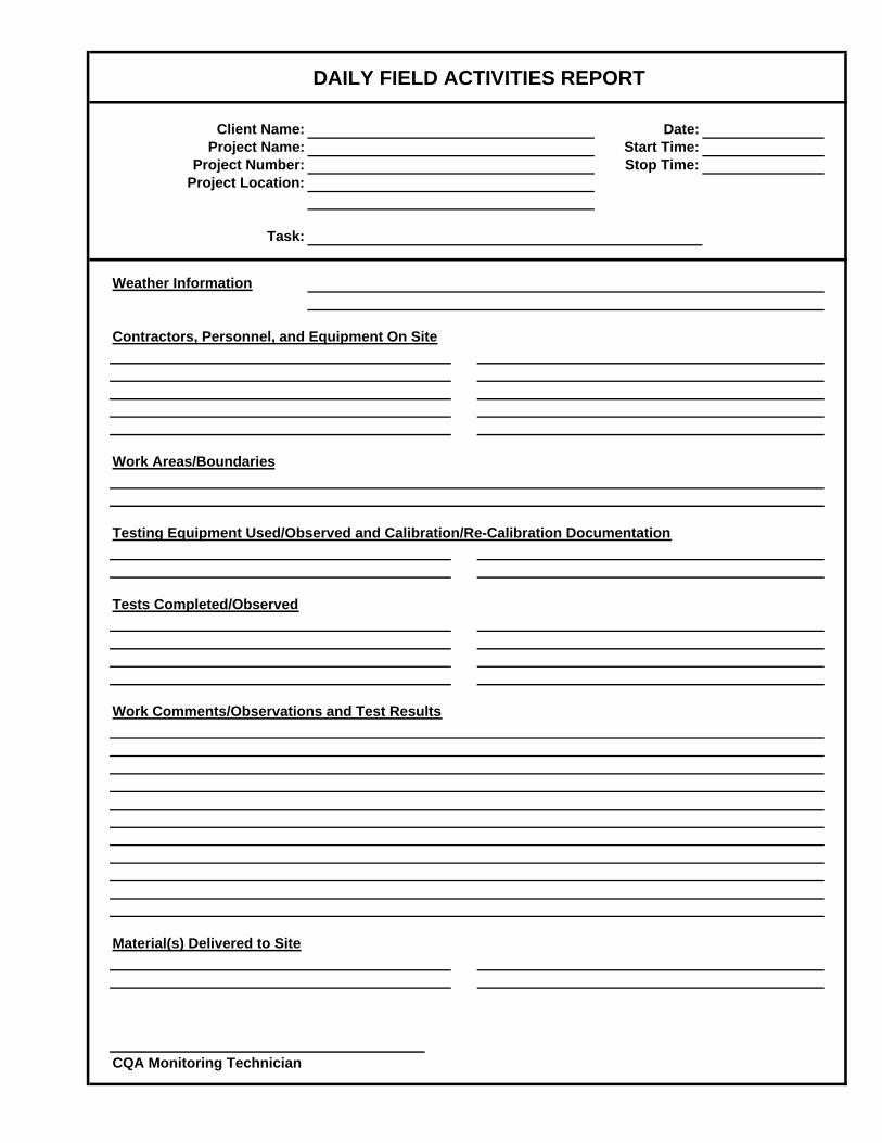
Client Name: Date:Project Name: Start Time:
Project Number: Stop Time:Project Location:
Task:
Weather Information
Contractors, Personnel, and Equipment On Site
Work Areas/Boundaries
Testing Equipment Used/Observed and Calibration/Re-Calibration Documentation
Tests Completed/Observed
Work Comments/Observations and Test Results
Material(s) Delivered to Site
CQA Monitoring Technician
DAILY FIELD ACTIVITIES REPORT

Client Name: Date:Project Name: Start Time:
Project Number: Stop Time:Project Location:
Task:
Work Boundaries (cont.)
Tests Completed/Observed (cont.)
Work Comments/Observations and Test Results (cont.)
CQA Monitoring Technician
DAILY FIELD ACTIVITIES REPORT (cont.)

Nuclear Density Gauge Test RecordDate:Page:
CQA Technician:Client Name:
Project Name: Material Designation:Target Dry Density: Standard Density:
Project Number: Target Moisture Range: Standard Moisture:Project Location: Target Percent Compaction:
Probe Wet Water Dry Water PercentTest-Lift Depth Density Weight Density Content Compaction Pass/Number Location (in.) (pcf) (lbs.) (pcf) (%) (%) Fail
MaterialDesignation
LiftRange
(in.)

Material Inventory Record Page: of
CQA Technician:
Client Name: Project Name:Project Location:
Project Number:
Material Type:
Roll Size Date Roll Lot/ Width Length Area QC Docs Date
Received No. Batch (ft) (ft) (sq. ft) Received Used Remarks

Seam/Non-Destructive Test RecordDate: Page of
CQA Technician:
Client Name: Project Name:Project Location:
Project Number:
Seam Seam Seamer Machine Trial Direction Weather/ Destruct Date Addn'l Tester VacuumTime Number Length Initials Number Weld # Seamed Temp Number Comments Tested Test #'s Initials Start End +/- Start End P/F Box P/F
*See Additional Non-Destructive Tests Record for test data.
Seaming Information Non-Destructive Testing InformationPressure Time Location/
Comments
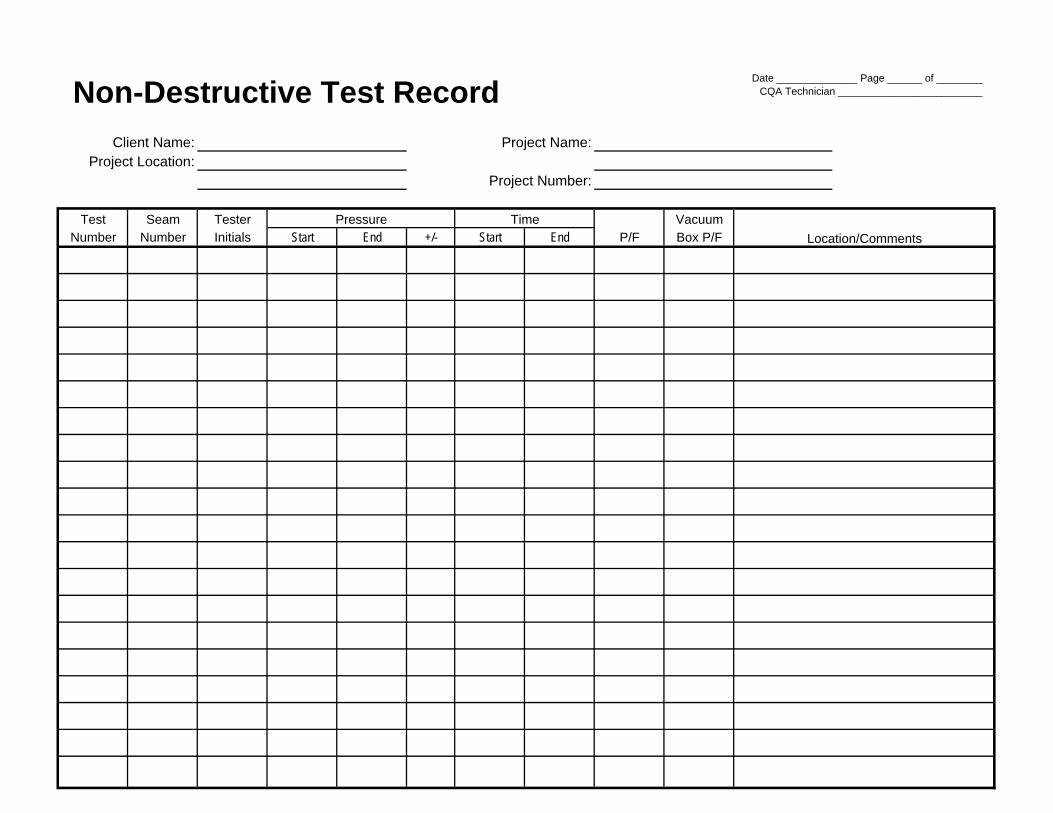
Non-Destructive Test Record Date ______________ Page ______ of ________CQA Technician _________________________
Client Name: Project Name:Project Location:
Project Number:
Test Seam Tester VacuumNumber Number Initials Start End +/- Start End P/F Box P/F Location/Comments
Pressure Time

Destructive Test RecordDate: Page of
Client Name: Specifications: mil CQA Technician:Project Name:
Wedge ExtrusionProject Number: Peel (P) ≥ ≥ pounds per inch (ppi)
Project Location: Shear (S) ≥ ≥ ppi
Sample Installer's Seamers Weld Machine Test Values Field/Lab RepairID QC Initials Type Number ppi Pass/Fail Number
PSPSPSPSPSPSPSPSPSPSPSPSPSPSPSPSPSPSPSPS
LocationSeamNumber

Repair Record Date: Page: ofCQA Technician:
Client Name: Project Name:Project Location:
Project Number:
Repair Panel/ Repair Machine Repair Repair Test Trial Weld Tester TestNumber Seam Crew Number Type Size Date Number Initials P/F
-
-
Location/Comments

Trial Weld RecordDate: Page of
Client Name: Specifications: mil CQA Technician:Project Name:
Wedge ExtrusionProject Number: Peel (P) ≥ ≥
Project Location: Shear (S) ≥ ≥
Trial Weld Ambient Installer's Seamers Machine Machine Weld Test Values Pass/ Type ofNumber Time Temp QC Initials Number Properties Type lbs/inch Fail Material Comments

APPENDIX D
2011 Test Pad Summary Report

TEST PAD SUMMARY REPORT
Barton County Sanitary Landfill
Barton County, Kansas
KDHE Solid Waste Permit Number 103 Aquaterra Project Number 4104.11
May 2011
Prepared For:
Barton County, Kansas

4104.11Test Pad Summary Report Barton County i Aquaterra
TABLE OF CONTENTS Page
2.1 Middle Horizon Lean Clay Test Pad ............................................................... 3
2.1.1 Pre-Construction Soil Testing ............................................................. 3
2.1.2 Construction Activities .................................................................................... 5
2.1.3 Material Observation ...................................................................................... 5
2.1.4 Nuclear Moisture and Density Testing ............................................................ 5
2.2 Lower Horizon Sandy Lean Clay Test Pad ..................................................... 6
2.2.1 Pre-Construction Soil Testing ............................................................. 6
2.2.2 Construction Activities .................................................................................... 8
2.2.4 Nuclear Moisture and Density Testing ............................................................ 9
3.1 In-Situ Hydraulic Conductivity Testing .......................................................... 11
3.1.1 Borehole and Casing Installation ...................................................... 11
3.1.2 Top Assembly Installation ................................................................. 12
3.1.2 Middle Horizon Lean Clay Test Pad Stage 1 Testing ........................ 12
3.1.2 Lower Horizon Sandy Lean Clay Test Pad Stage 1 Testing .............. 13
LIST OF APPENDICES Appendix A Geotechnical Laboratory Reports Appendix B Photo Log Appendix C Construction Observation and Testing Appendix D Boutwell Test Data

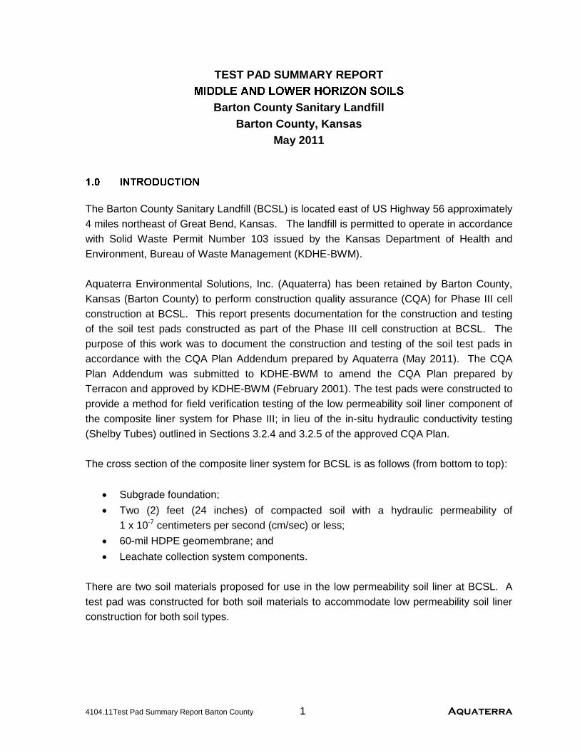
4104.11Test Pad Summary Report Barton County 1 Aquaterra
TEST PAD SUMMARY REPORT
Barton County Sanitary Landfill Barton County, Kansas
May 2011
The Barton County Sanitary Landfill (BCSL) is located east of US Highway 56 approximately 4 miles northeast of Great Bend, Kansas. The landfill is permitted to operate in accordance with Solid Waste Permit Number 103 issued by the Kansas Department of Health and Environment, Bureau of Waste Management (KDHE-BWM). Aquaterra Environmental Solutions, Inc. (Aquaterra) has been retained by Barton County, Kansas (Barton County) to perform construction quality assurance (CQA) for Phase III cell construction at BCSL. This report presents documentation for the construction and testing of the soil test pads constructed as part of the Phase III cell construction at BCSL. The purpose of this work was to document the construction and testing of the soil test pads in accordance with the CQA Plan Addendum prepared by Aquaterra (May 2011). The CQA Plan Addendum was submitted to KDHE-BWM to amend the CQA Plan prepared by Terracon and approved by KDHE-BWM (February 2001). The test pads were constructed to provide a method for field verification testing of the low permeability soil liner component of the composite liner system for Phase III; in lieu of the in-situ hydraulic conductivity testing (Shelby Tubes) outlined in Sections 3.2.4 and 3.2.5 of the approved CQA Plan. The cross section of the composite liner system for BCSL is as follows (from bottom to top):
Subgrade foundation; Two (2) feet (24 inches) of compacted soil with a hydraulic permeability of
1 x 10⁻⁷ centimeters per second (cm/sec) or less; 60-mil HDPE geomembrane; and Leachate collection system components.
There are two soil materials proposed for use in the low permeability soil liner at BCSL. A test pad was constructed for both soil materials to accommodate low permeability soil liner construction for both soil types.

4104.11/Test Pad Summary Report Barton County 2 Aquaterra
The two soil types are located on site and are described as follows:
Lean clay at depths ranging from approximately six feet to 12 feet below the original ground surface referred to herein as “middle horizon” lean clay; and
Sandy lean clay at depths ranging from approximately 12 feet to 40 feet below the original ground surface referred to herein as “lower horizon” sandy lean clay.
The middle horizon lean clay has been used successfully in previous low permeability soil liner installations and extensive historical test results for the material are available. Pre-construction testing was performed for Phase III cell construction and the results for the middle horizon lean clay corresponded well with historical test data. However, Aquaterra revised the Phase II placement zone to incorporate the results of Modified Proctor tests conducted for Phase III. The lower horizon sandy lean clay has not been used previously for low permeability soil liner, but has been used successfully in the past for final cover construction. Pre-construction soil testing was performed for Phase III to develop a placement range for the lower horizon sandy lean clay material.

4104.11/Test Pad Summary Report Barton County 3 Aquaterra
Two test pads, consisting of an area of approximately 5,000 square feet (sf), were constructed as part of the Phase III cell construction activities; one for each soil material. The test pad dimensions were approximately 50- by 100-feet, with a total thickness of 30 inches in six 6-inch compacted lifts. The following sections describe the construction procedures, observation, and testing for each test pad in greater detail.
2.1 Middle Horizon Lean Clay Test Pad
A sample of the middle horizon lean clay was collected on January 18, 2011 from the borrow area located to the north of the future Phase III cell. The soil sample was submitted to a geotechnical testing laboratory for evaluation of the following engineering properties of the soil:
Atterberg limits; Grain size analysis; Standard energy Proctor; Modified energy Proctor; and Hydraulic conductivity.
The middle horizon lean clay has been used for previous low permeability soil liner construction. The results of the pre-construction soil tests for Phase III were consistent with historical test results for the middle horizon lean clay. Table 1 summarizes pertinent results of the laboratory testing of engineering properties performed by Alpha-Omega Geotech, Inc. (Alpha-Omega) and historical test results for the middle horizon lean clay. Table 2 summarizes the results of the remolded hydraulic conductivity testing performed by Alpha-Omega. Copies of the laboratory testing results are provided in Appendix A. Table 1 - Middle Horizon Lean Clay Pre-Construction Testing (Sample B1-U)
Pre-Construction Soil Testing Results for Engineering Properties
Sample Atterberg Limits Proctor Tests*
Liquid Limit
Plastic Limit
Plasticity Index
Standard Energy Modified Energy
B1-U 38 20 18 99.6 pcf at 19.4% M.C. 113.8 at 15.2% M.C. Range of Historical
Results 37-52 15-19 20-35
98.5 pcf – 104.0 pcf 18.0% – 20.5% M.C.
None
*pcf = pounds per cubic feet, M.C. = moisture content
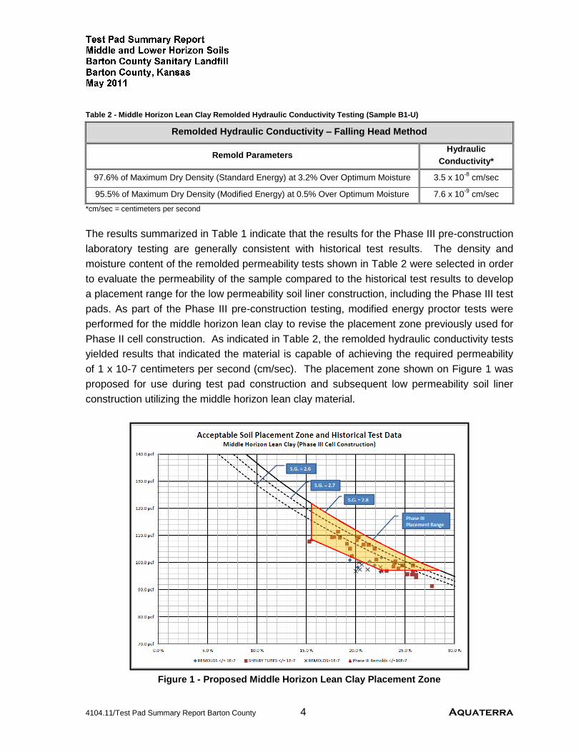
4104.11/Test Pad Summary Report Barton County 4 Aquaterra
Table 2 - Middle Horizon Lean Clay Remolded Hydraulic Conductivity Testing (Sample B1-U)
Remolded Hydraulic Conductivity – Falling Head Method
Remold Parameters Hydraulic
Conductivity*
97.6% of Maximum Dry Density (Standard Energy) at 3.2% Over Optimum Moisture 3.5 x 10⁻⁸ cm/sec
95.5% of Maximum Dry Density (Modified Energy) at 0.5% Over Optimum Moisture 7.6 x 10⁻⁹ cm/sec
*cm/sec = centimeters per second The results summarized in Table 1 indicate that the results for the Phase III pre-construction laboratory testing are generally consistent with historical test results. The density and moisture content of the remolded permeability tests shown in Table 2 were selected in order to evaluate the permeability of the sample compared to the historical test results to develop a placement range for the low permeability soil liner construction, including the Phase III test pads. As part of the Phase III pre-construction testing, modified energy proctor tests were performed for the middle horizon lean clay to revise the placement zone previously used for Phase II cell construction. As indicated in Table 2, the remolded hydraulic conductivity tests yielded results that indicated the material is capable of achieving the required permeability of 1 x 10⁻⁷ centimeters per second (cm/sec). The placement zone shown on Figure 1 was proposed for use during test pad construction and subsequent low permeability soil liner construction utilizing the middle horizon lean clay material.
Figure 1 - Proposed Middle Horizon Lean Clay Placement Zone

4104.11/Test Pad Summary Report Barton County 5 Aquaterra
2.1.2 Construction Activities
Material placed during test pad construction followed the methods outlined in the CQA Plan Addendum. A photo log documenting test pad construction and associated testing is included in Appendix B and Daily Field Activities Forms are included in Appendix C. The test pad construction area was prepared to the northeast of the Phase III construction area by removing the vegetation and topsoil and nominally compacting the subgrade. The middle horizon test pad was constructed adjacent to the lower horizon test pad. The middle horizon lean clay test pad material was excavated from a borrow source area to the north of Phases I and II. The liner material was initially placed at the southwest corner of the test pad area and spread in approximately 8-inch loose lifts with a scraper in rows for each lift. On the first lift, after spreading, the material was processed with a tractor and disc to promote drying. The second through fifth lifts for the middle horizon lean clay test pad were not excessively moist and drying was not required. Following the processing of the material, the material was compacted into 6-inch lifts using a Caterpillar 815 soil compactor. Upon completion of compaction, the motor grader ran over the test pad to smooth the surface and tested for moisture/density requirements with a nuclear density gauge. Prior to placement of subsequent lifts, the material was scarified to promote interlift bonding.
2.1.3 Material Observation
Excavation activities occurred within the borrow source area on site to the north of Phases I, II, and III. The CQA technician visually observed the soil to monitor consistency during construction. The range of color and texture appeared consistent during excavation and placement. The reaction of the soil to compaction imparted appeared consistent. Adequate stripping was conducted prior to excavation of soil material for test pad construction to remove topsoil and vegetation from the test pad construction area. Additionally, soil excavation and stockpiling was completed such that the middle horizon lean clay was appropriately segregated from the lower horizon sandy lean clay material. The middle horizon lean clay and lower horizon sandy lean clay originated from separate excavation areas and the materials were readily distinguishable by color and sand content. The middle horizon lean clay appears significantly darker in color.
2.1.4 Nuclear Moisture and Density Testing
The onsite CQA Technician performed moisture and density tests with a recently calibrated Troxler moisture/density gauge during the test pad construction. The nuclear density gauge is calibrated on an annual basis and a standard count was performed each morning to ensure the gauge was functioning properly. Testing was conducted according to the frequency outlined in the CQA Plan Addendum, with a minimum of four (4) tests per lift.

4104.11/Test Pad Summary Report Barton County 6 Aquaterra
Each 6-inch compacted lift was tested to confirm that the compacted liner material was placed in accordance with the moisture and density values defined by the target placement zone developed for middle horizon lean clay. Holes in the liner left by the nuclear density testing activities were filled with granular bentonite prior to placing the next lift of soil. A summary of the nuclear density field test results is provided on Table 3 and are included in Appendix C. Table 3 - Middle Horizon Lean Clay Test Pad Nuclear Testing
Summary of Nuclear Moisture and Density Testing Results Lift
Number Lift Range
(in) Test Results
1 0-6 Dry Density (pcf) 105.6 108.6 106.9 106.0 106.8 107.3
Moisture Content (%) 17.8 16.4 17.5 18.3 17.6 16.5
2 6-12 Dry Density (pcf) 105.9 104.9 104.8 106.6 104.6 105.7
Moisture Content (%) 17.5 18.3 18.4 17.4 18.1 20.0
3 12-18 Dry Density (pcf) 102.7 101.9 101.2 103.7 100.3 99.8
Moisture Content (%) 19.8 20.4 20.6 19.5 22.9 23.0
4 18-24 Dry Density (pcf) 104.0 102.5 101.9 101.1 104.4 101.6
Moisture Content (%) 18.0 19.4 20.1 20.3 19.2 21.9
5 24-30 Dry Density (pcf) 104.0 102.7 104.6 104.1 102.5 101.9
Moisture Content (%) 18.8 20.0 19.4 19.5 19.4 20.1
2.2 Lower Horizon Sandy Lean Clay Test Pad
A composite sample of the lower horizon lean clay was collected on January 18, 2011 from the borrow area located to the north of the future Phase III cell and the Phase III cell construction area. The soil sample was submitted to a geotechnical testing laboratory for evaluation of the following engineering properties of the soil:
Atterberg limits; Grain size analysis; Standard energy Proctor; Modified energy Proctor; and Hydraulic conductivity.
The lower horizon sandy lean clay has not been used previously for low permeability soil liner, but it has been used successfully for final cover construction. However, historical test results for hydraulic conductivity were unavailable for the material. Therefore, five (5) hydraulic conductivity tests were performed at various densities and moisture content to evaluate the remolded permeability of the lower horizon material. The results of the

4104.11/Test Pad Summary Report Barton County 7 Aquaterra
pre-construction soil tests for the lower horizon material indicated that the soil is capable of achieving the required permeability of 1x10⁻⁷ cm/sec. Table 4 provides a summary of pertinent results from the laboratory testing of engineering properties performed by Alpha-Omega Geotech, Inc. (Alpha-Omega). Table 5 summarizes the results of the remolded hydraulic conductivity testing performed by Alpha-Omega. Copies of the laboratory testing results are provided in Appendix A. Table 4 - Lower Horizon Sandy Lean Clay Pre-Construction Testing (Sample B-1,2,&3L)
Pre-Construction Soil Testing Results for Engineering Properties
Sample Atterberg Limits Proctor Tests*
Liquid Limit
Plastic Limit
Plasticity Index
Standard Energy Modified Energy
B-1, 2, & 3L 29 15 14 114.8 pcf at 13.5% M.C. 125.2 at 10.6% M.C.
*pcf = pounds per cubic feet, M.C. = moisture content
Table 5 - Lower Horizon Sandy Lean Clay Remolded Hydraulic Conductivity Testing (Sample B-1,2,&3L)
Remolded Hydraulic Conductivity – Falling Head Method
Remold Parameters Hydraulic
Conductivity*
99.9% of Maximum Dry Density (Standard Energy) at 0.4% Over Optimum Moisture 9.6 x 10⁻⁹ cm/sec
100.0% of Maximum Dry Density (Standard Energy) at 0.5% Over Optimum Moisture 9.4 x 10⁻⁹ cm/sec
95.8% of Maximum Dry Density (Standard Energy) at 2.4% Over Optimum Moisture 4.2 x 10⁻⁸ cm/sec
94.5% of Maximum Dry Density (Modified Energy) at 1.0% Over Optimum Moisture 2.2 x 10⁻⁸ cm/sec
97.5% of Maximum Dry Density (Modified Energy) at 0.5% Over Optimum Moisture 2.9 x 10⁻⁸ cm/sec
*cm/sec = centimeters per second The density and moisture content of the remolded permeability tests shown in Table 5 were selected in order to evaluate the permeability of the sample and develop a placement range zone for low permeability soil liner construction, including the Phase III test pads. As part of the Phase III pre-construction testing, modified energy proctor tests were performed for the lower horizon sandy lean clay to incorporate higher densities and provide a comprehensive placement zone. As indicated in Table 5, the remolded hydraulic conductivity tests yielded results that indicated the material is capable of achieving the required permeability of 1x10⁻⁷ centimeters per second (cm/sec). The placement zone shown on Figure 2 was proposed for use during test pad construction and subsequent low permeability soil liner construction utilizing the lower horizon sandy lean clay material.

4104.11/Test Pad Summary Report Barton County 8 Aquaterra
Figure 2 - Proposed Lower Horizon Sandy Lean Clay Placement Zone
2.2.2 Construction Activities
Material placed during test pad construction followed the methods outlined in the CQA Plan Addendum. A photo log documenting test pad construction and associated testing is included in Appendix B and Daily Field Activities Forms are included in Appendix C. The test pad construction area was prepared to northeast of the Phase III construction area by removing the vegetation and topsoil, and nominally compacting the subgrade. The lower horizon sandy lean clay test pad was constructed adjacent to the middle horizon test pad, directly to the west. The lower horizon sandy lean clay test pad material was excavated from Phase III construction area. The liner material was initially placed at the southwest corner of the test pad area and spread in approximately 8-inch loose lifts with a scraper in rows for each lift. Due to excessive moisture in the material, after spreading, the material was processed with a tractor and disc to promote drying. Following the processing of the material, the material was compacted into 6-inch lifts using a Caterpillar 815 soil compactor. Upon completion of compaction, the motor grader ran over the test pad to smooth the

4104.11/Test Pad Summary Report Barton County 9 Aquaterra
surface and tested for moisture/density requirements with a nuclear density gauge. Prior to placement of subsequent lifts, the material was scarified to promote interlift bonding. 2.2.3 Material Observation Excavation activities occurred within the Phase III construction area. The CQA technician visually observed the soil to monitor consistency during construction. The range of color and texture appeared consistent during excavation and placement, with the material generally having slightly excessive moisture. The reaction of the soil to discing for promotion of drying and compaction imparted appeared consistent. Adequate stripping was conducted prior to excavation of soil material for test pad construction to remove topsoil and vegetation from the test pad construction. Additionally, soil excavation and stockpiling was completed such that the middle horizon lean clay was appropriately segregated from the lower horizon sandy lean clay material. The middle horizon lean clay and lower horizon sandy lean clay originated from separate excavation areas and the materials were readily distinguishable by color and sand content. The middle horizon lean clay appears significantly darker in color.
2.2.4 Nuclear Moisture and Density Testing
The onsite CQA Technician performed moisture and density tests with a recently calibrated Troxler moisture/density gauge during the test pad construction. The nuclear density gauge is calibrated on an annual basis and a standard count was performed each morning to ensure the gauge was functioning properly. Testing was conducted according to the frequency outlined in the CQA Plan Addendum, with a minimum of four (4) tests per lift. Each 6-inch compacted lift was tested to confirm that the compacted liner material was placed in accordance with the moisture and density values defined by the target placement zone developed for middle horizon lean clay. Holes in the liner left by the nuclear density testing activities were filled with granular bentonite prior to placing the next lift of soil. A summary of the nuclear density field test results is provided on Table 6. Figures depicting the nuclear density test locations and the nuclear density gauge test records are included in Appendix C.

4104.11/Test Pad Summary Report Barton County 10 Aquaterra
Table 6 - Lower Horizon Sandy Lean Clay Test Pad Nuclear Testing Summary of Nuclear Moisture and Density Testing Results
Lift Number
Lift Range (in)
Test Results
1 0-6 Dry Density (pcf) 113.6 112.5 113.4 111.0 110.7 110.6
Moisture Content (%) 17.0 15.2 14.5 16.1 17.1 17.6
2 6-12 Dry Density (pcf) 111.9 115.0 112.5 111.3 111.8 112.1
Moisture Content (%) 17.4 14.0 16.7 17.9 17.5 17.1
3 12-18 Dry Density (pcf) 110.4 112.2 113.6 110.2 111.9 112.2
Moisture Content (%) 16.8 17.3 15.7 18.9 17.5 17.0
4 18-24 Dry Density (pcf) 111.3 110.4 112.1 110.9 110.5 110.7
Moisture Content (%) 17.8 18.8 16.6 17.3 17.8 17.8
5 24-30 Dry Density (pcf) 113.6 110.3 110.1 110.3 111.2 112.8
Moisture Content (%) 15.8 16.9 16.5 16.8 17.8 16.2

4104.11/Test Pad Summary Report Barton County 11 Aquaterra
3.1 In-Situ Hydraulic Conductivity Testing
Aquaterra conducted in-situ hydraulic conductivity testing in general accordance with ASTM D 6391-06: Standard Test Method for Field Measurement of Hydraulic Conductivity
Limits of Porous Materials Using Two Stages of Infiltration from a Borehole, commonly known as the “Boutwell Test”. This type of test is used to determine the field hydraulic conductivity of the compacted soil test liner; it is a falling head infiltration test conducted in a cased borehole. The first stage is performed with the bottom of the hole flush with the bottom of the casing for maximum effect of the vertical permeability. The following sections describe the testing procedures and results for each test pad constructed at BCSL. Photographs are included in Appendix B.
On May 10, 2011, Aquaterra personnel bored six test locations in each test pad. Boreholes were located on approximate 15- to 20-foot centers, and a minimum of 15 feet from the edge of the test pad. The general layout for both test pads is shown on Figure 6 in Appendix C. The boreholes were dug to a depth of approximately 14 inches below grade using a 6-inch diameter posthole digger/auger and then reamed with a 6-inch diameter flat-bottom auger, to create a smooth, flat surface at the bottom of the borehole. Eighteen-inch sections of 4-inch diameter Schedule 40 (SCH 40) poly-vinyl chloride (PVC) casing were placed in each borehole. Five of the casings were open-ended and one casing was capped at the bottom with a 4-inch diameter PVC cap. This capped casing served as the “dummy installation” and
was identified as the temperature effect gauge (TEG). Each casing was threaded at the top to allow connection to the top assembly of the Boutwell test. The annular space of each borehole was sealed using 1/4-inch and 3/8-inch bentonite pellets. The bentonite was placed in 1-inch layers followed by a small amount of water and tamped into place using a dowel rod. This procedure was continued until the entire annular space was sealed to ground level. The bentonite was required to hydrate a minimum of 12 hours; therefore, installation activities concluded for the day. Prior to leaving the site, plastic sheeting was installed around the casings and on top of the test pad area surrounding the casings. The perimeter of the plastic sheeting was held in-place with soil and taped to the casing, and a PVC cap was used to seal the top of the casings in order to protect the integrity of the borehole and bentonite seal in the event of inclement weather.

4104.11/Test Pad Summary Report Barton County 12 Aquaterra
The top assembly for each test location on both test pads consisted of the appropriate SCH 40 PVC fittings and clear standpipes, as shown in the photographs included in Appendix B. On May 11, 2011, the top assemblies were threaded onto the casings in the boreholes. Upon filling the standpipes with water, the time, temperature, and measurement of the water level were taken to initiate the test. Once the permeameters and TEG were installed and filled with water the stand pipe levels were recorded and checked periodically noting any change in water level as well as the current time and temperature. Photographs documenting the installation of each of the five permeameters (casing and top assembly) and TEG for each test pad are provided in Appendix B.
Stage 1 testing was terminated when the hydraulic conductivity (K1’) for each permeameter
indicated that steady state had been achieved for 24 hours. K1’ was determined based on a
time weighted average of the field readings. K1’ values for each of the five permeameters installed for the middle horizon test pad exhibited a hydraulic conductivity below 1x10⁻⁷ cm/sec, in accordance with the CQA Plan Addendum. The field data and final calculations for Stage 1 testing of the middle horizon lean clay test pad are included in Appendix D. Stage 1 testing yields the maximum possible value for vertical permeability and field hydraulic conductivity is considered to be equal to or less than K1’, which was indicated to be below 1 x 10⁻⁷ cm/sec for each Boutwell test. The purpose of the test was to demonstrate that hydraulic conductivity of the test pad was less than 1 x 10⁻⁷ cm/sec; therefore, the test was terminated at this point. As outlined in the CQA Plan Addendum, Stage 2 testing was not performed because the successful demonstration of Stage 1 testing precluded the necessity to conduct Stage 2 testing. Individual Boutwell test results for the middle horizon test pad are summarized in Table 7.
Table 7 - Middle Horizon Lean Clay Boutwell Test Results
Test Number Hydraulic Conductivity (cm/sec)
#1 8.82 X10 –8 #2 7.72 X10 –8 #3 5.02 X10 –8 #4 7.76 X10 –8 #5 8.78 X10 –8
AVERAGE 7.62 X10 –8

4104.11/Test Pad Summary Report Barton County 13 Aquaterra
Stage 1 testing was terminated when the hydraulic conductivity (K1’) for each permeameter
indicated that steady state had been achieved for 24 hours. K1’ was determined based on a
time weighted average of the field readings. K1’ values for each of the five permeameters installed for the middle horizon test pad exhibited a hydraulic conductivity below 1x10⁻⁷ cm/sec, in accordance with the CQA Plan Addendum. The field data and final calculations for Stage 1 testing of the middle horizon lean clay test pad are included in Appendix D. It should be noted that the testing for Boutwell Number 2 was started approximately 18 hours after the other tests because the initial installation of the permeameters contained a leak. Because Boutwell Number 2 had to run for additional time, the rest of the Boutwells were continued until Boutwell Number 2 reached a steady state condition for 24 hours. Stage 1 testing yields the maximum possible value for vertical permeability and field hydraulic conductivity is considered to be equal to or less than K1’, which was indicated to be below 1 x 10⁻⁷ cm/sec for each Boutwell test. The purpose of the test was to demonstrate that hydraulic conductivity of the test pad was less than 1 x 10⁻⁷ cm/sec; therefore, the test was terminated at this point. As outlined in the CQA Plan Addendum, Stage 2 testing was not performed because the successful demonstration of Stage 1 testing precluded the necessity to conduct Stage 2 testing. Individual Boutwell test results for the lower horizon test pad are summarized in Table 8.
Table 8 - Lower Horizon Sandy Lean Clay Boutwell Test Results
Test Number Hydraulic Conductivity (cm/sec)
#1 2.05 X10 –8 #2 9.33 X10 –8 #3 3.38 X10 –8 #4 4.11 X10 –8 #5 7.08 X10 –8
AVERAGE 5.19 X10 –8

4104.11/Test Pad Summary Report Barton County 14 Aquaterra
Based on the results of the test pad construction and evaluation, both the middle horizon lean clay and lower horizon sandy lean clay soils are acceptable for use in the liner construction for Phase III and future cells at this facility. CQA activities will be performed in accordance with the KDHE-approved CQA Plan and CQA Plan Addendum. The targeted dry density and moisture range for the middle horizon soil will be consistent with the placement zone shown in Figure 1, Section 2.1.1 of this report. The targeted dry density and moisture range for the lower horizon sandy lean clay will be consistent with the placement zone shown in Figure 2, Section 2.2.1 of this report. The placement zones for each soil type have also been included in Appendix A. This report has been prepared for the exclusive use of Barton County, Kansas and the Barton County Sanitary Landfill, for specific application to the project discussed, and has been prepared in accordance with generally accepted engineering practices.

APPENDIX A
GEOTECHNICAL LABORATORY REPORTS
MIDDLE HORIZON LEAN CLAY LOWER HORIZON SANDY LEAN CLAY

MIDDLE HORIZON LEAN CLAY
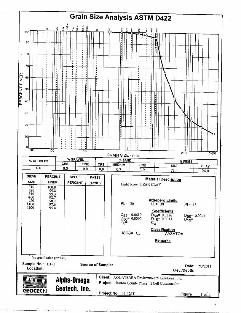


LOWER HORIZON SANDY LEAN CLAY

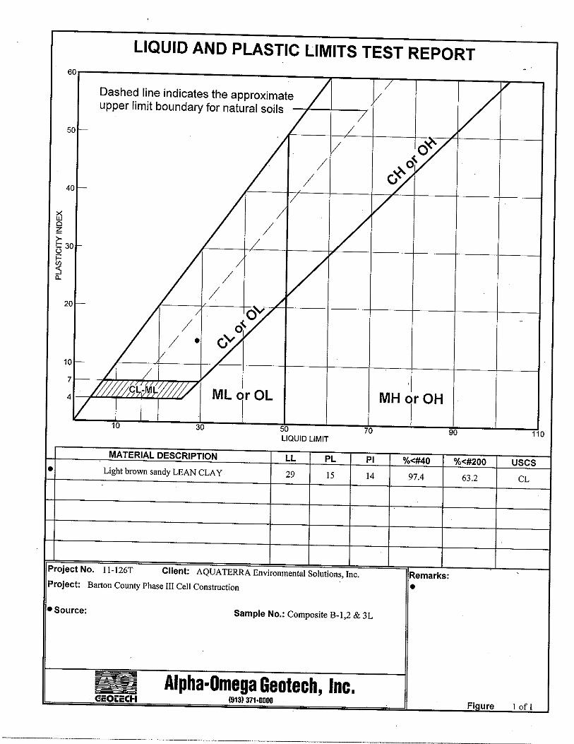
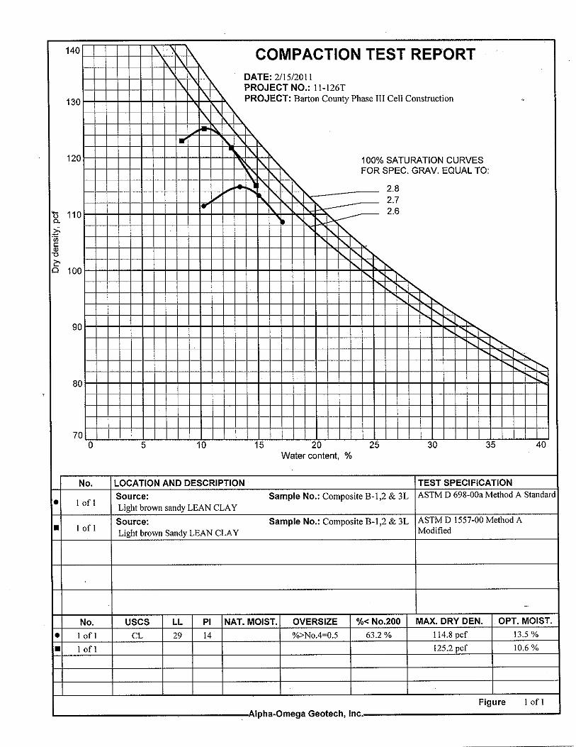

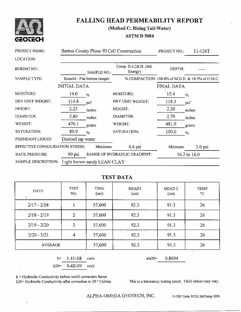


APPENDIX B
PHOTO LOG

Barton County Phase III CQA Aquaterra Project No. 4104.11 Page 1
Photo # 1 Photographer: WM Date: 3/9/11 Description: Test pad construction area (2 – 100 ft x 50 ft pads) after stripping and subgrade preparation. Photo # 2 Photographer: WM Date: 3/9/11 Description: Test pad construction area (2 – 100 ft x 50 ft pads) after stripping and subgrade preparation. Photo # 3 Photographer: WM Date: 3/9/11 Description: Placing and spreading middle horizon lean clay material for test pad construction. Discing lower horizon sandy lean clay material to promote drying.

Barton County Phase III CQA Aquaterra Project No. 4104.11 Page 2
Photo # 4 Photographer: WM Date: 3/9/11 Description: Discing lower horizon material test pad to promote drying and scarifying middle horizon material test pad. Photo # 5 Photographer: WM Date: 3/9/11 Description: Placing and spreading middle horizon material test pad with scraper. Photo # 6 Photographer: WM Date: 3/10/11 Description: Compacting lower horizon material test pad with pad foot compactor.

Barton County Phase III CQA Aquaterra Project No. 4104.11 Page 3
Photo # 7 Photographer: WM Date: 3/10/11 Description: Drying lower horizon material test pad with discer and placing and spreading middle horizon material test pad soil with scraper. Photo # 8 Photographer: WM Date: 3/10/11 Description: Drying lower horizon material test pad with discer and compacting lower horizon test pad with pad foot compactor. Photo # 9 Photographer: WM Date: 3/10/11 Description: Installing Boutwell test casinWM in the middle horizon lean clay test pad.

Barton County Phase III CQA Aquaterra Project No. 4104.11 Page 4
Photo # 10 Photographer: WM Date: 3/10/11 Description: Boutwell test location on lower horizon material test pad with protective plastic sheeting in-place. Photo # 11 Photographer: WM Date: 3/10/11 Description: Sealing Boutwell test casing with tamped bentonite seal. Photo # 12 Photographer: WM Date: 3/10/11 Description: Completed Boutwell casings for Number 3 and TEG on middle horizon material test pad.

Barton County Phase III CQA Aquaterra Project No. 4104.11 Page 5
Photo # 13 Photographer: WM Date: 3/10/11 Description: Completed Boutwell test casing. Photo # 14 Photographer: WM Date: 3/11/11 Description: Boutwells installed in lower horizon material test pad. Photo # 15 Photographer: WM Date: 3/11/11 Description: Boutwells installed in middle horizon material test pad.

Barton County Phase III CQA Aquaterra Project No. 4104.11 Page 6
Photo # 16 Photographer: WM Date: 3/11/11 Description: Close-up of Boutwell installed in middle horizon material test pad. Photo # 17 Photographer: WM Date: 3/11/11 Description: Connecting Boutwell apparatus to casing. Photo # 18 Photographer: WM Date: 3/11/11 Description: View of completed test pads .

APPENDIX C
CONSTRUCTION OBSERVATION AND TESTING
DAILY FIELD ACTIVITIES REPORTS NUCLEAR DENSITY GAUGE TEST RECORDS
PLACEMENT RANGE FIGURES TEST PADS LAYOUT FIGURES

DAILY FIELD ACTIVITIES REPORTS

Client Name: Date: March 7, 2011Aquaterra Project Name: Start Time: 5:00 AMAquaterra Project Number: Stop Time: 6:30 PMProject Location:
Task:
Weather Information
Contractors, Personnel, and Equipment On SiteWhit Martin - Aquaterra 1 -CAT 160H Road GraderEdd McDonald & 5 Operators - Sporer Land Development 4 - CAT 627G Soil Scrapers
1 - CAT 972G Loader1 - CAT D5N Dozer 1 - John Deere Tractor and Discer1 - CAT Water Truck 1 - CAT CS-563D Vibratory Compactor
Work Areas/Boundaries
Testing Equipment Used/Observed and Calibration/Re-Calibration DocumentationTroxler 3440 Nuclear Density Gauge
Tests Completed/Observed1-1 thru 1-6 2 Tests failed/4 passed
Work Comments/Observations and Test Results
passed, but the Southeast did not because the clay was still too moist. Decided to seal and allow wet weather to pass before continuing to build the test pads. Offsite at 1830.
Material(s) Delivered to SiteTruck loads of sand
AQUATERRACQA Monitoring Technician Environmental Solutions, Inc.
compaction test was ran in the Southwest corner. The test failed so decided to disc the clay again and allow to dry
Mob to the site from Kansas City at 0500. Arrived onsite at 0900. Met with Edd McDonald to discuss work plan.CAT Scrapers are collecting the lower horizon clay from the bottom of Phase III and relocating it to the North end
Phase III
Whit Martin
At 1400 began removing the vegetation and topsoil Northeast of Phase III to build the test pads.
out some. Recompacted and ran more tests. The Southwest and Northwest corners passed. The Northeast corner
to be conditioned. Stopped for one hour lunch at 1200.After lunch continued to move the lower horizon clay (Brown-sandy) from the bottom of Phase III to be stockpiled.
Placed the first loose lift of the lower horizon clay. Disced the clay and compacted. Scarified the surface and
DAILY FIELD ACTIVITIES REPORT
Test Pad Construction Observation
Overcast to Partly Sunny, 36-49 Degrees F., 10-15 mph NE wind
Great Bend, KS 67530
Barton CountyPhase III Cell Construction4104.11Barton County Sanitary Landfill

Client Name: Date: March 8, 2011Aquaterra Project Name: Start Time: 7:00 AMAquaterra Project Number: Stop Time: 6:30 PMProject Location:
Task:
Weather Information
Contractors, Personnel, and Equipment On SiteWhit Martin - Aquaterra 1 -CAT 160H Road GraderEdd McDonald & 5 Operators - Sporer Land Development 4 - CAT 627G Soil Scrapers
1 - CAT 972G Loader1 - John Deere Tractor and Discer1 - CAT D5N Dozer
Work Areas/Boundaries
Testing Equipment Used/Observed and Calibration/Re-Calibration DocumentationTroxler 3440 Nuclear Density Gauge
Tests Completed/ObservedNone
Work Comments/Observations and Test Results
Material(s) Delivered to SiteTruck loads of sand
AQUATERRACQA Monitoring Technician Environmental Solutions, Inc.
Offsite at 1830.
Whit Martin
Tractor disced through the clay material in the floor of Phase III and the stockpile at the North end of the cell..Scrapers continued to collect clay from the floor and relocate it to the stockpile.Stopped for lunch at 1200.After lunch continued to relocate clay from the floor of Phase III to the stockpile area.More rain began at about 1500. Disced through the stockpile clay and disced the clay to be used for the test pads.The rain is making the clay material very moist.
Test Pad Construction Observation
Overcast with Light Rain; 38-44 Deg. F; 10-20 mph NE wind
Phase III
Onsite at 0700. Material is very wet and muddy from the rain during the night and morning.
DAILY FIELD ACTIVITIES REPORT
Barton CountyPhase III Cell Construction4104.11Barton County Sanitary LandfillGreat Bend, KS 67530

Client Name: Date: March 9, 2011Aquaterra Project Name: Start Time: 7:00 AMAquaterra Project Number: Stop Time: 6:30 PMProject Location:
Task:
Weather Information
Contractors, Personnel, and Equipment On SiteWhit Martin - Aquaterra 1 -CAT 160H Road GraderEdd McDonald & 6 Operators - Sporer Land Development 4 - CAT 627G Soil Scrapers
1 - CAT 972G Loader1 - John Deere Tractor and Discer
1- CAT 815 Padfoot Compactor 1 - CAT D5N Dozer
Work Areas/Boundaries
Testing Equipment Used/Observed and Calibration/Re-Calibration DocumentationTroxler 3440 Nuclear Density Gauge
Tests Completed/ObservedLower Horizon Clay (test pad) Middle Horizon Clay (Test Pad)Tests 1-1 through 12-2. All passed Tests 1-1 through 12-2. All passed.
Work Comments/Observations and Test Results
Material(s) Delivered to SiteTruck loads of sand
AQUATERRACQA Monitoring Technician Environmental Solutions, Inc.
DAILY FIELD ACTIVITIES REPORT
Barton CountyPhase III Cell Construction4104.11Barton County Sanitary LandfillGreat Bend, KS 67530
Test Pad Construction Observation
Sunny with few clouds, 28-47 Deg. F, 10-15 mph SE wind
Phase III
Onsite at 0700. Soil scrapers continued relocating the clay from Phase III floor to the stockpile.Began discing through the light brown sandy (Lower Horizon) material.Waiting for a CAT 815 Padfoot Roller to arrive onsite before building the test pads.Stopped at 1200 for one hour lunch.After lunch continued relocating the Lower Horizon clay to a stockpile North of the equipment area.Placed the first loose lift of light brown, sandy clay and disced. Also placed the first loose lift of the Middle Horizonlight brown clay material and disced through it.The padfoot compactor onsite at 1545. Compacted the first lifts. Ran density tests and all passed on the Lower
Whit Martin
Horizon clay. Ran density tests on the first lift of the Middle Horizon clay and all passed. Placed and compacted second lift of Lower Horizon. Ran tests and all passed. Placed and compacted the Middle Horizon clay. Ran testsand all passed. Placed third lift of LH clay and disced. Ran tests and material was too wet. Decided to resume in the morning. Offsite at 1830.

Client Name: Date: March 10, 2011Aquaterra Project Name: Start Time: 7:00 AMAquaterra Project Number: Stop Time: 9:00 PMProject Location:
Task:
Weather Information
Contractors, Personnel, and Equipment On SiteWhit Martin - Aquaterra 1 -CAT 160H Road GraderEdd McDonald & 6 Operators - Sporer Land Development 4 - CAT 627G Soil ScrapersGlenn Swaggart/Brett O'Connor - Aquaterra 1 - CAT 972G Loader
1 - John Deere Tractor and Discer1- CAT 815F Padfoot Compactor 1 - CAT D5N Dozer
Work Areas/Boundaries
Testing Equipment Used/Observed and Calibration/Re-Calibration DocumentationTroxler 3440 Nuclear Density Gauge #23141
Tests Completed/ObservedLower Horizon Clay (test pad) Middle Horizon Clay (Test Pad)13-3 through 18-3 - All Passed 13-3 through 18-3 - All Passed19-4 through 24-4 - All Passed 19-4 through 24-4 - All Passed25-5 through 30-5 - All Passed 25-5 through 30-5 - All Passed
Work Comments/Observations and Test Results
Material(s) Delivered to SiteTruck loads of sand
AQUATERRACQA Monitoring Technician Environmental Solutions, Inc.
Material was still too moist so disced through again and compacted. Ran density tests and all passed. Placed the fifth lift of Middle Horizon. Material didn't need to be disced so just compacted. Ran tests and all passed.Glenn and Brett onsite to install Boutwells. Installed 5 Boutwell bases and a TEG on the Middle Horizon test pad.Installed 5 Boutwell bases and a TEG on the Lower Horizon test pad. Offsite at 2100.
Whit Martin
padfoot roller (13 passes). Ran density tests and all passed.Soil scrapers continued relocating the Lower Horizon clay to North stockpiles.Placed the third lift of Middle Horizon clay, disced, and compacted. Ran density tests and all passed.Placed the fourth lift of Lower Horizon. Disced and compacted. Ran density tests and all passed.Placed the fourth lift of Middle Horizon. Disced and compacted. Ran density tests and all passed.Stopped for one hour lunch at 1200. After lunch placed the fifth lift of Lower Horizon. Disced and compacted.
Test Pad Construction Observation
Sunny and clear, 26 - 66 Degrees F., 5-10 mph SW wind
Phase III and Test Pads
Onsite at 0700. Sporer disced through the third loose lift of Lower Horizon clay and then compacted with the
DAILY FIELD ACTIVITIES REPORT
Barton CountyPhase III Cell Construction4104.11Barton County Sanitary LandfillGreat Bend, KS 67530

Client Name: Date: March 11, 2011Aquaterra Project Name: Start Time: 7:00 AMAquaterra Project Number: Stop Time: 6:30 PMProject Location:
Task:
Weather Information
Contractors, Personnel, and Equipment On SiteWhit Martin - Aquaterra 1 -CAT 160H Road GraderEdd McDonald & 6 Operators - Sporer Land Development 4 - CAT 627G Soil ScrapersGlenn Swaggart/Brett O'Connor - Aquaterra 1 - CAT 972G LoaderKirkham-Michael Surveyors 1 - CAT 815F Padfoot Compactor
1 - CAT D5N Dozer
Work Areas/Boundaries
Testing Equipment Used/Observed and Calibration/Re-Calibration DocumentationTroxler 3440 Nuclear Density Gauge #23141
Tests Completed/ObservedSubgrade Lift #1B-S-1 through W-S-1 - All Passed
Work Comments/Observations and Test Results
Material(s) Delivered to SiteTruck loads of sand
AQUATERRACQA Monitoring Technician Environmental Solutions, Inc.
DAILY FIELD ACTIVITIES REPORT
Barton CountyPhase III Cell Construction4104.11Barton County Sanitary LandfillGreat Bend, KS 67530
Test Pad Construction Observation
Sunny with few clouds, 43-64 Degrees F, 15-20 mph SW wind
Phase III and Test Pads
Onsite at 0700. Soil Scrapers are relocating the Lower Horizon clay from the floor of Phase III to the stockpile.Filled the Boutwells with water and began running the perm tests.Surveyors onsite to verify the subgrade. Sporer realized that they had cut 2 feet too much on the floor and the South slope of Phase III Cell.Had to reinstall Boutwell #2 on the Lower Horizon test pad because the first one was leaking.Stopped for one hour lunch at 1200.After lunch, soil scrapers began placing the first lift of subgrade on the floor.Sporer finished for the day and offsite at 1530.Ran density tests (dry density at least 90% of 114.8 pcf) on the first lift of subgrade. All tests passed.Took readings from the Boutwells.Offsite at 1830.
Whit Martin

NUCLEAR DENSITY GAUGE TEST RECORDS

Nuclear Density Gauge Test RecordDate ___3-9-2011_____ Page ___1___ of ____2____
Aquaterra CQA Technician __W. Martin__________
Client Name: Barton CountyAquaterra Project Name: Phase III Cell Construction Material Designation: Standard Density: 2418
Target Dry Density: 97.2 pcf 108.7 pcf Standard Moisture: 614Aquaterra Project Number: 4104.11 Target Moisture Range: 22.6% 15.5%
Project Location: Barton County Landfill Target Percent Compaction: 4% 96%Great Bend, KS 67530
Probe Wet Water Dry Water PercentTest-Lift Depth Density Weight Density Content Compaction Pass/Number Location (in.) (pcf) (lbs.) (pcf) (%) (%) Fail
1-1 6 124.4 18.8 105.6 17.8 106.1 P
2-1 6 126.3 17.8 108.6 16.4 109.0 P
3-1 6 125.5 18.7 106.9 17.5 107.3 P
4-1 6 125.5 19.5 106.0 18.3 106.4 P
5-1 6 125.5 18.8 106.8 17.6 107.2 P
6-1 6 125.0 17.7 107.3 16.5 107.8 P
7-2 6 124.5 18.6 105.9 17.5 106.3 P
8-2 6 124.1 19.2 104.9 18.3 105.3 P
9-2 6 124.1 19.3 104.8 18.4 105.2 P
10-2 6 125.1 18.5 106.6 17.4 107.0 P
11-2 6 123.6 19.0 104.6 18.1 105.0 P
12-2 6 126.9 21.1 105.7 20.0 106.2 P
Lean Clay
CL 6-12 NE Corner
CL 6-12 NW Corner
CL 6-12 NW Middle
CL 6-12 SE Corner
CL 6-12 SE Corner
CL 6-12 SW Corner
CL 0-6 SW Corner
CL 0-6 SE Corner
CL 0-6 NE Central
CL 0-6 SW Corner
CL 0-6 NW Corner
CL 0-6 NE Corner
LiftMaterial Range
Designation (in.)

Nuclear Density Gauge Test RecordDate ___3-10-2011_____ Page ___2___ of ____2____
Aquaterra CQA Technician __W. Martin__________
Client Name: Barton CountyAquaterra Project Name: Phase III Cell Construction Material Designation: Standard Density: 2418
Target Dry Density: 97.2 pcf 108.7 pcf Standard Moisture: 611Aquaterra Project Number: 4104.11 Target Moisture Range: 22.6% 15.5%
Project Location: Barton County Landfill Target Percent Compaction: 4% 96%Great Bend, KS 67530
Probe Wet Water Dry Water PercentTest-Lift Depth Density Weight Density Content Compaction Pass/Number Location (in.) (pcf) (lbs.) (pcf) (%) (%) Fail
13-3 6 123.1 20.4 102.7 19.8 103.2 P
14-3 6 122.6 20.8 101.9 20.4 102.3 P
15-3 6 122.1 20.9 101.2 20.6 101.6 P
16-3 6 123.9 20.3 103.7 19.5 104.1 P
17-3 6 123.3 22.9 100.3 22.9 100.7 P
18-3 6 122.8 22.9 99.8 23.0 100.2 P
19-4 6 122.8 18.8 104.0 18.0 104.5 P
20-4 6 122.3 19.9 102.5 19.4 102.9 P
21-4 6 122.4 20.5 101.9 20.1 102.3 P
22-4 6 121.7 20.6 101.1 20.3 101.5 P
23-4 6 124.5 20.1 104.4 19.2 104.8 P
24-4 6 123.8 22.2 101.6 21.9 102.0 P
25-5 6 123.6 19.6 104.0 18.8 104.4 P
26-5 6 123.3 20.6 102.7 20.0 103.1 P
27-5 6 124.9 20.3 104.6 19.4 105.1 P
28-5 6 124.3 20.3 104.1 19.5 104.5 P
29-5 6 122.3 19.9 102.5 19.4 102.9 P
30-5 6 122.4 20.5 101.9 20.1 102.3 P
Lean Clay
LiftMaterial Range
Designation (in.)
CL 12-18 NE Corner
CL 12-18 NW Corner
CL 12-18 NE Middle
CL 12-18 West Middle
CL 12-18 SW Corner
CL 12-18 SE Corner
CL 18-24 NW Corner
CL 18-24 NE Corner
CL 18-24 West Middle
CL 18-24 East Middle
CL 18-24 SW Corner
CL 18-24 SE Corner
CL 24-30 NW Corner
CL 24-30 NE Corner
CL 24-30 West Middle
CL 24-30 East Middle
CL 24-30 SW Corner
CL 24-30 SE Corner
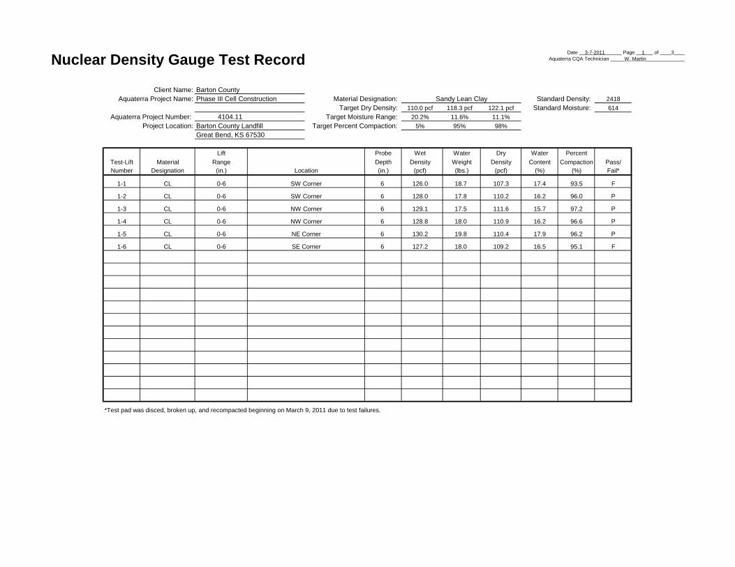
Nuclear Density Gauge Test RecordDate __3-7-2011______ Page __1___ of ____3____
Aquaterra CQA Technician _____W. Martin______________
Client Name: Barton CountyAquaterra Project Name: Phase III Cell Construction Material Designation: Standard Density: 2418
Target Dry Density: 110.0 pcf 118.3 pcf 122.1 pcf Standard Moisture: 614Aquaterra Project Number: 4104.11 Target Moisture Range: 20.2% 11.6% 11.1%
Project Location: Barton County Landfill Target Percent Compaction: 5% 95% 98%Great Bend, KS 67530
Probe Wet Water Dry Water PercentTest-Lift Depth Density Weight Density Content Compaction Pass/Number Location (in.) (pcf) (lbs.) (pcf) (%) (%) Fail*
1-1 6 126.0 18.7 107.3 17.4 93.5 F
1-2 6 128.0 17.8 110.2 16.2 96.0 P
1-3 6 129.1 17.5 111.6 15.7 97.2 P
1-4 6 128.8 18.0 110.9 16.2 96.6 P
1-5 6 130.2 19.8 110.4 17.9 96.2 P
1-6 6 127.2 18.0 109.2 16.5 95.1 F
*Test pad was disced, broken up, and recompacted beginning on March 9, 2011 due to test failures.
Sandy Lean Clay
CL 0-6 NE Corner
CL 0-6 SE Corner
CL 0-6 NW Corner
CL 0-6 NW Corner
CL 0-6 SW Corner
CL 0-6 SW Corner
LiftMaterial Range
Designation (in.)

Nuclear Density Gauge Test RecordDate __3-9-2011______ Page ___2__ of ____3____
Aquaterra CQA Technician _____W. Martin______________
Client Name: Barton CountyAquaterra Project Name: Phase III Cell Construction Material Designation: Standard Density: 2418
Target Dry Density: 110.0 pcf 118.3 pcf 122.1 pcf Standard Moisture: 614Aquaterra Project Number: 4104.11 Target Moisture Range: 20.2% 11.6% 11.1%
Project Location: Barton County Landfill Target Percent Compaction: 5% 95% 98%Great Bend, KS 67530
Probe Wet Water Dry Water PercentTest-Lift Depth Density Weight Density Content Compaction Pass/Number Location (in.) (pcf) (lbs.) (pcf) (%) (%) Fail
1-1 6 132.8 19.3 113.6 17.0 98.9 P
2-1 6 129.6 17.1 112.5 15.2 98.0 P
3-1 6 129.9 16.5 113.4 14.5 98.8 P
4-1 6 128.9 17.9 111.0 16.1 96.7 P
5-1 6 129.6 19.0 110.7 17.1 96.4 P
6-1 6 130.0 19.5 110.6 17.6 96.3 P
7-2 6 131.3 19.5 111.9 17.4 97.4 P
8-2 6 131.1 16.1 115.0 14.0 100.2 P
9-2 6 131.3 18.8 112.5 16.7 98.0 P
10-2 6 131.2 19.9 111.3 17.9 97.0 P
11-2 6 131.3 19.6 111.8 17.5 97.4 P
12-2 6 131.2 19.2 112.1 17.1 97.6 P
CL 6-12 SE Corner
CL 6-12 SW Corner
CL 6-12 SE Corner
CL 6-12 NE Corner
CL 6-12 NE Corner
CL 6-12 NW Corner
CL 0-6 SW Corner
CL 0-6 SE Corner
CL 0-6 NE Corner
CL 0-6 SW Corner
CL 0-6 NW Corner
CL 0-6 NE Corner
Sandy Lean Clay
LiftMaterial Range
Designation (in.)

Nuclear Density Gauge Test RecordDate __3-10-2011______ Page ___3__ of ____3____
Aquaterra CQA Technician _____W. Martin______________
Client Name: Barton CountyAquaterra Project Name: Phase III Cell Construction Material Designation: Standard Density: 2418
Target Dry Density: 110.0 pcf 118.3 pcf 122.1 pcf Standard Moisture: 611Aquaterra Project Number: 4104.11 Target Moisture Range: 20.2% 11.6% 11.1%
Project Location: Barton County Landfill Target Percent Compaction: 5% 95% 98%Great Bend, KS 67530
Probe Wet Water Dry Water PercentTest-Lift Depth Density Weight Density Content Compaction Pass/Number Location (in.) (pcf) (lbs.) (pcf) (%) (%) Fail
13-3 6 129.0 18.7 110.4 16.8 96.1 P
14-3 6 131.6 19.4 112.2 17.3 97.7 P
15-3 6 131.4 17.9 113.6 15.7 98.9 P
16-3 6 131.1 20.9 110.2 18.9 96.0 P
17-3 6 131.5 19.6 111.9 17.5 97.5 P
18-3 6 131.2 19.1 112.2 17.0 97.7 P
19-4 6 131.1 19.8 111.3 17.8 97.0 P
20-4 6 131.2 20.8 110.4 18.8 96.2 P
21-4 6 130.7 18.6 112.1 16.6 97.6 P
22-4 6 130.0 19.2 110.9 17.3 96.6 P
23-4 6 130.1 19.7 110.5 17.8 96.2 P
24-4 6 130.4 19.7 110.7 17.8 96.5 P
25-5 6 131.4 17.9 113.6 15.8 96.0 P
25-6 6 129.1 18.6 110.3 16.9 96.1 P
27-5 6 128.2 18.2 110.1 16.5 95.9 P
28-5 6 128.9 18.6 110.3 16.8 96.1 P
29-5 6 131.0 19.8 111.2 17.8 96.9 P
30-5 6 131.1 18.3 112.8 16.2 95.4 P
Sandy Lean Clay
LiftMaterial Range
Designation (in.)
CL 12-18 SE Corner
CL 12-18 SE Middle
CL 12-18 SW Corner
CL 12-18 SW Middle
CL 12-18 NW Corner
CL 12-18 NE Corner
CL 18-24 SE Corner
CL 18-24 SE Middle
CL 18-24 SW Corner
CL 18-24 West Middle
CL 18-24 NW Corner
CL 18-24 NE Corner
CL 24-30 SW Corner
CL 24-30 SE Corner
CL 24-30 West Middle
CL 24-30 East Middle
CL 24-30 NW Corner
CL 24-30 NE Corner

PLACEMENT RANGE FIGURES

70.0 pcf
80.0 pcf
90.0 pcf
100.0 pcf
110.0 pcf
120.0 pcf
130.0 pcf
140.0 pcf
0.0 % 5.0 % 10.0 % 15.0 % 20.0 % 25.0 % 30.0 %
Phase III Low Permeability Soil Liner Placement ZoneLower Horizon Sandy Lean Clay
Historical Proctor Results Phase III </= 10E‐7
S.G. = 2.6
S.G. = 2.7
S.G. = 2.8

70.0 pcf
80.0 pcf
90.0 pcf
100.0 pcf
110.0 pcf
120.0 pcf
130.0 pcf
140.0 pcf
0.0 % 5.0 % 10.0 % 15.0 % 20.0 % 25.0 % 30.0 %
Acceptable Soil Placement Zone and Historical Test Data Middle Horizon Lean Clay (Phase III Cell Construction)
REMOLDS </= 1E-7 SHELBY TUBES </= 1E-7 REMOLDS>1E-7 Phase III Remolds </=10E-7
S.G. = 2.6
S.G. = 2.7
S.G. = 2.8
Phase III Placement Range

TEST PADS LAYOUT FIGURES


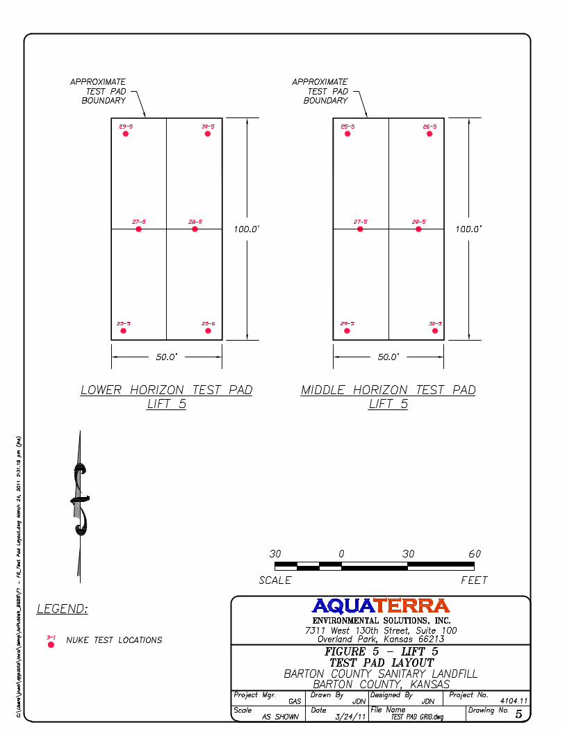


APPENDIX D
BOUTWELL TEST DATA
MIDDLE HORIZON LEAN CLAY TEST PAD LOWER HORIZON SANDY LEAN CLAY TEST PAD

MIDDLE HORIZON LEAN CLAY TEST PAD

AQUATERRAEnvironmental Solutions, Inc.
BARTON COUNTY LANDFILLTemp. Reading "R" Reading "R" BARTON COUNTY (deg F) (inches) (inches)
3/11/2011 14:59:00 51 22.69 START 21.75 1 MIDDLE HORIZON
3/11/2011 15:28:00 50 22.65 21.75 G. Swaggart
3/11/2011 16:23:00 50 22.45 21.80
3/11/2011 17:20:00 50 22.25 21.80
3/12/2011 10:04:00 42 17.15 20.55
3/12/2011 12:17:00 44 16.75 20.55
3/12/2011 15:21:00 46 16.30 20.55
3/12/2011 6:05:00 48 15.75 20.60
3/13/2011 9:59:00 41 13.00 19.45
3/13/2011 12:17:00 41 12.85 19.35
3/13/2011 15:10:00 41 12.45 19.35
3/14/2011 9:10:00 39 9.15 19.40
3/14/2011 12:18:00 39 8.75 19.15
3/14/2011 15:14:00 40 8.25 18.85
3/14/2011 18:05:00 41 7.90 18.75
3/15/2011 9:12:00 40 6.85 19.25
3/15/2011 12:37:00 40 6.50 18.65
3/15/2011 15:45:00 43 6.30 18.50
3/15/2011 18:37:00 45 6.00 18.50
3/16/2011 9:18:00 40 4.45 18.70
units: ("English" or "Metric")
a = (boundary condition - see figure)
d = 0.75 in (inside diameter of stand pipe)
D = 4 in (diameter of apparatus casing)
Z = 14.5 in (ground surface to bottom of casing)
RA = 14.5 in (ground surface to "0" mark)
b1 = 15.5 in (bottom of casing to bottom of soil liner)
ZW = 1000 in (depth to groundwater)
-1
TWO STAGE FIELD PERMEABILITY TEST
TEST UNIT
English
Project No:Test No.:
Technician:
STAGE ONE DATA ENTRY SHEETTEG Site
ClientDate Time Remarks Remarks

AQUATERRAEnvironmental Solutions, Inc.
TEST APPARATUS DATA
Test No: units: EnglishSite: a = -1
Client: d = 0.75 inJob No: D = 4 in
Technician: Z = 14.5 inRA = 14.5 inb1 = 15.5 inZW = 1000 in
L = 4 inb2 = 18 in
Temp. Reading "R" TEG Factor H1 H2 H2' H1 - H2' del T G1 Rt K1 Cumm Time Cumm Vol Cumm K1'(oF) (inches) "c" (cm) (cm) (cm) (cm) (cm) (sec) (cm/sec) (hrs) (cc) K1 * T (cm/sec)
3/11/2011 14:59:00 50.90 22.69 START
3/11/2011 15:28:00 50.20 22.65 0.00 170.66 170.56 170.56 0.10 1740 0.09543 1.28060 4.183E-08 0.483 2.850 7.278E-05 4.18E-08
3/11/2011 16:23:00 49.60 22.45 0.13 170.56 170.05 169.93 0.64 3300 0.09543 1.29284 1.395E-07 1.400 5.700 5.330E-04 1.06E-07
3/11/2011 17:20:00 49.50 22.25 0.00 170.05 169.55 169.55 0.51 3420 0.09543 1.29948 1.085E-07 2.350 8.551 9.040E-04 1.07E-07
3/12/2011 10:04:00 42.00 17.15 -3.18 169.55 156.59 159.77 9.78 60240 0.09543 1.37816 1.297E-07 19.083 11.401 8.717E-03 1.27E-07
3/12/2011 12:17:00 44.00 16.75 0.00 156.59 155.58 155.58 1.02 7980 0.09543 1.43388 1.116E-07 21.300 14.251 9.608E-03 1.25E-07
3/12/2011 15:21:00 46.00 16.30 0.00 155.58 154.43 154.43 1.14 11040 0.09543 1.39084 8.866E-08 24.367 17.101 1.059E-02 1.21E-07
3/12/2011 6:05:00 48.00 15.75 0.13 154.43 153.04 152.91 1.52 -33360 0.09543 1.34968 -3.829E-08 15.100 19.952 1.186E-02 2.18E-07
3/13/2011 9:59:00 40.80 13.00 -2.92 153.04 146.05 148.97 4.06 100440 0.09543 1.40643 3.597E-08 43.000 22.802 1.548E-02 1.00E-07
3/13/2011 12:17:00 40.60 12.85 -0.25 146.05 145.67 145.92 0.13 8280 0.09543 1.48564 1.490E-08 45.300 25.652 1.560E-02 9.57E-08
3/13/2011 15:10:00 40.50 12.45 0.00 145.67 144.65 144.65 1.02 10380 0.09543 1.48913 9.582E-08 48.183 28.502 1.659E-02 9.57E-08
3/14/2011 9:10:00 39.40 9.15 0.13 144.65 136.27 136.14 8.51 64800 0.09543 1.50332 1.342E-07 66.183 31.353 2.529E-02 1.06E-07
3/14/2011 12:18:00 39.20 8.75 -0.64 136.27 135.26 135.89 0.38 11280 0.09543 1.51876 3.597E-08 69.317 34.203 2.570E-02 1.03E-07
3/14/2011 15:14:00 39.70 8.25 -0.76 135.26 133.99 134.75 0.51 10560 0.09543 1.51517 5.152E-08 72.250 37.053 2.624E-02 1.01E-07
3/14/2011 18:05:00 41.40 7.90 -0.25 133.99 133.10 133.35 0.64 10260 0.09543 1.48934 6.581E-08 75.100 39.903 2.692E-02 9.96E-08
3/15/2011 9:12:00 39.60 6.85 1.27 133.10 130.43 129.16 3.94 54420 0.09543 1.49053 7.848E-08 90.217 42.754 3.119E-02 9.60E-08
3/15/2011 12:37:00 39.90 6.50 -1.52 130.43 129.54 131.06 -0.63 12300 0.09543 1.50799 -5.682E-08 93.633 45.604 3.049E-02 9.05E-08
3/15/2011 15:45:00 42.80 6.30 -0.38 129.54 129.03 129.41 0.13 11280 0.09543 1.47123 1.221E-08 96.767 48.454 3.063E-02 8.79E-08
3/15/2011 18:37:00 44.60 6.00 0.00 129.03 128.27 128.27 0.76 10320 0.09543 1.41855 7.770E-08 99.633 51.304 3.143E-02 8.76E-08
3/16/2011 9:18:00 40.00 4.45 0.51 128.27 124.33 123.83 4.45 52860 0.09543 1.45055 9.236E-08 114.317 54.154 3.631E-02 8.82E-08
Remarks
TWO STAGE FIELD PERMEABILITY TEST
1 MIDDLE HORIZONSITE/PROJECT INFORMATION
Date Time
APPARATUS DATA
STAGE ONE DATA REDUCTION
G. Swaggart
BARTON COUNTY BARTON COUNTY LANDFILL

AQUATERRAEnvironmental Solutions, Inc.
BARTON COUNTY LANDFILLTemp. Reading "R" Reading "R" BARTON COUNTY (deg F) (inches) (inches)
3/11/2011 14:55:00 51 21.05 START 21.75 2 MIDDLE HORIZON
3/11/2011 15:27:00 50 21.00 21.75 G. Swaggart
3/11/2011 16:22:00 50 20.89 21.80
3/11/2011 17:20:00 50 20.60 21.80
3/12/2011 10:05:00 42 17.15 20.55
3/12/2011 12:18:00 44 16.80 20.55
3/12/2011 15:22:00 46 16.35 20.55
3/12/2011 18:06:00 48 15.95 20.60
3/13/2011 9:59:00 41 13.85 19.45
3/13/2011 12:18:00 41 13.55 19.35
3/13/2011 15:11:00 41 13.10 19.35
3/14/2011 9:11:00 39 10.90 19.40
3/14/2011 12:19:00 39 10.45 19.15
3/14/2011 15:14:00 40 9.95 18.85
3/14/2011 18:06:00 41 9.60 18.75
3/15/2011 9:13:00 40 8.05 19.25
3/15/2011 12:38:00 40 7.60 18.65
3/15/2011 15:45:00 43 7.30 18.50
3/15/2011 18:37:00 45 6.95 18.50
3/16/2011 9:18:00 40 4.80 18.70
units: ("English" or "Metric")
a = (boundary condition - see figure)
d = 0.75 in (inside diameter of stand pipe)
D = 4 in (diameter of apparatus casing)
Z = 14.5 in (ground surface to bottom of casing)
RA = 15.25 in (ground surface to "0" mark)
b1 = 15.5 in (bottom of casing to bottom of soil liner)
ZW = 1000 in (depth to groundwater)
-1
TWO STAGE FIELD PERMEABILITY TEST
TEST UNIT
English
Project No:Test No.:
Technician:
STAGE ONE DATA ENTRY SHEETTEG Site
ClientDate Time Remarks Remarks

AQUATERRAEnvironmental Solutions, Inc.
TEST APPARATUS DATA
Test No: units: EnglishSite: a = -1
Client: d = 0.75 inJob No: D = 4 in
Technician: Z = 14.5 inRA = 15.25 inb1 = 15.5 inZW = 1000 in
L = 4 inb2 = 18 in
Temp. Reading "R" TEG Factor H1 H2 H2' H1 - H2' del T G1 Rt K1 Cumm Time Cumm Vol Cumm K1'(oF) (inches) "c" (cm) (cm) (cm) (cm) (cm) (sec) (cm/sec) (hrs) (cc) K1 * T (cm/sec)
3/11/2011 14:55:00 50.90 21.05 START
3/11/2011 15:27:00 50.20 21.00 0.00 168.40 168.28 168.28 0.13 1920 0.09543 1.28060 4.802E-08 0.533 2.850 9.220E-05 4.80E-08
3/11/2011 16:22:00 49.60 20.89 0.13 168.28 168.00 167.87 0.41 3300 0.09543 1.29284 9.040E-08 1.450 5.700 3.905E-04 7.48E-08
3/11/2011 17:20:00 49.50 20.60 0.00 168.00 167.26 167.26 0.74 3480 0.09543 1.29948 1.566E-07 2.417 8.551 9.355E-04 1.08E-07
3/12/2011 10:05:00 42.00 17.15 -3.18 167.26 158.50 161.67 5.59 60300 0.09543 1.37816 7.411E-08 19.167 11.401 5.405E-03 7.83E-08
3/12/2011 12:18:00 44.00 16.80 0.00 158.50 157.61 157.61 0.89 7980 0.09543 1.43388 9.645E-08 21.383 14.251 6.174E-03 8.02E-08
3/12/2011 15:22:00 46.00 16.35 0.00 157.61 156.46 156.46 1.14 11040 0.09543 1.39084 8.751E-08 24.450 17.101 7.140E-03 8.11E-08
3/12/2011 18:06:00 48.00 15.95 0.13 156.46 155.45 155.32 1.14 9840 0.09543 1.34968 9.597E-08 27.183 19.952 8.085E-03 8.26E-08
3/13/2011 9:59:00 40.80 13.85 -2.92 155.45 150.11 153.04 2.41 57180 0.09543 1.40643 3.672E-08 43.067 22.802 1.018E-02 6.57E-08
3/13/2011 12:18:00 40.60 13.55 -0.25 150.11 149.35 149.61 0.51 8340 0.09543 1.48564 5.763E-08 45.383 25.652 1.067E-02 6.53E-08
3/13/2011 15:11:00 40.50 13.10 0.00 149.35 148.21 148.21 1.14 10380 0.09543 1.48913 1.052E-07 48.267 28.502 1.176E-02 6.77E-08
3/14/2011 9:11:00 39.40 10.90 0.13 148.21 142.62 142.49 5.71 64800 0.09543 1.50332 8.706E-08 66.267 31.353 1.740E-02 7.29E-08
3/14/2011 12:19:00 39.20 10.45 -0.64 142.62 141.48 142.11 0.51 11280 0.09543 1.51876 4.585E-08 69.400 34.203 1.792E-02 7.17E-08
3/14/2011 15:14:00 39.70 9.95 -0.76 141.48 140.21 140.97 0.51 10500 0.09543 1.51517 4.954E-08 72.317 37.053 1.844E-02 7.08E-08
3/14/2011 18:06:00 41.40 9.60 -0.25 140.21 139.32 139.57 0.63 10320 0.09543 1.48934 6.252E-08 75.183 39.903 1.908E-02 7.05E-08
3/15/2011 9:13:00 39.60 8.05 1.27 139.32 135.38 134.11 5.21 54420 0.09543 1.49053 9.956E-08 90.300 42.754 2.450E-02 7.54E-08
3/15/2011 12:38:00 39.90 7.60 -1.52 135.38 134.24 135.76 -0.38 12300 0.09543 1.50799 -3.288E-08 93.717 45.604 2.409E-02 7.14E-08
3/15/2011 15:45:00 42.80 7.30 -0.38 134.24 133.48 133.86 0.38 11220 0.09543 1.47123 3.557E-08 96.833 48.454 2.449E-02 7.03E-08
3/15/2011 18:37:00 44.60 6.95 0.00 133.48 132.59 132.59 0.89 10320 0.09543 1.41855 8.766E-08 99.700 51.304 2.540E-02 7.08E-08
3/16/2011 9:18:00 40.00 4.80 0.51 132.59 127.13 126.62 5.97 52860 0.09543 1.45055 1.206E-07 114.383 54.154 3.177E-02 7.72E-08
TWO STAGE FIELD PERMEABILITY TEST
2 MIDDLE HORIZONSITE/PROJECT INFORMATION
Date Time
APPARATUS DATA
STAGE ONE DATA REDUCTION
G. Swaggart
BARTON COUNTY BARTON COUNTY LANDFILL
Remarks
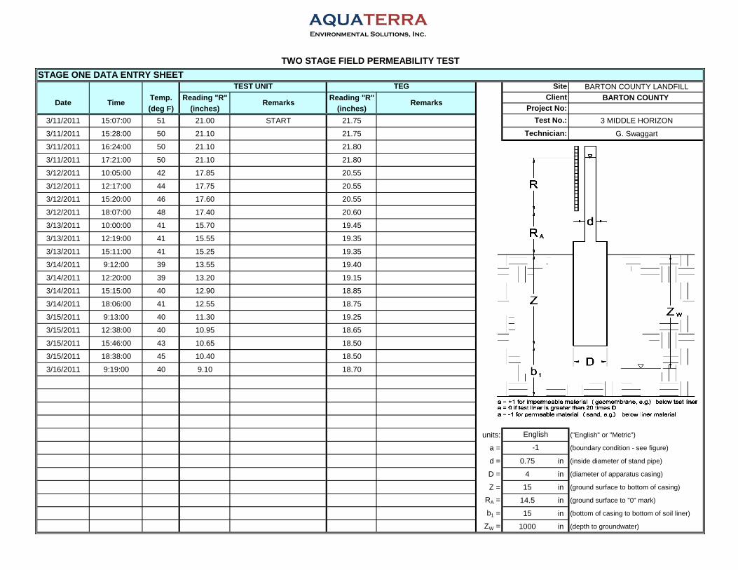
AQUATERRAEnvironmental Solutions, Inc.
BARTON COUNTY LANDFILLTemp. Reading "R" Reading "R" BARTON COUNTY (deg F) (inches) (inches)
3/11/2011 15:07:00 51 21.00 START 21.75 3 MIDDLE HORIZON
3/11/2011 15:28:00 50 21.10 21.75 G. Swaggart
3/11/2011 16:24:00 50 21.10 21.80
3/11/2011 17:21:00 50 21.10 21.80
3/12/2011 10:05:00 42 17.85 20.55
3/12/2011 12:17:00 44 17.75 20.55
3/12/2011 15:20:00 46 17.60 20.55
3/12/2011 18:07:00 48 17.40 20.60
3/13/2011 10:00:00 41 15.70 19.45
3/13/2011 12:19:00 41 15.55 19.35
3/13/2011 15:11:00 41 15.25 19.35
3/14/2011 9:12:00 39 13.55 19.40
3/14/2011 12:20:00 39 13.20 19.15
3/14/2011 15:15:00 40 12.90 18.85
3/14/2011 18:06:00 41 12.55 18.75
3/15/2011 9:13:00 40 11.30 19.25
3/15/2011 12:38:00 40 10.95 18.65
3/15/2011 15:46:00 43 10.65 18.50
3/15/2011 18:38:00 45 10.40 18.50
3/16/2011 9:19:00 40 9.10 18.70
units: ("English" or "Metric")
a = (boundary condition - see figure)
d = 0.75 in (inside diameter of stand pipe)
D = 4 in (diameter of apparatus casing)
Z = 15 in (ground surface to bottom of casing)
RA = 14.5 in (ground surface to "0" mark)
b1 = 15 in (bottom of casing to bottom of soil liner)
ZW = 1000 in (depth to groundwater)
-1
TWO STAGE FIELD PERMEABILITY TEST
TEST UNIT
English
Project No:Test No.:
Technician:
STAGE ONE DATA ENTRY SHEETTEG Site
ClientDate Time Remarks Remarks

AQUATERRAEnvironmental Solutions, Inc.
TEST APPARATUS DATA
Test No: units: EnglishSite: a = -1
Client: d = 0.75 inJob No: D = 4 in
Technician: Z = 15 inRA = 14.5 inb1 = 15.5 inZW = 1000 in
L = 4 inb2 = 18 in
Temp. Reading "R" TEG Factor H1 H2 H2' H1 - H2' del T G1 Rt K1 Cumm Time Cumm Vol Cumm K1'(oF) (inches) "c" (cm) (cm) (cm) (cm) (cm) (sec) (cm/sec) (hrs) (cc) K1 * T (cm/sec)
3/11/2011 15:07:00 50.90 21.00 START
3/11/2011 15:28:00 50.20 21.10 0.00 167.64 167.89 167.89 -0.25 1260 0.09543 1.28060 -1.468E-07 0.350 2.850 -1.850E-04 -1.47E-07
3/11/2011 16:24:00 49.60 21.10 0.13 167.89 167.89 167.77 0.13 3360 0.09543 1.29284 2.779E-08 1.283 5.700 -9.166E-05 -1.98E-08
3/11/2011 17:21:00 49.50 21.10 0.00 167.89 167.89 167.89 0.00 3420 0.09543 1.29948 0.000E+00 2.233 8.551 -9.166E-05 -1.14E-08
3/12/2011 10:05:00 42.00 17.85 -3.18 167.89 159.64 162.81 5.08 60240 0.09543 1.37816 6.708E-08 18.967 11.401 3.949E-03 5.78E-08
3/12/2011 12:17:00 44.00 17.75 0.00 159.64 159.39 159.39 0.25 7920 0.09543 1.43388 2.751E-08 21.167 14.251 4.167E-03 5.47E-08
3/12/2011 15:20:00 46.00 17.60 0.00 159.39 159.00 159.00 0.38 10980 0.09543 1.39084 2.893E-08 24.217 17.101 4.485E-03 5.14E-08
3/12/2011 18:07:00 48.00 17.40 0.13 159.00 158.50 158.37 0.64 10020 0.09543 1.34968 5.144E-08 27.000 19.952 5.000E-03 5.14E-08
3/13/2011 10:00:00 40.80 15.70 -2.92 158.50 154.18 157.10 1.40 57180 0.09543 1.40643 2.078E-08 42.883 22.802 6.188E-03 4.01E-08
3/13/2011 12:19:00 40.60 15.55 -0.25 154.18 153.80 154.05 0.13 8340 0.09543 1.48564 1.401E-08 45.200 25.652 6.305E-03 3.87E-08
3/13/2011 15:11:00 40.50 15.25 0.00 153.80 153.04 153.04 0.76 10320 0.09543 1.48913 6.840E-08 48.067 28.502 7.011E-03 4.05E-08
3/14/2011 9:12:00 39.40 13.55 0.13 153.04 148.72 148.59 4.44 64860 0.09543 1.50332 6.520E-08 66.083 31.353 1.124E-02 4.72E-08
3/14/2011 12:20:00 39.20 13.20 -0.64 148.72 147.83 148.46 0.25 11280 0.09543 1.51876 2.196E-08 69.217 34.203 1.149E-02 4.61E-08
3/14/2011 15:15:00 39.70 12.90 -0.76 147.83 147.07 147.83 0.00 10500 0.09543 1.51517 0.000E+00 72.133 37.053 1.149E-02 4.42E-08
3/14/2011 18:06:00 41.40 12.55 -0.25 147.07 146.18 146.43 0.64 10260 0.09543 1.48934 5.994E-08 74.983 39.903 1.210E-02 4.48E-08
3/15/2011 9:13:00 39.60 11.30 1.27 146.18 143.00 141.73 4.44 54420 0.09543 1.49053 8.072E-08 90.100 42.754 1.650E-02 5.09E-08
3/15/2011 12:38:00 39.90 10.95 -1.52 143.00 142.11 143.64 -0.63 12300 0.09543 1.50799 -5.184E-08 93.517 45.604 1.586E-02 4.71E-08
3/15/2011 15:46:00 42.80 10.65 -0.38 142.11 141.35 141.73 0.38 11280 0.09543 1.47123 3.341E-08 96.650 48.454 1.623E-02 4.67E-08
3/15/2011 18:38:00 44.60 10.40 0.00 141.35 140.72 140.72 0.63 10320 0.09543 1.41855 5.906E-08 99.517 51.304 1.684E-02 4.70E-08
3/16/2011 9:19:00 40.00 9.10 0.51 140.72 137.41 136.91 3.81 52860 0.09543 1.45055 7.188E-08 114.200 54.154 2.064E-02 5.02E-08
TWO STAGE FIELD PERMEABILITY TEST
3 MIDDLE HORIZONSITE/PROJECT INFORMATION
Date Time
APPARATUS DATA
STAGE ONE DATA REDUCTION
G. Swaggart
BARTON COUNTY BARTON COUNTY LANDFILL
Remarks

AQUATERRAEnvironmental Solutions, Inc.
BARTON COUNTY LANDFILLTemp. Reading "R" Reading "R" BARTON COUNTY (deg F) (inches) (inches)
3/11/2011 15:10:00 51 22.05 START 21.75 4 MIDDLE HORIZON
3/11/2011 15:30:00 50 22.05 21.75 G. Swaggart
3/11/2011 16:26:00 50 21.80 21.80
3/11/2011 17:22:00 50 21.60 21.80
3/12/2011 10:06:00 42 16.90 20.55
3/12/2011 12:18:00 44 16.60 20.55
3/12/2011 15:23:00 46 16.30 20.55
3/12/2011 18:08:00 48 16.00 20.60
3/13/2011 10:00:00 41 13.80 19.45
3/13/2011 12:20:00 41 13.50 19.35
3/13/2011 15:12:00 41 13.20 19.35
3/14/2011 9:13:00 39 11.10 19.40
3/14/2011 12:21:00 39 10.75 19.15
3/14/2011 15:16:00 40 10.35 18.85
3/14/2011 18:07:00 41 10.05 18.75
3/15/2011 9:14:00 40 8.75 19.25
3/15/2011 12:39:00 40 8.25 18.65
3/15/2011 15:47:00 43 7.70 18.50
3/15/2011 18:39:00 45 7.35 18.50
3/16/2011 9:20:00 40 5.65 18.70
units: ("English" or "Metric")
a = (boundary condition - see figure)
d = 0.75 in (inside diameter of stand pipe)
D = 4 in (diameter of apparatus casing)
Z = 15 in (ground surface to bottom of casing)
RA = 13.75 in (ground surface to "0" mark)
b1 = 15 in (bottom of casing to bottom of soil liner)
ZW = 1000 in (depth to groundwater)
-1
TWO STAGE FIELD PERMEABILITY TEST
TEST UNIT
English
Project No:Test No.:
Technician:
STAGE ONE DATA ENTRY SHEETTEG Site
ClientDate Time Remarks Remarks

AQUATERRAEnvironmental Solutions, Inc.
TEST APPARATUS DATA
Test No: units: EnglishSite: a = -1
Client: d = 0.75 inJob No: D = 4 in
Technician: Z = 15 inRA = 13.75 inb1 = 15.5 inZW = 1000 in
L = 4 inb2 = 18 in
Temp. Reading "R" TEG Factor H1 H2 H2' H1 - H2' del T G1 Rt K1 Cumm Time Cumm Vol Cumm K1'(oF) (inches) "c" (cm) (cm) (cm) (cm) (cm) (sec) (cm/sec) (hrs) (cc) K1 * T (cm/sec)
3/11/2011 15:10:00 50.90 22.05 START
3/11/2011 15:30:00 50.20 22.05 0.00 168.40 168.40 168.40 0.00 1200 0.09543 1.28060 0.000E+00 0.333 2.850 0.000E+00 0.00E+00
3/11/2011 16:26:00 49.60 21.80 0.13 168.40 167.77 167.64 0.76 3360 0.09543 1.29284 1.665E-07 1.267 5.700 5.595E-04 1.23E-07
3/11/2011 17:22:00 49.50 21.60 0.00 167.77 167.26 167.26 0.51 3360 0.09543 1.29948 1.119E-07 2.200 8.551 9.356E-04 1.18E-07
3/12/2011 10:06:00 42.00 16.90 -3.18 167.26 155.32 158.50 8.76 60240 0.09543 1.37816 1.175E-07 18.933 11.401 8.013E-03 1.18E-07
3/12/2011 12:18:00 44.00 16.60 0.00 155.32 154.56 154.56 0.76 7920 0.09543 1.43388 8.497E-08 21.133 14.251 8.686E-03 1.14E-07
3/12/2011 15:23:00 46.00 16.30 0.00 154.56 153.80 153.80 0.76 11100 0.09543 1.39084 5.910E-08 24.217 17.101 9.342E-03 1.07E-07
3/12/2011 18:08:00 48.00 16.00 0.13 153.80 153.04 152.91 0.89 9900 0.09543 1.34968 7.542E-08 26.967 19.952 1.009E-02 1.04E-07
3/13/2011 10:00:00 40.80 13.80 -2.92 153.04 147.45 150.37 2.67 57120 0.09543 1.40643 4.131E-08 42.833 22.802 1.245E-02 8.07E-08
3/13/2011 12:20:00 40.60 13.50 -0.25 147.45 146.69 146.94 0.51 8400 0.09543 1.48564 5.825E-08 45.167 25.652 1.294E-02 7.96E-08
3/13/2011 15:12:00 40.50 13.20 0.00 146.69 145.92 145.92 0.76 10320 0.09543 1.48913 7.172E-08 48.033 28.502 1.368E-02 7.91E-08
3/14/2011 9:13:00 39.40 11.10 0.13 145.92 140.59 140.46 5.46 64860 0.09543 1.50332 8.437E-08 66.050 31.353 1.915E-02 8.05E-08
3/14/2011 12:21:00 39.20 10.75 -0.64 140.59 139.70 140.34 0.25 11280 0.09543 1.51876 2.324E-08 69.183 34.203 1.941E-02 7.79E-08
3/14/2011 15:16:00 39.70 10.35 -0.76 139.70 138.68 139.45 0.25 10500 0.09543 1.51517 2.506E-08 72.100 37.053 1.968E-02 7.58E-08
3/14/2011 18:07:00 41.40 10.05 -0.25 138.68 137.92 138.18 0.51 10260 0.09543 1.48934 5.084E-08 74.950 39.903 2.020E-02 7.49E-08
3/15/2011 9:14:00 39.60 8.75 1.27 137.92 134.62 133.35 4.57 54420 0.09543 1.49053 8.811E-08 90.067 42.754 2.499E-02 7.71E-08
3/15/2011 12:39:00 39.90 8.25 -1.52 134.62 133.35 134.87 -0.25 12300 0.09543 1.50799 -2.205E-08 93.483 45.604 2.472E-02 7.35E-08
3/15/2011 15:47:00 42.80 7.70 -0.38 133.35 131.95 132.33 1.02 11280 0.09543 1.47123 9.520E-08 96.617 48.454 2.579E-02 7.42E-08
3/15/2011 18:39:00 44.60 7.35 0.00 131.95 131.06 131.06 0.89 10320 0.09543 1.41855 8.868E-08 99.483 51.304 2.671E-02 7.46E-08
3/16/2011 9:20:00 40.00 5.65 0.51 131.06 126.75 126.24 4.83 52860 0.09543 1.45055 9.825E-08 114.167 54.154 3.190E-02 7.76E-08
TWO STAGE FIELD PERMEABILITY TEST
4 MIDDLE HORIZONSITE/PROJECT INFORMATION
Date Time
APPARATUS DATA
STAGE ONE DATA REDUCTION
G. Swaggart
BARTON COUNTY BARTON COUNTY LANDFILL
Remarks

AQUATERRAEnvironmental Solutions, Inc.
BARTON COUNTY LANDFILLTemp. Reading "R" Reading "R" BARTON COUNTY (deg F) (inches) (inches)
3/11/2011 15:08:00 51 22.05 START 21.75 5 MIDDLE HORIZON
3/11/2011 15:31:00 50 22.00 21.75 G. Swaggart
3/11/2011 16:27:00 50 21.85 21.80
3/11/2011 17:22:00 50 21.65 21.80
3/12/2011 10:06:00 42 16.30 20.55
3/12/2011 12:19:00 44 16.10 20.55
3/12/2011 15:23:00 46 15.85 20.55
3/12/2011 18:08:00 48 15.60 20.60
3/13/2011 10:01:00 41 12.45 19.45
3/13/2011 12:20:00 41 12.25 19.35
3/13/2011 15:13:00 41 11.95 19.35
3/14/2011 9:14:00 39 9.30 19.40
3/14/2011 12:22:00 39 8.90 19.15
3/14/2011 15:17:00 40 8.35 18.85
3/14/2011 18:08:00 41 7.95 18.75
3/15/2011 9:15:00 40 6.80 19.25
3/15/2011 12:40:00 40 6.50 18.65
3/15/2011 15:48:00 43 6.30 18.50
3/15/2011 18:40:00 45 6.05 18.50
3/16/2011 9:20:00 40 4.25 18.70
units: ("English" or "Metric")
a = (boundary condition - see figure)
d = 0.75 in (inside diameter of stand pipe)
D = 4 in (diameter of apparatus casing)
Z = 14.5 in (ground surface to bottom of casing)
RA = 13.5 in (ground surface to "0" mark)
b1 = 15.5 in (bottom of casing to bottom of soil liner)
ZW = 1000 in (depth to groundwater)
-1
TWO STAGE FIELD PERMEABILITY TEST
TEST UNIT
English
Project No:Test No.:
Technician:
STAGE ONE DATA ENTRY SHEETTEG Site
ClientDate Time Remarks Remarks

AQUATERRAEnvironmental Solutions, Inc.
TEST APPARATUS DATA
Test No: units: EnglishSite: a = -1
Client: d = 0.75 inJob No: D = 4 in
Technician: Z = 14.5 inRA = 13.5 inb1 = 15.5 inZW = 1000 in
L = 4 inb2 = 18 in
Temp. Reading "R" TEG Factor H1 H2 H2' H1 - H2' del T G1 Rt K1 Cumm Time Cumm Vol Cumm K1'(oF) (inches) "c" (cm) (cm) (cm) (cm) (cm) (sec) (cm/sec) (hrs) (cc) K1 * T (cm/sec)
3/11/2011 15:08:00 50.90 22.05 START
3/11/2011 15:31:00 50.20 22.00 0.00 166.50 166.37 166.37 0.13 1380 0.09543 1.28060 6.758E-08 0.383 2.850 9.325E-05 6.76E-08
3/11/2011 16:27:00 49.60 21.85 0.13 166.37 165.99 165.86 0.51 3360 0.09543 1.29284 1.123E-07 1.317 5.700 4.706E-04 9.93E-08
3/11/2011 17:22:00 49.50 21.65 0.00 165.99 165.48 165.48 0.51 3300 0.09543 1.29948 1.152E-07 2.233 8.551 8.507E-04 1.06E-07
3/12/2011 10:06:00 42.00 16.30 -3.18 165.48 151.89 155.07 10.41 60240 0.09543 1.37816 1.419E-07 18.967 11.401 9.399E-03 1.38E-07
3/12/2011 12:19:00 44.00 16.10 0.00 151.89 151.38 151.38 0.51 7980 0.09543 1.43388 5.745E-08 21.183 14.251 9.858E-03 1.29E-07
3/12/2011 15:23:00 46.00 15.85 0.00 151.38 150.75 150.75 0.64 11040 0.09543 1.39084 5.054E-08 24.250 17.101 1.042E-02 1.19E-07
3/12/2011 18:08:00 48.00 15.60 0.13 150.75 150.11 149.99 0.76 9900 0.09543 1.34968 6.593E-08 27.000 19.952 1.107E-02 1.14E-07
3/13/2011 10:01:00 40.80 12.45 -2.92 150.11 142.11 145.03 5.08 57180 0.09543 1.40643 8.081E-08 42.883 22.802 1.569E-02 1.02E-07
3/13/2011 12:20:00 40.60 12.25 -0.25 142.11 141.61 141.86 0.25 8340 0.09543 1.48564 3.041E-08 45.200 25.652 1.594E-02 9.80E-08
3/13/2011 15:13:00 40.50 11.95 0.00 141.61 140.84 140.84 0.76 10380 0.09543 1.48913 7.387E-08 48.083 28.502 1.671E-02 9.65E-08
3/14/2011 9:14:00 39.40 9.30 0.13 140.84 134.11 133.99 6.86 64860 0.09543 1.50332 1.104E-07 66.100 31.353 2.387E-02 1.00E-07
3/14/2011 12:22:00 39.20 8.90 -0.64 134.11 133.10 133.73 0.38 11280 0.09543 1.51876 3.655E-08 69.233 34.203 2.428E-02 9.74E-08
3/14/2011 15:17:00 39.70 8.35 -0.76 133.10 131.70 132.46 0.64 10500 0.09543 1.51517 6.586E-08 72.150 37.053 2.497E-02 9.62E-08
3/14/2011 18:08:00 41.40 7.95 -0.25 131.70 130.68 130.94 0.76 10260 0.09543 1.48934 8.038E-08 75.000 39.903 2.580E-02 9.56E-08
3/15/2011 9:15:00 39.60 6.80 1.27 130.68 127.76 126.49 4.19 54420 0.09543 1.49053 8.520E-08 90.117 42.754 3.044E-02 9.38E-08
3/15/2011 12:40:00 39.90 6.50 -1.52 127.76 127.00 128.52 -0.76 12300 0.09543 1.50799 -6.957E-08 93.533 45.604 2.958E-02 8.78E-08
3/15/2011 15:48:00 42.80 6.30 -0.38 127.00 126.49 126.87 0.13 11280 0.09543 1.47123 1.245E-08 96.667 48.454 2.972E-02 8.54E-08
3/15/2011 18:40:00 44.60 6.05 0.00 126.49 125.86 125.86 0.63 10320 0.09543 1.41855 6.602E-08 99.533 51.304 3.040E-02 8.48E-08
3/16/2011 9:20:00 40.00 4.25 0.51 125.86 121.29 120.78 5.08 52800 0.09543 1.45055 1.080E-07 114.200 54.154 3.611E-02 8.78E-08
TWO STAGE FIELD PERMEABILITY TEST
5 MIDDLE HORIZONSITE/PROJECT INFORMATION
Date Time
APPARATUS DATA
STAGE ONE DATA REDUCTION
G. Swaggart
BARTON COUNTY BARTON COUNTY LANDFILL
Remarks

LOWER HORIZON SANDY LEAN CLAY TEST PAD

AQUATERRAEnvironmental Solutions, Inc.
BARTON COUNTY LANDFILLTemp. Reading "R" Reading "R" BARTON COUNTY (deg F) (inches) (inches)
3/11/2011 15:26:00 57 27.05 START 29.85 1 LOWER
3/11/2011 16:20:00 57 26.75 29.95 G. Swaggart
3/11/2011 17:19:00 57 26.05 30.00
3/12/2011 10:00:00 47 22.30 28.30
3/12/2011 12:12:00 50 22.50 28.00
3/12/2011 15:17:00 52 23.05 27.85
3/12/2011 18:03:00 53 23.00 27.95
3/13/2011 9:55:00 45 21.70 26.85
3/13/2011 12:15:00 44 21.60 26.80
3/13/2011 15:04:00 44 21.45 26.75
3/14/2011 9:06:00 45 20.55 26.80
3/14/2011 12:12:00 45 20.35 26.55
3/14/2011 15:09:00 45 20.30 26.30
3/14/2011 18:01:00 46 20.30 26.30
3/15/2011 9:06:00 44 19.55 26.70
3/15/2011 12:34:00 45 19.45 26.05
3/15/2011 15:38:00 47 19.55 25.75
3/15/2011 18:33:00 49 20.00 25.95
3/16/2011 9:14:00 46 18.25 25.85
units: ("English" or "Metric")
a = (boundary condition - see figure)
d = 0.75 in (inside diameter of stand pipe)
D = 4 in (diameter of apparatus casing)
Z = 16 in (ground surface to bottom of casing)
RA = 15.75 in (ground surface to "0" mark)
b1 = 14 in (bottom of casing to bottom of soil liner)
ZW = 1000 in (depth to groundwater)
-1
TWO STAGE FIELD PERMEABILITY TEST
TEST UNIT
English
Project No:Test No.:
Technician:
STAGE ONE DATA ENTRY SHEETTEG Site
ClientDate Time Remarks Remarks
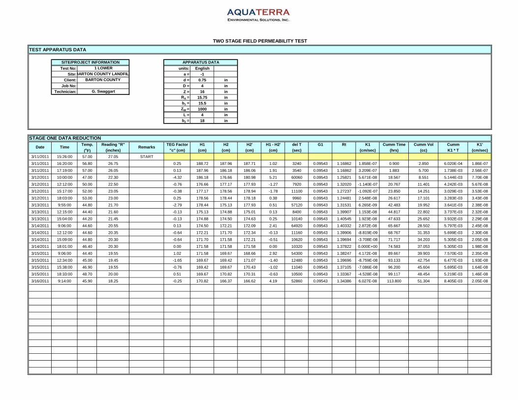
AQUATERRAEnvironmental Solutions, Inc.
TEST APPARATUS DATA
Test No: units: EnglishSite: a = -1
Client: d = 0.75 inJob No: D = 4 in
Technician: Z = 16 inRA = 15.75 inb1 = 15.5 inZW = 1000 in
L = 4 inb2 = 18 in
Temp. Reading "R" TEG Factor H1 H2 H2' H1 - H2' del T G1 Rt K1 Cumm Time Cumm Vol Cumm K1'(oF) (inches) "c" (cm) (cm) (cm) (cm) (cm) (sec) (cm/sec) (hrs) (cc) K1 * T (cm/sec)
3/11/2011 15:26:00 57.00 27.05 START
3/11/2011 16:20:00 56.80 26.75 0.25 188.72 187.96 187.71 1.02 3240 0.09543 1.16862 1.858E-07 0.900 2.850 6.020E-04 1.86E-07
3/11/2011 17:19:00 57.00 26.05 0.13 187.96 186.18 186.06 1.91 3540 0.09543 1.16862 3.209E-07 1.883 5.700 1.738E-03 2.56E-07
3/12/2011 10:00:00 47.00 22.30 -4.32 186.18 176.66 180.98 5.21 60060 0.09543 1.25821 5.671E-08 18.567 8.551 5.144E-03 7.70E-08
3/12/2011 12:12:00 50.00 22.50 -0.76 176.66 177.17 177.93 -1.27 7920 0.09543 1.32020 -1.140E-07 20.767 11.401 4.242E-03 5.67E-08
3/12/2011 15:17:00 52.00 23.05 -0.38 177.17 178.56 178.94 -1.78 11100 0.09543 1.27237 -1.092E-07 23.850 14.251 3.029E-03 3.53E-08
3/12/2011 18:03:00 53.00 23.00 0.25 178.56 178.44 178.18 0.38 9960 0.09543 1.24481 2.548E-08 26.617 17.101 3.283E-03 3.43E-08
3/13/2011 9:55:00 44.80 21.70 -2.79 178.44 175.13 177.93 0.51 57120 0.09543 1.31531 6.265E-09 42.483 19.952 3.641E-03 2.38E-08
3/13/2011 12:15:00 44.40 21.60 -0.13 175.13 174.88 175.01 0.13 8400 0.09543 1.39907 1.153E-08 44.817 22.802 3.737E-03 2.32E-08
3/13/2011 15:04:00 44.20 21.45 -0.13 174.88 174.50 174.63 0.25 10140 0.09543 1.40545 1.923E-08 47.633 25.652 3.932E-03 2.29E-08
3/14/2011 9:06:00 44.60 20.55 0.13 174.50 172.21 172.09 2.41 64920 0.09543 1.40332 2.872E-08 65.667 28.502 5.797E-03 2.45E-08
3/14/2011 12:12:00 44.60 20.35 -0.64 172.21 171.70 172.34 -0.13 11160 0.09543 1.39906 -8.819E-09 68.767 31.353 5.699E-03 2.30E-08
3/14/2011 15:09:00 44.80 20.30 -0.64 171.70 171.58 172.21 -0.51 10620 0.09543 1.39694 -3.708E-08 71.717 34.203 5.305E-03 2.05E-08
3/14/2011 18:01:00 46.40 20.30 0.00 171.58 171.58 171.58 0.00 10320 0.09543 1.37822 0.000E+00 74.583 37.053 5.305E-03 1.98E-08
3/15/2011 9:06:00 44.40 19.55 1.02 171.58 169.67 168.66 2.92 54300 0.09543 1.38247 4.172E-08 89.667 39.903 7.570E-03 2.35E-08
3/15/2011 12:34:00 45.00 19.45 -1.65 169.67 169.42 171.07 -1.40 12480 0.09543 1.39696 -8.759E-08 93.133 42.754 6.477E-03 1.93E-08
3/15/2011 15:38:00 46.90 19.55 -0.76 169.42 169.67 170.43 -1.02 11040 0.09543 1.37105 -7.086E-08 96.200 45.604 5.695E-03 1.64E-08
3/15/2011 18:33:00 48.70 20.00 0.51 169.67 170.82 170.31 -0.63 10500 0.09543 1.33367 -4.528E-08 99.117 48.454 5.219E-03 1.46E-08
3/16/2011 9:14:00 45.90 18.25 -0.25 170.82 166.37 166.62 4.19 52860 0.09543 1.34386 6.027E-08 113.800 51.304 8.405E-03 2.05E-08
TWO STAGE FIELD PERMEABILITY TEST
1 LOWERSITE/PROJECT INFORMATION
Date Time
APPARATUS DATA
STAGE ONE DATA REDUCTION
G. Swaggart
BARTON COUNTY BARTON COUNTY LANDFILL
Remarks

AQUATERRAEnvironmental Solutions, Inc.
BARTON COUNTY LANDFILLTemp. Reading "R" Reading "R" BARTON COUNTY (deg F) (inches) (inches)
3/12/2011 10:01:00 47 29.25 START 20.55 2 LOWER HORIZON
3/12/2011 12:13:00 50 27.15 20.55 G. Swaggart
3/12/2011 15:18:00 52 26.85 20.55
3/12/2011 18:03:00 53 26.70 20.60
3/13/2011 9:55:00 45 23.25 26.85
3/13/2011 12:16:00 44 23.05 26.80
3/13/2011 15:05:00 44 22.80 26.75
3/14/2011 9:06:00 45 20.80 26.80
3/14/2011 12:13:00 45 20.50 26.55
3/14/2011 15:10:00 45 20.25 26.30
3/14/2011 18:01:00 46 20.20 26.30
3/15/2011 9:07:00 44 18.95 26.70
3/15/2011 12:32:00 45 18.70 26.05
3/15/2011 15:39:00 47 18.60 25.75
3/15/2011 18:33:00 49 18.80 25.95
3/16/2011 9:14:00 46 17.00 25.85
units: ("English" or "Metric")
a = (boundary condition - see figure)
d = 0.75 in (inside diameter of stand pipe)
D = 4 in (diameter of apparatus casing)
Z = 16 in (ground surface to bottom of casing)
RA = 16.25 in (ground surface to "0" mark)
b1 = 14 in (bottom of casing to bottom of soil liner)
ZW = 1000 in (depth to groundwater)
-1
TWO STAGE FIELD PERMEABILITY TEST
TEST UNIT
English
Project No:Test No.:
Technician:
STAGE ONE DATA ENTRY SHEETTEG Site
ClientDate Time Remarks Remarks

AQUATERRAEnvironmental Solutions, Inc.
TEST APPARATUS DATA
Test No: units: EnglishSite: a = -1
Client: d = 0.75 inJob No: D = 4 in
Technician: Z = 16 inRA = 16.25 inb1 = 15.5 inZW = 1000 in
L = 4 inb2 = 18 in
Temp. Reading "R" TEG Factor H1 H2 H2' H1 - H2' del T G1 Rt K1 Cumm Time Cumm Vol Cumm K1'(oF) (inches) "c" (cm) (cm) (cm) (cm) (cm) (sec) (cm/sec) (hrs) (cc) K1 * T (cm/sec)
3/12/2011 10:01:00 47.00 29.25 START
3/12/2011 12:13:00 50.00 27.15 0.00 195.58 190.25 190.25 5.33 7920 0.09543 1.32020 4.399E-07 2.200 2.850 3.484E-03 4.40E-07
3/12/2011 15:18:00 52.00 26.85 0.00 190.25 189.48 189.48 0.76 11100 0.09543 1.27237 4.390E-08 5.283 5.700 3.971E-03 2.09E-07
3/12/2011 18:03:00 53.00 26.70 0.13 189.48 189.10 188.98 0.51 9900 0.09543 1.24481 3.221E-08 8.033 8.551 4.290E-03 1.48E-07
3/13/2011 9:55:00 44.80 23.25 15.88 189.10 180.34 164.47 24.64 57120 0.09543 1.31531 3.068E-07 23.900 11.401 2.181E-02 2.54E-07
3/13/2011 12:16:00 44.40 23.05 -0.13 180.34 179.83 179.96 0.38 8460 0.09543 1.39907 3.338E-08 26.250 14.251 2.209E-02 2.34E-07
3/13/2011 15:05:00 44.20 22.80 -0.13 179.83 179.20 179.32 0.51 10140 0.09543 1.40545 3.742E-08 29.067 17.101 2.247E-02 2.15E-07
3/14/2011 9:06:00 44.60 20.80 0.13 179.20 174.12 173.99 5.21 64860 0.09543 1.40332 6.089E-08 47.083 19.952 2.642E-02 1.56E-07
3/14/2011 12:13:00 44.60 20.50 -0.64 174.12 173.36 173.99 0.13 11220 0.09543 1.39906 8.683E-09 50.200 22.802 2.652E-02 1.47E-07
3/14/2011 15:10:00 44.80 20.25 -0.64 173.36 172.72 173.36 0.00 10620 0.09543 1.39694 0.000E+00 53.150 25.652 2.652E-02 1.39E-07
3/14/2011 18:01:00 46.40 20.20 0.00 172.72 172.59 172.59 0.13 10260 0.09543 1.37822 9.429E-09 56.000 28.502 2.662E-02 1.32E-07
3/15/2011 9:07:00 44.40 18.95 1.02 172.59 169.42 168.40 4.19 54360 0.09543 1.38247 5.966E-08 71.100 31.353 2.986E-02 1.17E-07
3/15/2011 12:32:00 45.00 18.70 -1.65 169.42 168.78 170.43 -1.02 12300 0.09543 1.39696 -6.480E-08 74.517 34.203 2.906E-02 1.08E-07
3/15/2011 15:39:00 46.90 18.60 -0.76 168.78 168.53 169.29 -0.51 11220 0.09543 1.37105 -3.505E-08 77.633 37.053 2.867E-02 1.03E-07
3/15/2011 18:33:00 48.70 18.80 0.51 168.53 169.04 168.53 0.00 10440 0.09543 1.33367 0.000E+00 80.533 39.903 2.867E-02 9.89E-08
3/16/2011 9:14:00 45.90 17.00 -0.25 169.04 164.47 164.72 4.32 52860 0.09543 1.34386 6.278E-08 95.217 42.754 3.199E-02 9.33E-08
TWO STAGE FIELD PERMEABILITY TEST
2 LOWER HORIZONSITE/PROJECT INFORMATION
Date Time
APPARATUS DATA
STAGE ONE DATA REDUCTION
G. Swaggart
BARTON COUNTY BARTON COUNTY LANDFILL
Remarks

AQUATERRAEnvironmental Solutions, Inc.
BARTON COUNTY LANDFILLTemp. Reading "R" Reading "R" BARTON COUNTY (deg F) (inches) (inches)
3/11/2011 14:46:00 57 25.40 START 29.70 3 LOWER
3/11/2011 15:25:00 57 23.75 29.86 G. Swaggart
3/11/2011 16:19:00 57 23.40 29.95
3/11/2011 17:18:00 57 23.15 30.00
3/12/2011 9:58:00 47 18.15 28.30
3/12/2011 12:09:00 50 18.30 28.00
3/12/2011 15:17:00 52 18.40 27.85
3/12/2011 18:00:00 53 18.45 27.95
3/13/2011 9:55:00 45 16.90 26.85
3/13/2011 12:14:00 44 16.75 26.80
3/13/2011 15:06:00 44 16.50 26.75
3/14/2011 9:05:00 45 15.45 26.80
3/14/2011 12:14:00 45 15.25 26.55
3/14/2011 15:10:00 45 15.00 26.30
3/14/2011 18:02:00 46 15.30 26.30
3/15/2011 9:07:00 44 15.05 26.70
3/15/2011 12:32:00 45 14.90 26.05
3/15/2011 15:40:00 47 14.75 25.75
3/15/2011 18:34:00 49 14.40 25.95
3/16/2011 9:15:00 46 13.55 25.85
units: ("English" or "Metric")
a = (boundary condition - see figure)
d = 0.75 in (inside diameter of stand pipe)
D = 4 in (diameter of apparatus casing)
Z = 15.5 in (ground surface to bottom of casing)
RA = 18 in (ground surface to "0" mark)
b1 = 14.5 in (bottom of casing to bottom of soil liner)
ZW = 1000 in (depth to groundwater)
-1
TWO STAGE FIELD PERMEABILITY TEST
TEST UNIT
English
Project No:Test No.:
Technician:
STAGE ONE DATA ENTRY SHEETTEG Site
ClientDate Time Remarks Remarks

AQUATERRAEnvironmental Solutions, Inc.
TEST APPARATUS DATA
Test No: units: EnglishSite: a = -1
Client: d = 0.75 inJob No: D = 4 in
Technician: Z = 15.5 inRA = 18 inb1 = 15.5 inZW = 1000 in
L = 4 inb2 = 18 in
Temp. Reading "R" TEG Factor H1 H2 H2' H1 - H2' del T G1 Rt K1 Cumm Time Cumm Vol Cumm K1'(oF) (inches) "c" (cm) (cm) (cm) (cm) (cm) (sec) (cm/sec) (hrs) (cc) K1 * T (cm/sec)
3/11/2011 14:46:00 56.80 25.40 START
3/11/2011 15:25:00 56.80 23.75 0.41 188.98 184.79 184.38 4.60 2340 0.09543 1.17028 1.175E-06 0.650 2.850 2.751E-03 1.18E-06
3/11/2011 16:19:00 56.80 23.40 0.23 184.79 183.90 183.67 1.12 3240 0.09543 1.17028 2.091E-07 1.550 5.700 3.428E-03 6.14E-07
3/11/2011 17:18:00 57.00 23.15 0.13 183.90 183.26 183.13 0.76 3540 0.09543 1.16862 1.308E-07 2.533 8.551 3.891E-03 4.27E-07
3/12/2011 9:58:00 47.00 18.15 -4.32 183.26 170.56 174.88 8.38 60000 0.09543 1.25821 9.369E-08 19.200 11.401 9.513E-03 1.38E-07
3/12/2011 12:09:00 50.00 18.30 -0.76 170.56 170.94 171.70 -1.14 7860 0.09543 1.32020 -1.071E-07 21.383 14.251 8.671E-03 1.13E-07
3/12/2011 15:17:00 52.00 18.40 -0.38 170.94 171.20 171.58 -0.63 11280 0.09543 1.27237 -3.991E-08 24.517 17.101 8.221E-03 9.31E-08
3/12/2011 18:00:00 53.00 18.45 0.25 171.20 171.32 171.07 0.13 9780 0.09543 1.24481 9.014E-09 27.233 19.952 8.309E-03 8.48E-08
3/13/2011 9:55:00 44.80 16.90 -2.79 171.32 167.39 170.18 1.14 57300 0.09543 1.31531 1.466E-08 43.150 22.802 9.149E-03 5.89E-08
3/13/2011 12:14:00 44.40 16.75 -0.13 167.39 167.01 167.13 0.25 8340 0.09543 1.39907 2.431E-08 45.467 25.652 9.352E-03 5.71E-08
3/13/2011 15:06:00 44.20 16.50 -0.13 167.01 166.37 166.50 0.51 10320 0.09543 1.40545 3.959E-08 48.333 28.502 9.761E-03 5.61E-08
3/14/2011 9:05:00 44.60 15.45 0.13 166.37 163.70 163.58 2.79 64740 0.09543 1.40332 3.503E-08 66.317 31.353 1.203E-02 5.04E-08
3/14/2011 12:14:00 44.60 15.25 -0.64 163.70 163.20 163.83 -0.13 11340 0.09543 1.39906 -9.130E-09 69.467 34.203 1.193E-02 4.77E-08
3/14/2011 15:10:00 44.80 15.00 -0.64 163.20 162.56 163.20 0.00 10560 0.09543 1.39694 0.000E+00 72.400 37.053 1.193E-02 4.58E-08
3/14/2011 18:02:00 46.40 15.30 0.00 162.56 163.32 163.32 -0.76 10320 0.09543 1.37822 -5.960E-08 75.267 39.903 1.131E-02 4.17E-08
3/15/2011 9:07:00 44.40 15.05 1.02 163.32 162.69 161.67 1.65 54300 0.09543 1.38247 2.469E-08 90.350 42.754 1.265E-02 3.89E-08
3/15/2011 12:32:00 45.00 14.90 -1.65 162.69 162.31 163.96 -1.27 12300 0.09543 1.39696 -8.428E-08 93.767 45.604 1.161E-02 3.44E-08
3/15/2011 15:40:00 46.90 14.75 -0.76 162.31 161.93 162.69 -0.38 11280 0.09543 1.37105 -2.720E-08 96.900 48.454 1.131E-02 3.24E-08
3/15/2011 18:34:00 48.70 14.40 0.51 161.93 161.04 160.53 1.40 10440 0.09543 1.33367 1.056E-07 99.800 51.304 1.241E-02 3.45E-08
3/16/2011 9:15:00 45.90 13.55 -0.25 161.04 158.88 159.13 1.91 52860 0.09543 1.34386 2.887E-08 114.483 54.154 1.394E-02 3.38E-08
TWO STAGE FIELD PERMEABILITY TEST
3 LOWERSITE/PROJECT INFORMATION
Date Time
APPARATUS DATA
STAGE ONE DATA REDUCTION
G. Swaggart
BARTON COUNTY BARTON COUNTY LANDFILL
Remarks

AQUATERRAEnvironmental Solutions, Inc.
BARTON COUNTY LANDFILLTemp. Reading "R" Reading "R" BARTON COUNTY (deg F) (inches) (inches)
3/11/2011 14:35:00 57 28.15 START 29.70 4 LOWER
3/11/2011 15:23:00 57 27.60 29.85 G. Swaggart
3/11/2011 16:17:00 57 27.55 29.95
3/11/2011 17:17:00 57 27.37 30.00
3/12/2011 9:58:00 47 21.70 28.30
3/12/2011 12:10:00 50 21.70 28.00
3/12/2011 15:15:00 52 21.80 27.85
3/12/2011 18:01:00 53 21.90 27.95
3/13/2011 9:53:00 45 19.30 26.80
3/13/2011 12:13:00 44 19.20 26.85
3/13/2011 15:06:00 44 19.05 26.75
3/14/2011 9:03:00 45 18.00 26.80
3/14/2011 12:15:00 45 17.85 26.55
3/14/2011 15:11:00 45 17.75 26.30
3/14/2011 18:03:00 46 17.75 26.30
3/15/2011 9:08:00 44 16.85 26.70
3/15/2011 12:33:00 45 16.60 26.05
3/15/2011 15:41:00 47 16.50 25.75
3/15/2011 18:35:00 49 16.30 25.95
3/16/2011 9:15:00 46 14.60 25.85
units: ("English" or "Metric")
a = (boundary condition - see figure)
d = 0.75 in (inside diameter of stand pipe)
D = 4 in (diameter of apparatus casing)
Z = 14.5 in (ground surface to bottom of casing)
RA = 19.25 in (ground surface to "0" mark)
b1 = 15.5 in (bottom of casing to bottom of soil liner)
ZW = 1000 in (depth to groundwater)
-1
TWO STAGE FIELD PERMEABILITY TEST
TEST UNIT
English
Project No:Test No.:
Technician:
STAGE ONE DATA ENTRY SHEETTEG Site
ClientDate Time Remarks Remarks

AQUATERRAEnvironmental Solutions, Inc.
TEST APPARATUS DATA
Test No: units: EnglishSite: a = -1
Client: d = 0.75 inJob No: D = 4 in
Technician: Z = 14.5 inRA = 19.25 inb1 = 15.5 inZW = 1000 in
L = 4 inb2 = 18 in
Temp. Reading "R" TEG Factor H1 H2 H2' H1 - H2' del T G1 Rt K1 Cumm Time Cumm Vol Cumm K1'(oF) (inches) "c" (cm) (cm) (cm) (cm) (cm) (sec) (cm/sec) (hrs) (cc) K1 * T (cm/sec)
3/11/2011 14:35:00 56.80 28.15 START
3/11/2011 15:23:00 56.80 27.60 0.38 196.60 195.20 194.82 1.78 2880 0.09543 1.17028 3.523E-07 0.800 2.850 1.015E-03 3.52E-07
3/11/2011 16:17:00 56.80 27.55 0.25 195.20 195.07 194.82 0.38 3240 0.09543 1.17028 6.735E-08 1.700 5.700 1.233E-03 2.01E-07
3/11/2011 17:17:00 57.00 27.37 0.13 195.07 194.61 194.49 0.58 3600 0.09543 1.16862 9.291E-08 2.700 8.551 1.567E-03 1.61E-07
3/12/2011 9:58:00 47.00 21.70 -4.32 194.61 180.21 184.53 10.08 60060 0.09543 1.25821 1.064E-07 19.383 11.401 7.956E-03 1.14E-07
3/12/2011 12:10:00 50.00 21.70 -0.76 180.21 180.21 180.98 -0.76 7920 0.09543 1.32020 -6.712E-08 21.583 14.251 7.424E-03 9.55E-08
3/12/2011 15:15:00 52.00 21.80 -0.38 180.21 180.47 180.85 -0.63 11100 0.09543 1.27237 -3.848E-08 24.667 17.101 6.997E-03 7.88E-08
3/12/2011 18:01:00 53.00 21.90 0.25 180.47 180.72 180.47 0.00 9960 0.09543 1.24481 -1.324E-21 27.433 19.952 6.997E-03 7.08E-08
3/13/2011 9:53:00 44.80 19.30 -2.92 180.72 174.12 177.04 3.68 57120 0.09543 1.31531 4.525E-08 43.300 22.802 9.582E-03 6.15E-08
3/13/2011 12:13:00 44.40 19.20 0.13 174.12 173.86 173.74 0.38 8400 0.09543 1.39907 3.482E-08 45.633 25.652 9.874E-03 6.01E-08
3/13/2011 15:06:00 44.20 19.05 -0.25 173.86 173.48 173.74 0.13 10380 0.09543 1.40545 9.442E-09 48.517 28.502 9.972E-03 5.71E-08
3/14/2011 9:03:00 44.60 18.00 0.13 173.48 170.82 170.69 2.79 64620 0.09543 1.40332 3.365E-08 66.467 31.353 1.215E-02 5.08E-08
3/14/2011 12:15:00 44.60 17.85 -0.64 170.82 170.43 171.07 -0.25 11520 0.09543 1.39906 -1.722E-08 69.667 34.203 1.195E-02 4.76E-08
3/14/2011 15:11:00 44.80 17.75 -0.64 170.43 170.18 170.82 -0.38 10560 0.09543 1.39694 -2.819E-08 72.600 37.053 1.165E-02 4.46E-08
3/14/2011 18:03:00 46.40 17.75 0.00 170.18 170.18 170.18 0.00 10320 0.09543 1.37822 0.000E+00 75.467 39.903 1.165E-02 4.29E-08
3/15/2011 9:08:00 44.40 16.85 1.02 170.18 167.89 166.88 3.30 54300 0.09543 1.38247 4.761E-08 90.550 42.754 1.424E-02 4.37E-08
3/15/2011 12:33:00 45.00 16.60 -1.65 167.89 167.26 168.91 -1.02 12300 0.09543 1.39696 -6.539E-08 93.967 45.604 1.343E-02 3.97E-08
3/15/2011 15:41:00 46.90 16.50 -0.76 167.26 167.01 167.77 -0.51 11280 0.09543 1.37105 -3.518E-08 97.100 48.454 1.303E-02 3.73E-08
3/15/2011 18:35:00 48.70 16.30 0.51 167.01 166.50 165.99 1.02 10440 0.09543 1.33367 7.439E-08 100.000 51.304 1.381E-02 3.84E-08
3/16/2011 9:15:00 45.90 14.60 -0.25 166.50 162.18 162.43 4.06 52800 0.09543 1.34386 6.002E-08 114.667 54.154 1.698E-02 4.11E-08
TWO STAGE FIELD PERMEABILITY TEST
4 LOWERSITE/PROJECT INFORMATION
Date Time
APPARATUS DATA
STAGE ONE DATA REDUCTION
G. Swaggart
BARTON COUNTY BARTON COUNTY LANDFILL
Remarks

AQUATERRAEnvironmental Solutions, Inc.
BARTON COUNTY LANDFILLTemp. Reading "R" Reading "R" BARTON COUNTY (deg F) (inches) (inches)
3/11/2011 14:38:00 57 27.80 START 29.70 5 LOWER
3/11/2011 15:23:00 57 26.49 29.85 G. Swaggart
3/11/2011 16:17:00 57 26.15 29.95
3/11/2011 17:17:00 57 25.85 30.00
3/12/2011 9:58:00 47 17.95 28.30
3/12/2011 12:10:00 50 17.80 28.00
3/12/2011 15:15:00 52 17.45 27.85
3/12/2011 18:01:00 53 17.15 27.95
3/13/2011 9:54:00 45 16.15 26.85
3/13/2011 12:13:00 44 15.95 26.80
3/13/2011 15:07:00 44 15.60 26.75
3/14/2011 9:04:00 45 13.95 26.80
3/14/2011 12:16:00 45 13.55 26.55
3/14/2011 15:12:00 45 13.05 26.30
3/14/2011 18:03:00 46 12.40 26.30
3/15/2011 9:09:00 44 10.90 26.70
3/15/2011 12:34:00 45 10.55 26.05
3/15/2011 15:42:00 47 10.30 25.75
3/15/2011 18:35:00 49 10.00 25.95
3/16/2011 9:16:00 46 8.45 25.85
units: ("English" or "Metric")
a = (boundary condition - see figure)
d = 0.75 in (inside diameter of stand pipe)
D = 4 in (diameter of apparatus casing)
Z = 15.5 in (ground surface to bottom of casing)
RA = 16.75 in (ground surface to "0" mark)
b1 = 14.5 in (bottom of casing to bottom of soil liner)
ZW = 1000 in (depth to groundwater)
-1
TWO STAGE FIELD PERMEABILITY TEST
TEST UNIT
English
Project No:Test No.:
Technician:
STAGE ONE DATA ENTRY SHEETTEG Site
ClientDate Time Remarks Remarks

AQUATERRAEnvironmental Solutions, Inc.
TEST APPARATUS DATA
Test No: units: EnglishSite: a = -1
Client: d = 0.75 inJob No: D = 4 in
Technician: Z = 15.5 inRA = 16.75 inb1 = 15.5 inZW = 1000 in
L = 4 inb2 = 18 in
Temp. Reading "R" TEG Factor H1 H2 H2' H1 - H2' del T G1 Rt K1 Cumm Time Cumm Vol Cumm K1'(oF) (inches) "c" (cm) (cm) (cm) (cm) (cm) (sec) (cm/sec) (hrs) (cc) K1 * T (cm/sec)
3/11/2011 14:38:00 56.80 27.80 START
3/11/2011 15:23:00 57.00 26.49 0.38 191.90 188.57 188.19 3.71 2700 0.09543 1.16862 8.060E-07 0.750 2.850 2.176E-03 8.06E-07
3/11/2011 16:17:00 56.80 26.15 0.25 188.57 187.71 187.45 1.12 3240 0.09543 1.16862 2.046E-07 1.650 5.700 2.839E-03 4.78E-07
3/11/2011 17:17:00 57.00 25.85 0.13 187.71 186.94 186.82 0.89 3600 0.09543 1.16862 1.471E-07 2.650 8.551 3.369E-03 3.53E-07
3/12/2011 9:58:00 47.00 17.95 -4.32 186.94 166.88 171.20 15.75 60060 0.09543 1.25821 1.759E-07 19.333 11.401 1.394E-02 2.00E-07
3/12/2011 12:10:00 50.00 17.80 -0.76 166.88 166.50 167.26 -0.38 7920 0.09543 1.32020 -3.628E-08 21.533 14.251 1.365E-02 1.76E-07
3/12/2011 15:15:00 52.00 17.45 -0.38 166.50 165.61 165.99 0.51 11100 0.09543 1.27237 3.343E-08 24.617 17.101 1.402E-02 1.58E-07
3/12/2011 18:01:00 53.00 17.15 0.25 165.61 164.85 164.59 1.02 9960 0.09543 1.24481 7.340E-08 27.383 19.952 1.475E-02 1.50E-07
3/13/2011 9:54:00 44.80 16.15 -2.79 164.85 162.31 165.10 -0.25 57180 0.09543 1.31531 -3.380E-09 43.267 22.802 1.456E-02 9.35E-08
3/13/2011 12:13:00 44.40 15.95 -0.13 162.31 161.80 161.93 0.38 8340 0.09543 1.39907 3.762E-08 45.583 25.652 1.487E-02 9.06E-08
3/13/2011 15:07:00 44.20 15.60 -0.13 161.80 160.91 161.04 0.76 10440 0.09543 1.40545 6.065E-08 48.483 28.502 1.550E-02 8.88E-08
3/14/2011 9:04:00 44.60 13.95 0.13 160.91 156.72 156.59 4.32 64620 0.09543 1.40332 5.637E-08 66.433 31.353 1.915E-02 8.01E-08
3/14/2011 12:16:00 44.60 13.55 -0.64 156.72 155.70 156.34 0.38 11520 0.09543 1.39906 2.821E-08 69.633 34.203 1.947E-02 7.77E-08
3/14/2011 15:12:00 44.80 13.05 -0.64 155.70 154.43 155.07 0.63 10560 0.09543 1.39694 5.159E-08 72.567 37.053 2.002E-02 7.66E-08
3/14/2011 18:03:00 46.40 12.40 0.00 154.43 152.78 152.78 1.65 10260 0.09543 1.37822 1.378E-07 75.417 39.903 2.143E-02 7.89E-08
3/15/2011 9:09:00 44.40 10.90 1.02 152.78 148.97 147.96 4.83 54360 0.09543 1.38247 7.790E-08 90.517 42.754 2.566E-02 7.88E-08
3/15/2011 12:34:00 45.00 10.55 -1.65 148.97 148.08 149.73 -0.76 12300 0.09543 1.39696 -5.530E-08 93.933 45.604 2.498E-02 7.39E-08
3/15/2011 15:42:00 46.90 10.30 -0.76 148.08 147.45 148.21 -0.13 11280 0.09543 1.37105 -9.944E-09 97.067 48.454 2.487E-02 7.12E-08
3/15/2011 18:35:00 48.70 10.00 0.51 147.45 146.69 146.18 1.27 10380 0.09543 1.33367 1.061E-07 99.950 51.304 2.597E-02 7.22E-08
3/16/2011 9:16:00 45.90 8.45 -0.25 146.69 142.75 143.00 3.68 52860 0.09543 1.34386 6.169E-08 114.633 54.154 2.923E-02 7.08E-08
Remarks
TWO STAGE FIELD PERMEABILITY TEST
5 LOWERSITE/PROJECT INFORMATION
Date Time
APPARATUS DATA
STAGE ONE DATA REDUCTION
G. Swaggart
BARTON COUNTY BARTON COUNTY LANDFILL

TECHNICAL SPECIFICATIONS

TECHNICAL SPECIFICATIONS: DIVISION 1 GENERAL REQUIREMENTS

Phase IV Cell Construction
Section 01010
SCOPE OF WORK
01010.1 LOCATION OF WORK
The Barton County Sanitary Landfill is located at 350 Northeast 30 Road in Great Bend, Kansas in the East ½ of Section 12, Township 19 South, Range 13 West, Barton County, Kansas. Barton County Sanitary Landfill is an active municipal solid waste disposal facility operating under Kansas Department of Health and Environment issued permit No. 103. The facility consists of approximately 385 acres, of which approximately 97.3 acres are currently permitted for waste disposal.
01010.2 INTENT OF THE CONTRACT
The intent of this Contract is to provide information regarding the construction and completion of the WORK in accordance with the PROJECT DOCUMENTS using a standard of care consistent with the solid waste facility construction industry and in compliance with the Kansas Department of Health and Environment (KDHE) approved permit documents, applicable regulations, and consistent with the other requirements contained herein. Unless otherwise specified, the CONTRACTOR shall furnish all labor, materials, tools, equipment and incidentals that are necessary to complete the WORK in a proper, complete, and acceptable manner in accordance with the PROJECT DOCUMENTS.
01010.3 DESCRIPTION OF WORK
The work to be performed for this contract includes, but is not necessarily limited to, excavating soil and placing and compacting structural fill to achieve subgrade elevations, constructing a 2-feet thick low permeability soil liner, supplying and installing the geosynthetic liner components, installing a 12-inch thick sand protection/drainage layer, and supplying and installing leachate collection piping, valves, drainage gravel and appurtenances for an approximate 6.25-acre municipal solid waste landfill cell. The geosynthetic components for the cell consist of textured 60 mil high density polyethylene (HDPE) geomembrane on the side slopes, smooth 60 mil HDPE geomembrane on the floor, geosynthetic drainage composite comprised of a drainage net with 6 oz/yd2 non-woven geotextile heat bonded to both sides overlain on the textured geomembrane, geosynthetic drainage composite comprised of a drainage net and a single 6 oz/yd2 non-woven geotextile heat bonded on one side overlain on the smooth geomembrane, and an 8 oz./yd2 non-woven filter geotextile placed over the drainage gravel material surrounding the leachate collection piping. The primary construction items for the cell consist of the following:
• Mobilizing and demobilizing equipment, supplies and temporary facilities to and from the
PROJECT SITE.

Section 01010 Scope Of Work Phase IV Cell Construction Barton County Sanitary Landfill
Phase IV Cell Construction 01010-2
• Performing earthwork cut and fill to achieve subgrade elevations.
• Constructing a 2-foot thick low permeability soil liner.
• Excavating and backfilling geosynthetics anchor trench.
• Providing and installing 60 mil textured HDPE geomembrane.
• Providing and installing 60 mil smooth HDPE geomembrane.
• Providing and installing double-sided geosynthetic drainage composite.
• Providing and installing single-sided geosynthetic drainage composite.
• Providing and installing 6-inch diameter HDPE SDR-11 perforated leachate collection pipe,
fittings, and appurtenances including the surrounding granular drainage material and 8 oz/yd2 non-woven geotextile covering.
• Installing a 12-inch thick sand protection/drainage layer.
• Providing and installing perimeter gas vents.
• Providing and installing a temporary rain flap berm and sacrificial rain flap berm along the existing cell tie connection point including, sand and 60 mil geomembrane to construct these rain flaps. The contractor will be responsible for maintaining and repairing the sacrificial rain flap throughout construction to prevent storm water from entering the landfill’s leachate collection system.
• Providing and installing a temporary liner termination berm along the north edge of the cell including sand berm, plywood, soil backfill, and 60 mil HDPE rain flap.
• Performing seeding, fertilizing, and mulching to re-vegetate disturbed areas.
All work shall be carried out and maintained in accordance with the PROJECT DOCUMENTS subject to the approval of the ENGINEER, OWNER, and CQA CONSULTANT. Any materials which are found to be outside the tolerances identified in the PROJECT DOCUMENTS must be reworked or removed and replaced to the approval of the OWNER, ENGINEER, and CQA CONSULTANT, at the CONTRACTOR’S expense. CONTRACTOR shall be responsible for any damage its operations cause to any portion of the WORK or PROJECT SITE, regardless of the circumstances, and will repair this damage to the approval of the OWNER at no additional cost to the OWNER.

Section 01010 Scope Of Work Phase IV Cell Construction Barton County Sanitary Landfill
Phase IV Cell Construction 01010-3
01010.4 OWNER-SUPPLIED MATERIALS
For the purpose of this Contract, the OWNER will provide the following:
• Non-potable water (on-site ponds, weather dependent).
• On-site borrow source for subgrade and compacted soil liner material.
• Sand for protection/drainage layer All other construction materials required for this project shall be supplied by the CONTRACTOR.
01010.5 OWNER-SUPPLIED SERVICES
Services to be provided by the OWNER for this project include:
• OWNER will provide adequate storage area and equipment parking area in the vicinity of the construction area. This area is listed as the “Contractors Staging Area” on the Construction Drawings.
• OWNER will provide a Site Manager to interface with CONTRACTORS working at the PROJECT SITE.
• OWNER will provide a disposal area for any municipal solid waste that is generated by the CONTRACTOR to execute the project.
• OWNER will prepare as-constructed certification surveys for subgrade, top of earthen liner, and top of the sand protection/drainage layer. These surveys will be performed to demonstrate layer thickness compliance with the Kansas Department of Health and Environment regulations. The surveying provided by the OWNER does not include construction staking and other surveying required to complete construction as shown on the Construction Drawings. Construction surveying is the responsibility of the CONTRACTOR. The OWNER will provide on-site benchmarks as shown on the Construction Drawings.
• OWNER will provide approval of WORK.
01010.6 CONTRACTOR’S SCOPE OF WORK
The CONTRACTOR shall furnish all labor, materials, and equipment for the construction of the WORK as shown and indicated on the PROJECT DOCUMENTS. The scope of work covered by this Contract includes, but is not necessarily limited to, the following: (These items correspond to the items in the bid worksheet.)

Section 01010 Scope Of Work Phase IV Cell Construction Barton County Sanitary Landfill
Phase IV Cell Construction 01010-4
1. Furnish all transportation, equipment, and labor required to supply all materials and
equipment at the PROJECT SITE and remove equipment and unused materials at the end of construction. CONTRACTOR shall provide for the unloading, storing, securing, and protection of materials at the PROJECT SITE.
2. Furnish equipment and labor required to perform soil excavation and decommissioning of existing temporary liner termination berm to achieve subgrade elevations in accordance with the PROJECT DOCUMENTS. Excavated soil shall be segregated and stockpiled for use in constructing the low permeability compacted soil liner.
3. Furnish equipment and labor required to place structural fill to achieve subgrade elevations in accordance with the PROJECT DOCUMENTS.
4. Furnish labor and equipment necessary to construct the compacted low permeability soil liner (1x10⁻⁷ cm/sec hydraulic conductivity) in accordance with the PROJECT DOCUMENTS. Low permeability soil liner materials are available within the Phase IV limits and from adjacent borrow area.
5. Furnish labor and equipment necessary to excavate and backfill the geosynthetics anchor trench along the cell boundary in accordance with the PROJECT DOCUMENTS.
6. Furnish materials, labor, and equipment necessary to install the textured 60-mil HDPE geomembrane on the cell side-slopes in accordance with the PROJECT DOCUMENTS.
7. Furnish materials, labor, and equipment necessary to install the smooth 60-mil HDPE geomembrane on the cell floor in accordance with the PROJECT DOCUMENTS.
8. Furnish materials, labor, and equipment necessary to install the double-sided geosynthetic drainage composite on the cell side-slopes in accordance with the PROJECT DOCUMENTS.
9. Furnish materials, labor, and equipment necessary to install the single-sided geosynthetic drainage composite on the cell floor in accordance with the PROJECT DOCUMENTS.
10. Furnish materials, labor, and equipment necessary to install the perforated 6-inch SDR 11 HDPE pipe, fittings and appurtenances, 2-inch drainage gravel, and 8 oz/yd2 non-woven geotextile in accordance with the PROJECT DOCUMENTS.
11. Furnish labor and equipment necessary to install the 12-inch thick sand protective/drainage
layer in accordance with the PROJECT DOCUMENTS. The sand material will be provided and stockpiled by the owner on the site. Low ground pressure equipment (<5psi) is required to spread the sand over the cell to avoid damaging the underlying liner system components.

Section 01010 Scope Of Work Phase IV Cell Construction Barton County Sanitary Landfill
Phase IV Cell Construction 01010-5
12. Furnish materials, labor, and equipment necessary to install the perimeter gas vents in accordance with the PROJECT DOCUMENTS. The gas vents include 4-inch Schedule 40 polyvinyl chloride (PVC) pipe, 4-inch Schedule 40 PVC slotted pipe, and 4-inch Schedule 40 PVC fittings.
13. Furnish materials, labor, and equipment necessary to install the temporary storm water diversion berm within the Phase IV cell as shown on the Construction Drawings and along the northern edges of Phases I, II and III. The temporary storm water berm includes the sand drainage material berm construction, 60-mil HDPE rain flap, and required anchoring material.
14. Furnish materials, labor, and equipment necessary to install the temporary liner termination berm along the northern extents of the Phase IV cell as shown on the Construction Drawings. The separation berm includes the providing and installing of soil, sand, 60-mil HDPE rain flap, and plywood.
15. Furnish materials, labor, and equipment necessary for seeding, fertilizing, and mulching to restore vegetation in disturbed areas.
In addition to the above items, the CONTRACTOR shall provide all necessary construction surveying services necessary to maintain horizontal and vertical control during execution of all WORK at the PROJECT SITE, provide a full-time project manager/construction superintendent who shall direct and oversee all work for the duration of the project, and provide all necessary facilities (i.e., construction trailer, electrical, sanitary, potable water, facsimile, and telephone) as may be required by CONTRACTOR’S personnel. The OWNER shall provide prior approval of any CONTRACTOR facility locations.
01010.7 SERVICES TO BE FURNISHED BY OTHERS
The following services will be provided by others:
• Construction Quality Assurance Testing– SCS Engineers • Design Services – SCS Engineers • Certification Surveying Services – To Be Determined.
01010.8 COORDINATION BETWEEN CONTRACTORS
Before any work is installed, each CONTRACTOR shall carefully review Construction Drawings and Technical Specifications for each trade and job condition. Any lack of coordination between the CONTRACTOR’S work, other Contractors, Drawings, Specifications, or job conditions shall be immediately reported to OWNER in writing. If the CONTRACTOR fails to call such conflict or lack of

Section 01010 Scope Of Work Phase IV Cell Construction Barton County Sanitary Landfill
Phase IV Cell Construction 01010-6
coordination between other Contractors, plans, specifications, or job conditions to OWNER’S attention before any work is done, it will be assumed that no conflict or lack of coordination exists, and that all deadlines in the approved schedule will be met. Notwithstanding the above, every attempt will be made by CONTRACTOR, OWNER, and CQA CONSULTANT to ensure well-coordinated operations and construction activities during this project.
01010.9 WORK HOURS
Construction activities will not be limited to the landfill operating hours. Contractor will be provided separate access to the PROJECT SITE as shown on the Construction Drawings. A minimum of a 24-hour notice must be given to the Landfill prior to any material delivery. 01010.10 MISCELLANEOUS PROVISIONS Maintain conditions of existing access and haul roads on the PROJECT SITE and adjacent facilities for cleanliness and such that access is not hindered as a result of construction related activities or deterioration.
***End of Section 01010***

Phase IV Cell Construction
Section 01110
MEASUREMENT AND PAYMENT
01110.1 SUMMARY A. This section describes the measurement methods to be used and general payment
descriptions for each section of WORK.
01110.2 GENERAL MEASUREMENT AND PAYMENT PROVISIONS A. Unless specified as a Lump Sum item, all Contract prices shall be based on a price
per unit of measurement for materials and/or services. The Contract Price shall be adjusted for the actual quantities required and approved by the OWNER.
B. The CONTRACTOR shall take all measurements and compute all preliminary pay quantities, using methods sufficiently accurate to satisfy the ENGINEER.
C. The ENGINEER shall verify all measurements and determine final pay quantities. D. Payment shall only be made for WORK as specifically described in these Technical
Specifications and indicated on the Construction Drawings. E. Payment shall only be made for approved, in-place materials and WORK, unless
specifically permitted by these Technical specifications, or as approved by the OWNER.
F. OWNER shall retain 10 percent from progress payments until construction is complete.
01110.3 SPECIFIC BID ITEM MEASUREMENT AND PAYMENT GUIDELINES 1. Mobilization and Demobilization
A. Measurement The WORK for this item shall be measured on the basis of satisfactory evidence of mobilization and demobilization of sufficient labor, equipment and material to adequately advance the WORK. Measurement shall also include performance and payment bonds. Measurement shall be 50% for mobilization and 50% for demobilization after substantial completion.
B. Payment The Lump Sum Price shall be payment in full less retainage as detailed in Section 01110.2 for mobilizing all labor, equipment, materials and other incidentals to the PROJECT SITE and removal of equipment and left over materials at the end of the project, as well as CONTRACTOR provided utilities and ongoing related expenses considered normal for administration of the WORK. Payment shall constitute full compensation less retainage for all mobilization, demobilization, and construction preparation activities. No additional payment will be made for additional mobilizations to the PROJECT SITE.
2. Excavation to Subgrade A. Measurement

Section 01110 Measurement And Payment Phase IV Cell Construction Barton County Sanitary Landfill
Phase IV Cell Construction 01110-2
The WORK for this item shall be measured on a cubic yard basis of excavated soil to the grades and elevations of the designed subgrade (2 feet below top of compacted soil liner elevations as depicted on the Construction Drawings). This includes decommissioning and removing the existing cell termination berm on the north side of Phase I, II, III cells. Soil shall be stockpiled in accordance with the PROJECT DOCUMENTS or as directed by Owner. Measurements shall be based on before and after topographic surveys of the excavation area.
B. Payment The Contract Unit Price shall be full compensation less retainage as detailed in Section 01110.2 for all labor, materials, equipment, and incidentals required to excavate the existing grade to achieve the subgrade elevations in accordance with the PROJECT DOCUMENTS. No additional payment shall be made for excavation outside of designated work areas or depths below designed subgrade elevations.
3. Compacted Fill A. Measurement
The WORK for this item shall be measured on a cubic yard basis of compacted fill to the grades and elevations of the designed subgrade (2 feet below top of compacted soil liner elevations as depicted on the Construction Drawings). Measurements shall be based on before and after topographic surveys of the compacted fill areas.
B. Payment The Contract Unit Price shall be full compensation less retainage as detailed in Section 01110.2 for all labor, materials, equipment, and incidentals required to place and compact structural fill to achieve the subgrade elevations in accordance with the PROJECT DOCUMENTS. No additional payment shall be made for compacted fill installed outside of designated work areas or above the designed subgrade elevations.
4. Construct 2-foot Thick Compacted Soil Liner A. Measurement
The WORK for this item shall be measured on a square foot basis of installed 2 feet thick compacted soil liner to the grades and elevations as shown on the Construction Drawings. Compacted soil liner must be compacted and moistened to conditions designated within the CQA Plan and must have a thickness of no less than 2.00 feet. Measurements shall be based on plan area of the Phase IV Limits as depicted on the Construction Drawings. Sufficient cost should be built in to construct compacted soil liner beyond the phase limits as depicted in the PROJECT DOCUMENTS. No additional payment shall be made for low permeability soil liner material installed outside of the Phase IV limits or material placed in excess of 2.0 feet thickness.

Section 01110 Measurement And Payment Phase IV Cell Construction Barton County Sanitary Landfill
Phase IV Cell Construction 01110-3
B. Payment The Contract Unit Price shall be full compensation less retainage as detailed in Section 01110.2 for all labor, materials, equipment, and incidentals required to moisture condition, place, compact, grade, and smooth the compacted soil liner to the grades and elevations shown on the Construction Drawings (2 feet minimum thickness above subgrade elevations) and in accordance with the PROJECT DOCUMENTS. No additional payment will be made for soil liner constructed beyond the limits of the Phase IV Limits.
5. Excavate and Backfill Anchor Trench A. Measurement
The WORK for this item shall be measured on a lineal foot of constructed anchor trench as shown on the Construction Drawings.. Measurements shall be based on a plan survey lineal foot of anchor trench installed.
B. Payment The Contract Unit Price shall be full compensation less retainage as detailed in Section 01110.2 for all labor, equipment, and incidentals required to excavate, backfill, and compact the geosynthetics anchor trench according to the dimensions and locations shown on the Construction Drawings and in accordance with the PROJECT DOCUMENTS.
6. Provide and Install 60 mil Textured Geomembrane A. Measurement
The WORK for this item shall be measured on an installed square foot basis. Measurements shall be based on a plan survey of the finished compacted soil liner surface from 10 feet beyond the toe of slope to the Phase IV limits, as shown on the Construction Drawings. No additional payments will be made for material incorporated in seams, overlaps, patches, anchor trench, shrinkage, swelling, creep, or for required material beyond the Phase IV limits.
B. Payment The Contract Unit Price shall be full compensation less retainage as detailed in Section 01110.2 for all labor, material, equipment, and other incidentals required for the provision and installation of the 60 mil textured geomembrane as indicated on the Construction Drawings and as described in the Technical Specifications and CQA Plan.
7. Provide and Install 60 mil Smooth Geomembrane A. Measurement
The WORK for this item shall be measured on an installed square foot basis. Measurements shall be based on a plan survey of the finished compacted soil liner surface from Phase IV limits in the south to Phase IV limits in the north, and 10 feet inside the toe of the east and west slopes, as shown on the Construction

Section 01110 Measurement And Payment Phase IV Cell Construction Barton County Sanitary Landfill
Phase IV Cell Construction 01110-4
Drawings. No additional payments will be made for material incorporated in seams, overlaps, patches, shrinkage, swelling, creep, or for required material placed beyond the Phase IV limits.
B. Payment
The Contract Unit Price shall be full compensation less retainage as detailed in Section 01110.2 for all labor, material, equipment, and other incidentals required for provision and installation of the 60 mil smooth geomembrane as indicated on the Construction Drawings and as described in the Technical Specifications and CQA Plan.
8. Provide and Install Double Sided Geocomposite A. Measurement
The WORK for this item shall be measured on an installed square foot basis. Measurements shall be based on a plan survey of the finished compacted soil liner surface from 10 feet beyond the toe of slope to the Phase IV limits, as shown on the Construction Drawings. No additional payments will be made for material incorporated in seams, overlaps, patches, anchor trench, shrinkage, swelling, creep, or for required material placed beyond the Phase IV limits.
B. Payment The Contract Unit Price shall be full compensation less retainage as detailed in Section 01110.2 for all labor, material, equipment, and other incidentals required for the provision and installation of double sided geocomposite as indicated on the Construction Drawings and as described in the Technical Specifications and CQA Plan.
9. Provide and Install Single Sided Geocomposite A. Measurement
The WORK for this item shall be measured on an installed square foot basis. Measurements shall be based on a plan survey of the finished compacted soil liner surface within the Phase IV limits in the south and north, and 10 ft inside of the toe of the east and west slopes, as shown on the Construction Drawings. No additional payments will be made for material incorporated in seams, overlaps, patches, shrinkage, swelling, creep, or for material placed beyond the above outlined limits.
B. Payment The Contract Unit Price shall be full compensation less retainage as detailed in Section 01110.2 for all labor, material, equipment, and other incidentals required for provision and installation of single sided geocomposite as indicated on the Construction Drawings and as described in the Technical Specifications and CQA Plan.

Section 01110 Measurement And Payment Phase IV Cell Construction Barton County Sanitary Landfill
Phase IV Cell Construction 01110-5
10. Provide and Install Leachate Collection Piping A. Measurement
The WORK for this item shall be measured on a lineal foot of installed perforated pipe as shown on the Construction Drawings. Measurements shall be based on a plan survey of the installed pipe.
B. Payment The Contract Unit Price shall be full compensation less retainage as detailed in Section 01110.2 for all labor, material, equipment, and other incidentals required to provide and install the perforated leachate collection pipe, fittings, drainage gravel, and 8 oz/yd2 non-woven geotextile, in accordance with the PROJECT DOCUMENTS.
11. Install 12-inch Thick Sand Drainage Layer A. Measurement
The WORK for this item shall be measured on square foot basis of installed 12-inch thick sand protection/drainage layer within the Phase IV limits as shown on the Construction Drawings. Measurements shall be based on plan area for sand protection/drainage layer installation as depicted on the Construction Drawings. No payments shall be made for sand protection/drainage layer material placed outside of the Phase IV limits or for excess sand placement.
B. Payment The Contract Unit Price shall be full compensation less retainage as detailed in Section 01110.2 for all materials, labor, equipment, and incidentals required to install the 12-inch thick sand drainage layer in accordance with the PROJECT DOCUMENTS.
12. Provide and Install Perimeter Gas Vents A. Measurement
The WORK for this item shall be measured on the basis of satisfactory installation of each perimeter gas vent apparatus.
B. Payment The Contract Unit Price shall be payment in full less retainage as detailed in Section 01110.2 for providing and installing Schedule 40 PVC solid pipe, Schedule 40 PVC slotted pipe, and Schedule 40 PVC fittings as shown on the Construction Drawings and as described in the Technical Specifications.
13. Provide & Install Temporary Rain Flap Berm A. Measurement
The WORK for this item shall be measured on a lineal foot of installed rain flap as shown on the Construction Drawings. Measurements shall be based on a plan survey of the completed berm.
B. Payment

Section 01110 Measurement And Payment Phase IV Cell Construction Barton County Sanitary Landfill
Phase IV Cell Construction 01110-6
The Contract Unit Price shall be full compensation less retainage as detailed in Section 01110.2 for all labor, equipment, materials, and incidentals required to construct the berms within the Phase IV Limits and the berms along Phase I, II, and III, including sand material for berm construction, 60-mil HDPE rain flap, and to maintain the sacrificial rain flap throughout construction in a leak free manner and in accordance with the PROJECT DOCUMENTS.
14. Provide & Install Temporary Liner Termination Berm A. Measurement
The WORK for this item shall be measured on a lineal foot of installed berm as shown on the Construction Drawings. Measurements shall be based on a plan survey of the completed berm.
B. Payment The Contract Unit Price shall be full compensation less retainage as detailed in Section 01110.2 for all labor, equipment, materials, and incidentals required to construct the berm including sand berm construction, soil backfill, 60-mil HDPE rain flap, and new plywood installation in accordance with the PROJECT DOCUMENTS.
15. Seeding and Mulching A. Measurement
The WORK for this item shall be measured on the basis of satisfactory work for seeding, fertilizing, and mulching to restore vegetation on disturbed areas and provision, installation and maintenance of temporary sediment barriers and erosion control measures.
B. Payment The Contract Unit Price shall be payment in full less retainage as detailed in Section 01110.2 for restoring vegetation on disturbed areas and provision, installation and maintenance of temporary sediment barriers and erosion control measures as described in the Technical Specifications.
***End of Section 01110***

Phase IV Cell Construction
Section 01120
GENERAL PROVISIONS AND DEFINITIONS
01120.1 SUMMARY A. This section includes the general provisions and definitions associated with completion of
WORK.
01120.2 DEFINITIONS A. The OWNER: Barton County, Kansas B. The ENGINEER or CQA CONSULTANT: Individual(s), firm(s) or corporation(s) who have
entered into contractual agreements with the OWNER to perform CONSTRUCTION QUALITY ASSURANCE (CQA) during the completion of WORK at the PROJECT SITE.
C. The CONTRACTOR(S): Individual(s), firm(s) or corporation(s) who have entered into contractual agreements with the OWNER to perform various WORK tasks and/or supply materials at the PROJECT SITE. There may be one or more CONTRACTORS.
D. The SUBCONTRACTOR(S): Individual(s), firm(s), or corporation(s) supplying WORK and/or materials at the PROJECT SITE pursuant to separate contractual agreements with the CONTRACTOR(S).
E. WORK: The entire construction or the various separately identifiable parts thereof required to be provided under the contractual agreements for the Barton County Sanitary Landfill Phase IV Cell Construction. WORK includes and is the result of performing and/or providing all labor, services, and documentation necessary to produce such construction; furnishing, installing, and incorporating all materials and equipment into such construction; and may include related services such as testing, start-up, and commissioning, all as required by the PROJECT DOCUMENTS.
F. PROJECT DOCUMENTS: The combination of the Site’s approved Permits, Construction Drawings, CQA Plan, Products’ Manufacturer’s Recommendations and these Technical Specifications.
G. PROJECT SITE: Lands or areas indicated in the contractual agreements as being furnished by OWNER upon which WORK is to be performed or designated for use by CONTRACTOR(S).
H. Unit price is an amount proposed by bidders, stated on the Bid Form, as a price per unit of measurement for materials or services added to or deducted from the Contract Sum by appropriate modification, if the estimated quantities of WORK required by the Contract Documents are increased or decreased. Unit prices include all necessary material, plus cost for delivery, installation, insurance, overhead, profit, and applicable taxes.
01120.3 FORM OF SPECIFICATIONS A. The Technical Specifications are written in an imperative and abbreviated form. The
imperative language of the technical sections is directed at the CONTRACTOR unless specifically noted otherwise. Incomplete sentences in the specifications shall be completed by inserting either "shall", "the CONTRACTOR shall", "shall be" or similar mandatory phrases by inference in the same manner as they are applied to notes on drawings. Words

Section 01120 General Provisions And Definitions Phase IV Cell Construction Barton County Sanitary Landfill
Phase IV Cell Construction 01120-2
"shall be" shall be supplied by inference where a colon (:) is used within sentences or phrases. Except as worded to the contrary, indicated requirements whether stated imperatively or otherwise shall be fulfilled (performed).
B. Items of WORK are specified by section. Specifications or requirements of one or more sections may apply to or be referenced in other sections.
C. The CONTRACTOR shall perform or provide items of WORK stated and shall comply with the requirements stated in each section, unless the items are specifically assigned to other CONTRACTORS, the ENGINEER, or the OWNER.
D. The term "provide" or "provided" shall mean furnished and installed by the CONTRACTOR.
01120.4 QUALITY ASSURANCE / QUALITY CONTROL A. The OWNER shall retain the ENGINEER to perform CQA for the WORK. B. The ENGINEER shall monitor and document the WORK completed by the CONTRACTOR.
Performance criteria set forth in the PROJECT DOCUMENTS shall be the standard for the WORK to be performed by the CONTRACTOR.
C. The CONTRACTOR shall be responsible for reworking or removing and replacing nonconforming construction materials that do not meet the requirements of the PROJECT DOCUMENTS.
01120.5 PERMITS A. No permits are anticipated to be required for the completion of the WORK.
***End of Section 01120***

Phase IV Cell Construction
Section 01130
SPECIAL PROVISIONS
01130.1 SUMMARY A. Section includes special provisions and administrative procedures required during the
WORK.
01130.2 LANDFILL GAS A. Landfill gas is approximately fifty (50) percent methane, fifty (50) percent carbon dioxide,
and trace amounts of other gases. The gas is saturated with moisture and will support combustion.
01130.3 LEACHATE A. Leachate is liquid that has percolated through solid waste and contains extracted
dissolved or suspended solids.
01130.4 UTILITIES A. CONTRACTOR is responsible for providing any temporary water, power, and sanitary
facilities required at the site during the construction of the WORK.
01130.5 SAFETY AND PROTECTION A. General
1. CONTRACTOR is advised that the proposed WORK will be performed at the Barton County Sanitary Landfill. CONTRACTOR shall comply with all Federal, State, and local safety codes, ordinances, and regulations, including the requirements of the Occupational Safety and Health Administration (OSHA), the Division of Industrial Safety, and other such safety measures as may be required by the above-mentioned regulatory agencies whenever any work is being performed in or within fifty (50) feet of a refuse-filled area.
2. Landfill gas is colorless, can be odorless, may contain hydrogen sulfide, is combustible, and contains no oxygen. Landfill gas can also migrate through soil near the landfill. CONTRACTOR is advised of the need for precautions against fire, explosion, and asphyxiation when working in or near refuse-filled areas.
3. CONTRACTOR shall implement explosion protection measures during construction. Caution shall be exercised on overnight stoppages to prevent methane accumulation. CONTRACTOR shall be responsible for enforcing all additional explosion protection precautions according to the Guidelines prepared by the Solid Waste Association of North America (SWANA) Landfill Gas Division, Health and Safety Task Force.
4. CONTRACTOR shall implement fire control measures during construction.

Section 01130 Special Provisions Phase IV Cell Construction Barton County Sanitary Landfill
Phase IV Cell Construction 01130-2
5. First aid facilities conforming at least to the minimum requirements of OSHA shall be provided in a readily accessible location or locations.
6. CONTRACTOR shall make all reports available as required by any authority having jurisdiction and shall permit all safety inspections of the WORK being performed under this contract.
7. CONTRACTOR shall be prepared to respond to potential injuries, illnesses, or situations of imminent hazard to employees or public health and safety. Personnel from local medical facilities shall be contacted in case of a medical need, and the quickest route to these facilities shall be determined in advance.
B. Landfill Safety Hazards 1. Potential landfill safety hazards may include the following:
a. Fires may start or be started from exposed and/or confined decomposing solid waste.
b. Fires or explosions may occur in confined or enclosed spaces. c. Landfill gases displace oxygen and may cause an oxygen deficiency in
underground trenches, vaults, conduits, and structures. d. Heavy acid gases, including hydrogen sulfide may be present. Hydrogen sulfide
is a colorless, toxic, flammable gas which, in low concentrations, has an offensive odor described as that of rotten eggs. It is unlikely that hazardous concentrations of hydrogen sulfide will build up except in vaults or other confined spaces. In addition, hydrogen sulfide quickly numbs the olfactory senses so that reliance upon odor can lead to a very dangerous condition and cause instant death.
e. Wildlife, which could represent hazards to humans, including rattlesnakes and black widow spiders. Rodents, birds, and stray dogs should be treated as potential hazards.
2. Air quality studies consistently show that concentrations of most potentially hazardous substances (Priority Pollutants) in the ambient air on and in the vicinity of sanitary landfills are well below threshold limits. However, in confined or enclosed areas or venting sources of gas on or adjacent to landfills, dangerous concentrations of combustible and possibly toxic gases may accumulate. Oxygen depletion may also occur in these areas of confinement; therefore, planning shall be performed followed by safety procedures which shall be continuously observed.
C. Level of Protection 1. Three levels of protection are described as follows:
a. Level D: Coveralls, chemical-resistant boots with steel toe and shank, hard hat and goggles.
b. Level C: A NIOSH-approved half-face air purifying respirator with acid gas/organic vapor cartridges and goggles (or safety glasses) may be worn when none to very limited accidental exposure is anticipated. Appropriate protective clothing, eg.,Tyvek suit, chemical-resistant boots with steel toe and shank, goggles, inner and outer chemical-resistant gloves, and hard hat.

Section 01130 Special Provisions Phase IV Cell Construction Barton County Sanitary Landfill
Phase IV Cell Construction 01130-3
OR Level C: A NIOSH-approved full-face air purifying mask connected by a hose to a portable combination-type nonorganic vapor/acid gas canister with HEPA filter. Appropriate protective clothing, e.g., Tyvek suit with gloves and boots.
c. Level B: A portable, self-contained breathing apparatus with same protective clothing as mentioned above.
2. All clothing must be appropriately donned, secured, taped, and worn. 3. Based on prevailing site conditions, it is anticipated that Level D protection shall be
enforced for site activities at all times. However, if CONTRACTOR believes that higher levels of protection are required and the ENGINEER and OWNER concur, the CONTRACTOR will be compensated for the additional levels of protection provided by a Change Order approved by the OWNER.
4. With consideration for the fact that excessive application of “level of protection” can also be a safety hazard (such as causing accidents due to limitations of vision, clumsiness, and heat stress), the level of protection may be adjusted by the CONTRACTOR. Under no circumstances shall the CONTRACTOR allow his personnel to be overexposed beyond allowable limits.
5. Chemical cartridge respirators can be used for gaseous contaminants (not hydrogen sulfide) only if oxygen concentration is satisfactory and if the chemical contaminants have been identified, the concentrations are monitored, the cartridges are effective in removing the contaminants, and if the contaminants have good warning properties. If all of the above conditions cannot be satisfied, a special auxiliary plan is required. Air purifying respirators will not be used for protection in environments containing constituents which have poor warning properties and which are near, at, or above, or can reasonably be expected to be near, at, or above the threshold limit value. Initial characterization in conjunction with continuous monitoring of total hydrocarbons in parts per million (ppm) as methane can be used to monitor conditions to ensure dangerous levels are not reached. Written records of monitoring should be maintained.
6. Self-contained breathing apparatus or supplied-air masks shall be used when entering areas containing oxygen deficient atmospheres, unknown atmospheres, or atmospheres considered to be at or above Immediately Dangerous to Life and Health (IDLH) levels (as declared and published by NIOSH). Under no circumstances should any worker ever inhale raw, undiluted landfill gas.
7. The length of time a canister or cartridge is effective in removing hazardous material from the ambient air will depend on the concentration of hazardous material in the air and the level of effort required for a worker to accomplish his assigned tasks. The higher the breathing rate, the more frequently canisters will need to be replaced. These maximum operating periods vary according to manufacturer, so it will be necessary to monitor the total usage of cartridges and canisters during all work requiring a respirator. Monitoring will be the responsibility of the CONTRACTOR.

Section 01130 Special Provisions Phase IV Cell Construction Barton County Sanitary Landfill
Phase IV Cell Construction 01130-4
8. The cartridges or respirators chosen will be rated for the removal of both organic vapors and acid gases. The type of respirator recommended has been based on an 8-hour day for each worker at the site. Disposable clothing, if worn, shall be worn only once and then securely bagged in plastic and placed in a trash receptacle. Under no circumstances shall workers be permitted to wear the disposable clothing or rubber boots off site.
D. Planning 1. The address, telephone number, and location map of the local hospital and medical
emergency room shall be prominently posted. In addition, the telephone number of ambulance and fire department/rescue units shall be posted.
2. Fires or explosions in confined areas are caused by a source of ignition. Smoking shall be strictly forbidden. Non-sparking and/or explosion-proof tools shall be used in vaults, trenches, or other enclosed areas. Positive ventilation is required in construction shacks or other structures on or near a landfill. Temporary structures on the landfill surface shall be constructed on supports with a ventilated area under the main floor.
E. General Requirements 1. The CONTRACTOR shall assign a site Safety Officer during the course of the Work.
The site Safety Officer shall conduct safety orientation and instruction at all meetings with all workers prior to the start of operations. This person shall be trained in the use of all of the recommended safety equipment. The workers shall be advised concerning the kind and degree of hazard associated with the operations and the safety precautions required. Any persons employed after the initiation of operations shall also be oriented and instructed on said safety hazards and precautions.
2. Smoking or open flames shall be prohibited within the PROJECT SITE. 3. No worker shall be allowed to work alone at any time in or immediately near an
excavation and/or construction area. Another worker shall be present at the site, but shall maintain a safe distance to preclude possible adverse impacts from landfill gas.
4. The CONTRACTOR is responsible for monitoring the PROJECT SITE for levels of methane and hydrogen sulfide to ensure safe working conditions.
5. No worker shall handle excavated refuse without wearing work gloves. 6. Construction equipment shall be equipped with a vertical exhaust at least five (5) feet
above grade and/or with spark arrestors. 7. Motors utilized in the excavation area shall be explosion-proof. 8. No arc welding shall be permitted in or within fifty (50) feet of an excavation area or
where monitoring indicates the potential presence of methane. 9. No excavation or drilled hole greater than twelve (12) inches deep shall be left open
overnight unless securely covered in an acceptable manner. 10. A minimum of two (2) fire extinguishers of the 50-pound dry chemical type shall be
maintained or kept within easy access of working area.

Section 01130 Special Provisions Phase IV Cell Construction Barton County Sanitary Landfill
Phase IV Cell Construction 01130-5
11. Startup and shutdown of equipment shall not be performed in areas of exposed refuse.
12. In addition to conforming to the safety rules and regulations of governmental authorities having jurisdiction, the CONTRACTOR is advised of the presence of methane gas emanating from the natural decomposition of refuse buried at the jobsite and shall take precautions to ensure the safety of workers and the public.
13. A copy of the safety plan shall be posted at the jobsite. Scheduled meetings shall be held to review the safety program.
14. CONTRACTOR shall adequately identify and guard all hazardous areas and conditions by visual warning devices and, where necessary, physical barriers. Such devices shall, at a minimum, conform to the requirements of OSHA.
F. Safety Equipment 1. Prior to commencement of the construction of landfill gas migration control facilities,
the following equipment shall be provided by the CONTRACTOR: a. Hard hats, work gloves, coveralls, and chemical-resistant boots with steel-toe
and shank for all personnel. b. First aid kit, eye wash station, stretcher, and blankets. c. Two (2) fire extinguishers, 50-pound dry chemical-type. d. No smoking signs. e. Barricades. f. Ladders. g. Suitable cover plate for excavations that will remain open at end of Working day. h. Clean water, soap, and paper towels.
01130.6 SITE CONDITIONS
A. CONTRACTOR shall be responsible for having determined to their satisfaction, prior to the submission of their bid, the nature and location of the WORK, the conformation of the ground, the character and quality of the landfill, the type and quantity of materials to be encountered, the character of equipment and facilities needed preliminary to and during the execution of the WORK, the general and local conditions, and all other matters which can in any way affect the WORK under the Contract. The prices established for the WORK to be completed will reflect all costs pertaining to the WORK. Any claims for extras based on landfill or groundwater table conditions will not be allowed.
***END OF SECTION 01130***

Phase IV Cell Construction
Section 01210
UNIT PRICES
01210.1 SUMMARY A. Section includes administrative and procedural requirements for unit prices.
01210.2 DEFINITIONS A. Unit price is an amount proposed by bidders, stated on the Bid Form or in letter format, as
a price per unit of measurement for materials or services added to or deducted from the Contract Sum by appropriate modification, if the estimated quantities of WORK required by the PROJECT DOCUMENTS are increased or decreased.
01210.3 PROCEDURES A. Unit prices include all necessary material, plus cost for delivery, installation, insurance,
overhead, profit, and applicable taxes. B. Refer to the Bid Form for instructions regarding the methods of measurement and
payment for unit prices. C. The OWNER reserves the right to reject the CONTRACTOR’S measurement of
work-in-place that involves use of established unit prices, and to have this WORK measured, at the OWNER’S expense, by an independent surveyor acceptable to the CONTRACTOR.
***End of Section 01210***

Phase IV Cell Construction
Section 01310
PROJECT MANAGEMENT AND COORDINATION
01310.1 SUMMARY A. This section includes administrative and supervisory requirements necessary for coordinating
construction operations including, but not necessarily limited to, the following: 1. General project coordination procedures. 2. Conservation. 3. Administrative and supervisory personnel. 4. Cleaning and protection.
01310.2 COORDINATION A. CONTRACTOR shall coordinate construction operations in accordance with the PROJECT
DOUCMENTS to assure efficient and orderly installation of each part of the WORK including: 1. Schedule construction operations in the sequence required to obtain the best results
where installation of one part of the WORK depends on installation of other components, before or after its own installation.
2. Coordinate installation of different components to assure maximum accessibility for required maintenance, service, and repair.
3. Make provisions to accommodate items scheduled for later installation. B. CONTRACTOR shall coordinate scheduling and timing of required administrative procedures
with other construction activities to avoid conflicts and assure orderly progress of the WORK. Such administrative activities include, but are not limited to, the following:
1. Installation and removal of temporary facilities. 2. Delivery and processing of submittals. 3. Progress meetings. 4. Project closeout activities.
C. CONTRACTOR shall coordinate construction operations to assure that operations are carried out with consideration given to conservation of energy, water, and materials.
01310.3 SUBMITTALS A. No later than five days prior to commencement of the WORK, CONTRACTOR shall submit a
list of the CONTRACTOR'S principal staff assignments, including the superintendent and other personnel in attendance at the PROJECT SITE. The listing shall also identify individuals and their duties and responsibilities. List their addresses and telephone numbers. CONTRACTOR shall post copies of the list in the Project meeting room, the temporary field office, and near each temporary telephone.
01310.4 GENERAL COORDINATION PROVISIONS A. CONTRACTOR shall require the Installer of each major component to inspect both the
substrate and conditions under which WORK is to be performed. CONTRACTOR shall not

Section 01310 Project Management And Coordination Phase IV Cell Construction Barton County Sanitary Landfill
Phase IV Cell Construction 01310-2
allow questionable WORK to proceed until unsatisfactory conditions have been corrected in a manner acceptable to the ENGINEER and/or OWNER.
01310.5 CLEANING AND PROTECTION A. CONTRACTOR shall clean and protect construction in progress and adjoining materials in
place, during handling and installation. Apply protective covering where required to assure protection from damage or deterioration until Final Completion.
B. CONTRACTOR shall clean and provide maintenance on completed construction as frequently as necessary through the remainder of the construction period. Adjust and lubricate operable components to assure operability without damaging effects.
***End of Section 01310***

Phase IV Cell Construction
Section 01320
PROJECT MEETINGS
01320.1 SUMMARY A. This section includes requirements regarding attendance at project update meetings.
CONTRACTOR’S representatives shall attend all project conferences and progress meetings and shall be authorized to act on behalf of the CONTRACTOR.
01320.2 PRE-CONSTRUCTION CONFERENCE A. Conference shall be held at a date, time, and location selected by OWNER. B. Conference shall be attended by:
1. CONTRACTOR'S Office Representative; 2. CONTRACTOR'S Resident Superintendent; 3. Any SUBCONTRACTOR or Supplier whom CONTRACTOR may invite or
ENGINEER may request; 4. ENGINEER'S Representative; and 5. OWNER.
C. The agenda shall include, but not be limited to, the following subjects: 1. Presentation of the preliminary construction progress schedule and preliminary
submittal schedule. 2. Review of procedures for handling submittals. 3. Direction of correspondence and coordinating responsibility between
CONTRACTORS. 4. Review of required attendees and agenda at any scheduled progress meetings. 5. Field and laboratory testing of material requirements. 6. Schedule of values, application for payment and progress payment procedures. 7. OWNER'S jobsite rules and regulations.
01320.3 PROGRESS MEETINGS A. CONTRACTOR shall attend all progress meetings, at a minimum of one per week, and
any such additional meetings as requested by OWNER or ENGINEER. Progress meetings will be held at the PROJECT SITE.
B. Progress meetings shall be attended by: 1. ENGINEER'S Representative; 2. CONTRACTOR'S Resident Superintendent; 3. SUBCONTRACTORS as appropriate to agenda; 4. Suppliers as appropriate to agenda; and 5. OWNER.
C. The suggested agenda shall include, but not be limited to, the following subjects: 1. Review and approval of record of previous meeting. 2. Review of WORK progress since previous meeting. 3. Field observations, problems and conflicts.

Section 01320 Project Meetings Phase IV Cell Construction Barton County Sanitary Landfill
Phase IV Cell Construction 01320-2
4. Problems which are or could impact schedule. 5. Review of off-site delivery schedules. 6. Corrective measures and procedures to regain schedule (if applicable). 7. Coordination of CONTRACTOR'S schedules. 8. Planned activities and progress during upcoming work period. 9. New or additional WORK activities. 10. Review submittal schedule and expedite submittals as required. 11. Review of site quality and safety standards. 12. Pending design changes and/or substitutions. 13. Review proposed changes for effect on construction schedule and completion date. 14. Other business as needed.
***End of Section 01320***

Phase IV Cell Construction
Section 01340
SUBMITTALS
01340.1 SUMMARY A. This section includes instructions to CONTRACTOR regarding submittal procedures,
review, and approval.
01340.2 GENERAL SUBMITTAL REQUIREMENTS A. This Section specifies procedural requirements for work-related submittals, which include
shop drawings, substitutions, product data, samples, construction progress schedules, quality control test results and other miscellaneous work-related submittals.
B. Administrative submittals such as listing of manufacturers, suppliers, subcontractors, bonds, payment applications and insurance certificates shall also be covered under this section.
C. Documentation requirements are covered by detailed requirements listed herein. The ENGINEER will determine if documentation is complete as submitted by the CONTRACTOR, and reserves the right to disapprove any materials, schedules, methods, equipment, plans, drawings, or other submittals that do not meet the contract requirements.
D. Types of work-related submittals: 1. Substitutes or "or equal" items:
a. This item shall include material or equipment CONTRACTOR requests ENGINEER or OWNER to accept as a substitute for items specified or described by using proprietary name or name of a particular supplier.
2. Shop drawings: a. This item shall include technical data and drawings specifically prepared for this
project, including fabrication and installation drawings, diagrams, actual performance curves, data sheets, schedules, templates, patterns, reports, instructions, operations and maintenance manuals, design mix formulas, measurements, and similar information not in standard print form.
E. Submittals must be submitted at least 7 days in advance to allow Engineer sufficient time to review.
F. Contractor will be responsible for ENGINEER costs to review submittals which are not approved in the first or second review.
01340.3 SUBMITTAL PROCEDURES A. CONTRACTOR shall prepare and submit to ENGINEER for review and approval a
submittal schedule. 1. A preliminary submittal schedule shall be submitted to ENGINEER at least five days
before the scheduled pre-construction conference. 2. ENGINEER will review schedule for requirements related to other work and usage of
PROJECT SITE.

Section 01340 Submittals Phase IV Cell Construction Barton County Sanitary Landfill
Phase IV Cell Construction 01340-2
3. Within one week after the pre-construction conference, CONTRACTOR shall prepare and submit a final submittal schedule to ENGINEER.
4. As applicable, each submittal shall be prepared and transmitted to ENGINEER sufficiently in advance of the scheduled performance of the related work or other applicable activity. Material submittals must be approved by the ENGINEER prior to delivery to the PROJECT SITE.
B. CONTRACTOR shall coordinate submittals as follows: 1. CONTRACTOR shall coordinate preparation and processing of each submittal with
other submittals and related work activities, such as substitution requests, testing, purchasing, fabrication, delivery, and similar activities that require sequential activity.
2. CONTRACTOR shall coordinate submittal of different units of interrelated work so that one submittal shall not be delayed by ENGINEER needing to review a related submittal. ENGINEER reserves the right to withhold action on any submittal requiring coordination with other submittals until related submittals are received.
C. CONTRACTOR shall prepare submittals as follows: 1. CONTRACTOR shall stamp and sign each submittal certifying review and
acceptance of submittal. 2. CONTRACTOR shall provide transmittal form identifying:
a. Date and revision of submittal; b. Project title and number; c. Submittal and transmittal number; d. Contract identification; e. Applicable names of CONTRACTOR, Supplier, and Manufacturer; f. Identification of product with equipment identification numbers, if applicable, and
specification section number; and g. Variations from requirements of the PROJECT DOCUMENTS.
01340.4 ACTION OF SUBMITTALS A. ENGINEER'S action shall include:
1. General a. Except for submittals for record and similar purposes, where action and return on
submittals is required or requested, ENGINEER shall review each submittal, mark with appropriate action and return. Where submittal must be held for coordination, ENGINEER will advise CONTRACTOR.
b. ENGINEER will stamp each submittal to be returned with a uniform, self-explanatory action stamp, appropriately marked and executed to indicate whether submittal returned is for unrestricted use, final-but restricted use (as marked), must be revised and resubmitted (use not permitted), or without action (as explained on transmittal form).
B. Action Stamp

Section 01340 Submittals Phase IV Cell Construction Barton County Sanitary Landfill
Phase IV Cell Construction 01340-3
1. Approved: Where submittal is so marked, work covered by submittal may proceed provided it complies with requirements of the PROJECT DOCUMENTS. Acceptance of work will depend upon that compliance.
2. Approved with noted exceptions: When submittal is so marked, work covered by submittal may proceed provided it complies with both the notations and/or corrections marked on the submittal and with the requirements of the PROJECT DOCUMENTS. Acceptance of WORK will depend upon that compliance.
3. Not approved: When submittal is so marked, work covered by submittal shall not proceed as submittal does not comply with the requirements of the PROJECT DOCUMENTS. A new submittal shall be prepared which meets the PROJECT DOCUMENTS.
4. Revise and resubmit: When submittal is so marked, WORK covered by submittal shall not proceed (including purchasing, fabrication, or material delivery) as submittal does not comply with the requirements of the PROJECT DOCUMENTS. Submittal shall be revised or a new submittal prepared in accordance with the ENGINEER'S notations stating reasons for returning submittal. Repeat as necessary to obtain different action marking.
01340.5 SAMPLES A. Submit full-size samples cured and finished as specified and identical with the material
proposed. 1. Include the following:
a. Specification Section number and reference. b. Generic description of the Sample. c. Sample source. d. Product name or name of the manufacturer. e. Availability and delivery time.
2. Submit samples for review of size, kind, color, pattern, and texture, for a check of these characteristics, and for a comparison of these characteristics between the final submittal and the actual component as delivered and installed. Where variations are inherent in the material, submit at least three units that show limits of the variations.
a. Refer to other Sections for requirements for samples that illustrate workmanship, fabrication techniques, details of assembly, connections, operation, and similar characteristics.
b. Refer to other Sections for samples to be incorporated in the WORK. Samples must be undamaged at time of use.
c. Samples not incorporated into the WORK, or designated as the OWNER'S property, are the CONTRACTOR'S property and shall be removed from the PROJECT SITE.
01340.6 QUALITY CONTROL SUBMITTALS

Section 01340 Submittals Phase IV Cell Construction Barton County Sanitary Landfill
Phase IV Cell Construction 01340-4
A. Submit quality control submittals, including design data, certifications, manufacturer’s instructions, and manufacturer's field reports required under other Sections of the PROJECT DOCUMENTS.
1. Where it is required that certification of a product or installation complies with specified requirements is required, submit a notarized certification from the manufacturer certifying compliance. Certification shall be signed by an officer authorized to sign documents on behalf of the company.
***End of Section 01340***

Phase IV Cell Construction
Section 01350
ENVIRONMENTAL PROTECTION
01350.1 SUMMARY A. Section includes furnishing all labor, material and equipment required for the protection of
the environment during the WORK including: 1. Compliance with laws. 2. Noise. 3. Land Resources Protection. 4. Water Resources Protection. 5. Air Resources Protection. 6. Recording and Preserving Historical and Archeological Finds. 7. Protection of Wildlife. 8. Disposal of Debris. 9. Maintenance of Pollution Control Facilities During Construction. 10. Dust Control. 11. Odor Control. 12. Litter.
01350.2 DEFINITIONS A. Environmental Protection - Protection of the environment in its natural state to the
greatest extent possible during project construction, and an effort to enhance the natural appearance in its final condition. Environmental protection requires consideration of noise level, and protection of air, water and land resources. It involves solid waste management, and activities aimed at abatement of pollution in general.
01350.3 SUBMITTALS A. None
01350.4 COMPLIANCE WITH LAWS A. It is the CONTRACTOR'S responsibility to assure himself/herself that all applicable
Federal, State and local laws concerning pollution of rivers, streams, waterways and drainage channels are being complied with by his personnel and subcontractors.
B. When CONTRACTOR is in non-compliance with applicable Federal, State, and local laws or regulations, OWNER may issue an order stopping all or part of the WORK until satisfactory corrective actions have been taken. No part of the time lost due to any such stop order shall be made subject of a claim for extension of time, or for extra compensation or damages by the CONTRACTOR.
01350.5 NOISE LEVELS A. Excessive use of vehicle horns and unmuffled exhaust systems will not be tolerated.
CONTRACTOR is to take corrective action to eliminate such deficiencies.
Section 01350 Environmental Protection Phase IV Cell Construction Barton County Sanitary Landfill
Phase IV Cell Construction 01350-2
01350.6 LAND RESOURCES PROTECTION A. CONTRACTOR shall preserve all land resources within PROJECT SITE premises in their
present condition or restore them to a natural condition at project completion except as otherwise delineated by PROJECT DOCUMENTS.
B. Off-site areas where CONTRACTOR will deforest or clear shall be restored to their former condition.
C. Selective placement of materials shall be done so as to minimize erosion. CONTRACTOR shall comply with all applicable laws concerning soil erosion and sediment control.
01350.7 WATER RESOURCES PROTECTION A. CONTRACTOR shall not pollute any streams, rivers, waterways or drainage channels
with fuels, oils, solvents, acids, insecticides, herbicides, trash or other harmful material and/or substances. Secondary or dual containment will be provided for all above-ground fuel storage tanks.
B. Soil erosion shall be kept to a minimum by use of rough grading. C. Run-on and run-off storm water shall be controlled.
01350.8 AIR RESOURCES PROTECTION A. CONTRACTOR shall minimize pollution of air. B. Measures shall be taken to prevent fires, excessive vehicle smoke and excessive
releases of organic vapors to atmosphere during excavations.
01350.9 PROTECTION OF FISH AND WILDLIFE A. CONTRACTOR shall perform all WORK in a manner that will not endanger fish and
wildlife. CONTRACTOR will not be permitted to alter water flows or otherwise disturb native habitat adjacent to the PROJECT SITE, which, in the opinion of the ENGINEER, are critical to fish and wildlife.
01350.10 DISPOSAL OF DEBRIS A. All debris resulting from CONTRACTOR operations on this PROJECT SITE shall be
removed and disposed at CONTRACTOR'S expense. Transport and disposal shall comply with all applicable Federal, State and local laws. Such materials are to be removed from the PROJECT SITE prior to final completion and acceptance of the WORK.
B. Excavated soil and fill materials shall be disposed at the site as directed by the OWNER and ENGINEER.
C. Excavated refuse materials shall be disposed at the working face of the landfill at no cost to the CONTRACTOR as approved by the OWNER. The vehicle used to transport excavated refuse materials shall be covered and cleaned to prevent any materials from dispersing during transport.

Section 01350 Environmental Protection Phase IV Cell Construction Barton County Sanitary Landfill
Phase IV Cell Construction 01350-3
01350.11 MAINTENANCE OF POLLUTION CONTROL FACILITIES DURING CONSTRUCTION A. CONTRACTOR shall maintain all facilities provided for pollution control as long as
construction operations continue. B. CONTRACTOR is responsible to maintain and service his/her equipment in a suitable
and clean manner. CONTRACTOR shall prohibit the discharge, leaking, or spilling of any fuels, oils, grease, lubricants or other potentially hazardous substances to the surface. Any contamination caused by the CONTRACTOR'S equipment or operations shall be immediately reported to the OWNER or ENGINEER. A cleanup plan shall be prepared and executed by the CONTRACTOR to the satisfaction of the OWNER and ENGINEER.
01350.12 DUST CONTROL A. CONTRACTOR shall be responsible for maintaining dust control during the completion of
the construction. B. Trucked water shall be used for dust control as approved by the OWNER.
01350.13 ODOR CONTROL A. CONTRACTOR shall be responsible for maintaining odor control during construction. B. Excavated materials causing odors shall be loaded directly onto trucks provided by the
CONTRACTOR and shall be disposed at the working face of the landfill on a continuous basis as directed by the ENGINEER. All excavated refuse materials shall be disposed by the end of the work day. Under no circumstances shall odorous excavated materials remain on the transport truck for longer than one (1) hour.
01350.14 LITTER A. CONTRACTOR shall be required to control, collect, and dispose all litter excavated or
exposed during construction. B. Litter shall be disposed at the working face of the Landfill at the end of each working day
at no cost to CONTRACTOR.
***End of Section 01350***

Phase IV Cell Construction
Section 01400
QUALITY ASSURANCE AND CONTROL SERVICES
01400.1 SUMMARY A. This section includes the responsibilities of the CONTRACTOR to cooperate and coordinate with a
third party Technical Representative (CQA CONSULTANT).
01400.2 DESCRIPTION OF WORK A. OWNER shall employ and pay for the services of the Technical Representative to perform
construction monitoring and testing services to assure the OWNER that the WORK is completed according to the PROJECT DOCUMENTS.
B. CONTRACTOR shall cooperate with the Technical Representative to facilitate the execution of its required services.
C. Employment of the Technical Representative shall in no way relieve the CONTRACTOR’S obligations to perform the WORK and supply materials in accordance with the PROJECT DOCUMENTS.
D. The CONTRACTOR shall provide all quality control testing and services required by the PROJECT DOCUMENTS or the CONTRACTOR’S approved Quality Assurance/Quality Control (QA/QC) Plan. The CONTRACTOR shall also provide any additional testing he/she requires to control construction quality at no additional cost to the OWNER. Quality control testing and services do not include activities performed by the Technical Representative.
01400.3 CONTRACTOR’S RESPONSIBILITIES The CONTRACTOR shall:
A. Cooperate with the Technical Representative and its personnel and provide access to WORK and to Supplier's operations.
B. Secure and deliver to the Technical Representative adequate quantities of representative samples of materials proposed to be used which require testing.
C. Furnish copies of Supplier's test reports as required. D. Furnish incidental labor and facilities:
1. To provide access to WORK to be tested. 2. To obtain and handle samples at the PROJECT SITE or at the source of the product to be
tested. 3. To facilitate inspections and tests. 4. For storage and curing of test samples.
E. Coordinate activities to accommodate services with a minimum delay. Notify Technical Representative 48 hours in advance of operations to allow for laboratory assignment of personnel and scheduling of tests. When tests or inspections cannot be performed after such notice, reimbursing the OWNER for laboratory personnel and travel expenses incurred due to CONTRACTOR’S negligence.
F. Employ and pay for the services of a separate, qualified independent testing laboratory to perform additional inspections, sampling and testing required:
1. For the CONTRACTOR’S convenience; 2. When initial tests indicate WORK does not comply with PROJECT DOCUMENTS
G. Promptly notify the Technical Representative of observed irregularities or deficiencies of WORK or

Section 01400 Quality Assurance And Control Services Phase IV Cell Construction Barton County Sanitary Landfill
Phase IV Cell Construction 01400-2
products. H. Promptly submit three copies of a written report of each test to Technical Representative. Each
report shall include: 1. Date issued. 2. Project title and number. 3. Testing laboratory name, address and telephone number. 4. Name and signature of laboratory inspector. 5. Date and time of sampling or inspection. 6. Record of temperature and weather conditions. 7. Date of test. 8. Identification of product and specification section. 9. Location of sample or test in the Project. 10. Type of inspection or test. 11. Results of tests and compliance with Contract Documents. 12. Interpretation of test results, when requested by Technical Representative.
I. Be responsible for retesting where results of inspections and tests prove unsatisfactory and indicates noncompliance with requirements.
01400.4 REPAIR AND PROTECTION A. Unless specified otherwise, the CONTRACTOR shall protect construction exposed for testing and
shall repair construction damaged by sampling, testing, or inspection.
***End of Section 01400***

Phase IV Cell Construction
Section 01510
TEMPORARY FACILITIES AND CONTROLS
01510.1 SUMMARY A. Section includes furnishing, installation, and maintenance of temporary facilities and
controls required for construction. All facilities shall be removed upon completion of WORK.
01510.2 REGULATIONS AND STANDARDS A. CONTRACTOR shall comply with industry standards and applicable laws and regulations
of authorities having jurisdiction including, but not limited to, the following: 1. Building code requirements. 2. Health and safety regulations. 3. Police, fire department, and rescue squad rules. 4. Environmental protection regulations.
B. Comply with NFPA 241 "Standard for Safeguarding Construction, Alterations, and Demolition Operations," ANSI A10 Series standards for "Safety Requirements for Construction and Demolition," and NECA Electrical Design Library "Temporary Electrical Facilities."
01510.3 TEMPORARY WATER FACILITIES A. Provide, maintain and pay for potable and nonpotable water services required to support
construction operations. Install service(s) at time of site mobilization. B. CONTRACTOR shall make arrangements to obtain potable and nonpotable water from
off-site source(s) as necessary. Owner will provide access to on-site ponds for non-potable water on an as-available basis.
C. CONTRACTOR shall be responsible to protect water supply facilities used within the jobsite, including freeze protection.
01510.4 TEMPORARY SANITARY FACILITIES A. Provide, maintain and pay for sanitary facilities required to support construction
operations. Sanitary facilities shall be in compliance with state and local health and sanitation regulations. Provide facilities at time of site mobilization.
B. Separate sanitary facilities for men and women shall be provided. C. CONTRACTOR shall not use existing sanitary facilities. D. CONTRACTOR shall clean area of facilities daily and maintain in sanitary condition.
Provide toilet paper, paper towels and soap in suitable dispensers.
01510.5 TEMPORARY FIRE PROTECTION A. Provide, maintain in working order and pay for fire extinguisher and such other equipment
as dictated by OSHA, the National Electric Code (NEC) and the National Fire Protection Association (NFPA No. 70).

Section 01510 Temporary Facilities And Controls Phase IV Cell Construction Barton County Sanitary Landfill
Phase IV Cell Construction 01510-2
01510.6 WATER CONTROL A. CONTRACTOR shall, at all times, grade site to drain and maintain excavations free of
water. CONTRACTOR shall provide, operate and maintain pumping equipment. B. CONTRACTOR shall protect site from ponding or running water. CONTRACTOR shall
provide water barriers, (such as silt fences) as necessary to protect PROJECT SITE from soil erosion.
C. CONTRACTOR shall exercise caution and attempt to minimize increases in suspended solids and turbidity in surface waters within and adjacent to PROJECT SITE. Spoils shall not be deposited in surface waters. CONTRACTOR shall control and minimize sediment run-off and excavation erosion to surface waters.
01510.7 ACCESS ROADS A. CONTRACTOR shall provide, maintain and pay for temporary roadways required to
support and carry out construction operations in a clean, dust free and drivable condition. B. Extend and relocate roadways as WORK progress requires. Provide detours necessary
for unimpeded traffic flow. C. Site access and temporary roadways shall stay within designated landfill boundaries. D. Traffic control at the PROJECT SITE entrance and within the PROJECT SITE shall be
performed as part of this requirement and shall include proper signs, barricades and diversions.
01510.8 DAMAGE TO EXISTING PROPERTY A. CONTRACTOR shall replace or repair CONTRACTOR caused damage to existing
buildings, sidewalks, roads, parking lot surfacing or any other existing asset.
01510.9 FIELD OFFICES AND BUILDINGS A. CONTRACTOR shall provide and maintain a temporary field office for CONTRACTOR'S
use if it is necessary to complete the WORK. B. OWNER will provide a temporary field office for ENGINEER.
01510.10 TEMPORARY ELECTRICITY AND LIGHTING A. Install initial services at time of site mobilization. Arrange for suitable transformer
capacity to supply at least ten (10) percent more power than expected requirements. Modify and extend services as required to support work progress.
B. All circuits throughout the construction site shall be protected either by a ground fault interrupter or an approved grounding system.
C. CONTRACTOR shall be responsible for providing continuous service, including the use of emergency generator power when temporary service is interrupted during site work.
D. Disconnect and remove temporary electrical and lighting systems upon substantial completion of site work.

Section 01510 Temporary Facilities And Controls Phase IV Cell Construction Barton County Sanitary Landfill
Phase IV Cell Construction 01510-3
E. If, in the opinion of the CONTRACTOR, portable generators of sufficient capacity are more economical than regular electrical service, they may be used, if at least one back-up generator is provided.
F. All utility hook ups shall be in compliance with NEC and State and local utility codes and regulations.
01510.11 REMOVAL OF UTILITIES, FACILITIES AND CONTROLS A. CONTRACTOR shall remove temporary abovegrade or buried utilities, equipment,
facilities and materials prior to final application for payment inspection. B. CONTRACTOR shall grade, repair and restore areas used for temporary facilities. C. CONTRACTOR shall restore any existing facilities used during construction to original
condition and restore permanent facilities used during construction to specified condition.
01510.12 COSTS A. CONTRACTOR shall obtain and pay for permits, inspections, and temporary easements. B. CONTRACTOR shall pay for installation, operation, maintenance and removal of
temporary facilities, utilities and controls.
01510.13 MATERIALS A. CONTRACTOR shall provide new materials. If acceptable to the OWNER, the
CONTRACTOR may use undamaged, previously used materials in serviceable condition. Provide materials suitable for the use intended.
01510.14 INSTALLATION, GENERAL A. Use qualified personnel to install temporary facilities. Locate facilities where they will
serve the Project adequately and result in minimum interference with performance of the WORK, and a minimum interference to the regular activities at the PROJECT SITE. Relocate and modify facilities as required.
1. Provide each facility ready for use when needed to avoid delay. Maintain and modify as required. Do not remove until facilities are no longer needed or are replaced by authorized use of completed permanent facilities.
2. Conditions of Use: Keep temporary facilities clean and neat in appearance. Operate safely and efficiently. Relocate as the WORK progresses. Do not overload facilities or permit them to interfere with progress. Take necessary fire-prevention measures. Do not allow hazardous, dangerous, or unsanitary conditions, or public nuisances to develop or persist on-site.
01510.15 SUPPORT FACILITIES INSTALLATION A. Locate field offices, storage sheds, and other construction and support facilities for easy
access. Maintain facilities until near Substantial Completion. Remove prior to

Section 01510 Temporary Facilities And Controls Phase IV Cell Construction Barton County Sanitary Landfill
Phase IV Cell Construction 01510-4
Substantial Completion. Personnel remaining after Substantial Completion will be permitted to use permanent facilities, under conditions acceptable to the OWNER.
B. Review subparagraph below with OWNER’S insurance carrier. 1. Provide incombustible construction for offices, shops, and sheds located within the
construction area or within 30 feet of building lines. Comply with requirements of NFPA 241.
2. Field Offices: Provide heated and air-conditioned, insulated, weather-tight temporary offices of size to accommodate personnel at the PROJECT SITE. Provide offices on foundations adequate for normal loading. Provide units with lockable entrances, operable windows, and serviceable finishes. Keep the office clean and orderly for use for small progress meetings. Insert additional equipment, such as fax or copying machines.
3. Storage and Fabrication Sheds: Install sheds equipped to accommodate materials and equipment involved. Sheds may be open shelters or fully enclosed spaces within the building.
4. Dewatering Facilities and Drains: For temporary drainage and dewatering operations not directly associated with construction, comply with dewatering requirements of applicable PROJECT DOCUMENTS. Where feasible, utilize the same facilities. Maintain excavations and construction free of water.
5. Waste Collection and Disposal: Collect waste daily and dispose of as agreed with OWNER.
01510.16 OPERATION A. Enforce discipline in use of temporary facilities. Limit availability to intended uses to
minimize waste and abuse.
01510.17 MAINTENANCE A. Maintain facilities in operating condition until removal. Protect from damage by freezing
temperatures and similar elements. Maintain temporary enclosures, heating, cooling, humidity control, ventilation, and similar facilities on a 24-hour basis where required to achieve indicated results and to avoid damage.
01510.18 PROTECTION A. Prevent water-filled piping from freezing. Maintain markers for underground lines.
Protect during excavation.
01510.19 TERMINATION AND REMOVAL A. Remove each temporary facility when the need has ended, when replaced by a
permanent facility or no later than Substantial Completion. Complete or restore permanent construction delayed because of interference with the temporary facility.

Section 01510 Temporary Facilities And Controls Phase IV Cell Construction Barton County Sanitary Landfill
Phase IV Cell Construction 01510-5
Repair damaged Work, clean exposed surfaces, and replace construction that cannot be satisfactorily repaired.
1. Materials and temporary facilities are the CONTRACTOR'S property. The OWNER reserves the right to take possession of project identification signs.
2. At Substantial Completion, clean and renovate permanent facilities used during the construction period.
***End of Section 01510***

Phase IV Cell Construction
Section 01620
SECURITY
01620.1 SUMMARY A. This section includes the requirement to maintain a secure PROJECT SITE during the
completion of construction activities.
01620.2 ENTRANCE CONTROL A. Control of persons and vehicles entering and leaving the PROJECT SITE shall be
provided by the CONTRACTOR during the construction period onsite. PROJECT SITE security shall be maintained at all times, both during and after working hours. The CONTRACTOR shall exclude personnel from the site not properly identified. The CONTRACTOR shall:
1. Maintain a current list of persons allowed on site and submit a copy of the list to the OWNER and ENGINEER.
2. Require all site visitors to sign in upon entering the PROJECT SITE and to sign out when leaving.
01620.3 SITE SECURITY PROTOCOLS A. The CONTRACTOR shall submit a set of PROJECT SITE security protocols to the
OWNER and ENGINEER. These protocols shall address as a minimum: 1. Description of standard operating procedures for responses to emergency situations
such as contingencies, telephone numbers, radio frequencies, and call signs. B. CONTRACTOR shall be responsible for the security of all his/her personnel, equipment,
vehicles, field offices, sheds, and employee facilities during the active construction period. CONTRACTOR shall be responsible for loss or injury to persons or property where his work is involved and shall provide such security and take such precautionary measures to protect CONTRACTOR'S and OWNER'S interests. CONTRACTOR shall not receive monetary compensation or additional construction time for any equipment or material losses due to site security breaches, such as vandalism or theft.
***End of Section 01620***

Phase IV Cell Construction
Section 01710
CONSTRUCTION LAYOUT AND SURVEYING
01710.1 SUMMARY A. Section specifies the OWNER’S and CONTRACTOR’S construction surveying
responsibilities.
01710.2 CONSTRUCTION SURVEYING A. CONTRACTOR shall complete the layout of the Work from the control points provided by the
OWNER and shall be responsible for all measurements that may be required for execution of the WORK to the location and limits prescribed in the PROJECT DOCUMENTS, subject to such modification as may be required to meet changed conditions of the WORK.
B. CONTRACTOR shall be responsible for all grade staking and location/control surveys during the completion of the WORK.
01710.3 QUALITY CONTROL A. CONTRACTOR shall perform surveying required to verify construction quantities for
measurement and payment acceptable to the ENGINEER. B. OWNER will complete “As-built” and certification surveys (completed subgrade, top of
compacted soil liner, top of granular drainage layer, and top of leachate collection pipe). The purpose of the certification surveys is to document elevations and layer thicknesses are in accordance with the PROJECT DOCUMENTS.
1. OWNER will be responsible for cost for the surveyor to complete 5 trips to the site. a. Additional trips required by the Surveyor due to phasing of WORK or incomplete
WORK will be at the CONTRACTORS expense. b. CONTRACTOR must provide written notice at least 7 days prior to needing the
Surveyor on-site.
01710.4 SUBMITTALS A. Submit legible copies of survey notes and documentation verifying accuracy of survey work to
ENGINEER upon request.
01710.5 PROJECT RECORD DOCUMENTS A. At project completion, survey notes and documentation verifying survey work shall be
submitted to ENGINEER.
01710.6 SURVEY REFERENCE POINTS A. OWNER will provide permanent survey benchmarks for survey control and reference points
near the project work area. B. CONTRACTOR shall be responsible to protect survey control and reference points. C. CONTRACTOR shall be responsible for all grade staking and location/control surveys.
01710.7 FIELD ENGINEERING REQUIREMENTS A. CONTRACTOR shall utilize recognized field engineering practices.

Section 01710 Construction Layout And Surveying Phase IV Cell Construction Barton County Sanitary Landfill
Phase IV Cell Construction 01710-2
B. CONTRACTOR shall periodically verify elevations, lines and levels by instrumentation and similar appropriate means, such as grade stakes for fill placement and slopes.
01710.8 SURVEYS FOR MEASUREMENT AND PAYMENT A. Surveys shall be performed to determine quantities of unit cost work and to establish
measurement reference lines. Notify OWNER and ENGINEER prior to starting WORK. B. CONTRACTOR'S engineer or representative shall calculate quantities for payment purposes.
All quantities must be approved by the ENGINEER. The OWNER reserves the right to reject the CONTRACTOR’S measurement of work-in-place that involves use of established unit prices, and to have this WORK measured and/or calculated, at the OWNER’S expense, by an independent engineer or surveyor acceptable to the CONTRACTOR.
01710.9 GENERAL A. Benchmark monuments and other control points for horizontal and vertical control will be
provided by the OWNER. B. CONTRACTOR shall carefully preserve all established monuments, benchmarks, reference
points, stakes, and other control points. 1. Promptly replace lost or destroyed Project Site control points at no additional cost to
OWNER. 2. Base replacements on original survey control points 3. CONTRACTOR shall be responsible for any construction errors or loss of time resulting
from loss or disturbance of control points. C. CONTRACTOR shall notify OWNER in writing of benchmarks, reference lines, or other
control points which may have been disturbed or which appear to be off line or grade.
01710.10 PERFORMANCE A. CONTRACTOR shall be responsible for all measurements that may be required for execution
of the WORK to the location and limits prescribed in the PROJECT DOCUMENTS, subject to such modification as may be required to meet changed conditions in the WORK.
B. CONTRACTOR shall perform all surveys required for determining quantities for progress payment estimates.
C. OWNER or ENGINEER does not guarantee the existence and location of underground facilities or utilities. Before beginning WORK, CONTRACTOR shall investigate and verify the existence and location of underground facilities or utilities.
D. OWNER will perform “As-Built” and certification surveying. The CONTRACTOR shall inform the OWNER and ENGINEER that the following grades have been achieved (subgrade, top of compacted soil liner, top of drainage layer, and top of leachate collection pipe). The OWNER’S surveyor will then survey those items to verify the work (elevations and thickness) is in accordance with the PROJECT DOCUMENTS. Costs for additional surveys required because the CONTRACTOR has not met the project specifications for elevations or layer thicknesses are the CONTRACTOR’S responsibility.
***End of Section 01710***
Phase IV Cell Construction
Section 01720
CONTRACT CLOSEOUT PROCEDURES
01720.1 SUMMARY A. This section includes administrative provisions for Substantial Completion and for Final
Acceptance required for Contract Closeout following the completion of the WORK.
01720.2 SUBSTANTIAL COMPLETION A. When CONTRACTOR considers WORK (or designated portion of WORK) is substantially
completed, submit written notice with list of items completed or corrected. B. Should inspection by ENGINEER find WORK is not substantially complete, the ENGINEER
will promptly notify CONTRACTOR in writing, listing observed deficiencies and create an entry into the deficiency/correction log.
C. CONTRACTOR shall remedy deficiencies and send a second written notice of substantial completion. ENGINEER shall observe and approve all corrections and note in deficiency/correction log.
D. When ENGINEER finds WORK is substantially complete, ENGINEER will prepare a Certificate of Substantial Completion.
01720.3 FINAL COMPLETION A. When CONTRACTOR considers Work is complete, submit written certification:
1. PROJECT DOCUMENTS have been reviewed. 2. WORK has been inspected for compliance with the PROJECT DOCUMENTS. 3. WORK has been completed in accordance with the PROJECT DOCUMENTS, and
deficiencies listed with Certificate of Substantial Completion have been corrected. 4. WORK is complete and ready for final inspection.
B. Should ENGINEER’S inspection find WORK incomplete, the ENGINEER will promptly notify CONTRACTOR in writing listing observed deficiencies.
C. CONTRACTOR shall remedy deficiencies and send a second certification of final completion.
D. When ENGINEER finds WORK is complete, the ENGINEER will consider closeout submittals.
E. CONTRACTOR will submit all data required by the ENGINEER for the preparation of the project record drawings.
01720.4 REINSPECTION FEES A. Should status of completion of WORK require reinspection by ENGINEER due to failure of
WORK to comply with CONTRACTOR'S claims on initial inspection, ENGINEER may deduct the amount of ENGINEER compensation for reinspection services from final payment to CONTRACTOR.
01720.5 CLOSEOUT SUBMITTALS

Section 01720 Contract Closeout Procedures Phase IV Cell Construction Barton County Sanitary Landfill
Phase IV Cell Construction 01720-2
A. Evidence of Payment and Release of Liens shall be in accordance with Conditions of the Contract.
01720.6 RECORD DOCUMENT SUBMITTALS A. Do not use record documents for construction purposes. Protect record documents from
deterioration and loss in a secure location. Provide access to record documents for the OWNER'S reference during normal working hours.
B. Maintain a clean, undamaged set of blue-line or black-line prints of Construction Drawings and Shop Drawings. Mark the set to show the actual installation where the installation varies substantially from the Work as originally shown. Mark which drawing is most capable of showing conditions fully and accurately.
1. Mark record sets with red erasable pencil. Use other colors to distinguish between variations in separate categories of the WORK.
2. Mark new information that is important to the OWNER, but was not shown on Construction Drawings or Shop Drawings.
3. Note related change-order numbers where applicable. 4. Organize record drawing sheets into manageable sets. Bind sets with durable-paper
cover sheets; print suitable titles, dates, and other identification on the cover of each set.
C. Maintain one complete copy of the Technical Specifications, including addenda. Include with the Technical Specifications one copy of other written construction documents, such as Change Orders and modifications issued in printed form during construction.
1. Mark these documents to show substantial variations in actual WORK performed in comparison with the text of the Technical Specifications and modifications.
2. Give particular attention to substitutions and selection of options and information on concealed construction that cannot otherwise be readily discerned later by direct observation.
3. Note related record drawing information and product data. 4. Upon completion of the WORK, submit record Technical Specifications to the OWNER
for the OWNER'S records.
01720.7 STATEMENT OF ADJUSTMENT OF ACCOUNTS A. Submit final statement reflecting adjustments to Contract Sum indicating:
1. Original contract sum. 2. Previous change orders. 3. Changes under allowances. 4. Changes under unit prices. 5. Deductions for uncorrected work. 6. Penalties. 7. Deductions for liquidated damages. 8. Deduction for re-inspection fees. 9. Other adjustments to contract sum. 10. Total contract sum as adjusted. 11. Previous payments. 12. Sum remaining due.

Section 01720 Contract Closeout Procedures Phase IV Cell Construction Barton County Sanitary Landfill
Phase IV Cell Construction 01720-3
B. ENGINEER will issue a final change order reflecting approved adjustments to contract sum not previously made by change orders.
01720.8 APPLICATION FOR FINAL PAYMENT A. When all adjustments have been made, CONTRACTOR shall submit application for final
payment and retainage.
01720.9 PAYMENT A. There shall be no separate payment to CONTRACTOR for any work associated with this
section. Any work required to be performed shall be considered as included in the unit or lump sum prices paid for the work involved.
01720.10 FINAL CLEANING A. General cleaning is required during construction. B. Remove temporary structures, tools, equipment, supplies, and surplus materials. C. Remove temporary protection and facilities installed for protection of the WORK during
construction. D. Comply with regulations of authorities having jurisdiction and safety standards for cleaning.
Do not burn waste materials. Do not bury debris or excess materials on the OWNER'S property. Do not discharge volatile, harmful, or dangerous materials into drainage systems. Remove waste materials from the site and dispose of lawfully.
1. Where extra materials of value remain after completion of associated WORK, they become the OWNER'S property. Dispose of these materials as directed by the OWNER.
E. Repairs 1. Repair damaged protective coated surfaces. 2. Repair roads, walks, fences, and other items damaged or deteriorated because of
construction operations. 3. Restore all ground areas affected by construction operations.
***End of Section 01720***

TECHNICAL SPECIFICATIONS: DIVISION 2 SITE WORK

Phase IV Cell Construction 02150-1
Section 02150
SITE CLEARING AND GRUBBING 02150.1 SUMMARY
A. Section includes WORK associated with the clearing, grubbing and stripping of small brush, trees, and miscellaneous vegetation from the PROJECT SITE in accordance with the PROJECT DOCUMENTS.
02150.2 RELATED SECTIONS
A. Section 02240 EARTHWORK 02150.3 QUALITY ASSURANCE AND QUALITY CONTROL
A. Site clearing and grubbing shall be performed in a manner that does not disturb existing structures, utilities, monitoring wells or other facilities not indicated to be removed or abandoned as directed by the ENGINEER.
B. Site clearing and grubbing shall be coordinated with the utility companies. C. Cleared and grubbed materials shall be disposed at the site as directed by the OWNER.
02150.4 SUBMITTALS
A. None 02150.5 PROTECTION OF EXISTING SITE
A. CONTRACTOR is expected to visit the site to observe the site grades and conditions under which the WORK will be performed.
B. A site reconnaissance with the OWNER, ENGINEER, and CONTRACTOR will be conducted to identify and tag plant life designated to remain.
C. CONTRACTOR is to protect from damage during construction existing site improvements to remain. Restore damaged improvements to their original condition, as acceptable to OWNER and ENGINEER.
D. Do not excavate within drip line of trees, unless otherwise indicated by the OWNER. E. Repair or replace trees and vegetation indicated to remain as final landscaping that are
damaged by construction operations in a manner approved by OWNER and ENGINEER. F. Locate, identify and protect above and below ground utilities. Do not interrupt utilities serving
facilities occupied by OWNER or others unless permitted in writing. Arrange to provide temporary utility services as directed by the ENGINEER.
02150.6 CLEARING AND GRUBBING
A. Remove trees and shrubs from areas required for access to site and execution of WORK. Stockpile cleared materials at a location determined by the OWNER or ENGINEER.
B. Remove stumps and main root balls from cleared areas. Stumps, roots and other organic debris shall be removed to a depth of not less than eighteen (18) inches below grade. Within areas to be filled, stump holes and depressions shall be backfilled with subgrade material and compacted. Stockpile grubbed materials at a location determined by the OWNER.

Section 02150 Site Clearing And Grubbing Phase IV Cell Construction Barton County Sanitary Landfill
Phase IV Cell Construction 02150-2
C. Strip site vegetation, including roots, from cleared and grubbed areas. Stockpile this material at a location determined by the OWNER.
D. Vegetative materials removed from the construction work areas shall be disposed at the site as directed by the OWNER.
***End of Section 02150***

Phase IV Cell Construction 02230-1
Section 02230
GRANULAR DRAINAGE MATERIALS 02230.1 SUMMARY
A. These requirements outline the associated WORK including testing, sample collection, excavation, loading, shipping, delivering, stockpiling, placement and installation of granular fill materials (clean 2-inch drainage gravel leachate pipe encasement and sand protection/drainage layer). It will be necessary to furnish all labor, materials, equipment and incidentals required and to install granular fill materials in accordance with the PROJECT DOCUMENTS. The Owner will supply the drainage/protective sand that is to be placed one foot thick across the cell floor. The sand material will be stored on-site near Phase IV for the CONTRACTOR to utilize for Phase IV Construction.
02230.2 RELATED SECTIONS
A. Section 02240 EARTHWORK B. Section 02241 COMPACTED EARTHEN LINER C. Section 02600 HIGH DENSITY POLYETHYLENE GEOMEMBRANE D. Section 15010 HIGH DENSITY POLYETHYLENE PIPING
02230.3 REFERENCES
A. American Society for Testing and Materials (ASTM): 1. ASTM C136 – Standard Method for Sieve Analysis of Fine and Coarse Aggregates 2. ASTM D75 – Standard Practice for Sampling Aggregates 3. ASTM D422 – Standard Test Method for Particle-Size Analysis of Soils 4. ASTM D2434 - Standard Test Method for Permeability of Granular Soils (Constant Head) 5. ASTM D3042 - Standard Test Method for Insoluble Residue in Carbonate Aggregates.
02230.4 QUALITY ASSURANCE AND QUALITY CONTROL
A. The Quality Control and Quality Assurance consists of laboratory conformance testing of the samples supplied from the drainage sand and gravel sources and quality control during installation.
B. The OWNER or CQA CONSULTANT shall coordinate and schedule all tests as required by the PROJECT DOCUMENTS.
C. Conformance testing requirements are specified in Paragraph 02230.8. The purpose of conformance testing is to assure that the supplied samples from each source are in accordance with the PROJECT DOCUMENTS.
D. Field quality control requirements are specified in Paragraph 02230.10. The purpose of field quality control procedures is to assure that the drainage layer has been installed in accordance with the PROJECT DOCUMENTS.
02230.5 SUBMITTALS AND CONSTRUCTION RECORDS
A. The CONTRACTOR shall submit the following information in accordance with Section 01340: 1. Identification of the gravel and sand supplier.

Section 02230 Granular Drainage Materials Phase IV Cell Construction Barton County Sanitary Landfill
Phase IV Cell Construction 02230-2
2. A description of the installation procedure for leachate collection system; a schedule and granular fill installation for lateral drainage layer and a list of installation equipment.
3. 5-gallon samples for laboratory testing from each granular fill and coarse aggregate source to be used in this project, collected in accordance with ASTM D75.
02230.6 DELIVERY, STORAGE, AND HANDLING
A. If granular fill materials are delivered to the PROJECT SITE prior to placement approval, materials shall be stockpiled on site in accordance with the PROJECT DOCUMENTS, or as designated by the OWNER or ENGINEER. Provisions shall be implemented to minimize surface water impact on the stockpile. Removal and placement of granular fill material shall be done in a manner to minimize intrusion of soils adjacent to and beneath the stockpile.
02230.7 MATERIALS
A. Sand Drainage Material (Material for Sand Protection/Drainage Layer) 1. Material shall have a permeability greater than 0.01 cm/sec as determined by ASTM
D2434. 2. Material shall have Carbonate Content of less than 20% as determined by ASTM D3042. 3. Material shall be clean granular silicious material of any particle shape within the
following limits (ASTM D422).
Sieve Size Percent Passing by Weight 1/2-in ≥ 95% #30 ≤ 30% #200 ≤ 05%
B. Drainage Gravel (Material for Leachate Encasement)
1. Washed gravel shall be used for bedding material around the leachate collection pipes, wrapped with geotextile fabric in accordance with the PROJECT DOCUMENTS. The drainage gravel shall be sound, hard, durable, resistant to weathering, and shall be free of overburden, spoil, shale, and organic material.
2. Drainage gravel shall have a permeability of greater than or equal to 1 cm/sec. This will be met by meeting the gradation in the table listed below.
3. The drainage gravel shall be rounded and shall have particle size gradation within the following limits (ASTM D422).
Sieve Size Percent Passing by Weight 3-in ≥ 95% 1-in ≤ 10% #12 Sieve ≤ 05%

Section 02230 Granular Drainage Materials Phase IV Cell Construction Barton County Sanitary Landfill
Phase IV Cell Construction 02230-3
#200 Sieve ≤ 05%
02230.8 CONFORMANCE TESTING A. Drainage Sand and Gravel
1. Conformance testing shall be performed by CQA CONSULTANT on samples from each source of granular fill material to assure compliance with the PROJECT DOCUMENTS. The following test shall be performed on the samples.
a. Sieve Analysis (ASTM D422) b. Carbonate Content (ASTM D 3042) c. Permeability (ASTM D2434)
02230.9 PLACEMENT
A. After installation completion and acceptance of the geosynthetic liner system and related work activities, place the granular drainage material in accordance with the PROJECT DOCUMENTS.
B. During the placement of the granular drainage material, no construction equipment shall be allowed directly on the geomembrane and any damage shall be repaired immediately in accordance with Section 02600.
C. Care shall be taken to protect the geomembrane liner. Sand ramps shall be provided at down slopes and in other heavily traveled areas. All heavily traveled areas shall have a minimum of 3-ft. of material above the liner. Only large radius turns by the loader and other equipment shall be permitted as sharp turns may damage the liner.
D. Drainage materials shall not be placed over a fold in the geomembrane. E. Drainage media shall be placed on the side slopes starting at the toe of the slope and
working toward the top of the slope. F. Drainage layer material can only be spread when the geomembrane is taut or stretched
evenly over the base of the landfill. The drainage layer material shall not be spread when the geomembrane is elongated due to higher daytime temperatures and exposure to sun. The CONTRACTOR shall make provisions to cover the geomembrane under non-elongated conditions.
G. The leachate piping shall be installed, and shall be backfilled with coarse aggregate in accordance with the PROJECT DOCUMENTS. Care shall be taken during backfilling of the pipe to assure the pipe will not be crushed or otherwise damaged. The geotextile fabric shall be overlapped at least 3-in over the coarse aggregate.
H. Following construction of the leachate piping, the granular fill material shall be brought to final grade as specified herein.

Section 02230 Granular Drainage Materials Phase IV Cell Construction Barton County Sanitary Landfill
Phase IV Cell Construction 02230-4
FIELD QUALITY ASSURANCE/QUALITY CONTROL I. Samples shall be taken for every 5,000 cubic yards of material (sand), and taken for every
2,000 cubic yards (gravel), from aggregate delivery trucks prior to placement. The sand layer thickness shall be measured periodically throughout the day during construction to confirm that the thickness of the installed material is in accordance with the PROJECT DOCUMENTS. The samples shall be taken by the CQA CONSULTANT and the following tests shall be performed on the samples. a. Sieve Analysis (ASTM C136) b. Carbonate Content (ASTM D 3042) c. Permeability (ASTM D2434)
***End of Section 02230***

Phase IV Cell Construction 02240-1
Section 02240
EARTHWORK 02240.1 SUMMARY
A. Section includes excavating, filling, compacting, grading and related WORK items.
02240.2 RELATED SECTIONS A. SECTION 02230 GRANULAR DRAINAGE MATERIAL B. SECTION 02241 COMPACTED SOIL LINER
02240.3 REFERENCES
A. American Society for Testing and Materials (ASTM) most current versions: 1. ASTM D698 – Standard Test Methods for Laboratory Compaction Characteristics of Soil
Using Standard Effort (12,400 ftlbf/ft3 (600 kNm/m3)). 02240.4 QUALITY ASSURANCE AND QUALITY CONTROL
A. The OWNER will retain the CQA CONSULTANT to perform CQA for the project. The CQA CONSULTANT will monitor and document the WORK completed by the CONTRACTOR. Performance criteria set forth in the PROJECT DOCUMENTS will be the standard for the WORK to be performed by the CONTRACTOR.
B. The CQA CONSULTANT will perform the field and laboratory soil and drainage material testing, in order to pre-qualify the materials, as described in the PROJECT DOCUMENTS (except for proof rolling, and other similar items that the CONTRACTOR shall perform and the CQA CONSULTANT will observe). The CONTRACTOR shall be responsible for providing adequate notice prior to needing in-place field and laboratory tests performed (e.g., density, moisture content or hydraulic conductivity testing). The CONTRACTOR shall schedule work activities to avoid interruptions and impacting the progress schedule and be aware that some laboratory tests may require more than one week to complete (hydraulic conductivity).
C. The CONTRACTOR shall be responsible for reworking or removing and replacing nonconforming soil and other construction materials that do not meet the requirements of the PROJECT DOCUMENTS.
D. The CONTRACTOR shall be responsible for all survey work required to complete construction in accordance with the PROJECT DOCUMENTS.
02240.5 TOLERANCES
A. Excavation and backfill grades will conform to the lines, grades, sections and elevations shown on the Construction Drawings. Grading tolerances will be as listed in the CQA Plan. There is no negative grade tolerance for the soil liner and granular drainage layer thickness. The compacted soil liner and granular drainage layer thickness shall be at least two and one foot, respectively, as documented by survey measurements.

Section 02240 Earthwork Phase IV Cell Construction Barton County Sanitary Landfill
Phase IV Cell Construction 02240-2
02240.6 MATERIALS A. General
1. All fill material must be approved by the CQA CONSULTANT. 2. Excavated materials from the PROJECT SITE may be used as fill material in accordance
with the PROJECT DOCUMENTS. 3. The final surface of all excavated areas and all areas designated to receive fill will be
prepared and accepted in accordance with the PROJECT DOCUMENTS. The final surface will also be free of loose material, clods and any other debris including grade stakes and hubs.
4. Natural subgrade soils or compacted fill softened by frost, flooding, weather or any other natural or man-made events will be removed and replaced or recompacted in accordance with the PROJECT DOCUMENTS.
5. Fill will not be placed on snow, ice, or frozen ground surfaces. B. Subgrade Fill
1. Subgrade fill materials will refer to materials used for the construction of the subgrade beyond the permitted limits of the landfill, not otherwise included under Structural Fill.
2. Subgrade fill materials will be removed from the borrow area as directed by the OWNER or the CQA CONSULTANT.
3. The subgrade fill materials will be prepared by the CONTRACTOR and tested by the CQA CONSULTANT to verify compliance with the PROJECT DOCUMENTS.
4. Subgrade fill soil will be free of debris, roots, organic matter, frozen matter, roots, wood, peat, cinders, rubbish, stones having any dimension greater than three (3) inches or any other deleterious materials.
C. Compacted Soil Liner 1. Compacted soil liner materials will refer to materials used for the construction of the
compacted soil liner. 2. Compacted soil liner materials will be removed from the stockpile or borrow area as
directed by the OWNER and CQA CONSULTANT. 3. The compacted soil liner materials will be moisture conditioned and installed by the
CONTRACTOR and tested by the CQA CONSULTANT to verify compliance with the Testing Frequencies and Requirements listed in the PROJECT DOCUMENTS.
4. Compacted soil liner materials will be free of debris, roots, organic matter, frozen matter, roots, wood, peat, cinders, rubbish, deleterious material, or stones having any dimension greater than two (2) inches. Soil will be compacted to within the density and moisture content permitted in the PROJECT DOCUMENTS that will achieve a maximum hydraulic conductivity of 1 x 10⁻⁷ cm/sec.
D. Structural Fill 1. Structural fill materials will refer to materials used for subgrade construction and
backfilling the anchor trench. 2. Structural fill materials will be removed from the borrow area as directed by the OWNER
or the CQA CONSULTANT. 3. The structural fill materials will be prepared by the CONTRACTOR and tested by the CQA
CONSULTANT to verify compliance with the PROJECT DOCUMENTS.

Section 02240 Earthwork Phase IV Cell Construction Barton County Sanitary Landfill
Phase IV Cell Construction 02240-3
4. Structural fill materials will be free of debris, roots, organic matter, frozen matter, roots, wood, peat, cinders, rubbish, stones having any dimension greater than two (2) inches or any other deleterious materials.
02240.7 SURFACE DRAINAGE
A. The CONTRACTOR will control grading around excavations to prevent surface water from flowing into excavation areas. CONTRACTOR shall drain or pump as required to continuously maintain all excavations and trenches free of water or mud from any source, and discharge to approved drains or drainage channels.
B. The CONTRACTOR shall provide surface water diversion as needed at the CONTRACTOR’S expense, without obstructing current site water and traffic flow as directed by the OWNER. Drainage features will be removed at the CONTRACTOR’S expense if directed by the OWNER.
02240.8 EXCAVATION
A. The CONTRACTOR shall excavate to elevations and dimensions necessary to complete construction as shown on the Construction Drawings.
B. All excavated materials will be segregated and stockpiled or disposed onsite in accordance with the PROJECT DOCUMENTS, or as directed by the OWNER or ENGINEER.
C. The CONTRACTOR shall implement erosion control measures for soil stockpiles. Stockpiles will be graded to provide positive drainage at all times.
D. The CONTRACTOR shall apply water as needed to the PROJECT SITE to minimize airborne dust as directed by the OWNER or ENGINEER.
E. The CONTRACTOR shall excavate all loose soil materials (e.g., colluvium, alluvium, or landslide debris) from any area to receive backfill. The OWNER or ENGINEER will determine the extent of over-excavation required.
F. The final surface of all excavated areas and all areas designated to receive fill will be prepared, proof-rolled and accepted by the CQA CONSULTANT in accordance with the PROJECT DOCUMENTS.
G. The final surface of all excavated areas and all areas designated to receive fill will be free of loose material, clods and any other debris including grade stakes and hubs.
02240.9 PLACEMENT AND COMPACTION
A. The OWNER and CQA CONSULTANT will be notified forty eight (48) hours prior to CONTRACTOR placing any fill material.
B. The CONTRACTOR shall place and compact fill in accordance with industry standard construction practices and procedures.
C. Hauling and spreading equipment will not be considered compaction equipment. D. Exposed areas to receive fill, backfill, or embankment shall be proofrolled to detect localized
zones of excessively wet, unstable, organic, or low bearing capacity materials to the extent as follows:
1. Proof roll as a single-pass operation with conventional compaction equipment during subgrade preparation and prior to placement of fill, and as a spot check process without

Section 02240 Earthwork Phase IV Cell Construction Barton County Sanitary Landfill
Phase IV Cell Construction 02240-4
the need for complete coverage per unit area of tire. Soft spots shall be overexcavated, backfilled, and compacted with suitable material.
E. The CONTRACTOR shall be responsible for maintaining proper lift thickness. The maximum loose lift thickness will not exceed eight (8) inches.
F. Soil utilized for structural components shall be compacted to a minimum of 95percent of the maximum dry density as determined by the testing performed in accordance with ASTM D698 by the CQA CONSULTANT. The compacted soil liner shall be compacted to at least 95 percent of the maximum dry density at a moisture content at or exceeding the optimum moisture content or as directed by the CQA CONSULTANT.
G. Each accepted lift will be left rough or scarified at least one (1) inch before placing the next overlying lift.
H. Final surfaces will be graded smooth to the lines and elevations shown on the Construction Drawings.
I. Final surfaces will be smooth drum rolled and be free of loose material, clods, and other debris including grade stakes and hubs.
J. The structural fill material for the anchor trench backfill material will be nominally compacted to the satisfaction of the CQA CONSULTANT.
K. Sand Protection/Drainage Layer 1. The CONTRACTOR shall place the sand protection/drainage material so as not to
damage the geomembrane or geocomposite. Low ground pressure equipment (less than 5 psi ground pressure) shall be used to spread the sand drainage material. Any damage to the geomembrane or the geocomposite will be repaired at the CONTRACTOR’S expense.
2. Drainage material ramps shall be provided for hauling equipment that does not meet the low ground pressure requirements. The haul ramps shall have a minimum of three feet of material above the geomembrane and geocomposite. Only large radius turns by the haul trucks and other equipment shall be permitted as sharp turns may damage the underlying liner.
3. Drainage layer material can only be spread when the geomembrane is taut or stretched evenly over the base of the landfill. Drainage material shall not be placed over folds in the geomembrane. The drainage layer material shall not be spread when the geomembrane is elongated due to higher daytime temperatures and exposure to sun. The CONTRACTOR shall make provisions to cover the geomembrane under non-elongated conditions.
4. Drainage Material shall be placed on the side slopes starting at the toe of the slope and working toward the top of the slope.
5. Fill around pipes shall be placed so that deflection of the pipe or load damage does not occur.
***End of Section 02240***

Phase IV Cell Construction 02241-1
Section 02241
COMPACTED SOIL LINER 02241.1 SUMMARY
A. This Section describes WORK necessary to construct a minimum 2-foot thick compacted soil liner, including all filling, backfilling, sorting, moisture conditioning, processing, compacting, and all related items necessary to complete the WORK.
B. Related Work Specified Elsewhere 1. SECTION 02240 EARTHWORK
02241.2 REFERENCES
A. American Society for Testing and Materials (ASTM) most current versions: 1. ASTM D698 – Standard Test Methods for Laboratory Compaction Characteristics of
Soil Using Standard Effort (12,400 ftlbf/ft3 (600 kNm/m3)). 2. ASTM D1556 - Standard Test Method for Density and Unit Weight of Soil in Place by
Sand-Cone Method. 3. ASTM D1557 - Standard Test Methods for Laboratory Compaction Characteristics of
Soil Using Modified Effort (56,000 ft-lbf/ft3 (2,700 kN-m/m3)). 4. ASTM D2167 - Standard Test Method for Density and Unit Weight of Soil in Place by
the Rubber Balloon Method. 5. ASTM D2216 - Standard Test Methods for Laboratory Determination of Water
(Moisture) Content of Soil and Rock by Mass. 6. ASTM D2487 - Standard Practice for Classification of Soils for Engineering Purposes
(Unified Soil Classification System). 7. ASTM D2937 - Standard Test Method for Density of Soil in Place by the Drive-
Cylinder Method. 8. ASTM D4318 – Standard Test Methods for Liquid Limit, Plastic Limit, and Plasticity
Index of Soils. 9. ASTM D4643 - Standard Test Method for Determination of Water Content of Soil and
Rock by Microwave Oven Heating. 10. ASTM D6391 - Standard Test Method for Field Measurement of Hydraulic
Conductivity Using Borehole Infiltration. 11. ASTM D6913 – Standard Test Methods for Particle-Size Distribution (Gradation) of
Soils Using Sieve Analysis. 12. ASTM D6938 - Standard Test Methods for In-Place Density and Water Content of
Soil and Soil-Aggregate by Nuclear Methods (Shallow Depth).
02241.3 SUBMITTALS AND CONSTRUCTION RECORDS A. Submittals:
1. A detailed plan for moisture conditioning, placing, processing, compacting, final grading, and maintaining the compacted soil liner. This plan must be similar to the methods used to construct the test pad for each soil type. This plan shall include, but is not limited to, the following information:

Section 02241 Compacted Soil Liner Phase IV Cell Construction Barton County Sanitary Landfill
Phase IV Cell Construction 02241-2
i. Listing of the proposed types, manufacturer, and model number of the placement and moisture conditioning equipment, along with a detailed description of placement and moisture conditioning methods. Methods of grade and lift thickness control should be discussed in detail.
ii. A listing of the proposed processing equipment, including manufacturer and model number, and a detailed description of the processing procedure.
iii. A listing of the proposed compaction equipment, including manufacturer and model number, and a detailed description of compaction methods.
iv. A detailed description of final grading equipment, including manufacturer and model number, and procedures for final grading of the compacted soil liner surface and preparation of the surface for geomembrane liner placement.
v. A detailed description of the proposed methods and equipment for maintenance and protection of the compacted soil liner surface from desiccation, freezing, and other damaging events.
B. Construction Records: 1. Survey information as described in this Section.
02241.4 TEST PAD CONSTRUCTION
A. A test pad will be required if contractor proposes alternative means and methods that vary from the 2011 Test Pad Report included in the CQA Plan or if non-similar soil is used to construct the compacted soil layer of the landfill cell when compared to the existing soils used to construct the previous test pads.
B. The test pad is to be constructed in accordance with the CQA Plan and Site Permit requirements.
02241.5 SOIL LINER MATERIAL
A. The soil liner shall be compacted within the acceptable moisture and dry density placement zone as prescribed in the CQA Plan.
B. The soil liner material shall have a maximum particle size of 2 inches in any dimension, and shall be kept free of all organic matter and foreign debris at the time of placement.
02241.6 EQUIPMENT
A. Equipment for compacting and shaping the compacted soil liner shall, at a minimum, consist of the following:
1. A footed drum roller imparting a kneading action to the soil material, with a foot length that fully penetrates the loose lift thickness.
2. A smooth steel drum roller for shaping the compacted soil surface prior to placement of the geomembrane liner.
3. See the Test Pad Report within the CQA Plan for other equipment that shall be used to construct the compacted soil layer.

Section 02241 Compacted Soil Liner Phase IV Cell Construction Barton County Sanitary Landfill
Phase IV Cell Construction 02241-3
02241.7 SOIL LINER SUBGRADE A. Prepare subgrade in accordance with the PROJECT DOCUMENTS. B. The upper six inches of the subgrade surface on which the compacted soil/soil liner is to be
placed shall be smooth graded and proof rolled. C. Proof roll to identify soft spots in the subgrade. Areas where pumping or rutting is observed
during proof rolling, or continues to occur with compaction, shall be undercut, backfilled with suitable materials, and compacted until deficient conditions are corrected.
D. Subgrade material shall not have rock or gravel particles larger than 2 inches on the final surface of the subgrade.
E. Subgrade shall be graded smooth and surveyed prior to constructing compacted soil liner. F. Construction of the compacted soil liner shall not begin until the subgrade has been prepared
in accordance with the PROJECT DOCUMENTS and approved by the Owner and CQA CONSULTANT.
02241.8 SOIL LINER PLACEMENT
A. Construct compacted soil liner to the contours and elevations indicated on the Construction Drawings.
B. The compacted soil liner shall be developed, in general, by compacting successive 6-inch thick layers (maximum compacted lift thickness) of approved soil material for a total compacted soil liner thickness of not less than 2 feet.
C. Bench Phase IV compacted soil liner into existing Phase I, II, and III overbuild liner at a 2-foot minimum width per 6-inch lift
D. Compacted soil liner material shall be placed in loose lifts not exceeding 8 inches in thickness.
E. Final compacted thickness of each lift shall not be greater than 6 inches. F. Compact each lift so that the in-place dry unit weight and moisture content are within the
acceptable placement zone as prescribed by the CQA Plan. G. CONTRACTOR shall stair step in each lift, similar to the tie in detail, of clay if the Cell will be
constructed in phases. H. Protect soil liner from damage caused by freezing, desiccation or other harsh exposure
conditions. Geosynthetic installation and drainage layer installation shall be sequenced appropriately to minimize the potential for damage caused by freezing, desiccation or other harsh exposure conditions. Damaged compacted soil liner material shall be repaired at the CONTRACTOR’S expense including removal and reinstallation of any overlying geosynthetic and/or drainage layers.
I. Protect the compacted soil liner after placement of the final lift so that the in-place dry unit weight and moisture content are maintained within the acceptable placement zone until the final lift is covered by the geomembrane liner.
J. If the soil liner is damaged by weather exposure, remove and replace the damaged material, adjust the moisture content if required, and recompact to meet the requirements of the PROJECT DOCUMENTS.
K. Each lift shall not contain rock or stone particles larger than 2 inches in dimension.

Section 02241 Compacted Soil Liner Phase IV Cell Construction Barton County Sanitary Landfill
Phase IV Cell Construction 02241-4
02241.9 FIELD QUALITY ASSURANCE/QUALITY CONTROL A. Quality Assurance:
1. A CQA CONSULTANT has been retained by the OWNER to monitor CONTRACTOR’S compliance with the PROJECT DOCUMENTS. The CQA Plan is included for review with these technical specifications.
2. The CQA CONSULTANT will perform the tests prescribed in the CQA plan to determine conformance with project specifications and specified density and hydraulic conductivity relationships.
B. Quality Control: 1. Perform quality control testing considered necessary to permit completion of the WORK
in compliance with the PROJECT DOCUMENTS. 2. Rework areas identified by the CQA CONSULTANT as not meeting the PROJECT
DOCUMENTS or placement criteria until those areas satisfy the PROJECT DOCUMENTS or placement criteria as prescribed by the CQA Plan.
***End of Section 02241***

Phase IV Cell Construction 02250-1
Section 02250
GEOTEXTILE 02250.1 SUMMARY
A. This section describes the material and placement requirements for the geotextile associated with the construction of the Phase IV Cell.
B. The geotextile associated with the construction of the Phase IV Cell shall be supplied and installed by the CONTRACTOR.
C. The 8 oz/sy non-woven separatory geotextile shall be used to cover the aggregate in the leachate collection system as shown in the Construction Drawings.
02250.2 RELATED SECTIONS
A. Section 02230 GRANULAR DRAINAGE MATERIALS B. Section 02300 GEOSYNTHETIC DRAINAGE COMPOSITE C. Section 15010 HDPE PIPING
02250.3 QUALITY ASSURANCE AND QUALITY CONTROL
A. Quality control material testing shall be provided by the GEOSYNTHETICS MANUFACTURER and shall be in accordance with the PROJECT DOCUMENTS.
B. American Society for Testing and Materials (ASTM) most current versions: 1. ASTM D4491, Standard Test Methods for Water Permeability of Geotextiles by
Permittivity 2. ASTM D4533, Standard Test Method for Trapezoidal Tearing Strength of Geotextiles 3. ASTM D4632, Standard Test Method for Grab Breaking Load and Elongation of
Geotextiles 4. ASTM D4751, Standard Test Methods for Determining Apparent Opening Size of a
Geotextile 5. ASTM D5261, Standard Test Method for Measuring Mass per Unit Area of
Geotextiles 6. ASTM D6241, Standard Test Method for Static Puncture Strength of Geotextiles and
Geotextile-Related Products Using a 50-mm Probe 7. ASTM D7238, Standard Test Method for Effect of Exposure of Unreinforced
Polyolefin Geomembrane Using Fluorescent UV Condensation Apparatus C. Geosynthetic Institute most current versions:
1. GRI Test Method GT13 (a) - ASTM Version, Specification for Test Methods and Properties for Geotextiles Used as Separation Between Subgrade Soil and Aggregate.
D. Manufacturing and fabricating CONTRACTOR will demonstrate 5 years continuous experience including a minimum of 5,000,0000 SF of geotextile installation in the past 3 years.
E. The CONTRACTOR superintendent or foreman will demonstrate previous responsibility for installation of a minimum of 2,000,000 SF of geotextiles.
F. Installer shall attend pre-installation conference.

Section 02250 Geotextile Phase IV Cell Construction Barton County Sanitary Landfill
Phase IV Cell Construction 02250-2
SUBMITTALS A. Material/product verification data and quality control test results shall be submitted to the
ENGINEER including: 1. Manufacturer's specifications and installation recommendations for the geotextile. 2. Quality control certificates signed by a responsible entity employed by geotextile
manufacturer. Each quality control certificate shall include roll identification numbers, testing procedures, and results of quality control tests.
02250.4 GENERAL
A. Geotextile Requirements: 1. Furnish materials that meets or exceeds criteria as follows (See CQA Plan for
additional details):
Tested Property
Test Method
Geotextile Properties
Note 8 oz/sy Mass/Unit Area oz/yd2 MARV ASTM D5261 8
Grab Tensile Strength, lb. MARV ASTM D4632 113 Grab Tensile Elongation, % MARV ASTM D4632 50
Trapezoidal Tear Strength, lb. MARV ASTM D4533 41 CBR Puncture Strength, lb. MARV ASTM D6241 230
Permittivity, sec-1 MARV ASTM D4491 0.02 Apparent Opening Size, in MAV ASTM D4751 0.024
UV Stability/UV Resistance % MV ASTM D7238 50 (min)
2. Geotextile shall be stock products. The supplier shall not furnish products specifically manufactured to meet the requirements.
3. Geotextile shall be comprised of polymeric yarns, or fibers, oriented into a stable network that retains its structure during handling and placement.
4. The geotextile shall be stored in the original, unopened wrapping in a dry area and protected from precipitation and direct sun light. The material shall be stored above the ground surface and beneath a roof or other protective covering.
5. The CONTRACTOR shall submit a material certification signed by the geotextile manufacturer stating the product performance data and the product specifications to the ENGINEER for approval before installation.
02250.5 INSTALLATION
A. The geotextile shall be installed in the areas shown on the Construction Drawings. B. The geotextile shall be installed and seamed (sewn or fusion bonded) in accordance with the
manufacturer's specifications, procedures and recommendations, as reviewed by the ENGINEER. Geotextile panels shall be overlapped along all edges a minimum of 6 inches.
C. Geotextile that is torn or otherwise damaged shall not be used. D. No horizontal seams shall be allowed on side slopes.

Section 02250 Geotextile Phase IV Cell Construction Barton County Sanitary Landfill
Phase IV Cell Construction 02250-3
E. The thread shall be polymeric thread with chemical resistance equal to or exceeding that of the geotextile and of such color that it is easily distinguished from the geotextile.
F. Geotextile shall be covered as soon as practical to protect it from ultraviolet light damage. G. In the presence of wind, all geotextiles shall be weighted by sandbags or approved
equivalent. H. Adhere to the following stipulations while working on or near geotextile:
1. No smoking shall be allowed. 2. No glass or metal containers or other sharp objects shall be used. 3. No construction installation equipment shall pass over any exposed fabric surface. 4. Remove snow and water from the ground surface prior to fabric installation. 5. Do not drive on the Geonet or Geomembrane, utilize a slip-sheet, if necessary, to pull
the geotextile and/or drainage net across the cell as required. 02250.7 ACCEPTANCE
A. The CONTRACTOR retains ownership and responsibility for geotextile until accepted by OWNER and ENGINEER.
B. OWNER shall accept geotextile only when the following are completed: 1. Installation of geotextile, or section(s) thereof. 2. All quality control documentation for installation is complete. 3. Verification of adequacy of field seams and repairs. 4. Recommended acceptance by ENGINEER. 5. After overlying materials have been installed.
***End of Section 02250***

Phase IV Cell Construction 02300-1
Section 02300
GEOSYNTHETIC DRAINAGE COMPOSITE 02300.1 SUMMARY
A. This Section includes 0.2-inch bi-planar drainage net with heat bonded 6 oz/sy geotextile to one or both sides, forming the geosynthetic drainage composite (geocomposite) which will be installed over the geomembrane liner.
B. The geocomposite associated with the construction shall be supplied and installed by the CONTRACTOR.
02300.2 RELATED SECTIONS
1. Section 02250 GEOTEXTILE 2. Section 02600 HIGH DENSITY POLYETHLENE (HDPE) GEOMEMBRANE
02300.3 REFERENCES
A. American Society for Testing and Materials (ASTM) 1. ASTM D1505 Test Method for Density of Plastics by the Density-Gradient
Method 2. ASTM D 4218 Standard Test Method for Determination of Carbon Black Content
in Polyethylene Compounds By the Muffle-Furnace Technique 3. ASTM D 4355 Standard Test Method for Deterioration of Geotextiles by
Exposure to Light, Moisture and Heat in a Xenon Arc Type Apparatus 4. ASTM D 4491 Standard Test Methods for Water Permeability of Geotextiles by
Permittivity 5. ASTM D 4533 Standard Test Method for Trapezoid Tearing Strength of
Geotextiles 6. ASTM D 4632 Standard Test Method for Grab Breaking Load and Elongation of
Geotextiles 7. ASTM D 4716 Standard Test Method for Determining the (In-Plane) Flow Rate
Per Unit Width and Hydraulic Transmissivity of a Geosynthetic Using a Constant Head
8. ASTM D 4751 Standard Test Methods for Determining Apparent Opening Size of a Geotextile
9. ASTM D 5199 Standard Test Method for Measuring the Nominal Thickness of Geosynthetics
10. ASTM D 5261 Standard Test Method for Measuring Mass Per Unit Area of Geotextiles
11. ASTM D 6241 Standard Test Method for Static Puncture Strength of Geotextiles and Geotextile-Related Products Using a 50-mm Probe
12. ASTM D 7005 Standard Test Method for Determining The Bond Strength (Ply-Adhesion) of Geocomposites
13. ASTM D 7179 Standard Test Method for Determining Geonet Breaking Force

Section 02300 Geosynthetic Drainage Composite Phase IV Cell Construction Barton County Sanitary Landfill
Phase IV Cell Construction 02300-2
B. Geosynthetic Research Institute (GRI) 1. GRI GN-4 - Test Method, Required Properties and Testing Frequency for Biplanar
Geonets and Biplanar Geonet Composites. 02300.4 QUALITY ASSURANCE AND QUALITY CONTROL
A. At the discretion of the Owner and CQA Consultant, geosynthetic rolls may be selected for conformance sampling by a third party (independent of the Manufacture, Contractor, and Owner) to verify adequacy of the Manufacturer’s product and/or confirm proper handling and storage.
1. Conformance testing of the geocomposite may include, but not be limited to: a. Mass/Unit Area: ASTM D5261 b. Tensile Properties: ASTM D5035 c. Thickness: ASTM D5199 d. Transmissivity: ASTM D4716 e. Determination of Adhesion and Bond Strength of Geocomposites: ASTM D7005 f. Percent Carbon Black: ASTM D4218 g. Density: ASTM D1505 h. UV Resistance: ASTM D4355 i. Permeability: ASTM D4491 j. Apparent Opening Size: ASTM D4751 k. Puncture Resistance: ASTM D4833 l. Grab Tensile: ASTM D 4632
2. CQA CONSULTANT may revise the test methods used for determination of conformance properties to allow for use of improved methods.
B. All geocomposite conformance test data as well as geocomposite manufacturer quality control testing shall meet or exceed requirements of this Section, CQA Plan and GRI GN-4. Any materials that do not conform to these requirements shall be retested or rejected at the direction of CQA CONSULTANT.
1. Geocomposite that is rejected shall be removed from the PROJECT SITE and replaced. C. OWNER will furnish, as part of the engineering services contract, a Construction Quality
Assurance (CQA) program. One or more CQA officers and technicians will be on site during the geocomposite installation.
D. CONTRACTOR shall provide one or more Construction Quality Control (CQC) Managers to monitor installation, testing, and documentation. The CQA CONSULTANT and CQC Manager will coordinate all activities relating to installation, testing, and documentation.
02300.5 SUBMITTALS
A. Submittals shall be in accordance with these technical specifications. B. Submittals shall include:
1. Product Data: Specifications, installation instructions, and general recommendations from materials manufacturer of geocomposite. Specification sheets shall give full details of minimum physical properties and test methods used and should cover topics outlined in GRI-GN4.
2. Geocomposite manufacturer’s quality control certificates for each roll of geocomposite delivered to the PROJECT SITE. The quality control certificates shall be submitted prior to installation.

Section 02300 Geosynthetic Drainage Composite Phase IV Cell Construction Barton County Sanitary Landfill
Phase IV Cell Construction 02300-3
02300.6 DELIVERY, STORAGE, AND HANDLING
A. Receive, store, and handle the geocomposite materials as recommended by manufacturer. Cover all materials completely while stored at the PROJECT SITE prior to use.
B. Damaged material on rolls shall be cut out and removed from the PROJECT SITE. C. In accordance to GRI-GN4.
02300.7 GEOCOMPOSITE
A. The geocomposite shall be a 0.2-inch bi-planar drainage net with 6.0 ounce per square yard non-woven geotextile heat bonded to one side for use on the cell floor, and heat bonded to both sides for use on the side slopes. No burning through geotextile will be permitted.
1. Geotextile: Shall be in accordance with GRI-GN4. B. Shall be manufactured of new, first quality products. C. Shall be free of tears, punctures, or contamination by foreign material. All such defects shall
be repaired in a manner satisfactory to the CQA CONSULTANT. D. HDPE Geocomposite properties shall meet the Geocomposite Requirements listed in the
CQA Plan and GRI-GN4. 02300.8 PREPARATION
A. Surfaces to be lined shall be smooth and free of all rocks, stones, sticks, roots, sharp objects, soil or debris of any kind.
B. The surface shall provide a firm foundation for the fabric with no sudden, sharp, or abrupt changes or breaks in grade.
C. Standing water or excessive moisture shall be removed prior to installing the geocomposite. 02300.9 INSTALLATION
A. Installation of material shall conform to the PROJECT DOCUMENTS. B. Material Placement:
1. The geocomposite roll shall be installed in the direction of the slope and in the intended direction of flow unless otherwise specified by the CQA CONSULTANT.
2. In the presence of wind, all geocomposites shall be weighted down with sandbags or the equivalent. Such sandbags shall be used during placement and remain until replaced with cover material.
3. The geocomposite shall be properly anchored in the anchor trench to resist sliding. Anchor trench compacting equipment shall not come into direct contact with the geocomposite.
4. Heavy equipment shall not drive on the geocomposite. Fill shall be placed and spread over the geocomposite using low ground pressure equipment approved by the CQA CONSULTANT.
5. Care shall be taken when cutting geocomposite in place to not cut or damage other associated geosynthetic materials.
C. Seams and Overlaps: 1. Each component of the geocomposite will be secured or seamed to the like component at
overlaps. 2. Geonet Components

Section 02300 Geosynthetic Drainage Composite Phase IV Cell Construction Barton County Sanitary Landfill
Phase IV Cell Construction 02300-4
a. Adjacent edges of the geonet along the length of the geocomposite roll shall be placed with the edges of each geonet butted against each other.
b. The overlaps shall be joined by tying the geonet structure with plastic cable ties. These ties shall be spaced every 5 feet along the roll length or more frequently if recommended by the Manufacturer.
c. Adjoining geocomposite rolls (end to end) across the roll width should be shingled down in the direction of the slope, with the geonet portion of the top overlapping the geonet portion of the bottom geocomposite a minimum of 12 inches across the roll width.
d. The geonet portion should be tied together every 6 inches in the anchor trench or as specified by the CQA CONSULTANT.
D. Repair: 1. Prior to covering the deployed geocomposite, each roll shall be inspected for damage
resulting from construction. 2. Any rips, tears or damaged areas on the deployed geocomposite shall be removed and
patched. The patch shall be secured to the original geonet by tying every 6 inches with the approved tying devices. If the area to be repaired is more than 50 percent of the width of the panel, the damaged area shall be cut out and the two portions of the geonet shall be joined in accordance with this section.
***End of Section 02300***

Phase IV Cell Construction 02600-1
Section 02600
HIGH DENSITY POLYETHYLENE (HDPE) GEOMEMBRANE 02600.1 SUMMARY
A. This section describes the material and placement requirements for the completion of the geomembrane installation associated with the Phase IV Cell Construction as shown on the Construction Drawings.
B. The HDPE Geomembrane associated with the construction of the Phase IV Cell shall be supplied and installed by the CONTRACTOR.
02600.2 RELATED SECTIONS
A. Section 02241 COMPACTED SOIL LINER B. Section 02250 GEOTEXTILE C. Section 02300 GEOSYNTHETIC DRAINAGE COMPOSITE
02600.3 QUALITY ASSURANCE AND QUALITY CONTROL
A. Quality control testing shall be provided by the geomembrane manufacturer in accordance with GRI-GM13 standards and these Technical Specifications.
B. The OWNER will retain the CQA CONSULTANT to perform CQA for the project. The CQA CONSULTANT will monitor and document the work completed by the CONTRACTOR. Performance criteria set forth in the PROJECT DOCUMENTS shall be the standard for the WORK to be performed by the CONTRACTOR.
C. The CONTRACTOR shall be responsible for removing and replacing nonconforming geomembrane materials that do not meet the requirements of the PROJECT DOCUMENTS at no additional cost to the OWNER.
D. American Society for Testing and Materials (ASTM) most current versions: 1. ASTM D1004 Standard Test Method for Tear Resistance (Graves Tear) of Plastic Film
and Sheeting 2. ASTM D1505 Standard Test Method for Density of Plastics by the Density-Gradient
Technique 3. ASTM D3895 Standard Test Method for Oxidative-Induction Time of Polyolefins by
Differential Scanning Calorimetry 4. ASTM D4218 Standard Test Method for Determination of Carbon Black Content in
Polyethylene Compounds By the Muffle-Furnace Technique 5. ASTM D4833 Standard Test Method for Index Puncture Resistance of Geomembranes
and Related Products 6. ASTM D5199 Standard Test Method for Measuring Nominal Thickness of Geosynthetics 7. ASTM D5596 Standard Test Method for Microscopic Evaluation of the Dispersion of
Carbon Black in Polyolefin Geosynthetics 8. ASTM D5994 Standard Test Method for Measuring Core Thickness of Textured
Geomembranes 9. ASTM D6392 Standard Test Method for Determining the Integrity of Nonreinforced
Geomembrane Seams Produced Using Thermo-Fusion Methods

Section 02600 High Density Polyethylene (HDPE) Geomembrane Phase IV Cell Construction Barton County Sanitary Landfill
Phase IV Cell Construction 02600-2
10. ASTM D6693 Standard Test Method for Determining Tensile Properties of Nonreinforced Polyethylene and Nonreinforced Flexible Polypropylene Geomembranes
E. Geosynthetic Research Institute (GRI) 1. GRI GM13 Test Methods, Test Properties and Testing Frequency for High Density
Polyethylene (HDPE) Smooth and Textured Geomembranes 2. GRI GM19a Seam Strength and Related Properties of Thermally Bonded Homogeneous
Polyolefin Geomembranes/Barrier 02600.4 QUALIFICATIONS
A. Geomembrane Manufacturer 1. The geomembrane manufacturer shall have at least 5 years of continuous experience in
manufacturing polyethylene geomembrane and/or experience totaling 10,000,000 square feet of polyethylene geomembrane.
B. Geomembrane Installer 1. The installation CONTRACTOR shall be the manufacturer or an approved installer
trained to install the manufacturer’s geomembrane. 2. The installation CONTRACTOR shall perform the installation under the constant
directions of a field installation supervisor who shall remain on site and be responsible, throughout the liner installation for panel layout, seaming, testing, repairs, and all other activities. The field installation supervisor shall have installed or supervised the installation of a minimum of 2,000,000 square feet of polyethylene geomembrane.
3. Seaming shall be performed under the direction of a master seamer who has seamed a minimum of 2,000,000 square feet of polyethylene geomembrane, using the same type of seaming apparatus specified for this project. The field supervisor and/or master seamer shall be present whenever seaming is performed.
02600.5 SUBMITTALS
A. Material/product verification data and quality control test results shall be submitted by the CONTRACTOR to the ENGINEER. The quality control certificates pertaining to manufactured geomembrane shall be provided by the geomembrane manufacturer to the ENGINEER prior to any geomembrane installation. The ENGINEER shall review the test results for completeness and for compliance with the required minimum properties for the manufactured geomembrane in this section. Materials and rolls which are in noncompliance with the minimum required properties shall be rejected.
1. The CONTRACTOR shall submit the following for approval, prior to geomembrane deployment. a. Manufacturer's specifications for the geomembrane, which includes the properties
measured and the test methods. b. Written certification that minimum values given in geomembrane manufacturer's
specification are guaranteed by geomembrane manufacturer.

Section 02600 High Density Polyethylene (HDPE) Geomembrane Phase IV Cell Construction Barton County Sanitary Landfill
Phase IV Cell Construction 02600-3
c. Quality control certificates, signed by a responsible entity employed by geomembrane manufacturer. Each quality control certificate shall include roll identification numbers, testing procedures, and results of quality control tests.
2. The CONTRACTOR shall submit the following for approval, as geomembrane installation proceeds. a. Surface acceptance certificates, signed daily by the CONTRACTOR for each area
that will be covered by geomembrane in that day’s operation. b. The CONTRACTOR shall provide the ENGINEER with daily reports of:
i. The total quantity and location of geomembrane placed; ii. Total number and location of seams completed, seamer’s, and units used; iii. Changes in layout drawings; iv. Results of test seams; v. Location and results of nondestructive testing; vi. Location and results of repairs; and vii. Location and results of destructive test samples.
02600.6 GEOMEMBRANE
A. The geomembrane consists of 60 mil thick HDPE smooth and textured geomembrane as shown on the Construction Drawings.
B. The geomembrane shall be manufactured of first quality newly produced raw materials. C. The geomembrane shall meet or exceed specifications as outlined in the most current
version GRI GM13, GRI GM19a, and herein. D. Test results and certification shall be submitted to the ENGINEER for approval prior to
delivery of the geomembrane to the PROJECT SITE. Alternate testing methods may be used with prior approval by the ENGINEER and OWNER.
02600.7 MATERIAL DELIVERY AND PROTECTION
A. Geomembrane shall be packaged and labeled prior to shipment to the PROJECT SITE. The label shall indicate the geomembrane manufacturer, geomembrane fabricator, type of geomembrane, thickness and identification number. During transportation the geomembrane shall be handled so that no damage is caused. The geomembrane manufacturer shall be responsible for the geomembrane transportation.
B. The storage of the geomembrane is the responsibility of the CONTRACTOR. The geomembrane shall be protected from direct sunlight and heat to prevent degradation of the material and adhesion. Adequate measures shall be taken to keep the geomembrane away from deteriorating sources such as theft and vandalism. On-site handling of the geomembrane is the responsibility of the CONTRACTOR. Appropriate equipment shall be used in moving the rolls and methods for moving the rolls shall be in accordance with Manufacturer recommendations.
C. The geomembrane shall be free of pinholes and reasonably free from surface blemishes and other defects as judged by the CQA CONSULTANT.
Section 02600 High Density Polyethylene (HDPE) Geomembrane Phase IV Cell Construction Barton County Sanitary Landfill
Phase IV Cell Construction 02600-4
02600.8 UNDERLYING SURFACE PREPARATION A. Surfaces to be lined shall be smooth and free of all rocks, stones, sticks, roots, sharp objects,
soil or debris of any kind. The surface should provide a firm foundation for the geomembrane with no sudden, sharp or abrupt changes or break in grade. No standing water or excessive moisture shall be allowed. The CONTRACTOR shall certify in writing daily that the surface on which the geomembrane is to be installed is acceptable. Any damage to the surface caused by the CONTRACTOR’S vehicles shall be repaired at the CONTRACTOR’S expense.
B. An anchor trench shall be required as shown on the Construction Drawings. The CONTRACTOR shall take precautions to minimize loose soil underlying the geomembrane in the anchor trench.
02600.9 INSTALLATION
A. The geomembrane shall be installed in accordance with the PROJECT DOCUMENTS, manufacturer's specifications, procedures and recommendations, and industry standards.
B. The field-erection drawings showing geomembrane panel layout shall be submitted by the CONTRACTOR and approved by the ENGINEER prior to geomembrane installation.
C. The geomembrane shall be installed as soon as possible after the underlying surface has been completed and approved by the ENGINEER.
D. Field seams shall be in accordance with the manufacturer's procedures, which are subject to acceptance by the ENGINEER. The welding (seaming) machine type, method, and procedures shall be submitted for the ENGINEER'S review at least two weeks prior to implementation.
E. All welding material shall be of a type recommended or supplied by the geomembrane manufacturer and shall be delivered in the original sealed containers. Each container shall be marked with an indelible label bearing the brand name, manufacturer's mark number, and complete direction as to proper storage.
F. The welding equipment used shall be capable of continuously monitoring and controlling the temperature of the zone of contact where the machine is actually fusing the lining material to assure that changes in environmental and weather conditions will not affect the integrity of the weld.
G. All completed welds of the work shall be tightly bonded. Any geomembrane area showing attrition due to excessive scuffing, cleaning, grinding, puncture, or distress from any cause shall be replaced or repaired.
H. No "fish mouths" shall be allowed within the seam area. Where "fish mouths" occur, the material shall be cut, overlapped and an overlapping extrusion weld followed by an additional patch shall be applied.
I. Geomembrane placement and seaming shall stop at an ambient temperature below 5oF or above 104oF, unless other specified conditions for seaming are followed. Below 32oF, seaming is only allowed in compliance with GRI GM9. In all cases, the geomembrane shall be clean and dry.
J. Seams at panel corners shall be completed with a patch having a minimum dimension of 18 inches. The patch shall be extrusion welded to the parent sheet.

Section 02600 High Density Polyethylene (HDPE) Geomembrane Phase IV Cell Construction Barton County Sanitary Landfill
Phase IV Cell Construction 02600-5
K. Personnel working on the geomembrane shall not smoke, wear damaging shoes, or engage in any activity that can damage the geomembrane.
L. The CONTRACTOR shall be responsible for protecting the leading edges of the geomembrane between construction of the partial geomembrane sections. The CONTRACTOR shall also be responsible for removing the protective cover and for repairing any damage to the existing geomembrane when installing the next geomembrane section.
M. No horizontal seams should be within 5 feet of the toe of the slope. Cross seams shall be at 45-degrees perpendicular to the direction of slope.
N. The number of seams should be minimized directly under the leachate line. O. Seaming shall extend to the outside edge of panels to be placed in anchor trenches. P. No excessive grinding prior to welding shall be permitted. Overground or improperly ground
areas shall be replaced at the CONTRACTOR’S expense. Q. At the end of each day or installation segment, all unseamed edges shall be anchored by
rope, sand bags, or other approved device. Staples, U-shaped rods, or other penetrating anchors shall not be used to secure the geomembrane.
R. Any damage to the liner due to wind, rain, hail, or other weather shall be the sole responsibility of the CONTRACTOR.
S. Geomembrane seams should be shingled in a manner which directs water to flow on top of the downhill panel.
02600.10 FIELD SEAM TESTING AND QUALITY CONTROL
A. The geomembrane seam strength and related properties shall meet or exceed properties in accordance with GRI GM19a.
B. Field seam testing and repairs shall be in accordance with the CQA Plan, GRI GM19a, manufacturer’s recommendations, and these Technical Specifications.
C. The CONTRACTOR shall employ onsite physical nondestructive continuous testing on all seams to assure watertight homogenous seams. All testing shall be observed by the CQA CONSULTANT. Acceptable methods are:
1. Double seam pressurization (30 -35 psi held for 5 minutes with a loss of no more than 2 psi, with verification that entire seam length was tested)(ASTM D5820); and
2. Vacuum Chamber (5 psi vacuum held for 10 seconds)(ASTM D5641) D. A quality control technician shall inspect each seam. Any area showing a defect shall be
marked and repaired in accordance with PROJECT. The locations and types of defect shall be indicated on the record drawings.
E. Trial welds for fusion welds shall be a minimum of five feet long, and extrusion Trial welds shall be a minimum of four feet long. Test welds from each welding machine, operated by the assigned seaming technician, shall be run each day prior to geomembrane welding and under the same conditions that exist for the geomembrane welding. Additional test welds shall be performed at least once every 5 hours for each welding machine and operator. The test weld shall be marked with date, ambient temperature, welding machine number, and operator’s initials. Samples of each weld, 1-inch wide, shall be cut from the test weld (5 samples minimum). These samples shall be tested in the field with a tensometer for both shear (2 specimens) and peel (3 specimens) for single-track fusion welds or extrusion welds.

Section 02600 High Density Polyethylene (HDPE) Geomembrane Phase IV Cell Construction Barton County Sanitary Landfill
Phase IV Cell Construction 02600-6
For dual-track fusion welds, the CONTRACTOR shall test each track as if it was a single-track weld. No sample shall fail in the weld/seam. This and other passing criteria shall be presented in the CONTRACTOR’S geomembrane quality control plan. If a test seam fails, seaming deficiencies shall be corrected and then this test weld procedure repeated until 2 consecutive successful full test seams are achieved. The CONTRACTOR shall maintain a log of all test weld seaming results. The CQA CONSULTANT shall observe all test welds and subsequent testing.
F. The CONTRACTOR shall remove and test random weld samples (3 to 4 feet long) from the geomembrane at a minimum frequency of one per 500 feet of welded seam and at locations designated by the CQA CONSULTANT. The samples shall be obtained by the CONTRACTOR and cut into a minimum of 3 individual portions. One portion will be tested by the CONTRACTOR, the second will go to the ENGINEER for independent laboratory testing, and the third shall be provided to the OWNER for archiving. Each sample shall be of an adequate size to test 5 specimens in peel and 5 specimens in shear in accordance with ASTM D6392. Destructive test results shall meet the current GRI GM-19a standards, unless CQA plan is more restrictive, to be considered a passing seam. Seams shall be tested in peel and shear and on both sides of fusion welds.
1. The weld samples shall be numbered consecutively and marked with the date, seam number, location on the seam welding machine number, and operator’s initials. If a weld sample fails, additional samples shall be collected at least 10 feet on each side of the original sample and tested. If these 2 samples do not pass, then additional samples shall be taken, at least 10 feet away, until the questionable seam area is defined. The CONTRACTOR shall maintain a log of all weld sample results. The CQA CONSULTANT shall observe the removal of all weld samples and subsequent testing. If discrepancies arise between the CONTRACTOR’S test results and any of the CQA CONSULTANT’S independent test results (e.g., one pass and one fail), the CQA CONSULTANT’S independent laboratory test results shall govern the collection of additional samples and seam repair.
2. Any failing seams or defects discovered during destructive and/or nondestructive testing and inspection shall be repaired, by capping, in accordance with the CQA Plan and manufacturer’s recommendations. No repairs shall be made to fusion seams by applying an extrusion bead to a seam edge. All repairs shall be tested for seam integrity by nondestructive methods. The locations shall be indicated on the field record drawings.
02600.11 WARRANTY
A. Geomembrane shall be warranted, on a pro-rata basis against Manufacturer’s defects for a period of 5 years from the date of installation.
B. Installation shall be warranted against defects in workmanship for a period of 1 year from the date of geomembrane installation.

Section 02600 High Density Polyethylene (HDPE) Geomembrane Phase IV Cell Construction Barton County Sanitary Landfill
Phase IV Cell Construction 02600-7
02600.12 ACCEPTANCE A. The CONTRACTOR retains ownership and responsibility for the geomembrane until
accepted by the OWNER and ENGINEER. Any damage to the geomembrane due to wind, rain, hail or other weather condition shall be the sole responsibility of the CONTRACTOR. At OWNER'S and ENGINEER’S discretion, the geomembrane may be accepted in sections or at points of substantial completion.
B. OWNER shall accept the geomembrane only when the following are completed: 1. Installation of geomembrane, or section thereof. 2. All CQA documentation for testing and installation is complete. 3. Verification of adequacy of field seams and repairs including associated testing. 4. Recommended acceptance by ENGINEER.
***End of Section 02600***

Phase IV Cell Construction 02900-1
Section 02900
SEEDING, FERTILIZING, AND MULCHING 02900.1 SUMMARY
A. Section includes requirements, procedures, and methods related to the CONTRACTOR’S responsibilities for the completion of seeding, fertilizing, and mulching to revegetate the perimeter of Phase III Cell and any other areas disturbed by the CONTRACTOR as directed by the OWNER or ENGINEER.
02900.2 RELATED SECTIONS
A. Section 02240 EARTHWORK 02900.3 QUALITY ASSURANCE AND QUALITY CONTROL
A. Seeding, fertilizing shall be completed in accordance with the materials manufacturer’s recommendations, the Technical Specifications or as directed by the OWNER or ENGINEER.
B. Seeding in windy weather or when soil is dry, excessively wet, frozen, or other untillable condition shall not be permitted.
C. Seeded, fertilized, and mulched areas shall be protected against traffic, vehicle or pedestrian, or other use immediately after completion of WORK by placing appropriate signs or barriers around the seeded area as directed by OWNER or ENGINEER.
02900.4 SUBMITTALS
A. Material manufacturer’s and supplier’s specifications and test data for seed, fertilizer, and mulch materials shall be submitted to the ENGINEER to demonstrate compliance with these Technical Specifications.
02900.5 SEED
A. Provide fresh, clean, new crop seed complying with tolerance for purity and germination established by Official Seed Analysis of North America and as required below.
1. Seed Mixture: a. An interim cover shall be planted, initially, which will establish itself quickly and reduce
erosion. The cover crop planting schedule and options are as follows:
Planting Date Crop Type Application Rate of
Pure Live Seed (lbs / ac) Apr 20 – May 15 Wheat 60
May 16 – Aug 10 Sudan Grass or Grain Sorghum
10 15
Aug 11 – Nov 15 and Jan 15 to Apr 19
Annual Ryegrass and Alta Fescue or Kentucky 31
Fescue
50 and 90
2. Moldy seed or seed that has been damaged in storage shall not be used.

Section 02900 Seeding, Fertilizing, and Mulching Phase IV Cell Construction Barton County Sanitary Landfill
Phase IV Cell Construction 02900-2
02900.6 FERTILIZER A. Fertilizer shall be commercial grade granular fertilizer. B. The fertilizer shall be delivered to the PROJECT SITE in clean, sealed containers that bear a
label fully describing the contents, the chemical analysis of each nutrient, the fertilizer grade, the net bulk and the name and address of the manufacturer.
C. Fertilizer shall be applied prior to applying the interim crop cover seed. 02900.7 MULCH
A. Mulch shall be native prairie hay or straw. The mulch shall be free of weed seeds and other noxious and undesirable seeds. The mulch shall be clean and relatively free of foreign material.
B. All seeded areas shall be mulched. Disturbed areas outside of authorized construction limits shall be mulched at the CONTRACTOR'S expense.
02900.8 WATER
A. Water shall be clean and secured from a source approved by the OWNER or ENGINEER. 02900.9 SEED BED PREPARATION
A. Soil shall be raked or harrowed prior to fertilizing and seeding. The resulting seedbed shall be clean, friable and firm without excessive weedy competition. The area shall be free of stones, woody material and other foreign objects that would hamper planting and maintenance operations.
B. After completing the raking of the soil the fertilizer shall be spread evenly and incorporated into the soil according to the specified rates.
02900.10 SEEDING
A. Seeding shall be completed immediately following the fertilizer application. Apply seed mix at the rate specified per acre. Seeding shall be completed with a grass drill.
02900.11 MULCHING
A. The mulch material shall be uniformly spread at the specified rate by hand or with special mulch-spreading equipment. Mulching shall immediately follow seeding operations. The mulch shall be uniformly applied over seeded areas at the rate of one (1) pound per square yard. To prevent excessive loss of the mulch from wind or rain, the mulch shall be securely anchored into the soil by cutting or pushing with a mulch tiller (heavy disc). Care shall be exercised so as not to use an excessive amount of mulch or unduly disturb the grass seeding.
02900.12 WATERING
A. Water newly seeded area in a timely and effective manner to prevent drought or flooded conditions. Application shall be made at rates less than or equal to soil infiltration rates as determined by the ENGINEER. Short, more frequent water application to low permeability areas and steeper slopes shall be required to prevent surface ponding or surface runoff.

Section 02900 Seeding, Fertilizing, and Mulching Phase IV Cell Construction Barton County Sanitary Landfill
Phase IV Cell Construction 02900-3
Erosion damage caused by excess irrigation water shall be repaired at the CONTRACTOR’S expense.
02900.13 EROSION CONTROL AND TEMPORARY SEDIMENT BARRIERS
A. Materials 1. Straw bales shall consist of a minimum 40 lb securely bound straw bales. 2. Silt fence shall consist of Mirafi 100X or equal attached to the upstream side of the
support posts. B. Execution
1. CONTRACTOR shall install erosion control and / or sediment barriers at the base of all un-vegetated stockpiles, un-vegetated fill and cut slopes and along drainage channels adjacent to grading operations and as shown on the Construction Drawings. Silt fences shall be installed if grading operations must be performed during rainy periods, or erosion is occurring on previously graded areas and the area may potentially allow sediment to run into the storm water collection system or off-site.
2. Sediment barriers shall be installed where required to minimize the amount of sediment leaving the work area and shall comply with State, Federal and local erosion control requirements.
3. Silt fences shall be installed in accordance with the manufacturer’s written recommendations.
4. Baled straw shall be laid end to end such that no gap exists between bales and securely fastened to the ground with at least two #4 reinforcing bars or wooden stakes per bale.
5. The CONTRACTOR shall be responsible for maintaining erosion control measures throughout the course of the project.
***End of Section 02900***

TECHNICAL SPECIFICATIONS: DIVISION 15 MECHANICAL
Phase IV Cell Construction
Section 15010
HIGH DENSITY POLYETHYLENE (HDPE) PIPING
15010.1 SUMMARY A. Section includes furnishing all labor, materials, equipment, and incidentals necessary to
install and test high density polyethylene (HDPE) piping and pipe fittings for the Phase IV Cell as shown on the Construction Drawings.
15010.2 RELATED SECTIONS A. Section 02250 GEOTEXTILE B. Section 02300 GEOSYNTHETIC DRAINAGE COMPOSITE C. Section 02600 HIGH DENSITY POLYETHYLENE (HDPE) GEOMEMBRANE
15010.3 QUALITY ASSURANCE AND QUALITY CONTROL A. None
15010.4 SUBMITTALS A. A statement, in writing, from the pipe manufacturer, stating the manufacturer is listed with the
Plastic Pipe Institute as a qualified extruder for polyethylene resin being used to manufacture the HDPE pipe for this Project.
B. Catalog information confirming the pipes and fittings conform to the requirements of the PROJECT DOCUMENTS.
C. The CONTRACTOR shall submit manufacturer’s certification and test reports as follows: That the HDPE pipe was manufactured from resins in compliance with the PROJECT DOCUMENTS. The certificate shall state the specific resin, its source, and the specific information required by ASTM 1248. The pipe shall not contain recycled compound except that generated in the manufacturer’s own plant from resin of the same specification from the raw material. The pipe shall be homogenous throughout and free of visible cracks, holes, foreign inclusions, or other deleterious defects and shall be identical in color, density, melt index, and other physical properties.
D. The HDPE pipe manufacturer shall provide certification that stress regression testing has been performed on the specific product. This stress regression testing shall have been completed in accordance with ASTM D-2837, and the manufacturer shall provide a product supplying a minimum hydrostatic design basis (HDB) of 1,500 psi, as determined in accordance with ASTM D-2837. The manufacturer must warrant the pipe to be free from defects in material and workmanship in accordance with ASTM D-3350 and F-714.
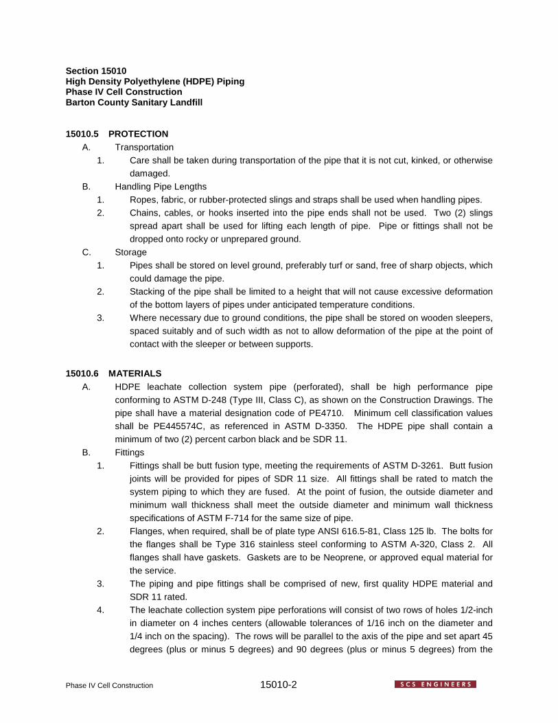
Section 15010 High Density Polyethylene (HDPE) Piping Phase IV Cell Construction Barton County Sanitary Landfill
Phase IV Cell Construction 15010-2
15010.5 PROTECTION A. Transportation
1. Care shall be taken during transportation of the pipe that it is not cut, kinked, or otherwise damaged.
B. Handling Pipe Lengths 1. Ropes, fabric, or rubber-protected slings and straps shall be used when handling pipes. 2. Chains, cables, or hooks inserted into the pipe ends shall not be used. Two (2) slings
spread apart shall be used for lifting each length of pipe. Pipe or fittings shall not be dropped onto rocky or unprepared ground.
C. Storage 1. Pipes shall be stored on level ground, preferably turf or sand, free of sharp objects, which
could damage the pipe. 2. Stacking of the pipe shall be limited to a height that will not cause excessive deformation
of the bottom layers of pipes under anticipated temperature conditions. 3. Where necessary due to ground conditions, the pipe shall be stored on wooden sleepers,
spaced suitably and of such width as not to allow deformation of the pipe at the point of contact with the sleeper or between supports.
15010.6 MATERIALS A. HDPE leachate collection system pipe (perforated), shall be high performance pipe
conforming to ASTM D-248 (Type III, Class C), as shown on the Construction Drawings. The pipe shall have a material designation code of PE4710. Minimum cell classification values shall be PE445574C, as referenced in ASTM D-3350. The HDPE pipe shall contain a minimum of two (2) percent carbon black and be SDR 11.
B. Fittings 1. Fittings shall be butt fusion type, meeting the requirements of ASTM D-3261. Butt fusion
joints will be provided for pipes of SDR 11 size. All fittings shall be rated to match the system piping to which they are fused. At the point of fusion, the outside diameter and minimum wall thickness shall meet the outside diameter and minimum wall thickness specifications of ASTM F-714 for the same size of pipe.
2. Flanges, when required, shall be of plate type ANSI 616.5-81, Class 125 lb. The bolts for the flanges shall be Type 316 stainless steel conforming to ASTM A-320, Class 2. All flanges shall have gaskets. Gaskets are to be Neoprene, or approved equal material for the service.
3. The piping and pipe fittings shall be comprised of new, first quality HDPE material and SDR 11 rated.
4. The leachate collection system pipe perforations will consist of two rows of holes 1/2-inch in diameter on 4 inches centers (allowable tolerances of 1/16 inch on the diameter and 1/4 inch on the spacing). The rows will be parallel to the axis of the pipe and set apart 45 degrees (plus or minus 5 degrees) and 90 degrees (plus or minus 5 degrees) from the

Section 15010 High Density Polyethylene (HDPE) Piping Phase IV Cell Construction Barton County Sanitary Landfill
Phase IV Cell Construction 15010-3
adjacent row as depicted in the Construction Drawings. C. The CONTRACTOR shall submit a certification from the manufacturer of the piping and pipe
fittings, stating that the piping meets physical property requirements for the intended application.
D. Each standard and random length of pipe in compliance with this specification shall be clearly marked at a minimum with:
1. Pipe size. 2. SDR number. 3. Class and profile numbers.
15010.7 PREPARATION A. The manufacturer shall furnish complete written instructions for the storage, handling,
installation, fusion, and repair of the piping in compliance with this Technical Specification and the conditions of the warranty.
B. The interior of all pipes shall be thoroughly cleaned of all foreign material and shall be kept clean during installation operations by means of plugs or other industry-approved methods.
15010.8 INSTALLATION A. Cutting shall be completed with approved mechanical cutters in a manner that will not
damage the pipe. Pipe shall be firmly and uniformly supported on the granular bedding material. Pipe interior shall be kept thoroughly clean as the work progresses. Care shall be taken that pipe is not disturbed until joints are cured. Any adapters for joining shall be in accordance with the pipe manufacturer’s printed instructions.
B. Joining (HDPE Pipe). Sections of the HDPE pipe (40-foot joints) shall be joined into continuous lengths by the butt fusion method and shall be performed in strict conformance with the pipe manufacturer’s recommendations using approved equipment. All valves and transition piping shall be by butt fusion, electrofusion, flange or mechanical joint connections. Joining and installation of pipe shall be accomplished under the direction of an authorized manufacturer’s representative.
C. Handling Pipeline. The handling of the pipeline shall be in such a manner that the pipe is not damaged by dragging it over sharp and cutting objects.
D. Pipe and fittings shall be selected so that there will be as small a deviation as possible at the joints, and so that inverts present a smooth surface. Pipe and fittings which do not fit together to form a tight fitting joint will be rejected.
E. All pipe cuts shall be square, perpendicular to center line of pipe. F. Damaged pipe that results in reduction of the wall thickness by more than approximately
ten (10) percent should be cut out and discarded. Damaged pipe shall be repaired according to manufacturer’s recommendations.
G. CONTRACTOR shall protect the pipe and workers from the build-up of static electricity, which

Section 15010 High Density Polyethylene (HDPE) Piping Phase IV Cell Construction Barton County Sanitary Landfill
Phase IV Cell Construction 15010-4
can be generated in the pipe by friction from the handling of pipe in storage, shipping, and installation. CONTRACTOR shall minimize the hazard of discharge by applying a film of water to the work surface, to drain away the static electricity. Other recommendations by the pipe manufacturer will be acceptable.
15010.9 TESTING A. None
15010.10 CERTIFICATION OF COMPLETION A. Upon completion of the backfilling operation over the piping system, the Contractor shall
certify the following to the OWNER and ENGINEER. 1. The piping system has been constructed in accordance with the approved PROJECT
DOCUMENTS. 2. The piping system has not been damaged during the backfilling operation or construction.
***End of Section 15010***

Phase IV Cell Construction
Section 15020
POLYVINYL CHLORIDE (PVC) PIPING
15020.1 SUMMARY A. Section includes furnishing all labor, materials, equipment, and incidentals necessary to
install and test polyvinyl chloride piping (PVC) piping and pipe fittings for the Phase IV Cell as shown on the Construction Drawings.
15020.2 RELATED SECTIONS A. Section 02250 GEOTEXTILE B. Section 02300 GEOSYNTHETIC DRAINAGE COMPOSITE C. Section 02600 HIGH DENSITY POLYETHYLENE (HDPE) GEOMEMBRANE
15020.3 QUALITY ASSURANCE AND QUALITY CONTROL A. None
15020.4 SUBMITTALS A. Submit manufacturer’s catalog data and descriptive literature for PVC, pipe, fittings, solvent,
and miscellaneous materials. Show dimensions and materials of construction by specification reference and grade.
15020.5 PROTECTION
A. Transportation 1. Care shall be taken during transportation of the pipe that it is not cut, kinked, or otherwise
damaged. B. Storage
1. Pipes shall be stored on level ground, preferably turf or sand, free of sharp objects, which could damage the pipe.
2. Stacking of the pipe shall be limited to a height that will not cause excessive deformation of the bottom layers of pipes under anticipated temperature conditions.
3. Where necessary due to ground conditions, the pipe shall be stored on wooden sleepers, spaced suitably and of such width as not to allow deformation of the pipe at the point of contact with the sleeper or between supports.
15020.6 MATERIALS A. Perimeter gas vent system shall be schedule 40 PVC pipe, as shown on the Construction
Drawings. B. Fittings
1. Fittings shall be schedule 40, meeting the requirements of ASTM D-2466.

Section 15010 Polyvinyl Chloride (PVC) Piping Phase IV Cell Construction Barton County Sanitary Landfill
Phase IV Cell Construction 15010-2
15020.7 PREPARATION B. The interior of all pipes shall be thoroughly cleaned of all foreign material and shall be kept
clean during installation operations by means of plugs or other industry-approved methods. C. Do not install PVC pipe when the temperature is below 40 degrees F or above 90 degrees F. D. Before installation, check pipe and fittings for cuts, scratches, gouges, buckling, kinking, or
splitting on pipe end. Remove any pipe section containing defects by cutting out the damaged section as a complete cylinder.
15020.8 INSTALLATION A. Cutting shall be completed with approved mechanical cutters in a manner that will not
damage the pipe. Pipe interior shall be kept thoroughly clean as the work progresses. B. Pipe and fitting joints shall be solvent welded except where threaded joints are required. C. Handling Pipeline. The handling of the pipeline shall be in such a manner that the pipe is not
damaged. D. Solvent Cement for socket joints shall comply with ASTM D 2564 and F 656 C. Pipe and fittings which do not fit together to form a tight fitting joint will be rejected. E. All pipe cuts shall be square, perpendicular to center line of pipe.
15020.9 TESTING F. None
15020.10 CERTIFICATION OF COMPLETION G. Upon completion of the installation of the perimeter gas vents, the Contractor shall certify the
following to the OWNER and ENGINEER. 1. The piping system has been constructed in accordance with the approved PROJECT
DOCUMENTS. 2. The piping system has not been damaged during construction.
***End of Section 15020***

PHASE IV CELL CONSTRUCTION DRAWINGS

BARTON COUNTY SANITARY LANDFILL350 NORTHEAST 30th ROAD, GREAT BEND, KANSAS
PHASE IV CELL CONSTRUCTIONSOLID WASTE PERMIT NO. 103
TITLESHEET NO.
1. COVERSHEET
2. SITE LAYOUT
3. GRADING PLAN
4. SURVEY POINT TABLE
5. DETAILS SHEET 1
6. DETAILS SHEET 2
7. DETAILS SHEET 3
SCS ENGINEERS8575 WEST 110th STREET, SUITE 100
OVERLAND PARK, KANSAS 66210(913) 681-0030 FAX (913) 681-0012
PROJECT NO. 27219346.01KS CERTIFICATE OF AUTHORITY # E-669
PREPARED BY
PREPARED FOR
BARTON COUNTY, KANSAS1200 MAIN, ROOM 108
GREAT BEND, KANSAS 67530
DECEMBER 2019PROJECT LOCATIONDRAWING INDEX

C&D LANDFILL BOUNDARY(CONSTRUCTED OVER CLOSEDPRE-SUBTITLE D MSW LANDFILL)
LEACHATE STORAGE TANKSHEAVY EQUIPMENT BUILDING
MAIN FACILITYENTRANCE(GATED)
CHAINLINK FENCE CONSTRUCTIONENTRANCE
EXIS
TING
GAS
LIN
E AN
D FI
BER
OPT
IC L
INES
(80'
EAS
EMEN
T)
EXISTING POWER LINE
(120' RIGHT OF W
AY)
TIREPILE
WHITEGOODS PILE
CLOSED C&DWASTE
MANAGEMENTUNIT BOUNDARY
~4.5 ACRES ±
FUTURE VALLEY FILLEXPANSION AREA
EXCESS SOIL STOCKPILE
301 5165.0600 4615.5280 1885.42
201 6467.017 4536.400 1881.570
DESCRIPTIONELEVATIONEASTINGNORTHING#
303 7624.1272 2353.6412 1882.82
206 5133.001 3581.951 1888.605
205 5140.6618 3134.1402 1886.54
Kan
sas
Cer
tific
ate
of
Aut
ho
riza
tion
#E
-669
PH
. (91
3) 6
81-0
030
FA
X. (
913)
681
-001
2
8575
W. 1
10th
St,
Ste
. 100
2 7
Ove
rlan
d P
ark,
Kan
sas
6621
0B
AR
TON
CO
UN
TY S
AN
ITA
RY
LA
ND
FILL
350
NO
RTH
EA
ST
30TH
RO
AD
, GR
EA
T B
EN
D, K
AN
SA
S
BA
RTO
N C
OU
NTY
, KA
NS
AS
SIT
E L
AY
OU
T
PH
AS
E IV
CE
LL C
ON
STR
UC
TIO
N
SC
S E
NG
INE
ER
S
T:\2
7219
346.
01\D
ata
and
Cal
cula
tions
\Aut
oC
AD
\Site
Lay
out
v0.
01.d
wg
Dec
19,
201
9 -
8:44
am L
ayo
ut N
ame:
2 S
ite L
ayo
ut B
y: 4
470d
awLEGEND
BENCHMARK
PROPERTY LINE
150' BUFFER LINE
FUTURE VALLEY FILL EXPANSION AREA
PAVED ROAD
UNPAVED ROAD
VEGETATION / TREES
WETLAND (APPROXIMATE)
BUILDING/STRUCTURE/TANK
FENCE
SIGN
UTILITY POLE
UNDERGROUND UTILITY
WATER WELL (APPROXIMATE)
EXISTING GRADE 2' CONTOUR
EXISTING GRADE 10' CONTOUR
SOLID WASTE BOUNDARY (APPROXIMATE)
WASTE MANAGEMENT UNIT (APPROXIMATE)
WASTE MANAGEMENT UNIT PHASE BOUNDARY
GROUNDWATER MONITORING WELL
GAS MONITORING PROBE
STORM WATER DRAINAGE DITCH
STORM WATER CULVERT
MANHOLE
GENERAL NOTES
1. EXISTING GRADE TOPOGRAPHY COMPILED BASED ON THE FOLLOWING:AERIAL SURVEY COMPLETED ON JULY 15, 2000 BY MILES AIR PHOTOSURVEY.AERIAL SURVEY COMPLETED ON JUNE 24, 2002 BY MILES AIR PHOTOSURVEY.AERIAL SURVEY COMPLETED APRIL 14, 2008 BY MILES AIR PHOTOSURVEY.TOPOGRAPHIC SURVEY COMPLETED BY SCS AQUATERRA ON JULY 11AND SEPTEMBER 11, 12, AND 14, 2012.TOPOGRAPHIC SURVEY COMPLETED BY SCS AQUATERRA ON MAY 28,2014.TOPOGRAPHIC SURVEY COMPLETED BY SCS AQUATERRA ON APRIL 6,2015.TOPOGRAPHIC SURVEY COMPLETED BY SCS ENGINEERS ON MARCH 23AND 24, 2016.TOPOGRAPHIC SURVEY COMPLETED BY SCS ENGINEERS ON APRIL 12,2017 AND MAY 9, 2017.TOPOGRAPHIC SURVEY COMPLETED BY SCS ENGINEERS ON MARCH 22,2018.TOPOGRAPHIC SURVEY COMPLETED BY SCS ENGINEERS ON APRIL 24,2019.
2. BENCHMARK COORDINATES BASED ON LOCAL GRID COORDINATE SYSTEMWITH POINT OF BEGINNING AT THE SOUTHEAST CORNER OF SECTION 12,TOWNSHIP 19 SOUTH, RANCH 13 WEST, BARTON COUNTY, KANSAS. GRIDPOINT OF BEGINNING GIVEN THE FOLLOWING COORDINATES: 5,000 N,5,000 E.
3. BENCHMARK ELEVATIONS BASED ON LOCAL LANDFILL DATUM.
CONSTRUCTION NOTES:
1. LOCATIONS OF EXISTING UTILITIES, EASEMENTS, AND BUILDINGS DEPICTEDON PLANS ARE APPROXIMATE. THE CONTRACTOR SHALL BE RESPONSIBLEFOR LOCATING AND PROTECTING ALL UTILITIES. ANY DAMAGE TO EXISTINGUTILITIES SHALL BE REPAIRED AT THE CONTRACTOR'S EXPENSE.
2. ALL EXCAVATED SOIL SHALL BE SEGREGATED AND STOCKPILED AS SHOWNON THE DRAWINGS OR AS DIRECTED BY THE OWNER OR ENGINEER. SOILSTOCKPILES SHALL HAVE A SLIT FENCE PLACED BELOW THE STOCKPILE
3. CONSTRUCTION ENTRANCE SHALL BE MAINTAINED BY THE CONTRACTOR INA CONDITION THAT WILL PREVENT TRACKING OR FLOWING OF SEDIMENTONTO PUBLIC RIGHT-OF-WAYS AND STREETS. MAINTENANCE MAY INCLUDEPERIODIC TOP DRESSING WITH ADDITIONAL CRUSHED STONE ASCONDITIONS WARRANT. REPAIR OF ENTRANCE AND CLEANING OFRIGHT-OF-WAYS AND PAVED STREETS THAT HAVE BEEN SOILED BYCONSTRUCTION ACTIVITIES SHALL BE THE CONTRACTORS RESPONSIBILITY.
4. DURING ALL SOIL DISTURBING ACTIVITIES, THE CONTRACTOR SHALL TAKEAPPROPRIATE STEPS, USING ACCEPTED CONSTRUCTION METHODS, TOMINIMIZE THE TIME OF EXPOSURE OF UNPROTECTED SOIL AND OTHERCONSTRUCTION MATERIALS TO RAINFALL. ALL DISTURBED AREAS WILL BESEEDED AND MULCHED ACCORDING TO THE SEEDING SCHEDULE,EXCLUDING AREAS WITHIN THE WASTE MANAGEMENT UNIT.
5. SOIL STOCKPILES SHALL HAVE A SILT FENCE PLACED BELOW THESTOCKPILE.
6. THE CONTRACTOR SHALL INSPECT ALL EROSION CONTROLS AT LEASTEVERY TWO WEEKS, AND FOLLOWING ANY STORM EVENT DURING WHICHPRECIPITATION IS 12 INCH OR GREATER. ACCUMULATED SEDIMENT SHALL BEREMOVED FROM BEHIND SILT FENCES, AND TORN SILT FENCES MENDEDOR REPLACED. ACCUMULATED SEDIMENT IN DITCHES THAT THREATENSTHE INTEGRITY OR FUNCTION OF THESE STRUCTURES SHALL BEEXCAVATED AND REMOVED.
7. IT IS THE CONTRACTOR'S RESPONSIBILITY TO ENSURE THAT EROSIONCONTROL MEASURES MEET THE MINIMUM FEDERAL, STATE, AND LOCALREGULATIONS. IT IS THE CONTRACTOR'S RESPONSIBILITY TO MAINTAIN ALLEROSION CONTROL DEVICES UNTIL FINAL COMPLETION.
8. SUFFICIENT SOIL TO CONSTRUCT THE PHASE IV CELL LOW PERMEABILITYSOIL LINER LIES WITHIN THE PROPOSED EXCAVATION LIMITS OF PHASE IVAND PROPOSED EXCAVATION LIMITS.
9. THE CONTRACTOR IS RESPONSIBLE FOR EXCAVATING AND STOCKPILINGALL SOIL IN A MANNER THAT WILL KEEP UNLIKE SOILS SEGREGATED INTOTHEIR OWN STOCKPILES. FOR ADDITIONAL SOIL INFORMATION SEE THECQA REPORT AND TEST PAD REPORT. IF CONTRACTOR FAILS TO KEEPSOILS SEGREGATED THEN CONTRACTOR WILL BE SOLELY RESPONSIBLEFOR COST AND TIME ASSOCIATED WITH DEVELOPING A NEW TEST PAD NOTLIMITED TO CONSTRUCTION AND OTHER ENGINEERING COSTS
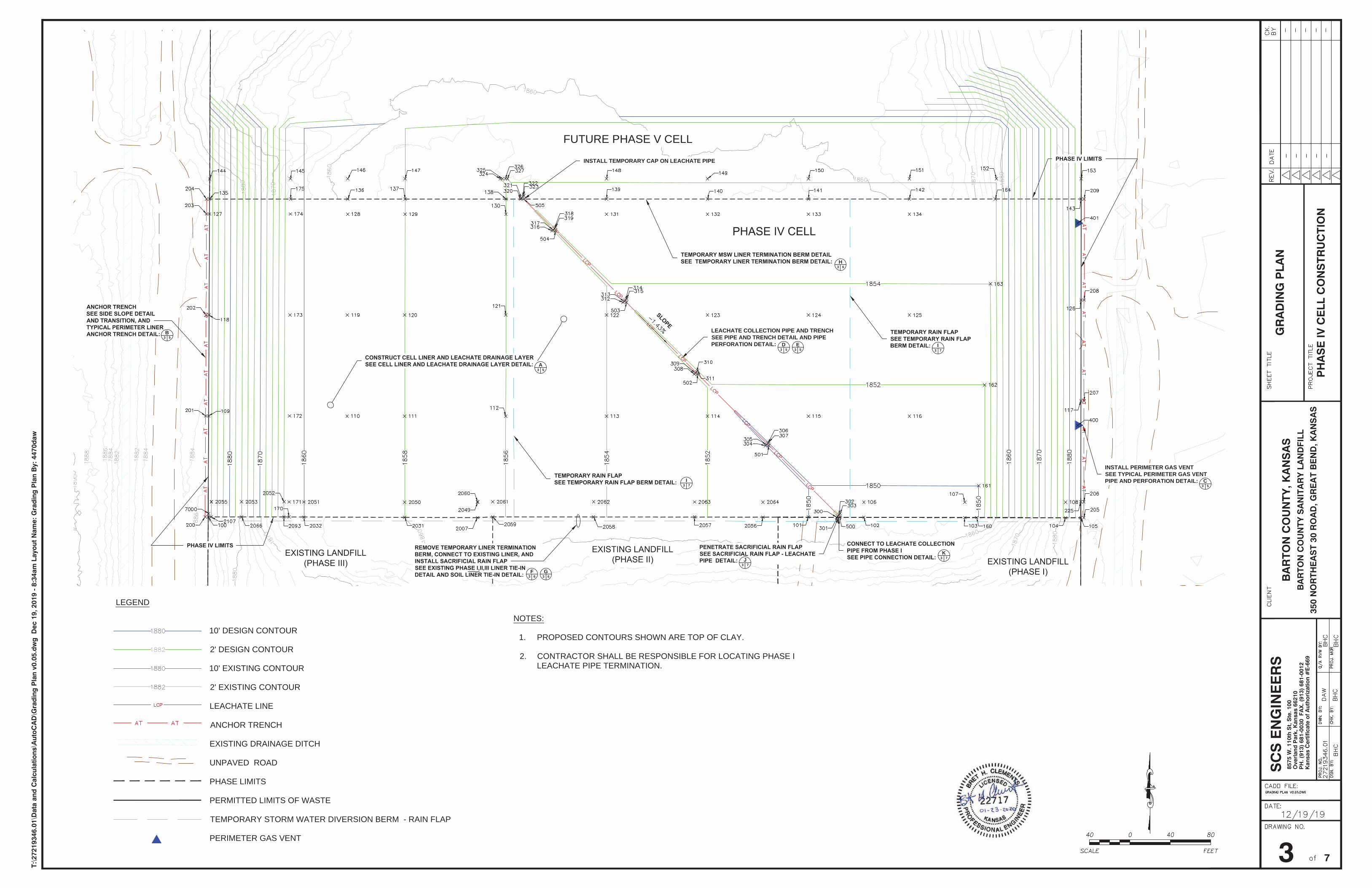
F63
G63
INSTALL PERIMETER GAS VENTSEE TYPICAL PERIMETER GAS VENTPIPE AND PERFORATION DETAIL:
LEACHATE COLLECTION PIPE AND TRENCHSEE PIPE AND TRENCH DETAIL AND PIPEPERFORATION DETAIL: D
53E
53
B53
H63
C53
FUTURE PHASE V CELL
A53
I73
I73
J73
K73
INSTALL TEMPORARY CAP ON LEACHATE PIPE
Kan
sas
Cer
tific
ate
of
Aut
ho
riza
tion
#E
-669
PH
. (91
3) 6
81-0
030
FA
X. (
913)
681
-001
2
8575
W. 1
10th
St,
Ste
. 100
3 7
Ove
rlan
d P
ark,
Kan
sas
6621
0B
AR
TON
CO
UN
TY S
AN
ITA
RY
LA
ND
FILL
350
NO
RTH
EA
ST
30 R
OA
D, G
RE
AT
BE
ND
, KA
NS
AS
BA
RTO
N C
OU
NTY
, KA
NS
AS
GR
AD
ING
PLA
N
PH
AS
E IV
CE
LL C
ON
STR
UC
TIO
N
SC
S E
NG
INE
ER
S
T:\2
7219
346.
01\D
ata
and
Cal
cula
tions
\Aut
oC
AD
\Gra
din
g P
lan
v0.0
5.d
wg
Dec
19,
201
9 -
8:34
am L
ayo
ut N
ame:
Gra
din
g P
lan
By:
447
0daw
NOTES:
1. PROPOSED CONTOURS SHOWN ARE TOP OF CLAY.
2. CONTRACTOR SHALL BE RESPONSIBLE FOR LOCATING PHASE ILEACHATE PIPE TERMINATION.
LEGEND
10' DESIGN CONTOUR
2' DESIGN CONTOUR
10' EXISTING CONTOUR
2' EXISTING CONTOUR
LEACHATE LINE
ANCHOR TRENCH
EXISTING DRAINAGE DITCH
UNPAVED ROAD
PHASE LIMITS
PERMITTED LIMITS OF WASTE
TEMPORARY STORM WATER DIVERSION BERM - RAIN FLAP
PERIMETER GAS VENT

Point # Northing Easting Design Top of SubgradeElevation
Design Top of ClayElevation
Design Top of SandElevation Description
109 6466.050 3254.614 1885.02 1887.02 1888.02 Phase IV Limits110 6465.969 3391.917 1857.14 1859.14 1860.14 Phase IV111 6465.895 3449.011 1856.00 1858.00 1859.00 Phase IV112 6465.895 3549.011 1854.00 1856.00 1857.00 Phase IV113 6465.895 3649.011 1852.00 1854.00 1855.00 Phase IV114 6465.895 3749.011 1850.00 1852.00 1853.00 Phase IV115 6465.895 3849.011 1849.38 1851.38 1852.38 Phase IV116 6465.895 3949.011 1849.38 1851.38 1852.38 Phase IV117 6480.925 4119.071 1881.79 1883.79 1884.79 Phase IV Limits118 6566.049 3255.073 1885.02 1887.02 1888.02 Phase IV Limits119 6565.966 3392.151 1857.14 1859.14 1860.14 Phase IV120 6565.895 3449.011 1856.00 1858.00 1859.00 Phase IV121 6565.895 3549.011 1854.00 1856.00 1857.00 Phase IV122 6565.895 3649.011 1852.00 1854.00 1855.00 Phase IV123 6565.895 3749.011 1851.37 1853.37 1854.37 Phase IV124 6565.895 3849.011 1851.38 1853.38 1854.38 Phase IV125 6565.895 3949.011 1851.38 1853.38 1854.38 Phase IV126 6580.925 4119.187 1881.91 1883.91 1884.91 Phase IV Limits127 6666.048 3255.533 1885.01 1887.01 1888.01 Phase IV Limits128 6665.964 3392.385 1857.14 1859.14 1860.14 Phase IV129 6665.895 3449.360 1856.00 1858.00 1859.00 Phase IV130 6665.895 3549.360 1854.00 1856.00 1857.00 Phase IV131 6665.895 3649.011 1853.37 1855.37 1856.37 Phase IV132 6665.895 3749.011 1853.37 1855.37 1856.37 Phase IV133 6665.895 3849.011 1853.38 1855.38 1856.38 Phase IV134 6665.895 3949.011 1853.38 1855.38 1856.38 Phase IV135 6680.795 3255.601 1885.01 1887.01 1888.01 Phase IV Limits136 6680.815 3392.602 1857.14 1859.14 1860.14 Phase IV137 6680.824 3449.377 1856.00 1858.00 1859.00 Phase IV138 6680.839 3549.377 1854.00 1856.00 1857.00 Phase IV139 6680.854 3649.011 1853.67 1855.67 1856.67 Phase IV140 6680.869 3749.011 1853.67 1855.67 1856.67 Phase IV141 6680.884 3849.011 1853.68 1855.68 1856.68 Phase IV142 6680.899 3949.011 1853.68 1855.68 1856.68 Phase IV143 6680.925 4119.304 1882.05 1884.05 1885.05 Phase IV Limits144 6700.792 3255.693 1885.01 1887.01 Phase IV Overbuild145 6700.804 3335.824 1858.30 1860.30 Phase IV Overbuild146 6700.813 3392.602 1857.14 1859.14 Phase IV Overbuild147 6700.822 3449.400 1856.00 1858.00 Phase IV Overbuild148 6700.852 3649.008 1854.07 1856.07 Phase IV Overbuild149 6700.868 3749.008 1854.07 1856.07 Phase IV Overbuild150 6700.883 3849.008 1854.08 1856.08 Phase IV Overbuild151 6700.898 3949.008 1854.08 1856.08 Phase IV Overbuild152 6700.912 4035.324 1854.08 1856.08 Phase IV Overbuild153 6700.925 4119.327 1882.08 1884.08 Phase IV Overbuild161 6396.855 4017.604 1848.00 1850.00 1851.00 Phase IV Toe of East Slope
162 6496.848 4023.718 1850.00 1852.00 1853.00 Phase IV Toe of East Slope
163 6596.841 4029.402 1852.00 1854.00 1855.00 Phase IV Toe of East Slope
164 6680.912 4034.186 1853.68 1855.68 1856.68 Phase IV Toe of East Slope
170 6365.980 3334.355 1858.29 1860.29 1861.29 Phase IV Toe of Slope
171 6380.811 3334.424 1858.29 1860.29 1861.29 Phase IV Toe of West Slope
172 6466.042 3334.823 1858.29 1860.29 1861.29 Phase IV Toe of West Slope
173 6566.037 3335.290 1858.28 1860.28 1861.28 Phase IV Toe of West Slope
174 6666.033 3335.758 1858.27 1860.27 1861.27 Phase IV Toe of West Slope
175 6680.807 3335.827 1858.27 1860.27 1861.27 Phase IV Toe of West Slope225 6380.925 4118.955 1881.79 1883.79 1884.79 Phase IV Limits
Point # Northing Easting Design Top of SubgradeElevation
Design Top of ClayElevation
Design Top of SandElevation Description
300 6365.638 3876.891 1847.44 1849.44 1850.44 Leachate Trench301 6366.712 3877.971 1845.92 1847.92 1850.42 Leachate Trench302 6368.123 3879.389 1845.92 1847.92 1850.42 Leachate Trench303 6369.198 3880.471 1847.44 1849.44 1850.44 Leachate Trench304 6436.561 3806.393 1848.85 1850.85 1851.85 Leachate Trench305 6437.623 3807.461 1847.35 1849.35 1851.85 Leachate Trench306 6439.033 3808.879 1847.35 1849.35 1851.85 Leachate Trench307 6440.100 3809.951 1848.85 1850.85 1851.85 Leachate Trench308 6507.483 3735.895 1850.27 1852.27 1853.27 Leachate Trench309 6508.533 3736.951 1848.78 1850.78 1853.28 Leachate Trench310 6509.944 3738.369 1848.78 1850.78 1853.28 Leachate Trench311 6511.002 3739.433 1850.27 1852.27 1853.27 Leachate Trench312 6578.406 3665.397 1851.68 1853.68 1854.68 Leachate Trench313 6579.444 3666.441 1850.21 1852.21 1854.71 Leachate Trench314 6580.855 3667.859 1850.21 1852.21 1854.71 Leachate Trench315 6581.904 3668.914 1851.68 1853.68 1854.68 Leachate Trench316 6649.329 3594.899 1853.09 1855.09 1856.09 Leachate Trench317 6650.355 3595.931 1851.63 1853.63 1856.13 Leachate Trench318 6651.765 3597.349 1851.63 1853.63 1856.13 Leachate Trench319 6652.806 3598.395 1853.09 1855.09 1856.09 Leachate Trench320 6680.841 3563.575 1853.72 1855.72 Leachate Trench321 6681.862 3564.602 1852.27 1854.27 Leachate Trench322 6683.272 3566.02 1852.27 1854.27 Leachate Trench323 6684.309 3567.062 1853.72 1855.72 Leachate Trench
324 6700.836 3543.700 1854.11 1856.11 Leachate Trench Phase IVOverbuild
325 6700.836 3545.735 1852.65 1854.65 Leachate Trench Phase IVOverbuild
326 6700.837 3548.555 1852.62 1854.62 Leachate Trench Phase IVOverbuild
327 6700.837 3550.624 1854.07 1856.07 Leachate Trench Phase IVOverbuild
Point # Northing Easting Top of Pipe Elevation Description
500 6365.752 3880.336 1848.93 Top of LeachatePipe
501 6436.663 3809.826 1850.36 Top of LeachatePipe
502 6507.574 3739.316 1851.79 Top of LeachatePipe
503 6578.485 3668.805 1853.22 Top of LeachatePipe
504 6649.395 3598.295 1854.65 Top of LeachatePipe
505 6680.836 3567.033 1855.28 Top of LeachatePipe
Point # Northing Easting Survey ReferenceElevation Description
400 6456.669 4115.809 1882.71 Perimeter Gas Vent401 6657.020 4115.763 1882.85 Perimeter Gas Vent
Point # Northing Easting Survey ReferenceElevation Description
200 6366.065 3251.154 1887.03 Phase IV Anchor Trench201 6466.05 3251.614 1887.02 Phase IV Anchor Trench202 6566.049 3252.073 1887.02 Phase IV Anchor Trench203 6666.048 3252.533 1887.01 Phase IV Anchor Trench204 6680.808 3252.601 1887.01 Phase IV Anchor Trench205 6365.157 4121.937 1883.79 Phase IV Anchor Trench206 6380.925 4121.955 1883.79 Phase IV Anchor Trench207 6480.925 4122.071 1883.79 Phase IV Anchor Trench208 6580.925 4122.187 1883.91 Phase IV Anchor Trench209 6680.921 4122.304 1884.05 Phase IV Anchor Trench
Point # Northing Easting Certified SubgradeElevation
Certified Top ClayElevation
Top of SandAs-Built Elevation
Design SubgradeElevation
Design Top of ClayElevation
Design Top of SandElevation Description
2007 6365.420 3521.120 1854.63 1856.70 1857.80 Phase III As-Built Edge of Overbuild/FML Extents2031 6365.590 3449.010 1855.90 1858.07 1861.84 Phase III Cell Floor/FML Extents/Storm water Berm2032 6365.820 3349.010 1857.98 1860.06 1861.11 Phase III Cell Floor/FML Extents2049 6380.450 3521.240 1854.56 1856.56 1854.56 1856.56 1857.56 Extent of Overbuild2050 6380.620 3448.990 1856.00 1858.00 1856.00 1858.00 1859.00 Extent of Overbuild2051 6380.850 3349.060 1858.00 1860.00 1858.00 1860.00 1861.00 Extent of Overbuild2052 6380.900 3329.330 1859.99 1861.99 1859.99 1861.99 1862.99 Extent of Overbuild2053 6380.990 3287.290 1874.00 1876.00 1874.00 1876.00 1877.00 Extent of Overbuild2055 6381.030 3257.330 1883.99 1885.99 1883.99 1885.99 1886.99 Extent of Overbuild2056 6365.820 3803.900 1848.61 1850.95 1853.49 Phase II As-Built Point2057 6365.860 3736.110 1850.28 1852.36 1853.52 Phase II As-Built Point2058 6365.950 3636.120 1852.30 1854.35 1855.46 Phase II As-Built Point2059 6366.020 3536.160 1854.05 1856.36 1857.69 Phase II As-Built Point2060 6381.070 3521.160 1854.36 1856.68 1854.56 1856.56 1857.56 Phase II As-Built Point2061 6381.040 3536.160 1854.26 1856.33 1854.26 1856.26 1857.26 Phase II As-Built Point2062 6380.950 3636.170 1852.24 1854.41 1852.26 1854.26 1855.26 Phase II As-Built Point2063 6380.840 3736.160 1850.02 1852.40 1850.26 1852.26 1853.26 Phase II As-Built Point2064 6380.770 3803.940 1848.73 1851.20 1848.90 1850.90 1851.90 Phase II As-Built Point2066 6366.080 3287.230 1873.94 1876.17 1877.39 Phase III Mid Slpe/FML Extents2093 6365.870 3329.230 1859.98 1862.04 1863.20 Phase III Toe of Slope/FML Extents2107 6366.030 3257.230 1883.95 1886.02 1887.05 Phase III Top of Slope/ FML Extents7000 6369.300 3254.790 Phase III As Built Inside Top Edge of Anchor Trench
100 6366.051 3254.154 1885.03 1887.03 1888.03 Phase IV Limits
101 6365.895 3849.011 1848.00 1850.00 1851.00 1848.00 1850.00 1851.00 Phase IV
102 6365.585 3903.903 1847.37 1849.37 1850.37 1847.37 1849.37 1850.37 Phase IV
103 6365.388 4003.910 1847.37 1849.37 1850.37 1847.37 1849.37 1850.37 Phase IV
104 6365.190 4103.902 1876.78 1878.78 1879.78 1876.78 1878.78 1879.78 Phase IV
105 6365.161 4118.937 1881.79 1883.79 1884.79 1881.79 1883.79 1884.79 Phase IV Limits
106 6380.770 3903.903 1847.68 1849.68 1847.68 1849.68 1850.68 Phase IV
107 6380.770 4003.910 1847.68 1849.68 1847.68 1849.68 1850.68 Phase IV
108 6380.770 4103.902 1876.77 1878.77 1876.77 1878.77 1879.77 Phase IV
160 6365.364 4015.681 1847.37 1849.37 1850.37 1847.37 1849.37 1850.37 Phase IV Toe of East Slope
300 6365.638 3876.891 1847.44 1849.44 1850.44 Leachate Trench
301 6366.712 3877.971 1845.92 1847.92 1850.42 Leachate Trench
302 6368.123 3879.389 1845.92 1847.92 1850.42 Leachate Trench
303 6369.198 3880.471 1847.44 1849.44 1850.44 Leachate Trench
Kan
sas
Cer
tific
ate
of
Aut
ho
riza
tion
#E
-669
PH
. (91
3) 6
81-0
030
FA
X. (
913)
681
-001
2
8575
W. 1
10th
St,
Ste
. 100
4 7
Ove
rlan
d P
ark,
Kan
sas
6621
0B
AR
TON
CO
UN
TY S
AN
ITA
RY
LA
ND
FILL
350
NO
RTH
EA
ST
30 R
OA
D, G
RE
AT
BE
ND
, KA
NS
AS
BA
RTO
N C
OU
NTY
, KA
NS
AS
PO
INTS
TA
BLE
PH
AS
E IV
CE
LL C
ON
STR
UC
TIO
N
SC
S E
NG
INE
ER
S
T:\2
7219
346.
01\D
ata
and
Cal
cula
tions
\Aut
oC
AD
\Gra
din
g P
lan
v0.0
5.d
wg
Dec
19,
201
9 -
8:36
am L
ayo
ut N
ame:
Po
ints
Tab
le B
y: 4
470d
aw
SEE DETAIL B ON PAGE 5 FOR ANCHOR TRENCH SURVEYREFERENCE
SEE DETAIL C ON PAGE 5 FOR PERIMETER GAS VENT SURVEYREFERENCE
SEE DETAIL G ON PAGE 6 FOR TIE IN DETAILS
SEE DETAIL D ON PAGE 5 FOR LEACHATE TRENCH SURVEYREFERENCE
SEE DETAIL D ON PAGE 5 FOR LEACHATE PIPE SURVEYREFERENCE
100' GRID AND BREAKLINE POINTS LEACHATE TRENCH POINTS PARAMETER GAS VENTS
ANCHOR TRENCH POINTS
LEACHTATE PIPE POINTS
AS-BUILT AND CERTIFIED POINTS

Not to ScaleCELL LINER AND LEACHATE DRAINAGE LAYER DETAILA
3 5
24" MIN. COMPACTED SOIL LINERPERMEABILITY OF 1X10⁻⁷ CM/SEC OR LESS
(SEE NOTE 2)
(FML) 60-MIL HDPE GEOMEMBRANE(SEE NOTE 3)
12" MIN. SAND PROTECTION/DRAINAGE LAYER
(GDN) GEOSYNTHETIC DRAINAGE COMPOSITE(SEE NOTE 4)
SCARIFIED AND COMPACTED SUBGRADE(SEE NOTE 1) SAND PROTECTION/DRAINAGE LAYER COMPOSITION:
> 95% PASSING 1/2" SIEVE< 30% PASSING #30 SIEVE< 5% PASSING #200 SIEVE
SURVEY REFERENCE TOP OFSUBGRADE ELEVATION
SURVEY REFERENCE TOP OFCLAY ELEVATION
SURVEY REFERENCE TOP OFSAND ELEVATION
NOTES:
1. SUBGRADE SHALL BE PROOF ROLLED AND AREAS OF SOFTSPOTS OR PUMPING SHOULD BE REWORKED IN ACCORDANCEWITH THE CQA PLAN.
2. COMPACTION AND MOISTURE REQUIREMENTS PER MATERIALSPECIFIC TESTING PROVIDED IN THE CQA REPORT APPENDIX.
3. 60 MIL GEOMEMBRANE SHALL BE TEXTURED ON BOTH SIDES.SMOOTH GEOMEMBRANE MAY BE USED ON THE CELL FLOORAFTER A 10' RUNOUT.
4. GEOSYNTHETIC DRAINAGE COMPOSITE IS 0.2" BI-PLANARDRAINAGE NET WITH 6.0 OZ/SY NON-WOVEN GEOTEXTILEHEAT BONDED TO BOTH SIDES FOR SIDE SLOPES. ON THECELL FLOOR, THE DRAINAGE COMPOSITE IS 0.2" BI-PLANARDRAINAGE NET WITH 6.0 OZ/SY NON-WOVEN GEOTEXTILEHEAT BONDED TO THE TOP OF THE GEONET.
SAND PROTECTION/DRAINAGE LAYER
36" MIN.12" MIN.
36" MIN.
12" MIN.
36" MIN.
Not to ScaleTYPICAL PERIMETER LINER ANCHOR TRENCH DETAILB
3 5
CELL LINERSEE DETAIL: A
SURVEY REFERENCEANCHOR TRENCH
SURVEY REFERENCE PHASE IVLIMITS
TEMPORARY COMPACTED SOIL BERM
TEXTUREDGEOMEMBRANE
10' MIN.
SMOOTHGEOMEMBRANE
CELL LINERSEE DETAIL: A
SIDE SLOPE DETAIL AND TRANSITION, AND
PERIMETER GAS VENT (EAST SIDE ONLY)SEE DETAIL: C
SLOPE TO DRAIN
SURV
EY R
EFER
ENCE
TOE
OF
SLOP
E
60" 60"
60"
APPROX. 10'
4" DIA. SCHEDULE 40 PVCSLIP CAP
4" DIA. SCHEDULE 40 PVC TEE4" DIA. SCHEDULE 40 PVC 90°
ELBOW4" DIA. SCHEDULE 40 PVC
PIPE
4" DIA. SCHEDULE 40 PVC TEE4" DIA. SCHEDULE 40 PVC0.030" SLOTTED SCREEN
4" DIA. SCHEDULE 40 PVC SLIP CAP
Not to ScaleTYPICAL PERIMETER GAS VENT PIPE & PERFORATION DETAILC
3 5
60"TYPICAL
SEE DETAIL: A
MSW WASTE LIMIT(APPROXIMATE)
4" DIA. SCHEDULE 40 PVC SLIP CAP
4" DIA. SCHEDULE 40 PVC SLIP CAP
4" DIA. SCHEDULE 40 PVC PIPE
4" DIA. SCHEDULE 40 PVC 90° ELBOW
PERIMETER GAS VENT
SURVEY REFERENCEGAS VENT
SURVEY REFERENCEGAS VENT
60-MIL HDPE GEOMEMBRANE
GEOSYNTHETIC DRAINAGECOMPOSITE
COMPACTED SOIL LINER
12"
CLEAN 2" DRAINAGE GRAVEL
6"1:1 18"
8 OZ./SQ.YD. FILTER GEOTEXTILE
3' OVERLAP
6" M
IN.
Not to ScalePIPE AND TRENCH DETAIL D
3 5
6" DIA. SDR 11 HDPE PERFORATED PIPESEE DETAIL: E
SCARIFIED AND RECOMPACTED SUBGRADE
CELL LINERSEE DETAIL: A
24"
SURVEY REFERENCELEACHATE TRENCH
SURVEY REFERENCELEACHATE TRENCH
SURVEY REFERENCELEACHATE TRENCH
SURVEY REFERENCELEACHATE TRENCH
SURVEY REFERENCE TOP OFLEACHATE PIPE
24"
NOTES:
1. DO NOT COVER LEACHATE PIPE UNTIL CERTIFICATION SURVEY IS COMPLETE. TOP OF PIPEMUST BE CERTIFIED ON 100' INTERVALS AND MAINTAIN A CONSISTENT SLOPE OF 1.43%
2. LEAVE EXCESS 8 OZ/SY GEOTEXTILE, SAND, AGGREGATE, AND FLANGED PIPE SEGMENT ATCONNECTION POINT OF EXISTING CELL TO ALLOW OWNER TO MAKE FINAL CONNECTION.
3. TERMINATE PERFORATED PIPE WITH 6" CAP IMMEDIATELY PRIOR TO PENETRATING THETEMPORARY LINER TERMINATION BERM RAIN FLAP AT THE LIMITS OF PHASE IV AND PHASE VSURVEY LOCATION OF END CAP PRIOR TO COVERING.
BOTTOM VIEW
END SECTION VIEW
6"
1/2" DIA. HOLE
SIDE VIEW4"
45° 45°
Not to Scale PIPE PERFORATION DETAILE
3 5NOTES:
1. TWO ROWS ALONG BOTTOM ONLY.
A1
DETAIL OR SECTION LETTER
DRAWING REFERENCE WHEREDETAIL IS SHOWN
DRAWING WHERE DETAIL ORSECTION IS FIRST LOCATED
1
PH
. (91
3) 6
81-0
030
FA
X. (
913)
681
-001
2
8575
W. 1
10th
St,
Ste
. 100
5 7
Ove
rlan
d P
ark,
Kan
sas
6621
0
BA
RTO
N C
OU
NTY
SA
NIT
AR
Y L
AN
DFI
LL
350
NO
RTH
EA
ST
30 R
OA
D, G
RE
AT
BE
ND
, KA
NS
AS
BA
RTO
N C
OU
NTY
, KA
NS
AS
DE
TAIL
S I
PH
AS
E IV
CE
LL C
ON
STR
UC
TIO
N
SC
S E
NG
INE
ER
S
T:\2
7219
346.
01\D
ata
and
Cal
cula
tions
\Aut
oC
AD
\Det
ails
.dw
g D
ec 1
9, 2
019
- 8:
37am
Lay
out
Nam
e: D
etai
ls I
By:
447
0daw
KA
NS
AS
CE
RTI
FIC
ATE
OF
AU
THO
RIZ
ATI
ON
#E
-669

Not to ScaleTEMPORARY LINER TERMINATION BERM DETAILH
3 6
CELL
LIM
ITS
WELD 60-MIL GEOMEMBRANE RAIN FLAPTO 60-MIL GEOMEMBRANE ON CELL FLOOR
58-INCH THICK PLYWOOD
4' X 8' SHEETS COVERING EDGE OFGEOMEMBRANE
NOMINALLY COMPACTEDSOIL BACKFILL
LINER SYSTEMSEE DETAIL: A
SAND BERM
EDGE
OF
OVER
BUIL
D
RAIN FLAP
24"
4' PLYWOOD
20' MIN.
48" M
IN.
PHASE IV LIMITSFUTURE PHASE V
TERMINATE GEOMEMBRANE& SOIL LINER
TERMINATE GEOSYNTHETICDRAINAGE COMPOSITE
SURVEY REFERENCETOP OF SUBGRADE, EXTENT
OF OVERBUILD
TERMINATE LEACHATE PIPEINSTALL6" CAP
PHASE IV
2' MIN.
REMOVE EXISTINGSOIL BERM
FLOW
4'
15'
REMOVE EXISTING SANDBAGS OR SOIL
REMOVE EXISTING 1/2"X4'X8'PLYWOOD
PHASE I,II,IIISAND PROTECTION/DRAINAGELAYER
PHASE I, II, IIICOMPACTED SOIL LINER
LOCATION FOR AS BUILTGEOMEMBRANE LINER EXTENTS
REMOVE EXISTING TEMPORARY 60 MILHDPE GEOMEMBRANE FLAP SUPPORTEDBY SOIL BERM AND SECURED IN PLACE
PHASE I, II, III
PHASE I,II,IIIOVERBUILD
CCOOMMPACT
EXISTINGPHASE I, II, III
FLOW
4'
15'
Not to ScaleEXISTING PHASE I, II, III LINER TIE-IN DETAILF
3 6
PHASE I,II,IIISAND PROTECTION/DRAINAGELAYER
PHASE I, II, IIICOMPACTED SOIL LINER
LOCATION FOR AS BUILTGEOMEMBRANE LINER EXTENTS
PHASE I, II, III
PHASE IV
INSTALL LINER SYSTEMSEE DETAIL A
PHASE I,II,IIIOVERBUILD
LINER TIE INSEE DETAIL G
CCOOMMPACT
36" M
IN.
SACRIFICIAL RAIN FLAPTO BE INSTALLED TO PREVENT STORM WATERFROM ENTERING THE EXISTING LEACHATECOLLECTION SYSTEM
PHASE I, II, IIIPHASE IV
NOTES:
1. PHASES I,II,III TERMINATION BERM AND GEOMEMBRANE FLAP TO BE REMOVED2. NEW SACRIFICIAL RAIN FLAP TO BE REMOVED IN SECTIONS BY OWNER PRIOR TO
PLACING WASTE IN ADJACENT AREA.3. GDN, GEOTEXTILE AND SAND INSTALLED FOR OWNER TO COMPLETE FINAL
CONNECTION.
EXISTING
NEW
FOLD BACK EXCESS GDN AND GEOTEXTILE
WELD SACRIFICIAL CONSTRUCTION RAIN FLAP TOEXISTING GEOMEMBRANE
PLACE SANDBAGS
INSTALL AS SHOWN IN DETAIL J
SUFFICIENT SAND TO BE LEFT TO ALLOW FORDRAINAGE LAYER CONNECTION BY OWNER
NEWPHASE IV
EXTRUSION OR FUSION WELD NEW60-MIL HDPE GEOMEMBRANE TO
EXISTING.LEAVE GDN AND SAND TO ALLOW
OWNER TO MAKE FINAL CONNECTION
NOTES:
1. LOCATE LIMITS OF EXISTING SOIL LINER.
2. UNCOVER EXISTING GEOMEMBRANE COVERED WITH PLYWOOD. SECURE, PROTECT,AND REPAIR DAMAGE.
3. PLACE 12" DRAINAGE LAYER ON TOP OF GEOSYNTHETIC DRAINAGE COMPOSITE.
4. EVENLY DIVIDE TIE IN OVER 10 FEET. STEPS WILL BE 6 INCHES HIGH.
6''TYP
Not to ScaleSOIL LINER TIE-IN DETAILG
3 6
PHASE IV COMPACTED SOIL LINEREXISTING PHASE I,II,IIICOMPACTED SOIL LINERLIMITS OF EXISTING OVERBUILD
SURVEY REFERENCE
MIN 2'
LINER SYSTEMSEE DETAIL: A
MIN 2' MIN 2'
EXCAVATE EXISTING OVERBUILDSOIL LINER TO FORM STAIR STEPS
SAND PROTECTION/DRAINAGELAYER
FINAL CONNECTION BY OWNER:
1. CUT SACRIFICIAL RAIN FLAP AND REMOVE RAIN FLAP AND SAND BAGS.2. LAY GDN FLAT TO CONNECT TO PHASE IV GDN AND TIE DRAINAGE NETS
TOGETHER WITH ZIP TIES EVERY 5 FEET.3. SPREAD SAND FROM ADJACANT PILE ONTO GDN UNTIL AT LEAST 1' OF COVERAGE.
(LOW PRESSURE GROUND EQUIPMENT MUST BE USED)
FINAL CONNECTION AT LEACHATE PIPE BY OWNER:
1. REMOVE BLIND FLANGE FROM LEACHATE PIPE2. INSERT SEGMENT OF PIPE AND USE STAINLESS STEEL BOLTS TO SECURE PIPE3. BACKFILL TRENCH WITH AGGREGATE STOCKPILED ADJACENT TO CONNECTION
POINT4. PULL EXCESS 8OZ GEOTEXTIE OVER AGGREGATE5. COVER GEOTEXTILE WITH MIN 6" OF SAND
A1
DETAIL OR SECTION LETTER
DRAWING REFERENCE WHEREDETAIL IS SHOWN
DRAWING WHERE DETAIL ORSECTION IS FIRST LOCATED
1
6 7
T:\2
7219
346.
01\D
ata
and
Cal
cula
tions
\Aut
oC
AD
\Det
ails
.dw
g D
ec 1
9, 2
019
- 8:
38am
Lay
out
Nam
e: D
etai
ls II
By:
447
0daw
BA
RTO
N C
OU
NTY
SA
NIT
AR
Y L
AN
DFI
LL
350
NO
RTH
EA
ST
30 R
OA
D, G
RE
AT
BE
ND
, KA
NS
AS
BA
RTO
N C
OU
NTY
, KA
NS
AS
DE
TAIL
S II
PH
AS
E IV
CE
LL C
ON
STR
UC
TIO
NK
ansa
s C
ertif
icat
e o
f A
uth
ori
zatio
n #
E-6
69P
H. (
913)
681
-003
0 F
AX
. (91
3) 6
81-0
012
8575
W. 1
10th
St,
Ste
. 100
Ove
rlan
d P
ark,
Kan
sas
6621
0
SC
S E
NG
INE
ER
S

FLOW
48" MIN. TEMPORARY SAND BERM
SUBGRADE
SAND PROTECTION/DRAINAGE LAYER
FLOW
COMPACTED SOIL LINER24"
FUTURE CONNECTION OF GEOSYNTHETICDRAINAGE COMPOSITE
FUTUREDISPOSAL
AREA OF CELLACTIVE
DISPOSALAREA OF CELL
SELECT FILL OPERATIONSLAYER (WASTE BY OTHERS)
SOLID WASTE (BY OTHERS)
Not to ScaleTEMPORARY RAIN FLAP BERM DETAILI
3 7
TEMPORARY 60 MIL HDPEFLAP SUPPORTED BY
DRAINAGE MATERIAL ANDSECURED IN PLACE
SANDBAGS(OR SOIL)
CELL LINERSEE DETAIL: A
SUFFICIENT SAND TO BE LEFT TO ALLOW FORDRAINAGE LAYER CONNECTION BY OWNER
CELL LINERSEE DETAIL: A
WELD RAIN FLAP TOFLOOR GEOMEMBRANE
Not to ScaleSACRIFICIAL RAIN FLAP - LEACHATE PIPE DETAILJ
3 7
DIRECTION OF
FLOW
PHASE IV
SACRIFICIAL 60 MIL HDPE RAIN FLAPWELDED TO 60 MIL HDPE LINER
BLIND FLANGE
6" DIA. HDPEPERFORATED PIPE
TOP OF TRENCH
BOTTOM OF TRENCH
PHASE I,II,IIIBLIND FLANGE
SOLID HDPESDR 11 PIECE
PLAN VIEW
PREFABRICATED CONNECTION PIECE TO BEINSTALLED BY OWNER WHEN SACRIFICIAL RAINFLAP IS REMOVED
NOTES:
1. LEAVE EXCESS ROCK PILE UP TO BE PLACED WHEN RAIN FLAP IS REMOVED.
FLANGEADAPTOR
FLANGE ADAPTOR
FLANGE ADAPTOR
FLOW
Not to ScalePIPE CONNECTION DETAILK
3 7
PHASE I SANDPROTECTION/DRAINAGE LAYER
PHASE ICOMPACTED SOIL LINER
EXISTING 6" SDR 17 HDPEPERFORATED PIPE
PHASE I
PHASE IV
TIE NEW PIPE INTO EXISTING PIPE PER DETAIL J
CLEAN 2" DRAINAGE GRAVEL
PHASE IVCOMPACTED SOIL LINER
NEW 6" SDR 11 HDPEPERFORATED PIPEPHASE IV SAND
PROTECTION/DRAINAGE LAYER
A1
DETAIL OR SECTION LETTER
DRAWING REFERENCE WHEREDETAIL IS SHOWN
DRAWING WHERE DETAIL ORSECTION IS FIRST LOCATED
1
7 7
T:\2
7219
346.
01\D
ata
and
Cal
cula
tions
\Aut
oC
AD
\Det
ails
.dw
g D
ec 1
9, 2
019
- 8:
38am
Lay
out
Nam
e: D
etai
ls II
I By:
447
0daw
BA
RTO
N C
OU
NTY
SA
NIT
AR
Y L
AN
DFI
LL
350
NO
RTH
EA
ST
30 R
OA
D, G
RE
AT
BE
ND
, KA
NS
AS
BA
RTO
N C
OU
NTY
, KA
NS
AS
DE
TAIL
S II
I
PH
AS
E IV
CE
LL C
ON
STR
UC
TIO
NK
ansa
s C
ertif
icat
e o
f A
uth
ori
zatio
n #
E-6
69P
H. (
913)
681
-003
0 F
AX
. (91
3) 6
81-0
012
8575
W. 1
10th
St,
Ste
. 100
Ove
rlan
d P
ark,
Kan
sas
6621
0
SC
S E
NG
INE
ER
S