A parametric investigation into the development of cold formed ...
11
This is a repository copy of A parametric investigation into the development of cold formed steel free form grid shells. White Rose Research Online URL for this paper: http://eprints.whiterose.ac.uk/123409/ Version: Accepted Version Proceedings Paper: Iuorio, O and Sanctis, H (2017) A parametric investigation into the development of cold formed steel free form grid shells. In: Bögle, A and Grohmann, M, (eds.) Interfaces. Architecture, Engineering, Science, IASS 2017. Interfaces. Architecture, Engineering, Science, IASS 2017, 25-28 Sep 2017, Hamburg. . [email protected] https://eprints.whiterose.ac.uk/ Reuse Unless indicated otherwise, fulltext items are protected by copyright with all rights reserved. The copyright exception in section 29 of the Copyright, Designs and Patents Act 1988 allows the making of a single copy solely for the purpose of non-commercial research or private study within the limits of fair dealing. The publisher or other rights-holder may allow further reproduction and re-use of this version - refer to the White Rose Research Online record for this item. Where records identify the publisher as the copyright holder, users can verify any specific terms of use on the publisher’s website. Takedown If you consider content in White Rose Research Online to be in breach of UK law, please notify us by emailing [email protected] including the URL of the record and the reason for the withdrawal request.
-
Upload
khangminh22 -
Category
Documents
-
view
1 -
download
0
Transcript of A parametric investigation into the development of cold formed ...
This is a repository copy of A parametric investigation into the development of cold formedsteel free form grid shells.
White Rose Research Online URL for this paper:http://eprints.whiterose.ac.uk/123409/
Version: Accepted Version
Proceedings Paper:Iuorio, O and Sanctis, H (2017) A parametric investigation into the development of cold formed steel free form grid shells. In: Bögle, A and Grohmann, M, (eds.) Interfaces. Architecture, Engineering, Science, IASS 2017. Interfaces. Architecture, Engineering, Science, IASS 2017, 25-28 Sep 2017, Hamburg. .
[email protected]://eprints.whiterose.ac.uk/
Reuse Unless indicated otherwise, fulltext items are protected by copyright with all rights reserved. The copyright exception in section 29 of the Copyright, Designs and Patents Act 1988 allows the making of a single copy solely for the purpose of non-commercial research or private study within the limits of fair dealing. The publisher or other rights-holder may allow further reproduction and re-use of this version - refer to the White Rose Research Online record for this item. Where records identify the publisher as the copyright holder, users can verify any specific terms of use on the publisher’s website.
Takedown If you consider content in White Rose Research Online to be in breach of UK law, please notify us by emailing [email protected] including the URL of the record and the reason for the withdrawal request.
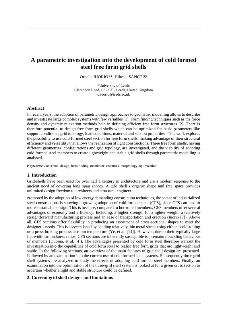
A parametric investigation into the development of cold formed steel free form grid shells
Ornella IUORIO a*, Hiltred SANCTISa
*University of Leeds Clarendon Road, LS2 9JT, Leeds, United Kingdom
Abstract In recent years, the adoption of parametric design approaches to geometric modelling allows to describe and investigate large complex systems with few variables [1]. Form finding techniques such as the force density and dynamic relaxation methods help in defining efficient free form structures [2]. There is therefore potential to design free form grid shells which can be optimized for basic parameters like support conditions, grid topology, load conditions, material and section properties. This work explores the possibility to use cold-formed steel section for free form shells, making advantage of their structural efficiency and versatility that allows the realization of light constructions. Three free form shells, having different geometries, configurations and grid topology, are investigated, and the viability of adopting cold formed steel members to create lightweight and stable grid shells through parametric modelling is analysed.
Keywords: Conceptual design, form finding, membrane structures, morphology, optimization.
1. Introduction Grid-shells have been used for over half a century in architecture and are a modern response to the ancient need of covering long span spaces. A grid shell’s organic shape and free space provides unlimited design freedom to architects and structural engineer.
Promoted by the adoption of low energy demanding construction techniques, the sector of industrialized steel constructions is showing a growing adoption of cold formed steel (CFS), since CFS can lead to more sustainable design. This is because, compared to hot-rolled members, CFS members offer several advantages of economy and efficiency. Including, a higher strength for a lighter weight, a relatively straightforward manufacturing process and an ease of transportation and erection (Iuorio [7]). Above all, CFS sections offer flexibility in producing an assortment of cross-sectional shapes to meet the designer’s needs. This is accomplished by bending relatively thin metal sheets using either a cold-rolling or a press-braking process at room temperature (Ye, et al. [14]). However, due to their typically large flat width-to-thickness ratios, CFS sections are inherently susceptible to premature buckling behaviour of members (Dubina, et al. [4]). The advantages presented by cold form steel therefore warrant the investigation into the capabilities of cold form steel to realise free form grids that are lightweight and stable. In the following sections, an overview of the main features of grid shell design are presented. Followed by an examination into the current use of cold formed steel systems. Subsequently three grid shell systems are analyzed to study the effects of adopting cold formed steel members. Finally, an examination into the optimisation of the three-grid shell system is looked at for a given cross section to ascertain whether a light and stable structure could be defined.
2. Current grid shell designs and limitations

2
Geometries and materials Most grid shells are based on some simple patterns (Figure 1): hexagonal, diamond, triangle or quadrangular. Triangle-based grid-shells have demonstrated to provide a good strength but quad-based structures have become popular in the last decade, because of their improved aesthetics and pleasant
mathematical properties. Conversely, there exist fewer studies on more general polygonal structures, Pietroni et al [11] researched into grid shell structures that were based on Voronoi tessellations with the aim of improving the strength of the grid-shell as well as its aesthetics. The resulting Voronoi mesh is made of cells with variable density, depending on the amount of stress and oriented along directions of maximum stress, see figure 1 e.
a b c d e
Figure 1: Mesh Geometry: a) Hexagonal, b) Diamond, c) Triangular, d) Quadrangular (Pourebrahimi, et al. [12]), e) Voronoi mesh (Pietroni, et al [11]).
While the mesh geometry of the grid shell is important, another factor to consider is the choice of material currently available. Figure 2 shows the mechanical strength of different construction materials with the circles highlighting the variation for each material. The most common material adopted for grid structures is timber, because it can bend elastically without breaking thanks to the low-density and high strain range. However, timber has low stress limits (Bouverel, et al. [3]). As the popularity of grid shells grew, steel replaced timber in glass grid shell structures with wide spans, taking advantage of the higher elastic modulus and strength compared to timber. Thus, today many free forms and irregular grid shells covered with glass panels are usually made of hot rolled steel. Fibre glass reinforced polymer is also becoming a popular material to realize free form shells as it has higher strength compared to timber and it is lighter than steel. However these polymers suffer from problems such as long term creep. (Pourebrahimi, et al. [12]).
Figure 2: Graph of elastic modulus against strength of materials, (Bouverel, et al. [3]).

3
Grid shell structures are uniquely well-suited to lightweight, large-span roofs, with many applications. This includes huge and open free standing structures, rapid erection of large temporary shelter and living space as disaster relief, and the formation of roofing over existing structure without the need for intermediate supports. There are several examples that exist around the world which are considered triumphs of efficient, aesthetic structural design and innovation, and are evidence to the engineering
and architectural value of grid shells. Some examples of grid shells are shown below for different materials highlighting the limitations in each of them.
Timber grid shell structure
The Weald and Downland Open Air Museum shown in figure 3a, brought innovation to timber grid shells due to the novel features of its double-layer timber grid shell roof. Apart from being the first such structure in Britain, it was the first built with ‘optimised’ green oak, the first designed in accordance with the new timber Eurocode and the first to use a new patented node joint system (Weald & Downland- Living museum [13]). However, the use of a double layer system due to timber’s low stress limits and the process of removing imperfections in timber members results in high material consumption.
Steel grid shell structure
The courtyard roof covering the Museum of Hamburg History shown in figure 3b, emerged as a response to an ambitious architectural program with strict structural requirements. With its exceptional lightness and transparency as well as features of structural design innovations, the structure has become well-known amongst both architects and structural engineers. But the structure suffered from stability problems requiring cross bracings and cable diagrams to mitigate the problem.
Glass fibre reinforced polymer(GFRP) structure
To demonstrate the feasibility of composite grid shells Bouverel et al [3] project involved building grid shells in GFRP. The first prototype was a purely experimental structure that was tested under several loading conditions to investigate the true behaviour of grid shell structures and then compare it with the numerical models. The behaviour of the prototype was very close to simulations performed with the numerical model. With the final grid shell built to house people at the Solidays festival, shown in figure 3c. However due to the nature of glass fibre reinforced polymer the stress was limited to avoid creep or fibre rupture.
a b c
Figure 3: a) Timber grid shell (Pourebrahimi, et al. [12]), b) Steel grid shell (Ermias, et al. [5]), c) GFRP grid shell (Bouverel, et al. [3]).
4
3. Design of cold formed steel grid shells From the previous examples, each of the grid shell structures using timber, steel and glass fibre reinforced polymer possessed some form of limitations. From high material consumption in construction to stability issues. These problems mean that a grid shell structure designed to embody
the principles of being lightweight, efficient and stable will fall short of their potential in these aspirations. So, cold formed steel could hold the possibility in resolving these issues.
Cold formed steel system
Cold-formed steel may have potential in designing grid shells. They are traditionally centered around their use as secondary load-bearing elements in buildings e.g. as roof purlins or stud walls. However, over the past decades there has been a widening in the range of applications for cold-formed steel beyond these traditional areas. Good example is the emergence of specialized and standardized cold-formed steel framing systems, which allow low- to mid-rise buildings to be constructed entirely out of cold-formed steel. As testified by the extensive work in research and application developed by the Author (Iuorio, et al [8]) and shown in figure 4 (Fiorino et al [6]).
Figure 4: Cold formed steel low rise building, (Fiorino, et al [6]).
Grid shell system
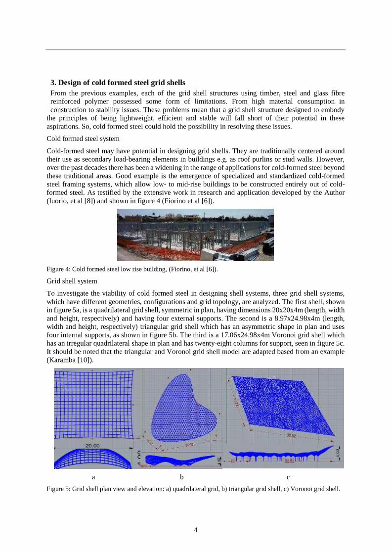
To investigate the viability of cold formed steel in designing shell systems, three grid shell systems, which have different geometries, configurations and grid topology, are analyzed. The first shell, shown in figure 5a, is a quadrilateral grid shell, symmetric in plan, having dimensions 20x20x4m (length, width and height, respectively) and having four external supports. The second is a 8.97x24.98x4m (length, width and height, respectively) triangular grid shell which has an asymmetric shape in plan and uses four internal supports, as shown in figure 5b. The third is a 17.06x24.98x4m Voronoi grid shell which has an irregular quadrilateral shape in plan and has twenty-eight columns for support, seen in figure 5c. It should be noted that the triangular and Voronoi grid shell model are adapted based from an example (Karamba [10]).
a b c
Figure 5: Grid shell plan view and elevation: a) quadrilateral grid, b) triangular grid shell, c) Voronoi grid shell.

5
3.1. Form finding, optimisation and structural analysis 3.1.1. Setup of model program
Figure 6 shows overall how the program is set up using Grasshopper a plugin for the software called Rhinoceros. First the surface mesh and the fixed and variable parameters are implemented. The data is
then assembled to be inputted into Karamba’s Large deformation analysis, which is a form finding program to create the grid shell structure (see figure 5a-c). A structural analysis of the model is implemented to evaluate the displacement, the weight and the strain energy, where this last is a measure of the stiffness. In terms of optimising the structure, the cross sections are improved using Karamba’s optimised cross section function. Next an automated optimisation is accomplished by using a Multi-Objective Genetic Algorithm (MOGA). A MOGA is, therefore created using the evolutionary solver program called Octopus. The member length, height of the structure and member size is inputted into octopus. In this case the data from the displacement, weight and strain energy function is then inputted into octopus and an iterative process occurs to meet the defined objectives. Finally, the data from the model analysis function is then inputted into the model view function to visually represent the data. The beam view function is used to show the structure of the model. The data is also represented via the utilisation function and highlights the individual failure of the elements if the value is greater than 1. The program also shows the nodal displacement of the beam and the beam forces.
Figure 6: Summary of the program setup.
3.1.2. Setup of experiment
The first part of the experiment is used to study the influence of the different parameters and their impact on the weight and stability of the grid shell systems. For each of the grid shell system, support condition, joint connection, load, material grade and grid topology are fixed parameters, as shown in table 1. Cross section properties, member length and structure height, are instead variable, as shown in table 2. The cross sections are: cold formed circular hollow section (CHSC), cold formed square hollow section (SHSC), and hot rolled square hollow section (SHSH). In the analysis, for each cross section, the member length changes, while the height of the structure is fixed. In the structural analysis, the loads

6
are applied per table 3 and, for each configuration, the weight of the structure, the displacements and the strain energy are evaluated. Then, the structural analysis is repeated, but this time for each of the cross section the member length is fixed and the height of the structure is changed.
Table 1: Fixed parameters Table 2: Variable parameters
Table 3: Structural loads
Loads Values
Cladding load 0.49 kN/m2
Imposed load 0.6 kN/m2
Wind load 0.7 kN/m2
The second part of the experiment looks at optimising each of the grid shell structure based on multiple objectives (see table 4) to find the optimum solutions. For this experiment, the fixed parameters and the structural loads are the same as previously presented in table 1 and table 3, respectively. The multi-objective optimisation procedure is undertaken by using octopus. The algorithm settings for octopus is summarized in table 6, and the program would complete four iterations. The program automatically alters the variable parameters synthetized in table 5 to simultaneously find the best solution for each iteration. In this second part of the experiment, the cross section is a circular hollow section (CHSC) but the member size will result from the optimization procedure. For each grid shell system, the weight, the displacements, and the strain energy are analyzed.
Table 4: Setting for Octopus algorithm. Table 5: Variable parameters
Variable parameters Value Cross section properties CHSC139.7x6.3
SHSC140x6.3 SHSH140x6.3
Member length The length, is set between 1 to 3 metres at 1 metre increments.
Structure height The height is set between 4 to 8 metres at 1 metre increments.
Fixed parameters Value Support conditions Pinned Joint connection Rigid Load Structure self-weight and
glazing (1.5 kN/݉ଶ ) Material Steel grade S355
Grid topology - Quadrilateral grid tiling - Triangular grid tiling - Voronoi tiling
Objectives Range
Displacement Minimum displacement to achieve stability.
Weight Minimum weight to achieve an economical design.
Strain energy Minimum strain energy (indicator of stiffness) to achieve stability.
Variable parameters Value
Cross sectional properties
CHSC, member size dependent on program
Member length The length, is set as between 1 to 3 metres at 1 metre increments.
Maximum height The height is set as between 4 to 8 metres at 1 metre increments.

7
Table 6 Algorithm setting for Octopus.
3.2 Discussion of experiment p1 Figure 6a shows that altering the member length of the structures (from 1 to 3 m) generally favored increasing the member length, which leaded to a reduction in the weight of the structure. However, at larger member lengths corresponded an increment in the strain energy and so a reduction in stiffness, with a consequent increment in the displacement of the structure. Whereas figure 6b shows that altering the height of the structure by increasing the height from 4 to 8 m caused a slight increment in the weight of the structure but a significant decrease in the strain energy. This lead to an increase in the stiffness of the structure and consequently a reduction in displacement.
In terms of sections, using cold formed steel circular hollow section (CHSC), allowed to obtained lower weight structure. On the other hand, square hollow section was the best in providing stability due to the low strain energy and therefore low displacement of the structure. While there was some difference between the hot rolled and cold formed square hollow section the results were not significant.
In general, the experiment highlighted that Karamba had some issue as there were some anomalies in the results when the complexity in regards to the shape of the structure increased, such as the triangular and voronoi models. For better analysis and validating the accuracy of Karamba another software would need to be used such as Autodesk robot which has proven to be reliable but is slow due to the poor integration with rhino and grasshopper.
As previously stated, the cold formed circular hollow section produces a lightweight structure. However, the results showed that the displacements and the strain energy were much higher than what would be expected for these structures and indicated that the structures were not stable. This is verified when checking the utilisation factors, which is a comparison of the applied stress against an individual member’s yield stress, whereby the value should be equal to or below one to avoid failure. However, some of the members had values much higher than one indicating, that the member failed. This is most likely due to the inadequate member sizing, then the influence of any of the variable parameters. Hence the inadequate member sizing was rectified with an optimisation procedure, which was implemented as part of the modelling in experiment 2.
3.3. Discussion of experiment 2 From the earlier discussion, it was mentioned that cold formed circular hollow section was good in terms of producing a low weight structure but had problems with stability. For this reason, a second experiment was set up, to optimize the structures in order to find stable configurations. Figure 7 and 8 show the final optimised version for each of the grid shells. Whereby, the axial stresses are represented as red for compressive stress and blue for tensile stress. For the quadrilateral grid shell a pattern emerged where there was a reduction in the weight of the structure as the member size decreased while the height of the structure increased to amplify the stiffness.
Name Values Elitism 0.5 Elitism gives the percentage of new solutions that are
formed out of the elite instead of the entire pool of solutions.
Mutation Probability 0.1 Probability of each parameter/ gene to become mutated Mutation Rate 0.5 Controls the changes in the parameters’ values, a high rate
means big changes, however this is kept low Crossover Rate 0.5 Probability of two subsequently generated solutions to
exchange parameter values. Population Size 50 Number of solutions per generation Max. Generations 4 Octopus will stop after this number of generations to reduce
the memory footprint for long searches

8
a)
b)
Figure 6: a) altering member length and b) altering the structure height
However, there was an increment in the displacements but this was much lower compared to the results in the first experiment. Another pattern was that both the quadrilateral and voronoi model opted for smaller member lengths thereby increasing the number of members and reducing the size of the grid cell, most likely to increase the stiffness of the structure. This correlates with the results found in experiment one in regards to the relationship between the member length and the height of the structure to the displacement. While optimising the triangular model to reduce the weight of the structure two member sizes were chosen. One was for the boundary members where there was high stress and so bigger member sizes were required and the other was for the internal members. The optimisation of the triangular model opted for increasing the member lengths thereby reducing the number of members and increasing the size of the grid cell. This was most likely an attempt to reduce the weight of the structure to compensate for the big member sizes that were used compared to the other models. This links with the results found in experiment one, in regards to the relationship between the member length and the weight of the structure. The final optimised version were structures (table 7) that had lower weight compared to the previous iterations, better stiffness and minor displacement. Achieving in producing

9
structures that are lightweight and stable using cold formed steel. When comparing the models, depending on the initial parameters, results could be found faster if they were closer to the final solution such as the voronoi structure. As the complexity of the structure increases from the quadrilateral to triangular and then the voronoi model, the longer it took to find new solutions for each iteration. This agrees with Jiang’s [9] research as he found that the method does converge very fast to an optimum
solution, if the problem is described appropriately and the GAs settings are intelligently tuned. These iterations would ideally stop when there were no significant changes in the solution or if the new solutions were the same as the previous solution. This experiment highlights that the current optimisation tool had difficulties with optimising complex models such as the triangular grid shell as further iteration would be needed to reach the optimum solution but this would be a time-consuming process.
Figure 7: 3D view of the optimised quadrilateral and triangular model’s axial stress.
Figure 8: 3D view of the optimised voronoi model’s axial stress.
Table 7. Optimized shells: final defined parameters
Quadrilateral shell Triangular shell Voronoi shell
Number of iterations 4 4 3
Final height (m) 8 7 8
Cross section CHSC 168.3x12.5 Boundary members: CHSC 355x16.0
Internal members: CHSC 273x16.0
CHSC 114.3x6.0
Member length (m) 1 3 1
Maximum Displacement (m) 0.0782 0.0426 0.0142
Weight (kN) 576 1142 610
Strain Energy (kNm) 64.005 165.169 14.178
4. Conclusion, remarks and recommendations The first experiment has given some insight into how a cold form steel performs under different types of grid shell structures. The experiment shows that for a fixed member size, the increase in member length and decrease in height produces the best solution in terms of achieving minimum weight. While

10
increasing, the height increases the stiffness of the structure. It was found for cold formed steel using circular hollow section performed better at producing a lightweight structure. Whereas the cold formed square hollow section was better in achieving minimum displacement and strain energy. The second experiment highlighted the limitations in the automated process of optimising a structure as the complexity of the structure increases.
There are several improvements and further work which could be carried out in future investigations. There is further scope to look at using several different members size, to analyse how the increase in member length and height impacts the structure in terms of achieving minimum weight, displacement and stiffness. Future research could examine how timber and glass fibre reinforced polymer effect grid shell structures compared to cold formed steel in producing a lightweight structure. Additional analysis could look at different cross sections rather than just circular hollow sections or square hollow sections to make full use of cold formed steel. More research could look at the effects of different types of connections and investigate how it effects the stability of the structure.
References [1] Adriaenssens S., Bletzinger K., Block P., Ramm E., Veenendaal D., Williams C., 2014. Shell
structures for architecture: Form Finding and Optimization. Oxon: Routledge
[2] Burlow, P., Falk, A. & Turrin, M., 2009. Optimization of structural form using a genetic algorithm to search associative parametric geometry, Proceeding ICSA10.
[3] Bouverel O., Caron J.F., Tayeb F., Du Peloux L., 2012. Gridshells in composite materials: Construction of a 300 m2 forum for the solidays festival in paris. Structural Engineering international. DOI: 10.2749/101686612X13363869853572
[4] Dubina D., Ungureanu V., Landolfo R., 2012. Design of cold-formed steel structures. Eurocode 3: design of steel structures Part 1-3: design of cold-formed steel structures. ECCS Design Manuals.
[5] Ermias, Y., Shabtai, B. & Szerzo, P., 2013. The courtyard roof of the museum of Hamburg history. [Online] Available at: http://shells.princeton.edu/Ham.html [Accessed 10 February 2017].
[6] Fiorino L; Iuorio O; Landolfo R (2014) Designing CFS structures: The new school bfs in naples. Thin-Walled Structures, 78 , pp. 37-47.
[7] Iuorio O. 2007. Cold-formed steel housing. Pollack Periodica, 2 (3), pp. 97-108. [8] Iuorio O., Fiorino L., Landolfo R., 2014. Testing CFS structures: The new school BFS in
Naples. Thin-Walled Structures, 84 , pp. 275-288. [9] Jiang, Y., 2015. Free form finding of grid shell structures, Illinois: University of Illinois. [10] Karamba3d, 2016. Large Deformation of Voronoi Gridshell. [Online] Available at:
http://www.karamba3d.com/examples/hard/bubble-form-finding-a-voronoi-gridshell/ [Accessed 23 January 2017].
[11] Pietroni, N., Tonelli D., Puppo E., Froli M., Scopigno R., Paolo Cignoni1 2015. Voronoi Grid-Shell Structures. [Online] Available at: https://arxiv.org/pdf/1408.6591.pdf.
[12] Pourebrahimi, M., Hasan, M. & Reza, M., 2015. Gridshells, Downland Gridshells: A Creative Mechanism in Setting. Bulletin of Environment, Pharmacology and Life Sciences, 4(1), pp. 20-27.
[13] Weald & Downland- Living museum, 2014. Downland gridshell- Project history and design brief. [Online] Available at: http://www.wealddown.co.uk/explore/buildings/further-reading/downland-gridshell-project-history-design-brief/ [Accessed 24 January 2017].
[14] Ye, J., Hajirasouliha, I., Becque, J. & Pilakoutas, K., 2015. Development of more efficient cold-formed steel channel sections in bending. Thin Waleed Structures. Elesevier, Issue 101, pp. 1-13.