A NOVEL DUAL-POINT CLAMPER FOR LOW-RIGIDITY PLATE MILLING WITH DEFORMATION COMPENSATION
11
IJRET: International Journal of Research in Engineering and Technology eISSN: 2319-1163 | pISSN: 2321-7308 __________________________________________________________________________________________ Volume: 02 Issue: 12 | Dec-2013, Available @ http://www.ijret.org 182 A NOVEL DUAL-POINT CLAMPER FOR LOW-RIGIDITY PLATE MILLING WITH DEFORMATION COMPENSATION ZhaoliangJiang 1 , WeixianShao 2 , WeiYi 3 2, 3 School of Mechanical Engineering, Shandong University, Ji’nan, P.R.China, 250061 1 Key Laboratory of High-efficiency and Clean Mechanical Manufacture at Shandong University, Ministry of Education, Ji’nan, P.R.China, 250061 Abstract The surface profile accuracy plays a significant role in achieving the overall product’s functional performance, which is seriously impacted by the cutting forces, clamping forces, and residual stresses. Conventionally, many researches about deformation compensation focus on cutting forces and fixture layout and do not consider clamping forces. Actually, clamping forces, which would dynamically change along with the movements of cutting tools, are essential in precision machining process. In this paper, a novel dual-point clamper method with adaptive deformation compensation is proposed to improve the workpieces milling precision. Based on the Generalized Principle of Superposition Method, a mathematical model considering the deflection from both cutting forces and clamping forces has been estimated and compared with the traditional clamping scheme. Both 3D finite element model (FEM) based simulation experiments and experimental case studies are carried out, and their results show good agreement with each other. The deflection computation and prediction from numerical studies indicates the efficiency and correctness of the proposed approach. Keywords: Compensation; Deformation; Fixture; Milling -----------------------------------------------------------------------***---------------------------------------------------------------------- 1. INTRODUCTION End milling is one of the most widely used machining methods for material removing. Precision machining is the crucial part of modern manufacturing. For easy bending or distorting workpieces, it is still challenge to achieve precision machining because the undercutting or over-cutting from cutting forces and clamping forces during milling will lead to workpieces deformation. It is really difficult to guarantee the dimensional and geometric accuracy of the workpieces under this situation. Therefore, many researchers have made a lot of efforts in this field. Kris M.Y. Law (2003) presented a process design methodology and a tool deflection error compensation program algorithm to achieve a significant reduction in the tool deflection errors in end milling of pockets. U. Heisel (2011) presented a model-based error compensation method for thin-walled, cylindrical parts in turning in order to quantify and minimize the clamping-induced deformations. Ratchev(2003,2004,2005) established a flexible force model for low-rigidity or thin-walled parts. This deformation prediction model was based on the integration of an extended perfect plastic layer model and a finite element model. They further studied the compensation strategy which was based on optimizing the tool path and taking into account the predicted milling error. Kim (2003) analyzed the 3-dimensional form errors of a ball-end milled surface due to the elastic compliance, and modeled the cutter as a cantilever beam consisting of the shank and the flute. Liu (2002) presented a dynamic cutting force model for peripheral milling, which included the size effect of under-formed chip thickness, the influence of the effective rake angle and the chip flow angle. Their simulation results indicated that the cutting force distribution in the cut-in process had a significant influence on the dimensional accuracy of the finished parts. Zheng(2001) established a mechanical and technological model involving the real process constraints(such as locating and supporting) and loads(cutting, clamping and supporting forces) to reduce workpiece deformation during machining. Kang(2007) presented a method to estimate the actual cutting depth of flexible cutting systems based on the cutting force signal. Wang (2006) analyzed the cutting force and the predication of residual stresses redistribution. Shimana(2012) established a method for real-time compensation of machining errors caused by deflection of the end mill. De´pince´ (2006) presented an integrated methodology that could predict the deformation and compensate the deformation to meet the part-tolerance requirements. Chen (2009) established a dynamical model to predict the deformation of a thin-walled multilayer part machining and proposed an approach to compensate the machining error at each layer. Wan(2006, 2008) investigated the surface dimensional error control for peripheral milling of thin-walled workpieces. Optimal selection and optimization method had been proposed to select the feed per tooth and depth of cutting simultaneously aiming at high productivity machining without sacrificing machining precision. Jiang (2010) presented a novel zonal compensation method to
-
Upload
independent -
Category
Documents
-
view
2 -
download
0
Transcript of A NOVEL DUAL-POINT CLAMPER FOR LOW-RIGIDITY PLATE MILLING WITH DEFORMATION COMPENSATION
IJRET: International Journal of Research in Engineering and Technology eISSN: 2319-1163 | pISSN: 2321-7308
__________________________________________________________________________________________
Volume: 02 Issue: 12 | Dec-2013, Available @ http://www.ijret.org 182
A NOVEL DUAL-POINT CLAMPER FOR LOW-RIGIDITY PLATE
MILLING WITH DEFORMATION COMPENSATION
ZhaoliangJiang1, WeixianShao2, WeiYi3
2, 3School of Mechanical Engineering, Shandong University, Ji’nan, P.R.China, 250061 1Key Laboratory of High-efficiency and Clean Mechanical Manufacture at Shandong University, Ministry of Education,
Ji’nan, P.R.China, 250061
Abstract The surface profile accuracy plays a significant role in achieving the overall product’s functional performance, which is seriously impacted by the cutting forces, clamping forces, and residual stresses. Conventionally, many researches about deformation compensation focus on cutting forces and fixture layout and do not consider clamping forces. Actually, clamping forces, which would dynamically change along with the movements of cutting tools, are essential in precision machining process. In this paper, a novel dual-point clamper method with adaptive deformation compensation is proposed to improve the workpieces milling precision. Based on the Generalized Principle of Superposition Method, a mathematical model considering the deflection from both cutting forces and clamping forces has been estimated and compared with the traditional clamping scheme. Both 3D finite element model (FEM) based simulation experiments and experimental case studies are carried out, and their results show good agreement with each other. The deflection computation and prediction from numerical studies indicates the efficiency and correctness of the proposed approach. Keywords: Compensation; Deformation; Fixture; Milling
-----------------------------------------------------------------------***---------------------------- ------------------------------------------
1. INTRODUCTION
End milling is one of the most widely used machining methods for material removing. Precision machining is the crucial part of modern manufacturing. For easy bending or distorting workpieces, it is still challenge to achieve precision machining because the undercutting or over-cutting from cutting forces and clamping forces during milling will lead to workpieces deformation. It is really difficult to guarantee the dimensional and geometric accuracy of the workpieces under this situation. Therefore, many researchers have made a lot of efforts in this field. Kris M.Y. Law (2003) presented a process design methodology and a tool deflection error compensation program algorithm to achieve a significant reduction in the tool deflection errors in end milling of pockets. U. Heisel (2011) presented a model-based error compensation method for thin-walled, cylindrical parts in turning in order to quantify and minimize the clamping-induced deformations. Ratchev(2003,2004,2005) established a flexible force model for low-rigidity or thin-walled parts. This deformation prediction model was based on the integration of an extended perfect plastic layer model and a finite element model. They further studied the compensation strategy which was based on optimizing the tool path and taking into account the predicted milling error. Kim (2003) analyzed the 3-dimensional form errors of a ball-end milled surface due to the elastic compliance, and modeled the cutter as a cantilever beam
consisting of the shank and the flute. Liu (2002) presented a dynamic cutting force model for peripheral milling, which included the size effect of under-formed chip thickness, the influence of the effective rake angle and the chip flow angle. Their simulation results indicated that the cutting force distribution in the cut-in process had a significant influence on the dimensional accuracy of the finished parts. Zheng(2001) established a mechanical and technological model involving the real process constraints(such as locating and supporting) and loads(cutting, clamping and supporting forces) to reduce workpiece deformation during machining. Kang(2007) presented a method to estimate the actual cutting depth of flexible cutting systems based on the cutting force signal. Wang (2006) analyzed the cutting force and the predication of residual stresses redistribution. Shimana(2012) established a method for real-time compensation of machining errors caused by deflection of the end mill. De´pince´ (2006) presented an integrated methodology that could predict the deformation and compensate the deformation to meet the part-tolerance requirements. Chen (2009) established a dynamical model to predict the deformation of a thin-walled multilayer part machining and proposed an approach to compensate the machining error at each layer. Wan(2006, 2008) investigated the surface dimensional error control for peripheral milling of thin-walled workpieces. Optimal selection and optimization method had been proposed to select the feed per tooth and depth of cutting simultaneously aiming at high productivity machining without sacrificing machining precision. Jiang (2010) presented a novel zonal compensation method to
IJRET: International Journal of Research in Engineering and Technology eISSN: 2319-1163 | pISSN: 2321-7308
__________________________________________________________________________________________
Volume: 02 Issue: 12 | Dec-2013, Available @ http://www.ijret.org 183
compensate the workpieces elastic deformation through fixture layout optimization based on High Definition Metrology (HDM). In summary, although remarkable process in compensating the deformation and minimizing the surface dimensional errors has been made, research on deformation compensation focuses solely on cutting forces and fixture layout. However, clamping forces, which will change along with the cutting tool movement, shouldn’t be ignored in practice. Traditional clamp with single clamping point only has one clamping force application point, which is not suitable for dynamic adjustment for the deflection compensation. In this paper, a novel dual-point clamper method with deformation compensation is proposed and development. The two points share the clamping forces and their values will change respectively along with the cutting tool movement to resist the workpieces deflection. The rest of this paper is organized as follows. Section 2 describes the deflection of end milling constrained by traditional clamp. Section 3 presents the deflection of end milling constrained by our novel dual-point clamp. Section 4 gives a simulation study of the proposed method. Section 5 gives a case study of the proposed method. The conclusions and future work of this research are summarized in section 6.
2. PART MILLING DEFLECTION
CONSTRAINED BY TRADITIONAL CLAMP
Four supports and four clamping points fixture layout is traditionally utilized for milling rectangle workpieces, where the supports and the clamping points are vertical alignment respectively (see Fig. 1(a)). Milling behavior of the workpiece continuously changes along with the cutting tool moving from one side to the other. When the cutting tool moves to point N, cutting force F coupled with clamping forces FA and FB will bend the workpiece (see Fig. 1 (b)). Since clamping forces FA and FB have little effect on the workpiece deflection, the deflection at point N (shown in Fig. 1 (c)) is expressed as,
1Nω =2
1
( )=
3
Fd d s
EIω +
(1) Where, ω�� denotes the workpiece deflection at point N when cutting tool cuts at this point, F is the cutting force, s is the distance between the two supports, d refers to the distance from the cutting tool to the support P, E is the Modulus of elasticity, I is the moment of inertia section against the neutral axis. Direction of cutting force F is upside when spiral mill is adopted. Here, we utilize letter N refer to the cutting tool location where scope within the right side of support P.
Fig.1. Deflection of end milling constrained by traditional clamp when cutting tool locates at point N
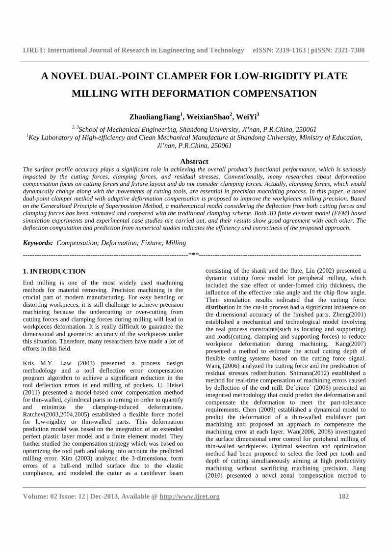
Similarly, when cutting tool moves to point R located between the two supports as shown in Fig. 2 (a)), the workpiece deflection at point R caused by the cutting force F shown in Fig. 2(b) is expressed as,
2 2 2
1 2
( )[ ( ) ]
6R
Fd s d s s d d
EIsω ω − − − −= =
(2)
Where, ω�� denotes the workpiece deflection at point R when cutting tool cuts at this point. The actual cutting depth is bigger than the theoretical value under the impact of the workpieces deflection, which we called it over-cutting. The bigger the deflection is, the serious the over-cutting happens, which will lead to the workpieces deformation.
IJRET: International Journal of Research in Engineering and Technology eISSN: 2319-1163 | pISSN: 2321-7308
__________________________________________________________________________________________
Volume: 02 Issue: 12 | Dec-2013, Available @ http://www.ijret.org 184
FBFFA
RE P
(a) The abbreviated drawing of the workpieces (b) Deflection of the workpieces
Fig 2 Deflection of end milling constrained by traditional clamp when the cutting tool locates at point R
3. DEFLECTION OF END MILLING
CONSTRAINED BY DUAL-POINT CLAMP
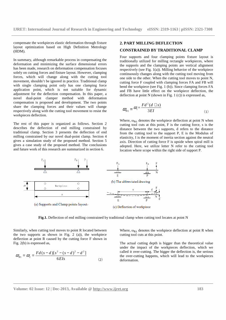
Cutting forces will cause low stiffness workpieces bending during material removing. The main task of clamping force is to fix the workpieces at right position in traditional fixture layout. Considering the fact that traditional clamper only has one clamping force action point, reasonable optimization of it will be helpful to compensate the machining deformation of
the workpieces. Therefore, we extend the traditional clamp with single clamping point to a novel one with two clamping points as shown in Fig.3, which is called dual-point clamp. The two clamping points located at each side of the support cooperatively share the clamping force. Because the workpieces will be bended by cutting forces during milling, acting force at each point of the dual-point clamp will adaptively adjust dynamically to resist the workpiece deflection change when cutting tool moves.
Clamp points
(a) Dual-point clamp (b) 3D sketch of the dual-point clamp work status
Workpiece
Clamp Clamp
SupportSupport
A B C D
(c) 2D sketch of the dual-point clamp work status
Fig 3 Novel clamp with dual clamping points
Compared with the traditional clamping method, the clamping force at point C will increase and the clamping force at point D will decrease to resist the deflection of the workpieces when cutting tool moves to point N as shown in Fig. 4 (a). The workpieces deflection at point N impacted by FC can be represented as
1
( )( )
6C
C
F a s a s b d
EIsω − +=
(3) Where, a is the distance from cutting tool to support P. Similarly, the workpieces deflection at point N impacted by FD can be represented as,
IJRET: International Journal of Research in Engineering and Technology eISSN: 2319-1163 | pISSN: 2321-7308
__________________________________________________________________________________________
Volume: 02 Issue: 12 | Dec-2013, Available @ http://www.ijret.org 185
2
1
(3 )
3 6D D
D
F asd F a d a
EI EIω −= − −
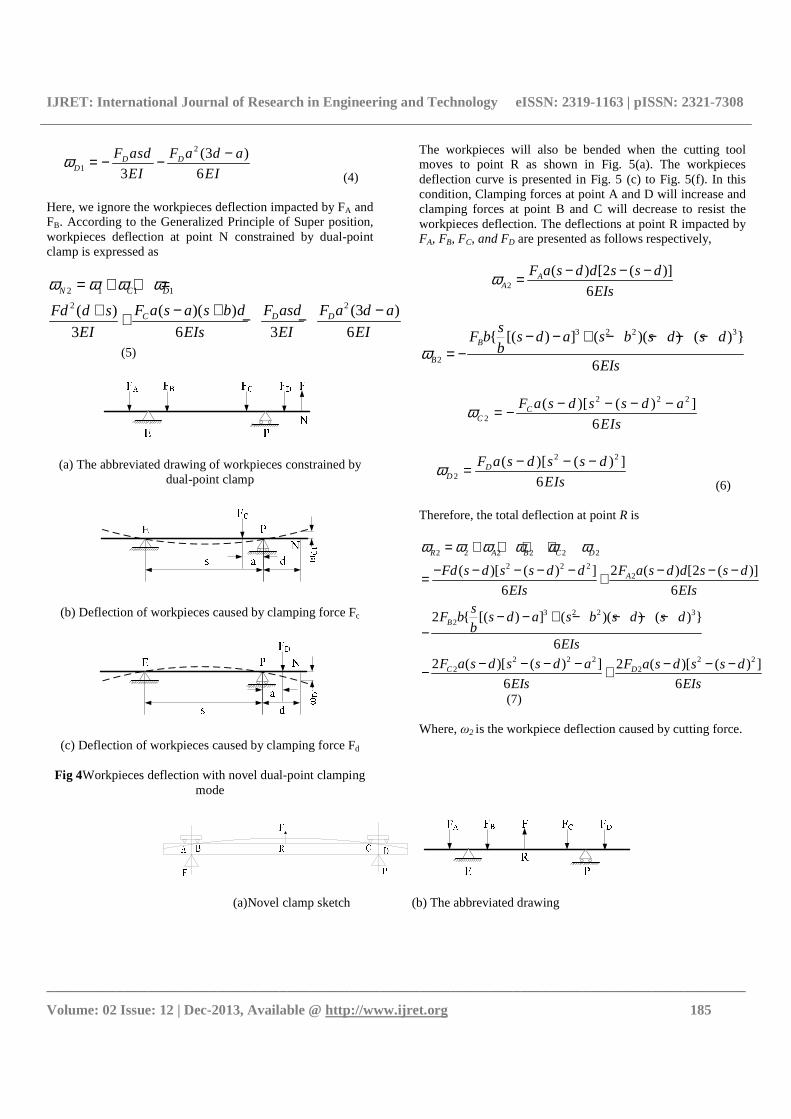
(4)
Here, we ignore the workpieces deflection impacted by FA and FB. According to the Generalized Principle of Super position, workpieces deflection at point N constrained by dual-point clamp is expressed as
2 1 1 1
22 ( )( ) (3 )( )
3 6 3 6
N C D
C D DF a s a s b d F asd F a d aFd d s
EI EIs EI EI
ω ω ω ω= + + =
− + −+ + − −
(5)
(a) The abbreviated drawing of workpieces constrained by dual-point clamp
(b) Deflection of workpieces caused by clamping force Fc
(c) Deflection of workpieces caused by clamping force Fd
Fig 4Workpieces deflection with novel dual-point clamping mode
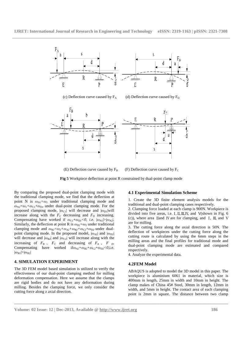
The workpieces will also be bended when the cutting tool moves to point R as shown in Fig. 5(a). The workpieces deflection curve is presented in Fig. 5 (c) to Fig. 5(f). In this condition, Clamping forces at point A and D will increase and clamping forces at point B and C will decrease to resist the workpieces deflection. The deflections at point R impacted by FA, FB, FC, and FD are presented as follows respectively,
2
( ) [2 ( )]
6A
A
F a s d d s s d
EIsω − − −=
3 2 2 3
2
{ [( ) ] ( )( ) ( ) }
6
B
B
sF b s d a s b s d s d
bEIs
ω− − + − − − −
= −
2 2 2
2
( )[ ( ) ]
6C
C
F a s d s s d a
EIsω − − − −= −
2 2
2
( )[ ( ) ]
6D
D
F a s d s s d
EIsω − − −=
(6) Therefore, the total deflection at point R is
2 2 2 2 2 2
2 2 22
3 2 2 32
2 2 2 2 22 2
2 ( ) [2 ( )]( )[ ( ) ]
6 6
2 { [( ) ] ( )( ) ( ) }
6
2 ( )[ ( ) ] 2 ( )[ ( ) ]
6 6
R A B C D
A
B
C D
F a s d d s s dFd s d s s d d
EIs EIss
F b s d a s b s d s db
EIs
F a s d s s d a F a s d s s d
EIs EIs
ω ω ω ω ω ω= + + + +
− − −− − − − −= +
− − + − − − −−
− − − − − − −− +
(7)
Where, ω2 is the workpiece deflection caused by cutting force.
(a)Novel clamp sketch (b) The abbreviated drawing
IJRET: International Journal of Research in Engineering and Technology eISSN: 2319-1163 | pISSN: 2321-7308
__________________________________________________________________________________________
Volume: 02 Issue: 12 | Dec-2013, Available @ http://www.ijret.org 186
(c) Deflection curve caused by FA (d) Deflection curve caused by FD
(E) Deflection curve caused by FB (F) Deflection curve caused by FC
Fig 5 Workpiece deflection at point R constrained by dual-point clamp mode
By comparing the proposed dual-point clamping mode with the traditional clamping mode, we find that the deflection at point N is ωN1=ω1 under traditional clamping mode and ωN2=ω1+ωC1+ωD1 under dual-point clamping mode. For the proposed clamping mode, |ωC1| will decrease and |ωD1|will increase along with the FC decreasing and FD increasing. Compensating have worked if ωC1+ωD1<0, i.e. |ωN1|>|ωN2|. Similarly, the deflection at point R is ωR1=ω2 under traditional clamping mode and ωR2=ω2+ωA2+ωB2+ωC2+ωD2 under dual-point clamping mode. In the proposed model, |ωA2| and |ωD2| will decrease and |ωB2| and |ωC2| will increase along with the increasing of FB 、 FC and decreasing of FA 、 F D. Compensating have worked ifωA2+ωB2+ωC2+ωD2<0,i.e. |ωR1|>|ωR2| 4. SIMULATION EXPERIMENT
The 3D FEM model based simulation is utilized to verify the effectiveness of our dual-point clamping method for milling deformation compensation. Here we assume that the clamps are rigid bodies and do not have any deformation during milling. Besides the clamping force, we only consider the cutting force along z axial direction.
4.1 Experimental Simulation Scheme
1. Create the 3D finite element analysis models for the traditional and dual-point clamping cases respectively. 2. Clamping force loaded at each clamp is 900N. Workpiece is divided into five areas, i.e.Ⅰ,Ⅱ,Ⅲ,Ⅳ, and Ⅴ(shown in Fig. 6 (c)), where area Ⅱand Ⅳ are for clamping, and Ⅰ, Ⅲ, and Ⅴ are for milling. 3. The cutting force along the axial direction is 50N. The deflection of workpieces under the cutting force along the cutting route is calculated by using the 6mm steps in the milling areas and the final profiles for traditional mode and dual-point clamping mode are estimated and compared respectively. 4. Analyze the experimental data. 4.2FEM Model
ABAQUS is adopted to model the 3D model in this paper. The workpiece is aluminium 6061 in material, which size is 400mm in length, 25mm in width and 10mm in height. The clamp makes of China 45# Steel, 30mm in length, 12mm in width, and 5mm in height. The contact area of each clamping point is 2mm in square. The distance between two clamp
IJRET: International Journal of Research in Engineering and Technology eISSN: 2319-1163 | pISSN: 2321-7308
__________________________________________________________________________________________
Volume: 02 Issue: 12 | Dec-2013, Available @ http://www.ijret.org 187
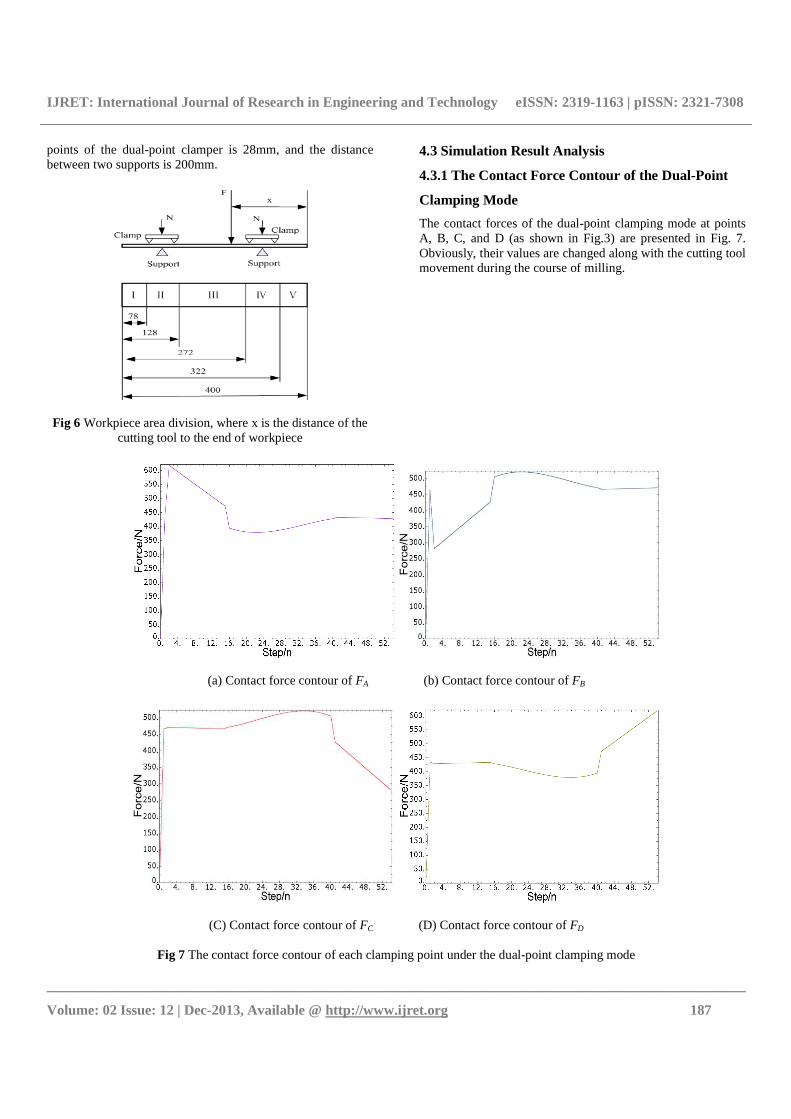
points of the dual-point clamper is 28mm, and the distance between two supports is 200mm.
Fig 6 Workpiece area division, where x is the distance of the
cutting tool to the end of workpiece
4.3 Simulation Result Analysis
4.3.1 The Contact Force Contour of the Dual-Point
Clamping Mode
The contact forces of the dual-point clamping mode at points A, B, C, and D (as shown in Fig.3) are presented in Fig. 7. Obviously, their values are changed along with the cutting tool movement during the course of milling.
(a) Contact force contour of FA (b) Contact force contour of FB
(C) Contact force contour of FC (D) Contact force contour of FD
Fig 7 The contact force contour of each clamping point under the dual-point clamping mode
IJRET: International Journal of Research in Engineering and Technology eISSN: 2319-1163 | pISSN: 2321-7308
__________________________________________________________________________________________
Volume: 02 Issue: 12 | Dec-2013, Available @ http://www.ijret.org 188
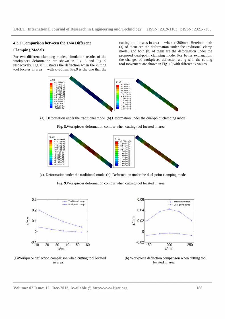
4.3.2 Comparison between the Two Different
Clamping Models
For two different clamping modes, simulation results of the workpieces deformation are shown in Fig. 8 and Fig. 9 respectively. Fig. 8 illustrates the deflection when the cutting tool locates in area � with x=36mm. Fig.9 is the one that the
cutting tool locates in area � when x=200mm. Hereinto, both (a) of them are the deformation under the traditional clamp mode,, and both (b) of them are the deformation under the proposed dual-point clamping mode. For better explanation, the changes of workpieces deflection along with the cutting tool movement are shown in Fig. 10 with different x values.
(a). Deformation under the traditional mode (b).Deformation under the dual-point clamping mode
Fig. 8.Workpieces deformation contour when cutting tool located in area �
(a). Deformation under the traditional mode (b). Deformation under the dual-point clamping mode
Fig. 9.Workpieces deformation contour when cutting tool located in area �
Traditional clamp
Dual-point clamp
(a)Workpiece deflection comparison when cutting tool located
in area �
Traditional clamp
Dual-point clamp
(b) Workpiece deflection comparison when cutting tool located in area �
IJRET: International Journal of Research in Engineering and Technology eISSN: 2319-1163 | pISSN: 2321-7308
__________________________________________________________________________________________
Volume: 02 Issue: 12 | Dec-2013, Available @ http://www.ijret.org 189
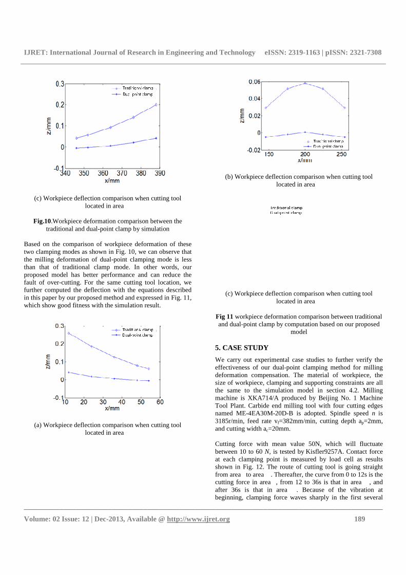
(c) Workpiece deflection comparison when cutting tool located in area �
Fig.10.Workpiece deformation comparison between the
traditional and dual-point clamp by simulation Based on the comparison of workpiece deformation of these two clamping modes as shown in Fig. 10, we can observe that the milling deformation of dual-point clamping mode is less than that of traditional clamp mode. In other words, our proposed model has better performance and can reduce the fault of over-cutting. For the same cutting tool location, we further computed the deflection with the equations described in this paper by our proposed method and expressed in Fig. 11, which show good fitness with the simulation result.
(a) Workpiece deflection comparison when cutting tool located in area �
(b) Workpiece deflection comparison when cutting tool located in area �
(c) Workpiece deflection comparison when cutting tool located in area �
Fig 11 workpiece deformation comparison between traditional and dual-point clamp by computation based on our proposed
model 5. CASE STUDY
We carry out experimental case studies to further verify the effectiveness of our dual-point clamping method for milling deformation compensation. The material of workpiece, the size of workpiece, clamping and supporting constraints are all the same to the simulation model in section 4.2. Milling machine is XKA714/A produced by Beijing No. 1 Machine Tool Plant. Carbide end milling tool with four cutting edges named ME-4EA30M-20D-B is adopted. Spindle speed n is 3185r/min, feed rate vf=382mm/min, cutting depth ap=2mm, and cutting width ac=20mm. Cutting force with mean value 50N, which will fluctuate between 10 to 60 N, is tested by Kisfler9257A. Contact force at each clamping point is measured by load cell as results shown in Fig. 12. The route of cutting tool is going straight from area�to area �. Thereafter, the curve from 0 to 12s is the cutting force in area�, from 12 to 36s is that in area �, and after 36s is that in area �. Because of the vibration at beginning, clamping force waves sharply in the first several
IJRET: International Journal of Research in Engineering and Technology eISSN: 2319-1163 | pISSN: 2321-7308
__________________________________________________________________________________________
Volume: 02 Issue: 12 | Dec-2013, Available @ http://www.ijret.org 190
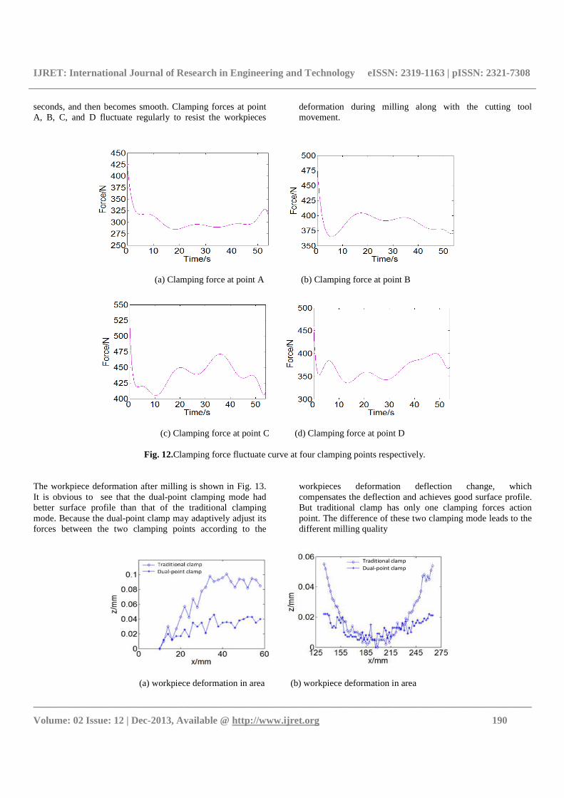
seconds, and then becomes smooth. Clamping forces at point A, B, C, and D fluctuate regularly to resist the workpieces
deformation during milling along with the cutting tool movement.
(a) Clamping force at point A (b) Clamping force at point B
(c) Clamping force at point C (d) Clamping force at point D
Fig. 12.Clamping force fluctuate curve at four clamping points respectively.
The workpiece deformation after milling is shown in Fig. 13. It is obvious to see that the dual-point clamping mode had better surface profile than that of the traditional clamping mode. Because the dual-point clamp may adaptively adjust its forces between the two clamping points according to the
workpieces deformation deflection change, which compensates the deflection and achieves good surface profile. But traditional clamp has only one clamping forces action point. The difference of these two clamping mode leads to the different milling quality
Traditional clamp
Dual-point clamp
(a) workpiece deformation in area � (b) workpiece deformation in area �
IJRET: International Journal of Research in Engineering and Technology eISSN: 2319-1163 | pISSN: 2321-7308
__________________________________________________________________________________________
Volume: 02 Issue: 12 | Dec-2013, Available @ http://www.ijret.org 191
Traditional clamp
Dual-point clamp
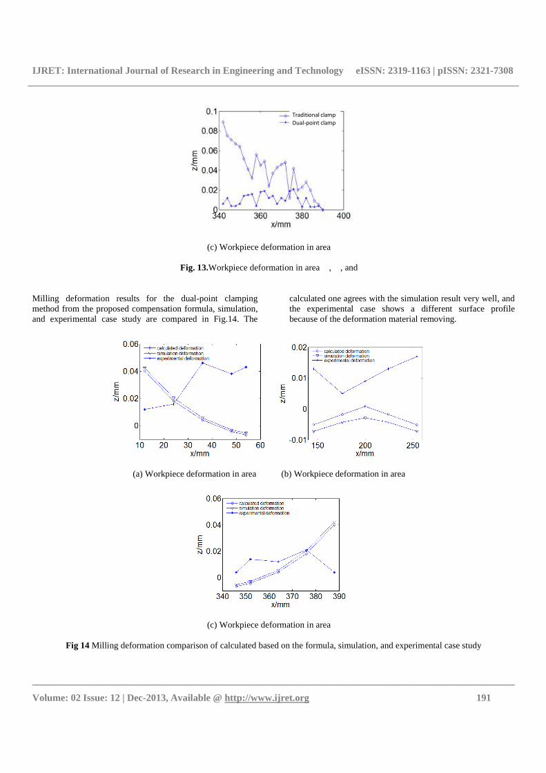
(c) Workpiece deformation in area �
Fig. 13.Workpiece deformation in area �, �, and �
Milling deformation results for the dual-point clamping method from the proposed compensation formula, simulation, and experimental case study are compared in Fig.14. The
calculated one agrees with the simulation result very well, and the experimental case shows a different surface profile because of the deformation material removing.
(a) Workpiece deformation in area � (b) Workpiece deformation in area �
(c) Workpiece deformation in area �
Fig 14 Milling deformation comparison of calculated based on the formula, simulation, and experimental case study
IJRET: International Journal of Research in Engineering and Technology eISSN: 2319-1163 | pISSN: 2321-7308
__________________________________________________________________________________________
Volume: 02 Issue: 12 | Dec-2013, Available @ http://www.ijret.org 192
CONCLUSIONS AND FUTURE WORK
Based on our proposed novel dual-point clamp method, a new approach for milling deformation compensation is proposed in this paper. The approach utilizes the dynamic clamping force to resist workpiece deformation during milling. It extends the clamp from single clamping point to multiple points. Both simulation and experimental case studies are used to illustrate the effectiveness of the proposed method. The results demonstrate that this new proposed approach is feasible and effective for compensating the workpiece deformation during milling. The future work of this research is to expand this new proposed to analyze different materials. It is also interesting to extend this method for milling deformation compensation considering clamping force, 3D cutting force and heat transfer together. ACKNOWLEDGEMENTS
The authors acknowledge support by the National Natural Science Foundation of China under Grant Number 51175304, and the Scientific Research Foundation for the Returned Overseas Chinese Scholars, State Education Ministry. Thanks for all the former research contributed to this paper. REFERENCES
[1] Chen Weifang, Xue Jianbin, et al. 2009, Deformation prediction and error compensation in multilayer milling processes for thin-walled parts. International Journal of Machine Tools & Manufacture 49: 859–864
[2] Jiang ZhaoLiang, Liu Yumei and Shan Yunxiao. 2010, Zonal Compensation for Work-piece Elastic Deformation through Fixture Layout Optimization. Applied Mechanics and Materials 26-28:854-857
[3] Kang Yonggang, Wang Zhongqi, Wu Jianjun, et al. 2007, Fast prediction of static form errors in peripheral milling ofthin-walled workpieces using real cutting depth. Journal of Northwestern Polytechnical University 25(2):251-256
[4] Kenji Shimana, Eiji Kondo, et al. 2012, An approach to compensation of machining error caused by deflection of end mill. Procedia CIRP 1: 677 – 678
[5] Kim G M, Kim B H,Chu C N. 2003, Estimation of cutter deflection and form error in ball- end milling processes. International Journal of Machine Tools and Manufacture43:917-924.
[6] Kris M.Y. Law, Geddam A. 2003, Error compensation in the end milling of pockets: a methodology. Journal of Materials Processing Technology, 6716: 1-7.
[7] Liu X W,Cheng K,Webb D,et al. 2002, Prediction of cutting force distribution and its influence on dimensional accuracy in peripheral milling. International Journal of Machine Tools and Manufacture, 42:791-800.
[8] Philippe De´pince´, Jean-Yves Hascoe¨t. 2006, Active integration of tool deformation effects in end
milling.Part1,prediction of milled surfaces, International Journal of Machine Tools and Manufacture 46:937–944.
[9] PhilippeDe´pince´, Jean-YvesHascoe¨t, 2006, Active integration of tool deformation effects in end milling.Part2,compensation of tool deformation, International Journal of Machine Tools and Manufacture 46:945–956.
[10] SvetanRatchev, Evan Govender, Stan Nikov, et al., 2003, Force and deformation modeling in milling of low-rigidity complex parts, Journal of Materials Processing Technology 143–144:796–801.
[11] S. Ratchev, S. Liu,W. Huang, A.A. Becker, 2004, A flexible force model for end milling of low-rigidity parts, Journal of Materials Processing Technology 153–154:134–138.
[12] S. Ratchev, S. Liu, A.A. Becker, 2005, Error compensation strategy in milling flexible thin-wall parts, Journal of Materials Processing Technology 162–163:673–681.
[13] U. Heisel, C. Kang. 2011, Model-based form error compensation in the turning of thin-walled cylindrical parts. Production Engineering 5:151-158
[14] Wan M., W.H. Zhang. 2006, Efficient algorithms for calculations of static form errors in peripheral milling. Journal of Materials Processing Technology 171(1): 156-165.
[15] Wan M., W.H. Zhang, G.H. Qin, Z.P. Wang. 2008, Strategies for error prediction and error control in peripheral milling of thin-walled workpiece, International Journal of Machine Tools and Manufacture 48,(12-13): 1366-1374.
[16] Wang Zengqiang, MengXiaoxian, RenJunxue, et al. 2006, Ascheme for the compensation of deformation error in NC maching of thin-walled complex parts. Maching Tool and Hydraulics (4): 61-63.
[17] Zheng Lian-yu, Wang Shu-chun. 2001, Approaches to improve the process quality of thin-walled workpiece in NC machine. Acta Aeronautica et Astronautica Sinica 22(5): 424-428