A new versatile in-process monitoring system for milling
10
UNCORRECTED PROOF International Journal of Machine Tools & Manufacture ] (]]]]) ]]]–]]] A new versatile in-process monitoring system for milling Mathieu Ritou, Sebastien Garnier , Benoit Furet, Jean-Yves Hascoet Institut de Recherche en Communications et Cybernetique de Nantes (IRCCyN), UMR CNRS 6597, 1 rue de la Noe, BP92101, 44321 Nantes, Cedex 03, France Received 10 October 2005; received in revised form 19 December 2005; accepted 3 January 2006 Abstract Tool condition monitoring (TCM) systems can improve productivity and ensure workpiece quality, yet, there is a lack of reliable TCM solutions for small-batch or one-off manufacturing of industrial parts. TCM methods which include the characteristics of the cut seem to be particularly suitable for these demanding applications. In the first section of this paper, three process-based indicators have been retrieved from literature dealing with TCM. They are analysed using a cutting force model and experiments are carried out in industrial conditions. Specific transient cuttings encountered during the machining of the test part reveal the indicators to be unreliable. Consequently, in the second section, a versatile in-process monitoring method is suggested. Based on experiments carried out under a range of different cutting conditions, an adequate indicator is proposed: the relative radial eccentricity of the cutters is estimated at each instant and characterizes the tool state. It is then compared with the previous tool state in order to detect cutter breakage or chipping. Lastly, the new approach is shown to be reliable when implemented during the machining of the test part. r 2006 Published by Elsevier Ltd. Keywords: Milling; Monitoring; Cutting force model; Cutter breakage; Small-batch manufacturing 1. Introduction Machining problems, such as cutter breakage, excessive wear, chatter and collision, impede production consistency and quality. Loss can be significant, particularly when high added value parts like moulds and dies or aeronautical motor and structure parts are machined. They are manufactured in small batches or one-off productions. Thus, their machining should be monitored as soon as the first part is produced. Loss due to disturbance could be prevented, or at least limited, using an in-process tool condition monitoring (TCM) system. An accurate and reliable TCM system could increase savings between 10% and 40% [1]. However, there is a lack of reliable TCM solutions for small-batch manufacturing of industrial parts in milling [2]; the subject of this paper. Part machining time can last for several days, without stopping during the off- duty hours of the operators. Thus, to prevent machining from being stopped too often, no false alarms can be allowed. The TCM system must, therefore, be completely reliable [3] as soon as the first part is machined. Certain information is needed to evaluate process conditions. This is provided by one or several sensors which are placed in the machine tool. Various methods then allow analysis and decision-making, Fig. 1. The teach- in method is used for mass production and most commercial TCM systems are based on this principle [4]. It requires the machining of a few parts (trial cuts) to measure a reference signal. Thresholds are then set on either side of the signal, based on heuristic knowledge [5]. As monitoring trial cuts is impossible, this is incompatible with small-batch manufacturing [6]. It was suggested that the measured reference signal be replaced with an estimated one, using a cutting force model [7,8]. This enabled us to monitor the machining of the first part. The relevancy of this method relies on the accuracy of the force model. Till now, average cutting force values per spindle revolution were estimated and the gap between measured and estimated forces was significant. Further- more, in milling, it is assumed that if a tooth is chipped or broken, this tooth removes a smaller volume of material ARTICLE IN PRESS www.elsevier.com/locate/ijmactool 1 3 5 7 9 11 13 15 17 19 21 23 25 27 29 31 33 35 37 39 41 43 45 47 49 51 53 55 57 59 61 63 65 67 69 71 73 75 77 79 81 83 3B2v8:06a=w ðDec 5 2003Þ:51c þ model MTM : 1857 Prod:Type:FTP pp:1210ðcol:fig::4;5;8;9;10;11Þ ED:R:JothiL: PAGN:bhagya SCAN:v4soft 0890-6955/$ - see front matter r 2006 Published by Elsevier Ltd. doi:10.1016/j.ijmachtools.2006.01.001 Corresponding author. Tel.: +33 2 40 37 69 54; fax: +33 2 40 37 69 30. E-mail address: [email protected] (S. Garnier).
Transcript of A new versatile in-process monitoring system for milling

ARTICLE IN PRESS
1
3
5
7
9
11
13
15
17
19
21
23
25
27
29
31
33
35
37
39
41
43
45
47
49
51
53
55
57
3B2v8:06a=w ðDec 5 2003Þ:51cþmodel
MTM : 1857 Prod:Type:FTPpp:1210ðcol:fig::4;5;8;9;10;11Þ
ED:R:JothiL:PAGN:bhagya SCAN:v4soft
0890-6955/$ - se
doi:10.1016/j.ijm
�CorrespondE-mail addr
International Journal of Machine Tools & Manufacture ] (]]]]) ]]]–]]]
www.elsevier.com/locate/ijmactool
A new versatile in-process monitoring system for milling
Mathieu Ritou, Sebastien Garnier�, Benoit Furet, Jean-Yves Hascoet
Institut de Recherche en Communications et Cybernetique de Nantes (IRCCyN), UMR CNRS 6597, 1 rue de la Noe, BP92101, 44321 Nantes, Cedex 03,
France
Received 10 October 2005; received in revised form 19 December 2005; accepted 3 January 2006
D PROOFAbstract
Tool condition monitoring (TCM) systems can improve productivity and ensure workpiece quality, yet, there is a lack of reliable TCM
solutions for small-batch or one-off manufacturing of industrial parts. TCM methods which include the characteristics of the cut seem to
be particularly suitable for these demanding applications. In the first section of this paper, three process-based indicators have been
retrieved from literature dealing with TCM. They are analysed using a cutting force model and experiments are carried out in industrial
conditions. Specific transient cuttings encountered during the machining of the test part reveal the indicators to be unreliable.
Consequently, in the second section, a versatile in-process monitoring method is suggested. Based on experiments carried out under a
range of different cutting conditions, an adequate indicator is proposed: the relative radial eccentricity of the cutters is estimated at each
instant and characterizes the tool state. It is then compared with the previous tool state in order to detect cutter breakage or chipping.
Lastly, the new approach is shown to be reliable when implemented during the machining of the test part.
r 2006 Published by Elsevier Ltd.
Keywords: Milling; Monitoring; Cutting force model; Cutter breakage; Small-batch manufacturing
E5961
63
65
67
69
71
73
75
UNCORRECT1. IntroductionMachining problems, such as cutter breakage, excessivewear, chatter and collision, impede production consistencyand quality. Loss can be significant, particularly when highadded value parts like moulds and dies or aeronauticalmotor and structure parts are machined. They aremanufactured in small batches or one-off productions.Thus, their machining should be monitored as soon as thefirst part is produced. Loss due to disturbance could beprevented, or at least limited, using an in-process toolcondition monitoring (TCM) system. An accurate andreliable TCM system could increase savings between 10%and 40% [1]. However, there is a lack of reliable TCMsolutions for small-batch manufacturing of industrial partsin milling [2]; the subject of this paper. Part machining timecan last for several days, without stopping during the off-duty hours of the operators. Thus, to prevent machiningfrom being stopped too often, no false alarms can be
77
79
e front matter r 2006 Published by Elsevier Ltd.
achtools.2006.01.001
ing author. Tel.: +332 40 37 69 54; fax: +33 2 40 37 69 30.
ess: [email protected] (S. Garnier).
allowed. The TCM system must, therefore, be completelyreliable [3] as soon as the first part is machined.Certain information is needed to evaluate process
conditions. This is provided by one or several sensorswhich are placed in the machine tool. Various methodsthen allow analysis and decision-making, Fig. 1. The teach-in method is used for mass production and mostcommercial TCM systems are based on this principle [4].It requires the machining of a few parts (trial cuts) tomeasure a reference signal. Thresholds are then set oneither side of the signal, based on heuristic knowledge [5].As monitoring trial cuts is impossible, this is incompatiblewith small-batch manufacturing [6].It was suggested that the measured reference signal be
replaced with an estimated one, using a cutting force model[7,8]. This enabled us to monitor the machining of the firstpart. The relevancy of this method relies on the accuracy ofthe force model. Till now, average cutting force values perspindle revolution were estimated and the gap betweenmeasured and estimated forces was significant. Further-more, in milling, it is assumed that if a tooth is chipped orbroken, this tooth removes a smaller volume of material
81
83

ED PROOF
ARTICLE IN PRESS
MTM : 1857
1
3
5
7
9
11
13
15
17
19
21
23
25
27
29
31
33
35
37
39
41
43
45
47
49
51
53
55
57
59
61
63
65
67
69
71
73
75
77
79
81
83
85
87
89
91
93
95
97
99
101
103
105
107
109
111
113
Industrial & academic approachesto TCM in milling
Part specific approaches Generic approaches
Teach-inmethod
Predictivemethod
Simple signalprocessing
Process-basedsignal processing
ArtificialIntelligence
Fig. 1. TCM classification.
Table 1
Summary of properties of process-based TCM criteria
Process-based
TCM criteria
Cutter breakage
or chipping
detection
Unaffected by
cutter
eccentricity
Unaffected by
changes in
cutting
conditions
Altintas
Yellowley [6]
| � �
Lee et al. [19] | | �
Kim Chu [20] | | ??
Deyuan et al.
[21]
| | ??
ϕs
N
a e
fz
Ft
tooth j
εj-1tooth j -1
hc(ϕ)
Fx
FrFy
ϕ
mea
n fo
rce pe
ak-t
o-va
lley
peak
1 spindlerevolution
resu
ltant
for
cetime
Fig. 2. Chip thickness and forces in milling.
M. Ritou et al. / International Journal of Machine Tools & Manufacture ] (]]]]) ]]]–]]]2
UNCORRECT
than before breakage and the following one a largervolume [9]. Therefore, the cutting force per tooth periodshould be considered, rather than per spindle revolution.This method is consequently not suitable for cutterbreakage detection.
The milling forces waveform has led various authors tofeature extraction methods from the force signals of anincident. These methods are generic and applicable fromthe production of the first part. Many studies have beencarried out on artificial intelligence (AI), e.g. neuralnetworks, fuzzy logic. Neural networks or hybrid AIsystems are viable for TCM [10]. Networks are trainedusing trial cuts. This then leads to the generalizationproblem: under other cutting conditions, the neuralnetwork may be unreliable [11]. Users may have to trainthe network again in order to monitor the machining of anew part [12].
Other authors suggested specific feature extraction of anincident using digital signal processing methods, e.g.autoregressive filter [13,14], synchronized averaging[15,16], wavelet transform [17,18]. However, if basicprocess knowledge is ignored, it is harder to differentiatetool breakage from the effects of tool runout or transientcutting. Indeed, adequate force models have been devel-oped [6] and geometric, kinematic and mechanisticcharacteristics of the cutting process are, or couldpotentially be, controlled during milling operations [11].They can be used to improve or simplify the signal-processing method and increase its reliability.
Little literature has been published on process-basedsignal processing, where characteristics of the cut wereincluded (Table 1). This method is particularly suitable forthe monitoring of small-batch manufacturing of industrialparts.
At each spindle revolution, a force value is extracted foreach tooth, before calculating the indicator value (Fig. 2).Altintas and Yellowley [6] used the first and the seconddifferences of mean forces, between adjacent teeth. It wasshown that, it was impossible to distinguish tool breakagefrom cutter runout [19]. Lee et al. [19] added a newindicator to the first-order autoregressive filter proposed byAltintas [14]: the relative variation of average tooth force,between two consecutive revolutions. They introduced theidea that each tooth can be monitored individually. But thecriteria [6,19] were affected by changes in cutting condi-tions and therefore tool breakage detection was unreliable[20]. Kim and Chu [20] proposed the tool failure index(TFI), which is the ratio of peak-to-valley cutting forces
between adjacent teeth, divided by its own past averageratio. The average ratio is intended to prevent the TFIfrom cutting conditions changes. In this paper, the TFI isretained for further experiments to examine whether it isunaffected by changes in cutting conditions. Lastly,Deyuan et al. [21] proposed two indicators: the peak rateKm is the ratio of the difference to the sum between peakforces of adjacent teeth. The relative eccentricity rate Bm issimilar to the ratio of tooth eccentricity to maximum chipthickness. The authors specified that the indicators wereindependent of cutting conditions. As for TFI, the twoindicators have been retained.Generally, few experiments are carried out to evaluate
the relevancy of the criteria. Nevertheless, machining doesnot comply with high-speed machining cutting conditionsand trajectories used for industrial manufacturing. Theyconsist of a simple straight path, conducted under an over-limited range of cutting conditions. The latter are generallylow, e.g. cutting speeds of less than 40m/min whilemachining carbon steel or aluminium alloy[8,15,17–19,22,23]. In this way, significant and suddenchanges are encountered neither in cutting conditions nor

E
ARTICLE IN PRESS
MTM : 1857
1
3
5
7
9
11
13
15
17
19
21
23
25
27
29
31
33
35
37
39
41
43
45
47
49
51
53
55
57
59
61
63
65
67
69
71
73
75
77
79
81
83
85
87
89
91
93
95
97
99
M. Ritou et al. / International Journal of Machine Tools & Manufacture ] (]]]]) ]]]–]]] 3
ORRECT
in cutting forces, respectively. Thus, there is a lower riskthat cutting forces transients would be misinterpreted andgenerate false alarms. So, there is generally a lack ofexperiments under industrial cutting conditions andtrajectories. This is also the case with the retained criteria.
In the first section of this paper, we will present a studyof three process-based TCM indicators, extracted fromliterature. It is verified whether they are unaffected bychanges in cutting conditions, so as to evaluate theirrelevancy for the monitoring of small-batch manufacturingof industrial parts. Experiments were carried out undervarious real industrial machining settings. The criteria werefound to be unreliable, due to misinterpretation of suddenchanges in cutting conditions. Therefore, in the secondsection, a versatile in-process monitoring system issuggested, to tackle the problem of reliability. A newapproach is proposed based on our experiments of millingforces under a range of cutting conditions. Relative radialeccentricity is estimated and this characterizes instant toolstate. Unlike the criteria extracted from literature, this newapproach was successfully implemented using the sameexperiments.
2. Criteria extracted from literature
2.1. Definition ½20; 21�
Peak Fj and peak-to-valley PVj values are extracted frommilling resultant forces, for each tooth j and for eachspindle revolution (Fig. 2). PVj represents the mean of PVj
over the last 10 spindle revolutions, whereas F is the meanof the peak forces during the current spindle revolution. Z
is the tooth number. Then, the criteria for each tooth andeach spindle revolution are calculated as follows:
TFIj ¼
PVj
PVj�1
PVj
PVj�1
; Kmj ¼Fj � Fj�1
Fj þ Fj�1,
Bmj ¼XZ
k¼2
Fk
F� 1
� �. ð1Þ
The TFI takes into account the last 10 spindle turns to
UNC
Fig. 3. Test part and toolpath (on the lef
D PROOF
prevent it from tool runout and changes in cuttingconditions. So, whether the tool is new or worn, TFI ¼ 1during steady cuts. It focuses on sudden force transients todetect cutter breakage. After an event, it returns to 1. Thus,it is important to distinguish transient cut and problemcorrectly when forces vary. Bm and Km characterize theprocess at any given spindle revolution and their values arecompared to fixed thresholds [21,24].
2.2. Analytic study
In order to determine what the criteria depend on,Sabberwal [25] force models are used, where kt and kr areconstants, hcðjÞ ¼ f z sinðjÞ the instant chip thickness [26],ap the depth of cut, fz the feed per tooth. An overview andparticulars of force models were published [27,28]. How-ever, for an early study, Sabberwal force models were used.
F t ¼ kthcðjÞap;
F r ¼ krF t:
((2)
The term ej defines tooth radial eccentricity, the influence ofthe cutter shape, tool and spindle runout and the amountof cutter chipping. Relative radial eccentricity Dej isintroduced in the expression of instant chip thicknessremoved by tooth #j [21,29]:
hc jðjÞ ¼ f z sinjþ ej � ej�1 ¼ hcðjÞ þ Dej. (3)
Using the hypothesis that only one tooth participates in thecut at the same time (hc is the maximum chip thickness andK a specific cutting coefficient),
PVj ¼ Fj ¼ Kapðhc þ DejÞ. (4)
An equivalent formulation of criteria is obtained, depend-ing on cutting conditions:
TFIj ¼hc þ Dej
hc þ Dej�1
,hc þ Dej
hc þ Dej�1
,
Kmj ¼Dej � Dej�1
2hc þ Dej þ Dej�1; Bmj ¼
ej
hc. ð5Þ
In the case of breakage or chipping of teeth #j, ej decreases.So, criteria formulation allows them to be detected. Theinfluence of hc can be seen for each indicator. Therefore, if
101
103
105
107
109
111
113t). Experimental set-up (on the right).

ARTICLE IN PRESS
MTM : 1857
1
3
5
7
9
11
13
15
17
19
21
23
25
27
29
31
33
35
37
39
41
43
45
47
49
51
53
55
57
59
61
63
65
67
M. Ritou et al. / International Journal of Machine Tools & Manufacture ] (]]]]) ]]]–]]]4
the feedrate or the width of cut varies during the machiningof a part, the criteria should vary and this could affect theirreliability.
This explains why such experiments have been carriedout, where feedrate and width of cut vary duringmachining. A corresponding test part was designed. Apocketing operation was chosen with a zigzag strategy,allowing up milling and down milling. This comprises bothsimple and sharp turns (Fig. 3), where the feedrate shoulddrop, due to the limited acceleration available on themachine axes [30]. A contouring path finishes the pocket.
69
71
73
75
77
79
81
83
85
87
89
91
93
95
97
99
101
103
CORRECT
2.3. Experiments
Cutting force signals were measured using a 9257AKistler quartz three-component dynamometer, sampling at64 kHz. The dynamometer was mounted between theworkpiece and the table of a Sabre Cincinnati machiningcentre. The X- and Y-axis position encoders were measuredusing a sample frequency set at 500Hz [31]. The workpiecewas made of 7075 aluminium alloy. The parameters werethe feed per tooth (0.08, 0.12, 0.16 and 0.2mm/rev/tooth),the width of cut (15%, 40%, 65%, 90% of tool diameter)and the tool (a 32mm diameter with two inserts and a20mm diameter endmill with three flutes). Different sets ofthese parameters were tested at every level of the work-piece. Depth of cut was 2.5mm. Since cutting speed was650m/min, spindle speeds were 6500 and 10 000RPM, andfeedrates ranged from 1 to 6m/min. So, unlike manystudies, the experiments were carried out under realindustrial cutting conditions.
The X and Y force components were low-filtered at twicethe tooth passing frequency before calculating the resultantforce. Then, force minimums and maximums were calcu-lated for each tooth and for each spindle revolution, toevaluate Fj and PVj. Based on axes encoder measurements,the instant feedrate Vf was calculated as well as the instantwidth of cut ae. The edges of the workpiece were discretizedevery 0.05mm. Then, for each new tool position, intersec-tions with the swept volume of the tool led to the entry andexit angles of the teeth and then the instant width of cut aewas obtained. The Z-axis of Fig. 4 represents the instantcutting conditions (Vf and ae) during the machining of thepocket. It reveals that sudden changes occur duringturning.
UN
Fig. 4. Instant feedrate and width of cut during pocket machining
ED PROOF
2.4. Implementation of criteria
The criteria were applied to the force signals measuredduring the machining of the pocket. The instant feedrateand instant width of cut allowed a better understanding ofthe behaviour of these criteria (cf. two first graphs in Fig.5). The third graph represents the resultant cutting forces(blue curve). Peak-to-valley values were extracted from thelatter for each spindle revolution and each tooth (red, greenand black curves). Then, the TFI was calculated from thesevalues (fourth graph). In this way, peak values per toothwere extracted (fifth graph) and Deyuan et al.’s criteriawere calculated.During steady cuts, TFI ¼ 1. Bm and Km take a set of
values for each tooth. If a problem occurs, force signals aremodified and the indicator values change, allowing incidentdetection [20,21]. Note that Bm always goes beyond thethreshold proposed by Deyuan et al. during finish millingbecause the chip thickness is too inferior to the cuttereccentricity [24]. There would be a permanent false alarm,in this situation.During simple turns (e.g. zone 1 Fig. 3 or first turn Fig.
5), the feedrate of the axes of the machine slows downwhilst turning because the acceleration of each axis islimited [30]. Therefore, the feedrate decreases. It was foundthat ae also varies. Towards the end of a straight pathpreceding a turn, the width of cut increases due to thematerial left behind during the previous path, as betweenpositions a and b in Fig. 6. Turning begins at position b.Since the acceleration available on machine tool axes islimited, feedrate slows down and the controller adds aportion of circle in the corner, to allow turning with a lowerbut acceptable feedrate [30]. Disregarding spindle rotation,the tool turns around an axis located on its left. Its rightside moves into the material, increasing the exit angle js
and leading to down milling. On the left-hand side,material has already been partially removed, so the entryangle je decreases a little and ae reaches a peak at positionc. During the second half of the turn, ae decreases becauseje decreases further and js has reached its maximum. Afterd, the link path begins, the tool penetrates the material andthe width of cut can reach a full diameter immersion.Under these moderate changes in cutting conditions,criteria variations are negligible (Fig. 5) and tool breakagecan be detected regardless [24].
105
107
109
111
113(CAM settings: Vf ¼ 3:6m=min, ae ¼ 65%, tool +20mm).

RECTED PROOF
ARTICLE IN PRESS
MTM : 1857
1
3
5
7
9
11
13
15
17
19
21
23
25
27
29
31
33
35
37
39
41
43
45
47
49
51
53
55
57
59
61
63
65
67
69
71
73
75
77
79
81
83
85
87
89
91
93
95
97
99
101
103
105
107
109
111
113
Fig. 5. Behaviour of TFI, Km and Bm criteria during rough milling of pockets, calculated from peak-to-valley PVj and peak Fj values of resultant cutting
force (CAM settings: Vf ¼ 3:6m=min, ae ¼ 65%, tool +20mm).
M. Ritou et al. / International Journal of Machine Tools & Manufacture ] (]]]]) ]]]–]]] 5
UNCOROn the contrary, during sharp turns (second turn in Fig.
5), the changes in cutting conditions are more significant.The drop of ae is substantial because, in the second half ofthe turn, most of the material on the left of the tool hasalready been removed. However, the influence of ae isnegligible: beyond ae ¼ 50% of tool diameter,maxfsinjg ¼ 1. So, maximum chip thickness ðhc ¼ f z �
maxfsinjgÞ and peak forces are theoretically unaffected. Inthe ae graph in Fig. 5, a minimum of 35% is reached. Thiscorresponds to j ¼ 751 and maxfsinjg ¼ 0:95, i.e. 95% ofits previous value. As the ae minimum is reached when thefeedrate returns to a medium value, the influence of ae isnegligible in this case, unlike during entry and exittransients and finish paths.
During sharp turns, the fall in feedrate is significant and,due to the relative cutter eccentricity Dej, some of the teeth
remove hardly any material. That only a few teeth of thetool participate in the cut is quite usual: this happensduring entry and exit transients, sharp turns and finishpaths (according to cutting conditions). Fig. 7 reveals that,in these cases, false alarms would have been sounded. Thiscan be explained by the equivalent formulation of thecriteria (Eq. (5)) [24]. Consequently, the criteria areunreliable during significant changes in cutting conditions.This contradicts what the developers of the criteria [20,21]suggested.
2.5. Conclusions of the studied criteria
It was shown that the three process-based TCM criteriaretrieved from literature are unreliable. Although, duringsteady cut or moderate changes in cutting conditions,

RECT
O
ARTICLE IN PRESS
MTM : 1857
1
3
5
7
9
11
13
15
17
19
21
23
25
27
29
31
33
35
37
39
41
43
45
47
49
51
53
55
57
59
61
63
65
67
69
71
73
75
77
79
81
83
85
87
89
91
93
95
97
99
101
103
105
107
109
111
113
-1
0
1
0
0.2
0.4
0.6
0.8
1
cos
ϕw
idth
of
cut a
e
teeth exit angle
ϕs
entry angle ϕe
Timea c d
toolpath
feed direction
current immergedsector of the tool
previous immergedsector of the tool
b
(a) (b)
(c) (d)
Fig. 6. Variation of the instant width of cut during turns.
Fig. 7. False alarms, applying criteria [20,21] to the machining of a pocket
level.
M. Ritou et al. / International Journal of Machine Tools & Manufacture ] (]]]]) ]]]–]]]6
UNCORreliable tool breakage detection could be carried out, faultydetection would be encountered when some of the teeth donot participate in the cut, namely during entry and exittransients, sharp turns and finish paths (according tocutting conditions). The main problem of the TCM criteriais correctly distinguishing transient cuts and problems,when force transients occur.
For example, about 6 false alarms per pocket level werefound applying the criteria to the force signals measuredduring our experiments, whereas no disturbances occurredduring machining. The part is composed of 10 levels.Therefore, 60 false alarms would result during the completemachining of this relatively simple part. Numerous falsealarms would be sounded during the machining of acomplex industrial part. The TCM system would soon be
OFswitched off [4]. This is the reason, why a new approach issuggested in the following section: to solve the problem ofreliability.
ED PR3. Versatile in-process monitoring through estimation of
cutter eccentricity
In this section, the authors will suggest a versatilemonitoring of the tool state. The principle and restrictionsof the TCM method are specified. Then, a suitableindicator which estimates the relative cutter eccentricityof the teeth is developed based on a milling forces study.
3.1. Principle
Numerous reasons may cause transients in millingforces. Some need the reaction of a TCM system, e.g.cutter breakage or chipping, excessive wear, chatter orcollision, whereas others do not, e.g. entry or exittransients, turns, steps, hard points in the workpiecematerial, chip congestion and recycling, dynamic phenom-ena of the cut or cutter micro-welding. Interpreting everycase from force signals is arduous and somewhat unreli-able. This is why a versatile in-process monitoring system,is proposed in this paper: only the zones where the TCMsystem can perform reliably are monitored.The tool state is characterized by a set of parameters. As
long as no problem occurs, the estimated tool state isassumed to remain identical (whatever the cutting condi-tions). Monitoring is paused during estimated tool statevariation and resumes when stability returns. If the toolstate is different, a problem has occurred. In this way,decisions are made with certainty. The authors suggest thatlong-term effects such as tool wear could also be detected,by periodically comparing the current tool state with theinitial tool state.
ARTICLE IN PRESS
MTM : 1857
1
3
5
7
9
11
13
15
17
19
21
23
25
27
29
31
33
35
37
39
41
43
45
47
49
51
53
55
57
59
61
63
65
67
69
71
73
75
M. Ritou et al. / International Journal of Machine Tools & Manufacture ] (]]]]) ]]]–]]] 7
A suitable indicator for versatile monitoring is required.Whether the tool is new or damaged, TFI ¼ 1 duringsteady cuts and Deyuan et al.’s criteria vary by 140% underthe range of cutting conditions of our experimentspresented in Section 3.2; so, these criteria are incompatiblewith versatile monitoring. Therefore, it is suggested thatthe relative radial eccentricity of cutters Dej characterizestool state, enabling detection of cutter breakage, chipping,and potentially reverse displacement of the cutting edgedue to wear. Tool state is estimated using cutting forcesignals. As noted earlier, an average of forces during onespindle revolution is inaccurate for cutter breakagedetection. Instant forces could be affected by industrialconditions and more difficult to implement. So, one valueper tooth and per spindle revolution seems suitable. If Fj isconsidered, rather than PVj, it can be seen that the gapbetween the curves for each tooth is more consistent (cf.Fig. 5). Therefore, characterizing tool state using forcepeaks is more relevant.
E
77
79
81
83
85
87
89
91
CT3.2. Force model
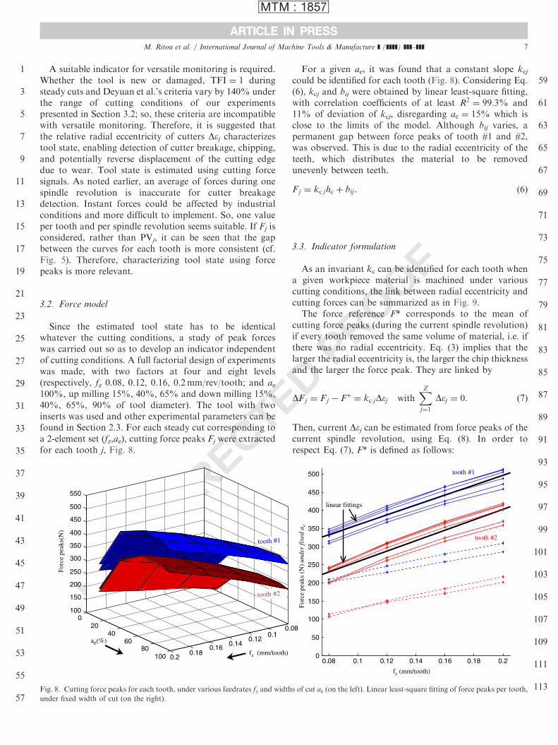
Since the estimated tool state has to be identicalwhatever the cutting conditions, a study of peak forceswas carried out so as to develop an indicator independentof cutting conditions. A full factorial design of experimentswas made, with two factors at four and eight levels(respectively, fz 0.08, 0.12, 0.16, 0.2mm/rev/tooth; and ae100%, up milling 15%, 40%, 65% and down milling 15%,40%, 65%, 90% of tool diameter). The tool with twoinserts was used and other experimental parameters can befound in Section 2.3. For each steady cut corresponding toa 2-element set (fz,ae), cutting force peaks Fj were extractedfor each tooth j, Fig. 8.
UNCORRE
0.0.1
0.120.14
0.160.18
0.2
020
4060
80100
100
150
200
250
300
350
400
450
500
550
fz (mm/tooth)
ae(%)
Forc
e pe
aks(
N)
tooth #1
tooth #2
Fig. 8. Cutting force peaks for each tooth, under various feedrates fz and width
under fixed width of cut (on the right).
For a given ae, it was found that a constant slope kcj
could be identified for each tooth (Fig. 8). Considering Eq.(6), kcj and bij were obtained by linear least-square fitting,with correlation coefficients of at least R2 ¼ 99:3% and11% of deviation of kcj, disregarding ae ¼ 15% which isclose to the limits of the model. Although bij varies, apermanent gap between force peaks of tooth #1 and #2,was observed. This is due to the radial eccentricity of theteeth, which distributes the material to be removedunevenly between teeth.
Fj ¼ kc jhc þ bij . (6)
D PROOF
3.3. Indicator formulation
As an invariant kc can be identified for each tooth whena given workpiece material is machined under variouscutting conditions, the link between radial eccentricity andcutting forces can be summarized as in Fig. 9.The force reference F* corresponds to the mean of
cutting force peaks (during the current spindle revolution)if every tooth removed the same volume of material, i.e. ifthere was no radial eccentricity. Eq. (3) implies that thelarger the radial eccentricity is, the larger the chip thicknessand the larger the force peak. They are linked by
DF j ¼ Fj � F� ¼ kc jDej withXZ
j¼1
Dej ¼ 0. (7)
Then, current Dej can be estimated from force peaks of thecurrent spindle revolution, using Eq. (8). In order torespect Eq. (7), F* is defined as follows:
93
95
97
99
101
103
105
107
109
111
113
08
0.08 0.1 0.12 0.14 0.16 0.18 0.20
50
100
150
200
250
300
350
400
450
500
fz (mm/tooth)
tooth #1
tooth #2
linear fittings
Forc
e pe
aks
(N)u
nder
fixe
d a e
s of cut ae (on the left). Linear least-square fitting of force peaks per tooth,
ARTICLE IN PRESS
MTM : 1857
1
3
5
7
9
11
13
15
17
19
21
23
25
27
29
31
33
35
37
39
41
43
45
47
49
51
53
55
57
59
61
63
65
M. Ritou et al. / International Journal of Machine Tools & Manufacture ] (]]]]) ]]]–]]]8
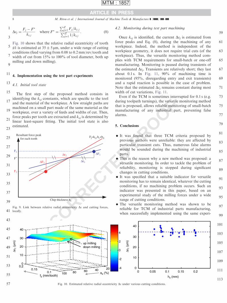
Dej ¼Fj � F�
kc j
where F� ¼
PZj¼1 Fj=kc jPZj¼1 1=kc j
. (8)
Fig. 10 shows that the relative radial eccentricity of tooth#1 is estimated at 35� 5 mm, under a wide range of cuttingconditions (feed varying from 0.08 to 0.2mm/rev/tooth andwidth of cut from 15% to 100% of tool diameter, both upmilling and down milling).
67
69
71
73
75
77
79
4. Implementation using the test part experiments
4.1. Initial tool state
The first step of the proposed method consists inidentifying the kcj constants, which are specific to the tooland the material of the workpiece. A few straight paths aremachined on a small part made of the same material as theworkpiece, over a variety of feeds and widths of cut. Then,force peaks per tooth are extracted and kcj is determined bylinear least-square fitting. The initial tool state is alsoestimated.
UNCORRECT∆ε1
∆ε2∆F1
∆F2
Chip thickness hc
Fj=kcj.hc+bijResultant force peak
for each tooth
F1
F∗
F2
Fig. 9. Link between relative radial eccentricity De and cutting forces,
locally.
Fig. 10. Estimated relative radial eccentrici
OF
4.2. Monitoring during test part machining
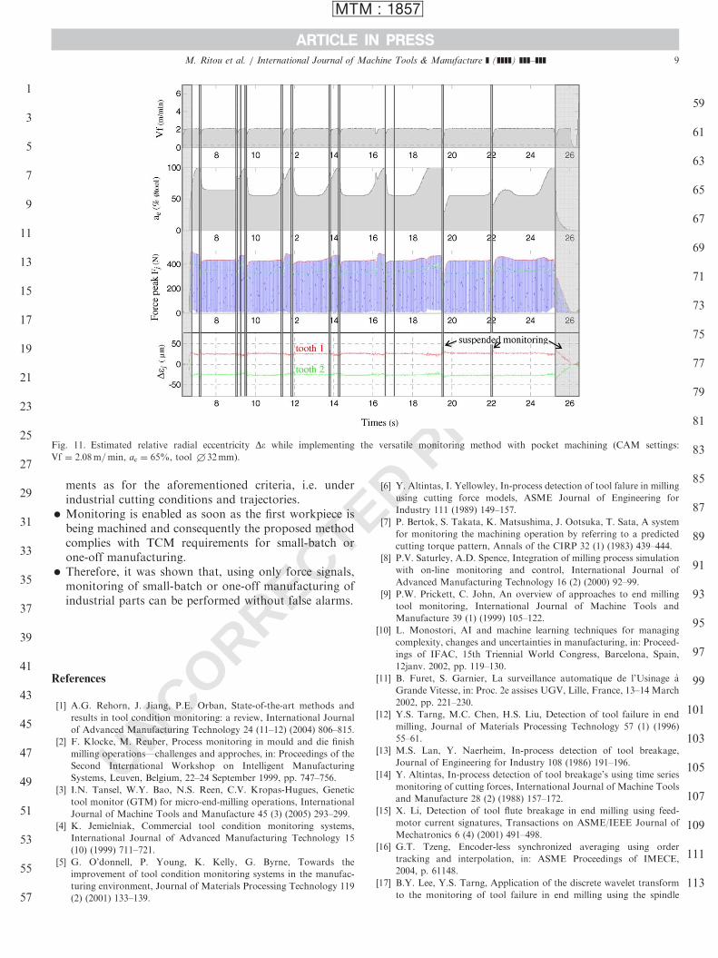
Once kcj is identified, the current Dej is estimated fromforce peaks and Eq. (8), during the machining of anyworkpiece. Indeed, the method is independent of theworkpiece geometry, it does not require trial cuts (of theworkpiece). Thus, the versatile monitoring method com-plies with TCM requirements for small-batch or one-offmanufacturing. Monitoring is paused during transients ofthe estimated Dej. Transients are relatively short; they lastabout 0.1 s. In Fig. 11, 90% of machining time ismonitored (95%, disregarding entry and exit transients)and a rapid reaction is possible in the case of problem.Note that the estimated Dej remains constant during mostwidth of cut variations, Fig. 11.Even if the TCM is sometimes interrupted for 0.1 s (e.g.
during toolpath turnings), the versatile monitoring methodthat is proposed, allows reliable monitoring of small-batchmanufacturing of any industrial part, preventing falsealarms.
5. Conclusions
81
�E
83
85
ty D
PRO
It was found that three TCM criteria proposed byprevious authors were unreliable: they are affected byparticular transient cuts. Thus, numerous false alarmswould be sounded during the machining of industrialparts.
�87
89
DThis is the reason why a new method was proposed: aversatile monitoring. In order to tackle the problem ofreliability, monitoring is stopped during significantchanges in cutting conditions.
�91
93
95
It was specified that a suitable indicator for versatilemonitoring has to remain identical, whatever the cuttingconditions, if no machining problem occurs. Such anindicator was presented in this paper, based on anexperimental study of the milling forces under a widerange of cutting conditions.
�97
The versatile monitoring method was shown to bereliable for TCM of industrial parts manufacturing,when successfully implemented using the same experi-99
101
103
105
107
109
111
113e under various cutting conditions.
PROOF
ARTICLE IN PRESS
MTM : 1857
1
3
5
7
9
11
13
15
17
19
21
23
25
27
29
31
33
35
37
39
41
43
45
47
49
51
53
55
57
59
61
63
65
67
69
71
73
75
77
79
81
83
85
Fig. 11. Estimated relative radial eccentricity De while implementing the versatile monitoring method with pocket machining (CAM settings:
Vf ¼ 2:08m=min, ae ¼ 65%, tool +32mm).
M. Ritou et al. / International Journal of Machine Tools & Manufacture ] (]]]]) ]]]–]]] 9
ments as for the aforementioned criteria, i.e. underindustrial cutting conditions and trajectories.
87
� E 89 TMonitoring is enabled as soon as the first workpiece isbeing machined and consequently the proposed methodcomplies with TCM requirements for small-batch orone-off manufacturing.
91
�93
CTherefore, it was shown that, using only force signals,monitoring of small-batch or one-off manufacturing ofindustrial parts can be performed without false alarms.
E95
R 9799
101
103
105
107
109
111
113
UNCORReferences
[1] A.G. Rehorn, J. Jiang, P.E. Orban, State-of-the-art methods and
results in tool condition monitoring: a review, International Journal
of Advanced Manufacturing Technology 24 (11–12) (2004) 806–815.
[2] F. Klocke, M. Reuber, Process monitoring in mould and die finish
milling operations—challenges and approches, in: Proceedings of the
Second International Workshop on Intelligent Manufacturing
Systems, Leuven, Belgium, 22–24 September 1999, pp. 747–756.
[3] I.N. Tansel, W.Y. Bao, N.S. Reen, C.V. Kropas-Hugues, Genetic
tool monitor (GTM) for micro-end-milling operations, International
Journal of Machine Tools and Manufacture 45 (3) (2005) 293–299.
[4] K. Jemielniak, Commercial tool condition monitoring systems,
International Journal of Advanced Manufacturing Technology 15
(10) (1999) 711–721.
[5] G. O’donnell, P. Young, K. Kelly, G. Byrne, Towards the
improvement of tool condition monitoring systems in the manufac-
turing environment, Journal of Materials Processing Technology 119
(2) (2001) 133–139.
D [6] Y. Altintas, I. Yellowley, In-process detection of tool falure in milling
using cutting force models, ASME Journal of Engineering for
Industry 111 (1989) 149–157.
[7] P. Bertok, S. Takata, K. Matsushima, J. Ootsuka, T. Sata, A system
for monitoring the machining operation by referring to a predicted
cutting torque pattern, Annals of the CIRP 32 (1) (1983) 439–444.
[8] P.V. Saturley, A.D. Spence, Integration of milling process simulation
with on-line monitoring and control, International Journal of
Advanced Manufacturing Technology 16 (2) (2000) 92–99.
[9] P.W. Prickett, C. John, An overview of approaches to end milling
tool monitoring, International Journal of Machine Tools and
Manufacture 39 (1) (1999) 105–122.
[10] L. Monostori, AI and machine learning techniques for managing
complexity, changes and uncertainties in manufacturing, in: Proceed-
ings of IFAC, 15th Triennial World Congress, Barcelona, Spain,
12janv. 2002, pp. 119–130.
[11] B. Furet, S. Garnier, La surveillance automatique de l’Usinage a
Grande Vitesse, in: Proc. 2e assises UGV, Lille, France, 13–14 March
2002, pp. 221–230.
[12] Y.S. Tarng, M.C. Chen, H.S. Liu, Detection of tool failure in end
milling, Journal of Materials Processing Technology 57 (1) (1996)
55–61.
[13] M.S. Lan, Y. Naerheim, In-process detection of tool breakage,
Journal of Engineering for Industry 108 (1986) 191–196.
[14] Y. Altintas, In-process detection of tool breakage’s using time series
monitoring of cutting forces, International Journal of Machine Tools
and Manufacture 28 (2) (1988) 157–172.
[15] X. Li, Detection of tool flute breakage in end milling using feed-
motor current signatures, Transactions on ASME/IEEE Journal of
Mechatronics 6 (4) (2001) 491–498.
[16] G.T. Tzeng, Encoder-less synchronized averaging using order
tracking and interpolation, in: ASME Proceedings of IMECE,
2004, p. 61148.
[17] B.Y. Lee, Y.S. Tarng, Application of the discrete wavelet transform
to the monitoring of tool failure in end milling using the spindle

ARTICLE IN PRESS
MTM : 1857
1
3
5
7
9
11
13
15
17
19
21
23
25
27
29
31
33
35
37
39
41
43
45
M. Ritou et al. / International Journal of Machine Tools & Manufacture ] (]]]]) ]]]–]]]10
motor current, International Journal of Advanced Manufacturing
Technology 15 (4) (1999) 238–243.
[18] S.X. Xu, J. Zhao, J.M. Zhan, G. Le, Research on a fault monitoring
system in free-form surface CNC machining based on wavelet
analysis, Journal of Materials Processing Technology 129 (3) (2002)
588–591.
[19] J.M. Lee, D.K. Choi, J. Kim, C.N. Chu, Real time tool breakage
monitoring for NC milling process, Annals of the CIRP 44 (1) (1995)
59–62.
[20] G.D. Kim, C.N. Chu, In-process tool fracture monitoring in face
milling using spindle motor current and tool fracture index,
International Journal of Advanced Manufacturing Technology 18
(6) (2001) 383–389.
[21] Z. Deyuan, H. Huntay, C. Dingchang, On-line detection of tool
breakages using teletering of cutting forces in milling, International
Journal of Machine Tools and Manufacture 35 (1) (1995) 19–27.
[22] J.C. Chen, An effective fuzzy-nets training scheme for monitoring
tool breakage, Journal of Intelligent Manufacturing 11 (1) (2000)
85–101.
[23] R.J. Romero-Troncoso, G. Herrera-Ruiz, I. Terol-Villalobos, C.
Jauregui-Correa, Driver current analysis for sensorless tool breakage
monitoring of CNC milling machines, International Journal of
Machine Tools and Manufacture 43 (15) (2003) 1529–1534.
[24] S. Garnier, M. Ritou, B. Furet, J.Y. Hascoet, Comparison and
analysis of in-process tool condition monitoring criterions in milling,
UNCORRECT
F
in: Proceedings of the Seventh International Conference on Advanced
Manufacturing Systems and Technology, Udine, Italy, 9–10 June
2005, pp. 523–532.
[25] A.J.P. Sabberwal, Chip section and cutting force during the milling
operation, Annals of the CIRP (1960) 197–203.
[26] M.E. Martelloti, An analysis of the the milling forces, Transactions of
ASME 63 (1941) 677–700.
[27] S. Smith, J. Tlusty, An overview of modeling and simulation of the
milling process, Journal of Engineering for Industry 113 (1991)
169–175.
[28] M. Cherif, H. Thomas, B. Furet, J.Y. Hascoet, Generic modelling of
milling forces for CAD/CAM applications, International Journal of
Machine Tools and Manufacture 44 (1) (2004) 29–37.
[29] N. Kasashima, K. Mori, G. Herrera-Ruiz, N. Taniguchi, Online
failure detection in face milling using discrete wavelet transform,
Annals of the CIRP 44 (1) (1995) 483–487.
[30] A. Dugas, J.J. Lee, J.Y. Hascoet, High Speed Milling: Solid
Simulation and Machine Limits, Collective Book, Kluwer Academic
Publishers, New York, 2001, pp. 287–295.
[31] A. Dugas, M. Terrier, J.Y. Hascoet, Free form surface measurement
method and machine qualification for high speed milling, in:
Proceedings of IDMME, Clermont-Ferrand, France, 14–16 May
2002 cd rom.
47
OED PRO 49