A Multi-view Opto-Xray Imaging System
8
A Multi-view Opto-Xray Imaging System Development and First Application in Trauma Surgery Joerg Traub 1 , Tim Hauke Heibel 1 , Philipp Dressel 1 , Sandro Michael Heining 2 , Rainer Graumann 3 , and Nassir Navab 1 1 Computer Aided Medical Procedures (CAMP), TUM, Munich, Germany 2 Trauma Surgery Department, Klinikum Innenstadt, LMU Munich, Germany 3 Siemens SP, Siemens Medical, Erlangen, Germany Abstract. The success of minimally invasive trauma and orthopedic surgery procedures has resulted in an increase of the use of fluoroscopic imaging. A system aiming to reduce the amount of radiation has been introduced by Navab et al. [1]. It uses an optical imaging system rigidly attached to the gantry such that the optical and X-ray imaging geometry is identical. As an extension to their solution, we developed a multi-view system which offers 3D navigation during trauma surgery and ortho- pedic procedures. We use an additional video camera in an orthogonal arrangement to the first video camera and a minimum of two X-ray im- ages. Furthermore, tools such as a surgical drill are extended by optical markers and tracked with the same optical cameras. Exploiting that the cross ratio is invariant in projective geometry, we can estimate the tip of the instrument in the X-ray image without external tracking systems. This paper thus introduces the first multi-view Opto- Xray system for computer aided surgery. First tests have proven the accuracy of the cali- bration and the instrument tracking. Phantom and cadaver experiments were conducted for pedicle screw placement in spinal surgery. Using a postoperative CT, we evaluate the quality of the placement of the pedicle screws in 3D. 1 Introduction Mobile C-arm systems are established in everyday routines in orthopedic and trauma surgery. The trend toward minimally invasive applications increases the use of fluoroscopic images within surgery and thus the radiation dose [2,3]. Nowa- days the combined use of mobile C-arms, that are capable of 3D reconstruction, and a tracking system provide navigation information during surgery, e.g. [4]. Systems using this technique use so called registration free navigation methods based on a mobile C-arm with 3D reconstruction capabilities tracked by an ex- ternal optical tracking system. The imaging device is tracked and the volume is reconstructed in the same reference frame in which the instruments and the pa- tient are tracked. Hayashibe et al. [5] combined the registration free navigation approach using an intra-operative tracked C-arm with reconstruction capabilities and in-situ visualization by volume rendered views from any arbitrary position of a swivel arm mounted monitor. N. Ayache, S. Ourselin, A. Maeder (Eds.): MICCAI 2007, Part II, LNCS 4792, pp. 18–25, 2007. c Springer-Verlag Berlin Heidelberg 2007
Transcript of A Multi-view Opto-Xray Imaging System
A Multi-view Opto-Xray Imaging SystemDevelopment and First Application in Trauma Surgery
Joerg Traub1, Tim Hauke Heibel1, Philipp Dressel1, Sandro Michael Heining2,Rainer Graumann3, and Nassir Navab1
1 Computer Aided Medical Procedures (CAMP), TUM, Munich, Germany2 Trauma Surgery Department, Klinikum Innenstadt, LMU Munich, Germany
3 Siemens SP, Siemens Medical, Erlangen, Germany
Abstract. The success of minimally invasive trauma and orthopedicsurgery procedures has resulted in an increase of the use of fluoroscopicimaging. A system aiming to reduce the amount of radiation has beenintroduced by Navab et al. [1]. It uses an optical imaging system rigidlyattached to the gantry such that the optical and X-ray imaging geometryis identical. As an extension to their solution, we developed a multi-viewsystem which offers 3D navigation during trauma surgery and ortho-pedic procedures. We use an additional video camera in an orthogonalarrangement to the first video camera and a minimum of two X-ray im-ages. Furthermore, tools such as a surgical drill are extended by opticalmarkers and tracked with the same optical cameras. Exploiting that thecross ratio is invariant in projective geometry, we can estimate the tipof the instrument in the X-ray image without external tracking systems.This paper thus introduces the first multi-view Opto- Xray system forcomputer aided surgery. First tests have proven the accuracy of the cali-bration and the instrument tracking. Phantom and cadaver experimentswere conducted for pedicle screw placement in spinal surgery. Using apostoperative CT, we evaluate the quality of the placement of the pediclescrews in 3D.
1 Introduction
Mobile C-arm systems are established in everyday routines in orthopedic andtrauma surgery. The trend toward minimally invasive applications increases theuse of fluoroscopic images within surgery and thus the radiation dose [2,3]. Nowa-days the combined use of mobile C-arms, that are capable of 3D reconstruction,and a tracking system provide navigation information during surgery, e.g. [4].Systems using this technique use so called registration free navigation methodsbased on a mobile C-arm with 3D reconstruction capabilities tracked by an ex-ternal optical tracking system. The imaging device is tracked and the volume isreconstructed in the same reference frame in which the instruments and the pa-tient are tracked. Hayashibe et al. [5] combined the registration free navigationapproach using an intra-operative tracked C-arm with reconstruction capabilitiesand in-situ visualization by volume rendered views from any arbitrary positionof a swivel arm mounted monitor.
N. Ayache, S. Ourselin, A. Maeder (Eds.): MICCAI 2007, Part II, LNCS 4792, pp. 18–25, 2007.c© Springer-Verlag Berlin Heidelberg 2007
A Multi-view Opto-Xray Imaging System 19
Augmenting interventional imaging data using mirror constructions were pro-posed by Stetten et al. [6] for tomographic reflection on Ultrasound and Fichtin-ger et al. for navigated needle insertion based on CT [7] and MR [8].
Another approach for augmentation of intraoperative image data is the physi-cal attachment of an optical camera to an X-ray source as proposed by Navab etal. [1]. It uses a single optical camera rigidly attached to the gantry such that theoptical and X-ray imaging geometry is aligned. This enabled a real time videoimage and X-ray overlay that was registered by construction. No registration ofthe patient was required in their approach. This provided an accurate position-ing and guidance of instruments in 2D. However, no depth control was possible.Thus their system was limited to applications where depth did not matter, likein intramedullary-nail locking as proposed by their group [9].
As an extension to their proposed system, we developed a system that is alsocapable of depth control during trauma surgery and orthopedic procedures us-ing only one additional X-ray image and a second video camera that is rigidlyattached to the C-arm. Furthermore, we implemented a system to track an in-strument in 2D. Using cross ratio we estimate the position of the tip in theimage. After one time calibration of the newly attached second video camera weare able to show the instrument tip in the orthogonal X-ray view. The feasibilityof the system has been validated trough cadaver studies where we successfullyidentified all six pedicle screws placed using the procedure. The accuracy of theplacement was validated using a postoperative CT.
2 System Setup
2.1 System Components
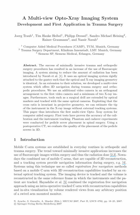
The system consists of an Iso3D C-arm (Siemens Medical, Erlangen, Germany)with two attached Flea video color cameras (Point Grey Research Inc., Van-couver, BC, Canada) (see figure 1). The first camera is attached as proposedearlier by Navab et al. using a double mirror construction with X-ray transpar-ent mirrors [1]. The second camera is attached orthogonal to the gantry suchthat its view is aligned with the X-ray image after a 90 degrees orbital rotationof the C-arm (see figure 1). Furthermore, the system includes a standard PCwith a framegrabber card to access the analog images of the C-arm. A customdeveloped visualization and navigation software is used (see section 2.3).
2.2 System Calibration
For both cameras the calibration process can be devided in two consecutivesteps. In the first step the cameras are physically attached such that the opticalcenter and axis virtually coincide with the X-ray imaging system at all time forthe gantry mounted camera and at particular C-arm positions for the orthogo-nal mounted camera. The second step is to compute the homographies to alignthe video images with the X-ray images. For both video cameras the distor-tion is computed using the Matlab camera calibration toolbox and the images

20 J. Traub et al.
Fig. 1. The C-arm with two attached optical cameras. The first camera is attachedto the gantry with a double mirror construction. The second camera is attached in anorthogonal direction with a single mirror construction.
are undistorted using Intel OpenCV library. The use of flat panel displays orstandard distortion correction methods is recommended 1.
Notation. Since we have images at different positions of the C-arm superscript0 denote cameras and images at a 0 degree orbital rotation and superscript 90 de-note cameras and images acquired by the C-arm after an orbital rotation around90 degree. Furthermore subscript x is used for X-ray, g for gantry mounted, ando for the orthogonal mounted cameras.
X-ray to Gantry Mounted Camera Calibration. Initially the gantry moun-ted camera is physically placed such, that its optical center and axis are alignedrespectively with the X-ray source. This alignment is achieved by a bi-planar cal-ibration phantom and mounting the camera using a double mirror construction.To superimpose the X-ray image onto the video image a homography HI0
g←I0x
iscomputed. Thanks to this homography the effects of X-ray distortions close tothe image center are diminished. The procedure of the gantry mounted cameracalibration is described in detail by Navab et al. [1].
X-ray to Orthogonal Mounted Camera Calibration. We constrained theattachment of the second camera to be orthogonal with respect to the gantry.This attachment provides best results for the depth navigation, assuming theinstruments are always used down the beam as in the single camera navigationsystem [1]. The physical attachment and calibration of the second camera atalternative positions is also possible with the procedure described in this section.1 See http://campar.in.tum.de/Events/VideoCamCSquare for a video demonstration
of the calibration and navigation procedure.
A Multi-view Opto-Xray Imaging System 21
To acquire an X-ray image I90x corresponding to the view I0
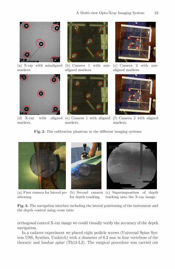
o of the orthogonalmounted camera, we have to ensure that after an orbital rotation the opticalcenter and axis of the X-ray gantry and the orthogonal camera are aligned.Since the gantry mounted camera is already physically aligned with the X-raydevice, the problem can be reduced to physically aligning the gantry mountedand orthogonal mounted camera after rotation. This alignment is achieved witha bi-planar calibration pattern. A set of markers is placed on each plane suchthat subsets of two markers, one on each plane, are aligned in the image ofthe gantry mounted camera I0
g at the initial position of the C-arm (see figure2(e)). In the next step, the C-arm is rotated by −90 degrees in orbital(see figure2(c)). Now the orthogonal mounted camera is physically moved in six degreesof freedom, until all marker tuples from the calibration pattern are lined up inimage I−90
o in exactly the same way as they were for the gantry mounted camera(see figure 2(f)). Note that the calibration only has to be performed once thesystem is constructed. Once the system is built, the alignment is preserved byconstruction.
For a proper alignment of the X-ray image I90x at 90 degree rotation in or-
bital direction and the image I0o of the orthogonal camera with no rotation, two
homographies remain to be computed. A first homography HI90g ←I90
xthat maps
the X-ray image I90x to the gantry mounted image I90
g and a second homogra-phy HI0
o←I90g
mapping the image of the gantry mounted camera to the image ofthe orthogonal mounted camera. The final homography used to map the X-rayimage I90
x onto the orthogonal mounted camera image I0o uses the hompgraphy
HI0o←I90
x= HI0
o←I90g
·HI90g ←I90
x, a combination of the two homograpies computed
earlier. Both homographies are computed using corresponding points in the im-ages. Even though the gantry camera is rigidly mounted a second estimation ofthe homography HI90
g ←I90x
is determined to approximately compensate distortioneffects of the X-ray image after rotation.
2.3 Navigation System
The navigation does not require any further calibration or registration procedure.The previously described calibration routine has to be performed only once whilethe system is built and it is valid as long as the cameras do not move with respectto the gantry.
For the navigation the acquisition of two X-ray images I0x and I90
x with aprecise orbital rotation, such that the acquired images correspond to the imagesof the gantry attached camera I0
g and the orthogonal camera I0o , has to be
ensured. Therefore an image I0o of the second camera is captured before the
rotation. Using image overlay techniques of this captured image I0o and a live
video image I0→90g during the orbital rotation with the homography HI0
o←I90g
applied, we ensure that the first camera has the same position and orientationas the second camera before the rotation. Thus the X-ray image I90
x we take fromthis position corresponds to the captured image I0
o . Furthermore, after preciserotation of the C-arm back to its original position, the orthogonal taken X-rayimage I90
x can be overlaid on the live image I0o of the orthogonal mounted camera
22 J. Traub et al.
by applying the computed homography HI0o←I90
x. The rotation back is ensured
using combined X-ray and optical markers attached to the side of our surgicalobject that are visible in the X-ray image I90
x and the image I0o of the orthogonal
camera. The acquisition of a second X-ray image I0x at position zero and the use
of the homography HI0g←I0
xenables the lateral control using the gantry mounted
camera (see figure 3(a). The image I0o of the orthogonal camera is used by an
instrument tracking module (see figure 2.4). The estimated distal end of theinstrument in the orthogonal image I0
g is superimposed on the X-ray image I90x
taken at 90 degree rotation (see figure 3(c)).
2.4 Instrument Tracking
The surgical tool is extended by three markers collinear arranged on the instru-ment axis. We use retro-reflective circular markers that are illuminated by anadditional light source attached to the orthogonal camera. This setup results inthe markers being seen by the orthogonal camera as bright ellipses, which canbe easily detected by image thresholding. From the binary image all contoursare extracted using the Intel OpenCV library. In a post-processing step we filterthose contours having a low compactness value and those having a smaller areathan a threshold (default values are 0.6 for the compactness and 50 pixels forthe area). For all contours being retained by the filtering routine, the sub-pixelcentroids are computed based on grayscale image moments. Finally those threecontours yielding an optimal least squares line fitting are assumed to be the onescorresponding to our circular markers.
Having three collinear markers detected in the 2D image plane, we are ableto compute the position of the instrument tip. Given the 3D geometry of ourinstrument, i.e. the position of the distal end of the instrument with respectto the other three markers, we compute the tip of the instrument in the imagebased on the cross-ratio.
cross =d12d23
d13d24=
Δx12Δx23
Δx13Δx24=
Δy12Δy23
Δy13Δy24(1)
Here dij are the distances between the markers i and j, respectively betweena marker and the tool tip. Investigating the distances in x- and y-directionseparately gives us Δxij and Δyij where Δx24 = |x2 − x4| and Δy24 = |y2 − y4|contain the unknown coordinates x4 and y4 of the instrument tip. Since the X-ray image I90
x is registered with the live video image I0o of the second camera by
HI0o←I90
g, we know exactly the position of the tip in the X-ray image I90
x takenat 90 degree rotation (see figure 3(c)).
3 Experiments and Results
First the feasibility of the system was tested on a spine phantom. We used atracked awl, a pedicle probe and a T-handle to place pedicle screws. Using an
A Multi-view Opto-Xray Imaging System 23
(a) X-ray with misalignedmarkers.
(b) Camera 1 with mis-aligned markers.
(c) Camera 2 with mis-aligned markers.
(d) X-ray with alignedmarkers.
(e) Camera 1 with alignedmarkers.
(f) Camera 2 with alignedmarkers.
Fig. 2. The calibration phantom in the different imaging systems
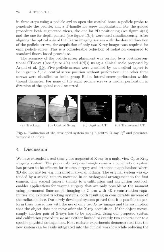
(a) First camera for lateral po-sitioning.
(b) Second camerafor depth tracking.
(c) Superimposition of depthtracking onto the X-ray image.
Fig. 3. The navigation interface including the lateral positioning of the instrument andthe depth control using cross ratio
orthogonal control X-ray image we could visually verify the accuracy of the depthnavigation.
In a cadaver experiment we placed eight pedicle screws (Universal Spine Sys-tem USS, Synthes, Umkirch) with a diameter of 6.2 mm in four vertebrae of thethoracic and lumbar spine (Th12-L3). The surgical procedure was carried out
24 J. Traub et al.
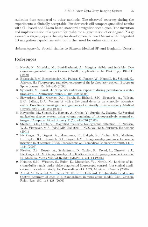
in three steps using a pedicle awl to open the cortical bone, a pedicle probe topenetrate the pedicle, and a T-handle for screw implantation. For the guidedprocedure both augmented views, the one for 2D positioning (see figure 4(a))and the one for depth control (see figure 4(b)), were used simultaneously. Afteraligning the optical axis of the C-arm imaging system with the desired directionof the pedicle screws, the acquisition of only two X-ray images was required foreach pedicle screw. This is a considerable reduction of radiation compared tostandard fluoro based procedure.
The accuracy of the pedicle screw placement was verified by a postinterven-tional CT-scan ((see figure 4(c) and 4(d))) using a clinical scale proposed byArand et al. [10]. Five pedicle screws were classified by an medical expert tobe in group A, i.e. central screw position without perforation. The other threescrews were classified to be in group B, i.e. lateral screw perforation withinthread diameter. For none of the eight pedicle screws a medial perforation indirection of the spinal canal occurred.
(a) Tracking. (b) Control X-ray. (c) Sagittal CT. (d) Transversal CT.
Fig. 4. Evaluation of the developed system using a control X-ray I90x and postinter-
ventional CT data
4 Discussion
We have extended a real-time video augmented X-ray to a multi-view Opto-Xrayimaging system. The previously proposed single camera augmentation systemhas proven to be efficient for trauma surgery and orthopedic applications where3D did not matter, e.g. intramedullary-nail locking. The original system was ex-tended by a second camera mounted in an orthogonal arrangement to the firstcamera. The second camera, thanks to a calibration and navigation protocol,enables applications for trauma surgery that are only possible at the momentusing permanent fluoroscopic imaging or C-arm with 3D reconstruction capa-bilities and external tracking systems, both resulting in considerable increase ofthe radiation dose. Our newly developed system proved that it is possible to per-form these procedures with the use of only two X-ray images and the assumptionthat the object does not move after the X-ray acquisition. If the object moves,simply another pair of X-rays has to be acquired. Using our proposed systemand calibration procedure we are neither limited to exactly two cameras nor to aspecific physical arrangement. First cadaver experiments demonstrated that thenew system can be easily integrated into the clinical workflow while reducing the
A Multi-view Opto-Xray Imaging System 25
radiation dose compared to other methods. The observed accuracy during theexperiments is clinically acceptable. Further work will compare quantified resultswith CT based and C-arm based standard navigation techniques. The inventionand implementation of a system for real-time augmentation of orthogonal X-rayviews of a surgery, opens the way for development of new C-arms with integrated3D navigation capabilities with no further need for online calibration.
Acknowlegments. Special thanks to Siemens Medical SP and Benjamin Ockert.
References
1. Navab, N., Mitschke, M., Bani-Hashemi, A.: Merging visible and invisible: Twocamera-augmented mobile C-arm (CAMC) applications. In: IWAR, pp. 134–141(1999)
2. Boszczyk, B.M, Bierschneider, M., Panzer, S., Panzer, W., Harstall, R., Schmid, K.,Jaksche, H.: Fluoroscopic radiation exposure of the kyphoplasty patient. EuropeanSpine Journal 15, 347–355 (2006)
3. Synowitz, M., Kiwit, J.: Surgeon’s radiation exposure during percutaneous verte-broplasty. J. Neurosurg. Spine. 4, 106–109 (2006)
4. Siewerdsen, J.H., Moseley, D.J., Burch, S., Bisland, S.K., Bogaards, A., Wilson,B.C., Jaffray, D.A.: Volume ct with a flat-panel detector on a mobile, isocentricc-arm: Pre-clinical investigation in guidance of minimally invasive surgery. MedicalPhysics 32(1), 241–254 (2005)
5. Hayashibe, M., Suzuki, N., Hattori, A., Otake, Y., Suzuki, S., Nakata, N.: Surgicalnavigation display system using volume rendering of intraoperatively scanned ctimages. Computer Aided Surgery 11(5), 240–246 (2006)
6. Stetten, G.D., Chib, V.: Magnified real-time tomographic reflection. In: Niessen,W.J., Viergever, M.A. (eds.) MICCAI 2001. LNCS, vol. 2208, Springer, Heidelberg(2001)
7. Fichtinger, G., Deguet, A., Masamune, K., Balogh, E., Fischer, G.S., Mathieu,H., Taylor, R.H., Zinreich, S.J., Fayad, L.M.: Image overlay guidance for needleinsertion in ct scanner. IEEE Transactions on Biomedical Engineering 52(8), 1415–1424 (2005)
8. Fischer, G.S., Deguet, A., Schlattman, D., Taylor, R., Fayad, L., Zinreich, S.J.,Fichtinger, G.: Mri image overlay: Applications to arthrography needle insertion.In: Medicine Meets Virtual Reality (MMVR), vol. 14 (2006)
9. Heining, S.M., Wiesner, S., Euler, E., Mutschler, W., Navab, N.: Locking of in-tramedullary nails under video-augmented flouroscopic control: first clinical appli-cation in a cadaver study. In: Proceedings of CAOS, Montreal, Canada (2006)
10. Arand, M., Schempf, M., Fleiter, T., Kinzl, L., Gebhard, F.: Qualitative and quan-titative accuracy of caos in a standardized in vitro spine model. Clin. Orthop.Relat. Res. 450, 118–128 (2006)