A multi-layered development framework for medical imaging applications
6
A Multi-Layered Development Framework for Medical Imaging Applications Abstract Computer Aided Diagnostic comprises wide research ar- eas with stability and reliability software requirements. We propose a set of libraries aiming to provide a development framework for medical applications. This work discusses this framework’s libraries developed for both medical imag- ing systems and general physical simulations. Their inter- nal interactions tend to be transparent to the developer and easy to use at the same time while providing flexibility to in- teract with other codes. The robustness of the code is shown in complex applications like the medical workstation here exemplified, while its flexibility and fast prototyping char- acteristics are demonstrated with some simple prototypes. 1. Introduction Advances in medical imaging improved medical deci- sion aided by computer, i.e , as the technology in that area advances, fewer are the errors with wrong medical judg- ment. This paper presents the design of a radiological 3D workstation (hereafter referred to as “WS”) and its imple- mentation with basic algorithm and rendering libraries de- veloped in-house. We also present the reasons on the choice of building a complete set of libraries from scratch instead of adopting an already established solution. There are many recent medical imaging software that use the ITK[13] and VTK[23] approach for building their own application systems. Software examples of this can be found in Invesalius[3], which is a free medical soft- ware (CC-GPL) developed by CenPRA (Renato Archer Research Center), VolView[4], developed by Kitware, CardioViz3D[2, 27], by the ASCLEPIOS research team and OsiriX[22], by the OsiriX Foundation. They all have 3D and 2D representation and registration capabilities that are found in VTK and ITK. To unite ITK and VTK in a single application means interacting with two different codebases that have two completely opposite coding styles (ITK is based in meta- programming and VTK in pure object oriented code). Al- though they are complementary, they are not easily attach- Figure 1. Talairach atlas application able software libraries[26] and this union complexity is in- creased every time a new piece of software is created over or joined with those, which happens with vtkINRIA[27] and 3DSlicer[19]. A more consistent software approach would benefit code maintainability and cohesion. A cleaner and less generic design may be observed with MiTK and 3DMed[5], although somewhat less flexi- ble since they do not provide easy integration with other li- braries like the present paper’s libraries do. For instance, on of our framework’s modules, the Abstraction Layer (AL), contains a lot of abstract classes and interfaces which can be easily used to extend our framework’s capabilities, like render switch and model/scene object generic abstractions. Other AL facilities include lots of factories and higher level interfaces for accessing the under-the-hood layer called Core. This, from a software engineering point-of-view, in- tends to achieve a greater flexibility, modularity and code maintainability/reusage than in similar frameworks, at least for medical imaging systems. 1.1. Motivation The widely known Boost C++ library has statistics in its site demonstrating the value of its code[25]. That shows that creating and maintaining an entire framework is expen-
-
Upload
independent -
Category
Documents
-
view
0 -
download
0
Transcript of A multi-layered development framework for medical imaging applications
A Multi-Layered Development Framework for Medical Imaging Applications
Abstract
Computer Aided Diagnostic comprises wide research ar-eas with stability and reliability software requirements. Wepropose a set of libraries aiming to provide a developmentframework for medical applications. This work discussesthis framework’s libraries developed for both medical imag-ing systems and general physical simulations. Their inter-nal interactions tend to be transparent to the developer andeasy to use at the same time while providing flexibility to in-teract with other codes. The robustness of the code is shownin complex applications like the medical workstation hereexemplified, while its flexibility and fast prototyping char-acteristics are demonstrated with some simple prototypes.
1. Introduction
Advances in medical imaging improved medical deci-sion aided by computer, i.e , as the technology in that areaadvances, fewer are the errors with wrong medical judg-ment. This paper presents the design of a radiological 3Dworkstation (hereafter referred to as “WS”) and its imple-mentation with basic algorithm and rendering libraries de-veloped in-house. We also present the reasons on the choiceof building a complete set of libraries from scratch insteadof adopting an already established solution.
There are many recent medical imaging software thatuse the ITK[13] and VTK[23] approach for building theirown application systems. Software examples of this canbe found in Invesalius[3], which is a free medical soft-ware (CC-GPL) developed by CenPRA (Renato ArcherResearch Center), VolView[4], developed by Kitware,CardioViz3D[2, 27], by the ASCLEPIOS research team andOsiriX[22], by the OsiriX Foundation. They all have 3Dand 2D representation and registration capabilities that arefound in VTK and ITK.
To unite ITK and VTK in a single application meansinteracting with two different codebases that have twocompletely opposite coding styles (ITK is based in meta-programming and VTK in pure object oriented code). Al-though they are complementary, they are not easily attach-
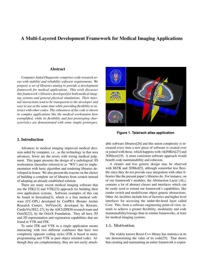
Figure 1. Talairach atlas application
able software libraries[26] and this union complexity is in-creased every time a new piece of software is created overor joined with those, which happens with vtkINRIA[27] and3DSlicer[19]. A more consistent software approach wouldbenefit code maintainability and cohesion.
A cleaner and less generic design may be observedwith MiTK and 3DMed[5], although somewhat less flexi-ble since they do not provide easy integration with other li-braries like the present paper’s libraries do. For instance, onof our framework’s modules, the Abstraction Layer (AL),contains a lot of abstract classes and interfaces which canbe easily used to extend our framework’s capabilities, likerender switch and model/scene object generic abstractions.Other AL facilities include lots of factories and higher levelinterfaces for accessing the under-the-hood layer calledCore. This, from a software engineering point-of-view, in-tends to achieve a greater flexibility, modularity and codemaintainability/reusage than in similar frameworks, at leastfor medical imaging systems.
1.1. Motivation
The widely known Boost C++ library has statistics in itssite demonstrating the value of its code[25]. That showsthat creating and maintaining an entire framework is expen-
sive and there must be good reasons for doing so, however,for some specific applications like medical imaging systemsand game engines there are reasons for coding teams to havetheir own homemade code even if that means to write codefrom scratch and maintaining that code.
With the availability of well-established libraries suit-able to develop a medical 3D workstation, a sound rea-son must be provided for the development of in-house codefrom scratch. One good reason for doing this is that weneeded different functionalities than the ones that the avail-able APIs provide, such as the GPGPU use for physicalsimulation as well as visualization effects and multithreadimplementations of specific algorithms to take advantageof multiple cores CPUs. Implementing this set of toolsfrom scratch required an understanding of the whole setof algorithms completely and the hability to identify thehot spots and bottlenecks. This knowledge is essential onporting these operations to another computing architectureand since we have developed at first instance a CPU ver-sion of them, comparisons between both implementationscan be performed. Also, when there are a couple of differ-ent teams working together, having a common library thatthey all understand is good because they can exchange ex-periences more easily than when they are using completedifferent technologies/softwares. That way they share thesame problems and may work together for a better sharedlesson.
The following case represents an example of code mis-management. Our research groups developed an applicationbased on the Talairach Atlas[16] (figure 1) in parallel withthe base framework when its API was still unstable. The ap-plication stopped being developed for a period of time andwhen the code was re-merged with the up-to-date librariesit simply broke and the effort to make it work again wasconsidered too great and the project was abandoned.
The Talairach problem happened because there was agreat part of the logic code in the application. When itwas not maintained anymore, this logic became incompat-ible with the one found in the basic libraries. That consti-tuted a learning experience for the framework’s team whichnow keeps the workstation always working with the newestcode and avoids leaving logic code in the application.
2. Libraries architecture
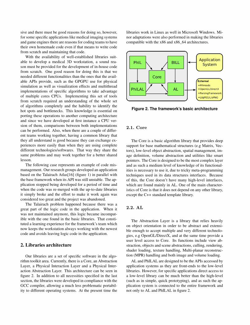
Our libraries are a set of specific software in the algo-rithm toolkit area. Currently, there is a Core, an AbstractionLayer, a Physical Interaction Layer and a Physical Inter-action Abstraction Layer. This architecture can be seen infigure 2. In addition to all necessities specified in the lastsection, the libraries were developed in compliance with theGCC compiler, allowing a much less problematic portabil-ity to different operating systems. At the present time the
libraries work in Linux as well in Microsoft Windows. Mi-nor adaptations were also performed in making the librariescompatible with the x86 and x86_64 architectures.
Figure 2. The framework’s basic architecture
2.1. Core
The Core is a basic algorithm library that provides deepsupport for base mathematical structures (e.g Matrix, Vec-tors), low-level object abstraction, spatial management, im-age definition, volume abstraction and utilities like smartpointers. The Core is designed to be the most complex layerand as such a medium level of knowledge of its functional-ities is necessary to use it, due to tricky meta-programmingtechniques used in its data structures interfaces. Becauseof this, the Core doesn’t have many high-level interfaces,which are found mainly in AL. One of the main character-istics of Core is that it does not depend on any other library,except the C++ standard template library.
2.2. AL
The Abstraction Layer is a library that relies heavilyon object orientation in order to be abstract and extensi-ble enough to accept multiple and very different technolo-gies, e.g OpenGL/DirectX, and at the same time provide auser level access to Core. Its functions include view ab-straction, objects and scene abstractions, culling, rendering,shader loading, texture handling, Multi-planar reconstruc-tion (MPR) handling and both image and volume loading.
AL and PhILAL are designed to be the APIs accessed byapplication systems as they are front-ends to the low-levellibraries. However, for specific applications direct access toa low-level library can be much better than the high-level(such as in simple, quick prototyping), and as such the ap-plication system is connected to the entire framework andnot only to AL and PhILAL in figure 2.
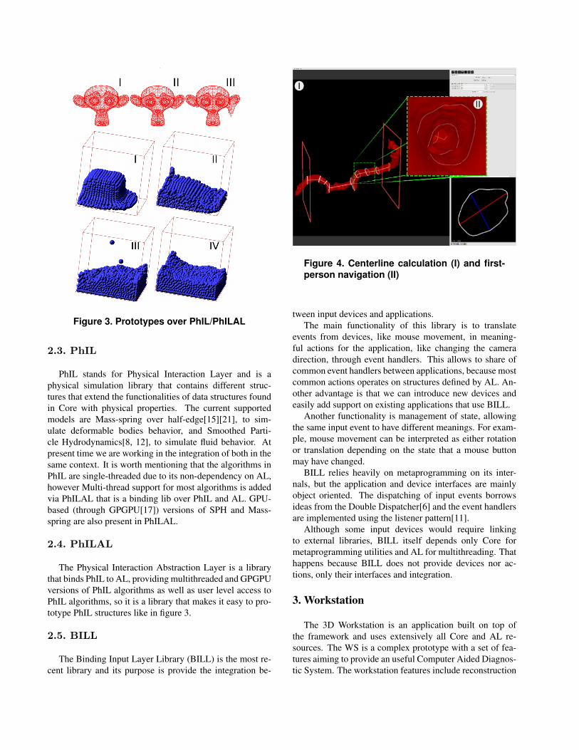
Figure 3. Prototypes over PhIL/PhILAL
2.3. PhIL
PhIL stands for Physical Interaction Layer and is aphysical simulation library that contains different struc-tures that extend the functionalities of data structures foundin Core with physical properties. The current supportedmodels are Mass-spring over half-edge[15][21], to sim-ulate deformable bodies behavior, and Smoothed Parti-cle Hydrodynamics[8, 12], to simulate fluid behavior. Atpresent time we are working in the integration of both in thesame context. It is worth mentioning that the algorithms inPhIL are single-threaded due to its non-dependency on AL,however Multi-thread support for most algorithms is addedvia PhILAL that is a binding lib over PhIL and AL. GPU-based (through GPGPU[17]) versions of SPH and Mass-spring are also present in PhILAL.
2.4. PhILAL
The Physical Interaction Abstraction Layer is a librarythat binds PhIL to AL, providing multithreaded and GPGPUversions of PhIL algorithms as well as user level access toPhIL algorithms, so it is a library that makes it easy to pro-totype PhIL structures like in figure 3.
2.5. BILL
The Binding Input Layer Library (BILL) is the most re-cent library and its purpose is provide the integration be-
Figure 4. Centerline calculation (I) and first-person navigation (II)
tween input devices and applications.The main functionality of this library is to translate
events from devices, like mouse movement, in meaning-ful actions for the application, like changing the cameradirection, through event handlers. This allows to share ofcommon event handlers between applications, because mostcommon actions operates on structures defined by AL. An-other advantage is that we can introduce new devices andeasily add support on existing applications that use BILL.
Another functionality is management of state, allowingthe same input event to have different meanings. For exam-ple, mouse movement can be interpreted as either rotationor translation depending on the state that a mouse buttonmay have changed.
BILL relies heavily on metaprogramming on its inter-nals, but the application and device interfaces are mainlyobject oriented. The dispatching of input events borrowsideas from the Double Dispatcher[6] and the event handlersare implemented using the listener pattern[11].
Although some input devices would require linkingto external libraries, BILL itself depends only Core formetaprogramming utilities and AL for multithreading. Thathappens because BILL does not provide devices nor ac-tions, only their interfaces and integration.
3. Workstation
The 3D Workstation is an application built on top ofthe framework and uses extensively all Core and AL re-sources. The WS is a complex prototype with a set of fea-tures aiming to provide an useful Computer Aided Diagnos-tic System. The workstation features include reconstruction
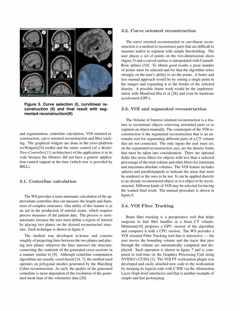
Figure 5. Curve selection (I), curvilinear re-construction (II) and final result with seg-mented reconstruction(III)
and segmentation, centerline calculation, VOI oriented re-construction, curve oriented reconstruction and fiber track-ing. The graphical widgets are done in the cross-platformwxWidgets[24] toolkit and the entire control (of a Model-View-Controller[11] architecture) of the application is in itscode because the libraries did not have a generic applica-tion control support at the time (which now is provided byBILL).
3.1. Centerline calculation
The WS provides a semi-automatic calculation of the ap-proximate centerline that can measure the length and diam-eters of complex structures. One utility of this feature is asan aid in the production of arterial stents, which requiresprecise measures of the patient data. The process is semi-automatic because the user must define a region of interestby placing two planes on the desired reconstructed struc-ture. Such technique is shown in figure 4.
The method was developed in-house and consistsroughly of projecting lines between the two planes and plac-ing new planes wherever the lines intersect the structure,connecting the centroids of the generated cross-sections ina manner similar to [9]. Although centerline computationalgorithms are usually voxel-based [14, 7], the method usedoperates on polygonal meshes generated by the MarchingCubes reconstruction. As such, the quality of the generatedcenterline is more dependent of the resolution of the gener-ated mesh than of the volumetric data [20].
3.2. Curve oriented reconstruction
The curve oriented reconstruction or curvilinear recon-struction is a method to reconstruct parts that are difficult tomeasure and/or to segment with simple thresholding. Theuser places a set of points on the two-dimensional slices(figure 5) and a curved surface is interpolated with Catmull-Rom splines [10]. To obtain good results a great numberof points must be selected and for that the algorithm reliesstrongly on the user’s ability to set the points. A better andless manual approach would be by setting a single point inthe images and expanding it to the border of the selecteddensity. A possible future work would be the implemen-tation with Mumford-Sha et al [28] and even be hardwareaccelerated (GPU).
3.3. VOI and segmented reconstruction
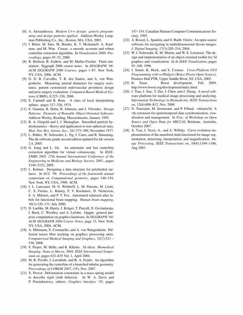
The Volume of Interest oriented reconstruction is a fea-ture to reconstruct objects removing unwanted parts or tosegment an object manually. The counterpart of the VOI re-construction is the segmented reconstruction that is an au-tomatic tool for segmenting different parts of a CT volumethat are not connected. The only inputs the user must set,on the segmented reconstruction case, are the density limitsthat must be taken into consideration. There are optionalfields like noise filters for objects with less than a selectedpercentage of the total volume and other filters for minimumand maximum absolute volumes. The VOI feature includesspheres and parallelepipeds to indicate the areas that mustbe rendered or the ones to be not. It can be applied directlyto an already reconstructed object or to a object to be recon-structed. Different kinds of VOI may be selected for havingthe wanted final result. The manual procedure is shown infigure 6.
3.4. VOI Fiber Tracking
Brain fiber tracking is a preoperative tool that helpssurgeons to find fiber bundles in a brain CT volume.Mittmann[18] proposes a GPU version of the algorithmand compares it with a CPU version. The WS provides aVOI oriented Fiber Tracking tool that is interactive — theuser moves the bounding volume and the tracts that passthrough the volume are automatically computed and dis-played. Such operation is shown in figure 7 and is com-puted in real-time on the Graphics Processing Unit usingNVIDIA’s CUDA [1]. The VOI FT workstation plugin wasdeveloped and easily attached new code to the workstationby merging its logical code with C3DE via the AbstractionLayer (high-level interfaces) and that is another example ofsimple and fast prototyping.
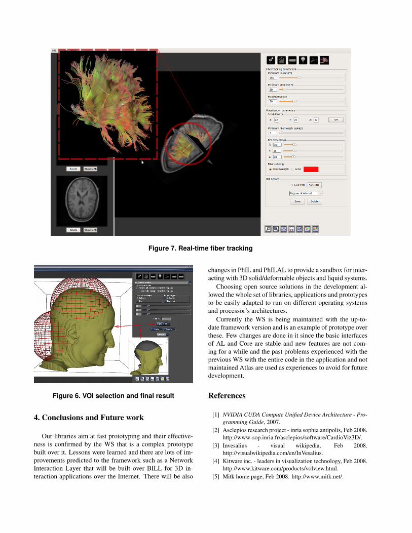
Figure 7. Real-time fiber tracking
Figure 6. VOI selection and final result
4. Conclusions and Future work
Our libraries aim at fast prototyping and their effective-ness is confirmed by the WS that is a complex prototypebuilt over it. Lessons were learned and there are lots of im-provements predicted to the framework such as a NetworkInteraction Layer that will be built over BILL for 3D in-teraction applications over the Internet. There will be also
changes in PhIL and PhILAL to provide a sandbox for inter-acting with 3D solid/deformable objects and liquid systems.
Choosing open source solutions in the development al-lowed the whole set of libraries, applications and prototypesto be easily adapted to run on different operating systemsand processor’s architectures.
Currently the WS is being maintained with the up-to-date framework version and is an example of prototype overthese. Few changes are done in it since the basic interfacesof AL and Core are stable and new features are not com-ing for a while and the past problems experienced with theprevious WS with the entire code in the application and notmaintained Atlas are used as experiences to avoid for futuredevelopment.
References
[1] NVIDIA CUDA Compute Unified Device Architecture - Pro-gramming Guide, 2007.
[2] Asclepios research project - inria sophia antipolis, Feb 2008.http://www-sop.inria.fr/asclepios/software/CardioViz3D/.
[3] Invesalius - visual wikipedia, Feb 2008.http://visualwikipedia.com/en/InVesalius.
[4] Kitware inc. - leaders in visualization technology, Feb 2008.http://www.kitware.com/products/volview.html.
[5] Mitk home page, Feb 2008. http://www.mitk.net/.
[6] A. Alexandrescu. Modern C++ design: generic program-ming and design patterns applied. Addison-Wesley Long-man Publishing Co., Inc., Boston, MA, USA, 2001.
[7] I. Bitter, M. Sato, M. Bender, K. T. Mcdonnell, A. Kauf-man, and M. Wan. Ceasar: a smooth, accurate and robustcenterline extraction algorithm. In Visualization 2000. Pro-ceedings, pages 45–52, 2000.
[8] R. Bridson, R. Fedkiw, and M. Muller-Fischer. Fluid sim-ulation: Siggraph 2006 course notes. In SIGGRAPH ’06:ACM SIGGRAPH 2006 Courses, pages 1–87, New York,NY, USA, 2006. ACM.
[9] D. D. B. Carvalho, T. R. dos Santos, and A. von Wan-genheim. Measuring arterial diameters for surgery assis-tance, patient customized endovascular prosthesis designand post-surgery evaluation. Computed-Based Medical Sys-tems (CBMS), 0:225–230, 2006.
[10] E. Catmull and R. Rom. A class of local interpolatingsplines. pages 317–326, 1974.
[11] E. Gamma, R. Helm, R. Johnson, and J. Vlissides. DesignPatterns: Elements of Reusable Object-Oriented Software.Addison Wesley, Reading, Massachusetts, January 1995.
[12] R. A. Gingold and J. J. Monaghan. Smoothed particle hy-drodynamics - theory and application to non-spherical stars.Mon. Not. Roy. Astron. Soc., 181:375–389, November 1977.
[13] L. Ibáñez, W. Schroeder, L. Ng, J. Cates, and R. Hamming.The itk software guide second edition updated for itk version2.4, 2005.
[14] G. Jiang and L. Gu. An automatic and fast centerlineextraction algorithm for virtual colonoscopy. In IEEE-EMBS 2005. 27th Annual International Conference of theEngineering in Medicine and Biology Society, 2005., pages5149–5152, 2005.
[15] L. Kettner. Designing a data structure for polyhedral sur-faces. In SCG ’98: Proceedings of the fourteenth annualsymposium on Computational geometry, pages 146–154,New York, NY, USA, 1998. ACM.
[16] J. L. Lancaster, M. G. Woldorff, L. M. Parsons, M. Liotti,C. S. Freitas, L. Rainey, P. V. Kochunov, D. Nickerson,S. A. Mikiten, and P. T. Fox. Automated talairach atlas la-bels for functional brain mapping. Human brain mapping,10(3):120–131, July 2000.
[17] D. Luebke, M. Harris, J. Krüger, T. Purcell, N. Govindaraju,I. Buck, C. Woolley, and A. Lefohn. Gpgpu: general pur-pose computation on graphics hardware. In SIGGRAPH ’04:ACM SIGGRAPH 2004 Course Notes, page 33, New York,NY, USA, 2004. ACM.
[18] A. Mittmann, E. Comunello, and A. von Wangenheim. Dif-fusion tensor fiber tracking on graphics processing units.Computerized Medical Imaging and Graphics, 32(7):521 –530, 2008.
[19] S. Pieper, M. Halle, and R. Kikinis. 3d slicer. BiomedicalImaging: Nano to Macro, 2004. IEEE International Sympo-sium on, pages 632–635 Vol. 1, April 2004.
[20] M. R. Pivello, I. Larrabide, and R. A. Feijóo. An algorithmfor generating the centerline of a branched tubular geometry.Proceedings of COBEM 2007, (19), Nov. 2007.
[21] X. Provot. Deformation constraints in a mass-spring modelto describe rigid cloth behavior. In W. A. Davis andP. Prusinkiewicz, editors, Graphics Interface ’95, pages
147–154. Canadian Human-Computer Communications So-ciety, 1995.
[22] A. Rosset, L. Spadola, and O. Ratib. Osirix: An open-sourcesoftware for navigating in multidimensional dicom images.J. Digital Imaging, 17(3):205–216, 2004.
[23] W. J. Schroeder, K. M. Martin, and W. E. Lorensen. The de-sign and implementation of an object-oriented toolkit for 3dgraphics and visualization. In In IEEE Visualization, pages93–100, 1996.
[24] J. Smart, K. Hock, and S. Csomor. Cross-Platform GUIProgramming with wxWidgets (Bruce Perens Open Source).Prentice Hall PTR, Upper Saddle River, NJ, USA, 2005.
[25] B. Team. Boost development, Feb. 2009.http://www.boost.org/development/index.html.
[26] J. Tian, J. Xue, Y. Dai, J. Chen, and J. Zheng. A novel soft-ware platform for medical image processing and analyzing.Information Technology in Biomedicine, IEEE Transactionson, 12(6):800–812, Nov. 2008.
[27] N. Toussaint, M. Sermesant, and P. Fillard. vtkinria3d: Avtk extension for spatiotemporal data synchronization, visu-alization and management. In Proc. of Workshop on OpenSource and Open Data for MICCAI, Brisbane, Australia,October 2007.
[28] A. Tsai, J. Yezzi, A., and A. Willsky. Curve evolution im-plementation of the mumford-shah functional for image seg-mentation, denoising, interpolation, and magnification. Im-age Processing, IEEE Transactions on, 10(8):1169–1186,Aug 2001.