Basic Physics for Medical Imaging - OpenStax CNX
329
Basic Physics for Medical Imaging Collection edited by: Wade Hedegard Content authors: OpenStax Based on: College Physics <http://legacy.cnx.org/content/col11406/1.7>. Online: <https://legacy.cnx.org/content/col11630/1.1> This selection and arrangement of content as a collection is copyrighted by Wade Hedegard. Creative Commons Attribution License 3.0 http://creativecommons.org/licenses/by/3.0/ Collection structure revised: 2014/02/17 PDF Generated: 2022/01/31 17:27:16 For copyright and attribution information for the modules contained in this collection, see the "Attributions" section at the end of the collection. 1
-
Upload
khangminh22 -
Category
Documents
-
view
0 -
download
0
Transcript of Basic Physics for Medical Imaging - OpenStax CNX

Basic Physics for Medical ImagingCollection edited by: Wade HedegardContent authors: OpenStaxBased on: College Physics <http://legacy.cnx.org/content/col11406/1.7>.Online: <https://legacy.cnx.org/content/col11630/1.1>This selection and arrangement of content as a collection is copyrighted by Wade Hedegard.Creative Commons Attribution License 3.0 http://creativecommons.org/licenses/by/3.0/Collection structure revised: 2014/02/17PDF Generated: 2022/01/31 17:27:16For copyright and attribution information for the modules contained in this collection, see the "Attributions" section at the end ofthe collection.
1

2
This OpenStax book is available for free at https://legacy.cnx.org/content/col11630/1.1

Table of Contents1 Introduction: The Nature of Science and Physics . . . . . . . . . . . . . . . . . . . . . . . . . . . . . . . . . . . 5
Physics: An Introduction . . . . . . . . . . . . . . . . . . . . . . . . . . . . . . . . . . . . . . . . . . . . . . . . . 6Physical Quantities and Units . . . . . . . . . . . . . . . . . . . . . . . . . . . . . . . . . . . . . . . . . . . . . . 13Accuracy, Precision, and Significant Figures . . . . . . . . . . . . . . . . . . . . . . . . . . . . . . . . . . . . . . . 20Approximation . . . . . . . . . . . . . . . . . . . . . . . . . . . . . . . . . . . . . . . . . . . . . . . . . . . . . . 24
2 Physics of Hearing . . . . . . . . . . . . . . . . . . . . . . . . . . . . . . . . . . . . . . . . . . . . . . . . . . . . 31Sound . . . . . . . . . . . . . . . . . . . . . . . . . . . . . . . . . . . . . . . . . . . . . . . . . . . . . . . . . . . 32Speed of Sound, Frequency, and Wavelength . . . . . . . . . . . . . . . . . . . . . . . . . . . . . . . . . . . . . . 34Sound Intensity and Sound Level . . . . . . . . . . . . . . . . . . . . . . . . . . . . . . . . . . . . . . . . . . . . 37Doppler Effect and Sonic Booms . . . . . . . . . . . . . . . . . . . . . . . . . . . . . . . . . . . . . . . . . . . . . 41Sound Interference and Resonance: Standing Waves in Air Columns . . . . . . . . . . . . . . . . . . . . . . . . . . 46Hearing . . . . . . . . . . . . . . . . . . . . . . . . . . . . . . . . . . . . . . . . . . . . . . . . . . . . . . . . . . 53Ultrasound . . . . . . . . . . . . . . . . . . . . . . . . . . . . . . . . . . . . . . . . . . . . . . . . . . . . . . . . 58
3 Magnetism . . . . . . . . . . . . . . . . . . . . . . . . . . . . . . . . . . . . . . . . . . . . . . . . . . . . . . . . . 73Magnets . . . . . . . . . . . . . . . . . . . . . . . . . . . . . . . . . . . . . . . . . . . . . . . . . . . . . . . . . 74Ferromagnets and Electromagnets . . . . . . . . . . . . . . . . . . . . . . . . . . . . . . . . . . . . . . . . . . . . 76Magnetic Fields and Magnetic Field Lines . . . . . . . . . . . . . . . . . . . . . . . . . . . . . . . . . . . . . . . . 80Magnetic Field Strength: Force on a Moving Charge in a Magnetic Field . . . . . . . . . . . . . . . . . . . . . . . . 81Force on a Moving Charge in a Magnetic Field: Examples and Applications . . . . . . . . . . . . . . . . . . . . . . 83The Hall Effect . . . . . . . . . . . . . . . . . . . . . . . . . . . . . . . . . . . . . . . . . . . . . . . . . . . . . . 88Magnetic Force on a Current-Carrying Conductor . . . . . . . . . . . . . . . . . . . . . . . . . . . . . . . . . . . . 90Torque on a Current Loop: Motors and Meters . . . . . . . . . . . . . . . . . . . . . . . . . . . . . . . . . . . . . . 92Magnetic Fields Produced by Currents: Ampere’s Law . . . . . . . . . . . . . . . . . . . . . . . . . . . . . . . . . 96Magnetic Force between Two Parallel Conductors . . . . . . . . . . . . . . . . . . . . . . . . . . . . . . . . . . . 100More Applications of Magnetism . . . . . . . . . . . . . . . . . . . . . . . . . . . . . . . . . . . . . . . . . . . . 101
4 Electromagnetic Waves . . . . . . . . . . . . . . . . . . . . . . . . . . . . . . . . . . . . . . . . . . . . . . . . . 119Maxwell’s Equations: Electromagnetic Waves Predicted and Observed . . . . . . . . . . . . . . . . . . . . . . . . 120Production of Electromagnetic Waves . . . . . . . . . . . . . . . . . . . . . . . . . . . . . . . . . . . . . . . . . 122The Electromagnetic Spectrum . . . . . . . . . . . . . . . . . . . . . . . . . . . . . . . . . . . . . . . . . . . . . 125Energy in Electromagnetic Waves . . . . . . . . . . . . . . . . . . . . . . . . . . . . . . . . . . . . . . . . . . . 138
5 Introduction to Quantum Physics . . . . . . . . . . . . . . . . . . . . . . . . . . . . . . . . . . . . . . . . . . . 149Quantization of Energy . . . . . . . . . . . . . . . . . . . . . . . . . . . . . . . . . . . . . . . . . . . . . . . . . 150The Photoelectric Effect . . . . . . . . . . . . . . . . . . . . . . . . . . . . . . . . . . . . . . . . . . . . . . . . 152Photon Energies and the Electromagnetic Spectrum . . . . . . . . . . . . . . . . . . . . . . . . . . . . . . . . . 155Photon Momentum . . . . . . . . . . . . . . . . . . . . . . . . . . . . . . . . . . . . . . . . . . . . . . . . . . . 162The Particle-Wave Duality . . . . . . . . . . . . . . . . . . . . . . . . . . . . . . . . . . . . . . . . . . . . . . . 165The Wave Nature of Matter . . . . . . . . . . . . . . . . . . . . . . . . . . . . . . . . . . . . . . . . . . . . . . . 166Probability: The Heisenberg Uncertainty Principle . . . . . . . . . . . . . . . . . . . . . . . . . . . . . . . . . . . 169The Particle-Wave Duality Reviewed . . . . . . . . . . . . . . . . . . . . . . . . . . . . . . . . . . . . . . . . . . 174
6 Atomic Physics . . . . . . . . . . . . . . . . . . . . . . . . . . . . . . . . . . . . . . . . . . . . . . . . . . . . . 185Discovery of the Atom . . . . . . . . . . . . . . . . . . . . . . . . . . . . . . . . . . . . . . . . . . . . . . . . . 186Discovery of the Parts of the Atom: Electrons and Nuclei . . . . . . . . . . . . . . . . . . . . . . . . . . . . . . . 187Bohr’s Theory of the Hydrogen Atom . . . . . . . . . . . . . . . . . . . . . . . . . . . . . . . . . . . . . . . . . . 194X Rays: Atomic Origins and Applications . . . . . . . . . . . . . . . . . . . . . . . . . . . . . . . . . . . . . . . . 201Applications of Atomic Excitations and De-Excitations . . . . . . . . . . . . . . . . . . . . . . . . . . . . . . . . . 206The Wave Nature of Matter Causes Quantization . . . . . . . . . . . . . . . . . . . . . . . . . . . . . . . . . . . 214Patterns in Spectra Reveal More Quantization . . . . . . . . . . . . . . . . . . . . . . . . . . . . . . . . . . . . . 216Quantum Numbers and Rules . . . . . . . . . . . . . . . . . . . . . . . . . . . . . . . . . . . . . . . . . . . . . 219The Pauli Exclusion Principle . . . . . . . . . . . . . . . . . . . . . . . . . . . . . . . . . . . . . . . . . . . . . . 223
7 Radioactivity and Nuclear Physics . . . . . . . . . . . . . . . . . . . . . . . . . . . . . . . . . . . . . . . . . . . 241Nuclear Radioactivity . . . . . . . . . . . . . . . . . . . . . . . . . . . . . . . . . . . . . . . . . . . . . . . . . . 242Radiation Detection and Detectors . . . . . . . . . . . . . . . . . . . . . . . . . . . . . . . . . . . . . . . . . . . 246Substructure of the Nucleus . . . . . . . . . . . . . . . . . . . . . . . . . . . . . . . . . . . . . . . . . . . . . . 249Nuclear Decay and Conservation Laws . . . . . . . . . . . . . . . . . . . . . . . . . . . . . . . . . . . . . . . . 253Half-Life and Activity . . . . . . . . . . . . . . . . . . . . . . . . . . . . . . . . . . . . . . . . . . . . . . . . . . 260Binding Energy . . . . . . . . . . . . . . . . . . . . . . . . . . . . . . . . . . . . . . . . . . . . . . . . . . . . . 266Tunneling . . . . . . . . . . . . . . . . . . . . . . . . . . . . . . . . . . . . . . . . . . . . . . . . . . . . . . . . 271
8 Medical Applications of Nuclear Physics . . . . . . . . . . . . . . . . . . . . . . . . . . . . . . . . . . . . . . . 285Medical Imaging and Diagnostics . . . . . . . . . . . . . . . . . . . . . . . . . . . . . . . . . . . . . . . . . . . 286Biological Effects of Ionizing Radiation . . . . . . . . . . . . . . . . . . . . . . . . . . . . . . . . . . . . . . . . . 290Therapeutic Uses of Ionizing Radiation . . . . . . . . . . . . . . . . . . . . . . . . . . . . . . . . . . . . . . . . 296
Appendix A: Selected Radioactive Isotopes . . . . . . . . . . . . . . . . . . . . . . . . . . . . . . . . . . . . . . 303Appendix B: Glossary of Key Symbols and Notation . . . . . . . . . . . . . . . . . . . . . . . . . . . . . . . . . . 307Index . . . . . . . . . . . . . . . . . . . . . . . . . . . . . . . . . . . . . . . . . . . . . . . . . . . . . . . . . . . . 319

This OpenStax book is available for free at https://legacy.cnx.org/content/col11630/1.1

1 INTRODUCTION: THE NATURE OFSCIENCE AND PHYSICS
Figure 1.1 Galaxies are as immense as atoms are small. Yet the same laws of physics describe both, and all the rest of nature—an indication of theunderlying unity in the universe. The laws of physics are surprisingly few in number, implying an underlying simplicity to nature’s apparent complexity.(credit: NASA, JPL-Caltech, P. Barmby, Harvard-Smithsonian Center for Astrophysics)
Chapter Outline1.1. Physics: An Introduction
• Explain the difference between a principle and a law.• Explain the difference between a model and a theory.
1.2. Physical Quantities and Units• Perform unit conversions both in the SI and English units.• Explain the most common prefixes in the SI units and be able to write them in scientific notation.
1.3. Accuracy, Precision, and Significant Figures• Determine the appropriate number of significant figures in both addition and subtraction, as well as multiplication and
division calculations.• Calculate the percent uncertainty of a measurement.
1.4. Approximation• Make reasonable approximations based on given data.
Introduction to Science and the Realm of Physics, Physical Quantities, and Units
What is your first reaction when you hear the word “physics”? Did you imagine working through difficult equations or memorizingformulas that seem to have no real use in life outside the physics classroom? Many people come to the subject of physics with abit of fear. But as you begin your exploration of this broad-ranging subject, you may soon come to realize that physics plays amuch larger role in your life than you first thought, no matter your life goals or career choice.
For example, take a look at the image above. This image is of the Andromeda Galaxy, which contains billions of individual stars,huge clouds of gas, and dust. Two smaller galaxies are also visible as bright blue spots in the background. At a staggering 2.5million light years from the Earth, this galaxy is the nearest one to our own galaxy (which is called the Milky Way). The stars andplanets that make up Andromeda might seem to be the furthest thing from most people’s regular, everyday lives. But Andromedais a great starting point to think about the forces that hold together the universe. The forces that cause Andromeda to act as itdoes are the same forces we contend with here on Earth, whether we are planning to send a rocket into space or simply raisethe walls for a new home. The same gravity that causes the stars of Andromeda to rotate and revolve also causes water to flowover hydroelectric dams here on Earth. Tonight, take a moment to look up at the stars. The forces out there are the same as theones here on Earth. Through a study of physics, you may gain a greater understanding of the interconnectedness of everythingwe can see and know in this universe.
Think now about all of the technological devices that you use on a regular basis. Computers, smart phones, GPS systems, MP3players, and satellite radio might come to mind. Next, think about the most exciting modern technologies that you have heardabout in the news, such as trains that levitate above tracks, “invisibility cloaks” that bend light around them, and microscopicrobots that fight cancer cells in our bodies. All of these groundbreaking advancements, commonplace or unbelievable, rely on theprinciples of physics. Aside from playing a significant role in technology, professionals such as engineers, pilots, physicians,physical therapists, electricians, and computer programmers apply physics concepts in their daily work. For example, a pilot mustunderstand how wind forces affect a flight path and a physical therapist must understand how the muscles in the bodyexperience forces as they move and bend. As you will learn in this text, physics principles are propelling new, excitingtechnologies, and these principles are applied in a wide range of careers.
Chapter 1 | Introduction: The Nature of Science and Physics 5

In this text, you will begin to explore the history of the formal study of physics, beginning with natural philosophy and the ancientGreeks, and leading up through a review of Sir Isaac Newton and the laws of physics that bear his name. You will also beintroduced to the standards scientists use when they study physical quantities and the interrelated system of measurementsmost of the scientific community uses to communicate in a single mathematical language. Finally, you will study the limits of ourability to be accurate and precise, and the reasons scientists go to painstaking lengths to be as clear as possible regarding theirown limitations.
1.1 Physics: An Introduction
Figure 1.2 The flight formations of migratory birds such as Canada geese are governed by the laws of physics. (credit: David Merrett)
The physical universe is enormously complex in its detail. Every day, each of us observes a great variety of objects andphenomena. Over the centuries, the curiosity of the human race has led us collectively to explore and catalog a tremendouswealth of information. From the flight of birds to the colors of flowers, from lightning to gravity, from quarks to clusters of galaxies,from the flow of time to the mystery of the creation of the universe, we have asked questions and assembled huge arrays offacts. In the face of all these details, we have discovered that a surprisingly small and unified set of physical laws can explainwhat we observe. As humans, we make generalizations and seek order. We have found that nature is remarkably cooperative—itexhibits the underlying order and simplicity we so value.
It is the underlying order of nature that makes science in general, and physics in particular, so enjoyable to study. For example,what do a bag of chips and a car battery have in common? Both contain energy that can be converted to other forms. The law ofconservation of energy (which says that energy can change form but is never lost) ties together such topics as food calories,batteries, heat, light, and watch springs. Understanding this law makes it easier to learn about the various forms energy takesand how they relate to one another. Apparently unrelated topics are connected through broadly applicable physical laws,permitting an understanding beyond just the memorization of lists of facts.
The unifying aspect of physical laws and the basic simplicity of nature form the underlying themes of this text. In learning to applythese laws, you will, of course, study the most important topics in physics. More importantly, you will gain analytical abilities thatwill enable you to apply these laws far beyond the scope of what can be included in a single book. These analytical skills will helpyou to excel academically, and they will also help you to think critically in any professional career you choose to pursue. Thismodule discusses the realm of physics (to define what physics is), some applications of physics (to illustrate its relevance toother disciplines), and more precisely what constitutes a physical law (to illuminate the importance of experimentation to theory).
Science and the Realm of Physics
Science consists of the theories and laws that are the general truths of nature as well as the body of knowledge they encompass.Scientists are continually trying to expand this body of knowledge and to perfect the expression of the laws that describe it.Physics is concerned with describing the interactions of energy, matter, space, and time, and it is especially interested in whatfundamental mechanisms underlie every phenomenon. The concern for describing the basic phenomena in nature essentiallydefines the realm of physics.
Physics aims to describe the function of everything around us, from the movement of tiny charged particles to the motion ofpeople, cars, and spaceships. In fact, almost everything around you can be described quite accurately by the laws of physics.Consider a smart phone (Figure 1.3). Physics describes how electricity interacts with the various circuits inside the device. Thisknowledge helps engineers select the appropriate materials and circuit layout when building the smart phone. Next, consider aGPS system. Physics describes the relationship between the speed of an object, the distance over which it travels, and the timeit takes to travel that distance. When you use a GPS device in a vehicle, it utilizes these physics equations to determine thetravel time from one location to another.
6 Chapter 1 | Introduction: The Nature of Science and Physics
This OpenStax book is available for free at https://legacy.cnx.org/content/col11630/1.1

Figure 1.3 The Apple “iPhone” is a common smart phone with a GPS function. Physics describes the way that electricity flows through the circuits ofthis device. Engineers use their knowledge of physics to construct an iPhone with features that consumers will enjoy. One specific feature of an iPhoneis the GPS function. GPS uses physics equations to determine the driving time between two locations on a map. (credit: @gletham GIS, Social, MobileTech Images)
Applications of Physics
You need not be a scientist to use physics. On the contrary, knowledge of physics is useful in everyday situations as well as innonscientific professions. It can help you understand how microwave ovens work, why metals should not be put into them, andwhy they might affect pacemakers. (See Figure 1.4 and Figure 1.5.) Physics allows you to understand the hazards of radiationand rationally evaluate these hazards more easily. Physics also explains the reason why a black car radiator helps remove heatin a car engine, and it explains why a white roof helps keep the inside of a house cool. Similarly, the operation of a car’s ignitionsystem as well as the transmission of electrical signals through our body’s nervous system are much easier to understand whenyou think about them in terms of basic physics.
Physics is the foundation of many important disciplines and contributes directly to others. Chemistry, for example—since it dealswith the interactions of atoms and molecules—is rooted in atomic and molecular physics. Most branches of engineering areapplied physics. In architecture, physics is at the heart of structural stability, and is involved in the acoustics, heating, lighting,and cooling of buildings. Parts of geology rely heavily on physics, such as radioactive dating of rocks, earthquake analysis, andheat transfer in the Earth. Some disciplines, such as biophysics and geophysics, are hybrids of physics and other disciplines.
Physics has many applications in the biological sciences. On the microscopic level, it helps describe the properties of cell wallsand cell membranes (Figure 1.6 and Figure 1.7). On the macroscopic level, it can explain the heat, work, and power associatedwith the human body. Physics is involved in medical diagnostics, such as x-rays, magnetic resonance imaging (MRI), andultrasonic blood flow measurements. Medical therapy sometimes directly involves physics; for example, cancer radiotherapyuses ionizing radiation. Physics can also explain sensory phenomena, such as how musical instruments make sound, how theeye detects color, and how lasers can transmit information.
It is not necessary to formally study all applications of physics. What is most useful is knowledge of the basic laws of physics anda skill in the analytical methods for applying them. The study of physics also can improve your problem-solving skills.Furthermore, physics has retained the most basic aspects of science, so it is used by all of the sciences, and the study ofphysics makes other sciences easier to understand.
Figure 1.4 The laws of physics help us understand how common appliances work. For example, the laws of physics can help explain how microwaveovens heat up food, and they also help us understand why it is dangerous to place metal objects in a microwave oven. (credit: MoneyBlogNewz)
Chapter 1 | Introduction: The Nature of Science and Physics 7

Figure 1.5 These two applications of physics have more in common than meets the eye. Microwave ovens use electromagnetic waves to heat food.Magnetic resonance imaging (MRI) also uses electromagnetic waves to yield an image of the brain, from which the exact location of tumors can bedetermined. (credit: Rashmi Chawla, Daniel Smith, and Paul E. Marik)
Figure 1.6 Physics, chemistry, and biology help describe the properties of cell walls in plant cells, such as the onion cells seen here. (credit: UmbertoSalvagnin)
Figure 1.7 An artist’s rendition of the structure of a cell membrane. Membranes form the boundaries of animal cells and are complex in structure andfunction. Many of the most fundamental properties of life, such as the firing of nerve cells, are related to membranes. The disciplines of biology,chemistry, and physics all help us understand the membranes of animal cells. (credit: Mariana Ruiz)
Models, Theories, and Laws; The Role of Experimentation
The laws of nature are concise descriptions of the universe around us; they are human statements of the underlying laws or rulesthat all natural processes follow. Such laws are intrinsic to the universe; humans did not create them and so cannot changethem. We can only discover and understand them. Their discovery is a very human endeavor, with all the elements of mystery,imagination, struggle, triumph, and disappointment inherent in any creative effort. (See Figure 1.8 and Figure 1.9.) Thecornerstone of discovering natural laws is observation; science must describe the universe as it is, not as we may imagine it tobe.
8 Chapter 1 | Introduction: The Nature of Science and Physics
This OpenStax book is available for free at https://legacy.cnx.org/content/col11630/1.1

Figure 1.8 Isaac Newton (1642–1727) was very reluctant to publish his revolutionary work and had to be convinced to do so. In his later years, hestepped down from his academic post and became exchequer of the Royal Mint. He took this post seriously, inventing reeding (or creating ridges) onthe edge of coins to prevent unscrupulous people from trimming the silver off of them before using them as currency. (credit: Arthur Shuster and ArthurE. Shipley: Britain’s Heritage of Science. London, 1917.)
Figure 1.9 Marie Curie (1867–1934) sacrificed monetary assets to help finance her early research and damaged her physical well-being with radiationexposure. She is the only person to win Nobel prizes in both physics and chemistry. One of her daughters also won a Nobel Prize. (credit: WikimediaCommons)
We all are curious to some extent. We look around, make generalizations, and try to understand what we see—for example, welook up and wonder whether one type of cloud signals an oncoming storm. As we become serious about exploring nature, webecome more organized and formal in collecting and analyzing data. We attempt greater precision, perform controlledexperiments (if we can), and write down ideas about how the data may be organized and unified. We then formulate models,theories, and laws based on the data we have collected and analyzed to generalize and communicate the results of theseexperiments.
A model is a representation of something that is often too difficult (or impossible) to display directly. While a model is justifiedwith experimental proof, it is only accurate under limited situations. An example is the planetary model of the atom in whichelectrons are pictured as orbiting the nucleus, analogous to the way planets orbit the Sun. (See Figure 1.10.) We cannot observeelectron orbits directly, but the mental image helps explain the observations we can make, such as the emission of light from hotgases (atomic spectra). Physicists use models for a variety of purposes. For example, models can help physicists analyze ascenario and perform a calculation, or they can be used to represent a situation in the form of a computer simulation. A theory isan explanation for patterns in nature that is supported by scientific evidence and verified multiple times by various groups ofresearchers. Some theories include models to help visualize phenomena, whereas others do not. Newton’s theory of gravity, forexample, does not require a model or mental image, because we can observe the objects directly with our own senses. Thekinetic theory of gases, on the other hand, is a model in which a gas is viewed as being composed of atoms and molecules.Atoms and molecules are too small to be observed directly with our senses—thus, we picture them mentally to understand whatour instruments tell us about the behavior of gases.
A law uses concise language to describe a generalized pattern in nature that is supported by scientific evidence and repeatedexperiments. Often, a law can be expressed in the form of a single mathematical equation. Laws and theories are similar in thatthey are both scientific statements that result from a tested hypothesis and are supported by scientific evidence. However, the
Chapter 1 | Introduction: The Nature of Science and Physics 9

designation law is reserved for a concise and very general statement that describes phenomena in nature, such as the law thatenergy is conserved during any process, or Newton’s second law of motion, which relates force, mass, and acceleration by thesimple equation F = ma . A theory, in contrast, is a less concise statement of observed phenomena. For example, the Theory of
Evolution and the Theory of Relativity cannot be expressed concisely enough to be considered a law. The biggest differencebetween a law and a theory is that a theory is much more complex and dynamic. A law describes a single action, whereas atheory explains an entire group of related phenomena. And, whereas a law is a postulate that forms the foundation of thescientific method, a theory is the end result of that process.
Less broadly applicable statements are usually called principles (such as Pascal’s principle, which is applicable only in fluids),but the distinction between laws and principles often is not carefully made.
Figure 1.10 What is a model? This planetary model of the atom shows electrons orbiting the nucleus. It is a drawing that we use to form a mentalimage of the atom that we cannot see directly with our eyes because it is too small.
Models, Theories, and Laws
Models, theories, and laws are used to help scientists analyze the data they have already collected. However, often after amodel, theory, or law has been developed, it points scientists toward new discoveries they would not otherwise have made.
The models, theories, and laws we devise sometimes imply the existence of objects or phenomena as yet unobserved. Thesepredictions are remarkable triumphs and tributes to the power of science. It is the underlying order in the universe that enablesscientists to make such spectacular predictions. However, if experiment does not verify our predictions, then the theory or law iswrong, no matter how elegant or convenient it is. Laws can never be known with absolute certainty because it is impossible toperform every imaginable experiment in order to confirm a law in every possible scenario. Physicists operate under theassumption that all scientific laws and theories are valid until a counterexample is observed. If a good-quality, verifiableexperiment contradicts a well-established law, then the law must be modified or overthrown completely.
The study of science in general and physics in particular is an adventure much like the exploration of uncharted ocean.Discoveries are made; models, theories, and laws are formulated; and the beauty of the physical universe is made more sublimefor the insights gained.
The Scientific Method
As scientists inquire and gather information about the world, they follow a process called the scientific method. Thisprocess typically begins with an observation and question that the scientist will research. Next, the scientist typicallyperforms some research about the topic and then devises a hypothesis. Then, the scientist will test the hypothesis byperforming an experiment. Finally, the scientist analyzes the results of the experiment and draws a conclusion. Note that thescientific method can be applied to many situations that are not limited to science, and this method can be modified to suitthe situation.
Consider an example. Let us say that you try to turn on your car, but it will not start. You undoubtedly wonder: Why will thecar not start? You can follow a scientific method to answer this question. First off, you may perform some research todetermine a variety of reasons why the car will not start. Next, you will state a hypothesis. For example, you may believe thatthe car is not starting because it has no engine oil. To test this, you open the hood of the car and examine the oil level. Youobserve that the oil is at an acceptable level, and you thus conclude that the oil level is not contributing to your car issue. Totroubleshoot the issue further, you may devise a new hypothesis to test and then repeat the process again.
The Evolution of Natural Philosophy into Modern Physics
Physics was not always a separate and distinct discipline. It remains connected to other sciences to this day. The word physicscomes from Greek, meaning nature. The study of nature came to be called “natural philosophy.” From ancient times through theRenaissance, natural philosophy encompassed many fields, including astronomy, biology, chemistry, physics, mathematics, andmedicine. Over the last few centuries, the growth of knowledge has resulted in ever-increasing specialization and branching ofnatural philosophy into separate fields, with physics retaining the most basic facets. (See Figure 1.11, Figure 1.12, and Figure1.13.) Physics as it developed from the Renaissance to the end of the 19th century is called classical physics. It wastransformed into modern physics by revolutionary discoveries made starting at the beginning of the 20th century.
10 Chapter 1 | Introduction: The Nature of Science and Physics
This OpenStax book is available for free at https://legacy.cnx.org/content/col11630/1.1

Figure 1.11 Over the centuries, natural philosophy has evolved into more specialized disciplines, as illustrated by the contributions of some of thegreatest minds in history. The Greek philosopher Aristotle (384–322 B.C.) wrote on a broad range of topics including physics, animals, the soul,politics, and poetry. (credit: Jastrow (2006)/Ludovisi Collection)
Figure 1.12 Galileo Galilei (1564–1642) laid the foundation of modern experimentation and made contributions in mathematics, physics, andastronomy. (credit: Domenico Tintoretto)
Figure 1.13 Niels Bohr (1885–1962) made fundamental contributions to the development of quantum mechanics, one part of modern physics. (credit:United States Library of Congress Prints and Photographs Division)
Classical physics is not an exact description of the universe, but it is an excellent approximation under the following conditions:Matter must be moving at speeds less than about 1% of the speed of light, the objects dealt with must be large enough to beseen with a microscope, and only weak gravitational fields, such as the field generated by the Earth, can be involved. Becausehumans live under such circumstances, classical physics seems intuitively reasonable, while many aspects of modern physicsseem bizarre. This is why models are so useful in modern physics—they let us conceptualize phenomena we do not ordinarilyexperience. We can relate to models in human terms and visualize what happens when objects move at high speeds or imaginewhat objects too small to observe with our senses might be like. For example, we can understand an atom’s properties becausewe can picture it in our minds, although we have never seen an atom with our eyes. New tools, of course, allow us to better
Chapter 1 | Introduction: The Nature of Science and Physics 11

picture phenomena we cannot see. In fact, new instrumentation has allowed us in recent years to actually “picture” the atom.
Limits on the Laws of Classical Physics
For the laws of classical physics to apply, the following criteria must be met: Matter must be moving at speeds less thanabout 1% of the speed of light, the objects dealt with must be large enough to be seen with a microscope, and only weakgravitational fields (such as the field generated by the Earth) can be involved.
Figure 1.14 Using a scanning tunneling microscope (STM), scientists can see the individual atoms that compose this sheet of gold. (credit:Erwinrossen)
Some of the most spectacular advances in science have been made in modern physics. Many of the laws of classical physicshave been modified or rejected, and revolutionary changes in technology, society, and our view of the universe have resulted.Like science fiction, modern physics is filled with fascinating objects beyond our normal experiences, but it has the advantageover science fiction of being very real. Why, then, is the majority of this text devoted to topics of classical physics? There are twomain reasons: Classical physics gives an extremely accurate description of the universe under a wide range of everydaycircumstances, and knowledge of classical physics is necessary to understand modern physics.
Modern physics itself consists of the two revolutionary theories, relativity and quantum mechanics. These theories deal with thevery fast and the very small, respectively. Relativity must be used whenever an object is traveling at greater than about 1% ofthe speed of light or experiences a strong gravitational field such as that near the Sun. Quantum mechanics must be used forobjects smaller than can be seen with a microscope. The combination of these two theories is relativistic quantum mechanics,and it describes the behavior of small objects traveling at high speeds or experiencing a strong gravitational field. Relativisticquantum mechanics is the best universally applicable theory we have. Because of its mathematical complexity, it is used onlywhen necessary, and the other theories are used whenever they will produce sufficiently accurate results. We will find, however,that we can do a great deal of modern physics with the algebra and trigonometry used in this text.
Check Your Understanding
A friend tells you he has learned about a new law of nature. What can you know about the information even before yourfriend describes the law? How would the information be different if your friend told you he had learned about a scientifictheory rather than a law?
SolutionWithout knowing the details of the law, you can still infer that the information your friend has learned conforms to therequirements of all laws of nature: it will be a concise description of the universe around us; a statement of the underlyingrules that all natural processes follow. If the information had been a theory, you would be able to infer that the information willbe a large-scale, broadly applicable generalization.
Equation Grapher
Learn about graphing polynomials. The shape of the curve changes as the constants are adjusted. View the curves for theindividual terms (e.g. y = bx ) to see how they add to generate the polynomial curve.
(This media type is not supported in this reader. Click to open media in browser.) (http://legacy.cnx.org/content/m42092/1.15/#graphing_polynomials)
Figure 1.15
12 Chapter 1 | Introduction: The Nature of Science and Physics
This OpenStax book is available for free at https://legacy.cnx.org/content/col11630/1.1

1.2 Physical Quantities and Units
Figure 1.16 The distance from Earth to the Moon may seem immense, but it is just a tiny fraction of the distances from Earth to other celestial bodies.(credit: NASA)
The range of objects and phenomena studied in physics is immense. From the incredibly short lifetime of a nucleus to the age ofthe Earth, from the tiny sizes of sub-nuclear particles to the vast distance to the edges of the known universe, from the forceexerted by a jumping flea to the force between Earth and the Sun, there are enough factors of 10 to challenge the imagination ofeven the most experienced scientist. Giving numerical values for physical quantities and equations for physical principles allowsus to understand nature much more deeply than does qualitative description alone. To comprehend these vast ranges, we mustalso have accepted units in which to express them. And we shall find that (even in the potentially mundane discussion of meters,kilograms, and seconds) a profound simplicity of nature appears—most physical quantities can be expressed as combinations ofonly four fundamental physical quantities: length, mass, time, and electric current.
We define a physical quantity either by specifying how it is measured or by stating how it is calculated from othermeasurements. For example, we define distance and time by specifying methods for measuring them, whereas we defineaverage speed by stating that it is calculated as distance traveled divided by time of travel.
Measurements of physical quantities are expressed in terms of units, which are standardized values. For example, the length ofa race, which is a physical quantity, can be expressed in units of meters (for sprinters) or kilometers (for distance runners).Without standardized units, it would be extremely difficult for scientists to express and compare measured values in a meaningfulway. (See Figure 1.17.)
Figure 1.17 Distances given in unknown units are maddeningly useless.
There are two major systems of units used in the world: SI units (also known as the metric system) and English units (alsoknown as the customary or imperial system). English units were historically used in nations once ruled by the British Empireand are still widely used in the United States. Virtually every other country in the world now uses SI units as the standard; themetric system is also the standard system agreed upon by scientists and mathematicians. The acronym “SI” is derived from theFrench Système International.
SI Units: Fundamental and Derived Units
Table 1.1 gives the fundamental SI units that are used throughout this textbook. This text uses non-SI units in a few applicationswhere they are in very common use, such as the measurement of blood pressure in millimeters of mercury (mm Hg). Whenevernon-SI units are discussed, they will be tied to SI units through conversions.
Table 1.1 Fundamental SI Units
Length Mass Time Electric Current
meter (m) kilogram (kg) second (s) ampere (A)
Chapter 1 | Introduction: The Nature of Science and Physics 13

It is an intriguing fact that some physical quantities are more fundamental than others and that the most fundamental physicalquantities can be defined only in terms of the procedure used to measure them. The units in which they are measured are thuscalled fundamental units. In this textbook, the fundamental physical quantities are taken to be length, mass, time, and electriccurrent. (Note that electric current will not be introduced until much later in this text.) All other physical quantities, such as forceand electric charge, can be expressed as algebraic combinations of length, mass, time, and current (for example, speed is lengthdivided by time); these units are called derived units.
Units of Time, Length, and Mass: The Second, Meter, and KilogramThe Second
The SI unit for time, the second (abbreviated s), has a long history. For many years it was defined as 1/86,400 of a mean solarday. More recently, a new standard was adopted to gain greater accuracy and to define the second in terms of a non-varying, orconstant, physical phenomenon (because the solar day is getting longer due to very gradual slowing of the Earth’s rotation).Cesium atoms can be made to vibrate in a very steady way, and these vibrations can be readily observed and counted. In 1967the second was redefined as the time required for 9,192,631,770 of these vibrations. (See Figure 1.18.) Accuracy in thefundamental units is essential, because all measurements are ultimately expressed in terms of fundamental units and can be nomore accurate than are the fundamental units themselves.
Figure 1.18 An atomic clock such as this one uses the vibrations of cesium atoms to keep time to a precision of better than a microsecond per year.The fundamental unit of time, the second, is based on such clocks. This image is looking down from the top of an atomic fountain nearly 30 feet tall!(credit: Steve Jurvetson/Flickr)
The Meter
The SI unit for length is the meter (abbreviated m); its definition has also changed over time to become more accurate andprecise. The meter was first defined in 1791 as 1/10,000,000 of the distance from the equator to the North Pole. Thismeasurement was improved in 1889 by redefining the meter to be the distance between two engraved lines on a platinum-iridiumbar now kept near Paris. By 1960, it had become possible to define the meter even more accurately in terms of the wavelengthof light, so it was again redefined as 1,650,763.73 wavelengths of orange light emitted by krypton atoms. In 1983, the meter wasgiven its present definition (partly for greater accuracy) as the distance light travels in a vacuum in 1/299,792,458 of a second.(See Figure 1.19.) This change defines the speed of light to be exactly 299,792,458 meters per second. The length of the meterwill change if the speed of light is someday measured with greater accuracy.
Figure 1.19 The meter is defined to be the distance light travels in 1/299,792,458 of a second in a vacuum. Distance traveled is speed multiplied bytime.
The Kilogram
The SI unit for mass is the kilogram (abbreviated kg); it was previously defined to be the mass of a platinum-iridium cylinder keptwith the old meter standard at the International Bureau of Weights and Measures near Paris. Exact replicas of the previouslydefined kilogram are also kept at the United States’ National Institute of Standards and Technology, or NIST, located inGaithersburg, Maryland outside of Washington D.C., and at other locations around the world. The determination of all othermasses could be ultimately traced to a comparison with the standard mass. Even though the platinum-iridium cylinder wasresistant to corrosion, airborne contaminants were able to adhere to its surface, slightly changing its mass over time. In May2019, the scientific community adopted a more stable definition of the kilogram. The kilogram is now defined in terms of thesecond, the meter, and Planck's constant, h (a quantum mechanical value that relates a photon's energy to its frequency).
Electric current and its accompanying unit, the ampere, will be introduced in Introduction to Electric Current, Resistance, andOhm's Law (https://legacy.cnx.org/content/m42339/latest/) when electricity and magnetism are covered. The initial modules
14 Chapter 1 | Introduction: The Nature of Science and Physics
This OpenStax book is available for free at https://legacy.cnx.org/content/col11630/1.1

in this textbook are concerned with mechanics, fluids, heat, and waves. In these subjects all pertinent physical quantities can beexpressed in terms of the fundamental units of length, mass, and time.
Metric Prefixes
SI units are part of the metric system. The metric system is convenient for scientific and engineering calculations because theunits are categorized by factors of 10. Table 1.2 gives metric prefixes and symbols used to denote various factors of 10.
Metric systems have the advantage that conversions of units involve only powers of 10. There are 100 centimeters in a meter,1000 meters in a kilometer, and so on. In nonmetric systems, such as the system of U.S. customary units, the relationships arenot as simple—there are 12 inches in a foot, 5280 feet in a mile, and so on. Another advantage of the metric system is that thesame unit can be used over extremely large ranges of values simply by using an appropriate metric prefix. For example,distances in meters are suitable in construction, while distances in kilometers are appropriate for air travel, and the tiny measureof nanometers are convenient in optical design. With the metric system there is no need to invent new units for particularapplications.
The term order of magnitude refers to the scale of a value expressed in the metric system. Each power of 10 in the metric
system represents a different order of magnitude. For example, 101 , 102 , 103 , and so forth are all different orders of
magnitude. All quantities that can be expressed as a product of a specific power of 10 are said to be of the same order of
magnitude. For example, the number 800 can be written as 8×10² , and the number 450 can be written as 4.5×10². Thus,
the numbers 800 and 450 are of the same order of magnitude: 102. Order of magnitude can be thought of as a ballpark
estimate for the scale of a value. The diameter of an atom is on the order of 10−10 m, while the diameter of the Sun is on the
order of 109 m.
The Quest for Microscopic Standards for Basic Units
The fundamental units described in this chapter are those that produce the greatest accuracy and precision inmeasurement. There is a sense among physicists that, because there is an underlying microscopic substructure to matter, itwould be most satisfying to base our standards of measurement on microscopic objects and fundamental physicalphenomena such as the speed of light. A microscopic standard has been accomplished for the standard of time, which isbased on the oscillations of the cesium atom.
The standard for length was once based on the wavelength of light (a small-scale length) emitted by a certain type of atom,but it has been supplanted by the more precise measurement of the speed of light. If it becomes possible to measure themass of atoms or a particular arrangement of atoms such as a silicon sphere to greater precision than the kilogramstandard, it may become possible to base mass measurements on the small scale. There are also possibilities that electricalphenomena on the small scale may someday allow us to base a unit of charge on the charge of electrons and protons, butat present current and charge are related to large-scale currents and forces between wires.
Chapter 1 | Introduction: The Nature of Science and Physics 15

Table 1.2 Metric Prefixes for Powers of 10 and their Symbols
Prefix Symbol Value Example (some are approximate)
exa E 1018 exameter Em 1018 m distance light travels in a century
peta P 1015 petasecond Ps 1015 s 30 million years
tera T 1012 terawatt TW 1012 W powerful laser output
giga G 109 gigahertz GHz 109 Hz a microwave frequency
mega M 106 megacurie MCi 106 Ci high radioactivity
kilo k 103 kilometer km 103 m about 6/10 mile
hecto h 102 hectoliter hL 102 L 26 gallons
deka da 101 dekagram dag 101 g teaspoon of butter
— — 100 (=1)
deci d 10−1 deciliter dL 10−1 L less than half a soda
centi c 10−2 centimeter cm 10−2 m fingertip thickness
milli m 10−3 millimeter mm 10−3 m flea at its shoulders
micro µ 10−6 micrometer µm 10−6 m detail in microscope
nano n 10−9 nanogram ng 10−9 g small speck of dust
pico p 10−12 picofarad pF 10−12 F small capacitor in radio
femto f 10−15 femtometer fm 10−15 m size of a proton
atto a 10−18 attosecond as 10−18 s time light crosses an atom
Known Ranges of Length, Mass, and Time
The vastness of the universe and the breadth over which physics applies are illustrated by the wide range of examples of knownlengths, masses, and times in Table 1.3. Examination of this table will give you some feeling for the range of possible topics andnumerical values. (See Figure 1.20 and Figure 1.21.)
Figure 1.20 Tiny phytoplankton swims among crystals of ice in the Antarctic Sea. They range from a few micrometers to as much as 2 millimeters inlength. (credit: Prof. Gordon T. Taylor, Stony Brook University; NOAA Corps Collections)
16 Chapter 1 | Introduction: The Nature of Science and Physics
This OpenStax book is available for free at https://legacy.cnx.org/content/col11630/1.1

Figure 1.21 Galaxies collide 2.4 billion light years away from Earth. The tremendous range of observable phenomena in nature challenges theimagination. (credit: NASA/CXC/UVic./A. Mahdavi et al. Optical/lensing: CFHT/UVic./H. Hoekstra et al.)
Unit Conversion and Dimensional Analysis
It is often necessary to convert from one type of unit to another. For example, if you are reading a European cookbook, somequantities may be expressed in units of liters and you need to convert them to cups. Or, perhaps you are reading walkingdirections from one location to another and you are interested in how many miles you will be walking. In this case, you will needto convert units of feet to miles.
Let us consider a simple example of how to convert units. Let us say that we want to convert 80 meters (m) to kilometers (km).
The first thing to do is to list the units that you have and the units that you want to convert to. In this case, we have units inmeters and we want to convert to kilometers.
Next, we need to determine a conversion factor relating meters to kilometers. A conversion factor is a ratio expressing howmany of one unit are equal to another unit. For example, there are 12 inches in 1 foot, 100 centimeters in 1 meter, 60 seconds in1 minute, and so on. In this case, we know that there are 1,000 meters in 1 kilometer.
Now we can set up our unit conversion. We will write the units that we have and then multiply them by the conversion factor sothat the units cancel out, as shown:
(1.1)80m× 1 km1000m = 0.080 km.
Note that the unwanted m unit cancels, leaving only the desired km unit. You can use this method to convert between any typesof unit.
Click Appendix C (https://legacy.cnx.org/content/m42720/latest/) for a more complete list of conversion factors.
Chapter 1 | Introduction: The Nature of Science and Physics 17

Table 1.3 Approximate Values of Length, Mass, and Time
Lengths in metersMasses in kilograms (moreprecise values in parentheses)
Times in seconds (more precisevalues in parentheses)
10−18 Present experimental limit tosmallest observable detail 10−30
Mass of an electron⎛⎝9.11×10⁻³¹ kg⎞⎠ 10−23 Time for light to cross a
proton
10−15 Diameter of a proton 10−27Mass of a hydrogen atom⎛⎝1.67×10⁻²⁷ kg⎞⎠ 10−22 Mean life of an extremely
unstable nucleus
10−14 Diameter of a uranium nucleus 10−15 Mass of a bacterium 10−15 Time for one oscillation ofvisible light
10−10 Diameter of a hydrogen atom 10−5 Mass of a mosquito 10−13 Time for one vibration of anatom in a solid
10−8 Thickness of membranes in cells ofliving organisms 10−2 Mass of a hummingbird 10−8 Time for one oscillation of an
FM radio wave
10−6 Wavelength of visible light 1 Mass of a liter of water (abouta quart) 10−3 Duration of a nerve impulse
10−3 Size of a grain of sand 102 Mass of a person 1 Time for one heartbeat
1 Height of a 4-year-old child 103 Mass of a car 105 One day⎛⎝8.64×10⁴ s⎞⎠
102 Length of a football field 108 Mass of a large ship 107 One year (y)⎛⎝3.16×10⁷ s⎞⎠
104 Greatest ocean depth 1012 Mass of a large iceberg 109 About half the lifeexpectancy of a human
107 Diameter of the Earth 1015 Mass of the nucleus of a comet 1011 Recorded history
1011 Distance from the Earth to the Sun 1023Mass of the Moon⎛⎝7.35×10²² kg⎞⎠ 1017 Age of the Earth
1016 Distance traveled by light in 1 year(a light year) 1025
Mass of the Earth⎛⎝5.97×1024 kg⎞⎠ 1018 Age of the universe
1021 Diameter of the Milky Way galaxy 1030Mass of the Sun⎛⎝1.99×1030 kg⎞⎠
1022 Distance from the Earth to thenearest large galaxy (Andromeda) 1042 Mass of the Milky Way galaxy
(current upper limit)
1026 Distance from the Earth to theedges of the known universe 1053 Mass of the known universe
(current upper limit)
Example 1.1 Unit Conversions: A Short Drive Home
Suppose that you drive the 10.0 km from your university to home in 20.0 min. Calculate your average speed (a) in kilometersper hour (km/h) and (b) in meters per second (m/s). (Note: Average speed is distance traveled divided by time of travel.)
Strategy
First we calculate the average speed using the given units. Then we can get the average speed into the desired units bypicking the correct conversion factor and multiplying by it. The correct conversion factor is the one that cancels theunwanted unit and leaves the desired unit in its place.
Solution for (a)
(1) Calculate average speed. Average speed is distance traveled divided by time of travel. (Take this definition as a given fornow—average speed and other motion concepts will be covered in a later module.) In equation form,
(1.2)average speed = distancetime .
(2) Substitute the given values for distance and time.
18 Chapter 1 | Introduction: The Nature of Science and Physics
This OpenStax book is available for free at https://legacy.cnx.org/content/col11630/1.1

(1.3)average speed = 10.0 km20.0 min = 0.500 km
min.
(3) Convert km/min to km/h: multiply by the conversion factor that will cancel minutes and leave hours. That conversionfactor is 60 min/hr . Thus,
(1.4)average speed =0.500 km min×60 min
1 h = 30.0 km h .
Discussion for (a)
To check your answer, consider the following:
(1) Be sure that you have properly cancelled the units in the unit conversion. If you have written the unit conversion factorupside down, the units will not cancel properly in the equation. If you accidentally get the ratio upside down, then the unitswill not cancel; rather, they will give you the wrong units as follows:
(1.5) kmmin× 1 hr
60 min = 160
km ⋅ hr min2 ,
which are obviously not the desired units of km/h.
(2) Check that the units of the final answer are the desired units. The problem asked us to solve for average speed in unitsof km/h and we have indeed obtained these units.
(3) Check the significant figures. Because each of the values given in the problem has three significant figures, the answershould also have three significant figures. The answer 30.0 km/hr does indeed have three significant figures, so this isappropriate. Note that the significant figures in the conversion factor are not relevant because an hour is defined to be 60minutes, so the precision of the conversion factor is perfect.
(4) Next, check whether the answer is reasonable. Let us consider some information from the problem—if you travel 10 kmin a third of an hour (20 min), you would travel three times that far in an hour. The answer does seem reasonable.
Solution for (b)
There are several ways to convert the average speed into meters per second.
(1) Start with the answer to (a) and convert km/h to m/s. Two conversion factors are needed—one to convert hours toseconds, and another to convert kilometers to meters.
(2) Multiplying by these yields
(1.6)Average speed = 30.0kmh × 1 h
3,600 s×1,000 m1 km ,
(1.7)Average speed = 8.33ms .
Discussion for (b)
If we had started with 0.500 km/min, we would have needed different conversion factors, but the answer would have beenthe same: 8.33 m/s.
You may have noted that the answers in the worked example just covered were given to three digits. Why? When do youneed to be concerned about the number of digits in something you calculate? Why not write down all the digits yourcalculator produces? The module Accuracy, Precision, and Significant Figures will help you answer these questions.
Nonstandard Units
While there are numerous types of units that we are all familiar with, there are others that are much more obscure. Forexample, a firkin is a unit of volume that was once used to measure beer. One firkin equals about 34 liters. To learn moreabout nonstandard units, use a dictionary or encyclopedia to research different “weights and measures.” Take note of anyunusual units, such as a barleycorn, that are not listed in the text. Think about how the unit is defined and state itsrelationship to SI units.
Check Your Understanding
Some hummingbirds beat their wings more than 50 times per second. A scientist is measuring the time it takes for ahummingbird to beat its wings once. Which fundamental unit should the scientist use to describe the measurement? Whichfactor of 10 is the scientist likely to use to describe the motion precisely? Identify the metric prefix that corresponds to thisfactor of 10.
SolutionThe scientist will measure the time between each movement using the fundamental unit of seconds. Because the wings beat
so fast, the scientist will probably need to measure in milliseconds, or 10−3 seconds. (50 beats per second corresponds to
Chapter 1 | Introduction: The Nature of Science and Physics 19

20 milliseconds per beat.)
Check Your Understanding
One cubic centimeter is equal to one milliliter. What does this tell you about the different units in the SI metric system?
SolutionThe fundamental unit of length (meter) is probably used to create the derived unit of volume (liter). The measure of a milliliteris dependent on the measure of a centimeter.
1.3 Accuracy, Precision, and Significant Figures
Figure 1.22 A double-pan mechanical balance is used to compare different masses. Usually an object with unknown mass is placed in one pan andobjects of known mass are placed in the other pan. When the bar that connects the two pans is horizontal, then the masses in both pans are equal.The “known masses” are typically metal cylinders of standard mass such as 1 gram, 10 grams, and 100 grams. (credit: Serge Melki)
Figure 1.23 Many mechanical balances, such as double-pan balances, have been replaced by digital scales, which can typically measure the mass ofan object more precisely. Whereas a mechanical balance may only read the mass of an object to the nearest tenth of a gram, many digital scales canmeasure the mass of an object up to the nearest thousandth of a gram. (credit: Karel Jakubec)
Accuracy and Precision of a Measurement
Science is based on observation and experiment—that is, on measurements. Accuracy is how close a measurement is to thecorrect value for that measurement. For example, let us say that you are measuring the length of standard computer paper. Thepackaging in which you purchased the paper states that it is 11.0 inches long. You measure the length of the paper three timesand obtain the following measurements: 11.1 in., 11.2 in., and 10.9 in. These measurements are quite accurate because they arevery close to the correct value of 11.0 inches. In contrast, if you had obtained a measurement of 12 inches, your measurementwould not be very accurate.
The precision of a measurement system refers to how close the agreement is between repeated measurements (which arerepeated under the same conditions). Consider the example of the paper measurements. The precision of the measurementsrefers to the spread of the measured values. One way to analyze the precision of the measurements would be to determine therange, or difference, between the lowest and the highest measured values. In that case, the lowest value was 10.9 in. and thehighest value was 11.2 in. Thus, the measured values deviated from each other by at most 0.3 in. These measurements wererelatively precise because they did not vary too much in value. However, if the measured values had been 10.9, 11.1, and 11.9,
20 Chapter 1 | Introduction: The Nature of Science and Physics
This OpenStax book is available for free at https://legacy.cnx.org/content/col11630/1.1

then the measurements would not be very precise because there would be significant variation from one measurement toanother.
The measurements in the paper example are both accurate and precise, but in some cases, measurements are accurate but notprecise, or they are precise but not accurate. Let us consider an example of a GPS system that is attempting to locate theposition of a restaurant in a city. Think of the restaurant location as existing at the center of a bull’s-eye target, and think of eachGPS attempt to locate the restaurant as a black dot. In Figure 1.24, you can see that the GPS measurements are spread out farapart from each other, but they are all relatively close to the actual location of the restaurant at the center of the target. Thisindicates a low precision, high accuracy measuring system. However, in Figure 1.25, the GPS measurements are concentratedquite closely to one another, but they are far away from the target location. This indicates a high precision, low accuracymeasuring system.
Figure 1.24 A GPS system attempts to locate a restaurant at the center of the bull’s-eye. The black dots represent each attempt to pinpoint the locationof the restaurant. The dots are spread out quite far apart from one another, indicating low precision, but they are each rather close to the actual locationof the restaurant, indicating high accuracy. (credit: Dark Evil)
Figure 1.25 In this figure, the dots are concentrated rather closely to one another, indicating high precision, but they are rather far away from the actuallocation of the restaurant, indicating low accuracy. (credit: Dark Evil)
Accuracy, Precision, and Uncertainty
The degree of accuracy and precision of a measuring system are related to the uncertainty in the measurements. Uncertainty isa quantitative measure of how much your measured values deviate from a standard or expected value. If your measurementsare not very accurate or precise, then the uncertainty of your values will be very high. In more general terms, uncertainty can bethought of as a disclaimer for your measured values. For example, if someone asked you to provide the mileage on your car, youmight say that it is 45,000 miles, plus or minus 500 miles. The plus or minus amount is the uncertainty in your value. That is, youare indicating that the actual mileage of your car might be as low as 44,500 miles or as high as 45,500 miles, or anywhere inbetween. All measurements contain some amount of uncertainty. In our example of measuring the length of the paper, we mightsay that the length of the paper is 11 in., plus or minus 0.2 in. The uncertainty in a measurement, A , is often denoted as δA(“delta A ”), so the measurement result would be recorded as A ± δA . In our paper example, the length of the paper could be
expressed as 11 in. ± 0.2.
The factors contributing to uncertainty in a measurement include:
1. Limitations of the measuring device,
2. The skill of the person making the measurement,
3. Irregularities in the object being measured,
4. Any other factors that affect the outcome (highly dependent on the situation).
In our example, such factors contributing to the uncertainty could be the following: the smallest division on the ruler is 0.1 in., theperson using the ruler has bad eyesight, or one side of the paper is slightly longer than the other. At any rate, the uncertainty in ameasurement must be based on a careful consideration of all the factors that might contribute and their possible effects.
Chapter 1 | Introduction: The Nature of Science and Physics 21

Making Connections: Real-World Connections – Fevers or Chills?
Uncertainty is a critical piece of information, both in physics and in many other real-world applications. Imagine you arecaring for a sick child. You suspect the child has a fever, so you check his or her temperature with a thermometer. What ifthe uncertainty of the thermometer were 3.0ºC ? If the child’s temperature reading was 37.0ºC (which is normal body
temperature), the “true” temperature could be anywhere from a hypothermic 34.0ºC to a dangerously high 40.0ºC . A
thermometer with an uncertainty of 3.0ºC would be useless.
Percent Uncertainty
One method of expressing uncertainty is as a percent of the measured value. If a measurement A is expressed with
uncertainty, δA , the percent uncertainty (%unc) is defined to be
(1.8)% unc =δAA ×100%.
Example 1.2 Calculating Percent Uncertainty: A Bag of Apples
A grocery store sells 5-lb bags of apples. You purchase four bags over the course of a month and weigh the apples each
time. You obtain the following measurements:
• Week 1 weight: 4.8 lb• Week 2 weight: 5.3 lb• Week 3 weight: 4.9 lb• Week 4 weight: 5.4 lb
You determine that the weight of the 5-lb bag has an uncertainty of ±0.4 lb . What is the percent uncertainty of the bag’s
weight?
Strategy
First, observe that the expected value of the bag’s weight, A , is 5 lb. The uncertainty in this value, δA , is 0.4 lb. We can
use the following equation to determine the percent uncertainty of the weight:
(1.9)% unc =δAA ×100%.
Solution
Plug the known values into the equation:
(1.10)% unc =0.4 lb5 lb ×100% = 8%.
Discussion
We can conclude that the weight of the apple bag is 5 lb ± 8% . Consider how this percent uncertainty would change if the
bag of apples were half as heavy, but the uncertainty in the weight remained the same. Hint for future calculations: whencalculating percent uncertainty, always remember that you must multiply the fraction by 100%. If you do not do this, you willhave a decimal quantity, not a percent value.
Uncertainties in Calculations
There is an uncertainty in anything calculated from measured quantities. For example, the area of a floor calculated frommeasurements of its length and width has an uncertainty because the length and width have uncertainties. How big is theuncertainty in something you calculate by multiplication or division? If the measurements going into the calculation have smalluncertainties (a few percent or less), then the method of adding percents can be used for multiplication or division. Thismethod says that the percent uncertainty in a quantity calculated by multiplication or division is the sum of the percentuncertainties in the items used to make the calculation. For example, if a floor has a length of 4.00 m and a width of 3.00 m ,
with uncertainties of 2% and 1% , respectively, then the area of the floor is 12.0 m2 and has an uncertainty of 3% .
(Expressed as an area this is 0.36 m2 , which we round to 0.4 m2 since the area of the floor is given to a tenth of a square
meter.)
Check Your Understanding
A high school track coach has just purchased a new stopwatch. The stopwatch manual states that the stopwatch has anuncertainty of ±0.05 s. The team's top sprinter clocked a 100 meter sprint at 12.04 seconds last week and at 11.96 seconds
22 Chapter 1 | Introduction: The Nature of Science and Physics
This OpenStax book is available for free at https://legacy.cnx.org/content/col11630/1.1

this week. Can we conclude that this week's time was faster?
SolutionNo, the uncertainty in the stopwatch is too great to effectively differentiate between the sprint times.
Precision of Measuring Tools and Significant Figures
An important factor in the accuracy and precision of measurements involves the precision of the measuring tool. In general, aprecise measuring tool is one that can measure values in very small increments. For example, a standard ruler can measurelength to the nearest millimeter, while a caliper can measure length to the nearest 0.01 millimeter. The caliper is a more precisemeasuring tool because it can measure extremely small differences in length. The more precise the measuring tool, the moreprecise and accurate the measurements can be.
When we express measured values, we can only list as many digits as we initially measured with our measuring tool. Forexample, if you use a standard ruler to measure the length of a stick, you may measure it to be 36.7 cm . You could not express
this value as 36.71 cm because your measuring tool was not precise enough to measure a hundredth of a centimeter. It should
be noted that the last digit in a measured value has been estimated in some way by the person performing the measurement.For example, the person measuring the length of a stick with a ruler notices that the stick length seems to be somewhere inbetween 36.6 cm and 36.7 cm , and he or she must estimate the value of the last digit. Using the method of significant
figures, the rule is that the last digit written down in a measurement is the first digit with some uncertainty. In order to determinethe number of significant digits in a value, start with the first measured value at the left and count the number of digits through thelast digit written on the right. For example, the measured value 36.7 cm has three digits, or significant figures. Significant
figures indicate the precision of a measuring tool that was used to measure a value.
Zeros
Special consideration is given to zeros when counting significant figures. The zeros in 0.053 are not significant, because they areonly placekeepers that locate the decimal point. There are two significant figures in 0.053. The zeros in 10.053 are notplacekeepers but are significant—this number has five significant figures. The zeros in 1300 may or may not be significantdepending on the style of writing numbers. They could mean the number is known to the last digit, or they could beplacekeepers. So 1300 could have two, three, or four significant figures. (To avoid this ambiguity, write 1300 in scientificnotation.) Zeros are significant except when they serve only as placekeepers.
Check Your Understanding
Determine the number of significant figures in the following measurements:
a. 0.0009
b. 15,450.0
c. 6×10³
d. 87.990
e. 30.42
Solution
(a) 1; the zeros in this number are placekeepers that indicate the decimal point
(b) 6; here, the zeros indicate that a measurement was made to the 0.1 decimal point, so the zeros are significant
(c) 1; the value 103 signifies the decimal place, not the number of measured values
(d) 5; the final zero indicates that a measurement was made to the 0.001 decimal point, so it is significant
(e) 4; any zeros located in between significant figures in a number are also significant
Significant Figures in Calculations
When combining measurements with different degrees of accuracy and precision, the number of significant digits in the finalanswer can be no greater than the number of significant digits in the least precise measured value. There are two different rules,one for multiplication and division and the other for addition and subtraction, as discussed below.
1. For multiplication and division: The result should have the same number of significant figures as the quantity having theleast significant figures entering into the calculation. For example, the area of a circle can be calculated from its radius using
A = πr2 . Let us see how many significant figures the area has if the radius has only two—say, r = 1.2 m . Then,
(1.11)A = πr2 = (3.1415927...)×(1.2 m)2 = 4.5238934 m2
is what you would get using a calculator that has an eight-digit output. But because the radius has only two significant figures, itlimits the calculated quantity to two significant figures or
Chapter 1 | Introduction: The Nature of Science and Physics 23

(1.12)A=4.5 m2,
even though π is good to at least eight digits.
2. For addition and subtraction: The answer can contain no more decimal places than the least precise measurement.Suppose that you buy 7.56-kg of potatoes in a grocery store as measured with a scale with precision 0.01 kg. Then you drop off6.052-kg of potatoes at your laboratory as measured by a scale with precision 0.001 kg. Finally, you go home and add 13.7 kg ofpotatoes as measured by a bathroom scale with precision 0.1 kg. How many kilograms of potatoes do you now have, and howmany significant figures are appropriate in the answer? The mass is found by simple addition and subtraction:
(1.13)7.56 kg- 6.052 kg+13.7 kg
15.208 kg = 15.2 kg.
Next, we identify the least precise measurement: 13.7 kg. This measurement is expressed to the 0.1 decimal place, so our finalanswer must also be expressed to the 0.1 decimal place. Thus, the answer is rounded to the tenths place, giving us 15.2 kg.
Significant Figures in this Text
In this text, most numbers are assumed to have three significant figures. Furthermore, consistent numbers of significant figuresare used in all worked examples. You will note that an answer given to three digits is based on input good to at least three digits,for example. If the input has fewer significant figures, the answer will also have fewer significant figures. Care is also taken thatthe number of significant figures is reasonable for the situation posed. In some topics, particularly in optics, more accuratenumbers are needed and more than three significant figures will be used. Finally, if a number is exact, such as the two in theformula for the circumference of a circle, c = 2πr , it does not affect the number of significant figures in a calculation.
Check Your Understanding
Perform the following calculations and express your answer using the correct number of significant digits.
(a) A woman has two bags weighing 13.5 pounds and one bag with a weight of 10.2 pounds. What is the total weight of thebags?
(b) The force F on an object is equal to its mass m multiplied by its acceleration a . If a wagon with mass 55 kg
accelerates at a rate of 0.0255 m/s2 , what is the force on the wagon? (The unit of force is called the newton, and it is
expressed with the symbol N.)
Solution
(a) 37.2 pounds; Because the number of bags is an exact value, it is not considered in the significant figures.
(b) 1.4 N; Because the value 55 kg has only two significant figures, the final value must also contain two significant figures.
Estimation
Explore size estimation in one, two, and three dimensions! Multiple levels of difficulty allow for progressive skill improvement.
(This media type is not supported in this reader. Click to open media in browser.) (http://legacy.cnx.org/content/m42120/1.20/#EstimationSimulation)
Figure 1.26
1.4 Approximation
On many occasions, physicists, other scientists, and engineers need to make approximations or “guesstimates” for a particularquantity. What is the distance to a certain destination? What is the approximate density of a given item? About how large acurrent will there be in a circuit? Many approximate numbers are based on formulae in which the input quantities are known onlyto a limited accuracy. As you develop problem-solving skills (that can be applied to a variety of fields through a study of physics),you will also develop skills at approximating. You will develop these skills through thinking more quantitatively, and by beingwilling to take risks. As with any endeavor, experience helps, as well as familiarity with units. These approximations allow us torule out certain scenarios or unrealistic numbers. Approximations also allow us to challenge others and guide us in ourapproaches to our scientific world. Let us do two examples to illustrate this concept.
Example 1.3 Approximate the Height of a Building
Can you approximate the height of one of the buildings on your campus, or in your neighborhood? Let us make anapproximation based upon the height of a person. In this example, we will calculate the height of a 39-story building.
Strategy
24 Chapter 1 | Introduction: The Nature of Science and Physics
This OpenStax book is available for free at https://legacy.cnx.org/content/col11630/1.1

Think about the average height of an adult male. We can approximate the height of the building by scaling up from theheight of a person.
Solution
Based on information in the example, we know there are 39 stories in the building. If we use the fact that the height of onestory is approximately equal to about the length of two adult humans (each human is about 2-m tall), then we can estimatethe total height of the building to be
(1.14)2 m1 person×2 person
1 story ×39 stories = 156 m.
Discussion
You can use known quantities to determine an approximate measurement of unknown quantities. If your hand measures 10cm across, how many hand lengths equal the width of your desk? What other measurements can you approximate besideslength?
Example 1.4 Approximating Vast Numbers: a Trillion Dollars
Figure 1.27 A bank stack contains one-hundred $100 bills, and is worth $10,000. How many bank stacks make up a trillion dollars? (credit:Andrew Magill)
The U.S. federal debt in the 2008 fiscal year was a little less than $10 trillion. Most of us do not have any concept of howmuch even one trillion actually is. Suppose that you were given a trillion dollars in $100 bills. If you made 100-bill stacks andused them to evenly cover a football field (between the end zones), make an approximation of how high the money pilewould become. (We will use feet/inches rather than meters here because football fields are measured in yards.) One of yourfriends says 3 in., while another says 10 ft. What do you think?
Strategy
When you imagine the situation, you probably envision thousands of small stacks of 100 wrapped $100 bills, such as youmight see in movies or at a bank. Since this is an easy-to-approximate quantity, let us start there. We can find the volume ofa stack of 100 bills, find out how many stacks make up one trillion dollars, and then set this volume equal to the area of thefootball field multiplied by the unknown height.
Solution
(1) Calculate the volume of a stack of 100 bills. The dimensions of a single bill are approximately 3 in. by 6 in. A stack of 100of these is about 0.5 in. thick. So the total volume of a stack of 100 bills is:
(1.15)volume of stack = length×width×height,volume of stack = 6 in.×3 in.×0.5 in.,volume of stack = 9 in.3 .
(2) Calculate the number of stacks. Note that a trillion dollars is equal to $1×10¹², and a stack of one-hundred $100
bills is equal to $10,000, or $1×10⁴ . The number of stacks you will have is:
(1.16)$1×10¹²(a trillion dollars)/ $1×10⁴ per stack = 1×10⁸ stacks.
(3) Calculate the area of a football field in square inches. The area of a football field is 100 yd×50 yd, which gives
Chapter 1 | Introduction: The Nature of Science and Physics 25

accuracy:
approximation:
classical physics:
conversion factor:
derived units:
English units:
fundamental units:
kilogram:
law:
meter:
method of adding percents:
5,000 yd2. Because we are working in inches, we need to convert square yards to square inches:
(1.17)Area = 5,000 yd2× 3 ft1 yd× 3 ft
1 yd×12 in.1 ft ×12 in.
1 ft = 6,480,000 in.2 ,
Area ≈ 6×106 in.2 .
This conversion gives us 6×106 in.2 for the area of the field. (Note that we are using only one significant figure in these
calculations.)
(4) Calculate the total volume of the bills. The volume of all the $100 -bill stacks is
9 in.3 / stack×108 stacks = 9×108 in.3.(5) Calculate the height. To determine the height of the bills, use the equation:
(1.18)volume of bills = area of field×height of money:
Height of money = volume of billsarea of field ,
Height of money = 9×108in.3
6×106in.2 = 1.33×102 in.,
Height of money ≈ 1×102 in. = 100 in.
The height of the money will be about 100 in. high. Converting this value to feet gives
(1.19)100 in.× 1 ft12 in. = 8.33 ft ≈ 8 ft.
Discussion
The final approximate value is much higher than the early estimate of 3 in., but the other early estimate of 10 ft (120 in.) wasroughly correct. How did the approximation measure up to your first guess? What can this exercise tell you in terms of rough“guesstimates” versus carefully calculated approximations?
Check Your Understanding
Using mental math and your understanding of fundamental units, approximate the area of a regulation basketball court.Describe the process you used to arrive at your final approximation.
SolutionAn average male is about two meters tall. It would take approximately 15 men laid out end to end to cover the length, and
about 7 to cover the width. That gives an approximate area of 420 m2 .
Glossary
the degree to which a measured value agrees with correct value for that measurement
an estimated value based on prior experience and reasoning
physics that was developed from the Renaissance to the end of the 19th century
a ratio expressing how many of one unit are equal to another unit
units that can be calculated using algebraic combinations of the fundamental units
system of measurement used in the United States; includes units of measurement such as feet, gallons, andpounds
units that can only be expressed relative to the procedure used to measure them
the SI unit for mass, abbreviated (kg)
a description, using concise language or a mathematical formula, a generalized pattern in nature that is supported byscientific evidence and repeated experiments
the SI unit for length, abbreviated (m)
the percent uncertainty in a quantity calculated by multiplication or division is the sum of thepercent uncertainties in the items used to make the calculation
26 Chapter 1 | Introduction: The Nature of Science and Physics
This OpenStax book is available for free at https://legacy.cnx.org/content/col11630/1.1

metric system:
model:
modern physics:
order of magnitude:
percent uncertainty:
physical quantity :
physics:
precision:
quantum mechanics:
relativity:
scientific method:
second:
SI units :
significant figures:
theory:
uncertainty:
units :
a system in which values can be calculated in factors of 10
representation of something that is often too difficult (or impossible) to display directly
the study of relativity, quantum mechanics, or both
refers to the size of a quantity as it relates to a power of 10
the ratio of the uncertainty of a measurement to the measured value, expressed as a percentage
a characteristic or property of an object that can be measured or calculated from other measurements
the science concerned with describing the interactions of energy, matter, space, and time; it is especially interestedin what fundamental mechanisms underlie every phenomenon
the degree to which repeated measurements agree with each other
the study of objects smaller than can be seen with a microscope
the study of objects moving at speeds greater than about 1% of the speed of light, or of objects being affected by astrong gravitational field
a method that typically begins with an observation and question that the scientist will research; next, thescientist typically performs some research about the topic and then devises a hypothesis; then, the scientist will test thehypothesis by performing an experiment; finally, the scientist analyzes the results of the experiment and draws aconclusion
the SI unit for time, abbreviated (s)
the international system of units that scientists in most countries have agreed to use; includes units such as meters,liters, and grams
express the precision of a measuring tool used to measure a value
an explanation for patterns in nature that is supported by scientific evidence and verified multiple times by variousgroups of researchers
a quantitative measure of how much your measured values deviate from a standard or expected value
a standard used for expressing and comparing measurements
Section Summary
1.1 Physics: An Introduction• Science seeks to discover and describe the underlying order and simplicity in nature.• Physics is the most basic of the sciences, concerning itself with energy, matter, space and time, and their interactions.• Scientific laws and theories express the general truths of nature and the body of knowledge they encompass. These laws
of nature are rules that all natural processes appear to follow.
1.2 Physical Quantities and Units• Physical quantities are a characteristic or property of an object that can be measured or calculated from other
measurements.• Units are standards for expressing and comparing the measurement of physical quantities. All units can be expressed as
combinations of four fundamental units.• The four fundamental units we will use in this text are the meter (for length), the kilogram (for mass), the second (for time),
and the ampere (for electric current). These units are part of the metric system, which uses powers of 10 to relate quantitiesover the vast ranges encountered in nature.
• The four fundamental units are abbreviated as follows: meter, m; kilogram, kg; second, s; and ampere, A. The metricsystem also uses a standard set of prefixes to denote each order of magnitude greater than or lesser than the fundamentalunit itself.
• Unit conversions involve changing a value expressed in one type of unit to another type of unit. This is done by usingconversion factors, which are ratios relating equal quantities of different units.
1.3 Accuracy, Precision, and Significant Figures• Accuracy of a measured value refers to how close a measurement is to the correct value. The uncertainty in a
measurement is an estimate of the amount by which the measurement result may differ from this value.• Precision of measured values refers to how close the agreement is between repeated measurements.• The precision of a measuring tool is related to the size of its measurement increments. The smaller the measurement
Chapter 1 | Introduction: The Nature of Science and Physics 27

increment, the more precise the tool.• Significant figures express the precision of a measuring tool.• When multiplying or dividing measured values, the final answer can contain only as many significant figures as the least
precise value.• When adding or subtracting measured values, the final answer cannot contain more decimal places than the least precise
value.
1.4 Approximation
Scientists often approximate the values of quantities to perform calculations and analyze systems.
Conceptual Questions
1.1 Physics: An Introduction
1. Models are particularly useful in relativity and quantum mechanics, where conditions are outside those normally encounteredby humans. What is a model?
2. How does a model differ from a theory?
3. If two different theories describe experimental observations equally well, can one be said to be more valid than the other(assuming both use accepted rules of logic)?
4. What determines the validity of a theory?
5. Certain criteria must be satisfied if a measurement or observation is to be believed. Will the criteria necessarily be as strict foran expected result as for an unexpected result?
6. Can the validity of a model be limited, or must it be universally valid? How does this compare to the required validity of atheory or a law?
7. Classical physics is a good approximation to modern physics under certain circumstances. What are they?
8. When is it necessary to use relativistic quantum mechanics?
9. Can classical physics be used to accurately describe a satellite moving at a speed of 7500 m/s? Explain why or why not.
1.2 Physical Quantities and Units
10. Identify some advantages of metric units.
1.3 Accuracy, Precision, and Significant Figures
11. What is the relationship between the accuracy and uncertainty of a measurement?
12. Prescriptions for vision correction are given in units called diopters (D). Determine the meaning of that unit. Obtaininformation (perhaps by calling an optometrist or performing an internet search) on the minimum uncertainty with whichcorrections in diopters are determined and the accuracy with which corrective lenses can be produced. Discuss the sources ofuncertainties in both the prescription and accuracy in the manufacture of lenses.
28 Chapter 1 | Introduction: The Nature of Science and Physics
This OpenStax book is available for free at https://legacy.cnx.org/content/col11630/1.1

Problems & Exercises
1.2 Physical Quantities and Units
1. The speed limit on some interstate highways is roughly 100km/h. (a) What is this in meters per second? (b) How manymiles per hour is this?
2. A car is traveling at a speed of 33 m/s . (a) What is its
speed in kilometers per hour? (b) Is it exceeding the90 km/h speed limit?
3. Show that 1.0 m/s = 3.6 km/h . Hint: Show the explicit
steps involved in converting 1.0 m/s = 3.6 km/h.4. American football is played on a 100-yd-long field,excluding the end zones. How long is the field in meters?(Assume that 1 meter equals 3.281 feet.)
5. Soccer fields vary in size. A large soccer field is 115 m longand 85 m wide. What are its dimensions in feet and inches?(Assume that 1 meter equals 3.281 feet.)
6. What is the height in meters of a person who is 6 ft 1.0 in.tall? (Assume that 1 meter equals 39.37 in.)
7. Mount Everest, at 29,028 feet, is the tallest mountain onthe Earth. What is its height in kilometers? (Assume that 1kilometer equals 3,281 feet.)
8. The speed of sound is measured to be 342 m/s on a
certain day. What is this in km/h?
9. Tectonic plates are large segments of the Earth’s crust thatmove slowly. Suppose that one such plate has an averagespeed of 4.0 cm/year. (a) What distance does it move in 1 s atthis speed? (b) What is its speed in kilometers per millionyears?
10. (a) Refer to Table 1.3 to determine the average distancebetween the Earth and the Sun. Then calculate the averagespeed of the Earth in its orbit in kilometers per second. (b)What is this in meters per second?
1.3 Accuracy, Precision, and SignificantFigures
Express your answers to problems in this section to thecorrect number of significant figures and proper units.
11. Suppose that your bathroom scale reads your mass as 65kg with a 3% uncertainty. What is the uncertainty in your mass(in kilograms)?
12. A good-quality measuring tape can be off by 0.50 cm overa distance of 20 m. What is its percent uncertainty?
13. (a) A car speedometer has a 5.0% uncertainty. What is
the range of possible speeds when it reads 90 km/h ? (b)
Convert this range to miles per hour. (1 km = 0.6214 mi)
14. An infant’s pulse rate is measured to be 130 ± 5 beats/
min. What is the percent uncertainty in this measurement?
15. (a) Suppose that a person has an average heart rate of72.0 beats/min. How many beats does he or she have in 2.0y? (b) In 2.00 y? (c) In 2.000 y?
16. A can contains 375 mL of soda. How much is left after308 mL is removed?
17. State how many significant figures are proper in theresults of the following calculations: (a)
(106.7)(98.2) / (46.210)(1.01) (b) (18.7)2 (c)
⎛⎝1.60×10⁻¹⁹⎞⎠(3712) .
18. (a) How many significant figures are in the numbers 99and 100? (b) If the uncertainty in each number is 1, what isthe percent uncertainty in each? (c) Which is a moremeaningful way to express the accuracy of these twonumbers, significant figures or percent uncertainties?
19. (a) If your speedometer has an uncertainty of 2.0 km/hat a speed of 90 km/h , what is the percent uncertainty? (b)
If it has the same percent uncertainty when it reads 60 km/h, what is the range of speeds you could be going?
20. (a) A person’s blood pressure is measured to be120 ± 2 mm Hg . What is its percent uncertainty? (b)
Assuming the same percent uncertainty, what is theuncertainty in a blood pressure measurement of 80 mm Hg?
21. A person measures his or her heart rate by counting thenumber of beats in 30 s . If 40 ± 1 beats are counted in
30.0 ± 0.5 s , what is the heart rate and its uncertainty in
beats per minute?
22. What is the area of a circle 3.102 cm in diameter?
23. If a marathon runner averages 9.5 mi/h, how long does ittake him or her to run a 26.22-mi marathon?
24. A marathon runner completes a 42.188-km course in
2 h , 30 min, and 12 s . There is an uncertainty of 25 m in
the distance traveled and an uncertainty of 1 s in the elapsedtime. (a) Calculate the percent uncertainty in the distance. (b)Calculate the uncertainty in the elapsed time. (c) What is theaverage speed in meters per second? (d) What is theuncertainty in the average speed?
25. The sides of a small rectangular box are measured to be1.80 ± 0.01 cm , 2.05 ± 0.02 cm, and 3.1 ± 0.1 cmlong. Calculate its volume and uncertainty in cubiccentimeters.
26. When non-metric units were used in the United Kingdom,a unit of mass called the pound-mass (lbm) was employed,where 1 lbm = 0.4539 kg . (a) If there is an uncertainty of
0.0001 kg in the pound-mass unit, what is its percent
uncertainty? (b) Based on that percent uncertainty, whatmass in pound-mass has an uncertainty of 1 kg whenconverted to kilograms?
27. The length and width of a rectangular room are measuredto be 3.955 ± 0.005 m and 3.050 ± 0.005 m . Calculate
the area of the room and its uncertainty in square meters.
28. A car engine moves a piston with a circular cross sectionof 7.500 ± 0.002 cm diameter a distance of
3.250 ± 0.001 cm to compress the gas in the cylinder. (a)
By what amount is the gas decreased in volume in cubiccentimeters? (b) Find the uncertainty in this volume.
1.4 Approximation
29. How many heartbeats are there in a lifetime?
Chapter 1 | Introduction: The Nature of Science and Physics 29

30. A generation is about one-third of a lifetime.Approximately how many generations have passed since theyear 0 AD?
31. How many times longer than the mean life of anextremely unstable atomic nucleus is the lifetime of a human?(Hint: The lifetime of an unstable atomic nucleus is on the
order of 10−22 s .)
32. Calculate the approximate number of atoms in abacterium. Assume that the average mass of an atom in thebacterium is ten times the mass of a hydrogen atom. (Hint:
The mass of a hydrogen atom is on the order of 10−27 kg
and the mass of a bacterium is on the order of 10−15 kg. )
Figure 1.28 This color-enhanced photo shows Salmonella typhimurium(red) attacking human cells. These bacteria are commonly known forcausing foodborne illness. Can you estimate the number of atoms ineach bacterium? (credit: Rocky Mountain Laboratories, NIAID, NIH)
33. Approximately how many atoms thick is a cell membrane,assuming all atoms there average about twice the size of ahydrogen atom?
34. (a) What fraction of Earth’s diameter is the greatest oceandepth? (b) The greatest mountain height?
35. (a) Calculate the number of cells in a hummingbirdassuming the mass of an average cell is ten times the massof a bacterium. (b) Making the same assumption, how manycells are there in a human?
36. Assuming one nerve impulse must end before anothercan begin, what is the maximum firing rate of a nerve inimpulses per second?
30 Chapter 1 | Introduction: The Nature of Science and Physics
This OpenStax book is available for free at https://legacy.cnx.org/content/col11630/1.1

2 PHYSICS OF HEARING
Figure 2.1 This tree fell some time ago. When it fell, atoms in the air were disturbed. Physicists would call this disturbance sound whether someonewas around to hear it or not. (credit: B.A. Bowen Photography)
Chapter Outline2.1. Sound
• Define sound and hearing.• Describe sound as a longitudinal wave.
2.2. Speed of Sound, Frequency, and Wavelength• Define pitch.• Describe the relationship between the speed of sound, its frequency, and its wavelength.• Describe the effects on the speed of sound as it travels through various media.• Describe the effects of temperature on the speed of sound.
2.3. Sound Intensity and Sound Level• Define intensity, sound intensity, and sound pressure level.• Calculate sound intensity levels in decibels (dB).
2.4. Doppler Effect and Sonic Booms• Define Doppler effect, Doppler shift, and sonic boom.• Calculate the frequency of a sound heard by someone observing Doppler shift.• Describe the sounds produced by objects moving faster than the speed of sound.
2.5. Sound Interference and Resonance: Standing Waves in Air Columns• Define antinode, node, fundamental, overtones, and harmonics.• Identify instances of sound interference in everyday situations.• Describe how sound interference occurring inside open and closed tubes changes the characteristics of the sound,
and how this applies to sounds produced by musical instruments.• Calculate the length of a tube using sound wave measurements.
2.6. Hearing• Define hearing, pitch, loudness, timbre, note, tone, phon, ultrasound, and infrasound.• Compare loudness to frequency and intensity of a sound.• Identify structures of the inner ear and explain how they relate to sound perception.
2.7. Ultrasound• Define acoustic impedance and intensity reflection coefficient.• Describe medical and other uses of ultrasound technology.• Calculate acoustic impedance using density values and the speed of ultrasound.
Chapter 2 | Physics of Hearing 31

• Calculate the velocity of a moving object using Doppler-shifted ultrasound.
Introduction to the Physics of Hearing
If a tree falls in the forest and no one is there to hear it, does it make a sound? The answer to this old philosophical questiondepends on how you define sound. If sound only exists when someone is around to perceive it, then there was no sound.However, if we define sound in terms of physics; that is, a disturbance of the atoms in matter transmitted from its origin outward(in other words, a wave), then there was a sound, even if nobody was around to hear it.
Such a wave is the physical phenomenon we call sound. Its perception is hearing. Both the physical phenomenon and itsperception are interesting and will be considered in this text. We shall explore both sound and hearing; they are related, but arenot the same thing. We will also explore the many practical uses of sound waves, such as in medical imaging.
(This media type is not supported in this reader. Click to open media in browser.) (http://legacy.cnx.org/content/m42254/1.10/#concept-trailer-waves-and-sound)
2.1 Sound
Figure 2.2 This glass has been shattered by a high-intensity sound wave of the same frequency as the resonant frequency of the glass. While thesound is not visible, the effects of the sound prove its existence. (credit: ||read||, Flickr)
Sound can be used as a familiar illustration of waves. Because hearing is one of our most important senses, it is interesting tosee how the physical properties of sound correspond to our perceptions of it. Hearing is the perception of sound, just as vision isthe perception of visible light. But sound has important applications beyond hearing. Ultrasound, for example, is not heard butcan be employed to form medical images and is also used in treatment.
The physical phenomenon of sound is defined to be a disturbance of matter that is transmitted from its source outward. Sound isa wave. On the atomic scale, it is a disturbance of atoms that is far more ordered than their thermal motions. In many instances,sound is a periodic wave, and the atoms undergo simple harmonic motion. In this text, we shall explore such periodic soundwaves.
A vibrating string produces a sound wave as illustrated in Figure 2.3, Figure 2.4, and Figure 2.5. As the string oscillates backand forth, it transfers energy to the air, mostly as thermal energy created by turbulence. But a small part of the string’s energygoes into compressing and expanding the surrounding air, creating slightly higher and lower local pressures. Thesecompressions (high pressure regions) and rarefactions (low pressure regions) move out as longitudinal pressure waves havingthe same frequency as the string—they are the disturbance that is a sound wave. (Sound waves in air and most fluids arelongitudinal, because fluids have almost no shear strength. In solids, sound waves can be both transverse and longitudinal.)Figure 2.5 shows a graph of gauge pressure versus distance from the vibrating string.
Figure 2.3 A vibrating string moving to the right compresses the air in front of it and expands the air behind it.
32 Chapter 2 | Physics of Hearing
This OpenStax book is available for free at https://legacy.cnx.org/content/col11630/1.1

Figure 2.4 As the string moves to the left, it creates another compression and rarefaction as the ones on the right move away from the string.
Figure 2.5 After many vibrations, there are a series of compressions and rarefactions moving out from the string as a sound wave. The graph showsgauge pressure versus distance from the source. Pressures vary only slightly from atmospheric for ordinary sounds.
The amplitude of a sound wave decreases with distance from its source, because the energy of the wave is spread over a largerand larger area. But it is also absorbed by objects, such as the eardrum in Figure 2.6, and converted to thermal energy by theviscosity of air. In addition, during each compression a little heat transfers to the air and during each rarefaction even less heattransfers from the air, so that the heat transfer reduces the organized disturbance into random thermal motions. (Theseprocesses can be viewed as a manifestation of the second law of thermodynamics presented in Introduction to the SecondLaw of Thermodynamics: Heat Engines and Their Efficiency (https://legacy.cnx.org/content/m42234/latest/) .) Whetherthe heat transfer from compression to rarefaction is significant depends on how far apart they are—that is, it depends onwavelength. Wavelength, frequency, amplitude, and speed of propagation are important for sound, as they are for all waves.
Figure 2.6 Sound wave compressions and rarefactions travel up the ear canal and force the eardrum to vibrate. There is a net force on the eardrum,since the sound wave pressures differ from the atmospheric pressure found behind the eardrum. A complicated mechanism converts the vibrations tonerve impulses, which are perceived by the person.
Wave Interference
WMake waves with a dripping faucet, audio speaker, or laser! Add a second source or a pair of slits to create an interferencepattern.(This media type is not supported in this reader. Click to open media in browser.) (http://legacy.cnx.org/content/m42255/1.12/#fs-id1167067067106)
Chapter 2 | Physics of Hearing 33

2.2 Speed of Sound, Frequency, and Wavelength
Figure 2.7 When a firework explodes, the light energy is perceived before the sound energy. Sound travels more slowly than light does. (credit:Dominic Alves, Flickr)
Sound, like all waves, travels at a certain speed and has the properties of frequency and wavelength. You can observe directevidence of the speed of sound while watching a fireworks display. The flash of an explosion is seen well before its sound isheard, implying both that sound travels at a finite speed and that it is much slower than light. You can also directly sense thefrequency of a sound. Perception of frequency is called pitch. The wavelength of sound is not directly sensed, but indirectevidence is found in the correlation of the size of musical instruments with their pitch. Small instruments, such as a piccolo,typically make high-pitch sounds, while large instruments, such as a tuba, typically make low-pitch sounds. High pitch meanssmall wavelength, and the size of a musical instrument is directly related to the wavelengths of sound it produces. So a smallinstrument creates short-wavelength sounds. Similar arguments hold that a large instrument creates long-wavelength sounds.
The relationship of the speed of sound, its frequency, and wavelength is the same as for all waves:
(2.1)vw = fλ,
where vw is the speed of sound, f is its frequency, and λ is its wavelength. The wavelength of a sound is the distance
between adjacent identical parts of a wave—for example, between adjacent compressions as illustrated in Figure 2.8. Thefrequency is the same as that of the source and is the number of waves that pass a point per unit time.
Figure 2.8 A sound wave emanates from a source vibrating at a frequency f , propagates at vw , and has a wavelength λ .
Table 2.1 makes it apparent that the speed of sound varies greatly in different media. The speed of sound in a medium isdetermined by a combination of the medium’s rigidity (or compressibility in gases) and its density. The more rigid (or lesscompressible) the medium, the faster the speed of sound. For materials that have similar rigidities, sound will travel fasterthrough the one with the lower density because the sound energy is more easily transferred from particle to particle. The speedof sound in air is low, because air is compressible. Because liquids and solids are relatively rigid and very difficult to compress,the speed of sound in such media is generally greater than in gases.
34 Chapter 2 | Physics of Hearing
This OpenStax book is available for free at https://legacy.cnx.org/content/col11630/1.1

Table 2.1 Speed of Sound inVarious Media
Medium vw(m/s)
Gases at 0ºC
Air 331
Carbon dioxide 259
Oxygen 316
Helium 965
Hydrogen 1290
Liquids at 20ºC
Ethanol 1160
Mercury 1450
Water, fresh 1480
Sea water 1540
Human tissue 1540
Solids (longitudinal or bulk)
Vulcanized rubber 54
Polyethylene 920
Marble 3810
Glass, Pyrex 5640
Lead 1960
Aluminum 5120
Steel 5960
Earthquakes, essentially sound waves in Earth’s crust, are an interesting example of how the speed of sound depends on therigidity of the medium. Earthquakes have both longitudinal and transverse components, and these travel at different speeds. Thebulk modulus of granite is greater than its shear modulus. For that reason, the speed of longitudinal or pressure waves (P-waves) in earthquakes in granite is significantly higher than the speed of transverse or shear waves (S-waves). Both componentsof earthquakes travel slower in less rigid material, such as sediments. P-waves have speeds of 4 to 7 km/s, and S-wavescorrespondingly range in speed from 2 to 5 km/s, both being faster in more rigid material. The P-wave gets progressively fartherahead of the S-wave as they travel through Earth’s crust. The time between the P- and S-waves is routinely used to determinethe distance to their source, the epicenter of the earthquake.
The speed of sound is affected by temperature in a given medium. For air at sea level, the speed of sound is given by
(2.2)vw = (331 m/s) T273 K,
where the temperature (denoted as T ) is in units of kelvin. The speed of sound in gases is related to the average speed of
particles in the gas, vrms , and that
(2.3)vrms = 3kTm ,
where k is the Boltzmann constant ( 1.38×10⁻²³ J/K ) and m is the mass of each (identical) particle in the gas. So, it is
reasonable that the speed of sound in air and other gases should depend on the square root of temperature. While notnegligible, this is not a strong dependence. At 0ºC , the speed of sound is 331 m/s, whereas at 20.0ºC it is 343 m/s, less than
a 4% increase. Figure 2.9 shows a use of the speed of sound by a bat to sense distances. Echoes are also used in medicalimaging.
Chapter 2 | Physics of Hearing 35

Figure 2.9 A bat uses sound echoes to find its way about and to catch prey. The time for the echo to return is directly proportional to the distance.
One of the more important properties of sound is that its speed is nearly independent of frequency. This independence iscertainly true in open air for sounds in the audible range of 20 to 20,000 Hz. If this independence were not true, you wouldcertainly notice it for music played by a marching band in a football stadium, for example. Suppose that high-frequency soundstraveled faster—then the farther you were from the band, the more the sound from the low-pitch instruments would lag that fromthe high-pitch ones. But the music from all instruments arrives in cadence independent of distance, and so all frequencies musttravel at nearly the same speed. Recall that
(2.4)vw = fλ.
In a given medium under fixed conditions, vw is constant, so that there is a relationship between f and λ ; the higher the
frequency, the smaller the wavelength. See Figure 2.10 and consider the following example.
Figure 2.10 Because they travel at the same speed in a given medium, low-frequency sounds must have a greater wavelength than high-frequencysounds. Here, the lower-frequency sounds are emitted by the large speaker, called a woofer, while the higher-frequency sounds are emitted by thesmall speaker, called a tweeter.
Example 2.1 Calculating Wavelengths: What Are the Wavelengths of Audible Sounds?
Calculate the wavelengths of sounds at the extremes of the audible range, 20 and 20,000 Hz, in 30.0ºC air. (Assume that
the frequency values are accurate to two significant figures.)
Strategy
To find wavelength from frequency, we can use vw = fλ .
Solution
1. Identify knowns. The value for vw , is given by
(2.5)vw = (331 m/s) T273 K.
2. Convert the temperature into kelvin and then enter the temperature into the equation
(2.6)vw = (331 m/s) 303 K273 K = 348.7 m/s.
3. Solve the relationship between speed and wavelength for λ :
(2.7)λ = vwf .
4. Enter the speed and the minimum frequency to give the maximum wavelength:
(2.8)λmax = 348.7 m/s20 Hz = 17 m.
5. Enter the speed and the maximum frequency to give the minimum wavelength:
36 Chapter 2 | Physics of Hearing
This OpenStax book is available for free at https://legacy.cnx.org/content/col11630/1.1

(2.9)λmin = 348.7 m/s20,000 Hz = 0.017 m = 1.7 cm.
Discussion
Because the product of f multiplied by λ equals a constant, the smaller f is, the larger λ must be, and vice versa.
The speed of sound can change when sound travels from one medium to another. However, the frequency usually remains thesame because it is like a driven oscillation and has the frequency of the original source. If vw changes and f remains the
same, then the wavelength λ must change. That is, because vw = fλ , the higher the speed of a sound, the greater its
wavelength for a given frequency.
Making Connections: Take-Home Investigation—Voice as a Sound Wave
Suspend a sheet of paper so that the top edge of the paper is fixed and the bottom edge is free to move. You could tape thetop edge of the paper to the edge of a table. Gently blow near the edge of the bottom of the sheet and note how the sheetmoves. Speak softly and then louder such that the sounds hit the edge of the bottom of the paper, and note how the sheetmoves. Explain the effects.
Check Your Understanding
Imagine you observe two fireworks explode. You hear the explosion of one as soon as you see it. However, you see theother firework for several milliseconds before you hear the explosion. Explain why this is so.
SolutionSound and light both travel at definite speeds. The speed of sound is slower than the speed of light. The first firework isprobably very close by, so the speed difference is not noticeable. The second firework is farther away, so the light arrives atyour eyes noticeably sooner than the sound wave arrives at your ears.
Check Your Understanding
You observe two musical instruments that you cannot identify. One plays high-pitch sounds and the other plays low-pitchsounds. How could you determine which is which without hearing either of them play?
SolutionCompare their sizes. High-pitch instruments are generally smaller than low-pitch instruments because they generate asmaller wavelength.
2.3 Sound Intensity and Sound Level
Figure 2.11 Noise on crowded roadways like this one in Delhi makes it hard to hear others unless they shout. (credit: Lingaraj G J, Flickr)
In a quiet forest, you can sometimes hear a single leaf fall to the ground. After settling into bed, you may hear your blood pulsingthrough your ears. But when a passing motorist has his stereo turned up, you cannot even hear what the person next to you inyour car is saying. We are all very familiar with the loudness of sounds and aware that they are related to how energetically thesource is vibrating. In cartoons depicting a screaming person (or an animal making a loud noise), the cartoonist often shows anopen mouth with a vibrating uvula, the hanging tissue at the back of the mouth, to suggest a loud sound coming from the throatFigure 2.12. High noise exposure is hazardous to hearing, and it is common for musicians to have hearing losses that aresufficiently severe that they interfere with the musicians’ abilities to perform. The relevant physical quantity is sound intensity, aconcept that is valid for all sounds whether or not they are in the audible range.
Chapter 2 | Physics of Hearing 37

Intensity is defined to be the power per unit area carried by a wave. Power is the rate at which energy is transferred by the wave.In equation form, intensity I is
(2.10)I = PA,
where P is the power through an area A . The SI unit for I is W/m2 . The intensity of a sound wave is related to its amplitude
squared by the following relationship:
(2.11)I =
⎛⎝Δp⎞⎠22ρvw
.
Here Δp is the pressure variation or pressure amplitude (half the difference between the maximum and minimum pressure in
the sound wave) in units of pascals (Pa) or N/m2 . (We are using a lower case p for pressure to distinguish it from power,
denoted by P above.) The energy (as kinetic energy mv2
2 ) of an oscillating element of air due to a traveling sound wave is
proportional to its amplitude squared. In this equation, ρ is the density of the material in which the sound wave travels, in units
of kg/m3 , and vw is the speed of sound in the medium, in units of m/s. The pressure variation is proportional to the amplitude
of the oscillation, and so I varies as (Δp)2 (Figure 2.12). This relationship is consistent with the fact that the sound wave is
produced by some vibration; the greater its pressure amplitude, the more the air is compressed in the sound it creates.
Figure 2.12 Graphs of the gauge pressures in two sound waves of different intensities. The more intense sound is produced by a source that haslarger-amplitude oscillations and has greater pressure maxima and minima. Because pressures are higher in the greater-intensity sound, it can exertlarger forces on the objects it encounters.
Sound intensity levels are quoted in decibels (dB) much more often than sound intensities in watts per meter squared. Decibelsare the unit of choice in the scientific literature as well as in the popular media. The reasons for this choice of units are related tohow we perceive sounds. How our ears perceive sound can be more accurately described by the logarithm of the intensity ratherthan directly to the intensity. The sound intensity level β in decibels of a sound having an intensity I in watts per meter
squared is defined to be
(2.12)β (dB) = 10 log10
⎛⎝ I
I0
⎞⎠,
where I0 = 10–12 W/m2 is a reference intensity. In particular, I0 is the lowest or threshold intensity of sound a person with
normal hearing can perceive at a frequency of 1000 Hz. Sound intensity level is not the same as intensity. Because β is defined
in terms of a ratio, it is a unitless quantity telling you the level of the sound relative to a fixed standard ( 10–12 W/m2 , in this
case). The units of decibels (dB) are used to indicate this ratio is multiplied by 10 in its definition. The bel, upon which the decibelis based, is named for Alexander Graham Bell, the inventor of the telephone.
38 Chapter 2 | Physics of Hearing
This OpenStax book is available for free at https://legacy.cnx.org/content/col11630/1.1

Table 2.2 Sound Intensity Levels and Intensities
Sound intensity level β (dB) Intensity I(W/m2) Example/effect
0 1×10–12 Threshold of hearing at 1000 Hz
10 1×10–11 Rustle of leaves
20 1×10⁻¹⁰ Whisper at 1 m distance
30 1×10⁻⁹ Quiet home
40 1×10⁻⁸ Average home
50 1×10⁻⁷ Average office, soft music
60 1×10⁻⁶ Normal conversation
70 1×10⁻⁵ Noisy office, busy traffic
80 1×10⁻⁴ Loud radio, classroom lecture
90 1×10⁻³ Inside a heavy truck; damage from prolonged exposure[1]
100 1×10⁻² Noisy factory, siren at 30 m; damage from 8 h per day exposure
110 1×10⁻¹ Damage from 30 min per day exposure
120 1 Loud rock concert, pneumatic chipper at 2 m; threshold of pain
140 1×10² Jet airplane at 30 m; severe pain, damage in seconds
160 1×10⁴ Bursting of eardrums
The decibel level of a sound having the threshold intensity of 10 – 12 W/m2 is β = 0 dB , because log10 1 = 0 . That is, the
threshold of hearing is 0 decibels. Table 2.2 gives levels in decibels and intensities in watts per meter squared for some familiarsounds.
One of the more striking things about the intensities in Table 2.2 is that the intensity in watts per meter squared is quite small formost sounds. The ear is sensitive to as little as a trillionth of a watt per meter squared—even more impressive when you realize
that the area of the eardrum is only about 1 cm2 , so that only 10 – 16 W falls on it at the threshold of hearing! Air molecules in
a sound wave of this intensity vibrate over a distance of less than one molecular diameter, and the gauge pressures involved are
less than 10 – 9 atm.
Another impressive feature of the sounds in Table 2.2 is their numerical range. Sound intensity varies by a factor of 1012 from
threshold to a sound that causes damage in seconds. You are unaware of this tremendous range in sound intensity because howyour ears respond can be described approximately as the logarithm of intensity. Thus, sound intensity levels in decibels fit yourexperience better than intensities in watts per meter squared. The decibel scale is also easier to relate to because most people
are more accustomed to dealing with numbers such as 0, 53, or 120 than numbers such as 1.00×10 – 11 .
One more observation readily verified by examining Table 2.2 or using I =⎛⎝Δp⎞⎠2ρvw
2is that each factor of 10 in intensity
corresponds to 10 dB. For example, a 90 dB sound compared with a 60 dB sound is 30 dB greater, or three factors of 10 (that is,
103 times) as intense. Another example is that if one sound is 107 as intense as another, it is 70 dB higher. See Table 2.3.
1. Several government agencies and health-related professional associations recommend that 85 dB not be exceeded for8-hour daily exposures in the absence of hearing protection.
Chapter 2 | Physics of Hearing 39

Table 2.3 Ratios ofIntensities andCorresponding Differencesin Sound Intensity Levels
I2 / I1 β2 – β1
2.0 3.0 dB
5.0 7.0 dB
10.0 10.0 dB
Example 2.2 Calculating Sound Intensity Levels: Sound Waves
Calculate the sound intensity level in decibels for a sound wave traveling in air at 0ºC and having a pressure amplitude of
0.656 Pa.
Strategy
We are given Δp , so we can calculate I using the equation I = ⎛⎝Δp⎞⎠2 / ⎛⎝2pvw
⎞⎠2 . Using I , we can calculate β straight
from its definition in β (dB) = 10 log10⎛⎝I / I0
⎞⎠ .
Solution
(1) Identify knowns:
Sound travels at 331 m/s in air at 0ºC .
Air has a density of 1.29 kg/m3 at atmospheric pressure and 0ºC .
(2) Enter these values and the pressure amplitude into I = ⎛⎝Δp⎞⎠2 / ⎛⎝2ρvw
⎞⎠ :
(2.13)I =
⎛⎝Δp⎞⎠22ρvw
= (0.656 Pa)2
2⎛⎝1.29 kg/m3⎞⎠(331 m/s)= 5.04×10⁻⁴ W/m2.
(3) Enter the value for I and the known value for I0 into β (dB) = 10 log10⎛⎝I / I0
⎞⎠ . Calculate to find the sound intensity
level in decibels:
(2.14)10 log10⎛⎝5.04×10⁸⎞⎠ = 10 ⎛⎝8.70⎞⎠ dB = 87 dB.
Discussion
This 87 dB sound has an intensity five times as great as an 80 dB sound. So a factor of five in intensity corresponds to adifference of 7 dB in sound intensity level. This value is true for any intensities differing by a factor of five.
Example 2.3 Change Intensity Levels of a Sound: What Happens to the Decibel Level?
Show that if one sound is twice as intense as another, it has a sound level about 3 dB higher.
Strategy
You are given that the ratio of two intensities is 2 to 1, and are then asked to find the difference in their sound levels indecibels. You can solve this problem using of the properties of logarithms.
Solution
(1) Identify knowns:
The ratio of the two intensities is 2 to 1, or:
(2.15)I2I1
= 2.00.
We wish to show that the difference in sound levels is about 3 dB. That is, we want to show:
(2.16)β2 − β1 = 3 dB.
Note that:
(2.17)log10 b − log10a = log10⎛⎝ba⎞⎠.
40 Chapter 2 | Physics of Hearing
This OpenStax book is available for free at https://legacy.cnx.org/content/col11630/1.1

(2) Use the definition of β to get:
(2.18)β2 − β1 = 10 log10
⎛⎝
I2I1
⎞⎠ = 10 log10 2.00 = 10 (0.301) dB.
Thus,
(2.19)β2 − β1 = 3.01 dB.
Discussion
This means that the two sound intensity levels differ by 3.01 dB, or about 3 dB, as advertised. Note that because only theratio I2 / I1 is given (and not the actual intensities), this result is true for any intensities that differ by a factor of two. For
example, a 56.0 dB sound is twice as intense as a 53.0 dB sound, a 97.0 dB sound is half as intense as a 100 dB sound,and so on.
It should be noted at this point that there is another decibel scale in use, called the sound pressure level, based on the ratio ofthe pressure amplitude to a reference pressure. This scale is used particularly in applications where sound travels in water. It isbeyond the scope of most introductory texts to treat this scale because it is not commonly used for sounds in air, but it isimportant to note that very different decibel levels may be encountered when sound pressure levels are quoted. For example,ocean noise pollution produced by ships may be as great as 200 dB expressed in the sound pressure level, where the morefamiliar sound intensity level we use here would be something under 140 dB for the same sound.
Take-Home Investigation: Feeling Sound
Find a CD player and a CD that has rock music. Place the player on a light table, insert the CD into the player, and startplaying the CD. Place your hand gently on the table next to the speakers. Increase the volume and note the level when thetable just begins to vibrate as the rock music plays. Increase the reading on the volume control until it doubles. What hashappened to the vibrations?
Check Your Understanding
Describe how amplitude is related to the loudness of a sound.
SolutionAmplitude is directly proportional to the experience of loudness. As amplitude increases, loudness increases.
Check Your Understanding
Identify common sounds at the levels of 10 dB, 50 dB, and 100 dB.
Solution
10 dB: Running fingers through your hair.
50 dB: Inside a quiet home with no television or radio.
100 dB: Take-off of a jet plane.
2.4 Doppler Effect and Sonic Booms
The characteristic sound of a motorcycle buzzing by is an example of the Doppler effect. The high-pitch scream shiftsdramatically to a lower-pitch roar as the motorcycle passes by a stationary observer. The closer the motorcycle brushes by, themore abrupt the shift. The faster the motorcycle moves, the greater the shift. We also hear this characteristic shift in frequencyfor passing race cars, airplanes, and trains. It is so familiar that it is used to imply motion and children often mimic it in play.
The Doppler effect is an alteration in the observed frequency of a sound due to motion of either the source or the observer.Although less familiar, this effect is easily noticed for a stationary source and moving observer. For example, if you ride a trainpast a stationary warning bell, you will hear the bell’s frequency shift from high to low as you pass by. The actual change infrequency due to relative motion of source and observer is called a Doppler shift. The Doppler effect and Doppler shift arenamed for the Austrian physicist and mathematician Christian Johann Doppler (1803–1853), who did experiments with bothmoving sources and moving observers. Doppler, for example, had musicians play on a moving open train car and also playstanding next to the train tracks as a train passed by. Their music was observed both on and off the train, and changes infrequency were measured.
What causes the Doppler shift? Figure 2.13, Figure 2.14, and Figure 2.15 compare sound waves emitted by stationary andmoving sources in a stationary air mass. Each disturbance spreads out spherically from the point where the sound was emitted.If the source is stationary, then all of the spheres representing the air compressions in the sound wave centered on the same
Chapter 2 | Physics of Hearing 41

point, and the stationary observers on either side see the same wavelength and frequency as emitted by the source, as in Figure2.13. If the source is moving, as in Figure 2.14, then the situation is different. Each compression of the air moves out in a spherefrom the point where it was emitted, but the point of emission moves. This moving emission point causes the air compressions tobe closer together on one side and farther apart on the other. Thus, the wavelength is shorter in the direction the source ismoving (on the right in Figure 2.14), and longer in the opposite direction (on the left in Figure 2.14). Finally, if the observersmove, as in Figure 2.15, the frequency at which they receive the compressions changes. The observer moving toward thesource receives them at a higher frequency, and the person moving away from the source receives them at a lower frequency.
Figure 2.13 Sounds emitted by a source spread out in spherical waves. Because the source, observers, and air are stationary, the wavelength andfrequency are the same in all directions and to all observers.
Figure 2.14 Sounds emitted by a source moving to the right spread out from the points at which they were emitted. The wavelength is reduced and,consequently, the frequency is increased in the direction of motion, so that the observer on the right hears a higher-pitch sound. The opposite is true forthe observer on the left, where the wavelength is increased and the frequency is reduced.
Figure 2.15 The same effect is produced when the observers move relative to the source. Motion toward the source increases frequency as theobserver on the right passes through more wave crests than she would if stationary. Motion away from the source decreases frequency as the observeron the left passes through fewer wave crests than he would if stationary.
We know that wavelength and frequency are related by vw = fλ , where vw is the fixed speed of sound. The sound moves in a
medium and has the same speed vw in that medium whether the source is moving or not. Thus f multiplied by λ is a
constant. Because the observer on the right in Figure 2.14 receives a shorter wavelength, the frequency she receives must behigher. Similarly, the observer on the left receives a longer wavelength, and hence he hears a lower frequency. The same thinghappens in Figure 2.15. A higher frequency is received by the observer moving toward the source, and a lower frequency isreceived by an observer moving away from the source. In general, then, relative motion of source and observer toward oneanother increases the received frequency. Relative motion apart decreases frequency. The greater the relative speed is, thegreater the effect.
The Doppler Effect
The Doppler effect occurs not only for sound but for any wave when there is relative motion between the observer and thesource. There are Doppler shifts in the frequency of sound, light, and water waves, for example. Doppler shifts can be used
42 Chapter 2 | Physics of Hearing
This OpenStax book is available for free at https://legacy.cnx.org/content/col11630/1.1

to determine velocity, such as when ultrasound is reflected from blood in a medical diagnostic. The recession of galaxies isdetermined by the shift in the frequencies of light received from them and has implied much about the origins of theuniverse. Modern physics has been profoundly affected by observations of Doppler shifts.
For a stationary observer and a moving source, the frequency fobs received by the observer can be shown to be
(2.20)fobs = fs⎛⎝
vwvw ± vs
⎞⎠,
where fs is the frequency of the source, vs is the speed of the source along a line joining the source and observer, and vw is
the speed of sound. The minus sign is used for motion toward the observer and the plus sign for motion away from the observer,producing the appropriate shifts up and down in frequency. Note that the greater the speed of the source, the greater the effect.Similarly, for a stationary source and moving observer, the frequency received by the observer fobs is given by
(2.21)fobs = fs⎛⎝vw ± vobs
vw⎞⎠,
where vobs is the speed of the observer along a line joining the source and observer. Here the plus sign is for motion toward the
source, and the minus is for motion away from the source.
Example 2.4 Calculate Doppler Shift: A Train Horn
Suppose a train that has a 150-Hz horn is moving at 35.0 m/s in still air on a day when the speed of sound is 340 m/s.
(a) What frequencies are observed by a stationary person at the side of the tracks as the train approaches and after itpasses?
(b) What frequency is observed by the train’s engineer traveling on the train?
Strategy
To find the observed frequency in (a), fobs = fs⎛⎝
vwvw ± vs
⎞⎠, must be used because the source is moving. The minus sign
is used for the approaching train, and the plus sign for the receding train. In (b), there are two Doppler shifts—one for amoving source and the other for a moving observer.
Solution for (a)
(1) Enter known values into fobs = fs⎛⎝
vwvw – vs
⎞⎠.
(2.22)fobs = fs⎛⎝
vwvw − vs
⎞⎠ = (150 Hz)⎛⎝ 340 m/s
340 m/s – 35.0 m/s⎞⎠
(2) Calculate the frequency observed by a stationary person as the train approaches.
(2.23)fobs = (150 Hz)(1.11) = 167 Hz
(3) Use the same equation with the plus sign to find the frequency heard by a stationary person as the train recedes.
(2.24)fobs = fs⎛⎝
vwvw + vs
⎞⎠ = (150 Hz)⎛⎝ 340 m/s
340 m/s + 35.0 m/s⎞⎠
(4) Calculate the second frequency.
(2.25)fobs = (150 Hz)(0.907) = 136 Hz
Discussion on (a)
The numbers calculated are valid when the train is far enough away that the motion is nearly along the line joining train andobserver. In both cases, the shift is significant and easily noticed. Note that the shift is 17.0 Hz for motion toward and 14.0Hz for motion away. The shifts are not symmetric.
Solution for (b)
(1) Identify knowns:
• It seems reasonable that the engineer would receive the same frequency as emitted by the horn, because the relativevelocity between them is zero.
• Relative to the medium (air), the speeds are vs = vobs = 35.0 m/s.• The first Doppler shift is for the moving observer; the second is for the moving source.
(2) Use the following equation:
Chapter 2 | Physics of Hearing 43

(2.26)fobs = ⎡⎣ fs⎛⎝vw ± vobs
vw⎞⎠⎤⎦⎛⎝
vwvw ± vs
⎞⎠.
The quantity in the square brackets is the Doppler-shifted frequency due to a moving observer. The factor on the right is theeffect of the moving source.
(3) Because the train engineer is moving in the direction toward the horn, we must use the plus sign for vobs; however,
because the horn is also moving in the direction away from the engineer, we also use the plus sign for vs . But the train is
carrying both the engineer and the horn at the same velocity, so vs = vobs . As a result, everything but fs cancels, yielding
(2.27)fobs = fs.
Discussion for (b)
We may expect that there is no change in frequency when source and observer move together because it fits yourexperience. For example, there is no Doppler shift in the frequency of conversations between driver and passenger on amotorcycle. People talking when a wind moves the air between them also observe no Doppler shift in their conversation.The crucial point is that source and observer are not moving relative to each other.
Sonic Booms to Bow Wakes
What happens to the sound produced by a moving source, such as a jet airplane, that approaches or even exceeds the speed ofsound? The answer to this question applies not only to sound but to all other waves as well.
Suppose a jet airplane is coming nearly straight at you, emitting a sound of frequency fs . The greater the plane’s speed vs , the
greater the Doppler shift and the greater the value observed for fobs . Now, as vs approaches the speed of sound, fobs
approaches infinity, because the denominator in fobs = fs⎛⎝
vwvw ± vs
⎞⎠ approaches zero. At the speed of sound, this result
means that in front of the source, each successive wave is superimposed on the previous one because the source movesforward at the speed of sound. The observer gets them all at the same instant, and so the frequency is infinite. (Before airplanesexceeded the speed of sound, some people argued it would be impossible because such constructive superposition wouldproduce pressures great enough to destroy the airplane.) If the source exceeds the speed of sound, no sound is received by theobserver until the source has passed, so that the sounds from the approaching source are mixed with those from it whenreceding. This mixing appears messy, but something interesting happens—a sonic boom is created. (See Figure 2.16.)
Figure 2.16 Sound waves from a source that moves faster than the speed of sound spread spherically from the point where they are emitted, but thesource moves ahead of each. Constructive interference along the lines shown (actually a cone in three dimensions) creates a shock wave called a
sonic boom. The faster the speed of the source, the smaller the angle θ .
There is constructive interference along the lines shown (a cone in three dimensions) from similar sound waves arriving theresimultaneously. This superposition forms a disturbance called a sonic boom, a constructive interference of sound created by anobject moving faster than sound. Inside the cone, the interference is mostly destructive, and so the sound intensity there is muchless than on the shock wave. An aircraft creates two sonic booms, one from its nose and one from its tail. (See Figure 2.17.)During television coverage of space shuttle landings, two distinct booms could often be heard. These were separated by exactlythe time it would take the shuttle to pass by a point. Observers on the ground often do not see the aircraft creating the sonicboom, because it has passed by before the shock wave reaches them, as seen in Figure 2.17. If the aircraft flies close by at lowaltitude, pressures in the sonic boom can be destructive and break windows as well as rattle nerves. Because of how destructivesonic booms can be, supersonic flights are banned over populated areas of the United States.
44 Chapter 2 | Physics of Hearing
This OpenStax book is available for free at https://legacy.cnx.org/content/col11630/1.1

Figure 2.17 Two sonic booms, created by the nose and tail of an aircraft, are observed on the ground after the plane has passed by.
Sonic booms are one example of a broader phenomenon called bow wakes. A bow wake, such as the one in Figure 2.18, iscreated when the wave source moves faster than the wave propagation speed. Water waves spread out in circles from the pointwhere created, and the bow wake is the familiar V-shaped wake trailing the source. A more exotic bow wake is created when asubatomic particle travels through a medium faster than the speed of light travels in that medium. (In a vacuum, the maximum
speed of light will be c = 3.00×10⁸ m/s ; in the medium of water, the speed of light is closer to 0.75c . If the particle creates
light in its passage, that light spreads on a cone with an angle indicative of the speed of the particle, as illustrated in Figure 2.19.Such a bow wake is called Cerenkov radiation and is commonly observed in particle physics.
Figure 2.18 Bow wake created by a duck. Constructive interference produces the rather structured wake, while there is relatively little wave actioninside the wake, where interference is mostly destructive. (credit: Horia Varlan, Flickr)
Figure 2.19 The blue glow in this research reactor pool is Cerenkov radiation caused by subatomic particles traveling faster than the speed of light inwater. (credit: U.S. Nuclear Regulatory Commission)
Doppler shifts and sonic booms are interesting sound phenomena that occur in all types of waves. They can be of considerableuse. For example, the Doppler shift in ultrasound can be used to measure blood velocity, while police use the Doppler shift inradar (a microwave) to measure car velocities. In meteorology, the Doppler shift is used to track the motion of storm clouds; such“Doppler Radar” can give velocity and direction and rain or snow potential of imposing weather fronts. In astronomy, we canexamine the light emitted from distant galaxies and determine their speed relative to ours. As galaxies move away from us, theirlight is shifted to a lower frequency, and so to a longer wavelength—the so-called red shift. Such information from galaxies far, faraway has allowed us to estimate the age of the universe (from the Big Bang) as about 14 billion years.
Chapter 2 | Physics of Hearing 45

Check Your Understanding
Why did scientist Christian Doppler observe musicians both on a moving train and also from a stationary point not on thetrain?
SolutionDoppler needed to compare the perception of sound when the observer is stationary and the sound source moves, as wellas when the sound source and the observer are both in motion.
Check Your Understanding
Describe a situation in your life when you might rely on the Doppler shift to help you either while driving a car or walking neartraffic.
SolutionIf I am driving and I hear Doppler shift in an ambulance siren, I would be able to tell when it was getting closer and also if ithas passed by. This would help me to know whether I needed to pull over and let the ambulance through.
2.5 Sound Interference and Resonance: Standing Waves in Air Columns
Figure 2.20 Some types of headphones use the phenomena of constructive and destructive interference to cancel out outside noises. (credit: JVCAmerica, Flickr)
Interference is the hallmark of waves, all of which exhibit constructive and destructive interference exactly analogous to that seenfor water waves. In fact, one way to prove something “is a wave” is to observe interference effects. So, sound being a wave, weexpect it to exhibit interference; we have already mentioned a few such effects, such as the beats from two similar notes playedsimultaneously.
Figure 2.21 shows a clever use of sound interference to cancel noise. Larger-scale applications of active noise reduction bydestructive interference are contemplated for entire passenger compartments in commercial aircraft. To obtain destructiveinterference, a fast electronic analysis is performed, and a second sound is introduced with its maxima and minima exactlyreversed from the incoming noise. Sound waves in fluids are pressure waves and consistent with Pascal’s principle; pressuresfrom two different sources add and subtract like simple numbers; that is, positive and negative gauge pressures add to a muchsmaller pressure, producing a lower-intensity sound. Although completely destructive interference is possible only under thesimplest conditions, it is possible to reduce noise levels by 30 dB or more using this technique.
Figure 2.21 Headphones designed to cancel noise with destructive interference create a sound wave exactly opposite to the incoming sound. Theseheadphones can be more effective than the simple passive attenuation used in most ear protection. Such headphones were used on the record-setting, around the world nonstop flight of the Voyager aircraft to protect the pilots’ hearing from engine noise.
46 Chapter 2 | Physics of Hearing
This OpenStax book is available for free at https://legacy.cnx.org/content/col11630/1.1

Where else can we observe sound interference? All sound resonances, such as in musical instruments, are due to constructiveand destructive interference. Only the resonant frequencies interfere constructively to form standing waves, while others interferedestructively and are absent. From the toot made by blowing over a bottle, to the characteristic flavor of a violin’s sounding box,to the recognizability of a great singer’s voice, resonance and standing waves play a vital role.
Interference
Interference is such a fundamental aspect of waves that observing interference is proof that something is a wave. The wavenature of light was established by experiments showing interference. Similarly, when electrons scattered from crystalsexhibited interference, their wave nature was confirmed to be exactly as predicted by symmetry with certain wavecharacteristics of light.
Suppose we hold a tuning fork near the end of a tube that is closed at the other end, as shown in Figure 2.22, Figure 2.23,Figure 2.24, and Figure 2.25. If the tuning fork has just the right frequency, the air column in the tube resonates loudly, but atmost frequencies it vibrates very little. This observation just means that the air column has only certain natural frequencies. Thefigures show how a resonance at the lowest of these natural frequencies is formed. A disturbance travels down the tube at thespeed of sound and bounces off the closed end. If the tube is just the right length, the reflected sound arrives back at the tuningfork exactly half a cycle later, and it interferes constructively with the continuing sound produced by the tuning fork. The incomingand reflected sounds form a standing wave in the tube as shown.
Figure 2.22 Resonance of air in a tube closed at one end, caused by a tuning fork. A disturbance moves down the tube.
Figure 2.23 Resonance of air in a tube closed at one end, caused by a tuning fork. The disturbance reflects from the closed end of the tube.
Figure 2.24 Resonance of air in a tube closed at one end, caused by a tuning fork. If the length of the tube L is just right, the disturbance gets back
to the tuning fork half a cycle later and interferes constructively with the continuing sound from the tuning fork. This interference forms a standing wave,and the air column resonates.
Chapter 2 | Physics of Hearing 47

Figure 2.25 Resonance of air in a tube closed at one end, caused by a tuning fork. A graph of air displacement along the length of the tube showsnone at the closed end, where the motion is constrained, and a maximum at the open end. This standing wave has one-fourth of its wavelength in the
tube, so that λ = 4L .
The standing wave formed in the tube has its maximum air displacement (an antinode) at the open end, where motion isunconstrained, and no displacement (a node) at the closed end, where air movement is halted. The distance from a node to anantinode is one-fourth of a wavelength, and this equals the length of the tube; thus, λ = 4L . This same resonance can be
produced by a vibration introduced at or near the closed end of the tube, as shown in Figure 2.26. It is best to consider this anatural vibration of the air column independently of how it is induced.
Figure 2.26 The same standing wave is created in the tube by a vibration introduced near its closed end.
Given that maximum air displacements are possible at the open end and none at the closed end, there are other, shorterwavelengths that can resonate in the tube, such as the one shown in Figure 2.27. Here the standing wave has three-fourths ofits wavelength in the tube, or L = (3 / 4)λ′ , so that λ′ = 4L / 3 . Continuing this process reveals a whole series of shorter-
wavelength and higher-frequency sounds that resonate in the tube. We use specific terms for the resonances in any system. Thelowest resonant frequency is called the fundamental, while all higher resonant frequencies are called overtones. All resonantfrequencies are integral multiples of the fundamental, and they are collectively called harmonics. The fundamental is the firstharmonic, the first overtone is the second harmonic, and so on. Figure 2.28 shows the fundamental and the first three overtones(the first four harmonics) in a tube closed at one end.
Figure 2.27 Another resonance for a tube closed at one end. This has maximum air displacements at the open end, and none at the closed end. The
wavelength is shorter, with three-fourths λ′ equaling the length of the tube, so that λ′ = 4L / 3 . This higher-frequency vibration is the first
overtone.
48 Chapter 2 | Physics of Hearing
This OpenStax book is available for free at https://legacy.cnx.org/content/col11630/1.1

Figure 2.28 The fundamental and three lowest overtones for a tube closed at one end. All have maximum air displacements at the open end and noneat the closed end.
The fundamental and overtones can be present simultaneously in a variety of combinations. For example, middle C on a trumpethas a sound distinctively different from middle C on a clarinet, both instruments being modified versions of a tube closed at oneend. The fundamental frequency is the same (and usually the most intense), but the overtones and their mix of intensities aredifferent and subject to shading by the musician. This mix is what gives various musical instruments (and human voices) theirdistinctive characteristics, whether they have air columns, strings, sounding boxes, or drumheads. In fact, much of our speech isdetermined by shaping the cavity formed by the throat and mouth and positioning the tongue to adjust the fundamental andcombination of overtones. Simple resonant cavities can be made to resonate with the sound of the vowels, for example. (SeeFigure 2.29.) In boys, at puberty, the larynx grows and the shape of the resonant cavity changes giving rise to the difference inpredominant frequencies in speech between men and women.
Figure 2.29 The throat and mouth form an air column closed at one end that resonates in response to vibrations in the voice box. The spectrum ofovertones and their intensities vary with mouth shaping and tongue position to form different sounds. The voice box can be replaced with a mechanicalvibrator, and understandable speech is still possible. Variations in basic shapes make different voices recognizable.
Now let us look for a pattern in the resonant frequencies for a simple tube that is closed at one end. The fundamental hasλ = 4L , and frequency is related to wavelength and the speed of sound as given by:
(2.28)vw = fλ.
Solving for f in this equation gives
(2.29)f = vwλ = vw
4L ,
where vw is the speed of sound in air. Similarly, the first overtone has λ′ = 4L / 3 (see Figure 2.28), so that
(2.30)f ′ = 3vw4L = 3 f .
Because f ′ = 3 f , we call the first overtone the third harmonic. Continuing this process, we see a pattern that can be
generalized in a single expression. The resonant frequencies of a tube closed at one end are
(2.31)fn = nvw4L , n = 1,3,5,
where f1 is the fundamental, f3 is the first overtone, and so on. It is interesting that the resonant frequencies depend on the
speed of sound and, hence, on temperature. This dependence poses a noticeable problem for organs in old unheatedcathedrals, and it is also the reason why musicians commonly bring their wind instruments to room temperature before playingthem.
Example 2.5 Find the Length of a Tube with a 128 Hz Fundamental
(a) What length should a tube closed at one end have on a day when the air temperature, is 22.0ºC , if its fundamental
Chapter 2 | Physics of Hearing 49

frequency is to be 128 Hz (C below middle C)?
(b) What is the frequency of its fourth overtone?
Strategy
The length L can be found from the relationship in fn = nvw4L , but we will first need to find the speed of sound vw .
Solution for (a)
(1) Identify knowns:
• the fundamental frequency is 128 Hz• the air temperature is 22.0ºC
(2) Use fn = nvw4L to find the fundamental frequency ( n = 1 ).
(2.32)f1 = vw4L
(3) Solve this equation for length.
(2.33)L = vw4 f 1
(4) Find the speed of sound using vw = (331 m/s) T273 K .
(2.34)vw = (331 m/s) 295 K
273 K = 344 m/s
(5) Enter the values of the speed of sound and frequency into the expression for L .
(2.35)L = vw4 f 1
= 344 m/s4(128 Hz) = 0.672 m
Discussion on (a)
Many wind instruments are modified tubes that have finger holes, valves, and other devices for changing the length of theresonating air column and hence, the frequency of the note played. Horns producing very low frequencies, such as tubas,require tubes so long that they are coiled into loops.
Solution for (b)
(1) Identify knowns:
• the first overtone has n = 3• the second overtone has n = 5• the third overtone has n = 7• the fourth overtone has n = 9
(2) Enter the value for the fourth overtone into fn = nvw4L .
(2.36)f9 = 9vw4L = 9 f 1 = 1.15 kHz
Discussion on (b)
Whether this overtone occurs in a simple tube or a musical instrument depends on how it is stimulated to vibrate and thedetails of its shape. The trombone, for example, does not produce its fundamental frequency and only makes overtones.
Another type of tube is one that is open at both ends. Examples are some organ pipes, flutes, and oboes. The resonances oftubes open at both ends can be analyzed in a very similar fashion to those for tubes closed at one end. The air columns in tubesopen at both ends have maximum air displacements at both ends, as illustrated in Figure 2.30. Standing waves form as shown.
50 Chapter 2 | Physics of Hearing
This OpenStax book is available for free at https://legacy.cnx.org/content/col11630/1.1

Figure 2.30 The resonant frequencies of a tube open at both ends are shown, including the fundamental and the first three overtones. In all cases themaximum air displacements occur at both ends of the tube, giving it different natural frequencies than a tube closed at one end.
Based on the fact that a tube open at both ends has maximum air displacements at both ends, and using Figure 2.30 as a guide,we can see that the resonant frequencies of a tube open at both ends are:
(2.37)fn = nvw2L , n = 1, 2, 3...,
where f1 is the fundamental, f2 is the first overtone, f3 is the second overtone, and so on. Note that a tube open at both
ends has a fundamental frequency twice what it would have if closed at one end. It also has a different spectrum of overtonesthan a tube closed at one end. So if you had two tubes with the same fundamental frequency but one was open at both ends andthe other was closed at one end, they would sound different when played because they have different overtones. Middle C, forexample, would sound richer played on an open tube, because it has even multiples of the fundamental as well as odd. A closedtube has only odd multiples.
Real-World Applications: Resonance in Everyday Systems
Resonance occurs in many different systems, including strings, air columns, and atoms. Resonance is the driven or forcedoscillation of a system at its natural frequency. At resonance, energy is transferred rapidly to the oscillating system, and theamplitude of its oscillations grows until the system can no longer be described by Hooke’s law. An example of this is thedistorted sound intentionally produced in certain types of rock music.
Wind instruments use resonance in air columns to amplify tones made by lips or vibrating reeds. Other instruments also use airresonance in clever ways to amplify sound. Figure 2.31 shows a violin and a guitar, both of which have sounding boxes but withdifferent shapes, resulting in different overtone structures. The vibrating string creates a sound that resonates in the soundingbox, greatly amplifying the sound and creating overtones that give the instrument its characteristic flavor. The more complex theshape of the sounding box, the greater its ability to resonate over a wide range of frequencies. The marimba, like the one shownin Figure 2.32 uses pots or gourds below the wooden slats to amplify their tones. The resonance of the pot can be adjusted byadding water.
Chapter 2 | Physics of Hearing 51

Figure 2.31 String instruments such as violins and guitars use resonance in their sounding boxes to amplify and enrich the sound created by theirvibrating strings. The bridge and supports couple the string vibrations to the sounding boxes and air within. (credits: guitar, Feliciano Guimares,Fotopedia; violin, Steve Snodgrass, Flickr)
Figure 2.32 Resonance has been used in musical instruments since prehistoric times. This marimba uses gourds as resonance chambers to amplifyits sound. (credit: APC Events, Flickr)
We have emphasized sound applications in our discussions of resonance and standing waves, but these ideas apply to anysystem that has wave characteristics. Vibrating strings, for example, are actually resonating and have fundamentals andovertones similar to those for air columns. More subtle are the resonances in atoms due to the wave character of their electrons.Their orbitals can be viewed as standing waves, which have a fundamental (ground state) and overtones (excited states). It isfascinating that wave characteristics apply to such a wide range of physical systems.
Check Your Understanding
Describe how noise-canceling headphones differ from standard headphones used to block outside sounds.
SolutionRegular headphones only block sound waves with a physical barrier. Noise-canceling headphones use destructiveinterference to reduce the loudness of outside sounds.
52 Chapter 2 | Physics of Hearing
This OpenStax book is available for free at https://legacy.cnx.org/content/col11630/1.1

Check Your Understanding
How is it possible to use a standing wave's node and antinode to determine the length of a closed-end tube?
SolutionWhen the tube resonates at its natural frequency, the wave's node is located at the closed end of the tube, and the antinodeis located at the open end. The length of the tube is equal to one-fourth of the wavelength of this wave. Thus, if we know thewavelength of the wave, we can determine the length of the tube.
Sound
This simulation lets you see sound waves. Adjust the frequency or volume and you can see and hear how the wavechanges. Move the listener around and hear what she hears.
(This media type is not supported in this reader. Click to open media in browser.) (http://legacy.cnx.org/content/m42296/1.16/#fs-id1167061330647)
Figure 2.33
2.6 Hearing
Figure 2.34 Hearing allows this vocalist, his band, and his fans to enjoy music. (credit: West Point Public Affairs, Flickr)
The human ear has a tremendous range and sensitivity. It can give us a wealth of simple information—such as pitch, loudness,and direction. And from its input we can detect musical quality and nuances of voiced emotion. How is our hearing related to thephysical qualities of sound, and how does the hearing mechanism work?
Hearing is the perception of sound. (Perception is commonly defined to be awareness through the senses, a typically circulardefinition of higher-level processes in living organisms.) Normal human hearing encompasses frequencies from 20 to 20,000 Hz,an impressive range. Sounds below 20 Hz are called infrasound, whereas those above 20,000 Hz are ultrasound. Neither isperceived by the ear, although infrasound can sometimes be felt as vibrations. When we do hear low-frequency vibrations, suchas the sounds of a diving board, we hear the individual vibrations only because there are higher-frequency sounds in each. Otheranimals have hearing ranges different from that of humans. Dogs can hear sounds as high as 30,000 Hz, whereas bats anddolphins can hear up to 100,000-Hz sounds. You may have noticed that dogs respond to the sound of a dog whistle whichproduces sound out of the range of human hearing. Elephants are known to respond to frequencies below 20 Hz.
The perception of frequency is called pitch. Most of us have excellent relative pitch, which means that we can tell whether onesound has a different frequency from another. Typically, we can discriminate between two sounds if their frequencies differ by0.3% or more. For example, 500.0 and 501.5 Hz are noticeably different. Pitch perception is directly related to frequency and isnot greatly affected by other physical quantities such as intensity. Musical notes are particular sounds that can be produced bymost instruments and in Western music have particular names. Combinations of notes constitute music. Some people canidentify musical notes, such as A-sharp, C, or E-flat, just by listening to them. This uncommon ability is called perfect pitch.
The ear is remarkably sensitive to low-intensity sounds. The lowest audible intensity or threshold is about 10−12 W/m2 or 0
dB. Sounds as much as 1012 more intense can be briefly tolerated. Very few measuring devices are capable of observations
over a range of a trillion. The perception of intensity is called loudness. At a given frequency, it is possible to discern differencesof about 1 dB, and a change of 3 dB is easily noticed. But loudness is not related to intensity alone. Frequency has a major effecton how loud a sound seems. The ear has its maximum sensitivity to frequencies in the range of 2000 to 5000 Hz, so that soundsin this range are perceived as being louder than, say, those at 500 or 10,000 Hz, even when they all have the same intensity.Sounds near the high- and low-frequency extremes of the hearing range seem even less loud, because the ear is even lesssensitive at those frequencies. Table 2.4 gives the dependence of certain human hearing perceptions on physical quantities.
Chapter 2 | Physics of Hearing 53

Table 2.4 Sound Perceptions
Perception Physical quantity
Pitch Frequency
Loudness Intensity and Frequency
TimbreNumber and relative intensity of multiple frequencies.Subtle craftsmanship leads to non-linear effects and more detail.
Note Basic unit of music with specific names, combined to generate tunes
Tone Number and relative intensity of multiple frequencies.
When a violin plays middle C, there is no mistaking it for a piano playing the same note. The reason is that each instrumentproduces a distinctive set of frequencies and intensities. We call our perception of these combinations of frequencies andintensities tone quality, or more commonly the timbre of the sound. It is more difficult to correlate timbre perception to physicalquantities than it is for loudness or pitch perception. Timbre is more subjective. Terms such as dull, brilliant, warm, cold, pure,and rich are employed to describe the timbre of a sound. So the consideration of timbre takes us into the realm of perceptualpsychology, where higher-level processes in the brain are dominant. This is true for other perceptions of sound, such as musicand noise. We shall not delve further into them; rather, we will concentrate on the question of loudness perception.
A unit called a phon is used to express loudness numerically. Phons differ from decibels because the phon is a unit of loudnessperception, whereas the decibel is a unit of physical intensity. Figure 2.35 shows the relationship of loudness to intensity (orintensity level) and frequency for persons with normal hearing. The curved lines are equal-loudness curves. Each curve islabeled with its loudness in phons. Any sound along a given curve will be perceived as equally loud by the average person. Thecurves were determined by having large numbers of people compare the loudness of sounds at different frequencies and soundintensity levels. At a frequency of 1000 Hz, phons are taken to be numerically equal to decibels. The following example helpsillustrate how to use the graph:
Figure 2.35 The relationship of loudness in phons to intensity level (in decibels) and intensity (in watts per meter squared) for persons with normalhearing. The curved lines are equal-loudness curves—all sounds on a given curve are perceived as equally loud. Phons and decibels are defined to bethe same at 1000 Hz.
Example 2.6 Measuring Loudness: Loudness Versus Intensity Level and Frequency
(a) What is the loudness in phons of a 100-Hz sound that has an intensity level of 80 dB? (b) What is the intensity level indecibels of a 4000-Hz sound having a loudness of 70 phons? (c) At what intensity level will an 8000-Hz sound have thesame loudness as a 200-Hz sound at 60 dB?
Strategy for (a)
The graph in Figure 2.35 should be referenced in order to solve this example. To find the loudness of a given sound, youmust know its frequency and intensity level and locate that point on the square grid, then interpolate between loudnesscurves to get the loudness in phons.
Solution for (a)
(1) Identify knowns:
• The square grid of the graph relating phons and decibels is a plot of intensity level versus frequency—both physicalquantities.
• 100 Hz at 80 dB lies halfway between the curves marked 70 and 80 phons.
(2) Find the loudness: 75 phons.
Strategy for (b)
54 Chapter 2 | Physics of Hearing
This OpenStax book is available for free at https://legacy.cnx.org/content/col11630/1.1

The graph in Figure 2.35 should be referenced in order to solve this example. To find the intensity level of a sound, youmust have its frequency and loudness. Once that point is located, the intensity level can be determined from the verticalaxis.
Solution for (b)
(1) Identify knowns:
• Values are given to be 4000 Hz at 70 phons.
(2) Follow the 70-phon curve until it reaches 4000 Hz. At that point, it is below the 70 dB line at about 67 dB.
(3) Find the intensity level:
67 dB
Strategy for (c)
The graph in Figure 2.35 should be referenced in order to solve this example.
Solution for (c)
(1) Locate the point for a 200 Hz and 60 dB sound.
(2) Find the loudness: This point lies just slightly above the 50-phon curve, and so its loudness is 51 phons.
(3) Look for the 51-phon level is at 8000 Hz: 63 dB.
Discussion
These answers, like all information extracted from Figure 2.35, have uncertainties of several phons or several decibels,partly due to difficulties in interpolation, but mostly related to uncertainties in the equal-loudness curves.
Further examination of the graph in Figure 2.35 reveals some interesting facts about human hearing. First, sounds below the0-phon curve are not perceived by most people. So, for example, a 60 Hz sound at 40 dB is inaudible. The 0-phon curverepresents the threshold of normal hearing. We can hear some sounds at intensity levels below 0 dB. For example, a 3-dB,5000-Hz sound is audible, because it lies above the 0-phon curve. The loudness curves all have dips in them between about2000 and 5000 Hz. These dips mean the ear is most sensitive to frequencies in that range. For example, a 15-dB sound at 4000Hz has a loudness of 20 phons, the same as a 20-dB sound at 1000 Hz. The curves rise at both extremes of the frequencyrange, indicating that a greater-intensity level sound is needed at those frequencies to be perceived to be as loud as at middlefrequencies. For example, a sound at 10,000 Hz must have an intensity level of 30 dB to seem as loud as a 20 dB sound at 1000Hz. Sounds above 120 phons are painful as well as damaging.
We do not often utilize our full range of hearing. This is particularly true for frequencies above 8000 Hz, which are rare in theenvironment and are unnecessary for understanding conversation or appreciating music. In fact, people who have lost the abilityto hear such high frequencies are usually unaware of their loss until tested. The shaded region in Figure 2.36 is the frequencyand intensity region where most conversational sounds fall. The curved lines indicate what effect hearing losses of 40 and 60phons will have. A 40-phon hearing loss at all frequencies still allows a person to understand conversation, although it will seemvery quiet. A person with a 60-phon loss at all frequencies will hear only the lowest frequencies and will not be able tounderstand speech unless it is much louder than normal. Even so, speech may seem indistinct, because higher frequencies arenot as well perceived. The conversational speech region also has a gender component, in that female voices are usuallycharacterized by higher frequencies. So the person with a 60-phon hearing impediment might have difficulty understanding thenormal conversation of a woman.
Figure 2.36 The shaded region represents frequencies and intensity levels found in normal conversational speech. The 0-phon line represents thenormal hearing threshold, while those at 40 and 60 represent thresholds for people with 40- and 60-phon hearing losses, respectively.
Hearing tests are performed over a range of frequencies, usually from 250 to 8000 Hz, and can be displayed graphically in anaudiogram like that in Figure 2.37. The hearing threshold is measured in dB relative to the normal threshold, so that normal
Chapter 2 | Physics of Hearing 55

hearing registers as 0 dB at all frequencies. Hearing loss caused by noise typically shows a dip near the 4000 Hz frequency,irrespective of the frequency that caused the loss and often affects both ears. The most common form of hearing loss comes withage and is called presbycusis—literally elder ear. Such loss is increasingly severe at higher frequencies, and interferes withmusic appreciation and speech recognition.
Figure 2.37 Audiograms showing the threshold in intensity level versus frequency for three different individuals. Intensity level is measured relative tothe normal threshold. The top left graph is that of a person with normal hearing. The graph to its right has a dip at 4000 Hz and is that of a child whosuffered hearing loss due to a cap gun. The third graph is typical of presbycusis, the progressive loss of higher frequency hearing with age. Testsperformed by bone conduction (brackets) can distinguish nerve damage from middle ear damage.
The Hearing Mechanism
The hearing mechanism involves some interesting physics. The sound wave that impinges upon our ear is a pressure wave.The ear is a transducer that converts sound waves into electrical nerve impulses in a manner much more sophisticated than,but analogous to, a microphone. Figure 2.38 shows the gross anatomy of the ear with its division into three parts: the outerear or ear canal; the middle ear, which runs from the eardrum to the cochlea; and the inner ear, which is the cochlea itself.The body part normally referred to as the ear is technically called the pinna.
Figure 2.38 The illustration shows the gross anatomy of the human ear.
The outer ear, or ear canal, carries sound to the recessed protected eardrum. The air column in the ear canal resonates and ispartially responsible for the sensitivity of the ear to sounds in the 2000 to 5000 Hz range. The middle ear converts sound intomechanical vibrations and applies these vibrations to the cochlea. The lever system of the middle ear takes the force exerted on
56 Chapter 2 | Physics of Hearing
This OpenStax book is available for free at https://legacy.cnx.org/content/col11630/1.1

the eardrum by sound pressure variations, amplifies it and transmits it to the inner ear via the oval window, creating pressurewaves in the cochlea approximately 40 times greater than those impinging on the eardrum. (See Figure 2.39.) Two muscles inthe middle ear (not shown) protect the inner ear from very intense sounds. They react to intense sound in a few milliseconds andreduce the force transmitted to the cochlea. This protective reaction can also be triggered by your own voice, so that hummingwhile shooting a gun, for example, can reduce noise damage.
Figure 2.39 This schematic shows the middle ear’s system for converting sound pressure into force, increasing that force through a lever system, andapplying the increased force to a small area of the cochlea, thereby creating a pressure about 40 times that in the original sound wave. A protectivemuscle reaction to intense sounds greatly reduces the mechanical advantage of the lever system.
Figure 2.40 shows the middle and inner ear in greater detail. Pressure waves moving through the cochlea cause the tectorialmembrane to vibrate, rubbing cilia (called hair cells), which stimulate nerves that send electrical signals to the brain. Themembrane resonates at different positions for different frequencies, with high frequencies stimulating nerves at the near end andlow frequencies at the far end. The complete operation of the cochlea is still not understood, but several mechanisms for sendinginformation to the brain are known to be involved. For sounds below about 1000 Hz, the nerves send signals at the samefrequency as the sound. For frequencies greater than about 1000 Hz, the nerves signal frequency by position. There is astructure to the cilia, and there are connections between nerve cells that perform signal processing before information is sent tothe brain. Intensity information is partly indicated by the number of nerve signals and by volleys of signals. The brain processesthe cochlear nerve signals to provide additional information such as source direction (based on time and intensity comparisons ofsounds from both ears). Higher-level processing produces many nuances, such as music appreciation.
Figure 2.40 The inner ear, or cochlea, is a coiled tube about 3 mm in diameter and 3 cm in length if uncoiled. When the oval window is forced inward,as shown, a pressure wave travels through the perilymph in the direction of the arrows, stimulating nerves at the base of cilia in the organ of Corti.
Hearing losses can occur because of problems in the middle or inner ear. Conductive losses in the middle ear can be partiallyovercome by sending sound vibrations to the cochlea through the skull. Hearing aids for this purpose usually press against thebone behind the ear, rather than simply amplifying the sound sent into the ear canal as many hearing aids do. Damage to thenerves in the cochlea is not repairable, but amplification can partially compensate. There is a risk that amplification will producefurther damage. Another common failure in the cochlea is damage or loss of the cilia but with nerves remaining functional.Cochlear implants that stimulate the nerves directly are now available and widely accepted. Over 100,000 implants are in use, inabout equal numbers of adults and children.
The cochlear implant was pioneered in Melbourne, Australia, by Graeme Clark in the 1970s for his deaf father. The implantconsists of three external components and two internal components. The external components are a microphone for picking upsound and converting it into an electrical signal, a speech processor to select certain frequencies and a transmitter to transfer thesignal to the internal components through electromagnetic induction. The internal components consist of a receiver/transmittersecured in the bone beneath the skin, which converts the signals into electric impulses and sends them through an internal cableto the cochlea and an array of about 24 electrodes wound through the cochlea. These electrodes in turn send the impulses
Chapter 2 | Physics of Hearing 57

directly into the brain. The electrodes basically emulate the cilia.
Check Your Understanding
Are ultrasound and infrasound imperceptible to all hearing organisms? Explain your answer.
SolutionNo, the range of perceptible sound is based in the range of human hearing. Many other organisms perceive eitherinfrasound or ultrasound.
2.7 Ultrasound
Figure 2.41 Ultrasound is used in medicine to painlessly and noninvasively monitor patient health and diagnose a wide range of disorders. (credit:abbybatchelder, Flickr)
Any sound with a frequency above 20,000 Hz (or 20 kHz)—that is, above the highest audible frequency—is defined to beultrasound. In practice, it is possible to create ultrasound frequencies up to more than a gigahertz. (Higher frequencies aredifficult to create; furthermore, they propagate poorly because they are very strongly absorbed.) Ultrasound has a tremendousnumber of applications, which range from burglar alarms to use in cleaning delicate objects to the guidance systems of bats. Webegin our discussion of ultrasound with some of its applications in medicine, in which it is used extensively both for diagnosis andfor therapy.
Characteristics of Ultrasound
The characteristics of ultrasound, such as frequency and intensity, are wave properties common to all types of waves.Ultrasound also has a wavelength that limits the fineness of detail it can detect. This characteristic is true of all waves. Wecan never observe details significantly smaller than the wavelength of our probe; for example, we will never see individualatoms with visible light, because the atoms are so small compared with the wavelength of light.
Ultrasound in Medical Therapy
Ultrasound, like any wave, carries energy that can be absorbed by the medium carrying it, producing effects that vary with
intensity. When focused to intensities of 103 to 105 W/m2 , ultrasound can be used to shatter gallstones or pulverize
cancerous tissue in surgical procedures. (See Figure 2.42.) Intensities this great can damage individual cells, variously causingtheir protoplasm to stream inside them, altering their permeability, or rupturing their walls through cavitation. Cavitation is thecreation of vapor cavities in a fluid—the longitudinal vibrations in ultrasound alternatively compress and expand the medium, andat sufficient amplitudes the expansion separates molecules. Most cavitation damage is done when the cavities collapse,producing even greater shock pressures.
58 Chapter 2 | Physics of Hearing
This OpenStax book is available for free at https://legacy.cnx.org/content/col11630/1.1

Figure 2.42 The tip of this small probe oscillates at 23 kHz with such a large amplitude that it pulverizes tissue on contact. The debris is then aspirated.The speed of the tip may exceed the speed of sound in tissue, thus creating shock waves and cavitation, rather than a smooth simple harmonicoscillator–type wave.
Most of the energy carried by high-intensity ultrasound in tissue is converted to thermal energy. In fact, intensities of 103 to
104 W/m2 are commonly used for deep-heat treatments called ultrasound diathermy. Frequencies of 0.8 to 1 MHz are typical.
In both athletics and physical therapy, ultrasound diathermy is most often applied to injured or overworked muscles to relievepain and improve flexibility. Skill is needed by the therapist to avoid “bone burns” and other tissue damage caused byoverheating and cavitation, sometimes made worse by reflection and focusing of the ultrasound by joint and bone tissue.
In some instances, you may encounter a different decibel scale, called the sound pressure level, when ultrasound travels inwater or in human and other biological tissues. We shall not use the scale here, but it is notable that numbers for sound pressurelevels range 60 to 70 dB higher than you would quote for β , the sound intensity level used in this text. Should you encounter a
sound pressure level of 220 decibels, then, it is not an astronomically high intensity, but equivalent to about 155 dB—highenough to destroy tissue, but not as unreasonably high as it might seem at first.
Ultrasound in Medical Diagnostics
When used for imaging, ultrasonic waves are emitted from a transducer, a crystal exhibiting the piezoelectric effect (theexpansion and contraction of a substance when a voltage is applied across it, causing a vibration of the crystal). These high-frequency vibrations are transmitted into any tissue in contact with the transducer. Similarly, if a pressure is applied to the crystal(in the form of a wave reflected off tissue layers), a voltage is produced which can be recorded. The crystal therefore acts as botha transmitter and a receiver of sound. Ultrasound is also partially absorbed by tissue on its path, both on its journey away fromthe transducer and on its return journey. From the time between when the original signal is sent and when the reflections fromvarious boundaries between media are received, (as well as a measure of the intensity loss of the signal), the nature andposition of each boundary between tissues and organs may be deduced.
Reflections at boundaries between two different media occur because of differences in a characteristic known as the acousticimpedance Z of each substance. Impedance is defined as
(2.38)Z = ρv,
where ρ is the density of the medium (in kg/m3 ) and v is the speed of sound through the medium (in m/s). The units for Z
are therefore kg/(m2 · s) .
Table 2.5 shows the density and speed of sound through various media (including various soft tissues) and the associatedacoustic impedances. Note that the acoustic impedances for soft tissue do not vary much but that there is a big differencebetween the acoustic impedance of soft tissue and air and also between soft tissue and bone.
Chapter 2 | Physics of Hearing 59

Table 2.5 The Ultrasound Properties of Various Media, Including Soft Tissue Found in the Body
MediumDensity (kg/
m3)Speed of Ultrasound (m/s)
Acoustic Impedance⎛⎝kg/⎛⎝m2 ⋅ s⎞⎠
⎞⎠
Air 1.3 330 429
Water 1000 1500 1.5×10⁶
Blood 1060 1570 1.66×10⁶
Fat 925 1450 1.34×10⁶
Muscle (average) 1075 1590 1.70×10⁶
Bone (varies) 1400–1900 4080 5.7×10⁶ to 7.8×10⁶
Barium titanate (transducermaterial)
5600 5500 30.8×10⁶
At the boundary between media of different acoustic impedances, some of the wave energy is reflected and some is transmitted.The greater the difference in acoustic impedance between the two media, the greater the reflection and the smaller thetransmission.
The intensity reflection coefficient a is defined as the ratio of the intensity of the reflected wave relative to the incident
(transmitted) wave. This statement can be written mathematically as
(2.39)a =
⎛⎝Z2 − Z1
⎞⎠2
⎛⎝Z1 + Z2
⎞⎠2,
where Z1 and Z2 are the acoustic impedances of the two media making up the boundary. A reflection coefficient of zero
(corresponding to total transmission and no reflection) occurs when the acoustic impedances of the two media are the same. Animpedance “match” (no reflection) provides an efficient coupling of sound energy from one medium to another. The image formedin an ultrasound is made by tracking reflections (as shown in Figure 2.43) and mapping the intensity of the reflected soundwaves in a two-dimensional plane.
Example 2.7 Calculate Acoustic Impedance and Intensity Reflection Coefficient: Ultrasound andFat Tissue
(a) Using the values for density and the speed of ultrasound given in Table 2.5, show that the acoustic impedance of fat
tissue is indeed 1.34×10⁶ kg/(m2 ·s) .
(b) Calculate the intensity reflection coefficient of ultrasound when going from fat to muscle tissue.
Strategy for (a)
The acoustic impedance can be calculated using Z = ρv and the values for ρ and v found in Table 2.5.
Solution for (a)
(1) Substitute known values from Table 2.5 into Z = ρv .
(2.40)Z = ρv = ⎛⎝925 kg/m3⎞⎠(1450 m/s)
(2) Calculate to find the acoustic impedance of fat tissue.
(2.41)1.34×10⁶ kg/(m2 ·s)
This value is the same as the value given for the acoustic impedance of fat tissue.
Strategy for (b)
The intensity reflection coefficient for any boundary between two media is given by a =⎛⎝Z2 − Z1
⎞⎠2
⎛⎝Z1 + Z2
⎞⎠2 , and the acoustic
impedance of muscle is given in Table 2.5.
Solution for (b)
60 Chapter 2 | Physics of Hearing
This OpenStax book is available for free at https://legacy.cnx.org/content/col11630/1.1

Substitute known values into a =⎛⎝Z2 − Z1
⎞⎠2
⎛⎝Z1 + Z2
⎞⎠2 to find the intensity reflection coefficient:
(2.42)
a =⎛⎝Z2 − Z1
⎞⎠2
⎛⎝Z1 + Z2
⎞⎠2 =
⎛⎝1.34×10⁶ kg/(m2 · s) − 1.70×10⁶ kg/(m2 · s)⎞⎠
2
⎛⎝1.70×10⁶ kg/(m2 · s) + 1.34×10⁶ kg/(m2 · s)⎞⎠
2 = 0.014
Discussion
This result means that only 1.4% of the incident intensity is reflected, with the remaining being transmitted.
The applications of ultrasound in medical diagnostics have produced untold benefits with no known risks. Diagnostic intensities
are too low (about 10−2 W/m2 ) to cause thermal damage. More significantly, ultrasound has been in use for several decades
and detailed follow-up studies do not show evidence of ill effects, quite unlike the case for x-rays.
Figure 2.43 (a) An ultrasound speaker doubles as a microphone. Brief bleeps are broadcast, and echoes are recorded from various depths. (b) Graphof echo intensity versus time. The time for echoes to return is directly proportional to the distance of the reflector, yielding this informationnoninvasively.
The most common ultrasound applications produce an image like that shown in Figure 2.44. The speaker-microphonebroadcasts a directional beam, sweeping the beam across the area of interest. This is accomplished by having multipleultrasound sources in the probe’s head, which are phased to interfere constructively in a given, adjustable direction. Echoes aremeasured as a function of position as well as depth. A computer constructs an image that reveals the shape and density ofinternal structures.
Chapter 2 | Physics of Hearing 61

Figure 2.44 (a) An ultrasonic image is produced by sweeping the ultrasonic beam across the area of interest, in this case the woman’s abdomen. Dataare recorded and analyzed in a computer, providing a two-dimensional image. (b) Ultrasound image of 12-week-old fetus. (credit: Margaret W.Carruthers, Flickr)
How much detail can ultrasound reveal? The image in Figure 2.44 is typical of low-cost systems, but that in Figure 2.45 showsthe remarkable detail possible with more advanced systems, including 3D imaging. Ultrasound today is commonly used inprenatal care. Such imaging can be used to see if the fetus is developing at a normal rate, and help in the determination ofserious problems early in the pregnancy. Ultrasound is also in wide use to image the chambers of the heart and the flow of bloodwithin the beating heart, using the Doppler effect (echocardiology).
Whenever a wave is used as a probe, it is very difficult to detect details smaller than its wavelength λ . Indeed, current
technology cannot do quite this well. Abdominal scans may use a 7-MHz frequency, and the speed of sound in tissue is about
1540 m/s—so the wavelength limit to detail would be λ = vwf = 1540 m/s
7×10⁶ Hz= 0.22 mm . In practice, 1-mm detail is
attainable, which is sufficient for many purposes. Higher-frequency ultrasound would allow greater detail, but it does notpenetrate as well as lower frequencies do. The accepted rule of thumb is that you can effectively scan to a depth of about 500λinto tissue. For 7 MHz, this penetration limit is 500×0.22 mm , which is 0.11 m. Higher frequencies may be employed in
smaller organs, such as the eye, but are not practical for looking deep into the body.
62 Chapter 2 | Physics of Hearing
This OpenStax book is available for free at https://legacy.cnx.org/content/col11630/1.1

Figure 2.45 A 3D ultrasound image of a fetus. As well as for the detection of any abnormalities, such scans have also been shown to be useful forstrengthening the emotional bonding between parents and their unborn child. (credit: Jennie Cu, Wikimedia Commons)
In addition to shape information, ultrasonic scans can produce density information superior to that found in X-rays, because theintensity of a reflected sound is related to changes in density. Sound is most strongly reflected at places where density changesare greatest.
Another major use of ultrasound in medical diagnostics is to detect motion and determine velocity through the Doppler shift of anecho, known as Doppler-shifted ultrasound. This technique is used to monitor fetal heartbeat, measure blood velocity, anddetect occlusions in blood vessels, for example. (See Figure 2.46.) The magnitude of the Doppler shift in an echo is directlyproportional to the velocity of whatever reflects the sound. Because an echo is involved, there is actually a double shift. The firstoccurs because the reflector (say a fetal heart) is a moving observer and receives a Doppler-shifted frequency. The reflector thenacts as a moving source, producing a second Doppler shift.
Figure 2.46 This Doppler-shifted ultrasonic image of a partially occluded artery uses color to indicate velocity. The highest velocities are in red, whilethe lowest are blue. The blood must move faster through the constriction to carry the same flow. (credit: Arning C, Grzyska U, Wikimedia Commons)
A clever technique is used to measure the Doppler shift in an echo. The frequency of the echoed sound is superimposed on thebroadcast frequency, producing beats. The beat frequency is FB = ∣ f1 − f2 ∣ , and so it is directly proportional to the Doppler
shift ( f1 − f2 ) and hence, the reflector’s velocity. The advantage in this technique is that the Doppler shift is small (because the
reflector’s velocity is small), so that great accuracy would be needed to measure the shift directly. But measuring the beatfrequency is easy, and it is not affected if the broadcast frequency varies somewhat. Furthermore, the beat frequency is in theaudible range and can be amplified for audio feedback to the medical observer.
Uses for Doppler-Shifted Radar
Doppler-shifted radar echoes are used to measure wind velocities in storms as well as aircraft and automobile speeds. Theprinciple is the same as for Doppler-shifted ultrasound. There is evidence that bats and dolphins may also sense the velocityof an object (such as prey) reflecting their ultrasound signals by observing its Doppler shift.
Example 2.8 Calculate Velocity of Blood: Doppler-Shifted Ultrasound
Ultrasound that has a frequency of 2.50 MHz is sent toward blood in an artery that is moving toward the source at 20.0 cm/s,as illustrated in Figure 2.47. Use the speed of sound in human tissue as 1540 m/s. (Assume that the frequency of 2.50 MHzis accurate to seven significant figures.)
Chapter 2 | Physics of Hearing 63

a. What frequency does the blood receive?
b. What frequency returns to the source?
c. What beat frequency is produced if the source and returning frequencies are mixed?
Figure 2.47 Ultrasound is partly reflected by blood cells and plasma back toward the speaker-microphone. Because the cells are moving, twoDoppler shifts are produced—one for blood as a moving observer, and the other for the reflected sound coming from a moving source. Themagnitude of the shift is directly proportional to blood velocity.
Strategy
The first two questions can be answered using fobs = fs⎛⎝
vwvw ± vs
⎞⎠ and fobs = fs
⎛⎝vw ± vobs
vw⎞⎠ for the Doppler shift.
The last question asks for beat frequency, which is the difference between the original and returning frequencies.
Solution for (a)
(1) Identify knowns:
• The blood is a moving observer, and so the frequency it receives is given by
(2.43)fobs = fs⎛⎝vw ± vobs
vw⎞⎠.
• vb is the blood velocity ( vobs here) and the plus sign is chosen because the motion is toward the source.
(2) Enter the given values into the equation.
(2.44)fobs = (2,500,000 Hz)⎛⎝1540 m/s+0.2 m/s1540 m/s
⎞⎠
(3) Calculate to find the frequency: 2,500,325 Hz.
Solution for (b)
(1) Identify knowns:
• The blood acts as a moving source.• The microphone acts as a stationary observer.• The frequency leaving the blood is 2,500,325 Hz, but it is shifted upward as given by
(2.45)fobs = fs⎛⎝
vwvw – vb
⎞⎠.
fobs is the frequency received by the speaker-microphone.
• The source velocity is vb .
• The minus sign is used because the motion is toward the observer.
The minus sign is used because the motion is toward the observer.
(2) Enter the given values into the equation:
(2.46)fobs = (2,500,325 Hz)⎛⎝ 1540 m/s1540 m/s − 0.200 m/s
⎞⎠
64 Chapter 2 | Physics of Hearing
This OpenStax book is available for free at https://legacy.cnx.org/content/col11630/1.1

acoustic impedance:
antinode:
bow wake:
(3) Calculate to find the frequency returning to the source: 2,500,649 Hz.
Solution for (c)
(1) Identify knowns:
• The beat frequency is simply the absolute value of the difference between fs and fobs , as stated in:
(2.47)fB = ∣ fobs − fs ∣ .
(2) Substitute known values:
(2.48)∣ 2,500,649 Hz − 2,500,000 Hz ∣
(3) Calculate to find the beat frequency: 649 Hz.
Discussion
The Doppler shifts are quite small compared with the original frequency of 2.50 MHz. It is far easier to measure the beatfrequency than it is to measure the echo frequency with an accuracy great enough to see shifts of a few hundred hertz out ofa couple of megahertz. Furthermore, variations in the source frequency do not greatly affect the beat frequency, becauseboth fs and fobs would increase or decrease. Those changes subtract out in fB = ∣ fobs − fs ∣ .
Industrial and Other Applications of Ultrasound
Industrial, retail, and research applications of ultrasound are common. A few are discussed here. Ultrasonic cleaners havemany uses. Jewelry, machined parts, and other objects that have odd shapes and crevices are immersed in a cleaning fluidthat is agitated with ultrasound typically about 40 kHz in frequency. The intensity is great enough to cause cavitation, whichis responsible for most of the cleansing action. Because cavitation-produced shock pressures are large and well transmittedin a fluid, they reach into small crevices where even a low-surface-tension cleaning fluid might not penetrate.
Sonar is a familiar application of ultrasound. Sonar typically employs ultrasonic frequencies in the range from 30.0 to 100kHz. Bats, dolphins, submarines, and even some birds use ultrasonic sonar. Echoes are analyzed to give distance and sizeinformation both for guidance and finding prey. In most sonar applications, the sound reflects quite well because the objectsof interest have significantly different density than the medium in which they travel. When the Doppler shift is observed,velocity information can also be obtained. Submarine sonar can be used to obtain such information, and there is evidencethat some bats also sense velocity from their echoes.
Similarly, there are a range of relatively inexpensive devices that measure distance by timing ultrasonic echoes. Manycameras, for example, use such information to focus automatically. Some doors open when their ultrasonic ranging devicesdetect a nearby object, and certain home security lights turn on when their ultrasonic rangers observe motion. Ultrasonic“measuring tapes” also exist to measure such things as room dimensions. Sinks in public restrooms are sometimesautomated with ultrasound devices to turn faucets on and off when people wash their hands. These devices reduce thespread of germs and can conserve water.
Ultrasound is used for nondestructive testing in industry and by the military. Because ultrasound reflects well from any largechange in density, it can reveal cracks and voids in solids, such as aircraft wings, that are too small to be seen with x-rays.For similar reasons, ultrasound is also good for measuring the thickness of coatings, particularly where there are severallayers involved.
Basic research in solid state physics employs ultrasound. Its attenuation is related to a number of physical characteristics,making it a useful probe. Among these characteristics are structural changes such as those found in liquid crystals, thetransition of a material to a superconducting phase, as well as density and other properties.
These examples of the uses of ultrasound are meant to whet the appetites of the curious, as well as to illustrate theunderlying physics of ultrasound. There are many more applications, as you can easily discover for yourself.
Check Your Understanding
Why is it possible to use ultrasound both to observe a fetus in the womb and also to destroy cancerous tumors in the body?
SolutionUltrasound can be used medically at different intensities. Lower intensities do not cause damage and are used for medicalimaging. Higher intensities can pulverize and destroy targeted substances in the body, such as tumors.
Glossary
property of medium that makes the propagation of sound waves more difficult
point of maximum displacement
V-shaped disturbance created when the wave source moves faster than the wave propagation speed
Chapter 2 | Physics of Hearing 65

Doppler effect:
Doppler shift:
Doppler-shifted ultrasound:
fundamental:
harmonics:
hearing:
infrasound:
intensity:
intensity reflection coefficient:
loudness:
node:
note:
overtones:
phon:
pitch:
sonic boom:
sound:
sound intensity level:
sound pressure level:
timbre:
tone:
ultrasound:
an alteration in the observed frequency of a sound due to motion of either the source or the observer
the actual change in frequency due to relative motion of source and observer
a medical technique to detect motion and determine velocity through the Doppler shift of anecho
the lowest-frequency resonance
the term used to refer collectively to the fundamental and its overtones
the perception of sound
sounds below 20 Hz
the power per unit area carried by a wave
a measure of the ratio of the intensity of the wave reflected off a boundary between twomedia relative to the intensity of the incident wave
the perception of sound intensity
point of zero displacement
basic unit of music with specific names, combined to generate tunes
all resonant frequencies higher than the fundamental
the numerical unit of loudness
the perception of the frequency of a sound
a constructive interference of sound created by an object moving faster than sound
a disturbance of matter that is transmitted from its source outward
a unitless quantity telling you the level of the sound relative to a fixed standard
the ratio of the pressure amplitude to a reference pressure
number and relative intensity of multiple sound frequencies
number and relative intensity of multiple sound frequencies
sounds above 20,000 Hz
Section Summary
2.1 Sound• Sound is a disturbance of matter that is transmitted from its source outward.• Sound is one type of wave.• Hearing is the perception of sound.
2.2 Speed of Sound, Frequency, and Wavelength
The relationship of the speed of sound vw , its frequency f , and its wavelength λ is given by
vw = fλ,
which is the same relationship given for all waves.
In air, the speed of sound is related to air temperature T by
vw = (331 m/s) T273 K.
vw is the same for all frequencies and wavelengths.
2.3 Sound Intensity and Sound Level• Intensity is the same for a sound wave as was defined for all waves; it is
66 Chapter 2 | Physics of Hearing
This OpenStax book is available for free at https://legacy.cnx.org/content/col11630/1.1

I = PA,
where P is the power crossing area A . The SI unit for I is watts per meter squared. The intensity of a sound wave is
also related to the pressure amplitude Δp
I =⎛⎝Δp⎞⎠22ρvw
,
where ρ is the density of the medium in which the sound wave travels and vw is the speed of sound in the medium.
• Sound intensity level in units of decibels (dB) is
β (dB) = 10 log10⎛⎝ I
I0
⎞⎠,
where I0 = 10–12 W/m2 is the threshold intensity of hearing.
2.4 Doppler Effect and Sonic Booms• The Doppler effect is an alteration in the observed frequency of a sound due to motion of either the source or the observer.• The actual change in frequency is called the Doppler shift.• A sonic boom is constructive interference of sound created by an object moving faster than sound.• A sonic boom is a type of bow wake created when any wave source moves faster than the wave propagation speed.• For a stationary observer and a moving source, the observed frequency fobs is:
fobs = fs⎛⎝
vwvw ± vs
⎞⎠,
where fs is the frequency of the source, vs is the speed of the source, and vw is the speed of sound. The minus sign is
used for motion toward the observer and the plus sign for motion away.• For a stationary source and moving observer, the observed frequency is:
fobs = fs⎛⎝vw ± vobs
vw⎞⎠,
where vobs is the speed of the observer.
2.5 Sound Interference and Resonance: Standing Waves in Air Columns• Sound interference and resonance have the same properties as defined for all waves.• In air columns, the lowest-frequency resonance is called the fundamental, whereas all higher resonant frequencies are
called overtones. Collectively, they are called harmonics.• The resonant frequencies of a tube closed at one end are:
fn = nvw4L , n = 1, 3, 5...,
f1 is the fundamental and L is the length of the tube.
• The resonant frequencies of a tube open at both ends are:
fn = nvw2L , n = 1, 2, 3...
2.6 Hearing• The range of audible frequencies is 20 to 20,000 Hz.• Those sounds above 20,000 Hz are ultrasound, whereas those below 20 Hz are infrasound.• The perception of frequency is pitch.• The perception of intensity is loudness.• Loudness has units of phons.
2.7 Ultrasound• The acoustic impedance is defined as:
Z = ρv,ρ is the density of a medium through which the sound travels and v is the speed of sound through that medium.
• The intensity reflection coefficient a , a measure of the ratio of the intensity of the wave reflected off a boundary between
two media relative to the intensity of the incident wave, is given by
Chapter 2 | Physics of Hearing 67

a =⎛⎝Z2 − Z1
⎞⎠2
⎛⎝Z1 + Z2
⎞⎠2.
• The intensity reflection coefficient is a unitless quantity.
Conceptual Questions
2.2 Speed of Sound, Frequency, and Wavelength
1. How do sound vibrations of atoms differ from thermal motion?
2. When sound passes from one medium to another where its propagation speed is different, does its frequency or wavelengthchange? Explain your answer briefly.
2.3 Sound Intensity and Sound Level
3. Six members of a synchronized swim team wear earplugs to protect themselves against water pressure at depths, but theycan still hear the music and perform the combinations in the water perfectly. One day, they were asked to leave the pool so thedive team could practice a few dives, and they tried to practice on a mat, but seemed to have a lot more difficulty. Why might thisbe?
4. A community is concerned about a plan to bring train service to their downtown from the town’s outskirts. The current soundintensity level, even though the rail yard is blocks away, is 70 dB downtown. The mayor assures the public that there will be adifference of only 30 dB in sound in the downtown area. Should the townspeople be concerned? Why?
2.4 Doppler Effect and Sonic Booms
5. Is the Doppler shift real or just a sensory illusion?
6. Due to efficiency considerations related to its bow wake, the supersonic transport aircraft must maintain a cruising speed thatis a constant ratio to the speed of sound (a constant Mach number). If the aircraft flies from warm air into colder air, should itincrease or decrease its speed? Explain your answer.
7. When you hear a sonic boom, you often cannot see the plane that made it. Why is that?
2.5 Sound Interference and Resonance: Standing Waves in Air Columns
8. How does an unamplified guitar produce sounds so much more intense than those of a plucked string held taut by a simplestick?
9. You are given two wind instruments of identical length. One is open at both ends, whereas the other is closed at one end.Which is able to produce the lowest frequency?
10. What is the difference between an overtone and a harmonic? Are all harmonics overtones? Are all overtones harmonics?
2.6 Hearing
11. Why can a hearing test show that your threshold of hearing is 0 dB at 250 Hz, when Figure 2.36 implies that no one can hearsuch a frequency at less than 20 dB?
2.7 Ultrasound
12. If audible sound follows a rule of thumb similar to that for ultrasound, in terms of its absorption, would you expect the high orlow frequencies from your neighbor’s stereo to penetrate into your house? How does this expectation compare with yourexperience?
13. Elephants and whales are known to use infrasound to communicate over very large distances. What are the advantages ofinfrasound for long distance communication?
14. It is more difficult to obtain a high-resolution ultrasound image in the abdominal region of someone who is overweight than forsomeone who has a slight build. Explain why this statement is accurate.
15. Suppose you read that 210-dB ultrasound is being used to pulverize cancerous tumors. You calculate the intensity in watts
per centimeter squared and find it is unreasonably high ( 105 W/cm2 ). What is a possible explanation?
68 Chapter 2 | Physics of Hearing
This OpenStax book is available for free at https://legacy.cnx.org/content/col11630/1.1

Problems & Exercises
2.2 Speed of Sound, Frequency, andWavelength
1. When poked by a spear, an operatic soprano lets out a1200-Hz shriek. What is its wavelength if the speed of soundis 345 m/s?
2. What frequency sound has a 0.10-m wavelength when thespeed of sound is 340 m/s?
3. Calculate the speed of sound on a day when a 1500 Hzfrequency has a wavelength of 0.221 m.
4. (a) What is the speed of sound in a medium where a100-kHz frequency produces a 5.96-cm wavelength? (b)Which substance in Table 2.1 is this likely to be?
5. Show that the speed of sound in 20.0ºC air is 343 m/s, as
claimed in the text.
6. Air temperature in the Sahara Desert can reach 56.0ºC(about 134ºF ). What is the speed of sound in air at that
temperature?
7. Dolphins make sounds in air and water. What is the ratio ofthe wavelength of a sound in air to its wavelength inseawater? Assume air temperature is 20.0ºC .
8. A sonar echo returns to a submarine 1.20 s after beingemitted. What is the distance to the object creating the echo?(Assume that the submarine is in the ocean, not in freshwater.)
9. (a) If a submarine’s sonar can measure echo times with aprecision of 0.0100 s, what is the smallest difference indistances it can detect? (Assume that the submarine is in theocean, not in fresh water.)
(b) Discuss the limits this time resolution imposes on theability of the sonar system to detect the size and shape of theobject creating the echo.
10. A physicist at a fireworks display times the lag betweenseeing an explosion and hearing its sound, and finds it to be0.400 s. (a) How far away is the explosion if air temperature is24.0ºC and if you neglect the time taken for light to reach
the physicist? (b) Calculate the distance to the explosiontaking the speed of light into account. Note that this distanceis negligibly greater.
11. Suppose a bat uses sound echoes to locate its insectprey, 3.00 m away. (See Figure 2.9.) (a) Calculate the echotimes for temperatures of 5.00ºC and 35.0ºC . (b) What
percent uncertainty does this cause for the bat in locating theinsect? (c) Discuss the significance of this uncertainty andwhether it could cause difficulties for the bat. (In practice, thebat continues to use sound as it closes in, eliminating most ofany difficulties imposed by this and other effects, such asmotion of the prey.)
2.3 Sound Intensity and Sound Level
12. What is the intensity in watts per meter squared of85.0-dB sound?
13. The warning tag on a lawn mower states that it producesnoise at a level of 91.0 dB. What is this in watts per metersquared?
14. A sound wave traveling in 20ºC air has a pressure
amplitude of 0.5 Pa. What is the intensity of the wave?
15. What intensity level does the sound in the precedingproblem correspond to?
16. What sound intensity level in dB is produced by
earphones that create an intensity of 4.00×10⁻² W/m2 ?
17. Show that an intensity of 10–12 W/m2 is the same as
10–16 W/cm2 .
18. (a) What is the decibel level of a sound that is twice asintense as a 90.0-dB sound? (b) What is the decibel level of asound that is one-fifth as intense as a 90.0-dB sound?
19. (a) What is the intensity of a sound that has a level 7.00
dB lower than a 4.00×10⁻⁹ W/m2 sound? (b) What is the
intensity of a sound that is 3.00 dB higher than a
4.00×10⁻⁹ W/m2 sound?
20. (a) How much more intense is a sound that has a level17.0 dB higher than another? (b) If one sound has a level23.0 dB less than another, what is the ratio of theirintensities?
21. People with good hearing can perceive sounds as low inlevel as –8.00 dB at a frequency of 3000 Hz. What is the
intensity of this sound in watts per meter squared?
22. If a large housefly 3.0 m away from you makes a noise of40.0 dB, what is the noise level of 1000 flies at that distance,assuming interference has a negligible effect?
23. Ten cars in a circle at a boom box competition produce a120-dB sound intensity level at the center of the circle. Whatis the average sound intensity level produced there by eachstereo, assuming interference effects can be neglected?
24. The amplitude of a sound wave is measured in terms ofits maximum gauge pressure. By what factor does theamplitude of a sound wave increase if the sound intensitylevel goes up by 40.0 dB?
25. If a sound intensity level of 0 dB at 1000 Hz correspondsto a maximum gauge pressure (sound amplitude) of
10–9 atm , what is the maximum gauge pressure in a 60-dB
sound? What is the maximum gauge pressure in a 120-dBsound?
26. An 8-hour exposure to a sound intensity level of 90.0 dBmay cause hearing damage. What energy in joules falls on a0.800-cm-diameter eardrum so exposed?
27. (a) Ear trumpets were never very common, but they didaid people with hearing losses by gathering sound over alarge area and concentrating it on the smaller area of theeardrum. What decibel increase does an ear trumpet produce
if its sound gathering area is 900 cm2 and the area of the
eardrum is 0.500 cm2 , but the trumpet only has an
efficiency of 5.00% in transmitting the sound to the eardrum?(b) Comment on the usefulness of the decibel increase foundin part (a).
Chapter 2 | Physics of Hearing 69

28. Sound is more effectively transmitted into a stethoscopeby direct contact than through the air, and it is furtherintensified by being concentrated on the smaller area of theeardrum. It is reasonable to assume that sound is transmittedinto a stethoscope 100 times as effectively compared withtransmission though the air. What, then, is the gain indecibels produced by a stethoscope that has a sound
gathering area of 15.0 cm2 , and concentrates the sound
onto two eardrums with a total area of 0.900 cm2 with an
efficiency of 40.0%?
29. Loudspeakers can produce intense sounds withsurprisingly small energy input in spite of their lowefficiencies. Calculate the power input needed to produce a90.0-dB sound intensity level for a 12.0-cm-diameter speakerthat has an efficiency of 1.00%. (This value is the soundintensity level right at the speaker.)
2.4 Doppler Effect and Sonic Booms
30. (a) What frequency is received by a person watching anoncoming ambulance moving at 110 km/h and emitting asteady 800-Hz sound from its siren? The speed of sound onthis day is 345 m/s. (b) What frequency does she receiveafter the ambulance has passed?
31. (a) At an air show a jet flies directly toward the stands at aspeed of 1200 km/h, emitting a frequency of 3500 Hz, on aday when the speed of sound is 342 m/s. What frequency isreceived by the observers? (b) What frequency do theyreceive as the plane flies directly away from them?
32. What frequency is received by a mouse just before beingdispatched by a hawk flying at it at 25.0 m/s and emitting ascreech of frequency 3500 Hz? Take the speed of sound tobe 331 m/s.
33. A spectator at a parade receives an 888-Hz tone from anoncoming trumpeter who is playing an 880-Hz note. At whatspeed is the musician approaching if the speed of sound is338 m/s?
34. A commuter train blows its 200-Hz horn as it approachesa crossing. The speed of sound is 335 m/s. (a) An observerwaiting at the crossing receives a frequency of 208 Hz. Whatis the speed of the train? (b) What frequency does theobserver receive as the train moves away?
35. Can you perceive the shift in frequency produced whenyou pull a tuning fork toward you at 10.0 m/s on a day whenthe speed of sound is 344 m/s? To answer this question,calculate the factor by which the frequency shifts and see if itis greater than 0.300%.
36. Two eagles fly directly toward one another, the first at15.0 m/s and the second at 20.0 m/s. Both screech, the firstone emitting a frequency of 3200 Hz and the second oneemitting a frequency of 3800 Hz. What frequencies do theyreceive if the speed of sound is 330 m/s?
37. What is the minimum speed at which a source must traveltoward you for you to be able to hear that its frequency isDoppler shifted? That is, what speed produces a shift of0.300% on a day when the speed of sound is 331 m/s?
2.5 Sound Interference and Resonance:Standing Waves in Air Columns
38. A “showy” custom-built car has two brass horns that aresupposed to produce the same frequency but actually emit263.8 and 264.5 Hz. What beat frequency is produced?
39. What beat frequencies will be present: (a) If the musicalnotes A and C are played together (frequencies of 220 and264 Hz)? (b) If D and F are played together (frequencies of297 and 352 Hz)? (c) If all four are played together?
40. What beat frequencies result if a piano hammer hits threestrings that emit frequencies of 127.8, 128.1, and 128.3 Hz?
41. A piano tuner hears a beat every 2.00 s when listening toa 264.0-Hz tuning fork and a single piano string. What are thetwo possible frequencies of the string?
42. (a) What is the fundamental frequency of a 0.672-m-longtube, open at both ends, on a day when the speed of sound is344 m/s? (b) What is the frequency of its second harmonic?
43. If a wind instrument, such as a tuba, has a fundamentalfrequency of 32.0 Hz, what are its first three overtones? It isclosed at one end. (The overtones of a real tuba are morecomplex than this example, because it is a tapered tube.)
44. What are the first three overtones of a bassoon that has afundamental frequency of 90.0 Hz? It is open at both ends.(The overtones of a real bassoon are more complex than thisexample, because its double reed makes it act more like atube closed at one end.)
45. How long must a flute be in order to have a fundamentalfrequency of 262 Hz (this frequency corresponds to middle Con the evenly tempered chromatic scale) on a day when airtemperature is 20.0ºC ? It is open at both ends.
46. What length should an oboe have to produce afundamental frequency of 110 Hz on a day when the speed ofsound is 343 m/s? It is open at both ends.
47. What is the length of a tube that has a fundamentalfrequency of 176 Hz and a first overtone of 352 Hz if thespeed of sound is 343 m/s?
48. (a) Find the length of an organ pipe closed at one end thatproduces a fundamental frequency of 256 Hz when airtemperature is 18.0ºC . (b) What is its fundamental
frequency at 25.0ºC ?
49. By what fraction will the frequencies produced by a windinstrument change when air temperature goes from 10.0ºCto 30.0ºC ? That is, find the ratio of the frequencies at those
temperatures.
50. The ear canal resonates like a tube closed at one end.(See Figure 2.38.) If ear canals range in length from 1.80 to2.60 cm in an average population, what is the range offundamental resonant frequencies? Take air temperature tobe 37.0ºC , which is the same as body temperature. How
does this result correlate with the intensity versus frequencygraph (Figure 2.36 of the human ear?
51. Calculate the first overtone in an ear canal, whichresonates like a 2.40-cm-long tube closed at one end, bytaking air temperature to be 37.0ºC . Is the ear particularly
sensitive to such a frequency? (The resonances of the earcanal are complicated by its nonuniform shape, which weshall ignore.)
52. A crude approximation of voice production is to considerthe breathing passages and mouth to be a resonating tubeclosed at one end. (See Figure 2.29.) (a) What is thefundamental frequency if the tube is 0.240-m long, by takingair temperature to be 37.0ºC ? (b) What would this frequency
become if the person replaced the air with helium? Assumethe same temperature dependence for helium as for air.
70 Chapter 2 | Physics of Hearing
This OpenStax book is available for free at https://legacy.cnx.org/content/col11630/1.1

53. (a) Students in a physics lab are asked to find the lengthof an air column in a tube closed at one end that has afundamental frequency of 256 Hz. They hold the tubevertically and fill it with water to the top, then lower the waterwhile a 256-Hz tuning fork is rung and listen for the firstresonance. What is the air temperature if the resonanceoccurs for a length of 0.336 m? (b) At what length will theyobserve the second resonance (first overtone)?
54. What frequencies will a 1.80-m-long tube produce in theaudible range at 20.0ºC if: (a) The tube is closed at one
end? (b) It is open at both ends?
2.6 Hearing
55. The factor of 10−12 in the range of intensities to which
the ear can respond, from threshold to that causing damageafter brief exposure, is truly remarkable. If you could measuredistances over the same range with a single instrument andthe smallest distance you could measure was 1 mm, whatwould the largest be?
56. The frequencies to which the ear responds vary by a
factor of 103 . Suppose the speedometer on your car
measured speeds differing by the same factor of 103 , and
the greatest speed it reads is 90.0 mi/h. What would be theslowest nonzero speed it could read?
57. What are the closest frequencies to 500 Hz that anaverage person can clearly distinguish as being different infrequency from 500 Hz? The sounds are not presentsimultaneously.
58. Can the average person tell that a 2002-Hz sound has adifferent frequency than a 1999-Hz sound without playingthem simultaneously?
59. If your radio is producing an average sound intensity levelof 85 dB, what is the next lowest sound intensity level that isclearly less intense?
60. Can you tell that your roommate turned up the sound onthe TV if its average sound intensity level goes from 70 to 73dB?
61. Based on the graph in Figure 2.35, what is the thresholdof hearing in decibels for frequencies of 60, 400, 1000, 4000,and 15,000 Hz? Note that many AC electrical appliancesproduce 60 Hz, music is commonly 400 Hz, a referencefrequency is 1000 Hz, your maximum sensitivity is near 4000Hz, and many older TVs produce a 15,750 Hz whine.
62. What sound intensity levels must sounds of frequencies60, 3000, and 8000 Hz have in order to have the sameloudness as a 40-dB sound of frequency 1000 Hz (that is, tohave a loudness of 40 phons)?
63. What is the approximate sound intensity level in decibelsof a 600-Hz tone if it has a loudness of 20 phons? If it has aloudness of 70 phons?
64. (a) What are the loudnesses in phons of sounds havingfrequencies of 200, 1000, 5000, and 10,000 Hz, if they are allat the same 60.0-dB sound intensity level? (b) If they are allat 110 dB? (c) If they are all at 20.0 dB?
65. Suppose a person has a 50-dB hearing loss at allfrequencies. By how many factors of 10 will low-intensitysounds need to be amplified to seem normal to this person?Note that smaller amplification is appropriate for more intensesounds to avoid further hearing damage.
66. If a woman needs an amplification of 5.0×10¹² times
the threshold intensity to enable her to hear at all frequencies,what is her overall hearing loss in dB? Note that smalleramplification is appropriate for more intense sounds to avoidfurther damage to her hearing from levels above 90 dB.
67. (a) What is the intensity in watts per meter squared of ajust barely audible 200-Hz sound? (b) What is the intensity inwatts per meter squared of a barely audible 4000-Hz sound?
68. (a) Find the intensity in watts per meter squared of a60.0-Hz sound having a loudness of 60 phons. (b) Find theintensity in watts per meter squared of a 10,000-Hz soundhaving a loudness of 60 phons.
69. A person has a hearing threshold 10 dB above normal at100 Hz and 50 dB above normal at 4000 Hz. How much moreintense must a 100-Hz tone be than a 4000-Hz tone if theyare both barely audible to this person?
70. A child has a hearing loss of 60 dB near 5000 Hz, due tonoise exposure, and normal hearing elsewhere. How muchmore intense is a 5000-Hz tone than a 400-Hz tone if they areboth barely audible to the child?
71. What is the ratio of intensities of two sounds of identicalfrequency if the first is just barely discernible as louder to aperson than the second?
2.7 Ultrasound
Unless otherwise indicated, for problems in this section,assume that the speed of sound through human tissuesis 1540 m/s.
72. What is the sound intensity level in decibels of ultrasound
of intensity 105 W/m2 , used to pulverize tissue during
surgery?
73. Is 155-dB ultrasound in the range of intensities used fordeep heating? Calculate the intensity of this ultrasound andcompare this intensity with values quoted in the text.
74. Find the sound intensity level in decibels of
2.00×10⁻² W/m2 ultrasound used in medical diagnostics.
75. The time delay between transmission and the arrival ofthe reflected wave of a signal using ultrasound travelingthrough a piece of fat tissue was 0.13 ms. At what depth didthis reflection occur?
76. In the clinical use of ultrasound, transducers are alwayscoupled to the skin by a thin layer of gel or oil, replacing theair that would otherwise exist between the transducer and theskin. (a) Using the values of acoustic impedance given inTable 2.5 calculate the intensity reflection coefficient betweentransducer material and air. (b) Calculate the intensityreflection coefficient between transducer material and gel(assuming for this problem that its acoustic impedance isidentical to that of water). (c) Based on the results of yourcalculations, explain why the gel is used.
77. (a) Calculate the minimum frequency of ultrasound thatwill allow you to see details as small as 0.250 mm in humantissue. (b) What is the effective depth to which this sound iseffective as a diagnostic probe?
78. (a) Find the size of the smallest detail observable inhuman tissue with 20.0-MHz ultrasound. (b) Is its effectivepenetration depth great enough to examine the entire eye(about 3.00 cm is needed)? (c) What is the wavelength ofsuch ultrasound in 0ºC air?
Chapter 2 | Physics of Hearing 71

79. (a) Echo times are measured by diagnostic ultrasoundscanners to determine distances to reflecting surfaces in apatient. What is the difference in echo times for tissues thatare 3.50 and 3.60 cm beneath the surface? (This difference isthe minimum resolving time for the scanner to see details assmall as 0.100 cm, or 1.00 mm. Discrimination of smaller timedifferences is needed to see smaller details.) (b) Discusswhether the period T of this ultrasound must be smaller than
the minimum time resolution. If so, what is the minimumfrequency of the ultrasound and is that out of the normalrange for diagnostic ultrasound?
80. (a) How far apart are two layers of tissue that produceechoes having round-trip times (used to measure distances)that differ by 0.750 μs ? (b) What minimum frequency must
the ultrasound have to see detail this small?
81. (a) A bat uses ultrasound to find its way among trees. Ifthis bat can detect echoes 1.00 ms apart, what minimumdistance between objects can it detect? (b) Could thisdistance explain the difficulty that bats have finding an opendoor when they accidentally get into a house?
82. A dolphin is able to tell in the dark that the ultrasoundechoes received from two sharks come from two differentobjects only if the sharks are separated by 3.50 m, one beingthat much farther away than the other. (a) If the ultrasoundhas a frequency of 100 kHz, show this ability is not limited byits wavelength. (b) If this ability is due to the dolphin’s abilityto detect the arrival times of echoes, what is the minimumtime difference the dolphin can perceive?
83. A diagnostic ultrasound echo is reflected from movingblood and returns with a frequency 500 Hz higher than itsoriginal 2.00 MHz. What is the velocity of the blood? (Assumethat the frequency of 2.00 MHz is accurate to sevensignificant figures and 500 Hz is accurate to three significantfigures.)
84. Ultrasound reflected from an oncoming bloodstream thatis moving at 30.0 cm/s is mixed with the original frequency of2.50 MHz to produce beats. What is the beat frequency?(Assume that the frequency of 2.50 MHz is accurate to sevensignificant figures.)
72 Chapter 2 | Physics of Hearing
This OpenStax book is available for free at https://legacy.cnx.org/content/col11630/1.1

3 MAGNETISM
Figure 3.1 The magnificent spectacle of the Aurora Borealis, or northern lights, glows in the northern sky above Bear Lake near Eielson Air ForceBase, Alaska. Shaped by the Earth’s magnetic field, this light is produced by radiation spewed from solar storms. (credit: Senior Airman Joshua Strang,via Flickr)
Chapter Outline3.1. Magnets
• Describe the difference between the north and south poles of a magnet.• Describe how magnetic poles interact with each other.
3.2. Ferromagnets and Electromagnets• Define ferromagnet.• Describe the role of magnetic domains in magnetization.• Explain the significance of the Curie temperature.• Describe the relationship between electricity and magnetism.
3.3. Magnetic Fields and Magnetic Field Lines• Define magnetic field and describe the magnetic field lines of various magnetic fields.
3.4. Magnetic Field Strength: Force on a Moving Charge in a Magnetic Field• Describe the effects of magnetic fields on moving charges.• Use the right hand rule 1 to determine the velocity of a charge, the direction of the magnetic field, and the direction of
the magnetic force on a moving charge.• Calculate the magnetic force on a moving charge.
3.5. Force on a Moving Charge in a Magnetic Field: Examples and Applications• Describe the effects of a magnetic field on a moving charge.• Calculate the radius of curvature of the path of a charge that is moving in a magnetic field.
3.6. The Hall Effect• Describe the Hall effect.• Calculate the Hall emf across a current-carrying conductor.
3.7. Magnetic Force on a Current-Carrying Conductor• Describe the effects of a magnetic force on a current-carrying conductor.• Calculate the magnetic force on a current-carrying conductor.
3.8. Torque on a Current Loop: Motors and Meters• Describe how motors and meters work in terms of torque on a current loop.• Calculate the torque on a current-carrying loop in a magnetic field.
3.9. Magnetic Fields Produced by Currents: Ampere’s Law• Calculate current that produces a magnetic field.• Use the right hand rule 2 to determine the direction of current or the direction of magnetic field loops.
3.10. Magnetic Force between Two Parallel Conductors• Describe the effects of the magnetic force between two conductors.• Calculate the force between two parallel conductors.
Chapter 3 | Magnetism 73

3.11. More Applications of Magnetism• Describe some applications of magnetism.
Introduction to Magnetism
One evening, an Alaskan sticks a note to his refrigerator with a small magnet. Through the kitchen window, the Aurora Borealisglows in the night sky. This grand spectacle is shaped by the same force that holds the note to the refrigerator.
People have been aware of magnets and magnetism for thousands of years. The earliest records date to well before the time ofChrist, particularly in a region of Asia Minor called Magnesia (the name of this region is the source of words like magnetic).Magnetic rocks found in Magnesia, which is now part of western Turkey, stimulated interest during ancient times. A practicalapplication for magnets was found later, when they were employed as navigational compasses. The use of magnets incompasses resulted not only in improved long-distance sailing, but also in the names of “north” and “south” being given to thetwo types of magnetic poles.
Today magnetism plays many important roles in our lives. Physicists’ understanding of magnetism has enabled the developmentof technologies that affect our everyday lives. The iPod in your purse or backpack, for example, wouldn’t have been possiblewithout the applications of magnetism and electricity on a small scale.
The discovery that weak changes in a magnetic field in a thin film of iron and chromium could bring about much larger changesin electrical resistance was one of the first large successes of nanotechnology. The 2007 Nobel Prize in Physics went to AlbertFert from France and Peter Grunberg from Germany for this discovery of giant magnetoresistance and its applications tocomputer memory.
All electric motors, with uses as diverse as powering refrigerators, starting cars, and moving elevators, contain magnets.Generators, whether producing hydroelectric power or running bicycle lights, use magnetic fields. Recycling facilities employmagnets to separate iron from other refuse. Hundreds of millions of dollars are spent annually on magnetic containment of fusionas a future energy source. Magnetic resonance imaging (MRI) has become an important diagnostic tool in the field of medicine,and the use of magnetism to explore brain activity is a subject of contemporary research and development. The list ofapplications also includes computer hard drives, tape recording, detection of inhaled asbestos, and levitation of high-speedtrains. Magnetism is used to explain atomic energy levels, cosmic rays, and charged particles trapped in the Van Allen belts.Once again, we will find all these disparate phenomena are linked by a small number of underlying physical principles.
Figure 3.2 Engineering of technology like iPods would not be possible without a deep understanding magnetism. (credit: Jesse! S?, Flickr)
(This media type is not supported in this reader. Click to open media in browser.) (http://legacy.cnx.org/content/m42365/1.8/#concept-trailer-megnetic-forces)
3.1 Magnets
Figure 3.3 Magnets come in various shapes, sizes, and strengths. All have both a north pole and a south pole. There is never an isolated pole (amonopole).
74 Chapter 3 | Magnetism
This OpenStax book is available for free at https://legacy.cnx.org/content/col11630/1.1

All magnets attract iron, such as that in a refrigerator door. However, magnets may attract or repel other magnets.Experimentation shows that all magnets have two poles. If freely suspended, one pole will point toward the north. The two polesare thus named the north magnetic pole and the south magnetic pole (or more properly, north-seeking and south-seekingpoles, for the attractions in those directions).
Universal Characteristics of Magnets and Magnetic Poles
It is a universal characteristic of all magnets that like poles repel and unlike poles attract. (Note the similarity withelectrostatics: unlike charges attract and like charges repel.)
Further experimentation shows that it is impossible to separate north and south poles in the manner that + and − chargescan be separated.
Figure 3.4 One end of a bar magnet is suspended from a thread that points toward north. The magnet’s two poles are labeled N and S for north-seeking and south-seeking poles, respectively.
Misconception Alert: Earth’s Magnetic Poles
Earth acts like a very large bar magnet with its south-seeking pole near the geographic North Pole. That is why the northpole of your compass is attracted toward the geographic north pole of Earth—because the magnetic pole that is near thegeographic North Pole is actually a south magnetic pole! Confusion arises because the geographic term “North Pole” hascome to be used (incorrectly) for the magnetic pole that is near the North Pole. Thus, “north magnetic pole” is actually amisnomer—it should be called the south magnetic pole.
Figure 3.5 Unlike poles attract, whereas like poles repel.
Chapter 3 | Magnetism 75

Figure 3.6 North and south poles always occur in pairs. Attempts to separate them result in more pairs of poles. If we continue to split the magnet, wewill eventually get down to an iron atom with a north pole and a south pole—these, too, cannot be separated.
The fact that magnetic poles always occur in pairs of north and south is true from the very large scale—for example, sunspotsalways occur in pairs that are north and south magnetic poles—all the way down to the very small scale. Magnetic atoms haveboth a north pole and a south pole, as do many types of subatomic particles, such as electrons, protons, and neutrons.
Making Connections: Take-Home Experiment—Refrigerator Magnets
We know that like magnetic poles repel and unlike poles attract. See if you can show this for two refrigerator magnets. Willthe magnets stick if you turn them over? Why do they stick to the door anyway? What can you say about the magneticproperties of the door next to the magnet? Do refrigerator magnets stick to metal or plastic spoons? Do they stick to all typesof metal?
3.2 Ferromagnets and Electromagnets
Ferromagnets
Only certain materials, such as iron, cobalt, nickel, and gadolinium, exhibit strong magnetic effects. Such materials are calledferromagnetic, after the Latin word for iron, ferrum. A group of materials made from the alloys of the rare earth elements arealso used as strong and permanent magnets; a popular one is neodymium. Other materials exhibit weak magnetic effects, whichare detectable only with sensitive instruments. Not only do ferromagnetic materials respond strongly to magnets (the way iron isattracted to magnets), they can also be magnetized themselves—that is, they can be induced to be magnetic or made intopermanent magnets.
Figure 3.7 An unmagnetized piece of iron is placed between two magnets, heated, and then cooled, or simply tapped when cold. The iron becomes apermanent magnet with the poles aligned as shown: its south pole is adjacent to the north pole of the original magnet, and its north pole is adjacent tothe south pole of the original magnet. Note that there are attractive forces between the magnets.
When a magnet is brought near a previously unmagnetized ferromagnetic material, it causes local magnetization of the materialwith unlike poles closest, as in Figure 3.7. (This results in the attraction of the previously unmagnetized material to the magnet.)What happens on a microscopic scale is illustrated in Figure 3.8. The regions within the material called domains act like smallbar magnets. Within domains, the poles of individual atoms are aligned. Each atom acts like a tiny bar magnet. Domains aresmall and randomly oriented in an unmagnetized ferromagnetic object. In response to an external magnetic field, the domainsmay grow to millimeter size, aligning themselves as shown in Figure 3.8(b). This induced magnetization can be made permanentif the material is heated and then cooled, or simply tapped in the presence of other magnets.
76 Chapter 3 | Magnetism
This OpenStax book is available for free at https://legacy.cnx.org/content/col11630/1.1

Figure 3.8 (a) An unmagnetized piece of iron (or other ferromagnetic material) has randomly oriented domains. (b) When magnetized by an externalfield, the domains show greater alignment, and some grow at the expense of others. Individual atoms are aligned within domains; each atom acts like atiny bar magnet.
Conversely, a permanent magnet can be demagnetized by hard blows or by heating it in the absence of another magnet.Increased thermal motion at higher temperature can disrupt and randomize the orientation and the size of the domains. There isa well-defined temperature for ferromagnetic materials, which is called the Curie temperature, above which they cannot bemagnetized. The Curie temperature for iron is 1043 K (770ºC) , which is well above room temperature. There are several
elements and alloys that have Curie temperatures much lower than room temperature and are ferromagnetic only below thosetemperatures.
Electromagnets
Early in the 19th century, it was discovered that electrical currents cause magnetic effects. The first significant observation wasby the Danish scientist Hans Christian Oersted (1777–1851), who found that a compass needle was deflected by a current-carrying wire. This was the first significant evidence that the movement of charges had any connection with magnets.Electromagnetism is the use of electric current to make magnets. These temporarily induced magnets are calledelectromagnets. Electromagnets are employed for everything from a wrecking yard crane that lifts scrapped cars to controllingthe beam of a 90-km-circumference particle accelerator to the magnets in medical imaging machines (See Figure 3.9).
Figure 3.9 Instrument for magnetic resonance imaging (MRI). The device uses a superconducting cylindrical coil for the main magnetic field. Thepatient goes into this “tunnel” on the gurney. (credit: Bill McChesney, Flickr)
Figure 3.10 shows that the response of iron filings to a current-carrying coil and to a permanent bar magnet. The patterns aresimilar. In fact, electromagnets and ferromagnets have the same basic characteristics—for example, they have north and southpoles that cannot be separated and for which like poles repel and unlike poles attract.
Chapter 3 | Magnetism 77

Figure 3.10 Iron filings near (a) a current-carrying coil and (b) a magnet act like tiny compass needles, showing the shape of their fields. Theirresponse to a current-carrying coil and a permanent magnet is seen to be very similar, especially near the ends of the coil and the magnet.
Combining a ferromagnet with an electromagnet can produce particularly strong magnetic effects. (See Figure 3.11.) Wheneverstrong magnetic effects are needed, such as lifting scrap metal, or in particle accelerators, electromagnets are enhanced byferromagnetic materials. Limits to how strong the magnets can be made are imposed by coil resistance (it will overheat and meltat sufficiently high current), and so superconducting magnets may be employed. These are still limited, because superconductingproperties are destroyed by too great a magnetic field.
Figure 3.11 An electromagnet with a ferromagnetic core can produce very strong magnetic effects. Alignment of domains in the core produces amagnet, the poles of which are aligned with the electromagnet.
Figure 3.12 shows a few uses of combinations of electromagnets and ferromagnets. Ferromagnetic materials can act asmemory devices, because the orientation of the magnetic fields of small domains can be reversed or erased. Magneticinformation storage on videotapes and computer hard drives are among the most common applications. This property is vital inour digital world.
78 Chapter 3 | Magnetism
This OpenStax book is available for free at https://legacy.cnx.org/content/col11630/1.1

Figure 3.12 An electromagnet induces regions of permanent magnetism on a floppy disk coated with a ferromagnetic material. The information storedhere is digital (a region is either magnetic or not); in other applications, it can be analog (with a varying strength), such as on audiotapes.
Current: The Source of All Magnetism
An electromagnet creates magnetism with an electric current. In later sections we explore this more quantitatively, finding thestrength and direction of magnetic fields created by various currents. But what about ferromagnets? Figure 3.13 shows modelsof how electric currents create magnetism at the submicroscopic level. (Note that we cannot directly observe the paths ofindividual electrons about atoms, and so a model or visual image, consistent with all direct observations, is made. We candirectly observe the electron’s orbital angular momentum, its spin momentum, and subsequent magnetic moments, all of whichare explained with electric-current-creating subatomic magnetism.) Currents, including those associated with othersubmicroscopic particles like protons, allow us to explain ferromagnetism and all other magnetic effects. Ferromagnetism, forexample, results from an internal cooperative alignment of electron spins, possible in some materials but not in others.
Crucial to the statement that electric current is the source of all magnetism is the fact that it is impossible to separate north andsouth magnetic poles. (This is far different from the case of positive and negative charges, which are easily separated.) A currentloop always produces a magnetic dipole—that is, a magnetic field that acts like a north pole and south pole pair. Since isolatednorth and south magnetic poles, called magnetic monopoles, are not observed, currents are used to explain all magneticeffects. If magnetic monopoles did exist, then we would have to modify this underlying connection that all magnetism is due toelectrical current. There is no known reason that magnetic monopoles should not exist—they are simply never observed—and sosearches at the subnuclear level continue. If they do not exist, we would like to find out why not. If they do exist, we would like tosee evidence of them.
Electric Currents and Magnetism
Electric current is the source of all magnetism.
Chapter 3 | Magnetism 79

Figure 3.13 (a) In the planetary model of the atom, an electron orbits a nucleus, forming a closed-current loop and producing a magnetic field with anorth pole and a south pole. (b) Electrons have spin and can be crudely pictured as rotating charge, forming a current that produces a magnetic fieldwith a north pole and a south pole. Neither the planetary model nor the image of a spinning electron is completely consistent with modern physics.However, they do provide a useful way of understanding phenomena.
Magnets and Electromagnets
Explore the interactions between a compass and bar magnet. Discover how you can use a battery and wire to make amagnet! Can you make it a stronger magnet? Can you make the magnetic field reverse?
(This media type is not supported in this reader. Click to open media in browser.) (http://legacy.cnx.org/content/m42368/1.13/#fs-id1167062389771)
Figure 3.14
3.3 Magnetic Fields and Magnetic Field Lines
Einstein is said to have been fascinated by a compass as a child, perhaps musing on how the needle felt a force without directphysical contact. His ability to think deeply and clearly about action at a distance, particularly for gravitational, electric, andmagnetic forces, later enabled him to create his revolutionary theory of relativity. Since magnetic forces act at a distance, wedefine a magnetic field to represent magnetic forces. The pictorial representation of magnetic field lines is very useful invisualizing the strength and direction of the magnetic field. As shown in Figure 3.15, the direction of magnetic field lines isdefined to be the direction in which the north end of a compass needle points. The magnetic field is traditionally called theB-field.
Figure 3.15 Magnetic field lines are defined to have the direction that a small compass points when placed at a location. (a) If small compasses areused to map the magnetic field around a bar magnet, they will point in the directions shown: away from the north pole of the magnet, toward the southpole of the magnet. (Recall that the Earth’s north magnetic pole is really a south pole in terms of definitions of poles on a bar magnet.) (b) Connectingthe arrows gives continuous magnetic field lines. The strength of the field is proportional to the closeness (or density) of the lines. (c) If the interior ofthe magnet could be probed, the field lines would be found to form continuous closed loops.
Small compasses used to test a magnetic field will not disturb it. (This is analogous to the way we tested electric fields with asmall test charge. In both cases, the fields represent only the object creating them and not the probe testing them.) Figure 3.16shows how the magnetic field appears for a current loop and a long straight wire, as could be explored with small compasses. Asmall compass placed in these fields will align itself parallel to the field line at its location, with its north pole pointing in thedirection of B. Note the symbols used for field into and out of the paper.
80 Chapter 3 | Magnetism
This OpenStax book is available for free at https://legacy.cnx.org/content/col11630/1.1

Figure 3.16 Small compasses could be used to map the fields shown here. (a) The magnetic field of a circular current loop is similar to that of a barmagnet. (b) A long and straight wire creates a field with magnetic field lines forming circular loops. (c) When the wire is in the plane of the paper, thefield is perpendicular to the paper. Note that the symbols used for the field pointing inward (like the tail of an arrow) and the field pointing outward (likethe tip of an arrow).
Making Connections: Concept of a Field
A field is a way of mapping forces surrounding any object that can act on another object at a distance without apparentphysical connection. The field represents the object generating it. Gravitational fields map gravitational forces, electric fieldsmap electrical forces, and magnetic fields map magnetic forces.
Extensive exploration of magnetic fields has revealed a number of hard-and-fast rules. We use magnetic field lines to representthe field (the lines are a pictorial tool, not a physical entity in and of themselves). The properties of magnetic field lines can besummarized by these rules:
1. The direction of the magnetic field is tangent to the field line at any point in space. A small compass will point in thedirection of the field line.
2. The strength of the field is proportional to the closeness of the lines. It is exactly proportional to the number of lines per unitarea perpendicular to the lines (called the areal density).
3. Magnetic field lines can never cross, meaning that the field is unique at any point in space.
4. Magnetic field lines are continuous, forming closed loops without beginning or end. They go from the north pole to the southpole.
The last property is related to the fact that the north and south poles cannot be separated. It is a distinct difference from electricfield lines, which begin and end on the positive and negative charges. If magnetic monopoles existed, then magnetic field lineswould begin and end on them.
3.4 Magnetic Field Strength: Force on a Moving Charge in a Magnetic Field
What is the mechanism by which one magnet exerts a force on another? The answer is related to the fact that all magnetism iscaused by current, the flow of charge. Magnetic fields exert forces on moving charges, and so they exert forces on othermagnets, all of which have moving charges.
Right Hand Rule 1
The magnetic force on a moving charge is one of the most fundamental known. Magnetic force is as important as theelectrostatic or Coulomb force. Yet the magnetic force is more complex, in both the number of factors that affects it and in itsdirection, than the relatively simple Coulomb force. The magnitude of the magnetic force F on a charge q moving at a speed
v in a magnetic field of strength B is given by
(3.1)F = qvB sin θ,
where θ is the angle between the directions of v and B. This force is often called the Lorentz force. In fact, this is how we
define the magnetic field strength B —in terms of the force on a charged particle moving in a magnetic field. The SI unit for
magnetic field strength B is called the tesla (T) after the eccentric but brilliant inventor Nikola Tesla (1856–1943). To determine
how the tesla relates to other SI units, we solve F = qvB sin θ for B .
(3.2)B = Fqv sin θ
Because sin θ is unitless, the tesla is
(3.3)1 T = 1 NC ⋅ m/s = 1 N
A ⋅ m
Chapter 3 | Magnetism 81

(note that C/s = A).
Another smaller unit, called the gauss (G), where 1 G = 10−4 T , is sometimes used. The strongest permanent magnets have
fields near 2 T; superconducting electromagnets may attain 10 T or more. The Earth’s magnetic field on its surface is only about
5×10⁻⁵ T , or 0.5 G.
The direction of the magnetic force F is perpendicular to the plane formed by v and B , as determined by the right hand rule
1 (or RHR-1), which is illustrated in Figure 3.17. RHR-1 states that, to determine the direction of the magnetic force on a positivemoving charge, you point the thumb of the right hand in the direction of v , the fingers in the direction of B , and a perpendicular
to the palm points in the direction of F . One way to remember this is that there is one velocity, and so the thumb represents it.
There are many field lines, and so the fingers represent them. The force is in the direction you would push with your palm. Theforce on a negative charge is in exactly the opposite direction to that on a positive charge.
Figure 3.17 Magnetic fields exert forces on moving charges. This force is one of the most basic known. The direction of the magnetic force on a
moving charge is perpendicular to the plane formed by v and B and follows right hand rule–1 (RHR-1) as shown. The magnitude of the force is
proportional to q , v , B , and the sine of the angle between v and B .
Making Connections: Charges and Magnets
There is no magnetic force on static charges. However, there is a magnetic force on moving charges. When charges arestationary, their electric fields do not affect magnets. But, when charges move, they produce magnetic fields that exert forceson other magnets. When there is relative motion, a connection between electric and magnetic fields emerges—each affectsthe other.
Example 3.1 Calculating Magnetic Force: Earth’s Magnetic Field on a Charged Glass Rod
With the exception of compasses, you seldom see or personally experience forces due to the Earth’s small magnetic field.To illustrate this, suppose that in a physics lab you rub a glass rod with silk, placing a 20-nC positive charge on it. Calculatethe force on the rod due to the Earth’s magnetic field, if you throw it with a horizontal velocity of 10 m/s due west in a placewhere the Earth’s field is due north parallel to the ground. (The direction of the force is determined with right hand rule 1 asshown in Figure 3.18.)
82 Chapter 3 | Magnetism
This OpenStax book is available for free at https://legacy.cnx.org/content/col11630/1.1

Figure 3.18 A positively charged object moving due west in a region where the Earth’s magnetic field is due north experiences a force that isstraight down as shown. A negative charge moving in the same direction would feel a force straight up.
Strategy
We are given the charge, its velocity, and the magnetic field strength and direction. We can thus use the equationF = qvB sin θ to find the force.
Solution
The magnetic force is
(3.4)F = qvB sin θ.
We see that sin θ = 1 , since the angle between the velocity and the direction of the field is 90º . Entering the other given
quantities yields
(3.5)F = ⎛⎝20×10–9 C⎞⎠(10 m/s)⎛⎝5×10–5 T⎞⎠
= 1×10–11 (C ⋅ m/s)⎛⎝ NC ⋅ m/s
⎞⎠ = 1×10–11 N.
Discussion
This force is completely negligible on any macroscopic object, consistent with experience. (It is calculated to only one digit,since the Earth’s field varies with location and is given to only one digit.) The Earth’s magnetic field, however, does producevery important effects, particularly on submicroscopic particles. Some of these are explored in Force on a Moving Chargein a Magnetic Field: Examples and Applications.
3.5 Force on a Moving Charge in a Magnetic Field: Examples and Applications
Magnetic force can cause a charged particle to move in a circular or spiral path. Cosmic rays are energetic charged particles inouter space, some of which approach the Earth. They can be forced into spiral paths by the Earth’s magnetic field. Protons ingiant accelerators are kept in a circular path by magnetic force. The bubble chamber photograph in Figure 3.19 shows chargedparticles moving in such curved paths. The curved paths of charged particles in magnetic fields are the basis of a number ofphenomena and can even be used analytically, such as in a mass spectrometer.
Chapter 3 | Magnetism 83

Figure 3.19 Trails of bubbles are produced by high-energy charged particles moving through the superheated liquid hydrogen in this artist’s rendition ofa bubble chamber. There is a strong magnetic field perpendicular to the page that causes the curved paths of the particles. The radius of the path canbe used to find the mass, charge, and energy of the particle.
So does the magnetic force cause circular motion? Magnetic force is always perpendicular to velocity, so that it does no work onthe charged particle. The particle’s kinetic energy and speed thus remain constant. The direction of motion is affected, but not thespeed. This is typical of uniform circular motion. The simplest case occurs when a charged particle moves perpendicular to auniform B -field, such as shown in Figure 3.20. (If this takes place in a vacuum, the magnetic field is the dominant factor
determining the motion.) Here, the magnetic force supplies the centripetal force Fc = mv2 / r . Noting that sin θ = 1 , we see
that F = qvB .
Figure 3.20 A negatively charged particle moves in the plane of the page in a region where the magnetic field is perpendicular into the page(represented by the small circles with x’s—like the tails of arrows). The magnetic force is perpendicular to the velocity, and so velocity changes indirection but not magnitude. Uniform circular motion results.
Because the magnetic force F supplies the centripetal force Fc , we have
(3.6)qvB = mv2
r .
Solving for r yields
(3.7)r = mvqB .
Here, r is the radius of curvature of the path of a charged particle with mass m and charge q , moving at a speed vperpendicular to a magnetic field of strength B . If the velocity is not perpendicular to the magnetic field, then v is the
component of the velocity perpendicular to the field. The component of the velocity parallel to the field is unaffected, since themagnetic force is zero for motion parallel to the field. This produces a spiral motion rather than a circular one.
84 Chapter 3 | Magnetism
This OpenStax book is available for free at https://legacy.cnx.org/content/col11630/1.1

Example 3.2 Calculating the Curvature of the Path of an Electron Moving in a Magnetic Field: AMagnet on a TV Screen
A magnet brought near an old-fashioned TV screen such as in Figure 3.21 (TV sets with cathode ray tubes instead of LCDscreens) severely distorts its picture by altering the path of the electrons that make its phosphors glow. (Don’t try this athome, as it will permanently magnetize and ruin the TV.) To illustrate this, calculate the radius of curvature of the path of
an electron having a velocity of 6.00×10⁷ m/s (corresponding to the accelerating voltage of about 10.0 kV used in some
TVs) perpendicular to a magnetic field of strength B = 0.500 T (obtainable with permanent magnets).
Figure 3.21 Side view showing what happens when a magnet comes in contact with a computer monitor or TV screen. Electrons moving towardthe screen spiral about magnetic field lines, maintaining the component of their velocity parallel to the field lines. This distorts the image on thescreen.
Strategy
We can find the radius of curvature r directly from the equation r = mvqB , since all other quantities in it are given or known.
Solution
Using known values for the mass and charge of an electron, along with the given values of v and B gives us
(3.8)
r = mvqB =
⎛⎝9.11×10⁻³¹ kg⎞⎠
⎛⎝6.00×10⁷ m/s⎞⎠
⎛⎝1.60×10⁻¹⁹ C⎞⎠(0.500 T)
= 6.83×10⁻⁴ mor
(3.9)r = 0.683 mm.Discussion
The small radius indicates a large effect. The electrons in the TV picture tube are made to move in very tight circles, greatlyaltering their paths and distorting the image.
Figure 3.22 shows how electrons not moving perpendicular to magnetic field lines follow the field lines. The component ofvelocity parallel to the lines is unaffected, and so the charges spiral along the field lines. If field strength increases in the directionof motion, the field will exert a force to slow the charges, forming a kind of magnetic mirror, as shown below.
Chapter 3 | Magnetism 85

Figure 3.22 When a charged particle moves along a magnetic field line into a region where the field becomes stronger, the particle experiences a forcethat reduces the component of velocity parallel to the field. This force slows the motion along the field line and here reverses it, forming a “magneticmirror.”
The properties of charged particles in magnetic fields are related to such different things as the Aurora Australis or AuroraBorealis and particle accelerators. Charged particles approaching magnetic field lines may get trapped in spiral orbits about thelines rather than crossing them, as seen above. Some cosmic rays, for example, follow the Earth’s magnetic field lines, enteringthe atmosphere near the magnetic poles and causing the southern or northern lights through their ionization of molecules in theatmosphere. This glow of energized atoms and molecules is seen in Figure 3.1. Those particles that approach middle latitudesmust cross magnetic field lines, and many are prevented from penetrating the atmosphere. Cosmic rays are a component ofbackground radiation; consequently, they give a higher radiation dose at the poles than at the equator.
Figure 3.23 Energetic electrons and protons, components of cosmic rays, from the Sun and deep outer space often follow the Earth’s magnetic fieldlines rather than cross them. (Recall that the Earth’s north magnetic pole is really a south pole in terms of a bar magnet.)
Some incoming charged particles become trapped in the Earth’s magnetic field, forming two belts above the atmosphere knownas the Van Allen radiation belts after the discoverer James A. Van Allen, an American astrophysicist. (See Figure 3.24.) Particlestrapped in these belts form radiation fields (similar to nuclear radiation) so intense that piloted space flights avoid them andsatellites with sensitive electronics are kept out of them. In the few minutes it took lunar missions to cross the Van Allen radiationbelts, astronauts received radiation doses more than twice the allowed annual exposure for radiation workers. Other planetshave similar belts, especially those having strong magnetic fields like Jupiter.
86 Chapter 3 | Magnetism
This OpenStax book is available for free at https://legacy.cnx.org/content/col11630/1.1

Figure 3.24 The Van Allen radiation belts are two regions in which energetic charged particles are trapped in the Earth’s magnetic field. One belt liesabout 300 km above the Earth’s surface, the other about 16,000 km. Charged particles in these belts migrate along magnetic field lines and arepartially reflected away from the poles by the stronger fields there. The charged particles that enter the atmosphere are replenished by the Sun andsources in deep outer space.
Back on Earth, we have devices that employ magnetic fields to contain charged particles. Among them are the giant particleaccelerators that have been used to explore the substructure of matter. (See Figure 3.25.) Magnetic fields not only control thedirection of the charged particles, they also are used to focus particles into beams and overcome the repulsion of like charges inthese beams.
Figure 3.25 The Fermilab facility in Illinois has a large particle accelerator (the most powerful in the world until 2008) that employs magnetic fields(magnets seen here in orange) to contain and direct its beam. This and other accelerators have been in use for several decades and have allowed usto discover some of the laws underlying all matter. (credit: ammcrim, Flickr)
Thermonuclear fusion (like that occurring in the Sun) is a hope for a future clean energy source. One of the most promisingdevices is the tokamak, which uses magnetic fields to contain (or trap) and direct the reactive charged particles. (See Figure3.26.) Less exotic, but more immediately practical, amplifiers in microwave ovens use a magnetic field to contain oscillatingelectrons. These oscillating electrons generate the microwaves sent into the oven.
Chapter 3 | Magnetism 87

Figure 3.26 Tokamaks such as the one shown in the figure are being studied with the goal of economical production of energy by nuclear fusion.Magnetic fields in the doughnut-shaped device contain and direct the reactive charged particles. (credit: David Mellis, Flickr)
Mass spectrometers have a variety of designs, and many use magnetic fields to measure mass. The curvature of a chargedparticle’s path in the field is related to its mass and is measured to obtain mass information. (See More Applications ofMagnetism.) Historically, such techniques were employed in the first direct observations of electron charge and mass. Today,mass spectrometers (sometimes coupled with gas chromatographs) are used to determine the make-up and sequencing of largebiological molecules.
3.6 The Hall Effect
We have seen effects of a magnetic field on free-moving charges. The magnetic field also affects charges moving in a conductor.One result is the Hall effect, which has important implications and applications.
Figure 3.27 shows what happens to charges moving through a conductor in a magnetic field. The field is perpendicular to theelectron drift velocity and to the width of the conductor. Note that conventional current is to the right in both parts of the figure. Inpart (a), electrons carry the current and move to the left. In part (b), positive charges carry the current and move to the right.Moving electrons feel a magnetic force toward one side of the conductor, leaving a net positive charge on the other side. Thisseparation of charge creates a voltage ε , known as the Hall emf, across the conductor. The creation of a voltage across a
current-carrying conductor by a magnetic field is known as the Hall effect, after Edwin Hall, the American physicist whodiscovered it in 1879.
Figure 3.27 The Hall effect. (a) Electrons move to the left in this flat conductor (conventional current to the right). The magnetic field is directly out ofthe page, represented by circled dots; it exerts a force on the moving charges, causing a voltage ε , the Hall emf, across the conductor. (b) Positive
charges moving to the right (conventional current also to the right) are moved to the side, producing a Hall emf of the opposite sign, –ε . Thus, if the
direction of the field and current are known, the sign of the charge carriers can be determined from the Hall effect.
One very important use of the Hall effect is to determine whether positive or negative charges carries the current. Note that in
88 Chapter 3 | Magnetism
This OpenStax book is available for free at https://legacy.cnx.org/content/col11630/1.1

Figure 3.27(b), where positive charges carry the current, the Hall emf has the sign opposite to when negative charges carry thecurrent. Historically, the Hall effect was used to show that electrons carry current in metals and it also shows that positivecharges carry current in some semiconductors. The Hall effect is used today as a research tool to probe the movement ofcharges, their drift velocities and densities, and so on, in materials. In 1980, it was discovered that the Hall effect is quantized, anexample of quantum behavior in a macroscopic object.
The Hall effect has other uses that range from the determination of blood flow rate to precision measurement of magnetic fieldstrength. To examine these quantitatively, we need an expression for the Hall emf, ε , across a conductor. Consider the balance
of forces on a moving charge in a situation where B , v , and l are mutually perpendicular, such as shown in Figure 3.28.
Although the magnetic force moves negative charges to one side, they cannot build up without limit. The electric field caused bytheir separation opposes the magnetic force, F = qvB , and the electric force, Fe = qE , eventually grows to equal it. That is,
(3.10)qE = qvB
or
(3.11)E = vB.
Note that the electric field E is uniform across the conductor because the magnetic field B is uniform, as is the conductor. For
a uniform electric field, the relationship between electric field and voltage is E = ε / l , where l is the width of the conductor and
ε is the Hall emf. Entering this into the last expression gives
(3.12)εl = vB.
Solving this for the Hall emf yields
(3.13)ε = Blv (B, v, and l, mutually perpendicular),
where ε is the Hall effect voltage across a conductor of width l through which charges move at a speed v .
Figure 3.28 The Hall emf ε produces an electric force that balances the magnetic force on the moving charges. The magnetic force produces charge
separation, which builds up until it is balanced by the electric force, an equilibrium that is quickly reached.
One of the most common uses of the Hall effect is in the measurement of magnetic field strength B . Such devices, called Hall
probes, can be made very small, allowing fine position mapping. Hall probes can also be made very accurate, usuallyaccomplished by careful calibration. Another application of the Hall effect is to measure fluid flow in any fluid that has freecharges (most do). (See Figure 3.29.) A magnetic field applied perpendicular to the flow direction produces a Hall emf ε as
shown. Note that the sign of ε depends not on the sign of the charges, but only on the directions of B and v . The magnitude
of the Hall emf is ε = Blv , where l is the pipe diameter, so that the average velocity v can be determined from ε providing
the other factors are known.
Chapter 3 | Magnetism 89

Figure 3.29 The Hall effect can be used to measure fluid flow in any fluid having free charges, such as blood. The Hall emf ε is measured across the
tube perpendicular to the applied magnetic field and is proportional to the average velocity v .
Example 3.3 Calculating the Hall emf: Hall Effect for Blood Flow
A Hall effect flow probe is placed on an artery, applying a 0.100-T magnetic field across it, in a setup similar to that in Figure3.29. What is the Hall emf, given the vessel’s inside diameter is 4.00 mm and the average blood velocity is 20.0 cm/s?
Strategy
Because B , v , and l are mutually perpendicular, the equation ε = Blv can be used to find ε .
Solution
Entering the given values for B , v , and l gives
(3.14)ε = Blv = (0.100 T)⎛⎝4.00×10⁻³ m⎞⎠(0.200 m/s)= 80.0 μV
Discussion
This is the average voltage output. Instantaneous voltage varies with pulsating blood flow. The voltage is small in this type ofmeasurement. ε is particularly difficult to measure, because there are voltages associated with heart action (ECG voltages)
that are on the order of millivolts. In practice, this difficulty is overcome by applying an AC magnetic field, so that the Hall emfis AC with the same frequency. An amplifier can be very selective in picking out only the appropriate frequency, eliminatingsignals and noise at other frequencies.
3.7 Magnetic Force on a Current-Carrying Conductor
Because charges ordinarily cannot escape a conductor, the magnetic force on charges moving in a conductor is transmitted tothe conductor itself.
Figure 3.30 The magnetic field exerts a force on a current-carrying wire in a direction given by the right hand rule 1 (the same direction as that on theindividual moving charges). This force can easily be large enough to move the wire, since typical currents consist of very large numbers of movingcharges.
We can derive an expression for the magnetic force on a current by taking a sum of the magnetic forces on individual charges.
90 Chapter 3 | Magnetism
This OpenStax book is available for free at https://legacy.cnx.org/content/col11630/1.1

(The forces add because they are in the same direction.) The force on an individual charge moving at the drift velocity vd is
given by F = qvdB sin θ . Taking B to be uniform over a length of wire l and zero elsewhere, the total magnetic force on the
wire is then F = (qvdB sin θ)(N) , where N is the number of charge carriers in the section of wire of length l . Now,
N = nV , where n is the number of charge carriers per unit volume and V is the volume of wire in the field. Noting that
V = Al , where A is the cross-sectional area of the wire, then the force on the wire is F = (qvdB sin θ)(nAl) . Gathering
terms,
(3.15)F = (nqAvd)lB sin θ.
Because nqAvd = I (see Current (https://legacy.cnx.org/content/m42341/latest/) ),
(3.16)F = IlB sin θ
is the equation for magnetic force on a length l of wire carrying a current I in a uniform magnetic field B , as shown in Figure
3.31. If we divide both sides of this expression by l , we find that the magnetic force per unit length of wire in a uniform field is
Fl = IB sin θ . The direction of this force is given by RHR-1, with the thumb in the direction of the current I . Then, with the
fingers in the direction of B , a perpendicular to the palm points in the direction of F , as in Figure 3.31.
Figure 3.31 The force on a current-carrying wire in a magnetic field is F = IlB sin θ . Its direction is given by RHR-1.
Example 3.4 Calculating Magnetic Force on a Current-Carrying Wire: A Strong Magnetic Field
Calculate the force on the wire shown in Figure 3.30, given B = 1.50 T , l = 5.00 cm , and I = 20.0 A .
Strategy
The force can be found with the given information by using F = IlB sin θ and noting that the angle θ between I and Bis 90º , so that sin θ = 1 .
Solution
Entering the given values into F = IlB sin θ yields
(3.17)F = IlB sin θ = (20.0 A)(0.0500 m)(1.50 T)(1).
The units for tesla are 1 T = NA ⋅ m ; thus,
(3.18)F = 1.50 N.Discussion
This large magnetic field creates a significant force on a small length of wire.
Magnetic force on current-carrying conductors is used to convert electric energy to work. (Motors are a prime example—theyemploy loops of wire and are considered in the next section.) Magnetohydrodynamics (MHD) is the technical name given to a
Chapter 3 | Magnetism 91

clever application where magnetic force pumps fluids without moving mechanical parts. (See Figure 3.32.)
Figure 3.32 Magnetohydrodynamics. The magnetic force on the current passed through this fluid can be used as a nonmechanical pump.
A strong magnetic field is applied across a tube and a current is passed through the fluid at right angles to the field, resulting in aforce on the fluid parallel to the tube axis as shown. The absence of moving parts makes this attractive for moving a hot,chemically active substance, such as the liquid sodium employed in some nuclear reactors. Experimental artificial hearts aretesting with this technique for pumping blood, perhaps circumventing the adverse effects of mechanical pumps. (Cellmembranes, however, are affected by the large fields needed in MHD, delaying its practical application in humans.) MHDpropulsion for nuclear submarines has been proposed, because it could be considerably quieter than conventional propellerdrives. The deterrent value of nuclear submarines is based on their ability to hide and survive a first or second nuclear strike. Aswe slowly disassemble our nuclear weapons arsenals, the submarine branch will be the last to be decommissioned because ofthis ability (See Figure 3.33.) Existing MHD drives are heavy and inefficient—much development work is needed.
Figure 3.33 An MHD propulsion system in a nuclear submarine could produce significantly less turbulence than propellers and allow it to run moresilently. The development of a silent drive submarine was dramatized in the book and the film The Hunt for Red October.
3.8 Torque on a Current Loop: Motors and Meters
Motors are the most common application of magnetic force on current-carrying wires. Motors have loops of wire in a magneticfield. When current is passed through the loops, the magnetic field exerts torque on the loops, which rotates a shaft. Electricalenergy is converted to mechanical work in the process. (See Figure 3.34.)
92 Chapter 3 | Magnetism
This OpenStax book is available for free at https://legacy.cnx.org/content/col11630/1.1

Figure 3.34 Torque on a current loop. A current-carrying loop of wire attached to a vertically rotating shaft feels magnetic forces that produce aclockwise torque as viewed from above.
Let us examine the force on each segment of the loop in Figure 3.34 to find the torques produced about the axis of the verticalshaft. (This will lead to a useful equation for the torque on the loop.) We take the magnetic field to be uniform over therectangular loop, which has width w and height l . First, we note that the forces on the top and bottom segments are vertical
and, therefore, parallel to the shaft, producing no torque. Those vertical forces are equal in magnitude and opposite in direction,so that they also produce no net force on the loop. Figure 3.35 shows views of the loop from above. Torque is defined asτ = rF sin θ , where F is the force, r is the distance from the pivot that the force is applied, and θ is the angle between rand F . As seen in Figure 3.35(a), right hand rule 1 gives the forces on the sides to be equal in magnitude and opposite in
direction, so that the net force is again zero. However, each force produces a clockwise torque. Since r = w / 2 , the torque on
each vertical segment is (w / 2)F sin θ , and the two add to give a total torque.
(3.19)τ = w2 F sin θ + w
2 F sin θ = wF sin θ
Chapter 3 | Magnetism 93

Figure 3.35 Top views of a current-carrying loop in a magnetic field. (a) The equation for torque is derived using this view. Note that the perpendicular
to the loop makes an angle θ with the field that is the same as the angle between w / 2 and F . (b) The maximum torque occurs when θ is a right
angle and sin θ = 1 . (c) Zero (minimum) torque occurs when θ is zero and sin θ = 0 . (d) The torque reverses once the loop rotates past
θ = 0 .
Now, each vertical segment has a length l that is perpendicular to B , so that the force on each is F = IlB . Entering F into
the expression for torque yields
(3.20)τ = wIlB sin θ.
If we have a multiple loop of N turns, we get N times the torque of one loop. Finally, note that the area of the loop is A = wl ;
the expression for the torque becomes
(3.21)τ = NIAB sin θ.This is the torque on a current-carrying loop in a uniform magnetic field. This equation can be shown to be valid for a loop of anyshape. The loop carries a current I , has N turns, each of area A , and the perpendicular to the loop makes an angle θ with
the field B . The net force on the loop is zero.
Example 3.5 Calculating Torque on a Current-Carrying Loop in a Strong Magnetic Field
Find the maximum torque on a 100-turn square loop of a wire of 10.0 cm on a side that carries 15.0 A of current in a 2.00-Tfield.
Strategy
Torque on the loop can be found using τ = NIAB sin θ . Maximum torque occurs when θ = 90º and sin θ = 1 .
Solution
94 Chapter 3 | Magnetism
This OpenStax book is available for free at https://legacy.cnx.org/content/col11630/1.1

For sin θ = 1 , the maximum torque is
(3.22)τmax = NIAB.
Entering known values yields
(3.23)τmax = (100)(15.0 A)⎛⎝0.100 m2⎞⎠(2.00 T)= 30.0 N ⋅ m.
Discussion
This torque is large enough to be useful in a motor.
The torque found in the preceding example is the maximum. As the coil rotates, the torque decreases to zero at θ = 0 . The
torque then reverses its direction once the coil rotates past θ = 0 . (See Figure 3.35(d).) This means that, unless we do
something, the coil will oscillate back and forth about equilibrium at θ = 0 . To get the coil to continue rotating in the same
direction, we can reverse the current as it passes through θ = 0 with automatic switches called brushes. (See Figure 3.36.)
Figure 3.36 (a) As the angular momentum of the coil carries it through θ = 0 , the brushes reverse the current to keep the torque clockwise. (b) The
coil will rotate continuously in the clockwise direction, with the current reversing each half revolution to maintain the clockwise torque.
Meters, such as those in analog fuel gauges on a car, are another common application of magnetic torque on a current-carryingloop. Figure 3.37 shows that a meter is very similar in construction to a motor. The meter in the figure has its magnets shaped tolimit the effect of θ by making B perpendicular to the loop over a large angular range. Thus the torque is proportional to I and
not θ . A linear spring exerts a counter-torque that balances the current-produced torque. This makes the needle deflection
proportional to I . If an exact proportionality cannot be achieved, the gauge reading can be calibrated. To produce a
galvanometer for use in analog voltmeters and ammeters that have a low resistance and respond to small currents, we use alarge loop area A , high magnetic field B , and low-resistance coils.
Chapter 3 | Magnetism 95

Figure 3.37 Meters are very similar to motors but only rotate through a part of a revolution. The magnetic poles of this meter are shaped to keep the
component of B perpendicular to the loop constant, so that the torque does not depend on θ and the deflection against the return spring is
proportional only to the current I .
3.9 Magnetic Fields Produced by Currents: Ampere’s Law
How much current is needed to produce a significant magnetic field, perhaps as strong as the Earth’s field? Surveyors will tellyou that overhead electric power lines create magnetic fields that interfere with their compass readings. Indeed, when Oersteddiscovered in 1820 that a current in a wire affected a compass needle, he was not dealing with extremely large currents. Howdoes the shape of wires carrying current affect the shape of the magnetic field created? We noted earlier that a current loopcreated a magnetic field similar to that of a bar magnet, but what about a straight wire or a toroid (doughnut)? How is thedirection of a current-created field related to the direction of the current? Answers to these questions are explored in this section,together with a brief discussion of the law governing the fields created by currents.
Magnetic Field Created by a Long Straight Current-Carrying Wire: Right Hand Rule 2
Magnetic fields have both direction and magnitude. As noted before, one way to explore the direction of a magnetic field is withcompasses, as shown for a long straight current-carrying wire in Figure 3.38. Hall probes can determine the magnitude of thefield. The field around a long straight wire is found to be in circular loops. The right hand rule 2 (RHR-2) emerges from thisexploration and is valid for any current segment—point the thumb in the direction of the current, and the fingers curl in thedirection of the magnetic field loops created by it.
96 Chapter 3 | Magnetism
This OpenStax book is available for free at https://legacy.cnx.org/content/col11630/1.1

Figure 3.38 (a) Compasses placed near a long straight current-carrying wire indicate that field lines form circular loops centered on the wire. (b) Righthand rule 2 states that, if the right hand thumb points in the direction of the current, the fingers curl in the direction of the field. This rule is consistentwith the field mapped for the long straight wire and is valid for any current segment.
The magnetic field strength (magnitude) produced by a long straight current-carrying wire is found by experiment to be
(3.24)B = μ0 I
2πr (long straight wire),
where I is the current, r is the shortest distance to the wire, and the constant μ0 = 4π × 10−7 T ⋅ m/A is the permeability
of free space. (μ0 is one of the basic constants in nature. We will see later that μ0 is related to the speed of light.) Since the
wire is very long, the magnitude of the field depends only on distance from the wire r , not on position along the wire.
Example 3.6 Calculating Current that Produces a Magnetic Field
Find the current in a long straight wire that would produce a magnetic field twice the strength of the Earth’s at a distance of5.0 cm from the wire.
Strategy
The Earth’s field is about 5.0×10⁻⁵ T , and so here B due to the wire is taken to be 1.0×10⁻⁴ T . The equation
B = μ0 I2πr can be used to find I , since all other quantities are known.
Solution
Solving for I and entering known values gives
(3.25)
I = 2πrBμ0
=2π⎛⎝5.0×10⁻² m⎞⎠
⎛⎝1.0×10⁻⁴ T⎞⎠
4π×10−7 T ⋅ m/A= 25 A.
Discussion
So a moderately large current produces a significant magnetic field at a distance of 5.0 cm from a long straight wire. Notethat the answer is stated to only two digits, since the Earth’s field is specified to only two digits in this example.
Chapter 3 | Magnetism 97

Ampere’s Law and Others
The magnetic field of a long straight wire has more implications than you might at first suspect. Each segment of currentproduces a magnetic field like that of a long straight wire, and the total field of any shape current is the vector sum of the fieldsdue to each segment. The formal statement of the direction and magnitude of the field due to each segment is called the Biot-Savart law. Integral calculus is needed to sum the field for an arbitrary shape current. This results in a more complete law, calledAmpere’s law, which relates magnetic field and current in a general way. Ampere’s law in turn is a part of Maxwell’s equations,which give a complete theory of all electromagnetic phenomena. Considerations of how Maxwell’s equations appear to differentobservers led to the modern theory of relativity, and the realization that electric and magnetic fields are different manifestations ofthe same thing. Most of this is beyond the scope of this text in both mathematical level, requiring calculus, and in the amount ofspace that can be devoted to it. But for the interested student, and particularly for those who continue in physics, engineering, orsimilar pursuits, delving into these matters further will reveal descriptions of nature that are elegant as well as profound. In thistext, we shall keep the general features in mind, such as RHR-2 and the rules for magnetic field lines listed in Magnetic Fieldsand Magnetic Field Lines, while concentrating on the fields created in certain important situations.
Making Connections: Relativity
Hearing all we do about Einstein, we sometimes get the impression that he invented relativity out of nothing. On the contrary,one of Einstein’s motivations was to solve difficulties in knowing how different observers see magnetic and electric fields.
Magnetic Field Produced by a Current-Carrying Circular Loop
The magnetic field near a current-carrying loop of wire is shown in Figure 3.39. Both the direction and the magnitude of themagnetic field produced by a current-carrying loop are complex. RHR-2 can be used to give the direction of the field near theloop, but mapping with compasses and the rules about field lines given in Magnetic Fields and Magnetic Field Lines areneeded for more detail. There is a simple formula for the magnetic field strength at the center of a circular loop. It is
(3.26)B = μ0 I
2R (at center of loop),
where R is the radius of the loop. This equation is very similar to that for a straight wire, but it is valid only at the center of a
circular loop of wire. The similarity of the equations does indicate that similar field strength can be obtained at the center of aloop. One way to get a larger field is to have N loops; then, the field is B = Nμ0I / (2R) . Note that the larger the loop, the
smaller the field at its center, because the current is farther away.
Figure 3.39 (a) RHR-2 gives the direction of the magnetic field inside and outside a current-carrying loop. (b) More detailed mapping with compassesor with a Hall probe completes the picture. The field is similar to that of a bar magnet.
Magnetic Field Produced by a Current-Carrying Solenoid
A solenoid is a long coil of wire (with many turns or loops, as opposed to a flat loop). Because of its shape, the field inside asolenoid can be very uniform, and also very strong. The field just outside the coils is nearly zero. Figure 3.40 shows how thefield looks and how its direction is given by RHR-2.
98 Chapter 3 | Magnetism
This OpenStax book is available for free at https://legacy.cnx.org/content/col11630/1.1

Figure 3.40 (a) Because of its shape, the field inside a solenoid of length l is remarkably uniform in magnitude and direction, as indicated by the
straight and uniformly spaced field lines. The field outside the coils is nearly zero. (b) This cutaway shows the magnetic field generated by the currentin the solenoid.
The magnetic field inside of a current-carrying solenoid is very uniform in direction and magnitude. Only near the ends does itbegin to weaken and change direction. The field outside has similar complexities to flat loops and bar magnets, but the magneticfield strength inside a solenoid is simply
(3.27)B = μ0nI (inside a solenoid),
where n is the number of loops per unit length of the solenoid (n = N / l , with N being the number of loops and l the
length). Note that B is the field strength anywhere in the uniform region of the interior and not just at the center. Large uniform
fields spread over a large volume are possible with solenoids, as Example 3.7 implies.
Example 3.7 Calculating Field Strength inside a Solenoid
What is the field inside a 2.00-m-long solenoid that has 2000 loops and carries a 1600-A current?
Strategy
To find the field strength inside a solenoid, we use B = μ0nI . First, we note the number of loops per unit length is
(3.28)n = Nl = 2000
2.00 m = 1000 m−1 = 10 cm−1 .
Solution
Substituting known values gives
(3.29)B = μ0nI = ⎛⎝4π×10−7 T ⋅ m/A⎞⎠⎛⎝1000 m−1⎞⎠(1600 A)
= 2.01 T.Discussion
This is a large field strength that could be established over a large-diameter solenoid, such as in medical uses of magneticresonance imaging (MRI). The very large current is an indication that the fields of this strength are not easily achieved,however. Such a large current through 1000 loops squeezed into a meter’s length would produce significant heating. Highercurrents can be achieved by using superconducting wires, although this is expensive. There is an upper limit to the current,since the superconducting state is disrupted by very large magnetic fields.
There are interesting variations of the flat coil and solenoid. For example, the toroidal coil used to confine the reactive particles intokamaks is much like a solenoid bent into a circle. The field inside a toroid is very strong but circular. Charged particles travel incircles, following the field lines, and collide with one another, perhaps inducing fusion. But the charged particles do not cross fieldlines and escape the toroid. A whole range of coil shapes are used to produce all sorts of magnetic field shapes. Addingferromagnetic materials produces greater field strengths and can have a significant effect on the shape of the field.Ferromagnetic materials tend to trap magnetic fields (the field lines bend into the ferromagnetic material, leaving weaker fieldsoutside it) and are used as shields for devices that are adversely affected by magnetic fields, including the Earth’s magnetic field.
Chapter 3 | Magnetism 99

Generator
Generate electricity with a bar magnet! Discover the physics behind the phenomena by exploring magnets and how you canuse them to make a bulb light.
(This media type is not supported in this reader. Click to open media in browser.) (http://legacy.cnx.org/content/m42382/1.14/#eip-id1167066993771)
Figure 3.41
3.10 Magnetic Force between Two Parallel Conductors
You might expect that there are significant forces between current-carrying wires, since ordinary currents produce significantmagnetic fields and these fields exert significant forces on ordinary currents. But you might not expect that the force betweenwires is used to define the ampere. It might also surprise you to learn that this force has something to do with why large circuitbreakers burn up when they attempt to interrupt large currents.
The force between two long straight and parallel conductors separated by a distance r can be found by applying what we have
developed in preceding sections. Figure 3.42 shows the wires, their currents, the fields they create, and the subsequent forcesthey exert on one another. Let us consider the field produced by wire 1 and the force it exerts on wire 2 (call the force F2 ). The
field due to I1 at a distance r is given to be
(3.30)B1 = μ0 I1
2πr .
Figure 3.42 (a) The magnetic field produced by a long straight conductor is perpendicular to a parallel conductor, as indicated by RHR-2. (b) A viewfrom above of the two wires shown in (a), with one magnetic field line shown for each wire. RHR-1 shows that the force between the parallelconductors is attractive when the currents are in the same direction. A similar analysis shows that the force is repulsive between currents in oppositedirections.
This field is uniform along wire 2 and perpendicular to it, and so the force F2 it exerts on wire 2 is given by F = IlB sin θ with
sin θ = 1 :
(3.31)F2 = I2lB1.
By Newton’s third law, the forces on the wires are equal in magnitude, and so we just write F for the magnitude of F2 . (Note
that F1 = −F2 .) Since the wires are very long, it is convenient to think in terms of F / l , the force per unit length. Substituting
the expression for B1 into the last equation and rearranging terms gives
(3.32)Fl = μ0 I1 I2
2πr .
F / l is the force per unit length between two parallel currents I1 and I2 separated by a distance r . The force is attractive if
the currents are in the same direction and repulsive if they are in opposite directions.
This force is responsible for the pinch effect in electric arcs and plasmas. The force exists whether the currents are in wires ornot. In an electric arc, where currents are moving parallel to one another, there is an attraction that squeezes currents into asmaller tube. In large circuit breakers, like those used in neighborhood power distribution systems, the pinch effect canconcentrate an arc between plates of a switch trying to break a large current, burn holes, and even ignite the equipment. Anotherexample of the pinch effect is found in the solar plasma, where jets of ionized material, such as solar flares, are shaped bymagnetic forces.
The operational definition of the ampere is based on the force between current-carrying wires. Note that for parallel wires
100 Chapter 3 | Magnetism
This OpenStax book is available for free at https://legacy.cnx.org/content/col11630/1.1

separated by 1 meter with each carrying 1 ampere, the force per meter is
(3.33)Fl =
⎛⎝4π×10−7 T ⋅ m/A⎞⎠(1 A)2
(2π)(1 m) = 2×10⁻⁷ N/m.
Since μ0 is exactly 4π×10−7 T ⋅ m/A by definition, and because 1 T = 1 N/(A ⋅ m) , the force per meter is exactly
2×10⁻⁷ N/m . This is the basis of the operational definition of the ampere.
The Ampere
The official definition of the ampere is:
One ampere of current through each of two parallel conductors of infinite length, separated by one meter in empty space
free of other magnetic fields, causes a force of exactly 2×10⁻⁷ N/m on each conductor.
Infinite-length straight wires are impractical and so, in practice, a current balance is constructed with coils of wire separated by afew centimeters. Force is measured to determine current. This also provides us with a method for measuring the coulomb. Wemeasure the charge that flows for a current of one ampere in one second. That is, 1 C = 1 A ⋅ s . For both the ampere and the
coulomb, the method of measuring force between conductors is the most accurate in practice.
3.11 More Applications of Magnetism
Mass Spectrometry
The curved paths followed by charged particles in magnetic fields can be put to use. A charged particle moving perpendicular toa magnetic field travels in a circular path having a radius r .
(3.34)r = mvqB
It was noted that this relationship could be used to measure the mass of charged particles such as ions. A mass spectrometer isa device that measures such masses. Most mass spectrometers use magnetic fields for this purpose, although some of themhave extremely sophisticated designs. Since there are five variables in the relationship, there are many possibilities. However, ifv , q , and B can be fixed, then the radius of the path r is simply proportional to the mass m of the charged particle. Let us
examine one such mass spectrometer that has a relatively simple design. (See Figure 3.43.) The process begins with an ionsource, a device like an electron gun. The ion source gives ions their charge, accelerates them to some velocity v , and directs a
beam of them into the next stage of the spectrometer. This next region is a velocity selector that only allows particles with aparticular value of v to get through.
Chapter 3 | Magnetism 101

Figure 3.43 This mass spectrometer uses a velocity selector to fix v so that the radius of the path is proportional to mass.
The velocity selector has both an electric field and a magnetic field, perpendicular to one another, producing forces in oppositedirections on the ions. Only those ions for which the forces balance travel in a straight line into the next region. If the forcesbalance, then the electric force F = qE equals the magnetic force F = qvB , so that qE = qvB . Noting that q cancels, we
see that
(3.35)v = EB
is the velocity particles must have to make it through the velocity selector, and further, that v can be selected by varying E and
B . In the final region, there is only a uniform magnetic field, and so the charged particles move in circular arcs with radii
proportional to particle mass. The paths also depend on charge q , but since q is in multiples of electron charges, it is easy to
determine and to discriminate between ions in different charge states.
Mass spectrometry today is used extensively in chemistry and biology laboratories to identify chemical and biological substancesaccording to their mass-to-charge ratios. In medicine, mass spectrometers are used to measure the concentration of isotopesused as tracers. Usually, biological molecules such as proteins are very large, so they are broken down into smaller fragmentsbefore analyzing. Recently, large virus particles have been analyzed as a whole on mass spectrometers. Sometimes a gaschromatograph or high-performance liquid chromatograph provides an initial separation of the large molecules, which are theninput into the mass spectrometer.
Cathode Ray Tubes—CRTs—and the Like
What do non-flat-screen TVs, old computer monitors, x-ray machines, and the 2-mile-long Stanford Linear Accelerator have incommon? All of them accelerate electrons, making them different versions of the electron gun. Many of these devices usemagnetic fields to steer the accelerated electrons. Figure 3.44 shows the construction of the type of cathode ray tube (CRT)found in some TVs, oscilloscopes, and old computer monitors. Two pairs of coils are used to steer the electrons, one verticallyand the other horizontally, to their desired destination.
102 Chapter 3 | Magnetism
This OpenStax book is available for free at https://legacy.cnx.org/content/col11630/1.1

Figure 3.44 The cathode ray tube (CRT) is so named because rays of electrons originate at the cathode in the electron gun. Magnetic coils are used tosteer the beam in many CRTs. In this case, the beam is moved down. Another pair of horizontal coils would steer the beam horizontally.
Magnetic Resonance Imaging
Magnetic resonance imaging (MRI) is one of the most useful and rapidly growing medical imaging tools. It non-invasivelyproduces two-dimensional and three-dimensional images of the body that provide important medical information with none of thehazards of x-rays. MRI is based on an effect called nuclear magnetic resonance (NMR) in which an externally appliedmagnetic field interacts with the nuclei of certain atoms, particularly those of hydrogen (protons). These nuclei possess their ownsmall magnetic fields, similar to those of electrons and the current loops discussed earlier in this chapter.
When placed in an external magnetic field, such nuclei experience a torque that pushes or aligns the nuclei into one of two newenergy states—depending on the orientation of its spin (analogous to the N pole and S pole in a bar magnet). Transitions fromthe lower to higher energy state can be achieved by using an external radio frequency signal to “flip” the orientation of the smallmagnets. (This is actually a quantum mechanical process. The direction of the nuclear magnetic field is quantized as is energy inthe radio waves. We will return to these topics in later chapters.) The specific frequency of the radio waves that are absorbed andreemitted depends sensitively on the type of nucleus, the chemical environment, and the external magnetic field strength.Therefore, this is a resonance phenomenon in which nuclei in a magnetic field act like resonators (analogous to those discussedin the treatment of sound in Oscillatory Motion and Waves (https://legacy.cnx.org/content/m42239/latest/) ) that absorb andreemit only certain frequencies. Hence, the phenomenon is named nuclear magnetic resonance (NMR).
NMR has been used for more than 50 years as an analytical tool. It was formulated in 1946 by F. Bloch and E. Purcell, with the1952 Nobel Prize in Physics going to them for their work. Over the past two decades, NMR has been developed to producedetailed images in a process now called magnetic resonance imaging (MRI), a name coined to avoid the use of the word“nuclear” and the concomitant implication that nuclear radiation is involved. (It is not.) The 2003 Nobel Prize in Medicine went toP. Lauterbur and P. Mansfield for their work with MRI applications.
The largest part of the MRI unit is a superconducting magnet that creates a magnetic field, typically between 1 and 2 T instrength, over a relatively large volume. MRI images can be both highly detailed and informative about structures and organfunctions. It is helpful that normal and non-normal tissues respond differently for slight changes in the magnetic field. In mostmedical images, the protons that are hydrogen nuclei are imaged. (About 2/3 of the atoms in the body are hydrogen.) Theirlocation and density give a variety of medically useful information, such as organ function, the condition of tissue (as in thebrain), and the shape of structures, such as vertebral disks and knee-joint surfaces. MRI can also be used to follow themovement of certain ions across membranes, yielding information on active transport, osmosis, dialysis, and other phenomena.With excellent spatial resolution, MRI can provide information about tumors, strokes, shoulder injuries, infections, etc.
An image requires position information as well as the density of a nuclear type (usually protons). By varying the magnetic fieldslightly over the volume to be imaged, the resonant frequency of the protons is made to vary with position. Broadcast radiofrequencies are swept over an appropriate range and nuclei absorb and reemit them only if the nuclei are in a magnetic field withthe correct strength. The imaging receiver gathers information through the body almost point by point, building up a tissue map.The reception of reemitted radio waves as a function of frequency thus gives position information. These “slices” or crosssections through the body are only several mm thick. The intensity of the reemitted radio waves is proportional to theconcentration of the nuclear type being flipped, as well as information on the chemical environment in that area of the body.Various techniques are available for enhancing contrast in images and for obtaining more information. Scans called T1, T2, orproton density scans rely on different relaxation mechanisms of nuclei. Relaxation refers to the time it takes for the protons toreturn to equilibrium after the external field is turned off. This time depends upon tissue type and status (such as inflammation).
While MRI images are superior to x rays for certain types of tissue and have none of the hazards of x rays, they do notcompletely supplant x-ray images. MRI is less effective than x rays for detecting breaks in bone, for example, and in imagingbreast tissue, so the two diagnostic tools complement each other. MRI images are also expensive compared to simple x-rayimages and tend to be used most often where they supply information not readily obtained from x rays. Another disadvantage ofMRI is that the patient is totally enclosed with detectors close to the body for about 30 minutes or more, leading toclaustrophobia. It is also difficult for the obese patient to be in the magnet tunnel. New “open-MRI” machines are now available inwhich the magnet does not completely surround the patient.
Over the last decade, the development of much faster scans, called “functional MRI” (fMRI), has allowed us to map thefunctioning of various regions in the brain responsible for thought and motor control. This technique measures the change inblood flow for activities (thought, experiences, action) in the brain. The nerve cells increase their consumption of oxygen whenactive. Blood hemoglobin releases oxygen to active nerve cells and has somewhat different magnetic properties whenoxygenated than when deoxygenated. With MRI, we can measure this and detect a blood oxygen-dependent signal. Most of thebrain scans today use fMRI.
Chapter 3 | Magnetism 103

Ampere’s law:
B-field:
Biot-Savart law:
Curie temperature:
direction of magnetic field lines:
domains:
electromagnet:
electromagnetism:
ferromagnetic:
gauss:
Hall effect:
Hall emf:
Lorentz force:
magnetic field:
magnetic field lines:
Other Medical Uses of Magnetic Fields
Currents in nerve cells and the heart create magnetic fields like any other currents. These can be measured but with some
difficulty since their strengths are about 10−6 to 10−8 less than the Earth’s magnetic field. Recording of the heart’s magnetic
field as it beats is called a magnetocardiogram (MCG), while measurements of the brain’s magnetic field is called amagnetoencephalogram (MEG). Both give information that differs from that obtained by measuring the electric fields of theseorgans (ECGs and EEGs), but they are not yet of sufficient importance to make these difficult measurements common.
In both of these techniques, the sensors do not touch the body. MCG can be used in fetal studies, and is probably more sensitivethan echocardiography. MCG also looks at the heart’s electrical activity whose voltage output is too small to be recorded bysurface electrodes as in EKG. It has the potential of being a rapid scan for early diagnosis of cardiac ischemia (obstruction ofblood flow to the heart) or problems with the fetus.
MEG can be used to identify abnormal electrical discharges in the brain that produce weak magnetic signals. Therefore, it looksat brain activity, not just brain structure. It has been used for studies of Alzheimer’s disease and epilepsy. Advances ininstrumentation to measure very small magnetic fields have allowed these two techniques to be used more in recent years. Whatis used is a sensor called a SQUID, for superconducting quantum interference device. This operates at liquid heliumtemperatures and can measure magnetic fields thousands of times smaller than the Earth’s.
Finally, there is a burgeoning market for magnetic cures in which magnets are applied in a variety of ways to the body, frommagnetic bracelets to magnetic mattresses. The best that can be said for such practices is that they are apparently harmless,unless the magnets get close to the patient’s computer or magnetic storage disks. Claims are made for a broad spectrum ofbenefits from cleansing the blood to giving the patient more energy, but clinical studies have not verified these claims, nor isthere an identifiable mechanism by which such benefits might occur.
Magnet and Compass
Ever wonder how a compass worked to point you to the Arctic? Explore the interactions between a compass and barmagnet, and then add the Earth and find the surprising answer! Vary the magnet's strength, and see how things change bothinside and outside. Use the field meter to measure how the magnetic field changes.
(This media type is not supported in this reader. Click to open media in browser.) (http://legacy.cnx.org/content/m42388/1.16/#eip-id1167065942392)
Figure 3.45
Glossary
the physical law that states that the magnetic field around an electric current is proportional to the current;each segment of current produces a magnetic field like that of a long straight wire, and the total field of any shapecurrent is the vector sum of the fields due to each segment
another term for magnetic field
a physical law that describes the magnetic field generated by an electric current in terms of a specificequation
the temperature above which a ferromagnetic material cannot be magnetized
the direction that the north end of a compass needle points
regions within a material that behave like small bar magnets
an object that is temporarily magnetic when an electrical current is passed through it
the use of electrical currents to induce magnetism
materials, such as iron, cobalt, nickel, and gadolinium, that exhibit strong magnetic effects
G, the unit of the magnetic field strength; 1 G = 10–4 T
the creation of voltage across a current-carrying conductor by a magnetic field
the electromotive force created by a current-carrying conductor by a magnetic field, ε = Blv
the force on a charge moving in a magnetic field
the representation of magnetic forces
the pictorial representation of the strength and the direction of a magnetic field
104 Chapter 3 | Magnetism
This OpenStax book is available for free at https://legacy.cnx.org/content/col11630/1.1

magnetic field strength (magnitude) produced by a long straight current-carrying wire:
magnetic field strength at the center of a circular loop:
magnetic field strength inside a solenoid:
magnetic force:
magnetic monopoles:
magnetic resonance imaging (MRI):
magnetized:
magnetocardiogram (MCG):
magnetoencephalogram (MEG):
Maxwell’s equations:
meter:
motor:
north magnetic pole:
nuclear magnetic resonance (NMR):
permeability of free space:
right hand rule 1 (RHR-1):
right hand rule 2 (RHR-2):
solenoid:
south magnetic pole:
tesla:
defined as B = μ0 I2πr , where I
is the current, r is the shortest distance to the wire, and μ0 is the permeability of free space
defined as B = μ0 I2R where R is the radius of the loop
defined as B = μ0nI where n is the number of loops per unit length of the
solenoid (n = N / l , with N being the number of loops and l the length)
the force on a charge produced by its motion through a magnetic field; the Lorentz force
an isolated magnetic pole; a south pole without a north pole, or vice versa (no magnetic monopole hasever been observed)
a medical imaging technique that uses magnetic fields create detailed images ofinternal tissues and organs
to be turned into a magnet; to be induced to be magnetic
a recording of the heart’s magnetic field as it beats
a measurement of the brain’s magnetic field
a set of four equations that describe electromagnetic phenomena
common application of magnetic torque on a current-carrying loop that is very similar in construction to a motor; bydesign, the torque is proportional to I and not θ , so the needle deflection is proportional to the current
loop of wire in a magnetic field; when current is passed through the loops, the magnetic field exerts torque on theloops, which rotates a shaft; electrical energy is converted to mechanical work in the process
the end or the side of a magnet that is attracted toward Earth’s geographic north pole
a phenomenon in which an externally applied magnetic field interacts with the nuclei ofcertain atoms
the measure of the ability of a material, in this case free space, to support a magnetic field; the
constant μ0 = 4π×10−7 T ⋅ m/A
the rule to determine the direction of the magnetic force on a positive moving charge: when thethumb of the right hand points in the direction of the charge’s velocity v and the fingers point in the direction of the
magnetic field B , then the force on the charge is perpendicular and away from the palm; the force on a negative charge
is perpendicular and into the palm
a rule to determine the direction of the magnetic field induced by a current-carrying wire: Point thethumb of the right hand in the direction of current, and the fingers curl in the direction of the magnetic field loops
a thin wire wound into a coil that produces a magnetic field when an electric current is passed through it
the end or the side of a magnet that is attracted toward Earth’s geographic south pole
T, the SI unit of the magnetic field strength; 1 T = 1 NA ⋅ m
Section Summary
3.1 Magnets• Magnetism is a subject that includes the properties of magnets, the effect of the magnetic force on moving charges and
currents, and the creation of magnetic fields by currents.• There are two types of magnetic poles, called the north magnetic pole and south magnetic pole.• North magnetic poles are those that are attracted toward the Earth’s geographic north pole.• Like poles repel and unlike poles attract.• Magnetic poles always occur in pairs of north and south—it is not possible to isolate north and south poles.
Chapter 3 | Magnetism 105

3.2 Ferromagnets and Electromagnets• Magnetic poles always occur in pairs of north and south—it is not possible to isolate north and south poles.• All magnetism is created by electric current.• Ferromagnetic materials, such as iron, are those that exhibit strong magnetic effects.• The atoms in ferromagnetic materials act like small magnets (due to currents within the atoms) and can be aligned, usually
in millimeter-sized regions called domains.• Domains can grow and align on a larger scale, producing permanent magnets. Such a material is magnetized, or induced
to be magnetic.• Above a material’s Curie temperature, thermal agitation destroys the alignment of atoms, and ferromagnetism disappears.• Electromagnets employ electric currents to make magnetic fields, often aided by induced fields in ferromagnetic materials.
3.3 Magnetic Fields and Magnetic Field Lines• Magnetic fields can be pictorially represented by magnetic field lines, the properties of which are as follows:
1. The field is tangent to the magnetic field line.
2. Field strength is proportional to the line density.
3. Field lines cannot cross.
4. Field lines are continuous loops.
3.4 Magnetic Field Strength: Force on a Moving Charge in a Magnetic Field• Magnetic fields exert a force on a moving charge q, the magnitude of which is
F = qvB sin θ,where θ is the angle between the directions of v and B .
• The SI unit for magnetic field strength B is the tesla (T), which is related to other units by
1 T = 1 NC ⋅ m/s = 1 N
A ⋅ m.
• The direction of the force on a moving charge is given by right hand rule 1 (RHR-1): Point the thumb of the right hand in thedirection of v , the fingers in the direction of B , and a perpendicular to the palm points in the direction of F .
• The force is perpendicular to the plane formed by v and B . Since the force is zero if v is parallel to B , charged
particles often follow magnetic field lines rather than cross them.
3.5 Force on a Moving Charge in a Magnetic Field: Examples and Applications• Magnetic force can supply centripetal force and cause a charged particle to move in a circular path of radius
r = mvqB,
where v is the component of the velocity perpendicular to B for a charged particle with mass m and charge q .
3.6 The Hall Effect• The Hall effect is the creation of voltage ε , known as the Hall emf, across a current-carrying conductor by a magnetic field.
• The Hall emf is given by
ε = Blv (B, v, and l, mutually perpendicular)for a conductor of width l through which charges move at a speed v .
3.7 Magnetic Force on a Current-Carrying Conductor• The magnetic force on current-carrying conductors is given by
F = IlB sin θ,where I is the current, l is the length of a straight conductor in a uniform magnetic field B , and θ is the angle between
I and B . The force follows RHR-1 with the thumb in the direction of I .
3.8 Torque on a Current Loop: Motors and Meters• The torque τ on a current-carrying loop of any shape in a uniform magnetic field. is
τ = NIAB sin θ,where N is the number of turns, I is the current, A is the area of the loop, B is the magnetic field strength, and θ is
the angle between the perpendicular to the loop and the magnetic field.
106 Chapter 3 | Magnetism
This OpenStax book is available for free at https://legacy.cnx.org/content/col11630/1.1

3.9 Magnetic Fields Produced by Currents: Ampere’s Law• The strength of the magnetic field created by current in a long straight wire is given by
B = μ0 I2πr (long straight wire),
where I is the current, r is the shortest distance to the wire, and the constant μ0 = 4π × 10−7 T ⋅ m/A is the
permeability of free space.• The direction of the magnetic field created by a long straight wire is given by right hand rule 2 (RHR-2): Point the thumb of
the right hand in the direction of current, and the fingers curl in the direction of the magnetic field loops created by it.• The magnetic field created by current following any path is the sum (or integral) of the fields due to segments along the
path (magnitude and direction as for a straight wire), resulting in a general relationship between current and field known asAmpere’s law.
• The magnetic field strength at the center of a circular loop is given by
B = μ0 I2R (at center of loop),
where R is the radius of the loop. This equation becomes B = μ0nI / (2R) for a flat coil of N loops. RHR-2 gives the
direction of the field about the loop. A long coil is called a solenoid.• The magnetic field strength inside a solenoid is
B = μ0nI (inside a solenoid),where n is the number of loops per unit length of the solenoid. The field inside is very uniform in magnitude and direction.
3.10 Magnetic Force between Two Parallel Conductors• The force between two parallel currents I1 and I2 , separated by a distance r , has a magnitude per unit length given by
Fl = μ0 I1 I2
2πr .• The force is attractive if the currents are in the same direction, repulsive if they are in opposite directions.
3.11 More Applications of Magnetism• Crossed (perpendicular) electric and magnetic fields act as a velocity filter, giving equal and opposite forces on any charge
with velocity perpendicular to the fields and of magnitude
v = EB.
Conceptual Questions
3.1 Magnets
1. Volcanic and other such activity at the mid-Atlantic ridge extrudes material to fill the gap between separating tectonic platesassociated with continental drift. The magnetization of rocks is found to reverse in a coordinated manner with distance from theridge. What does this imply about the Earth’s magnetic field and how could the knowledge of the spreading rate be used to giveits historical record?
3.3 Magnetic Fields and Magnetic Field Lines
2. Explain why the magnetic field would not be unique (that is, not have a single value) at a point in space where magnetic fieldlines might cross. (Consider the direction of the field at such a point.)
3. List the ways in which magnetic field lines and electric field lines are similar. For example, the field direction is tangent to theline at any point in space. Also list the ways in which they differ. For example, electric force is parallel to electric field lines,whereas magnetic force on moving charges is perpendicular to magnetic field lines.
4. Noting that the magnetic field lines of a bar magnet resemble the electric field lines of a pair of equal and opposite charges, doyou expect the magnetic field to rapidly decrease in strength with distance from the magnet? Is this consistent with yourexperience with magnets?
5. Is the Earth’s magnetic field parallel to the ground at all locations? If not, where is it parallel to the surface? Is its strength thesame at all locations? If not, where is it greatest?
3.4 Magnetic Field Strength: Force on a Moving Charge in a Magnetic Field
6. If a charged particle moves in a straight line through some region of space, can you say that the magnetic field in that region isnecessarily zero?
Chapter 3 | Magnetism 107

3.5 Force on a Moving Charge in a Magnetic Field: Examples and Applications
7. How can the motion of a charged particle be used to distinguish between a magnetic and an electric field?
8. High-velocity charged particles can damage biological cells and are a component of radiation exposure in a variety of locationsranging from research facilities to natural background. Describe how you could use a magnetic field to shield yourself.
9. If a cosmic ray proton approaches the Earth from outer space along a line toward the center of the Earth that lies in the planeof the equator, in what direction will it be deflected by the Earth’s magnetic field? What about an electron? A neutron?
10. What are the signs of the charges on the particles in Figure 3.46?
Figure 3.46
11. Which of the particles in Figure 3.47 has the greatest velocity, assuming they have identical charges and masses?
Figure 3.47
12. Which of the particles in Figure 3.47 has the greatest mass, assuming all have identical charges and velocities?
13. While operating, a high-precision TV monitor is placed on its side during maintenance. The image on the monitor changescolor and blurs slightly. Discuss the possible relation of these effects to the Earth’s magnetic field.
3.6 The Hall Effect
14. Discuss how the Hall effect could be used to obtain information on free charge density in a conductor. (Hint: Consider howdrift velocity and current are related.)
3.7 Magnetic Force on a Current-Carrying Conductor
15. Draw a sketch of the situation in Figure 3.30 showing the direction of electrons carrying the current, and use RHR-1 to verifythe direction of the force on the wire.
16. Verify that the direction of the force in an MHD drive, such as that in Figure 3.32, does not depend on the sign of the chargescarrying the current across the fluid.
17. Why would a magnetohydrodynamic drive work better in ocean water than in fresh water? Also, why would superconductingmagnets be desirable?
18. Which is more likely to interfere with compass readings, AC current in your refrigerator or DC current when you start yourcar? Explain.
3.8 Torque on a Current Loop: Motors and Meters
19. Draw a diagram and use RHR-1 to show that the forces on the top and bottom segments of the motor’s current loop inFigure 3.34 are vertical and produce no torque about the axis of rotation.
3.9 Magnetic Fields Produced by Currents: Ampere’s Law
20. Make a drawing and use RHR-2 to find the direction of the magnetic field of a current loop in a motor (such as in Figure3.34). Then show that the direction of the torque on the loop is the same as produced by like poles repelling and unlike polesattracting.
108 Chapter 3 | Magnetism
This OpenStax book is available for free at https://legacy.cnx.org/content/col11630/1.1

3.10 Magnetic Force between Two Parallel Conductors
21. Is the force attractive or repulsive between the hot and neutral lines hung from power poles? Why?
22. If you have three parallel wires in the same plane, as in Figure 3.48, with currents in the outer two running in oppositedirections, is it possible for the middle wire to be repelled by both? Attracted by both? Explain.
Figure 3.48 Three parallel coplanar wires with currents in the outer two in opposite directions.
23. Suppose two long straight wires run perpendicular to one another without touching. Does one exert a net force on the other?If so, what is its direction? Does one exert a net torque on the other? If so, what is its direction? Justify your responses by usingthe right hand rules.
24. Use the right hand rules to show that the force between the two loops in Figure 3.49 is attractive if the currents are in thesame direction and repulsive if they are in opposite directions. Is this consistent with like poles of the loops repelling and unlikepoles of the loops attracting? Draw sketches to justify your answers.
Figure 3.49 Two loops of wire carrying currents can exert forces and torques on one another.
25. If one of the loops in Figure 3.49 is tilted slightly relative to the other and their currents are in the same direction, what arethe directions of the torques they exert on each other? Does this imply that the poles of the bar magnet-like fields they create willline up with each other if the loops are allowed to rotate?
26. Electric field lines can be shielded by the Faraday cage effect. Can we have magnetic shielding? Can we have gravitationalshielding?
3.11 More Applications of Magnetism
27. Measurements of the weak and fluctuating magnetic fields associated with brain activity are called magnetoencephalograms(MEGs). Do the brain’s magnetic fields imply coordinated or uncoordinated nerve impulses? Explain.
28. Discuss the possibility that a Hall voltage would be generated on the moving heart of a patient during MRI imaging. Alsodiscuss the same effect on the wires of a pacemaker. (The fact that patients with pacemakers are not given MRIs is significant.)
29. A patient in an MRI unit turns his head quickly to one side and experiences momentary dizziness and a strange taste in hismouth. Discuss the possible causes.
Chapter 3 | Magnetism 109

30. You are told that in a certain region there is either a uniform electric or magnetic field. What measurement or observationcould you make to determine the type? (Ignore the Earth’s magnetic field.)
31. An example of magnetohydrodynamics (MHD) comes from the flow of a river (salty water). This fluid interacts with the Earth’smagnetic field to produce a potential difference between the two river banks. How would you go about calculating the potentialdifference?
32. Draw gravitational field lines between 2 masses, electric field lines between a positive and a negative charge, electric fieldlines between 2 positive charges and magnetic field lines around a magnet. Qualitatively describe the differences between thefields and the entities responsible for the field lines.
110 Chapter 3 | Magnetism
This OpenStax book is available for free at https://legacy.cnx.org/content/col11630/1.1

Problems & Exercises
3.4 Magnetic Field Strength: Force on a MovingCharge in a Magnetic Field
1. What is the direction of the magnetic force on a positivecharge that moves as shown in each of the six cases shownin Figure 3.50?
Figure 3.50
2. Repeat Exercise 3.1 for a negative charge.
3. What is the direction of the velocity of a negative chargethat experiences the magnetic force shown in each of thethree cases in Figure 3.51, assuming it moves perpendicularto B?
Figure 3.51
4. Repeat Exercise 3.3 for a positive charge.
5. What is the direction of the magnetic field that produces themagnetic force on a positive charge as shown in each of thethree cases in the figure below, assuming B is perpendicular
to v ?
Figure 3.52
6. Repeat Exercise 3.5 for a negative charge.
7. What is the maximum magnitude of the force on analuminum rod with a 0.100-μC charge that you pass
between the poles of a 1.50-T permanent magnet at a speedof 5.00 m/s? In what direction is the force?
8. (a) Aircraft sometimes acquire small static charges.Suppose a supersonic jet has a 0.500-μC charge and flies
due west at a speed of 660 m/s over the Earth’s magneticsouth pole (near Earth's geographic north pole), where the
8.00×10⁻⁵-T magnetic field points straight down. What are
the direction and the magnitude of the magnetic force on theplane? (b) Discuss whether the value obtained in part (a)implies this is a significant or negligible effect.
9. (a) A cosmic ray proton moving toward the Earth at
5.00×10⁷ m/s experiences a magnetic force of
1.70×10⁻¹⁶ N . What is the strength of the magnetic field if
there is a 45º angle between it and the proton’s velocity? (b)
Is the value obtained in part (a) consistent with the knownstrength of the Earth’s magnetic field on its surface? Discuss.
10. An electron moving at 4.00×10³ m/s in a 1.25-T
magnetic field experiences a magnetic force of
1.40×10⁻¹⁶ N . What angle does the velocity of the
electron make with the magnetic field? There are twoanswers.
11. (a) A physicist performing a sensitive measurement wantsto limit the magnetic force on a moving charge in her
equipment to less than 1.00×10⁻¹² N . What is the
greatest the charge can be if it moves at a maximum speed of30.0 m/s in the Earth’s field? (b) Discuss whether it would bedifficult to limit the charge to less than the value found in (a)by comparing it with typical static electricity and noting thatstatic is often absent.
3.5 Force on a Moving Charge in a MagneticField: Examples and Applications
If you need additional support for these problems, see MoreApplications of Magnetism.
Chapter 3 | Magnetism 111

12. A cosmic ray electron moves at 7.50×10⁶ m/sperpendicular to the Earth’s magnetic field at an altitude
where field strength is 1.00×10⁻⁵ T . What is the radius of
the circular path the electron follows?
13. A proton moves at 7.50×10⁷ m/s perpendicular to a
magnetic field. The field causes the proton to travel in acircular path of radius 0.800 m. What is the field strength?
14. (a) Viewers of Star Trek hear of an antimatter drive on theStarship Enterprise. One possibility for such a futuristicenergy source is to store antimatter charged particles in avacuum chamber, circulating in a magnetic field, and thenextract them as needed. Antimatter annihilates with normalmatter, producing pure energy. What strength magnetic field
is needed to hold antiprotons, moving at 5.00×10⁷ m/s in a
circular path 2.00 m in radius? Antiprotons have the samemass as protons but the opposite (negative) charge. (b) Isthis field strength obtainable with today’s technology or is it afuturistic possibility?
15. (a) An oxygen-16 ion with a mass of 2.66×10⁻²⁶ kg
travels at 5.00×10⁶ m/s perpendicular to a 1.20-T
magnetic field, which makes it move in a circular arc with a0.231-m radius. What positive charge is on the ion? (b) Whatis the ratio of this charge to the charge of an electron? (c)Discuss why the ratio found in (b) should be an integer.
16. What radius circular path does an electron travel if itmoves at the same speed and in the same magnetic field asthe proton in Exercise 3.13?
17. A velocity selector in a mass spectrometer uses a 0.100-Tmagnetic field. (a) What electric field strength is needed to
select a speed of 4.00×10⁶ m/s ? (b) What is the voltage
between the plates if they are separated by 1.00 cm?
18. An electron in a TV CRT moves with a speed of
6.00×10⁷ m/s , in a direction perpendicular to the Earth’s
field, which has a strength of 5.00×10⁻⁵ T . (a) What
strength electric field must be applied perpendicular to theEarth’s field to make the electron moves in a straight line? (b)If this is done between plates separated by 1.00 cm, what isthe voltage applied? (Note that TVs are usually surroundedby a ferromagnetic material to shield against externalmagnetic fields and avoid the need for such a correction.)
19. (a) At what speed will a proton move in a circular path ofthe same radius as the electron in Exercise 3.12? (b) Whatwould the radius of the path be if the proton had the samespeed as the electron? (c) What would the radius be if theproton had the same kinetic energy as the electron? (d) Thesame momentum?
20. A mass spectrometer is being used to separate commonoxygen-16 from the much rarer oxygen-18, taken from asample of old glacial ice. (The relative abundance of theseoxygen isotopes is related to climatic temperature at the timethe ice was deposited.) The ratio of the masses of these two
ions is 16 to 18, the mass of oxygen-16 is 2.66×10⁻²⁶ kg,
and they are singly charged and travel at 5.00×10⁶ m/s in
a 1.20-T magnetic field. What is the separation between theirpaths when they hit a target after traversing a semicircle?
21. (a) Triply charged uranium-235 and uranium-238 ions arebeing separated in a mass spectrometer. (The much rareruranium-235 is used as reactor fuel.) The masses of the ions
are 3.90×10⁻²⁵ kg and 3.95×10⁻²⁵ kg , respectively,
and they travel at 3.00×10⁵ m/s in a 0.250-T field. What is
the separation between their paths when they hit a targetafter traversing a semicircle? (b) Discuss whether thisdistance between their paths seems to be big enough to bepractical in the separation of uranium-235 from uranium-238.
3.6 The Hall Effect
22. A large water main is 2.50 m in diameter and the averagewater velocity is 6.00 m/s. Find the Hall voltage produced if
the pipe runs perpendicular to the Earth’s 5.00×10⁻⁵-Tfield.
23. What Hall voltage is produced by a 0.200-T field appliedacross a 2.60-cm-diameter aorta when blood velocity is 60.0cm/s?
24. (a) What is the speed of a supersonic aircraft with a17.0-m wingspan, if it experiences a 1.60-V Hall voltagebetween its wing tips when in level flight over the northmagnetic pole, where the Earth’s field strength is
8.00×10⁻⁵ T? (b) Explain why very little current flows as a
result of this Hall voltage.
25. A nonmechanical water meter could utilize the Hall effectby applying a magnetic field across a metal pipe andmeasuring the Hall voltage produced. What is the averagefluid velocity in a 3.00-cm-diameter pipe, if a 0.500-T fieldacross it creates a 60.0-mV Hall voltage?
26. Calculate the Hall voltage induced on a patient’s heartwhile being scanned by an MRI unit. Approximate theconducting path on the heart wall by a wire 7.50 cm long thatmoves at 10.0 cm/s perpendicular to a 1.50-T magnetic field.
27. A Hall probe calibrated to read 1.00 μV when placed in
a 2.00-T field is placed in a 0.150-T field. What is its outputvoltage?
28. Using information in m42346 (https://legacy.cnx.org/content/m42346/latest/#fs-id1889050) , what would the Hallvoltage be if a 2.00-T field is applied across a 10-gaugecopper wire (2.588 mm in diameter) carrying a 20.0-Acurrent?
29. Show that the Hall voltage across wires made of the samematerial, carrying identical currents, and subjected to thesame magnetic field is inversely proportional to theirdiameters. (Hint: Consider how drift velocity depends on wirediameter.)
30. A patient with a pacemaker is mistakenly being scannedfor an MRI image. A 10.0-cm-long section of pacemaker wiremoves at a speed of 10.0 cm/s perpendicular to the MRIunit’s magnetic field and a 20.0-mV Hall voltage is induced.What is the magnetic field strength?
112 Chapter 3 | Magnetism
This OpenStax book is available for free at https://legacy.cnx.org/content/col11630/1.1

3.7 Magnetic Force on a Current-CarryingConductor
31. What is the direction of the magnetic force on the currentin each of the six cases in Figure 3.53?
Figure 3.53
32. What is the direction of a current that experiences themagnetic force shown in each of the three cases in Figure3.54, assuming the current runs perpendicular to B ?
Figure 3.54
33. What is the direction of the magnetic field that producesthe magnetic force shown on the currents in each of the threecases in Figure 3.55, assuming B is perpendicular to I ?
Figure 3.55
34. (a) What is the force per meter on a lightning bolt at theequator that carries 20,000 A perpendicular to the Earth’s
3.00×10⁻⁵-T field? (b) What is the direction of the force if
the current is straight up and the Earth’s field direction is duenorth, parallel to the ground?
35. (a) A DC power line for a light-rail system carries 1000 A
at an angle of 30.0º to the Earth’s 5.00×10⁻⁵ -T field.
What is the force on a 100-m section of this line? (b) Discusspractical concerns this presents, if any.
36. What force is exerted on the water in an MHD driveutilizing a 25.0-cm-diameter tube, if 100-A current is passedacross the tube that is perpendicular to a 2.00-T magneticfield? (The relatively small size of this force indicates theneed for very large currents and magnetic fields to makepractical MHD drives.)
37. A wire carrying a 30.0-A current passes between thepoles of a strong magnet that is perpendicular to its field andexperiences a 2.16-N force on the 4.00 cm of wire in the field.What is the average field strength?
38. (a) A 0.750-m-long section of cable carrying current to acar starter motor makes an angle of 60º with the Earth’s
5.50×10⁻⁵ T field. What is the current when the wire
experiences a force of 7.00×10⁻³ N ? (b) If you run the
wire between the poles of a strong horseshoe magnet,subjecting 5.00 cm of it to a 1.75-T field, what force is exertedon this segment of wire?
39. (a) What is the angle between a wire carrying an 8.00-Acurrent and the 1.20-T field it is in if 50.0 cm of the wireexperiences a magnetic force of 2.40 N? (b) What is the forceon the wire if it is rotated to make an angle of 90º with the
field?
40. The force on the rectangular loop of wire in the magneticfield in Figure 3.56 can be used to measure field strength.The field is uniform, and the plane of the loop is perpendicularto the field. (a) What is the direction of the magnetic force onthe loop? Justify the claim that the forces on the sides of theloop are equal and opposite, independent of how much of theloop is in the field and do not affect the net force on the loop.(b) If a current of 5.00 A is used, what is the force per tesla onthe 20.0-cm-wide loop?
Figure 3.56 A rectangular loop of wire carrying a current is
perpendicular to a magnetic field. The field is uniform in the region
shown and is zero outside that region.
3.8 Torque on a Current Loop: Motors and
Chapter 3 | Magnetism 113

Meters
41. (a) By how many percent is the torque of a motordecreased if its permanent magnets lose 5.0% of theirstrength? (b) How many percent would the current need to beincreased to return the torque to original values?
42. (a) What is the maximum torque on a 150-turn squareloop of wire 18.0 cm on a side that carries a 50.0-A current ina 1.60-T field? (b) What is the torque when θ is 10.9º?43. Find the current through a loop needed to create amaximum torque of 9.00 N ⋅ m. The loop has 50 square
turns that are 15.0 cm on a side and is in a uniform 0.800-Tmagnetic field.
44. Calculate the magnetic field strength needed on a200-turn square loop 20.0 cm on a side to create a maximumtorque of 300 N ⋅ m if the loop is carrying 25.0 A.
45. Since the equation for torque on a current-carrying loop isτ = NIAB sin θ , the units of N ⋅ m must equal units of
A ⋅ m2 T . Verify this.
46. (a) At what angle θ is the torque on a current loop 90.0%
of maximum? (b) 50.0% of maximum? (c) 10.0% ofmaximum?
47. A proton has a magnetic field due to its spin on its axis.The field is similar to that created by a circular current loop
0.650×10⁻¹⁵ m in radius with a current of 1.05×10⁴ A(no kidding). Find the maximum torque on a proton in a2.50-T field. (This is a significant torque on a small particle.)
48. (a) A 200-turn circular loop of radius 50.0 cm is vertical,with its axis on an east-west line. A current of 100 A circulatesclockwise in the loop when viewed from the east. The Earth’sfield here is due north, parallel to the ground, with a strength
of 3.00×10⁻⁵ T . What are the direction and magnitude of
the torque on the loop? (b) Does this device have anypractical applications as a motor?
49. Repeat Exercise 3.41, but with the loop lying flat on theground with its current circulating counterclockwise (whenviewed from above) in a location where the Earth’s field isnorth, but at an angle 45.0º below the horizontal and with a
strength of 6.00×10⁻⁵ T .
3.10 Magnetic Force between Two ParallelConductors
50. (a) The hot and neutral wires supplying DC power to alight-rail commuter train carry 800 A and are separated by75.0 cm. What is the magnitude and direction of the forcebetween 50.0 m of these wires? (b) Discuss the practicalconsequences of this force, if any.
51. The force per meter between the two wires of a jumpercable being used to start a stalled car is 0.225 N/m. (a) Whatis the current in the wires, given they are separated by 2.00cm? (b) Is the force attractive or repulsive?
52. A 2.50-m segment of wire supplying current to the motorof a submerged submarine carries 1000 A and feels a 4.00-Nrepulsive force from a parallel wire 5.00 cm away. What is thedirection and magnitude of the current in the other wire?
53. The wire carrying 400 A to the motor of a commuter train
feels an attractive force of 4.00×10⁻³ N/m due to a
parallel wire carrying 5.00 A to a headlight. (a) How far apartare the wires? (b) Are the currents in the same direction?
54. An AC appliance cord has its hot and neutral wiresseparated by 3.00 mm and carries a 5.00-A current. (a) Whatis the average force per meter between the wires in the cord?(b) What is the maximum force per meter between the wires?(c) Are the forces attractive or repulsive? (d) Do appliancecords need any special design features to compensate forthese forces?
55. Figure 3.57 shows a long straight wire near a rectangularcurrent loop. What is the direction and magnitude of the totalforce on the loop?
Figure 3.57
56. Find the direction and magnitude of the force that eachwire experiences in Figure 3.58(a) by, using vector addition.
Figure 3.58
57. Find the direction and magnitude of the force that eachwire experiences in Figure 3.58(b), using vector addition.
3.11 More Applications of Magnetism
58. Indicate whether the magnetic field created in each of thethree situations shown in Figure 3.59 is into or out of thepage on the left and right of the current.
Figure 3.59
114 Chapter 3 | Magnetism
This OpenStax book is available for free at https://legacy.cnx.org/content/col11630/1.1

59. What are the directions of the fields in the center of theloop and coils shown in Figure 3.60?
Figure 3.60
60. What are the directions of the currents in the loop andcoils shown in Figure 3.61?
Figure 3.61
61. To see why an MRI utilizes iron to increase the magneticfield created by a coil, calculate the current needed in a400-loop-per-meter circular coil 0.660 m in radius to create a1.20-T field (typical of an MRI instrument) at its center with noiron present. The magnetic field of a proton is approximately
like that of a circular current loop 0.650×10⁻¹⁵ m in radius
carrying 1.05×10⁴ A . What is the field at the center of such
a loop?
62. Inside a motor, 30.0 A passes through a 250-turn circularloop that is 10.0 cm in radius. What is the magnetic fieldstrength created at its center?
63. Nonnuclear submarines use batteries for power whensubmerged. (a) Find the magnetic field 50.0 cm from astraight wire carrying 1200 A from the batteries to the drivemechanism of a submarine. (b) What is the field if the wires toand from the drive mechanism are side by side? (c) Discussthe effects this could have for a compass on the submarinethat is not shielded.
64. How strong is the magnetic field inside a solenoid with10,000 turns per meter that carries 20.0 A?
65. What current is needed in the solenoid described in
Exercise 3.58 to produce a magnetic field 104 times the
Earth’s magnetic field of 5.00×10⁻⁵ T ?
66. How far from the starter cable of a car, carrying 150 A,must you be to experience a field less than the Earth’s
(5.00×10⁻⁵ T)? Assume a long straight wire carries the
current. (In practice, the body of your car shields thedashboard compass.)
67. Measurements affect the system being measured, suchas the current loop in Figure 3.56. (a) Estimate the field theloop creates by calculating the field at the center of a circularloop 20.0 cm in diameter carrying 5.00 A. (b) What is thesmallest field strength this loop can be used to measure, if itsfield must alter the measured field by less than 0.0100%?
68. Figure 3.62 shows a long straight wire just touching aloop carrying a current I1 . Both lie in the same plane. (a)
What direction must the current I2 in the straight wire have
to create a field at the center of the loop in the directionopposite to that created by the loop? (b) What is the ratio ofI1 / I2 that gives zero field strength at the center of the loop?
(c) What is the direction of the field directly above the loopunder this circumstance?
Figure 3.62
69. Find the magnitude and direction of the magnetic field atthe point equidistant from the wires in Figure 3.58(a), usingthe rules of vector addition to sum the contributions from eachwire.
70. Find the magnitude and direction of the magnetic field atthe point equidistant from the wires in Figure 3.58(b), usingthe rules of vector addition to sum the contributions from eachwire.
71. What current is needed in the top wire in Figure 3.58(a)to produce a field of zero at the point equidistant from thewires, if the currents in the bottom two wires are both 10.0 Ainto the page?
72. Calculate the size of the magnetic field 20 m below a highvoltage power line. The line carries 450 MW at a voltage of300,000 V.
Chapter 3 | Magnetism 115

73. Integrated Concepts
(a) A pendulum is set up so that its bob (a thin copper disk)swings between the poles of a permanent magnet as shownin Figure 3.63. What is the magnitude and direction of themagnetic force on the bob at the lowest point in its path, if ithas a positive 0.250 μC charge and is released from a
height of 30.0 cm above its lowest point? The magnetic fieldstrength is 1.50 T. (b) What is the acceleration of the bob atthe bottom of its swing if its mass is 30.0 grams and it is hungfrom a flexible string? Be certain to include a free-bodydiagram as part of your analysis.
Figure 3.63
74. Integrated Concepts
(a) What voltage will accelerate electrons to a speed of
6.00×10⁶ m/s ? (b) Find the radius of curvature of the path
of a proton accelerated through this potential in a 0.500-Tfield and compare this with the radius of curvature of anelectron accelerated through the same potential.
75. Integrated Concepts
Find the radius of curvature of the path of a 25.0-MeV protonmoving perpendicularly to the 1.20-T field of a cyclotron.
76. Integrated Concepts
To construct a nonmechanical water meter, a 0.500-Tmagnetic field is placed across the supply water pipe to ahome and the Hall voltage is recorded. (a) Find the flow ratein liters per second through a 3.00-cm-diameter pipe if theHall voltage is 60.0 mV. (b) What would the Hall voltage be forthe same flow rate through a 10.0-cm-diameter pipe with thesame field applied?
77. Integrated Concepts
(a) Using the values given for an MHD drive in Exercise 3.59,and assuming the force is uniformly applied to the fluid,
calculate the pressure created in N/m2 . (b) Is this a
significant fraction of an atmosphere?
78. Integrated Concepts
(a) Calculate the maximum torque on a 50-turn, 1.50 cmradius circular current loop carrying 50 μA in a 0.500-T field.
(b) If this coil is to be used in a galvanometer that reads50 μA full scale, what force constant spring must be used, if
it is attached 1.00 cm from the axis of rotation and isstretched by the 60º arc moved?
79. Integrated Concepts
A current balance used to define the ampere is designed sothat the current through it is constant, as is the distancebetween wires. Even so, if the wires change length withtemperature, the force between them will change. Whatpercent change in force per degree will occur if the wires arecopper?
80. Integrated Concepts
(a) Show that the period of the circular orbit of a chargedparticle moving perpendicularly to a uniform magnetic field isT = 2πm / (qB) . (b) What is the frequency f ? (c) What is
the angular velocity ω ? Note that these results are
independent of the velocity and radius of the orbit and, hence,of the energy of the particle. (Figure 3.64.)
Figure 3.64 Cyclotrons accelerate charged particles orbiting in a
magnetic field by placing an AC voltage on the metal Dees, between
which the particles move, so that energy is added twice each orbit. The
frequency is constant, since it is independent of the particle energy—the
radius of the orbit simply increases with energy until the particles
approach the edge and are extracted for various experiments and
applications.
81. Integrated Concepts
A cyclotron accelerates charged particles as shown in Figure3.64. Using the results of the previous problem, calculate thefrequency of the accelerating voltage needed for a proton in a1.20-T field.
82. Integrated Concepts
(a) A 0.140-kg baseball, pitched at 40.0 m/s horizontally and
perpendicular to the Earth’s horizontal 5.00×10⁻⁵ T field,
has a 100-nC charge on it. What distance is it deflected fromits path by the magnetic force, after traveling 30.0 mhorizontally? (b) Would you suggest this as a secrettechnique for a pitcher to throw curve balls?
116 Chapter 3 | Magnetism
This OpenStax book is available for free at https://legacy.cnx.org/content/col11630/1.1

83. Integrated Concepts
(a) What is the direction of the force on a wire carrying acurrent due east in a location where the Earth’s field is duenorth? Both are parallel to the ground. (b) Calculate the forceper meter if the wire carries 20.0 A and the field strength is
3.00×10⁻⁵ T . (c) What diameter copper wire would have
its weight supported by this force? (d) Calculate theresistance per meter and the voltage per meter needed.
84. Integrated Concepts
One long straight wire is to be held directly above another byrepulsion between their currents. The lower wire carries 100A and the wire 7.50 cm above it is 10-gauge (2.588 mmdiameter) copper wire. (a) What current must flow in theupper wire, neglecting the Earth’s field? (b) What is the
smallest current if the Earth’s 3.00×10⁻⁵ T field is parallel
to the ground and is not neglected? (c) Is the supported wirein a stable or unstable equilibrium if displaced vertically? Ifdisplaced horizontally?
85. Unreasonable Results
(a) Find the charge on a baseball, thrown at 35.0 m/s
perpendicular to the Earth’s 5.00×10⁻⁵ T field, that
experiences a 1.00-N magnetic force. (b) What isunreasonable about this result? (c) Which assumption orpremise is responsible?
86. Unreasonable Results
A charged particle having mass 6.64×10⁻²⁷ kg (that of a
helium atom) moving at 8.70×10⁵ m/s perpendicular to a
1.50-T magnetic field travels in a circular path of radius 16.0mm. (a) What is the charge of the particle? (b) What isunreasonable about this result? (c) Which assumptions areresponsible?
87. Unreasonable Results
An inventor wants to generate 120-V power by moving a
1.00-m-long wire perpendicular to the Earth’s 5.00×10⁻⁵ Tfield. (a) Find the speed with which the wire must move. (b)What is unreasonable about this result? (c) Whichassumption is responsible?
88. Unreasonable Results
Frustrated by the small Hall voltage obtained in blood flowmeasurements, a medical physicist decides to increase theapplied magnetic field strength to get a 0.500-V output forblood moving at 30.0 cm/s in a 1.50-cm-diameter vessel. (a)What magnetic field strength is needed? (b) What isunreasonable about this result? (c) Which premise isresponsible?
89. Unreasonable Results
A surveyor 100 m from a long straight 200-kV DC power linesuspects that its magnetic field may equal that of the Earthand affect compass readings. (a) Calculate the current in the
wire needed to create a 5.00×10⁻⁵ T field at this distance.
(b) What is unreasonable about this result? (c) Whichassumption or premise is responsible?
90. Construct Your Own Problem
Consider a mass separator that applies a magnetic fieldperpendicular to the velocity of ions and separates the ionsbased on the radius of curvature of their paths in the field.Construct a problem in which you calculate the magnetic fieldstrength needed to separate two ions that differ in mass, butnot charge, and have the same initial velocity. Among thethings to consider are the types of ions, the velocities theycan be given before entering the magnetic field, and areasonable value for the radius of curvature of the paths theyfollow. In addition, calculate the separation distance betweenthe ions at the point where they are detected.
91. Construct Your Own Problem
Consider using the torque on a current-carrying coil in amagnetic field to detect relatively small magnetic fields (lessthan the field of the Earth, for example). Construct a problemin which you calculate the maximum torque on a current-carrying loop in a magnetic field. Among the things to beconsidered are the size of the coil, the number of loops it has,the current you pass through the coil, and the size of the fieldyou wish to detect. Discuss whether the torque produced islarge enough to be effectively measured. Your instructor mayalso wish for you to consider the effects, if any, of the fieldproduced by the coil on the surroundings that could affectdetection of the small field.
Chapter 3 | Magnetism 117

118 Chapter 3 | Magnetism
This OpenStax book is available for free at https://legacy.cnx.org/content/col11630/1.1

4 ELECTROMAGNETIC WAVES
Figure 4.1 Human eyes detect these orange “sea goldie” fish swimming over a coral reef in the blue waters of the Gulf of Eilat (Red Sea) using visiblelight. (credit: Daviddarom, Wikimedia Commons)
Chapter Outline4.1. Maxwell’s Equations: Electromagnetic Waves Predicted and Observed
• Restate Maxwell’s equations.4.2. Production of Electromagnetic Waves
• Describe the electric and magnetic waves as they move out from a source, such as an AC generator.• Explain the mathematical relationship between the magnetic field strength and the electrical field strength.• Calculate the maximum strength of the magnetic field in an electromagnetic wave, given the maximum electric field
strength.4.3. The Electromagnetic Spectrum
• List three “rules of thumb” that apply to the different frequencies along the electromagnetic spectrum.• Explain why the higher the frequency, the shorter the wavelength of an electromagnetic wave.• Draw a simplified electromagnetic spectrum, indicating the relative positions, frequencies, and spacing of the different
types of radiation bands.• List and explain the different methods by which electromagnetic waves are produced across the spectrum.
4.4. Energy in Electromagnetic Waves• Explain how the energy and amplitude of an electromagnetic wave are related.• Given its power output and the heating area, calculate the intensity of a microwave oven’s electromagnetic field, as
well as its peak electric and magnetic field strengths
Introduction to Electromagnetic Waves
The beauty of a coral reef, the warm radiance of sunshine, the sting of sunburn, the X-ray revealing a broken bone, evenmicrowave popcorn—all are brought to us by electromagnetic waves. The list of the various types of electromagnetic waves,ranging from radio transmission waves to nuclear gamma-ray ( γ -ray) emissions, is interesting in itself.
Even more intriguing is that all of these widely varied phenomena are different manifestations of the samething—electromagnetic waves. (See Figure 4.2.) What are electromagnetic waves? How are they created, and how do they
Chapter 4 | Electromagnetic Waves 119

travel? How can we understand and organize their widely varying properties? What is their relationship to electric and magneticeffects? These and other questions will be explored.
Misconception Alert: Sound Waves vs. Radio Waves
Many people confuse sound waves with radio waves, one type of electromagnetic (EM) wave. However, sound and radiowaves are completely different phenomena. Sound creates pressure variations (waves) in matter, such as air or water, oryour eardrum. Conversely, radio waves are electromagnetic waves, like visible light, infrared, ultraviolet, X-rays, and gammarays. EM waves don’t need a medium in which to propagate; they can travel through a vacuum, such as outer space.
A radio works because sound waves played by the D.J. at the radio station are converted into electromagnetic waves, thenencoded and transmitted in the radio-frequency range. The radio in your car receives the radio waves, decodes theinformation, and uses a speaker to change it back into a sound wave, bringing sweet music to your ears.
Discovering a New Phenomenon
It is worth noting at the outset that the general phenomenon of electromagnetic waves was predicted by theory before it wasrealized that light is a form of electromagnetic wave. The prediction was made by James Clerk Maxwell in the mid-19th centurywhen he formulated a single theory combining all the electric and magnetic effects known by scientists at that time.“Electromagnetic waves” was the name he gave to the phenomena his theory predicted.
Such a theoretical prediction followed by experimental verification is an indication of the power of science in general, and physicsin particular. The underlying connections and unity of physics allow certain great minds to solve puzzles without having all thepieces. The prediction of electromagnetic waves is one of the most spectacular examples of this power. Certain others, such asthe prediction of antimatter, will be discussed in later modules.
Figure 4.2 The electromagnetic waves sent and received by this 50-foot radar dish antenna at Kennedy Space Center in Florida are not visible, buthelp track expendable launch vehicles with high-definition imagery. The first use of this C-band radar dish was for the launch of the Atlas V rocketsending the New Horizons probe toward Pluto. (credit: NASA)
4.1 Maxwell’s Equations: Electromagnetic Waves Predicted and Observed
The Scotsman James Clerk Maxwell (1831–1879) is regarded as the greatest theoretical physicist of the 19th century. (SeeFigure 4.3.) Although he died young, Maxwell not only formulated a complete electromagnetic theory, represented by Maxwell’sequations, he also developed the kinetic theory of gases and made significant contributions to the understanding of color visionand the nature of Saturn’s rings.
120 Chapter 4 | Electromagnetic Waves
This OpenStax book is available for free at https://legacy.cnx.org/content/col11630/1.1

Figure 4.3 James Clerk Maxwell, a 19th-century physicist, developed a theory that explained the relationship between electricity and magnetism andcorrectly predicted that visible light is caused by electromagnetic waves. (credit: G. J. Stodart)
Maxwell brought together all the work that had been done by brilliant physicists such as Oersted, Coulomb, Gauss, and Faraday,and added his own insights to develop the overarching theory of electromagnetism. Maxwell’s equations are paraphrased here inwords because their mathematical statement is beyond the level of this text. However, the equations illustrate how apparentlysimple mathematical statements can elegantly unite and express a multitude of concepts—why mathematics is the language ofscience.
Maxwell’s Equations1. Electric field lines originate on positive charges and terminate on negative charges. The electric field is defined as the
force per unit charge on a test charge, and the strength of the force is related to the electric constant ε0 , also known
as the permittivity of free space. From Maxwell’s first equation we obtain a special form of Coulomb’s law known asGauss’s law for electricity.
2. Magnetic field lines are continuous, having no beginning or end. No magnetic monopoles are known to exist. Thestrength of the magnetic force is related to the magnetic constant μ0 , also known as the permeability of free space.
This second of Maxwell’s equations is known as Gauss’s law for magnetism.
3. A changing magnetic field induces an electromotive force (emf) and, hence, an electric field. The direction of the emfopposes the change. This third of Maxwell’s equations is Faraday’s law of induction, and includes Lenz’s law.
4. Magnetic fields are generated by moving charges or by changing electric fields. This fourth of Maxwell’s equationsencompasses Ampere’s law and adds another source of magnetism—changing electric fields.
Maxwell’s equations encompass the major laws of electricity and magnetism. What is not so apparent is the symmetry thatMaxwell introduced in his mathematical framework. Especially important is his addition of the hypothesis that changing electricfields create magnetic fields. This is exactly analogous (and symmetric) to Faraday’s law of induction and had been suspectedfor some time, but fits beautifully into Maxwell’s equations.
Symmetry is apparent in nature in a wide range of situations. In contemporary research, symmetry plays a major part in thesearch for sub-atomic particles using massive multinational particle accelerators such as the new Large Hadron Collider atCERN.
Making Connections: Unification of Forces
Maxwell’s complete and symmetric theory showed that electric and magnetic forces are not separate, but differentmanifestations of the same thing—the electromagnetic force. This classical unification of forces is one motivation for currentattempts to unify the four basic forces in nature—the gravitational, electrical, strong, and weak nuclear forces.
Since changing electric fields create relatively weak magnetic fields, they could not be easily detected at the time of Maxwell’shypothesis. Maxwell realized, however, that oscillating charges, like those in AC circuits, produce changing electric fields. Hepredicted that these changing fields would propagate from the source like waves generated on a lake by a jumping fish.
The waves predicted by Maxwell would consist of oscillating electric and magnetic fields—defined to be an electromagnetic wave(EM wave). Electromagnetic waves would be capable of exerting forces on charges great distances from their source, and theymight thus be detectable. Maxwell calculated that electromagnetic waves would propagate at a speed given by the equation
(4.1)c = 1μ0 ε0
.
When the values for μ0 and ε0 are entered into the equation for c , we find that
Chapter 4 | Electromagnetic Waves 121

(4.2)c = 1
(8.85×10⁻¹² C2
N ⋅ m2)(4π×10−7 T ⋅ mA )
= 3.00×10⁸ m/s,
which is the speed of light. In fact, Maxwell concluded that light is an electromagnetic wave having such wavelengths that it canbe detected by the eye.
Other wavelengths should exist—it remained to be seen if they did. If so, Maxwell’s theory and remarkable predictions would beverified, the greatest triumph of physics since Newton. Experimental verification came within a few years, but not beforeMaxwell’s death.
Hertz’s Observations
The German physicist Heinrich Hertz (1857–1894) was the first to generate and detect certain types of electromagnetic waves inthe laboratory. Starting in 1887, he performed a series of experiments that not only confirmed the existence of electromagneticwaves, but also verified that they travel at the speed of light.
Hertz used an AC RLC (resistor-inductor-capacitor) circuit that resonates at a known frequency f0 = 12π LC
and connected
it to a loop of wire as shown in Figure 4.4. High voltages induced across the gap in the loop produced sparks that were visibleevidence of the current in the circuit and that helped generate electromagnetic waves.
Across the laboratory, Hertz had another loop attached to another RLC circuit, which could be tuned (as the dial on a radio) to
the same resonant frequency as the first and could, thus, be made to receive electromagnetic waves. This loop also had a gapacross which sparks were generated, giving solid evidence that electromagnetic waves had been received.
Figure 4.4 The apparatus used by Hertz in 1887 to generate and detect electromagnetic waves. An RLC circuit connected to the first loop caused
sparks across a gap in the wire loop and generated electromagnetic waves. Sparks across a gap in the second loop located across the laboratory gaveevidence that the waves had been received.
Hertz also studied the reflection, refraction, and interference patterns of the electromagnetic waves he generated, verifying theirwave character. He was able to determine wavelength from the interference patterns, and knowing their frequency, he couldcalculate the propagation speed using the equation υ = fλ (velocity—or speed—equals frequency times wavelength). Hertz
was thus able to prove that electromagnetic waves travel at the speed of light. The SI unit for frequency, the hertz (1 Hz = 1 cycle/s ), is named in his honor.
4.2 Production of Electromagnetic Waves
We can get a good understanding of electromagnetic waves (EM) by considering how they are produced. Whenever a currentvaries, associated electric and magnetic fields vary, moving out from the source like waves. Perhaps the easiest situation tovisualize is a varying current in a long straight wire, produced by an AC generator at its center, as illustrated in Figure 4.5.
122 Chapter 4 | Electromagnetic Waves
This OpenStax book is available for free at https://legacy.cnx.org/content/col11630/1.1

Figure 4.5 This long straight gray wire with an AC generator at its center becomes a broadcast antenna for electromagnetic waves. Shown here are
the charge distributions at four different times. The electric field ( E ) propagates away from the antenna at the speed of light, forming part of an
electromagnetic wave.
The electric field ( E ) shown surrounding the wire is produced by the charge distribution on the wire. Both the E and the
charge distribution vary as the current changes. The changing field propagates outward at the speed of light.
There is an associated magnetic field ( B ) which propagates outward as well (see Figure 4.6). The electric and magnetic fields
are closely related and propagate as an electromagnetic wave. This is what happens in broadcast antennae such as those inradio and TV stations.
Closer examination of the one complete cycle shown in Figure 4.5 reveals the periodic nature of the generator-driven chargesoscillating up and down in the antenna and the electric field produced. At time t = 0 , there is the maximum separation of
charge, with negative charges at the top and positive charges at the bottom, producing the maximum magnitude of the electricfield (or E -field) in the upward direction. One-fourth of a cycle later, there is no charge separation and the field next to the
antenna is zero, while the maximum E -field has moved away at speed c .
As the process continues, the charge separation reverses and the field reaches its maximum downward value, returns to zero,and rises to its maximum upward value at the end of one complete cycle. The outgoing wave has an amplitude proportional tothe maximum separation of charge. Its wavelength (λ) is proportional to the period of the oscillation and, hence, is smaller for
short periods or high frequencies. (As usual, wavelength and frequency ⎛⎝ f ⎞⎠ are inversely proportional.)
Electric and Magnetic Waves: Moving Together
Following Ampere’s law, current in the antenna produces a magnetic field, as shown in Figure 4.6. The relationship between Eand B is shown at one instant in Figure 4.6 (a). As the current varies, the magnetic field varies in magnitude and direction.
Figure 4.6 (a) The current in the antenna produces the circular magnetic field lines. The current ( I ) produces the separation of charge along the wire,
which in turn creates the electric field as shown. (b) The electric and magnetic fields ( E and B ) near the wire are perpendicular; they are shown
here for one point in space. (c) The magnetic field varies with current and propagates away from the antenna at the speed of light.
The magnetic field lines also propagate away from the antenna at the speed of light, forming the other part of the
Chapter 4 | Electromagnetic Waves 123

electromagnetic wave, as seen in Figure 4.6 (b). The magnetic part of the wave has the same period and wavelength as theelectric part, since they are both produced by the same movement and separation of charges in the antenna.
The electric and magnetic waves are shown together at one instant in time in Figure 4.7. The electric and magnetic fieldsproduced by a long straight wire antenna are exactly in phase. Note that they are perpendicular to one another and to thedirection of propagation, making this a transverse wave.
Figure 4.7 A part of the electromagnetic wave sent out from the antenna at one instant in time. The electric and magnetic fields ( E and B ) are in
phase, and they are perpendicular to one another and the direction of propagation. For clarity, the waves are shown only along one direction, but theypropagate out in other directions too.
Electromagnetic waves generally propagate out from a source in all directions, sometimes forming a complex radiation pattern. Alinear antenna like this one will not radiate parallel to its length, for example. The wave is shown in one direction from theantenna in Figure 4.7 to illustrate its basic characteristics.
Instead of the AC generator, the antenna can also be driven by an AC circuit. In fact, charges radiate whenever they areaccelerated. But while a current in a circuit needs a complete path, an antenna has a varying charge distribution forming astanding wave, driven by the AC. The dimensions of the antenna are critical for determining the frequency of the radiatedelectromagnetic waves. This is a resonant phenomenon and when we tune radios or TV, we vary electrical properties to achieveappropriate resonant conditions in the antenna.
Receiving Electromagnetic Waves
Electromagnetic waves carry energy away from their source, similar to a sound wave carrying energy away from a standingwave on a guitar string. An antenna for receiving EM signals works in reverse. And like antennas that produce EM waves,receiver antennas are specially designed to resonate at particular frequencies.
An incoming electromagnetic wave accelerates electrons in the antenna, setting up a standing wave. If the radio or TV isswitched on, electrical components pick up and amplify the signal formed by the accelerating electrons. The signal is thenconverted to audio and/or video format. Sometimes big receiver dishes are used to focus the signal onto an antenna.
In fact, charges radiate whenever they are accelerated. When designing circuits, we often assume that energy does not quicklyescape AC circuits, and mostly this is true. A broadcast antenna is specially designed to enhance the rate of electromagneticradiation, and shielding is necessary to keep the radiation close to zero. Some familiar phenomena are based on the productionof electromagnetic waves by varying currents. Your microwave oven, for example, sends electromagnetic waves, calledmicrowaves, from a concealed antenna that has an oscillating current imposed on it.
Relating E -Field and B -Field Strengths
There is a relationship between the E - and B -field strengths in an electromagnetic wave. This can be understood by again
considering the antenna just described. The stronger the E -field created by a separation of charge, the greater the current and,
hence, the greater the B -field created.
Since current is directly proportional to voltage (Ohm’s law) and voltage is directly proportional to E -field strength, the two
should be directly proportional. It can be shown that the magnitudes of the fields do have a constant ratio, equal to the speed oflight. That is,
(4.3)EB = c
is the ratio of E -field strength to B -field strength in any electromagnetic wave. This is true at all times and at all locations in
space. A simple and elegant result.
Example 4.1 Calculating B -Field Strength in an Electromagnetic Wave
What is the maximum strength of the B -field in an electromagnetic wave that has a maximum E -field strength of
124 Chapter 4 | Electromagnetic Waves
This OpenStax book is available for free at https://legacy.cnx.org/content/col11630/1.1

1000 V/m ?
Strategy
To find the B -field strength, we rearrange the above equation to solve for B , yielding
(4.4)B = Ec .
Solution
We are given E , and c is the speed of light. Entering these into the expression for B yields
(4.5)B = 1000 V/m3.00×108 m/s
= 3.33×10⁻⁶ T,
Where T stands for Tesla, a measure of magnetic field strength.
Discussion
The B -field strength is less than a tenth of the Earth’s admittedly weak magnetic field. This means that a relatively strong
electric field of 1000 V/m is accompanied by a relatively weak magnetic field. Note that as this wave spreads out, say withdistance from an antenna, its field strengths become progressively weaker.
The result of this example is consistent with the statement made in the module Maxwell’s Equations: Electromagnetic WavesPredicted and Observed that changing electric fields create relatively weak magnetic fields. They can be detected inelectromagnetic waves, however, by taking advantage of the phenomenon of resonance, as Hertz did. A system with the samenatural frequency as the electromagnetic wave can be made to oscillate. All radio and TV receivers use this principle to pick upand then amplify weak electromagnetic waves, while rejecting all others not at their resonant frequency.
Take-Home Experiment: Antennas
For your TV or radio at home, identify the antenna, and sketch its shape. If you don’t have cable, you might have an outdooror indoor TV antenna. Estimate its size. If the TV signal is between 60 and 216 MHz for basic channels, then what is thewavelength of those EM waves?
Try tuning the radio and note the small range of frequencies at which a reasonable signal for that station is received. (This iseasier with digital readout.) If you have a car with a radio and extendable antenna, note the quality of reception as the lengthof the antenna is changed.
Radio Waves and Electromagnetic Fields
Broadcast radio waves from KPhET. Wiggle the transmitter electron manually or have it oscillate automatically. Display thefield as a curve or vectors. The strip chart shows the electron positions at the transmitter and at the receiver.
(This media type is not supported in this reader. Click to open media in browser.) (http://legacy.cnx.org/content/m42440/1.17/#fs-id1167065661124)
Figure 4.8
4.3 The Electromagnetic Spectrum
In this module we examine how electromagnetic waves are classified into categories such as radio, infrared, ultraviolet, and soon, so that we can understand some of their similarities as well as some of their differences. We will also find that there are manyconnections with previously discussed topics, such as wavelength and resonance. A brief overview of the production andutilization of electromagnetic waves is found in Table 4.1.
Chapter 4 | Electromagnetic Waves 125

Table 4.1 Electromagnetic Waves
Type of EMwave
Production ApplicationsLife sciences
aspectIssues
Radio & TV Accelerating chargesCommunicationsRemote controls
MRIRequires controls forband use
MicrowavesAccelerating charges & thermalagitation
Communications OvensRadar
Deep heating Cell phone use
InfraredThermal agitations & electronictransitions
Thermal imagingHeating
Absorbed byatmosphere
Greenhouse effect
Visible lightThermal agitations & electronictransitions
All pervasivePhotosynthesis Humanvision
UltravioletThermal agitations & electronictransitions
Sterilization Cancercontrol
Vitamin D productionOzone depletion Cancercausing
X-raysInner electronic transitions andfast collisions
Medical SecurityMedical diagnosisCancer therapy
Cancer causing
Gamma rays Nuclear decayNuclearmedicineSecurity
Medical diagnosisCancer therapy
Cancer causingRadiation damage
Connections: Waves
There are many types of waves, such as water waves and even earthquakes. Among the many shared attributes of wavesare propagation speed, frequency, and wavelength. These are always related by the expression vW = fλ . This module
concentrates on EM waves, but other modules contain examples of all of these characteristics for sound waves andsubmicroscopic particles.
As noted before, an electromagnetic wave has a frequency and a wavelength associated with it and travels at the speed of light,or c . The relationship among these wave characteristics can be described by vW = fλ , where vW is the propagation speed
of the wave, f is the frequency, and λ is the wavelength. Here vW = c , so that for all electromagnetic waves,
(4.6)c = fλ.
Thus, for all electromagnetic waves, the greater the frequency, the smaller the wavelength.
Figure 4.9 shows how the various types of electromagnetic waves are categorized according to their wavelengths andfrequencies—that is, it shows the electromagnetic spectrum. Many of the characteristics of the various types of electromagneticwaves are related to their frequencies and wavelengths, as we shall see.
Figure 4.9 The electromagnetic spectrum, showing the major categories of electromagnetic waves. The range of frequencies and wavelengths isremarkable. The dividing line between some categories is distinct, whereas other categories overlap.
Electromagnetic Spectrum: Rules of Thumb
Three rules that apply to electromagnetic waves in general are as follows:
• High-frequency electromagnetic waves are more energetic and are more able to penetrate than low-frequency waves.• High-frequency electromagnetic waves can carry more information per unit time than low-frequency waves.
126 Chapter 4 | Electromagnetic Waves
This OpenStax book is available for free at https://legacy.cnx.org/content/col11630/1.1

• The shorter the wavelength of any electromagnetic wave probing a material, the smaller the detail it is possible toresolve.
Note that there are exceptions to these rules of thumb.
Transmission, Reflection, and Absorption
What happens when an electromagnetic wave impinges on a material? If the material is transparent to the particular frequency,then the wave can largely be transmitted. If the material is opaque to the frequency, then the wave can be totally reflected. Thewave can also be absorbed by the material, indicating that there is some interaction between the wave and the material, such asthe thermal agitation of molecules.
Of course it is possible to have partial transmission, reflection, and absorption. We normally associate these properties withvisible light, but they do apply to all electromagnetic waves. What is not obvious is that something that is transparent to light maybe opaque at other frequencies. For example, ordinary glass is transparent to visible light but largely opaque to ultravioletradiation. Human skin is opaque to visible light—we cannot see through people—but transparent to X-rays.
Radio and TV Waves
The broad category of radio waves is defined to contain any electromagnetic wave produced by currents in wires and circuits.Its name derives from their most common use as a carrier of audio information (i.e., radio). The name is applied toelectromagnetic waves of similar frequencies regardless of source. Radio waves from outer space, for example, do not comefrom alien radio stations. They are created by many astronomical phenomena, and their study has revealed much about natureon the largest scales.
There are many uses for radio waves, and so the category is divided into many subcategories, including microwaves and thoseelectromagnetic waves used for AM and FM radio, cellular telephones, and TV.
The lowest commonly encountered radio frequencies are produced by high-voltage AC power transmission lines at frequenciesof 50 or 60 Hz. (See Figure 4.10.) These extremely long wavelength electromagnetic waves (about 6000 km!) are one means ofenergy loss in long-distance power transmission.
Figure 4.10 This high-voltage traction power line running to Eutingen Railway Substation in Germany radiates electromagnetic waves with very longwavelengths. (credit: Zonk43, Wikimedia Commons)
There is an ongoing controversy regarding potential health hazards associated with exposure to these electromagnetic fields ( E-fields). Some people suspect that living near such transmission lines may cause a variety of illnesses, including cancer. Butdemographic data are either inconclusive or simply do not support the hazard theory. Recent reports that have looked at manyEuropean and American epidemiological studies have found no increase in risk for cancer due to exposure to E -fields.
Extremely low frequency (ELF) radio waves of about 1 kHz are used to communicate with submerged submarines. The abilityof radio waves to penetrate salt water is related to their wavelength (much like ultrasound penetrating tissue)—the longer thewavelength, the farther they penetrate. Since salt water is a good conductor, radio waves are strongly absorbed by it, and verylong wavelengths are needed to reach a submarine under the surface. (See Figure 4.11.)
Chapter 4 | Electromagnetic Waves 127

Figure 4.11 Very long wavelength radio waves are needed to reach this submarine, requiring extremely low frequency signals (ELF). Shorterwavelengths do not penetrate to any significant depth.
AM radio waves are used to carry commercial radio signals in the frequency range from 540 to 1600 kHz. The abbreviation AMstands for amplitude modulation, which is the method for placing information on these waves. (See Figure 4.12.) A carrierwave having the basic frequency of the radio station, say 1530 kHz, is varied or modulated in amplitude by an audio signal. Theresulting wave has a constant frequency, but a varying amplitude.
A radio receiver tuned to have the same resonant frequency as the carrier wave can pick up the signal, while rejecting the manyother frequencies impinging on its antenna. The receiver’s circuitry is designed to respond to variations in amplitude of the carrierwave to replicate the original audio signal. That audio signal is amplified to drive a speaker or perhaps to be recorded.
Figure 4.12 Amplitude modulation for AM radio. (a) A carrier wave at the station’s basic frequency. (b) An audio signal at much lower audiblefrequencies. (c) The amplitude of the carrier is modulated by the audio signal without changing its basic frequency.
FM Radio Waves
FM radio waves are also used for commercial radio transmission, but in the frequency range of 88 to 108 MHz. FM stands forfrequency modulation, another method of carrying information. (See Figure 4.13.) Here a carrier wave having the basicfrequency of the radio station, perhaps 105.1 MHz, is modulated in frequency by the audio signal, producing a wave of constantamplitude but varying frequency.
Figure 4.13 Frequency modulation for FM radio. (a) A carrier wave at the station’s basic frequency. (b) An audio signal at much lower audiblefrequencies. (c) The frequency of the carrier is modulated by the audio signal without changing its amplitude.
Since audible frequencies range up to 20 kHz (or 0.020 MHz) at most, the frequency of the FM radio wave can vary from thecarrier by as much as 0.020 MHz. Thus the carrier frequencies of two different radio stations cannot be closer than 0.020 MHz.An FM receiver is tuned to resonate at the carrier frequency and has circuitry that responds to variations in frequency,reproducing the audio information.
128 Chapter 4 | Electromagnetic Waves
This OpenStax book is available for free at https://legacy.cnx.org/content/col11630/1.1

FM radio is inherently less subject to noise from stray radio sources than AM radio. The reason is that amplitudes of waves add.So an AM receiver would interpret noise added onto the amplitude of its carrier wave as part of the information. An FM receivercan be made to reject amplitudes other than that of the basic carrier wave and only look for variations in frequency. It is thuseasier to reject noise from FM, since noise produces a variation in amplitude.
Television is also broadcast on electromagnetic waves. Since the waves must carry a great deal of visual as well as audioinformation, each channel requires a larger range of frequencies than simple radio transmission. TV channels utilize frequenciesin the range of 54 to 88 MHz and 174 to 222 MHz. (The entire FM radio band lies between channels 88 MHz and 174 MHz.)These TV channels are called VHF (for very high frequency). Other channels called UHF (for ultra high frequency) utilize aneven higher frequency range of 470 to 1000 MHz.
The TV video signal is AM, while the TV audio is FM. Note that these frequencies are those of free transmission with the userutilizing an old-fashioned roof antenna. Satellite dishes and cable transmission of TV occurs at significantly higher frequenciesand is rapidly evolving with the use of the high-definition or HD format.
Example 4.2 Calculating Wavelengths of Radio Waves
Calculate the wavelengths of a 1530-kHz AM radio signal, a 105.1-MHz FM radio signal, and a 1.90-GHz cell phone signal.
Strategy
The relationship between wavelength and frequency is c = fλ , where c = 3.00×10⁸ m / s is the speed of light (the
speed of light is only very slightly smaller in air than it is in a vacuum). We can rearrange this equation to find the wavelengthfor all three frequencies.
Solution
Rearranging gives
(4.7)λ = cf .
(a) For the f = 1530 kHz AM radio signal, then,
(4.8)λ = 3.00×10⁸ m/s
1530×103 cycles/s= 196 m.
(b) For the f = 105.1 MHz FM radio signal,
(4.9)λ = 3.00×10⁸ m/s
105.1×10⁶ cycles/s= 2.85 m.
(c) And for the f = 1.90 GHz cell phone,
(4.10)λ = 3.00×10⁸ m/s
1.90×10⁹ cycles/s= 0.158 m.
Discussion
These wavelengths are consistent with the spectrum in Figure 4.9. The wavelengths are also related to other properties ofthese electromagnetic waves, as we shall see.
The wavelengths found in the preceding example are representative of AM, FM, and cell phones, and account for some of thedifferences in how they are broadcast and how well they travel. The most efficient length for a linear antenna, such as discussedin Production of Electromagnetic Waves, is λ / 2 , half the wavelength of the electromagnetic wave. Thus a very large
antenna is needed to efficiently broadcast typical AM radio with its carrier wavelengths on the order of hundreds of meters.
One benefit to these long AM wavelengths is that they can go over and around rather large obstacles (like buildings and hills),just as ocean waves can go around large rocks. FM and TV are best received when there is a line of sight between thebroadcast antenna and receiver, and they are often sent from very tall structures. FM, TV, and mobile phone antennasthemselves are much smaller than those used for AM, but they are elevated to achieve an unobstructed line of sight. (SeeFigure 4.14.)
Chapter 4 | Electromagnetic Waves 129

Figure 4.14 (a) A large tower is used to broadcast TV signals. The actual antennas are small structures on top of the tower—they are placed at greatheights to have a clear line of sight over a large broadcast area. (credit: Ozizo, Wikimedia Commons) (b) The NTT Dokomo mobile phone tower atTokorozawa City, Japan. (credit: tokoroten, Wikimedia Commons)
Radio Wave Interference
Astronomers and astrophysicists collect signals from outer space using electromagnetic waves. A common problem forastrophysicists is the “pollution” from electromagnetic radiation pervading our surroundings from communication systems ingeneral. Even everyday gadgets like our car keys having the facility to lock car doors remotely and being able to turn TVs on andoff using remotes involve radio-wave frequencies. In order to prevent interference between all these electromagnetic signals,strict regulations are drawn up for different organizations to utilize different radio frequency bands.
One reason why we are sometimes asked to switch off our mobile phones (operating in the range of 1.9 GHz) on airplanes andin hospitals is that important communications or medical equipment often uses similar radio frequencies and their operation canbe affected by frequencies used in the communication devices.
For example, radio waves used in magnetic resonance imaging (MRI) have frequencies on the order of 100 MHz, although thisvaries significantly depending on the strength of the magnetic field used and the nuclear type being scanned. MRI is an importantmedical imaging and research tool, producing highly detailed two- and three-dimensional images. Radio waves are broadcast,absorbed, and reemitted in a resonance process that is sensitive to the density of nuclei (usually protons or hydrogen nuclei).
The wavelength of 100-MHz radio waves is 3 m, yet using the sensitivity of the resonant frequency to the magnetic field strength,details smaller than a millimeter can be imaged. This is a good example of an exception to a rule of thumb (in this case, therubric that details much smaller than the probe’s wavelength cannot be detected). The intensity of the radio waves used in MRIpresents little or no hazard to human health.
Microwaves
Microwaves are the highest-frequency electromagnetic waves that can be produced by currents in macroscopic circuits and
devices. Microwave frequencies range from about 109 Hz to the highest practical LC resonance at nearly 1012 Hz . Since
they have high frequencies, their wavelengths are short compared with those of other radio waves—hence the name“microwave.”
Microwaves can also be produced by atoms and molecules. They are, for example, a component of electromagnetic radiationgenerated by thermal agitation. The thermal motion of atoms and molecules in any object at a temperature above absolute zerocauses them to emit and absorb radiation.
Since it is possible to carry more information per unit time on high frequencies, microwaves are quite suitable forcommunications. Most satellite-transmitted information is carried on microwaves, as are land-based long-distance transmissions.A clear line of sight between transmitter and receiver is needed because of the short wavelengths involved.
Radar is a common application of microwaves that was first developed in World War II. By detecting and timing microwaveechoes, radar systems can determine the distance to objects as diverse as clouds and aircraft. A Doppler shift in the radar echocan be used to determine the speed of a car or the intensity of a rainstorm. Sophisticated radar systems are used to map theEarth and other planets, with a resolution limited by wavelength. (See Figure 4.15.) The shorter the wavelength of any probe, thesmaller the detail it is possible to observe.
130 Chapter 4 | Electromagnetic Waves
This OpenStax book is available for free at https://legacy.cnx.org/content/col11630/1.1

Figure 4.15 An image of Sif Mons with lava flows on Venus, based on Magellan synthetic aperture radar data combined with radar altimetry to producea three-dimensional map of the surface. The Venusian atmosphere is opaque to visible light, but not to the microwaves that were used to create thisimage. (credit: NSSDC, NASA/JPL)
Heating with Microwaves
How does the ubiquitous microwave oven produce microwaves electronically, and why does food absorb them preferentially?Microwaves at a frequency of 2.45 GHz are produced by accelerating electrons. The microwaves are then used to induce analternating electric field in the oven.
Water and some other constituents of food have a slightly negative charge at one end and a slightly positive charge at one end(called polar molecules). The range of microwave frequencies is specially selected so that the polar molecules, in trying to keeporienting themselves with the electric field, absorb these energies and increase their temperatures—called dielectric heating.
The energy thereby absorbed results in thermal agitation heating food and not the plate, which does not contain water. Hot spotsin the food are related to constructive and destructive interference patterns. Rotating antennas and food turntables help spreadout the hot spots.
Another use of microwaves for heating is within the human body. Microwaves will penetrate more than shorter wavelengths intotissue and so can accomplish “deep heating” (called microwave diathermy). This is used for treating muscular pains, spasms,tendonitis, and rheumatoid arthritis.
Making Connections: Take-Home Experiment—Microwave Ovens1. Look at the door of a microwave oven. Describe the structure of the door. Why is there a metal grid on the door? How
does the size of the holes in the grid compare with the wavelengths of microwaves used in microwave ovens? What isthis wavelength?
2. Place a glass of water (about 250 ml) in the microwave and heat it for 30 seconds. Measure the temperature gain (theΔT ). Assuming that the power output of the oven is 1000 W, calculate the efficiency of the heat-transfer process.
3. Remove the rotating turntable or moving plate and place a cup of water in several places along a line parallel with theopening. Heat for 30 seconds and measure the ΔT for each position. Do you see cases of destructive interference?
Microwaves generated by atoms and molecules far away in time and space can be received and detected by electronic circuits.Deep space acts like a blackbody with a 2.7 K temperature, radiating most of its energy in the microwave frequency range. In1964, Penzias and Wilson detected this radiation and eventually recognized that it was the radiation of the Big Bang’s cooledremnants.
Infrared Radiation
The microwave and infrared regions of the electromagnetic spectrum overlap (see Figure 4.9). Infrared radiation is generallyproduced by thermal motion and the vibration and rotation of atoms and molecules. Electronic transitions in atoms and moleculescan also produce infrared radiation.
The range of infrared frequencies extends up to the lower limit of visible light, just below red. In fact, infrared means “below red.”Frequencies at its upper limit are too high to be produced by accelerating electrons in circuits, but small systems, such as atomsand molecules, can vibrate fast enough to produce these waves.
Water molecules rotate and vibrate particularly well at infrared frequencies, emitting and absorbing them so efficiently that theemissivity for skin is e = 0.97 in the infrared. Night-vision scopes can detect the infrared emitted by various warm objects,
including humans, and convert it to visible light.
We can examine radiant heat transfer from a house by using a camera capable of detecting infrared radiation. Reconnaissancesatellites can detect buildings, vehicles, and even individual humans by their infrared emissions, whose power radiation isproportional to the fourth power of the absolute temperature. More mundanely, we use infrared lamps, some of which are calledquartz heaters, to preferentially warm us because we absorb infrared better than our surroundings.
The Sun radiates like a nearly perfect blackbody (that is, it has e = 1 ), with a 6000 K surface temperature. About half of the
Chapter 4 | Electromagnetic Waves 131

solar energy arriving at the Earth is in the infrared region, with most of the rest in the visible part of the spectrum, and a relativelysmall amount in the ultraviolet. On average, 50 percent of the incident solar energy is absorbed by the Earth.
The relatively constant temperature of the Earth is a result of the energy balance between the incoming solar radiation and theenergy radiated from the Earth. Most of the infrared radiation emitted from the Earth is absorbed by CO2 and H2 O in the
atmosphere and then radiated back to Earth or into outer space. This radiation back to Earth is known as the greenhouse effect,and it maintains the surface temperature of the Earth about 40ºC higher than it would be if there is no absorption. Some
scientists think that the increased concentration of CO2 and other greenhouse gases in the atmosphere, resulting from
increases in fossil fuel burning, has increased global average temperatures.
Visible Light
Visible light is the narrow segment of the electromagnetic spectrum to which the normal human eye responds. Visible light isproduced by vibrations and rotations of atoms and molecules, as well as by electronic transitions within atoms and molecules.The receivers or detectors of light largely utilize electronic transitions. We say the atoms and molecules are excited when theyabsorb and relax when they emit through electronic transitions.
Figure 4.16 shows this part of the spectrum, together with the colors associated with particular pure wavelengths. We usuallyrefer to visible light as having wavelengths of between 400 nm and 750 nm. (The retina of the eye actually responds to thelowest ultraviolet frequencies, but these do not normally reach the retina because they are absorbed by the cornea and lens ofthe eye.)
Red light has the lowest frequencies and longest wavelengths, while violet has the highest frequencies and shortestwavelengths. Blackbody radiation from the Sun peaks in the visible part of the spectrum but is more intense in the red than in theviolet, making the Sun yellowish in appearance.
Figure 4.16 A small part of the electromagnetic spectrum that includes its visible components. The divisions between infrared, visible, and ultravioletare not perfectly distinct, nor are those between the seven rainbow colors.
Living things—plants and animals—have evolved to utilize and respond to parts of the electromagnetic spectrum they areembedded in. Visible light is the most predominant and we enjoy the beauty of nature through visible light. Plants are moreselective. Photosynthesis makes use of parts of the visible spectrum to make sugars.
Example 4.3 Integrated Concept Problem: Correcting Vision with Lasers
During laser vision correction, a brief burst of 193-nm ultraviolet light is projected onto the cornea of a patient. It makes aspot 0.80 mm in diameter and evaporates a layer of cornea 0.30 μm thick. Calculate the energy absorbed, assuming the
corneal tissue has the same properties as water; it is initially at 34ºC . Assume the evaporated tissue leaves at a
temperature of 100ºC .
Strategy
The energy from the laser light goes toward raising the temperature of the tissue and also toward evaporating it. Thus wehave two amounts of heat to add together. Also, we need to find the mass of corneal tissue involved.
Solution
To figure out the heat required to raise the temperature of the tissue to 100ºC , we can apply concepts of thermal energy.
We know that
(4.11)Q = mcΔT ,
where Q is the heat required to raise the temperature, ΔT is the desired change in temperature, m is the mass of tissue
to be heated, and c is the specific heat of water equal to 4186 J/kg/K.
Without knowing the mass m at this point, we have
(4.12)Q = m(4186 J/kg/K)(100ºC – 34ºC) = m(276,276 J/kg) = m(276 kJ/kg).
The latent heat of vaporization of water is 2256 kJ/kg, so that the energy needed to evaporate mass m is
(4.13)Qv = mLv = m(2256 kJ/kg).
To find the mass m , we use the equation ρ = m / V , where ρ is the density of the tissue and V is its volume. For this
132 Chapter 4 | Electromagnetic Waves
This OpenStax book is available for free at https://legacy.cnx.org/content/col11630/1.1

case,
(4.14)m = ρV
= (1000 kg/m3)(area×thickness(m3 ))
= (1000 kg/m3)(π(0.80×10 – 3 m)2 / 4)(0.30×10 – 6 m)
= 0.151×10 – 9 kg.
Therefore, the total energy absorbed by the tissue in the eye is the sum of Q and Qv :
(4.15)Qtot = m(cΔT + Lv) = (0.151×10⁻⁹ kg)(276 kJ/kg + 2256 kJ/kg) = 382×10−9 kJ.
Discussion
The lasers used for this eye surgery are excimer lasers, whose light is well absorbed by biological tissue. They evaporaterather than burn the tissue, and can be used for precision work. Most lasers used for this type of eye surgery have anaverage power rating of about one watt. For our example, if we assume that each laser burst from this pulsed laser lasts for10 ns, and there are 400 bursts per second, then the average power is Qtot ×400 = 150 mW .
Optics is the study of the behavior of visible light and other forms of electromagnetic waves. Optics falls into two distinctcategories. When electromagnetic radiation, such as visible light, interacts with objects that are large compared with itswavelength, its motion can be represented by straight lines like rays. Ray optics is the study of such situations and includeslenses and mirrors.
When electromagnetic radiation interacts with objects about the same size as the wavelength or smaller, its wave naturebecomes apparent. For example, observable detail is limited by the wavelength, and so visible light can never detect individualatoms, because they are so much smaller than its wavelength. Physical or wave optics is the study of such situations andincludes all wave characteristics.
Take-Home Experiment: Colors That Match
When you light a match you see largely orange light; when you light a gas stove you see blue light. Why are the colorsdifferent? What other colors are present in these?
Ultraviolet Radiation
Ultraviolet means “above violet.” The electromagnetic frequencies of ultraviolet radiation (UV) extend upward from violet, thehighest-frequency visible light. Ultraviolet is also produced by atomic and molecular motions and electronic transitions. Thewavelengths of ultraviolet extend from 400 nm down to about 10 nm at its highest frequencies, which overlap with the lowest X-ray frequencies. It was recognized as early as 1801 by Johann Ritter that the solar spectrum had an invisible component beyondthe violet range.
Solar UV radiation is broadly subdivided into three regions: UV-A (320–400 nm), UV-B (290–320 nm), and UV-C (220–290 nm),ranked from long to shorter wavelengths (from smaller to larger energies). Most UV-B and all UV-C is absorbed by ozone ( O3 )
molecules in the upper atmosphere. Consequently, 99% of the solar UV radiation reaching the Earth’s surface is UV-A.
Human Exposure to UV Radiation
It is largely exposure to UV-B that causes skin cancer. It is estimated that as many as 20% of adults will develop skin cancer overthe course of their lifetime. Again, treatment is often successful if caught early. Despite very little UV-B reaching the Earth’ssurface, there are substantial increases in skin-cancer rates in countries such as Australia, indicating how important it is that UV-B and UV-C continue to be absorbed by the upper atmosphere.
All UV radiation can damage collagen fibers, resulting in an acceleration of the aging process of skin and the formation ofwrinkles. Because there is so little UV-B and UV-C reaching the Earth’s surface, sunburn is caused by large exposures, and skincancer from repeated exposure. Some studies indicate a link between overexposure to the Sun when young and melanoma laterin life.
The tanning response is a defense mechanism in which the body produces pigments to absorb future exposures in inert skinlayers above living cells. Basically UV-B radiation excites DNA molecules, distorting the DNA helix, leading to mutations and thepossible formation of cancerous cells.
Repeated exposure to UV-B may also lead to the formation of cataracts in the eyes—a cause of blindness among people living inthe equatorial belt where medical treatment is limited. Cataracts, clouding in the eye’s lens and a loss of vision, are age related;60% of those between the ages of 65 and 74 will develop cataracts. However, treatment is easy and successful, as one replacesthe lens of the eye with a plastic lens. Prevention is important. Eye protection from UV is more effective with plastic sunglassesthan those made of glass.
A major acute effect of extreme UV exposure is the suppression of the immune system, both locally and throughout the body.
Chapter 4 | Electromagnetic Waves 133

Low-intensity ultraviolet is used to sterilize haircutting implements, implying that the energy associated with ultraviolet isdeposited in a manner different from lower-frequency electromagnetic waves. (Actually this is true for all electromagnetic waveswith frequencies greater than visible light.)
Flash photography is generally not allowed of precious artworks and colored prints because the UV radiation from the flash cancause photo-degradation in the artworks. Often artworks will have an extra-thick layer of glass in front of them, which isespecially designed to absorb UV radiation.
UV Light and the Ozone Layer
If all of the Sun’s ultraviolet radiation reached the Earth’s surface, there would be extremely grave effects on the biosphere fromthe severe cell damage it causes. However, the layer of ozone ( O3 ) in our upper atmosphere (10 to 50 km above the Earth)
protects life by absorbing most of the dangerous UV radiation.
Unfortunately, today we are observing a depletion in ozone concentrations in the upper atmosphere. This depletion has led to theformation of an “ozone hole” in the upper atmosphere. The hole is more centered over the southern hemisphere, and changeswith the seasons, being largest in the spring. This depletion is attributed to the breakdown of ozone molecules by refrigerantgases called chlorofluorocarbons (CFCs).
The UV radiation helps dissociate the CFC’s, releasing highly reactive chlorine (Cl) atoms, which catalyze the destruction of theozone layer. For example, the reaction of CFCl3 with a photon of light (hv) can be written as:
(4.16)CFCl3 + hv → CFCl2 + Cl.
The Cl atom then catalyzes the breakdown of ozone as follows:
(4.17)Cl + O3 → ClO + O2 and ClO + O3 → Cl + 2O2.
A single chlorine atom could destroy ozone molecules for up to two years before being transported down to the surface. TheCFCs are relatively stable and will contribute to ozone depletion for years to come. CFCs are found in refrigerants, airconditioning systems, foams, and aerosols.
International concern over this problem led to the establishment of the “Montreal Protocol” agreement (1987) to phase out CFCproduction in most countries. However, developing-country participation is needed if worldwide production and elimination ofCFCs is to be achieved. Probably the largest contributor to CFC emissions today is India. But the protocol seems to be working,as there are signs of an ozone recovery. (See Figure 4.17.)
Figure 4.17 This map of ozone concentration over Antarctica in October 2011 shows severe depletion suspected to be caused by CFCs. Lessdramatic but more general depletion has been observed over northern latitudes, suggesting the effect is global. With less ozone, more ultravioletradiation from the Sun reaches the surface, causing more damage. (credit: NASA Ozone Watch)
Benefits of UV Light
Besides the adverse effects of ultraviolet radiation, there are also benefits of exposure in nature and uses in technology. VitaminD production in the skin (epidermis) results from exposure to UVB radiation, generally from sunlight. A number of studies indicatelack of vitamin D can result in the development of a range of cancers (prostate, breast, colon), so a certain amount of UVexposure is helpful. Lack of vitamin D is also linked to osteoporosis. Exposures (with no sunscreen) of 10 minutes a day to arms,face, and legs might be sufficient to provide the accepted dietary level. However, in the winter time north of about 37º latitude,
most UVB gets blocked by the atmosphere.
UV radiation is used in the treatment of infantile jaundice and in some skin conditions. It is also used in sterilizing workspacesand tools, and killing germs in a wide range of applications. It is also used as an analytical tool to identify substances.
When exposed to ultraviolet, some substances, such as minerals, glow in characteristic visible wavelengths, a process called
134 Chapter 4 | Electromagnetic Waves
This OpenStax book is available for free at https://legacy.cnx.org/content/col11630/1.1

fluorescence. So-called black lights emit ultraviolet to cause posters and clothing to fluoresce in the visible. Ultraviolet is alsoused in special microscopes to detect details smaller than those observable with longer-wavelength visible-light microscopes.
Things Great and Small: A Submicroscopic View of X-Ray Production
X-rays can be created in a high-voltage discharge. They are emitted in the material struck by electrons in the dischargecurrent. There are two mechanisms by which the electrons create X-rays.
The first method is illustrated in Figure 4.18. An electron is accelerated in an evacuated tube by a high positive voltage. Theelectron strikes a metal plate (e.g., copper) and produces X-rays. Since this is a high-voltage discharge, the electron gainssufficient energy to ionize the atom.
Figure 4.18 Artist’s conception of an electron ionizing an atom followed by the recapture of an electron and emission of an X-ray. An energeticelectron strikes an atom and knocks an electron out of one of the orbits closest to the nucleus. Later, the atom captures another electron, and theenergy released by its fall into a low orbit generates a high-energy EM wave called an X-ray.
In the case shown, an inner-shell electron (one in an orbit relatively close to and tightly bound to the nucleus) is ejected. Ashort time later, another electron is captured and falls into the orbit in a single great plunge. The energy released by this fallis given to an EM wave known as an X-ray. Since the orbits of the atom are unique to the type of atom, the energy of the X-ray is characteristic of the atom, hence the name characteristic X-ray.
The second method by which an energetic electron creates an X-ray when it strikes a material is illustrated in Figure 4.19.The electron interacts with charges in the material as it penetrates. These collisions transfer kinetic energy from the electronto the electrons and atoms in the material.
Figure 4.19 Artist’s conception of an electron being slowed by collisions in a material and emitting X-ray radiation. This energetic electron makesnumerous collisions with electrons and atoms in a material it penetrates. An accelerated charge radiates EM waves, a second method by whichX-rays are created.
A loss of kinetic energy implies an acceleration, in this case decreasing the electron’s velocity. Whenever a charge isaccelerated, it radiates EM waves. Given the high energy of the electron, these EM waves can have high energy. We callthem X-rays. Since the process is random, a broad spectrum of X-ray energy is emitted that is more characteristic of theelectron energy than the type of material the electron encounters. Such EM radiation is called “bremsstrahlung” (German for“braking radiation”).
Chapter 4 | Electromagnetic Waves 135

X-Rays
In the 1850s, scientists (such as Faraday) began experimenting with high-voltage electrical discharges in tubes filled withrarefied gases. It was later found that these discharges created an invisible, penetrating form of very high frequencyelectromagnetic radiation. This radiation was called an X-ray, because its identity and nature were unknown.
As described in Things Great and Small, there are two methods by which X-rays are created—both are submicroscopicprocesses and can be caused by high-voltage discharges. While the low-frequency end of the X-ray range overlaps with theultraviolet, X-rays extend to much higher frequencies (and energies).
X-rays have adverse effects on living cells similar to those of ultraviolet radiation, and they have the additional liability of beingmore penetrating, affecting more than the surface layers of cells. Cancer and genetic defects can be induced by exposure to X-rays. Because of their effect on rapidly dividing cells, X-rays can also be used to treat and even cure cancer.
The widest use of X-rays is for imaging objects that are opaque to visible light, such as the human body or aircraft parts. Inhumans, the risk of cell damage is weighed carefully against the benefit of the diagnostic information obtained. However,questions have risen in recent years as to accidental overexposure of some people during CT scans—a mistake at least in partdue to poor monitoring of radiation dose.
The ability of X-rays to penetrate matter depends on density, and so an X-ray image can reveal very detailed density information.Figure 4.20 shows an example of the simplest type of X-ray image, an X-ray shadow on film. The amount of information in asimple X-ray image is impressive, but more sophisticated techniques, such as CT scans, can reveal three-dimensionalinformation with details smaller than a millimeter.
Figure 4.20 This shadow X-ray image shows many interesting features, such as artificial heart valves, a pacemaker, and the wires used to close thesternum. (credit: P. P. Urone)
The use of X-ray technology in medicine is called radiology—an established and relatively cheap tool in comparison to moresophisticated technologies. Consequently, X-rays are widely available and used extensively in medical diagnostics. During WorldWar I, mobile X-ray units, advocated by Madame Marie Curie, were used to diagnose soldiers.
Because they can have wavelengths less than 0.01 nm, X-rays can be scattered (a process called X-ray diffraction) to detect theshape of molecules and the structure of crystals. X-ray diffraction was crucial to Crick, Watson, and Wilkins in the determinationof the shape of the double-helix DNA molecule.
X-rays are also used as a precise tool for trace-metal analysis in X-ray induced fluorescence, in which the energy of the X-rayemissions are related to the specific types of elements and amounts of materials present.
Gamma Rays
Soon after nuclear radioactivity was first detected in 1896, it was found that at least three distinct types of radiation were beingemitted. The most penetrating nuclear radiation was called a gamma ray ( γ ray) (again a name given because its identity and
character were unknown), and it was later found to be an extremely high frequency electromagnetic wave.
In fact, γ rays are any electromagnetic radiation emitted by a nucleus. This can be from natural nuclear decay or induced
nuclear processes in nuclear reactors and weapons. The lower end of the γ-ray frequency range overlaps the upper end of the
X-ray range, but γ rays can have the highest frequency of any electromagnetic radiation.
Gamma rays have characteristics identical to X-rays of the same frequency—they differ only in source. At higher frequencies, γrays are more penetrating and more damaging to living tissue. They have many of the same uses as X-rays, including cancertherapy. Gamma radiation from radioactive materials is used in nuclear medicine.
Figure 4.21 shows a medical image based on γ rays. Food spoilage can be greatly inhibited by exposing it to large doses of γradiation, thereby obliterating responsible microorganisms. Damage to food cells through irradiation occurs as well, and the long-term hazards of consuming radiation-preserved food are unknown and controversial for some groups. Both X-ray and γ-raytechnologies are also used in scanning luggage at airports.
136 Chapter 4 | Electromagnetic Waves
This OpenStax book is available for free at https://legacy.cnx.org/content/col11630/1.1

Figure 4.21 This is an image of the γ rays emitted by nuclei in a compound that is concentrated in the bones and eliminated through the kidneys.
Bone cancer is evidenced by nonuniform concentration in similar structures. For example, some ribs are darker than others. (credit: P. P. Urone)
Detecting Electromagnetic Waves from Space
A final note on star gazing. The entire electromagnetic spectrum is used by researchers for investigating stars, space, and time.As noted earlier, Penzias and Wilson detected microwaves to identify the background radiation originating from the Big Bang.Radio telescopes such as the Arecibo Radio Telescope in Puerto Rico and Parkes Observatory in Australia were designed todetect radio waves.
Infrared telescopes need to have their detectors cooled by liquid nitrogen to be able to gather useful signals. Since infraredradiation is predominantly from thermal agitation, if the detectors were not cooled, the vibrations of the molecules in the antennawould be stronger than the signal being collected.
The most famous of these infrared sensitive telescopes is the James Clerk Maxwell Telescope in Hawaii. The earliesttelescopes, developed in the seventeenth century, were optical telescopes, collecting visible light. Telescopes in the ultraviolet,X-ray, and γ -ray regions are placed outside the atmosphere on satellites orbiting the Earth.
The Hubble Space Telescope (launched in 1990) gathers ultraviolet radiation as well as visible light. In the X-ray region, there isthe Chandra X-ray Observatory (launched in 1999), and in the γ -ray region, there is the new Fermi Gamma-ray Space
Telescope (launched in 2008—taking the place of the Compton Gamma Ray Observatory, 1991–2000.).
Color Vision
Make a whole rainbow by mixing red, green, and blue light. Change the wavelength of a monochromatic beam or filter whitelight. View the light as a solid beam, or see the individual photons.
(This media type is not supported in this reader. Click to open media in browser.) (http://legacy.cnx.org/content/m42444/1.15/#fs-id1167064871798)
Figure 4.22
Chapter 4 | Electromagnetic Waves 137

4.4 Energy in Electromagnetic Waves
Anyone who has used a microwave oven knows there is energy in electromagnetic waves. Sometimes this energy is obvious,such as in the warmth of the summer sun. Other times it is subtle, such as the unfelt energy of gamma rays, which can destroyliving cells.
Electromagnetic waves can bring energy into a system by virtue of their electric and magnetic fields. These fields can exertforces and move charges in the system and, thus, do work on them. If the frequency of the electromagnetic wave is the same asthe natural frequencies of the system (such as microwaves at the resonant frequency of water molecules), the transfer of energyis much more efficient.
Connections: Waves and Particles
The behavior of electromagnetic radiation clearly exhibits wave characteristics. But we shall find in later modules that at highfrequencies, electromagnetic radiation also exhibits particle characteristics. These particle characteristics will be used toexplain more of the properties of the electromagnetic spectrum and to introduce the formal study of modern physics.
Another startling discovery of modern physics is that particles, such as electrons and protons, exhibit wave characteristics.This simultaneous sharing of wave and particle properties for all submicroscopic entities is one of the great symmetries innature.
Figure 4.23 Energy carried by a wave is proportional to its amplitude squared. With electromagnetic waves, larger E -fields and B -fields exert larger
forces and can do more work.
But there is energy in an electromagnetic wave, whether it is absorbed or not. Once created, the fields carry energy away from asource. If absorbed, the field strengths are diminished and anything left travels on. Clearly, the larger the strength of the electricand magnetic fields, the more work they can do and the greater the energy the electromagnetic wave carries.
A wave’s energy is proportional to its amplitude squared ( E2 or B2 ). This is true for waves on guitar strings, for water waves,
and for sound waves, where amplitude is proportional to pressure. In electromagnetic waves, the amplitude is the maximumfield strength of the electric and magnetic fields. (See Figure 4.23.)
Thus the energy carried and the intensity I of an electromagnetic wave is proportional to E2 and B2 . In fact, for a continuous
sinusoidal electromagnetic wave, the average intensity Iave is given by
(4.18)Iave =
cε0 E02
2 ,
where c is the speed of light, ε0 is the permittivity of free space, and E0 is the maximum electric field strength; intensity, as
always, is power per unit area (here in W/m2 ).
The average intensity of an electromagnetic wave Iave can also be expressed in terms of the magnetic field strength by using
the relationship B = E / c , and the fact that ε0 = 1 / μ0c2 , where μ0 is the permeability of free space. Algebraic
manipulation produces the relationship
(4.19)Iave =
cB02
2μ0,
where B0 is the maximum magnetic field strength.
One more expression for Iave in terms of both electric and magnetic field strengths is useful. Substituting the fact that
c ⋅ B0 = E0 , the previous expression becomes
138 Chapter 4 | Electromagnetic Waves
This OpenStax book is available for free at https://legacy.cnx.org/content/col11630/1.1

amplitude:
(4.20)Iave = E0 B0
2μ0.
Whichever of the three preceding equations is most convenient can be used, since they are really just different versions of thesame principle: Energy in a wave is related to amplitude squared. Furthermore, since these equations are based on theassumption that the electromagnetic waves are sinusoidal, peak intensity is twice the average; that is, I0 = 2Iave .
Example 4.4 Calculate Microwave Intensities and Fields
On its highest power setting, a certain microwave oven projects 1.00 kW of microwaves onto a 30.0 by 40.0 cm area. (a)
What is the intensity in W/m2 ? (b) Calculate the peak electric field strength E0 in these waves. (c) What is the peak
magnetic field strength B0 ?
Strategy
In part (a), we can find intensity from its definition as power per unit area. Once the intensity is known, we can use theequations below to find the field strengths asked for in parts (b) and (c).
Solution for (a)
Entering the given power into the definition of intensity, and noting the area is 0.300 by 0.400 m, yields
(4.21)I = PA = 1.00 kW
0.300 m × 0.400 m.
Here I = Iave , so that
(4.22)Iave = 1000 W0.120 m2 = 8.33×10³ W/m2.
Note that the peak intensity is twice the average:
(4.23)I0 = 2Iave = 1.67×10⁴ W / m2.
Solution for (b)
To find E0 , we can rearrange the first equation given above for Iave to give
(4.24)
E0 = ⎛⎝2Iavecε0⎞⎠
1/2.
Entering known values gives
(4.25)E0 = 2(8.33×10³ W/m2)
(3.00×10⁸ m/s)(8.85×10 – 12 C2 / N ⋅ m2)= 2.51×10³ V/m.
Solution for (c)
Perhaps the easiest way to find magnetic field strength, now that the electric field strength is known, is to use therelationship given by
(4.26)B0 = E0
c .
Entering known values gives
(4.27)B0 = 2.51×10³ V/m
3.0×10⁸ m/s= 8.35×10⁻⁶ T.
Discussion
As before, a relatively strong electric field is accompanied by a relatively weak magnetic field in an electromagnetic wave,since B = E / c , and c is a large number.
Glossary
the height, or magnitude, of an electromagnetic wave
Chapter 4 | Electromagnetic Waves 139

amplitude modulation (AM):
carrier wave:
electric field:
electric field lines:
electric field strength:
electromagnetic spectrum:
electromagnetic waves:
electromotive force (emf):
extremely low frequency (ELF):
frequency:
frequency modulation (FM):
gamma ray:
hertz:
infrared radiation (IR):
intensity:
magnetic field:
magnetic field lines:
magnetic field strength:
maximum field strength:
Maxwell’s equations:
microwaves:
oscillate:
radar:
radio waves:
resonant:
RLC circuit:
speed of light:
standing wave:
a method for placing information on electromagnetic waves by modulating the amplitude of acarrier wave with an audio signal, resulting in a wave with constant frequency but varying amplitude
an electromagnetic wave that carries a signal by modulation of its amplitude or frequency
a vector quantity (E); the lines of electric force per unit charge, moving radially outward from a positive chargeand in toward a negative charge
a pattern of imaginary lines that extend between an electric source and charged objects in thesurrounding area, with arrows pointed away from positively charged objects and toward negatively charged objects. Themore lines in the pattern, the stronger the electric field in that region
the magnitude of the electric field, denoted E-field
the full range of wavelengths or frequencies of electromagnetic radiation
radiation in the form of waves of electric and magnetic energy
energy produced per unit charge, drawn from a source that produces an electrical current
electromagnetic radiation with wavelengths usually in the range of 0 to 300 Hz, but alsoabout 1kHz
the number of complete wave cycles (up-down-up) passing a given point within one second (cycles/second)
a method of placing information on electromagnetic waves by modulating the frequency of acarrier wave with an audio signal, producing a wave of constant amplitude but varying frequency
( γ ray); extremely high frequency electromagnetic radiation emitted by the nucleus of an atom, either from
natural nuclear decay or induced nuclear processes in nuclear reactors and weapons. The lower end of the γ -ray
frequency range overlaps the upper end of the X-ray range, but γ rays can have the highest frequency of any
electromagnetic radiation
an SI unit denoting the frequency of an electromagnetic wave, in cycles per second
a region of the electromagnetic spectrum with a frequency range that extends from just below the redregion of the visible light spectrum up to the microwave region, or from 0.74 μm to 300 μm
the power of an electric or magnetic field per unit area, for example, Watts per square meter
a vector quantity (B); can be used to determine the magnetic force on a moving charged particle
a pattern of continuous, imaginary lines that emerge from and enter into opposite magnetic poles. Thedensity of the lines indicates the magnitude of the magnetic field
the magnitude of the magnetic field, denoted B-field
the maximum amplitude an electromagnetic wave can reach, representing the maximum amount ofelectric force and/or magnetic flux that the wave can exert
a set of four equations that comprise a complete, overarching theory of electromagnetism
electromagnetic waves with wavelengths in the range from 1 mm to 1 m; they can be produced by currents inmacroscopic circuits and devices
to fluctuate back and forth in a steady beat
a common application of microwaves. Radar can determine the distance to objects as diverse as clouds and aircraft,as well as determine the speed of a car or the intensity of a rainstorm
electromagnetic waves with wavelengths in the range from 1 mm to 100 km; they are produced by currents inwires and circuits and by astronomical phenomena
a system that displays enhanced oscillation when subjected to a periodic disturbance of the same frequency as itsnatural frequency
an electric circuit that includes a resistor, capacitor and inductor
in a vacuum, such as space, the speed of light is a constant 3 x 10⁸ m/s
a wave that oscillates in place, with nodes where no motion happens
140 Chapter 4 | Electromagnetic Waves
This OpenStax book is available for free at https://legacy.cnx.org/content/col11630/1.1

thermal agitation:
transverse wave:
TV:
ultra-high frequency (UHF):
ultraviolet radiation (UV):
very high frequency (VHF):
visible light:
wavelength:
X-ray:
the thermal motion of atoms and molecules in any object at a temperature above absolute zero, whichcauses them to emit and absorb radiation
a wave, such as an electromagnetic wave, which oscillates perpendicular to the axis along the line of travel
video and audio signals broadcast on electromagnetic waves
TV channels in an even higher frequency range than VHF, of 470 to 1000 MHz
electromagnetic radiation in the range extending upward in frequency from violet light andoverlapping with the lowest X-ray frequencies, with wavelengths from 400 nm down to about 10 nm
TV channels utilizing frequencies in the two ranges of 54 to 88 MHz and 174 to 222 MHz
the narrow segment of the electromagnetic spectrum to which the normal human eye responds
the distance from one peak to the next in a wave
invisible, penetrating form of very high frequency electromagnetic radiation, overlapping both the ultraviolet range andthe γ -ray range
Section Summary
4.1 Maxwell’s Equations: Electromagnetic Waves Predicted and Observed• Electromagnetic waves consist of oscillating electric and magnetic fields and propagate at the speed of light c . They were
predicted by Maxwell, who also showed that
c = 1μ0 ε0
,
where μ0 is the permeability of free space and ε0 is the permittivity of free space.
• Maxwell’s prediction of electromagnetic waves resulted from his formulation of a complete and symmetric theory ofelectricity and magnetism, known as Maxwell’s equations.
• These four equations are paraphrased in this text, rather than presented numerically, and encompass the major laws ofelectricity and magnetism. First is Gauss’s law for electricity, second is Gauss’s law for magnetism, third is Faraday’s law ofinduction, including Lenz’s law, and fourth is Ampere’s law in a symmetric formulation that adds another source ofmagnetism—changing electric fields.
4.2 Production of Electromagnetic Waves• Electromagnetic waves are created by oscillating charges (which radiate whenever accelerated) and have the same
frequency as the oscillation.• Since the electric and magnetic fields in most electromagnetic waves are perpendicular to the direction in which the wave
moves, it is ordinarily a transverse wave.• The strengths of the electric and magnetic parts of the wave are related by
EB = c,
which implies that the magnetic field B is very weak relative to the electric field E .
4.3 The Electromagnetic Spectrum• The relationship among the speed of propagation, wavelength, and frequency for any wave is given by vW = fλ , so that
for electromagnetic waves,
c = fλ,where f is the frequency, λ is the wavelength, and c is the speed of light.
• The electromagnetic spectrum is separated into many categories and subcategories, based on the frequency andwavelength, source, and uses of the electromagnetic waves.
• Any electromagnetic wave produced by currents in wires is classified as a radio wave, the lowest frequencyelectromagnetic waves. Radio waves are divided into many types, depending on their applications, ranging up tomicrowaves at their highest frequencies.
• Infrared radiation lies below visible light in frequency and is produced by thermal motion and the vibration and rotation ofatoms and molecules. Infrared’s lower frequencies overlap with the highest-frequency microwaves.
• Visible light is largely produced by electronic transitions in atoms and molecules, and is defined as being detectable by thehuman eye. Its colors vary with frequency, from red at the lowest to violet at the highest.
• Ultraviolet radiation starts with frequencies just above violet in the visible range and is produced primarily by electronictransitions in atoms and molecules.
• X-rays are created in high-voltage discharges and by electron bombardment of metal targets. Their lowest frequencies
Chapter 4 | Electromagnetic Waves 141

overlap the ultraviolet range but extend to much higher values, overlapping at the high end with gamma rays.• Gamma rays are nuclear in origin and are defined to include the highest-frequency electromagnetic radiation of any type.
4.4 Energy in Electromagnetic Waves• The energy carried by any wave is proportional to its amplitude squared. For electromagnetic waves, this means intensity
can be expressed as
Iave =cε0 E0
2
2 ,
where Iave is the average intensity in W/m2 , and E0 is the maximum electric field strength of a continuous sinusoidal
wave.• This can also be expressed in terms of the maximum magnetic field strength B0 as
Iave =cB0
2
2μ0and in terms of both electric and magnetic fields as
Iave = E0 B02μ0
.
• The three expressions for Iave are all equivalent.
Conceptual Questions
4.2 Production of Electromagnetic Waves
1. The direction of the electric field shown in each part of Figure 4.5 is that produced by the charge distribution in the wire.Justify the direction shown in each part, using the Coulomb force law and the definition of E = F / q , where q is a positive test
charge.
2. Is the direction of the magnetic field shown in Figure 4.6 (a) consistent with the right-hand rule for current (RHR-2) in thedirection shown in the figure?
3. Why is the direction of the current shown in each part of Figure 4.6 opposite to the electric field produced by the wire’s chargeseparation?
4. In which situation shown in Figure 4.24 will the electromagnetic wave be more successful in inducing a current in the wire?Explain.
Figure 4.24 Electromagnetic waves approaching long straight wires.
5. In which situation shown in Figure 4.25 will the electromagnetic wave be more successful in inducing a current in the loop?Explain.
Figure 4.25 Electromagnetic waves approaching a wire loop.
142 Chapter 4 | Electromagnetic Waves
This OpenStax book is available for free at https://legacy.cnx.org/content/col11630/1.1

6. Should the straight wire antenna of a radio be vertical or horizontal to best receive radio waves broadcast by a verticaltransmitter antenna? How should a loop antenna be aligned to best receive the signals? (Note that the direction of the loop thatproduces the best reception can be used to determine the location of the source. It is used for that purpose in tracking taggedanimals in nature studies, for example.)
7. Under what conditions might wires in a DC circuit emit electromagnetic waves?
8. Give an example of interference of electromagnetic waves.
9. Figure 4.26 shows the interference pattern of two radio antennas broadcasting the same signal. Explain how this is analogousto the interference pattern for sound produced by two speakers. Could this be used to make a directional antenna system thatbroadcasts preferentially in certain directions? Explain.
Figure 4.26 An overhead view of two radio broadcast antennas sending the same signal, and the interference pattern they produce.
10. Can an antenna be any length? Explain your answer.
4.3 The Electromagnetic Spectrum
11. If you live in a region that has a particular TV station, you can sometimes pick up some of its audio portion on your FM radioreceiver. Explain how this is possible. Does it imply that TV audio is broadcast as FM?
12. Explain why people who have the lens of their eye removed because of cataracts are able to see low-frequency ultraviolet.
13. How do fluorescent soap residues make clothing look “brighter and whiter” in outdoor light? Would this be effective incandlelight?
14. Give an example of resonance in the reception of electromagnetic waves.
15. Illustrate that the size of details of an object that can be detected with electromagnetic waves is related to their wavelength,by comparing details observable with two different types (for example, radar and visible light or infrared and X-rays).
16. Why don’t buildings block radio waves as completely as they do visible light?
17. Make a list of some everyday objects and decide whether they are transparent or opaque to each of the types ofelectromagnetic waves.
18. Your friend says that more patterns and colors can be seen on the wings of birds if viewed in ultraviolet light. Would youagree with your friend? Explain your answer.
19. The rate at which information can be transmitted on an electromagnetic wave is proportional to the frequency of the wave. Isthis consistent with the fact that laser telephone transmission at visible frequencies carries far more conversations per opticalfiber than conventional electronic transmission in a wire? What is the implication for ELF radio communication with submarines?
20. Give an example of energy carried by an electromagnetic wave.
21. In an MRI scan, a higher magnetic field requires higher frequency radio waves to resonate with the nuclear type whosedensity and location is being imaged. What effect does going to a larger magnetic field have on the most efficient antenna tobroadcast those radio waves? Does it favor a smaller or larger antenna?
22. Laser vision correction often uses an excimer laser that produces 193-nm electromagnetic radiation. This wavelength isextremely strongly absorbed by the cornea and ablates it in a manner that reshapes the cornea to correct vision defects. Explainhow the strong absorption helps concentrate the energy in a thin layer and thus give greater accuracy in shaping the cornea.Also explain how this strong absorption limits damage to the lens and retina of the eye.
Chapter 4 | Electromagnetic Waves 143

Problems & Exercises
4.1 Maxwell’s Equations: ElectromagneticWaves Predicted and Observed
1. Verify that the correct value for the speed of light c is
obtained when numerical values for the permeability andpermittivity of free space ( μ0 and ε0 ) are entered into the
equation c = 1μ0 ε0
.
2. Show that, when SI units for μ0 and ε0 are entered, the
units given by the right-hand side of the equation in theproblem above are m/s.
4.2 Production of Electromagnetic Waves
3. What is the maximum electric field strength in anelectromagnetic wave that has a maximum magnetic field
strength of 5.00×10⁻⁴ T (about 10 times the Earth’s)?
4. The maximum magnetic field strength of an
electromagnetic field is 5×10⁻⁶ T . Calculate the maximum
electric field strength if the wave is traveling in a medium inwhich the speed of the wave is 0.75c .
5. Verify the units obtained for magnetic field strength B in
Example 4.1 (using the equation B = Ec ) are in fact teslas
(T).
4.3 The Electromagnetic Spectrum
6. (a) Two microwave frequencies are authorized for use inmicrowave ovens: 900 and 2560 MHz. Calculate thewavelength of each. (b) Which frequency would producesmaller hot spots in foods due to interference effects?
7. (a) Calculate the range of wavelengths for AM radio givenits frequency range is 540 to 1600 kHz. (b) Do the same forthe FM frequency range of 88.0 to 108 MHz.
8. A radio station utilizes frequencies between commercialAM and FM. What is the frequency of a 11.12-m-wavelengthchannel?
9. Find the frequency range of visible light, given that itencompasses wavelengths from 380 to 760 nm.
10. Combing your hair leads to excess electrons on the comb.How fast would you have to move the comb up and down toproduce red light?
11. Electromagnetic radiation having a 15.0 − μmwavelength is classified as infrared radiation. What is itsfrequency?
12. Approximately what is the smallest detail observable witha microscope that uses ultraviolet light of frequency
1.20×10¹⁵ Hz ?
13. A radar used to detect the presence of aircraft receives a
pulse that has reflected off an object 6×10⁻⁵ s after it was
transmitted. What is the distance from the radar station to thereflecting object?
14. Some radar systems detect the size and shape of objectssuch as aircraft and geological terrain. Approximately what isthe smallest observable detail utilizing 500-MHz radar?
15. Determine the amount of time it takes for X-rays of
frequency 3×10¹⁸ Hz to travel (a) 1 mm and (b) 1 cm.
16. If you wish to detect details of the size of atoms (about
1×10⁻¹⁰ m ) with electromagnetic radiation, it must have a
wavelength of about this size. (a) What is its frequency? (b)What type of electromagnetic radiation might this be?
17. If the Sun suddenly turned off, we would not know it untilits light stopped coming. How long would that be, given that
the Sun is 1.50×10¹¹ m away?
18. Distances in space are often quoted in units of light years,the distance light travels in one year. (a) How many meters isa light year? (b) How many meters is it to Andromeda, the
nearest large galaxy, given that it is 2.00×10⁶ light years
away? (c) The most distant galaxy yet discovered is
12.0×10⁹ light years away. How far is this in meters?
19. A certain 50.0-Hz AC power line radiates anelectromagnetic wave having a maximum electric fieldstrength of 13.0 kV/m. (a) What is the wavelength of this verylow frequency electromagnetic wave? (b) What is itsmaximum magnetic field strength?
20. During normal beating, the heart creates a maximum4.00-mV potential across 0.300 m of a person’s chest,creating a 1.00-Hz electromagnetic wave. (a) What is themaximum electric field strength created? (b) What is thecorresponding maximum magnetic field strength in theelectromagnetic wave? (c) What is the wavelength of theelectromagnetic wave?
21. (a) The ideal size (most efficient) for a broadcast antennawith one end on the ground is one-fourth the wavelength (λ / 4 ) of the electromagnetic radiation being sent out. If a
new radio station has such an antenna that is 50.0 m high,what frequency does it broadcast most efficiently? Is this inthe AM or FM band? (b) Discuss the analogy of thefundamental resonant mode of an air column closed at oneend to the resonance of currents on an antenna that is one-fourth their wavelength.
22. (a) What is the wavelength of 100-MHz radio waves usedin an MRI unit? (b) If the frequencies are swept over a±1.00 range centered on 100 MHz, what is the range of
wavelengths broadcast?
23. (a) What is the frequency of the 193-nm ultravioletradiation used in laser eye surgery? (b) Assuming theaccuracy with which this EM radiation can ablate the corneais directly proportional to wavelength, how much moreaccurate can this UV be than the shortest visible wavelengthof light?
144 Chapter 4 | Electromagnetic Waves
This OpenStax book is available for free at https://legacy.cnx.org/content/col11630/1.1

24. TV-reception antennas for VHF are constructed with crosswires supported at their centers, as shown in Figure 4.27.The ideal length for the cross wires is one-half the wavelengthto be received, with the more expensive antennas having onefor each channel. Suppose you measure the lengths of thewires for particular channels and find them to be 1.94 and0.753 m long, respectively. What are the frequencies forthese channels?
Figure 4.27 A television reception antenna has cross wires of various
lengths to most efficiently receive different wavelengths.
25. Conversations with astronauts on lunar walks had anecho that was used to estimate the distance to the Moon. Thesound spoken by the person on Earth was transformed into aradio signal sent to the Moon, and transformed back intosound on a speaker inside the astronaut’s space suit. Thissound was picked up by the microphone in the space suit(intended for the astronaut’s voice) and sent back to Earth asa radio echo of sorts. If the round-trip time was 2.60 s, whatwas the approximate distance to the Moon, neglecting anydelays in the electronics?
26. Lunar astronauts placed a reflector on the Moon’ssurface, off which a laser beam is periodically reflected. Thedistance to the Moon is calculated from the round-trip time.(a) To what accuracy in meters can the distance to the Moonbe determined, if this time can be measured to 0.100 ns? (b)What percent accuracy is this, given the average distance to
the Moon is 3.84×10⁸ m ?
27. Radar is used to determine distances to various objectsby measuring the round-trip time for an echo from the object.(a) How far away is the planet Venus if the echo time is 1000s? (b) What is the echo time for a car 75.0 m from a HighwayPolice radar unit? (c) How accurately (in nanoseconds) mustyou be able to measure the echo time to an airplane 12.0 kmaway to determine its distance within 10.0 m?
28. Integrated Concepts
(a) Calculate the ratio of the highest to lowest frequencies ofelectromagnetic waves the eye can see, given thewavelength range of visible light is from 380 to 760 nm. (b)Compare this with the ratio of highest to lowest frequenciesthe ear can hear.
29. Integrated Concepts
(a) Calculate the rate in watts at which heat transfer through
radiation occurs (almost entirely in the infrared) from 1.0 m2
of the Earth’s surface at night. Assume the emissivity is 0.90,the temperature of the Earth is 15ºC , and that of outer
space is 2.7 K. (b) Compare the intensity of this radiation withthat coming to the Earth from the Sun during the day, which
averages about 800 W/m2 , only half of which is absorbed.
(c) What is the maximum magnetic field strength in theoutgoing radiation, assuming it is a continuous wave?
4.4 Energy in Electromagnetic Waves
30. What is the intensity of an electromagnetic wave with apeak electric field strength of 125 V/m?
31. Find the intensity of an electromagnetic wave having a
peak magnetic field strength of 4.00×10⁻⁹ T .
32. Assume the helium-neon lasers commonly used instudent physics laboratories have power outputs of 0.250mW. (a) If such a laser beam is projected onto a circular spot1.00 mm in diameter, what is its intensity? (b) Find the peakmagnetic field strength. (c) Find the peak electric fieldstrength.
33. An AM radio transmitter broadcasts 50.0 kW of poweruniformly in all directions. (a) Assuming all of the radio wavesthat strike the ground are completely absorbed, and that thereis no absorption by the atmosphere or other objects, what isthe intensity 30.0 km away? (Hint: Half the power will bespread over the area of a hemisphere.) (b) What is themaximum electric field strength at this distance?
34. Suppose the maximum safe intensity of microwaves for
human exposure is taken to be 1.00 W/m2 . (a) If a radar
unit leaks 10.0 W of microwaves (other than those sent by itsantenna) uniformly in all directions, how far away must you beto be exposed to an intensity considered to be safe? Assumethat the power spreads uniformly over the area of a spherewith no complications from absorption or reflection. (b) Whatis the maximum electric field strength at the safe intensity?(Note that early radar units leaked more than modern onesdo. This caused identifiable health problems, such ascataracts, for people who worked near them.)
Chapter 4 | Electromagnetic Waves 145

35. A 2.50-m-diameter university communications satellitedish receives TV signals that have a maximum electric fieldstrength (for one channel) of 7.50 μV/m . (See Figure
4.28.) (a) What is the intensity of this wave? (b) What is thepower received by the antenna? (c) If the orbiting satellite
broadcasts uniformly over an area of 1.50×10¹³ m2 (a
large fraction of North America), how much power does itradiate?
Figure 4.28 Satellite dishes receive TV signals sent from orbit. Although
the signals are quite weak, the receiver can detect them by being tuned
to resonate at their frequency.
36. Lasers can be constructed that produce an extremely highintensity electromagnetic wave for a brief time—called pulsedlasers. They are used to ignite nuclear fusion, for example.Such a laser may produce an electromagnetic wave with a
maximum electric field strength of 1.00×10¹¹ V / m for a
time of 1.00 ns. (a) What is the maximum magnetic fieldstrength in the wave? (b) What is the intensity of the beam?
(c) What energy does it deliver on a 1.00-mm2 area?
37. Show that for a continuous sinusoidal electromagneticwave, the peak intensity is twice the average intensity (
I0 = 2I ave ), using either the fact that E0 = 2Erms , or
B0 = 2Brms , where rms means average (actually root
mean square, a type of average).
38. Suppose a source of electromagnetic waves radiatesuniformly in all directions in empty space where there are noabsorption or interference effects. (a) Show that the intensity
is inversely proportional to r2 , the distance from the source
squared. (b) Show that the magnitudes of the electric andmagnetic fields are inversely proportional to r .
39. Integrated Concepts
An LC circuit with a 5.00-pF capacitor oscillates in such a
manner as to radiate at a wavelength of 3.30 m. (a) What isthe resonant frequency? (b) What inductance is in series withthe capacitor?
40. Integrated Concepts
What capacitance is needed in series with an 800 − μHinductor to form a circuit that radiates a wavelength of 196 m?
41. Integrated Concepts
Police radar determines the speed of motor vehicles using thesame Doppler-shift technique employed for ultrasound inmedical diagnostics. Beats are produced by mixing thedouble Doppler-shifted echo with the original frequency. If
1.50×10⁹ -Hz microwaves are used and a beat frequency
of 150 Hz is produced, what is the speed of the vehicle?(Assume the same Doppler-shift formulas are valid with thespeed of sound replaced by the speed of light.)
42. Integrated Concepts
Assume the mostly infrared radiation from a heat lamp actslike a continuous wave with wavelength 1.50 μm . (a) If the
lamp’s 200-W output is focused on a person’s shoulder, overa circular area 25.0 cm in diameter, what is the intensity in
W/m2 ? (b) What is the peak electric field strength? (c) Find
the peak magnetic field strength. (d) How long will it take toincrease the temperature of the 4.00-kg shoulder by 2.00º C, assuming no other heat transfer and given that its specific
heat is 3.47×10³ J/kg ⋅ ºC ?
43. Integrated Concepts
On its highest power setting, a microwave oven increases thetemperature of 0.400 kg of spaghetti by 45.0ºC in 120 s. (a)
What was the rate of power absorption by the spaghetti, given
that its specific heat is 3.76×10³ J/kg ⋅ ºC ? (b) Find the
average intensity of the microwaves, given that they areabsorbed over a circular area 20.0 cm in diameter. (c) What isthe peak electric field strength of the microwave? (d) What isits peak magnetic field strength?
44. Integrated Concepts
Electromagnetic radiation from a 5.00-mW laser is
concentrated on a 1.00-mm2 area. (a) What is the intensity
in W/m2 ? (b) Suppose a 2.00-nC static charge is in the
beam. What is the maximum electric force it experiences? (c)If the static charge moves at 400 m/s, what maximummagnetic force can it feel?
45. Integrated Concepts
A 200-turn flat coil of wire 30.0 cm in diameter acts as anantenna for FM radio at a frequency of 100 MHz. Themagnetic field of the incoming electromagnetic wave isperpendicular to the coil and has a maximum strength of
1.00×10⁻¹² T . (a) What power is incident on the coil? (b)
What average emf is induced in the coil over one-fourth of acycle? (c) If the radio receiver has an inductance of 2.50 μH, what capacitance must it have to resonate at 100 MHz?
46. Integrated Concepts
If electric and magnetic field strengths vary sinusoidally intime, being zero at t = 0 , then E = E0 sin 2π ft and
B = B0 sin 2π ft . Let f = 1.00 GHz here. (a) When are
the field strengths first zero? (b) When do they reach theirmost negative value? (c) How much time is needed for themto complete one cycle?
146 Chapter 4 | Electromagnetic Waves
This OpenStax book is available for free at https://legacy.cnx.org/content/col11630/1.1

47. Unreasonable Results
A researcher measures the wavelength of a 1.20-GHzelectromagnetic wave to be 0.500 m. (a) Calculate the speedat which this wave propagates. (b) What is unreasonableabout this result? (c) Which assumptions are unreasonable orinconsistent?
48. Unreasonable Results
The peak magnetic field strength in a residential microwave
oven is 9.20×10⁻⁵ T . (a) What is the intensity of the
microwave? (b) What is unreasonable about this result? (c)What is wrong about the premise?
49. Unreasonable Results
An LC circuit containing a 2.00-H inductor oscillates at such
a frequency that it radiates at a 1.00-m wavelength. (a) Whatis the capacitance of the circuit? (b) What is unreasonableabout this result? (c) Which assumptions are unreasonable orinconsistent?
50. Unreasonable Results
An LC circuit containing a 1.00-pF capacitor oscillates at
such a frequency that it radiates at a 300-nm wavelength. (a)What is the inductance of the circuit? (b) What isunreasonable about this result? (c) Which assumptions areunreasonable or inconsistent?
51. Create Your Own Problem
Consider electromagnetic fields produced by high voltagepower lines. Construct a problem in which you calculate the
intensity of this electromagnetic radiation in W/m2 based on
the measured magnetic field strength of the radiation in ahome near the power lines. Assume these magnetic fieldstrengths are known to average less than a μT . The
intensity is small enough that it is difficult to imaginemechanisms for biological damage due to it. Discuss howmuch energy may be radiating from a section of power lineseveral hundred meters long and compare this to the powerlikely to be carried by the lines. An idea of how much powerthis is can be obtained by calculating the approximate currentresponsible for μT fields at distances of tens of meters.
52. Create Your Own Problem
Consider the most recent generation of residential satellitedishes that are a little less than half a meter in diameter.Construct a problem in which you calculate the powerreceived by the dish and the maximum electric field strengthof the microwave signals for a single channel received by thedish. Among the things to be considered are the powerbroadcast by the satellite and the area over which the poweris spread, as well as the area of the receiving dish.
Chapter 4 | Electromagnetic Waves 147

148 Chapter 4 | Electromagnetic Waves
This OpenStax book is available for free at https://legacy.cnx.org/content/col11630/1.1

5 INTRODUCTION TO QUANTUM PHYSICS
Figure 5.1 A black fly imaged by an electron microscope is as monstrous as any science-fiction creature. (credit: U.S. Department of Agriculture viaWikimedia Commons)
Chapter Outline5.1. Quantization of Energy
• Explain Max Planck’s contribution to the development of quantum mechanics.• Explain why atomic spectra indicate quantization.
5.2. The Photoelectric Effect• Describe a typical photoelectric-effect experiment.• Determine the maximum kinetic energy of photoelectrons ejected by photons of one energy or wavelength, when
given the maximum kinetic energy of photoelectrons for a different photon energy or wavelength.5.3. Photon Energies and the Electromagnetic Spectrum
• Explain the relationship between the energy of a photon in joules or electron volts and its wavelength or frequency.• Calculate the number of photons per second emitted by a monochromatic source of specific wavelength and power.
5.4. Photon Momentum• Relate the linear momentum of a photon to its energy or wavelength, and apply linear momentum conservation to
simple processes involving the emission, absorption, or reflection of photons.• Account qualitatively for the increase of photon wavelength that is observed, and explain the significance of the
Compton wavelength.5.5. The Particle-Wave Duality
• Explain what the term particle-wave duality means, and why it is applied to EM radiation.5.6. The Wave Nature of Matter
• Describe the Davisson-Germer experiment, and explain how it provides evidence for the wave nature of electrons.5.7. Probability: The Heisenberg Uncertainty Principle
• Use both versions of Heisenberg’s uncertainty principle in calculations.• Explain the implications of Heisenberg’s uncertainty principle for measurements.
5.8. The Particle-Wave Duality Reviewed• Explain the concept of particle-wave duality, and its scope.
Introduction to Quantum Physics
Quantum mechanics is the branch of physics needed to deal with submicroscopic objects. Because these objects are smallerthan we can observe directly with our senses and generally must be observed with the aid of instruments, parts of quantummechanics seem as foreign and bizarre as parts of relativity. But, like relativity, quantum mechanics has been shown to bevalid—truth is often stranger than fiction.
Certain aspects of quantum mechanics are familiar to us. We accept as fact that matter is composed of atoms, the smallest unit
Chapter 5 | Introduction to Quantum Physics 149

of an element, and that these atoms combine to form molecules, the smallest unit of a compound. (See Figure 5.2.) While wecannot see the individual water molecules in a stream, for example, we are aware that this is because molecules are so smalland so numerous in that stream. When introducing atoms, we commonly say that electrons orbit atoms in discrete shells arounda tiny nucleus, itself composed of smaller particles called protons and neutrons. We are also aware that electric charge comes intiny units carried almost entirely by electrons and protons. As with water molecules in a stream, we do not notice individualcharges in the current through a lightbulb, because the charges are so small and so numerous in the macroscopic situations wesense directly.
Figure 5.2 Atoms and their substructure are familiar examples of objects that require quantum mechanics to be fully explained. Certain of theircharacteristics, such as the discrete electron shells, are classical physics explanations. In quantum mechanics we conceptualize discrete “electronclouds” around the nucleus.
Making Connections: Realms of Physics
Classical physics is a good approximation of modern physics under conditions first discussed in the The Nature of Scienceand Physics. Quantum mechanics is valid in general, and it must be used rather than classical physics to describe smallobjects, such as atoms.
Atoms, molecules, and fundamental electron and proton charges are all examples of physical entities that are quantized—thatis, they appear only in certain discrete values and do not have every conceivable value. Quantized is the opposite of continuous.We cannot have a fraction of an atom, or part of an electron’s charge, or 14-1/3 cents, for example. Rather, everything is built ofintegral multiples of these substructures. Quantum physics is the branch of physics that deals with small objects and thequantization of various entities, including energy and angular momentum. Just as with classical physics, quantum physics hasseveral subfields, such as mechanics and the study of electromagnetic forces. The correspondence principle states that in theclassical limit (large, slow-moving objects), quantum mechanics becomes the same as classical physics. In this chapter, webegin the development of quantum mechanics and its description of the strange submicroscopic world. In later chapters, we willexamine many areas, such as atomic and nuclear physics, in which quantum mechanics is crucial.
5.1 Quantization of Energy
Planck’s Contribution
Energy is quantized in some systems, meaning that the system can have only certain energies and not a continuum of energies,unlike the classical case. This would be like having only certain speeds at which a car can travel because its kinetic energy canhave only certain values. We also find that some forms of energy transfer take place with discrete lumps of energy. While most ofus are familiar with the quantization of matter into lumps called atoms, molecules, and the like, we are less aware that energy,too, can be quantized. Some of the earliest clues about the necessity of quantum mechanics over classical physics came fromthe quantization of energy.
150 Chapter 5 | Introduction to Quantum Physics
This OpenStax book is available for free at https://legacy.cnx.org/content/col11630/1.1

Figure 5.3 Graphs of blackbody radiation (from an ideal radiator) at three different radiator temperatures. The intensity or rate of radiation emissionincreases dramatically with temperature, and the peak of the spectrum shifts toward the visible and ultraviolet parts of the spectrum. The shape of thespectrum cannot be described with classical physics.
Where is the quantization of energy observed? Let us begin by considering the emission and absorption of electromagnetic (EM)radiation. The EM spectrum radiated by a hot solid is linked directly to the solid’s temperature. (See Figure 5.3.) An ideal radiatoris one that has an emissivity of 1 at all wavelengths and, thus, is jet black. Ideal radiators are therefore called blackbodies, and
their EM radiation is called blackbody radiation. It was discussed that the total intensity of the radiation varies as T 4 , the
fourth power of the absolute temperature of the body, and that the peak of the spectrum shifts to shorter wavelengths at highertemperatures. All of this seems quite continuous, but it was the curve of the spectrum of intensity versus wavelength that gave aclue that the energies of the atoms in the solid are quantized. In fact, providing a theoretical explanation for the experimentallymeasured shape of the spectrum was a mystery at the turn of the century. When this “ultraviolet catastrophe” was eventuallysolved, the answers led to new technologies such as computers and the sophisticated imaging techniques described in earlierchapters. Once again, physics as an enabling science changed the way we live.
The German physicist Max Planck (1858–1947) used the idea that atoms and molecules in a body act like oscillators to absorband emit radiation. The energies of the oscillating atoms and molecules had to be quantized to correctly describe the shape ofthe blackbody spectrum. Planck deduced that the energy of an oscillator having a frequency f is given by
(5.1)E = ⎛⎝n + 12⎞⎠hf .
Here n is any nonnegative integer (0, 1, 2, 3, …). The symbol h stands for Planck’s constant, given by
(5.2)h = 6.626×10⁻³⁴ J ⋅ s.
The equation E = ⎛⎝n + 12⎞⎠hf means that an oscillator having a frequency f (emitting and absorbing EM radiation of frequency
f ) can have its energy increase or decrease only in discrete steps of size
(5.3)ΔE = hf .
It might be helpful to mention some macroscopic analogies of this quantization of energy phenomena. This is like a pendulumthat has a characteristic oscillation frequency but can swing with only certain amplitudes. Quantization of energy also resemblesa standing wave on a string that allows only particular harmonics described by integers. It is also similar to going up and down ahill using discrete stair steps rather than being able to move up and down a continuous slope. Your potential energy takes ondiscrete values as you move from step to step.
Using the quantization of oscillators, Planck was able to correctly describe the experimentally known shape of the blackbodyspectrum. This was the first indication that energy is sometimes quantized on a small scale and earned him the Nobel Prize inPhysics in 1918. Although Planck’s theory comes from observations of a macroscopic object, its analysis is based on atoms andmolecules. It was such a revolutionary departure from classical physics that Planck himself was reluctant to accept his own ideathat energy states are not continuous. The general acceptance of Planck’s energy quantization was greatly enhanced byEinstein’s explanation of the photoelectric effect (discussed in the next section), which took energy quantization a step further.Planck was fully involved in the development of both early quantum mechanics and relativity. He quickly embraced Einstein’sspecial relativity, published in 1905, and in 1906 Planck was the first to suggest the correct formula for relativistic momentum,p = γmu .
Chapter 5 | Introduction to Quantum Physics 151

Figure 5.4 The German physicist Max Planck had a major influence on the early development of quantum mechanics, being the first to recognize thatenergy is sometimes quantized. Planck also made important contributions to special relativity and classical physics. (credit: Library of Congress, Printsand Photographs Division via Wikimedia Commons)
Note that Planck’s constant h is a very small number. So for an infrared frequency of 1014 Hz being emitted by a blackbody,
for example, the difference between energy levels is only ΔE = hf =(6.63×10⁻³⁴ J·s)(1014 Hz)= 6.63×10⁻²⁰ J, or about
0.4 eV. This 0.4 eV of energy is significant compared with typical atomic energies, which are on the order of an electron volt, orthermal energies, which are typically fractions of an electron volt. But on a macroscopic or classical scale, energies are typicallyon the order of joules. Even if macroscopic energies are quantized, the quantum steps are too small to be noticed. This is anexample of the correspondence principle. For a large object, quantum mechanics produces results indistinguishable from thoseof classical physics.
Atomic Spectra
Now let us turn our attention to the emission and absorption of EM radiation by gases. The Sun is the most common example ofa body containing gases emitting an EM spectrum that includes visible light. We also see examples in neon signs and candleflames. Studies of emissions of hot gases began more than two centuries ago, and it was soon recognized that these emissionspectra contained huge amounts of information. The type of gas and its temperature, for example, could be determined. We nowknow that these EM emissions come from electrons transitioning between energy levels in individual atoms and molecules; thus,they are called atomic spectra. Atomic spectra remain an important analytical tool today. Figure 5.5 shows an example of anemission spectrum obtained by passing an electric discharge through a material. One of the most important characteristics ofthese spectra is that they are discrete. By this we mean that only certain wavelengths, and hence frequencies, are emitted. Thisis called a line spectrum. If frequency and energy are associated as ΔE = hf , the energies of the electrons in the emitting
atoms and molecules are quantized. This is discussed in more detail later in this chapter.
Figure 5.5 Emission spectrum of oxygen. When an electrical discharge is passed through a substance, its atoms and molecules absorb energy, whichis reemitted as EM radiation. The discrete nature of these emissions implies that the energy states of the atoms and molecules are quantized. Suchatomic spectra were used as analytical tools for many decades before it was understood why they are quantized. (credit: Teravolt, WikimediaCommons)
It was a major puzzle that atomic spectra are quantized. Some of the best minds of 19th-century science failed to explain whythis might be. Not until the second decade of the 20th century did an answer based on quantum mechanics begin to emerge.Again a macroscopic or classical body of gas was involved in the studies, but the effect, as we shall see, is due to individualatoms and molecules.
Models of the Hydrogen Atom
How did scientists figure out the structure of atoms without looking at them? Try out different models by shooting light at theatom. Check how the prediction of the model matches the experimental results.
(This media type is not supported in this reader. Click to open media in browser.) (http://legacy.cnx.org/content/m42554/1.15/#fs-id1167067184393)
Figure 5.6
5.2 The Photoelectric Effect
When light strikes materials, it can eject electrons from them. This is called the photoelectric effect, meaning that light (photo)produces electricity. One common use of the photoelectric effect is in light meters, such as those that adjust the automatic iris onvarious types of cameras. In a similar way, another use is in solar cells, as you probably have in your calculator or have seen ona roof top or a roadside sign. These make use of the photoelectric effect to convert light into electricity for running different
152 Chapter 5 | Introduction to Quantum Physics
This OpenStax book is available for free at https://legacy.cnx.org/content/col11630/1.1

devices.
Figure 5.7 The photoelectric effect can be observed by allowing light to fall on the metal plate in this evacuated tube. Electrons ejected by the light arecollected on the collector wire and measured as a current. A retarding voltage between the collector wire and plate can then be adjusted so as todetermine the energy of the ejected electrons. For example, if it is sufficiently negative, no electrons will reach the wire. (credit: P.P. Urone)
This effect has been known for more than a century and can be studied using a device such as that shown in Figure 5.7. Thisfigure shows an evacuated tube with a metal plate and a collector wire that are connected by a variable voltage source, with thecollector more negative than the plate. When light (or other EM radiation) strikes the plate in the evacuated tube, it may ejectelectrons. If the electrons have energy in electron volts (eV) greater than the potential difference between the plate and the wirein volts, some electrons will be collected on the wire. Since the electron energy in eV is qV , where q is the electron charge and
V is the potential difference, the electron energy can be measured by adjusting the retarding voltage between the wire and the
plate. The voltage that stops the electrons from reaching the wire equals the energy in eV. For example, if –3.00 V barely stops
the electrons, their energy is 3.00 eV. The number of electrons ejected can be determined by measuring the current between thewire and plate. The more light, the more electrons; a little circuitry allows this device to be used as a light meter.
What is really important about the photoelectric effect is what Albert Einstein deduced from it. Einstein realized that there wereseveral characteristics of the photoelectric effect that could be explained only if EM radiation is itself quantized: the apparentlycontinuous stream of energy in an EM wave is actually composed of energy quanta called photons. In his explanation of thephotoelectric effect, Einstein defined a quantized unit or quantum of EM energy, which we now call a photon, with an energyproportional to the frequency of EM radiation. In equation form, the photon energy is
(5.4)E = hf ,
where E is the energy of a photon of frequency f and h is Planck’s constant. This revolutionary idea looks similar to Planck’s
quantization of energy states in blackbody oscillators, but it is quite different. It is the quantization of EM radiation itself. EMwaves are composed of photons and are not continuous smooth waves as described in previous chapters on optics. Theirenergy is absorbed and emitted in lumps, not continuously. This is exactly consistent with Planck’s quantization of energy levelsin blackbody oscillators, since these oscillators increase and decrease their energy in steps of hf by absorbing and emitting
photons having E = hf . We do not observe this with our eyes, because there are so many photons in common light sources
that individual photons go unnoticed. (See Figure 5.8.) The next section of the text (Photon Energies and the ElectromagneticSpectrum) is devoted to a discussion of photons and some of their characteristics and implications. For now, we will use thephoton concept to explain the photoelectric effect, much as Einstein did.
Figure 5.8 An EM wave of frequency f is composed of photons, or individual quanta of EM radiation. The energy of each photon is E = hf , where
h is Planck’s constant and f is the frequency of the EM radiation. Higher intensity means more photons per unit area. The flashlight emits large
numbers of photons of many different frequencies, hence others have energy E′ = hf ′ , and so on.
The photoelectric effect has the properties discussed below. All these properties are consistent with the idea that individualphotons of EM radiation are absorbed by individual electrons in a material, with the electron gaining the photon’s energy. Someof these properties are inconsistent with the idea that EM radiation is a simple wave. For simplicity, let us consider what happenswith monochromatic EM radiation in which all photons have the same energy hf .
1. If we vary the frequency of the EM radiation falling on a material, we find the following: For a given material, there is athreshold frequency f0 for the EM radiation below which no electrons are ejected, regardless of intensity. Individual
photons interact with individual electrons. Thus if the photon energy is too small to break an electron away, no electrons willbe ejected. If EM radiation was a simple wave, sufficient energy could be obtained by increasing the intensity.
2. Once EM radiation falls on a material, electrons are ejected without delay. As soon as an individual photon of a sufficiently
Chapter 5 | Introduction to Quantum Physics 153

high frequency is absorbed by an individual electron, the electron is ejected. If the EM radiation were a simple wave,several minutes would be required for sufficient energy to be deposited to the metal surface to eject an electron.
3. The number of electrons ejected per unit time is proportional to the intensity of the EM radiation and to no othercharacteristic. High-intensity EM radiation consists of large numbers of photons per unit area, with all photons having thesame characteristic energy hf .
4. If we vary the intensity of the EM radiation and measure the energy of ejected electrons, we find the following: Themaximum kinetic energy of ejected electrons is independent of the intensity of the EM radiation. Since there are so manyelectrons in a material, it is extremely unlikely that two photons will interact with the same electron at the same time,thereby increasing the energy given it. Instead (as noted in 3 above), increased intensity results in more electrons of thesame energy being ejected. If EM radiation were a simple wave, a higher intensity could give more energy, and higher-energy electrons would be ejected.
5. The kinetic energy of an ejected electron equals the photon energy minus the binding energy of the electron in the specificmaterial. An individual photon can give all of its energy to an electron. The photon’s energy is partly used to break theelectron away from the material. The remainder goes into the ejected electron’s kinetic energy. In equation form, this isgiven by
(5.5)KEe = hf − BE,where KEe is the maximum kinetic energy of the ejected electron, hf is the photon’s energy, and BE is the binding
energy of the electron to the particular material. (BE is sometimes called the work function of the material.) This equation,due to Einstein in 1905, explains the properties of the photoelectric effect quantitatively. An individual photon of EMradiation (it does not come any other way) interacts with an individual electron, supplying enough energy, BE, to break itaway, with the remainder going to kinetic energy. The binding energy is BE = hf0 , where f0 is the threshold frequency
for the particular material. Figure 5.9 shows a graph of maximum KEe versus the frequency of incident EM radiation
falling on a particular material.
Figure 5.9 Photoelectric effect. A graph of the kinetic energy of an ejected electron, KEe , versus the frequency of EM radiation impinging on a
certain material. There is a threshold frequency below which no electrons are ejected, because the individual photon interacting with an individual
electron has insufficient energy to break it away. Above the threshold energy, KEe increases linearly with f , consistent with KEe = hf − BE .
The slope of this line is h —the data can be used to determine Planck’s constant experimentally. Einstein gave the first successful explanation of such
data by proposing the idea of photons—quanta of EM radiation.
Einstein’s idea that EM radiation is quantized was crucial to the beginnings of quantum mechanics. It is a far more generalconcept than its explanation of the photoelectric effect might imply. All EM radiation can also be modeled in the form of photons,and the characteristics of EM radiation are entirely consistent with this fact. (As we will see in the next section, many aspects ofEM radiation, such as the hazards of ultraviolet (UV) radiation, can be explained only by photon properties.) More famous formodern relativity, Einstein planted an important seed for quantum mechanics in 1905, the same year he published his first paperon special relativity. His explanation of the photoelectric effect was the basis for the Nobel Prize awarded to him in 1921.Although his other contributions to theoretical physics were also noted in that award, special and general relativity were not fullyrecognized in spite of having been partially verified by experiment by 1921. Although hero-worshipped, this great man neverreceived Nobel recognition for his most famous work—relativity.
Example 5.1 Calculating Photon Energy and the Photoelectric Effect: A Violet Light
(a) What is the energy in joules and electron volts of a photon of 420-nm violet light? (b) What is the maximum kineticenergy of electrons ejected from calcium by 420-nm violet light, given that the binding energy (or work function) of electronsfor calcium metal is 2.71 eV?
154 Chapter 5 | Introduction to Quantum Physics
This OpenStax book is available for free at https://legacy.cnx.org/content/col11630/1.1

Strategy
To solve part (a), note that the energy of a photon is given by E = hf . For part (b), once the energy of the photon is
calculated, it is a straightforward application of KEe = hf –BE to find the ejected electron’s maximum kinetic energy, since
BE is given.
Solution for (a)
Photon energy is given by
(5.6)E = hf
Since we are given the wavelength rather than the frequency, we solve the familiar relationship c = fλ for the frequency,
yielding
(5.7)f = cλ.
Combining these two equations gives the useful relationship
(5.8)E = hcλ .
Now substituting known values yields
(5.9)
E =⎛⎝6.63×10⁻³⁴ J ⋅ s⎞⎠
⎛⎝3.00×10⁸ m/s⎞⎠
420×10–9 m= 4.74×10⁻¹⁹ J.
Converting to eV, the energy of the photon is
(5.10)E = ⎛⎝4.74×10⁻¹⁹ J⎞⎠ 1 eV1.6×10–19 J
= 2.96 eV.
Solution for (b)
Finding the kinetic energy of the ejected electron is now a simple application of the equation KEe = hf –BE . Substituting
the photon energy and binding energy yields
(5.11)KEe = hf – BE = 2.96 eV – 2.71 eV = 0.246 eV.
Discussion
The energy of this 420-nm photon of violet light is a tiny fraction of a joule, and so it is no wonder that a single photon wouldbe difficult for us to sense directly—humans are more attuned to energies on the order of joules. But looking at the energy inelectron volts, we can see that this photon has enough energy to affect atoms and molecules. A DNA molecule can bebroken with about 1 eV of energy, for example, and typical atomic and molecular energies are on the order of eV, so that theUV photon in this example could have biological effects. The ejected electron (called a photoelectron) has a rather lowenergy, and it would not travel far, except in a vacuum. The electron would be stopped by a retarding potential of but 0.26eV. In fact, if the photon wavelength were longer and its energy less than 2.71 eV, then the formula would give a negativekinetic energy, an impossibility. This simply means that the 420-nm photons with their 2.96-eV energy are not much abovethe frequency threshold. You can show for yourself that the threshold wavelength is 459 nm (blue light). This means that ifcalcium metal is used in a light meter, the meter will be insensitive to wavelengths longer than those of blue light. Such alight meter would be completely insensitive to red light, for example.
Photoelectric Effect
See how light knocks electrons off a metal target, and recreate the experiment that spawned the field of quantummechanics.
(This media type is not supported in this reader. Click to open media in browser.) (http://legacy.cnx.org/content/m42558/1.14/#fs-id1167066060245)
Figure 5.10
5.3 Photon Energies and the Electromagnetic Spectrum
Ionizing Radiation
A photon is a quantum of EM radiation. Its energy is given by E = hf and is related to the frequency f and wavelength λ of
the radiation by
(5.12)E = hf = hcλ (energy of a photon),
Chapter 5 | Introduction to Quantum Physics 155

where E is the energy of a single photon and c is the speed of light. When working with small systems, energy in eV is often
useful. Note that Planck’s constant in these units is
(5.13)h = 4.14×10⁻¹⁵ eV ⋅ s.Since many wavelengths are stated in nanometers (nm), it is also useful to know that
(5.14)hc = 1240 eV ⋅ nm.These will make many calculations a little easier.
All EM radiation is composed of photons. Figure 5.11 shows various divisions of the EM spectrum plotted against wavelength,frequency, and photon energy. Previously in this book, photon characteristics were alluded to in the discussion of some of thecharacteristics of UV, x rays, and γ rays, the first of which start with frequencies just above violet in the visible spectrum. It was
noted that these types of EM radiation have characteristics much different than visible light. We can now see that such propertiesarise because photon energy is larger at high frequencies.
Figure 5.11 The EM spectrum, showing major categories as a function of photon energy in eV, as well as wavelength and frequency. Certaincharacteristics of EM radiation are directly attributable to photon energy alone.
Table 5.1 Representative Energies for Submicroscopic Effects(Order of Magnitude Only)
Rotational energies of molecules 10−5 eV
Vibrational energies of molecules 0.1 eV
Energy between outer electron shells in atoms 1 eV
Binding energy of a weakly bound molecule 1 eV
Energy of red light 2 eV
Binding energy of a tightly bound molecule 10 eV
Energy to ionize atom or molecule 10 to 1000 eV
Photons act as individual quanta and interact with individual electrons, atoms, molecules, and so on. The energy a photoncarries is, thus, crucial to the effects it has. Table 5.1 lists representative submicroscopic energies in eV. When we comparephoton energies from the EM spectrum in Figure 5.11 with energies in the table, we can see how effects vary with the type ofEM radiation.
Gamma rays, a form of nuclear and cosmic EM radiation, can have the highest frequencies and, hence, the highest photon
energies in the EM spectrum. For example, a γ -ray photon with f = 1021 Hz has an energy
E = hf = 6.63×10⁻¹³ J = 4.14 MeV. This is sufficient energy to ionize thousands of atoms and molecules, since only 10 to
1000 eV are needed per ionization. In fact, γ rays are one type of ionizing radiation, as are x rays and UV, because they
produce ionization in materials that absorb them. Because so much ionization can be produced, a single γ -ray photon can
cause significant damage to biological tissue, killing cells or damaging their ability to properly reproduce. When cell reproductionis disrupted, the result can be cancer, one of the known effects of exposure to ionizing radiation. Since cancer cells are rapidlyreproducing, they are exceptionally sensitive to the disruption produced by ionizing radiation. This means that ionizing radiation
156 Chapter 5 | Introduction to Quantum Physics
This OpenStax book is available for free at https://legacy.cnx.org/content/col11630/1.1

has positive uses in cancer treatment as well as risks in producing cancer.
Figure 5.12 One of the first x-ray images, taken by Röentgen himself. The hand belongs to Bertha Röentgen, his wife. (credit: Wilhelm ConradRöntgen, via Wikimedia Commons)
High photon energy also enables γ rays to penetrate materials, since a collision with a single atom or molecule is unlikely to
absorb all the γ ray’s energy. This can make γ rays useful as a probe, and they are sometimes used in medical imaging. x
rays, as you can see in Figure 5.11, overlap with the low-frequency end of the γ ray range. Since x rays have energies of keV
and up, individual x-ray photons also can produce large amounts of ionization. At lower photon energies, x rays are not aspenetrating as γ rays and are slightly less hazardous. X rays are ideal for medical imaging, their most common use, and a fact
that was recognized immediately upon their discovery in 1895 by the German physicist W. C. Roentgen (1845–1923). (SeeFigure 5.12.) Within one year of their discovery, x rays (for a time called Roentgen rays) were used for medical diagnostics.Roentgen received the 1901 Nobel Prize for the discovery of x rays.
Connections: Conservation of Energy
Once again, we find that conservation of energy allows us to consider the initial and final forms that energy takes, withouthaving to make detailed calculations of the intermediate steps. Example 5.2 is solved by considering only the initial and finalforms of energy.
Chapter 5 | Introduction to Quantum Physics 157

Figure 5.13 X rays are produced when energetic electrons strike the copper anode of this cathode ray tube (CRT). Electrons (shown here as separateparticles) interact individually with the material they strike, sometimes producing photons of EM radiation.
While γ rays originate in nuclear decay, x rays are produced by the process shown in Figure 5.13. Electrons ejected by thermal
agitation from a hot filament in a vacuum tube are accelerated through a high voltage, gaining kinetic energy from the electricalpotential energy. When they strike the anode, the electrons convert their kinetic energy to a variety of forms, including thermalenergy. But since an accelerated charge radiates EM waves, and since the electrons act individually, photons are also produced.Some of these x-ray photons obtain the kinetic energy of the electron. The accelerated electrons originate at the cathode, sosuch a tube is called a cathode ray tube (CRT), and various versions of them are found in older TV and computer screens as wellas in x-ray machines.
Example 5.2 X-ray Photon Energy and X-ray Tube Voltage
Find the maximum energy in eV of an x-ray photon produced by electrons accelerated through a potential difference of 50.0kV in a CRT like the one in Figure 5.13.
Strategy
Electrons can give all of their kinetic energy to a single photon when they strike the anode of a CRT. (This is something likethe photoelectric effect in reverse.) The kinetic energy of the electron comes from electrical potential energy. Thus we cansimply equate the maximum photon energy to the electrical potential energy—that is, hf = qV. (We do not have to
calculate each step from beginning to end if we know that all of the starting energy qV is converted to the final form hf. )
Solution
The maximum photon energy is hf = qV , where q is the charge of the electron and V is the accelerating voltage. Thus,
(5.15)hf = (1.60×10⁻¹⁹ C)(50.0×10³ V).
From the definition of the electron volt, we know 1 eV = 1.60×10⁻¹⁹ J , where 1 J = 1 C ⋅ V. Gathering factors and
converting energy to eV yields
(5.16)hf = (50.0×10³)(1.60×10⁻¹⁹ C ⋅ V)⎛⎝ 1 eV
1.60×10⁻¹⁹ C ⋅ V⎞⎠ = (50.0×10³)(1 eV) = 50.0 keV.
Discussion
This example produces a result that can be applied to many similar situations. If you accelerate a single elementary charge,like that of an electron, through a potential given in volts, then its energy in eV has the same numerical value. Thus a50.0-kV potential generates 50.0 keV electrons, which in turn can produce photons with a maximum energy of 50 keV.Similarly, a 100-kV potential in an x-ray tube can generate up to 100-keV x-ray photons. Many x-ray tubes have adjustablevoltages so that various energy x rays with differing energies, and therefore differing abilities to penetrate, can be generated.
158 Chapter 5 | Introduction to Quantum Physics
This OpenStax book is available for free at https://legacy.cnx.org/content/col11630/1.1

Figure 5.14 X-ray spectrum obtained when energetic electrons strike a material. The smooth part of the spectrum is bremsstrahlung, while the peaksare characteristic of the anode material. Both are atomic processes that produce energetic photons known as x-ray photons.
Figure 5.14 shows the spectrum of x rays obtained from an x-ray tube. There are two distinct features to the spectrum. First, thesmooth distribution results from electrons being decelerated in the anode material. A curve like this is obtained by detectingmany photons, and it is apparent that the maximum energy is unlikely. This decelerating process produces radiation that is calledbremsstrahlung (German for braking radiation). The second feature is the existence of sharp peaks in the spectrum; these arecalled characteristic x rays, since they are characteristic of the anode material. Characteristic x rays come from atomicexcitations unique to a given type of anode material. They are akin to lines in atomic spectra, implying the energy levels of atomsare quantized. Phenomena such as discrete atomic spectra and characteristic x rays are explored further in Atomic Physics.
Ultraviolet radiation (approximately 4 eV to 300 eV) overlaps with the low end of the energy range of x rays, but UV is typicallylower in energy. UV comes from the de-excitation of atoms that may be part of a hot solid or gas. These atoms can be givenenergy that they later release as UV by numerous processes, including electric discharge, nuclear explosion, thermal agitation,and exposure to x rays. A UV photon has sufficient energy to ionize atoms and molecules, which makes its effects different fromthose of visible light. UV thus has some of the same biological effects as γ rays and x rays. For example, it can cause skin
cancer and is used as a sterilizer. The major difference is that several UV photons are required to disrupt cell reproduction or killa bacterium, whereas single γ -ray and X-ray photons can do the same damage. But since UV does have the energy to alter
molecules, it can do what visible light cannot. One of the beneficial aspects of UV is that it triggers the production of vitamin D inthe skin, whereas visible light has insufficient energy per photon to alter the molecules that trigger this production. Infantilejaundice is treated by exposing the baby to UV (with eye protection), called phototherapy, the beneficial effects of which arethought to be related to its ability to help prevent the buildup of potentially toxic bilirubin in the blood.
Example 5.3 Photon Energy and Effects for UV
Short-wavelength UV is sometimes called vacuum UV, because it is strongly absorbed by air and must be studied in avacuum. Calculate the photon energy in eV for 100-nm vacuum UV, and estimate the number of molecules it could ionize orbreak apart.
Strategy
Using the equation E = hf and appropriate constants, we can find the photon energy and compare it with energy
information in Table 5.1.
Solution
The energy of a photon is given by
(5.17)E = hf = hcλ .
Using hc = 1240 eV ⋅ nm, we find that
(5.18)E = hcλ = 1240 eV ⋅ nm
100 nm = 12.4 eV.
Discussion
According to Table 5.1, this photon energy might be able to ionize an atom or molecule, and it is about what is needed tobreak up a tightly bound molecule, since they are bound by approximately 10 eV. This photon energy could destroy about adozen weakly bound molecules. Because of its high photon energy, UV disrupts atoms and molecules it interacts with. Onegood consequence is that all but the longest-wavelength UV is strongly absorbed and is easily blocked by sunglasses. Infact, most of the Sun’s UV is absorbed by a thin layer of ozone in the upper atmosphere, protecting sensitive organisms on
Chapter 5 | Introduction to Quantum Physics 159

Earth. Damage to our ozone layer by the addition of such chemicals as CFC’s has reduced this protection for us.
Visible Light
The range of photon energies for visible light from red to violet is 1.63 to 3.26 eV, respectively (left for this chapter’s Problemsand Exercises to verify). These energies are on the order of those between outer electron shells in atoms and molecules. Thismeans that these photons can be absorbed by atoms and molecules. A single photon can actually stimulate the retina, forexample, by altering a receptor molecule that then triggers a nerve impulse. Photons can be absorbed or emitted only by atomsand molecules that have precisely the correct quantized energy step to do so. For example, if a red photon of frequency fencounters a molecule that has an energy step, ΔE, equal to hf , then the photon can be absorbed. Violet flowers absorb
red and reflect violet; this implies there is no energy step between levels in the receptor molecule equal to the violet photon’senergy, but there is an energy step for the red.
There are some noticeable differences in the characteristics of light between the two ends of the visible spectrum that are due tophoton energies. Red light has insufficient photon energy to expose most black-and-white film, and it is thus used to illuminatedarkrooms where such film is developed. Since violet light has a higher photon energy, dyes that absorb violet tend to fade morequickly than those that do not. (See Figure 5.15.) Take a look at some faded color posters in a storefront some time, and you willnotice that the blues and violets are the last to fade. This is because other dyes, such as red and green dyes, absorb blue andviolet photons, the higher energies of which break up their weakly bound molecules. (Complex molecules such as those in dyesand DNA tend to be weakly bound.) Blue and violet dyes reflect those colors and, therefore, do not absorb these more energeticphotons, thus suffering less molecular damage.
Figure 5.15 Why do the reds, yellows, and greens fade before the blues and violets when exposed to the Sun, as with this poster? The answer isrelated to photon energy. (credit: Deb Collins, Flickr)
Transparent materials, such as some glasses, do not absorb any visible light, because there is no energy step in the atoms ormolecules that could absorb the light. Since individual photons interact with individual atoms, it is nearly impossible to have twophotons absorbed simultaneously to reach a large energy step. Because of its lower photon energy, visible light can sometimespass through many kilometers of a substance, while higher frequencies like UV, x ray, and γ rays are absorbed, because they
have sufficient photon energy to ionize the material.
Example 5.4 How Many Photons per Second Does a Typical Light Bulb Produce?
Assuming that 10.0% of a 100-W light bulb’s energy output is in the visible range (typical for incandescent bulbs) with anaverage wavelength of 580 nm, calculate the number of visible photons emitted per second.
Strategy
Power is energy per unit time, and so if we can find the energy per photon, we can determine the number of photons persecond. This will best be done in joules, since power is given in watts, which are joules per second.
Solution
160 Chapter 5 | Introduction to Quantum Physics
This OpenStax book is available for free at https://legacy.cnx.org/content/col11630/1.1

The power in visible light production is 10.0% of 100 W, or 10.0 J/s. The energy of the average visible photon is found bysubstituting the given average wavelength into the formula
(5.19)E = hcλ .
This produces
(5.20)E = (6.63×10⁻³⁴ J ⋅ s)(3.00×10⁸ m/s)
580×10–9 m= 3.43×10⁻¹⁹ J.
The number of visible photons per second is thus
(5.21)photon/s = 10.0 J/s3.43×10–19 J/photon
= 2.92×10¹⁹ photon/s.
Discussion
This incredible number of photons per second is verification that individual photons are insignificant in ordinary humanexperience. It is also a verification of the correspondence principle—on the macroscopic scale, quantization becomesessentially continuous or classical. Finally, there are so many photons emitted by a 100-W lightbulb that it can be seen bythe unaided eye many kilometers away.
Lower-Energy Photons
Infrared radiation (IR) has even lower photon energies than visible light and cannot significantly alter atoms and molecules. IRcan be absorbed and emitted by atoms and molecules, particularly between closely spaced states. IR is extremely strongly
absorbed by water, for example, because water molecules have many states separated by energies on the order of 10–5 eV to
10–2 eV, well within the IR and microwave energy ranges. This is why in the IR range, skin is almost jet black, with an
emissivity near 1—there are many states in water molecules in the skin that can absorb a large range of IR photon energies. Notall molecules have this property. Air, for example, is nearly transparent to many IR frequencies.
Microwaves are the highest frequencies that can be produced by electronic circuits, although they are also produced naturally.Thus microwaves are similar to IR but do not extend to as high frequencies. There are states in water and other molecules that
have the same frequency and energy as microwaves, typically about 10–5 eV. This is one reason why food absorbs
microwaves more strongly than many other materials, making microwave ovens an efficient way of putting energy directly intofood.
Photon energies for both IR and microwaves are so low that huge numbers of photons are involved in any significant energytransfer by IR or microwaves (such as warming yourself with a heat lamp or cooking pizza in the microwave). Visible light, IR,microwaves, and all lower frequencies cannot produce ionization with single photons and do not ordinarily have the hazards ofhigher frequencies. When visible, IR, or microwave radiation is hazardous, such as the inducement of cataracts by microwaves,the hazard is due to huge numbers of photons acting together (not to an accumulation of photons, such as sterilization by weakUV). The negative effects of visible, IR, or microwave radiation can be thermal effects, which could be produced by any heatsource. But one difference is that at very high intensity, strong electric and magnetic fields can be produced by photons actingtogether. Such electromagnetic fields (EMF) can actually ionize materials.
Misconception Alert: High-Voltage Power Lines
Although some people think that living near high-voltage power lines is hazardous to one’s health, ongoing studies of thetransient field effects produced by these lines show their strengths to be insufficient to cause damage. Demographic studiesalso fail to show significant correlation of ill effects with high-voltage power lines. The American Physical Society issued areport over 10 years ago on power-line fields, which concluded that the scientific literature and reviews of panels show noconsistent, significant link between cancer and power-line fields. They also felt that the “diversion of resources to eliminate athreat which has no persuasive scientific basis is disturbing.”
It is virtually impossible to detect individual photons having frequencies below microwave frequencies, because of their lowphoton energy. But the photons are there. A continuous EM wave can be modeled as photons. At low frequencies, EM waves aregenerally treated as time- and position-varying electric and magnetic fields with no discernible quantization. This is anotherexample of the correspondence principle in situations involving huge numbers of photons.
Color Vision
Make a whole rainbow by mixing red, green, and blue light. Change the wavelength of a monochromatic beam or filter whitelight. View the light as a solid beam, or see the individual photons.
Chapter 5 | Introduction to Quantum Physics 161

(This media type is not supported in this reader. Click to open media in browser.) (http://legacy.cnx.org/content/m42563/1.16/#fs-id1167064871798)
Figure 5.16
5.4 Photon Momentum
Measuring Photon Momentum
The quantum of EM radiation we call a photon has properties analogous to those of particles we can see, such as grains ofsand. A photon interacts as a unit in collisions or when absorbed, rather than as an extensive wave. Massive quanta, likeelectrons, also act like macroscopic particles—something we expect, because they are the smallest units of matter. Particlescarry momentum as well as energy. Despite photons having no mass, there has long been evidence that EM radiation carriesmomentum. (Maxwell and others who studied EM waves predicted that they would carry momentum.) It is now a well-establishedfact that photons do have momentum. In fact, photon momentum is suggested by the photoelectric effect, where photons knockelectrons out of a substance. Figure 5.17 shows macroscopic evidence of photon momentum.
Figure 5.17 The tails of the Hale-Bopp comet point away from the Sun, evidence that light has momentum. Dust emanating from the body of the cometforms this tail. Particles of dust are pushed away from the Sun by light reflecting from them. The blue ionized gas tail is also produced by photonsinteracting with atoms in the comet material. (credit: Geoff Chester, U.S. Navy, via Wikimedia Commons)
Figure 5.17 shows a comet with two prominent tails. What most people do not know about the tails is that they always pointaway from the Sun rather than trailing behind the comet (like the tail of Bo Peep’s sheep). Comet tails are composed of gasesand dust evaporated from the body of the comet and ionized gas. The dust particles recoil away from the Sun when photonsscatter from them. Evidently, photons carry momentum in the direction of their motion (away from the Sun), and some of thismomentum is transferred to dust particles in collisions. Gas atoms and molecules in the blue tail are most affected by otherparticles of radiation, such as protons and electrons emanating from the Sun, rather than by the momentum of photons.
Connections: Conservation of Momentum
Not only is momentum conserved in all realms of physics, but all types of particles are found to have momentum. We expectparticles with mass to have momentum, but now we see that massless particles including photons also carry momentum.
Momentum is conserved in quantum mechanics just as it is in relativity and classical physics. Some of the earliest directexperimental evidence of this came from scattering of x-ray photons by electrons in substances, named Compton scattering after
162 Chapter 5 | Introduction to Quantum Physics
This OpenStax book is available for free at https://legacy.cnx.org/content/col11630/1.1

the American physicist Arthur H. Compton (1892–1962). Around 1923, Compton observed that x rays scattered from materialshad a decreased energy and correctly analyzed this as being due to the scattering of photons from electrons. This phenomenoncould be handled as a collision between two particles—a photon and an electron at rest in the material. Energy and momentumare conserved in the collision. (See Figure 5.18) He won a Nobel Prize in 1929 for the discovery of this scattering, now calledthe Compton effect, because it helped prove that photon momentum is given by
(5.22)p = hλ ,
where h is Planck’s constant and λ is the photon wavelength. (Note that relativistic momentum given as p = γmu is valid
only for particles having mass.)
Figure 5.18 The Compton effect is the name given to the scattering of a photon by an electron. Energy and momentum are conserved, resulting in areduction of both for the scattered photon. Studying this effect, Compton verified that photons have momentum.
We can see that photon momentum is small, since p = h / λ and h is very small. It is for this reason that we do not ordinarily
observe photon momentum. Our mirrors do not recoil when light reflects from them (except perhaps in cartoons). Compton sawthe effects of photon momentum because he was observing x rays, which have a small wavelength and a relatively largemomentum, interacting with the lightest of particles, the electron.
Example 5.5 Electron and Photon Momentum Compared
(a) Calculate the momentum of a visible photon that has a wavelength of 500 nm. (b) Find the velocity of an electron havingthe same momentum. (c) What is the energy of the electron, and how does it compare with the energy of the photon?
Strategy
Finding the photon momentum is a straightforward application of its definition: p = hλ . If we find the photon momentum is
small, then we can assume that an electron with the same momentum will be nonrelativistic, making it easy to find itsvelocity and kinetic energy from the classical formulas.
Solution for (a)
Photon momentum is given by the equation:
(5.23)p = hλ .
Entering the given photon wavelength yields
(5.24)p = 6.63×10⁻³⁴ J ⋅ s
500×10–9 m= 1.33×10⁻²⁷ kg ⋅ m/s.
Solution for (b)
Since this momentum is indeed small, we will use the classical expression p = mv to find the velocity of an electron with
this momentum. Solving for v and using the known value for the mass of an electron gives
(5.25)v = p
m = 1.33×10⁻²⁷ kg ⋅ m/s9.11×10–31 kg
= 1460 m/s ≈ 1460 m/s.
Solution for (c)
The electron has kinetic energy, which is classically given by
Chapter 5 | Introduction to Quantum Physics 163

(5.26)KEe = 12mv2.
Thus,
(5.27)KEe = 12(9.11×10⁻³ kg)(1455 m/s)2 = 9.64×10⁻²⁵ J.
Converting this to eV by multiplying by (1 eV) / (1.602×10⁻¹⁹ J) yields
(5.28)KEe = 6.02×10⁻⁶ eV.
The photon energy E is
(5.29)E = hcλ = 1240 eV ⋅ nm
500 nm = 2.48 eV,
which is about five orders of magnitude greater.
Discussion
Photon momentum is indeed small. Even if we have huge numbers of them, the total momentum they carry is small. Anelectron with the same momentum has a 1460 m/s velocity, which is clearly nonrelativistic. A more massive particle with thesame momentum would have an even smaller velocity. This is borne out by the fact that it takes far less energy to give anelectron the same momentum as a photon. But on a quantum-mechanical scale, especially for high-energy photonsinteracting with small masses, photon momentum is significant. Even on a large scale, photon momentum can have aneffect if there are enough of them and if there is nothing to prevent the slow recoil of matter. Comet tails are one example,but there are also proposals to build space sails that use huge low-mass mirrors (made of aluminized Mylar) to reflectsunlight. In the vacuum of space, the mirrors would gradually recoil and could actually take spacecraft from place to place inthe solar system. (See Figure 5.19.)
Figure 5.19 (a) Space sails have been proposed that use the momentum of sunlight reflecting from gigantic low-mass sails to propel spacecraft aboutthe solar system. A Russian test model of this (the Cosmos 1) was launched in 2005, but did not make it into orbit due to a rocket failure. (b) A U.S.
version of this, labeled LightSail-1, is scheduled for trial launches in the first part of this decade. It will have a 40-m2 sail. (credit: Kim Newton/NASA)
Relativistic Photon Momentum
There is a relationship between photon momentum p and photon energy E that is consistent with the relation given previously
for the relativistic total energy of a particle as E2 = (pc)2 + (mc)2 . We know m is zero for a photon, but p is not, so that
E2 = (pc)2 + (mc2 )2 becomes
(5.30)E = pc,
or
(5.31)p = Ec (photons).
To check the validity of this relation, note that E = hc / λ for a photon. Substituting this into p = E/c yields
(5.32)p = (hc / λ) / c = hλ ,
as determined experimentally and discussed above. Thus, p = E/c is equivalent to Compton’s result p = h / λ . For a further
verification of the relationship between photon energy and momentum, see Example 5.6.
164 Chapter 5 | Introduction to Quantum Physics
This OpenStax book is available for free at https://legacy.cnx.org/content/col11630/1.1

Photon Detectors
Almost all detection systems talked about thus far—eyes, photographic plates, photomultiplier tubes in microscopes, andCCD cameras—rely on particle-like properties of photons interacting with a sensitive area. A change is caused and eitherthe change is cascaded or zillions of points are recorded to form an image we detect. These detectors are used inbiomedical imaging systems, and there is ongoing research into improving the efficiency of receiving photons, particularly bycooling detection systems and reducing thermal effects.
Example 5.6 Photon Energy and Momentum
Show that p = E/c for the photon considered in the Example 5.5.
Strategy
We will take the energy E found in Example 5.5, divide it by the speed of light, and see if the same momentum is obtained
as before.
Solution
Given that the energy of the photon is 2.48 eV and converting this to joules, we get
(5.33)p = E
c = (2.48 eV)(1.60×10⁻¹⁹ J/eV)3.00×108 m/s
= 1.33×10⁻²⁷ kg ⋅ m/s.
Discussion
This value for momentum is the same as found before (note that unrounded values are used in all calculations to avoid evensmall rounding errors), an expected verification of the relationship p = E/c . This also means the relationship between
energy, momentum, and mass given by E2 = (pc)2 + (mc)2 applies to both matter and photons. Once again, note that
p is not zero, even when m is.
Problem-Solving Suggestion
Note that the forms of the constants h = 4.14×10⁻¹⁵ eV ⋅ s and hc = 1240 eV ⋅ nm may be particularly useful for this
section’s Problems and Exercises.
5.5 The Particle-Wave Duality
We have long known that EM radiation is a wave, capable of interference and diffraction. We now see that light can be modeledas photons, which are massless particles. This may seem contradictory, since we ordinarily deal with large objects that never actlike both wave and particle. An ocean wave, for example, looks nothing like a rock. To understand small-scale phenomena, wemake analogies with the large-scale phenomena we observe directly. When we say something behaves like a wave, we mean itshows interference effects analogous to those seen in overlapping water waves. (See Figure 5.20.) Two examples of waves aresound and EM radiation. When we say something behaves like a particle, we mean that it interacts as a discrete unit with nointerference effects. Examples of particles include electrons, atoms, and photons of EM radiation. How do we talk about aphenomenon that acts like both a particle and a wave?
Figure 5.20 (a) The interference pattern for light through a double slit is a wave property understood by analogy to water waves. (b) The properties ofphotons having quantized energy and momentum and acting as a concentrated unit are understood by analogy to macroscopic particles.
Chapter 5 | Introduction to Quantum Physics 165

There is no doubt that EM radiation interferes and has the properties of wavelength and frequency. There is also no doubt that itbehaves as particles—photons with discrete energy. We call this twofold nature the particle-wave duality, meaning that EMradiation has both particle and wave properties. This so-called duality is simply a term for properties of the photon analogous tophenomena we can observe directly, on a macroscopic scale. If this term seems strange, it is because we do not ordinarilyobserve details on the quantum level directly, and our observations yield either particle or wavelike properties, but never bothsimultaneously.
Since we have a particle-wave duality for photons, and since we have seen connections between photons and matter in that bothhave momentum, it is reasonable to ask whether there is a particle-wave duality for matter as well. If the EM radiation we oncethought to be a pure wave has particle properties, is it possible that matter has wave properties? The answer is yes. Theconsequences are tremendous, as we will begin to see in the next section.
Quantum Wave Interference
When do photons, electrons, and atoms behave like particles and when do they behave like waves? Watch waves spreadout and interfere as they pass through a double slit, then get detected on a screen as tiny dots. Use quantum detectors toexplore how measurements change the waves and the patterns they produce on the screen.
(This media type is not supported in this reader. Click to open media in browser.) (http://legacy.cnx.org/content/m42573/1.10/#quantumwave)
5.6 The Wave Nature of Matter
De Broglie Wavelength
In 1923 a French physics graduate student named Prince Louis-Victor de Broglie (1892–1987) made a radical proposal based onthe hope that nature is symmetric. If EM radiation has both particle and wave properties, then nature would be symmetric ifmatter also had both particle and wave properties. If what we once thought of as an unequivocal wave (EM radiation) is also aparticle, then what we think of as an unequivocal particle (matter) may also be a wave. De Broglie’s suggestion, made as part ofhis doctoral thesis, was so radical that it was greeted with some skepticism. A copy of his thesis was sent to Einstein, who said itwas not only probably correct, but that it might be of fundamental importance. With the support of Einstein and a few otherprominent physicists, de Broglie was awarded his doctorate.
De Broglie took both relativity and quantum mechanics into account to develop the proposal that all particles have a wavelength,given by
(5.34)λ = hp(matter and photons),
where h is Planck’s constant and p is momentum. This is defined to be the de Broglie wavelength. (Note that we already
have this for photons, from the equation p = h / λ .) The hallmark of a wave is interference. If matter is a wave, then it must
exhibit constructive and destructive interference. Why isn’t this ordinarily observed? The answer is that in order to see significantinterference effects, a wave must interact with an object about the same size as its wavelength. Since h is very small, λ is also
small, especially for macroscopic objects. A 3-kg bowling ball moving at 10 m/s, for example, has
(5.35)λ = h / p = (6.63×10⁻³⁴ J·s) / [(3 kg)(10 m/s)] = 2×10–35 m.
This means that to see its wave characteristics, the bowling ball would have to interact with something about 10–35 m in
size—far smaller than anything known. When waves interact with objects much larger than their wavelength, they shownegligible interference effects and move in straight lines (such as light rays in geometric optics). To get easily observedinterference effects from particles of matter, the longest wavelength and hence smallest mass possible would be useful.Therefore, this effect was first observed with electrons.
American physicists Clinton J. Davisson and Lester H. Germer in 1925 and, independently, British physicist G. P. Thomson (sonof J. J. Thomson, discoverer of the electron) in 1926 scattered electrons from crystals and found diffraction patterns. Thesepatterns are exactly consistent with interference of electrons having the de Broglie wavelength and are somewhat analogous tolight interacting with a diffraction grating. (See Figure 5.21.)
Connections: Waves
All microscopic particles, whether massless, like photons, or having mass, like electrons, have wave properties. Therelationship between momentum and wavelength is fundamental for all particles.
De Broglie’s proposal of a wave nature for all particles initiated a remarkably productive era in which the foundations for quantummechanics were laid. In 1926, the Austrian physicist Erwin Schrödinger (1887–1961) published four papers in which the wavenature of particles was treated explicitly with wave equations. At the same time, many others began important work. Among themwas German physicist Werner Heisenberg (1901–1976) who, among many other contributions to quantum mechanics,formulated a mathematical treatment of the wave nature of matter that used matrices rather than wave equations. We will dealwith some specifics in later sections, but it is worth noting that de Broglie’s work was a watershed for the development of
166 Chapter 5 | Introduction to Quantum Physics
This OpenStax book is available for free at https://legacy.cnx.org/content/col11630/1.1

quantum mechanics. De Broglie was awarded the Nobel Prize in 1929 for his vision, as were Davisson and G. P. Thomson in1937 for their experimental verification of de Broglie’s hypothesis.
Figure 5.21 This diffraction pattern was obtained for electrons diffracted by crystalline silicon. Bright regions are those of constructive interference,while dark regions are those of destructive interference. (credit: Ndthe, Wikimedia Commons)
Example 5.7 Electron Wavelength versus Velocity and Energy
For an electron having a de Broglie wavelength of 0.167 nm (appropriate for interacting with crystal lattice structures that areabout this size): (a) Calculate the electron’s velocity, assuming it is nonrelativistic. (b) Calculate the electron’s kinetic energyin eV.
Strategy
For part (a), since the de Broglie wavelength is given, the electron’s velocity can be obtained from λ = h / p by using the
nonrelativistic formula for momentum, p = mv. For part (b), once v is obtained (and it has been verified that v is
nonrelativistic), the classical kinetic energy is simply (1 / 2)mv2 .
Solution for (a)
Substituting the nonrelativistic formula for momentum ( p = mv ) into the de Broglie wavelength gives
(5.36)λ = hp = h
mv.
Solving for v gives
(5.37)v = hmλ.
Substituting known values yields
(5.38)v = 6.63×10⁻³⁴ J ⋅ s
(9.11×10⁻³¹ kg)(0.167×10⁻⁹ m)= 4.36×10⁶ m/s.
Solution for (b)
While fast compared with a car, this electron’s speed is not highly relativistic, and so we can comfortably use the classicalformula to find the electron’s kinetic energy and convert it to eV as requested.
(5.39)KE = 12mv2
= 12(9.11×10⁻³¹ kg)(4.36×10⁶ m/s)2
= (86.4×10⁻¹⁸ J)⎛⎝ 1 eV1.602×10–19 J
⎞⎠
= 54.0 eV
Chapter 5 | Introduction to Quantum Physics 167

Discussion
This low energy means that these 0.167-nm electrons could be obtained by accelerating them through a 54.0-V electrostaticpotential, an easy task. The results also confirm the assumption that the electrons are nonrelativistic, since their velocity isjust over 1% of the speed of light and the kinetic energy is about 0.01% of the rest energy of an electron (0.511 MeV). If theelectrons had turned out to be relativistic, we would have had to use more involved calculations employing relativisticformulas.
Electron Microscopes
One consequence or use of the wave nature of matter is found in the electron microscope. As we have discussed, there is a limitto the detail observed with any probe having a wavelength. Resolution, or observable detail, is limited to about one wavelength.Since a potential of only 54 V can produce electrons with sub-nanometer wavelengths, it is easy to get electrons with muchsmaller wavelengths than those of visible light (hundreds of nanometers). Electron microscopes can, thus, be constructed todetect much smaller details than optical microscopes. (See Figure 5.22.)
There are basically two types of electron microscopes. The transmission electron microscope (TEM) accelerates electrons thatare emitted from a hot filament (the cathode). The beam is broadened and then passes through the sample. A magnetic lensfocuses the beam image onto a fluorescent screen, a photographic plate, or (most probably) a CCD (light sensitive camera),from which it is transferred to a computer. The TEM is similar to the optical microscope, but it requires a thin sample examined in
a vacuum. However it can resolve details as small as 0.1 nm ( 10−10 m ), providing magnifications of 100 million times the size
of the original object. The TEM has allowed us to see individual atoms and structure of cell nuclei.
The scanning electron microscope (SEM) provides images by using secondary electrons produced by the primary beaminteracting with the surface of the sample (see Figure 5.22). The SEM also uses magnetic lenses to focus the beam onto thesample. However, it moves the beam around electrically to “scan” the sample in the x and y directions. A CCD detector is used toprocess the data for each electron position, producing images like the one at the beginning of this chapter. The SEM has theadvantage of not requiring a thin sample and of providing a 3-D view. However, its resolution is about ten times less than a TEM.
Figure 5.22 Schematic of a scanning electron microscope (SEM) (a) used to observe small details, such as those seen in this image of a tooth of aHimipristis, a type of shark (b). (credit: Dallas Krentzel, Flickr)
Electrons were the first particles with mass to be directly confirmed to have the wavelength proposed by de Broglie.Subsequently, protons, helium nuclei, neutrons, and many others have been observed to exhibit interference when they interactwith objects having sizes similar to their de Broglie wavelength. The de Broglie wavelength for massless particles was wellestablished in the 1920s for photons, and it has since been observed that all massless particles have a de Broglie wavelengthλ = h / p. The wave nature of all particles is a universal characteristic of nature. We shall see in following sections that
implications of the de Broglie wavelength include the quantization of energy in atoms and molecules, and an alteration of ourbasic view of nature on the microscopic scale. The next section, for example, shows that there are limits to the precision withwhich we may make predictions, regardless of how hard we try. There are even limits to the precision with which we maymeasure an object’s location or energy.
Making Connections: A Submicroscopic Diffraction Grating
The wave nature of matter allows it to exhibit all the characteristics of other, more familiar, waves. Diffraction gratings, forexample, produce diffraction patterns for light that depend on grating spacing and the wavelength of the light. This effect, as
168 Chapter 5 | Introduction to Quantum Physics
This OpenStax book is available for free at https://legacy.cnx.org/content/col11630/1.1

with most wave phenomena, is most pronounced when the wave interacts with objects having a size similar to itswavelength. For gratings, this is the spacing between multiple slits.) When electrons interact with a system having a spacingsimilar to the electron wavelength, they show the same types of interference patterns as light does for diffraction gratings, asshown at top left in Figure 5.23.
Atoms are spaced at regular intervals in a crystal as parallel planes, as shown in the bottom part of Figure 5.23. Thespacings between these planes act like the openings in a diffraction grating. At certain incident angles, the paths of electronsscattering from successive planes differ by one wavelength and, thus, interfere constructively. At other angles, the pathlength differences are not an integral wavelength, and there is partial to total destructive interference. This type of scatteringfrom a large crystal with well-defined lattice planes can produce dramatic interference patterns. It is called Bragg reflection,for the father-and-son team who first explored and analyzed it in some detail. The expanded view also shows the path-length differences and indicates how these depend on incident angle θ in a manner similar to the diffraction patterns for x
rays reflecting from a crystal.
Figure 5.23 The diffraction pattern at top left is produced by scattering electrons from a crystal and is graphed as a function of incident anglerelative to the regular array of atoms in a crystal, as shown at bottom. Electrons scattering from the second layer of atoms travel farther thanthose scattered from the top layer. If the path length difference (PLD) is an integral wavelength, there is constructive interference.
Let us take the spacing between parallel planes of atoms in the crystal to be d . As mentioned, if the path length difference
(PLD) for the electrons is a whole number of wavelengths, there will be constructive interference—that is,PLD = nλ(n = 1, 2, 3, … ) . Because AB = BC = d sin θ, we have constructive interference when nλ = 2d sin θ.This relationship is called the Bragg equation and applies not only to electrons but also to x rays.
The wavelength of matter is a submicroscopic characteristic that explains a macroscopic phenomenon such as Braggreflection. Similarly, the wavelength of light is a submicroscopic characteristic that explains the macroscopic phenomenon ofdiffraction patterns.
5.7 Probability: The Heisenberg Uncertainty Principle
Probability Distribution
Matter and photons are waves, implying they are spread out over some distance. What is the position of a particle, such as anelectron? Is it at the center of the wave? The answer lies in how you measure the position of an electron. Experiments show thatyou will find the electron at some definite location, unlike a wave. But if you set up exactly the same situation and measure itagain, you will find the electron in a different location, often far outside any experimental uncertainty in your measurement.Repeated measurements will display a statistical distribution of locations that appears wavelike. (See Figure 5.24.)
Chapter 5 | Introduction to Quantum Physics 169

Figure 5.24 The building up of the diffraction pattern of electrons scattered from a crystal surface. Each electron arrives at a definite location, whichcannot be precisely predicted. The overall distribution shown at the bottom can be predicted as the diffraction of waves having the de Brogliewavelength of the electrons.
Figure 5.25 Double-slit interference for electrons (a) and photons (b) is identical for equal wavelengths and equal slit separations. Both patterns areprobability distributions in the sense that they are built up by individual particles traversing the apparatus, the paths of which are not individuallypredictable.
After de Broglie proposed the wave nature of matter, many physicists, including Schrödinger and Heisenberg, explored theconsequences. The idea quickly emerged that, because of its wave character, a particle’s trajectory and destination cannot beprecisely predicted for each particle individually. However, each particle goes to a definite place (as illustrated in Figure 5.24).After compiling enough data, you get a distribution related to the particle’s wavelength and diffraction pattern. There is a certainprobability of finding the particle at a given location, and the overall pattern is called a probability distribution. Those whodeveloped quantum mechanics devised equations that predicted the probability distribution in various circumstances.
It is somewhat disquieting to think that you cannot predict exactly where an individual particle will go, or even follow it to itsdestination. Let us explore what happens if we try to follow a particle. Consider the double-slit patterns obtained for electrons andphotons in Figure 5.25. First, we note that these patterns are identical, following d sin θ = mλ , the equation for double-slit
constructive interference developed in Photon Energies and the Electromagnetic Spectrum, where d is the slit separation
and λ is the electron or photon wavelength.
Both patterns build up statistically as individual particles fall on the detector. This can be observed for photons or electrons—fornow, let us concentrate on electrons. You might imagine that the electrons are interfering with one another as any waves do. Totest this, you can lower the intensity until there is never more than one electron between the slits and the screen. The sameinterference pattern builds up! This implies that a particle’s probability distribution spans both slits, and the particles actuallyinterfere with themselves. Does this also mean that the electron goes through both slits? An electron is a basic unit of matter thatis not divisible. But it is a fair question, and so we should look to see if the electron traverses one slit or the other, or both. Onepossibility is to have coils around the slits that detect charges moving through them. What is observed is that an electron alwaysgoes through one slit or the other; it does not split to go through both. But there is a catch. If you determine that the electron wentthrough one of the slits, you no longer get a double slit pattern—instead, you get single slit interference. There is no escape byusing another method of determining which slit the electron went through. Knowing the particle went through one slit forces asingle-slit pattern. If you do not observe which slit the electron goes through, you obtain a double-slit pattern.
170 Chapter 5 | Introduction to Quantum Physics
This OpenStax book is available for free at https://legacy.cnx.org/content/col11630/1.1

Heisenberg Uncertainty
How does knowing which slit the electron passed through change the pattern? The answer is fundamentallyimportant—measurement affects the system being observed. Information can be lost, and in some cases it is impossible tomeasure two physical quantities simultaneously to exact precision. For example, you can measure the position of a movingelectron by scattering light or other electrons from it. Those probes have momentum themselves, and by scattering from theelectron, they change its momentum in a manner that loses information. There is a limit to absolute knowledge, even in principle.
Figure 5.26 Werner Heisenberg was one of the best of those physicists who developed early quantum mechanics. Not only did his work enable adescription of nature on the very small scale, it also changed our view of the availability of knowledge. Although he is universally recognized for hisbrilliance and the importance of his work (he received the Nobel Prize in 1932, for example), Heisenberg remained in Germany during World War II andheaded the German effort to build a nuclear bomb, permanently alienating himself from most of the scientific community. (credit: Author Unknown, viaWikimedia Commons)
It was Werner Heisenberg who first stated this limit to knowledge in 1929 as a result of his work on quantum mechanics and thewave characteristics of all particles. (See Figure 5.26). Specifically, consider simultaneously measuring the position andmomentum of an electron (it could be any particle). There is an uncertainty in position Δx that is approximately equal to the
wavelength of the particle. That is,
(5.40)Δx ≈ λ.As discussed above, a wave is not located at one point in space. If the electron’s position is measured repeatedly, a spread inlocations will be observed, implying an uncertainty in position Δx . To detect the position of the particle, we must interact with it,
such as having it collide with a detector. In the collision, the particle will lose momentum. This change in momentum could beanywhere from close to zero to the total momentum of the particle, p = h / λ . It is not possible to tell how much momentum will
be transferred to a detector, and so there is an uncertainty in momentum Δp , too. In fact, the uncertainty in momentum may
be as large as the momentum itself, which in equation form means that
(5.41)Δp ≈ hλ .
The uncertainty in position can be reduced by using a shorter-wavelength electron, since Δx ≈ λ . But shortening the
wavelength increases the uncertainty in momentum, since Δp ≈ h / λ . Conversely, the uncertainty in momentum can be
reduced by using a longer-wavelength electron, but this increases the uncertainty in position. Mathematically, you can expressthis trade-off by multiplying the uncertainties. The wavelength cancels, leaving
(5.42)ΔxΔp ≈ h.
So if one uncertainty is reduced, the other must increase so that their product is ≈ h .
With the use of advanced mathematics, Heisenberg showed that the best that can be done in a simultaneous measurement ofposition and momentum is
(5.43)ΔxΔp ≥ h4π.
This is known as the Heisenberg uncertainty principle. It is impossible to measure position x and momentum p
Chapter 5 | Introduction to Quantum Physics 171

simultaneously with uncertainties Δx and Δp that multiply to be less than h / 4π . Neither uncertainty can be zero. Neither
uncertainty can become small without the other becoming large. A small wavelength allows accurate position measurement, butit increases the momentum of the probe to the point that it further disturbs the momentum of a system being measured. Forexample, if an electron is scattered from an atom and has a wavelength small enough to detect the position of electrons in theatom, its momentum can knock the electrons from their orbits in a manner that loses information about their original motion. It istherefore impossible to follow an electron in its orbit around an atom. If you measure the electron’s position, you will find it in adefinite location, but the atom will be disrupted. Repeated measurements on identical atoms will produce interesting probabilitydistributions for electrons around the atom, but they will not produce motion information. The probability distributions are referredto as electron clouds or orbitals. The shapes of these orbitals are often shown in general chemistry texts and are discussed inThe Wave Nature of Matter Causes Quantization.
Example 5.8 Heisenberg Uncertainty Principle in Position and Momentum for an Atom
(a) If the position of an electron in an atom is measured to an accuracy of 0.0100 nm, what is the electron’s uncertainty invelocity? (b) If the electron has this velocity, what is its kinetic energy in eV?
Strategy
The uncertainty in position is the accuracy of the measurement, or Δx = 0.0100 nm . Thus the smallest uncertainty in
momentum Δp can be calculated using ΔxΔp ≥ h/4π . Once the uncertainty in momentum Δp is found, the uncertainty
in velocity can be found from Δp = mΔv .
Solution for (a)
Using the equals sign in the uncertainty principle to express the minimum uncertainty, we have
(5.44)ΔxΔp = h4π.
Solving for Δp and substituting known values gives
(5.45)Δp = h
4πΔx = 6.63×10⁻³⁴ J ⋅ s4π(1.00×10⁻¹¹ m)
= 5.28×10⁻²⁴ kg ⋅ m/s.
Thus,
(5.46)Δp = 5.28×10⁻²⁴ kg ⋅ m/s = mΔv.
Solving for Δv and substituting the mass of an electron gives
(5.47)Δv = Δp
m = 5.28×10⁻²⁴ kg ⋅ m/s9.11×10–31 kg
= 5.79×10⁶ m/s.
Solution for (b)
Although large, this velocity is not highly relativistic, and so the electron’s kinetic energy is
(5.48)KEe = 12mv2
= 12(9.11×10⁻³¹ kg)(5.79×10⁶ m/s)2
= (1.53×10⁻¹⁷ J)⎛⎝ 1 eV1.60×10–19 J
⎞⎠ = 95.5 eV.
Discussion
Since atoms are roughly 0.1 nm in size, knowing the position of an electron to 0.0100 nm localizes it reasonably well insidethe atom. This would be like being able to see details one-tenth the size of the atom. But the consequent uncertainty invelocity is large. You certainly could not follow it very well if its velocity is so uncertain. To get a further idea of how large theuncertainty in velocity is, we assumed the velocity of the electron was equal to its uncertainty and found this gave a kineticenergy of 95.5 eV. This is significantly greater than the typical energy difference between levels in atoms (see Table 5.1), sothat it is impossible to get a meaningful energy for the electron if we know its position even moderately well.
Why don’t we notice Heisenberg’s uncertainty principle in everyday life? The answer is that Planck’s constant is very small. Thusthe lower limit in the uncertainty of measuring the position and momentum of large objects is negligible. We can detect sunlightreflected from Jupiter and follow the planet in its orbit around the Sun. The reflected sunlight alters the momentum of Jupiter andcreates an uncertainty in its momentum, but this is totally negligible compared with Jupiter’s huge momentum. Thecorrespondence principle tells us that the predictions of quantum mechanics become indistinguishable from classical physics forlarge objects, which is the case here.
172 Chapter 5 | Introduction to Quantum Physics
This OpenStax book is available for free at https://legacy.cnx.org/content/col11630/1.1

Heisenberg Uncertainty for Energy and Time
There is another form of Heisenberg’s uncertainty principle for simultaneous measurements of energy and time. In equationform,
(5.49)ΔEΔt ≥ h4π,
where ΔE is the uncertainty in energy and Δt is the uncertainty in time. This means that within a time interval Δt , it is not
possible to measure energy precisely—there will be an uncertainty ΔE in the measurement. In order to measure energy more
precisely (to make ΔE smaller), we must increase Δt . This time interval may be the amount of time we take to make the
measurement, or it could be the amount of time a particular state exists, as in the next Example 5.9.
Example 5.9 Heisenberg Uncertainty Principle for Energy and Time for an Atom
An atom in an excited state temporarily stores energy. If the lifetime of this excited state is measured to be 1.0×10⁻¹⁰ s ,
what is the minimum uncertainty in the energy of the state in eV?
Strategy
The minimum uncertainty in energy ΔE is found by using the equals sign in ΔEΔt ≥ h/4π and corresponds to a
reasonable choice for the uncertainty in time. The largest the uncertainty in time can be is the full lifetime of the excited
state, or Δt = 1.0×10⁻¹⁰ s .
Solution
Solving the uncertainty principle for ΔE and substituting known values gives
(5.50)ΔE = h
4πΔt = 6.63×10⁻³⁴ J ⋅ s4π(1.0×10⁻¹⁰ s)
= 5.3×10⁻²⁵ J.
Now converting to eV yields
(5.51)ΔE = (5.3×10⁻²⁵ J)⎛⎝ 1 eV
1.6×10⁻¹⁹ J⎞⎠ = 3.3×10⁻⁶ eV.
Discussion
The lifetime of 10−10 s is typical of excited states in atoms—on human time scales, they quickly emit their stored energy.
An uncertainty in energy of only a few millionths of an eV results. This uncertainty is small compared with typical excitationenergies in atoms, which are on the order of 1 eV. So here the uncertainty principle limits the accuracy with which we canmeasure the lifetime and energy of such states, but not very significantly.
The uncertainty principle for energy and time can be of great significance if the lifetime of a system is very short. Then Δt is
very small, and ΔE is consequently very large. Some nuclei and exotic particles have extremely short lifetimes (as small as
10−25 s ), causing uncertainties in energy as great as many GeV ( 109 eV ). Stored energy appears as increased rest mass,
and so this means that there is significant uncertainty in the rest mass of short-lived particles. When measured repeatedly, aspread of masses or decay energies are obtained. The spread is ΔE . You might ask whether this uncertainty in energy could
be avoided by not measuring the lifetime. The answer is no. Nature knows the lifetime, and so its brevity affects the energy of theparticle. This is so well established experimentally that the uncertainty in decay energy is used to calculate the lifetime of short-lived states. Some nuclei and particles are so short-lived that it is difficult to measure their lifetime. But if their decay energy canbe measured, its spread is ΔE , and this is used in the uncertainty principle ( ΔEΔt ≥ h/4π ) to calculate the lifetime Δt .
There is another consequence of the uncertainty principle for energy and time. If energy is uncertain by ΔE , then conservation
of energy can be violated by ΔE for a time Δt . Neither the physicist nor nature can tell that conservation of energy has been
violated, if the violation is temporary and smaller than the uncertainty in energy. While this sounds innocuous enough, we shallsee in later chapters that it allows the temporary creation of matter from nothing and has implications for how nature transmitsforces over very small distances.
Finally, note that in the discussion of particles and waves, we have stated that individual measurements produce precise orparticle-like results. A definite position is determined each time we observe an electron, for example. But repeatedmeasurements produce a spread in values consistent with wave characteristics. The great theoretical physicist Richard Feynman(1918–1988) commented, “What there are, are particles.” When you observe enough of them, they distribute themselves as youwould expect for a wave phenomenon. However, what there are as they travel we cannot tell because, when we do try tomeasure, we affect the traveling.
Chapter 5 | Introduction to Quantum Physics 173

5.8 The Particle-Wave Duality Reviewed
Particle-wave duality—the fact that all particles have wave properties—is one of the cornerstones of quantum mechanics. Wefirst came across it in the treatment of photons, those particles of EM radiation that exhibit both particle and wave properties, butnot at the same time. Later it was noted that particles of matter have wave properties as well. The dual properties of particles andwaves are found for all particles, whether massless like photons, or having a mass like electrons. (See Figure 5.27.)
Figure 5.27 On a quantum-mechanical scale (i.e., very small), particles with and without mass have wave properties. For example, both electrons andphotons have wavelengths but also behave as particles.
There are many submicroscopic particles in nature. Most have mass and are expected to act as particles, or the smallest units ofmatter. All these masses have wave properties, with wavelengths given by the de Broglie relationship λ = h / p . So, too, do
combinations of these particles, such as nuclei, atoms, and molecules. As a combination of masses becomes large, particularly ifit is large enough to be called macroscopic, its wave nature becomes difficult to observe. This is consistent with our commonexperience with matter.
Some particles in nature are massless. We have only treated the photon so far, but all massless entities travel at the speed oflight, have a wavelength, and exhibit particle and wave behaviors. They have momentum given by a rearrangement of the deBroglie relationship, p = h / λ . In large combinations of these massless particles (such large combinations are common only for
photons or EM waves), there is mostly wave behavior upon detection, and the particle nature becomes difficult to observe. Thisis also consistent with experience. (See Figure 5.28.)
Figure 5.28 On a classical scale (macroscopic), particles with mass behave as particles and not as waves. Particles without mass act as waves andnot as particles.
The particle-wave duality is a universal attribute. It is another connection between matter and energy. Not only has modernphysics been able to describe nature for high speeds and small sizes, it has also discovered new connections and symmetries.There is greater unity and symmetry in nature than was known in the classical era—but they were dreamt of. A beautiful poemwritten by the English poet William Blake some two centuries ago contains the following four lines:
To see the World in a Grain of Sand
And a Heaven in a Wild Flower
Hold Infinity in the palm of your hand
And Eternity in an hour
Integrated Concepts
The problem set for this section involves concepts from this chapter and several others. Physics is most interesting when appliedto general situations involving more than a narrow set of physical principles. For example, photons have momentum, hence therelevance of Linear Momentum and Collisions (https://legacy.cnx.org/content/m42155/latest/) . The following topics areinvolved in some or all of the problems in this section:
• Dynamics: Newton’s Laws of Motion (https://legacy.cnx.org/content/m42129/latest/)• Work, Energy, and Energy Resources (https://legacy.cnx.org/content/m42145/latest/)• Linear Momentum and Collisions (https://legacy.cnx.org/content/m42155/latest/)• Heat and Heat Transfer Methods (https://legacy.cnx.org/content/m42221/latest/)• Electric Potential and Electric Field (https://legacy.cnx.org/content/m42320/latest/)• Electric Current, Resistance, and Ohm’s Law (https://legacy.cnx.org/content/m42339/latest/)• Wave Optics (https://legacy.cnx.org/content/m42496/latest/)• Special Relativity (https://legacy.cnx.org/content/m42525/latest/)
174 Chapter 5 | Introduction to Quantum Physics
This OpenStax book is available for free at https://legacy.cnx.org/content/col11630/1.1

Problem-Solving Strategy1. Identify which physical principles are involved.
2. Solve the problem using strategies outlined in the text.
Example 5.10 illustrates how these strategies are applied to an integrated-concept problem.
Example 5.10 Recoil of a Dust Particle after Absorbing a Photon
The following topics are involved in this integrated concepts worked example:
Table 5.2 Topics
Photons (quantum mechanics)
Linear Momentum
A 550-nm photon (visible light) is absorbed by a 1.00-μg particle of dust in outer space. (a) Find the momentum of such a
photon. (b) What is the recoil velocity of the particle of dust, assuming it is initially at rest?
Strategy Step 1
To solve an integrated-concept problem, such as those following this example, we must first identify the physical principlesinvolved and identify the chapters in which they are found. Part (a) of this example asks for the momentum of a photon, atopic of the present chapter. Part (b) considers recoil following a collision, a topic of Linear Momentum and Collisions(https://legacy.cnx.org/content/m42155/latest/) .
Strategy Step 2
The following solutions to each part of the example illustrate how specific problem-solving strategies are applied. Theseinvolve identifying knowns and unknowns, checking to see if the answer is reasonable, and so on.
Solution for (a)
The momentum of a photon is related to its wavelength by the equation:
(5.52)p = hλ .
Entering the known value for Planck’s constant h and given the wavelength λ , we obtain
(5.53)p = 6.63×10⁻³⁴ J ⋅ s
550×10–9 m= 1.21×10⁻²⁷ kg ⋅ m/s.
Discussion for (a)
This momentum is small, as expected from discussions in the text and the fact that photons of visible light carry smallamounts of energy and momentum compared with those carried by macroscopic objects.
Solution for (b)
Conservation of momentum in the absorption of this photon by a grain of dust can be analyzed using the equation:
(5.54)p1 + p2 = p′1+ p′2(Fnet = 0).
The net external force is zero, since the dust is in outer space. Let 1 represent the photon and 2 the dust particle. Before thecollision, the dust is at rest (relative to some observer); after the collision, there is no photon (it is absorbed). Soconservation of momentum can be written
(5.55)p1 = p′2 = mv,
where p1 is the photon momentum before the collision and p′2 is the dust momentum after the collision. The mass and
recoil velocity of the dust are m and v , respectively. Solving this for v , the requested quantity, yields
(5.56)v = pm,
where p is the photon momentum found in part (a). Entering known values (noting that a microgram is 10−9 kg ) gives
Chapter 5 | Introduction to Quantum Physics 175

atomic spectra:
binding energy:
blackbody:
blackbody radiation:
bremsstrahlung:
characteristic x rays:
Compton effect:
correspondence principle:
de Broglie wavelength:
gamma ray:
Heisenberg’s uncertainty principle:
infrared radiation:
ionizing radiation:
microwaves:
particle-wave duality:
photoelectric effect:
photon:
photon energy:
photon momentum:
Planck’s constant:
probability distribution:
quantized:
quantum mechanics:
ultraviolet radiation:
uncertainty in energy:
uncertainty in momentum:
(5.57)v = 1.21×10⁻²⁷ kg ⋅ m/s
1.00×10 – 9 kg
= 1.21×10⁻¹⁸ m/s.Discussion
The recoil velocity of the particle of dust is extremely small. As we have noted, however, there are immense numbers ofphotons in sunlight and other macroscopic sources. In time, collisions and absorption of many photons could cause asignificant recoil of the dust, as observed in comet tails.
Glossary
the electromagnetic emission from atoms and molecules
also called the work function; the amount of energy necessary to eject an electron from a material
an ideal radiator, which can radiate equally well at all wavelengths
the electromagnetic radiation from a blackbody
German for braking radiation; produced when electrons are decelerated
x rays whose energy depends on the material they were produced in
the phenomenon whereby x rays scattered from materials have decreased energy
in the classical limit (large, slow-moving objects), quantum mechanics becomes the same asclassical physics
the wavelength possessed by a particle of matter, calculated by λ = h / p
also γ -ray; highest-energy photon in the EM spectrum
a fundamental limit to the precision with which pairs of quantities (momentum andposition, and energy and time) can be measured
photons with energies slightly less than red light
radiation that ionizes materials that absorb it
photons with wavelengths on the order of a micron ( μm )
the property of behaving like either a particle or a wave; the term for the phenomenon that all particleshave wave characteristics
the phenomenon whereby some materials eject electrons when light is shined on them
a quantum, or particle, of electromagnetic radiation
the amount of energy a photon has; E = hf
the amount of momentum a photon has, calculated by p = hλ = E
c
h = 6.626×10⁻³⁴ J ⋅ s
the overall spatial distribution of probabilities to find a particle at a given location
the fact that certain physical entities exist only with particular discrete values and not every conceivable value
the branch of physics that deals with small objects and with the quantization of various entities,especially energy
UV; ionizing photons slightly more energetic than violet light
lack of precision or lack of knowledge of precise results in measurements of energy
lack of precision or lack of knowledge of precise results in measurements of momentum
176 Chapter 5 | Introduction to Quantum Physics
This OpenStax book is available for free at https://legacy.cnx.org/content/col11630/1.1

uncertainty in position:
uncertainty in time:
visible light:
x ray:
lack of precision or lack of knowledge of precise results in measurements of position
lack of precision or lack of knowledge of precise results in measurements of time
the range of photon energies the human eye can detect
EM photon between γ -ray and UV in energy
Section Summary
5.1 Quantization of Energy• The first indication that energy is sometimes quantized came from blackbody radiation, which is the emission of EM
radiation by an object with an emissivity of 1.• Planck recognized that the energy levels of the emitting atoms and molecules were quantized, with only the allowed values
of E = ⎛⎝n + 12⎞⎠hf , where n is any non-negative integer (0, 1, 2, 3, …).
• h is Planck’s constant, whose value is h = 6.626×10⁻³⁴ J ⋅ s.• Thus, the oscillatory absorption and emission energies of atoms and molecules in a blackbody could increase or decrease
only in steps of size ΔE = hf where f is the frequency of the oscillatory nature of the absorption and emission of EM
radiation.• Another indication of energy levels being quantized in atoms and molecules comes from the lines in atomic spectra, which
are the EM emissions of individual atoms and molecules.
5.2 The Photoelectric Effect• The photoelectric effect is the process in which EM radiation ejects electrons from a material.• Einstein proposed photons to be quanta of EM radiation having energy E = hf , where f is the frequency of the
radiation.• All EM radiation is composed of photons. As Einstein explained, all characteristics of the photoelectric effect are due to the
interaction of individual photons with individual electrons.• The maximum kinetic energy KEe of ejected electrons (photoelectrons) is given by KEe = hf – BE , where hf is the
photon energy and BE is the binding energy (or work function) of the electron to the particular material.
5.3 Photon Energies and the Electromagnetic Spectrum• Photon energy is responsible for many characteristics of EM radiation, being particularly noticeable at high frequencies.• Photons have both wave and particle characteristics.
5.4 Photon Momentum
• Photons have momentum, given by p = hλ , where λ is the photon wavelength.
• Photon energy and momentum are related by p = Ec , where E = hf = hc / λ for a photon.
5.5 The Particle-Wave Duality• EM radiation can behave like either a particle or a wave.• This is termed particle-wave duality.
5.6 The Wave Nature of Matter
• Particles of matter also have a wavelength, called the de Broglie wavelength, given by λ = hp , where p is momentum.
• Matter is found to have the same interference characteristics as any other wave.
5.7 Probability: The Heisenberg Uncertainty Principle• Matter is found to have the same interference characteristics as any other wave.• There is now a probability distribution for the location of a particle rather than a definite position.• Another consequence of the wave character of all particles is the Heisenberg uncertainty principle, which limits the
precision with which certain physical quantities can be known simultaneously. For position and momentum, the uncertainty
principle is ΔxΔp ≥ h4π , where Δx is the uncertainty in position and Δp is the uncertainty in momentum.
• For energy and time, the uncertainty principle is ΔEΔt ≥ h4π where ΔE is the uncertainty in energy and Δt is the
Chapter 5 | Introduction to Quantum Physics 177

uncertainty in time.• These small limits are fundamentally important on the quantum-mechanical scale.
5.8 The Particle-Wave Duality Reviewed• The particle-wave duality refers to the fact that all particles—those with mass and those without mass—have wave
characteristics.• This is a further connection between mass and energy.
Conceptual Questions
5.1 Quantization of Energy
1. Give an example of a physical entity that is quantized. State specifically what the entity is and what the limits are on itsvalues.
2. Give an example of a physical entity that is not quantized, in that it is continuous and may have a continuous range of values.
3. What aspect of the blackbody spectrum forced Planck to propose quantization of energy levels in its atoms and molecules?
4. If Planck’s constant were large, say 1034 times greater than it is, we would observe macroscopic entities to be quantized.
Describe the motions of a child’s swing under such circumstances.
5. Why don’t we notice quantization in everyday events?
5.2 The Photoelectric Effect
6. Is visible light the only type of EM radiation that can cause the photoelectric effect?
7. Which aspects of the photoelectric effect cannot be explained without photons? Which can be explained without photons? Arethe latter inconsistent with the existence of photons?
8. Is the photoelectric effect a direct consequence of the wave character of EM radiation or of the particle character of EMradiation? Explain briefly.
9. Insulators (nonmetals) have a higher BE than metals, and it is more difficult for photons to eject electrons from insulators.Discuss how this relates to the free charges in metals that make them good conductors.
10. If you pick up and shake a piece of metal that has electrons in it free to move as a current, no electrons fall out. Yet if youheat the metal, electrons can be boiled off. Explain both of these facts as they relate to the amount and distribution of energyinvolved with shaking the object as compared with heating it.
5.3 Photon Energies and the Electromagnetic Spectrum
11. Why are UV, x rays, and γ rays called ionizing radiation?
12. How can treating food with ionizing radiation help keep it from spoiling? UV is not very penetrating. What else could beused?
13. Some television tubes are CRTs. They use an approximately 30-kV accelerating potential to send electrons to the screen,where the electrons stimulate phosphors to emit the light that forms the pictures we watch. Would you expect x rays also to becreated?
14. Tanning salons use “safe” UV with a longer wavelength than some of the UV in sunlight. This “safe” UV has enough photonenergy to trigger the tanning mechanism. Is it likely to be able to cause cell damage and induce cancer with prolongedexposure?
15. Your pupils dilate when visible light intensity is reduced. Does wearing sunglasses that lack UV blockers increase ordecrease the UV hazard to your eyes? Explain.
16. One could feel heat transfer in the form of infrared radiation from a large nuclear bomb detonated in the atmosphere 75 kmfrom you. However, none of the profusely emitted x rays or γ rays reaches you. Explain.
17. Can a single microwave photon cause cell damage? Explain.
18. In an x-ray tube, the maximum photon energy is given by hf = qV . Would it be technically more correct to say
hf = qV + BE, where BE is the binding energy of electrons in the target anode? Why isn’t the energy stated the latter way?
5.4 Photon Momentum
19. Which formula may be used for the momentum of all particles, with or without mass?
20. Is there any measurable difference between the momentum of a photon and the momentum of matter?
21. Why don’t we feel the momentum of sunlight when we are on the beach?
178 Chapter 5 | Introduction to Quantum Physics
This OpenStax book is available for free at https://legacy.cnx.org/content/col11630/1.1

5.6 The Wave Nature of Matter
22. How does the interference of water waves differ from the interference of electrons? How are they analogous?
23. Describe one type of evidence for the wave nature of matter.
24. Describe one type of evidence for the particle nature of EM radiation.
5.7 Probability: The Heisenberg Uncertainty Principle
25. What is the Heisenberg uncertainty principle? Does it place limits on what can be known?
5.8 The Particle-Wave Duality Reviewed
26. In what ways are matter and energy related that were not known before the development of relativity and quantummechanics?
In what ways are matter and energy related that were not known before the development of relativity and quantum mechanics?
Chapter 5 | Introduction to Quantum Physics 179

Problems & Exercises
5.1 Quantization of Energy
1. A LiBr molecule oscillates with a frequency of
1.7×10¹³ Hz. (a) What is the difference in energy in eV
between allowed oscillator states? (b) What is theapproximate value of n for a state having an energy of 1.0
eV?
2. The difference in energy between allowed oscillator statesin HBr molecules is 0.330 eV. What is the oscillationfrequency of this molecule?
3. A physicist is watching a 15-kg orangutan at a zoo swinglazily in a tire at the end of a rope. He (the physicist) noticesthat each oscillation takes 3.00 s and hypothesizes that theenergy is quantized. (a) What is the difference in energy injoules between allowed oscillator states? (b) What is thevalue of n for a state where the energy is 5.00 J? (c) Can the
quantization be observed?
5.2 The Photoelectric Effect
4. What is the longest-wavelength EM radiation that can ejecta photoelectron from silver, given that the binding energy is4.73 eV? Is this in the visible range?
5. Find the longest-wavelength photon that can eject anelectron from potassium, given that the binding energy is 2.24eV. Is this visible EM radiation?
6. What is the binding energy in eV of electrons inmagnesium, if the longest-wavelength photon that can ejectelectrons is 337 nm?
7. Calculate the binding energy in eV of electrons inaluminum, if the longest-wavelength photon that can ejectthem is 304 nm.
8. What is the maximum kinetic energy in eV of electronsejected from sodium metal by 450-nm EM radiation, giventhat the binding energy is 2.28 eV?
9. UV radiation having a wavelength of 120 nm falls on goldmetal, to which electrons are bound by 4.82 eV. What is themaximum kinetic energy of the ejected photoelectrons?
10. Violet light of wavelength 400 nm ejects electrons with amaximum kinetic energy of 0.860 eV from sodium metal.What is the binding energy of electrons to sodium metal?
11. UV radiation having a 300-nm wavelength falls onuranium metal, ejecting 0.500-eV electrons. What is thebinding energy of electrons to uranium metal?
12. What is the wavelength of EM radiation that ejects2.00-eV electrons from calcium metal, given that the bindingenergy is 2.71 eV? What type of EM radiation is this?
13. Find the wavelength of photons that eject 0.100-eVelectrons from potassium, given that the binding energy is2.24 eV. Are these photons visible?
14. What is the maximum velocity of electrons ejected from amaterial by 80-nm photons, if they are bound to the materialby 4.73 eV?
15. Photoelectrons from a material with a binding energy of2.71 eV are ejected by 420-nm photons. Once ejected, howlong does it take these electrons to travel 2.50 cm to adetection device?
16. A laser with a power output of 2.00 mW at a wavelengthof 400 nm is projected onto calcium metal. (a) How manyelectrons per second are ejected? (b) What power is carriedaway by the electrons, given that the binding energy is 2.71eV?
17. (a) Calculate the number of photoelectrons per second
ejected from a 1.00-mm 2 area of sodium metal by 500-nm
EM radiation having an intensity of 1.30 kW/m2 (the
intensity of sunlight above the Earth’s atmosphere). (b) Giventhat the binding energy is 2.28 eV, what power is carried awayby the electrons? (c) The electrons carry away less powerthan brought in by the photons. Where does the other powergo? How can it be recovered?
18. Unreasonable Results
Red light having a wavelength of 700 nm is projected ontomagnesium metal to which electrons are bound by 3.68 eV.(a) Use KEe = hf – BE to calculate the kinetic energy of
the ejected electrons. (b) What is unreasonable about thisresult? (c) Which assumptions are unreasonable orinconsistent?
19. Unreasonable Results
(a) What is the binding energy of electrons to a material fromwhich 4.00-eV electrons are ejected by 400-nm EM radiation?(b) What is unreasonable about this result? (c) Whichassumptions are unreasonable or inconsistent?
5.3 Photon Energies and the ElectromagneticSpectrum
20. What is the energy in joules and eV of a photon in a radiowave from an AM station that has a 1530-kHz broadcastfrequency?
21. (a) Find the energy in joules and eV of photons in radiowaves from an FM station that has a 90.0-MHz broadcastfrequency. (b) What does this imply about the number ofphotons per second that the radio station must broadcast?
22. Calculate the frequency in hertz of a 1.00-MeV γ -ray
photon.
23. (a) What is the wavelength of a 1.00-eV photon? (b) Findits frequency in hertz. (c) Identify the type of EM radiation.
24. Do the unit conversions necessary to show thathc = 1240 eV ⋅ nm, as stated in the text.
25. Confirm the statement in the text that the range of photonenergies for visible light is 1.63 to 3.26 eV, given that therange of visible wavelengths is 380 to 760 nm.
26. (a) Calculate the energy in eV of an IR photon of
frequency 2.00×10¹³ Hz. (b) How many of these photons
would need to be absorbed simultaneously by a tightly boundmolecule to break it apart? (c) What is the energy in eV of a
γ ray of frequency 3.00×10²⁰ Hz? (d) How many tightly
bound molecules could a single such γ ray break apart?
27. Prove that, to three-digit accuracy,
h = 4.14×10⁻¹⁵ eV ⋅ s, as stated in the text.
28. (a) What is the maximum energy in eV of photonsproduced in a CRT using a 25.0-kV accelerating potential,such as a color TV? (b) What is their frequency?
180 Chapter 5 | Introduction to Quantum Physics
This OpenStax book is available for free at https://legacy.cnx.org/content/col11630/1.1

29. What is the accelerating voltage of an x-ray tube thatproduces x rays with a shortest wavelength of 0.0103 nm?
30. (a) What is the ratio of power outputs by two microwaveovens having frequencies of 950 and 2560 MHz, if they emitthe same number of photons per second? (b) What is theratio of photons per second if they have the same poweroutput?
31. How many photons per second are emitted by theantenna of a microwave oven, if its power output is 1.00 kWat a frequency of 2560 MHz?
32. Some satellites use nuclear power. (a) If such a satelliteemits a 1.00-W flux of γ rays having an average energy of
0.500 MeV, how many are emitted per second? (b) These γrays affect other satellites. How far away must anothersatellite be to only receive one γ ray per second per square
meter?
33. (a) If the power output of a 650-kHz radio station is 50.0kW, how many photons per second are produced? (b) If theradio waves are broadcast uniformly in all directions, find thenumber of photons per second per square meter at a distanceof 100 km. Assume no reflection from the ground orabsorption by the air.
34. How many x-ray photons per second are created by an x-ray tube that produces a flux of x rays having a power of 1.00W? Assume the average energy per photon is 75.0 keV.
35. (a) How far away must you be from a 650-kHz radiostation with power 50.0 kW for there to be only one photonper second per square meter? Assume no reflections orabsorption, as if you were in deep outer space. (b) Discussthe implications for detecting intelligent life in other solarsystems by detecting their radio broadcasts.
36. Assuming that 10.0% of a 100-W light bulb’s energyoutput is in the visible range (typical for incandescent bulbs)with an average wavelength of 580 nm, and that the photonsspread out uniformly and are not absorbed by theatmosphere, how far away would you be if 500 photons persecond enter the 3.00-mm diameter pupil of your eye? (Thisnumber easily stimulates the retina.)
37. Construct Your Own Problem
Consider a laser pen. Construct a problem in which youcalculate the number of photons per second emitted by thepen. Among the things to be considered are the laser pen’swavelength and power output. Your instructor may also wishfor you to determine the minimum diffraction spreading in thebeam and the number of photons per square centimeter thepen can project at some large distance. In this latter case,you will also need to consider the output size of the laserbeam, the distance to the object being illuminated, and anyabsorption or scattering along the way.
5.4 Photon Momentum
38. (a) Find the momentum of a 4.00-cm-wavelengthmicrowave photon. (b) Discuss why you expect the answer to(a) to be very small.
39. (a) What is the momentum of a 0.0100-nm-wavelengthphoton that could detect details of an atom? (b) What is itsenergy in MeV?
40. (a) What is the wavelength of a photon that has a
momentum of 5.00×10⁻²⁹ kg ⋅ m/s ? (b) Find its energy in
eV.
41. (a) A γ -ray photon has a momentum of
8.00×10⁻²¹ kg ⋅ m/s . What is its wavelength? (b)
Calculate its energy in MeV.
42. (a) Calculate the momentum of a photon having awavelength of 2.50 μm . (b) Find the velocity of an electron
having the same momentum. (c) What is the kinetic energy ofthe electron, and how does it compare with that of thephoton?
43. Repeat the previous problem for a 10.0-nm-wavelengthphoton.
44. (a) Calculate the wavelength of a photon that has thesame momentum as a proton moving at 1.00% of the speedof light. (b) What is the energy of the photon in MeV? (c)What is the kinetic energy of the proton in MeV?
45. (a) Find the momentum of a 100-keV x-ray photon. (b)Find the equivalent velocity of a neutron with the samemomentum. (c) What is the neutron’s kinetic energy in keV?
46. Take the ratio of relativistic rest energy, E = γmc2 , to
relativistic momentum, p = γmu , and show that in the limit
that mass approaches zero, you find E / p = c .
47. Construct Your Own Problem
Consider a space sail such as mentioned in Example 5.5.Construct a problem in which you calculate the light pressure
on the sail in N/m2 produced by reflecting sunlight. Also
calculate the force that could be produced and how mucheffect that would have on a spacecraft. Among the things tobe considered are the intensity of sunlight, its averagewavelength, the number of photons per square meter thisimplies, the area of the space sail, and the mass of thesystem being accelerated.
48. Unreasonable Results
A car feels a small force due to the light it sends out from itsheadlights, equal to the momentum of the light divided by thetime in which it is emitted. (a) Calculate the power of each
headlight, if they exert a total force of 2.00×10⁻² Nbackward on the car. (b) What is unreasonable about thisresult? (c) Which assumptions are unreasonable orinconsistent?
5.6 The Wave Nature of Matter
49. At what velocity will an electron have a wavelength of1.00 m?
50. What is the wavelength of an electron moving at 3.00% ofthe speed of light?
51. At what velocity does a proton have a 6.00-fm wavelength(about the size of a nucleus)? Assume the proton is
nonrelativistic. (1 femtometer = 10−15 m. )
52. What is the velocity of a 0.400-kg billiard ball if itswavelength is 7.50 cm (large enough for it to interfere withother billiard balls)?
53. Find the wavelength of a proton moving at 1.00% of thespeed of light.
54. Experiments are performed with ultracold neutrons havingvelocities as small as 1.00 m/s. (a) What is the wavelength ofsuch a neutron? (b) What is its kinetic energy in eV?
Chapter 5 | Introduction to Quantum Physics 181

55. (a) Find the velocity of a neutron that has a 6.00-fmwavelength (about the size of a nucleus). Assume the neutronis nonrelativistic. (b) What is the neutron’s kinetic energy inMeV?
56. What is the wavelength of an electron acceleratedthrough a 30.0-kV potential, as in a TV tube?
57. What is the kinetic energy of an electron in a TEM havinga 0.0100-nm wavelength?
58. (a) Calculate the velocity of an electron that has awavelength of 1.00 μm. (b) Through what voltage must the
electron be accelerated to have this velocity?
59. The velocity of a proton emerging from a Van de Graaffaccelerator is 25.0% of the speed of light. (a) What is theproton’s wavelength? (b) What is its kinetic energy, assumingit is nonrelativistic? (c) What was the equivalent voltagethrough which it was accelerated?
60. The kinetic energy of an electron accelerated in an x-raytube is 100 keV. Assuming it is nonrelativistic, what is itswavelength?
61. Unreasonable Results
(a) Assuming it is nonrelativistic, calculate the velocity of anelectron with a 0.100-fm wavelength (small enough to detectdetails of a nucleus). (b) What is unreasonable about thisresult? (c) Which assumptions are unreasonable orinconsistent?
5.7 Probability: The Heisenberg UncertaintyPrinciple
62. (a) If the position of an electron in a membrane ismeasured to an accuracy of 1.00 μm , what is the electron’s
minimum uncertainty in velocity? (b) If the electron has thisvelocity, what is its kinetic energy in eV? (c) What are theimplications of this energy, comparing it to typical molecularbinding energies?
63. (a) If the position of a chlorine ion in a membrane ismeasured to an accuracy of 1.00 μm , what is its minimum
uncertainty in velocity, given its mass is 5.86×10⁻²⁶ kg ?
(b) If the ion has this velocity, what is its kinetic energy in eV,and how does this compare with typical molecular bindingenergies?
64. Suppose the velocity of an electron in an atom is known
to an accuracy of 2.0×10³ m/s (reasonably accurate
compared with orbital velocities). What is the electron’sminimum uncertainty in position, and how does this comparewith the approximate 0.1-nm size of the atom?
65. The velocity of a proton in an accelerator is known to anaccuracy of 0.250% of the speed of light. (This could be smallcompared with its velocity.) What is the smallest possibleuncertainty in its position?
66. A relatively long-lived excited state of an atom has alifetime of 3.00 ms. What is the minimum uncertainty in itsenergy?
67. (a) The lifetime of a highly unstable nucleus is 10−20 s .
What is the smallest uncertainty in its decay energy? (b)Compare this with the rest energy of an electron.
68. The decay energy of a short-lived particle has anuncertainty of 1.0 MeV due to its short lifetime. What is thesmallest lifetime it can have?
69. The decay energy of a short-lived nuclear excited statehas an uncertainty of 2.0 eV due to its short lifetime. What isthe smallest lifetime it can have?
70. What is the approximate uncertainty in the mass of amuon, as determined from its decay lifetime?
71. Derive the approximate form of Heisenberg’s uncertaintyprinciple for energy and time, ΔEΔt ≈ h , using the
following arguments: Since the position of a particle isuncertain by Δx ≈ λ , where λ is the wavelength of the
photon used to examine it, there is an uncertainty in the timethe photon takes to traverse Δx . Furthermore, the photon
has an energy related to its wavelength, and it can transfersome or all of this energy to the object being examined. Thusthe uncertainty in the energy of the object is also related to λ. Find Δt and ΔE ; then multiply them to give the
approximate uncertainty principle.
5.8 The Particle-Wave Duality Reviewed
72. Integrated Concepts
The 54.0-eV electron in Example 5.7 has a 0.167-nmwavelength. If such electrons are passed through a double slitand have their first maximum at an angle of 25.0º , what is
the slit separation d ?
73. Integrated Concepts
An electron microscope produces electrons with a 2.00-pmwavelength. If these are passed through a 1.00-nm single slit,at what angle will the first diffraction minimum be found?
74. Integrated Concepts
A certain heat lamp emits 200 W of mostly IR radiationaveraging 1500 nm in wavelength. (a) What is the averagephoton energy in joules? (b) How many of these photons arerequired to increase the temperature of a person’s shoulderby 2.0ºC , assuming the affected mass is 4.0 kg with a
specific heat of 0.83 kcal/kg ⋅ ºC . Also assume no other
significant heat transfer. (c) How long does this take?
75. Integrated Concepts
On its high power setting, a microwave oven produces 900 Wof 2560 MHz microwaves. (a) How many photons per secondis this? (b) How many photons are required to increase thetemperature of a 0.500-kg mass of pasta by 45.0ºC ,
assuming a specific heat of 0.900 kcal/kg ⋅ ºC ? Neglect all
other heat transfer. (c) How long must the microwaveoperator wait for their pasta to be ready?
76. Integrated Concepts
(a) Calculate the amount of microwave energy in joulesneeded to raise the temperature of 1.00 kg of soup from20.0ºC to 100ºC . (b) What is the total momentum of all the
microwave photons it takes to do this? (c) Calculate thevelocity of a 1.00-kg mass with the same momentum. (d)What is the kinetic energy of this mass?
182 Chapter 5 | Introduction to Quantum Physics
This OpenStax book is available for free at https://legacy.cnx.org/content/col11630/1.1

77. Integrated Concepts
(a) What is γ for an electron emerging from the Stanford
Linear Accelerator with a total energy of 50.0 GeV? (b) Findits momentum. (c) What is the electron’s wavelength?
78. Integrated Concepts
(a) What is γ for a proton having an energy of 1.00 TeV,
produced by the Fermilab accelerator? (b) Find itsmomentum. (c) What is the proton’s wavelength?
79. Integrated Concepts
An electron microscope passes 1.00-pm-wavelengthelectrons through a circular aperture 2.00 μm in diameter.
What is the angle between two just-resolvable point sourcesfor this microscope?
80. Integrated Concepts
(a) Calculate the velocity of electrons that form the samepattern as 450-nm light when passed through a double slit.(b) Calculate the kinetic energy of each and compare them.(c) Would either be easier to generate than the other?Explain.
81. Integrated Concepts
(a) What is the separation between double slits that producesa second-order minimum at 45.0º for 650-nm light? (b) What
slit separation is needed to produce the same pattern for1.00-keV protons.
82. Integrated Concepts
A laser with a power output of 2.00 mW at a wavelength of400 nm is projected onto calcium metal. (a) How manyelectrons per second are ejected? (b) What power is carriedaway by the electrons, given that the binding energy is 2.71eV? (c) Calculate the current of ejected electrons. (d) If thephotoelectric material is electrically insulated and acts like a2.00-pF capacitor, how long will current flow before thecapacitor voltage stops it?
83. Integrated Concepts
One problem with x rays is that they are not sensed.Calculate the temperature increase of a researcher exposedin a few seconds to a nearly fatal accidental dose of x raysunder the following conditions. The energy of the x-ray
photons is 200 keV, and 4.00×10¹³ of them are absorbed
per kilogram of tissue, the specific heat of which is0.830 kcal/kg ⋅ ºC . (Note that medical diagnostic x-ray
machines cannot produce an intensity this great.)
84. Integrated Concepts
A 1.00-fm photon has a wavelength short enough to detectsome information about nuclei. (a) What is the photonmomentum? (b) What is its energy in joules and MeV? (c)What is the (relativistic) velocity of an electron with the samemomentum? (d) Calculate the electron’s kinetic energy.
85. Integrated Concepts
The momentum of light is exactly reversed when reflectedstraight back from a mirror, assuming negligible recoil of themirror. Thus the change in momentum is twice the photon
momentum. Suppose light of intensity 1.00 kW/m2 reflects
from a mirror of area 2.00 m2 . (a) Calculate the energy
reflected in 1.00 s. (b) What is the momentum imparted to themirror? (c) Using the most general form of Newton’s secondlaw, what is the force on the mirror? (d) Does the assumptionof no mirror recoil seem reasonable?
86. Integrated Concepts
Sunlight above the Earth’s atmosphere has an intensity of
1.30 kW/m2 . If this is reflected straight back from a mirror
that has only a small recoil, the light’s momentum is exactlyreversed, giving the mirror twice the incident momentum. (a)Calculate the force per square meter of mirror. (b) Very lowmass mirrors can be constructed in the near weightlessnessof space, and attached to a spaceship to sail it. Once done,the average mass per square meter of the spaceship is 0.100kg. Find the acceleration of the spaceship if all other forcesare balanced. (c) How fast is it moving 24 hours later?
Chapter 5 | Introduction to Quantum Physics 183

184 Chapter 5 | Introduction to Quantum Physics
This OpenStax book is available for free at https://legacy.cnx.org/content/col11630/1.1

6 ATOMIC PHYSICS
Figure 6.1 Individual carbon atoms are visible in this image of a carbon nanotube made by a scanning tunneling electron microscope. (credit: TanerYildirim, National Institute of Standards and Technology, via Wikimedia Commons)
Chapter Outline6.1. Discovery of the Atom
• Describe the basic structure of the atom, the substructure of all matter.6.2. Discovery of the Parts of the Atom: Electrons and Nuclei
• Describe how electrons were discovered.• Explain the Millikan oil drop experiment.• Describe Rutherford’s gold foil experiment.• Describe Rutherford’s planetary model of the atom.
6.3. Bohr’s Theory of the Hydrogen Atom• Describe the mysteries of atomic spectra.• Explain Bohr’s theory of the hydrogen atom.• Explain Bohr’s planetary model of the atom.• Illustrate energy state using the energy-level diagram.• Describe the triumphs and limits of Bohr’s theory.
6.4. X Rays: Atomic Origins and Applications• Define x-ray tube and its spectrum.• Show the x-ray characteristic energy.• Specify the use of x rays in medical observations.• Explain the use of x rays in CT scanners in diagnostics.
6.5. Applications of Atomic Excitations and De-Excitations• Define and discuss fluorescence.• Define metastable.• Describe how laser emission is produced.• Explain population inversion.• Define and discuss holography.
6.6. The Wave Nature of Matter Causes Quantization• Explain Bohr’s model of atom.• Define and describe quantization of angular momentum.• Calculate the angular momentum for an orbit of atom.• Define and describe the wave-like properties of matter.
6.7. Patterns in Spectra Reveal More Quantization• State and discuss the Zeeman effect.• Define orbital magnetic field.• Define orbital angular momentum.• Define space quantization.
6.8. Quantum Numbers and Rules• Define quantum number.• Calculate angle of angular momentum vector with an axis.• Define spin quantum number.
6.9. The Pauli Exclusion Principle• Define the composition of an atom along with its electrons, neutrons, and protons.• Explain the Pauli exclusion principle and its application to the atom.
Chapter 6 | Atomic Physics 185

• Specify the shell and subshell symbols and their positions.• Define the position of electrons in different shells of an atom.• State the position of each element in the periodic table according to shell filling.
Introduction to Atomic Physics
From childhood on, we learn that atoms are a substructure of all things around us, from the air we breathe to the autumn leavesthat blanket a forest trail. Invisible to the eye, the existence and properties of atoms are used to explain many phenomena—atheme found throughout this text. In this chapter, we discuss the discovery of atoms and their own substructures; we then applyquantum mechanics to the description of atoms, and their properties and interactions. Along the way, we will find, much like thescientists who made the original discoveries, that new concepts emerge with applications far beyond the boundaries of atomicphysics.
6.1 Discovery of the Atom
How do we know that atoms are really there if we cannot see them with our eyes? A brief account of the progression from theproposal of atoms by the Greeks to the first direct evidence of their existence follows.
People have long speculated about the structure of matter and the existence of atoms. The earliest significant ideas to surviveare due to the ancient Greeks in the fifth century BCE, especially those of the philosophers Leucippus and Democritus. (There issome evidence that philosophers in both India and China made similar speculations, at about the same time.) They consideredthe question of whether a substance can be divided without limit into ever smaller pieces. There are only a few possible answersto this question. One is that infinitesimally small subdivision is possible. Another is what Democritus in particular believed—thatthere is a smallest unit that cannot be further subdivided. Democritus called this the atom. We now know that atoms themselvescan be subdivided, but their identity is destroyed in the process, so the Greeks were correct in a respect. The Greeks also feltthat atoms were in constant motion, another correct notion.
The Greeks and others speculated about the properties of atoms, proposing that only a few types existed and that all matter wasformed as various combinations of these types. The famous proposal that the basic elements were earth, air, fire, and water wasbrilliant, but incorrect. The Greeks had identified the most common examples of the four states of matter (solid, gas, plasma, andliquid), rather than the basic elements. More than 2000 years passed before observations could be made with equipmentcapable of revealing the true nature of atoms.
Over the centuries, discoveries were made regarding the properties of substances and their chemical reactions. Certainsystematic features were recognized, but similarities between common and rare elements resulted in efforts to transmute them(lead into gold, in particular) for financial gain. Secrecy was endemic. Alchemists discovered and rediscovered many facts but didnot make them broadly available. As the Middle Ages ended, alchemy gradually faded, and the science of chemistry arose. Itwas no longer possible, nor considered desirable, to keep discoveries secret. Collective knowledge grew, and by the beginningof the 19th century, an important fact was well established—the masses of reactants in specific chemical reactions always have aparticular mass ratio. This is very strong indirect evidence that there are basic units (atoms and molecules) that have these samemass ratios. The English chemist John Dalton (1766–1844) did much of this work, with significant contributions by the Italianphysicist Amedeo Avogadro (1776–1856). It was Avogadro who developed the idea of a fixed number of atoms and molecules ina mole, and this special number is called Avogadro’s number in his honor. The Austrian physicist Johann Josef Loschmidt wasthe first to measure the value of the constant in 1865 using the kinetic theory of gases.
Patterns and Systematics
The recognition and appreciation of patterns has enabled us to make many discoveries. The periodic table of elements wasproposed as an organized summary of the known elements long before all elements had been discovered, and it led tomany other discoveries. We shall see in later chapters that patterns in the properties of subatomic particles led to theproposal of quarks as their underlying structure, an idea that is still bearing fruit.
Knowledge of the properties of elements and compounds grew, culminating in the mid-19th-century development of the periodictable of the elements by Dmitri Mendeleev (1834–1907), the great Russian chemist. Mendeleev proposed an ingenious arraythat highlighted the periodic nature of the properties of elements. Believing in the systematics of the periodic table, he alsopredicted the existence of then-unknown elements to complete it. Once these elements were discovered and determined to haveproperties predicted by Mendeleev, his periodic table became universally accepted.
Also during the 19th century, the kinetic theory of gases was developed. Kinetic theory is based on the existence of atoms andmolecules in random thermal motion and provides a microscopic explanation of the gas laws, heat transfer, and thermodynamics(see Introduction to Temperature, Kinetic Theory, and the Gas Laws (https://legacy.cnx.org/content/m42213/latest/) andIntroduction to Laws of Thermodynamics (https://legacy.cnx.org/content/m42231/latest/) ). Kinetic theory works so wellthat it is another strong indication of the existence of atoms. But it is still indirect evidence—individual atoms and molecules hadnot been observed. There were heated debates about the validity of kinetic theory until direct evidence of atoms was obtained.
The first truly direct evidence of atoms is credited to Robert Brown, a Scottish botanist. In 1827, he noticed that tiny pollen grainssuspended in still water moved about in complex paths. This can be observed with a microscope for any small particles in a fluid.The motion is caused by the random thermal motions of fluid molecules colliding with particles in the fluid, and it is now calledBrownian motion. (See Figure 6.2.) Statistical fluctuations in the numbers of molecules striking the sides of a visible particlecause it to move first this way, then that. Although the molecules cannot be directly observed, their effects on the particle can be.
186 Chapter 6 | Atomic Physics
This OpenStax book is available for free at https://legacy.cnx.org/content/col11630/1.1

By examining Brownian motion, the size of molecules can be calculated. The smaller and more numerous they are, the smallerthe fluctuations in the numbers striking different sides.
Figure 6.2 The position of a pollen grain in water, measured every few seconds under a microscope, exhibits Brownian motion. Brownian motion is dueto fluctuations in the number of atoms and molecules colliding with a small mass, causing it to move about in complex paths. This is nearly directevidence for the existence of atoms, providing a satisfactory alternative explanation cannot be found.
It was Albert Einstein who, starting in his epochal year of 1905, published several papers that explained precisely how Brownianmotion could be used to measure the size of atoms and molecules. (In 1905 Einstein created special relativity, proposed photonsas quanta of EM radiation, and produced a theory of Brownian motion that allowed the size of atoms to be determined. All of thiswas done in his spare time, since he worked days as a patent examiner. Any one of these very basic works could have been thecrowning achievement of an entire career—yet Einstein did even more in later years.) Their sizes were only approximately
known to be 10−10 m , based on a comparison of latent heat of vaporization and surface tension made in about 1805 by
Thomas Young of double-slit fame and the famous astronomer and mathematician Simon Laplace.
Using Einstein’s ideas, the French physicist Jean-Baptiste Perrin (1870–1942) carefully observed Brownian motion; not only didhe confirm Einstein’s theory, he also produced accurate sizes for atoms and molecules. Since molecular weights and densities ofmaterials were well established, knowing atomic and molecular sizes allowed a precise value for Avogadro’s number to beobtained. (If we know how big an atom is, we know how many fit into a certain volume.) Perrin also used these ideas to explainatomic and molecular agitation effects in sedimentation, and he received the 1926 Nobel Prize for his achievements. Mostscientists were already convinced of the existence of atoms, but the accurate observation and analysis of Brownian motion wasconclusive—it was the first truly direct evidence.
A huge array of direct and indirect evidence for the existence of atoms now exists. For example, it has become possible toaccelerate ions (much as electrons are accelerated in cathode-ray tubes) and to detect them individually as well as measuretheir masses (see More Applications of Magnetism for a discussion of mass spectrometers). Other devices that observeindividual atoms, such as the scanning tunneling electron microscope, will be discussed elsewhere. (See Figure 6.3.) All of ourunderstanding of the properties of matter is based on and consistent with the atom. The atom’s substructures, such as electronshells and the nucleus, are both interesting and important. The nucleus in turn has a substructure, as do the particles of which itis composed. These topics, and the question of whether there is a smallest basic structure to matter, will be explored in laterparts of the text.
Figure 6.3 Individual atoms can be detected with devices such as the scanning tunneling electron microscope that produced this image of individualgold atoms on a graphite substrate. (credit: Erwin Rossen, Eindhoven University of Technology, via Wikimedia Commons)
6.2 Discovery of the Parts of the Atom: Electrons and Nuclei
Just as atoms are a substructure of matter, electrons and nuclei are substructures of the atom. The experiments that were usedto discover electrons and nuclei reveal some of the basic properties of atoms and can be readily understood using ideas such aselectrostatic and magnetic force, already covered in previous chapters.
Chapter 6 | Atomic Physics 187

Charges and Electromagnetic Forces
In previous discussions, we have noted that positive charge is associated with nuclei and negative charge with electrons.We have also covered many aspects of the electric and magnetic forces that affect charges. We will now explore thediscovery of the electron and nucleus as substructures of the atom and examine their contributions to the properties ofatoms.
The Electron
Gas discharge tubes, such as that shown in Figure 6.4, consist of an evacuated glass tube containing two metal electrodes anda rarefied gas. When a high voltage is applied to the electrodes, the gas glows. These tubes were the precursors to today’s neonlights. They were first studied seriously by Heinrich Geissler, a German inventor and glassblower, starting in the 1860s. TheEnglish scientist William Crookes, among others, continued to study what for some time were called Crookes tubes, whereinelectrons are freed from atoms and molecules in the rarefied gas inside the tube and are accelerated from the cathode (negative)to the anode (positive) by the high potential. These “cathode rays” collide with the gas atoms and molecules and excite them,resulting in the emission of electromagnetic (EM) radiation that makes the electrons’ path visible as a ray that spreads and fadesas it moves away from the cathode.
Gas discharge tubes today are most commonly called cathode-ray tubes, because the rays originate at the cathode. Crookesshowed that the electrons carry momentum (they can make a small paddle wheel rotate). He also found that their normallystraight path is bent by a magnet in the direction expected for a negative charge moving away from the cathode. These were thefirst direct indications of electrons and their charge.
Figure 6.4 A gas discharge tube glows when a high voltage is applied to it. Electrons emitted from the cathode are accelerated toward the anode; theyexcite atoms and molecules in the gas, which glow in response. Once called Geissler tubes and later Crookes tubes, they are now known as cathode-ray tubes (CRTs) and are found in older TVs, computer screens, and x-ray machines. When a magnetic field is applied, the beam bends in the directionexpected for negative charge. (credit: Paul Downey, Flickr)
The English physicist J. J. Thomson (1856–1940) improved and expanded the scope of experiments with gas discharge tubes.(See Figure 6.5 and Figure 6.6.) He verified the negative charge of the cathode rays with both magnetic and electric fields.Additionally, he collected the rays in a metal cup and found an excess of negative charge. Thomson was also able to measurethe ratio of the charge of the electron to its mass, qe / me —an important step to finding the actual values of both qe and
me . Figure 6.7 shows a cathode-ray tube, which produces a narrow beam of electrons that passes through charging plates
connected to a high-voltage power supply. An electric field E is produced between the charging plates, and the cathode-ray
tube is placed between the poles of a magnet so that the electric field E is perpendicular to the magnetic field B of the magnet.
These fields, being perpendicular to each other, produce opposing forces on the electrons. As discussed for mass spectrometersin More Applications of Magnetism, if the net force due to the fields vanishes, then the velocity of the charged particle isv = E / B . In this manner, Thomson determined the velocity of the electrons and then moved the beam up and down by
adjusting the electric field.
188 Chapter 6 | Atomic Physics
This OpenStax book is available for free at https://legacy.cnx.org/content/col11630/1.1

Figure 6.5 J. J. Thomson (credit: www.firstworldwar.com, via Wikimedia Commons)
Figure 6.6 Diagram of Thomson’s CRT. (credit: Kurzon, Wikimedia Commons)
Figure 6.7 This schematic shows the electron beam in a CRT passing through crossed electric and magnetic fields and causing phosphor to glowwhen striking the end of the tube.
To see how the amount of deflection is used to calculate qe / me , note that the deflection is proportional to the electric force on
the electron:
(6.1)F = qeE.
But the vertical deflection is also related to the electron’s mass, since the electron’s acceleration is
(6.2)a = Fme
.
The value of F is not known, since qe was not yet known. Substituting the expression for electric force into the expression for
acceleration yields
Chapter 6 | Atomic Physics 189

(6.3)a = Fme
= qe Eme
.
Gathering terms, we have
(6.4)qeme
= aE .
The deflection is analyzed to get a , and E is determined from the applied voltage and distance between the plates; thus,qeme
can be determined. With the velocity known, another measurement ofqeme
can be obtained by bending the beam of electrons
with the magnetic field. Since Fmag = qevB = mea , we have qe / me = a / vB . Consistent results are obtained using
magnetic deflection.
What is so important about qe / me , the ratio of the electron’s charge to its mass? The value obtained is
(6.5)qeme
= −1.76×10¹¹ C/kg (electron).
This is a huge number, as Thomson realized, and it implies that the electron has a very small mass. It was known from
electroplating that about 108 C/kg is needed to plate a material, a factor of about 1000 less than the charge per kilogram of
electrons. Thomson went on to do the same experiment for positively charged hydrogen ions (now known to be bare protons)and found a charge per kilogram about 1000 times smaller than that for the electron, implying that the proton is about 1000 timesmore massive than the electron. Today, we know more precisely that
(6.6)q pm p
= 9.58×10⁷ C/kg(proton),
where q p is the charge of the proton and m p is its mass. This ratio (to four significant figures) is 1836 times less charge per
kilogram than for the electron. Since the charges of electrons and protons are equal in magnitude, this implies m p = 1836me .
Thomson performed a variety of experiments using differing gases in discharge tubes and employing other methods, such as thephotoelectric effect, for freeing electrons from atoms. He always found the same properties for the electron, proving it to be anindependent particle. For his work, the important pieces of which he began to publish in 1897, Thomson was awarded the 1906Nobel Prize in Physics. In retrospect, it is difficult to appreciate how astonishing it was to find that the atom has a substructure.Thomson himself said, “It was only when I was convinced that the experiment left no escape from it that I published my belief inthe existence of bodies smaller than atoms.”
Thomson attempted to measure the charge of individual electrons, but his method could determine its charge only to the order ofmagnitude expected.
Since Faraday’s experiments with electroplating in the 1830s, it had been known that about 100,000 C per mole was needed toplate singly ionized ions. Dividing this by the number of ions per mole (that is, by Avogadro’s number), which was approximately
known, the charge per ion was calculated to be about 1.6×10⁻¹⁹ C , close to the actual value.
An American physicist, Robert Millikan (1868–1953) (see Figure 6.8), decided to improve upon Thomson’s experiment formeasuring qe and was eventually forced to try another approach, which is now a classic experiment performed by students.
The Millikan oil drop experiment is shown in Figure 6.9.
190 Chapter 6 | Atomic Physics
This OpenStax book is available for free at https://legacy.cnx.org/content/col11630/1.1

Figure 6.8 Robert Millikan (credit: Unknown Author, via Wikimedia Commons)
Figure 6.9 The Millikan oil drop experiment produced the first accurate direct measurement of the charge on electrons, one of the most fundamentalconstants in nature. Fine drops of oil become charged when sprayed. Their movement is observed between metal plates with a potential applied tooppose the gravitational force. The balance of gravitational and electric forces allows the calculation of the charge on a drop. The charge is found to be
quantized in units of −1.6×10⁻¹⁹ C , thus determining directly the charge of the excess and missing electrons on the oil drops.
In the Millikan oil drop experiment, fine drops of oil are sprayed from an atomizer. Some of these are charged by the process andcan then be suspended between metal plates by a voltage between the plates. In this situation, the weight of the drop isbalanced by the electric force:
(6.7)mdrop g = qeE
The electric field is produced by the applied voltage, hence, E = V / d , and V is adjusted to just balance the drop’s weight.
The drops can be seen as points of reflected light using a microscope, but they are too small to directly measure their size andmass. The mass of the drop is determined by observing how fast it falls when the voltage is turned off. Since air resistance isvery significant for these submicroscopic drops, the more massive drops fall faster than the less massive, and sophisticatedsedimentation calculations can reveal their mass. Oil is used rather than water, because it does not readily evaporate, and somass is nearly constant. Once the mass of the drop is known, the charge of the electron is given by rearranging the previousequation:
(6.8)q =
mdrop gE =
mdrop gdV ,
where d is the separation of the plates and V is the voltage that holds the drop motionless. (The same drop can be observed
for several hours to see that it really is motionless.) By 1913 Millikan had measured the charge of the electron qe to an accuracy
of 1%, and he improved this by a factor of 10 within a few years to a value of −1.60×10⁻¹⁹ C . He also observed that all
charges were multiples of the basic electron charge and that sudden changes could occur in which electrons were added orremoved from the drops. For this very fundamental direct measurement of qe and for his studies of the photoelectric effect,
Millikan was awarded the 1923 Nobel Prize in Physics.
With the charge of the electron known and the charge-to-mass ratio known, the electron’s mass can be calculated. It is
Chapter 6 | Atomic Physics 191

(6.9)m = qe⎛⎝
qeme⎞⎠.
Substituting known values yields
(6.10)me = −1.60×10⁻¹⁹ C
−1.76×10¹¹ C/kg
or
(6.11)me = 9.11×10⁻³¹ kg (electron’s mass),
where the round-off errors have been corrected. The mass of the electron has been verified in many subsequent experimentsand is now known to an accuracy of better than one part in one million. It is an incredibly small mass and remains the smallestknown mass of any particle that has mass. (Some particles, such as photons, are massless and cannot be brought to rest, buttravel at the speed of light.) A similar calculation gives the masses of other particles, including the proton. To three digits, themass of the proton is now known to be
(6.12)m p = 1.67×10⁻²⁷ kg (proton’s mass),
which is nearly identical to the mass of a hydrogen atom. What Thomson and Millikan had done was to prove the existence ofone substructure of atoms, the electron, and further to show that it had only a tiny fraction of the mass of an atom. The nucleus ofan atom contains most of its mass, and the nature of the nucleus was completely unanticipated.
Another important characteristic of quantum mechanics was also beginning to emerge. All electrons are identical to one another.The charge and mass of electrons are not average values; rather, they are unique values that all electrons have. This is true ofother fundamental entities at the submicroscopic level. All protons are identical to one another, and so on.
The Nucleus
Here, we examine the first direct evidence of the size and mass of the nucleus. In later chapters, we will examine many otheraspects of nuclear physics, but the basic information on nuclear size and mass is so important to understanding the atom that weconsider it here.
Nuclear radioactivity was discovered in 1896, and it was soon the subject of intense study by a number of the best scientists inthe world. Among them was New Zealander Lord Ernest Rutherford, who made numerous fundamental discoveries and earnedthe title of “father of nuclear physics.” Born in Nelson, Rutherford did his postgraduate studies at the Cavendish Laboratories inEngland before taking up a position at McGill University in Canada where he did the work that earned him a Nobel Prize inChemistry in 1908. In the area of atomic and nuclear physics, there is much overlap between chemistry and physics, withphysics providing the fundamental enabling theories. He returned to England in later years and had six future Nobel Prizewinners as students. Rutherford used nuclear radiation to directly examine the size and mass of the atomic nucleus. Theexperiment he devised is shown in Figure 6.10. A radioactive source that emits alpha radiation was placed in a lead containerwith a hole in one side to produce a beam of alpha particles, which are a type of ionizing radiation ejected by the nuclei of aradioactive source. A thin gold foil was placed in the beam, and the scattering of the alpha particles was observed by the glowthey caused when they struck a phosphor screen.
Figure 6.10 Rutherford’s experiment gave direct evidence for the size and mass of the nucleus by scattering alpha particles from a thin gold foil. Alpha
particles with energies of about 5 MeV are emitted from a radioactive source (which is a small metal container in which a specific amount of a
radioactive material is sealed), are collimated into a beam, and fall upon the foil. The number of particles that penetrate the foil or scatter to variousangles indicates that gold nuclei are very small and contain nearly all of the gold atom’s mass. This is particularly indicated by the alpha particles thatscatter to very large angles, much like a soccer ball bouncing off a goalie’s head.
Alpha particles were known to be the doubly charged positive nuclei of helium atoms that had kinetic energies on the order of5 MeV when emitted in nuclear decay, which is the disintegration of the nucleus of an unstable nuclide by the spontaneous
emission of charged particles. These particles interact with matter mostly via the Coulomb force, and the manner in which they
192 Chapter 6 | Atomic Physics
This OpenStax book is available for free at https://legacy.cnx.org/content/col11630/1.1

scatter from nuclei can reveal nuclear size and mass. This is analogous to observing how a bowling ball is scattered by an objectyou cannot see directly. Because the alpha particle’s energy is so large compared with the typical energies associated withatoms ( MeV versus eV ), you would expect the alpha particles to simply crash through a thin foil much like a supersonic
bowling ball would crash through a few dozen rows of bowling pins. Thomson had envisioned the atom to be a small sphere inwhich equal amounts of positive and negative charge were distributed evenly. The incident massive alpha particles would sufferonly small deflections in such a model. Instead, Rutherford and his collaborators found that alpha particles occasionally werescattered to large angles, some even back in the direction from which they came! Detailed analysis using conservation ofmomentum and energy—particularly of the small number that came straight back—implied that gold nuclei are very smallcompared with the size of a gold atom, contain almost all of the atom’s mass, and are tightly bound. Since the gold nucleus isseveral times more massive than the alpha particle, a head-on collision would scatter the alpha particle straight back toward thesource. In addition, the smaller the nucleus, the fewer alpha particles that would hit one head on.
Although the results of the experiment were published by his colleagues in 1909, it took Rutherford two years to convince himselfof their meaning. Like Thomson before him, Rutherford was reluctant to accept such radical results. Nature on a small scale is sounlike our classical world that even those at the forefront of discovery are sometimes surprised. Rutherford later wrote: “It wasalmost as incredible as if you fired a 15-inch shell at a piece of tissue paper and it came back and hit you. On consideration, Irealized that this scattering backwards ... [meant] ... the greatest part of the mass of the atom was concentrated in a tinynucleus.” In 1911, Rutherford published his analysis together with a proposed model of the atom. The size of the nucleus was
determined to be about 10−15 m , or 100,000 times smaller than the atom. This implies a huge density, on the order of
1015 g/cm3 , vastly unlike any macroscopic matter. Also implied is the existence of previously unknown nuclear forces to
counteract the huge repulsive Coulomb forces among the positive charges in the nucleus. Huge forces would also be consistentwith the large energies emitted in nuclear radiation.
The small size of the nucleus also implies that the atom is mostly empty inside. In fact, in Rutherford’s experiment, most alphaswent straight through the gold foil with very little scattering, since electrons have such small masses and since the atom wasmostly empty with nothing for the alpha to hit. There were already hints of this at the time Rutherford performed his experiments,since energetic electrons had been observed to penetrate thin foils more easily than expected. Figure 6.11 shows a schematic
of the atoms in a thin foil with circles representing the size of the atoms (about 10−10 m ) and dots representing the nuclei.
(The dots are not to scale—if they were, you would need a microscope to see them.) Most alpha particles miss the small nucleiand are only slightly scattered by electrons. Occasionally, (about once in 8000 times in Rutherford’s experiment), an alpha hits anucleus head-on and is scattered straight backward.
Figure 6.11 An expanded view of the atoms in the gold foil in Rutherford’s experiment. Circles represent the atoms (about 10−10 m in diameter),
while the dots represent the nuclei (about 10−15 m in diameter). To be visible, the dots are much larger than scale. Most alpha particles crash
through but are relatively unaffected because of their high energy and the electron’s small mass. Some, however, head straight toward a nucleus andare scattered straight back. A detailed analysis gives the size and mass of the nucleus.
Based on the size and mass of the nucleus revealed by his experiment, as well as the mass of electrons, Rutherford proposedthe planetary model of the atom. The planetary model of the atom pictures low-mass electrons orbiting a large-mass nucleus.The sizes of the electron orbits are large compared with the size of the nucleus, with mostly vacuum inside the atom. This pictureis analogous to how low-mass planets in our solar system orbit the large-mass Sun at distances large compared with the size ofthe sun. In the atom, the attractive Coulomb force is analogous to gravitation in the planetary system. (See Figure 6.12.) Notethat a model or mental picture is needed to explain experimental results, since the atom is too small to be directly observed withvisible light.
Chapter 6 | Atomic Physics 193

Figure 6.12 Rutherford’s planetary model of the atom incorporates the characteristics of the nucleus, electrons, and the size of the atom. This modelwas the first to recognize the structure of atoms, in which low-mass electrons orbit a very small, massive nucleus in orbits much larger than thenucleus. The atom is mostly empty and is analogous to our planetary system.
Rutherford’s planetary model of the atom was crucial to understanding the characteristics of atoms, and their interactions andenergies, as we shall see in the next few sections. Also, it was an indication of how different nature is from the familiar classicalworld on the small, quantum mechanical scale. The discovery of a substructure to all matter in the form of atoms and moleculeswas now being taken a step further to reveal a substructure of atoms that was simpler than the 92 elements then known. Wehave continued to search for deeper substructures, such as those inside the nucleus, with some success. In later chapters, wewill follow this quest in the discussion of quarks and other elementary particles, and we will look at the direction the searchseems now to be heading.
Rutherford Scattering
How did Rutherford figure out the structure of the atom without being able to see it? Simulate the famous experiment inwhich he disproved the Plum Pudding model of the atom by observing alpha particles bouncing off atoms and determiningthat they must have a small core.
(This media type is not supported in this reader. Click to open media in browser.) (http://legacy.cnx.org/content/m42592/1.14/#fs-id1167067048815)
Figure 6.13
6.3 Bohr’s Theory of the Hydrogen Atom
The great Danish physicist Niels Bohr (1885–1962) made immediate use of Rutherford’s planetary model of the atom. (Figure6.14). Bohr became convinced of its validity and spent part of 1912 at Rutherford’s laboratory. In 1913, after returning toCopenhagen, he began publishing his theory of the simplest atom, hydrogen, based on the planetary model of the atom. Fordecades, many questions had been asked about atomic characteristics. From their sizes to their spectra, much was known aboutatoms, but little had been explained in terms of the laws of physics. Bohr’s theory explained the atomic spectrum of hydrogenand established new and broadly applicable principles in quantum mechanics.
Figure 6.14 Niels Bohr, Danish physicist, used the planetary model of the atom to explain the atomic spectrum and size of the hydrogen atom. Hismany contributions to the development of atomic physics and quantum mechanics, his personal influence on many students and colleagues, and hispersonal integrity, especially in the face of Nazi oppression, earned him a prominent place in history. (credit: Unknown Author, via WikimediaCommons)
Mysteries of Atomic Spectra
As noted in Quantization of Energy , the energies of some small systems are quantized. Atomic and molecular emission andabsorption spectra have been known for over a century to be discrete (or quantized). (See Figure 6.15.) Maxwell and others hadrealized that there must be a connection between the spectrum of an atom and its structure, something like the resonantfrequencies of musical instruments. But, in spite of years of efforts by many great minds, no one had a workable theory. (It was arunning joke that any theory of atomic and molecular spectra could be destroyed by throwing a book of data at it, so complexwere the spectra.) Following Einstein’s proposal of photons with quantized energies directly proportional to their wavelengths, itbecame even more evident that electrons in atoms can exist only in discrete orbits.
194 Chapter 6 | Atomic Physics
This OpenStax book is available for free at https://legacy.cnx.org/content/col11630/1.1

Figure 6.15 Part (a) shows, from left to right, a discharge tube, slit, and diffraction grating producing a line spectrum. Part (b) shows the emission linespectrum for iron. The discrete lines imply quantized energy states for the atoms that produce them. The line spectrum for each element is unique,providing a powerful and much used analytical tool, and many line spectra were well known for many years before they could be explained withphysics. (credit for (b): Yttrium91, Wikimedia Commons)
In some cases, it had been possible to devise formulas that described the emission spectra. As you might expect, the simplestatom—hydrogen, with its single electron—has a relatively simple spectrum. The hydrogen spectrum had been observed in theinfrared (IR), visible, and ultraviolet (UV), and several series of spectral lines had been observed. (See Figure 6.16.) Theseseries are named after early researchers who studied them in particular depth.
The observed hydrogen-spectrum wavelengths can be calculated using the following formula:
(6.13)1λ = R⎛⎝⎜ 1nf
2 − 1ni
2
⎞⎠⎟,
where λ is the wavelength of the emitted EM radiation and R is the Rydberg constant, determined by the experiment to be
(6.14)R = 1.097×10⁷ / m (or m−1).
The constant nf is a positive integer associated with a specific series. For the Lyman series, nf = 1 ; for the Balmer series,
nf = 2 ; for the Paschen series, nf = 3 ; and so on. The Lyman series is entirely in the UV, while part of the Balmer series is
visible with the remainder UV. The Paschen series and all the rest are entirely IR. There are apparently an unlimited number ofseries, although they lie progressively farther into the infrared and become difficult to observe as nf increases. The constant niis a positive integer, but it must be greater than nf . Thus, for the Balmer series, nf = 2 and ni = 3, 4, 5, 6, ... . Note that nican approach infinity. While the formula in the wavelengths equation was just a recipe designed to fit data and was not based onphysical principles, it did imply a deeper meaning. Balmer first devised the formula for his series alone, and it was later found todescribe all the other series by using different values of nf . Bohr was the first to comprehend the deeper meaning. Again, we
see the interplay between experiment and theory in physics. Experimentally, the spectra were well established, an equation wasfound to fit the experimental data, but the theoretical foundation was missing.
Chapter 6 | Atomic Physics 195

Figure 6.16 A schematic of the hydrogen spectrum shows several series named for those who contributed most to their determination. Part of theBalmer series is in the visible spectrum, while the Lyman series is entirely in the UV, and the Paschen series and others are in the IR. Values of nfand ni are shown for some of the lines.
196 Chapter 6 | Atomic Physics
This OpenStax book is available for free at https://legacy.cnx.org/content/col11630/1.1
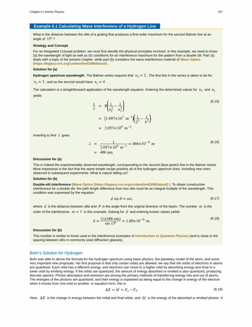
Example 6.1 Calculating Wave Interference of a Hydrogen Line
What is the distance between the slits of a grating that produces a first-order maximum for the second Balmer line at anangle of 15º ?
Strategy and Concept
For an Integrated Concept problem, we must first identify the physical principles involved. In this example, we need to know(a) the wavelength of light as well as (b) conditions for an interference maximum for the pattern from a double slit. Part (a)deals with a topic of the present chapter, while part (b) considers the wave interference material of Wave Optics(https://legacy.cnx.org/content/m42496/latest/) .
Solution for (a)
Hydrogen spectrum wavelength. The Balmer series requires that nf = 2 . The first line in the series is taken to be for
ni = 3 , and so the second would have ni = 4 .
The calculation is a straightforward application of the wavelength equation. Entering the determined values for nf and niyields
(6.15)1λ = R
⎛⎝⎜ 1nf
2 − 1ni
2
⎞⎠⎟
= ⎛⎝1.097×10⁷ m–1⎞⎠
⎛⎝ 1
22 − 142⎞⎠
= 2.057×10⁶ m–1 .
Inverting to find λ gives
(6.16)λ = 12.057×10⁶ m–1 = 486×10−9 m
= 486 nm.Discussion for (a)
This is indeed the experimentally observed wavelength, corresponding to the second (blue-green) line in the Balmer series.More impressive is the fact that the same simple recipe predicts all of the hydrogen spectrum lines, including new onesobserved in subsequent experiments. What is nature telling us?
Solution for (b)
Double-slit interference (Wave Optics (https://legacy.cnx.org/content/m42496/latest/) ). To obtain constructiveinterference for a double slit, the path length difference from two slits must be an integral multiple of the wavelength. Thiscondition was expressed by the equation
(6.17)d sin θ = mλ,
where d is the distance between slits and θ is the angle from the original direction of the beam. The number m is the
order of the interference; m = 1 in this example. Solving for d and entering known values yields
(6.18)d = (1)(486 nm)sin 15º = 1.88×10⁻⁶ m.
Discussion for (b)
This number is similar to those used in the interference examples of Introduction to Quantum Physics (and is close to thespacing between slits in commonly used diffraction glasses).
Bohr’s Solution for Hydrogen
Bohr was able to derive the formula for the hydrogen spectrum using basic physics, the planetary model of the atom, and somevery important new proposals. His first proposal is that only certain orbits are allowed: we say that the orbits of electrons in atomsare quantized. Each orbit has a different energy, and electrons can move to a higher orbit by absorbing energy and drop to alower orbit by emitting energy. If the orbits are quantized, the amount of energy absorbed or emitted is also quantized, producingdiscrete spectra. Photon absorption and emission are among the primary methods of transferring energy into and out of atoms.The energies of the photons are quantized, and their energy is explained as being equal to the change in energy of the electronwhen it moves from one orbit to another. In equation form, this is
(6.19)ΔE = hf = Ei − Ef.
Here, ΔE is the change in energy between the initial and final orbits, and hf is the energy of the absorbed or emitted photon. It
Chapter 6 | Atomic Physics 197

is quite logical (that is, expected from our everyday experience) that energy is involved in changing orbits. A blast of energy isrequired for the space shuttle, for example, to climb to a higher orbit. What is not expected is that atomic orbits should bequantized. This is not observed for satellites or planets, which can have any orbit given the proper energy. (See Figure 6.17.)
Figure 6.17 The planetary model of the atom, as modified by Bohr, has the orbits of the electrons quantized. Only certain orbits are allowed, explainingwhy atomic spectra are discrete (quantized). The energy carried away from an atom by a photon comes from the electron dropping from one allowedorbit to another and is thus quantized. This is likewise true for atomic absorption of photons.
Figure 6.18 shows an energy-level diagram, a convenient way to display energy states. In the present discussion, we takethese to be the allowed energy levels of the electron. Energy is plotted vertically with the lowest or ground state at the bottomand with excited states above. Given the energies of the lines in an atomic spectrum, it is possible (although sometimes verydifficult) to determine the energy levels of an atom. Energy-level diagrams are used for many systems, including molecules andnuclei. A theory of the atom or any other system must predict its energies based on the physics of the system.
Figure 6.18 An energy-level diagram plots energy vertically and is useful in visualizing the energy states of a system and the transitions between them.
This diagram is for the hydrogen-atom electrons, showing a transition between two orbits having energies E4 and E2 .
Bohr was clever enough to find a way to calculate the electron orbital energies in hydrogen. This was an important first step thathas been improved upon, but it is well worth repeating here, because it does correctly describe many characteristics ofhydrogen. Assuming circular orbits, Bohr proposed that the angular momentum L of an electron in its orbit is quantized,
that is, it has only specific, discrete values. The value for L is given by the formula
(6.20)L = mevrn = n h2π(n = 1, 2, 3, … ),
where L is the angular momentum, me is the electron’s mass, rn is the radius of the n th orbit, and h is Planck’s constant.
Note that angular momentum is L = Iω . For a small object at a radius r, I = mr2 and ω = v / r , so that
198 Chapter 6 | Atomic Physics
This OpenStax book is available for free at https://legacy.cnx.org/content/col11630/1.1

L = ⎛⎝mr2⎞⎠(v / r) = mvr . Quantization says that this value of mvr can only be equal to h / 2, 2h / 2, 3h / 2 , etc. At the time,
Bohr himself did not know why angular momentum should be quantized, but using this assumption he was able to calculate theenergies in the hydrogen spectrum, something no one else had done at the time.
From Bohr’s assumptions, we will now derive a number of important properties of the hydrogen atom from the classical physicswe have covered in the text. We start by noting the centripetal force causing the electron to follow a circular path is supplied bythe Coulomb force. To be more general, we note that this analysis is valid for any single-electron atom. So, if a nucleus has Zprotons ( Z = 1 for hydrogen, 2 for helium, etc.) and only one electron, that atom is called a hydrogen-like atom. The spectra
of hydrogen-like ions are similar to hydrogen, but shifted to higher energy by the greater attractive force between the electron
and nucleus. The magnitude of the centripetal force is me v2 / rn , while the Coulomb force is k⎛⎝Zqe⎞⎠(qe) / rn
2 . The tacit
assumption here is that the nucleus is more massive than the stationary electron, and the electron orbits about it. This isconsistent with the planetary model of the atom. Equating these,
(6.21)kZqe
2
rn2 = me v2
rn(Coulomb = centripetal).
Angular momentum quantization is stated in an earlier equation. We solve that equation for v , substitute it into the above, and
rearrange the expression to obtain the radius of the orbit. This yields:
(6.22)rn = n2
Z aB , for allowed orbits(n = 1,2,3, … ),
where aB is defined to be the Bohr radius, since for the lowest orbit (n = 1) and for hydrogen (Z = 1) , r1 = aB . It is left
for this chapter’s Problems and Exercises to show that the Bohr radius is
(6.23)aB = h2
4π2 me kqe2 = 0.529×10⁻¹⁰ m.
These last two equations can be used to calculate the radii of the allowed (quantized) electron orbits in any hydrogen-likeatom. It is impressive that the formula gives the correct size of hydrogen, which is measured experimentally to be very close to
the Bohr radius. The earlier equation also tells us that the orbital radius is proportional to n2 , as illustrated in Figure 6.19.
Figure 6.19 The allowed electron orbits in hydrogen have the radii shown. These radii were first calculated by Bohr and are given by the equation
rn = n2
Z aB . The lowest orbit has the experimentally verified diameter of a hydrogen atom.
To get the electron orbital energies, we start by noting that the electron energy is the sum of its kinetic and potential energy:
(6.24)En = KE + PE.
Kinetic energy is the familiar KE = (1 / 2)me v2 , assuming the electron is not moving at relativistic speeds. Potential energy for
the electron is electrical, or PE = qeV , where V is the potential due to the nucleus, which looks like a point charge. The
Chapter 6 | Atomic Physics 199

nucleus has a positive charge Zqe ; thus, V = kZqe / rn , recalling an earlier equation for the potential due to a point charge.
Since the electron’s charge is negative, we see that PE = −kZqe / rn . Entering the expressions for KE and PE , we find
(6.25)En = 1
2me v2 − kZqe2
rn.
Now we substitute rn and v from earlier equations into the above expression for energy. Algebraic manipulation yields
(6.26)En = − Z 2
n2 E0(n = 1, 2, 3, ...)
for the orbital energies of hydrogen-like atoms. Here, E0 is the ground-state energy (n = 1) for hydrogen (Z = 1) and is
given by
(6.27)E0 = 2π2 qe
4 me k2
h2 = 13.6 eV.
Thus, for hydrogen,
(6.28)En = −13.6 eVn2 (n = 1, 2, 3, ...).
Figure 6.20 shows an energy-level diagram for hydrogen that also illustrates how the various spectral series for hydrogen arerelated to transitions between energy levels.
Figure 6.20 Energy-level diagram for hydrogen showing the Lyman, Balmer, and Paschen series of transitions. The orbital energies are calculatedusing the above equation, first derived by Bohr.
Electron total energies are negative, since the electron is bound to the nucleus, analogous to being in a hole without enoughkinetic energy to escape. As n approaches infinity, the total energy becomes zero. This corresponds to a free electron with no
kinetic energy, since rn gets very large for large n , and the electric potential energy thus becomes zero. Thus, 13.6 eV is
needed to ionize hydrogen (to go from –13.6 eV to 0, or unbound), an experimentally verified number. Given more energy, theelectron becomes unbound with some kinetic energy. For example, giving 15.0 eV to an electron in the ground state of hydrogenstrips it from the atom and leaves it with 1.4 eV of kinetic energy.
Finally, let us consider the energy of a photon emitted in a downward transition, given by the equation to be
200 Chapter 6 | Atomic Physics
This OpenStax book is available for free at https://legacy.cnx.org/content/col11630/1.1

(6.29)ΔE = hf = Ei − Ef.
Substituting En = ( – 13.6 eV / n2) , we see that
(6.30)hf = (13.6 eV)
⎛⎝⎜ 1nf
2 − 1ni
2
⎞⎠⎟.
Dividing both sides of this equation by hc gives an expression for 1 / λ :
(6.31)hfhc = f
c = 1λ = (13.6 eV)
hc⎛⎝⎜ 1nf
2 − 1ni
2
⎞⎠⎟.
It can be shown that
(6.32)⎛⎝13.6 eV
hc⎞⎠ =
(13.6 eV)⎛⎝1.602×10⁻¹⁹ J/eV⎞⎠⎛⎝6.626×10−34 J·s⎞⎠
⎛⎝2.998×10⁸ m/s⎞⎠
= 1.097×10⁷ m–1 = R
is the Rydberg constant. Thus, we have used Bohr’s assumptions to derive the formula first proposed by Balmer years earlieras a recipe to fit experimental data.
(6.33)1λ = R⎛⎝⎜ 1nf
2 − 1ni
2
⎞⎠⎟
We see that Bohr’s theory of the hydrogen atom answers the question as to why this previously known formula describes the
hydrogen spectrum. It is because the energy levels are proportional to 1 / n2 , where n is a non-negative integer. A downward
transition releases energy, and so ni must be greater than nf . The various series are those where the transitions end on a
certain level. For the Lyman series, nf = 1 — that is, all the transitions end in the ground state (see also Figure 6.20). For the
Balmer series, nf = 2 , or all the transitions end in the first excited state; and so on. What was once a recipe is now based in
physics, and something new is emerging—angular momentum is quantized.
Triumphs and Limits of the Bohr Theory
Bohr did what no one had been able to do before. Not only did he explain the spectrum of hydrogen, he correctly calculated thesize of the atom from basic physics. Some of his ideas are broadly applicable. Electron orbital energies are quantized in allatoms and molecules. Angular momentum is quantized. The electrons do not spiral into the nucleus, as expected classically(accelerated charges radiate, so that the electron orbits classically would decay quickly, and the electrons would sit on thenucleus—matter would collapse). These are major triumphs.
But there are limits to Bohr’s theory. It cannot be applied to multielectron atoms, even one as simple as a two-electron heliumatom. Bohr’s model is what we call semiclassical. The orbits are quantized (nonclassical) but are assumed to be simple circularpaths (classical). As quantum mechanics was developed, it became clear that there are no well-defined orbits; rather, there areclouds of probability. Bohr’s theory also did not explain that some spectral lines are doublets (split into two) when examinedclosely. We shall examine many of these aspects of quantum mechanics in more detail, but it should be kept in mind that Bohrdid not fail. Rather, he made very important steps along the path to greater knowledge and laid the foundation for all of atomicphysics that has since evolved.
Models of the Hydrogen Atom
How did scientists figure out the structure of atoms without looking at them? Try out different models by shooting light at theatom. Check how the prediction of the model matches the experimental results.
(This media type is not supported in this reader. Click to open media in browser.) (http://legacy.cnx.org/content/m42596/1.18/#fs-id1167067184393)
Figure 6.21
6.4 X Rays: Atomic Origins and Applications
Each type of atom (or element) has its own characteristic electromagnetic spectrum. X rays lie at the high-frequency end of anatom’s spectrum and are characteristic of the atom as well. In this section, we explore characteristic x rays and some of theirimportant applications.
We have previously discussed x rays as a part of the electromagnetic spectrum in Photon Energies and the ElectromagneticSpectrum. That module illustrated how an x-ray tube (a specialized CRT) produces x rays. Electrons emitted from a hot filamentare accelerated with a high voltage, gaining significant kinetic energy and striking the anode.
There are two processes by which x rays are produced in the anode of an x-ray tube. In one process, the deceleration of
Chapter 6 | Atomic Physics 201

electrons produces x rays, and these x rays are called bremsstrahlung, or braking radiation. The second process is atomic innature and produces characteristic x rays, so called because they are characteristic of the anode material. The x-ray spectrum inFigure 6.22 is typical of what is produced by an x-ray tube, showing a broad curve of bremsstrahlung radiation with characteristicx-ray peaks on it.
Figure 6.22 X-ray spectrum obtained when energetic electrons strike a material, such as in the anode of a CRT. The smooth part of the spectrum isbremsstrahlung radiation, while the peaks are characteristic of the anode material. A different anode material would have characteristic x-ray peaks atdifferent frequencies.
The spectrum in Figure 6.22 is collected over a period of time in which many electrons strike the anode, with a variety ofpossible outcomes for each hit. The broad range of x-ray energies in the bremsstrahlung radiation indicates that an incidentelectron’s energy is not usually converted entirely into photon energy. The highest-energy x ray produced is one for which all ofthe electron’s energy was converted to photon energy. Thus the accelerating voltage and the maximum x-ray energy are relatedby conservation of energy. Electric potential energy is converted to kinetic energy and then to photon energy, so thatEmax = hfmax = qeV . Units of electron volts are convenient. For example, a 100-kV accelerating voltage produces x-ray
photons with a maximum energy of 100 keV.
Some electrons excite atoms in the anode. Part of the energy that they deposit by collision with an atom results in one or more ofthe atom’s inner electrons being knocked into a higher orbit or the atom being ionized. When the anode’s atoms de-excite, theyemit characteristic electromagnetic radiation. The most energetic of these are produced when an inner-shell vacancy isfilled—that is, when an n = 1 or n = 2 shell electron has been excited to a higher level, and another electron falls into the
vacant spot. A characteristic x ray (see Photon Energies and the Electromagnetic Spectrum) is electromagnetic (EM)radiation emitted by an atom when an inner-shell vacancy is filled. Figure 6.23 shows a representative energy-level diagram thatillustrates the labeling of characteristic x rays. X rays created when an electron falls into an n = 1 shell vacancy are called Kαwhen they come from the next higher level; that is, an n = 2 to n = 1 transition. The labels K, L, M,... come from the older
alphabetical labeling of shells starting with K rather than using the principal quantum numbers 1, 2, 3, …. A more energetic Kβ
x ray is produced when an electron falls into an n = 1 shell vacancy from the n = 3 shell; that is, an n = 3 to n = 1transition. Similarly, when an electron falls into the n = 2 shell from the n = 3 shell, an Lα x ray is created. The energies of
these x rays depend on the energies of electron states in the particular atom and, thus, are characteristic of that element: everyelement has it own set of x-ray energies. This property can be used to identify elements, for example, to find trace (small)amounts of an element in an environmental or biological sample.
202 Chapter 6 | Atomic Physics
This OpenStax book is available for free at https://legacy.cnx.org/content/col11630/1.1

Figure 6.23 A characteristic x ray is emitted when an electron fills an inner-shell vacancy, as shown for several transitions in this approximate energylevel diagram for a multiple-electron atom. Characteristic x rays are labeled according to the shell that had the vacancy and the shell from which the
electron came. A Kα x ray, for example, is produced when an electron coming from the n = 2 shell fills the n = 1 shell vacancy.
Example 6.2 Characteristic X-Ray Energy
Calculate the approximate energy of a Kα x ray from a tungsten anode in an x-ray tube.
Strategy
How do we calculate energies in a multiple-electron atom? In the case of characteristic x rays, the following approximatecalculation is reasonable. Characteristic x rays are produced when an inner-shell vacancy is filled. Inner-shell electrons arenearer the nucleus than others in an atom and thus feel little net effect from the others. This is similar to what happens insidea charged conductor, where its excess charge is distributed over the surface so that it produces no electric field inside. It is
reasonable to assume the inner-shell electrons have hydrogen-like energies, as given by En = − Z 2
n2 E0 (n = 1, 2, 3, ...) .
As noted, a Kα x ray is produced by an n = 2 to n = 1 transition. Since there are two electrons in a filled K shell, a
vacancy would leave one electron, so that the effective charge would be Z − 1 rather than Z . For tungsten, Z = 74 , so
that the effective charge is 73.
Solution
En = − Z 2
n2 E0 (n = 1, 2, 3, ...) gives the orbital energies for hydrogen-like atoms to be En = −(Z 2 / n2)E0 , where
E0 = 13.6 eV . As noted, the effective Z is 73. Now the Kα x-ray energy is given by
(6.34)EKα = ΔE = Ei−Ef = E2−E1,
where
(6.35)E1 = − Z 2
12 E0 = −732
1⎛⎝13.6 eV⎞⎠ = − 72.5 keV
and
(6.36)E2 = − Z 2
22 E0 = −732
4⎛⎝13.6 eV⎞⎠ = − 18.1 keV.
Thus,
(6.37)EKα = − 18.1 keV − ⎛⎝− 72.5 keV⎞⎠ = 54.4 keV.
Discussion
This large photon energy is typical of characteristic x rays from heavy elements. It is large compared with other atomicemissions because it is produced when an inner-shell vacancy is filled, and inner-shell electrons are tightly bound.Characteristic x ray energies become progressively larger for heavier elements because their energy increases
approximately as Z 2 . Significant accelerating voltage is needed to create these inner-shell vacancies. In the case of
Chapter 6 | Atomic Physics 203

tungsten, at least 72.5 kV is needed, because other shells are filled and you cannot simply bump one electron to a higherfilled shell. Tungsten is a common anode material in x-ray tubes; so much of the energy of the impinging electrons isabsorbed, raising its temperature, that a high-melting-point material like tungsten is required.
Medical and Other Diagnostic Uses of X-rays
All of us can identify diagnostic uses of x-ray photons. Among these are the universal dental and medical x rays that havebecome an essential part of medical diagnostics. (See Figure 6.25 and Figure 6.26.) X rays are also used to inspect ourluggage at airports, as shown in Figure 6.24, and for early detection of cracks in crucial aircraft components. An x ray is not onlya noun meaning high-energy photon, it also is an image produced by x rays, and it has been made into a familiar verb—to be x-rayed.
Figure 6.24 An x-ray image reveals fillings in a person’s teeth. (credit: Dmitry G, Wikimedia Commons)
Figure 6.25 This x-ray image of a person’s chest shows many details, including an artificial pacemaker. (credit: Sunzi99, Wikimedia Commons)
Figure 6.26 This x-ray image shows the contents of a piece of luggage. The denser the material, the darker the shadow. (credit: IDuke, WikimediaCommons)
The most common x-ray images are simple shadows. Since x-ray photons have high energies, they penetrate materials that areopaque to visible light. The more energy an x-ray photon has, the more material it will penetrate. So an x-ray tube may beoperated at 50.0 kV for a chest x ray, whereas it may need to be operated at 100 kV to examine a broken leg in a cast. The depthof penetration is related to the density of the material as well as to the energy of the photon. The denser the material, the fewerx-ray photons get through and the darker the shadow. Thus x rays excel at detecting breaks in bones and in imaging otherphysiological structures, such as some tumors, that differ in density from surrounding material. Because of their high photonenergy, x rays produce significant ionization in materials and damage cells in biological organisms. Modern uses minimizeexposure to the patient and eliminate exposure to others. Biological effects of x rays will be explored in the next chapter alongwith other types of ionizing radiation such as those produced by nuclei.
As the x-ray energy increases, the Compton effect (see Photon Momentum) becomes more important in the attenuation of the xrays. Here, the x ray scatters from an outer electron shell of the atom, giving the ejected electron some kinetic energy whilelosing energy itself. The probability for attenuation of the x rays depends upon the number of electrons present (the material’sdensity) as well as the thickness of the material. Chemical composition of the medium, as characterized by its atomic number Z ,
is not important here. Low-energy x rays provide better contrast (sharper images). However, due to greater attenuation and less
204 Chapter 6 | Atomic Physics
This OpenStax book is available for free at https://legacy.cnx.org/content/col11630/1.1

scattering, they are more absorbed by thicker materials. Greater contrast can be achieved by injecting a substance with a largeatomic number, such as barium or iodine. The structure of the part of the body that contains the substance (e.g., the gastro-intestinal tract or the abdomen) can easily be seen this way.
Breast cancer is the second-leading cause of death among women worldwide. Early detection can be very effective, hence theimportance of x-ray diagnostics. A mammogram cannot diagnose a malignant tumor, only give evidence of a lump or region ofincreased density within the breast. X-ray absorption by different types of soft tissue is very similar, so contrast is difficult; this isespecially true for younger women, who typically have denser breasts. For older women who are at greater risk of developingbreast cancer, the presence of more fat in the breast gives the lump or tumor more contrast. MRI (Magnetic resonance imaging)has recently been used as a supplement to conventional x rays to improve detection and eliminate false positives. The subject’sradiation dose from x rays will be treated in a later chapter.
A standard x ray gives only a two-dimensional view of the object. Dense bones might hide images of soft tissue or organs. If youtook another x ray from the side of the person (the first one being from the front), you would gain additional information. Whileshadow images are sufficient in many applications, far more sophisticated images can be produced with modern technology.Figure 6.27 shows the use of a computed tomography (CT) scanner, also called computed axial tomography (CAT) scanner. Xrays are passed through a narrow section (called a slice) of the patient’s body (or body part) over a range of directions. An arrayof many detectors on the other side of the patient registers the x rays. The system is then rotated around the patient and anotherimage is taken, and so on. The x-ray tube and detector array are mechanically attached and so rotate together. Complexcomputer image processing of the relative absorption of the x rays along different directions produces a highly-detailed image.Different slices are taken as the patient moves through the scanner on a table. Multiple images of different slices can also becomputer analyzed to produce three-dimensional information, sometimes enhancing specific types of tissue, as shown in Figure6.28. G. Hounsfield (UK) and A. Cormack (US) won the Nobel Prize in Medicine in 1979 for their development of computedtomography.
Figure 6.27 A patient being positioned in a CT scanner aboard the hospital ship USNS Mercy. The CT scanner passes x rays through slices of thepatient’s body (or body part) over a range of directions. The relative absorption of the x rays along different directions is computer analyzed to producehighly detailed images. Three-dimensional information can be obtained from multiple slices. (credit: Rebecca Moat, U.S. Navy)
Figure 6.28 This three-dimensional image of a skull was produced by computed tomography, involving analysis of several x-ray slices of the head.(credit: Emailshankar, Wikimedia Commons)
X-Ray Diffraction and Crystallography
Since x-ray photons are very energetic, they have relatively short wavelengths. For example, the 54.4-keV Kα x ray of Example
6.2 has a wavelength λ = hc / E = 0.0228 nm . Thus, typical x-ray photons act like rays when they encounter macroscopic
objects, like teeth, and produce sharp shadows; however, since atoms are on the order of 0.1 nm in size, x rays can be used todetect the location, shape, and size of atoms and molecules. The process is called x-ray diffraction, because it involves thediffraction and interference of x rays to produce patterns that can be analyzed for information about the structures that scatteredthe x rays. Perhaps the most famous example of x-ray diffraction is the discovery of the double-helix structure of DNA in 1953 byan international team of scientists working at the Cavendish Laboratory—American James Watson, Englishman Francis Crick,and New Zealand–born Maurice Wilkins. Using x-ray diffraction data produced by Rosalind Franklin, they were the first to discernthe structure of DNA that is so crucial to life. For this, Watson, Crick, and Wilkins were awarded the 1962 Nobel Prize inPhysiology or Medicine. There is much debate and controversy over the issue that Rosalind Franklin was not included in theprize.
Figure 6.29 shows a diffraction pattern produced by the scattering of x rays from a crystal. This process is known as x-ray
Chapter 6 | Atomic Physics 205

crystallography because of the information it can yield about crystal structure, and it was the type of data Rosalind Franklinsupplied to Watson and Crick for DNA. Not only do x rays confirm the size and shape of atoms, they give information on theatomic arrangements in materials. For example, current research in high-temperature superconductors involves complexmaterials whose lattice arrangements are crucial to obtaining a superconducting material. These can be studied using x-raycrystallography.
Figure 6.29 X-ray diffraction from the crystal of a protein, hen egg lysozyme, produced this interference pattern. Analysis of the pattern yieldsinformation about the structure of the protein. (credit: Del45, Wikimedia Commons)
Historically, the scattering of x rays from crystals was used to prove that x rays are energetic EM waves. This was suspectedfrom the time of the discovery of x rays in 1895, but it was not until 1912 that the German Max von Laue (1879–1960) convincedtwo of his colleagues to scatter x rays from crystals. If a diffraction pattern is obtained, he reasoned, then the x rays must bewaves, and their wavelength could be determined. (The spacing of atoms in various crystals was reasonably well known at thetime, based on good values for Avogadro’s number.) The experiments were convincing, and the 1914 Nobel Prize in Physics wasgiven to von Laue for his suggestion leading to the proof that x rays are EM waves. In 1915, the unique father-and-son team ofSir William Henry Bragg and his son Sir William Lawrence Bragg were awarded a joint Nobel Prize for inventing the x-rayspectrometer and the then-new science of x-ray analysis. The elder Bragg had migrated to Australia from England just aftergraduating in mathematics. He learned physics and chemistry during his career at the University of Adelaide. The younger Braggwas born in Adelaide but went back to the Cavendish Laboratories in England to a career in x-ray and neutron crystallography;he provided support for Watson, Crick, and Wilkins for their work on unraveling the mysteries of DNA and to Max Perutz for his1962 Nobel Prize-winning work on the structure of hemoglobin. Here again, we witness the enabling nature ofphysics—establishing instruments and designing experiments as well as solving mysteries in the biomedical sciences.
Certain other uses for x rays will be studied in later chapters. X rays are useful in the treatment of cancer because of theinhibiting effect they have on cell reproduction. X rays observed coming from outer space are useful in determining the nature oftheir sources, such as neutron stars and possibly black holes. Created in nuclear bomb explosions, x rays can also be used todetect clandestine atmospheric tests of these weapons. X rays can cause excitations of atoms, which then fluoresce (emittingcharacteristic EM radiation), making x-ray-induced fluorescence a valuable analytical tool in a range of fields from art toarchaeology.
6.5 Applications of Atomic Excitations and De-Excitations
Many properties of matter and phenomena in nature are directly related to atomic energy levels and their associated excitationsand de-excitations. The color of a rose, the output of a laser, and the transparency of air are but a few examples. (See Figure6.30.) While it may not appear that glow-in-the-dark pajamas and lasers have much in common, they are in fact differentapplications of similar atomic de-excitations.
Figure 6.30 Light from a laser is based on a particular type of atomic de-excitation. (credit: Jeff Keyzer)
The color of a material is due to the ability of its atoms to absorb certain wavelengths while reflecting or reemitting others. Asimple red material, for example a tomato, absorbs all visible wavelengths except red. This is because the atoms of its
206 Chapter 6 | Atomic Physics
This OpenStax book is available for free at https://legacy.cnx.org/content/col11630/1.1

hydrocarbon pigment (lycopene) have levels separated by a variety of energies corresponding to all visible photon energiesexcept red. Air is another interesting example. It is transparent to visible light, because there are few energy levels that visiblephotons can excite in air molecules and atoms. Visible light, thus, cannot be absorbed. Furthermore, visible light is only weaklyscattered by air, because visible wavelengths are so much greater than the sizes of the air molecules and atoms. Light mustpass through kilometers of air to scatter enough to cause red sunsets and blue skies.
Fluorescence and Phosphorescence
The ability of a material to emit various wavelengths of light is similarly related to its atomic energy levels. Figure 6.31 shows ascorpion illuminated by a UV lamp, sometimes called a black light. Some rocks also glow in black light, the particular colors beinga function of the rock’s mineral composition. Black lights are also used to make certain posters glow.
Figure 6.31 Objects glow in the visible spectrum when illuminated by an ultraviolet (black) light. Emissions are characteristic of the mineral involved,since they are related to its energy levels. In the case of scorpions, proteins near the surface of their skin give off the characteristic blue glow. This is acolorful example of fluorescence in which excitation is induced by UV radiation while de-excitation occurs in the form of visible light. (credit: KenBosma, Flickr)
In the fluorescence process, an atom is excited to a level several steps above its ground state by the absorption of a relativelyhigh-energy UV photon. This is called atomic excitation. Once it is excited, the atom can de-excite in several ways, one ofwhich is to re-emit a photon of the same energy as excited it, a single step back to the ground state. This is called atomic de-excitation. All other paths of de-excitation involve smaller steps, in which lower-energy (longer wavelength) photons are emitted.Some of these may be in the visible range, such as for the scorpion in Figure 6.31. Fluorescence is defined to be any processin which an atom or molecule, excited by a photon of a given energy, and de-excites by emission of a lower-energy photon.
Fluorescence can be induced by many types of energy input. Fluorescent paint, dyes, and even soap residues in clothes makecolors seem brighter in sunlight by converting some UV into visible light. X rays can induce fluorescence, as is done in x-rayfluoroscopy to make brighter visible images. Electric discharges can induce fluorescence, as in so-called neon lights and in gas-discharge tubes that produce atomic and molecular spectra. Common fluorescent lights use an electric discharge in mercuryvapor to cause atomic emissions from mercury atoms. The inside of a fluorescent light is coated with a fluorescent material thatemits visible light over a broad spectrum of wavelengths. By choosing an appropriate coating, fluorescent lights can be mademore like sunlight or like the reddish glow of candlelight, depending on needs. Fluorescent lights are more efficient in convertingelectrical energy into visible light than incandescent filaments (about four times as efficient), the blackbody radiation of which isprimarily in the infrared due to temperature limitations.
This atom is excited to one of its higher levels by absorbing a UV photon. It can de-excite in a single step, re-emitting a photon ofthe same energy, or in several steps. The process is called fluorescence if the atom de-excites in smaller steps, emitting energydifferent from that which excited it. Fluorescence can be induced by a variety of energy inputs, such as UV, x-rays, and electricaldischarge.
The spectacular Waitomo caves on North Island in New Zealand provide a natural habitat for glow-worms. The glow-worms hangup to 70 silk threads of about 30 or 40 cm each to trap prey that fly towards them in the dark. The fluorescence process is veryefficient, with nearly 100% of the energy input turning into light. (In comparison, fluorescent lights are about 20% efficient.)
Fluorescence has many uses in biology and medicine. It is commonly used to label and follow a molecule within a cell. Suchtagging allows one to study the structure of DNA and proteins. Fluorescent dyes and antibodies are usually used to tag themolecules, which are then illuminated with UV light and their emission of visible light is observed. Since the fluorescence of eachelement is characteristic, identification of elements within a sample can be done this way.
Figure 6.32 shows a commonly used fluorescent dye called fluorescein. Below that, Figure 6.33 reveals the diffusion of afluorescent dye in water by observing it under UV light.
Chapter 6 | Atomic Physics 207

Figure 6.32 Fluorescein, shown here in powder form, is used to dye laboratory samples. (credit: Benjah-bmm27, Wikimedia Commons)
Figure 6.33 Here, fluorescent powder is added to a beaker of water. The mixture gives off a bright glow under ultraviolet light. (credit: Bricksnite,Wikimedia Commons)
Nano-Crystals
Recently, a new class of fluorescent materials has appeared—“nano-crystals.” These are single-crystal molecules less than100 nm in size. The smallest of these are called “quantum dots.” These semiconductor indicators are very small (2–6 nm)and provide improved brightness. They also have the advantage that all colors can be excited with the same incidentwavelength. They are brighter and more stable than organic dyes and have a longer lifetime than conventional phosphors.They have become an excellent tool for long-term studies of cells, including migration and morphology. (Figure 6.34.)
Figure 6.34 Microscopic image of chicken cells using nano-crystals of a fluorescent dye. Cell nuclei exhibit blue fluorescence while neurofilamentsexhibit green. (credit: Weerapong Prasongchean, Wikimedia Commons)
Once excited, an atom or molecule will usually spontaneously de-excite quickly. (The electrons raised to higher levels areattracted to lower ones by the positive charge of the nucleus.) Spontaneous de-excitation has a very short mean lifetime of
typically about 10−8 s . However, some levels have significantly longer lifetimes, ranging up to milliseconds to minutes or even
hours. These energy levels are inhibited and are slow in de-exciting because their quantum numbers differ greatly from those ofavailable lower levels. Although these level lifetimes are short in human terms, they are many orders of magnitude longer than istypical and, thus, are said to be metastable, meaning relatively stable. Phosphorescence is the de-excitation of a metastablestate. Glow-in-the-dark materials, such as luminous dials on some watches and clocks and on children’s toys and pajamas, aremade of phosphorescent substances. Visible light excites the atoms or molecules to metastable states that decay slowly,releasing the stored excitation energy partially as visible light. In some ceramics, atomic excitation energy can be frozen in afterthe ceramic has cooled from its firing. It is very slowly released, but the ceramic can be induced to phosphoresce by heating—aprocess called “thermoluminescence.” Since the release is slow, thermoluminescence can be used to date antiquities. The lesslight emitted, the older the ceramic. (See Figure 6.35.)
208 Chapter 6 | Atomic Physics
This OpenStax book is available for free at https://legacy.cnx.org/content/col11630/1.1

Figure 6.35 Atoms frozen in an excited state when this Chinese ceramic figure was fired can be stimulated to de-excite and emit EM radiation byheating a sample of the ceramic—a process called thermoluminescence. Since the states slowly de-excite over centuries, the amount of
thermoluminescence decreases with age, making it possible to use this effect to date and authenticate antiquities. This figure dates from the 11th
century. (credit: Vassil, Wikimedia Commons)
Lasers
Lasers today are commonplace. Lasers are used to read bar codes at stores and in libraries, laser shows are staged forentertainment, laser printers produce high-quality images at relatively low cost, and lasers send prodigious numbers of telephonemessages through optical fibers. Among other things, lasers are also employed in surveying, weapons guidance, tumoreradication, retinal welding, and for reading music CDs and computer CD-ROMs.
Why do lasers have so many varied applications? The answer is that lasers produce single-wavelength EM radiation that is alsovery coherent—that is, the emitted photons are in phase. Laser output can, thus, be more precisely manipulated than incoherentmixed-wavelength EM radiation from other sources. The reason laser output is so pure and coherent is based on how it isproduced, which in turn depends on a metastable state in the lasing material. Suppose a material had the energy levels shown inFigure 6.36. When energy is put into a large collection of these atoms, electrons are raised to all possible levels. Most return to
the ground state in less than about 10−8 s , but those in the metastable state linger. This includes those electrons originally
excited to the metastable state and those that fell into it from above. It is possible to get a majority of the atoms into themetastable state, a condition called a population inversion.
Chapter 6 | Atomic Physics 209

Figure 6.36 (a) Energy-level diagram for an atom showing the first few states, one of which is metastable. (b) Massive energy input excites atoms to avariety of states. (c) Most states decay quickly, leaving electrons only in the metastable and ground state. If a majority of electrons are in themetastable state, a population inversion has been achieved.
Once a population inversion is achieved, a very interesting thing can happen, as shown in Figure 6.37. An electronspontaneously falls from the metastable state, emitting a photon. This photon finds another atom in the metastable state andstimulates it to decay, emitting a second photon of the same wavelength and in phase with the first, and so on. Stimulatedemission is the emission of electromagnetic radiation in the form of photons of a given frequency, triggered by photons of thesame frequency. For example, an excited atom, with an electron in an energy orbit higher than normal, releases a photon of aspecific frequency when the electron drops back to a lower energy orbit. If this photon then strikes another electron in the samehigh-energy orbit in another atom, another photon of the same frequency is released. The emitted photons and the triggeringphotons are always in phase, have the same polarization, and travel in the same direction. The probability of absorption of aphoton is the same as the probability of stimulated emission, and so a majority of atoms must be in the metastable state toproduce energy. Einstein (again Einstein, and back in 1917!) was one of the important contributors to the understanding ofstimulated emission of radiation. Among other things, Einstein was the first to realize that stimulated emission and absorption areequally probable. The laser acts as a temporary energy storage device that subsequently produces a massive energy output ofsingle-wavelength, in-phase photons.
Figure 6.37 One atom in the metastable state spontaneously decays to a lower level, producing a photon that goes on to stimulate another atom to de-excite. The second photon has exactly the same energy and wavelength as the first and is in phase with it. Both go on to stimulate the emission ofother photons. A population inversion is necessary for there to be a net production rather than a net absorption of the photons.
The name laser is an acronym for light amplification by stimulated emission of radiation, the process just described. The processwas proposed and developed following the advances in quantum physics. A joint Nobel Prize was awarded in 1964 to AmericanCharles Townes (1915–), and Nikolay Basov (1922–2001) and Aleksandr Prokhorov (1916–2002), from the Soviet Union, for thedevelopment of lasers. The Nobel Prize in 1981 went to Arthur Schawlow (1921-1999) for pioneering laser applications. Theoriginal devices were called masers, because they produced microwaves. The first working laser was created in 1960 at HughesResearch labs (CA) by T. Maiman. It used a pulsed high-powered flash lamp and a ruby rod to produce red light. Today the name
210 Chapter 6 | Atomic Physics
This OpenStax book is available for free at https://legacy.cnx.org/content/col11630/1.1

laser is used for all such devices developed to produce a variety of wavelengths, including microwave, infrared, visible, andultraviolet radiation. Figure 6.38 shows how a laser can be constructed to enhance the stimulated emission of radiation. Energyinput can be from a flash tube, electrical discharge, or other sources, in a process sometimes called optical pumping. A largepercentage of the original pumping energy is dissipated in other forms, but a population inversion must be achieved. Mirrors canbe used to enhance stimulated emission by multiple passes of the radiation back and forth through the lasing material. One ofthe mirrors is semitransparent to allow some of the light to pass through. The laser output from a laser is a mere 1% of the lightpassing back and forth in a laser.
Figure 6.38 Typical laser construction has a method of pumping energy into the lasing material to produce a population inversion. (a) Spontaneousemission begins with some photons escaping and others stimulating further emissions. (b) and (c) Mirrors are used to enhance the probability ofstimulated emission by passing photons through the material several times.
Lasers are constructed from many types of lasing materials, including gases, liquids, solids, and semiconductors. But all lasersare based on the existence of a metastable state or a phosphorescent material. Some lasers produce continuous output; others
are pulsed in bursts as brief as 10−14 s . Some laser outputs are fantastically powerful—some greater than 1012 W —but the
more common, everyday lasers produce something on the order of 10−3 W . The helium-neon laser that produces a familiar
red light is very common. Figure 6.39 shows the energy levels of helium and neon, a pair of noble gases that work well together.An electrical discharge is passed through a helium-neon gas mixture in which the number of atoms of helium is ten times that ofneon. The first excited state of helium is metastable and, thus, stores energy. This energy is easily transferred by collision toneon atoms, because they have an excited state at nearly the same energy as that in helium. That state in neon is alsometastable, and this is the one that produces the laser output. (The most likely transition is to the nearby state, producing 1.96eV photons, which have a wavelength of 633 nm and appear red.) A population inversion can be produced in neon, becausethere are so many more helium atoms and these put energy into the neon. Helium-neon lasers often have continuous output,because the population inversion can be maintained even while lasing occurs. Probably the most common lasers in use today,including the common laser pointer, are semiconductor or diode lasers, made of silicon. Here, energy is pumped into the materialby passing a current in the device to excite the electrons. Special coatings on the ends and fine cleavings of the semiconductormaterial allow light to bounce back and forth and a tiny fraction to emerge as laser light. Diode lasers can usually run continuallyand produce outputs in the milliwatt range.
Chapter 6 | Atomic Physics 211

Figure 6.39 Energy levels in helium and neon. In the common helium-neon laser, an electrical discharge pumps energy into the metastable states ofboth atoms. The gas mixture has about ten times more helium atoms than neon atoms. Excited helium atoms easily de-excite by transferring energy toneon in a collision. A population inversion in neon is achieved, allowing lasing by the neon to occur.
There are many medical applications of lasers. Lasers have the advantage that they can be focused to a small spot. They alsohave a well-defined wavelength. Many types of lasers are available today that provide wavelengths from the ultraviolet to theinfrared. This is important, as one needs to be able to select a wavelength that will be preferentially absorbed by the material ofinterest. Objects appear a certain color because they absorb all other visible colors incident upon them. What wavelengths areabsorbed depends upon the energy spacing between electron orbitals in that molecule. Unlike the hydrogen atom, biologicalmolecules are complex and have a variety of absorption wavelengths or lines. But these can be determined and used in theselection of a laser with the appropriate wavelength. Water is transparent to the visible spectrum but will absorb light in the UVand IR regions. Blood (hemoglobin) strongly reflects red but absorbs most strongly in the UV.
Laser surgery uses a wavelength that is strongly absorbed by the tissue it is focused upon. One example of a medical applicationof lasers is shown in Figure 6.40. A detached retina can result in total loss of vision. Burns made by a laser focused to a smallspot on the retina form scar tissue that can hold the retina in place, salvaging the patient’s vision. Other light sources cannot befocused as precisely as a laser due to refractive dispersion of different wavelengths. Similarly, laser surgery in the form of cuttingor burning away tissue is made more accurate because laser output can be very precisely focused and is preferentially absorbedbecause of its single wavelength. Depending upon what part or layer of the retina needs repairing, the appropriate type of lasercan be selected. For the repair of tears in the retina, a green argon laser is generally used. This light is absorbed well by tissuescontaining blood, so coagulation or “welding” of the tear can be done.
Figure 6.40 A detached retina is burned by a laser designed to focus on a small spot on the retina, the resulting scar tissue holding it in place. The lensof the eye is used to focus the light, as is the device bringing the laser output to the eye.
In dentistry, the use of lasers is rising. Lasers are most commonly used for surgery on the soft tissue of the mouth. They can beused to remove ulcers, stop bleeding, and reshape gum tissue. Their use in cutting into bones and teeth is not quite so common;here the erbium YAG (yttrium aluminum garnet) laser is used.
The massive combination of lasers shown in Figure 6.41 can be used to induce nuclear fusion, the energy source of the sun andhydrogen bombs. Since lasers can produce very high power in very brief pulses, they can be used to focus an enormous amountof energy on a small glass sphere containing fusion fuel. Not only does the incident energy increase the fuel temperaturesignificantly so that fusion can occur, it also compresses the fuel to great density, enhancing the probability of fusion. Thecompression or implosion is caused by the momentum of the impinging laser photons.
212 Chapter 6 | Atomic Physics
This OpenStax book is available for free at https://legacy.cnx.org/content/col11630/1.1

Figure 6.41 This system of lasers at Lawrence Livermore Laboratory is used to ignite nuclear fusion. A tremendous burst of energy is focused on asmall fuel pellet, which is imploded to the high density and temperature needed to make the fusion reaction proceed. (credit: Lawrence LivermoreNational Laboratory, Lawrence Livermore National Security, LLC, and the Department of Energy)
Music CDs are now so common that vinyl records are quaint antiquities. CDs (and DVDs) store information digitally and have amuch larger information-storage capacity than vinyl records. An entire encyclopedia can be stored on a single CD. Figure 6.42illustrates how the information is stored and read from the CD. Pits made in the CD by a laser can be tiny and very accuratelyspaced to record digital information. These are read by having an inexpensive solid-state infrared laser beam scatter from pits asthe CD spins, revealing their digital pattern and the information encoded upon them.
Figure 6.42 A CD has digital information stored in the form of laser-created pits on its surface. These in turn can be read by detecting the laser lightscattered from the pit. Large information capacity is possible because of the precision of the laser. Shorter-wavelength lasers enable greater storagecapacity.
Holograms, such as those in Figure 6.43, are true three-dimensional images recorded on film by lasers. Holograms are used foramusement, decoration on novelty items and magazine covers, security on credit cards and driver’s licenses (a laser and otherequipment is needed to reproduce them), and for serious three-dimensional information storage. You can see that a hologram isa true three-dimensional image, because objects change relative position in the image when viewed from different angles.
Figure 6.43 Credit cards commonly have holograms for logos, making them difficult to reproduce (credit: Dominic Alves, Flickr)
The name hologram means “entire picture” (from the Greek holo, as in holistic), because the image is three-dimensional.Holography is the process of producing holograms and, although they are recorded on photographic film, the process is quitedifferent from normal photography. Holography uses light interference or wave optics, whereas normal photography usesgeometric optics. Figure 6.44 shows one method of producing a hologram. Coherent light from a laser is split by a mirror, with
Chapter 6 | Atomic Physics 213

part of the light illuminating the object. The remainder, called the reference beam, shines directly on a piece of film. Lightscattered from the object interferes with the reference beam, producing constructive and destructive interference. As a result, theexposed film looks foggy, but close examination reveals a complicated interference pattern stored on it. Where the interferencewas constructive, the film (a negative actually) is darkened. Holography is sometimes called lensless photography, because ituses the wave characteristics of light as contrasted to normal photography, which uses geometric optics and so requires lenses.
Figure 6.44 Production of a hologram. Single-wavelength coherent light from a laser produces a well-defined interference pattern on a piece of film.The laser beam is split by a partially silvered mirror, with part of the light illuminating the object and the remainder shining directly on the film.
Light falling on a hologram can form a three-dimensional image. The process is complicated in detail, but the basics can beunderstood as shown in Figure 6.45, in which a laser of the same type that exposed the film is now used to illuminate it. Themyriad tiny exposed regions of the film are dark and block the light, while less exposed regions allow light to pass. The film thusacts much like a collection of diffraction gratings with various spacings. Light passing through the hologram is diffracted invarious directions, producing both real and virtual images of the object used to expose the film. The interference pattern is thesame as that produced by the object. Moving your eye to various places in the interference pattern gives you differentperspectives, just as looking directly at the object would. The image thus looks like the object and is three-dimensional like theobject.
Figure 6.45 A transmission hologram is one that produces real and virtual images when a laser of the same type as that which exposed the hologramis passed through it. Diffraction from various parts of the film produces the same interference pattern as the object that was used to expose it.
The hologram illustrated in Figure 6.45 is a transmission hologram. Holograms that are viewed with reflected light, such as thewhite light holograms on credit cards, are reflection holograms and are more common. White light holograms often appear a littleblurry with rainbow edges, because the diffraction patterns of various colors of light are at slightly different locations due to theirdifferent wavelengths. Further uses of holography include all types of 3-D information storage, such as of statues in museumsand engineering studies of structures and 3-D images of human organs. Invented in the late 1940s by Dennis Gabor(1900–1979), who won the 1971 Nobel Prize in Physics for his work, holography became far more practical with the developmentof the laser. Since lasers produce coherent single-wavelength light, their interference patterns are more pronounced. Theprecision is so great that it is even possible to record numerous holograms on a single piece of film by just changing the angle ofthe film for each successive image. This is how the holograms that move as you walk by them are produced—a kind of lenslessmovie.
In a similar way, in the medical field, holograms have allowed complete 3-D holographic displays of objects from a stack ofimages. Storing these images for future use is relatively easy. With the use of an endoscope, high-resolution 3-D holographicimages of internal organs and tissues can be made.
6.6 The Wave Nature of Matter Causes Quantization
After visiting some of the applications of different aspects of atomic physics, we now return to the basic theory that was built uponBohr’s atom. Einstein once said it was important to keep asking the questions we eventually teach children not to ask. Why isangular momentum quantized? You already know the answer. Electrons have wave-like properties, as de Broglie later proposed.They can exist only where they interfere constructively, and only certain orbits meet proper conditions, as we shall see in the nextmodule.
Following Bohr’s initial work on the hydrogen atom, a decade was to pass before de Broglie proposed that matter has wave
214 Chapter 6 | Atomic Physics
This OpenStax book is available for free at https://legacy.cnx.org/content/col11630/1.1

properties. The wave-like properties of matter were subsequently confirmed by observations of electron interference whenscattered from crystals. Electrons can exist only in locations where they interfere constructively. How does this affect electrons inatomic orbits? When an electron is bound to an atom, its wavelength must fit into a small space, something like a standing waveon a string. (See Figure 6.46.) Allowed orbits are those orbits in which an electron constructively interferes with itself. Not allorbits produce constructive interference. Thus only certain orbits are allowed—the orbits are quantized.
Figure 6.46 (a) Waves on a string have a wavelength related to the length of the string, allowing them to interfere constructively. (b) If we imagine thestring bent into a closed circle, we get a rough idea of how electrons in circular orbits can interfere constructively. (c) If the wavelength does not fit intothe circumference, the electron interferes destructively; it cannot exist in such an orbit.
For a circular orbit, constructive interference occurs when the electron’s wavelength fits neatly into the circumference, so thatwave crests always align with crests and wave troughs align with troughs, as shown in Figure 6.46 (b). More precisely, when anintegral multiple of the electron’s wavelength equals the circumference of the orbit, constructive interference is obtained. Inequation form, the condition for constructive interference and an allowed electron orbit is
(6.38)nλn = 2πrn(n = 1, 2, 3 ...),
where λn is the electron’s wavelength and rn is the radius of that circular orbit. The de Broglie wavelength is
λ = h / p = h / mv , and so here λ = h / me v . Substituting this into the previous condition for constructive interference
produces an interesting result:
(6.39)nhme v = 2πrn .
Rearranging terms, and noting that L = mvr for a circular orbit, we obtain the quantization of angular momentum as the
condition for allowed orbits:
(6.40)L = mevrn = n h2π(n = 1, 2, 3 ...).
This is what Bohr was forced to hypothesize as the rule for allowed orbits, as stated earlier. We now realize that it is the conditionfor constructive interference of an electron in a circular orbit. Figure 6.47 illustrates this for n = 3 and n = 4.
Waves and Quantization
The wave nature of matter is responsible for the quantization of energy levels in bound systems. Only those states wherematter interferes constructively exist, or are “allowed.” Since there is a lowest orbit where this is possible in an atom, theelectron cannot spiral into the nucleus. It cannot exist closer to or inside the nucleus. The wave nature of matter is whatprevents matter from collapsing and gives atoms their sizes.
Chapter 6 | Atomic Physics 215

Figure 6.47 The third and fourth allowed circular orbits have three and four wavelengths, respectively, in their circumferences.
Because of the wave character of matter, the idea of well-defined orbits gives way to a model in which there is a cloud ofprobability, consistent with Heisenberg’s uncertainty principle. Figure 6.48 shows how this applies to the ground state ofhydrogen. If you try to follow the electron in some well-defined orbit using a probe that has a small enough wavelength to getsome details, you will instead knock the electron out of its orbit. Each measurement of the electron’s position will find it to be in adefinite location somewhere near the nucleus. Repeated measurements reveal a cloud of probability like that in the figure, witheach speck the location determined by a single measurement. There is not a well-defined, circular-orbit type of distribution.Nature again proves to be different on a small scale than on a macroscopic scale.
Figure 6.48 The ground state of a hydrogen atom has a probability cloud describing the position of its electron. The probability of finding the electron isproportional to the darkness of the cloud. The electron can be closer or farther than the Bohr radius, but it is very unlikely to be a great distance fromthe nucleus.
There are many examples in which the wave nature of matter causes quantization in bound systems such as the atom.Whenever a particle is confined or bound to a small space, its allowed wavelengths are those which fit into that space. Forexample, the particle in a box model describes a particle free to move in a small space surrounded by impenetrable barriers. Thisis true in blackbody radiators (atoms and molecules) as well as in atomic and molecular spectra. Various atoms and moleculeswill have different sets of electron orbits, depending on the size and complexity of the system. When a system is large, such as agrain of sand, the tiny particle waves in it can fit in so many ways that it becomes impossible to see that the allowed states arediscrete. Thus the correspondence principle is satisfied. As systems become large, they gradually look less grainy, andquantization becomes less evident. Unbound systems (small or not), such as an electron freed from an atom, do not havequantized energies, since their wavelengths are not constrained to fit in a certain volume.
Quantum Wave Interference
When do photons, electrons, and atoms behave like particles and when do they behave like waves? Watch waves spreadout and interfere as they pass through a double slit, then get detected on a screen as tiny dots. Use quantum detectors toexplore how measurements change the waves and the patterns they produce on the screen.
(This media type is not supported in this reader. Click to open media in browser.) (http://legacy.cnx.org/content/m42606/1.10/#quantumwave)
6.7 Patterns in Spectra Reveal More Quantization
High-resolution measurements of atomic and molecular spectra show that the spectral lines are even more complex than theyfirst appear. In this section, we will see that this complexity has yielded important new information about electrons and their orbits
216 Chapter 6 | Atomic Physics
This OpenStax book is available for free at https://legacy.cnx.org/content/col11630/1.1

in atoms.
In order to explore the substructure of atoms (and knowing that magnetic fields affect moving charges), the Dutch physicistHendrik Lorentz (1853–1930) suggested that his student Pieter Zeeman (1865–1943) study how spectra might be affected bymagnetic fields. What they found became known as the Zeeman effect, which involved spectral lines being split into two or moreseparate emission lines by an external magnetic field, as shown in Figure 6.49. For their discoveries, Zeeman and Lorentzshared the 1902 Nobel Prize in Physics.
Zeeman splitting is complex. Some lines split into three lines, some into five, and so on. But one general feature is that theamount the split lines are separated is proportional to the applied field strength, indicating an interaction with a moving charge.The splitting means that the quantized energy of an orbit is affected by an external magnetic field, causing the orbit to haveseveral discrete energies instead of one. Even without an external magnetic field, very precise measurements showed thatspectral lines are doublets (split into two), apparently by magnetic fields within the atom itself.
Figure 6.49 The Zeeman effect is the splitting of spectral lines when a magnetic field is applied. The number of lines formed varies, but the spread isproportional to the strength of the applied field. (a) Two spectral lines with no external magnetic field. (b) The lines split when the field is applied. (c)The splitting is greater when a stronger field is applied.
Bohr’s theory of circular orbits is useful for visualizing how an electron’s orbit is affected by a magnetic field. The circular orbitforms a current loop, which creates a magnetic field of its own, Borb as seen in Figure 6.50. Note that the orbital magnetic
field Borb and the orbital angular momentum Lorb are along the same line. The external magnetic field and the orbital
magnetic field interact; a torque is exerted to align them. A torque rotating a system through some angle does work so that thereis energy associated with this interaction. Thus, orbits at different angles to the external magnetic field have different energies.What is remarkable is that the energies are quantized—the magnetic field splits the spectral lines into several discrete lines thathave different energies. This means that only certain angles are allowed between the orbital angular momentum and the externalfield, as seen in Figure 6.51.
Figure 6.50 The approximate picture of an electron in a circular orbit illustrates how the current loop produces its own magnetic field, called Borb . It
also shows how Borb is along the same line as the orbital angular momentum Lorb .
Chapter 6 | Atomic Physics 217

Figure 6.51 Only certain angles are allowed between the orbital angular momentum and an external magnetic field. This is implied by the fact that theZeeman effect splits spectral lines into several discrete lines. Each line is associated with an angle between the external magnetic field and magneticfields due to electrons and their orbits.
We already know that the magnitude of angular momentum is quantized for electron orbits in atoms. The new insight is that thedirection of the orbital angular momentum is also quantized. The fact that the orbital angular momentum can have only certaindirections is called space quantization. Like many aspects of quantum mechanics, this quantization of direction is totallyunexpected. On the macroscopic scale, orbital angular momentum, such as that of the moon around the earth, can have anymagnitude and be in any direction.
Detailed treatment of space quantization began to explain some complexities of atomic spectra, but certain patterns seemed tobe caused by something else. As mentioned, spectral lines are actually closely spaced doublets, a characteristic called finestructure, as shown in Figure 6.52. The doublet changes when a magnetic field is applied, implying that whatever causes thedoublet interacts with a magnetic field. In 1925, Sem Goudsmit and George Uhlenbeck, two Dutch physicists, successfullyargued that electrons have properties analogous to a macroscopic charge spinning on its axis. Electrons, in fact, have an internalor intrinsic angular momentum called intrinsic spin S . Since electrons are charged, their intrinsic spin creates an intrinsic
magnetic field Bint , which interacts with their orbital magnetic field Borb . Furthermore, electron intrinsic spin is quantized in
magnitude and direction, analogous to the situation for orbital angular momentum. The spin of the electron can have only onemagnitude, and its direction can be at only one of two angles relative to a magnetic field, as seen in Figure 6.53. We refer to thisas spin up or spin down for the electron. Each spin direction has a different energy; hence, spectroscopic lines are split into two.Spectral doublets are now understood as being due to electron spin.
Figure 6.52 Fine structure. Upon close examination, spectral lines are doublets, even in the absence of an external magnetic field. The electron has anintrinsic magnetic field that interacts with its orbital magnetic field.
218 Chapter 6 | Atomic Physics
This OpenStax book is available for free at https://legacy.cnx.org/content/col11630/1.1

Figure 6.53 The intrinsic magnetic field Bint of an electron is attributed to its spin, S , roughly pictured to be due to its charge spinning on its axis.
This is only a crude model, since electrons seem to have no size. The spin and intrinsic magnetic field of the electron can make only one of two angleswith another magnetic field, such as that created by the electron’s orbital motion. Space is quantized for spin as well as for orbital angular momentum.
These two new insights—that the direction of angular momentum, whether orbital or spin, is quantized, and that electrons haveintrinsic spin—help to explain many of the complexities of atomic and molecular spectra. In magnetic resonance imaging, it is theway that the intrinsic magnetic field of hydrogen and biological atoms interact with an external field that underlies the diagnosticfundamentals.
6.8 Quantum Numbers and Rules
Physical characteristics that are quantized—such as energy, charge, and angular momentum—are of such importance thatnames and symbols are given to them. The values of quantized entities are expressed in terms of quantum numbers, and therules governing them are of the utmost importance in determining what nature is and does. This section covers some of the moreimportant quantum numbers and rules—all of which apply in chemistry, material science, and far beyond the realm of atomicphysics, where they were first discovered. Once again, we see how physics makes discoveries which enable other fields to grow.
The energy states of bound systems are quantized, because the particle wavelength can fit into the bounds of the system in only
certain ways. This was elaborated for the hydrogen atom, for which the allowed energies are expressed as En ∝ 1/n2 , where
n = 1, 2, 3, ... . We define n to be the principal quantum number that labels the basic states of a system. The lowest-energy
state has n = 1 , the first excited state has n = 2 , and so on. Thus the allowed values for the principal quantum number are
(6.41)n = 1, 2, 3, ....
This is more than just a numbering scheme, since the energy of the system, such as the hydrogen atom, can be expressed assome function of n , as can other characteristics (such as the orbital radii of the hydrogen atom).
The fact that the magnitude of angular momentum is quantized was first recognized by Bohr in relation to the hydrogen atom; it isnow known to be true in general. With the development of quantum mechanics, it was found that the magnitude of angularmomentum L can have only the values
(6.42)L = l(l + 1) h2π (l = 0, 1, 2, ..., n − 1),
where l is defined to be the angular momentum quantum number. The rule for l in atoms is given in the parentheses. Given
n , the value of l can be any integer from zero up to n − 1 . For example, if n = 4 , then l can be 0, 1, 2, or 3.
Note that for n = 1 , l can only be zero. This means that the ground-state angular momentum for hydrogen is actually zero, not
h / 2π as Bohr proposed. The picture of circular orbits is not valid, because there would be angular momentum for any circular
orbit. A more valid picture is the cloud of probability shown for the ground state of hydrogen in Figure 6.48. The electron actuallyspends time in and near the nucleus. The reason the electron does not remain in the nucleus is related to Heisenberg’suncertainty principle—the electron’s energy would have to be much too large to be confined to the small space of the nucleus.
Chapter 6 | Atomic Physics 219

Now the first excited state of hydrogen has n = 2 , so that l can be either 0 or 1, according to the rule in L = l(l + 1) h2π .
Similarly, for n = 3 , l can be 0, 1, or 2. It is often most convenient to state the value of l , a simple integer, rather than
calculating the value of L from L = l(l + 1) h2π . For example, for l = 2 , we see that
(6.43)L = 2(2 + 1) h2π = 6 h
2π = 0.390h = 2.58×10⁻³⁴ J ⋅ s.
It is much simpler to state l = 2 .
As recognized in the Zeeman effect, the direction of angular momentum is quantized. We now know this is true in allcircumstances. It is found that the component of angular momentum along one direction in space, usually called the z -axis, can
have only certain values of Lz . The direction in space must be related to something physical, such as the direction of the
magnetic field at that location. This is an aspect of relativity. Direction has no meaning if there is nothing that varies with direction,as does magnetic force. The allowed values of Lz are
(6.44)Lz = mlh2π
⎛⎝ml = −l, − l + 1, ..., − 1, 0, 1, ... l − 1, l⎞⎠,
where Lz is the z -component of the angular momentum and ml is the angular momentum projection quantum number. The
rule in parentheses for the values of ml is that it can range from −l to l in steps of one. For example, if l = 2 , then ml can
have the five values –2, –1, 0, 1, and 2. Each ml corresponds to a different energy in the presence of a magnetic field, so that
they are related to the splitting of spectral lines into discrete parts, as discussed in the preceding section. If the z -component of
angular momentum can have only certain values, then the angular momentum can have only certain directions, as illustrated inFigure 6.54.
Figure 6.54 The component of a given angular momentum along the z -axis (defined by the direction of a magnetic field) can have only certain values;
these are shown here for l = 1 , for which ml = − 1, 0, and +1 . The direction of L is quantized in the sense that it can have only certain
angles relative to the z -axis.
Example 6.3 What Are the Allowed Directions?
Calculate the angles that the angular momentum vector L can make with the z -axis for l = 1 , as illustrated in Figure
6.54.
Strategy
Figure 6.54 represents the vectors L and Lz as usual, with arrows proportional to their magnitudes and pointing in the
220 Chapter 6 | Atomic Physics
This OpenStax book is available for free at https://legacy.cnx.org/content/col11630/1.1

correct directions. L and Lz form a right triangle, with L being the hypotenuse and Lz the adjacent side. This means
that the ratio of Lz to L is the cosine of the angle of interest. We can find L and Lz using L = l(l + 1) h2π and
Lz = m h2π .
Solution
We are given l = 1 , so that ml can be +1, 0, or −1. Thus L has the value given by L = l(l + 1) h2π .
(6.45)L = l(l + 1)h
2π = 2h2π
Lz can have three values, given by Lz = mlh2π .
(6.46)
Lz = mlh2π =
⎧
⎩⎨⎪⎪
h2π, ml = +1
0, ml = 0
− h2π, ml = −1
As can be seen in Figure 6.54, cos θ = Lz /L, and so for ml =+1 , we have
(6.47)
cos θ1 = LZL =
h2π2h2π
= 12
= 0.707.
Thus,
(6.48)θ1 = cos−10.707 = 45.0º.
Similarly, for ml = 0 , we find cos θ2 = 0 ; thus,
(6.49)θ2 = cos−10 = 90.0º.
And for ml = −1 ,
(6.50)
cos θ3 = LZL =
− h2π2h2π
= − 12
= −0.707,
so that
(6.51)θ3 = cos−1(−0.707) = 135.0º.
Discussion
The angles are consistent with the figure. Only the angle relative to the z -axis is quantized. L can point in any direction as
long as it makes the proper angle with the z -axis. Thus the angular momentum vectors lie on cones as illustrated. This
behavior is not observed on the large scale. To see how the correspondence principle holds here, consider that the smallestangle ( θ1 in the example) is for the maximum value of ml = 0 , namely ml = l . For that smallest angle,
(6.52)cos θ = Lz
L = ll(l + 1)
,
which approaches 1 as l becomes very large. If cos θ = 1 , then θ = 0º . Furthermore, for large l , there are many values
of ml , so that all angles become possible as l gets very large.
Intrinsic Spin Angular Momentum Is Quantized in Magnitude and Direction
There are two more quantum numbers of immediate concern. Both were first discovered for electrons in conjunction with finestructure in atomic spectra. It is now well established that electrons and other fundamental particles have intrinsic spin, roughlyanalogous to a planet spinning on its axis. This spin is a fundamental characteristic of particles, and only one magnitude ofintrinsic spin is allowed for a given type of particle. Intrinsic angular momentum is quantized independently of orbital angular
Chapter 6 | Atomic Physics 221

momentum. Additionally, the direction of the spin is also quantized. It has been found that the magnitude of the intrinsic(internal) spin angular momentum, S , of an electron is given by
(6.53)S = s(s + 1) h2π (s = 1 / 2 for electrons),
where s is defined to be the spin quantum number. This is very similar to the quantization of L given in L = l(l + 1) h2π ,
except that the only value allowed for s for electrons is 1/2.
The direction of intrinsic spin is quantized, just as is the direction of orbital angular momentum. The direction of spin angularmomentum along one direction in space, again called the z -axis, can have only the values
(6.54)Sz = msh2π⎛⎝ms = −1
2, + 12⎞⎠
for electrons. Sz is the z -component of spin angular momentum and ms is the spin projection quantum number. For
electrons, s can only be 1/2, and ms can be either +1/2 or –1/2. Spin projection ms =+1 / 2 is referred to as spin up, whereas
ms = −1 / 2 is called spin down. These are illustrated in Figure 6.53.
Intrinsic Spin
In later chapters, we will see that intrinsic spin is a characteristic of all subatomic particles. For some particles s is half-
integral, whereas for others s is integral—there are crucial differences between half-integral spin particles and integral spin
particles. Protons and neutrons, like electrons, have s = 1 / 2 , whereas photons have s = 1 , and other particles called
pions have s = 0 , and so on.
To summarize, the state of a system, such as the precise nature of an electron in an atom, is determined by its particular
quantum numbers. These are expressed in the form ⎛⎝n, l, ml , ms
⎞⎠ —see Table 6.1 For electrons in atoms, the principal
quantum number can have the values n = 1, 2, 3, ... . Once n is known, the values of the angular momentum quantum
number are limited to l = 1, 2, 3, ...,n − 1 . For a given value of l , the angular momentum projection quantum number can
have only the values ml = −l, − l + 1, ..., − 1, 0, 1, ..., l − 1, l . Electron spin is independent of n, l, and ml , always
having s = 1 / 2 . The spin projection quantum number can have two values, ms = 1 / 2 or − 1 / 2 .
Table 6.1 Atomic Quantum Numbers
Name Symbol Allowed values
Principal quantum number n 1, 2, 3, ...
Angular momentum l 0, 1, 2, ...n − 1
Angular momentum projection ml −l, −l + 1, ..., − 1, 0, 1, ..., l − 1, l (or 0, ±1, ±2, ..., ± l)
Spin[1] s 1/2(electrons)
Spin projection ms −1/2, + 1/2
Figure 6.55 shows several hydrogen states corresponding to different sets of quantum numbers. Note that these clouds ofprobability are the locations of electrons as determined by making repeated measurements—each measurement finds theelectron in a definite location, with a greater chance of finding the electron in some places rather than others. With repeatedmeasurements, the pattern of probability shown in the figure emerges. The clouds of probability do not look like nor do theycorrespond to classical orbits. The uncertainty principle actually prevents us and nature from knowing how the electron gets fromone place to another, and so an orbit really does not exist as such. Nature on a small scale is again much different from that onthe large scale.
1. The spin quantum number s is usually not stated, since it is always 1/2 for electrons
222 Chapter 6 | Atomic Physics
This OpenStax book is available for free at https://legacy.cnx.org/content/col11630/1.1

Figure 6.55 Probability clouds for the electron in the ground state and several excited states of hydrogen. The nature of these states is determined by
their sets of quantum numbers, here given as⎛⎝n, l, ml
⎞⎠ . The ground state is (0, 0, 0); one of the possibilities for the second excited state is (3, 2, 1).
The probability of finding the electron is indicated by the shade of color; the darker the coloring the greater the chance of finding the electron.
We will see that the quantum numbers discussed in this section are valid for a broad range of particles and other systems, suchas nuclei. Some quantum numbers, such as intrinsic spin, are related to fundamental classifications of subatomic particles, andthey obey laws that will give us further insight into the substructure of matter and its interactions.
Stern-Gerlach Experiment
The classic Stern-Gerlach Experiment shows that atoms have a property called spin. Spin is a kind of intrinsic angularmomentum, which has no classical counterpart. When the z-component of the spin is measured, one always gets one of twovalues: spin up or spin down.
(This media type is not supported in this reader. Click to open media in browser.) (http://legacy.cnx.org/content/m42614/1.21/#SternGerlach)
Figure 6.56
6.9 The Pauli Exclusion Principle
Multiple-Electron Atoms
All atoms except hydrogen are multiple-electron atoms. The physical and chemical properties of elements are directly related tothe number of electrons a neutral atom has. The periodic table of the elements groups elements with similar properties intocolumns. This systematic organization is related to the number of electrons in a neutral atom, called the atomic number, Z . We
shall see in this section that the exclusion principle is key to the underlying explanations, and that it applies far beyond the realm
Chapter 6 | Atomic Physics 223

of atomic physics.
In 1925, the Austrian physicist Wolfgang Pauli (see Figure 6.57) proposed the following rule: No two electrons can have thesame set of quantum numbers. That is, no two electrons can be in the same state. This statement is known as the Pauliexclusion principle, because it excludes electrons from being in the same state. The Pauli exclusion principle is extremelypowerful and very broadly applicable. It applies to any identical particles with half-integral intrinsic spin—that is, havings = 1/2, 3/2, ... Thus no two electrons can have the same set of quantum numbers.
Pauli Exclusion Principle
No two electrons can have the same set of quantum numbers. That is, no two electrons can be in the same state.
Figure 6.57 The Austrian physicist Wolfgang Pauli (1900–1958) played a major role in the development of quantum mechanics. He proposed theexclusion principle; hypothesized the existence of an important particle, called the neutrino, before it was directly observed; made fundamentalcontributions to several areas of theoretical physics; and influenced many students who went on to do important work of their own. (credit: NobelFoundation, via Wikimedia Commons)
Let us examine how the exclusion principle applies to electrons in atoms. The quantum numbers involved were defined inQuantum Numbers and Rules as n, l, ml , s , and ms . Since s is always 1 / 2 for electrons, it is redundant to list s , and so
we omit it and specify the state of an electron by a set of four numbers ⎛⎝n, l, ml , ms⎞⎠ . For example, the quantum numbers
(2, 1, 0, −1 / 2) completely specify the state of an electron in an atom.
Since no two electrons can have the same set of quantum numbers, there are limits to how many of them can be in the sameenergy state. Note that n determines the energy state in the absence of a magnetic field. So we first choose n , and then we
see how many electrons can be in this energy state or energy level. Consider the n = 1 level, for example. The only value lcan have is 0 (see Table 6.1 for a list of possible values once n is known), and thus ml can only be 0. The spin projection ms
can be either +1 / 2 or −1 / 2 , and so there can be two electrons in the n = 1 state. One has quantum numbers
(1, 0, 0, +1/2) , and the other has (1, 0, 0, −1/2) . Figure 6.58 illustrates that there can be one or two electrons having
n = 1 , but not three.
224 Chapter 6 | Atomic Physics
This OpenStax book is available for free at https://legacy.cnx.org/content/col11630/1.1

Figure 6.58 The Pauli exclusion principle explains why some configurations of electrons are allowed while others are not. Since electrons cannot have
the same set of quantum numbers, a maximum of two can be in the n = 1 level, and a third electron must reside in the higher-energy n = 2 level.
If there are two electrons in the n = 1 level, their spins must be in opposite directions. (More precisely, their spin projections must differ.)
Shells and Subshells
Because of the Pauli exclusion principle, only hydrogen and helium can have all of their electrons in the n = 1 state. Lithium
(see the periodic table) has three electrons, and so one must be in the n = 2 level. This leads to the concept of shells and shell
filling. As we progress up in the number of electrons, we go from hydrogen to helium, lithium, beryllium, boron, and so on, andwe see that there are limits to the number of electrons for each value of n . Higher values of the shell n correspond to higher
energies, and they can allow more electrons because of the various combinations of l, ml , and ms that are possible. Each
value of the principal quantum number n thus corresponds to an atomic shell into which a limited number of electrons can go.
Shells and the number of electrons in them determine the physical and chemical properties of atoms, since it is the outermostelectrons that interact most with anything outside the atom.
The probability clouds of electrons with the lowest value of l are closest to the nucleus and, thus, more tightly bound. Thus
when shells fill, they start with l = 0 , progress to l = 1 , and so on. Each value of l thus corresponds to a subshell.
The table given below lists symbols traditionally used to denote shells and subshells.
Table 6.2 Shell andSubshell Symbols
Shell Subshell
n l Symbol
1 0 s
2 1 p
3 2 d
4 3 f
5 4 g
5 h
6[2] i
To denote shells and subshells, we write nl with a number for n and a letter for l . For example, an electron in the n = 1 state
2. It is unusual to deal with subshells having l greater than 6, but when encountered, they continue to be labeled in
alphabetical order.
Chapter 6 | Atomic Physics 225

must have l = 0 , and it is denoted as a 1s electron. Two electrons in the n = 1 state is denoted as 1s2 . Another example is
an electron in the n = 2 state with l = 1 , written as 2p . The case of three electrons with these quantum numbers is written
2p3 . This notation, called spectroscopic notation, is generalized as shown in Figure 6.59.
Figure 6.59
Counting the number of possible combinations of quantum numbers allowed by the exclusion principle, we can determine howmany electrons it takes to fill each subshell and shell.
Example 6.4 How Many Electrons Can Be in This Shell?
List all the possible sets of quantum numbers for the n = 2 shell, and determine the number of electrons that can be in the
shell and each of its subshells.
Strategy
Given n = 2 for the shell, the rules for quantum numbers limit l to be 0 or 1. The shell therefore has two subshells, labeled
2s and 2p . Since the lowest l subshell fills first, we start with the 2s subshell possibilities and then proceed with the 2psubshell.
Solution
It is convenient to list the possible quantum numbers in a table, as shown below.
Figure 6.60
Discussion
It is laborious to make a table like this every time we want to know how many electrons can be in a shell or subshell. Thereexist general rules that are easy to apply, as we shall now see.
The number of electrons that can be in a subshell depends entirely on the value of l . Once l is known, there are a fixed
number of values of ml , each of which can have two values for ms First, since ml goes from −l to l in steps of 1, there are
2l + 1 possibilities. This number is multiplied by 2, since each electron can be spin up or spin down. Thus the maximum
number of electrons that can be in a subshell is 2(2l + 1) .
For example, the 2s subshell in Example 6.4 has a maximum of 2 electrons in it, since 2(2l + 1) = 2(0 + 1) = 2 for this
subshell. Similarly, the 2p subshell has a maximum of 6 electrons, since 2(2l + 1) = 2(2 + 1) = 6 . For a shell, the maximum
number is the sum of what can fit in the subshells. Some algebra shows that the maximum number of electrons that can be in a
shell is 2n2 .
For example, for the first shell n = 1 , and so 2n2 = 2 . We have already seen that only two electrons can be in the n = 1shell. Similarly, for the second shell, n = 2 , and so 2n2 = 8 . As found in Example 6.4, the total number of electrons in the
226 Chapter 6 | Atomic Physics
This OpenStax book is available for free at https://legacy.cnx.org/content/col11630/1.1

n = 2 shell is 8.
Example 6.5 Subshells and Totals for n = 3
How many subshells are in the n = 3 shell? Identify each subshell, calculate the maximum number of electrons that will fit
into each, and verify that the total is 2n2 .
Strategy
Subshells are determined by the value of l ; thus, we first determine which values of l are allowed, and then we apply the
equation “maximum number of electrons that can be in a subshell = 2(2l + 1) ” to find the number of electrons in each
subshell.
Solution
Since n = 3 , we know that l can be 0, 1 , or 2 ; thus, there are three possible subshells. In standard notation, they are
labeled the 3s , 3p , and 3d subshells. We have already seen that 2 electrons can be in an s state, and 6 in a p state,
but let us use the equation “maximum number of electrons that can be in a subshell = 2(2l + 1) ” to calculate the maximum
number in each:
(6.55)3s has l = 0; thus, 2(2l + 1) = 2(0 + 1) = 23p has l = 1; thus, 2(2l + 1) = 2(2 + 1) = 63d has l = 2; thus, 2(2l + 1) = 2(4 + 1) = 10Total = 18(in the n = 3 shell)
The equation “maximum number of electrons that can be in a shell = 2n2 ” gives the maximum number in the n = 3 shell
to be
(6.56)Maximum number of electrons = 2n2 = 2(3)2 = 2(9) = 18.
Discussion
The total number of electrons in the three possible subshells is thus the same as the formula 2n2 . In standard
(spectroscopic) notation, a filled n = 3 shell is denoted as 3s2 3p6 3d10 . Shells do not fill in a simple manner. Before the
n = 3 shell is completely filled, for example, we begin to find electrons in the n = 4 shell.
Shell Filling and the Periodic Table
Table 6.3 shows electron configurations for the first 20 elements in the periodic table, starting with hydrogen and its singleelectron and ending with calcium. The Pauli exclusion principle determines the maximum number of electrons allowed in eachshell and subshell. But the order in which the shells and subshells are filled is complicated because of the large numbers ofinteractions between electrons.
Chapter 6 | Atomic Physics 227

Table 6.3 Electron Configurations of Elements Hydrogen Through Calcium
Element Number of electrons (Z) Ground state configuration
H 1 1s1
He 2 1s2
Li 3 1s2 2s1
Be 4 " 2s2
B 5 " 2s2 2p1
C 6 " 2s2 2p2
N 7 " 2s2 2p3
O 8 " 2s2 2p4
F 9 " 2s2 2p5
Ne 10 " 2s2 2p6
Na 11 " 2s2 2p6 3s1
Mg 12 " " " 3s2
Al 13 " " " 3s2 3p1
Si 14 " " " 3s2 3p2
P 15 " " " 3s2 3p3
S 16 " " " 3s2 3p4
Cl 17 " " " 3s2 3p5
Ar 18 " " " 3s2 3p6
K 19 " " " 3s2 3p6 4s1
Ca 20 " " " " " 4s2
Examining the above table, you can see that as the number of electrons in an atom increases from 1 in hydrogen to 2 in heliumand so on, the lowest-energy shell gets filled first—that is, the n = 1 shell fills first, and then the n = 2 shell begins to fill.
Within a shell, the subshells fill starting with the lowest l , or with the s subshell, then the p , and so on, usually until all
subshells are filled. The first exception to this occurs for potassium, where the 4s subshell begins to fill before any electrons go
into the 3d subshell. The next exception is not shown in Table 6.3; it occurs for rubidium, where the 5s subshell starts to fill
before the 4d subshell. The reason for these exceptions is that l = 0 electrons have probability clouds that penetrate closer to
the nucleus and, thus, are more tightly bound (lower in energy).
Figure 6.61 shows the periodic table of the elements, through element 118. Of special interest are elements in the main groups,namely, those in the columns numbered 1, 2, 13, 14, 15, 16, 17, and 18.
228 Chapter 6 | Atomic Physics
This OpenStax book is available for free at https://legacy.cnx.org/content/col11630/1.1

angular momentum quantum number:
atom:
atomic de-excitation:
Figure 6.61 Periodic table of the elements (credit: National Institute of Standards and Technology, U.S. Department of Commerce)
The number of electrons in the outermost subshell determines the atom’s chemical properties, since it is these electrons that arefarthest from the nucleus and thus interact most with other atoms. If the outermost subshell can accept or give up an electroneasily, then the atom will be highly reactive chemically. Each group in the periodic table is characterized by its outermost electronconfiguration. Perhaps the most familiar is Group 18 (Group VIII), the noble gases (helium, neon, argon, etc.). These gases areall characterized by a filled outer subshell that is particularly stable. This means that they have large ionization energies and donot readily give up an electron. Furthermore, if they were to accept an extra electron, it would be in a significantly higher leveland thus loosely bound. Chemical reactions often involve sharing electrons. Noble gases can be forced into unstable chemicalcompounds only under high pressure and temperature.
Group 17 (Group VII) contains the halogens, such as fluorine, chlorine, iodine and bromine, each of which has one less electron
than a neighboring noble gas. Each halogen has 5 p electrons (a p5 configuration), while the p subshell can hold 6
electrons. This means the halogens have one vacancy in their outermost subshell. They thus readily accept an extra electron (itbecomes tightly bound, closing the shell as in noble gases) and are highly reactive chemically. The halogens are also likely toform singly negative ions, such as C1− , fitting an extra electron into the vacancy in the outer subshell. In contrast, alkali metals,
such as sodium and potassium, all have a single s electron in their outermost subshell (an s1 configuration) and are members
of Group 1 (Group I). These elements easily give up their extra electron and are thus highly reactive chemically. As you might
expect, they also tend to form singly positive ions, such as Na+ , by losing their loosely bound outermost electron. They are
metals (conductors), because the loosely bound outer electron can move freely.
Of course, other groups are also of interest. Carbon, silicon, and germanium, for example, have similar chemistries and are inGroup 4 (Group IV). Carbon, in particular, is extraordinary in its ability to form many types of bonds and to be part of long chains,such as inorganic molecules. The large group of what are called transitional elements is characterized by the filling of the dsubshells and crossing of energy levels. Heavier groups, such as the lanthanide series, are more complex—their shells do not fillin simple order. But the groups recognized by chemists such as Mendeleev have an explanation in the substructure of atoms.
Stern-Gerlach Experiment
Build an atom out of protons, neutrons, and electrons, and see how the element, charge, and mass change. Then play agame to test your ideas!
(This media type is not supported in this reader. Click to open media in browser.) (http://legacy.cnx.org/content/m42618/1.17/#SternGerlach)
Figure 6.62
Glossary
a quantum number associated with the angular momentum of electrons
basic unit of matter, which consists of a central, positively charged nucleus surrounded by negatively charged electrons
process by which an atom transfers from an excited electronic state back to the ground state electronicconfiguration; often occurs by emission of a photon
Chapter 6 | Atomic Physics 229

atomic excitation:
atomic number:
Bohr radius:
Brownian motion:
cathode-ray tube:
double-slit interference:
energies of hydrogen-like atoms:
energy-level diagram:
fine structure:
fluorescence:
hologram:
holography:
hydrogen spectrum wavelengths:
hydrogen-like atom:
intrinsic magnetic field:
intrinsic spin:
laser:
magnitude of the intrinsic (internal) spin angular momentum:
metastable:
orbital angular momentum:
orbital magnetic field:
Pauli exclusion principle:
phosphorescence:
planetary model of the atom:
population inversion:
quantum numbers:
Rydberg constant:
shell:
space quantization:
spin projection quantum number:
a state in which an atom or ion acquires the necessary energy to promote one or more of its electrons toelectronic states higher in energy than their ground state
the number of protons in the nucleus of an atom
the mean radius of the orbit of an electron around the nucleus of a hydrogen atom in its ground state
the continuous random movement of particles of matter suspended in a liquid or gas
a vacuum tube containing a source of electrons and a screen to view images
an experiment in which waves or particles from a single source impinge upon two slits so that theresulting interference pattern may be observed
Bohr formula for energies of electron states in hydrogen-like atoms:
En = − Z 2
n2 E0(n = 1, 2, 3, … )
a diagram used to analyze the energy level of electrons in the orbits of an atom
the splitting of spectral lines of the hydrogen spectrum when the spectral lines are examined at very highresolution
any process in which an atom or molecule, excited by a photon of a given energy, de-excites by emission of alower-energy photon
means entire picture (from the Greek word holo, as in holistic), because the image produced is three dimensional
the process of producing holograms
the wavelengths of visible light from hydrogen; can be calculated by 1λ = R⎛⎝⎜ 1nf
2 − 1ni
2
⎞⎠⎟
any atom with only a single electron
the magnetic field generated due to the intrinsic spin of electrons
the internal or intrinsic angular momentum of electrons
acronym for light amplification by stimulated emission of radiation
given by S = s(s + 1) h2π
a state whose lifetime is an order of magnitude longer than the most short-lived states
an angular momentum that corresponds to the quantum analog of classical angular momentum
the magnetic field generated due to the orbital motion of electrons
a principle that states that no two electrons can have the same set of quantum numbers; that is,no two electrons can be in the same state
the de-excitation of a metastable state
the most familiar model or illustration of the structure of the atom
the condition in which the majority of atoms in a sample are in a metastable state
the values of quantized entities, such as energy and angular momentum
a physical constant related to the atomic spectra with an established value of 1.097×10⁷ m−1
a probability cloud for electrons that has a single principal quantum number
the fact that the orbital angular momentum can have only certain directions
quantum number that can be used to calculate the intrinsic electron angular momentumalong the z -axis
230 Chapter 6 | Atomic Physics
This OpenStax book is available for free at https://legacy.cnx.org/content/col11630/1.1

spin quantum number:
stimulated emission:
subshell:
x rays:
x-ray diffraction:
z-component of spin angular momentum:
z-component of the angular momentum:
Zeeman effect:
the quantum number that parameterizes the intrinsic angular momentum (or spin angularmomentum, or simply spin) of a given particle
emission by atom or molecule in which an excited state is stimulated to decay, most readily caused bya photon of the same energy that is necessary to excite the state
the probability cloud for electrons that has a single angular momentum quantum number l
a form of electromagnetic radiation
a technique that provides the detailed information about crystallographic structure of natural andmanufactured materials
component of intrinsic electron spin along the z -axis
component of orbital angular momentum of electron along the z -axis
the effect of external magnetic fields on spectral lines
Section Summary
6.1 Discovery of the Atom• Atoms are the smallest unit of elements; atoms combine to form molecules, the smallest unit of compounds.• The first direct observation of atoms was in Brownian motion.
• Analysis of Brownian motion gave accurate sizes for atoms ( 10−10 m on average) and a precise value for Avogadro’s
number.
6.2 Discovery of the Parts of the Atom: Electrons and Nuclei• Atoms are composed of negatively charged electrons, first proved to exist in cathode-ray-tube experiments, and a positively
charged nucleus.• All electrons are identical and have a charge-to-mass ratio of
qeme
= − 1.76×10¹¹ C/kg.• The positive charge in the nuclei is carried by particles called protons, which have a charge-to-mass ratio of
q pm p
= 9.57×10⁷ C/kg.• Mass of electron,
me = 9.11×10⁻³¹ kg.• Mass of proton,
m p = 1.67×10⁻²⁷ kg.• The planetary model of the atom pictures electrons orbiting the nucleus in the same way that planets orbit the sun.
6.3 Bohr’s Theory of the Hydrogen Atom• The planetary model of the atom pictures electrons orbiting the nucleus in the way that planets orbit the sun. Bohr used the
planetary model to develop the first reasonable theory of hydrogen, the simplest atom. Atomic and molecular spectra arequantized, with hydrogen spectrum wavelengths given by the formula
1λ = R⎛⎝⎜ 1nf
2 − 1ni
2
⎞⎠⎟,
where λ is the wavelength of the emitted EM radiation and R is the Rydberg constant, which has the value
R = 1.097×10⁷ m−1 .• The constants ni and nf are positive integers, and ni must be greater than nf .
• Bohr correctly proposed that the energy and radii of the orbits of electrons in atoms are quantized, with energy fortransitions between orbits given by
ΔE = hf = Ei − Ef,where ΔE is the change in energy between the initial and final orbits and hf is the energy of an absorbed or emitted
photon. It is useful to plot orbital energies on a vertical graph called an energy-level diagram.• Bohr proposed that the allowed orbits are circular and must have quantized orbital angular momentum given by
Chapter 6 | Atomic Physics 231

L = mevrn = n h2π(n = 1, 2, 3 …),
where L is the angular momentum, rn is the radius of the nth orbit, and h is Planck’s constant. For all one-electron
(hydrogen-like) atoms, the radius of an orbit is given by
rn = n2
Z aB(allowed orbits n = 1, 2, 3, ...),
Z is the atomic number of an element (the number of electrons is has when neutral) and aB is defined to be the Bohr
radius, which is
aB = h2
4π2 me kqe2 = 0.529×10⁻¹⁰ m.
• Furthermore, the energies of hydrogen-like atoms are given by
En = − Z 2
n2 E0(n = 1, 2, 3 ...),
where E0 is the ground-state energy and is given by
E0 = 2π2 qe4 me k2
h2 = 13.6 eV.
Thus, for hydrogen,
En = −13.6 eVn2 (n, = , 1, 2, 3 ...).
• The Bohr Theory gives accurate values for the energy levels in hydrogen-like atoms, but it has been improved upon inseveral respects.
6.4 X Rays: Atomic Origins and Applications• X rays are relatively high-frequency EM radiation. They are produced by transitions between inner-shell electron levels,
which produce x rays characteristic of the atomic element, or by decelerating electrons.• X rays have many uses, including medical diagnostics and x-ray diffraction.
6.5 Applications of Atomic Excitations and De-Excitations• An important atomic process is fluorescence, defined to be any process in which an atom or molecule is excited by
absorbing a photon of a given energy and de-excited by emitting a photon of a lower energy.• Some states live much longer than others and are termed metastable.• Phosphorescence is the de-excitation of a metastable state.• Lasers produce coherent single-wavelength EM radiation by stimulated emission, in which a metastable state is stimulated
to decay.• Lasing requires a population inversion, in which a majority of the atoms or molecules are in their metastable state.
6.6 The Wave Nature of Matter Causes Quantization• Quantization of orbital energy is caused by the wave nature of matter. Allowed orbits in atoms occur for constructive
interference of electrons in the orbit, requiring an integral number of wavelengths to fit in an orbit’s circumference; that is,
nλn = 2πrn(n = 1, 2, 3 ...),where λn is the electron’s de Broglie wavelength.
• Owing to the wave nature of electrons and the Heisenberg uncertainty principle, there are no well-defined orbits; rather,there are clouds of probability.
• Bohr correctly proposed that the energy and radii of the orbits of electrons in atoms are quantized, with energy fortransitions between orbits given by
ΔE = hf = Ei − Ef,where ΔE is the change in energy between the initial and final orbits and hf is the energy of an absorbed or emitted
photon.• It is useful to plot orbit energies on a vertical graph called an energy-level diagram.• The allowed orbits are circular, Bohr proposed, and must have quantized orbital angular momentum given by
L = mevrn = n h2π(n = 1, 2, 3 ...),
where L is the angular momentum, rn is the radius of orbit n , and h is Planck’s constant.
232 Chapter 6 | Atomic Physics
This OpenStax book is available for free at https://legacy.cnx.org/content/col11630/1.1

6.7 Patterns in Spectra Reveal More Quantization• The Zeeman effect—the splitting of lines when a magnetic field is applied—is caused by other quantized entities in atoms.• Both the magnitude and direction of orbital angular momentum are quantized.• The same is true for the magnitude and direction of the intrinsic spin of electrons.
6.8 Quantum Numbers and Rules• Quantum numbers are used to express the allowed values of quantized entities. The principal quantum number n labels
the basic states of a system and is given by
n = 1, 2, 3,....• The magnitude of angular momentum is given by
L = l(l + 1) h2π (l = 0, 1, 2, ..., n − 1),
where l is the angular momentum quantum number. The direction of angular momentum is quantized, in that its
component along an axis defined by a magnetic field, called the z -axis is given by
Lz = mlh2π
⎛⎝ml, = , − , l, ,, − , l, + , 1, ..., ,, , − , 1, 0, 1, ..., , l, − , 1,, , l⎞⎠,
Lz is the z -component of the angular momentum and ml is the angular momentum projection quantum number.
Similarly, the electron’s intrinsic spin angular momentum S is given by
S = s(s + 1) h2π (s = 1 / 2 for electrons),
s is defined to be the spin quantum number. Finally, the direction of the electron’s spin along the z -axis is given by
Sz = msh2π⎛⎝ms = −1
2, + 12⎞⎠,
where Sz is the z -component of spin angular momentum and ms is the spin projection quantum number. Spin projection
ms =+1 / 2 is referred to as spin up, whereas ms = −1 / 2 is called spin down. Table 6.1 summarizes the atomic
quantum numbers and their allowed values.
6.9 The Pauli Exclusion Principle• The state of a system is completely described by a complete set of quantum numbers. This set is written as ⎛⎝n, l, ml , ms
⎞⎠ .
• The Pauli exclusion principle says that no two electrons can have the same set of quantum numbers; that is, no twoelectrons can be in the same state.
• This exclusion limits the number of electrons in atomic shells and subshells. Each value of n corresponds to a shell, and
each value of l corresponds to a subshell.
• The maximum number of electrons that can be in a subshell is 2(2l + 1) .
• The maximum number of electrons that can be in a shell is 2n2 .
Conceptual Questions
6.1 Discovery of the Atom
1. Name three different types of evidence for the existence of atoms.
2. Explain why patterns observed in the periodic table of the elements are evidence for the existence of atoms, and whyBrownian motion is a more direct type of evidence for their existence.
3. If atoms exist, why can’t we see them with visible light?
Chapter 6 | Atomic Physics 233

6.2 Discovery of the Parts of the Atom: Electrons and Nuclei
4. What two pieces of evidence allowed the first calculation of me , the mass of the electron?
(a) The ratios qe / me and q p / m p .
(b) The values of qe and EB .
(c) The ratio qe / me and qe .
Justify your response.
5. How do the allowed orbits for electrons in atoms differ from the allowed orbits for planets around the sun? Explain how thecorrespondence principle applies here.
6.3 Bohr’s Theory of the Hydrogen Atom
6. How do the allowed orbits for electrons in atoms differ from the allowed orbits for planets around the sun? Explain how thecorrespondence principle applies here.
7. Explain how Bohr’s rule for the quantization of electron orbital angular momentum differs from the actual rule.
8. What is a hydrogen-like atom, and how are the energies and radii of its electron orbits related to those in hydrogen?
6.4 X Rays: Atomic Origins and Applications
9. Explain why characteristic x rays are the most energetic in the EM emission spectrum of a given element.
10. Why does the energy of characteristic x rays become increasingly greater for heavier atoms?
11. Observers at a safe distance from an atmospheric test of a nuclear bomb feel its heat but receive none of its copious x rays.Why is air opaque to x rays but transparent to infrared?
12. Lasers are used to burn and read CDs. Explain why a laser that emits blue light would be capable of burning and readingmore information than one that emits infrared.
13. Crystal lattices can be examined with x rays but not UV. Why?
14. CT scanners do not detect details smaller than about 0.5 mm. Is this limitation due to the wavelength of x rays? Explain.
6.5 Applications of Atomic Excitations and De-Excitations
15. How do the allowed orbits for electrons in atoms differ from the allowed orbits for planets around the sun? Explain how thecorrespondence principle applies here.
16. Atomic and molecular spectra are discrete. What does discrete mean, and how are discrete spectra related to thequantization of energy and electron orbits in atoms and molecules?
17. Hydrogen gas can only absorb EM radiation that has an energy corresponding to a transition in the atom, just as it can onlyemit these discrete energies. When a spectrum is taken of the solar corona, in which a broad range of EM wavelengths arepassed through very hot hydrogen gas, the absorption spectrum shows all the features of the emission spectrum. But when suchEM radiation passes through room-temperature hydrogen gas, only the Lyman series is absorbed. Explain the difference.
18. Lasers are used to burn and read CDs. Explain why a laser that emits blue light would be capable of burning and readingmore information than one that emits infrared.
19. The coating on the inside of fluorescent light tubes absorbs ultraviolet light and subsequently emits visible light. An inventorclaims that he is able to do the reverse process. Is the inventor’s claim possible?
20. What is the difference between fluorescence and phosphorescence?
21. How can you tell that a hologram is a true three-dimensional image and that those in 3-D movies are not?
6.6 The Wave Nature of Matter Causes Quantization
22. How is the de Broglie wavelength of electrons related to the quantization of their orbits in atoms and molecules?
6.7 Patterns in Spectra Reveal More Quantization
23. What is the Zeeman effect, and what type of quantization was discovered because of this effect?
6.8 Quantum Numbers and Rules
24. Define the quantum numbers n, l, ml , s , and ms .
25. For a given value of n , what are the allowed values of l ?
26. For a given value of l , what are the allowed values of ml ? What are the allowed values of ml for a given value of n ? Give
an example in each case.
234 Chapter 6 | Atomic Physics
This OpenStax book is available for free at https://legacy.cnx.org/content/col11630/1.1

27. List all the possible values of s and ms for an electron. Are there particles for which these values are different? The same?
6.9 The Pauli Exclusion Principle
28. Identify the shell, subshell, and number of electrons for the following: (a) 2p3 . (b) 4d9 . (c) 3s1 . (d) 5g16 .
29. Which of the following are not allowed? State which rule is violated for any that are not allowed. (a) 1p3 (b) 2p8 (c) 3g11
(d) 4 f 2
Chapter 6 | Atomic Physics 235

Problems & Exercises
6.1 Discovery of the Atom
1. Using the given charge-to-mass ratios for electrons andprotons, and knowing the magnitudes of their charges areequal, what is the ratio of the proton’s mass to the electron’s?(Note that since the charge-to-mass ratios are given to onlythree-digit accuracy, your answer may differ from theaccepted ratio in the fourth digit.)
2. (a) Calculate the mass of a proton using the charge-to-mass ratio given for it in this chapter and its known charge.(b) How does your result compare with the proton mass givenin this chapter?
3. If someone wanted to build a scale model of the atom witha nucleus 1.00 m in diameter, how far away would the nearestelectron need to be?
6.2 Discovery of the Parts of the Atom:Electrons and Nuclei
4. Rutherford found the size of the nucleus to be about
10−15 m . This implied a huge density. What would this
density be for gold?
5. In Millikan’s oil-drop experiment, one looks at a small oildrop held motionless between two plates. Take the voltagebetween the plates to be 2033 V, and the plate separation to
be 2.00 cm. The oil drop (of density 0.81 g/cm3 ) has a
diameter of 4.0×10⁻⁶ m . Find the charge on the drop, in
terms of electron units.
6. (a) An aspiring physicist wants to build a scale model of ahydrogen atom for her science fair project. If the atom is 1.00m in diameter, how big should she try to make the nucleus?
(b) How easy will this be to do?
6.3 Bohr’s Theory of the Hydrogen Atom
7. By calculating its wavelength, show that the first line in theLyman series is UV radiation.
8. Find the wavelength of the third line in the Lyman series,and identify the type of EM radiation.
9. Look up the values of the quantities in aB = h2
4π2 me kqe2 ,
and verify that the Bohr radius aB is 0.529×10⁻¹⁰ m .
10. Verify that the ground state energy E0 is 13.6 eV by
using E0 = 2π2 qe4 me k2
h2 .
11. If a hydrogen atom has its electron in the n = 4 state,
how much energy in eV is needed to ionize it?
12. A hydrogen atom in an excited state can be ionized withless energy than when it is in its ground state. What is n for
a hydrogen atom if 0.850 eV of energy can ionize it?
13. Find the radius of a hydrogen atom in the n = 2 state
according to Bohr’s theory.
14. Show that (13.6 eV) / hc = 1.097×10⁷ m = R(Rydberg’s constant), as discussed in the text.
15. What is the smallest-wavelength line in the Balmerseries? Is it in the visible part of the spectrum?
16. Show that the entire Paschen series is in the infrared partof the spectrum. To do this, you only need to calculate theshortest wavelength in the series.
17. Do the Balmer and Lyman series overlap? To answer this,calculate the shortest-wavelength Balmer line and thelongest-wavelength Lyman line.
18. (a) Which line in the Balmer series is the first one in theUV part of the spectrum?
(b) How many Balmer series lines are in the visible part of thespectrum?
(c) How many are in the UV?
19. A wavelength of 4.653 μm is observed in a hydrogen
spectrum for a transition that ends in the nf = 5 level. What
was ni for the initial level of the electron?
20. A singly ionized helium ion has only one electron and is
denoted He+ . What is the ion’s radius in the ground state
compared to the Bohr radius of hydrogen atom?
21. A beryllium ion with a single electron (denoted Be3 + ) is
in an excited state with radius the same as that of the groundstate of hydrogen.
(a) What is n for the Be3 + ion?
(b) How much energy in eV is needed to ionize the ion fromthis excited state?
22. Atoms can be ionized by thermal collisions, such as at thehigh temperatures found in the solar corona. One such ion is
C+5 , a carbon atom with only a single electron.
(a) By what factor are the energies of its hydrogen-like levelsgreater than those of hydrogen?
(b) What is the wavelength of the first line in this ion’sPaschen series?
(c) What type of EM radiation is this?
23. Verify Equations rn = n2
Z aB and
aB = h2
4π2 me kqe2 = 0.529×10⁻¹⁰ m using the approach
stated in the text. That is, equate the Coulomb and centripetalforces and then insert an expression for velocity from thecondition for angular momentum quantization.
24. The wavelength of the four Balmer series lines forhydrogen are found to be 410.3, 434.2, 486.3, and 656.5 nm.What average percentage difference is found between thesewavelength numbers and those predicted by
1λ = R⎛⎝⎜ 1nf
2 − 1ni
2
⎞⎠⎟ ? It is amazing how well a simple formula
(disconnected originally from theory) could duplicate thisphenomenon.
236 Chapter 6 | Atomic Physics
This OpenStax book is available for free at https://legacy.cnx.org/content/col11630/1.1

6.4 X Rays: Atomic Origins and Applications
25. (a) What is the shortest-wavelength x-ray radiation thatcan be generated in an x-ray tube with an applied voltage of50.0 kV? (b) Calculate the photon energy in eV. (c) Explainthe relationship of the photon energy to the applied voltage.
26. A color television tube also generates some x rays whenits electron beam strikes the screen. What is the shortestwavelength of these x rays, if a 30.0-kV potential is used toaccelerate the electrons? (Note that TVs have shielding toprevent these x rays from exposing viewers.)
27. An x ray tube has an applied voltage of 100 kV. (a) Whatis the most energetic x-ray photon it can produce? Expressyour answer in electron volts and joules. (b) Find thewavelength of such an X–ray.
28. The maximum characteristic x-ray photon energy comesfrom the capture of a free electron into a K shell vacancy.
What is this photon energy in keV for tungsten, assuming thefree electron has no initial kinetic energy?
29. What are the approximate energies of the Kα and Kβ x
rays for copper?
6.5 Applications of Atomic Excitations and De-Excitations
30. Figure 6.39 shows the energy-level diagram for neon. (a)Verify that the energy of the photon emitted when neon goesfrom its metastable state to the one immediately below isequal to 1.96 eV. (b) Show that the wavelength of thisradiation is 633 nm. (c) What wavelength is emitted when theneon makes a direct transition to its ground state?
31. A helium-neon laser is pumped by electric discharge.What wavelength electromagnetic radiation would be neededto pump it? See Figure 6.39 for energy-level information.
32. Ruby lasers have chromium atoms doped in an aluminumoxide crystal. The energy level diagram for chromium in aruby is shown in Figure 6.63. What wavelength is emitted bya ruby laser?
Figure 6.63 Chromium atoms in an aluminum oxide crystal have these
energy levels, one of which is metastable. This is the basis of a ruby
laser. Visible light can pump the atom into an excited state above the
metastable state to achieve a population inversion.
33. (a) What energy photons can pump chromium atoms in aruby laser from the ground state to its second and thirdexcited states? (b) What are the wavelengths of thesephotons? Verify that they are in the visible part of thespectrum.
34. Some of the most powerful lasers are based on theenergy levels of neodymium in solids, such as glass, asshown in Figure 6.64. (a) What average wavelength light canpump the neodymium into the levels above its metastablestate? (b) Verify that the 1.17 eV transition produces1.06 μm radiation.
Figure 6.64 Neodymium atoms in glass have these energy levels, one
of which is metastable. The group of levels above the metastable state
is convenient for achieving a population inversion, since photons of
many different energies can be absorbed by atoms in the ground state.
6.8 Quantum Numbers and Rules
35. If an atom has an electron in the n = 5 state with
ml = 3 , what are the possible values of l ?
36. An atom has an electron with ml = 2 . What is the
smallest value of n for this electron?
37. What are the possible values of ml for an electron in the
n = 4 state?
38. What, if any, constraints does a value of ml = 1 place
on the other quantum numbers for an electron in an atom?
39. (a) Calculate the magnitude of the angular momentum foran l = 1 electron. (b) Compare your answer to the value
Bohr proposed for the n = 1 state.
40. (a) What is the magnitude of the angular momentum foran l = 1 electron? (b) Calculate the magnitude of the
electron’s spin angular momentum. (c) What is the ratio ofthese angular momenta?
41. Repeat Exercise 6.40 for l = 3 .
42. (a) How many angles can L make with the z -axis for an
l = 2 electron? (b) Calculate the value of the smallest
angle.
43. What angles can the spin S of an electron make with the
z -axis?
6.9 The Pauli Exclusion Principle
44. (a) How many electrons can be in the n = 4 shell?
(b) What are its subshells, and how many electrons can be ineach?
Chapter 6 | Atomic Physics 237

45. (a) What is the minimum value of 1 for a subshell that has11 electrons in it?
(b) If this subshell is in the n = 5 shell, what is the
spectroscopic notation for this atom?
46. (a) If one subshell of an atom has 9 electrons in it, what isthe minimum value of l ? (b) What is the spectroscopic
notation for this atom, if this subshell is part of the n = 3shell?
47. (a) List all possible sets of quantum numbers⎛⎝n, l, ml , ms
⎞⎠ for the n = 3 shell, and determine the
number of electrons that can be in the shell and each of itssubshells.
(b) Show that the number of electrons in the shell equals
2n2 and that the number in each subshell is 2(2l + 1) .
48. Which of the following spectroscopic notations are not
allowed? (a) 5s1 (b) 1d1 (c) 4s3 (d) 3p7 (e) 5g15 . State
which rule is violated for each that is not allowed.
49. Which of the following spectroscopic notations areallowed (that is, which violate none of the rules regarding
values of quantum numbers)? (a) 1s1 (b) 1d3 (c) 4s2 (d)
3p7 (e) 6h20
50. (a) Using the Pauli exclusion principle and the rulesrelating the allowed values of the quantum numbers⎛⎝n, l, ml , ms
⎞⎠ , prove that the maximum number of electrons
in a subshell is 2n2 .
(b) In a similar manner, prove that the maximum number of
electrons in a shell is 2n2.
51. Integrated Concepts
Estimate the density of a nucleus by calculating the density ofa proton, taking it to be a sphere 1.2 fm in diameter. Compareyour result with the value estimated in this chapter.
52. Integrated Concepts
The electric and magnetic forces on an electron in the CRT inFigure 6.7 are supposed to be in opposite directions. Verifythis by determining the direction of each force for the situationshown. Explain how you obtain the directions (that is, identifythe rules used).
53. (a) What is the distance between the slits of a diffractiongrating that produces a first-order maximum for the firstBalmer line at an angle of 20.0º ?
(b) At what angle will the fourth line of the Balmer seriesappear in first order?
(c) At what angle will the second-order maximum be for thefirst line?
54. Integrated Concepts
A galaxy moving away from the earth has a speed of0.0100c . What wavelength do we observe for an ni = 7 to
nf = 2 transition for hydrogen in that galaxy?
55. Integrated Concepts
Calculate the velocity of a star moving relative to the earth ifyou observe a wavelength of 91.0 nm for ionized hydrogencapturing an electron directly into the lowest orbital (that is, ani = ∞ to nf = 1 , or a Lyman series transition).
56. Integrated Concepts
In a Millikan oil-drop experiment using a setup like that inFigure 6.9, a 500-V potential difference is applied to platesseparated by 2.50 cm. (a) What is the mass of an oil drophaving two extra electrons that is suspended motionless bythe field between the plates? (b) What is the diameter of thedrop, assuming it is a sphere with the density of olive oil?
57. Integrated Concepts
What double-slit separation would produce a first-ordermaximum at 3.00º for 25.0-keV x rays? The small answer
indicates that the wave character of x rays is best determinedby having them interact with very small objects such as atomsand molecules.
58. Integrated Concepts
In a laboratory experiment designed to duplicate Thomson’sdetermination of qe / me , a beam of electrons having a
velocity of 6.00×10⁷ m/s enters a 5.00×10⁻³ Tmagnetic field. The beam moves perpendicular to the field ina path having a 6.80-cm radius of curvature. Determineqe / me from these observations, and compare the result
with the known value.
59. Integrated Concepts
Find the value of l , the orbital angular momentum quantum
number, for the moon around the earth. The extremely largevalue obtained implies that it is impossible to tell thedifference between adjacent quantized orbits for macroscopicobjects.
60. Integrated Concepts
Particles called muons exist in cosmic rays and can becreated in particle accelerators. Muons are very similar toelectrons, having the same charge and spin, but they have amass 207 times greater. When muons are captured by anatom, they orbit just like an electron but with a smaller radius,
since the mass in aB = h2
4π2 me kqe2 = 0.529×10⁻¹⁰ m is
207 me .
(a) Calculate the radius of the n = 1 orbit for a muon in a
uranium ion ( Z = 92 ).
(b) Compare this with the 7.5-fm radius of a uranium nucleus.Note that since the muon orbits inside the electron, it falls intoa hydrogen-like orbit. Since your answer is less than theradius of the nucleus, you can see that the photons emittedas the muon falls into its lowest orbit can give informationabout the nucleus.
61. Integrated Concepts
Calculate the minimum amount of energy in joules needed tocreate a population inversion in a helium-neon laser
containing 1.00×10⁻⁴ moles of neon.
238 Chapter 6 | Atomic Physics
This OpenStax book is available for free at https://legacy.cnx.org/content/col11630/1.1

62. Integrated Concepts
A carbon dioxide laser used in surgery emits infraredradiation with a wavelength of 10.6 μm . In 1.00 ms, this
laser raised the temperature of 1.00 cm3 of flesh to 100ºCand evaporated it.
(a) How many photons were required? You may assume fleshhas the same heat of vaporization as water. (b) What was theminimum power output during the flash?
63. Integrated Concepts
Suppose an MRI scanner uses 100-MHz radio waves.
(a) Calculate the photon energy.
(b) How does this compare to typical molecular bindingenergies?
64. Integrated Concepts
(a) An excimer laser used for vision correction emits 193-nmUV. Calculate the photon energy in eV.
(b) These photons are used to evaporate corneal tissue,which is very similar to water in its properties. Calculate theamount of energy needed per molecule of water to make thephase change from liquid to gas. That is, divide the heat ofvaporization in kJ/kg by the number of water molecules in akilogram.
(c) Convert this to eV and compare to the photon energy.Discuss the implications.
65. Integrated Concepts
A neighboring galaxy rotates on its axis so that stars on oneside move toward us as fast as 200 km/s, while those on theother side move away as fast as 200 km/s. This causes theEM radiation we receive to be Doppler shifted by velocitiesover the entire range of ±200 km/s. What range ofwavelengths will we observe for the 656.0-nm line in theBalmer series of hydrogen emitted by stars in this galaxy.(This is called line broadening.)
66. Integrated Concepts
A pulsar is a rapidly spinning remnant of a supernova. Itrotates on its axis, sweeping hydrogen along with it so thathydrogen on one side moves toward us as fast as 50.0 km/s,while that on the other side moves away as fast as 50.0 km/s.This means that the EM radiation we receive will be Dopplershifted over a range of ±50.0 km/s . What range of
wavelengths will we observe for the 91.20-nm line in theLyman series of hydrogen? (Such line broadening is observedand actually provides part of the evidence for rapid rotation.)
67. Integrated Concepts
Prove that the velocity of charged particles moving along astraight path through perpendicular electric and magneticfields is v = E / B . Thus crossed electric and magnetic fields
can be used as a velocity selector independent of the chargeand mass of the particle involved.
68. Unreasonable Results
(a) What voltage must be applied to an X-ray tube to obtain0.0100-fm-wavelength X-rays for use in exploring the detailsof nuclei? (b) What is unreasonable about this result? (c)Which assumptions are unreasonable or inconsistent?
69. Unreasonable Results
A student in a physics laboratory observes a hydrogenspectrum with a diffraction grating for the purpose ofmeasuring the wavelengths of the emitted radiation. In thespectrum, she observes a yellow line and finds its wavelengthto be 589 nm. (a) Assuming this is part of the Balmer series,determine ni , the principal quantum number of the initial
state. (b) What is unreasonable about this result? (c) Whichassumptions are unreasonable or inconsistent?
70. Construct Your Own Problem
The solar corona is so hot that most atoms in it are ionized.Consider a hydrogen-like atom in the corona that has only asingle electron. Construct a problem in which you calculateselected spectral energies and wavelengths of the Lyman,Balmer, or other series of this atom that could be used toidentify its presence in a very hot gas. You will need tochoose the atomic number of the atom, identify the element,and choose which spectral lines to consider.
71. Construct Your Own Problem
Consider the Doppler-shifted hydrogen spectrum receivedfrom a rapidly receding galaxy. Construct a problem in whichyou calculate the energies of selected spectral lines in theBalmer series and examine whether they can be described
with a formula like that in the equation 1λ = R⎛⎝⎜ 1nf
2 − 1ni
2
⎞⎠⎟ ,
but with a different constant R .
Chapter 6 | Atomic Physics 239

240 Chapter 6 | Atomic Physics
This OpenStax book is available for free at https://legacy.cnx.org/content/col11630/1.1

7 RADIOACTIVITY AND NUCLEAR PHYSICS
Figure 7.1 The synchrotron source produces electromagnetic radiation, as evident from the visible glow. (credit: United States Department of Energy,via Wikimedia Commons)
Chapter Outline7.1. Nuclear Radioactivity
• Explain nuclear radiation.• Explain the types of radiation—alpha emission, beta emission, and gamma emission.• Explain the ionization of radiation in an atom.• Define the range of radiation.
7.2. Radiation Detection and Detectors• Explain the working principle of a Geiger tube.• Define and discuss radiation detectors.
7.3. Substructure of the Nucleus• Define and discuss the nucleus in an atom.• Define atomic number.• Define and discuss isotopes.• Calculate the density of the nucleus.• Explain nuclear force.
7.4. Nuclear Decay and Conservation Laws• Define and discuss nuclear decay.• State the conservation laws.• Explain parent and daughter nucleus.• Calculate the energy emitted during nuclear decay.
7.5. Half-Life and Activity• Define half-life.• Define dating.• Calculate age of old objects by radioactive dating.
7.6. Binding Energy• Define and discuss binding energy.• Calculate the binding energy per nucleon of a particle.
7.7. Tunneling• Define and discuss tunneling.• Define potential barrier.• Explain quantum tunneling.
Chapter 7 | Radioactivity and Nuclear Physics 241

Introduction to Radioactivity and Nuclear Physics
There is an ongoing quest to find substructures of matter. At one time, it was thought that atoms would be the ultimatesubstructure, but just when the first direct evidence of atoms was obtained, it became clear that they have a substructure and atiny nucleus. The nucleus itself has spectacular characteristics. For example, certain nuclei are unstable, and their decay emitsradiations with energies millions of times greater than atomic energies. Some of the mysteries of nature, such as why the core ofthe earth remains molten and how the sun produces its energy, are explained by nuclear phenomena. The exploration ofradioactivity and the nucleus revealed fundamental and previously unknown particles, forces, and conservation laws. Thatexploration has evolved into a search for further underlying structures, such as quarks. In this chapter, the fundamentals ofnuclear radioactivity and the nucleus are explored. The following two chapters explore the more important applications of nuclearphysics in the field of medicine. We will also explore the basics of what we know about quarks and other substructures smallerthan nuclei.
7.1 Nuclear Radioactivity
The discovery and study of nuclear radioactivity quickly revealed evidence of revolutionary new physics. In addition, uses fornuclear radiation also emerged quickly—for example, people such as Ernest Rutherford used it to determine the size of thenucleus and devices were painted with radon-doped paint to make them glow in the dark (see Figure 7.2). We therefore beginour study of nuclear physics with the discovery and basic features of nuclear radioactivity.
Figure 7.2 The dials of this World War II aircraft glow in the dark, because they are painted with radium-doped phosphorescent paint. It is a poignantreminder of the dual nature of radiation. Although radium paint dials are conveniently visible day and night, they emit radon, a radioactive gas that ishazardous and is not directly sensed. (credit: U.S. Air Force Photo)
Discovery of Nuclear Radioactivity
In 1896, the French physicist Antoine Henri Becquerel (1852–1908) accidentally found that a uranium-rich mineral calledpitchblende emits invisible, penetrating rays that can darken a photographic plate enclosed in an opaque envelope. The raystherefore carry energy; but amazingly, the pitchblende emits them continuously without any energy input. This is an apparentviolation of the law of conservation of energy, one that we now understand is due to the conversion of a small amount of mass
into energy, as related in Einstein’s famous equation E = mc2 . It was soon evident that Becquerel’s rays originate in the nuclei
of the atoms and have other unique characteristics. The emission of these rays is called nuclear radioactivity or simplyradioactivity. The rays themselves are called nuclear radiation. A nucleus that spontaneously destroys part of its mass to emitradiation is said to decay (a term also used to describe the emission of radiation by atoms in excited states). A substance orobject that emits nuclear radiation is said to be radioactive.
Two types of experimental evidence imply that Becquerel’s rays originate deep in the heart (or nucleus) of an atom. First, theradiation is found to be associated with certain elements, such as uranium. Radiation does not vary with chemical state—that is,uranium is radioactive whether it is in the form of an element or compound. In addition, radiation does not vary with temperature,pressure, or ionization state of the uranium atom. Since all of these factors affect electrons in an atom, the radiation cannot comefrom electron transitions, as atomic spectra do. The huge energy emitted during each event is the second piece of evidence that
the radiation cannot be atomic. Nuclear radiation has energies of the order of 106 eV per event, which is much greater than
the typical atomic energies (a few eV ), such as that observed in spectra and chemical reactions, and more than ten times as
high as the most energetic characteristic x rays. Becquerel did not vigorously pursue his discovery for very long. In 1898, MarieCurie (1867–1934), then a graduate student married to the already well-known French physicist Pierre Curie (1859–1906),began her doctoral study of Becquerel’s rays. She and her husband soon discovered two new radioactive elements, which shenamed polonium (after her native land) and radium (because it radiates). These two new elements filled holes in the periodictable and, further, displayed much higher levels of radioactivity per gram of material than uranium. Over a period of four years,working under poor conditions and spending their own funds, the Curies processed more than a ton of uranium ore to isolate agram of radium salt. Radium became highly sought after, because it was about two million times as radioactive as uranium.Curie’s radium salt glowed visibly from the radiation that took its toll on them and other unaware researchers. Shortly aftercompleting her Ph.D., both Curies and Becquerel shared the 1903 Nobel Prize in physics for their work on radioactivity. Pierrewas killed in a horse cart accident in 1906, but Marie continued her study of radioactivity for nearly 30 more years. Awarded the1911 Nobel Prize in chemistry for her discovery of two new elements, she remains the only person to win Nobel Prizes in physicsand chemistry. Marie’s radioactive fingerprints on some pages of her notebooks can still expose film, and she suffered fromradiation-induced lesions. She died of leukemia likely caused by radiation, but she was active in research almost until her death
242 Chapter 7 | Radioactivity and Nuclear Physics
This OpenStax book is available for free at https://legacy.cnx.org/content/col11630/1.1

in 1934. The following year, her daughter and son-in-law, Irene and Frederic Joliot-Curie, were awarded the Nobel Prize inchemistry for their discovery of artificially induced radiation, adding to a remarkable family legacy.
Alpha, Beta, and Gamma
Research begun by people such as New Zealander Ernest Rutherford soon after the discovery of nuclear radiation indicated thatdifferent types of rays are emitted. Eventually, three types were distinguished and named alpha (α) , beta ⎛⎝β⎞⎠ , and gamma (γ) ,
because, like x-rays, their identities were initially unknown. Figure 7.3 shows what happens if the rays are passed through amagnetic field. The γ s are unaffected, while the α s and β s are deflected in opposite directions, indicating the α s are
positive, the β s negative, and the γ s uncharged. Rutherford used both magnetic and electric fields to show that α s have a
positive charge twice the magnitude of an electron, or +2 ∣ qe ∣ . In the process, he found the α s charge to mass ratio to be
several thousand times smaller than the electron’s. Later on, Rutherford collected α s from a radioactive source and passed an
electric discharge through them, obtaining the spectrum of recently discovered helium gas. Among many important discoveriesmade by Rutherford and his collaborators was the proof that α radiation is the emission of a helium nucleus. Rutherford won the
Nobel Prize in chemistry in 1908 for his early work. He continued to make important contributions until his death in 1934.
Figure 7.3 Alpha, beta, and gamma rays are passed through a magnetic field on the way to a phosphorescent screen. The α s and β s bend in
opposite directions, while the γ s are unaffected, indicating a positive charge for α s, negative for β s, and neutral for γ s. Consistent results are
obtained with electric fields. Collection of the radiation offers further confirmation from the direct measurement of excess charge.
Other researchers had already proved that β s are negative and have the same mass and same charge-to-mass ratio as the
recently discovered electron. By 1902, it was recognized that β radiation is the emission of an electron. Although β s are
electrons, they do not exist in the nucleus before it decays and are not ejected atomic electrons—the electron is created in thenucleus at the instant of decay.
Since γ s remain unaffected by electric and magnetic fields, it is natural to think they might be photons. Evidence for this grew,
but it was not until 1914 that this was proved by Rutherford and collaborators. By scattering γ radiation from a crystal and
observing interference, they demonstrated that γ radiation is the emission of a high-energy photon by a nucleus. In fact, γradiation comes from the de-excitation of a nucleus, just as an x ray comes from the de-excitation of an atom. The names " γray" and "x ray" identify the source of the radiation. At the same energy, γ rays and x rays are otherwise identical.
Chapter 7 | Radioactivity and Nuclear Physics 243

Table 7.1 Properties of Nuclear Radiation
Type of Radiation Range
α -Particles A sheet of paper, a few cm of air, fractions of a mm of tissue
β -Particles A thin aluminum plate, or tens of cm of tissue
γ Rays Several cm of lead or meters of concrete
Ionization and Range
Two of the most important characteristics of α , β , and γ rays were recognized very early. All three types of nuclear radiation
produce ionization in materials, but they penetrate different distances in materials—that is, they have different ranges. Let usexamine why they have these characteristics and what are some of the consequences.
Like x rays, nuclear radiation in the form of α s, β s, and γ s has enough energy per event to ionize atoms and molecules in
any material. The energy emitted in various nuclear decays ranges from a few keV to more than 10 MeV , while only a few
eV are needed to produce ionization. The effects of x rays and nuclear radiation on biological tissues and other materials, such
as solid state electronics, are directly related to the ionization they produce. All of them, for example, can damage electronics orkill cancer cells. In addition, methods for detecting x rays and nuclear radiation are based on ionization, directly or indirectly. All ofthem can ionize the air between the plates of a capacitor, for example, causing it to discharge. This is the basis of inexpensivepersonal radiation monitors, such as pictured in Figure 7.4. Apart from α , β , and γ , there are other forms of nuclear radiation
as well, and these also produce ionization with similar effects. We define ionizing radiation as any form of radiation thatproduces ionization whether nuclear in origin or not, since the effects and detection of the radiation are related to ionization.
Figure 7.4 These dosimeters (literally, dose meters) are personal radiation monitors that detect the amount of radiation by the discharge of arechargeable internal capacitor. The amount of discharge is related to the amount of ionizing radiation encountered, a measurement of dose. Onedosimeter is shown in the charger. Its scale is read through an eyepiece on the top. (credit: L. Chang, Wikimedia Commons)
The range of radiation is defined to be the distance it can travel through a material. Range is related to several factors,including the energy of the radiation, the material encountered, and the type of radiation (see Figure 7.5). The higher the energy,the greater the range, all other factors being the same. This makes good sense, since radiation loses its energy in materialsprimarily by producing ionization in them, and each ionization of an atom or a molecule requires energy that is removed from theradiation. The amount of ionization is, thus, directly proportional to the energy of the particle of radiation, as is its range.
244 Chapter 7 | Radioactivity and Nuclear Physics
This OpenStax book is available for free at https://legacy.cnx.org/content/col11630/1.1

Figure 7.5 The penetration or range of radiation depends on its energy, the material it encounters, and the type of radiation. (a) Greater energy meansgreater range. (b) Radiation has a smaller range in materials with high electron density. (c) Alphas have the smallest range, betas have a greaterrange, and gammas penetrate the farthest.
Radiation can be absorbed or shielded by materials, such as the lead aprons dentists drape on us when taking x rays. Lead is aparticularly effective shield compared with other materials, such as plastic or air. How does the range of radiation depend onmaterial? Ionizing radiation interacts best with charged particles in a material. Since electrons have small masses, they mostreadily absorb the energy of the radiation in collisions. The greater the density of a material and, in particular, the greater thedensity of electrons within a material, the smaller the range of radiation.
Collisions
Conservation of energy and momentum often results in energy transfer to a less massive object in a collision. This wasdiscussed in detail in Work, Energy, and Energy Resources (https://legacy.cnx.org/content/m42145/latest/) , forexample.
Different types of radiation have different ranges when compared at the same energy and in the same material. Alphas have theshortest range, betas penetrate farther, and gammas have the greatest range. This is directly related to charge and speed of theparticle or type of radiation. At a given energy, each α , β , or γ will produce the same number of ionizations in a material (each
ionization requires a certain amount of energy on average). The more readily the particle produces ionization, the more quickly itwill lose its energy. The effect of charge is as follows: The α has a charge of +2qe , the β has a charge of −qe , and the γis uncharged. The electromagnetic force exerted by the α is thus twice as strong as that exerted by the β and it is more likely
to produce ionization. Although chargeless, the γ does interact weakly because it is an electromagnetic wave, but it is less likely
to produce ionization in any encounter. More quantitatively, the change in momentum Δp given to a particle in the material is
Δp = FΔt , where F is the force the α , β , or γ exerts over a time Δt . The smaller the charge, the smaller is F and the
smaller is the momentum (and energy) lost. Since the speed of alphas is about 5% to 10% of the speed of light, classical (non-relativistic) formulas apply.
The speed at which they travel is the other major factor affecting the range of α s, β s, and γ s. The faster they move, the less
time they spend in the vicinity of an atom or a molecule, and the less likely they are to interact. Since α s and β s are particles
with mass (helium nuclei and electrons, respectively), their energy is kinetic, given classically by 12mv2 . The mass of the β
particle is thousands of times less than that of the α s, so that β s must travel much faster than α s to have the same energy.
Since β s move faster (most at relativistic speeds), they have less time to interact than α s. Gamma rays are photons, which
must travel at the speed of light. They are even less likely to interact than a β , since they spend even less time near a given
atom (and they have no charge). The range of γ s is thus greater than the range of β s.
Alpha radiation from radioactive sources has a range much less than a millimeter of biological tissues, usually not enough toeven penetrate the dead layers of our skin. On the other hand, the same α radiation can penetrate a few centimeters of air, so
mere distance from a source prevents α radiation from reaching us. This makes α radiation relatively safe for our body
compared to β and γ radiation. Typical β radiation can penetrate a few millimeters of tissue or about a meter of air. Beta
radiation is thus hazardous even when not ingested. The range of β s in lead is about a millimeter, and so it is easy to store β
Chapter 7 | Radioactivity and Nuclear Physics 245

sources in lead radiation-proof containers. Gamma rays have a much greater range than either α s or β s. In fact, if a given
thickness of material, like a lead brick, absorbs 90% of the γ s, then a second lead brick will only absorb 90% of what got
through the first. Thus, γ s do not have a well-defined range; we can only cut down the amount that gets through. Typically, γ s
can penetrate many meters of air, go right through our bodies, and are effectively shielded (that is, reduced in intensity toacceptable levels) by many centimeters of lead. One benefit of γ s is that they can be used as radioactive tracers (see Figure
7.6).
Figure 7.6 This image of the concentration of a radioactive tracer in a patient’s body reveals where the most active bone cells are, an indication ofbone cancer. A short-lived radioactive substance that locates itself selectively is given to the patient, and the radiation is measured with an external
detector. The emitted γ radiation has a sufficient range to leave the body—the range of α s and β s is too small for them to be observed outside
the patient. (credit: Kieran Maher, Wikimedia Commons)
Beta Decay
Build an atom out of protons, neutrons, and electrons, and see how the element, charge, and mass change. Then play agame to test your ideas!
(This media type is not supported in this reader. Click to open media in browser.) (http://legacy.cnx.org/content/m42623/1.17/#fs-id1167067184393)
Figure 7.7
7.2 Radiation Detection and Detectors
It is well known that ionizing radiation affects us but does not trigger nerve impulses. Newspapers carry stories aboutunsuspecting victims of radiation poisoning who fall ill with radiation sickness, such as burns and blood count changes, but whonever felt the radiation directly. This makes the detection of radiation by instruments more than an important research tool. Thissection is a brief overview of radiation detection and some of its applications.
Human Application
The first direct detection of radiation was Becquerel’s fogged photographic plate. Photographic film is still the most commondetector of ionizing radiation, being used routinely in medical and dental x rays. Nuclear radiation is also captured on film, suchas seen in Figure 7.8. The mechanism for film exposure by ionizing radiation is similar to that by photons. A quantum of energyinteracts with the emulsion and alters it chemically, thus exposing the film. The quantum come from an α -particle, β -particle, or
photon, provided it has more than the few eV of energy needed to induce the chemical change (as does all ionizing radiation).The process is not 100% efficient, since not all incident radiation interacts and not all interactions produce the chemical change.The amount of film darkening is related to exposure, but the darkening also depends on the type of radiation, so that absorbersand other devices must be used to obtain energy, charge, and particle-identification information.
246 Chapter 7 | Radioactivity and Nuclear Physics
This OpenStax book is available for free at https://legacy.cnx.org/content/col11630/1.1

Figure 7.8 Film badges contain film similar to that used in this dental x-ray film and is sandwiched between various absorbers to determine thepenetrating ability of the radiation as well as the amount. (credit: Werneuchen, Wikimedia Commons)
Another very common radiation detector is the Geiger tube. The clicking and buzzing sound we hear in dramatizations anddocumentaries, as well as in our own physics labs, is usually an audio output of events detected by a Geiger counter. Theserelatively inexpensive radiation detectors are based on the simple and sturdy Geiger tube, shown schematically in Figure 7.9(b).A conducting cylinder with a wire along its axis is filled with an insulating gas so that a voltage applied between the cylinder andwire produces almost no current. Ionizing radiation passing through the tube produces free ion pairs (each pair consisting of onepositively charged particle and one negatively charged particle) that are attracted to the wire and cylinder, forming a current thatis detected as a count. The word count implies that there is no information on energy, charge, or type of radiation with a simpleGeiger counter. They do not detect every particle, since some radiation can pass through without producing enough ionization tobe detected. However, Geiger counters are very useful in producing a prompt output that reveals the existence and relativeintensity of ionizing radiation.
Figure 7.9 (a) Geiger counters such as this one are used for prompt monitoring of radiation levels, generally giving only relative intensity and notidentifying the type or energy of the radiation. (credit: TimVickers, Wikimedia Commons) (b) Voltage applied between the cylinder and wire in a Geigertube causes ions and electrons produced by radiation passing through the gas-filled cylinder to move towards them. The resulting current is detectedand registered as a count.
Chapter 7 | Radioactivity and Nuclear Physics 247

Another radiation detection method records light produced when radiation interacts with materials. The energy of the radiation issufficient to excite atoms in a material that may fluoresce, such as the phosphor used by Rutherford’s group. Materials calledscintillators use a more complex collaborative process to convert radiation energy into light. Scintillators may be liquid or solid,and they can be very efficient. Their light output can provide information about the energy, charge, and type of radiation.Scintillator light flashes are very brief in duration, enabling the detection of a huge number of particles in short periods of time.Scintillator detectors are used in a variety of research and diagnostic applications. Among these are the detection by satellite-mounted equipment of the radiation from distant galaxies, the analysis of radiation from a person indicating body burdens, andthe detection of exotic particles in accelerator laboratories.
Light from a scintillator is converted into electrical signals by devices such as the photomultiplier tube shown schematically inFigure 7.10. These tubes are based on the photoelectric effect, which is multiplied in stages into a cascade of electrons, hencethe name photomultiplier. Light entering the photomultiplier strikes a metal plate, ejecting an electron that is attracted by apositive potential difference to the next plate, giving it enough energy to eject two or more electrons, and so on. The final outputcurrent can be made proportional to the energy of the light entering the tube, which is in turn proportional to the energy depositedin the scintillator. Very sophisticated information can be obtained with scintillators, including energy, charge, particle identification,direction of motion, and so on.
Figure 7.10 Photomultipliers use the photoelectric effect on the photocathode to convert the light output of a scintillator into an electrical signal. Eachsuccessive dynode has a more-positive potential than the last and attracts the ejected electrons, giving them more energy. The number of electrons isthus multiplied at each dynode, resulting in an easily detected output current.
Solid-state radiation detectors convert ionization produced in a semiconductor (like those found in computer chips) directly intoan electrical signal. Semiconductors can be constructed that do not conduct current in one particular direction. When a voltage isapplied in that direction, current flows only when ionization is produced by radiation, similar to what happens in a Geiger tube.Further, the amount of current in a solid-state detector is closely related to the energy deposited and, since the detector is solid, itcan have a high efficiency (since ionizing radiation is stopped in a shorter distance in solids fewer particles escape detection). Aswith scintillators, very sophisticated information can be obtained from solid-state detectors.
Radioactive Dating Game
Learn about different types of radiometric dating, such as carbon dating. Understand how decay and half life work to enableradiometric dating to work. Play a game that tests your ability to match the percentage of the dating element that remains tothe age of the object.
(This media type is not supported in this reader. Click to open media in browser.) (http://legacy.cnx.org/content/m42627/1.14/#fs-id1167065978782)
Figure 7.11
248 Chapter 7 | Radioactivity and Nuclear Physics
This OpenStax book is available for free at https://legacy.cnx.org/content/col11630/1.1

7.3 Substructure of the Nucleus
What is inside the nucleus? Why are some nuclei stable while others decay? (See Figure 7.12.) Why are there different types ofdecay ( α , β and γ )? Why are nuclear decay energies so large? Pursuing natural questions like these has led to far more
fundamental discoveries than you might imagine.
Figure 7.12 Why is most of the carbon in this coal stable (a), while the uranium in the disk (b) slowly decays over billions of years? Why is cesium inthis ampule (c) even less stable than the uranium, decaying in far less than 1/1,000,000 the time? What is the reason uranium and cesium undergo
different types of decay ( α and β , respectively)? (credits: (a) Bresson Thomas, Wikimedia Commons; (b) U.S. Department of Energy; (c)
Tomihahndorf, Wikimedia Commons)
We have already identified protons as the particles that carry positive charge in the nuclei. However, there are actually two typesof particles in the nuclei—the proton and the neutron, referred to collectively as nucleons, the constituents of nuclei. As its nameimplies, the neutron is a neutral particle ( q = 0 ) that has nearly the same mass and intrinsic spin as the proton. Table 7.2
compares the masses of protons, neutrons, and electrons. Note how close the proton and neutron masses are, but the neutron isslightly more massive once you look past the third digit. Both nucleons are much more massive than an electron. In fact,m p = 1836me (as noted in Medical Applications of Nuclear Physics and mn = 1839me .
Table 7.2 also gives masses in terms of mass units that are more convenient than kilograms on the atomic and nuclear scale.The first of these is the unified atomic mass unit (u), defined as
(7.1)1 u = 1.6605×10⁻²⁷ kg.
This unit is defined so that a neutral carbon 12 C atom has a mass of exactly 12 u. Masses are also expressed in units of
MeV/c2 . These units are very convenient when considering the conversion of mass into energy (and vice versa), as is so
prominent in nuclear processes. Using E = mc2 and units of m in MeV/c2 , we find that c2 cancels and E comes out
conveniently in MeV. For example, if the rest mass of a proton is converted entirely into energy, then
(7.2)E = mc2 = (938.27 MeV/c2)c2 = 938.27 MeV.
It is useful to note that 1 u of mass converted to energy produces 931.5 MeV, or
(7.3)1 u = 931.5 MeV/c2.All properties of a nucleus are determined by the number of protons and neutrons it has. A specific combination of protons andneutrons is called a nuclide and is a unique nucleus. The following notation is used to represent a particular nuclide:
(7.4)ZA XN,
where the symbols A , X , Z , and N are defined as follows: The number of protons in a nucleus is the atomic number Z ,
as defined in Medical Applications of Nuclear Physics. X is the symbol for the element, such as Ca for calcium. However,once Z is known, the element is known; hence, Z and X are redundant. For example, Z = 20 is always calcium, and
calcium always has Z = 20 . N is the number of neutrons in a nucleus. In the notation for a nuclide, the subscript N is usually
omitted. The symbol A is defined as the number of nucleons or the total number of protons and neutrons,
(7.5)A = N + Z,
where A is also called the mass number. This name for A is logical; the mass of an atom is nearly equal to the mass of its
nucleus, since electrons have so little mass. The mass of the nucleus turns out to be nearly equal to the sum of the masses ofthe protons and neutrons in it, which is proportional to A . In this context, it is particularly convenient to express masses in units
of u. Both protons and neutrons have masses close to 1 u, and so the mass of an atom is close to A u. For example, in an
oxygen nucleus with eight protons and eight neutrons, A = 16 , and its mass is 16 u. As noticed, the unified atomic mass unit is
defined so that a neutral carbon atom (actually a 12 C atom) has a mass of exactly 12 u . Carbon was chosen as the standard,
partly because of its importance in organic chemistry (see Appendix A (https://legacy.cnx.org/content/m42699/latest/) ).
Chapter 7 | Radioactivity and Nuclear Physics 249

Table 7.2 Masses of the Proton, Neutron, and Electron
Particle Symbol kg u MeV/c2
Proton p 1.67262×10⁻²⁷ 1.007276 938.27
Neutron n 1.67493×10⁻²⁷ 1.008665 939.57
Electron e 9.1094×10⁻³¹ 0.00054858 0.511
Let us look at a few examples of nuclides expressed in the ZA XN notation. The nucleus of the simplest atom, hydrogen, is a
single proton, or 11 H (the zero for no neutrons is often omitted). To check this symbol, refer to the periodic table—you see that
the atomic number Z of hydrogen is 1. Since you are given that there are no neutrons, the mass number A is also 1. Suppose
you are told that the helium nucleus or α particle has two protons and two neutrons. You can then see that it is written 24 He2 .
There is a scarce form of hydrogen found in nature called deuterium; its nucleus has one proton and one neutron and, hence,
twice the mass of common hydrogen. The symbol for deuterium is, thus, 12 H1 (sometimes D is used, as for deuterated water
D2 O ). An even rarer—and radioactive—form of hydrogen is called tritium, since it has a single proton and two neutrons, and it
is written 13 H2 . These three varieties of hydrogen have nearly identical chemistries, but the nuclei differ greatly in mass,
stability, and other characteristics. Nuclei (such as those of hydrogen) having the same Z and different N s are defined to be
isotopes of the same element.
There is some redundancy in the symbols A , X , Z , and N . If the element X is known, then Z can be found in a periodic
table and is always the same for a given element. If both A and X are known, then N can also be determined (first find Z ;
then, N = A − Z ). Thus the simpler notation for nuclides is
(7.6)A X,
which is sufficient and is most commonly used. For example, in this simpler notation, the three isotopes of hydrogen are1 H, 2 H, and 3 H, while the α particle is 4 He . We read this backward, saying helium-4 for 4 He , or uranium-238 for
238 U . So for 238 U , should we need to know, we can determine that Z = 92 for uranium from the periodic table, and, thus,
N = 238 − 92 = 146 .
A variety of experiments indicate that a nucleus behaves something like a tightly packed ball of nucleons, as illustrated in Figure7.13. These nucleons have large kinetic energies and, thus, move rapidly in very close contact. Nucleons can be separated by alarge force, such as in a collision with another nucleus, but resist strongly being pushed closer together. The most compellingevidence that nucleons are closely packed in a nucleus is that the radius of a nucleus, r , is found to be given approximately by
(7.7)r = r0A1 / 3,
where r0 = 1.2 fm and A is the mass number of the nucleus. Note that r3 ∝ A . Since many nuclei are spherical, and the
volume of a sphere is V = (4 / 3)πr3 , we see that V ∝ A —that is, the volume of a nucleus is proportional to the number of
nucleons in it. This is what would happen if you pack nucleons so closely that there is no empty space between them.
Figure 7.13 A model of the nucleus.
Nucleons are held together by nuclear forces and resist both being pulled apart and pushed inside one another. The volume ofthe nucleus is the sum of the volumes of the nucleons in it, here shown in different colors to represent protons and neutrons.
Example 7.1 How Small and Dense Is a Nucleus?
(a) Find the radius of an iron-56 nucleus. (b) Find its approximate density in kg / m3 , approximating the mass of 56 Fe to
be 56 u.
250 Chapter 7 | Radioactivity and Nuclear Physics
This OpenStax book is available for free at https://legacy.cnx.org/content/col11630/1.1

Strategy and Concept
(a) Finding the radius of 56 Fe is a straightforward application of r = r0A1 / 3, given A = 56 . (b) To find the
approximate density, we assume the nucleus is spherical (this one actually is), calculate its volume using the radius found in
part (a), and then find its density from ρ = m/V . Finally, we will need to convert density from units of u / fm3 to
kg / m3 .
Solution
(a) The radius of a nucleus is given by
(7.8)r = r0A1 / 3.
Substituting the values for r0 and A yields
(7.9)r = (1.2 fm)(56)1/3 = (1.2 fm)(3.83)= 4.6 fm.
(b) Density is defined to be ρ = m/V , which for a sphere of radius r is
(7.10)ρ = mV = m
(4/3)πr3.
Substituting known values gives
(7.11)ρ = 56 u(1.33)(3.14)(4.6 fm)3
= 0.138 u/fm3.
Converting to units of kg / m3 , we find
(7.12)ρ = (0.138 u/fm3)(1.66×10–27 kg/u)⎛⎝ 1 fm
10–15 m⎞⎠
= 2.3×10¹⁷ kg/m3.
Discussion
(a) The radius of this medium-sized nucleus is found to be approximately 4.6 fm, and so its diameter is about 10 fm, or
10–14 m . In our discussion of Rutherford’s discovery of the nucleus, we noticed that it is about 10–15 m in diameter
(which is for lighter nuclei), consistent with this result to an order of magnitude. The nucleus is much smaller in diameter
than the typical atom, which has a diameter of the order of 10–10 m .
(b) The density found here is so large as to cause disbelief. It is consistent with earlier discussions we have had about thenucleus being very small and containing nearly all of the mass of the atom. Nuclear densities, such as found here, are about
2×10¹⁴ times greater than that of water, which has a density of “only” 103 kg/m3 . One cubic meter of nuclear matter,
such as found in a neutron star, has the same mass as a cube of water 61 km on a side.
Nuclear Forces and Stability
What forces hold a nucleus together? The nucleus is very small and its protons, being positive, exert tremendous repulsive
forces on one another. (The Coulomb force increases as charges get closer, since it is proportional to 1 / r2 , even at the tiny
distances found in nuclei.) The answer is that two previously unknown forces hold the nucleus together and make it into a tightlypacked ball of nucleons. These forces are called the weak and strong nuclear forces. Nuclear forces are so short ranged thatthey fall to zero strength when nucleons are separated by only a few fm. However, like glue, they are strongly attracted when thenucleons get close to one another. The strong nuclear force is about 100 times more attractive than the repulsive EM force,easily holding the nucleons together. Nuclear forces become extremely repulsive if the nucleons get too close, making nucleonsstrongly resist being pushed inside one another, something like ball bearings.
The fact that nuclear forces are very strong is responsible for the very large energies emitted in nuclear decay. During decay, theforces do work, and since work is force times the distance ( W = Fd cos θ ), a large force can result in a large emitted energy.
In fact, we know that there are two distinct nuclear forces because of the different types of nuclear decay—the strong nuclearforce is responsible for α decay, while the weak nuclear force is responsible for β decay.
Chapter 7 | Radioactivity and Nuclear Physics 251

The many stable and unstable nuclei we have explored, and the hundreds we have not discussed, can be arranged in a tablecalled the chart of the nuclides, a simplified version of which is shown in Figure 7.14. Nuclides are located on a plot of Nversus Z . Examination of a detailed chart of the nuclides reveals patterns in the characteristics of nuclei, such as stability,
abundance, and types of decay, analogous to but more complex than the systematics in the periodic table of the elements.
Figure 7.14 Simplified chart of the nuclides, a graph of N versus Z for known nuclides. The patterns of stable and unstable nuclides reveal
characteristics of the nuclear forces. The dashed line is for N = Z . Numbers along diagonals are mass numbers A .
In principle, a nucleus can have any combination of protons and neutrons, but Figure 7.14 shows a definite pattern for those thatare stable. For low-mass nuclei, there is a strong tendency for N and Z to be nearly equal. This means that the nuclear force
is more attractive when N = Z . More detailed examination reveals greater stability when N and Z are even
numbers—nuclear forces are more attractive when neutrons and protons are in pairs. For increasingly higher masses, there areprogressively more neutrons than protons in stable nuclei. This is due to the ever-growing repulsion between protons. Sincenuclear forces are short ranged, and the Coulomb force is long ranged, an excess of neutrons keeps the protons a little fartherapart, reducing Coulomb repulsion. Decay modes of nuclides out of the region of stability consistently produce nuclides closer tothe region of stability. There are more stable nuclei having certain numbers of protons and neutrons, called magic numbers.Magic numbers indicate a shell structure for the nucleus in which closed shells are more stable. Nuclear shell theory has beenvery successful in explaining nuclear energy levels, nuclear decay, and the greater stability of nuclei with closed shells. We havebeen producing ever-heavier transuranic elements since the early 1940s, and we have now produced the element withZ = 118 . There are theoretical predictions of an island of relative stability for nuclei with such high Z s.
252 Chapter 7 | Radioactivity and Nuclear Physics
This OpenStax book is available for free at https://legacy.cnx.org/content/col11630/1.1

Figure 7.15 The German-born American physicist Maria Goeppert Mayer (1906–1972) shared the 1963 Nobel Prize in physics with J. Jensen for thecreation of the nuclear shell model. This successful nuclear model has nucleons filling shells analogous to electron shells in atoms. It was inspired bypatterns observed in nuclear properties. (credit: Nobel Foundation via Wikimedia Commons)
7.4 Nuclear Decay and Conservation Laws
Nuclear decay has provided an amazing window into the realm of the very small. Nuclear decay gave the first indication of theconnection between mass and energy, and it revealed the existence of two of the four basic forces in nature. In this section, weexplore the major modes of nuclear decay; and, like those who first explored them, we will discover evidence of previouslyunknown particles and conservation laws.
Some nuclides are stable, apparently living forever. Unstable nuclides decay (that is, they are radioactive), eventually producinga stable nuclide after many decays. We call the original nuclide the parent and its decay products the daughters. Some
radioactive nuclides decay in a single step to a stable nucleus. For example, 60 Co is unstable and decays directly to 60 Ni ,
which is stable. Others, such as 238 U , decay to another unstable nuclide, resulting in a decay series in which each
subsequent nuclide decays until a stable nuclide is finally produced. The decay series that starts from 238 U is of particular
interest, since it produces the radioactive isotopes 226 Ra and 210 Po , which the Curies first discovered (see Figure 7.16).
Radon gas is also produced ( 222 Rn in the series), an increasingly recognized naturally occurring hazard. Since radon is a
noble gas, it emanates from materials, such as soil, containing even trace amounts of 238 U and can be inhaled. The decay of
radon and its daughters produces internal damage. The 238 U decay series ends with 206 Pb , a stable isotope of lead.
Chapter 7 | Radioactivity and Nuclear Physics 253

Figure 7.16 The decay series produced by238 U , the most common uranium isotope. Nuclides are graphed in the same manner as in the chart of
nuclides. The type of decay for each member of the series is shown, as well as the half-lives. Note that some nuclides decay by more than one mode.You can see why radium and polonium are found in uranium ore. A stable isotope of lead is the end product of the series.
Note that the daughters of α decay shown in Figure 7.16 always have two fewer protons and two fewer neutrons than the
parent. This seems reasonable, since we know that α decay is the emission of a 4 He nucleus, which has two protons and two
neutrons. The daughters of β decay have one less neutron and one more proton than their parent. Beta decay is a little more
subtle, as we shall see. No γ decays are shown in the figure, because they do not produce a daughter that differs from the
parent.
Alpha Decay
In alpha decay, a 4 He nucleus simply breaks away from the parent nucleus, leaving a daughter with two fewer protons and
two fewer neutrons than the parent (see Figure 7.17). One example of α decay is shown in Figure 7.16 for 238 U . Another
nuclide that undergoes α decay is 239 Pu . The decay equations for these two nuclides are
(7.13)238 U → 234 Th92234 + 4He
and
(7.14)239 Pu → 235 U + 4He.
254 Chapter 7 | Radioactivity and Nuclear Physics
This OpenStax book is available for free at https://legacy.cnx.org/content/col11630/1.1

Figure 7.17 Alpha decay is the separation of a4 He nucleus from the parent. The daughter nucleus has two fewer protons and two fewer neutrons
than the parent. Alpha decay occurs spontaneously only if the daughter and4 He nucleus have less total mass than the parent.
If you examine the periodic table of the elements, you will find that Th has Z = 90 , two fewer than U, which has Z = 92 .
Similarly, in the second decay equation, we see that U has two fewer protons than Pu, which has Z = 94 . The general rule for
α decay is best written in the format ZA XN . If a certain nuclide is known to α decay (generally this information must be looked
up in a table of isotopes, such as in Appendix B), its α decay equation is
(7.15)ZA XN → Z − 2
A − 4 YN − 2 + 24He2
⎛⎝α decay⎞⎠
where Y is the nuclide that has two fewer protons than X, such as Th having two fewer than U. So if you were told that 239 Puα decays and were asked to write the complete decay equation, you would first look up which element has two fewer protons
(an atomic number two lower) and find that this is uranium. Then since four nucleons have broken away from the original 239, itsatomic mass would be 235.
It is instructive to examine conservation laws related to α decay. You can see from the equation
ZA XN → Z − 2
A − 4 YN − 2 + 24He2 that total charge is conserved. Linear and angular momentum are conserved, too. Although
conserved angular momentum is not of great consequence in this type of decay, conservation of linear momentum hasinteresting consequences. If the nucleus is at rest when it decays, its momentum is zero. In that case, the fragments must fly inopposite directions with equal-magnitude momenta so that total momentum remains zero. This results in the α particle carrying
away most of the energy, as a bullet from a heavy rifle carries away most of the energy of the powder burned to shoot it. Totalmass–energy is also conserved: the energy produced in the decay comes from conversion of a fraction of the original mass. Asdiscussed in Atomic Physics, the general relationship is
(7.16)E = ( Δ m)c2.
Here, E is the nuclear reaction energy (the reaction can be nuclear decay or any other reaction), and Δm is the difference in
mass between initial and final products. When the final products have less total mass, Δm is positive, and the reaction releases
energy (is exothermic). When the products have greater total mass, the reaction is endothermic ( Δm is negative) and must be
induced with an energy input. For α decay to be spontaneous, the decay products must have smaller mass than the parent.
Example 7.2 Alpha Decay Energy Found from Nuclear Masses
Find the energy emitted in the α decay of 239 Pu .
Strategy
Nuclear reaction energy, such as released in α decay, can be found using the equation E = (Δm)c2 . We must first find
Δm , the difference in mass between the parent nucleus and the products of the decay. This is easily done using masses
given in Appendix A (https://legacy.cnx.org/content/m42699/latest/) .
Solution
The decay equation was given earlier for 239 Pu ; it is
(7.17)239 Pu → 235 U + 4He.
Thus the pertinent masses are those of 239 Pu , 235 U , and the α particle or 4 He , all of which are listed in Appendix A
(https://legacy.cnx.org/content/m42699/latest/) . The initial mass was m(239Pu) = 239.052157 u . The final mass is the
sum m(235U)+m(4He)= 235.043924 u + 4.002602 u = 239.046526 u . Thus,
(7.18)Δm = m(239Pu) − [m(235U) + m(4 He)]= 239.052157 u − 239.046526 u= 0.0005631 u.
Chapter 7 | Radioactivity and Nuclear Physics 255

Now we can find E by entering Δm into the equation:
(7.19)E = (Δm)c2 = (0.005631 u)c2.
We know 1 u = 931.5 MeV/c2 , and so
(7.20)E = (0.005631)(931.5 MeV / c2)(c2 ) = 5.25 MeV.
Discussion
The energy released in this α decay is in the MeV range, about 106 times as great as typical chemical reaction
energies, consistent with many previous discussions. Most of this energy becomes kinetic energy of the α particle (or
4 He nucleus), which moves away at high speed. The energy carried away by the recoil of the 235 U nucleus is much
smaller in order to conserve momentum. The 235 U nucleus can be left in an excited state to later emit photons ( γ rays).
This decay is spontaneous and releases energy, because the products have less mass than the parent nucleus. Thequestion of why the products have less mass will be discussed in Binding Energy. Note that the masses given in AppendixA (https://legacy.cnx.org/content/m42699/latest/) are atomic masses of neutral atoms, including their electrons. The massof the electrons is the same before and after α decay, and so their masses subtract out when finding Δm . In this case,
there are 94 electrons before and after the decay.
Beta Decay
There are actually three types of beta decay. The first discovered was “ordinary” beta decay and is called β− decay or electron
emission. The symbol β− represents an electron emitted in nuclear beta decay. Cobalt-60 is a nuclide that β− decays in the
following manner:
(7.21)60 Co → 60 Ni + β− + neutrino.
The neutrino is a particle emitted in beta decay that was unanticipated and is of fundamental importance. The neutrino was noteven proposed in theory until more than 20 years after beta decay was known to involve electron emissions. Neutrinos are sodifficult to detect that the first direct evidence of them was not obtained until 1953. Neutrinos are nearly massless, have nocharge, and do not interact with nucleons via the strong nuclear force. Traveling approximately at the speed of light, they havelittle time to affect any nucleus they encounter. This is, owing to the fact that they have no charge (and they are not EM waves),they do not interact through the EM force. They do interact via the relatively weak and very short range weak nuclear force.Consequently, neutrinos escape almost any detector and penetrate almost any shielding. However, neutrinos do carry energy,angular momentum (they are fermions with half-integral spin), and linear momentum away from a beta decay. When accuratemeasurements of beta decay were made, it became apparent that energy, angular momentum, and linear momentum were notaccounted for by the daughter nucleus and electron alone. Either a previously unsuspected particle was carrying them away, orthree conservation laws were being violated. Wolfgang Pauli made a formal proposal for the existence of neutrinos in 1930. TheItalian-born American physicist Enrico Fermi (1901–1954) gave neutrinos their name, meaning little neutral ones, when hedeveloped a sophisticated theory of beta decay (see Figure 7.18). Part of Fermi’s theory was the identification of the weaknuclear force as being distinct from the strong nuclear force and in fact responsible for beta decay.
256 Chapter 7 | Radioactivity and Nuclear Physics
This OpenStax book is available for free at https://legacy.cnx.org/content/col11630/1.1

Figure 7.18 Enrico Fermi was nearly unique among 20th-century physicists—he made significant contributions both as an experimentalist and atheorist. His many contributions to theoretical physics included the identification of the weak nuclear force. The fermi (fm) is named after him, as are anentire class of subatomic particles (fermions), an element (Fermium), and a major research laboratory (Fermilab). His experimental work includedstudies of radioactivity, for which he won the 1938 Nobel Prize in physics, and creation of the first nuclear chain reaction. (credit: United StatesDepartment of Energy, Office of Public Affairs)
The neutrino also reveals a new conservation law. There are various families of particles, one of which is the electron family. Wepropose that the number of members of the electron family is constant in any process or any closed system. In our example ofbeta decay, there are no members of the electron family present before the decay, but after, there is an electron and a neutrino.So electrons are given an electron family number of +1 . The neutrino in β− decay is an electron’s antineutrino, given the
symbol ν¯ e , where ν is the Greek letter nu, and the subscript e means this neutrino is related to the electron. The bar indicates
this is a particle of antimatter. (All particles have antimatter counterparts that are nearly identical except that they have theopposite charge. Antimatter is almost entirely absent on Earth, but it is found in nuclear decay and other nuclear and particle
reactions as well as in outer space.) The electron’s antineutrino ν¯ e , being antimatter, has an electron family number of –1 .
The total is zero, before and after the decay. The new conservation law, obeyed in all circumstances, states that the total electronfamily number is constant. An electron cannot be created without also creating an antimatter family member. This law isanalogous to the conservation of charge in a situation where total charge is originally zero, and equal amounts of positive andnegative charge must be created in a reaction to keep the total zero.
If a nuclide ZA XN is known to β− decay, then its β− decay equation is
(7.22)XN → YN − 1 + β− + ν- e (β− decay),
where Y is the nuclide having one more proton than X (see Figure 7.19). So if you know that a certain nuclide β− decays, you
can find the daughter nucleus by first looking up Z for the parent and then determining which element has atomic number
Z + 1 . In the example of the β− decay of 60 Co given earlier, we see that Z = 27 for Co and Z = 28 is Ni. It is as if one
of the neutrons in the parent nucleus decays into a proton, electron, and neutrino. In fact, neutrons outside of nuclei do justthat—they live only an average of a few minutes and β− decay in the following manner:
(7.23)n → p + β− + ν- e.
Figure 7.19 In β−decay, the parent nucleus emits an electron and an antineutrino. The daughter nucleus has one more proton and one less neutron
than its parent. Neutrinos interact so weakly that they are almost never directly observed, but they play a fundamental role in particle physics.
We see that charge is conserved in β− decay, since the total charge is Z before and after the decay. For example, in 60 Codecay, total charge is 27 before decay, since cobalt has Z = 27 . After decay, the daughter nucleus is Ni, which has Z = 28 ,
Chapter 7 | Radioactivity and Nuclear Physics 257

and there is an electron, so that the total charge is also 28 + (–1) or 27. Angular momentum is conserved, but not obviously
(you have to examine the spins and angular momenta of the final products in detail to verify this). Linear momentum is alsoconserved, again imparting most of the decay energy to the electron and the antineutrino, since they are of low and zero mass,respectively. Another new conservation law is obeyed here and elsewhere in nature. The total number of nucleons A is
conserved. In 60 Co decay, for example, there are 60 nucleons before and after the decay. Note that total A is also conserved
in α decay. Also note that the total number of protons changes, as does the total number of neutrons, so that total Z and total
N are not conserved in β− decay, as they are in α decay. Energy released in β− decay can be calculated given the masses
of the parent and products.
Example 7.3 β− Decay Energy from Masses
Find the energy emitted in the β− decay of 60 Co .
Strategy and Concept
As in the preceding example, we must first find Δm , the difference in mass between the parent nucleus and the products of
the decay, using masses given in Appendix A (https://legacy.cnx.org/content/m42699/latest/) . Then the emitted energy
is calculated as before, using E = (Δm)c2 . The initial mass is just that of the parent nucleus, and the final mass is that of
the daughter nucleus and the electron created in the decay. The neutrino is massless, or nearly so. However, since themasses given in Appendix A (https://legacy.cnx.org/content/m42699/latest/) are for neutral atoms, the daughter nucleushas one more electron than the parent, and so the extra electron mass that corresponds to the β– is included in the atomic
mass of Ni. Thus,
(7.24)Δm = m(60 Co) − m(60 Ni).
Solution
The β− decay equation for 60 Co is
(7.25)2760 Co33 → 28
60 Ni32 + β − + ν̄ e.
As noticed,
(7.26)Δm = m(60 Co) − m(60 Ni).
Entering the masses found in Appendix A (https://legacy.cnx.org/content/m42699/latest/) gives
(7.27)Δm = 59.933820 u − 59.930789 u = 0.003031 u.Thus,
(7.28)E = (Δm)c2 = (0.003031 u)c2.
Using 1 u = 931.5 MeV / c2 , we obtain
(7.29)E = (0.003031)(931.5 MeV / c2)(c2 ) = 2.82 MeV.
Discussion and Implications
Perhaps the most difficult thing about this example is convincing yourself that the β− mass is included in the atomic mass
of 60 Ni . Beyond that are other implications. Again the decay energy is in the MeV range. This energy is shared by all of
the products of the decay. In many 60 Co decays, the daughter nucleus 60 Ni is left in an excited state and emits photons
( γ rays). Most of the remaining energy goes to the electron and neutrino, since the recoil kinetic energy of the daughter
nucleus is small. One final note: the electron emitted in β− decay is created in the nucleus at the time of decay.
The second type of beta decay is less common than the first. It is β+ decay. Certain nuclides decay by the emission of a
positive electron. This is antielectron or positron decay (see Figure 7.20).
258 Chapter 7 | Radioactivity and Nuclear Physics
This OpenStax book is available for free at https://legacy.cnx.org/content/col11630/1.1

Figure 7.20 β+decay is the emission of a positron that eventually finds an electron to annihilate, characteristically producing gammas in opposite
directions.
The antielectron is often represented by the symbol e+ , but in beta decay it is written as β+ to indicate the antielectron was
emitted in a nuclear decay. Antielectrons are the antimatter counterpart to electrons, being nearly identical, having the samemass, spin, and so on, but having a positive charge and an electron family number of –1 . When a positron encounters an
electron, there is a mutual annihilation in which all the mass of the antielectron-electron pair is converted into pure photon
energy. (The reaction, e+ + e− → γ + γ , conserves electron family number as well as all other conserved quantities.) If a
nuclide ZA XN is known to β+ decay, then its β+ decay equation is
(7.30)ZA XN → YN + 1 + β+ + νe (β+ decay),
where Y is the nuclide having one less proton than X (to conserve charge) and νe is the symbol for the electron’s neutrino,
which has an electron family number of +1 . Since an antimatter member of the electron family (the β+ ) is created in the
decay, a matter member of the family (here the νe ) must also be created. Given, for example, that 22 Na β+ decays, you can
write its full decay equation by first finding that Z = 11 for 22 Na , so that the daughter nuclide will have Z = 10 , the atomic
number for neon. Thus the β+ decay equation for 22 Na is
(7.31)1122 Na11 → 10
22 Ne12 + β+ + νe.
In β+ decay, it is as if one of the protons in the parent nucleus decays into a neutron, a positron, and a neutrino. Protons do not
do this outside of the nucleus, and so the decay is due to the complexities of the nuclear force. Note again that the total number
of nucleons is constant in this and any other reaction. To find the energy emitted in β+ decay, you must again count the number
of electrons in the neutral atoms, since atomic masses are used. The daughter has one less electron than the parent, and one
electron mass is created in the decay. Thus, in β+ decay,
(7.32)Δm = m(parent) − [m(daughter) + 2me],
since we use the masses of neutral atoms.
Electron capture is the third type of beta decay. Here, a nucleus captures an inner-shell electron and undergoes a nuclear
reaction that has the same effect as β+ decay. Electron capture is sometimes denoted by the letters EC. We know that
electrons cannot reside in the nucleus, but this is a nuclear reaction that consumes the electron and occurs spontaneously only
when the products have less mass than the parent plus the electron. If a nuclide ZA XN is known to undergo electron capture,
then its electron capture equation is
(7.33)ZA XN + e− → YN + 1 + νe(electron capture, or EC).
Any nuclide that can β+ decay can also undergo electron capture (and often does both). The same conservation laws are
obeyed for EC as for β+ decay. It is good practice to confirm these for yourself.
All forms of beta decay occur because the parent nuclide is unstable and lies outside the region of stability in the chart ofnuclides. Those nuclides that have relatively more neutrons than those in the region of stability will β− decay to produce a
daughter with fewer neutrons, producing a daughter nearer the region of stability. Similarly, those nuclides having relatively moreprotons than those in the region of stability will β− decay or undergo electron capture to produce a daughter with fewer protons,
nearer the region of stability.
Chapter 7 | Radioactivity and Nuclear Physics 259

Gamma Decay
Gamma decay is the simplest form of nuclear decay—it is the emission of energetic photons by nuclei left in an excited state bysome earlier process. Protons and neutrons in an excited nucleus are in higher orbitals, and they fall to lower levels by photon
emission (analogous to electrons in excited atoms). Nuclear excited states have lifetimes typically of only about 10−14 s, an
indication of the great strength of the forces pulling the nucleons to lower states. The γ decay equation is simply
(7.34)ZA XN
* → XN + γ1 + γ2 + ⋯ (γ decay)
where the asterisk indicates the nucleus is in an excited state. There may be one or more γ s emitted, depending on how the
nuclide de-excites. In radioactive decay, γ emission is common and is preceded by γ or β decay. For example, when 60 Co
β− decays, it most often leaves the daughter nucleus in an excited state, written 60 Ni* . Then the nickel nucleus quickly γdecays by the emission of two penetrating γ s:
(7.35)60 Ni* → 60 Ni + γ1 + γ2.
These are called cobalt γ rays, although they come from nickel—they are used for cancer therapy, for example. It is again
constructive to verify the conservation laws for gamma decay. Finally, since γ decay does not change the nuclide to another
species, it is not prominently featured in charts of decay series, such as that in Figure 7.16.
There are other types of nuclear decay, but they occur less commonly than α , β , and γ decay. Spontaneous fission is the
most important of the other forms of nuclear decay because of its applications in nuclear power and weapons. It is covered in thenext chapter.
7.5 Half-Life and Activity
Unstable nuclei decay. However, some nuclides decay faster than others. For example, radium and polonium, discovered by theCuries, decay faster than uranium. This means they have shorter lifetimes, producing a greater rate of decay. In this section weexplore half-life and activity, the quantitative terms for lifetime and rate of decay.
Half-Life
Why use a term like half-life rather than lifetime? The answer can be found by examining Figure 7.21, which shows how thenumber of radioactive nuclei in a sample decreases with time. The time in which half of the original number of nuclei decay isdefined as the half-life, t1 / 2 . Half of the remaining nuclei decay in the next half-life. Further, half of that amount decays in the
following half-life. Therefore, the number of radioactive nuclei decreases from N to N / 2 in one half-life, then to N / 4 in the
next, and to N / 8 in the next, and so on. If N is a large number, then many half-lives (not just two) pass before all of the nuclei
decay. Nuclear decay is an example of a purely statistical process. A more precise definition of half-life is that each nucleus hasa 50% chance of living for a time equal to one half-life t1 / 2 . Thus, if N is reasonably large, half of the original nuclei decay in a
time of one half-life. If an individual nucleus makes it through that time, it still has a 50% chance of surviving through anotherhalf-life. Even if it happens to make it through hundreds of half-lives, it still has a 50% chance of surviving through one more. Theprobability of decay is the same no matter when you start counting. This is like random coin flipping. The chance of heads is50%, no matter what has happened before.
260 Chapter 7 | Radioactivity and Nuclear Physics
This OpenStax book is available for free at https://legacy.cnx.org/content/col11630/1.1

Figure 7.21 Radioactive decay reduces the number of radioactive nuclei over time. In one half-life t1 / 2 , the number decreases to half of its original
value. Half of what remains decay in the next half-life, and half of those in the next, and so on. This is an exponential decay, as seen in the graph of thenumber of nuclei present as a function of time.
There is a tremendous range in the half-lives of various nuclides, from as short as 10−23 s for the most unstable, to more than
1016 y for the least unstable, or about 46 orders of magnitude. Nuclides with the shortest half-lives are those for which the
nuclear forces are least attractive, an indication of the extent to which the nuclear force can depend on the particular combinationof neutrons and protons. The concept of half-life is applicable to other subatomic particles, as will be discussed in ParticlePhysics (https://legacy.cnx.org/content/m42667/latest/) . It is also applicable to the decay of excited states in atoms andnuclei. The following equation gives the quantitative relationship between the original number of nuclei present at time zero ( N0) and the number ( N ) at a later time t :
(7.36)N = N0e−λt,
where e = 2.71828... is the base of the natural logarithm, and λ is the decay constant for the nuclide. The shorter the half-
life, the larger is the value of λ , and the faster the exponential e−λt decreases with time. The relationship between the decay
constant λ and the half-life t1 / 2 is
(7.37)λ = ln(2)t1/2
≈ 0.693t1 / 2
.
To see how the number of nuclei declines to half its original value in one half-life, let t = t1 / 2 in the exponential in the equation
N = N0e−λt . This gives N = N0 e−λt = N0 e−0.693 = 0.500N0 . For integral numbers of half-lives, you can just divide the
original number by 2 over and over again, rather than using the exponential relationship. For example, if ten half-lives havepassed, we divide N by 2 ten times. This reduces it to N / 1024 . For an arbitrary time, not just a multiple of the half-life, the
exponential relationship must be used.
Radioactive dating is a clever use of naturally occurring radioactivity. Its most famous application is carbon-14 dating.
Carbon-14 has a half-life of 5730 years and is produced in a nuclear reaction induced when solar neutrinos strike 14 N in the
atmosphere. Radioactive carbon has the same chemistry as stable carbon, and so it mixes into the ecosphere, where it isconsumed and becomes part of every living organism. Carbon-14 has an abundance of 1.3 parts per trillion of normal carbon.Thus, if you know the number of carbon nuclei in an object (perhaps determined by mass and Avogadro’s number), you multiply
that number by 1.3×10⁻¹² to find the number of 14 C nuclei in the object. When an organism dies, carbon exchange with the
environment ceases, and 14 C is not replenished as it decays. By comparing the abundance of 14 C in an artifact, such as
mummy wrappings, with the normal abundance in living tissue, it is possible to determine the artifact’s age (or time since death).Carbon-14 dating can be used for biological tissues as old as 50 or 60 thousand years, but is most accurate for younger
samples, since the abundance of 14 C nuclei in them is greater. Very old biological materials contain no 14 C at all. There are
instances in which the date of an artifact can be determined by other means, such as historical knowledge or tree-ring counting.These cross-references have confirmed the validity of carbon-14 dating and permitted us to calibrate the technique as well.Carbon-14 dating revolutionized parts of archaeology and is of such importance that it earned the 1960 Nobel Prize in chemistryfor its developer, the American chemist Willard Libby (1908–1980).
One of the most famous cases of carbon-14 dating involves the Shroud of Turin, a long piece of fabric purported to be the burialshroud of Jesus (see Figure 7.22). This relic was first displayed in Turin in 1354 and was denounced as a fraud at that time by a
Chapter 7 | Radioactivity and Nuclear Physics 261

French bishop. Its remarkable negative imprint of an apparently crucified body resembles the then-accepted image of Jesus, andso the shroud was never disregarded completely and remained controversial over the centuries. Carbon-14 dating was notperformed on the shroud until 1988, when the process had been refined to the point where only a small amount of materialneeded to be destroyed. Samples were tested at three independent laboratories, each being given four pieces of cloth, with onlyone unidentified piece from the shroud, to avoid prejudice. All three laboratories found samples of the shroud contain 92% of the14 C found in living tissues, allowing the shroud to be dated (see Example 7.4).
Figure 7.22 Part of the Shroud of Turin, which shows a remarkable negative imprint likeness of Jesus complete with evidence of crucifixion wounds.The shroud first surfaced in the 14th century and was only recently carbon-14 dated. It has not been determined how the image was placed on thematerial. (credit: Butko, Wikimedia Commons)
262 Chapter 7 | Radioactivity and Nuclear Physics
This OpenStax book is available for free at https://legacy.cnx.org/content/col11630/1.1

Example 7.4 How Old Is the Shroud of Turin?
Calculate the age of the Shroud of Turin given that the amount of 14 C found in it is 92% of that in living tissue.
Strategy
Knowing that 92% of the 14 C remains means that N / N0 = 0.92 . Therefore, the equation N = N0e−λt can be used to
find λt . We also know that the half-life of 14 C is 5730 y, and so once λt is known, we can use the equation λ = 0.693t1 / 2
to find λ and then find t as requested. Here, we postulate that the decrease in 14 C is solely due to nuclear decay.
Solution
Solving the equation N = N0e−λt for N / N0 gives
(7.38)NN0
= e−λt.
Thus,
(7.39)0.92 = e−λt.Taking the natural logarithm of both sides of the equation yields
(7.40)ln 0.92 = –λtso that
(7.41)−0.0834 = −λt.Rearranging to isolate t gives
(7.42)t = 0.0834λ .
Now, the equation λ = 0.693t1 / 2
can be used to find λ for 14 C . Solving for λ and substituting the known half-life gives
(7.43)λ = 0.693t1 / 2
= 0.6935730 y.
We enter this value into the previous equation to find t :
(7.44)t = 0.08340.6935730 y
= 690 y.
Discussion
This dates the material in the shroud to 1988–690 = a.d. 1300. Our calculation is only accurate to two digits, so that the yearis rounded to 1300. The values obtained at the three independent laboratories gave a weighted average date of a.d.
1320 ± 60 . The uncertainty is typical of carbon-14 dating and is due to the small amount of 14 C in living tissues, the
amount of material available, and experimental uncertainties (reduced by having three independent measurements). It ismeaningful that the date of the shroud is consistent with the first record of its existence and inconsistent with the period inwhich Jesus lived.
There are other forms of radioactive dating. Rocks, for example, can sometimes be dated based on the decay of 238 U . The
decay series for 238 U ends with 206 Pb , so that the ratio of these nuclides in a rock is an indication of how long it has been
since the rock solidified. The original composition of the rock, such as the absence of lead, must be known with some
confidence. However, as with carbon-14 dating, the technique can be verified by a consistent body of knowledge. Since 238 U
has a half-life of 4.5×10⁹ y, it is useful for dating only very old materials, showing, for example, that the oldest rocks on Earth
solidified about 3.5×10⁹ years ago.
Activity, the Rate of Decay
What do we mean when we say a source is highly radioactive? Generally, this means the number of decays per unit time is veryhigh. We define activity R to be the rate of decay expressed in decays per unit time. In equation form, this is
Chapter 7 | Radioactivity and Nuclear Physics 263

(7.45)R = ΔNΔt
where ΔN is the number of decays that occur in time Δt . The SI unit for activity is one decay per second and is given the
name becquerel (Bq) in honor of the discoverer of radioactivity. That is,
(7.46)1 Bq = 1 decay/s.
Activity R is often expressed in other units, such as decays per minute or decays per year. One of the most common units for
activity is the curie (Ci), defined to be the activity of 1 g of 226 Ra , in honor of Marie Curie’s work with radium. The definition of
curie is
(7.47)1 Ci = 3.70×10¹⁰ Bq,
or 3.70×10¹⁰ decays per second. A curie is a large unit of activity, while a becquerel is a relatively small unit.
1 MBq = 100 microcuries (μCi) . In countries like Australia and New Zealand that adhere more to SI units, most radioactive
sources, such as those used in medical diagnostics or in physics laboratories, are labeled in Bq or megabecquerel (MBq).
Intuitively, you would expect the activity of a source to depend on two things: the amount of the radioactive substance present,and its half-life. The greater the number of radioactive nuclei present in the sample, the more will decay per unit of time. Theshorter the half-life, the more decays per unit time, for a given number of nuclei. So activity R should be proportional to the
number of radioactive nuclei, N , and inversely proportional to their half-life, t1 / 2 . In fact, your intuition is correct. It can be
shown that the activity of a source is
(7.48)R = 0.693Nt1 / 2
where N is the number of radioactive nuclei present, having half-life t1 / 2 . This relationship is useful in a variety of calculations,
as the next two examples illustrate.
Example 7.5 How Great Is the 14 C Activity in Living Tissue?
Calculate the activity due to 14 C in 1.00 kg of carbon found in a living organism. Express the activity in units of Bq and Ci.
Strategy
To find the activity R using the equation R = 0.693Nt1 / 2
, we must know N and t1 / 2 . The half-life of 14 C can be found in
Appendix B, and was stated above as 5730 y. To find N , we first find the number of 12 C nuclei in 1.00 kg of carbon using
the concept of a mole. As indicated, we then multiply by 1.3×10⁻¹² (the abundance of 14 C in a carbon sample from a
living organism) to get the number of 14 C nuclei in a living organism.
Solution
One mole of carbon has a mass of 12.0 g, since it is nearly pure 12 C . (A mole has a mass in grams equal in magnitude to
A found in the periodic table.) Thus the number of carbon nuclei in a kilogram is
(7.49)N(12 C) = 6.02×10²³ mol–1
12.0 g/mol ×(1000 g) = 5.02×1025 .
So the number of 14 C nuclei in 1 kg of carbon is
(7.50)N(14 C) = (5.02×1025)(1.3×10⁻¹²) = 6.52×10¹³.
Now the activity R is found using the equation R = 0.693Nt1 / 2
.
Entering known values gives
(7.51)R = 0.693(6.52×10¹³)
5730 y = 7.89×10⁹ y–1,
264 Chapter 7 | Radioactivity and Nuclear Physics
This OpenStax book is available for free at https://legacy.cnx.org/content/col11630/1.1

or 7.89×10⁹ decays per year. To convert this to the unit Bq, we simply convert years to seconds. Thus,
(7.52)R = (7.89×10⁹ y–1) 1.00 y
3.16×10⁷ s= 250 Bq,
or 250 decays per second. To express R in curies, we use the definition of a curie,
(7.53)R = 250 Bq
3.7×10¹⁰ Bq/Ci= 6.76×10⁻⁹ Ci.
Thus,
(7.54)R = 6.76 nCi.Discussion
Our own bodies contain kilograms of carbon, and it is intriguing to think there are hundreds of 14 C decays per second
taking place in us. Carbon-14 and other naturally occurring radioactive substances in our bodies contribute to thebackground radiation we receive. The small number of decays per second found for a kilogram of carbon in this example
gives you some idea of how difficult it is to detect 14 C in a small sample of material. If there are 250 decays per second in
a kilogram, then there are 0.25 decays per second in a gram of carbon in living tissue. To observe this, you must be able todistinguish decays from other forms of radiation, in order to reduce background noise. This becomes more difficult with an
old tissue sample, since it contains less 14 C , and for samples more than 50 thousand years old, it is impossible.
Human-made (or artificial) radioactivity has been produced for decades and has many uses. Some of these include medicaltherapy for cancer, medical imaging and diagnostics, and food preservation by irradiation. Many applications as well as thebiological effects of radiation are explored in Medical Applications of Nuclear Physics, but it is clear that radiation ishazardous. A number of tragic examples of this exist, one of the most disastrous being the meltdown and fire at the Chernobylreactor complex in the Ukraine (see Figure 7.23). Several radioactive isotopes were released in huge quantities, contaminatingmany thousands of square kilometers and directly affecting hundreds of thousands of people. The most significant releases were
of 131 I , 90 Sr , 137 Cs , 239 Pu , 238 U , and 235 U . Estimates are that the total amount of radiation released was about 100
million curies.
Human and Medical Applications
Figure 7.23 The Chernobyl reactor. More than 100 people died soon after its meltdown, and there will be thousands of deaths from radiation-inducedcancer in the future. While the accident was due to a series of human errors, the cleanup efforts were heroic. Most of the immediate fatalities werefirefighters and reactor personnel. (credit: Elena Filatova)
Example 7.6 What Mass of 137 Cs Escaped Chernobyl?
It is estimated that the Chernobyl disaster released 6.0 MCi of 137 Cs into the environment. Calculate the mass of 137 Csreleased.
Strategy
We can calculate the mass released using Avogadro’s number and the concept of a mole if we can first find the number of
nuclei N released. Since the activity R is given, and the half-life of 137 Cs is found in Appendix B to be 30.2 y, we can
use the equation R = 0.693Nt1 / 2
to find N .
Chapter 7 | Radioactivity and Nuclear Physics 265

Solution
Solving the equation R = 0.693Nt1 / 2
for N gives
(7.55)N = Rt1/2
0.693.
Entering the given values yields
(7.56)N = (6.0 MCi)(30.2 y)
0.693 .
Converting curies to becquerels and years to seconds, we get
(7.57)N = (6.0×10⁶ Ci)(3.7×10¹⁰ Bq/Ci)(30.2 y)(3.16×10⁷ s/y)
0.693= 3.1×1026 .
One mole of a nuclide A X has a mass of A grams, so that one mole of 137 Cs has a mass of 137 g. A mole has
6.02×10²³ nuclei. Thus the mass of 137 Cs released was
(7.58)m = ⎛⎝ 137 g
6.02×10²³⎞⎠(3.1×1026 ) = 70×103 g
= 70 kg.
Discussion
While 70 kg of material may not be a very large mass compared to the amount of fuel in a power plant, it is extremelyradioactive, since it only has a 30-year half-life. Six megacuries (6.0 MCi) is an extraordinary amount of activity but is only afraction of what is produced in nuclear reactors. Similar amounts of the other isotopes were also released at Chernobyl.Although the chances of such a disaster may have seemed small, the consequences were extremely severe, requiringgreater caution than was used. More will be said about safe reactor design in the next chapter, but it should be noted thatWestern reactors have a fundamentally safer design.
Activity R decreases in time, going to half its original value in one half-life, then to one-fourth its original value in the next half-
life, and so on. Since R = 0.693Nt1 / 2
, the activity decreases as the number of radioactive nuclei decreases. The equation for R
as a function of time is found by combining the equations N = N0e−λt and R = 0.693Nt1 / 2
, yielding
(7.59)R = R0e−λt,
where R0 is the activity at t = 0 . This equation shows exponential decay of radioactive nuclei. For example, if a source
originally has a 1.00-mCi activity, it declines to 0.500 mCi in one half-life, to 0.250 mCi in two half-lives, to 0.125 mCi in three
half-lives, and so on. For times other than whole half-lives, the equation R = R0e−λt must be used to find R .
Alpha Decay
Watch alpha particles escape from a polonium nucleus, causing radioactive alpha decay. See how random decay timesrelate to the half life.
(This media type is not supported in this reader. Click to open media in browser.) (http://legacy.cnx.org/content/m42636/1.15/#AlphaDecay)
7.6 Binding Energy
The more tightly bound a system is, the stronger the forces that hold it together and the greater the energy required to pull itapart. We can therefore learn about nuclear forces by examining how tightly bound the nuclei are. We define the binding energy(BE) of a nucleus to be the energy required to completely disassemble it into separate protons and neutrons. We can determine
the BE of a nucleus from its rest mass. The two are connected through Einstein’s famous relationship E = (Δm)c2 . A bound
system has a smaller mass than its separate constituents; the more tightly the nucleons are bound together, the smaller themass of the nucleus.
Imagine pulling a nuclide apart as illustrated in Figure 7.24. Work done to overcome the nuclear forces holding the nucleus
266 Chapter 7 | Radioactivity and Nuclear Physics
This OpenStax book is available for free at https://legacy.cnx.org/content/col11630/1.1

together puts energy into the system. By definition, the energy input equals the binding energy BE. The pieces are at rest whenseparated, and so the energy put into them increases their total rest mass compared with what it was when they were glued
together as a nucleus. That mass increase is thus Δm = BE / c2 . This difference in mass is known as mass defect. It implies
that the mass of the nucleus is less than the sum of the masses of its constituent protons and neutrons. A nuclide A X has Zprotons and N neutrons, so that the difference in mass is
(7.60)Δm = (Zm p + Nmn) − mtot.
Thus,
(7.61)BE = (Δm)c2 = [(Zmp + Nmn) − mtot]c2,
where mtot is the mass of the nuclide A X , m p is the mass of a proton, and mn is the mass of a neutron. Traditionally, we
deal with the masses of neutral atoms. To get atomic masses into the last equation, we first add Z electrons to mtot , which
gives m⎛⎝A X⎞⎠ , the atomic mass of the nuclide. We then add Z electrons to the Z protons, which gives Zm⎛⎝1 H⎞⎠ , or Z times
the mass of a hydrogen atom. Thus the binding energy of a nuclide A X is
(7.62)BE = ⎧⎩⎨[Zm(1 H) + Nmn] − m(A X)⎫⎭⎬c
2.
The atomic masses can be found in Appendix A (https://legacy.cnx.org/content/m42699/latest/) , most conveniently
expressed in unified atomic mass units u ( 1 u = 931.5 MeV / c2 ). BE is thus calculated from known atomic masses.
Figure 7.24 Work done to pull a nucleus apart into its constituent protons and neutrons increases the mass of the system. The work to disassemble thenucleus equals its binding energy BE. A bound system has less mass than the sum of its parts, especially noticeable in the nuclei, where forces andenergies are very large.
Things Great and Small
Nuclear Decay Helps Explain Earth’s Hot Interior
A puzzle created by radioactive dating of rocks is resolved by radioactive heating of Earth’s interior. This intriguing story isanother example of how small-scale physics can explain large-scale phenomena.
Radioactive dating plays a role in determining the approximate age of the Earth. The oldest rocks on Earth solidified about
3.5×10⁹ years ago—a number determined by uranium-238 dating. These rocks could only have solidified once the
surface of the Earth had cooled sufficiently. The temperature of the Earth at formation can be estimated based ongravitational potential energy of the assemblage of pieces being converted to thermal energy. Using heat transfer conceptsdiscussed in Thermodynamics (https://legacy.cnx.org/content/m42231/latest/) it is then possible to calculate how long it
would take for the surface to cool to rock-formation temperatures. The result is about 109 years. The first rocks formed
have been solid for 3.5×10⁹ years, so that the age of the Earth is approximately 4.5×10⁹ years. There is a large body of
other types of evidence (both Earth-bound and solar system characteristics are used) that supports this age. The puzzle isthat, given its age and initial temperature, the center of the Earth should be much cooler than it is today (see Figure 7.25).
Chapter 7 | Radioactivity and Nuclear Physics 267

Figure 7.25 The center of the Earth cools by well-known heat transfer methods. Convection in the liquid regions and conduction move thermalenergy to the surface, where it radiates into cold, dark space. Given the age of the Earth and its initial temperature, it should have cooled to alower temperature by now. The blowup shows that nuclear decay releases energy in the Earth’s interior. This energy has slowed the coolingprocess and is responsible for the interior still being molten.
We know from seismic waves produced by earthquakes that parts of the interior of the Earth are liquid. Shear or transversewaves cannot travel through a liquid and are not transmitted through the Earth’s core. Yet compression or longitudinal wavescan pass through a liquid and do go through the core. From this information, the temperature of the interior can be
estimated. As noticed, the interior should have cooled more from its initial temperature in the 4.5×10⁹ years since its
formation. In fact, it should have taken no more than about 109 years to cool to its present temperature. What is keeping it
hot? The answer seems to be radioactive decay of primordial elements that were part of the material that formed the Earth(see the blowup in Figure 7.25).
Nuclides such as 238 U and 40 K have half-lives similar to or longer than the age of the Earth, and their decay still
contributes energy to the interior. Some of the primordial radioactive nuclides have unstable decay products that also
release energy— 238 U has a long decay chain of these. Further, there were more of these primordial radioactive nuclides
early in the life of the Earth, and thus the activity and energy contributed were greater then (perhaps by an order ofmagnitude). The amount of power created by these decays per cubic meter is very small. However, since a huge volume ofmaterial lies deep below the surface, this relatively small amount of energy cannot escape quickly. The power produced nearthe surface has much less distance to go to escape and has a negligible effect on surface temperatures.
A final effect of this trapped radiation merits mention. Alpha decay produces helium nuclei, which form helium atoms whenthey are stopped and capture electrons. Most of the helium on Earth is obtained from wells and is produced in this manner.Any helium in the atmosphere will escape in geologically short times because of its high thermal velocity.
What patterns and insights are gained from an examination of the binding energy of various nuclides? First, we find that BE isapproximately proportional to the number of nucleons A in any nucleus. About twice as much energy is needed to pull apart a
nucleus like 24 Mg compared with pulling apart 12 C , for example. To help us look at other effects, we divide BE by A and
consider the binding energy per nucleon, BE / A . The graph of BE / A in Figure 7.26 reveals some very interesting aspects
of nuclei. We see that the binding energy per nucleon averages about 8 MeV, but is lower for both the lightest and heaviestnuclei. This overall trend, in which nuclei with A equal to about 60 have the greatest BE / A and are thus the most tightly
bound, is due to the combined characteristics of the attractive nuclear forces and the repulsive Coulomb force. It is especiallyimportant to note two things—the strong nuclear force is about 100 times stronger than the Coulomb force, and the nuclearforces are shorter in range compared to the Coulomb force. So, for low-mass nuclei, the nuclear attraction dominates and eachadded nucleon forms bonds with all others, causing progressively heavier nuclei to have progressively greater values of BE / A .
This continues up to A ≈ 60 , roughly corresponding to the mass number of iron. Beyond that, new nucleons added to a
nucleus will be too far from some others to feel their nuclear attraction. Added protons, however, feel the repulsion of all otherprotons, since the Coulomb force is longer in range. Coulomb repulsion grows for progressively heavier nuclei, but nuclearattraction remains about the same, and so BE / A becomes smaller. This is why stable nuclei heavier than A ≈ 40 have more
neutrons than protons. Coulomb repulsion is reduced by having more neutrons to keep the protons farther apart (see Figure7.27).
268 Chapter 7 | Radioactivity and Nuclear Physics
This OpenStax book is available for free at https://legacy.cnx.org/content/col11630/1.1
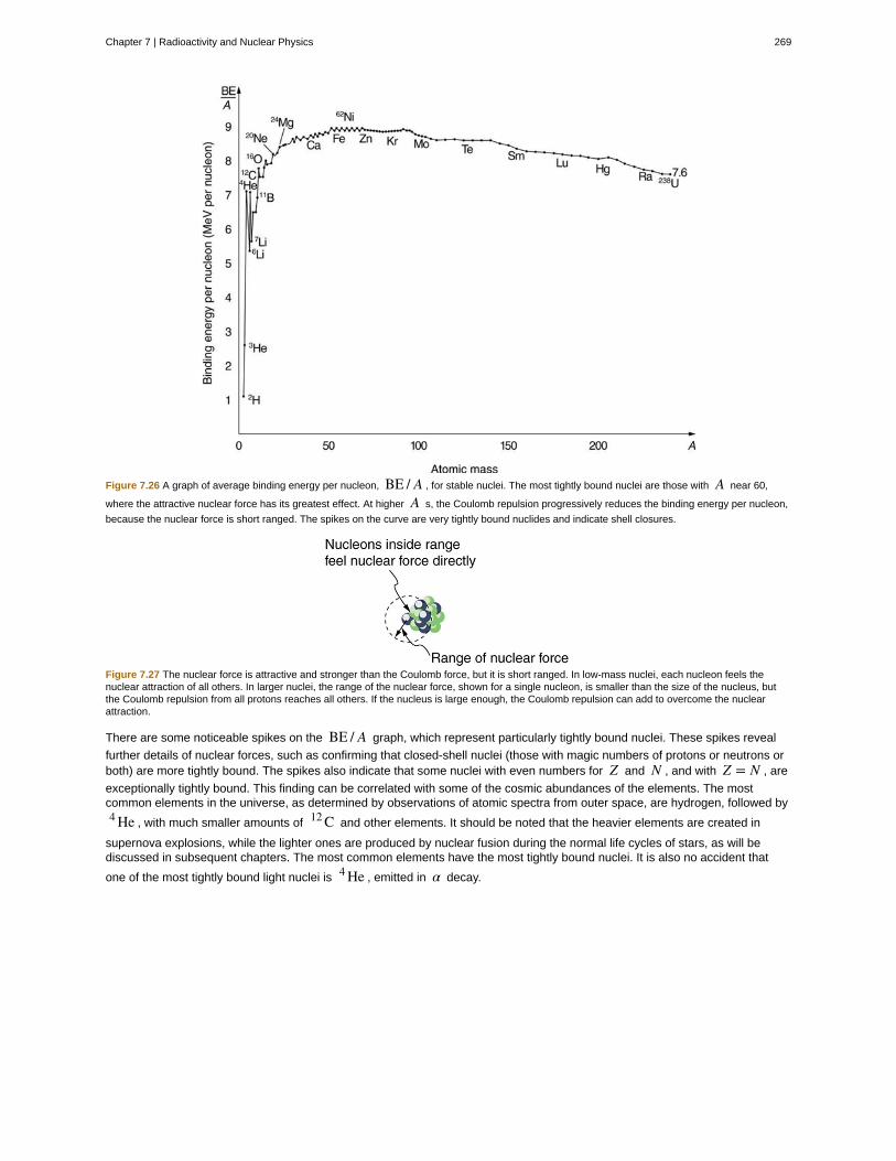
Figure 7.26 A graph of average binding energy per nucleon, BE / A , for stable nuclei. The most tightly bound nuclei are those with A near 60,
where the attractive nuclear force has its greatest effect. At higher A s, the Coulomb repulsion progressively reduces the binding energy per nucleon,
because the nuclear force is short ranged. The spikes on the curve are very tightly bound nuclides and indicate shell closures.
Figure 7.27 The nuclear force is attractive and stronger than the Coulomb force, but it is short ranged. In low-mass nuclei, each nucleon feels thenuclear attraction of all others. In larger nuclei, the range of the nuclear force, shown for a single nucleon, is smaller than the size of the nucleus, butthe Coulomb repulsion from all protons reaches all others. If the nucleus is large enough, the Coulomb repulsion can add to overcome the nuclearattraction.
There are some noticeable spikes on the BE / A graph, which represent particularly tightly bound nuclei. These spikes reveal
further details of nuclear forces, such as confirming that closed-shell nuclei (those with magic numbers of protons or neutrons orboth) are more tightly bound. The spikes also indicate that some nuclei with even numbers for Z and N , and with Z = N , are
exceptionally tightly bound. This finding can be correlated with some of the cosmic abundances of the elements. The mostcommon elements in the universe, as determined by observations of atomic spectra from outer space, are hydrogen, followed by4 He , with much smaller amounts of 12 C and other elements. It should be noted that the heavier elements are created in
supernova explosions, while the lighter ones are produced by nuclear fusion during the normal life cycles of stars, as will bediscussed in subsequent chapters. The most common elements have the most tightly bound nuclei. It is also no accident that
one of the most tightly bound light nuclei is 4 He , emitted in α decay.
Chapter 7 | Radioactivity and Nuclear Physics 269

Example 7.7 What Is BE/ A for an Alpha Particle?
Calculate the binding energy per nucleon of 4 He , the α particle.
Strategy
To find BE / A , we first find BE using the Equation BE = {[Zm(1 H) + Nmn] − m(A X)}c2 and then divide by A . This
is straightforward once we have looked up the appropriate atomic masses in Appendix A (https://legacy.cnx.org/content/m42699/latest/) .
Solution
The binding energy for a nucleus is given by the equation
(7.63)BE = {[Zm(1 H) + Nmn] − m(A X)}c2.
For 4 He , we have Z = N = 2 ; thus,
(7.64)BE = {[2m(1 H) + 2mn] − m(4 He)}c2.
Appendix A (https://legacy.cnx.org/content/m42699/latest/) gives these masses as m(4 He) = 4.002602 u ,
m(1 H) = 1.007825 u , and mn = 1.008665 u . Thus,
(7.65)BE = (0.030378 u)c2.
Noting that 1 u = 931.5 MeV/c2 , we find
(7.66)BE = (0.030378)(931.5 MeV/c2)c2 = 28.3 MeV.
Since A = 4 , we see that BE / A is this number divided by 4, or
(7.67)BE / A = 7.07 MeV/nucleon.Discussion
This is a large binding energy per nucleon compared with those for other low-mass nuclei, which have
BE / A ≈ 3 MeV/nucleon . This indicates that 4 He is tightly bound compared with its neighbors on the chart of the
nuclides. You can see the spike representing this value of BE / A for 4 He on the graph in Figure 7.26. This is why 4 He
is stable. Since 4 He is tightly bound, it has less mass than other A = 4 nuclei and, therefore, cannot spontaneously
decay into them. The large binding energy also helps to explain why some nuclei undergo α decay. Smaller mass in the
decay products can mean energy release, and such decays can be spontaneous. Further, it can happen that two protonsand two neutrons in a nucleus can randomly find themselves together, experience the exceptionally large nuclear force that
binds this combination, and act as a 4 He unit within the nucleus, at least for a while. In some cases, the 4 He escapes,
and α decay has then taken place.
There is more to be learned from nuclear binding energies. The general trend in BE / A is fundamental to energy production in
stars, and to fusion and fission energy sources on Earth, for example. This is one of the applications of nuclear physics coveredin Medical Applications of Nuclear Physics. The abundance of elements on Earth, in stars, and in the universe as a whole isrelated to the binding energy of nuclei and has implications for the continued expansion of the universe.
Problem-Solving StrategiesFor Reaction And Binding Energies and Activity Calculations in Nuclear Physics
1. Identify exactly what needs to be determined in the problem (identify the unknowns). This will allow you to decide whetherthe energy of a decay or nuclear reaction is involved, for example, or whether the problem is primarily concerned withactivity (rate of decay).
2. Make a list of what is given or can be inferred from the problem as stated (identify the knowns).
3. For reaction and binding-energy problems, we use atomic rather than nuclear masses. Since the masses of neutral atoms
are used, you must count the number of electrons involved. If these do not balance (such as in β+ decay), then an energy
adjustment of 0.511 MeV per electron must be made. Also note that atomic masses may not be given in a problem; theycan be found in tables.
4. For problems involving activity, the relationship of activity to half-life, and the number of nuclei given in the equation
270 Chapter 7 | Radioactivity and Nuclear Physics
This OpenStax book is available for free at https://legacy.cnx.org/content/col11630/1.1

R = 0.693Nt1 / 2
can be very useful. Owing to the fact that number of nuclei is involved, you will also need to be familiar with
moles and Avogadro’s number.
5. Perform the desired calculation; keep careful track of plus and minus signs as well as powers of 10.
6. Check the answer to see if it is reasonable: Does it make sense? Compare your results with worked examples and otherinformation in the text. (Heeding the advice in Step 5 will also help you to be certain of your result.) You must understandthe problem conceptually to be able to determine whether the numerical result is reasonable.
Nuclear Fission
Start a chain reaction, or introduce non-radioactive isotopes to prevent one. Control energy production in a nuclear reactor!
(This media type is not supported in this reader. Click to open media in browser.) (http://legacy.cnx.org/content/m42640/1.16/#fs-id1167063693188)
Figure 7.28
7.7 Tunneling
Protons and neutrons are bound inside nuclei, that means energy must be supplied to break them away. The situation isanalogous to a marble in a bowl that can roll around but lacks the energy to get over the rim. It is bound inside the bowl (seeFigure 7.29). If the marble could get over the rim, it would gain kinetic energy by rolling down outside. However classically, if themarble does not have enough kinetic energy to get over the rim, it remains forever trapped in its well.
Figure 7.29 The marble in this semicircular bowl at the top of a volcano has enough kinetic energy to get to the altitude of the dashed line, but notenough to get over the rim, so that it is trapped forever. If it could find a tunnel through the barrier, it would escape, roll downhill, and gain kineticenergy.
In a nucleus, the attractive nuclear potential is analogous to the bowl at the top of a volcano (where the “volcano” refers only tothe shape). Protons and neutrons have kinetic energy, but it is about 8 MeV less than that needed to get out (see Figure 7.30).That is, they are bound by an average of 8 MeV per nucleon. The slope of the hill outside the bowl is analogous to the repulsiveCoulomb potential for a nucleus, such as for an α particle outside a positive nucleus. In α decay, two protons and two neutrons
spontaneously break away as a 4 He unit. Yet the protons and neutrons do not have enough kinetic energy to get over the rim.
So how does the α particle get out?
Figure 7.30 Nucleons within an atomic nucleus are bound or trapped by the attractive nuclear force, as shown in this simplified potential energy curve.An α particle outside the range of the nuclear force feels the repulsive Coulomb force. The α particle inside the nucleus does not have enough
kinetic energy to get over the rim, yet it does manage to get out by quantum mechanical tunneling.
The answer was supplied in 1928 by the Russian physicist George Gamow (1904–1968). The α particle tunnels through a
region of space it is forbidden to be in, and it comes out of the side of the nucleus. Like an electron making a transition betweenorbits around an atom, it travels from one point to another without ever having been in between. Figure 7.31 indicates how thisworks. The wave function of a quantum mechanical particle varies smoothly, going from within an atomic nucleus (on one side ofa potential energy barrier) to outside the nucleus (on the other side of the potential energy barrier). Inside the barrier, the wavefunction does not become zero but decreases exponentially, and we do not observe the particle inside the barrier. The probability
Chapter 7 | Radioactivity and Nuclear Physics 271

of finding a particle is related to the square of its wave function, and so there is a small probability of finding the particle outsidethe barrier, which implies that the particle can tunnel through the barrier. This process is called barrier penetration or quantummechanical tunneling. This concept was developed in theory by J. Robert Oppenheimer (who led the development of the firstnuclear bombs during World War II) and was used by Gamow and others to describe α decay.
Figure 7.31 The wave function representing a quantum mechanical particle must vary smoothly, going from within the nucleus (to the left of the barrier)to outside the nucleus (to the right of the barrier). Inside the barrier, the wave function does not abruptly become zero; rather, it decreasesexponentially. Outside the barrier, the wave function is small but finite, and there it smoothly becomes sinusoidal. Owing to the fact that there is a smallprobability of finding the particle outside the barrier, the particle can tunnel through the barrier.
Good ideas explain more than one thing. In addition to qualitatively explaining how the four nucleons in an α particle can get out
of the nucleus, the detailed theory also explains quantitatively the half-life of various nuclei that undergo α decay. This
description is what Gamow and others devised, and it works for α decay half-lives that vary by 17 orders of magnitude.
Experiments have shown that the more energetic the α decay of a particular nuclide is, the shorter is its half-life. Tunneling
explains this in the following manner: For the decay to be more energetic, the nucleons must have more energy in the nucleusand should be able to ascend a little closer to the rim. The barrier is therefore not as thick for more energetic decay, and theexponential decrease of the wave function inside the barrier is not as great. Thus the probability of finding the particle outside thebarrier is greater, and the half-life is shorter.
Tunneling as an effect also occurs in quantum mechanical systems other than nuclei. Electrons trapped in solids can tunnel fromone object to another if the barrier between the objects is thin enough. The process is the same in principle as described for αdecay. It is far more likely for a thin barrier than a thick one. Scanning tunneling electron microscopes function on this principle.The current of electrons that travels between a probe and a sample tunnels through a barrier and is very sensitive to itsthickness, allowing detection of individual atoms as shown in Figure 7.32.
272 Chapter 7 | Radioactivity and Nuclear Physics
This OpenStax book is available for free at https://legacy.cnx.org/content/col11630/1.1

activity:
alpha decay:
alpha rays:
antielectron:
antimatter:
atomic mass:
atomic number:
barrier penetration:
becquerel:
Figure 7.32 (a) A scanning tunneling electron microscope can detect extremely small variations in dimensions, such as individual atoms. Electronstunnel quantum mechanically between the probe and the sample. The probability of tunneling is extremely sensitive to barrier thickness, so that theelectron current is a sensitive indicator of surface features. (b) Head and mouthparts of Coleoptera Chrysomelidea as seen through an electronmicroscope (credit: Louisa Howard, Dartmouth College)
Quantum Tunneling and Wave Packets
Watch quantum "particles" tunnel through barriers. Explore the properties of the wave functions that describe these particles.
(This media type is not supported in this reader. Click to open media in browser.) (http://legacy.cnx.org/content/m42644/1.12/#QuantumTunneling)
Glossary
the rate of decay for radioactive nuclides
type of radioactive decay in which an atomic nucleus emits an alpha particle
one of the types of rays emitted from the nucleus of an atom
another term for positron
composed of antiparticles
the total mass of the protons, neutrons, and electrons in a single atom
number of protons in a nucleus
quantum mechanical effect whereby a particle has a nonzero probability to cross through a potentialenergy barrier despite not having sufficient energy to pass over the barrier; also called quantum mechanical tunneling
SI unit for rate of decay of a radioactive material
Chapter 7 | Radioactivity and Nuclear Physics 273

beta decay:
beta rays:
binding energy:
binding energy per nucleon:
carbon-14 dating:
chart of the nuclides:
curie:
daughter:
decay:
decay constant:
decay equation:
decay series:
electron capture:
electron capture equation:
electron’s antineutrino:
electron’s neutrino:
gamma decay:
gamma rays:
Geiger tube:
half-life:
ionizing radiation:
isotopes:
magic numbers:
mass number:
neutrino:
neutron:
nuclear radiation:
nuclear reaction energy:
nucleons:
nucleus:
nuclide:
parent:
photomultiplier:
positron:
positron decay:
type of radioactive decay in which an atomic nucleus emits a beta particle
one of the types of rays emitted from the nucleus of an atom
the energy needed to separate nucleus into individual protons and neutrons
the binding energy calculated per nucleon; it reveals the details of the nuclear force—larger theBE / A , the more stable the nucleus
a radioactive dating technique based on the radioactivity of carbon-14
a table comprising stable and unstable nuclei
the activity of 1g of 226 Ra , equal to 3.70×10¹⁰ Bq
the nucleus obtained when parent nucleus decays and produces another nucleus following the rules and theconservation laws
the process by which an atomic nucleus of an unstable atom loses mass and energy by emitting ionizing particles
quantity that is inversely proportional to the half-life and that is used in equation for number of nuclei as afunction of time
the equation to find out how much of a radioactive material is left after a given period of time
process whereby subsequent nuclides decay until a stable nuclide is produced
the process in which a proton-rich nuclide absorbs an inner atomic electron and simultaneously emits aneutrino
equation representing the electron capture
antiparticle of electron’s neutrino
a subatomic elementary particle which has no net electric charge
type of radioactive decay in which an atomic nucleus emits a gamma particle
one of the types of rays emitted from the nucleus of an atom
a very common radiation detector that usually gives an audio output
the time in which there is a 50% chance that a nucleus will decay
radiation (whether nuclear in origin or not) that produces ionization whether nuclear in origin or not
nuclei having the same Z and different N s
a number that indicates a shell structure for the nucleus in which closed shells are more stable
number of nucleons in a nucleus
an electrically neutral, weakly interacting elementary subatomic particle
a neutral particle that is found in a nucleus
rays that originate in the nuclei of atoms, the first examples of which were discovered by Becquerel
the energy created in a nuclear reaction
the particles found inside nuclei
a region consisting of protons and neutrons at the center of an atom
a type of atom whose nucleus has specific numbers of protons and neutrons
the original state of nucleus before decay
a device that converts light into electrical signals
the particle that results from positive beta decay; also known as an antielectron
type of beta decay in which a proton is converted to a neutron, releasing a positron and a neutrino
274 Chapter 7 | Radioactivity and Nuclear Physics
This OpenStax book is available for free at https://legacy.cnx.org/content/col11630/1.1

protons:
quantum mechanical tunneling:
radiation detector:
radioactive:
radioactive dating:
radioactivity:
radius of a nucleus:
range of radiation:
rate of decay:
scintillators:
solid-state radiation detectors:
tunneling:
the positively charged nucleons found in a nucleus
quantum mechanical effect whereby a particle has a nonzero probability to cross through apotential energy barrier despite not having sufficient energy to pass over the barrier; also called barrier penetration
a device that is used to detect and track the radiation from a radioactive reaction
a substance or object that emits nuclear radiation
an application of radioactive decay in which the age of a material is determined by the amount ofradioactivity of a particular type that occurs
the emission of rays from the nuclei of atoms
the radius of a nucleus is r = r0A1 / 3
the distance that the radiation can travel through a material
the number of radioactive events per unit time
a radiation detection method that records light produced when radiation interacts with materials
semiconductors fabricated to directly convert incident radiation into electrical current
a quantum mechanical process of potential energy barrier penetration
Section Summary
7.1 Nuclear Radioactivity• Some nuclei are radioactive—they spontaneously decay destroying some part of their mass and emitting energetic rays, a
process called nuclear radioactivity.• Nuclear radiation, like x rays, is ionizing radiation, because energy sufficient to ionize matter is emitted in each decay.• The range (or distance traveled in a material) of ionizing radiation is directly related to the charge of the emitted particle and
its energy, with greater-charge and lower-energy particles having the shortest ranges.• Radiation detectors are based directly or indirectly upon the ionization created by radiation, as are the effects of radiation
on living and inert materials.
7.2 Radiation Detection and Detectors• Radiation detectors are based directly or indirectly upon the ionization created by radiation, as are the effects of radiation
on living and inert materials.
7.3 Substructure of the Nucleus• Two particles, both called nucleons, are found inside nuclei. The two types of nucleons are protons and neutrons; they are
very similar, except that the proton is positively charged while the neutron is neutral. Some of their characteristics are givenin Table 7.2 and compared with those of the electron. A mass unit convenient to atomic and nuclear processes is theunified atomic mass unit (u), defined to be
1 u = 1.6605×10⁻²⁷ kg = 931.46 MeV / c2.• A nuclide is a specific combination of protons and neutrons, denoted by
ZA XN or simply A X,
Z is the number of protons or atomic number, X is the symbol for the element, N is the number of neutrons, and A is the
mass number or the total number of protons and neutrons,
A = N + Z.• Nuclides having the same Z but different N are isotopes of the same element.
• The radius of a nucleus, r , is approximately
r = r0A1 / 3,where r0 = 1.2 fm . Nuclear volumes are proportional to A . There are two nuclear forces, the weak and the strong.
Systematics in nuclear stability seen on the chart of the nuclides indicate that there are shell closures in nuclei for values ofZ and N equal to the magic numbers, which correspond to highly stable nuclei.
7.4 Nuclear Decay and Conservation Laws• When a parent nucleus decays, it produces a daughter nucleus following rules and conservation laws. There are three
Chapter 7 | Radioactivity and Nuclear Physics 275

major types of nuclear decay, called alpha (α), beta ⎛⎝β⎞⎠, and gamma (γ) . The α decay equation is
ZA XN → Z − 2
A − 4 YN − 2 + 24He2.
• Nuclear decay releases an amount of energy E related to the mass destroyed Δm by
E = (Δm)c2.• There are three forms of beta decay. The β− decay equation is
ZA XN → Z + 1
A YN − 1 + β− + ν̄ e.• The β+ decay equation is
ZA XN → Z − 1
A YN + 1 + β+ + νe.• The electron capture equation is
ZA XN + e− → Z − 1
A YN + 1 + νe.• β− is an electron, β+ is an antielectron or positron, νe represents an electron’s neutrino, and ν̄ e is an electron’s
antineutrino. In addition to all previously known conservation laws, two new ones arise— conservation of electron familynumber and conservation of the total number of nucleons. The γ decay equation is
XN* → XN + γ1 + γ2 + ⋯γ is a high-energy photon originating in a nucleus.
7.5 Half-Life and Activity• Half-life t1 / 2 is the time in which there is a 50% chance that a nucleus will decay. The number of nuclei N as a function
of time is
N = N0e−λt,where N0 is the number present at t = 0 , and λ is the decay constant, related to the half-life by
λ = 0.693t1 / 2
.• One of the applications of radioactive decay is radioactive dating, in which the age of a material is determined by the
amount of radioactive decay that occurs. The rate of decay is called the activity R :
R = ΔNΔt .
• The SI unit for R is the becquerel (Bq), defined by
1 Bq = 1 decay/s.• R is also expressed in terms of curies (Ci), where
1 Ci = 3.70×10¹⁰ Bq.• The activity R of a source is related to N and t1 / 2 by
R = 0.693Nt1 / 2
.
• Since N has an exponential behavior as in the equation N = N0e−λt , the activity also has an exponential behavior,
given by
R = R0e−λt,where R0 is the activity at t = 0 .
7.6 Binding Energy• The binding energy (BE) of a nucleus is the energy needed to separate it into individual protons and neutrons. In terms of
atomic masses,
BE = {[Zm(1 H) + Nmn] − m(A X)}c2,
where m⎛⎝1 H⎞⎠ is the mass of a hydrogen atom, m⎛⎝A X⎞⎠ is the atomic mass of the nuclide, and mn is the mass of a
276 Chapter 7 | Radioactivity and Nuclear Physics
This OpenStax book is available for free at https://legacy.cnx.org/content/col11630/1.1

neutron. Patterns in the binding energy per nucleon, BE / A , reveal details of the nuclear force. The larger the BE / A ,
the more stable the nucleus.
7.7 Tunneling• Tunneling is a quantum mechanical process of potential energy barrier penetration. The concept was first applied to explain
α decay, but tunneling is found to occur in other quantum mechanical systems.
Conceptual Questions
7.1 Nuclear Radioactivity
1. Suppose the range for 5.0 MeVα ray is known to be 2.0 mm in a certain material. Does this mean that every 5.0 MeVα a
ray that strikes this material travels 2.0 mm, or does the range have an average value with some statistical fluctuations in thedistances traveled? Explain.
2. What is the difference between γ rays and characteristic x rays? Is either necessarily more energetic than the other? Which
can be the most energetic?
3. Ionizing radiation interacts with matter by scattering from electrons and nuclei in the substance. Based on the law ofconservation of momentum and energy, explain why electrons tend to absorb more energy than nuclei in these interactions.
4. What characteristics of radioactivity show it to be nuclear in origin and not atomic?
5. What is the source of the energy emitted in radioactive decay? Identify an earlier conservation law, and describe how it wasmodified to take such processes into account.
6. Consider Figure 7.3. If an electric field is substituted for the magnetic field with positive charge instead of the north pole andnegative charge instead of the south pole, in which directions will the α , β , and γ rays bend?
7. Explain how an α particle can have a larger range in air than a β particle with the same energy in lead.
8. Arrange the following according to their ability to act as radiation shields, with the best first and worst last. Explain yourordering in terms of how radiation loses its energy in matter.
(a) A solid material with low density composed of low-mass atoms.
(b) A gas composed of high-mass atoms.
(c) A gas composed of low-mass atoms.
(d) A solid with high density composed of high-mass atoms.
9. Often, when people have to work around radioactive materials spills, we see them wearing white coveralls (usually a plasticmaterial). What types of radiation (if any) do you think these suits protect the worker from, and how?
7.2 Radiation Detection and Detectors
10. Is it possible for light emitted by a scintillator to be too low in frequency to be used in a photomultiplier tube? Explain.
7.3 Substructure of the Nucleus
11. The weak and strong nuclear forces are basic to the structure of matter. Why we do not experience them directly?
12. Define and make clear distinctions between the terms neutron, nucleon, nucleus, nuclide, and neutrino.
13. What are isotopes? Why do different isotopes of the same element have similar chemistries?
7.4 Nuclear Decay and Conservation Laws
14. Star Trek fans have often heard the term “antimatter drive.” Describe how you could use a magnetic field to trap antimatter,such as produced by nuclear decay, and later combine it with matter to produce energy. Be specific about the type of antimatter,the need for vacuum storage, and the fraction of matter converted into energy.
15. What conservation law requires an electron’s neutrino to be produced in electron capture? Note that the electron no longerexists after it is captured by the nucleus.
16. Neutrinos are experimentally determined to have an extremely small mass. Huge numbers of neutrinos are created in asupernova at the same time as massive amounts of light are first produced. When the 1987A supernova occurred in the LargeMagellanic Cloud, visible primarily in the Southern Hemisphere and some 100,000 light-years away from Earth, neutrinos fromthe explosion were observed at about the same time as the light from the blast. How could the relative arrival times of neutrinosand light be used to place limits on the mass of neutrinos?
17. What do the three types of beta decay have in common that is distinctly different from alpha decay?
Chapter 7 | Radioactivity and Nuclear Physics 277

7.5 Half-Life and Activity
18. In a 3×10⁹ -year-old rock that originally contained some 238 U , which has a half-life of 4.5×10⁹ years, we expect to find
some 238 U remaining in it. Why are 226 Ra , 222 Rn , and 210 Po also found in such a rock, even though they have much
shorter half-lives (1600 years, 3.8 days, and 138 days, respectively)?
19. Does the number of radioactive nuclei in a sample decrease to exactly half its original value in one half-life? Explain in termsof the statistical nature of radioactive decay.
20. Radioactivity depends on the nucleus and not the atom or its chemical state. Why, then, is one kilogram of uranium moreradioactive than one kilogram of uranium hexafluoride?
21. Explain how a bound system can have less mass than its components. Why is this not observed classically, say for a buildingmade of bricks?
22. Spontaneous radioactive decay occurs only when the decay products have less mass than the parent, and it tends toproduce a daughter that is more stable than the parent. Explain how this is related to the fact that more tightly bound nuclei aremore stable. (Consider the binding energy per nucleon.)
23. To obtain the most precise value of BE from the equation BE=⎡⎣ZM⎛⎝1 H⎞⎠+ Nmn⎤⎦c2 − m⎛⎝A X⎞⎠c2 , we should take into
account the binding energy of the electrons in the neutral atoms. Will doing this produce a larger or smaller value for BE? Why isthis effect usually negligible?
24. How does the finite range of the nuclear force relate to the fact that BE / A is greatest for A near 60?
7.6 Binding Energy
25. Why is the number of neutrons greater than the number of protons in stable nuclei having A greater than about 40, and why
is this effect more pronounced for the heaviest nuclei?
7.7 Tunneling
26. A physics student caught breaking conservation laws is imprisoned. She leans against the cell wall hoping to tunnel outquantum mechanically. Explain why her chances are negligible. (This is so in any classical situation.)
27. When a nucleus α decays, does the α particle move continuously from inside the nucleus to outside? That is, does it travel
each point along an imaginary line from inside to out? Explain.
278 Chapter 7 | Radioactivity and Nuclear Physics
This OpenStax book is available for free at https://legacy.cnx.org/content/col11630/1.1

Problems & Exercises
7.2 Radiation Detection and Detectors
1. The energy of 30.0 eV is required to ionize a molecule of
the gas inside a Geiger tube, thereby producing an ion pair.Suppose a particle of ionizing radiation deposits 0.500 MeV ofenergy in this Geiger tube. What maximum number of ionpairs can it create?
2. A particle of ionizing radiation creates 4000 ion pairs in thegas inside a Geiger tube as it passes through. What minimumenergy was deposited, if 30.0 eV is required to create each
ion pair?
3. (a) Repeat Exercise 7.2, and convert the energy to joulesor calories. (b) If all of this energy is converted to thermalenergy in the gas, what is its temperature increase, assuming
50.0 cm3 of ideal gas at 0.250-atm pressure? (The small
answer is consistent with the fact that the energy is large on aquantum mechanical scale but small on a macroscopicscale.)
4. Suppose a particle of ionizing radiation deposits 1.0 MeV inthe gas of a Geiger tube, all of which goes to creating ionpairs. Each ion pair requires 30.0 eV of energy. (a) Theapplied voltage sweeps the ions out of the gas in 1.00 μs .
What is the current? (b) This current is smaller than the actualcurrent since the applied voltage in the Geiger tubeaccelerates the separated ions, which then create other ionpairs in subsequent collisions. What is the current if this lasteffect multiplies the number of ion pairs by 900?
7.3 Substructure of the Nucleus
5. Verify that a 2.3×10¹⁷ kg mass of water at normal
density would make a cube 60 km on a side, as claimed inExample 7.1. (This mass at nuclear density would make acube 1.0 m on a side.)
6. Find the length of a side of a cube having a mass of 1.0 kgand the density of nuclear matter, taking this to be
2.3×10¹⁷ kg/m3 .
7. What is the radius of an α particle?
8. Find the radius of a 238 Pu nucleus. 238 Pu is a
manufactured nuclide that is used as a power source onsome space probes.
9. (a) Calculate the radius of 58 Ni , one of the most tightly
bound stable nuclei.
(b) What is the ratio of the radius of 58 Ni to that of 258 Ha ,
one of the largest nuclei ever made? Note that the radius ofthe largest nucleus is still much smaller than the size of anatom.
10. The unified atomic mass unit is defined to be
1 u = 1.6605×10⁻²⁷ kg . Verify that this amount of mass
converted to energy yields 931.5 MeV. Note that you mustuse four-digit or better values for c and ∣ qe ∣ .
11. What is the ratio of the velocity of a β particle to that of
an α particle, if they have the same nonrelativistic kinetic
energy?
12. If a 1.50-cm-thick piece of lead can absorb 90.0% of theγ rays from a radioactive source, how many centimeters of
lead are needed to absorb all but 0.100% of the γ rays?
13. The detail observable using a probe is limited by itswavelength. Calculate the energy of a γ -ray photon that has
a wavelength of 1×10⁻¹⁶ m , small enough to detect details
about one-tenth the size of a nucleon. Note that a photonhaving this energy is difficult to produce and interacts poorlywith the nucleus, limiting the practicability of this probe.
14. (a) Show that if you assume the average nucleus is
spherical with a radius r = r0A1 / 3 , and with a mass of Au, then its density is independent of A .
(b) Calculate that density in u/fm3 and kg/m3 , and
compare your results with those found in Example 7.1 for56 Fe .
15. What is the ratio of the velocity of a 5.00-MeV β ray to
that of an α particle with the same kinetic energy? This
should confirm that β s travel much faster than α s even
when relativity is taken into consideration. (See also Exercise7.11.)
16. (a) What is the kinetic energy in MeV of a β ray that is
traveling at 0.998c ? This gives some idea of how energetic
a β ray must be to travel at nearly the same speed as a γray. (b) What is the velocity of the γ ray relative to the βray?
7.4 Nuclear Decay and Conservation Laws
In the following eight problems, write the complete decay
equation for the given nuclide in the complete ZA XN
notation. Refer to the periodic table for values of Z .
17. β− decay of 3 H (tritium), a manufactured isotope of
hydrogen used in some digital watch displays, andmanufactured primarily for use in hydrogen bombs.
18. β− decay of 40 K , a naturally occurring rare isotope of
potassium responsible for some of our exposure tobackground radiation.
19. β+ decay of 50 Mn .
20. β+ decay of 52 Fe .
21. Electron capture by 7 Be .
22. Electron capture by 106 In .
23. α decay of 210 Po , the isotope of polonium in the decay
series of 238 U that was discovered by the Curies. A favorite
isotope in physics labs, since it has a short half-life anddecays to a stable nuclide.
Chapter 7 | Radioactivity and Nuclear Physics 279

24. α decay of 226 Ra , another isotope in the decay series
of 238 U , first recognized as a new element by the Curies.
Poses special problems because its daughter is a radioactivenoble gas.
In the following four problems, identify the parent nuclide and
write the complete decay equation in the ZA XN notation.
Refer to the periodic table for values of Z .
25. β− decay producing 137 Ba . The parent nuclide is a
major waste product of reactors and has chemistry similar topotassium and sodium, resulting in its concentration in yourcells if ingested.
26. β− decay producing 90 Y . The parent nuclide is a
major waste product of reactors and has chemistry similar to
calcium, so that it is concentrated in bones if ingested ( 90 Yis also radioactive.)
27. α decay producing 228 Ra . The parent nuclide is nearly
100% of the natural element and is found in gas lantern
mantles and in metal alloys used in jets ( 228 Ra is also
radioactive).
28. α decay producing 208 Pb . The parent nuclide is in the
decay series produced by 232 Th , the only naturally
occurring isotope of thorium.
29. When an electron and positron annihilate, both theirmasses are destroyed, creating two equal energy photons topreserve momentum. (a) Confirm that the annihilation
equation e+ + e− → γ + γ conserves charge, electron
family number, and total number of nucleons. To do this,identify the values of each before and after the annihilation.(b) Find the energy of each γ ray, assuming the electron and
positron are initially nearly at rest. (c) Explain why the two γrays travel in exactly opposite directions if the center of massof the electron-positron system is initially at rest.
30. Confirm that charge, electron family number, and the totalnumber of nucleons are all conserved by the rule for αdecay given in the equation Z
A XN → Z − 2A − 4 YN − 2 + 2
4He2 .
To do this, identify the values of each before and after thedecay.
31. Confirm that charge, electron family number, and the totalnumber of nucleons are all conserved by the rule for β−
decay given in the equation
ZA XN → Z + 1
A YN − 1 + β− + ν̄ e . To do this, identify the
values of each before and after the decay.
32. Confirm that charge, electron family number, and the totalnumber of nucleons are all conserved by the rule for β−
decay given in the equation
ZA XN → Z − 1
A YN − 1 + β− + νe . To do this, identify the
values of each before and after the decay.
33. Confirm that charge, electron family number, and the totalnumber of nucleons are all conserved by the rule for electroncapture given in the equation
ZA XN + e− → Z − 1
A YN + 1 + νe . To do this, identify the
values of each before and after the capture.
34. A rare decay mode has been observed in which 222 Ra
emits a 14 C nucleus. (a) The decay equation is
222 Ra →A X+14 C . Identify the nuclide A X . (b) Find the
energy emitted in the decay. The mass of 222 Ra is
222.015353 u.
35. (a) Write the complete α decay equation for 226 Ra .
(b) Find the energy released in the decay.
36. (a) Write the complete α decay equation for 249 Cf .
(b) Find the energy released in the decay.
37. (a) Write the complete β− decay equation for the
neutron. (b) Find the energy released in the decay.
38. (a) Write the complete β− decay equation for 90 Sr , a
major waste product of nuclear reactors. (b) Find the energyreleased in the decay.
39. Calculate the energy released in the β+ decay of 22 Na, the equation for which is given in the text. The masses of22 Na and 22 Ne are 21.994434 and 21.991383 u,
respectively.
40. (a) Write the complete β+ decay equation for 11 C .
(b) Calculate the energy released in the decay. The masses
of 11 C and 11 B are 11.011433 and 11.009305 u,
respectively.
41. (a) Calculate the energy released in the α decay of
238 U .
(b) What fraction of the mass of a single 238 U is destroyed
in the decay? The mass of 234 Th is 234.043593 u.
(c) Although the fractional mass loss is large for a singlenucleus, it is difficult to observe for an entire macroscopicsample of uranium. Why is this?
42. (a) Write the complete reaction equation for electron
capture by 7 Be.
(b) Calculate the energy released.
43. (a) Write the complete reaction equation for electron
capture by 15 O .
(b) Calculate the energy released.
7.5 Half-Life and Activity
Data from the appendices and the periodic table may beneeded for these problems.
280 Chapter 7 | Radioactivity and Nuclear Physics
This OpenStax book is available for free at https://legacy.cnx.org/content/col11630/1.1

44. An old campfire is uncovered during an archaeologicaldig. Its charcoal is found to contain less than 1/1000 the
normal amount of 14 C . Estimate the minimum age of the
charcoal, noting that 210 = 1024 .
45. A 60 Co source is labeled 4.00 mCi, but its present
activity is found to be 1.85×10⁷ Bq. (a) What is the present
activity in mCi? (b) How long ago did it actually have a4.00-mCi activity?
46. (a) Calculate the activity R in curies of 1.00 g of 226 Ra .
(b) Discuss why your answer is not exactly 1.00 Ci, given thatthe curie was originally supposed to be exactly the activity ofa gram of radium.
47. Show that the activity of the 14 C in 1.00 g of 12 Cfound in living tissue is 0.250 Bq.
48. Mantles for gas lanterns contain thorium, because it formsan oxide that can survive being heated to incandescence for
long periods of time. Natural thorium is almost 100% 232 Th ,
with a half-life of 1.405×10¹⁰ y . If an average lantern
mantle contains 300 mg of thorium, what is its activity?
49. Cow’s milk produced near nuclear reactors can be tested
for as little as 1.00 pCi of 131 I per liter, to check for possible
reactor leakage. What mass of 131 I has this activity?
50. (a) Natural potassium contains 40 K , which has a half-
life of 1.277×10⁹ y. What mass of 40 K in a person would
have a decay rate of 4140 Bq? (b) What is the fraction of40 K in natural potassium, given that the person has 140 g
in his body? (These numbers are typical for a 70-kg adult.)
51. There is more than one isotope of natural uranium. If a
researcher isolates 1.00 mg of the relatively scarce 235 Uand finds this mass to have an activity of 80.0 Bq, what is itshalf-life in years?
52. 50 V has one of the longest known radioactive half-lives.
In a difficult experiment, a researcher found that the activity of
1.00 kg of 50 V is 1.75 Bq. What is the half-life in years?
53. You can sometimes find deep red crystal vases in antiquestores, called uranium glass because their color wasproduced by doping the glass with uranium. Look up thenatural isotopes of uranium and their half-lives, and calculatethe activity of such a vase assuming it has 2.00 g of uraniumin it. Neglect the activity of any daughter nuclides.
54. A tree falls in a forest. How many years must pass before
the 14 C activity in 1.00 g of the tree’s carbon drops to 1.00
decay per hour?
55. What fraction of the 40 K that was on Earth when it
formed 4.5×10⁹ years ago is left today?
56. A 5000-Ci 60 Co source used for cancer therapy is
considered too weak to be useful when its activity falls to3500 Ci. How long after its manufacture does this happen?
57. Natural uranium is 0.7200% 235 U and 99.27% 238 U .
What were the percentages of 235 U and 238 U in natural
uranium when Earth formed 4.5×10⁹ years ago?
58. The β− particles emitted in the decay of 3 H (tritium)
interact with matter to create light in a glow-in-the-dark exitsign. At the time of manufacture, such a sign contains 15.0 Ci
of 3 H . (a) What is the mass of the tritium? (b) What is its
activity 5.00 y after manufacture?
59. World War II aircraft had instruments with glowing radium-painted dials (see Figure 7.2). The activity of one such
instrument was 1.0×10⁵ Bq when new. (a) What mass of
226 Ra was present? (b) After some years, the phosphors on
the dials deteriorated chemically, but the radium did notescape. What is the activity of this instrument 57.0 years afterit was made?
60. (a) The 210 Po source used in a physics laboratory is
labeled as having an activity of 1.0 μCi on the date it was
prepared. A student measures the radioactivity of this sourcewith a Geiger counter and observes 1500 counts per minute.She notices that the source was prepared 120 days beforeher lab. What fraction of the decays is she observing with herapparatus? (b) Identify some of the reasons that only afraction of the α s emitted are observed by the detector.
61. Armor-piercing shells with depleted uranium cores arefired by aircraft at tanks. (The high density of the uraniummakes them effective.) The uranium is called depleted
because it has had its 235 U removed for reactor use and is
nearly pure 238 U . Depleted uranium has been erroneously
called non-radioactive. To demonstrate that this is wrong: (a)
Calculate the activity of 60.0 g of pure 238 U . (b) Calculate
the activity of 60.0 g of natural uranium, neglecting the 234 Uand all daughter nuclides.
62. The ceramic glaze on a red-orange Fiestaware plate is
U2 O3 and contains 50.0 grams of 238 U , but very little
235 U . (a) What is the activity of the plate? (b) Calculate the
total energy that will be released by the 238 U decay. (c) If
energy is worth 12.0 cents per kW ⋅ h , what is the monetary
value of the energy emitted? (These plates went out ofproduction some 30 years ago, but are still available ascollectibles.)
Chapter 7 | Radioactivity and Nuclear Physics 281

63. Large amounts of depleted uranium ( 238 U ) are
available as a by-product of uranium processing for reactorfuel and weapons. Uranium is very dense and makes goodcounter weights for aircraft. Suppose you have a 4000-kg
block of 238 U . (a) Find its activity. (b) How many calories
per day are generated by thermalization of the decay energy?(c) Do you think you could detect this as heat? Explain.
64. The Galileo space probe was launched on its long journeypast several planets in 1989, with an ultimate goal of Jupiter.
Its power source is 11.0 kg of 238 Pu , a by-product of
nuclear weapons plutonium production. Electrical energy isgenerated thermoelectrically from the heat produced whenthe 5.59-MeV α particles emitted in each decay crash to a
halt inside the plutonium and its shielding. The half-life of238 Pu is 87.7 years. (a) What was the original activity of the
238 Pu in becquerel? (b) What power was emitted in
kilowatts? (c) What power was emitted 12.0 y after launch?You may neglect any extra energy from daughter nuclidesand any losses from escaping γ rays.
65. Construct Your Own Problem
Consider the generation of electricity by a radioactive isotopein a space probe, such as described in Exercise 7.64.Construct a problem in which you calculate the mass of aradioactive isotope you need in order to supply power for along space flight. Among the things to consider are theisotope chosen, its half-life and decay energy, the powerneeds of the probe and the length of the flight.
66. Unreasonable Results
A nuclear physicist finds 1.0 μg of 236 U in a piece of
uranium ore and assumes it is primordial since its half-life is
2.3×10⁷ y . (a) Calculate the amount of 236 U that would
had to have been on Earth when it formed 4.5×10⁹ y ago
for 1.0 μg to be left today. (b) What is unreasonable about
this result? (c) What assumption is responsible?
67. Unreasonable Results
(a) Repeat Exercise 7.57 but include the 0.0055% natural
abundance of 234 U with its 2.45×10⁵ y half-life. (b) What
is unreasonable about this result? (c) What assumption is
responsible? (d) Where does the 234 U come from if it is not
primordial?
68. Unreasonable Results
The manufacturer of a smoke alarm decides that the smallestcurrent of α radiation he can detect is 1.00 μA . (a) Find
the activity in curies of an α emitter that produces a
1.00 μA current of α particles. (b) What is unreasonable
about this result? (c) What assumption is responsible?
7.6 Binding Energy
69. 2 H is a loosely bound isotope of hydrogen. Called
deuterium or heavy hydrogen, it is stable but relativelyrare—it is 0.015% of natural hydrogen. Note that deuteriumhas Z = N , which should tend to make it more tightly
bound, but both are odd numbers. Calculate BE/A , the
binding energy per nucleon, for 2 H and compare it with the
approximate value obtained from the graph in Figure 7.26.
70. 56 Fe is among the most tightly bound of all nuclides. It
is more than 90% of natural iron. Note that 56 Fe has even
numbers of both protons and neutrons. Calculate BE/A , the
binding energy per nucleon, for 56 Fe and compare it with
the approximate value obtained from the graph in Figure7.26.
71. 209 Bi is the heaviest stable nuclide, and its BE / A is
low compared with medium-mass nuclides. Calculate BE/A ,
the binding energy per nucleon, for 209 Bi and compare it
with the approximate value obtained from the graph in Figure7.26.
72. (a) Calculate BE / A for 235 U , the rarer of the two
most common uranium isotopes. (b) Calculate BE / A for
238 U . (Most of uranium is 238 U .) Note that 238 U has
even numbers of both protons and neutrons. Is the BE / A of
238 U significantly different from that of 235 U ?
73. (a) Calculate BE / A for 12 C . Stable and relatively
tightly bound, this nuclide is most of natural carbon. (b)
Calculate BE / A for 14 C . Is the difference in BE / A
between 12 C and 14 C significant? One is stable and
common, and the other is unstable and rare.
74. The fact that BE / A is greatest for A near 60 implies
that the range of the nuclear force is about the diameter ofsuch nuclides. (a) Calculate the diameter of an A = 60nucleus. (b) Compare BE / A for 58 Ni and 90 Sr . The first
is one of the most tightly bound nuclides, while the second islarger and less tightly bound.
75. The purpose of this problem is to show in three ways thatthe binding energy of the electron in a hydrogen atom isnegligible compared with the masses of the proton andelectron. (a) Calculate the mass equivalent in u of the 13.6-eVbinding energy of an electron in a hydrogen atom, andcompare this with the mass of the hydrogen atom obtainedfrom Appendix A (https://legacy.cnx.org/content/m42699/latest/) . (b) Subtract the mass of the proton given in Table7.2 from the mass of the hydrogen atom given in Appendix A(https://legacy.cnx.org/content/m42699/latest/) . You willfind the difference is equal to the electron’s mass to threedigits, implying the binding energy is small in comparison. (c)Take the ratio of the binding energy of the electron (13.6 eV)to the energy equivalent of the electron’s mass (0.511 MeV).(d) Discuss how your answers confirm the stated purpose ofthis problem.
282 Chapter 7 | Radioactivity and Nuclear Physics
This OpenStax book is available for free at https://legacy.cnx.org/content/col11630/1.1

76. Unreasonable Results
A particle physicist discovers a neutral particle with a mass of2.02733 u that he assumes is two neutrons bound together.(a) Find the binding energy. (b) What is unreasonable aboutthis result? (c) What assumptions are unreasonable orinconsistent?
7.7 Tunneling
77. Derive an approximate relationship between the energy ofα decay and half-life using the following data. It may be
useful to graph the log of t1/2 against Eα to find some
straight-line relationship.
Table 7.3 Energy and Half-Life for α Decay
Nuclide Eα (MeV) t1/2
216 Ra 9.5 0.18 μs
194 Po 7.0 0.7 s
240 Cm 6.4 27 d
226 Ra 4.91 1600 y
232 Th 4.1 1.4×10¹⁰ y
78. Integrated Concepts
A 2.00-T magnetic field is applied perpendicular to the path ofcharged particles in a bubble chamber. What is the radius ofcurvature of the path of a 10 MeV proton in this field? Neglectany slowing along its path.
79. (a) Write the decay equation for the α decay of 235 U .
(b) What energy is released in this decay? The mass of thedaughter nuclide is 231.036298 u. (c) Assuming the residualnucleus is formed in its ground state, how much energy goesto the α particle?
80. Unreasonable Results
The relatively scarce naturally occurring calcium isotope48 Ca has a half-life of about 2×10¹⁶ y . (a) A small
sample of this isotope is labeled as having an activity of 1.0
Ci. What is the mass of the 48 Ca in the sample? (b) What is
unreasonable about this result? (c) What assumption isresponsible?
81. Unreasonable Results
A physicist scatters γ rays from a substance and sees
evidence of a nucleus 7.5×10⁻¹³ m in radius. (a) Find the
atomic mass of such a nucleus. (b) What is unreasonableabout this result? (c) What is unreasonable about theassumption?
82. Unreasonable Results
A frazzled theoretical physicist reckons that all conservationlaws are obeyed in the decay of a proton into a neutron,
positron, and neutrino (as in β+ decay of a nucleus) and
sends a paper to a journal to announce the reaction as apossible end of the universe due to the spontaneous decay ofprotons. (a) What energy is released in this decay? (b) Whatis unreasonable about this result? (c) What assumption isresponsible?
83. Construct Your Own Problem
Consider the decay of radioactive substances in the Earth’sinterior. The energy emitted is converted to thermal energythat reaches the earth’s surface and is radiated away intocold dark space. Construct a problem in which you estimatethe activity in a cubic meter of earth rock? And then calculatethe power generated. Calculate how much power must crosseach square meter of the Earth’s surface if the power isdissipated at the same rate as it is generated. Among thethings to consider are the activity per cubic meter, the energyper decay, and the size of the Earth.
Chapter 7 | Radioactivity and Nuclear Physics 283

284 Chapter 7 | Radioactivity and Nuclear Physics
This OpenStax book is available for free at https://legacy.cnx.org/content/col11630/1.1

8 MEDICAL APPLICATIONS OF NUCLEARPHYSICS
Figure 8.1 Tori Randall, Ph.D., curator for the Department of Physical Anthropology at the San Diego Museum of Man, prepares a 550-year-oldPeruvian child mummy for a CT scan at Naval Medical Center San Diego. (credit: U.S. Navy photo by Mass Communication Specialist 3rd ClassSamantha A. Lewis)
Chapter Outline8.1. Medical Imaging and Diagnostics
• Explain the working principle behind an anger camera.• Describe the SPECT and PET imaging techniques.
8.2. Biological Effects of Ionizing Radiation• Define various units of radiation.• Describe RBE.
8.3. Therapeutic Uses of Ionizing Radiation• Explain the concept of radiotherapy and list typical doses for cancer therapy.
Introduction to Applications of Nuclear Physics
Applications of nuclear physics have become an integral part of modern life. From the bone scan that detects a cancer to theradioiodine treatment that cures another, nuclear radiation has diagnostic and therapeutic effects on medicine. From the fissionpower reactor to the hope of controlled fusion, nuclear energy is now commonplace and is a part of our plans for the future. Yet,the destructive potential of nuclear weapons haunts us, as does the possibility of nuclear reactor accidents. Certainly, severalapplications of nuclear physics escape our view, as seen in Figure 8.2. Not only has nuclear physics revealed secrets of nature,it has an inevitable impact based on its applications, as they are intertwined with human values. Because of its potential foralleviation of suffering, and its power as an ultimate destructor of life, nuclear physics is often viewed with ambivalence. But itprovides perhaps the best example that applications can be good or evil, while knowledge itself is neither.
Chapter 8 | Medical Applications of Nuclear Physics 285

Figure 8.2 Customs officers inspect vehicles using neutron irradiation. Cars and trucks pass through portable x-ray machines that reveal their contents.(credit: Gerald L. Nino, CBP, U.S. Dept. of Homeland Security)
Figure 8.3 This image shows two stowaways caught illegally entering the United States from Canada. (credit: U.S. Customs and Border Protection)
8.1 Medical Imaging and Diagnostics
A host of medical imaging techniques employ nuclear radiation. What makes nuclear radiation so useful? First, γ radiation can
easily penetrate tissue; hence, it is a useful probe to monitor conditions inside the body. Second, nuclear radiation depends onthe nuclide and not on the chemical compound it is in, so that a radioactive nuclide can be put into a compound designed forspecific purposes. The compound is said to be tagged. A tagged compound used for medical purposes is called aradiopharmaceutical. Radiation detectors external to the body can determine the location and concentration of aradiopharmaceutical to yield medically useful information. For example, certain drugs are concentrated in inflamed regions of thebody, and this information can aid diagnosis and treatment as seen in Figure 8.4. Another application utilizes aradiopharmaceutical which the body sends to bone cells, particularly those that are most active, to detect cancerous tumors orhealing points. Images can then be produced of such bone scans. Radioisotopes are also used to determine the functioning ofbody organs, such as blood flow, heart muscle activity, and iodine uptake in the thyroid gland.
Figure 8.4 A radiopharmaceutical is used to produce this brain image of a patient with Alzheimer’s disease. Certain features are computer enhanced.(credit: National Institutes of Health)
Medical Application
Table 8.1 lists certain medical diagnostic uses of radiopharmaceuticals, including isotopes and activities that are typicallyadministered. Many organs can be imaged with a variety of nuclear isotopes replacing a stable element by a radioactive isotope.One common diagnostic employs iodine to image the thyroid, since iodine is concentrated in that organ. The most active thyroid
286 Chapter 8 | Medical Applications of Nuclear Physics
This OpenStax book is available for free at https://legacy.cnx.org/content/col11630/1.1

cells, including cancerous cells, concentrate the most iodine and, therefore, emit the most radiation. Conversely, hypothyroidismis indicated by lack of iodine uptake. Note that there is more than one isotope that can be used for several types of scans.Another common nuclear diagnostic is the thallium scan for the cardiovascular system, particularly used to evaluate blockages inthe coronary arteries and examine heart activity. The salt TlCl can be used, because it acts like NaCl and follows the blood.Gallium-67 accumulates where there is rapid cell growth, such as in tumors and sites of infection. Hence, it is useful in cancerimaging. Usually, the patient receives the injection one day and has a whole body scan 3 or 4 days later because it can takeseveral days for the gallium to build up.
Chapter 8 | Medical Applications of Nuclear Physics 287

Table 8.1 Diagnostic Uses of Radiopharmaceuticals
Procedure, isotopeTypical activity (mCi), where
1 mCi = 3.7×10⁷ Bq
Brain scan
99m Tc 7.5
113m In 7.5
11 C (PET) 20
13 N (PET) 20
15 O (PET) 50
18 F (PET) 10
Lung scan
99m Tc 2
133 Xe 7.5
Cardiovascular blood pool
131 I 0.2
99m Tc 2
Cardiovascular arterial flow
201 Tl 3
24 Na 7.5
Thyroid scan
131 I 0.05
123 I 0.07
Liver scan
198 Au (colloid) 0.1
99m Tc (colloid) 2
Bone scan
85 Sr 0.1
99m Tc 10
Kidney scan
197 Hg 0.1
99m Tc 1.5
Note that Table 8.1 lists many diagnostic uses for 99m Tc , where “m” stands for a metastable state of the technetium nucleus.
Perhaps 80 percent of all radiopharmaceutical procedures employ 99m Tc because of its many advantages. One is that the
decay of its metastable state produces a single, easily identified 0.142-MeV γ ray. Additionally, the radiation dose to the patient
288 Chapter 8 | Medical Applications of Nuclear Physics
This OpenStax book is available for free at https://legacy.cnx.org/content/col11630/1.1

is limited by the short 6.0-h half-life of 99m Tc . And, although its half-life is short, it is easily and continuously produced on site.
The basic process for production is neutron activation of molybdenum, which quickly β decays into 99m Tc . Technetium-99m
can be attached to many compounds to allow the imaging of the skeleton, heart, lungs, kidneys, etc.
Figure 8.5 shows one of the simpler methods of imaging the concentration of nuclear activity, employing a device called anAnger camera or gamma camera. A piece of lead with holes bored through it collimates γ rays emerging from the patient,
allowing detectors to receive γ rays from specific directions only. The computer analysis of detector signals produces an image.
One of the disadvantages of this detection method is that there is no depth information (i.e., it provides a two-dimensional view ofthe tumor as opposed to a three-dimensional view), because radiation from any location under that detector produces a signal.
Figure 8.5 An Anger or gamma camera consists of a lead collimator and an array of detectors. Gamma rays produce light flashes in the scintillators.The light output is converted to an electrical signal by the photomultipliers. A computer constructs an image from the detector output.
Imaging techniques much like those in x-ray computed tomography (CT) scans use nuclear activity in patients to form three-dimensional images. Figure 8.6 shows a patient in a circular array of detectors that may be stationary or rotated, with detectoroutput used by a computer to construct a detailed image. This technique is called single-photon-emission computedtomography(SPECT) or sometimes simply SPET. The spatial resolution of this technique is poor, about 1 cm, but the contrast(i.e. the difference in visual properties that makes an object distinguishable from other objects and the background) is good.
Figure 8.6 SPECT uses a geometry similar to a CT scanner to form an image of the concentration of a radiopharmaceutical compound. (credit: Woldo,Wikimedia Commons)
Images produced by β+ emitters have become important in recent years. When the emitted positron ( β+ ) encounters an
electron, mutual annihilation occurs, producing two γ rays. These γ rays have identical 0.511-MeV energies (the energy comes
from the destruction of an electron or positron mass) and they move directly away from one another, allowing detectors todetermine their point of origin accurately, as shown in Figure 8.7. The system is called positron emission tomography (PET).It requires detectors on opposite sides to simultaneously (i.e., at the same time) detect photons of 0.511-MeV energy and utilizes
computer imaging techniques similar to those in SPECT and CT scans. Examples of β+ -emitting isotopes used in PET are
11 C , 13 N , 15 O , and 18 F , as seen in Table 8.1. This list includes C, N, and O, and so they have the advantage of being
able to function as tags for natural body compounds. Its resolution of 0.5 cm is better than that of SPECT; the accuracy andsensitivity of PET scans make them useful for examining the brain’s anatomy and function. The brain’s use of oxygen and water
can be monitored with 15 O . PET is used extensively for diagnosing brain disorders. It can note decreased metabolism in
certain regions prior to a confirmation of Alzheimer’s disease. PET can locate regions in the brain that become active when a
Chapter 8 | Medical Applications of Nuclear Physics 289

person carries out specific activities, such as speaking, closing their eyes, and so on.
Figure 8.7 A PET system takes advantage of the two identical γ -ray photons produced by positron-electron annihilation. These γ rays are emitted in
opposite directions, so that the line along which each pair is emitted is determined. Various events detected by several pairs of detectors are thenanalyzed by the computer to form an accurate image.
Simplified MRI
Is it a tumor? Magnetic Resonance Imaging (MRI) can tell. Your head is full of tiny radio transmitters (the nuclear spins of thehydrogen nuclei of your water molecules). In an MRI unit, these little radios can be made to broadcast their positions, givinga detailed picture of the inside of your head.
(This media type is not supported in this reader. Click to open media in browser.) (http://legacy.cnx.org/content/m42649/1.12/#SimplifiedMRI)
8.2 Biological Effects of Ionizing Radiation
We hear many seemingly contradictory things about the biological effects of ionizing radiation. It can cause cancer, burns, andhair loss, yet it is used to treat and even cure cancer. How do we understand these effects? Once again, there is an underlyingsimplicity in nature, even in complicated biological organisms. All the effects of ionizing radiation on biological tissue can beunderstood by knowing that ionizing radiation affects molecules within cells, particularly DNA molecules.
Let us take a brief look at molecules within cells and how cells operate. Cells have long, double-helical DNA moleculescontaining chemical codes called genetic codes that govern the function and processes undertaken by the cell. It is forunraveling the double-helical structure of DNA that James Watson, Francis Crick, and Maurice Wilkins received the Nobel Prize.Damage to DNA consists of breaks in chemical bonds or other changes in the structural features of the DNA chain, leading tochanges in the genetic code. In human cells, we can have as many as a million individual instances of damage to DNA per cellper day. It is remarkable that DNA contains codes that check whether the DNA is damaged or can repair itself. It is like an autocheck and repair mechanism. This repair ability of DNA is vital for maintaining the integrity of the genetic code and for the normalfunctioning of the entire organism. It should be constantly active and needs to respond rapidly. The rate of DNA repair dependson various factors such as the cell type and age of the cell. A cell with a damaged ability to repair DNA, which could have beeninduced by ionizing radiation, can do one of the following:
• The cell can go into an irreversible state of dormancy, known as senescence.• The cell can commit suicide, known as programmed cell death.• The cell can go into unregulated cell division leading to tumors and cancers.
Since ionizing radiation damages the DNA, which is critical in cell reproduction, it has its greatest effect on cells that rapidlyreproduce, including most types of cancer. Thus, cancer cells are more sensitive to radiation than normal cells and can be killedby it easily. Cancer is characterized by a malfunction of cell reproduction, and can also be caused by ionizing radiation. Withoutcontradiction, ionizing radiation can be both a cure and a cause.
To discuss quantitatively the biological effects of ionizing radiation, we need a radiation dose unit that is directly related to thoseeffects. All effects of radiation are assumed to be directly proportional to the amount of ionization produced in the biologicalorganism. The amount of ionization is in turn proportional to the amount of deposited energy. Therefore, we define a radiationdose unit called the rad, as 1/100 of a joule of ionizing energy deposited per kilogram of tissue, which is
(8.1)1 rad = 0.01 J/kg.
For example, if a 50.0-kg person is exposed to ionizing radiation over her entire body and she absorbs 1.00 J, then her whole-body radiation dose is
(8.2)(1.00 J) / (50.0 kg) = 0.0200 J/kg = 2.00 rad.
290 Chapter 8 | Medical Applications of Nuclear Physics
This OpenStax book is available for free at https://legacy.cnx.org/content/col11630/1.1

If the same 1.00 J of ionizing energy were absorbed in her 2.00-kg forearm alone, then the dose to the forearm would be
(8.3)(1.00 J) / (2.00 kg) = 0.500 J/kg = 50.0 rad,
and the unaffected tissue would have a zero rad dose. While calculating radiation doses, you divide the energy absorbed by themass of affected tissue. You must specify the affected region, such as the whole body or forearm in addition to giving thenumerical dose in rads. The SI unit for radiation dose is the gray (Gy), which is defined to be
(8.4)1 Gy = 1 J/kg = 100 rad.
However, the rad is still commonly used. Although the energy per kilogram in 1 rad is small, it has significant effects since the
energy causes ionization. The energy needed for a single ionization is a few eV, or less than 10−18 J . Thus, 0.01 J of ionizing
energy can create a huge number of ion pairs and have an effect at the cellular level.
The effects of ionizing radiation may be directly proportional to the dose in rads, but they also depend on the type of radiationand the type of tissue. That is, for a given dose in rads, the effects depend on whether the radiation is α, β, γ, x-ray, or some
other type of ionizing radiation. In the earlier discussion of the range of ionizing radiation, it was noted that energy is deposited ina series of ionizations and not in a single interaction. Each ion pair or ionization requires a certain amount of energy, so that thenumber of ion pairs is directly proportional to the amount of the deposited ionizing energy. But, if the range of the radiation issmall, as it is for α s, then the ionization and the damage created is more concentrated and harder for the organism to repair, as
seen in Figure 8.8. Concentrated damage is more difficult for biological organisms to repair than damage that is spread out, soshort-range particles have greater biological effects. The relative biological effectiveness (RBE) or quality factor (QF) is givenin Table 8.2 for several types of ionizing radiation—the effect of the radiation is directly proportional to the RBE. A dose unit moreclosely related to effects in biological tissue is called the roentgen equivalent man or rem and is defined to be the dose in radsmultiplied by the relative biological effectiveness.
(8.5)rem = rad×RBE
Figure 8.8 The image shows ionization created in cells by α and γ radiation. Because of its shorter range, the ionization and damage created by αis more concentrated and harder for the organism to repair. Thus, the RBE for α s is greater than the RBE for γ s, even though they create the same
amount of ionization at the same energy.
So, if a person had a whole-body dose of 2.00 rad of γ radiation, the dose in rem would be
(2.00 rad)(1) = 2.00 rem whole body . If the person had a whole-body dose of 2.00 rad of α radiation, then the dose in rem
would be (2.00 rad)(20) = 40.0 rem whole body . The α s would have 20 times the effect on the person than the γ s for
the same deposited energy. The SI equivalent of the rem is the sievert (Sv), defined to be Sv = Gy×RBE , so that
(8.6)1 Sv = 1 Gy×RBE = 100 rem.
The RBEs given in Table 8.2 are approximate, but they yield certain insights. For example, the eyes are more sensitive toradiation, because the cells of the lens do not repair themselves. Neutrons cause more damage than γ rays, although both are
neutral and have large ranges, because neutrons often cause secondary radiation when they are captured. Note that the RBEsare 1 for higher-energy β s, γ s, and x-rays, three of the most common types of radiation. For those types of radiation, the
numerical values of the dose in rem and rad are identical. For example, 1 rad of γ radiation is also 1 rem. For that reason, rads
are still widely quoted rather than rem. Table 8.3 summarizes the units that are used for radiation.
Misconception Alert: Activity vs. Dose
“Activity” refers to the radioactive source while “dose” refers to the amount of energy from the radiation that is deposited in aperson or object.
A high level of activity doesn’t mean much if a person is far away from the source. The activity R of a source depends upon the
quantity of material (kg) as well as the half-life. A short half-life will produce many more disintegrations per second. Recall that
Chapter 8 | Medical Applications of Nuclear Physics 291

R = 0.693Nt1 / 2
. Also, the activity decreases exponentially, which is seen in the equation R = R0e−λt .
Table 8.2 Relative Biological Effectiveness
Type and energy of radiation RBE[1]
X-rays 1
γ rays 1
β rays greater than 32 keV 1
β rays less than 32 keV 1.7
Neutrons, thermal to slow (<20 keV) 2–5
Neutrons, fast (1–10 MeV) 10 (body), 32 (eyes)
Protons (1–10 MeV) 10 (body), 32 (eyes)
α rays from radioactive decay 10–20
Heavy ions from accelerators 10–20
Table 8.3 Units for Radiation
Quantity SI unit name Definition Former unit Conversion
Activity Becquerel (bq) decay/s Curie (Ci) 1 Bq = 2.7×10⁻¹¹ Ci
Absorbed dose Gray (Gy) 1 J/kg rad Gy = 100 rad
Dose Equivalent Sievert (Sv) 1 J/kg × RBE rem Sv = 100 rem
The large-scale effects of radiation on humans can be divided into two categories: immediate effects and long-term effects. Table8.4 gives the immediate effects of whole-body exposures received in less than one day. If the radiation exposure is spread outover more time, greater doses are needed to cause the effects listed. This is due to the body’s ability to partially repair thedamage. Any dose less than 100 mSv (10 rem) is called a low dose, 0.1 Sv to 1 Sv (10 to 100 rem) is called a moderate dose,and anything greater than 1 Sv (100 rem) is called a high dose. There is no known way to determine after the fact if a personhas been exposed to less than 10 mSv.
Table 8.4 Immediate Effects of Radiation (Adults, Whole Body, Single Exposure)
Dose in Sv [2] Effect
0–0.10 No observable effect.
0.1 – 1 Slight to moderate decrease in white blood cell counts.
0.5 Temporary sterility; 0.35 for women, 0.50 for men.
1 – 2 Significant reduction in blood cell counts, brief nausea and vomiting. Rarely fatal.
2 – 5 Nausea, vomiting, hair loss, severe blood damage, hemorrhage, fatalities.
4.5 LD50/32. Lethal to 50% of the population within 32 days after exposure if not treated.
5 – 20 Worst effects due to malfunction of small intestine and blood systems. Limited survival.
>20 Fatal within hours due to collapse of central nervous system.
Immediate effects are explained by the effects of radiation on cells and the sensitivity of rapidly reproducing cells to radiation.The first clue that a person has been exposed to radiation is a change in blood count, which is not surprising since blood cellsare the most rapidly reproducing cells in the body. At higher doses, nausea and hair loss are observed, which may be due tointerference with cell reproduction. Cells in the lining of the digestive system also rapidly reproduce, and their destruction causesnausea. When the growth of hair cells slows, the hair follicles become thin and break off. High doses cause significant cell deathin all systems, but the lowest doses that cause fatalities do so by weakening the immune system through the loss of white bloodcells.
The two known long-term effects of radiation are cancer and genetic defects. Both are directly attributable to the interference ofradiation with cell reproduction. For high doses of radiation, the risk of cancer is reasonably well known from studies of exposed
1. Values approximate, difficult to determine.2. Multiply by 100 to obtain dose in rem.
292 Chapter 8 | Medical Applications of Nuclear Physics
This OpenStax book is available for free at https://legacy.cnx.org/content/col11630/1.1

groups. Hiroshima and Nagasaki survivors and a smaller number of people exposed by their occupation, such as radium dialpainters, have been fully documented. Chernobyl victims will be studied for many decades, with some data already available. Forexample, a significant increase in childhood thyroid cancer has been observed. The risk of a radiation-induced cancer for lowand moderate doses is generally assumed to be proportional to the risk known for high doses. Under this assumption, any doseof radiation, no matter how small, involves a risk to human health. This is called the linear hypothesis and it may be prudent,but it is controversial. There is some evidence that, unlike the immediate effects of radiation, the long-term effects are cumulativeand there is little self-repair. This is analogous to the risk of skin cancer from UV exposure, which is known to be cumulative.
There is a latency period for the onset of radiation-induced cancer of about 2 years for leukemia and 15 years for most otherforms. The person is at risk for at least 30 years after the latency period. Omitting many details, the overall risk of a radiation-
induced cancer death per year per rem of exposure is about 10 in a million, which can be written as 10 / 106 rem · y .
If a person receives a dose of 1 rem, his risk each year of dying from radiation-induced cancer is 10 in a million and that riskcontinues for about 30 years. The lifetime risk is thus 300 in a million, or 0.03 percent. Since about 20 percent of all worldwidedeaths are from cancer, the increase due to a 1 rem exposure is impossible to detect demographically. But 100 rem (1 Sv), whichwas the dose received by the average Hiroshima and Nagasaki survivor, causes a 3 percent risk, which can be observed in thepresence of a 20 percent normal or natural incidence rate.
The incidence of genetic defects induced by radiation is about one-third that of cancer deaths, but is much more poorly known.
The lifetime risk of a genetic defect due to a 1 rem exposure is about 100 in a million or 3.3 / 106 rem ⋅ y , but the normal
incidence is 60,000 in a million. Evidence of such a small increase, tragic as it is, is nearly impossible to obtain. For example,there is no evidence of increased genetic defects among the offspring of Hiroshima and Nagasaki survivors. Animal studies donot seem to correlate well with effects on humans and are not very helpful. For both cancer and genetic defects, the approach tosafety has been to use the linear hypothesis, which is likely to be an overestimate of the risks of low doses. Certain researcherseven claim that low doses are beneficial. Hormesis is a term used to describe generally favorable biological responses to lowexposures of toxins or radiation. Such low levels may help certain repair mechanisms to develop or enable cells to adapt to theeffects of the low exposures. Positive effects may occur at low doses that could be a problem at high doses.
Even the linear hypothesis estimates of the risks are relatively small, and the average person is not exposed to large amounts ofradiation. Table 8.5 lists average annual background radiation doses from natural and artificial sources for Australia, the UnitedStates, Germany, and world-wide averages. Cosmic rays are partially shielded by the atmosphere, and the dose depends uponaltitude and latitude, but the average is about 0.40 mSv/y. A good example of the variation of cosmic radiation dose with altitudecomes from the airline industry. Monitored personnel show an average of 2 mSv/y. A 12-hour flight might give you an exposure of0.02 to 0.03 mSv.
Doses from the Earth itself are mainly due to the isotopes of uranium, thorium, and potassium, and vary greatly by location.Some places have great natural concentrations of uranium and thorium, yielding doses ten times as high as the average value.Internal doses come from foods and liquids that we ingest. Fertilizers containing phosphates have potassium and uranium. Sowe are all a little radioactive. Carbon-14 has about 66 Bq/kg radioactivity whereas fertilizers may have more than 3000 Bq/kgradioactivity. Medical and dental diagnostic exposures are mostly from x-rays. It should be noted that x-ray doses tend to belocalized and are becoming much smaller with improved techniques. Table 8.6 shows typical doses received during variousdiagnostic x-ray examinations. Note the large dose from a CT scan. While CT scans only account for less than 20 percent of thex-ray procedures done today, they account for about 50 percent of the annual dose received.
Radon is usually more pronounced underground and in buildings with low air exchange with the outside world. Almost all soil
contains some 226 Ra and 222 Rn , but radon is lower in mainly sedimentary soils and higher in granite soils. Thus, the
exposure to the public can vary greatly, even within short distances. Radon can diffuse from the soil into homes, especially
basements. The estimated exposure for 222 Rn is controversial. Recent studies indicate there is more radon in homes than had
been realized, and it is speculated that radon may be responsible for 20 percent of lung cancers, being particularly hazardous tothose who also smoke. Many countries have introduced limits on allowable radon concentrations in indoor air, often requiring themeasurement of radon concentrations in a house prior to its sale. Ironically, it could be argued that the higher levels of radonexposure and their geographic variability, taken with the lack of demographic evidence of any effects, means that low-levelradiation is less dangerous than previously thought.
Radiation Protection
Laws regulate radiation doses to which people can be exposed. The greatest occupational whole-body dose that is alloweddepends upon the country and is about 20 to 50 mSv/y and is rarely reached by medical and nuclear power workers. Higherdoses are allowed for the hands. Much lower doses are permitted for the reproductive organs and the fetuses of pregnantwomen. Inadvertent doses to the public are limited to 1 / 10 of occupational doses, except for those caused by nuclear power,
which cannot legally expose the public to more than 1 / 1000 of the occupational limit or 0.05 mSv/y (5 mrem/y). This has been
exceeded in the United States only at the time of the Three Mile Island (TMI) accident in 1979. Chernobyl is another story.Extensive monitoring with a variety of radiation detectors is performed to assure radiation safety. Increased ventilation in uraniummines has lowered the dose there to about 1 mSv/y.
Chapter 8 | Medical Applications of Nuclear Physics 293

Table 8.5 Background Radiation Sources and Average Doses
Source Dose (mSv/y)[3]
Source Australia Germany United States World
Natural Radiation - external
Cosmic Rays 0.30 0.28 0.30 0.39
Soil, building materials 0.40 0.40 0.30 0.48
Radon gas 0.90 1.1 2.0 1.2
Natural Radiation - internal
40 K, 14 C, 226 Ra 0.24 0.28 0.40 0.29
Medical & Dental 0.80 0.90 0.53 0.40
TOTAL 2.6 3.0 3.5 2.8
To physically limit radiation doses, we use shielding, increase the distance from a source, and limit the time of exposure.
Figure 8.9 illustrates how these are used to protect both the patient and the dental technician when an x-ray is taken. Shieldingabsorbs radiation and can be provided by any material, including sufficient air. The greater the distance from the source, themore the radiation spreads out. The less time a person is exposed to a given source, the smaller is the dose received by theperson. Doses from most medical diagnostics have decreased in recent years due to faster films that require less exposure time.
Figure 8.9 A lead apron is placed over the dental patient and shielding surrounds the x-ray tube to limit exposure to tissue other than the tissue that isbeing imaged. Fast films limit the time needed to obtain images, reducing exposure to the imaged tissue. The technician stands a few meters awaybehind a lead-lined door with a lead glass window, reducing her occupational exposure.
Table 8.6 Typical Doses Received DuringDiagnostic X-ray Exams
Procedure Effective dose (mSv)
Chest 0.02
Dental 0.01
Skull 0.07
Leg 0.02
Mammogram 0.40
Barium enema 7.0
Upper GI 3.0
CT head 2.0
CT abdomen 10.0
Problem-Solving Strategy
You need to follow certain steps for dose calculations, which are
3. Multiply by 100 to obtain dose in mrem/y.
294 Chapter 8 | Medical Applications of Nuclear Physics
This OpenStax book is available for free at https://legacy.cnx.org/content/col11630/1.1

Step 1. Examine the situation to determine that a person is exposed to ionizing radiation.
Step 2. Identify exactly what needs to be determined in the problem (identify the unknowns). The most straightforward problemsask for a dose calculation.
Step 3. Make a list of what is given or can be inferred from the problem as stated (identify the knowns). Look for information onthe type of radiation, the energy per event, the activity, and the mass of tissue affected.
Step 4. For dose calculations, you need to determine the energy deposited. This may take one or more steps, depending on thegiven information.
Step 5. Divide the deposited energy by the mass of the affected tissue. Use units of joules for energy and kilograms for mass. Tocalculate the dose in Gy, use the definition that 1 Gy = 1 J/kg.
Step 6. To calculate the dose in mSv, determine the RBE (QF) of the radiation. Recall that1 mSv = 1 mGy×RBE (or 1 rem = 1 rad×RBE) .
Step 7. Check the answer to see if it is reasonable: Does it make sense? The dose should be consistent with the numbers givenin the text for diagnostic, occupational, and therapeutic exposures.
Example 8.1 Dose from Inhaled Plutonium
Calculate the dose in rem/y for the lungs of a weapons plant employee who inhales and retains an activity of
1.00 μCi of 239 Pu in an accident. The mass of affected lung tissue is 2.00 kg, the plutonium decays by emission of a
5.23-MeV α particle, and you may assume the higher value of the RBE for α s from Table 8.2.
Strategy
Dose in rem is defined by 1 rad = 0.01 J/kg and rem = rad×RBE . The energy deposited is divided by the mass of
tissue affected and then multiplied by the RBE. The latter two quantities are given, and so the main task in this example willbe to find the energy deposited in one year. Since the activity of the source is given, we can calculate the number of decays,multiply by the energy per decay, and convert MeV to joules to get the total energy.
Solution
The activity R = 1.00 μCi = 3.70×10⁴ Bq = 3.70×10⁴ decays/s. So, the number of decays per year is obtained by
multiplying by the number of seconds in a year:
(8.7)⎛⎝3.70×10⁴ decays/s⎞⎠
⎛⎝3.16×10⁷ s⎞⎠ = 1.17×10¹² decays.
Thus, the ionizing energy deposited per year is
(8.8)E = ⎛⎝1.17×10¹² decays⎞⎠⎛⎝5.23 MeV/decay⎞⎠×
⎛⎝1.60×10⁻¹³ J
MeV⎞⎠ = 0.978 J.
Dividing by the mass of the affected tissue gives
(8.9)Emass = 0.978 J
2.00 kg = 0.489 J/kg.
One Gray is 1.00 J/kg, and so the dose in Gy is
(8.10)dose in Gy = 0.489 J/kg
1.00 (J/kg)/Gy = 0.489 Gy.
Now, the dose in Sv is
(8.11)dose in Sv = Gy×RBE(8.12)= ⎛
⎝0.489 Gy⎞⎠(20) = 9.8 Sv.
Discussion
First note that the dose is given to two digits, because the RBE is (at best) known only to two digits. By any standard, thisyearly radiation dose is high and will have a devastating effect on the health of the worker. Worse yet, plutonium has a longradioactive half-life and is not readily eliminated by the body, and so it will remain in the lungs. Being an α emitter makes
the effects 10 to 20 times worse than the same ionization produced by β s, γ rays, or x-rays. An activity of 1.00 μCi is
created by only 16 μg of 239 Pu (left as an end-of-chapter problem to verify), partly justifying claims that plutonium is the
most toxic substance known. Its actual hazard depends on how likely it is to be spread out among a large population andthen ingested. The Chernobyl disaster’s deadly legacy, for example, has nothing to do with the plutonium it put into theenvironment.
Chapter 8 | Medical Applications of Nuclear Physics 295

Risk versus Benefit
Medical doses of radiation are also limited. Diagnostic doses are generally low and have further lowered with improvedtechniques and faster films. With the possible exception of routine dental x-rays, radiation is used diagnostically only whenneeded so that the low risk is justified by the benefit of the diagnosis. Chest x-rays give the lowest doses—about 0.1 mSv to thetissue affected, with less than 5 percent scattering into tissues that are not directly imaged. Other x-ray procedures range upwardto about 10 mSv in a CT scan, and about 5 mSv (0.5 rem) per dental x-ray, again both only affecting the tissue imaged. Medicalimages with radiopharmaceuticals give doses ranging from 1 to 5 mSv, usually localized. One exception is the thyroid scan using131 I . Because of its relatively long half-life, it exposes the thyroid to about 0.75 Sv. The isotope 123 I is more difficult to
produce, but its short half-life limits thyroid exposure to about 15 mSv.
Alpha Decay
Watch alpha particles escape from a polonium nucleus, causing radioactive alpha decay. See how random decay timesrelate to the half life.
(This media type is not supported in this reader. Click to open media in browser.) (http://legacy.cnx.org/content/m42652/1.16/#AlphaDecay)
8.3 Therapeutic Uses of Ionizing Radiation
Therapeutic applications of ionizing radiation, called radiation therapy or radiotherapy, have existed since the discovery of x-rays and nuclear radioactivity. Today, radiotherapy is used almost exclusively for cancer therapy, where it saves thousands oflives and improves the quality of life and longevity of many it cannot save. Radiotherapy may be used alone or in combinationwith surgery and chemotherapy (drug treatment) depending on the type of cancer and the response of the patient. A carefulexamination of all available data has established that radiotherapy’s beneficial effects far outweigh its long-term risks.
Medical Application
The earliest uses of ionizing radiation on humans were mostly harmful, with many at the level of snake oil as seen in Figure8.10. Radium-doped cosmetics that glowed in the dark were used around the time of World War I. As recently as the 1950s,radon mine tours were promoted as healthful and rejuvenating—those who toured were exposed but gained no benefits. Radiumsalts were sold as health elixirs for many years. The gruesome death of a wealthy industrialist, who became psychologicallyaddicted to the brew, alerted the unsuspecting to the dangers of radium salt elixirs. Most abuses finally ended after the legislationin the 1950s.
Figure 8.10 The properties of radiation were once touted for far more than its modern use in cancer therapy. Until 1932, radium was advertised for avariety of uses, often with tragic results. (credit: Struthious Bandersnatch.)
Radiotherapy is effective against cancer because cancer cells reproduce rapidly and, consequently, are more sensitive to
296 Chapter 8 | Medical Applications of Nuclear Physics
This OpenStax book is available for free at https://legacy.cnx.org/content/col11630/1.1

radiation. The central problem in radiotherapy is to make the dose for cancer cells as high as possible while limiting the dose fornormal cells. The ratio of abnormal cells killed to normal cells killed is called the therapeutic ratio, and all radiotherapytechniques are designed to enhance this ratio. Radiation can be concentrated in cancerous tissue by a number of techniques.One of the most prevalent techniques for well-defined tumors is a geometric technique shown in Figure 8.11. A narrow beam ofradiation is passed through the patient from a variety of directions with a common crossing point in the tumor. This concentrates
the dose in the tumor while spreading it out over a large volume of normal tissue. The external radiation can be x-rays, 60 Co γrays, or ionizing-particle beams produced by accelerators. Accelerator-produced beams of neutrons, π-mesons , and heavy ions
such as nitrogen nuclei have been employed, and these can be quite effective. These particles have larger QFs or RBEs andsometimes can be better localized, producing a greater therapeutic ratio. But accelerator radiotherapy is much more expensiveand less frequently employed than other forms.
Figure 8.11 The60 Co source of γ -radiation is rotated around the patient so that the common crossing point is in the tumor, concentrating the dose
there. This geometric technique works for well-defined tumors.
Another form of radiotherapy uses chemically inert radioactive implants. One use is for prostate cancer. Radioactive seeds
(about 40 to 100 and the size of a grain of rice) are placed in the prostate region. The isotopes used are usually 135 I (6-month
half life) or 103 Pd (3-month half life). Alpha emitters have the dual advantages of a large QF and a small range for better
localization.
Radiopharmaceuticals are used for cancer therapy when they can be localized well enough to produce a favorable therapeuticratio. Thyroid cancer is commonly treated utilizing radioactive iodine. Thyroid cells concentrate iodine, and cancerous thyroidcells are more aggressive in doing this. An ingenious use of radiopharmaceuticals in cancer therapy tags antibodies withradioisotopes. Antibodies produced by a patient to combat his cancer are extracted, cultured, loaded with a radioisotope, andthen returned to the patient. The antibodies are concentrated almost entirely in the tissue they developed to fight, thus localizingthe radiation in abnormal tissue. The therapeutic ratio can be quite high for short-range radiation. There is, however, a significantdose for organs that eliminate radiopharmaceuticals from the body, such as the liver, kidneys, and bladder. As with mostradiotherapy, the technique is limited by the tolerable amount of damage to the normal tissue.
Table 8.7 lists typical therapeutic doses of radiation used against certain cancers. The doses are large, but not fatal becausethey are localized and spread out in time. Protocols for treatment vary with the type of cancer and the condition and response ofthe patient. Three to five 200-rem treatments per week for a period of several weeks is typical. Time between treatments allowsthe body to repair normal tissue. This effect occurs because damage is concentrated in the abnormal tissue, and the abnormaltissue is more sensitive to radiation. Damage to normal tissue limits the doses. You will note that the greatest doses are given toany tissue that is not rapidly reproducing, such as in the adult brain. Lung cancer, on the other end of the scale, cannot ordinarilybe cured with radiation because of the sensitivity of lung tissue and blood to radiation. But radiotherapy for lung cancer doesalleviate symptoms and prolong life and is therefore justified in some cases.
Chapter 8 | Medical Applications of Nuclear Physics 297

Anger camera:
gamma camera:
gray (Gy):
high dose:
hormesis:
linear hypothesis:
low dose:
moderate dose:
positron emission tomography (PET):
quality factor:
rad:
radiopharmaceutical:
radiotherapy:
relative biological effectiveness (RBE):
roentgen equivalent man (rem):
shielding:
sievert:
single-photon-emission computed tomography (SPECT):
tagged:
therapeutic ratio:
Table 8.7 Cancer Radiotherapy
Type of Cancer Typical dose (Sv)
Lung 10–20
Hodgkin’s disease 40–45
Skin 40–50
Ovarian 50–75
Breast 50–80+
Brain 80+
Neck 80+
Bone 80+
Soft tissue 80+
Thyroid 80+
Finally, it is interesting to note that chemotherapy employs drugs that interfere with cell division and is, thus, also effective againstcancer. It also has almost the same side effects, such as nausea and hair loss, and risks, such as the inducement of anothercancer.
Glossary
a common medical imaging device that uses a scintillator connected to a series of photomultipliers
another name for an Anger camera
the SI unit for radiation dose which is defined to be 1 Gy = 1 J/kg = 100 rad
a dose greater than 1 Sv (100 rem)
a term used to describe generally favorable biological responses to low exposures of toxins or radiation
assumption that risk is directly proportional to risk from high doses
a dose less than 100 mSv (10 rem)
a dose from 0.1 Sv to 1 Sv (10 to 100 rem)
tomography technique that uses β+ emitters and detects the two annihilation γrays, aiding in source localization
same as relative biological effectiveness
the ionizing energy deposited per kilogram of tissue
compound used for medical imaging
the use of ionizing radiation to treat ailments
a number that expresses the relative amount of damage that a fixed amount ofionizing radiation of a given type can inflict on biological tissues
a dose unit more closely related to effects in biological tissue
a technique to limit radiation exposure
the SI equivalent of the rem
tomography performed with γ -emitting radiopharmaceuticals
process of attaching a radioactive substance to a chemical compound
the ratio of abnormal cells killed to normal cells killed
298 Chapter 8 | Medical Applications of Nuclear Physics
This OpenStax book is available for free at https://legacy.cnx.org/content/col11630/1.1

Section Summary
8.1 Medical Imaging and Diagnostics• Radiopharmaceuticals are compounds that are used for medical imaging and therapeutics.• The process of attaching a radioactive substance is called tagging.• Table 8.1 lists certain diagnostic uses of radiopharmaceuticals including the isotope and activity typically used in
diagnostics.• One common imaging device is the Anger camera, which consists of a lead collimator, radiation detectors, and an analysis
computer.• Tomography performed with γ -emitting radiopharmaceuticals is called SPECT and has the advantages of x-ray CT scans
coupled with organ- and function-specific drugs.
• PET is a similar technique that uses β+ emitters and detects the two annihilation γ rays, which aid to localize the source.
8.2 Biological Effects of Ionizing Radiation• The biological effects of ionizing radiation are due to two effects it has on cells: interference with cell reproduction, and
destruction of cell function.• A radiation dose unit called the rad is defined in terms of the ionizing energy deposited per kilogram of tissue:
1 rad = 0.01 J/kg.• The SI unit for radiation dose is the gray (Gy), which is defined to be 1 Gy = 1 J/kg = 100 rad.• To account for the effect of the type of particle creating the ionization, we use the relative biological effectiveness (RBE) or
quality factor (QF) given in Table 8.2 and define a unit called the roentgen equivalent man (rem) as
rem = rad×RBE.• Particles that have short ranges or create large ionization densities have RBEs greater than unity. The SI equivalent of the
rem is the sievert (Sv), defined to be
Sv = Gy×RBE and 1 Sv = 100 rem.• Whole-body, single-exposure doses of 0.1 Sv or less are low doses while those of 0.1 to 1 Sv are moderate, and those over
1 Sv are high doses. Some immediate radiation effects are given in Table 8.4. Effects due to low doses are not observed,but their risk is assumed to be directly proportional to those of high doses, an assumption known as the linear hypothesis.
Long-term effects are cancer deaths at the rate of 10 / 106 rem·y and genetic defects at roughly one-third this rate.
Background radiation doses and sources are given in Table 8.5. World-wide average radiation exposure from naturalsources, including radon, is about 3 mSv, or 300 mrem. Radiation protection utilizes shielding, distance, and time to limitexposure.
8.3 Therapeutic Uses of Ionizing Radiation• Radiotherapy is the use of ionizing radiation to treat ailments, now limited to cancer therapy.• The sensitivity of cancer cells to radiation enhances the ratio of cancer cells killed to normal cells killed, which is called the
therapeutic ratio.• Doses for various organs are limited by the tolerance of normal tissue for radiation. Treatment is localized in one region of
the body and spread out in time.
Conceptual Questions
8.1 Medical Imaging and Diagnostics
1. In terms of radiation dose, what is the major difference between medical diagnostic uses of radiation and medical therapeuticuses?
2. One of the methods used to limit radiation dose to the patient in medical imaging is to employ isotopes with short half-lives.How would this limit the dose?
8.2 Biological Effects of Ionizing Radiation
3. Isotopes that emit α radiation are relatively safe outside the body and exceptionally hazardous inside. Yet those that emit γradiation are hazardous outside and inside. Explain why.
4. Why is radon more closely associated with inducing lung cancer than other types of cancer?
5. The RBE for low-energy β s is 1.7, whereas that for higher-energy β s is only 1. Explain why, considering how the range of
radiation depends on its energy.
Chapter 8 | Medical Applications of Nuclear Physics 299

6. Which methods of radiation protection were used in the device shown in the first photo in Figure 8.12? Which were used inthe situation shown in the second photo?
Figure 8.12 (a) This x-ray fluorescence machine is one of the thousands used in shoe stores to produce images of feet as a check on the fit of shoes.
They are unshielded and remain on as long as the feet are in them, producing doses much greater than medical images. Children were fascinated with
them. These machines were used in shoe stores until laws preventing such unwarranted radiation exposure were enacted in the 1950s. (credit:
Andrew Kuchling ) (b) Now that we know the effects of exposure to radioactive material, safety is a priority. (credit: U.S. Navy)
7. What radioisotope could be a problem in homes built of cinder blocks made from uranium mine tailings? (This is true of homesand schools in certain regions near uranium mines.)
8. Are some types of cancer more sensitive to radiation than others? If so, what makes them more sensitive?
9. Suppose a person swallows some radioactive material by accident. What information is needed to be able to assess possibledamage?
8.3 Therapeutic Uses of Ionizing Radiation
10. Radiotherapy is more likely to be used to treat cancer in elderly patients than in young ones. Explain why. Why isradiotherapy used to treat young people at all?
300 Chapter 8 | Medical Applications of Nuclear Physics
This OpenStax book is available for free at https://legacy.cnx.org/content/col11630/1.1

Problems & Exercises
8.1 Medical Imaging and Diagnostics
1. A neutron generator uses an α source, such as radium, to
bombard beryllium, inducing the reaction4 He + 9Be → 12 C + n . Such neutron sources are called
RaBe sources, or PuBe sources if they use plutonium to getthe α s. Calculate the energy output of the reaction in MeV.
2. Neutrons from a source (perhaps the one discussed in thepreceding problem) bombard natural molybdenum, which is
24 percent 98 Mo . What is the energy output of the reaction
98 Mo + n → 99 Mo + γ ? The mass of 98 Mo is given in
Appendix A: Atomic Masses (https://legacy.cnx.org/
content/m42699/latest/) , and that of 99 Mo is 98.907711 u.
3. The purpose of producing 99 Mo (usually by neutron
activation of natural molybdenum, as in the preceding
problem) is to produce 99m Tc. Using the rules, verify that
the β− decay of 99 Mo produces 99m Tc . (Most 99m Tcnuclei produced in this decay are left in a metastable excited
state denoted 99m Tc .)
4. (a) Two annihilation γ rays in a PET scan originate at the
same point and travel to detectors on either side of thepatient. If the point of origin is 9.00 cm closer to one of thedetectors, what is the difference in arrival times of thephotons? (This could be used to give position information, butthe time difference is small enough to make it difficult.)
(b) How accurately would you need to be able to measurearrival time differences to get a position resolution of 1.00mm?
5. Table 8.1 indicates that 7.50 mCi of 99m Tc is used in a
brain scan. What is the mass of technetium?
6. The activities of 131 I and 123 I used in thyroid scans are
given in Table 8.1 to be 50 and 70 μCi , respectively. Find
and compare the masses of 131 I and 123 I in such scans,
given their respective half-lives are 8.04 d and 13.2 h. Themasses are so small that the radioiodine is usually mixed withstable iodine as a carrier to ensure normal chemistry anddistribution in the body.
7. (a) Neutron activation of sodium, which is 100% 23 Na ,
produces 24 Na , which is used in some heart scans, as seen
in Table 8.1. The equation for the reaction is23 Na + n → 24 Na + γ . Find its energy output, given the
mass of 24 Na is 23.990962 u.
(b) What mass of 24 Na produces the needed 5.0-mCi
activity, given its half-life is 15.0 h?
8.2 Biological Effects of Ionizing Radiation
8. What is the dose in mSv for: (a) a 0.1 Gy x-ray? (b) 2.5mGy of neutron exposure to the eye? (c) 1.5 mGy of αexposure?
9. Find the radiation dose in Gy for: (a) A 10-mSv fluoroscopicx-ray series. (b) 50 mSv of skin exposure by an α emitter. (c)
160 mSv of β– and γ rays from the 40 K in your body.
10. How many Gy of exposure is needed to give a canceroustumor a dose of 40 Sv if it is exposed to α activity?
11. What is the dose in Sv in a cancer treatment that exposesthe patient to 200 Gy of γ rays?
12. One half the γ rays from 99m Tc are absorbed by a
0.170-mm-thick lead shielding. Half of the γ rays that pass
through the first layer of lead are absorbed in a second layerof equal thickness. What thickness of lead will absorb all butone in 1000 of these γ rays?
13. A plumber at a nuclear power plant receives a whole-bodydose of 30 mSv in 15 minutes while repairing a crucial valve.Find the radiation-induced yearly risk of death from cancerand the chance of genetic defect from this maximumallowable exposure.
14. In the 1980s, the term picowave was used to describefood irradiation in order to overcome public resistance byplaying on the well-known safety of microwave radiation. Findthe energy in MeV of a photon having a wavelength of apicometer.
15. Find the mass of 239 Pu that has an activity of
1.00 μCi .
8.3 Therapeutic Uses of Ionizing Radiation
16. A beam of 168-MeV nitrogen nuclei is used for cancertherapy. If this beam is directed onto a 0.200-kg tumor andgives it a 2.00-Sv dose, how many nitrogen nuclei werestopped? (Use an RBE of 20 for heavy ions.)
17. (a) If the average molecular mass of compounds in food is50.0 g, how many molecules are there in 1.00 kg of food? (b)How many ion pairs are created in 1.00 kg of food, if it isexposed to 1000 Sv and it takes 32.0 eV to create an ionpair? (c) Find the ratio of ion pairs to molecules. (d) If theseion pairs recombine into a distribution of 2000 newcompounds, how many parts per billion is each?
18. Calculate the dose in Sv to the chest of a patient given anx-ray under the following conditions. The x-ray beam intensity
is 1.50 W/m2 , the area of the chest exposed is
0.0750 m2 , 35.0% of the x-rays are absorbed in 20.0 kg of
tissue, and the exposure time is 0.250 s.
19. (a) A cancer patient is exposed to γ rays from a 5000-Ci
60 Co transillumination unit for 32.0 s. The γ rays are
collimated in such a manner that only 1.00% of them strikethe patient. Of those, 20.0% are absorbed in a tumor having amass of 1.50 kg. What is the dose in rem to the tumor, if theaverage γ energy per decay is 1.25 MeV? None of the β s
from the decay reach the patient. (b) Is the dose consistentwith stated therapeutic doses?
Chapter 8 | Medical Applications of Nuclear Physics 301

20. What is the mass of 60 Co in a cancer therapy
transillumination unit containing 5.00 kCi of 60 Co ?
21. Large amounts of 65 Zn are produced in copper exposed
to accelerator beams. While machining contaminated copper,
a physicist ingests 50.0 μCi of 65 Zn . Each 65 Zn decay
emits an average γ -ray energy of 0.550 MeV, 40.0% of
which is absorbed in the scientist’s 75.0-kg body. What dosein mSv is caused by this in one day?
22. Naturally occurring 40 K is listed as responsible for 16
mrem/y of background radiation. Calculate the mass of 40 Kthat must be inside the 55-kg body of a woman to produce
this dose. Each 40 K decay emits a 1.32-MeV β , and 50%
of the energy is absorbed inside the body.
23. (a) Background radiation due to 226 Ra averages only
0.01 mSv/y, but it can range upward depending on where a
person lives. Find the mass of 226 Ra in the 80.0-kg body of
a man who receives a dose of 2.50-mSv/y from it, noting that
each 226 Ra decay emits a 4.80-MeV α particle. You may
neglect dose due to daughters and assume a constantamount, evenly distributed due to balanced ingestion andbodily elimination. (b) Is it surprising that such a small masscould cause a measurable radiation dose? Explain.
24. The annual radiation dose from 14 C in our bodies is
0.01 mSv/y. Each 14 C decay emits a β– averaging 0.0750
MeV. Taking the fraction of 14 C to be 1.3×10⁻¹² N of
normal 12 C , and assuming the body is 13% carbon,
estimate the fraction of the decay energy absorbed. (The restescapes, exposing those close to you.)
25. If everyone in Australia received an extra 0.05 mSv peryear of radiation, what would be the increase in the number ofcancer deaths per year? (Assume that time had elapsed forthe effects to become apparent.) Assume that there are
200×10−4 deaths per Sv of radiation per year. What
percent of the actual number of cancer deaths recorded isthis?
302 Chapter 8 | Medical Applications of Nuclear Physics
This OpenStax book is available for free at https://legacy.cnx.org/content/col11630/1.1

APPENDIX A | SELECTED RADIOACTIVEISOTOPES
Decay modes are α , β− , β+ , electron capture (EC) and isomeric transition (IT). EC results in the same daughter nucleus as
would β+ decay. IT is a transition from a metastable excited state. Energies for β±decays are the maxima; average energies
are roughly one-half the maxima.
Table A1 Selected Radioactive Isotopes
Isotope t 1/2 DecayMode(s) Energy(MeV) Percent γ -Ray Energy(MeV) Percent
3H 12.33 y β−0.0186 100%
14C 5730 y β−0.156 100%
13N 9.96 min β+1.20 100%
22Na 2.602 y β+0.55 90% γ 1.27 100%
32P 14.28 d β−1.71 100%
35S 87.4 d β−0.167 100%
36Cl 3.00×10⁵y β−0.710 100%
40K 1.28×10⁹y β−1.31 89%
43K 22.3 h β−0.827 87% γ s 0.373 87%
0.618 87%
45Ca 165 d β−0.257 100%
51Cr 27.70 d EC γ 0.320 10%
52Mn 5.59d β+3.69 28% γ s 1.33 28%
1.43 28%
52Fe 8.27 h β+1.80 43% 0.169 43%
0.378 43%
59Fe 44.6 d β− s 0.273 45% γ s 1.10 57%
0.466 55% 1.29 43%
60Co 5.271 y β−0.318 100% γ s 1.17 100%
1.33 100%
65Zn 244.1 d EC γ 1.12 51%
67Ga 78.3 h EC γ s 0.0933 70%
0.185 35%
0.300 19%
others
75Se 118.5 d EC γ s 0.121 20%
0.136 65%
Appendix A 303

Isotope t 1/2 DecayMode(s) Energy(MeV) Percent γ -Ray Energy(MeV) Percent
0.265 68%
0.280 20%
others
86Rb 18.8 d β− s 0.69 9% γ 1.08 9%
1.77 91%
85Sr 64.8 d EC γ 0.514 100%
90Sr 28.8 y β−0.546 100%
90Y 64.1 h β−2.28 100%
99mTc 6.02 h IT γ 0.142 100%
113mIn 99.5 min IT γ 0.392 100%
123I 13.0 h EC γ 0.159 ≈100%
131I 8.040 d β− s 0.248 7% γ s 0.364 85%
0.607 93% others
others
129Cs 32.3 h EC γ s 0.0400 35%
0.372 32%
0.411 25%
others
137Cs 30.17 y β− s 0.511 95% γ 0.662 95%
1.17 5%
140Ba 12.79 d β−1.035 ≈100% γ s 0.030 25%
0.044 65%
0.537 24%
others
198Au 2.696 d β−1.161 ≈100% γ 0.412 ≈100%
197Hg 64.1 h EC γ 0.0733 100%
210Po 138.38 d α 5.41 100%
226Ra 1.60×10³y αs 4.68 5% γ 0.186 100%
4.87 95%
235U 7.038×10⁸y α 4.68 ≈100% γ s numerous <0.400%
238U 4.468×10⁹y αs 4.22 23% γ 0.050 23%
4.27 77%
237Np 2.14×10⁶y αs numerous γ s numerous <0.250%
4.96 (max.)
239Pu 2.41×10⁴y αs 5.19 11% γ s 7.5×10⁻⁵ 73%
5.23 15% 0.013 15%
304 Appendix A
This OpenStax book is available for free at https://legacy.cnx.org/content/col11630/1.1

Isotope t 1/2 DecayMode(s) Energy(MeV) Percent γ -Ray Energy(MeV) Percent
5.24 73% 0.052 10%
others
243Am 7.37×10³y αs Max. 5.44 γ s 0.075
5.37 88% others
5.32 11%
others
Appendix A 305

306 Appendix A
This OpenStax book is available for free at https://legacy.cnx.org/content/col11630/1.1

APPENDIX B | GLOSSARY OF KEY SYMBOLSAND NOTATION
In this glossary, key symbols and notation are briefly defined.
Table B1
Symbol Definition
any symbol average (indicated by a bar over a symbol—e.g., v̄ is average velocity)
°C Celsius degree
°F Fahrenheit degree
// parallel
⊥ perpendicular
∝ proportional to
± plus or minus
0 zero as a subscript denotes an initial value
α alpha rays
α angular acceleration
α temperature coefficient(s) of resistivity
β beta rays
β sound level
β volume coefficient of expansion
β−electron emitted in nuclear beta decay
β+positron decay
γ gamma rays
γ surface tension
γ = 1 / 1 − v2 / c2 a constant used in relativity
Δ change in whatever quantity follows
δ uncertainty in whatever quantity follows
ΔE change in energy between the initial and final orbits of an electron in an atom
ΔE uncertainty in energy
Δm difference in mass between initial and final products
ΔN number of decays that occur
Δp change in momentum
Δp uncertainty in momentum
ΔPEg change in gravitational potential energy
Δθ rotation angle
Appendix B 307

Symbol Definition
Δs distance traveled along a circular path
Δt uncertainty in time
Δt0 proper time as measured by an observer at rest relative to the process
ΔV potential difference
Δx uncertainty in position
ε0 permittivity of free space
η viscosity
θ angle between the force vector and the displacement vector
θ angle between two lines
θ contact angle
θ direction of the resultant
θb Brewster's angle
θc critical angle
κ dielectric constant
λ decay constant of a nuclide
λ wavelength
λn wavelength in a medium
μ0 permeability of free space
μk coefficient of kinetic friction
μs coefficient of static friction
ve electron neutrino
π+ positive pion
π−negative pion
π0 neutral pion
ρ density
ρc critical density, the density needed to just halt universal expansion
ρfl fluid density
ρ̄ obj average density of an object
ρ / ρw specific gravity
τ characteristic time constant for a resistance and inductance (RL) or resistance and capacitance (RC)circuit
τ characteristic time for a resistor and capacitor (RC) circuit
τ torque
Υ upsilon meson
Φ magnetic flux
308 Appendix B
This OpenStax book is available for free at https://legacy.cnx.org/content/col11630/1.1

Symbol Definition
ϕ phase angle
Ω ohm (unit)
ω angular velocity
A ampere (current unit)
A area
A cross-sectional area
A total number of nucleons
a acceleration
aB Bohr radius
ac centripetal acceleration
at tangential acceleration
AC alternating current
AM amplitude modulation
atm atmosphere
B baryon number
B blue quark color
B̄ antiblue (yellow) antiquark color
b quark flavor bottom or beauty
B bulk modulus
B magnetic field strength
Bint electron’s intrinsic magnetic field
Borb orbital magnetic field
BE binding energy of a nucleus—it is the energy required to completely disassemble it into separate protonsand neutrons
BE / A binding energy per nucleon
Bq becquerel—one decay per second
C capacitance (amount of charge stored per volt)
C coulomb (a fundamental SI unit of charge)
Cp total capacitance in parallel
Cs total capacitance in series
CG center of gravity
CM center of mass
c quark flavor charm
c specific heat
c speed of light
Cal kilocalorie
Appendix B 309

Symbol Definition
cal calorie
COPhp heat pump’s coefficient of performance
COPref coefficient of performance for refrigerators and air conditioners
cos θ cosine
cot θ cotangent
csc θ cosecant
D diffusion constant
d displacement
d quark flavor down
dB decibel
di distance of an image from the center of a lens
do distance of an object from the center of a lens
DC direct current
E electric field strength
ε emf (voltage) or Hall electromotive force
emf electromotive force
E energy of a single photon
E nuclear reaction energy
E relativistic total energy
E total energy
E0 ground state energy for hydrogen
E0 rest energy
EC electron capture
Ecap energy stored in a capacitor
Eff efficiency—the useful work output divided by the energy input
EffC Carnot efficiency
Ein energy consumed (food digested in humans)
Eind energy stored in an inductor
Eout energy output
e emissivity of an object
e+ antielectron or positron
eV electron volt
F farad (unit of capacitance, a coulomb per volt)
F focal point of a lens
F force
310 Appendix B
This OpenStax book is available for free at https://legacy.cnx.org/content/col11630/1.1

Symbol Definition
F magnitude of a force
F restoring force
FB buoyant force
Fc centripetal force
Fi force input
Fnet net force
Fo force output
FM frequency modulation
f focal length
f frequency
f0 resonant frequency of a resistance, inductance, and capacitance (RLC) series circuit
f0 threshold frequency for a particular material (photoelectric effect)
f1 fundamental
f2 first overtone
f3 second overtone
fB beat frequency
fk magnitude of kinetic friction
fs magnitude of static friction
G gravitational constant
G green quark color
G¯ antigreen (magenta) antiquark color
g acceleration due to gravity
g gluons (carrier particles for strong nuclear force)
h change in vertical position
h height above some reference point
h maximum height of a projectile
h Planck's constant
hf photon energy
hi height of the image
ho height of the object
I electric current
I intensity
I intensity of a transmitted wave
I moment of inertia (also called rotational inertia)
Appendix B 311

Symbol Definition
I0 intensity of a polarized wave before passing through a filter
Iave average intensity for a continuous sinusoidal electromagnetic wave
Irms average current
J joule
J / Ψ Joules/psi meson
K kelvin
k Boltzmann constant
k force constant of a spring
Kα x rays created when an electron falls into an n = 1 shell vacancy from the n = 3 shell
Kβ x rays created when an electron falls into an n = 2 shell vacancy from the n = 3 shell
kcal kilocalorie
KE translational kinetic energy
KE + PE mechanical energy
KEe kinetic energy of an ejected electron
KErel relativistic kinetic energy
KErot rotational kinetic energy
KE thermal energy
kg kilogram (a fundamental SI unit of mass)
L angular momentum
L liter
L magnitude of angular momentum
L self-inductance
ℓ angular momentum quantum number
Lα x rays created when an electron falls into an n = 2 shell
Le electron total family number
Lμ muon family total number
Lτ tau family total number
Lf heat of fusion
Lf and Lv latent heat coefficients
Lorb orbital angular momentum
Ls heat of sublimation
Lv heat of vaporization
Lz z - component of the angular momentum
M angular magnification
312 Appendix B
This OpenStax book is available for free at https://legacy.cnx.org/content/col11630/1.1

Symbol Definition
M mutual inductance
m indicates metastable state
m magnification
m mass
m mass of an object as measured by a person at rest relative to the object
m meter (a fundamental SI unit of length)
m order of interference
m overall magnification (product of the individual magnifications)
m⎛⎝A X⎞⎠ atomic mass of a nuclide
MA mechanical advantage
me magnification of the eyepiece
me mass of the electron
mℓ angular momentum projection quantum number
mn mass of a neutron
mo magnification of the objective lens
mol mole
m p mass of a proton
ms spin projection quantum number
N magnitude of the normal force
N newton
N normal force
N number of neutrons
n index of refraction
n number of free charges per unit volume
NA Avogadro's number
Nr Reynolds number
N ⋅ m newton-meter (work-energy unit)
N ⋅ m newtons times meters (SI unit of torque)
OE other energy
P power
P power of a lens
P pressure
p momentum
p momentum magnitude
p relativistic momentum
ptot total momentum
Appendix B 313

Symbol Definition
ptot'
total momentum some time later
Pabs absolute pressure
Patm atmospheric pressure
Patm standard atmospheric pressure
PE potential energy
PEel elastic potential energy
PEelec electric potential energy
PEs potential energy of a spring
Pg gauge pressure
Pin power consumption or input
Pout useful power output going into useful work or a desired, form of energy
Q latent heat
Q net heat transferred into a system
Q flow rate—volume per unit time flowing past a point
+Q positive charge
−Q negative charge
q electron charge
q p charge of a proton
q test charge
QF quality factor
R activity, the rate of decay
R radius of curvature of a spherical mirror
R red quark color
R̄ antired (cyan) quark color
R resistance
R resultant or total displacement
R Rydberg constant
R universal gas constant
r distance from pivot point to the point where a force is applied
r internal resistance
r⊥ perpendicular lever arm
r radius of a nucleus
r radius of curvature
r resistivity
314 Appendix B
This OpenStax book is available for free at https://legacy.cnx.org/content/col11630/1.1

Symbol Definition
r or rad radiation dose unit
rem roentgen equivalent man
rad radian
RBE relative biological effectiveness
RC resistor and capacitor circuit
rms root mean square
rn radius of the nth H-atom orbit
Rp total resistance of a parallel connection
Rs total resistance of a series connection
Rs Schwarzschild radius
S entropy
S intrinsic spin (intrinsic angular momentum)
S magnitude of the intrinsic (internal) spin angular momentum
S shear modulus
S strangeness quantum number
s quark flavor strange
s second (fundamental SI unit of time)
s spin quantum number
s total displacement
sec θ secant
sin θ sine
sz z-component of spin angular momentum
T period—time to complete one oscillation
T temperature
Tc critical temperature—temperature below which a material becomes a superconductor
T tension
T tesla (magnetic field strength B)
t quark flavor top or truth
t time
t1 / 2 half-life—the time in which half of the original nuclei decay
tan θ tangent
U internal energy
u quark flavor up
u unified atomic mass unit
u velocity of an object relative to an observer
u' velocity relative to another observer
Appendix B 315

Symbol Definition
V electric potential
V terminal voltage
V volt (unit)
V volume
v relative velocity between two observers
v speed of light in a material
v velocity
v̄ average fluid velocity
VB − VA change in potential
vd drift velocity
Vp transformer input voltage
Vrms rms voltage
Vs transformer output voltage
vtot total velocity
vw propagation speed of sound or other wave
vw wave velocity
W work
W net work done by a system
W watt
w weight
wfl weight of the fluid displaced by an object
Wc total work done by all conservative forces
Wnc total work done by all nonconservative forces
Wout useful work output
X amplitude
X symbol for an element
AZ XN notation for a particular nuclide
x deformation or displacement from equilibrium
x displacement of a spring from its undeformed position
x horizontal axis
XC capacitive reactance
XL inductive reactance
xrms root mean square diffusion distance
y vertical axis
Y elastic modulus or Young's modulus
316 Appendix B
This OpenStax book is available for free at https://legacy.cnx.org/content/col11630/1.1

Symbol Definition
Z atomic number (number of protons in a nucleus)
Z impedance
Appendix B 317

318 Appendix B
This OpenStax book is available for free at https://legacy.cnx.org/content/col11630/1.1

IndexAAccuracy, 20accuracy, 26acoustic impedance , 59, 65activity, 263, 273alpha, 243alpha decay, 254, 273alpha rays, 273Ampere’s law, 98, 104amplitude, 123, 138, 139amplitude modulation, 128amplitude modulation (AM), 140Anger camera, 289, 298angular momentum quantum number,219, 229antielectron, 258, 273antimatter, 257, 273antinode, 48, 65approximation, 26approximations, 24atom, 186, 229atomic de-excitation, 207, 229atomic excitation, 207, 230atomic mass, 249, 273atomic number, 223, 230, 249, 273atomic spectra, 152, 176BB-field, 80, 104barrier penetration, 272, 273becquerel, 264, 273beta, 243beta decay, 256, 274beta rays, 274binding energy, 154, 176, 266, 274binding energy per nucleon, 268, 274Biot-Savart law, 98, 104blackbodies, 151blackbody, 176blackbody radiation, 151, 176Bohr radius, 199, 230bow wake, 45, 65bremsstrahlung, 159, 176Brownian motion, 186, 230Ccarbon-14 dating, 261, 274carrier wave, 128, 140cathode-ray tube, 230cathode-ray tubes, 188characteristic x rays, 159, 176chart of the nuclides, 252, 274classical physics, 10, 26Compton effect, 163, 176conversion factor, 17, 26correspondence principle, 150, 176curie, 264, 274Curie temperature, 77, 104Ddaughter, 274daughters, 253de Broglie wavelength, 166, 176decay, 242, 253, 274decay constant, 261, 274decay equation, 255, 255, 259, 274decay series, 253, 274derived units, 14, 26direction of magnetic field lines, 80,
104domains, 76, 104Doppler effect, 41, 66Doppler shift, 41, 66Doppler-shifted ultrasound, 63, 66Double-slit interference, 197double-slit interference, 230Eelectric and magnetic fields, 138electric field, 123, 140Electric field lines, 121electric field lines, 140electric field strength, 140electromagnet, 104electromagnetic spectrum, 140electromagnetic waves, 119, 122, 138,140Electromagnetism, 77electromagnetism, 104electromagnets, 77electromotive force (emf), 140Electron capture, 259electron capture, 274electron capture equation, 259, 274electron’s antineutrino, 257, 274electron’s neutrino, 259, 274energies of hydrogen-like atoms, 200,230energy-level diagram, 198, 230English units, 13, 26Extremely low frequency (ELF), 127extremely low frequency (ELF), 140Fferromagnetic, 76, 104fine structure, 218, 230Fluorescence, 207fluorescence, 230frequency, 123, 140frequency modulation, 128frequency modulation (FM), 140fundamental, 48, 66fundamental units, 14, 26Ggamma, 243gamma camera, 289, 298Gamma decay, 260gamma decay, 274gamma ray, 136, 140, 176Gamma rays, 156gamma rays, 274gauss, 82, 104Geiger tube, 247, 274gray (Gy), 291, 298Hhalf-life, 260, 274Hall effect, 88, 104Hall emf, 88, 104harmonics, 48, 66Hearing, 32, 53hearing, 66Heisenberg uncertainty principle, 171Heisenberg’s uncertainty principle ,173, 176hertz, 140high dose, 292, 298hologram, 213, 230Holography, 213holography, 230
Hormesis, 293hormesis, 298Hydrogen spectrum wavelength, 197hydrogen spectrum wavelengths, 230hydrogen-like atom, 199, 230hydrogen-spectrum wavelengths, 195IInfrared radiation, 131infrared radiation, 176infrared radiation (IR), 140Infrared radiation (IR), 161infrasound, 53, 66intensity, 38, 66, 138, 140intensity reflection coefficient, 60, 66intrinsic magnetic field , 218, 230intrinsic spin, 218, 230ionizing radiation, 156, 176, 244, 274isotopes, 250, 274Kkilogram, 14, 26Llaser, 210, 230law, 9, 26linear hypothesis, 293, 298Lorentz force, 81, 104loudness, 53, 66low dose, 292, 298Mmagic numbers, 252, 274magnetic field, 80, 104, 123, 140magnetic field lines, 80, 104, 140Magnetic field lines, 121magnetic field strength, 140magnetic field strength (magnitude)produced by a long straight current-carrying wire, 97, 105magnetic field strength at the center ofa circular loop, 98, 105magnetic field strength inside asolenoid, 99, 105magnetic force, 81, 105magnetic monopoles, 79, 105Magnetic resonance imaging (MRI),103magnetic resonance imaging (MRI),105magnetized, 76, 105magnetocardiogram (MCG), 104, 105magnetoencephalogram (MEG), 104,105magnitude of the intrinsic (internal) spinangular momentum, 222, 230mass number, 249, 274maximum field strength, 138, 140Maxwell’s equations, 98, 105, 120, 140metastable, 208, 230meter, 14, 26, 105Meters, 95method of adding percents, 22, 26metric system, 15, 27Microwaves, 130, 161microwaves, 140, 176model, 9, 27moderate dose, 292, 298Modern physics, 12modern physics, 27motor, 105Motors, 92
Index 319

Nneutrino, 256, 274neutron, 249, 274node, 48, 66north magnetic pole, 75, 105note, 66notes, 53nuclear magnetic resonance (NMR),103, 105nuclear radiation, 242, 274nuclear reaction energy, 255, 274nucleons, 249, 274nucleus, 274nuclide, 249, 274Oorbital angular momentum, 217, 230orbital magnetic field, 217, 230order of magnitude, 15, 27oscillate, 140overtones, 48, 66Pparent, 253, 274particle-wave duality, 166, 176Particle-wave duality, 174Pauli exclusion principle, 224, 230percent uncertainty, 22, 27permeability of free space, 97, 105phon, 54, 66Phosphorescence, 208phosphorescence, 230photoelectric effect, 152, 176photomultiplier, 248, 274photon, 153, 162, 176photon energy, 153, 176photon momentum, 163, 176physical quantity, 13, 27Physics, 6physics, 27pitch, 34, 53, 66Planck’s constant, 151, 176planetary model of the atom, 193, 230population inversion, 209, 230positron, 259, 274positron decay, 258, 274positron emission tomography (PET),289, 298precision, 20, 27probability distribution, 170, 176protons, 249, 275Qquality factor, 291, 298quantized, 150, 176quantum mechanical tunneling, 272,275Quantum mechanics, 12quantum mechanics, 27, 150, 176quantum numbers, 219, 230Rrad, 290, 298Radar, 130radar, 140radiation detector, 247, 275radio waves, 120, 127, 140radioactive, 242, 275Radioactive dating, 261radioactive dating, 275radioactivity, 242, 275
radiopharmaceutical, 286, 298radiotherapy, 296, 298radius of a nucleus, 250, 275range of radiation, 244, 275rate of decay, 263, 275relative biological effectiveness, 291relative biological effectiveness (RBE),298Relativity, 12relativity, 27resonant, 124, 140right hand rule 1, 82right hand rule 1 (RHR-1), 105right hand rule 2, 96right hand rule 2 (RHR-2), 105RLC circuit, 140roentgen equivalent man, 291roentgen equivalent man (rem), 298Rydberg constant, 195, 201, 230Sscientific method, 10, 27scintillators, 248, 275second, 14, 27shell, 225, 230shielding, 294, 298SI units, 13, 27sievert, 291, 298significant figures, 23, 27single-photon-emission computedtomography (SPECT), 298single-photon-emission computedtomography(SPECT), 289solenoid, 98, 105Solid-state radiation detectors, 248solid-state radiation detectors, 275sonic boom, 44, 66sound, 32, 66sound intensity level, 38, 66sound pressure level, 41, 66south magnetic pole, 75, 105space quantization, 218, 230speed of light, 140spin projection quantum number, 222,230spin quantum number, 222, 231standing wave, 124, 140Stimulated emission, 210stimulated emission, 231subshell, 225, 231Ttagged, 286, 298Television, 129tesla, 81, 105theory, 9, 27therapeutic ratio, 297, 298thermal agitation, 130, 141timbre, 54, 66tone, 54, 66transverse wave, 124, 141Tunneling, 272tunneling, 275TV, 141Uultra high frequency, 129ultra-high frequency (UHF), 141ultrasound, 53, 66Ultraviolet radiation, 159ultraviolet radiation, 176
ultraviolet radiation (UV), 133, 141uncertainty, 21, 27uncertainty in energy, 173, 176uncertainty in momentum, 171, 176uncertainty in position, 171, 177uncertainty in time, 173, 177units, 13, 27Vvery high frequency, 129very high frequency (VHF), 141Visible light, 132visible light, 141, 160, 177Wwavelength, 123, 141Xx ray, 177x rays, 157, 231X rays, 201X-ray, 136, 141x-ray diffraction, 205, 231Zz-component of spin angularmomentum, 231z-component of the angularmomentum, 231z -component of spin angular
momentum, 222z -component of the angular
momentum, 220Zeeman effect, 217, 231
320 Index
This OpenStax book is available for free at https://legacy.cnx.org/content/col11630/1.1

ATTRIBUTIONSCollection: Basic Physics for Medical ImagingEdited by: Wade HedegardURL: https://legacy.cnx.org/content/col11630/1.1/Copyright: Wade HedegardLicense: http://creativecommons.org/licenses/by/3.0/Based on: College Physics <http://legacy.cnx.org/content/col11406/1.7> arranged by OpenStax.
Module: Introduction to Science and the Realm of Physics, Physical Quantities, and UnitsBy: OpenStaxURL: https://legacy.cnx.org/content/m42119/1.3/Copyright: Rice UniversityLicense: http://creativecommons.org/licenses/by/3.0/
Module: Physics: An IntroductionBy: OpenStaxURL: https://legacy.cnx.org/content/m42092/1.4/Copyright: Rice UniversityLicense: http://creativecommons.org/licenses/by/4.0/
Module: Physical Quantities and UnitsBy: OpenStaxURL: https://legacy.cnx.org/content/m42091/1.7/Copyright: Rice UniversityLicense: http://creativecommons.org/licenses/by/4.0/
Module: Accuracy, Precision, and Significant FiguresBy: OpenStaxURL: https://legacy.cnx.org/content/m42120/1.7/Copyright: Rice UniversityLicense: http://creativecommons.org/licenses/by/4.0/
Module: ApproximationBy: OpenStaxURL: https://legacy.cnx.org/content/m42121/1.5/Copyright: Rice UniversityLicense: http://creativecommons.org/licenses/by/4.0/
Module: Introduction to the Physics of HearingBy: OpenStaxURL: https://legacy.cnx.org/content/m42254/1.3/Copyright: Rice UniversityLicense: http://creativecommons.org/licenses/by/4.0/
Module: SoundBy: OpenStaxURL: https://legacy.cnx.org/content/m42255/1.3/Copyright: Rice UniversityLicense: http://creativecommons.org/licenses/by/4.0/
Module: Speed of Sound, Frequency, and WavelengthBy: OpenStaxURL: https://legacy.cnx.org/content/m42256/1.4/Copyright: Rice UniversityLicense: http://creativecommons.org/licenses/by/3.0/
Module: Sound Intensity and Sound Level
Index 321

By: OpenStaxURL: https://legacy.cnx.org/content/m42257/1.3/Copyright: Rice UniversityLicense: http://creativecommons.org/licenses/by/3.0/
Module: Doppler Effect and Sonic BoomsBy: OpenStaxURL: https://legacy.cnx.org/content/m42712/1.2/Copyright: Rice UniversityLicense: http://creativecommons.org/licenses/by/3.0/
Module: Sound Interference and Resonance: Standing Waves in Air ColumnsBy: OpenStaxURL: https://legacy.cnx.org/content/m42296/1.4/Copyright: Rice UniversityLicense: http://creativecommons.org/licenses/by/4.0/
Module: HearingBy: OpenStaxURL: https://legacy.cnx.org/content/m42297/1.3/Copyright: Rice UniversityLicense: http://creativecommons.org/licenses/by/3.0/
Module: UltrasoundBy: OpenStaxURL: https://legacy.cnx.org/content/m42298/1.6/Copyright: Rice UniversityLicense: http://creativecommons.org/licenses/by/4.0/
Module: Introduction to MagnetismBy: OpenStaxURL: https://legacy.cnx.org/content/m42365/1.2/Copyright: Rice UniversityLicense: http://creativecommons.org/licenses/by/4.0/
Module: MagnetsBy: OpenStaxURL: https://legacy.cnx.org/content/m42366/1.3/Copyright: Rice UniversityLicense: http://creativecommons.org/licenses/by/4.0/
Module: Ferromagnets and ElectromagnetsBy: OpenStaxURL: https://legacy.cnx.org/content/m42368/1.4/Copyright: Rice UniversityLicense: http://creativecommons.org/licenses/by/4.0/
Module: Magnetic Fields and Magnetic Field LinesBy: OpenStaxURL: https://legacy.cnx.org/content/m42370/1.2/Copyright: Rice UniversityLicense: http://creativecommons.org/licenses/by/3.0/
Module: Magnetic Field Strength: Force on a Moving Charge in a Magnetic FieldBy: OpenStaxURL: https://legacy.cnx.org/content/m42372/1.4/Copyright: Rice UniversityLicense: http://creativecommons.org/licenses/by/4.0/
Module: Force on a Moving Charge in a Magnetic Field: Examples and Applications
322 Index
This OpenStax book is available for free at https://legacy.cnx.org/content/col11630/1.1

By: OpenStaxURL: https://legacy.cnx.org/content/m42375/1.2/Copyright: Rice UniversityLicense: http://creativecommons.org/licenses/by/4.0/
Module: The Hall EffectBy: OpenStaxURL: https://legacy.cnx.org/content/m42377/1.3/Copyright: Rice UniversityLicense: http://creativecommons.org/licenses/by/3.0/
Module: Magnetic Force on a Current-Carrying ConductorBy: OpenStaxURL: https://legacy.cnx.org/content/m42398/1.4/Copyright: Rice UniversityLicense: http://creativecommons.org/licenses/by/4.0/
Module: Torque on a Current Loop: Motors and MetersBy: OpenStaxURL: https://legacy.cnx.org/content/m42380/1.2/Copyright: Rice UniversityLicense: http://creativecommons.org/licenses/by/3.0/
Module: Magnetic Fields Produced by Currents: Ampere’s LawBy: OpenStaxURL: https://legacy.cnx.org/content/m42382/1.2/Copyright: Rice UniversityLicense: http://creativecommons.org/licenses/by/4.0/
Module: Magnetic Force between Two Parallel ConductorsBy: OpenStaxURL: https://legacy.cnx.org/content/m42386/1.4/Copyright: Rice UniversityLicense: http://creativecommons.org/licenses/by/3.0/
Module: More Applications of MagnetismBy: OpenStaxURL: https://legacy.cnx.org/content/m42388/1.4/Copyright: Rice UniversityLicense: http://creativecommons.org/licenses/by/4.0/
Module: Introduction to Electromagnetic WavesBy: OpenStaxURL: https://legacy.cnx.org/content/m42434/1.3/Copyright: Rice UniversityLicense: http://creativecommons.org/licenses/by/3.0/
Module: Maxwell’s Equations: Electromagnetic Waves Predicted and ObservedBy: OpenStaxURL: https://legacy.cnx.org/content/m42437/1.2/Copyright: Rice UniversityLicense: http://creativecommons.org/licenses/by/4.0/
Module: Production of Electromagnetic WavesBy: OpenStaxURL: https://legacy.cnx.org/content/m42440/1.5/Copyright: Rice UniversityLicense: http://creativecommons.org/licenses/by/4.0/
Module: The Electromagnetic Spectrum
Index 323

By: OpenStaxURL: https://legacy.cnx.org/content/m42444/1.6/Copyright: Rice UniversityLicense: http://creativecommons.org/licenses/by/4.0/
Module: Energy in Electromagnetic WavesBy: OpenStaxURL: https://legacy.cnx.org/content/m42446/1.4/Copyright: Rice UniversityLicense: http://creativecommons.org/licenses/by/3.0/
Module: Introduction to Quantum PhysicsBy: OpenStaxURL: https://legacy.cnx.org/content/m42550/1.2/Copyright: Rice UniversityLicense: http://creativecommons.org/licenses/by/4.0/
Module: Quantization of EnergyBy: OpenStaxURL: https://legacy.cnx.org/content/m42554/1.4/Copyright: Rice UniversityLicense: http://creativecommons.org/licenses/by/4.0/
Module: The Photoelectric EffectBy: OpenStaxURL: https://legacy.cnx.org/content/m42558/1.5/Copyright: Rice UniversityLicense: http://creativecommons.org/licenses/by/4.0/
Module: Photon Energies and the Electromagnetic SpectrumBy: OpenStaxURL: https://legacy.cnx.org/content/m42563/1.7/Copyright: Rice UniversityLicense: http://creativecommons.org/licenses/by/4.0/
Module: Photon MomentumBy: OpenStaxURL: https://legacy.cnx.org/content/m42568/1.4/Copyright: Rice UniversityLicense: http://creativecommons.org/licenses/by/4.0/
Module: The Particle-Wave DualityBy: OpenStaxURL: https://legacy.cnx.org/content/m42573/1.3/Copyright: Rice UniversityLicense: http://creativecommons.org/licenses/by/4.0/
Module: The Wave Nature of MatterBy: OpenStaxURL: https://legacy.cnx.org/content/m42576/1.5/Copyright: Rice UniversityLicense: http://creativecommons.org/licenses/by/3.0/
Module: Probability: The Heisenberg Uncertainty PrincipleBy: OpenStaxURL: https://legacy.cnx.org/content/m42579/1.5/Copyright: Rice UniversityLicense: http://creativecommons.org/licenses/by/4.0/
Module: The Particle-Wave Duality Reviewed
324 Index
This OpenStax book is available for free at https://legacy.cnx.org/content/col11630/1.1

By: OpenStaxURL: https://legacy.cnx.org/content/m42581/1.6/Copyright: Rice UniversityLicense: http://creativecommons.org/licenses/by/3.0/
Module: Introduction to Atomic PhysicsBy: OpenStaxURL: https://legacy.cnx.org/content/m42585/1.2/Copyright: Rice UniversityLicense: http://creativecommons.org/licenses/by/3.0/
Module: Discovery of the AtomBy: OpenStaxURL: https://legacy.cnx.org/content/m42589/1.2/Copyright: Rice UniversityLicense: http://creativecommons.org/licenses/by/3.0/
Module: Discovery of the Parts of the Atom: Electrons and NucleiBy: OpenStaxURL: https://legacy.cnx.org/content/m42592/1.6/Copyright: Rice UniversityLicense: http://creativecommons.org/licenses/by/4.0/
Module: Bohr’s Theory of the Hydrogen AtomBy: OpenStaxURL: https://legacy.cnx.org/content/m42596/1.5/Copyright: Rice UniversityLicense: http://creativecommons.org/licenses/by/4.0/
Module: X Rays: Atomic Origins and ApplicationsBy: OpenStaxURL: https://legacy.cnx.org/content/m42599/1.3/Copyright: Rice UniversityLicense: http://creativecommons.org/licenses/by/4.0/
Module: Applications of Atomic Excitations and De-ExcitationsBy: OpenStaxURL: https://legacy.cnx.org/content/m42602/1.2/Copyright: Rice UniversityLicense: http://creativecommons.org/licenses/by/4.0/
Module: The Wave Nature of Matter Causes QuantizationBy: OpenStaxURL: https://legacy.cnx.org/content/m42606/1.3/Copyright: Rice UniversityLicense: http://creativecommons.org/licenses/by/4.0/
Module: Patterns in Spectra Reveal More QuantizationBy: OpenStaxURL: https://legacy.cnx.org/content/m42609/1.2/Copyright: Rice UniversityLicense: http://creativecommons.org/licenses/by/3.0/
Module: Quantum Numbers and RulesBy: OpenStaxURL: https://legacy.cnx.org/content/m42614/1.10/Copyright: Rice UniversityLicense: http://creativecommons.org/licenses/by/4.0/
Module: The Pauli Exclusion Principle
Index 325

By: OpenStaxURL: https://legacy.cnx.org/content/m42618/1.7/Copyright: Rice UniversityLicense: http://creativecommons.org/licenses/by/4.0/
Module: Introduction to Radioactivity and Nuclear PhysicsBy: OpenStaxURL: https://legacy.cnx.org/content/m42620/1.2/Copyright: Rice UniversityLicense: http://creativecommons.org/licenses/by/4.0/
Module: Nuclear RadioactivityBy: OpenStaxURL: https://legacy.cnx.org/content/m42623/1.7/Copyright: Rice UniversityLicense: http://creativecommons.org/licenses/by/4.0/
Module: Radiation Detection and DetectorsBy: OpenStaxURL: https://legacy.cnx.org/content/m42627/1.4/Copyright: Rice UniversityLicense: http://creativecommons.org/licenses/by/4.0/
Module: Substructure of the NucleusBy: OpenStaxURL: https://legacy.cnx.org/content/m42631/1.3/Copyright: Rice UniversityLicense: http://creativecommons.org/licenses/by/4.0/
Module: Nuclear Decay and Conservation LawsBy: OpenStaxURL: https://legacy.cnx.org/content/m42633/1.6/Copyright: Rice UniversityLicense: http://creativecommons.org/licenses/by/4.0/
Module: Half-Life and ActivityBy: OpenStaxURL: https://legacy.cnx.org/content/m42636/1.6/Copyright: Rice UniversityLicense: http://creativecommons.org/licenses/by/4.0/
Module: Binding EnergyBy: OpenStaxURL: https://legacy.cnx.org/content/m42640/1.5/Copyright: Rice UniversityLicense: http://creativecommons.org/licenses/by/4.0/
Module: TunnelingBy: OpenStaxURL: https://legacy.cnx.org/content/m42644/1.5/Copyright: Rice UniversityLicense: http://creativecommons.org/licenses/by/4.0/
Module: Introduction to Applications of Nuclear PhysicsBy: OpenStaxURL: https://legacy.cnx.org/content/m42646/1.3/Copyright: Rice UniversityLicense: http://creativecommons.org/licenses/by/4.0/
Module: Medical Imaging and Diagnostics
326 Index
This OpenStax book is available for free at https://legacy.cnx.org/content/col11630/1.1

By: OpenStaxURL: https://legacy.cnx.org/content/m42649/1.5/Copyright: Rice UniversityLicense: http://creativecommons.org/licenses/by/4.0/
Module: Biological Effects of Ionizing RadiationBy: OpenStaxURL: https://legacy.cnx.org/content/m42652/1.4/Copyright: Rice UniversityLicense: http://creativecommons.org/licenses/by/4.0/
Module: Therapeutic Uses of Ionizing RadiationBy: OpenStaxURL: https://legacy.cnx.org/content/m42654/1.5/Copyright: Rice UniversityLicense: http://creativecommons.org/licenses/by/3.0/
Module: Selected Radioactive IsotopesBy: OpenStaxURL: https://legacy.cnx.org/content/m42702/1.2/Copyright: Rice UniversityLicense: http://creativecommons.org/licenses/by/4.0/
Module: Glossary of Key Symbols and NotationBy: OpenStaxURL: https://legacy.cnx.org/content/m42709/1.4/Copyright: Rice UniversityLicense: http://creativecommons.org/licenses/by/4.0/
Index 327

328 Index
This OpenStax book is available for free at https://legacy.cnx.org/content/col11630/1.1

ABOUT CONNEXIONSSince 1999, Connexions has been pioneering a global system where anyone can create course materials and makethem fully accessible and easily reusable free of charge. We are a Web-based authoring, teaching and learningenvironment open to anyone interested in education, including students, teachers, professors and lifelong learners.We connect ideas and facilitate educational communities. Connexions's modular, interactive courses are in useworldwide by universities, community colleges, K-12 schools, distance learners, and lifelong learners. Connexionsmaterials are in many languages, including English, Spanish, Chinese, Japanese, Italian, Vietnamese, French,Portuguese, and Thai.
Index 329