Accessible Physics Concepts for Blind Students - OpenStax ...
784
Accessible Physics Concepts for Blind Students By: R.G. (Dick) Baldwin
-
Upload
khangminh22 -
Category
Documents
-
view
0 -
download
0
Transcript of Accessible Physics Concepts for Blind Students - OpenStax ...

Accessible Physics Concepts for BlindStudents
By:R.G. (Dick) Baldwin


Accessible Physics Concepts for BlindStudents
By:R.G. (Dick) Baldwin
Online:< http://cnx.org/content/col11294/1.35/ >
OpenStax-CNX

This selection and arrangement of content as a collection is copyrighted by R.G. (Dick) Baldwin. It is licensed under
the Creative Commons Attribution License 3.0 (http://creativecommons.org/licenses/by/3.0/).
Collection structure revised: August 12, 2011
PDF generated: October 2, 2015
For copyright and attribution information for the modules contained in this collection, see p. 772.

Table of Contents
1 Phy1000: Introduction to Accessible Physics Concepts . . . . . . . . . . . . . . . . . . . . . . . . . . . . . . . . . . . . . . . 12 Phy1002: If You Can Imagine It, You Can Draw It using SVG . . . . . . . . . . . . . . . . . . . . . . . . . . . . . . 73 Phy1004: Manual Creation of Tactile Graphics . . . . . . . . . . . . . . . . . . . . . . . . . . . . . . . . . . . . . . . . . . . . . . . 534 Phy1006: A small-scale demonstration of the IVEO Learning System . . . . . . . . . . . . . . . . . . . . . 695 Phy1010: JavaScript . . . . . . . . . . . . . . . . . . . . . . . . . . . . . . . . . . . . . . . . . . . . . . . . . . . . . . . . . . . . . . . . . . . . . . . . . . . . . 856 Brief Trigonometry Tutorial . . . . . . . . . . . . . . . . . . . . . . . . . . . . . . . . . . . . . . . . . . . . . . . . . . . . . . . . . . . . . . . . . . . 1057 Scale Factors, Ratios, and Proportions . . . . . . . . . . . . . . . . . . . . . . . . . . . . . . . . . . . . . . . . . . . . . . . . . . . . . . . 1558 Scienti�c Notation and Signi�cant Figures . . . . . . . . . . . . . . . . . . . . . . . . . . . . . . . . . . . . . . . . . . . . . . . . . . . 1679 Units and Dimensional Analysis . . . . . . . . . . . . . . . . . . . . . . . . . . . . . . . . . . . . . . . . . . . . . . . . . . . . . . . . . . . . . . . 18110 Motion � Displacement and Vectors . . . . . . . . . . . . . . . . . . . . . . . . . . . . . . . . . . . . . . . . . . . . . . . . . . . . . . . . . 20911 Motion � Uniform and Relative Velocity . . . . . . . . . . . . . . . . . . . . . . . . . . . . . . . . . . . . . . . . . . . . . . . . . . . . 27312 Motion � Variable Velocity and Acceleration . . . . . . . . . . . . . . . . . . . . . . . . . . . . . . . . . . . . . . . . . . . . . . . 32513 Force � Introduction to Statics, Equilibrium, and Forces . . . . . . . . . . . . . . . . . . . . . . . . . . . . . . . . . . 37514 Force � Vector Solutions for Coplanar Forces Concurrent at a Point . . . .. . . . . . . . . . . . . . . . . 38315 Force � Moments, Torque, Couple, and Equilibrium . . . . . . . . . . . . . . . . . . . . . . . . . . . . . . . . . . . . . . . 44516 Force � Center of Gravity . . . . . . . . . . . . . . . . . . . . . . . . . . . . . . . . . . . . . . . . . . . . . . . . . . . . . . . . . . . . . . . . . . . . . 49717 Force and Motion � Introduction . . . . . . . . . . . . . . . . . . . . . . . . . . . . . . . . . . . . . . . . . . . . . . . . . . . . . . . . . . . . 52518 Force and Motion � Units of Force . . . . . . . . . . . . . . . . . . . . . . . . . . . . . . . . . . . . . . . . . .. . . . . . . . . . . . . . . . . 53119 Force and Motion � Momentum, Impulse, and Conservation of Momen-
tum . . . . . . . . . . . . . . . . . . . . . . . . . . . . . . . . . . . . . . . . . . . . . . . . . . . . . . . . . . . . . . . . . . . . . . . . . . . . . . . . . . . . . . . . . . . . 55320 Energy � Work . . . . . . . . . . . . . . . . . . . . . . . . . . . . . . . . . . . . . . . . . . . . . . . . . . . . . . . . . . . . . . . . . . . . . . . . . . . . . . . . . 57721 Energy � Potential Energy . . . . . . . . . . . . . . . . . . . . . . . . . . . . . . . . . . . . . . . . . . . . . . . . . . . . . . . . . . . . . . . . . . . . 58722 Energy � Kinetic and Mechanical Energy . . . . . . . . . . . . . . . . . . . . . . . . . . . . . . . . . . . . . . . . . . . . . . . . . . . 59523 Energy � Power . . . . . . . . . . . . . . . . . . . . . . . . . . . . . . . . . . . . . . . . . . . . . . . . . . . . . . . . . . . . . . . . . . . . . . . . . . . . . . . . 60724 Energy � Internal and External Forces . . . . . . . . . . . . . . . . . . . . . . . . . . . . . . . . . . . . . . . . . . . . . . . . . . . . . . 61325 Energy � Elastic and Inelastic Collisions in Two Dimensions . . . . . . . . . . . . .. . . . . . . . . . . . . . . . . 61926 Relationships Among Kinematics, Newton's Laws, Vectors, 2D Motion,
2D Forces, Momentum, Work, Energy, and Power . . . . . . . . . . . . . . . . . . . . . . . . . . . . . . . . . . . . . . . 64927 Vector Subtraction . . . . . . . . . . . . . . . . . . . . . . . . . . . . . . . . . . . . . . . . . . . . . . . . . . . . . . . . . . . .. . . . . . . . . . . . . . . . . 65728 Circular Motion � Speed and Velocity . . . . . . . . . . . . . . . . . . . . . . . . . . . . . . . . . . . . . . . . . . . . . . . . . . . . . . . 66929 Circular Motion � Acceleration and Centripetal Force . . . . . . . . . . . . . . . . . . . .. . . . . . . . . . . . . . . . . 67530 Circular Motion � The Mathematics of Circular Motion . . . . . . . . . . . . . . . . . . . . . . . . . . . . . . . . . . 68331 Angular Momentum � Rotational Kinetic Energy and Inertia . . . . . . . . . . . . . . . . . . . . . . . . . . . . 69532 Vector Multiplication . . . . . . . . . . . . . . . . . . . . . . . . . . . . . . . . . . . . . . . . . . . . . . . . . . . . . . . . . . . . . . . . . . . . . . . . . . 71133 Angular Momentum � The Mathematics of Torque . . . . . . . . . . . . . . . . . . . . . . . . . . . . . . . . . . . . . . . . 72134 Angular Momentum � Torque, Work and Energy . . . . . . . . . . . . . . . . . . . . . . . . . . . . . . . . . . . . . . . . . . 73935 Angular Momentum � Rotational Equilibrium . . . . . . . . . . . . . . . . . . . . . . . . . . . . . . . . . . . . . . . . . . . . . 74736 Angular Momentum � The Physics of Rolling Objects . . . . . . . . . . . . . . . . . . . . . . . . . . . . . . . . . . . . 759Index . . . . . . . . . . . . . . . . . . . . . . . . . . . . . . . . . . . . . . . . . . . . . . . . . . . . . . . . . . . . . . . . . . . . . . . . . . . . . . . . . . . . . . . . . . . . . . . 769Attributions . . . . . . . . . . . . . . . . . . . . . . . . . . . . . . . . . . . . . . . . . . . . . . . . . . . . . . . . . . . . . . . . . . . . . . . . . . . . . . . . . . . . . . . .772

iv
Available for free at Connexions <http://cnx.org/content/col11294/1.35>

Chapter 1
Phy1000: Introduction to Accessible
Physics Concepts1
1.1 Table of Contents
• Preface (p. 1)
· General (p. 1)· Impetus for this collection of modules (p. 2)· Prerequisite requirements (p. 2)· Supplemental material (p. 3)
• Discussion (p. 3)
· Algebra (p. 3)· Using a graph board (p. 4)· Using a protractor (p. 4)· JavaScript programming (p. 4)· Trigonometry (p. 5)· Pictures and diagrams (p. 5)· Greek characters (p. 5)
• Resources (p. 5)• Miscellaneous (p. 6)
1.2 Preface
1.2.1 General
This is the �rst module in a collection of modules designed to make physics accessible to blind students.If you opened this page in the Book context, a Table of Contents for the book (or collection) should be
available above and to the left of this paragraph. Otherwise, click here 2 to open the page in the context ofthe Book.
This book is intended to supplement but not to replace the textbook in an introductory high school orcollege physics course.
1This content is available online at <http://cnx.org/content/m37432/1.5/>.2http://cnx.org/contents/a7842db2-93c6-4c06-a5e3-56c282358143
Available for free at Connexions <http://cnx.org/content/col11294/1.35>
1

2CHAPTER 1. PHY1000: INTRODUCTION TO ACCESSIBLE PHYSICS
CONCEPTS
1.2.2 Impetus for this collection of modules
I am a professor of Computer Information Technology at Austin Community College in Austin, TX. Forthe past couple of years, I have had the privilege of teaching object-oriented Java programming to a blindstudent. That has gone very well.
Assist a student in physicsDuring a recent semester, I volunteered to assist this student in her e�orts to successfully complete a
physics course that she was taking in another department of the college. I quickly learned that she facedsigni�cant barriers in this endeavor, not the least of which was the general lack of accessibility providedby the electronic versions of the textbook. (The student had access to both pdf and Word formats of thetextbook.)
Not compatible with accessibility toolsI am not visually impaired, so for me the textbook was adequate. However, it contains numerous elements
that don't work well when viewed by a blind student using accessibility tools such as an audible screen readerand an electronic line-by-line Braille display.
Pictures and diagramsFor example, each chapter contains numerous pictures and diagrams that are an integral part of the
teaching material. In some cases, there is a reasonable verbal explanation for a picture or diagram and insome cases there is little or no explanation. Therefore, a blind student using this particular textbook isdeprived of a signi�cant portion of the teaching material.
Physics can be di�cult under the best of conditionsLearning physics is di�cult for many students even when they have full access to all of the available
teaching resources. Learning physics is even more di�cult when the student is deprived of some of theavailable teaching resources.
Greek charactersWhile it is not surprising that the textbook is full of Greek characters and other fancy typesetting
elements such as subscripts, superscripts, vector symbols, etc., this also leads to di�culties relative to theuse of a screen reader and Braille display.
Mathematics and equationsThe language of physics is mathematics. Many blind students are fully capable of understanding math-
ematics and equations when they are presented in a format that is accessible to the student.Hundreds of equationsEach chapter in the textbook contains dozens and in some cases hundreds of equations. The equations
in the pdf version of the textbook look OK to a sighted person like myself. However, they mostly look likegarbage when viewed by a blind student using an audible screen reader and a Braille display.
The Word version is worseThe equations are garbage when viewed by a sighted person using the Word version of the textbook. I
don't know what process was used to convert the pdf version to a Word version, but I do know that theequations weren't properly converted from pdf format to Word format.
Overcoming the barriersThe situations described above are just a few of the barriers that I will attempt to overcome in the
modules in this collection. I will have more to say about this later.
1.2.3 Prerequisite requirements
Accessibility toolsIn addition to an Internet connection and a browser, you will need the following tools (as a minimum)
to work through the exercises in these modules:
• A graph board for plotting graphs and vector diagrams (http://www.youtube.com/watch?v=c8plj9UsJbg 3 ).
3http://www.youtube.com/watch?v=c8plj9UsJbg
Available for free at Connexions <http://cnx.org/content/col11294/1.35>

3
• A protractor for measuring angles ( http://www.youtube.com/watch?v=v-F06HgiUpw 4 ).• An audio screen reader that is compatible with your operating system, such as the NonVisual Desktop
Access program (NVDA) that is freely available at http://www.nvda-project.org/ 5 .• A refreshable Braille display capable of providing a line by line tactile output of information displayed
on the computer screen ( http://www.userite.com/ecampus/lesson1/tools.php 6 ). While I understandthat these devices are fairly expensive, you may not be able to work through the exercises without one.
• The ability to create tactile graphics as described here 7 .
I will have more to say about the need for and the use of these tools later.Prerequisite knowledgeThe minimum prerequisites for understanding the material in these modules include the following.
• A good understanding of algebra.• An understanding of the use of a graph board for plotting graphs and vector diagrams (
http://www.youtube.com/watch?v=c8plj9UsJbg 8 ). I will have more to say about this later.• An understanding of the use of a protractor for measuring angles (
http://www.youtube.com/watch?v=v-F06HgiUpw 9 ). I will have more to say about this lateras well.
• A basic understanding of the use of sine, cosine, and tangent from trigonometry (http://www.clarku.edu/∼djoyce/trig/ 10 ). Once again, I will have more to say about this later.
• An introductory understanding of JavaScript programming ( http://www.dickbaldwin.com/tocjscript1.htm11 and http://www.w3schools.com/js/default.asp 12 ). Ditto on more to say about this later.
• An understanding of the creation and use of tactile graphics as described here 13 .
1.2.4 Supplemental material
I recommend that you also study the other lessons in my extensive collection of online programming tutorials.You will �nd a consolidated index at www.DickBaldwin.com 14 .
1.3 Discussion
The following sections expand on the discussion from above.
1.3.1 Algebra
As I mentioned earlier, the language of physics is mathematics. In order to understand the material in thiscollection, you will need a good foundation in algebra. If you have such a foundation, you will probablyknow that to be the case. If not, you might want to work on that before embarking on a course in physics.
4http://www.youtube.com/watch?v=v-F06HgiUpw5http://www.nvda-project.org/6http://www.userite.com/ecampus/lesson1/tools.php7http://cnx.org/contents/9fe07552-485f-43e7-9753-87133cf604828http://www.youtube.com/watch?v=c8plj9UsJbg9http://www.youtube.com/watch?v=v-F06HgiUpw
10http://www.clarku.edu/∼djoyce/trig/11http://www.dickbaldwin.com/tocjscript1.htm12http://www.w3schools.com/js/default.asp13http://cnx.org/contents/9fe07552-485f-43e7-9753-87133cf6048214http://www.dickbaldwin.com/toc.htm
Available for free at Connexions <http://cnx.org/content/col11294/1.35>

4CHAPTER 1. PHY1000: INTRODUCTION TO ACCESSIBLE PHYSICS
CONCEPTS
1.3.2 Using a graph board
There is a good chance that you already know how to use a graph board based on your earlier courseworkin algebra. If not, there is a series of videos beginning at http://www.youtube.com/watch?v=c8plj9UsJbg15 that will teach you what a graph board is and how to use it.
Why would I direct a blind student to a video?Of course, you may be wondering why I would direct a blind student to an instructional video. My hope
is that if you need this information on graph boards, you can �nd a sighted friend who will help you to workthrough the series of graph-board tutorials on the website referred to above.
You will need a graph boardYou will need a graph board to complete many of the exercises in this collection. If you don't have access
to one, it shouldn't be too di�cult for you and a sighted friend to make one using a sheet of Styrofoam,corkboard, bulletin-board material or any �at surface into which you can push pins and expect them to stayuntil you pull them out.
Tactile grid linesTo create the tactile grid lines on your homemade graph board, ask your sighted friend to draw
the grid lines on a sheet of heavy paper and then perforate them using a serrated tracing wheel (http://en.wikipedia.org/wiki/Tracing_wheel 16 ). Then turn the paper over and pin it to the backingmaterial so that you can feel the perforated grid lines.
Perforating with a tracing wheelI �nd that it works well to place the paper on a sheet of Styrofoam to perforate the lines with the tracing
wheel. Also, some tracing wheels work better than others for this purpose. The serrations are very sharp onsome wheels and less sharp on others. The sharp ones work best.
1.3.3 Using a protractor
There is also a good chance that you already know how to use a protractor to measure an-gles based on your earlier coursework in algebra. If not, there is a series of videos beginning athttp://www.youtube.com/watch?v=v-F06HgiUpw 17 that will teach you how to measure angles with a pro-tractor.
Once again, you may be wondering why I would direct a blind student to an instructional video. Asbefore, my hope is that if you need this information, you can �nd a sighted friend who will help you to workthrough the series of protractor video tutorials.
You will need a protractorYou will need a protractor to complete many of the exercises in this collection. While it may be possible
to adapt a protractor normally used by sighted students for this purpose, this will probably be more di�cultthan making a graph board.
A protractor that looks like the one in the video can be purchased athttp://shop.aph.org/webapp/wcs/stores/servlet/Product_Braille-Large%20Print%20Protractor_1-04115-00P_10001_11051 18 . However, this is not a recommendation that you purchase this particular brand ofprotractor. You should do your own shopping and make your own decision.
1.3.4 JavaScript programming
As I stated earlier, you will need an introductory understanding of JavaScript programming (http://www.dickbaldwin.com/tocjscript1.htm 19 and http://www.w3schools.com/js/default.asp 20 ) to work
15http://www.youtube.com/watch?v=c8plj9UsJbg16http://en.wikipedia.org/wiki/Tracing_wheel17http://www.youtube.com/watch?v=v-F06HgiUpw18http://shop.aph.org/webapp/wcs/stores/servlet/Product_Braille-Large%20Print%20Protractor_1-04115-
00P_10001_1105119http://www.dickbaldwin.com/tocjscript1.htm20http://www.w3schools.com/js/default.asp
Available for free at Connexions <http://cnx.org/content/col11294/1.35>

5
through the exercises in this collection of modules. Why is that?Incompatible typesetting elementsTypical physics textbooks designed for use by sighted students are full of typesetting elements that are
often incompatible with accessibility tools such as screen reading software, a Braille display, or both.In writing these modules, I will need a way to ensure that all of the text, including the text in equa-
tions and other mathematical expressions, is compatible with those tools. One way that I hope to dothat is to ensure that all of the text consists only of the characters on a standard QWERTY keyboard (http://en.wikipedia.org/wiki/QWERTY 21 ).
Restrict to QWERTY charactersOne way to accomplish that goal is to write all equations and other mathematical expressions in a format
that is compatible with a standard computer programming language that will only accept a subset of thecharacters on a QWERTY keyboard. I have selected the programming language named JavaScript for thispurpose. While JavaScript is not my favorite programming language, it is adequate for this purpose and isprobably the most accessible programming language for blind students.
Prior knowledge of JavaScript is not requiredIt will not be necessary for you to have prior knowledge of or to develop expertise in JavaScript pro-
gramming to understand and work through these modules. One of the early modules in the collection willbe a module on JavaScript programming. That module will be designed to teach you what you need toknow about JavaScript programming to satisfy your needs. There will also be additional information aboutJavaScript programming scattered throughout the modules on an as-needed basis.
1.3.5 Trigonometry
While it would be advantageous for you to have prior knowledge of trigonometry, that is also not a require-ment. One of the early modules in the collection will be an introduction to trigonometry. That modulewill be designed to teach you what you need to know to understand and work through the material in themodules. There may also be additional information about trigonometry scattered throughout the moduleson an as-needed basis.
1.3.6 Pictures and diagrams
I will be very frugal with the use of pictures and diagrams.In those cases where a picture or a diagram is needed, I will make such pictures and diagrams as simple
as possible so that a blind student can print an enlarged version and ask a sighted friend to perforate thelines using a tracing wheel. Then the student can turn the paper over and explore the perforations whilereading the text.
In many cases, I will provide detailed instructions for using a graph board to create the picture or diagram.Finally, I will provide SVG graphics �les for all pictures and diagrams so that you can convert them to
tactile graphics as described here 22 .
1.3.7 Greek characters
I will not use any Greek characters in the modules. In those cases where the use of a Greek character isunavoidable or highly desirable, I will spell out the name of the character using QWERTY characters.
1.4 Resources
I will publish a module containing consolidated links to resources on my Connexions web page and willupdate and add to the list as the modules in this collection are published.
21http://en.wikipedia.org/wiki/QWERTY22http://cnx.org/contents/9fe07552-485f-43e7-9753-87133cf60482
Available for free at Connexions <http://cnx.org/content/col11294/1.35>

6CHAPTER 1. PHY1000: INTRODUCTION TO ACCESSIBLE PHYSICS
CONCEPTS
1.5 Miscellaneous
This section contains a variety of miscellaneous information.
Housekeeping material
• Module name: Introduction to Accessible Physics Concepts• File: Phy1000.htm• Revised: 09/29/15• Keywords:
· physics· accessible· blind· graph board· protractor· screen reader· Braille display· JavaScript· trigonometry
Disclaimers: Financial : Although the openstax CNX site makes it possible for you todownload a PDF �le for the collection that contains this module at no charge, and also makes itpossible for you to purchase a pre-printed version of the PDF �le, you should be aware that someof the HTML elements in this module may not translate well into PDF.
You also need to know that Prof. Baldwin receives no �nancial compensation from openstaxCNX even if you purchase the PDF version of the collection.
In the past, unknown individuals have copied Prof. Baldwin's modules from cnx.org, convertedthem to Kindle books, and placed them for sale on Amazon.com showing Prof. Baldwin as theauthor. Prof. Baldwin neither receives compensation for those sales nor does he know who doesreceive compensation. If you purchase such a book, please be aware that it is a copy of a collectionthat is freely available on openstax CNX and that it was made and published without the priorknowledge of Prof. Baldwin.
A�liation : Prof. Baldwin is a professor of Computer Information Technology at AustinCommunity College in Austin, TX.
-end-
Available for free at Connexions <http://cnx.org/content/col11294/1.35>

Chapter 2
Phy1002: If You Can Imagine It, You
Can Draw It using SVG1
2.1 Table of Contents
• Preface (p. 8)
· General (p. 8)· Prerequisites (p. 8)· Viewing tip (p. 9)
* Figures (p. 9)* Listings (p. 9)
· Supplemental material (p. 10)
• Discussion (p. 10)
· Creation of tactile graphics (p. 10)· What is SVG (Scalable Vector Graphics) ? (p. 10)· What does this mean to you? (p. 11)· Sample drawing (p. 12)· Two approaches (p. 20)
* Writing raw SVG code (p. 20)* Using drawing tools (p. 22)
· Sample program (p. 23)
* Beginning of the program named Svg21a.java (p. 23)* Create a drawing canvas (p. 24)* Draw a rectangular border on the canvas (p. 26)* Draw the �oor and the wall (p. 28)* Draw more rectangles (p. 31)* Draw a polygon (p. 33)* Draw the rectangular pulley support (p. 35)* Draw a circle (p. 35)* Draw more lines (p. 36)* Change line thicknesses (p. 38)* Draw text (p. 40)* Write the output �le (p. 41)* The remaining Java code (p. 41)
1This content is available online at <http://cnx.org/content/m39607/1.6/>.
Available for free at Connexions <http://cnx.org/content/col11294/1.35>
7

8CHAPTER 2. PHY1002: IF YOU CAN IMAGINE IT, YOU CAN DRAW IT
USING SVG
· The SVG graphics library (p. 42)· Another sample program (p. 43)
• Writing, compiling, and running Java programs (p. 43)
· Writing Java code (p. 43)· Preparing to compile and run Java code (p. 43)
* The java development kit (JDK) (p. 43)* JDOM version 1.1.1 (p. 44)
· Compiling and running Java code (p. 44)
• Resources (p. 45)• Complete program listings (p. 45)• Miscellaneous (p. 51)
2.2 Preface
2.2.1 General
This module is part of a collection of modules designed to make physics concepts accessible to blind students.If you opened this page in the context of the book, a Table of Contents for the book (or collection)
should be available above and to the left of this paragraph. Otherwise, click here 2 to open the book at thebeginning.
This book is intended to supplement but not to replace the textbook in an introductory high school orcollege physics course.
The study of physics is replete with requirements to create and analyze technical drawings. This isobviously more di�cult for blind students than for sighted students. However, blind students can drawtechnical diagrams and the purpose of this module is to show you how. If you can imagine it, you can drawit using SVG.
2.2.2 Prerequisites
In addition to an Internet connection and a browser, you will need the following tools (as a minimum) towork through the exercises in these modules:
• A graph board for plotting graphs and vector diagrams (http://www.youtube.com/watch?v=c8plj9UsJbg 3 ).
• A protractor for measuring angles ( http://www.youtube.com/watch?v=v-F06HgiUpw 4 ).• An audio screen reader that is compatible with your operating system, such as the NonVisual Desktop
Access program (NVDA), which is freely available at http://www.nvda-project.org/ 5 .• A refreshable Braille display capable of providing a line by line tactile output of information displayed
on the computer monitor ( http://www.userite.com/ecampus/lesson1/tools.php 6 ).• A device to create Braille labels. Will be used to label graphs constructed on the graph board.• The ability to create tactile graphics as described here 7 .
The minimum prerequisites for understanding the material in these modules include:
• A good understanding of algebra.
2http://cnx.org/contents/a7842db2-93c6-4c06-a5e3-56c2823581433http://www.youtube.com/watch?v=c8plj9UsJbg4http://www.youtube.com/watch?v=v-F06HgiUpw5http://www.nvda-project.org/6http://www.userite.com/ecampus/lesson1/tools.php7http://cnx.org/contents/9fe07552-485f-43e7-9753-87133cf60482
Available for free at Connexions <http://cnx.org/content/col11294/1.35>

9
• An understanding of the use of a graph board for plotting graphs and vector diagrams (http://www.youtube.com/watch?v=c8plj9UsJbg 8 ).
• An understanding of the use of a protractor for measuring angles (http://www.youtube.com/watch?v=v-F06HgiUpw 9 ).
• A basic understanding of the use of sine, cosine, and tangent from trigonometry (http://www.clarku.edu/∼djoyce/trig/ 10 ).
• An introductory understanding of JavaScript programming ( http://www.dickbaldwin.com/tocjscript1.htm11 and http://www.w3schools.com/js/default.asp 12 ).
• An understanding of all of the material covered in the earlier modules in this collection.• An understanding of the creation and use of tactile graphics as described here 13 .
2.2.3 Viewing tip
I recommend that you open another copy of this document in a separate browser window and use thefollowing links to easily �nd and view the �gures and listings while you are reading about them.
2.2.3.1 Figures
• Figure 1 (p. 15) . Mirror image from the �le named Svg21a1r.svg.• Figure 2 (p. 19) . Non-mirror-image version of the image from the �le named Svg21a1r.svg.
2.2.3.2 Listings
• Listing 1 (p. 21) . Raw SVG code for Figure 2.• Listing 2 (p. 23) . Beginning of the program named Svg21a.java.• Listing 3 (p. 25) . Create a drawing canvas.• Listing 4 (p. 26) . SVG code to create a canvas.• Listing 5 (p. 27) . Draw a rectangular border on the canvas.• Listing 6 (p. 27) . SVG code to draw a rectangle.• Listing 7 (p. 29) . Draw the �oor and the wall.• Listing 8 (p. 30) . SVG code to draw a line.• Listing 9 (p. 32) . Draw more rectangles.• Listing 10 (p. 33) . SVG code to draw more rectangles.• Listing 11 (p. 33) . Draw a polygon.• Listing 12 (p. 34) . SVG code to draw a polygon.• Listing 13 (p. 35) . Draw the rectangular pulley support.• Listing 14 (p. 35) . Draw a circle.• Listing 15 (p. 36) . SVG code to draw a circle.• Listing 16 (p. 37) . Draw more lines.• Listing 17 (p. 38) . SVG code to draw more lines.• Listing 18 (p. 39) . Set the stroke-width attribute value.• Listing 19 (p. 39) . Modi�ed stroke-width attribute value.• Listing 20 (p. 40) . Draw text.• Listing 21 (p. 41) . SVG code to draw text.• Listing 22 (p. 41) . Write the output �le.
8http://www.youtube.com/watch?v=c8plj9UsJbg9http://www.youtube.com/watch?v=v-F06HgiUpw
10http://www.clarku.edu/∼djoyce/trig/11http://www.dickbaldwin.com/tocjscript1.htm12http://www.w3schools.com/js/default.asp13http://cnx.org/contents/9fe07552-485f-43e7-9753-87133cf60482
Available for free at Connexions <http://cnx.org/content/col11294/1.35>

10CHAPTER 2. PHY1002: IF YOU CAN IMAGINE IT, YOU CAN DRAW IT
USING SVG
• Listing 23 (p. 42) . The remaining Java code.• Listing 24 (p. 44) . Windows batch �le.• Listing 25 (p. 46) . The program named Svg21a.java.• Listing 26 (p. 48) . The program named SvgLib21.java.• Listing 27 (p. 50) . The program named Svg21.java.
2.2.4 Supplemental material
I recommend that you also study the other lessons in my extensive collection of online programming tutorials.You will �nd a consolidated index at www.DickBaldwin.com 14 .
2.3 Discussion
2.3.1 Creation of tactile graphics
The module titled Manual Creation of Tactile Graphics 15 explains how to create tactile graphics from svg�les that I will provide.
If you are going to have an assistant create tactile graphics for this module, you will need to downloadthe �le named Phy1002.zip 16 , which contains the svg �les for this module. Extract the svg �les from thezip �le and provide them to your assistant.
In each case where I am providing an svg �le for the creation of tactile graphics, I will identify the nameof the appropriate svg �le and display an image of the contents of the �le for the bene�t of your assistant.As explained here 17 , those images will be mirror images of the actual images so that your assistant canemboss the image from the back of the paper and you can explore it from the front.
I will also display a non-mirror-image version of the image so that your assistant can easily read the textin the image.
2.3.2 What is SVG (Scalable Vector Graphics) ?
The shortest answer that I can come up with is that SVG is a technology that makes it possible for a blindstudent to create technical drawings. If the student can imagine it, the student can draw it using SVG anddrawing tools that I will provide in this module.
According to Wikipedia 18
"Scalable Vector Graphics (SVG) is a family of speci�cations of an XML-based �le format for describingtwo-dimensional vector graphics, both static and dynamic (i.e. interactive or animated).
The SVG speci�cation is an open standard that has been under development by the World Wide WebConsortium (W3C) since 1999. SVG images and their behaviors are de�ned in XML text �les. This meansthat they can be searched, indexed, scripted and, if required, compressed.
Since they are XML �les , SVG images can be created and edited with any text editor, but it isoften more convenient to create these types of images with drawing programs such as Inkscape 19 .
All major modern web browsers have at least some degree of support and render SVG markup directly,including Mozilla Firefox, Internet Explorer 9, Google Chrome and Safari. However, no earlier versions ofMicrosoft Internet Explorer (IE) support SVG natively."
The SVG home pageThe SVG home page is located at http://www.w3.org/TR/SVG/ 20
14http://www.dickbaldwin.com/toc.htm15http://cnx.org/contents/9fe07552-485f-43e7-9753-87133cf60482/Manual-Creation-of-Tactile-Gra16http://cnx.org/content/m39607/latest/Phy1002.zip17http://cnx.org/contents/9fe07552-485f-43e7-9753-87133cf6048218http://en.wikipedia.org/wiki/Scalable_Vector_Graphics19http://inkscape.org/20http://www.w3.org/TR/SVG/
Available for free at Connexions <http://cnx.org/content/col11294/1.35>

11
That is where you will �nd technical speci�cations for the many capabilities that SVG has to o�er. Thosecapabilities are vast. In this module, you will learn to create SVG �les to draw the following basic shapesalong with text:
• line• rectangle• circle• ellipse• polyline• polygon
You will also learn how to manipulate certain aspects of the following attributes on those shapes and onthe text that you create:
• stroke• stroke-width• stroke-opacity• �ll• �ll-opacity• font-style• font-weight
While this barely scratches the surface in terms of overall SVG capability, it does provide a set of toolsthat will put you in good stead relative to creating drawings for your science, technology, engineering, andmathematics courses.
2.3.3 What does this mean to you?
Let me refer back (p. 10) to the most important statement so far in this document:" Since they are XML �les, SVG images can be created and edited with any text editor "What this means is that if you can imagine a technical drawing in terms of objects created from the basic
shapes (p. 11) listed above along with their attributes (p. 11) , and you can mentally organize the sizes andpositions of those objects in a drawing, you can use a text editor to create an SVG �le, which, in turn canbe used to render the drawing on the screen or on paper.
Using the SVG �leOnce the drawing exists in the form of an SVG �le, it can be printed and submitted as part of an
assignment. Also, if you have access to the necessary equipment or assistance, it can be turned into a tactiledrawing for you and other blind students to explore by touch.
You can also use the �le format converter at http://www.online-utility.org/image_converter.jsp 21
to convert the �le to other formats such as png and jpeg . This makes it possible for you touse the drawing for other purposes, such as conversion to sound using software that is available athttp://www.seeingwithsound.com/winvoice.htm 22 .
And last but not least, if you happen to have access to the IVEO learning system 23 , the SVG �les thatyou create can be used with that system to be explored by touch and sound.
Even though you may be blind or visually impaired and you may never have drawn anything in your life,don't let that stop you. If you can imagine it, you can draw it using SVG. My purpose in publishing thismodule is to help you develop that skill.
21http://www.online-utility.org/image_converter.jsp22http://www.seeingwithsound.com/winvoice.htm23http://www.viewplus.com/solutions/touch-audio-learning/
Available for free at Connexions <http://cnx.org/content/col11294/1.35>

12CHAPTER 2. PHY1002: IF YOU CAN IMAGINE IT, YOU CAN DRAW IT
USING SVG
2.3.4 Sample drawing
Before going any further, I am going to provide the SVG �les for a sample drawing that I will discuss indetail later. Hopefully, you can ask your assistant to print the �le named Svg21a1r.svg and create atactile version of the drawing as described here 24 .
Tactile graphicsThe �le named Svg21a1r.svg contains a mirror image of the image that I created for this discussion.
You should have downloaded that �le earlier (p. 10) . Figure 1 (p. 15) shows the mirror image that iscontained in that �le for the bene�t of your assistant who will create the tactile graphic for this discussion.
24http://cnx.org/contents/9fe07552-485f-43e7-9753-87133cf60482
Available for free at Connexions <http://cnx.org/content/col11294/1.35>

13
Available for free at Connexions <http://cnx.org/content/col11294/1.35>

14CHAPTER 2. PHY1002: IF YOU CAN IMAGINE IT, YOU CAN DRAW IT
USING SVG
Available for free at Connexions <http://cnx.org/content/col11294/1.35>

15
Figure 1 . Mirror image from the �le named Svg21a1r.svg.
Table 2.1
Figure 2 (p. 19) shows a non-mirror-image version of the same image.
Available for free at Connexions <http://cnx.org/content/col11294/1.35>

16CHAPTER 2. PHY1002: IF YOU CAN IMAGINE IT, YOU CAN DRAW IT
USING SVG
Available for free at Connexions <http://cnx.org/content/col11294/1.35>

17
Available for free at Connexions <http://cnx.org/content/col11294/1.35>

18CHAPTER 2. PHY1002: IF YOU CAN IMAGINE IT, YOU CAN DRAW IT
USING SVG
Available for free at Connexions <http://cnx.org/content/col11294/1.35>

19
Figure 2 . Non-mirror-image version of the image from the �le named Svg21a1r.svg.
Table 2.2
This image contains only one line of text. It reads "Friction free table" and appears on the side of atable. Therefore, I didn't provide a key-value table as described here 25 .
What does the image show ?Just in case you were unable to get a tactile version of the image, I will describe it to you. It isn't very
complicated.There are three objects connected together with a cord. Two of the objects, each of which has a square
shape, are setting on top of a table. The left end of the table is attached to a wall. The right end of thetable is supported by a table leg.
The leftmost object on the table is tied to the wall. The two objects on the table are tied to one another.The third object is shaped like a triangle. It is connected to the rightmost square object with a cord, but
it is not setting on the table. Instead, there is a pulley wheel connected to the rightmost corner of the table.The triangular object is hanging from the cord, which threads up and over the pulley wheel and connects tothe rightmost square object, which is to the left of the pulley wheel.
A label on the table reads "Friction free table."Straight lines, rectangles, circles, and polygons
25http://cnx.org/contents/9fe07552-485f-43e7-9753-87133cf60482
Available for free at Connexions <http://cnx.org/content/col11294/1.35>

20CHAPTER 2. PHY1002: IF YOU CAN IMAGINE IT, YOU CAN DRAW IT
USING SVG
As you may have observed from the description, this drawing is made up entirely of straight lines,rectangles, a polygon for the triangle, and a circle for the pulley wheel. This is representative of many ofthe drawing used to illustrate physics concepts.
This drawing uses all of the basic shapes described earlier (p. 11) except for the ellipse and the polyline.Di�erent line thicknesses were used to visually di�erentiate the objects from one another.
Processing an SVG �leAn SVG �le can be processed using an SVG processor, such as IE 9 or Firefox 5 to convert the commands
contained in the SVG �le into a drawing. If you are using a browser as your SVG processor, the drawingwill appear in the browser window, from which it can be viewed and/or printed.
In addition, some products, such as Inkscape 26 and the IVEO learning system 27 can read the SVG �ledirectly and use it to provide additional bene�ts such as converting text labels and shapes into spoken wordsand displaying the drawing in tactile form using an embossing graphic printer.
Also, as mentioned earlier (p. 11) , you can convert the SVG �le to other formats, such as png and jpegfor use with other programs such as The vOICe Learning Edition 28 .
2.3.5 Two approaches
There are at least two approaches for using SVG to create a drawing like this:
• writing raw SVG code• using drawing tools
2.3.5.1 Writing raw SVG code
As mentioned earlier, the contents of an SVG �le are plain text. That text can be produced using any plaintext editor, such as Windows Notepad.
If you are willing to study the speci�cations at http://www.w3.org/TR/SVG/ 29 , you can use your texteditor to create raw SVG code and accomplish everything that is possible using SVG. However, that can bea daunting task.
Listing 1 (p. 21) shows the raw SVG code that produced the image shown in Figure 2 (p. 19) . Youmight conclude that you don't want to spend your time writing text like that when you should be studyingphysics concepts instead.
26http://inkscape.org/27http://www.viewplus.com/solutions/touch-audio-learning/28http://www.seeingwithsound.com/winvoice.htm29http://www.w3.org/TR/SVG/
Available for free at Connexions <http://cnx.org/content/col11294/1.35>

21
Listing 1 . Raw SVG code for Figure 2.
<?xml version="1.0" encoding="UTF-8"?><!DOCTYPE svg PUBLIC "-//W3C//DTD SVG 1.1//EN"
"http://www.w3.org/Graphics/SVG/1.1/DTD/svg11.dtd">
<svg xmlns="http://www.w3.org/2000/svg" version="1.1"
width="990" height="765"><title>Document Title</title><rect fill="none" stroke="black" stroke-width="3"
x="1" y="1" width="987" height="762"><title>rectangle</title>
</rect><line stroke="black" stroke-width="9"
x1="45" y1="720" x2="945" y2="720"><title>line</title>
</line><line stroke="black" stroke-width="9"
x1="90" y1="720" x2="90" y2="90"><title>line</title>
</line><rect fill="none" stroke="black" stroke-width="3"
x="90" y="405" width="630" height="90"><title>rectangle</title>
</rect><rect fill="none" stroke="black" stroke-width="3"
x="585" y="495" width="45" height="225"><title>rectangle</title>
</rect><rect fill="none" stroke="black" stroke-width="5"
x="180" y="225" width="180" height="180"><title>rectangle</title>
</rect><rect fill="none" stroke="black" stroke-width="5"
x="450" y="225" width="180" height="180"><title>rectangle</title>
</rect><polygon stroke="black" stroke-width="5" fill="none"
points="675 675 855 675 765 540 "><title>polygon</title>
</polygon><rect fill="none" stroke="black" stroke-width="5"
x="709" y="346" width="35" height="95"><title>rectangle</title>
</rect><circle fill="none" stroke="black" stroke-width="5"
cx="725" cy="355" r="41"><title>circle</title>
</circle><line stroke="black" stroke-width="3"
x1="90" y1="315" x2="180" y2="315"><title>line</title>
</line><line stroke="black" stroke-width="3"
x1="360" y1="315" x2="450" y2="315"><title>line</title>
</line><line stroke="black" stroke-width="3"
x1="630" y1="315" x2="725" y2="315"><title>line</title>
</line><line stroke="black" stroke-width="3"
x1="765" y1="360" x2="765" y2="540"><title>line</title>
</line><text fill="black" stroke="black"
x="225" y="468" font-size="32" font-family="arial">Friction free table.
</text></svg>
Available for free at Connexions <http://cnx.org/content/col11294/1.35>

22CHAPTER 2. PHY1002: IF YOU CAN IMAGINE IT, YOU CAN DRAW IT
USING SVG
Table 2.3
Although the concepts involved in manually writing SVG code aren't complicated, the process is verytedious and you are very likely to make errors in the coding process.
2.3.5.2 Using drawing tools
Fortunately for sighted students, drawing tools are readily available that make the creation of SVG drawingsrelatively easy. One of the best is the free open source SVG graphics editor named Inkscape 30 . Sightedstudents are able to use that editor with the mouse and the keyboard to create drawings in a visual drawingenvironment.
I use Inkscape 31 all of the time to create SVG �les for the drawings that I need. However, I don't knowof any blind students that have attempted to use Inkscape 32 . It doesn't look to me like it would be veryaccessible for blind students. However, it is free, so you should give it a try just so you will know for sure.
SVG drawing editors for blind studentsI am unaware of any SVG drawing editors that are designed for use by blind students who are unable to
use a mouse. (If you know of any, please let me know.) Therefore, I will provide an SVG graphics librarythat I have designed speci�cally for blind students in this module. It isn't Inkscape 33 ; far from it. However,it does not require the use of a mouse and it works well. It is my hope that the use of my library will makeit possible for you to use SVG to draw the diagrams that you need to successfully pursue your courseworkin physics and other technical areas.
Seeking improvements in the interfaceThere are a large number of excellent blind programmers scattered around the world. It is my hope
that one or more of those programmers will pick up the challenge and develop an improved interface for thelibrary that will make it even easier for blind students to draw using SVG.
I would like to see a JavaScript version of an SVG drawing editor designed for use by blind students. That'snot because JavaScript is my favorite programming language, which it isn't. That is because JavaScript hasthe lowest barrier to entry of any programming environment that I am aware of. (See my JavaScript modulehere 34 .
How does it work?Basically what I will provide in this module is an SVG graphics library written in the Java programming
language along with a template and instructions for you to use in writing Java programs to produce thedrawings that you need.
I don't have a fancy interface to go with the graphics library. Instead, I will provide a template that youcan use to write a new Java program for each new drawing. The procedure will be to write a program thatencapsulates the drawing that you have in your mind. When you run the program, it will produce the SVG�le that describes your drawing.
If you determine that there are errors in your drawing, you can make corrections to your program codeand run it again to get a new version of the SVG �le.
Raw SVG code versus my SVG graphics libraryOnly you can decide whether you prefer to write raw SVG code or you prefer to use the graphics library.
I will present examples of both in this module.I will point out one major advantage of using the library, however. Once you learn how to write Java
programs that incorporate the library to create drawings, there is nothing to prevent you from expandingthose programs to also solve physics problem and draw graphs of the results.
For example, suppose you have a physics assignment to compute and draw the trajectory of a projectile.Using raw SVG code, you would �rst need to compute and save the coordinates of the projectile as a set ofincremental data points. Then you could write raw SVG code incorporating that data to draw the trajectory.
30http://inkscape.org/31http://inkscape.org/32http://inkscape.org/33http://inkscape.org/34http://cnx.org/contents/9eb6aeee-1604-4bde-b81f-912622f036d1
Available for free at Connexions <http://cnx.org/content/col11294/1.35>

23
Using the library, you could write a program that would compute and also draw the trajectory in a singleoperation. In my opinion, that would be a much cleaner solution to the assignment.
2.3.6 Sample program
A complete listing of the program named Svg21a.java , that was used to produce the drawing shown inFigure 2 (p. 19) is provided in Listing 25 (p. 46) near the end of the module.
This program requires access to the SVG graphics library in the �le named SvgLib21.java . A completelisting of this program is shown in Listing 26 (p. 48) near the end of the module.
This program also requires access to the free Java Development Kit 35 , version 6 or later, which I willalso discuss later.
Finally, this program also requires access to JDOM 1.1.1 36 , which is free, and which I will also discusslater.
Purpose of the programThe primary purpose of this program is to demonstrate the use of my SVG graphics library in the �le
named SvgLib21 . It uses that library to draw an abbreviated version of a mass-pulley system shown inFigure 4 of the module that you will �nd here 37 .
The drawing in that module contains several lines of text. However, this program draws only one lineof text. Otherwise, the drawing produced by this program is the same as the drawing used in that moduletitled Force and Motion � Units of Force 38 .
I created the original drawing using Inkscape 39 . I created this drawing using my SVG graphics libraryand the program that I am about to discuss.
This program was tested using J2SE 6, JDOM 1.1.1, and Firefox 5 running under Windows Vista HomePremium Edition.
2.3.6.1 Beginning of the program named Svg21a.java
I will explain this program in fragments and explain how you can write similar programs to create the SVGdrawing �les that you need. The �rst fragment, which shows the beginning of the program, is shown inListing 2 (p. 23) .
(Note that complete listings are provided in Listing 25 (p. 46) , Listing 26 (p. 48) , and Listing 27(p. 50) . That code is ready to copy into your editor, save as Java source code �les, compile, and run asexplained under Writing, compiling, and running Java programs (p. 43) .)
Listing 2 . Beginning of the program named Svg21a.java.
import java.io.*;
import org.jdom.*;
public class Svg21a{
public static void main(String[] args){
//DO NOT MODIFY ANY OF THE CODE ABOVE THIS LINE.
//##################################################//
35http://www.oracle.com/technetwork/java/javase/downloads/index.html36http://www.jdom.org/37http://cnx.org/contents/16d1b592-5126-458f-883e-3ae872cc18c0#Figure_438http://cnx.org/contents/16d1b592-5126-458f-883e-3ae872cc18c039http://inkscape.org/
Available for free at Connexions <http://cnx.org/content/col11294/1.35>

24CHAPTER 2. PHY1002: IF YOU CAN IMAGINE IT, YOU CAN DRAW IT
USING SVG
Table 2.4
Java commentsWhenever you see the following character sequence, //, in a Java program, the text that follows to the
end of the line is a comment. That is to say, that text is meant to provide information to a human readerand is ignored by the computer.
Listing 2 (p. 23) contains two comments. I will use many more comments in subsequent listings to helpexplain the code.
Java program �lesJava programs are simply text �les with the �le name of your choice and an extension of .java. You can
create those �les using any plain text editor. I will explain later how you can "compile" those �les to createexecutable programs.
If this were a module on computer programming, I would explain what is meant by the program codein Listing 2 (p. 23) . However, since this is not a module on computer program, I will simply tell you toreplicate the text shown in Listing 2 (p. 23) at the beginning of your Java program �le with one exception.That exception has to do with the name of the program and the name of the �le.
The name of the programThe name of this program is Svg21a . You can see that name on the line following the word class in
Listing 2 (p. 23) . You can use just about any name you want as long as the �rst character is a letter andthe remainder of the name contains only letters and numbers. However, the name of the program, as shownin Listing 2 (p. 23) , must match the name of the �le containing that program except that the �le namemust have an extension of .java.
For example, this program named Svg21a is stored in a �le named Svg21a.java .Also be aware that everything in Java, including program names and �le names, is case sensitive. By
that I mean that Joe is not the same as jOe, which is not the same as joE.
2.3.6.2 Create a drawing canvas
The next code fragment is shown at the top of Listing 3 (p. 25) . This fragment contains two Javaprogramming statements.
(Usually Java program statements end with a semicolon.)These must be the �rst two statements in your Java program and they must appear only once.The �rst statement, down to the semicolon, creates the canvas on which the drawing will appear. You
may modify this statement as explained below.The second statement at the bottom of Listing 3 (p. 25) is a housekeeping statement and must not be
modi�ed.
Available for free at Connexions <http://cnx.org/content/col11294/1.35>

25
Listing 3 . Create a drawing canvas.
//ONLY THE CODE BELOW THIS LINE CAN BE MODIFIED
//CREATE A DRAWING CANVAS
//This must be the first statement that you write in
// the program and it must appear only once.
//The following statement creates a canvas that is
// 8.5x11 inches in size in a landscape layout.
Element svg = SvgLib21.makeSvg(ns,
"Document Title",
11, //width
8.5 //height
);
//DO NOT MODIFY THE FOLLOWING STATEMENT
//This statement must immediately follow the call to
// the makeSvg method above and this statement MUST
// NOT BE MODIFIED.
Document doc = new Document(svg,docType);
Table 2.5
What does this code mean?The �rst statement shown in Listing 3 (p. 25) creates a canvas that is 8.5 x 11 inches in size in a landscape
layout. In other words, the canvas has a width of 11 inches and a height of 8.5 inches. When you printthe drawing produced on this canvas, it should �t perfectly on 8.5x11 inch paper provided that you tell theprinter to print in landscape (as opposed to portrait) mode.
If your printer uses 8.5 x 11 inch paper, the only modi�cation that you will want to make to this statementis to sometimes reverse the order of the width and height values (see the comments) to cause the canvasto accommodate portrait mode.
If your printer uses larger paper, you might want to modify the width and height values to accommodatethe actual size of your printer paper.
When modifying the width and height values in the �rst statement, be careful not to delete the comma andDON'T MAKE ANY OTHER CHANGES to the statement with the possible exception of the "DocumentTitle" parameter discussed below.
The Document TitleThe makeSvg method, and most of the other makeZzz methods discussed below have a parameter
that adds a title to the SVG element. These parameters have default values in this program such as"Document Title", "line", "rectangle", "circle", "ellipse", "polyline", and "polygon".
The purpose of these parameters is to provide compatibility with the speaking capability of the IVEOviewer 40 .
If the output SVG �le is opened in the IVEO viewer 41 , the title for the svg element is spoken whenthe user opens the �le.
The titles for the individual shapes are spoken by the IVEO viewer 42 when the user touches a corre-sponding shape on the touchpad or clicks on that shape on the screen.
40http://www.viewplus.com/solutions/touch-audio-learning/41http://www.viewplus.com/solutions/touch-audio-learning/42http://www.viewplus.com/solutions/touch-audio-learning/
Available for free at Connexions <http://cnx.org/content/col11294/1.35>

26CHAPTER 2. PHY1002: IF YOU CAN IMAGINE IT, YOU CAN DRAW IT
USING SVG
If the SVG �le won't be used with the IVEO viewer 43 , just leave the title strings unchanged. If theSVG �le will be used with the the IVEO viewer 44 , you can modify those strings to cause the viewer tospeak whatever titles you choose. (Don't remove the quotation marks if you modify the title string.)
You can read more about this capability under The SVG graphics library (p. 42) .SVG code to create a canvasIf you were to delete all of the remaining code in Listing 25 (p. 46) down to but not including the
statement that writes the output SVG �le, the resulting SVG code would be that shown in Listing 4 (p. 26).
Listing 4 . SVG code to create a canvas.
<?xml version="1.0" encoding="UTF-8"?><!DOCTYPE svg PUBLIC "-//W3C//DTD SVG 1.1//EN"
"http://www.w3.org/Graphics/SVG/1.1/DTD/svg11.dtd">
<svg xmlns="http://www.w3.org/2000/svg" version="1.1"
width="990" height="765"><title>Document Title</title>
Table 2.6
The width and the height of the canvasThe �rst three lines of text in Listing 4 (p. 26) constitute housekeeping information that you needn't
worry about. It will always be the same.The fourth and �fth lines of text in Listing 4 (p. 26) de�ne the width and height of the canvas.As you can see, the width is set to a value of 990 and the height is set to a value of 765.The last line of text in Listing 4 (p. 26) is the title element discussed earlier (p. 25) .SVG unitsSVG doesn't inherently deal with dimensions in inches (although it is possible to specify inches when
you de�ne the value for a size attribute.) . Instead, it deals with dimensions in something that I will referto as "SVG units", and for reasons that I am unable to explain, there appear to be 90 SVG units per inchor 35.43 SVG units per centimeter.
Thus, a width of 990 (as shown in Listing 4 (p. 26) ) corresponds to a width of 11 inches and a heightof 765 corresponds to a height of 8.5 inches.
If you elect to write raw SVG code for you drawings, you will need to think in terms of SVG units insteadof inches (or write all of the size attribute values something like "8.5in") . However, I designed my SVGgraphics library so that you can think in terms of inches instead of SVG units without having to rememberto specify the units for every size value.
2.3.6.3 Draw a rectangular border on the canvas
The Java code in Listing 5 (p. 27) draws a rectangular border on the canvas by creating an SVG element oftype rect (for rectangle) .
43http://www.viewplus.com/solutions/touch-audio-learning/44http://www.viewplus.com/solutions/touch-audio-learning/
Available for free at Connexions <http://cnx.org/content/col11294/1.35>

27
Listing 5 . Draw a rectangular border on the canvas.
//Draw a rectangular border on the canvas.
Element border = SvgLib21.makeRect(svg,
ns,
"rectangle",//title
0.015,/lower-left x-coordinate in inches
0.015,//lower-left y-coordinate in inches
10.97,//width in inches
8.47 //height in inches
);
Table 2.7
What are you allowed to change?There are only six things that you are allowed to change in the code in Listing 5 (p. 27) (pay attention
to the comments) :
1. The name of the rect element, which is border in Listing 5 (p. 27) . (Later on, I will refer tothis as an object instead of an element.)
2. The title for the element, which is "rectangle" in Listing 5 (p. 27) .3. The x-coordinate of the lower-left corner of the rectangle, which is 0.015 inches in Listing 5 (p. 27) .4. The y-coordinate of the lower-left corner of the rectangle, which is 0.015 inches in Listing 5 (p. 27) .5. The width of the rectangle, which is 10.97 inches in Listing 5 (p. 27) .6. The height of the rectangle, which is 8.47 inches in Listing 5 (p. 27) .
Multiple rect elementsYou can replicate this code to de�ne as many rect elements as you need in your drawing so long as you
provide a unique name for each element (object) .The size of the rectangleIf you carefully examine the values that I speci�ed for the coordinates of the lower-left corner, the width,
and the height, you will see that I made the rectangle slightly smaller than the size of the paper so that itwill �t just inside the edges of the paper.
SVG code to draw a rectangleThe use of the Java code in Listing 5 (p. 27) to draw a rectangle results in the SVG code shown in
Listing 6 (p. 27) .
Listing 6 . SVG code to draw a rectangle.
<rect fill="none" stroke="black" stroke-width="1"
x="1" y="1" width="987" height="762"><title>rectangle</title>
</rect>
Table 2.8
Available for free at Connexions <http://cnx.org/content/col11294/1.35>

28CHAPTER 2. PHY1002: IF YOU CAN IMAGINE IT, YOU CAN DRAW IT
USING SVG
In order to force the SVG code to �t in this publication format, it was necessary for me to insert a linebreak following the "1". Those two lines were originally a single line in the SVG code.
View my tutorialsSVG is simply one �avor of something called XML. I have published hundreds of online tutorials on Java
programming, XML, and SVG. If you are interested in reading what I have to say in those tutorials, justGoogle the following keywords:
• Richard Baldwin Java• Richard Baldwin XML• Richard Baldwin SVG
The rect elementThe four lines in Listing 6 (p. 27) that begin with an angle bracket followed by rect and end with />
constitute what is called an XML element named rect .The rect element has a title element as its content. The title element has the word rectangle
as its content.The attributes of the rect elementThe following items are known as the attributes of the rect element:
• �ll• stroke• stroke-width• x• y• width• height
The attribute valuesThe text that appears in quotation marks, such as "762" are known as the values of the attribute to
which they are joined by an equals character "=".How does it all work?When an SVG processor, such as the one incorporated into Firefox 5, sees an SVG/XML element named
rect in an SVG �le, it knows that it needs to draw a rectangle. It then looks to the attributes and theirvalues to determine other aspects of that rectangle.
For example, in this case, the SVG processor is told to draw a rectangle consisting of an outline only(�ll="none") .
The color of the outline is to be black (stroke="black") .The thickness of the outline is to be a single SVG unit (stroke-width="1") .The lower-left corner of the outline is to be very close to the origin when described in SVG units (x="1"
and y="1") .The width of the rectangle is to be 987 SVG units (width="987") , and the height of the rectangle is
to be 762 SVG units (height="762") .If you were to run the program at this point, open the output SVG �le in Firefox 5, and print the result,
you would have a blank sheet of paper with a black outline barely inside the edges of the paper. (Note,however, that on my system, there is a margin of approximately one-half inch at the bottom of the paper.)
2.3.6.4 Draw the �oor and the wall
In the image shown in Figure 2 (p. 19) , the �oor consists of a line parallel to the horizontal axis nearthe bottom of the drawing. The wall consists of a line parallel to the vertical axis near the left side of thedrawing. The Java code in Listing 7 (p. 29) causes those two lines to be drawn.
(All coordinate values and dimensions given in this and the following Java code are in inches, so I willstop mentioning that at this point.)
Available for free at Connexions <http://cnx.org/content/col11294/1.35>

29
Listing 7 . Draw the �oor and the wall.
//Draw the floor.
Element floor = SvgLib21.makeLine(svg,
ns,
"line",//title
0.5, //x-coordinate of one end of line
0.5, //y-coordinate of one end of line
10.5,//x-coordinate of other end of line
0.5 //y-coordinate of other end of line
);
//Draw the wall.
Element wall = SvgLib21.makeLine(svg,
ns,
"line",
1.0,
0.5,
1.0,
7.5
);
Table 2.9
Two SVG elements of type lineEach of the Java statements in Listing 7 (p. 29) causes a new SVG element of type line to be created.
The �rst element is named �oor in the Java code. ( I will have more to say about element nameslater .) The second element is named wall . (See Listing 8 (p. 30) later.)
What can you change?As before, there are only six things that you are allowed to change in each of the Java statements in
Listing 7 (p. 29) :
• The names of the line elements (�oor and wall in Listing 7 (p. 29) .)• The values of the titles ("line" in Listing 7 (p. 29) .)• The x and y coordinate values for one end of each line.• The x and y coordinate values for the other end of each line.
If you examine the x and y coordinate values for one end of the line named �oor in Listing 7 (p. 29) (0.5,0.5) , you will see that one end of the line is near the origin at the lower-left corner of the drawing.
If you examine the x and y coordinate values for the other end of the line named �oor (10.5, 0.5) ,you will see that the other end of the line is near the lower-right corner of the drawing. Furthermore, bothy-coordinate values are 0.5, meaning that the line is parallel to the horizontal axis as desired.
A similar analysis of the line named wall will reveal that it intersects the �oor near the left end at(1.0, 0.5) and is parallel to the vertical axis.
SVG code to draw a lineListing 8 (p. 30) shows the two line elements created by the Java code shown in Listing 7 (p. 29) .
Available for free at Connexions <http://cnx.org/content/col11294/1.35>

30CHAPTER 2. PHY1002: IF YOU CAN IMAGINE IT, YOU CAN DRAW IT
USING SVG
Listing 8 . SVG code to draw a line.
<line stroke="black" stroke-width="1"
x1="45" y1="720" x2="945" y2="720"><title>line</title>
</line>
<line stroke="black" stroke-width="1"
x1="90" y1="720" x2="90" y2="90"><title>line</title>
</line>
Table 2.10
An explanation of element namesI promised earlier (p. 29) that I would have more to say about element names later. That time has come.SVG elements don't have names, other than the name that de�nes the type of element such as rect (
Listing 6 (p. 27) ) and line ( Listing 8 (p. 30) ). Names such as border ( Listing 5 (p. 27)), �oor and wall ( Listing 7 (p. 29) ) are purely Java mechanisms for keeping track of the di�erentelements in the drawing.
(I should have been referring border, �oor, and wall as objects instead of elements in the Java codeearlier, but I didn't want to make things even more confusing than they may already be.)
The names disappearBy the time the Java code is converted into SVG code, those identifying names have disappeared and
the SVG code consists of
• elements of speci�c types• having attributes with
· speci�c names· and speci�c values.
(There is also something in the SVG code called content, which is represented by the title element inListing 8 (p. 30) .)
The line elementsThe �rst SVG element named line in Listing 8 (p. 30) corresponds to the Java object named �oor
in Listing 7 (p. 29) . The second SVG element named line in Listing 8 (p. 30) corresponds to the Javaobject named wall in Listing 7 (p. 29) .
Attributes of the line elementsThe stroke and stroke-width attributes in Listing 8 (p. 30) should already be familiar to you as should
the coordinate attributes named x1, y1, x2, and y2.Unlike the SVG code for the rect element in Listing 6 (p. 27) , where there was only one pair of
coordinate attributes named x and y, a line element as shown in Listing 8 (p. 30) requires two sets ofcoordinate attributes. Therefore, the two sets are distinguished from one another by appending a 1 and a 2to the basic attribute names of x and y (x1, y1, x2, and y2) .
If you compare the coordinate attributes in Listing 8 (p. 30) with the coordinate values in the Java codein Listing 7 (p. 29) , and convert from inches to SVG units, you should �nd that they match.
Available for free at Connexions <http://cnx.org/content/col11294/1.35>

31
2.3.6.5 Draw more rectangles
The Java code in Listing 9 (p. 32) causes four more rectangles to be drawn that represent the followingobjects in the drawing:
• The top of the table on which two rectangular masses are setting.• The table leg that supports the rightmost end of the table. (The leftmost end is attached to the wall.)
• One of the rectangular masses, referred to as Mass C. (This mass sets on top of the table closest tothe wall on the left end of the table.)
• The other rectangular mass referred to as Mass B. (This mass sets on top of the table closest to therightmost end of the table away from the wall.)
Available for free at Connexions <http://cnx.org/content/col11294/1.35>

32CHAPTER 2. PHY1002: IF YOU CAN IMAGINE IT, YOU CAN DRAW IT
USING SVG
Listing 9 . Draw more rectangles.
//Draw the table top.
Element tableTop = SvgLib21.makeRect(svg,
ns,
"rectangle",
1.0,
3.0,
7.0,
1.0
);
//Draw the table leg.
Element tableLeg = SvgLib21.makeRect(svg,
ns,
"rectangle",
6.5,
0.5,
0.5,
2.5
);
//Draw Mass C
Element massC = SvgLib21.makeRect(svg,
ns,
"rectangle",
2.0,
4.0,
2.0,
2.0
);
//Draw Mass B
Element massB = SvgLib21.makeRect(svg,
ns,
"rectangle",
5.0,
4.0,
2.0,
2.0
);
Table 2.11
The corresponding SVG codeThe Java code in Listing 9 (p. 32) causes the four rect elements shown in Listing 10 (p. 33) to be
created in the output SVG code.
Available for free at Connexions <http://cnx.org/content/col11294/1.35>

33
Listing 10 . SVG code to draw more rectangles.
<rect fill="none" stroke="black" stroke-width="1"
x="90" y="405" width="630" height="90"><title>rectangle</title>
</rect>
<rect fill="none" stroke="black" stroke-width="1"
x="585" y="495" width="45" height="225"><title>rectangle</title>
</rect>
<rect fill="none" stroke="black" stroke-width="1"
x="180" y="225" width="180" height="180"><title>rectangle</title>
</rect>
<rect fill="none" stroke="black" stroke-width="1"
x="450" y="225" width="180" height="180"><title>rectangle</title>
</rect>
Table 2.12
You already know all about drawing rectangles, so no further explanation of the code in Listing 9 (p. 32)and Listing 10 (p. 33) should be needed.
2.3.6.6 Draw a polygon
The next task is to draw a triangular object that represents Mass C in the drawing. This is accomplishedby the Java code in Listing 11 (p. 33) that causes a polygon, in the shape of a triangle, to be drawn.
Listing 11 . Draw a polygon.
//Draw Mass A
Element massA = SvgLib21.makePolygon(
svg,
ns,
"polygon",
new double[]{
7.5, 1.0,//x-y coordinate pair
9.5, 1.0,//x-y coordinate pair
8.5, 2.5 //x-y coordinate pair
});
Table 2.13
Available for free at Connexions <http://cnx.org/content/col11294/1.35>

34CHAPTER 2. PHY1002: IF YOU CAN IMAGINE IT, YOU CAN DRAW IT
USING SVG
What can you modify?You can modify the following items in the Java code shown in Listing 11 (p. 33) .
• The name of the object ( massA in Listing 11 (p. 33) ).• The title ( "polygon" in Listing 11 (p. 33) ).• The number of x-y coordinate pairs in the list of x-y coordinate pairs along with the values of the
coordinates.
What is a polygon?In SVG terminology, a polygon is a drawing that consists of a series of points in two-dimensional space
connected by line segments. An additional line segment is automatically drawn from the last point to the�rst point. For example, triangles, pentagons, and hexagons are polygons.
What is a polyline?In SVG terminology, a polyline is exactly like a polygon except that a line segment is not automatically
drawn to connect the last point to the �rst point.There are no polyline elements in this example drawing, but there is one in the program for a di�erent
drawing shown in Listing 27 (p. 50) . The Java code for drawing a polyline is the same as the Java code fordrawing a polygon. The di�erence between the two occurs when the SVG processor draws the shapes andeither does, or does not automatically connect the last point to the �rst point.
The most versatile shapeThe polyline is the most versatile of all of the basic shapes. With enough patience, it can be used to draw
any shape that can be drawn with curved lines. To draw a curved line using polyline elements, approximateit using a large number of short line segments. For example, polyline elements provide an ideal mechanismfor drawing the kind of shapes that are commonly referred to as "curves" in math, physics, and engineeringcourses. By this, I mean a drawing that shows how a dependent variable behaves relative to an independentvariable.
Drawing the polygon (or the polyline)Getting back to the Java code in Listing 11 (p. 33) , you can insert any number (two or more) of
x-y coordinate-pairs inside the curly brackets (but you must insert them in pairs) . Line segments will bedrawn from the �rst coordinate location to the second, from the second to the third, and so on. (Of coursethere need to be two or more coordinate pairs in order for things to make sense.)
If you examine the coordinate values shown in Listing 11 (p. 33) , you will see that they de�ne thevertices of a triangle whose base is parallel to the horizontal axis. Since this is a polygon, it will be drawnas a closed triangle with lines for all three sides. If it were a polyline, it would not be drawn as a closedtriangle. Instead, only two lines would be drawn and the third side of the triangle would be open.
SVG code to draw a polygonListing 12 (p. 34) shows the SVG code produced by the Java code in Listing 11 (p. 33) .
Listing 12 . SVG code to draw a polygon.
<polygon stroke="black" stroke-width="1" fill="none"
points="675 675 855 675 765 540 "><title>polygon</title>
</polygon>
Table 2.14
The attribute named points
Available for free at Connexions <http://cnx.org/content/col11294/1.35>

35
The polygon element in Listing 12 (p. 34) contains a new attribute name that you haven't seen before:points .
As you have probably �gured out by now, the value of the attribute named points is a series of numericvalues, separated by spaces, that represent the x-y coordinate pairs in Listing 11 (p. 33) , converted frominches to SVG units.
Hopefully by now you are beginning to see patterns that relate the Java code to the resulting SVG code.
2.3.6.7 Draw the rectangular pulley support
The drawing in Figure 2 (p. 19) shows a pulley connected to the rightmost end of the table. The drawingof the pulley consists of a rectangle as the support member and a circle as the pulley wheel. The Java codeto draw the pulley support is shown in Listing 13 (p. 35) .
Listing 13 . Draw the rectangular pulley support.
//Draw pulley support
Element pullySupport = SvgLib21.makeRect(svg,
ns,
"rectangle",
7.883,
3.595,
0.392,
1.06
);
Table 2.15
The Java code in Listing 13 (p. 35) simply draws another rectangle, so it shouldn't need further expla-nation.
2.3.6.8 Draw a circle
The Java code in Listing 14 (p. 35) draws a circle to serve as the pulley wheel in the drawing.
Listing 14 . Draw a circle.
//Draw the pulley wheel.
Element pulleyWheel = SvgLib21.makeCircle(
svg,
ns,
"circle",
8.05, //x-coordinate of center of circle
4.56, //y-coordinate of center of circle
0.45 //radius of circle
);
Available for free at Connexions <http://cnx.org/content/col11294/1.35>

36CHAPTER 2. PHY1002: IF YOU CAN IMAGINE IT, YOU CAN DRAW IT
USING SVG
Table 2.16
What are you allowed to change?There are only four things that you are allowed to change in the code in Listing 14 (p. 35) :
1. The name of the circle object, which is pulleyWheel in Listing 14 (p. 35) .2. The title ( "circle" in Listing 14 (p. 35) ) .3. The value of the x-coordinate of the center of the circle.4. The value of the y-coordinate of the center of the circle.5. The radius of the circle.
You will need to examine the coordinate values for the center of the circle along with the radius of the circleand imagine how the position and size of the circle relates to the right end of the table top in Figure 2 (p.19) . (Or hopefully, get a tactile version of the drawing and explore it by touch.)
SVG code to draw a circleListing 15 (p. 36) shows the SVG code produced by the Java code in Listing 14 (p. 35) .
Listing 15 . SVG code to draw a circle.
<circle fill="none" stroke="black" stroke-width="1"
cx="725" cy="355" r="41"><title>circle</title>
</circle>
Table 2.17
By now, you should see the pattern and there should be no need to explain the relationship between theattributes of the circle element and the parameter values in the call to the makeCircle method in Listing14 (p. 35) .
2.3.6.9 Draw more lines
The earlier section titled What does the image show (p. 19) describes how three cords are used to tie themasses to one another and to tie the leftmost mass to the wall. This is accomplished using the four calls tothe Java makeLine method shown in Listing 16 (p. 37) .
Available for free at Connexions <http://cnx.org/content/col11294/1.35>

37
Listing 16 . Draw more lines.
//Draw cord from wall to Mass C
Element cordR = SvgLib21.makeLine(svg,
ns,
"line",
1.0,
5.0,
2,
5.0
);
//Draw cord from Mass C to Mass B
Element cordQ = SvgLib21.makeLine(svg,
ns,
"line",
4.0,
5.0,
5.0,
5.0
);
//Draw cord from Mass B to the top of the pulley.
Element cordP1 = SvgLib21.makeLine(svg,
ns,
"line",
7.0,
5.0,
8.05,
5.0
);
//Draw the cord from the right side of the pulley to
// Mass A
Element cordP2 = SvgLib21.makeLine(svg,
ns,
"line",
8.5,
4.5,
8.5,
2.5
);
Table 2.18
Available for free at Connexions <http://cnx.org/content/col11294/1.35>

38CHAPTER 2. PHY1002: IF YOU CAN IMAGINE IT, YOU CAN DRAW IT
USING SVG
There is nothing new in Listing 16 (p. 37) .SVG code to draw more linesThe Java code in Listing 16 (p. 37) produces the SVG code shown in Listing 17 (p. 38) .
Listing 17 . SVG code to draw more lines.
<line stroke="black" stroke-width="1"
x1="90" y1="315" x2="180" y2="315"><title>line</title>
</line>
<line stroke="black" stroke-width="1"
x1="360" y1="315" x2="450" y2="315"><title>line</title>
</line>
<line stroke="black" stroke-width="1"
x1="630" y1="315" x2="725" y2="315"><title>line</title>
</line>
<line stroke="black" stroke-width="1"
x1="765" y1="360" x2="765" y2="540"><title>line</title>
</line>
Table 2.19
There is also nothing new in Listing 17 (p. 38) .
2.3.6.10 Change line thicknesses
With the exception of text to be discussed shortly, we have now created an element for every object that weneed in our drawing.
As you may have noticed, the value of the stroke-width attribute for every element created so far hasbeen "1". That is the default value. We may not be satis�ed with that default value in all cases. We mayprefer that some of the lines that describe the geometrical objects be thicker than lines that describe othergeometrical objects.
My SVG graphics library provides a method named setStrokeWidth that we can use to adjust thestroke-width attribute values for an element before the �nal output SVG �le is written. (As you will see ifyou examine Listing 27 (p. 50) , the library provides methods that let you adjust other attribute valuesas well.)
Set the stroke-widthThe line thickness is controlled by the value of the stroke-width attribute in the SVG element that
causes the geometrical object to be drawn.Listing 18 (p. 39) contains a series of Java statements that set new values for the stroke-width attribute
for each of a variety of objects. Since the statements are all essentially the same, I will discuss only the �rstone.
Available for free at Connexions <http://cnx.org/content/col11294/1.35>

39
Listing 18 . Set the stroke-width attribute value.
SvgLib21.setStrokeWidth(
border,//name of the object of interest
0.03 //new value for the stroke-width attribute
);
SvgLib21.setStrokeWidth(floor,0.1);
SvgLib21.setStrokeWidth(wall,0.1);
SvgLib21.setStrokeWidth(tableTop,0.03);
SvgLib21.setStrokeWidth(tableLeg,0.03);
SvgLib21.setStrokeWidth(massC,0.05);
SvgLib21.setStrokeWidth(massB,0.05);
SvgLib21.setStrokeWidth(massA,0.05);
SvgLib21.setStrokeWidth(pullySupport,0.05);
SvgLib21.setStrokeWidth(pulleyWheel,0.05);
SvgLib21.setStrokeWidth(cordR,0.03);
SvgLib21.setStrokeWidth(cordQ,0.03);
SvgLib21.setStrokeWidth(cordP1,0.03);
SvgLib21.setStrokeWidth(cordP2,0.03);
Table 2.20
What are you allowed to change?There are only two things that you can change in a call to the setStrokeWidth method as shown in
Listing 18 (p. 39) :
• The name of the Java object of interest ( border for the �rst call in Listing 18 (p. 39) ).• The new value for the stroke-width attribute in the SVG element that corresponds to the speci�ed
Java object (0.03 for the �rst call in Listing 18) .
Recall that border is the name of the Java object that is used to draw a rectangular border on the canvas(see Listing 5 (p. 27) ).
Recall also that the initial default value of the stroke-width attribute for the rect element was equal to"1" (see Listing 6 (p. 27) ).
To see the e�ect of the �rst call to the setStrokeWidth method in Listing 18 (p. 39) , go back andtake a look at the �nal SVG output code in Listing 1 (p. 21) . Pay particular attention to the �rst rectelement.
Modi�ed stroke-width attribute valueI have reproduced that rect element in Listing 19 (p. 39) for convenient viewing.
Listing 19 . Modi�ed stroke-width attribute value.
continued on next page
Available for free at Connexions <http://cnx.org/content/col11294/1.35>

40CHAPTER 2. PHY1002: IF YOU CAN IMAGINE IT, YOU CAN DRAW IT
USING SVG
<rect fill="none" stroke="black" stroke-width="3"
x="1" y="1" width="987" height="762"><title>rectangle</title>
</rect>
Table 2.21
As mentioned earlier, the default value for the stroke-width attribute of the rect element shown in Listing6 (p. 27) was "1". However, after I added the �rst call to the setStrokeWidth method in Listing 18 (p.39) and re-ran the program, the attribute value was changed to "3" corresponding approximately to a linethickness of 0.03 inch.
If you compare the parameter values to the remaining calls to the setStrokeWidth method in Listing18 (p. 39) with the �nal values of the stroke-width attribute values in Listing 1 (p. 21) , they should allcorrespond accordingly.
2.3.6.11 Draw text
All that we have left to do in this program is to draw some text and write the output SVG �le.The Java code in Listing 20 (p. 40) can be used to draw one line of text.
Listing 20 . Draw text.
//Draw text
Element textA = SvgLib21.makeText(
svg,
ns,
2.5, //x-coordinate of beginning of text
3.3, //y-coordinate of beginning of text
"arial",//font-family (optionally "")
32, //font size in points
"Friction free table." //text to be drawn
);
Table 2.22
UsageBegin by setting the name of the Java object ( textA in Listing 20 (p. 40) ) to the name that
you prefer.Then set the x and y coordinate values for the location in the drawing where the text will be drawn.
This speci�es the location of the lower-left corner of the �rst character in the text string.Then set the name of the font family (" arial " in Listing 20 (p. 40) ) or optionally leave that
name blank. If no name is set ("") or an invalid name is set, a default font family will be used.Then set the font size to the desired font size in points ( 32 in Listing 20 (p. 40) ).Finally, set the last parameter to the string of text that is to be drawn.Make sure that you include the quotation marks in both cases where they are used in Listing 20 (p. 40) .Don't make any other changes to the code shown in Listing 20 (p. 40) .
Available for free at Connexions <http://cnx.org/content/col11294/1.35>

41
Setting the font style and font weightBy default the text is normal (not bold, not italic, etc.) . My SVG graphics library provides methods
by which you can change the weight and style of the text, such as making it bold and italic. (See usageinstructions for those methods in Listing 27 (p. 50) .)
SVG code to draw textListing 21 (p. 41) shows the SVG code produced by the Java code in Listing 20 (p. 40) .
Listing 21 . SVG code to draw text.
<text fill="black" stroke="black" x="225" y="468"
font-size="32" font-family="arial">Friction free table.
</text>
Table 2.23
You should be able to recognize all of the attributes and their values shown in Listing 21 (p. 41) .The content of an elementThere is something in Listing 21 (p. 41) that was not previously discussed in any detail � content. The
actual text, Friction free table , is not an attribute. Instead, it is what is called content in XML/SVG.In addition, many of the earlier SVG code fragments had elements whose content consisted of a title
element, which in turn had text content with words like line , polygon , etc.This isn't particularly important to you as a user of my SVG graphics library. However, if you elect to
create drawings by writing raw SVG code, this is something that you will need to study a little more deeply.
2.3.6.12 Write the output �le
If you elect to create your drawings by writing raw SVG code in a text editor, all you need to do to writethe output �le is to save the text �le from inside the editor.
However, if you elect to use my SVG graphics library and create your drawings by writing Java code,you need to include the code shown in Listing 22 (p. 41) to cause the �nal output SVG �le to be written.
(Don't include the .svg extension in the �le name that you specify. It is added automatically.)
Listing 22 . Write the output �le.
//WRITE OUTPUT FILE
SvgLib21.writePrettyFile("Svg21a",doc);
Table 2.24
This must be the last statement that you write in your program. Otherwise, you will get an incomplete�le.
Set the value inside the quotation marks to the desired path and �lename for the �le.(Don't include the .svg extension in the �le name that you specify. It is added automatically.)Don't make any other changes to the code in Listing 22 (p. 41) .
Available for free at Connexions <http://cnx.org/content/col11294/1.35>
42CHAPTER 2. PHY1002: IF YOU CAN IMAGINE IT, YOU CAN DRAW IT
USING SVG
The Java code in Listing 22 (p. 41) writes the output �le with the name Svg21.svg in the folder fromwhich the program is being executed (the current folder) . Because it is being written into the currentfolder, it isn't necessary to provide a path.
2.3.6.13 The remaining Java code
The remaining code that you will need to include in your Java program �le is shown in Listing 23 (p. 42) .Simply copy this code, without modi�cations, and paste it at the end of your �le.
Listing 23 . The remaining Java code.
//ONLY THE CODE ABOVE THIS LINE CAN BE MODIFIED
//##################################################//
//DO NOT MODIFY ANY OF THE FOLLOWING CODE.
}//end main
//----------------------------------------------------//
//Create a String variable containing the namespace
// URI to reduce the amount of typing that is required
// later. Note that the variable name is short and
// easy to type.
static String ns = "http://www.w3.org/2000/svg";
//For clarity, create strings containing the name of
// the element that is constrained by the DTD (the
// root element), the Public ID of the DTD, and the
// System ID of the DTD.
static String dtdConstrainedElement = "svg";
static String dtdPublicID = "-//W3C//DTD SVG 1.1//EN";
static String dtdSystemID =
"http://www.w3.org/Graphics/SVG/1.1/DTD/svg11.dtd";
static DocType docType = new DocType(
dtdConstrainedElement,dtdPublicID,dtdSystemID);
}//end class
Table 2.25
2.3.7 The SVG graphics library
The Java code for my SVG graphics library is provided in Listing 26 (p. 48) . All you need to do is copythis code into a �le named SvgLib21.java and place that �le in the same folder with your program code.I will explain later what you need to do after that.
The graphics library in Listing 26 was updated on 08/11/11 to add new features. However, the textin this module has not been updated to illustrate the use of those new features. The downloadabledocumentation has been updated to include those features.
Available for free at Connexions <http://cnx.org/content/col11294/1.35>

43
IVEO compatibilityNote that the library was revised on 08/07/11 to add a title element to each shape element and to the
svg element. As a result, when the output SVG �le is opened in the IVEO viewer 45 and you click on ashape, information about that shape is spoken by IVEO. When you open the �le in the IVEO viewer 46 ,the text content of the title element belonging to the svg element is spoken.
Note that you must be careful about the order in which you add the shapes to the drawing. For example, arectangle that is added after a line is added can cover the line and prevent the information about the line frombeing spoken by IVEO even though the rectangle may be transparent. Therefore, for IVEO compatibility,you must not allow one shape object to cover another shape object.
Graphics library documentationClick here 47 to download a zip �le named SvgLib21Docs.zip containing standard Java documentation
for the graphics library.To view the documentation, YOU MUST EXTRACT the contents of the zip �le into an empty
folder. (Forgive me for shouting, but my students are constantly forgetting to extract materialfrom a zip �le before they try to use that material.) Then open the �le named index.htmlin your browser. If you are unfamiliar with the format of the documentation, the explanation athttp://www.apl.jhu.edu/∼hall/java/beginner/api.html 48 might be helpful.
2.3.8 Another sample program
Another sample program that produces a di�erent drawing is provided in Listing 27 (p. 50) . This programcontains extensive usage instructions in the form of comments for all of the capabilities of my SVG graphicslibrary. If you encounter any di�culties using the library, you should consult the instructions in that program.
2.4 Writing, compiling, and running Java programs
2.4.1 Writing Java code
Fortunately, writing Java code is straightforward. You can write Java code using any plain text editor. Yousimply need to cause the output �le to have an extension of .java.
There are a number of high-level Integrated Development Environments (IDEs) available, such as Eclipseand NetBeans, but they tend to be overkill for the relatively simple Java programs described in this module.
There are also some low-level IDEs available, such as JCreator and DrJava, which are very useful forsighted students. However, I don't know anything about their level of accessibility. I normally use a freeversion of JCreator, mainly because it contains a color-coded editor, but that feature wouldn't be useful fora blind student.
So, just �nd an editor that you are happy with and use it to write your Java code.
2.4.2 Preparing to compile and run Java code
Perhaps the most complicated thing is to get your computer set up for compiling and running Java code inthe �rst place.
2.4.2.1 The java development kit (JDK)
You will need to download and install the free Java JDK fromhttp://www.oracle.com/technetwork/java/javase/downloads/index.html 49
45http://www.viewplus.com/solutions/touch-audio-learning/46http://www.viewplus.com/solutions/touch-audio-learning/47http://cnx.org/content/m39607/latest/SvgLib21Docs.zip48http://www.apl.jhu.edu/∼hall/java/beginner/api.html49http://www.oracle.com/technetwork/java/javase/downloads/index.html
Available for free at Connexions <http://cnx.org/content/col11294/1.35>
44CHAPTER 2. PHY1002: IF YOU CAN IMAGINE IT, YOU CAN DRAW IT
USING SVG
I notice that Java SE 7 has been released very recently. However, my SVG graphics library was testedusing Java SE 6 Update 26, and that is what I would recommend. Also there is a 64-bit version, butmy library has not been tested with the 64-bit version. If your operating system will accommodate it, Irecommend that you stick with the 32 bit version just in case the 64-bit version is not compatible with mylibrary.
You will �nd installation instructions on the download page shown above.
2.4.2.2 JDOM version 1.1.1
You will also need to download and install a class library named JDOM 1.1.1 at http://www.jdom.org/ 50
When you do that download, you will receive a zip �le that also contains some installation instructions.However, my experience is that those installation instructions are overkill, at least that is the case on aWindows machine.
All you need to do is to extract the �le named jdom.jar from the zip �le (look for it in the builddirectory in the zip �le) , store it somewhere on your disk, and put it on the classpath at compile time andruntime. (I will explain the bit about the classpath a little later.)
In my case, I'm running Windows Vista Premium Home Edition and I elected to store the jdom.jar�le in the following folder :
C:\Program Files (x86)\Java\jdom-1.1.1\build\jdom.jarIt doesn't really matter where you store it as long as you know how to specify that location in the
classpath later.
2.4.3 Compiling and running Java code
There are a variety of ways to compile and run Java code. The way that I will describe here is the mostbasic and, in my opinion, the most reliable. These instructions apply to a Windows operating system. If youare using a di�erent operating system, you will need to translate the instructions to your operating system.
Write your Java programBegin by writing your Java program into a text �le with an extension of .java. Save it in a folder
somewhere on your disk. Make sure that you adhere to the earlier instructions regarding the name of theclass and the name of the �le, and remember that everything is case sensitive.
Create a �le named SvgLib21.java that contains an exact replica of the Java code in Listing 26 (p.48) . Store that �le in the same folder as your Java program.
Create a batch �le (or whatever the equivalent is for your operating system) containing the text shownin Listing 24 (p. 44) .
Then execute the batch �le.If everything is successful, a Firefox window should open showing your drawing ready to be printed.
50http://www.jdom.org/
Available for free at Connexions <http://cnx.org/content/col11294/1.35>

45
Listing 24 . Windows batch �le.
cls
del *.class
del Svg21a.svg
javac -cp ".;C:\Program Files (x86)\Java\jdom-1.1.1\build\jdom.jar" SvgLib21.java
javac -cp ".;C:\Program Files (x86)\Java\jdom-1.1.1\build\jdom.jar" Svg21a.java
java -cp ".;C:\Program Files (x86)\Java\jdom-1.1.1\build\jdom.jar" Svg21a
start Firefox.exe Svg21a.svg
pause
Table 2.26
Comments regarding the batch �leNote that the text inside the quotation marks is the same as the location where I stored the �le (p. 44)
named jdom.jar . In fact, it is identical except that ".;" appears before that location in Listing 24 (p. 44). You need to cause your batch �le to identify the location of the �le named jdom.jar on your system justlike I did in Listing 24 (p. 44) .
Do not modify the text that reads "SvgLib21.java" in Listing 24 (p. 44) .Replace the text that reads "Svg21a" in all three locations in Listing 24 (p. 44) with the name of your
program. Note, however, that the �rst time it appears, it is specifying the name of the output SVG �le. Incase you elected to give your output SVG �le a di�erent name than the name of your program, you need toinsert that name in place of Svg21a.svg .
Starting the browser automaticallyListing 24 (p. 44) also assumes that you have Firefox 5 or later installed on your system and starts it
running automatically . (It will probably also work with earlier versions of Firefox. However, I have beenunable to cause either Google Chrome or IE 9 to start automatically using this approach.)
In any event, the last line of text before the pause can be deleted from Listing 24 (p. 44) with no harmfule�ects. It simply won't start the browser automatically if you delete that text. In that case, you will haveto manually open the output SVG �le in the browser (or in some other SVG processor program) in orderto print it. (Opening the SVG �le manually seems to work in Firefox 5, IE 9, and Google Chrome 12.)
Don't delete the pause commandThe pause command causes the command-line window to stay on the screen. You will need to examine
the contents of the window if there are errors when you attempt to compile and run your program, so don'tdelete the pause command.
Translate to other operating systemsRemember, the format of the batch �le in Listing 24 (p. 44) is a Windows format. If you are using a
di�erent operating system, you will need to translate the information in Listing 24 (p. 44) into the correctformat for your operating system.
2.5 Resources
I will publish a module containing consolidated links to resources on my Connexions web page and willupdate and add to the list as additional modules in this collection are published.
Available for free at Connexions <http://cnx.org/content/col11294/1.35>

46CHAPTER 2. PHY1002: IF YOU CAN IMAGINE IT, YOU CAN DRAW IT
USING SVG
2.6 Complete program listings
Complete listings of the three programs discussed in this module are provided in Listing 25 (p. 46) , Listing26 (p. 48) , and Listing 27 (p. 50) .
Available for free at Connexions <http://cnx.org/content/col11294/1.35>

47
Listing 25 . The program named Svg21a.java.
/*File Svg21a.java,
Copyright 2011, R.G.Baldwin
Revised 08/07/11 to support the addition of a title
parameter to each element for IVEO compatibility. If the
output SVG file is opened in IVEO, the title for the svg
element is spoken when the user opens the file, and the
titles for the individual elements are spoken when the
user touches a corresponding shape on the touchpad or
clicks on that shape on the screen. If the SVG file won't
be used with IVEO, just leave the title strings unchanged.
This program requires access to the file
named SvgLib21.java
This is a demonstration program.
This program uses JDOM 1.1.1 and an SVG graphics library
class of my own design named SvgLib21 to draw an
abbreviated version of the mass-pulley system shown in Figure 4
of the module that you will find at
http://cnx.org/contents/16d1b592-5126-458f-883e-3ae872cc18c0.
Only one line of text is drawn by this program. Otherwise,
the drawing produced by this program is the same as
the drawing in the file named Phy1150a1.svg used in
that module titled Force and Motion -- Units of Force. The
original drawing was produced by a sighted person using
Inkscape. This drawing was produced by a sighted person
using Baldwin's svg drawing library.
Tested using J2SE 6, JDOM 1.1.1, and Firefox 5
running under Windows Vist Home Premium Edition.
*********************************************************/
import java.io.*;
import org.jdom.*;
public class Svg21a{
public static void main(String[] args){
//DO NOT MODIFY ANY OF THE CODE ABOVE THIS LINE.
//##################################################//
//ONLY THE CODE BELOW THIS LINE CAN BE MODIFIED
//CREATE A DRAWING CANVAS
//This must be the first statement that you write in
// the program and it must appear only once.
//The following statement creates a canvas that is
// 8.5x11 inches in size in a landscape layout.
Element svg = SvgLib21.makeSvg(ns,
"Document Title",
11,//width
8.5 //height
);
//DO NOT MODIFY THE FOLLOWING STATEMENT
//This statement must immediately follow the call to
// the makeSvg method above and this statement MUST
// NOT BE MODIFIED.
Document doc = new Document(svg,docType);
//Draw a rectangular border on the canvas.
Element border = SvgLib21.makeRect(svg,
ns,
"rectangle",
0.015,
0.015,
10.97,
8.47
);
//Draw the floor.
Element floor = SvgLib21.makeLine(svg,
ns,
"line",
0.5,
0.5,
10.5,
0.5
);
//Draw the wall.
Element wall = SvgLib21.makeLine(svg,
ns,
"line",
1.0,
0.5,
1.0,
7.5
);
//Draw the table top.
Element tableTop = SvgLib21.makeRect(svg,
ns,
"rectangle",
1.0,
3.0,
7.0,
1.0
);
//Draw the table leg.
Element tableLeg = SvgLib21.makeRect(svg,
ns,
"rectangle",
6.5,
0.5,
0.5,
2.5
);
//Draw Mass C
Element massC = SvgLib21.makeRect(svg,
ns,
"rectangle",
2.0,
4.0,
2.0,
2.0
);
//Draw Mass B
Element massB = SvgLib21.makeRect(svg,
ns,
"rectangle",
5.0,
4.0,
2.0,
2.0
);
//Draw Mass A
Element massA = SvgLib21.makePolygon(svg,
ns,
"polygon",
new double[]{
7.5,1.0,
9.5,1.0,
8.5,2.5
});
//Draw pully support
Element pullySupport = SvgLib21.makeRect(svg,
ns,
"rectangle",
7.883,
3.595,
0.392,
1.06
);
//Draw the pulley wheel.
Element pulleyWheel = SvgLib21.makeCircle(svg,
ns,
"circle",
8.05,
4.56,
0.45
);
//Draw cord from wall to Mass C
Element cordR = SvgLib21.makeLine(svg,
ns,
"line",
1.0,
5.0,
2,
5.0
);
//Draw cord from Mass C to Mass B
Element cordQ = SvgLib21.makeLine(svg,
ns,
"line",
4.0,
5.0,
5.0,
5.0
);
//Draw cord from Mass B to the top of the pulley.
Element cordP1 = SvgLib21.makeLine(svg,
ns,
"line",
7.0,
5.0,
8.05,
5.0
);
//Draw the cord from the right side of the pulley to
// Mass A
Element cordP2 = SvgLib21.makeLine(svg,
ns,
"line",
8.5,
4.5,
8.5,
2.5
);
//Set the line thicknesses for various objects.
SvgLib21.setStrokeWidth(border,0.03);
SvgLib21.setStrokeWidth(floor,0.1);
SvgLib21.setStrokeWidth(wall,0.1);
SvgLib21.setStrokeWidth(tableTop,0.03);
SvgLib21.setStrokeWidth(tableLeg,0.03);
SvgLib21.setStrokeWidth(massC,0.05);
SvgLib21.setStrokeWidth(massB,0.05);
SvgLib21.setStrokeWidth(massA,0.05);
SvgLib21.setStrokeWidth(pullySupport,0.05);
SvgLib21.setStrokeWidth(pulleyWheel,0.05);
SvgLib21.setStrokeWidth(cordR,0.03);
SvgLib21.setStrokeWidth(cordQ,0.03);
SvgLib21.setStrokeWidth(cordP1,0.03);
SvgLib21.setStrokeWidth(cordP2,0.03);
//Draw text
Element textA = SvgLib21.makeText(
svg,
ns,
2.5,
3.3,
"arial",
32,
"Friction free table."
);
//WRITE OUTPUT FILE
//Don't include extension in output file name.
SvgLib21.writePrettyFile("Svg21a",doc);
//ONLY THE CODE ABOVE THIS LINE CAN BE MODIFIED
//##################################################//
//DO NOT MODIFY ANY OF THE FOLLOWING CODE.
}//end main
//----------------------------------------------------//
//Create a String variable containing the namespace
// URI to reduce the amount of typing that is required
// later. Note that the variable name is short and
// easy to type.
static String ns = "http://www.w3.org/2000/svg";
//For clarity, create strings containing the name of
// the element that is constrained by the DTD (the
// root element), the Public ID of the DTD, and the
// System ID of the DTD.
static String dtdConstrainedElement = "svg";
static String dtdPublicID = "-//W3C//DTD SVG 1.1//EN";
static String dtdSystemID =
"http://www.w3.org/Graphics/SVG/1.1/DTD/svg11.dtd";
static DocType docType = new DocType(
dtdConstrainedElement,dtdPublicID,dtdSystemID);
}//end class Svg21a
Available for free at Connexions <http://cnx.org/content/col11294/1.35>

48CHAPTER 2. PHY1002: IF YOU CAN IMAGINE IT, YOU CAN DRAW IT
USING SVG
Table 2.27
Note that the strange comments in Listing 26 (p. 48) were placed there so that the program namedjavadoc could be used to produce standard Java documentation 51 for the graphic library.
51http://cnx.org/content/m39607/latest/SvgLib21Docs.zip
Available for free at Connexions <http://cnx.org/content/col11294/1.35>

49
Listing 26 . The program named SvgLib21.java.
import java.io.*;
import org.jdom.*;
import org.jdom.output.XMLOutputter;
import org.jdom.output.Format;
/**
File SvgLib21.java
<p>Copyright 2011, R.G.Baldwin
<p>Revised 08/11/11 to add a method named setDescription
that can be called to add a <desc> element to any other
element. The description can be spoken in IVEO by first
selecting the element an pressing Ctrl+d.
<p>Revised 08/07/11 to add a parameter for the title to
allow the user to pass in a string for the title element.
<p>Revised 08/06/11 to add a title element to each shape
element. As a result, when the SVG file is
opened in IVEO and you click on the shape, the name of
the shape is spoken by IVEO. Note, however, that you
must be careful about the order in which you add the
shapes to the drawing. For example, a rectangle that
is added after a line is added can cover the line
and prevent the information about the line from being
spoken even though the rectangle may be transparent.
Therefore, for IVEO compatibility, you must not allow
one shape object to cover another shape object.
<p>DESCRIPTION
<p>This is a graphics library that is designed to eliminate
much of the pain involved in writing JDOM code to
create SVG output. The library contains individual
static methods that are used to construct and return
all of the SVG basic shape elements, text elements,
description elements and comment elements.
<p>In addition there are methods to set various attributes
on shape elements and text elements.
This library provides methods to instantiate, return,
and manipulate the following types of SVG elements:
<ul><li>line</li><li>rect</li><li>circle</li><li>ellipse</li><li>polyline</li><li>polygon</li><li>desc</li><li>comment</li><li>text</li></ul><p>Methods that return elements set the stroke attribute
value to black and set the stroke-width attribute
value to 1.
<p>All of the methods that accept coordinate values or
dimensions as input require those values to be in
inches or fractions thereof. They are then converted
to svg units using a scale factor of 90 svg units
per inch.
<p>All incoming vertical coordinate values are modified
to cause the origin to be at the lower-left corner.
Positive x is to the right and positive y is up the
page. Therefore, the user can think in terms of a
typical graphing assignment with the origin at the
lower-left corner.
<p>One svg unit equals approximately 0.011 inch. An svg
unit is not necessarily the same size as a pixel on a
monitor or a printer. However, dimensions specified in
inches should be very close when you print the image.
<p>In addition to the methods mentioned above, this library
provides two different methods for writing the final
SVG/XML out to a file. One is named writePrettyFile and
the other is named writeCompactFile.
<p>Tested using J2SE 6.0, JDOM 1.1.1, Firefox 5, running
under Windows Vista Home Premius Edition.
<p>author: Richard G. Baldwin
*/
public class SvgLib21{
/*The following instance variable is used to cause the
origin to be at the bottom left corner of the
drawing.
*/
private static double svgHeight = 11.0;
//----------------------------------------------------//
/**This method constructs and returns a circle node for
*a given parent in a given namespace. By default,the
*stroke is black, the stroke-width is 1, and the fill
*is none. Other methods can be called to change these
*default values later.
*
* @param parent the SVG parent element
* @param namespace the SVG namespace
* @param elementTitle the title for IVEO compatibility
* @param cx the x-coordinate of the center in inches
* @param cy the y-coordinate of the center in inches
* @param r the radius of the circle in inches
*
* @return A reference to an object that represents an
*SVG circle element
*/
public static Element makeCircle(
Element parent,
String namespace,
String elementTitle,
double cx,//Center coordinate in inches
double cy,//Center coordinate in inches
double r //Radius in inches
){
Element circle = new Element("circle",namespace);
parent.addContent(circle);
//Set default attribute vales
circle.setAttribute("fill","none");
circle.setAttribute("stroke","black");
circle.setAttribute("stroke-width","1");
//Set user specified attribute values.
int cxInPix = (int)(Math.round(cx*90));
int cyInPix =
(int)(Math.round((svgHeight-cy)*90));
int rInPix = (int)(Math.round(r*90));
circle.setAttribute("cx",""+cxInPix);
circle.setAttribute("cy",""+cyInPix);
circle.setAttribute("r",""+rInPix);
//Add a title element for IVEO compatibility
Element title = new Element("title",namespace);
title.addContent(elementTitle);
circle.addContent(title);
return circle;
}//end makeCircle
//----------------------------------------------------//
/**This method constructs and returns a comment node
*for a given given parent.
*
* @param parent the SVG parent element
* @param text the text content for this comment element
*
*@return A reference to an object that represents an
*SVG comment element.
*/
public static Comment makeComment(
Element parent,//The parent of this element.
String text//Text content for this element.
){
Comment comment = new Comment(text);
parent.addContent(comment);
return comment;
}//end makeComment
//----------------------------------------------------//
/**
*DEPRECATED This method has been deprecated Use the
*method named setDescription instead.
*
*This method constructs and returns a description node
*for a given namespace and a given parent.
*
* @param parent the SVG parent element
* @param nameSpace the SVG namespace
* @param text the text content for this desc element
*
*@return A reference to an object that represents an
*SVG desc element.
*/
public static Element makeDescription(
Element parent,//The parent of this element.
String nameSpace,//The namespace.
String text//Text content for this element.
){
Element desc = new Element("desc",nameSpace);
parent.addContent(desc);
desc.setText(text);
return desc;
}//end makeDescription
//----------------------------------------------------//
/**This method constructs and returns an ellipse node
*for a given parent in a given namespace. By default,
*the stroke is black, the stroke-width is 1, and the
*fill is none.
*
* @param parent the SVG parent element
* @param namespace the SVG namespace
* @param elementTitle the title for IVEO compatibility
* @param cx the x-coordinate of the center in inches
* @param cy the y-coordinate of the center in inches
* @param rx the horizontal radius of the ellipse
* in inches
* @param ry the vertical radius of the ellipse
* in inches
*
* @return A reference to an object that represents an
*SVG ellipse element
*/
public static Element makeEllipse(
Element parent,
String namespace,
String elementTitle,
double cx,//Center coordinate in inches
double cy,//Center coordinate in inches
double rx,//Horizontal radius in inches
double ry //Vertical radius in inches
){
Element ellipse = new Element("ellipse",namespace);
parent.addContent(ellipse);
//Set default attribute vales
ellipse.setAttribute("fill","none");
ellipse.setAttribute("stroke","black");
ellipse.setAttribute("stroke-width","1");
//Set user specified attribute values.
int cxInPix = (int)(Math.round(cx*90));
int cyInPix =
(int)(Math.round((svgHeight-cy)*90));
int rxInPix = (int)(Math.round(rx*90));
int ryInPix = (int)(Math.round(ry*90));
ellipse.setAttribute("cx",""+cxInPix);
ellipse.setAttribute("cy",""+cyInPix);
ellipse.setAttribute("rx",""+rxInPix);
ellipse.setAttribute("ry",""+ryInPix);
//Add a title element for IVEO compatibility
Element title = new Element("title",namespace);
title.addContent(elementTitle);
ellipse.addContent(title);
return ellipse;
}//end makeEllipse
//----------------------------------------------------//
/**This method constructs and returns a line node for a
*given parent in a given namespace. By default, the
*stroke is black and the stroke-width is 1.
*
* @param parent the SVG parent element
* @param namespace the SVG namespace
* @param elementTitle the title for IVEO compatibility
* @param x1 start x-coordinate in inches
* @param y1 start y-coordinate in inches
* @param x2 end x-coordinate in inches
* @param y2 end y-coordinate in inches
*
* @return A reference to an object that represents an
*SVG line element
*/
public static Element makeLine(
Element parent,
String namespace,
String elementTitle,
double x1,//Start coordinate in inches
double y1,//Start coordinate in inches
double x2,//End coordinate in inches
double y2 //End coordinate in inches
){
Element line = new Element("line",namespace);
parent.addContent(line);
//Set default attribute vales
line.setAttribute("stroke","black");
line.setAttribute("stroke-width","1");
//Set user specified attribute values.
int x1InPix = (int)(Math.round(x1*90));
int y1InPix =
(int)(Math.round((svgHeight-y1)*90));
int x2InPix = (int)(Math.round(x2*90));
int y2InPix =
(int)(Math.round((svgHeight-y2)*90));
line.setAttribute("x1",""+x1InPix);
line.setAttribute("y1",""+y1InPix);
line.setAttribute("x2",""+x2InPix);
line.setAttribute("y2",""+y2InPix);
//Add a title element for IVEO compatibility
Element title = new Element("title",namespace);
title.addContent(elementTitle);
line.addContent(title);
return line;
}//end makeLine
//----------------------------------------------------//
/**This method constructs and returns a polygon node for
*a given parent in a given namespace.
*<p>*The array of type double[], which contains the
*coordinates for each point in the polygon, must
*contain an even number of values for the polygon
*to be drawn correctly. Otherwise, it simply won't be
*drawn.
*<p>*The values are extracted from the array, converted
*to svg units as type int, and treated as coordinate
*values x1,y1, x2,y2, x3,y3 ... etc.
*<p>*The stroke is set to black one pixel wide with no
*fill.
*<p>*The main difference between a polygon and a polyline
*is that a polygon is automatically closed by
*connecting the last point to the first point.
*
* @param parent the SVG parent element
* @param namespace the SVG namespace
* @param elementTitle the title for IVEO compatibility
* @param points an array of x-y coordinate pairs in
* inches that define the locations of the vertices of
* the polygon.
*
* @return A reference to an object that represents an
*SVG polygon element
*/
public static Element makePolygon(Element parent,
String namespace,
String elementTitle,
double[] points){
Element polygon = new Element("polygon",namespace);
parent.addContent(polygon);
//Set default attributes.
polygon.setAttribute("stroke","black");
polygon.setAttribute("stroke-width","1");
polygon.setAttribute("fill","none");
//Set user specified attributes.
String dataPoints = "";
for(int cnt=0;cnt<points.length;cnt++){//Correct all of the y coordinates to place the
// origin at the bottom left.
if(cnt%2==0){
//even values
dataPoints += "" +
(int)(Math.round(points[cnt]*90)) + " ";
}else{
//odd values
dataPoints += "" +
(int)(Math.round((svgHeight-points[cnt])
*90)) + " ";
}//end else
}//end for loop
polygon.setAttribute("points",dataPoints);
//Add a title element for IVEO compatibility
Element title = new Element("title",namespace);
title.addContent(elementTitle);
polygon.addContent(title);
return polygon;
}//end makePolygon
//----------------------------------------------------//
/**This method constructs and returns a polyline node
*for a given parent in a given namespace.
*<p>*The array of type double[], which contains the
*coordinates for each point in the polyline, must
*contain an even number of values for the polyline
*to be drawn correctly. Otherwise, it simply won't be
*drawn.
*<p>*The values are extracted from the array, converted
*to svg units as type int, and treated as coordinate
*values x1,y1, x2,y2, x3,y3 ... etc.
*<p>*The stroke is set to black one pixel wide with no
*fill.
*<p>*The main difference between a polyline and a polygon
*is that a polygon is automatically closed by
*connecting the last point to the first point.
*
* @param parent the SVG parent element
* @param namespace the SVG namespace
* @param elementTitle the title for IVEO compatibility
* @param points an array of x-y coordinate pairs in
* inches that define the locations of the end points
* and the vertices of the polyline.
*
* @return A reference to an object that represents an
*SVG polyline element
*/
public static Element makePolyline(Element parent,
String namespace,
String elementTitle,
double[] points){
Element polyline = new Element("polyline",namespace);
parent.addContent(polyline);
//Set default attributes
polyline.setAttribute("stroke","black");
polyline.setAttribute("stroke-width","1");
polyline.setAttribute("fill","none");
//Set user specified attributes.
String dataPoints = "";
for(int cnt=0;cnt<points.length;cnt++){//Correct all of the y coordinates to place the
// origin at the bottom left.
if(cnt%2==0){
//even values
dataPoints += "" +
(int)(Math.round(points[cnt]*90)) + " ";
}else{
//odd values
dataPoints += "" +
(int)(Math.round((svgHeight-points[cnt])
*90)) + " ";
}//end else
}//end for loop
polyline.setAttribute("points",dataPoints);
//Add a title element for IVEO compatibility
Element title = new Element("title",namespace);
title.addContent(elementTitle);
polyline.addContent(title);
return polyline;
}//end makePolyline
//----------------------------------------------------//
/**This method constructs and returns a rect node for a
*given parent in a given namespace. By default,the
*stroke is black, the stroke-width is 1, and the fill
*is none.
*
* @param parent the SVG parent element
* @param namespace the SVG namespace
* @param elementTitle the title for IVEO compatibility
* @param x x-coordinate of lower left corner in inches
* @param y y-coordinate of lower left corner in inches
* @param width width in inches
* @param height height in inches
*
* @return A reference to an object that represents an
*SVG rect element
*/
public static Element makeRect(
Element parent,
String namespace,
String elementTitle,
double x,//Lower-left corner in inches.
double y,//Lower-left corner in inches.
double width,//in inches
double height//in inches
){
Element rect = new Element("rect",namespace);
parent.addContent(rect);
//Set default attribute values.
rect.setAttribute("fill","none");
rect.setAttribute("stroke","black");
rect.setAttribute("stroke-width","1");
//Set user specified attribute values.
int xInPix = (int)(Math.round(x*90));
int yInPix =
(int)(Math.round((svgHeight-y-height)*90));
int widthInPix = (int)(Math.round(width*90));
int heightInPix = (int)(Math.round(height*90));
rect.setAttribute("x",""+xInPix);
rect.setAttribute("y",""+yInPix);
rect.setAttribute("width",""+widthInPix);
rect.setAttribute("height",""+heightInPix);
//Add a title element for IVEO compatibility
Element title = new Element("title",namespace);
title.addContent(elementTitle);
rect.addContent(title);
return rect;
}//end makeRect
//----------------------------------------------------//
/**This method constructs and returns a reference to an
*SVG root element node named svg.
*
*The svg element represents the canvas on which
*various shapes can be drawn. The width and height
*attribute values of the svg element establish the
*physical size of the canvas on the screen and on
*the printer.
*
*The preserveAspectRatio defaults to none.
*
* @param ns the SVG namespace URI
* @param documentTitle the title for IVEO compatibility
* @param dWidth the width of the canvas in inches
* @param dHeight the height of the canvas in inches
*
* @return A reference to an SVG element object
*/
public static Element makeSvg(
String ns,//namespace URI
String documentTitle,
double dWidth,
double dHeight
){
Element svg = new Element("svg",ns);
//Save the height of the canvas. This is used later
// to make corrections to y-coordinate values to put
// the origin at the lower-left corner of the canvas.
svgHeight = dHeight;
int width = (int)(Math.round(dWidth*90));
int height = (int)(Math.round(dHeight*90));
//Set default attribute values.
svg.setAttribute("version","1.1");
svg.setAttribute("width",""+width);
svg.setAttribute("height",""+height);
//Add a title element for IVEO compatibility
Element title = new Element("title",ns);
title.addContent(documentTitle);
svg.addContent(title);
return svg;
}//end makeSvg
//----------------------------------------------------//
/**This method constructs and returns a text node for a
*given parent in a given namespace. By default,the
*stroke is black, and the fill is none.
*
* @param parent the SVG parent element
* @param namespace the SVG namespace
* @param x x-coordinate of lower left corner of first
* character in inches
* @param y y-coordinate of lower left corner of first
* character in inches
* @param fontFamily font family such as arial
* @param fontSize font size in points such as 32
* @param textIn the text to be displayed
*
* @return A reference to an object that represents an
*SVG text element
*/
public static Element makeText(
Element parent,
String namespace,
double x,//Beginning coordinate in inches
double y,//Beginning coordinate in inches
String fontFamily, //Font face
int fontSize, //font size in points
String textIn //text to be displayed
){
Element text = new Element("text",namespace);
parent.addContent(text);
//Set default attribute values
text.setAttribute("fill","black");
text.setAttribute("stroke","black");
//Set user specified attribute values.
int xInPix = (int)(Math.round(x*90));
int yInPix = (int)(Math.round((svgHeight-y)*90));
text.setAttribute("x",""+xInPix);
text.setAttribute("y",""+yInPix);
text.addContent(textIn);
text.setAttribute("font-size","" +fontSize);
text.setAttribute("font-family",fontFamily);
return text;
}//end makeText
//----------------------------------------------------//
/**This method can be used to set the fill color for
*closed shapes such as rectangles, circles, ellipses,
*and polygons. It can also be applied to polylines,
*but the results may not be what you expect.
*<p>*The fill color can be set to "none" or to any of the
*color names at
*<p><a href="http://www.w3.org/TR/SVG/types.html#ColorKeywords">http://www.w3.org/TR/SVG/types.html#ColorKeywords</a>
*<p>*There may be other possibilities as well.
*
*@param element the element for which the fill will be
*set
*@param fillColor the new color for the fill
*/
public static void setFill(Element element,
String fillColor){
element.setAttribute("fill",fillColor);
}//end setFill
//----------------------------------------------------//
/**This method can be used to set the fill opacity for
*all closed shapes such as rectangles, circles,
*ellipses, and polygons.
*<p>*The fill opacity can be set to any value between
*0,0 and 1.0 inclusive, where 0.0 is totally
*transparent and 1.0 is totally opaque.
*
*@param element the element for which the opacity
*will be set
*@param opacity the numeric opacity value
*/
public static void setFillOpacity(Element element,
double opacity){
element.setAttribute("fill-opacity","" + opacity);
}//end setFillOpacity
//----------------------------------------------------//
/**This method can be used to set the font style
*for text.
*<p>*The font-style can be set to
*<p>*normal | italic | oblique
*
*@param element the text element for which the font
*style will be set
*@param fontStyle the new font style
*/
public static void setFontStyle(Element element,
String fontStyle){
element.setAttribute("font-style","" + fontStyle);
}//end setFontStyle
//----------------------------------------------------//
/**This method can be used to set the font weight
*for text.
*<p>*The font-weight can be set to
*<p>*normal | bold | bolder | lighter | 100 | 200 | 300|
*400 | 500 | 600 | 700 | 800 | 900 |
*
*@param element the text element for which the font
*weight will be set
*@param fontWeight the new font weight
*/
public static void setFontWeight(Element element,
String fontWeight){
element.setAttribute("font-weight","" + fontWeight);
}//end setFontWeight
//----------------------------------------------------//
/**This method can be used to set the stroke color for
*all shapes.
*<p>*The stroke color can be set to "none" or any of the
*color names at
*<p><a href="http://www.w3.org/TR/SVG/types.html#ColorKeywords">http://www.w3.org/TR/SVG/types.html#ColorKeywords</a>
*<p>*There may be other possibilities as well.
*
*@param element the element for which the stroke color
*will be set
*@param strokeColor the new stroke color
*/
public static void setStroke(Element element,
String strokeColor){
element.setAttribute("stroke",strokeColor);
}//end setStroke
//----------------------------------------------------//
/**This method can be used to set the stroke opacity
*for all shapes.
*<p>*The stroke opacity can be set to any value between
*0,0 and 1.0 inclusive, where 0.0 is totally
*transparent and 1.0 is totally opaque.
*
*@param element the element for which the stroke color
*will be set
*@param opacity the numeric opacity value
*/
public static void setStrokeOpacity(Element element,
double opacity){
element.setAttribute("stroke-opacity","" + opacity);
}//end setStrokeOpacity
//----------------------------------------------------//
/**This method can be used to set the stroke width
*for rectangles, circles, ellipses, lines, polylines,
*and polygons.
*
*@param element the element for which the stroke color
*will be set
*@param widthInInches the new stroke width in inches
*or parts thereof
*/
public static void setStrokeWidth(Element element,
double widthInInches){
//Scale and round the double width value to an
// int value in svg units where there are 90 svg
// units per inch.
int widthInPix =
(int)(Math.round(widthInInches*90));
element.setAttribute("stroke-width","" + widthInPix);
}//end setStrokeWidth
//----------------------------------------------------//
/**This method can be used to add a description <desc>*element to any other element
*
* @param parent the element to which the description
*will be added
* @param namespace the SVG namespace
*@param description the text for the new description.
*/
public static void setDescription(Element parent,
String namespace,
String description){
Element desc = new Element("desc",namespace);
parent.addContent(desc);
desc.addContent(description);
}//end setStrokeWidth
//----------------------------------------------------//
/**This method writes the SVG code into an output file
*in whitespace-normalized format, which is more
*efficient than the prettyPrint format.
*@param fname path and name of output SVG file
*including the .svg filename extension
*@param doc a reference to an object of type Document
*which was instantiated as
*<p>*new Document(svg,docType)
*<p>*where svg is the root element of the SVG document
*<p>*and docType was instantiated as
*<p>*DocType docType = new DocType(
* dtdConstrainedElement,dtdPublicID,dtdSystemID);
*/
public static void writeCompactFile(
String fname, Document doc){
try{
FileOutputStream out = new FileOutputStream(fname);
XMLOutputter xmlOut =
new XMLOutputter(Format.getCompactFormat());
xmlOut.output(doc,out);
out.flush();
out.close();
}catch (IOException e){
System.err.println(e);
}//end catch
}//end writePrettyFile
//----------------------------------------------------//
/**This method writes the SVG code into an output file
*in pretty-print format. The pretty-print format
*is less efficient than the compact format, but it
*is very useful during test and debugging because
*you can view source in your browser and the XML
*code will be reasonably well formatted.
*<p>*Note that the extension is automatically appended to
*the output file name, so it should not be included
*in the file name input parameter.
*
*@param fname path and name of output SVG file
*excluding the .svg filename extension
*@param doc a reference to an object of type Document
*which was instantiated as
*<p>*new Document(svg,docType)
*<p>*where svg is the root element of the SVG document
*<p>*and docType was instantiated as
*<p>*DocType docType = new DocType(
* dtdConstrainedElement,dtdPublicID,dtdSystemID);
*/
public static void writePrettyFile(
String fname, Document doc){
try{
FileOutputStream out =
new FileOutputStream(fname + ".svg");
XMLOutputter xmlOut =
new XMLOutputter(Format.getPrettyFormat());
xmlOut.output(doc,out);
out.flush();
out.close();
}catch (IOException e){
System.err.println(e);
}//end catch
}//end writePrettyFile
//----------------------------------------------------//
}//end class SvgLib21
Available for free at Connexions <http://cnx.org/content/col11294/1.35>

50CHAPTER 2. PHY1002: IF YOU CAN IMAGINE IT, YOU CAN DRAW IT
USING SVG
Table 2.28
��
Available for free at Connexions <http://cnx.org/content/col11294/1.35>

51
Listing 27 . The program named Svg21.java.
/*File Svg21.java,
Copyright 2011, R.G.Baldwin
Revised 08/07/11 to support the addition of a title
parameter to each element for IVEO compatibility. If the
output SVG file is opened in IVEO, the title for the svg
element is spoken when the user opens the file, and the
titles for the individual elements are spoken when the
user touches a corresponding shape on the touchpad or
clicks on that shape on the screen. If the SVG file won't
be used with IVEO, just leave the title strings unchanged.
This program requires access to the file
named SvgLib21.java
This is a demonstration program.
This program uses JDOM 1.1.1 and an SVG graphics library
class of my own design named SvgLib21 to create an XML
file named Svg21.svg that draws at least one of each of
the following six basic SVG shapes when rendered in an
SVG graphics engine such as Firefox 5.
* rectangle
* circle
* ellipse
* line
* polyline
* polygon
In addition, the program illustrates the creation of the
following two types of elements in the output SVG file.
* description
* comment
The main purpose is to demonstrate how to create an SVG
file using the JDOM SVG graphics library that can be
displayed using Firefox 5 or IE 9. The file can also
be opened in other programs such as InkScape and IVEO.
All coordinate values are in inches and fractions of
inches.
One svg unit equals approximately 0.011 inch. An svg
unit is not necessarily the same size as a pixel on your
monitor or your printer. However, dimensions specified
in inches should be very close when you print the image.
By default, all lines that define the geometric shapes
are black and are one pixel wide. This can be changed
by calling appropriate methods to change attribute values.
By default, the fill attribute for all geometric shapes
is "none". This can be changed by calling appropriate
methods to change attribute values.
This program creates a canvas that is 8.5x11 inch in
a portrait orientation.
The origin is at the lower-left corner. Positive x is
to the right and positive y is up the page.
Tested using J2SE 6, JDOM 1.1.1, and Firefox 5
running under Windows Vist Home Premium Edition.
*********************************************************/
import java.io.*;
import org.jdom.*;
public class Svg21{
public static void main(String[] args){
//DO NOT MODIFY ANY OF THE CODE ABOVE THIS LINE.
//##################################################//
//ONLY THE CODE BELOW THIS LINE CAN BE MODIFIED
//CREATE A DRAWING CANVAS
//This must be the first statement that you write in
// the program and it must appear only once.
//The following statement creates a canvas that is
// 8.5x11 inches in size in a portrait layout. The
// size of the canvas can be changed by changing the
// width and height parameters in the method call.
Element svg = SvgLib21.makeSvg(ns,
"Document Title",
8.5,//width
11 //height
);
//DO NOT MODIFY THE FOLLOWING STATEMENT
//This statement must immediately follow the call to
// the makeSvg method above and this statement MUST
// NOT BE MODIFIED.
Document doc = new Document(svg,docType);
//DESCRIPTION ELEMENT
//The following code can be used to add a <desc>// element to the svg file if you want one. Replace
// the text in quotation marks with your description.
// Don't make any other changes to the code.
SvgLib21.makeDescription(svg,
ns,
"The basic SVG shapes."
);
//XML/SVG COMMENT
//The following code can be used to insert a comment
// into the svg file if you want one. Replace the
// text in quotatin marks with your comment text.
// Don't make any other changes to the code. You can
// insert as many statements of this type as you
// need, one for each comment. A comment will be
// inserted into the svg file each time you insert a
// makeComment statement.
SvgLib21.makeComment(svg,
"Show outline of canvas."
);
//Create some geometrical shapes.
//LINE SEGMENT
//The following code can be used to draw a line
// segment.
//Set the values of the first two parameters
// following ns to specify the x and y coordinates of
// one end of the line segment.
//Set the final two parameters to specify the other
// end of the line segment.
//By default the line segment (the stroke) is one
// pixel wide and black.
//You can insert as many statements of this type as
// you need, one for each line segment.
//Give each line segment a unique name such as lineA,
// lineB, lineC, etc.
//Don't make any other changes to the code, and in
// particular, don't delete the commas.
//The line segment drawn by the following statement
// extends from the lower-left to the upper-right
// corner of the canvas.
Element lineA = SvgLib21.makeLine(svg,
ns,
"line",
0,
0,
8.5,
11.0
);
//RECTANGLE
//The following code can be used to draw a
// rectangle whose sides are parallel to the
// horizontal and vertical axes.
//Set the values of the first two parameters
// following ns to specify the x and y coordinates of
// the lower-left corner of the rectangle.
//Set the final two parameters to specify the width
// and height of the rectangle.
//By default the outline of the rectangle (the stroke)
// is one pixel wide and black.
//You can insert as many statements of this type as
// you need, one for each rectangle.
//Give each rectangle a unique name such as rectA,
// rectB, rectC, etc.
//Don't make any other changes to the code.
//The rectangle drawn by this statement barely fits
// inside the 8.5x11 inch canvas with a portrait
// layout.
Element rectA = SvgLib21.makeRect(svg,
ns,
"rectangle",
0.05,
0.05,
8.4,
10.9
);
//CIRCLE
//The following code can be used to draw a circle.
//Set the first two parameters following ns to
// specify the x and y coordinates of the center of
// the circle.
//Set the third parameter to specify the radius of
// the circle.
//By default the outline of the circle (the stroke)
// is one pixel wide and black.
//You can insert as many statements of this type as
// you need, one for each circle.
//Give each circle a unique name such as circleA,
// circleB, circleC, etc.
//Don't make any other changes to the code.
// The circle drawn by this statement is centered in
// the canvas. The radius is slightly less than half
// the width of the canvas.
Element circleA = SvgLib21.makeCircle(svg,
ns,
"circle",
4.25,
5.5,
4.15
);
//ELLIPSE
//The following code can be used to draw an ellipse
// whose major and minor axes are parallel to the
// horizontal and vertical axes.
//Set the first two parameters following ns to
// specify the x and y coordinates of the center of
// the ellipse.
//Set the third parameter to specify the horizontal
// radius of the ellipse.
//Set the fourth parameter to specify the vertical
// radius.
//By default the outline of the ellipse (the stroke)
// is one pixel wide and black.
//You can insert as many statements of this type as
// you need, one for each ellipse.
//Give each ellipse a unique name such as ellipseA,
// ellipseB, ellipseC, etc.
//Don't make any other changes to the code.
//The ellipse drawn by this statement is centered in
// the canvas. It is two inches wide and one inch
// high.
Element ellipseA = SvgLib21.makeEllipse(svg,
ns,
"ellipse",
4.25,
5.5,
1.0,
0.5
);
//POLYLINE
//The following code can be used to draw a polyline,
// which is a line constructed from a set of line
// segments that extend from one set of x,y
// coordinate values to the next set of x,y
// coordinate values.
//This is the most versatile of all of the shapes.
// With enough patience, it can be used to draw any
// shape that can be drawn with curved lines. To
// draw a curved line, approximate it using a large
// number of short line segments.
//Insert any number of x,y coordinate-pairs inside
// the curly brackets.
//By default, the polyline is black with a line width
// (thickness) of one pixel.
//You can insert as many statements of this type as
// you need, one for each polyline.
//Give each polyline a unique name such as polylineA,
// polylineB, polylineC, etc.
//Don't make any other changes to the code.
//The polyline drawn by the coordinate values used
// here consists of two line segments that form two
// sides of a triangle with the third or top side
// missing.
Element polylineA = SvgLib21.makePolyline(
svg,
ns,
"polyline",
new double[]{
3.25,4.02,
4.25,3.01,
5.25,4.02
});
//POLYGON
//The following code can be used to draw a polygon,
// which is like a polyline except that an extra line
// is automatically drawn to connect the last point
// to the first point. You can use a polygon to draw
// any closed shape.
//For example, you could use a polygon to draw a
// rectangle whose sides are not parallel to the
// horizontal and vertical axes, or an ellipse whose
// axes are not parallel to the horizontal and
// vertical axes.
//Insert any number of x,y coordinate-pairs inside
// the curly brackets.
//By default, the polygon is black with a line
// thickness of one pixel.
//You can insert as many statements of this type as
// you need, one for each polygon.
//Give each polygon a unique name such as polygonA,
// polygonB, polygonC, etc.
//Don't make any other changes to the code.
//The polygon drawn by the coordinate values used
// here draws two line segments that form two sides of
// a triangle with the third or top side being
// automatically drawn.
Element polygonA = SvgLib21.makePolygon(svg,
ns,
"polygon",
new double[]{
3.25,8.02,
4.25,7.01,
5.25,8.02
});
//TEXT
//The following code can be used to add one line of
// text to the drawing.
//Set the values of the first two parameters
// following ns to specify the x and y coordinates of
// the bottom left corner of the first letter in the
// line of text.
//Set the third parameter following ns to the name of
// the font family. If no name or an invalid name is
// entered between the quotation marks, a default
// font family will be used.
//Set the fourth parameter following ns to the
// desired size of the text in points.
//Set the last parameter to the string of text that
// is to be drawn.
//By default the text is normal (not bold, not
// italic, etc.).
//You can insert as many statements of this type as
// you need, one for each line of text.
//Give each line of text a unique name such as textA,
// textB, textC, etc.
//Don't make any other changes to the code.
//The line of text drawn by the following statement
// is positioned 2.125 inches from the left edge of
// the canvas one inch up from the bottom.
//The bold italic decoration will be applied later.
Element textA = SvgLib21.makeText(
svg,
ns,
2.125,
1.00,
"arial",
36,
"Here is some bold italic text."
);
//Decorate the objects in the drawing.
//FONT STYLE
//The following code can be used to set the font
// style to normal | italic | oblique where
// the | character means you must specify one of the
// choices as a parameter.
//Set the value of the first parameter to the name of
// the line of text being modified.
//Set the value of the second parameter to one of the
// available choices.
//Each time you call this method, you must pass a
// reference to an existing text object as the first
// parameter.
//Don't make any other changes to the code.
//The following statement changes the style of textA
// from normal to italic.
SvgLib21.setFontStyle(textA,
"italic"
);
//FONT WEIGHT
//The following code can be used to set the font
// weight to normal | bold | bolder | lighter | 100 |
// 200 | 300| 400 | 500 | 600 | 700 | 800 | 900
// where the | character means you must specify one
// of the choices as a parameter.
//Set the value of the first parameter to the name of
// the line of text being modified.
//Set the value of the second parameter to one of the
// available choices.
//Each time you call this method, you must pass a
// reference to an existing text object as the first
// parameter.
//Don't make any other changes to the code.
//The following statement statement changes the
// weight of textA from its previous weight to bold.
SvgLib21.setFontWeight(textA,
"bold"
);
//LINE WIDTH
//The following code can be used to specify the
// stroke (line) width for rectangles, circles,
// ellipses, lines, polylines, and polygons.
//Set the value of the first parameter to the name of
// the object whose line width is being modified.
//Set the second parameter to the value of the
// desired line width in inches.
//Each time you call the method, you must pass a
// reference to an existing object as the first
// parameter
//Don't make any other changes to the code.
//Note that when you increase the thickness of a line,
// the original one-pixel line remains in the center
// of the new thicker line. In other words, the
// thickness of the line increases on both sides of
// the original line.
// The following statement changes the line width of
// the rectangle to 0.1 inch.
SvgLib21.setStrokeWidth(rectA,0.1);
// The following statement changes the line width of
// the ellipse to 0.25 inch.
SvgLib21.setStrokeWidth(ellipseA,0.25);
// The following statement changes the line width of
// the polyline to 0.15 inch.
SvgLib21.setStrokeWidth(polylineA,0.15);
// The following statement changes the line width of
// the polygon to 0.15 inch.
SvgLib21.setStrokeWidth(polygonA,0.15);
// The following statement changes the line width of
// the line to 0.1 inch.
SvgLib21.setStrokeWidth(lineA,0.1);
// The following statement changes the line width of
// the circle to 0.1 inch.
SvgLib21.setStrokeWidth(circleA,0.1);
//With the exception of the code to write the output
// file, the following code may not be of interest
// to blind students. However, it may be of interest
// to students with low vision, so I am including it
// for completeness.
//STROKE OPACITY
//The following code can be used to specify the
// stroke opacity for rectangles, circles, ellipses,
// lines, polylines, and polygons.
//Set the value of the first parameter to the name of
// the object whose stroke opacity is being modified.
//Set the second parameter to the value of the
// desired opacity level. A value of 0.0 causes the
// stroke to be totally transparent. A value of 1.0
// causes the stroke to be completely opaque. Values
// between 0.0 and 1.0 result in a proportional
// opacity level.
//Each time you call the method, you must pass a
// reference to an existing object as the first
// parameter
//Don't make any other changes to the code.
//The following statement changes the line to be
//40-percent opaque, or 60-percent transparent,
// whichever you prefer.
SvgLib21.setStrokeOpacity(lineA,0.4);
//FILL COLOR
//The following code can be used to specify the fill
// color for closed shapes such as rectangles,
// circles, ellipses, and polygons. It can also be
// applied to polylines, but the results may not be
// what you expect.
//Set the value of the first parameter to the name of
// the object whose fill color is being modified.
//Set the second parameter to the name of the desired
// color. The fill color can be set to "none" or to
// the name of any of the colors at
// http://www.w3.org/TR/SVG/types.html#ColorKeywords,
// and possibly some other values as well.
//Each time you call the method, you must pass a
// reference to an existing object as the first
// parameter
//Don't make any other changes to the code.
//The following statement changes the fill color for
// the polygon from its previous fill color to dark
// blue.
SvgLib21.setFill(polygonA,"blue");
//FILL OPACITY
//The following code can be used to specify the fill
// opacity for rectangles, circles, ellipses,
// polylines, and polygons. (As with fill color, it
// might not work as expected with polylines.)
//Set the value of the first parameter to the name of
// the object whose fill opacity is being modified.
//Set the second parameter to the value of the
// desired opacity level (see the discussion regarding
// opacity values above).
// Each time you call the method, you must pass a
// reference to an existing object as the first
// parameter
//Don't make any other changes to the code.
//The following statement changes the dark blue fill
// for the polygon to become only 30-percent opaque.
// Because the background underneath the fill is
// white, this causes the visible color of the fill
// to change to a light blue.
SvgLib21.setFillOpacity(polygonA,0.3);
//STROKE COLOR
//The following code can be used to specify the
// stroke color for rectangles, circles, ellipses,
// lines, polylines, and polygons.
//Set the value of the first parameter to the name of
// the object whose stroke color is being modified.
//Set the second parameter to the name of the desired
// color. (See the discussion of available colors
// above.)
//Each time you call the method, you must pass a
// reference to an existing object as the first
// parameter.
//Don't make any other changes to the code.
//The following statement changes the stroke color
// for the polygon from its previous color to red.
SvgLib21.setStroke(polygonA,"red");
//WRITE OUTPUT FILE
//The following code can be used to write an output
// file containing the instructions needed by an svg
// processor (such as a browser) to display the
// drawing.
//This must be the last statement that you write in
// your program. Otherwise, you will get an
// incomplete file.
//Set the value of the first parameter to the desired
// path and name for the file. Always specify the
// extension to be svg.
//Don't make any other changes to the code.
//The following code writes the output file with the
// name Svg21.svg in the folder from which the
// program is being executed (the current folder).
//Don't include extension in output file name.
SvgLib21.writePrettyFile("Svg21",doc);
//ONLY THE CODE ABOVE THIS LINE CAN BE MODIFIED
//##################################################//
//DO NOT MODIFY ANY OF THE FOLLOWING CODE.
}//end main
//----------------------------------------------------//
//Create a String variable containing the namespace
// URI to reduce the amount of typing that is required
// later. Note that the variable name is short and
// easy to type.
static String ns = "http://www.w3.org/2000/svg";
//For clarity, create strings containing the name of
// the element that is constrained by the DTD (the
// root element), the Public ID of the DTD, and the
// System ID of the DTD.
static String dtdConstrainedElement = "svg";
static String dtdPublicID = "-//W3C//DTD SVG 1.1//EN";
static String dtdSystemID =
"http://www.w3.org/Graphics/SVG/1.1/DTD/svg11.dtd";
static DocType docType = new DocType(
dtdConstrainedElement,dtdPublicID,dtdSystemID);
}//end class Svg21
Available for free at Connexions <http://cnx.org/content/col11294/1.35>

52CHAPTER 2. PHY1002: IF YOU CAN IMAGINE IT, YOU CAN DRAW IT
USING SVG
Table 2.29
2.7 Miscellaneous
This section contains a variety of miscellaneous information.
Housekeeping material
• Module name: If You Can Imagine It, You Can Draw It using SVG• File: Phy1002.htm• Revised: 09/29/15• Keywords:
· physics· accessible· accessibility· blind· graph board· protractor· screen reader· refreshable Braille display· JavaScript· trigonometry· SVG· scalable vector graphics
Disclaimers: Financial : Although the openstax CNX site makes it possible for you todownload a PDF �le for the collection that contains this module at no charge, and also makes itpossible for you to purchase a pre-printed version of the PDF �le, you should be aware that someof the HTML elements in this module may not translate well into PDF.
You also need to know that Prof. Baldwin receives no �nancial compensation from openstaxCNX even if you purchase the PDF version of the collection.
In the past, unknown individuals have copied Prof. Baldwin's modules from cnx.org, convertedthem to Kindle books, and placed them for sale on Amazon.com showing Prof. Baldwin as theauthor. Prof. Baldwin neither receives compensation for those sales nor does he know who doesreceive compensation. If you purchase such a book, please be aware that it is a copy of a collectionthat is freely available on openstax CNX and that it was made and published without the priorknowledge of Prof. Baldwin.
A�liation : Prof. Baldwin is a professor of Computer Information Technology at AustinCommunity College in Austin, TX.
-end-
Available for free at Connexions <http://cnx.org/content/col11294/1.35>

Chapter 3
Phy1004: Manual Creation of Tactile
Graphics1
3.1 Table of Contents
• Preface (p. 53)
· General (p. 53)· Prerequisites (p. 54)· Viewing tip (p. 54)
* Figures (p. 54)
· Supplemental material (p. 54)
• Discussion (p. 55)
· Scalable vector graphics (p. 55)· Download the svg �le (p. 55)· The need for graphics in physics (p. 55)· A range of options (p. 55)· Manual embossing (p. 56)
• Resources (p. 67)• Miscellaneous (p. 67)
3.2 Preface
3.2.1 General
This module is part of a collection of modules designed to make physics concepts accessible to blind students.If you opened this page in the context of the book, a Table of Contents for the book (or collection)
should be available above and to the left of this paragraph. Otherwise, click here 2 to open the book at thebeginning.
This book is intended to supplement but not to replace the textbook in an introductory high school orcollege physics course.
This module describes one of the ways for creating tactile graphics for the modules in this collection.
1This content is available online at <http://cnx.org/content/m38546/1.9/>.2http://cnx.org/contents/a7842db2-93c6-4c06-a5e3-56c282358143
Available for free at Connexions <http://cnx.org/content/col11294/1.35>
53

54 CHAPTER 3. PHY1004: MANUAL CREATION OF TACTILE GRAPHICS
3.2.2 Prerequisites
In addition to an Internet connection and a browser, you will need the following tools (as a minimum) towork through the exercises in these modules:
• A graph board for plotting graphs and vector diagrams (http://www.youtube.com/watch?v=c8plj9UsJbg 3 ).
• A protractor for measuring angles ( http://www.youtube.com/watch?v=v-F06HgiUpw 4 ).• An audio screen reader that is compatible with your operating system, such as the NonVisual Desktop
Access program (NVDA), which is freely available at http://www.nvda-project.org/ 5 .• A refreshable Braille display capable of providing a line by line tactile output of information displayed
on the computer monitor ( http://www.userite.com/ecampus/lesson1/tools.php 6 ).• A device to create Braille labels. Will be used to label graphs constructed on the graph board.
As you will see in this module, there are some additional requirements for creating and exploring tactilegraphics.
The minimum prerequisites for understanding the material in these modules include:
• A good understanding of algebra.• An understanding of the use of a graph board for plotting graphs and vector diagrams (
http://www.youtube.com/watch?v=c8plj9UsJbg 7 ).• An understanding of the use of a protractor for measuring angles (
http://www.youtube.com/watch?v=v-F06HgiUpw 8 ).• A basic understanding of the use of sine, cosine, and tangent from trigonometry (
http://www.clarku.edu/∼djoyce/trig/ 9 ).• An introductory understanding of JavaScript programming ( http://www.dickbaldwin.com/tocjscript1.htm
10 and http://www.w3schools.com/js/default.asp 11 ).• An understanding of all of the material covered in the earlier modules in this collection.
3.2.3 Viewing tip
I recommend that you open another copy of this document in a separate browser window and use thefollowing links to easily �nd and view the �gures while you are reading about them.
3.2.3.1 Figures
• Figure 1 (p. 60) . Mirror image from �le 1.svg.• Figure 2 (p. 64) . Normal image from �le 1.svg.• Figure 3 (p. 65) . Text values for Braille keys in �le 1.svg.
3.2.4 Supplemental material
I recommend that you also study the other lessons in my extensive collection of online programming tutorials.You will �nd a consolidated index at www.DickBaldwin.com 12 .
3http://www.youtube.com/watch?v=c8plj9UsJbg4http://www.youtube.com/watch?v=v-F06HgiUpw5http://www.nvda-project.org/6http://www.userite.com/ecampus/lesson1/tools.php7http://www.youtube.com/watch?v=c8plj9UsJbg8http://www.youtube.com/watch?v=v-F06HgiUpw9http://www.clarku.edu/∼djoyce/trig/
10http://www.dickbaldwin.com/tocjscript1.htm11http://www.w3schools.com/js/default.asp12http://www.dickbaldwin.com/toc.htm
Available for free at Connexions <http://cnx.org/content/col11294/1.35>

55
3.3 Discussion
I will begin this discussion with a discussion of a type of graphics �le known as Scalable Vector Graphics �le.
3.3.1 Scalable vector graphics
There are a variety of di�erent formats for storing graphics information in disk �les. One of those formats,and the one that I have adopted for this collection of modules, is called Scalable Vector Graphics 13 . Filescontaining Scalable Vector Graphics information typically have an extension of svg, and are often referredto simply as svg �les.
You will �nd a good explanation of Scalable Vector Graphics in the Wikipedia article titled ScalableVector Graphics 14 .
Can be scaled without corruptionFor my purposes, the major advantage of using svg �les is that they can be enlarged or reduced in size
without corrupting the image. For example, the images in the svg �les that I will provide are designed to beprinted on 8.5x11 inch paper stock. However, if you have access to a printer that can handle larger paper,you can use a program such as the free svg editing program named Inkscape 15 to enlarge the images withoutcorrupting them. You can then print the larger images on larger paper stock.
3.3.2 Download the svg �le
You will need to download an svg graphics �le named 1.svg to complete the work in this module. Click thislink to download a zip �le named 1004.zip 16 containing the �le named 1.svg.
3.3.3 The need for graphics in physics
It is very di�cult to learn introductory physics without having access to a variety of pictures, charts, anddiagrams. Many of you are likely to need those materials in tactile form. While we can transmit words,sounds, and pictures via the Internet, we still don't have the ability to transmit tactile graphics via theInternet.
This means that it will be necessary for you to use the svg �les that I provide and to make your ownarrangements for having those �les converted into tactile graphics.
3.3.4 A range of options
Depending on the resources that you have available, you have a range of options for the creation andexploration of tactile graphics.
My plan is to provide the necessary svg graphics �les to produce tactile graphics for a range of di�erentresources.
Machine embossing of tactile graphicsOne of the available options for creating (and exploring) machine-embossed tactile graphics (on paper) is
the IVEO Hands on Learning System 17 from ViewPlus Technologies 18 . (See the disclaimer (p. 67) below.)The svg �les that I will provide are intended to be compatible with the IVEO Learning System.The opposite end of the budgetary spectrumAt the opposite end of the budgetary spectrum is the student whose only resource for tactile graphics
is a human embosser using various tools from a tactile graphics kit 19 to manually emboss printed versions
13http://www.w3.org/TR/SVG/14http://en.wikipedia.org/wiki/Scalable_Vector_Graphics15http://inkscape.org/16http://cnx.org/content/m38546/latest/1004.zip17http://www.viewplus.com/solutions/touch-audio-learning/18http://www.viewplus.com/products/braille-printers/19http://www.fredshead.info/2006/01/tactile-graphics-kit-replacement-parts.html
Available for free at Connexions <http://cnx.org/content/col11294/1.35>

56 CHAPTER 3. PHY1004: MANUAL CREATION OF TACTILE GRAPHICS
of the svg �les. The �les (and the supplementary information that I will provide) are designed to supportmanual embossing as well as machine embossing. (The �le that I will provide for this module is intended formanual embossing only. Future modules will include the necessary �les for machine embossing.)
StepsThere are two steps involved in �rst creating and then using tactile graphics:
1. Embossing a paper copy of the graphic2. Exploring the embossed copy of the graphic using touch, and in some cases, sound.
Embossing the graphicThere are at least two ways to emboss the paper copy of the graphic:
1. Manual embossing2. Machine embossing using a graphics-compatible Braille printer such as those from ViewPlus Technolo-
gies 20 .
Exploring the graphicThere are at least two possibilities for exploring the graphic:
• Exploration using touch alone.• Exploration using the IVEO Hands on Learning System with a ViewPlus touchpad, which adds sound
to the mix.
Several combinations availableDepending on available resources, individual students might �nd themselves combining either of the two
embossing methods with either of the two exploration methods. The �les that I will provide for many of themodules will be designed to satisfy all four possible combinations.
However, my guess is that most students will �nd themselves in a situation where they are limited tomanual embossing and exploration by touch only when they �rst begin studying the modules in this collection.Therefore, I will limit the discussion in this module to the use of the svg �les for manual embossing. I willexplain how to use the svg �les for the other three combinations in future modules
3.3.5 Manual embossing
If there is at least one sighted person who is willing to assist you, you should be able to use the svg �les thatI will provide to create manually-embossed tactile graphics for the images in this collection. I will refer tothat sighted person as "your assistant" in the following discussion.
Description of the scenarioThis scenario assumes that you don't have access to an embossing printer and you don't have access to
the computer and touchpad resources necessary to support the IVEO system. Therefore, you will need toarrange for an assistant to manually emboss the images for you. You will also need to explore the embossedimage by touch alone, using the supplementary information that I will provide in this module.
The �le named 1.svgFor this scenario, you will need to extract and print the �le named 1.svg from the zip �le mentioned
earlier (p. 55) . You could use the free IVEO Viewer software to print it on an ordinary non-embossingprinter. However, since this scenario has no IVEO involvement, it isn't necessary to use the IVEO Viewersoftware to print it. A simple alternative approach is to
• Ask the your assistant to open the �le named 1.svg in either Firefox 5 (or later) or Internet Explorer9 (or later).
• Set Page Setup on the File menu to Portrait or Landscape as appropriate.• Select Print Preview
20http://www.viewplus.com/products/braille-printers/
Available for free at Connexions <http://cnx.org/content/col11294/1.35>

57
• Use the print scaling capabilities of the browser to make the image as large as will �t on a single page.
• Print the �le.
Another alternativeAnother alternative, (which may do a better job of maintaining the actual size of the graphic than
either browser mentioned above), is to print the �le using a free svg drawing program named Inkscape (seehttp://inkscape.org/download/ 21 ).
Inkscape can appear to be rather daunting when it �rst appears on the screen. However, the process ofopening a �le in Inkscape and printing the �le can all be handled by making simple selections from the Filemenu.
More importantly, as I mentioned earlier, if your printer can accommodate paper that is wider than 8.5inches, the Inkscape program can also be used to enlarge the image in the svg �le to provide you with alarger tactile graphic image.
A scaled version of the graphicFigure 1 (p. 60) shows a scaled version of the graphic contained in the �le named 1.svg for the bene�t
of your assistant who will emboss the image. Note that this is a mirror image of the image that is to bepresented to the student after embossing. Having a mirror image makes it possible for the assistant to embossthe image from the back of the paper, producing the correctly-oriented image on the front of the paper.
21http://inkscape.org/download/
Available for free at Connexions <http://cnx.org/content/col11294/1.35>

58 CHAPTER 3. PHY1004: MANUAL CREATION OF TACTILE GRAPHICS
Available for free at Connexions <http://cnx.org/content/col11294/1.35>

59
Available for free at Connexions <http://cnx.org/content/col11294/1.35>

60 CHAPTER 3. PHY1004: MANUAL CREATION OF TACTILE GRAPHICS
Figure 1 . Mirror image from �le 1.svg.
Table 3.1
Figure 2 (p. 64) shows the same image in normal (not mirror image) orientation.
Available for free at Connexions <http://cnx.org/content/col11294/1.35>

61
Available for free at Connexions <http://cnx.org/content/col11294/1.35>

62 CHAPTER 3. PHY1004: MANUAL CREATION OF TACTILE GRAPHICS
Available for free at Connexions <http://cnx.org/content/col11294/1.35>

63
Available for free at Connexions <http://cnx.org/content/col11294/1.35>

64 CHAPTER 3. PHY1004: MANUAL CREATION OF TACTILE GRAPHICS
Figure 2 . Normal image from �le 1.svg.
Table 3.2
The imageThis image is provided as a test case to allow you and your assistant to experiment and to determine
what works best for you. Much of the information and many of the objects in the image have to do withthings that you haven't learned yet, so you shouldn't expect to understand why they are there.
Your assistant will probably notice that all of the text is printed backwards. This is because the svg �lecontains a mirror image of the actual image. In e�ect, your assistant will emboss the image from the backside of the paper. When you turn it over and explore the front side using touch, you will be exploring theimage in the orientation that it is intended to be viewed.
Your assistant will also notice that there is a (reversed) letter in a small oblique font to the right (fromher viewpoint) of each of the major text elements in the image, plus a few other letters in that same fontscattered throughout the image. These are key characters, which are to be embossed in Braille. I will havemore to say about this later.
Manual embossingIf your assistant has experience with manual embossing, the two of you probably know more about
manually embossing tactile graphics than I do. However, manual embossing experience is not a requirement.Just about any sighted person should be able to emboss the images with your help.
Mostly straight linesMost of the lines for the images in these modules will either be straight lines or gently curving lines that
can be embossed using a serrated tracing wheel. (Serrated tracing wheels can be purchased at fabric, hobby,or craft stores. If there is a choice, ask your assistant to purchase the wheel with the sharpest serrations.)
Available for free at Connexions <http://cnx.org/content/col11294/1.35>

65
Just ask your assistant to emboss narrow lines once in the center of the line, and to emboss wide linestwice, once on each side of the line. Very wide lines can be embossed three times, once on each side andonce in the center. The use of a straight edge as a guide works very well for straight lines. If the line is notstraight, your assistant should do her best to follow the line with the tracing wheel on a freehand basis.
A backing pad is requiredDon't attempt to emboss the image with the paper on a hard surface. You will need to place it on a
backing pad of some sort so that the serrations will penetrate the paper. A block of Styrofoam works prettywell for this purpose, as does a piece of corrugated cardboard from a cardboard packing box. Many tactilegraphics kits 22 include a backing pad, but those kits are pretty expensive and may be overkill for yourneeds.
You may be able to identify another inexpensive material for a backing pad that works even better. Ifyou do, I would like to hear about it so that I can pass that information along to other students.
Don't emboss the English text charactersThe most di�cult thing about manually embossing the image in Figure 1 (p. 60) is the task of embossing
the English text labels in a form that is accessible to a blind student. Therefore, I don't intend for yourassistant to emboss that text, unless she elects to do so using Braille as described below (p. 66) .
Key charactersThe image in the �le named 1.svg contains 19 strategically placed key characters consisting of the char-
acters from A through S. (Other images in other modules will have di�erent numbers of key characters.) Asmentioned earlier, the key characters are printed in a smaller oblique font to make them easily distinguishablefrom the regular text. (They are also printed as a mirror image of the actual English character.)
Emboss the lines and Braille the key charactersYour assistant should emboss all of the lines in the image, and should replace the smaller, oblique key
characters of "A" through "S" with corresponding Braille characters using a slate and stylus. This may bethe point where you will need to help. If your assistant doesn't know Braille, have her place the Brailletemplate over the character and tell you what the character is so that you can emboss it yourself.
Alternatively, your assistant can �nd a visual chart showing Braille characters for the alphabet atWikipedia. (See http://en.wikipedia.org/wiki/Braille#Letters_and_numbers 23 .)
Make sure the orientation is correctEach Braille character should be embossed in reversed orientation relative to that chart. For example,
when you turn the paper over and touch it, you should recognize the Braille character for an "A" where thekey value "A" appears (reversed) in English text on the printed mirror image.
In addition to the key characters, you or your assistant should emboss a Braille label of your own choosingon each image so that you can identify it later.
You may need a �agSome of the key characters, such as the letter "A", with a small number of dots may be di�cult for you
to locate on the embossed image. Therefore, you and your assistant may need to emboss some sort of a �agnear the Braille character to alert you of its presence. One possibility would be to use the tracing wheelto emboss a small X next to the Braille key character. If the two of you come up with a �ag that is bothe�ective and easy to create, I would like to hear about it so that I can pass the information along to otherstudents.
Key-value pairsFigure 3 (p. 65) contains the text values associated with each of the Braille key characters shown in
Figure 1 (p. 60) .
Figure 3 . Text values for Braille keys in �le 1.svg.
continued on next page
22http://www.fredshead.info/2006/01/tactile-graphics-kit-replacement-parts.html23http://en.wikipedia.org/wiki/Braille#Letters_and_numbers
Available for free at Connexions <http://cnx.org/content/col11294/1.35>

66 CHAPTER 3. PHY1004: MANUAL CREATION OF TACTILE GRAPHICS
A: Beam supported by a diagonal cable
B: V
C: H
D: M*g
E: T
F: Ty
G: Tx
H: 30 degrees
I: The large characters are 32 pt and these characters are 16 pt
J: Note: Vectors not drawn to scale
K: Wall supporting beam
L: Vertical support vector at wall
M: Horizontal support vector at wall
N: Beam
O: Weight vector for beam
P: Horizontal component of tension vector
Q: Tension vector
R: Vertical component of tension vector
S: Physical support cable
Table 3.3
The text values in the right-hand column in Figure 3 (p. 65) are the text values that you would read ifall of the text on the image were embossed in Braille. However, embossing all of that text in Braille wouldmake your assistant's job much more di�cult. Therefore, in the interest of simplicity, my approach will be topresent the text for an individual image as shown in Figure 3, (p. 65) and to provide Braille key characterson the images that you can use to tie the text to the image.
On the other handIf your assistant is good at manually embossing with Braille and can spare the time to do so, there is no
reason that she can't simply emboss Braille right over the printed text. Then, except for keys that refer toobjects such as the key labeled "M" in Figure 2 (p. 64) , you and your assistant can simply ignore the keys.
The intended operational modeThe intended operational mode is for you to locate an object of interest on the embossed image, locate the
Braille key associated with that object, and then come back to Figure 3 (p. 65) to read the text associatedwith that object.
A vector diagramOnce you begin exploring the embossed image from the �le named 1.svg by touch, you will discover that
there are several objects on the image that consist of heavy straight lines with arrow heads. Those objectsare what we will refer to as vectors in subsequent modules.
This diagram includes a vertical wall on the left side of the image. A rectangular beam protrudeshorizontally from the wall towards the right a little below the vertical center of the image. A supportingcable is attached to the right end of the beam at an angle of 30 degrees and attaches back to the wall abovethe point where the beam is attached to the wall.
The image shows the vectors associated with various forces in the wall-beam-cable con�guration alongwith the beam and the cable in the background. This will be a common theme throughout this collection.A picture of something will be presented in the background and vectors will be shown in the foreground.
Very light gray shadingYour assistant will note that I represented the wall and the beam with a very light gray shading and a
few widely-spaced dots along the edges. I also represented the cable as a dashed line.
Available for free at Connexions <http://cnx.org/content/col11294/1.35>

67
I'm not sure of the best way to emboss the beam and the wall. One approach would be to simply use thetracing wheel and emboss the outline of the beam and the wall. However, I'm concerned that the additionof the horizontal and vertical lines required to do that would make it more di�cult for you to discern themore important information, which is the location and direction of each vector.
You and your assistant will probably need to discuss this issue and determine what works best for youin terms of identifying the location and shape of the beam and the wall. Ideally, you will come up with asolution that can be applied to the background pictures in other images in future modules.
One option might be to print two copies of the �le and ask your assistant to emboss only the outer frameand the background picture in one, and to emboss everything but the background picture in the other.
If you come up with a really good idea in this regard, I would like to hear what it is so that I can passit along to other students.
3.4 Resources
I will publish a module containing consolidated links to resources on my Connexions web page and willupdate and add to the list as additional modules in this collection are published.
3.5 Miscellaneous
This section contains a variety of miscellaneous information.
Housekeeping material
• Module name: Manual Creation of Tactile Graphics• File: Phy1004.htm• Revised: 09/30/15• Keywords:
· physics· accessible· accessibility· blind· graph board· protractor· screen reader· refreshable Braille display· JavaScript· trigonometry· tactile graphics· embossing· IVEO
Disclaimers: Financial : Although the openstax CNX site makes it possible for you todownload a PDF �le for the collection that contains this module at no charge, and also makes itpossible for you to purchase a pre-printed version of the PDF �le, you should be aware that someof the HTML elements in this module may not translate well into PDF.
You also need to know that Prof. Baldwin receives no �nancial compensation from openstaxCNX even if you purchase the PDF version of the collection.
In the past, unknown individuals have copied Prof. Baldwin's modules from cnx.org, convertedthem to Kindle books, and placed them for sale on Amazon.com showing Prof. Baldwin as theauthor. Prof. Baldwin neither receives compensation for those sales nor does he know who does
Available for free at Connexions <http://cnx.org/content/col11294/1.35>

68 CHAPTER 3. PHY1004: MANUAL CREATION OF TACTILE GRAPHICS
receive compensation. If you purchase such a book, please be aware that it is a copy of a collectionthat is freely available on openstax CNX and that it was made and published without the priorknowledge of Prof. Baldwin.
A�liation : Prof. Baldwin is a professor of Computer Information Technology at AustinCommunity College in Austin, TX.
-end-
Available for free at Connexions <http://cnx.org/content/col11294/1.35>

Chapter 4
Phy1006: A small-scale demonstration of
the IVEO Learning System1
4.1 Table of Contents
• Preface (p. 70)
· General (p. 70)· Prerequisites (p. 70)· Viewing tip (p. 71)
* Figures (p. 71)* Listings (p. 71)
· Supplemental material (p. 71)
• Discussion (p. 71)
· Creation of tactile graphics (p. 71)· What is the IVEO Hands-on-Learning System? (p. 71)
* A disclaimer (p. 71)* A description by the manufacturer (p. 72)* The component parts (p. 72)* Brief operational description (p. 72)
· A program to create a drawing (p. 73)· Instructions (p. 76)
* Acquire a USB digitizer tablet (p. 76)* Create the SVG �le (p. 76)* Install Inkscape (p. 77)* Print a mirror image (p. 77)* Manually emboss the image (p. 77)* Load the SVG �le into the IVEO Viewer (p. 78)* Explore the image with your �ngers (p. 78)
· Tactile, audio, and visual information (p. 79)
• Resources (p. 80)• Complete program listings (p. 80)• Miscellaneous (p. 82)
1This content is available online at <http://cnx.org/content/m40516/1.2/>.
Available for free at Connexions <http://cnx.org/content/col11294/1.35>
69

70CHAPTER 4. PHY1006: A SMALL-SCALE DEMONSTRATION OF THE
IVEO LEARNING SYSTEM
4.2 Preface
4.2.1 General
This module is part of a collection of modules designed to make physics concepts accessible to blind students.If you opened this page in the context of the book, a Table of Contents for the book (or collection)
should be available above and to the left of this paragraph. Otherwise, click here 2 to open the book at thebeginning.
This book is intended to supplement but not to replace the textbook in an introductory high school orcollege physics course.
According to the manufacturer 3 , "The IVEO Hands-on-Learning System 4 teaches using touch,sound, and sight combined. This method utilizes any or all three learning modalities to help students learnfaster and retain information longer, meanwhile, making learning more fun and interactive."
Unfortunately, it may not be practical for you to get a hands-on demonstration. This module explainshow you might be able to create your own small-scale demonstration at little or no cost.
4.2.2 Prerequisites
In addition to an Internet connection and a browser, you will need the following tools (as a minimum) towork through the exercises in these modules:
• A graph board for plotting graphs and vector diagrams (http://www.youtube.com/watch?v=c8plj9UsJbg 5 ).
• A protractor for measuring angles ( http://www.youtube.com/watch?v=v-F06HgiUpw 6 ).• An audio screen reader that is compatible with your operating system, such as the NonVisual Desktop
Access program (NVDA), which is freely available at http://www.nvda-project.org/ 7 .• A refreshable Braille display capable of providing a line by line tactile output of information displayed
on the computer monitor ( http://www.userite.com/ecampus/lesson1/tools.php 8 ).• A device to create Braille labels. Will be used to label graphs constructed on the graph board.• The ability to create tactile graphics as described here 9 .
The minimum prerequisites for understanding the material in these modules include:
• A good understanding of algebra.• An understanding of the use of a graph board for plotting graphs and vector diagrams (
http://www.youtube.com/watch?v=c8plj9UsJbg 10 ).• An understanding of the use of a protractor for measuring angles (
http://www.youtube.com/watch?v=v-F06HgiUpw 11 ).• A basic understanding of the use of sine, cosine, and tangent from trigonometry (
http://www.clarku.edu/∼djoyce/trig/ 12 ).• An introductory understanding of JavaScript programming ( http://www.dickbaldwin.com/tocjscript1.htm
13 and http://www.w3schools.com/js/default.asp 14 ).
2http://cnx.org/contents/a7842db2-93c6-4c06-a5e3-56c2823581433http://www.viewplus.com/4http://www.viewplus.com/solutions/touch-audio-learning/5http://www.youtube.com/watch?v=c8plj9UsJbg6http://www.youtube.com/watch?v=v-F06HgiUpw7http://www.nvda-project.org/8http://www.userite.com/ecampus/lesson1/tools.php9http://cnx.org/contents/9fe07552-485f-43e7-9753-87133cf60482
10http://www.youtube.com/watch?v=c8plj9UsJbg11http://www.youtube.com/watch?v=v-F06HgiUpw12http://www.clarku.edu/∼djoyce/trig/13http://www.dickbaldwin.com/tocjscript1.htm14http://www.w3schools.com/js/default.asp
Available for free at Connexions <http://cnx.org/content/col11294/1.35>

71
• An understanding of all of the material covered in the earlier modules in this collection.• An understanding of the creation and use of tactile graphics as described here 15 .• An understanding of and the ability to use my SVG graphics library to draw diagrams as described
here 16 .
4.2.3 Viewing tip
I recommend that you open another copy of this document in a separate browser window and use thefollowing links to easily �nd and view the �gures and listings while you are reading about them.
4.2.3.1 Figures
• Figure 1 (p. 75) . Image from the �le named Svg23.svg.
4.2.3.2 Listings
• Listing 1 (p. 73) . Code requiring changes.• Listing 2 (p. 81) . Complete listing of the program named Svg23.java.• Listing 3 (p. 82) . Batch �le to compile and run the program named Svg23.java.
4.2.4 Supplemental material
I recommend that you also study the other lessons in my extensive collection of online programming tutorials.You will �nd a consolidated index at www.DickBaldwin.com 17 .
4.3 Discussion
4.3.1 Creation of tactile graphics
The module titled Manual Creation of Tactile Graphics 18 explains how to create tactile graphics from svg�les that I will provide.
Normally in these modules, I provide the SVG �les that you need to create tactile graphic. However,in this module, you will create your own SVG �le by editing, compiling and running a program that I willprovide named Svg23.java .
4.3.2 What is the IVEO Hands-on-Learning System ?
4.3.2.1 A disclaimer
I have no a�liation with ViewPlus Technologies Inc. 19 , the manufacturer of the IVEO 20 system, otherthan being an acquaintance and admirer of Dr. John Gardner, President and Chief Technical O�cer of thecompany. However, as an independent observer, I believe that IVEO 21 is a great system and I wish it werepossible for every student to have access to such a system.
The words that you see here are my words, except for a few words that I copied from the ViewPlus 22
website and presented in quotation marks earlier (p. 70) .
15http://cnx.org/contents/9fe07552-485f-43e7-9753-87133cf6048216http://cnx.org/contents/0803a1bf-9c6d-435a-a5f1-e21b1dbd978c17http://www.dickbaldwin.com/toc.htm18http://cnx.org/contents/9fe07552-485f-43e7-9753-87133cf60482/Phy1004-Manual-Creation-of-Tac19http://www.viewplus.com/solutions/touch-audio-learning/20http://www.viewplus.com/solutions/touch-audio-learning/21http://www.viewplus.com/solutions/touch-audio-learning/22http://www.viewplus.com/solutions/touch-audio-learning/
Available for free at Connexions <http://cnx.org/content/col11294/1.35>

72CHAPTER 4. PHY1006: A SMALL-SCALE DEMONSTRATION OF THE
IVEO LEARNING SYSTEM
4.3.2.2 A description by the manufacturer
I will begin by referring you to an article written by John Gardner titled Accessing Graphical Informationwith IVEO SVG at http://www.access2science.com/jagqn/iveo.html 23 . I recommend that you read thatarticle �rst and then come back and �nish reading this module.
4.3.2.3 The component parts
If I understand it correctly, a complete IVEO System 24 consists of the following components:
• A computer• An embossing machine capable of producing embossed or tactile graphics• A free program called the IVEO Viewer that can be downloaded from
http://downloads.viewplus.com/software/IVEOViewer/ 25
• A large 11x14 touchpad
In this module, I will assume that you have the necessary computer. I will also assume that you don't havea suitable graphics embossing machine but instead you have a friendly sighted assistant who is willing tomanually emboss the required printed image for you.
I will assume that you can download the IVEO Viewer 26 software.I will assume that you do not have an 11x14 touchpad, but instead you are able to come up with a
suitable USB digitizing tablet. I will write this module around the use of a rather antiquated Wacom 5.0 x3.62-inch digitizing tablet that I have owned for quite a few years. Your digitizing tablet will probably be adi�erent size, so I will explain how to accommodate the di�erence is size.
I will also assume that you can download and install the free Inkscape program fromhttp://inkscape.org/download/ 27 . That program will be needed to �ip and print an SVG �le to produce amirror image that your assistant can manually emboss from the back side.
4.3.2.4 Brief operational description
The operation of the IVEO System 28 essentially consists of the following steps. These steps assume thatyour hardware and software system has been installed and tested.
• Open the SVG �le in the IVEO Viewer 29
• Make adjustments, if necessary, in the Page Setup item on the File menu to specify the size ofthe page containing the drawing.
• Print the drawing from the File menu on an embossing graphic printer.• Place the embossed graphic image on the touchpad and clamp it in position.• Press Ctrl+U and step through a spoken process of calibrating the touchpad with the current image.
• Explore the embossed graphic image with your �ngers, pressing with a single �nger on those featuresof the embossed image that interest you. If you press on a feature and you hear spoken informationabout that feature, press Ctrl+d and you may or may not hear additional information about thefeature. This will depend on whether additional information was provided by the author of the SVG�le.
• Exercise other features, such as a feature that allows you to zoom in on speci�c areas of the image.
23http://www.access2science.com/jagqn/iveo.html24http://www.viewplus.com/solutions/touch-audio-learning/25http://downloads.viewplus.com/software/IVEOViewer/26http://downloads.viewplus.com/software/IVEOViewer/27http://inkscape.org/download/28http://www.viewplus.com/solutions/touch-audio-learning/29http://downloads.viewplus.com/software/IVEOViewer/
Available for free at Connexions <http://cnx.org/content/col11294/1.35>

73
Since I am assuming that you don't have access to either a touchpad or an embossing graphics printer, I willshow you how to work around some of these steps. However, even with the workarounds, you should still beable to get a feel for the behavior of the system.
4.3.3 A program to create a drawing
A complete Java program named Svg23.java is provided in Listing 2 (p. 81) .The purpose of this program is to demonstrate how to use my graphics library named SvgLib21 (see
Listing 26 here 30 ) to create an SVG �le containing a simple drawing that can be used with a commonUSB digitizer tablet and the IVEO System 31 .
All dimensions in the program are written in terms of the variables named width and height .Therefore, the only change that that you should need to make is to replace the dimensions of my digitizertablet with the dimensions of your digitizer tablet in the code fragment shown in Listing 1 (p. 73) .
Having done that, you should be able to compile and run the program and it should produce an output�le named Svg23.svg .
Listing 1 . Code requiring changes.
//Change the following two values to the width and
// the height of your digitizing pad in inches.
double width = 5.0;
double height = 3.62;
Table 4.1
The imageFor the bene�t of your assistant who will emboss your image, Figure 1 (p. 75) shows a reduced-size
version of the image in the output SVG �le for the dimensions of my digitizer tablet. The image should bevery similar for the dimensions of your digitizer tablet.
30http://cnx.org/contents/0803a1bf-9c6d-435a-a5f1-e21b1dbd978c31http://www.viewplus.com/solutions/touch-audio-learning/
Available for free at Connexions <http://cnx.org/content/col11294/1.35>

74CHAPTER 4. PHY1006: A SMALL-SCALE DEMONSTRATION OF THE
IVEO LEARNING SYSTEM
Available for free at Connexions <http://cnx.org/content/col11294/1.35>

75
Figure 1 . Image from the �le named Svg23.svg.
Table 4.2
Available for free at Connexions <http://cnx.org/content/col11294/1.35>

76CHAPTER 4. PHY1006: A SMALL-SCALE DEMONSTRATION OF THE
IVEO LEARNING SYSTEM
Description of the imageFor your bene�t, the image consists of a rectangle drawn with a thin line that is the same size as the
active area on my digitizer tablet (5.0 x 3.62 inches) .A circle with a radius of one inch is centered in the left half of the drawing.A triangle, with its base parallel to the horizontal axis, is horizontally centered in the right half of the
drawing.A diagonal line extends from the lower left corner to the upper right corner of the drawing.Some text shows in the upper-left corner of the drawing.There is a small circle below the triangle, which I will refer to as a pseudo-text marker . I will
explain the purpose of the pseudo-text marker later.Although the dimensions of your digitizer tablet will probably be di�erent than mine, the overall layout
of the shapes in your SVG �le should be very similar to mine.
4.3.4 Instructions
In this section, I will provide instructions and explain the steps that you and your assistant will need to takein order to create your own small-scale demonstration of the IVEO System 32 .
4.3.4.1 Acquire a USB digitizer tablet
I put this instruction at the beginning of the list because without a USB digitizer tablet (or somethingto suitably replace the touchpad) , there can be no demonstration. Assuming that you don't have such atablet, you should check with your friends, take a look on Ebay, etc.
(I will point out, however, that if you have low vision but can still see the computer screen and can usea mouse, you may be able to create this demonstration without the need for a digitizer tablet.)
The brand and size of the tablet isn't terribly important, although the larger the tablet, the closer yoursmall-scale demonstration will come to representing the real thing.
It is critical that the tablet connects to the computer via a USB port. It is also critical that the operationof the tablet emulates a mouse. By this, I mean that when you touch the tactile image on the tablet in agiven location, the e�ect must be the same as if you were to use a mouse and click the corresponding locationon the image on the screen.
Some tablets work only with a stylus, some work from either a �nger touch or a stylus, and possibly someonly work from a �nger touch. Once again, this isn't too important, but the use of a tablet that works froma �nger touch will be closer to the real thing than one that requires a stylus. (Mine requires a stylus.)
4.3.4.2 Create the SVG �le
Once you have acquired your digitizer tablet and you know the dimensions of the active area on your tablet,it is time to create an SVG �le that you can use for testing.
Copy the Java code from Listing 2 (p. 81) into a text �le with the name Svg23.java . Make thechanges shown in Figure 1 (p. 75) to replace the dimensions of my tablet with the dimensions of your tablet.Note that dimensions are in inches.
Copy the text from Listing 3 (p. 82) into a text �le with the name Svg23.bat .Using the two �les listed above, along with the instructions in the module titled If You Can Imagine
T, You Can Draw It using SVG 33 , and Listing 26 here 34 ) , compile and run the program namedSvg23.java , producing an output �le named Svg23.svg .
32http://www.viewplus.com/solutions/touch-audio-learning/33http://cnx.org/contents/0803a1bf-9c6d-435a-a5f1-e21b1dbd978c34http://cnx.org/contents/0803a1bf-9c6d-435a-a5f1-e21b1dbd978c
Available for free at Connexions <http://cnx.org/content/col11294/1.35>

77
4.3.4.3 Install Inkscape
This would be a good time for you to download and install the Inkscape 35 program. You will be needing itshortly so that your assistant can
• create a mirror image of the image in the SVG �le, and• print the mirror image for manual embossing.
4.3.4.4 Print a mirror image
The Inkscape program is a relatively complex program, and an inexperienced user could easilydamage or modify an SVG �le. Therefore, the instructions in this section should be performedusing a copy of the �le named Svg23.svg .
Ask your assistant to start the Inkscape program and to open a copy of the �le named Svg23.svg inthat program.
• Press Ctrl+Alt+A to prepare the image for a horizontal �ip. Your assistant should see a bunch oflittle arrows on the screen indicating that all of the objects in the image have been selected.
• Pull down the Object menu and select Flip Horizontal . Your assistant should see the image�ipped from its normal state to a mirror image of its normal state.
• Press Ctrl+P to cause the �ipped image to be printed.• Press Ctrl+Q to quit. When the opportunity presents itself, click the button labeled Close without
saving ..
The printed outputYour assistant should see the mirror image of an image that is very similar to Figure 1 (p. 75) . However,
the overall size of the image will be di�erent from Figure 1 (p. 75) due to the di�ering sizes of our respectivetablets.
All of the shapes in the image should be contained inside a rectangle that is very close to the size of theactive area on your tablet. If that is not the case, something is wrong and you will need to backtrack and�x the problem.
4.3.4.5 Manually emboss the image
Ask your assistant to use a tracing wheel or something similar to manually emboss the printed mirror image.Ask him or her to try to emboss the heavy lines as double lines to make them easier for you to locate andidentify with your �ngers.
A text blockThere will be some text in the upper-right corner of the mirror image. It won't be necessary to emboss
the characters in that text. Simply emboss some marks that will alert you to the location of the text.A pseudo-text markerThere is also a small circle underneath the triangle. (Depending on the size of your digitizer tablet, the
circle may actually appear on top of the triangle.) Once again, it won't be necessary to emboss that circleas a circle. Simply emboss an X there so that you will be able to discern the location of that circle. (Thisis the pseudo-text marker that I referred to earlier (p. 76) . I will explain its purpose later.)
Attach the image to the digitizer tabletOnce the image has been embossed, trim the image very carefully at the rectangular border. Using
masking tape or something similar turn the image over with the ink side down and a�x it to the active areaof your tablet. Be very careful because proper alignment is critical at this point.
Ask your assistant to somehow mark the upper-left and lower-right corners of the rectangle so that youcan discern them later when times comes to calibrate the touchpad.
35http://inkscape.org/download/
Available for free at Connexions <http://cnx.org/content/col11294/1.35>

78CHAPTER 4. PHY1006: A SMALL-SCALE DEMONSTRATION OF THE
IVEO LEARNING SYSTEM
4.3.4.6 Load the SVG �le into the IVEO Viewer
Start the IVEO Viewer 36 program running. When it is running and ready for action, you should hear awelcome message.
Open the SVG �lePress Ctrl+O to open the SVG �le. Navigate the disk and open the �le named Svg23.svg . When
the �le opens in IVEO, you should hear something like the following:"Document title description of the document"The page setup operationOpen the File menu and select the item named Page Setup .Select Letter (Landscape) if your rectangle is wider than it is tall. Select Letter (Portrait) if
your rectangle is taller than it is wide.Then click the OK button.You may be asked "Do you want to �t the image to the new page size?" If so, click the Yes button.Calibrate the touchpadPress Ctrl+U to calibrate the touchpad to your image.You will be asked to "Touch top left corner of the image."At this point, you should touch the top left corner of the image that is taped onto your tablet. Follow
the verbal instruction and press the space bar to con�rm.You will then be asked to "Touch bottom right corner of the image." Touch the bottom right corner of
the image that is taped onto your tablet, and press the space bar to con�rm.You should hear "calibration �nished."
4.3.4.7 Explore the image with your �ngers
You are now ready to begin the exploration of the image using your �ngers, or a combination of your �ngersand a stylus depending on the kind of tablet that you are using.
Even though you are probably accustomed to exploring with multiple �ngers, when time comes totouch an object and elicit a spoken response, you should touch with only one �nger. Otherwise thesystem won't know which touch to pay attention to and you probably won't get the desired result.
Touch the text objectIf you touch the area near the upper-left corner that your assistant has identi�ed as containing text, you
should hear "This is a text object." If you are interested in doing so, you can locate the code in Listing 2(p. 81) responsible for this behavior by searching that listing for the matching text.
Touch the circleTouch anywhere inside the circle in the left half of your image and you should hear "Circle."Then press Ctrl+d and you should hear "Circle Description of the circle."In other words, once you touch one of the objects and hear a voice that identi�es the object, you can
press Ctrl+d to hear more information about the object.Once again, if you are interested in doing so, you can search for this text in the Java code in Listing 2
(p. 81) and see the code that is responsible for this behavior.Touch the triangleIf you touch anywhere inside the triangle in the right half of your image, you should hear "Triangle."
Pressing Ctrl+d at that point will provide additional information about the triangle.Touch the pseudo-text markerIf you touch the marker underneath (or perhaps on) the triangle, you should hear "This is pseudo text
identi�ed by a text marker."This is an alternative to actually putting text in the drawing as was done above (p. 78) . This approach
can be used to include text in the drawing without allowing the text to cause the drawing to become messy.
36http://downloads.viewplus.com/software/IVEOViewer/
Available for free at Connexions <http://cnx.org/content/col11294/1.35>

79
It is useful when there is a lot text that needs to be included in the drawing. It is also useful when twoordinary text objects would overlap.
The downside is that a sighted teacher or a low-vision student can't see the text. It only becomes exposedwhen the SVG �le is processed using the IVEO system 37 .
Touch the lineTry to touch the line that extends from the lower left to the upper right corner of the rectangle. This can
sometimes be di�cult, particularly if the printed and embossed version of the drawing isn't well registeredon the touchpad.
If you succeed in touching the line, you should hear "Diagonal line." Pressing Ctrl+d should thenresult in a voice saying "Diagonal line Description of diagonal line."
The di�culty of touching the line is one illustration of the need for a large touchpad for use with IVEO.If this same drawing were enlarged to �t on the 11x14 inch IVEO touchpad, the line would be much thickerand easier to touch.
The border rectangleThere is a good possibility that when you attempted to touch the line, you heard "Border rectangle"
instead of "Diagonal line." This is because all of the area within the rectangular border not covered by oneof the other objects belongs to the rectangular object that forms the border.
If you did hear "Border rectangle" and you were to press Ctrl+d , you should hear "Border rectangleDescription of border rectangle."
The document titleIf you press the d key at any time, you should hear "Document title Description of the document." This
is the same thing that you should have heard when the SVG �le was opened in the IVEO Viewer 38 .
4.3.5 Tactile, audio, and visual information
The words that are spoken when you touch an object or press Ctrl+d are de�ned by the author of theSVG �le when the �le is created. The purpose is to provide information that can't easily be provided solelythrough tactile means.
In other words, there is a limit to the amount of information about a drawing or an image that can beprovided solely through touch. For the blind student, IVEO makes it possible to supplement the tactileinformation with additional information that is delivered by voice. Thus, a blind student has access to bothtactile and audible information when exploring the drawing.
If a student has low vision but still has some ability to see the screen, visual information is also presentedin the form of the drawing on the screen. The low-vision student may be able to explore the drawing using amouse and receive the same audible information and may not need a touchpad. Thus, a low-vision studenthas access to tactile, audible, and visual information.
Not much information in this demonstration �leI was the author of this demonstration SVG �le. Because it is a demonstration, I didn't include much
real information in the audible realm. My objective was simply to give your an opportunity to see how thesystem works.
As you read earlier in the article titled Accessing Graphical Information with IVEO SVG 39 , the IVEOSystem 40 provides some other features as well. However, now that you have reached this point, you canexplore those other features on your own. Just remember that some features, such as zooming for example,probably can't be demonstrated with a small digitizing tablet.
37http://www.viewplus.com/solutions/touch-audio-learning/38http://downloads.viewplus.com/software/IVEOViewer/39http://www.access2science.com/jagqn/iveo.html40http://www.viewplus.com/solutions/touch-audio-learning/
Available for free at Connexions <http://cnx.org/content/col11294/1.35>

80CHAPTER 4. PHY1006: A SMALL-SCALE DEMONSTRATION OF THE
IVEO LEARNING SYSTEM
4.4 Resources
I will publish a module containing consolidated links to resources on my Connexions web page and willupdate and add to the list as additional modules in this collection are published.
4.5 Complete program listings
Listing 2 (p. 81) contains the Java code to produce the SVG �le needed for this demonstration.
Available for free at Connexions <http://cnx.org/content/col11294/1.35>

81
Listing 2 . Complete listing of the program named Svg23.java.
/*File Svg23.java,
The purpose of this program is to demonstrate how to use
my graphics library named SvgLib21 to create a simple
SVG file that can be used with a small Wacom digitizer
tablet with the IVEO learning system.
All dimensions are written in terms of width and height.
Therefore, the only change that should be needed is to
change the hard-coded values for width and height in
inches where indicated.
*********************************************************/
import java.io.*;
import org.jdom.*;
public class Svg23{
public static void main(String[] args){
//DO NOT MODIFY ANY OF THE CODE ABOVE THIS LINE.
//##################################################//
//ONLY THE CODE BELOW THIS LINE CAN BE MODIFIED
/**
*CREATE A DRAWING CANVAS
*This must be the first statement that you write in
*the program and it must appear only once.
*The following statement creates a canvas that is
*8.5x11 inches in size in a portrait layout. The
*size was chosen to match my printer page size.
*I will actually restrict the size of my drawing
*to 5.0x3.62 inches by drawing a border rectangle of
*that size and then drawing everything inside that
*rectangle. This size was chosen to match the size
*of my Wacom digitizer pad. The title is "Document
*Title", which will be spoken by IVEO when the
*SVG file is loaded into IVEO.
*/
Element svg = SvgLib21.makeSvg(ns,
"Document Title",
8.5,
11
);
//DO NOT MODIFY THE FOLLOWING STATEMENT
//This statement must immediately follow the call to
// the makeSvg method above and this statement MUST
// NOT BE MODIFIED.
Document doc = new Document(svg,docType);
/**
*Add a description element to the document.
*The description can be spoken in IVEO by pressing
*the d key.
*/
SvgLib21.setDescription(
svg,
ns,
"Description of the document");
//Change the following two values to the width and
// the height of your digitizing pad in inches.
double width = 5.0;
double height = 3.62;
/**
*Draw a border rectangle whose size defines the
*working area that will be processed in IVEO. Avoid
*the edges of the page in order to avoid potential
*issues with printing near the edges of the page.
*The lower left corner of this rectangle is located
*at x=1 inch and y=1 inch. The width is 5 inches
*and the height is 3.62 inches. The title is
*"Border rectangle". The title can be spoken in
*IVEO by selecting the object. The default stroke
*width is one pixel. It should be left that way
*to provide for more accurate triming of the printed
*version of the drawing. A printed and embossed
*version of the drawing will be required along with
*the digitizer pad to use this file with IVEO.
*Don't make any changes to the following code.
*/
Element borderRectangle = SvgLib21.makeRect(
svg,
ns,
"Border rectangle",
1.0,
1.0,
width,
height
);
/**
*Add a description element to the border rectangle.
*The description can be spoken in IVEO by first
*selecting the border rectangle and then pressing
*Ctrl+d.
*/
SvgLib21.setDescription(
borderRectangle,
ns,
"Description of borderRectangle");
/**
*Draw a circle with a radius of 1 inch centered in
*the left half of the border rectangle. Remember
*that the border rectangle has been offset by one
*inch in both the horizontal and vertical directions
*to avoid potential printing problems at the edge
*of the paper. The title is "circle".
*Don't make any changes to the following code.
*/
Element theCircle = SvgLib21.makeCircle(svg,
ns,
"circle",
1+width/4,
1+height/2,
1.0
);
/**
*Set the stroke width of the circle to 0.05 inch.
*With the exception of the border rectangle, this
*is probably the minimum width to use for any shape
*to help ensure that you can locate the line with
*your fingers.
*/
SvgLib21.setStrokeWidth(theCircle,0.05);
/**
*Add a description element to theCircle.
*/
SvgLib21.setDescription(
theCircle,
ns,
"Description of the circle.");
/**
*Draw a triangle that is centered in the right half
*of the border rectangle.
*/
Element theTriangle = SvgLib21.makePolygon(
svg,
ns,
"triangle",
new double[]{
1+9*width/16,2.0,
1+15*width/16,2.0,
1+3*width/4,height
});
/**
*Set the stroke width of the theTriangle to
*0.05 inch.
*/
SvgLib21.setStrokeWidth(theTriangle,0.05);
/**
*Add a description element to theTriangle.
*/
SvgLib21.setDescription(
theTriangle,
ns,
"Description of the triangle.");
/**
*Draw a line from the lower-left to the upper-right
*corner of the border rectangle.
*/
Element diagonalLine = SvgLib21.makeLine(
svg,
ns,
"Diagonal line",
1.0,
1.0,
1+width,
1+height
);
/**
*Set the stroke width of the diagonal line
*to 0.05 inch.
*/
SvgLib21.setStrokeWidth(diagonalLine,0.05);
/**
*Add a description element to diagonalLine.
*/
SvgLib21.setDescription(
diagonalLine,
ns,
"Description of the diagonal line.");
/**
*Draw text with a size of 20 points and an arial
*font face in the upper-left corner of the drawing.
*/
Element textA = SvgLib21.makeText(
svg,
ns,
1+width/16,
1+height-0.32,
"arial",
20,
"This is a text object."
);
/**
*Draw a circular marker for pseudo-text below
*the theTriangle. The text is spoken in IVEO by
*selecting the marker. The purpose of pseudo-text
*markers is to reduce the clutter and overlap that
*can occur when there is a need for a lot of text
*in the drawing or there is a need for text objects
*that overlap one another.
*/
Element textMarker = SvgLib21.makeCircle(
svg,
ns,
"This is pseudo-text identified by a text marker.",
1+3*width/4,
1+0.2*height,
.125
);
/**
*Set the stroke width of the textMarker to 0.05 inch.
*/
SvgLib21.setStrokeWidth(textMarker,0.05);
/**
*Write the output file
*/
SvgLib21.writePrettyFile("Svg23",doc);
//ONLY THE CODE ABOVE THIS LINE CAN BE MODIFIED
//##################################################//
//DO NOT MODIFY ANY OF THE FOLLOWING CODE.
}//end main
//----------------------------------------------------//
//Create a String variable containing the namespace
// URI to reduce the amount of typing that is required
// later. Note that the variable name is short and
// easy to type.
static String ns = "http://www.w3.org/2000/svg";
//For clarity, create strings containing the name of
// the element that is constrained by the DTD (the
// root element), the Public ID of the DTD, and the
// System ID of the DTD.
static String dtdConstrainedElement = "svg";
static String dtdPublicID = "-//W3C//DTD SVG 1.1//EN";
static String dtdSystemID =
"http://www.w3.org/Graphics/SVG/1.1/DTD/svg11.dtd";
static DocType docType = new DocType(
dtdConstrainedElement,dtdPublicID,dtdSystemID);
}}//end class Svg23
Available for free at Connexions <http://cnx.org/content/col11294/1.35>

82CHAPTER 4. PHY1006: A SMALL-SCALE DEMONSTRATION OF THE
IVEO LEARNING SYSTEM
Table 4.3
Listing 3 (p. 82) contains the commands for a batch �le that can be used, with modi�cations, to compileand run the program named Svg23.java . See If You Can Imagine It, You Can Draw It using SVG 41 forinstructions on how to use the batch �le.
Listing 3 . Batch �le to compile and run the program named Svg23.java.
cls
set classpath=.;C:\Program Files (x86)\Java\jdom-1.1.1\build\jdom.jardel *.class
del Svg23.svg
javac SvgLib21.java
javac Svg23.java
java Svg23
start Firefox.exe Svg23.svg
pause
Table 4.4
4.6 Miscellaneous
This section contains a variety of miscellaneous information.
Housekeeping material
• Module name: A small-scale demonstration of the IVEO Learning System• File: Phy1006.htm• Revised: 09/30/15• Keywords:
· physics· accessible· accessibility· blind· graph board· protractor· screen reader· refreshable Braille display· JavaScript· trigonometry· touchpad· digitizer tablet
Disclaimers: Financial : Although the openstax CNX site makes it possible for you todownload a PDF �le for the collection that contains this module at no charge, and also makes it
41http://cnx.org/contents/0803a1bf-9c6d-435a-a5f1-e21b1dbd978c
Available for free at Connexions <http://cnx.org/content/col11294/1.35>

83
possible for you to purchase a pre-printed version of the PDF �le, you should be aware that someof the HTML elements in this module may not translate well into PDF.
You also need to know that Prof. Baldwin receives no �nancial compensation from openstaxCNX even if you purchase the PDF version of the collection.
In the past, unknown individuals have copied Prof. Baldwin's modules from cnx.org, convertedthem to Kindle books, and placed them for sale on Amazon.com showing Prof. Baldwin as theauthor. Prof. Baldwin neither receives compensation for those sales nor does he know who doesreceive compensation. If you purchase such a book, please be aware that it is a copy of a collectionthat is freely available on openstax CNX and that it was made and published without the priorknowledge of Prof. Baldwin.
A�liation : Prof. Baldwin is a professor of Computer Information Technology at AustinCommunity College in Austin, TX.
-end-
Available for free at Connexions <http://cnx.org/content/col11294/1.35>

84CHAPTER 4. PHY1006: A SMALL-SCALE DEMONSTRATION OF THE
IVEO LEARNING SYSTEM
Available for free at Connexions <http://cnx.org/content/col11294/1.35>

Chapter 5
Phy1010: JavaScript1
5.1 Table of Contents
• Preface (p. 86)
· General (p. 86)· Prerequisites (p. 86)· Viewing tip (p. 87)
* Figures (p. 87)* Listings (p. 87)
· Supplemental material (p. 87)
• General background information (p. 87)• Discussion (p. 87)
· Why I chose JavaScript (p. 88)· Facilities required (p. 88)· A minimal JavaScript script (p. 88)· Strings (p. 90)· Screen output (p. 90)· Structured programming (p. 90)
* Functions (p. 91)* Arithmetic operators (p. 93)* Sequence (p. 94)* Selection (p. 94)* Relational and logical operators (p. 97)* Variables (p. 97)* The string concatenation operator (p. 99)* Repetition (p. 99)
· Programming errors (p. 101)
* Assistance using Google Chrome (p. 101)* Assistance using Firefox (p. 102)
• Run the scripts (p. 102)• Resources (p. 103)• Miscellaneous (p. 103)
1This content is available online at <http://cnx.org/content/m37433/1.4/>.
Available for free at Connexions <http://cnx.org/content/col11294/1.35>
85

86 CHAPTER 5. PHY1010: JAVASCRIPT
5.2 Preface
5.2.1 General
This module is part of a collection of modules designed to make physics concepts accessible to blind students.If you opened this page in the context of the book, a Table of Contents for the book (or collection)
should be available above and to the left of this paragraph. Otherwise, click here 2 to open the book at thebeginning.
This book is intended to supplement but not to replace the textbook in an introductory high school orcollege physics course.
5.2.2 Prerequisites
In addition to an Internet connection and a browser, you will need the following tools (as a minimum) towork through the exercises in these modules:
• A graph board for plotting graphs and vector diagrams (http://www.youtube.com/watch?v=c8plj9UsJbg 3 ).
• A protractor for measuring angles ( http://www.youtube.com/watch?v=v-F06HgiUpw 4 ).• An audio screen reader that is compatible with your operating system, such as the NonVisual Desktop
Access program (NVDA), which is freely available at http://www.nvda-project.org/ 5 .• A refreshable Braille display capable of providing a line by line tactile output of information displayed
on the computer monitor ( http://www.userite.com/ecampus/lesson1/tools.php 6 ).• The ability to create tactile graphics as described here 7 .
The minimum prerequisites for understanding the material in these modules include:
• A good understanding of algebra.• An understanding of the use of a graph board for plotting graphs and vector diagrams (
http://www.youtube.com/watch?v=c8plj9UsJbg 8 ).• An understanding of the use of a protractor for measuring angles (
http://www.youtube.com/watch?v=v-F06HgiUpw 9 ).• A basic understanding of the use of sine, cosine, and tangent from trigonometry (
http://www.clarku.edu/∼djoyce/trig/ 10 ). (This information will be provided in a later module.)
• An introductory understanding of JavaScript programming ( http://www.dickbaldwin.com/tocjscript1.htm11 and http://www.w3schools.com/js/default.asp 12 ). (The purpose of this module is to help yougain that understanding.)
• An understanding of the creation and use of tactile graphics as described here 13 .
2http://cnx.org/contents/a7842db2-93c6-4c06-a5e3-56c2823581433http://www.youtube.com/watch?v=c8plj9UsJbg4http://www.youtube.com/watch?v=v-F06HgiUpw5http://www.nvda-project.org/6http://www.userite.com/ecampus/lesson1/tools.php7http://cnx.org/contents/9fe07552-485f-43e7-9753-87133cf604828http://www.youtube.com/watch?v=c8plj9UsJbg9http://www.youtube.com/watch?v=v-F06HgiUpw
10http://www.clarku.edu/∼djoyce/trig/11http://www.dickbaldwin.com/tocjscript1.htm12http://www.w3schools.com/js/default.asp13http://cnx.org/contents/9fe07552-485f-43e7-9753-87133cf60482
Available for free at Connexions <http://cnx.org/content/col11294/1.35>

87
5.2.3 Viewing tip
I recommend that you open another copy of this document in a separate browser window and use thefollowing links to easily �nd and view the �gures and listings while you are reading about them.
5.2.3.1 Figures
• Figure 1 (p. 89) . Output from script in Listing 1.• Figure 2 (p. 93) . Output from script in Listing 2.• Figure 3 (p. 94) . Binary arithmetic operators.• Figure 4 (p. 94) . General syntax for selection statement.• Figure 5 (p. 95) . Real-world analogy of a selection statement.• Figure 6 (p. 96) . Output from script in Listing 3.• Figure 7 (p. 97) . Relational operators.• Figure 8 (p. 99) . Output from script in Listing 4.• Figure 9 (p. 100) . General syntax for a while loop.• Figure 10 (p. 101) . Output from script in Listing 5.
5.2.3.2 Listings
• Listing 1 (p. 89) . A minimal JavaScript script.• Listing 2 (p. 92) . An example function named getHalf.• Listing 3 (p. 96) . A selection script example.• Listing 4 (p. 98) . A sample script that uses variables.• Listing 5 (p. 100) . A simple while loop.
5.2.4 Supplemental material
I recommend that you also study the other lessons in my extensive collection of online programming tutorials.You will �nd a consolidated index at www.DickBaldwin.com 14 .
5.3 General background information
I explained in the earlier module titled Introduction to Accessible Physics Concepts 15 why you will needan introductory understanding of JavaScript programming ( http://www.dickbaldwin.com/tocjscript1.htm16 and http://www.w3schools.com/js/default.asp 17 ) to understand the modules in this collection. I won'trepeat that explanation here. Instead, I will simply launch into the material to help you gain that under-standing.
5.4 Discussion
The goal of this module is to provide an introductory JavaScript programming tutorial that is accessible toblind students with no programming experience.
14http://www.dickbaldwin.com/toc.htm15http://cnx.org/contents/aba5529d-dddd-43de-8748-48bb84f818c0/Phy1000-Introduction-to-Access16http://www.dickbaldwin.com/tocjscript1.htm17http://www.w3schools.com/js/default.asp
Available for free at Connexions <http://cnx.org/content/col11294/1.35>

88 CHAPTER 5. PHY1010: JAVASCRIPT
5.4.1 Why I chose JavaScript
I chose JavaScript for use in these modules for several reasons.FreeFirst, JavaScript is free. The capability to program in JavaScript is available to anyone who has a
modern browser installed on their computer. Therefore, cost is not an excuse for not learning to programwith JavaScript.
If you are reading this module using a modern browser, you have the ability to program using JavaScriptimmediately. You don't have to go out and buy anything, so that isn't an excuse for putting it o� untiltomorrow.
If you don't have a modern browser, you can download a free copy of the Firefox browser athttp://www.mozilla.com/en-US/�refox/�refox.html 18 .
FunAlso, programming with JavaScript can be fun. There are a lot of really interesting things that you can
do with JavaScript such as playing sound �les (see http://www.javascripter.net/faq/sound/play.htm 19 ).OOPJavaScript encompasses modern programming concepts. For example, JavaScript is based on the concept
of objects. Object-Oriented Programming (OOP) is here to stay. (For an extensive discussion of OOP, seethe early lessons in my online programming tutorials at http://www.dickbaldwin.com/toc.htm 20 .)
A free audible, tactile scienti�c calculatorMost importantly, I chose JavaScript because you will be able to use it, along with a screen reader and a
Braille display to create your own scienti�c calculator. You can use JavaScript to create solutions to manyof the exercises in the modules in this collection of physics concepts.
5.4.2 Facilities required
To use JavaScript for its intended purpose in the modules in this collection, you will need the following:
• Access to the Internet, a screen reader, and a Braille display.• A modern browser such as Firefox 3.6 (see http://www.mozilla.com/en-US/�refox/�refox.html 21 ).• A plain text editor such as Windows notepad, or my favorite, Arachnophilia, which can be downloaded
for free at http://www.arachnoid.com/arachnophilia/ 22 .
5.4.3 A minimal JavaScript script
Listing 1 (p. 89) shows a minimal JavaScript script.
18http://www.mozilla.com/en-US/�refox/�refox.html19http://www.javascripter.net/faq/sound/play.htm20http://www.dickbaldwin.com/toc.htm21http://www.mozilla.com/en-US/�refox/�refox.html22http://www.arachnoid.com/arachnophilia/
Available for free at Connexions <http://cnx.org/content/col11294/1.35>

89
Listing 1 . A minimal JavaScript script.
<!-- File JavaScript01.html --><html><body><script language="JavaScript1.3">
document.write("Insert JavaScript between script tags.","</br>")document.write("Hello from JavaScript")
</script></body></html>
Table 5.1
Run the scriptTo run this JavaScript script:
• Copy all of the text from the body of Listing 1 (p. 89) into your plain text editor and save the �lewith an extension of .htm (test.html for example).
• Open that �le in your browser. (In most cases, you should be able to simply drag the �le and drop itonto an open browser page to open it. If that doesn't work, open it from the browser's File menu.)
And the result is...When you do that, the text shown in Figure 1 (p. 89) should appear in the browser window.
Figure 1 . Output from script in Listing 1.
Insert JavaScript between script tags.
Hello from JavaScript
Table 5.2
That's all there is to itAll you have to do to write and run a JavaScript script is to:
• Copy the text (often referred to as code or source code) from Listing 1 (p. 89) into your plain texteditor.
• Replace the code between the two lines containing the word script with the code for your new script,leaving the two lines containing the word script intact.
• Save the �le with an extension of .html. (The �le can have any legal �le name so long as the extensionis .html.)
• Open the new html �le in your browser.
When you do that, the script code will be executed.Display results in the browser windowIf your script code contains statements that begin with document.write , followed by a pair of
matching parentheses, (as shown in Listing 1 (p. 89) ), the code in the parentheses will be evaluated andthe results of that evaluation will appear in your browser window.
At that point, you will have access to your script code as well as the results of running your script usingyour screen reader and your Braille display.
Available for free at Connexions <http://cnx.org/content/col11294/1.35>

90 CHAPTER 5. PHY1010: JAVASCRIPT
5.4.4 Strings
In programming, we often refer to a group of sequential characters (such as your �rst name) as a string .In JavaScript format (often called syntax), such groups of characters are surrounded by matching quotationmarks to cause the group to be recognized as a single string.
The following strings appear in the JavaScript code in Listing 1 (p. 89) :
1. "Insert JavaScript between script tags."2.
"</br>"
3. "Hello from JavaScript"
The �rst two strings appear, separated by a comma, inside the matching parentheses following the �rstoccurrence of document.write . (We often call the items inside the matching parentheses the argumentlist.)
The last item in the above list appears in the argument list following the second occurrence of docu-ment.write in Listing 1 (p. 89) .
5.4.5 Screen output
If you examine Figure 1 (p. 89) , you will see that the �rst and third items from the above list (p. 90)appear, without their quotation marks, in the browser window. However, the second item does not appearin the browser window.
Purpose of document.writeAlthough this is a simpli�cation, for purposes of the modules in this collection, it will su�ce to say that
the purpose of the document.write command is to cause the items in its argument list to be displayed inthe browser window. You can place one or more items in the argument list. If there is more than one itemin the argument list, the items must be separated by a comma as shown in Listing 1 (p. 89) .
Displaying stringsWith some exceptions, items that appear in the argument list surrounded by matching quotation marks
(strings) will be displayed in the browser window.The exceptions include the second item in the above list (p. 90) . This item is a special command to the
browser, commonly known as a break tag. The occurrence of a break tag tells the browser to go downto the next line before displaying any additional material.
Such browser commands usually begin with a left angle bracket as shown in Listing 1 (p. 89) . Becauseof this, it is usually wise to avoid displaying strings that begin with left angle brackets unless you know forsure that your string won't be interpreted as a command to the browser.
Displaying material other than stringsI will show you how to display material other than strings in a later section titled The string concatenation
operator (p. 99) . Before getting into that, however, I will discuss several other topics.
5.4.6 Structured programming
When a student enrolls in the Object-Oriented Programming course that I teach at my college, I expectthat student to have knowledge of something called structured programming, which is generally de�ned asincluding the following topics:
1. Functions with parameter passing2. Sequence3. Selection (if-else)4. Repetition (for, while, and do-while loops)
Available for free at Connexions <http://cnx.org/content/col11294/1.35>

91
I also expect them to know how to use variables and how to use operators (add, subtract, multiply, divide,etc.).
You will need to have an introductory knowledge of these topics to understand the JavaScript scriptsthat I will use to explain physics concepts in later modules. I will brie�y explain these topics in this moduleand will discuss them further in later modules where they are used.
5.4.6.1 Functions
Functions, or procedures as they are called in some languages, provide a fundamental building block forvirtually every programming language. The purpose of a function is to encapsulate the ability to perform atask into a single set of code and to be able to execute that code from a variety of di�erent locations withinthe script. This can eliminate the requirement to repeat the same code over and over when the same task isrequired at multiple points in the script.
The surface area of a sphereFor example, if you write a script that frequently needs to calculate the surface area of a sphere, you can
encapsulate those calculations in a function. Then, whenever your script needs to know the surface area ofa sphere, it can simply call the function and provide the radius of the sphere as a parameter. The functionwill perform the calculation and return the answer to be used by the script at that point.
A JavaScript function de�nitionA JavaScript function de�nition has the following basic parts as shown in Listing 2 (p. 92) :
1. The function keyword.2. The function name.3. A comma-separated list of arguments enclosed in parentheses. (If there are no arguments, which is
perfectly legal, the parentheses must still follow the function name but they will be empty.)4. The statements in the body of the function enclosed in curly brackets.
Two sides to every functionThere are two sides to the use of every function:
1. The function de�nition.2. The function call.
The de�nition names the function and speci�es how it will behave when it is called.The call to the function temporarily passes control to the statements in the function causing them to
behave as previously de�ned.Once the statements have been executed, control is returned to the point in the script where the call was
made. The function may, or may not return a value when it returns control.The argument listAs in the sphere example discussed above, it is often useful to pass information to the function for it to
use in doing whatever it is supposed to do (but this is not always required). When we call the function, weinclude parameters in the call to the function that match up with the argument list mentioned above. Thatis the mechanism used to pass information to a function. (This will probably make more sense when you seean example. Again, in some cases, no arguments are required.)
The purpose of a functionUsually (but not always), the purpose of a function is to calculate or otherwise determine some value
and return it. In the sphere example mentioned earlier, the purpose of the function would be to calculateand return the surface area of the sphere. Returning a value is accomplished using the return keyword inthe body of the function.
Sometimes, the purpose of a function is not to return a value, but instead to cause some action to occur,such as displaying information in the browser window. In that case, a return statement is not required.However, it doesn't cause any problem to put a return statement at the end of the function's body withnothing to the right of the word return.
Available for free at Connexions <http://cnx.org/content/col11294/1.35>

92 CHAPTER 5. PHY1010: JAVASCRIPT
An example function named getHalfThe code in Listing 2 (p. 92) de�nes a function named getHalf and then calls that function from two
di�erent locations in a script, passing a di�erent parameter value with each call.
Listing 2 . An example function named getHalf.
<!-- File JavaScript02.html --><html><body><script language="JavaScript1.3">
//This is the syntax for a comment.
//Define the function named getHalf()
function getHalf(incomingParameter) {
return incomingParameter/2;
}//end function getHalf()
document.write("Call getHalf for 10.6","</br>")document.write("Half is: ", getHalf(10.6),"</br>");
document.write("Call getHalf again for 12.3","</br>")document.write("Half is: ", getHalf(12.3));
</script></body></html>
Table 5.3
A note about commentsNote the line of code immediately following the �rst script tag that begins with //. Whenever
JavaScript code contains such a pair of slash marks (that are not inside of a quoted string), everything fromthat point to the end of the line is treated as a comment. A comment is intended for human consumptiononly and is completely ignored when the script is run.
The function de�nitionThe function de�nition in Listing 1 (p. 89) consists of the three lines of code following the comment that
begins with "//De�ne the function..."As explained earlier, this function de�nition contains:
• The function keyword• The function name: getHalf• An argument list containing a single parameter named incomingParameter• A function body enclosed in a pair of matching curly brackets
Simpler than the surface area of a sphereThe function named getHalf is somewhat simpler than one that could be used to calculate the surface
area of a sphere, but the basic concept is the same. This function expects to receive one parameter.The code in the body of the function uses the division operator, "/", to divide the value of the incoming
parameter by 2. Then it returns the result of that calculation. When the function returns, the return valuewill replace the call to the function in the calling script.
Available for free at Connexions <http://cnx.org/content/col11294/1.35>

93
Two calls to the functionThe function is called twice in the body of the script in Listing 2 (p. 92) , passing a di�erent value for
the parameter during each call.Each call to the function named getHalf is embedded as one of the elements in the argument list
following document.write .write is also a functionAlthough I didn't mention this earlier because you weren't ready for it yet, write is also the name of a
function. However, the write function is prede�ned in JavaScript and we can use it to display informationin the browser window without having to de�ne it �rst.
(Actually, write is a special kind of a function that we call a method , but you don't need to worryabout that unless you want to dig much deeper into the object-oriented aspects of JavaScript.)
Two calls to the getHalf functionThe script in Listing 2 (p. 92) calls the function named getHalf twice in two di�erent locations, each
of which is embedded in the argument list of a call to the write method. Each call passes a di�erentparameter value to the getHalf function.
The order of operationsWhen a call to a function or method (such as the call to the write method) includes a call to another
function or method in its argument list, the call to the function in the argument list must be completedbefore the call can be made to the function having the argument list. Therefore in each of these two cases,the call to the getHalf function must be completed before the call to the write method can be executed.
Output from script in Listing 2 (p. 92)Each call to the getHalf function returns a value that is half the value of its incoming parameter.As I mentioned earlier, when the function returns, the returned value replaces the call to the function.
Therefore, in each case, the returned value from the call to the getHalf function becomes part of theargument list for the write method before that method is called. This causes the two calls to the writemethod in Listing 2 (p. 92) to display the values returned from the calls to the getHalf function as shownin Figure 2 (p. 93) .
Figure 2 . Output from script in Listing 2.
Call getHalf for 10.6
Half is: 5.3
Call getHalf again for 12.3
Half is: 6.15
Table 5.4
Good programming designIt is a principle of good programming design that each function should perform only one task, and should
perform it well. The task performed by the function named getHalf is to calculate and return half thevalue that it receives, and it does that task very well.
5.4.6.2 Arithmetic operators
The division operation in Listing 2 (p. 92) introduced the use of arithmetic operators.In computer programming jargon, we speak of operators and operands. Operators operate on operands.As a real-world example, if you were to go to the hospital for knee surgery, the surgeon would be the
operator and you would be the operand . The surgeon would operate on you.Binary operators
Available for free at Connexions <http://cnx.org/content/col11294/1.35>

94 CHAPTER 5. PHY1010: JAVASCRIPT
The operators that we will use in the modules in this collection will usually be restricted to those thathave two operands, a left operand and a right operand . (Operators with two operands are commonlycalled binary operators .)
In the function named getHalf in Listing 2 (p. 92) , the "/" character is the division operator. The leftoperand is incomingParameter and the right operand is 2 . The result is that the incoming parameteris divided by the right operand (2).
Binary arithmetic operatorsThe binary arithmetic operators supported by JavaScript are shown in Figure 3 (p. 94) .
Figure 3 . Binary arithmetic operators.
+ Addition: Adds the operands
- Subtraction: Subtracts the right operand from the left operand
* Multiplication: Multiplies the operands
/ Division: Divides the left operand by the right operand
% Modulus: Returns integer remainder of dividing the left operand
by the right operand
Table 5.5
We will use these operators extensively as we work through the physics exercises in future modules.
5.4.6.3 Sequence
Of the four items listed under Structured programming (p. 90) earlier, the simplest one is sequence .The concept of sequence in structured programming simply means that code statements can be executed
in sequential order. Listing 2 (p. 92) provides a good example of the sequential execution of statements.The code in Listing 2 (p. 92) shows four sequential statements that begin with document.write.
5.4.6.4 Selection
The next item that we will discuss from the list under Structured programming (p. 90) is selection .While not as simple as sequence , selection is something that you probably do many times each daywithout even thinking about it. Therefore, once you understand it, it isn't complicated.
General syntax for selection statementThe general syntax for a selection statement (often called an if-else statement) is shown in Figure 4
(p. 94) .
Figure 4 . General syntax for selection statement.
if(conditional expression is true){
execute code
}else{//optional
execute alternative code
}//end selection statement
Available for free at Connexions <http://cnx.org/content/col11294/1.35>

95
Table 5.6
A selection statement performs a logical test that returns either true or false. Depending on the result,speci�c code is executed to control the behavior of the script.
A real-world analogyFigure 5 (p. 95) shows a real-world analogy of a selection statement that you might make on your day
o�.
Figure 5 . Real-world analogy of a selection statement.
if(it is not raining){
Play tennis
Go for a walk
Relax on the beach
}else{//optional
Make popcorn
Watch TV
}//end selection statement
Table 5.7
In this analogy, you would check outside to con�rm that it is not raining. If the condition is true (meaningthat it isn't raining), you would play tennis, go for a walk, and then relax on the beach. If it is raining,(meaning that the test condition is false), you would make some popcorn and relax in front of the TV.
The else clause is optionalNote that when writing JavaScript code, the else clause shown in Figure 5 (p. 95) is optional. In other
words, you might choose to direct the script to take some speci�c action if the condition is true, but simplytransfer control to the next sequential statement in the script if the condition is false.
A selection script exampleListing 3 (p. 96) shows a sample script containing two selection statements (commonly called if-else
statements) in sequence.
Available for free at Connexions <http://cnx.org/content/col11294/1.35>

96 CHAPTER 5. PHY1010: JAVASCRIPT
Listing 3 . A selection script example.
<!-- File JavaScript03.html --><html><body><script language="JavaScript1.3">
if(3 > 2){
document.write("3 is greater than 2.","</br>")}else{
document.write("3 is not greater than 2.")
}//end if
if(3 < 2){
document.write("3 is less than 2.","</br>")}else{
document.write("3 is not less than 2.")
}//end if
</script></body></html>
Table 5.8
If 3 is greater than 2...The conditional clause in the �rst if statement in Listing 3 uses the "greater-than" relational operator
">" to determine if the literal value 3 is greater than the literal value 2, producing the �rst line of outputshown in Figure 6 (p. 96) .
Figure 6 . Output from script in Listing 3 (p. 96) .
3 is greater than 2.
3 is not less than 2.
Table 5.9
The test returns trueSince 3 is always greater than 2, the statement in the line immediately following the �rst test in Listing
3 (p. 96) is executed and the code in the line following the word else is skipped producing the �rst line ofoutput text shown in Figure 6 (p. 96) .
If 3 is less than 2...The conditional clause in the second if statement in Listing 3 (p. 96) uses the "less-than" relational
operator (see Figure 7 (p. 97) ) to determine if the literal value 3 is less than the literal value 2.The test returns falseSince 3 isn't less than 2, the statement in the line immediately following the second test in Listing 3
(p. 96) is skipped and the statement in the line immediately following the second word else is executedproducing the second line of output text shown in Figure 6 (p. 96) .
Available for free at Connexions <http://cnx.org/content/col11294/1.35>

97
5.4.6.5 Relational and logical operators
I doubt that I will need to use logical operators in the modules in this collection. If I do, I will explain themat the time. However, I will use relational operators.
The relational operators that are supported by JavaScript are shown in Figure 7 (p. 97) .
Figure 7 . Relational operators.
> Left operand is greater than right operand
>= Left operand is greater than or equal to right operand
< Left operand is less than right operand
<= Left operand is less than or equal to right operand
== Left operand is equal to right operand
!= Left operand is not equal to right operand
Table 5.10
As with the arithmetic operators discussed earlier, we will use these operators extensively as we workthrough the physics exercises in future modules.
5.4.6.6 Variables
The next item in the list under Structured programming (p. 90) is repetition . Before I can explainrepetition, however, I need to explain the use of variables.
What is a variable?You can think of a variable as the symbolic name for a pigeonhole in memory where the script can store
a value. The script can change the values stored in that pigeonhole during the execution of the script. Oncea value has been stored in a variable, that value can be accessed by calling out the name of the variable.
Variable namesVariable names must conform to the naming rules for identi�ers. A JavaScript identi�er must start with
a letter or underscore "_". Following this, you can use either letters or the symbols for the digits (0-9) inthe variable name.
JavaScript is case sensitive. Therefore letters include the characters "A" through "Z" (uppercase) andthe characters "a" through "z" (lowercase).
Declaring a variableIn many languages, including JavaScript, you must declare a variable before you can use it. However,
JavaScript is very loose in this regard. There are two ways to declare a variable in JavaScript:
• By simply assigning it a value; for example, x = 10• By using the keyword var ; for example, var x = 10
ScopeWhen working with variables in JavaScript and other languages as well, you must always be concerned
about an issue known as scope. Among other things, scope determines which statements in a script haveaccess to a variable.
Two kinds of variablesJavaScript recognizes two kinds of variables:
• local• global
Available for free at Connexions <http://cnx.org/content/col11294/1.35>

98 CHAPTER 5. PHY1010: JAVASCRIPT
Local variables are variables that are declared inside a function. Global variables are variables that aredeclared outside a function.
ScopeLocal variables may only be accessed by other code within the same function following the declaration of
the variable. Hence, the scope of local variables is limited to the function or method in which it is declared.Global variables may be accessed by any code within the script following the declaration of the variable.
Hence, the scope of global variables is the entire script.Use of the keyword varUsing var to declare a global variable is optional. However, you must use var to declare a variable
inside a function (a local variable).A sample script that uses variablesA sample script that uses variables to store data is shown in Listing 4 (p. 98) .
Listing 4 . A sample script that uses variables.
<!-- File JavaScript04.html --><html><body><script language="JavaScript1.3">
//Define the function named getArea()
function getArea(theRadius) {
//declare a local variable
var theArea
//calculate the area
theArea = Math.PI * theRadius * theRadius
return theArea
}//end function getArea()
//=========================================//
//declare a global variable without keyword var
area = getArea(3.2)//call the function
document.write("Area is: " + area)
</script></body></html>
Table 5.11
The area of a circleListing 4 (p. 98) begins by de�ning a function that will compute and return the area of a circle given the
radius of the circle as an incoming parameter.The code in the function begins by declaring a variable named theArea . E�ectively, this declaration
sets aside a pigeon hole in memory and gives it the name theArea . Once the variable is declared, it canbe accessed by calling out its name. It can be used to store data, or it can be used to retrieve data previouslystored there.
Behavior of the function named getAreaYou may recall that the area of a circle is calculated by multiplying the mathematical constant PI by
the radius squared. There is no squaring operator in JavaScript. Therefore, you can square a value bymultiplying it by itself.
Available for free at Connexions <http://cnx.org/content/col11294/1.35>

99
PI times the square of the radiusThe code in the function named getArea in Listing 4 (p. 98) computes the area and uses the
assignment operator "=" to store the result in the variable named theArea . This statement representsa case where a value is being stored in a variable (assigned to the variable) for safekeeping.
Then the code in the function extracts the value stored in the variable named theArea and returnsthat value. After that, the function terminates and returns control to the place in the calling script fromwhich it was originally called.
The variable named areaFurther down the page in Listing 4 (p. 98) , the script declares a variable named area without using the
keyword var . (Note, however, that the keyword var could have been used here. I prefer that approachfor reasons that I won't get into here.)
The script calls the getArea function, passing a radius value of 3.2 as a parameter. As you learnedearlier, the value returned by the function replaces the call to the function, which is then assigned to thevariable named area .
Display the resultsThen the script calls the write method to display some text followed by the value stored in the variable
named area , producing the output shown in Figure 8 (p. 99) in the browser window.
Figure 8 . Output from script in Listing 4 (p. 98) .
Area is: 32.169908772759484
Table 5.12
5.4.6.7 The string concatenation operator
The code in Listing 4 (p. 98) exposes another operator that I will refer to as the string concatenationoperator .
Note the argument list for the call to the write method in Listing 4 (p. 98) . In addition to being usedto perform numeric addition, the plus operator "+" can be used to concatenate (join) two strings.
If two strings are joined by the + operator, the two strings will produce a new string that replaces thecombination of the two original strings and the + operator.
If the left operand to the + operator is a string and the right operand is a numeric value (or the nameof a variable containing a numeric value), the numeric value will be replaced by a string of characters thatrepresent that numeric value and the two strings will be concatenated into a single string.
5.4.6.8 Repetition
The last item in the list under Structured programming (p. 90) is repetition , and that will be the topicof this section.
Repetition (also referred to as looping) means the act of causing something to repeat.A repetition or loop is a set of commands that executes repeatedly until a speci�ed condition is met.JavaScript supports three loop statements:
• while• for• do-while
Available for free at Connexions <http://cnx.org/content/col11294/1.35>

100 CHAPTER 5. PHY1010: JAVASCRIPT
The while loopThe while loop is not only the simplest of the three, it is also the most fundamental. It can be used to
satisfy any requirement for repetition in a JavaScript script. The other two exist solely for added conveniencein some situations. Therefore, I will concentrate on the while loop, and leave the other two be be discussedin a future module, if at all.
Loop while a condition is trueA while loop executes the statements in its body for as long as a speci�ed condition evaluates to true.
The general syntax of a while loop is shown in Figure 9 (p. 100) .
Figure 9 . General syntax for a while loop.
while(condition is true){
//Execute statements in body of loop.
}//end while statement
Table 5.13
When the condition is no longer true...When the conditional expression evaluates to false, control passes to the next statement following the
while loop.while loops can be nested inside of other statements, including other while loops.An in�nite loopAs with all loop statements, you must be careful to make certain that the conditional expression eventually
evaluates to false. Otherwise, control will be trapped inside the while loop in what is commonly called anin�nite loop.
A simple while loopThe script in Listing 5 (p. 100) illustrates the use of a simple while loop.
Listing 5 . A simple while loop.
<!-- File JavaScript05.html --><html><body><script language="JavaScript1.3">
cnt = 4//initialize a counter variable
while(cnt >= 0){//begin while loop
//display value of counter
document.write("cnt = " + cnt + "</br>")cnt = cnt - 1//decrement counter
}//end while loop
document.write("The End.");
</script></body></html>
Available for free at Connexions <http://cnx.org/content/col11294/1.35>

101
Table 5.14
A counting loopThis script initializes the value of a counter variable named cnt to 4. Control continues to loop (iterate)
for as long as the value of the counter is greater than or equal to zero. During each iteration of the loop, thecurrent value of cnt is displayed and then the value of cnt is reduced by a value of 1.
Repeat the testAt that point, control returns to the top of the loop where the test is repeated. This process produces
the �rst �ve lines of output text shown in Figure 10 (p. 101) .
Figure 10 . Output from script in Listing 5 (p. 100) .
cnt = 4
cnt = 3
cnt = 2
cnt = 1
cnt = 0
The End.
Table 5.15
When the test returns false...When the test in Listing 5 (p. 100) returns false, meaning that cnt is no longer greater than or equal
to zero, control exits the while loop and goes to the next statement following the while loop. This isthe statement that calls the write method to display the last line of text in Figure 10 (p. 101) .
5.4.7 Programming errors
From time to time, we all make errors when writing scripts or programs. Typical errors include typing aperiod instead of a comma, failing to include a matching right parenthesis, etc. Usually, when you make aprogramming error using JavaScript, some or all of the script simply doesn't execute.
Finding and �xing the errorsThe worst thing about programming errors is the need to �nd and �x them. The Firefox and Google
Chrome browsers have easy-to-use mechanisms to help you identify the cause of the problem so that you can�x it. Internet Explorer probably has similar capability, but so far, I haven't �gured out how to access it.
My recommendation is to simply open the �les containing your JavaScript code in either Firefox orGoogle Chrome. Or, you can open the �le in Internet Explorer, but if it doesn't do what you expect it todo, open it again in Google Chrome or Firefox for assistance in �nding and �xing the problem.
5.4.7.1 Assistance using Google Chrome
You can open the JavaScript console in the Chrome browser by holding down the Ctrl key and the Shift keyand pressing the J key. The console will open at the bottom of the Chrome browser window. You can alsoclose the console with the same keystroke.
The format of the console is a little messy and may be di�cult for blind students to navigate. However,it can be useful in locating errors if you can navigate it.
An error message in the consoleIf you open an html �le containing a JavaScript error in the browser while the console is open, an error
message will appear in the console. For example, I am looking at such an error as I type this document. Itconsists of a round red circle with a white x followed by the following text:
Available for free at Connexions <http://cnx.org/content/col11294/1.35>

102 CHAPTER 5. PHY1010: JAVASCRIPT
"Uncaught SyntaxError: Unexpected number"The �le name and line numberOn the far right side of the same line is text that reads junk.html:23. That is the name of the �le and the
line number in that �le containing the error. That text is a hyperlink. If the hyperlink is selected, anotherpart of the console opens showing the o�ending line of JavaScript code. I'm not sure that would be usefulto a blind student, because navigation within the console would probably be a problem.
The description is unreliableAlso, in this particular case the description of the error isn't very useful in determining the cause of the
error although sometimes it may be useful. My advice is not to put too much faith in that description. Theerror was actually a missing relational operator in a comparison clause.
The line number is very importantProbably the most useful information is the line number that you can use to go back and examine your
source code, looking for an error in that line of code.
5.4.7.2 Assistance using Firefox
You can open an error console when using the Firefox browser by holding down the Ctrl key and the Shiftkey and pressing the J key. The console will open in a separate window. Unlike with Chrome, repeating thekeystroke won't close the error console.
An error message in the consoleIf you open an html �le containing a JavaScript error in the browser while the error console is open, an
error message will appear in the console. For example, I am looking at such an error as I type this document.It consists of a round red circle with a white x and the following text:
missing ) after condition�le: �html �le name and path here� Line: 23while(h 0){The middle line is a hyperlinkThe middle line of text that contains the �le name to the left of the line number is a hyperlink. In this
case, the hyperlink may be useful, depending on how things are treated by your screen reader and yourBraille display. If you select the link, a window will open showing the source code with the problem linehighlighted. Pressing the right arrow key will cause a blinking cursor to appear between the �rst and secondcharacters in that line. If a blind student can identify the highlighted line with the blinking cursor, thatwould be useful.
The description is unreliableAs with Chrome, in this particular case the description of the error isn't very useful in determining the
cause of the error although sometimes it may be useful. My advice is not to put too much faith in thatdescription. The error was actually a missing relational operator in a comparison clause.
The line number is very importantProbably the most useful information is the line number that you can use to go back and examine your
source code, looking for an error in that line of code.
5.5 Run the scripts
I encourage you to run the scripts that I have presented in this lesson to con�rm that you get the sameresults. Copy the code for each script into a text �le with an extension of html. Then open that �le inyour browser. Experiment with the code, making changes, and observing the results of your changes. Makecertain that you can explain why your changes behave as they do.
Available for free at Connexions <http://cnx.org/content/col11294/1.35>

103
5.6 Resources
I will publish a module containing consolidated links to resources on my Connexions web page and willupdate and add to the list as additional modules in this collection are published.
5.7 Miscellaneous
This section contains a variety of miscellaneous information.
Housekeeping material
• Module name: JavaScript• File: Phy1010.htm• Revised: 09/30/15• Keywords:
· physics· accessible· blind· graph board· protractor· screen reader· refreshable Braille display· JavaScript· trigonometry· function· argument· parameter· sequence· selection· repetition· structured programming· string· arithmetic operators· relational operators· string concatenation· variable
Disclaimers: Financial : Although the openstax CNX site makes it possible for you todownload a PDF �le for the collection that contains this module at no charge, and also makes itpossible for you to purchase a pre-printed version of the PDF �le, you should be aware that someof the HTML elements in this module may not translate well into PDF.
You also need to know that Prof. Baldwin receives no �nancial compensation from openstaxCNX even if you purchase the PDF version of the collection.
In the past, unknown individuals have copied Prof. Baldwin's modules from cnx.org, convertedthem to Kindle books, and placed them for sale on Amazon.com showing Prof. Baldwin as theauthor. Prof. Baldwin neither receives compensation for those sales nor does he know who doesreceive compensation. If you purchase such a book, please be aware that it is a copy of a collectionthat is freely available on openstax CNX and that it was made and published without the priorknowledge of Prof. Baldwin.
A�liation : Prof. Baldwin is a professor of Computer Information Technology at AustinCommunity College in Austin, TX.
Available for free at Connexions <http://cnx.org/content/col11294/1.35>

104 CHAPTER 5. PHY1010: JAVASCRIPT
-end-
Available for free at Connexions <http://cnx.org/content/col11294/1.35>

Chapter 6
Brief Trigonometry Tutorial1
6.1 Table of Contents
• Preface (p. 105)
· General (p. 105)· Prerequisites (p. 106)· Viewing tip (p. 106)
* Figures (p. 106)* Listings (p. 107)
· Supplemental material (p. 107)
• General background information (p. 107)• Discussion (p. 108)
· Degrees versus radians (p. 108)· Sine, cosine, and tangent (p. 110)
* The sine and arcsine of an angle (p. 117)* The cosine and arccosine of an angle (p. 122)* The tangent and arctangent of an angle (p. 126)
· Dealing with quadrants (p. 130)· Normal (non-mirror-image) graphics (p. 145)
• Run the scripts (p. 153)• Resources (p. 153)• Miscellaneous (p. 153)
6.2 Preface
6.2.1 General
This module is part of a collection of modules designed to make physics concepts accessible to blind students.If you opened this page in the context of the book, a Table of Contents for the book (or collection)
should be available above and to the left of this paragraph. Otherwise, click here 2 to open the book at thebeginning.
This book is intended to supplement but not to replace the textbook in an introductory high school orcollege physics course.
1This content is available online at <http://cnx.org/content/m37435/1.8/>.2http://cnx.org/contents/a7842db2-93c6-4c06-a5e3-56c282358143
Available for free at Connexions <http://cnx.org/content/col11294/1.35>
105

106 CHAPTER 6. BRIEF TRIGONOMETRY TUTORIAL
Many of the computational requirements for an introductory physics course involve trigonometry. Thismodule provides a brief tutorial on trigonometry fundamentals that is designed to be accessible to blindstudents.
6.2.2 Prerequisites
In addition to an Internet connection and a browser, you will need the following tools (as a minimum) towork through the exercises in these modules:
• A graph board for plotting graphs and vector diagrams (http://www.youtube.com/watch?v=c8plj9UsJbg 3 ).
• A protractor for measuring angles ( http://www.youtube.com/watch?v=v-F06HgiUpw 4 ).• An audio screen reader that is compatible with your operating system, such as the NonVisual Desktop
Access program (NVDA), which is freely available at http://www.nvda-project.org/ 5 .• A refreshable Braille display capable of providing a line by line tactile output of information displayed
on the computer screen ( http://www.userite.com/ecampus/lesson1/tools.php 6 ).• The ability to create tactile graphics as described here 7 .
The minimum prerequisites for understanding the material in these modules include:
• A good understanding of algebra.• An understanding of the use of a graph board for plotting graphs and vector diagrams (
http://www.youtube.com/watch?v=c8plj9UsJbg 8 ).• An understanding of the use of a protractor for measuring angles (
http://www.youtube.com/watch?v=v-F06HgiUpw 9 ).• A basic understanding of the use of sine, cosine, and tangent from trigonometry (
http://www.clarku.edu/∼djoyce/trig/ 10 ). (The purpose of this module is to help you to gainsuch an understanding.)
• An introductory understanding of JavaScript programming ( http://www.dickbaldwin.com/tocjscript1.htm11 and http://www.w3schools.com/js/default.asp 12 ).
• An understanding of all of the material covered in the earlier modules in this collection.• An understanding of the manual creation and use of tactile graphics as described here 13 .
6.2.3 Viewing tip
I recommend that you open another copy of this document in a separate browser window and use thefollowing links to easily �nd and view the �gures and listings while you are reading about them.
6.2.3.1 Figures
• Figure 1 (p. 109) . Output for script in Listing 1.• Figure 2 (p. 115) . Mirror image from �le Phy1020b1.svg.• Figure 3 (p. 116) . Page Setup for �le Phy1020b1.svg.
3http://www.youtube.com/watch?v=c8plj9UsJbg4http://www.youtube.com/watch?v=v-F06HgiUpw5http://www.nvda-project.org/6http://www.userite.com/ecampus/lesson1/tools.php7http://cnx.org/contents/9fe07552-485f-43e7-9753-87133cf604828http://www.youtube.com/watch?v=c8plj9UsJbg9http://www.youtube.com/watch?v=v-F06HgiUpw
10http://www.clarku.edu/∼djoyce/trig/11http://www.dickbaldwin.com/tocjscript1.htm12http://www.w3schools.com/js/default.asp13http://cnx.org/contents/9fe07552-485f-43e7-9753-87133cf60482
Available for free at Connexions <http://cnx.org/content/col11294/1.35>

107
• Figure 4 (p. 116) . Text values for Braille keys in �le Phy1020b2svg.• Figure 5 (p. 119) . Output for script in Listing 2.• Figure 6 (p. 120) . Output for script in Listing 3.• Figure 7 (p. 121) . Interesting sine equations.• Figure 8 (p. 124) . Interesting cosine equations.• Figure 9 (p. 125) . Output for script in Listing 5• Figure 10 (p. 126) . Two very important equations.• Figure 11 (p. 129) . Interesting tangent equations.• Figure 12 (p. 130) . Output for script in Listing 7.• Figure 13 (p. 134) . Sinusoidal values at 90-degree increments.• Figure 14 (p. 135) . Sinusoidal values at 45-degree increments.• Figure 15 (p. 136) . Sinusoidal values at 22.5-degree increments.• Figure 16 (p. 140) . Mirror image plot of cosine and sine curves from the �le named Phy1020a1svg.• Figure 17 (p. 142) . Algebraic signs versus quadrants.• Figure 18 (p. 144) . Output from the code in Listing 9.• Figure 19 (p. 149) . Normal image from �le Phy1020b1.svg.• Figure 20 (p. 153) . Normal image plot of cosine and sine curves from the �le named Phy1020a1svg.
6.2.3.2 Listings
• Listing 1 (p. 109) . Conversions between radians and degrees.• Listing 2 (p. 118) . Arcsin of 3-4-5 triangle.• Listing 3 (p. 120) . Finding length of the opposite side.• Listing 4 (p. 123) . Arccosine of 3-4-5 triangle.• Listing 5 (p. 125) . Finding the length of the adjacent side.• Listing 6 (p. 128) . Arctan of 3-4-5 triangle.• Listing 7 (p. 129) . Finding the length of the opposite side.• Listing 8 (p. 132) . Sinusoidal amplitude versus angle.• Listing 9 (p. 143) . A function to deal with quadrants.
6.2.4 Supplemental material
I recommend that you also study the other lessons in my extensive collection of online programming tutorials.You will �nd a consolidated index at www.DickBaldwin.com 14 .
6.3 General background information
Many of the computational requirements for an introductory physics course involve trigonometry. Thismodule provides a brief tutorial on trigonometry fundamentals that is designed to be accessible to blindstudents.
Sine, cosine, and tangentThere are many topics, such as identities, that are covered in an introductory trigonometry course that
won't be covered in this module. Instead, this module will concentrate mainly on performing computationson right angles using the sine, cosine, and tangent of an angle.
If I �nd it necessary to deal with identities in a later module, I will come back and update this moduleaccordingly.
14http://www.dickbaldwin.com/toc.htm
Available for free at Connexions <http://cnx.org/content/col11294/1.35>

108 CHAPTER 6. BRIEF TRIGONOMETRY TUTORIAL
6.4 Discussion
Download �lesYou will need to download two svg graphics �les to complete the work in this module. Click this link to
download a zip �le named Phy1020.zip 15 containing those svg �les.If you don't already have it, you may also need to download and install the free
IVEO Viewer software. As of this writing, the Viewer is available for downloading athttp://www.viewplus.com/products/software/hands-on-learning/ 16 .
Graph board and protractorUnless you can create tactile graphics on paper, you will need your graph board and your protractor to
perform the exercises in this module. Please prepare your graph board with perpendicular horizontal andvertical axes with the origin located near the center of the graph board.
6.4.1 Degrees versus radians
The most common unit of angular measurement used by the general public is the degree. As you are probablyaware, there are 360 degrees in a circle.
The most common unit of angular measurement used by scientists and engineers is the radian.(If you would like more background on radians, go to http://www.clarku.edu/∼djoyce/trig/ 17 .)Conversions between radians and degreesYou may or may not be aware that one radian is equal to approximately 57.3 degrees. It is easier to
remember, however, that 180 degrees is equal to PI radians where PI is the mathematical constant havingan approximate value of 3.14159. We will use this latter relationship extensively to convert from degrees toradians and to convert from radians to degrees while working through the exercises in these modules.
An exercise involving degrees and radiansLet's do a short exercise involving degrees and radians. Please create an html �le containing the code
shown in Listing 1 (p. 109) and open it in your browser.
15http://cnx.org/content/m37435/latest/Phy1020.zip16http://www.viewplus.com/products/software/hands-on-learning/17http://www.clarku.edu/∼djoyce/trig/
Available for free at Connexions <http://cnx.org/content/col11294/1.35>

109
Listing 1 . Conversions between radians and degrees.
<!-- File JavaScript01.html --><html><body><script language="JavaScript1.3">
function toRadians(degrees){
return degrees*Math.PI/180
}//end function toRadians
//============================================//
function toDegrees(radians){
return radians*180/Math.PI
}//end function toDegrees
//============================================//
var degrees = 90
var radians = toRadians(degrees)
document.write("degrees = " + degrees +
" : radians = " + radians + "</br>")radians = 1
degrees = toDegrees(radians)
document.write("radians = " + radians +
" : degrees = " + degrees + "</br>")
radians = Math.PI
degrees = toDegrees(radians)
document.write("radians = " + radians +
" : degrees = " + degrees)
</script></body></html>
Table 6.1
Output for script in Listing 1When you open the �le in your browser, the text shown in Figure 1 (p. 109) should be displayed in the
browser window.
Figure 1 . Output for script in Listing 1.
degrees = 90 : radians = 1.5707963267948965
radians = 1 : degrees = 57.29577951308232
radians = 3.141592653589793 : degrees = 180
Table 6.2
Available for free at Connexions <http://cnx.org/content/col11294/1.35>

110 CHAPTER 6. BRIEF TRIGONOMETRY TUTORIAL
The toRadians and toDegrees functionsBecause it will frequently be necessary for us to convert between degrees and radians, I decided to write
two functions that we will use to make those conversions. That will eliminate the need for us to stop andthink about the conversion (and possibly get it backwards) when writing code. We will simply call thefunction that performs the conversion in the required direction.
The toRadians function expects to receive an input parameter describing an angle in degrees andreturns the value for that same angle in radians.
The toDegrees function expects to receive an input parameter describing an angle in radians andreturns the value for that same angle in degrees.
Global variables named degrees and radiansThe code in Listing 1 (p. 109) begins by declaring global variables named degrees and radians .
The variable named degrees is initialized to 90 degrees.The toRadians function is called to convert that value of degrees to radians. The returned value in
radians is stored in the variable named radians .Display contents of both variablesThen the document.write method is called to display the values contained in both variables, producing
the �rst line of output text shown in Figure 1 (p. 109) .Modify variable contents, convert, and display againFollowing that, a value of 1 is assigned to the variable named radians . The toDegrees function is
called to convert that value to degrees, and the result is stored in the variable named degrees .Once again, the document.write method is called to display the current contents of both variables,
producing the second line of output text shown in Figure 1 (p. 109) .One more timeFinally, the mathematical constant, PI, is stored in the variable named radians . Then that value is
converted to degrees and stored in the variable named degrees . The current values in both variables aredisplayed, producing the last line of output text shown in Figure 1.
And the results were...As you can see from Figure 1 (p. 109) ,
• Ninety degrees is equal to 1.57 radians• One radian is equal to 57.296 degrees• 3.14 (PI) radians is equal to 180 degrees
A templateYou might want to save your html �le as a template for use with future exercises that require conversions
between radians and degrees. This will be particularly useful when we write scripts that use JavaScript'sbuilt-in trigonometric methods. Those methods deal with angles almost exclusively in radians while we tendto think of angles in degrees. We will use these two functions to perform conversions between degrees andradians when required.
6.4.2 Sine, cosine, and tangent
An exercise involving a right triangleFor the next exercise, I would like for you to create a right triangle on your graph board by placing
pushpins at the following coordinates:
• The origin• x=3, y=0• x=3, y=4
(If you are able to use the svg �le mentioned below (p. 111) to create tactile graphics, it probably won't benecessary for you to do the graph-board exercise. You can explore the tactile graphics instead.)
The vertices of a right triangle
Available for free at Connexions <http://cnx.org/content/col11294/1.35>

111
Each pushpin represents a vertex of a right triangle. If you enclose all three pushpins with a rubber band,you will have "drawn" a right triangle with its base on the horizontal axis.
The base of the triangle will have a length of three units. Another side of the triangle will have a lengthof four units. The hypotenuse of the triangle will have still another length.
The angle at the originThe base and the hypotenuse will form an angle at the origin opening outward to the right. As mentioned
before, the base will be on the horizontal axis. The side that connects the base and the far end of thehypotenuse will be parallel to the vertical axis.
Names for the three sides of the right triangleLets establish some names for the three sides of the right triangle when located on the graph board in
this manner.We will continue to refer to the hypotenuse as the hypotenuse and abbreviate it hyp . We will refer to
the base as the adjacent side relative to the angle at the origin and abbreviate it adj . We will refer tothe third side as the opposite side relative to the angle at the origin and abbreviate it opp .
Tactile graphics � the �le named Phy1020b1.svgMuch of the material in the next several paragraphs will only make sense to you if you are very familiar
with the module named Manual Creation of Tactile Graphics 18 .When you downloaded the zip �le named Phy1020.zip using the link given above (p. 108) , you should
have found that the zip �le contains a �le named Phy1020b1.svg.The purpose of this �le is to make it possible for you to create tactile graphics for the right triangle.
The procedure for creating the tactile graphics is explained in the earlier module named Manual Creationof Tactile Graphics 19 .
Image from �le Phy1020b1.svgFor the bene�t of any sighted persons that may be assisting you, Figure 2 (p. 115) shows a reduced
version of the graphic contained in the �le named Phy1020b1.svg. This is a mirror image of the image thatis to be presented to the student after embossing. A non-mirror-image version is presented in Figure 19 (p.149) .
18http://cnx.org/contents/9fe07552-485f-43e7-9753-87133cf6048219http://cnx.org/contents/9fe07552-485f-43e7-9753-87133cf60482
Available for free at Connexions <http://cnx.org/content/col11294/1.35>
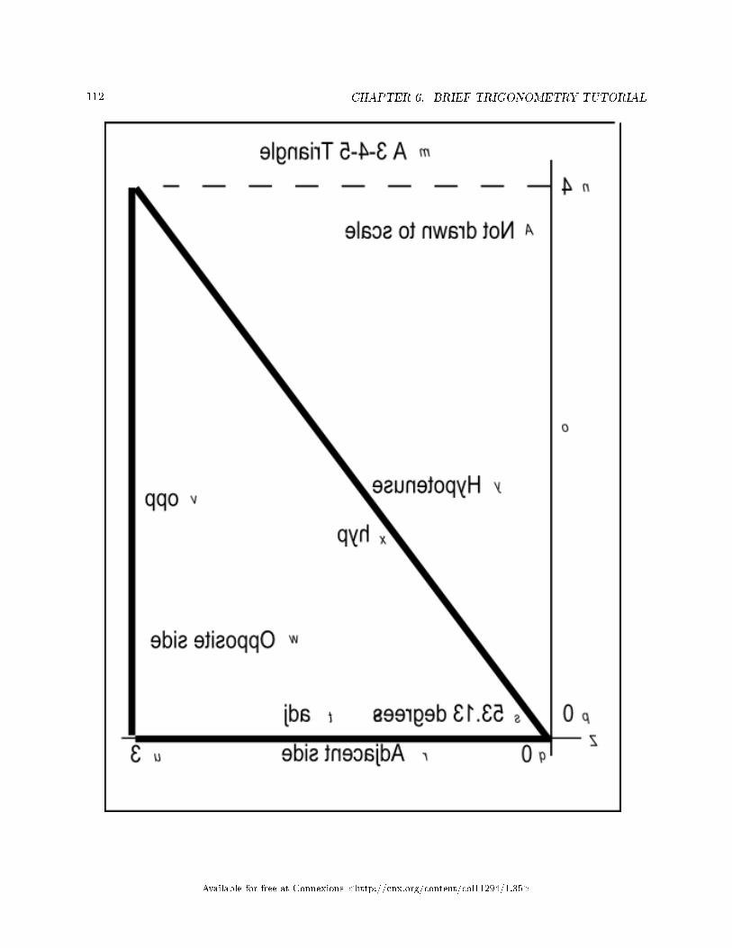
112 CHAPTER 6. BRIEF TRIGONOMETRY TUTORIAL
Available for free at Connexions <http://cnx.org/content/col11294/1.35>

113
Available for free at Connexions <http://cnx.org/content/col11294/1.35>

114 CHAPTER 6. BRIEF TRIGONOMETRY TUTORIAL
Available for free at Connexions <http://cnx.org/content/col11294/1.35>

115
Figure 2 . Mirror image from �le Phy1020b1.svg.
Available for free at Connexions <http://cnx.org/content/col11294/1.35>

116 CHAPTER 6. BRIEF TRIGONOMETRY TUTORIAL
Table 6.3
Page Setup informationIf you use the IVEO Viewer software to print this svg �le, you will need to set up the page by selecting
Page Setup on the IVEO File menu. The Page Setup information for this �le is shown in Figure 3 (p. 116). These are the default settings for Letter (Portrait) in IVEO.
Figure 3 . Page Setup for �le Phy1020b1.svg.
Paper List: Letter (Portrait)
Paper Width: 8.5 inch
Paper Height: 11.0 inch
Orientation: portrait
Left Margin: 0.75 inch
Right Margin: 0.3 inch
Top Margin: 0.75 inch
Bottom Margin: 0.3 inch
Table 6.4
Braille keysNote that the �le named Phy1020b1.svg and Figure 2 (p. 115) contain keys using the characters from
"m" through "z" and "A" that can be used to create Braille characters during manual embossing. The keycharacters are shown in an oblique font that is smaller than the normal text. The purpose of these keys isexplained in the earlier module titled Manual Creation of Tactile Graphics 20 .
Key-value pairsFigure 4 (p. 116) contains the text values associated with each of the Braille keys.
Figure 4 . Text values for Braille keys in �le Phy1020b2svg.
m: A 3-4-5 Triangle
n: 4
o: Vertical axis
p: 0
q: 0
r: Adjacent side
s: 53.13 Degrees
t: adj
u: 3
v: opp
w: Opposite side
x: hyp
y: Hypotenuse
z: Horizontal axis
A: Not drawn to scale
20http://cnx.org/contents/9fe07552-485f-43e7-9753-87133cf60482
Available for free at Connexions <http://cnx.org/content/col11294/1.35>

117
Table 6.5
The length of the hypotenuseNow that you have your right triangle on the graph board, or you have access to tactile graphics created
from the svg �le, and you know the lengths of the adjacent and opposite sides, do you remember how tocalculate the length of the hypotenuse?
The Pythagorean theoremHopefully you know that for a right triangle, the square of the hypotenuse is equal to the sum of the
squares of the two other sides. Thus, the length of the hypotenuse is equal to the square root of the sum ofthe squares of the other two sides.
In this case we can do the arithmetic in our heads to compute the length of the hypotenuse. (I plannedit that way.)
The square of the adjacent side is 9. The square of the opposite side is 16. The sum of the squares is 25,and the square root of 25 is 5. Thus, the length of the hypotenuse is 5.
A 3-4-5 triangleYou have created a rather unique triangle. You have created a right triangle in which the sides are either
equal to, or proportional to the integer values 3, 4, and 5.I chose this triangle on purpose for its simplicity. We will use it to investigate some aspects of trigonom-
etry.
6.4.2.1 The sine and arcsine of an angle
You will often hear people talk about the sine of an angle or the cosine of an angle. Just what is the sine ofan angle anyway?
Although the sine of an angle is based on very speci�c geometric considerations involving circles (seehttp://www.clarku.edu/∼djoyce/trig/ 21 ), for our purposes, the sine of an angle is simply a ratio betweenthe lengths of two di�erent sides of a right triangle.
A ratio of two sidesFor our purposes, we will say that the sine of an angle is equal to the ratio of the opposite side and the
hypotenuse. Therefore, in the case of the 3-4-5 triangle that you have on your graph board, the sine ofthe angle at the origin is equal to 4/5 or 0.8.
If we know the lengths of the hypotenuse and the opposite side, we can compute the sine and use it todetermine the value of the angle. (We will do this later using the arcsine.)
Conversely, if we know the value of the angle but don't know the lengths of the hypotenuse and/or theopposite side, we can obtain the value of the sine of the angle using a scienti�c calculator (such as the Googlecalculator) or lookup table.
The sine of an angle � sample computation
Enter the following into the Google search box:
sin(53.13010235415598 degrees)
The following will appear immediately below the search box:
sin(53.13010235415598 degrees) = 0.8
This matches the value that we computed above (p. 117) as the ratio of the opposite side and thehypotenuse.
The arcsine (inverse sine) of an angleThe arcsine of an angle is the value of the angle having a given sine value. In other words, if you know
the value of the sine of an unknown angle, you can use a scienti�c calculator or lookup table to �nd thevalue of the angle.
21http://www.clarku.edu/∼djoyce/trig/
Available for free at Connexions <http://cnx.org/content/col11294/1.35>

118 CHAPTER 6. BRIEF TRIGONOMETRY TUTORIAL
For example, we know that the sine of the angle at the origin on your graph board is 4/5. From that,we can determine the value of the angle. However, we probably can't do this calculation in our heads so wewill use the Google calculator to compute the value of the angle.
The arcsine of an angle � sample computation
Enter the following into the Google search box:
arcsin(4/5) in degrees
The following will appear immediately below the search box:
arcsin(4/5) = 53.1301024 degrees
This is the angle that corresponds to a ratio of the opposite side to the hypotenuse of 4/5.
We can also write a JavaScript script to perform the calculation, which we will do shortly.Getting the angle for a known sine valuePlease use your protractor to measure and record the angle at the origin on your graph board, or measure
it on your tactile graphic. Then create an html �le containing the code shown in Listing 2 (p. 118) and openit in your browser.
Listing 2 . Arcsin of 3-4-5 triangle.
<!-- File JavaScript02.html --><html><body><script language="JavaScript1.3">
function toRadians(degrees){
return degrees*Math.PI/180
}//end function toRadians
//============================================//
function toDegrees(radians){
return radians*180/Math.PI
}//end function toDegrees
//============================================//
var opp = 4
var hyp = 5
var ratio = opp/hyp
var angRad = Math.asin(ratio)
var angDeg = toDegrees(angRad)
document.write("radians = " + angRad + "</br>")document.write("degrees = " + angDeg)
</script></body></html>
Table 6.6
Available for free at Connexions <http://cnx.org/content/col11294/1.35>

119
The output for the angleWhen you open your html �le in your browser, the output shown in Figure 5 (p. 119) should appear in
the browser window.
Figure 5 . Output for script in Listing 2.
radians = 0.9272952180016123
degrees = 53.13010235415598
Table 6.7
Did you measure the angle to be 53 degrees with your protractor. If so, congratulations. If not, youshould probably take another look at it.
De�ne conversion functionsThe code in Listing 2 (p. 118) begins by de�ning the functions named toRadians and toDegrees
that we developed earlier in Listing 1 (p. 109) . (In this case, we will only need the function namedtoDegrees so I could have omitted the code for the function named toRadians .)
Declare and initialize variablesThen the code in Listing 2 (p. 118) declares and initializes variables to represent the lengths of the
opposite side and the hypotenuse for the triangle on your graph board ( opp and hyp ). Then itcomputes and saves the ratio of the two. (We learned earlier that the ratio is the value of the sine of theangle at the origin even though we don't know the value of the angle.)
The built-in Math.asin methodJavaScript has a built-in method named Math.asin that receives the sine value for an unknown angle
and returns the value of the corresponding angle in radians. (The Math.asin method has the same purposeat the word arcsin in the Google calculator.)
The returned value is an angle between -PI/2 and PI/2 radians. (I will have more to say about thislater.)
Listing 2 (p. 118) calls the Math.asin method, passing the ratio (sine of the angle) as a parameter,and stores the returned value in a variable named angRad .
Then Listing 2 (p. 118) calls the toDegrees method, passing the value of angRad as a parameterand stores the returned value in a variable named angDeg .
Finally, Listing 2 (p. 118) calls the document.write method twice in success to display the anglevalues shown in Figure 5 (p. 119) .
Another exercise with a di�erent viewpointNow let's approach things from a di�erent viewpoint. Assume that
• You know the value of the angle in degrees.• You know the length of the hypotenuse.• You need to �nd the length of the opposite side.
Assume also that for some reason you can't simply measure the length of the opposite side. Therefore, youmust calculate it. This is a common situation in physics, so let's see if we can write a script that will performthat calculation for us.
Please create an html �le containing the code shown in Listing 3 (p. 120) and open the �le in yourbrowser.
Available for free at Connexions <http://cnx.org/content/col11294/1.35>

120 CHAPTER 6. BRIEF TRIGONOMETRY TUTORIAL
Listing 3 . Finding length of the opposite side.
<!-- File JavaScript03.html --><html><body><script language="JavaScript1.3">
function toRadians(degrees){
return degrees*Math.PI/180
}//end function toRadians
//============================================//
function toDegrees(radians){
return radians*180/Math.PI
}//end function toDegrees
//============================================//
var hyp = 5
var angDeg = 53.13
var angRad = toRadians(angDeg)
var sine = Math.sin(angRad)
var opp = hyp * sine
document.write("opposite = " + opp + "</br>")
hyp = opp/sine
document.write("hypotenuse = " + hyp + "</br>")
</script></body></html>
Table 6.8
The output for the opposite sideWhen you open your html �le in your browser, the output shown in Figure 3 should appear in your
browser window.
Figure 6 . Output for script in Listing 3.
opposite = 3.999994640742543
hypotenuse = 5
Table 6.9
Computing length of opposite side with the Google calculatorWe could also compute the length of the opposite side using the Google calculator.
Available for free at Connexions <http://cnx.org/content/col11294/1.35>

121
The length of the opposite side � sample computation
Enter the following into the Google search box:
5*sin(53.1301024 degrees)
The following will appear immediately below the search box:
5 * sin(53.1301024 degrees) = 4
This is the length of the opposite side for the given angle and the given length of the hypotenuse.
Interesting equationsWe learned earlier that the sine of the angle is equal to the ratio of the opposite side and the hypotenuse.
We also learned that the angle is the arcsine of that ratio.If we know any two of those values ( angle , opp , hyp ), we can �nd the third (with a little
algebraic manipulation) as shown in Figure 7 (p. 121) .
Figure 7 . Interesting sine equations.
sine(angle) = opp/hyp
angle = arcsine(opp/hyp)
opp = hyp * sine(angle)
hyp = opp/sine(angle)
Table 6.10
Getting back to Listing 3After de�ning the radian/degree conversion functions, Listing 3 (p. 120) declares and initializes variables
representing the length of the hypotenuse and the angle in degrees. (Note that the angle in degrees wastruncated to four signi�cant digits, which may introduce a slight inaccuracy into the computations.)
Get and use the sine of the angleThat angle is converted to radians and passed as a parameter to the Math.sin method, which returns
the value of the sine of the angle.The value for the sine of the angle is then used in an algebraic equation to compute the length of the
opposite side, which is displayed in Figure 6 (p. 120) . (This equation is one of the equations shown inFigure 7 (p. 121) .)
Looks very close to meAs you can see, the computed value for the opposite side shown in Figure 6 (p. 120) is extremely close
to the known value of 4 units.Re-compute the length of the hypotenuseAfter that, the value of the hypotenuse is re-computed (as though it were the unknown in the problem)
using the value of the sine and the recently computed value of the opposite side. (Once again, one of theequations from Figure 7 (p. 121) is used to perform the computation.) The output length for the hypotenuseis shown in Figure 6 (p. 120) , and it matches the known value.
Example usage of Math.asin and Math.sin methodsListing 2 (p. 118) and Listing 3 (p. 120) provide examples of how to use the JavaScript Math.asin
and Math.sin methods to �nd the angle, the opposite side, or the hypotenuse of a right triangle when theother two are known as shown by the equations in Figure 7 (p. 121) .
Available for free at Connexions <http://cnx.org/content/col11294/1.35>

122 CHAPTER 6. BRIEF TRIGONOMETRY TUTORIAL
6.4.2.2 The cosine and arccosine of an angle
You are going to �nd the discussion in this section to be very similar to the discussion in the previous sectionon the sine and the arcsine of an angle.
Once again, although the cosine of an angle is based on very speci�c geometric considerations involvingcircles (see http://www.clarku.edu/∼djoyce/trig/ 22 ), for our purposes, the cosine of an angle is simply aratio between the lengths of two di�erent sides of a right triangle.
A ratio of two sidesFor our purposes, we will say that the cosine of an angle is equal to the ratio of the adjacent side and
the hypotenuse. Therefore, in the case of the 3-4-5 triangle that you have on your graph board, the cosineof the angle at the origin is equal to 3/5 or 0.6.
As before, if we know the lengths of the hypotenuse and the adjacent side, we can compute the cosineand use it to determine the value of the angle. (We will do this later.)
Conversely, if we know the value of the angle but don't know the lengths of the hypotenuse and/or theadjacent side, we can obtain the cosine value (the ratio of the adjacent side and the hypotenuse) using ascienti�c calculator or lookup table and use it for other purposes later.
The cosine of an angle � sample computation
Enter the following into the Google search box:
cos(53.13010235415598 degrees)
The following will appear immediately below the search box:
cos(53.13010235415598 degrees) = 0.6
This matches the ratio of the adjacent side to the hypotenuse for a 3-4-5 triangle.
The arccosine (inverse cosine) of an angleThe arccosine of an angle is the value of the angle having a given cosine value. In other words, if you
know the value of the cosine of an unknown angle, you can use a scienti�c calculator or lookup table to �ndthe value of the angle.
Getting the angle for a known cosine valueFor example, we know that the cosine of the angle at the origin on your graph board is 0.6. From that,
we can determine the value of the angle using either the Google calculator or JavaScript.
The arccosine of an angle � sample computation
Enter the following into the Google search box:
arccos(3/5) in degrees
The following will appear immediately below the search box:
arccos(3/5) = 53.1301024 degrees
This is the angle that corresponds to a ratio of the adjacent side to the hypotenuse of 3/5.
As you should expect. the computed angle is the same as before. We didn't change the angle, we simplycomputed it using a di�erent approach.
Getting the angle using JavaScriptPlease create an html �le containing the code shown in Listing 4 (p. 123) and open it in your browser.
22http://www.clarku.edu/∼djoyce/trig/
Available for free at Connexions <http://cnx.org/content/col11294/1.35>

123
Listing 4 . Arccosine of 3-4-5 triangle.
<!-- File JavaScript04.html --><html><body><script language="JavaScript1.3">
function toRadians(degrees){
return degrees*Math.PI/180
}//end function toRadians
//============================================//
function toDegrees(radians){
return radians*180/Math.PI
}//end function toDegrees
//============================================//
var adj = 3
var hyp = 5
var ratio = adj/hyp
var angRad = Math.acos(ratio)
var angDeg = toDegrees(angRad)
document.write("radians = " + angRad + "</br>")document.write("degrees = " + angDeg)
</script></body></html>
Table 6.11
Similar to a previous scriptIf you examine the code in Listing 4 (p. 123) carefully, you will see that it is very similar to the code in
Listing 2 (p. 118) with a couple of exceptions:
• The variable opp having a value of 4 was replaced by the variable adj having a value of 3.• The call to the Math.asin method was replaced by a call to the Math.acos method.
The outputWhen you load your html �le into your browser, it should produce the output shown earlier in Figure
5 (p. 119) . In other words, we know that the angle at the origin didn't change. What changed was themanner in which we computed the value of that angle.
Di�erent approaches to the same solutionIn Listing 2 (p. 118) , we used the length of the hypotenuse and the length of the opposite side, along
with the arcsine method to compute the angle.In Listing 4 (p. 123) , we used the length of the hypotenuse and the length of the adjacent side, along
with the arccosine method to compute the angle.Which approach should you use?As would be expected, since the angle didn't change, both approaches produced the same result. Deciding
which approach to use often depends on the values that are available to use in the computation.Sometimes you only have the lengths of the hypotenuse and the opposite side available, in which case
you could use the arcsine. Sometimes you only have the lengths of the hypotenuse and the adjacent side
Available for free at Connexions <http://cnx.org/content/col11294/1.35>

124 CHAPTER 6. BRIEF TRIGONOMETRY TUTORIAL
available, in which case you could use the arccosine. Sometimes you have the lengths of both the oppositeside and the adjacent side in addition to the length of the hypotenuse, in which case you can use eitherapproach.
Both approaches use the length of the hypotenuseIt is important to note however that both of these approaches require you to have the length of the
hypotenuse. Later in this module we will discuss the tangent and arctangent for an angle, which allows us towork with the opposite side and the adjacent side devoid of the length of the hypotenuse. (Of course, if youhave the lengths of the opposite side and the adjacent side, you can always �nd the length of the hypotenuseusing the Pythagorean theorem.)
Interesting cosine equationsThe equations in Figure 8 (p. 124) are similar to equations in Figure 7 (p. 121) . The di�erence is that
the equations in Figure 7 (p. 121) are based on the use of the sine of the angle and the opposite side whereasthe equations in Figure 8 (p. 124) are based on the use of the cosine of the angle and the adjacent side.
As you can see in Figure 8 (p. 124) , if you know any two of the values for angle , adj , and hyp ,you can �nd the other value. This is illustrated in the script shown in Listing 5 (p. 125) , which producesthe output shown in Figure 9 (p. 125) .
Figure 8 . Interesting cosine equations.
cosine(angle) = adj/hyp
angle = arccosine(adj/hyp)
adj = hyp * cosine(angle)
hyp = adj/cosine(angle)
Table 6.12
Finding the length of the adjacent sideThe code in Listing 5 (p. 125) is very similar to the code in Listing 2 (p. 118) . The main di�erence
is that Listing 2 (p. 118) is based on the use of the sine of the angle and the length of the opposite sidewhereas Listing 5 (p. 125) is based on the use of the cosine of the angle and the length of the adjacent side.
Available for free at Connexions <http://cnx.org/content/col11294/1.35>

125
Listing 5 . Finding the length of the adjacent side.
<!-- File JavaScript05.html --><html><body><script language="JavaScript1.3">
function toRadians(degrees){
return degrees*Math.PI/180
}//end function toRadians
//============================================//
function toDegrees(radians){
return radians*180/Math.PI
}//end function toDegrees
//============================================//
var hyp = 5
var angDeg = 53.13
var angRad = toRadians(angDeg)
var cosine = Math.cos(angRad)
var adj = hyp * cosine
document.write("adjacent = " + adj + "</br>")
hyp = adj/cosine
document.write("hypotenuse = " + hyp + "</br>")
</script></body></html>
Table 6.13
No further explanation neededBecause of the similarity of Listing 5 (p. 125) and Listing 2 (p. 118) , no further explanation of the code
in Listing 5 (p. 125) should be needed. As you can see from Figure 9 (p. 125) , the output values match theknown lengths for the hypotenuse and the adjacent side for the triangle on your plot board.
Figure 9 . Output for script in Listing 5.
adjacent = 3.0000071456633126
hypotenuse = 5
Table 6.14
Computing length of adjacent side with the Google calculatorWe could also compute the length of the adjacent side using the Google calculator.
Available for free at Connexions <http://cnx.org/content/col11294/1.35>
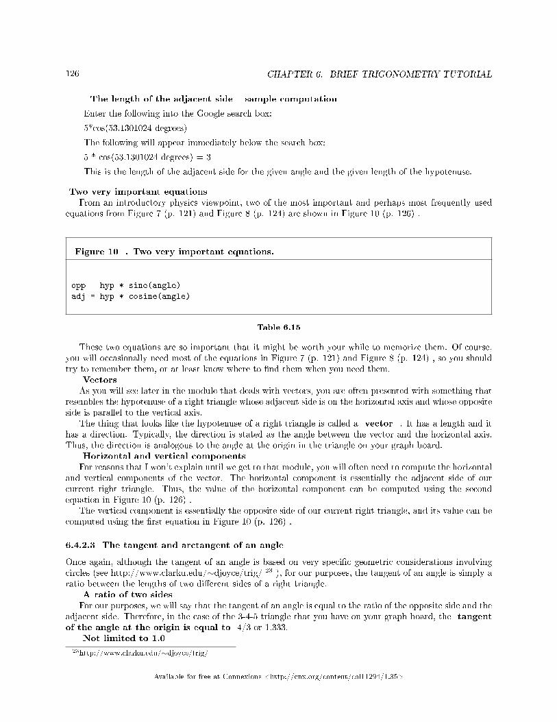
126 CHAPTER 6. BRIEF TRIGONOMETRY TUTORIAL
The length of the adjacent side � sample computation
Enter the following into the Google search box:
5*cos(53.1301024 degrees)
The following will appear immediately below the search box:
5 * cos(53.1301024 degrees) = 3
This is the length of the adjacent side for the given angle and the given length of the hypotenuse.
Two very important equationsFrom an introductory physics viewpoint, two of the most important and perhaps most frequently used
equations from Figure 7 (p. 121) and Figure 8 (p. 124) are shown in Figure 10 (p. 126) .
Figure 10 . Two very important equations.
opp = hyp * sine(angle)
adj = hyp * cosine(angle)
Table 6.15
These two equations are so important that it might be worth your while to memorize them. Of course,you will occasionally need most of the equations in Figure 7 (p. 121) and Figure 8 (p. 124) , so you shouldtry to remember them, or at least know where to �nd them when you need them.
VectorsAs you will see later in the module that deals with vectors, you are often presented with something that
resembles the hypotenuse of a right triangle whose adjacent side is on the horizontal axis and whose oppositeside is parallel to the vertical axis.
The thing that looks like the hypotenuse of a right triangle is called a vector . It has a length and ithas a direction. Typically, the direction is stated as the angle between the vector and the horizontal axis.Thus, the direction is analogous to the angle at the origin in the triangle on your graph board.
Horizontal and vertical componentsFor reasons that I won't explain until we get to that module, you will often need to compute the horizontal
and vertical components of the vector. The horizontal component is essentially the adjacent side of ourcurrent right triangle. Thus, the value of the horizontal component can be computed using the secondequation in Figure 10 (p. 126) .
The vertical component is essentially the opposite side of our current right triangle, and its value can becomputed using the �rst equation in Figure 10 (p. 126) .
6.4.2.3 The tangent and arctangent of an angle
Once again, although the tangent of an angle is based on very speci�c geometric considerations involvingcircles (see http://www.clarku.edu/∼djoyce/trig/ 23 ), for our purposes, the tangent of an angle is simply aratio between the lengths of two di�erent sides of a right triangle.
A ratio of two sidesFor our purposes, we will say that the tangent of an angle is equal to the ratio of the opposite side and the
adjacent side. Therefore, in the case of the 3-4-5 triangle that you have on your graph board, the tangentof the angle at the origin is equal to 4/3 or 1.333.
Not limited to 1.0
23http://www.clarku.edu/∼djoyce/trig/
Available for free at Connexions <http://cnx.org/content/col11294/1.35>

127
Note that the absolute value for the sine and the cosine of an angle is limited to a maximum value of 1.0.However, the tangent of an angle is not so limited. In fact, the tangent of 45 degrees is 1.0 and the tangentof 90 degrees is in�nity. This results from the length of the adjacent side, which is the denominator in theratio, going to zero at 90 degrees.
Dividing by zero in a script is usually not a good thing. This is a pitfall that you must watch out forwhen working with tangents. I will provide code later on that shows you how deal with this issue.
Computing the tangentIf we know the lengths of the opposite side and the adjacent side, we can compute the tangent and use
it for other purposes later without having to know the value of the angle.Conversely, if we know the value of the angle but don't know the lengths of the adjacent side and/or the
opposite side, we can obtain the tangent value using a scienti�c calculator or lookup table and use it forother purposes later.
The tangent of an angle � sample computation
Enter the following into the Google search box:
tan(53.13010235415598 degrees)
The following will appear immediately below the search box:
tan(53.13010235415598 degrees) = 1.33333333
This agrees with the ratio that we computed earlier (p. 126) .
The arctangent (inverse tangent) of an angleThe arctangent of an angle is the value of the angle having a given tangent value. (For example, as
mentioned above, the arctangent of in�nity is 90 degrees and the arctangent of 1.0 is 45 degrees.) In otherwords, if you know the value of the tangent of an unknown angle, you can use a scienti�c calculator or lookuptable to �nd the value of the angle.
For example, we know that the tangent of the angle at the origin on your graph board is 1.333. Fromthat, we can determine the value of the angle.
The arctangent of an angle � sample computation
Enter the following into the Google search box:
arctan(4/3) in degrees
The following will appear immediately below the search box:
arctan(4/3) = 53.1301024 degrees
We can also write a JavaScript script to perform the calculation.Getting the angle for a known tangent value using JavaScriptPlease create an html �le containing the code shown in Listing 6 (p. 128) and open it in your browser.
Available for free at Connexions <http://cnx.org/content/col11294/1.35>

128 CHAPTER 6. BRIEF TRIGONOMETRY TUTORIAL
Listing 6 . Arctan of 3-4-5 triangle.
<!-- File JavaScript06.html --><html><body><script language="JavaScript1.3">
function toRadians(degrees){
return degrees*Math.PI/180
}//end function toRadians
//============================================//
function toDegrees(radians){
return radians*180/Math.PI
}//end function toDegrees
//============================================//
var opp = 4
var adj = 3
var ratio = opp/adj
var angRad = Math.atan(ratio)
var angDeg = toDegrees(angRad)
document.write("radians = " + angRad + "</br>")document.write("degrees = " + angDeg)
</script></body></html>
Table 6.16
The output from the scriptOnce again, when you open this �le in your browser, the output shown in Figure 5 (p. 119) should appear
in your browser window.The code in Listing 6 (p. 128) is very similar to the code in Listing 2 (p. 118) . They both describe the
same right triangle, so the output should be the same in both cases.The code in Listing 2 (p. 118) uses the opposite side and the hypotenuse along with the arcsine to
compute the angle. The code in Listing 6 (p. 128) uses the opposite side and the adjacent side along withthe arctangent to compute the angle. Otherwise, no further explanation should be required.
Interesting tangent equationsIn the spirit of Figure 7 (p. 121) and Figure 8 (p. 124) , Figure 11 (p. 129) provides some interesting
equations that deal with the angle, the opposite side, and the adjacent side. Given any two, you can �ndthe third using either the tangent or arctangent.
Figure 11 . Interesting tangent equations.
continued on next page
Available for free at Connexions <http://cnx.org/content/col11294/1.35>

129
tangent(angle) = opp/adj
angle = arctangent(opp/adj)
opp = tangent(angle) * adj
adj = opp/tangent(angle)
Table 6.17
An exercise involving the tangentPlease copy the code from Listing 7 (p. 129) into an html �le and open it in your browser.
Listing 7 . Finding the length of the opposite side.
<!-- File JavaScript07.html --><html><body><script language="JavaScript1.3">
function toRadians(degrees){
return degrees*Math.PI/180
}//end function toRadians
//============================================//
function toDegrees(radians){
return radians*180/Math.PI
}//end function toDegrees
//============================================//
var adj = 3
var angDeg = 53.13
var angRad = toRadians(angDeg)
var tangent = Math.tan(angRad)
var opp = adj * tangent
document.write("opposite = " + opp + "</br>")
adj = opp/tangent
document.write("adjacent = " + adj + "</br>")
</script></body></html>
Table 6.18
When you open your html �le in your browser, the output shown in Figure 12 (p. 130) should appear inyour browser window. We can see that the values in Figure 12 (p. 130) are correct for our 3-4-5 triangle.
Available for free at Connexions <http://cnx.org/content/col11294/1.35>

130 CHAPTER 6. BRIEF TRIGONOMETRY TUTORIAL
Figure 12 . Output for script in Listing 7.
opposite = 3.9999851132269173
adjacent = 3
Table 6.19
Very similar codeThe code in Listing 7 (p. 129) is very similar to the code in Listing 3 (p. 120) and Listing 5 (p. 125) .
The essential di�erences are that
• Listing 3 (p. 120) uses the sine along with the opposite side and the hypotenuse.• Listing 5 (p. 125) uses the cosine along with the adjacent side and the hypotenuse.• Listing 7 (p. 129) uses the tangent along with the opposite side and the adjacent side.
You should be able to work through those di�erences without further explanation from me.The cotangent of an angleThere is also something called the cotangent of an angle, which is simply the ratio of the adjacent side to
the opposite side. If you know how to work with the tangent, you don't ordinarily need to use the cotangent,so I won't discuss it further.
Computing length of opposite side with the Google calculatorWe could also compute the length of the opposite side using the Google calculator.
The length of the opposite side � sample computation
Enter the following into the Google search box:
3*tan(53.1301024 degrees)
The following will appear immediately below the search box:
3 * tan(53.1301024 degrees) = 4.00000001
6.4.3 Dealing with di�erent quadrants
Up to this point, we have dealt exclusively with angles in the range of 0 to 90 degrees (the �rst quadrant).As long as you stay in the �rst quadrant, things are relatively straightforward.
As you are probably aware, however, angles can range anywhere from 0 to 360 degrees (or more). Onceyou begin working with angles that are greater then 90 degrees, things become a little less straightforward.
Another svg �leWhen you downloaded the zip �le named Phy1020.zip using the link given above (p. 108) , you should
also have found that the zip �le contains a �le named Phy1020a1.svg.The purpose of this �le is to make it possible for you to create tactile graphics for sine and cosine curves
using the procedure explained in the earlier module named Manual Creation of Tactile Graphics 24 .If you have the ability to create tactile graphics, you don't need to perform the work in the following
graph board exercise. However, you should read about it anyway because that will probably help you tobetter understand the sine and the cosine of an angle.
I will get back to tactile graphics after I describe the graph board exercise.Another graph board exerciseIn this graph board exercise, we will plot a graph of the amplitude of the sine of an angle on the vertical
axis versus the angle itself on the horizontal.
24http://cnx.org/contents/9fe07552-485f-43e7-9753-87133cf60482
Available for free at Connexions <http://cnx.org/content/col11294/1.35>

131
We will also do the same thing for the cosine. It would be very good if you could plot one curve on thetop half of your graph board and the other curve on the bottom half of your graph board so that you caneasily compare the two.
Interpreting gridline valuesSince I don't know how many tactile grid lines there are on your graph board, I can't tell you exactly
how to interpret the grid lines so as to make maximum use of the space on the board. All that I can tellyou is that the vertical amplitude values for each curve will range from -1.0 to +1.0. We would like to plotvalues from -360 degrees to + 360 degrees on the horizontal. You should interpret the values of the gridlineson your graph board accordingly.
Sinusoidal amplitude versus anglePlease copy the code from Listing 8 (p. 132) into an html �le and open the �le in your browser.
Available for free at Connexions <http://cnx.org/content/col11294/1.35>

132 CHAPTER 6. BRIEF TRIGONOMETRY TUTORIAL
Listing 8 . Sinusoidal amplitude versus angle.
<;!-- File JavaScriptZZ.html --><;html><;body><;script language="JavaScript1.3">
function toRadians(degrees){
return degrees*Math.PI/180
}//end function toRadians
//============================================//
function toDegrees(radians){
return radians*180/Math.PI
}//end function toDegrees
//============================================//
var angInc = 90
var angStart = -360
var ang = angStart
var angEnd = 360
var sine
var cosine
while(ang <;= angEnd){
//Compute sine and cosine of angle
sine = Math.sin(toRadians(ang))
cosine = Math.cos(toRadians(ang))
//Reduce the number of digits in the output
sine = (Math.round(100*sine))/100
cosine = (Math.round(100*cosine))/100
//Display the results
document.write("Angle: " + ang +
" Sine: " + sine +
" Cosine: " + cosine +
"<;/br>")
//Increase the angle for next iteration
ang = ang + angInc
}//end while loop
<;/script><;/body><;/html>
Table 6.20
Output from the scriptWhen you open your html �le in your browser, the output shown in Figure 13 (p. 134) should appear in
your browser window.
Available for free at Connexions <http://cnx.org/content/col11294/1.35>

133
Available for free at Connexions <http://cnx.org/content/col11294/1.35>
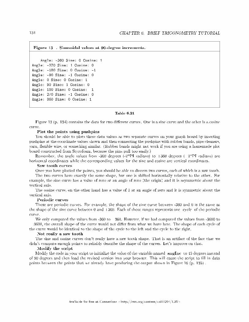
134 CHAPTER 6. BRIEF TRIGONOMETRY TUTORIAL
Figure 13 . Sinusoidal values at 90-degree increments.
Angle: -360 Sine: 0 Cosine: 1
Angle: -270 Sine: 1 Cosine: 0
Angle: -180 Sine: 0 Cosine: -1
Angle: -90 Sine: -1 Cosine: 0
Angle: 0 Sine: 0 Cosine: 1
Angle: 90 Sine: 1 Cosine: 0
Angle: 180 Sine: 0 Cosine: -1
Angle: 270 Sine: -1 Cosine: 0
Angle: 360 Sine: 0 Cosine: 1
Table 6.21
Figure 13 (p. 134) contains the data for two di�erent curves. One is a sine curve and the other is a cosinecurve.
Plot the points using pushpinsYou should be able to plots these data values as two separate curves on your graph board by inserting
pushpins at the coordinate values shown and then connecting the pushpins with rubber bands, pipe cleaners,yarn, �exible wire, or something similar. (Rubber bands might not work if you are using a homemade plotboard constructed from Styrofoam, because the pins pull too easily.)
Remember, the angle values from -360 degrees (-2*PI radians) to +360 degrees (+2*PI radians) arehorizontal coordinates while the corresponding values for the sine and cosine are vertical coordinates.
Saw tooth curvesOnce you have plotted the points, you should be able to discern two curves, each of which is a saw tooth.The two curves have exactly the same shape, but one is shifted horizontally relative to the other. For
example, the sine curve has a value of zero at an angle of zero (the origin) and it is asymmetric about thevertical axis.
The cosine curve, on the other hand has a value of 1 at an angle of zero and it is symmetric about thevertical axis.
Periodic curvesThese are periodic curves. For example, the shape of the sine curve between -360 and 0 is the same as
the shape of the sine curve between 0 and +360. Each of those ranges represents one cycle of the periodiccurve.
We only computed the values from -360 to +360. However, if we had computed the values from -3600 to+ 3600, the overall shape of the curve would not di�er from what we have here. The shape of each cycle ofthe curve would be identical to the shape of the cycle to the left and the cycle to the right.
Not really a saw toothThe sine and cosine curves don't really have a saw tooth shape. That is an artifact of the fact that we
didn't compute enough points to reliably describe the shape of the curves. Let's improve on that.Modify the scriptModify the code in your script to initialize the value of the variable named angInc to 45 degrees instead
of 90 degrees and then load the revised version into your browser. This will cause the script to �ll in datapoints between the points that we already have producing the output shown in Figure 16 (p. 135) .
Available for free at Connexions <http://cnx.org/content/col11294/1.35>

135
Figure 14 . Sinusoidal values at 45-degree increments.
Angle: -360 Sine: 0 Cosine: 1
Angle: -315 Sine: 0.71 Cosine: 0.71
Angle: -270 Sine: 1 Cosine: 0
Angle: -225 Sine: 0.71 Cosine: -0.71
Angle: -180 Sine: 0 Cosine: -1
Angle: -135 Sine: -0.71 Cosine: -0.71
Angle: -90 Sine: -1 Cosine: 0
Angle: -45 Sine: -0.71 Cosine: 0.71
Angle: 0 Sine: 0 Cosine: 1
Angle: 45 Sine: 0.71 Cosine: 0.71
Angle: 90 Sine: 1 Cosine: 0
Angle: 135 Sine: 0.71 Cosine: -0.71
Angle: 180 Sine: 0 Cosine: -1
Angle: 225 Sine: -0.71 Cosine: -0.71
Angle: 270 Sine: -1 Cosine: 0
Angle: 315 Sine: -0.71 Cosine: 0.71
Angle: 360 Sine: 0 Cosine: 1
Table 6.22
Plot the new pointsEvery other line of text in Figure 14 (p. 135) should contain sine and cosine values for angles that are
half way between the points that you already have plotted. Use pushpins to plot the new points and connectall of the points in each curve using rubber bands, pipe cleaners, or whatever you �nd most useful for thispurpose.
Same shape but shifted horizontallyThe two curves still have the same shape, although shifted horizontally relative to one another and they
are still periodic. However, they no longer have a saw tooth shape. They tend to be a little more roundednear the peaks and they are beginning to provide a better representation of the actual shapes of the sineand cosine curves.
Let's do it againChange the value of the variable named angInc from 45 degrees to 22.5 degrees and load the new
version of the html �le into your browser. Now the output should look like Figure 15 (p. 136) .
Available for free at Connexions <http://cnx.org/content/col11294/1.35>
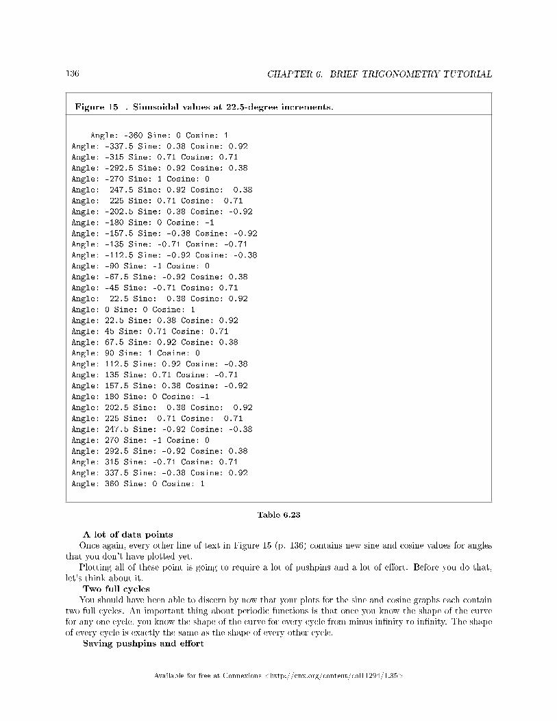
136 CHAPTER 6. BRIEF TRIGONOMETRY TUTORIAL
Figure 15 . Sinusoidal values at 22.5-degree increments.
Angle: -360 Sine: 0 Cosine: 1
Angle: -337.5 Sine: 0.38 Cosine: 0.92
Angle: -315 Sine: 0.71 Cosine: 0.71
Angle: -292.5 Sine: 0.92 Cosine: 0.38
Angle: -270 Sine: 1 Cosine: 0
Angle: -247.5 Sine: 0.92 Cosine: -0.38
Angle: -225 Sine: 0.71 Cosine: -0.71
Angle: -202.5 Sine: 0.38 Cosine: -0.92
Angle: -180 Sine: 0 Cosine: -1
Angle: -157.5 Sine: -0.38 Cosine: -0.92
Angle: -135 Sine: -0.71 Cosine: -0.71
Angle: -112.5 Sine: -0.92 Cosine: -0.38
Angle: -90 Sine: -1 Cosine: 0
Angle: -67.5 Sine: -0.92 Cosine: 0.38
Angle: -45 Sine: -0.71 Cosine: 0.71
Angle: -22.5 Sine: -0.38 Cosine: 0.92
Angle: 0 Sine: 0 Cosine: 1
Angle: 22.5 Sine: 0.38 Cosine: 0.92
Angle: 45 Sine: 0.71 Cosine: 0.71
Angle: 67.5 Sine: 0.92 Cosine: 0.38
Angle: 90 Sine: 1 Cosine: 0
Angle: 112.5 Sine: 0.92 Cosine: -0.38
Angle: 135 Sine: 0.71 Cosine: -0.71
Angle: 157.5 Sine: 0.38 Cosine: -0.92
Angle: 180 Sine: 0 Cosine: -1
Angle: 202.5 Sine: -0.38 Cosine: -0.92
Angle: 225 Sine: -0.71 Cosine: -0.71
Angle: 247.5 Sine: -0.92 Cosine: -0.38
Angle: 270 Sine: -1 Cosine: 0
Angle: 292.5 Sine: -0.92 Cosine: 0.38
Angle: 315 Sine: -0.71 Cosine: 0.71
Angle: 337.5 Sine: -0.38 Cosine: 0.92
Angle: 360 Sine: 0 Cosine: 1
Table 6.23
A lot of data pointsOnce again, every other line of text in Figure 15 (p. 136) contains new sine and cosine values for angles
that you don't have plotted yet.Plotting all of these point is going to require a lot of pushpins and a lot of e�ort. Before you do that,
let's think about it.Two full cyclesYou should have been able to discern by now that your plots for the sine and cosine graphs each contain
two full cycles. An important thing about periodic functions is that once you know the shape of the curvefor any one cycle, you know the shape of the curve for every cycle from minus in�nity to in�nity. The shapeof every cycle is exactly the same as the shape of every other cycle.
Saving pushpins and e�ort
Available for free at Connexions <http://cnx.org/content/col11294/1.35>

137
If you are running out of pushpins or running out of patience, you might consider updating your plotsfor only one cycle.
You should be able to discern that your curves no longer have a saw tooth shape. Each time we have runthe script, we have sampled the amplitude values of each curve at twice as many points as before. Therefore,the curves should be taking on a smoother rounded shape that is better representation of the actual shapeof the curves.
Continue the processYou can continue this process of improving the curves for as long as you have the graph board space,
pushpins, and patience to do so. Just divide the value of the variable named angInc by a factor of twoand rerun the script. That will produce twice as many data points that are only half as far apart on thehorizontal axis.
If you choose to do so, you can plot only the new points in one-half of a cycle to get an idea of the shape.By now you should have discerned that each half of a cycle has the same shape, only one half is above thehorizontal axis and the other half is a mirror image below the axis.
Plot of cosine and sine curvesGetting back to tactile graphics, for the bene�t of any sighted person that may be assisting you, Figure
16 (p. 140) shows a cosine curve plotted above a sine curve very similar to the curves that you have plottedon your graph board. ( Figure 16 (p. 140) shows a mirror image of the actual curves because the �le namedPhy1020a1.svg is intended to be used for manual embossing from the back of the paper.) A non-mirror-imageversion is shown in Figure 20 (p. 153) .
Available for free at Connexions <http://cnx.org/content/col11294/1.35>

138 CHAPTER 6. BRIEF TRIGONOMETRY TUTORIAL
Available for free at Connexions <http://cnx.org/content/col11294/1.35>

139
Available for free at Connexions <http://cnx.org/content/col11294/1.35>

140 CHAPTER 6. BRIEF TRIGONOMETRY TUTORIAL
Figure 16 . Mirror image plot of cosine and sine curves from the �le named Phy1020a1svg.
Table 6.24
This image contains lines that aren't straight, but with a little care, your assistant should be able to doa reasonably good job of embossing them when the image is printed as the full 8.5x11 inch version.
Page setupIf you use the IVEO Viewer to print the �le named Phy1020a1.svg, you should use the default Page
Setup selection for Letter (Landscape).Grid linesThe image in Figure 16 (p. 140) contains 7 vertical grid lines. The vertical grid line in the center
represents an angle of zero degrees. The space between each grid line on either side of the center representsan angle of 90 degrees or PI/2 radians.
There are two horizontal grid lines. One is one-fourth of the way down from the top. The other isone-fourth of the way up from the bottom.
The curvesA cosine curve is plotted with vertical values relative to the top grid line. It extends from -360 degrees
on the left to +360 degrees on the right.A sine curve is plotted with vertical values relative to the bottom grid line. It also extends from -360
degrees on the left to +360 degrees on the right. (Note once again that Figure 16 (p. 140) was �ippedhorizontally to crate a mirror image.)
Return values for the Math.asin, Math.acos, and Math.atan methods
Available for free at Connexions <http://cnx.org/content/col11294/1.35>

141
I told you earlier that the Math.asin method returns a value between -PI/2 and PI/2. However, Ididn't tell you that the Math.acos method returns a value between 0 and PI, or that the Math.atanmethod returns a value between -PI/2 and PI/2. You now have enough information to understand why thisis true.
Smooth curvesIf you examine the two curves that you have just plotted, you can surmise that the sine and cosine
functions are smooth curves whose values range between -1 and +1 inclusive. For every possible valuebetween -1 and +1, there is an angle in the range -PI/2 and PI/2 whose sine value matches that value.There is also an angle in the range 0 and PI whose cosine value matches that value.
(Although you haven't plotted the curve for the tangent, a similar situation holds there also.)An in�nite number of anglesTherefore, given a speci�c numeric value between -1 and +1, there are an in�nite number of angles whose
sine and cosine values match that numeric value and the method has no way of distinguishing between them.Therefore, the Math.asin method returns the matching angle that is closest to zero and the Math.acosmethod returns the matching positive angle that is closest to zero.
What can we learn from this?One important thing that we can learn is there is no di�erence between the sine or cosine of an angle
and the sine or cosine of a di�erent angle that di�ers from the original angle by 360 degrees. Thus, theMath.asin and Math.acos methods cannot be used to distinguish between angles that di�er by 360degrees. (As you learned above, the situation involving the Math.asin and Math.acos methods is evenmore stringent than that.)
One-quarter cycle contains all of the informationAnother thing that we can learn is that once you know the shape of the cosine curve from 0 degrees to
90 degrees, you have enough information to construct the entire cosine curve and the entire sine curve acrossany range of angles. Every possible value or the negative of every possible value that can occur in a sine orcosine curve occurs in the cosine curve between 0 degrees and 90 degrees. Furthermore, the order of thosevalues is also well de�ned.
Think about these relationshipsYou should think about these kinds of relationships. As I mentioned earlier, as long as we are working with
angles between 0 and 90 degrees, everything is relatively straightforward. However, once we start workingwith angles between 90 degrees and 360 degrees (or greater), things become a little less straightforward.
If you have a good picture in your mind of the shape of the two curves between -360 degrees and +360degrees, you may be able to avoid errors once you start working on physics problems that involve anglesoutside the range of 0 to 90 degrees.
QuadrantsWe often think of a two-dimensional space with horizontal and vertical axes and the origin at the center
in quadrants. Each quadrant is bounded by half the horizontal axis and half the vertical axis.It is common practice to number the quadrants in counter-clockwise order with the upper-right quadrant
being quadrant 1, the upper-left quadrant being quadrant 2, the bottom-left quadrant being quadrant 3, andthe bottom-right quadrant being quadrant 4.
Angles fall in quadrantsIf you measure the angle between the positive horizontal axis and a line segment that emanates from the
origin, quadrant 1 contains angles between 0 and PI/2, quadrant 2 contains the angles between PI/2 and PI,quadrant 3 contains the angles between PI and 3*PI/2, and quadrant 4 contains the angles between 3*PI/2and 2*PI (or zero). (Note that I didn't attempt to reconcile the inclusion of each axis in the two quadrantson either side of the axis.)
Algebraic signs versus quadrant numberIt is sometimes useful to consider how the algebraic sign of the sine, cosine, and tangent values varies
among the four quadrants. Figure 17 (p. 142) contains a table that shows the sign of the sine, cosine, andtangent values for each of the four quadrants
Available for free at Connexions <http://cnx.org/content/col11294/1.35>

142 CHAPTER 6. BRIEF TRIGONOMETRY TUTORIAL
Figure 17 . Algebraic signs versus quadrants.
1 2 3 4
sine + + - -
cosine + - - +
tangent + - + -
Table 6.25
Working with arctangents is more di�cult than arcsine or arccosineWorking with arctangent is somewhat more di�cult than working with arcsine or arccosine, if for no
other reason than the possibility of dividing by zero when working with the arctangent.Listing 9 (p. 143) shows a JavaScript function named getAngle that deals with this issue.
Available for free at Connexions <http://cnx.org/content/col11294/1.35>

143
Listing 9 . A function to deal with quadrants.
<!---------------- File JavaScript09.html ---------------------><html><body><script language="JavaScript1.3">
document.write("Start Script </br>");
//The purpose of this function is to receive the adjacent
// and opposite side values for a right triangle and to
// return the angle in degrees in the correct quadrant.
function getAngle(adjacent,opposite){
if((adjacent == 0) && (opposite == 0)){
//Angle is indeterminate. Just return zero.
return 0;
}else if((adjacent == 0) && (opposite > 0)){
//Avoid divide by zero denominator.
return 90;
}else if((adjacent == 0) && (opposite < 0)){
//Avoid divide by zero denominator.
return -90;
}else if((adjacent < 0) && (opposite >= 0)){
//Correct to second quadrant
return Math.atan(opposite/adjacent)*180/Math.PI + 180;
}else if((adjacent < 0) && (opposite <= 0)){
//Correct to third quadrant
return Math.atan(opposite/adjacent)*180/Math.PI + 180;
}else{
//First and fourth quadrants. No correction required.
return Math.atan(opposite/adjacent)*180/Math.PI;
}//end else
}//end function getAngle
//Modify these values and run for different cases.
var adj = 3;
var opp = 4;
document.write("adj = " + adj.toFixed(2) +
" opp = " + opp.toFixed(2) + " units</br>");
document.write("angle = " + getAngle(adj,opp).toFixed(2)
+ " units</br>");
var adj = -3;
var opp = 4;
document.write("adj = " + adj.toFixed(2) +
" opp = " + opp.toFixed(2) + " units</br>");
document.write("angle = " + getAngle(adj,opp).toFixed(2)
+ " units</br>");
var adj = -3;
var opp = -4;
document.write("adj = " + adj.toFixed(2) +
" opp = " + opp.toFixed(2) + " units</br>");
document.write("angle = " + getAngle(adj,opp).toFixed(2)
+ " units</br>");
var adj = 3;
var opp = -4;
document.write("adj = " + adj.toFixed(2) +
" opp = " + opp.toFixed(2) + " units</br>");
document.write("angle = " + getAngle(adj,opp).toFixed(2)
+ " units</br>");
</script></body></html>
Available for free at Connexions <http://cnx.org/content/col11294/1.35>

144 CHAPTER 6. BRIEF TRIGONOMETRY TUTORIAL
Table 6.26
The code in Listing 9 (p. 143) begins by de�ning a function named getAngle that accepts the signed valuesof the adjacent side and the opposite side of the right triangle and returns the angle that the hypotenusemakes with the positive horizontal axis.
Then the code in Listing 9 (p. 143) tests the result for four di�erent triangles situated in each of the fourquadrants.
Figure 18 (p. 144) shows the output produced by this script.
Figure 18 . Output from the code in Listing 9.
Start Script
adj = 3.00 opp = 4.00 units
angle = 53.13 units
adj = -3.00 opp = 4.00 units
angle = 126.87 units
adj = -3.00 opp = -4.00 units
angle = 233.13 units
adj = 3.00 opp = -4.00 units
angle = -53.13 units
Table 6.27
This is an issue that will become important when we reach the module that deals with vectors in all fourquadrants.
Structure of the scriptThe script shown in Listing 9 (p. 143) begins by de�ning a function named getAngle . The purpose
of this function is to return an angle in degrees in the correct quadrant based on the lengths of the adjacentand opposite sides of an enclosing right triangle. As mentioned above, the returned angle is the angle thatthe hypotenuse makes with the positive horizontal axis.
An indeterminate resultThe getAngle function calls the Math.atan method to compute the angle whose tangent is the ratio of
the opposite side to the adjacent side of a right triangle.If the lengths of both the opposite and adjacent sides are zero, the ratio opposite/adjacent is indeterminate
and the value of the angle cannot be computed. In fact there is no angle corresponding to the ratio 0/0.However, the function must either return the value of an angle, or must return some sort of �ag indicatingthat computation of the angle is not possible.
In this case, the function simply returns the value zero for the angle.Avoiding division by zeroIf the length of adjacent side is zero and the length of opposite side is not zero, the ratio opposite/adjacent
is in�nite. Therefore, the value of the angle cannot be computed. However, in this case, the angle is knownto be 90 degrees (for opposite greater than zero) or 270 degrees (-90 degrees, for opposite less than zero).The getAngle function traps both of those cases and returns the correct angle in each case.
Correcting for the quadrantThe Math.atan method receives one parameter and it is either a positive or negative value. If the value is
positive, the method returns an angle between 0 and 90 degrees. If the value is negative, the method returnsan angle between 0 and -90 degrees. Thus, the angles returned by the Math.atan method always lie in the�rst or fourth quadrants.
Available for free at Connexions <http://cnx.org/content/col11294/1.35>

145
(Actually, as I mentioned earlier, +90 degrees and -90 degrees are not possible because the tangent of+90 degrees or -90 degrees is an in�nitely large positive or negative value. However, the method can handleangles that are very close to +90 or -90 degrees.)
A negative opposite/adjacent ratioIf the opposite/adjacent ratio is negative, this doesn't necessarily mean that the angle lies in the fourth
quadrant. That negative ratio could result from a positive value for opposite and a negative value foradjacent. In that case, the angle would lie in the second quadrant between 90 degrees and 180 degrees.
The getAngle function tests the signs of the values for opposite and adjacent. If the signs indicate thatthe angle lies in the second quadrant, the value returned from the Math.atan method is corrected to placethe angle in the second quadrant. The corrected angle is returned by the getAngle function.
A positive opposite/adjacent ratioSimilarly, if the opposite/adjacent ratio is positive, this doesn't necessarily mean that the angle lies in
the �rst quadrant. That positive ratio could result from a negative opposite value and a negative adjacentvalue. In that case, the angle would lie in the third quadrant between 180 degrees and 270 degrees.
Again, the getAngle function tests the signs of the values for opposite and adjacent. If both values arenegative, the value returned from the Math.atan method is corrected to place the angle in the third quadrant.
No corrections required...Finally, if no corrections are required for the quadrant, the getAngle function returns the value returned
by the Math.atan method. Note however, that in all cases, the Math.atan method returns the angle inradians. That value is converted to degrees by the getAngle function and the returned value is in degrees.
Positive and negative anglesAs you can see from the results of the test shown in Figure 18 (p. 144) , angles in the �rst, second,
and third quadrants are returned as positive angles in degrees. However, angles in the fourth quadrant arereturned as negative angles in degrees.
6.4.4 Normal (non-mirror-image) graphics
Figure 2 (p. 115) and Figure 16 (p. 140) show the actual mirror image versions of the images contained inthe svg �les. Figure 19 (p. 149) and Figure 20 (p. 153) show the same images in their non-mirror-imageorientation.
Available for free at Connexions <http://cnx.org/content/col11294/1.35>

146 CHAPTER 6. BRIEF TRIGONOMETRY TUTORIAL
Available for free at Connexions <http://cnx.org/content/col11294/1.35>

147
Available for free at Connexions <http://cnx.org/content/col11294/1.35>
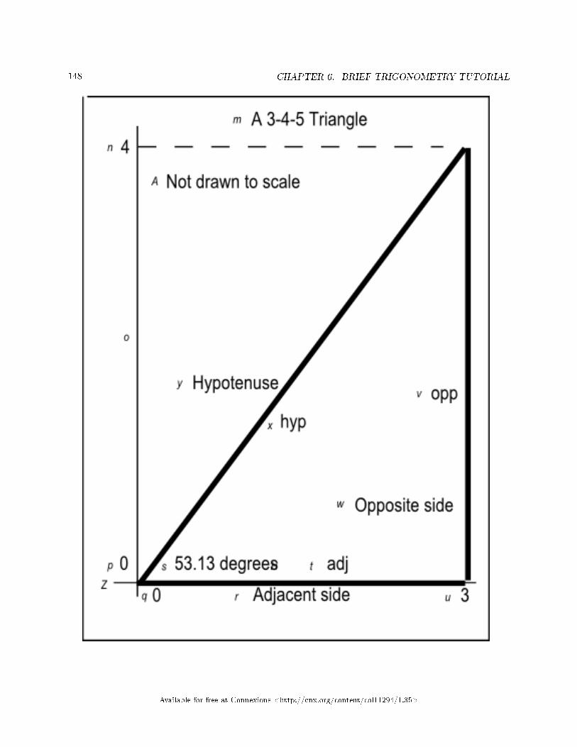
148 CHAPTER 6. BRIEF TRIGONOMETRY TUTORIAL
Available for free at Connexions <http://cnx.org/content/col11294/1.35>

149
Figure 19 . Normal image from �le Phy1020b1.svg.
Available for free at Connexions <http://cnx.org/content/col11294/1.35>

150 CHAPTER 6. BRIEF TRIGONOMETRY TUTORIAL
Table 6.28
Available for free at Connexions <http://cnx.org/content/col11294/1.35>

151
Available for free at Connexions <http://cnx.org/content/col11294/1.35>

152 CHAPTER 6. BRIEF TRIGONOMETRY TUTORIAL
Available for free at Connexions <http://cnx.org/content/col11294/1.35>

153
Figure 20 . Normal image plot of cosine and sine curves from the �le named Phy1020a1svg.
Table 6.29
6.5 Run the scripts
I encourage you to run the scripts that I have presented in this lesson to con�rm that you get the sameresults. Copy the code for each script into a text �le with an extension of html. Then open that �le inyour browser. Experiment with the code, making changes, and observing the results of your changes. Makecertain that you can explain why your changes behave as they do.
6.6 Resources
I will publish a module containing consolidated links to resources on my Connexions web page and willupdate and add to the list as additional modules in this collection are published.
6.7 Miscellaneous
This section contains a variety of miscellaneous information.
Housekeeping material
Available for free at Connexions <http://cnx.org/content/col11294/1.35>

154 CHAPTER 6. BRIEF TRIGONOMETRY TUTORIAL
• Module name: Brief Trigonometry Tutorial• Revised: 09/30/15• File: Phy1020.htm• Keywords:
· physics· accessible· blind· graph board· protractor· screen reader· refreshable Braille display· JavaScript· trigonometry· angle· sine· cosine· tangent· arcsine· arccosine· arctangent· quadrant
Disclaimers: Financial : Although the openstax CNX site makes it possible for you todownload a PDF �le for the collection that contains this module at no charge, and also makes itpossible for you to purchase a pre-printed version of the PDF �le, you should be aware that someof the HTML elements in this module may not translate well into PDF.
You also need to know that Prof. Baldwin receives no �nancial compensation from openstaxCNX even if you purchase the PDF version of the collection.
In the past, unknown individuals have copied Prof. Baldwin's modules from cnx.org, convertedthem to Kindle books, and placed them for sale on Amazon.com showing Prof. Baldwin as theauthor. Prof. Baldwin neither receives compensation for those sales nor does he know who doesreceive compensation. If you purchase such a book, please be aware that it is a copy of a collectionthat is freely available on openstax CNX and that it was made and published without the priorknowledge of Prof. Baldwin.
A�liation : Prof. Baldwin is a professor of Computer Information Technology at AustinCommunity College in Austin, TX.
-end-
Available for free at Connexions <http://cnx.org/content/col11294/1.35>

Chapter 7
Scale Factors, Ratios, and Proportions1
7.1 Table of Contents
• Preface (p. 155)
· General (p. 155)· Prerequisites (p. 156)· Viewing tip (p. 156)
* Figures (p. 156)* Listings (p. 157)
· Supplemental material (p. 157)
• General background information (p. 157)• Discussion (p. 157)
· Scale factors (p. 157)· Ratios (p. 157)· Proportions (p. 159)
• Run the scripts (p. 164)• Resources (p. 164)• Miscellaneous (p. 164)
7.2 Preface
7.2.1 General
This module is part of a collection of modules designed to make physics concepts accessible to blind students.If you opened this page in the context of the book, a Table of Contents for the book (or collection)
should be available above and to the left of this paragraph. Otherwise, click here 2 to open the book at thebeginning.
This book is intended to supplement but not to replace the textbook in an introductory high school orcollege physics course.
This module provides a brief tutorial on scale factors, ratios, and proportions that is designed to beaccessible to blind students.
1This content is available online at <http://cnx.org/content/m37436/1.3/>.2http://cnx.org/contents/a7842db2-93c6-4c06-a5e3-56c282358143
Available for free at Connexions <http://cnx.org/content/col11294/1.35>
155

156 CHAPTER 7. SCALE FACTORS, RATIOS, AND PROPORTIONS
7.2.2 Prerequisites
In addition to an Internet connection and a browser, you will need the following tools (as a minimum) towork through the exercises in these modules:
• A graph board for plotting graphs and vector diagrams (http://www.youtube.com/watch?v=c8plj9UsJbg 3 ).
• A protractor for measuring angles ( http://www.youtube.com/watch?v=v-F06HgiUpw 4 ).• An audio screen reader that is compatible with your operating system, such as the NonVisual Desktop
Access program (NVDA), which is freely available at http://www.nvda-project.org/ 5 .• A refreshable Braille display capable of providing a line by line tactile output of information displayed
on the computer monitor ( http://www.userite.com/ecampus/lesson1/tools.php 6 ).• A device to create Braille labels. Will be used to label graphs constructed on the graph board.• The ability to create tactile graphics as described here 7 .
The minimum prerequisites for understanding the material in these modules include:
• A good understanding of algebra.• An understanding of the use of a graph board for plotting graphs and vector diagrams (
http://www.youtube.com/watch?v=c8plj9UsJbg 8 ).• An understanding of the use of a protractor for measuring angles (
http://www.youtube.com/watch?v=v-F06HgiUpw 9 ).• A basic understanding of the use of sine, cosine, and tangent from trigonometry (
http://www.clarku.edu/∼djoyce/trig/ 10 ).• An introductory understanding of JavaScript programming ( http://www.dickbaldwin.com/tocjscript1.htm
11 and http://www.w3schools.com/js/default.asp 12 ).• An understanding of all of the material covered in the earlier modules in this collection.• An understanding of the creation and use of tactile graphics as described here 13 .
7.2.3 Viewing tip
I recommend that you open another copy of this document in a separate browser window and use thefollowing links to easily �nd and view the �gures and listings while you are reading about them.
7.2.3.1 Figures
• Figure 1 (p. 159) . Screen output for Listing #1.• Figure 2 (p. 161) . Screen output for Listing #2.• Figure 3 (p. 164) . Screen output for Listing #3.
3http://www.youtube.com/watch?v=c8plj9UsJbg4http://www.youtube.com/watch?v=v-F06HgiUpw5http://www.nvda-project.org/6http://www.userite.com/ecampus/lesson1/tools.php7http://cnx.org/contents/9fe07552-485f-43e7-9753-87133cf604828http://www.youtube.com/watch?v=c8plj9UsJbg9http://www.youtube.com/watch?v=v-F06HgiUpw
10http://www.clarku.edu/∼djoyce/trig/11http://www.dickbaldwin.com/tocjscript1.htm12http://www.w3schools.com/js/default.asp13http://cnx.org/contents/9fe07552-485f-43e7-9753-87133cf60482
Available for free at Connexions <http://cnx.org/content/col11294/1.35>

157
7.2.3.2 Listings
• Listing 1 (p. 158) . Exercise on scale factors• Listing 2 (p. 161) . Circumference is proportional to radius.• Listing 3 (p. 163) . Area is proportional to radius squared.
7.2.4 Supplemental material
I recommend that you also study the other lessons in my extensive collection of online programming tutorials.You will �nd a consolidated index at www.DickBaldwin.com 14 .
7.3 General background information
Mathematical expressions are used in physics to describe relationships that are di�cult to express in words.The expressions use algebraic symbols to represent quantities that consist of numbers and units.
Measurements are importantConclusions that are drawn in physics and other sciences ranging from chemistry to the social sciences
are often based on measurements such as length, width, weight, salinity, population, density, etc.Each number in an equation often represents the results of a measurement, which is made in terms of a
standard. The units indicate which standard was used to make the measurements.Knowledge of units is criticalA number that is used to indicate the result of a measurement is of little value unless we know the units
in which the measurement was made. For example, it isn't very useful to know that the length of an objectis 125 unless we know whether the units are meters, centimeters, millimeters, or miles.
The Google calculatorAlthough I won't go into detail in this module, I will tell you that the Google calculator is very good at
helping you to keep track of units. For example, if you enter the following expression in the Google searchbox,
3 ft + 1 yd + 36 inchesThe following result will be displayed immediately below the search box:(3 ft) + (1 yd) + (36 inches) = 2.7432 meters
7.4 Discussion
We often express the relationship between two items using a scale factor.
7.4.1 Scale factors
For example, we might say that that a colt doubled its weight in one year. This means that the colt's weightafter one year was equal to the colt's weight at birth multiplied by a factor of two. The factor is the numberby which a quantity is multiplied or divided when it is changed from one value to another.
7.4.2 Ratios
The factor is the ratio of the new value to the old value. Regarding the colt mentioned above, we mightwrite:
NewWeight / BirthWeight = 2where the slash character "/" indicates division.Percentage increases
14http://www.dickbaldwin.com/toc.htm
Available for free at Connexions <http://cnx.org/content/col11294/1.35>

158 CHAPTER 7. SCALE FACTORS, RATIOS, AND PROPORTIONS
It is also common for us to talk about something increasing or decreasing by a given percentage value.For example, we might say that a colt increased its weight by 50-percent in one year. This is equivalent tosaying:
NewWeight = BirthWeight * (1 + 50/100)This assumes that when evaluating a mathematical expression:
• The asterisk character " * " indicates multiplication.• Computations begin inside of the inner-most pair of matching parentheses and work outward from
there.• Multiplication and division are performed before addition and subtraction are performed.
This is typical behavior for computer programs and spreadsheets, but not necessarily for hand calculators.Percentage decreasesIn my dreams, I might say that I went on a diet and my weight decreased by 25-percent in one year.
This would be equivalent to saying:NewWeight = OldWeight * (1 - 25/100)Exercise on scale factors
Write a script that has the following behavior. Given a chalk line that is 100 inches long, draw otherchalk lines that are:
• A. Twice the length of the original line.• B. Twenty-�ve percent of the length of the original line.• C. Twenty-�ve percent greater than the length of the original line.• D. Twenty-�ve percent less than the length of the original line.
My version of the script is shown in Listing 1.
Listing 1 . Exercise on scale factors
<!-- File JavaScript01.html --><html><body><script language="JavaScript1.3">
//Do the computations
var origLine = 100
var lineA = 2 * origLine
var lineB = (25/100) * origLine
var lineC = (1 + 25/100) * origLine
var lineD = (1 - 25/100) * origLine
//Display the results
document.write("Original line = "
+ origLine + "</br>")document.write("A = " + lineA + "</br>")document.write("B = " + lineB + "</br>")document.write("C = " + lineC + "</br>")document.write("D = " + lineD + "</br>")
</script></body></html>
Available for free at Connexions <http://cnx.org/content/col11294/1.35>

159
Table 7.1
Screen outputWhen you copy the code from Listing 1 into an html �le and open the �le in your web browser, the
output text shown in Figure 1 should appear in your browser window.
Figure 1 . Screen output for Listing #1.
Original line = 100
A = 200
B = 25
C = 125
D = 75
Table 7.2
Note that although they sound similar, speci�cations B and D above (p. 158) don't mean the same thing.
7.4.3 Proportions
We talk about increasing or changing a value by some factor because we can often simplify a problem bythinking in terms of proportions.
A symbol for proportionality
Physics textbooks often use a character that doesn't appear on a QWERTY keyboard to indicate"is proportional to." That character is probably not in the vocabulary of typical screen readers andis probably not compatible with Braille displays.
I will use a "$" character for that purpose because:
• It does appear on a QWERTY keyboard.• It isn't typically used in mathematical expressions unless American currency is involved.• It is not a JavaScript operator.
For example, I will write A $ B to indicate that A is proportional to B.
When we say that A is proportional to B, orA $ Bwe mean that if B increases by some factor, then A must increase by the same factor.Circumference of a circleLet's illustrate what we mean with a couple of examples. For the �rst example, we will consider the
circumference of a circle. Hopefully, you know that the circumference of a circle is given by the expression:C = 2 * PI * rwhere:
• C is the circumference of the circle• PI is the mathematical constant 3.14159...• r is the radius of the circle
Available for free at Connexions <http://cnx.org/content/col11294/1.35>

160 CHAPTER 7. SCALE FACTORS, RATIOS, AND PROPORTIONS
From this expression, we can conclude thatC $ rIf we modify the radius...If we double the radius, the circumference will also double. If we reduce the radius by 25-percent,
the circumference will also be reduced by 25-percent. This is illustrated by the script in Listing 2.
Available for free at Connexions <http://cnx.org/content/col11294/1.35>

161
Listing 2 . Circumference is proportional to radius.
<!-- File JavaScript02.html --><html><body><script language="JavaScript1.3">
var r = 10
var C = 2 * Math.PI * r
document.write("r =" + r +
", C = " + C + "</br>")
//Multiply r by 2. Then display r and C
r = r * 2
C = 2 * Math.PI * r
document.write("r =" + r +
", C = " + C + "</br>")
//Reduce r by 25%, Then display r and C
r = r * (1 - 25/100)
C = 2 * Math.PI * r
document.write("r =" + r +
", C = " + C + "</br>")
</script></body></html>
Table 7.3
Output from the scriptWhen you open the script shown in Listing 2 in your browser, the text shown in Figure 2 should appear
in your browser window.
Figure 2 . Screen output for Listing #2.
r =10, C = 62.83185307179586
r =20, C = 125.66370614359172
r =15, C = 94.24777960769379
Table 7.4
Figure 2 shows the value of the circumference for three di�erent values for the radius. You should beable to con�rm that the combination of the three lines of output text satisfy the proportionality rules statedearlier (p. 160) .
For example, you can con�rm these results by entering the following three expressions in the Googlesearch box and recording the results that appear immediately below the search box:
2*pi*102*pi*20
Available for free at Connexions <http://cnx.org/content/col11294/1.35>
162 CHAPTER 7. SCALE FACTORS, RATIOS, AND PROPORTIONS
2*pi*15Area of a circleBefore I can discuss the area of a circle, I need to de�ne a symbol that we can use to indicate exponen-
tiation.
A symbol for exponentiation
Physics textbooks typically use a superscript character to indicate that a value is raised to a power,such as the radius of a circle squared.
Superscripts may or may not be in the vocabulary of screen readers, but probably are not compatiblewith Braille displays. Therefore, we need a symbol that is compatible with both.
When I need to indicate that a value is raised to a power, I will use the "^" character, such as inthe following text that indicates radius squared, or radius raised to the second power.
radius^2
In those cases where the exponent is a fraction, or is negative, I will surround it with parentheses,such as in
radius^(1/2), and
distance^(-2)
The �rst term indicates the square root of the radius. The second term indicates that distance isbeing raised to the -2 power.
I chose to use the "^" character to indicate exponentiation because it is used as the exponentiationoperator in some programming languages, such as BASIC. The "^" character is also recognized bythe Google calculator as an exponentiation operator.
Unfortunately, there is no exponentiation operator in JavaScript, so we will need a di�erent approachto raise a value to a power in our JavaScript scripts. As you will see later, we will use the built-inMath.pow method for that purpose.
An expression for the area of a circleFrom earlier courses, you should know that the area of a circle is given byA = PI * r^2where
• A is the area.• PI is the mathematical constant 3.14159...• r is the radius of the circle.
Proportional to the square of the radiusFrom this, we can conclude that the area of a circle is not proportional to the radius. Instead, it is
proportional to the square of the radius as inA $ r^2If you change the radius...
If you change the value of the radius, the area changes in proportion to the square of the radius. If theradius doubles, the area increases by four. If the radius is decreased by 25-percent, the area decreases bymore than 25-percent. This is illustrated by the script in Listing 3.
Available for free at Connexions <http://cnx.org/content/col11294/1.35>

163
Listing 3 . Area is proportional to radius squared.
<!-- File JavaScript03.html --><html><body><script language="JavaScript1.3">
var r = 10
var A = Math.PI * Math.pow(r,2)
document.write("r =" + r +
", A = " + A + "</br>")
//Multiply r by 2. Then display r and C
r = r * 2
var A = Math.PI * Math.pow(r,2)
document.write("r =" + r +
", A = " + A + "</br>")
//Reduce r by 25%, Then display r and C
r = r * (1 - 25/100)
var A = Math.PI * Math.pow(r,2)
document.write("r =" + r +
", A = " + A + "</br>")
//Compute and the display the cube root
// of a number.
var X = Math.pow(8,1/3)
document.write("Cube root of 8 = " + X)
</script></body></html>
Table 7.5
The JavaScript Math.pow methodListing 3 calls a built-in JavaScript method that I have not used before: Math.pow . This method is
called to raise a value to a power. It requires two parameters. The �rst parameter is the value that is to beraised to a power and the second parameter is the power to which the value is to be raised.
The method returns the method raised to the power.Fractional exponentsAlthough this topic is not directly related to the discussion on proportionality, as long as I am introducing
the method named Math.pow , I will point out the it is legal for the exponent to be a fraction. The lastlittle bit of code in Listing 3 raises the value 8 to the 1/3 power. This actually computes the cube root ofthe value 8. As you should be able to con�rm in your head, the cube root of 8 is 2, because two raised tothe third power is 8.
Output from the scriptWhen you open the script shown in Listing 3 in your browser, the text shown in Figure 3 should appear
in your browser window.
Available for free at Connexions <http://cnx.org/content/col11294/1.35>
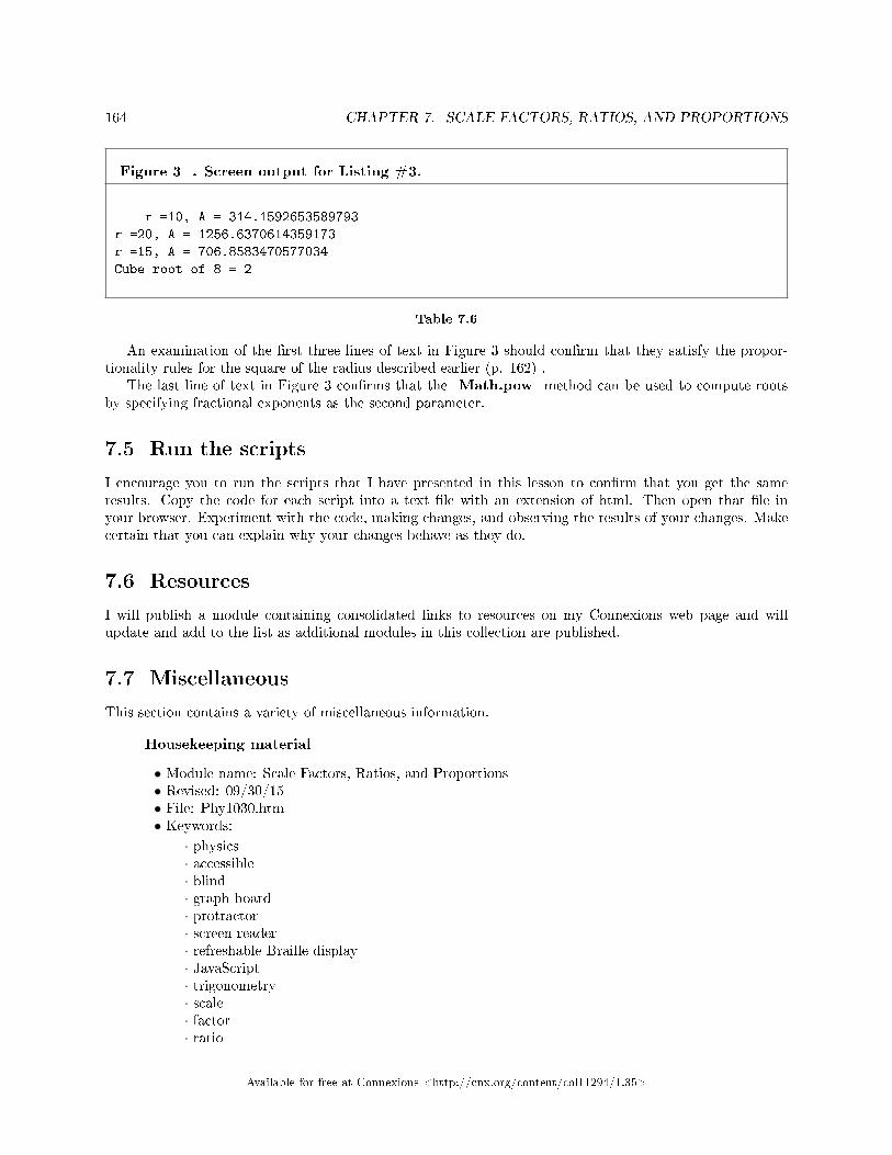
164 CHAPTER 7. SCALE FACTORS, RATIOS, AND PROPORTIONS
Figure 3 . Screen output for Listing #3.
r =10, A = 314.1592653589793
r =20, A = 1256.6370614359173
r =15, A = 706.8583470577034
Cube root of 8 = 2
Table 7.6
An examination of the �rst three lines of text in Figure 3 should con�rm that they satisfy the propor-tionality rules for the square of the radius described earlier (p. 162) .
The last line of text in Figure 3 con�rms that the Math.pow method can be used to compute rootsby specifying fractional exponents as the second parameter.
7.5 Run the scripts
I encourage you to run the scripts that I have presented in this lesson to con�rm that you get the sameresults. Copy the code for each script into a text �le with an extension of html. Then open that �le inyour browser. Experiment with the code, making changes, and observing the results of your changes. Makecertain that you can explain why your changes behave as they do.
7.6 Resources
I will publish a module containing consolidated links to resources on my Connexions web page and willupdate and add to the list as additional modules in this collection are published.
7.7 Miscellaneous
This section contains a variety of miscellaneous information.
Housekeeping material
• Module name: Scale Factors, Ratios, and Proportions• Revised: 09/30/15• File: Phy1030.htm• Keywords:
· physics· accessible· blind· graph board· protractor· screen reader· refreshable Braille display· JavaScript· trigonometry· scale· factor· ratio
Available for free at Connexions <http://cnx.org/content/col11294/1.35>

165
· proportion· Google calculator
Disclaimers: Financial : Although the openstax CNX site makes it possible for you todownload a PDF �le for the collection that contains this module at no charge, and also makes itpossible for you to purchase a pre-printed version of the PDF �le, you should be aware that someof the HTML elements in this module may not translate well into PDF.
You also need to know that Prof. Baldwin receives no �nancial compensation from openstaxCNX even if you purchase the PDF version of the collection.
In the past, unknown individuals have copied Prof. Baldwin's modules from cnx.org, convertedthem to Kindle books, and placed them for sale on Amazon.com showing Prof. Baldwin as theauthor. Prof. Baldwin neither receives compensation for those sales nor does he know who doesreceive compensation. If you purchase such a book, please be aware that it is a copy of a collectionthat is freely available on openstax CNX and that it was made and published without the priorknowledge of Prof. Baldwin.
A�liation : Prof. Baldwin is a professor of Computer Information Technology at AustinCommunity College in Austin, TX.
-end-
Available for free at Connexions <http://cnx.org/content/col11294/1.35>

166 CHAPTER 7. SCALE FACTORS, RATIOS, AND PROPORTIONS
Available for free at Connexions <http://cnx.org/content/col11294/1.35>

Chapter 8
Scienti�c Notation and Signi�cant
Figures1
8.1 Table of Contents
• Preface (p. 167)
· General (p. 167)· Prerequisites (p. 168)· Viewing tip (p. 168)
* Figures (p. 168)* Listings (p. 169)
· Supplemental material (p. 169)
• General background information (p. 169)
· Accuracy and precision (p. 169)· Scienti�c notation (p. 170)· Signi�cant �gures (p. 171)
• Discussion and sample code (p. 172)• Run the scripts (p. 179)• Resources (p. 179)• Miscellaneous (p. 179)
8.2 Preface
8.2.1 General
This module is part of a collection of modules designed to make physics concepts accessible to blind students.If you opened this page in the context of the book, a Table of Contents for the book (or collection)
should be available above and to the left of this paragraph. Otherwise, click here 2 to open the book at thebeginning.
This book is intended to supplement but not to replace the textbook in an introductory high school orcollege physics course.
The purpose of this module is to explain the use of scienti�c notation and signi�cant �gures in a formatthat is accessible to blind students.
1This content is available online at <http://cnx.org/content/m37445/1.5/>.2http://cnx.org/contents/a7842db2-93c6-4c06-a5e3-56c282358143
Available for free at Connexions <http://cnx.org/content/col11294/1.35>
167

168 CHAPTER 8. SCIENTIFIC NOTATION AND SIGNIFICANT FIGURES
8.2.2 Prerequisites
In addition to an Internet connection and a browser, you will need the following tools (as a minimum) towork through the exercises in these modules:
• A graph board for plotting graphs and vector diagrams (http://www.youtube.com/watch?v=c8plj9UsJbg 3 ).
• A protractor for measuring angles ( http://www.youtube.com/watch?v=v-F06HgiUpw 4 ).• An audio screen reader that is compatible with your operating system, such as the NonVisual Desktop
Access program (NVDA), which is freely available at http://www.nvda-project.org/ 5 .• A refreshable Braille display capable of providing a line by line tactile output of information displayed
on the computer monitor ( http://www.userite.com/ecampus/lesson1/tools.php 6 ).• The ability to create tactile graphics as described here 7 .
The minimum prerequisites for understanding the material in these modules include:
• A good understanding of algebra.• An understanding of the use of a graph board for plotting graphs and vector diagrams (
http://www.youtube.com/watch?v=c8plj9UsJbg 8 ).• An understanding of the use of a protractor for measuring angles (
http://www.youtube.com/watch?v=v-F06HgiUpw 9 ).• A basic understanding of the use of sine, cosine, and tangent from trigonometry (
http://www.clarku.edu/∼djoyce/trig/ 10 ).• An introductory understanding of JavaScript programming ( http://www.dickbaldwin.com/tocjscript1.htm
11 and http://www.w3schools.com/js/default.asp 12 ).• An understanding of all of the material covered in the earlier modules in this collection.• An understanding of the creation and use of tactile graphics as described here 13 .
8.2.3 Viewing tip
I recommend that you open another copy of this document in a separate browser window and use thefollowing links to easily �nd and view the �gures and listings while you are reading about them.
8.2.3.1 Figures
• Figure 1 (p. 172) . Examples of signi�cant �gures.• Figure 2 (p. 173) . Screen output from Listing #1.• Figure 3 (p. 175) . Screen output from Listing #2.• Figure 4 (p. 176) . Behavior of the toPrecision method.• Figure 5 (p. 179) . Screen output from Listing #3.
3http://www.youtube.com/watch?v=c8plj9UsJbg4http://www.youtube.com/watch?v=v-F06HgiUpw5http://www.nvda-project.org/6http://www.userite.com/ecampus/lesson1/tools.php7http://cnx.org/contents/9fe07552-485f-43e7-9753-87133cf604828http://www.youtube.com/watch?v=c8plj9UsJbg9http://www.youtube.com/watch?v=v-F06HgiUpw
10http://www.clarku.edu/∼djoyce/trig/11http://www.dickbaldwin.com/tocjscript1.htm12http://www.w3schools.com/js/default.asp13http://cnx.org/contents/9fe07552-485f-43e7-9753-87133cf60482
Available for free at Connexions <http://cnx.org/content/col11294/1.35>

169
8.2.3.2 Listings
• Listing 1 (p. 173) . An exercise involving addition.• Listing 2 (p. 175) . An exercise involving multiplication.• Listing 3 (p. 178) . An exercise involving combined operations.
8.2.4 Supplemental material
I recommend that you also study the other lessons in my extensive collection of online programming tutorials.You will �nd a consolidated index at www.DickBaldwin.com 14 .
8.3 General background information
This section will contain a discussion of accuracy, precision, scienti�c notation, and signi�cant �gures.
8.3.1 Accuracy and precision
Let's begin with a brief discussion of accuracy and precision. These two terms are often confused in everydayconversation, but they have very di�erent meanings in the world of science and engineering.
AccuracyIn science and engineering, the accuracy of a measurement system is the degree of closeness of measure-
ments of a quantity to its actual (true) value.PrecisionThe precision of a measurement system (also called reproducibility or repeatability) is the degree to which
repeated measurements under unchanged conditions show the same result.Four possibilitiesA measurement system can be:
• Both accurate and precise.• Accurate but not precise.• Precise but not accurate.• Neither accurate nor precise.
A hypothetical experimentConsider an experiment where a �rearm is clamped into a �xture, very carefully aimed at a bulls eye
on a downrange target, and �red six times. (Although you may never have seen or touched a �rearm, youprobably have a pretty good idea of how they behave.)
If the six holes produced by the bullets in the target fall in a tight cluster in the bulls eye, the systemcan be considered to be both accurate and precise.
If all of the holes fall in the general area of the bulls eye but the cluster is not very tight, the system canbe considered to be accurate but not precise.
If all of the holes fall in a tight cluster but the cluster is some distance from the bulls eye, the systemcan be considered to be precise but not accurate.
If the holes are scattered across a wide area of the target, the system can be considered to be neitheraccurate nor precise.
Another use of the word precisionAnother use of the word precision, which will be important in this module, is based on the concept that
the precision of a measurement describes the units that you use to measure something.How tall are you?
14http://www.dickbaldwin.com/toc.htm
Available for free at Connexions <http://cnx.org/content/col11294/1.35>

170 CHAPTER 8. SCIENTIFIC NOTATION AND SIGNIFICANT FIGURES
For example, if you tell someone that you are about �ve feet tall, that wouldn't be very precise. If youtold someone that you are 62 inches tall, that would be more precise. If you told someone that you are 62.3inches tall, that would be even more precise, and if you told someone that you are 62.37 inches tall, thatwould be very precise for a measurement of that nature.
The smaller the unit...The smaller the unit you use to measure with, the more precise the measurement can be. For example,
assume that you measure someone's height with a tactile measuring stick that is longer than the person istall. Assume also that the measuring stick is graduated only in feet. In that case, the best that you couldhope for would be to get the measurement correct to the nearest foot and perhaps estimate a second digitto the nearest tenth of a foot.
One-inch graduationsOn the other hand, if the measuring stick is graduated in inches and you are careful, you should be able
to get the measurement correct to the nearest inch and perhaps estimate another digit to the nearest tenthof an inch. The second measurement using the one-inch graduations would be more precise than the �rstusing the one-foot graduations.
Diminishing returnsIf the measuring stick were graduated in tenth-inch units, however, that may or may not lead to a more
precise measurement. That would be approaching the point of diminishing returns where your inability totake full advantage of the more precise graduations and the inability of the subject to always stand with thesame degree of rigidity might come into play.
8.3.2 Scienti�c notation
According to Wikipedia 15 , scienti�c notation is a way of writing numbers that accommodates values toolarge or small to be conveniently written in standard decimal notation. The notation has a number of usefulproperties and is commonly used by scientists and engineers. A variation of scienti�c notation is also usedinternally by computers.
Scienti�c notation formatNumbers in scienti�c notation are written using the following format:x * 10^ywhich can be read as the value x multiplied by ten raised to the y power where y is an integer and
x is any real number. (Constraints are placed on the value of x when using the normalized form ofscienti�c notation which I will explain below.)
The values for x and y can be either positive or negative.The term referred to as x is often called the signi�cand or the mantissa (not to be confused with
the term mantissa used with common logarithms).The computer display version of scienti�c notationBecause of di�culties involved in displaying superscripts in the output of computer programs, a typical
display of a number in scienti�c notation by a computer program might look something like the followingexample:
-3.141592653589793e+1where
• Either numeric value can be positive, negative, or zero.• The number of digits in the numeric value to the left of the e (the mantissa) may range from a few
to many.• The e may be either upper-case or lower-case depending on the computer and the program.
A power of ten is understoodIn this format, it is understood that the number consists of the value to the left of the e (the mantissa)
multiplied by ten raised to a power given by the value to the right of the e (the exponent).
15http://en.wikipedia.org/wiki/Scienti�c_notation
Available for free at Connexions <http://cnx.org/content/col11294/1.35>
171
For example, in JavaScript exponential format, the value -10*Math.PI is displayed as-3.141592653589793e+1The value Math.PI/10 is displayed as3.141592653589793e-1The value Math.PI is displayed as3.141592653589793e+0The value 0 is displayed as0e+0The normalized form of scienti�c notationUsing general scienti�c notation, the number -65700 could be written in several di�erent ways including
the following:
• -6.57 * 10^4• -65.7 * 10^3• -657 * 10^2
In normalized scienti�c notation, the exponent is chosen such that the absolute value of the mantissa is atleast one but less than ten. For example, -65700 is written:
-6.57 * 10^4In normalized notation the exponent is negative for a number with absolute value between 0 and 1. For
example, the value 0.00657 would be written:6.57 * 10^(-3)The 10 and the exponent are usually omitted when the exponent is 0.
8.3.3 Signi�cant �gures
According to Wikipedia 16 , The signi�cant �gures of a number are those digits that carry meaning con-tributing to its precision. This includes all digits except:
• Leading zeros where they serve merely as placeholders to indicate the scale of the number (.00356 forexample).
• Spurious digits introduced, for example, by calculations carried out to greater accuracy than that ofthe original data, or measurements reported to a greater precision than the equipment supports.
A popular physics textbook provides a more complete set of rules for identifying the signi�cant �gures in anumber:
1. Nonzero digits are always signi�cant.2. Final or ending zeros written to the right of the decimal point are signi�cant.3. Zeros written to the right of the decimal point for the purpose of spacing the decimal point are not
signi�cant.4. Zeros written to the left of the decimal point may be signi�cant, or they may only be there to space
the decimal point. For example, 200 cm could have one, two, or three signi�cant �gures; it's not clearwhether the distance was measured to the nearest 1 cm, to the nearest 10 cm, or to the nearest 100cm. On the other hand, 200.0 cm has four signi�cant �gures (see rule 5). Rewriting the number inscienti�c notation is one way to remove the ambiguity.
5. Zeros written between signi�cant �gures are signi�cant.
Ambiguity of the last digit in scienti�c notationAgain, according to Wikipedia 17 , it is customary in scienti�c measurements to record all the signi�cant
digits from the measurements, and to guess one additional digit if there is any information at all available to
16http://en.wikipedia.org/wiki/Signi�cant_�gures17http://en.wikipedia.org/wiki/Scienti�c_notation
Available for free at Connexions <http://cnx.org/content/col11294/1.35>
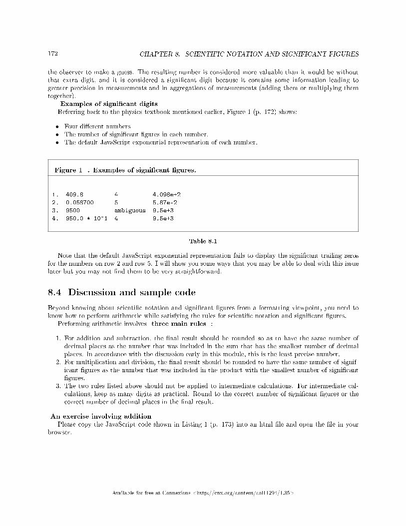
172 CHAPTER 8. SCIENTIFIC NOTATION AND SIGNIFICANT FIGURES
the observer to make a guess. The resulting number is considered more valuable than it would be withoutthat extra digit, and it is considered a signi�cant digit because it contains some information leading togreater precision in measurements and in aggregations of measurements (adding them or multiplying themtogether).
Examples of signi�cant digitsReferring back to the physics textbook mentioned earlier, Figure 1 (p. 172) shows:
• Four di�erent numbers• The number of signi�cant �gures in each number.• The default JavaScript exponential representation of each number.
Figure 1 . Examples of signi�cant �gures.
1. 409.8 4 4.098e+2
2. 0.058700 5 5.87e-2
3. 9500 ambiguous 9.5e+3
4. 950.0 * 10^1 4 9.5e+3
Table 8.1
Note that the default JavaScript exponential representation fails to display the signi�cant trailing zerosfor the numbers on row 2 and row 5. I will show you some ways that you may be able to deal with this issuelater but you may not �nd them to be very straightforward.
8.4 Discussion and sample code
Beyond knowing about scienti�c notation and signi�cant �gures from a formatting viewpoint, you need toknow how to perform arithmetic while satisfying the rules for scienti�c notation and signi�cant �gures.
Performing arithmetic involves three main rules :
1. For addition and subtraction, the �nal result should be rounded so as to have the same number ofdecimal places as the number that was included in the sum that has the smallest number of decimalplaces. In accordance with the discussion early in this module, this is the least precise number.
2. For multiplication and division, the �nal result should be rounded to have the same number of signif-icant �gures as the number that was included in the product with the smallest number of signi�cant�gures.
3. The two rules listed above should not be applied to intermediate calculations. For intermediate cal-culations, keep as many digits as practical. Round to the correct number of signi�cant �gures or thecorrect number of decimal places in the �nal result.
An exercise involving additionPlease copy the JavaScript code shown in Listing 1 (p. 173) into an html �le and open the �le in your
browser.
Available for free at Connexions <http://cnx.org/content/col11294/1.35>

173
Listing 1 . An exercise involving addition.
<!-- File JavaScript01.html --><html><body><script language="JavaScript1.3">
//Compute and display the sum of three
// numbers
var a = 169.01
var b = 0.00356
var c = 385.293
var sum = a + b + c
document.write("sum = " + sum + "</br>")
//Round the sum to the correct number
// of digits to the right of the decimal
// point.
var round = sum.toFixed(2)
document.write("round = " + round + "</br>")
//Display a final line as a hedge against
// unidentified coding errors.
document.write("The End")
</script></body></html>
Table 8.2
Screen outputWhen you open the html �le in your browser, the text shown in Figure 2 (p. 173) should appear in your
browser.
Figure 2 . Screen output from Listing #1.
sum = 554.30656
round = 554.31
The End
Table 8.3
The code in Listing 1 (p. 173) begins by declaring three variables named a , b , and c , addingthem together, and displaying the sum in the JavaScript default format in the browser window.
Too many decimal digitsAs you can see from the �rst line in Figure 2 (p. 173) , the result is computed and displayed with eight
decimal digits, �ve of which are to the right of the decimal point. We know, however, from rule #1 (p. 172), that we should present the result rounded to a precision of two digits to the right of the decimal point in
Available for free at Connexions <http://cnx.org/content/col11294/1.35>

174 CHAPTER 8. SCIENTIFIC NOTATION AND SIGNIFICANT FIGURES
order to match the least precise of the numbers included in the sum. In this case, the value stored in thevariable named a is the least precise.
Correct the problemThe code in Listing 1 (p. 173) calls a method named toFixed on the value stored in the variable sum
passing a value of 2 as a parameter to the method. This method returns the value from sum rounded totwo decimal digits. The returned value is stored in the variable named round . Then the script displaysthat value as the second line of text in Figure 2 (p. 173) .
The output text that reads "The End"There is a downside to using JavaScript (as opposed to other programming languages such as Java).
By default, if there is a coding error in your script, there is no indication of the error in the output in themain browser window. Instead, the browser simply refuses to display some or all of the output that you areexpecting to see. (Remember, I told you that JavaScript is not my favorite programming language, but it isprobably the most accessible for blind students who have no programming experience.)
Put a marker at the endWriting the script in such a way that a known line of text, such as "The End" will appear following all
of the other output won't solve coding errors. However, if it doesn't appear, you will know that there is acoding error and some or all of the output text may be missing.
JavaScript and error consolesI explained how you can open a JavaScript console in the Google Chrome browser or an error console
in the Firefox browser in an earlier module titled JavaScript for Blind Students 18 . While the diagnosticinformation provided in those consoles is limited, it will usually indicate the line number in the source codewhere the programming error was detected. Knowing the line number will help you examine the code and�x the error.
An exercise involving multiplicationPlease copy the code shown in Listing 2 (p. 175) into an html �le and open it in your browser.
18http://cnx.org/contents/9eb6aeee-1604-4bde-b81f-912622f036d1
Available for free at Connexions <http://cnx.org/content/col11294/1.35>

175
Listing 2 . An exercise involving multiplication.
<!-- File JavaScript02.html --><html><body><script language="JavaScript1.3">
//Compute and display the product of three
// numbers, each having a different number
// of significant figures.
var a = 169.01
var b = 0.00356
var c = 386.253
var product = a * b * c
document.write("product = " + product + "</br>")
//Round the product to the correct number
// of significant figures
var rounded = product.toPrecision(5)
document.write("rounded = " + rounded + "</br>")
//Display a final line as a hedge against
// unidentified coding errors.
document.write("The End")
</script></body></html>
Table 8.4
The screen outputWhen you open your html �le in your browser, the text shown in Figure 3 (p. 175) should appear in
your browser window.
Figure 3 . Screen output from Listing #2.
product = 232.39900552679998
rounded = 232.40
The End
Table 8.5
The code in Listing 2 (p. 175) begins by declaring three variables named a , b , and c , multiplyingthem together, and displaying the product in the browser window. Each of the factors in the product havea di�erent number of signi�cant �gures, with the factor of value 169.01 having the least number (5) ofsigni�cant �gures. We know from rule #2 (p. 172) , therefore, that we need to present the result roundedto �ve signi�cant �gures.
The toPrecision method
Available for free at Connexions <http://cnx.org/content/col11294/1.35>

176 CHAPTER 8. SCIENTIFIC NOTATION AND SIGNIFICANT FIGURES
Listing 2 (p. 175) calls a method named toPrecision on the variable named product , passing thedesired number of signi�cant �gures (5) as a parameter. The method rounds the value stored in productto the desired number of digits and returns the result, which is stored in the variable named rounded .Then the contents of the variable named rounded are displayed, producing the second line of text inFigure 3 (p. 175) .
What about other parameter valuesNote that the method named toPrecision knows nothing about signi�cant �gures. It was up to me to
�gure out the desired number of signi�cant �gures in advance and to pass that value as a parameter to themethod.
Although this has nothing to do with signi�cant �gures, it may be instructive to examine the behaviorof the method named toPrecision for several di�erent parameter values.
Figure 4 (p. 176) shows the result of replacing the parameter value of 5 in the call to the toPrecisionmethod with the values in the �rst column of Figure 4 (p. 176) and displaying the value returned by themethod.
Figure 4 . Behavior of the toPrecision method.
1 rounded = 2e+2
2 rounded = 2.3e+2
3 rounded = 232
4 rounded = 232.4
5 rounded = 232.40
6 rounded = 232.399
7 rounded = 232.3990
10 rounded = 232.3990055
15 rounded = 232.399005526800
20 rounded = 232.39900552679998214
Table 8.6
And the point is...The point to this is to emphasize that the method named toPrecision is not a method that knows
how to compute and display the required number of signi�cant �gures. Instead, according to the JavaScriptdocumentation:
"The toPrecision() method formats a number to a speci�ed length. A decimal point and nulls are added(if needed), to create the speci�ed length."
It is up to you, the author of the script, to determine what that length should be and to provide thatinformation as a parameter to the toPrecision method.
Combined operationsThis is where things become a little hazy. I have been unable to �nd de�nitive information as to how
to treat the precision and the number of signi�cant �gures when doing computations that combine additionand/or subtraction with multiplication and/or division.
Two contradictory proceduresI have found two procedures documented on the web that seem to be somewhat contradictory. Both
sources seem to say that you should perform the addition and/or subtraction �rst and that you should applyrule #1 (p. 172) to the results. However, they di�er with regard to how stringently you apply that rulebefore moving on to the multiplication and/or division.
The more stringent procedure
Available for free at Connexions <http://cnx.org/content/col11294/1.35>
177
One source seems to suggest that you should round the results of the addition and/or subtraction ac-cording to rule #1 (p. 172) and replace the addition or subtraction expression in your overall expressionwith the rounded result. Using that approach, you simply create one the factors that will be used later inthe multiplication and/or division. That factor has a well-de�ned number of signi�cant �gures.
Then you proceed with the multiplication and/or division and adjust the number of signi�cant �gures inthe �nal result according to rule #2 (p. 172) .
The less stringent procedureThe other source seems to suggest that you mentally round the results of the addition and/or subtraction
according to rule #1 (p. 172) and make a note of the number of signi�cant �gures that would result if youwere to actually round the result. However, you should not actually round the result at that point in time.In other words, you should use the raw result of the addition and/or subtraction as a factor in the upcomingmultiplication and/or division knowing that you may be carrying excess precision according to rule #1 (p.172) .
Then you proceed with the multiplication and/or division and adjust the number of signi�cant �gures inthe �nal result according to rule #2 (p. 172) . However, when you adjust the number of signi�cant �gures,you should include the number of signi�cant �gures from your note in the decision process. If that is thesmallest number of signi�cant �gures of all the factors, you should use it as the number of signi�cant �guresfor the �nal result.
Consult with your instructorBefore accepting either of these procedures as the correct procedure, I recommend that you consult with
your physics instructor to con�rm which, if either of the procedures is correct for combined operations.An exercise involving combined operationsEvaluate the following expression and display the �nal result with the correct number of signi�cant
�gures.(169.01 + 3294.6372) * (0.00365 - 29.333)Please copy the code from Listing 3 (p. 178) into an html �le and open it in your browser.
Available for free at Connexions <http://cnx.org/content/col11294/1.35>
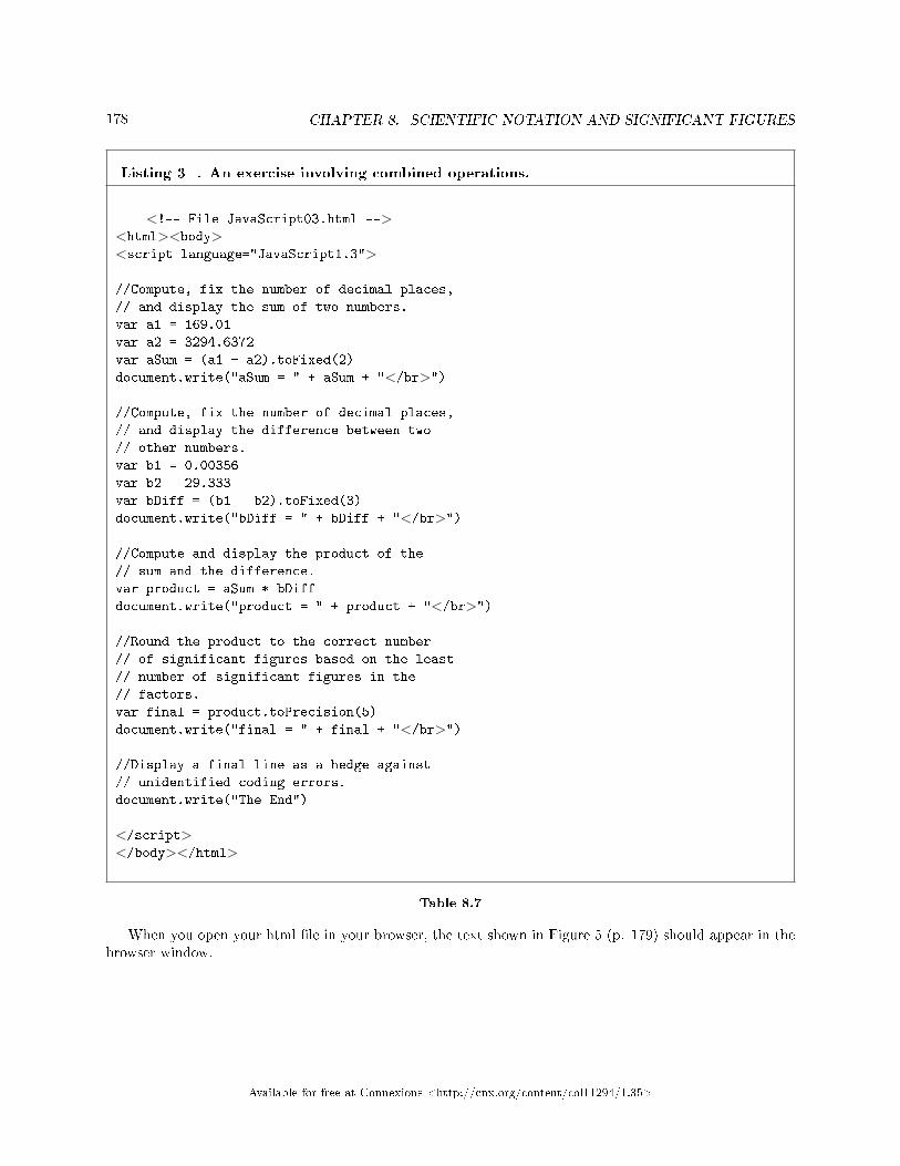
178 CHAPTER 8. SCIENTIFIC NOTATION AND SIGNIFICANT FIGURES
Listing 3 . An exercise involving combined operations.
<!-- File JavaScript03.html --><html><body><script language="JavaScript1.3">
//Compute, fix the number of decimal places,
// and display the sum of two numbers.
var a1 = 169.01
var a2 = 3294.6372
var aSum = (a1 + a2).toFixed(2)
document.write("aSum = " + aSum + "</br>")
//Compute, fix the number of decimal places,
// and display the difference between two
// other numbers.
var b1 = 0.00356
var b2 = 29.333
var bDiff = (b1 - b2).toFixed(3)
document.write("bDiff = " + bDiff + "</br>")
//Compute and display the product of the
// sum and the difference.
var product = aSum * bDiff
document.write("product = " + product + "</br>")
//Round the product to the correct number
// of significant figures based on the least
// number of significant figures in the
// factors.
var final = product.toPrecision(5)
document.write("final = " + final + "</br>")
//Display a final line as a hedge against
// unidentified coding errors.
document.write("The End")
</script></body></html>
Table 8.7
When you open your html �le in your browser, the text shown in Figure 5 (p. 179) should appear in thebrowser window.
Available for free at Connexions <http://cnx.org/content/col11294/1.35>

179
Figure 5 . Screen output from Listing #3.
aSum = 3463.65
bDiff = -29.329
product = -101585.39085000001
final = -1.0159e+5
The End
Table 8.8
The more stringent procedureThe code in Listing 3 (p. 178) implements the more stringent procedure (p. 176) , not because it is
necessarily the correct one. Rather, it is simpler to implement in a script.Do addition and subtraction �rstListing 3 (p. 178) begins by adding two numbers, adjusting the precision to the least precise of the two
numbers, and saving the result in the variable named aSum .Then Listing 3 (p. 178) subtracts one number from another number, adjusts the precision to the least
precise of the two numbers, and saves the result in the variable named bDi� .Display to get information on signi�cant �guresBoth results are displayed immediately after they are obtained. This is necessary for me to know which
one has the least number of signi�cant �gures. I need to know that to be able to properly adjust the numberof signi�cant �gures in the �nal product.
In other words, it was necessary for me to write and execute the addition/subtraction portion of thescript in order to get the information required to write the remainder of the script.
Do the multiplicationThen Listing 3 (p. 178) multiplies the sum and di�erence values and displays the result in the default
format with far too many signi�cant �gures as shown by the third line of text in Figure 5 (p. 179) .Finally Listing 3 (p. 178) adjusts the number of signi�cant �gures in the product based on the number of
signi�cant �gures in bDi� and displays the �nal result with �ve signi�cant �gures in normalized scienti�c(exponential) notation.
8.5 Run the scripts
I encourage you to run the scripts that I have presented in this lesson to con�rm that you get the sameresults. Copy the code for each script into a text �le with an extension of html. Then open that �le inyour browser. Experiment with the code, making changes, and observing the results of your changes. Makecertain that you can explain why your changes behave as they do.
8.6 Resources
I will publish a module containing consolidated links to resources on my Connexions web page and willupdate and add to the list as additional modules in this collection are published.
8.7 Miscellaneous
This section contains a variety of miscellaneous information.
Housekeeping material
Available for free at Connexions <http://cnx.org/content/col11294/1.35>

180 CHAPTER 8. SCIENTIFIC NOTATION AND SIGNIFICANT FIGURES
• Module name: Scienti�c Notation and Signi�cant Figures• File: Phy1040.htm• Revised: 10/01/15• Keywords:
· physics· accessible· blind· screen reader· Braille display· JavaScript· scienti�c notation· signi�cant �gures· accuracy· precision
Disclaimers: Financial : Although the openstax CNX site makes it possible for you todownload a PDF �le for the collection that contains this module at no charge, and also makes itpossible for you to purchase a pre-printed version of the PDF �le, you should be aware that someof the HTML elements in this module may not translate well into PDF.
You also need to know that Prof. Baldwin receives no �nancial compensation from openstaxCNX even if you purchase the PDF version of the collection.
In the past, unknown individuals have copied Prof. Baldwin's modules from cnx.org, convertedthem to Kindle books, and placed them for sale on Amazon.com showing Prof. Baldwin as theauthor. Prof. Baldwin neither receives compensation for those sales nor does he know who doesreceive compensation. If you purchase such a book, please be aware that it is a copy of a collectionthat is freely available on openstax CNX and that it was made and published without the priorknowledge of Prof. Baldwin.
A�liation : Prof. Baldwin is a professor of Computer Information Technology at AustinCommunity College in Austin, TX.
-end-
Available for free at Connexions <http://cnx.org/content/col11294/1.35>

Chapter 9
Units and Dimensional Analysis1
9.1 Table of Contents
• Preface (p. 181)
· General (p. 181)· Prerequisites (p. 182)· Viewing tip (p. 182)
* Figures (p. 183)* Listings (p. 183)
· Supplemental material (p. 183)
• General background information (p. 183)
· Formatting mathematical expressions (p. 183)· What do we mean by units? (p. 184)· SI units (p. 184)· Pre�xes for powers of ten (p. 186)· Dimensional analysis (p. 186)
• Discussion and sample code (p. 186)
· Exercise on manually converting units (p. 187)· Using JavaScript to convert units (p. 189)· More substantive JavaScript examples (p. 193)
* Free fall exercise (p. 193)* A plotting exercise (p. 195)
· Non-mirror-image graphics (p. 202)
• Run the scripts (p. 207)• Resources (p. 207)• Miscellaneous (p. 207)
9.2 Preface
9.2.1 General
This module is part of a collection of modules designed to make physics concepts accessible to blind students.
1This content is available online at <http://cnx.org/content/m37480/1.6/>.
Available for free at Connexions <http://cnx.org/content/col11294/1.35>
181

182 CHAPTER 9. UNITS AND DIMENSIONAL ANALYSIS
If you opened this page in the context of the book, a Table of Contents for the book (or collection)should be available above and to the left of this paragraph. Otherwise, click here 2 to open the book at thebeginning.
This book is intended to supplement but not to replace the textbook in an introductory high school orcollege physics course.
The purpose of this module is to explain units and dimensional analysis in a format that is accessible toblind students.
9.2.2 Prerequisites
In addition to an Internet connection and a browser, you will need the following tools (as a minimum) towork through the exercises in these modules:
• A graph board for plotting graphs and vector diagrams (http://www.youtube.com/watch?v=c8plj9UsJbg 3 ).
• A protractor for measuring angles ( http://www.youtube.com/watch?v=v-F06HgiUpw 4 ).• An audio screen reader that is compatible with your operating system, such as the NonVisual Desktop
Access program (NVDA), which is freely available at http://www.nvda-project.org/ 5 .• A refreshable Braille display capable of providing a line by line tactile output of information displayed
on the computer monitor ( http://www.userite.com/ecampus/lesson1/tools.php 6 ).• A device to create Braille labels. Will be used to label graphs constructed on the graph board.• The ability to create tactile graphics as described here 7 .
The minimum prerequisites for understanding the material in these modules include:
• A good understanding of algebra.• An understanding of the use of a graph board for plotting graphs and vector diagrams (
http://www.youtube.com/watch?v=c8plj9UsJbg 8 ).• An understanding of the use of a protractor for measuring angles (
http://www.youtube.com/watch?v=v-F06HgiUpw 9 ).• A basic understanding of the use of sine, cosine, and tangent from trigonometry (
http://www.clarku.edu/∼djoyce/trig/ 10 ).• An introductory understanding of JavaScript programming ( http://www.dickbaldwin.com/tocjscript1.htm
11 and http://www.w3schools.com/js/default.asp 12 )).• An understanding of all of the material covered in the earlier modules in this collection.• An understanding of the creation and use of tactile graphics as described here 13 .
9.2.3 Viewing tip
I recommend that you open another copy of this document in a separate browser window and use thefollowing links to easily �nd and view the �gures and listings while you are reading about them.
2http://cnx.org/contents/a7842db2-93c6-4c06-a5e3-56c2823581433http://www.youtube.com/watch?v=c8plj9UsJbg4http://www.youtube.com/watch?v=v-F06HgiUpw5http://www.nvda-project.org/6http://www.userite.com/ecampus/lesson1/tools.php7http://cnx.org/contents/9fe07552-485f-43e7-9753-87133cf604828http://www.youtube.com/watch?v=c8plj9UsJbg9http://www.youtube.com/watch?v=v-F06HgiUpw
10http://www.clarku.edu/∼djoyce/trig/11http://www.dickbaldwin.com/tocjscript1.htm12http://www.w3schools.com/js/default.asp13http://cnx.org/contents/9fe07552-485f-43e7-9753-87133cf60482
Available for free at Connexions <http://cnx.org/content/col11294/1.35>

183
9.2.3.1 Figures
• Figure 1 (p. 184) . Single-line format.• Figure 2 (p. 185) . SI base units.• Figure 3 (p. 185) . Examples of SI derived units.• Figure 4 (p. 186) . A sampling of SI pre�xes.• Figure 5 (p. 191) . Screen output for Listing #1.• Figure 6 (p. 194) . Screen output for Listing #2.• Figure 7 (p. 197) . Screen output for Listing #3.• Figure 8 (p. 201) . Mirror image from the �le named Phy1050a1.svg.• Figure 9 (p. 202) . Key-value table for the image shown in Figure 8.• Figure 10 (p. 206) . Non-mirror-image version of the image from the �le named Phy1050a1.svg.
9.2.3.2 Listings
• Listing 1 (p. 190) . Convert from paces to miles.• Listing 2 (p. 194) . Free fall exercise.• Listing 3 (p. 196) . A plotting exercise.
9.2.4 Supplemental material
I recommend that you also study the other lessons in my extensive collection of online programming tutorials.You will �nd a consolidated index at www.DickBaldwin.com 14 .
9.3 General background information
As a young engineering student many years ago, I was told that when evaluating mathematical expressions,I should always embed the units in the expression, manipulate them algebraically, and con�rm that the unitsthat survive until the end of the evaluation are correct relative to the problem speci�cations.
Three good reasonsThere are at least three good reasons for following this procedure:
• It shows what the units of the result are. A common mistake is to get the correct numerical result ofa calculation but to write it with the wrong units.
• It shows where unit conversions must be performed. If units that should have canceled do not cancel,we need to go back and perform the necessary conversions. For example, when a speed in miles perhour is being calculated and the result comes out with units of miles per second, we should convertseconds to hours.
• It helps to locate mistakes. If a velocity (meters per second) is being calculated and the units comeout as seconds per meter, we know to look for an error.
9.3.1 Formatting mathematical expressions
A signi�cant disadvantageThis is an area where blind students may be at a signi�cant disadvantage relative to sighted students
due mainly to the fact that blind students using screen readers and Braille displays can only see one line oftext at a time. It is much easier (for me anyway) to correctly manipulate the units when the expression iswritten on two or more lines.
14http://www.dickbaldwin.com/toc.htm
Available for free at Connexions <http://cnx.org/content/col11294/1.35>

184 CHAPTER 9. UNITS AND DIMENSIONAL ANALYSIS
Multiple-line formatWhat I mean by this is that a sighted student would typically write a fraction as a horizontal line with
the numerator above the line and the denominator below the line using superscripts to indicate exponents.The product of two fractions would typically be written in the same format with a multiplication indicatorjoining the two fractions.
Single-line formatA blind student constrained to seeing only one line of text at a time would probably need to write and
evaluate the product of the two fractions using a format something like that shown in Figure 1 (p. 184) .
Figure 1 . Single-line format.
((3*x^2)/(4*x) * (6/(4*x) = (18*x^2)/(16*x^2) = 18/16
Table 9.1
With enough time and practice, I might become almost as pro�cient in evaluating expressions as shownin Figure 1 (p. 184) as in evaluating expressions in a multiple-line format, but I'm afraid that I would needa lot of time and a lot of practice to achieve that pro�ciency.
We must work with what we are givenHowever, we must work with what we are given so the mathematical expressions in this module (and
most of the other modules as well) will all be in a single-line format. The good news is that the single-lineformat can usually be easily translated into a format that is suitable for evaluation using JavaScript.
9.3.2 What do we mean by units?
Let me try to answer this important question with an example.If you were to walk from your home to your school and count your steps, you might report that the
distance from your home to your school is 2112 steps or paces. If you are a male student, this wouldprobably be approximately one mile, using assumptions that I will explain later. If you are a female, itwould probably be somewhat less than a mile because your pace would probably be a little shorter thanyour male friend's pace.
A pace is a unit of measurementIn this case, the pace would be a unit of measurement. However, it would not be a standard unit because
the length of a pace for one student is often di�erent from the length of a pace for a di�erent student. Amale student, for example, typically has a longer pace length than a female student.
Standard unitsStandard units are units whose value has been set by some o�cial agency that has the authority to set
standards. One such standard unit is the mile, which as you may know is equal to 5280 foots (more correctlypronounced feet).
A foot is also a standard unit, which you may also know is equal to 12 inches. An inch is another standardunit.
9.3.3 SI units
The discrepancy between the pronunciation of the unit foot and its plural feet is an example of theneed for more consistency in the use of units. Many physics books use a system of units called SI units .SI is an abbreviation for a French name, which I am unable to pronounce, and which is probably also notcompatible with your screen reader and your Braille display.
Available for free at Connexions <http://cnx.org/content/col11294/1.35>

185
I won't attempt to explain much about SI units. You can probably �nd a good explanation in yourtextbook, and if not, you can Google SI units and �nd hundreds of web pages that explain the system invarying levels of detail.
Tables of SI unitsMost of those references will probably also provide tables for the units, but those tables may be partially
incompatible with your screen reader and Braille display due to the extensive use of superscripts. Therefore,I will attempt to provide accessible tables in Figure 2 (p. 185) and Figure 3 (p. 185) .
Don't ignore the detailsNote, however, that you should not ignore the online SI-unit tables altogether. They are likely to contain
important information that I won't reproduce here, such as the fact that the meter is a unit of length andits value is the length of the path travelled by light in a vacuum during a time interval of 1/299792458 of asecond.
Base units and derived unitsWhen reading about SI units, you will �nd that they are often divided into base units and derived units.
I will put the base units in Figure 2 (p. 185) and some sample derived units in Figure 3 (p. 185) .
Figure 2 . SI base units.
Base Quantity Name Symbol
length meter m
mass kilogram kg
time second s
electric current ampere A
thermodynamic temperature kelvin K
amount of substance mole mol
luminous intensity candela cd
Table 9.2
Note that the list of derived units in Figure 3 (p. 185) is only a sampling of di�erent units that can bederived from the base units.
The exponentiation indicatorAs is the case throughout these modules, the character "^" that you see used extensively in Figure 3
(p. 185) indicates that the character following the ^ is an exponent. Note also that when the exponent isnegative, it is enclosed along with its minus sign in parentheses for clarity.
Figure 3 . Examples of SI derived units.
area square meter m^2
volume cubic meter m^3
speed, velocity meter per second m/s
acceleration meter per second squared m/s^2
wave number reciprocal meter m^(-1)
mass density kilogram per cubic meter kg/m^3
specific volume cubic meter per kilogram m^3/kg
current density ampere per square meter A/m^2
Available for free at Connexions <http://cnx.org/content/col11294/1.35>

186 CHAPTER 9. UNITS AND DIMENSIONAL ANALYSIS
Table 9.3
9.3.4 Pre�xes for powers of ten
As an alternative to explicitly writing powers of ten, SI uses pre�xes for units to indicate power of ten factors.Figure 4 (p. 186) shows some of the powers of ten and the SI pre�xes used for them.
Figure 4 . A sampling of SI pre�xes.
Prefix-(abbreviation) Power of Ten
peta-(P) 10^15
tera-(T) 10^12
giga-(G) 10^9
mega-(M) 10^6
kilo-(k) 10^3
deci-(d) 10^(-1)
centi-(c) 10^(-2)
milli-(m) 10^(-3)
micro-(Greek letter mu) 10^(-6)
nano-(n) 10^(-9)
pico-(p) 10^(-12)
femto-(f) 10^(-15)
Table 9.4
9.3.5 Dimensional analysis
As typically used in physics, the word dimensions means basic types of units such as time, length, andmass (see Figure 2 (p. 185) ).
There are many di�erent units that are used to express length, for example, such as foot, mile, meter,inch, etc.
Because they all have dimensions of length, you can convert from one to another. For example one mileis equal to 5280 feet.
Cannot convert between units of di�erent dimensionsWhen evaluating mathematical expressions, we can add, subtract, or equate quantities only if they have
the same dimensions (although they may not necessarily be given in the same units). For example, it ispossible to add 3 meters to 2 inches (after converting units), but it is not possible to add 3 meters to 2kilograms.
To analyze dimensions, you should treat them as algebraic quantities using the same procedures that wewill use in the upcoming exercise on manually converting units.
9.4 Discussion and sample code
Let's manually work through an exercise to determine the distance from your home to your school in milesgiven that we know the distance in paces. (I will convert this to a JavaScript script later in the module.)
Available for free at Connexions <http://cnx.org/content/col11294/1.35>

187
As we discussed earlier, you have already determined that the distance from your home to your schoolis 2112 paces. We have also recognized that the length of one of your paces is likely to be di�erent from thelength of someone else's paces.
9.4.1 Exercise on manually converting units
This is a somewhat long and tedious explanation, but unless you already have quite a lot of experience inthis area, you should probably bear with me as I walk you through it.
Convert your pace length to standard unitsFirst we must convert the length of your pace to standard units, which we can then convert to miles.A calibration exerciseAssume that you go into an empty parking lot, mark your starting position, walk 100 paces, and then
mark your ending position on the pavement. Assume that you then use a tactile measuring tape to measurethe distance from the starting position to the ending position and you �nd that distance to be 3000 inches.
From that, we could conclude that for your pace length,100 paces = 3000 inchesThus, we have calibrated your pace length in terms of the standard unit inch.The plural versus the singularNote that the use of the plural such as inches and the singular such as inch has no impact on the
results of our computations. we can switch back and forth from the plural to the singular at will as long asit makes sense to do so.
A conversion factorIf we divide both sides of the above equation (p. 187) by 100 paces, we get1 = 3000 inches/100 paces = 30 inches/paceNote that we now have a 1 on the left side and a fraction on the right side.Multiplication by 1Multiplying a value by 1 doesn't change the value. This means that if we multiply a term in an algebraic
expression by30*inch/pacewe won't change the intrinsic value of the term, although we might change the units in which that value
is expressed.The term30*inch/pacecan be used to convert a quantity in units of paces to the same quantity in units of inches.Move your body forwardSo now we know that on the average, each time you execute one pace, you have moved your body forward
by 30 inches. The next task is to determine how far you have moved your body when you have executed2112 paces (the distance from home to school measured in paces).
Convert from paces to inchesWe can begin by determining the distance from home to school in inches as follows:distance = (2112*pace) * (30*inch/pace)A review of algebraAt this point, let's review a little algebra:Given the expression: ((w/x)*(y/z))we can rewrite this as(w*y)/(x*z)Given this expression, we can reverse the process by rearranging and factoring out the terms producing
our original expression:((w/x)*(y/z))An algebraic manipulationWe determined earlier thatdistance = (2112*pace) * (30*inch/pace)
Available for free at Connexions <http://cnx.org/content/col11294/1.35>

188 CHAPTER 9. UNITS AND DIMENSIONAL ANALYSIS
Applying the algebraic process shown above to the problem at hand, we can rearrange terms and factorour expression to produce
distance = (2112 * 30 * pace * inch)/paceThe distance in inchesAt this point, we have a fraction that contains the unit pace in both the numerator and the denominator.
We can cancel those two terms leaving us withdistance = (2112 * 30 * inch) = 63360 * inchSo good so far. We now know the distance from home to school as expressed in units of inches (even
though the original measurement was made in paces and not in inches). The distance hasn't changed. Whathas changed is the units in which we are expressing that distance.
Still not what we are looking forWhile this is interesting, it still isn't what we are looking for. We want to know the distance in miles.
Therefore, we need to convert the distance in inches to the distance in miles.How many inches are in a mile?At this point, we don't know how many inches are in a mile (but we could calculate it if we wanted to).
However, we do know how many inches are in a foot and we know how many feet are in a mile.A conversion factor for inches to feetFor starters, lets calculate a factor that we can use to convert from inches to feet. We know that12*inches = 1*footIf we divide each side by 12*inches, we get1 = 1*foot/12*inchesLet's refer to this as a conversion factorMultiplication by 1Since the expression on the right side is equal to 1, we can multiply any expression in an equation with
the conversion factor1*foot/12*incheswithout changing the intrinsic value of that expression. (Once again, although we won't be changing the
intrinsic value of the expression, we may cause that intrinsic value to be expressed in di�erent units.)We can use this conversion factor to convert a distance value expressed in inches into the value for the
same distance expressed in feet.A conversion factor for feet to inchesWe could also use the reciprocal of the expression to convert a distance value expressed in feet into the
value for the same distance expressed in inches. I will have more to say on this later.A conversion factor for feet to milesSimilarly, we could use the same procedure to show that1 = 1*mile/5280*footAgain, since the expression on the right side is equal to 1, we can multiply any expression in an equation
with the expression on the right without changing the intrinsic value of the original expression. This con-version expression can be used to convert from feet to miles. Its reciprocal could be used to convert frommiles to feet.
Back to the problem at handWe determined earlier that the distance expressed in inches from home to school isdistance = 63360 * inchWe can probably agree that multiplying the expression on the right as follows would not change the
intrinsic value for the distance.distance = 63360 * inch * 1 * 1In fact, we could probably agree that it wouldn't change anything at all.Substitute the two conversion factorsHaving agreed on that, we can substitute the two conversion factors derived earlier, each of which has a
value of 1, for the last two factors in our distance equation.distance = 63360 * inch * (1*foot/12*inch) * (1*mile/5280*foot)
Available for free at Connexions <http://cnx.org/content/col11294/1.35>

189
Rearranging the termsWe can rearrange the terms and rewrite this equation asdistance = (63360 * inch * 1*foot * 1 * mile)/(12*inch*5280*foot)Canceling like termsCanceling out like terms in the numerator and denominator leaves us withdistance = (63360*mile)/(12*5280)Doing the arithmetic, we getdistance = 1*mile(Obviously, I started out with a set of numbers that were designed to cause the �nal answer to be one
mile, but that was simply for convenience.)There you have itYou have seen a detailed procedure for converting from a distance expressed in paces (for a speci�c
individual) to the same distance expressed in miles. Obviously, once you understand the overall procedure,you could omit and/or combine some of the steps to simplify the process.
9.4.2 Using JavaScript to convert units
Let's write, execute, and analyze a script that solves the same problem.The objective of the script is to convert a distance of 2112 paces to a distance in miles where it is given
that
• 100 paces = 3000 inches• 12 inches = 1 foot• 5280 feet = 1 mile
Please copy the code from Listing 1 (p. 190) into an html �le and open the �le in your browser.
Available for free at Connexions <http://cnx.org/content/col11294/1.35>

190 CHAPTER 9. UNITS AND DIMENSIONAL ANALYSIS
Listing 1 . Convert from paces to miles.
>!-- File JavaScript01.html ------------------------------ >>html �body >>script language="JavaScript1.3" >
var d = 2112 //distance, units = paces
document.write(
"d = " + d + " paces" + ">/br >")
var d2 = 3000 //distance, units = inches
var d3 = 100 //distance, units = paces
var f1 = d2/d3 //factor, units = inches/pace
document.write(
"f1 =" + f1 + " inches/pace" + ">/br >")
//pace*inch/pace = inch
var d = d *f1 //distance, units = inches
document.write(
"d = " + d + " inches" + ">/br >")
var f2 = 1/12 //factor, units = feet/inch
document.write(
"f2 = " + f2 + " feet/inch" + ">/br >")
//inch*feet/inch = feet
var d = d *f2 //distance, units = feet
document.write(
"d = " + d + " feet" + ">/br >")
var f3 = 1/5280 //factor, units = miles/foot
document.write(
"f3 = " + f3 + " miles/foot" + ">/br >")
//feet*mile/feet = mile
var d = d *f3 //distance, units = miles
document.write(
"d = " + d + " mile" + ">/br >")
//Now reverse the process using reciprocals
//(pace/inch)*(inch/foot)*(foot/mile) = pace/mile
var f4 =(1/f1)*(1/f2)*(1/f3) //factor, units = paces/mile
document.write(
"f4 = " + f4 + " paces/mile" + ">/br >")
//miles*paces/mile = paces
var d = d *f4 //distance, units = paces
document.write(
"d = " + d + " paces" + ">/br >")
document.write("The End")
>/script >>/body �/html >
Available for free at Connexions <http://cnx.org/content/col11294/1.35>

191
Table 9.5
Screen outputWhen you open the html �le in your browser, the text shown in Figure 5 (p. 191) should appear in your
browser window.
Figure 5 . Screen output for Listing #1.
d = 2112 paces
f1 =30 inches/pace
d = 63360 inches
f2 = 0.08333333333333333 feet/inch
d = 5280 feet
f3 = 0.0001893939393939394 miles/foot
d = 1 mile
f4 = 2112 paces/mile
d = 2112 paces
The End
Table 9.6
Discuss the output �rstLet's begin our discussion with the screen output shown in Figure 5 (p. 191) and then go back and
examine the code that produced that output.Figure 5 (p. 191) begins with a distance (labeled d ) expressed in units of paces. The value is 2112
paces, which is the distance from your home to your school discussed earlier.Convert paces to inchesThen Figure 5 (p. 191) shows the conversion factor (labeled f1 ) that can be used to convert a value
expressed in paces to a value expressed in inches.That conversion factor is applied to the original distance producing an output consisting of the same
distance expressed in inches instead of paces. The distance is now 63360 inches.Convert from inches to feetFollowing that, f2 shows the conversion factor that can be used to convert a value expressed in inches
to the same value expressed in feet.That conversion factor is applied to the current distance value producing an output consisting of the
same distance expressed in feet instead of inches. The distance is now 5280 feet.Convert from feet to milesFinally, Figure 5 (p. 191) shows the conversion factor (labeled f3 ) that can be used to convert a value
expressed in feet to the same value expressed in miles.That conversion factor is applied to the current distance value producing a �nal output consisting of
the same distance expressed in miles instead of feet. That distance is now one mile (obviously I chose thenumbers to make it come out that way).
That is the number that we were looking for.Reverse the processIf a conversion factor X can be used to convert from A-units to B-units, the reciprocal of X can be used
to convert from B-units back to A-units.As you will see later, the conversion factor f4 shown in Figure 5 (p. 191) was computed as the product
of the reciprocals of f1 , f2 , and f3 . The result is that the conversion factor labeled f4 can be usedto convert a value expressed in miles to the same value expressed in paces (according to the pace-length forone individual).
Available for free at Connexions <http://cnx.org/content/col11294/1.35>

192 CHAPTER 9. UNITS AND DIMENSIONAL ANALYSIS
That conversion factor was applied to the distance expressed in miles to produce the same distanceexpressed in paces. As you might have guessed, this value of 2112 paces shown near the end of Figure 5 (p.191) matches the value shown at the beginning of Figure 5 (p. 191) .
Analysis of the scriptNow lets analyze the script code in Listing 1 (p. 190) that produced the text output shown in Figure 5
(p. 191) .Listing 1 (p. 190) begins by declaring and initializing the variables d , d2 , and d3 , which are
respectively,
• The home to school distance in paces.• The two values that represent the relationship between paces and inches for one individual.
Various values are displayed as the script executes using calls to the document.write method. You shouldhave no di�culty identify the code that displays the values, so I will skip over that code in this discussion.
Compute, save, and apply the conversion factor f1Then Listing 1 (p. 190) declares a variable named f1 and populates it with the value of a conversion
factor that can be used to convert paces to inches. This conversion factor is computed from the knownrelationship between paces and inches mentioned earlier.
The conversion factor named f1 is applied to the distance in paces converting it to a value that representsthe same distance in inches (63360 inches).
Analysis of the unitsThe comment that reads//pace*inch/pace = inchis an analysis that shows the units that will result from applying the conversion factor to the distance at
this point. As you can see, the pace terms will cancel and the result will be in inches.Compute, save, and apply the conversion factor f2Following that, a conversion factor named f2 is computed that can be used convert a value expressed
in inches to the same value expressed in feet. This conversion factor is based on the known fact that thereare 12 inches in a foot.
The factor named f2 is applied to the distance that is now expressed in inches converting it to a newvalue that expresses the same distance in feet (5280 feet).
Analysis of the unitsThe comment that reads//inch*feet/inch = feetis an analysis that shows the units that will result from applying the conversion factor to the distance at
this point. As you can see, the inch terms will cancel and the result will be in feet.Compute, save, and apply the conversion factor f3Following that, a conversion factor named f3 is computed that can be used to convert a value expressed
in feet to the same value expressed in miles. This conversion factor is based on the known fact that thereare 5280 feet in a mile.
The factor named f3 is applied to the distance that is now expressed in feet converting it to a new valuethat expresses the same distance in miles (1 mile).
Analysis of the unitsThe comment that reads//feet*mile/feet = mileis an analysis that shows the units that will result from applying the conversion factor to the distance at
this point. As you can see, the feet terms will cancel and the result will be in miles.That satis�es the speci�cationsThat satis�es the original program speci�cation. However, I mentioned earlier that if a conversion factor
X can be used to convert from A-units to B-units, the reciprocal of X can be used to convert from B-unitsback to A-units.
Reversing the process
Available for free at Connexions <http://cnx.org/content/col11294/1.35>
193
Continuing with Listing 1 (p. 190) , the comment that reads//(pace/inch)*(inch/foot)*(foot/mile) = pace/mileshows the units that survive from a product of the reciprocals of f1 , f2 , and f3 . As you can
see, after canceling out inches and feet, the result of multiplying the reciprocals of those three conversionfactors is a new conversion factor that can be used to convert a value expressed in miles to a new value thatrepresents the same distance expressed in paces.
That conversion factor is applied to the distance in miles producing an output of 2112, which unsurpris-ingly, is the distance in paces that we started o� with.
9.4.3 More substantive JavaScript examples
Assume that you drop a rock from a balloon at a height of 10000 feet above the ground, Further assumethat the positive direction is up and the negative direction is down.
What would be the height of the rock above the ground at the end of ten seconds? What would be theheight of the rock at the end of twenty seconds?
An equation relating distance, acceleration, and timeAs you will learn in a future module, the following equation gives the distance that the rock will travel
as a function of time assuming that the initial velocity is zero . (The assumption is that the rock wassimply dropped and not thrown .)
d = 0.5 * g * t^2where
• d is the distance traveled• g is the acceleration of gravity (approximately -32.2 ft/s^2)• t is time is seconds
9.4.3.1 Free fall exercise
Please copy the code from Listing 2 (p. 194) into an html �le and open it in your browser.
Available for free at Connexions <http://cnx.org/content/col11294/1.35>

194 CHAPTER 9. UNITS AND DIMENSIONAL ANALYSIS
Listing 2 . Free fall exercise.
>!-- File JavaScript02.html --<>html<>body<>script language="JavaScript1.3"<
//Function to compute free-fall distance for a given time
// in seconds.
function distance(time){
var g = -32.174; //acceleration of gravity in feet/sec^2
var d = 0.5 * g * time * time;//(feet/sec^2)*sec^2 = feet
return new Number(d.toFixed(0));
}//end function
//Compute and display height at ten seconds.
var t1 = 10;//time in seconds
var d1 = distance(t1);//distance traveled in feet
var h1 = 10000 + d1;//height in feet
document.write("At " + t1 + " seconds:" +">/br<");document.write("distance traveled = " + d1 +" feet>/br<")document.write("height = " + h1 +" feet>/br<")
//Compute and display height at twenty seconds.
var t2 = 20;//time in seconds
var d2 = distance(t2);//distance traveled in feet
var h2 = 10000 + d2;//height in feet
document.write(">/br<At " + t2 + " seconds:" +">/br<");document.write("distance traveled = " + d2 +" feet>/br<")document.write("height = " + h2 +" feet>/br<")
document.write(">/br<The End")
>/script<>/body<>/html<
Table 9.7
Screen outputWhen you open the html �le in your browser, the text shown in Figure 6 (p. 194) should appear in your
browser window.
Figure 6 . Screen output for Listing #2.
continued on next page
Available for free at Connexions <http://cnx.org/content/col11294/1.35>

195
At 10 seconds:
distance traveled = -1609 feet
height = 8391 feet
At 20 seconds:
distance traveled = -6435 feet
height = 3565 feet
The End
Table 9.8
As you can see from Figure 6 (p. 194) , after ten seconds, the rock will have traveled a distance of -1609feet. (The minus sign indicates downward motion.)
Adding this value to the initial height of 10000 feet produces a value of 8391 for the height of the rockat the end of 10 seconds.
Similarly, Figure 6 (p. 194) gives us 3565 for the height of the rock at 20 seconds.Analysis of the codeThe code in Listing 2 (p. 194) begins by de�ning a function that computes and returns the distance
traveled for a rock falling toward the earth for a given time interval since release assuming that the initialvelocity was zero (the rock was simply dropped).
This function implements the equation (p. 193) shown earlier, and expects to receive the time as aninput parameter. It returns the distance traveled during that time interval.
Note that the interaction of units is shown in the comments with the result that the returned value is infeet.
Call the function twice in successionThen the code calls that function twice in succession for two di�erent time intervals (10 seconds and 20
seconds) to determine the distance traveled during each time interval.In both cases, the distance traveled is added to the initial height of 10000 feet to determine the height of
the rock at the end of the time interval.Also, in both cases, the time interval, the distance traveled, and the resulting height of the rock above
the ground are displayed as shown in Figure 6 (p. 194) .Note again that in all cases, the interactions of the various units are shown in the comments.
9.4.3.2 A plotting exercise
Let's do another exercise and this time plot the results.Please prepare your plot board to plot a curve de�ned by several points. Interpret the grid lines such
that you can plot values ranging from 0 to 10000 feet on the vertical axis and you can plot values rangingfrom 0 to 30 seconds on the horizontal axis.
A tactile graphIf you have an assistant who will download the zip �le named Phy1050.zip 15 , extract the �le named
Phy1050a1.svg, and use that �le to create a tactile graph as described in the module named Manual Creationof Tactile Graphics 16 . You can explore the tactile graph instead. Regardless, you should write the scriptand examine the printed output as described in the following paragraphs.
JavaScript codeCopy the code from Listing 3 (p. 196) into an html �le and open it in your browser.
15http://cnx.org/content/m37480/latest/Phy1050.zip16http://cnx.org/contents/9fe07552-485f-43e7-9753-87133cf60482/Phy1004-Manual-Creation-of-Tac
Available for free at Connexions <http://cnx.org/content/col11294/1.35>

196 CHAPTER 9. UNITS AND DIMENSIONAL ANALYSIS
Listing 3 . A plotting exercise.
<!-- File JavaScript03.html --<<html�body<<script language="JavaScript1.3"<
//Function to compute free-fall distance for a given time
// interval in seconds.
function distance(time){
var g = -32.174; //acceleration of gravity in feet/sec^2
var d = 0.5 * g * time * time;//(feet/sec^2)*sec^2 = feet
return new Number(d.toFixed(0));
}//end function
//Compute the height of the rock every two seconds from
// release until the rock hits the ground.
var t = 0;//seconds
while(t <= 30){
d = distance(t);//distance traveled in feet
h = 10000 + d;//height in feet
//Don't allow the height to go negative (underground)
if(h < 0){
h = 0;
}//end if
//Display time and height at current time.
document.write("time = " + t +
" height = " + h + "<br/<");t = t + 2;
}//end while
document.write("</br<The End")
</script�/body�/html<
Table 9.9
The screen outputWhen you open the html �le in your browser, the text shown in Figure 7 (p. 197) should appear in your
browser window.
Figure 7 . Screen output for Listing #3.
continued on next page
Available for free at Connexions <http://cnx.org/content/col11294/1.35>

197
time = 0 height = 10000
time = 2 height = 9936
time = 4 height = 9743
time = 6 height = 9421
time = 8 height = 8970
time = 10 height = 8391
time = 12 height = 7683
time = 14 height = 6847
time = 16 height = 5882
time = 18 height = 4788
time = 20 height = 3565
time = 22 height = 2214
time = 24 height = 734
time = 26 height = 0
time = 28 height = 0
time = 30 height = 0
The End
Table 9.10
Plot the dataUsing pushpins, rubber bands, pipe cleaners, or whatever works best for you, plot the 16 points shown
in Figure 7 (p. 197) on your graph board. Your horizontal axis should be the time axis and your verticalaxis should be the height axis.
If we have both done everything correctly, the shape of your curve should be an upside-down parabolawith its high point at a value of 10000. (If the word parabola is new to you, don't worry about it. It's notimportant for the purpose of this module.)
The tactile graphFor the bene�t of your assistant who will create the tactile graph, Figure 8 (p. 201) shows the image that
is contained in the �le named Phy1050.svg. As usual, this is a mirror image of the actual image in anticipationof the fact that your assistant will emboss the image from the back side of the paper. A non-mirror-imageversion of this same image is shown in Figure 10 (p. 206) .
Available for free at Connexions <http://cnx.org/content/col11294/1.35>

198 CHAPTER 9. UNITS AND DIMENSIONAL ANALYSIS
Available for free at Connexions <http://cnx.org/content/col11294/1.35>

199
Available for free at Connexions <http://cnx.org/content/col11294/1.35>
200 CHAPTER 9. UNITS AND DIMENSIONAL ANALYSIS
Available for free at Connexions <http://cnx.org/content/col11294/1.35>
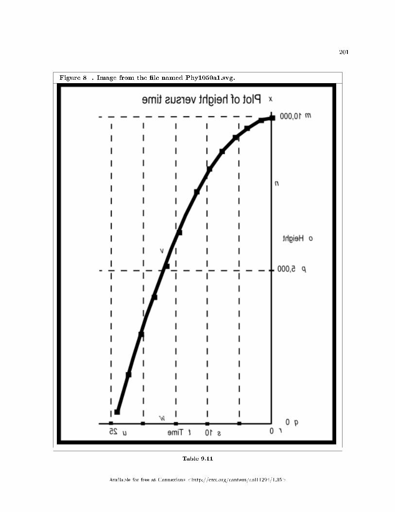
201
Figure 8 . Image from the �le named Phy1050a1.svg.
Table 9.11
Available for free at Connexions <http://cnx.org/content/col11294/1.35>

202 CHAPTER 9. UNITS AND DIMENSIONAL ANALYSIS
Key-value pairsHopefully, by now you are familiar with the concept of key-value pairs as used in these modules. If not,
please go back and study the section on Key-value pairs in conjunction with Figure 2 of the module namedManual Creation of Tactile Graphics 17 .
Figure 9 (p. 202) below contains the key-value table for the image shown in Figure 8 (p. 201) .
Figure 9 . Key-value table for the image shown in Figure 8.
m: 10,000
n: Vertical axis
o: Height
p: 5,000
q: 0
r: 0
s: 10
t: Time
u: 25
v: Height versus time curve
w: Horizontal axis
x: Plot of height versus time
Table 9.12
Change in height increases with timeGetting back to the height versus time values shown in Figure 7 (p. 197) and plotted on your graph
board or tactile graph, the value for height should decrease for each successive time value.However, the change in height should increase for each successive time interval until the height goes to
zero. The height goes to zero when the rock has landed on the ground somewhere between 24 and 26 seconds.It continues at zero after that.
(Note that I put code into the script to prevent the value of height from going negative.)The increase in the change in the height value during each successive time interval is the result of the
time being squared in the equation given earlier (p. 193) . It is also the result of the acceleration of gravitythat causes the downward speed of the rock to increase as the rock falls.
Analysis of the codeListing 3 (p. 196) calls a function copied from the previous exercise inside a while loop to compute
the distance traveled and the resulting height for a series of time values ranging from 0 to 30 seconds intwo-second intervals.
Those values are displayed as shown in Figure 7 (p. 197) .Understanding the code in Listing 2 (p. 194) and Listing 3 (p. 196) is important. However, it is more
important at this point that you understand the handling of units as shown in the comments in the code.
9.4.4 Non-mirror-image graphics
Figure 8 (p. 201) shows the actual mirror image contained in the �le named Phy1050a1.svg. Figure 10 (p.206) shows a non-mirror-image version of that same image.
17http://cnx.org/contents/9fe07552-485f-43e7-9753-87133cf60482/Phy1004-Manual-Creation-of-Tac
Available for free at Connexions <http://cnx.org/content/col11294/1.35>

203
Available for free at Connexions <http://cnx.org/content/col11294/1.35>
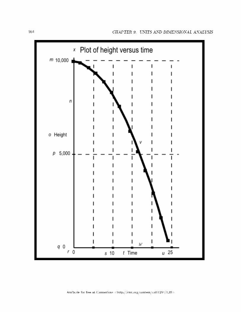
204 CHAPTER 9. UNITS AND DIMENSIONAL ANALYSIS
Available for free at Connexions <http://cnx.org/content/col11294/1.35>

205
Available for free at Connexions <http://cnx.org/content/col11294/1.35>

206 CHAPTER 9. UNITS AND DIMENSIONAL ANALYSIS
Figure 10 . Non-mirror-image version of the image from the �le named Phy1050a1.svg.
Table 9.13
Available for free at Connexions <http://cnx.org/content/col11294/1.35>
207
9.5 Run the scripts
I encourage you to run the scripts that I have presented in this lesson to con�rm that you get the sameresults. Copy the code for each script into a text �le with an extension of html. Then open that �le inyour browser. Experiment with the code, making changes, and observing the results of your changes. Makecertain that you can explain why your changes behave as they do.
9.6 Resources
I will publish a module containing consolidated links to resources on my Connexions web page and willupdate and add to the list as additional modules in this collection are published.
9.7 Miscellaneous
This section contains a variety of miscellaneous information.
Housekeeping material
• Module name: Units and Dimensional Analysis• File: Phy1050.htm• Revised: 10/01/15• Keywords:
· physics· accessible· blind· graph board· screen reader· Braille display· JavaScript· units· dimensional analysis· SI units· powers of ten· acceleration of gravity
Disclaimers: Financial : Although the openstax CNX site makes it possible for you todownload a PDF �le for the collection that contains this module at no charge, and also makes itpossible for you to purchase a pre-printed version of the PDF �le, you should be aware that someof the HTML elements in this module may not translate well into PDF.
You also need to know that Prof. Baldwin receives no �nancial compensation from openstaxCNX even if you purchase the PDF version of the collection.
In the past, unknown individuals have copied Prof. Baldwin's modules from cnx.org, convertedthem to Kindle books, and placed them for sale on Amazon.com showing Prof. Baldwin as theauthor. Prof. Baldwin neither receives compensation for those sales nor does he know who doesreceive compensation. If you purchase such a book, please be aware that it is a copy of a collectionthat is freely available on openstax CNX and that it was made and published without the priorknowledge of Prof. Baldwin.
A�liation : Prof. Baldwin is a professor of Computer Information Technology at AustinCommunity College in Austin, TX.
-end-
Available for free at Connexions <http://cnx.org/content/col11294/1.35>

208 CHAPTER 9. UNITS AND DIMENSIONAL ANALYSIS
Available for free at Connexions <http://cnx.org/content/col11294/1.35>

Chapter 10
Motion � Displacement and Vectors1
10.1 Table of Contents
• Preface (p. 209)
· General (p. 209)· Prerequisites (p. 210)· Viewing tip (p. 210)
* Figures (p. 210)* Listings (p. 211)
· Supplemental material (p. 211)
• General background information (p. 211)• Discussion and sample code (p. 212)
· Creation of tactile graphics (p. 212)· Displacement (p. 212)· Addition and subtraction of vectors (p. 223)· Mathematical solutions (p. 240)
* Using the Math.atan method (p. 241)* Mathematical solution to an earlier problem (p. 244)* Subtracting vectors (p. 247)* Adding more than two vectors (p. 247)
· Non-mirror-image graphics (p. 249)
• Run the scripts (p. 270)• Resources (p. 270)• Miscellaneous (p. 270)
10.2 Preface
10.2.1 General
This module is part of a collection of modules designed to make physics concepts accessible to blind students.If you opened this page in the context of the book, a Table of Contents for the book (or collection)
should be available above and to the left of this paragraph. Otherwise, click here 2 to open the book at thebeginning.
1This content is available online at <http://cnx.org/content/m37660/1.4/>.2http://cnx.org/contents/a7842db2-93c6-4c06-a5e3-56c282358143
Available for free at Connexions <http://cnx.org/content/col11294/1.35>
209

210 CHAPTER 10. MOTION � DISPLACEMENT AND VECTORS
This book is intended to supplement but not to replace the textbook in an introductory high school orcollege physics course.
The purpose of this module is to introduce motion and to explain displacement and vector analysis in aformat that is accessible to blind students.
10.2.2 Prerequisites
In addition to an Internet connection and a browser, you will need the following tools (as a minimum) towork through the exercises in these modules:
• A graph board for plotting graphs and vector diagrams (http://www.youtube.com/watch?v=c8plj9UsJbg 3 ).
• A protractor for measuring angles ( http://www.youtube.com/watch?v=v-F06HgiUpw 4 ).• An audio screen reader that is compatible with your operating system, such as the NonVisual Desktop
Access program (NVDA), which is freely available at http://www.nvda-project.org/ 5 .• A refreshable Braille display capable of providing a line by line tactile output of information displayed
on the computer monitor ( http://www.userite.com/ecampus/lesson1/tools.php 6 ).• The ability to create tactile graphics as described here 7 .
The minimum prerequisites for understanding the material in these modules include:
• A good understanding of algebra.• An understanding of the use of a graph board for plotting graphs and vector diagrams (
http://www.youtube.com/watch?v=c8plj9UsJbg 8 ).• An understanding of the use of a protractor for measuring angles (
http://www.youtube.com/watch?v=v-F06HgiUpw 9 ).• A basic understanding of the use of sine, cosine, and tangent from trigonometry (
http://www.clarku.edu/∼djoyce/trig/ 10 ).• An introductory understanding of JavaScript programming ( http://www.dickbaldwin.com/tocjscript1.htm
11 and http://www.w3schools.com/js/default.asp 12 ).• An understanding of all of the material covered in the earlier modules in this collection.• An understanding of the creation and use of tactile graphics as described here 13 .
10.2.3 Viewing tip
I recommend that you open another copy of this document in a separate browser window and use thefollowing links to easily �nd and view the �gures and listings while you are reading about them.
10.2.3.1 Figures
• Figure 1 (p. 213) . Key-value pairs for the image in Phy1060a1.svg.• Figure 2 (p. 217) . Mirror image contained in the �le named Phy1060a1.svg.• Figure 3 (p. 218) . Key-value pairs for the image in Phy1060b1.svg.
3http://www.youtube.com/watch?v=c8plj9UsJbg4http://www.youtube.com/watch?v=v-F06HgiUpw5http://www.nvda-project.org/6http://www.userite.com/ecampus/lesson1/tools.php7http://cnx.org/contents/9fe07552-485f-43e7-9753-87133cf604828http://www.youtube.com/watch?v=c8plj9UsJbg9http://www.youtube.com/watch?v=v-F06HgiUpw
10http://www.clarku.edu/∼djoyce/trig/11http://www.dickbaldwin.com/tocjscript1.htm12http://www.w3schools.com/js/default.asp13http://cnx.org/contents/9fe07552-485f-43e7-9753-87133cf60482
Available for free at Connexions <http://cnx.org/content/col11294/1.35>
211
• Figure 4 (p. 222) . Mirror image contained in the �le named Phy1060b1.svg.• Figure 5 (p. 224) . Key-value pairs for the image in Phy1060c1.svg.• Figure 6 (p. 228) . Mirror image contained in the �le named Phy1060c1.svg.• Figure 7 (p. 229) . Key-value pairs for the image in Phy1060d1.svg.• Figure 8 (p. 233) . Mirror image contained in the �le named Phy1060d1.svg.• Figure 9 (p. 235) . Key-value pairs for the image in Phy1060e1.svg.• Figure 10 (p. 239) . Mirror image contained in the �le named Phy1060e1.svg.• Figure 11 (p. 243) . Screen output for Listing #1.• Figure 12 (p. 246) . Screen output for Listing #2.• Figure 13 (p. 249) . Screen output for Listing #3.• Figure 14 (p. 253) . Non-mirror-image version of the image contained in the �le named Phy1060a1.svg.
• Figure 15 (p. 257) . Non-mirror-image version of the image contained in the �le named Phy1060b1.svg.
• Figure 16 (p. 261) . Non-mirror-image version of the image contained in the �le named Phy1060c1.svg.
• Figure 17 (p. 265) . Non-mirror-image version of the image contained in the �le named Phy1060d1.svg.
• Figure 18 (p. 269) . Non-mirror-image version of the mage contained in the �le named Phy1060e1.svg.
10.2.3.2 Listings
• Listing 1 (p. 242) . Using the Math.atan method.• Listing 2 (p. 245) . The sum of two vectors.• Listing 3 (p. 247) . The sum of four vectors.
10.2.4 Supplemental material
I recommend that you also study the other lessons in my extensive collection of online programming tutorials.You will �nd a consolidated index at www.DickBaldwin.com 14 .
10.3 General background information
Bodies - not a reference to peopleTo begin with, physics textbooks often refer to something called bodies . By this, they are not referring
to living bodies or the carcasses of once living creatures. Instead, they are referring to what people mightordinarily call objects.
For example, somewhere in this series of modules, we will discuss something call ed a free body diagram. A free body diagram can be drawn relative to any object, such as a child sitting motionless in a swing onthe playground or a piano hanging on a rope.
Rest and motionWhile nothing in the universe is truly motionless (at rest), some things around us such as buildings seem
to be at rest, while other things such as planes, trains, and busses appear to be in motion.There is no such thing as absolute rest. However, two bodies moving together at the same rate (with
reference to some third body) may be deemed to be at rest relative to one another.Therefore, if you are standing motionless on the Earth, you are at rest relative to the Earth with reference
to the Sun.Kinematics and kinetics
14http://www.dickbaldwin.com/toc.htm
Available for free at Connexions <http://cnx.org/content/col11294/1.35>

212 CHAPTER 10. MOTION � DISPLACEMENT AND VECTORS
The fundamental properties of motion are often referred to as kinematics . The relationships betweenmotion and force are often referred to as kinetics . These are the topics that will be covered in this andthe next several modules in this collection.
DisplacementIf one body is moved with respect to another body, either one of them may be said to have had a
displacement . Displacement, along with vector analysis will be the primary topics covered in thismodule.
10.4 Discussion and sample code
10.4.1 Creation of tactile graphics
The module titled Manual Creation of Tactile Graphics 15 explained how to create tactile graphics from svg�les that I will provide.
If you are going to have an assistant create tactile graphics for this module, you will need to downloadthe �le named Phy1060.zip 16 , which contains the svg �les for this module. Extract the svg �les from thezip �le and provide them to your assistant.
Also, if you are going to use tactile graphics, it probably won't be necessary for you to perform the graphboard exercises. However, you should still walk through the graph board exercises in your mind because Iwill often embed important physics concepts in the instructions for doing the graph board exercises.
In each case where I am providing an svg �le for the creation of tactile graphics, I will identify the nameof the appropriate svg �le and display an image of the contents of the �le for the bene�t of your assistant.As explained here 17 , those images will be mirror images of the actual images so that your assistant canemboss the image from the back of the paper and you can explore it from the front.
Also in those cases, I will provide a table of key-value pairs that explain how the Braille keys in the imagerelate to text or objects in the image.
10.4.2 Displacement
As mentioned above, if one body is moved with respect to another body, either one of them may be said tohave had a displacement .
Displacement is not the same as distanceAssume, for example, that you go to the local high school and run �ve laps around the track, stopping
exactly where you started. The distance that you have run will be the length of the path that you followedwhile running. However, while you may be completely out of breath by that point in time, the magnitudeof your displacement will have been zero.
Scalars versus vectorsDistance is a scalar quantity, while displacement is a vector quantity. Scalar quantities have only
magnitude, such as three kilometers.Vector quantities have two parts: magnitude and direction . For example, you might describe a
vector quantity as having a magnitude of three kilometers and a direction of northwest.Magnitude and directionA displacement vector must have both magnitude and direction. For example, if you were to run about
three-fourths of the way around the track, the distance that you ran would be the length of your path.However, the magnitude of your displacement would be the straight-line distance from your starting point
to your stopping point.The direction of your displacement would be an angle measured between some reference (such as due
east, for example) and an imaginary line connecting your starting point and your stopping point.
15http://cnx.org/contents/9fe07552-485f-43e7-9753-87133cf60482/Phy1004-Manual-Creation-of-Tac16http://cnx.org/content/m37660/latest/Phy1060.zip17http://cnx.org/contents/9fe07552-485f-43e7-9753-87133cf60482
Available for free at Connexions <http://cnx.org/content/col11294/1.35>

213
If you stop where you start...Getting back to the original proposition, if your stopping point is exactly the same as your starting point,
the magnitude of your displacement vector will be zero and the angle of your displacement vector will beindeterminate.
Vector notationAssume that there are three spots marked on the top of a table as A, B, and C. If an object is moved
from A to B and then from B to C, using vectors, it may be stated that:vecAC = vecAB + vecBCwhere vecAB, vecBC, and vecAC represent vectors.Typical notationA typical notation for a vector in a physics textbook is something like AB, possibly in boldface and/or
italics, with a small arrow drawn above the two letters. However, there is no such small arrow on a QWERTYkeyboard, and even if there were, it might not be compatible with your screen reader and/or your Brailledisplay.
My alternative notationTherefore, I will use the following notationvecABto indicate a vector extending from the spot labeled A to the spot labeled B.In order to determine direction in an unambiguous way, you often need to know where the vector starts
(the tail) and where it ends (the head). The notation used above indicates that the tail of the vector is atA and the head is at B.
In some cases, particularly in JavaScript code where a vector is de�ned by magnitude and directioninstead of by a starting point and an ending point, I will refer to a vector simply as
vecA, vecB, etc.A graph board exerciseThe svg �le for this exercise is named Phy1060a1.svg. The table of key-value pairs for this �le is provided
in Figure 1 (p. 213) .
Figure 1 . Key-value pairs for the image in Phy1060a1.svg.
m: vecAC = vecAB + vecBC
n: A
o: B
p: C
q: This is vector AB
r: This is vector BC
s: This is vector AC, which is the sum of the other two vectors
t: File: Phy1060a1.svg
Table 10.1
The image contained in this �le is shown in Figure 2 (p. 217) . A non-mirror-image version of the �le isshown in Figure 14 (p. 253) .
Available for free at Connexions <http://cnx.org/content/col11294/1.35>

214 CHAPTER 10. MOTION � DISPLACEMENT AND VECTORS
Available for free at Connexions <http://cnx.org/content/col11294/1.35>

215
Available for free at Connexions <http://cnx.org/content/col11294/1.35>
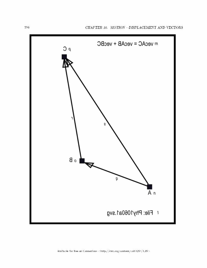
216 CHAPTER 10. MOTION � DISPLACEMENT AND VECTORS
Available for free at Connexions <http://cnx.org/content/col11294/1.35>
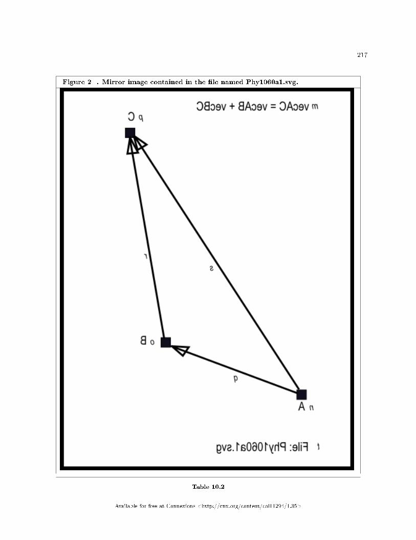
217
Figure 2 . Mirror image contained in the �le named Phy1060a1.svg.
Table 10.2
Available for free at Connexions <http://cnx.org/content/col11294/1.35>

218 CHAPTER 10. MOTION � DISPLACEMENT AND VECTORS
Graph board instructionsPlease mark three points on your graph board using pushpins and mentally label them A, B, and C.
Then use rubber bands, pipe cleaners, or whatever works best for you to connect them in such a way thatthey form a triangle. That triangle is a physical representation of the vector equation
vecAC = vecAB + vecBCWhat does this mean?This vector equation does not mean that the algebraic sum of two sides of the triangle are equal to the
third side. However, it does mean that the displacement vecAB together with the displacement vecBC, havean e�ect that is equivalent to the single displacement vector vecAC.
Scalar addition and subtractionWhen adding or subtracting scalars, you only need to take the magnitude values of the scalars into
account and perform normal arithmetic using those magnitude values. An example would be to add 6 birdsand 5 birds to produce a sum of 11 birds.
Vector addition and subtractionHowever, when adding or subtracting vectors, you not only need to take the magnitude of the vectors
into account, you also need to take the directions of the vectors into account.Another graph board exercise � a familiar exampleThe svg �le for this exercise is named Phy1060b1.svg. The table of key-value pairs for this �le is provided
in Figure 3 (p. 218) .
Figure 3 . Key-value pairs for the image in Phy1060b1.svg.
m: vecAC = vecAB + vecBC
n: C
o: North
p: Resultant vector A C
q: Displacement vector B C
r: Displacement vector A B
s: A
t: B
u: File: Phy1060b1.svg
v: East
Table 10.3
The image contained in this �le is shown in Figure 4 (p. 222) . A non-mirror-image version of the �le isshown in Figure 15 (p. 257) .
Available for free at Connexions <http://cnx.org/content/col11294/1.35>

219
Available for free at Connexions <http://cnx.org/content/col11294/1.35>

220 CHAPTER 10. MOTION � DISPLACEMENT AND VECTORS
Available for free at Connexions <http://cnx.org/content/col11294/1.35>

221
Available for free at Connexions <http://cnx.org/content/col11294/1.35>

222 CHAPTER 10. MOTION � DISPLACEMENT AND VECTORS
Figure 4 . Mirror image contained in the �le named Phy1060b1.svg.
Table 10.4
Available for free at Connexions <http://cnx.org/content/col11294/1.35>

223
Graph board instructionsPlace a pin in the graph board and mentally designate that point as point A. Now pretend that you walk
30 meters due east and place a pin at that point. Mentally designate that point as point B.Up to this point, your displacement can be represented by vecAB with a magnitude of 30 and an angle
of zero (assuming that due east represents an angle of zero).Walk 40 meters due northNow pretend that you walk 40 meters due north, mentally designate the stopping point as C, and place
a pin there. Your displacement relative to point B can be represented as vecBC with a magnitude of 40meters and a direction of north or 90 degrees.
Displacement relative to point AThe interesting question is, what is your displacement relative to your starting point at A?The displacement vector vecAC is the straight line from point A to point C, pointing in a direction from
A to C. This vector is shown in the vector equationvecAC = vecAB + vecBCas the sum of the two vectors that describe the two segments of your journey from A to C.Graphical addition of vectorsThis process of connecting two or more vectors tail-to-head in sequence and then measuring the distance
and direction from the tail of the �rst vector to the head of the last vector is known as the graphical additionof vectors. The resulting vector (in this case vecAC) is known as the sum of the vectors that make up thesequence. (The resulting vector is often called the resultant.)
A 3-4-5 triangleRecalling what we learned in an earlier module where I discussed a 3-4-5 triangle, the magnitude of the
vector from A to C (the hypotenuse of a right triangle with sides of 30 and 40) is 50 meters. I also recallthat the angle is approximately 53 degrees relative to the horizontal (east-west) line.
You should be able to measure the length of vecAC as well as the angle between that vector and thehorizontal and get reasonable agreement with the above.
No requirement for a right triangleWhile this example is based on a right triangle, that is not a requirement for adding vectors. I chose a
3-4-5 right triangle for the example because I knew what the answer would be in advance and also becauseit should have been familiar to you.
Graphic representation of vectorsMany problems in kinematics and kinetics can be solved graphically using a graphical representation of
vectors.Vectors are typically drawn as a heavy line between two points with an arrow head at one end and nothing
in particular at the other end. The end with the arrow head is commonly called the head of the vector andthe other end is commonly called the tail.
Vectors on a graph boardAs a blind student, you can't easily draw vectors, but you can represent vectors on your graph board by
connecting two pushpins with something straight (like a stretched rubber band) and using something tactileto mark the head.
(Perhaps you could use a pushpin with a cylindrical top to indicate the tail and a pushpin with a sphericaltop to represent the head. Another option might be to get some small buttons and place the pin at the headthrough one of the holes in the button.)
Somewhat inconvenientConstructing vectors on a graph board is less convenient for blind students than drawing them on graph
paper is for sighted students. Fortunately, as you will soon learn, it isn't necessary to use graphics to solvevector problems. You can also solve such problems mathematically, which will often be the better choice forblind students.
10.4.3 Addition and subtraction of vectors
There are at least two kinds of quantities in physics:
Available for free at Connexions <http://cnx.org/content/col11294/1.35>

224 CHAPTER 10. MOTION � DISPLACEMENT AND VECTORS
• scalars, having magnitude only• vectors, having both magnitude and direction
You already know how to do scalar arithmetic. Otherwise, you probably wouldn't be interested in physics.One textbook describes vectors as "straight lines, with proper directions, indicated by arrowheads, and
with lengths drawn to scale designated by vecAB (my notation), etc.Another exampleLet's go back to our original equationvecAC = vecAB + vecBCand assume that the magnitude of vecAB is 30 and the magnitude of vecBC is 40. The sum of those two
vectors (vecAC) can have a magnitude anywhere from 10 to 70 depending on the relative angles of vecABand vecBC.
A triangle with sides of 30, 4 0, and ?The svg �le for this exercise is named Phy1060c1.svg. The table of key-value pairs for this �le is provided
in Figure 5 (p. 224) .
Figure 5 . Key-value pairs for the image in Phy1060c1.svg.
m: vecAC = vecAB + vecBC
n: C
o: North
p: Resultant vector A C
q: Displacement vector B C
r: Displacement vector A B
s: A
t: B
u: File: Phy1060c1.svg
v: East
w: 135 degrees
Table 10.5
The image contained in this �le is shown in Figure 6 (p. 228) . A non-mirror-image version of the �le isshown in Figure 16 (p. 261) .
Available for free at Connexions <http://cnx.org/content/col11294/1.35>
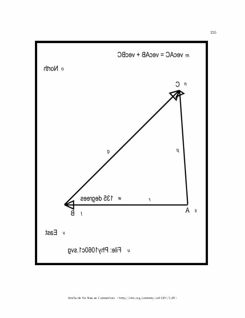
225
Available for free at Connexions <http://cnx.org/content/col11294/1.35>

226 CHAPTER 10. MOTION � DISPLACEMENT AND VECTORS
Available for free at Connexions <http://cnx.org/content/col11294/1.35>

227
Available for free at Connexions <http://cnx.org/content/col11294/1.35>

228 CHAPTER 10. MOTION � DISPLACEMENT AND VECTORS
Figure 6 . Mirror image contained in the �le named Phy1060c1.svg.
Table 10.6
Available for free at Connexions <http://cnx.org/content/col11294/1.35>
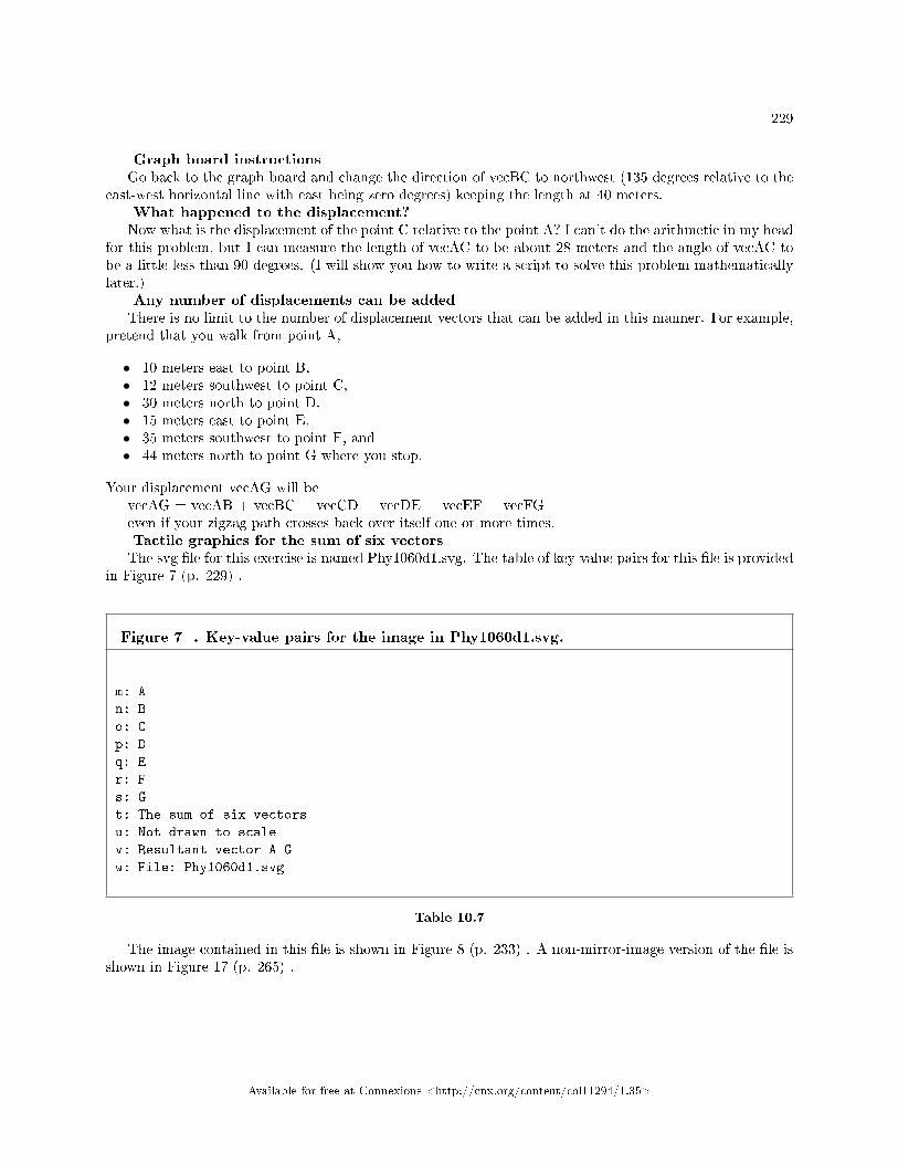
229
Graph board instructionsGo back to the graph board and change the direction of vecBC to northwest (135 degrees relative to the
east-west horizontal line with east being zero degrees) keeping the length at 40 meters.What happened to the displacement?Now what is the displacement of the point C relative to the point A? I can't do the arithmetic in my head
for this problem, but I can measure the length of vecAC to be about 28 meters and the angle of vecAC tobe a little less than 90 degrees. (I will show you how to write a script to solve this problem mathematicallylater.)
Any number of displacements can be addedThere is no limit to the number of displacement vectors that can be added in this manner. For example,
pretend that you walk from point A,
• 10 meters east to point B,• 12 meters southwest to point C,• 30 meters north to point D,• 15 meters east to point E,• 35 meters southwest to point F, and• 44 meters north to point G where you stop.
Your displacement vecAG will bevecAG = vecAB + vecBC + vecCD + vecDE + vecEF + vecFGeven if your zigzag path crosses back over itself one or more times.Tactile graphics for the sum of six vectorsThe svg �le for this exercise is named Phy1060d1.svg. The table of key-value pairs for this �le is provided
in Figure 7 (p. 229) .
Figure 7 . Key-value pairs for the image in Phy1060d1.svg.
m: A
n: B
o: C
p: D
q: E
r: F
s: G
t: The sum of six vectors
u: Not drawn to scale
v: Resultant vector A G
w: File: Phy1060d1.svg
Table 10.7
The image contained in this �le is shown in Figure 8 (p. 233) . A non-mirror-image version of the �le isshown in Figure 17 (p. 265) .
Available for free at Connexions <http://cnx.org/content/col11294/1.35>

230 CHAPTER 10. MOTION � DISPLACEMENT AND VECTORS
Available for free at Connexions <http://cnx.org/content/col11294/1.35>

231
Available for free at Connexions <http://cnx.org/content/col11294/1.35>

232 CHAPTER 10. MOTION � DISPLACEMENT AND VECTORS
Available for free at Connexions <http://cnx.org/content/col11294/1.35>

233
Figure 8 . Mirror image contained in the �le named Phy1060d1.svg.
Table 10.8
Available for free at Connexions <http://cnx.org/content/col11294/1.35>
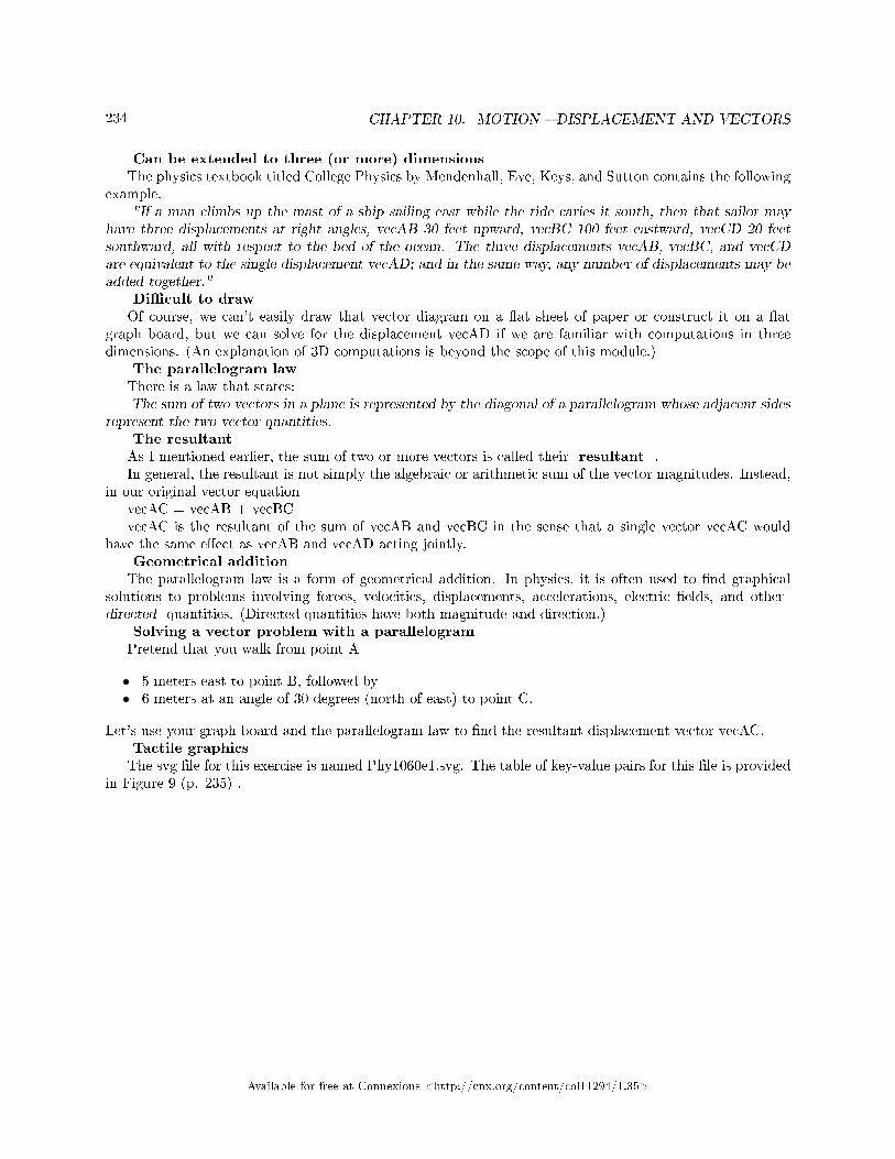
234 CHAPTER 10. MOTION � DISPLACEMENT AND VECTORS
Can be extended to three (or more) dimensionsThe physics textbook titled College Physics by Mendenhall, Eve, Keys, and Sutton contains the following
example."If a man climbs up the mast of a ship sailing east while the tide caries it south, then that sailor may
have three displacements at right angles, vecAB 30 feet upward, vecBC 100 feet eastward, vecCD 20 feetsouthward, all with respect to the bed of the ocean. The three displacements vecAB, vecBC, and vecCDare equivalent to the single displacement vecAD; and in the same way, any number of displacements may beadded together."
Di�cult to drawOf course, we can't easily draw that vector diagram on a �at sheet of paper or construct it on a �at
graph board, but we can solve for the displacement vecAD if we are familiar with computations in threedimensions. (An explanation of 3D computations is beyond the scope of this module.)
The parallelogram lawThere is a law that states:The sum of two vectors in a plane is represented by the diagonal of a parallelogram whose adjacent sides
represent the two vector quantities.The resultantAs I mentioned earlier, the sum of two or more vectors is called their resultant .In general, the resultant is not simply the algebraic or arithmetic sum of the vector magnitudes. Instead,
in our original vector equationvecAC = vecAB + vecBCvecAC is the resultant of the sum of vecAB and vecBC in the sense that a single vector vecAC would
have the same e�ect as vecAB and vecAD acting jointly.Geometrical additionThe parallelogram law is a form of geometrical addition. In physics, it is often used to �nd graphical
solutions to problems involving forces, velocities, displacements, accelerations, electric �elds, and otherdirected quantities. (Directed quantities have both magnitude and direction.)
Solving a vector problem with a parallelogramPretend that you walk from point A
• 5 meters east to point B, followed by• 6 meters at an angle of 30 degrees (north of east) to point C.
Let's use your graph board and the parallelogram law to �nd the resultant displacement vector vecAC.Tactile graphicsThe svg �le for this exercise is named Phy1060e1.svg. The table of key-value pairs for this �le is provided
in Figure 9 (p. 235) .
Available for free at Connexions <http://cnx.org/content/col11294/1.35>

235
Figure 9 . Key-value pairs for the image in Phy1060e1.svg.
m: Adding vectors using the parallelogram law.
n: B
o: C
p: A
q: Vector B C
r: Resultant vector
s: Vector A B
t: Line parallel to vector A B
u: Line parallel to vector B C
v: File: Phy1060e1.svg
Table 10.9
The image contained in this �le is shown in Figure 10 (p. 239) . A non-mirror-image version of the �leis shown in Figure 18 (p. 269) .
Available for free at Connexions <http://cnx.org/content/col11294/1.35>

236 CHAPTER 10. MOTION � DISPLACEMENT AND VECTORS
Available for free at Connexions <http://cnx.org/content/col11294/1.35>

237
Available for free at Connexions <http://cnx.org/content/col11294/1.35>

238 CHAPTER 10. MOTION � DISPLACEMENT AND VECTORS
Available for free at Connexions <http://cnx.org/content/col11294/1.35>

239
Figure 10 . Mirror image contained in the �le named Phy1060e1.svg.
Table 10.10
Available for free at Connexions <http://cnx.org/content/col11294/1.35>

240 CHAPTER 10. MOTION � DISPLACEMENT AND VECTORS
Put both vector tails at point AMentally designate the starting point on your graph board as point A. Construct a vector with a length
of 5 meters and an angle of 0 degrees relative to the horizontal with its tail at point A. Mentally designatethis vector as vecAB.
Construct a second vector with a length of 6 meters at an angle of 30 degrees with its tail at point A.Mentally designate this vector as vecBC.
Parallel linesNow comes the tricky part. Using a rubber band and a push pin, construct a line at least 6 meters long
starting at the head of vecBC. Make this line parallel to vecAB.(There are drawing tools that make it easy for sighted students to draw a line that is parallel to another
line. This is one reason why this is a popular technique for graphically adding vectors.)Construct another line, at least 7 meters long, starting at the head of vecAB. Make this line parallel to
vecBC.A parallelogramPush a pin into the graph board at the intersection of the two lines.The two lines and the two vectors should now form a parallelogram. In other words, you should now
have four pins located at the four corners of a parallelogram.Solving for the resultant vectorAccording to the parallelogram law, the resultant vector, vecAC, is represented by a directed line that
extends from point A to the intersection of the two lines that you constructed earlier. In other words, thesum of the two vectors is equal to a diagonal line that extends from the starting point to the opposite corneron the parallelogram that you constructed.
Subtracting vectorsIn normal arithmetic subtraction, a subtrahend is subtracted from a minuend to �nd a di�erence
.To subtract a subtrahend vector from a minuend vector (in a plane), add 180 degrees to the direction of
the subtrahend vector, causing it to point in the opposite direction, and add the modi�ed subtrahend vectorto the minuend vector.
If you subtract vecAB in the above example from vecBC, you should be able to show that the di�erencevector is represented by the other diagonal in the parallelogram. However, you will probably �nd it easierto do this mathematically rather than doing it graphically.
10.4.4 Mathematical solutions
The horizontal component of the sum of two or more vectors is the sum of the horizontal components of thevectors.
The vertical component of the sum of two or more vectors is the sum of the vertical components of thevectors.
The horizontal and vertical componentsThe horizontal and vertical components respectively of a vector vecAB are equal to
• vecABh = vecABmag * cos(angle)• vecABv = vecABmag * sin(angle)
where
• angle is the angle that the vector makes relative to the horizontal axis.• vecABh, vecABv, and vecABmag are respectively the horizontal component, the vertical component,
and the magnitude of the vector vecAB
The magnitude of the resultant vector
Available for free at Connexions <http://cnx.org/content/col11294/1.35>

241
Given the horizontal and vertical components of the resultant vector, the magnitude of the resultantvector can be found using the Pythagorean theorem as the square root of the sum of the squares of thehorizontal and vertical components.
The angle of the resultant vectorThe angle that the resultant vector makes with the horizontal axis is the arctangent (corrected for
quadrant) of the ratio of the vertical component to the horizontal component.
10.4.4.1 Using the Math.atan method
We will need to deal with several issues that arise when using the Math.atan method. Therefore, I will writea script that contains a function to deal with those issues. Then we can simply copy that function into futurescripts without having to consider those issues at that time.
Please copy the code shown in Listing 1 (p. 242) into an html �le and open the �le in your browser.
Available for free at Connexions <http://cnx.org/content/col11294/1.35>
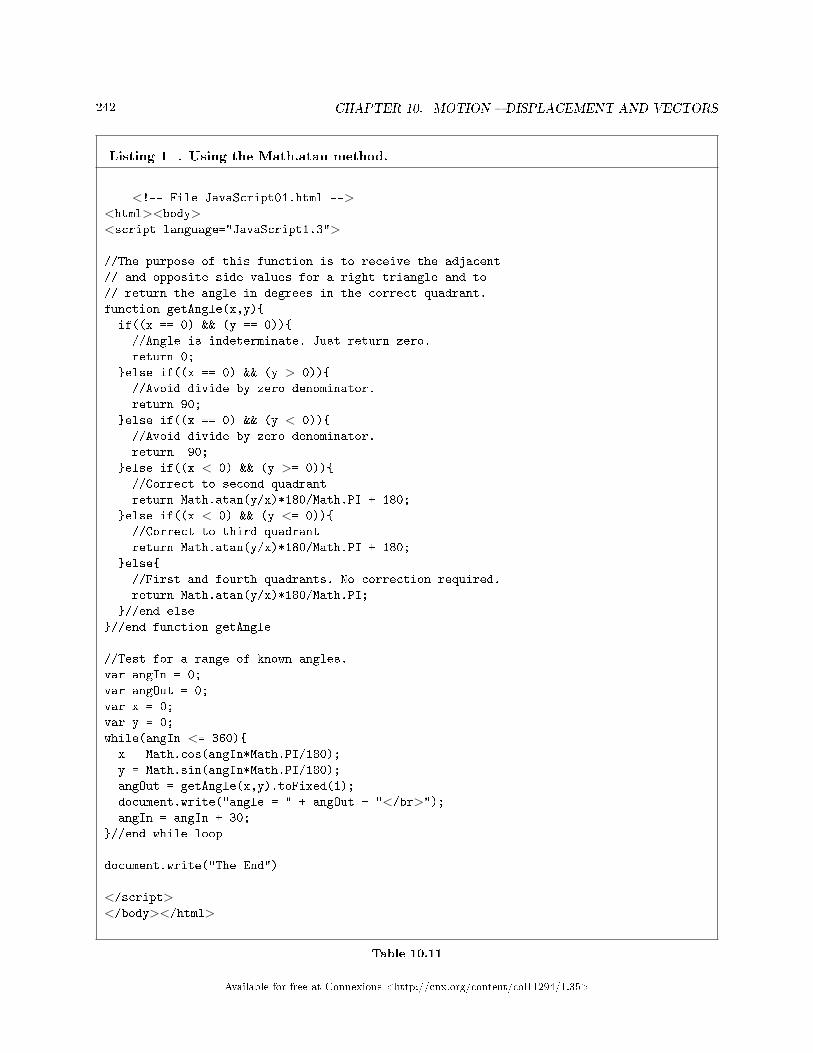
242 CHAPTER 10. MOTION � DISPLACEMENT AND VECTORS
Listing 1 . Using the Math.atan method.
<!-- File JavaScript01.html --><html><body><script language="JavaScript1.3">
//The purpose of this function is to receive the adjacent
// and opposite side values for a right triangle and to
// return the angle in degrees in the correct quadrant.
function getAngle(x,y){
if((x == 0) && (y == 0)){
//Angle is indeterminate. Just return zero.
return 0;
}else if((x == 0) && (y > 0)){
//Avoid divide by zero denominator.
return 90;
}else if((x == 0) && (y < 0)){
//Avoid divide by zero denominator.
return -90;
}else if((x < 0) && (y >= 0)){
//Correct to second quadrant
return Math.atan(y/x)*180/Math.PI + 180;
}else if((x < 0) && (y <= 0)){
//Correct to third quadrant
return Math.atan(y/x)*180/Math.PI + 180;
}else{
//First and fourth quadrants. No correction required.
return Math.atan(y/x)*180/Math.PI;
}//end else
}//end function getAngle
//Test for a range of known angles.
var angIn = 0;
var angOut = 0;
var x = 0;
var y = 0;
while(angIn <= 360){
x = Math.cos(angIn*Math.PI/180);
y = Math.sin(angIn*Math.PI/180);
angOut = getAngle(x,y).toFixed(1);
document.write("angle = " + angOut + "</br>");angIn = angIn + 30;
}//end while loop
document.write("The End")
</script></body></html>
Table 10.11
Available for free at Connexions <http://cnx.org/content/col11294/1.35>

243
The screen outputThe text shown in Figure 11 should appear in your browser window when you open the html �le in your
browser.
Figure 11 . Screen output for Listing #1.
angle = 0.0
angle = 30.0
angle = 60.0
angle = 90.0
angle = 120.0
angle = 150.0
angle = 180.0
angle = 210.0
angle = 240.0
angle = 270.0
angle = -60.0
angle = -30.0
angle = -0.0
The End
Table 10.12
Structure of the scriptThe script shown in Listing 1 (p. 242) begins by de�ning a function named getAngle . The purpose
of this function is to return an angle in degrees in the correct quadrant based on the lengths of the adjacentand opposite sides of an enclosing right triangle.
Then the script uses a while loop to test the function for a series of known angles ranging from 0 to360 degrees inclusive.
An indeterminate resultThe getAngle function calls the Math.atan method to compute the angle whose tangent is the ratio of
the opposite side (y) to the adjacent side (x) of a right triangle.If both x and y are zero, the ratio y/x is indeterminate and the value of the angle cannot be computed.
In fact there is no angle corresponding to the ratio 0/0. However, the function must either return the valueof an angle, or must return some sort of �ag indicating that computation of the angle is not possible.
In this case, the function simply returns the value zero for the angle.Avoiding division by zeroIf the value of x is zero and the value of y is not zero, the ratio y/x is in�nite. Therefore, the value of the
angle cannot be computed. However, in this case, the angle is known to be 90 degrees (for y greater thanzero) or 270 degrees (-90 degrees, for y less than zero). The getAngle function traps both of those cases andreturns the correct angle in each case.
Correcting for the quadrantThe Math.atan method receives one parameter and it is either a positive or negative value. If the value is
positive, the method returns an angle between 0 and 90 degrees. If the value is negative, the method returnsan angle between 0 and -90 degrees. Thus, the angles returned by the Math.atan method always lie in the�rst or fourth quadrants.
(Actually, as I mentioned earlier, +90 degrees and -90 degrees are not possible because the tangent of+90 degrees or -90 degrees is an in�nitely large positive or negative value. However, the method can handleangles that are very close to +90 or -90 degrees.)
Available for free at Connexions <http://cnx.org/content/col11294/1.35>

244 CHAPTER 10. MOTION � DISPLACEMENT AND VECTORS
A negative y/x ratioIf the y/x ratio is negative, this doesn't necessarily mean that the angle lies in the fourth quadrant. That
negative ratio could result from a positive value for y and a negative value for x. In that case, the anglewould lie in the second quadrant between 90 degrees and 180 degrees.
The getAngle function tests the signs of the values for y and x. If the signs indicate that the angle lies inthe second quadrant, the value returned from the Math.atan method is corrected to place the angle in thesecond quadrant. The corrected angle is returned by the getAngle function.
A positive y/x ratioSimilarly, if the y/x ratio is positive, this doesn't necessarily mean that the angle lies in the �rst quadrant.
That positive ratio could result from a negative y value and a negative x value. In that case, the angle wouldlie in the third quadrant between 180 degrees and 270 degrees.
Again, the getAngle function tests the signs of the values for y and x. If both values are negative, thevalue returned from the Math.atan method is corrected to place the angle in the third quadrant.
No corrections required...Finally, if no corrections are required for the quadrant, the getAngle function returns the value returned
by the Math.atan method. Note however, that in all cases, the Math.atan method returns the angle inradians. That value is converted to degrees by the getAngle function and the returned value is in degrees.
Positive and negative anglesAs you can see from the results of the test shown in Figure 11 , angles in the �rst, second, and third
quadrants are returned as positive angles in degrees. However, angles in the fourth quadrant are returnedas negative angles in degrees.
10.4.4.2 Mathematical solution to an earlier problem
Earlier (p. 224) in this module, I described a problem involving the sum of two displacement vectors. Onevector had a magnitude of 30 meters with an angle of 0. The other vector had a magnitude of 40 meterswith an angle of 135 degrees.
On the basis of a graphic solution, I estimated the length of the resultant vector to be about 28 metersand the angle of the resultant vector to be a little less than 90 degrees. I promised to provide a mathematicalsolution for that problem later, and that time has come.
Please copy the code shown in Listing 2 (p. 245) into an html �le and open that �le in your browser.
Available for free at Connexions <http://cnx.org/content/col11294/1.35>

245
Listing 2 . The sum of two vectors.
<!-- File JavaScript02.html --><html><body><script language="JavaScript1.3">
//The purpose of this function is to receive the adjacent
// and opposite side values for a right triangle and to
// return the angle in degrees in the correct quadrant.
function getAngle(x,y){
if((x == 0) && (y == 0)){
//Angle is indeterminate. Just return zero.
return 0;
}else if((x == 0) && (y > 0)){
//Avoid divide by zero denominator.
return 90;
}else if((x == 0) && (y < 0)){
//Avoid divide by zero denominator.
return -90;
}else if((x < 0) && (y >= 0)){
//Correct to second quadrant
return Math.atan(y/x)*180/Math.PI + 180;
}else if((x < 0) && (y <= 0)){
//Correct to third quadrant
return Math.atan(y/x)*180/Math.PI + 180;
}else{
//First and fourth quadrants. No correction required.
return Math.atan(y/x)*180/Math.PI;
}//end else
}//end function getAngle
//Specify the magnitudes and angles of two vectors.
//Convert the angles from degrees to radians.
var vecABmag = 30;//at an angle of 0
var vecABang = 0*Math.PI/180;//degrees*radians/degrees=radians
var vecBCmag = 40;//at an angle of 135
var vecBCang = 135*Math.PI/180;//degrees*radians/degrees=radians
//Compute the horizontal and vertical components of each vector.
var vecABh = vecABmag*Math.cos(vecABang);
var vecABv = vecABmag*Math.sin(vecABang);
var vecBCh = vecBCmag*Math.cos(vecBCang);
var vecBCv = vecBCmag*Math.sin(vecBCang);
//Compute the sums of the horizontal and vertical components from
// the two vectors to get the horizontal and vertical component
// of the resultant vector.
var vecResultH = vecABh + vecBCh;
var vecResultV = vecABv + vecBCv;
//Use the Pythagorean theorem to compute the magnitude of the
// resultant vector.
var vecResultMag = Math.sqrt(Math.pow(vecResultH,2) +
Math.pow(vecResultV,2));
//Compute the angle of the resultant.
vecResultAng = getAngle(vecResultH,vecResultV);
document.write("Hello from JavaScript" + "</br>")document.write("vecABv = " + vecABv + "</br>");document.write("vecABh = " + vecABh + "</br>");document.write("vecBCv = " + vecBCv + "</br>");document.write("vecBCh = " + vecBCh + "</br>");document.write("vecResultMag = " + vecResultMag + " </br>");document.write("vecResultAng = " + vecResultAng + " </br>");
document.write("The End")
</script></body></html>
Available for free at Connexions <http://cnx.org/content/col11294/1.35>

246 CHAPTER 10. MOTION � DISPLACEMENT AND VECTORS
Table 10.13
Screen outputWhen you open the html �le in your browser, the text shown in Figure 12 should appear in your browser
window.
Figure 12 . Screen output for Listing #2.
Hello from JavaScript
vecABv = 0
vecABh = 30
vecBCv = 28.284271247461902
vecBCh = -28.2842712474619
vecResultMag = 28.336261665087125
vecResultAng = 86.5286817554714
The End
Table 10.14
Explanation of the codeListing 2 (p. 245) begins with a copy of the getAngle method that I explained in conjunction with Listing
1 (p. 242) . I won't repeat that explanation here.De�ne magnitudes and angles of vectorsThen Listing 2 (p. 245) declares and initializes four variables that represent the magnitude and angle of
each of the two vectors. The variable names that end with "mag" contain magnitude values and the variablenames that end with "ang" contain angle values, which are converted from degrees to radians.
Compute horizontal and vertical componentsThen Listing 2 (p. 245) calls the Math.cos and Math.sin methods to compute the horizontal and vertical
components of each vector. The variable names that end with "h" contain horizontal component values andthe variable names that end with "v" contain vertical component values.
Compute the sums of the componentsThe procedure for adding two or more vectors is to
• Add the horizontal components of all the vectors to get the horizontal component of the resultantvector.
• Add the vertical components of all the vectors to get the vertical component of the resultant vector.• Compute the magnitude (if needed) of the resultant vector as the square root of the sum of the
squares of the horizontal and vertical components.• Compute the angle (if needed) of the resultant vector as the arctangent of the ratio of the vertical
component and the horizontal component.
Listing 2 (p. 245) computes the sum of the horizontal components from each of the vectors and saves theresult in the variable named vecResultH . Then it computes the sum of the vertical components andsaves the result in the variable named vecResultV .
Compute the magnitude of the resultantIn many cases, simply knowing the horizontal and vertical components is the solution to the problem.
However, in some cases, it is necessary to convert those components into a magnitude and an angle.There are a couple of ways to compute the magnitude. One way is to use the Pythagorean theorem as
described above (p. 246) to compute the square root of the sum of the squares of the horizontal and verticalcomponents.
Available for free at Connexions <http://cnx.org/content/col11294/1.35>

247
The Math.sqrt and Math.pow methodsThe method named Math.sqrt can be called to return the square root of its positive argument. (If the
argument is negative, the method returns NaN, which is an abbreviation for "Not a Number".)The method named Math.pow can be called to raise the value speci�ed by the �rst argument to the
power speci�ed by the second argument.Listing 2 (p. 245) calls those two methods to compute the magnitude of the resultant and to save that
value in the variable named vecResultMag .Compute the angle of the resultantThen Listing 2 (p. 245) calls the getAngle method that we developed earlier to get the angle of the
resultant and to save the angle in degrees in the variable named vecResultAng .Display the resultsFinally Listing 2 (p. 245) calls the document.write method several times in succession to display the
values stored in some of the variables mentioned above in the browser window as shown in Figure 12 . Asyou can see, the magnitude and angle of the resultant agrees with the estimate that I made using the graphicmethod earlier.
10.4.4.3 Subtracting vectors
To subtract one vector from another using the mathematical approach, simply reverse the algebraic sign onthe horizontal and vertical components for the subtrahend vector and perform the addition shown in Listing2 (p. 245) .
10.4.4.4 Adding more than two vectors
Let's work through a problem that requires the addition of four vectors.A graphical solutionFirst I would like for you to lay out the vectors, tail-to-head on your graph board to create a solution to
this problem.Pretend that you take a walk consisting of the following sequential segments. Angles are speci�ed relative
to east with east being zero degrees. Positive angles are counter-clockwise and negative angles are clockwise.The segments are as follows:
• 12 meters at 20 degrees• 8 meters at 120 degrees• 10.5 meters at -74 degrees• 12.5 meters at 145 degrees
What is your �nal displacement?When you reach the end of the walk, what is your displacement (distance and direction) relative to
the location at which you began the walk. You should be able to do a reasonable job of measuring thedisplacement using your graph board.
A mathematical solutionPlease copy the code shown in Listing 3 (p. 247) into an html �le and open the html �le in your browser.
Listing 3 . The sum of four vectors.
continued on next page
Available for free at Connexions <http://cnx.org/content/col11294/1.35>

248 CHAPTER 10. MOTION � DISPLACEMENT AND VECTORS
<!-- File JavaScript03.html --><html><body><script language="JavaScript1.3">
//The purpose of this function is to receive the adjacent
// and opposite side values for a right triangle and to
// return the angle in degrees in the correct quadrant.
function getAngle(x,y){
if((x == 0) && (y == 0)){
//Angle is indeterminate. Just return zero.
return 0;
}else if((x == 0) && (y > 0)){
//Avoid divide by zero denominator.
return 90;
}else if((x == 0) && (y < 0)){
//Avoid divide by zero denominator.
return -90;
}else if((x < 0) && (y >= 0)){
//Correct to second quadrant
return Math.atan(y/x)*180/Math.PI + 180;
}else if((x < 0) && (y <= 0)){
//Correct to third quadrant
return Math.atan(y/x)*180/Math.PI + 180;
}else{
//First and fourth quadrants. No correction required.
return Math.atan(y/x)*180/Math.PI;
}//end else
}//end function getAngle
//Specify the magnitudes and angles of four vectors.
//Convert the angles from degrees to radians.
var vecAmag = 12;
var vecAang = 20*Math.PI/180;//degrees*radians/degrees=radians
var vecBmag = 8;
var vecBang = 120*Math.PI/180;//degrees*radians/degrees=radians
var vecCmag = 10.5;
var vecCang = -74*Math.PI/180;//degrees*radians/degrees=radians
var vecDmag = 12.5;
var vecDang = 145*Math.PI/180;//degrees*radians/degrees=radians
//Compute the horizontal and vertical components of each vector.
var vecAh = vecAmag*Math.cos(vecAang);
var vecAv = vecAmag*Math.sin(vecAang);
var vecBh = vecBmag*Math.cos(vecBang);
var vecBv = vecBmag*Math.sin(vecBang);
var vecCh = vecCmag*Math.cos(vecCang);
var vecCv = vecCmag*Math.sin(vecCang);
var vecDh = vecDmag*Math.cos(vecDang);
var vecDv = vecDmag*Math.sin(vecDang);
//Compute the sums of the horizontal and vertical components from
// the four vectors to get the horizontal and vertical component
// of the resultant vector.
var vecResultH = vecAh + vecBh + vecCh + vecDh;
var vecResultV = vecAv + vecBv + vecCv + vecDv;
//Use the Pythagorean theorem to compute the magnitude of the
// resultant vector.
var vecResultMag = Math.sqrt(Math.pow(vecResultH,2) +
Math.pow(vecResultV,2));
//Compute the angle of the resultant vector.
vecResultAng = getAngle(vecResultH,vecResultV);
document.write("Hello from JavaScript" + "</br>")document.write(
"vecResultMag = " + vecResultMag.toFixed(2) + " </br>");document.write(
"vecResultAng = " + vecResultAng.toFixed(2) + " </br>");
document.write("The End")
</script></body></html>
Available for free at Connexions <http://cnx.org/content/col11294/1.35>

249
Table 10.15
Screen outputThe text shown in Figure 13 should appear in your browser when you open the html �le in your browser.
Figure 13 . Screen output for Listing #3.
Hello from JavaScript
vecResultMag = 8.11
vecResultAng = 90.49
The End
Table 10.16
As you can see, the displacement vector is just a little over eight meters at an angle of about 90.5 degrees.In other words, your ending position was approximately 8 meters north of your starting position. Hopefullyyou were able to arrive at a very similar answer using your graph board.
Explanation of the codeThe code in Listing 3 (p. 247) is very similar to the code in Listing 2 (p. 245) . However, there is more
of it because the code is adding four vectors instead of only 2.As before, Listing 2 (p. 245) begins with the getAngle method that we developed earlier.Magnitude and angle for each vectorThen Listing 2 (p. 245) de�nes eight variables containing the magnitudes and angles of the four segments
of the walk.(Note that the names that I used for the variables in this script are somewhat simpler than the names
that I used in Listing 2.)Horizontal and vertical componentsFollowing that, Listing 2 (p. 245) computes the horizontal and vertical components for each of the four
vectors and saves those values in eight di�erent variables.Sums of componentsThen Listing 2 (p. 245) computes and saves the sum of all four horizontal components and computes
and saves the sum of all four vertical components.After that, there is essentially no di�erence between the script in Listing 3 (p. 247) and the script in
Listing 2 (p. 245) .Other vector operationsIn addition to the addition and subtraction of vectors, there are other operations that can be performed
using vectors, such as the dot product and the cross product. However, those operations are beyond thescope of this module.
10.4.5 Non-mirror-image graphics
Figure 14 (p. 253) through Figure 18 (p. 269) below are non-mirror-image versions of Figure 2 (p. 217) ,Figure 4 (p. 222) , Figure 6 (p. 228) , Figure 8 (p. 233) , and Figure 10 (p. 239) .
Available for free at Connexions <http://cnx.org/content/col11294/1.35>

250 CHAPTER 10. MOTION � DISPLACEMENT AND VECTORS
Available for free at Connexions <http://cnx.org/content/col11294/1.35>

251
Available for free at Connexions <http://cnx.org/content/col11294/1.35>

252 CHAPTER 10. MOTION � DISPLACEMENT AND VECTORS
Available for free at Connexions <http://cnx.org/content/col11294/1.35>

253
Figure 14 . Non-mirror-image version of the image contained in the �le named Phy1060a1.svg.
Table 10.17
Available for free at Connexions <http://cnx.org/content/col11294/1.35>

254 CHAPTER 10. MOTION � DISPLACEMENT AND VECTORS
Available for free at Connexions <http://cnx.org/content/col11294/1.35>

255
Available for free at Connexions <http://cnx.org/content/col11294/1.35>

256 CHAPTER 10. MOTION � DISPLACEMENT AND VECTORS
Available for free at Connexions <http://cnx.org/content/col11294/1.35>

257
Figure 15 . Non-mirror-image version of the image contained in the �le named Phy1060b1.svg.
Table 10.18
Available for free at Connexions <http://cnx.org/content/col11294/1.35>

258 CHAPTER 10. MOTION � DISPLACEMENT AND VECTORS
Available for free at Connexions <http://cnx.org/content/col11294/1.35>
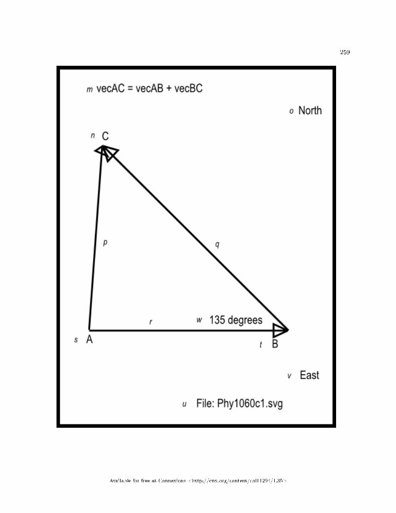
259
Available for free at Connexions <http://cnx.org/content/col11294/1.35>
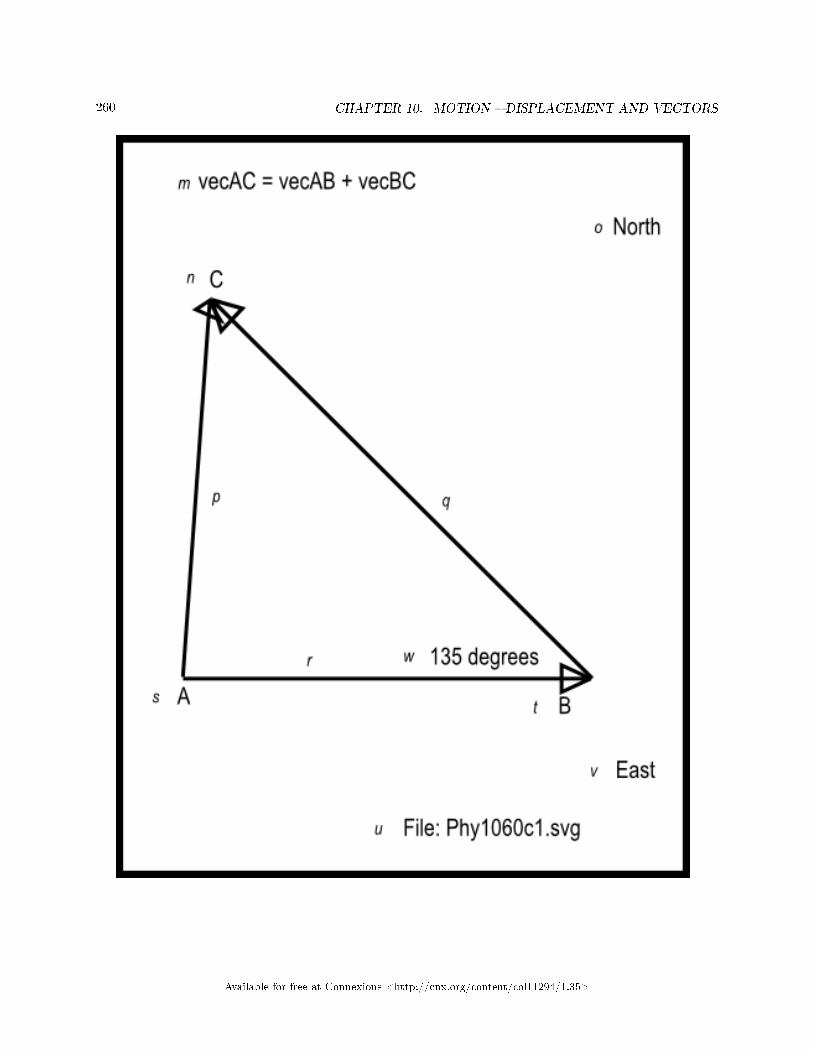
260 CHAPTER 10. MOTION � DISPLACEMENT AND VECTORS
Available for free at Connexions <http://cnx.org/content/col11294/1.35>

261
Figure 16 . Non-mirror-image version of the image contained in the �le named Phy1060c1.svg.
Table 10.19
Available for free at Connexions <http://cnx.org/content/col11294/1.35>

262 CHAPTER 10. MOTION � DISPLACEMENT AND VECTORS
Available for free at Connexions <http://cnx.org/content/col11294/1.35>

263
Available for free at Connexions <http://cnx.org/content/col11294/1.35>

264 CHAPTER 10. MOTION � DISPLACEMENT AND VECTORS
Available for free at Connexions <http://cnx.org/content/col11294/1.35>

265
Figure 17 . Non-mirror-image version of the image contained in the �le named Phy1060d1.svg.
Table 10.20
Available for free at Connexions <http://cnx.org/content/col11294/1.35>

266 CHAPTER 10. MOTION � DISPLACEMENT AND VECTORS
Available for free at Connexions <http://cnx.org/content/col11294/1.35>

267
Available for free at Connexions <http://cnx.org/content/col11294/1.35>

268 CHAPTER 10. MOTION � DISPLACEMENT AND VECTORS
Available for free at Connexions <http://cnx.org/content/col11294/1.35>

269
Figure 18 . Non-mirror-image version of the mage contained in the �le named Phy1060e1.svg.
Table 10.21
Available for free at Connexions <http://cnx.org/content/col11294/1.35>

270 CHAPTER 10. MOTION � DISPLACEMENT AND VECTORS
10.5 Run the scripts
I encourage you to run the scripts that I have presented in this lesson to con�rm that you get the sameresults. Copy the code for each script into a text �le with an extension of html. Then open that �le inyour browser. Experiment with the code, making changes, and observing the results of your changes. Makecertain that you can explain why your changes behave as they do.
10.6 Resources
I will publish a module containing consolidated links to resources on my Connexions web page and willupdate and add to the list as additional modules in this collection are published.
10.7 Miscellaneous
This section contains a variety of miscellaneous information.
Housekeeping material
• Module name: Motion � Displacement and Vectors for Blind Students• File: Phy1060.htm• Revised: 10/01/15• Keywords:
· physics· accessible· blind· graph board· protractor· screen reader· refreshable Braille display· JavaScript· trigonometry· motion· rest· body· displacement· velocity· acceleration· kinematics· kinetics· resultant· subtrahend· minuend
Disclaimers: Financial : Although the openstax CNX site makes it possible for you todownload a PDF �le for the collection that contains this module at no charge, and also makes itpossible for you to purchase a pre-printed version of the PDF �le, you should be aware that someof the HTML elements in this module may not translate well into PDF.
You also need to know that Prof. Baldwin receives no �nancial compensation from openstaxCNX even if you purchase the PDF version of the collection.
Available for free at Connexions <http://cnx.org/content/col11294/1.35>

271
In the past, unknown individuals have copied Prof. Baldwin's modules from cnx.org, convertedthem to Kindle books, and placed them for sale on Amazon.com showing Prof. Baldwin as theauthor. Prof. Baldwin neither receives compensation for those sales nor does he know who doesreceive compensation. If you purchase such a book, please be aware that it is a copy of a collectionthat is freely available on openstax CNX and that it was made and published without the priorknowledge of Prof. Baldwin.
A�liation : Prof. Baldwin is a professor of Computer Information Technology at AustinCommunity College in Austin, TX.
-end-
Available for free at Connexions <http://cnx.org/content/col11294/1.35>

272 CHAPTER 10. MOTION � DISPLACEMENT AND VECTORS
Available for free at Connexions <http://cnx.org/content/col11294/1.35>

Chapter 11
Motion � Uniform and Relative Velocity1
11.1 Table of Contents
• Preface (p. 273)
· General (p. 273)· Prerequisites (p. 274)· Viewing tip (p. 274)
* Figures (p. 274)* Listings (p. 275)
· Supplemental material (p. 275)
• General background information (p. 275)• Discussion and sample code (p. 276)
· Creation of tactile graphics (p. 276)· A simple exercise on uniform velocity (p. 276)· An exercise on average velocity (p. 279)· Multiple concurrent velocities (p. 287)
* Exercise #1 for a man on a train (p. 287)* Exercise #2 for a man on a train (p. 296)* An exercise with three vectors in a plane (p. 301)
· Non-mirror-image graphics (p. 307)
• Run the scripts (p. 323)• Resources (p. 323)• Miscellaneous (p. 323)
11.2 Preface
11.2.1 General
This module is part of a collection of modules designed to make physics concepts accessible to blind students.If you opened this page in the context of the book, a Table of Contents for the book (or collection)
should be available above and to the left of this paragraph. Otherwise, click here 2 to open the book at thebeginning.
1This content is available online at <http://cnx.org/content/m38042/1.4/>.2http://cnx.org/contents/a7842db2-93c6-4c06-a5e3-56c282358143
Available for free at Connexions <http://cnx.org/content/col11294/1.35>
273

274 CHAPTER 11. MOTION � UNIFORM AND RELATIVE VELOCITY
This book is intended to supplement but not to replace the textbook in an introductory high school orcollege physics course.
The purpose of this module is to explain uniform velocity and relative velocity in a format that isaccessible to blind students.
11.2.2 Prerequisites
In addition to an Internet connection and a browser, you will need the following tools (as a minimum) towork through the exercises in these modules:
• A graph board for plotting graphs and vector diagrams (http://www.youtube.com/watch?v=c8plj9UsJbg 3 ).
• A protractor for measuring angles ( http://www.youtube.com/watch?v=v-F06HgiUpw 4 ).• An audio screen reader that is compatible with your operating system, such as the NonVisual Desktop
Access program (NVDA), which is freely available at http://www.nvda-project.org/ 5 .• A refreshable Braille display capable of providing a line by line tactile output of information displayed
on the computer monitor ( http://www.userite.com/ecampus/lesson1/tools.php 6 ).• A device to create Braille labels. Will be used to label graphs constructed on the graph board.• The ability to create tactile graphics as described here 7 .
The minimum prerequisites for understanding the material in these modules include:
• A good understanding of algebra.• An understanding of the use of a graph board for plotting graphs and vector diagrams (
http://www.youtube.com/watch?v=c8plj9UsJbg 8 ).• An understanding of the use of a protractor for measuring angles (
http://www.youtube.com/watch?v=v-F06HgiUpw 9 ).• A basic understanding of the use of sine, cosine, and tangent from trigonometry (
http://www.clarku.edu/∼djoyce/trig/ 10 ).• An introductory understanding of JavaScript programming ( http://www.dickbaldwin.com/tocjscript1.htm
11 and http://www.w3schools.com/js/default.asp 12 ).• An understanding of all of the material covered in the earlier modules in this collection.• An understanding of the creation and use of tactile graphics as described here 13 .
11.2.3 Viewing tip
I recommend that you open another copy of this document in a separate browser window and use thefollowing links to easily �nd and view the �gures and listings while you are reading about them.
11.2.3.1 Figures
• Figure 1 (p. 278) . Screen output for Listing #1.• Figure 2 (p. 279) . Key-value pairs for the image in Phy1070a1.svg.
3http://www.youtube.com/watch?v=c8plj9UsJbg4http://www.youtube.com/watch?v=v-F06HgiUpw5http://www.nvda-project.org/6http://www.userite.com/ecampus/lesson1/tools.php7http://cnx.org/contents/9fe07552-485f-43e7-9753-87133cf604828http://www.youtube.com/watch?v=c8plj9UsJbg9http://www.youtube.com/watch?v=v-F06HgiUpw
10http://www.clarku.edu/∼djoyce/trig/11http://www.dickbaldwin.com/tocjscript1.htm12http://www.w3schools.com/js/default.asp13http://cnx.org/contents/9fe07552-485f-43e7-9753-87133cf60482
Available for free at Connexions <http://cnx.org/content/col11294/1.35>

275
• Figure 3 (p. 283) . Mirror image contained in the �le named Phy1070a1.svg.• Figure 4 (p. 286) . Screen output for Listing #2.• Figure 5 (p. 288) . Key-value pairs for the image in Phy1070b1.svg.• Figure 6 (p. 291) . Mirror image contained in the �le named Phy1070b1.svg.• Figure 7 (p. 293) . Screen output for Listing #3.• Figure 8 (p. 296) . Key-value pairs for the image in Phy1070c1.svg.• Figure 9 (p. 300) . Mirror image contained in the �le named Phy1070c1.svg.• Figure 10 (p. 301) . Screen output for Exercise #2 for a man on a train.• Figure 11 (p. 301) .Key-value pairs for the image in Phy1070d1.svg.• Figure 12 (p. 305) .Mirror image contained in the �le named Phy1070d1.svg.• Figure 13 (p. 307) . Screen output for Listing #4.• Figure 14 (p. 311) . Non-mirror-image contained in the �le named Phy1070a1.svg.• Figure 15 (p. 315) . Non-mirror-image contained in the �le named Phy1070b1.svg.• Figure 16 (p. 319) . Non-mirror-image contained in the �le named Phy1070c1.svg.• Figure 17 (p. 323) . Non-mirror-image contained in the �le named Phy1070d1.svg.
11.2.3.2 Listings
• Listing 1 (p. 278) . A simple exercise on uniform velocity.• Listing 2 (p. 285) . An exercise on average velocity.• Listing 3 (p. 292) . Exercise #1 for a man on a train.• Listing 4 (p. 306) . An exercise with three vectors in a plane.
11.2.4 Supplemental material
I recommend that you also study the other lessons in my extensive collection of online programming tutorials.You will �nd a consolidated index at www.DickBaldwin.com 14 .
11.3 General background information
What is velocity?Velocity is the time rate of change of position. Since displacement is the change of position, velocity is
also the rate of displacement. Since displacement is a vector quantity, velocity is also a vector quantity � ithas magnitude and direction.
An airplane may traverse 350 miles in a northeasterly direction in one hour. This statement describes avector quantity (velocity) because it has both magnitude and direction.
The same airplane may traverse 350 miles in a southwesterly direction in one hour. This statementdescribes a di�erent velocity. Even though the magnitude is the same in both cases, the direction is di�erent.Hence, the velocity is di�erent.
What is speed?Speed is distance covered in a unit of time without reference to direction. Since there is no reference to
direction, speed is a scalar quantity.A car may traverse 60 miles in one hour. An airplane may traverse 350 miles in one hour. An excellent
runner may traverse one mile in three minutes. All of these statements describe scalar quantities (speed)since there is no reference to direction.
A person in a seat on a Ferris wheel may travel around the axle in the center of the wheel at a constantrotational speed. However, that person's velocity is not constant. The velocity is continually changingbecause the direction of motion is continually changing.
14http://www.dickbaldwin.com/toc.htm
Available for free at Connexions <http://cnx.org/content/col11294/1.35>

276 CHAPTER 11. MOTION � UNIFORM AND RELATIVE VELOCITY
Uniform velocityVelocity is uniform when equal distances along a straight line are traversed in equal intervals of time. In
this casev = s/twhere
• v is uniform velocity• s is the distance traveled (displacement)• t is an interval of time
What about the direction?Because uniform velocity occurs along a straight line, the computations involving uniform velocity, dis-
tance, and time may not necessarily include the direction of that straight line. However, since both displace-ment and velocity are vector quantities, it is understood that the direction of velocity is the same as thedirection of the displacement.
On the other hand, as you will see later, when combining two or more uniform velocities into a singleresultant velocity, the directions of the di�erent uniform velocities becomes extremely important.
Speed, distance, and timeNote also that this same equation can be applied to computations involving speed, distance, and time
where
• v represents speed and not velocity• s is the distance traveled (not necessarily in a straight line)• t is an interval of time
Units of velocityThe units of velocity are units of distance (such as meters) divided by units of time (such as seconds).
11.4 Discussion and sample code
11.4.1 Creation of tactile graphics
The module titled Manual Creation of Tactile Graphics 15 explains how to create tactile graphics from svg�les that I will provide.
If you are going to have an assistant create tactile graphics for this module, you will need to downloadthe �le named Phy1070.zip 16 , which contains the svg �les for this module. Extract the svg �les from thezip �le and provide them to your assistant.
In each case where I am providing an svg �le for the creation of tactile graphics, I will identify the nameof the appropriate svg �le and display an image of the contents of the �le for the bene�t of your assistant.As explained here 17 , those images will be mirror images of the actual images so that your assistant canemboss the image from the back of the paper and you can explore it from the front.
Also in those cases, I will provide a table of key-value pairs that explain how the Braille keys in the imagerelate to text or objects in the image.
11.4.2 A simple exercise on uniform velocity
Let's begin this section with a short exercise involving uniform velocity.How long does it take an airplane traveling at a uniform velocity of 350 miles per hour to traverse a
distance of 700 miles?Please copy the code shown in Listing 1 (p. 278) into an html �le and open the �le in your browser.
15http://cnx.org/contents/9fe07552-485f-43e7-9753-87133cf60482/Phy1004-Manual-Creation-of-Tac16http://cnx.org/content/m38042/latest/Phy1070.zip17http://cnx.org/contents/9fe07552-485f-43e7-9753-87133cf60482
Available for free at Connexions <http://cnx.org/content/col11294/1.35>

277
Available for free at Connexions <http://cnx.org/content/col11294/1.35>

278 CHAPTER 11. MOTION � UNIFORM AND RELATIVE VELOCITY
Listing 1 . A simple exercise on uniform velocity.
<!---------------- File JavaScript01.html ---------------------><html><body><script language="JavaScript1.3">
document.write("Start Script" + "</br>")
var velocity = 350;//uniform velocity in miles/hour
var distance = 700;//miles
var time = distance/velocity;//miles/(miles/hour) = hours
document.write("uniform velocity = " + velocity +
" miles/hour</br>");document.write("distance = " + distance + " miles</br>");document.write("time = " + time + " hours</br>");document.write("End Script")
</script></body></html>
Table 11.1
Screen outputThe text shown in Figure 1 (p. 278) should appear in your browser window when you open the html �le
in your browser.
Figure 1 . Screen output for Listing #1.
Start Script
speed = 350 miles/hour
distance = 700 miles
time = 2 hours
End Script
Table 11.2
Analysis of the codeThe equation given earlier (p. 276) that shows the relationship among uniform velocity, distance, and
time can be manipulated algebraically to �nd any one of the three terms when the values of the other twoterms are known. The objective in this exercise is to �nd the time required to traverse a known distancewith a known uniform velocity.
Algebraic manipulation of the equationMultiplying both sides of the equation by t and dividing both sides by v allows us to rewrite the equation
ast = s/ vwhere
Available for free at Connexions <http://cnx.org/content/col11294/1.35>

279
• v is uniform velocity• s is the distance traveled• t is an interval of time
The solution to the problem is...This version of the equation is used in Listing 1 (p. 278) to solve for the time required to traverse 700
miles at a uniform velocity of 350 miles/hour. The answer is 2 hours as shown in Figure 1 (p. 278) .Declare and initialize variablesThe code in Listing 1 (p. 278) begins by declaring and initializing variables named velocity and
distance . Note that the units are shown in the comments. I recommend that you always do that in orderto keep the units straight.
Perform the arithmeticThen Listing 1 (p. 278) declares a variable named time and sets its value equal to distance divided
by velocity . Once again, note the treatment of the units in the comments, showing that the units for theresult of the division are hours.
Display the resultsFinally, Listing 1 (p. 278) calls the document.write method several times in succession to display the
results shown in Figure 1 (p. 278) .
11.4.3 An exercise on average velocity
A hockey puck is struck by a player causing it to travel northeast at a uniform velocity of 50 feet per secondfor 15 feet, at which point it is struck by another player.
When struck by the second player, the direction of motion is changed to northwest with a uniform velocityof 60 feet per second.
It is stopped by a third player after traveling 20 feet in the northwest direction.
• What is the time required for the puck to complete each leg of its journey?• What is the average velocity of the puck from the start to the end of its journey?
Tactile graphicsAn svg �le named Phy1070a1.svg is provided for the creation of a tactile displacement vector diagram
for this scenario. The table of key-value pairs for this �le is provided in Figure 2 (p. 279) . Some of thevalues shown are based on a JavaScript solution to the problem shown later in Figure 4 (p. 286) .
Figure 2 . Key-value pairs for the image in Phy1070a1.svg.
m: An exercise on average velocity
n: 25 ft @ 39.5 ft/sec 98.1 degrees
o: 15 ft @ 50 ft/sec 45 degrees
p: 20 ft @ 60 ft/sec 135 degrees
q: File: Phy1070a1.svg
r: A
s: C
t: B
u: Displacement vector A B
v: Displacement vector B C
w: Resultant vector A C
Available for free at Connexions <http://cnx.org/content/col11294/1.35>

280 CHAPTER 11. MOTION � UNIFORM AND RELATIVE VELOCITY
Table 11.3
The image contained in this �le is shown in Figure 3 (p. 283) for the bene�t of your assistant who willmanually emboss the diagram. A non-mirror-image version is shown in Figure 14 (p. 311) .
Available for free at Connexions <http://cnx.org/content/col11294/1.35>

281
Available for free at Connexions <http://cnx.org/content/col11294/1.35>

282 CHAPTER 11. MOTION � UNIFORM AND RELATIVE VELOCITY
Available for free at Connexions <http://cnx.org/content/col11294/1.35>

283
Figure 3 . Mirror image contained in the �le named Phy1070a1.svg.
Table 11.4
Available for free at Connexions <http://cnx.org/content/col11294/1.35>

284 CHAPTER 11. MOTION � UNIFORM AND RELATIVE VELOCITY
Let's write a script to solve the problemPlease copy the code from Listing 2 (p. 285) into an html �le and open it in your browser.
Available for free at Connexions <http://cnx.org/content/col11294/1.35>

285
Listing 2 . An exercise on average velocity.
<!---------------- File JavaScript02.html ---------------------><html><body><script language="JavaScript1.3">
document.write("Start Script </br>");
//The purpose of this function is to receive the adjacent
// and opposite side values for a right triangle and to
// return the angle in degrees in the correct quadrant.
function getAngle(x,y){
if((x == 0) && (y == 0)){
//Angle is indeterminate. Just return zero.
return 0;
}else if((x == 0) && (y > 0)){
//Avoid divide by zero denominator.
return 90;
}else if((x == 0) && (y < 0)){
//Avoid divide by zero denominator.
return -90;
}else if((x < 0) && (y >= 0)){
//Correct to second quadrant
return Math.atan(y/x)*180/Math.PI + 180;
}else if((x < 0) && (y <= 0)){
//Correct to third quadrant
return Math.atan(y/x)*180/Math.PI + 180;
}else{
//First and fourth quadrants. No correction required.
return Math.atan(y/x)*180/Math.PI;
}//end else
}//end function getAngle
//Compute the time required to traverse each leg. Identify
// the two legs as A and B.
var vecAmag = 15;//displacement in feet
var vecAang = 45;//displacement angle in degrees
var vecAvel = 50;//velocity magnitude in feet per second
var timeA = vecAmag/vecAvel;//feet/(feet/second) = seconds
var vecBmag = 20;//displacement in feet
var vecBang = 135;//displacement angle in degrees
var vecBvel = 60;//velocity magnitude in feet per second
var timeB = vecBmag/vecBvel;//feet/(feet/second) = seconds
//Compute the overall displacement
//Compute the horizontal and vertical components
// of each vector.
var vecAh = vecAmag*Math.cos(vecAang*Math.PI/180);
var vecAv = vecAmag*Math.sin(vecAang*Math.PI/180);
var vecBh = vecBmag*Math.cos(vecBang*Math.PI/180);
var vecBv = vecBmag*Math.sin(vecBang*Math.PI/180);
//Compute the sums of the horizontal and vertical
// components from the two vectors to get the
// horizontal and vertical component of the
// resultant vector.
var vecResultH = vecAh + vecBh;
var vecResultV = vecAv + vecBv;
//Use the Pythagorean theorem to compute the magnitude of the
// resultant vector in feet.
var vecResultMag = Math.sqrt(Math.pow(vecResultH,2) +
Math.pow(vecResultV,2));
//Compute the angle of the resultant vector in degrees.
vecResultAng = getAngle(vecResultH,vecResultV);
var totalTime = timeA + timeB;//seconds
var vecVelMag = vecResultMag/totalTime;//feet/second
var vecVelAng = vecResultAng;//degrees
document.write("Time for leg A = " + timeA.toFixed(2) +
" seconds</br>");document.write("Time for leg B = " + timeB.toFixed(2) +
" seconds</br>");document.write("Displacement magnitude = " +
vecResultMag.toFixed(2) + " feet</br>");document.write("Displacement angle = " +
vecResultAng.toFixed(2) + " degrees</br>");document.write("Total time = " + totalTime.toFixed(2) +
" seconds</br>");document.write("Average velocity magnitude = " +
vecVelMag.toFixed(2) + " feet/second</br>");document.write("Average velocity angle = " +
vecVelAng.toFixed(2) + " degrees</br>");
document.write("End Script");
</script></body></html>
Available for free at Connexions <http://cnx.org/content/col11294/1.35>

286 CHAPTER 11. MOTION � UNIFORM AND RELATIVE VELOCITY
Table 11.5
Screen outputThe text shown in Figure 4 (p. 286) should appear in your browser window when the html �le is opened
in your browser.
Figure 4 . Screen output for Listing #2.
Start Script
Time for leg A = 0.30 seconds
Time for leg B = 0.33 seconds
Displacement magnitude = 25.00 feet
Displacement angle = 98.13 degrees
Total time = 0.63 seconds
Average velocity magnitude = 39.47 feet/second
Average velocity angle = 98.13 degrees
End Script
Table 11.6
Analysis of the codeIn this exercise, the puck makes a journey across the ice consisting of two sequential legs in di�erent
directions with di�erent magnitudes of velocity. Although each leg involves motion along a line, the totaltrip is not along a line.
The objective of the script is to
• Compute and display the time required to traverse each leg of the trip based on the given information.
• Compute and display the magnitude and the angle of the displacement from start to �nish.• Compute and display the time required to complete the entire trip, which is the sum of the times from
both legs.• Compute and display the magnitude of the average velocity as the magnitude of the displacement
divided by the total time.• Recognize that the angle of the average velocity is the same as the angle of the displacement.
The getAngle functionThe code in Listing 2 (p. 285) begins with the getAngle function that we developed and used an
earlier module. The purpose of the function is to receive the adjacent and opposite side values for a righttriangle as parameters and to return the angle in degrees in the correct quadrant.
I explained this function in an earlier module and won't repeat that explanation in this module.Compute the time for each legFollowing the de�nition of the getAngle function, Listing 2 (p. 285) computes the time required to
traverse each leg of the trip. For variable naming purposes, the two legs are identi�ed as A and B.Variable names that end with "mag" contain vector magnitudes. Variable names that end with "ang"
contain vector angles. Variable names that end with "vel" contain the magnitudes of straight-line, uniformvelocities.
The time to complete each leg of the trip is computed by dividing the magnitude of the displacementvector for that leg by the magnitude of the straight-line velocity for that leg. The resulting times have unitsof seconds, and are saved in the variables named timeA and timeB .
The overall displacement
Available for free at Connexions <http://cnx.org/content/col11294/1.35>

287
The magnitude and angle of the overall displacement for the two-leg trip (identi�ed by the variablesnamed vecResultMag and vecResultAng respectively) are computed using procedures that wereexplained in an earlier module. Therefore, I won't repeat that explanation in this module.
The magnitude of the overall displacement is stored in the variable named vecResultMag , and theangle for the overall displacement is stored in the variable named vecResultAng .
The total timeThe total time for the trip, identi�ed by the variable named totalTime , is computed as the sum of
the times for the individual legs.Magnitude of the average velocity vectorThe magnitude of the average velocity vector, identi�ed by the variable named vecVelMag , is compute
by dividing the magnitude of the displacement vector by the total time. This results in a value having unitsof feet/second as shown by the comments.
The direction of the average velocity vectorThe direction of the average velocity vector, identi�ed by the variable named vecVelAng , is recognized
as being the same as the direction of the overall displacement vector with units of degrees.Display the resultsFinally, the document.write method is called several times in succession to display the output text
shown in Figure 4 (p. 286) .
11.4.4 Multiple concurrent velocities
When a body has multiple concurrent velocities, the overall velocity of the body is equal to the vector sumof the individual velocities. You can compute that vector sum in any way that works for you, including theparallelogram rule, a tail-to-head vector diagram, or the mathematical techniques that we will use here.
Relative velocityIn this section, we will also be dealing with a topic called relative velocity . For example, suppose we
see a man walking down the aisle in a passenger car of a train that is moving slowly at a uniform velocityalong a straight track. How fast is the man moving?
The frame of referenceThe answer to that question depends on the frame of reference of the observer. For example, to another
passenger in the same rail car, it may appear that the man is moving at about 3 feet per second, which is areasonably comfortable walking speed.
However, to someone standing on the ground outside of the passenger car (pretend that the side of thecar is transparent), it may appear that the man is moving much faster or much slower than 3 feet per second,depending on which direction the man is moving relative to the motion of the train.
It could even turn out that insofar as the outside observer is concerned, the man isn't moving at all, oris moving backwards.
11.4.4.1 Exercise #1 for a man on a train
A man is walking along the aisle in a passenger car of a train that is moving at 1 mile per hour toward theeast. The man is walking in the same direction that the train is moving. The man is walking at a uniformvelocity of 2.933 feet per second. (You will see shortly why I chose such a strange walking speed for theman.) What is the man's overall velocity with reference to the ground?
Tactile graphicsAn svg �le named Phy1070b1.svg is provided for the creation of a tactile velocity vector diagram for this
scenario. The table of key-value pairs for this �le is provided in Figure 5 (p. 288) .
Available for free at Connexions <http://cnx.org/content/col11294/1.35>

288 CHAPTER 11. MOTION � UNIFORM AND RELATIVE VELOCITY
Figure 5 . Key-value pairs for the image in Phy1070b1.svg.
m: Exercise #1 for a man on a train
n: Velocity vectors are shown below
o: Train
p: Man
q: Sum of the two velocity vectors
r: File: Phy1070b1.svg
Table 11.7
The image contained in this �le is shown in Figure 6 (p. 291) for the bene�t of your assistant who willmanually emboss the diagram. A non-mirror-image version is shown in Figure 15 (p. 315) .
The units for both velocity vectors must be the same. Therefore, the length of the velocity vector for theman is based on a conversion from 2.933 feet per second to 2 miles per hour.
Available for free at Connexions <http://cnx.org/content/col11294/1.35>
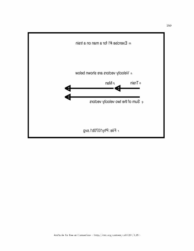
289
Available for free at Connexions <http://cnx.org/content/col11294/1.35>

290 CHAPTER 11. MOTION � UNIFORM AND RELATIVE VELOCITY
Available for free at Connexions <http://cnx.org/content/col11294/1.35>
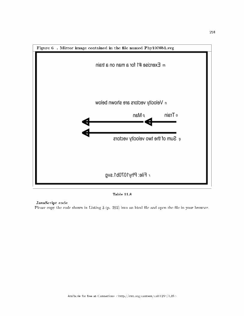
291
Figure 6 . Mirror image contained in the �le named Phy1070b1.svg
Table 11.8
JavaScript codePlease copy the code shown in Listing 3 (p. 292) into an html �le and open the �le in your browser.
Available for free at Connexions <http://cnx.org/content/col11294/1.35>

292 CHAPTER 11. MOTION � UNIFORM AND RELATIVE VELOCITY
Listing 3 . Exercise #1 for a man on a train.
<!---------------- File JavaScript03.html ---------------------><html><body><script language="JavaScript1.3">
document.write("Start Script </br>");
//The purpose of this function is to receive the adjacent
// and opposite side values for a right triangle and to
// return the angle in degrees in the correct quadrant.
function getAngle(x,y){
if((x == 0) && (y == 0)){
//Angle is indeterminate. Just return zero.
return 0;
}else if((x == 0) && (y > 0)){
//Avoid divide by zero denominator.
return 90;
}else if((x == 0) && (y < 0)){
//Avoid divide by zero denominator.
return -90;
}else if((x < 0) && (y >= 0)){
//Correct to second quadrant
return Math.atan(y/x)*180/Math.PI + 180;
}else if((x < 0) && (y <= 0)){
//Correct to third quadrant
return Math.atan(y/x)*180/Math.PI + 180;
}else{
//First and fourth quadrants. No correction required.
return Math.atan(y/x)*180/Math.PI;
}//end else
}//end function getAngle
//------------------------------------------------------------//
//The purpose of this function is to add two vectors, given
// the magnitude and angle (in degrees) for each vector.
// The magnitude and angle (in degrees) of the resultant
// vector is returned in a two-element array, with the
// magnitude in the element at index 0 and the angle in the
// element at index 1. Note that this function calls the
// getAngle function, which must also be provided in the
// script. To use this function to subtract one vector from
// another, add 180 degrees to the angle for the subtrahend
// vector before passing the angle to the function. To use
// this function to add more than two vectors, add the first
// two vectors as normal, then add the output from this
// function to the third vector, etc., until all of the
// vectors have been included in the sum.
function vectorSum(vecAmag,vecAang,vecBmag,vecBang){
var vecResult = new Array(2);
//Compute the horizontal and vertical components
// of each vector.
var vecAh = vecAmag*Math.cos(vecAang*Math.PI/180);
var vecAv = vecAmag*Math.sin(vecAang*Math.PI/180);
var vecBh = vecBmag*Math.cos(vecBang*Math.PI/180);
var vecBv = vecBmag*Math.sin(vecBang*Math.PI/180);
//Compute the sums of the horizontal and vertical
// components from the two vectors to get the
// horizontal and vertical component of the
// resultant vector.
var vecResultH = vecAh + vecBh;
var vecResultV = vecAv + vecBv;
//Use the Pythagorean theorem to compute the magnitude of
// the resultant vector.
vecResult[0] = Math.sqrt(Math.pow(vecResultH,2) +
Math.pow(vecResultV,2));
//Compute the angle of the resultant vector in degrees.
vecResult[1] = getAngle(vecResultH,vecResultV);
return vecResult;
}//end vectorSum function
//------------------------------------------------------------//
//The main script body begins here.
//Establish the magnitude and angle for each vector.
var vecTrainMag = 1;//magnitude of velocity of train in miles/hr
var vecTrainAng = 0;//angle of velocity of train in degrees
var vecManMag = 2.933*3600*(1/5280);//Magnitude of velocity of
// man (ft/sec)*(sec/hr)*(mile/ft)
// = miles/hour
var vecManAng = 0;//angle of velocity of man in degrees
//Add the two vectors
var resultant = vectorSum(vecTrainMag,vecTrainAng,
vecManMag,vecManAng);
//Display the magnitude and direction of the resultant vector.
document.write("Velocity magnitude = " +
resultant[0].toFixed(2) + " miles/hour</br>");document.write("Velocity angle = " +
resultant[1].toFixed(2) + " degrees</br>");
document.write("End Script");
</script></body></html>
Available for free at Connexions <http://cnx.org/content/col11294/1.35>

293
Table 11.9
Screen outputThe text shown in Figure 7 (p. 293) should appear in your browser window when you open the html �le
in your browser.
Figure 7 . Screen output for Listing #3.
Start Script
Velocity magnitude = 3.00 miles/hour
Velocity angle = 0.00 degrees
End Script
Table 11.10
Analysis of the codeAs before, the script begins by de�ning the getAngle function, which doesn't require further explanation.The vectorSum functionAs you can see from Listing 3 (p. 292) , this script contains a new function named vectorSum . The
purpose of this function is to add two vectors, given the magnitude and angle (in degrees) for each vectoras incoming parameters. (The function assumes that both incoming magnitude parameters are expressed inthe same units.)
The need to add two vectors occurs so often in physics that I decided to encapsulate the capability into afunction that we can copy into future scripts. That will relieve us of the need to rewrite the code each timewe need that functionality.
Return an array objectThe magnitude and the angle (in degrees) of the resultant vector is returned in a two-element array
object, with the magnitude in the element at index 0 and the angle in the element at index 1. I will have amore to say about arrays shortly.
Note that this function calls the getAngle function, which must also be provided in the script.Subtraction of vectorsThe function can also be used to subtract one vector from another. To subtract one vector from another,
simply add 180 degrees to the angle for the subtrahend vector before passing the angle to the function.Adding more than two vectorsAlthough the function can only be used to add two vectors, it can be called repeatedly to add any number
of vectors two at a time.To use this function to add more than two vectors, add the �rst two vectors as normal. Then add the
vector output from the function to the third vector, etc., until all of the vectors have been included in thesum.
The code in the vectorSum functionMost of the code in the function is the same as code that I have explained in earlier modules. However,
there are a couple of lines of code that are di�erent.The function begins with the following statement:var vecResult = new Array(2);The purpose of this statement is to create a two-element array object named vecResult .What is an array object?You can think of an array object as a software object containing pigeon holes into which you can store
data and from which you can later retrieve that data. This particular array object has two pigeon holes,and they are numbered 0 and 1.
Available for free at Connexions <http://cnx.org/content/col11294/1.35>

294 CHAPTER 11. MOTION � UNIFORM AND RELATIVE VELOCITY
This array object will be used as a container to return the magnitude and angle values for the resultantvector.
Can only return one itemA JavaScript function can only return one item. Up to this point in these modules, that item has consisted
of a single numeric value, such as the angle value that is returned from the getAngle function.However, the vectorSum function needs to return two di�erent values. One way to do that is to put those
two values in the pigeon holes of an array object and return that array object as the one item that can bereturned.
Store the resulting magnitude in the array objectOnce the array object is created, the code in the function shown in Listing 3 (p. 292) is essentially the
same as the code used earlier to add two vectors, down to the statement that begins with:vecResult[0] = Math.sqrt(Math.pow(vecResultH,2) +...That statement computes the magnitude of the resultant vector the same way as before, but instead of
storing the value of the magnitude in a variable, it is stored in the �rst pigeon hole of the array object.The value is directed into the �rst pigeon hole (technically called element) by the "[0]" that you see
following the name of the array object in that statement.Store the resulting angle in the array objectImmediately thereafter, the statement in Listing 3 (p. 292) that readsvecResult[1] = getAngle(vecResultH,vecResultV);computes the angle for the resultant vector and stores it in the second element in the array object (the
element identi�ed by the index value 1).Return the array object for use laterThese same index values along with the square brackets "[ ]" will be used later to retrieve the magnitude
and angle values from the array object.Finally, the function returns the array object to the calling script by executing the statement that readsreturn vecResult;The main script bodyThe main script body begins where indicated by the comment in Listing 3 (p. 292) .The �rst four statements establish values for the magnitude and direction of the two vectors that represent
the train and the man. There is nothing in those statements that you haven't seen before.Note the treatment of the unitsHowever, I encourage you to pay attention to the treatment of units in the comments for the value stored
in the variable named vecManMag . The arithmetic in that statement uses two di�erent conversionfactors to convert the value from feet per second to miles per hour.
Once again, working through the units in this fashion can help you to organize your arithmetic correctly.Call the vectorSum functionThe statement that beginsvar resultant = vectorSum(vecTrainMag...calls the new vectorSum function to add the two vectors, passing the magnitude and angle for each vector
as parameters.Store the returned array object in a variableThis statement also declares a new variable named resultant . The array object that is returned from
the vectorSum function is stored in this variable.Once this statement �nishes executing, the magnitude and angle of the resultant vector have been com-
puted and saved for later use. (In this script, the only use of those two values is to display them later.However, they will be used in a more signi�cant way in another exercise later.)
Code to display the resultsThe call to the vectorSum function is followed by three calls to the document.write method. The �rst
two calls display magnitude and angle values, and the third call simply displays some text to indicate thatthe script has �nished executing.
Displaying the magnitude value
Available for free at Connexions <http://cnx.org/content/col11294/1.35>

295
If you examine the statement containing the �rst call to the document.write method, you will see thatthe argument list contains the following expression:
resultant[0].toFixed(2)In this case, the "[0]" means to retrieve the value stored in the array element identi�ed by the index value
0.Once that value has been retrieved, the built-in toFixed method is called, passing the literal value 2 as a
parameter, to format the value so that it will be displayed with two digits to the right of the decimal point.Figure 7 (p. 293) shows that value displayed in the line of text that reads:Velocity magnitude = 3.00 miles/hour(Note that very few of the values that I display in these modules comply with the rules for decimal digits
and signi�cant �gures that I explained in an earlier module titled Scienti�c Notation and Signi�cant Figuresfor Blind Students .)
A partial solution to the problemA partial answer to the question posed for this exercise is that the magnitude of the man's overall velocity
with respect to the ground is 3 miles per hour as shown in Figure 7 (p. 293) .The rest of the solutionThe next statement in Listing 3 (p. 292) uses a similar syntax to retrieve the value from the second
element in the array object (the element with an index value of 1) and to display it asVelocity angle = 0.00 degreesas shown in Figure 7 (p. 293) .This means that the man is moving due east (the same direction that the train is moving) with a velocity
of 3 miles per hour with reference to the ground.Analysis of the resultsNow I will tell you why I used a strange walking speed (2.933 feet per second) for the man. As it turns
out, this is very close to 2 miles per hour, and I wanted the man to have a walking speed that would resultin simple numeric results.
Let's review the problemThe train is moving east with a uniform velocity of 1 mile per hour relative to the ground.The man is moving east with a uniform velocity of 2 miles per hour (2.933 feet per second) relative to
the train.What is the man's velocity relative to the ground?The algebraic sum of the magnitudesBecause the man and the train are both moving along the same straight line, and the man's velocity is
stated relative to the train, the magnitude of the man's velocity relative to the ground is the algebraic sumof the magnitudes of the two velocities. Because they are both moving in the same direction, that algebraicsum is additive.
An analysis of the velocitiesThe train is moving 1 mile per hour with reference to the ground, and the man is moving 2 miles per
hour with reference to the train (along the same line and in the same direction as the train). Therefore, theman is moving 1+2=3 miles per hour with reference to the ground.
This means that an observer standing on the ground at a point on a line perpendicular to the train wouldperceive the man to be moving to the to the right with a velocity of 3 miles per hour (assuming that thetrain is moving to the right).
A zero-degree angle is not requiredNote that it isn't necessary that the train and the man be moving at an angle of zero degrees (east). The
magnitude of the result would be the same regardless of the direction that they are moving provided theyare moving along the same straight line.
We will specify a di�erent common direction for the train and the man in the next exercise.
Available for free at Connexions <http://cnx.org/content/col11294/1.35>

296 CHAPTER 11. MOTION � UNIFORM AND RELATIVE VELOCITY
11.4.4.2 Exercise #2 for a man on a train
A man is walking in a passenger car of a train that is moving at 1 mile per hour toward the northeast (45degrees). The man is walking in the opposite direction than the train is moving at 2.933 feet per second.(This means that the angle for the man's velocity vector is 225 degrees.)
What is the man's velocity with reference to the ground?Tactile graphicsAn svg �le named Phy1070c1.svg is provided for the creation of a tactile velocity vector diagram for this
scenario. The table of key-value pairs for this �le is provided in Figure 8 (p. 296) .
Figure 8 . Key-value pairs for the image in Phy1070c1.svg.
m: Exercise #2 for a man on a train
n: Velocity vectors are shown below
o: Train
p: Man
q: Sum of the two velocity vectors
r: File: Phy1070c1.svg
Table 11.11
The image contained in this �le is shown in Figure 9 (p. 300) for the bene�t of your assistant who willmanually emboss the diagram. A non-mirror-image version is shown in Figure 16 (p. 319) .
The units for both velocity vectors must be the same. Therefore, the length of the velocity vector for theman is based on a conversion from 2.933 feet per second to 2 miles per hour.
Available for free at Connexions <http://cnx.org/content/col11294/1.35>

297
Available for free at Connexions <http://cnx.org/content/col11294/1.35>

298 CHAPTER 11. MOTION � UNIFORM AND RELATIVE VELOCITY
Available for free at Connexions <http://cnx.org/content/col11294/1.35>

299
Available for free at Connexions <http://cnx.org/content/col11294/1.35>

300 CHAPTER 11. MOTION � UNIFORM AND RELATIVE VELOCITY
Figure 9 . Mirror image contained in the �le named Phy1070c1.svg
Table 11.12
Make a new html �lePlease copy the code from the previous exercise into a new html �le, make the changes described below,
and open the html �le in your browser.
• Change the value of vecTrainAng from 0 to 45.• Change the value of vecManAng from 0 to 225.
(Because of the small di�erences between this script and the previous script, I won't publish a copy of thisnew script here.)
Screen outputThe text shown in Figure 10 (p. 301) should appear in your browser window when you open the �le in
your browser.
Available for free at Connexions <http://cnx.org/content/col11294/1.35>

301
Figure 10 . Screen output for Exercise #2 for a man on a train.
Start Script
Velocity magnitude = 1.00 miles/hour
Velocity angle = 225.00 degrees
End Script
Table 11.13
Analysis of the resultsThe man and the train are still moving along the same straight line even though the angle is no longer
0. Therefore, the magnitudes of the two vectors still add algebraically. In this case, however, the man andthe train are moving in opposite directions, so they are no longer additive.
The man has a greater velocity magnitudeThe magnitude of the man's velocity in the direction of 225 degrees is greater than the magnitude of the
train's velocity in the opposite direction of 45 degrees.As you can see from Figure 10 (p. 301) , the man's velocity with reference to the ground is 1 mile per
hour at an angle of 225 degrees. This means that an observer standing on the ground at a point on a lineperpendicular to the train would perceive the man to be moving to the left at 1 mile per hour (assumingthat the train is moving to the right).
11.4.4.3 An exercise with three vectors in a plane
Now we are going to take a look at an exercise involving three vectors in a plane, which are not in a line.An aircraft carrier is steaming east with a uniform velocity of 2 miles per hour relative to the ground
beneath the ocean. A large platform on the deck is sliding northeast with a uniform velocity of 2 miles perhour relative to the ship. A man is walking north on the platform with a uniform velocity of 2 miles perhour relative to the platform.
What is the velocity of the platform with reference to the ground below the ocean?What is the velocity of the man with reference to the ground below the ocean?Tactile graphicsAn svg �le named Phy1070d1.svg is provided for the creation of a tactile velocity vector diagram for this
scenario. The table of key-value pairs for this �le is provided in Figure 11 .
Figure 11 . Key-value pairs for the image in Phy1070d1.svg.
m: Exercise with three vectors in a plane
n: Man velocity vector
o: Sum of three vectors
p: Platform velocity vector
q: Ship velocity vector
r: File: Phy1070d1.svg
s: Sum of two vectors
t: Summation vector lines are dashed
Table 11.14
Available for free at Connexions <http://cnx.org/content/col11294/1.35>

302 CHAPTER 11. MOTION � UNIFORM AND RELATIVE VELOCITY
The image contained in this �le is shown in Figure 12 for the bene�t of your assistant who will manuallyemboss the diagram. A non-mirror-image version is shown in Figure 17 (p. 323) .
Available for free at Connexions <http://cnx.org/content/col11294/1.35>

303
Available for free at Connexions <http://cnx.org/content/col11294/1.35>
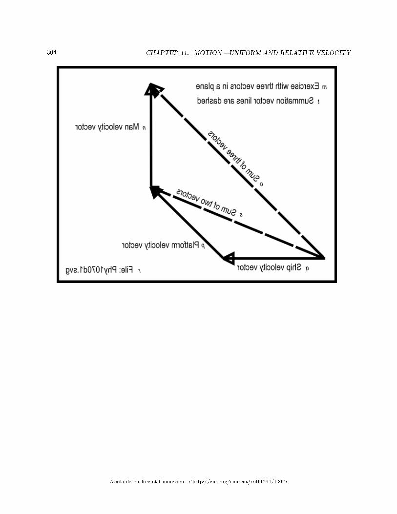
304 CHAPTER 11. MOTION � UNIFORM AND RELATIVE VELOCITY
Available for free at Connexions <http://cnx.org/content/col11294/1.35>

305
Figure 12 . Mirror image contained in the �le named Phy1070d1.svg
Table 11.15
Create the scriptPlease copy the code from Listing 4 (p. 306) into an html �le and open the html �le in your browser.
Available for free at Connexions <http://cnx.org/content/col11294/1.35>

306 CHAPTER 11. MOTION � UNIFORM AND RELATIVE VELOCITY
Listing 4 . An exercise with three vectors in a plane.
<!---------------- File JavaScript04.html ---------------------><html><body><script language="JavaScript1.3">
document.write("Start Script </br>");
//The purpose of this function is to receive the adjacent
// and opposite side values for a right triangle and to
// return the angle in degrees in the correct quadrant.
function getAngle(x,y){
if((x == 0) && (y == 0)){
//Angle is indeterminate. Just return zero.
return 0;
}else if((x == 0) && (y > 0)){
//Avoid divide by zero denominator.
return 90;
}else if((x == 0) && (y < 0)){
//Avoid divide by zero denominator.
return -90;
}else if((x < 0) && (y >= 0)){
//Correct to second quadrant
return Math.atan(y/x)*180/Math.PI + 180;
}else if((x < 0) && (y <= 0)){
//Correct to third quadrant
return Math.atan(y/x)*180/Math.PI + 180;
}else{
//First and fourth quadrants. No correction required.
return Math.atan(y/x)*180/Math.PI;
}//end else
}//end function getAngle
//------------------------------------------------------------//
//The purpose of this function is to add two vectors, given
// the magnitude and angle (in degrees) for each vector.
// The magnitude and angle (in degrees) of the resultant
// vector is returned in a two-element array, with the
// magnitude in the element at index 0 and the angle in the
// element at index 1. Note that this function calls the
// getAngle function, which must also be provided in the
// script. To use this function to subtract one vector from
// another, add 180 degrees to the angle for the subtrahend
// vector before passing the angle to the function. To use
// this function to add more than two vectors, add the first
// two vectors as normal, then add the output from this
// function to the third vector, etc., until all of the
// vectors have been included in the sum.
function vectorSum(vecAmag,vecAang,vecBmag,vecBang){
var vecResult = new Array(2);
//Compute the horizontal and vertical components
// of each vector.
var vecAh = vecAmag*Math.cos(vecAang*Math.PI/180);
var vecAv = vecAmag*Math.sin(vecAang*Math.PI/180);
var vecBh = vecBmag*Math.cos(vecBang*Math.PI/180);
var vecBv = vecBmag*Math.sin(vecBang*Math.PI/180);
//Compute the sums of the horizontal and vertical
// components from the two vectors to get the
// horizontal and vertical component of the
// resultant vector.
var vecResultH = vecAh + vecBh;
var vecResultV = vecAv + vecBv;
//Use the Pythagorean theorem to compute the magnitude of
// the resultant vector.
vecResult[0] = Math.sqrt(Math.pow(vecResultH,2) +
Math.pow(vecResultV,2));
//Compute the angle of the resultant vector in degrees.
vecResult[1] = getAngle(vecResultH,vecResultV);
return vecResult;
}//end vectorSum function
//------------------------------------------------------------//
//Main body of script begins here.
//Establish the magnitude and angle for each vector.
var vecShipMag = 2;//magnitude of velocity of ship in miles/hr
var vecShipAng = 0;//angle of velocity of ship in degrees
var vecPlatMag = 2;//magnitude of velocity of platform miles/hr
var vecPlatAng = 45;//angle of velocity of platform in degrees
var vecManMag = 2;//Magnitude of velocity of man in miles/hr
var vecManAng = 90;//angle of velocity of man in degrees
//Add two vectors
var platformVel =
vectorSum(vecShipMag,vecShipAng,vecPlatMag,vecPlatAng);
//Add in the third vector
var manVel =
vectorSum(platformVel[0],platformVel[1],vecManMag,vecManAng);
//Display the magnitude and direction of the resultant vectors.
document.write("Platform velocity magnitude = " +
platformVel[0].toFixed(2) + " miles/hour</br>");document.write("Platform velocity angle = " +
platformVel[1].toFixed(2) + " degrees</br>");document.write("Man velocity magnitude = " +
manVel[0].toFixed(2) + " miles/hour</br>");document.write("Man velocity angle = " +
manVel[1].toFixed(2) + " degrees</br>");
document.write("End Script");
</script></body></html>
Available for free at Connexions <http://cnx.org/content/col11294/1.35>

307
Table 11.16
Screen outputThe text shown in Figure 13 (p. 307) should appear in your browser window when the html �le is opened
in your browser.
Figure 13 . Screen output for Listing #4.
Start Script
Platform velocity magnitude = 3.70 miles/hour
Platform velocity angle = 22.50 degrees
Man velocity magnitude = 4.83 miles/hour
Man velocity angle = 45.00 degrees
End Script
Table 11.17
Analysis of the codeThe velocity of the platform relative to the ground is the vector sum of the ship's velocity and the velocity
of the platform relative to the ship. The man's velocity is the vector sum of the platform's velocity relativeto the ground and the man's velocity relative to the platform.
Listing 4 (p. 306) begins with copies of the getAngle function and the vectorSum function, which I havealready explained. This discussion begins at the comment that reads "Main body of script begins here."
The main body of the scriptThe main body begins with the declaration and initialization of six variables whose contents represent
the magnitude and the angle of the ship, the platform, and the man.Add the �rst two vectorsThe vectorSum function is called to add the ship's velocity vector (relative to the ground) and the
platform's velocity vector (relative to the ship). The resultant vector produced by adding those two vectorsis stored in the array-object variable named platformVel for use later. This is the platform's velocityvector relative to the ground.
Add the man's vector to the sumThen the vectorSum function is called again to add the platform's velocity vector (relative to the ground)
and the man's velocity vector (relative to the platform). Note that the two values stored in the platformVelarray object are extracted and passed as parameters to the vectorSum function.
The resultant vector produced by that addition is saved in the array-object variable named manVel .This is the man's velocity vector relative to the ground.
Display the resultsFinally, the method named document.write is called four times in succession to extract and print the four
values stored in the two array objects, producing the text output shown in Figure 13 (p. 307) .
11.4.5 Non-mirror-image graphics
Figure 14 (p. 311) through Figure 17 (p. 323) below are non-mirror-image versions of Figure 3 (p. 283) ,Figure 6 (p. 291) , Figure 9 (p. 300) , and Figure 12 (p. 305) respectively.
Available for free at Connexions <http://cnx.org/content/col11294/1.35>

308 CHAPTER 11. MOTION � UNIFORM AND RELATIVE VELOCITY
Available for free at Connexions <http://cnx.org/content/col11294/1.35>

309
Available for free at Connexions <http://cnx.org/content/col11294/1.35>

310 CHAPTER 11. MOTION � UNIFORM AND RELATIVE VELOCITY
Available for free at Connexions <http://cnx.org/content/col11294/1.35>
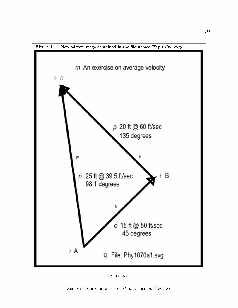
311
Figure 14 . Non-mirror-image contained in the �le named Phy1070a1.svg.
Table 11.18
Available for free at Connexions <http://cnx.org/content/col11294/1.35>

312 CHAPTER 11. MOTION � UNIFORM AND RELATIVE VELOCITY
Available for free at Connexions <http://cnx.org/content/col11294/1.35>

313
Available for free at Connexions <http://cnx.org/content/col11294/1.35>

314 CHAPTER 11. MOTION � UNIFORM AND RELATIVE VELOCITY
Available for free at Connexions <http://cnx.org/content/col11294/1.35>

315
Figure 15 . Non-mirror-image contained in the �le named Phy1070b1.svg.
Table 11.19
Available for free at Connexions <http://cnx.org/content/col11294/1.35>
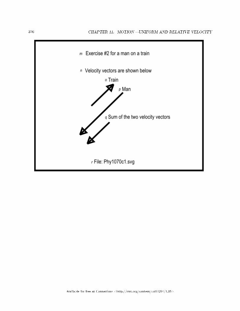
316 CHAPTER 11. MOTION � UNIFORM AND RELATIVE VELOCITY
Available for free at Connexions <http://cnx.org/content/col11294/1.35>
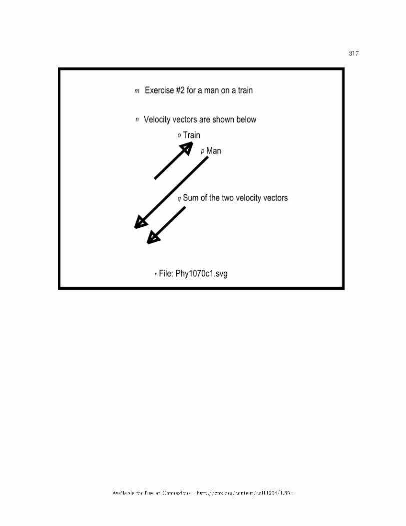
317
Available for free at Connexions <http://cnx.org/content/col11294/1.35>

318 CHAPTER 11. MOTION � UNIFORM AND RELATIVE VELOCITY
Available for free at Connexions <http://cnx.org/content/col11294/1.35>

319
Figure 16 . Non-mirror-image contained in the �le named Phy1070c1.svg.
Table 11.20
Available for free at Connexions <http://cnx.org/content/col11294/1.35>

320 CHAPTER 11. MOTION � UNIFORM AND RELATIVE VELOCITY
Available for free at Connexions <http://cnx.org/content/col11294/1.35>

321
Available for free at Connexions <http://cnx.org/content/col11294/1.35>

322 CHAPTER 11. MOTION � UNIFORM AND RELATIVE VELOCITY
Available for free at Connexions <http://cnx.org/content/col11294/1.35>

323
Figure 17 . Non-mirror-image contained in the �le named Phy1070d1.svg.
Table 11.21
11.5 Run the scripts
I encourage you to run the scripts that I have presented in this lesson to con�rm that you get the sameresults. Copy the code for each script into a text �le with an extension of html. Then open that �le inyour browser. Experiment with the code, making changes, and observing the results of your changes. Makecertain that you can explain why your changes behave as they do.
11.6 Resources
I will publish a module containing consolidated links to resources on my Connexions web page and willupdate and add to the list as additional modules in this collection are published.
11.7 Miscellaneous
This section contains a variety of miscellaneous information.
Housekeeping material
Available for free at Connexions <http://cnx.org/content/col11294/1.35>

324 CHAPTER 11. MOTION � UNIFORM AND RELATIVE VELOCITY
• Module name: Motion � Uniform and Relative Velocity• File: Phy1070.htm• Revised: 10/02/15• Keywords:
· physics· accessible· blind· graph board· protractor· screen reader· refreshable Braille display· JavaScript· trigonometry· vector· velocity· uniform velocity· relative velocity· resultant· motion· displacement· subtrahend· array object
Disclaimers: Financial : Although the openstax CNX site makes it possible for you todownload a PDF �le for the collection that contains this module at no charge, and also makes itpossible for you to purchase a pre-printed version of the PDF �le, you should be aware that someof the HTML elements in this module may not translate well into PDF.
You also need to know that Prof. Baldwin receives no �nancial compensation from openstaxCNX even if you purchase the PDF version of the collection.
In the past, unknown individuals have copied Prof. Baldwin's modules from cnx.org, convertedthem to Kindle books, and placed them for sale on Amazon.com showing Prof. Baldwin as theauthor. Prof. Baldwin neither receives compensation for those sales nor does he know who doesreceive compensation. If you purchase such a book, please be aware that it is a copy of a collectionthat is freely available on openstax CNX and that it was made and published without the priorknowledge of Prof. Baldwin.
A�liation : Prof. Baldwin is a professor of Computer Information Technology at AustinCommunity College in Austin, TX.
-end-
Available for free at Connexions <http://cnx.org/content/col11294/1.35>

Chapter 12
Motion � Variable Velocity and
Acceleration1
12.1 Table of Contents
• Preface (p. 326)
· General (p. 326)· Prerequisites (p. 326)· Viewing tip (p. 327)
* Figures (p. 327)* Listings (p. 327)
· Supplemental material (p. 327)
• General background information (p. 327)
· Variable velocity (p. 327)· Acceleration (p. 328)· The acceleration of gravity (p. 329)
• Discussion and sample code (p. 330)
· Creation of tactile graphics (p. 330)· Variable velocity exercise #1 (p. 331)· Variable velocity exercise #2 (p. 345)· Acceleration of gravity exercise #1 (p. 348)· Acceleration of gravity exercise #2 (p. 352)· Acceleration of gravity exercise #3 (p. 365)· Other useful equations (p. 369)
* Exercise to �nd the velocity (p. 369)* Exercise to �nd the height (p. 371)
• Run the scripts (p. 372)• Resources (p. 372)• Miscellaneous (p. 372)
1This content is available online at <http://cnx.org/content/m38074/1.4/>.
Available for free at Connexions <http://cnx.org/content/col11294/1.35>
325

326 CHAPTER 12. MOTION � VARIABLE VELOCITY AND ACCELERATION
12.2 Preface
12.2.1 General
This module is part of a collection of modules designed to make physics concepts accessible to blind students.If you opened this page in the context of the book, a Table of Contents for the book (or collection)
should be available above and to the left of this paragraph. Otherwise, click here 2 to open the book at thebeginning.
This book is intended to supplement but not to replace the textbook in an introductory high school orcollege physics course.
The purpose of this module is to explain variable velocity and acceleration in a format that is accessibleto blind students.
12.2.2 Prerequisites
In addition to an Internet connection and a browser, you will need the following tools (as a minimum) towork through the exercises in these modules:
• A graph board for plotting graphs and vector diagrams (http://www.youtube.com/watch?v=c8plj9UsJbg 3 ).
• A protractor for measuring angles ( http://www.youtube.com/watch?v=v-F06HgiUpw 4 ).• An audio screen reader that is compatible with your operating system, such as the NonVisual Desktop
Access program (NVDA), which is freely available at http://www.nvda-project.org/ 5 .• A refreshable Braille display capable of providing a line by line tactile output of information displayed
on the computer monitor ( http://www.userite.com/ecampus/lesson1/tools.php 6 ).• A device to create Braille labels. Will be used to label graphs constructed on the graph board.• The ability to create tactile graphics as described here 7 .
The minimum prerequisites for understanding the material in these modules include:
• A good understanding of algebra.• An understanding of the use of a graph board for plotting graphs and vector diagrams (
http://www.youtube.com/watch?v=c8plj9UsJbg 8 ).• An understanding of the use of a protractor for measuring angles (
http://www.youtube.com/watch?v=v-F06HgiUpw 9 ).• A basic understanding of the use of sine, cosine, and tangent from trigonometry (
http://www.clarku.edu/∼djoyce/trig/ 10 ).• An introductory understanding of JavaScript programming ( http://www.dickbaldwin.com/tocjscript1.htm
11 and http://www.w3schools.com/js/default.asp 12 ).• An understanding of all of the material covered in the earlier modules in this collection.• An understanding of the creation and use of tactile graphics as described here 13 .
2http://cnx.org/contents/a7842db2-93c6-4c06-a5e3-56c2823581433http://www.youtube.com/watch?v=c8plj9UsJbg4http://www.youtube.com/watch?v=v-F06HgiUpw5http://www.nvda-project.org/6http://www.userite.com/ecampus/lesson1/tools.php7http://cnx.org/contents/9fe07552-485f-43e7-9753-87133cf604828http://www.youtube.com/watch?v=c8plj9UsJbg9http://www.youtube.com/watch?v=v-F06HgiUpw
10http://www.clarku.edu/∼djoyce/trig/11http://www.dickbaldwin.com/tocjscript1.htm12http://www.w3schools.com/js/default.asp13http://cnx.org/contents/9fe07552-485f-43e7-9753-87133cf60482
Available for free at Connexions <http://cnx.org/content/col11294/1.35>
327
12.2.3 Viewing tip
I recommend that you open another copy of this document in a separate browser window and use thefollowing links to easily �nd and view the �gures and listings while you are reading about them.
12.2.3.1 Figures
• Figure 1 (p. 335) . Mirror image contained in the �le named Phy1080a1.svg.• Figure 2 (p. 339) . Non-mirror-image contained in the �le named Phy1080a1.svg.• Figure 3 (p. 340) . Key-value pairs for the image in Phy1080a1.svg.• Figure 4 (p. 343) . Screen output for Listing #1.• Figure 5 (p. 344) . Displacement versus time for �rst �ve time intervals.• Figure 6 (p. 347) . Screen output for Listing #2.• Figure 7 (p. 351) . Screen output for Listing #3.• Figure 8 (p. 355) . Screen output for Listing #4 at 45 degrees.• Figure 9 (p. 359) . Mirror image contained in the �le named Phy1080b1.svg.• Figure 10 (p. 363) . Non-mirror-image contained in the �le named Phy1080b1.svg.• Figure 11 (p. 363) . Key-value pairs for the image in Phy1080b1.svg.• Figure 12 (p. 364) . Screen output for Listing #4 at 60 degrees.• Figure 13 (p. 368) . Screen output for Listing #5.• Figure 14 (p. 370) . Screen output for Listing #6.• Figure 15 (p. 372) . Screen output for Listing #7.
12.2.3.2 Listings
• Listing 1 (p. 341) . Variable velocity exercise #1.• Listing 2 (p. 346) . Variable velocity exercise #2.• Listing 3 (p. 350) . Acceleration of gravity exercise #1.• Listing 4 (p. 354) . Acceleration of gravity exercise #2.• Listing 5 (p. 367) . Acceleration of gravity exercise #3.• Listing 6 (p. 370) . Exercise to �nd the velocity.• Listing 7 (p. 371) . Exercise to �nd the height.
12.2.4 Supplemental material
I recommend that you also study the other lessons in my extensive collection of online programming tutorials.You will �nd a consolidated index at www.DickBaldwin.com 14 .
12.3 General background information
I will provide an introduction to variable velocity, acceleration, and the acceleration of gravity in this section.I will provide exercises on those topics in the next section.
12.3.1 Variable velocity
What is velocity?To review, you learned in an earlier module that velocity is the rate of change of position. Since displace-
ment is a change in position, velocity is also the rate of displacement.Uniform versus variable velocity
14http://www.dickbaldwin.com/toc.htm
Available for free at Connexions <http://cnx.org/content/col11294/1.35>

328 CHAPTER 12. MOTION � VARIABLE VELOCITY AND ACCELERATION
Previous modules have dealt exclusively with uniform velocity. However, many situations in life involvevariable velocity and acceleration. For example, the simple act of stopping an automobile at a tra�c lightand then resuming the trip once the light turns green involves variable velocity and acceleration.
Three equationsI will explain both of these topics in this module using three well-known physics equations that deal with
the displacement of a projectile in a vacuum under the in�uence of gravity .The equation that we will spend the most time on ish = v0*t + 0.5*g*t^2where
• h is the distance of the projectile above the surface of the earth• v0 is the initial velocity of the projectile• t is time in seconds• g is the acceleration of gravity, approximately 9.8 meters per second squared, or approximately 32.2 feet
per second squared at the surface of the earth. (We will also do an exercise involving the accelerationof gravity on the moon.)
(I will provide the other two equations later (p. 369) .)
12.3.2 Acceleration
Everyone is familiar with the acceleration that occurs when a motor vehicle speeds up or slows down. Whenthe vehicle speeds up very rapidly, the positive acceleration forces us against the back of the seat. (Thisinvolves the relationship among force, mass, and acceleration, which will be the subject of a future module.)
If the vehicle slows down very rapidly or stops suddenly, the negative acceleration may cause us to crashinto the windshield, the dashboard, or a deployed airbag.
The accelerator pedalA common name for the pedal that causes gasoline to be fed to the engine is often called the accelerator
pedal because it causes the vehicle to speed up. (However, I have never heard anyone refer to the pedal thatcauses the vehicle to slow down as the deceleration pedal. Instead, it is commonly called the brake pedal.)
De�nitionsDisplacement is a change in position.Velocity is the rate of change of position or the rate of displacement.Acceleration is the rate of change of velocity.Jerk is the rate of change of acceleration (not covered in this module).According to this author 15 , there is no universally accepted name for the rate of change of jerk.The algebraic sign of accelerationWhen the velocity of a moving object increases, that is viewed as positive acceleration. When the velocity
of the object decreases, that is viewed as negative acceleration.Uniform or variable accelerationAcceleration may be uniform or variable. It is uniform only if equal changes in velocity occur in equal
intervals of time.A vector quantityAcceleration has both direction and magnitude. Therefore, acceleration is a vector quantity.The units for accelerationThe above de�nition (p. 328) for acceleration leads to some interesting units for acceleration. For
example, consider a situation in which the velocity of an object changes by 5 feet/second in a one-secondtime interval. Writing this as an algebraic expression gives us
(5 feet/second)/secondMultiplying the numerator and the denominator of the fraction by 1/second gives us5 feet/(second*second)
15http://math.ucr.edu/home/baez/physics/General/jerk.html
Available for free at Connexions <http://cnx.org/content/col11294/1.35>

329
This is often written as5 feet/second^2which is pronounced �ve feet per second squared.
12.3.3 The acceleration of gravity
The exercises in the remainder of this module are based on the following two assumptions:
• For practical purposes, the e�ect of the acceleration of gravity is the same regardless of the height ofan object above the surface of the earth, provided that the distance above the surface of the earth issmall relative to the radius of the earth.
• In the absence of an atmosphere, all objects fall toward the earth with the same acceleration regardlessof their masses.
Let's examine the validity of these two assumptions.Newton's law of universal gravitationThis law 16 states that every point mass in the universe attracts every other point mass with a force
that is directly proportional to the product of their masses and inversely proportional to the square of thedistance between them. (Separately it has been shown that large spherically symmetrical masses attract andare attracted as if all their mass were concentrated at their centers.)
E�ect of gravity versus altitudeAn object at the surface of the earth is approximately 3963 miles from the center of the earth. An object
that is six miles above the surface of the earth (typical �ying altitude for a passenger plane) is approximately3969 miles from the center of the earth.
Therefore, (if I didn't make an arithmetic error) the gravitational attraction between the earth and thatobject changes by less than 0.5 percent when the object is transported from the surface of the earth to aposition that is six miles above the surface of the earth.
For practical purposes, therefore, we can assume that the acceleration of gravity is constant up to at least32000 feet above the surface of the earth.
Acceleration is independent of massNewton's law, as applied to the gravitational attraction of the earth, expressed in algebraic terms, looks
something like the following :f =E*m/d^2where
• f is the attractive force between the earth and another object• E is the mass of the earth• m is the mass of the other object• d is the distance between the center of mass of the earth and the center of mass of the other object
Force equals mass times accelerationIn a future module, we will learn that an object that is free to move will move and will accelerate
when subjected to a force. The acceleration of the object will be proportional to the force and inverselyproportional to its mass. In other words,
a = f/mwhere
• a is the acceleration in units such as meters/sec^2• f is force in units such as kilograms*meters/sec^2 (newtons)• m is mass in units such as kilograms
16http://en.wikipedia.org/wiki/Newton's_law_of_universal_gravitation
Available for free at Connexions <http://cnx.org/content/col11294/1.35>

330 CHAPTER 12. MOTION � VARIABLE VELOCITY AND ACCELERATION
By multiplying both sides of the equation by m, we get a more common presentation of this relationship,which is
f = m*awhere the symbols mean the same as listed above (p. 329) .A ratio of two di�erent forces of gravityNow let's use the equation from above (p. 329) to form a ratio of the forces exerted on two di�erent
masses by the earth, assuming that both masses are the same distance from the center of the earth.f1/f2 =(E*m1/d^2)/(E*m2/d^2)Cancel like terms to simplifyIf we cancel like terms from the numerator and denominator of the expression on the right, we can
simplify the ratio tof1/f2 = m1/m2Replacing the forces on the left by the expression from above (p. 330) , we getm1*a1/m2*a2 = m1/m2Multiplying both sides by m2/m1 we geta1/a2 = 1ora1 = a2This shows that the acceleration resulting from the gravitational force exerted on two objects that are
equally distant from the center of mass of the earth is the same regardless of the di�erences in mass of thetwo objects.
12.4 Discussion and sample code
I will present and explain several di�erent scenarios based on the above assumptions in this section.
12.4.1 Creation of tactile graphics
The module titled Manual Creation of Tactile Graphics 17 explained how to create tactile graphics from svg�les that I will provide.
If you are going to have an assistant create tactile graphics for this module, you will need to downloadthe �le named Phy1080.zip 18 , which contains the svg �les for this module. Extract the svg �les from thezip �le and provide them to your assistant.
Also, if you are going to use tactile graphics, it probably won't be necessary for you to perform the graphboard exercises. However, you should still walk through the graph board exercises in your mind because Iwill often embed important physics concepts in the instructions for doing the graph board exercises.
In each case where I am providing an svg �le for the creation of tactile graphics, I will identify the nameof the appropriate svg �le and display an image of the contents of the �le for the bene�t of your assistant.As explained here 19 , those images will be mirror images of the actual images so that your assistant canemboss the image from the back of the paper and you can explore it from the front.
I will also display a non-mirror-image version of the image so that your assistant can easily read the textin the image.
Also in those cases, I will provide a table of key-value pairs that explain how the Braille keys in the imagerelate to text or objects in the image.
17http://cnx.org/contents/9fe07552-485f-43e7-9753-87133cf60482/Phy1004-Manual-Creation-of-Tac18http://cnx.org/content/m38074/latest/Phy1080.zip19http://cnx.org/contents/9fe07552-485f-43e7-9753-87133cf60482
Available for free at Connexions <http://cnx.org/content/col11294/1.35>

331
12.4.2 Variable velocity exercise #1
An archer that is six feet tall shoots an arrow directly upward with a velocity of 100 feet per second. Assumethe arrow is at a height of 6 feet when it leaves the bow. Also ignore the e�ects of air resistance.
Plot height versus timeUse your graph board and about 30 pushpins to plot the height of the arrow on the vertical axis versus
time on the horizontal axis. Because of the large number of points, you shouldn't need to connect the pinsto get a good feel for the shape of the graph. Plot one point each 0.25 seconds. Allow for a maximum timevalue of about 7 seconds and a maximum height value of about 165 feet.
Tactile graphicsThe svg �le named Phy1080a1 contains a graph that serves for this exercise plus the next couple of
exercises. This graph plots the height of the arrow, the velocity of the arrow, and the acceleration of thearrow versus time from the time that it is released until it strikes the ground approximately six seconds later.
The image contained in this �le is shown in Figure 1 (p. 335) for the bene�t of your assistant who willmanually emboss the diagram. Note that as usual, this is a mirror image of the image that is to be presentedto the student after embossing. A non-mirror-image version is shown in Figure 2 (p. 339) .
Available for free at Connexions <http://cnx.org/content/col11294/1.35>

332 CHAPTER 12. MOTION � VARIABLE VELOCITY AND ACCELERATION
Available for free at Connexions <http://cnx.org/content/col11294/1.35>
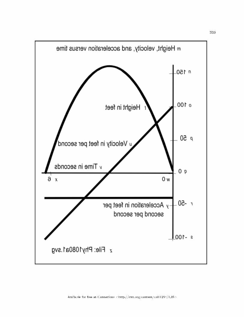
333
Available for free at Connexions <http://cnx.org/content/col11294/1.35>
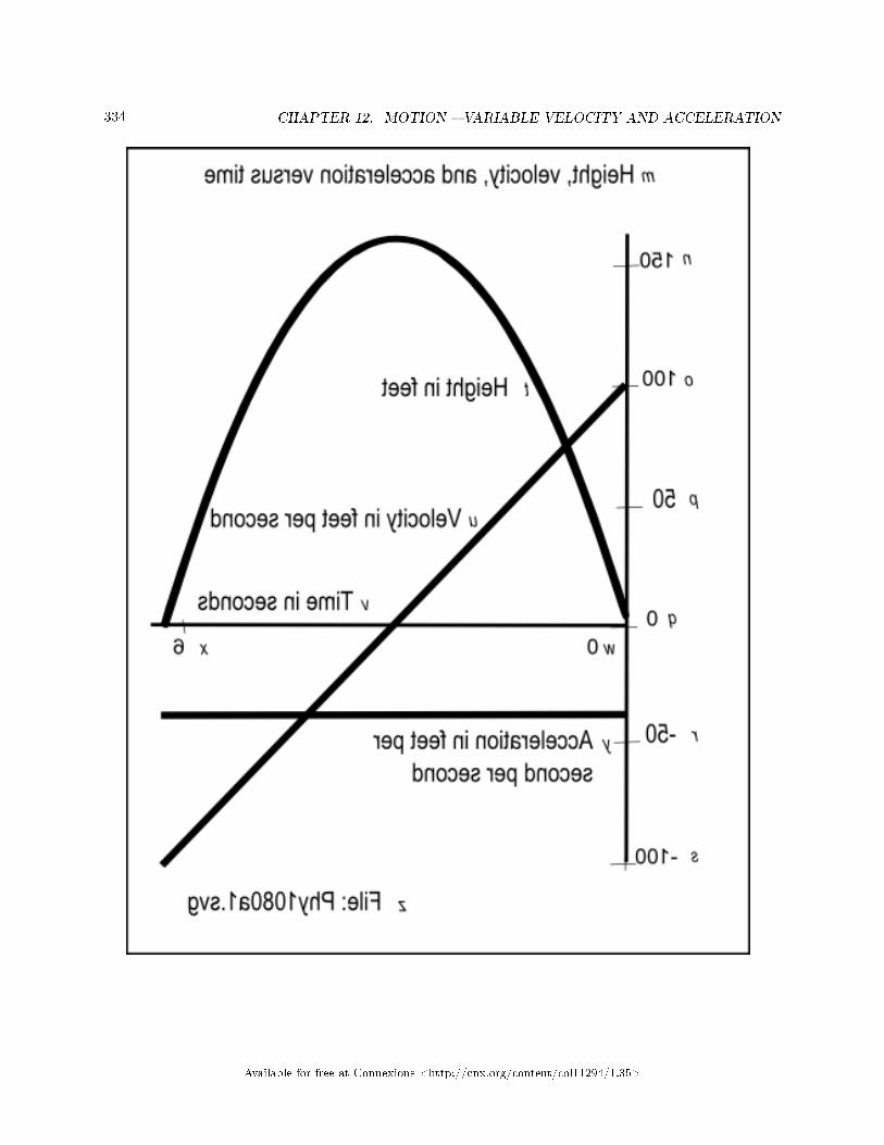
334 CHAPTER 12. MOTION � VARIABLE VELOCITY AND ACCELERATION
Available for free at Connexions <http://cnx.org/content/col11294/1.35>

335
Figure 1 . Mirror image contained in the �le named Phy1080a1.svg.
Table 12.1
Available for free at Connexions <http://cnx.org/content/col11294/1.35>

336 CHAPTER 12. MOTION � VARIABLE VELOCITY AND ACCELERATION
Available for free at Connexions <http://cnx.org/content/col11294/1.35>

337
Available for free at Connexions <http://cnx.org/content/col11294/1.35>

338 CHAPTER 12. MOTION � VARIABLE VELOCITY AND ACCELERATION
Available for free at Connexions <http://cnx.org/content/col11294/1.35>

339
Figure 2 . Non-mirror-image contained in the �le named Phy1080a1.svg.
Table 12.2
Available for free at Connexions <http://cnx.org/content/col11294/1.35>

340 CHAPTER 12. MOTION � VARIABLE VELOCITY AND ACCELERATION
Key-value pairsThe table of key-value pairs for this �le is provided in Figure 3 (p. 340) .
Figure 3 . Key-value pairs for the image in Phy1080a1.svg.
m: Height, velocity, and acceleration versus time.
n: 150
o: 100
p: 50
q: 0
r: -50
s: -100
t: Height in feet
u: Velocity in feet per second
v: Time in seconds
w: 0
x: 6
y: Acceleration in feet per second per second
z: File: Phy1080a1.svg
Table 12.3
Create a scriptPlease copy the code shown in Listing 1 (p. 341) into an html �le and open the �le in your browser.
Available for free at Connexions <http://cnx.org/content/col11294/1.35>

341
Listing 1 . Variable velocity exercise #1.
<!---------------- File JavaScript01.html ---------------------><html><body><script language="JavaScript1.3">
document.write("Start Script </br>");
//Declare and initialize constants
var g = -32.2;//acceleration of gravity in ft/(sec*sec)
var v0 = 100;//initial velocity in ft/sec
var h0 = 6;//initial height in feet
var tInc = 0.25;//calculation interval in seconds
//Declare and initialize working variables
var t = .0001;//current time in seconds
var h = h0;//current height in feet
//The following variable is used to insert spaces in
// the output display.
var sp = " "
//Compute and display various values for as long as the
// height of the projectile is above the ground.
while(h > 0){
//This is the general equation for the height of a
// projectile under the influence of gravity in a
// vacuum.
h = h0 + v0*t +0.5*g*t*t;
//Display the information for this iteration
document.write(
"t = " + t.toFixed(2) + " seconds" + sp +
" h = " + h.toFixed(1) + " feet" + sp +
"</br>");
//Increment the time for the next iteration.
t = t + tInc;
}//end while loop
document.write("End Script");
</script></body></html>
Table 12.4
Screen outputThe text shown in Figure 4 (p. 343) should appear in your browser window when you open the html �le
in your browser.
Available for free at Connexions <http://cnx.org/content/col11294/1.35>

342 CHAPTER 12. MOTION � VARIABLE VELOCITY AND ACCELERATION
Available for free at Connexions <http://cnx.org/content/col11294/1.35>

343
Figure 4 . Screen output for Listing #1.
Start Script
t = 0.00 seconds h = 6.0 feet
t = 0.25 seconds h = 30.0 feet
t = 0.50 seconds h = 52.0 feet
t = 0.75 seconds h = 72.0 feet
t = 1.00 seconds h = 89.9 feet
t = 1.25 seconds h = 105.8 feet
t = 1.50 seconds h = 119.8 feet
t = 1.75 seconds h = 131.7 feet
t = 2.00 seconds h = 141.6 feet
t = 2.25 seconds h = 149.5 feet
t = 2.50 seconds h = 155.4 feet
t = 2.75 seconds h = 159.2 feet
t = 3.00 seconds h = 161.1 feet
t = 3.25 seconds h = 160.9 feet
t = 3.50 seconds h = 158.8 feet
t = 3.75 seconds h = 154.6 feet
t = 4.00 seconds h = 148.4 feet
t = 4.25 seconds h = 140.2 feet
t = 4.50 seconds h = 130.0 feet
t = 4.75 seconds h = 117.7 feet
t = 5.00 seconds h = 103.5 feet
t = 5.25 seconds h = 87.2 feet
t = 5.50 seconds h = 69.0 feet
t = 5.75 seconds h = 48.7 feet
t = 6.00 seconds h = 26.4 feet
t = 6.25 seconds h = 2.1 feet
t = 6.50 seconds h = -24.2 feet
End Script
Table 12.5
Analysis of the outputYou should be able to tell that your curve begins at a height of 6 feet and increases on a point-by-point
basis out to about 3 seconds. The maximum value should occur around 3 seconds and the plot should go tozero between 6.25 seconds and 6.5 seconds.
Not a trip to outer spaceAs you are probably aware, shooting an arrow upward does not cause the arrow to go into outer space,
unless the arrow is self-propelled and manages to reach a velocity commonly known as the "escape velocity."Instead, for any practical value of initial velocity (neglecting air resistance), gravitational attraction will
eventually cause the arrow to slow down, reverse course, and fall back to earth with continually increasingvelocity until it strikes the earth and stops. That is the message conveyed by the plot on your graph board.
The maximum heightAt about 3 seconds and a height of about 161 feet, the kinetic energy provided by the initial velocity
will have been dissipated by the gravitational attraction of the earth. At that point, the arrow won't go anyhigher. Instead, it will start falling back toward the earth. Somewhere around 6.25 seconds, it will strikethe earth.
The shape of the curve
Available for free at Connexions <http://cnx.org/content/col11294/1.35>

344 CHAPTER 12. MOTION � VARIABLE VELOCITY AND ACCELERATION
The shape of this curve is controlled by only two factors: the initial velocity of the arrow and thegravitational attraction of the earth. The archer has some degree of control over the initial velocity, but hasno control over the gravitational attraction of the earth.
In theory, in the absence of an atmosphere, if the arrow is shot straight up, the arrow should land in thesame place from which it was shot. In practice in the real world, wind and other factors would probablyprevent that from happening.
Variable velocityWe learned in an earlier module that if velocity is uniform, the displacement should be the same during
each successive equal interval of time. However, we can see from Figure 4 (p. 343) that is not true in thiscase. For example, Figure 5 (p. 344) shows the displacement versus time for the �rst �ve time intervals andwe can see that it is anything but uniform.
Figure 5 . Displacement versus time for �rst �ve time intervals.
Interval Displacement
1 24
2 22
3 20
4 17.9
5 15.9
Table 12.6
Successively decreasing or increasing displacementReferring back to Figure 4 (p. 343) (along with Figure 5 (p. 344) ), we see that the displacement during
the �rst 0.25 second time interval was 24 feet, but the displacement between 2.75 seconds and 3.0 secondswas only 1.9 feet, Furthermore, the displacement was -0.2 feet during the interval between 3 seconds and3.25 second indicating that the arrow had begun falling back to the earth.
From that point until contact with the ground, the displacement increased during each 0.25 secondinterval.
In this case, the velocity clearly wasn't uniform. Instead it was variable.Measuring variable velocity in the real worldMeasuring variable velocity in the real world can be di�cult. What you need to do is to measure the
displacement of an object in as short a time interval as possible and then divide the displacement by the valueof the time interval. If you can do this at enough points in time, you can construct curves that represent thevariable velocity to which the object is being subjected.
Estimating variable velocity graphicallyAssuming that you are able to create a plot of displacement versus time at closely-spaced points, you can
estimate the variable velocity curve by connecting each pair of points with a straight line and measuring theslope of each such straight line segment. An estimate of the velocity during the interval de�ned by a pair ofpoints is the slope of the line that connects those points. The closer the points are, the better will be theestimate of the velocity at a point half way between those two points.
In the situation where you are able to collect enough data to draw a smooth curve of displacement versustime, the instantaneous velocity at any point on that curve is the slope of a line that is tangent to the curveat that point. Note, however, that the construction of such a tangent line is no small feat.
Units of velocityIf you recall your high school geometry course, you may remember that the slope of a line is given by the
"rise over run." In other words, the slope of the line is the ratio of the height to the base of a right trianglefor which the hypotenuse is on or parallel to the line.
Available for free at Connexions <http://cnx.org/content/col11294/1.35>

345
Estimate some variable velocity valuesAt this point, I encourage you to use a straight edge, place it �rmly against two pins that de�ne a time
interval on your graph board, estimate the slope of the edge, and record that slope as your estimate of thevelocity at the center of that time interval.
Explanation of the codeThe code in Listing 1 (p. 341) begins by declaring and initializing values to contain the parameters of
the problem:
• The acceleration of gravity in feet/sec^2. Note that this value is negative indicating that the gravita-tional attraction is toward the center of the earth (down).
• The initial velocity of the arrow in feet/sec. This value is positive because the direction of velocity isaway from the center of the earth (up).
• The height of the arrow when it is released, positive values meaning up from the ground.• The time interval at which successive estimates of the height of the arrow will be computed.
Working variablesFollowing that, the code in Listing 1 (p. 341) declares and initializes two working variables for time and
distance that will change as the program progresses.Then Listing 1 (p. 341) declares and initializes a variable named sp that is used solely to insert spaces
between the columns in the output display.A while loopA while loop is used to evaluate the equation given earlier (p. 328) , to compute and display the height
of the arrow every 0.25 seconds for as long as the arrow is above the ground (height is positive). The loopcontinues to iterate and display time and height values in two separate columns (see Figure 4 (p. 343) )until the computation produces one negative height value.
When the test at the top of the while loop determines that the previously-computed value for heightwas negative,
• The body of the loop is skipped.• The "End Script" message is displayed.• The script terminates.
As you can see, this is not a complicated script in comparison with some of the scripts that were presentedin earlier modules.
12.4.3 Variable velocity exercise #2
Estimating variable velocity with a computer modelLet's write a script that approximates the graphic procedure that I described earlier.Please copy the code from Listing 2 (p. 346) into an html �le and open the �le in your browser.
Available for free at Connexions <http://cnx.org/content/col11294/1.35>

346 CHAPTER 12. MOTION � VARIABLE VELOCITY AND ACCELERATION
Listing 2 . Variable velocity exercise #2.
<!---------------- File JavaScript2.html ---------------------><html><body><script language="JavaScript1.3">
document.write("Start Script </br>");
//Declare and initialize constants
var g = -32.2;//acceleration of gravity in ft/sec/sec
var v0 = 100;//initial velocity in ft/sec
var h0 = 6;//initial height in feet
var tInc = 0.25;//calculation interval in seconds
//Declare and initialize working variables
var t = .0001;//current time in seconds
var h = h0;//current height in feet
var v = 0;//current velocity in feet/sec
var oldT = 0;//previous time in seconds
var delT = 0;//change in time in seconds
var oldH = h0;//previous height in feet
var delH = 0;//change in height in feet
//The following variable is used to insert spaces in
// the output display.
var sp = " "
//Compute and display various values for as long as the
// height of the projectile is above the ground.
while(h > 0){
//This is the general equation for the height of a
// projectile under the influence of gravity in a
// vacuum.
h = h0 + v0*t +0.5*g*t*t;
//Compute and save the time interval since the
// previous estimate of height, etc.
delT = t-oldT;
oldT = t;//Save the current time for the next iteration
//Estimate the velocity based on the change in
// height since the previous estimate.
delH = h-oldH;
v = delH/delT;//compute velocity
oldH = h;//Save the current height for the next iteration.
//Display the information for this iteration
document.write(
"t = " + t.toFixed(2) + " seconds" + sp +
" h = " + h.toFixed(1) + " feet" + sp +
" v = " + v.toFixed(2) + " feet/second" + sp +
"</br>");
//Increment the time for the next iteration.
t = t + tInc;
}//end while loop
document.write("End Script");
</script></body></html>
Available for free at Connexions <http://cnx.org/content/col11294/1.35>

347
Table 12.7
Screen outputThe text shown in Figure 6 (p. 347) should appear in your browser window when the html �le opens in
your browser.
Figure 6 . Screen output for Listing #2.
Start Script
t = 0.00 seconds h = 6.0 feet v = 100.00 feet/second
t = 0.25 seconds h = 30.0 feet v = 95.97 feet/second
t = 0.50 seconds h = 52.0 feet v = 87.92 feet/second
t = 0.75 seconds h = 72.0 feet v = 79.87 feet/second
t = 1.00 seconds h = 89.9 feet v = 71.82 feet/second
t = 1.25 seconds h = 105.8 feet v = 63.77 feet/second
t = 1.50 seconds h = 119.8 feet v = 55.72 feet/second
t = 1.75 seconds h = 131.7 feet v = 47.67 feet/second
t = 2.00 seconds h = 141.6 feet v = 39.62 feet/second
t = 2.25 seconds h = 149.5 feet v = 31.57 feet/second
t = 2.50 seconds h = 155.4 feet v = 23.52 feet/second
t = 2.75 seconds h = 159.2 feet v = 15.47 feet/second
t = 3.00 seconds h = 161.1 feet v = 7.42 feet/second
t = 3.25 seconds h = 160.9 feet v = -0.63 feet/second
t = 3.50 seconds h = 158.8 feet v = -8.68 feet/second
t = 3.75 seconds h = 154.6 feet v = -16.73 feet/second
t = 4.00 seconds h = 148.4 feet v = -24.78 feet/second
t = 4.25 seconds h = 140.2 feet v = -32.83 feet/second
t = 4.50 seconds h = 130.0 feet v = -40.88 feet/second
t = 4.75 seconds h = 117.7 feet v = -48.93 feet/second
t = 5.00 seconds h = 103.5 feet v = -56.98 feet/second
t = 5.25 seconds h = 87.2 feet v = -65.03 feet/second
t = 5.50 seconds h = 69.0 feet v = -73.08 feet/second
t = 5.75 seconds h = 48.7 feet v = -81.13 feet/second
t = 6.00 seconds h = 26.4 feet v = -89.18 feet/second
t = 6.25 seconds h = 2.1 feet v = -97.23 feet/second
t = 6.50 seconds h = -24.2 feet v = -105.28 feet/second
End Script
Table 12.8
Tactile graphicsThe velocity values shown in Figure 6 (p. 347) are plotted in the image that is contained in the �le
named Phy1080b1.svg, along with the height values and the acceleration values.Analysis of the resultsThe di�erence between Figure 4 (p. 343) and Figure 6 (p. 347) is the addition of a column of velocity
information on the right in Figure 6 (p. 347) . As you can see, the velocity begins with a positive value of100 feet/second at the top of the velocity column.
The velocity goes to zero somewhere between 3 and 3.25 seconds, which is the point where the height ofthe arrow reaches its maximum.
Available for free at Connexions <http://cnx.org/content/col11294/1.35>

348 CHAPTER 12. MOTION � VARIABLE VELOCITY AND ACCELERATION
At 3.25 seconds, the velocity switches from positive to negative meaning that the arrow begins fallingback toward the earth. The velocity reaches -100 feet/second somewhere between 6.25 and 6.5 seconds,which is about the same time that the arrow hits the ground.
Plot the velocity curveI believe you might �nd it useful to plot the velocity curve on the graph board without removing the
height curve if you can. That will give you a good opportunity to use your hands to "see" the big pictureinsofar as the relationship between the height (displacement) and the velocity are concerned.
When you do that, hopefully you will recognize that the velocity curve for this particular situation is astraight line with a negative slope. That straight line crosses the horizontal axis going from positive territoryinto negative territory about half way between the original release of the arrow and the point where the arrowstrikes the ground.
Analysis of the codeA comparison of Listing 2 (p. 346) with Listing 1 (p. 341) shows the addition of the following variables:
• var oldT = 0; //previous time in seconds• var delT = 0; //change in time in seconds• var oldH = h0; //previous height in feet• var delH = 0; //change in height in feet
Save values for use in next iterationAs you will see when I get into an explanation of the while loop, the variables oldT and oldH are
used to save the time value and the height value during each iteration to make those values available duringthe next iteration.
Compute changes in time and heightInside the while loop, the current value of t and the value stored in oldT are used to compute the
change in time since the previous iteration. The current value of h and the value stored in oldH are usedto compute the change in height since the previous iteration. These change values are saved in the variablesnamed delT and delH .
Velocity is the ratio of the changesIn this case, the value in delH represents the displacement of the arrow during the time interval and
the value stored in delT represents the length of the time interval. As you already know, the velocity isthe ratio of those two values. The value for velocity is computed along with the time and the height andthen the script executes the next iteration of the while loop.
The while loopThe while loop in Listing 2 (p. 346) begins the same as in Listing 1 (p. 341) . After the new height
value is computed, the script performs the computations described above to estimate and display the velocityfor the time interval since the previous iteration.
In addition, the script saves the current values of t and h in oldT and oldH to be used to estimatethe velocity during the next iteration of the while loop.
Finally, the time value is increased by the value stored in the variable named tInc , and control goesback to the top of the loop where the current value of height is tested to determine if it has become negative(meaning that the arrow has hit the ground).
12.4.4 Acceleration of gravity exercise #1
To repeat the earlier de�nition, acceleration is the rate of change of velocity.You learned earlier that velocity is the rate of change of position. Then you learned that we can estimate
the velocity of a moving object at a point in time by determining the slope of a curve that plots the positionof the object versus time at that particular point in time.
Positive and negative velocityPositive slopes indicate positive velocity and negative slopes indicate negative velocity. In the case of our
arrow, the velocity went to zero and switched from positive to negative at the point where the arrow reached
Available for free at Connexions <http://cnx.org/content/col11294/1.35>

349
its maximum height and began to fall back toward the earth. In a math class, that point would likely bereferred to as an in�ection point on the curve of position versus time.
Estimating accelerationWe can extend that procedure to estimate the acceleration of a moving object at a point in time by
determining the slope of a curve that plots the velocity of the object versus time at that particular point intime. Positive slopes indicate positive acceleration and negative slopes indicate negative acceleration.
Estimate some velocity values graphicallyIf you have the velocity curve from Figure 6 (p. 347) plotted on your graph board, I recommend that
you estimate and record the slope and hence the acceleration at a few points. That should be easy to do inthis case, because the velocity curve should be a straight line with a negative slope.
A constant acceleration valueIf the velocity curve is a straight line with a negative slope, and if the acceleration at any point in
time is equal to the slope of the velocity curve, that means that the acceleration has a constant negativevalue throughout the time interval of interest. In fact, you should �nd that the value of the acceleration isapproximately -32.2 feet/second^2, which is known as the acceleration of gravity .
Create a scriptPlease copy the code from Listing 3 (p. 350) into an html �le and open that �le in your browser.
Available for free at Connexions <http://cnx.org/content/col11294/1.35>

350 CHAPTER 12. MOTION � VARIABLE VELOCITY AND ACCELERATION
Listing 3 . Acceleration of gravity exercise #1.
<!---------------- File JavaScript99.html ---------------------><html><body><script language="JavaScript1.3">
document.write("Start Script </br>");
//Declare and initialize constants
var g = -32.2;//acceleration of gravity in ft/(sec*sec)
var v0 = 100;//initial velocity in ft/sec
var h0 = 6;//initial height in feet
var tInc = 0.25;//calculation interval in seconds
//Declare and initialize working variables
var t = .0001;//current time in seconds
var h = h0;//current height in feet
var v = 0;//current velocity in feet/sec
var a = 0;//current acceleration in feet/(sec*sec)
var oldT = 0;//previous time in seconds
var delT = 0;//change in time in seconds
var oldH = h0;//previous height in feet
var delH = 0;//change in height in feet
var oldV = 0;//previous velocity in feet/sec
var delV = 0;//change in velocity in feet/sec
//The following variable is used to insert spaces in
// the output display.
var sp = " ";
//Compute and display various values for as long as the
// height of the projectile is above the ground.
while(h > 0){
//This is the general equation for the height of a
// projectile under the influence of gravity in a
// vacuum.
h = h0 + v0*t +0.5*g*t*t;
//Compute and save the time interval since the
// previous estimate of height, etc.
delT = t-oldT;
oldT = t;//Save the current time for the next iteration.
//Estimate the velocity based on the change in
// height since the previous estimate.
delH = h-oldH;
v = delH/delT;//compute velocity
oldH = h;//Save the current height for the next iteration.
//Estimate the acceleration based on the change in
// velocity once the data pipeline is full.
delV = v - oldV;
oldV = v;//Save the current velocity for the next iteration.
if(t > 2*tInc){
a = delV/delT;//compute acceleration
}//end if
//Display the information for this iteration
document.write(
"t = " + t.toFixed(2) + " sec" + sp +
" h = " + h.toFixed(0) + " ft" + sp +
" v = " + v.toFixed(2) + " ft/sec" + sp +
" a = " + a.toFixed(2) + " ft/(sec*sec)" +
"</br>");
//Increment the time for the next iteration.
t = t + tInc;
}//end while loop
document.write("End Script");
</script></body></html>
Available for free at Connexions <http://cnx.org/content/col11294/1.35>

351
Table 12.9
Screen outputThe text shown in Figure 7 (p. 351) should appear in your browser window when the html �le is opened
in your browser.
Figure 7 . Screen output for Listing #3.
Start Script
t = 0.00 sec h = 6 ft v = 100.00 ft/sec a = 0.00 ft/(sec*sec)
t = 0.25 sec h = 30 ft v = 95.97 ft/sec a = 0.00 ft/(sec*sec)
t = 0.50 sec h = 52 ft v = 87.92 ft/sec a = -32.20 ft/(sec*sec)
t = 0.75 sec h = 72 ft v = 79.87 ft/sec a = -32.20 ft/(sec*sec)
t = 1.00 sec h = 90 ft v = 71.82 ft/sec a = -32.20 ft/(sec*sec)
t = 1.25 sec h = 106 ft v = 63.77 ft/sec a = -32.20 ft/(sec*sec)
t = 1.50 sec h = 120 ft v = 55.72 ft/sec a = -32.20 ft/(sec*sec)
t = 1.75 sec h = 132 ft v = 47.67 ft/sec a = -32.20 ft/(sec*sec)
t = 2.00 sec h = 142 ft v = 39.62 ft/sec a = -32.20 ft/(sec*sec)
t = 2.25 sec h = 149 ft v = 31.57 ft/sec a = -32.20 ft/(sec*sec)
t = 2.50 sec h = 155 ft v = 23.52 ft/sec a = -32.20 ft/(sec*sec)
t = 2.75 sec h = 159 ft v = 15.47 ft/sec a = -32.20 ft/(sec*sec)
t = 3.00 sec h = 161 ft v = 7.42 ft/sec a = -32.20 ft/(sec*sec)
t = 3.25 sec h = 161 ft v = -0.63 ft/sec a = -32.20 ft/(sec*sec)
t = 3.50 sec h = 159 ft v = -8.68 ft/sec a = -32.20 ft/(sec*sec)
t = 3.75 sec h = 155 ft v = -16.73 ft/sec a = -32.20 ft/(sec*sec)
t = 4.00 sec h = 148 ft v = -24.78 ft/sec a = -32.20 ft/(sec*sec)
t = 4.25 sec h = 140 ft v = -32.83 ft/sec a = -32.20 ft/(sec*sec)
t = 4.50 sec h = 130 ft v = -40.88 ft/sec a = -32.20 ft/(sec*sec)
t = 4.75 sec h = 118 ft v = -48.93 ft/sec a = -32.20 ft/(sec*sec)
t = 5.00 sec h = 103 ft v = -56.98 ft/sec a = -32.20 ft/(sec*sec)
t = 5.25 sec h = 87 ft v = -65.03 ft/sec a = -32.20 ft/(sec*sec)
t = 5.50 sec h = 69 ft v = -73.08 ft/sec a = -32.20 ft/(sec*sec)
t = 5.75 sec h = 49 ft v = -81.13 ft/sec a = -32.20 ft/(sec*sec)
t = 6.00 sec h = 26 ft v = -89.18 ft/sec a = -32.20 ft/(sec*sec)
t = 6.25 sec h = 2 ft v = -97.23 ft/sec a = -32.20 ft/(sec*sec)
t = 6.50 sec h = -24 ft v = -105.28 ft/sec a = -32.20 ft/(sec*sec)
End Script
Table 12.10
Tactile graphicsThe acceleration values shown in Figure 7 (p. 351) are plotted in the image that is contained in the �le
named Phy1080b1.svg, along with the height values and the velocity values.Analysis of the resultsThe main di�erence between Figure 7 (p. 351) and Figure 6 (p. 347) is the addition of an acceleration
column on the right in Figure 7 (p. 351) . (In addition, I abbreviated feet and seconds as ft and sec, andreduced the space between columns to make it all �t in the available space.)
Except for the �rst two values at the top of the acceleration column, every acceleration value is -32.2ft/(sec*sec). This is what we predicted earlier when we observed that the velocity curve is a straight line
Available for free at Connexions <http://cnx.org/content/col11294/1.35>

352 CHAPTER 12. MOTION � VARIABLE VELOCITY AND ACCELERATION
with a constant negative slope. (Note that the procedure used to estimate the acceleration did not allow foran accurate estimate of acceleration for the �rst two values in the acceleration column.)
Free fallAccording to Wikipedia 20 , free fall is any motion of a body where gravity is the only force acting upon
it.Since this de�nition does not specify velocity, it also applies to objects initially moving upward (which is
the case with our arrow that was shot upward).Free fall was demonstrated on the moon by astronaut David Scott on August 2, 1971. He simultaneously
released a hammer and a feather from the same height above the moon's surface. The hammer and the featherboth fell at the same rate and hit the ground at the same time. This demonstrated Galileo's discovery thatin the absence of air resistance, all objects experience the same acceleration due to gravity.
By the way, it is no accident that the value shown for acceleration in Figure 4 matches the value speci�edfor the acceleration of gravity near the beginning of the code in Listing 3 (p. 350) .
Analysis of the codeThe code in Listing 3 (p. 350) is very similar to the code in Listing 2 (p. 346) with the addition of the
code necessary to estimate the acceleration values on the basis of the slope of the velocity curve.The code that estimates the acceleration in Listing 3 (p. 350) is so similar to the code that estimates the
velocity in Listing 2 (p. 346) that I won't bore you by explaining the code in detail.However, there is one bit of new code that is worthy of note. Without going into detail as to the reasons
why, this procedure is incapable of accurately estimating the slope of the velocity curve during the �rst twotime intervals. Therefore, an if statement was written into the while loop to force the accelerationestimate to be zero for the �rst two time intervals.
12.4.5 Acceleration of gravity exercise #2
In the previous exercises, the arrow was shot straight up in the air. However, that is rarely the case.Normally, an arrow is shot in an attempt to strike a target some horizontal distance away.
A more realistic scenarioLet's modify our scenario such that the archer shoots the arrow with an initial velocity of 100 feet per
second at an angle of 45 degrees relative to the horizontal axis. We will compute and plot the horizontal andvertical position of the arrow at uniform increments in time from the beginning to the end of its trajectory.
Motion of a projectile with uniform accelerationThe following equation describes the straight-line motion of a projectile with uniform acceleration .d = v0*t +0.5*a*t^2where
• d is distance in units of distance• v0 is the initial velocity in units of distance/time• t is time in units of time• a is acceleration in units of distance/time^2
As usual, the units for distance, time, velocity, and acceleration must be consistent with one another.Shooting the arrow straight upIf we shoot an arrow straight up, as was the case in the previous exercises, the initial velocity doesn't have
a horizontal component. Instead, the initial velocity has only a vertical component and the correspondingmotion of the arrow has only a vertical component. In other words, the arrow goes straight up and it comesdown in the same spot.
Shooting the arrow other than straight upHowever, if we shoot the arrow in a direction other than straight up or straight down, the initial velocity
has both a vertical component and a horizontal component. Therefore, the resulting motion has both avertical component and a horizontal component.
20http://en.wikipedia.org/wiki/Free_fall#Uniform_gravitational_�eld_without_air_resistance
Available for free at Connexions <http://cnx.org/content/col11294/1.35>

353
To determine the position of the arrow at some time after it is released, we must determine both thevertical and the horizontal component of its motion.
Compute vertical and horizontal components independentlyThe equation given above (p. 352) can be used to compute the vertical and horizontal components of
motion independently of one another. This approach can be used to give us the position as a function oftime along each axis. We can then use that information to determine and plot the position of the arrow inx-y space at one or more points in time.
Vertical and horizontal motion components are independentIt is important to understand that the vertical and horizontal components of motion are independent of
one another. In other words, changing the vertical component of motion doesn't e�ect the horizontal motionand changing the horizontal component of motion doesn't e�ect the vertical motion. The overall motionseen by an observer is the superposition of the two.
Create a scriptPlease copy the code shown in Listing 4 (p. 354) into an html �le and open the �le in your browser.
Available for free at Connexions <http://cnx.org/content/col11294/1.35>

354 CHAPTER 12. MOTION � VARIABLE VELOCITY AND ACCELERATION
Listing 4 . Acceleration of gravity exercise #2.
<!---------------- File JavaScript04.html ---------------------><html><body><script language="JavaScript1.3">
document.write("Start Script </br>");
//Define common parameters
var ang = 45;//firing angle degrees re the horizontal
var tInc = 0.25;//calculation interval in seconds
var v0 = 100;//initial velocity in ft/sec
//Define horizontal parameters
var ax = 0;//horizontal acceleration
var vx0 = v0*Math.cos(
ang*Math.PI/180);//component of initial velocity in ft/sec
var x0 = 0;//initial x-offset in feet
//Define vertical parameters
var ay = -32.2;//vertical acceleration in ft/sec*sec
var vy0 = v0*Math.sin(
ang*Math.PI/180);//component of initial velocity in ft/sec
var y0 = 6;//initial height in feet
//Declare and initialize working variables
var t = .0001;//current time in seconds
var x = x0;//current x in feet
var y = y0;//current height in feet
//The following variable is used to insert spaces in
// the output display.
var sp = " "
//Compute and display the horizontal and vertical
// positions of the projectile at uniform increments
// of time
while(y > 0){
//These are the general equations for the straight-
// line motion of a projectile under the influence
// of uniform acceleration in a vacuum.
y = y0 + vy0*t + 0.5*ay*t*t;
x = x0 + vx0*t + 0.5*ax*t*t;
//Display the information for this iteration
document.write(
"t = " + t.toFixed(2) + " seconds" + sp +
" x = " + x.toFixed(1) + " feet" + sp +
" y = " + y.toFixed(1) + " feet" + sp +
"</br>");
//Increment the time for the next iteration.
t = t + tInc;
}//end while loop
document.write("End Script");
</script></body></html>
Available for free at Connexions <http://cnx.org/content/col11294/1.35>

355
Table 12.11
Screen outputThe text shown in Figure 8 (p. 355) should appear in your browser when you open the html �le in your
browser.
Figure 8 . Screen output for Listing #4 at 45 degrees.
Start Script
t = 0.00 seconds x = 0.0 feet y = 6.0 feet
t = 0.25 seconds x = 17.7 feet y = 22.7 feet
t = 0.50 seconds x = 35.4 feet y = 37.3 feet
t = 0.75 seconds x = 53.0 feet y = 50.0 feet
t = 1.00 seconds x = 70.7 feet y = 60.6 feet
t = 1.25 seconds x = 88.4 feet y = 69.2 feet
t = 1.50 seconds x = 106.1 feet y = 75.8 feet
t = 1.75 seconds x = 123.8 feet y = 80.4 feet
t = 2.00 seconds x = 141.4 feet y = 83.0 feet
t = 2.25 seconds x = 159.1 feet y = 83.6 feet
t = 2.50 seconds x = 176.8 feet y = 82.2 feet
t = 2.75 seconds x = 194.5 feet y = 78.7 feet
t = 3.00 seconds x = 212.1 feet y = 73.2 feet
t = 3.25 seconds x = 229.8 feet y = 65.8 feet
t = 3.50 seconds x = 247.5 feet y = 56.3 feet
t = 3.75 seconds x = 265.2 feet y = 44.8 feet
t = 4.00 seconds x = 282.8 feet y = 31.2 feet
t = 4.25 seconds x = 300.5 feet y = 15.7 feet
t = 4.50 seconds x = 318.2 feet y = -1.8 feet
End Script
Table 12.12
Tactile graphicsThe svg �le named Phy1080b1 contains a graph that shows the trajectory of the arrow for �ring angles
of both 45 degrees and 60 degrees. The vertical axis shows the height in feet and the horizontal axis showsthe �ight distance in feet.
The image contained in this �le is shown in Figure 9 (p. 359) for the bene�t of your assistant who willmanually emboss the diagram. Note that as usual, this is a mirror image of the image that is to be presentedto the student after embossing. A non-mirror-image version is shown in Figure 10 (p. 363) .
Available for free at Connexions <http://cnx.org/content/col11294/1.35>

356 CHAPTER 12. MOTION � VARIABLE VELOCITY AND ACCELERATION
Available for free at Connexions <http://cnx.org/content/col11294/1.35>

357
Available for free at Connexions <http://cnx.org/content/col11294/1.35>

358 CHAPTER 12. MOTION � VARIABLE VELOCITY AND ACCELERATION
Available for free at Connexions <http://cnx.org/content/col11294/1.35>

359
Figure 9 . Mirror image contained in the �le named Phy1080b1.svg.
Table 12.13
Available for free at Connexions <http://cnx.org/content/col11294/1.35>

360 CHAPTER 12. MOTION � VARIABLE VELOCITY AND ACCELERATION
Available for free at Connexions <http://cnx.org/content/col11294/1.35>

361
Available for free at Connexions <http://cnx.org/content/col11294/1.35>
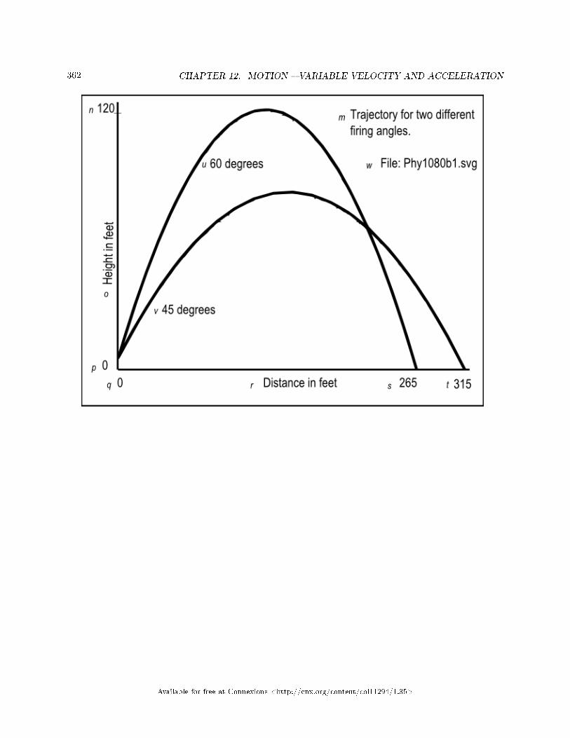
362 CHAPTER 12. MOTION � VARIABLE VELOCITY AND ACCELERATION
Available for free at Connexions <http://cnx.org/content/col11294/1.35>

363
Figure 10 . Non-mirror-image contained in the �le named Phy1080b1.svg.
Table 12.14
Key-value pairsThe key-value pairs for the image in the �le named Phy1080b1 are shown in Figure 11 (p. 363) .
Figure 11 . Key-value pairs for the image in Phy1080b1.svg.
m: Trajectory for two different firing angles
n: 120
o: Height in feet
p: 0
q: 0
r: Distance in feet
s: 265
t: 315
u: 60 degrees
v: 45 degrees
w: File: Phy1080b1.svg
Available for free at Connexions <http://cnx.org/content/col11294/1.35>

364 CHAPTER 12. MOTION � VARIABLE VELOCITY AND ACCELERATION
Table 12.15
Analysis of the outputFigure 8 (p. 355) contains the x and y coordinates of the arrow's position every 0.25 seconds from the
time that it is released until it strikes the ground a little less than 4.5 seconds later.If you are unable to create tactile graphics based on the �le named Phy1080b1.svg, I recommend that
you plot the arrow's positions on your graph board in order to get a feel for the shape of the trajectory Thisis a classic trajectory curve that applies to many di�erent types of projectiles.
Compute for a di�erent angleNext, I recommend that you modify the script by changing the value of the variable named ang from
45 degrees to 60 degrees and load the modi�ed version of the html �le into your browser. This shouldproduce the output shown in Figure 12 (p. 364) . This output is also plotted in the image in the �le namedPhy1080b1.svg.
Figure 12 . Screen output for Listing #4 at 60 degrees.
Start Script
t = 0.00 seconds x = 0.0 feet y = 6.0 feet
t = 0.25 seconds x = 12.5 feet y = 26.7 feet
t = 0.50 seconds x = 25.0 feet y = 45.3 feet
t = 0.75 seconds x = 37.5 feet y = 61.9 feet
t = 1.00 seconds x = 50.0 feet y = 76.5 feet
t = 1.25 seconds x = 62.5 feet y = 89.1 feet
t = 1.50 seconds x = 75.0 feet y = 99.7 feet
t = 1.75 seconds x = 87.5 feet y = 108.3 feet
t = 2.00 seconds x = 100.0 feet y = 114.8 feet
t = 2.25 seconds x = 112.5 feet y = 119.4 feet
t = 2.50 seconds x = 125.0 feet y = 121.9 feet
t = 2.75 seconds x = 137.5 feet y = 122.4 feet
t = 3.00 seconds x = 150.0 feet y = 120.9 feet
t = 3.25 seconds x = 162.5 feet y = 117.4 feet
t = 3.50 seconds x = 175.0 feet y = 111.9 feet
t = 3.75 seconds x = 187.5 feet y = 104.3 feet
t = 4.00 seconds x = 200.0 feet y = 94.8 feet
t = 4.25 seconds x = 212.5 feet y = 83.2 feet
t = 4.50 seconds x = 225.0 feet y = 69.7 feet
t = 4.75 seconds x = 237.5 feet y = 54.1 feet
t = 5.00 seconds x = 250.0 feet y = 36.5 feet
t = 5.25 seconds x = 262.5 feet y = 16.9 feet
t = 5.50 seconds x = 275.0 feet y = -4.7 feet
End Script
Table 12.16
Plot this curve alsoOnce again, if you are unable to create tactile graphics from the �le named Phy1080b1.svg, I recommend
that you plot this set of results on top of the previous results for 45 degrees and compare the two. Whicharrow went higher? Which arrow went further along the horizontal axis?
Available for free at Connexions <http://cnx.org/content/col11294/1.35>

365
Perhaps you could do the same thing for some other launch angles and determine the launch angle thatprovides the greatest horizontal range and which launch angle provides the greatest vertical height. How fardoes the arrow �y when launched at an angle of 0 degrees from a height of 6 feet?
Analysis of the codeThe code in this script treats the horizontal and vertical components of motion independently and uses
the equation given above (p. 352) to determine the position along that axis as a function of time every 0.25seconds.
Common parameter valuesThe code in Listing 4 (p. 354) begins by de�ning common parameter values for the �ring angle, the time
increment at which coordinate values will be computed and displayed, and the initial velocity of the arrowin the �ring direction.
Horizontal and vertical parametersFollowing that, the code in Listing 4 (p. 354) de�nes horizontal parameters and vertical parameters that
will be used to compute the horizontal and vertical components of motion respectively.Horizontal accelerationThe horizontal acceleration is set to zero. In the absence of air resistance, there is nothing to cause the
horizontal component of the arrow to speed up or slow down until it stops suddenly when it hits the ground.Vertical accelerationThe vertical acceleration is set to the acceleration of gravity at the surface of the earth, which is the same
value used for the previous exercises in this module.Decompose the initial velocityThe cosine and sine functions are used to decompose the initial velocity into horizontal and vertical
components of velocity.Initial horizontal and vertical positionsFinally, the horizontal position when the arrow is released is set to 0 and the vertical position is set to 6
feet, approximately the height of the release point for an archer that is six feet tall.Working variablesAfter de�ning the horizontal and vertical parameters, the code in Listing 4 (p. 354) declares working
variables for time, horizontal position (x), and vertical position (y).A while loopA while loop is used to iterate for as long as the arrow is above the ground.During each iteration, the equation given above (p. 352) is evaluated twice, once to determine the height
of the arrow and once to determine the horizontal position of the arrow at the current time.Time starts at 0, and increments by +0.25 seconds during each iteration.The document.write method is called inside the while loop to display the results shown in Figure 8 (p.
355) .
12.4.6 Acceleration of gravity exercise #3
A quadratic equationNow let's turn things around and approach the problem from a di�erent viewpoint. If we subtract d
from both sides of the motion equation given above (p. 352) , replace a by g to avoid confusion later, andthen rearrange the terms, we get the following equation :
0.5*g*t^2+v0*t-d = 0where
• d is distance in units of distance• v0 is the initial velocity in units of distance/time• t is time in units of time• g is acceleration in units of distance/time^2
Available for free at Connexions <http://cnx.org/content/col11294/1.35>

366 CHAPTER 12. MOTION � VARIABLE VELOCITY AND ACCELERATION
In this form, you may recognize this as a standard quadratic equation which is often written asa*t^2 + b*t + c = 0(Now you know why I replaced the acceleration term a by the acceleration term g earlier. I need to
use the symbol a in the standard quadratic equation.)Standard solution for a quadratic equationGiven values for a, b, and c, you should know that the solution for determining the values for t is to �nd
the roots of the equation.There are two roots (hence two values for t). You should also know that the two roots can be found by
evaluating the quadratic formula in two forms.t1 = (-b+Math.sqrt(b*b-4*a*c))/(2*a);t2 = (-b-Math.sqrt(b*b-4*a*c))/(2*a);Using the solutionRelating the coe�cients in the standard motion equation (p. 365) to the coe�cients in the standard
quadratic equation (p. 366) gives us:
• a = 0.5*g• b = v0• c = -d
The scenarioLet's use the scenario posed in the �rst exercise (p. 331) in this module. In this scenario, an archer that
is six feet tall shoots an arrow directly upward with a velocity of 100 feet per second. Assume that the arrowis at a height of 6 feet when it leaves the bow. Also ignore the e�ects of air resistance.
Referring back to Figure 1...We learned from the table in Figure 4 (p. 343) that the arrow was at a height of 89.9 feet at 1 second
on the way up from the surface of the earth, and was at a height of 89.9 feet again on the way down atapproximately 5.2 seconds.
Let's pretend that we don't have the table in Figure 1 (p. 343) and write a script that uses the quadraticform of the standard motion equation (p. 365) along with the quadratic formula (p. 366) to compute thetimes that the arrow was at a height of 89.9 feet.
Do it also for the moonTo make the problem even more interesting, let's also cause the script to compute and display the times
that the arrow was at a height of 89.9 feet assuming that the archer was standing on the surface of the mooninstead of the earth.
An issue involving the initial heightThe standard motion equation (p. 365) can be used to compute the time that the arrow has traveled to
any speci�c height, relative to the height from which it was released. Therefore, since the arrow was releasedfrom a height of 6 feet and it initially traveled up, we need to determine the time at which it had traveled83.9 feet to �nd the time that it was actually at 89.9 feet.
The JavaScript codePlease copy the code from Listing 5 (p. 367) into an html �le and open the �le in your browser.
Available for free at Connexions <http://cnx.org/content/col11294/1.35>

367
Listing 5 . Acceleration of gravity exercise #3.
<!---------------- File JavaScript05.html ---------------------><html><body><script language="JavaScript1.3">
document.write("Start Script </br></br>");
//The purpose of the getRoots function is to compute and
// return the roots of a quadratic equation expressed in
// the format
// a*x^2 + b*x + c = 0
//The roots are returned in the elements of a two-element
// array. If the roots are imaginary, the function
// returns NaN for the value of each root.
function getRoots(a,b,c){
var roots = new Array(2);
roots[0] = (-b+Math.sqrt(b*b-4*a*c))/(2*a);
roots[1] = (-b-Math.sqrt(b*b-4*a*c))/(2*a);
return roots;
}//end getRoots
//Initialize the problem parameters.
var gE = -32.2;//gravity in ft/sec*sec on Earth
var gM = -32.2*0.167;//gravity in ft/sec*sec on the Moon
var v0 = 100;//initial velocity in ft/sec
var d0 = 6;//initial height in feet
var d = 89.9-d0;//target height corrected for initial height
//Equate problem parameters to coefficients in a
// standard quadratic equation.
var a = 0.5*gE;
var b = v0;
var c = -d;
//Solve the quadratic formula for the two times at which the
// height matches the target height corrected for the
// initial height.
var roots = getRoots(a,b,c);
//Extract the two time values from the array.
var t1 = roots[0];//time in seconds
var t2 = roots[1];//time in seconds
//Display the results for the earth.
document.write("On Earth </br>");document.write("Arrow is at " + (d+d0) + " feet at " +
t1.toFixed(2) + " seconds" + "</br>");document.write("Arrow is at " + (d+d0) + " feet at " +
t2.toFixed(2) + " seconds" + "</br></br>");
//Compute and display for the moon
//Adjust the value of a to represent the acceleration
// of gravity on the moon
a = 0.5*gM;
//Solve the quadratic formula for the two times at which the
// height matches the target height corrected for the
// initial height.
roots = getRoots(a,b,c);
//Extract the two time values from the array.
var t1 = roots[0];//time in seconds
var t2 = roots[1];//time in seconds
//Display the results.
document.write("On the Moon </br>");document.write("Arrow is at " + (d+d0) + " feet at " +
t1.toFixed(2) + " seconds" + "</br>");document.write("Arrow is at " + (d+d0) + " feet at " +
t2.toFixed(2) + " seconds" + "</br></br>");
document.write("End Script");
</script></body></html>
Available for free at Connexions <http://cnx.org/content/col11294/1.35>

368 CHAPTER 12. MOTION � VARIABLE VELOCITY AND ACCELERATION
Table 12.17
Screen outputThe text shown in Figure 13 (p. 368) should appear in the browser window when you open the html �le
in the browser.
Figure 13 . Screen output for Listing #5.
Start Script
On Earth
Arrow is at 89.9 feet at 1.00 seconds
Arrow is at 89.9 feet at 5.21 seconds
On the Moon
Arrow is at 89.9 feet at 0.86 seconds
Arrow is at 89.9 feet at 36.33 seconds
End Script
Table 12.18
A function named getRootsThe quadratic formula isn't very complicated, but it is fairly tedious and easy to type incorrectly. There-
fore, I decided to encapsulate it in a function that we can copy into future scripts saving us the need to typeit correctly in the future.
Listing 5 (p. 367) begins with the de�nition of a function named getRoots that receives the parametersa, b, and c, and returns the roots of the quadratic equation in a two-element array.
Real or imaginary rootsThe roots of a quadratic equation can be either real or imaginary. If the roots are imaginary, this function
simply returns NaN (not a number) for each root.The parameters of the problemFollowing the de�nition of the getRoots function, Listing 5 (p. 367) declares and initializes several
variables to establish the parameters of the problem, such as the acceleration of gravity on the earth andmoon, the initial velocity of the arrow, etc.
The computed height versus the target heightThe target height for the problem is 89.9 feet. Note that the variable named d contains that value less
the initial height of 6 feet. Thus, the script will �nd the time at which the arrow has traveled 83.9 feet onthe way up, and the time that it has traveled that same distance on the way back down.
Establish quadratic coe�cientsThe next three lines of code use the problem parameters to establish values for the standard coe�cients
of a quadratic equation, a, b, and c, as described above (p. 365) . Note that at this point in the script, thecoe�cient named a is based on the acceleration of gravity on earth. (Later, it will be changed to re�ectthe acceleration of gravity on the moon.)
Get the roots of the quadratic equationThen the script calls the getRoots function, passing a, b, and c as parameters, and stores the returned
array containing the roots in the variable named roots .Following that, the script extracts the roots from the array and displays them as shown by the text in
the upper half of Figure 13 (p. 368) .
Available for free at Connexions <http://cnx.org/content/col11294/1.35>

369
Repeat the process for the moonThen Listing 5 (p. 367) sets the value of the coe�cient named a to re�ect the acceleration of gravity
on the moon, repeats the process, and displays the results in the lower half of Figure 13 (p. 368) .Note that the arrow reaches the target height somewhat quicker on the moon due to the lower acceleration
of gravity, and takes much longer to arrive at the same height on the way back down to the surface of themoon. Were we to create a chart similar to Figure 4 (p. 343) for the moon, we would see that the arrowgoes much higher before turning around and falling back to the surface of the moon.
12.4.7 Other useful equations
You have learned how to use the following equation to solve various physics problems involving motion in astraight line with uniform acceleration so far in this module.
h = v0*t + 0.5*g*t^2where
• h is the distance of the projectile above the surface of the earth in units of distance• v0 is the initial velocity of the projectile in units of distance/time• t is time in seconds• g is the acceleration of gravity, approximately 9.8 meters per second squared, or approximately 32.2
feet per second squared.
Some physics textbooks also list the following equations as being important .v = v0 + g*tv^2 = v0^2 + 2*g*hwhere v is the velocity of the object and the other terms are the same as described above (p. 369) .
12.4.7.1 Exercise to �nd the velocity
Let's do an exercise using the �rst of the two equations given above (p. 369) .An individual on the surface of the earth shoots an arrow directly upward with a velocity of 100 feet per
second. How many seconds elapse before the arrow turns and starts falling towards the surface of the earth.Ignore the e�ects of air resistance.
Create a scriptPlease copy the code from Listing 6 (p. 370) into an html �le and open the �le in your browser.
Available for free at Connexions <http://cnx.org/content/col11294/1.35>

370 CHAPTER 12. MOTION � VARIABLE VELOCITY AND ACCELERATION
Listing 6 . Exercise to �nd the velocity.
<!---------------- File JavaScript06.html ---------------------><html><body><script language="JavaScript1.3">
document.write("Start Script </br></br>");
//Initialize the problem parameters.
var g = -32.2;//gravity in ft/sec*sec on Earth
var v0 = 100;//initial velocity in ft/sec
//Given that v = v0 + g * t
//At what time does the velocity go to zero?
//Rearrange the terms in the equation.
var t = -v0/g;
//Display the results
document.write("Arrow has zero velocity at " +
t.toFixed(2) + " seconds " + "</br>");
document.write("</br>End Script");
</script></body></html>
Table 12.19
Screen outputThe text shown in Figure 14 (p. 370) should appear in your browser window when you open the html
�le in your browser.
Figure 14 . Screen output for Listing #6.
Start Script
Arrow has zero velocity at 3.11 seconds
End Script
Table 12.20
Analysis of the codeCompared to working through the solutions to the previous exercises, this one seems almost trivial.After establishing values for the acceleration of gravity and the initial velocity of the arrow, the code in
Listing 6 (p. 370) rearranges the �rst equation given above (p. 369) and solves for the value of time at which
Available for free at Connexions <http://cnx.org/content/col11294/1.35>

371
the velocity goes to zero. This is the point in time when the arrow turns from moving up and begins fallingback toward the earth.
The results are shown in Figure 14 (p. 370) . You should compare this result with Figure 1 (p. 335) ,which shows that the arrow reaches its maximum height at approximately 3 seconds, which agrees very wellwith the result shown in Figure 14 (p. 370) .
12.4.7.2 Exercise to �nd the height
Let's do an exercise using the second of the two equations given above (p. 369) .An individual that is six feet tall standing on the surface of the earth shoots an arrow directly upward
with a velocity of 100 feet per second. What is the maximum height achieved by the arrow before it turnsand falls back towards the surface of the earth? Ignore the e�ects of air resistance.
Create a scriptPlease copy the code from Listing 7 (p. 371) into an html �le and open the �le in your browser.
Listing 7 . Exercise to �nd the height.
<!---------------- File JavaScript07.html ---------------------><html><body><script language="JavaScript1.3">
document.write("Start Script </br></br>");
//Initialize the problem parameters.
var g = -32.2;//gravity in ft/sec*sec on Earth
var v0 = 100;//initial velocity in ft/sec
var h0 = 6;//initial height
//Given that v^2 = v0^2 + 2*g*h
//What is the maximum height reached by the arrow?
//Note that the maximum height is six feet more than
// the value given by the above equation because that
// equation is based on the point of release.
//The maximum height occurs when the velocity goes to zero.
//Setting the velocity to zero and rearranging the terms
// in the equation gives:
var h = h0 + (-(v0 * v0))/(2*g);
//Display the results
document.write("Arrow reaches maximum height of " +
h.toFixed(2) + " feet " + "</br>");
document.write("</br>End Script");
</script></body></html>
Table 12.21
Available for free at Connexions <http://cnx.org/content/col11294/1.35>
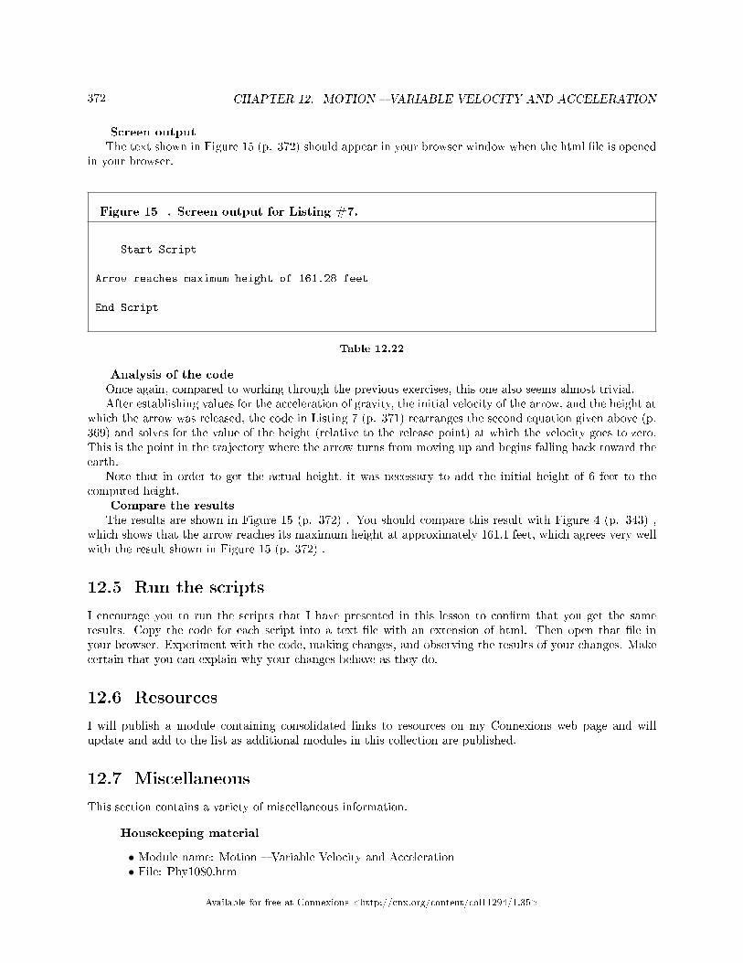
372 CHAPTER 12. MOTION � VARIABLE VELOCITY AND ACCELERATION
Screen outputThe text shown in Figure 15 (p. 372) should appear in your browser window when the html �le is opened
in your browser.
Figure 15 . Screen output for Listing #7.
Start Script
Arrow reaches maximum height of 161.28 feet
End Script
Table 12.22
Analysis of the codeOnce again, compared to working through the previous exercises, this one also seems almost trivial.After establishing values for the acceleration of gravity, the initial velocity of the arrow, and the height at
which the arrow was released, the code in Listing 7 (p. 371) rearranges the second equation given above (p.369) and solves for the value of the height (relative to the release point) at which the velocity goes to zero.This is the point in the trajectory where the arrow turns from moving up and begins falling back toward theearth.
Note that in order to get the actual height, it was necessary to add the initial height of 6 feet to thecomputed height.
Compare the resultsThe results are shown in Figure 15 (p. 372) . You should compare this result with Figure 4 (p. 343) ,
which shows that the arrow reaches its maximum height at approximately 161.1 feet, which agrees very wellwith the result shown in Figure 15 (p. 372) .
12.5 Run the scripts
I encourage you to run the scripts that I have presented in this lesson to con�rm that you get the sameresults. Copy the code for each script into a text �le with an extension of html. Then open that �le inyour browser. Experiment with the code, making changes, and observing the results of your changes. Makecertain that you can explain why your changes behave as they do.
12.6 Resources
I will publish a module containing consolidated links to resources on my Connexions web page and willupdate and add to the list as additional modules in this collection are published.
12.7 Miscellaneous
This section contains a variety of miscellaneous information.
Housekeeping material
• Module name: Motion � Variable Velocity and Acceleration• File: Phy1080.htm
Available for free at Connexions <http://cnx.org/content/col11294/1.35>

373
• Revised: 10/02/15• Keywords:
· physics· accessible· blind· graph board· protractor· screen reader· refreshable Braille display· JavaScript· trigonometry· velocity· instantaneous velocity· variable velocity· acceleration· acceleration of gravity· gravity· tangent line· slope of a line· in�ection point
Disclaimers: Financial : Although the openstax CNX site makes it possible for you todownload a PDF �le for the collection that contains this module at no charge, and also makes itpossible for you to purchase a pre-printed version of the PDF �le, you should be aware that someof the HTML elements in this module may not translate well into PDF.
You also need to know that Prof. Baldwin receives no �nancial compensation from openstaxCNX even if you purchase the PDF version of the collection.
In the past, unknown individuals have copied Prof. Baldwin's modules from cnx.org, convertedthem to Kindle books, and placed them for sale on Amazon.com showing Prof. Baldwin as theauthor. Prof. Baldwin neither receives compensation for those sales nor does he know who doesreceive compensation. If you purchase such a book, please be aware that it is a copy of a collectionthat is freely available on openstax CNX and that it was made and published without the priorknowledge of Prof. Baldwin.
A�liation : Prof. Baldwin is a professor of Computer Information Technology at AustinCommunity College in Austin, TX.
-end-
Available for free at Connexions <http://cnx.org/content/col11294/1.35>

374 CHAPTER 12. MOTION � VARIABLE VELOCITY AND ACCELERATION
Available for free at Connexions <http://cnx.org/content/col11294/1.35>

Chapter 13
Force � Introduction to Statics,
Equilibrium, and Forces1
13.1 Table of Contents
• Preface (p. 375)
· General (p. 375)· Prerequisites (p. 375)· Supplemental material (p. 376)
• General background information (p. 376)
· A real-world example of force and equilibrium (p. 376)· Other examples of force (p. 379)
• Resources (p. 380)• Miscellaneous (p. 380)
13.2 Preface
13.2.1 General
This module is part of a collection of modules designed to make physics concepts accessible to blind students.If you opened this page in the context of the book, a Table of Contents for the book (or collection)
should be available above and to the left of this paragraph. Otherwise, click here 2 to open the book at thebeginning.
This book is intended to supplement but not to replace the textbook in an introductory high school orcollege physics course.
The purpose of this module is to provide an introduction to statics, equilibrium, and forces in a formatthat is accessible to blind students.
13.2.2 Prerequisites
In addition to an Internet connection and a browser, you will need the following tools (as a minimum) towork through the exercises in these modules:
1This content is available online at <http://cnx.org/content/m38117/1.3/>.2http://cnx.org/contents/a7842db2-93c6-4c06-a5e3-56c282358143
Available for free at Connexions <http://cnx.org/content/col11294/1.35>
375

376CHAPTER 13. FORCE � INTRODUCTION TO STATICS, EQUILIBRIUM,
AND FORCES
• A graph board for plotting graphs and vector diagrams (http://www.youtube.com/watch?v=c8plj9UsJbg 3 ).
• A protractor for measuring angles ( http://www.youtube.com/watch?v=v-F06HgiUpw 4 ).• An audio screen reader that is compatible with your operating system, such as the NonVisual Desktop
Access program (NVDA), which is freely available at http://www.nvda-project.org/ 5 .• A refreshable Braille display capable of providing a line by line tactile output of information displayed
on the computer monitor ( http://www.userite.com/ecampus/lesson1/tools.php 6 ).
The minimum prerequisites for understanding the material in these modules include:
• A good understanding of algebra.• An understanding of the use of a graph board for plotting graphs and vector diagrams (
http://www.youtube.com/watch?v=c8plj9UsJbg 7 ).• An understanding of the use of a protractor for measuring angles (
http://www.youtube.com/watch?v=v-F06HgiUpw 8 ).• A basic understanding of the use of sine, cosine, and tangent from trigonometry (
http://www.clarku.edu/∼djoyce/trig/ 9 ).• An introductory understanding of JavaScript programming ( http://www.dickbaldwin.com/tocjscript1.htm
10 and http://www.w3schools.com/js/default.asp 11 ).• An understanding of all of the material covered in the earlier modules in this collection.
13.2.3 Supplemental material
I recommend that you also study the other lessons in my extensive collection of online programming tutorials.You will �nd a consolidated index at www.DickBaldwin.com 12 .
13.3 General background information
I will provide general information about forces and equilibrium in this module and will provide exercisesinvolving those forces in a future module.
13.3.1 A real-world example of force and equilibrium
Assume that you are standing on the surface of the earth. As I explained in an earlier module, there is agravitational attraction between your body mass and the mass of the earth that is directly proportional tothe product of the two masses and inversely proportional to the square of the distance between the centerof mass of your body and the center of mass of the earth.
What about a gas planet?If the earth was a gas planet such as Jupiter, that gravitational attraction would probably pull your body
into the inner portions of the planet and your life would probably come to an abrupt end. That would besimilar to trying to stand on the surface of a lake.
Impenetrable material
3http://www.youtube.com/watch?v=c8plj9UsJbg4http://www.youtube.com/watch?v=v-F06HgiUpw5http://www.nvda-project.org/6http://www.userite.com/ecampus/lesson1/tools.php7http://www.youtube.com/watch?v=c8plj9UsJbg8http://www.youtube.com/watch?v=v-F06HgiUpw9http://www.clarku.edu/∼djoyce/trig/
10http://www.dickbaldwin.com/tocjscript1.htm11http://www.w3schools.com/js/default.asp12http://www.dickbaldwin.com/toc.htm
Available for free at Connexions <http://cnx.org/content/col11294/1.35>

377
Fortunately, the earth is made of rock and other relatively impenetrable material, which prevents youfrom being pulled into the inner portions of the earth by that gravitational attraction.
In order to prevent you from being pulled into the earth, the ground that you are standing on must pushup on the bottom of your feet by an amount equal to the gravitational pull that is being exerted on yourbody.
Your skeleton is criticalIn addition, the bones in your inner skeleton must be capable of withstanding the pull of gravity on your
body to prevent your body from turning into a puddle on the surface of the earth. For example, a raw eggdoesn't have an inner skeleton; it has an exoskeleton, the shell. When you break the shell over a frying panand dump the egg out of the shell, the attraction of gravity causes it to become a puddle in the frying pan.
The push is a forceIn simpli�ed terms, a force is a push or a pull. The push that is being exerted upward on the bottom of
your feet by the surface of the earth is commonly called a force.The gravitational attraction that is trying to pull you into the center of the earth is also a force (which
is often referred to as your weight).EquilibriumIf you are standing in one spot without moving up or down, the entire system that constitutes your body
and the earth is in equilibrium. This means that the upward force being exerted on the bottom of your feetby the surface of the earth is equal in magnitude and opposite in direction from the gravitational force thatis trying to pull you into the earth.
An object is in equilibrium when it is not being accelerated. It may be at rest and remain at rest or itmay be moving with a constant velocity and continue to move at the same velocity. If it is being accelerated,which includes changing its direction of motion, it is not in equilibrium.
Force is a vector quantityIn order for a body to be in equilibrium, the vector sum of all the forces acting on that body must be
zero.The bathroom scalesMany households in the U.S. have a device that is commonly known as the bathroom scale. We use it to
determine "how much we weigh."Assume that you walk into your bathroom and step onto the bathroom scale. To understand everything
that is going on, we need to recognize that the house and the scale inside the house are also being pulledtoward the center of the earth by gravitational attraction. Fortunately the surface of the earth normallyexerts an upward force on the foundation of the house to prevent that from happening. The foundationexerts an upward force on the bathroom �oor, and the �oor exerts an upward force on the scale.
When the strength of the earth fails...Sometimes, under some conditions, the surface of the earth fails to exert an upward force on the foundation
of a house su�cient to prevent it from accelerating toward the center of the earth. I recently saw a video onthe news of a house that was pulled into a sinkhole in Florida. I have seen several news videos where houseshave been pulled toward the center of the earth during landslides in California.
How much do you weigh?When you are standing on the scale, the gravitational force exerted on your body is being supported by
the top surface of the scale. The top surface of the scale is pushing up with a force that is equal and oppositeto the gravitational force that is trying to pull you toward the center of the earth.
The scale also has a weightA gravitational force is also being exerted on the scale trying to pull it into the center of the earth. The
�oor underneath the scale is exerting an upward force on the scale equal to the combined gravitational forceof you and the scale, causing you, the scale, and the �oor to be in equilibrium.
CompressionThese two forces, one pushing down on the top of the scale and the other pushing up on the bottom of the
scale causes the scale to experience something commonly called compression. In other words, the opposing
Available for free at Connexions <http://cnx.org/content/col11294/1.35>

378CHAPTER 13. FORCE � INTRODUCTION TO STATICS, EQUILIBRIUM,
AND FORCES
forces are trying to squeeze the scale into a puddle but the material from which the scale was constructedwon't allow that to happen.
Tension versus compressionAs an aside, the state that we call tension is the opposite of the state that we call compression. If you sit
with all of your weight on a stool, the legs of that stool will be in a state of compression. If you sit with allof your weight in a porch swing supported by chains attached to the ceiling, those chains will be in tension.
A readout in poundsThe bathroom scale contains a mechanism that is capable of measuring the amount of compression that
it is experiencing. It also contains a display mechanism that displays the amount of compression. Typicallyin the U.S., that compression value is converted to force and displayed in units of pounds.
The objective of the bathroom scaleThe objective of the bathroom scale, therefore, is to measure the gravitational force exerted on your body
(your weight) and to display that value for your pleasure or displeasure as the case may be.UnitsIn the so-called English system of units that is commonly used in the U.S., the word pound is used to
indicate mass and the words pound force are used to indicate force. That can be confusing.In the International System of Units, abbreviated SI, the standard unit of mass is the kilogram, abbre-
viated kg, and the standard unit of force is the newton, abbreviated N.A derived unitAs you learned in an earlier module, the SI units consist of base units and units that are derived from
base units. The newton is a derived unit, which when expressed in SI base units is:1 N = 1 kg *m/s^2where
• N is the symbol for newton• kg is the symbol for mass in kilograms• m is the symbol for length in meters• s is the symbol for time in seconds• ^2 means "raised to the second power" or squared
Knowing the relationship between the newton and its base units is important when you are evaluating anequation and need to cause the units to cancel out so as to end up with only the correct units for the result.
Conversion factorThe force that is trying to pull you into the center of the earth (your weight) can be expressed in any of
the following units:
• pound force• newtons• kg*m/s^2
The following conversion factor can be used to convert from English units to SI units:1 pound force = 4.44822162 newtonsTo convert your weight from pounds to newtons, multiply your weight in pounds by 4.448.To convert your weight from newtons to pounds, divide your weight in newtons by 4.448.If your bathroom scale says that your weight is 100 pounds, a bathroom scale calibrated in newtons
would say that your weight is 444.8 newtons.The basis for your weightYou may be wondering why you weigh as much as you do (other than as a result of your appetite for
sweets). As mentioned earlier, the basis for your weight is the gravitational attraction between your bodymass and the mass of the earth.
The acceleration of gravity
Available for free at Connexions <http://cnx.org/content/col11294/1.35>

379
In an earlier module, you learned that two bodies in free fall above the surface of the earth, in the absenceof an atmosphere, will accelerate toward the center of the earth at the same rate, which is about 32.2 ft/sec^2or 9.8 m/s^2.
Your weight, or the gravitational force exerted on your body, is the force necessary to cause your bodyto accelerate toward the center of the earth at 32.2 ft/sec^2.
Acceleration = force/massYou also learned in an earlier module that the acceleration of an object due to an applied force is directly
proportional to the force and inversely proportional to the mass of the object.Therefore, a greater force must be applied to an object with greater mass to achieve the same acceleration.
The greater your body mass, the greater must be the force that will cause your body to accelerate at 32.2ft/sec^2 toward the center of the earth.
Your weightThat force is what we commonly refer to as your weight. The greater your body mass, the greater will
be your weight.Your body in equilibriumIf you climb out and sit on the limb of a tree, that limb must be capable of exerting an amount of upward
force su�cient to cancel the gravitational force acting on your body. Otherwise, you will fall to the surfaceof the earth or to something between the limb and the surface of the earth that is capable of exerting thatupward force..
If the limb doesn't break and you are able to sit there in comfort, the entire system including the tree,the limb, your body, and the earth will be in equilibrium.
Your body out of equilibriumIf the limb is incapable of sustaining that amount of upward force, it will break and allow you to accelerate
towards the center of the earth. That means that the system is not in equilibrium.
13.3.2 Other examples of force
So far, I have limited the discussion to forces that are directly attributable to gravitational attraction. Ibegan this explanation with that limitation because the e�ects of gravitational force are something that mostof us understand pretty well.
However, there are many other examples of force, most which involve the conversion of energy into force.A human who lifts weightsFor example, a human who lifts weight eats a diet that contains energy, commonly measured in calories.
The human body has the ability to convert that energy into the contraction of muscle tissue.When the contraction of muscle tissue is applied in just the right way, a human is capable of generating
forces that overcome the force of gravity exerted on an object and lift that object from the surface of theearth, or whatever is supporting it.
Conversion of chemical energyA chemical explosion has the ability to convert chemical energy into force and cause large rocks to break
their molecular bonds and shatter into small pieces, or to cause rockets to overcome the force of gravity andaccelerate into outer space, leaving the e�ects of the earth's gravitational �eld behind.
Overcoming gravityMuch energy is expended in daily life to overcome the force of gravity. For example, chemical energy
is converted to force to lift large steel beams high in the air to build skyscrapers. Human caloric energy isconverted to various forces to tote roo�ng shingles up a ladder onto a rooftop to make a house water proof.Various types of energy are converted to various forces to lift water to irrigate crops. Chemical energy isconverted to various forces to cause airplanes to �y. Thermal energy is converted to various forces to causehot-air balloons to �y.
Converting kinetic energy to forceVarious weather processes cause solar energy to be converted into kinetic energy in the form of moving
air (wind). The blades on a windmill convert that kinetic energy to forces that are used to pump water orto make electrical power.
Available for free at Connexions <http://cnx.org/content/col11294/1.35>

380CHAPTER 13. FORCE � INTRODUCTION TO STATICS, EQUILIBRIUM,
AND FORCES
When water moves from a high altitude to a lower altitude, potential energy is converted to kineticenergy. The blades on a water wheel or a turbine convert that kinetic energy into forces that are used togrind grain or make electrical power.
Conversion of energy to forceWith the possible exception of gravitational force, I can't think of any kind of force that doesn't result
from the conversion of some form of energy. As an engineer, I strongly suspect that even gravitational forceresults from the conversion of energy at some level, although that conversion may take place at the molecularor atomic level.
13.4 Resources
I will publish a module containing consolidated links to resources on my Connexions web page and willupdate and add to the list as additional modules in this collection are published.
13.5 Miscellaneous
This section contains a variety of miscellaneous information.
Housekeeping material
• Module name: Force � Introduction to Statics, Equilibrium, and Forces• File: Phy1090.htm• Revised: 10/02/15• Keywords:
· physics· accessible· blind· graph board· protractor· screen reader· refreshable Braille display· JavaScript· trigonometry· statics· forces· equilibrium
Disclaimers: Financial : Although the openstax CNX site makes it possible for you todownload a PDF �le for the collection that contains this module at no charge, and also makes itpossible for you to purchase a pre-printed version of the PDF �le, you should be aware that someof the HTML elements in this module may not translate well into PDF.
You also need to know that Prof. Baldwin receives no �nancial compensation from openstaxCNX even if you purchase the PDF version of the collection.
In the past, unknown individuals have copied Prof. Baldwin's modules from cnx.org, convertedthem to Kindle books, and placed them for sale on Amazon.com showing Prof. Baldwin as theauthor. Prof. Baldwin neither receives compensation for those sales nor does he know who doesreceive compensation. If you purchase such a book, please be aware that it is a copy of a collectionthat is freely available on openstax CNX and that it was made and published without the priorknowledge of Prof. Baldwin.
Available for free at Connexions <http://cnx.org/content/col11294/1.35>

381
A�liation : Prof. Baldwin is a professor of Computer Information Technology at AustinCommunity College in Austin, TX.
-end-
Available for free at Connexions <http://cnx.org/content/col11294/1.35>

382CHAPTER 13. FORCE � INTRODUCTION TO STATICS, EQUILIBRIUM,
AND FORCES
Available for free at Connexions <http://cnx.org/content/col11294/1.35>

Chapter 14
Force � Vector Solutions for Coplanar
Forces Concurrent at a Point1
14.1 Table of Contents
• Preface (p. 383)
· General (p. 383)· Prerequisites (p. 384)· Viewing tip (p. 384)
* Figures (p. 385)* Listings (p. 385)
· Supplemental material (p. 385)
• General background information (p. 385)
· Creation of tactile graphics (p. 385)· The law of sines (p. 386)· The law of cosines (p. 396)
• Discussion and sample code (p. 397)
· Using the graph board (p. 397)· Parallelogram of forces (p. 397)· Triangle of forces (p. 418)· Trigonometric solution to the triangle of forces (p. 428)· Using components to analyze for equilibrium (p. 428)
• Run the scripts (p. 442)• Resources (p. 442)• Miscellaneous (p. 442)
14.2 Preface
14.2.1 General
This module is part of a collection of modules designed to make physics concepts accessible to blind students.
1This content is available online at <http://cnx.org/content/m38125/1.5/>.
Available for free at Connexions <http://cnx.org/content/col11294/1.35>
383

384CHAPTER 14. FORCE � VECTOR SOLUTIONS FOR COPLANAR FORCES
CONCURRENT AT A POINT
If you opened this page in the context of the book, a Table of Contents for the book (or collection)should be available above and to the left of this paragraph. Otherwise, click here 2 to open the book at thebeginning.
This book is intended to supplement but not to replace the textbook in an introductory high school orcollege physics course.
This module explains the law of sines and the law of cosines. It also explains vector solutions for coplanarforces that are concurrent at a point in a format that is accessible to blind students.
14.2.2 Prerequisites
In addition to an Internet connection and a browser, you will need the following tools (as a minimum) towork through the exercises in these modules:
• A graph board for plotting graphs and vector diagrams (http://www.youtube.com/watch?v=c8plj9UsJbg 3 ).
• A protractor for measuring angles ( http://www.youtube.com/watch?v=v-F06HgiUpw 4 ).• An audio screen reader that is compatible with your operating system, such as the NonVisual Desktop
Access program (NVDA), which is freely available at http://www.nvda-project.org/ 5 .• A refreshable Braille display capable of providing a line by line tactile output of information displayed
on the computer monitor ( http://www.userite.com/ecampus/lesson1/tools.php 6 ).• A device to create Braille labels. Will be used to label graphs constructed on the graph board.• The ability to create tactile graphics as described here 7 .
The minimum prerequisites for understanding the material in these modules include:
• A good understanding of algebra.• An understanding of the use of a graph board for plotting graphs and vector diagrams (
http://www.youtube.com/watch?v=c8plj9UsJbg 8 ).• An understanding of the use of a protractor for measuring angles (
http://www.youtube.com/watch?v=v-F06HgiUpw 9 ).• A basic understanding of the use of sine, cosine, and tangent from trigonometry (
http://www.clarku.edu/∼djoyce/trig/ 10 ).• An introductory understanding of JavaScript programming ( http://www.dickbaldwin.com/tocjscript1.htm
11 and http://www.w3schools.com/js/default.asp 12 ).• An understanding of all of the material covered in the earlier modules in this collection.• An understanding of the creation and use of tactile graphics as described here 13 .
14.2.3 Viewing tip
I recommend that you open another copy of this document in a separate browser window and use thefollowing links to easily �nd and view the �gures and listings while you are reading about them.
2http://cnx.org/contents/a7842db2-93c6-4c06-a5e3-56c2823581433http://www.youtube.com/watch?v=c8plj9UsJbg4http://www.youtube.com/watch?v=v-F06HgiUpw5http://www.nvda-project.org/6http://www.userite.com/ecampus/lesson1/tools.php7http://cnx.org/contents/9fe07552-485f-43e7-9753-87133cf604828http://www.youtube.com/watch?v=c8plj9UsJbg9http://www.youtube.com/watch?v=v-F06HgiUpw
10http://www.clarku.edu/∼djoyce/trig/11http://www.dickbaldwin.com/tocjscript1.htm12http://www.w3schools.com/js/default.asp13http://cnx.org/contents/9fe07552-485f-43e7-9753-87133cf60482
Available for free at Connexions <http://cnx.org/content/col11294/1.35>

385
14.2.3.1 Figures
• Figure 1 (p. 390) . Mirror image from the �le named Phy1100a1.svg.• Figure 2 (p. 394) . Non-mirror-image version of the image from the �le named Phy1100a1.svg.• Figure 3 (p. 395) . Key-value pairs for the image in the �le named Phy1100a1.svg.• Figure 4 (p. 401) . Mirror image contained in the �le named Phy1100b1.svg.• Figure 5 (p. 405) . Non-mirror-image version of the image from the �le named Phy1100b1.svg.• Figure 6 (p. 406) . Key-value pairs for the image in the �le named Phy1100b1.svg.• Figure 7 (p. 411) . Mirror image from the �le named Phy1100c1.svg.• Figure 8 (p. 415) . Non-mirror-image version of the image from the �le named Phy1100c1.svg.• Figure 9 (p. 416) . Key-value pairs for the image in the �le named Phy1100c1.svg.• Figure 10 (p. 422) . Mirror image from the �le named Phy1100d1.svg.• Figure 11 (p. 426) . Non-mirror-image version of the image from the �le named Phy1100d1.svg.• Figure 12 (p. 427) . Key-value pairs for the image in the �le named Phy1100d1.svg.• Figure 13 (p. 433) . Mirror image from the �le named Phy1100e1.svg.• Figure 14 (p. 437) . Non-mirror-image version of the image from the �le named Phy1100e1.svg.• Figure 15 (p. 438) . Key-value pairs for the image in the �le named Phy1100e1.svg.• Figure 16 (p. 440) . Screen output for Listing #1.• Figure 17 (p. 441) . Changes to Listing #1.• Figure 18 (p. 441) . Screen output for modi�ed Listing #1.
14.2.3.2 Listings
• Listing 1 (p. 439) . Tent pole exercise.
14.2.4 Supplemental material
I recommend that you also study the other lessons in my extensive collection of online programming tutorials.You will �nd a consolidated index at www.DickBaldwin.com 14 .
14.3 General background information
14.3.1 Creation of tactile graphics
The module titled Manual Creation of Tactile Graphics 15 explains how to create tactile graphics from svg�les that I will provide.
If you are going to have an assistant create tactile graphics for this module, you will need to downloadthe �le named Phy1100.zip 16 , which contains the svg �les for this module. Extract the svg �les from thezip �le and provide them to your assistant.
Also, if you are going to use tactile graphics, it probably won't be necessary for you to perform the graphboard exercises. However, you should still walk through the graph board exercises in your mind because Iwill often embed important physics concepts in the instructions for doing the graph board exercises.
In each case where I am providing an svg �le for the creation of tactile graphics, I will identify the nameof the appropriate svg �le and display an image of the contents of the �le for the bene�t of your assistant.As explained here 17 , those images will be mirror images of the actual images so that your assistant canemboss the image from the back of the paper and you can explore it from the front.
14http://www.dickbaldwin.com/toc.htm15http://cnx.org/contents/9fe07552-485f-43e7-9753-87133cf60482/Phy1004-Manual-Creation-of-Tac16http://cnx.org/content/m38125/latest/Phy1100.zip17http://cnx.org/contents/9fe07552-485f-43e7-9753-87133cf60482
Available for free at Connexions <http://cnx.org/content/col11294/1.35>
386CHAPTER 14. FORCE � VECTOR SOLUTIONS FOR COPLANAR FORCES
CONCURRENT AT A POINT
I will also display a non-mirror-image version of the image so that your assistant can easily read the textin the image.
Also in those cases, I will provide a table of key-value pairs that explain how the Braille keys in the imagerelate to text or objects in the image.
14.3.2 The law of sines
Much of the background material needed for this module was presented in the earlier module titled Intro-duction to Statics, Equilibrium, and Forces 18 . However, beginning with this module, you will need someinformation on trigonometry that was not presented in the earlier module titled Brief Trigonometry Tutorial19 . That item is known as the law of sines (see http://en.wikipedia.org/wiki/Law_of_sines 20 ).
Proving identitiesWhen I was a student in a trigonometry course many years ago, students were required to "prove identi-
ties" which was a process very similar to proving theorems in plane geometry. That activity included doingsuch things as proving that the law of sines is true.
I don't know if mathematics instructors still require students to prove identities or not. In any event, wewill simply accept such mathematical truths in this collection of modules and won't worry about provingthat they are true.
We will work through some exercises in this module to show how the law of sines can be used to advantage.Beyond the right trianglePrevious modules using trigonometry have dealt almost exclusively with right triangles. Beginning in
this module, we will start using trigonometry to solve problems that involve triangles that are not righttriangles.
Tactile graphicsThe svg �le that is required to create tactile graphics for this exercise is named Phy1100a1.svg. You
should have downloaded (p. 385) that �le earlier.Figure 1 (p. 390) shows the mirror image that is contained in that �le for the bene�t of your assistant
who will create the tactile graphic for this exercise.
18http://cnx.org/contents/52e8554d-a0e3-4a2f-b18f-6e876178c921/Phy1090-Force�-Introduction-19http://cnx.org/contents/257998f1-068b-4c59-8924-78a29a68b610/Phy1020-Brief-Trigonometry-Tut20http://en.wikipedia.org/wiki/Law_of_sines
Available for free at Connexions <http://cnx.org/content/col11294/1.35>

387
Available for free at Connexions <http://cnx.org/content/col11294/1.35>

388CHAPTER 14. FORCE � VECTOR SOLUTIONS FOR COPLANAR FORCES
CONCURRENT AT A POINT
Available for free at Connexions <http://cnx.org/content/col11294/1.35>
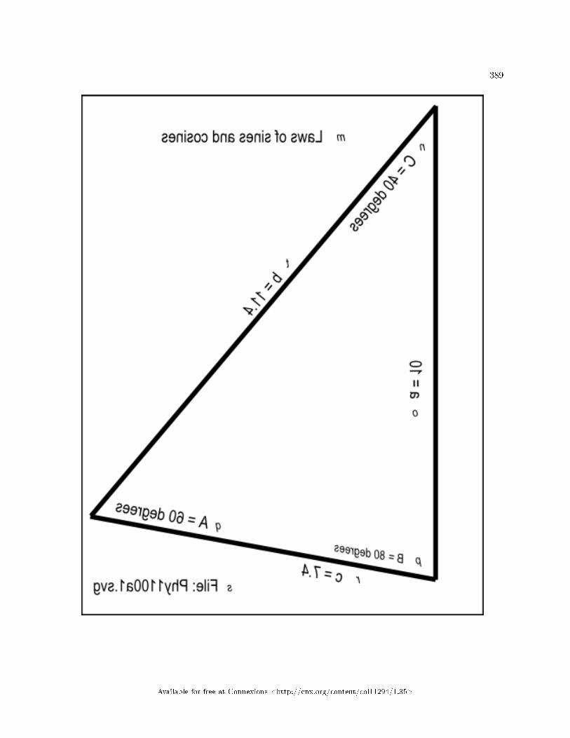
389
Available for free at Connexions <http://cnx.org/content/col11294/1.35>

390CHAPTER 14. FORCE � VECTOR SOLUTIONS FOR COPLANAR FORCES
CONCURRENT AT A POINT
Figure 1 . Mirror image from the �le named Phy1100a1.svg.
Table 14.1
Available for free at Connexions <http://cnx.org/content/col11294/1.35>

391
Figure 2 (p. 394) shows a non-mirror-image version of the same image.
Available for free at Connexions <http://cnx.org/content/col11294/1.35>

392CHAPTER 14. FORCE � VECTOR SOLUTIONS FOR COPLANAR FORCES
CONCURRENT AT A POINT
Available for free at Connexions <http://cnx.org/content/col11294/1.35>

393
Available for free at Connexions <http://cnx.org/content/col11294/1.35>

394CHAPTER 14. FORCE � VECTOR SOLUTIONS FOR COPLANAR FORCES
CONCURRENT AT A POINT
Figure 2 . Non-mirror-image version of the image from the �le named Phy1100a1.svg.
Table 14.2
Available for free at Connexions <http://cnx.org/content/col11294/1.35>

395
Key-value pairsFigure 3 (p. 395) shows the key-value pairs that go with the image in the �le named Phy1100a1.svg.
Figure 3 . Key-value pairs for the image in the �le named Phy1100a1.svg.
m: Laws of sines and cosines
n: C = 40 degrees
o: a = 10
p: B = 80 degrees
q: A = 60 degrees
r: c = 7.4
s: File: Phy1100a1.svg
t: b = 11.4
Table 14.3
Create a trianglePlease use your graph board to create a triangle with the dimensions, angles, and labels speci�ed below.Use your Braille labeler to label the sides of the triangle a, b, and c. Label the angle opposite from side
a as A, the angle opposite side b as B, and the angle opposite side c as C.Adjust your triangle to make side a equal to 10 units, angle B equal to 80 degrees, and angle C equal
to 40 degrees. Using the above relationship, we also know that angle A is equal to 60 degrees because theangles in a triangle must sum to 180 degrees.
Using the law of sinesThe law of sines can be used to compute the remaining sides of a triangle when two angles and a side
are known. Of course, if you know two of the angles of a triangle, you also know the third angle because thesum of the angles in a triangle is always 180 degrees.
Use the Google calculatorAll of the arithmetic and trigonometric requirements in this section can be satis�ed using the Google
calculator. Go to Google and enter the following in the search box:sine 80 degreesGoogle should produce a line of output text that reads:sine(80 degrees) = 0.984807753Record this value for future use.Get and record two more valuesGo to Google again and enter sine 40 degrees. The output should be:sine(40 degrees) = 0.64278761Doing the same thing again for 60 degrees produces:sine(60 degrees) = 0.866025404The law of sines formula
Given the names of the sides and angles that you have applied to your triangle, the law of sines says thatthe following is true:
(a/sin A) = (b/sin B) = (c/sin C)In general, the law of sines states that the ratio of the length of any side to the sine of the opposite angle
is equal to the ratio of any other side to the sine of its opposite angle.Compute the length of side bSubstituting the known values in the above formula gives us:(10/0.866) = (b/0.985) = (c/0.643)
Available for free at Connexions <http://cnx.org/content/col11294/1.35>

396CHAPTER 14. FORCE � VECTOR SOLUTIONS FOR COPLANAR FORCES
CONCURRENT AT A POINT
Combining the �rst and second ratios and rearranging terms gives us:b = 10 * 0.985/0.866 = 11.4(You can also use the search box at Google to perform arithmetic such as 10 * 0.985/0.866.)Compute the length of side cCombining the �rst and third ratios and rearranging terms gives us:c = 10*0.643/.866 = 7.42Hopefully, you can con�rm these values (approximately) by making measurements on the triangle on
your graph board.Another use for the law of sinesThe law of sines can also be used when two sides and one of the non-enclosed angles is known to �nd the
values of the other side and the values of the other two angles.Let's give that scenario a test drivePretend that all we know about the triangle is the following:
• Side a = 10• Side b = 11.3741339• Angle B = 80 degrees• sin B = 0.984807753
We need to solve for angles A and C as well as side c.Substitution of known valuesRecall that the general formula for the law of sines is:(a/sin A) = (b/sin B) = (c/sin C)Substitution of the known values into the formula gives:(10/sin A) = (11.3741339/0.984807753) = (c/sin C)Rearranging termsUsing the �rst two ratios and rearranging terms gives us:sin A = 10*0.984807753/11.3741339 = 0.865830983A = arcsine(0.865830983) = 1.04680884 radians = 60 degrees(Note that I used an extreme number of decimal digits to avoid rounding errors and cause the �nal answer
to come out almost exactly correct.)Compute the value of angle cNow that we know the values of angles A and B, we also know thatAngle C = 180 - 80 - 60 = 40 degrees.Compute the length of side cUsing the second and third ratios and rearranging terms, we can solve for side c as:c = sin C * (11.3741339/0.984807753)= 0.64278761 * (11.3741339/0.984807753)= 7.42393866Thus, we have determined that:
• Angle A = 60 degrees• Angle C = 40 degrees• Side c = 7.42
These values all match what we know to be true from the �rst example.
14.3.3 The law of cosines
In addition to the law of sines, there is also a law of cosines. The law of cosines is useful for computingthe third side of a triangle when two sides and their enclosed angle are known. The law is also useful incomputing the angles of a triangle when all three sides are known.
Using the same names for the sides and the angles, there are three formulas for the law of cosines :
Available for free at Connexions <http://cnx.org/content/col11294/1.35>

397
• c^2 = a^2 + b^2 - 2*a*b*cos C• a^2 = b^2 + c^2 - 2*b*c*cos A• b^2 = a^2 + c^2 - 2*a*c*cos B
Compute the length of side cUsing the known values from the earlier example, we can compute the length of side c by entering the
following expression into the Google search box:sqrt(10^2 + 11.3^2 - 2*10*11.3*cos(40*pi/180))This produces an answer of 7.39, which is close enough to the known value for the length of side c.Compute angle C in degreesSimilarly, using the known values from the earlier example, we can compute the angle C knowing the
lengths of the three sides. Enter the following expression into the Google search box:arccos((10^2 + 11.3^2 - 7.39^2)/(2*10*11.3))*180/piThis produces an answer of 40.02 which is close enough to the known value for the angle C in degrees.An exercise for the studentI will leave it as an exercise for the student to work through the algebra to determine how I used the
known values and the �rst formula given above (p. 396) to construct the expressions that I entered into theGoogle search box.
14.4 Discussion and sample code
Now that we have expanded our knowledge of trigonometry, let's examine some solutions to problems in-volving force using vectors.
All of the exercises that we will work through in this module involve forces in a two-dimensional plane(coplanar) that meet at a point (concurrent at a point). This excludes forces that create moments or torques,which will be the topic of future modules, and also excludes forces that may come from any direction in athird dimension.
14.4.1 Using the graph board
You will be making heavy use of your graph board in this module. In order to make the instructions lessawkward, I am going to begin using drawing syntax when talking about the graph board. For example, whenI say draw a line from 3,5 to 10,15, that will mean for you to insert a pin at coordinates x=3 and y=5, toinsert a second pin at x=10 and y=15, and to connect the two pins with a rubber band, a pipe cleaner, awire, a piece of yarn, or whatever works for you.
14.4.2 Parallelogram of forces
Force is a vector. It has both magnitude and direction. You learned in an earlier module that you can resolvevectors two at a time using a method that involves parallelograms.
Stated more formally, any two forces meeting at a point can be replaced by a single resultant force, whichis represented by the diagonal of a parallelogram whose two adjacent sides represent the two forces.
Tactile graphicsThe �le named Phy1100b1.svg contains an image from which your assistant can create a tactile graphic
to illustrate the scenario described below (p. 406) .Figure 4 (p. 401) shows the mirror image that is contained in that �le for the bene�t of your assistant
who will create the tactile graphic for this exercise.
Available for free at Connexions <http://cnx.org/content/col11294/1.35>

398CHAPTER 14. FORCE � VECTOR SOLUTIONS FOR COPLANAR FORCES
CONCURRENT AT A POINT
Available for free at Connexions <http://cnx.org/content/col11294/1.35>

399
Available for free at Connexions <http://cnx.org/content/col11294/1.35>

400CHAPTER 14. FORCE � VECTOR SOLUTIONS FOR COPLANAR FORCES
CONCURRENT AT A POINT
Available for free at Connexions <http://cnx.org/content/col11294/1.35>

401
Figure 4 . Mirror image contained in the �le named Phy1100b1.svg.
Table 14.4
Available for free at Connexions <http://cnx.org/content/col11294/1.35>

402CHAPTER 14. FORCE � VECTOR SOLUTIONS FOR COPLANAR FORCES
CONCURRENT AT A POINT
Figure 5 (p. 405) shows a non-mirror-image version of the same image.
Available for free at Connexions <http://cnx.org/content/col11294/1.35>

403
Available for free at Connexions <http://cnx.org/content/col11294/1.35>

404CHAPTER 14. FORCE � VECTOR SOLUTIONS FOR COPLANAR FORCES
CONCURRENT AT A POINT
Available for free at Connexions <http://cnx.org/content/col11294/1.35>

405
Figure 5 . Non-mirror-image version of the image from the �le named Phy1100b1.svg.
Table 14.5
Available for free at Connexions <http://cnx.org/content/col11294/1.35>

406CHAPTER 14. FORCE � VECTOR SOLUTIONS FOR COPLANAR FORCES
CONCURRENT AT A POINT
Figure 6 (p. 406) shows the key-value pairs that go with the image in the �le named Phy1100b1.svg.
Figure 6 . Key-value pairs for the image in the �le named Phy1100b1.svg.
m: Schematic diagram of the scenario
n: pipe
o: cord under tension
p: slack cord
q: cord under tension
r: cord under tension
s: 1.02 kg mass
t: File: Phy1100b1.svg
u: small connecting ring
Table 14.6
The scenarioPlease draw a schematic diagram of this scenario on your graph board.A strong pipe extends from left to right in the work area supported on both ends. You can get your
hands around the pipe to attach things to it.Light, strong, �exible cordsYou tie two light, strong, �exible cords to the pipe approximately one meter apart. (the distance isn't
critical). We will ignore the weight of the cords. You thread the ends of the two cords through a small ringthat is just large enough for you to tie four cords onto the ring. (The only purpose of the ring is to providea convenient way to attach cords together at a single point.)
Adjust the position of the ringYou adjust the position of the ring on each of the cords so that the cord on the left forms a 60-degree
south of east angle with the pipe and the cord on the right forms a 45 degree south of west angle with thepipe. Then you tie both cords to the ring at that point.
A triangleWhen you pull straight down on the ring, the two cords and the pipe form a triangle. The interior angle
at the upper-left vertex is 60 degrees, the interior angle at the upper-right vertex is 45 degrees, and becausethe sum of the angles in a triangle is 180 degrees, the interior angle at the bottom vertex is 75 degrees.
Attach a mass to the ringYou tie a short cord to the bottom of the ring and tie a 1.02 kg mass to the cord. (A 1.02 kg mass has
a weight of approximately 10 newtons.). Then you allow the two cords that are tied to the pipe to supportthe mass, which pulls straight down with a force of 10 newtons.
The structure of the systemNow, let's think about the structure of this system. It consists of three cords emanating out from a small
ring with each cord exerting a force on the ring.Compression or tension?To begin with, a �exible cord cannot support a compressive force. If you push on one end of a cord in
an attempt to push the object attached to the other end, the cord will simply bend. Therefore, the cords inthis scenario cannot possibly exert a pushing force on the ring.
However, a cord can support a tension or pulling force. In other words, any or all of the cords can supporta pulling force on the ring.
Nothing else is touching the ringThe ring is not in contact with anything other than the three cords at this point in time, and the ring is
in equilibrium. By that I mean that the ring has zero velocity and no acceleration.
Available for free at Connexions <http://cnx.org/content/col11294/1.35>

407
(We are also assuming that the ring is, for all practical purposes, a point and it is not experiencing amoment or a torque. Once again, we'll get into moments and torques in a future module.)
Thee pulling forcesSo, we know that the ring is being subjected to three pulling forces. A pulling force of 10 newtons is
pulling straight down toward the center of the earth. The forces associated with the two upper cords mustbe along the lengths of the cords. Otherwise, the cords and the ring would be moving.
Tactile graphicsThe �le named Phy1100c1.svg contains a force vector diagram for this scenario.Figure 7 (p. 411) shows the mirror image that is contained in that �le for the bene�t of your assistant
who will create the tactile graphic for this exercise.
Available for free at Connexions <http://cnx.org/content/col11294/1.35>

408CHAPTER 14. FORCE � VECTOR SOLUTIONS FOR COPLANAR FORCES
CONCURRENT AT A POINT
Available for free at Connexions <http://cnx.org/content/col11294/1.35>

409
Available for free at Connexions <http://cnx.org/content/col11294/1.35>

410CHAPTER 14. FORCE � VECTOR SOLUTIONS FOR COPLANAR FORCES
CONCURRENT AT A POINT
Available for free at Connexions <http://cnx.org/content/col11294/1.35>

411
Figure 7 . Mirror image from the �le named Phy1100c1.svg.
Table 14.7
Available for free at Connexions <http://cnx.org/content/col11294/1.35>

412CHAPTER 14. FORCE � VECTOR SOLUTIONS FOR COPLANAR FORCES
CONCURRENT AT A POINT
Figure 8 (p. 415) shows a non-mirror-image version of the same image.
Available for free at Connexions <http://cnx.org/content/col11294/1.35>

413
Available for free at Connexions <http://cnx.org/content/col11294/1.35>

414CHAPTER 14. FORCE � VECTOR SOLUTIONS FOR COPLANAR FORCES
CONCURRENT AT A POINT
Available for free at Connexions <http://cnx.org/content/col11294/1.35>

415
Figure 8 . Non-mirror-image version of the image from the �le named Phy1100c1.svg.
Table 14.8
Available for free at Connexions <http://cnx.org/content/col11294/1.35>

416CHAPTER 14. FORCE � VECTOR SOLUTIONS FOR COPLANAR FORCES
CONCURRENT AT A POINT
Figure 9 (p. 416) shows the key-value pairs that go with the image in the �le named Phy1100c1.svg.
Figure 9 . Key-value pairs for the image in the �le named Phy1100c1.svg.
m: Force vector diagram.
n: Parallelogram lines
o: 7.3 newtons
p: Vector C
q: Resultant
r: 10 newtons
s: Vector B
t: 5.3 newtons
u: 60 degrees
v: 45 degrees
w: 10 newtons
x: Vector A
y: File: Phy1100c1.svg
Table 14.9
Directions of the forcesThe fact that the cords can only support tension tells us that one of the two forces pulling in an upward
direction is actually pulling at an angle of 45 degrees north of east(the direction of the cord). The otherforce is pulling at angle of 60 degrees north of west.
What is the tension in each cord?So, three interesting questions are:
• What is the tension in each of the cords.• How much of the 10-newton load is being carried by the cord on the right.• How much of the load is being carried by the cord on the left?
We can determine the answers to those questions using the parallelogram rule. At least we can �nd thetension in each of the cords and determine if those tensions are su�cient to carry the 10-newton load.
The parallelogram ruleAs I told you earlier, any two forces meeting at a point (we're considering the ring to be a point) can
be replaced by a single resultant force, which is represented by the diagonal of a parallelogram whose twoadjacent sides represent the two forces.
If we can �gure out what the resultant force is, we can �gure out the answer to the above questionsregarding the tensions and the load being borne by each of the upper cords.
We should be able to �gure out what the resultant force is with a thought experiment based on our lifeexperiences.
Tie a fourth cord to the ringPretend that you tie another cord to the top of the ring and loop it over the pipe somewhere between
the tie points of the other two cords. (This cord is indicated by the object labeled "slack cord" in the imagein the �le named Phy1100b1.svg and also in the image in Figure 5 (p. 405) .)
Then pull very slowly on that fourth cord until both of the other cords go slack. At that point, the fourthcord, (which is somewhat analogous to the resultant of the forces in the other two cords) has assumed theentire 10-newton load.
Is the ring in equilibrium?
Available for free at Connexions <http://cnx.org/content/col11294/1.35>

417
Did the ring and the mass move sideways when the other two cords went slack. If so, the equilibrium ofthe system was disrupted. Relax the tension on the fourth cord, move it slightly sideways, and repeat theexperiment. Continue this process until you �nd a location where the ring doesn't move sideways when thefourth cord assumes the total load.
Only one location will su�ceYou can probably agree, from prior experience on the swing set at the playground as a child, that the
only location at which the fourth cord can assume the total load without the ring moving sideways is whenthe fourth cord passes over the pipe directly above the ring and the mass. Therefore, we know that theresultant of the forces being exerted by the original two upper cords must be on a vertical line directly abovethe ring and the mass.
The diagonalWe also know on the basis of the above rule (p. 416) that the length of the resultant force is proportional
to the length of the diagonal of a parallelogram whose two adjacent sides represent the two forces that arebeing resolved.
The resultant forceThe resultant force is indicated by a heavy dashed vector pointing upward in the image in Phy1100c1.svg.
Two sides of the parallelogram are represented by lighter dashed lines. The other two sides of the parallel-ogram are represented by heavy solid vectors, one at 45 degrees relative to the horizontal and the other at60 degrees relative to the horizontal.
The length of the resultant force vectorLet's think a bit about the required length of the resultant force vector. The above experiment resolves
the force system into only two forces acting on the ring. (The original two upward force vectors are eliminatedfrom the picture when those two cords go slack.) One force is directed up and the other force is directeddown.
The vector sum must be zero for equilibriumWe also know that the vector sum of all the forces acting on a point must be zero in in order for the
point to be in equilibrium. Since there are the only two forces acting on the ring, the only way that theycan sum to zero is for them to be equal in magnitude and opposite in direction from one another.
Equal and oppositeThe force vector pulling down on the ring has a magnitude of 10 newtons. We know because we tied a
ten-newton load to the bottom of the ring. Therefore, the magnitude of the resultant vector pulling up onthe ring must also be 10 newtons. That is the required length of the diagonal of the parallelogram discussedearlier.
The graphical solutionDraw the force vector pointing straight up from the ring with a length of ten units. (You can use whatever
drawing scale is convenient for your drawing.) That is the diagonal of a parallelogram. Two force vectors liealong the lines of the two cords. Those two force vectors form the adjacent sides of a parallelogram, but wedon't yet know their lengths.
Complete the parallelogramThe lengths of the force vectors that lie along the lines of the cords are equal to the sides of the paral-
lelogram. That provides the answer to the original question regarding the tension in each of the cords. Thetension in each cord is equal to the length of the side of the parallelogram using the same scale that wasused to draw the 10-newton diagonal length.
Drawing the parallelogram might be di�cultDrawing the parallelogram is not particularly easy even for a sighted person without special drawing
tools. Here is one way that I have found to do it.Draw a horizontal line (parallel to the pipe) that just touches the tip of the force vector that represents
the diagonal. Then use your protractor to draw lines that begin at the tip of the force vector and emanatedownward on both sides of the diagonal at angles of 60 degrees south of east and 45 degrees south of west.Be sure to do it in the correct order so that you end up with a parallelogram.
Mark the spots
Available for free at Connexions <http://cnx.org/content/col11294/1.35>

418CHAPTER 14. FORCE � VECTOR SOLUTIONS FOR COPLANAR FORCES
CONCURRENT AT A POINT
Mark the spots where those lines cross the two upper cords. Those spots are the tips of the force vectorsin the cords.
My answerWhen I did it graphically (using pencil, paper, protractor, and ruler), I got the length of the force vector
pointing 45 degrees north of east to have a length of 5.3 newtons. I got the length of the force vectorpointing north of west to be 7.3 newtons. These are the values on the upper force vectors in the image inPhy1100c1.svg.
Numeric sum exceeds 10 newtonsYou may have noticed that the numeric sum of the magnitudes of these two force vectors exceeds the
load of 10 newtons. How can that be?The answer is that when force vectors that are supporting a vertical load go o� in a direction other than
vertical, only the vertical component of the force vector counts insofar as supporting the load is concerned.The vertical components of the two force vectors are:
• 5.3*sin(45 degrees) = 3.74• 7.3*sin(60 degrees) = 6.32
The sum of the vertical components is:6.32 + 3.74 = 10.06which is close enough to the downward force being exerted on the ring by the mass.Your answerWere you able to get reasonably close to my answers? If so, congratulations. If not, don't worry too
much about it. The most important thing is for you to understand the process and not to develop expertisein constructing accurate drawings using pushpins and rubber bands. However, I do believe that constructingvector diagrams will help you gain a better understanding of the process.
Later I will show you how to solve the same .problem mathematically which is probably the better choicefor a blind student.
14.4.3 Triangle of forces
Now let's take another look at the same problem from a somewhat di�erent graphical viewpoint. To recap,we have a point in a plane (the ring) which is subjected to the following three vector forces and the ring isin equilibrium. (All angles are given relative to the positive horizontal axis).
• Vector A � A force of 10 newtons at an angle of -90 degrees.• Vector B � A force of an unknown magnitude at an angle of 45 degrees.• Vector C � A force of an unknown magnitude at an angle of 120 degrees.
We know that in order for the ring to be in equilibrium, the sum of the vectors for these three forces mustadd to zero. What are the magnitudes of the forces that vector B and vector C exert on the ring?
Drawing tail to tipYou learned in an earlier module that you can add vectors graphically by drawing them tail to tip. Once
you have done that, the resultant vector is a vector that extends from the tail of the �rst vector to the tipof the last vector.
Tactile graphicsThe �le named Phy1100d1.svg contains the image that is required to create a tactile graphic for this
scenario.Figure 10 (p. 422) shows the mirror image that is contained in that �le for the bene�t of your assistant
who will create the tactile graphic for this exercise.
Available for free at Connexions <http://cnx.org/content/col11294/1.35>

419
Available for free at Connexions <http://cnx.org/content/col11294/1.35>
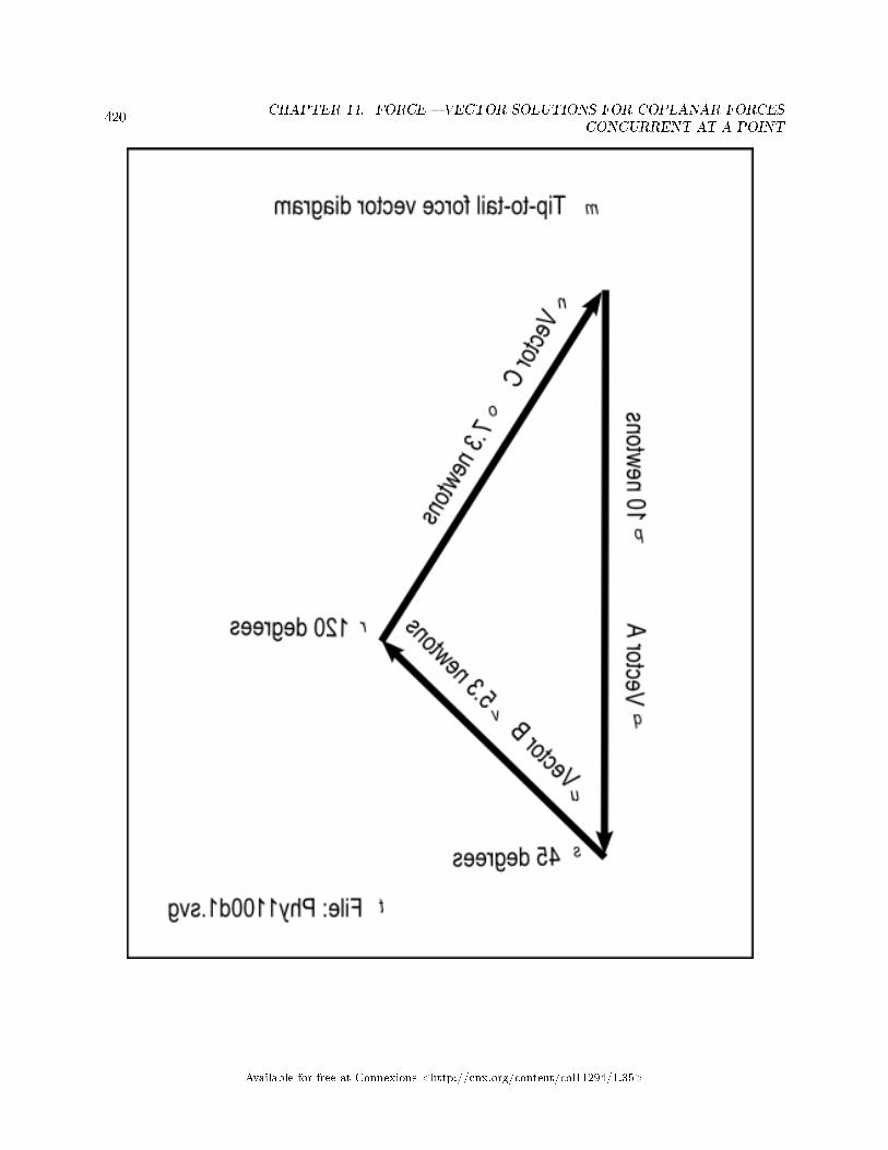
420CHAPTER 14. FORCE � VECTOR SOLUTIONS FOR COPLANAR FORCES
CONCURRENT AT A POINT
Available for free at Connexions <http://cnx.org/content/col11294/1.35>

421
Available for free at Connexions <http://cnx.org/content/col11294/1.35>

422CHAPTER 14. FORCE � VECTOR SOLUTIONS FOR COPLANAR FORCES
CONCURRENT AT A POINT
Figure 10 . Mirror image from the �le named Phy1100d1.svg.
Table 14.10
Available for free at Connexions <http://cnx.org/content/col11294/1.35>

423
Figure 11 (p. 426) shows a non-mirror-image version of the same image.
Available for free at Connexions <http://cnx.org/content/col11294/1.35>

424CHAPTER 14. FORCE � VECTOR SOLUTIONS FOR COPLANAR FORCES
CONCURRENT AT A POINT
Available for free at Connexions <http://cnx.org/content/col11294/1.35>

425
Available for free at Connexions <http://cnx.org/content/col11294/1.35>

426CHAPTER 14. FORCE � VECTOR SOLUTIONS FOR COPLANAR FORCES
CONCURRENT AT A POINT
Figure 11 . Non-mirror-image version of the image from the �le named Phy1100d1.svg.
Table 14.11
Available for free at Connexions <http://cnx.org/content/col11294/1.35>

427
Figure 12 (p. 427) shows the key-value pairs that go with the image in the �le named Phy1100d1.svg.
Figure 12 . Key-value pairs for the image in the �le named Phy1100d1.svg.
m: Tip-to-tail force vector diagram
n: Vector C
o: 7.3 newtons
p: 10 newtons
q: Vector A
r: 120 degrees
s: 45 degrees
t: File: Phy1100d1.svg
u: Vector B
v: 5.3 newtons
Table 14.12
A closed path for equilibriumFor this case where the sum must be zero, the resultant vector must have a zero length. This means that
the tip of the last vector must touch the tail of the �rst vector. In other words, the connected vectors mustdescribe a closed path.
In the earlier modules, you were given the magnitude and direction of several vectors and you arrangedthem tail to tip in order to �nd the resultant vector. However, for this problem, you know the direction andmagnitude of one vector but you only know the directions for the other two vectors. You need to �nd theirmagnitudes.
Knowing that the three vectors must form a closed path makes a graphical solution to this problempossible.
Draw a vector diagramBegin by drawing vector A with a length of 10 newtons at an angle of -90 degrees, using whatever plotting
scale works for you. The tail for this vector will be at the top of the vertical line and the tip will be at thebottom.
Add vector B to the diagramGo to the tip of vector A and draw vector B with an unspeci�ed length at an angle of 45 degrees. The
tail of vector B will touch the tip of vector A and the tip of vector B will be somewhere up and to the rightof the tip of vector A.
Add vector C to the diagramGo to the tail of vector A and draw vector C with an unspeci�ed length at an angle of 120 degrees. The
tip of vector C will touch the tail of vector A and the tail of vector C will be somewhere down and to theright of the tail of vector A.
The lines should crossIf you did everything right, the lines that describe vector B and vector C should cross. Use a pushpin to
mark the place where they cross. This point will be the tip of vector B and will be the tail of vector C.Measure the lengths of vector B and vector CAt this point, you can measure the lengths of the lines that describe vector B and vector C. Using the
same plotting scale that you used for the 10-newton vector A, you can determine the magnitudes of each ofthose vectors.
Since this is the same problem as before, the magnitudes for those two vectors should be the same asbefore. Vector B should be about 5.3 newtons and vector C should be about 7.3 newtons.
Was this easier than the parallelogram?
Available for free at Connexions <http://cnx.org/content/col11294/1.35>

428CHAPTER 14. FORCE � VECTOR SOLUTIONS FOR COPLANAR FORCES
CONCURRENT AT A POINT
I suspect that you probably found the physical construction of the triangle solution to be easier than thephysical construction of the parallelogram solution. I further suspect that the trigonometric solution, whichI will explain in the next section, will be even easier for blind students.
14.4.4 Trigonometric solution to the triangle of forces
Let's pretend that you don't have a graphic solution for this problem. However, you do have a rough sketchof what the triangle looks like on your graph board. Use your Braille labeler to label the three vectors inthe sketch A, B, and C. Then label the angles opposite each side as a, b, and c respectively.
Here are the facts as we know them at this point:
• Vector A = 10 newtons.• Angle a = 105 degrees.• Sine 105 degrees = 0.966• Angle b = 30 degrees• Sine 30 degrees = 0..5• Angle c = 45 degrees• Sine c = 0.707
The law of sinesWe will solve this problem using the law of sines that I explained earlier. Given the names that we have
applied to the sides and the angles for this triangle, the law of sines can be written as follows:(A/sin a) = (B/sin b) = (C/sin c)(Note that upper and lower-case letters were switched relative to the law of sines given near the beginning
(p. 395) of this module.)Solve for the length of side BUsing the �rst two ratios and rearranging terms givesB = A*sin b/sin a = 5.18Solve for the length of side CUsing the �rst and third ratio and rearranging terms givesC = A*sin c/sin a = 7.32The answersThese are the answers that we are looking for:
• B = 5.18 newtons• C = 7.32 newtons
14.4.5 Using components to analyze for equilibrium
Tent pole exercisePlease sketch this scenario on your graph board. Then we will solve the problem using a script and
components.A bird's eye view of the top of a tent pole shows guy wires extending outward and exerting radial
10-newton forces on a tent pole at the following angles :
• 0 degrees• 45 degrees• 90 degrees• 135 degrees• 180 degrees• 225 degrees• 270 degrees
Available for free at Connexions <http://cnx.org/content/col11294/1.35>

429
Tactile graphicsThe image in the �le named Phy1100e1.svg contains seven vectors of equal length emanating out from a
common point at the angles given above.Figure 13 (p. 433) shows the mirror image that is contained in that �le for the bene�t of your assistant
who will create the tactile graphic for this exercise.
Available for free at Connexions <http://cnx.org/content/col11294/1.35>

430CHAPTER 14. FORCE � VECTOR SOLUTIONS FOR COPLANAR FORCES
CONCURRENT AT A POINT
Available for free at Connexions <http://cnx.org/content/col11294/1.35>

431
Available for free at Connexions <http://cnx.org/content/col11294/1.35>

432CHAPTER 14. FORCE � VECTOR SOLUTIONS FOR COPLANAR FORCES
CONCURRENT AT A POINT
Available for free at Connexions <http://cnx.org/content/col11294/1.35>

433
Figure 13 . Mirror image from the �le named Phy1100e1.svg.
Table 14.13
Available for free at Connexions <http://cnx.org/content/col11294/1.35>

434CHAPTER 14. FORCE � VECTOR SOLUTIONS FOR COPLANAR FORCES
CONCURRENT AT A POINT
Figure 14 (p. 437) shows a non-mirror-image version of the same image.
Available for free at Connexions <http://cnx.org/content/col11294/1.35>

435
Available for free at Connexions <http://cnx.org/content/col11294/1.35>

436CHAPTER 14. FORCE � VECTOR SOLUTIONS FOR COPLANAR FORCES
CONCURRENT AT A POINT
Available for free at Connexions <http://cnx.org/content/col11294/1.35>

437
Figure 14 . Non-mirror-image version of the image from the �le named Phy1100e1.svg.
Table 14.14
Available for free at Connexions <http://cnx.org/content/col11294/1.35>

438CHAPTER 14. FORCE � VECTOR SOLUTIONS FOR COPLANAR FORCES
CONCURRENT AT A POINT
Figure 15 (p. 438) shows the key-value pairs that go with the image in the �le named Phy1100e1.svg.
Figure 15 . Key-value pairs for the image in the �le named Phy1100e1.svg.
m: Tent pole exercise
n: File: Phy1100e1.svg
Table 14.15
EquilibriumIs the tent pole in equilibrium? If not, why not? What new force would need to be added to cause it to
be in equilibrium?You can probably solve this exercise in your head by inspection of the force vectors because they are all
of the same length and they emanate outward at regularly spaced angles around the pole.Could be more complexNote, however, that the scenario could be much more complicated involving force vectors with di�erent
lengths arranged at seemingly random angles around the pole.The important point is, the same general scheme would be used to solve the more complicated problem
as is used to solve this simple exercise. However, the code in the script for the more complicated versionwould probably be somewhat more messy.
The scheme for the solutionThe solution is to compute the sum of the force vectors to determine if the resultant vector is zero. If it
is not zero, the tent pole would not be in equilibrium. It would be necessary to add a new force vector withthe same magnitude as the resultant vector but in a direction that is the exact opposite of the direction ofthe resultant vector to cause the tent pole to be in equilibrium.
Create a scriptPlease copy the code from Listing 1 (p. 439) into an html �le and open the �le in your browser.
Available for free at Connexions <http://cnx.org/content/col11294/1.35>

439
Listing 1 . Tent pole exercise.
<!---------------- File JavaScript01.html ---------------------><html><body><script language="JavaScript1.3">
document.write("Start Script </br></br>");
//The purpose of this function is to receive the adjacent
// and opposite side values for a right triangle and to
// return the angle in degrees in the correct quadrant.
function getAngle(x,y){
if((x == 0) && (y == 0)){
//Angle is indeterminate. Just return zero.
return 0;
}else if((x == 0) && (y > 0)){
//Avoid divide by zero denominator.
return 90;
}else if((x == 0) && (y < 0)){
//Avoid divide by zero denominator.
return -90;
}else if((x < 0) && (y >= 0)){
//Correct to second quadrant
return Math.atan(y/x)*180/Math.PI + 180;
}else if((x < 0) && (y <= 0)){
//Correct to third quadrant
return Math.atan(y/x)*180/Math.PI + 180;
}else{
//First and fourth quadrants. No correction required.
return Math.atan(y/x)*180/Math.PI;
}//end else
}//end function getAngle
var resultX = 0;//magnitude in newtons
var resultY = 0;//magnitude in newtons
var ang = 0;//degrees
var mag = 10;//newtons
while(ang <= 270){
resultX = resultX + mag*Math.cos(ang*Math.PI/180);
resultY = resultY + mag*Math.sin(ang*Math.PI/180);
ang = ang + 45;
}//end while loop
var resultAng = getAngle(resultX,resultY);
var resultMag = Math.sqrt(resultX*resultX +
resultY*resultY);
document.write("The resultant is:" + "</br>");document.write("Magnitude = " + resultMag.toFixed(2) +
"</br>");document.write("Angle = " + resultAng.toFixed(2) +
"</br>");
document.write("</br>End Script");
</script></body></html>
Available for free at Connexions <http://cnx.org/content/col11294/1.35>

440CHAPTER 14. FORCE � VECTOR SOLUTIONS FOR COPLANAR FORCES
CONCURRENT AT A POINT
Table 14.16
Screen outputThe text shown in Figure 16 (p. 440) should appear in your browser window when you open the html
�le in your browser.
Figure 16 . Screen output for Listing #1.
Start Script
The resultant is:
Magnitude = 10.00
Angle = 135.00
End Script
Table 14.17
Analysis of the outputFigure 16 (p. 440) shows the resultant force when the vector forces shown earlier (p. 428) are added.The requirement for equilibrium
Two or more coplanar forces concurrent at a point are in equilibrium if the sums of their components,taken along two mutually perpendicular axes are zero.
The vector sum is not zeroAs you can see from Figure 16 (p. 440) , the vector sum of the forces shown earlier (p. 428) is not zero.
The resultant vector has a magnitude of 10 newtons and a direction of 135 degrees.Therefore, the tent pole is not in equilibrium and is subject to falling down. If it falls, it will probably fall
in the direction of 135 degrees because there is a resultant force of 10 newtons pulling it in that direction.Add a 10-newton force at 315 degreesTo put the tent pole in equilibrium, we would need to add one more force of 10 newtons in the opposite
direction of the resultant shown in Figure 16 (p. 440) . In particular, one more guy wire is needed that addsa 10-newton pulling force in the direction of 315 degrees.
Analysis of the codeWe will deal with causing the tent pole to be in equilibrium shortly. Right now, let's make certain that
we understand the code shown in Listing 1 (p. 439) .I doubt that you will �nd anything new in this script because I explained the use of components for
computing vector sums in an earlier module.A function named getAngleListing 1 (p. 439) begins with the de�nition of a function named getAngle that I explained in an earlier
module. Therefore, I won't explain that code again in this module.Declare working variablesFollowing the de�nition of the getAngle function, Listing 1 (p. 439) declares and initializes several
working variables.Enter a while loopThen control goes into a while loop that computes the sum of the x-components and the sum of the
y-components for each of the forces shown earlier (p. 428) .Those forces are uniformly spaced around the tent pole with a 10-newton force vector every 45 degrees be-
ginning at 0 and extending to 270 degrees inclusive. That makes it easy to compute and add the componentsusing a while loop.
Available for free at Connexions <http://cnx.org/content/col11294/1.35>

441
The code in the while loop begins by computing the components of the force vector at 0 degrees, andthen computes and accumulates the x and y components for each of the remaining force vectors with a newforce vector every 45 degrees up to and including the force vector at 270 degrees.
Storage locations for the vector sumWhen the while loop exits, after computing the sum of the x-components and the sum of the y-components
for the seven forces shown earlier (p. 428) , the sum of the x-components is stored in the variable namedresultX and the sum of the y-components is stored in the variable named resultY.
Compute the magnitude and angle of the resultant vectorThe magnitude of the resultant vector is computed as the square root of the sum of the squares of the x
and y components. The getAngle method is called to get the angle of the resultant force vector.Then those values are displayed in the browser window as shown in Figure 16 (p. 440) .Now let's �x the problemWe said earlier that we can cause the tent pole to be in equilibrium by adding one additional 10-newton
force at an angle of 315 degrees. We can easily accomplish this by making the changes shown in Figure 17(p. 441) to the code in Listing 1 (p. 439) .
Figure 17 . Changes to Listing #1. .
Change the code that reads:
while(ang <= 270){
to read
while(ang <= 315){
Table 14.18
This change will cause one more 10-newton force vector at an angle of 315 degrees to be added to thesum of the vectors.
Make the changeMake that change and open the modi�ed html �le in your browser. When you do, the text shown in
Figure 18 (p. 441) should appear in your browser window.
Figure 18 . Screen output for modi�ed Listing #1.
Start Script
The resultant is:
Magnitude = 0.00
Angle = 198.43
End Script
Table 14.19
Available for free at Connexions <http://cnx.org/content/col11294/1.35>

442CHAPTER 14. FORCE � VECTOR SOLUTIONS FOR COPLANAR FORCES
CONCURRENT AT A POINT
Magnitude of resultant vector is zeroThe signi�cant thing about Figure 18 (p. 441) is that the magnitude of the resultant vector is now 0,
which satis�es the requirement for equilibrium stated earlier (p. 440) .Pay no attention to the angle shown in Figure 18 (p. 441) . It is meaningless. It is not possible to
compute a valid angle for a vector that has a magnitude of zero.
14.5 Run the scripts
I encourage you to run the script and perform the calculations that I have presented in this lesson to con�rmthat you get the same results. Experiment with the code and the calculations, making changes, and observingthe results of your changes. Make certain that you can explain why your changes behave as they do.
14.6 Resources
I will publish a module containing consolidated links to resources on my Connexions web page and willupdate and add to the list as additional modules in this collection are published.
14.7 Miscellaneous
This section contains a variety of miscellaneous information.
Housekeeping material
• Module name: Force � Vector Solutions for Coplanar Forces Concurrent at a Point• File: Phy1100.htm• Revised: 10/02/15• Keywords:
· physics· accessible· blind· graph board· protractor· screen reader· refreshable Braille display· JavaScript· trigonometry· coplanar forces· law of sines· law of cosines· parallelogram rule· triangle rule· resultant· equilibrium
Disclaimers: Financial : Although the openstax CNX site makes it possible for you todownload a PDF �le for the collection that contains this module at no charge, and also makes itpossible for you to purchase a pre-printed version of the PDF �le, you should be aware that someof the HTML elements in this module may not translate well into PDF.
You also need to know that Prof. Baldwin receives no �nancial compensation from openstaxCNX even if you purchase the PDF version of the collection.
Available for free at Connexions <http://cnx.org/content/col11294/1.35>
443
In the past, unknown individuals have copied Prof. Baldwin's modules from cnx.org, convertedthem to Kindle books, and placed them for sale on Amazon.com showing Prof. Baldwin as theauthor. Prof. Baldwin neither receives compensation for those sales nor does he know who doesreceive compensation. If you purchase such a book, please be aware that it is a copy of a collectionthat is freely available on openstax CNX and that it was made and published without the priorknowledge of Prof. Baldwin.
A�liation : Prof. Baldwin is a professor of Computer Information Technology at AustinCommunity College in Austin, TX.
-end-
Available for free at Connexions <http://cnx.org/content/col11294/1.35>

444CHAPTER 14. FORCE � VECTOR SOLUTIONS FOR COPLANAR FORCES
CONCURRENT AT A POINT
Available for free at Connexions <http://cnx.org/content/col11294/1.35>

Chapter 15
Force � Moments, Torque, Couple, and
Equilibrium1
15.1 Table of Contents
• Preface (p. 445)
· General (p. 445)· Prerequisites (p. 446)· Viewing tip (p. 446)
* Figures (p. 447)
· Supplemental material (p. 447)
• General background information (p. 447)• Discussion and sample code (p. 449)
· Conditions for equilibrium (p. 449)· Equilibrium for a body with an arbitrary shape (p. 449)· A spring balance or spring scale (p. 460)· Exercise relating pound-force to kilogram-force (p. 461)· Exercise involving a trapeze bar (p. 463)· A more general case for the trapeze bar (p. 473)· Apply the weight at di�erent locations on the trapeze (p. 474)· Hypothetical replacement by a single upward force (p. 474)· Exercise involving a bar supported at only one point (p. 475)· Couples (p. 484)
• Complete the exercises (p. 494)• Resources (p. 494)• Miscellaneous (p. 494)
15.2 Preface
15.2.1 General
This module is part of a collection of modules designed to make physics concepts accessible to blind students.
1This content is available online at <http://cnx.org/content/m38167/1.4/>.
Available for free at Connexions <http://cnx.org/content/col11294/1.35>
445

446CHAPTER 15. FORCE � MOMENTS, TORQUE, COUPLE, AND
EQUILIBRIUM
If you opened this page in the context of the book, a Table of Contents for the book (or collection)should be available above and to the left of this paragraph. Otherwise, click here 2 to open the book at thebeginning.
This book is intended to supplement but not to replace the textbook in an introductory high school orcollege physics course.
This module explains moments, torque, and couples in a format that is accessible to blind students.
15.2.2 Prerequisites
In addition to an Internet connection and a browser, you will need the following tools (as a minimum) towork through the exercises in these modules:
• A graph board for plotting graphs and vector diagrams (http://www.youtube.com/watch?v=c8plj9UsJbg 3 ).
• A protractor for measuring angles ( http://www.youtube.com/watch?v=v-F06HgiUpw 4 ).• An audio screen reader that is compatible with your operating system, such as the NonVisual Desktop
Access program (NVDA), which is freely available at http://www.nvda-project.org/ 5 .• A refreshable Braille display capable of providing a line by line tactile output of information displayed
on the computer monitor ( http://www.userite.com/ecampus/lesson1/tools.php 6 ).• A device to create Braille labels. Will be used to label graphs constructed on the graph board.• The ability to create tactile graphics as described here 7 .
The minimum prerequisites for understanding the material in these modules include:
• A good understanding of algebra.• An understanding of the use of a graph board for plotting graphs and vector diagrams (
http://www.youtube.com/watch?v=c8plj9UsJbg 8 ).• An understanding of the use of a protractor for measuring angles (
http://www.youtube.com/watch?v=v-F06HgiUpw 9 ).• A basic understanding of the use of sine, cosine, and tangent from trigonometry (
http://www.clarku.edu/∼djoyce/trig/ 10 ).• An introductory understanding of JavaScript programming ( http://www.dickbaldwin.com/tocjscript1.htm
11 and http://www.w3schools.com/js/default.asp 12 ).• An understanding of all of the material covered in the earlier modules in this collection.• An understanding of the creation and use of tactile graphics as described here 13 .
15.2.3 Viewing tip
I recommend that you open another copy of this document in a separate browser window and use thefollowing link to easily �nd and view the �gure while you are reading about it.
2http://cnx.org/contents/a7842db2-93c6-4c06-a5e3-56c2823581433http://www.youtube.com/watch?v=c8plj9UsJbg4http://www.youtube.com/watch?v=v-F06HgiUpw5http://www.nvda-project.org/6http://www.userite.com/ecampus/lesson1/tools.php7http://cnx.org/contents/9fe07552-485f-43e7-9753-87133cf604828http://www.youtube.com/watch?v=c8plj9UsJbg9http://www.youtube.com/watch?v=v-F06HgiUpw
10http://www.clarku.edu/∼djoyce/trig/11http://www.dickbaldwin.com/tocjscript1.htm12http://www.w3schools.com/js/default.asp13http://cnx.org/contents/9fe07552-485f-43e7-9753-87133cf60482
Available for free at Connexions <http://cnx.org/content/col11294/1.35>

447
15.2.3.1 Figures
• Figure 1 (p. 454) . Mirror image from the �le named Phy1110a1.svg.• Figure 2 (p. 458) . Non-mirror-image version of the image from the �le named Phy1110a1.svg.• Figure 3 (p. 458) . Key-value pairs for the image in the �le named Phy1110a1.svg.• Figure 4 (p. 462) . Relationship between pound-force and kilogram-force.• Figure 5 (p. 467) . Mirror image from the �le named Phy1110b1.svg.• Figure 6 (p. 471) . Non-mirror-image version of the image from the �le named Phy1110b1.svg.• Figure 7 (p. 472) . Key-value pairs for the image in the �le named Phy1110b1.svg.• Figure 8 (p. 478) . Mirror image from the �le named Phy1110c1.svg.• Figure 9 (p. 482) . Non-mirror-image version of the image from the �le named Phy1110c1.svg.• Figure 10 (p. 482) . Key-value pairs for the image in the �le named Phy1110c1.svg.• Figure 11 (p. 488) . Mirror image from the �le named Phy1110d1.svg.• Figure 12 (p. 492) . Non-mirror-image version of the image from the �le named Phy1110d1.svg.• Figure 13 (p. 493) . Key-value pairs for the image in the �le named Phy1110d1.svg.
15.2.4 Supplemental material
I recommend that you also study the other lessons in my extensive collection of online programming tutorials.You will �nd a consolidated index at www.DickBaldwin.com 14 .
15.3 General background information
Creation of tactile graphicsThe module titled Manual Creation of Tactile Graphics 15 explains how to create tactile graphics from
svg �les that I will provide.If you are going to have an assistant create tactile graphics for this module, you will need to download
the �le named Phy1110.zip 16 , which contains the svg �les for this module. Extract the svg �les from thezip �le and provide them to your assistant.
Also, if you are going to use tactile graphics, it probably won't be necessary for you to perform the graphboard exercises. However, you should still walk through the graph board exercises in your mind because Iwill often embed important physics concepts in the instructions for doing the graph board exercises.
In each case where I am providing an svg �le for the creation of tactile graphics, I will identify the nameof the appropriate svg �le and display an image of the contents of the �le for the bene�t of your assistant.As explained here 17 , those images will be mirror images of the actual images so that your assistant canemboss the image from the back of the paper and you can explore it from the front.
I will also display a non-mirror-image version of the image so that your assistant can easily read the textin the image.
Also in those cases, I will provide a table of key-value pairs that explain how the Braille keys in the imagerelate to text or objects in the image.
Conditions for equilibriumYou learned in earlier modules that the vector sum of all forces acting on a body must be zero in order
for that body to be in equilibrium. There is a second, equally important condition for equilibrium:The sum of all torques acting upon a body in equilibrium measured about any axis must be zero.A see saw toy
14http://www.dickbaldwin.com/toc.htm15http://cnx.org/contents/9fe07552-485f-43e7-9753-87133cf60482/Phy1004-Manual-Creation-of-Tac16http://cnx.org/content/m38167/latest/Phy1110.zip17http://cnx.org/contents/9fe07552-485f-43e7-9753-87133cf60482
Available for free at Connexions <http://cnx.org/content/col11294/1.35>

448CHAPTER 15. FORCE � MOMENTS, TORQUE, COUPLE, AND
EQUILIBRIUM
When I was a child, virtually every playground meant for children had one or more tows commonly calledsee saws. I never see them any more. They have probably been banned as a safety hazard along with swingsand other toys.
Hopefully you have had the privilege of riding on a see saw, because riding on a see saw can provideseveral di�erent physics lessons.
A simple deviceA see saw is a simple device. It can be as simple as a long board balanced on a fulcrum near the center.
A child sits on each end. As one child goes down, the other child goes up. Each child uses their feet topropel their end of the board upward. When one end goes up, the other end goes down.
It's the negative acceleration that hurtsEven under the worst of conditions a see saw can prove to be a good physics lesson for a child. The lesson
begins when the child on one end jumps o� while the child on the other end is high in the air. The remainingchild suddenly begins a free fall toward the center of the earth with an acceleration of approximately 32.2feet/sec^2.
After experiencing that once or twice, the child comes to learn that it is not the high downward velocitythat hurts. Instead, it is the very high negative acceleration when the child makes contact with the groundthat hurts.
Position relative to the fulcrumChildren also quickly learn that when two children of di�erent body masses play on a see saw, the one
with the greatest body mass must sit closer to the fulcrum. Otherwise, the see saw will only be in equilibriumwhen one end is touching the ground and the other end is high in the air.
Children learn that if each child sits just the right distance from the fulcrum with the more massive childcloser to the fulcrum, they can cause the board to balance and be in equilibrium, at least for a short periodof time. They also learn that is the seating position that provides the smoothest up and down motion.
Each child exerts a downward forceAlthough the children probably don't realize it, each child exerts a downward force on the board equal
to the body mass of the child multiplied by the acceleration of gravity. Those forces are commonly referredto as the weights of the children.
Balance and equilibriumWhen the see saw is in equilibrium (with both ends o� the ground), the fulcrum exerts an upward force
on the board that is equal to the combined weights of the children. Otherwise, the see saw and the childrenwould either �y o� into space, or sink into the earth.
In addition, when the see saw is in equilibrium with both ends o� the ground, the product of each child'sweight and the distance of the child from the fulcrum is equal to the product of the other child's weight andthe distance of the other child from the fulcrum. Children usually �gure out how that works but I doubtthat they understand why it works.
The crankI have an emergency light that has a crank on the side. When I turn the crank, an electrical generator
inside the light turns, which generates electrical power that illuminates a light bulb in the end of the light.There are many other examples of cranks in common use. For example, I have an automobile jack with
a crank that is used to raise the automobile in order to replace a �at tire.Sailboats have hand-operated windlasses with cranks that are used to shorten the length of ropes to raise
the sails. Awnings have cranks that are used to raise or lower the awning to create more or less shade fromthe sun.
A toggle switch on the wall is a small crank with about a 30-degree angle of travel that is used to turnthe lights on and o�. Pushing the handle in one direction or the other causes an axel to turn inside theswitch causing an electrical contact to be closed or open.
The turning e�ect of a crankWhen analyzing a crank, there are at least two factors that must be considered. One factor is the force
exerted on the handle. The second is the length of the crank arm. The turning e�ect depends on the productof the force and the length of the crank arm.
Available for free at Connexions <http://cnx.org/content/col11294/1.35>
449
Moments or torquesCranks are often used, (along with other mechanical devices such as screws) to provide mechanical
advantage. The same turning e�ect (torque) can be achieved with a long crank arm and a small force, or ashort crank arm and a large force. (Remember, the torque is the product of the two.) For example, muchmore torque is required to raise my automobile o� the ground than is required to open or close the electricalcontacts inside a toggle switch. Therefore, the crank arm on my automobile jack is much longer than thecrank arm on a toggle switch.
By de�nition, (see College Physics by Mendenhall, Keys, Eve, and Sutton)The torque or moment of a force about an axis through the point O is de�ned as the product of the
force and the perpendicular distance from O to the line of action of the force.Do torque and moment of a force mean the same thing?This de�nition would have you believe that the torque of a force and the moment of a force mean the
same thing. If you Google the di�erence between torque and moment, you will �nd many who agree thatthey mean the same thing and many who disagree. However, for practical purposes in this module, we willassume that they mean the same thing.
The turning action has a directionLike force, the turning action of torque has a direction. Unlike force, however, for which the direction
is a line through a point, the direction of the turning action of a torque is rotational about a point. Thedirection can be either clockwise or counter-clockwise. In this module, we will assume that a counter-clockwise direction is positive and a clockwise direction is negative.
(Although the turning action of a torque is rotational about a point, the true direction of a torque issaid to be perpendicular to the plane containing the forces. That topic is beyond the scope of this module.)
A machine that converts force to torqueA crank is a machine that converts force along a line into torque about a point. When the crank arm on
my automobile jack is horizontal with the crank handle to the right, and I push down on the crank handle,a clockwise torque is developed about the axle at the other end of the crank arm.
That axle is actually a large screw, and the torque causes the screw to turn. The other end of that screwis threaded through a mechanism that is often referred to as a "scissors jack." The rotational motion of thescrew causes a small platform to raise underneath my car to lift it o� the ground.
Oops, need to change directionWhen I push down on the crank handle and the screw begins to turn, the crank arm rotates along with
the screw. Therefore, the crank arm is no longer horizontal but is oriented at an angle slightly south of east.In order to keep the screw turning, I must adjust the direction of my force to being a little west of southinstead of being straight down. As the process continues, I must continually adjust the direction of the forceto be perpendicular to the length of the crank arm.
15.4 Discussion and sample code
Let's begin the discussion by expanding the conditions for equilibrium beyond the conditions that we haveconsidered in earlier modules.
15.4.1 Conditions for equilibrium
In order for a body to be in equilibrium,The vector sum of all forces acting on the body must be zero and the sum of all torques acting on the
body measured about any axis must be zero.
15.4.2 Equilibrium for a body with an arbitrary shape
Achieving equilibrium may be easier said than done for a body with an arbitrary shape. Let's consider what�rst appears to be a simple example. Using your graph board, mark out a square that is four units on each
Available for free at Connexions <http://cnx.org/content/col11294/1.35>

450CHAPTER 15. FORCE � MOMENTS, TORQUE, COUPLE, AND
EQUILIBRIUM
side. You should probably make it rather large using four or �ve divisions on the graph board to representone unit. Let this square represent a square board that is free to move horizontally or vertically and is alsofree to rotate.
Mark four points with pinsAssume that the lower left corner of the square is the origin with coordinates of x=0 and y=0. Place
pins at the following coordinate positions:
• A. x=1, y=1• B.x=1, y=2• C. x=3, y=2• D. x=2, y=1
Draw vectorsNow use rubber bands or pipe cleaners to draw the following force vectors originating at the locations of
the pins. (Positive angles are measured counter-clockwise relative to the positive x axis.)
• A. 5 units magnitude at 180 degrees• B. 2.8 units magnitude at 45 degrees• C. 3 units magnitude at 0 degrees• D. 2 units magnitude at -90 or +270 degrees
Tactile graphicsThe svg �le that is required to create tactile graphics for this exercise is named Phy1110a1.svg. You
should have downloaded (p. 447) that �le earlier. This �le contains a vector diagram that represents theinstructions given above (p. 450) .
Figure 1 (p. 454) shows the mirror image that is contained in that �le for the bene�t of your assistantwho will create the tactile graphic for this exercise.
Available for free at Connexions <http://cnx.org/content/col11294/1.35>

451
Available for free at Connexions <http://cnx.org/content/col11294/1.35>

452CHAPTER 15. FORCE � MOMENTS, TORQUE, COUPLE, AND
EQUILIBRIUM
Available for free at Connexions <http://cnx.org/content/col11294/1.35>

453
Available for free at Connexions <http://cnx.org/content/col11294/1.35>

454CHAPTER 15. FORCE � MOMENTS, TORQUE, COUPLE, AND
EQUILIBRIUM
Figure 1 . Mirror image from the �le named Phy1110a1.svg.
Table 15.1
Figure 2 (p. 458) shows a non-mirror-image version of the same image.
Available for free at Connexions <http://cnx.org/content/col11294/1.35>

455
Available for free at Connexions <http://cnx.org/content/col11294/1.35>

456CHAPTER 15. FORCE � MOMENTS, TORQUE, COUPLE, AND
EQUILIBRIUM
Available for free at Connexions <http://cnx.org/content/col11294/1.35>

457
Available for free at Connexions <http://cnx.org/content/col11294/1.35>

458CHAPTER 15. FORCE � MOMENTS, TORQUE, COUPLE, AND
EQUILIBRIUM
Figure 2 . Non-mirror-image version of the image from the �le named Phy1110a1.svg.
Table 15.2
Figure 3 (p. 458) shows the key-value pairs that go with the image in the �le named Phy1110a1.svg.
Figure 3 . Key-value pairs for the image in the �le named Phy1110a1.svg.
m: Equilibrium for a body with an arbitrary shape
n: B
o: C
p: D
q: A
r: File: Phy1110a1.svg
s: The sum of the torques about point D is - 8.936.
Table 15.3
Compute the vector sum of the forces
Available for free at Connexions <http://cnx.org/content/col11294/1.35>

459
Begin by computing the horizontal and vertical components of the force at B. As you know by now, thehorizontal component is equal to the magnitude of the vector (2.8) multiplied by the cosine of 45 degrees andthe vertical component is equal to the magnitude of the vector multiplied by the sine of 45 degrees. Boththe sine and the cosine of 45 degrees is 0.707, so the horizontal and vertical components are both equal to2. (Obviously, I planned it that way.)
The horizontal and vertical componentsThe remaining vectors are either horizontal or vertical so no trigonometry is required to compute their
components.The horizontal components of all the vectors consist of:
• A. 5 units at 180 degrees = -5• Bx. 2 units at 0 degrees = +2• C. 3 units at 0 degrees = +3
The sum of the horizontal components is 0.The vertical components of all the vectors consist of:
• By. 2 units at 90 degrees = +2• D. 2 units at -90 or +270 degrees = -2
The sum of the vertical components is also 0. Therefore, the system exhibits the �rst condition of equilibrium.Compute the moment or torqueThe second condition for equilibrium states that the sum of all torques acting on the body measured
about any axis must be zero.You can often reduce the complexity of the computation for computing torque by judicious selection of
the point about which the torque will be computed.Compute the torque about point DIn this case, we can simplify the arithmetic by choosing an axis that goes through the point at D.If you examine your graph, you will see that the line of action for forces A and D both go through the
point at D. Therefore, neither of those forces creates a moment about point D so we can exclude them fromour computation.
Forces B and C create a torque about DFurther examination of your graph will reveal that forces B and C both create a torque about D, and
they both create a clockwise or negative torque. Since there are no more forces being exerted on the board,the sum of the torques cannot be zero.
Thus, we can tell by inspection that this body is not in equilibrium.For completeness...Just for completeness, let's compute the torque about the point at D. If you extend the line of action for
force B down and to the left, you will see that the distance from point D to that line, along a path that isperpendicular to the line, is 2.12 units. (You can compute that distance using either trigonometry or thePythagorean theory.)
The components of the torque about the point at D are:
• B. 2.12 * (-2.8) = -5.936• C. 1 * (-3) = -3
The sum of the torques about point D is not zero. Instead, it is -8.936. Therefore, the system does notsatisfy the second condition for equilibrium.
Can equilibrium be achieved through the addition or modi�cation of forces?Obviously, if you add four more forces that are equal in magnitude and opposite in direction to the four
existing forces, the system will be in equilibrium.Also, if you allow the board to turn clockwise by several degrees, there is a point at which it will stop
turning and will be in equilibrium.
Available for free at Connexions <http://cnx.org/content/col11294/1.35>

460CHAPTER 15. FORCE � MOMENTS, TORQUE, COUPLE, AND
EQUILIBRIUM
Beyond those possibilities, I am unable, simply by inspection, to identify any forces that could be modi�edor added to bring the system into equilibrium. If it is required to add or modify forces to achieve equilibrium,I would need to construct and solve some simultaneous equations involving trigonometry. I have decided toopt out of that and will leave that as an exercise for the student.
The examples that follow will be less complicated than that.
15.4.3 A spring balance or spring scale
A �sherman's scaleWhat is a spring balance or spring scale? A spring scale is often called a �sherman's scale because a lot
of �shermen carry one in their tackle box. They use it weigh the �sh that they catch.An old-fashioned spring scale consists of a sti� coil spring with a hook connected to each end. The spring
is enclosed in a case that has a vertical slot with numbers along the side of the slot. There is a pointerattached to the spring that sticks out through the slot.
When you hold the top hook with one hand and hang something on the bottom hook, the spring extendscausing the pointer to move downward. The distance that the pointer moves is an indication of the weightof the mass connected to the bottom hook.
A luggage scaleBecause of the high fees that the airlines charge for overweight luggage, I carry a modern version of a
spring scale when I travel so that I can weigh my luggage before check-in and make adjustments to thecontents of each piece of luggage as appropriate. My spring scale is very similar to a �sherman's scale exceptthat it is designed to weigh much heavier items than �sh and is more modern in appearance.
My spring scale is designed to make it easy to measure the weight of a piece of luggage. (It also has abuilt-in tape measure, calibrated in both inches and centimeters that can be used to measure the dimensionsof a piece of luggage, but that is not germane to this discussion.)
Construction of my spring scaleMy spring scale has:
• A handle on the top• A hook on the bottom• A very sti� spring on the inside, and• A circular dial with a red hand and a black hand on the front. The dial is calibrated both in lb
(pounds-force) and in kg (kilograms-force).
The red and black handsThe red hand is normally in rotational equilibrium pointing to zero on the dial. The black hand can be
rotated 360 degrees using a knob on the front of the scale.Weighing a piece of luggageYou begin the process of weighing a piece of luggage by turning the black hand to point to zero. Then
you hook the scale onto the handle on the luggage and pull up on the scale, causing the luggage to be liftedo� the �oor.
The red and black hands moveWhen you do that, the spring extends very slightly allowing the hook to move relative to the body of the
scale, which in turn causes the entire scale to become slightly longer from top to bottom. The change in thestate of the spring is proportional to the downward force (weight) exerted by the luggage on the hook.
The internal mechanism causes the red hand to rotate around the center of the dial. The position of thered hand indicates the weight of the luggage when compared to the printed calibrations on the face of thedial.
EquilibriumWhen you are supporting the weight of the luggage with the spring scale, the luggage is being pulled
down by the force of gravity and is being pulled up by the hook and your muscles. This causes the systemto be in momentary equilibrium.
Available for free at Connexions <http://cnx.org/content/col11294/1.35>

461
The black hand also movesFor convenience, the black hand moves along with the red hand, but unlike the red hand, the black hand
doesn't return to zero when the luggage is allowed to settle back onto the �oor. The position of the blackhand, therefore, indicates the maximum angular excursion of the red hand, which indicates the weight of theluggage in either lb or kg.
Applying a force manuallyWhen I hold the handle in one hand and pull on the hook with the other hand so that the overall length
of the scale increases by about 1/4 inch, the red hand moves to a position indicating a force of approximately20 lb or 9 kg.
When a spring balance is used in the following exercises, we will assume that the change in the overalllength of the scale is negligible relative to the overall dimensions of the problem.
The di�erence between force and massThe SI unit for mass is the kilogram with a symbol of kg.An often-used non-SI unit for mass is the pound.An area of potential confusionDoes the relationship between 20 lb and 9 kg as printed on the dial of my spring scale make sense? It
only makes sense if you know what is meant by those abbreviations. (They do not indicate a 20-pound massor a 9-kg mass as the abbreviations might lead you to believe.)
This is an area of physics that can be confusing � the di�erence between force and mass.
15.4.4 Exercise relating pound-force to kilogram-force
Let's work through an exercise using the following abbreviations and see if we can justify the relationshipbetween lb and kg indicated by the dial on my spring scale:
• lbf means pounds-force• pound means pounds mass• kgf means kilograms-force• kg means kilograms mass• N means newtons• m means meters• s means seconds• ft means feet
We will compute the relationship between pounds-force and kilograms-force using the force unit of newtonsan intermediary.
We will assume that the acceleration of gravity is either 32.17 ft/s^2 or 9.81 m/s^2.The calculations are shown in Figure 4 (p. 462) .
Available for free at Connexions <http://cnx.org/content/col11294/1.35>

462CHAPTER 15. FORCE � MOMENTS, TORQUE, COUPLE, AND
EQUILIBRIUM
Figure 4 . Relationship between pound-force and kilogram-force.
Begin with known conversion factors:
1 lbf = 1 pound * 32.17 * ft/s^2
1 pound = 0.45 * kg
Substitute kg for pound.
1 lbf = 0.45 * kg * 32.17 * ft/s^2
Substitute meters for feet.
1 ft = 0.30 m
1 lbf = 0.45 * kg * 32.17 * 0.30 * m/s^2
Do the arithmetic and substitute (1 N)
for (1 kg*m/s^2)
1 lbf = 4.34 * kg*m/s^2 = 4.34 N
Now compute the relationship between kgf and N
Begin with some more known quantities.
1 kgf = 1 kg * 9.81 * m/s^2
1 N = 1 kg*m/s^2
Substitute (1 N) for (1 kg * m/s^2)
1 kgf = 9.81 N
Now form a ratio between 1 lbf and 1 kgf
1 lbf/1 kgf = (4.34 N)/(9.81 N)
Cancel like terms, do the arithmetic, and
multiply both sides by kgf.
1 lbf = 0.44 kgf
Table 15.4
Is this the correct answer?According to the online units converter 18 ,1 pound-force (lbf) = 0.45359237 kilogram-force (kgf)Considering that I rounded all computations to two decimal digits, my result is pretty close.Apply conversion factor to the spring scale calibrationWe now have a conversion factor that allows us to convert between lbf and kgf:1 pound-force (lbf) = 0.45359237 kilogram-force (kgf)If we multiply 20 lbf by0.45 to convert that value to force in units of kgf, we get 9.0 kgf. This agrees
with the calibrations on my spring scale.What do these terms really mean?
18http://www.translatorscafe.com/cafe/units-converter/force/calculator/kilogram-force-[kgf]-to-newton-[N]/
Available for free at Connexions <http://cnx.org/content/col11294/1.35>

463
One lbf is the amount of force that is required to cause a one-pound mass to accelerate at 32.2 ft/s^2due to the force of gravity.
One kgf is the amount of force required to cause a one-kg mass to accelerate at 9.81 m/s^2 due to theforce of gravity.
15.4.5 Exercise involving a trapeze bar
Use your graph board to construct a picture that looks something like a very long trapeze bar. By this, Imean a horizontal bar with a rope tied to each end. The other end of each rope is �rmly attached to theceiling. Make the horizontal bar ten meters in length.
Tactile graphicsThe �le named Phy1110b1.svg contains an image that represents this scenario. The image shows the
trapeze bar, the ropes, and the spring scales. The image also shows vectors that represent the forces actingon the trapeze bar.
Figure 5 (p. 467) shows the mirror image that is contained in that �le for the bene�t of your assistantwho will create the tactile graphic for this exercise.
Available for free at Connexions <http://cnx.org/content/col11294/1.35>

464CHAPTER 15. FORCE � MOMENTS, TORQUE, COUPLE, AND
EQUILIBRIUM
Available for free at Connexions <http://cnx.org/content/col11294/1.35>

465
Available for free at Connexions <http://cnx.org/content/col11294/1.35>

466CHAPTER 15. FORCE � MOMENTS, TORQUE, COUPLE, AND
EQUILIBRIUM
Available for free at Connexions <http://cnx.org/content/col11294/1.35>

467
Figure 5 . Mirror image from the �le named Phy1110b1.svg.
Table 15.5
Available for free at Connexions <http://cnx.org/content/col11294/1.35>

468CHAPTER 15. FORCE � MOMENTS, TORQUE, COUPLE, AND
EQUILIBRIUM
Figure 6 (p. 471) shows a non-mirror-image version of the same image.
Available for free at Connexions <http://cnx.org/content/col11294/1.35>

469
Available for free at Connexions <http://cnx.org/content/col11294/1.35>

470CHAPTER 15. FORCE � MOMENTS, TORQUE, COUPLE, AND
EQUILIBRIUM
Available for free at Connexions <http://cnx.org/content/col11294/1.35>

471
Figure 6 . Non-mirror-image version of the image from the �le named Phy1110b1.svg.
Table 15.6
Available for free at Connexions <http://cnx.org/content/col11294/1.35>

472CHAPTER 15. FORCE � MOMENTS, TORQUE, COUPLE, AND
EQUILIBRIUM
Figure 7 (p. 472) shows the key-value pairs that go with the image in the �le named Phy1110b1.svg.
Figure 7 . Key-value pairs for the image in the �le named Phy1110b1.svg.
m: Exercise involving a trapeze bar
n: Rope
o: Rope
p: Spring scale
q: Spring scale
r: P = 8 N
s: Q = 2 N
t: a
u: b
v: A
w: C = 2 m
x: B
y: 0 m
z: Trapeze bar
mm: 10 m
mn: W = 10 N
mo: File: Phy1110b1.svg
Table 15.7
Insert a hypothetical spring scale in each ropeNow cut each rope somewhere along its length and insert something that is meant to replicate a spring
scale in each rope. Assume that the weights of the ropes, the spring scales, and the bar are negligible. Alsoassume that the extension of the spring scales caused by loading is negligible. (In other words, the bar willremain horizontal even when downward forces are applied.)
Each spring scale will exert an upward force on the bar and will, at the same time indicate the amountof force with which that end of the bar is pulling down on the rope that supports it.
The bar is in equilibriumBy default, the bar is in equilibrium. By that I mean that the bar doesn't accelerate in any direction, nor
does it rotate about any axis. Furthermore, the weight being registered on each spring scale is negligible.Label points and distances on your drawingUse your Braille labeler to label the left end of the bar A and the right end of the bar B. Use pins to
subdivide the bar into ten units.Now assume that you will hang a 10 N weight somewhere on the bar between the ropes. Label that point
C. Label the distance from C to A as a, and label the distance from C to B as b. Label the weight as W.Add the weight to the barThe situation changes when you add the 10 N weight to the bar. Each spring scale now exerts an upward
force on its end of the bar that is no longer negligible. Label the upward force on the left end P and labelthe upward force on the right end Q.
Is the bar in equilibriumI believe that most of you will know, based on experience with the trapeze bar on the playground, that
the bar will still be in equilibrium. When you hung quietly on a trapeze bar as a child, it didn't accelerateo� in some direction, nor did it rotate about any axis. So, we know from experience that the bar is still inequilibrium.
Three forces
Available for free at Connexions <http://cnx.org/content/col11294/1.35>

473
There are now three forces being exerted on the bar: P, Q, and W. We know from earlier modules thatthe vector sum of those three forces must be zero in order for the bar to be in equilibrium. This system issimple enough that we can perform the vector sum in our heads. We don't need to draw a vector diagram.We see that
P + Q - W = 0Adding W to both sides of the equation gives us:P + Q = W ( eq. a1 )The values for P and QWhat are the values for P and Q? We know that wherever we place the weight along the horizontal length
of the bar, the bar will continue to be in equilibrium. Therefore, the sum of P and Q must be equal to Wregardless of the position of W (so long as the position of W is between the ropes and the ropes don't break).
Compute the torque about CAssume that positive coordinates are to the right with the origin at the left end of the bar. Computing
the torque about the point C gives us:(C-A)*(P) + (C-B)*(Q) = 0Let's put some numbers in the problem now.
• Let C = 2• Let A = 0• Let B = 10• Let W = 10
Substituting numbers in the above equation gives us:(2)*(P) + (-8)*(Q) = 0Simplify and rearrange termsSimplifying, rearranging terms, and dividing both sides by 2 gives us:P = 4*Q ( eq. a2 )Two equations and two unknownsIncluding eq. a1 (p. 473) , (repeated below) we now have two equations and two unknowns.P + Q = WInserting the numeric value for W gives usP + Q = 10, orQ = 10 - P ( eq. a3 )Substituting this value of Q into eq. a2 (p. 473) gives usP = 4*(10 - P), orP = 40 - 4*P, or5*P = 40, orP = 8which is one of the answers that we are looking for.Inserting the value for P into eq. a3 (p. 473) gives usQ = 10 - 8, orQ = 2which is the other answer that we are looking for.
15.4.6 A more general case of the trapeze bar
Let's pick another point, label it X, and compute the moments about that point. Those moments must alsosum to zero for the bar to be in equilibrium. (The moments computed about any point on the bar must sumto zero for the bar to be in equilibrium.)
The moments about X produced by the three forces are:
• P: (X-A)*(P)
Available for free at Connexions <http://cnx.org/content/col11294/1.35>

474CHAPTER 15. FORCE � MOMENTS, TORQUE, COUPLE, AND
EQUILIBRIUM
• W: (X-C)*(W)• Q: (X-B)*(Q)
Let X = 5Substituting for X gives us:(5)*(P) - (3)*(10) + (-5)*(Q) = 0Simplifying, rearranging terms, and diving both sides by 5 gives us:P - Q - 6 = 0, orP = Q + 6 ( eq. a4 )Now we can use this equation along with eq.a1 (p. 473) to solve for Q.P + Q = 10, from eq.a1 (p. 473) , orQ = 10 - PSubstituting this value for Q in eq. a4 (p. 474) gives us,P = 10 - P + 6Simplifying and dividing both sides by 2 gives us,P = 8 , which is the same answer as before (which it should be)Substitution of P back into eq. a1 gives us,Q = 2
15.4.7 Apply the weight at di�erent locations on the trapeze
If you solve for P and Q for any location of the weight between the ropes, you will �nd that the values forthe upward forces at each end of the bar are inversely proportional to the distance from the weight to thatend of the bar.
For example, for equilibrium, using the dimension symbols established for your drawing earlier:a*P = b*QDividing both sides by a gives:P = (b/a)*QWeight is centeredIf b/a = 1 (weight is centered), then:P = Q meaning that both upward forces are equal.Weight towards the left endIf b/a = 4 (weight at 2), then:P = 4*Q meaning that most of the force is being exerted by the rope on the left end.Weight toward the rightIf b/a = 1/4 (weight at 8), thenP = Q/4 meaning that most of the force is being exerted by the rope on the right end.Weight at the right endIf b/a = 0 (weight at 10, right end of the bar)P = 0 meaning that all of the force is being exerted by the rope on the right end of the bar.Because P + Q = W, we conclude that Q = WThe bar is essentially eliminatedThe scenario where b/a = 0 essentially eliminates the bar from consideration. The weight is hanging
directly on the rope on the right end of the bar and the weightless bar and the other rope are simply �oatingin the air.
15.4.8 Hypothetical replacement by a single upward force
If we were to draw an imaginary force labeled R pointing directly up from the point C where R is equal toP + Q, we could imagine the forces P and Q as being replaced by R. In that case, R would be the resultantof P and Q and would be equal in magnitude and opposite in direction to the downward force W.
Available for free at Connexions <http://cnx.org/content/col11294/1.35>

475
In the absence of the forces P and Q, the force R would produce the same turning e�ect on the bar asdo the forces P and Q jointly.
If the magnitude of R were not equal to the magnitude of W, the vector sum of the forces would not bezero, there would be a torque about any point on the bar other than at the point C, and the bar would notbe in equilibrium.
15.4.9 Exercise involving a bar supported at only one point
Tactile graphicsThe �le named Phy1110c1.svg contains a vector diagram that represents this scenario. All of the action
occurs near the right end of the bar, so only the right end is shown in the image.Figure 8 (p. 478) shows the mirror image that is contained in that �le for the bene�t of your assistant
who will create the tactile graphic for this exercise.
Available for free at Connexions <http://cnx.org/content/col11294/1.35>
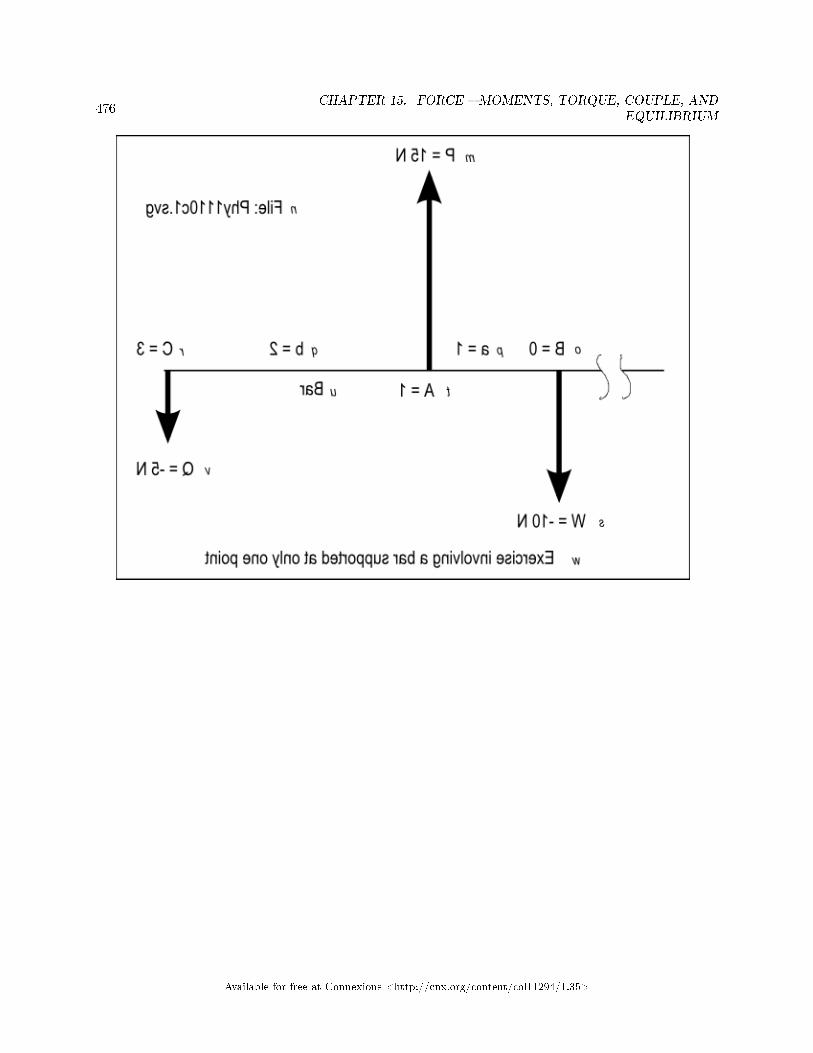
476CHAPTER 15. FORCE � MOMENTS, TORQUE, COUPLE, AND
EQUILIBRIUM
Available for free at Connexions <http://cnx.org/content/col11294/1.35>

477
Available for free at Connexions <http://cnx.org/content/col11294/1.35>

478CHAPTER 15. FORCE � MOMENTS, TORQUE, COUPLE, AND
EQUILIBRIUM
Figure 8 . Mirror image from the �le named Phy1110c1.svg.
Table 15.8
Figure 9 (p. 482) shows a non-mirror-image version of the same image.
Available for free at Connexions <http://cnx.org/content/col11294/1.35>

479
Available for free at Connexions <http://cnx.org/content/col11294/1.35>

480CHAPTER 15. FORCE � MOMENTS, TORQUE, COUPLE, AND
EQUILIBRIUM
Available for free at Connexions <http://cnx.org/content/col11294/1.35>

481
Available for free at Connexions <http://cnx.org/content/col11294/1.35>

482CHAPTER 15. FORCE � MOMENTS, TORQUE, COUPLE, AND
EQUILIBRIUM
Figure 9 . Non-mirror-image version of the image from the �le named Phy1110c1.svg.
Table 15.9
Figure 10 (p. 482) shows the key-value pairs that go with the image in the �le named Phy1110c1.svg.
Figure 10 . Key-value pairs for the image in the �le named Phy1110c1.svg.
m: P = 15 N
n: File: Phy1110c1.svg
o: B = 0
p: a = 1
q: b = 2
r: C = 3
s: W = -10 N
t: A = 1
u: Bar
v: Q = -5 N
w: Exercise involving a bar supported at only one point
Available for free at Connexions <http://cnx.org/content/col11294/1.35>

483
Table 15.10
Unlike or antiparallelIt's time to modify your drawing to re�ect a di�erent scenario.Make your bar 20 units in length. Draw a downward force labeled Q at the right end of the bar. Label
this as point C on the bar.Draw an upward force labeled P somewhere on the bar. Label the location of this point on the bar as AIn this case, we have two parallel forces, P and Q pulling in opposite directions but not in the same line
of action. These forces are said to be unlike or antiparallel .Add another downward forceDraw a downward force labeled W somewhere to the left of A. Label this point as B and consider it to
be the horizontal origin. Directions to the right of B are positive directions.Label the horizontal distance from B to A as a. Label the horizontal distance from A to C as b.What is required for equilibrium?We can look at this scenario and tell that the forces labeled W and P, both of which point down, must
be on opposite sides of the force labeled P. Otherwise, the bar will rotate in a clockwise direction.The following two conditions must be true for the bar to be in equilibrium.P + W + Q = 0, orP = - (W + Q) (vector sum must be zero)a*P + (a+b) * Q = 0 (moments around point B)The planWe will set values for all the variables in the two conditions other than a and P and then solve for values
of a and P that will result in the bar being in equilibrium .
• Let W = -10• Let Q = -5• Let b = 2
The computationsSubstituting these values into the two conditions and rearranging terms gives us:P = -(W + Q), orP = 15 , this is one of the answersa*P +(a+2)*(-5) = 0, or15*a -5*a -10 = 0, or10*a = 10, ora = 1 , this is the other answerThe answersTherefore, for the values of W, Q, and b given above (p. 483) , P must be equal to 15 and a must be
equal to 1 for the bar to be in equilibrium.Variation of a and P with changes in QNow let's see how P and a vary with respect to the value of Q
• Let W = -10• Let Q = -20• Let b = 2
P = -(W + Q) = 30a*P +(a+2)*(-20) = 0, or30*a -20*a -40 = 0, or10*a = 40, ora = 4As you can see, keeping the location of P constant and increasing the value for Q requires the value of P
to increase and the location of W to move further to the left.
Available for free at Connexions <http://cnx.org/content/col11294/1.35>

484CHAPTER 15. FORCE � MOMENTS, TORQUE, COUPLE, AND
EQUILIBRIUM
15.4.10 Couples
Now draw a new scenario where antiparallel forces, each having a magnitude of 10 newtons are acting inopposite directions on a bar, with each force in the same plane and both forces perpendicular to the bar.Label one force P and the other force Q.
Tactile graphicsThe �le named Phy1110d1.svg contains a vector diagram that represents this scenario. It shows two 10
N forces labeled P and Q along with an unknown force labeled X.Figure 11 (p. 488) shows the mirror image that is contained in that �le for the bene�t of your assistant
who will create the tactile graphic for this exercise.
Available for free at Connexions <http://cnx.org/content/col11294/1.35>

485
Available for free at Connexions <http://cnx.org/content/col11294/1.35>

486CHAPTER 15. FORCE � MOMENTS, TORQUE, COUPLE, AND
EQUILIBRIUM
Available for free at Connexions <http://cnx.org/content/col11294/1.35>

487
Available for free at Connexions <http://cnx.org/content/col11294/1.35>

488CHAPTER 15. FORCE � MOMENTS, TORQUE, COUPLE, AND
EQUILIBRIUM
Figure 11 . Mirror image from the �le named Phy1110d1.svg.
Table 15.11
Available for free at Connexions <http://cnx.org/content/col11294/1.35>

489
Figure 12 (p. 492) shows a non-mirror-image version of the same image.
Available for free at Connexions <http://cnx.org/content/col11294/1.35>

490CHAPTER 15. FORCE � MOMENTS, TORQUE, COUPLE, AND
EQUILIBRIUM
Available for free at Connexions <http://cnx.org/content/col11294/1.35>

491
Available for free at Connexions <http://cnx.org/content/col11294/1.35>

492CHAPTER 15. FORCE � MOMENTS, TORQUE, COUPLE, AND
EQUILIBRIUM
Figure 12 . Non-mirror-image version of the image from the �le named Phy1110d1.svg.
Table 15.12
Available for free at Connexions <http://cnx.org/content/col11294/1.35>

493
Figure 13 (p. 493) shows the key-value pairs that go with the image in the �le named Phy1110d1.svg.
Figure 13 . Key-value pairs for the image in the �le named Phy1110d1.svg.
m: An exercise on couples
n: P = 10 N
o: X = ?
p: Bar
q: Location of X = ?
r: Q = 10 N
s: File: Phy1110d1.svg
Table 15.13
The moments about a pointIf you compute the moments about any point on this bar, they won't sum to zero. Therefore, the bar
isn't in equilibrium. Can you �nd the location and magnitude of a single force that can be applied to thebar to cause it to be in equilibrium?
Consider the �rst condition for equilibriumThe vector sum of the forces must be zero.In this case, the vector sum of the forces isP - Q + X = 010 - 10 + X = 0where X is an unknown force.As you can see, there is no value for X that will satisfy this condition other than X=0. If X=0, there is
no force, so there is no single force that can be applied to the bar to cause it to be in equilibrium.A coupleTwo forces equal in magnitude but opposite in direction and not in the same line constitute a couple
.Stated di�erently,A couple is a system of forces with a non-zero moment but no resultant force. In other words, the vector
sum of the forces is zero but the sum of the moments is not zero.A simple coupleThe simplest kind of couple consists of two equal and opposite forces whose lines of action do not coincide.
This is often called a "simple couple."The units for a coupleThe SI unit for the torque is the newton meter, which when expanded into SI base units is kg*m^2/s^2.The moment of force for a couple is uniqueThe moment of a force is only de�ned with respect to a certain point P (it is said to be the "moment
about P"). In general when P is changed, the moment changes.However, the moment (torque) of a couple is independent of the reference point P. Any point will give
the same moment.Let's prove thatThe moment of a couple is independent of the point about which it is measured. Can we prove the truth
of that statement?Imagine a horizontal bar that is �ve units long. Imagine an upward force at the right end of the bar with
a magnitude of P. Imagine a downward force with the same magnitude d units to the left of the �rst force.Imagine that the location of this force is labeled as X.
Available for free at Connexions <http://cnx.org/content/col11294/1.35>

494CHAPTER 15. FORCE � MOMENTS, TORQUE, COUPLE, AND
EQUILIBRIUM
Imagine that the left end of the bar is labeled A and the distance from point A to point X is labeled asb. Imagine another point somewhere between A and X that is labeled as B. Imagine that the distance fromA to B is labeled as c.
Compute the moments about the point AMa = (b+d)*P-b*P, orMa = b*P+d*P-b*p, orMa = d*pNow compute the moments about the point B.Mb = (b-c+d)*P-(b-c)*P, orMb = b*P-c*P+d*P-b*P+c*P, orMb = d*PThe moments are the same regardless of the point about which they are computed. The value d*P is
called the moment or torque of a couple.The torque of a coupleThe torque of a couple is the product of either force and the perpendicular distance between the lines of
actions of the forces.
15.5 Complete the exercises
I encourage you to complete the exercises that I have presented in this lesson to con�rm that you get thesame results. Experiment with the procedures, making changes, and observing the results of your changes.Make certain that you can explain why your changes behave as they do.
15.6 Resources
I will publish a module containing consolidated links to resources on my Connexions web page and willupdate and add to the list as additional modules in this collection are published.
15.7 Miscellaneous
This section contains a variety of miscellaneous information.
Housekeeping material
• Module name: Force � Moments, Torque, Couple, and Equilibrium• File: Phy1110.htm• Revised: 10/02/15• Keywords:
· physics· accessible· blind· graph board· protractor· screen reader· refreshable Braille display· JavaScript· trigonometry· moment· torque· couple
Available for free at Connexions <http://cnx.org/content/col11294/1.35>

495
· equilibrium
Disclaimers: Financial : Although the openstax CNX site makes it possible for you todownload a PDF �le for the collection that contains this module at no charge, and also makes itpossible for you to purchase a pre-printed version of the PDF �le, you should be aware that someof the HTML elements in this module may not translate well into PDF.
You also need to know that Prof. Baldwin receives no �nancial compensation from openstaxCNX even if you purchase the PDF version of the collection.
In the past, unknown individuals have copied Prof. Baldwin's modules from cnx.org, convertedthem to Kindle books, and placed them for sale on Amazon.com showing Prof. Baldwin as theauthor. Prof. Baldwin neither receives compensation for those sales nor does he know who doesreceive compensation. If you purchase such a book, please be aware that it is a copy of a collectionthat is freely available on openstax CNX and that it was made and published without the priorknowledge of Prof. Baldwin.
A�liation : Prof. Baldwin is a professor of Computer Information Technology at AustinCommunity College in Austin, TX.
-end-
Available for free at Connexions <http://cnx.org/content/col11294/1.35>

496CHAPTER 15. FORCE � MOMENTS, TORQUE, COUPLE, AND
EQUILIBRIUM
Available for free at Connexions <http://cnx.org/content/col11294/1.35>

Chapter 16
Force � Center of Gravity1
16.1 Table of Contents
• Preface (p. 497)
· General (p. 497)· Prerequisites (p. 498)· Viewing tip (p. 498)
* Figures (p. 498)
· Supplemental material (p. 499)
• General background information (p. 499)• Discussion and computations (p. 501)
· Creation of tactile graphics (p. 501)· Equilibrium: stable, unstable, and neutral (p. 501)· An exercise involving the tipping point (p. 502)· A real-world example (p. 521)
• Do the computations (p. 522)• Resources (p. 522)• Miscellaneous (p. 522)
16.2 Preface
16.2.1 General
This module is part of a collection of modules designed to make physics concepts accessible to blind students.If you opened this page in the context of the book, a Table of Contents for the book (or collection)
should be available above and to the left of this paragraph. Otherwise, click here 2 to open the book at thebeginning.
This book is intended to supplement but not to replace the textbook in an introductory high school orcollege physics course.
This module explains force and center of gravity in a format that is accessible to blind students.
1This content is available online at <http://cnx.org/content/m38168/1.4/>.2http://cnx.org/contents/a7842db2-93c6-4c06-a5e3-56c282358143
Available for free at Connexions <http://cnx.org/content/col11294/1.35>
497

498 CHAPTER 16. FORCE � CENTER OF GRAVITY
16.2.2 Prerequisites
In addition to an Internet connection and a browser, you will need the following tools (as a minimum) towork through the exercises in these modules:
• A graph board for plotting graphs and vector diagrams (http://www.youtube.com/watch?v=c8plj9UsJbg 3 ).
• A protractor for measuring angles ( http://www.youtube.com/watch?v=v-F06HgiUpw 4 ).• An audio screen reader that is compatible with your operating system, such as the NonVisual Desktop
Access program (NVDA), which is freely available at http://www.nvda-project.org/ 5 .• A refreshable Braille display capable of providing a line by line tactile output of information displayed
on the computer monitor ( http://www.userite.com/ecampus/lesson1/tools.php 6 ).• A device to create Braille labels. Will be used to label graphs constructed on the graph board.• The ability to create tactile graphics as described here 7 .
The minimum prerequisites for understanding the material in these modules include:
• A good understanding of algebra.• An understanding of the use of a graph board for plotting graphs and vector diagrams (
http://www.youtube.com/watch?v=c8plj9UsJbg 8 ).• An understanding of the use of a protractor for measuring angles (
http://www.youtube.com/watch?v=v-F06HgiUpw 9 ).• A basic understanding of the use of sine, cosine, and tangent from trigonometry (
http://www.clarku.edu/∼djoyce/trig/ 10 ).• An introductory understanding of JavaScript programming ( http://www.dickbaldwin.com/tocjscript1.htm
11 and http://www.w3schools.com/js/default.asp 12 ).• An understanding of all of the material covered in the earlier modules in this collection.• An understanding of the creation and use of tactile graphics as described here 13 .
16.2.3 Viewing tip
I recommend that you open another copy of this document in a separate browser window and use thefollowing links to easily �nd and view the �gures while you are reading about them.
16.2.3.1 Figures
• Figure 1 (p. 506) . Mirror image from the �le named Phy1120a1.svg.• Figure 2 (p. 510) . Non-mirror-image version of the image from the �le named Phy1120a1.svg.• Figure 3 (p. 511) . Key-value pairs for the image in the �le named Phy1120a1.svg.• Figure 4 (p. 515) . Mirror image from the �le named Phy1120b1.svg.• Figure 5 (p. 519) . Non-mirror-image version of the image from the �le named Phy1120b1.svg.• Figure 6 (p. 520) . Key-value pairs for the image in the �le named Phy1120b1.svg.
3http://www.youtube.com/watch?v=c8plj9UsJbg4http://www.youtube.com/watch?v=v-F06HgiUpw5http://www.nvda-project.org/6http://www.userite.com/ecampus/lesson1/tools.php7http://cnx.org/contents/9fe07552-485f-43e7-9753-87133cf604828http://www.youtube.com/watch?v=c8plj9UsJbg9http://www.youtube.com/watch?v=v-F06HgiUpw
10http://www.clarku.edu/∼djoyce/trig/11http://www.dickbaldwin.com/tocjscript1.htm12http://www.w3schools.com/js/default.asp13http://cnx.org/contents/9fe07552-485f-43e7-9753-87133cf60482
Available for free at Connexions <http://cnx.org/content/col11294/1.35>

499
16.2.4 Supplemental material
I recommend that you also study the other lessons in my extensive collection of online programming tutorials.You will �nd a consolidated index at www.DickBaldwin.com 14 .
16.3 General background information
The gravitational constantThe gravitational constant, G, is a constant that is used in the calculation of the gravitational attraction
between objects with mass. The value of G is approximately:G = 6.67 * 10^(-11) *m^3*kg^(-1)*s^(-2), orG = 6.67 * 10^(-11) N*(m/kg)^2According to the law of universal gravitation, the attractive force (F) between two bodies is proportional
to the product of their masses (m1 and m2), and inversely proportional to the square of the distance (r)between them:
F = G*m1*m2/r^2Newton's law of gravitationNewton's law of gravitation proposes that every small element of matter, m, attracts every other small
element of matter, m' with a force that is proportional to the product of the masses and inversely proportionalto the square of the distance between them, so that at the small element level,
F = G*m*m'/r^2As a result, we tend to fall toward the earth unless we are supported by upward forces, such as the �oor
that we are standing on.An important simpli�cationIt would be very di�cult to deal with the attraction of gravity if we were required to deal with every
object (including the earth) in terms of the many small elements of mass that make up the object.Newton simpli�ed that process by proving mathematically that the earth regarded as a sphere attracts
a body as if the whole mass of the earth were concentrated at its center.Almost parallel forcesThe attraction of the earth on the elements of our body produces forces on those elements that are almost
parallel. Those forces lie along lines that all end at a point that is almost 4000 miles beneath the surface ofthe earth.
At that distance, each pair of force lines forms the sides of a triangle with extremely long sides, anextremely small angle, and an extremely narrow base. As a practical matter, therefore, we can assume thatthose forces are parallel insofar as estimating the e�ect that the sum of all of those elemental forces have onour bodies.
The center of gravity C.G.It can be proved that:The resultant of the weights of all the elements of a rigid body passes through a certain �xed point
commonly called its center of gravity, C.G., regardless of the orientation of that body relative to the earth.For purposes of computations involving statics, the mass of a rigid body may be considered as if concen-
trated at it C.G., and its weight may be considered to center at this same point.(Recall that the weight of an object is the force required to cause the mass of that object to fall toward
the center of the earth with an acceleration of approximately 32.2 ft/s^2 or 9.81 m/s^2.)A plumb-bob or plummetA plumb-bob or a plummet is a weight, usually with a pointed tip on the bottom, that is suspended from
a string and used as a vertical reference line, or plumb-line.When the string is attached to an object that is �xed relative to the surface of the earth and the plummet
is allowed to hang down, it will eventually (when it stops swinging) point directly at the center of mass ofthe earth.
14http://www.dickbaldwin.com/toc.htm
Available for free at Connexions <http://cnx.org/content/col11294/1.35>

500 CHAPTER 16. FORCE � CENTER OF GRAVITY
Common uses for a plummetThe plummet is most commonly used in construction projects to ensure that constructions are "plumb",
or vertical.It is also used in land surveying to set a surveying instrument exactly over a �xed survey marker, or to
transcribe positions onto the ground for placing a marker.Experimental veri�cation of the C.G.I'm aware that as a blind student, you probably can't perform this experiment, but hopefully you can
imagine it.Make a hangerUse a plummet to draw a vertical line on a �at, smooth, vertical surface (such as a wall). Drive a �nishing
nail (a nail with a small head) into the surface on the vertical line allowing a small portion of the nail tostick out. Cause the nail to be as horizontal as practical.
Make an irregular objectCut an irregular shape out of a piece of �at cardboard and punch several holes around the perimeter of
the shape.Perform the experimentUsing several holes in succession, including holes on all four sides of the cardboard, hang the cardboard
on the nail in such a way that the cardboard is free to swing and settle into a stable orientation.Once the cardboard stops swinging, mark the point on the bottom of the cardboard that coincides with
the vertical line that you drew on the vertical surface.After you have done this several times, draw lines from each hole to the corresponding mark that you
made on the opposite edge of the cardboard. All of these lines should cross at a single point. That point isthe C.G. for that particular irregular shape of cardboard.
Modify the experimentCut regular shapes of cardboard such as rectangles, triangles, hexagons, octagons, etc, and repeat the
experiment with those shapes. Observe the location of the C.G. for those shapes.Rectangular shapesYou should �nd that the C.G. for a rectangular piece of cardboard is at the center of the rectangle. This
should be the case for all rectangles ranging from squares to long skinny rectangles (although it may di�cultto measure for long skinny rectangles.)
Triangular shapesThe C.G. for a triangular shape should be at the intersection of its medians.In case you have forgotten, the median of a triangle is a line segment from a vertex of the triangle to
the midpoint of the side opposite that vertex. Because there are three vertices, there are three medians. Nomatter what shape the triangle, all three medians intersect at a single point, which is called the centroid ofthe triangle. That point would also be the C.G. for a triangular-shaped piece of cardboard.
The doughnut holeCut a piece of cardboard in the general shape of a doughnut or tire with a hole in the middle and perform
the experiment using that shape. Observe that the C.G. can be located in the doughnut hole. The C.G. ofan object doesn't have to be in a solid part of the object.
A void in a 3D objectIt is also possible for the C.G. to be located in a cavity in a three-dimensional object. For example, the
C.G. for a small section of cylindrical pipe that is cut square on both ends would be in the center of the voidhalf way between the ends of the pipe.
Available for free at Connexions <http://cnx.org/content/col11294/1.35>

501
16.4 Discussion and computations
16.4.1 Creation of tactile graphics
The module titled Manual Creation of Tactile Graphics 15 explains how to create tactile graphics from svg�les that I will provide.
If you are going to have an assistant create tactile graphics for this module, you will need to downloadthe �le named Phy1120.zip 16 , which contains the svg �les for this module. Extract the svg �les from thezip �le and provide them to your assistant.
Also, if you are going to use tactile graphics, it probably won't be necessary for you to perform the graphboard exercises. However, you should still walk through the graph board exercises in your mind because Iwill often embed important physics concepts in the instructions for doing the graph board exercises.
In each case where I am providing an svg �le for the creation of tactile graphics, I will identify the nameof the appropriate svg �le and display an image of the contents of the �le for the bene�t of your assistant.As explained here 17 , those images will will be mirror images of the actual images so that your assistantcan emboss the image from the back of the paper and you can explore it from the front.
I will also display a non-mirror-image version of the image so that your assistant can easily read the textin the image.
Also in those cases, I will provide a table of key-value pairs that explain how the Braille keys in the imagerelate to text or objects in the image.
16.4.2 Equilibrium: stable, unstable, and neutral
When a vertical line through the C.G. of a body falls within the area covered by the supporting base, thebody can rest in equilibrium. A body in equilibrium can be further quali�ed as being either stable, unstable,or neutral.
• Stable equilibrium: If a body at rest receives a small displacement and tends to return to its formerposition, that body is said to be in stable equilibrium.
• Unstable equilibrium: If that body tends to move further away, then that body is said to be in unstableequilibrium.
• Neutral equilibrium: If it does neither, the body is said to be in neutral equilibrium.
A practical exampleConsider the case of a round pencil, sharpened on one end and �at on the other end. If you lay the
pencil �at on the table and give it a very small push, it will move and then stop. That pencil is said to bein neutral equilibrium. It doesn't tend to return to its original position, and except for rolling a smalldistance as a result of inertia, it doesn't tend to move further away.
Balance it on the �at endIf you balance the pencil on its �at end and give it a very small push at the other end, it will tip slightly
and then return to its original position. This assumes that you don't push it beyond its tipping point, whichwe will discuss in more detail later.
The pencil in this con�guration is said to be in stable equilibrium. The key to success is that youdon't tip it so far that a vertical line through the C.G. moves outside the circle that de�nes the area of thesupporting base of the pencil.
Balance it on its pointAssume that you rub the pencil lead back and forth a few times to slightly �atten the pointed end. If
you were able to balance the pencil on that very small �attened surface, and then blow on the pencil verylightly, it would probably tip over and fall �at on the table. The smaller the �attened surface supporting
15http://cnx.org/contents/9fe07552-485f-43e7-9753-87133cf60482/Phy1004-Manual-Creation-of-Tac16http://cnx.org/content/m38168/latest/Phy1120.zip17http://cnx.org/contents/9fe07552-485f-43e7-9753-87133cf60482
Available for free at Connexions <http://cnx.org/content/col11294/1.35>

502 CHAPTER 16. FORCE � CENTER OF GRAVITY
the pencil, the easier it would be to cause it to tip over. The pencil in that state would be said to be inunstable equilibrium.
Stability is importantStability is very important for many things such as boats and airplanes. Usually, the lower the C.G., the
more stable will be the object.A high-wire artistFor example, a high-wire artist at the circus may carry a long �exible pole, perpendicular to the wire
held near the center of the pole at about thigh height. In this case, the supporting surface is the feet on thewire.
The �ex in the pole allows the ends of the pole, and conceivably a large portion of the pole to hang lowerthan the soles of the feet. This has the e�ect of lowering the C.G. of the combination of the person and thepole considerably. If the C.G. is below the supporting surface, which in this case is the soles of the feet, thecombination of the person and the pole will be very stable.
Cargo shipsThe people that load cargo ships try to keep the C.G. of the loaded ship low in the hull of the ship.
Sometimes they add extra weight called ballast very low in the hull to get the C.G. as low as possible.Cargo aircraftThe people that load large military cargo aircraft are very careful how they load the cargo in order to
control the location of the C.G. of the aircraft to maintain stability of the aircraft. The position of the C.G.relative to the axis of the wings is very important.
Children's toysWhen my children were young, they had toys with a round bottom and something like a clown's head
on the top. The toys had a heavy weight inside and very close to the bottom. This caused the C.G. to bevery low in the toy. When the child pushed the toy over, it would return to an upright position. The toywas very stable.
16.4.3 An exercise involving the tipping point
Let's see if we can demonstrate stability or the lack thereof with a thought experiment. Begin by drawingtwo rectangles on your graph board side by side. Make each rectangle 2 units wide and �ve units tall.
Two boxesPretend that these rectangles represent side views of two cardboard boxes with dimensions of 2x2x5 ft.
Assume that each box contains identical heavy material at one end and the remainder of the box is �lledwith very light packing material. Assume that the heavy contents are at the bottom of the left box and atthe top of the right box. (The boxes and their contents are just alike, but one is upside down relative to theother.)
Tactile graphicsThe �le named Phy1120a1.svg contains an image that represents this scenario. The image shows two
boxes, as described above (p. 502) , tipped over to their tipping points (p. 521) .Figure 1 (p. 506) shows the mirror image that is contained in that �le for the bene�t of your assistant
who will create the tactile graphic for this exercise.
Available for free at Connexions <http://cnx.org/content/col11294/1.35>

503
Available for free at Connexions <http://cnx.org/content/col11294/1.35>

504 CHAPTER 16. FORCE � CENTER OF GRAVITY
Available for free at Connexions <http://cnx.org/content/col11294/1.35>

505
Available for free at Connexions <http://cnx.org/content/col11294/1.35>

506 CHAPTER 16. FORCE � CENTER OF GRAVITY
Figure 1 . Mirror image from the �le named Phy1120a1.svg.
Table 16.1
Figure 2 (p. 510) shows a non-mirror-image version of the same image.
Available for free at Connexions <http://cnx.org/content/col11294/1.35>

507
Available for free at Connexions <http://cnx.org/content/col11294/1.35>

508 CHAPTER 16. FORCE � CENTER OF GRAVITY
Available for free at Connexions <http://cnx.org/content/col11294/1.35>

509
Available for free at Connexions <http://cnx.org/content/col11294/1.35>

510 CHAPTER 16. FORCE � CENTER OF GRAVITY
Figure 2 . Non-mirror-image version of the image from the �le named Phy1120a1.svg.
Table 16.2
Figure 3 (p. 511) shows the key-value pairs that go with the image in the �le named Phy1120a1.svg.
Available for free at Connexions <http://cnx.org/content/col11294/1.35>

511
Figure 3 . Key-value pairs for the image in the �le named Phy1120a1.svg.
m: An exercise involving the tipping point
n: Tipping point = 45 degrees
o: Tipping point = 14 degrees
p: Center of gravity
q: Center of gravity
r: 45 degrees
s: 76 degrees
t: W
u: W
v: File: Phy1120a1.svg
w: Floor
x: Box
y: Box
Table 16.3
Mark the C.G. of each boxGetting back to your drawing, assume that the C.G. of the left box is one foot up from the bottom and
the C.G. of the right box is one foot down from the top (4 feet up from the bottom). In both cases, theC.G. is at the horizontal center of the box. Insert a pin at the location of the C.G. for both boxes and labelit C.G. in both cases.
The weight of each boxThe downward force that is the weight of each box is on a vertical line that goes through the C.G. and
the total weight appears to be concentrated at the C.G. Therefore, when the box is setting �at on the �oor,the weight vector for each box is on a line that is 1 ft. from either side of the box.
Vertical weight vectorsBegin at the C.G. for each box and draw a vertical line that extends 7 units down from the C.G. for each
box. Label each line as W. These are weight vectors.Both boxes are in equilibriumWe know from experience that both of these boxes are in equilibrium. We have also just learned that so
long as the vertical weight vector that goes through the C.G. also goes through the two-foot wide supportingbase of the box, the box will be in stable equilibrium.
What is the tipping point?Label the bottom-right corner of each box as b. Pretend that you drive a nail immediately to the right
of point b and allow it to protrude up from the �oor so that when you push on the top-left corner of thebox, it will rotate around point b instead of sliding to the right.
How far can we tip each box in a clockwise direction around the bottom right corner before we loseequilibrium?
Tactile graphicsThe �le named Phy1120b1.svg contains an image that shows the triangles discussed below (p. 520) .Figure 4 (p. 515) shows the mirror image that is contained in that �le for the bene�t of your assistant
who will create the tactile graphic for this exercise.
Available for free at Connexions <http://cnx.org/content/col11294/1.35>

512 CHAPTER 16. FORCE � CENTER OF GRAVITY
Available for free at Connexions <http://cnx.org/content/col11294/1.35>

513
Available for free at Connexions <http://cnx.org/content/col11294/1.35>

514 CHAPTER 16. FORCE � CENTER OF GRAVITY
Available for free at Connexions <http://cnx.org/content/col11294/1.35>

515
Figure 4 . Mirror image from the �le named Phy1120b1.svg.
Table 16.4
Available for free at Connexions <http://cnx.org/content/col11294/1.35>

516 CHAPTER 16. FORCE � CENTER OF GRAVITY
Figure 5 (p. 519) shows a non-mirror-image version of the same image.
Available for free at Connexions <http://cnx.org/content/col11294/1.35>

517
Available for free at Connexions <http://cnx.org/content/col11294/1.35>

518 CHAPTER 16. FORCE � CENTER OF GRAVITY
Available for free at Connexions <http://cnx.org/content/col11294/1.35>

519
Figure 5 . Non-mirror-image version of the image from the �le named Phy1120b1.svg.
Table 16.5
Available for free at Connexions <http://cnx.org/content/col11294/1.35>

520 CHAPTER 16. FORCE � CENTER OF GRAVITY
Figure 6 (p. 520) shows the key-value pairs that go with the image in the �le named Phy1120b1.svg.
Figure 6 . Key-value pairs for the image in the �le named Phy1120b1.svg.
m: An exercise involving the tipping point, part 2
n: K1 = 1.414
o: K2 = 4.123
p: Z1 = 1
q: Z2 = 4
r: R = 1
s: R = 1
t: 45 degrees
u: 14 degrees
v: Center of gravity
w: Center of gravity
x: b
y: b
z: Floor
mm: W
mn: W
mo: File: Phy1120b1.svg
Table 16.6
The lines K1 , K2, Z1, Z2, and RTo answer this question, begin by drawing a line from the C.G. to point b for each box. Label this line
K1 for the left box and K2 for the right box.Label the line segment that extends from the C.G. to the bottom of the left box as Z1 and label the line
segment that extends from the C.G. to the bottom of the right box as Z2. Label the line segment that isthe right half of the bottom of each box as R.
Right trianglesIn the left box, the line segments K1, Z1, and R form a right triangle for which the lengths of two line
segments are:
• Z1 = 1• R = 1
In the right box, the line segments K2, Z2, and R form a right triangle for which the lengths of two linesegments are:
• Z2 = 4• R = 1
Compute the lengths of K1 and K2Using the Pythagorean theorem and the Google calculator, we can compute the following lengths:K1 = sqrt(1^2 + 1^2) = 1.414K2 = sqrt(1^2 + 4^2) = 4.123The sides of the right trianglesNext, we will compute the interior angle for each triangle at the C.G. vertex. Label the interior angle for
the left box P1 and label the interior angle for the right box P2.
Available for free at Connexions <http://cnx.org/content/col11294/1.35>

521
We know the lengths of all three sides of each triangle. There are a couple of ways that we can usetrigonometry to �nd the interior angles. Considering the triangle from the viewpoint of the interior angle atthe C.G. for the left triangle:
• hypotenuse = K1 = 1.414• base = Z1 = 1• opposite side = R = 1
For the right triangle,
• hypotenuse = K2 = 4.123• base = Z2 = 4• opposite side = R = 1
Compute the interior angles at each C.G. vertexUsing the Google calculator, we can compute the interior angle at the C.G. for each box as follows:
• P1 = arcsine(1/1.414)*180/PI = 45 degrees• P2 = arcsine(1/4.123)*180/PI = 14 degrees
Tilt each box and observe the angles at the C.G. verticesNow pretend that you exert a force on the top-left corner of each box causing it to rotate around the
lower-right corner at point b. As you do that, the weight vector would rotate around the C.G. in a counter-clockwise direction (always pointing straight down) and the angle between the weight vector and the lineK1 or K2 would decrease.
The tipping pointWhen the angle between the weight vector and the line K1 or K2 goes to zero degrees for either box,
the tipping point for that box will have been reached. (See the image in the �le named Phy1120a1.svg, orFigure 1 (p. 506) .)
At that exact point, the box will still be in equilibrium, but it will be in unstable equilibrium. Exertinga little more force to the right will cause the box to turn all the way over onto its side under its own weight.Relaxing the force a little when the box is in that position will allow it to rotate back towards its originalposition.
What are the tipping point angles?The box on the left would need to rotate slightly more than 45 degrees clockwise around point b before
the direction of the weight vector through the C.G. would move to the right of point b, causing the box tocontinue rotating under its own weight.
However, the box on the right would only need to rotate slightly more than 14 degrees clockwise aroundpoint b before the direction of the weight vector through the C.G. would move to the right of point b causingthe box to continue rotating under its own weight.
ConclusionTherefore, the box on the left is more stable than the box on the right. If you want to lessen the likelihood
of an object tipping over, cause the C.G. of the object to be near the bottom of the object.An exercise for the studentI will leave it as an exercise for the student to compute moments about point b to con�rm the tipping
angle for each box where the torque about point b changes from counter-clockwise to clockwise.
16.4.4 A real-world example
Let me illustrate this situation with a real-world example that may seem familiar to you. Assume that youput some �owers with long stems in a lightweight plastic vase and set the vase on a table. The C.G. of thevase and the �owers would be relatively high, and it wouldn't take much of a sideways push to cause thevase to turn over.
Available for free at Connexions <http://cnx.org/content/col11294/1.35>

522 CHAPTER 16. FORCE � CENTER OF GRAVITY
Now assume that you add water to the vase until it is about half full. This would cause the C.G. of thevase, the water, and the �owers to move down, probably into the bottom half of the vase. This would makeit more di�cult to tip the vase over. Of course, when it does tip over, it would make a bigger mess thanwould be the case without the water.
16.5 Do the computations
I encourage you to repeat the computations that I have performed in this module. Experiment with thecomputations, making changes, and observing the results of your changes. Make certain that you can explainwhy your changes behave as they do.
16.6 Resources
I will publish a module containing consolidated links to resources on my Connexions web page and willupdate and add to the list as additional modules in this collection are published.
16.7 Miscellaneous
This section contains a variety of miscellaneous information.
Housekeeping material
• Module name: Force � Center of Gravity• File: Phy1120.htm• Revised: Revised: 10/02/15• Keywords:
· physics· accessible· blind· graph board· protractor· screen reader· refreshable Braille display· JavaScript· trigonometry· force· center of gravity· gravitational constant
Disclaimers: Financial : Although the openstax CNX site makes it possible for you todownload a PDF �le for the collection that contains this module at no charge, and also makes itpossible for you to purchase a pre-printed version of the PDF �le, you should be aware that someof the HTML elements in this module may not translate well into PDF.
You also need to know that Prof. Baldwin receives no �nancial compensation from openstaxCNX even if you purchase the PDF version of the collection.
In the past, unknown individuals have copied Prof. Baldwin's modules from cnx.org, convertedthem to Kindle books, and placed them for sale on Amazon.com showing Prof. Baldwin as theauthor. Prof. Baldwin neither receives compensation for those sales nor does he know who doesreceive compensation. If you purchase such a book, please be aware that it is a copy of a collection
Available for free at Connexions <http://cnx.org/content/col11294/1.35>

523
that is freely available on openstax CNX and that it was made and published without the priorknowledge of Prof. Baldwin.
A�liation : Prof. Baldwin is a professor of Computer Information Technology at AustinCommunity College in Austin, TX.
-end-
Available for free at Connexions <http://cnx.org/content/col11294/1.35>

524 CHAPTER 16. FORCE � CENTER OF GRAVITY
Available for free at Connexions <http://cnx.org/content/col11294/1.35>

Chapter 17
Force and Motion � Introduction1
17.1 Table of Contents
• Preface (p. 525)
· General (p. 525)· Prerequisites (p. 525)· Supplemental material (p. 526)
• Discussion (p. 526)
· Aristotle's contribution, or lack thereof (p. 527)· Galileo's contribution (p. 527)· Newton's contribution (p. 527)
* Three laws of motion (p. 528)
· Law 1 (p. 528)· Law 2 (p. 528)· Law 3 (p. 528)
· Mass, momentum, force, and acceleration (p. 528)
• Resources (p. 529)• Miscellaneous (p. 529)
17.2 Preface
17.2.1 General
This module is part of a book 2 (or collection) designed to make physics concepts accessible to blindstudents. The collection is intended to supplement but not to replace the textbook in an introductory coursein high school or college physics.
This module introduces force and motion in a format that is accessible to blind students.
17.2.2 Prerequisites
In addition to an Internet connection and a browser, you will need the following tools (as a minimum) towork through the exercises in these modules:
1This content is available online at <http://cnx.org/content/m38170/1.3/>.2http://cnx.org/contents/a7842db2-93c6-4c06-a5e3-56c282358143
Available for free at Connexions <http://cnx.org/content/col11294/1.35>
525

526 CHAPTER 17. FORCE AND MOTION � INTRODUCTION
• A graph board for plotting graphs and vector diagrams (http://www.youtube.com/watch?v=c8plj9UsJbg 3 ).
• A protractor for measuring angles ( http://www.youtube.com/watch?v=v-F06HgiUpw 4 ).• An audio screen reader that is compatible with your operating system, such as the NonVisual Desktop
Access program (NVDA), which is freely available at http://www.nvda-project.org/ 5 .• A refreshable Braille display capable of providing a line by line tactile output of information displayed
on the computer monitor ( http://www.userite.com/ecampus/lesson1/tools.php 6 ).• A device to create Braille labels. Will be used to label graphs constructed on the graph board.
The minimum prerequisites for understanding the material in these modules include:
• A good understanding of algebra.• An understanding of the use of a graph board for plotting graphs and vector diagrams (
http://www.youtube.com/watch?v=c8plj9UsJbg 7 ).• An understanding of the use of a protractor for measuring angles (
http://www.youtube.com/watch?v=v-F06HgiUpw 8 ).• A basic understanding of the use of sine, cosine, and tangent from trigonometry (
http://www.clarku.edu/∼djoyce/trig/ 9 ).• An introductory understanding of JavaScript programming ( http://www.dickbaldwin.com/tocjscript1.htm
10 and http://www.w3schools.com/js/default.asp 11 ).• An understanding of all of the material covered in the earlier modules in this collection.
17.2.3 Supplemental material
I recommend that you also study the other lessons in my extensive collection of online programming tutorials.You will �nd a consolidated index at www.DickBaldwin.com 12 .
17.3 Discussion
We dealt with bodies in equilibrium in earlier modules. By equilibrium, I mean that we dealt with forcesacting on bodies at rest or forces acting on bodies in uniform motion. A body in equilibrium does notaccelerate as a result of the forces acting on it.
An example of a body experiencing forces while at restA highway bridge is an example of a body at rest being acted upon by a variety of forces. As vehicles
enter and exit the bridge, those vehicles exert forces on the bridge. The impact of those forces is "felt" by allthe structural members that make up the bridge. The tension and compression in the various members ofthe bridge change as vehicles enter and leave the bridge, but the bridge remains in the same �xed location.If properly designed, the bridge doesn't experience acceleration and crash into the river below as a result ofthose changing forces.
Unbalanced forcesIn this module, we begin a study of the in�uence of unbalanced forces acting on bodies along with a
study of the motion produced in bodies as a result of unbalanced forces.
3http://www.youtube.com/watch?v=c8plj9UsJbg4http://www.youtube.com/watch?v=v-F06HgiUpw5http://www.nvda-project.org/6http://www.userite.com/ecampus/lesson1/tools.php7http://www.youtube.com/watch?v=c8plj9UsJbg8http://www.youtube.com/watch?v=v-F06HgiUpw9http://www.clarku.edu/∼djoyce/trig/
10http://www.dickbaldwin.com/tocjscript1.htm11http://www.w3schools.com/js/default.asp12http://www.dickbaldwin.com/toc.htm
Available for free at Connexions <http://cnx.org/content/col11294/1.35>

527
Statics versus dynamicsThe earlier modules dealt with statics . We now begin a study of dynamics . The study of dynamics
hinges largely on three important laws of motion, which were stated by Sir Issac Newton in 1686.Making bodies moveWe know from experience that we can cause small bodies to move by pulling or pushing them with our
hands. In other words, we can cause a body to move by exerting a force on the body. We also know thatlarger bodies can be caused to move by pulling or pushing them with a machine or with a beast of burden.
We are also familiar with the idea of falling bodies that move independently of someone pushing orpulling. We have come to know this as the result of the gravitational attraction between masses.
17.3.1 Aristotle's contribution, or lack thereof
I have never forgotten my physics professor, Brother Rudolph, at St. Mary's University in San Antonio,Texas, telling the class that Aristotle was a hindrance to science.
Aristotle taught that heavier bodies fall faster than lighter bodies, but he was wrong. It has been proventhat all bodies fall towards the earth at the same acceleration when the e�ects of air resistance are eliminated.
This is not too di�cult to prove for yourself. A small piece of paper will fall to the ground much moreslowly than a coin when the paper is in its normal state. However, if the paper is crumpled into a very tightball, greatly reducing the e�ect of air resistance, it will fall to the ground almost as fast as the coin.
17.3.2 Galileo's contribution
Galileo and Newton clari�ed the ideas of motion through a series of experiments. For example, Galileodiscovered the important relationship between force and acceleration. He concluded that in the absence ofair resistance, freely falling objects have the same acceleration regardless of their di�ering weights.
Acceleration of gravity is constantBy rolling balls down inclined planes, Galileo discovered that the distance covered under a steady force
is proportional to the square of the time of descent. By this, he concluded that acceleration is constant, atleast near the surface of the earth.
Two cannon ballsThe story goes that Galileo dropped two cannon balls of di�erent weights o� the Leaning Tower of Pisa
and observed that they struck the ground below at exactly the same time. From this, he concluded thatfalling bodies are subject to the same acceleration regardless of their weight.
InertiaBy rolling a ball down one inclined plane and up a facing incline plane, Galileo observed that the ball
tended to rise to (almost) the original height on the second inclined plane. This was true even if the secondincline plane was less steep than the �rst.
This suggested that if the second inclined plane were perfectly �at, the ball would roll forever trying toregain its original height. From this, Galileo is said to have concluded that objects at rest tend to remainat rest, and objects in motion tend to remain in motion with the same velocity. (Recall that a change indirection is a change in velocity.)
This property of matter not to change its state of rest or of uniform motion at a constant velocity iscalled inertia .
Force is required to cause a changeWhenever a body changes from a state of rest to a state of motion, or changes its motion from one
velocity to a di�erent velocity, a force is required to cause that change.
17.3.3 Newton's contribution
Newton continued Galileo's study of motion and formulated his �ndings in three laws of motion. The �rsttwo laws were formal statements of Galileo's earlier conclusions. The third law formulated a �nding thatwas original to Newton.
Available for free at Connexions <http://cnx.org/content/col11294/1.35>
528 CHAPTER 17. FORCE AND MOTION � INTRODUCTION
17.3.3.1 Three laws of motion
Unlike those before them, Galileo and Newton saw that in the absence of friction, force was required tochange motion, not to maintain it.
The PrincipiaAs mentioned earlier, Newton formulated the earlier �ndings of Galileo in two laws of motion and added a
third law based on his own �ndings. He published those laws in a document which, when translated from theoriginal Latin, was titled something like: "Mathematical Principles of Natural Philosophy." This documentis often referred to simply as the Principia.
The three laws are paraphrased in the following sections.
17.3.3.1.1 Law 1
Every body remains in a state of rest or of uniform motion in a straight line unless compelledto change that state by external force acting upon it.
Another interpretation of this law reads as follows:Every object in a state of uniform motion tends to remain in that state of motion unless
an external force is applied to it. (This suggests that a state of rest is motion with zero velocity.)This law is generally regarded as recognition of Galileo's concept of inertia and is often referred to as the
"Law of Inertia."The law explains what force does, but does not suggest how force should be measured.
17.3.3.1.2 Law 2
Rate of change of momentum is proportional to the impressed force and takes place in thedirection of that force.
Another interpretation of the second law is:The relationship between an object's mass m, its acceleration a, and the applied force F is
F = m*a (where the * indicates multiplication) . Acceleration and force are vectors; in thislaw the direction of the force vector is the same as the direction of the acceleration vector.
This law, in conjunction with the third law, allows quantitative calculations of dynamics and a de�nitionof mass. In particular, how do velocities change when forces are applied.
The relationships among momentum, force, mass, and accelerations will be explained later.
17.3.3.1.3 Law 3
Action and reaction are equal and opposite, and act on di�erent bodies.Another interpretation of this law is:For every action there is an equal and opposite reaction.This law means that forces act in equal and opposite pairs. Whenever two bodies act upon one another,
equal and opposite changes of momentum occur in the two bodies.An example of the e�ect of this law occurs when a person attempts to jump from a small boat to a pier.
If the boat is free to move, it will tend to move away from the pier as the person attempts to launch himselfin the direction of the pier. This may leave the person momentarily hanging in the air between the boat andthe pier waiting to experience the acceleration of gravity and fall into the water.
In order to understand the full importance of these laws, it is necessary to understand the concepts ofand relationships among mass, momentum, force, and acceleration.
17.3.4 Mass, momentum, force, and acceleration
Newton introduced the term mass as being distinct from weight . Mass is not easy to de�ne in its ownright. Mass can be thought of as being a "quantity of matter" or a "measure of inertia."
Available for free at Connexions <http://cnx.org/content/col11294/1.35>

529
One of the properties of mass in a gravitational �eld is weight. Newton showed that weight is proportionalto mass.
(In earlier modules, we have said that the weight of a body is a measure of the force required to causethat body to accelerate toward the surface of the earth at a rate of approximately 32.2 ft/s^2 or 9.81 m/s^2.)
Newton also worked with the concept of momentum , which is the product of the mass and thevelocity of an object. Momentum is a vector quantity, having the same direction as the velocity to which itapplies. Therefore, momenta are always added or subtracted as vectors.
The rate of change of momentumAs indicated in the second law (p. 528) , the force required to bring about a change in momentum is
proportional to the rate of change of the momentum:F $ (m*v2 - m*v1)/twhere the momentum is changed from a value of m*v1 to a value of m*v2 in a time interval t .(Note that I elected to use the $ character to indicate "is proportional to." Textbooks typically use a
Greek letter for this purpose, which is not compatible with many Braille displays and some audio screenreaders.)
Given that the mass is constant (for the scenarios addressed in this collection of modules), and accelerationis given by the rate of change of velocity, factoring mass out of the above equation gives us
F $ m*(v2 - v1)/t, orF $ m*awhere a is acceleration. Thus, force is proportional to the product of mass and acceleration. For a given
mass, a speci�c force is required to cause that mass to accelerate by a given amount.
17.4 Resources
I will publish a module containing consolidated links to resources on my Connexions web page and willupdate and add to the list as additional modules in this collection are published.
17.5 Miscellaneous
This section contains a variety of miscellaneous information.
Housekeeping material
• Module name: Force and Motion � Introduction• File: Phy1140.htm• Revised: 10/02/15• Keywords:
· physics· accessible· accessibility· blind· graph board· protractor· screen reader· refreshable Braille display· JavaScript· trigonometry· Galileo· Newton· inertia· mass
Available for free at Connexions <http://cnx.org/content/col11294/1.35>

530 CHAPTER 17. FORCE AND MOTION � INTRODUCTION
· momentum· force· acceleration
Disclaimers: Financial : Although the openstax CNX site makes it possible for you todownload a PDF �le for the collection that contains this module at no charge, and also makes itpossible for you to purchase a pre-printed version of the PDF �le, you should be aware that someof the HTML elements in this module may not translate well into PDF.
You also need to know that Prof. Baldwin receives no �nancial compensation from openstaxCNX even if you purchase the PDF version of the collection.
In the past, unknown individuals have copied Prof. Baldwin's modules from cnx.org, convertedthem to Kindle books, and placed them for sale on Amazon.com showing Prof. Baldwin as theauthor. Prof. Baldwin neither receives compensation for those sales nor does he know who doesreceive compensation. If you purchase such a book, please be aware that it is a copy of a collectionthat is freely available on openstax CNX and that it was made and published without the priorknowledge of Prof. Baldwin.
A�liation : Prof. Baldwin is a professor of Computer Information Technology at AustinCommunity College in Austin, TX.
-end-
Available for free at Connexions <http://cnx.org/content/col11294/1.35>

Chapter 18
Force and Motion � Units of Force1
18.1 Table of Contents
• Preface (p. 532)
· General (p. 532)· Prerequisites (p. 532)· Viewing tip (p. 532)
* Figures (p. 533)
· Supplemental material (p. 533)
• Background information (p. 533)
· Creation of tactile graphics (p. 533)· Things can be confusing (p. 533)· SI units and the newton (p. 534)· A practical example using the Google calculator (p. 535)· Other units (p. 536)
* poundal (p. 536)* dyne (p. 537)
· Acceleration of gravity (p. 537)
* pound-force (p. 537)* gram-force (p. 538)* kilogram-force (p. 538)
· Weight is a force (p. 538)
• Sample problems (p. 539)
· A static scenario (p. 539)· First dynamic scenario (p. 548)· Second dynamic scenario (p. 548)· Third dynamic scenario (p. 549)
• Do the calculations (p. 550)• Resources (p. 550)• Miscellaneous (p. 550)
1This content is available online at <http://cnx.org/content/m38211/1.3/>.
Available for free at Connexions <http://cnx.org/content/col11294/1.35>
531

532 CHAPTER 18. FORCE AND MOTION � UNITS OF FORCE
18.2 Preface
18.2.1 General
This module is part of a book 2 (or collection) designed to make physics concepts accessible to blindstudents. The collection is intended to supplement but not to replace the textbook in an introductory coursein high school or college physics.
This module explains various units of force in a format that is accessible to blind students.
18.2.2 Prerequisites
In addition to an Internet connection and a browser, you will need the following tools (as a minimum) towork through the exercises in these modules:
• A graph board for plotting graphs and vector diagrams (http://www.youtube.com/watch?v=c8plj9UsJbg 3 ).
• A protractor for measuring angles ( http://www.youtube.com/watch?v=v-F06HgiUpw 4 ).• An audio screen reader that is compatible with your operating system, such as the NonVisual Desktop
Access program (NVDA), which is freely available at http://www.nvda-project.org/ 5 .• A refreshable Braille display capable of providing a line by line tactile output of information displayed
on the computer monitor ( http://www.userite.com/ecampus/lesson1/tools.php 6 ).• A device to create Braille labels. Will be used to label graphs constructed on the graph board.• The ability to create tactile graphics as described here 7 .
The minimum prerequisites for understanding the material in these modules include:
• A good understanding of algebra.• An understanding of the use of a graph board for plotting graphs and vector diagrams (
http://www.youtube.com/watch?v=c8plj9UsJbg 8 ).• An understanding of the use of a protractor for measuring angles (
http://www.youtube.com/watch?v=v-F06HgiUpw 9 ).• A basic understanding of the use of sine, cosine, and tangent from trigonometry (
http://www.clarku.edu/∼djoyce/trig/ 10 ).• An introductory understanding of JavaScript programming ( http://www.dickbaldwin.com/tocjscript1.htm
11 and http://www.w3schools.com/js/default.asp 12 ).• An understanding of all of the material covered in the earlier modules in this collection.• An understanding of the creation and use of tactile graphics as described here 13 .
18.2.3 Viewing tip
I recommend that you open another copy of this document in a separate browser window and use thefollowing links to easily �nd and view the �gures while you are reading about them.
2http://cnx.org/contents/a7842db2-93c6-4c06-a5e3-56c2823581433http://www.youtube.com/watch?v=c8plj9UsJbg4http://www.youtube.com/watch?v=v-F06HgiUpw5http://www.nvda-project.org/6http://www.userite.com/ecampus/lesson1/tools.php7http://cnx.org/contents/9fe07552-485f-43e7-9753-87133cf604828http://www.youtube.com/watch?v=c8plj9UsJbg9http://www.youtube.com/watch?v=v-F06HgiUpw
10http://www.clarku.edu/∼djoyce/trig/11http://www.dickbaldwin.com/tocjscript1.htm12http://www.w3schools.com/js/default.asp13http://cnx.org/contents/9fe07552-485f-43e7-9753-87133cf60482
Available for free at Connexions <http://cnx.org/content/col11294/1.35>

533
18.2.3.1 Figures
• Figure 1 (p. 534) . SI base units.• Figure 2 (p. 535) . Examples of SI derived units.• Figure 3 (p. 543) . Mirror image of the image from the �le named Phy1150a1.svg.• Figure 4 (p. 547) . Non-mirror image of the image from the �le named Phy1150a1.svg.• Figure 5 (p. 547) . Key-value pairs for the image in the �le named Phy1150a1.svg.
18.2.4 Supplemental material
I recommend that you also study the other lessons in my extensive collection of online programming tutorials.You will �nd a consolidated index at www.DickBaldwin.com 14 .
18.3 Background information
18.3.1 Creation of tactile graphics
The module titled Manual Creation of Tactile Graphics 15 explains how to create tactile graphics from svg�les that I will provide.
If you are going to have an assistant create tactile graphics for this module, you will need to downloadthe �le named Phy1150.zip 16 , which contains the svg �le for this module. Extract the svg �le from the zip�le and provide them to your assistant.
Also, if you are going to use tactile graphics, it probably won't be necessary for you to perform the graphboard exercises. However, you should still walk through the graph board exercises in your mind because Iwill often embed important physics concepts in the instructions for doing the graph board exercises.
In each case where I am providing an svg �le for the creation of tactile graphics, I will identify the nameof the appropriate svg �le and display an image of the contents of the �le for the bene�t of your assistant.As explained here 17 , those images will be mirror images of the actual images so that your assistant canemboss the image from the back of the paper and you can explore it from the front.
I will also display a non-mirror-image version of the image so that your assistant can easily read the textin the image.
Also in those cases, I will provide a table of key-value pairs that explain how the Braille keys in the imagerelate to text or objects in the image.
18.3.2 Things can be confusing
One of the more confusing things about physics textbooks can be their treatment of the units in which forceis measured and reported. Several di�erent units are often used including:
• newton• poundal• dyne• pound-force• gram-force• kilogram-force
14http://www.dickbaldwin.com/toc.htm15http://cnx.org/contents/9fe07552-485f-43e7-9753-87133cf60482/Phy1004-Manual-Creation-of-Tac16http://cnx.org/content/m38211/latest/Phy1150.zip17http://cnx.org/contents/9fe07552-485f-43e7-9753-87133cf60482
Available for free at Connexions <http://cnx.org/content/col11294/1.35>

534 CHAPTER 18. FORCE AND MOTION � UNITS OF FORCE
The �rst three units in the above list are said to be absolute units of force because they are measuredin fundamental units of mass, length, and time. The last three units are tied directly to the gravitationalattraction between the earth and other objects.
The newton, which is an SI derived unit, is possibly the most universally accepted unit of force in theyear 2011.
Force equals the product of mass and accelerationYou learned in an earlier module that the force that is required to cause a given mass to be accelerated
by a given amount is proportional to the product of the mass and the acceleration. If we specify mass andacceleration in consistent units, we can write
f = m * awhere
• f is force• m is mass• a is acceleration
18.3.3 SI units and the newton
Many physics books use a system of units called SI units . SI is an abbreviation for a French name,which I am unable to pronounce, and which is probably also not compatible with your screen reader andyour Braille display.
I won't attempt to explain much about SI units in this module. I provided some information in an earliermodule titled Units and Dimensional Analysis 18 . Also, you can probably �nd a good explanation in yourtextbook, and if not, you can Google SI units and �nd hundreds of web pages that explain the system invarying levels of detail.
Tables of SI unitsMost of those references will probably also provide tables for the units, but those tables may be partially
incompatible with your screen reader and Braille display due to the extensive use of superscripts. Therefore,I will provide tables that should be accessible in Figure 1 (p. 534) and Figure 2 (p. 535) .
Base units and derived unitsWhen reading about SI units, you will �nd that they are often divided into base units and derived units.
I will put the base units in Figure 1 (p. 534) and some sample derived units in Figure 2 (p. 535) .
Figure 1 . SI base units.
Base Quantity Name Symbol
length meter m
mass kilogram kg
time second s
electric current ampere A
thermodynamic temperature kelvin K
amount of substance mole mol
luminous intensity candela cd
Table 18.1
18http://cnx.org/contents/c595fef6-42c1-4219-ac6c-0becf9651733/Phy1050-Units-and-Dimensional-
Available for free at Connexions <http://cnx.org/content/col11294/1.35>

535
Note that the list of derived units in Figure 2 (p. 535) is only a sampling of di�erent units that can bederived from the base units.
The exponentiation indicatorAs is the case throughout these modules, the character "^" that you see used extensively in Figure 2
(p. 535) indicates that the character following the ^ is an exponent. Note also that when the exponent isnegative, it is enclosed along with its minus sign in parentheses for clarity.
Figure 2 . Examples of SI derived units.
force newton kg*m/s^2
area square meter m^2
volume cubic meter m^3
speed, velocity meter per second m/s
acceleration meter per second squared m/s^2
wave number reciprocal meter m^(-1)
mass density kilogram per cubic meter kg/m^3
specific volume cubic meter per kilogram m^3/kg
current density ampere per square meter A/m^2
Table 18.2
The newtonThe �rst derived unit listed in Figure 2 (p. 535) is the newton, which is the product of the base unit for
mass (kg) and the base unit for acceleration (m/s^2). Thus, the units for the newton arekg*m/s^2A newton is a unit of force that causes a mass of one kilogram to be accelerated by one meter per second
squared (1 m/s^2).
18.3.4 A practical example using the Google calculator
When making physics calculations, It is extremely important that you understand and keep track of theunits that you are using. The Google search box can serve your needs as a scienti�c calculator if you arecareful how you use it. For example, if you enter an expression such as 3+5 in the Google search box andpress the Enter key, the result of evaluating that expression will be displayed immediately below the searchbox.
A physics problemA typical problem in a physics textbook states that a 2-kg mass is moving in a circular path with a
constant angular velocity of 5 radians per second and with a tangential velocity of 3 m/sec. The objectiveis to �nd the centripetal force on the mass.
You will learn all that you need to know to solve this problem in future modules. For now, just bearwith me and concentrate on the use of the Google search box as a scienti�c calculator.
As you will learn in a future module, a radian is a dimensionless quantity, and the proper units for anangular velocity of 5 radians per second is simply 5/s. (It also works to spell radians out, but abbreviationsfor radians may not work in the Google calculator.)
The algebraic solutionOnce you work through the algebra for this problem, you will have determined that the answer to the
problem is given by the following expression:centripetal force = 2kg * (5/s) *(3m/s)Let Google do the work
Available for free at Connexions <http://cnx.org/content/col11294/1.35>

536 CHAPTER 18. FORCE AND MOTION � UNITS OF FORCE
Enter the following expression into the Google search box and press the Enter key:2kg * (5/s) *(3m/s)The following text should appear immediately below the search box.2 kg * (5 / s) * (3 (m / s)) = 30 newtonsNote that in this case, I used the correct symbols for SI units.Do it again with the units spelled di�erentlyEnter the following expression into the search box and press the Enter key.2 kilograms * (5 radians/second) * (3 meters/second)The following text should appear immediately below the search box.2 kilograms * ((5 radians) / second) * (3 (meters / second)) = 30 newtonsDo it one more timeLet's do it one more time, this time mixing metric and English units. Enter the following expression into
the search box and press the Enter key.2 kilograms * (5 radians/second) * (9.8425197 feet/second)The following output should appear below the search box:2 kilograms * ((5 radians) / second) * (9.8425197 (feet / second)) = 30 newtonsThe conclusionGiven an input with units in the correct format, the Google calculator is not only able to deal with those
units and perform the calculation correctly, it is also able to properly convert the result to the correct valuein derived units (newtons in this case).
18.3.5 Other units
When analyzing a physics problem, the safest approach is probably to convert all of the given informationinto SI units and solve the problem in SI units, converting the result back to some other system of units ifrequired. However, some textbooks and some physics professors may not allow that approach. Therefore,you need to know something about the other units of force that you may encounter.
18.3.5.1 poundal
As you learned in an earlier module, the pound is a unit of mass.There is a very handy online mass unit converter at http://www.onlineconversion.com/weight_common.htm
19 . However, I don't know if it is accessible for screen readers and Braille displays. According to thatconverter,
1 pound = 0.45359237 kilogramsCan use Google for conversionEven if that converter isn't accessible, you can use the Google calculator to make such conversions. Enter
the following in the Google search box and press the Enter key:conversion pound to kilogramThe following text should appear immediately below the search box:1 pound = 0.45359237 kilogramsThe footA foot is a unit of length commonly used for measurements in the United States.1 foot = 0.3048 metersThe poundal unit of forceA poundal is a unit of force that causes a mass of one pound to accelerate at one foot per second squared
(1 ft/s^2).Because the poundal and the newton are both units of force, we can convert from one to the other as
follows:1 poundal = 0.138254954 newton
19http://www.onlineconversion.com/weight_common.htm
Available for free at Connexions <http://cnx.org/content/col11294/1.35>

537
18.3.5.2 dyne
The gram is another unit of mass and the centimeter is another unit of length.1 gram = 0.001 kilogram1 centimeter = 0.01 meterThe dyne unit of forceA dyne is a unit for force that causes a mass of one gram to accelerate at one centimeter per second
squared (1 cm/s^2). Once again, we can convert back and forth between dynes and newtons using thefollowing relationship:
1 dyne = 0.00001 newton
18.3.6 Acceleration of gravity
The values for the next three units of force that I will explain depend on the gravitational attraction betweenthe earth and other objects.
The universal law of gravitation tells us that objects having mass are attracted to one another by a forcethat is proportional to the product of their masses and inversely proportional to the distance between them.
attractive force = G*m1*m2/d^2where
• G is the gravitational constant 6.673*10^(-11)*m^3*kg^(-1)*s^(-2)• m1 and m2 are the masses involved• d is the distance between the masses
It is also true that for large spherical masses like the earth, the e�ect is as if all of the mass is concentratedat a point located at the center of the sphere.
Objects are attracted to the earthTherefore, all objects on or near the surface of the earth are attracted toward the center of the earth by
an amount given by the above equation (p. 537) .Neglecting friction such as air resistance, objects near the surface at di�erent points on earth fall with
an acceleration somewhere between about 9.78 m/s^2 and 9.82 m/s^2 depending on latitude.
18.3.6.1 pound-force
The unit of force named pound-force incorporates the gravitational pull of the earth in its de�nition. Onepound-force is the force required to cause a mass of one standard pound to be accelerated by an amountequal to the standard acceleration of gravity that exists near the surface of the earth.
In accordance with the General Conference on Weights and Measures 20 , standard gravity is usuallytaken to be 9.80665 m/s^2 (32.174049 ft/s^2).
The acceleration of the standard gravitational �eld and the international avoirdupois pound 21 de�ne thepound-force as:
• 1 pound-force = 1 pound * 32.174049 ft/s^2• 1 pound-force = 0.45359237kg * 9.80665 m/s^2• 1 pound-force = 4.44822162 newton
20http://en.wikipedia.org/wiki/General_Conference_on_Weights_and_Measures21http://en.wikipedia.org/wiki/Pound_(mass)#International_pound
Available for free at Connexions <http://cnx.org/content/col11294/1.35>

538 CHAPTER 18. FORCE AND MOTION � UNITS OF FORCE
18.3.6.2 gram-force
As with pound-force, the unit of force named gram-force also incorporates the gravitational pull of the earthin its de�nition. One gram force is the force required to cause a one-gram mass to be accelerated by 980.665cm/s^2.
We can convert force back and forth between units of gram-force and units of newton using the followingrelationship.
1 gram-force = 0.00980665 newton
18.3.6.3 kilogram-force
Finally, the unit of force named kilogram-force also incorporates the gravitational pull of the earth in itsde�nition. One kilogram-force is the force required to cause a one-kilogram mass to be accelerated 9.80665m/s^2.
Once again, we can convert between force units of kilogram-force and newton using the following rela-tionship.
1 kilogram-force = 9.80665 newton
18.3.7 Weight is a force
Despite the fact that scales in the grocery stores in the United States have displays that read in pounds(which is a unit of mass), weight is not a measure of mass. Weight is a measure of force.
What exactly is the weight of an object?The measurement that we normally think of as the weight of an object with a given mass is the force
exerted on that object at the surface of the earth by the gravitational attraction between that object andthe earth.
The weight of that same object on the surface of the moon would be the force exerted on that object bythe gravitational attraction between that object and the moon.
Weighing a package of hamburgerAssume that you have a package that contains a one-pound mass of hamburger. You put it on a scale on
the surface of the earth and the display reads 1 pound.Now assume that you take the same scale and the same package of hamburger to the surface of the moon
and place the package on the scale. The display would no longer read 1 pound.The weight indicated by the scale would be di�erent because the gravitational attraction between the
mass of the hamburger and the mass of the moon would be less than the gravitational attraction betweenthe mass of the hamburger and the mass of the earth.
According to the calculator at http://www.moonconnection.com/moon_gravity.phtml 22 , the scalewould read 0.2 pounds on the moon.
What does the output of the scale really mean?When you see a scale with a display that reads pound, it should read pound-force instead. If it reads
kilogram, it should read kilogram-force instead. Pound-force, kilogram-force, and gram-force are units thatare tied directly to the gravitational attraction between the earth and other objects.
WeightlessnessWhen astronauts go into space and speak of being weightless, they probably aren't completely weightless.
However, their weight is probably so low that it seems to them to be zero.The reduction in an astronaut's weight occurs because the distance between the astronaut and any large
massive object (such as the earth or the moon) is so great that the gravitational attraction between them isvery small.
22http://www.moonconnection.com/moon_gravity.phtml
Available for free at Connexions <http://cnx.org/content/col11294/1.35>
539
18.4 Sample problems
Let's work through several sample problems involving forces. The �rst will be a statics problem and the lastthree will be dynamics problems.
18.4.1 A static scenario
It will probably help you to keep track of everything if you draw the scenario on your graph board.Draw a side view of two cubes with di�erent masses on the top of a �at level horizontal friction-free table.
Label them Mass C and Mass B. Mass C is on the left and Mass B is on the right.Mass B is close to the rightmost edge of the table and Mass C is to the left of Mass B.Label Mass C as 3 kg and label Mass B as 2 kg.A mass hanging on a cordDraw a strong but lightweight cord, connected to the right side of Mass B and thread the cord over a
very light frictionless pulley that changes the orientation of the cord from horizontal to vertical. The pulleyis attached to the right edge of the table.
Draw a triangle-shaped mass connected to the cord that hangs down from the pulley. Label this Mass Aand label it as 5 kg.
Two additional cordsDraw a strong but lightweight cord connecting Mass B to Mass C.Draw another strong but lightweight cord connecting Mass C to a vertical wall on the left side of Mass
C. That cord prevents any of the masses from moving and keeps the entire system in equilibrium with the5-kg mass suspended from the cord that is threaded over the pulley.
Everything should be lined upThe pulley, both masses, and all three horizontal segments of cord above the tabletop should be in a
straight line. The attachment heights of the cords and the top of the pulley should be such that all of thecords above the tabletop are horizontal. In other words, there should be no vertical components in any ofthe forces that act on the cords above the tabletop.
Label the tension in each cordLabel the tension in the cord between Mass B and Mass A as P. Label the tension in the cord between
Mass C and Mass B as Q Label the tension in the cord between the wall and Mass C as R.Tactile graphicsThe svg �le that is required to create tactile graphics for this exercise is named Phy1150a1.svg. You
should have downloaded (p. 533) that �le earlier. This �le contains an image that represents the instructionsgiven above (p. 539) .
Figure 3 (p. 543) shows the mirror image that is contained in that �le for the bene�t of your assistantwho will create the tactile graphic for this exercise.
Available for free at Connexions <http://cnx.org/content/col11294/1.35>

540 CHAPTER 18. FORCE AND MOTION � UNITS OF FORCE
Available for free at Connexions <http://cnx.org/content/col11294/1.35>

541
Available for free at Connexions <http://cnx.org/content/col11294/1.35>

542 CHAPTER 18. FORCE AND MOTION � UNITS OF FORCE
Available for free at Connexions <http://cnx.org/content/col11294/1.35>

543
Figure 3 . Mirror image of the image from the �le named Phy1150a1.svg.
Table 18.3
Figure 4 (p. 547) shows a non-mirror-image version of the same image.
Available for free at Connexions <http://cnx.org/content/col11294/1.35>

544 CHAPTER 18. FORCE AND MOTION � UNITS OF FORCE
Available for free at Connexions <http://cnx.org/content/col11294/1.35>

545
Available for free at Connexions <http://cnx.org/content/col11294/1.35>

546 CHAPTER 18. FORCE AND MOTION � UNITS OF FORCE
Available for free at Connexions <http://cnx.org/content/col11294/1.35>

547
Figure 4 . Non-mirror image of the image from the �le named Phy1150a1.svg.
Table 18.4
Figure 5 (p. 547) shows the key-value pairs that go with the image in the �le named Phy1150a1.svg
Figure 5 . Key-value pairs for the image in the �le named Phy1150a1.svg.
m: R
n: Q
o: Friction free pulley
p: Friction free table
q: P
r: Mass A 5 kg
s: Mass C 3 kg
t: Mass B 2 kg
u: A static scenario
v: File: Phy1150a1.svg
Table 18.5
Available for free at Connexions <http://cnx.org/content/col11294/1.35>

548 CHAPTER 18. FORCE AND MOTION � UNITS OF FORCE
The questionWhat are the tensions P, Q, and R in the individual cord segments when the system is in equilibrium
and nothing is moving?The answersMass A is in equilibrium because the upward force exerted by the cord attached to the top of Mass A is
equal to the downward force of gravity that is exerted on Mass A.Therefore, when the system is in equilibrium, the tension P is equal to the weight of Mass A, which is
equal to the product of its mass and the acceleration of gravity.P = 5*kg*9.81*m/s^2 = 49.05 newtonsThe e�ect of the pulleyA single-wheel, frictionless, lightweight pulley as described here changes the direction of the cord, but
does not change the tension P in the cord. The tension in the cord is the same on both sides of the pulley.Support from the tableMass B and Mass C are both in vertical equilibrium because their weight is being supported by the table.Horizontal equilibriumMass B is in horizontal equilibrium because the force exerted on one side of the mass by tension Q is
equal to the force exerted on the other side of the mass by tension P, which is 49.05 newtons.Mass C is in horizontal equilibrium because the force exerted on one side of the mass by tension R is
equal to the force exerted on the other side of the mass by tension Q, which as explained above, is 49.05newtons.
The wall exerts a force that is equal in magnitude and opposite in direction to tension R in the cord thatattaches Mass C to the wall.
Tensions are all the sameTherefore, the tensions in all three cords are the same and the force exerted by the wall supports the
weight of Mass A hanging by the cord on the other end of the chain.P = Q = R = 49.05 newtons
18.4.2 First dynamic scenario
Now assume that someone cuts the cord that attaches Mass A to Mass B. What happens to the tension ineach cord? Which, if any of the masses move, and if they move, what is their acceleration?
We probably don't need to do any calculations to answer these questions. Life experience tells us thatthe tension in each cord immediately goes to zero when the cord holding up the weight is cut.
MovementMass B and Mass C remain in equilibrium with no horizontal forces acting on them and their weights
being supported by the table. They don't move.Mass A immediately begins a free fall toward the �oor with an acceleration that is equal to the acceleration
of gravity at 9.81 m/s^2. A short segment of cord trails out behind Mass A like an unopened parachute.
18.4.3 Second dynamic scenario
Now assume that we start over with the original static scenario and someone cuts the cord that attachesMass A to Mass B. What happens to the tension in each cord? Which, if any of the masses move, and ifthey move, what is their acceleration?
This situation is a little more complicated and will probably require some calculations to sort out.It seem obvious that the tensions labeled Q and R immediately go to zero, but the tension labeled P
does not go to zero.MovementMass C remains in equilibrium with no horizontal forces acting on it and its weight being supported by
the table. It does not move.However, Mass A starts falling toward the �oor, dragging Mass B horizontally towards the pulley.The driving force
Available for free at Connexions <http://cnx.org/content/col11294/1.35>

549
The only force causing Mass A and Mass B to move is the weight of Mass A (49.05 newtons), which hasnot changed. However, that force is now trying to move a total of 7 kg instead of only 5 kg as in the �rstdynamic scenario above.
A force of 49.05 newtons is not su�cient to cause a mass of 7 kg to accelerate at 9.81 m/s^2. Instead,the acceleration of each mass is proportional to the force and inversely proportional to the total mass.
a = f/m = (49.05*newtons)/(7*kg)Entering the rightmost expression into the Google search box and pressing Enter tells us thata = 7.0 m / s^2Thus, the acceleration of Mass A and Mass B is 7 m/s^2, a little less than the acceleration of gravity.What is the value of tension P?Tension P is exerting a horizontal force on the right side of Mass B that is causing that mass to accelerate
at 7.0 m / s^2. The force required to achieve that acceleration on a mass of 2 kg isP = m*a = 2 kg*7.0 m / s^2Once again using the Google calculator, we learn thatP = 14 newtonsThus, although the tension at P did not go to zero when the cord was cut at Q, the resulting tension in
the cord at P was substantially reduced relative to the tension at P while the system was in equilibrium.
18.4.4 Third dynamic scenario
Now assume that we start over with the original static scenario and someone cuts the cord that attachesMass C to the wall. What happens to the tension in each cord? Which, if any of the masses move, and ifthey move, what is their acceleration?
This situation is considerably more complicated and will de�nitely require some calculations. The tensionlabeled R goes to zero immediately, but the tensions labeled P and Q do not go to zero.
MovementNone of the masses remain in equilibrium. Mass A starts falling toward the �oor, dragging Mass B and
Mass C horizontally toward the pulley.The driving forceOnce again, the only force causing all three masses to move is the weight of Mass A (49.05 newtons),
which has not changed. However, that force is now trying to move a total of 10 kg instead of only 5 kg or 7kg as in the two scenarios described above.
A force of 49.05 newtons is not su�cient to cause a mass of 10 kg to accelerate at 9.81 m/s^2. Instead,the acceleration of each mass is proportional to the force and inversely proportional to the total mass.
a = f/m = (49.05*newtons)/(10*kg)Entering the rightmost expression into the Google search box and pressing Enter tells us thata = 4.9 m / s^2Half the acceleration of gravityNote that this is half the acceleration of gravity. This makes sense, because the force attributable to
gravitational attraction acting on a mass of 5 kg is being applied to 10 kg of mass. It follows, therefore, thatthe acceleration that is achieved will be only half the acceleration of gravity.
What is the value of tension P?Tension P is exerting a horizontal force on the right side of Mass B that is causing that mass and Mass
C to accelerate at 4.9 m / s^2. The force required to achieve that acceleration on a mass of 5 kg isP = m*a = 5*kg*4.9 m / s^2Once again using the Google calculator, we learn thatP = 24.5 newtonsMass B and Mass C together represent 50-percent of the total mass, and tension P is 50-percent of the
force applied to the total mass.What is the value of tension Q?Tension Q is exerting a horizontal force on the right side of Mass C that is causing Mass C to accelerate
at 4.9 m / s^2. The force required to achieve that acceleration on a mass of 3 kg is
Available for free at Connexions <http://cnx.org/content/col11294/1.35>

550 CHAPTER 18. FORCE AND MOTION � UNITS OF FORCE
Q = m*a = 3*kg*4.9 m / s^2Once again using the Google calculator, we learn thatQ = 14.7 newtonsMass C is 30-percent of the total mass, and tension Q is 30-percent of the force applied to the total mass.
18.5 Do the calculations
I encourage you to repeat the calculations that I have presented in this lesson to con�rm that you get thesame results. Experiment with the scenarios, making changes, and observing the results of your changes.Make certain that you can explain why your changes behave as they do.
18.6 Resources
I will publish a module containing consolidated links to resources on my Connexions web page and willupdate and add to the list as additional modules in this collection are published.
18.7 Miscellaneous
This section contains a variety of miscellaneous information.
Housekeeping material
• Module name: Force and Motion � Units of Force• File: Phy1150.htm• Revised: 10/02/15• Keywords:
· physics· accessible· accessibility· blind· graph board· protractor· screen reader· refreshable Braille display· JavaScript· trigonometry· newton· poundal· dyne· weight· weightlessness
Disclaimers: Financial : Although the openstax CNX site makes it possible for you todownload a PDF �le for the collection that contains this module at no charge, and also makes itpossible for you to purchase a pre-printed version of the PDF �le, you should be aware that someof the HTML elements in this module may not translate well into PDF.
You also need to know that Prof. Baldwin receives no �nancial compensation from openstaxCNX even if you purchase the PDF version of the collection.
Available for free at Connexions <http://cnx.org/content/col11294/1.35>

551
In the past, unknown individuals have copied Prof. Baldwin's modules from cnx.org, convertedthem to Kindle books, and placed them for sale on Amazon.com showing Prof. Baldwin as theauthor. Prof. Baldwin neither receives compensation for those sales nor does he know who doesreceive compensation. If you purchase such a book, please be aware that it is a copy of a collectionthat is freely available on openstax CNX and that it was made and published without the priorknowledge of Prof. Baldwin.
A�liation : Prof. Baldwin is a professor of Computer Information Technology at AustinCommunity College in Austin, TX.
-end-
Available for free at Connexions <http://cnx.org/content/col11294/1.35>

552 CHAPTER 18. FORCE AND MOTION � UNITS OF FORCE
Available for free at Connexions <http://cnx.org/content/col11294/1.35>

Chapter 19
Force and Motion � Momentum,
Impulse, and Conservation of
Momentum1
19.1 Table of Contents
• Preface (p. 554)
· General (p. 554)· Prerequisites (p. 554)· Viewing tip (p. 555)
* Figures (p. 555)* Listings (p. 555)
· Supplemental material (p. 555)
• Discussion (p. 555)
· Newton's cradle (p. 555)· Momentum (p. 556)· Impulse (p. 557)· The physics of collisions (p. 558)· Action and reaction (p. 560)· Conservation of momentum (p. 562)· Center of mass (p. 563)
* Location of the center of mass (p. 563)* Motion of the center of mass (p. 564)
• Example scenarios (p. 564)
· Momentum examples (p. 564)
* A sprinter (p. 564)* A truck (p. 565)* Change in momentum due to change in speed and direction (p. 565)* Change in momentum due to change in speed only (p. 567)* Change in momentum due to change in direction only (p. 568)
· Impulse examples (p. 569)
1This content is available online at <http://cnx.org/content/m38234/1.4/>.
Available for free at Connexions <http://cnx.org/content/col11294/1.35>
553

554CHAPTER 19. FORCE AND MOTION � MOMENTUM, IMPULSE, AND
CONSERVATION OF MOMENTUM
* Pushing a wagon part 1 (p. 569)* Pushing a wagon part 2 (p. 569)* Pushing a wagon part 3 (p. 570)
· Action and reaction example (p. 570)· Conservation of momentum example (p. 571)· Center of mass examples (p. 571)
* Two objects (p. 571)* Three objects (p. 574)
• Do the calculations (p. 575)• Resources (p. 575)• Miscellaneous (p. 575)
19.2 Preface
19.2.1 General
This module is part of a book 2 (or collection) designed to make physics concepts accessible to blindstudents. The collection is intended to supplement but not to replace the textbook in an introductory coursein high school or college physics.
This module explains momentum, impulse, and the conservation of momentum in a format that is acces-sible to blind students.
19.2.2 Prerequisites
In addition to an Internet connection and a browser, you will need the following tools (as a minimum) towork through the exercises in these modules:
• A graph board for plotting graphs and vector diagrams (http://www.youtube.com/watch?v=c8plj9UsJbg 3 ).
• A protractor for measuring angles ( http://www.youtube.com/watch?v=v-F06HgiUpw 4 ).• An audio screen reader that is compatible with your operating system, such as the NonVisual Desktop
Access program (NVDA), which is freely available at http://www.nvda-project.org/ 5 .• A refreshable Braille display capable of providing a line by line tactile output of information displayed
on the computer monitor ( http://www.userite.com/ecampus/lesson1/tools.php 6 ).• A device to create Braille labels. Will be used to label graphs constructed on the graph board.
The minimum prerequisites for understanding the material in these modules include:
• A good understanding of algebra.• An understanding of the use of a graph board for plotting graphs and vector diagrams (
http://www.youtube.com/watch?v=c8plj9UsJbg 7 ).• An understanding of the use of a protractor for measuring angles (
http://www.youtube.com/watch?v=v-F06HgiUpw 8 ).• A basic understanding of the use of sine, cosine, and tangent from trigonometry (
http://www.clarku.edu/∼djoyce/trig/ 9 ).
2http://cnx.org/contents/a7842db2-93c6-4c06-a5e3-56c2823581433http://www.youtube.com/watch?v=c8plj9UsJbg4http://www.youtube.com/watch?v=v-F06HgiUpw5http://www.nvda-project.org/6http://www.userite.com/ecampus/lesson1/tools.php7http://www.youtube.com/watch?v=c8plj9UsJbg8http://www.youtube.com/watch?v=v-F06HgiUpw9http://www.clarku.edu/∼djoyce/trig/
Available for free at Connexions <http://cnx.org/content/col11294/1.35>

555
• An introductory understanding of JavaScript programming ( http://www.dickbaldwin.com/tocjscript1.htm10 and http://www.w3schools.com/js/default.asp 11 ).
• An understanding of all of the material covered in the earlier modules in this collection.
19.2.3 Viewing tip
I recommend that you open another copy of this document in a separate browser window and use thefollowing links to easily �nd and view the �gures and listings while you are reading about them.
19.2.3.1 Figures
• Figure 1 (p. 567) . Solution results.• Figure 2 (p. 568) . Change in speed only.• Figure 3 (p. 569) . Change in direction only.• Figure 4 (p. 574) . Center of mass for two objects.• Figure 5 (p. 575) . Center of mass for three objects.
19.2.3.2 Listings
• Listing 1 (p. 566) . Solution script.• Listing 2 (p. 573) . Center of mass for two objects.• Listing 3 (p. 574) . Change to add a third object.
19.2.4 Supplemental material
I recommend that you also study the other lessons in my extensive collection of online programming tutorials.You will �nd a consolidated index at www.DickBaldwin.com 12 .
19.3 Discussion
This module will describe and discuss some scenarios which, never having been seen, may be hard for a blindstudent to imagine. Some of those scenarios can be di�cult to believe even when you can see them.
19.3.1 Newton's cradle
The behavior of Newton's cradle is somewhat di�cult to believe even when you see it in operation. Newton'scradle is a gadget that is often found in novelty shops. It typically consists of an open wood or metal framewith about �ve steel balls suspended by strings on parallel beams that run from one end to the other alongthe top.
Several steel balls in a rowEach ball is suspended by two strings so that the ball forms the lower vertex of a triangle and the two
equal-length strings form the sides of the triangle. Each string is attached at the upper end to a beam. Thepurpose of suspending each ball by two strings instead of suspending them on a single string is to cause allof the balls to swing back and forth along the same straight line.
A collision
10http://www.dickbaldwin.com/tocjscript1.htm11http://www.w3schools.com/js/default.asp12http://www.dickbaldwin.com/toc.htm
Available for free at Connexions <http://cnx.org/content/col11294/1.35>

556CHAPTER 19. FORCE AND MOTION � MOMENTUM, IMPULSE, AND
CONSERVATION OF MOMENTUM
When the system is in equilibrium, the balls are lined up in a row and each ball barely touches the onenext to it. If you pull one of the balls at the end back and then release it, allowing it to swing down, it willstrike its neighbor on the downswing.
Only the ball on the other end appears to moveSurprisingly, the neighboring ball doesn't appear to move when struck, nor does its neighbor, nor does
that neighbor's neighbor. The only ball that appears to move is the ball at the far end of the line. That ballwill be sent o� in an upswing.
The process is reversedWhen that ball reaches the top of its upswing, it will reverse direction, swing back down, and collide
with its neighbor. This causes the ball that was used to start the process to be sent o� in an upswing.The process continuesLeft alone, this process will continue until all of the energy in the system has been dissipated, which can
be many minutes or even hours later.Newton's cradle illustrates the conservation of momentum. You will �nd an interesting article that
explains some of the technical details at http://en.wikipedia.org/wiki/Newton%27s_cradle. 13
19.3.2 Momentum
You learned in an earlier module that momentum is the product of the mass of an object and the velocityof the object. Because velocity is a vector quantity, momentum is also a vector quantity. The direction ofthe momentum vector is the same as the direction of the underlying velocity vector.
A common symbol for momentum is pA common symbol for momentum is p . Momentum is a derived item in the SI system of units. In the
SI system, momentum is de�ned as kg*m/s.In equation form , therefore:
• momentum = mass * velocity, or• p = m * v in units of kg*m/s
Facts worth remembering � Momentum
• momentum = mass * velocity, or• p = m * v
The units of momentum are kg*m/s
Mass in actionMomentum can also be thought of as "mass in motion." Since all objects have mass, if an object is
moving, its mass is in motion. Therefore, the object has momentum.Proportional to both mass and velocityFrom the above equation (p. 556) , it can be seen that an object can have a large momentum if either
its mass or its velocity is large. Both variables are of equal importance in determining the momentum of anobject.
A car and a tennis ballConsider the case of a car and a tennis ball rolling down the street at the same speed. Because the car
has greater mass, it has more momentum than the tennis ball. However, if the car stops and the tennis ballcontinues to roll, the tennis ball then has the greater momentum.
Momentum is zero at restThe momentum of any object at rest is zero. Objects at rest do not have momentum because their mass
is not in motion.The quantity of momentumThe quantity of momentum possessed by an object depends on:
13http://en.wikipedia.org/wiki/Newton's_cradle
Available for free at Connexions <http://cnx.org/content/col11294/1.35>

557
• How much mass is moving, and• How fast the mass is moving.
For example, a small mass moving very fast can have the same momentum as a large mass moving slowly.You sometimes hear about the major damage that a very small piece of space junk moving at a very highspeed could do if it were to strike the International Space Station.
A bullet shot from a �rearm has a very small mass, but it has a very high velocity. Consequently, itprobably has more momentum than a baseball pitched from second base to home plate, even though thebaseball has much more mass.
What happened to the dinosaurs?Similarly, you may have heard that an asteroid with a mass that was small relative to the mass of the
earth but with an extremely high velocity led to the extinction of the dinosaurs about 160 million years agowhen it collided with the earth in the Gulf of Mexico.
19.3.3 Impulse
Momentum can be changed by a forceAn object with momentum can be stopped if a force is applied against it for a given amount of time. For
example, when a car approaches a red tra�c light, the driver applies the brakes. The friction of the tireson the pavement applies a force to the car, which eventually reduces the car's velocity to zero. When thevelocity goes to zero, the momentum also goes to zero.
Therefore, the momentum of an object can be changed by applying a force to the object over a givenperiod of time.
Unbalanced forces cause accelerationAs you learned in earlier modules, an unbalanced force always accelerates an object, either causing the
object to speed up or causing the object to slow down. Either way, the application of an unbalanced force toan object will change the velocity of the object. When the velocity of the object is changed, the momentumof the object is changed as well.
The impulseLet's use what we know from Newton's second law to derive a concept known as impulse .The product of mass and accelerationYou learned in an earlier module that force is equal to the product of mass and acceleration:F = m * awhere
• F represents Force• m represents mass• a represents acceleration
The rate of change of velocityYou also learned that acceleration is the time rate of change of velocity, ora = (v2 - v1)/twhere
• v2 - v1 indicates a change in velocity during a time interval given by t.
Combine and rearrange equationsTherefore, by substitution we can write:F = m * (v2 - v1)/tMultiplying both sides by t givesF * t = m * (v2 - v1), orF*t = m*v2 - m*v1where
Available for free at Connexions <http://cnx.org/content/col11294/1.35>

558CHAPTER 19. FORCE AND MOTION � MOMENTUM, IMPULSE, AND
CONSERVATION OF MOMENTUM
• F*t represents impulse• m*v2 and m*v1 each represent momentum• m*v2 - m*v1 represents a change in momentum
A change in momentumAt this point, you should recognize that the product of mass and a change in velocity is a change in
momentum.In physics, the product of force and time is given the name impulse . It follows, therefore, thatimpulse = F*t = change in momentumThis equation is often referred to as the impulse-momentum change equation .
Facts worth remembering � The impulse-momentum change equation
impulse = F*t = change in momentum
F*t = m*v2 - m*v1
where
• F*t represents impulse• m*v2 and m*v1 each represent momentum• m*v2 - m*v1 represents a change in momentum
19.3.4 The physics of collisions
One area of physics where momentum plays a large part is the physics of collisions. Momentum and possiblechanges in momentum are involved in the interactions among all moving objects, even when the changes inmomentum are not visually obvious.
For example, the passage of a moving iron object through the magnetic �eld of a moving magnet willcause changes in the momentum of both the iron object and the magnet, but the result may not be obvious.
Collisions may be more obviousThe type of interaction that we call a collision may be the type of interaction that is the most familiar to
us. Collisions between objects happen all the time. This module will discuss several examples that involvecollisions.
Collisions in everyday lifeI may be wrong, but I suspect that as a blind student, you may be more attuned to collisions in everyday
life than your fellow sighted students. For example, each time the end of your cane touches an object, acollision has occurred. Regardless of how light the touch, you probably recognize that collision and takeappropriate action.
The impulse-momentum change equationA law associated with the impulse-momentum change equation (p. 558) may be expressed in the following
way (see http://www.physicsclassroom.com/Class/momentum/U4l1b.cfm 14 ):In a collision, an object experiences a force for a speci�c amount of time that results in a change in
momentum. The result of the force acting for the given amount of time is that the object's mass eitherspeeds up or slows down (or changes direction). The impulse experienced by the object equals the changein momentum of the object.
In equation form,F * t = m * (v2 - v1)All objects in a collision experience an impulseWhen a collision occurs, each object involved in the collision experiences an impulse. The impulse is
equal to the change in momentum.A hypothetical collision with a punching bag
14http://www.physicsclassroom.com/Class/momentum/U4l1b.cfm
Available for free at Connexions <http://cnx.org/content/col11294/1.35>

559
In gyms where students practice boxing, there is usually a large object called a punching bag. Somepunching bags are large cylindrical containers made of leather or some other pliable material �lled withsomething like sand. Typically, they hang from the ceiling or from an overhead beam.
A void below the punching bagOften, the punching bag is not attached to the �oor and the bottom of the punching bag is often several
feet above the �oor. This leaves a void between the bottom of the punching bag and the �oor.A walk through the gymAssume that you, as a blind student are walking through a gym that contains a punching bag of the type
described above. Because of the void, you may not detect the presence of the punching bag with your caneand you might walk directly into the punching bag.
A force over a short period of timeUnlike a solid wall, the punching bag probably wouldn't stop your forward progress instantly. Instead,
there would probably be a period of time during which the bag would exert a force on you and you wouldexert an equal but opposite force on the bag.
Initially, both you and the heavy punching bag would probably move in the direction that you are walking.Shortly thereafter, your forward velocity would probably go to zero.
Then the punching bag would probably push you backwards giving you a negative velocity as the bagswings like a pendulum. However the collision plays itself out, you would experience an impulse that wouldchange your momentum and the momentum of the punching bag as well.
An ideal assumptionIf we assume (ideally) that the force exerted on you by the bag is constant at ten newtons for a total of
�ve seconds, the impulse would be equal to 50*N*s.(In reality, the force would vary during the time interval and the computation of the impulse would be
somewhat more complicated. For a time-varying force, the impulse is the area under a graph of force versustime. The average of the force over the given time interval cal also be used to compute the impulse whenthe force is not constant.)
The e�ect of the time intervalThe impulse, or the change in momentum, is equal to the product of the force and the time. Therefore,
a large force over a short period of time can produce the same change in momentum as is produced by asmaller force over a longer period of time.
The e�ect on the object experiencing the change in momentum can be quite di�erent for the two cases.This is particularly true when the human body experiences a change in momentum. Among other things,air bags in cars are designed to lengthen the time over which the change in momentum occurs for a humanbody involved in a collision. In addition, the air bag can also spread the force over a larger portion of thebody, which can reduce the damage to the body caused by the change in momentum.
Another representation of unitsIn any event, if we substitute the units for the newton in the above expression, we get50*N*s = 50*(kg*m/s^2)*s = 50*kg*m/sTwo ways to represent the units of an impulseTherefore, we can represent the units for an impulse as either N*s or as kg*m/s. You should recognize
the latter as the product of mass and velocity, which are the same units as momentum.In a collision, the impulse experienced by an object is always equal to the change in momentum experi-
enced by the object.A Super BallConsider the case of a Super Ball bouncing o� of a solid concrete �oor. (Super Ball is a brand name
and registered trademark of Wham-O Incorporated.)The main characteristic of a Super Ball is its ability to bounce almost as high as the height from which it
was released when dropped onto a solid surface. As a result, when the Super Ball collides with the �oor, itdemonstrates a strong rebound e�ect . The greater the rebound e�ect, the greater will be the acceleration,momentum change, and impulse in a collision.
A rebound collision
Available for free at Connexions <http://cnx.org/content/col11294/1.35>

560CHAPTER 19. FORCE AND MOTION � MOMENTUM, IMPULSE, AND
CONSERVATION OF MOMENTUM
A rebound collision involves a change in direction in addition to a change in speed. Because the directionchanges, there is a large velocity change even if the magnitude of the velocity stays the same.
Elastic collisionCollisions in which objects rebound with the same speed (and thus, the same momentum and kinetic
energy) as they had prior to the collision are known as elastic collisions .Stated di�erently, an elastic collision is a collision between two bodies in which the total kinetic energy of
the two bodies after the collision is equal to their total kinetic energy before the collision. Elastic collisionsoccur only if there is no net conversion of kinetic energy into other forms.
Facts worth remembering � Elastic collision
An elastic collision is a collision between two bodies in which the total kinetic energy of the twobodies after the collision is equal to their total kinetic energy before the collision.
Energy conversionA future module will explain kinetic energy and other forms of energy, such as potential energy in detail.
Brie�y, kinetic energy is energy possessed by a moving object simply because it is moving. For example, ithurts more to be hit by a fast moving baseball than to be hit by a slow moving baseball, simply because thecollision with a fast moving baseball imparts more energy into your body. In other words, the kinetic energypossessed by the fast-moving baseball is converted into pain in your body.
Characteristics of an elastic collisionAn elastic collision is typically characterized by a large velocity change, a large momentum change, a
large impulse, and a large force.While the case of a Super Ball bouncing on a solid concrete �oor isn't a perfect elastic collision, it comes
very close. The amount of kinetic energy that is converted into other forms of energy during each bounceis very low, and the ball will continue bouncing for a very long time with the height of each bounce beingalmost as high as the height of the previous bounce.
19.3.5 Action and reaction
Two objects collide when they make contact while one or both are moving. As is the case with all interactionsinvolving two or more moving objects, a collision results in a force being applied to all of the objects involvedin the collision. The behavior of such collisions is governed by Newton's laws of motion.
Newton's third lawOne paraphrased version of Newton's third law (see http://www.physicsclassroom.com/Class/momentum/u4l2a.cfm
15 ) reads:... in every interaction, there is a pair of forces acting on the two interacting objects. The size of the
force on the �rst object equals the size of the force on the second object. The direction of the force on the�rst object is opposite to the direction of the force on the second object. Forces always come in pairs - equaland opposite action-reaction force pairs.
According to Newton's third law, when two objects are involved in a collision, the two objects experienceforces that are equal in magnitude and opposite in direction.
In most cases, the collision will cause one object to gain momentum and the other object to lose momen-tum. This, in turn, will cause one object to speed up and the other object to slow down.
Railroad carsAs a child, I grew up living next to a very large railroad yard. I was accustomed to hearing the sounds
of controlled collisions between railroad cars.How railroad couples workThe devices that hold railroad cars together in a train are activated by a controlled collision. While one
railroad car is either standing still, or moving at a slow speed, another railroad car purposely collides withthe �rst car. When that happens, the two railroad cars become fastened together (coupled).
15http://www.physicsclassroom.com/Class/momentum/u4l2a.cfm
Available for free at Connexions <http://cnx.org/content/col11294/1.35>

561
The distribution of momentumPrior to the collision, each car possesses a given amount of momentum, which can be zero for a car at
rest or non-zero for a car in motion. After the collision, the momentum of each car will have changed.The conservation of momentum � a previewAs I will explain later, (except for the conversion of some kinetic energy into other forms, such as sound
energy) the two cars coupled together will possess the total amount of momentum that was possessed by theindividual cars prior to the collision. This typically means that one car speeds up and the other car slowsdown.
A change in momentumDuring the time frame surrounding the instant of the collision, each car experiences a change in mo-
mentum. With su�ciently accurate measuring devices, you could measure and record the rate of change ofmomentum during that short time frame.
Accelerations are not necessarily equalAlthough the forces experienced by the objects are equal in magnitude, the changes in velocity (acceler-
ations) experienced by the two objects are not necessarily equal.The acceleration is equal to...As we learned in an earlier module, the acceleration experienced by an object is proportional to the
applied force and inversely proportional to the mass of the object. Therefore, di�erent masses experiencingthe same magnitude of force will experience di�erent magnitudes of acceleration.
Kicking a lightweight aluminum canConsider what happens when someone leaves an empty lightweight aluminum drink can on the �oor and
you accidently kick it with your bare foot while walking briskly across the room. The can exerts a force onyour foot, which fortunately doesn't hurt too much because of the small mass of the can. Your foot exertsan equal and opposite force on the can that probably sends it �ying across the room.
The velocity of the can changes by a large amount, going from zero to a velocity that sends it �ying.Thus, the acceleration of the can is large.
The velocity of your foot, on the other hand, changes very little at the moment of impact as a result ofits large mass (although your muscular reaction might be such as to slow the foot down shortly thereafter).Thus, the magnitude of the acceleration of your foot due solely to the collision is small.
Kicking a heavy canNow consider the same scenario except that this time, the can contains your brother's collection of rocks.
In this case, the acceleration of the can due to the collision with your foot would probably be quite small, andthe (negative) acceleration of your foot due to the collision might be much larger than with the lightweightcan.
The can of rocks probably wouldn't go �ying across the room, but might simply turn over, spilling therocks on the �oor.
The negative acceleration experienced by your foot might result in some broken toes.Once again, the forces would be equal in magnitude and opposite in direction, but the acceleration of
each object would be inversely proportional to the mass of the object.Equal and opposite forcesWhen you kick the can, your foot would exert a force on the can in the direction of motion of your foot.
The can would exert a force on your foot that is equal in magnitude but opposite in direction.The forward force on the can would cause it to gain velocity in the direction that your foot is moving.
The backward force on your foot would cause your foot to slow down.Equal accelerationIn the unlikely event that the mass of the can is exactly equal to the mass of your foot, the negative
acceleration experienced by your foot would be equal to the positive acceleration exerted on the can. Thatis the one case where not only the magnitudes of the forces, but also the magnitudes of the accelerationswould be equal.
For collisions between equal-mass objects, each object experiences the same acceleration.
Available for free at Connexions <http://cnx.org/content/col11294/1.35>

562CHAPTER 19. FORCE AND MOTION � MOMENTUM, IMPULSE, AND
CONSERVATION OF MOMENTUM
19.3.6 Conservation of momentum
When two objects interact in an isolated system , the total momentum of the two objects before theinteraction is equal to the total momentum of the two objects after the interaction. The momentum lost byone object is gained by the other object.
Facts worth remembering � Isolated system
An isolated system is a system that is free from the in�uence of a net external force that alters themomentum of the system.
The total momentum of a collection of objects in a system is conserved. The total amount of momentum isconstant.
Many forms of interaction are possibleThere are many ways that two objects can interact. For example, when a car pulls away from a stoplight,
it gains momentum by exerting frictional forces on the surface of the earth. When that happens, the earthloses an equal amount of momentum. (Fortunately, this represents a very small fraction of the earth'smomentum, so the loss of momentum isn't noticeable.)
When the driver applies the brakes and stops the car at the next stop light (by exerting frictional forceson the surface of the earth), the car loses all of its momentum and the earth gains an equal amount ofmomentum. (Once again, this represents a very small fraction of the earth's momentum, so the gain ofmomentum isn't noticeable.)
Railroad cars and controlled collisionsEarlier in this module, I described a process where controlled collisions are used to couple railroad cars
together.While one railroad car is either standing still, or moving at a slow speed, another railroad car purposely
collides with that car. When that happens, the two railroad cars become fastened together (coupled).Distribution of momentumPrior to the collision, each car possesses a given amount of momentum, which can be zero for a car at
rest or non-zero for a car in motion. After the collision, the momentum of each car will have changed.Except for the conversion of some kinetic energy into other forms, such as sound energy, the two cars
coupled together will possess the total amount of momentum that was possessed by the individual cars priorto the collision.
This typically means that one car speeds up and the other car slows down. During the time framesurrounding the instant of the collision, each car experiences a change in momentum.
A logical proof of the conservation of momentumWe already know that when two objects interact, each object exerts a force on the other object. The two
forces are equal in magnitude and opposite in direction.We can probably agree that when two objects interact, the amount of time that object-A interacts with
object-B is the same as the amount of time that object-B interacts with object-A.Therefore, if the forces are equal and opposite, and the times are the same, we can writeFa*t = -Fb*twhere
• Fa and Fb represent forces exerted on objects A and B respectively.• t represents the time during which the objects interact.
Impulses acting on objects A and BYou should recognize these terms as the impulses acting on objects A and B. Therefore, the impulses
acting on the two objects are equal and opposite.Impulses are equal and objectYou learned earlier that the impulse acting on an object is equal to the change in momentum of the
object. If the impulses acting on the two objects are equal and opposite, then the change in momentumexperienced by the two objects must be equal and opposite.
Available for free at Connexions <http://cnx.org/content/col11294/1.35>

563
We can express this in equation form asma*(va2 - va1) = -mb*(vb2 - vb1)where
• ma and mb are the masses of objects A and B respectively• (va2 - va1) is the change in velocity of object-A• (vb2 - vb1) is the change in velocity of object-B
The law of conservation of momentumThis equation is a statement of the law of conservation of momentum. The change in momentum expe-
rienced by object-A is equal to and opposite of the change in momentum experienced by object-B.Stated di�erently, the momentum lost by object-A is gained by object-B, or vice-versa.That being the case, the total momentum possessed by the system containing object-A and object-B
remains unchanged by the interaction of the two objects. The total momentum of the system is conserved.
Facts worth remembering � The law of conservation of momentum
For a collision occurring between object-A and object-B in an isolated system, the total momentumof the two objects before the collision is equal to the total momentum of the two objects after thecollision. (By total momentum we mean the vector sum of the individual momenta of the objects.)
Bowling ball and bowling pinsBowling is a game where the players roll a heavy ball down a long smooth wooden platform in an attempt
to knock down ten heavy wooden objects (bowling pins) arranged in a triangle at the end of the platform.The bowling pins are shaped something like a �ower vase that is larger at the bottom than at the top. Thus,each bowling pin has a low center of gravity.
When the ball strikes the cluster of bowling pins, there are eleven objects involved in a conservation ofmomentum process. The momentum that is lost by the bowling ball is distributed among the ten bowlingpins, but the momentum is probably not distributed evenly among the bowling pins. There is a lot of chaosat the time of impact with the bowling ball colliding with the pins, pins colliding with other pins, etc. Someof the energy is also converted to sound.
19.3.7 Center of mass
Interactions between parts of a system transfer momentum between the parts, but do not change the totalmomentum of the system. We can de�ne a point called the center of mass that serves as an average locationof a system of parts.
The center of mass need not necessarily be at a location that is either in or on one of the parts. Forexample, the center of mass of a pair of heavy rods connected at one end so as to form a "V" shape issomewhere in space between the two rods.
Having determined the center of mass for a system, we can treat the mass of the system as if it were allconcentrated at the center of mass.
19.3.7.1 Location of the center of mass
For a system composed of two masses, the center of mass lies somewhere on a line between the two masses.The center of mass is a weighted average of the positions of the two masses.
Facts worth remembering � Center of mass for two objects
For a pair of masses located at two points along the x-axis, we can write
xcm = (m1*x1/M) + (m2*x2/M)
where
Available for free at Connexions <http://cnx.org/content/col11294/1.35>

564CHAPTER 19. FORCE AND MOTION � MOMENTUM, IMPULSE, AND
CONSERVATION OF MOMENTUM
• xcm is the x-coordinate of the center of mass• m1 and m2 are the values of the two masses• x1 and x2 are the locations of the two masses• M is the sum of m1 and m2
Multiple masses in three dimensionsWhen we have multiple masses in three dimensions, the de�nition of the center of mass is somewhat more
complicated.
Facts worth remembering � Center of mass for many objects
Vector form:
rcm = sum over all i(mi*ri / M)
Component form:
xcm = sum over all i(mi*xi / M)
ycm = sum over all i(mi*yi / M)
zcm = sum over all i(mi*zi / M)
where
• Vector form
· rcm is a position vector describing the location of the center of mass· ri are position vectors describing the locations of all the masses· mi are masses for i=1, i=2, etc.
• Component form
· xcm, ycm, and zcm are the locations of the center of mass along 3-dimensional axes.· mi are masses for i=1, i=2, etc.· xi, yi, and zi are the locations of the masses along 3-dimensional axes for i=1, i=2, etc.· M is the sum of all of the masses
19.3.7.2 Motion of the center of mass
It can be shown that in an isolated system, the center of mass must move with constant velocity regardlessof the motions of the individual particles.
It can be shown that in a non-isolated system, if a net external force acts on a system, the center of massdoes not move with constant velocity. Instead, it moves as if all the mass were concentrated there into a�ctitious point particle with all the external forces acting on that point.
19.4 Example scenarios
This section contains explanations and computations involving momentum, impulse, action and reaction,and the conservation of momentum.
19.4.1 Momentum examples
This section contains several examples involving momentum
19.4.1.1 A sprinter
Use the Google calculator to compute the momentum of a 70-kg sprinter running 30 m/s at 0 degrees.Answer: 2100 kg*m/s at 0 degrees
Available for free at Connexions <http://cnx.org/content/col11294/1.35>

565
19.4.1.2 A truck
Use the Google calculator to compute the momentum in kg*m/s of a 2205-lb truck traveling 33.6 miles perhour at 0 degrees when the changes listed below occur:
1. Initial momentum2. Momentum when velocity is doubled3. Momentum at initial velocity when mass is doubled4. Momentum when both velocity and mass are doubled
Answers:1. Enter the following into the Google calculator and press Enter to produce the results shown.
• convert 2205 lb to kg = 1000.17118 kilograms• convert 33.6 mph to m/s = 15.020544 meters / second• 1000 kg*15 m/s = 15000 m kg / s
Therefore, the initial momentum = 15000*kg*m/s at 0 degrees2. 1000 kg*30 m/s = 30000 m kg / s at 0 degrees3. 2000 kg*15 m/s = 30000 m kg / s at 0 degrees4. 2000 kg*30 m/s = 60000 m kg / s at 0 degrees
19.4.1.3 Change in momentum due to change in speed and direction
A car with a weight of 10000 newtons is moving in a direction of 90 degrees at 40 m/s. After going around acurve in the road, the car is moving in a direction of 0 degrees at 20 m/s. What is the change in momentumof the car?
Solution:While this problem could be solved using the Google calculator, because of the number of steps involved,
JavaScript is probably a better approach.The solution script for this problem is shown in Listing 1 (p. 566) .
Available for free at Connexions <http://cnx.org/content/col11294/1.35>
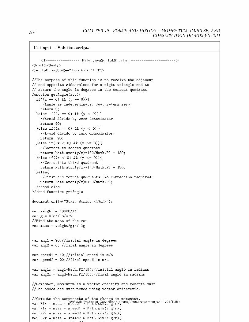
566CHAPTER 19. FORCE AND MOTION � MOMENTUM, IMPULSE, AND
CONSERVATION OF MOMENTUM
Listing 1 . Solution script.
<!---------------- File JavaScript01.html ---------------------><html><body><script language="JavaScript1.3">
//The purpose of this function is to receive the adjacent
// and opposite side values for a right triangle and to
// return the angle in degrees in the correct quadrant.
function getAngle(x,y){
if((x == 0) && (y == 0)){
//Angle is indeterminate. Just return zero.
return 0;
}else if((x == 0) && (y > 0)){
//Avoid divide by zero denominator.
return 90;
}else if((x == 0) && (y < 0)){
//Avoid divide by zero denominator.
return -90;
}else if((x < 0) && (y >= 0)){
//Correct to second quadrant
return Math.atan(y/x)*180/Math.PI + 180;
}else if((x < 0) && (y <= 0)){
//Correct to third quadrant
return Math.atan(y/x)*180/Math.PI + 180;
}else{
//First and fourth quadrants. No correction required.
return Math.atan(y/x)*180/Math.PI;
}//end else
}//end function getAngle
document.write("Start Script </br>");
var weight = 10000//N
var g = 9.8// m/s^2
//Find the mass of the car
var mass = weight/g;// kg
var ang1 = 90;//initial angle in degrees
var ang2 = 0; //final angle in degrees
var speed1 = 40;//initial speed in m/s
var speed2 = 20;//final speed in m/s
var ang1r = ang1*Math.PI/180;//initial angle in radians
var ang2r = ang2*Math.PI/180;//final angle in radians
//Remember, momentum is a vector quantity and momenta must
// be added and subtracted using vector arithmetic.
//Compute the components of the change in momentum.
var P1x = mass * speed1 * Math.cos(ang1r);
var P1y = mass * speed1 * Math.sin(ang1r);
var P2x = mass * speed2 * Math.cos(ang2r);
var P2y = mass * speed2 * Math.sin(ang2r);
var deltaPx = P2x-P1x;//change in horizontal component
var deltaPy = P2y-P1y;//change in vertical component
//Compute the magnitude of the change in momentum using
// the Pythagorean theorem.
var deltaPm = Math.sqrt(deltaPx*deltaPx + deltaPy*deltaPy);
//Compute the angle of the change in momentum usiing
// trigonometry.
var deltaPa = getAngle(deltaPx,deltaPy);
document.write("The givens." + "</br>");document.write("weight = " + weight.toFixed(0)
+ " kg</br>");document.write("speed1 = " + speed1.toFixed(0)
+ " m/s</br>");document.write("angle 1 = " + ang1.toFixed(0)
+ " degrees</br>");document.write("speed2 = " + speed2.toFixed(0)
+ " m/s</br>");document.write("angle 2 = " + ang2.toFixed(0)
+ " degrees</br>");
document.write("Computed mass." + "</br>");document.write("mass = " + mass.toFixed(0) + " kg</br>");
document.write("Components of momentum vectors." + "</br>");document.write("P1x = " + P1x.toFixed(0) + "</br>");document.write("P1y = " + P1y.toFixed(0) + "</br>");document.write("P2x = " + P2x.toFixed(0) + "</br>");document.write("P2y = " + P2y.toFixed(0) + "</br>");
document.write("Components of momentum change vectors."
+ "</br>");document.write("deltaPx = " + deltaPx.toFixed(0) + "</br>");document.write("deltaPy = " + deltaPy.toFixed(0) + "</br>");
document.write("Magnitude and angle of change vector."
+ "</br>");document.write("deltaPm = " + deltaPm.toFixed(0)
+ " m kg/s</br>");document.write("deltaPa = " + deltaPa.toFixed(0)
+ " degrees</br>");
document.write("End Script");
</script></body></html>
Available for free at Connexions <http://cnx.org/content/col11294/1.35>

567
Table 19.1
The comments in Listing 1 (p. 566) explain the steps involved in �nding the solution.The output produced by Listing 1 (p. 566) is shown in Figure 1 (p. 567) with the magnitude and angle
of the vector that describes the change of momentum at the end.
Figure 1 . Solution results.
Start Script
The givens.
weight = 10000 kg
speed1 = 40 m/s
angle 1 = 90 degrees
speed2 = 20 m/s
angle 2 = 0 degrees
Computed mass.
mass = 1020 kg
Components of momentum vectors.
P1x = 0
P1y = 40816
P2x = 20408
P2y = 0
Components of momentum change vectors.
deltaPx = 20408
deltaPy = -40816
Magnitude and angle of change vector.
deltaPm = 45634 m kg/s
deltaPa = -63 degrees
End Script
Table 19.2
I �nd it interesting that the magnitude of the change in momentum is greater than the magnitude ofeither the initial or �nal momentum.
19.4.1.4 Change in momentum due to change in speed only
What happens if the car in the previous example changes speed but doesn't change direction.Solution:Change the given conditions in the script in Listing 1 to those shown at the beginning of Figure 2 (p.
568) .
Figure 2 . Change in speed only.
continued on next page
Available for free at Connexions <http://cnx.org/content/col11294/1.35>

568CHAPTER 19. FORCE AND MOTION � MOMENTUM, IMPULSE, AND
CONSERVATION OF MOMENTUM
Start Script
The givens.
weight = 10000 kg
speed1 = 40 m/s
angle 1 = 90 degrees
speed2 = 20 m/s
angle 2 = 90 degrees
Computed mass.
mass = 1020 kg
Components of momentum vectors.
P1x = 0
P1y = 40816
P2x = 0
P2y = 20408
Components of momentum change vectors.
deltaPx = -0
deltaPy = -20408
Magnitude and angle of change vector.
deltaPm = 20408 m kg/s
deltaPa = 270 degrees
End Script
Table 19.3
This change causes the car to slow down, but to continue in the same direction. As a result, the angle ofthe change in momentum is an angle that is opposite to the direction that the car is moving. The magnitudeof the change in momentum depends entirely on the initial and �nal speeds.
19.4.1.5 Change in momentum due to change in direction only
What happens if the car in the previous example changes direction but doesn't change speed?Solution:Change the given conditions in the script in Listing 1 (p. 566) to those shown at the beginning of Figure
3 (p. 569) . This scenario simulates the car making a 10-degree turn to the right without changing speed.
Available for free at Connexions <http://cnx.org/content/col11294/1.35>

569
Figure 3 . Change in direction only.
Start Script
The givens.
weight = 10000 kg
speed1 = 40 m/s
angle 1 = 90 degrees
speed2 = 40 m/s
angle 2 = 80 degrees
Computed mass.
mass = 1020 kg
Components of momentum vectors.
P1x = 0
P1y = 40816
P2x = 7088
P2y = 40196
Components of momentum change vectors.
deltaPx = 7088
deltaPy = -620
Magnitude and angle of change vector.
deltaPm = 7115 m kg/s
deltaPa = -5 degrees
End Script
Table 19.4
19.4.2 Impulse examples
This section contains several examples involving the impulse.
19.4.2.1 Pushing a wagon part 1
1. What is the impulse experienced by pushing a 10-kg wagon that was initially at rest, with a constantforce of 2 newtons for a period of 3 seconds?
Answer:The impulse is given by the product of force and time. The mass of the wagon is super�uous for this
question.impulse = 2 N * 3 s = 6*N*s
19.4.2.2 Pushing a wagon part 2
2. What is the acceleration of the wagon in question 1 above?Answer:Now we do need to know the mass.The most straightforward solution comes from the fact that we know the mass and that the force is
uniform. Therefore,F = m*a, ora = F/m = 2N/10kg = 0.2 m/s^2A more interesting solution comes from the fact that since
Available for free at Connexions <http://cnx.org/content/col11294/1.35>

570CHAPTER 19. FORCE AND MOTION � MOMENTUM, IMPULSE, AND
CONSERVATION OF MOMENTUM
impulse = F*t, andF = m*a, thenimpulse = m*a*t, ora = impulse/(m*t) = 6*N*s/(10*kg*3*s) = 0.2 m/s^2
19.4.2.3 Pushing a wagon part 3
3. What is the velocity at the end of the 3-second interval in question 1 above.Answer:The impulse is equal to the change in momentum, and the initial velocity is 0.impulse = m*(v2 - v1) = m*v2, orv2 = impulse/m = 6*N*s/(10*kg) = 0.6 m/sWe can check that answer by knowing that the acceleration is uniform at 0.3 m/s^2 for 3 s = 0.6 m/s.
19.4.3 Action and reaction example
A dip in the poolYou have a body mass of 70 kg. You are on your knees on an in�atable raft in a swimming pool. The
raft has a mass of 1 kg. Your outstretched hands are about two meters from a safety rope that is strungacross the pool.
You decide to launch yourself from the raft to catch the rope, exerting a force with a horizontal componentof 5 newtons. (You assume that the vertical component of your launching force will take care of the downwardpull of gravity, allowing you to �y in a parabolic arc to the rope.) Assuming uniform acceleration (which isunrealistic but we will assume that anyway), how long will it take you to �y through the air to reach therope?
Answer:The force that you exert on the raft will be equal and opposite to the force that the raft exerts on you.
Therefore,F = my*ay = -mr*arwhere
• my and mr are the mass of you and the raft respectively• ay and ar are the accelerations experienced by you and the raft respectively
Thereforeay = F/my = 5N/70kg = 0.07143 m/s^2 toward the ropear = -F/mr = -5N/1kg = -5.00000 m/s^2 away from the ropeWe learned in an earlier module that given a constant acceleration, the distance traveled versus time is:d = v0t + 0.5*a*t^2In this case, v0 is zero, sod = 0.5*ay*t^2, ort = sqrt(d/(0.5*ay)), ort = sqrt(2m/(0.5*0.07143m/s^2)) = 7.48324 secondsI doubt that you will stay in the air long enough to reach the rope.During that time period, the raft will travel the following distance in the opposite direction (assuming
no resistance from the water).d = 0.5*ar*t^2, ord = 0.5*(-5m/s^2)*(7.48324s)^2 = -140 meters
Available for free at Connexions <http://cnx.org/content/col11294/1.35>
571
19.4.4 Conservation of momentum example
Railroad carsGetting back to my example of coupling railroad cars, when the collision has been completed, the two
masses have e�ectively been joined into a single mass and they are moving at the same velocity.In that case, we can write the above equation (p. 563) asma*(v2 - va1) = -mb*(v2 - vb1)ma*v2 +mb*v2 = ma*va1 +mb*vb1v2 = (ma*va1 +mb*vb1)/(ma + mb)where
• ma an mb represent the masses for Car-A and Car-B respectively• v2 is the velocity of the coupled cars after the collision• va1 and vb1 represent the initial velocities for Car-A and Car-B respectively
Then for any set of assumed mass values for the railroad cars and assumed values for the initial velocities,we can calculate the �nal velocity of the coupled pair of railroad cars.
Scenario #1: Assume that the two railroad cars are just alike and empty giving them the same mass.Also assume that the initial velocity for Car-A is 10 m/s and the initial velocity for Car-b is 0.
Question: What would be the �nal velocity of the coupled railroad cars?Answer: For this scenario, we havev2 = (ma*va1 +mb*vb1)/(ma + mb), orv2 = (ma*10)/2*ma = 5 m/sThe �nal velocity of the pair of coupled cars is half the initial velocity of the car that was moving.Scenario #2: Now assume that due to loading, Car-A has twice the mass of Car-B, the initial velocity
for Car-A is 10m/s and the initial velocity for Car-B is 0.Question: What would be the �nal velocity of the coupled railroad cars?Answer: For this scenario, we havev2 = (ma*va1 +mb*vb1)/(ma + mb), orv2 = (ma*va1)/(ma + 0.5ma), orv2 = ma*10/1.5*ma = 6.67 m/sWhen the car at rest is less massive than the car in motion, the �nal velocity is a little higher than when
the two cars have the same mass.Scenario #3: Finally, assume that due to loading, Car-A has twice the mass of Car-B, the initial velocity
for Car-A is 10m/s and the initial velocity for Car-B is 5m/s.Question: What would be the �nal velocity of each railroad car?Answer: For this scenario, we havev2 = (ma*va1 +mb*vb1)/(ma + mb), orv2 = (ma*10 +0.5ma*5)/(1.5*ma), orv2 = (10/1.5) + (0.5*5/1.5) = 8.33 m/sWhen both cars are already moving in the same direction, the �nal velocity in that direction is greater
than when one of the cars is stationary.
19.4.5 Center of mass examples
This section contains solutions to problems involving the center of mass.
19.4.5.1 Two objects
Two objects are located on a �at lawn with the following mass values and locations:
• obj1m = 15 kg• obj1x = 1 m
Available for free at Connexions <http://cnx.org/content/col11294/1.35>

572CHAPTER 19. FORCE AND MOTION � MOMENTUM, IMPULSE, AND
CONSERVATION OF MOMENTUM
• obj1y = 5 m• obj2m = 3 kg• obj2x = 4 m• obj2y = 2 m
What are the coordinates of the center of mass?Solution:A JavaScript script that will solve this problem is shown in Listing 2 (p. 573) .
Available for free at Connexions <http://cnx.org/content/col11294/1.35>

573
Listing 2 . Center of mass for two objects.
<!---------------- File JavaScript02.html ---------------------><html><body><script language="JavaScript1.3">
document.write("Start Script </br>");
//Create arrays for mass,xCoor, and yCoor values;
var mass = new Array(15,3);
var xCoor = new Array(1,4);
var yCoor = new Array(5,2);
//Declare a counter variable.
var cnt = 0;
//Use a loop to compute total mass by summing the individual
// mass values.
var massTotal = 0;
for(cnt = 0;cnt < mass.length;cnt++){
massTotal += mass[cnt];
}//end for loop
//Use a loop to compute x-coordinate of the center of mass
// by summing the normalized sum of products.
var cmX = 0;
for(cnt = 0;cnt < mass.length;cnt++){
cmX += mass[cnt]*xCoor[cnt]/massTotal
}//end for loop
//Use a loop to compute y-coordinate of the center of mass
// by summing the normalized sum of products.
var cmY = 0;
for(cnt = 0;cnt < mass.length;cnt++){
cmY += mass[cnt]*yCoor[cnt]/massTotal
}//end for loop
//Display the results
document.write("massTotal = " + massTotal + " kg</br>");document.write("cmX = " + cmX + " meters</br>");document.write("cmY = " + cmY + " meters</br>");
document.write("End Script");
</script></body></html>
Table 19.5
The comments describe how the problem is solved.
Available for free at Connexions <http://cnx.org/content/col11294/1.35>

574CHAPTER 19. FORCE AND MOTION � MOMENTUM, IMPULSE, AND
CONSERVATION OF MOMENTUM
The output is shown in Figure 4 (p. 574) .
Figure 4 . Center of mass for two objects.
Start Script
massTotal = 18 kg
cmX = 1.5 meters
cmY = 4.5 meters
End Script
Table 19.6
The x-coordinate for the center of mass is 1.5 meters, and the y-coordinate for the center of mass is 4.5meters.
19.4.5.2 Three objects
Three objects are located on a �at lawn with the following mass values and locations:
• obj1m = 5 kg• obj1x = 1 m• obj1y = 1 m• obj2m = 5 kg• obj2x = 3 m• obj2y = 1 m• obj3m = 10 kg• obj3x = 2 m• obj3y = 3 m
What are the coordinates of the center of mass?Use the code from Listing 2 (p. 573) but make the change shown in Listing 3 (p. 574) in order to populate
the world with three objects having di�erent mass values and di�erent coordinates.
Listing 3 . Change to add a third object.
//Create arrays for mass,xCoor, and yCoor values;
var mass = new Array(5,5,10);
var xCoor = new Array(1,3,2);
var yCoor = new Array(1,1,3);
Table 19.7
The output is shown in Figure 5 (p. 575) .
Available for free at Connexions <http://cnx.org/content/col11294/1.35>

575
Figure 5 . Center of mass for three objects.
Start Script
massTotal = 20 kg
cmX = 2 meters
cmY = 2 meters
End Script
Table 19.8
19.5 Do the calculations
I encourage you to repeat the calculations that I have presented in this lesson to con�rm that you get thesame results. Experiment with the scenarios, making changes, and observing the results of your changes.Make certain that you can explain why your changes behave as they do.
19.6 Resources
I will publish a module containing consolidated links to resources on my Connexions web page and willupdate and add to the list as additional modules in this collection are published.
19.7 Miscellaneous
This section contains a variety of miscellaneous information.
Housekeeping material
• Module name: Force and Motion � Momentum, Impulse, and Conservation of Momentum forBlind Students• File: Phy1160.htm• Revised: 10/02/15• Keywords:
· physics· accessible· accessibility· blind· graph board· protractor· screen reader· refreshable Braille display· JavaScript· trigonometry· conservation of momentum· momentum· Newton's cradle· impulse· action and reaction
Available for free at Connexions <http://cnx.org/content/col11294/1.35>

576CHAPTER 19. FORCE AND MOTION � MOMENTUM, IMPULSE, AND
CONSERVATION OF MOMENTUM
Disclaimers: Financial : Although the openstax CNX site makes it possible for you todownload a PDF �le for the collection that contains this module at no charge, and also makes itpossible for you to purchase a pre-printed version of the PDF �le, you should be aware that someof the HTML elements in this module may not translate well into PDF.
You also need to know that Prof. Baldwin receives no �nancial compensation from openstaxCNX even if you purchase the PDF version of the collection.
In the past, unknown individuals have copied Prof. Baldwin's modules from cnx.org, convertedthem to Kindle books, and placed them for sale on Amazon.com showing Prof. Baldwin as theauthor. Prof. Baldwin neither receives compensation for those sales nor does he know who doesreceive compensation. If you purchase such a book, please be aware that it is a copy of a collectionthat is freely available on openstax CNX and that it was made and published without the priorknowledge of Prof. Baldwin.
A�liation : Prof. Baldwin is a professor of Computer Information Technology at AustinCommunity College in Austin, TX.
-end-
Available for free at Connexions <http://cnx.org/content/col11294/1.35>

Chapter 20
Energy � Work1
20.1 Table of Contents
• Preface (p. 577)
· General (p. 577)· Prerequisites (p. 577)· Supplemental material (p. 578)
• General background information (p. 578)
· An assumption of constant velocity (p. 578)· Use your graph board for sketches (p. 579)· Work in everyday life (p. 579)· Work in physics (p. 579)
• Sample calculations (p. 582)
· Single force on a body (p. 582)· Multiple forces on a body (p. 583)· Force parallel to a ramp (p. 584)
• Do the calculations (p. 584)• Resources (p. 585)• Miscellaneous (p. 585)
20.2 Preface
20.2.1 General
This module is part of a book 2 (or collection) designed to make physics concepts accessible to blindstudents. The collection is intended to supplement but not to replace the textbook in an introductory coursein high school or college physics.
This module explains energy and work in a format that is accessible to blind students.
20.2.2 Prerequisites
In addition to an Internet connection and a browser, you will need the following tools (as a minimum) towork through the exercises in these modules:
1This content is available online at <http://cnx.org/content/m38267/1.3/>.2http://cnx.org/contents/a7842db2-93c6-4c06-a5e3-56c282358143
Available for free at Connexions <http://cnx.org/content/col11294/1.35>
577

578 CHAPTER 20. ENERGY � WORK
• A graph board for plotting graphs and vector diagrams (http://www.youtube.com/watch?v=c8plj9UsJbg 3 ).
• A protractor for measuring angles ( http://www.youtube.com/watch?v=v-F06HgiUpw 4 ).• An audio screen reader that is compatible with your operating system, such as the NonVisual Desktop
Access program (NVDA), which is freely available at http://www.nvda-project.org/ 5 .• A refreshable Braille display capable of providing a line by line tactile output of information displayed
on the computer monitor ( http://www.userite.com/ecampus/lesson1/tools.php 6 ).• A device to create Braille labels. Will be used to label graphs constructed on the graph board.
The minimum prerequisites for understanding the material in these modules include:
• A good understanding of algebra.• An understanding of the use of a graph board for plotting graphs and vector diagrams (
http://www.youtube.com/watch?v=c8plj9UsJbg 7 ).• An understanding of the use of a protractor for measuring angles (
http://www.youtube.com/watch?v=v-F06HgiUpw 8 ).• A basic understanding of the use of sine, cosine, and tangent from trigonometry (
http://www.clarku.edu/∼djoyce/trig/ 9 ).• An introductory understanding of JavaScript programming ( http://www.dickbaldwin.com/tocjscript1.htm
10 and http://www.w3schools.com/js/default.asp 11 ).• An understanding of all of the material covered in the earlier modules in this collection.
20.2.3 Supplemental material
I recommend that you also study the other lessons in my extensive collection of online programming tutorials.You will �nd a consolidated index at www.DickBaldwin.com 12 .
20.3 General background information
I will explain some of the background material regarding work in this section and show how to work problemsinvolving work later (p. 582) .
20.3.1 An assumption of constant velocity
In order to simplify the solutions to the problems, many of the example problems in this module will makethe assumption that an object is moving with constant velocity. Let's review what that means in terms ofwhat you have learned from earlier modules.
Unbalanced forces cause accelerationWe know that whenever unbalanced forces are applied to an object, that object will accelerate. What
does it mean, therefore, when we make a statement like "a force of 1 newton to the right was applied to anobject to cause that object to move 1 meter to the right at a constant velocity"?
Conditions for constant velocityWe know that the statement means at least the following things:
3http://www.youtube.com/watch?v=c8plj9UsJbg4http://www.youtube.com/watch?v=v-F06HgiUpw5http://www.nvda-project.org/6http://www.userite.com/ecampus/lesson1/tools.php7http://www.youtube.com/watch?v=c8plj9UsJbg8http://www.youtube.com/watch?v=v-F06HgiUpw9http://www.clarku.edu/∼djoyce/trig/
10http://www.dickbaldwin.com/tocjscript1.htm11http://www.w3schools.com/js/default.asp12http://www.dickbaldwin.com/toc.htm
Available for free at Connexions <http://cnx.org/content/col11294/1.35>

579
• At some point in the past, there was an unbalanced force applied to the object to cause it to beginmoving to the right. That force is ignored by the statement of the problem.
• At the beginning of the time frame covered by the problem, the object was in equilibrium, moving ata constant velocity to the right.
• During the time frame of the problem, there must be a 1 newton balancing force being exerted tothe left to prevent the 1 newton force being applied to the right from causing the object to acceleratetowards the right. That force is also ignored by the statement of the problem.
20.3.2 Use your graph board for sketches
As a sighted person, I often �nd it useful to make sketches of the physical scenarios for problems of the typesthat I will discuss in this module.
You may also �nd it useful to use your graph board to create "sketches" of the physical scenarios in orderto better understand the solutions to the problems.
20.3.3 Work in everyday life
You hear the word work in many situations in everyday life. For example, someone might say "My gasolinebill is high because I have to drive a long way to work every day."
Someone else might say "She works very hard at being popular."Or, you might hear someone say "It's going to take a lot of work to lift that heavy sofa into the back of
that truck."The latter expression comes closest to describing what is mean by work in physics.
20.3.4 Work in physics
According to College Physics by Mendenhall et alIf a body on which a force F is acting is displaced by a distance d, then the work done by the force is
F*d*cos(theta), where theta is the angle between the path d and the line of action of F.Thus, the term work has a very precise meaning in physics. In equation form, we can represent
work asW = F * d * cos(theta)where
• W represents work• F represents a force that causes the displacement of an object• d represents the magnitude of the displacement• theta is the angle between the line of action of the force and the direction of the displacement
Three key ingredientsAccording to the Physics Classroom (see http://www.physicsclassroom.com/Class/energy/u5l1a.cfm 13
), there are three key ingredients to work: force , displacement , and cause .In order for a force to qualify as having done work on an object, there must be a displacement and the
force must cause the displacement.Commonplace examples of workExamples of work are commonplace in everyday life:
• A bulldozer pushing dirt. The bulldozer exerts a horizontal force to move the dirt.• An elevator lifting people from the �rst to the tenth �oor. The cable on the elevator exerts an upward
force to move the people upward by approximately 110 feet.
13http://www.physicsclassroom.com/Class/energy/u5l1a.cfm
Available for free at Connexions <http://cnx.org/content/col11294/1.35>

580 CHAPTER 20. ENERGY � WORK
• You lifting your backpack full of books onto your back. Your muscles exert a force to raise severalheavy books, possibly displacing them both vertically and horizontally at the same time.
However, some things that we might initially think of as work don't really qualify as work according to thephysics de�nition of work.
Suzie and the heavy trunkYour college dorm is equipped with a rope on a pulley that can be used to lift heavy objects and swing
them into a window on the second �oor. Suzie has used the pulley and the rope to lift her heavy trunk upto the level of the window. She asks you to hold the rope and maintain the trunk at that level while shegoes up the stairs to pull it in the window.
Suzie likes to gossipSuzie, however, really likes to gossip. On the way up to the window, she meets some friends and starts
talking, leaving you holding onto the rope. After about 30 minutes, you become really tired and frustratedand you lower the trunk back to ground level.
Did you do any work on the trunk?The answer is that you did not do any work on the trunk. Although you became very hot and tired
standing there and holding the rope, you did not cause a displacement of the trunk. For 30 minutes, yousimply held the rope causing the trunk to remain at the same location. At the end of that period, you carefullyallowed the rope to slip through your hands while the force of gravity caused a downward displacement onthe trunk.
Was any work done on the trunk?Was any work done on the trunk from the time Suzie handed you the rope until the trunk was back on
the ground?Yes, the force of gravity caused the height of the trunk to be displaced from the level of the second �oor
window downward to the ground, so the force of gravity did work on the trunk.Was any work done on the trunk from the time that Suzie started raising it until it was back on the
ground?The answer is no. The net displacement of the trunk over that time period was zero. If the displacement
was zero, no work could have been done. In this case, the positive work done by Suzie in lifting the trunk tothe second �oor window was canceled out by the negative work done by gravity when you allowed the trunkto return to the ground.
Measurement of work can depend on the time intervalAs you can see, therefore, the amount of work done in some cases can depend on the time interval over
which the measurement is made.Also, as you can see, certain activities (such as holding a rope to keep a trunk from falling) can make
you very tired even though you are not doing any work.Mathematical representation of workAs stated earlier, we can represent work asW = F * d * cos(theta)where
• F represents a force being applied to an object• d represents the displacement of the object• theta is the angle between the displacement path d and the line of action of the force.
Work is a scalar quantityAlthough both force and displacement are vector quantities, the product of those two vectors with the
cosine of an angle produces a scalar quantity. Work has a magnitude but no direction. The product is oftencalled a scalar product or a dot product.
The scalar or dot productThe scalar product (or dot product ) of two vectors is de�ned by the equationvectorA * vectorB * cos(theta)
Available for free at Connexions <http://cnx.org/content/col11294/1.35>

581
where theta is the angle between the two vectors when they are drawn tail to tail.The special name and notation are used because this pattern occurs often in physics and mathematics.Units of workThe SI unit of work (and energy) is the newton-meter (N*m), which is given the name joule (symbol:
J), after the English physicist James Prescott Joule. One joule is equivalent to one newton of force causinga displacement of one meter.
A stubborn dogPretend that you have a dog that is very stubborn and just wants to sleep. You pull on the dog's leash
and cause the dog to slide 2 meters across the �oor. In this case, the displacement is horizontal and you arepulling at an angle of 30 degrees above the horizontal.
The work done on the dog would be the product of the horizontal component of the force that you exerton the leash (F*cos(theta)) and the displacement distance of 2 meters. If you were pulling with a constanthorizontal force component of 3 newtons, then you would have done 2*3=6 joules of work.
A stubborn pigA very large pig has escaped from its pen. You have a rope tied around the pig's neck and you are trying
to pull the pig back into the pen. The rope is horizontal and you pull with a steady force of 3 newtons.While you are pulling, however, the pig is backing up (actually pulling you forward away from the pen),
and travels 2 meters in the direction opposite the direction that you are pulling.In this case, the angle between the line of action of the force that you are exerting and the direction
of the pig's displacement is 180 degrees. Since the cosine of 180 degrees is -1, the product of the force,displacement, and cosine of 180 degrees would be -6. Therefore, your e�orts to move the pig toward the penare unsuccessful and you have done -6 joules of work on the pig.
Therefore, work can be either positive or negative.More on that stubborn pigThe very large pig has decided to lay down on a hydraulic lift on the back of a truck and someone
accidentally �ipped the switch causing the hydraulic lift to start moving up.You still have a rope tied around the pig's neck and you attempt to pull the pig o� the lift to prevent it
from getting hurt. You pull as hard as you can on the rope but the pig doesn't budge. The lift goes up twometers to the height of the truck bed and turns itself o� automatically with the pig still laying on the lift.
The angle is 90 degreesIn this case, the angle between the line of action of the force that you exert and the direction of dis-
placement of the pig is 90 degrees. The cosine of 90 degrees is 0. Therefore, the product of the force, thedisplacement, and the cosine of 90 degrees would be 0.
While you might be ready for a rest after exerting all of that e�ort trying to pull the pig o� the lift, youactually haven't done any work on the pig.
Therefore, work can even be zero if the line of action of the force is perpendicular to the displacement ofthe object. In this case, work did get done to raise the pig 2 meters o� the ground, but you didn't contributeanything to that work. The work was done by the mechanical system that operates the hydraulic lift on thetruck.
To do any work, a force must cause a displacement.More on the stubborn dogLet's go back and think a little more about the stubborn dog. Assume that you exert a force of 3.46
newtons on the leash and the leash makes an angle of 30 degrees with the horizontal �oor. This causes thedog to slide 2 meters across the �oor, but doesn't lift the dog o� the �oor. What is the work that you do onthe dog?
The horizontal component Fx of the force F is given byFx = F*cos(30 degrees), orFx = 3.46*cos(30 degrees)Enter the following into the Google calculator search box:3.46*cos(30 degrees)
Available for free at Connexions <http://cnx.org/content/col11294/1.35>

582 CHAPTER 20. ENERGY � WORK
and with rounding, you will learn that the horizontal component of the force that you exerted on theleash is
3 newtons.How much work was done?The work done on the dog is the product of the horizontal component of the force that you exert on the
leash and the horizontal displacement distance of 2 meters.Assuming that you were pulling the leash with a constant force of 3.46 newtons, at an angle of 30 degrees
relative to the horizontal �oor, you would do 2*3=6 joules of work on the dog.Be careful how you handle the angle thetaThe angle theta is the angle between the line of action of the force and the direction of the displacement.
It is only because I set the scenario up that way that the 30-degree angle in the previous stubborn-dogscenario is 30 degrees relative to the horizontal.
In that scenario, the line of action of the 3.46-newton force was at 30 degrees relative to the horizontal, butthe displacement was horizontal. Therefore, it was necessary to take the angle into account when computingthe work done on the dog. In other words, the work done on the dog was:
W = 3.46N * 2m * cos(30 degrees) = 6 joulesOne more discussion about the stubborn dogAssume that instead of pulling the dog across a horizontal �oor, you are pulling the dog up a ramp that
has an angle of 30 degrees relative to the horizontal.In this case, you pull on the leash at an angle of 30 degrees relative to the horizontal, which is parallel to
the ramp. Once again, you pull with a force of 3.46 newtons. This time, you cause the dog to slide 2 metersup the ramp.
In this case, the angle between the direction of the displacement and the line of action of the force is 0degrees. The cosine of 0 degrees is +1. Therefore, the work done on the dog is
(3.46 N) * 2 m * cos(0 degrees) = 6.92 joules(You may recognize the format of some of the mathematical expressions in the above paragraphs as being
the format of the output of the Google calculator.)
20.4 Sample calculations
I will present and explain several scenarios in this section involving force and work.In some cases, I will use the Google calculator to perform the arithmetic, and the format of the mathe-
matical expressions will be the format of the output from the Google calculator (except that I will usuallydiscard some of the digits to the right of the decimal point).
20.4.1 Single force on a body
A horizontal forceA horizontal force of 10 N towards the right is applied to a 15-kg body causing the body to move 5 m to
the right at constant speed. How much work is done on the body?Answer:(10 newtons) * 5 meters = 50 joulesNote that the mass of the object is super�uous in this problem.A force at 30 degreesA force of 10 N is applied to a 15-kg body at an angle of 30 degrees relative to the horizontal causing the
body to move 5 m to the right at constant speed. How much work is done on the body?Answer:(10 N) * 5 m * cos(30 degrees) = 43.3 joulesOnce again, the mass of the object is super�uous.A vertical forceThe mass is not super�uous for this scenario.
Available for free at Connexions <http://cnx.org/content/col11294/1.35>

583
A force is applied to a 10-kg body at an angle of 90 degrees relative to the horizontal causing the bodyto move 5 m straight up at constant velocity. How much work is done on the body?
Answer:Weight = (10 kg) * 9.81 * (m / (s^2)) = 98.1 newtonsUnder the constant velocity assumption explained earlier, an upward force equal to the weight of the
object will cause the object to continue moving in an upward direction, and eventually move 5 m straightup. The angle between the action line of the force and the displacement is 0 degrees. Therefore, the workdone to the object is:
(98.1 N) * 5 m * cos(0 degrees) = 490.5 joules
20.4.2 Multiple forces on a body
A block on a friction-free surfaceA block on a friction-free surface is subjected to three forces:
1. Weight = 15 N2. Upward force from the surface = 15 N3. A 5 N force to the right that causes the block to move 5 m to the right at constant velocity.
How much work does each force do on the block.Answer:Forces 1 and 2 are perpendicular to the direction of displacement, so they cannot do work on the block.Force 3 is in the same direction as the displacement and does the following work on the block:(5 N) * 5 m * cos(0 degrees) = 25 joulesA moving block encounters frictionA block is sliding to the right on a friction free surface. Suddenly the block encounters an area on the
surface where the friction is not zero. The friction causes the block to stop after moving 5 m to the right.When the block encounters the frictional surface, it is subjected to the following three forces:
1. Weight = 15 N2. Upward force from the surface = 15 N3. A 5 N force to the left caused by the friction.
How much work does each force do on the block?Answer:Forces 1 and 2 are perpendicular to the direction of displacement, so they cannot do work on the block.The angle between force 3 and the direction of displacement is 180 degrees. Force 3 does the following
work on the block:(5 N) * 5 m * cos(180 degrees) = -25 joulesNote that in this case, the work done is negative.Another friction scenarioA block on a frictional surface is subjected to four forces:
1. Weight = 15 N2. Upward force from the surface = 15 N3. A 5 N force to the right causes the block to move 5 m to the right at constant speed.4. A 5 N force to the left caused by friction.
How much work does each force do on the block?Answer:Forces 1 and 2 are perpendicular to the direction of displacement, so they cannot do work on the block.The work done by force 3 is:(5 N) * 5 m * cos(0 degrees) = 25 joulesThe work done by force 4 is:(5 N) * 5 m * cos(180 degrees) = -25 joules
Available for free at Connexions <http://cnx.org/content/col11294/1.35>

584 CHAPTER 20. ENERGY � WORK
20.4.3 Force parallel to a ramp
A man and a crateA man needs to load a crate with friction-free wheels and a weight of 1000 N onto the bed of a truck
that is 1 m o� the ground. He has two di�erent ramps that he can use to push the crate up the ramp andonto the truck.
One ramp is 2.5 m long and the other ramp is 5 m long.He is able to push the crate up the ramp by pushing in a direction that is parallel to the ramp.QuestionsWhat is the force that he must exert parallel to each ramp to push the crate up the ramp.Which ramp requires the least amount of work to push the crate up the ramp?Required forceTrigonometry can be used to compute the amount of force required, parallel to the ramp, to push the
crate up the ramp as a function of the angle that the ramp makes with the horizontal. That force is equal tothe product of the weight of the crate (1000 N or 225 pound-force) and the sine of the angle that the rampmakes relative to the horizontal.
For example, other than the requirement to overcome inertia to get the crate moving, no force is requiredto push the crate if the angle is 0 degrees. At the other extreme, if the angle is 90 degrees, the man mustlift the crate straight up, bearing the entire weight of the crate. For angles in between these two extremes,the required force is within the capability of one man to achieve.
AnswersRamp #1
• Truck bed height = 1.0m• Ramp length = 2.5m• Ramp angle = arcsin(1 / 2.5) = 23.58 degrees• Weight of crate = 1000N• Component of crate's weight parallel to ramp = 1000 N * sin(23.58 degrees) = 400.03 newtons. This
is the force that must be exerted to push the crate up the ramp.• Work = (400.03 newtons) * 2.5 meters = 1000.08 joules
Ramp #2
• Truck bed height = 1.0m• Ramp length = 5m• Ramp angle = arcsin(1 / 5) = 11.54 degrees• Weight of crate = 1000N• Component of crate's weight parallel to ramp = 1000 N * sin(11.54 degrees) = 200.05 newtons. This
is the force that must be exerted to push the crate up the ramp.• Work = (200.05 newtons) * 5 meters = 1000.25 joules
The e�ect of the rampThe man only has to exert half as much force to push the crate up Ramp #2 as is required for Ramp
#1.However, he has to push it twice as far with Ramp #2, so the amount of work done on the crate in both
cases is 1000 joules.Like many other simple machines, the use of a ramp (inclined plane) reduces the force required to do a
job but it doesn't reduce the amount of work required to do the job.
20.5 Do the calculations
I encourage you to repeat the calculations that I have presented in this lesson to con�rm that you get thesame results. Experiment with the scenarios, making changes, and observing the results of your changes.Make certain that you can explain why your changes behave as they do.
Available for free at Connexions <http://cnx.org/content/col11294/1.35>
585
20.6 Resources
I will publish a module containing consolidated links to resources on my Connexions web page and willupdate and add to the list as additional modules in this collection are published.
20.7 Miscellaneous
This section contains a variety of miscellaneous information.
Housekeeping material
• Module name: Energy � Work• File: Phy1170.htm• Revised: 10/02/15• Keywords:
· physics· accessible· accessibility· blind· graph board· protractor· screen reader· refreshable Braille display· JavaScript· trigonometry· work· energy· power
Disclaimers: Financial : Although the openstax CNX site makes it possible for you todownload a PDF �le for the collection that contains this module at no charge, and also makes itpossible for you to purchase a pre-printed version of the PDF �le, you should be aware that someof the HTML elements in this module may not translate well into PDF.
You also need to know that Prof. Baldwin receives no �nancial compensation from openstaxCNX even if you purchase the PDF version of the collection.
In the past, unknown individuals have copied Prof. Baldwin's modules from cnx.org, convertedthem to Kindle books, and placed them for sale on Amazon.com showing Prof. Baldwin as theauthor. Prof. Baldwin neither receives compensation for those sales nor does he know who doesreceive compensation. If you purchase such a book, please be aware that it is a copy of a collectionthat is freely available on openstax CNX and that it was made and published without the priorknowledge of Prof. Baldwin.
A�liation : Prof. Baldwin is a professor of Computer Information Technology at AustinCommunity College in Austin, TX.
-end-
Available for free at Connexions <http://cnx.org/content/col11294/1.35>

586 CHAPTER 20. ENERGY � WORK
Available for free at Connexions <http://cnx.org/content/col11294/1.35>

Chapter 21
Energy � Potential Energy1
21.1 Table of Contents
• Preface (p. 587)
· General (p. 587)· Prerequisites (p. 587)· Supplemental material (p. 588)
• General background information (p. 588)
· Graphic examples of potential energy (p. 588)· Potential energy (p. 589)
* Gravitational potential energy (p. 590)* Elastic potential energy (p. 591)
· Summary (p. 592)
• Sample calculations (p. 593)• Do the calculations (p. 594)• Resources (p. 594)• Miscellaneous (p. 594)
21.2 Preface
21.2.1 General
This module is part of a book 2 (or collection) designed to make physics concepts accessible to blindstudents. The collection is intended to supplement but not to replace the textbook in an introductory coursein high school or college physics.
This module explains potential energy in a format that is accessible to blind sudents.
21.2.2 Prerequisites
In addition to an Internet connection and a browser, you will need the following tools (as a minimum) towork through the exercises in these modules:
• A graph board for plotting graphs and vector diagrams (http://www.youtube.com/watch?v=c8plj9UsJbg 3 ).
1This content is available online at <http://cnx.org/content/m38279/1.3/>.2http://cnx.org/contents/a7842db2-93c6-4c06-a5e3-56c2823581433http://www.youtube.com/watch?v=c8plj9UsJbg
Available for free at Connexions <http://cnx.org/content/col11294/1.35>
587

588 CHAPTER 21. ENERGY � POTENTIAL ENERGY
• A protractor for measuring angles ( http://www.youtube.com/watch?v=v-F06HgiUpw 4 ).• An audio screen reader that is compatible with your operating system, such as the NonVisual Desktop
Access program (NVDA), which is freely available at http://www.nvda-project.org/ 5 .• A refreshable Braille display capable of providing a line by line tactile output of information displayed
on the computer monitor ( http://www.userite.com/ecampus/lesson1/tools.php 6 ).• A device to create Braille labels. Will be used to label graphs constructed on the graph board.
The minimum prerequisites for understanding the material in these modules include:
• A good understanding of algebra.• An understanding of the use of a graph board for plotting graphs and vector diagrams (
http://www.youtube.com/watch?v=c8plj9UsJbg 7 ).• An understanding of the use of a protractor for measuring angles (
http://www.youtube.com/watch?v=v-F06HgiUpw 8 ).• A basic understanding of the use of sine, cosine, and tangent from trigonometry (
http://www.clarku.edu/∼djoyce/trig/ 9 ).• An introductory understanding of JavaScript programming ( http://www.dickbaldwin.com/tocjscript1.htm
10 and http://www.w3schools.com/js/default.asp 11 ).• An understanding of all of the material covered in the earlier modules in this collection.
21.2.3 Supplemental material
I recommend that you also study the other lessons in my extensive collection of online programming tutorials.You will �nd a consolidated index at www.DickBaldwin.com 12 .
21.3 General background information
I will begin this explanation with a couple of graphic examples.
21.3.1 Graphic examples of potential energy
Gravitational potential energyIf you �nd a �at rock with a mass of 10 kg on the ground at a location on the surface of the earth where
the ground is �at for miles around, that rock has little or no potential energy.A change in potential energyIf you pick that rock up and balance it on a limb of a tree that is 2 meters o� the ground, you have done
at least two things:
• You have done work on the rock by exerting a force on the rock that displaced it upward by 2 meters.With some simplifying assumptions, we can calculate that you have done 196.2 joules of work on therock.
• You have caused the rock to have gravitational potential energy that it did not have in its earlierposition on the ground.
4http://www.youtube.com/watch?v=v-F06HgiUpw5http://www.nvda-project.org/6http://www.userite.com/ecampus/lesson1/tools.php7http://www.youtube.com/watch?v=c8plj9UsJbg8http://www.youtube.com/watch?v=v-F06HgiUpw9http://www.clarku.edu/∼djoyce/trig/
10http://www.dickbaldwin.com/tocjscript1.htm11http://www.w3schools.com/js/default.asp12http://www.dickbaldwin.com/toc.htm
Available for free at Connexions <http://cnx.org/content/col11294/1.35>

589
An accident waiting to happenPerhaps the change in potential energy can best be illustrated by stating that the rock now has the
potential to crack someone's skull open if they happen to be standing under the limb when the rock fallstowards the ground with an acceleration of 9.8 m/s^2.
When the rock was laying on the surface of the earth, it did not have that potential. You created thatpotential by imparting potential energy into the rock when you listed it from the ground and balanced it onthe limb.
Elastic potential energyConsider a common rubber band. Because of its small mass, a rubber band can never be expected to
acquire much in the way of gravitational potential energy. However, it can acquire a considerable amount ofelastic potential energy.
While I don't recommend that you try the experiment with the rock described earlier, this is an experimentthat you can try with no permanent damage to your person.
Thread your arm through the rubber bandFind a strong rubber band and thread your left arm through the rubber band up to the wrist. Make
certain that the rubber band �ts loosely on your arm. At that point, the rubber band has little or nopotential energy.
Change the potential energyNow grasp the rubber band between the thumb and fore�nger of your right hand and stretch it to the
point where it is almost ready to break.At that point, you have expended your energy in stretching the rubber band, and the rubber band has
acquired elastic potential energy.How much elastic potential energy?How much elastic potential energy did the rubber band acquire? You can get a qualitative estimate of
the amount of potential energy by releasing the rubber band and letting it strike your bare wrist.When the rubber band contacts your skin, it will impart energy into the nerve ending in your skin as its
potential energy goes back to zero. If it hurts a lot, there was a lot of elastic potential energy stored in thestretched rubber band. If it doesn't hurt very much, there probably wasn't much potential energy stored inthe rubber band, or you have very tough skin with few nerve endings.
21.3.2 Potential energy
There are several ways that an object can acquire and store energy, which we will refer to as potentialenergy . Two of the most common ways are:
• Raising the object to a new height above the surface of the earth (gravitational potential energy)• Deforming the object within its elastic limit (elastic potential energy)
Increasing the potential energy of the rockFor example, elevating the rock by 2 meters above the ground as described earlier imparted energy into
the rock. (Work was done on the rock in order to increase its height above the ground.)Storing the potential energyBalancing the rock on the limb caused that energy to be (temporarily) stored in the rock as gravitational
potential energy. The rock stores that energy for so long as it is held at that elevated position.Releasing the potential energyTipping the rock o� the limb so that it would fall back to the ground caused that potential energy to be
released and caused the potential energy of the rock to go back to zero.Potential energy and the rubber bandSimilarly, stretching and then releasing the rubber band as described above �rst stored, and then released
elastic potential energy in the rubber band.Work is required to increase the potential energy of an objectIn both cases, it was necessary for you to expend energy in order to increase the amount of energy stored
in the rock and the rubber band.
Available for free at Connexions <http://cnx.org/content/col11294/1.35>

590 CHAPTER 21. ENERGY � POTENTIAL ENERGY
21.3.2.1 Gravitational potential energy
Gravitational potential energy is the energy stored in an object as the result of the gravitational attractionbetween the earth and the object. In practical terms, the energy is stored as the result of the objects heightabove the surface of the earth.
Every object that has a position above the surface of the earth has stored gravitational potential energy.Some common examples are
• Books on a bookshelf• An air conditioning unit in a window on the third story of an apartment building• You, when you climb a tree and sit on a limb or walk up the stairs to your classroom.
Because all objects are attracted to a point in the center of the earth, all objects that don't rest on thesurface of the earth have potential energy.
All objects have stored gravitational potential energyEven those objects that do rest on the surface of the earth have potential energy, because they have a
strong tendency to make their way to the center of the earth. In most cases, however, that desire cannot beful�lled so we usually consider the surface of the earth to be the reference point for gravitational potentialenergy.
The deepIn the �nal analysis, however, only those objects that rest at the bottom of the deepest point in the
ocean cannot be forced to give up stored gravitational potential energy. In theory, every other object couldbe transported to and dropped to that point on the ocean bed, thereby giving up stored potential energy inthe process.
The height and the mass are criticalThe magnitude of the potential energy possessed by the rock balanced on the tree limb in the earlier
example depends on two things: the height of the rock above the ground and the mass of the rock.Gravitational potential energy is proportional to massThe gravitational potential energy of an object is proportional to the mass of the object. Objects with
more mass are capable of having more potential energy than objects with less mass. Therefore, if the rubberband discussed in the earlier example were to be placed on the same limb as the rock, the rock would havemore gravitational potential energy than the rubber band due to its greater mass.
Gravitational potential energy is proportional to heightGravitational potential energy is also proportional to the distance of the object from the center of the
earth. Thus, a 10 kg rock falling from 50 meters onto your head would do more damage than the same 10 kgrock falling onto your head from 2 meters. In both cases, the potential energy of the rock would be convertedto kinetic energy, (which is a topic for a future module), and that kinetic energy would be converted to painwhen the rock strikes your head.
The higher the starting point for the rock,
• the faster it would be going right before it strikes your head,• the more kinetic energy it would possess at that point in time, and• the more damage it would do to your head.
Gravitational potential energy is proportional to the product of mass, height, and gravityThus, the gravitational potential energy of an object that is elevated above the surface of the earth is
equal to the product of the mass of the object, the height of the object, and the acceleration of gravity.Expressed as an equation, we can write:
PEg = mass*kg * gravity*m/s^2 * height*mwhere
• PEg represents gravitational potential energy• mass, gravity, and height represent their namesakes
Available for free at Connexions <http://cnx.org/content/col11294/1.35>

591
• kg, m, and s represent kilogram, meter, and second
Units of gravitational potential energyAs you can see from above, the units of gravitational potential energy arekg*m^2/s^2 = kg*(m/s^2)*(m) = N*m = jouleWhat is the zero height reference?Because the determination of gravitational potential energy requires knowledge of the height of the object,
you must determine the height of the object above a zero-height reference level. Therefore, to determinethe gravitational potential energy of an object, you must �rst decide what level you are going to consider tobe zero height.
The ultimate referenceThe ultimate zero-height reference is the point in the center of the earth to which all objects are attracted.
Using that point, however, would lead to a lot of arithmetic accuracy problems. The radius of the earth issomething like 6378100 meters, and that depends on where on the earth you are standing � death valley,Mount Everest, or somewhere in between.
I will leave it as an exercise for the student to determine why the use of the center of the earth as the zero-height reference might lead to arithmetic accuracy problems when doing calculations involving gravitationalpotential energy.
Doubling the height doubles the gravitational potential energyThe gravitational potential energy of an object is directly proportional to its height above the zero posi-
tion. Therefore, doubling or tripling the height of the object above the zero position will have a correspondingdoubling or tripling e�ect on the gravitational potential energy.
21.3.2.2 Elastic potential energy
Elastic potential energy is the energy stored in an object as a result of deforming the object within its elasticlimit, such as stretching a rubber band, stretching a coil spring in a �sherman's scale, or compressing a coilspring in the suspension of an automobile.
The elastic limitMany materials are elastic up to a point, some more than others. This means that they can recover from
a deformation up to a point.However, most materials have an elastic limit. The elastic limit is the point beyond which the material
cannot recover from a deformation.A rubber bandFor example, if you stretch a rubber band by an inch or two, it will usually recover when the load is
removed. However, if you stretch it too far, it will break. In that case, the rubber band has clearly beendeformed beyond its elastic limit.
A steel beamA steel beam that supports a bridge can normally �ex by a small amount when loaded by tra�c on the
bridge and return to its original shape once the load is removed. However, there is a point beyond which itcannot recover if �exed too far.
A coil springA coil spring in an old-fashioned �sherman's scale can stretch up to a certain limit when loaded with a
�sh, and then return to its original length when the �sh is removed. However, if it is stretched beyond itselastic limit, it won't return to its original length when the load is removed. (The enclosure on a �sherman'sscale is usually designed to prevent the spring from being stretched beyond its elastic limit.)
Many objects store elastic potential energyElastic potential energy can be stored in steel beams, rubber bands, golf balls, springs, automobile tires,
etc. The amount of elastic potential energy stored in such a device is related to the amount by which theobject is deformed (usually stretched or compressed). The more the object is deformed, up to a point, themore elastic potential energy is stored in the object.
Springs are a special case
Available for free at Connexions <http://cnx.org/content/col11294/1.35>

592 CHAPTER 21. ENERGY � POTENTIAL ENERGY
Springs are a special case of an object that can store elastic potential energy either through stretchingor compression. Some springs are probably manufactured with one or the other in mind while other springsmay be manufactured to serve both purposes.
For example, the spring in a �sherman's scale is probably manufactured with only stretching in mind.The process of weighing a �sh on a �sherman's scale is to hang the �sh on a hook on the bottom end of thespring and measure how far the spring stretches.
On the other hand, I believe, but am not certain, that the coil springs in the suspension of a car servetheir purpose by both stretching an compressing.
A force is requiredA force is required to compress or stretch a spring. The more the spring is compressed or stretched
(depending on its purpose), the more force will be required to compress or stretch it further.The spring constantFor certain springs, the amount of force required to compress or stretch the spring (up to a limit) is
directly proportional to the amount of stretch or compression. This can be expressed in equation form asFs = k * xwhere
• Fs is the force applied to the spring• k is the constant of proportionality• x is the amount of stretch or compression of the spring
Hooke's lawThe constant of proportionality in the above equation is known as the spring constant . Springs
that behave this way are said to follow Hooke's law, named after the 17th century British physicist RobertHooke.
The equilibrium stateIf the spring is not compressed or stretched, it is in its equilibrium state, and there is no potential energy
stored in it. The equilibrium state is the state that the spring naturally assumes when no forces are actingon it. This state could be called the zero-potential energy state.
(This is the state of the rubber band that hung loosely around your wrist in the experiment at thebeginning of this module.)
Potential energy versus stretch or compressionThere is an equation for springs that relates the amount of elastic potential energy to the amount of
stretch (or compression) and the spring constant. The equation isPEs = 0.5 * k * x^2where
• PEs represents the elastic potential energy stored in the spring• k is the spring constant for the material from which the spring is made• x is the amount of compression or stretch relative to the equilibrium state.
21.3.3 Summary
Gravitational potential energy can be stored in an object by moving it further away from the center of theearth. As a practical matter, this usually means moving it to a higher position relative to the ground, the�oor, or a tabletop.
Elastic potential energy can be stored in an object by deforming it within its elastic limit. Usually, butnot always, this involves stretching or compressing the object, but it could also mean twisting it or deformingit in some other way. If the deformation doesn't exceed the elastic limit of the object, it will return to itsoriginal shape when the load is removed.
Available for free at Connexions <http://cnx.org/content/col11294/1.35>
593
Some materials, such as the spring material in a �sherman's scale, can sustain considerable deformationbefore reaching the elastic limit. Other materials, such as toasted bread, not only reach their elastic limit,but also reach their structural limit and break at the slightest amount of deformation.
Other materials, such as fresh bread and modeling clay have a low elastic limit but a relatively highstructural limit. In other words, they doesn't return to their original shape when deformed, but they alsodon't easily break when deformed.
21.4 Sample calculations
The rock and the treeYou pick a �at rock with a 10kg mass o� the ground and balance it on a tree limb 2 meters above the
ground.What was the gravitational potential energy of the rock before your arrival and what change in gravita-
tional potential energy did you impart to the rock by your actions?Answer:Assuming that the rock was �at and the ground was �at and there was essentially no chance the the rock
could roll downhill, the gravitational potential energy of the rock before you picked it up was zero.Using the Google calculator to do the arithmetic and handle the units, after you balanced the rock on
the tree limb, the potential energy was:(10 kg) * (9.8 (m / (s^2))) * (2 m) = 196 joulesTherefore, the change in gravitational potential energy was 196 joules.A crate and a rampYou push a 100 kg mass up a 5 meter-long ramp and onto a platform at the upper end of the ramp. The
ramp makes an angle of 36.9 degrees relative to the ground on which it is setting.What change in gravitational potential energy did you impart to the crate?Answer:First compute the height of the platform at the upper end of the ramp.height = 5 * sin(36.9 degrees) = 3mNow compute the change in gravitational potential energy.(100 kg) * (9.8 (m / (s^2))) * (3 m) = 2940 joulesAll that matters insofar as the change in gravitational potential energy is concerned is that the crate was
lifted 3 meters higher than its initial position. How that lift was accomplished doesn't matter. It could beaccomplished with a ramp, a pulley, or with brute strength and the change in gravitational potential energywould be the same.
More on the crate and the rampHow much work was done on the crate in pushing it to the top of the ramp?Answer:The �rst task is to compute the force parallel to the ramp that is required to push the crate up the ramp,
ignoring the extra push required to get it moving at the bottom of the ramp. That parallel force is equal tothe component of the crate's weight that is pushing down parallel to the ramp.
A little trigonometry will reveal that the component of the crate's weight that is parallel to the ramp isequal to the product of the total weight of the crate and the sine of the ramp angle relative to the horizontalground. That gives us a requirement for a force pushing up the ramp and parallel to the ramp of
(100 kg) * 9.8 (m / (s^2)) * sin(36.9 degrees) = 588 newtonsThe angle between the line of action of the force and the displacement direction of the crate was 0 degrees.
Therefore, the work done on the crate was:(588 newtons) * 5 m * cos(0) = 2940 joulesNote that the work done on the crate to move it to its new position was equal to the change in gravitational
potential energy for the crate. As you may have guessed, that is not a coincidence. You will learn moreabout that relationship in a future module.
Available for free at Connexions <http://cnx.org/content/col11294/1.35>
594 CHAPTER 21. ENERGY � POTENTIAL ENERGY
21.5 Do the calculations
I encourage you to repeat the calculations that I have presented in this lesson to con�rm that you get thesame results. Experiment with the scenarios, making changes, and observing the results of your changes.Make certain that you can explain why your changes behave as they do.
21.6 Resources
I will publish a module containing consolidated links to resources on my Connexions web page and willupdate and add to the list as additional modules in this collection are published.
21.7 Miscellaneous
This section contains a variety of miscellaneous information.
Housekeeping material
• Module name: Energy � Potential Energy• File: Phy1180.htm• Revised: 10/02/15• Keywords:
· physics· accessible· accessibility· blind· graph board· protractor· screen reader· refreshable Braille display· JavaScript· trigonometry· potential energy· work· gravitational potential energy· elastic potential energy
Disclaimers: Financial : Although the openstax CNX site makes it possible for you todownload a PDF �le for the collection that contains this module at no charge, and also makes itpossible for you to purchase a pre-printed version of the PDF �le, you should be aware that someof the HTML elements in this module may not translate well into PDF.
You also need to know that Prof. Baldwin receives no �nancial compensation from openstaxCNX even if you purchase the PDF version of the collection.
In the past, unknown individuals have copied Prof. Baldwin's modules from cnx.org, convertedthem to Kindle books, and placed them for sale on Amazon.com showing Prof. Baldwin as theauthor. Prof. Baldwin neither receives compensation for those sales nor does he know who doesreceive compensation. If you purchase such a book, please be aware that it is a copy of a collectionthat is freely available on openstax CNX and that it was made and published without the priorknowledge of Prof. Baldwin.
A�liation : Prof. Baldwin is a professor of Computer Information Technology at AustinCommunity College in Austin, TX.
-end-
Available for free at Connexions <http://cnx.org/content/col11294/1.35>

Chapter 22
Energy � Kinetic and Mechanical
Energy1
22.1 Table of Contents
• Preface (p. 595)
· General (p. 595)· Prerequisites (p. 595)· Supplemental material (p. 596)
• General background information (p. 596)
· Kinetic energy (p. 596)· Mechanical energy (p. 599)· Total mechanical energy (p. 601)
• Sample calculations (p. 602)
· Kinetic energy (p. 602)· Mechanical energy (p. 603)
• Do the calculations (p. 604)• Resources (p. 604)• Miscellaneous (p. 604)
22.2 Preface
22.2.1 General
This module is part of a book 2 (or collection) designed to make physics concepts accessible to blindstudents. The collection is intended to supplement but not to replace the textbook in an introductory coursein high school or college physics.
This module explains kinetic and mechanical energy in a format that is accessible to blind students.
22.2.2 Prerequisites
In addition to an Internet connection and a browser, you will need the following tools (as a minimum) towork through the exercises in these modules:
1This content is available online at <http://cnx.org/content/m38296/1.3/>.2http://cnx.org/contents/a7842db2-93c6-4c06-a5e3-56c282358143
Available for free at Connexions <http://cnx.org/content/col11294/1.35>
595

596 CHAPTER 22. ENERGY � KINETIC AND MECHANICAL ENERGY
• A graph board for plotting graphs and vector diagrams (http://www.youtube.com/watch?v=c8plj9UsJbg 3 ).
• A protractor for measuring angles ( http://www.youtube.com/watch?v=v-F06HgiUpw 4 ).• An audio screen reader that is compatible with your operating system, such as the NonVisual Desktop
Access program (NVDA), which is freely available at http://www.nvda-project.org/ 5 .• A refreshable Braille display capable of providing a line by line tactile output of information displayed
on the computer monitor ( http://www.userite.com/ecampus/lesson1/tools.php 6 ).• A device to create Braille labels. Will be used to label graphs constructed on the graph board.
The minimum prerequisites for understanding the material in these modules include:
• A good understanding of algebra.• An understanding of the use of a graph board for plotting graphs and vector diagrams (
http://www.youtube.com/watch?v=c8plj9UsJbg 7 ).• An understanding of the use of a protractor for measuring angles (
http://www.youtube.com/watch?v=v-F06HgiUpw 8 ).• A basic understanding of the use of sine, cosine, and tangent from trigonometry (
http://www.clarku.edu/∼djoyce/trig/ 9 ).• An introductory understanding of JavaScript programming ( http://www.dickbaldwin.com/tocjscript1.htm
10 and http://www.w3schools.com/js/default.asp 11 ).• An understanding of all of the material covered in the earlier modules in this collection.
22.2.3 Supplemental material
I recommend that you also study the other lessons in my extensive collection of online programming tutorials.You will �nd a consolidated index at www.DickBaldwin.com 12 .
22.3 General background information
In an earlier module, you learned about two forms of potential energy:
• gravitational potential energy• elastic potential energy
In this module, you will learn about kinetic energy and mechanical energy.
22.3.1 Kinetic energy
Review regarding gravitational potential energyRecall that gravitational potential energy is energy possessed by an object due to its distance from the
center of the earth. Gravitational potential energy is driven by the attraction between the earth and allobjects on the earth.
Review regarding elastic potential energy
3http://www.youtube.com/watch?v=c8plj9UsJbg4http://www.youtube.com/watch?v=v-F06HgiUpw5http://www.nvda-project.org/6http://www.userite.com/ecampus/lesson1/tools.php7http://www.youtube.com/watch?v=c8plj9UsJbg8http://www.youtube.com/watch?v=v-F06HgiUpw9http://www.clarku.edu/∼djoyce/trig/
10http://www.dickbaldwin.com/tocjscript1.htm11http://www.w3schools.com/js/default.asp12http://www.dickbaldwin.com/toc.htm
Available for free at Connexions <http://cnx.org/content/col11294/1.35>

597
Elastic potential energy is energy possessed by objects that have been deformed within their elastic limits.Elastic potential energy is driven by a desire of those deformed objects to return to their non-deformed stateof equilibrium.
Kinetic energyKinetic energy is energy possessed by an object because of its motion. Kinetic energy is driven by the
tendency of a moving object to continue moving at the same velocity. When an object is in motion, somethingearlier did work on the object to cause it to attain its velocity and force will be required to cause it to changeits velocity.
There's that little brother againWhen your little brother throws a ball and scores a solid hit on your back (not a glancing blow), the
velocity of the ball goes to zero upon contact and the kinetic energy possessed by the baseball is releasedinto your body. This can sometimes cause pain, particularly if the ball possesses a lot of kinetic energy.
Forms of kinetic energyKinetic energy comes in a variety of forms, including:
• rotational, which is due to rotational motion such as a wheel on a bicycle• translational, which is due to the movement of an object from one location to another location
I will concentrate on translational kinetic energy in this module and will deal with other forms of kineticenergy in future modules.
Two factors control the amount of kinetic energyThe amount of translational kinetic energy possessed by a moving object depends on two factors:
1. The mass of the object.2. The velocity of the object.
How did the object attain its current velocity?Note that it doesn't matter how the object attained its current velocity. The object may have attained
its current velocity by accelerating very slowly over a period of years. The object may have fallen o� a tallbookshelf and attained its current velocity fairly quickly as a result of the acceleration of gravity. Or, theobject may have been shot out of a cannon due to an explosion of gun powder and acquired its currentvelocity very quickly.
With regard to the kinetic energy currently possessed by the object, the only things that are importantare:
1. What is the mass of the object?2. What is the current velocity of the object?
Calculating kinetic energyWe know that an object can have motion (and hence kinetic energy) at the current time only if work
was done on the object earlier to put it in motion. We also know that the kinetic energy will be equal tothe work that was performed on the object to put it in motion with the possible loss of kinetic energy dueto friction or other factors over time.
Knowing those things, and assuming that the object gained its current velocity as a result of constantacceleration, we can derive an equation that represents the kinetic energy possessed by the object.
The de�nition of work � reviewRecall the de�nition of work:work = force * displacement * cos(theta)where
• theta is the angle between the direction of displacement and the line of action of the force.
Available for free at Connexions <http://cnx.org/content/col11294/1.35>

598 CHAPTER 22. ENERGY � KINETIC AND MECHANICAL ENERGY
In this case, we might as well assume that theta is 0 degrees.The equation for workTherefore, W = f*dwhere
• W represents work, and ultimately kinetic energy• f represents force• d represents distance or displacement
Acceleration is caused by forceWe also know that a given force applied to an object will produce a given acceleration, as inf = m*awhere
• f represents force• m represents mass• a represents acceleration
Distance traveled by an object under constant accelerationIn an earlier module, you learned that when an object is subjected to a constant acceleration, the distance
traveled by the object in a given time is represented byd = 0.5*a*t^2where
• d represents the distance traveled• a represents the constant acceleration• t represents time
SubstitutionTherefore, by substitution we can writeW = f*d = 0.5*f*a*t*t, orW = 0.5*m*a*a*t*tWe're almost thereRecognizing that a = v/t where v represents velocity and t represents time, we can writeW = 0.5*m*(v/t)*(v/t)*t*tCanceling terms in the numerator and denominator, we can writeW = 0.5*m*v*v = 0.5*m*v^2And we're thereSince the kinetic energy possessed by the object equals the work that was done on the object to produce
the current velocity (assuming no energy loss in the interval), we can writeKE = 0.5*m*v^2where
• KE represents the kinetic energy possessed by the object• m represents the mass of the object• v represents the velocity of the object
Once again, even though I assumed constant acceleration to derive this equation, the equation is trueregardless of the nature of the acceleration that caused the object to possess its current velocity.
KE varies as the square of the velocityThis is an extremely important equation, because it shows that the kinetic energy possessed by an object
increases as the square of the velocity of the object. For example, if you are struck by a falling book witha velocity of 2 m/s, it will do four times as much work in damaging your body as a book with a velocity ofonly 1 m/s.
Available for free at Connexions <http://cnx.org/content/col11294/1.35>

599
If the driver of a car increases the speed of the car from 55 mph to 70 mph, this represents about a27-percent increase in speed but it also represents about a 62-percent increase in kinetic energy.
Miscellaneous facts about kinetic energyLike work, kinetic energy is a scalar quantity. It has magnitude but not direction.Also like work and potential energy, the standard unit of kinetic energy is the joule. However, there are
many other units that are used to express energy including:
• 1 foot-pound = 1.36 joules• 1 British thermal unit (Btu) = 1055.1 joules• 1 kilowatt-hour = 3600000 joules• 1 calorie = 4.18 joules• 1 electron volt = 1.6*10^(-19) joules• 1 hartree = 4.4*10^(-18) joules• 1 ton of TNT = 4.18 *10^9 joules
Some sample calculations involving kinetic energy are presented later (p. 602) .
22.3.2 Mechanical energy
We know what it means to do work on an object. When a force is applied to an object causing a displacementof the object (such as lifting a small child and placing that child into a feeding chair), work has been doneon the object.
Force is a two-way streetA force doesn't exist in isolation. From Newton's third law, we know that for each force that is applied
to one object, an equal and opposite force is applied to the other object. When you lift the child and placethe child into a feeding chair, you supply the force necessary to overcome the force of gravity and lift thechild. (You also do the work necessary to increase the child's gravitational potential energy.)
Work is also a two-way streetIn all cases where a force is applied to an object (work is done on the object), some other object must
apply the force and do the work. That force may be applied by a person, a motor, a beast of burden, rushingwater, wind, etc.
An exchange of energyIn all such cases, the object doing the work possesses either potential energy or kinetic energy or both
that is exchanged with the object upon which the work is performed. (When you lift the child and placethe child into a feeding chair, you are expending potential energy that you possess in order to increase thepotential energy possessed by the child.)
The type of energy expendedFor example, the energy being expended may be in the form of
• chemical energy such as the energy stored in food, fuel, or TNT• atomic energy such as is used in a nuclear power plant• radiant energy such as energy received from the sun• gravitational potential energy and/or kinetic energy as in the case of water rushing downhill through
a turbine,• elastic potential energy such as the energy stored in the spring that closes the gate to my back yard
after someone opens that gate and twists the spring
Work causes objects to gain energyWhenever work is done on an object, that object gains energy (as in the case of lifting a child into a
feeding chair, thereby increasing the child's gravitational potential energy).Mechanical energy
Available for free at Connexions <http://cnx.org/content/col11294/1.35>

600 CHAPTER 22. ENERGY � KINETIC AND MECHANICAL ENERGY
According to The Physics Classroom (see http://www.physicsclassroom.com/class/energy/u5l1d.cfm 13
), the energy acquired by the objects upon which work is done is known as mechanical energy .Mechanical energy is the energy that is possessed by an object due to its motion or due to its position
(where position includes the deformation, stretching, compressing, etc., involved in elastic potential energy).Mechanical energy can be either kinetic energy resulting from motion or potential energy resulting fromthe position of the object.
A speeding car has kinetic energy. An airplane in �ight has both kinetic energy and gravitational potentialenergy. A stretched or compressed or twisted spring has elastic potential energy. (The spring on my gatedoesn't obviously stretch or compress when the gate is opened. Instead, it twists.)
The ability to do workMechanical energy is often de�ned as the ability to do work because an object that has mechanical energy
can do work. For example, the book on the top bookshelf has the ability to do work on your head if it fallson your head.
When a falling book strikes your headWhen at rest on the bookshelf, the book has mechanical energy in the form of gravitational potential
energy. On the way down, some of that potential energy is converted to kinetic energy.When the book strikes your head and causes your head, the bone in your head, or possibly both, to be
displaced, it gives up some of its kinetic energy. The kinetic energy given up by the book is absorbed byyour head.
At that point, the book still has mechanical energy in the form of potential energy, and possibly somekinetic energy as well. The remaining mechanical energy could do work on your toe if the book happens toland on your toe.
In summary...The mechanical energy possessed by an object makes it possible for the object to apply a force to some
other object to cause the other object to be displaced, thus doing work on the other object.A moving hammerFor example, a moving hammer can cause a nail to be displaced and driven into a piece of wood. In the
case of a hammer, simply laying the hammer on the head of the nail, which means applying the hammer'spotential energy to the head of the nail, probably won't displace the nail. However, giving the hammer agood swing, thereby imparting kinetic energy into the hammer, gives the hammer the capability to displacethe nail.
Potential energy being dissipatedIf you swing a hammer repeatedly for the purpose of driving nails, after awhile you will probably begin to
feel tired. This is because each time you swing the hammer and impart mechanical energy into the hammer,that energy is being expended by your body. After awhile, your available potential energy in the form ofchemical energy will have been depleted (or at least reduced) and you will feel tired.
The suction- cup dart gunWhen I was a child, a commonly available toy was a gun that was designed to shoot projectiles at a
target. The projectiles (darts) were sticks with rubber suction cups on one end. (Note that darts also comein another form that has a sharp but sturdy pin on one end and a construction that is very aerodynamic.Those darts are meant to be thrown at a target instead of being shot from a gun.)
The suction-cup dartFor the suction-cup dart, the target was very smooth. If the dart struck the target straight on with
very little angle, the suction cup would adhere to the target by squeezing air out from the suction cup andcreating a weak vacuum.
Cocking the gunTo prepare the gun for shooting the dart, the stick would be inserted into the barrel of the gun and
pushed against a spring contained inside the gun until some sort of catching mechanism would click intoplace. That mechanism would hold the spring in a compressed position until the child pulled the trigger.
13http://www.physicsclassroom.com/class/energy/u5l1d.cfm
Available for free at Connexions <http://cnx.org/content/col11294/1.35>

601
With the spring compressed, the gun possessed mechanical energy due to the elastic potential energy ofthe spring.
Shooting the gunWhen the trigger was pulled, the catch would release, the spring would expand, and the dart would shoot
out of the gun at relatively high speed.Be careful what you aim atI still recall getting in trouble with my mother for lying on my bed and shooting darts at the ceiling,
which made little round circles on the ceiling that she had to clean o�. (I forgot to mention that you normallylick the suction cup before loading it into the gun so that it will make a good seal when it strikes the target.)
An exchange of mechanical energyWhen the dart is loaded into the gun and the spring is compressed, the gun possesses mechanical energy.
When the trigger is pulled, that mechanical energy does work on the dart causing the dart to be displacedvery rapidly shooting out of the barrel of the gun. The elastic potential energy in the spring is exchangedfor kinetic energy in the dart.
Another energy exchangeWhen the dart strikes the target, the kinetic energy in the dart is exchanged for elastic potential energy
in the rubber suction cup on the front of the dart. When the striking angle is nearly perpendicular to thetarget, the air is forced out of the suction-cup causing the dart to adhere to the smooth surface.
Mechanical energy possessed by the dartAt that point in time, the dart has gravitational potential energy due to its height above the �oor and
the suction cup has elastic potential energy due to having been deformed within its elastic limit.The slightest air leak will cause the suction cup to return to its original shape, thereby causing the dart
to pop o� the target. Then the gravitational potential energy possessed by the dart will cause it to fall tothe �oor.
22.3.3 Total mechanical energy
The total amount of mechanical energy possessed by an object is the sum of the potential and kinetic energypossessed by the object. Therefore,
TME = PE + KEwhere
• TME represents the total mechanical energy• PE represents the total potential energy• KE represents the kinetic energy
Because the potential energy can be of two forms,TME = PEs + PEg + KEwhere
• TME represents the total mechanical energy• PEs represents the potential energy due to deformation such as stretching, compressing, twisting, etc.
• PEg represents the potential energy due to gravity• KE represents the kinetic energy
Energy is a scalar quantityAs mentioned earlier, energy is a scalar and not a vector quantity. Therefore, the total mechanical energy
is simply the sum of the three types of energy possessed by the object. There are no angles or directions tocontend with when computing the sum.
Conversion of energy between typesOver the course of time, a moving object can convert the types of energy between the di�erent forms. A
good example is the pendulum on a clock, or a child sitting motionless in a swing that is in motion.
Available for free at Connexions <http://cnx.org/content/col11294/1.35>

602 CHAPTER 22. ENERGY � KINETIC AND MECHANICAL ENERGY
When the pendulum reaches its highest point...There is an instant in time where a swinging pendulum is at its highest point and it is not moving. At
that instant, it has no kinetic energy but it has maximum gravitational potential energy.When the pendulum reaches its lowest point...As the pendulum goes through the lowest point in its swing, it has the greatest speed and therefore the
greatest amount of kinetic energy. If you de�ne the zero height reference as the height of the pendulum atthat point, then it has no potential energy at that point in time.
Swapping kinetic energy for potential energyTherefore, the total mechanical energy of the pendulum is swapped back and forth between kinetic energy
and potential energy in a very smooth way.If the pendulum were swinging in a friction-free environment, it would continue that process forever. The
total amount of mechanical energy would stay the same but at any instant in time would be divided betweenpotential and kinetic energy.
Of course, there is no such thing as a friction-free environment and a small amount of energy is dissipatedby friction each time the pendulum swings through a cycle. Over time, therefore, the total mechanical energyin the pendulum would be depleted and the pendulum would stop swinging.
Pendulum clocks have springsThat is why pendulum clocks have springs or weights that store potential energy and impart a small
amount of energy into the pendulum mechanism during each swing.Where does the potential energy come fromThat raises another issue. What happens to the clock when the spring or weights expend all of their
stored energy. The answer is that eventually the pendulum will stop swinging and the clock will stop runningunless a human imparts more energy into the spring or weight system that keeps the clock running.
Twenty-four hours of controlled energy transfersI can still remember my grandfather winding the spring on his pendulum clock as the last thing he did
before going to bed each night. He was converting potential energy derived from food into elastic potentialenergy in the clock's spring.
During the next 24 hours, that elastic potential energy would be converted to a combination of gravita-tional potential energy and kinetic energy in the pendulum, which would move the hands on the clock toindicate the correct time.
The next night, my grandfather would start the process all over again by imparting energy into the clock'sspring.
22.4 Sample calculations
I will present and explain sample calculations involving both kinetic energy and mechanical energy in thissection.
22.4.1 Kinetic energy
A roller coaster carWhat is the kinetic energy possessed by a 1378 pound roller coaster car that is moving with a speed of
60 ft/sec?Answer:Enter the following expression into the Google search box:0.5*1378lb * (60ft/s)^2The resulting kinetic energy is 1.045 * 10^5 joules.Similarly, you could enter the following into the Google search box:0.5*625kg * (60ft/s)^2and you would get the same answer of 1.045 * 10^5 joules.
Available for free at Connexions <http://cnx.org/content/col11294/1.35>

603
As you can see, it doesn't matter whether you use English units or SI units for mass and velocity, as longas you do the calculation correctly. The answer is the same, because the kinetic energy of the object doesn'tchange just because you express those quantities in di�erent units.
More on the roller coaster carWhat would be the kinetic energy of another car with the same mass but with three times the speed?Answer:We don't even need to evaluate the equation to answer this question. We know that the kinetic energy
varies as the square of the speed, so if we triple the speed, we will increase the kinetic energy by a factor of3*3=9. Therefore,
KE = 9*1.045 * 10^5 joules = 9.405 * 10^5 joulesDead Fred the daredevilDead Fred, the daredevil possessed a kinetic energy of 18000 joules just prior to hitting a solid brick wall
on his motorcycle. If his mass was 176 pounds, what was his speed?Answer:KE = 0.5*m*v^2, orv^2 = KE/(0.5*m), orv = sqrt(KE/(0.5*m)), orv = sqrt(18000joules/(0.5*176pound))Enter the right-hand expression above into the Google search box and you should get a velocity ofv = 21.24 m/s
22.4.2 Mechanical energy
A dart gunA dart with a mass of 0.1 kg leaves the muzzle of a dart gun with a velocity of 10 m/s. The child is
holding the dart gun at a position that is 1 m above the ground. At that instant,
1. What is the potential energy of the dart?2. What is the kinetic energy of the dart?3. What is the total mechanical energy of the dart?4. Assuming no losses of energy due to friction or other causes, what is the change in the total mechanical
energy of the gun at the instant the dart exits the gun?
Answers:1. Assuming that the dart was not deformed as it was forced out of the barrel of the gun, the potential
energy of the dart is given bymass*gravity*heightEnter the following into the Google search box:(0.1 kg) * (9.8 (m / (s^2))) * (1 m)The result should be:Potential energy = 0.98 joules2. The kinetic energy of the dart is given by0.5*m*v^2Enter the following into the Google search box:0.5*0.1kg*(10m/s)^2The result should be:kinetic energy = 5 joules3. The total mechanical energy of the dart is the simple sum of the potential energy and the kinetic
energy, which is:Total mechanical energy = 5.98 joules4. When the dart exits the gun, the gravitational potential energy of the gun is reduced because the total
mass of the gun and the dart is reduced by the mass of the dart.
Available for free at Connexions <http://cnx.org/content/col11294/1.35>
604 CHAPTER 22. ENERGY � KINETIC AND MECHANICAL ENERGY
In addition, the elastic potential energy stored in the spring is imparted into the dart in the form ofkinetic energy.
Therefore, the loss in mechanical energy of the gun is equal to the total mechanical energy of the dartimmediately upon exit from the gun barrel. Therefore, the total mechanical energy of the gun is reduced by5.98 joules when the dart exits the gun.
A crate on a ski runA crate containing soft drinks with a mass of 5 kg is accidentally released at the top of a ski run and
slides down the ski run to the valley below. The height of the point where the crate is released is 100 mabove the valley �oor. The crate goes through numerous dips and over many small hills on the way downbut never stops.
Assuming there is no friction, no air resistance, no deformation, and no loss of energy in any form duringthe trip, what is the magnitude of the crate's velocity when it reaches the valley �oor?
Answer:As presented, this is a simple case of the conversion of gravitational potential energy into kinetic energy.
The fact that the crate slowed down and sped up several times during the trip while negotiating little dipsand hills doesn't matter. All that really matters is the balance of energy between the starting point andpoint where the crate reached the valley �oor. With no energy loss during the trip, the total mechanicalenergy at the end of the trip must equal the total mechanical energy at the beginning of the trip.
At the top of the hill, the crate's gravitational potential energy was equal tom*g*h = 5kg*(9.8m/s^2)*100m = 4900 joulesTherefore, at the bottom of the hill, with no remaining potential energy, the crate's kinetic energy must
be equal to0.5*m*v^2 = 4900 joulesRearranging terms gives usv^2 = (4900 joules)/(0.5*m), orv = sqrt((4900 joules)/(0.5*m)), orv = sqrt((4900 joules)/(0.5*5kg))Entering this expression into the Google calculator gives us the crate's velocity when it reached the valley
�oor asv = 44.3 m/s
22.5 Do the calculations
I encourage you to repeat the calculations that I have presented in this lesson to con�rm that you get thesame results. Experiment with the scenarios, making changes, and observing the results of your changes.Make certain that you can explain why your changes behave as they do.
22.6 Resources
I will publish a module containing consolidated links to resources on my Connexions web page and willupdate and add to the list as additional modules in this collection are published.
22.7 Miscellaneous
This section contains a variety of miscellaneous information.
Housekeeping material
• Module name: Energy � Kinetic and Mechanical Energy• File: Phy1190.htm
Available for free at Connexions <http://cnx.org/content/col11294/1.35>

605
• Revised: 10/02/15• Keywords:
· physics· accessible· accessibility· blind· graph board· protractor· screen reader· refreshable Braille display· JavaScript· trigonometry· potential energy· work· gravitational potential energy· elastic potential energy· kinetic energy· mechanical energy· total mechanical energy
Disclaimers: Financial : Although the openstax CNX site makes it possible for you todownload a PDF �le for the collection that contains this module at no charge, and also makes itpossible for you to purchase a pre-printed version of the PDF �le, you should be aware that someof the HTML elements in this module may not translate well into PDF.
You also need to know that Prof. Baldwin receives no �nancial compensation from openstaxCNX even if you purchase the PDF version of the collection.
In the past, unknown individuals have copied Prof. Baldwin's modules from cnx.org, convertedthem to Kindle books, and placed them for sale on Amazon.com showing Prof. Baldwin as theauthor. Prof. Baldwin neither receives compensation for those sales nor does he know who doesreceive compensation. If you purchase such a book, please be aware that it is a copy of a collectionthat is freely available on openstax CNX and that it was made and published without the priorknowledge of Prof. Baldwin.
A�liation : Prof. Baldwin is a professor of Computer Information Technology at AustinCommunity College in Austin, TX.
-end-
Available for free at Connexions <http://cnx.org/content/col11294/1.35>

606 CHAPTER 22. ENERGY � KINETIC AND MECHANICAL ENERGY
Available for free at Connexions <http://cnx.org/content/col11294/1.35>

Chapter 23
Energy � Power1
23.1 Table of Contents
• Preface (p. 607)
· General (p. 607)· Prerequisites (p. 607)· Supplemental material (p. 608)
• General background information (p. 608)• Sample calculations (p. 610)• Do the calculations (p. 611)• Resources (p. 611)• Miscellaneous (p. 611)
23.2 Preface
23.2.1 General
This module is part of a book 2 (or collection) designed to make physics concepts accessible to blindstudents. The collection is intended to supplement but not to replace the textbook in an introductory coursein high school or college physics.
This module explains power in a format that is accessible to blind students.
23.2.2 Prerequisites
In addition to an Internet connection and a browser, you will need the following tools (as a minimum) towork through the exercises in these modules:
• A graph board for plotting graphs and vector diagrams (http://www.youtube.com/watch?v=c8plj9UsJbg 3 ).
• A protractor for measuring angles ( http://www.youtube.com/watch?v=v-F06HgiUpw 4 ).• An audio screen reader that is compatible with your operating system, such as the NonVisual Desktop
Access program (NVDA), which is freely available at http://www.nvda-project.org/ 5 .
1This content is available online at <http://cnx.org/content/m38354/1.3/>.2http://cnx.org/contents/a7842db2-93c6-4c06-a5e3-56c2823581433http://www.youtube.com/watch?v=c8plj9UsJbg4http://www.youtube.com/watch?v=v-F06HgiUpw5http://www.nvda-project.org/
Available for free at Connexions <http://cnx.org/content/col11294/1.35>
607

608 CHAPTER 23. ENERGY � POWER
• A refreshable Braille display capable of providing a line by line tactile output of information displayedon the computer monitor ( http://www.userite.com/ecampus/lesson1/tools.php 6 ).
• A device to create Braille labels. Will be used to label graphs constructed on the graph board.
The minimum prerequisites for understanding the material in these modules include:
• A good understanding of algebra.• An understanding of the use of a graph board for plotting graphs and vector diagrams (
http://www.youtube.com/watch?v=c8plj9UsJbg 7 ).• An understanding of the use of a protractor for measuring angles (
http://www.youtube.com/watch?v=v-F06HgiUpw 8 ).• A basic understanding of the use of sine, cosine, and tangent from trigonometry (
http://www.clarku.edu/∼djoyce/trig/ 9 ).• An introductory understanding of JavaScript programming ( http://www.dickbaldwin.com/tocjscript1.htm
10 and http://www.w3schools.com/js/default.asp 11 ).• An understanding of all of the material covered in the earlier modules in this collection.
23.2.3 Supplemental material
I recommend that you also study the other lessons in my extensive collection of online programming tutorials.You will �nd a consolidated index at www.DickBaldwin.com 12 .
23.3 General background information
What is work?You learned in an earlier module that work occurs when a force causes a mass to be displaced by some
distance. You learned that the equation for the quantity of work done is equal toW = (f*newton)*(d*meter) = f*d*N*mYou also learned that work is measured in joules, where one joule is equal to one newton multiplied by
one meter.1 joule = 1 N * 1 m, or1 joule = (1 kg * m/s^2) * m, or1 joule = 1 kg*m^2/s^2Paste the right-hand expression into the Google search box and press Enter just to be sure.What about time?Note that the equation for work says nothing about time. The same amount of work is done if it takes
one second or one month for the object to which the force is applied to move by the same distance.That doesn't sound right!This goes against our normal concept of work. If Joe spreads one cubic yard of topsoil on the lawn in one
hour and Bill requires three hours to do the same job, we might say that Joe is working harder than Bill.PowerTo be correct from a physics viewpoint, we would need to say that Joe is delivering more power than
Bill. In other words, power is a measure of the rate at which work is done. They both do the same amountof work, but Joe does it more quickly than Bill. Hence Joe delivers more power than Bill.
6http://www.userite.com/ecampus/lesson1/tools.php7http://www.youtube.com/watch?v=c8plj9UsJbg8http://www.youtube.com/watch?v=v-F06HgiUpw9http://www.clarku.edu/∼djoyce/trig/
10http://www.dickbaldwin.com/tocjscript1.htm11http://www.w3schools.com/js/default.asp12http://www.dickbaldwin.com/toc.htm
Available for free at Connexions <http://cnx.org/content/col11294/1.35>

609
Power in equation formPower is the ratio of work to time. In equation form,Power = Work/timeThe SI unit for powerThe SI unit for power is the watt . One watt of power is being delivered when one joule of work or
energy is being delivered each second.An electric heaterIn other words, if you have an electric heater that is properly rated at 60 watts, it will deliver 60 joules
of energy per second when it is turned on.This means that somewhere in the world, someone or something must be doing work at a rate of 60 joules
per second in order to insert the energy into the electrical grid that your heater will be taking out of thegrid and turning into heat energy.
HorsepowerFor historical reasons, particularly in the U.S., we also use the term horsepower to describe the power
delivered by a machine. This is particularly true in the automotive industry, but it applies to other kindsof machines as well. We might speak of a car with a 300 horsepower engine, or a clothes washing machinewith a quarter-horsepower motor.
One horsepower is equal to approximately 750 watts.Most machines do workMost machines are designed to consume electrical or chemical energy and do work on an object. Some
machines, such as the treadmill at the health center, are designed to consume human energy in order to dowork.
In order for a machine to do work, it must consume energy in some form.Power ratings for machinesMachines are often described by a power rating. The power rating indicates the rate at which that
machine can do work on objects.When I was in the military many years ago, there were potato peeling machines in kitchens in the mess
halls. Their purpose was to do work on potatoes by removing the peel. Presumably a machine with a highpower rating could peel more potatoes per hour than one with a lower power rating.
Automobile engines and horsepowerAutomobile engines are often rated in terms of power using horsepower as the units. At the drag-race
track, contests are held to determine which vehicle can move from point A to point B in the shortest amountof time.
Since work is measured as force multiplied by distance, and power is measured as the work done per unitof time, everything else being equal, one would expect that the vehicle with the highest power rating wouldbe the winner in moving a given distance in the shortest amount of time.
What about the units?What are the units of power? We know thatPower = force * distance/secondsWe know that the units of force aref = m*a = kg*m/s^2We know that the units of time are seconds, and the units of distance are meters. Therefore,Power = f*d/time = (kg*m/s^2)*(m/s) = (kg*m^2)/(s^3), orPower = kg*(m^2)*(s^(-3))Plug the right-hand expression into the Google search box and you will learn that1 watt = 1 kg*(m^2)*(s^(-3)), or1 watt = 1 N*m/sAnother viewpointAs explained above,Power = force*distance/timeWe learned in earlier modules that velocity is equal to the ratio of displacement and time. Therefore,
Available for free at Connexions <http://cnx.org/content/col11294/1.35>

610 CHAPTER 23. ENERGY � POWER
Power = force * velocityTherefore, power is proportional to both force and velocity. A truck in a load-pulling contest that moves
rather slowly but with great force is powerful.Similarly, a racing motorcycle that moves very fast with relatively little force is also powerful.And the great granddaddy of them all, a huge boulder that plows through a house at great speed during
a landslide is very powerful.
23.4 Sample calculations
A story of two cranesOne crane named A lifts a 1000 kg object to a height of 100 meters in 10 seconds. Another crane named
B requires 100 seconds to do the same thing.Which crane does the most work?Which crane delivers the most power?Solution:Both cranes do the same amount of work by displacing the same object the same distance against the
force of gravity. The work done is equal to(1000kg*9.8m/s^2)*100m = 980000 joulesCrane A delivers 980000 joules in 10 seconds. Therefore, crane A delivers(980000 joules) / (10 seconds) = 98000 wattsCrane B delivers(980000 joules) / (100 seconds) = 9800 wattsTherefore, crane A delivers the most power.Another story about cranesOne crane named A lifts a 1000 kg object to a height of 100 meters in 10 seconds. Another crane named
B lifts a 500 kg object to a height of 100 meters in 5 seconds.Which crane does the most work?Which crane delivers the most power?Solution:The work done by crane A is(1000 kg) * (9.8 (m / (s^2))) * (100 m) = 980000 joulesThe work done by crane B is(500 kg) * (9.8 (m / (s^2))) * (100 m) = 490000 joulesTherefore crane A does the most work.Crane A delivers 980000 joules in 10 seconds. Therefore, crane A delivers(980000 joules) / (10 seconds) = 98000 wattsCrane B delivers(490000 joules) / (5 seconds) = 98000 wattsTherefore, both cranes deliver the same amount of power.Your electric billAn electric bill is often expressed in terms of kilowatt-hours (kwh). One kilowatt-hour represents a power
expenditure of 1000 watts in one hour.How many joules of energy are represented by 100 kwh?Solution:1 kwh = 1000 watt * 1 hour * 3600 s/hour, or1 kwh = 3.6*10^6 watt*s1 watt = 1 N*m/s, therefore1 kwh = 3.6*10^6 *(N*m/s) * s = 3.6*10^6 N*m1 joule = 1 N*m, therefore1 kwh = 3.6*10^6 joules, and100 kwh = 3.6*10^8 joules
Available for free at Connexions <http://cnx.org/content/col11294/1.35>

611
23.5 Do the calculations
I encourage you to repeat the calculations that I have presented in this lesson to con�rm that you get thesame results. Experiment with the scenarios, making changes, and observing the results of your changes.Make certain that you can explain why your changes behave as they do.
23.6 Resources
I will publish a module containing consolidated links to resources on my Connexions web page and willupdate and add to the list as additional modules in this collection are published.
23.7 Miscellaneous
This section contains a variety of miscellaneous information.
Housekeeping material
• Module name: Energy � Power• File: Phy1200.htm• Revised: 10/02/15• Keywords:
· physics· accessible· accessibility· blind· graph board· protractor· screen reader· refreshable Braille display· JavaScript· trigonometry· potential energy· work· gravitational potential energy· elastic potential energy· kinetic energy· mechanical energy· total mechanical energy· power· watt
Disclaimers: Financial : Although the openstax CNX site makes it possible for you todownload a PDF �le for the collection that contains this module at no charge, and also makes itpossible for you to purchase a pre-printed version of the PDF �le, you should be aware that someof the HTML elements in this module may not translate well into PDF.
You also need to know that Prof. Baldwin receives no �nancial compensation from openstaxCNX even if you purchase the PDF version of the collection.
In the past, unknown individuals have copied Prof. Baldwin's modules from cnx.org, convertedthem to Kindle books, and placed them for sale on Amazon.com showing Prof. Baldwin as theauthor. Prof. Baldwin neither receives compensation for those sales nor does he know who does
Available for free at Connexions <http://cnx.org/content/col11294/1.35>

612 CHAPTER 23. ENERGY � POWER
receive compensation. If you purchase such a book, please be aware that it is a copy of a collectionthat is freely available on openstax CNX and that it was made and published without the priorknowledge of Prof. Baldwin.
A�liation : Prof. Baldwin is a professor of Computer Information Technology at AustinCommunity College in Austin, TX.
-end-
Available for free at Connexions <http://cnx.org/content/col11294/1.35>

Chapter 24
Energy � Internal and External Forces1
24.1 Table of Contents
• Preface (p. 613)
· General (p. 613)· Prerequisites (p. 613)· Supplemental material (p. 614)
• Discussion (p. 614)• Resources (p. 617)• Miscellaneous (p. 617)
24.2 Preface
24.2.1 General
This module is part of a collection (see http://cnx.org/content/col11294/latest/ 2 ) of modules designed tomake physics concepts accessible to blind students. The collection is intended to supplement but not toreplace the textbook in an introductory course in high school or college physics.
This module explains internal and external forces in a format that is accessible to blind students.
24.2.2 Prerequisites
In addition to an Internet connection and a browser, you will need the following tools (as a minimum) towork through the exercises in these modules:
• A graph board for plotting graphs and vector diagrams (http://www.youtube.com/watch?v=c8plj9UsJbg 3 ).
• A protractor for measuring angles ( http://www.youtube.com/watch?v=v-F06HgiUpw 4 ).• An audio screen reader that is compatible with your operating system, such as the NonVisual Desktop
Access program (NVDA), which is freely available at http://www.nvda-project.org/ 5 .• A refreshable Braille display capable of providing a line by line tactile output of information displayed
on the computer monitor ( http://www.userite.com/ecampus/lesson1/tools.php 6 ).
1This content is available online at <http://cnx.org/content/m38362/1.2/>.2http://cnx.org/content/col11294/latest/3http://www.youtube.com/watch?v=c8plj9UsJbg4http://www.youtube.com/watch?v=v-F06HgiUpw5http://www.nvda-project.org/6http://www.userite.com/ecampus/lesson1/tools.php
Available for free at Connexions <http://cnx.org/content/col11294/1.35>
613

614 CHAPTER 24. ENERGY � INTERNAL AND EXTERNAL FORCES
• A device to create Braille labels. Will be used to label graphs constructed on the graph board.
The minimum prerequisites for understanding the material in these modules include:
• A good understanding of algebra.• An understanding of the use of a graph board for plotting graphs and vector diagrams (
http://www.youtube.com/watch?v=c8plj9UsJbg 7 ).• An understanding of the use of a protractor for measuring angles (
http://www.youtube.com/watch?v=v-F06HgiUpw 8 ).• A basic understanding of the use of sine, cosine, and tangent from trigonometry (
http://www.clarku.edu/∼djoyce/trig/ 9 ).• An introductory understanding of JavaScript programming ( http://www.dickbaldwin.com/tocjscript1.htm
10 and http://www.w3schools.com/js/default.asp 11 ).• An understanding of all of the material covered in the earlier modules in this collection.
24.2.3 Supplemental material
I recommend that you also study the other lessons in my extensive collection of online programming tutorials.You will �nd a consolidated index at www.DickBaldwin.com 12 .
24.3 Discussion
WorkYou learned in an earlier module that work is done on an object when that object is displaced by a
force. You further learned that the amount of work done is proportional to the product of the force, thedisplacement distance, and the cosine of the angle between them.
Mechanical energyYou also learned in an earlier module that mechanical energy is the energy that is possessed by an object
due to its motion or due to its position (where position includes the deformation, stretching, compressing,etc., involved in elastic potential energy) .
Mechanical energy can be either kinetic energy resulting from motion or potential energy resulting fromthe position of the object.
Two categories of forceWhen speaking of work and energy, we can categorize force into two categories:
• internal or conservative force• external or non-conservative force
In theory, the distinction between the two categories is not complicated. Work done on an object solely byinternal forces cannot change the total mechanical energy possessed by an object. Work done on an objectby external forces can change the total mechanical energy possessed by an object.
Internal forcesInternal forces are forces that can act on an object without physically touching the object. Examples of
internal forces include:
• the force of gravity
7http://www.youtube.com/watch?v=c8plj9UsJbg8http://www.youtube.com/watch?v=v-F06HgiUpw9http://www.clarku.edu/∼djoyce/trig/
10http://www.dickbaldwin.com/tocjscript1.htm11http://www.w3schools.com/js/default.asp12http://www.dickbaldwin.com/toc.htm
Available for free at Connexions <http://cnx.org/content/col11294/1.35>

615
• electrical forces• magnetic forces• spring forces
These forces cannot change the total mechanical energy possessed by an object, but can transform thatenergy between potential energy and kinetic energy.
External forcesExamples of external forces include:
• applied force• normal force• tension force• friction force• air resistance force
When work is done on an object by external forces, the total mechanical energy, consisting of kinetic energyplus potential energy, will change. The work can be positive, in which case the total mechanical energy willincrease. The work can be negative, in which case the total mechanical energy will decrease. The change inmechanical energy will be equal to the net work that is done on the object.
A Super Ball exampleAssume that a Super Ball (a toy manufactured by Wham-O that bounces with great vigor) is at rest
on a table. The ball has a certain amount of potential energy due to its position relative to the �oor. Whileat rest, however, it has no kinetic energy. The total mechanical energy possessed by the ball is the potentialenergy due to gravity.
The ball fallsAssume that the ball is dangerously close to the edge of the table and the family cat accidently tips the
ball o� the table.As the ball falls towards the �oor, it will be losing potential energy because its height above the �oor
will be decreasing. At the same time, it will be gaining kinetic energy because its speed will be increasing.A transfer of energyAssuming that we can neglect air resistance and that no forces other than the force of gravity are acting
on the ball, during its fall, it will be subjected only to the internal force of gravity. During that timeinterval, its total mechanical energy cannot change. The loss in potential energy will be replaced by anincrease in kinetic energy and the total mechanical energy possessed by the ball will remain constant.
An external force is appliedSuddenly the ball reaches the �oor. At that instant, an external upward force will be applied to the ball
by the normal force exerted by the �oor. There will be a change in the total mechanical energy possessedby the ball, if for no reason other than the fact that some of the energy is converted into sound wave energy.Both the kinetic energy and the gravitational potential energy will go to zero for a very short period of time.
Negative workThe work done on the ball by the �oor will be negative because the force will be in the opposite direction
of the direction of the displacement. Thus, the total mechanical energy will be decreased.Conversion into elastic potential energyHowever, some of the mechanical energy will probably be converted into elastic potential energy as the
ball is compressed.Shortly thereafter, that elastic potential energy will be converted into kinetic energy as the ball expands
causing it to bounce up.Another trip involving only internal forcesOn the way up from the bounce, the potential energy due to gravity will be increasing and the kinetic
energy will be decreasing until the ball reaches the top of the bounce.For an instant, the kinetic energy will be zero and the gravitational potential energy will be at its
maximum. Then the ball will begin its trip back toward the �oor, gaining kinetic energy and losing potentialenergy along the way.
Available for free at Connexions <http://cnx.org/content/col11294/1.35>

616 CHAPTER 24. ENERGY � INTERNAL AND EXTERNAL FORCES
Application of another external forceThen the ball will strike the �oor again, and the process will repeat. Each time the ball strikes the �oor,
some of the total mechanical energy will be lost, having been converted into some other form of energy suchas thermal energy, sound wave energy, etc.
All of the potential energy is expendedEventually, an amount of energy equal to the original potential energy will have been converted into
those other forms of energy and the ball will come to rest on �oor. However, because of the design of theSuper Ball, many cycles of the process may be required for the ball to come to rest.
An aside � a ball of Play DohConsider what would happen if instead of being a Super Ball, the toy were a ball of Play Doh (a toy
manufactured by Hasbro that doesn't bounce very well) . The ball of Play Doh would probably only makeone trip from the tabletop to the �oor.
On the way down, the ball of Play Doh would exchange potential energy for kinetic energy. When ithits the �oor, all of the kinetic energy would probably be expended by converting it to heat energy, soundenergy, etc., and by deforming the ball of Play Doh beyond its elastic limit. (Play Doh has a very low elasticlimit, if any.)
Not done with the Super Ball yetNow let's get back to the case of the Super Ball. Keep in mind that the total mechanical energy possessed
by the ball when it comes to rest on the �oor is not zero, because it still feels an attraction due to the forceof gravity. Thus, it still possesses gravitational potential energy.
If all of this has been happening in a second-story loft, and the cat comes along again and causes theball to roll o� the edge of the loft �oor, a process similar to that described above will occur all over againinvolving the ball and the �oor below the loft.
Another phenomenaThere is another phenomena that would probably occur with the Super Ball, but which would be visible
only through the use of high-speed photography or other sensitive technology.OscillationsThe impact with the �oor would probably cause the ball to go into spring-like oscillations. By this I
mean that it would be compressed by the impact with the �oor. When it expands, (in addition to causing itto bounce upward), the ball would probably over-expand or stretch and gain elastic potential energy in thestretched con�guration.
Energy conversionDuring this process, the potential energy due to compression would be converted to kinetic energy as the
molecules in the ball �y away from one another, and then be converted into potential energy again as themolecules �y too far away from one another (stretch).
Compress againThen the ball would compress again and the process of stretching and compressing would continue
until the elastic potential energy stored by the compression of the impact with the �oor is expended bytransforming it into heat energy, sound energy, etc.
Between impacts with the �oor, this process would be occurring in addition to the activity involvinggravitational potential energy.
A Slinky toyA Slinky is a toy that was patented by R.T. James in 1946 and is currently manufactured by James
industries.The original Slinky toy was a coil spring made of spring steel with a diameter of about two inches. I can
still remember the �rst time I saw one "crawling" down a �ight of stairs, and I can remember the studentthat brought it to elementary school to show it o�. (Slinky toys are also made of plastic these days and aremade with di�erent diameters.)
If you hold one end of a Slinky toy and allow the other end to fall toward the �oor, the type of oscillationsdescribed above can easily be observed by a sighted person. The bottom end of the spring goes up and downrather slowly, exchanging elastic potential energy for kinetic energy and back again during each cycle.
Available for free at Connexions <http://cnx.org/content/col11294/1.35>

617
Probably discernable by a blind studentIf a blind student were to do this with a Slinky toy, particularly with one of the older and heavier versions
made of spring steel, the student would probably be able to feel the oscillations as the bottom end of thespring goes up and down.
The blind student could also probably experience the phenomena by gently touching one side of thespring and feeling the individual coils moving up and down as the spring stretches and compresses.
Conservative versus non-conservative forcesInternal forces are often referred to as conservative forces because they are incapable of changing the
total mechanical energy possessed by an object. In other words, the mechanical energy possessed by anobject is conserved when the object is acted upon by internal forces.
External forces, on the other hand, are often referred to as non-conservative forces for exactly theopposite reason. The mechanical energy possessed by an object is not conserved when the object is actedupon by external forces. In particular, the mechanical energy possessed by the object will either increase ordecrease by the net positive or negative work done on the object by external forces.
External forces always occurWhile discussing physics concepts, we often like to assume conditions such as a friction-free surface,
etc. However, there is no such thing as a friction-free surface. If there were, we could build the ultimateperpetual-motion machine and solve the world's energy problems forever.
A skier on a friction-free surfaceIf we speak of a skier gliding down a hill on a friction free surface, we can talk about the skier losing
potential energy and gaining kinetic energy on the way down. Neglecting air resistance and other externalforces, we can say that there is no change in the mechanical energy possessed by the skier on the trip downthe hill. The skier's potential energy is converted to kinetic energy.
Bad for the ski businessBut what happens when the skier reaches the bottom of the hill? Some external force must be applied to
the skier to cause the skier's velocity to change. (Remember, the velocity of an object can only be changedby the application of a force.)
Without the application of that external force, the skier would continue moving with the same velocityand disappear over the horizon. It would be bad for the ski business if every skier disappeared after onlyone trip down the ski slope.
A falling objectIt has been said that a fall doesn't hurt you. It's the sudden stop (negative acceleration) at the end of
the fall that hurts. We can discuss the concept of only internal forces acting on an object while it is fallingby neglecting air resistance and other external forces.
Eventually, however, that falling object must reach the surface of the earth, the �oor, the table top, orsome other surface that represents the zero reference for gravitational potential energy. When that happens,an external force must occur to change the object's velocity and change the mechanical energy possessed bythe object.
24.4 Resources
I will publish a module containing consolidated links to resources on my Connexions web page and willupdate and add to the list as additional modules in this collection are published.
24.5 Miscellaneous
This section contains a variety of miscellaneous information.
note: Housekeeping material
• Module name: Energy � Internal and External Forces for Blind Students
Available for free at Connexions <http://cnx.org/content/col11294/1.35>

618 CHAPTER 24. ENERGY � INTERNAL AND EXTERNAL FORCES
• File: Phy1210.htm• Keywords:
· physics· accessible· accessibility· blind· graph board· protractor· screen reader· refreshable Braille display· JavaScript· trigonometry· potential energy· work· gravitational potential energy· elastic potential energy· kinetic energy· mechanical energy· total mechanical energy· power· watt· internal force· conservative force· external force· non-conservative force
note: Disclaimers: Financial : Although the Connexions site makes it possible for you todownload a PDF �le for this module at no charge, and also makes it possible for you to purchase apre-printed version of the PDF �le, you should be aware that some of the HTML elements in thismodule may not translate well into PDF.
I also want you to know that I receive no �nancial compensation from the Connexions website evenif you purchase the PDF version of the module.
A�liation : I am a professor of Computer Information Technology at Austin Community Collegein Austin, TX.
-end-
Available for free at Connexions <http://cnx.org/content/col11294/1.35>

Chapter 25
Energy � Elastic and Inelastic Collisions
in Two Dimensions1
25.1 Table of Contents
• Preface (p. 619)
· General (p. 619)· Prerequisites (p. 620)· Viewing tip (p. 620)
* Figures (p. 620)* Listings (p. 621)
· Supplemental material (p. 621)
• Discussion (p. 621)• Example scenarios (p. 624)
· One-dimensional scenarios (p. 624)
* The rear end car crash (p. 624)* A perfectly inelastic car crash (p. 628)
· Two-dimensional scenarios (p. 631)
* Elastic collision between two pucks on friction-free ice (p. 632)* Perfectly inelastic collision between objects with odd angles (p. 636)* Rotating the axes for simpli�cation (p. 640)
• Run the scripts (p. 647)• Resources (p. 647)• Miscellaneous (p. 647)
25.2 Preface
25.2.1 General
This module is part of a collection (see http://cnx.org/content/col11294/latest/ 2 ) of modules designed tomake physics concepts accessible to blind students. The collection is intended to supplement but not toreplace the textbook in an introductory course in high school or college physics.
1This content is available online at <http://cnx.org/content/m38431/1.2/>.2http://cnx.org/content/col11294/latest/
Available for free at Connexions <http://cnx.org/content/col11294/1.35>
619

620CHAPTER 25. ENERGY � ELASTIC AND INELASTIC COLLISIONS IN
TWO DIMENSIONS
This module explains elastic and inelastic collisions in two dimensions in a format that is accessible toblind students.
25.2.2 Prerequisites
In addition to an Internet connection and a browser, you will need the following tools (as a minimum) towork through the exercises in these modules:
• A graph board for plotting graphs and vector diagrams (http://www.youtube.com/watch?v=c8plj9UsJbg 3 ).
• A protractor for measuring angles ( http://www.youtube.com/watch?v=v-F06HgiUpw 4 ).• An audio screen reader that is compatible with your operating system, such as the NonVisual Desktop
Access program (NVDA), which is freely available at http://www.nvda-project.org/ 5 .• A refreshable Braille display capable of providing a line by line tactile output of information displayed
on the computer monitor ( http://www.userite.com/ecampus/lesson1/tools.php 6 ).• A device to create Braille labels. Will be used to label graphs constructed on the graph board.
The minimum prerequisites for understanding the material in these modules include:
• A good understanding of algebra.• An understanding of the use of a graph board for plotting graphs and vector diagrams (
http://www.youtube.com/watch?v=c8plj9UsJbg 7 ).• An understanding of the use of a protractor for measuring angles (
http://www.youtube.com/watch?v=v-F06HgiUpw 8 ).• A basic understanding of the use of sine, cosine, and tangent from trigonometry (
http://www.clarku.edu/∼djoyce/trig/ 9 ).• An introductory understanding of JavaScript programming ( http://www.dickbaldwin.com/tocjscript1.htm
10 and http://www.w3schools.com/js/default.asp 11 ).• An understanding of all of the material covered in the earlier modules in this collection.
25.2.3 Viewing tip
I recommend that you open another copy of this document in a separate browser window and use thefollowing links to easily �nd and view the �gures and listings while you are reading about them.
25.2.3.1 Figures
• Figure 1 (p. 622) . Equations for collisions of two objects in two-dimensional space.• Figure 2 (p. 628) . Output for the rear end car crash.• Figure 3 (p. 631) . Output for the perfectly inelastic car crash.• Figure 4 (p. 636) . Output for an elastic collision between two pucks on friction-free ice.• Figure 5 (p. 640) . Output for a perfectly inelastic collision between objects with odd angles.• Figure 6 (p. 646) . Output for rotation of the axes for simpli�cation.
3http://www.youtube.com/watch?v=c8plj9UsJbg4http://www.youtube.com/watch?v=v-F06HgiUpw5http://www.nvda-project.org/6http://www.userite.com/ecampus/lesson1/tools.php7http://www.youtube.com/watch?v=c8plj9UsJbg8http://www.youtube.com/watch?v=v-F06HgiUpw9http://www.clarku.edu/∼djoyce/trig/
10http://www.dickbaldwin.com/tocjscript1.htm11http://www.w3schools.com/js/default.asp
Available for free at Connexions <http://cnx.org/content/col11294/1.35>

621
25.2.3.2 Listings
• Listing 1 (p. 624) . The rear end car crash.• Listing 2 (p. 628) . A perfectly inelastic car crash.• Listing 3 (p. 632) . Elastic collision between two pucks on friction-free ice.• Listing 4 (p. 636) . Perfectly inelastic collision between objects with odd angles.• Listing 5 (p. 641) . Rotation of the axes for simpli�cation.
25.2.4 Supplemental material
I recommend that you also study the other lessons in my extensive collection of online programming tutorials.You will �nd a consolidated index at www.DickBaldwin.com 12 .
25.3 Discussion
I have touched on collisions in one dimension in earlier modules. I will deal with collisions in a more rigorousmanner in this module, and will also extend the analysis to two dimensions.
note: Facts worth remembering � Types of collisions
An elastic collision is one in which the total kinetic energy is the same before and after thecollision.
An inelastic collision is one in which the �nal kinetic energy is less than the initial kinetic energy.
A perfectly inelastic collision is one that results in the two objects sticking together. Thedecrease of kinetic energy in a perfectly inelastic collision is as large as possible (consistent withthe conservation of momentum).
Momentum is conserved regardless of whether the collision is elastic or inelastic.
A general solution for elastic collisionsI will provide you with three equations that apply in general to elastic collisions in two dimensions.
However, as you will see, there are more than three variables involved in such collisions. With only threeequations, you can only solve for three unknowns. Therefore, in order to solve the general problem, thevalues of all the other variables must be known.
The two-dimensional solution can be applied to one-dimensional problems by constraining the directionsof motion of the two objects to either be the same or to di�er by 180 degrees. If possible, such problemsshould be structured to cause the directions to be along the x-axis. This will often simplify the solution.
A general solution for inelastic collisionsThe case for inelastic collisions is more restrictive than the case for elastic collisions. Only two of the
equations mentioned above apply to inelastic collisions. As a result, you can only solve for two unknownvalues for an inelastic collision. The values for all of the other variables must be known.
Collision equationsThe equations for collisions of two objects in two-dimensional space are shown in Figure 1 (p. 622) . Note
that it is assumed that the two objects constitute an isolated system � that is, a closed system that is notsubject to external interactions. This requires that both the magnitude and the direction of the momentumfor the system be the same at the beginning and the end of the collision.
12http://www.dickbaldwin.com/toc.htm
Available for free at Connexions <http://cnx.org/content/col11294/1.35>

622CHAPTER 25. ENERGY � ELASTIC AND INELASTIC COLLISIONS IN
TWO DIMENSIONS
Equations for collisions of two objects in two-dimensional space.
Using conservation of momentum alone, we have two
equations, allowing us to solve for two unknowns.
m1*u1x + m2*u2x = m1*v1x + m2*v2x
m1*u1y + m2*u2y = m1*v1y + m2*v2y
Using conservation of kinetic energy for the elastic
case gives us one additional equation, allowing us
to solve for three unknowns.
0.5*m1*u1^2 + 0.5*m2*u2^2 = 0.5*m1*v1^2 + 0.5*m2*v2^2
Velocities can be decomposed into their x and
y-components using the following equations:
u1x = u1*cos(a1)
u1y = u1*sin(a1)
u2x = u2*cos(a2)
u2y = u2*sin(a2)
v1x = v1*cos(b1)
v1y = v1*sin(b1)
v2x = v2*cos(b2)
v2y = v2*sin(b2)
Substitution yields the following for the two momentum
equations:
m1*u1*cos(a1) + m2*u2*cos(a2) = m1*v1*cos(b1) + m2*v2*cos(b2)
m1*u1*sin(a1) + m2*u2*sin(a2) = m1*v1*sin(b1) + m2*v2*sin(b2)
where:
m1 and m2 are the masses of the two objects in kg
u1 and u2 are the magnitudes of the initial
velocities of the two objects. Velocities are
measured in meters/second
v1 and v2 are the magnitudes of the final velocities
of the two objects
u1x, u1y, v1x, and v1y are the x and y-components
of the initial and final velocities in 2D space.
a1 and a2 are angles that describe the initial
directions of the two objects through 2D space.
Angles are measured counter-clockwise relative to
the positive x-axis
b1 and b2 are angles that describe the final
directions of the two objects through 2D space
It is assumed that the two objects constitute an
isolated system.
Variables:
m1, m2, u1, u2, v1, v2, a1, a2, b1, b2
Figure 25.1: Equations for collisions of two objects in two-dimensional space.
Available for free at Connexions <http://cnx.org/content/col11294/1.35>

623
What do the equations imply?The �rst two equations based on momentum in Figure 1 (p. 622) require that the combined momentum
of the two objects be the same, along each axis, before and after the collision. Thus, one of the equationsdeals with momentum along the horizontal axis and the other equation deals with momentum along thevertical axis.
The terms in the two equations are:
• m1 and m2 represent the masses of object 1 and object 2.• u1x and u2x represent the components of the velocities of the two objects along the horizontal or x
axis before the collision.• u1y and u2y represent the components of the velocities of the two objects along the vertical or y axis
before the collision.• v1x and v2x represent the components of the velocities of the two objects along the horizontal or x
axis after the collision.• v1y and v2y represent the components of the velocities of the two objects along the vertical or y axis
after the collision.
The third or energy equationAs indicated in Figure 1 (p. 622) , this equation can only be used for the case of an elastic collision. This
equation requires that the total kinetic energy of the two objects before the collision be equal to the totalkinetic energy of the two objects after the collision.
In addition to the masses described above, this equation introduces the following terms:
• u1 and u2 represent the magnitudes of the velocities of the two objects before the collision.• v1 and v2 represent the magnitudes of the velocities of the two objects after the collision.
De�nition of the anglesIn order to compute the horizontal and vertical components of the velocities before and after the equations,
you must know the directions in which the objects are moving before and after the collision. Those directionsappear as angles in Figure 1 (p. 622) where
• a1 and a2 are angles measured counter clockwise relative to the horizontal axis that represent thedirection of travel of each of the objects respectively before the collision.
• b1 and b2 are angles measured counter clockwise relative to the horizontal axis that represent thedirection of travel of each of the objects respectively after the collision.
Ten variablesAs you can see in Figure 1 (p. 622) , these equations involve ten variables. That means that in order for
a solution to be possible, the values for eight of the variables must be know for an inelastic collision, and thevalues for seven of the variables must be known for an elastic collision.
Not conceptually di�cultIf you believe in the laws of conservation of momentum and conservation of energy on which these three
equations are based, the solution to collision problems is not conceptually di�cult.However, depending on which variables are known, which are unknown, and whether the collision is
elastic, inelastic, or perfectly inelastic, you can come up with equations that are di�cult to solve from analgebra/trigonometry viewpoint.
Axis rotationFor the case where none of the given directions are along the x- axis or the y-axis, you can sometimes
simplify the algebraic/trigonometric problem by rotating the axis so as to place one of those directions alongthe x-axis or the y-axis. This will often cause one or more terms in the set of equations to go to zero, thussimplifying the solution to the set of equations.
Having done that, you can rotate the axis by the same amount in the opposite direction at the end tocause the �nal solution to apply to the original axes. I will present an example of this in the next section.
Available for free at Connexions <http://cnx.org/content/col11294/1.35>

624CHAPTER 25. ENERGY � ELASTIC AND INELASTIC COLLISIONS IN
TWO DIMENSIONS
25.4 Example scenarios
Several examplesI will use the information in Figure 1 (p. 622) to analyze several scenarios involving collisions in both
one dimension and two dimensions in this section.The use of JavaScriptAll of these examples could be solved using the Google calculator. However, several steps are involved
and I �nd it easier to keep things organized and perform the steps in the correct order by using JavaScriptto compute and display the solution.
Note, however, that JavaScript will only do the arithmetic for you. You must still do the alge-bra/trigonometry yourself. In these examples, I will usually work through the algebra in comment sectionsand switch to actual code when it is time to compute and display one or more values.
25.4.1 One-dimensional scenarios
The �rst one-dimensional scenario involves an automobile accident.
25.4.1.1 The rear end car crash
The description as well as the solution to the problem are shown in Listing 1 (p. 624) .
Listing 25.1: The rear end car crash.
<!---------------- File JavaScript01.html ---------------------><html><body><script language="JavaScript1.3">
/*
This script simulates car #2 rear-ending car #1 in a
one-dimensional elastic collision while car #1 was stopped.
The script computes and displays the speed of car #2
immediately before the collision under the assumption that
car #1 was moving at 20 m/s just after the collision.
Using conservation of momentum alone, we have two
equations, allowing us to solve for two unknowns.
m1*u1x + m2*u2x = m1*v1x + m2*v2x
m1*u1y + m2*u2y = m1*v1y + m2*v2y
Using conservation of kinetic energy for the elastic
case gives us one additional equation, allowing us
to solve for three unknowns.
0.5*m1*u1^2 + 0.5*m2*u2^2 = 0.5*m1*v1^2 + 0.5*m2*v2^2
Variables:
m1, m2, u1, u2, v1, v2, a1, a2, b1, b2
*/
document.write("Start Script </br>");
Available for free at Connexions <http://cnx.org/content/col11294/1.35>

625
//Solve for u2 and v2 for an elastic collision
var m1 = 1500;//kg
var m2 = 2000;//kg
//Velocities before the collision
var u1 = 0;//meters per second - standing still
var u2;//unknown value to be determined
//Velocities after the collision
var v1 = 20;//meters/second
var v2;//unknown value to be determined
//Angles
var a1 = 0;//car was not moving
var a2 = 0;//moving straight ahead
var b1 = 0;//moving straight ahead
var b2 = 0;//moving straight ahead
//Convert angles to radians
A1 = a1*Math.PI/180;
A2 = a2*Math.PI/180;
B1 = b1*Math.PI/180;
B2 = b2*Math.PI/180;
//Compute and print the x and y components of velocity
u1x = u1*Math.cos(A1)
u1y = u1*Math.sin(A1)
//u2x = u2*Math.cos(A2)//unknown
//u2y = u2*Math.sin(A2)//unknown
v1x = v1*Math.cos(B1)
v1y = v1*Math.sin(B1)
//v2x = v2*Math.cos(B2)//unknown
//v2y = v2*Math.sin(B2)//unknown
document.write("x and y components of velocity</br>");document.write("u1x = " + u1x.toFixed(3) + "</br>");document.write("u1y = " + u1y.toFixed(3) + "</br>");document.write("v1x = " + v1x.toFixed(3) + "</br>");document.write("v1y = " + v1y.toFixed(3) + "</br>");document.write("==============================="+ " </br>");
/*
Prepare the equations for use in solving the problem.
Given the following three equations
m1*u1x + m2*u2x = m1*v1x + m2*v2x
m1*u1y + m2*u2y = m1*v1y + m2*v2y
0.5*m1*u1^2 + 0.5*m2*u2^2 = 0.5*m1*v1^2 + 0.5*m2*v2^2
Eliminate all of the components for which the above printout
Available for free at Connexions <http://cnx.org/content/col11294/1.35>

626CHAPTER 25. ENERGY � ELASTIC AND INELASTIC COLLISIONS IN
TWO DIMENSIONS
shows zero or for which the given values show zero.
0 + m2*u2x = m1*v1x + m2*v2x
0 + m2*u2y = 0 + m2*v2y
0 + 0.5*m2*u2^2 = 0.5*m1*v1^2 + 0.5*m2*v2^2
Although it isn't totally obvious from the equations, at this
point we need to recognize that because all velocities are
defined to occur along the x-axis, all of the terms in the
middle equation above that deals with the y-component of
velocity must be zero. Therefore, we can eliminate that
equation entirely.
We also need to recognize that because there are no velocity
components along the y-axis, the velocity components along
the x-axis are actually the magnitudes of those velocity
components. Thus, u2x = u2.
Now we will make the substitutions and eliminate terms with a
value of 0 in the process, yielding
m2*u2 = m1*v1 + m2*v2
0.5*m2*u2^2 = 0.5*m1*v1^2 + 0.5*m2*v2^2
Substituting known values into the two equations yields
2000*u2 = 1500*20 + 2000*v2
2000*u2^2 = 1500*20*20 + 2000*v2^2
Simplifying the two equations yields
u2 = 15 + v2
u2*u2 = 300 + v2*v2
Now we need to eliminate one equation through substitution
v2 = u2 - 15
u2*u2 = 300 + (u2 - 15)*(u2 - 15)
u2*u2 = 300 + u2*u2 - 30*u2 +225
u2*u2 - 300 - u2*u2 + 30*u2 -225 = 0
u2*u2 - u2*u2 + 30*u2 - 300 -225 = 0
30*u2 - 525 = 0
30*u2 = 525
*/
//Compute and print the first speed value
document.write("Speed values</br>");u2 = 525/30;
document.write("u2 = " + u2.toFixed(2) + " m/s</br>");
/*
Available for free at Connexions <http://cnx.org/content/col11294/1.35>

627
Substituting this value back into an earlier energy equation
yields
v2*v2 = u2*u2 - 300;
*/
//Compute and display the second speed value
v2 = Math.sqrt(u2*u2 - 300);
document.write("v2 = " + v2.toFixed(2) + " m/s</br>");document.write("==============================="+ " </br>");
//Check the answers for conservation of momentum
document.write("Check for conservation of momentum</br>");var mou = m1*u1 + m2*u2;
var mov = m1*v1 + m2*v2;
document.write("mou = " + mou.toFixed(0) + " Kg*m/s</br>");document.write("mov = " + mov.toFixed(0) + " Kg*m/s</br>");
document.write("==============================="+ " </br>");
//Check the answer for elastic collision
var keIn = 0.5*m1*u1*u1 + 0.5*m2*u2*u2;
var keOut = 0.5*m1*v1*v1 + 0.5*m2*v2*v2;
document.write("Check for conservation of energy</br>");document.write("keIn = " + keIn.toFixed(0)
+ " Kg*m^2/s^2</br>");document.write("keOut = " + keOut.toFixed(0)
+ " Kg*m^2/s^2</br>");
document.write("End Script");
</script></body></html>
The outputThe output produced by this script is shown in Figure 2 (p. 628) .The only comments that I will make in addition to the comments in Listing 1 (p. 624) are that the values
displayed for mou, mov, keIn, and keOut near the end of Figure 2 (p. 628) show that both momentum andkinetic energy were conserved. Therefore, the requirements for an elastic collision were met.
The meaning of each of those terms is as follows:
• mou represents total momentum before the crash• mov represents total momentum after the crash• keIn represents total kinetic energy before the crash• keOut represents total kinetic energy after the crash
Available for free at Connexions <http://cnx.org/content/col11294/1.35>

628CHAPTER 25. ENERGY � ELASTIC AND INELASTIC COLLISIONS IN
TWO DIMENSIONS
Output for the rear end car crash.
Start Script
x and y components of velocity
u1x = 0.000
u1y = 0.000
v1x = 20.000
v1y = 0.000
===============================
Speed values
u2 = 17.50 m/s
v2 = 2.50 m/s
===============================
Check for conservation of momentum
mou = 35000 Kg*m/s
mov = 35000 Kg*m/s
===============================
Check for conservation of energy
keIn = 306250 Kg*m^2/s^2
keOut = 306250 Kg*m^2/s^2
End Script
Figure 25.2: Output for the rear end car crash.
25.4.1.2 A perfectly inelastic car crash
The description and the solution to another rear end car crash are provided in Listing 2 (p. 628) . Whereasthe previous car-crash scenario described an elastic collision, this scenario describes a perfectly inelasticcollision.In this crash, the two cars become entangled and move forward as a single object following thecollision. Therefore, this is an example of a perfectly inelastic collision.
Listing 25.2: A perfectly inelastic car crash.
<!---------------- File JavaScript10.html ---------------------><html><body><script language="JavaScript1.3">
/*
This script simulates car #2 rear-ending car #1 in a
one-dimensional perfectly inelastic collision while car #1 was
stopped.
Available for free at Connexions <http://cnx.org/content/col11294/1.35>
629
Assume that car #2 was moving at 17.5 m/s immediately before
the collision. The cars became entangled and moved as a single
object in a straight line following the collision. Find
the velocity of the two objects immediately following the
collision. Find the total momentum of the two objects
immediately before and immediately after the collision.
Using conservation of momentum alone, we have two
equations, allowing us to solve for two unknowns.
m1*u1x + m2*u2x = m1*v1x + m2*v2x
m1*u1y + m2*u2y = m1*v1y + m2*v2y
However, because the cars are moving along the x-axis, all
terms in the second equation must be zero. This limits us to
only the first equation shown above. Note also that because
this is an inelastic collision, we can't use the equation
based on conservation of energy.
Variables:
m1, m2, u1, u2, v1, v2, a1, a2, b1, b2
*/
document.write("Start Script </br>");
var m1 = 1500;//kg
var m2 = 2000;//kg
//Velocities before the collision
var u1 = 0;//meters per second - standing still
var u2 = 17.5;//meters per second
//Velocities after the collision
var v1;//unknown but v2 = v1
var v2;//unknown value to be determined
//Angles
var a1 = 0;//car was not moving
var a2 = 0;//moving straight ahead
var b1;//unknown but not needed
var b2;//unknown but not needed
//Convert angles to radians
A1 = a1*Math.PI/180;
A2 = a2*Math.PI/180;
//B1 = b1*Math.PI/180;
//B2 = b2*Math.PI/180;
//Compute and print the initial x and y components of velocity.
// Because both cars are moving along the x-axis, all
// y-components are zero and all x components are equal to the
// magnitude.
u1x = u1
Available for free at Connexions <http://cnx.org/content/col11294/1.35>

630CHAPTER 25. ENERGY � ELASTIC AND INELASTIC COLLISIONS IN
TWO DIMENSIONS
u1y = 0
u2x = u2
u2y = 0
//v1x = v1//unknown
v1y = 0
//v2x = v2//unknown
v2y = 0
document.write("Initial velocities</br>");document.write("u1x = " + u1x.toFixed(2) + "</br>");document.write("u2x = " + u2x.toFixed(2) + "</br>");document.write("==============================="+ " </br>");
/*
Prepare the equations for use in solving the problem.
Given the following three equations
m1*u1x + m2*u2x = m1*v1x + m2*v2x
m1*u1y + m2*u2y = m1*v1y + m2*v2y
0.5*m1*u1^2 + 0.5*m2*u2^2 = 0.5*m1*v1^2 + 0.5*m2*v2^2
Only the first equation can be used for an inelastic collision
moving along the x-axis. This gives us the following equation
to work with.
m1*u1x + m2*u2x = m1*v1x + m2*v2x
Eliminate all of the components which are known to be zero.
m2*u2x = m1*v1x + m2*v2x
For a perfectly inelastic collision, v2=v1 yielding
m2*u2x = m1*v1x + m2*v1x, or
m2*u2x = (m1 + m2)*v1x
Rearranging terms gives the following:
*/
//Compute and print the final speed values
v1x = m2*u2x/(m1 + m2)
v2x = v1x;//required for a perfectly inelastic collision
document.write("Final speed values</br>");document.write("v1x = " + v1x.toFixed(2) + " m/s</br>");document.write("v2x = " + v2x.toFixed(2) + " m/s</br>");document.write("==============================="+ " </br>");
//Check the answer for conservation of momentum
document.write("Check for conservation of momentum</br>");var mou = m1*u1x + m2*u2x;//momentum before the collision
Available for free at Connexions <http://cnx.org/content/col11294/1.35>

631
var mov = m1*v1x + m2*v2x;//momentum after the collision
document.write("mou = " + mou.toFixed(0) + " Kg*m/s</br>");document.write("mov = " + mov.toFixed(0) + " Kg*m/s</br>");
document.write("==============================="+ " </br>");
document.write("End Script");
</script></body></html>
The outputFigure 3 (p. 631) shows the output for the car crash scenario portrayed by Listing 2.
Output for the perfectly inelastic car crash.
Start Script
Initial velocities
u1x = 0.00
u2x = 17.50
===============================
Final speed values
v1x = 10.00 m/s
v2x = 10.00 m/s
===============================
Check for conservation of momentum
mou = 35000 Kg*m/s
mov = 35000 Kg*m/s
===============================
End Script
Figure 25.3: Output for the perfectly inelastic car crash.
25.4.2 Two-dimensional scenarios
Now we will examine some two-dimensional scenarios. In these scenarios, the objects are free to move in aplane described by horizontal and vertical coordinates. Instead of the directions of motion being limited toonly forward and backward, any object can move in any direction from 0 to 360 degrees.
Available for free at Connexions <http://cnx.org/content/col11294/1.35>

632CHAPTER 25. ENERGY � ELASTIC AND INELASTIC COLLISIONS IN
TWO DIMENSIONS
25.4.2.1 Elastic collision between two pucks on friction-free ice
The description and the solution to a scenario involving an elastic collision between two pucks on friction-freeice is shown in Listing 3 (p. 632) . As you will see:
• The pucks are free to move in two dimensions.• Even though this is an elastic collision, there were only two unknowns, so it wasn't necessary to use
the energy-conservation equation to �nd a solution.
Three unknowns can be challengingElastic collisions involving three unknowns, particularly those where one or more angles are unknown,
can be challenging from an algebraic/trigonometric viewpoint. Those solutions typically involve a quadraticequation containing trigonometric functions. This is not one of those especially challenging scenarios.
Listing 25.3: Elastic collision between two pucks on friction-free ice.
<!---------------- File JavaScript02.html ---------------------><html><body><script language="JavaScript1.3">/*
Obj1 and Obj2 are identical and are on friction-free ice. Obj1
has an initial velocity of 2.0 m/s in the direction
of 0 degrees. Obj2 is at rest. Obj1 collides elastically with
Obj2 and Obj1 moves off at 1.0 m/s at an angle of 60 degrees
north of east. What is the speed and direction of Obj2 after
the collision?
Using conservation of momentum alone, we have two
equations, allowing us to solve for two unknowns.
m1*u1x + m2*u2x = m1*v1x + m2*v2x
m1*u1y + m2*u2y = m1*v1y + m2*v2y
Using conservation of kinetic energy for the elastic
case gives us one additional equation, allowing us
to solve for three unknowns.
0.5*m1*u1^2 + 0.5*m2*u2^2 = 0.5*m1*v1^2 + 0.5*m2*v2^2
The specifications tell us that this is an elastic collision,
so we are free to use any or all of the three equations to
solve the problem. In this case, we have three equations but
only two unknowns, v2 and b1, so we won't need all three
of the equations.
Note that the specifications don't specify the values of the
masses, but do specify that they are the same. Therefore, we
will be able to cancel them out of all three equations.
Variables:
m1, m2, u1, u2, v1, v2, a1, a2, b1, b2
Available for free at Connexions <http://cnx.org/content/col11294/1.35>

633
*/
document.write("Start Script </br>");
//var m1 = unknown;//kg
//var m2 = m1;//kg
var u1 = 2;//meters per second
var u2 = 0;//meters per second -- at rest
var v1 = 1;//meter per second
var v2;//unknown -- to find
var a1 = 0;//degrees
var a2 = 0;//degrees -- at rest
var b1 = 60;//degrees
var b2;//unknown -- to find
//Convert angles to radians
A1 = a1*Math.PI/180;
A2 = a2*Math.PI/180;
B1 = b1*Math.PI/180;
//B2 = b2*Math.PI/180;//unknown
//Compute the initial x and y components of velocity
u1x = u1*Math.cos(A1)
u1y = u1*Math.sin(A1)
u2x = u2*Math.cos(A2)
u2y = u2*Math.sin(A2)
v1x = v1*Math.cos(B1)
v1y = v1*Math.sin(B1)
//v2x = v2*Math.cos(B2) //unknown
//v2y = v2*Math.sin(B2) //unknown
/*
For the special case of m2=m1 the three equations can be
written as follows (after canceling out the m-terms):
u1x + u2x = v1x + v2x
u1y + u2y = v1y + v2y
0.5*u1*u1 + 0.5*u2*u2 = 0.5*v1*v1 + 0.5*v2*v2
Identify all terms that are known to be zero
u1x + 0 = v1x + v2x
0 + 0 = v1y + v2y
0.5*u1*u1 + 0.5*0*0 = 0.5*v1*v1 + 0.5*v2*v2
Removing those terms yields
u1x = v1x + v2x
0 = v1y + v2y
0.5*u1*u1 = 0.5*v1*v1 + 0.5*v2*v2
Available for free at Connexions <http://cnx.org/content/col11294/1.35>

634CHAPTER 25. ENERGY � ELASTIC AND INELASTIC COLLISIONS IN
TWO DIMENSIONS
Divide through the energy equation by 0.5 for simplification
u1x = v1x + v2x
0 = v1y + v2y
u1*u1 = v1*v1 + v2*v2
Substitute known values
2 = 0.5 + v2x
0 = 0.866 + v2y
u1*u1 + = v1*v1 + v2*v2
This problem can be solved without using the energy equation.
I will use the energy equation later to check the results.
*/
//Compute the components, magnitude, and direction of the
// final velocity of obj #2
v2x = 2 - 0.5;
v2y = -0.866;
v2 = Math.sqrt(v2x*v2x + v2y*v2y);
b2 = getAngle(1.5,-0.866);
//Display the known values along with the results.
document.write("u1x = " + u1x.toFixed(2) + " m/s</br>");document.write("u1y = " + u1y.toFixed(2) + " m/s</br>");document.write("u2x = " + u2x.toFixed(2) + " m/s</br>");document.write("u2y = " + u2y.toFixed(2) + " m/s</br>");
document.write("v1x = " + v1x.toFixed(2) + " m/s</br>");document.write("v1y = " + v1y.toFixed(2) + " m/s</br>");
document.write("v2x = " + v2x.toFixed(2) + " m/s</br>");document.write("v2y = " + v2y.toFixed(3) + " m/s</br>");
document.write("u1 = " + u1.toFixed(2) + " m/s</br>");document.write("u2 = " + u2.toFixed(2) + " m/s</br>");
document.write("v1 = " + v1.toFixed(2) + " m/s</br>");
document.write("==============================="+ " </br>");document.write("v2 = " + v2.toFixed(2) + " m/s</br>");document.write("b2 = " + b2.toFixed(2) + " degrees</br>");document.write("==============================="+ " </br>");
//Check the answers assuming that the mass of the objects
// is one Kg each.
var moux = u1x + u2x;
var movx = v1x + v2x;
var mouy = u1y + u2y;
var movy = v1y + v2y;
Available for free at Connexions <http://cnx.org/content/col11294/1.35>

635
document.write("moux = " + moux.toFixed(2) + " Kg*m/s</br>");document.write("movx = " + movx.toFixed(2) + " Kg*m/s</br>");document.write("mouy = " + mouy.toFixed(2) + " Kg*m/s</br>");document.write("movy = " + movy.toFixed(2) + " Kg*m/s</br>");
//Check to confirm an elastic collision
var u1 = Math.sqrt(u1x*u1x + u1y*u1y);
var u2 = Math.sqrt(u2x*u2x + u2y*u2y);
var v1 = Math.sqrt(v1x*v1x + v1y*v1y);
var v2 = Math.sqrt(v2x*v2x + v2y*v2y);
var mou = 0.5*u1*u1 + 0.5*u2*u2;
var mov = 0.5*v1*v1 + 0.5*v2*v2;
document.write("mou = " + mou.toFixed(2) + " Kg*m/s</br>");document.write("mov = " + mov.toFixed(2) + " Kg*m/s</br>");document.write("==============================="+ " </br>");
//The purpose of this function is to receive the adjacent
// and opposite side values for a right triangle and to
// return the angle in degrees in the correct quadrant.
function getAngle(x,y){
if((x == 0) && (y == 0)){
//Angle is indeterminate. Just return zero.
return 0;
}else if((x == 0) && (y > 0)){
//Avoid divide by zero denominator.
return 90;
}else if((x == 0) && (y < 0)){
//Avoid divide by zero denominator.
return -90;
}else if((x < 0) && (y >= 0)){
//Correct to second quadrant
return Math.atan(y/x)*180/Math.PI + 180;
}else if((x < 0) && (y <= 0)){
//Correct to third quadrant
return Math.atan(y/x)*180/Math.PI + 180;
}else{
//First and fourth quadrants. No correction required.
return Math.atan(y/x)*180/Math.PI;
}//end else
}//end function getAngle
document.write("End Script");
</script></body></html>
The outputThe output for this scenario is shown in Figure 4 (p. 636) .
Available for free at Connexions <http://cnx.org/content/col11294/1.35>

636CHAPTER 25. ENERGY � ELASTIC AND INELASTIC COLLISIONS IN
TWO DIMENSIONS
Output for an elastic collision between two pucks on friction-free ice.
Start Script
u1x = 2.00 m/s
u1y = 0.00 m/s
u2x = 0.00 m/s
u2y = 0.00 m/s
v1x = 0.50 m/s
v1y = 0.87 m/s
v2x = 1.50 m/s
v2y = -0.866 m/s
u1 = 2.00 m/s
u2 = 0.00 m/s
v1 = 1.00 m/s
===============================
v2 = 1.73 m/s
b2 = -30.00 degrees
===============================
moux = 2.00 Kg*m/s
movx = 2.00 Kg*m/s
mouy = 0.00 Kg*m/s
movy = 0.00 Kg*m/s
mou = 2.00 Kg*m/s
mov = 2.00 Kg*m/s
===============================
End Script
Figure 25.4: Output for an elastic collision between two pucks on friction-free ice.
Hopefully the comments in the script will be su�cient to explain the solution to this problem.
25.4.2.2 Perfectly inelastic collision between objects with odd angles
Listing 4 (p. 636) provides the description and the solution to a scenario involving a perfectly inelasticcollision between two objects in a friction-free environment moving at odd angles. By odd angles, I meanthat neither object is moving along either the x-axis or the y-axis, either before or after the collision.
Listing 25.4: Perfectly inelastic collision between objects with odd angles.
<!---------------- File JavaScript03.html ---------------------><html><body><script language="JavaScript1.3">/*
Available for free at Connexions <http://cnx.org/content/col11294/1.35>

637
Obj1 with a mass of 1 Kg and an initial velocity of 3000 m/s
in a direction 67 degrees north of east collides in a perfectly
inelastic manner with Obj2, whose mass is also 1 Kg and whose
initial velocity is 2000 m/s in a direction 45 degrees north of east.
Calculate (1) the angle of motion of the combined bodies,
and (2) the magnitude of the momentum of the combined bodies
after the collision.
Using conservation of momentum alone, we have two
equations, allowing us to solve for two unknowns.
m1*u1x + m2*u2x = m1*v1x + m2*v2x
m1*u1y + m2*u2y = m1*v1y + m2*v2y
Variables:
m1, m2, u1, u2, v1, v2, a1, a2, b1, b2
*/
document.write("Start Script </br>");
var m1 = 1;//kg
var m2 = 1;//kg
var u1 = 3000;//meters per second
var u2 = 2000;//meters per second
var v1;//unknown -- to be found
var v2;//unknown -- to be found
var a1 = 67;//degrees
var a2 = 45;//degrees
var b1;//unknown -- to be found
var b2;//unknown -- to be found
//Perfectly inelastic collision so v2=v1 and b2=b1
//Convert angles to radians
A1 = a1*Math.PI/180;
A2 = a2*Math.PI/180;
//B1 = b1*Math.PI/180;//unknown
//B2 = b2*Math.PI/180;//unknown
//Compute the x and y components of velocity
u1x = u1*Math.cos(A1)
u1y = u1*Math.sin(A1)
u2x = u2*Math.cos(A2)
u2y = u2*Math.sin(A2)
//v1x = v1*Math.cos(B1)//unknown
//v1y = v1*Math.sin(B1)//unknown
//v2x = v2*Math.cos(B2)//unknown
Available for free at Connexions <http://cnx.org/content/col11294/1.35>

638CHAPTER 25. ENERGY � ELASTIC AND INELASTIC COLLISIONS IN
TWO DIMENSIONS
//v2y = v2*Math.sin(B2)//unknown
/*
For the special case of m2=m1=1 and v2=v1 (perfectly inelastic
collision) we can simplify the equations to the following:
u1x + u2x = 2*v1x
u1y + u2y = 2*v1y
*/
//Rearranging terms yields
v1x = (u1x + u2x)/2
v1y = (u1y + u2y)/2
//Knowing the x and y components of the final velocity, we can
// find the angle and magnitude as
b1 = getAngle(v1x,v1y);
v1 = Math.sqrt(v1x*v1x + v1y*v1y);
//Compute the momentum after the collision
var Px = v1x*(m1 + m2);
var Py = v1y*(m1 + m2);
var Pmag = Math.sqrt(Px*Px + Py*Py);
//Display the results
document.write("b1 = " + b1.toFixed(1) + " degrees</br>");document.write("v1 = " + v1.toFixed(0) + " m/s</br>");document.write("v1x = " + v1x.toFixed(0) + " m/s</br>");document.write("v1y = " + v1y.toFixed(0) + " m/s</br>");document.write("Px = " + Px.toFixed(0) + " Kg*m/s</br>");document.write("Py = " + Py.toFixed(0) + " Kg*m/s</br>");document.write("Pmag = " + Pmag.toFixed(0) + " Kg*m/s</br>");document.write("==============================="+ " </br>");
//Check the answer for perfect inelastic collision
v2x = v1x;
v2y = v1y;
v2 = v1;
var moux = u1x + u2x;
var movx = v1x + v2x;
var mouy = u1y + u2y;
var movy = v1y + v2y;
var mou = Math.sqrt(moux * moux + mouy * mouy);
var mov = Math.sqrt(movx * movx + movy * movy);
document.write("moux = " + moux.toFixed(0) + " Kg*m/s</br>");document.write("movx = " + movx.toFixed(0) + " Kg*m/s</br>");document.write("mouy = " + mouy.toFixed(0) + " Kg*m/s</br>");document.write("movy = " + movy.toFixed(0) + " Kg*m/s</br>");document.write("mou = " + mou.toFixed(0) + " Kg*m/s</br>");document.write("mov = " + mov.toFixed(0) + " Kg*m/s</br>");
Available for free at Connexions <http://cnx.org/content/col11294/1.35>

639
document.write("==============================="+ " </br>");
//The purpose of this function is to receive the adjacent
// and opposite side values for a right triangle and to
// return the angle in degrees in the correct quadrant.
function getAngle(x,y){
if((x == 0) && (y == 0)){
//Angle is indeterminate. Just return zero.
return 0;
}else if((x == 0) && (y > 0)){
//Avoid divide by zero denominator.
return 90;
}else if((x == 0) && (y < 0)){
//Avoid divide by zero denominator.
return -90;
}else if((x < 0) && (y >= 0)){
//Correct to second quadrant
return Math.atan(y/x)*180/Math.PI + 180;
}else if((x < 0) && (y <= 0)){
//Correct to third quadrant
return Math.atan(y/x)*180/Math.PI + 180;
}else{
//First and fourth quadrants. No correction required.
return Math.atan(y/x)*180/Math.PI;
}//end else
}//end function getAngle
document.write("End Script");
</script></body></html>
The outputThe output for the script shown in Listing 4 (p. 636) is provided in Figure 5 (p. 640) .
Available for free at Connexions <http://cnx.org/content/col11294/1.35>

640CHAPTER 25. ENERGY � ELASTIC AND INELASTIC COLLISIONS IN
TWO DIMENSIONS
Output for a perfectly inelastic collision between objects with odd angles.
Start Script
b1 = 58.2 degrees
v1 = 2456 m/s
v1x = 1293 m/s
v1y = 2088 m/s
Px = 2586 Kg*m/s
Py = 4176 Kg*m/s
Pmag = 4912 Kg*m/s
===============================
moux = 2586 Kg*m/s
movx = 2586 Kg*m/s
mouy = 4176 Kg*m/s
movy = 4176 Kg*m/s
mou = 4912 Kg*m/s
mov = 4912 Kg*m/s
===============================
End Script
Figure 25.5: Output for a perfectly inelastic collision between objects with odd angles.
As before, I will allow the comments in Listing 4 (p. 636) serve as the explanation for the solution ofthis scenario.
25.4.2.3 Rotating the axes for simpli�cation
The scenario shown in Listing 5 (p. 641) illustrates how, in some cases, you can simplify the alge-bra/trigonometry by rotating the axes. This situation occurs when none of the directions involving thetwo objects lies along either the x or y axis. In those cases, you may be able to simplify the three equationsthat you develop by rotating the axes such that one of the directions lies along either the x or the y axis.That will often cause some of the terms in the equations to go to zero and drop out of the equations.
A crash at an intersectionIf you examine the scenario shown in Listing 5 (p. 641) carefully, you will see that it is the classic collision
at the intersection of two streets that are perpendicular to one another. However, the streets don't run innorth-south, east-west directions.
Rotating the axes simpli�ed the problemIn this particular case, rotating the axes so that one street runs east and west while the other street runs
north and south simpli�es the equations considerably.Don't forget the rotate the axes back at the endOf course, if you rotate the axes to simplify the solution, you must remember to rotate it back again,
and correct the solution accordingly, once you have a solution. The procedure for doing that is illustratedin the scenario shown in Listing 5 (p. 641) .
Available for free at Connexions <http://cnx.org/content/col11294/1.35>

641
Listing 25.5: Rotation of the axes for simpli�cation.
<!---------------- File JavaScript04.html ---------------------><html><body><script language="JavaScript1.3">
/*
Two objects collide in a perfectly inelastic collision. Obj1
has a mass of 10000 kg and is traveling 30 degrees north of
east at 15 m/s. Obj2 has a mass of 1500 kg and is traveling
30 degrees west of north, or 120 degrees at 25 m/s. Find
the direction that the two object move and the speed of that
movement following the collision.
Note that this script illustrates rotating the axis to simplify
the problem.
Using conservation of momentum alone, we have two
equations, allowing us to solve for two unknowns.
m1*u1x + m2*u2x = m1*v1x + m2*v2x
m1*u1y + m2*u2y = m1*v1y + m2*v2y
Variables:
m1, m2, u1, u2, v1, v2, a1, a2, b1, b2
*/
document.write("Start Script </br>");
var m1 = 10000;//kg
var m2 = 1500;//kg
var u1 = 15;//meters per second
var u2 = 25;//meters per second
var v1;//unknown -- to be found
var v2;//unknown -- to be found
var a1 = 30;//degrees
var a2 = 120;//degrees
var b1;//unknown -- to be found
var b2;//unknown -- to be found
//For a perfectly inelastic collision, v2=v1 and b2=b1
//Convert angles to radians
A1 = a1*Math.PI/180;
A2 = a2*Math.PI/180;
//B1 = b1*Math.PI/180;//unknown
//B2 = b2*Math.PI/180;//unknown
//Compute the x and y components of velocity
u1x = u1*Math.cos(A1)
u1y = u1*Math.sin(A1)
Available for free at Connexions <http://cnx.org/content/col11294/1.35>

642CHAPTER 25. ENERGY � ELASTIC AND INELASTIC COLLISIONS IN
TWO DIMENSIONS
u2x = u2*Math.cos(A2)
u2y = u2*Math.sin(A2)
//v1x = v1*Math.cos(B1)//unknown
//v1y = v1*Math.sin(B1)//unknown
//v2x = v2*Math.cos(B2)//unknown
//v2y = v2*Math.sin(B2)//unknown
//Display the x and y components of initial velocity
document.write("x and y components of initial velocity</br>");document.write("u1x = " + u1x.toFixed(2) + " m/s</br>");document.write("u1y = " + u1y.toFixed(2) + " m/s</br>");document.write("u2x = " + u2x.toFixed(2) + " m/s</br>");document.write("u2y = " + u2y.toFixed(2) + " m/s</br>");document.write("==============================="+ " </br>");
/*
Given the following two equations
m1*u1x + m2*u2x = m1*v1x + m2*v2x
m1*u1y + m2*u2y = m1*v1y + m2*v2y
For the special case of v2=v1 (perfectly inelastic
collision), the equations can be simplified to the following:
m1*u1x + m2*u2x = (m1 + m2)*v1x
m1*u1y + m2*u2y = (m1 + m2)*v1y
Replace the terms with known x and y velocity component values.
m1*13 + m2*(-12.5) = (m1 + m2)*v1x
m1*7.5 + m2*21.6 = (m1 + m2)*v1y
A judicious examination of the problem reveals that if we were
to rotate the axis by 30 degrees clockwise, we could cause
some of the terms in these two equations to go to zero. We will
subtract 30 degrees from the given angles at this point and
add that 30 degrees back into the results at the end.
*/
a1 = a1 - 30;
a2 = a2 - 30;
//Convert the new angles to radians
A1 = a1*Math.PI/180;
A2 = a2*Math.PI/180;
//Recompute the x and y components of velocity
u1x = u1*Math.cos(A1)
u1y = u1*Math.sin(A1)
u2x = u2*Math.cos(A2)
u2y = u2*Math.sin(A2)
Available for free at Connexions <http://cnx.org/content/col11294/1.35>

643
//Display the new x and y components of initial velocity
document.write(" New x and y components of velocity</br>");document.write("u1x = " + u1x.toFixed(2) + " m/s</br>");document.write("u1y = " + u1y.toFixed(2) + " m/s</br>");document.write("u2x = " + u2x.toFixed(2) + " m/s</br>");document.write("u2y = " + u2y.toFixed(2) + " m/s</br>");document.write("==============================="+ " </br>");
/*
Returning now to the special case of v2=v1 (perfectly inelastic
collision):
m1*u1x + m2*u2x = (m1 + m2)*v1x
m1*u1y + m2*u2y = (m1 + m2)*v1y
Replace the x and y components of velocity with the modified
values, two of which are now 0. This results in a simplification
of the equations.
m1*15 + m2*0 = (m1 + m2)*v1x
m1*0 + m2*25 = (m1 + m2)*v1y
Plugging in the values for mass and eliminating terms with
a zero value yields
10000*15 = (10000 + 1500)*v1x
1500*25 = (10000 + 1500)*v1y
*/
//Rearranging terms yields
v1x = (10000*15)/(10000 + 1500)
v1y = (1500*25)/(10000 + 1500)
//Compute the magnitude and the angle of the velocity of the
// two objects following the collision.
v1 = Math.sqrt(v1x*v1x + v1y*v1y);
b1 = getAngle(v1x,v1y);
//Because this is a perfectly inelastic collision, v2=v1
// and b2=b1
v2 = v1;
b2 = b1;
//Display results for the modified angles
document.write("Results for modified angles</br>");document.write("v1x = " + v1x.toFixed(1) + " m/s</br>");document.write("v1y = " + v1y.toFixed(1) + " m/s</br>");document.write("v1 = " + v1.toFixed(1) + " m/s</br>");document.write("v2 = " + v2.toFixed(1) + " m/s</br>");document.write("b1 = " + b1.toFixed(1) + " degrees</br>");document.write("b2 = " + b2.toFixed(1) + " degrees</br>");document.write("==============================="+ " </br>");
Available for free at Connexions <http://cnx.org/content/col11294/1.35>

644CHAPTER 25. ENERGY � ELASTIC AND INELASTIC COLLISIONS IN
TWO DIMENSIONS
/*
Now we need to rotate the axis by 30 degrees counter-clockwise
to correct for the original rotation by 30 degrees clockwise.
The magnitude of the final velocity is the same regardless of
the orientation of the axes. Therefore, we will add 30 degrees
to the values of b1 and b2, and use the new angles along with
the magnitude of the final velocity to recompute the x and y
components of the final velocity.
*/
b1 = b1 + 30;
b2 = b1;
v1x = v1*Math.cos(b1*Math.PI/180);
v1y = v1*Math.sin(b1*Math.PI/180);
//Display results for the corrected angle
document.write("Results for corrected angle</br>");document.write("v1x = " + v1x.toFixed(1) + " m/s</br>");document.write("v1y = " + v1y.toFixed(1) + " m/s</br>");document.write("v1 = " + v1.toFixed(1) + " m/s</br>");document.write("v2 = " + v2.toFixed(1) + " m/s</br>");document.write("b1 = " + b1.toFixed(1) + " degrees</br>");document.write("b2 = " + b2.toFixed(1) + " degrees</br>");document.write("==============================="+ " </br>");
//Check the answer for a perfect inelastic collision. Must
// recognize that v2=v1 and correct the angles for a1 and a2.
v2x = v1x;
v2y = v1y;
u1x = u1*Math.cos((a1+30)*Math.PI/180);
u1y = u1*Math.sin((a1+30)*Math.PI/180);
u2x = u2*Math.cos((a2+30)*Math.PI/180);
u2y = u2*Math.sin((a2+30)*Math.PI/180);
var moux = m1*u1x + m2*u2x;
var movx = m1*v1x + m2*v2x;
var mouy = m1*u1y + m2*u2y;
var movy = m1*v1y + m2*v2y;
var mou = Math.sqrt(moux * moux + mouy * mouy);
var mov = Math.sqrt(movx * movx + movy * movy);
document.write("Check the answers.</br>");document.write("moux = " + moux.toFixed(0) + " Kg*m/s</br>");document.write("movx = " + movx.toFixed(0) + " Kg*m/s</br>");document.write("mouy = " + mouy.toFixed(0) + " Kg*m/s</br>");document.write("movy = " + movy.toFixed(0) + " Kg*m/s</br>");document.write("mou = " + mou.toFixed(0) + " Kg*m/s</br>");document.write("mov = " + mov.toFixed(0) + " Kg*m/s</br>");document.write("==============================="+ " </br>");
Available for free at Connexions <http://cnx.org/content/col11294/1.35>

645
//The purpose of this function is to receive the adjacent
// and opposite side values for a right triangle and to
// return the angle in degrees in the correct quadrant.
function getAngle(x,y){
if((x == 0) && (y == 0)){
//Angle is indeterminate. Just return zero.
return 0;
}else if((x == 0) && (y > 0)){
//Avoid divide by zero denominator.
return 90;
}else if((x == 0) && (y < 0)){
//Avoid divide by zero denominator.
return -90;
}else if((x < 0) && (y >= 0)){
//Correct to second quadrant
return Math.atan(y/x)*180/Math.PI + 180;
}else if((x < 0) && (y <= 0)){
//Correct to third quadrant
return Math.atan(y/x)*180/Math.PI + 180;
}else{
//First and fourth quadrants. No correction required.
return Math.atan(y/x)*180/Math.PI;
}//end else
}//end function getAngle
//The purpose of the getRoots function is to compute and
// return the roots of a quadratic equation expressed in
// the format
// a*x^2 + b*x + c = 0
//The roots are returned in the elements of a two-element
// array. If the roots are imaginary, the function
// returns NaN for the value of each root.
function getRoots(a,b,c){
var roots = new Array(2);
roots[0] = (-b+Math.sqrt(b*b-4*a*c))/(2*a);
roots[1] = (-b-Math.sqrt(b*b-4*a*c))/(2*a);
return roots;
}//end getRoots
document.write("End Script");
</script></body></html>
The outputThe output for this scenario is shown in Figure 6 (p. 646) .
Available for free at Connexions <http://cnx.org/content/col11294/1.35>

646CHAPTER 25. ENERGY � ELASTIC AND INELASTIC COLLISIONS IN
TWO DIMENSIONS
Output for rotation of the axes for simpli�cation.
Start Script
x and y components of initial velocity
u1x = 12.99 m/s
u1y = 7.50 m/s
u2x = -12.50 m/s
u2y = 21.65 m/s
===============================
New x and y components of velocity
u1x = 15.00 m/s
u1y = 0.00 m/s
u2x = 0.00 m/s
u2y = 25.00 m/s
===============================
Results for modified angles
v1x = 13.0 m/s
v1y = 3.3 m/s
v1 = 13.4 m/s
v2 = 13.4 m/s
b1 = 14.0 degrees
b2 = 14.0 degrees
===============================
Results for corrected angle
v1x = 9.7 m/s
v1y = 9.3 m/s
v1 = 13.4 m/s
v2 = 13.4 m/s
b1 = 44.0 degrees
b2 = 44.0 degrees
===============================
Check the answers.
moux = 111154 Kg*m/s
movx = 111154 Kg*m/s
mouy = 107476 Kg*m/s
movy = 107476 Kg*m/s
mou = 154616 Kg*m/s
mov = 154616 Kg*m/s
===============================
End Script
Figure 25.6: Output for rotation of the axes for simpli�cation.
Available for free at Connexions <http://cnx.org/content/col11294/1.35>

647
Once more, I will allow the comments in Listing 4 (p. 636) to serve as the explanation for the solutionof this scenario.
25.5 Run the scripts
I encourage you to run the scripts that I have presented in this lesson to con�rm that you get the sameresults. Copy the code for each script into a text �le with an extension of html. Then open that �le inyour browser. Experiment with the code, making changes, and observing the results of your changes. Makecertain that you can explain why your changes behave as they do.
25.6 Resources
I will publish a module containing consolidated links to resources on my Connexions web page and willupdate and add to the list as additional modules in this collection are published.
25.7 Miscellaneous
This section contains a variety of miscellaneous information.
note: Housekeeping material
• Module name: Energy � Elastic and Inelastic Collisions in Two Dimensions for Blind Students
• File: Phy1215.htm• Keywords:
· physics· accessible· accessibility· blind· graph board· protractor· screen reader· refreshable Braille display· JavaScript· trigonometry· one-dimensional· two-dimensional· collision· elastic collision· inelastic collision· perfectly inelastic collision· kinetic energy· conservation of momentum· conservation of energy
note: Disclaimers: Financial : Although the Connexions site makes it possible for you todownload a PDF �le for this module at no charge, and also makes it possible for you to purchase apre-printed version of the PDF �le, you should be aware that some of the HTML elements in thismodule may not translate well into PDF.
Available for free at Connexions <http://cnx.org/content/col11294/1.35>

648CHAPTER 25. ENERGY � ELASTIC AND INELASTIC COLLISIONS IN
TWO DIMENSIONS
I also want you to know that I receive no �nancial compensation from the Connexions website evenif you purchase the PDF version of the module.
A�liation : I am a professor of Computer Information Technology at Austin Community Collegein Austin, TX.
-end-
Available for free at Connexions <http://cnx.org/content/col11294/1.35>

Chapter 26
Relationships Among Kinematics,
Newton's Laws, Vectors, 2D Motion, 2D
Forces, Momentum, Work, Energy, and
Power1
26.1 Table of Contents
• Preface (p. 649)
· General (p. 649)· Prerequisites (p. 650)· Supplemental material (p. 650)
• Discussion (p. 650)
· An ideal rocket example (p. 651)
* Leg A (p. 652)* Leg B (p. 652)* Leg C (p. 653)* Leg D (p. 654)
• Do the calculations (p. 655)• Resources (p. 655)• Miscellaneous (p. 655)
26.2 Preface
26.2.1 General
This module is part of a collection (see http://cnx.org/content/col11294/latest/ 2 ) of modules designed tomake physics concepts accessible to blind students. The collection is intended to supplement but not toreplace the textbook in an introductory course in high school or college physics.
This module illustrates relationships among kinematics, Newton's laws, vectors, 2D linear motion, 2Dforces, momentum, work, energy, and power in a format that is accessible to blind students.
1This content is available online at <http://cnx.org/content/m38369/1.2/>.2http://cnx.org/content/col11294/latest/
Available for free at Connexions <http://cnx.org/content/col11294/1.35>
649

650CHAPTER 26. RELATIONSHIPS AMONG KINEMATICS, NEWTON'SLAWS, VECTORS, 2D MOTION, 2D FORCES, MOMENTUM, WORK,
ENERGY, AND POWER26.2.2 Prerequisites
In addition to an Internet connection and a browser, you will need the following tools (as a minimum) towork through the exercises in these modules:
• A graph board for plotting graphs and vector diagrams (http://www.youtube.com/watch?v=c8plj9UsJbg 3 ).
• A protractor for measuring angles ( http://www.youtube.com/watch?v=v-F06HgiUpw 4 ).• An audio screen reader that is compatible with your operating system, such as the NonVisual Desktop
Access program (NVDA), which is freely available at http://www.nvda-project.org/ 5 .• A refreshable Braille display capable of providing a line by line tactile output of information displayed
on the computer monitor ( http://www.userite.com/ecampus/lesson1/tools.php 6 ).• A device to create Braille labels. Will be used to label graphs constructed on the graph board.
The minimum prerequisites for understanding the material in these modules include:
• A good understanding of algebra.• An understanding of the use of a graph board for plotting graphs and vector diagrams (
http://www.youtube.com/watch?v=c8plj9UsJbg 7 ).• An understanding of the use of a protractor for measuring angles (
http://www.youtube.com/watch?v=v-F06HgiUpw 8 ).• A basic understanding of the use of sine, cosine, and tangent from trigonometry (
http://www.clarku.edu/∼djoyce/trig/ 9 ).• An introductory understanding of JavaScript programming ( http://www.dickbaldwin.com/tocjscript1.htm
10 and http://www.w3schools.com/js/default.asp 11 ).• An understanding of all of the material covered in the earlier modules in this collection.
26.2.3 Supplemental material
I recommend that you also study the other lessons in my extensive collection of online programming tutorials.You will �nd a consolidated index at www.DickBaldwin.com 12 .
26.3 Discussion
A wrap-up moduleThe next module following this one will involve circular motion, which will be a major change in direction
(no pun intended). Therefore, in this module, I will work through a major example involving a rocket thatwill tie together much of what you have learned in earlier modules.
Before we get to that example, however, let's do a quick review on external and internal forces.A quick review of external forcesYou learned in an earlier module that when work is done on an object by external forces, the total
mechanical energy possessed by the object, consisting of kinetic energy plus potential energy, must change.
3http://www.youtube.com/watch?v=c8plj9UsJbg4http://www.youtube.com/watch?v=v-F06HgiUpw5http://www.nvda-project.org/6http://www.userite.com/ecampus/lesson1/tools.php7http://www.youtube.com/watch?v=c8plj9UsJbg8http://www.youtube.com/watch?v=v-F06HgiUpw9http://www.clarku.edu/∼djoyce/trig/
10http://www.dickbaldwin.com/tocjscript1.htm11http://www.w3schools.com/js/default.asp12http://www.dickbaldwin.com/toc.htm
Available for free at Connexions <http://cnx.org/content/col11294/1.35>

651
The work done on the object by external forces can be positive, in which case the total mechanical energywill increase. The work can be negative, in which case the total mechanical energy will decrease. The changein mechanical energy will be equal to the net work that is done on the object.
In this case, the total mechanical energy is not conserved . Therefore, external forces are often referredto as non-conservative forces.
A quick review of internal forcesOn the other hand, you also learned that if work is done on an object only by internal forces, the total
mechanical energy possessed by the object cannot change. However, it can be transformed from potentialenergy to kinetic energy and vice versa.
In this case, the total mechanical energy is conserved . Therefore, internal forces are often referred toas conservative forces.
A quantitative relationshipThe quantitative relationship between work and mechanical energy can be stated as follows:MEf = MEi + Wewhere
• MEf and MEi represent the �nal and initial total mechanical energy possessed by the object respectively.
• We represents the work done on the object by external forces.
This equation states that the �nal amount of mechanical energy possessed by an object is equal to the initialmechanical energy plus the work done on the object by external forces.
Potential energy plus kinetic energyThe total mechanical energy at any point in time can be the sum of potential energy (gravitational or
elastic potential energy) and kinetic energy due to motion.Given that, we can rewrite the earlier equation as:KEf + PEf = KEi + PEi + Wewhere
• KEf and PEf represent the �nal kinetic and potential energy respectively.• KEi and PEi represent the initial kinetic and potential energy respectively.• We represents the work done on the object by external forces.
As mentioned, the work done by external forces can be either positive or negative work. Whether the workis positive or negative depends on the cosine of the angle between the direction of the force and the directionof the displacement of the object.
26.3.1 An ideal rocket example
Consider the following scenario. The owners of an experimental rocket lift the rocket onto a platform aboveground level and set it up for �ring.
Later, when they �re the rocket, it goes straight up while the rocket engine is burning. When the rocketengine runs out of fuel and stops burning, the rocket coasts to its apex and stops climbing. Then it fallsback to the surface of the earth in an unglamorous free fall.
Simplifying assumptionsWe will make some simplifying assumptions:
• The mass of the fuel is insigni�cant relative to the combined mass of the rocket and its payload.Therefore, expenditure of fuel doesn't a�ect the mass of the rocket in a signi�cant way.
• Air resistance is negligible. The rocket acts as if in a vacuum.
Initial conditionsHere are the initial conditions for the rocket experiment:
Available for free at Connexions <http://cnx.org/content/col11294/1.35>

652CHAPTER 26. RELATIONSHIPS AMONG KINEMATICS, NEWTON'SLAWS, VECTORS, 2D MOTION, 2D FORCES, MOMENTUM, WORK,
ENERGY, AND POWER• Platform height = 15 meters.• Mass of rocket and payload = 10kg.• Thrust of rocket is constant at 150 newtons during burn.• Burn time for the rocket = 10 seconds.
Legs of the tripWe will analyze the rocket's round trip from the ground, into the air, and back to the ground in several
legs as described below:
• Leg A: Manually lifting the rocket from the ground to the platform.• Leg B: Displacement of the rocket under rocket-engine power straight up.• Leg C: Displacement of the rocket without power while coasting to the apex.• Leg D: Displacement of the rocket in free fall from the apex back to the ground.
We will analyze several aspects of the state of the rocket at the end of each leg. We will also comparealternative ways of computing the state of the rocket.
26.3.1.1 Leg A
During this leg, the rocket is manually lifted from the ground to the platform. The rocket has no potentialor kinetic energy while on the ground, so it begins with zero mechanical energy.
An external force must be provided to lift the rocket from the ground to the platform in order to overcomethe internal force of gravity. As an external force, this force is capable of changing its mechanical energy,which it does.
When the rocket has been lifted onto the platform, the mechanical energy of the rocket consists of itsgravitational potential energy, which is equal to the work done to lift it to the platform. The kinetic energywill be 0 at that point because the rocket isn't moving.
Weight of the rocket = m*g = 10kg*9.8m/s^2 = 98 newtonsWork = f * d = 98N * 15m = 1470 joulesState at the end of Leg AThus, the total mechanical energy possessed by the rocket at the end of Leg A is 1470 joules.
26.3.1.2 Leg B
During this leg, which begins when the rocket engine �res, the rocket �ies straight up as a result of a constantupward force exerted by the rocket engine.
The net accelerationFor this leg, we need to determine the net acceleration that is applied to the rocket. The net acceleration
consists of the upward or positive acceleration due to the force of the rocket engine and the downward ornegative acceleration of gravity.
Aup = 150N/10kg = 15 m/s^2Ag = -9.8 m/s^2Anet = 15 m/s^2 - 9.8 m/s^2 = 5.2 m/s^2How far will the rocket go?The initial velocity of the rocket is zero. Given that, you learned in an earlier module that the distance
that the rocket will travel during the burn isd = 0.5*Anet*t^2 = 0.5 * (5.2 m/s^2) * (10s)^2, ord = 260 meters260 meters straight upIn other words, when the rocket runs out of fuel at the end of the 10-second burn, the rocket has traveled
straight up by 260 meters. Given that it started 15 meters above the ground, it is at a height of 275 metersabove the ground at that point in time.
Total mechanical energy
Available for free at Connexions <http://cnx.org/content/col11294/1.35>

653
At that point in time, the total mechanical energy possessed by the rocket consists of its gravitationalpotential energy plus its kinetic energy.
The kinetic energyTo compute the kinetic energy, we need to know the velocity. You learned in an earlier module that we
can compute the velocity asv = Anet * t = (5.2 m/s^2) * 10s = 52 m/sYou also learned earlier that the kinetic energy is equal toKE = 0.5 * m * v^2 = 0.5 * 10 kg * (52 m/s)^2 = 13520 joulesGravitational potential energyYou learned in an earlier module that the gravitational potential energy of an object due to its height
above the surface of the earth is equal toPEg = m * g * h = 10 kg * (9.8m/s^2) * 275 m = 26950 joulesNote that this value is computed using the height above the ground and not the height above the platform,
which is 260 meters.The total mechanical energyThus, the total mechanical energy at this point in time isME = 13520 joules + 26950 joules = 40470 joulesValidationLet's see if we can validate that result in some other way.We know that the mechanical energy of the rocket at rest on the platform was equal to 1470 joules.We can compute the work done in moving the rocket up by 260 meters by multiplying that distance by
the upward force. Thus,work = distance * thrust, orwork = 260 m * 150N = 39000 joulesAdditional mechanical energyThis is the mechanical energy added to the rocket after it left the platform while the engine was burning.
The total mechanical energy when the burn ends is the sum of that value and the mechanical energy that ithad while at rest on the platform. Thus, the total mechanical energy at the end of the burn is:
ME = 1470 joules + 39000 joules = 40470 joulesA good matchThis value matches the value computed earlier (p. 653) on the basis of the height of the rocket above the
surface of the earth and the velocity of the rocket. Thus, the two approaches agree with one another up tothis point.
State at the end of Leg BTherefore, at the end of Leg B,
• The total mechanical energy possessed by the rocket is equal to 40470 joules.• The gravitational potential energy is 26950 joules• The kinetic energy is 13520 joules• The rocket is out of fuel and is coasting upward with a velocity of 52 m/s.• The only force acting on the rocket is an internal downward force due to gravity, which is equal to
10kg * 9.8m/s^2 = 98 newtons.
26.3.1.3 Leg C
This is the part of the trip where the rocket coasts from its height at the end of Leg B to the apex of itstrip. The continued upward motion is due solely to its kinetic energy at the end of Leg B.
From the end of Leg B when the rocket engine stops burning, until the rocket crashes on the surface ofthe earth, the only forces acting on the rocket will be the internal force of gravity.
Total mechanical energy is conserved
Available for free at Connexions <http://cnx.org/content/col11294/1.35>

654CHAPTER 26. RELATIONSHIPS AMONG KINEMATICS, NEWTON'SLAWS, VECTORS, 2D MOTION, 2D FORCES, MOMENTUM, WORK,
ENERGY, AND POWERSince internal forces cannot change the mechanical energy possessed by an object, the total mechanical
energy for the rocket must remain at 40470 joules for the remainder of the trip.How long to reach the apex?We can compute the time required for the rocket to reach the apex ast = v/g = (52m/s)/(9.8m/s^2) = 5.31 secondsHow far will the rocket travel?Knowing the time required to reach the apex, we can compute the distance to the apex (during this leg
only) asd = v0*t - 0.5*g*t^2, ord = (52m/s) * (5.31s) - (0.5) * (9.8m/s^2)*(5.31s)^2, ord = 138 metersAn additional 138 metersIn other words, the rocket travels an additional 138 meters straight up after the rocket-engine stops
burning. This additional travel is due solely to the kinetic energy possessed by the rocket at the end of theburn.
The total height of the apexAdding 138 more meters to the height at the end of the burn causes the height at the apex to beheight at apex = 275m + 138m = 413 metersMechanical energy equals potential energy aloneAt that point, the total mechanical energy is equal to the gravitational potential energy because the
rocket isn't moving and the kinetic energy has gone to zero.ValidationWe can compute the total mechanical energy at this point asPEg = m*g*h = 10kg * (9.8m/s^2) * 413m = 40474 joulesThis result is close enough to the total mechanical energy (p. 653) at the end of Leg B to validate the
computations. In this case, we determined the height using time, velocity, and acceleration, and validatedthat height using work/energy concepts.
State at the end of Leg CAt the completion of Leg C:
• The rocket is at the apex at a height of 413 meters.• The total mechanical energy is 40470 joules.• The kinetic energy is 0 because for an instant, the rocket isn't moving.• The mechanical energy consists totally of gravitational potential energy.
26.3.1.4 Leg D
Leg D of the trip is fairly simple. The rocket falls for a distance of 413 meters under the in�uence of theinternal gravitational force.
No change in mechanical energyOnce again, because the force is an internal force, the total mechanical energy cannot be changed by
the work done by the force. However, the mechanical energy can be transformed from potential energy tokinetic energy.
At the instant before the rocket strikes the ground, it must still have a total mechanical energy value of40470 joules.
Kinetic energy: 40470, potential energy: 0At the instant before the rocket strikes the ground, all of the mechanical energy has been transformed
into kinetic energy. We can use that knowledge to compute the velocity of the rocket right before it strikesthe ground.
KE = 0.5*m*v^2, orv^2 = KE/(0.5*m), or
Available for free at Connexions <http://cnx.org/content/col11294/1.35>

655
v = (KE/(0.5*m))^(1/2) = (40470 joules/(0.5*10kg))^(1/2), orterminal velocity = v = 90 meters/secThus, the terminal velocity of the rocket when it strikes the ground is 90 meters/sec straight down.ValidationLet's see if we can validate that result using a di�erent approach. Given the height of the apex and the
acceleration of gravity, we can computer the transit time as413m = 0.5*g*t^2, ort^2 = 413m/(0.5*g), ort = (413m/(0.5*g))^(1/2) = (413m/(0.5*9.8m/s^2))^(1/2), ort = 9.18 secondsCompute the terminal velocityKnowing the time to make the trip to the ground along with the acceleration, we can compute the
terminal velocity asv = g * t = (9.8m/s^2)*9.18s = 90 m/swhich matches the terminal velocity (p. 655) arrived at on the basis of work and energy.State at the end of Leg DTherefore, at the end of Leg D, the rocket crashes into the ground. However, an instant before the crash,
• The total mechanical energy is 40470 joules.• The gravitational potential energy is 0.• The kinetic energy is 40470 joules.• The velocity is 90 m/s straight down toward the center of the earth.
26.4 Do the calculations
I encourage you to repeat the calculations that I have presented in this lesson to con�rm that you get thesame results. Experiment with the scenarios, making changes, and observing the results of your changes.Make certain that you can explain why your changes behave as they do.
26.5 Resources
I will publish a module containing consolidated links to resources on my Connexions web page and willupdate and add to the list as additional modules in this collection are published.
26.6 Miscellaneous
This section contains a variety of miscellaneous information.
note: Housekeeping material
• Module name: Relationships Among Kinematics, Newton's Laws, Vectors, 2D Motion, 2DForces, Momentum, Work, Energy, and Power for Blind Students• File: Phy1220.htm• Keywords:
· physics· accessible· accessibility· blind· graph board· protractor
Available for free at Connexions <http://cnx.org/content/col11294/1.35>

656CHAPTER 26. RELATIONSHIPS AMONG KINEMATICS, NEWTON'SLAWS, VECTORS, 2D MOTION, 2D FORCES, MOMENTUM, WORK,
ENERGY, AND POWER· screen reader· refreshable Braille display· JavaScript· trigonometry· potential energy· work· gravitational potential energy· elastic potential energy· kinetic energy· mechanical energy· total mechanical energy· power· watt· internal force· conservative force· external force· non-conservative force
note: Disclaimers: Financial : Although the Connexions site makes it possible for you todownload a PDF �le for this module at no charge, and also makes it possible for you to purchase apre-printed version of the PDF �le, you should be aware that some of the HTML elements in thismodule may not translate well into PDF.
I also want you to know that I receive no �nancial compensation from the Connexions website evenif you purchase the PDF version of the module.
A�liation : I am a professor of Computer Information Technology at Austin Community Collegein Austin, TX.
-end-
Available for free at Connexions <http://cnx.org/content/col11294/1.35>

Chapter 27
Vector Subtraction1
27.1 Table of Contents
• Preface (p. 657)
· General (p. 657)· Prerequisites (p. 658)· Viewing tip (p. 658)
* Figures (p. 658)* Listings (p. 658)
· Supplemental material (p. 659)
• Discussion (p. 659)• Examples of vector subtraction (p. 660)
· The parallelogram method (p. 660)· Angles, approaches, and vector naming convention (p. 660)· Trigonometric solutions (p. 661)· Orthogonal vectors (p. 663)
* Graphical solution for Cs=B+A (p. 663)* Graphical solution for Dd=B-A (p. 663)* Trigonometric solution for Cs=B+A and Dd=B-A (p. 664)
· Same magnitude, 45-degree angle (p. 664)
* Graphical solutions for sum and di�erence vectors (p. 664)
· Sum and di�erence for smaller and smaller angles (p. 665)
• Run the script (p. 667)• Resources (p. 667)• Miscellaneous (p. 667)
27.2 Preface
27.2.1 General
This module is part of a collection (see http://cnx.org/content/col11294/latest/ 2 ) of modules designed tomake physics concepts accessible to blind students. The collection is intended to supplement but not toreplace the textbook in an introductory course in high school or college physics.
1This content is available online at <http://cnx.org/content/m38374/1.2/>.2http://cnx.org/content/col11294/latest/
Available for free at Connexions <http://cnx.org/content/col11294/1.35>
657

658 CHAPTER 27. VECTOR SUBTRACTION
This module explains vector subtraction in a format that is accessible to blind students.
27.2.2 Prerequisites
In addition to an Internet connection and a browser, you will need the following tools (as a minimum) towork through the exercises in these modules:
• A graph board for plotting graphs and vector diagrams (http://www.youtube.com/watch?v=c8plj9UsJbg 3 ).
• A protractor for measuring angles ( http://www.youtube.com/watch?v=v-F06HgiUpw 4 ).• An audio screen reader that is compatible with your operating system, such as the NonVisual Desktop
Access program (NVDA), which is freely available at http://www.nvda-project.org/ 5 .• A refreshable Braille display capable of providing a line by line tactile output of information displayed
on the computer monitor ( http://www.userite.com/ecampus/lesson1/tools.php 6 ).• A device to create Braille labels. Will be used to label graphs constructed on the graph board.
The minimum prerequisites for understanding the material in these modules include:
• A good understanding of algebra.• An understanding of the use of a graph board for plotting graphs and vector diagrams (
http://www.youtube.com/watch?v=c8plj9UsJbg 7 ).• An understanding of the use of a protractor for measuring angles (
http://www.youtube.com/watch?v=v-F06HgiUpw 8 ).• A basic understanding of the use of sine, cosine, and tangent from trigonometry (
http://www.clarku.edu/∼djoyce/trig/ 9 ).• An introductory understanding of JavaScript programming ( http://www.dickbaldwin.com/tocjscript1.htm
10 and http://www.w3schools.com/js/default.asp 11 ).• An understanding of all of the material covered in the earlier modules in this collection.
27.2.3 Viewing tip
I recommend that you open another copy of this document in a separate browser window and use thefollowing links to easily �nd and view the �gures and listings while you are reading about them.
27.2.3.1 Figures
• Figure 1 (p. 664) . Program output for orthogonal vectors.• Figure 2 (p. 666) . Program output for smaller and smaller angles.
27.2.3.2 Listings
• Listing 1 (p. 661) . Add and subtract vectors using trigonometry.
3http://www.youtube.com/watch?v=c8plj9UsJbg4http://www.youtube.com/watch?v=v-F06HgiUpw5http://www.nvda-project.org/6http://www.userite.com/ecampus/lesson1/tools.php7http://www.youtube.com/watch?v=c8plj9UsJbg8http://www.youtube.com/watch?v=v-F06HgiUpw9http://www.clarku.edu/∼djoyce/trig/
10http://www.dickbaldwin.com/tocjscript1.htm11http://www.w3schools.com/js/default.asp
Available for free at Connexions <http://cnx.org/content/col11294/1.35>
659
27.2.4 Supplemental material
I recommend that you also study the other lessons in my extensive collection of online programming tutorials.You will �nd a consolidated index at www.DickBaldwin.com 12 .
27.3 Discussion
Earlier lessons have dealt quite a lot with vector addition, but I have had very little to say about vectorsubtraction. That is because we haven't had much need for vector subtraction until now. The next modulewill deal with circular motion and the need for understanding vector subtraction will be paramount inunderstanding the material in that lesson.
My objective in this lesson is to explain vector subtraction in su�cient depth that you can visualize whatit means when the text says that vector A is subtracted from vector B.
A simple ruleIf A and B are scalars and you are asked to subtract A from B, you should already know the rule that
says change the sign of A and then add.The same rule also applies to vector subtraction. If we need to subtract vector A from vector B, we need
to change the sign on the vector named A and then add it to the vector named B.Changing the sign of a vectorSo the question is, how do you change the sign of a vector? I will answer the question in three ways that
really mean the same thing:
1. Change the sign for the horizontal and vertical components of the vector.2. Draw the vector so that it points in exactly the opposite direction.3. Add 180 degrees to the angle that de�nes the vector.
If all else fails, just remember this simple rule and apply it using one of the three ways described above.Three ways to add vectorsLet's review three ways to add two vectors :
1. Draw them sequentially tail-to-head. The sum will be a vector that extends from the tail of the �rstvector to the head of the last vector.
2. Draw them tail-to-tail. Then draw a parallelogram where the two vectors form two sides of theparallelogram. The sum will be a vector that extends from the point where the tails join to theopposite corner of the parallelogram.
3. Using trigonometry, decompose both vectors into horizontal and vertical components. Add the hor-izontal components and add the vertical components. The result will be the horizontal and verticalcomponents of the sum vector. If needed, use trigonometry to convert the components of the sumvector into a magnitude and angle.
Creating vectors with a graph board is usefulI have stated in earlier modules that the third approach using trigonometry is probably the most practical
for blind students.However, I also believe that it is important to get a picture in the mind's eye as to what happens when
we add or subtract vectors. Therefore, I believe it is also useful for blind students to
• Use a graph board, a protractor, pipe cleaners, and pushpins to "draw" vectors.• Add them using one of the �rst two approaches listed above (p. 659) .• Develop a picture of the result in the mind's eye.
(Being able to see the addition and subtraction of vectors in the mind's eye is very important. As a sightedperson, I often close my eyes and draw vectors on the palm of my hand in order to get a better feel for whathappens when vectors are added or subtracted.)
12http://www.dickbaldwin.com/toc.htm
Available for free at Connexions <http://cnx.org/content/col11294/1.35>

660 CHAPTER 27. VECTOR SUBTRACTION
27.4 Examp les of vector subtraction
With that as an introduction, I am going to discuss some examples that are intended to help you to get agood feel for what it means to add, and more importantly to subtract two vectors. I hope that you will notonly follow along and work through the examples, but that you will also use your graph board and "draw"the examples as I describe them.
27.4.1 The parallelogram method
Before getting into the details of vector subtraction, let me make a few comments about the parallelogrammethod of vector addition.
Blind students should be able to do a pretty good job of adding two vectors with this method using agraph board, some pushpins, and �ve pipe cleaners. Try to keep the pipe cleaners as straight as practical.Consider making a loop at each end of four of the pipe cleaners that you can use to pin them down to thegraph board.
Given two vectors...Given two vectors A and B, which are speci�ed in terms of the magnitude of each vector and the angle
that each vector makes relative to the horizontal axis, follow these steps:
1. Cut or bend two pipe cleaners to the correct length for one of the vectors. Set one aside temporarily.2. Cut or bent two pipe cleaners to the correct length for the other vector. Set one aside temporarily.3. Position two of the pipe cleaners so as to represent the pair of vectors connected at their tails with the
correct angle between them. (Make each vector form the correct angle relative to the horizontal axis.)Pin each end of each vector down to hold it at the correct location with the correct angle. Think ofthe point where their tails join as the origin of a Cartesian coordinate system.
4. Use the other two pipe cleaners to form a parallelogram. Pin the ends of those pipe cleaners downusing the pushpins at the ends of the vectors plus one additional pushpin. If you pin the ends of thosetwo pipe cleaners to the ends of the vectors �rst, you should be able to �nd the point where thosetwo pipe cleaners meet and pin them down at that point. That will be the "opposite corner" of theparallelogram. If you end up with a four-sided geometric shape that is not a parallelogram, you haveused the �nal two pipe cleaners in the wrong order. Switch them and draw the parallelogram again.
5. Place a �fth pipe cleaner from the origin to the opposite corner of the parallelogram. The length ofthat vector will be the magnitude of the sum of the other two vectors. The angle that vector formswith the horizontal axis will be the angle of the sum of the other two vectors.
27.4.2 Angles, approaches, and vector naming convention
Make one vector horizontalIn order to make the computations and the manipulations of the pipe cleaners in the following examples
easier, I will cause one of the two vectors to lie on the horizontal axis with an angle of 0 degrees. That won'tmake the results any less general, but it will make it easier for you to get accurate results.
The parallelogram methodI may be wrong, but I believe that the parallelogram method for adding two vector is more practical for
blind students than the tail-to-tip method. Therefore, I will walk you through a parallelogram solution anda trigonometry solution for several of the example scenarios.
Vector naming conventionI will de�ne vectors in the following way:
• Bm = 10 units• Ba = 45 degrees• Cs = B + A• Cd = B - A
Available for free at Connexions <http://cnx.org/content/col11294/1.35>

661
where
• Bm is the magnitude of a vector named B.• Ba is the angle that the vector named B makes with the horizontal axis.• Cs and Cd are the sum and di�erence of two vectors respectively.• Csm and Cdm are the magnitudes of the sum and di�erence of two vectors.• Csa and Cda are the angles (relative to the horizontal axis) of the sum and di�erence of two vectors.
27.4.3 Trigonometric solutions
I'm going to write a JavaScript program such that we can simply plug numbers into the values of variablesin order to solve for the sum and di�erence of two vectors. This will be easier and less error prone thandoing lots of calculations using the Google calculator.
The code for the JavaScript program is shown in Listing 1 (p. 661) . There is nothing in Listing 1 (p.661) that you haven't seen in earlier modules, so it shouldn't require an explanation.
Listing 27.1: Add and subtract vectors using trigonometry.
<!------------ File JavaScript01.html ------------------><html><body><script language="JavaScript1.3">
document.write("Start Script </br>");
//The purpose of this function is to receive the adjacent
// and opposite side values for a right triangle and to
// return the angle in degrees in the correct quadrant.
function getAngle(x,y){
if((x == 0) && (y == 0)){
//Angle is indeterminate. Just return zero.
return 0;
}else if((x == 0) && (y > 0)){
//Avoid divide by zero denominator.
return 90;
}else if((x == 0) && (y < 0)){
//Avoid divide by zero denominator.
return -90;
}else if((x < 0) && (y >= 0)){
//Correct to second quadrant
return Math.atan(y/x)*180/Math.PI + 180;
}else if((x < 0) && (y <= 0)){
//Correct to third quadrant
return Math.atan(y/x)*180/Math.PI + 180;
}else{
//First and fourth quadrants. No correction required.
return Math.atan(y/x)*180/Math.PI;
}//end else
}//end function getAngle
//Modify these values and run for different cases.
Available for free at Connexions <http://cnx.org/content/col11294/1.35>

662 CHAPTER 27. VECTOR SUBTRACTION
var Bm = 10;
var Ba = 90;
var Am = 10;
var Aa = 0;
//Do not modify any of the following code.
//Convert angles to radians
var bAng = Ba*Math.PI/180;
var aAng = Aa*Math.PI/180;
//Compute horizontal and vertical components
// for each vector.
var Bx = Bm*Math.cos(bAng);
var By = Bm*Math.sin(bAng);
var Ax = Am*Math.cos(aAng);
var Ay = Am*Math.sin(aAng);
//Compute sum of vectors
var Cx = Bx + Ax;
var Cy = By + Ay;
var Ca = getAngle(Cx,Cy);
var Cm = Math.sqrt(Cx*Cx + Cy*Cy);
//Compute difference between vectors
var Dx = Bx - Ax;
var Dy = By - Ay;
var Da = getAngle(Dx,Dy);
var Dm = Math.sqrt(Dx*Dx + Dy*Dy);
document.write("Bm = " + Bm.toFixed(2) + "</br>");document.write("Ba = " + Ba.toFixed(2) + " deg</br>");document.write("Am = " + Am.toFixed(2) + "</br>");document.write("Aa = " + Aa.toFixed(2) + " deg</br>");
document.write("Bx = " + Bx.toFixed(2) + "</br>");document.write("By = " + By.toFixed(2) + "</br>");document.write("Ax = " + Ax.toFixed(2) + "</br>");document.write("Ay = " + Ay.toFixed(2) + "</br>");document.write("Cx = " + Cx.toFixed(2) + "</br>");document.write("Cy = " + Cy.toFixed(2) + "</br>");document.write("Ca = " + Ca.toFixed(2) + " deg</br>");document.write("Cm = " + Cm.toFixed(2) + "</br>");document.write("Da = " + Da.toFixed(2) + " deg</br>");document.write("Dm = " + Dm.toFixed(2) + "</br>");
document.write("End Script");
</script></body></html>
The one unique thing
Available for free at Connexions <http://cnx.org/content/col11294/1.35>

663
The only thing that is unique about Listing 1 (p. 661) is that we can plug values into the variablesnamed Bm, Ba, Am, and Aa to specify the magnitudes and angles for the vectors named B and A. (Thesame naming scheme is used for the variables as was described earlier.) Then when we open the script in ourbrowser, the sum and di�erence of the vectors B and A (plus some additional information) will be computedand displayed.
27.4.4 Orthogonal vectors
Orthogonal vectors are vectors that form a right angle when placed tail-to-tail. In other words, the anglebetween them is 90 degrees. Since this is a fairly easy case to work with, lets begin with a couple of examplesof this sort.
Speci�cation for two vectors
• Bm = 10 units• Ba = 90 degrees• Am = 10 units• Aa = 0 degrees
Use the graphical method and the trigonometric method to �nd Cs=B+A and Dd=B-A.
27.4.4.1 Graphical solution for Cs=B+A
Draw the two vectors on your graph board and construct the parallelogram as described earlier.In this case, the parallelogram simply becomes a square. You should �nd that the angle for the vector C
is 45 degrees. Using the Pythagorean theorem, you should �nd that the magnitude of the vector C is 14.14.Thus,
• Cm = 14.14 units• Ca = 45 degrees
27.4.4.2 Graphical solution for Dd=B-A
To subtract the vector A from the vector B, �ip vector A over and draw it pointing in exactly the oppositedirection. Stated di�erently, add 180 degrees to the angle for A and draw it. Then add the modi�ed vectorA to the original vector B.
Once again, the parallelogram is a square. Now you should �nd that the magnitude for vector D is 14.14units, and the angle for vector D is 135 degrees. Thus
• Dm = 14.14 units• Dz = 135 degrees
Sum and di�erence magnitudes are the sameNote that the magnitude of the di�erence vector is the same as the magnitude of the sum vector in this
case. As you will see later, that is not the case in general.Di�erence vector is perpendicular to the sum vectorAlso, the angle of the di�erence vector is 90 degrees greater than the angle of the sum vector. In other
words, the two vectors are perpendicular. As you will see later, that is the case in general.
Available for free at Connexions <http://cnx.org/content/col11294/1.35>

664 CHAPTER 27. VECTOR SUBTRACTION
27.4.4.3 Trigonometric solution for Cs=B+A and Dd=B-A
Figure 1 (p. 664) shows the program output for the sum and di�erence of a pair of orthogonal vectors. Theseare the same vectors for which you estimated the magnitudes and angles of the sum and di�erence vectorsearlier.
Program output for orthogonal vectors.
Start Script
Bm = 10.00
Ba = 90.00 deg
Am = 10.00
Aa = 0.00 deg
Bx = 0.00
By = 10.00
Ax = 10.00
Ay = 0.00
Cx = 10.00
Cy = 10.00
Ca = 45.00 deg
Cm = 14.14
Da = 135.00 deg
Dm = 14.14
End Script
Figure 27.1: Program output for orthogonal vectors.
The last �ve lines of output text in Figure 1 (p. 664) show the same results that you got using graphicalmethods to add and subtract the vectors.
27.4.5 Same magnitude, 45-degree angle
Now let's modify the problem and reduce the angle between the two vectors to 45 degrees. Assume that
• Bm = 10 units• Ba = 45 degrees• Am = 10 units• Aa = 0 degrees
Compute B+A and B-A as before.
27.4.5.1 Graphical solutions for sum and di�erence vectors
When you draw your parallelograms, you should �nd that:
Available for free at Connexions <http://cnx.org/content/col11294/1.35>

665
• The angle for the sum vector is now 22.5 degrees (the sum vector falls half way between the two vectorsbeing added).
• The angle for the di�erence vector is still equal to the angle for the sum vector plus 90 degrees, or112.5 degrees. (The di�erence vector is perpendicular to the sum vector.)
• The magnitude of the sum vector is now longer than before.• The magnitude of the di�erence vector is now shorter than before.
We could continue with graphical solutionsWe could continue this process for smaller and smaller angles between two vectors with the same or
di�erent magnitudes, and we would �nd that
• The direction of the sum vector continues to be between the two vectors being added.• The magnitude of the sum vector approaches the sum of the magnitudes of the two vectors as the angle
between them approaches zero.• The magnitude of the di�erence vector approaches the di�erence between the magnitudes of the two
vectors as the angle approaches zero.
When the two vectors have the same magnitudeFor the special case where the magnitudes of the two vectors being added and subtracted are the same,
• The magnitude of the sum vector approaches twice the magnitude of either vector as the angle betweenthe two vectors approaches zero.
• The magnitude of the di�erence vector approaches zero as the angle between the two vectors approacheszero.
• The angle for the di�erence vector continues to be equal to the angle for the sum vector plus 90 degreesas the angle between the two vectors approaches zero. (The di�erence vector is perpendicular to thesum vector.)
This case will be very important in the modules on circular motion,What happens to the angles?Getting back to your graph board drawing of the most recent scenario, there is another very important
characteristic that we might be able to recognize. When you add the negative of vector A to vector B inorder to subtract vector A from vector B, the direction of the resulting vector points at an angle that bisectsthe angle made by vectors B and -A.
An almost straight lineAs the angle between the vectors B and A approaches zero, the angle between the vectors B and - A
approaches 180 degrees. Therefore, those two vectors tend to describe a straight line when joined at theirtails as the angle between B and A approaches 0.
PerpendicularityThe magnitude of the vector that is the sum of B and -A approaches 0, while the direction of that
vector approaches perpendicularity with the (almost) straight line. That means that the di�erence vectorapproaches perpendicularity with each of the original vectors, B and A, as the angle between them approaches0.
Please remember this when we discuss centripetal force in a future module.
27.4.6 Sum and di�erence for smaller and smaller angles
It is di�cult and time consuming for blind students to do vector addition and subtraction with the graphboard. Therefore, I will make some minor modi�cations to the code in Listing 1 (p. 661) to cause the outputto be more compact and then run the script for a series of decreasing angles between the vectors A and Bwhile keeping the magnitudes of the two vectors the same. The results are shown in Figure 2 (p. 666) .
Available for free at Connexions <http://cnx.org/content/col11294/1.35>

666 CHAPTER 27. VECTOR SUBTRACTION
Program output for smaller and smaller angles.
Start Script
Bm = 10.00 Ba = 90.00 deg
Am = 10.00 Aa = 0.00 deg
Cm = 14.14 Ca = 45.00 deg
Dm = 14.14 Da = 135.00 deg
Start Script
Bm = 10.00 Ba = 45.00 deg
Am = 10.00 Aa = 0.00 deg
Cm = 18.48 Ca = 22.50 deg
Dm = 7.65 Da = 112.50 deg
Start Script
Bm = 10.00 Ba = 22.50 deg
Am = 10.00 Aa = 0.00 deg
Cm = 19.62 Ca = 11.25 deg
Dm = 3.90 Da = 101.25 deg
Start Script
Bm = 10.00 Ba = 11.25 deg
Am = 10.00 Aa = 0.00 deg
Cm = 19.90 Ca = 5.62 deg
Dm = 1.96 Da = 95.63 deg
Start Script
Bm = 10.00 Ba = 5.63 deg
Am = 10.00 Aa = 0.00 deg
Cm = 19.98 Ca = 2.81 deg
Dm = 0.98 Da = 92.81 deg
Start Script
Bm = 10.00 Ba = 2.81 deg
Am = 10.00 Aa = 0.00 deg
Cm = 19.99 Ca = 1.41 deg
Dm = 0.49 Da = 91.41 deg
Start Script
Bm = 10.00 Ba = 1.41 deg
Am = 10.00 Aa = 0.00 deg
Cm = 20.00 Ca = 0.70 deg
Dm = 0.25 Da = 90.70 deg
Start Script
Bm = 10.00 Ba = 0.07 deg
Am = 10.00 Aa = 0.00 deg
Cm = 20.00 Ca = 0.04 deg
Dm = 0.01 Da = 90.04 deg
Figure 27.2: Program output for smaller and smaller angles.
Available for free at Connexions <http://cnx.org/content/col11294/1.35>

667
The resultsNote in particular, the values of the magnitude of the di�erence vector (Dm) and the angle of the di�erence
vector (Da) in Figure 2 (p. 666) as the angle between the vectors B and A approaches zero.As you can see from Figure 2 (p. 666) , regardless of the angle between vectors B and A, the di�erence
vector is always perpendicular to the sum vector.As you also can also see from Figure 2 (p. 666) , for very small angles, the angle of the sum vector is very
close to the angles of the other two vectors. (They almost overlay one another.) Therefore, for very smallangles, the di�erence vector is very close to being perpendicular to each of the vectors being subtracted.
As I mentioned earlier, this conclusion will be very important in a future module dealing with circularmotion.
27.5 Run the script
I encourage you to run the script that I presented in this lesson to con�rm that you get the same results.Con�rm some of those results with your graph board.
Copy the code for the script into a text �le with an extension of html. Then open that �le in your browser.Experiment with the code, making changes, and observing the results of your changes. Make certain thatyou can explain why your changes behave as they do.
27.6 Resources
I will publish a module containing consolidated links to resources on my Connexions web page and willupdate and add to the list as additional modules in this collection are published.
27.7 Miscellaneous
This section contains a variety of miscellaneous information.
note: Housekeeping material
• Module name: Vector Subtraction for Blind Students• File: Phy1230.htm• Keywords:
· physics· accessible· accessibility· blind· graph board· protractor· screen reader· refreshable Braille display· JavaScript· trigonometry· vector
note: Disclaimers: Financial : Although the Connexions site makes it possible for you todownload a PDF �le for this module at no charge, and also makes it possible for you to purchase apre-printed version of the PDF �le, you should be aware that some of the HTML elements in thismodule may not translate well into PDF.
Available for free at Connexions <http://cnx.org/content/col11294/1.35>

668 CHAPTER 27. VECTOR SUBTRACTION
I also want you to know that I receive no �nancial compensation from the Connexions website evenif you purchase the PDF version of the module.
A�liation : I am a professor of Computer Information Technology at Austin Community Collegein Austin, TX.
-end-
Available for free at Connexions <http://cnx.org/content/col11294/1.35>

Chapter 28
Circular Motion � Speed and Velocity1
28.1 Table of Contents
• Preface (p. 669)
· General (p. 669)· Prerequisites (p. 669)· Supplemental material (p. 670)
• Discussion (p. 670)
· Uniform circular motion (p. 670)· Average speed (p. 671)· Velocity (p. 672)
• A thought experiment (p. 672)• Resources (p. 673)• Miscellaneous (p. 673)
28.2 Preface
28.2.1 General
This module is part of a collection (see http://cnx.org/content/col11294/latest/ 2 ) of modules designed tomake physics concepts accessible to blind students. The collection is intended to supplement but not toreplace the textbook in an introductory course in high school or college physics.
This module explains speed and velocity for circular motion in a format that is accessible to blind students.
28.2.2 Prerequisites
In addition to an Internet connection and a browser, you will need the following tools (as a minimum) towork through the exercises in these modules:
• A graph board for plotting graphs and vector diagrams (http://www.youtube.com/watch?v=c8plj9UsJbg 3 ).
• A protractor for measuring angles ( http://www.youtube.com/watch?v=v-F06HgiUpw 4 ).
1This content is available online at <http://cnx.org/content/m38399/1.2/>.2http://cnx.org/content/col11294/latest/3http://www.youtube.com/watch?v=c8plj9UsJbg4http://www.youtube.com/watch?v=v-F06HgiUpw
Available for free at Connexions <http://cnx.org/content/col11294/1.35>
669

670 CHAPTER 28. CIRCULAR MOTION � SPEED AND VELOCITY
• An audio screen reader that is compatible with your operating system, such as the NonVisual DesktopAccess program (NVDA), which is freely available at http://www.nvda-project.org/ 5 .
• A refreshable Braille display capable of providing a line by line tactile output of information displayedon the computer monitor ( http://www.userite.com/ecampus/lesson1/tools.php 6 ).
• A device to create Braille labels. Will be used to label graphs constructed on the graph board.
The minimum prerequisites for understanding the material in these modules include:
• A good understanding of algebra.• An understanding of the use of a graph board for plotting graphs and vector diagrams (
http://www.youtube.com/watch?v=c8plj9UsJbg 7 ).• An understanding of the use of a protractor for measuring angles (
http://www.youtube.com/watch?v=v-F06HgiUpw 8 ).• A basic understanding of the use of sine, cosine, and tangent from trigonometry (
http://www.clarku.edu/∼djoyce/trig/ 9 ).• An introductory understanding of JavaScript programming ( http://www.dickbaldwin.com/tocjscript1.htm
10 and http://www.w3schools.com/js/default.asp 11 ).• An understanding of all of the material covered in the earlier modules in this collection.
28.2.3 Supplemental material
I recommend that you also study the other lessons in my extensive collection of online programming tutorials.You will �nd a consolidated index at www.DickBaldwin.com 12 .
28.3 Discussion
Much of what you learned in earlier modules pertaining to linear motion applies also to circular motion.
28.3.1 Uniform circular motion
A ride on a carouselSuppose that you and three of your friends go to an amusement park and take a ride on the carousel.
In case, you are unfamiliar with a carousel, it is usually a large disk containing models of horses positionedaround concentric circles. Children sit on the horses while the disk spins. As the disk spins, music plays,and the horses go up and down.
Pay for a rideUsually, you pay for a ride and when the carousel stops, you get on one the horses. After everyone is
safely on a horse, the disk starts to spin. After getting up to speed, the disk spins at the same speed for afew minutes. Then it slows down and stops. Everyone gets o�, and a new group of riders get on.
Ignore the up and down motionFor this discussion, we will ignore the music and the up and down motion of the horses and consider only
the circular motion.Four sets of horses
5http://www.nvda-project.org/6http://www.userite.com/ecampus/lesson1/tools.php7http://www.youtube.com/watch?v=c8plj9UsJbg8http://www.youtube.com/watch?v=v-F06HgiUpw9http://www.clarku.edu/∼djoyce/trig/
10http://www.dickbaldwin.com/tocjscript1.htm11http://www.w3schools.com/js/default.asp12http://www.dickbaldwin.com/toc.htm
Available for free at Connexions <http://cnx.org/content/col11294/1.35>

671
Assume that it is a large carousel with horses on four equally spaced concentric circles. You take a seaton one of the horses on the outer circle and your three friends take seats on horses on the other three circles.The four of you are riding approximately side-by-side.
Constant speedOnce the carousel gets started and comes up to speed, it typically spins at a constant speed for several
minutes, after which it slows down and stops.During the time that the carousel is spinning at constant speed, you and each of your friends would be
experiencing uniform circular motion .
28.3.2 Average speed
Let's assume that the radius of the circle on which your horse is positioned is 10 meters. In other words,you are sitting on a horse that is 10 meters from the center of the carousel.
The circumference of the circleThen the circumference of the circle on which you are located would be equal toc1 = 2*pi*r1 = 2*pi*10m = 62.83 meterswhere
• c1 is the circumference of the outer circle• r1 is the radius of the outer circle• pi is the mathematical constant pi with a value of 3.14159• m is distance in meters
Time required to complete one cycleAs the disk spins, you pass the same sighted observer standing close to the carousel again and again.
Assume that the sighted observer determines that the time required for you to complete each cycle aroundthe carousel is 31.41 seconds.
The periodThe proper term for the time required for an object to complete one cycle with uniform circular motion
is period . Thus, your period would be 31.41 seconds.Periodic motionThe term period is also used to describe the motion of other objects, such as a pendulum, a rocking
chair, etc., resulting in a related term: periodic motion . Periodic motion is motion that is repeated inequal intervals of time. Circular motion is only one of many forms of periodic motion.
Average speedGetting back to your ride on the carousel, your average speed around the circumference of your circle
would be equal toAvg Speed = distance/time = circumference/time, orAvg Speed = 2*pi*radius/time, orAvg Speed = 2*pi*10m/31.41s = 2 m/swhere
• circumference is the circumference of the circle in meters• Avg speed represents average speed• time is the number of second required to complete one trip around the circumference; the period
Average speeds of your friendsNow consider the average speed that each of your friends are traveling. Each of you complete one cycle
in 31.41 seconds, but your friends don't travel as far as you do in that amount of time. The circumferenceof the circles on which they are traveling is smaller than the circumference of the circle on which you aretraveling. Therefore, your average speed is greater than your friends' average speeds.
Assume, for example, that the radii of the circles on which your friends are traveling are 9, 8, and 7meters respectively. The average speed for you and each of your friends will be
Available for free at Connexions <http://cnx.org/content/col11294/1.35>

672 CHAPTER 28. CIRCULAR MOTION � SPEED AND VELOCITY
• s1 = 2*pi*r1/time = 2*pi*10m/31.41s = 2 m/s• s2 = 2*pi*r2/time = 2*pi*9m/31.41s = 1.8 m/s• s3 = 2*pi*r3/time = 2*pi*8m/31.41s = 1.6 m/s• s4 = 2*pi*r4/time = 2*pi*8m/31.41s = 1.4 m/s
where
• s1 through s4 represent the four di�erent speeds• r1 through r4 represent the radii of the four circles
Speed is proportional to radiusAs you can see, the average speed for each rider is directly proportional to the radius of the circle on
which that rider is traveling. Doubling the radius doubles the average speed. If there were a horse located 5meters from the center of the carousel, the average speed for that horse would be only half of your averagespeed at 10 meters, or 1 m/s.
28.3.3 Velocity
Just because you are traveling at a constant speed (during a portion of the ride anyway), doesn't mean thatyou are traveling at a constant velocity. You learned in an earlier module that an object in motion tends toremain in motion in a straight line unless a force is applied to cause the object to change direction.
You are constantly changing directionWhen you are riding on the carousel, you are constantly changing direction. Otherwise you would travel
in a straight line instead of traveling in a circle.A force is required to cause you to continually change direction and to travel in a circle. That force is
exerted on your body by your grasp on the horse on which you are sitting.Goodbye horse and riderIf the brackets that attach your horse to the carousel were to break, you would continue to travel in a
straight line at that point, leaving the carousel behind.A tangential velocity vectorAt any instant in time, the direction of your velocity vector is a direction that is tangent to the circle
on which you are traveling. Stated di�erently, the direction of your velocity vector is along a line that isperpendicular to a line that extends from your center of mass to the center of the circle. (A tangent line isa line that touches a circle at one point but does not intersect it.) If you sit very straight on the horse andface straight ahead, you will be facing the direction of your velocity vector.
SummaryAn object moving in uniform circular motion is moving around the perimeter of the circle with a constant
speed. Although the speed of the object is constant, the object's velocity is constantly changing.The object's velocity vector has a constant magnitude but a changing direction. At any instant in time,
the direction of the velocity vector is tangent to the circle. As the object travels along the circular path,during one full rotation (cycle) around the center, the tangent line is always pointing in a new direction.During each cycle, the velocity vector points in the same (in�nite) set of directions.
A force must be exerted on an object to cause it to travel along a circular path instead of traveling ina straight line. As you will learn in a future module, this force is called the centripetal (center seeking)force.
28.4 A thought experiment
Assume that you attach one end of a garden hose to a faucet and then arrange the hose in a circle on theground. When you turn the water on, will the water exit the hose and continue moving in a circular path,or will it move in a straight line (ignoring the e�ects of gravity, air resistance, etc.)?
Available for free at Connexions <http://cnx.org/content/col11294/1.35>

673
You may already know from experience that when the water exits the hose, it moves in a straight line.While the water was inside the hose, it moved in a circular path due to the force exerted on the watermolecules by the inside surface of the hose.
When the water exits the hose, that force will no longer be applied to the water molecules. According toNewton, the water will continue in motion at a constant velocity, meaning that the direction of the velocityvector for the water molecules will not change.
28.5 Resources
I will publish a module containing consolidated links to resources on my Connexions web page and willupdate and add to the list as additional modules in this collection are published.
28.6 Miscellaneous
This section contains a variety of miscellaneous information.
note: Housekeeping material
• Module name: Circular Motion � Speed and Velocity for Blind Students• File: Phy1240.htm• Keywords:
· physics· accessible· accessibility· blind· graph board· protractor· screen reader· refreshable Braille display· JavaScript· trigonometry· uniform circular motion· average speed· velocity· velocity vector· circumference· radius· period· periodic motion· carousel
note: Disclaimers: Financial : Although the Connexions site makes it possible for you todownload a PDF �le for this module at no charge, and also makes it possible for you to purchase apre-printed version of the PDF �le, you should be aware that some of the HTML elements in thismodule may not translate well into PDF.
I also want you to know that I receive no �nancial compensation from the Connexions website evenif you purchase the PDF version of the module.
A�liation : I am a professor of Computer Information Technology at Austin Community Collegein Austin, TX.
-end-
Available for free at Connexions <http://cnx.org/content/col11294/1.35>

674 CHAPTER 28. CIRCULAR MOTION � SPEED AND VELOCITY
Available for free at Connexions <http://cnx.org/content/col11294/1.35>
Chapter 29
Circular Motion � Acceleration and
Centripetal Force1
29.1 Table of Contents
• Preface (p. 675)
· General (p. 675)· Prerequisites (p. 676)· Supplemental material (p. 676)
• Discussion (p. 676)
· Subtraction of vectors (p. 677)· An old-fashioned merry-go-round (p. 678)· A weight on a string (p. 679)· Water in a bucket (p. 679)· The moon and the Earth (p. 680)· The work-energy explanation (p. 680)· Centripetal, not centrifugal (p. 680)· Summary (p. 680)
• Example scenarios (p. 681)
· Scenario #1 (p. 681)· Scenario #2 (p. 681)· Scenario #3 (p. 681)
• Resources (p. 682)• Miscellaneous (p. 682)
29.2 Preface
29.2.1 General
This module is part of a collection (see http://cnx.org/content/col11294/latest/ 2 ) of modules designed tomake physics concepts accessible to blind students. The collection is intended to supplement but not toreplace the textbook in an introductory course in high school or college physics.
This module explains acceleration and centripetal force in a format that is accessible to blind students.
1This content is available online at <http://cnx.org/content/m38406/1.2/>.2http://cnx.org/content/col11294/latest/
Available for free at Connexions <http://cnx.org/content/col11294/1.35>
675

676CHAPTER 29. CIRCULAR MOTION � ACCELERATION AND
CENTRIPETAL FORCE
29.2.2 Prerequisites
In addition to an Internet connection and a browser, you will need the following tools (as a minimum) towork through the exercises in these modules:
• A graph board for plotting graphs and vector diagrams (http://www.youtube.com/watch?v=c8plj9UsJbg 3 ).
• A protractor for measuring angles ( http://www.youtube.com/watch?v=v-F06HgiUpw 4 ).• An audio screen reader that is compatible with your operating system, such as the NonVisual Desktop
Access program (NVDA), which is freely available at http://www.nvda-project.org/ 5 .• A refreshable Braille display capable of providing a line by line tactile output of information displayed
on the computer monitor ( http://www.userite.com/ecampus/lesson1/tools.php 6 ).• A device to create Braille labels. Will be used to label graphs constructed on the graph board.
The minimum prerequisites for understanding the material in these modules include:
• A good understanding of algebra.• An understanding of the use of a graph board for plotting graphs and vector diagrams (
http://www.youtube.com/watch?v=c8plj9UsJbg 7 ).• An understanding of the use of a protractor for measuring angles (
http://www.youtube.com/watch?v=v-F06HgiUpw 8 ).• A basic understanding of the use of sine, cosine, and tangent from trigonometry (
http://www.clarku.edu/∼djoyce/trig/ 9 ).• An introductory understanding of JavaScript programming ( http://www.dickbaldwin.com/tocjscript1.htm
10 and http://www.w3schools.com/js/default.asp 11 ).• An understanding of all of the material covered in the earlier modules in this collection.
29.2.3 Supplemental material
I recommend that you also study the other lessons in my extensive collection of online programming tutorials.You will �nd a consolidated index at www.DickBaldwin.com 12 .
29.3 Discussion
I purposely published an earlier module titled Vector Subtraction for Blind Students 13 in preparation forthis module.
An unbalanced net force is requiredAs you learned in an earlier module, in order for an object to travel in a circle under uniform circular
motion, a force must act on that object to cause it to stay on the circular path. Otherwise, according toNewton, the object will �y o� into space at a constant velocity (ignoring both air resistance and gravity).
Change of direction equals acceleration
3http://www.youtube.com/watch?v=c8plj9UsJbg4http://www.youtube.com/watch?v=v-F06HgiUpw5http://www.nvda-project.org/6http://www.userite.com/ecampus/lesson1/tools.php7http://www.youtube.com/watch?v=c8plj9UsJbg8http://www.youtube.com/watch?v=v-F06HgiUpw9http://www.clarku.edu/∼djoyce/trig/
10http://www.dickbaldwin.com/tocjscript1.htm11http://www.w3schools.com/js/default.asp12http://www.dickbaldwin.com/toc.htm13http://cnx.org/content/m38374/latest/?collection=col11294/latest
Available for free at Connexions <http://cnx.org/content/col11294/1.35>

677
Whenever the velocity vector that describes the motion of an object changes direction, that object hasundergone an acceleration, even if the magnitude of the velocity vector hasn't changed.
Continual change in directionThe velocity vector for an object that is traveling on a circular path at a constant speed is constantly
changing direction. Otherwise, the object would not stay on the circular path. As you are aware, velocity isa vector. That is, it has both magnitude and direction.
As you are also aware, acceleration (the time rate of change of velocity) is also a vector. That is to say,it also has magnitude and direction. The direction of the acceleration vector is the same as the direction ofthe force that caused the acceleration.
The direction of the acceleration vectorThe direction of the acceleration vector for an object under uniform circular motion always points to the
center of the circle.That may be di�cult for you to believe. I will try to convince you using several di�erent approaches,
some graphically satisfying, and some more anecdotal.
29.3.1 Subtraction of vectors
For this approach, I would like for you to use your graph board and follow along by creating and subtractingvectors. Use your graph board, some string, and a few pushpins to create an arc of a circle centered on theorigin of a Cartesian coordinate system. All you will need is about one-half of the circle, on and to the rightof the vertical axis.
Uniform circular motionWe will assume that on object is moving counter-clockwise around that circle with a uniform speed.The initial velocity vectorDraw a vector with a length of ten units with it's tail at the intersection of the circle and the positive
horizontal axis. This vector should point straight up in the direction of the positive y-axis. This vectorrepresents the velocity of the object as it crosses the horizontal axis on its trip around the circle.
The �nal velocity vectorNow go up to a point on the circle about 30 degrees relative to the positive horizontal axis (the exact
angle isn't critical). Draw a vector with a length of 10 units that is tangent to the circle at that point.It isn't easy to draw a vector that is tangent to a circle. However, the direction of that vector should be
perpendicular to a line that extends from the point on the circle to the center of the circle. That will causethe vector to be tangent to the circle at that point.
The initial and �nal velocity vectorsWe now have two vectors that represent the velocity vectors for the object at two di�erent points along
its circular path separated by a time interval. (The exact time interval doesn't matter at this point inthe discussion.) Label the vector at the horizontal axis as Vi (for initial vector). Label the vector at the30-degree point as Vf (for �nal vector).
Although there is no way for you to label it on the graph, we will represent the time interval required forthe object to move from the �rst point to the second point as dt (which is an abbreviation for delta-time,or change in time).
Average accelerationWe know that the average acceleration is the time rate of change of velocity. Therefore, we can writeAavg = (Vf - Vi)/dtwhere
• Aavg represents the average acceleration• Vf represents the velocity at the second point• Vi represents the velocity at the �rst point• (Vf - Vi) represents the change in velocity• dt represents the time interval over which that change took place
Available for free at Connexions <http://cnx.org/content/col11294/1.35>
678CHAPTER 29. CIRCULAR MOTION � ACCELERATION AND
CENTRIPETAL FORCE
Subtracting vectorsIn the earlier module titled Vector Subtraction for Blind Students 14 , you learned how to subtract the
vector named Vi from the vector named Vf using the parallelogram method.Let the time interval get smaller and smallerWhat we want to do in this module is to estimate what happens to (Vf - Vi) as the time interval, dt,
gets smaller and smaller.Given that the speed of the object remains constant, the point on the circumference of the circle that
represents the tail of Vf will move closer and closer to the horizontal axis as the time interval gets smaller.The angle between the vectors gets smaller and smallerThat, in turn, will cause the angle that Vf forms with the horizontal axis to move closer and closer to
90 degrees. That means that the di�erence in the angles that the two vectors make with the horizontal axiswill grow smaller and smaller, and the angle between the two vectors will grow smaller and smaller.
The di�erence vectorIn the earlier module, you learned that for very small angles, the di�erence vector is very close to being
perpendicular to both Vf and Vi. Being very close to perpendicular to both Vf and Vi means that theacceleration vector is very close to pointing directly at the center of the circle.
Using calculus, it can be shown that in the limit, as the time interval, dt, approaches zero, the directionof the acceleration vector points directly at the center of the circle.
The magnitude of the acceleration vectorIn the earlier module, you also learned that the magnitude of the di�erence vector approaches zero as the
angle between the two velocity vectors approaches zero. However, the acceleration is equal to the magnitudeof the di�erence vector divided by the scalar value of the time interval, dt, which is also approaching zero.One very small value divided by another very small value is not necessarily a very small value. It can beshown using calculus that in the limit, the magnitude of the acceleration vector is not zero.
The conclusionThe conclusion is that an object undergoing uniform circular motion experiences an acceleration vector
that points directly at the center of the circle and it has a non-zero magnitude.
29.3.2 An old-fashioned merry-go-round
That was the graphical explanation of the acceleration vector. Now I will cite a few anecdotal explanations.A long wooden plankWhen I was around ten or eleven years old, the child across the street from my house had an old-fashioned
homemade merry-go-round in his back yard. This device consisted of a long wooden plank with a hole inthe center. A large bolt was threaded through the hold and pushed vertically into a hole in the top of a postabout two feet tall. The bolt formed a spindle and the plank was able to rotate around the spindle.
Two handlesTwo short skinny boards were fastened to the plank about 18 inches from each end to form a sort of a
cross in each end. These boards extended about 9 inches on either side of the plank and were intended tobe handles.
A three-child operationIt took three children to operate this merry-go-round. One child sat on each end and the third child
pushed it around and around as fast as possible.OopsWe quickly learned that if we sat on the plank between the handle and the end of the plank and tried
to hold onto the handle, we would slide o� the end of the plank when the rotation of the plank reached acertain speed. Therefore, we learned to sit with our legs across the handle, with the handle pressing againstthe back insides of our knees. By doing this, we could survive without sliding o� the plank no matter howfast the third child caused the plank to rotate.
Why am I telling you this?
14http://cnx.org/content/m38374/latest/?collection=col11294/latest
Available for free at Connexions <http://cnx.org/content/col11294/1.35>

679
Although I didn't understand it at the time, when the plank was rotating around its spindle at a relativelyhigh rate of speed, the handle exerted a force on the inside of both knees. In other words, the handle exerteda force on each leg in the direction of the center of the plank. This is a force that we will call a centripetalforce .
note: Centripetal force
According to The Physics Classroom 15 , any object moving in a circle (or along a circular path)experiences a centripetal force. That is, there is some physical force pushing or pulling the objecttowards the center of the circle. This is the centripetal force requirement.
The word centripetal is merely an adjective used to describe the direction of the force. We are notintroducing a new type of force but rather describing the direction of the net force acting upon theobject that moves in the circle. Whatever the object, if it moves in a circle, there is some forceacting upon it to cause it to deviate from its straight-line path, accelerate inwards and move alonga circular path.
A centripetal force on my bodyThe e�ect of this centripetal force was to cause my body to accelerate in the direction of the force, which
was directly toward the spindle at the center of the plank. The spindle was at the center of the circle aroundwhich I was experiencing circular motion (although probably not uniform circular motion).
29.3.3 A weight on a string
Consider tying a weight, such as a full bottle of soda, to the end of a string. Then swing the bottle aroundand around above your head in an approximate circle. You will feel a force pulling your hand toward theperiphery of the circle, so you will exert a force on the string to keep the bottle from �ying away. The forcethat you exert on the string will be exerted on the bottle at the other end of the string and that force will bedirected along the string towards the center of the circle. That is the force that we will refer to as centripetal(center seeking) force, and that force will act on the mass of the bottle to cause the bottle to accelerate inthe direction of the center of the circle.
What happens if the string breaks?If the string breaks, there will no longer be a centripetal force acting on the bottle and it will �y o� into
space along a line that is tangential to its location on the circle at the instant the string breaks. It won'tcontinue moving in a circle. Instead, it will move in a straight line until the resistance of the air and forceof gravity bring it to a sudden stop on the ground. (Actually, it will move along a parabolic arc under theforce of gravity until it strikes the ground.)
29.3.4 Water in a bucket
If you don't mind taking a chance on getting wet, �ll a small bucket about half full of water. Then swingthe bucket rapidly in a circle in a vertical plane.
If you can swing the bucket fast enough, the water will stay in the bucket even when the bucket is upsidedown. Why is that? The water molecules want to move in a straight line. However, the inside surface ofthe bucket exerts a centripetal force on the water molecules causing them to accelerate toward the center ofthe circle. The centripetal force increases with the speed of the bucket. As long as the centripetal force isgreater than the weight of the water, the water won't fall out of the bucket onto your head. However, if youallow the speed of the bucket to decrease, you will reach the point where gravity will overcome, and you willprobably get wet.
15http://www.physicsclassroom.com/Class/circles/u6l1c.cfm
Available for free at Connexions <http://cnx.org/content/col11294/1.35>
680CHAPTER 29. CIRCULAR MOTION � ACCELERATION AND
CENTRIPETAL FORCE
29.3.5 The moon and the Earth
Don't ask me how it got started in the �rst place, but somehow the moon got started circling the Earth.The speed of the moon and the radius of its orbit is just exactly right so that the gravitational force that
the Earth exerts on the moon causes the moon to accelerate towards the Earth. The amount of accelerationtoward the earth, when combined with the speed of the moon, causes the moon to move in a uniform circularorbit around the Earth instead of either �ying o� into space or crashing into the Earth.
29.3.6 The work-energy explanation
It is probably time to start explaining this phenomena in a more technical and less anecdotal manner.The application of a centripetal force for uniform circular motion causes the direction of the object to be
changed without changing its speed. Let's see if we can explain this from a work-energy viewpoint.WorkRecall from an earlier module that work is a force acting upon an object to cause a displacement .
Also recall that the amount of work done on an object, expressed in Joules, is given byWork = F * D * cosine(theta)where
• F represents the force that causes the displacement expressed in Newtons.• D represents the amount of the displacement expressed in meters.• theta is the angle between the direction of the displacement and the line of action of the force.
Centripetal force points toward center of circleAs we showed (or claimed to show) earlier, the centripetal force for an object in uniform circular motion
always points in the direction of the center of the circle. At the same time, the velocity vector, whichrepresents the direction of the displacement is tangential to the circle. Therefore, the angle between thecentripetal force and the direction of displacement is 90 degrees. This means that the centripetal force doesno work on the object, because the cosine of 90 degrees is zero.
No work is doneWhen no work is done upon an object by external forces, the total mechanical energy, consisting of
potential energy plus kinetic energy, of the object remains constant. If an object is moving in a circle in aplane that is parallel to the surface of the Earth, the e�ect of gravity may pull the entire plane toward thesurface of the Earth, but it won't e�ect the circular motion unequally with respect to the position of theobject in the circle.
Therefore, if an object is moving in a horizontal circle at constant speed, the centripetal force does nowork on the object and cannot change the total mechanical energy of the object. The kinetic energy willremain constant and therefore, the speed of the object will remain constant. The centripetal force willaccelerate the object by changing its direction but will not change its speed.
29.3.7 Centripetal, not centrifugal
Don't confuse centripetal force with the word centrifugal . For some reason, many people mistakenly usethe word centrifugal (meaning outward) when they should use the word centripetal. In this case, centripetalis the correct word.
Maybe this is like the use of the words nuclear and nucular. Which is correct? I will leave that as anexercise for the student to determine.
29.3.8 Summary
An object in uniform circular motion must experience an unbalanced force pointing towards the center ofthe circle. This force is referred to as a centripetal force, where centripetal means inward seeking .
Available for free at Connexions <http://cnx.org/content/col11294/1.35>

681
This force is required to cause the object to continually change its direction in order to move along acircular path without changing its speed.
Because the centripetal force is directed perpendicular to the tangential velocity vector, the centripetalforce cannot change the total mechanical energy possessed by the object (the cosine of 90 degrees is 0).
Because the centripetal force has no impact on the potential energy possessed by the object, and becauseit cannot change the total mechanical energy, it cannot change the kinetic energy possessed by the object.Since it can't change the kinetic energy, it can't change the object's speed.
However, it can change the object's direction without changing its speed.
29.4 Example scenarios
29.4.1 Scenario #1
An object is moving with uniform circular motion in a counter-clockwise direction around a circle whosecenter is at the origin in a Cartesian coordinate system. When the object passes through the intersectionof the circle with the positive horizontal axis, what is the direction of the velocity vector relative to thehorizontal axis?
1. 0 degrees2. 180 degrees3. 90 degrees4. 270 degrees5. 30 degrees
The correct answer is #3, 90 degrees. At that point, the line tangent to the circle touches the circle whereit intersects the positive horizontal axis and is perpendicular to the horizontal axis. Because the motion iscounter-clockwise, the vector points up at 90 degrees (instead of down at 270 degrees) relative to the positivehorizontal axis.
29.4.2 Scenario #2
An object is moving with uniform circular motion in a counter-clockwise direction around a circle whosecenter is at the origin in a Cartesian coordinate system. When the object passes through the intersectionof the circle with the positive horizontal axis, what is the direction of the acceleration vector relative to thepositive horizontal axis?
1. 0 degrees2. 180 degrees3. 90 degrees4. 270 degrees5. 30 degrees
The correct answer is #2, 180 degrees. The acceleration vector for an object under uniform circular motionalways points in the direction of the center of the circle. At the intersection of the circle with the positivehorizontal axis, the direction of the center of the circle is 180 degrees relative to the positive horizontal axis.
29.4.3 Scenario #3
A heavy object is being swung on a string in a counter-clockwise direction around a circle whose center isat the origin in a Cartesian coordinate system. The plane of the circle is parallel to the ground so that wecan ignore the e�ects of gravity.
Just as the object passes through the intersection of the circle with the positive horizontal axis, the stringbreaks allowing the object to �y o� into the nearby playground space. What is the direction of motion ofthe object relative to the positive horizontal axis?
Available for free at Connexions <http://cnx.org/content/col11294/1.35>

682CHAPTER 29. CIRCULAR MOTION � ACCELERATION AND
CENTRIPETAL FORCE
1. 0 degrees2. 180 degrees3. 90 degrees4. 270 degrees5. 30 degrees6. The object will continue to move in a circle.
The correct answer is #3, 90 degrees, which is the direction of the velocity vector at the instant that thestring breaks. Because there will no longer be a centripetal force to cause the object to change direction andstay on the circular path, it will continue moving in the direction that it is moving when the string breaks.
29.5 Resources
I will publish a module containing consolidated links to resources on my Connexions web page and willupdate and add to the list as additional modules in this collection are published.
29.6 Miscellaneous
This section contains a variety of miscellaneous information.
note: Housekeeping material
• Module name: Circular Motion � Acceleration and Centripetal Force for Blind Students• File: Phy1250.htm• Keywords:
· physics· accessible· accessibility· blind· graph board· protractor· screen reader· refreshable Braille display· JavaScript· trigonometry· uniform circular motion· tangential· velocity vector· centripetal force· work-energy
note: Disclaimers: Financial : Although the Connexions site makes it possible for you todownload a PDF �le for this module at no charge, and also makes it possible for you to purchase apre-printed version of the PDF �le, you should be aware that some of the HTML elements in thismodule may not translate well into PDF.
I also want you to know that I receive no �nancial compensation from the Connexions website evenif you purchase the PDF version of the module.
A�liation : I am a professor of Computer Information Technology at Austin Community Collegein Austin, TX.
-end-
Available for free at Connexions <http://cnx.org/content/col11294/1.35>

Chapter 30
Circular Motion � The Mathematics of
Circular Motion1
30.1 Table of Contents
• Preface (p. 684) ;
· General (p. 684)· Prerequisites (p. 684)· Supplemental material (p. 684)
• Discussion (p. 685)
· Angular displacement and angular velocity (p. 685)
* Angular displacement (p. 685)* Angular velocity (p. 686)* Radian measure (p. 686)* Tangential displacement versus angular displacement (p. 687)* Tangential speed versus angular velocity (p. 688)
· The relationship between period and frequency (p. 689)· The relationship between angular velocity and frequency (p. 689)· Radial (centripetal) acceleration (p. 690)
• Example scenarios (p. 690)
· Circumference of the Earth at the equator (p. 690)· Speed of a point on the equator (p. 690)
* Solution A (p. 691)* Solution B (p. 691)
· Period and frequency (p. 691)· Radial acceleration (p. 691)
• Work through the examples (p. 692)• Resources (p. 692)• Miscellaneous (p. 692)
1This content is available online at <http://cnx.org/content/m38411/1.4/>.
Available for free at Connexions <http://cnx.org/content/col11294/1.35>
683

684CHAPTER 30. CIRCULAR MOTION � THE MATHEMATICS OF CIRCULAR
MOTION
30.2 Preface
30.2.1 General
This module is part of a collection (see http://cnx.org/content/col11294/latest/ 2 ) of modules designed tomake physics concepts accessible to blind students. The collection is intended to supplement but not toreplace the textbook in an introductory course in high school or college physics.
This module explains the mathematics of circular motion in a format that is accessible to blind students.
30.2.2 Prerequisites
In addition to an Internet connection and a browser, you will need the following tools (as a minimum) towork through the exercises in these modules:
• A graph board for plotting graphs and vector diagrams (http://www.youtube.com/watch?v=c8plj9UsJbg 3 ).
• A protractor for measuring angles ( http://www.youtube.com/watch?v=v-F06HgiUpw 4 ).• An audio screen reader that is compatible with your operating system, such as the NonVisual Desktop
Access program (NVDA), which is freely available at http://www.nvda-project.org/ 5 .• A refreshable Braille display capable of providing a line by line tactile output of information displayed
on the computer monitor ( http://www.userite.com/ecampus/lesson1/tools.php 6 ).• A device to create Braille labels. Will be used to label graphs constructed on the graph board.
The minimum prerequisites for understanding the material in these modules include:
• A good understanding of algebra.• An understanding of the use of a graph board for plotting graphs and vector diagrams (
http://www.youtube.com/watch?v=c8plj9UsJbg 7 ).• An understanding of the use of a protractor for measuring angles (
http://www.youtube.com/watch?v=v-F06HgiUpw 8 ).• A basic understanding of the use of sine, cosine, and tangent from trigonometry (
http://www.clarku.edu/∼djoyce/trig/ 9 ).• An introductory understanding of JavaScript programming ( http://www.dickbaldwin.com/tocjscript1.htm
10 and http://www.w3schools.com/js/default.asp 11 ).• An understanding of all of the material covered in the earlier modules in this collection.
30.2.3 Supplemental material
I recommend that you also study the other lessons in my extensive collection of online programming tutorials.You will �nd a consolidated index at www.DickBaldwin.com 12 .
2http://cnx.org/content/col11294/latest/3http://www.youtube.com/watch?v=c8plj9UsJbg4http://www.youtube.com/watch?v=v-F06HgiUpw5http://www.nvda-project.org/6http://www.userite.com/ecampus/lesson1/tools.php7http://www.youtube.com/watch?v=c8plj9UsJbg8http://www.youtube.com/watch?v=v-F06HgiUpw9http://www.clarku.edu/∼djoyce/trig/
10http://www.dickbaldwin.com/tocjscript1.htm11http://www.w3schools.com/js/default.asp12http://www.dickbaldwin.com/toc.htm
Available for free at Connexions <http://cnx.org/content/col11294/1.35>

685
30.3 Discussion
Now that you have an idea of how circular motion behaves from a physical viewpoint, let's take a look atthe mathematics that describe circular motion.
30.3.1 Angular displacement and angular velocity
We begin this module with two new terms: angular displacement and angular velocity .Dealing with points can be awkwardUp until now in this series of modules on circular motion, we have dealt mainly with the motion of points
involved in uniform circular motion. However, in some situations, that is awkward. Consider a wheel on acar, for example. There are an in�nite number of points on the wheel, and when the wheel is spinning, everypoint is moving with a di�erent velocity and/or acceleration. It would be di�cult for us to describe thatmotion in terms of the motions of all the points.
This causes us to seek a more comprehensive description that will encompass the motion of all of thepoints on the wheel. Two terms that accomplish that purpose are angular displacement and angular velocity.
30.3.1.1 Angular displacement
Approaching the situation from this viewpoint, we concentrate on angles instead of distances. If a wheel spinsthrough one-fourth of a complete revolution, every point on the wheel moves through the same 90-degreeangle. (However, as you learned in earlier modules, points at di�erent radii move di�erent distances.)
A set of new variablesWe will de�ne a set of variables involving angular motion that are analogous to displacement, velocity,
and acceleration in the realm of linear motion. However, we will use angular measurements instead of lineardistance measurements.
Angular displacementInstead of linear displacement, for example, we will speak of angular displacement. Angular displace-
ment is the angle through which a rotating body turns based on some starting and stopping criteria.A pie-shaped wedgeAs you learned in an earlier module, a point on a wheel moves along the circumference of a circle as the
wheel rotates. Viewing the rotating wheel from a vantage point that is perpendicular to the wheel, during agiven time interval, we see that the point sweeps out a pie-shaped wedge with its point at the center of thewheel.
An arc of a circleThe motion of the point describes an arc of a circle directly opposite the point at the center of the circle.
This pie-shaped wedge describes an angle, which is the angular displacement during that episode ofmovement. (You should be able to simulate this on your graph board in order to get a better picture in yourmind.)
note: De�nition of angular displacement
dA = Af - Ai
where
• dA represents the angular displacement• Ai is the angle that a line through the point makes with the horizontal axis when the episodebegins.• Af is the angle that a line through the point makes with the horizontal axis when the episodeends.
Physics books typically use Greek letters such as phi and theta to represent angles. However, it isunlikely that your Braille display can handle Greek characters, so I will stick with standard qwertykeyboard characters.
Available for free at Connexions <http://cnx.org/content/col11294/1.35>

686CHAPTER 30. CIRCULAR MOTION � THE MATHEMATICS OF CIRCULAR
MOTION
Angular displacement is a signed quantityThe direction of rotation is indicated by the algebraic sign of the angular displacement. It is conventional
to consider a counter clockwise rotation to result in a positive angular displacement.Units of angular displacementThe units of angular displacement are typically degrees or radians.
30.3.1.2 Angular velocity
That brings us to angular velocity, The average angular velocity is the average rate of change of angulardisplacement.
note: De�nition of angular velocity
wAvg = dA/dT
where
• wAvg represents average angular velocity• dA represents the angular displacement in a given time interval• dT represents the time interval
It is customary in physics books to represent angular velocity with the Greek letter omega. Inthis module, I will use a lower-case "w" character to represent angular velocity where appropriate,simply because it looks a lot like a Greek omega character.
Reduce the time intervalIf we allow the time interval dT to be come shorter and shorter, we are averaging over smaller and smaller
time intervals. In the limit, as dT approaches zero, wAvg becomes w, which is the instantaneous angularvelocity.
Angular velocity is a signed quantityAngular velocity is also a signed quantity with the sign indicating the direction of rotation. By convention,
counter clockwise rotation is viewed as positive rotation. The sign of angular velocity is the same as the signof the angular displacement that forms the basis for the angular velocity.
Units of angular velocityThe units of angular velocity are typically degrees per second or radians per second. You will learn later
that radians is a dimensionless quantity. Therefore, when angular velocity is measured in radians per second,it often appears simply as
w = 10/sec
30.3.1.3 Radian measure
The most familiar measurement of angles, in the U.S. is in degrees. However, in some situations, it is moreconvenient to measure angles in radians than in degrees.
This becomes most apparent when we need to relate angular displacement or angular velocity with thedistance traveled or the tangential speed of a point on a rotating object.
note: De�nition of a radian
One radian is an angular measurement, which is equal to an angle at the center of a circle whosearc is equal in length to the radius of the circle.
Simulate with a graph boardI recommend that you use your graph board to simulate an angle of one radian.Using your graph board along with some string and pushpins, draw a Cartesian coordinate system. Then
draw a circle with a convenient radius with its center at the origin of your coordinate system.
Available for free at Connexions <http://cnx.org/content/col11294/1.35>

687
Make the arc match the radiusCut a piece of string to the length of the radius of the circle. Then, beginning at the intersection of
the circle and the horizontal axis, lay the string along the circumference of the circle moving in a counterclockwise direction. Put a pushpin at the point where the string ends. Then stretch a rubber band fromthat point back to the center of the circle.
Measure the angleUsing your protractor, measure the angle that the rubber band makes with the horizontal axis. That
angle should be about 57.3 degrees, which is one radian.Measure the number of radians in 360 degreesNow, using the string whose length is equal to the radius of the circle as a measuring tool, determine
how many strings of that length you can lay end-to-end around the circumference of the circle.You should �nd that about 6.28 (2*pi) such strings are required to go all the way around the circumference
of the circle.An angle in radians is a ratio of lengthsAn angle measured in radians is a ratio of two values, each of which have units of length. Therefore, such
an angle has no dimensions.
note: Measurement of an angle in radians
angle = s/r
where
• s is the length of an arc along the circumference of a circle• r is the radius of the circle• angle is the angle subtended by the arc length, s
;
An example measurementAssume that the arc length is equal to one-half the circumference of the circle. This arc represents a
subtended angle of 180 degrees. Then,s = circumference/2 = pi * radiusangle = (pi * radius)/radius = piFrom this we can see that pi radians is equal to 180 degrees.Earlier we saw that 2*pi radians equal 360 degrees.
note: Facts worth remembering
• One radian is equal to approximately 57.3 degrees• Pi radians is equal to 180 degrees• 2*Pi radians are equal to 360 degrees
30.3.1.4 Tangential displacement versus angular displacement
Consider the case of a 1.5-radian angular displacement of a wheel in a given time interval. What is thecorresponding displacement of a point on the circumference of the wheel? Assume that the radius of thewheel is 0.5 meters.
angle = s/r, ors = angle * r, ors = 1.5 * 0.5m = 0.75mA simple solutionThus, we see that the tangential displacement of a point on the circumference of a wheel due to a given
angular displacement of the wheel in radians is simply the product of the displacement and the radius of thewheel.
Solving for the same result using angular displacement in degrees would be somewhat more complicated.
Available for free at Connexions <http://cnx.org/content/col11294/1.35>

688CHAPTER 30. CIRCULAR MOTION � THE MATHEMATICS OF CIRCULAR
MOTION
30.3.1.5 Tangential speed versus angular velocity
A similar simpli�cation occurs when dealing with the angular velocity of a wheel and the tangential speedof a point on the circumference of the wheel.
As in linear measurements, the average angular velocity of a wheel is equal to the angular displacementof the wheel divided by the time interval during which the displacement takes place.
note: Measurement of angular velocity in radians
w = dA/dT
By substitution,
w = (s/r)/dT = s/(r*dT)
where
• s is the length of an arc along the circumference of a circle• dA is an angular displacement in a given time interval• dT is the time interval• r is the radius of the circle• w is the angular velocity
Another exampleConsider the case of a 1.5-radian/second angular velocity of a wheel. What is the corresponding tangential
speed of a point on the circumference of the wheel? Assume that the radius of the wheel is 0.5 meters.The tangential speed is equal to the tangential displacement, s, divided by the time interval over which
the displacement occurs. Given the above information, we can write:w = s/(r*dT)Given thatv = s/dTSubstitution yieldsv; = w*r, orv = (1.5/s)*(0.5m) = 0.75 m/sAnother simple relationshipOnce again, if you keep your units straight, the tangential speed of a point on the circumference of the
wheel is simply equal to the angular velocity in radians per second multiplied by the radius of the wheel.
note: Facts worth remembering
tangential displacement = dA * r
tangential speed = w * r
where
• tangential displacement is the distance that a given point travels around the circumference ofa circle as a function of an angular displacement in radians.• tangential speed is the speed at which a point travels around the circumference of a circle asa function of an angular velocity in radians.• w is the angular velocity in radians/second• dA represents angular displacement• r represents radius
;
Available for free at Connexions <http://cnx.org/content/col11294/1.35>

689
30.3.2 The relationship between period and frequency
As you already know, when the speed of a point moving in a circle is constant, its motion is called uniformcircular motion.
As you also already know, even though the speed of the point is constant, the velocity is not constant.The velocity is constantly changing because the direction of the velocity vector is constantly changing.
The periodThe amount of time required for the point to travel completely around the circle is called the period of
the motion.The frequencyThe frequency of the motion, which is the number of revolutions per unit time, is de�ned as the reciprocal
of the period. That is,frequency in rev per sec = 1/(period in sec per rev), orf = 1/Twhere
• f represents frequency in revolutions per second• T represents period in seconds per revolution
30.3.3 The r elationship between angular velocity and frequency
The speed of a point moving completely around the circle is equal to the distance traveled divided by thetime.
sT = 2*pi*r/T, orsT = 2*pi*r*fwhere
• sT is the tangential speed• r is the radius• T is the time required for the point to make one complete revolution• f is the reciprocal of T
We know from before thatsT = w * r, orw = sT/rTherefore, by substitution from above,w = 2*pi*r*f/r = 2*pi*f, orthe angular velocity in radians per second is the product of 2*pi and the frequency in revolutions per
second.where
• sT is tangential speed• w is angular velocity in radians per second• f is frequency in revolutions per second, or cycles per second, or hertz
The SI unit for frequencyThe SI unit for frequency is hertz (Hz) where 1 Hz is equal to one revolution per second or one cycle per
second.
note: Facts worth remembering
w = 2*pi*f
where
Available for free at Connexions <http://cnx.org/content/col11294/1.35>

690CHAPTER 30. CIRCULAR MOTION � THE MATHEMATICS OF CIRCULAR
MOTION
• w is angular velocity in radians per second• f is frequency in revolutions per second, or cycles per second, or hertz
The SI unit for frequency is hertz (Hz) where 1 Hz is equal to one revolution per second or onecycle per second
30.3.4 Radial (centripetal) acceleration
In an earlier module, you learned how to subtract vectors and; demonstrate that the acceleration vector ofan object moving with uniform circular motion always points toward the center of the circle. However, inthat lesson, we did not address the magnitude of the acceleration vector. We will do that here.
A very di�cult derivationDeriving the magnitude of the acceleration vector depends very heavily on the use of vector diagrams,
complex assumptions, complicated equations. Unfortunately, this is one of those times that I won't be ableto present that derivation in a format that is accessible for blind students. In this case, blind students willsimply have to accept the �nal results in equation form and use those equations for the solution of problemsin this area.
note: Facts worth remembering
Ar = v^2/r, or
Ar = (w^2)*r
where
• Ar is the magnitude of the radial acceleration• v is the magnitude of the tangential velocity of the object moving around the circle• r is the radius of the circle• w is the angular velocity of the object moving around the circle
30.4 Example scenarios
In this section, I will work through some examples that illustrate what you learned in the earlier sectionalong with what you have learned in earlier modules.
30.4.1 Circumference of the Earth at the equator
The radius of the Earth at the equator is equal to approximately 6378km. What is the circumference of theearth at the equator.
Solution:If you were to travel around the Earth at the equator, you would travel along a circular arc that subtends
an angle of 2*pi radians. We know how to compute the length of the circular arc given the radius and thesubtended angle:
arc length = (subtended angle) * radius, orcircumference = 2*pi*6378km = 40074 km
30.4.2 Speed of a point on the equator
The Earth rotates around its axis once each 24 hours. Therefore, a point on the equator makes one full triparound a circle with the circumference of the Earth each 24 hours.
Assume you are standing at a point on the equator. Ignoring all of the other motions of the universe,what is the speed with which you are traveling around that circle?
What is the angular velocity of the earth in radians per second.Does the angular velocity of the Earth change when you drive North from the equator?
Available for free at Connexions <http://cnx.org/content/col11294/1.35>

691
30.4.2.1 Solution A
SpeedSince we already know the circumference of the Earth, we know that you will travel 40074 km each 24
hours. Therefore,speed = 40074km/24hr = 463.8 meters/second, orspeed = 1037 miles/hourDid you know that you are constantly moving through space at a speed slightly greater than 1000 miles
per hour?Angular velocityWe also know that the earth rotates around its axis by 2*pi radians each 24 hours. Therefore, the angular
velocity of the earth isw = 2*pi radians/24 hours = 7.27 *10^(-5) radians / secondDi�erences in angular velocityFor purposes of this discussion, the Earth does not distort as it rotates. Therefore, the angular velocity
of every point on the surface of the Earth rotates around the Earth's axis with the same angular velocity;namely 2*pi radians every 24 hours.
However I did see on TV the other day that the angular velocity of the Earth's core may be di�erentfrom the angular velocity of the outer crust of the Earth. Apparently this can happen because the core isnot �rmly attached to the crust, but rather is suspended in a bath of molten rock.
30.4.2.2 Solution B
You learned earlier that the speed is equal to the product of the angular velocity and the radius. Therefore,speed = w * r, orspeed = (7.27 *10^(-5) radians / second) * 6378km, orspeed = 463.7 m/swhich agrees with Solution A above.Note that w represents angular velocity and r represents radius in the above calculations.
30.4.3 Period and frequency
A child's toy contains a round disk that rotates with a period of 0.628 seconds.What is the frequency with which a spot on the edge of the disk passes a �xed mark on the body of the
toy.What is the angular velocity of the toy?Solution:f = 1/T = 1/(0.628) = 1.59 Hzw = 2*pi*f = 10 radian/secondwhere
• f represents frequency• T represents the period• w represents angular velocity
30.4.4 Radial acceleration
A student ties a 10 kg mass onto a �shing line with a breaking strength of 5 newtons, and then startsswinging the mass around over his head. The student tries very hard to cause the path to be circular. Thedistance from the center of the circle to the mass is 3 meters.
As time goes on, the student swings the mass faster and faster until the �shing line breaks. What is thetangential velocity of the mass when the �shing line breaks.
Available for free at Connexions <http://cnx.org/content/col11294/1.35>

692CHAPTER 30. CIRCULAR MOTION � THE MATHEMATICS OF CIRCULAR
MOTION
Solution:Centripetal force = mass * (centripetal acceleration), orf = m * Ar, orf = m * v^2/r, orv^2 = f*r/m, orv = (f*r/m)^(1/2), orv = (5 newtons * 3 meters/10 kg)^(1/2), orv = 1.22 m/sThe magnitude of the tangential velocity of the mass when the �shing line breaks is 1.22 meters/secondCheck the solution using angular velocity, ww = v / r, orw = (1.22 m/s) / 3m = 0.407 radians/secondThe angular velocity for a tangential velocity of 1.22 m/s is 0.407 radians/secondAr = (w^2)*r, orAr = (( 0.407 /second)^2)*3m, orAr = 0.5 m/s^2The magnitude of the radial acceleration is 0.5 m/s^2f = m * Ar, orf = 10kg*(0.5 m/s^2), orf = 5 newtons, orthe force equals 5 newtons, which matches the breaking strength of the �shing line.
30.5 Work through the examples
I encourage you to work through the examples that I have presented in this module to con�rm that you getthe same results. Experiment with the scenarios, making changes, and observing the results of your changes.Make certain that you can explain why your changes behave as they do.
30.6 Resources
I will publish a module containing consolidated links to resources on my Connexions web page and willupdate and add to the list as additional modules in this collection are published.
30.7 Miscellaneous
This section contains a variety of miscellaneous information.
note: Housekeeping material
• Module name: Circular Motion � The Mathematics of Circular Motion for Blind Students• File: Phy1260.htm• Keywords:
· physics· accessible· accessibility· blind· graph board· protractor· screen reader· refreshable Braille display
Available for free at Connexions <http://cnx.org/content/col11294/1.35>

693
· JavaScript· trigonometry· angular displacement· angular velocity· radian measure· tangential displacement· tangential speed· frequency· period· centripetal· centripetal acceleration· centripetal force
note: Disclaimers: Financial : Although the Connexions site makes it possible for you todownload a PDF �le for this module at no charge, and also makes it possible for you to purchase apre-printed version of the PDF �le, you should be aware that some of the HTML elements in thismodule may not translate well into PDF.
I also want you to know that I receive no �nancial compensation from the Connexions website evenif you purchase the PDF version of the module.
A�liation : I am a professor of Computer Information Technology at Austin Community Collegein Austin, TX.
-end-
Available for free at Connexions <http://cnx.org/content/col11294/1.35>

694CHAPTER 30. CIRCULAR MOTION � THE MATHEMATICS OF CIRCULAR
MOTION
Available for free at Connexions <http://cnx.org/content/col11294/1.35>

Chapter 31
Angular Momentum � Rotational
Kinetic Energy and Inertia1
31.1 Table of Contents
• Preface (p. 696)
· General (p. 696)· Prerequisites (p. 696)· Viewing tip (p. 696)
* Facts worth remembering (p. 697)
· Supplemental material (p. 697)
• Discussion (p. 697)
· Introduction (p. 697)· Calculating rotational kinetic energy (p. 698)· The rotational inertia (I) (p. 699)· Mass is no longer absolute (p. 700)· The parallel axis theorem (p. 701)· Examples of rotational inertia (p. 701)
• Example scenarios (p. 702)
· The 2x4 scenario (p. 703)· The dumbbell scenario (p. 703)· A pulley and two objects, part 1 (p. 704)· A pulley and two objects, part 2 (p. 706)· A pulley and two objects, part 3 (p. 706)· A pulley and two objects, part 4 (p. 707)· A pulley and two objects, part 5 (p. 707)· An Atwood machine (p. 708)· A �ywheel (p. 708)
• What have we learned? (p. 708)• Work through the examples (p. 709)• Resources (p. 709)• Miscellaneous (p. 709)
1This content is available online at <http://cnx.org/content/m38440/1.2/>.
Available for free at Connexions <http://cnx.org/content/col11294/1.35>
695

696CHAPTER 31. ANGULAR MOMENTUM � ROTATIONAL KINETIC
ENERGY AND INERTIA
31.2 Preface
31.2.1 General
This module is part of a collection (see http://cnx.org/content/col11294/latest/ 2 ) of modules designed tomake physics concepts accessible to blind students. The collection is intended to supplement but not toreplace the textbook in an introductory course in high school or college physics.
This module explains rotational kinetic energy and inertia in a format that is accessible to blind students.
31.2.2 Prerequisites
In addition to an Internet connection and a browser, you will need the following tools (as a minimum) towork through the exercises in these modules:
• A graph board for plotting graphs and vector diagrams (http://www.youtube.com/watch?v=c8plj9UsJbg 3 ).
• A protractor for measuring angles ( http://www.youtube.com/watch?v=v-F06HgiUpw 4 ).• An audio screen reader that is compatible with your operating system, such as the NonVisual Desktop
Access program (NVDA), which is freely available at http://www.nvda-project.org/ 5 .• A refreshable Braille display capable of providing a line by line tactile output of information displayed
on the computer monitor ( http://www.userite.com/ecampus/lesson1/tools.php 6 ).• A device to create Braille labels. Will be used to label graphs constructed on the graph board.
The minimum prerequisites for understanding the material in these modules include:
• A good understanding of algebra.• An understanding of the use of a graph board for plotting graphs and vector diagrams (
http://www.youtube.com/watch?v=c8plj9UsJbg 7 ).• An understanding of the use of a protractor for measuring angles (
http://www.youtube.com/watch?v=v-F06HgiUpw 8 ).• A basic understanding of the use of sine, cosine, and tangent from trigonometry (
http://www.clarku.edu/∼djoyce/trig/ 9 ).• An introductory understanding of JavaScript programming ( http://www.dickbaldwin.com/tocjscript1.htm
10 and http://www.w3schools.com/js/default.asp 11 ).• An understanding of all of the material covered in the earlier modules in this collection.
31.2.3 Viewing tip
I recommend that you open another copy of this document in a separate browser window and use thefollowing links to easily �nd and view the material listed below while you are reading about it.
2http://cnx.org/content/col11294/latest/3http://www.youtube.com/watch?v=c8plj9UsJbg4http://www.youtube.com/watch?v=v-F06HgiUpw5http://www.nvda-project.org/6http://www.userite.com/ecampus/lesson1/tools.php7http://www.youtube.com/watch?v=c8plj9UsJbg8http://www.youtube.com/watch?v=v-F06HgiUpw9http://www.clarku.edu/∼djoyce/trig/
10http://www.dickbaldwin.com/tocjscript1.htm11http://www.w3schools.com/js/default.asp
Available for free at Connexions <http://cnx.org/content/col11294/1.35>

697
31.2.4 Facts worth remembering
• Rotational inertia (p. 699)• Translational and Rotational Kinetic Energy (p. 700)• Finding the rotational inertia (p. 700)• The parallel axis theorem (p. 701)• Examples of rotational inertia (p. 702)
31.2.5 Supplemental material
I recommend that you also study the other lessons in my extensive collection of online programming tutorials.You will �nd a consolidated index at www.DickBaldwin.com 12 .
31.3 Discussion
What do we mean by rotational kinetic energy and rotational inertia?
31.3.1 Introduction
In an earlier module, you learned of Newton's �rst law, which can be paraphrased something like the following:Newton's �rst lawEvery body (that has mass) in a state of rest tends to remain at rest. Similarly, every body (that has
mass) in a state of motion tends to remain in motion in a straight line. In both cases, the body tends toremain in its current state unless compelled to change its state by external forces acting upon it.
This law is sometimes referred to as the "Law of Inertia" � objects that have mass don't like to changetheir velocity.
Newton's second lawNewton's second implies (once again paraphrasing) that the tendency to remain in the state of rest or
motion depends on the amount of mass possessed by the body.The greater the mass, the greater must be the external force required to cause the body to change its
state by a given amount. You will recognize this as being characterized by the equation that tells us thatacceleration (change of velocity) is proportional to the applied force and inversely proportional to the amountof mass.
Rotating rigid bodiesSimilar considerations also apply to the rotation of rigid bodies. In the case of rigid-body rotation,
however, it isn't simply the amount of mass that is important. The geometrical distribution of that massalso has an impact on the reluctance of a rotating body to change its state. We refer to this as rotationalinertia , which is sometimes called the moment of inertia .
Rotational inertia or moment of inertia?Rotational inertia and moment of inertia are simply two names that mean the same thing (some authors
prefer one, other authors prefer the other)I don't have a preference for either, but for consistency with the textbook currently being used for
introductory physics courses at the college where I teach, I will use the term rotational inertia instead ofmoment of inertia .
An exampleFor example, the same amount of mass can be used to create
• a tall solid cylinder with a small radius or• a thin disk with a large radius or• a very thin disk with most of the mass concentrated around the outer circumference of the disk.
12http://www.dickbaldwin.com/toc.htm
Available for free at Connexions <http://cnx.org/content/col11294/1.35>

698CHAPTER 31. ANGULAR MOMENTUM � ROTATIONAL KINETIC
ENERGY AND INERTIA
When rotated about its central axis, either disk has a greater rotational inertia than the cylinder, and thedisk with most of its mass concentrated around the outer circumference has a greater rotational inertia thanthe other two.
The rotational inertia increases as the mass is moved further from the axis of rotation, and the e�ectis proportional to square of that distance. As a result, given that the total mass is the same in all threecases, a greater external force is required to cause either disk to change its rotational state than is requiredto cause the cylinder to change its rotational state.
Work and kinetic energyYou also learned in an earlier module that work must be done on an object to cause it to have kinetic
energy, and the kinetic energy possessed by an object is proportional to one-half of the product of the object'smass and the square of its velocity.
KE = (1/2)*m*v^2where
• KE represents translational kinetic energy• m represents mass• v represents velocity
The rotational kinetic energy of a rotating bodyWhen I was a youngster, I learned the hard way that a rotating rigid object has rotational kinetic energy.
I had my bicycle turned upside down resting on the seat and the handle bars with the rear wheel turningvery fast. I was using a long thin triangular �le to chip mud o� of the bicycle. I accidentally allowed one endof the �le to come in contact with the tread on the spinning bicycle tire and ended up with a �le sticking inthe palm of my hand. Although I didn't know the technical term for rotational kinetic energy at the time,I did learn what rotational kinetic energy can do.
31.3.2 Calculating rotational kinetic energy
In principle, at least, we could calculate the rotational kinetic energy possessed by that spinning bicyclewheel by
• decomposing it into a very large number of small particles of mass,• computing the kinetic energy of each particle of mass, and• computing the sum of the kinetic energy values possessed by all of the particles of mass.
That would be a di�cult computation. We need a simpler way to express the rotational kinetic energy of arotating rigid body.
A simpler wayThere is a simpler way that is based on the tangential speed of each particle of mass and the angular
velocity of the rotating object.You should recall that when the angular velocity is expressed in radians per second, the tangential speed
of a point on the circumference of a circle is given byv = r * wwhere
• v represents the tangential speed of the point in meters per second• r represents the radius of the circle in meters• w represents the angular velocity in radians per second
Thus, the tangential speed of our hypothetical particle of mass is equal to the product of the distance ofthat particle from the center of rotation (the axle on my upturned bicycle) and the angular velocity of thewheel.
TerminologyThe convention is to use the Greek letter omega to represent angular velocity, but I decided to use the
"w" character because
Available for free at Connexions <http://cnx.org/content/col11294/1.35>
699
• your Braille pad probably can't display the Greek letter omega• the Greek letter omega looks a lot like a lower case "w"
Back to the bicycle wheelTherefore, if we consider the bicycle wheel to be made up of an extremely large number of particles of
mass, each located at a �xed distance from the axle, the kinetic energy of each particle would be given byKEr = (1/2)*m*v^2, orKEr = (1/2)*m*(r*w)^2, orKEr = (1/2)*m*(r^2)*(w^2)where all of the terms in this equation were de�ned earlier except for
• KEr, which represents rotational kinetic energy.
The total rotational kinetic energy of the bicycle wheelThen the total rotational kinetic energy of the bicycle wheel would beKErt = (1/2)*(sum from i=0 to i=N(mi*ri^2))*w^2where
• KErt represents the total rotational kinetic energy of the wheel• mi represents the ith mass particle in a set of N mass particles• ri represents the distance of the ith mass particle from the axis of rotation• w represents angular velocity in radians per second
SummationIt is conventional to use the Greek letter sigma to represent the sum with subscripts and superscripts
providing the limits of the sum. However, since your Braille display probably won't display the Greek lettersigma with subscripts and superscripts, we will have to settle for something like "sum from i=0 to i=N" tomean the same thing.
Factoring out like termsNote that then entire wheel rotates at the same angular velocity, so we can (and did) factor the (1/2)
and the w^2 out of the summation equation given above.Integral calculus is the keyRegardless of how di�cult it may seem to you to perform the summation given above, when you complete
a course in integral calculus, you will have learned how to do that sort of thing for a variety of geometricshapes such as solid cylinders, hollow cylinders, solid spheres, hollow spheres, squares, rectangles, rods, etc.As a result, engineering and physics handbooks contain tables with this sort of information for a variety ofcommon geometrical shapes.
(There is also such a table at http://en.wikipedia.org/wiki/List_of_moments_of_inertia 13 , but if youare a blind student, your accessibility equipment may not be able to read it reliably.)
31.3.3 The rotational inertia (I)
Getting back to the earlier equation for rotational kinetic energy (p. 699) , the quantity in parenthesescannot change for a given geometric shape. The distance between each mass particle and the axis of rotationstays the same for a rigid body, and the mass of each mass particle doesn't change. It is conventional to givethe quantity in parentheses the symbol I (upper-case "I") and refer to it as either the rotational inertia ,or the moment of inertia .
Therefore, using the terminology from the earlier equation for rotational kinetic energy (p. 699) ,
note: Facts worth remembering � Rotational Inertia
I = sum from i=0 to i=N(mi*ri^2)
where13http://en.wikipedia.org/wiki/List_of_moments_of_inertia
Available for free at Connexions <http://cnx.org/content/col11294/1.35>

700CHAPTER 31. ANGULAR MOMENTUM � ROTATIONAL KINETIC
ENERGY AND INERTIA
• I represents rotational inertia• SI units for rotational inertia are kg*m^2• mi represents the ith mass particle in a set of N mass particles• ri represents the distance of the ith mass particle from the axis of rotation
Translational versus rotational kinetic energyGiven that information, let's form an analogy between translational kinetic energy from an earlier module
and rotational kinetic energy from this module.
note: Facts worth remembering � Translational and Rotational Kinetic Energy
Kt = (1/2)*m*v^2
Kr = (1/2)*I*w^2
where
• Kt represents translational kinetic energy• Kr represents rotational kinetic energy• m represents mass in kg• v represents translational velocity in m/s• I represents rotational inertia in kg*m^2• w^2 represents angular velocity in radians per second
Comparing the termsWhen we compare the terms in the two expressions, we see that angular velocity in one case is analogous
to translational velocity in the other case.We also see that the rotational inertia in one expression is analogous to the mass in the other expression.
31.3.4 Mass is no longer absolute
As I explained earlier, mass is an absolute in translational terms. The translational inertia depends directlyon the amount of mass.
However, mass is not an absolute in rotational terms. The rotational inertia for rotation depends notonly upon the amount of mass involved, but also on how that mass is geometrically distributed within theobject relative to the axis of rotation.
A measure of inertiaIn translational terms, mass is a measure of the inertia of an object, or how di�cult it is to cause the
object to change its translational velocity.In rotational terms, for a rigid rotating object, the rotational inertia ( I ), is a measure of how hard it is
to cause the object to change its angular velocity.Finding the rotational inertiaHere are a few tips on how you might go about �nding the rotational inertia of an object.
note: Facts worth remembering � Finding the rotational inertia
1.If the object consists of a small number of parts in an easily-handled geometric con�guration,and you know the mass and position of each part, you may be able to estimate the rotationalinertia by evaluating the expression given earlier for the rotational inertia (p. 699) .
2.For symmetrical objects with simple geometric shapes, you may be able to use calculus toperform the summation given earlier for the rotational inertia (p. 699) .
3.Because the rotational inertia is a sum, you may be able to decompose the object into severalparts, �nd the rotational inertia for each part, and then add them together.
4.You may be able to apply the parallel axis theorem (p. 701) in conjunction with item 3.
Available for free at Connexions <http://cnx.org/content/col11294/1.35>

701
The rotational axis is very importantThe rotational inertia for an object depends heavily on the location of the axis of rotation. For example,
some vehicles have doors on the back that are hinged on one side. Other vehicles have doors on the back thatare hinged at the top. Given a door that has a rectangular shape, but which is not a square, the rotationalinertia when the door is hinged on the side would be di�erent from when the door is hinged at the top.
Assuming that both doors have the same mass, and are fastened to the vehicle with the same orientation,the center of mass for one arrangement would be further from the hinge than for the other arrangement.The arrangement for which the center of mass is further from the hinge would have the greater rotationalinertia.
A simple experimentPick up an eight-foot piece of 2x4 lumber, grasp it near one end, and try swinging it like a baseball bat.
You should �nd that to be relatively di�cult because it has a large rotational inertia when rotated aroundits end. (It also has a lot torque due to gravity when supported only at the end. Torque will be the topicfor a future module.)
Then grasp it in the center and rotate it as far as you can without hitting your body. You should �ndthat to be somewhat easier because it has a smaller rotational inertia when rotated around its center thanwhen rotated around its end.
I will have more to say about this later in this module.
31.3.5 The parallel axis theorem
It is possible to determine the rotational inertia of an object about any axis if we can determine the rotationalinertia of that same object about a parallel axis that goes through the center of mass of the object.
I will explain this in much more detail in the dumbbell scenario later in this module.
note: Facts worth remembering � The parallel axis theorem
The total rotational inertia of an object about a chosen axis is
• the rotational inertia about a parallel axis passing through the object's center of mass, plus• the rotational inertia of the center of mass, treated as a point mass, about the chosen axis.
We can express this theorem in equation form as
Itotal = M*D^2 + Icm
where
• Itotal is the total rotational inertia of the object• M is the mass of the object• D is the distance from the center of mass of the object to the chosen axis• Icm is the rotational inertia of the object through a parallel axis that passes through theobject's center of mass
31.3.6 Examples of rotational inertia
In this section, I will attempt to describe some simple geometric shapes and provide the formula forthe rotational inertia for each shape. This information is largely based on information gleaned fromhttp://en.wikipedia.org/wiki/List_of_moments_of_inertia 14 .
TerminologyUnless I specify otherwise, the axis of rotation will be the axis of symmetry, such as at the center of a
wheel. Also, unless I specify otherwise,
14http://en.wikipedia.org/wiki/List_of_moments_of_inertia
Available for free at Connexions <http://cnx.org/content/col11294/1.35>

702CHAPTER 31. ANGULAR MOMENTUM � ROTATIONAL KINETIC
ENERGY AND INERTIA
• r represents the radius• m represents the mass
note: Facts worth remembering � Examples of rotational inertia
Thin hollow cylindrical shape or hoop
Think of a can of beans without the beans and without the end caps.
I = m*r^2
Solid cylinder or disk
I = (1/2)*m*r^2
Thick-walled cylindrical tube with open ends, of inner radius r1, and outer radius r2
I = (1/2)*m*(r1^2 + r2^2)
Thin rectangular plate of height h and width w with axis of rotation in the center,perpendicular to the plate
I = (1/12)*m*(h^2 + w^2)
Solid sphere
I = (2/5)*m*r^2
Then hollow spherical shell
I = (2/3)*m*r^2
Thin rod of length L
Axis of rotation is perpendicular to the end of the rod.
I = (1/3)*m*L^2
Thin rectangular plate of width L and height H
Axis of rotation is along the edge of the plate parallel to the H dimension and perpendicular to thewidth L.
I = (1/3)*m*L^2
Thin rod of length L
Axis of rotation is through the center of the rod.
I = (1/12)*m*L^2
Thin rectangular plate of width L and height H
Axis of rotation is along the center of the plate parallel to the H dimension perpendicular to thewidth L.
I = (1/12)*m*L^2
31.4 Example scenarios
I will apply some of what we have learned to several di�erent scenarios in this section.
Available for free at Connexions <http://cnx.org/content/col11294/1.35>
703
31.4.1 The 2x4 scenario
Returning to the earlier example, pick up an eight-foot piece of 2x4 lumber, grasp it near one end, and tryswinging it like a baseball bat.
Then grasp it in the center and rotate it as far as you can without hitting your body.How does the rotational inertia with the axis at the end compare with the rotational inertia with the
axis at the center? What is the ratio of the two?Solution:Although this may not be a good approximation, we will use the formulas for a thin rectangular plate
of height h and width z from http://en.wikipedia.org/wiki/List_of_moments_of_inertia 15 . (A 2x4 isn'tvery thin so this may not be a good approximation.)
When rotated around the end,Iend = (1/3)*(m*h^2) + (1/12)*(m*z^2)When rotated around the center,Icen = (1/12)*(m*h^2 + m*z^2)where
• Iend is the rotational inertia with the axis of rotation at the end• Icen is the rotational inertia with the axis of rotation at the center• m is the mass• h is the height• z is the width (I avoided the use of w because I have been using that character for angular velocity.)
De�ne the numeric valuesLet h = 96 inches and z = 3.75 inches (a 2x4 really isn't 2 inches thick and 4 inches wide)Let mass = 1kg. We don't know what the mass of a 2.4 is. However, it will cancel out when we compute
the ratio of the two cases. We can use any value so long as we don't ascribe any credibility to the absoluterotational inertia value.
Substitute numeric values for symbolsIend = (1/3)*(1kg*(96inches)^2) + (1/12)*(1kg*(3.75 inches)^2)Plugging this expression into the Google calculator gives us:Iend = 1.98 m^2 kg(Remember, however, that this isn't an accurate absolute value because we aren't using the actual mass
of a piece of 2x4 lumber.)Icen = (1/12)*(1kg*(96inches)^2 + 1kg*(3.75inches)^2)The Google calculator gives usIcen = 0.496 m^2 kgAnd the ratio is...If I formulated the problem correctly before plugging the expressions into the Google calculator, the ratioIend/Icen = (1.98 m^2 kg)/(0.496 m^2 kg) = 3.99Therefore, it should have been about four times as di�cult to swing the 2x4 like a baseball bat than to
spin it at its center. (The downward torque caused by gravity probably made it seem even worse that that.)
31.4.2 The dumbbell scenario
Among other things, this scenario illustrates the parallel axis theorem (p. 701) .Consider a dumbbell, or a barbell, whichever you choose to call it. This object consists of two identical
solid spheres, each with mass M. The centers of mass of the spheres are separated by a distance L. Theradius of each sphere is R.
The spheres are connected by a thin rod with mass m of length d. Thus, the length of the rod is L-2*R.Find the rotational inertia of the dumbbell about an axis at the center of and perpendicular to the rod.
15http://en.wikipedia.org/wiki/List_of_moments_of_inertia
Available for free at Connexions <http://cnx.org/content/col11294/1.35>

704CHAPTER 31. ANGULAR MOMENTUM � ROTATIONAL KINETIC
ENERGY AND INERTIA
Solution:The total rotational inertia of the dumbbell about the chosen axis consists of the sum of three parts:
1. The rotational inertia of one sphere about that axis.2. The rotational inertia of the other sphere about that same axis.3. The rotational inertia of the rod about that axis.
There are really �ve items in the sumWe learned from the parallel axis theorem (p. 701) that the �rst two items in the above list are each
made up of the sum of two items:
1. The rotational inertia of a sphere about an axis passing through the sphere's center of mass2. The moment of inertia of the center of mass of the sphere, treated as a point particle, about the chosen
axis.
We learned from the earlier Examples of rotational inertia (p. 702) that the rotational inertia of a solidsphere about an axis through its center of mass is
Isphere = (2/5)*M*R^2We learned in Rotational inertia (p. 699) that the rotational inertia of a point mass rotating about a
chosen axis isI = M*r^2, or in this caseI = M*(L/2)^2Thus, the rotational inertia of each sphere about the chosen axis is the sum of those two, orIsphere_axis = (2/5)*M*R^2 + M*(L/2)^2The total rotational inertia of the dumbbell will be twice this value plus the rotational inertia of the rod
about the chosen axis. We learned in Examples of rotational inertia (p. 702) that the rotational inertiaabout the chosen axis for the rod is
Irod = (1/12)*m*d^2This, the total rotational inertia of the dumbbell about the chosen axis isItotal = Irod + 2*Isphere_axis, orItotal = (1/12)*m*d^2 + 2*((2/5)*M*R^2 + M*(L/2)^2)Because the length of the rod, d isd = L-2*RWe could substitute this expression for d giving usItotal = (1/12)*m*(L-2*R)^2 + 2*((2/5)*M*R^2 + M*(L/2)^2)which reduces the expression down to include
• m represents the mass of the rod• L represents the distance between the centers of mass of the two spheres• R represents the radius of each sphere• M represents the mass of each sphere
I will leave it as an exercise for the student to assign typical numeric values to each of those variables andto compute the rotational inertia of a dumbbell.
Another good exercise for the student would be to replace the spheres with disks having the same massand compare the rotational inertia of the two con�gurations.
31.4.3 A pulley and two objects, part 1
In this scenario, a friction-free pulley with a mass M and a rotational inertia I is suspended from a beam. Acord is threaded around the pulley and two objects with masses of m1 and m2 are fastened to the ends ofthe cord.
The cord will not stretch and will not slip on the surface of the pulley.
Available for free at Connexions <http://cnx.org/content/col11294/1.35>

705
When the two objects are held at the same level with the cord taut and released simultaneously, one maymove up and the other may move down, depending of the relative mass values of the two objects. Becausethe cord cannot stretch, the magnitude of the velocity of each object must be the same.
Ignoring air resistance, write a general equation for the magnitude of the velocity of each object aftereach object has moved a distance h.
Solution:With no friction and no air resistance, all forces acting on the system are conservative. Therefore, the
mechanical energy of the system must be preserved.deltaU + deltaK = 0where
• deltaU is the change in potential energy• deltaK is the change in kinetic energy
Since the pulley mechanism is in equilibrium, the only potential energy possessed by the system that canchange is the gravitational potential energy of the two objects. Therefore, when the objects move, thegravitational potential energy of the two objects is converted into translational kinetic energy of the objectsand rotational kinetic energy of the pulley.
Changes in potential energy of the systemIn order to keep our algebraic signs straight, we will assume that m1 is greater than (or possibly equal
to) m2. As a result, when the objects move, m1 will move down and m2 will move up.This will result in the following changes in the potential energy of the system.deltaU1 = -m1*g*hdeltaU2 = +m2*g*hwhere
• deltaU1 and deltaU2 represent the changes in gravitational potential energy for m1 and m2 respectively.
• g represents the acceleration of gravity.• h represents the magnitude of the change in height of each object.
The mechanical energy of the systemThe mechanical energy of the system includes the translational kinetic energy of each of the two objects
plus the rotational kinetic energy of the pulley.deltaK = (1/2)*(m1+m2)*v^2 + (1/2)*I*w^2where
• m1 and m2 are the mass values for each object• v is the magnitude of the translational velocity of each object• I is the rotational inertia of the pulley• w is the angular velocity of the pulley
Translational speed versus tangential speedBecause the cord cannot slip on the pulley, the tangential speed of a point on the edge of the pulley must
be equal to the translational speed of the objects.This tangential speed at the edge of the pulley is related to the angular velocity of the pulley as followsv = w*R, orw = v/RWhere
• v is the tangential speed of a point on the edge of the pulley, which is also the speed of the cord, whichis also the speed of each object.
• w is the angular velocity of the pulley.
Available for free at Connexions <http://cnx.org/content/col11294/1.35>

706CHAPTER 31. ANGULAR MOMENTUM � ROTATIONAL KINETIC
ENERGY AND INERTIA
• R is the radius of the pulley.
Substitute, combine terms, and simplifySubstitution of v/R for w yieldsdeltaK = (1/2)*(m1+m2)*v^2 + (1/2)*I*(v/R)^2Combining potential and kinetic energy yieldsdeltaU + deltaK = -m1*g*h + m2*g*h+ (1/2)*(m1+m2)*v^2 + (1/2)*I*(v/R)^2 = 0Simpli�cation yields(1/2)*(m1+m2)*v^2 + (1/2)*I*(1/R^2)*v^2 = (m1 - m2)*g*hSolving for v^2 yieldsv^2 = (2*(m1 - m2)*g*h)/((m1+m2) + I*(1/R^2)), orThe general equation for velocity isv = ((2*(m1 - m2)*g*h)/((m1+m2) + I*(1/R^2)))^(1/2)
31.4.4 A pulley and two objects, part 2
Make the following assumptions:The pulley is a uniform disk with a mass, M, of 1 kg and a radius, R, of 1 meter.m1 = 2 kgm2 = 1 kgh = 0.5 mFind the velocity v.Solution:Referring back to Examples of rotational inertia (p. 702) , and changing the notation to match that
being used in this scenario, we �nd that the rotational inertia for the pulley isI = (1/2)*M*(R)^2The rotational inertiaLet's begin by computing the rotational inertia of the pulley.I = (1/2)*1kg*(1m)^2, orI = 0.5*(m^2)*kgSubstitute values other than rotational inertiaSubstituting values into the general equation (p. 706) yieldsv = ((2*(2kg - 1kg)*(9.8m/s^2)*0.5m)/((2kg+1kg) + I*(1/(1m)^2)))^(1/2)where we still have the rotational inertia as a variable.We will use this equation again later in this module.Substitute the value for rotational inertiaSubstituting the value for rotational inertia computed above gives usv = ((2*(2kg - 1kg)*(9.8m/s^2)*0.5m)/((2kg+1kg) + (0.5*(m^2)*kg)*(1/(1m)^2)))^(1/2)We will also use this equation again later in this module.Assuming that I managed to get all of that done without making an error, the velocity isv = 1.67 m/s
31.4.5 A pulley and two objects, part 3
Assume the same conditions as in part 2 (p. 706) , except that m2 = m1 = 2 kg, what is the velocity?Solution:Starting with the equation from above (p. 706) and replacing each occurrence of 1kg with 2kg yieldsv = ((2*(2kg - 2kg)*(9.8m/s^2)*0.5m)/((2kg+2kg) + (0.5*(m^2)*kg)*(1/(1m)^2)))^(1/2)Using the Google calculator to solve this equation tells us thatv = 0 m/s.
Available for free at Connexions <http://cnx.org/content/col11294/1.35>

707
This is what we should expect for the two objects having the same mass. Each object has an equal desireto fall toward the earth, so they balance one another, causing the system to be in equilibrium.
31.4.6 A pulley and two objects, part 4
Go back to the conditions for part 2 (p. 706) except instead of assuming that the pulley is a uniform disk,assume that the pulley approximates a "thick-walled cylindrical tube with open ends, of inner radius r1,and outer radius r2" .
For this con�guration, we can approximate the rotational inertia asI = (1/2)*m*(r1^2 + r2^2) (see Examples of rotational inertia (p. 702) )For example, think of a pulley that looks something like a bicycle wheel with very lightweight spokes
connecting the outer rim to the axle.Let r1 = 0.9*r2 and let the mass be unchanged.Find the velocity.Solution:Given that the inner radius is 0.9 times the outer radius and the mass is unchanged, we can approximate
the rotational inertia for this pulley withI = (1/2)*M*((0.9*R)^2 + R^2)The rotational inertiaLet's compute the rotational inertia for this pulley.I = (1/2)*1kg*((0.9*1m)^2 + (1m)^2), orI = 0.905 (m^2)*kgAs you can see, the rotational inertia for this con�guration is almost double the rotational inertia for the
uniform disk con�guration.Start with the original equationGo back and get the original equation (p. 706) that contains numeric values but still has the rotational
inertia as a variable.v = ((2*(2kg - 1kg)*(9.8m/s^2)*0.5m)/((2kg+1kg) + I*(1/(1m)^2)))^(1/2)Substitute the rotational inertiaReplace the rotational inertia, I, with the approximate (p. 707) rotational inertia for our new pulley.v = ((2*(2kg - 1kg)*(9.8m/s^2)*0.5m)/((2kg+1kg) + (0.905 (m^2)*kg)*(1/(1m)^2)))^(1/2)Once again, if I managed to get through all of that without making an error, the velocity isv = 1.58 m/sAnalysisComparing this value with the velocity from part 2 (p. 706) , , we see that the velocity was reduced from
1.67 m/s to 1.58 m/s due to the increase in the rotational inertia of the pulley.This is what we should expect. Increasing the rotational inertia of the pulley causes it to take longer
to accelerate given the same external force that is causing it to change its angular velocity and acquirerotational kinetic energy.
31.4.7 A pulley and two objects, part 5
Let's make one more adjustment to the geometry of the pulley and observe the e�ect that it has on thesystem.
Keep all of the parameters the same as part 4 (p. 707) except let the radius of the pulley, R, be 10m.Find the velocity.Solution:Begin by computing the rotational inertia of the new pulley.I = (1/2)*M*((0.9*R)^2 + R^2), orI = (1/2)*1kg*((0.9*10m)^2 + (10m)^2), orI = 90.5 (m^2)*kg
Available for free at Connexions <http://cnx.org/content/col11294/1.35>

708CHAPTER 31. ANGULAR MOMENTUM � ROTATIONAL KINETIC
ENERGY AND INERTIA
Note that the rotational inertia is proportional to the square of the radius. Therefore, increasing theradius by a factor of 10 caused the rotational inertia to be increased by a factor of 100.
Generally speaking, moving the concentration of mass further from the axis of rotation will increase therotational inertia.
Start with the original equation as beforeGoing back and getting the original equation (p. 706) that contains numeric values but still has the
rotational inertia as a variable, we have.v = ((2*(2kg - 1kg)*(9.8m/s^2)*0.5m)/((2kg+1kg) + I*(1/(1m)^2)))^(1/2)Substitute the new rotational inertiaReplacing the rotational inertia, I, with the rotational inertia for our new pulley yields.v = ((2*(2kg - 1kg)*(9.8m/s^2)*0.5m)/((2kg+1kg) + (90.5 (m^2)*kg)*(1/(1m)^2)))^(1/2)Solving this equation with the Google calculator tells us that the new velocity value isv = 0.323 m/swhich is much lower than the velocity for either part 2 (p. 706) or part 4 (p. 707) .
31.4.8 An Atwood machine
In case you want to learn more about this topic, the arrangement of the pulley and the objects that we havebeen discussing is commonly called an Atwood machine. The device was invented in 1784 by Rev. GeorgeAtwood as a laboratory experiment to verify the mechanical laws of motion.
31.4.9 A �ywheel
A �ywheel is a device that is commonly used to smooth out the irregularities of angular velocity in rotationalmotion. For example, in the age of steam engines, the rotational motion was powered only during a portionof each cycle, and was coasting during the remainder of the cycle. Unless corrected, therefore, a loadedsteam engine output shaft would speed up and slow down once during each rotation of the shaft.
The correctionMost steam engines employed a large �ywheel that was turned by the output shaft to cause the angular
velocity to remain relatively constant despite the fact that rotational power was applied during only a portionof the cycle.
When rotational power was applied to the output shaft, the shaft turned the �ywheel. When rotationalpower was not applied to the output shaft, the �ywheel turned the shaft. Because the �ywheel had a largerotational inertia, it preferred to turn at a near constant angular velocity.
Physically, the �ywheels were usually large wheels with spokes and most of the mass distributed in a rimat the circumference of the wheel. This con�guration produced a large rotational inertia for a given amountof mass and a given amount of available space.
31.5 What have we learned?
Perhaps the most important thing for you to take away from this module is that
• although the rotational inertia of a rotating object is in�uenced by the mass of the object,• it is also very heavily in�uenced by the geometrical distribution of that mass.
Two rotating objects having exactly the same mass can have entirely di�erent rotational inertia values(moments of inertia).
For example, a �ywheel with the bulk of its mass concentrated a large distance from the axis of rotationis much more e�ective in smoothing out the angular velocity of the device than would be a �ywheel withthe same mass concentrated in a small radius near the axis of rotation.
Available for free at Connexions <http://cnx.org/content/col11294/1.35>

709
31.6 Work through the examples
I encourage you to work through the examples that I have presented in this lesson to con�rm that you getthe same results. Experiment with the examples, making changes, and observing the results of your changes.Make certain that you can explain why your changes behave as they do.
31.7 Resources
I will publish a module containing consolidated links to resources on my Connexions web page and willupdate and add to the list as additional modules in this collection are published.
31.8 Miscellaneous
This section contains a variety of miscellaneous information.
note: Housekeeping material
• Module name: Angular Momentum � Rotational Kinetic Energy and Inertia for Blind Students
• File: Phy1300.htm• Keywords:
· physics· accessible· accessibility· blind· graph board· protractor· screen reader· refreshable Braille display· JavaScript· trigonometry· rotational kinetic energy· rotational inertia· moment of inertia· Atwood machine· �ywheel
note: Disclaimers: Financial : Although the Connexions site makes it possible for you todownload a PDF �le for this module at no charge, and also makes it possible for you to purchase apre-printed version of the PDF �le, you should be aware that some of the HTML elements in thismodule may not translate well into PDF.
I also want you to know that I receive no �nancial compensation from the Connexions website evenif you purchase the PDF version of the module.
A�liation : I am a professor of Computer Information Technology at Austin Community Collegein Austin, TX.
-end-
Available for free at Connexions <http://cnx.org/content/col11294/1.35>

710CHAPTER 31. ANGULAR MOMENTUM � ROTATIONAL KINETIC
ENERGY AND INERTIA
Available for free at Connexions <http://cnx.org/content/col11294/1.35>

Chapter 32
Vector Multiplication1
32.1 Table of Contents
• Preface (p. 712)
· General (p. 712)· Prerequisites (p. 712)· Viewing tip (p. 712)
* Figures (p. 712)
· Supplemental material (p. 713)
• Discussion (p. 713)
· Dot product, inner product, or scalar product (p. 713)
* Background (p. 713)* Create a vector diagram on your graph board (p. 713)* The dot product (p. 714)* The projection of A onto B (p. 714)* Compute the projection (p. 714)* Compute the angle between the vectors (p. 715)* Perpendicular or parallel vectors (p. 715)* Summary for vector dot product (p. 715)
· Cross product (p. 716)
* Background (p. 716)* The right-hand rule (p. 717)* Create a vector diagram on your graph board (p. 717)* The cross product (p. 717)* The area of the parallelogram (p. 718)* The direction of the resultant vector (p. 718)* Perpendicular or parallel vectors (p. 718)* Summary for vector cross product (p. 719)
• Repeat the computations (p. 719)• Resources (p. 720)• Miscellaneous (p. 720)
1This content is available online at <http://cnx.org/content/m38455/1.2/>.
Available for free at Connexions <http://cnx.org/content/col11294/1.35>
711

712 CHAPTER 32. VECTOR MULTIPLICATION
32.2 Preface
32.2.1 General
This module is part of a collection (see http://cnx.org/content/col11294/latest/ 2 ) of modules designed tomake physics concepts accessible to blind students. The collection is intended to supplement but not toreplace the textbook in an introductory course in high school or college physics.
This module explains vector multiplication in a format that is accessible to blind students.
32.2.2 Prerequisites
In addition to an Internet connection and a browser, you will need the following tools (as a minimum) towork through the exercises in these modules:
• A graph board for plotting graphs and vector diagrams (http://www.youtube.com/watch?v=c8plj9UsJbg 3 ).
• A protractor for measuring angles ( http://www.youtube.com/watch?v=v-F06HgiUpw 4 ).• An audio screen reader that is compatible with your operating system, such as the NonVisual Desktop
Access program (NVDA), which is freely available at http://www.nvda-project.org/ 5 .• A refreshable Braille display capable of providing a line by line tactile output of information displayed
on the computer monitor ( http://www.userite.com/ecampus/lesson1/tools.php 6 ).• A device to create Braille labels. Will be used to label graphs constructed on the graph board.
The minimum prerequisites for understanding the material in these modules include:
• A good understanding of algebra.• An understanding of the use of a graph board for plotting graphs and vector diagrams (
http://www.youtube.com/watch?v=c8plj9UsJbg 7 ).• An understanding of the use of a protractor for measuring angles (
http://www.youtube.com/watch?v=v-F06HgiUpw 8 ).• A basic understanding of the use of sine, cosine, and tangent from trigonometry (
http://www.clarku.edu/∼djoyce/trig/ 9 ).• An introductory understanding of JavaScript programming ( http://www.dickbaldwin.com/tocjscript1.htm
10 and http://www.w3schools.com/js/default.asp 11 ).• An understanding of all of the material covered in the earlier modules in this collection.
32.2.3 Viewing tip
I recommend that you open another copy of this document in a separate browser window and use thefollowing links to easily �nd and view the �gures while you are reading about them.
32.2.3.1 Figures
• Figure 1 (p. 716) . Facts worth remembering for the dot product.• Figure 2 (p. 719) . Facts worth remembering for the cross product.
2http://cnx.org/content/col11294/latest/3http://www.youtube.com/watch?v=c8plj9UsJbg4http://www.youtube.com/watch?v=v-F06HgiUpw5http://www.nvda-project.org/6http://www.userite.com/ecampus/lesson1/tools.php7http://www.youtube.com/watch?v=c8plj9UsJbg8http://www.youtube.com/watch?v=v-F06HgiUpw9http://www.clarku.edu/∼djoyce/trig/
10http://www.dickbaldwin.com/tocjscript1.htm11http://www.w3schools.com/js/default.asp
Available for free at Connexions <http://cnx.org/content/col11294/1.35>

713
32.2.4 Supplemental material
I recommend that you also study the other lessons in my extensive collection of online programming tutorials.You will �nd a consolidated index at www.DickBaldwin.com 12 .
32.3 Discussion
You learned about vector addition and vector subtraction in earlier modules. It is also possible to multiplyvectors. That capability will become important in future modules.
There is more than one way to multiply vectors (see http://mathworld.wolfram.com/VectorMultiplication.html13 ). I will explain two of those ways in this module:
• dot product• cross product
32.3.1 Dot product, inner product, or scalar product
I will begin with some background information on the dot product of two vectors.
32.3.1.1 Background
The terms dot product, inner product, and scalar product all mean the same thing and are used in variouscontext's by di�erent authors.
The term dot product derives from the fact that a vector product of this sort is often written as thenames of the two vectors separated by a dot. However, that special dot character is probably not compatiblewith your Braille display. Therefore, I will write the dot product of the vectors named A and B as
(A dot B)The term scalar product derives from the fact that a vector product of this sort more closely resembles
scalar arithmetic than vector arithmetic. In particular, unlike the cross product (that will be discussed later),the result of the dot product does not have a direction.
32.3.1.2 Create a vector diagram on your graph board
In order for you to better understand the nature of a vector dot product, I recommend that you create aCartesian coordinate system on your graph board, and draw the following two vectors.
note: A vector diagram for your graph board
Draw the first vector from the origin to a point at
x = 1
y = 1.73
Label this vector A.
Draw a second vector from the origin to a point at
x = 2.9
y = 0.78
Label this vector B.
References to the vector coordinatesI will refer to the coordinates at the tip of vector A as ax and ay. Similarly, I will refer to the coordinates
at the tip of vector B as bx and by.
12http://www.dickbaldwin.com/toc.htm13http://mathworld.wolfram.com/VectorMultiplication.html
Available for free at Connexions <http://cnx.org/content/col11294/1.35>

714 CHAPTER 32. VECTOR MULTIPLICATION
32.3.1.3 The dot product
Using this nomenclature , the dot product of any two vectors is given by(A dot B) = (ax * bx) + (ay * by)where
• (A dot B) represents the dot product of the vectors named A and B• ax, ay, bx, and by are the coordinates of the tips of the vectors named A and B respectively
So what?By now you are probably saying "So what? Why should I care?"Although it isn't obvious from what you see above, the dot product of two vectors is also equal to the
product of their magnitudes and the cosine of the angle between them. In other words,(A dot B) = Amag*Bmag*cosine(angle between A and B)where
• Amag is the magnitude of vector A• Bmag is the magnitude of vector B
32.3.1.4 The projection of A onto B
If you divide the dot product of A and B by the magnitude of B, the result is equal to the projection ofvector A onto vector B. In other words,
(A dot B)/(Bmag) = projection of A onto BThis sort of projection operation is an operation that occurs frequently in physics. For example, the
horizontal component of a velocity vector is the projection of the velocity vector onto the horizontal axis.Similarly, the vertical component of a velocity vector is the projection of the velocity vector onto the verticalaxis.
Let's work through some numbersSubstituting your coordinate values into the expression given above (p. 714) yields(A dot B) = (ax * bx) + (ay * by), or(A dot B) = (1.0*2.9) + (1.73*0.78), or(A dot B) = 4.2494We will make use of this value a little later in this module.
32.3.1.5 Compute the projection
Suppose your problem calls for the projection of vector A onto vector B. Let's compute the value of that pro-jection. For this, we need to know the magnitude of vector B, which we can compute using the Pythagoreantheorem:
Bmag = sqrt(2.9*2.9 + 0.78*0.78), orBmag = 3.0The projection of A onto B is equal toProjection = (A dot B)/Bmag, orProjection = 4.294/3 = 1.43We will also have more to say about this value a little later in this module.What do we mean by the projection?Using the vectors on your graph board, draw a line segment beginning at the tip of vector A. Make that
line perpendicular to vector B and mark the point on vector B where that line intersects vector B.The distance from the origin to that point is the value of the projection of vector A onto vector B.According to the above arithmetic, that distance should be equal to 1.43 units. Hopefully when you
measure it on your graph board, you will get approximately the same value.
Available for free at Connexions <http://cnx.org/content/col11294/1.35>

715
32.3.1.6 Compute the angle between the vectors
Suppose instead that your problem calls for the angle between the two vectors. Given that the dot productis equal to the product of the magnitudes and the cosine of the angle between the vectors, the cosine of theangle between the vectors is equal to
cosine(angle) = (A dot B)/(Amag *Bmag)You may or may not know this from your earlier experience with trigonometry, but the angle in the above
expression is the arccosine of the cosine value.To compute the angle, we �rst need to compute the magnitude of vector A. Once again using the
Pythagorean theorem,Amag = sqrt(1.0*1.0+1.73*1.73), orAmag = 2Now compute the angle between the vectorsWe now have all of the information that we need to computer the angle between the vectors. Using
Google calculator nomenclature,Angle = arccos((A dot B)/(Amag *Bmag)) in degrees, orangle = arccos(4.294/(2*3)) in degrees, orangle = 44.30 degrees(Actually, I chose the original values in hopes of causing this �nal answer to come out to 45 degrees, but
the round o� errors along the way threw things o� a bit.)What have we learned?For these two vectors, we have learned that
• The angle between them is 44.3 degrees• The projection of vector A onto vector B is equal to 1.43 units
32.3.1.7 Perpendicular or parallel vectors
Now consider what happens as the angle varies between 90 degrees (perpendicular vectors) and 0 degrees(parallel vectors) for a given pair of vectors.
As the angle approaches 90 degrees, the cosine of the angle approaches 0, and the dot product of thevectors approaches 0.
As the angle approaches 0 degrees, the cosine of the angle approaches 1.0 and the dot product approachesa value that is the product of the magnitudes of the two vectors.
For a given pair of vectors, the dot product can be thought of as a measure of the extent to which theyare parallel. The closer they are to parallel, the greater will be the value of the dot product.
A check on the projection valueWe can check our earlier projection value from a di�erent viewpoint now that we know the angle between
the vectors.From the drawing on your graph board, you should see that vector A forms the hypotenuse of a right
triangle and the projection of vector A onto vector B forms the base of that triangle. You should know fromthe earlier module on trigonometry that the length of the base is
base = Amag * cos(angle), orbase = 2 * cos(44.3 degrees), orbase = 1.43 unitswhich matches the length of the projection that we computed earlier.
32.3.1.8 Summary for vector dot product
Figure 1 (p. 716) contains some facts worth remembering about the vector dot product.
Available for free at Connexions <http://cnx.org/content/col11294/1.35>

716 CHAPTER 32. VECTOR MULTIPLICATION
Facts worth remembering for the dot product.
Given two vectors, A and B with their tails at the origin and
their tips at ax, ay, bx, and by respectively
(A dot B) = (ax * bx) + (ay * by)
where
(A dot B) represents the dot product of the vectors
named A and B
also
(A dot B) = Amag*Bmag*cosine(angle between A and B)
where
Amag is the magnitude of vector A
Bmag is the magnitude of vector B
The projection of A onto B = (A dot B)/(Bmag)
The angle between A and B = arccos((A dot B)/(Amag *Bmag))
For a given pair of vectors, the dot product can be thought
of as a measure of the extent to which they are parallel.
The closer they are to parallel, the greater will be the
value of the dot product.
Figure 32.1: Facts worth remembering for the dot product.
32.3.2 Cross product
Let's begin our discussion of the vector cross product with some background information.
32.3.2.1 Background
The cross product , sometimes called a vector product , is an operation on two vectors in three-dimensionalspace. The operation results in a vector that is perpendicular to both of the vectors being multiplied.
The name of the operationThe name "cross product" derives from the fact that a special character that looks like an "x" is often
used to indicate the nature of the operation.
Available for free at Connexions <http://cnx.org/content/col11294/1.35>
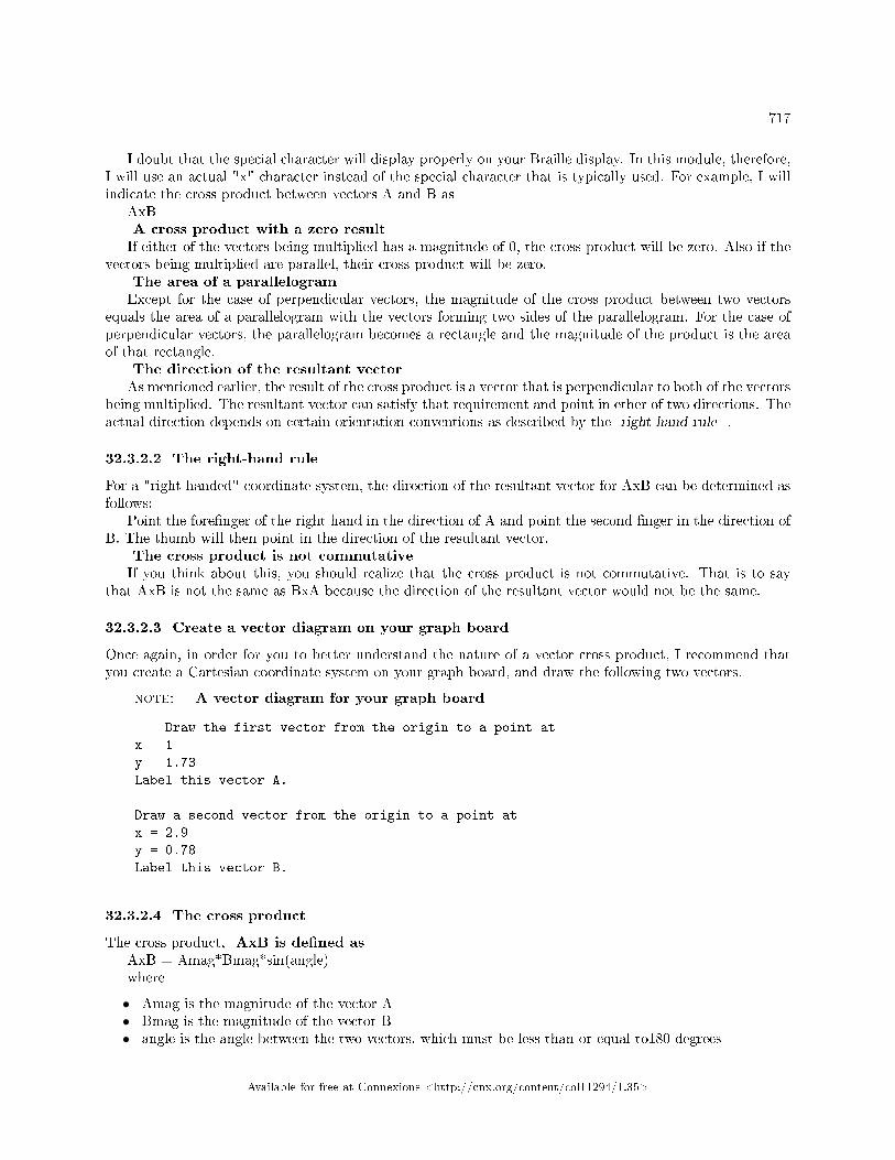
717
I doubt that the special character will display properly on your Braille display. In this module, therefore,I will use an actual "x" character instead of the special character that is typically used. For example, I willindicate the cross product between vectors A and B as
AxBA cross product with a zero resultIf either of the vectors being multiplied has a magnitude of 0, the cross product will be zero. Also if the
vectors being multiplied are parallel, their cross product will be zero.The area of a parallelogramExcept for the case of perpendicular vectors, the magnitude of the cross product between two vectors
equals the area of a parallelogram with the vectors forming two sides of the parallelogram. For the case ofperpendicular vectors, the parallelogram becomes a rectangle and the magnitude of the product is the areaof that rectangle.
The direction of the resultant vectorAs mentioned earlier, the result of the cross product is a vector that is perpendicular to both of the vectors
being multiplied. The resultant vector can satisfy that requirement and point in ether of two directions. Theactual direction depends on certain orientation conventions as described by the right-hand rule .
32.3.2.2 The right-hand rule
For a "right-handed" coordinate system, the direction of the resultant vector for AxB can be determined asfollows:
Point the fore�nger of the right hand in the direction of A and point the second �nger in the direction ofB. The thumb will then point in the direction of the resultant vector.
The cross product is not commutativeIf you think about this, you should realize that the cross product is not commutative. That is to say
that AxB is not the same as BxA because the direction of the resultant vector would not be the same.
32.3.2.3 Create a vector diagram on your graph board
Once again, in order for you to better understand the nature of a vector cross product, I recommend thatyou create a Cartesian coordinate system on your graph board, and draw the following two vectors.
note: A vector diagram for your graph board
Draw the first vector from the origin to a point at
x = 1
y = 1.73
Label this vector A.
Draw a second vector from the origin to a point at
x = 2.9
y = 0.78
Label this vector B.
32.3.2.4 The cross product
The cross product, AxB is de�ned asAxB = Amag*Bmag*sin(angle)where
• Amag is the magnitude of the vector A• Bmag is the magnitude of the vector B• angle is the angle between the two vectors, which must be less than or equal to180 degrees
Available for free at Connexions <http://cnx.org/content/col11294/1.35>

718 CHAPTER 32. VECTOR MULTIPLICATION
32.3.2.5 The area of the parallelogram
Use the vectors that you have drawn on your graph board to construct a parallelogram and see if you canestimate the area of that parallelogram.
Even if you were a sighted student having the parallelogram drawn on high-quality graph paper, it wouldbe something of a chore to manually determine the area of the parallelogram.
Let's work through some numbersLet's use the cross product to determine the area of the parallelogram.Given the de�nition (p. 717) of the cross product, we see that there are three values that we need:
• Amag• Bmag• angle
Same vectors as beforeIf we were starting out with two new vectors, we could compute the magnitude of each vector using
the Pythagorean theorem. We could also determine the angle by computing the vector dot product that Iexplained earlier in this module.
As you may have noticed, these are the same two vectors that we used earlier, and we computed thosethree values earlier. Going back and recovering those three values, we have
• Amag = 2.0• Bmag = 3.0• angle = 45 degrees (at least that is what I intended for it to be)
The area of the parallelogramUsing the earlier de�nition (p. 717) and the nomenclature for the Google calculator,AxB = Amag*Bmag*sin(angle), orAxB = 2.0*3.0*sin(45 degrees), orAxB = 4.24 square units
32.3.2.6 The direction of the resultant vector
If you place the end of your thumb at the origin of your Cartesian coordinate system, you should be able,with reasonable comfort, to point your fore�nger in the direction of A and your second �nger in the directionof B.
According to the right-hand rule (p. 717) , this means that the direction of the resultant vector is thedirection that your thumb is pointing, or straight down into the graph board.
32.3.2.7 Perpendicular or parallel vectors
Now consider what happens as the angle varies between 90 degrees (perpendicular vectors) and 0 degrees(parallel vectors) for a given pair of vectors.
As the angle approaches 0 degrees, the sine of the angle approaches 0, and the cross product of the vectorsapproaches 0.
As the angle approaches 90 degrees, the sine of the angle approaches 1.0 and the cross product approachesa value that is the product of the magnitudes of the two vectors.
Thus, for a given pair of vectors, the cross product can be thought of as a measure of the extent to whichthey are perpendicular to one another. The closer they are to perpendicular, the greater will be the value ofthe cross product.
Hence, the dot product is a measure of the extent to which two vectors are parallel to one another, whilethe cross product is a measure of the extent to which two vectors are perpendicular to one another.
Available for free at Connexions <http://cnx.org/content/col11294/1.35>

719
32.3.2.8 Summary for vector cross product
Figure 2 (p. 719) contains some facts worth remembering about the vector cross product.
Facts worth remembering for the cross product.
Given two vectors, A and B with their tails at the origin
AxB = Amag*Bmag*sin(angle between A and B)
where
AxB represents the cross product of the vectors
named A and B
Amag is the magnitude of vector A
Bmag is the magnitude of vector B
The cross product is a vector operation. The resultant vector
is perpendicular to the two vectors being multiplied. The
direction of the resultant vector can be determined by the
right-hand rule.
The magnitude of the product equals the area of a
parallelogram with the vectors forming two sides of the
parallelogram.
The cross product is not commutative. In other words, AxB
is not equal to BxA.
For a given pair of vectors, the cross product can be
thought of as a measure of the extent to which they are
perpendicular to one another. The closer they are to
perpendicular, the greater will be the value of the
cross product.
Figure 32.2: Facts worth remembering for the cross product.
32.4 Repeat the computations
I encourage you to repeat the computations that I have presented in this lesson to con�rm that you get thesame results. Then do similar computations for pairs of di�erent vectors. For example, swap the positionsof vectors A and B and see what this does to the direction of the resultant vector for a cross product.
Available for free at Connexions <http://cnx.org/content/col11294/1.35>

720 CHAPTER 32. VECTOR MULTIPLICATION
32.5 Resources
I will publish a module containing consolidated links to resources on my Connexions web page and willupdate and add to the list as additional modules in this collection are published.
32.6 Miscellaneous
This section contains a variety of miscellaneous information.
note: Housekeeping material
• Module name: Vector Multiplication for Blind Students• File: Phy1310.htm• Keywords:
· physics· accessible· accessibility· blind· graph board· protractor· screen reader· refreshable Braille display· JavaScript· trigonometry· dot product· inner product· scalar product· cross product· vector product· projection
note: Disclaimers: Financial : Although the Connexions site makes it possible for you todownload a PDF �le for this module at no charge, and also makes it possible for you to purchase apre-printed version of the PDF �le, you should be aware that some of the HTML elements in thismodule may not translate well into PDF.
I also want you to know that I receive no �nancial compensation from the Connexions website evenif you purchase the PDF version of the module.
A�liation : I am a professor of Computer Information Technology at Austin Community Collegein Austin, TX.
-end-
Available for free at Connexions <http://cnx.org/content/col11294/1.35>

Chapter 33
Angular Momentum � The Mathematics
of Torque1
33.1 Table of Contents
• Preface (p. 721)
· General (p. 721)· Prerequisites (p. 722)· Viewing tip (p. 722)
* Figures (p. 722)
· Supplemental material (p. 722)
• Discussion (p. 723)
· A review of rotational kinematics (p. 723)· Torque from a mathematical viewpoint (p. 726)· Torque from an anecdotal viewpoint (p. 731)· A graph board exercise on torque (p. 734)
• Example scenarios (p. 736)
· Net torque on the Lazy Susan turntable (p. 736)· A door-closing scenario (p. 736)· Torque and the moment of inertia (p. 737)
• Repeat the computations (p. 738)• Resources (p. 738)• Miscellaneous (p. 738)
33.2 Preface
33.2.1 General
This module is part of a collection (see http://cnx.org/content/col11294/latest/ 2 ) of modules designed tomake physics concepts accessible to blind students. The collection is intended to supplement but not toreplace the textbook in an introductory course in high school or college physics.
This module explains the mathematics of torque in a format that is accessible to blind students.
1This content is available online at <http://cnx.org/content/m38460/1.2/>.2http://cnx.org/content/col11294/latest/
Available for free at Connexions <http://cnx.org/content/col11294/1.35>
721

722CHAPTER 33. ANGULAR MOMENTUM � THE MATHEMATICS OF
TORQUE
33.2.2 Prerequisites
In addition to an Internet connection and a browser, you will need the following tools (as a minimum) towork through the exercises in these modules:
• A graph board for plotting graphs and vector diagrams (http://www.youtube.com/watch?v=c8plj9UsJbg 3 ).
• A protractor for measuring angles ( http://www.youtube.com/watch?v=v-F06HgiUpw 4 ).• An audio screen reader that is compatible with your operating system, such as the NonVisual Desktop
Access program (NVDA), which is freely available at http://www.nvda-project.org/ 5 .• A refreshable Braille display capable of providing a line by line tactile output of information displayed
on the computer monitor ( http://www.userite.com/ecampus/lesson1/tools.php 6 ).• A device to create Braille labels. Will be used to label graphs constructed on the graph board.
The minimum prerequisites for understanding the material in these modules include:
• A good understanding of algebra.• An understanding of the use of a graph board for plotting graphs and vector diagrams (
http://www.youtube.com/watch?v=c8plj9UsJbg 7 ).• An understanding of the use of a protractor for measuring angles (
http://www.youtube.com/watch?v=v-F06HgiUpw 8 ).• A basic understanding of the use of sine, cosine, and tangent from trigonometry (
http://www.clarku.edu/∼djoyce/trig/ 9 ).• An introductory understanding of JavaScript programming ( http://www.dickbaldwin.com/tocjscript1.htm
10 and http://www.w3schools.com/js/default.asp 11 ).• An understanding of all of the material covered in the earlier modules in this collection.
33.2.3 Viewing tip
I recommend that you open another copy of this document in a separate browser window and use thefollowing links to easily �nd and view the �gures while you are reading about them.
33.2.3.1 Figures
• Figure 1 (p. 727) . Tangential force, mass, radius, and angular acceleration.• Figure 2 (p. 727) . Tangential force, radius, angular acceleration, and moment of inertia.• Figure 3 (p. 728) . Torque, rotational inertia, and angular acceleration.• Figure 4 (p. 730) . The torque vector.• Figure 5 (p. 730) . A general equation for net torque.• Figure 6 (p. 734) . The de�nition of torque.
33.2.4 Supplemental material
I recommend that you also study the other lessons in my extensive collection of online programming tutorials.You will �nd a consolidated index at www.DickBaldwin.com 12 .
3http://www.youtube.com/watch?v=c8plj9UsJbg4http://www.youtube.com/watch?v=v-F06HgiUpw5http://www.nvda-project.org/6http://www.userite.com/ecampus/lesson1/tools.php7http://www.youtube.com/watch?v=c8plj9UsJbg8http://www.youtube.com/watch?v=v-F06HgiUpw9http://www.clarku.edu/∼djoyce/trig/
10http://www.dickbaldwin.com/tocjscript1.htm11http://www.w3schools.com/js/default.asp12http://www.dickbaldwin.com/toc.htm
Available for free at Connexions <http://cnx.org/content/col11294/1.35>

723
33.3 Discussion
I will begin this discussion with a brief review of what we have learned about the rotation of rigid bodiesand go from there into a discussion of torque.
33.3.1 A review of rotational kinematics
One of the objectives of this review is to summarize the angular kinematic variables that are used to describerotational motion and relate them to the translational kinematic variables that we already know about.
Given a system of particles, we can describe motion as having two components:
• The motion of the center of mass.• Motion relative to the center of mass.
TerminologyWhen an object rotates, it experiences an angular displacement, which I will refer to as theta in this
review.(Textbooks typically use the Greek letter theta for this purpose. However, your Braille display probably
won't display the Greek letter theta. Therefore, I will spell it out when I use it in text, and will replace itby the character "Q" when I use it in an equation.)
The time rate of change of the angular displacement is the angular velocity, which I will refer to as omegain this review.
The time rate of change of the angular velocity is the angular acceleration, which I will refer to as alphain this review.
Similarity to translational motionThese de�nitions are very similar to de�nitions from earlier modules having to do with translational
motion. For example, when an object moves, it experiences a displacement. The time rate of change of thedisplacement is the velocity, and the time rate of change of the velocity is the acceleration.
This similarity derives from the fact that rotational motion can be described by a single angular displace-ment, theta, just as linear motion can be described by a single spatial displacement, x.
Constant angular accelerationFor constant angular acceleration, we can derive a set of equations that are analogous to corresponding
equations for translational motion:Q = Q0 + w0*t + (1/2)*a*t^2w = w0 + a*tw^2 = w0^2 + 2*a*(Q - Q0)where
• Q represents the angular displacement theta• Q0 represents the initial angular displacement• w represents the angular velocity omega• w0 represents the initial angular velocity• a represents the angular acceleration alpha• t represents time in seconds
Corresponding translational equationsFor reference, here are the three translational equations that correspond to the equations given above
(p. 723) . These equations were explained in an earlier module that involved the constant translationalacceleration of gravity.
h = h0 v0*t + 0.5*g*t^2v = v0 + g*tv^2 = v0^2 + 2*g*(h-h0)where
Available for free at Connexions <http://cnx.org/content/col11294/1.35>

724CHAPTER 33. ANGULAR MOMENTUM � THE MATHEMATICS OF
TORQUE
• h represents the translational displacement• h0 represents the initial translational displacement• v represents the translational velocity• v0 represents the initial translational velocity• g represents the acceleration of gravity• t represents time in seconds
Motion of a point that is a �xed distance from the rotational axisIt is customary to de�ne counter clockwise rotation as the positive direction of rotation. That will be
the case in this review.Consider a rotating disk. Since all points on the disk are rotating together, we can determine the
linear displacement, speed and acceleration of any point on the disk in terms of the corresponding angularparameters.
Parameters for a point on a rotating diskConsider a point on the disk that is a distance R from the axis of rotation. Assume that the disk has
rotated through an angle theta. The point will have moved through a distance, s, along the circumferenceof a circle of radius R. The distance s is equal to the product of the radius and the angular displacementmeasured in radians:
s = R * Qwhere
• s represents the distance traveled around the circumference of a circle of radius R• R represents the radius of the circle• Q represents the displacement angle theta measured in radians
Relationship between speed and angular velocityWith a little calculus, we can �nd a relationship between the tangential speed of the point along its path
around the circle and the angular velocity of the disk:v = R*wwhere
• v represents the tangential speed of the point that is moving on the circumference of the circle• R represents the radius of the circle• w represents the angular velocity omega
Relationship between tangential acceleration and angular accelerationBy using a little more calculus, we can �nd a relationship between the tangential acceleration of the point
along its circular path and the angular acceleration of the disk:y = R*awhere
• y represents the tangential acceleration of the point along the circular path• R represents the radius• a represents the angular acceleration alpha
Kinetic energy in rotationConsider the hypothetical case of a rigid object made up of a set of point particles connected by rods
with zero mass. In other words, ignore the mass of the mechanism that holds the point particles in a rigidgeometry.
Assume that this object rotates about a �xed axis with a constant angular velocity, omega. Also assumethat you know the mass of each particle and that you know the distance of each particle from the axis ofrotation.
Kinetic energy of each individual particle
Available for free at Connexions <http://cnx.org/content/col11294/1.35>
725
We know how to compute the speed (p. 724) of each particle along its circular path.The kinetic energy of each particle would beKi = (1/2)*mi*vi^2where
• Ki is the kinetic energy of the ith point particle• mi is the mass of the ith point particle• vi is the speed of the ith point particle
Kinetic energy for translational motionHopefully you recognize the above equation (p. 725) as being the same as the following equation that we
saw in an earlier module involving the kinetic energy of an object in translational motion.KE = 0.5*m*v^2where
• KE represents the kinetic energy possessed by the object• m represents the mass of the object• vv represents the velocity of the object
Kinetic energy for the objectThe object described above (p. 724) is made up of a system of particles.The total kinetic energy of the system is the sum of the kinetic energy values of each of its particles.The kinetic energy for the system isKs = (1/2)*(sum from i=0 to i=N(mi*ri^2))*w^2where
• Ks represents the kinetic energy of the system• ((sum from i=0 to i=N(...)) represents the sum of the values resulting from evaluating the expression
in parentheses for each one of N+1 particles• mi represents the mass of the ith point particle• ri represents the distance of the ith point particle from the axis of rotation• w represents the angular velocity omega
Rotational inertia or moment of inertiaDe�ne the rotational inertia, or the moment of inertia, whichever term you prefer asI = sum from i=0 to i=N(mi*ri^2)where
• I represents the rotational inertia or the moment of inertia• mi represents the mass of the ith point particle• ri represents the distance of the ith point particle from the axis of rotation
Rotational kinetic energy based on rotational inertiaFrom this, we can determine thatKs = (1/2)*I*w^2where
• Ks represents the kinetic energy for the system• I represents the rotational inertia for the system• w represents the angular velocity of the system
Available for free at Connexions <http://cnx.org/content/col11294/1.35>

726CHAPTER 33. ANGULAR MOMENTUM � THE MATHEMATICS OF
TORQUE
Similar to translational kinetic energyNote the similarity between the kinetic energy of a rotating system and the kinetic energy an object
undergoing translational motion:Ke = (1/2)*I*w^2Kt = (1/2)*m*v^2where
• Kr represents the kinetic energy for the rotating system• I represents the rotational inertia for the rotating system• w represents the angular velocity of the rotating system• Kt represents translational kinetic energy• m represents the mass of an object undergoing translational motion• v represents the velocity speed of the object undergoing translational motion
Similarities between rotational inertia and massThe mass of an object tells us how its kinetic energy is related to the square of its velocity.The rotational inertia of a rotating object tells us how its kinetic energy is related to the square of its
angular velocity.The rotational inertia plays the same role in rotational motion that mass plays in translational motion.Di�erences between mass and rotational inertiaWhile mass and rotational inertia play similar roles, there are also major di�erences between the two
including:
• Rotational inertial depends not just on the total mass of an object, but also on the geometric distri-bution of the mass within the object.
• Rotational inertia also depends on the choice of the rotation axis, because distances are measuredrelative to that axis.
33.3.2 Torque from a mathematical viewpoint
Consider a point mass that is constrained to move in a circle. Let the mass be acted upon by an arbitraryforce F. We learned earlier that in order for the mass to be moving in a circle, there must be a componentof force, (the centripetal force), that is directed toward the center of the circle.
Tangential force, mass, radius, and angular accelerationIf we assume that the speed of the mass is changing, there must also be a component of the force that
is tangential to the circle at the location of the point mass acting on the mass. This force is required toproduce acceleration. Therefore, we can write:
Ft = m*yFrom above (p. 724) ,y = r*aSubstitution yieldsFt = m*r*a
Available for free at Connexions <http://cnx.org/content/col11294/1.35>

727
Tangential force, mass, radius, and angular acceleration.
Ft = m*r*awhere
• Ft represents the tangential force• m represents the mass• y represents the tangential acceleration of the point mass along the circular path• r represents the radius• a represents the angular acceleration alpha
Figure 33.1: Tangential force, mass, radius, and angular acceleration.
Tangential force, radius, angular acceleration, and moment of inertiaWe con�rmed earlier that the rotational analog of mass is the rotational inertia (p. 725) . In the case of
a single mass,I = m*r^2Substitution yieldsFt = m*r*a, orFt = (I/r^2)*r*a, orFt = (I/r)*aMultiplying both side by r yieldsr*Ft = I*a
Tangential force, radius, angular acceleration, and moment of inertia .
r*Ft = I*awhere
• Ft represents the tangential force• r represents the radius• I represents the rotational inertia or the moment of inertia, whichever term you prefer• a represents the angular acceleration alpha
Figure 33.2: Tangential force, radius, angular acceleration, and moment of inertia .
Available for free at Connexions <http://cnx.org/content/col11294/1.35>

728CHAPTER 33. ANGULAR MOMENTUM � THE MATHEMATICS OF
TORQUE
Similar to Newton's second lawThe equation (p. 727) in Figure 2 (p. 727) looks a lot like Newton's second law for translational motion,
which is often expressed asForce = mass * accelerationIn this case, the rotational inertia, I, is analogous to mass and the rotational acceleration, a, is analogous
to translational acceleration.If this similarity holds, that must mean that the term on the left side (p. 727) is analogous to force in
the tangential motion scenario.Torque, rotational inertia, and angular accelerationThe term on the left (p. 727) , consisting of the product of the force and the distance from the point of
application of the force to the axis of rotation is commonly known as the torque. The common symbol fortorque is the Greek letter tau, which I will replace with the character T in equations in this module.
T = r*Ft = I*a , orT = I*a
Torque, rotational inertia, and angular acceleration.
T = I*awhere
• T represents torque• r represents radius• Ft represents the tangential component of force• I represents rotational inertia or moment of inertia• a represents angular acceleration
Figure 33.3: Torque, rotational inertia, and angular acceleration.
Torque produces angular accelerationThus, we have determined that a torque, which is the product of a tangential force and the distance from
the application point of this force to the axis of rotation, produces an angular acceleration.This is beginning to look a lot like Newton's second law for rotation. We will re�ne it some more later to
improve the analogy. To do that, we will need to de�ne torque and angular acceleration as vector quantities.We will accomplish that using the cross product of two vectors that you learned about in an earlier module.
The convention for positive rotationIf you imagine a rotating object from a viewpoint in which the rotation axis is perpendicular to the page,
it is conventional to de�ne a counter clockwise rotation as the positive direction of rotation. That is theconvention that I will use in this module.
You learned about the right-hand rule involving vectors in an earlier module. There is a similar right-handrule that we use to describe rotating objects.
The right-hand rule for angular velocityIf you curl the �ngers of your right hand in the direction of rotation of the object, your thumb will point
in the direction of the angular velocity vector of the object.
Available for free at Connexions <http://cnx.org/content/col11294/1.35>

729
In other words, if some object is spinning in the counter-clockwise direction in the x-y plane, curling the�ngers of your right hand in this direction results in your thumb pointing in the +z direction which we de�neto be the direction of the angular velocity vector.
The rule for angular accelerationIf the magnitude of the angular velocity increases in time, then the angular acceleration vector has the
same direction as that of the angular velocity. If the magnitude of the angular velocity decreases in time,then the angular acceleration vector has the opposite direction as that of the angular velocity.
De�ning torque as a vector quantityThe magnitude of a torque is the product of two terms:
1. The length of a line that connects the axis of rotation to the point where the force acts. Refer to thisline as r.
2. The component of the force, Ft, that is perpendicular to this line.
De�ne theta as the angle between the line and the force vector F (not the tangential component of the forcevector but the force vector itself). Then the magnitude of the tangential force vector is given by
Ft = Fmag*sin(theta)where
• Ft represents the magnitude of the tangential force vector that is perpendicular to the line r• Fmag is the magnitude of the force vector• theta is the angle between the line and the force vector
De�ne a vector RLet R represent a vector that lies along the line from the axis of rotation to the point where the force
acts with its tail at the axis of rotation. I will refer to the magnitude of this vector as RmagDoing a little algebra, we can writeT = r*Ft, orTvec = Rmag*Fmag*sin(theta)where
• Tvec represents the tangential force vector• Rmag is the magnitude of the vector R• Fmag is the magnitude of the vector F
The cross productWhy do I refer to Tvec as a vector in the above (p. 729) equation?You learned in an earlier module that the cross product of two vectors A and B is given byAxB = Amag*Bmag*sin(angle between A and B)where
• AxB represents the cross product of the vectors named A and B• Amag is the magnitude of vector A• Bmag is the magnitude of vector B
The torque vectorComparing the torque vector (p. 729) with the cross product (p. 729) , we determine thatTvec = RxF
Available for free at Connexions <http://cnx.org/content/col11294/1.35>

730CHAPTER 33. ANGULAR MOMENTUM � THE MATHEMATICS OF
TORQUE
The torque vector .
Tvec = RxFwhere
• Tvec is a torque vector• R is a vector that points from the axis of rotation to the point where the vector force F is applied• F is a force vector• RxF is the vector cross product between the vector R and the vector F
Figure 33.4: The torque vector .
The direction of the torque vectorRecall from the earlier module that the direction of Tvec is perpendicular to both R and F and obeys
the right-hand rule in terms of its absolute direction.The relationship of torque and rotational inertiaCombining this with what we learned earlier about the relationship among torque, rotational inertia, and
rotational acceleration, we can writeTvec = I*A
A general equation for net torque.
Tvec = I*Awhere
• Tvec is the torque vector whose direction obeys the right-hand rule• I is the rotational inertia or the moment of inertia of the object about the chosen axis of rotation• A is the rotational acceleration treated as a vector whose direction obeys the right-hand rule
Figure 33.5: A general equation for net torque.
A general equation for net torqueThe equation shown in Figure 5 (p. 730) is a general equation for net torque. The net torque about an
axis of rotation is equal to the product of the rotational inertia about that axis and the angular acceleration.
Available for free at Connexions <http://cnx.org/content/col11294/1.35>

731
Similar to Newton's second lawThis equation is Newton's second law applied to a system of particles in rotation about a given axis. It
makes no assumptions about constant rotational velocity.
33.3.3 Torque from an anecdotal viewpoint
One of the objectives of this module is to develop concepts involving rotational motion that are analogousto concepts from earlier modules that involve translational motion.
A Lazy SusanOn my dining room table, there is a device that is commonly called a Lazy Susan. In case you are
unfamiliar with such devices, it is essentially a turntable. By a turntable, I mean a rather large diskmounted on bearings so that it is free to turn in a plane that is slightly above but parallel with the top ofthe dining room table.
The purpose of the Lazy SusanThe purpose of a Lazy Susan is to make it easier to serve food at the dining room table. Various dishes
are placed on it . When someone wants a helping of carrots, for example, instead of saying "Please pass thecarrots," they simply turn the Lazy Susan until they can reach the bowl of carrots and help themselves.
Not a module about carrotsHowever, we won't be discussing how to serve carrots in this module. In this module, I will use the Lazy
Susan, in its empty state between meals, to discuss various aspects of rotating rigid objects.To make it easier to type the material under discussion, I will refer to the Lazy Susan as a turntable.
(For some reason, I can type turntable much more quickly than I can type Lazy Susan.)Low angular acceleration when coastingMy turntable has pretty good bearings. It is also rather heavy for its size and therefore has a relatively
large rotational inertia or moment of inertia, whichever term you prefer.If you give it a good spin, it will spin for quite a while before all of its rotational energy is dissipated
through friction in the bearings and air resistance. By default, therefore, its angular acceleration is low. Inother words, the rate of change of its angular velocity is small.
A perpetual motion machineIf we could �nd a way to eliminate all of the frictional forces acting on the turntable, including air
resistance, then it would spin forever. In that case, we would have invented what has been called a perpetualmotion machine. The rate of change of angular velocity would be zero, meaning that its angular accelerationwould also be zero.
Similar to Newton's �rst lawThis reminds us of a moving body that satis�es Newton's �rst law, which can be paraphrased something
like the following:
• a body in motion, being acted upon by no net forces, will continue moving forever in a straight line.
In other words, that law tells us that absent a force to the contrary, a moving body will continue to movewith no change in velocity.
If we could eliminate all of the frictional forces acting on my turntable (which is a rotating body), wemight like to say that
• absent any net forces acting on the body, a rotating body with a constant rotational inertia will continuerotating with the same angular velocity forever.
However, that would not be a true statement.Houston, we have a problemAssume that you do the following to our hypothetical frictionless turntable while it is spinning. Using
one �nger from each hand, press on opposite sides of the turntable, applying an equal force directed towardsthe center of the turntable on each side of the turntable.
No net force
Available for free at Connexions <http://cnx.org/content/col11294/1.35>

732CHAPTER 33. ANGULAR MOMENTUM � THE MATHEMATICS OF
TORQUE
In this case, the turntable would not experience any net forces. Assuming that you are facing north whenyou do this, and that you press on the east and west sides of the turntable, the frictional forces generatedby your �ngers would be directed in opposite directions.
If the turntable were spinning counter clockwise (when viewed from the top), the frictional force createdby your �nger on the east side would be directed toward the south. The frictional force created by your�nger on the west side of the turntable would be directed toward the north.
From a translational viewpoint, at least, there would be no net force applied to the turntable. The forcethat points to the north would be cancelled by the force that points to the south. The force that pointsto the east would be cancelled by the force that points to the west. Therefore, the turntable would be intranslational equilibrium.
Acceleration would no longer be zeroDespite that, the velocity would be decreased meaning that the acceleration would no longer be zero.
From this we might conclude that just because a rotating object is in translational equilibrium, it is notnecessarily in rotational equilibrium.
The world of torqueWe have just entered the world of torque with this hypothetical experiment. Torque is a quantity that
plays a role in rotation that is analogous to the role that force plays in translation.However, torque is not separate from force. It is not possible to exert a torque without exerting a force.Torque is a measure...In anecdotal terms, torque is a measure of how e�ective a force is at changing the angular velocity of
an object. Stated di�erently, torque is a measure of how e�ective a force is at causing an object to have anon-zero angular acceleration.
Angular acceleration can be either positive or negativeFor an object that is rotating about a �xed axis (or is capable of rotating about a �xed axis), such as
my turntable, torque can either increase or decrease the angular velocity of the object.Net translational force was zeroWhen you pressed your �ngers on my turntable as described earlier, the net translational force applied
to the turntable was zero. Therefore, the turntable remained in translational equilibrium, meaning that itdidn't go sliding towards the edge of the table.
Net torque was not zeroHowever, the net torque was not zero, so it was not in angular equilibrium. The kinetic frictional forces
generated on each side of the turntable resulted in the same algebraic sign of non-zero angular acceleration.Each force caused the angular velocity to decrease. The two torques created by the kinetic friction forces
were not only equal, they had the same algebraic sign. Therefore, the turntable experienced a non-zero nettorque.
How are force and torque related?To begin with, torque is proportional to the magnitude of the applied force, but that is not the end of
the story. The rest of the story involves exactly where and in what direction the force is applied.Create a torque to close a doorFor example, consider applying a force for the purpose of creating a torque to close an open door. Initially,
the door has zero angular velocity.You could apply a force in any direction at any point on either side or the edge of the door that you are
tall enough to reach. However, with regard to the objective of closing the door, it would matter very muchwhere and in what direction you applied the force.
A very intuitive topicThe interesting thing about this topic is that you already know all about it from a practical and intuitive
viewpoint. You would already know intuitively where and in what direction to push on the door to cause itto close with a minimum expenditure of energy.
You probably wouldn't push on the edge of the doorIf you pushed on the edge of door, directing your force directly at the hinges (the axis of rotation), the
door wouldn't move. While this might prove to be a good form of isometric exercise, it would not be an
Available for free at Connexions <http://cnx.org/content/col11294/1.35>

733
e�ective way to close the door.A force in any other directionA force that is applied to the door, (even on the edge of the door) acting in any direction other than
directly toward the hinges could be decomposed into two components:
• A radial component acting directly towards the axis or rotation or the hinges.• A perpendicular component acting perpendicular to the surface of the door.
The radial component is wasted e�ortThe radial component would make no contribution to the development of the torque required to change
the angular velocity of the door and cause the door to close. Only the perpendicular component wouldcontribute to the development of such a torque.
Could develop torque at any point on the doorSo now you know that you could apply a force at any point on the door, and so long as that force has a
component that is perpendicular to the surface of the door, the perpendicular component would contributeto the development of torque.
Location, location, and locationHowever, it is also important where you push on the door to apply the force. If you push on what we
normally consider to be the inside surface of the door, it might create a torque, but that torque may have thewrong sign or direction to cause the door to close. In fact, that would cause the door to open even further.
Once you realize that you must push on what we would call the outside surface of the door, it would stillbe important where you push and apply the force. Suppose for example that you were to push at a pointthat is only one inch away from the hinge. You know intuitively that even for a lightweight door, you mighthave to apply a very strong force to cause the door to close by applying the force at that location.
Where would you push?You would probably push on the door at a point somewhere between the center of the door and the outer
edge of the door.If the door happened to be a really heavy door, you would probably push on the door at a point as
close to the outer edge as possible. This would make it possible for you to cause the door to close with theminimum e�ort on your part.
The magnitude of the torqueIn an attempt to codify your intuition, your instinctive knowledge, or perhaps your acquired knowledge
into something more mathematical, we will de�ne the magnitude of the torque astorque = r*FThe conventional symbol for torque is the Greek letter tau. However, your Braille display probably won't
display that Greek letter, so in this module, I will represent torque with the letter T as shown in Figure 6(p. 734) .
The sign convention for torqueIn this module, I will use a sign convention such that a force whose perpendicular component, when
acting alone, would cause the object to rotate in a counter clockwise direction as a positive torque.If that torque is the only torque acting, it would cause a positive angular acceleration.A de�nition of torqueYou saw a mathematical de�nition of torque earlier (p. 730) . Figure 6 (p. 734) shows a somewhat less
mathematical de�nition of torque.
Available for free at Connexions <http://cnx.org/content/col11294/1.35>

734CHAPTER 33. ANGULAR MOMENTUM � THE MATHEMATICS OF
TORQUE
The de�nition of torque.
T = r*Fwhere
• T represents torque• r is the shortest distance from the axis of rotation to the point of application of the applied force• F is the component of the applied force that is perpendicular to a line from the axis of rotation to
the point of the applied force
The SI unit for torque is newton meters or N*m.
Figure 33.6: The de�nition of torque.
The units can be confusingThe units for torque can be confusing because the SI unit for work or energy in joules is also N*m.
However, even though torque and energy have the same units, they have entirely di�erent meanings. Torqueis not a form of energy.
33.3.4 A graph board exercise on torque
Imagine a puck sliding in a circular groove that has been cut in the ice at an ice rink. A cross section of thegrove is rectangular so that the puck just �ts from side to side and sets level on the bottom of the groove.When a puck slides inside the groove, it will move in a large circle.
Apply a force to the puckIf you apply a force to the puck in (almost) any direction, a component of that force will directed toward
or away from the center of the circle. For any case where the direction of the force doesn't lie on a line fromthe puck to the center of the circle, there will also be a component of the force that is perpendicular to thatline, which will make it tangential to the circle.
Construct a graph board simulationUse your graph board and create a Cartesian coordinate system with the origin near the lower-left corner
of the graph board. Use pushpins and pipe cleaners to draw a quarter of a circle, with the center of thecircle at the origin. Make the radius approximately one-half of the smallest dimension of the graph board.This circle should include the entire upper-right quadrant of your Cartesian coordinate system.
Identify the location of the puckNow insert a pushpin at a point somewhere on the circle about mid way between the intersection of the
circle and the x and y axes of the coordinate system.Imagine that this is the puck mentioned above that is constrained to move in a circle. Label this point
P.A radial line from the centerUse a pipe cleaner or a rubber band to draw a line from the puck to the center of the circle. Label this
line r.Create a force vector
Available for free at Connexions <http://cnx.org/content/col11294/1.35>

735
Make a little loop at one end of a pipe cleaner that is about half the radius of your circle and place theloop around the pushpin that represents the puck at P.
Leave it loose enough that it can be rotated around the pin. Imagine that this is a vector that describesa force being applied to the puck with the tail of the vector at the puck.
Point the force vector at the centerBegin by pointing the force vector directly at the center of the circle. You will probably be able to
imagine that since the puck is not free to move directly to the center, a force in this direction will not causethe puck to move.
The technical reason that it won't cause the puck to move is because the force doesn't have a componentthat is tangent to the circle at the location of the puck.
Rotate the force vectorNow rotate the force vector clockwise by about 30 or 40 degrees and pin it down so that it won't move.
Label the tip of the force vector F.Draw the tangential component of the force vectorThis may be the most di�cult part of this exercise for a blind student. Use your protractor (or some
other method that you know about) to �nd a point on the line labeled r such that a line through that pointand perpendicular to r goes through the tip of the force vector. Mark that point with a pushpin and labelit Q.
Draw a line from Q to FUse a pipe cleaner to draw a line from Q to F. That line represents the component of the force vector
that is tangent to the circle at the location of the puck. (Actually it is parallel to the tangential componentof the force vector, but that is OK. It is still the correct length and points in the correct direction.) Thedirection of that tangential force component is from Q to F.
This is the component of the force vector that causes the puck to move. Label this vector Ft for tangentialforce.
The radial component of forceUse a pipe cleaner to draw a line from P to Q. This is the component of the force vector that points
directly from the puck to the center of the circle. This component won't cause the puck to move.A right triangleIf you examine your vector diagram at this point, you can determine that the points labeled P, Q, and F
represent the vertices of a right triangle, with the right angle at the point Q.The length of the tangential force vectorLabel the interior angle at P with an A. Now you should be able to determine that the length of the
tangential vector named Ft is equal to the product of the force F and the sine of the angle A.Ft = F*sin(A)where
• F is the force vector.• Ft is the component of the force vector that is tangent to the circle at the location of the puck. This
force is also perpendicular to the line from the puck to the center of the circle.• A is the angle that the force vector makes with the line r.
The torqueReferring back to Figure 6 (p. 734) , we �nd that the torque produced by this force is equal to the
product of the distance from the center to P and the tangential or perpendicular component of the forcevector.
Therefore,T = Ft*r, orT = F*sin(A)*rwhere
• T represents torque
Available for free at Connexions <http://cnx.org/content/col11294/1.35>

736CHAPTER 33. ANGULAR MOMENTUM � THE MATHEMATICS OF
TORQUE
• Ft represents the tangential component of the force vector• r represents the distance from the puck to the center of the circle• F represents the force vector• A represents the angle between the force vector and the line from the puck to the center of the circle
33.4 Example scenarios
This section contains several example scenarios involving torque.
33.4.1 Net torque on the Lazy Susan turntable
The turntable discussed earlier, which has a radius of 24 cm, is spinning clockwise. You press your �ngerson the east and west sides of the turntable with equal forces of 6.67 N. The coe�cient of friction betweenthe turntable and your �ngers is 0.75. What is the net torque on the wheel?
Solution:The 13.3 N force on each side of the table creates a tangential kinetic friction force on each side of the
table equal toFt = 6.67 N * 0.75Each force is in the opposite direction of the direction of rotation.The net torque is equal to the sum of the torques.Each torque is equal to the product of the force and the distance from the center of the turntable to the
point at which the force is applied.T = 2 * Ft * r, orT = 2 * 6.67 newtons * 0.75 * 24 cmEntering this expression into the Google calculator gives usT = 2.4 joulesHowever, this is one case where the Google calculator gives us a misleading answer. We know that torque
is not measured in joules. Instead, torque is measured in N*m. Therefore, the net torque on the turntable isT = 2.4 N*m
33.4.2 A door-closing scenario
When viewed from above, the scenario is a door that is open. From above, the wall to which the door isattached can be represented by a horizontal line that runs from west to east. The door can be representedby a line segment at an angle of about 45 degrees south of east. The line segment (door) is attached to thewall at the upper-left end of the line segment. That is the point where the door is hinged, and that point isthe axis of rotation for the door.
Assume that the axis of rotation extends out of the page towards you.The door will need to rotate about 45 degrees counter clockwise to become �ush with the wall and be
closed.A person is standing on the north side of the wall pulling on a rope that is attached to the door. The
rope is attached 11.5 cm from the hinge and makes a 45 degree angle with the surface of the door. Thatperson pulls on the rope with a force of 51 N.
Using the door hinges as the axis of rotation, �nd the magnitude of the torque that is exerted on thedoor. What is the sign of the torque.
Solution:This solution is based on the cross product from Figure 4 (p. 730) .The magnitude of the torque is given byT = r * F * sin(angle), orT = 11.5 cm * 51 newtons * sin(45 degrees)Entering this expression into the Google calculator gives us
Available for free at Connexions <http://cnx.org/content/col11294/1.35>

737
T = 4.15 N*mThe torque will cause the door to rotate in a counter clockwise direction. Therefore, the torque has a
positive sign.
33.4.3 Torque and the moment of inertia
Three objects are rotating about their centers. All three objects have a mass of 10 kg. The three objectshave the following shapes:
A. A solid disk with a moment of inertia given byI = (1/2)*m*r^2where
• r = 2m
B. A disk with a round hole in the center with a moment of inertia given byI = (1/2)*m*(r1^2 + r2^2)where
• r1 = 1m• r2 = 2m
C. A square plate with a moment of inertia given byI = (1/12)*m*(h^2 + w^2)where
• h = w = 3.54m
Find the net torque required to cause each object to accelerate at a rate of 10 radians/sec^2.Solution:All three solutions are based on the general equation for torque given in Figure 5 (p. 730) .A. T = I * A, orT = (1/2)*m*r^2 * A, orT = (1/2)*10kg*(2m)^2 * 10 radians/second^2Entering this expression into the Google calculator gives usT = 200 N*mB. T = I * A, orT = (1/2)*m*(r1^2 + r2^2) * A, orT = (1/2)*10kg*((1m)^2 + (2m)^2) * 10 radians/second^2, orT = 250 N*mNote that because more of the mass is located close to the outer edge of the disk, the moment of inertia
is higher and more torque is required to achieve the same acceleration for the same mass.C. T = I * A, orT = (1/12)*m*(h^2 + w^2) * A, orT = (1/12)*10kg*((3.54m)^2 + (3.54m)^2) * 10 radians/second^2, orT = 2.09 N*mNote that the square in part C was designed to have the same surface area as the disk in part A. The
mass in both cases was uniformly distributed throughout the entire surface. Under those conditions, a squarehas a slightly higher moment of inertia than a disk and thus requires a slightly greater torque to achieve thesame acceleration.
Available for free at Connexions <http://cnx.org/content/col11294/1.35>

738CHAPTER 33. ANGULAR MOMENTUM � THE MATHEMATICS OF
TORQUE
33.5 Repeat the computations
I encourage you to repeat the computations that I have presented in this lesson to con�rm that you get thesame results. Experiment with the scenarios, making changes, and observing the results of your changes.Make certain that you can explain why your changes behave as they do.
33.6 Resources
I will publish a module containing consolidated links to resources on my Connexions web page and willupdate and add to the list as additional modules in this collection are published.
33.7 Miscellaneous
This section contains a variety of miscellaneous information.
note: Housekeeping material
• Module name: Angular Momentum � The Mathematics of Torque for Blind Students• File: Phy1320.htm• Keywords:
· physics· accessible· accessibility· blind· graph board· protractor· screen reader· refreshable Braille display· JavaScript· trigonometry· torque· force· mass· angular acceleration· moment of inertia· rotational inertia· vector
note: Disclaimers: Financial : Although the Connexions site makes it possible for you todownload a PDF �le for this module at no charge, and also makes it possible for you to purchase apre-printed version of the PDF �le, you should be aware that some of the HTML elements in thismodule may not translate well into PDF.
I also want you to know that I receive no �nancial compensation from the Connexions website evenif you purchase the PDF version of the module.
A�liation : I am a professor of Computer Information Technology at Austin Community Collegein Austin, TX.
-end-
Available for free at Connexions <http://cnx.org/content/col11294/1.35>

Chapter 34
Angular Momentum � Torque, Work and
Energy1
34.1 Table of Contents
• Preface (p. 739)
· General (p. 739)· Prerequisites (p. 740)· Viewing tip (p. 740)
* Figures (p. 740)
· Supplemental material (p. 740)
• Discussion (p. 741)
· Constant torque (p. 741)· Variable torque (p. 744)
• Example scenario (p. 744)
· Part 1 (p. 744)· Part 2 (p. 745)
• Do the computations (p. 746)• Resources (p. 746)• Miscellaneous (p. 746)
34.2 Preface
34.2.1 General
This module is part of a collection (see http://cnx.org/content/col11294/latest/ 2 ) of modules designed tomake physics concepts accessible to blind students. The collection is intended to supplement but not toreplace the textbook in an introductory course in high school or college physics.
This module explains torque, work and energy in a format that is accessible to blind students.
1This content is available online at <http://cnx.org/content/m38461/1.2/>.2http://cnx.org/content/col11294/latest/
Available for free at Connexions <http://cnx.org/content/col11294/1.35>
739

740 CHAPTER 34. ANGULAR MOMENTUM � TORQUE, WORK AND ENERGY
34.2.2 Prerequisites
In addition to an Internet connection and a browser, you will need the following tools (as a minimum) towork through the exercises in these modules:
• A graph board for plotting graphs and vector diagrams (http://www.youtube.com/watch?v=c8plj9UsJbg 3 ).
• A protractor for measuring angles ( http://www.youtube.com/watch?v=v-F06HgiUpw 4 ).• An audio screen reader that is compatible with your operating system, such as the NonVisual Desktop
Access program (NVDA), which is freely available at http://www.nvda-project.org/ 5 .• A refreshable Braille display capable of providing a line by line tactile output of information displayed
on the computer monitor ( http://www.userite.com/ecampus/lesson1/tools.php 6 ).• A device to create Braille labels. Will be used to label graphs constructed on the graph board.
The minimum prerequisites for understanding the material in these modules include:
• A good understanding of algebra.• An understanding of the use of a graph board for plotting graphs and vector diagrams (
http://www.youtube.com/watch?v=c8plj9UsJbg 7 ).• An understanding of the use of a protractor for measuring angles (
http://www.youtube.com/watch?v=v-F06HgiUpw 8 ).• A basic understanding of the use of sine, cosine, and tangent from trigonometry (
http://www.clarku.edu/∼djoyce/trig/ 9 ).• An introductory understanding of JavaScript programming ( http://www.dickbaldwin.com/tocjscript1.htm
10 and http://www.w3schools.com/js/default.asp 11 ).• An understanding of all of the material covered in the earlier modules in this collection.
34.2.3 Viewing tip
I recommend that you open another copy of this document in a separate browser window and use thefollowing links to easily �nd and view the �gures while you are reading about them.
34.2.3.1 Figures
• Figure 1 (p. 742) . Work done by perpendicular component of force.• Figure 2 (p. 743) . Work done by constant torque.• Figure 3 (p. 744) . Power generated or consumed by a constant torque.
34.2.4 Supplemental material
I recommend that you also study the other lessons in my extensive collection of online programming tutorials.You will �nd a consolidated index at www.DickBaldwin.com 12 .
3http://www.youtube.com/watch?v=c8plj9UsJbg4http://www.youtube.com/watch?v=v-F06HgiUpw5http://www.nvda-project.org/6http://www.userite.com/ecampus/lesson1/tools.php7http://www.youtube.com/watch?v=c8plj9UsJbg8http://www.youtube.com/watch?v=v-F06HgiUpw9http://www.clarku.edu/∼djoyce/trig/
10http://www.dickbaldwin.com/tocjscript1.htm11http://www.w3schools.com/js/default.asp12http://www.dickbaldwin.com/toc.htm
Available for free at Connexions <http://cnx.org/content/col11294/1.35>

741
34.3 Discussion
This section will begin by developing the equations from which you can compute the work done by a constanttorque that causes a known displacement. Then it will provide a brief discussion of the situation where thetorque is not constant.
34.3.1 Constant torque
One of the textbooks that I have read uses a very familiar example to illustrate that torque can do work.The example is that of a person pulling on the rope on a power mower or outboard engine to try to get itstarted.
If you are unfamiliar with that scenario, many small internal combustion engines use a rope wrappedaround a pulley to start the engine. When the user pulls the rope, a torque is created on the pulley by therope. The torque causes an angular displacement of the pulley, which in turn causes certain parts inside theengine to move. If you are lucky and everything is working properly, the engine starts.
The machine �ghts backHowever, the machine �ghts back and the compression in the cylinders creates a resistive torque. If the
user pulls hard enough, the torque created by the user overcomes the resistive torque, the pulley turns, theparts inside the engine move appropriately, and hopefully the engine starts running.
When the engine refuses to start...Clearly when the engine refuses to start, it becomes apparent very quickly that torque can do work on a
human. A few dozen pulls on the rope will cause even the most physically �t user to become exhausted.The force does the workThe textbook point out that it is actually the force and not the torque that does the work. However,
torque and force are related in a very de�nitive way, and the textbook points out that it is often easer tocalculate the amount of work done on the basis of torque rather than making the calculation on the basis offorce.
Review � what is work?You learned in an earlier module on translational motion that the work done by a constant force is the
product of the force and the displacement caused by that force. In other words,Wt = Ft * dwhere
• Wt represents translational work in joules or newton-meters• Ft represents translational force in newtons• d represents the displacement in meters
A rotational analogySimilarly, work done by a constant torque can be calculated as the product of the constant torque and
the displacement caused by that torque.A constant torqueIt is important to note that the entire remaining discussion in this section applies only to the application
of a constant torque. I will have a few words about a variable torque in the next section (p. 744) .PowerThe power generated or consumed by the application of a constant torque can be calculated as the
product of the constant torque and the angular velocity.A wheel scenarioImagine a force being applied to a point on the outer edge of a wheel to cause an angular displacement
of the wheel. As you will recall from an earlier module, the torque produced by the force is equal to theproduct of
• the distance from the center of the wheel to the point where the force is applied and
Available for free at Connexions <http://cnx.org/content/col11294/1.35>

742 CHAPTER 34. ANGULAR MOMENTUM � TORQUE, WORK AND ENERGY
• the component of the force that is perpendicular to a line drawn from that point to the centerof the wheel.
The point moves through a circular arcWhen the force causes an angular displacement of the wheel, the point at which the point is applied
moves through a circular arc. The length of that circular, often referred to by s, can be measured. The workdone is equal to the product of
• the length of the circular arc and• the perpendicular component of applied force.
The work resulting from the application of the perpendicular force is given by the equation shown in Figure1 (p. 742) .
Work done by perpendicular component of force.
W = Fp * swhere
• W represents the work done by the perpendicular force• Fp is the perpendicular component of force described above (p. 742)• s is the length of the circular arc through which the point moves
Figure 34.1: Work done by perpendicular component of force.
Work as a function of torqueNow that we have the work as a function of the perpendicular force and the length of the arc, let's rewrite
it in terms of torque and displacement.TorqueWe know that torque is equal toT = r * Fpwhere
• T represents torque• r represents the distance from the center of the wheel to the point where the perpendicular force is
applied• Fp represents the perpendicular force
Arc lengthWe also know that the arc length is given bys = r * Awhere
• s represents the arc length
Available for free at Connexions <http://cnx.org/content/col11294/1.35>
743
• r represents the distance from the center of the wheel to the point where the perpendicular force isapplied as before
• A represents the angle of displacement measured in radians
Through substitutionW = Fp * s, orW = (T/r)*r*A, orThe work done by a constant torque is given by the equation shown in Figure 2.
Work done by constant torque.
W = T*Awhere
• W represents the work done by a constant torque• T represents the constant torque• A represents the angle of displacement measured in radians resulting from the application of the
constant torque
Work can be either positive or negative. If the torque and the angular displacement have the same sign,the work is positive. Otherwise, the work is negative.
Figure 34.2: Work done by constant torque.
PowerAs in the translational case, power is a measure of the work done per unit of time. If we divide both
sides of the above equation (p. 743) by time, we get(W/t) = T*(A/t)where
• W/t = work per second or power• A is the angular displacement in radians• t is time in seconds• A/t is the displacement in radians per second, which we recognize as angular velocity
Thus, the power generated or consumed by applying a constant torque is given by the equation shown inFigure 3 (p. 744) .
Available for free at Connexions <http://cnx.org/content/col11294/1.35>

744 CHAPTER 34. ANGULAR MOMENTUM � TORQUE, WORK AND ENERGY
Power generated or consumed by a constant torque.
P = T*wwhere
• P represents power in watts (joules per second or newton-meters per second)• T represents torque in newton meters• w represents angular velocity in radians per second
Figure 34.3: Power generated or consumed by a constant torque.
34.3.2 Variable torque
A torque doesn't have to be constant to do work. In fact, the torque generated by the user with the starterrope on the power mower discussed in the previous section probably isn't constant.
However, if the torque is not constant, you cannot use the equations developed in the previous section(p. 743) to compute the work done by the torque.
Maybe you can use calculusIf the torque as a function of time can be described by a function that you can integrate using integral
calculus, you can use calculus to compute the work done by the torque. However, in the real word, this isprobably rarely the case.
Maybe you can use a computerIf you are in the business of computing work done by a variable torque, the most likely case is that you
will have equipment that allows you to sample the torque and displacement values at uniform intervals oftime and to save the values of the samples for digital processing. Then you can use any one of several digitalmethods to approximately integrate the product of the torque function and the displacement function.
34.4 Example scenario
I once visited a factory where mirrors were made. At one of the stations on the manufacturing line, a personused a large horizontal grinding wheel to grind a bevel on the edge of the mirror.
Assume that the grinding wheel is a uniform disk with:
• A moment of inertia, I, equal to (1/2)*M*R^2• M = mass = 80 kg• R = radius = 0.0.5 meters
34.4.1 Part 1
Find the amount of work that must be done to bring the wheel from rest to an angular velocity of 8.38radians/sec
Solution:
Available for free at Connexions <http://cnx.org/content/col11294/1.35>

745
Recall from a previous module that the rotational kinetic energy for a rotating object is given byKs = (1/2)*I*w^2
• where Ks represents the kinetic energy for the system• I represents the rotational inertia for the system• w represents the angular velocity of the system
We could rewrite this equation asdeltaKs = (1/2)*I*(w0 - wf)^2where
• deltaKs represents the change in kinetic energy• w0 represents the initial kinetic energy• wf represents the �nal kinetic energy
However, since the initial kinetic energy value is zero, that would simply complicate the algebra. Therefore,we will stick with the original equation (p. 745) .
We either have, or can calculate values for all of the terms in this equation. Substituting the values givenabove gives us
Ks = (1/2)*I*w^2 , orKs = (1/2)*((1/2)*M*R^2)*w^2 , orKs = (1/2)*((1/2)*80kg*(0.5m)^2)*(8.38 radians/sec)^2Entering this expression into the Google calculator gives usKs = 351 joulesThis is the amount of work that must be done to bring the wheel from rest to an angular velocity of 8.38
radians/sec
34.4.2 Part 2
If the motor that drives the wheel delivers a constant torque of 10 N*m during this time, how many revolutionsdoes the wheel turn in coming up to speed.
Solution:We know how to relate the displacement angle and the work for a constant torque using the equation in
Figure 2 (p. 743) .W = T*Awhere
• W represents the work done by a constant torque• T represents the constant torque• A represents the angle of displacement measured in radians resulting from the application of the
constant torque
In this case, we know the amount of work and the value of the torque and need to �nd the angle. Therefore,A = W*joules/T*n*mHowever, this gives us the angular displacement in radians. We need to scale to convert it to revolutions.A = (W*joules/T*n*m)/2*pi, orA = (351joules/10newton meters)/(2*pi), orA = 5.59 revolutionsThis is the number of revolutions that the wheel turns in coming up to speed.
Available for free at Connexions <http://cnx.org/content/col11294/1.35>

746 CHAPTER 34. ANGULAR MOMENTUM � TORQUE, WORK AND ENERGY
34.5 Do the computations
I encourage you to repeat the computations that I have presented in this lesson to con�rm that you get thesame results. Experiment with the scenarios, making changes, and observing the results of your changes.Make certain that you can explain why your changes behave as they do.
34.6 Resources
I will publish a module containing consolidated links to resources on my Connexions web page and willupdate and add to the list as additional modules in this collection are published.
34.7 Miscellaneous
This section contains a variety of miscellaneous information.
note: Housekeeping material
• Module name: Angular Momentum � Torque, Work and Energy for Blind Students• File: Phy1330.htm• Keywords:
· physics· accessible· accessibility· blind· graph board· protractor· screen reader· refreshable Braille display· JavaScript· trigonometry· force· torque· work· energy
note: Disclaimers: Financial : Although the Connexions site makes it possible for you todownload a PDF �le for this module at no charge, and also makes it possible for you to purchase apre-printed version of the PDF �le, you should be aware that some of the HTML elements in thismodule may not translate well into PDF.
I also want you to know that I receive no �nancial compensation from the Connexions website evenif you purchase the PDF version of the module.
A�liation : I am a professor of Computer Information Technology at Austin Community Collegein Austin, TX.
-end-
Available for free at Connexions <http://cnx.org/content/col11294/1.35>

Chapter 35
Angular Momentum � Rotational
Equilibrium1
35.1 Table of Contents
• Preface (p. 748)
· General (p. 748)· Prerequisites (p. 748)· Supplemental material (p. 748)
• Discussion (p. 749)• Example scenarios (p. 750)
· Weights hanging on a beam (p. 750)
* Part 1 (p. 750)* Part 2 (p. 750)
· Beam supported by a diagonal cable (p. 750)
* Part 1 (p. 751)* Part 2 (p. 751)* Part 3 (p. 751)
· A crane scenario (p. 752)
* Part 1 (p. 752)* Part 2 (p. 753)* Part 3 (p. 753)
· Sliding a crate (p. 753)
* Part 1 (p. 753)* Part 2 (p. 753)
· Another crane scenario (p. 754)
* Part 1 (p. 754)* Part 2 (p. 754)* Part 3 (p. 754)
· A ladder scenario (p. 755)
* Part 1 (p. 755)* Part 2 (p. 755)
1This content is available online at <http://cnx.org/content/m38465/1.3/>.
Available for free at Connexions <http://cnx.org/content/col11294/1.35>
747

748 CHAPTER 35. ANGULAR MOMENTUM � ROTATIONAL EQUILIBRIUM
• Repeat the computations (p. 756)• Resources (p. 756)• Miscellaneous (p. 756)
35.2 Preface
35.2.1 General
This module is part of a collection (see http://cnx.org/content/col11294/latest/ 2 ) of modules designed tomake physics concepts accessible to blind students. The collection is intended to supplement but not toreplace the textbook in an introductory course in high school or college physics.
This module explains rotational equilibrium in a format that is accessible to blind students.
35.2.2 Prerequisites
In addition to an Internet connection and a browser, you will need the following tools (as a minimum) towork through the exercises in these modules:
• A graph board for plotting graphs and vector diagrams (http://www.youtube.com/watch?v=c8plj9UsJbg 3 ).
• A protractor for measuring angles ( http://www.youtube.com/watch?v=v-F06HgiUpw 4 ).• An audio screen reader that is compatible with your operating system, such as the NonVisual Desktop
Access program (NVDA), which is freely available at http://www.nvda-project.org/ 5 .• A refreshable Braille display capable of providing a line by line tactile output of information displayed
on the computer monitor ( http://www.userite.com/ecampus/lesson1/tools.php 6 ).• A device to create Braille labels. Will be used to label graphs constructed on the graph board.
The minimum prerequisites for understanding the material in these modules include:
• A good understanding of algebra.• An understanding of the use of a graph board for plotting graphs and vector diagrams (
http://www.youtube.com/watch?v=c8plj9UsJbg 7 ).• An understanding of the use of a protractor for measuring angles (
http://www.youtube.com/watch?v=v-F06HgiUpw 8 ).• A basic understanding of the use of sine, cosine, and tangent from trigonometry (
http://www.clarku.edu/∼djoyce/trig/ 9 ).• An introductory understanding of JavaScript programming ( http://www.dickbaldwin.com/tocjscript1.htm
10 and http://www.w3schools.com/js/default.asp 11 ).• An understanding of all of the material covered in the earlier modules in this collection.
35.2.3 Supplemental material
I recommend that you also study the other lessons in my extensive collection of online programming tutorials.You will �nd a consolidated index at www.DickBaldwin.com 12 .
2http://cnx.org/content/col11294/latest/3http://www.youtube.com/watch?v=c8plj9UsJbg4http://www.youtube.com/watch?v=v-F06HgiUpw5http://www.nvda-project.org/6http://www.userite.com/ecampus/lesson1/tools.php7http://www.youtube.com/watch?v=c8plj9UsJbg8http://www.youtube.com/watch?v=v-F06HgiUpw9http://www.clarku.edu/∼djoyce/trig/
10http://www.dickbaldwin.com/tocjscript1.htm11http://www.w3schools.com/js/default.asp12http://www.dickbaldwin.com/toc.htm
Available for free at Connexions <http://cnx.org/content/col11294/1.35>

749
35.3 Discussion
This module will consist of a short discussion followed by a lot of hands-on practical problem solving.Translational and rotational equilibriumYou learned in an earlier module that an object is in translational equilibrium when the net force acting
on it is zero. In other words, the vector sum of the forces acting on the object must be zero.However, you also learned in an earlier module that it is possible for the net force to be zero, while the net
torque is not zero. If the net torque is not zero, the object would have non-zero acceleration, and thereforewould not be in rotational equilibrium.
Be careful when climbing a ladderWhen you are climbing a ladder, for example, it would be highly undesirable for the system that includes
you and the ladder to not be in rotational equilibrium.Conditions for translational and rotational equilibriumWhile zero net force is su�cient to ensure translational equilibrium, zero net torque is also required to
ensure rotational equilibrium. When both translational and rotational equilibrium is achieved, the object issaid to be in a state of static equilibrium.
In order to achieve static equilibrium, the sum of the forces acting on the object must be zero and thesum of the torques about all axes must also be zero.
Choosing an axis of rotationIf an object is not already rotating, it may not be obvious how to determine the axis about which the
object is likely to rotate. You need to ensure that the sum of the torques about that axis are zero.As it turns out, you can choose just about any axis you please when doing the calculations to con�rm
that the sum of the torques are zero. You touched on this in an earlier module involving the parallel axistheorem. It can be shown that if the net force acting on an object is zero and the net torque about one axisis zero, the net torque about every other parallel axis will also be zero.
The worst case scenarioIn the worst case, therefore, you can ensure rotational equilibrium by ensuring that the net torque about
three orthogonal axes are zero. In some cases, it will be obvious that you only need to worry about one axis.In some cases, you would need to worry about two or three axes.
A ladderBefore climbing a ladder, for example, you need to ensure rotational equilibrium about
1. One axis that is parallel to the rungs on the ladder2. One axis that is perpendicular to a rectangle formed by two rungs and the side rails3. One axis that is parallel to the side rails on the ladder
The lack of rotational equilibrium about any of these three axes can result in a nasty fall from a ladder.Ensuring rotational equilibrium for a ladderLadder manufacturers install special "feet" with a high coe�cient of friction on ladders to avoid accidents
from the �rst item in the above list. These feet are designed to prevent the ladder from sliding away fromthe wall that it is leaning on.
They also install wide outriggers on the base of very tall ladders to avoid accidents from the second itemin the list. The outriggers are designed to prevent top of the ladder from sliding sideways on the wall.
Tree trimmers that use ladders to trim trees take special precautions to prevent accidents from the thirditem in the list in those cases where both sides of the top of the ladder are not �rmly supported.
Simpli�cation through the choice of an axisA judicious choice of axis can often greatly simplify the solution of an equilibrium problem by causing
one or more forces to go through the axis. This eliminates the e�ect of those forces from the computationof rotational equilibrium.
Available for free at Connexions <http://cnx.org/content/col11294/1.35>
750 CHAPTER 35. ANGULAR MOMENTUM � ROTATIONAL EQUILIBRIUM
35.4 Example scenarios
I will present several example scenarios involving rotational equilibrium in this section. In several cases, Iwill ask you to construct a replica of the scenario on your graph board.
All scenarios assume that counter clockwise rotation is the positive direction of rotation. All scenariosalso assume that the positive horizontal axis is to the right and the positive vertical axis is up.
35.4.1 Weights hanging on a beam
Using your graph board, draw a picture of a beam of length L hanging from a rope at its center. Hang amass M1 from the left end of the beam. Hang a mass M2 from the right end of the beam. Hang a mass M3half way between M1 and the tie-point of the rope.
Assume that the system is in static equilibrium.
35.4.1.1 Part 1
Find the value of M3 given the following:
• M1 = 1kg• M2 = 2kg
Solution:Choose the tie-point of the rope as the axis of rotation.The net torque about the axis of rotation isTnet = (L/2)*M1 + (L/4)*M3 - (L/2)*M2For rotational equilibrium, the net torque must be equal to zero.Rewriting and simplifying yieldsL*(M1)/2 + L*(M3)/4 = L*(M2)/2Dividing both sides by L yields(M1)/2 + (M3)/4 = (M2)/2Solving for M3 yieldsM3 = 2*M2 - 2*M1Substituting numeric values yieldsM3 = 2*2kg - 2*1kg, orM3 = 2kg
35.4.1.2 Part 2
If the mass of the beam is 2kg, what is the tension in the rope?Solution:In order for the system to be in translational equilibrium, the downward forces must be equal to the
upward force exerted by the rope.tension = (M1 + M2 + M3 + Mbeam)*gSubstituting numeric values yieldstension = (1kg + 2kg + 2kg + 2kg)*9.8m/s^2, ortension = 68.6 newtons
35.4.2 Beam supported by a diagonal cable
Draw the following picture on your graph board. A vertical wall is on the left. A beam is attached to thewall with a hinge and extends outward horizontally to the right. (Without further support, the beam is freeto rotate around the hinge causing the end of the beam to move up and down.)
Available for free at Connexions <http://cnx.org/content/col11294/1.35>

751
To support the horizontal orientation of the beam, a cable is attached to the end of the beam and isattached to the wall above the attachment point of the beam. The angle between the beam and the cableat the end of the beam is 30 degrees.
Assume that the system is in static equilibrium.Assume that
• the mass of the cable is negligible• the mass of the beam is given by M = 20kg• the length of the beam is L
35.4.2.1 Part 1
Draw vectors showing all of the forces that are exerted on the beam.Solution:The following forces are exerted on the beam:
• A horizontal force pushing outward on the left end of the beam. Label it H.• A vertical force supporting the beam where it is connected to the wall by the hinge. Label it V.• A tension force in the cable. Label it T.• The weight of the beam acting downward at the center of the beam. Label it M*g.• The horizontal component of the tension force pushing the beam towards the wall. Label it T*cos(30
degrees).• The vertical component of the tension force pushing the end of the beam upward. Label it T*sin(30
degrees).
35.4.2.2 Part 2
What is the most judicious location for computing the sum of the torques to establish rotational equilibrium?Solution:This is probably a matter of opinion. However, if the torques are computed around the point where the
beam attaches to the wall, three of the forces listed above pass through that point and can be ignored whencomputing the sum of the torques around that point. Therefore, I consider that to be the most judiciouspoint.
35.4.2.3 Part 3
Given the above assumptions (p. 751) , what are the magnitudes of the forces labeled V, H, and T requiredto produce translational and rotational equilibrium?
Solution:We begin by determining the required value of the tension in the cable, T, to produce rotational equilib-
rium.Solve for the value of TChoose the hinge as the axis of rotation for the reasons given above.For rotational equilibrium,L*T*sin(30 degrees) - (L/2)*M*g = 0Dividing both sides by L yieldsT*sin(30 degrees) - M*g/2 = 0Note that the actual length of the beam is not important for this computation.Solving for T yieldsT = (20kg*(9.8m/s^2)/2 )/sin(30 degrees), orT = 196 newtons
Available for free at Connexions <http://cnx.org/content/col11294/1.35>

752 CHAPTER 35. ANGULAR MOMENTUM � ROTATIONAL EQUILIBRIUM
Therefore, the tension in the cable is a force of 196 newtons directed from the end of the beam towardthe wall at an angle of 30 degrees north of west.
Solve for the value of VNow that we know the tension in the cable, we can compute the values for V and H.For translational equilibrium in the vertical dimension,V + T*sin(30 degrees) - M*g = 0, orV = M*g - T*sin(30 degrees)Inserting numeric values from above,V = (20kg*9.8m/s^2) - 196newtons * sin(30 degrees), orV = 98 newtonsCheck the result for VWe can check this result by computing the sum of the torques about the center of the beam.(L/2)*T*sin(30 degrees) - (L/2)*V = 0Dividing through by L/2 yieldsT*sin(30 degrees) - V = 0Inserting numeric values yields196*sin(30 degrees) - 98 = 0and the values for T and V check.Solve for the value of HKnowing the value of T also makes it possible for us to compute the value of H.For horizontal equilibrium,H - T*cos(30 degrees) = 0, orH = T*cos(30 degrees)Inserting numeric values yieldsH = 196newtons*cos(30 degrees), orH = 169.7 newtons
35.4.3 A crane scenario
Draw the following schematic diagram of a crane on your graph board.The crane consists of a boom attached to a horizontal surface with a pin. (The pin acts as a hinge and
the boom can rotate around the pin.) The boom extends upwards and to the right at an angle of 30 degreesrelative to the surface.
A weight of 6000 newtons is hanging from the end of the boom.A vertical cable is attached to a winch on an overhead beam and is also attached to the boom 2 meters
from the lower end.Assumptions:
• The length of the boom = L = 8m• The weight of the boom is negligible
35.4.3.1 Part 1
Draw a vector diagram showing the vertical forces being exerted on the boom.Solution:Three vertical forces are exerted on the boom:
1. A downward force at the lower end of the boom where the boom is attached to the pin. Label thisforce V.
2. An upward force at the point where the cable is attached to the boom. Label this force F.3. A downward force at the upper end of the boom where the 6000 newton weight is attached. Label this
force W.
Available for free at Connexions <http://cnx.org/content/col11294/1.35>

753
35.4.3.2 Part 2
What is the downward force on the cable?Let the lower end of the boom be the axis of rotation.Compute the torques due to the cable and the weight. The sum of those torques must be zero for
rotational stability.2m * F*cos(30 degrees) - 8m*6000 newtons * cos(30 degrees) = 0Divide both sides of the equation by cos(30 degrees)2m*F = 8m*6000 newtons, orF = (8M*6000newtons)/2m, orF = 24000 newtonsTherefore, the force pulling down on the cable is 24000 newtons.
35.4.3.3 Part 3
What is the magnitude and direction of the force on the pin at the bottom of the boom?For vertical equilibrium, the vertical forces must sum to zero.V + 24000 newtons - 6000 newtons = 0, orV = 6000 newtons - 24000 newtons, orV = -18000 newtonsTherefore, the force on the pin is 18000 newtons down.
35.4.4 Sliding a crate
A crate is being slid to the right on a horizontal �oor by pulling on a rope tied to the right side of the crate.Width of the crate = w = 4 mHeight of the crate = h = 3 mCoe�cient of kinetic friction = u = 0..5Attachment point of rope = d = ?
35.4.4.1 Part 1
Draw a picture of the crate showing the forces that are being exerted on the crate.Solution:The crate is a rectangle with the dimensions given above. There are three forces acting on the crate.There is a downward force at the bottom center of the crate, which is the weight of the crate. Label it
F1.There is a horizontal force pointing to the left at the bottom of the crate. This is the force of friction.
Label it F2.There is a horizontal force pointing to the right on the right side of the crate that is d units above the
�oor. This is the force that is pulling the crate to the right. Label it F3.
35.4.4.2 Part 2
What is the maximum value for d that allows the crate to slide without tipping over?Compute the sum of the horizontal forces.F3 - F2 = 0, orF3 - m*g*u = 0, orF3 = m*g*uCompute the torques about the bottom right corner.(w/2)*F1 - d*F3 = 0, ord*F3 = (w/2)*F1, ord*F3 = (w/2)*m*g
Available for free at Connexions <http://cnx.org/content/col11294/1.35>

754 CHAPTER 35. ANGULAR MOMENTUM � ROTATIONAL EQUILIBRIUM
Substitution yieldsd*m*g*u = (w/2)*m*gSimpli�cation yieldsd*u = (w/2), ord = (w/2)/uInserting values yieldsd = (4/2)/0.5, ord = 4 mSince the height of the crate is only 3 m, it is not possible to tip it over by pulling on a rope attached to
the right side of the crate.
35.4.5 Another crane scenario
The boom of a crane is pinned at the intersection of a horizontal �oor and a vertical wall. The boom slopestoward the upper right.
A mass hangs from the top end of the boom.The top end of the boom is connected to the vertical wall by a cable that is stretched horizontally from
the wall to the boom.Length of cable = X = 4 mHeight of cable = Y = 3 mMass = M = 2000 kgThe weight of the boom is negligible.
35.4.5.1 Part 1
Draw the forces acting on the boom.Solution:There are four forces acting on the boom:A downward force that is attributable to the mass hanging on the top end of the boom. Label this force
F1.A force pointing to the left from the top end of the boom due to the cable. Label this force F2.A force pointing up at the bottom end of the boom. Label this force F3.A force pointing to the right at the bottom of the boom. Label this force F4.
35.4.5.2 Part 2
Find the tension in the cable.Solution:For rotational equilibrium, the sum of the torques about the bottom of the boom must be zero.F2*Y = F1*X, orF2*Y = M*g*X, orF2 = (M*g*X)*/YInserting numeric values yieldsF2 = (2000kg*(9.8m/s^2)*4m)/3mF2 = 26133 newtonsTherefore, the tension in the cable is equal to 26133 newtons
35.4.5.3 Part 3
Find the force pushing against the bottom end of the boom along the length of the boom. Also �nd theangle between that force and the �oor.
For horizontal equilibrium
Available for free at Connexions <http://cnx.org/content/col11294/1.35>

755
F4 = F2 = 26133 newtonsFor vertical equilibriumF3 = F1 = M*g = 2000kg*9.8m/s^2, orF3 = 19600 newtonsThe magnitude of the force = sqrt(F4^2 + F3^2), orMagnitude = sqrt(26133^2 + 19600^2), orMagnitude = 32666 newtonsTherefore, the magnitude of the force is 32666 newtons.The angle of the force isangle = atan(19600 newtons/26133 newtons) in degreesangle = 36.9 degrees north of east
35.4.6 A ladder scenario
A ladder is sitting on a horizontal �oor and leaning against a smooth wall. A bucket of paint is hangingfrom a rung 80-percent up from the bottom of the ladder. The parameters are as follows:
• Length of ladder = L = 5 m• Angle between ladder and �oor = A = 50 degrees• Mass of the bucket of paint = m = 2.5 kg• Mass of the ladder = M = 12 kg• Coe�cient of static friction = u = ?
35.4.6.1 Part 1
Draw a vector diagram of the forces acting on the ladder.Solution:There are �ve forces acting on the ladder:
1. A force directed outward from the wall at the top of the ladder. Label this force F1.2. A force pushing straight down due to the mass of the bucket of paint. Label this force F2.3. A force pushing straight down due to the mass of the ladder. Label this force F3.4. A force at the bottom of the ladder directed toward the wall due to static friction. Label this force F4.
5. A force at the bottom of the ladder directed straight up due to the weight of the ladder and the bucketof paint. Label this force F5.
35.4.6.2 Part 2
The ladder is in static equilibrium.The coe�cient of static friction between the ladder and the wall is zero.What is the minimum possible value for the coe�cient of static friction between the ladder and the �oor.F1 = ?F2 = m*g = 2.5kg * 9.8m/s^2 = 24.5 newtonsF3 = M*g = 12kg*9.8m/s^2 = 117.6 newtonsF4 = F5*uFor vertical equilibrium,F5 = F2 + F3 = (2.5kg + 12kg)*9.8m/s^2 = 142 newtonsFor rotational equilibrium, the sum of the torques about the bottom of the ladder must be zero.Compute the horizontal distance to the line of action of the weight of the ladder.X1 = (L/2)*cos(50 degrees), or
Available for free at Connexions <http://cnx.org/content/col11294/1.35>

756 CHAPTER 35. ANGULAR MOMENTUM � ROTATIONAL EQUILIBRIUM
X1 = ((5/2)m)*cos(50 degrees), orX1 = 1.61mCompute the horizontal distance to the line of action of the weight of the bucket of paint.X2 = 0.8*5m*cos(50 degrees), orX2 = 2.57mCompute the vertical distance to the line of action of the horizontal force at the top of the ladder.Y1 = 5m*sin(50 degrees), orY1 = 3.83mCompute sum of the torques about the bottom of the ladder.Y1*F1 - X2*F2 - X1*F3 = 0, orF1 = (X2*F2 + X1*F3)/Y1, orF1 = (2.57m*24.5 newtons+ 1.61m*117.6 newtons)/3.83mF1 = 65.87 newtonsFor horizontal equilibrium,F4 = 65.87 newtonsBy substitution,F4 = F5*u = 65.87 newtonsu = (65.87 newtons)/F5, oru = (65.87 newtons)/142 newtons, oru = 0.46While the coe�cient of static friction could be higher than this and still achieve static equilibrium, if the
coe�cient were any lower, the ladder would slide away from the wall.
35.5 Repeat the computations
I encourage you to repeat the computations that I have presented in this lesson to con�rm that you get thesame results. Experiment with the scenarios, making changes, and observing the results of your changes.Make certain that you can explain why your changes behave as they do.
35.6 Resources
I will publish a module containing consolidated links to resources on my Connexions web page and willupdate and add to the list as additional modules in this collection are published.
35.7 Miscellaneous
This section contains a variety of miscellaneous information.
note: Housekeeping material
• Module name: Angular Momentum � Rotational equilibrium for Blind Students• File: Phy1340.htm• Keywords:
· physics· accessible· accessibility· blind· graph board· protractor· screen reader
Available for free at Connexions <http://cnx.org/content/col11294/1.35>

757
· refreshable Braille display· JavaScript· trigonometry· rotational equilibrium· translational equilibrium· static equilibrium· beam· boom· crane· crate· ladder
note: Disclaimers: Financial : Although the Connexions site makes it possible for you todownload a PDF �le for this module at no charge, and also makes it possible for you to purchase apre-printed version of the PDF �le, you should be aware that some of the HTML elements in thismodule may not translate well into PDF.
I also want you to know that I receive no �nancial compensation from the Connexions website evenif you purchase the PDF version of the module.
A�liation : I am a professor of Computer Information Technology at Austin Community Collegein Austin, TX.
-end-
Available for free at Connexions <http://cnx.org/content/col11294/1.35>

758 CHAPTER 35. ANGULAR MOMENTUM � ROTATIONAL EQUILIBRIUM
Available for free at Connexions <http://cnx.org/content/col11294/1.35>

Chapter 36
Angular Momentum � The Physics of
Rolling Objects1
36.1 Table of Contents
• Preface (p. 759)
· General (p. 759)· Prerequisites (p. 760)· Viewing tip (p. 760)
* Figures (p. 760)
· Supplemental material (p. 760)
• Discussion (p. 761)
· Rotational versus translational kinetic energy (p. 762)· Total kinetic energy (p. 763)· Acceleration of a rolling object (p. 764)
• Example scenarios (p. 764)
· Rolling cylinders (p. 764)
* Part 1 (p. 764)* Part 2 (p. 765)
· Acceleration of a rolling cylinder (p. 765)
• Work through the computations (p. 767)• Resources (p. 767)• Miscellaneous (p. 767)
36.2 Preface
36.2.1 General
This module is part of a collection (see http://cnx.org/content/col11294/latest/ 2 ) of modules designed tomake physics concepts accessible to blind students. The collection is intended to supplement but not toreplace the textbook in an introductory course in high school or college physics.
This module explains the physics of rolling objects in a format that is accessible to blind students.
1This content is available online at <http://cnx.org/content/m38498/1.2/>.2http://cnx.org/content/col11294/latest/
Available for free at Connexions <http://cnx.org/content/col11294/1.35>
759

760CHAPTER 36. ANGULAR MOMENTUM � THE PHYSICS OF ROLLING
OBJECTS
36.2.2 Prerequisites
In addition to an Internet connection and a browser, you will need the following tools (as a minimum) towork through the exercises in these modules:
• A graph board for plotting graphs and vector diagrams (http://www.youtube.com/watch?v=c8plj9UsJbg 3 ).
• A protractor for measuring angles ( http://www.youtube.com/watch?v=v-F06HgiUpw 4 ).• An audio screen reader that is compatible with your operating system, such as the NonVisual Desktop
Access program (NVDA), which is freely available at http://www.nvda-project.org/ 5 .• A refreshable Braille display capable of providing a line by line tactile output of information displayed
on the computer monitor ( http://www.userite.com/ecampus/lesson1/tools.php 6 ).• A device to create Braille labels. Will be used to label graphs constructed on the graph board.
The minimum prerequisites for understanding the material in these modules include:
• A good understanding of algebra.• An understanding of the use of a graph board for plotting graphs and vector diagrams (
http://www.youtube.com/watch?v=c8plj9UsJbg 7 ).• An understanding of the use of a protractor for measuring angles (
http://www.youtube.com/watch?v=v-F06HgiUpw 8 ).• A basic understanding of the use of sine, cosine, and tangent from trigonometry (
http://www.clarku.edu/∼djoyce/trig/ 9 ).• An introductory understanding of JavaScript programming ( http://www.dickbaldwin.com/tocjscript1.htm
10 and http://www.w3schools.com/js/default.asp 11 ).• An understanding of all of the material covered in the earlier modules in this collection.
36.2.3 Viewing tip
I recommend that you open another copy of this document in a separate browser window and use thefollowing links to easily �nd and view the �gures while you are reading about them.
36.2.3.1 Figures
• Figure 1 (p. ??) . Examples of moment of inertia.• Figure 2 (p. 763) . Relationship between rotational and translational kinetic energy.
36.2.4 Supplemental material
I recommend that you also study the other lessons in my extensive collection of online programming tutorials.You will �nd a consolidated index at www.DickBaldwin.com 12 .
3http://www.youtube.com/watch?v=c8plj9UsJbg4http://www.youtube.com/watch?v=v-F06HgiUpw5http://www.nvda-project.org/6http://www.userite.com/ecampus/lesson1/tools.php7http://www.youtube.com/watch?v=c8plj9UsJbg8http://www.youtube.com/watch?v=v-F06HgiUpw9http://www.clarku.edu/∼djoyce/trig/
10http://www.dickbaldwin.com/tocjscript1.htm11http://www.w3schools.com/js/default.asp12http://www.dickbaldwin.com/toc.htm
Available for free at Connexions <http://cnx.org/content/col11294/1.35>

761
36.3 Discussion
What happens when objects with di�erent moments of inertia (rotational inertia) roll down a hill? Does themoment of inertia e�ect how the objects roll? Those are the kinds of questions that we will explore in thismodule.
A symmetrical object rolling down an inclineImagine an object that is symmetrical about its center of mass (such as a sphere or a cylinder) rolling
down an incline. The center of mass experiences translational motion as it rolls down the incline. In addition,the object is rotating about an axis that passes through the center of mass.
The translational velocityIf the object is rolling without slipping, the translational velocity of the center of mass is given byVcm = W*Rwhere
• Vcm represents the translational velocity of the center of mass• W represents the angular velocity• R represents the radius
A well-de�ned relationshipThis means that there is a well-de�ned relationship between the rolling object's translational and ro-
tational kinetic energies. The total kinetic energy of a rolling object is the sum of its translational androtational kinetic energies.
A clueThis may give you a clue as to where we are heading with this. As a preview, when an object rolls down
an incline it exchanges potential energy for kinetic energy. Some of that potential energy is transformed intotranslational kinetic energy and some is transformed into rotational kinetic energy. The manner in whichthat potential energy is distributed between the two forms of kinetic energy has an impact on how the objectrolls.
Cylinders, disks, and spheresImagine a cylinder-like, disk-like, or sphere-like object that has a mass M and a radius R rolling down an
incline. The moment of inertia for each of four di�erent geometrical examples is shown in Figure 1 (p. ??) .I = M*R^2Solid cylinder or diskI = (1/2)*M*R^2Solid sphereI = (2/5)*M*R^2Then hollow spherical shellI = (2/3)*M*R^2
I = M*R^2Solid cylinder or diskI = (1/2)*M*R^2Solid sphereI = (2/5)*M*R^2Then hollow spherical shellI = (2/3)*M*R^2
Thin hollow cylindrical shape or hoop I = M*R^2 Solid cylinder or disk I = (1/2)*M*R^2 Solid sphere I = (2/5)*M*R^2 Then hollow spherical shell I = (2/3)*M*R^2
Available for free at Connexions <http://cnx.org/content/col11294/1.35>

762CHAPTER 36. ANGULAR MOMENTUM � THE PHYSICS OF ROLLING
OBJECTS
Figure 36.1: Examples of moment of inertia.
A very important constantAs you can see from Figure 1 (p. ??) , for these four shapes at least, the moment of inertia is equal to a
constant multiplied by the product of the mass and the square of the radius. (As far as I know, this constanthasn't been given a widely-recognized name.)
In these four cases, we can write an expression for the moment of inertia for rotation about the center ofmass as
Icm = Q*M*(R^2)where
• Icm represents the moment of inertia through the center of mass• Q represents a constant that applies for a particular shape• M represents the mass• R represents the radius
The purpose of the constantThe purpose of the constant, Q, is to specify how the mass is distributed relative to the axis of rotation.
Larger values of Q generally indicate that the mass is distributed further from the axis of rotation. Similarly,larger values of Q also indicate larger moments of inertia.
36.3.1 Rotational versus translational kinetic energy
Given the relationshipsIcm (p. 762) = Q*M*R^2, andVcm (p. 761) = W*R, andKrot = (1/2)*Icm*W^2where
• Icm represents the moment of inertia through the center of mass• Q represents a constant that applies for a particular shape• M represents the mass• R represents the radius• Vcm represents the translational velocity of the center of mass• W represents the angular velocity• R represents the radius• Krot represents the rotational kinetic energy that you learned about in an earlier module 13
We can substitute and writeKrot = (1/2)*(Q*M*R^2)*(Vcm/R)^2, orKrot = (1/2)*(Q*M*R^2)*(Vcm^2/R^2), orKrot = (1/2)*(Q*M)*(Vcm^2), orKrot = Q*(1/2)*(M)*(Vcm^2)Given thatKtr = (1/2)*(M)*(Vcm^2)where
• Ktr represents translational kinetic energy, which you also learned about in the earlier module 14
13http://cnx.org/content/m38440/latest/#Translational_and_Rotational_Kinetic_Energy14http://cnx.org/content/m38440/latest/#Translational_and_Rotational_Kinetic_Energy
Available for free at Connexions <http://cnx.org/content/col11294/1.35>

763
A relationship between rotational and translational kinetic energy can be derived. That relationship is givenby the expression shown in Figure 2 (p. 763) .
Relationship between rotational and translational kinetic energy.
Krot = Q*Ktrwhere
• Krot represents rotational kinetic energy• Ktr represents translational kinetic energy• Q is a constant that depends on how the mass is geometrically distributed in the rolling object
Figure 36.2: Relationship between rotational and translational kinetic energy.
A very interesting equationThe equation shown in Figure 2 (p. 763) is very interesting. It shows that the relationship that determines
the distribution of kinetic energy between translational kinetic energy and rotational kinetic depends solelyon the constant Q, and is independent of the mass, the radius, etc.
The constant Q depends on how the mass is geometrically distributed in the rolling object. Generallyspeaking, the more the mass is distributed toward the outer edge of the object, the greater will be the valueof Q.
36.3.2 Total kinetic energy
The total kinetic energy is given byK = Ktr + Krot, orK = (1/2)*M*(Vcm)^2 + (1/2)*Icm*W^2where
• K represents total kinetic energy• M represents the mass• Vcm represents the translational velocity of the center of mass• Icm represents the moment of inertia through the center of mass• W represents the angular velocity
Through substitution we can writeK = Ktr + Krot, orK = Ktr + Q*Ktr, orK = (1 + Q)*Ktr, orK = (1 + Q)*(1/2)*M*(Vcm)^2Thus, an object with a given mass and a given translational velocity has a total kinetic energy that is
proportional to (1+Q). The larger the value of Q, the greater will be the kinetic energy possessed by theobject.
Available for free at Connexions <http://cnx.org/content/col11294/1.35>

764CHAPTER 36. ANGULAR MOMENTUM � THE PHYSICS OF ROLLING
OBJECTS
From Figure 1 (p. ??) , a rolling hollow cylinder with a Q value of 1 would have a greater total kineticenergy than a solid cylinder with the same mass and a Q value of 0.5 rolling with the same translationalvelocity. This is because the cylinder would have more rotational kinetic energy.
36.3.3 Acceleration of a rolling object
If there were no friction, an object would not roll down an incline. Instead it would simply slide down theincline. In the absence of torque, the rotational inertia of the object would prevent it from experiencingangular acceleration.
The frictional force parallel to the incline and pointing up the incline produces a torque that causes theobject to experience angular acceleration.
36.4 Example scenarios
In this section, I will explain some example scenarios involving various aspects of rolling solid and hollowcylinders.
36.4.1 Rolling cylinders
A cylindrical shell and a solid cylinder, each of unknown mass and unknown radii roll down an incline ofunknown height and unknown angle.
36.4.1.1 Part 1
Which object will have the greater translational velocity when they reach the bottom of the incline?Solution:From Figure 1 (p. ??) , the rotational inertia for a thin hollow cylinder is given byI = M*R^2The rotational inertia for a solid cylinder is given byI = (1/2)*MR^2Let the cylindrical shell be identi�ed as M1 and the solid cylinder be identi�ed as M2.The total kinetic for each object at the bottom is equal to potential energy for that object at the top.
Therefore,M1*g*h = K1 = (1+Q1)*M1*(V1cm)^2, andM2*g*h = K2 = (1+Q2)*M2*(V2cm)^2Eliminating the mass from both sides of both equations yieldsg*h = (1+Q1)*(V1cm)^2, andg*h = (1+Q2)*(V2cm)^2Solving each equation for the velocity yieldsV1cm = ((g*h)/(1+Q1))^(1/2), andV2cm = ((g*h)/(1+Q2))^(1/2)Taking the ratios of the velocities yieldsV1cm/V2cm = ((1+Q2)/(1+Q1))^(1/2)Solving for V1cm in terms of V2cm yieldsV1cm = V2cm * ((1+Q2)/(1+Q1))^(1/2)From Figure 1 (p. ??) ,For the cylindrical shell, Q1 = 1 andFor the solid cylinder, Q2 = (1/2)Substituting values yieldsV1cm = V2cm * ((1+(1/2))/(1+1))^(1/2)Solving with the Google calculator yields
Available for free at Connexions <http://cnx.org/content/col11294/1.35>

765
V1cm = V2cm * 0.866Therefore, the translational velocity of the cylindrical shell is less than the translational velocity the solid
cylinder by a factor of 0.866. This is because more of the potential energy is transformed into rotationalkinetic energy in the cylindrical shell, resulting in less translational kinetic energy and less translationalvelocity.
Note that this result is independent of the mass of the objects, the radii of the objects, the height of theincline, and the angle of the incline.
36.4.1.2 Part 2
What percentage of the total kinetic energy is translational kinetic energy for each of the cylinders in Part1 (p. 764) ?
Solution:From above (p. 763) ,K = (1 + Q)*(1/2)*M*(Vcm)^2We know from earlier modules thatKtr = (1/2)*M*(Vcm)^2Taking the ratio of Ktr to K gives usKtr/K = ((1/2)*M*(Vcm)^2)/((1 + Q)*(1/2)*M*(Vcm)^2)Simpli�cation yieldsKtr/K = 1/(1+Q), orKtr = K * (1/(1+Q))For the cylindrical shellKtr = K * (1/(1+1)) = K * (1/2)Half or 50 percent of the total kinetic energy is translational kinetic energy for the cylindrical shell.For the solid cylinderKtr = K * (1/(1+Q)) = K * (1/(1+(1/2))) = K * 0.67Sixty-seven percent of the total kinetic energy is translational kinetic energy for the solid cylinder.
36.4.2 Acceleration of a rolling cylinder
A solid cylinder is rolling down an incline without slipping. What is the translational acceleration of thecylinder? How does that acceleration compare with the acceleration of the same object sliding down theincline?
Assume that
• The angle of incline is represented by U• The value of Q for the cylinder is (1/2)• The coe�cient of friction is unknown• The mass of the cylinder is unknown• The radius of the cylinder is unknown
Solution:The only forces acting on the cylinder are the force of gravity and an unknown frictional force parallel to
the incline and pointing up the incline. The force of gravity does not produce a torque on the object actingabout the center of mass. Therefore, the only torque is produced by the unknown force of friction.
Angular acceleration is commonly represented by the Greek letter alpha. However, your Braille displayprobably won't display the Greek letter alpha, so we will let angular acceleration be represented by "An"and will let translational acceleration be represented by "Atr".
We know that the relationship between torque, angular acceleration, and moment of inertia isSum of torques = I*AnWe only have one torque. Therefore,
Available for free at Connexions <http://cnx.org/content/col11294/1.35>
766CHAPTER 36. ANGULAR MOMENTUM � THE PHYSICS OF ROLLING
OBJECTS
T = I*AnWe also know thatT = R*fwhere
• T is the torque• R is the radius• f is the unknown frictional force
Therefore,T = I*An, orAn = T/I, orAn = R*f/I, orf = An*I/Rwhere
• T represents the torque• I represents the moment of inertia• R represents the radius• f represents the unknown frictional force
As we discussed earlier, when an object is rolling with a given angular velocity, the translational velocity ofthe axis of rotation is proportional to the radius of the object. The greater the radius, the greater will bethe translational velocity. Thus, the translational velocity is proportional to the angular velocity with theradius being the proportionality constant. We can write
Vcm = W*RIf the object is not slipping, the rate of change of the translational velocity must also be proportional to
the rate of change of the angular velocity through the same proportionality constant, which is the radius.Therefore, we can writeAtr = R*An, orAn = Atr/RThe translational acceleration is also given by the net force divided by the mass. The net force is
the component of the weight pointing down the incline minus the force of friction pointing up the incline.Therefore, we can write
M*g*sin(U) - f = M*AtrSubstitution from above yieldsM*g*sin(U) - (An*I/R) = M*AtrFurther substitution from above yieldsM*g*sin(U) - ((Atr/R)*I/R) = M*Atr, orM*g*sin(U) - (Atr*I/(R^2)) = M*AtrSolving for Atr yieldsM*Atr + (Atr*I/(R^2)) = M*g*sin(U), orAtr * (M + I/(R^2)) = M*g*sin(U), orAtr = (M*g*sin(U))/(M + I/(R^2)), orAtr = (g*sin(U))/(1 + I/(M*R^2))For a solid cylinder,I = (1/2)*M*R^2By substitutionAtr = (g*sin(U))/(1 + ((1/2)*M*R^2)/(M*R^2)), orAtr = (g*sin(U))/(1 + (1/2)), orAtr = (g*sin(U))/(3/2), orTherefore, the translational acceleration of the rolling solid cylinder is given by
Available for free at Connexions <http://cnx.org/content/col11294/1.35>

767
Atr = (2/3)*(g*sin(U))If the cylinder were sliding in the total absence of friction, from what you learned in earlier modules, the
acceleration would simply beAtr = g*sin(U)Therefore, if there is su�cient friction to cause the cylinder to roll without slipping, the translational
acceleration will be only (2/3) of the sliding acceleration. Once again, this is the result of a portion of thepotential energy being transformed into rotational kinetic energy, resulting in less translational velocity, andless translational acceleration.
36.5 Work through the computations
I encourage you to work through the computations that I have presented in this lesson to con�rm that youget the same results. Experiment with the scenarios, making changes, and observing the results of yourchanges. Make certain that you can explain why your changes behave as they do.
36.6 Resources
I will publish a module containing consolidated links to resources on my Connexions web page and willupdate and add to the list as additional modules in this collection are published.
36.7 Miscellaneous
This section contains a variety of miscellaneous information.
note: Housekeeping material
• Module name: Angular Momentum � The Physics of Rolling Objects for Blind Students• File: Phy1350.htm• Keywords:
· physics· accessible· accessibility· blind· graph board· protractor· screen reader· refreshable Braille display· JavaScript· trigonometry· rotational kinetic energy· translational kinetic energy
note: Disclaimers: Financial : Although the Connexions site makes it possible for you todownload a PDF �le for this module at no charge, and also makes it possible for you to purchase apre-printed version of the PDF �le, you should be aware that some of the HTML elements in thismodule may not translate well into PDF.
I also want you to know that I receive no �nancial compensation from the Connexions website evenif you purchase the PDF version of the module.
A�liation : I am a professor of Computer Information Technology at Austin Community Collegein Austin, TX.
Available for free at Connexions <http://cnx.org/content/col11294/1.35>

768CHAPTER 36. ANGULAR MOMENTUM � THE PHYSICS OF ROLLING
OBJECTS
-end-
Available for free at Connexions <http://cnx.org/content/col11294/1.35>

INDEX 769
Index of Keywords and Terms
Keywords are listed by the section with that keyword (page numbers are in parentheses). Keywordsdo not necessarily appear in the text of the page. They are merely associated with that section. Ex.apples, � 1.1 (1) Terms are referenced by the page they appear on. Ex. apples, 1
A acceleration, � 10(209), � 12(325), � 17(525)acceleration of gravity, � 9(181), � 12(325)accessibility, � 2(7), � 3(53), � 4(69), � 17(525),� 18(531), � 19(553), � 20(577), � 21(587),� 22(595), � 23(607), � 24(613), � 25(619),� 26(649), � 27(657), � 28(669), � 29(675),� 30(683), � 31(695), � 32(711), � 33(721),� 34(739), � 35(747), � 36(759)accessible, � 1(1), � 2(7), � 3(53), � 4(69),� 5(85), � 6(105), � 7(155), � 8(167), � 9(181),� 10(209), � 11(273), � 12(325), � 13(375),� 14(383), � 15(445), � 16(497), � 17(525),� 18(531), � 19(553), � 20(577), � 21(587),� 22(595), � 23(607), � 24(613), � 25(619),� 26(649), � 27(657), � 28(669), � 29(675),� 30(683), � 31(695), � 32(711), � 33(721),� 34(739), � 35(747), � 36(759)accuracy, � 8(167)action and reaction, � 19(553)angle, � 6(105)angular acceleration, � 33(721)angular displacement, � 30(683)angular velocity, � 30(683)arccosine, � 6(105)arcsine, � 6(105)arctangent, � 6(105)argument, � 5(85)arithmetic operators, � 5(85)array object, � 11(273)Atwood machine, � 31(695)average speed, � 28(669)
B beam, � 35(747)blind, � 1(1), � 2(7), � 3(53), � 4(69), � 5(85),� 6(105), � 7(155), � 8(167), � 9(181),� 10(209), � 11(273), � 12(325), � 13(375),� 14(383), � 15(445), � 16(497), � 17(525),� 18(531), � 19(553), � 20(577), � 21(587),� 22(595), � 23(607), � 24(613), � 25(619),� 26(649), � 27(657), � 28(669), � 29(675),� 30(683), � 31(695), � 32(711), � 33(721),� 34(739), � 35(747), � 36(759)
body, � 10(209)boom, � 35(747)Braille display, � 1(1), � 7(155), � 8(167),� 9(181)
C carousel, � 28(669)center of gravity, � 16(497)centripetal, � 30(683)centripetal acceleration, � 30(683)centripetal force, � 29(675), � 30(683)circumference, � 28(669)collision, � 25(619)conservation of energy, � 25(619)conservation of momentum, � 19(553),� 25(619)conservative force, � 24(613), � 26(649)coplanar forces, � 14(383)cosine, � 6(105)couple, � 15(445)crane, � 35(747)crate, � 35(747)cross product, � 32(711)
D digitizer tablet, � 4(69)dimensional analysis, � 9(181)displacement, � 10(209), � 11(273)dot product, � 32(711)dyne, � 18(531)
E elastic collision, � 25(619)elastic potential energy, � 21(587), � 22(595),� 23(607), � 24(613), � 26(649)embossing, � 3(53)energy, � 20(577), � 34(739)equilibrium, � 13(375), � 14(383), � 15(445)external force, � 24(613), � 26(649)
F factor, � 7(155)�ywheel, � 31(695)force, � 16(497), � 17(525), � 33(721), � 34(739)forces, � 13(375)frequency, � 30(683)
Available for free at Connexions <http://cnx.org/content/col11294/1.35>

770 INDEX
function, � 5(85)
G Galileo, � 17(525)Google calculator, � 7(155)graph board, � 1(1), � 2(7), � 3(53), � 4(69),� 5(85), � 6(105), � 9(181), � 10(209),� 11(273), � 12(325), � 13(375), � 14(383),� 15(445), � 16(497), � 17(525), � 18(531),� 19(553), � 20(577), � 21(587), � 22(595),� 23(607), � 24(613), � 25(619), � 26(649),� 27(657), � 28(669), � 29(675), � 30(683),� 31(695), � 32(711), � 33(721), � 34(739),� 35(747), � 36(759)gravitational constant, � 16(497)gravitational potential energy, � 21(587),� 22(595), � 23(607), � 24(613), � 26(649)gravity, � 12(325)
I impulse, � 19(553)inelastic collision, � 25(619)inertia, � 17(525)in�ection point, � 12(325)inner product, � 32(711)instantaneous velocity, � 12(325)internal force, � 24(613), � 26(649)IVEO, � 3(53), � 4(69)IVEO Hands-on-Learning System, � 4(69)IVEO Learning System, � 4(69)
J JavaScript, � 1(1), � 2(7), � 3(53), � 4(69),� 5(85), � 6(105), � 7(155), � 8(167), � 9(181),� 10(209), � 11(273), � 12(325), � 13(375),� 14(383), � 15(445), � 16(497), � 17(525),� 18(531), � 19(553), � 20(577), � 21(587),� 22(595), � 23(607), � 24(613), � 25(619),� 26(649), � 27(657), � 28(669), � 29(675),� 30(683), � 31(695), � 32(711), � 33(721),� 34(739), � 35(747), � 36(759)
K kinematics, � 10(209)kinetic energy, � 22(595), � 23(607), � 24(613),� 25(619), � 26(649)kinetics, � 10(209)
L ladder, � 35(747)law of cosines, � 14(383)law of sines, � 14(383)
M mass, � 17(525), � 33(721)mechanical energy, � 22(595), � 23(607),� 24(613), � 26(649)minuend, � 10(209)moment, � 15(445)
moment of inertia, � 31(695), � 33(721)momentum, � 17(525), � 19(553)motion, � 10(209), � 11(273)
N Newton, � 17(525), � 18(531)Newton's cradle, � 19(553)non-conservative force, � 24(613), � 26(649)
O one-dimensional, � 25(619)
P parallelogram rule, � 14(383)parameter, � 5(85)perfectly inelastic collision, � 25(619)period, � 28(669), � 30(683)periodic motion, � 28(669)physics, � 1(1), � 2(7), � 3(53), � 4(69),� 5(85), � 6(105), � 7(155), � 8(167), � 9(181),� 10(209), � 11(273), � 12(325), � 13(375),� 14(383), � 15(445), � 16(497), � 17(525),� 18(531), � 19(553), � 20(577), � 21(587),� 22(595), � 23(607), � 24(613), � 25(619),� 26(649), � 27(657), � 28(669), � 29(675),� 30(683), � 31(695), � 32(711), � 33(721),� 34(739), � 35(747), � 36(759)potential energy, � 21(587), � 22(595),� 23(607), � 24(613), � 26(649)poundal, � 18(531)power, � 20(577), � 23(607), � 24(613),� 26(649)powers of ten, � 9(181)precision, � 8(167)projection, � 32(711)proportion, � 7(155)protractor, � 1(1), � 2(7), � 3(53), � 4(69),� 5(85), � 6(105), � 10(209), � 11(273),� 12(325), � 13(375), � 14(383), � 15(445),� 16(497), � 17(525), � 18(531), � 19(553),� 20(577), � 21(587), � 22(595), � 23(607),� 24(613), � 25(619), � 26(649), � 27(657),� 28(669), � 29(675), � 30(683), � 31(695),� 32(711), � 33(721), � 34(739), � 35(747),� 36(759)
Q quadrant, � 6(105)
R radian measure, � 30(683)radius, � 28(669)ratio, � 7(155)refreshable Braille display, � 2(7), � 3(53),� 4(69), � 5(85), � 6(105), � 10(209), � 11(273),� 12(325), � 13(375), � 14(383), � 15(445),� 16(497), � 17(525), � 18(531), � 19(553),� 20(577), � 21(587), � 22(595), � 23(607),
Available for free at Connexions <http://cnx.org/content/col11294/1.35>

INDEX 771
� 24(613), � 25(619), � 26(649), � 27(657),� 28(669), � 29(675), � 30(683), � 31(695),� 32(711), � 33(721), � 34(739), � 35(747),� 36(759)relational operators, � 5(85)relative velocity, � 11(273)repetition, � 5(85)rest, � 10(209)resultant, � 10(209), � 11(273), � 14(383)rotational equilibrium, � 35(747)rotational inertia, � 31(695), � 33(721)rotational kinetic energy, � 31(695), � 36(759)
S scalable vector graphics, � 2(7)scalar product, � 32(711)scale, � 7(155)scienti�c notation, � 8(167)screen reader, � 1(1), � 2(7), � 3(53), � 4(69),� 5(85), � 6(105), � 7(155), � 8(167), � 9(181),� 10(209), � 11(273), � 12(325), � 13(375),� 14(383), � 15(445), � 16(497), � 17(525),� 18(531), � 19(553), � 20(577), � 21(587),� 22(595), � 23(607), � 24(613), � 25(619),� 26(649), � 27(657), � 28(669), � 29(675),� 30(683), � 31(695), � 32(711), � 33(721),� 34(739), � 35(747), � 36(759)selection, � 5(85)sequence, � 5(85)SI units, � 9(181)signi�cant �gures, � 8(167)sine, � 6(105)slope of a line, � 12(325)static equilibrium, � 35(747)statics, � 13(375)string, � 5(85)string concatenation, � 5(85)structured programming, � 5(85)subtrahend, � 10(209), � 11(273)SVG, � 2(7)
T tactile graphics, � 3(53)
tangent, � 6(105)tangent line, � 12(325)tangential, � 29(675)tangential displacement, � 30(683)tangential speed, � 30(683)torque, � 15(445), � 33(721), � 34(739)total mechanical energy, � 22(595), � 23(607),� 24(613), � 26(649)touchpad, � 4(69)translational equilibrium, � 35(747)translational kinetic energy, � 36(759)triangle rule, � 14(383)trigonometry, � 1(1), � 2(7), � 3(53), � 4(69),� 5(85), � 6(105), � 10(209), � 11(273),� 12(325), � 13(375), � 14(383), � 15(445),� 16(497), � 17(525), � 18(531), � 19(553),� 20(577), � 21(587), � 22(595), � 23(607),� 24(613), � 25(619), � 26(649), � 27(657),� 28(669), � 29(675), � 30(683), � 31(695),� 32(711), � 33(721), � 34(739), � 35(747),� 36(759)two-dimensional, � 25(619)
U uniform circular motion, � 28(669), � 29(675)uniform velocity, � 11(273)units, � 9(181)
V variable, � 5(85)variable velocity, � 12(325)vector, � 11(273), � 27(657), � 33(721)vector product, � 32(711)velocity, � 10(209), � 11(273), � 12(325),� 28(669)velocity vector, � 28(669), � 29(675)
W watt, � 23(607), � 24(613), � 26(649)weight, � 18(531)weightlessness, � 18(531)work, � 20(577), � 21(587), � 22(595),� 23(607), � 24(613), � 26(649), � 34(739)work-energy, � 29(675)
Available for free at Connexions <http://cnx.org/content/col11294/1.35>

772 ATTRIBUTIONS
Attributions
Collection: Accessible Physics Concepts for Blind StudentsEdited by: R.G. (Dick) BaldwinURL: http://cnx.org/content/col11294/1.35/License: http://creativecommons.org/licenses/by/3.0/
Module: "Phy1000: Introduction to Accessible Physics Concepts"By: R.G. (Dick) BaldwinURL: http://cnx.org/content/m37432/1.5/Pages: 1-6Copyright: R.G. (Dick) BaldwinLicense: http://creativecommons.org/licenses/by/4.0/
Module: "Phy1002: If You Can Imagine It, You Can Draw It using SVG"By: R.G. (Dick) BaldwinURL: http://cnx.org/content/m39607/1.6/Pages: 7-51Copyright: R.G. (Dick) BaldwinLicense: http://creativecommons.org/licenses/by/4.0/
Module: "Phy1004: Manual Creation of Tactile Graphics"By: R.G. (Dick) BaldwinURL: http://cnx.org/content/m38546/1.9/Pages: 53-68Copyright: R.G. (Dick) BaldwinLicense: http://creativecommons.org/licenses/by/4.0/
Module: "Phy1006: A small-scale demonstration of the IVEO Learning System"By: R.G. (Dick) BaldwinURL: http://cnx.org/content/m40516/1.2/Pages: 69-83Copyright: R.G. (Dick) BaldwinLicense: http://creativecommons.org/licenses/by/4.0/
Module: "Phy1010: JavaScript"By: R.G. (Dick) BaldwinURL: http://cnx.org/content/m37433/1.4/Pages: 85-104Copyright: R.G. (Dick) BaldwinLicense: http://creativecommons.org/licenses/by/4.0/
Module: "Phy1020: Brief Trigonometry Tutorial"Used here as: "Brief Trigonometry Tutorial"By: R.G. (Dick) BaldwinURL: http://cnx.org/content/m37435/1.8/Pages: 105-154Copyright: R.G. (Dick) BaldwinLicense: http://creativecommons.org/licenses/by/4.0/
Available for free at Connexions <http://cnx.org/content/col11294/1.35>

ATTRIBUTIONS 773
Module: "Phy1030: Scale Factors, Ratios, and Proportions"Used here as: "Scale Factors, Ratios, and Proportions"By: R.G. (Dick) BaldwinURL: http://cnx.org/content/m37436/1.3/Pages: 155-165Copyright: R.G. (Dick) BaldwinLicense: http://creativecommons.org/licenses/by/4.0/
Module: "Phy1040: Scienti�c Notation and Signi�cant Figures"Used here as: "Scienti�c Notation and Signi�cant Figures"By: R.G. (Dick) BaldwinURL: http://cnx.org/content/m37445/1.5/Pages: 167-180Copyright: R.G. (Dick) BaldwinLicense: http://creativecommons.org/licenses/by/4.0/
Module: "Phy1050: Units and Dimensional Analysis"Used here as: "Units and Dimensional Analysis"By: R.G. (Dick) BaldwinURL: http://cnx.org/content/m37480/1.6/Pages: 181-207Copyright: R.G. (Dick) BaldwinLicense: http://creativecommons.org/licenses/by/4.0/
Module: "Phy1060: Motion � Displacement and Vectors"Used here as: "Motion � Displacement and Vectors"By: R.G. (Dick) BaldwinURL: http://cnx.org/content/m37660/1.4/Pages: 209-271Copyright: R.G. (Dick) BaldwinLicense: http://creativecommons.org/licenses/by/4.0/
Module: "Phy1070: Motion � Uniform and Relative Velocity"Used here as: "Motion � Uniform and Relative Velocity"By: R.G. (Dick) BaldwinURL: http://cnx.org/content/m38042/1.4/Pages: 273-324Copyright: R.G. (Dick) BaldwinLicense: http://creativecommons.org/licenses/by/4.0/
Module: "Phy1080: Motion � Variable Velocity and Acceleration"Used here as: "Motion � Variable Velocity and Acceleration"By: R.G. (Dick) BaldwinURL: http://cnx.org/content/m38074/1.4/Pages: 325-373Copyright: R.G. (Dick) BaldwinLicense: http://creativecommons.org/licenses/by/4.0/
Available for free at Connexions <http://cnx.org/content/col11294/1.35>

774 ATTRIBUTIONS
Module: "Phy1090: Force � Introduction to Statics, Equilibrium, and Forces"Used here as: "Force � Introduction to Statics, Equilibrium, and Forces"By: R.G. (Dick) BaldwinURL: http://cnx.org/content/m38117/1.3/Pages: 375-381Copyright: R.G. (Dick) BaldwinLicense: http://creativecommons.org/licenses/by/4.0/
Module: "Phy1100: Force � Vector Solutions for Coplanar Forces Concurrent at a Point"Used here as: "Force � Vector Solutions for Coplanar Forces Concurrent at a Point"By: R.G. (Dick) BaldwinURL: http://cnx.org/content/m38125/1.5/Pages: 383-443Copyright: R.G. (Dick) BaldwinLicense: http://creativecommons.org/licenses/by/4.0/
Module: "Phy1110: Force � Moments, Torque, Couple, and Equilibrium"Used here as: "Force � Moments, Torque, Couple, and Equilibrium"By: R.G. (Dick) BaldwinURL: http://cnx.org/content/m38167/1.4/Pages: 445-495Copyright: R.G. (Dick) BaldwinLicense: http://creativecommons.org/licenses/by/4.0/
Module: "Phy1120: Force � Center of Gravity"Used here as: "Force � Center of Gravity"By: R.G. (Dick) BaldwinURL: http://cnx.org/content/m38168/1.4/Pages: 497-523Copyright: R.G. (Dick) BaldwinLicense: http://creativecommons.org/licenses/by/4.0/
Module: "Phy1140: Force and Motion � Introduction"Used here as: "Force and Motion � Introduction"By: R.G. (Dick) BaldwinURL: http://cnx.org/content/m38170/1.3/Pages: 525-530Copyright: R.G. (Dick) BaldwinLicense: http://creativecommons.org/licenses/by/4.0/
Module: "Phy1150: Force and Motion � Units of Force"Used here as: "Force and Motion � Units of Force"By: R.G. (Dick) BaldwinURL: http://cnx.org/content/m38211/1.3/Pages: 531-551Copyright: R.G. (Dick) BaldwinLicense: http://creativecommons.org/licenses/by/4.0/
Available for free at Connexions <http://cnx.org/content/col11294/1.35>

ATTRIBUTIONS 775
Module: "Phy1160: Force and Motion � Momentum, Impulse, and Conservation of Momentum"Used here as: "Force and Motion � Momentum, Impulse, and Conservation of Momentum"By: R.G. (Dick) BaldwinURL: http://cnx.org/content/m38234/1.4/Pages: 553-576Copyright: R.G. (Dick) BaldwinLicense: http://creativecommons.org/licenses/by/4.0/
Module: "Phy1170: Energy � Work"Used here as: "Energy � Work"By: R.G. (Dick) BaldwinURL: http://cnx.org/content/m38267/1.3/Pages: 577-585Copyright: R.G. (Dick) BaldwinLicense: http://creativecommons.org/licenses/by/4.0/
Module: "Phy1180: Energy � Potential Energy"Used here as: "Energy � Potential Energy"By: R.G. (Dick) BaldwinURL: http://cnx.org/content/m38279/1.3/Pages: 587-594Copyright: R.G. (Dick) BaldwinLicense: http://creativecommons.org/licenses/by/4.0/
Module: "Phy1190: Energy � Kinetic and Mechanical Energy"Used here as: "Energy � Kinetic and Mechanical Energy"By: R.G. (Dick) BaldwinURL: http://cnx.org/content/m38296/1.3/Pages: 595-605Copyright: R.G. (Dick) BaldwinLicense: http://creativecommons.org/licenses/by/4.0/
Module: "Phy1200: Energy � Power"Used here as: "Energy � Power"By: R.G. (Dick) BaldwinURL: http://cnx.org/content/m38354/1.3/Pages: 607-612Copyright: R.G. (Dick) BaldwinLicense: http://creativecommons.org/licenses/by/4.0/
Module: "Energy � Internal and External Forces"By: R.G. (Dick) BaldwinURL: http://cnx.org/content/m38362/1.2/Pages: 613-618Copyright: R.G. (Dick) BaldwinLicense: http://creativecommons.org/licenses/by/3.0/
Module: "Energy � Elastic and Inelastic Collisions in Two Dimensions"By: R.G. (Dick) BaldwinURL: http://cnx.org/content/m38431/1.2/Pages: 619-648Copyright: R.G. (Dick) BaldwinLicense: http://creativecommons.org/licenses/by/3.0/
Available for free at Connexions <http://cnx.org/content/col11294/1.35>

776 ATTRIBUTIONS
Module: "Relationships Among Kinematics, Newton's Laws, Vectors, 2D Motion, 2D Forces, Momentum,Work, Energy, and Power"By: R.G. (Dick) BaldwinURL: http://cnx.org/content/m38369/1.2/Pages: 649-656Copyright: R.G. (Dick) BaldwinLicense: http://creativecommons.org/licenses/by/3.0/
Module: "Vector Subtraction"By: R.G. (Dick) BaldwinURL: http://cnx.org/content/m38374/1.2/Pages: 657-668Copyright: R.G. (Dick) BaldwinLicense: http://creativecommons.org/licenses/by/3.0/
Module: "Circular Motion � Speed and Velocity"By: R.G. (Dick) BaldwinURL: http://cnx.org/content/m38399/1.2/Pages: 669-673Copyright: R.G. (Dick) BaldwinLicense: http://creativecommons.org/licenses/by/3.0/
Module: "Circular Motion � Acceleration and Centripetal Force"By: R.G. (Dick) BaldwinURL: http://cnx.org/content/m38406/1.2/Pages: 675-682Copyright: R.G. (Dick) BaldwinLicense: http://creativecommons.org/licenses/by/3.0/
Module: "Circular Motion � The Mathematics of Circular Motion"By: R.G. (Dick) BaldwinURL: http://cnx.org/content/m38411/1.4/Pages: 683-693Copyright: R.G. (Dick) BaldwinLicense: http://creativecommons.org/licenses/by/3.0/
Module: "Angular Momentum � Rotational Kinetic Energy and Inertia"By: R.G. (Dick) BaldwinURL: http://cnx.org/content/m38440/1.2/Pages: 695-709Copyright: R.G. (Dick) BaldwinLicense: http://creativecommons.org/licenses/by/3.0/
Module: "Vector Multiplication"By: R.G. (Dick) BaldwinURL: http://cnx.org/content/m38455/1.2/Pages: 711-720Copyright: R.G. (Dick) BaldwinLicense: http://creativecommons.org/licenses/by/3.0/
Available for free at Connexions <http://cnx.org/content/col11294/1.35>

ATTRIBUTIONS 777
Module: "Angular Momentum � The Mathematics of Torque"By: R.G. (Dick) BaldwinURL: http://cnx.org/content/m38460/1.2/Pages: 721-738Copyright: R.G. (Dick) BaldwinLicense: http://creativecommons.org/licenses/by/3.0/
Module: "Angular Momentum � Torque, Work and Energy"By: R.G. (Dick) BaldwinURL: http://cnx.org/content/m38461/1.2/Pages: 739-746Copyright: R.G. (Dick) BaldwinLicense: http://creativecommons.org/licenses/by/3.0/
Module: "Angular Momentum � Rotational Equilibrium"By: R.G. (Dick) BaldwinURL: http://cnx.org/content/m38465/1.3/Pages: 747-757Copyright: R.G. (Dick) BaldwinLicense: http://creativecommons.org/licenses/by/3.0/
Module: "Angular Momentum � The Physics of Rolling Objects"By: R.G. (Dick) BaldwinURL: http://cnx.org/content/m38498/1.2/Pages: 759-768Copyright: R.G. (Dick) BaldwinLicense: http://creativecommons.org/licenses/by/3.0/
Available for free at Connexions <http://cnx.org/content/col11294/1.35>

Accessible Physics Concepts for Blind StudentsBlind students should not be excluded from physics courses because of inaccessible textbooks. The modulesin this collection present physics concepts in a format that blind students can read using accessibility toolssuch as an audio screen reader and an electronic line-by-line Braille display. These modules are intended tosupplement and not to replace the physics textbook.
About OpenStax-CNXRhaptos is a web-based collaborative publishing system for educational material.