Emergency Medical Imaging - International Day of Radiology
157
HELP Emergency Medical Imaging Editor: Robert F. Dondelinger
-
Upload
khangminh22 -
Category
Documents
-
view
0 -
download
0
Transcript of Emergency Medical Imaging - International Day of Radiology

HELPEmergency Medical ImagingEditor: Robert F. Dondelinger

TABLE OF CONTENTS 3
HELP Emergency Medical Imaging
INTERNATIONAL DAY OFRADIOLOGYAN INITIATIVE OF THE ESR, ACR AND RSNA
Published by
the European Society of Radiology (ESR)
November 2017
Editor:
Robert F. Dondelinger
Managing Editor:
Julia Patuzzi
Copy Editor:
Matthew Urmston
Art Direction & Layout:
trafikant – Handel mit Gestaltung, Ronald Talasz
Coordination:
ESR Office, Neutorgasse 9, 1010 Vienna, Austria
Phone: (+ 43 1) 533 40 64-0
E-Mail: [email protected]
www.myESR.org
Photo Credits:
Unless otherwise indicated, all images are used by courtesy of the authors of the
respective chapters. Authors’ portraits provided by themselves.
ISBN: 978-3-9504388-4-0
TABLE OF CONTENTS
4 EDITORIAL
Robert F. Dondelinger
INTERVIEWS
10 Elizabeth Dick
16 Joseph S Yu
27 1: 3D IMAGING IN THE
EMERGENCY ROOM:
USEFUL DIAGNOSTIC TOOL
OR GADGET
Sebastian Leschka, Simon
Wildermuth, Hatem Alkadhi
41 2: BLEEDING BRAINS AND
CUT CORDS: IMAGING OF
NEURO-TRAUMA
Cormac O’Brien, Martin
Arrigan, Ronan Killeen,
Graeme McNeill
61 3: A SEARCHLIGHT
THROUGH THE FOG: IMAG-
ING OF NON-TRAUMATIC
NEURO-EMERGENCIES
Asif Mazumder
81 4: I CAN’T BREATHE!
IMAGING OF THORACIC
EMERGENCIES
Lorenzo Bonomo, Davide
Coviello, Davide Geat, Anna
Rita Larici
97 5: CARDIAC AND
CORONARY EMERGENCIES:
THE GROWTH OF CROSS-
SECTION IMAGING
Matthias Gutberlet
109 6: HOW MODERN IMAGING
CHANGES THE PARADIGM
OF HEPATO-BILIARY
EMERGENCIES
Yves Menu
125 7: ACUTE PANCREATITIS:
IMAGING EVIDENCES DIS-
ASTROUS COMPLICATIONS
FROM INFLAMMATION
Mirko D’Onofrio, Alessandro
Sarno, Riccardo de Robertis
143 8: MY BELLY HURTS:
DIAGNOSTIC MANAGEMENT
OF DIGESTIVE TRACT
EMERGENCIES
Patrice Taourel, Celine Orliac,
Ingrid Millet
159 9: ACUTE LUMBAR PAIN:
CROSS-SECTION IMAGING
GIVES THE ANSWER
Raymond H. Oyen
175 10: GYNAECOLOGICAL AND
OBSTETRICAL EMERGEN-
CIES: NON-RADIATING
IMAGING SOLVES THE
PROBLEM
Gabriele Masselli,
Martina Derme
187 11: THE NIGHT (AND DAY)
WATCH: THE RADIOLO-
GIST’S ROLE IN SPINAL AND
PELVIC TRAUMA
José Martel Villagrán, Maria
Jesús Diaz Candamio
203 12: RADIOGRAPHS ARE
HERE TO STAY IN THE
DIAGNOSIS OF UPPER LIMB
TRAUMA
Philippe Peetrons
215 13: THE CONTRIBUTIONS OF
ALL CURRENT CROSS-SEC-
TION IMAGING MODALITIES
TO DIAGNOSING ACUTE
INJURIES OF THE LOWER
LIMBS
Gunnar Åström
233 14: VASCULAR
EMERGENCIES: CROSS-
SECTION IMAGING HAS
LARGELY REPLACED
DIAGNOSTIC ANGIOGRAPHY
Fabrizio Fanelli, Alessandro
Cannavale, Mariangela Santoni
and Marianna Gazzetti
249 15: STOPPING BLEEDING
WITHOUT SURGERY:
RADIOLOGICAL
MANAGEMENT OF
VASCULAR INJURIES
Brian J. Schiro, Constantino S.
Peña and Barry T. Katzen
267 16: THE VISIBLE, THE
INVISIBLE AND THE
INVINCIBLE CLINICAL
RADIOLOGIST – WHERE
DOES TELERADIOLOGY FIT?
Dinesh Varma, Milo MacBain
279 17: CLINICAL DECISION
SUPPORT AND REFERRAL
GUIDELINES IN EMERGENCY
RADIOLOGY
Boris Brkljačić, Luis Donoso
293 18: TEAMWORKING
WITHIN THE EMERGENCY
DEPARTMENT: THE
DEVELOPING ROLE OF THE
RADIOGRAPHER
Bev Snaith, Petros Soulis
305 19: PATIENTS CAUGHT
BETWEEN FEAR AND
FASCINATION: THE
PATIENT’S PERSPECTIVE ON
EMERGENCY RADIOLOGY
Ian Banks, ESR Patient
Advisory Group

EDITORIAL 5
HELP Emergency Medical Imaging
4 EDITORIAL
HELP Emergency Medical Imaging
the discoverer was misspelled in the hurry of
typesetting during the night: Routgen instead
of Röntgen.
Already on December 28, Gustav Kaiser,
instructed by Exner on how to produce the
Röntgen rays, had obtained the first medical
radiographs ever, at the University of Vienna.
The documents were presented the next day
at a medical meeting. It is difficult to know the
exact day, however, as some today believe that
the date marked on the still-preserved radio-
graphs is apocryphal.
On January 13, 1896, Röntgen was summoned
before the German emperor Wilhelm II in Pots-
dam to give a demonstration of the properties
of ‘his’ rays. The emperor had been pressed
by his high military command, who wanted to
know if the rays, which are capable of pene-
trating solid matter, could be of any military
use and in such case wanted that they should
remain secret!
Finally, ten days later, on January 23, Röntgen
gave a public lecture at the medical-physical
society of Würzburg that was also attended by
German army officers. The news of the discov-
ery published in Vienna was reprinted by all
prominent newspapers worldwide during the
first two months of 1896. Never before had a
scientific discovery been made known so rap-
idly on both sides of the Atlantic Ocean.
Physical experimentation with Röntgen rays
went forward with tremendous speed. First
photographs using a fluorescent screen were
presented in Italy on January 25, 1896; a first
somewhat primitive prototype of a fluoroscope
was presented in Italy, called a ‘cryptoscope’,
and in the USA called ‘skiascope’ as early
as February 6. A method of intensifying the
signal obtained on radiographs with reduced
exposure time was discovered in New York
the next day, and, on March 17, Thomas A.
Edison cabled from New York to Lord Kelvin in
London triumphantly, that, after having tried
close to two thousand chemicals in less than
two months, he had discovered a compound
for making such powerful fluoroscopy screens
that radiographs become unnecessary! More
than one thousand articles were published
during 1896 and several books written, which
reported on experiences with x-rays. Röntgen
showed no interest in the development of their
medical applications, and only towards the end
of his life was he submitted to a radiograph
himself.
Since that time, Röntgen rays have come a
long way. After the introduction of conven-
tional tomography in the nineteen-twenties
and of the image intensifier in the fifties, their
last revival was the discovery of computerised
axial tomography in the late sixties. Other alter-
native sources of energy, capable of analysing
the structure of the human body and collecting
information on its functions have emerged
thereafter along with cross sectional imaging
techniques: non-ionising ultrasound as well as
magnetic resonance and nuclear medicine.
Those readers of this publication who live
in a country with a mixture of industrial and
post-industrial economy are highly privileged.
In their homeland, medical care is organised by
the state in such a way that not only the basic
needs, but also the more liberal expectations
of the population are largely satisfied and both
public and private health insurance coverage
is generally provided. The population takes the
availability of up-to date medical facilities for
EDITORIAL BY ROBERT F. DONDELINGER
On this International Day of Radiology, it is appropriate to think back to the early days of the discovery of the rays.
Wilhelm Conrad Röntgen, professor of physics at the University of
Würzburg, Germany, discovered x-rays, which are named after him in many
languages including German, on Friday, November 8, 1895 in the late after-
noon when the shimmery autumn daylight had sufficiently darkened. He
could observe a pale green light appearing on a fluorescent screen, placed
close to a cathode ray tube in operation in his laboratory. On December
22, after intense experimentation with the mysterious radiation, Röntgen
obtained a ‘radiograph’ of the hand skeleton of his wife Elsa. He had writ-
ten up the physical properties of the new rays in a few weeks’ time without
including a mathematical formula. Röntgen submitted his article entitled
‘Physical properties of a new kind of radiation’ to the medical-physical soci-
ety of Würzburg on Saturday, December 28 that same year.
Röntgen’s manuscript was immediately accepted for publication by the
editor of the society journal without review or correction and the article
appeared in the society journal in the beginning of January 1896.
Röntgen had written to his friend and former schoolmate at the University
of Zürich, Franz S. Exner, professor of physics at the University of Vienna,
about his discovery in the first week of December 1895 and had included
some of his radiographic documents. On Saturday, January 4, 1896, Exner
convened a small group of scientists and entertained them by showing
around the new photographs from his friend. Among the invited guests was
Ernst Lechner, a physicist from Prague who informed his father, editor of
the Viennese newspaper Neue Freie Presse, on the same evening. Much to
the surprise of those who had been present the night before, they read the
printed news of the discovery of a revolutionary radiation on the right lower
corner on the front page of the Sunday edition of the journal. The name of

EDITORIAL 7
HELP Emergency Medical Imaging
6 EDITORIAL
HELP Emergency Medical Imaging
strikes individuals who one second earlier were
in good condition. It kills predominantly people
of younger age groups and, apart from the
human suffering involved, has enormous social
and economic implications. More years of life
are lost by trauma than by cardiovascular dis-
ease and cancer together. However, due to the
lack of lobbying in favour of trauma patients,
notably by the pharmaceutical industry, the
amount of money invested in trauma preven-
tion and research expenditures in management
of trauma patients remains ridiculously low, in
comparison with that allocated to investigating
chronic medical diseases.
In everyday practice, it takes only a few
seconds to cross-section image the admitted
trauma victim from top to bottom, while his or
her resuscitation continues uninterrupted. The
policy regarding picking up and transporting
the victim has changed from ‘load and go’ to
‘stay and play’. Formerly, paramedics were
sent out to collect patients at the site of an
accident and bring him or her to the hospital
as rapidly as possible, now specialised emer-
gency physicians and anaesthesiologists resus-
citate and stabilise the victim on site. Comput-
erised tomography units that are installed in
an ambulance, ‘scanbulance’, are now being
tested.
In the following pages, you will have the
opportunity to learn that medical imaging is
capable of identifying with high precision var-
ious pathologies that can translate into emer-
gency situations. Experienced radiologists,
including younger staff members, who deal
with emergency medical imaging on a daily
basis have joined together with radiographers
and kindly agreed to participate in this project,
sharing with you their experience.
I express my warm thanks to all who have
offered their time to contribute. Thanks to
their competence, they made my editorial job
extremely easy. I address my warmest thanks
to the ESR Media and IDoR Management
Department of the European Society of Radi-
ology (ESR) for the efficient work which we
accomplished together.
The following pages present interviews with
Dr. Elizabeth Dick, president-elect of the
European Society of Emergency Radiology
(ESER), and Dr. Joseph S. Yu, current presi-
dent of the American Society of Emergency
Radiology (ASER), which absolutely deserve
your attention. Both radiologists devote much
of their clinical radiological time to emer-
gency patients and contribute, through the
respective societies they lead, to education in
and promotion of their subspecialty. You will
find a vivid description of the daily work of an
emergency radiologist on both sides of the
Atlantic in their particular environments. They
describe the scene in their respective hospitals
and countries. You may be interested in the
differences conforming to the very dissimilar
models of healthcare organisation adopted in
their countries. They stress using the available
imaging modalities discriminatingly, empha-
sise the importance of teamwork, and allow a
glimpse into difficulties, such as a shortage of
qualified radiologists, for which teleradiology
might be a partial answer.
It must be hoped that you will enjoy reading
but without ever having need of medical imag-
ing in an emergency situation.
Liège, November 8, 2017
granted. Hospitals are located at a reasonable
distance from home and are reachable in a
comfortable amount of time. In an emergency
they expect, when admitted even to a medi-
um-sized hospital, that a well-staffed emer-
gency department, open day and night, is the
rule. Modern medical equipment is expected
to be at hand and serviced round the clock by
experienced physicians.
Around the globe, however, this is far from
reality – in particular concerning the spread of
medical imaging capabilities. About half of the
world’s population will never be radiographed
during their lifetime, and three-quarters of
mankind have limited access or no access at all
to sophisticated medical diagnostic imaging,
such as that described in this book. Twenty
percent of the world’s population, at the very
best, benefits from the entire armamentarium
of high-cost cross-section imaging, func-
tional imaging, and therapeutic interventional
radiological procedures in the management of
an emergency situation. In large parts of the
world, significant medical progress could be
achieved simply by installing low cost rudi-
mentary radiographic units, such as those
promoted and quality-certified by the World
Health Organization (WHO) including basic
or portable ultrasound machines. Simple
standard x-ray equipment, if widely spread in
rural regions of underdeveloped or emerging
countries, would bring a dramatic change in
the management of emergencies. This could
be done by diagnosing or excluding the pres-
ence of a fracture, confirming rough diagnoses
of intrathoracic disease or evidencing certain
abdominal emergency conditions.
Unfortunately, manufacturers of x-ray
equipment show limited interest in such a
programme. They prefer to concentrate on
selling high cost sophisticated instrumentarium
that is renewed every five years. In addition,
governmental authorities of some of those
emerging countries prefer to invest in a few
prestigious high cost pieces of equipment, to
be installed in selected show-case hospitals
and located in the capital (‘capital syndrome’)
or in the few largest cities of their country,
neglecting the needs of the predominating
rural population.
Emergency medical imaging, as we conceive
it today, developed only recently. There was a
time, some 45 years ago, when I was a med-
ical student, when emergency departments
were equipped with only simple x-ray facilities.
The latest, newly acquired, tilting radiographic
table or tomographic table was installed in the
‘central’ department of radiology. Out-of-fash-
ion radiographic equipment was transferred
to the emergency department, to make room
for the next generation of equipment in the
central department. Radiologists considered
assignment to the eccentrically located emer-
gency department rather to be a punishment
than stimulating work or a promotion.
All this has changed dramatically. Digitised
radiography, ultrasound and computerised
tomography, reporting using speech recog-
nition software and immediate communica-
tion of the written report, digitised archiving
of medical imaging: all these novelties have
entered the emergency department. Comput-
erised tomography may even be present in the
shock room itself in trauma centres.
The polytraumatised patient is a medical
entity unto him or herself and deserves special
attention. Trauma is an unexpected event and

8 EDITORIAL
HELP Emergency Medical Imaging
PROF. ROBERT F.
DONDELINGER
accomplished his
medical studies at
University of Montpel-
lier, France, from 1969
to 1974, followed by
a one-year internship
and residency training
in radiology at the Department of Radiology
of University Hospital St. Eloi, Montpellier from
1974 to 1978. He defended an inaugural doctoral
dissertation on abdominal computed tomography
in 1977.
Prof. Dondelinger was in charge of Visceral
Radiology at the Department of Radiology of
Hospital Centre of Luxembourg (Grand-Duchy
of Luxembourg) from 1979 to 1991. He was
appointed Head of the Department of Medi-
cal Imaging at University Hospital Sart Tilman,
Liège, Belgium, and Full Professor of Radiology
at University of Liège from 1991 to 2009. He is
an Honorary Professor of Radiology at University
of Liège and continues to practice as a consult-
ant in the Department of Medical Imaging which
he began in 2009. Prof. Dondelinger has given
lectures and scientific presentations at many
international scientific meetings, has participated
regularly in teaching programmes organised
by the European Association of Radiology and
other organisations or scientific societies and has
directed courses, hands-on workshops and prac-
tical demonstrations in interventional radiology
throughout the world. He has (co-)edited books
and authored book chapters and many scientific
papers devoted to interventional radiology. He
has served on numerous advisory and editorial
boards of European and international scientific
journals.
Prof. Dondelinger was a founding member of the
Cardiovascular and Interventional Radiological
Society of Europe (CIRSE) in 1985, treasurer from
1997 to 1998 and secretary general from 1999 to
2001, as well as being founding president of the
European Society of Thoracic Imaging (ESTI) in
1993, President of the Society in 1997, founding
member of the European Society of Gastrointes-
tinal and Abdominal Radiology in 1990, president
in 2003, President of the Royal Belgian Society
of Radiology in 1999, and President of the Royal
Belgian Society of Gastro-enterology in 2000.
Prof. Dondelinger was made an Honorary Fellow
of the Royal College of Radiology, London, UK,
in 2004 and is an honorary member of other
national and international radiological societies.
He earned the title of Laureate of the University
and the Swiecicki II Prize of the University of
Montpellier in 1977 and the P. Masson Prize of
the French Society of Radiology in 1977. Prof.
Dondelinger was a recipient of the Mackenzie
Davidson Medal of the British Institute of Radi-
ology in 2000 and a recipient of the Gold Medal
of the European Society of Gastrointestinal and
Abdominal Radiology in 2006. Prof. Dondelinger
was named Knight of the Order of Merit of the
Grand-Duchy of Luxembourg in 2015.

HELP Emergency Medical ImagingHELP Emergency Medical Imaging
INTERVIEWS | ELIZABETH DICK 1110 INTERVIEWS | ELIZABETH DICK
lower morbidity and mortality, but all emer-
gency patients benefit from a closer relation-
ship between radiologists and the emergency
department team.
What does a typical day in the emergency department look like for a radiologist?I start my day at 7am by checking all the
reports from the night before so that I can
speak to the emergency teams as they do
their ward rounds at 8am. Our radiology regis-
trars and residents do two, twelve-hour shifts
(8am to 8pm), so this is a good opportunity
for the on-call registrars to discuss cases they
found particularly challenging. Like all hospi-
tals, we perform more imaging examinations
each year. On average, there are at least 25
patients who get imaging (mainly CT) over-
night, which means a huge responsibility for
the radiology registrars on call. Although they
may reach out to the duty consultant during
their call, for most scans, registrars issue a
report based on their own findings. We regu-
larly audit their reports, and the discrepancy
rate is very low – probably due to the fact that
they strive to work hard to learn. Also, they
get a lot of training and support before, during
and after being on call.
Teamwork is crucial in the emergency department. How is this accomplished in your department and who is involved?We have three or four consultants with a spe-
cial interest in emergency imaging with whom
the emergency department and radiology
registrars may consult. The most important
attribute for emergency radiologists is to be
approachable; I would never want a junior
doctor to think twice before calling me to ask
for help. The best way to achieve this is to
hold regular meetings during the week. In our
department, we meet every morning at 7am in
acute imaging, where consultants meet juniors
and informally review cases. Also, we meet
during emergency physicians’ training and at
the major trauma multidisciplinary meeting,
both of which occur weekly. I also make sure
that I come down to the emergency depart-
ment periodically, usually to attend major-
trauma calls. Most importantly, emergency
imaging cannot be a one-person service. To
ensure that as many emergency physicians
and radiologists as possible have rapport with
one another, I have senior registrars rotate
their attendance at the emergency-radiology
teaching. All the emergency physicians attend
these sessions, where they discuss interesting
cases from the week, and the radiologist leads
a lively discussion of the imaging and clinical
learning points. The meeting is informal, and
it provides a great learning forum for both the
emergency and radiology registrars. It also
means that when members of the emergency
or radiology team make contact, they already
know each other.
How satisfied are you with the workflow and your role in your department? How do you think it could be improved?Workforce is our biggest constraint; we
do not have enough radiologists in the
department to ensure that all reporting is
done quickly, particularly after hours. My
ideal would be for the picture archiving and
communication system (PACS) worklists for
radiology-emergency imaging to be nearly
empty (e.g. as soon as a case gets loaded
on PACS, a radiologist jumps in to start the
report). In an ideal world, all emergency
imaging would be reported within an hour
by a registrar (which does happen because
registrars are on a dedicated emergency
SEVERE SHORTAGE OF RADIOLOGISTS IN THE UK CREATES A GROWING DEMAND FOR TELERADIOLOGY SERVICES AND FORCES HOSPITALS TO INCREASINGLY OUTSOURCE THEIR USE AFTER HOURSAN INTERVIEW WITH DR. ELIZABETH DICK, IMPERIAL COLLEGE LONDON, UK, PRESIDENT ELECT OF THE EUROPEAN SOCIETY OF EMERGENCY RADIOLOGY (ESER)
Could you please describe the role of the radiologist in a typical emer-gency department in your country?It varies. In many hospitals, traditional model remains; radiology and
emergency departments are distant from each other. There may be one
or two consultant radiologists with an interest in emergency imaging who
are the ‘go to’ radiologists for the emergency team during the day. After
hours, on-call radiologists will be the point of contact, but they are busy
with many services, and increasingly may be remote from the hospital they
cover. Teleradiology often is used to deliver after-hours care, with obvious
advantages. The result is an inevitable loss of personal interaction between
the radiology and emergency departments. However, set against this tradi-
tional model is the ‘gold standard’. Since 2010, a network of major trauma
centres was set up across the UK to deliver excellence in trauma care. In
these centres, radiologists usually are an integral part of the trauma team,
and the CT scanner is usually co-located in the emergency department.
This has a ripple effect: Not only is trauma imaging improved, with resulting

HELP Emergency Medical ImagingHELP Emergency Medical Imaging
INTERVIEWS | ELIZABETH DICK 1312 INTERVIEWS | ELIZABETH DICK
Is teleradiology an issue in emergency radiology? If yes, how so, and how often is it used?Teleradiology is used frequently and increas-
ingly in the UK because of the serious radiol-
ogist shortage I mentioned earlier. There are
obvious advantages to teleradiology. How-
ever, the demand is huge, which can lead to
problems for teleradiology companies similar
to those in traditional hospital settings (e.g.
not enough radiologists to do the reporting).
Many radiologists who work in teleradiology
also work in the public hospital system, so
the pool of potential reporting radiologists
is relatively limited. It is vitally important that
teleradiologists not be disadvantaged in their
work compared with on-site, hospital radi-
ologists. Teleradiologists should have easy,
immediate access to all the previous imaging
studies and reports on every patient. Also,
teleradiologists should be able to easily
access patients’ electronic records while
reporting imaging studies to look up other
relevant clinical data, such as blood test
results and previous histopathology, if neces-
sary. This requires a high standard of seam-
less information-technology connectivity.
Are emergency radiologists active any-where other than emergency depart-ments? Do they have other non-emergency roles, or other emergency roles in other departments?At major trauma centres, radiologists are an
integral part of the trauma team; they attend
trauma calls and take part in governance,
education and planning. Good examples are
the recent major-trauma events in London
and Manchester. At my institution in Lon-
don, we have a mass-casualty event, on-call
rotation for terrorist attacks. During the
recent London Grenfell Tower fire, at least
seven radiologists attended immediately. The
first radiologists on the scene were able to
calculate the precise number of radiologists
needed and quickly call upon additional or
specialised colleagues over the following 24
hours.
Do you have direct contact with patients and if yes, what does it entail?Radiologists attend trauma calls to do
focussed assessment with sonography for
trauma (FAST) scans where needed, which
is the first point of contact. This may be fol-
lowed by interventional radiology or ultra-
sound examinations over the next few days.
Trauma patients may have problems down
the line. For example, they may develop pain
due to fracture malunion or avascular necro-
sis. I particularly enjoy follow up with these
trauma patients 6 or 12 months later, when
they develop problems during rehabilitation.
At this stage, I perform a musculoskeletal
ultrasound, in combination with MRI or CT,
and I work with the rehabilitation and ortho-
paedic consultants to help these patients
return to normal life.
How are radiologists in your country trained in emergency radiology? Is emergency radiology a recognised specialty in your country?This is a project for the future! We do not
have an emergency radiology subspecialty
in the UK, but all registrars are extensively
exposed to emergency radiology through-
out their training, both on call and during
their subspecialty training. There is obviously
much interest in emergency radiology in the
UK; whenever the British Society of Emer-
gency Radiology (BSER) runs a course, it
rotation) and then reviewed by a consultant
within six hours (which doesn’t happen).
Currently, the scans are reviewed within 24
hours by a consultant, and, as I said, the
discrepancy rate is low. A particular con-
cern is that our arrangements for weekend
coverage are piecemeal. Although many of
us would like to introduce a seven-day work
week (i.e. routine reporting lists for week-
ends), the hospital’s financial constraints
make this impossible. At the moment,
individual consultants usually come in and
check reports over the weekend, but the
system is not formally established. Other
hospitals across the UK have accepted that
the concept of in-house radiologists report-
ing ALL emergency cases is unachievable
because of the radiologist shortage. There-
fore, outsourcing to private teleradiology
companies is common in the UK. In fact, the
majority of UK hospitals make use of telera-
diology, and after-hours imaging is one area
where outsourcing is most popular.
Which modalities are used for different emergencies? Could you please give an over-view sorted by modalities?Plain x-rays remain the mainstay for emer-
gency imaging, and it is important not to skip
this step in the rush to perform more com-
plex investigations. In the case of a patient
with a twisted-ankle injury, subtle bony
avulsions can be hard to identify on MR, even
though the associated soft-tissue injuries are
obvious. But matching the plain radiograph
side by side with the MR makes it easy to
appreciate where the bony avulsions have
occurred.
Ultrasound is still an important modality in
the UK. For example, appendicitis often will
be diagnosed by ultrasound, but, of course,
this requires expertise. All junior radiolo-
gists become accomplished at ultrasound
and receive good, supervised training. So, I
anticipate that ultrasound will continue to be
a useful and important modality in the future
of emergency radiology.
CT is of course the key investigation for
many emergency patients, and, like the rest
of the world, we are experiencing an annual
increase in its usage. At my own institution,
the number of CTs performed on call has
quadrupled over the last six years, and I
cannot see how the trend would reverse.
Although some may say that we ‘over image’,
I believe that we make a significant differ-
ence in most cases. Whereas 25 years ago,
patients with an ‘acute abdomen’ would
frequently be taken straight to surgery for an
exploratory laparotomy, today patients rarely
are taken to surgery without some form of
imaging to ensure that surgery is warranted.
Our interventional radiology colleagues play
an active role, particularly in trauma, and
they work closely with the trauma surgeons.
For example, a patient with active splenic
bleeding may have the condition initially
embolised in interventional radiology and
then rushed to surgery for a splenectomy,
which is easier to perform in the absence of
active bleeding.
We run an MRI service around the clock for
neurological emergencies, including cord
compression and unstable cord injuries. This
service inevitably requires significant radio-
grapher expertise. Like all hospitals, we have
to think about education and training of our
radiographers to retain expert staff.

HELP Emergency Medical ImagingHELP Emergency Medical Imaging
INTERVIEWS | ELIZABETH DICK 1514 INTERVIEWS | ELIZABETH DICK
sells out quickly and more courses are added
in response to the demand.
Please feel free to add any information and thoughts on this topic you would like to share.The BSER was set up in 2014 in response
to the growth of emergency radiology as a
formal discipline in the UK. This society runs
annual meetings with workshop-based train-
ing in emergency radiology, which are pop-
ular with trainees and consultants alike, as
well as contributing to the national imaging
meetings. The BSER also advises the Royal
College of Radiologists on all emergency
imaging related topics and provides informa-
tion on scanning protocols and imaging in
special situations such as terrorist attacks.
DR. ELIZABETH
DICK, BSC, MD
has worked as a
consultant radiolo-
gist and honorary
senior lecturer at
Imperial College
London since 2002.
She completed her radiology training in Lon-
don at St. Bartholemew’s, the Royal Free and
Great Ormond Street Hospitals. She completed
a two-year, body MRI fellowship at Imperial
College, earning her doctorate in the process,
followed by a musculoskeletal fellowship at
Duke University in North Carolina, United
States, with Professor Clyde Helms. As the
trauma and emergency radiology lead, she set
up Imperial College as a major trauma centre.
She also set up an imaging primary-healthcare
liaison service for the area. Dr. Dick is a director
of medical education at Imperial College and
leads the faculty development programme, as
well as running a maternity mentorship scheme
for the trust. She teaches, interviews, recruits
and educates future doctors from school age
onward. She was an examiner for the Royal
College of Radiologists (RCR). She has set up
numerous popular national courses including
the Fellowship of Royal College of Radiology
(FRCR) Royal Free course and a body MRI
workshop. She has a keen interest in emerging
technology, and set up the first-wave, training
website for the RCR. She has published a CD,
two books, several chapters and more than 50
peer-reviewed and non-peer-reviewed articles.
Dr. Dick has a national and international profile,
publishing and speaking worldwide. She is
President of the British Society of Emergency
Radiology, and President Elect of the European
Society of Emergency Radiology (ESER). She
developed the webinar programme for ESER, a
key part of the new European Diploma in Emer-
gency Radiology (EDiR).

INTERVIEWS | JOSEPH S. YU 17
HELP Emergency Medical Imaging
16 INTERVIEWS | JOSEPH S. YU
HELP Emergency Medical Imaging
polychromatic x-ray beam. This beam
penetrates tissues, and images are pro-
duced based on the amount of attenua-
tion of these x-rays (i.e. how much of the
x-ray is not transmitted through the tissue)
and how closely the energy of the x-ray
exceeds the binding energy of the inner
electron shell. Tissue attenuation can be
manipulated by changing the strength of
the x-ray beam. A dual-energy CT uses
both the standard x-rays (at 140 kVp) and
a second, less powerful, x-ray (at 80 KVp),
thus expanding the versatility of the CT
scanner. The significant advantage of this
type of scanner is the ability to exploit the
effects of certain chemicals or substances
in the body. For instance, typically we use
iodinated intravenous contrast material to
enhance the vascularity of tissues. Dual-en-
ergy CT can select for iodine and create
exquisite pictures of the blood vessels,
as well as identify locations of contrast
extravasation arising from injured organs
that are leaking blood. It can improve the
quality of scans markedly in patients who
have metal in their bodies, such as artificial
joint replacements, by selecting the energy
that reduces artefacts; or it can differentiate
between the types of kidney stones, thus
influencing the proper treatment. Material
separation allows visualisation of noncal-
cified gallstones, and helps distinguish it
from cancer so that therapeutic decisions
are more precise. An important application
in trauma patients is detection of bone
marrow oedema to assess subtle fractures
that previously could only be done with
MR imaging. MR imaging in acute trauma
patient is not always possible. The potential
application of this technology is bright for
future tumour imaging.
What do you think are the most significant changes you have seen in emergency radi-ology since you began your training?There have been numerous advances and
innovations introduced during the past two
decades that have dramatically influenced
the manner in which radiology contributes
to the care of patients in the emergency
department.
First, technological advances remain the
driving force that has allowed imaging to
keep up with demand in the emergency
department. A huge advancement is the
advent of multidetector computed tomog-
raphy over a single-source CT. It created an
unprecedented escalation in CT use, with
an exponential growth from 1990 to 2005.
Much of that growth occurred in emergency
departments across the country. During
this period, there was roughly a three-fold
increase in the number of CT studies per-
formed. Multidetector CTs made it possible
to scan much faster, which allowed the ability
to scan organs, such as the heart with a sin-
gle breath-hold, and eliminated respiratory
artefacts that previously had the potential to
degrade image quality. Additionally, faster
scanning introduced imaging in different
vascular phases, and the development of
CT angiography has largely replaced cath-
eter-based diagnosis. Other technological
advances include image reconstruction into
three-dimensional anatomic depiction, which
improved the understanding of bone and
soft-tissue trauma; and the introduction of
newer applications, such as CT colonogra-
phy. However, the explosion of new technol-
ogy also added to the complexity, as well as
to the number, of images that accompanied
each study.
IN THE UNITED STATES, TECHNICAL ADVANCES IN CT, SUCH AS DUAL-ENERGY CT, REMAIN AT THE FOREFRONT OF RADIOLOGICAL INNOVATIONS IN EMERGENCY DEPARTMENTSAN INTERVIEW WITH DR. JOSEPH S. YU, OHIO STATE UNIVER-SITY, COLUMBUS, OHIO, UNITED STATES, PRESIDENT OF THE AMERICAN SOCIETY OF EMERGENCY RADIOLOGY (ASER)
Please summarise the innovations and trends in state-of-the-art emer-gency and trauma radiology? In other words, what’s new in emergency radiology?Over the years, there have been many innovations that have moved the
needle in favour of the patient in regard to emergency radiology. The
technological advances in CT have remained at the forefront, largely
because imaging is so fast; the equipment had become ubiquitous; and
the limits in resolution have been pushed further so that we are able to
look for and find very small pathology, be it in the bone or in the soft
tissue. There are few instances where CT has not contributed to the care
of patients in the emergency department, particularly in cases of severe
trauma, such as victims of motor-vehicle collisions.
These days, the most exciting advance in CT is the advent of dual-en-
ergy CT, a relatively new technology that uses x-rays of two different
strengths to create an image. A standard CT scanner uses a single,

INTERVIEWS | JOSEPH S. YU 19
HELP Emergency Medical Imaging
18 INTERVIEWS | JOSEPH S. YU
HELP Emergency Medical Imaging
violence or industrial accidents. In our depart-
ment, we employ six subspecialty emergency
radiologists, only one of which works dur-
ing daytime hours (8am to 5pm). Therefore,
interpretation of all emergency department
studies is a shared responsibility with subspe-
cialty radiologists in other sections. Because
the interpretation of daytime examinations
performed in the emergency department
take precedence over outpatient studies
and non-emergent examinations performed
on inpatients, the workflow design dictates
that all imaging studies from the emergency
department are colour-coded and prioritised
in the PACS. These studies appear as ‘first
study to read’ by an algorithm that moves
these examinations to the top of every work-
list, independent of subspecialty, so that
emergency department patients receive expe-
ditious attention throughout the department.
What does a typical day in the emergency department look like for a radiologist?I work in a large, academic institution with
approximately 1,600 hospital beds. We are
considered a tertiary care centre and we have
a Level 1 trauma designation by the American
College of Surgeons, which means that we
can accommodate all types of emergencies.
It requires 24-hour, in-house coverage by
general surgeons and prompt care available
by orthopaedic surgery, neurosurgery, anaes-
thesiology, emergency medicine, radiology,
internal medicine, plastic surgery, oral surgery
and critical care.
The emergency department has more than a
100-bed capacity. The radiology department
provides in-house, around-the-clock coverage
of our emergency department throughout
the year, including weekends and holidays.
Our emergency radiologists have their
reading rooms physically located within the
emergency department and adjacent to four
trauma bays, each capable of handling two
trauma patients at a time. We work in three
shifts that overlap by 2 to 4 hours during peak
times. Two shifts are 8 hours long and a third
is 10 hours long. In a typical 24 hour day, we
will interpret 50 to 80 CT examinations, 20 to
30 MR examinations, and about 12 to 20 ultra-
sound studies in addition to about 150 to 200
radiographs between three radiologists. On
average, three to six Level 1 trauma patients
are flown in to us via a two, dedicated helicop-
ters, distributing trauma patients between two
Level 1 hospitals in our city.
The patients we evaluate in our department
present with a wide variety of conditions,
including musculoskeletal injuries resulting
in fractures dislocations, and muscle and
ligament tears; blunt trauma that produces
a spectrum of pathology from liver lacera-
tions to pneumothoraces; penetrating inju-
ries arising from knife or gunshot wounds; in
addition to severe multiorgan injuries often
seen in polytrauma patients. We assess
ischaemic or thrombotic events that result in
strokes, ischaemic bowel or necrotic tissue.
As a stroke centre, each patient has a timer,
initiated from the onset of symptoms, so
that treatment is rapid and offers the best
chance of recovery. Infections are com-
mon. Conditions such as necrotising fasciitis
are life-threatening and require expedi-
tious access to imaging so that the extent
of disease may be documented, either for
preoperative assessment or as a baseline for
progression. As a heart hospital, a large num-
ber of patients who present with symptoms
that suggest an evolving heart attack have a
Secondly, the most important innovation in
the emergency department is the evolution
of around-the-clock, in-house staffing using
full-fledged emergency radiologists (i.e.
board-certified or board-eligible radiologists
who have completed a diagnostic radiology
residency). This provides high-quality, final
interpretations of imaging procedures per-
formed on all emergency department patients
and on inpatients who require emergent
imaging. Historically, after-hours imaging
procedures performed in the emergency
departments of academic institutions were
given a preliminary reading by a radiology
resident, who then reviewed the studies with a
board-certified faculty member the following
morning. Any discrepancies in interpretation
were reported to the emergency department
staff, and, if necessary, the patient was called
back for additional evaluation or change in
treatment. This often meant the care of the
patient was performed by an entirely differ-
ent team of doctors. In many smaller emer-
gency departments, the initial, primary reads
were often made by non-radiologists. There
were two major events that contributed to
the creation of a 24-hour, in-house model.
The first was a ruling by the Medicare, the
federally funded payer in the United States,
that payment for services rendered in the
emergency department would go to only one
provider, and that billing for the study would
be reimbursed only if interpretation of studies
was simultaneous with patient treatment. The
second event was the rapidly accelerating use
of CT, which required a level of expertise that
often exceeded a non-radiologist’s scope of
practice.
Thirdly, the picture archiving and commu-
nication system (PACS) has revolutionised
radiology. This advancement has changed
the way images are accessed and stored in
institutions, and has dramatically improved
clinicians’ access to these images from
anywhere in the world. With digital images,
anyone with an electronic device or computer
can view a patient’s study. This has promoted
a transparent method of patient care; created
efficiencies that were not present before; and
elevated the quality, timeliness, and delivery of
treatment.
Please describe the role of the radiologist in a typical emergency department in the United States?Radiologists perform one of the most critical
tasks in the emergency departments of many
institutions. They serve as the diagnostic
hub where all patients who require imaging
studies flow through. When multiple trauma
patients do present, they consume the undi-
vided attention and access to equipment that
radiology offers; all other patients wait as the
polytrauma victim receives an array of ser-
vices in a brief, but intense, time interval. How-
ever, the vast majority of emergency depart-
ment admissions are patients with acute,
self-limiting processes or those with compli-
cations of one or more systemic conditions
that require hospitalisation. These patients
also need prompt radiologic consultation and
imaging in order to justify hospital admission
and to begin therapy. As such, a close rela-
tionship between radiology and emergency
medicine makes the enterprise more efficient.
The actions of the radiologist influence
the outcome of many patients, but espe-
cially polytraumatised patients who have
been involved in motor-vehicle collisions or
have suffered penetrating injuries from gun

INTERVIEWS | JOSEPH S. YU 21
HELP Emergency Medical Imaging
20 INTERVIEWS | JOSEPH S. YU
HELP Emergency Medical Imaging
of careful selection criteria to enable a rapid
retrieval without impairing the speed of image
delivery to the PACS, since a large storage
archive can slow the speed of the PACS. This
affects how quickly one can scroll through
a study with multiple images like CT or MRI;
move from one patient to another; and
manipulate images, such as three-dimensional
pictures.
Providing an environment that is optimal
is expensive and requires the availability of
recurring financial resources and investments.
Avoiding change leads to stagnation quickly.
Having leadership in an institution that always
considers factors that increase the efficiency
of patient care delivery in a digital world is
important and one of the major things that
ultimately adds to our job satisfaction.
Which modalities are used for different emergencies? Could you please give an over-view, sorted by modalities? Which modali-ties are most essential to emergency room practice?In most instances, radiography is the standard
imaging modality to get an overview of the
chest, abdomen, pelvis, or appendicular skel-
eton. It is an adequate technique to evaluate
the bones for fractures in trauma, lungs for
pneumonia, or free air in the abdomen.
CT is the workhorse in the emergency depart-
ment for neuroradiological, abdominal, and
cardiovascular conditions. Non-contrast CT
is used to assess most cases of headaches,
which may be an indication of a haemorrhage,
stroke, aneurysm or cancer. CT of the spine
is used in patients who have back pain after
significant trauma or in whom the radio-
graphs are positive for fracture. This allows full
evaluation of all of the areas that are involved.
In an acute polytrauma scenario, a patient
frequently undergoes a head CT, chest CT,
abdomen and pelvis CT, and spine CT, when
necessary. Abdomen pain also is amenable
to evaluation with CT and in these situations,
both enteric and intravenous contrast gener-
ally are administered. CT also is an effective
modality to search for gas or inappropriately
located air. Since many infectious processes
result in the collection of gas, CT is particularly
useful. CT detects acute blood products, so
it is often used to evaluate whether patients
who present with decreased haemoglobin
are actively bleeding or have accumulated a
haematoma.
MRI is most useful for assessment of soft
tissues, owing to its superior contrast res-
olution. Specific tissue types are depicted
differently in the various imaging sequences
used on MR. It is relatively easy to differen-
tiate between scarring, acute swelling, fluid
containing structures, solid masses, vascular
structures, and tissues that contain blood
products. It is useful to search for radiograph-
ically occult fractures of the wrist or hip; or
for evaluation of the disc if a disc protrusion
is suspected as the cause for acute neu-
rologic symptoms. In the spinal column, it
is the modality of choice when spinal cord
impingent, nerve disease, or disc infection
is suspected. It is the primary modality to
evaluate for acute ligament tears, such as the
anterior cruciate ligament in the knee; ten-
don pathology such as rotator cuff tears in
the shoulder; and soft-tissue injury, such as a
muscle contusion. It is the preferred modality
in evaluating for soft tissue or bony infections,
both in acute and chronic situations, since
contrast resolution of MRI is unparalleled. It
unique pathway to the angiographic suites for
diagnosis and administration of thrombolytic
therapy.
Teamwork is crucial in an emergency depart-ment. How is this accomplished in your department, and who plays the most crucial roles on your team?Teamwork is important in any part of medi-
cine, but it is particularly critical for successful
evaluation of an acutely ill or traumatised
patient. Nowhere is this more evident than
when a Level 1 trauma patient arrives in the
emergency department. A patient who has
suffered severe multiorgan trauma from a
motor-vehicle accident, for instance, requires
cooperation between the attending emer-
gency physician, who is part of the teaching
faculty, and any number of residents from
different departments. Once the patient has
been triaged and the appropriate imaging
studies have been ordered by the emergency
physician, the general surgeon or the ortho-
paedic surgeon will then take the lead for the
subsequent care of the patient, depending
on what is discovered through imaging. In
these trauma patients, a standard battery of
imaging includes radiographs of the chest
and pelvis, and CT examinations of the cer-
vical spine, abdomen/pelvis, and often the
head. Additional radiographs and CTs are
requested based on physical examination. It
is not unusual for a severely injured patient
to undergo additional CT of the chest, and
the rest of the spine, and to have additional
radiographs performed of the extremities.
Patients who suffer penetrating injuries from
knife wounds or gun-shot wounds often end
up in the care of cardiac surgeons or neuro-
surgeons, depending on the magnitude of
their injuries.
The commonality in all of these types of
trauma is the contribution of the emergency
radiologist, who provides instantaneous, final
interpretation of all studies generated dur-
ing the care of the traumatised patient. In
our department, the goal is to have less than
one hour of turnaround time for all studies
in the emergency room, but we aim for 30
minutes for the majority of patients. The
emergency radiologist also works closely with
the radiology technology staff to ensure that
images are ready to be interpreted as soon
as they are completed, so that a final report
may be generated. If patients bring CDs of
images from another institution, the radiolo-
gist imports these images to the PACS and
provides interpretive support for these outside
studies. Generally, radiologists report their
findings directly to the emergency physician
or the lead trauma surgeon who has assumed
primary care of the patient.
Are you satisfied with the workflow and your role in your department? How would you like to see it improved?Yes, we are satisfied with the workflow and
the contribution of the emergency radiologist
to the department. The workflow is a culmina-
tion of the efforts of many individuals in multi-
ple departments. The institution is supported
by a large IT department that oversees the
network, servers, computers, data flow and
storage of information. We collaborate with
members of our own informatics team, which
facilitates the distribution of studies, mainte-
nance of departmental servers, and a smooth
functioning workflow, so that each section
is working at maximum efficiency. We have
10 years of patient-file storage in our depart-
ment, but retrieval of prior studies requires
methodical directives and implementation

INTERVIEWS | JOSEPH S. YU 23
HELP Emergency Medical Imaging
22 INTERVIEWS | JOSEPH S. YU
HELP Emergency Medical Imaging
Do you have direct contact with patients, and if yes, what does it entail?My contact with patients is limited to three
types of interactions. First, I have an oppor-
tunity to speak to patients whenever there is
a need for an interventional procedure, such
as an emergent joint aspiration to exclude or
confirm an infected joint. Generally, a limited
physical examination is required by our
institution prior to the procedure, and this
allows the radiologist to search out any prior
studies that may accompany the patient,
and also gives the patient time to ask ques-
tions. A second opportunity arises when a
patient has questions prior to an imaging
procedure. Because we are located within
the emergency department, patients have
access to radiologists whenever they have
a specific question related to their imaging
study, or if they have a particular question
or concern. We encourage the technologists
to call us when a patient has a question. The
third opportunity is when patients having a
CT or MRI suddenly become symptomatic
after intravenous administration of con-
trast media. When this occurs, radiologists
respond rapidly and provide treatment if
necessary.
How are radiologists in the United States trained in emergency radiology? Is emer-gency radiology a recognised specialty in the United States?There are two common pathways for a
radiologist to train in emergency radiology.
In both instances, the physician must first
complete a diagnostic radiology residency
after medical school. Then the radiologist
may seek a direct pathway by choosing a
fellowship that is dedicated to emergency
radiology. Currently, there are 13 of these
in North America. The other pathway is
more conventional; the radiologist selects
a diagnostic fellowship in neuroradiology,
musculoskeletal imaging, thoracic imaging,
or body imaging. After completing either
fellowship, the radiologist focuses on the
care of the urgent and emergent patient.
In the United States, emergency radiology is
not a recognised subspecialty of diagnostic
radiology by the American Board of Radi-
ology (ABR) as a specialty track for certifi-
cation. However, it has been recognised by
many major radiologic societies as a specific
educational track, including the largest radi-
ologic society, the Radiological Society of
North America (RSNA). The American Soci-
ety of Emergency Radiology (ASER) has
been in existence for nearly 30 years and its
flagship journal, Emergency Radiology, has
been published since 1994. Other interna-
tional societies dedicated to emergency
radiology formed in Europe and Asia.
One of the impediments to emergency radi-
ology becoming a subspecialty of radiology
is the demarcation from general radiology,
even though the conditions and diseases
that present to the emergency department
are clustered around very specific acute and
subacute pathology. Additionally, knowledge
requirements in general radiology include
classifications that often are not appropriate
to the urgent patient, and the breadth of
certification questions are of greater latitude
than the entities that fall in the scope of the
emergency radiologist’s practice. There are
ongoing efforts to bring these differences
to light with the ABR and to work toward a
certification process that would be specific
for this group of radiologists.
also is frequently used in evaluating patients
with cancer who may present with an acute
complication such as a pathologic fracture,
nerve impingement, or acute haemorrhage.
Ultrasound also has a role in the emergency
department. It is an effective method to
search for free fluid in the abdomen; to assess
soft-tissue masses as either solid or cavitary;
and to evaluate the vascularity of certain con-
ditions, such as arteriovenous malformations
that can present with pain or a mass.
Is teleradiology an issue in emergency radiology? If yes, how so, and how often is it used?Not all emergency departments require the
same quality of coverage. Level 1 trauma
centres differ greatly from a small, rural
hospital in terms of the types of patients
who present to the emergency department.
Because the needs are different, and owing
to a relative shortage of radiologists willing
to work after hours or at night, teleradiology
has flourished and is used in many institu-
tions to cover emergency radiology patients.
Only about 27% of academic institutions
provide 24-hour attending coverage of the
emergency department by board-certified or
board-eligible radiologists. More than 75% of
academic centres continue to provide pre-
liminary interpretations of night-time studies
performed by residents with different experi-
ences. It requires tremendous departmental
and institutional resources to provide 24-hour,
faculty coverage. There also are variations in
payment and time-off compensation that are
expected by those who provide this service.
It is an issue of scale and affordability. As
Medicare continues to exert pressure for
contemporaneous interpretation of imaging
procedures in emergency department
patients, teleradiology groups are stepping
in to provide these final readings for many
institutions.
Are emergency radiologists active anywhere other than emergency departments? Do they have other nonemergency roles, or other emergency roles in other departments?In many departments, an emergency radiolo-
gist performs a dual role by interpreting imag-
ing studies in their respective subspecialty
and to providing subspecialty coverage of the
emergency department. This is particularly
true in neuroradiology, where final interpre-
tations often are required to begin treatment.
For instance, this is especially applicable in
patients who present with an evolving stroke,
where time is of the essence and initiation of
appropriate therapy is critical for a favourable
outcome. In other situations, the complexity of
the vascular anatomy in the brain necessitates
a subspecialist to read MR or CT angiographic
studies to facilitate therapeutic intervention,
such as embolisation of a bleeding vascular
malformation or coiling an aneurysm.
Alternatively, emergency radiologists, who fre-
quently work in shifts, may be called upon by
the chief or chair of the radiology department
to contribute their expertise during routine
work hours to assist a section in the depart-
ment that may be short-staffed because of
meetings, vacations or attrition. Since it is
in the scope of the emergency radiologists’
practice to interpret a broad spectrum of
studies and modalities, and recognise a wide
latitude of pathologic conditions, they are
nimble and may easily be deployed into var-
ious areas of a department in the event of a
staffing need.

24 INTERVIEWS | JOSEPH S. YU
HELP Emergency Medical Imaging
DR. JOSEPH S. YU
is currently the vice
chairman of academic
affairs and educa-
tion; and professor of
radiology and ortho-
paedic surgery; and
obtained his medical
degree from the Ohio
State University in Columbus, Ohio, United States.
After completing a residency in diagnostic radiol-
ogy there, he trained with Dr. Donald Resnick at
the University of California in San Diego, Cali-
fornia. Since then, he has authored more than
300 papers, chapters and abstracts, and given
170 national and international lectures, including
20 visiting professorships. He is the author of
Musculoskeletal Imaging: Case Review, now in its
3rd edition and on the best-selling list of mus-
culoskeletal textbooks. He was co-editor of the
2008 American Roentgen Ray Society (ARRS)
course syllabus, ‘State-of-the-Art Emergency
and Trauma Radiology’ and in 2015, of ‘Problem
Solving in Emergency Radiology’, endorsed by
the ASER. To date, Dr. Yu and coinvestigators
have received more than $11 million in grants,
including the Osteoarthritis Initiative Grants. He
currently serves as president of the ASER. He has
served on numerous national and international
committees in many organisations, including
the ABR, American College of Radiology (ACR),
International Skeletal Society (ISS), ARRS, and
the RSNA. Dr. Yu has received honorary fellow
status in the ASER and ACR.

1 13D IMAGING
IN THE EMERGENCY
ROOM

CHAPTER 1 | 3D IMAGING IN THE EMERGENCY ROOM 29
HELP Emergency Medical Imaging
Imaging of emergency department patients
increased from 41% of patients being imaged
in 2002 to 47% in 2012 according to the 2012
US National Hospital Ambulatory Survey.
A retrospective data review of abdominal
imaging in emergency departments from
1990 to 2009 found an increased usage of
abdominal imaging per 1,000 emergency
department visits of 19%, mainly caused by an
18-fold increase in the usage of abdominal CT
scans while the number of conventional x-ray
abdominal examinations decreased by 82%.
A recent study demonstrated that results of
CT studies in emergency situations frequently
changed physicians’ diagnoses and admission
decisions, and that diagnostic uncertainty was
alleviated. Moreover, the usage of whole-body
CT in trauma patients has been suggested to
have reduced overall mortality compared to
an approach using conventional x-ray imaging
and ultrasound.
The timely diagnostic workup performed on
emergency department patients facilitates
decisions regarding treatment and possible
hospital admission. Factors under the radiol-
ogy department’s control that influence the
time to diagnosis are the patient’s room time
in the CT suite, correct choice of CT scan
protocol, optimised workflow, and the time
required for interpretation of images by the
attending radiologist. Improvement of the
radiological report turnaround time has been
the topic of several investigations in the past.
Surveys demonstrated that the satisfaction
of emergency department physicians with
radiological services principally depends on
aspects of quality including the clinical accu-
racy of the report (‘getting the answer right’)
and addressing the clinical question asked
by the ordering physician (‘answering the
right question’). The second-most important
issue determining satisfaction of the referring
physician is the timely arrival of the radiologi-
cal report. Hence, radiologists need to quickly
gain a comprehensive overview of all the
images in order not to delay the initiation of
treatment.
Nowadays the radiologist is subject to a huge
number of image viewing and interpreting
options. While source transverse images
remain most important for interpretation of
cross-sectional imaging studies, radiological
workstations capable of dedicated 2-dimen-
sional (2D) and 3D post-processing tech-
niques allow for displaying and reformatting
images according to individual needs, which
support the interpreter in the visualisation of
images and rapid navigation through the volu-
metric datasets.
IMAGE INTERPRETATION FROM PAST TO PRESENT: A DRAMATIC CHANGE IN THE RADIOLOGIST’S LIFE
Two decades ago, the radiologist’s image
interpretation process was simpler than today.
CT studies usually consisted of a relatively
small number of images (e.g. about 100
images from a spiral CT scan). Although some
reprocessing of images could be performed
directly at the scanner, once recorded on film
the major image properties such as contrast,
sharpness, brightness, noise and windowing
were fixed and immutable. The image display
systems of those times were a light box, and
‘high-end display tools’ were used for lighten-
ing and darkening areas and for magnifying
3D IMAGING IN THE EMERGENCY ROOM: USEFUL DIA GNO STIC TOOL OR GADGET BY SEBASTIAN LESCHKA, SIMON WILDERMUTH, HATEM ALKADHI
Radiological imaging has become one of the most relevant factors for rapid and accurate diagnostic workup of patients in the emergency department.
Early diagnosis and initiation of treatment facilitated by radiological imag-
ing has a relevant influence on a patient’s outcome, and the time to treat-
ment is a critical factor for life-threatening emergencies.
While conventional x-ray and ultrasound are still performed often, mod-
ern imaging modalities such as magnetic resonance imaging (MRI) and in
particular computed tomography (CT) are increasingly used for the diag-
nostic workup of patients with traumatic and nontraumatic emergencies.
Technical improvements in CT technology in the past years has resulted in
superior spatial resolution and increased scan speed and permit the recon-
struction of high quality images at any plane.

CHAPTER 1 | 3D IMAGING IN THE EMERGENCY ROOM 31
HELP Emergency Medical Imaging
30 CHAPTER 1 | 3D IMAGING IN THE EMERGENCY ROOM
HELP Emergency Medical Imaging
user-selectable curved surface are displayed
as a single 2D image. Curved MPRs permit
the radiologist to follow tortuous structures in
their entirety along their anatomical path in a
single 2D image which is particularly helpful
for visualisation pathology in tortuous ana-
tomical structures such as the vasculature, the
intestine and the pancreas.
MPRs are important for visualisation of skel-
etal disorders (Figure 1A) and in CT angi-
ography studies, but may also add value by
providing a quick overview in other scenarios
with coronal and sagittal reformats. Increasing
the slice thickness of an MPR can improve the
image impression in CT studies with increased
scatter noise by averaging the attenuation of
more voxels for the displayed voxel thereby
reducing the effect of attenuation outliers
from image noise. Ultra-thick MPRs with a slice
thickness of 500mm provide the impression of
a conventional plain film radiograph and may
be used as a substitute for a baseline image
in pelvic trauma patients for whom the initial
conventional radiography was withheld.
Maximum intensity projectionsMaximum intensity projections (MIP) resem-
ble MPR images by displaying the volumet-
ric dataset in transverse, coronal, or sagittal
and often a curved 2D image, but differ in
the reconstruction principle: While in MPR
images the voxels in the selected volume
are displayed as the attenuation average of
those voxels as parallel lines traced from the
viewpoint to the plane of projection, with MIP
images only the voxel with the highest attenu-
ation is displayed for each line (Figure 1B). As
a result, the generated MIP image is a 2D pro-
jection of a volumetric dataset usually lacking
depth information contained in the original
data. To add a 3D impression, a series of MIP
images can be generated, each one obtained
from a slightly more angulated viewpoint as
the preceding one creating the perception
of rotation, which is of interest when analys-
ing complex vascular structures. MIP images
improve the visualisation of dense structures
such as contrast attenuated vessels, calcifica-
tions, surgical clips, and foreign bodies; also
the time needed to analyse complex struc-
tures in different planes and with a non-linear
course may be reduced compared to viewing
the source transverse images alone. Since the
MIP technique is computationally fast, it is
possible to generate in real-time MIP images
with any desired slice thickness, and there-
fore it is feasible to scroll through the whole
scan volume in both directions. This results
in improved recognition of dense structures
because they are displayed in more than one
reconstructed MIP image and are always
displayed at maximum size. However, an
important shortcoming of MIP images is that
high-density structures will obscure informa-
tion from less dense anatomic structures in
the same projection line, for instance the intra-
vascular contrast in vessels may be masked by
severe calcified deposits in the arterial wall or
by the presence of vascular stent grafts.
Minimum intensity projectionMinimum intensity projection (MinIP) is a
variant of the MIP technique in which only the
minimum voxel attenuation along a line from
the viewer’s eye is selected as the value of the
corresponding display pixel, thereby highlight-
ing hypodense voxels in the volumetric data-
set. The use of MinIP may help the radiologist
to evaluate the extent and morphology of
smaller sized details. Measurements were per-
formed on filmed images using a conventional
ruler and the printed size scale and patholog-
ical findings were labelled using an adhesive
tape or marking pen.
Today, image viewing has improved dra-
matically compared to the above-described
process. Advances in CT technology allow
for the depiction of isotropic voxels pro-
viding equal dimensions along the x, y and
z-axis, representing a fundamental step from
cross-sectional to true 3D imaging because
isotropic voxels are a prerequisite for accurate
post-processing algorithms. Modern multide-
tector row CT systems produce vast amounts
of images per CT study, and the radiologist
must now view hundreds or thousands of
images per examination (e.g. a coronary CT
angiography may consist of more than 5,000
images). Thus, recording all images on film
is no longer practicable. Images are cur-
rently viewed on workstations using a Picture
Archiving and Communication System (PACS)
or dedicated radiological software packages
for image interpretation, navigation, and
post-processing. The intuitive and fast-work-
ing user interfaces of modern workstations
permit the manipulation of the images on the
fly including zooming or electronic caliper
measurements and using pre-set window and
level display settings for viewing. Interpreta-
tion of the studies on dedicated radiological
workstations using varied post-processing
algorithms renders complex anatomy as volu-
metric structures. The detection of disease is
enhanced and sometimes more time-efficient
when using 3D tools. Moreover, 3D imaging
can increase confidence in the diagnosis and
supports communication of the radiological
findings to referring physicians. Recent studies
have shown that using 3D reconstruction
techniques for interpreting volumetric data
improves the speed of recognition and inter-
pretation of a variety of clinical conditions.
POST-PROCESSING TECHNIQUES
Image post-processing is the manipula-
tion of radiographic images with the aim to
derive additional image information. 2D and
3D post-processing techniques including
multiplanar reformation (MPR), maximum
intensity projections (MIP), shaded surface
display (SSD) and volume rendering (VR)
have become routine applications and are
included in standard software packages on
stand-alone or PACS workstations. Advanced
imaging and post-processing tools includ-
ing computer-aided diagnosis (CAD); vessel
centreline extraction for the analysis of vessel
diameter and degree of stenosis and compo-
sition of atheromatous plaque; perfusion and
dual-energy analysis; and organ or bone seg-
mentation tools often need to be purchased
separately.
Multiplanar reformationsMultiplanar reformation (MPR) is the simplest
post-processing technique that provides alter-
native viewing perspectives of the volumetric
image dataset in coronal and sagittal as well
as any other plane. MPR images are obtained
by reordering the voxels in the selected image
plane excluding those voxels outside the
image plane and using conventional window
settings. In addition, curved MPR can be
performed in which all voxels contained in a

CHAPTER 1 | 3D IMAGING IN THE EMERGENCY ROOM 33
HELP Emergency Medical Imaging
32 CHAPTER 1 | 3D IMAGING IN THE EMERGENCY ROOM
HELP Emergency Medical Imaging
of a specific density with a clear volume depth
cue and may be used for studying fine details
such as articular bone surfaces. Moreover, SSD
provides superior speed in image rendering
compared to other 3D image post-processing
techniques, though typically exploits real-time
user manipulation of view perspective and
virtual light sources and thereby enhances
user interactivity. One major limitation of SSD
is the simplification of the resulting image with
frequently less than one tenth of the dataset
being used for SSD image display. Visualis-
ation of other structures requires the succes-
sive interactive exclusion/inclusion of different
tissue types by varying the threshold and
resizing/trimming the region of interest, thus
making the interpretation process time-con-
suming particularly in an emergency situation.
Consequently, SSD is almost obsolete today
and has been replaced by the volume render-
ing (VR) technique.
Volume rendering techniqueVolume rendering technique (VR) represents
a 3D post-processing technique to display
the entire volumetric image dataset. VR
uses predefined attenuation threshold levels
assigned to a specific colour and opacity to
determine the tissue represented in each voxel
of the volume dataset. Then, for each voxel in
the volume dataset the weighted sum of the
percentage of each tissue type represented
in the voxel is calculated to determine the
overall colour and transparency of each voxel.
The 3D volume is displayed by simulating rays
of light which are projected through the 3D
volume that contains the classified voxels.
Each voxel which is crossed by the simulated
rays modulates the colour of the light depend-
ing on the assigned colour and transparency
and contributes to the final projection and
final image also influenced by partial-volume
effects. Finally, 3D perception in the projected
image can be enhanced by implementing
additional effects such as reflection and
shadows on the surface of the rendered image
(Figure 1C). The resultant VR images contain
image depth information whilst maintaining
the 3D spatial relationship. Thresholding,
lightning and opacity parameters can be
interactively changed and allow a combined
display of different aspects such as opaque
and semi-transparent structures, thus making
this technique optimal for interactive data
exploration but inappropriate use of rendering
parameters has the hazard of masking find-
ings in the dataset.
Although high computational performance
is required for the rendering process, VR has
become standard in commercially available
radiological software packages and can be
considered presently to be the most impor-
tant 3D post-processing technique. VR is
particularly of interest when demonstrating
radiological findings to the surgeon or refer-
ring physician as the coloured 3D images are
frequently easier to understand for non-radi-
ologists than the 2D reformations. Advanced
display functions are available including fly-
ing-through, flying-around and multiple views
of the volume data with independent para-
meters in equal segments of the displayed
window.
Cinematic renderingCinematic rendering (CR) has been recently
implemented into clinical routine but is cur-
rently provided by a single vendor only. It rep-
resents a more recent image post-processing
FIGURE 1
43-year-old female patient after
blunt head trauma. (A) Transverse
MPR provides detailed information
regarding the various fracture lines.
(B) Thin MIP reformation (thickness
10mm) obscures image informa-
tion by displaying only those voxels
with the highest attenuation in the
reformatted image. (C) VR image
provides an overview of the course
of the fracture lines including depth
information. (D) CR adds realistic
illumination to the 3D image provid-
ing a natural representation of the
skull.
A B
C D
low-attenuating structures such as the airways
in the case of inhaled foreign bodies.
Shaded surface displayShaded surface display (SSD) is a process
in which apparent surfaces are determined
within the volume data and an image repre-
senting the derived surface is displayed. In
this technique thresholding is commonly used
to define the object of interest by compar-
ing each voxel density within a dataset to a
threshold value. The surface of the resulting
object is then modelled as a number of over-
lapping polygons derived from the boundary
of the selected region of interest while the
remainder of the dataset is not displayed. The
surface information model is then used to
calculate a perspective visualisation based on
a selectable observer position and virtual light
source positioning.
The principle diagnostic utility of SSD is its
ability to represent with great detail structures

CHAPTER 1 | 3D IMAGING IN THE EMERGENCY ROOM 35
HELP Emergency Medical Imaging
34 CHAPTER 1 | 3D IMAGING IN THE EMERGENCY ROOM
HELP Emergency Medical Imaging
even automatic virtual removal of bones and
vasculature from the dataset after contrast
injection or for highlighting these structures
and removing the remainder from the dataset,
easily creating detailed anatomical images
of the axial and appendicular skeleton or the
entire vascular tree.
Automatic registration of anatomical land-
marks in the volumetric dataset helps to align
reconstructions to anatomic structures includ-
ing aligning sagittal reconstructions of the
spine to the vertebrae centreline in patients
with scoliosis. Another tool permits automat-
ically stretching the rib into lines for the easy
assessment of fractures of the thoracic cage
in trauma imaging.
APPLICATION OF 3D IMAGING IN THE EMERGENCY ROOM
Vascular emergenciesVascular emergencies are commonly evalu-
ated by CT angiographic studies. MPR can
be used to define the longitudinal extent of
vascular pathology. Reformations aligned
perpendicular to the vessel centreline, thus
displaying the entire vessel midline on a single
2D image, are used to accurately measure
luminal diameter and to define the degree of
vessel stenosis. Curved-planar reformations
may be helpful to assess tortuous vasculature.
Post-processing with MIP can produce images
resembling that of catheter angiography – in
particular when bony structures have been
removed from the dataset by the means of
semiautomatic or automatic bone removal
software. Volume and cinematic rendering
enhances the planning of subsequent surgi-
cal procedures for pulmonary arteries, acute
aortic syndrome, vascular aneurysms as well
as peripheral artery disease. VR and CR are
particularly useful in displaying the extent of
the pathological process to the referring phy-
sician and surgeon and in demonstrating the
relationship of the pathology to neighbouring
anatomical structures.
Abdominal emergenciesAbdominal emergencies of non-intestinal
organs are frequently interpreted on axial
images alone whereas MPR in coronal and
sagittal planes are helpful to follow the course
of the intestine, easily allowing an adaptation
of the imaging planes optimized to the bowel
segment in question.
Multiplanar viewing is extremely useful to
determine the transition point from dilated
to non-dilated intestine in the case of
bowel obstruction and to identify the cause
of obstruction. In ureteral stone disease
oblique-coronal reconstructions are more
effective for precise stone localisation and
measurement than axial images. Oblique-cor-
onal reconstructions of CT urography pro-
vide images similar to conventional excretory
urography.
Trauma imagingIn trauma imaging, MPR in coronal and sagittal
planes as an adjunct to transverse images is
performed on a routine basis to convey infor-
mation about the course of a fracture or the
extent of deformities and the precise quantifi-
cation of the displacement of osseous frag-
ments. Curved MPRs can aid in the detection
technique, sharing similar rendering concepts
with VR by including the segmentation of data
based on voxel attenuation and using colour
look-up tables taking into account opacity
and brightness. However, CR differs from
VR regarding lighting properties. In general,
lighting in 3D rendered images such as VR
and CR is a function of ambient, diffuse and
specular light properties. In both techniques,
the brightness of each voxel is defined by the
distribution of these light properties which
results in different lighting of different body
parts relative to the artificial light source
introduced into the volume, giving rise to 3D
impressions of the images.
In VR, the individual differences in light emit-
ted onto the voxels are rather small as only
one light ray per pixel is modelled. In contrast,
CR uses a more complex path-traced light-
ing model integrating an immense number of
light rays, each with different paths to affect
each pixel of the rendered image. As a result,
the complex physics of the lighting effect can
model shadows, ambient occlusion, mul-
ti-scattering, and colour transmittance and
there are sophisticated camera models as
well, which include concepts such as aperture,
exposure and shutter speed.
Since the number of light paths which can be
traced is in theory infinite, and tracing of light
paths is computationally expensive, Mon-
te-Carlo simulations are used to generate a
randomised subset of light paths with ade-
quate distribution. In addition, the path-traced
CR lighting model takes into account the effect
of lighting on other voxels and subsequent
reflections; also the effect of body parts block-
ing the trace from the artificial light source to
other structures introduces shadowing into the
images. High dynamic range rendering light
maps are used for illumination, which lead to
natural illumination of the rendered data, in
contrast to the more synthetic light sources
used in VR (Figure 1D). As a result of the
differences in lighting functions, image depth
and shape perception are enhanced in CR
images providing a more natural and physically
accurate presentation of the medical data as
compared to conventional VR.
CR images may be – similar to VR – particu-
larly useful in depicting high-contrast struc-
tures such as contrast-enhanced vessels and
bones. However, despite the potential benefits
of CR compared to VR in the visualisation of
volume datasets, there is a higher computa-
tional demand required for CR because of
the more complex lighting model. Therefore,
interactive manipulation of the CR image is
currently characterised by repetitive recalcula-
tion processes.
ADVANCED TECHNOLOGIES TO AID THE RADIOLOGIST
Computer aided diagnosis tools can automat-
ically search an image or dataset and mark
candidate abnormalities for re-review by the
radiologist. CAD tools have been demon-
strated useful for nodule detection in mammo-
grams, chest radiographs and lung CT. CAD
has also been implemented to assess filling
defects in the pulmonary arteries thereby
aiding as a second reader potentially reducing
the hazard of false-negative interpretations.
Advanced segmentation tools provide algo-
rithms for threshold-based semi-automatic or

CHAPTER 1 | 3D IMAGING IN THE EMERGENCY ROOM 37
HELP Emergency Medical Imaging
36 CHAPTER 1 | 3D IMAGING IN THE EMERGENCY ROOM
HELP Emergency Medical Imaging
of rib fractures with an acceleration of the
reading time of trauma patient chest CTs (Fig-
ure 2). 3D reconstructions such as VR or CR
display a comprehensible view of damage and
are used to demonstrate complex fractures
and complicated spatial information about the
relative position of fracture fragments (Figure
3). The combination of CT angiography and
3D post-processing in trauma imaging can
be used to demonstrate the dislocation of
fracture fragments and their relationship to
the arteries.
SUMMARY
In conclusion, the rapid acquisition speed of
modern multidetector-row CT together with
high spatial resolution of the produced images
has accelerated the diagnostic workup of
patients with traumatic and nontraumatic con-
ditions in the emergency room. As the number
of images per CT study have greatly increased
over the years, the use of digital viewing and
navigation tools are mandatory. 2D and 3D
post-processing techniques expedite the
comprehensible view of complex anatomy and
support the radiologist in providing a time-ef-
ficient diagnosis and provide data that affect
patient management. In addition, 3D imaging
enhances communication of the radiological
findings with surgeons and referring physi-
cians. Advanced post-processing tools such
as computer-aided diagnosis or structure
segmentation tools on today’s radiological
workstations have undergone an automation
process. CT studies are already automati-
cally prepared even before the radiologist
opens the images for the first time due to
presets provided for the visualisation and
segmentation of osseous structures and vas-
cular systems or the coronary arteries.
FIGURE 2
56-year-old male patient after blunt chest trauma. Curved MPRs of the ribs reveal
at one glance multiple bilateral rib fractures. Such image post-processing tech-
niques can ease and quicken the analysis of CT images in the emergency setting.
FIGURE 3
42-year-old male after motor vehicle accident. (A and B) Cinematic rendering
images of the complex left-sided pelvic fractures. Note the lighting effects leading
to a realistic visualisation of the anatomy.
A B

CHAPTER 1 | 3D IMAGING IN THE EMERGENCY ROOM 39
HELP Emergency Medical Imaging
38 CHAPTER 1 | 3D IMAGING IN THE EMERGENCY ROOM
HELP Emergency Medical Imaging
PROF. HATEM ALKADHI
has been a Senior
Consultant at the
Institute of Diagnos-
tic Radiology at the
University Hospital,
Zurich, Switzerland,
since 2012. In 2013
he was appointed
Professor at the Medical Faculty of the University
of Zurich and since 2015 has been Full Professor for
Emergency Radiology at the Medical Faculty of the
University of Zurich.
He completed his medical studies at Ludwig
Maximilians University in Munich, Germany, in 1997,
which included a training period at the National
Hospital for Neurology and Neurosurgery, Queen’s
Square, London University. His doctoral dissertation
was titled ‘The anatomy of the motor structures in
the area of the hand: a neuroradiological and neu-
ro-anatomical study’.
From 1998 to 2001, Prof. Alkadhi was a Clinical
Fellow at the Institute of Neuroradiology at the
University of Zurich, and from 1999 to 2001, he
was a Research Fellow at the National Centre of
Competence in Research (NCCR) – Neural Plas-
ticity and Repair, Swiss National Foundation. From
2001 to 2002 he was a Clinical Fellow at the Clinic
for Neurosurgery and from 2002 to 2004 at the
Institute of Diagnostic Radiology at the University
Hospital Zurich.
Prof. Alkadhiwas Board certified in Radiology and
in Diagnostic Neuroradiology in 2004, and acted as
a Consultant for the next two years and as a Senior
Consultant from 2006 to 2009 at the Institute of
Diagnostic Radiology in Zurich.
DR. SEBASTIAN
LESCHKA
accomplished his
medical studies at
Medical School of Free
University of Berlin,
Germany, from 1996 to
2003. He gained pro-
fessional experience in
cardiology at Charité – Campus Benjamin Franklin
in Berlin in 2003 and in radiology at the Institute of
Diagnostic Radiology of the University Hospital of
Zurich, Switzerland, from 2004 to 2010.
He spent 2006 at the Institute of Neuroradiology
of the University Hospital of Zurich and 2007 at
the Institute of Radiology at Cantonal Hospital of
St. Gallen, Switzerland. Since 2010, Dr. Leschka has
DR. SIMON
WILDERMUTH
accomplished his
medical studies at the
University of Zurich,
Switzerland, from 1987
to 1993. He wrote his
doctoral thesis in 1994.
After his residency
training in radiology, he was Board certified in 1999.
He has accomplished residency training periods in
Zurich, at Harvard University and at Walter Reed
Army Medical Center, Washington DC, USA.
In 1999, Dr. Wildermuth joined the Institute of
Diagnostic Radiology at the University Hospital
of Zurich as a junior member. He was Head of the
3D and Post-processing Laboratory at the Insti-
tute of Radiology in Zurich from 1998 to 2005. In
2000 and 2001 he was a visiting scientist at the
Biocomputation Center at the NASA Research
Center, Moffett Field, California and at the National
Biocomputation Center, Stanford University, Palo
Alto, California, USA. Dr. Wildermuth became a staff
member at the Institute of Radiology in Zurich and
was the Head of CT Body Imaging and Head of
the 3D Post-processing Laboratory from 2001 to
2003. Dr. Wildermuth received his Habilitation at
the University of Zurich in 2004. That year as well
as in 2005 he became a senior staff member and
held the position of Section Chief of Computed
Tomography and from 2001 to 2005 the position
of Project Leader and Principal Investigator in the
NCCR Co-Me Project 12 at the National Centre of
Competence in Research (NCCR), Swiss Science
Foundation (SNF) – Intelligent Data Analysis and
Visualisation for Body Imaging and Computer
Aided Diagnosis. In 2008, Dr. Wildermuth was nom-
inated president of the Swiss Radiology Congress
of the Swiss Society of Radiology. Since 2003, he
has been an Associate Professor of Radiology at
the University of Zurich, since 2004 a committee
member of the Swiss Radiology Examination Board
for cross-sectional cardiovascular imaging and a
member of the Expert Commission of the Swiss
Society of Radiology. Since 2005, Dr. Wildermuth
has held the position of Chairman of the Institute of
Radiology and Nuclear Medicine at Cantonal Hospi-
tal of St. Gallen, since 2007 he has been Chairman
and member of the Management Board , since
2010 Deputy Hospital Director and Deputy Chair
of Management and since 2011, Medical Director
at Cantonal Hospital of St. Gallen. Dr. Wildermuth
is among other things a member of the European
Society of Cardiovascular Radiology (ESCR), and
the Cardiovascular and Interventional Radiological
Society of Europe (CIRSE).
He obtained his Habilitation (post-doctoral teach-
ing qualification) in 2006, having submitted a
thesis titled ‘The mitral and aortic valves: dynamic
imaging with multi-slice computed tomography’.
From 2005 to 2009, Prof. Alkadhi was a project
leader in Project 11, at NCCR – Computer Aided and
Image Guided Medical Interventions, Swiss National
Foundation.
From 2009 to 2010, he undertook studies at
Harvard School of Public Health, Boston, USA and
joined the research faculty in the Department of
Radiology at Massachusetts General Hospital (Har-
vard Medical School). He obtained the degree of
Master of Public Health in Clinical Effectiveness at
Harvard School of Public Health, summa cum laude.
held the position of Head of CT Imaging and Emer-
gency Radiology in St. Gallen and since 2016 he has
been Vice Head of the Division of Radiology and
Nuclear Medicine at the same hospital.
Dr. Leschka won numerous awards for scientific
posters presented at European radiological meet-
ings and congresses and recognition for published
scientific papers. He is a member of many scientific
radiological societies. His main fields of research
include cardiovascular and abdominal imaging,
emergency and forensic radiology.

2 2BLEEDING
BRAINS AND CUT CORDS

HELP Emergency Medical Imaging
CHAPTER 2 | BLEEDING BRAINS AND CUT CORDS 43
can range from minor to catastrophic or fatal.
Data from the Centre for Disease Control in
the United States of America suggests that 1.6
million head injuries occur in the US each year
with over 50,000 deaths and 70,000 perma-
nent neurological deficits. The 2016 report
from the Surgeons’ National Trauma Data
Bank survey demonstrates that injuries result-
ing from falls account for 44% of trauma inci-
dents while motor vehicle collisions accounted
for 26% of all cases.
Diagnostic imaging plays an important role in
decision making for immediate patient man-
agement as well as in assessing for potential
long-term complications. The true level of
minor brain and spine injury may be underesti-
mated as patients can be reluctant to present
for fear of implications for their work.
Traumatic Brain injury (TBI) refers to a brain
injury resulting from direct or indirect trauma.
TBI covers a diverse range of injuries and it
results in a broad set of outcomes such as
cognitive deficits, memory disorders, attention
loss, impaired executive functioning, increased
risk of mental health issues such as post-trau-
matic stress disorder or depression, headache,
and sleep disturbances.
Injuries to the vertebrae are common and
they can put the patient at risk of spinal cord
injury with associated potentially permanent
neurologic deficits. Traumatic spinal cord
injury (SCI) can have a profound impact on a
patient’s physical and psychosocial well-being.
The incidence of traumatic SCI is estimated to
be 30 to 80 new cases per million inhabitants
per year. The major causes of spinal trauma
are falls, traffic accidents, sports and blunt
impacts. The cost to individuals and society
is enormous due, once again, to the predom-
inance of injuries in younger people with
otherwise long life expectancy. Although SCI
remains a devastating injury, the standard of
care has improved steadily over the years with
the involvement of intensive monitoring and
rehabilitation in the post-acute phase. Rapid
diagnoses with an accurate and detailed char-
acterisation of the injury are vital to make sure
the patient gets the right treatment in a timely
manner. Quick identification of fractures,
haematomas, and other compressive lesions
on the spinal cord can help guide surgical
intervention and improve outcomes. Imaging
helps to diagnose complications early, before
they may have caused irreversible damage
and can help predict long-term outcomes. The
radiologist plays a pivotal role in the gather-
ing, interpretation and communication of this
information.
THE CHALLENGE OF DIAGNOSIS AND THE ROLE OF RADIOLOGY
In an emergency setting the clinician needs to
obtain the relevant information as quickly as
possible. The initial history and neurological
examination is the most important instrument
for the assessment of the severity level of
brain and spinal cord injury. This is primarily
achieved through asking the patient about
their symptoms and performing a primary
and subsequent secondary survey. The
primary survey involves a rapid assessment
of the patient’s airway, breathing, circulation
and neurological status. When the patient
is stabilised, this is followed by a secondary
survey which involves a top to toe examination
BLEEDING BRAINS AND CUT CORDS: IMAGING OF NEURO-TRAUMABY CORMAC O BRIEN, MARTIN ARRIGAN, RONAN KILLEEN, GRAEME MCNEILL
BRAIN AND SPINAL TRAUMA: THE PROBLEM
The human nervous system is an exquisitely complex and sensitive series of
interconnected cells that function to control everything that we do, see and
feel. Every thought and action originates in our brain and must be trans-
mitted down through our spine and peripheral nerves. Unlike other parts
of the body, the brain and spinal cord, collectively referred to as the central
nervous system (CNS), have very little capacity for repair. Damage can
have catastrophic permanent consequences for the patient.
Brain and spinal cord injuries are common and carry a high likelihood of
morbidity and mortality having potentially devastating impacts on the lives
of those affected and their families. The most common causes are motor
vehicle accidents, trauma and sporting injuries. Patients who do survive are
often left with severe permanent neurological deficits, some being left una-
ble to walk or perform their activities of daily living (ADLs) independently.
Brain and spinal trauma have massive social and economic costs in society.
Patients who injure their spinal cord can be paralysed, suffering from quad-
riplegia or paraplegia depending on where and what type of injury occurs.
The population who suffer injuries to their spinal cord and brain are dispro-
portionately young with most of their lives left to live. The severity of injury

HELP Emergency Medical ImagingHELP Emergency Medical Imaging
CHAPTER 2 | BLEEDING BRAINS AND CUT CORDS 4544 CHAPTER 2 | BLEEDING BRAINS AND CUT CORDS
that acute traumatic injuries in the brain and
spine are best initially evaluated by CT. CT
imaging, also known as ‘CAT scanning’, was
first developed in the late sixties by British
engineer Godfrey Newbold Hounsfield of EMI
Laboratories based on the work of physicist
Allan Cormack who were both later awarded
the Nobel Prize for their contributions to med-
icine and science.
CT scanners use narrow x-ray beams which
travel through the skull and spine at a vari-
ety of angles. These various x-ray images are
gathered and processed by computer cal-
culation into a series of highly detailed two
dimensional slices. The variation in the amount
of x-ray beams being blocked by different
tissue or bone mean that different parts of the
brain and spinal cord are brighter and darker.
Anatomical and pathological data is then
collected and processed in multiplanar recon-
structions enabling the radiologist to visualise
the brain in different planes. The first clinical
CT scanners were designed to assess the head
and brain, with larger models that could image
the spine only emerging later. Brain imaging
was the natural choice for initial studies both
as the technology grew out of a diagnostic
need and the fact that it was easier to scan
brains than other parts of the body. The orig-
inal scanners took several hours to acquire
the raw data for a single scan or ‘slice’ and it
took days to reconstruct a single image from
this raw data. CT has made great improve-
ments in speed, comfort and resolution. Faster
scanning helps to reduce artefacts such as
patient motion. This is particularly useful in
brain and spinal trauma cases as patients are
often confused, agitated and in severe pain.
Great work has been done to maintain image
quality with significant reduction in radiation
dose. Nowadays modern CT scanners collect
16 slices of data in less than a second, at a low
dose, and reconstruct high quality images
almost instantaneously.
Magnetic resonance imaging (MRI) avoids ion-
ising or x-radiation, instead using the variation
produced when the body is placed in a strong
magnetic field. MRI uses both static and
dynamic magnetic fields to generate signals
from water protons in the human body. T1 and
T2 times refer to the length of time it takes for
the spinning of the proton to return to normal
after a magnetic pulse is applied in the longi-
tudinal and transverse directions respectively.
These combined developments in the imaging
of brain and spinal trauma meant that radiol-
ogists were suddenly able to diagnose critical
and urgent pathology in the brain and spine
that would have been impossible in a living
person only a decade previously. Complica-
tions of trauma such as epidural haematoma
or spinal cord compression can be identified
in the acute phase using the modalities of
CT and MRI with a much higher sensitivity
and specificity than physical examination.
This means that the patient can get appro-
priate timely treatment that results in vastly
improved long term outcomes.
How and when to image?Imaging is invaluable in the initial assessment
of patients presenting to the emergency
department after trauma of the brain and
spinal cord. Radiologists play a vital role in
tailoring the study to gain as much informa-
tion as possible (e.g. the use of intravenous
contrast with a scan timed to assess for vascu-
lar damage) without jeopardising patient care
or safety. Patients with moderate or severe
to identify the presence of other injuries.
Frequently patients have several compound-
ing and distracting injuries; they may be in
pain, in a state of intoxication or may not be
fully conscious. Patients with spinal or brain
trauma may even be asymptomatic during
initial assessment. Certain common exam-
ination findings such as reflex testing can
often be unreliable in the acute phase as the
acutely injured patient may be suffering from
a ‘spinal shock’ at or below the level of injury.
In high pressure trauma situations where every
second counts it is often impossible to take
a full neurological history and perform a full
examination. Alertness and consciousness are
assessed clinically using the Glasgow Coma
Scale (GCS) (table 1).
Before the 1970s when computed tomogra-
phy (CT) imaging began to emerge, it was
extremely challenging to assess a patient with
suspected brain or spinal trauma. At that time
the standard of care included plain radio-
graphs looking for broken bones in the skull
or spine with subtle signs such as an air-fluid
level in the sinuses to suggest fractures. It was
often impossible to be certain what was going
on in a person’s brain or spine. The full diag-
nosis often would only have been discovered
during post-mortem examinations.
Early aggressive treatment can have a massive
impact on the outcome for patients after head
and spinal trauma. The ability to visualise and
diagnose problems with the brain, spine and
skull can allow assessment of their operability.
The images give the surgeons the opportunity
to see exactly where the bleeding or injury
is and it helps them plan the best approach
to the surgery; the optimal point at which
to make the incision or place a therapeutic
pressure-relieving hole in the skull to relieve
pressure in a swollen brain.
Prognostic information is important to
patients and their families. In the early days
after an injury, patients and their families want
to know what level of function they can hope
to achieve and whether they will be able to
perform self-care activities such as feeding,
bathing, and clothing. Even in the short history
of radiology, CT is a relatively recent phenom-
enon. Since its introduction, CT has revolu-
tionised the management of acute brain and
spinal trauma. Nowadays there is consensus
TABLE 1
Glasgow Coma Scale
CLINICALLY RESPONSE SCORE
Eye Opening Spontaneously 4
To Speech 3
To Pain 2
No Response 1
Verbal Response Orientated to time place and person
5
Confused 4
Inappropriate Words 3
Incomprehensible Sounds 2
No Response 1
Motor Response Obey Commands 6
Move to localised pain 5
Flexion withdrawal from pain 4
Abnormal flexion 3
Abnormal extension 2
No Response 1
Total Score Best Response 15
Comatose 8
Totally Unresponsive 3

HELP Emergency Medical ImagingHELP Emergency Medical Imaging
CHAPTER 2 | BLEEDING BRAINS AND CUT CORDS 4746 CHAPTER 2 | BLEEDING BRAINS AND CUT CORDS
moderate size collections of blood, subarach-
noid bleed or extradural bleeds, then they are
usually admitted and rescanned in 24 hrs if
there is any clinical deterioration.
MRI brain studies are usually used several days
after acute injury. MRI brain is rarely used in
the emergency setting as the acquisition of
images takes a relatively long time and is very
susceptible to patient motion. In addition, it
is difficult to monitor unstable patients in the
MRI scanner. Patients with significant collec-
tions of blood which are detected early often
end up going on to get neurosurgical inter-
vention and can make an excellent functional
recovery with adequate care.
Normal CT brain or spinal cord does not fully
exclude pathology. CT is limited with regard
to subtle injuries such as microstructural
white matter damage, spinal cord oedema
or diffuse vascular injury and does not ade-
quately assess the spinal cord (Figure 2). MRI
is extremely sensitive and may help the diag-
nosis especially in cases where the patient is
difficult to assess, but it can take up to an hour
to perform a full scan which can delay treat-
ment decisions.
CONDITIONS PICKED UP ON BRAIN AND SPINAL IMAGING
Intracranial pressure (ICP)The most urgent and potentially treatable
complication on head trauma is increased
intracranial pressure (ICP). The brain lies in a
rigid skull with minimal free space to expand.
If blood builds up inside the skull, intracranial
brain or spinal trauma will often receive a CT
scan immediately. In some cases patients can
be monitored for a period of time instead of
getting scanned. The role of imaging in minor
trauma is more difficult and several evi-
dence-based algorithms have been developed
for diagnostic imaging. The most commonly
used clinical criteria that we use to help us
decide which patients with minor head and
spinal trauma should get a brain or cervi-
cal spine CT are known as the Canadian CT
Head Rules and the Canadian C-Spine rules
(table 2). Guidelines like these help decide
when it is safe to avoid imaging, thus reducing
cost and radiation exposure to patients.
Intoxicated patients present a challenge as not
only are they more susceptible to trauma, they
are often harder to assess. Chronic alcohol
consumption can impact brain size which
means that there is more room in the skull
and more chance that an injury will cause a
problem. Other important factors that should
be considered are that children are less likely
to have any signs or symptoms; this can lower
the threshold to image when there is a signif-
icant mechanism of injury. Patients on long-
term blood thinners, for indications such as
heart arrhythmia and stroke or heart attack
prevention, will have an increased bleeding
risk and if they do bleed an increased risk of
it being catastrophic. Very high risk trauma
cases such traffic collisions are often imaged
in the absence of physical findings.
CT scanning is excellent at identifying acute
injuries that need urgent neurosurgical
interventions such as a bleed causing a mass
effect in the brain. CT provides excellent
information about bones and haemorrhage as
well as characterising foreign bodies such as
metal. It is cheap, rapid and readily available.
Images are processed using complex com-
puter algorithms to differentiate soft tissue,
air and bone. Images through any area of the
brain can be retrospectively processed if finer
detail is required. 3-D reconstructions can be
created to act as an aid to surgical planning or
to present information to the referring doctors
(Figure 1). Even in patients who do not need
immediate surgery, CT scanning can be used
to identify and monitor pathology that will
need close follow-up.
Patients who have small bleeds in their brain
are often re-scanned after a short interval to
make sure the bleed hasn’t enlarged or that
they are not developing swelling and oedema
of the brain. Sometimes the appearances on
imaging can lag behind actual damage and
examinations performed in the first three
hours can underestimate the damage that has
been caused. If the initial CT shows small or
TABLE 2
Canadian Head CT Rules
CANADIAN HEADCT RULES
IDICATIONS FOR SCAN IN CASES OF MINOR TRAUMA
HIGH RISK GCS < 15 at 2 hours
Suspected open or depressed fracture
Signs of base of skull fracture
Over 2 episodes of vomiting
Age over 65 years
MEDIUM RISK Amnesia of events leading up to impact
Dangerous mechanism of injury such as pedestrian struck by a vehicle
FIGURE 1
3-D reconstruction of an intracra-
nial angiogram.
FIGURE 2
Diffuse axonal injury. This patient
presented after head trauma with
a normal CT brain. This image
demonstrates multiple dark areas in
the left frontal lobe (white arrow) on
gradient echo MRI consistent with
magnetic susceptibility from haem-
orrhagic diffuse axonal injury.

HELP Emergency Medical ImagingHELP Emergency Medical Imaging
CHAPTER 2 | BLEEDING BRAINS AND CUT CORDS 4948 CHAPTER 2 | BLEEDING BRAINS AND CUT CORDS
may save the patient’s life and avert disaster
(Figure 5).
Diffuse axonal injury (DAI)Diffuse axonal injury refers to damage to
neurons caused by rapid shearing, rota-
tional and deceleration forces in the brain
tissue, and is very common in car acci-
dents. It can tear and damage the long
cables which carry signals in the brain
called ‘axons’ and impair or destroy their
ability to carry signals around the body. Up
to 20% of patients with moderate to severe
TBI will have a normal CT brain on the day
of admission.
DAI is identified in most cases of lethal
brain injury and it is likely that DAI is a
major mechanism of severe disability in
TBI survivors. MRI is more sensitive than
CT for DAI or shearing injury. DAI is often
initially considered in patients who lost
consciousness at the moment of impact
where the clinical exam is far worse than
the findings on initial CT scan. DAI is often
diffuse, frontal and bilateral occurring in the
deep white matter and at the grey-white
matter interface. The volume and quantity
of lesions correlates with the likelihood
that the patient will have a poorer out-
come. Haemorrhagic DAI are seen as foci
or high attenuation on CT. However DAI is
non-haemorrhagic in the majority of cases
and CT is therefore often normal. MRI is
a much more sensitive modality for the
detection of DAI. Consequences are serious
with patients who recover usually demon-
strating lingering effects such as headaches
and cognitive deficits. Patients with wide-
spread MRI abnormalities or brain stem
pressure increases. When ICP exceeds a crit-
ical point, parts of the brain can be displaced
and herniate with catastrophic conse-
quences. The vessels supplying and draining
the brain come under pressure and supply
can be cut off with that part of the brain
getting too little blood resulting in ischaemia
and possibly eventually necrosis or ending in
infarction (Figure 3). Acute blood in the brain
can be deposited in the cerebrospinal fluid
(CSF) containing ventricles. This blocks the
absorption of CSF with subsequent build-up
of fluid in the brain known as hydrocephalus.
Alternatively, ICP can increase if the brain
becomes swollen in what is referred to as
cerebral oedema. If increased pressure is
suspected, the immediate treatment involves
osmotic agents, hyperventilation and surgi-
cal evacuation. Surgical evacuation involves
the release of pressure by either creating a
small hole in the skull known as a Burr hole
or more commonly a segment of the skull is
removed in what is known as a craniotomy
(Figure 4).
HerniationBrain herniation is a potentially devastat-
ing complication of increased intracranial
pressure. This is when brain in one part of
the skull moves to another compartment
or when a part of the brain is squeezed out
of the skull towards the spinal canal. Her-
niation is often fatal due to the effect on
blood flow and resulting ‘brain death’ due
to compression of the brainstem. Once the
complications of herniation have developed,
it is often too late to intervene. The role
of imaging in emergency situations is to
identify the features of impending hernia-
tion, where quick neurosurgical intervention
FIGURE 3
Non-contrast CT scan of the brain
demonstrating normal sulci (white
arrows) on the right side of the pic-
ture with loss of sulci due to a bleed
on the left side of the picture (black
arrows).
FIGURE 4
CT scan of the brain performed to
assess the skull shows a defect in
the right of patient’s skull, consist-
ent with a ‘Burr Hole’: an emergency
procedure used to allow drainage of
blood and reduce pressure on the
brain.
FIGURE 5
CT scan demonstrating herniation
of the brain (white arrow) in this
patient with acute bleed.
FIGURE 6
Acute bleeds show up as bright
areas of high attenuation on CT
scans (white arrow).

HELP Emergency Medical ImagingHELP Emergency Medical Imaging
CHAPTER 2 | BLEEDING BRAINS AND CUT CORDS 5150 CHAPTER 2 | BLEEDING BRAINS AND CUT CORDS
Intraparenchymal haemorrhageTraumatic bleeds in the substance of the
brain, known as haemorrhagic contusions,
are very common in patients with trauma.
They are most severe where the brain collides
against the skull, which is typically at the base
of the brain in the frontal and temporal lobes.
When the brain collides against the skull, this
is called a ‘coup injury’. If the brain bounces
back and hits the side of the skull opposite
to where the trauma is being inflicted, this
is called ‘contra-coup injury’ (Figures 8A,
8B). Bleeds show up as bright areas of high
attenuation on CT, often with a surrounding
rim of dark low attenuation oedema. MRI
is also effective at demonstrating both the
bleed and the swelling. Imaging is vital as
these patients often develop complications
of mass effect and increased pressure in the
skull. Imaging aids the physician in planning
and optimising the timing of life-saving pres-
sure-reducing surgeries.
Sub-arachnoid haemorrhage (SAH)This refers to bleeds between the brain and
the layer immediately adjacent to it called the
arachnoid. Traumatic subarachnoid haemor-
rhage is usually close to the site of impact or
over the top of the brain, unlike haemorrhage
associated with aneurysms that are usually
centred at the base of the brain. SAHs are
more common in children and the elderly.
They often lie adjacent to a contusion. Before
the arrival of CT the only way to diagnose
them would be to perform a lumbar puncture
to obtain a sample of spinal fluid looking for
traces of blood products. CT is faster, safer,
less invasive and almost as sensitive as CSF
injuries will usually show minimal neurolog-
ical recovery even if the CT is normal and
there is no evidence of raised ICP.
HaemorrhageIn the context of trauma, the ability to
diagnose and rule out intracranial bleeding
is one of the primary responsibilities of the
radiologist. The most frequent indication for
referral is that of ‘query haemorrhage’. The
job of recognising, diagnosing and treating
traumatic causes of intracranial haemorrhage
is the day-to-day bread and butter of an
emergency radiologist. Brain imaging is used
not only to detect bleeds but also to monitor
for complications such as mass effects and
herniation. As the western population ages
there are increasing numbers of patients who
are taking long term blood thinning medica-
tions for a variety of reasons. Many of these
treatments are revolutionary and increase
overall survival for a broad cross-section
of the population. The trade off with new
anticoagulation medication is the increased
risk of a bleed if a patient suffers even mild
head trauma and increased risk of that
being a catastrophic event if they do bleed
(Figure 6).
Bleeding can be within the substance of the
brain or intra-parenchymal or overlying the
outside of the brain in an extra-parenchymal
or extra-axial location. There are several lay-
ers of tissue between the brain and the bony
skull. The thin pia layer which lies directly on
top of the brain, the arachnoid layer which
covers this, and the thick dura layer which
lies just inside the skull. We divide extra-ax-
ial bleeds into extradural (between the skull
and dura layer), subdural (between the dura
and arachnoid), and subarachnoid (between
the arachnoid and brain). Haemorrhages can
lead to brain herniation, oedema and hydro-
cephalus, causing significant morbidity and
mortality.
Bleeds can have a variety of appearances
on CT depending on the acuity of the blood.
In acute trauma, blood is very bright. If the
radiologist is able to identify a swirl pat-
tern within the bleed, this suggests that the
patient is bleeding actively and is an indica-
tion for emergency treatment. If a patient
is very anaemic with a low haemoglobin
level, it may be difficult to detect the blood.
Initially bleeds are brighter than the brain
matter. Following the first 24–72 hours the
blood begins to become darker, appearing
as dark as the brain and later even becom-
ing as dark as cerebrospinal fluid after about
1 month (Figure 7).
MR imaging has enhanced the evalua-
tion of intracranial haemorrhage. The MRI
appearances of blood evolve as the bleed
matures. After a few hours the haemoglo-
bin in the red blood cells loses its oxygen
and becomes deoxy-haemoglobin. This
concentration of red blood cells with fibrin
causes low signal on T2 weighted MRI
images. As the mixture is broken down, the
deoxy-haemoglobin changes once again,
this time into methaemoglobin, which has
a strong magnetic signal in an MRI scanner
and shows up easily. If tiny bleeds are reab-
sorbed as the brain is healing, they will often
leave behind traces of iron from the blood
known as hemosiderin deposition; dedicated
MRI sequences known as gradient echo or
susceptibility weight imaging are exquisitely
sensitive at picking up such deposits.
FIGURE 7
CT scan of the brain showing a
chronic subdural bleed demonstrat-
ing older blood which is lower in
attenuation or darker (white arrow).
FIGURE 8
CT scan of the brain demonstrating
a ‘coup’ injury with intraparenchy-
mal bleed and oedema in the ante-
rior part of the brain, near where the
patient was struck in the head.
A B

HELP Emergency Medical ImagingHELP Emergency Medical Imaging
CHAPTER 2 | BLEEDING BRAINS AND CUT CORDS 5352 CHAPTER 2 | BLEEDING BRAINS AND CUT CORDS
and displacing vital parts of the brain. Timely
identification of an epidural haematoma is
vital. Surgery to evacuate the blood saves
lives. CT is the optimal method for evalua-
tion and demonstrates a bright lens-shaped
appearance. It may cross the midline but does
not cross sutures unless there is a fracture
across the sutures (Figure 11C).
Foreign bodiesForeign bodies can injure the brain and spinal
cord with direct laceration, shock wave trans-
mission and cavitation. Imaging patients who
have been involved in high impact trauma or
who have been injured with knives or projec-
tiles provides a massive diagnostic challenge.
The best initial modality is often CT. If there
are pieces of the object left in place, this may
degrade and lower the quality of images pro-
duced. MRI is an alternative that is not as sen-
sitive to artefacts such as beam hardening but
this comes with a significant risk that the mag-
netic field may dislodge any retained pieces of
metal and cause further injury (Figure 12).
Vascular: dissection aneurysm and fistulaeIf the mechanism of injury is concerning for
vascular injury, i.e. stabbing or projectile,
then the radiologist has several options for
imaging the blood vessels. Imaging is used to
detect damage, plan the best way to repair
analysis. Modern MRI techniques are said to be
even more sensitive but CT is more appropri-
ate for use in the emergency setting. If blood
extends into the ventricles it can block the
flow and reabsorption of cerebrospinal fluid in
the brain leading to a build-up of pressure and
hydrocephalus (Figure 9).
Subdural haemorrhage (SDH)This is a bleed between the arachnoid and the
dura layer overlying the brain which expands
slowly as these bleeds originate mostly from
low pressure veins. Small subdural haemor-
rhages can be relatively subtle on CT when
they spread along the skull in a convex man-
ner. As the bleed matures and a clot forms it
becomes darker; approaching the attenuation
of normal brain after a few days which can
lead to diagnostic difficulties. The role of the
radiologist is to identify dangerous features
that require urgent surgical decompression
such as mass effect, shift of midline structures,
or brain herniation (Figures 10A, 10B, 11A, 11B).
Epidural haemorrhageEpidural or extradural haemorrhage is a
bleed just inside the skull which can expand
with ferocious speed and is often associated
with skull fractures. These haemorrhages are
associated with damage to an artery, these
carry flowing blood at high pressures which
explains why epidural haematomas can grow
very quickly. Patients often present with a
‘lucid interval’ after trauma where they recover
temporarily and prompt imaging is vital in
reaching the diagnosis. By the time the patient
develops symptoms it may be too late to inter-
vene. There can be a subsequent rapid decline
as the blood builds in the skull compressing
FIGURE 10
CT scan demonstrating a subdural
haematoma (white arrow) with mid-
line shift and effacement of the ven-
tricles and sulci (black arrow) on the
right side.
FIGURE 9
CT scan showing a cerebral contu-
sion (white arrow) with subarach-
noid extension into the ventricles
(black arrow).
A
B
FIGURE 11
(A/B): CT scan demonstrating an epidural haematoma (white arrow) with an associated fracture through the left side of the
skull (black arrow). Note that the blood is a similar shade of grey to the adjacent brain, suggesting that it is not acute.
(C): Extradural haematoma with associated skull fracture. There is a small black focus in the bright blood (white arrow) which
tells the radiologist that there is gas inside the skull vault; this indicates a skull fracture and a significant mechanism of trauma.
A B C

HELP Emergency Medical ImagingHELP Emergency Medical Imaging
CHAPTER 2 | BLEEDING BRAINS AND CUT CORDS 5554 CHAPTER 2 | BLEEDING BRAINS AND CUT CORDS
IschaemiaThe brain is a highly metabolic organ which
uses an enormous amount of oxygen and
any interruption in blood flow can cause
immediate and permanent damage. Most of
the injuries that take place in a trauma situa-
tion such as bleeding or fracture can result in
a part of the brain becoming poorly supplied
by blood.
SPINAL CORD INJURY
When it comes to spinal cord injury, time is
critical and unnecessary delay in treatment
can have a massive impact. Selecting the
most appropriate examination, performing the
scan and reporting the results to the team as
efficiently as possible is vital. The job of the
radiologist is threefold: rapid depiction of the
spinal cord, identification of unstable injuries,
and helping to figure out which patients need
immediate surgery. Compression of the spinal
cord can cut off sensation and motor function
to everything below that level. Imaging quickly
can help identify an area of the cord that is
under pressure so that it can be fixed before
it becomes irreversible (Figure 14). For low-
risk patients, plain radiographs are commonly
used in conjunction with clinical assessment.
Clinical findings include altered sensation,
limb weakness and urinary incontinence.
Standard x-ray images are inexpensive and
available but not very sensitive. CT is more
sensitive for detecting injury and is often used
in the first instance to assess moderate and
high risk injury. For assessing the spinal cord
directly, MRI is essential. MRI can be used as
the first investigation in patients who are very
high risk or to further characterise potential
the vessels and gather information about the
size and location of any lesions. Endovascu-
lar angiography is the gold standard where
a narrow catheter tube is passed over a wire
into the brain arteries via the arteries in the leg
or the arm using fluoroscopy in the interven-
tional radiology suite. This directly establishes
the shape and condition of the arteries. This
technique has the advantage that the radiol-
ogist could potentially intervene and treat the
patient during angiography. CT angiography is
a non-invasive alternative that allows excellent
assessment of blood vessels.
In many trauma cases, patients will have a
range of complicating injuries which could
make a big open operation unsafe, meaning
that endovascular repair which is less invasive
is frequently preferable. If a vessel is bleeding
and cannot be fixed it many need to be
occluded. The first port of call in the emer-
gency room remains an initial non-contrast CT
brain. Giving iodinated contrast initially can
obscure a bleed. Contrast shows up bright
on CT and can appear similar to blood in the
acute phase. CT angiogram can be performed
by injecting contrast before and during
scanning. The scan can be timed to allow
assessment of the arteries or veins. Magnetic
resonance angiogram is an alternative option
which can characterise the blood vessels using
a variety of techniques often without the use
of contrast. CT and MRI angiography have the
advantage of being lower risk than invasive
angiography with fewer complications and
providing additional information about the
outer wall of the blood vessel and about the
surrounding brain tissue (Figure 13).
FIGURE 13
In this 31-year old female a filling
defect is shown in the basilar artery
(white arrow) following a road traf-
fic accident. This patient had an
injury to one of the arteries in the
neck (not shown) that supplies the
basilar artery. The basilar artery is
the main blood supply to the back
of the brain and blockage can result
in a stroke.
FIGURE 12
Radiograph and CT showing a dense foreign body in the left sphenoid sinus (red arrow). There is a small dark area on the skull
radiograph in keeping with air in the skull (white arrow). This patient received a gunshot wound to the head.
FIGURE 14
T2-weighted MRI of the spinal cord
demonstrates swelling and oedema
of the upper cervical cord (white
arrow) with a complete transec-
tion through the lower cord (black
arrow).

HELP Emergency Medical ImagingHELP Emergency Medical Imaging
CHAPTER 2 | BLEEDING BRAINS AND CUT CORDS 5756 CHAPTER 2 | BLEEDING BRAINS AND CUT CORDS
transection and penetrating injury. The higher
the injury in the spinal cord the greater the
level of functionality that will be lost.
MRI is not only used as a primary investigation
or to evaluate damage picked up on CT but
also used in cases where CT scans are com-
pletely normal. In some cases initial investiga-
tions with radiographs and CT may be normal
but the spinal cord may still be damaged.
‘Spinal cord injuries without overt radiological
abnormality’ (SCIWORA), a term first coined
in the 1980s, occurs when there is discrepancy
between what is seen on CT and what is found
on clinical examination and history taking. It is
a common indication for MRI. Risk factors to
suspect SCIWORA are having been subjected
to blunt trauma or suffering from early or tran-
sient symptoms of neurologic deficit. Spinal
cord injuries can and do occur in the absence
of injury to the bony spinal column. SCIWORA
injuries underline the importance of MRI in
evaluating acute spinal cord trauma.
SUMMARY
Brain and spinal trauma can have catastrophic
consequences for patients and their families.
The pathway for patient assessment and treat-
ment has evolved and changed dramatically
over the past number of decades. Cross-sec-
tional imaging allows us to visualise what is
going inside the brain and spinal cord in ways
that would have been unthinkable only 50
years ago. CT and MRI scanning allow us to
gain information on the presence and extent
of damage to the brain and spinal cord which
affects treatment and helps save lives. With
advances in technology, scanning is becoming
ever faster, safer and more accurate, and
patients can now be scanned in a matter of
seconds. Radiologists can help guide the
best imaging methods, diagnose urgent
injuries, and direct and help enact lifesaving
treatments.
spinal cord injury detected on CT. Trauma MRI
provides excellent information on the cord
and soft tissue structures such as muscles,
ligaments, discs and nerves. MRI spine images
are most commonly from side to side, in a
sagittal plane. This compares to CT images
which are usually acquired from the top down
in an axial transverse plane and the informa-
tion reformatted into all other directions and
viewpoints. Axial transverse top-down MRI
images of the spine are very good at identify-
ing clinically relevant lesions such as disk her-
niation or haematomas that can cause spinal
cord compression but sagittal images allow
the radiologist to compare different sections
of the cord in one image and they have great
prognostic value.
The main sequences are fluid sensitive sag-
ittal T2 to evaluate the cord with a ‘gradient
echo’ sequence that is used to detect small
haemorrhagic cord contusions. Fat-supressed
STIR sequences can help to evaluate for bone
damage. The presence of a fracture increases
the chances of a spinal cord injury as does
the presence of degenerative bone disease
such as osteophytes (Figures 15, 16A, 16B).
The extent of spinal cord injury (SCI) can be
evaluated on MRI. There are several signal
patterns that correlate with prognosis. The
degree of maximal cord compression, extent
of cord haemorrhage and degree of swelling
have a direct correlation with outcome and
this information helps guide decisions on how
urgently to intervene. The prognosis can vary
from the best predicted outcome in a nor-
mal appearing cord where the architecture is
preserved, with worsening outcome if there is
single or multi-level oedema, with the worst
outcome associated with mixed haemorrhage
and oedema or architectural distortion such as
FIGURE 15
MRI demonstrating burst fracture of
the spine (black arrow). The swell-
ing of the spinal cord shows up
excellently as an area of high signal
(white arrow) on this T2 weighted
sagittal MRI sequence.
FIGURE 16
(A): CT Spine with a displaced frac-
ture of the twelfth thoracic verte-
bral body. (B): T2-weighted MRI
which demonstrates a complete
tear across the spinal cord, transec-
tion (white arrow) at this level.
A
B

HELP Emergency Medical ImagingHELP Emergency Medical Imaging
CHAPTER 2 | BLEEDING BRAINS AND CUT CORDS 5958 CHAPTER 2 | BLEEDING BRAINS AND CUT CORDS
DR. CORMAC
O’BRIEN
completed his med-
ical studies in 2013
and has worked as a
radiology resident in
St Vincent’s Uni-
versity Hospital at
Dublin, Ireland, since
2016. His main area of interest is emergency
imaging. Before embarking on radiology he pre-
viously worked in internal medicine and oncology
in Ireland and New Zealand. He is a keen cyclist
and after working in emergency radiology knows
to always wear a helmet.
DR. MARTIN
ARRIGAN
is a diagnostic radi-
ologist in Vancouver
General Hospital
(VGH), Canada, in the
divisions of neurora-
diology and musculo-
skeletal radiology. He
completed fellowship training in the University of
British Columbia Neuroradiology Program at VGH
in 2015, and subsequently a second Fellowship in
the University of Toronto Musculoskeletal Radiol-
ogy Program at Mount Sinai and Toronto Western
Hospitals. Prior to his fellowships he completed
his Specialist Registrar Training in St. James’s
Hospital, Dublin, Ireland, in 2014. Vancouver Gen-
eral Hospital is Canada’s second largest hospital,
it is a quaternary referral institution, and level 1
Trauma Centre for Western Canada.
DR. RONAN KILLEEN
is a consultant radiol-
ogist working within
St Vincent’s Health-
care Group and The
Royal Victoria Eye
and Ear Hospital in
Dublin, Ireland. He did
his fellowship training
in New York Presbyterian Hospital in neuroradiol-
ogy and molecular imaging and subsequently was
board certified as a nuclear medicine physician.
His particular interests are in multimodality imag-
ing of neurological disease including demyelina-
tion, head and neck cancer, and orbital disease
in addition to molecular imaging in dementia and
movement disorders.
DR. GRAEME
MCNEILL
is a consultant radiol-
ogist working within
the St Vincent’s
Healthcare Group
and the Royal Victoria
Eye and Ear Hospital
in Dublin, Ireland. He
completed fellowship training in both neurora-
diology and abdominal imaging at Vancouver
General Hospital, Canada, a level 1 Trauma Centre.

3 3A
SEARCH-LIGHT
THROUGH THE FOG

CHAPTER 3 | A SEARCHLIGHT THROUGH THE FOG 63
HELP Emergency Medical Imaging
acquire a volumetric computerised tomog-
raphy (CT) study of the head in seconds. In
fact, it can take longer to take the patient to
and onto the scanner than it takes to acquire
the images. This rapid assessment tool now
enables doctors to evaluate patients who were
impossible to diagnose or scan previously,
such as those who are unable to lie still for
a long period of time and patients who are
critically unwell. These can now be rapidly
evaluated with CT imaging, saving time and
increasing the chance of making a crucial
finding.
Magnetic resonance imaging (MRI) clearly
has an advantage over CT in that it does
not expose the patient to ionising radiation,
and provides excellent detail of the different
structures within and around the brain (called
tissue contrast). This method, especially within
the brain, has proven to be invaluable in mak-
ing subtle findings. MRI technology continues
to forge ahead in leaps and bounds, and not
just for research purposes within the academic
sphere. Increased field strength imaging at
three tesla (3T) is now commonplace, and has
helped in many diseases including in the man-
agement of patients with epileptic seizures,
enabling better detection of subtle lesions
near the edge of the brain that can be poten-
tially treated with surgery, curing the epilepsy
and potentially removing the need for med-
ication. Progress presses forward, with even
higher field strength imaging giving us more
even more detailed views of the brain, includ-
ing the arterial blood vessels and hippocam-
pus, the latter a key structure in memory and
seizures (Figures 1 and 2).
A SEARCHLIGHT THROUGH THE FOG: IMAGING OF NON- TRAU - MATIC NEURO- EMERGENCIESBY ASIF MAZUMDER
Imaging is they keystone of many patient pathways.
However, many acutely unwell patients with neurological disorders pres-
ent without a history of trauma. Trauma is the dramatic face of medicine
that is often portrayed on late evening television specials and long running
hospital dramas. However, non-traumatic neurological illness can be cat-
astrophic to the patient and can lead to chronic disability or indeed death
if not diagnosed and treated early. Confusingly, many diseases that do not
require emergency treatment can mimic other more pressing conditions,
which can be testing for the physicians at the bedside. The trusty steth-
oscope, tendon hammer and red lapel pin has thus made way for more
advanced technology to help decipher the complexity of acute neurolog-
ical conditions. The onus now falls on neuro-imaging to help unmask the
patient’s underlying pathology and the dependence on this technology
continues to increase as imaging increases in sophistication, and more
treatments become available.
With the advancement of imaging technologies, the speed of acquisition
of brain imaging has increased exponentially, to it now being possible to
FIGURE 1
The image depicts a modern 64 slice CT scanner, able
to rapidly acquire images of an ailing patient that can be
reconstructed in three planes quickly and easily.
FIGURE 2
The picture shows a modern three tesla (3T) MRI scanner
that is able to produce high quality imaging of the brain
and spine.

CHAPTER 3 | A SEARCHLIGHT THROUGH THE FOG 65
HELP Emergency Medical Imaging
64 CHAPTER 3 | A SEARCHLIGHT THROUGH THE FOG
HELP Emergency Medical Imaging
However, MRI has significant disadvantages.
Firstly, it is not suitable for patients with
ferromagnetic implants, most commonly
pacemakers, or those unable to tolerate the
narrow bore of the magnet or close-fitting
head coils. Again, in this area work continues
in both making many medical implants ‘MRI
conditional’ so that they can be scanned with
appropriate safety checks, and also in increas-
ing the use of ‘open MRI scanners’ that help
patients with claustrophobic symptoms.
The indications for plain film x-ray imaging
are declining, especially in the acute setting.
X-rays are rarely printed out onto film nowa-
days, and in acute non-traumatic neuro-emer-
gencies are rare. They are occasionally used
to evaluate bone injuries, or by neurosurgical
teams to assess the position and integrity of
shunt tubes that drain the brain of fluid (Fig-
ure 3).
The predominant imaging tool used for
emergency imaging remains CT due to speed,
cost and widespread availability. The ability
to rapidly evaluate the brain and skull in the
emergency setting when a patient presents
with a non-traumatic neurological condition
has enabled emergency physicians to rapidly
evaluate and appropriately refer conditions
that previously may have remained unde-
tected. It has also enabled those who are
suitable for emergency medical, surgical and
neuro-interventional treatment to be suitably
identified and treated.
Acute neurological patients can present with
a myriad of symptoms. These can range from
reduced conscious level, loss of speech, paral-
ysis of a limb or a ‘grand-mal’ seizure. The
onus often falls on the attending clinician to
decipher the mixture of findings to establish
a diagnosis, and identify what conditions may
need urgent treatment such as an ischaemic
stroke from a blocked large arterial vessel
feeding the brain or bleeding from a burst
blood vessel. This is where imaging is key, and
can make the difference. Over the next few
sections we will review some key areas where
neuroimaging has changed the approach to
some of these conditions.
ACUTE STROKE
Since the turn of the 21st century there have
been rapid developments in the treatment
of acute ischaemic stroke. This is the process
whereby the brain is starved of oxygen due
to a blockage of a blood vessel supplying
essential oxygen to the brain’s neurons. The
brain demands 15% of the output from the
heart, and the brain’s neural cells use 94%
of this supply. Some of the developments in
stroke management have been inspired by the
revolution in the treatment of acute myocar-
dial ischaemia in the late 20th century, which
has led to a dramatic increase in the outcomes
of patients with ‘heart attacks’. Patients with
acute brain ischaemia can present in a mul-
titude of different ways, depending on the
part of the brain that the stroke has affected.
The condition is also complicated by different
conditions presenting in the same way to the
emergency department doctor.
The ‘FAST’ campaign in the UK, informs the
public that when a person has a sudden onset
of abnormality in their Face, Arm or Speech
it is Time for them to attend hospital. This is
one example of how increasing awareness
FIGURE 3
(A and B) depict a now uncommon
test of a skull radiograph which uses
plain x-ray to image a patient. Note
the lack of distinction of the brain
soft tissue, rather only of bones and
metallic objects. In these images,
the wires visible are deep brain
stimulating wires which are inserted
for a movement disorder. These
can become dislodged or fracture
and so can be rapidly evaluated
with this test. (C) shows an image
from a CT scan of the head, reveal-
ing superior detail of the brain with
this technique which also uses x-ray
radiation. Finally, MRI shows how
exquisite the detail we can evaluate
is becoming, with (D) showing an
image at 3T of the brain’s arteries,
and (E) showing the blood vessels
of the brain at 7T, with fine vessels
that were only visible using invasive
angiography now becoming visible
using non-invasive techniques.
A B
C D
E

CHAPTER 3 | A SEARCHLIGHT THROUGH THE FOG 67
HELP Emergency Medical Imaging
66 CHAPTER 3 | A SEARCHLIGHT THROUGH THE FOG
HELP Emergency Medical Imaging
were used to remove clots blocking cerebral
arteries.
The key role for neuro-imaging in the acute
setting is to evaluate the brain to firstly estab-
lish if there is an alternative diagnosis for the
patient presenting with symptoms of an acute
stroke. This would predominantly be done
using CT, and be used to exclude acute bleed-
ing within the brain which can present with
similar findings at the bedside but cannot be
treated using this technique. Another reason
for imaging is to establish if there is a blocked
blood vessel which would be suitable for
being treated with thrombectomy.
Finally, it should be established that there is
salvageable brain tissue that would benefit
from the blood vessel supplying it being
restored with flow. This is the ultimate aim
of revascularisation therapy as there is little
point restoring blood flow to cells that have
demised. This can be established using dif-
ferent techniques, but the simplest involves
of the signs of a stroke can help with getting
these patients to hospitals quickly. The brain
is exquisitely sensitive to a lack of oxygen,
and the phrase often used is ‘time is brain’
when dealing with this category of acute
emergency.
One mechanism by which brain injury can
occur during a stroke is when the blood sup-
ply to the brain via one of the large arteries
at the base of the brain is interrupted by a
blood clot. The key to saving brain tissue
from the damaging effects of a lack of oxy-
gen is to remove the obstruction to blood
flow caused by this blood clot. Until recently
the established method was to use a pow-
erful ‘clot-busting’ medication such as tissue
plasminogen activator (tPA) to help dissolve
the clot and so restore blood flow. This was
proven effective in patients during trials in
the late 1990s, and became commonplace
management in the early 2000s in many
hospitals.
Subsequently however, it was found that clots
that are longer in length are less well dissolved
by this treatment and so patients are less likely
to recover blood flow to their brain tissues
even when treatment with a clot busting agent
via the veins is given. Therefore an alternative
method of removing the clot from the blood
vessel within the brain was pursued.
Imaging of the brain has been a complex pro-
cess, with a history of many different and cre-
ative methods employed by neuroradiologists
over the years. This has included injection of
air into the cerebrospinal fluid, called pneu-
mencephalography. Thankfully, techniques
such as this have been superseded in modern
imaging. The imaging of blood vessels has
been revolutionised by the Seldinger tech-
nique, developed by the Swedish radiologist
Dr. Sven Ivar Seldinger in 1953. This enables
radiologists to access the body’s arteries
via the main artery in the groin, the femoral
artery. Via this artery, a flexible plastic tube or
catheter is passed up through the main artery
of the body, the aorta, to the level of the heart.
A wire is used to help guide the catheter into
the appropriate position, under the guid-
ance of x-ray imaging. Once at the level of
the heart, during neuro-imaging procedures
the catheter is passed into the main arteries
supplying the brain, either the large carotid
arteries that supply the majority of the brain
tissue, or the smaller vertebral arteries at the
back of the neck.
This technique of cerebral angiography is
the platform from which the development of
mechanical clot removal, or thrombectomy
was developed. A larger catheter at the base
of the neck can be used as a delivery system
during this procedure to access and remove
clots within the arteries of the brain that cause
acute ischaemic stroke (Figure 4).
The clot can be retrieved either by direct
aspiration using a vacuum, or with a mechani-
cal retrieval device. These devices range from
helical shaped devices such as the MERCI
retriever, to the most commonly used SOL-
ITAIRE stent which is opened into the clot.
This technique has been developing over the
last 15 years, and was strongly supported in
2015 when five pivotal randomised control
trials published their findings. These trials:
MR CLEAN, REVASCAT, ESCAPE, SWIFT
PRIME and EXTEND-IA, showed a significant
benefit of using these devices with improved
outcomes for patients where these devices
FIGURE 4
(A) depicts a CT study showing a
dense clot on the left side of the
brain, in one of the main arter-
ies known as the Middle Cerebral
Artery (MCA). This supplies a large
area of the brain controlling many
vital functions. Figure (B) (other
but similar patient) shows perfu-
sion imaging depicting a ‘mismatch’
between the area of the brain that
has been damaged already through
a lack of oxygen, and the area of the
brain that is potentially salvageable,
called the ‘ischaemic penumbra’.
(C) on the left shows the vessel
prior to being opened up, where
the dye cannot pass the blockage,
and on the right shows the ves-
sel opened after the clot has been
removed, with the dye able to pass
into the smaller vessels that were
being starved of blood. Figure (D)
shows an example of a stent and (E)
an example of an extracted clot.
A B
C D
E

CHAPTER 3 | A SEARCHLIGHT THROUGH THE FOG 69
HELP Emergency Medical Imaging
68 CHAPTER 3 | A SEARCHLIGHT THROUGH THE FOG
HELP Emergency Medical Imaging
infrastructure. Establishing clear road maps
for the management of strokes of this
nature and ensuring there are services avail-
able round-the-clock for patients that need
it is the next hurdle for stroke services in
many regions.
SUBARACHNOID HAEMORRHAGE
In contrast to interruption of the blood
supply to the brain resulting in an ischae-
mic stroke, the other common presentation
for acute conscious-level deterioration in a
patient is haemorrhage. Acute bleeding into
the brain or the areas around the brain can
often present with a variety of symptoms,
the most common of which is headache.
A specific type of headache is associated
with blood within the space between the
membranes surrounding the brain, called
the subarachnoid space. The headache
associated with this is characteristically a
‘thunderclap’ headache, with the sufferer
experiencing ‘the worst headache of my life’
or similar description of intense severity. This
can be accompanied by reduced conscious-
ness, vomiting, neck pain or stiffness. This is
well recognised as an emergency and these
patients are often referred to the neurosur-
gical team.
Diagnosis of subarachnoid haemorrhage
in the acute setting, if the patient presents
within the first hours of their headache, is
relatively straightforward, with CT imaging of
the head being 100% sensitive and specific
to the presence of acute subarachnoid blood
within the first six hours of headache onset,
decreasing to 93% within 24 hours of onset.
This then decreases further to 50% if there is
a delay of a week from the symptoms. There-
fore, CT imaging is not reliable with delayed
presentations, in which case MRI imaging is
one possible test. More commonly, lumbar
puncture becomes the next line of investi-
gation. This procedure involves introducing
a fine spinal needle through the back into
the spinal canal where there is communica-
tion between the cerebrospinal fluid (CSF)
spaces around the brain and that bathing the
spinal cord and cauda equina nerve roots of
the lumbar spine. The fluid that is removed
is analysed for the presence of xanthochro-
mia (from the Greek xanthos = yellow and
chroma = colour), which is the appearance
of the CSF when tainted by the presence of
blood. CSF does not normally contain blood,
and should be colourless.
Once there has been confirmation of sub-
arachnoid haemorrhage, either on CT, via
lumbar puncture CSF analysis or on MRI, the
patient is then investigated for the presence
of an aneurysm. This is initially done using a
technique known as CT Angiography. This
requires precise timing and injection of iodi-
nated intravenous contrast via a pump injec-
tor. The contrast enters the circulation and
opacifies the arteries of the brain, allowing
visualisation of the source of bleeding. In the
majority of cases, the bleeding into the suba-
rachnoid space is caused by the presence of
a swelling in the wall of the artery, called an
aneurysm.
The aneurysm outpouching from the arter-
ies within the brain is often a fragile delicate
walled structure. These can be present
due to underlying genetic conditions and
reviewing the initial CT to evaluate for the
subtle early swelling that the brain develops
when starved of oxygen. Other techniques
are often only performed at neuroscience
centres, which are specialised in treating the
brain, and involve use of injected contrast
media to see areas of the brain that have
reduced blood flow but where neuronal
cells have not yet completely succumbed.
Now is when time is of the essence: if the
clot is not removed promptly, more of the
brain is lost. Should the situation be allowed
to continue, the patient may also develop
life threatening swelling and require neuro-
surgery to remove part of their skull (called
a hemicraniectomy) (Figure 5).
Under the guidance of a team including
a stroke physician and a radiologist, the
patient is transferred to the angiography
suite, where a radiologist trained in the
technique, often an interventional neurora-
diologist, will attempt to retrieve the clot if
it has presented with enough time available,
and restore blood flow to the brain. This can
take minutes to hours to perform depend-
ing on the complexity of the procedure, but
when it is successful can result in recovery
of function on the angiography table, with
restoration of the patient’s ability to speak,
move or see.
The development and confirmation of this
technique as an essential part of the man-
agement of a patient with acute ischae-
mic stroke has led to many challenges
for those involved. The thrombectomy
procedure is one that can be highly com-
plex and requires dextrous technical skills.
Thus, it requires extended training and
specialist facilities, which need to provide
FIGURE 5
(A) shows a patient’s brain with part of their skull removed surgically, with figures (B) and (C) showing volumetric imaging
which can be used to plan subsequent surgery to reconstruct the skull using a prosthesis.
A B C

CHAPTER 3 | A SEARCHLIGHT THROUGH THE FOG 71
HELP Emergency Medical Imaging
70 CHAPTER 3 | A SEARCHLIGHT THROUGH THE FOG
HELP Emergency Medical Imaging
Since the development of endovascular
techniques, the need to perform extensive
invasive surgery of this nature has reduced.
The technique, as with the method described
to retrieve clots, involves accessing the
arterial circulation via the femoral artery
in the groin. Catheters are then passed to
the cerebral arteries under guidewire guid-
ance. Using micro-wires (often 0.3556mm
in diameter) a catheter is positioned at the
base of the aneurysm. Fine platinum coils
are then positioned within the aneurysm sac
and detached using electrolysis. One or more
coils are then placed within the aneurysm
using this technique, packing the aneurysm.
Once it is sufficiently filled to consider it
‘excluded’ from the circulation of the parent
vessel, the catheters are removed. The pres-
ence of the coils promotes clotting of blood
within the aneurysm, and should be sufficient
to stop the bleeding. The coils then remain in
place for the life of the patient.
Coiling has provided a minimally invasive
method for treatment of patients with aneu-
rysmal subarachnoid haemorrhage. Trial
evidence from ISAT (International Subarach-
noid Aneurysm Trial) in 2005 provided sup-
portive evidence for this method although
a clear role remains for clipping aneurysms
surgically, especially aneurysms that are of
the shape not amenable to the coils staying
within the sac or those difficult to access
with endovascular techniques. The methods
of treating aneurysms continue to evolve,
with balloon assisting techniques, coated
coils, 3D coils and stents changing method-
ology continuously, the role of interventional
neuroradiologists continues to be a main-
stay of treatment in acute subarachnoid
haemorrhage.
CEREBRAL VENOUS SINUS THROMBOSIS
So far, we have concentrated on the intrac-
ranial arteries, as they are not only very
important in providing the brain with essential
oxygen, but also when damaged can cause
catastrophic bleeding in and around the brain.
In normal circulation, blood passes from the
arteries, through the capillaries, delivering vital
oxygen to the highly active and demanding
cerebral tissues. The blood, depleted of oxy-
gen, then passes into the veins, which drain
the deoxygenated blood back to the heart.
The brain has a complex network of veins to
do this, which have variable anatomy. The
larger venous structures are relatively con-
stant amongst most people.
The venous system generally contains slower
flowing blood, as the pulse wave pressure is
dampened by the capillary bed within the
brain tissues. However, under normal physi-
ological situations, blood usually flows freely
without problem. However, in certain circum-
stances, there is a greater propensity for clots
to form (a pro-coagulant state) such as when
there are certain medications in use (including
the oral contraceptive pill), or if the patient has
an inherited condition or a systemic condition
such as sepsis or malignancy. In these situ-
ations, the blood can form clots within the
brain’s draining venous vessels.
The results of this are a spectrum of variable
presentations, which can confuse and con-
found the clinicians. Patients can present with
headache, confusion, nausea and vomiting. As
you will have noted from the other conditions
presented so far, this is not a specific constel-
lation of findings, and so the attending doctor
FIGURE 6
(A) depicts a patient with a large
subarachnoid haemorrhage, with
the dense bright white coloured
blood extending along the spaces
of the brain where it should not be.
Figure (B), different patient, shows
a large aneurysm (labelled with a
star). (C) is an image of a recon-
structed CT angiography study
that shows how we are now able to
plan procedures using neuro-imag-
ing and advanced modelling soft-
ware to see what an aneurysm will
look like in 3D even before we have
anaesthetised the patient. Figures
(D and E) show a similar sequence
using dye injected into the patient’s
groin, and (F) is taken during the
coiling procedure with the metal-
lic coils being delicately inserted
into the fragile aneurysm sac under
x-ray guidance. Finally figure (G)
shows the 3D structure of one of the
coils outside of the body.
A
D E
F
B C
G
can vary in their size and shape. As blood
pulses past and into the aneurysm sac, a
tiny defect or rupture in the wall can result
in blood rushing out into the subarachnoid
space, resulting in the presentation as a
‘thunderclap’ headache. This is an emer-
gency and requires rapid assessment.
The treatment of patients with this condi-
tion has again been revolutionised by the
development of tiny platinum coils that
can be delivered into the aneurysm using
interventional neuroradiology techniques.
Prior to this, the only treatment of aneu-
rysms was down to neurosurgeons, who
needed to remove part of the skull, navigate
potentially eloquent areas of the brain and
search for the aneurysm through areas of
bleeding which potentially obscured their
views of the bleeding aneurysm. They then
carefully deployed a clip across the base of
the aneurysm, closing it off and stemming
the flow of blood out into the subarachnoid
space (Figure 6).

CHAPTER 3 | A SEARCHLIGHT THROUGH THE FOG 73
HELP Emergency Medical Imaging
72 CHAPTER 3 | A SEARCHLIGHT THROUGH THE FOG
HELP Emergency Medical Imaging
brain tumours). In the United States of Amer-
ica, the American Brain Tumour Association
and Central Brain Tumour Registry of the
United States reported that 80,000 brain
tumours are expected to be diagnosed over
2017. There are over 100 types of primary
brain tumour, and they can present in a
myriad of different ways depending on the
part of the brain they involved. For exam-
ple, a tumour within the area of the brain
that controls movement, the primary motor
cortex, will present with weakness. When
brain tumours occupy an area of the brain,
they disrupt or destroy the normal function
of that region. However, although there are
areas of the brain that have clearly attrib-
uted functions, others have more mysteri-
ous functions and consequentially require
more scrutiny to bring to light at the bedside
( Figures 8 and 9).
Thus, a patient presenting with a headache
may not have a finding that is picked up
with the normal bedside neurological exam-
ination, which is a good test for picking up
gross findings of weakness, sensory distur-
bance or visual loss. However, the subtle
evidence of a tumour within the parietal
lobe such as being unable to recognise
objects placed in the hand (astereognosis)
or to recognise numbers or letters traced
on the skin (graphesthesia) are more diffi-
cult to evaluate rapidly in the emergency
department. Tumours within the dominant
parietal lobe (on the left side in over 90% of
people) can present with Gerstmann syn-
drome, which is a loss of the ability to write
(agraphia), inability to count or perform
mathematical calculations (dyscalculia), ina-
bility to distinguish fingers of the hand (fin-
ger agnosia) and left-right disorientation.
must keep this rare but dangerous condition
in mind when noting a constellation of head-
ache presentations.
As the clot blocks off the venous vessel there
is a build-up of backpressure, much like what
would happen if you were to hold the end of
a hosepipe flowing with water. This build-up
of pressure results in initial swelling within the
brain substance, called venous hypertension.
Subsequently this can lead to fluid leaking
out of the vessels into the surrounding brain,
called oedema. This can cause deficits similar
to patients presenting with acute ischaemic
stroke such as weakness, or seizures if they
affect the temporal lobes in the brain. Ulti-
mately, this pressure can continue to lead to
blood leaking out and bleeding into the brain
substance (Figure 7).
The importance of recognising this condition
early centres on commencing medication
such as heparin to keep the blood ‘thin’. This
has been a mainstay of treatment since the
1940s, before which time people could pro-
gress to seizures, large bleeds in the brain or
death. This medication can be used to help
prevent the clot from extending further, and
reduce the chance of haemorrhage. Imaging
of the brain has helped pick up these patients
earlier, and ensure they are treated in a timely
fashion.
TUMOURS
Tumours in the brain can be benign or malig-
nant, and can begin in the brain (primary
brain tumours) or be from a cancer in the
body that has spread to the brain (secondary
FIGURE 7
(A and B) show how the large clot
(marked with arrows) within the
large draining vein across the top
of the brain, the superior sagittal
sinus, is causing a blockage.
A
B
FIGURE 8
(A and B) show a brain scan prior
to (A) and after (B) administration
of intravenous iodinated contrast.
This ‘lights up’ the brain tumour, in
this case one arising from the lining
of the brain called a meningioma,
which may otherwise be difficult to
detect as it is of a similar density to
the brain.
A
B

CHAPTER 3 | A SEARCHLIGHT THROUGH THE FOG 75
HELP Emergency Medical Imaging
74 CHAPTER 3 | A SEARCHLIGHT THROUGH THE FOG
HELP Emergency Medical Imaging
such as the frontal lobes. The hippocam-
pus is one such structure, and is part of
the archicortex, consisting of four layers of
neuronal cells, in contrast to the six-layered
cortex of the phylogenetically younger areas.
We cannot currently resolve the layers of the
cortex using imaging; however our tech-
niques continue to improve, with seven tesla
(7T) scanners now emerging from research
settings to becoming CE marked for clinical
use (Figure 10).
Aside from presenting with epileptic seizures,
temporal lobe tumours can present too with
complex and often vague symptoms, which
at first can be confusing for the patient, their
relatives and the attending doctor. There
can be disorders of auditory perception (the
primary auditory cortex is in this region),
disturbance of language, and problems with
memory. Unusual presentations of tempo-
ral lobe lesions include prosopagnosia, an
inability to recognise faces, which plainly can
overlap with the presentation of dementia,
thus imaging has helped in reviewing these
patients so that a hidden brain tumour is not
overlooked.
Aside from damaging specific areas of the
brain, tumours can also disrupt the flow of
CSF through the brain, in particular through
the ventricles of the brain. CSF bathes the
brain and contains the essential nutrients
that the brain requires, and also helps acts
as a fluid cushion. A tumour that blocks the
natural flow of CSF can cause a build up with
the ventricles which are reservoirs of CSF
within the brain. In this case the patient may
present with headache, vomiting or visual
disturbance, as the increase in pressure
caused by the blockage is transmitted to
The latter is often found in radiologists as a
common day-to-day discovery, so in isola-
tion these findings are rarely of concern.
Tumours within the frontal lobes can
present with alterations in mental state
or behaviour. For example, a patient may
present with a change in their personal-
ity, becoming aggressive when they were
always placid in the past, or behaving inap-
propriately in social situations as though
they were under the influence of alcohol
or some other substance when in fact they
are completely sober – these can be the
signs of a tumour, and could have resulted
in a referral to a psychiatrist. Indeed,
patients are regularly imaged now to
exclude such a mass prior to commencing
psychiatric treatment, as these symptoms
can overlap with those of a psychiatric
illness.
Occipital lobe tumours often present earlier
than others as they affect vision which is vital
to most people’s day-to-day functioning and
so is noticed early. There is a rare condition
called Anton-Babinsky syndrome (visual
anosognosia) where the afflicted person
suffers from cortical blindness, and has total
or near-total loss of vision due to damage of
both of the occipital lobes. Although blind,
these patients affirm that they are able to
see, and concoct a kaleidoscope of images
that they can see, despite clear and irrefuta-
ble evidence that they cannot.
Temporal lobe tumours can present acutely
to the emergency department as they
involve structures which, when damaged,
cause seizures. This is particularly relevant
when the tumour involves some of the phy-
logenetically older parts of the brain with
fewer layers than those of the neocortex,
FIGURE 9
(A – E) show a patient with multiple
tumour deposits within the brain,
which show blood products and
‘light up’ with contrast, this time
gadolinium contrast which is used
with MRI. This patient presented
with seizures, and has deposits in
the temporal lobes which could
have been the cause.
A B C
D E
FIGURE 10
This image shows a ‘ring enhanc-
ing’ tumour within the right tem-
poral lobe, in this case a primary
brain tumour called a glioblastoma
multiforme, a very aggressive brain
tumour.

CHAPTER 3 | A SEARCHLIGHT THROUGH THE FOG 77
HELP Emergency Medical Imaging
76 CHAPTER 3 | A SEARCHLIGHT THROUGH THE FOG
HELP Emergency Medical Imaging
steroids. This condition can present several
times in a patient, so-called ‘relapsing and
remitting’ MS, and imaging on these occa-
sions can help establish if the patient requires
escalation of treatment to one of the newer
disease modifying therapies (DMTs) such
as Tecfidera, Fingolimod or Tysabri. It may
also present with a visual disturbance when
the optic nerves are involved, called optic
neuritis, which can cause blurring of vision or
loss of colour vision, as well as pain when the
eyes are moved. MRI can be used to evaluate
the optic nerves in this situation, showing the
swelling of the nerves (Figures 12 and 13).
Other conditions that cause the immune
system to be weakened, and therefore make
the patient more susceptible to organisms
which would otherwise not be pathogenic,
can cause severe infections within the brain.
These ‘opportunistic infections’ can be dev-
astating to the patient and difficult to treat.
The Human Immunodeficiency Virus was
first discovered as the cause for Acquired
Immune Deficiency Syndrome (AIDS) in
1984. This virus targets the CD4 cell sur-
face receptor, which is present on several
of the immune system components within
the body, primarily the CD4+ lymphocyte, a
the eyes. This is a neurosurgical emergency,
which can be abated by the introduction of
a tube into the system to drain the fluid off.
This life-saving procedure is easily diagnosed
with a prompt CT scan, which can also be
used to help plan surgery (Figure 11).
INFLAMMATION AND INFECTION
The brain and spinal cord has a built in
defensive barrier against intruders, called the
‘blood brain barrier’. This is a semi-permeable
membrane which allows some substances to
cross but not others. It consists of endothelial
tissues which have tight junctions between
them; in particular these restrict the move-
ment of pathogens from the neurovascular
circulation into the brain. Damage to this can
result in the brain becoming infected and the
patient becoming severely ill. Infection within
the brain, much like infection elsewhere in the
body, can cause inflammation, abscess for-
mation and cell death. The inflammation can
involve the lining of the brain, whereupon the
resultant meningitis can be life-threatening.
One cause for inflammation within the brain
that can present to the emergency depart-
ment is one with a currently unknown under-
lying cause. Multiple Sclerosis (MS) in the
United Kingdom was estimated in 2013 by a
team from the University of Dundee to occur
in 203 per 100,000 of the population, with
6,000 people being diagnosed each year with
the condition. The key to multiple sclerosis is
that, despite the as yet unexplained underly-
ing cause, it has characteristic appearances
on neuroimaging within the brain and the
spinal cord.
The inflammatory process in multiple scle-
rosis involves the body’s immune system
mounting an abnormal response to the
protein rich layers that surround the nerves
in the central nervous system. This autoim-
mune process damages these myelin sheaths
that have a normal function in supporting the
conduction of nerve signals to and from the
brain. When this occurs, it can leave a scar
or ‘plaque’ within either the brain or spinal
cord, and often has a characteristic location.
Thus, acute imaging can identify this pattern
of imaging presentation and lead the clini-
cian to suggest an appropriate treatment of
FIGURE 12
(A) shows the white ‘plaques’ associated with multiple sclerosis. Figures (B and
C) show how newer MRI techniques such as double inversion recovery (DIR) can
help show these more easily.
FIGURE 11
(A and B) show very prominent
ventricles, the chambers within the
brain that drain off the CSF. Figure
(C) is a volumetric reconstruction of
these structures.
A B C
FIGURE 13
(A and B) are examples of optic
neuritis, where the main visual nerve
swells, with the left nerve here (on
the right of the image) being bright
in comparison to the other nerve.
A B
C
A
B

CHAPTER 3 | A SEARCHLIGHT THROUGH THE FOG 79
HELP Emergency Medical Imaging
78 CHAPTER 3 | A SEARCHLIGHT THROUGH THE FOG
HELP Emergency Medical Imaging
but potentially life-threatening condition that
affects this region is called Guillan-Barre syn-
drome, and can affect all ages, including chil-
dren, where the presentation of a progressive
loss of movement, and potentially breathing,
can be very frightening to both the child
and their carer. This is another autoimmune
condition where the body targets the periph-
eral nervous system. The disease either (and
most commonly) involves the nerve sheath
Schwann cells (Acute Inflammatory Demy-
elinating Polyneuropathy or AIDP) or the
nerve cells themselves (Acute Motor Axonal
Neuropathy – AMAN). The condition can
be diagnosed with MRI, with characteristic
appearances of the nerves enhancing after
gadolinium contrast. This condition can be
treated with intravenous immunoglobulin,
which is manufactured from pooled human
plasma, or plasmapheresis, which involves
removing the patient’s abnormal plasma
and replacing it with unaffected plasma or a
plasma substitute (Figure 16).
SUMMARY
The diagnosis of acute neurological condi-
tions has provided a challenge for clinicians
at the bedside for hundreds of years. In the
current age of neuroimaging, the develop-
ments in CT, MRI and interventional neu-
roradiology have endowed those treating
these complex conditions with an ability
to peer into the anatomy of the brain and
uncover pathologies that are potentially
treatable, with preservation or restoration
of the vital functions of day-to-day liv-
ing the loss of which would otherwise be
devastating.
crucial white blood cell. The lack of a robust
immune system in these patients leads them
to be infected with unusual organisms that
normally ‘peacefully’ exist inside the body
or on the skin of many of us. These include
fungal organisms such as Pneumocystis
jirovecii (a fungus named after the Czech
parasitologist Otto Jirovec), which causes a
form of pneumonia. One of the main condi-
tions to affect the brain includes infection
by the parasite Toxoplasma gondii, which
are known to thrive in domestic cats. When
present in the brain, the associated lesions
cause characteristic appearances after
injection of gadolinium contrast known as
‘ring enhancement’, the presence of which
guides the treating team to medicate using a
combination of pyrimethamine (usually used
for malaria), sulfadiazine (an antibiotic) and
folinic acid (Figures 14 and 15).
Finally, imaging of the spinal cord is an
essential part of the diagnosis of infections
of the nervous system as it is directly con-
nected to the brain. Infections in the brain
directly communicate with the spinal cord,
and the lower nerve roots extending from
spinal cord called the cauda equina. A rare
FIGURE 14
depicts the ‘ring enhancing’ lesions of toxoplasma gondii
within the brain with their characteristic nodule inside the ring.
A
DR. ASIF MAZUMDER
is a neuroradiologist
who divides his time
between Guy’s & St
Thomas’ Hospitals,
Evelina London Chil-
dren’s Hospital, King’s
College Hospital Neu-
rosciences Centre,
and King’s College London, part of the University
of London. He trained at Guy’s & St Thomas’ Hos-
pitals starting as a medical student to becoming a
consultant, with a two-year fellowship in neuro-
radiology at the National Hospital of Neurology
and Neurosurgery (Queen Square), London. He
has delivered lectures in neuroradiology through-
out the UK and runs courses on imaging which
attract students from around the globe. He
developed and leads an exclusively online training
programme for medical students in Somaliland.
He has subspecialist interests in neuro-oncology,
epilepsy and neuro-ophthalmology, and research
interests in headache and machine learning.
ACKNOWLEDGEMENTS
DR. ATA SIDDIQUI, Consultant Neuroradiologist,
King’s College Hospital, London, UK
DR. NAGA KANDASAMY, Consultant Interven-
tional Neuroradiologist, King’s College Hospital,
London, UK
DR. JONATHAN HART, Consultant Interven-
tional Neuroradiologist, King’s College Hospital,
London, UK
DR. GEOFFREY CHARLES-EDWARDS, Clinical
Physicist, King’s College London, UK
MR. RICHARD DURY, PhD Candidate, University
of Nottingham, UK
B
FIGURE 16
(A and B) evidence
the nerve appear-
ing bright due to
damage (MRI).
A B
FIGURE 15
(A and B) show a more classical brain abscess, which
also shows ‘ring enhancement’ on Figure (A). This could
be confusing as it also looks like the tumour we saw in
Figure 10. However, this mass is very bright on a specific
sequence called diffusion weighted imaging (B). This
sequence allows rapid diagnosis of the condition, which
can then be drained of the thick pus contained within it
through neurosurgery.
A B

4 4I CAN’T
BREATHE!

CHAPTER 4 | I CAN’T BREATHE! 83
HELP Emergency Medical Imaging
Multidetector CT (MDCT) is the most mod-
ern type of CT scanner. MDCT provides a 3D
volumetric examination of the whole thorax
within seconds and is well suited to examining
the lungs, the thoracic vessels, the chest wall
and the mediastinum. When indicated, an iodi-
nated contrast agent may be injected intrave-
nously to show cardiovascular injuries. MDCT
is more frequently used as the first imaging
test in emergency situations and especially in
polytrauma patients.
Ultrasonography in thoracic trauma patients
can be performed easily, quickly and safely
with a small mobile ultrasound unit that can be
carried to the bedside. The main use of ultra-
sound in the chest is the detection of soft tis-
sue collections and of small pneumothoraces
and pleural effusions not detectable on con-
ventional chest x-rays and, at times, the detec-
tion of costal cartilage fractures. Occasionally
it is used as a guide for aspiration of pleural
fluid collection. Ultrasound with transthoracic
and trans-oesophageal echocardiography
is used for the identification of cardiac and
aortic injuries.
Magnetic resonance imaging (MRI) is more
complex than CXR or CT. Chest MRI is par-
ticularly challenging since the lung contains a
large volume of air with no signal on MRI and
only small amounts of liquid and tissue gener-
ating a low signal. This, in addition to a num-
ber of artefact sources, makes MRI not useful
in the emergency of thoracic trauma.
TRAUMATIC INJURIES
Chest wall injuries and fractures of the ribs
and sternum, are the most frequent lesions
encountered in chest trauma; they affect the
majority of chest trauma patients. Other inju-
ries include pleural, pulmonary, mediastinal,
cardiac and diaphragmatic lesions. Isolated
chest injury is uncommon and this fact is con-
firmed in numerous statistics. Associated inju-
ries are present in about 80% of the patients
and they include cerebral, extremity, spinal,
abdominal and pelvic injuries.
Rib fracturesRib fractures are the most common skeletal
injury in blunt chest trauma and occur in over
50% of chest trauma patients. They commonly
affect elderly subjects and involve the lower
ribs (4th–10th ribs); 1st–3rd rib trauma is less com-
mon, yet more dangerous because of the pres-
ence of important anatomical structures in the
area: lung apex, aorta, subclavian vessels, and
brachial nervous plexus. They are often associ-
ated with traumatic pleuro-pulmonary lesions,
including pneumothorax (PNX) (Figure 1);
I CAN’T BREATHE! IMAGING OF THORACIC EMERGENCIESBY LORENZO BONOMO, DAVIDE COVIELLO, DAVIDE GEAT, ANNA RITA LARICI
Thoracic emergencies may be traumatic and non-traumatic.
Trauma is among the top ten causes of death worldwide (road injuries killed
1.3 million people in 2015, according to the World Health Organization), and
the leading cause of death in persons under the age of 40. 20–25% of trau-
matic deaths of civilians annually result from chest trauma. Blunt thoracic
injuries are more common than penetrating chest trauma with the most
frequent causes being motor vehicle accidents, falls and crush injuries. The
most frequent causes of penetrating traumatic injuries are stab and bullet
wounds. Imaging plays a central role in the assessment of trauma patients.
IMAGING TECHNIQUES
The chest radiograph (CXR) is the oldest radiographic technique and
remains the most common radiological examination performed in the world
today. CXR is the most important imaging examination for the initial assess-
ment of thoracic injuries and their management; it should be performed in
any patient in whom chest trauma is suspected. Trauma patients are often
unable to maintain a full-end inspiratory position because of pain, fatigue
or unconsciousness. The supine position makes identification of mediasti-
nal and pleural lesions more difficult and in these cases it is much better to
obtain a computer tomography (CT) scan.
FIGURE 1
Rib fractures. Chest radiograph of a 40-year-
old man involved in a car accident; there are
multiple rib fractures (blue circle); hyperlu-
cency of the right apex suggests pneumotho-
rax, a common complication of rib fractures.

CHAPTER 4 | I CAN’T BREATHE! 85
HELP Emergency Medical Imaging
84 CHAPTER 4 | I CAN’T BREATHE!
HELP Emergency Medical Imaging
under pressure, leading ultimately to the com-
pression of mediastinal structures: this condi-
tion is called tension pneumothorax and can
be life-threatening. Tension PNX and massive
PNX are medical emergencies and should be
recognised and treated immediately. Because
of the resulting impaired expansion of the
lung, the main symptoms of traumatic PNX
are shortness of breath and chest pain wors-
ened by breathing. CXR or CT are always per-
formed, often at the emergency department;
CT is preferred in particular cases because
of its diagnostic superiority. Both techniques
show the air accumulation between the pari-
etal and the visceral pleura; hyperlucency is
observed above the ‘pleural line’ at the apex
on an erect CXR, the lung volume is reduced
and, in the case of tension pneumothorax, the
mediastinum is shifted to the contralateral
side (Figure 2). To ensure proper lung re-ex-
pansion, the patient must undergo thoracic
drainage which will lead to a rapid improve-
ment in clinical conditions (Figure 3).
HaemothoraxIn polytraumatised patients with blunt chest
trauma, pleural effusions are present in
approximately 30–50% of cases. They are
frequently haematic in nature and known as
haemothorax. Common symptoms include
chest pain, tachycardia, hypotension and
pallor. On an erect CXR, a pleural effusion
has a meniscal shape and obliterates the
lateral costophrenic angles; the distinction
between haematic and serous pleural effu-
sion is quite clear on CT, due to the higher
density of blood which ranges from 35 to
70 HU (Hounsfield units, the CT measure
of density). The administration of iodinated
contrast medium during CT allows direct
visualisation of the injured vessel and a ‘jet’
within the haematoma in the case of active
bleeding (Figure 4).
Pulmonary contusion and lacerationThe impact of pulmonary contusion or
laceration depends on the traumatic energy
with which the pulmonary parenchyma
is compressed against the chest wall or
the other fixed anatomical parts like the
trachea and the bronchi; contusions occur
when a low energy impact damages the
alveolar capillaries resulting in oedema and
haemorrhagic focal deposits. High-energy
trauma often causes parenchymal tears
with destruction of the alveolar spaces,
resulting in pulmonary laceration. Paren-
chymal contusion is the most common
sometimes they even cause lesions to abdom-
inal organs such as the spleen and liver, espe-
cially if the 9th to 12th ribs are involved. Clinical
examination and imaging are both essential for
a diagnosis. CXR is the first-line imaging study,
but as many as 50% of rib fractures are not
seen on initial radiographs; CT, because of its
higher sensitivity, may be used to confirm the
diagnosis in selected patients.
Fractures of the sternumThese occur in up to 4% of blunt chest trauma
patients, mostly in high-speed deceleration
accidents and are always the hallmark of
severe trauma, and associated with a mortality
of up to 22%. Although a sternal fracture can
be detected on a true lateral chest radiograph,
the diagnosis is made more often on CT.
Other less frequent skeletal thoracic injuries
include sternoclavicular dislocation and scap-
ula-thoracic dissociation, which represent rare
injuries always related to high energy trauma
and most often encountered in motorcycle
accidents.
Pneumothorax (PNX)Pneumothorax refers to the presence of air
in the pleural cavity, the space separating the
lung from the chest wall. It affects approxi-
mately 60% of patients with severe thoracic
trauma and can be rapidly fatal. Traumatic
PNX is labelled open when it communicates
with the external atmosphere through an open
wound by gunshot, stabbing, etc. Conversely,
in a closed PNX there is no such communi-
cation; instead, other mechanisms of injury
are responsible, such as a fractured rib which
lacerates the parietal pleural layer. Rarely, air is
trapped in the pleural space and accumulates
FIGURE 2
Tension pneumothorax. Chest
radiograph (A) and CT (B) images
show the pleural line (yellow
arrow heads), the air accumulation
between the parietal and the vis-
ceral pleura as hyperlucency above
the pleural line (right blue circle),
lung volume reduction and the con-
tralateral dislocation of the medi-
astinum (red arrow).
A
B
FIGURE 3
Radiographic follow-up after place-
ment of a thoracic drainage (yellow
arrow) to ensure proper lung re-ex-
pansion.
FIGURE 4
Haemothorax. CT visualisation of
the injured vessel and a ‘jet’ within
the haematoma evidence active
bleeding (red arrow).

CHAPTER 4 | I CAN’T BREATHE! 87
HELP Emergency Medical Imaging
86 CHAPTER 4 | I CAN’T BREATHE!
HELP Emergency Medical Imaging
cause of pulmonary opacity on CXR after
blunt chest trauma. It appears as focal or
multifocal areas of confluent ‘ground-glass’
opacities or consolidations, usually visible in
the lung periphery adjacent to the area of
direct trauma (Figure 5). Pulmonary lacer-
ations are associated with heterogeneous
opacities with evidence of cavitation giving
a ‘Swiss cheese sign’ (Figure 6). Contusions
improve considerably over 48 to 72 hours,
while lacerations may persist for several
months.
Injuries of the thoracic aortaThoracic aortic injuries are life-threatening,
often fatal events. They result from either
blunt or penetrating trauma. Approximately
80% of patients with thoracic aortic injury
die at the trauma scene. In those who make
it to hospital, clinical diagnosis is difficult.
Aortic traumas may result in aortic lacera-
tion: a tear in the intima which may extend
along the vessel wall; aortic transection:
laceration of all three layers of the vessel
wall, also known as aortic rupture (Figure
7); aortic pseudoaneurysm: aortic rup-
ture contained by the external layer called
adventitia; aortic intramural haematoma:
haematoma within the aortic wall; or aortic
dissection: a longitudinal tear in the aortic
wall which is only rarely caused by trauma.
CXR remains the first examination to be
performed on patients with low energy
trauma. Mediastinal width greater than
8cm is considered pathologic; this finding
is highly sensitive (90%) but nonspecific
(10%), therefore further imaging investiga-
tions are needed to confirm the diagnosis.
Other radiographic findings include right
tracheal deviation and undefined aortic arc
contour.
CT, performed on patients with high energy
trauma or an abnormal chest radiograph, is
the reference standard in aortic evaluation
and allows differentiation between various
traumatic aortic disorders. It ought to be
performed before and after the adminis-
tration of intravenous iodinated contrast
and allows the visualisation both of indirect
signs, such as mediastinal haematoma, and
direct signs of aortic injury such as abnor-
mal aortic contour in mural haematomas
and extravasation of contrast in aortic rup-
ture (Figure 8). Treatment consists of aortic
stent grafting ( Figure 9) or open surgical
repair.
Cardiac injuriesCardiac trauma represents a serious, often
fatal, emergency. They are classified as:
penetrating, non-penetrating and iatro-
genic. CXR shows the enlargement of the
cardiac silhouette, a sign of pericardial effu-
sion or cardiac tamponade. CT can detect
the traumatic agent, a knife or a blade,
visualises the exact location of the lesions
and differentiates between serous effusions
and haematic effusions (Figure 10).
Diaphragmatic injuriesThese occur in 1–10% of blunt chest trauma
patients and result from high speed decel-
eration and crush accidents. They include
ruptures (which are the most frequent),
tears and peripheral avulsions. CXR remains
the most useful diagnostic tool for the diag-
nosis of diaphragmatic injuries, but a normal
FIGURE 5
Pulmonary contusion. Chest radio-
graph with multifocal areas of con-
fluent ‘ground-glass’ opacities and
consolidations in both lungs.
FIGURE 6
Pulmonary laceration. Traumatic
cavi tations in the lung can be
seen (‘Swiss cheese sign’, white
arrows). There is also right pneu-
mothorax (P).
FIGURE 7
Aortic rupture. Circumferential
transection of the aortic wall at
the post-isthmic portion (yellow
arrow). Blush of contrast medium
indicates active bleeding from the
aorta (yellow arrowhead) with
associated haemothorax.
FIGURE 8
Aortic transection or rupture. CT
image of aortic rupture shows
extravasation of contrast medium
(red arrow), and the resulting
haematoma (yellow arrowheads)
which widens the mediastinum.
FIGURE 9
Thoracic aortic stent. This patient
underwent endovascular treat-
ment following thoracic aortic rup-
ture.
FIGURE 10
Haemopericardium. CT shows hae-
matic effusion within the pericar-
dial sac (white arrowheads).

CHAPTER 4 | I CAN’T BREATHE! 89
HELP Emergency Medical Imaging
88 CHAPTER 4 | I CAN’T BREATHE!
HELP Emergency Medical Imaging
negative even in the presence of PE and
is mainly useful in order to rule out other
diseases, such as pneumonia and PNX,
which can present with the same symptoms.
CT angiography, on the other hand, is very
sensitive: the clot is clearly visible as a filling
defect within a pulmonary vessel (Figure 12).
CT angiography is the modality of choice
to detect or exclude PE because of its very
high accuracy, availability, rapidity and low
cost compared to other imaging modalities.
Aortic dissectionDissection of the aorta is a life-threatening
condition requiring immediate diagnosis
and treatment. Thoracic aortic dissec-
tion has an incidence of 3–4 cases per
100,000 people per year worldwide, and
it is more common in elderly hypertensive
men. It is also associated with genetic
syndromes such as Marfan’s syndrome and
also with trauma, including from surgery
and intra-vascular procedures. The most
common symptom is stabbing chest pain
related to the dissection itself; devastat-
ing complications are possible, including
aortic rupture and reduced blood supply
resulting in ischaemia to vital organs such
as the brain and the heart. CXR has a low
sensitivity and specificity and cannot rule
out dissection. CT angiography (CTA) has
a sensitivity and specificity of nearly 100%
and is needed to confirm the diagnosis.
CTA provides crucial information on the
extension of the dissection and therefore
guides its management (Figure 13). Aortic
dissection together with intramural haemat-
oma and penetrating atherosclerotic ulcer
are three closely related entities affecting
CXR does not exclude the diagnosis of
diaphragmatic lesion in cases involving the
suggestive biomechanics of trauma. CT is
required to rule out a diaphragmatic rupture
(Figure 11).
NON-TRAUMATIC EMERGENCIES
Non-traumatic thoracic emergencies are
very frequent in adults and even in children.
Patients usually present with breathing dif-
ficulties and/or chest pain. Non-traumatic
thoracic emergencies are less well defined
than those with traumatic causes. They may
have a cardiovascular or a non-cardiovascu-
lar origin. Cardiovascular diseases including
acute pulmonary embolism, acute aortic
dissection and acute coronary syndrome,
make up the triad of high risk diseases.
Pulmonary embolism (PE)PE is a common clinical problem that is
associated with considerable morbidity and
mortality.
PE is caused by a thrombus, a blood clot,
which obstructs a portion of the pulmonary
vasculature. 70% of patients with PE have
deep vein thrombosis (DVT): clots form
in the deep veins of the lower limbs and
subsequently travel via the venous system
through the heart to the lung vessels.
Several tests may be used to confirm the
diagnosis including lab tests (D-dimer),
CXR, CT, electrocardiogram (ECG) and
cardiac ultrasound. A CXR may be entirely
FIGURE 11
Diaphragmatic rupture (A, B). Chest
radiograph (A) demonstrates eleva-
tion of the left hemidiaphragm with
contralateral displacement of the
mediastinum. The coronal CT refor-
mation (B) shows elevated abdom-
inal organs within the left hemitho-
rax. These findings are suggestive
of diaphragmatic rupture which was
confirmed at surgery.
A
B
FIGURE 12
Pulmonary embolism. (A) A clot obstructing a pulmonary artery is seen as a
filling defect (yellow arrow); (B) distal lung ischaemia is well visualised on per-
fusion map.
FIGURE 13
Aortic dissection. CT angiography
shows a thin flap (yellow arrow)
representing the most inner layer of
the aortic wall (intima).
A B

CHAPTER 4 | I CAN’T BREATHE! 91
HELP Emergency Medical Imaging
90 CHAPTER 4 | I CAN’T BREATHE!
HELP Emergency Medical Imaging
Acute pulmonary oedemaPulmonary oedema is defined as presence
of excess extravascular fluid in the lungs.
The more common type of acute pulmo-
nary oedema is hydrostatic pulmonary
oedema and is due to acute cardiac fail-
ure or to cardiac fluid overload caused by
overhydration or renal failure. CXR is the
classical radiological examination for the
diagnosis of pulmonary oedema while lung
ultrasonography is an emerging technique.
CT is not performed for suspected pulmo-
nary oedema but pulmonary oedema is a
frequent finding in CT examinations per-
formed for other acute purposes. CXR in
one such patient (Figure 14) shows bilat-
eral wool-like opacities representing fluid
accumulating inside the lung. Note that the
failing heart of these patients looks much
larger than usual. CXR is also particularly
useful in the follow-up after treatment
( Figure 15).
PneumoniaPneumonia is an acute inflammation of the
lung caused by an infection. It is the main
cause of death among infectious diseases
in the world and has high mortality rates
among elderly people, when acquired in
underdeveloped countries or during hospi-
talisation. Most commonly, however, pneu-
monia is acquired outside the hospital and is
known as community acquired pneumonia
or (CAP). CAP incidence ranges between 1.6
and 12 cases per 1,000 people. It is caused
by aggressive bacteria, like streptococ-
cus pneumonia, that proliferate inside the
lung and elicit an extensive inflammatory
response: air sacs or alveoli become filled
with fluid and white blood cells are recruited
to fight the infection: the process interests a
vast area, usually an entire lobe of the lung.
CXR can be used to confirm the diagno-
sis: fluid-filled alveoli in the left lower lobe
appear as a ‘white’ area of consolidation
the thoracic aorta, clinically indistinguish-
able, which are gathered under the label
Acute Aortic Syndrome.
Acute Coronary Syndrome (ACS)The clinical scenarios of unstable angina,
non-ST-segment elevated myocardial ischae-
mia and ST-segment elevated myocardial
ischaemia on ECG make up Acute Coronary
Syndrome. These entities encompass the
most significant and potentially lethal causes
of chest pain in the emergency depart-
ment. Acute chest pain is one of the most
common complaints in patients presenting
to the emergency department. Pulmonary
embolism and acute aortic syndrome are
other potentially life-threatening diagnoses
that can manifest primarily as chest pain. On
initial presentation to the emergency depart-
ment, all such patients undergo initial evalu-
ation including history, physical examination,
ECG and CXR to identify or exclude coronary
syndrome and to identify non- cardiovascular
illnesses. Immediate cardiac and pulmonary
biomarker analysis plays a central role (tro-
ponin and D-dimer).
Pleural and parenchymal lung diseaseThese diseases commonly manifest with
symptoms of chest pain. Usually a typical
history and clinical findings can discriminate
pleuro-pulmonary entities from cardiac or
vascular pathology.
Pleural diseases are common and represent
a significant contribution to the workload of
the emergency department. CXR remains
the initial investigation of choice in the detec-
tion of pleural disease. Ultrasound is an easily
applicable, cheap and radiation-free tech-
nique used to assess pleural disease; it can
be performed at bedside and may be used to
guide aspiration.
Spontaneous pneumothoraxSpontaneous detachment of the pleural
layers from the chest wall occurs in the
absence of trauma and is classified as
primary or secondary depending on the
precipitating cause. Primary spontaneous
pneumothorax is a relatively common cause
of thoracic pain in young, thin, tall males
without pre-existent lung diseases, although
it is known that its occurrence is due to the
rupture of small subpleural bullae at the lung
apices. Secondary causes include chronic
obstructive pulmonary disease, infectious
aetiologies and cystic lung diseases. The
classic radiographic sign is identification of
the pleural line separated from the chest
wall which leaves an area of lucency absent
of parenchymal vessels. Whereas small
(< 2cm) asymptomatic pneumothoraces
need no treatment and undergo radiological
follow-up until resolution, in larger pneumo-
thoraces a tube is placed to drain air. Sec-
ondary forms of spontaneous pneumotho-
rax are a complication of a pre-existing lung
disease, such as emphysema, asthma, cystic
fibrosis or interstitial lung disease. CT may
be useful to better evaluate the underlying
pulmonary disease, as well as the pneumo-
thorax. Fast and readily available, CXR and
CT are most helpful in the acute setting to
establish the diagnosis of pneumothorax, as
well as in the subsequent follow-up, to guide
the treatment.
FIGURE 14
Acute pulmonary oedema. The sil-
houette of the failing heart is mark-
edly enlarged and bilateral wool-
like opacities are present.
FIGURE 15
Pulmonary oedema and follow-up
after medical treatment, which led
to a significant improvement of the
radiographic and clinical findings.
FIGURE 16
Lobar pneumonia. Lung paren-
chymal consolidation in the right
upper lung.

CHAPTER 4 | I CAN’T BREATHE! 93
HELP Emergency Medical Imaging
92 CHAPTER 4 | I CAN’T BREATHE!
HELP Emergency Medical Imaging
to reach the right lung because the right
bronchus is more vertical than the left one;
depending on where exactly the obstruction
is, symptoms vary greatly. While impac-
tion in the larynx or main bronchus causes
sudden-onset choking and may be fatal, a
small foreign body obstructing a peripheral
bronchus may not result in acute symptoms;
sometimes the only hints are recurrent pneu-
monia, chronic wheezing or breathlessness
because of the partial collapse, atelectasis,
of the lung where the obstruction is located.
In stable patients, CXR is the first imaging
modality: high-density radiopaque foreign
bodies, such as coins, are easy to see. None-
theless, even when the foreign body is not
visible, indirect signs caused by the obstruc-
tion such as atelectasis, pneumonia, or air
trapping in expiratory CXR, can suggest the
diagnosis (Figure 17). If the presence of a
foreign body is suspected on CXR, flexible
bronchoscopy using a fibre-optic cylindri-
cal scope can visualise the airways, confirm
the diagnosis and successfully remove the
foreign body.
SUMMARY
Thoracic emergencies include a number of
life-threatening conditions. Because there is
great overlapping in the symptoms patients
complain of, differentiating between them is
of pivotal importance. Radiological exam-
ination, particularly CXR and CT, are read-
ily-available rapid modalities that, within a
few minutes, allow for differential diagnosis
and treatment planning. In recent years,
much research has focused on radiation
dose reduction and new CT scanners
have been developed which deliver to the
patients a lower dose without compromis-
ing the very high diagnostic quality of the
studies.
(Figure 16). Because some of the symptoms
of pneumonia may be caused by other
diseases, CXR is sometimes necessary in
order to differentiate. CT better evaluates
pneumonia and may suggest the involved
pathogen, yet, due to the higher radiation
exposure to the patient, it is reserved for
particular circumstances such as severe
pneumonia, immunocompromised patients,
or patients with strong suspicion of pneu-
monia but negative CXR.
PAEDIATRIC NON-TRAUMATIC THORACIC EMERGENCIES
In children such emergencies are very
frequent and they usually present with
breathing difficulties. These emergencies
always require a rapid diagnosis to establish
a medical or surgical intervention plan and
radiological imaging often plays a key role.
Radiation safety must always be considered
when imaging children. There are many
different causes of thoracic emergencies in
children, some specific to certain age groups.
A wide variety of different conditions may
lead to thoracic emergencies in children; the
most urgent and important ones involve the
airways and may be life-threatening. CXR is
still the most important tool and can be sup-
plemented with ultrasound, CT and MRI.
One of the most common household acci-
dents, most frequent in the youngest chil-
dren, is foreign body aspiration. Pre-school
children are particularly at risk of aspirating
foreign bodies, for example seeds, nuts or
coins. Generally, inhaled foreign bodies tend
FIGURE 17
Inhaled foreign body. This 3-year-
old boy was brought to the emer-
gency department after inhaling
a nut. The density of the nut is not
sufficiently high to be directly iden-
tified on the chest radiograph, but
there is an indirect sign of bronchial
obstruction (right lower lobe ate-
lectasis).

CHAPTER 4 | I CAN’T BREATHE! 95
HELP Emergency Medical Imaging
94 CHAPTER 4 | I CAN’T BREATHE!
HELP Emergency Medical Imaging
PROF. LORENZO
BONOMO
is professor of radi-
ology at the Catholic
University of Rome.
He graduated from
the Medical School of
the Catholic University
of Rome in 1970 and began his residency in radiol-
ogy there where he became a certified radiologist
in 1975. In 1976 he moved to the University of Chi-
eti and was promoted to professor of radiology in
1983. He served there as chairman and professor
of radiology from 1986 to 2003.
Prof. Bonomo moved back to the Catholic Univer-
sity of Rome in 2003 and served as chairman and
professor of radiology from 2003 to 2016 when he
retired. From 2008 to 2016 he was director of the
training programme in radiology at the Catholic
University of Rome.
His main field of interest is thoracic radiology and
he has published over 400 scientific papers. He
served as President of the European Society of
Thoracic Imaging (ESTI) from 2000 to 2001.
From 2002 to 2004, as President of the Italian
Society of Radiology (SIRM), he supported inter-
national cooperation and actively contributed to
the founding of the European Society of Radiology
(ESR).
DR. ANNA RITA
LARICI
is a researcher in
chest radiology and a
clinical radiologist at
the Catholic University
of Rome. This field
of research investi-
gates lung cancer
and pulmonary nodule imaging, interstitial lung
diseases, lung perfusion, and CAD systems. She
did a postdoctoral fellowship in chest radiology at
the Department of Radiology at the University of
California in San Francisco in 2001. She is currently
a member of the Board of the European Society of
Thoracic Imaging and the President of the Italian
College of Chest Radiology. She is a reviewer for
European Radiology, European Journal of Radiol-
ogy, Diagnostic and Interventional Radiology and
La Radiologia Medica. She is author and co-author
of 6 book chapters and 30 peer-reviewed papers
in radiological journals.
An active member of the ESR for many years,
Prof. Bonomo served as President of the European
Congress of Radiology (ECR) 2012 and the ESR
from March 2014 to March 2015.
He has received widespread recognition for his
work and has been awarded honorary member-
ships by the Italian, Argentinian, Bulgarian, French,
German, Greek, Romanian, Serbian and Spanish
radiological societies as well as the RSNA and
ESTRO. He received honorary membership to ESTI
and the gold medal of the European Society of
Emergency Radiology (ESER).
DR. DAVIDE
COVIELLO
is a 2nd year resident
in radiology in the
training programme of
the Catholic University
of Rome.
DR. DAVIDE GEAT
is a 1st year resident
in radiology in the
training programme of
the Catholic University
of Rome.

5 5CARDIAC
AND CORONARY
EMERGENCIES

CHAPTER 5 | CARDIAC AND CORONARY EMERGENCIES 99
HELP Emergency Medical Imaging
coronary arteries in 1977 by Andreas Grüntzig,
a German physician born and raised in Saxony.
From that time on several minimal-invasive
procedures to treat occlusive coronary artery
as well as valve disease have been developed.
But the coronary arteries themselves could
only be visualised by invasive selective coro-
nary angiograms in the 1980s.
With the invention of computed tomography
(CT) in the early seventies (1971) by the
English engineer Godfrey N. Hounsfield
working at EMI industries (Electric and
Musical Industries), which also included EMI
records, non-invasive visualisation of the
coronary arteries became possible. This was
improved upon by the quicker electron beam
tomography (EBT) in 1983.
In the late 1970s and early 1980s magnetic res-
onance imaging (MRI) was invented and the
introduction of the first clinical MR systems
started in 1983. Therefore, in the late 1980s
and early 1990s, imaging of the coronaries
without radiation exposure became feasible,
but with a much longer acquisition time, lower
spatial resolution, and, therefore, lower reliabil-
ity compared to CT.
However, a fast, robust, reliable and cost-ef-
fective method to exclude occlusive coronary
artery disease also in an acute setting was
not available until the introduction of the first
spiral CT in 1989 and finally multislice CT in
1998 with the introduction of the first 4-row
CT. Nowadays, the guidelines recommend at
least a 64-row CT for coronary artery imaging,
which was first introduced in 2004, over ten
years ago.
These days cardiac CT is the non-invasive
method of choice to visualise the coronary
arteries and cardiac MR is preferred for further
functional and especially myocardial perfusion
studies and myocardial tissue characterisation.
THE ROLE OF CT IN CARDIAC AND CORONARY EMERGENCIES
For almost two decades CT has been the
non-invasive modality of choice for acute
vascular emergencies including aortic dissec-
tion or pulmonary embolism and has replaced
invasive diagnostic procedures or lung perfu-
sion scintigraphy.
CARDIAC AND CORONARY EMERGENCIES: THE GROWTH OF CROSS- SECTION IMAGINGBY MATTHIAS GUTBERLET
HISTORY OF CORONARY ARTERY IMAGING
The history of imaging in cardiac and coronary emergencies started
almost one hundred years ago with a self-experiment in Berlin by Werner
Forßmann 1929 – less than 40 years after Wilhelm Conrad Röntgen’s discov-
ery of x-rays in 1895. In 1929 Werner Forßmann was a physician in further
training at the department of surgery in Eberswalde, Brandenburg and later
worked with the famous Prof. Ferdinand Sauerbruch at the Charité in Berlin.
He finally received the Nobel Prize in Medicine in 1956 for his invention. This
involved using a urinary catheter, which he introduced via his antecubital
vein, to access the right side of his heart under x-ray fluoroscopy guidance.
Finally, he used x-rays to visualise the catheter tip at the right atrium.
It was some time before the first left heart catheterisation and especially
coronary artery visualisation in humans was unintentionally performed
by F. Mason Sones, a paediatric cardiologist at the Cleveland Clinic, in
1958. Melvin Judkins introduced the percutaneous transfemoral access for
selective coronary angiography which facilitated the procedure dramat-
ically. Charles Dotter, a pioneering interventional radiologist, also called
the ‘Father of Intervention’, performed the first percutaneous transluminal
angioplasty in a femoral artery, this was subsequently performed in the
FIGURE 1
CT of a type A and type B aortic dis-
section in an 83-year-old male. Tear of
the dissected vessel wall (arrow) of the
ascending aorta (A). Involvement of
the left coronary artery (arrows) with
its main stem in another patient (B).
A B

CHAPTER 5 | CARDIAC AND CORONARY EMERGENCIES 101
HELP Emergency Medical Imaging
100 CHAPTER 5 | CARDIAC AND CORONARY EMERGENCIES
HELP Emergency Medical Imaging
In pulmonary embolism one or more blood
clots, e.g. from a deep venous thrombosis,
embolise via the right heart to the pulmo-
nary arteries and obstruct larger or smaller
branches of the pulmonary vasculature
depending on the size of the clots. With a
special technique known as ‘Dual-Energy’
the reduced lung perfusion in more distally
located parts can also be assessed (Figure 3).
The symptoms include acute chest pain, but
of course more often shortness of breath
or dyspnoea. Depending on the size of the
embolised clots and the obstructed pulmo-
nary artery, acute right heart failure could
occur. CT is the fastest method to diagnose or
exclude pulmonary embolism as the cause of
acute chest pain.
According to recent European guidelines of
the European Society of Cardiology (ESC) on
the management of stable coronary artery
disease (CAD), several national guidelines,
including the German Disease Management
Guideline on chronic CAD, recommend coro-
nary artery computed tomography (CTA) in
suspected CAD especially for patients with a
low to intermediate probability of CAD.
Coronary CTA has shown in several clinical
trials over the last decade very high sensitivity
and especially very high negative predictive
value to exclude CAD, when at least a 64-slice
CT was used, in comparison to the ‘gold
standard’: invasive coronary catheterisation.
That means that, especially in the group of
patients with low to intermediate likelihood
of CAD, after coronary CTA, patients can be
discharged frequently without the need for
further diagnostic procedures or invasive
treatment, when CTA has excluded relevant
CAD.
So far no guidelines recommend CTA as the
first-line method in ACS. But the updated
British NICE-Guidelines (National Institute for
Clinical Excellence) from November 2016 rec-
ommend indirectly making use of CT coronary
angiography in patients with acute chest pain,
e.g. when the “… clinical assessment indicates
non-anginal chest pain but 12 lead resting ECG
has been done and indicates ST T changes or
Q waves …”
Therefore, it can be expected that in the
near future, alongside the evaluation of the
Aortic dissection is a tear of one or more
layers of a large trunk artery’s vessel wall,
which could lead to aortic rupture and
therefore can also be lethal. The most dan-
gerous form of aortic dissection is type A
dissection (Figure 1), in which the entry of
the tear is located in the aortic root, ascend-
ing aorta or the aortic arch up to the outlet
of the left subclavian artery. The ostia or ori-
fices of the coronary arteries may become
occluded during aortic dissection, the aortic
valve insufficient and a rupture of the aorta
into the pericardial sac can occur: all are life
threatening complications. An acute type
A dissection is an emergency and has to
be treated by open surgery as quickly as
possible. Up to 24% of patients with type A
dissection die within 24 hours. If the entry
of the aortic dissection is located distally
to the origin of the left subclavian artery it
is defined as a type B dissection and is less
severe.
Along with transthoracic and/or transoe-
sophageal echocardiography, CT is the
imaging modality of choice, which can be
performed within seconds. Due to cardiac
motion of the aortic root close to the left
ventricle, ECG gating is recommended to
perform this scan and for this reason usually
also allows for the assessment of the coro-
nary arteries, at least at their origin at the
aortic root. Possible involvement of the cor-
onary arteries by the dissection membrane
can also be assessed by CT. The symptoms
of an acute aortic dissection as well as pul-
monary embolism (Figure 2) include acute
chest pain and are therefore an important
differential diagnosis of acute coronary
syndrome (ACS). Both can usually only be
excluded by CT.
FIGURE 2
CT with contrast agent of a severe
pulmonary embolism (white arrows)
in a 38-year-old male with deep
vein thrombosis (DVT) of the left
leg after a transatlantic flight at the
pulmonary artery (PA) bifurcation
(A) and especially the main right
branch (B, C).
A: transverse, B: coronal and C: sag-
ittal reconstruction.
The ‘filling defects’ of the thrombi
(dark) in this contrast-enhanced CT
are clearly visible.
A
B
C
FIGURE 3
CT with the use of the ‘Dual Energy’
technique in a patient (A) with severe
pulmonary embolism and reduced
‘perfusion’ (white arrows), especially
of the right lung and a patient (B)
with normal ‘perfusion’ (orange) of the
lungs.
A B

CHAPTER 5 | CARDIAC AND CORONARY EMERGENCIES 103
HELP Emergency Medical Imaging
102 CHAPTER 5 | CARDIAC AND CORONARY EMERGENCIES
HELP Emergency Medical Imaging
of clinical MRI it was known that, with MR
contrast agents, the area of necrosis in acute
myocardial infarction can be visualised by an
increased delayed-contrast enhancement of
Gadolinium-based contrast agents. However,
the image quality was not good enough to
use it frequently. In the mid-1990s, special
inversion recovery sequences were intro-
duced with which the contrast between scar
tissue and non-diseased myocardium could
be intensified. This technique of viability
assessment is also known as the ‘late-Gad-
olinium-enhancement’ (LGE) technique. In
these LGE images bright signal indicates
dead tissue (Figure 5). Therefore, from
that time on, LGE has been used to predict
functional recovery after revascularisation by
bypass surgery. Due to the high spatial res-
olution of CMR compared to other methods
such as Single-Photon Emission CT (SPECT)
or Fluoro-Deoxy-Glucose-Positron Emission
Tomography (FDG-PET), the extent of scar
formation, the transmurality, can be more
precisely assessed. A segmental extent of
scar between 75–100% of the myocardium
makes a functional recovery after revascu-
larisation less likely as compared to a patient
with only 25% transmurality. Therefore,
risk-benefit assessments of further treatment
can be performed with LGE.
With additional sequences, such as water
sensitive sequences, myocardial oedema can
be assessed. Myocardial infarction can then
be classified as acute or chronic by using
these CMR techniques. Myocardial inflam-
mation can also be detected by using that
same CMR sequence. Furthermore, myocar-
dial haemorrhage as a result of reperfusion
injury or microvascular obstruction (MVO)
can be assessed by CMR. Both myocardial
FIGURE 4
Coronary CT in a 48-year-old male
presenting at the ER with acute
chest pain and no clinical, lab and
ECG findings for acute myocardial
infarction and a low to intermedi-
ate likelihood of CAD demonstrates
a high-degree stenosis of the left
coronary artery (arrows) due to
non-calcified, potentially ‘vulnera-
ble’ plaque (A, C, D). The stenosis
was verified by invasive catheter-
isation (B) and treated by PCI and
stent placement.
A B
C D
differential diagnoses in acute chest pain and
in stable coronary artery disease, CTA may
also play an emerging role in the emergency
room to explicitly rule out CAD, e.g. in instable
angina (Figure 4).
THE ROLE OF CARDIAC MAGNETIC RESONANCE (CMR) IMAGING IN CARDIAC AND CORONARY EMERGENCIES
From the above-mentioned it might be clear
that CMR with its much longer acquisition
times compared to CT may not be the first-
line method for emergencies. However it
can be used to exclude aortic dissection and
pulmonary embolism, if CT cannot be used
due to contraindications or if CMR is used as
a follow-up method. Nevertheless, due to the
unique capabilities of CMR, especially in tis-
sue characterisation, it is mainly used for risk
stratification in CAD and differential diagnosis
in acute chest pain, if CAD has already been
excluded invasively.
After acute myocardial infarction and revas-
cularisation of an obstructed coronary artery,
the unique features of CMR can be used for
risk stratification. From the very beginning
FIGURE 5
Cardiac magnetic resonance imag-
ing (CMR) of a 58-year-old male
after an occlusion of the circumflex
coronary artery with a correspond-
ing transmural myocardial infarction
of the lateral wall of the left ventri-
cle (LV) using the ‘late Gadolinium
enhancement’ (LGE) technique. (A)
4-chamber view, (B) short axis of
the LV demonstrates a ‘bright area’
indicating transmural scar forma-
tion including the posterior papil-
lary muscle. With a transmurality of
the lateral segment of almost 100%,
functional recovery after revascu-
larisation is very unlikely.
A
B

CHAPTER 5 | CARDIAC AND CORONARY EMERGENCIES 105
HELP Emergency Medical Imaging
104 CHAPTER 5 | CARDIAC AND CORONARY EMERGENCIES
HELP Emergency Medical Imaging
haemorrhage as well as MVO has a negative
influence on the individual prognosis of the
patient.
Beside acute myocardial infarction, several
other cardiac diseases may present with
infarct-like symptoms. Two of the most com-
mon ones are acute myocarditis and takot-
subo cardiomyopathy (TTC). Myocarditis is
an inflammatory disease of the myocardium
with various causes. Due to inflammation,
myocardial cell death can occur, similar to
myocardial infarction, and can be visualised
with LGE (Figure 6). However, myocarditis can
also occur without any visible cell damage or
functional impairment. CMR helps to further
characterise the afflicted myocardium accord-
ing to local, global, or diffuse inflammation or
fibrous tissue. TTC is also known as the bro-
ken-heart syndrome in the lay press. Takot-
subo is Japanese for an octopus trap, which
the left ventricle resembles with this disease
(Figure 7). Usually the apex of the left heart
chamber shows an ‘apical ballooning’ meaning
that the apex does not contract.
The morphologic appearance is similar to
a patient with myocardial infarction of the
anterior wall. But in contrary to myocardial
infarction the wall motion abnormality is usu-
ally fully reversible in TTC. TTC is triggered by
stressful events, e.g. death of a loved one, but
also by positive emotional stress.
Broken heart syndrome or stress cardiomyo-
pathy may be caused by the heart’s reaction
to a surge of stress hormones. However, the
exact mechanisms which lead to the dis-
ease are still not fully understood. When the
symptoms of TTC are treated, the wall motion
abnormality usually reverses itself within day
or weeks. CMR helps to differentiate between
acute myocardial infarction, myocarditis and
TTC by using different sequences to examine
for LGE, oedema and function. TTC usually
includes a local oedema at the site of the wall
motion abnormality, but no scar tissue for-
mation, whereas in myocardial infarction scar
tissue and oedema may be present similar to
myocarditis, but the LGE pattern is different.
The LGE in myocardial infarction usually starts
subendocardially at the inner border of the
heart chamber and in myocarditis usually sub-
endocardially at the outer border of the heart
(Figure 6).
FIGURE 6
Cardiac magnetic resonance
imaging (CMR) of a 40-year-old
male with acute myocarditis with
infarct-like symptoms and cell dam-
age (troponin elevation) demon-
strates the typical ‘late Gadolinium
enhancement’ pattern with mainly
subepicardially and intramyocardi-
ally located ‘patchwork’-like bright
areas.
FIGURE 7
Schematic (A) of a takotsubo (Japanese for octopus trap) and CMR of an
83-year-old female with infarct-like symptoms after emotional stress (B, D).
(B–D) The images demonstrate the typical ‘apical ballooning’ morphology of
the left ventricle (LV) in takotsubo cardiomyopathy (TTC), which is also known
as ‘Broken Heart Syndrome’ or stress cardiomyopathy. (B) CINE-MRI in the verti-
cal long axis during systole showing no systolic inward motion of the ventricular
wall as well as the corresponding image from invasive catheterisation (C). (D)
LGE-image shows only viable (black) myocardium, no bright scar formation.
A B
C D

106 CHAPTER 5 | CARDIAC AND CORONARY EMERGENCIES
HELP Emergency Medical Imaging
PROF. MATTHIAS
GUTBERLET
had his educa-
tion in medicine at
Philipps-University,
Medical School,
Marburg, Germany,
from 1985–1992. He
defended his disserta-
tion in orthopaedics in 1993 and underwent a res-
idency training in cardiology at the German Heart
Institute, Berlin (DHZB) from 1992–1995. Prof.
Gutberlet continued with a research fellowship
and residency training in diagnostic radiology at
Charité, Berlin, from 1995–2000. He trained in
nuclear medicine during a research fellowship at
Charité from 2000–2002. Prof. Gutberlet was a
consultant in diagnostic radiology in 2002 and
received his Habilitation (post-doctoral teaching
qualification) as Assistant Professor of Radiology
in 2002. He was certified as a specialist in nuclear
medicine in 2003. Since 2007, Prof. Gutberlet
has been Head of the Department of Diagnostic
and Interventional Radiology at the Heart Centre
of the University of Leipzig and has a professor-
ship for cardiovascular imaging at the University
of Leipzig, where he is involved in clinical and
research activities using PET/MR. Prof. Gutberlet
has mostly been involved in research projects
dealing with Doppler-ultrasound, contrast agents,
MDCT and MRI of the cardiovascular system. He
has been one of the project leaders of the Ger-
man Competence Network for Congenital Heart
Diseases since 2003 and has gathered first-hand
experience in cardiac PET/MR and interventional
MRI. Prof. Gutberlet was President of the Euro-
pean Society of Cardiovascular Radiology from
2015–2017, President of the Working Group of
Cardiovascular Imaging of the German Röntgen
Society (DRG) from 2014–2016, and Congress
President of the European Society of Cardiovas-
cular Radiology in 2009. He has been a member
of the European Board of Cardiac Radiology and
Q3-Adviser Cardiac CT and Cardiac MR of the
German Röntgen Society (DRG), since 2011. Prof.
Gutberlet has authored more than 200 publica-
tions in peer-reviewed scientific journals.

6 6CHANGING THE PARA-
DIGM OF HEPATO- BILIARY
EMERGENCIES

CHAPTER 6 | CHANGING THE PARADIGM OF HEPATO-BILIARY EMERGENCIES 111
HELP Emergency Medical Imaging
disease, the need for imaging for confirmation
before discharging the patient is clear. In this
common clinical setting, a normal abdominal
ultrasound and/or CT examination, including
the base of the thorax, allows for confident
decision-making by the treating physician.
Imaging should be readily available round-
the-clock at the emergency department and
radiologists should be able to manage urgent
examinations and should join in the discussion
of treatment options, based in part on imaging.
In other instances, it might be useful to obtain
follow-up imaging examinations, in order to
determine if the patient’s anatomical condi-
tion has improved, or conversely to decide
if a radiological interventional procedure or
surgery should replace inefficient conservative
treatment.
IMAGING MODALITIES
UltrasoundUltrasound is certainly the preferred initial
method for many reasons: it is widely available
and important information can be obtained
rapidly without the requirement of sophisti-
cated equipment. In feeble patients, ultrasound
can be performed at the patient’s bedside.
Depending on the local hospital organisa-
tion, emergency physicians sometimes per-
form ultrasound examinations on their own
in order to collect basic information, such as
gallbladder and bile duct dilatation, presence
of intraperitoneal fluid, or of an intrahepatic
mass. Results obtained depend on the opera-
tor’s skills and expertise as well as knowledge
of potential traps and pitfalls. If present or
suspected, uncertain diagnoses should be
clarified by the diagnostic team, in order to
rule out false-negative diagnoses. For instance,
detection of common bile duct stones by ultra-
sound is typically difficult, and, therefore, this
diagnosis cannot be discarded by ultrasound
alone. According to the policy adopted by the
emergency and radiology department, ultra-
sound could collect sufficient information for
the patient’s management, but some policies
demand further investigation, either with more
advanced ultrasound, including Doppler imag-
ing, or more commonly by CT and sometimes
MRI.
Computed tomographyCT is widely available round-the-clock in
many institutions. The number of CT exam-
inations performed for abdominal emer-
gencies is constantly growing. The main
advantage of CT is the complete all-organ
encompassing demonstration of the abdo-
men without any limitations related to
anatomical display. The images obtained can
be double read, possibly by a remote reader
when a specialised opinion is necessary. One
important limitation is radiation exposure,
especially in children and young adults, how-
ever modern equipment allows high quality
examination with reduced radiation doses.
Compared with CT performed a decade ago,
the overall radiation dose delivered to the
patient has dramatically decreased. Radiol-
ogists also adapt the examination technique
to the clinical situation, for instance acquir-
ing only diagnostically relevant images and
not necessarily always demanding plain and
contrast-enhanced series automatically for
all cases. In addition dual-energy CT allows
reconstructing virtual non-enhanced images
from post-injection acquisitions, rendering
HOW MODERN IMAGING CHANGES THE PARADIGM OF HEPATO-BILIARY EMERGENCIESBY YVES MENU
Acute diseases of the liver and bile ducts commonly present as abdominal emergencies.
Most are related to infection, inflammation or bleeding. Treatment of
hepato-biliary emergencies largely varies according to the identified cause,
but it is obvious that imaging has revolutionised the management of these
emergencies. For diagnostic purposes, ultrasound (US) and/or computed
tomography (CT) are almost always performed as first-line examinations
and magnetic resonance imaging (MRI) is also playing an increasingly
important role for the diagnosis of biliary diseases. Imaging is not only
crucial for the confirmation of the presence of a clinically suspected disease,
it also contributes guidance in selecting between conservative treatment,
interventional radiologic procedures, or surgery, and contributes in deciding
when treatment should be applied during the course of disease, taking into
account a patient’s clinical and biological background. The role of imaging
is most significant in solving problematic emergency situations. As clinical
presentation is often misleading, emergency physicians may have trouble
correlating a patient’s atypical symptoms to a liver or bile duct disease.
When a first clinical impression suggests there is probably no significant

CHAPTER 6 | CHANGING THE PARADIGM OF HEPATO-BILIARY EMERGENCIES 113
HELP Emergency Medical Imaging
112 CHAPTER 6 | CHANGING THE PARADIGM OF HEPATO-BILIARY EMERGENCIES
HELP Emergency Medical Imaging
options in hepato-biliary emergency cases
and will be more readily available, as is already
the case for patients with cerebral ischaemia
or spinal cord compression.
Other diagnostic modalitiesConventional radiography is no longer per-
formed for hepato-biliary emergencies. Angi-
ography has no indication for diagnosis and
has largely been replaced by CT; however it is
essential for demonstration of a focal bleeding
source and allows control of acute haemor-
rhage during diagnostic investigation by using
one of many vessel embolisation procedures.
Similarly, percutaneous or endoscopic opaci-
fication of the bile ducts and biliary drainage
procedures are part of the therapeutic arma-
mentarium in an acute setting.
ACUTE CHOLECYSTITIS
Acute cholecystitis is one of the most common
abdominal emergencies. Ultrasound is the
method of choice for detection and diagnostic
confirmation. However, CT may be useful in
addition, especially in the case of complicated
cholecystitis, as well as MRI, for cases which
are not so straight forward (Figure 1).
Calculous cholecystitisFortunately, cholecystitis develops only in a
minority (5–20%) of patients with gallstones,
and, for this reason, there is no room for
preventive treatment of gallstones in asymp-
tomatic patients. Most patients with acute
cholecystitis had previous episodes of bil-
iary colic and only a minority has no clinical
background. Obstruction of the cystic duct by
a stone causes inflammation and distension of
the gallbladder and consequently promotes
gallbladder infection. Clinical symptoms are
commonly suggestive: right upper quadrant
pain and fever of 38–39°. At physical exam-
ination, local guarding may be found and
Murphy’s manoeuvre is positive, which is pain
caused by palpation of the gallbladder area
that limits breathing. In some cases, symp-
toms might be less typical: vague epigastric
pain and doubtful Murphy’s manoeuvre. In
all cases ultrasound is the method of choice,
showing the association of intraluminal gall-
stones, wall thickening over 3mm and a posi-
tive ultrasound-guided Murphy’s manoeuvre,
when the gallbladder fossa is screened with
the ultrasound probe. Associated signs are
sludge of the bile contained in the gallbladder
and gallbladder wall distension.
Of note is the fact that the association of gall-
stones and thickened gallbladder wall is not
necessarily indicative of acute cholecystitis, as
stones are extremely common, and thickening
of the gallbladder wall as an isolated finding
is not pathognomonic. The latter can also be
found in patients with acute hepatitis, portal
hypertension, hypoalbuminemia or cardiac
failure. Important traps are an empty gallblad-
der and the existence of an asymptomatic
chronic cholecystitis. Murphy’s sign is in itself
not specific either, as it could be observed in
the case of peritoneal inflammation or acute
hepatitis.
Therefore, the diagnosis of acute cholecysti-
tis relies on the association of signs, together
with clinical symptoms. This underlines that
imaging findings should always be put into
perspective with the clinical background.
direct acquisition unnecessary. CT has, how-
ever, some limitations. For example, iodinated
contrast medium injection should not be
performed in patients with renal insufficiency
or with a previous intolerance to iodine. In
haemodynamically unstable patients, who
need to undergo laparotomy without delay,
the CT examination should not be performed,
unless the equipment is installed in the shock
room and resuscitation of the patient goes
on during image acquisition. Concerning bile
ducts, CT has limited capability in the detec-
tion of poorly calcified gallstones.
Magnetic resonance imagingAlthough MRI is still uncommonly applied in
emergency situations, its role in the evalua-
tion of hepatobiliary diseases is increasing,
mainly for the evaluation of bile duct pathol-
ogies. MRI should be performed exclusively
on stable patients, as acquisition time, even
when only basic sequences are obtained, is
much longer than for CT. Moreover, ferro-
magnetic resuscitation equipment may not
be compatible with the strong magnetic field
and cannot accompany the critically ill patient
inside the examination area. Minimal cooper-
ation from the patient is also necessary, for
instance to obtain breath hold images. Basic
contra-indications of MRI, such as ferromag-
netic implants including pacemakers, should
be meticulously searched for and located,
despite the emergency situation. The domi-
nant advantage of MRI over ultrasound and
CT is its reliable ability to examine the bile
ducts. In combination with ultrasound, MRI
might be limited to fast acquisition of cholan-
gio-pancreatography sequences (MRCP) with
breath-hold T1 and T2 weighted sequences,
for an examination time of the patient inside
the MRI tunnel not exceeding 10–15 minutes.
Thus emergency MRI examinations might
become more feasible in daily use. In the
future, MRI will become more and more part
of a decision tree of diagnostic modality
FIGURE 1
A 68-year-old male under medical treatment for myeloma who developed
right upper-quadrant abdominal pain and fever. Ultrasound (A) showed a dis-
tended gallbladder (star) with wall thickening (arrows). CT was not performed,
as iodinated contrast medium injection is contraindicated in this setting. MRI
(B) confirmed presence of distended gallbladder and wall thickening with pseu-
do-membranes (arrows). The patient was rapidly operated thereafter. Acalcu-
lous cholecystitis was found with gangrenous wall and early wall perforation.
A
B

CHAPTER 6 | CHANGING THE PARADIGM OF HEPATO-BILIARY EMERGENCIES 115
HELP Emergency Medical Imaging
114 CHAPTER 6 | CHANGING THE PARADIGM OF HEPATO-BILIARY EMERGENCIES
HELP Emergency Medical Imaging
as clinical signs may be misleading: gallbladder
wall thickening and positive Murphy’s sign may
be missing. CT is useful, showing absence of
contrast enhancement of the gallbladder wall,
possibly intramural gas bubbles, haemorrhage,
and internal membranes. Immuno-compro-
mised patients or those with vascular risk fac-
tors are especially vulnerable. Imaging offers
key elements for unequivocal immediate diag-
nosis and allows for appropriate treatment.
Another common complication of acute chol-
ecystitis is perforation, which may stay locally
limited due to peritoneal inflammation and
adhesions. A so called cholecystic phlegmon is
sometimes difficult to assess with ultrasound
and is much better seen on CT. Usually, this
pathology is controlled by medical treatment,
as peritoneal adhesions would make surgery
difficult in the emergency setting. A further
complication is represented by abscess for-
mation within the liver parenchyma (Figure 2).
This occurs in up to 10% of cases, by local
spread of infection. Although ultrasound is
able to detect a hepatic abscess, CT is more
accurate in delineating the exact location and
extent and allows for a more confident com-
parison of follow-up examinations.
Lastly, fistulisation of the acutely inflamed
gallbladder in the duodenum can occur. Gall-
bladder stones that pass through the fistulous
communication migrate through the duode-
num to the small intestine and, when large
enough, might become blocked in the ileum,
causing small bowel obstruction. Association
of aerobilia, or pneumobilia, which is the pres-
ence of gas in the gallbladder or bile ducts,
and small bowel obstruction is highly sugges-
tive, particularly when the calcified stone itself
is also depicted (Figure 3).
Conversely, a normal ultrasound examination
of the gallbladder is an excellent indicator of
absence of cholecystitis. In rare cases, ultra-
sound examination fails to demonstrate the
entire panel of signs and may even have dif-
ficulties locating the gallbladder, for instance
in the case of massive calcification of the
gallbladder wall, called ‘porcelain gallbladder’,
that might escape ultrasound demonstration
due to signal blackout. CT rescues the diag-
nosis showing either intensive calcification of
the gallbladder wall or in other situations its
unusual heterotopic location.
ComplicationsA major role of imaging is to detect compli-
cations of acute cholecystitis. Uncomplicated
presentation is usually treated conservatively
followed by delayed surgery after resolution or
significant improvement of local inflammation.
Conversely, complications such as gangrenous
cholecystitis and gallbladder perforation may
require immediate additional treatment. In
gangrenous cholecystitis, the gallbladder wall
is fragilised by ischaemia, leading to rupture
in the peritoneal cavity. A fatal outcome is
possible if left untreated. Diagnosis is difficult
FIGURE 2
A 72-year-old female presented with
right upper-quadrant abdominal pain
and fever. Ultrasound disclosed a
gallbladder stone and thickened gall-
bladder wall. Following conservative
treatment with antibiotics, fever did
not subside. CT with axial (A) and
coronal reformatted images (B) evi-
denced cholecystitis, a gallbladder
stone (star) and thickened gallblad-
der wall (arrows). Within the liver, a
hypoattenuated area with irregular
margins represented liver abscess (x).
Minimum Intensity Projection CT (C)
showed communication between the
gallbladder and the abscess (arrow).
MRI in axial (D) and coronal (E) planes
showed the stone (star), abscess (x)
and communication (arrow).
FIGURE 3
A 79-year-old female presented with
previous episodes of mild biliary colic
related to known gallstone. She sud-
denly experienced severe epigastric
pain and vomiting. Non-enhanced
CT (A) showed aerobilia (arrows)
and minimum intensity projection (B)
showed a fistula (arrow) between the
duodenum and air-filled gallbladder
(star) whereas the gallstone was no
longer visible. Axial slices covering the
lower abdomen (C) revealed the stone
located in the small bowel and causing
intestinal obstruction.
A
A B
C D
E
B
C

CHAPTER 6 | CHANGING THE PARADIGM OF HEPATO-BILIARY EMERGENCIES 117
HELP Emergency Medical Imaging
116 CHAPTER 6 | CHANGING THE PARADIGM OF HEPATO-BILIARY EMERGENCIES
HELP Emergency Medical Imaging
and may show dilation of the common bile
duct and intrahepatic ducts. However, as this
is a finding far from being constantly pres-
ent, the stone located in the common bile
duct may act as a check valve causing only
intermittent biliary obstruction. Moreover,
identification of common bile duct stones
is sometimes difficult, due to the anatom-
ical location of the distal segment of the
common bile duct, where most obstructive
stones are located, and the fact that it is hid-
den by gas contained in the digestive tract.
Therefore, whenever clinical symptoms are
suggestive of acute cholangitis, an appar-
ently negative or inconclusive ultrasound
examination should not be considered to rule
out acute cholangitis.
CT obtained in an axial plane and with 3D
reformatting depicts more clearly the com-
mon bile duct and detects thickening and
enhancement of the bile duct wall which
influences the inflammatory process. Unfor-
tunately common bile duct stones are not or
poorly calcified in the vast majority of cases
and may not be detected regularly, as their
attenuation values on CT may be similar to
that of bile or environmental tissue. Obtain-
ing non-enhanced and enhanced acquisi-
tions is recommended as slight hyperattenu-
ation of stones might become better visible,
when comparing both.
However, despite acceptable diagnostic
capability of CT, MRI is more commonly
used for detection of common bile duct
stones ( Figure 4), even when they are small
( Figure 5). MRCP is recognised as a robust
imaging technique, quick and non-invasive
for assessment of biliary obstruction. There
is no doubt that MRI will have an increasingly
important role in the evaluation of emergen-
cies related to bile duct pathology. Acute
cholangitis may be complicated by abscess
formation within the liver. CT and MRI are
well-adapted to the detection of abscesses.
LIVER ABSCESS
Liver abscesses occur commonly. Because
treatment differs, pyogenic and amoebic
abscesses are considered separately. In the
case of pyogenic, or bacterial, infection,
treatment is a combination of antibiotics,
cure of the origin of infection and some-
times abscess aspiration or drainage. In case
of amoebic abscess, specific treatment by
Metronidazole is provided and drainage is
only performed in selected cases, to prevent
rupture if it is a large abscess. Surgical drain-
age is no longer a first option for treatment
of liver abscesses.
Pyogenic abscessMost pyogenic or bacterial abscesses
originate from the digestive tract, from
conditions such as acute diverticulitis of the
sigmoid colon, from the bile ducts (Figure 6),
from septicaemia, or spread to the liver by
direct contact. Specific causes are iatro-
genic, after tumour ablation, or chemoem-
bolisation of a liver tumour. In 10% of cases,
no origin is found. In the past, acute appen-
dicitis was the main cause of liver abscess.
Ultrasound is commonly the first imaging
modality to be used. Although diagnosis is
Acalculous cholecystitisAcute cholecystitis developing without the
presence of gallbladder stones is a challeng-
ing diagnosis (Figure 1) and occurs in less
than 10% of the cases of acute cholecystitis.
Specific subgroups of patients are involved:
patients in the posttraumatic phase, those
admitted to the intensive care unit, and dia-
betic patients are some of the typical patient
profiles. Patients recently treated with
hepatic chemo-embolisation are similarly
exposed to an onset of acalculous chole-
cystitis. Despite the absence of gallstones,
imaging is usually able to provide a reliable
diagnosis, showing the signs of gallbladder
wall inflammation, while it is sometimes nec-
essary to perform percutaneous puncture
and/or drainage of the gallbladder to assess
the diagnosis and at the same time treat the
patient.
Percutaneous cholecystostomyDirected image-guided puncture of the gall-
bladder is performed for two reasons. One
is the difficulty of assessing the diagnosis,
for instance in the case of acalculous chole-
cystitis, another is to perform an emergency
treatment for critical patients who are unfit
or at high risk for surgery. Needle puncture
and catheter drainage of the gallbladder can
be performed at the patient’s bedside, under
ultrasound guidance. Although a transhe-
patic approach is recommended, traversing
the liver parenchyma for safety reasons and
avoiding direct emptying of infected bile
into the peritoneal cavity, recent studies
showed no real difference in terms of com-
plication with a direct subhepatic approach.
It is largely accepted that this treatment is
not definitively curative but gains time for
preparation of the patient for subsequent
surgery. However, large studies have demon-
strated that percutaneous cholecystostomy
may well be efficient in the long-term, even
in the absence of delayed surgery. Some
particularly frail patients could be con-
sidered eligible for conservative manage-
ment without surgery after percutaneous
cholecystostomy.
ACUTE CHOLANGITIS
Jaundice rarely represents an emergency
situation, as in most cases, when bile duct
obstruction is caused by tumour, compres-
sion of the bile duct is slowly progressive.
However, there is a specific clinical situation,
commonly associated with jaundice which
requires emergency management. Acute
cholangitis might evolve as a severe condi-
tion and be potentially life-threatening. The
most common cause for acute cholangitis
is common bile duct obstruction by gall-
stone. Other causes are iatrogenic, especially
after endoscopic retrograde cannulation
and contrast medium injection in the biliary
system. Clinically, the diagnosis is evident,
based on the sequence of pain-fever-jaun-
dice. Because bile duct stones favour biliary
stasis and consequently bile duct infection,
septicaemia might ensue, with dramatic con-
sequences such as septic shock and acute
renal failure.
Imaging is the cornerstone of diagnosis.
Ultrasound is the first method performed,

CHAPTER 6 | CHANGING THE PARADIGM OF HEPATO-BILIARY EMERGENCIES 119
HELP Emergency Medical Imaging
118 CHAPTER 6 | CHANGING THE PARADIGM OF HEPATO-BILIARY EMERGENCIES
HELP Emergency Medical Imaging
map of all collections even including those
of small dimensions. CT also can be used to
check the perihepatic anatomical environment
and the entire abdominal cavity to search for
the cause of infection, or for any other abscess
location: pulmonary, renal or splenic, in the
case of septicaemia.
MRI is mainly useful when a biliary origin of
infection is suspected. Many abscesses will
resolve following treatment of the origin and
administration of antibiotics (Figure 7). How-
ever, if the abscess origin is unclear, perform-
ing a needle puncture and aspiration of pus
content for bacteriological culture may be
indicated before antibiotics are given. Image-
guided insertion of a drainage catheter can
be useful for large abscesses or those located
subcapsularly, prone to extrahepatic rupture,
or if medical treatment alone is not followed by
rapid improvement of the patient. Sufficiently
large-bore catheters should be used in order
to empty the abscess as it usually contains
thick fluid and debris (Figure 6).
Amoebic abscessAmoebic abscess differs from pyogenic
abscess clinically and treatment is different.
The diagnosis is sustained by epidemiologi-
cal information regarding the contact of the
patient with an endemic spread of the amoe-
bic parasite in infested regions. It may take up
to five months for the abscess to develop after
initial contamination. The patient may present
with associated inconstant diarrhoea. Ultra-
sound shows a hypoechoic intrahepatic lesion,
usually well demarcated and with homogenous
content. At the early phase, however, ultra-
sound can be normal. CT shows the non-en-
hancing abscess content, with a possible
FIGURE 4
A 56-year-old female presented with sudden onset of epigastric pain, followed
by fever and jaundice. Ultrasound depicted bile duct and gallbladder dilatation
and the distal segment of the common bile duct remained obscured. CT (A)
confirmed dilatation of the common bile duct (arrows) and (B) of the gallbladder
(star) but was unable to detect the cause of bile duct obstruction. The arrow
points to the stone that was demonstrated by MRI. Axial MRI (C) confirmed gall-
bladder distension (star), sludge within the common bile duct (long arrow) and
in the gallbladder (arrowhead), together with wall thickening. Notice the inflam-
matory changes of the peritoneum in front of the gallbladder (short arrows).
MRCP (D) showed the stone causing biliary obstruction and located in the distal
common bile duct (arrow).
A B
C D
FIGURE 5
A 42-year-old female with epigas-
tric pain and fever. Ultrasound and
CT were normal. MRCP showed
a small stone as a hypointense
defect within the common bile duct
(arrow).
easily established when pus has collected
and one or more hypoechoic processes con-
taining more or less strong internal echoes
are seen, diagnosis might be difficult at the
early presuppurative phase, when pus has
not yet collected. Its misleading appearance
may even mimic a solid tumour.
CT is the most reliable imaging modality; it
shows the precise extent of the fluid collection,
with inflammatory enhancement of the limiting
pseudocapsule, septations, and an absence
of enhancement of the centre. Pyogenic
abscesses are commonly multiple whatever
their cause and CT is able to make a precise
FIGURE 6
A 61-year-old female with recently
detected pancreatic cancer. CT (A)
demonstrated bile duct dilatation
(arrows). Endoscopic stenting was
performed to relieve biliary obstruc-
tion. Reformatted CT (B) confirmed
the correct position of the stent
(arrows). Fever and pain developed
thereafter. Follow-up CT showed
cholecystitis as well as a hypoatten-
uating mass next to the gallbladder
(arrows) with gas (arrowheads) sug-
gesting liver abscess. Percutaneous
drainage of the abscess (C) was
carried out. Upon abscess resolu-
tion, the patient underwent resec-
tion of pancreatic cancer.
A
B
C

CHAPTER 6 | CHANGING THE PARADIGM OF HEPATO-BILIARY EMERGENCIES 121
HELP Emergency Medical Imaging
120 CHAPTER 6 | CHANGING THE PARADIGM OF HEPATO-BILIARY EMERGENCIES
HELP Emergency Medical Imaging
with abdominal trauma have liver injury. In
blunt abdominal trauma, the entire abdomen
has to be imaged and in polytrauma victims,
a diagnostic check from top to bottom is
required. Ultrasound and CT are used with
different goals.
Ultrasound is not faster to perform than CT
and has a limited potential for detection and
staging of liver injuries and associated trauma
to other structures, such as the digestive
tract or the diaphragm. However, ultrasound
may still be useful, when performed at the
patient’s bedside, to evidence intraperitoneal
bleeding, when the unstable patient is being
taken to the operating theatre.
CT is the gold standard for evaluation of both
blunt and penetrating trauma. The patient
is scanned faster than with ultrasound. In
trauma centres, CT equipment is installed
in the shock room and CT examination and
resuscitation of the patient can take place
simultaneously. When CT is not available in
the emergency department environment
and patient transport to a remotely located
CT unit is necessary, only haemodynamically
stable patients can be considered. When
performed, CT shows the type of liver injury:
contusion, laceration or fracture or pres-
ence of haematoma and shows the extent
of the injury including any large vessel injury
involved. In addition, CT detects ongoing
bleeding on iodinated contrast enhanced
scans, which is indicated by extravascular
contrast accumulation or pseudoaneurysm
or arteriovenous fistulas which may prompt
either endovascular haemostatic cathe-
ter-directed arterial embolisation or surgery
(Figure 9).
peripheral enhanced rim. Amoebic abscesses
are multiple in one-third of cases (Figure 8).
Imaging is most useful to evaluate the risk of
rupture and for selection of candidates for
percutaneous abscess drainage. Abscesses
larger than 10cm in diameter, abutting the liver
capsule, especially when located in the smaller
left liver lobe or close to the diaphragm, may
be considered for preventive drainage. How-
ever, only a minority of patients are concerned,
given the efficiency of medical treatment.
Hydatid cystAlthough echinococcal hydatid cysts are a
rather common parasitic liver disease in certain
areas, they rarely present as an emergency.
Only cases with rupture in the bile ducts may
be complicated by biliary obstruction and/
or cholangitis. The diagnosis is usually easily
established by ultrasound, CT or MRI. Biliary
rupture might be suspected if bile duct dilata-
tion is seen in association with hepatic hydatid
cyst.
LIVER BLEEDING
The most common cause for hepatic haem-
orrhage is penetrating or blunt abdominal
trauma. However, in some cases, non-trau-
matic bleeding can occur, mostly related to
liver tumours.
Liver injuryIn abdominal trauma, the liver is the most
commonly involved organ, followed closely
by the spleen. Approximately 25% of patients
A
FIGURE 8
A 52-year-old female presented
with diarrhoea, fever and right
upper-quadrant abdominal pain.
She had travelled to India two
months previous. Amoebiasis was
suspected and later confirmed by
specific blood tests. Coronal CT (A)
showed multiple hypoattenuating
areas in the liver (arrows) as well
as marked thickening of the cae-
cum (x). MRI before (B) and after
(C) Gadolinium chelate injection
confirmed hypointense amoebic
liver abscesses (star) with marked
enhancement of a pseudo-capsule
(arrows).
FIGURE 9
A 20-year-old patient was admitted in haemodynamic shock and with abdominal distension through an increasing amount of
peritoneal fluid following a car accident. After initial resuscitation of the patient, CT was obtained. Non-enhanced images (A)
showed a heterogeneous mass in the quadrate lobe of the liver (short arrows) with a less hypodense central area (long arrow)
representing post-traumatic haematoma containing an internal clot. Images obtained at the phase of arterial enhancement and
maximum intensity projection reformatting in the axial (B) and sagittal plane (C), showed extravasation of contrast (arrows)
representing ongoing haemorrhage. Images obtained at the portal phase of enhancement (D) showed the accumulation of
extravasated iodinated contrast within the haematoma. Outcome was uneventful after segmental liver resection.
B
A B C D
FIGURE 7
A 48-year-old male was treated for
multiple liver abscesses. CT showed
multiple hypoattenuating hepatic nod-
ules, without internal enhancement
(A). After medical treatment, follow-up
CT obtained two months later (B)
showed almost complete remission.
A
B
C

CHAPTER 6 | CHANGING THE PARADIGM OF HEPATO-BILIARY EMERGENCIES 123
HELP Emergency Medical Imaging
122 CHAPTER 6 | CHANGING THE PARADIGM OF HEPATO-BILIARY EMERGENCIES
HELP Emergency Medical Imaging
Liver tumourAlthough any liver tumour can potentially
bleed, haemorrhage is most often a compli-
cation of hepatocellular carcinoma or liver
cell adenoma. Intraperitoneal bleeding can
be life-threatening and might require emer-
gency arterial embolisation, while intrahe-
patic or subcapsular haemorrhage might be
managed conservatively. Ultrasound may
have difficulties differentiating haematoma
from tumour, while contrast-enhanced CT
delineates the tumoural components and
concomitant haematoma with more pre-
cision. A common situation is intraluminal
bleeding of biliary cysts, occurring sponta-
neously or after a limited upper-abdominal
contusion, but it often remains asymp-
tomatic and conservative management
is adequate, despite seemingly alarming
images seen on CT. MRI is especially use-
ful in demonstrating, with a particular MR
signal, blood content within the lesion, which
is usually more difficult to assess with CT
(Figure 11).
SUMMARY
In summary, cross-sectional imaging has
revolutionised the management of hepa-
to-biliary emergencies. The combination
of ultrasound, CT and MRI offers a wide
spectrum of specific information for the
diagnosis of virtually all clinical situations.
These examinations are complementary for
the detection and characterisation of dis-
ease, and provide unique information for the
selection of treatment options, monitoring
the treatment and guiding intervention.
Information gained by CT has reduced
the need for surgery in most cases of liver
trauma and hepatic debridement or resec-
tion are rarely performed, surgery being
limited to suturing of peripheral capsular
tears. Even in a limited penetrating injury,
surgical revision is not required in all cases,
as the cross-sectional images demonstrate
the pathway of penetration of a stab wound.
Treatment of liver contusion has become
more conservative, in the majority of cases,
even including some high grades. Urgent
surgery at admission is reserved for cases
where haemostasis is not obtained or for
large vein injury or other extrahepatic-asso-
ciated injuries which need surgical repair. CT
and/or MRI are optimal for the follow-up of
these patients, in order to assess the progres-
sive resolution of injury or pick up delayed
complications (Figure 10).
FIGURE 10
A 21-year-old female was admitted
following a car accident. Emer-
gency CT (A) showed laceration
of the right liver lobe. As no peri-
toneal fluid or ongoing bleeding
was observed, conservative treat-
ment was the option. Follow-up
CT obtained two months later (B)
showed complete resolution of liver
injury.
FIGURE 11
An 82-year-old female with known asymptomatic large biliary cysts in the liver.
She suddenly complained of right upper-abdominal pain irradiating to the right
shoulder. CT (A) showed a heterogeneous mass in the subdiaphragmatic right
liver lobe. MRI (B) confirmed a blood filled lesion on hyperintense T1 weighted
images. (C) Notice other biliary cysts (arrows) with a normal hypointense
appearance on T1 weighted images. Comparison with previous images con-
firmed that bleeding had occurred in a pre-existing cyst. The patient was treated
conservatively and symptoms resolved rapidly.
A B
A
BC
PROF. YVES MENU
is professor of radi-
ology and chairman
of the department
of radiology at Saint
Antoine Hospital,
Pierre & Marie Curie
University in Paris,
France. Originally from
Dijon in the east of France, Prof. Menu graduated
from the University of Paris VI Medical School in
1976, and began his residency in neurosurgery,
endocrinology and radiology at the Assistance Pub-
lique Hôpitaux de Paris and University of Paris in
1977. He became a board certified radiologist in 1981
and then a fellow at Beaujon Hospital’s department
of radiology in Clichy. At Beaujon Hospital, he was
promoted to professor of radiology, and in 1990
he was appointed chairman of the department of
radiology at Bichat Hospital in Paris. He returned to
Beaujon Hospital in 1993 and served as chairman
of the radiology department until 2003, when he
assumed until 2008 the post of chairman of Bicêtre
Hospital’s department of radiology as well as pro-
fessor of radiology at the University of Paris XI.
Prof. Menu’s main areas of interest are in the fields
of gastrointestinal radiology, oncologic imaging and
emergency radiology. He has published 191 peer-re-
viewed scientific articles, 19 book chapters and a
book. He has also delivered 290 lectures, presenta-
tions and invited talks around the world. A long-
time and active member of the ESR, Prof. Menu has
been committed to advancing the profession and
science of radiology. He served as president of ECR
2011 and on many of ECR’s Programme Planning
Committees. From January 2018 Prof. Menu will be
Editor-in-Chief of European Radiology, the ESR’s
scientific journal.

7 7ACUTE
PANCREATITIS

CHAPTER 7 | ACUTE PANCREATITIS 127
HELP Emergency Medical Imaging
in multisystem organ failure. Causes include
alcohol intoxication or small biliary stones that
have migrated to obstruct the main pancre-
atic excretory duct and less often include
other toxins, auto-immune reactions, pancre-
atic trauma or tumour. Another complication
is that the distal bile duct becomes easily
compressed when the pancreatic head swells
because it traverses the pancreatic head.
Fortunately, about 80 to 85% of patients suffer
only from a mild form of pancreatitis, whereas
approximately 15 to 20% develop a severe
form with potential life threatening complica-
tions. The main reason for the severity of acute
pancreatitis is that the pancreas is not limited
by a strong protecting capsule. In the case
of small ductal rupture, aggressive enzymes,
protease and lipase, which attack proteins and
fat, are released into the abdominal cavity.
Furthermore, the pancreas sits at the anatom-
ical frontier of the peritoneal cavity and the
retroperitoneal space. All abdominal compart-
ments can therefore become involved when
severe acute pancreatitis develops, leading to
a major crisis.
In 2012, the Atlanta Classification of acute
pancreatitis in adults was revised in order to
incorporate modern concepts of the disease,
to improve clinical assessment of severity, to
enable standardised reporting of data and to
facilitate communication among physicians
and between institutions. In particular, this
classification defines criteria for the diagno-
sis of acute pancreatitis, differentiates the
two types of acute pancreatitis (interstitial
oedematous or necrotising), classifies the
severity of acute pancreatitis into three cat-
egories, and defines the anatomical changes
that are observed on imaging in the gland
itself and the areas around it. The clinical
diagnosis of acute pancreatitis is based on
the acute onset of highly suggestive central
abdominal pain, often radiating to the back,
and serum lipase or amylase activity at least
3 times above the upper limits of normal.
Characteristic features of acute pancreatitis
are described on computed tomography (CT)
and less commonly on magnetic resonance
imaging (MRI) or ultrasound. When the levels
of serum lipase and amylase are not abnor-
mally elevated, but clinical symptoms strongly
suggest acute pancreatitis, imaging is required
to confirm the diagnosis. Imaging is usually not
required in the emergency department or on
the first day of admission.
Interstitial oedematous pancreatitisThe majority of patients with acute pancre-
atitis have a diffuse or occasionally localised
enlargement of the pancreas due to inflam-
matory oedema. On contrast-enhanced
CT, the pancreatic parenchyma is enlarged
and enhancement shows a homogeneous
or slightly heterogeneous gland. Fat planes
around the pancreas may appear normal, par-
ticularly in mild cases, but minimally obscured
peripancreatic fat is a more frequent observa-
tion (Figure 1). The clinical symptoms of inter-
stitial oedematous pancreatitis usually resolve
within the first week and no further imaging
control is needed.
Necrotising pancreatitisThis represents the most severe form of
acute pancreatitis. Isolated necrosis of the
pancreatic parenchyma is the least common
form of necrotising pancreatitis (<5%). Due to
the impairment of pancreatic perfusion and
ACUTE PANCRE-ATITIS: IMAGING EVIDENCES DISASTROUS COMPLICA-TIONS FROM INFLAMMATIONBY MIRKO D’ONOFRIO, ALESSANDRO SARNO, RICCARDO DE ROBERTIS
Non-traumatic pancreatic emergencies can be a consequence of pancreatic pathologies or secondary to pancreatic interventions.
Acute pancreatic conditions include inflammatory involvement of the gland,
pancreatic infections, pancreatic pathologies extending to adjacent organs,
or vascular complications as well as acute clinical manifestations of pancre-
atic tumour.
ACUTE PANCREATITIS
Acute pancreatitis is an inflammatory disorder of the pancreas with abnor-
mal activation of digestive enzymes leading to self-digestion of the pan-
creas and the surrounding tissue. The process consists of local inflammation
and systemic inflammatory response syndrome (SIRS), which may result

CHAPTER 7 | ACUTE PANCREATITIS 129
HELP Emergency Medical Imaging
128 CHAPTER 7 | ACUTE PANCREATITIS
HELP Emergency Medical Imaging
persist or be resorbed over a longer or shorter
time span.
According to the revised Atlanta classifica-
tion, the severity of acute pancreatitis can be
divided into three stages that are treated dif-
ferently: mild, moderately severe, and severe.
Mild acute pancreatitis is characterised by the
absence of organ failure and local or sys-
temic complications. Patients with mild acute
pancreatitis will usually not require pancreatic
imaging. Moderately severe acute pancreatitis
is characterised by the presence of transient
organ failure or local or systemic complica-
tions in the absence of persistent organ failure.
Severe acute pancreatitis is defined by per-
sistent organ failure. Patients with persistent
organ failure usually have one or more local
complications. The local complications defined
in the revised Atlanta classification are pancre-
atic and peripancreatic fluid collections. Here,
imaging is essential for a diagnosis.
Acute peripancreatic fluid collection (APFC)
is defined as an exudate originating from the
inflamed pancreas and occurring alongside
interstitial oedematous pancreatitis – within
the first four weeks after onset – with no
associated peripancreatic necrosis and without
the features of an organised pseudocyst. On
contrast-enhanced CT, one or more homoge-
neous collections containing fluid densities,
and confined by normal peripancreatic fat
planes, without intrapancreatic extension, are
evidenced. No definable wall encapsulating the
collection is present. Most acute fluid collec-
tions remain sterile and usually resolve sponta-
neously without intervention.
Pancreatic pseudocyst (PC) is a specific
fluid collection surrounded by a well-defined
peripancreatic tissue necrosis evolving over
several days, imaging can underestimate the
eventual extent of pancreatic necrosis and the
pattern of perfusion of the pancreatic paren-
chyma during the first days of the course of
the disease. Glandular contrast enhancement
may appear patchy. After one week of evo-
lution, a non-enhancing area of the pancreas
should be considered to represent paren-
chymal necrosis. The changes seen on con-
trast-enhanced CT are caused by the presence
of nonviable tissue and liquefying surrounding
fat.
Isolated peripancreatic necrosis is the sec-
ond-most common form of necrotising
pancreatitis and may be seen in approximately
20% of patients. It is important to recognise
this type of necrosis, because these patients
have a better prognosis than patients with
pancreatic parenchymal necrosis. On con-
trast-enhanced CT, the pancreas enhances
normally similar to interstitial oedematous
pancreatitis, but necrosis develops in peripan-
creatic tissue. Non-enhancing areas of hetero-
geneous attenuation values are demonstrated
in the lesser sac or in the retroperitoneal
space, showing liquid as well as non-liquefied
components.
The most common form of acute necrotising
pancreatitis is represented by a combination
of pancreatic parenchymal and peripancreatic
fat necrosis. This appearance can be noticed in
75 to 80% of patients. On contrast-enhanced
CT, a combination of the imaging findings
described above for pancreatic parenchymal
necrosis and peripancreatic necrosis can be
seen (Figure 2). The course of the disease is
variable, as necrotic changes may remain solid
or liquefy, stay sterile or become infected,
FIGURE 1
Non-enhanced CT (A) and con-
trast-enhanced CT on the arterial
phase (B) in a 44-year-old female
with interstitial oedematous pan-
creatitis. Notice normal pancreatic
parenchymal enhancement sur-
rounded by mild stranding of the
peripancreatic fat (arrow).
A
B
FIGURE 2
Non-enhanced CT (A) and con-
trast-enhanced CT in the arterial
phase (B) in a 52-year-old male
with necrotising acute pancreatitis
and necrosis involving both pan-
creatic and peripancreatic tissue.
Notice the presence of nonviable
non-enhanced pancreatic tissue in
the head of the pancreas consisting
predominantly of necrotic pancre-
atic parenchyma (arrow).
A
B

CHAPTER 7 | ACUTE PANCREATITIS 131
HELP Emergency Medical Imaging
130 CHAPTER 7 | ACUTE PANCREATITIS
HELP Emergency Medical Imaging
first week the distinction between these two
types of collections becomes clear. ANC may
appear homogeneous early in its course, but
generally heterogeneous changes due to the
necrotising process appear, with non-liquid
densities of varying degrees and in various
locations (Figure 5). ANC does not have a
definable wall; it may be loculated on multiple
sites, and intrapancreatic and/or extrapancre-
atic. The necrotic components can be missed
by CT. When there is clinical suspicion, MRI or
ultrasound are able to confirm the presence
or absence of such necrotic material with
more confidence, if considered relevant for
treatment. Interventional treatment is based
on the clinical presentation. ANC resolves
spontaneously in 20% of patients, becomes
superinfected in another 20%, and develops
into sterile walled-off necrosis in approximately
60%.
Walled-off necrosis (WON) consists of a
mature, encapsulated collection of pancre-
atic and/or peripancreatic necrosis and has a
well-defined inflammatory wall, which defines
the interface between the viable fat and the
necrosis. Usually this maturation occurs in the
subacute phase of necrotising pancreatitis,
after around four weeks of evolution of acute
pancreatitis. It represents the mature stage
of an ANC. WON may become infected, it
can be single or multiple and can involve the
pancreas alone, the peripancreatic fat alone,
or, most commonly, both, similar to ANC. On
contrast-enhanced CT, WON appears heter-
ogeneous with liquid and non-liquid densities
(Figures 6 and 7).
All four types of pancreatic fluid collections
can become superinfected, but, overall,
infection of APFC and PC is rare. Infection of
inflammatory wall, located in the peripan-
creatic tissue or occasionally partly or totally
intra-pancreatic. PC usually arises four weeks
or later after the clinical onset of acute inter-
stitial oedematous pancreatitis. PC is thought
to arise from disruption of the main excretory
pancreatic duct or its intrapancreatic branches
without recognisable pancreatic parenchymal
necrosis. According to the Atlanta classifica-
tion, PC does not result from an acute necrotic
collection (ANC) as defined below. PC may
also arise in the setting of acute necrotising
pancreatitis as a result of a disconnected duct
syndrome, whereby pancreatic parenchymal
necrosis of the neck or body of the gland
isolates a still viable distal pancreatic remnant.
Moreover, PC may be evident several weeks
after operative removal of the necrotised tis-
sue or necrosectomy, due to localised leakage
of the disconnected duct.
On contrast-enhanced CT, PC appears as a
well circumscribed fluid collection, completely
encapsulated, usually round or oval in shape,
with homogeneous fluid densities inside the
lesion and with no or only minimal non-liquid
component (Figure 3). Although contrast-en-
hanced CT is the imaging modality used most
commonly to characterise PC, MRI or ultra-
sound may be required to confirm the absence
of solid content in the collection (Figure 4).
Acute necrotic collection (ANC) may occur
with all three types of necrotising pancreatitis
and represents a combination of parenchymal
and fat necrosis mixed with exudates extend-
ing from the pancreas due to the release of
activated pancreatic enzymes into the pan-
creatic tissue and around it. Although within
the first week of evolution it may be difficult
to differentiate APFC from ANC, after the
FIGURE 5
Non-enhanced CT (A) and contrast-en-
hanced CT in the arterial (B) phase in a
45-year-old male with necrotising pan-
creatitis. Heterogeneous enhancement
of the pancreatic head due to pancre-
atic necrosis (arrow). ANC appears
heterogeneous due to the necrotising
process, with non-liquid densities. It
does not have a definable wall encap-
sulating the collection and is intra-pan-
creatic and extra-pancreatic in extent
(curved arrow).
A
B
FIGURE 3
Pseudocyst on contrast-enhanced CT
in the portal venous phase in axial (A)
and coronal (B) plane in a 60-year-
old male, 4 weeks after a first episode
of acute pancreatitis. The pseudocyst
(star) appears as a well circumscribed
fluid collection, completely encapsu-
lated, oval in shape, with homogene-
ous fluid densities and without any
non-liquid component.
A
B
FIGURE 4
Coronal plane MRI of a pancreatic
pseudocyst (star) on T2 HASTE
shows the homogeneously fluid
content of the collection.

CHAPTER 7 | ACUTE PANCREATITIS 133
HELP Emergency Medical Imaging
132 CHAPTER 7 | ACUTE PANCREATITIS
HELP Emergency Medical Imaging
pancreatic necrosis occurs in about 20% of
patients, usually between the second to fourth
weeks from the onset of symptoms. Super-
infection of a pancreatic fluid collection can
be diagnosed on CT when gas bubbles are
present within the fluid collection but pitfalls
are caused by spontaneous perforation into
the gastro-intestinal tract (Figure 8).
OPTIONS FOR IMAGING IN ACUTE PANCREATITIS
CT plays a primary role in the management
of pancreatitis, helping in confirmation of
the clinical diagnosis, assessing severity and
detecting complications, and is clearly the
method of choice for imaging the pancreas.
MRI or ultrasound is used for clarification of
the content of fluid collections, for evidencing
biliary stones, or when CT is contraindicated.
Imaging usually is not required in the initial
phase of acute pancreatitis or in patients with
acute pancreatitis who are rapidly improving
clinically. However, imaging is recommended
during the initial course, when the diagnosis
is indeterminate clinically. Unless contraindi-
cated, contrast-enhanced CT should be used,
particularly in patients with SIRS, organ failure,
or other clinical or biochemical predictors of
severe acute pancreatitis as well as in patients
who are suspected of developing local compli-
cations of acute pancreatitis. The optimal time
for scanning these patients is 72 hours, or later,
after the onset of symptoms. Re-examination
is indicated when the clinical picture drastically
changes or for guidance of percutaneous cath-
eter placement to drain fluid collections, for
follow-up after large-bore catheter drainage or
surgical debridement, and to establish a spe-
cific cause of acute pancreatitis (Figure 7A).
In assessing acute pancreatitis, following initial
scout images, the upper abdomen is scanned
with a low-dose technique to evidence stones,
calcifications, and possible haemorrhage.
Then, intravenous iodinated contrast is given
because CT diagnosis of pancreatic necrosis
relies on a lack of enhancement in the necrotic
areas of the pancreas. MRI could be useful
in patients with impaired renal function or
allergies to iodinated contrast, in young or
pregnant patients, in patients with suspected
biliary stones for better evaluation or when not
detected on CT, and for more precise assess-
ment of the composition of a pancreatic fluid
collection (Figure 9). MRI is more sensitive
than CT for detecting haemorrhage and for
demonstrating communication of a collection
with the pancreatic duct. Ultrasound has no
distinct role in acute presentation of pancrea-
titis. Moreover, the pancreas may appear com-
pletely normal in mild cases of acute pancreati-
tis. The principal role of ultrasound is to clarify
the presence or absence of solid components
within a fluid collection or for detection of
gallstones not seen on CT, or when CT is
contraindicated.
INVOLVEMENT OF ADJACENT ORGANS
Anatomical structures that are located close to
the pancreas from head to tail are: the duo-
denum, common bile duct, transverse colon,
splenic flexure of the colon, splenic vessels and
hilum of the spleen. The intimate relationship
A
FIGURE 6
Non-enhanced CT (A) and contrast-enhanced CT in the arterial phase (B) show
the evolution of ANC in WON. Heterogeneous lesion with liquid and non-liquid
densities and completely encapsulated by a well-defined wall (arrow). Notice the
presence of ascites (curved arrow).
B
A
FIGURE 7
Non-enhanced CT (A) and T1 GRE FS MRI after administration of gadolinium in
the arterial phase (B) during follow up of WON (arrow), in a young adult after
placement of a large-bore drainage catheter and progressive clearing of the fluid
collection in the pancreatic compartment.
B
FIGURE 8
Contrast-enhanced CT in the portal venous phase 10 days after onset of acute
necrotising pancreatitis; superinfection of ANC was clinically suspected. CT confirms
the presence of gas bubbles (curved arrow) within the fluid collection (arrow).

CHAPTER 7 | ACUTE PANCREATITIS 135
HELP Emergency Medical Imaging
134 CHAPTER 7 | ACUTE PANCREATITIS
HELP Emergency Medical Imaging
a peripancreatic collection directly erode the
intestinal wall. In intra-peritoneal fistulas, the
pancreatic juice collects in the peritoneal cav-
ity and presents as pancreatic ascites. Some-
times the fistula can develop in the retroper-
itoneal space, involving the kidney, the ureter
or the psoas muscle; it can also progress into
the thorax by infiltrating the mediastinal space
through the oesophageal/aortic hiatus or can
erode the parietal pleura, in the case of pan-
creaticopleural fistula. A self-limited abscess
can arise in any location at any time. External
pancreatic fistulas are more common, as a
complication of surgery or pancreatic needle
puncture. In most cases, it is caused by the
dehiscence of a surgical pancreatico-digestive
anastomosis or leakage at the residual pancre-
atic stump. An external fistula may be simple,
with direct communication of the main pan-
creatic duct, or duct of Wirsung, with the skin,
or it can be complicated by the involvement of
other structures of the digestive tract.
ImagingIn the past, diagnosis of digestive tract steno-
sis or obstruction was obtained by abdominal
radiographs, looking for signs of intestinal
blockage, a distended sentinel loop sign and/
or by oral opacification of the digestive tract.
A large mass effect in the upper abdomen and
the nature of the stenosis of the digestive tract,
fibrotic or neoplastic, could thus be evidenced.
Nowadays the examination of choice is CT,
which demonstrates the cause of obstruc-
tion and the relationship with the involved
organs. Whereas ultrasound can identify an
intrasplenic or perisplenic fluid collection, CT
and MRI demonstrate the content of the col-
lection, which is fluid, in the case of intrasplenic
or perisplenic pseudocyst, and haemorrhagic,
of the pancreas with these structures explains
their possible involvement in acute pancreati-
tis, which may cause gastro-intestinal obstruc-
tion, splenic involvement and formation of
fistulas in the digestive tract.
Bowel involvement can occur as a late com-
plication of a severe acute pancreatitis by
compression, when a large collection or
pseudocyst is present, or due to fibrous reac-
tion of the viscus during resorption of a fluid
collection. The transverse mesocolon or the
left anterior pararenal space are most often
involved. An acute intestinal obstruction is rare
in pancreatic diseases. However, stenosis of
the digestive tract is more common.
Involvement of the spleen is also a rare com-
plication of pancreatic inflammatory disease
and occurs in 1 to 5% of cases. Two different
mechanisms of splenic damage are defined:
indirect and direct. Indirect involvement of
the spleen may occur either due to damaged
splenic vessels, with consequent splenic haem-
orrhage and haematoma, or by destructive or
lytic action of necrotic haemorrhagic collec-
tions on the peritoneal layer of the spleen, with
consequent splenic rupture and haemoper-
itoneum. Direct involvement of the spleen is
less common and is caused by penetration of
acute pancreatic inflammation into the spleen
through the splenic-pancreatic ligament,
resulting in an intrasplenic pseudocyst or
abscess (Figure 10).
Pancreatic fistulas can be separated in two
different groups: internal and external. The
most commonly encountered internal pan-
creatic fistulas are the pancreatic-digestive
fistulas, in which the activated pancreatic
enzymes spreading from a disrupted duct or
FIGURE 10
MRI in a 40 year-old male patient
with a complication of acute pan-
creatitis represented by an intra-
splenic pseudocyst (star): (A)
T2-weighted axial imaging; (B):
T1-weighted axial post-contrast
imaging in the delayed portal phase
enhancement.
A
B
FIGURE 9
Contrast-enhanced CT in portal
venous (A) phase and T2 HASTE MRI
in a coronal plane (B) in a 62-year-old
male in the assessment of the com-
ponents of a pancreatic fluid collec-
tion: MRI shows more precisely the
presence of non-liquefied material or
necrotic debris (arrow).
A
B

CHAPTER 7 | ACUTE PANCREATITIS 137
HELP Emergency Medical Imaging
136 CHAPTER 7 | ACUTE PANCREATITIS
HELP Emergency Medical Imaging
Pseudoaneurysms usually occur in the proxim-
ity of pseudocysts. The pseudocyst, through
the action of proteolytic enzymes, erodes into
and communicates with the vessel lumen.
Haemorrhagic complications are expected in
6–31% of patients with pancreatic pseudocyst
and in 7–14% of those suffering from chronic
pancreatitis. Arterial disruption is one of the
most serious emergency conditions in pancre-
atic pathology. It is an uncommon complica-
tion of inflammatory pancreatic disease, but
mortality is higher than 50% in the absence of
appropriate and preventive therapy. Arterial
embolisation techniques play a significant role
in minimally invasive vascular therapy and are
applied systematically when pseudoaneurysm
is detected.
Venous complications are less commonly
reported and are often confined to thrombosis
of a large vein; the splenic vein being the most
often affected. A surge in procoagulant inflam-
matory mediators, blood stasis by external
compression from the surrounding inflamed
pancreas, and vessel spasm can cause venous
thrombosis in acute pancreatitis. Proteolytic
damage or inflammation of the vessel wall
may also contribute. Acute pancreatitis also
causes a systemic inflammatory response that
has effects on an endothelium-dependent
relaxing response for acetylcholine. However,
chronic pancreatitis, especially when calcified,
is the most common cause of splenic vein
thrombosis with 5–37% of patients affected.
Compression and/or venous involvement
induce thrombosis that leads to formation of
oesophageal or gastric varices, which can, in
turn, be responsible for acute bleeding. Throm-
bophlebitis of the peripancreatic tributaries
of the portal vein is an acute infection of the
portal venous system associated with hepatic
involvement. It can arise from the extension of
infected pancreatic necrosis along the sheath
of the portal vein followed by hepatic involve-
ment with hepatic abscess formation.
ImagingNon-invasive vascular imaging, Doppler
ultrasound, CT, and MRI, are almost as sen-
sitive as angiography and should be the first
choice in asymptomatic patients (Figure 11).
in the case of splenic haematoma. These imag-
ing modalities also better identify laceration,
capsular disruption, and haemoperitoneum
that may occur as a consequence later.
Although small splenic parenchymal lesions,
such as intra-splenic pseudocysts or subcap-
sular haematomas, probably heal spontane-
ously, the risk of splenic rupture remains. CT
is helpful in early detection and evaluation
of the extent and course of direct splenic
involvement.
Internal pancreatic fistulas are often an inci-
dental finding after repeated imaging, even
though they can signify serious clinical symp-
toms. Demonstration of a pancreatic-diges-
tive fistula is obtained by oral contrast study
of the digestive tract or by CT when gas is
recognised in the pancreatic collection in the
absence of sepsis. On imaging, the drastic
and sudden volume reduction of an intrapan-
creatic or peripancreatic pseudocyst, in the
presence of ascites, should raise the suspicion
of an intraperitoneal fistula. Small retroperito-
neal fistulas can be found incidentally on CT
examination that was required to elucidate the
cause of acute pain. Diagnostic confirmation of
an internal fistula can be made with magnetic
resonance cholangiopancreatography (MRCP),
which locates the site of the ductal rupture and
perhaps also the fluid collection or the viscus
involved.
External pancreatic fistulas can be diagnosed
by analysis of the fluid and imaging is required
to define the extent of fistulous tracts. Fis-
tulography or opacification of the fistulous
tract is the primary investigation to show the
structures involved and should be considered
in cases of complex fistulas. In selected cases,
CT examination combined with opacification
of the fistulous tract may be useful to delineate
more precisely all fistulous ramifications.
VASCULAR INVOLVEMENT
Pancreatitis may cause a spectrum of vas-
cular complications, ranging from inciden-
tally discovered pseudoaneurysms to acute
life-threatening arterial haemorrhage and
from asymptomatic venous thrombosis to
catastrophic variceal haemorrhage. Major
severe haemorrhagic arterial complications in
pancreatitis are infrequent but life-threatening
conditions can arise. Massive bleeding may be
due to pseudoaneurysmal disruption. Usually
it occurs late in the course of the disease or in
post-operative patients. The splenic artery is
the most commonly involved (60–65%), due
to its contiguity with the pancreas, followed, in
decreasing order of frequency, by gastroduo-
denal (20–25%), pancreaticoduodenal (10–
15%), hepatic (5–10%), and left gastric arteries
(2–5%). The true incidence of pseudoaneurysm
formation from pancreatitis is not well estab-
lished, although generally estimated low at
a range from 1.3 to 10%. A pseudoaneurysm
is defined as an encapsulated haematoma in
communication with the lumen of the rup-
tured vessel, where the external wall consists
of adventitia, perivascular tissue, fibrosis, or
clot. Leakage of pancreatic enzymes from an
inflamed pancreas may result in enzymatic
auto-digestion of the vascular wall, arterial wall
maceration and diffuse bleeding in association
with extensive necrosis, or pseudoaneurysm
formation.
FIGURE 11
(A) Ultrasound examination evi-
dences a round well-delineated hypo-
echoic intrasplenic lesion. Its vascular
nature is confirmed by bright signal
on colour-Doppler, (B) which high-
lights intrasplenic vascular structures
containing flow. Signal brightness is
correlated to intensity of flow.
A B
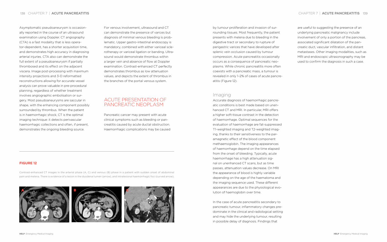
CHAPTER 7 | ACUTE PANCREATITIS 139
HELP Emergency Medical Imaging
138 CHAPTER 7 | ACUTE PANCREATITIS
HELP Emergency Medical Imaging
by tumour proliferation and invasion of sur-
rounding tissues. Most frequently, the patient
presents with melena due to bleeding in the
digestive tract or secondary to rupture of
perigastric varices that have developed after
splenic vein occlusion caused by tumour
compression. Acute pancreatitis occasionally
occurs as a consequence of pancreatic neo-
plasms. While chronic pancreatitis more often
coexists with a pancreatic mass, a tumour is
revealed in only 1–2% of cases of acute pancre-
atitis (Figure 12).
ImagingAccurate diagnosis of haemorrhagic pancre-
atic conditions is best made based on unen-
hanced CT and MRI. In particular, MRI offers
a higher soft-tissue contrast in the detection
of haemorrhage. Optimal sequences for the
evaluation of haemorrhage are fat-suppressed
T1-weighted imaging and T2-weighted imag-
ing, thanks to their sensitiveness to the par-
amagnetic effect of the blood component
methaemoglobin. The imaging appearances
of haemorrhage depend on the time elapsed
from the onset of bleeding. Typically, acute
haemorrhage has a high attenuation sig-
nal on unenhanced CT scans, but as time
passes, attenuation values decrease. On MRI
the appearance of blood is highly variable
depending on the age of the haematoma and
the imaging sequence used. These different
appearances are due to the physiological evo-
lution of haemoglobin over time.
In the case of acute pancreatitis secondary to
pancreatic tumour, inflammatory changes pre-
dominate in the clinical and radiological setting
and may hide the underlying tumour, resulting
in possible delay of diagnosis. Findings that
are useful to suggesting the presence of an
underlying pancreatic malignancy include
involvement of only a portion of the pancreas,
associated significant dilatation of the pan-
creatic duct, vascular infiltration, and distant
metastases. Other imaging modalities, such as
MRI and endoscopic ultrasonography may be
used to confirm the diagnosis in such a case.
Asymptomatic pseudoaneurysm is occasion-
ally reported in the course of an ultrasound
examination using Doppler. CT angiography
(CTA) is a fast modality that is less opera-
tor-dependent, has a shorter acquisition time,
and demonstrates high accuracy in diagnosing
arterial injuries. CTA also can demonstrate the
full extent of a pseudoaneurysm if partially
thrombosed and its effect on the adjacent
viscera. Image post-processing with maximum
intensity projections and 3-D reformatted
reconstructions allowing for accurate vessel
analysis can prove valuable in pre-procedural
planning, regardless of whether treatment
involves angiographic embolisation or sur-
gery. Most pseudoaneurysms are saccular in
shape, with the enhancing component possibly
surrounded by thrombus. When the patient
is in haemorrhagic shock, CT is the optimal
imaging technique: it detects perivascular
haemorrhagic collections and often, if present,
demonstrates the ongoing bleeding source.
For venous involvement, ultrasound and CT
can demonstrate the presence of varices but
diagnosis of minimal venous bleeding is prob-
lematic. Upper gastro-intestinal endoscopy is
mandatory, combined with either variceal scle-
rotherapy or variceal ligation or banding. Ultra-
sound would demonstrate thrombus within
a larger vein and absence of flow at Doppler
examination. Contrast-enhanced CT perfectly
demonstrates thrombus as low attenuation
values, and depicts the extent of thrombus in
the branches of the portal venous system.
ACUTE PRESENTATION OF PANCREATIC NEOPLASM
Pancreatic cancer may present with acute
clinical symptoms such as bleeding or pan-
creatitis caused by acute ductal obstruction.
Haemorrhagic complications may be caused
FIGURE 12
Contrast-enhanced CT images in the arterial phase (A, C) and venous (B) phase in a patient with sudden onset of abdominal
pain and melena. There is evidence of a lesion in the duodenal lumen (arrow), and intralesional haemorrhagic foci (curved arrow).
A B C

CHAPTER 7 | ACUTE PANCREATITIS 141
HELP Emergency Medical Imaging
140 CHAPTER 7 | ACUTE PANCREATITIS
HELP Emergency Medical Imaging
DR. MIRKO
D’ONOFRIO
accomplished his
studies in medicine
at the University of
Pavia, Italy, from
1991–1997 and had
his residency train-
ing in radiology at
the University of Verona from 1997–2001. Dr.
D’Onofrio has been a radiologist at G.B. Rossi
University Hospital of Verona since 2001. He was
appointed Associate Professor of Radiology in
2014. Dr. D’Onofrio was Chairman of the Guide-
lines Committee for the use of contrast media
in ultrasound, of interventional ultrasound, and
of elastography for the European Federation of
Societies for Ultrasound in Medicine and Biology
(EFSUMB). He is a member of the editorial board
of international scientific journals and a member
of national and international scientific societies.
He directed a multicentre study on contrast-en-
hanced ultrasonography of the pancreas. Dr.
D’Onofrio was a teacher at the Euroson School,
gave invited lectures at international scientific
meetings, and is a regular presenter at meet-
ings of national and international radiological
societies.
DR. RICCARDO DE
ROBERTIS
completed his med-
ical studies at the
University of Verona,
Italy, in 2010. He
became board cer-
tified in radiology in
2015 and is currently
a PhD candidate at the University of Verona. Dr.
De Robertis is a radiologist at the Department of
Radiology of P. Pederzoli Hospital in Peschiera
del Garda, Italy. His main field of interest is hepa-
to-biliary, pancreatic and interventional radiology.
He is a member of national and international
radiological societies and acts as a reviewer for
international radiological journals. Dr. Rossi has
given oral presentations at national and interna-
tional scientific meetings. He has co-authored
scientific papers and book chapters.
DR. ALESSANDRO
SARNO
accomplished his
medical studies at the
University of Verona,
Italy, from 2007–2013.
He is a resident in
training in radiology
at the University
Hospital of Verona and has contributed to several
book chapters.

8 8MY
BELLY HURTS

CHAPTER 8 | MY BELLY HURTS 145
HELP Emergency Medical Imaging
little value. CT gives much more information
for little added cost.
Today, CT is considered the ‘all-in-one’ emer-
gency diagnosis and triage for the acute
abdomen. But the role of CT extends beyond
its ability to diagnose causes of acute abdom-
inal pain. By showing accurately the stage, the
anatomic extension, and the potential resolu-
tion of disease without surgical treatment, CT
has dramatically changed the management
of gastro-intestinal emergencies. We will
illustrate this significant progress regarding
five common gastro-intestinal emergencies:
appendicitis, bowel obstruction, diverticuli-
tis, bowel perforation and acute mesenteric
ischaemia. We will not deal with gastrointesti-
nal bleeding for which the clinical presentation
is specific.
ULTRASOUND, CT, OR NO IMAGING FOR THE DIAGNOSIS OF APPENDICITIS: COMPLEMENTARITY OR COMPETITION?
Acute appendicitis, or inflammation of the
appendix, is currently the most frequent
cause of acute abdominal emergency requir-
ing surgery. It affects about 250,000 people
per year in the USA and represents about
three-quarters of paediatric surgical emergen-
cies. The diagnosis is usually performed based
on clinical symptoms including tenderness
at McBurney’s point, migratory abdominal
pain and on blood analysis: C-reactive pro-
tein (CRP) correlates with the severity of the
disease and white cell count (leucocytosis) is
more sensitive for the detection of early-stage
appendicitis. However, the clinical diagnosis
is not always straightforward when clinical
presentation is atypical, as is the case in about
50% of patients. This is particularly true in
young children unable to verbalise symptoms,
in old patients for whom clinical presentation
may be sub-acute despite advanced disease,
and in childbearing-age women because of
the high rate of alternative gynaecologic diag-
noses including pelvic inflammatory disease,
complication of an ovarian cyst, or adnexal
torsion.
These difficulties explain the risk of a strategy
only based on clinical and biological data: to
operate patients at the slightest suspicion
results in a negative appendectomy rate of
15–25%, and up to 40% in young women. It is
preferable to clinically monitor patients with
an increased risk of perforation, which can
lead to potentially life-threatening complica-
tions such as abscess, peritonitis and sepsis,
since there is a correlation between duration
of symptoms and the rate of complications.
Extensive use of imaging for the diagnosis of
appendicitis has allowed a decrease in the rate
of negative appendectomy and is optimisti-
cally known as prophylactic appendectomy
leading to bands and adhesions and delayed
surgery.
Ultrasound (US) and CT have been largely
assessed for the diagnosis of appendicitis
and, more recently, magnetic resonance
imaging (MRI) has also been evaluated
in dedicated populations such as preg-
nant women and children. The diagnostic
signs are well known. Ultrasound shows
an enlarged, non-compressible and pain-
ful appendix measuring more than 6mm in
diameter (Figure 1) and less useful ancillary
MY BELLY HURTS: DIAGNOSTIC MANAGEMENT OF DIGESTIVE TRACT EMER-GENCIESBY PATRICE TAOUREL, CELINE ORLIAC, INGRID MILLET
Acute abdominal pain is a common pres-entation in the ambulatory setting.
It accounts for about 1.5% of all medical consultations and 8% of all
emergency department visits in the United States in 2010. Although the
differential diagnosis of acute abdominal pain is considerable, including
hepatobiliary, urologic, gynaecologic, vascular and musculoskeletal con-
ditions, gastro-intestinal diseases constitute both the most frequent and
the most serious causes of acute abdominal pain.
Forty years ago, exploratory laparotomy was the standard for both diag-
nosis and treatment of gastro-intestinal causes of acute abdomen, but
invasive emergency surgery without a hint of diagnosis is often useless.
Twenty years ago, multiple studies showed the reliability of computed
tomography (CT) for the primary diagnosis of virtually all causes of
acute abdominal pain with the exception of acute cholecystitis and some
gynaecologic emergencies, such as pelvic inflammatory disease and
ectopic pregnancy. The benefit of CT in comparison to other imaging
examinations was particularly significant in gastro-intestinal emergen-
cies. Plain abdominal radiographs, which were traditionally considered
the first-line diagnostic modality in gastro-intestinal emergencies, are of

CHAPTER 8 | MY BELLY HURTS 147
HELP Emergency Medical Imaging
146 CHAPTER 8 | MY BELLY HURTS
HELP Emergency Medical Imaging
appendicitis and may shorten the hospital
stay. By preventing unnecessary operation
and patient observation and by permitting
early recognition of alternative diagnoses,
CT saves healthcare costs, up to almost 500
dollars per patient, despite the cost of CT
examination, as reported in a study pub-
lished 20 years ago.
Conversely, when radiation exposure is a
concern, particularly in pregnant, paediatric,
or young adult patients, ultrasound, despite
its slightly inferior performance to CT, is
often used as the first-line diagnostic modal-
ity. CT, and, following that, MRI, are advised
if ultrasound is non-diagnostic. What is
surprising for such a common disease is that
there is no consensus in the imaging options
for the diagnosis of appendicitis in chil-
dren. There is greater use of CT in the USA,
whereas ultrasound remains the first imaging
modality elsewhere.
In the same way, although one million CT
examinations are performed each year
around the world for acute right lower
abdominal pain, it is surprising that no con-
sensus exists on the recommended CT tech-
nique. All do agree though that thin slices
increase spatial resolution, which allows
multiplanar and notably coronal reformat-
ting, and thereby accuracy of the diagnosis
of appendicitis.
Controversies also exist about the use of
oral, rectal, and intravenous contrast and
about the size of the field of view. Should the
examination be focused on the appendiceal
area or performed on the entire abdomen
in order to make alternative diagnoses?
Such controversies are illustrated by the
findings such as calcification in the appendix
lumen or appendicolith, a fluid-filled appen-
dix, hypervascularisation of the appendiceal
wall, pericaecal fluid or inflammation of the
surrounding fat. CT shows increased trans-
verse diameter of the appendix, increased
thickness of the appendiceal wall, periappen-
diceal haziness (Figure 2) and in some cases
an appendicolith, caecal wall thickening or
the presence of a focal defect in the appen-
diceal wall or gas bubbles outside the diges-
tive tract when the appendix is perforated.
MRI shows an increased enhancement of the
appendiceal wall after intravenous injection
of contrast and oedema, particularly well
demonstrated by T2 signal hyperintensity
within the wall or surrounding the appendix.
If there were a competition between ultra-
sound and CT in terms of accuracy, CT is
the winner, at least in adult patients. CT has
better sensitivity and it is more accurate for
the diagnosis of appendix perforation, which
remains challenging at ultrasound. It also
allows for diagnosis of appendiceal plastron
represented by an agglutination of small
bowel loops. This may lead to a change of
treatment using antibiotherapy, percutane-
ous drainage of an abscess, when necessary
(Figure 3), and delayed rather than imme-
diate surgery. CT delineates a wide field of
view permitting easier identification of the
location of the appendix when atypical, since
its location within the abdomen is highly var-
iable. CT is more accurate for depicting most
of the alternative diagnoses, which include
mesenteric lymphadenitis, Crohn’s disease,
colon diverticulitis, caecal cancer, epiploic
appendagitis (Figure 4), or gynaecologic
or urologic diseases, the latter comprising
renal colic or pyelonephritis. CT can rule out
FIGURE 1
Ultrasound shows enlarged
(>6mm), non-compressible appen-
dix with hyperechogenecity of the
surrounding fat, reflecting peri-
appendiceal inflammation.
FIGURE 3
CT coronal reformatting of an
abscess located in the right iliac
fossa (arrows), illustrates a compli-
cated appendicitis. An endolumi-
nal calcification or appendicolith
is seen within the abscess (arrow-
head).
FIGURE 2
CT coronal reconstruction shows
increased thickness and enhance-
ment of the appendiceal wall
(arrows) suggestive of appendicitis.FIGURE 4
CT axial view of epiploic append-
agitis: a fat-density ovoid structure
adjacent to the colon (arrow). The
differential diagnosis is appendicitis.

CHAPTER 8 | MY BELLY HURTS 149
HELP Emergency Medical Imaging
148 CHAPTER 8 | MY BELLY HURTS
HELP Emergency Medical Imaging
Today, the management of suspected bowel
obstruction is adapted to the level, the
cause and whether ischaemia is present or
not. All this information is given by CT. More
than 50% of small bowel obstructions are
due to adhesion, the most common cause of
bowel obstruction, and treated without sur-
gery. CT has permitted a significant change
in management by solving the key issues in
patients with suspected bowel obstruction:
differentiation between mechanical obstruc-
tion and paralytic ileus, localising the level
of obstruction; evaluating high-grade versus
incomplete obstruction; showing the cause
of obstruction and identifying intestinal
loop strangulation. The complete diagnostic
work-up, based on the information gained
from CT, either medical or surgical therapy
will be adopted.
The pattern of major causes of intestinal
obstruction has changed over the past
five decades. The most common cause
was originally external hernia. Now, adhe-
sions comprise 60–80% of all causes in
industrialised countries; the other main
causes include inflammatory bowel disease,
internal (Figures 5A, 5B) and external her-
nias, primary tumours, peritoneal carcino-
matosis, acute focal inflammatory disease
entities such as appendicitis or diverticulitis
and intussusception. CT diagnosis of adhe-
sion in the past was considered difficult
because it was based on negative find-
ings, ruling out any other pathology. Thin
slices and multiplanar reformatting have
improved the diagnosis of peritoneal adhe-
sion. The transition zone is depicted with
more confidence, and the adhesive band
itself can be shown.
Gastro-duodenal obstruction accounts for
about 1% of bowel obstruction; malignant
tumour and peptic ulcer disease are the
two main causes. Gastric cancer is usually
responsible for gastric obstruction, whereas
duodenal obstruction is caused by pancre-
atic cancer (Figures 6A, 6B). In gastro-du-
odenal obstruction secondary to peptic
ulcer, the stenosis is often short and may be
recommendations of the American College
of Radiology, which conclude that the use
of oral or rectal contrast should depend on
institutional preferences. Despite this there
are important points of agreement for the
diagnosis of appendicitis. Imaging is helpful
and permits a decrease in the rate of nega-
tive appendectomy and easier identification
of complicated appendicitis, identifying
patients who would benefit from surgery and
those who would need clinical observation.
Ultrasound and CT are both accurate but
CT is still slightly superior, particularly for
the diagnosis of complicated appendicitis
and making alternative diagnoses. However,
there are still some controversies left open:
is imaging recommended for all suspected
appendicitis or should surgery be performed
without imaging when the clinical suspicion
is high? In young patients, and particularly
in children, for whom radiation is a concern,
should the strategy of CT as the all-in-one
examination be adopted or be replaced by
a more restrictive approach with CT per-
formed only if ultrasound is inconclusive?
BOWEL OBSTRUCTION: SURGERY IS NOT THE RULE
At the end of the last century, surgery was
considered the standard of care in manage-
ment of patients with bowel obstruction
with the adage ‘never let the sun set or
rise on a suspicion of small bowel obstruc-
tion’. The clinical diagnosis of small bowel
obstruction classically depends on four
cardinal findings: abdominal pain, vomit-
ing, constipation and abdominal disten-
sion. However, the clinical observations
vary with the degree and level of bowel
obstruction and with the vascular status
of the obstructed segment, making even
a positive diagnosis difficult. By contrast,
the presence of dilated bowel proximal
to a transition zone and a collapsed dis-
tal small bowel indicates with confidence
the diagnosis of intestinal obstruction and
shows precisely the level of the obstruction:
stomach, duodenum, small bowel, or colon.
Preferential causes are associated with each
location.
FIGURE 5
CT (A) axial and (B) coronal view of a
paraduodenal hernia, the most com-
mon type of internal hernia, which
has resulted in a closed-loop bowel
obstruction. Note the sac-like cluster
of small bowel loops in an atypical
position (arrows).
A B
FIGURE 6
CT (A) axial and (B) coronal view of
gastro-duodenal obstruction. Note
dilated stomach and duodenum
(arrows) caused by pancreatic cancer:
a hypodense pancreatic lesion can be
identified (arrowheads).
A B

CHAPTER 8 | MY BELLY HURTS 151
HELP Emergency Medical Imaging
150 CHAPTER 8 | MY BELLY HURTS
HELP Emergency Medical Imaging
irreversible ischaemia and localised infiltration
of the mesenteric fat is the most sensitive
finding of ischaemia.
Large bowel obstruction accounts for about
25% of all bowel obstruction and the two main
causes are colon cancer and sigmoid volvulus
(Figure 7). One of the advantages of CT in
comparison with contrast enema, classically
considered the gold standard imaging method
in large bowel obstruction, is improved
characterisation of the thickened bowel wall
responsible for stenosis and to differentiate
tumour from other causes. Furthermore,
right-sided colon obstruction is difficult to
characterise and, in cases of caecal volvu-
lus, abdominal plain film and contrast enema
may fail to identify the cause of obstruction.
Consequently, CT has become the standard
examination in the assessment of large bowel
obstruction.
The management of bowel obstruction
depends on cause and severity of obstruc-
tion. Nowadays, most surgeons recommend
surgery without delay when strangulation is
suspected: open laparotomy is recommended
when bowel wall necrosis is suspected,
whereas laparoscopy may be sufficient in
patients when no bowel resection is required
(Figure 8). Delayed surgery is recommended
in case of malignant tumour, whereas medi-
cal management is generally advised in most
cases of peritoneal carcinomatosis, radiation
enteritis or jejunal haematoma. Conservative
management is recommended with Crohn’s
disease when an acute flare causes bowel
obstruction, whereas obstruction caused by a
chronic fibrotic narrowing may, in some cases,
necessitate surgical resection. Lastly, small
bowel obstruction due to adhesion without
strangulation is generally treated medically
with diet and placement of a nasogastric tube;
surgery is performed only in case of failure of
medical management.
ACUTE SIGMOID DIVERTICULITIS: CT DIAGNOSIS IS NOT SUFFICIENT
Colon diverticula are acquired herniations
of the mucosa and parts of the submucosa
through the muscularis propria of the colon
wall. Colon diverticulosis is a clinically silent
disease resulting from the development of
multiple diverticula on the colonic wall. Diver-
ticulosis is the most common colonic disease
in the Western population, with an estimated
incidence of 30% in people over 50 years of
age and up to 60% over the age of 70. When
diverticula become diseased, they result in
acute inflammation, or diverticulitis, and fur-
ther complications or even diverticular haem-
orrhage. Diverticulitis occurs in 10 to 35% of
patients with diverticulosis and 30% of these
patients will have complicated diverticulitis.
Although CT is definitively considered the
best tool to diagnose acute diverticulitis, a
majority of outpatients with clinical and bio-
logical findings consistent with acute uncom-
plicated diverticulitis of predominantly the
sigmoid colon will not be investigated by CT.
This may have harmful consequences, since in
patients with left lower quadrant pain, alterna-
tive diagnoses should be considered includ-
ing colon carcinoma, colitis, either infectious,
inflammatory or ischaemic in origin, epiploic
appendagitis, functional colonic disorders and
difficult to identify at CT, obscuring differen-
tiation between obstruction related to peptic
ulcer and gastroparesis.
Since surgery is not considered first-line
treatment in small bowel obstruction due
to adhesions, it is important to search for
complications, which may make emergency
surgery mandatory. Closed-loop or incarcer-
ated intestinal obstruction is defined by an
obstruction of a loop of bowel at two or more
adjacent locations, the obstruction could be
an adhesive band or the neck of a hernia. CT
features include a ‘U’ or ‘C’ appearance of the
bowel loop pointing to the site of obstruction
or a radial arrangement of the bowel loops.
The adjacent vessels often show a swirled
configuration reflecting the twist in the mes-
entery. The complication of a closed loop
obstruction is strangulation with intestinal
ischaemia. The severity and duration of intes-
tinal and mesenteric obstruction determines
the grade of ischaemia. At first, venous return
from the involved bowel segment is compro-
mised because intraluminal pressure exceeds
venous pressure and congestion affects the
bowel wall and the mesentery, while the influx
of arterial blood still continues. Ischaemia is
resolved with emergent surgical treatment.
Increased bowel distension predisposes the
closed loop to rotate around the mesentery.
Consequently, arterial ischaemia ensues,
which aggravates bowel hypoxia and further
accelerates rapid development of bowel wall
gangrene and perforation. CT findings of
strangulation include lack of enhancement of
the incarcerated bowel wall after intravenous
administration of iodinated contrast, which
is the most specific finding of strangulation.
Spontaneous hyperdensity of the bowel wall
before contrast is the most specific finding of
FIGURE 7
CT coronal view of sigmoid volvu-
lus: large gas and stercoral con-
tent-filled loop (arrows) with sig-
moid transition zone and twisting
of mesenteric vessels ‘whirl sign’
(arrowhead).
FIGURE 8
Laparoscopic view of small bowel
obstruction resulting from a band.

CHAPTER 8 | MY BELLY HURTS 153
HELP Emergency Medical Imaging
152 CHAPTER 8 | MY BELLY HURTS
HELP Emergency Medical Imaging
including CT-guided percutaneous drain-
age and purulent or faecal peritonitis (stage
3–4) requiring surgical treatment. Nowadays,
therapeutic options for haemodynamically
stable patients include colectomy, laparo-
scopic lavage or medical treatment. Conse-
quently, the radiologist’s report should specify
the presence of phlegmon in uncomplicated
diverticulitis or the presence of an abscess;
should describe the location and extent, and
recognise the presence of extra-luminal gas
(Figure 10), or pericolic, mesocolic or free
fluid in the peritoneal cavity and the extent of
diverticulitis in the descending colon.
BOWEL PERFORATION: WHY MAKE IT SIMPLE WHEN WE CAN MAKE IT COMPLICATED?
Bowel perforation accounts for 1 to 3% of
acute abdominal syndrome and represents a
medical emergency. It can affect any seg-
ment of the digestive tract and complicate
any alteration of the bowel wall, whether the
cause is tumoural, inflammatory, ischaemic,
from radiation, or from ulcer. Nevertheless, the
list of most frequent causes can be shortened
to gastro-duodenal ulcer or sigmoid colon
diverticulitis.
Gas in the peritoneal cavity or pneumoper-
itoneum is the most characteristic sign of
digestive perforation. Plain films of the abdo-
men were the first radiographic examination
to diagnose bowel perforation. However,
although experimental studies show that as lit-
tle as 1ml of gas can theoretically be detected
on an erect chest radiograph beneath the dia-
phragm, abdominal radiographs miss about
half of the pneumoperitoneum in clinical prac-
tice, and the site of the perforation is ignored.
This stresses the role of CT in the diagnosis
of bowel perforation, which is able to identify
the site and cause of perforation. In France,
taking abdominal radiographs is no longer
recommended.
Abnormalities demonstrated on CT in bowel
perforation depend on site and cause of
bowel perforation. In oesophageal perfora-
tion, fluid collection located in the posterior
mediastinum pointing to focal mediastinitis
and pneumomediastinum is observed. In
gastroduodenal perforation a rupture of the
intestinal wall, most commonly located in the
duodenal bulb or pre-pyloric region, is a direct
sign of a perforated gastroduodenal ulcer
(Figures 11, 12). In small bowel perforation, CT
shows gas bubbles and localised fatty infil-
tration in the mesentery. Potential causes of
perforation are small bowel obstruction, acute
non-gastro-intestinal disease, such as pyelo-
nephritis or gynaecologic pathologies. Main
CT findings for the diagnosis of acute colonic
diverticulitis were already described twenty
years ago and associate both intramural
patterns: diverticula and bowel wall thicken-
ing as well as extramural patterns consisting
of inflammatory changes of the pericolic and
mesocolic fat (Figure 9).
However, CT has some difficulties in noting
the difference between sigmoid diverticulitis
and sigmoid cancer. One of the most helpful
findings in differentiation is multiple pericolic
lymph nodes measuring 1cm or more in the
short axis that are more frequent in carci-
noma. Another is a combination of a mild
circumferential thickening of the colonic wall
longer than 10cm with a progressive tran-
sition zone and the non-narrowed proximal
and distal colon associated with inflammatory
changes of the mesocolon, which are sugges-
tive of diverticulitis. A specific ring or double
ring pattern of the colon wall enhancement
can also be suggestive of diverticulitis. How-
ever, because these findings can lack specific-
ity, guidelines advise performing colonoscopy
after an episode of diverticulitis, particularly in
patients over 50.
CT is particularly able to differentiate uncom-
plicated from complicated diverticulitis.
Complicated diverticulitis must be investi-
gated in depth. Indeed, treatment options for
diverticulitis depend on CT evaluation with
a recent change towards less invasive ther-
apy. The classical surgical classification by
Hinchey is now outdated. This classification
divided complicated diverticulitis into moder-
ate and severe: peridiverticular abscess (stage
1–2) being managed with medical treatment
FIGURE 9
CT axial view of diverticulitis: bowel
wall thickening (arrows) and inflam-
matory changes in the surrounding
fat (arrowhead).
FIGURE 10
Complicated diverticulitis in the same
patient as Figure 9: bubbles of extra-
luminal gas are an indication for per-
foration (arrow).
FIGURE 11
Rupture of bowel wall (arrowheads)
in the pyloric region as result of per-
forated ulcer. CT patterns of associ-
ated peritonitis are free peritoneal
fluid and enhancement of peritoneal
reflections (arrows).

CHAPTER 8 | MY BELLY HURTS 155
HELP Emergency Medical Imaging
154 CHAPTER 8 | MY BELLY HURTS
HELP Emergency Medical Imaging
non-specific clinical presentation. Until now,
acute mesenteric ischaemia has always been
considered an abdominal emergency asso-
ciated with a high mortality rate and often
intestinal failure in survivors. An improvement
of prognosis requires a prompt diagnosis,
established as early as possible from the onset
of symptoms and multidisciplinary, multimodal
management.
Diagnosis is based on CT findings depending
on the stage of the disease. At the very early
stage, the neurogenic reaction of the intestine
to ischaemia is spastic reflex ileus, which leads
to a collapsed bowel with no endoluminal
content. In this case, bowel wall enhancement
is normal or in some cases appears brighter
than usual. Precise scrutiny of the splanchnic
vessels can lead to a discovery of the cause
of ischaemia. In the next stage, the lumen of
the small intestine will be distended by fluid,
the wall appears thinner than normal, and
accurate evaluation of bowel wall enhance-
ment is mandatory (Figure 14). At a late stage
intestinal infarction, necrosis of the involved
bowel is announced by the absence of intes-
tinal wall enhancement, intra-parietal, mes-
enteric, portal vein gas or pneumatosis and
free intraperitoneal air if bowel wall perfora-
tion has occurred. Splanchnic vessels must
be analysed in detail to identify the cause of
ischaemia, which can include arterial emboli,
arterial local thrombosis, arterial dissection,
vasculitis, mesenteric low flow in a suggestive
clinical setting, or finally other rare causes of
vascular obstruction such as trauma, tumour,
or extrinsic vascular compression. Another
cause can be mesenteric venous thrombosis,
ischaemia of the mesentery, Crohn’s disease,
lymphoma, small bowel diverticulitis, tubercu-
losis, jejunal ulcer, foreign body or vasculitis.
In appendiceal perforation, CT differentiates
complicated from uncomplicated appendicitis
based on the presence of abscess, phlegmon,
extraluminal air, extra-appendiceal calcifica-
tion or stercolith, a defect in enhancement
of the appendiceal wall and ileus. All these
observations are indications of a perforated
appendicitis. Free pneumoperitoneum occurs
rarely in appendicular perforation.
The two main causes of perforation are diver-
ticulitis and neoplasia. The tumour growth
itself can perforate the bowel wall; other-
wise, the mechanism is diastatic perforation
(Figure 13). Rarely, perforation complicates
an ischaemic colitis or a stercoral colitis. The
question is: does the site of perforation need
to be identified with absolute precision, as
emergency surgery will be necessary any-
way? The answer is yes: the type of surgery
to be performed is influenced by the site
and cause of perforation. In gastroduodenal
ulcer perforation of the anterior or lateral
wall, laparoscopy is the preferred option as
shown in a number of randomised studies,
whereas perforation of the posterior aspect
is easier managed by open surgery because
laparoscopic access to the posterior wall
remains cumbersome. Selected patients could
be managed non-operatively or with novel
endoscopic approaches such as endoscopic
clips or stents. Unlike gastroduodenal ulcer
perforation, small bowel perforation is best
treated by laparotomy. Colon perforation or
tumour-related perforation must be repaired
by open surgery. In contrast, management
of perforation from sigmoid diverticulitis
depends on the stage of the disease, as well
as on the preferences of the surgical team.
ACUTE MESENTERIC ISCHAEMIA: CT IS THE FIRST STEP TOWARDS SAVING GUTS AND EVEN LIVES
Nearly a century ago, Cokkinis stated that
“occlusion of the mesenteric vessels is apt
to be regarded as one of those conditions of
which diagnosis is impossible, the prognosis
hopeless and the treatment almost useless”.
Prognosis cannot significantly be changed
if the delay in diagnosis and treatment of
acute mesenteric ischaemia is not decreased.
Diagnostic delay is partly due to the relative
infrequency of the event and partly to its
FIGURE 12
Perforation of posterior aspect of the
duodenum (arrow) resulting in retro-
peritoneal abscess (arrowheads): (A)
axial scans and (B) reformatted sag-
ittal views.
A B
FIGURE 13
(A) CT views of perforated sigmoid
cancer: focal, irregular thickening of
the bowel wall (arrows). (B) Pericolic
enlarged lymph nodes, and extralumi-
nal gas bubbles (arrow).
A B
FIGURE 14
Small bowel ischaemia. (A) Absence
of bowel wall enhancement on
pre-contrast scan and (B) on
post-contrast CT images.
A B

CHAPTER 8 | MY BELLY HURTS 157
HELP Emergency Medical Imaging
156 CHAPTER 8 | MY BELLY HURTS
HELP Emergency Medical Imaging
in which acute mesenteric ischaemia is often
associated with a mesenteric arterial spasm.
The identification of vascular abnormalities,
even if isolated, is a key issue for therapy since
recognition of ischaemia before the onset
of bowel wall necrosis permits an adapted
treatment avoiding extended bowel resection.
Multidisciplinary and multimodal management
of acute mesenteric ischaemia, including gas-
troenterologists, diagnostic and interventional
radiologists and vascular and digestive sur-
geons in an intestinal stroke centre, may avoid
large intestinal resection, permanent intestinal
failure and patient death. The differentiation
between ischaemia as a potentially reversible
affliction and infarction as an irreversible afflic-
tion with necrosis of the involved intestinal
segment has a therapeutic impact since the
former can benefit from radiological endo-
luminal catheter-directed revascularisation
whereas the latter will need surgical revascu-
larisation and intestinal resection.
DR. PATRICE
TAOUREL
commenced a four
year residency in
radiology at the
University Hospi-
tal of Montpellier,
France, in 1983,
following the com-
pletion of his medical studies. After completing
a year of military service in Tunisia, working in
paediatric radiology, Dr. Taourel became a junior
staff member of the Department of Abdominal
Radiology at the University Hospital Saint Eloi in
Montpellier in 1988. He obtained his PhD in 1996
and was named Professor of Radiology in 1998 at
Hospital Lapeyronie, a public university hospital
in Montpellier. In 2000, he was named Head of
Department. Dr. Taourel was editor in chief of the
Journal de Radiologie Diagnostique et Inter-
ventionelle from 2007 to 2012. From 2007 to
2016, he served as Chairman of Radiology at the
University Hospitals in Montpellier, and in 2015,
he was elected Chairman of the medical com-
munity of the University Hospitals of Montpellier.
His main topics of interest in radiology are acute
abdomen, urological, gynaecological and breast
imaging. He has authored more than 150 indexed
publications and has 20 original articles published
in Radiology.
DR. CÉLINE ORLIAC
accomplished her
medical studies at the
School of Medicine,
University of Montpel-
lier, France, and her
residency training in
radiology at Lap-
eyronie University
Hospital in Montpellier. She is currently specialis-
ing in emergency radiology and breast and uro-
gynaecological imaging. Dr. Orliac is a member of
national and international radiological societies.
DR. INGRID MILLET
is professor of radi-
ology at the Depart-
ment of Radiology at
Lapeyronie University
Hospital in Montpell-
ier, France. Her main
research interests are
emergency radiol-
ogy, especially acute abdomen and whole body
computerised tomography in polytrauma. Dr.
Millet has authored or co-authored more than
thirty peer-reviewed publications in national or
international scientific journals, dealing with the
topics of emergency radiology, breast magnetic
resonance imaging and urological oncology. She
is a member of national and international radio-
logical societies.

9 9ACUTE
LUMBAR PAIN

CHAPTER 9 | ACUTE LUMBAR PAIN 161
HELP Emergency Medical Imaging
RENAL COLIC AND STONE DISEASE
Renal colic caused by ureteral stones is a com-
mon condition and is increasing in prevalence.
Most stones (approximately 80%) are calcium
based (calcium oxalate or phosphate, or a mix-
ture). Other types of stones include struvite
and uric acid stones. Unenhanced low-dose
CT of the abdomen has become the preferred
method for the evaluation of urolithiasis, signs
of obstruction and related complications.
Nearly all stones are easily visible on CT, with
the exception of uncommon matrix stones
and incrustations related to indinavir therapy.
Stone size (and total stone load), location,
and composition are factors considered when
determining treatment; these features should
be part of the CT report.
Reliable differentiation between stone types
is not possible using conventional CT. The CT
attenuation value can be used to suggest the
diagnosis of pure uric acid stones, which have
an attenuation of < 400 Hounsfield units (HU),
but there is a large overlap with attenuation
values of non-uric acid stones. Dual-energy
CT has been propagated to determine the
composition of stones. The attenuation of
stones differs at different energy levels, and
with appropriate post-processing tools, this
attenuation difference can be used to charac-
terise stone composition.
Although ureteral stones can rather easily
be diagnosed by following the course of the
ureter, differentiating between a stone and
an extraureteral calcification, i.e. a phlebolith
can occasionally be difficult to distinguish
especially in slender patients and/or when the
ureter is not dilated. Phleboliths are unlikely
ACUTE LUMBAR PAIN: CROSS-SECTION IMAGING GIVES THE ANSWERBY RAYMOND H. OYEN
Pathologies of the urinary tract are common in patients referred in emergency settings.
The appropriate use of imaging in suspected renal and ureteral pathol-
ogies, and the familiarity with the appearance of common pathologic
conditions is crucial for prompt diagnosis and further therapeutic
management.
Ultrasound is readily available in the emergency setting, but diagnostic
accuracy is largely operator-dependent. Recent advances in radiation-dose
reduction have resulted in high-quality CT images with relatively low radia-
tion doses. CT has become the primary and quickest imaging modality for
the assessment of suspected urinary tract pathologies in the acute setting
providing a definitive diagnosis and enabling appropriate treatment.
The most common emergency conditions of the kidneys and ureters are
related to urinary tract obstruction. Although various intrinsic or extrinsic
processes along the urinary tract may result in obstruction, by far the most
common cause is stone disease. Other conditions with different degrees
of severity such as infection, haemorrhage, acute ischaemic disease, and
traumatic injuries also occur.
FIGURE 1
Patient with right renal coli. Dis-
tal ureteral stone on the right (A).
Reformatted image demonstrating
the stone on the course of the ure-
ter (B).
A
B

CHAPTER 9 | ACUTE LUMBAR PAIN 163
HELP Emergency Medical Imaging
162 CHAPTER 9 | ACUTE LUMBAR PAIN
HELP Emergency Medical Imaging
considered to be a ‘systemic disease’ (collect-
ing system), and is frequently multifocal in the
upper tract and bladder. Haematuria is the
most common presentation. Imaging plays an
important role; careful evaluation of the entire
urinary tract is mandatory.
INFECTION – ACUTE PYELONEPHRITIS (APN)
Infection of the urinary tract usually ascends
from the bladder to involve the kidneys.
Infection of the kidney can also originate via
the haematogenous route. APN is a clinical
diagnosis; when imaging is considered nec-
essary to evaluate patients with suspected
APN (elderly patients, persisting fever under
appropriate treatment, immune-suppressed
patients), CECT is the preferred modal-
ity. Typical CECT-findings include wedge-
shaped or patchy areas of decreased cortical
enhancement with a ‘striated’ appearance
during the nephrographic phase. Persistent
striations on delayed scans (4–6 hours after
IV contrast administration) are seen due to
slow transit and prolonged accumulation of
contrast in the affected renal areas and are
highly suggestive of APN. This feature is useful
in selected patients to confirm the diagnosis
of APN or to differentiate from other pathol-
ogies (infarction, tumour). Interestingly and
surprisingly ultrasound is (false) negative in
approximately 50% of cases of CT-confirmed
pyelonephritis in native kidneys. In some cases
wedge-shaped or rounded hypo- or hyper-
echoic parenchymal areas may be seen; at
colour-Doppler ultrasound these areas are less
vascularised compared to the surrounding
unaffected parenchyma.
to have an attenuation greater than 300 HU,
unlike most stones. Additional signs includ-
ing the ‘soft-tissue rim sign’ (smaller ureteral
stones) and the ‘comet-tail sign’ (phleboliths)
can be helpful in making such a distinction in
some cases.
The main complication of urolithiasis is uri-
nary tract obstruction. CT findings of acute
obstruction include dilatation of the collecting
system, unilateral renal enlargement, per-
inephric and/or periureteric stranding. The
probability of spontaneous stone evacua-
tion depends on the size and location of the
obstructing stone. The most common loca-
tions for stone impaction are sites of anatomic
narrowing of the collecting system, i.e. the
ureteropelvic junction (UPJ), the cross-over
of the iliac vessels, and the ureterovesical
junction (UVJ). Obstructing proximal calculi
are typically larger than obstructing distal
calculi, with the average diameter of distal ure-
teral stones being 4mm. Nearly 90% of stones
measuring 1mm will spontaneously pass, the
rate decreasing to 25% for stones >9mm.
Spontaneous stone passage increases with
distal location of the stone, with almost 80%
of the stones at the UVJ passing spontane-
ously compared to only approximately half of
the stones in the proximal ureter.
Increased pressure in the renal pelvis results in
leakage of urine from a renal fornix. The cause
of obstruction is generally a ureteral stone
(usually in the distal ureter), although other
intrinsic or extrinsic causes can cause leakage.
Forniceal rupture indicates higher pressure,
leads to perirenal fluid infiltration and accu-
mulation, reduces the grade of dilatation of
the collecting system, and is usually more
painful. With forniceal ruptures, the grade
of obstruction is not necessarily correlated
with the grade of dilatation of the collecting
system.
Following lithotripsy, urinary tract obstruction
may occur due to passage of stone fragments
in the ureter, occasionally by a chain of multi-
ple small stone fragments.
In selected cases of clinical uncertainty,
patients with stone disease may need con-
trast-enhanced CT (CECT) to document
obstruction or to differentiate a stone from
an extraureteral calcification (usually phlebo-
lith). CECT can be useful for the evaluation of
nonopaque indinavir stones or matrix calculi,
seen as soft tissue attenuation causing filling
defects. CECT should also be performed in
cases of suspected infectious or vascular aeti-
ology (pyelonephritis, renal infarct).
OTHER CAUSES OF OBSTRUCTION
There are multiple other pathologic conditions
that may result in obstruction. Lesions within
the urinary tract (blood clots and urothelial
tumours) and outside of the urinary tract may
cause obstruction due to extrinsic compres-
sion: vascular aneurysms, retroperitoneal
fibrosis, retroperitoneal lymphadenopathy,
or fibrosis of the ureters due to prior surgery
or radiation therapy. Delayed imaging in the
excretory phase is essential for accurate
depiction of the level of ureteral obstruction.
Urothelial transitional cell carcinoma accounts
for approximately 10% of malignant tumours
of the upper urinary tract. It can only be
FIGURE 2
Ultrasound study in a young female
with clinical symptoms of acute
pyelonephritis. Ultrasound show-
ing a slightly hyperechoic area in
the upper pole of the right kidney
(A) with decreased vascularity of
the affected area at colour-Doppler
study (B).
A
B

CHAPTER 9 | ACUTE LUMBAR PAIN 165
HELP Emergency Medical Imaging
164 CHAPTER 9 | ACUTE LUMBAR PAIN
HELP Emergency Medical Imaging
diagnosis. Percutaneous image-guided
aspiration may be contributive toward diag-
nosis and speed up response to antibiotic
therapy.
INFECTION – PYONEPHROSIS
Pyonephrosis refers to the presence of pus
in a dilated collecting system, whatever the
obstructing cause (most often obstructing
stone), and is considered to be a urological
emergency. This condition is rapidly progres-
sive and should be suspected if a patient has
fever and flank pain in the context of urinary
tract obstruction. On CT, hydronephrosis
and perirenal inflammatory changes are
seen. Distinguishing between uncomplicated
hydronephrosis and pyonephrosis, though,
is difficult. On ultrasound, reflections may be
seen in the collecting system, at times with
a fluid-fluid level (urine/pus). The absence
of internal reflections/fluid levels however
does not exclude pyonephrosis. CT-features
suggestive of pyonephrosis include more
severe perinephric inflammatory changes
and increased pelvic wall thickness. Urgent
drainage is needed in cases of pyonephrosis
(percutaneous nephrostomy).
INFECTION – EMPHYSEMATOUS RENAL INFECTION
Emphysematous pyelonephritis, usually
caused by E. Coli, is considered to be a
severe necrotising renal infection that may be
rapidly progressive. It is seen predominantly
in female diabetic patients and may occur
secondary to urinary tract obstruction irre-
spective of the obstructing cause. Emphy-
sematous renal infections are best diagnosed
on CT, which can clearly demonstrate the
presence and extent of renal and extrare-
nal gas accumulation. Several classification
systems have been proposed depending on
the presence of renal and/or perirenal fluid
collections and with differences in mortality
rates. Treatment for this condition ranges
from medical management to percutaneous
drainage and nephrectomy.
In emphysematous pyelitis, gas accumulation
is limited to the collecting system, without
associated parenchymal destruction or col-
lection. This condition is considered benign
with a favourable outcome and is treated
medically.
VASCULAR – RENAL INFARCT
Renal infarct is most commonly due to
thromboembolic disease, with atrial fibril-
lation being the leading underlying cause.
Other aetiologies include atherosclerosis,
septic emboli from bacterial endocarditis,
aortic dissection, vasculitis, and trauma.
Patients present with symptoms mimicking
renal colic, i.e. abdominal or flank pain, hae-
maturia, nausea and vomiting, and elevated
white blood cell count and, contrary to renal
colic, elevated lactate dehydrogenase levels.
The CECT appearance of a renal infarct is
a wedge-shaped hypodensity or a patchy
hypodense appearance of the renal cortex,
and may resemble features of APN. There
may be a thin peripheral rim of enhancement
Focal bacterial nephritis is a form of localised
renal infection more likely to be a result of
haematogenous spread of infection. On CT,
this focal inflammation appears as a round
or wedge-shaped hypodense area with
patchy hypoenhancement on CECT. Such
inflammatory areas may have a pseudotu-
moural appearance, and correlation with
clinical symptoms and laboratory findings
are crucial.
INFECTION – RENAL ABSCESS
Renal abscess is a complication and more
advanced stage of focal renal infection.
Abscesses are rare with appropriate antibiotic
treatment. Abscesses may be located within
the kidney and/or in the perirenal space
and is more common in diabetic or immune
suppressed patients. On CECT, abscesses
are usually well delineated with thick walls,
central low density, and with an enhancing
peripheral surrounding rim. Percutaneous
image-guided aspiration may be indicated in
larger abscesses (> 3cm in diameter). Appro-
priate needle thickness is required for swift
aspiration of the thick and viscous purulent
content.
Cyst infection or any other pre-existing
cavity may cause abscesses as well. There
is a higher incidence of cyst infection in the
setting of polycystic kidney disease. These
infected cysts may be difficult to diagnose.
Comparison with previous imaging, when
available, and a subtle search for ‘second-
ary’ signs (thick wall, perilesional stranding,
fascial thickening) may be helpful for final
FIGURE 3
CECT of abscess in the right kidney,
showing a thick walled rounded
cavity, and some perirenal inflam-
mation. Axial (A) and coronal refor-
matted (B).
A
B

CHAPTER 9 | ACUTE LUMBAR PAIN 167
HELP Emergency Medical Imaging
166 CHAPTER 9 | ACUTE LUMBAR PAIN
HELP Emergency Medical Imaging
CECT is the preferred imaging modality in
cases of suspected renal trauma. Imaging
in both the corticomedullary phase and the
excretory phase is required to fully assess
renal trauma. Delayed scanning may be
required for diagnosis/exclusion or urinary
leakage.
Currently, the American Association for the
Surgery of Trauma grading system, based
on surgical findings, is most commonly
used. Grade I injuries are most common
and may not have any imaging findings or
may present with contusions (focal areas of
decreased enhancement) or small subcap-
sular haematomas. Grade II injuries include
perinephric haematomas and superficial
cortical lacerations <1cm, whereas in grade
III injuries, the laceration is >1cm without
collecting system injury. Grade IV inju-
ries include lacerations extending to the
collecting system, segmental infarcts, or
involvement of the main renal artery or vein.
Involvement of the vasculature or collect-
ing system with grade IV injuries may be
demonstrated by the presence of active
extravasation of enhanced blood on the
initial or delayed phase of imaging, and
extravasation of enhanced urine on the
delayed phase, respectively. Grade V injuries
include shattered kidney and avulsion or
thrombosis of the main renal artery or vein,
or avulsion of the UPJ. Management of renal
trauma is typically conservative except in
selected cases of grade IV and grade V inju-
ries. Input from an interventional radiologist
is required.
On CECT, active haemorrhage will appear on
the corticomedullary phase as a dense area
in or around the kidney in a linear or irregular
appearance, and often surrounded by a clot.
Contrast outside the confines of the kidney
or ureter on the excretory phase attests to
urinary extravasation. Full evaluation of pres-
ence/absence of urine extravasation may
require an additional scan phase after 10–15
minutes, or even later.
Ureteral trauma is less common than renal
trauma and most commonly occurs at
the fixation points of the ureteropelvic or
ureterovesical junctions. The most common
mechanism of injury is sudden deceleration,
which results in laceration of the ureter. Hae-
maturia is present in many patients, but not
always. CECT with appropriate timing will
demonstrate contrast extravasation from
the ureter. Differentiation between partial
and complete tears of the ureter is based on
the presence of contrast in the distal ureter
in the case of a partial tear, and the absence
of distal opacification of the ureter with a
complete tear. Complete tear of the ureter
requires surgical repair, while stenting can
often be successful for partial tears.
SPONTANEOUS HAEMORRHAGE – RENAL HAEMORRHAGE
The most common cause of spontaneous
renal haemorrhage is underlying neoplasm,
most frequently angiomyolipoma (AML),
followed by renal cell carcinoma. Non-ne-
oplastic causes include vascular disease
(polyarteritis nodosa or other vasculitis,
renal artery aneurysm, AV malformation or
fistula, or renal vein thrombosis), nephritis,
renal infection, and stone disease.
seen on the nephrographic phase, referred
to as the cortical or nephrographic rim sign.
This viable rim of renal cortical tissue is due
to a separate capsular vascular supply and
is often only first seen several days after the
infarct occurs. Treatment may include antico-
agulation, thrombolysis, and angioplasty.
VASCULAR – RENAL VEIN THROMBOSIS
Renal vein thrombosis occurs more com-
monly on the left side, most likely related to
the longer renal vein. Presentation includes
flank pain and haematuria. Renal vein throm-
bosis may be caused by hypercoagulable
states, nephrotic syndrome, invasion by neo-
plasm, trauma, extension of thrombus from
left ovarian vein, and, in infants, dehydration.
On CECT, clotting will be recognised in the
affected renal vein. (Partial) clot enhance-
ment is expected in tumour thrombus.
Enlargement of the kidney and perinephric
stranding due to congestion and oedema
are frequent. Imaging evaluation should
include accurate extent of clotting (into the
inferior vena cava, below/above diaphragm)
and careful analysis of eventual underlying
disease. Treatment of renal vein thrombosis
usually involves anticoagulation.
RENAL TRAUMA
Most renal injuries are due to blunt trauma,
and kidneys with pre-existing abnormalities
(unique hypertrophic kidney, renal ectopy,
UPJ-stenosis …) are at increased risk of injury.
FIGURE 4
Active haemorrhage after renal
biopsy: perirenal haematoma (A),
with active bleeding only visible at
colour-Doppler (B).
A
B

CHAPTER 9 | ACUTE LUMBAR PAIN 169
HELP Emergency Medical Imaging
168 CHAPTER 9 | ACUTE LUMBAR PAIN
HELP Emergency Medical Imaging
Presentation is typically with acute-onset
flank pain in the absence of haematuria.
If renal haemorrhage is caused by a mass,
CT will usually be able to demonstrate this.
AMLs may spontaneously haemorrhage,
most likely due to rupture of an aneurysm
or after mild abdominal trauma, exercise or
during pregnancy. Selective embolisation is
the preferred treatment option. As the risk
of haemorrhage increases with the size of
the lesion, prophylactic treatment is recom-
mended for lesions > 4cm in diameter using
embolisation or resection.
Renal cell carcinoma is the most common
malignant renal neoplasm. It is more com-
mon in males and typically presents in the
sixth and seventh decades of life. Symp-
tomatic RCCs with haematuria, palpable
abdominal mass, and flank pain are uncom-
mon; most cases nowadays are diagnosed
incidentally on cross-sectional imaging.
Simple renal cysts may also occasionally
haemorrhage due to trauma, enlargement,
or coagulopathy. There is a higher inci-
dence in patients with acquired renal cystic
disease under dialysis. There is also a higher
incidence of symptomatic cyst haemor-
rhage in the setting of autosomal dominant
polycystic kidney disease. This usually
resolves spontaneously.
In selected patients with perirenal haem-
orrhage without demonstrable cause,
repeat scanning after several weeks may
be recommended to ultimately confirm or
exclude the presence of an underlying renal
neoplasm.
SUBUROTHELIAL HAEMORRHAGE
Suburothelial haemorrhage is an uncom-
mon cause of haematuria (and pain), usually
seen in patients with a bleeding diathesis or
on anticoagulation. On unenhanced CT the
haemorrhage is seen as a high-density mural
thickening of the renal pelvis and/or proximal
ureter. On CECT only, it may be difficult to
differentiate the high-density mural thickening
from enhancement.
POSTPROCEDURAL – POSTOPERATIVE COMPLICATIONS
CT is useful in evaluating symptomatic
patients following renal or ureteral interven-
tion. Familiarity with different procedures
with their specific complications is essential.
At times, consultation of the referring sur-
geon is helpful for tailored imaging pro-
cedures. Examples include vascular injury
following biopsy or partial nephrectomy,
with sequelae ranging from active bleeding,
haematoma, renal infarct, AV-fistula, or pseu-
doaneurysm. Other potential complications of
partial nephrectomy include urinary leak and
infection.
A side effect of extracorporeal lithotripsy is
subcapsular haematoma which occurs in up
to 20% of patients; the clinical significance
though is low (1%).
Ureteral injury may occur as a complica-
tion of pelvic surgery such as hysterectomy
and rectal surgery. Unattended disruption
FIGURE 5
60-year-old male with massive
haematuria after partial nephrec-
tomy for renal cell carcinoma at the
lower pole of the left kidney. CECT
showing a pseudoaneurysm at the
lower pole. Coronal reformatted CT
(A) and (B). Treated with selective
embolisation with coils (C) and (D).
A B
C D
FIGURE 6
Massive haematuria and hypoten-
sion after percutaneous nephros-
tomy. Active haemorrhage. Intra-
renal haemorrhage extending to
the renal pelvis (A) and in addition
active bleeding in the abdomi-
nal wall from a branch of a lum-
bar artery (B). Both bleeding sites
successfully treated by selective
embolisation using intrarenal coils
(C) and (D) and microspheres in the
lumbar artery (E).
A
B
C
D
E

CHAPTER 9 | ACUTE LUMBAR PAIN 171
HELP Emergency Medical Imaging
170 CHAPTER 9 | ACUTE LUMBAR PAIN
HELP Emergency Medical Imaging
of a ureter may result in a urinary leak and
development of urinoma, while clipping of
a ureter will result in urinary tract obstruc-
tion and postoperative pain and decreased
renal function. Careful attention and delayed
excretory phase imaging is mandatory for
visualisation of the site of leakage. Presence
of an experienced radiologist during scan-
ning of these patients is recommended.
SCROTUM
Ultrasound is the key modality for the assess-
ment of scrotal content in the emergency set-
ting; comparative imaging with the unaffected
(asymptomatic) side is recommended. Ultra-
sound allows differentiation between testicular
and extratesticular disease processes. The
most common causes in the emergency set-
ting are inflammation, torsion and trauma.
In acute epididymitis, the inflammation is
usually located in the tail and body: focal or
diffuse epididymal thickening with hyper-
vascularity at colour-Doppler are seen. The
inflammation can extend to the testis. Areas
of liquefaction indicate abscess formation. A
reactive hydrocele is often present. Isolated
inflammation of the testis is extremely rare.
With torsion of the testis, the absence of
intratesticular flow (compared to the other
FIGURE 7
Patient with increasingly painful
abdomen ten days after partial
nephrectomy for papillary renal
cell carcinoma. Initial ultrasound
showing some perirenal fluid (A).
CECT in the nephrographic phase
showing decreased vascularity in
the lateral aspect of the kidney (B).
Delayed CT clearly shows urinary
leakage from a midpole calyx with
fistulisation to the skin (C) and (D).
3D-display of the urinary leakage
(E). DJ-stent inserted.
A
D E
B C
FIGURE 8
58-year-old male fallen from horse.
Recurrent haematuria eight days
after the event. Perirenal haemat-
oma (A) and tear at the anterior
aspect of the right kidney (B) with
urinary extravasation on delayed
scans (C) and (D).
A
C D
B
FIGURE 9
77-year-old male with acute abdo-
men. ‘Spontaneous’ perinephric
haemorrhage with hypovascular
mass lesion at posterior aspect of
the lower pole of the left kidney:
axial (A) and (B) and coronal refor-
matted (C). CT 6 months later shows
resorption of the haematoma and
the tumour at the lower pole (D).
A
C D
B

CHAPTER 9 | ACUTE LUMBAR PAIN 173
HELP Emergency Medical Imaging
172 CHAPTER 9 | ACUTE LUMBAR PAIN
HELP Emergency Medical Imaging
intratesticular haematoma and mild scrotal
trauma only, to avoid missing an underly-
ing testicular tumour. In these cases, MRI is
helpful to differentiate haemorrhage from
tumour.
PENIS
Injuries of the penis are rare urological emer-
gencies demanding immediate care. Causes
are direct injuries (traffic accidents, fights),
sexual intercourse or forceful self-manipu-
lation. Fracture of the penis with rupture of
the corpus cavernosum is the most frequent
condition and can be associated with rup-
ture of the corpus spongiosum and urethral
rupture.
In classical cases, patients mention a crack-
ing or popping noise with immediate pain
and loss of erection. Haematoma, occasion-
ally impressive, develops with or without
deviation of the penile shaft. Haemorrhage
of urethral discharge indicates injury of the
spongiosum. Urinary retention may occur.
Penile ultrasound and occasionally MRI is
indicated for appropriate diagnosis and
therapeutic management. Retrograde ure-
thrography is mandatory if urethral injury is
suspected.
PROFESSOR
RAYMOND OYEN
obtained his MD
degree at Catholic
University Leuven,
Belgium, in 1981. He
accomplished his
residency training in
radiology at Univer-
sity Hospital Leuven and earned a PhD degree
with his dissertation on the diagnosis and staging
of prostatic carcinoma. Professor Oyen was
appointed Professor of Radiology in 1994 and
Head of the Department of Radiology in 2010. He
has acted as President of the Scientific Council
of the Royal Belgian Society of Radiology since
2014. He is the co-founder of the European Soci-
ety of Uroradiology (ESUR) and became Presi-
dent-elect in 2016. Professor Oyen has authored
a long list of scientific publications in the field
of uroradiology. He is reviewer of six European
radiological journals.
testis) is the most reliable criterion for diag-
nosis. Attention should be paid to reactive
hyperaemia after spontaneous detorsion,
thus mimicking orchitis.
Acute segmental testicular infarction is a rare
condition in adults, most often idiopathic
(no demonstrable aetiology), with a (wedge-
shaped) avascular area in the testis, as well
as the base to the testicular surface, and the
tip towards the mediastinum. This condition
can have a pseudotumoural appearance;
familiarity with this rare condition can avoid
misinterpretation and save unnecessary
orchiectomy.
In cases of scrotal trauma it is essential to
assess testicular integrity, e.g. integrity of
the tunica albuginea to differentiate patients
for conservative treatment from those
requiring surgical intervention and repair.
Particular attention is required in men with
FIGURE 10
33-year-old male with blunt trauma
from sporting activity. Intratesticu-
lar haematoma at the lower pole of
the testis with integrity of the tunica
albuginea.

10 10GYNAECO-
LOGICAL AND OBSTETRICAL EMERGENCIES

CHAPTER 10 | GYNAECOLOGICAL AND OBSTETRICAL EMERGENCIES 177
HELP Emergency Medical Imaging
Transvaginal ultrasound has reported
sensitivities of 87.0–99.0% and specificities
of 94.0–99.9% for the diagnosis of EP. In
15–20% of patients, ultrasound provides a
definitive diagnosis, showing an extra-uterine
gestational sac (GS) containing a yolk sac
and/or embryo that may or may not have
cardiac activity. More frequently, it is only
suggestive of an EP showing the presence
of an adnexal mass and pelvic free fluid.
Echogenic fluid has been reported in 28–56%
of EP and it may signify tubal rupture. An
important ultrasound limitation is the inabil-
ity to differentiate haemorrhage from other
fluids.
Magnetic resonance imaging (MRI) is an
excellent problem-solving modality when
ultrasound is equivocal or inconclusive
before intervention or therapy. MRI pro-
vides additional information for complicated
forms of EP, when diagnosis is unclear
or ultrasound is equivocal, in particular
for unusual implantation sites. The major
roles of MRI are to identify fresh haemor-
rhage, to accurately localise the abnormal
implantation site, and to identify associated
congenital uterine anomalies or Mullerian
abnormalities. However, the role of MRI may
be restricted in haemodynamically unstable
patients, particularly in cases with ruptured
EP (Figure 1).
Computed tomography (CT) is not the imag-
ing modality of choice for diagnosing EP, but
it is occasionally performed when other dis-
eases are suspected, in unrelated conditions,
or in a trauma setting. CT demonstrates
haemoperitoneum with or without contrast
extravasation surrounding the uterus, but it
has low soft tissue resolution for identifying
the GS in EP. The rupture of EP, with seri-
ous bleeding and symptoms of shock, may
require an emergent pelvic and abdominal
CT inspection.
Expectant management is an option for
clinically stable asymptomatic women with
an ultrasound diagnosis of EP and a decreas-
ing serum hCG value, initially less than 1,500
mIU/ml. Medical therapy, using methotrexate
(MTX), should be offered to women with a
serum hCG value less than 5,000 mIU/ml,
and minimal symptoms. Surgery is usually
needed when EP causes severe symptoms,
bleeding, or when high hCG levels are pres-
ent – typically laparoscopic surgery. For
a ruptured EP, emergency laparotomy is
required.
Adnexal torsionAdnexal torsion is a gynaecological emer-
gency caused by partial or complete twisting
of the ovary, fallopian tube, or both along the
vascular pedicle. It is estimated to occur in
only 2.7% of gynaecologic emergencies. The
cause of adnexal torsion is not well described.
It is believed that an ovary of increased size
is more likely to swing around its pedicle. If
the torsion is not relieved, persistent vascular
occlusion results in infarction and necrosis of
adnexal structures. Early recognition is impor-
tant to preserve the affected ovary and pre-
vent serious complications, such as peritonitis
and infertility, but the diagnosis of adnexal
torsion poses a challenge because there are
no specific clinical signs, manifestations, or
biomarkers.
Although ultrasonography is the primary
imaging modality for evaluation of adnexal
GYNAECO-LOGICAL AND OBSTETRICAL EMERGENCIES: NON-RADIATING IMAGING SOLVES THE PROBLEMBY GABRIELE MASSELLI AND MARTINA DERME
GYNAECOLOGICAL EMERGENCIES
Ruptured ectopic pregnancyEctopic pregnancy (EP) occurs when the fertilised ovum implants and
matures external to the endometrial cavity. The incidence of EP is approx-
imately 11 in every 1,000 pregnancies, and it remains the main cause of
maternal death during the first trimester. Risk factors for EP include tubal
damage following surgery or infection, smoking, in vitro fertilisation, and
advanced maternal age. EP is most commonly located in the ampullary
portion of the Fallopian tube (80%). The prevalence of tubal rupture is
29.5%. The spectrum of clinical findings in EP ranges from completely
asymptomatic status to peritoneal irritation due to bleeding in peritoneal
cavity or even hypovolemic shock. Early diagnosis and treatment of EP are
crucial in order to reduce maternal mortality and preserve future fertility.
The initial evaluation includes a quantitative measurement of serum human
chorionic gonadotropin (hCG) and transvaginal ultrasound.

CHAPTER 10 | GYNAECOLOGICAL AND OBSTETRICAL EMERGENCIES 179
HELP Emergency Medical Imaging
178 CHAPTER 10 | GYNAECOLOGICAL AND OBSTETRICAL EMERGENCIES
HELP Emergency Medical Imaging
wall thickening of the twisted ovarian cystic
mass; uterine deviation towards the side of
torsion; and free fluid. The presence and
distribution of hypointensity on T2-weighed
imaging may play a supplementary role in the
detection of adnexal torsion (Figure 2).
Prompt intervention to preserve ovarian func-
tion should be laparoscopic wherever possible
and detorsion the treatment of choice in pre-
pubescent girls and women of reproductive
age. In older and postmenopausal women,
oophorectomy is the treatment of choice to
completely remove the risk of re-torsion.
Ruptured haemorrhagic corpus luteum cystRuptured corpus luteal cyst is a possible cause
of spontaneous haemoperitoneum in women
of reproductive age. Patients may present
a wide range of clinical signs, from no signs
to severe peritoneal irritation, which can be
confused with, for example, acute appendi-
citis. The evaluation of serum hCG-levels is
necessary to differentiate ruptured corpus
luteal cyst from ruptured EP, which may have
a similar presentation.
Various imaging modalities play an important
role in diagnosing the ruptured corpus luteum
cyst. Usually, ultrasound is the first imaging
modality due to its high sensitivity and fast
and easy access. On the other hand, it can be
difficult to localise the site of the disease and
bleeding.
Although MRI is the most adequate technique
for pelvic evaluation, thanks to its high soft-tis-
sue contrast capability, it is not usually used in
the acute setting due to its considerably long
torsion, the ultrasound findings are nonspe-
cific and have not been fully established in a
large series.
CT or MRI may serve as tools if the diagno-
sis remains unclear. Use of CT for evaluat-
ing a female patient presenting with acute
pelvic pain in the emergency department
has increased to exclude bowel or urologic
diseases, such as appendicitis, diverticulitis,
or ureter stones. Adding a coronal reforma-
tion to a transverse CT scan improves overall
accuracy for diagnosing adnexal torsion and
has proved valuable for detecting a twisted
adnexal pedicle.
MRI is particularly helpful in young or preg-
nant patients with equivocal sonographic
findings, as it provides excellent soft tissue
contrast without radiation exposure. The
characteristic MRI findings of adnexal torsion
have been described as follows: fallopian tube
thickening; whirlpool sign, which is a twisted
ovarian pedicle or twisted fallopian tube;
enlargement of the ovarian stroma; peripheral
ovarian follicles; symmetrical or asymmetrical
FIGURE 2
Ovarian torsion in a 42-year-old
woman at 26 weeks’ gestation with
acute pelvic pain. Axial (A) and
coronal (B) T2-weighted HASTE
MRI images showed an enlarged,
oedematous right ovary (arrows).
Axial T1-weighted sequence (C)
showed areas of increased signal
intensity (short arrow) within the
right ovary (long arrow) indicating
haemorrhagic infarction. A right
oophorectomy was performed.
A
B
FIGURE 1
A 32-year-old woman presenting
with acute pelvic pain and vaginal
bleeding. Transvaginal ultrasound
(A) showed the presence of a right
complex sac-like ring (arrow). Axial
CT scan (B) confirmed the pres-
ence of a right voluminous adnexal
mass (arrow). Axial (C) and coronal
(D) T2-weighted images of the pel-
vis showed a right heterogeneous
adnexal mass (long arrow) with fal-
lopian tube haematoma. Note the
normal right ovary (short arrow) in
C. Pre-contrast T1-weighted fat-sat-
urated MRI image (E) showed the
presence of fallopian tube haemat-
oma (long arrow) and haemoper-
itoneum (short arrow). A right sal-
pingectomy was performed.
A B
C D
E
C

CHAPTER 10 | GYNAECOLOGICAL AND OBSTETRICAL EMERGENCIES 181
HELP Emergency Medical Imaging
180 CHAPTER 10 | GYNAECOLOGICAL AND OBSTETRICAL EMERGENCIES
HELP Emergency Medical Imaging
days, intracellular deoxyhaemoglobin), early
subacute (3–7 days, intracellular methaemo-
globin), late subacute (≥14 days, extracellular
methaemoglobin) and chronic (>4 weeks,
intracellular haemosiderin and ferritin) (Figure
3). Gadolinium-based contrast agents cross
the placenta and are excreted by the foe-
tal kidneys into the amniotic fluid. Despite
the lack of any evidence of adverse effects
after MR studies in the human foetus, gado-
linium-based contrast agents are classified
as category C drugs by the Federal Drug
Administration (FDA) of the USA and should
only be administered to a pregnant patient “if
the potential benefit justifies the potential risk
to the foetus and using the smallest dose of
the most stable gadolinium agent”.
Given that CT is the ‘workhorse’ modality
for evaluation of pregnant trauma patients,
radiologists must pay particular attention to
radiation dose concerns. Several findings of
PA may be seen on CT images. PA is best
characterised on CT images as a contigu-
ous retroplacental or full-thickness area of
decreased enhancement that forms acute
angles to the myometrium.
As abruption may rapidly worsen, requiring
rapid surgical delivery to prevent adverse
maternal and foetal outcomes, an accurate
diagnosis of placental abruption and, pos-
sibly, the prediction of its worsening, are
extremely important when considering a
conservative treatment.
acquisition time, limited availability, and high
cost.
On CT examination, corpus luteum usually
appears as a well-circumscribed unilocular
adnexal lesion, rarely bilocular. The cyst walls
appear slightly thickened (<3mm) and show
a characteristic inhomogeneous contrast
enhancement after administration of con-
trast medium due to increased vascularity.
Contrast-enhanced CT may be helpful in
excluding other intra-abdominal diseases,
as for instance a ruptured hepatic adenoma
that can cause haemoperitoneum in the
young female patient.
Historically the treatment of corpus luteum
haemorrhage was exclusively surgical.
More recently, conservative management is
possible and considered the first treatment
of choice in patients with clear ultrasound
diagnosis, haemodynamic stability and sta-
ble haemoglobin values over 4–6 hours of
monitoring.
OBSTETRICAL EMERGENCIES
Placental abruptionPlacental abruption (PA) is defined as the
premature separation of the implanted
placenta before the delivery of the foetus. It
complicates about 1% of all pregnancies, and
it is a major obstetric complication asso-
ciated with an increased risk of foetal and
maternal morbidity and mortality. Several
risk factors have been associated with PA,
including young or advanced maternal age,
previous history of PA and/or caesarean
section, multiparity, cigarette smoking, mul-
tiple gestations, hypertensive and throm-
bophilic disorders, abdominal trauma, and
polyhydramnios. The main clinical features
are vaginal bleeding, abdominal pain, uterine
contractions or uterine tenderness, and
signs of foetal distress.
The most important ultrasound criteria for
PA (sensitivity 80%, specificity 92%) are the
detection of pre/retroplacental fluid collec-
tions, evidence of marginal subchorionic
or intra-amniotic haematomas, increased
placental thickness (>5cm), and jelly-like
movements of the chorionic plate. How-
ever, 25–50% of haematomas are mostly
retroplacental and are undetectable using
ultrasound, because the echotexture of
recent haemorrhage is similar to that of
the placenta or due to having small dimen-
sions. Moreover, clots resulting from chronic
abruption may drain through the cervix.
MRI is superior to ultrasound for the eval-
uation of placenta haemorrhage, because
it improves soft-tissue contrast, and has a
wider field-view. Diffusion-weighted and
T1-weighted MR sequences, which show a
sensitivity, respectively, of 100% and 94% and
a diagnostic accuracy, respectively, of 100%
and 97%, are more accurate than T2-weighted
half-Fourier RARE, with its sensitivity of 94%
and a diagnostic accuracy of 87%. In compar-
ison, true FISP sequences have a sensitivity
of 79% and a diagnostic accuracy of 90% for
the detection of placental abruption. More-
over, MRI can be used to date haemorrhage
on the basis of the paramagnetic effects of
methaemoglobin and to classify intrauterine
haematomas as hyperacute (first few hours,
intracellular oxyhaemoglobin), acute (1–3
A B
C D
FIGURE 3
A 29-year-old woman at 30 weeks’
gestation with acute pelvic pain
and vaginal bleeding. Axial (A)
and coronal (B) MRI T2-weighted
images showed the intrauterine
clot with mixed hypointense and
hyperintense areas placed along
the left side of the uterine cavity
and extended inferiorly to cover the
uterine ostium (long arrows). Coro-
nal T1-weighted fat-saturated gradi-
ent echo (C) and diffusion-weighted
(D) images showed heterogeneous
signal of the haematoma, indicat-
ing coexistent acute and subacute
haemorrhage. Note the normal pla-
centa located on the right (short
arrows). An emergency caesarean
section was performed.

CHAPTER 10 | GYNAECOLOGICAL AND OBSTETRICAL EMERGENCIES 183
HELP Emergency Medical Imaging
182 CHAPTER 10 | GYNAECOLOGICAL AND OBSTETRICAL EMERGENCIES
HELP Emergency Medical Imaging
When a diagnosis of complete uterine rup-
ture is established, the immediate stabilisa-
tion of the mother and the surgical delivery
of the foetus are imperative.
Placental adhesive disordersPlacental adhesive disorders (PAD) include
placenta accreta (placental villi attached to
the myometrium), placenta increta (placen-
tal villi invading the myometrium), and pla-
centa percreta (placental villi penetrating
up to the uterine serosa). The incidence of
PAD is 1 in 2,000 pregnancies, with a rapid
increase in recent years, reflecting the rising
number of caesarean sections and other
uterine surgery. PAD may trigger life-threat-
ening complications such as a catastrophic
haemorrhage, haemorrhagic shock, uterine
rupture, infection, and coagulation disor-
ders when the implanted tissue is massive
and deep, with a rich blood supply.
Ultrasound is the first imaging modality
used to diagnose PAD. Sonographic fea-
tures include loss of the normal hypoechoic
retroplacental myometrium zone, thinning
or disruption of the hyperechoic uterine
serosa-bladder interface, focal exophytic
masses, and lacunae in the placenta (this
latter finding is the most predictive sono-
graphic sign, with a sensitivity of 79%,
and a positive predictive value of 92%).
Colour-Doppler can add information and,
when three dimensions are available, can
often help to distinguish placenta accreta
from placenta percreta, highlighting areas
of increased vascularity with dilated blood
vessels that cross the placenta and the
uterine wall.
MRI is not used as the first imaging modality
to diagnose PAD, but can provide additional
information in equivocal patients, especially
those with a posterior placenta and previous
myomectomy. Lim et al. found that the volume
of dark placental bands (first described by
Lax) was the most predictive finding in true
PAD. Derman et al. confirmed that the most
reliable sign is a larger dark band on T2 Aste
images. They added an additional finding:
vessels of 6mm or larger, which presumably
correspond to lacunae. Moreover, when pla-
centa is percreta, MRI is able to depict infil-
tration of adjacent organs by showing tenting
of the bladder, interruption of the myometrial
line, and direct infiltration of pelvic organs
(Figure 5).
In summary, if ultrasound findings suggest
possible percreta or are inconclusive or nega-
tive in an at-risk woman, MRI can be very use-
ful. Invasion of adjacent organs can be seen
more conclusively on MRI than on ultrasound.
Situations in which MRI may also contribute
additional information include women with
placenta praevia with a posterior or lateral
implantation, a posterior scar from a myomec-
tomy, a history of difficult placental removal
in the past with a posterior or lateral placenta
in the present pregnancy, or a history of
endometrial ablation. The correct and prompt
diagnosis of placenta percreta is important
because this condition may cause uterine
rupture, requiring an emergency caesarean
section.
Placenta previaPlacenta previa is defined as the placenta
overlying the endocervical os. The incidence
is estimated to be 1 in 200 pregnancies at
Uterine ruptureUterine rupture is a rare obstetrical compli-
cation in developed countries, and fre-
quently results in life-threatening maternal
and foetal compromise. The risk of uterine
rupture in an unscarred uterus is extremely
rare at 2 per 10,000 (0.02%) deliveries and
the risk is mainly confined to multiparous
women in labour. Uterine rupture occurs
when a full-thickness disruption of the
uterine wall, which also involves the uter-
ine serosa, is present. Congenital uterine
anomalies, multiparity, uterine myomectomy
and/or caesarean deliveries, foetal macro-
somia, labour induction, and uterine trauma
all increase the risk of uterine rupture. The
classic signs and symptoms of uterine
rupture are foetal distress, loss of uterine
contractility, abdominal pain, haemorrhage,
and shock.
Diagnosis of uterine rupture by ultrasound
relies on non-specific and secondary signs,
including free fluid or haematoma formation.
Ultrasound may help to select a safe trial of
vaginal birth after Caesarean section (VBAC).
Uterine scar rupture can be predicted by
visualising a myometrial thickness of less than
2.0mm.
In comparison to ultrasound, MRI is less
operator-dependent, and provides a more
comprehensive examination with a larger
field-of-view. MRI allows for better evaluation
of soft tissues than CT and ultrasound. Finally,
MRI allows clear visualisation of the uterine
wall; therefore, it helps to diagnose both
antepartum uterine rupture when ultrasound
is indeterminate, showing the tear itself, and
other uterine wall defects, including uterine
dehiscence and uterine sacculation (Figure 4).
FIGURE 4
Uterine rupture in a 34-year-old
woman at 26 weeks’ gestation with
vomiting, acute abdominal pain
and tenderness in the upper quad-
rants. Abdominal ultrasonography
revealed only intraperitoneal fluid
representative of haemoperito-
neum. Axial T1-weighted (A) and
axial T2-weighted (B) MRI images
showed a posterior uterine rupture
(arrow) with extravasation of amni-
otic sac in the peritoneum. Emer-
gency laparotomy showed a 3cm
bleeding irregular uterine rupture.
A
B

CHAPTER 10 | GYNAECOLOGICAL AND OBSTETRICAL EMERGENCIES 185
HELP Emergency Medical Imaging
184 CHAPTER 10 | GYNAECOLOGICAL AND OBSTETRICAL EMERGENCIES
HELP Emergency Medical Imaging
term. Risk factors include previous caesarean
sections, previous spontaneous and elective
pregnancy terminations, previous uterine
surgery, increasing maternal parity, increas-
ing maternal age, smoking, cocaine use, mul-
tiple gestations, and prior previa. Placenta
previa is associated with numerous adverse
maternal and fetal-neonatal complications.
Many of these are direct consequences of
maternal haemorrhage. In fact, there is an
increased risk of postpartum haemorrhage
in the setting of previa, even without accreta.
This often is attributable to diffuse bleed-
ing at the placental implantation site in the
lower uterine segment. Now, most previas
are diagnosed by antenatal ultrasonogra-
phy. In cases of suspected placenta previa
on transabdominal ultrasonography, the
patient should undergo transvaginal ultra-
sonography to more accurately delineate the
relationship between the placenta and the
endocervical os. For example, transvaginal
ultrasonography will ‘reclassify’ a diagnosis
of low-lying placenta noted on transabdom-
inal ultrasonography in the second trimester
26–60% of the time. When a placenta previa
is suspected to be accreta on ultrasound,
an MRI can complete the diagnosis. The
only safe and appropriate mode of delivery
for placenta previa is by caesarean section.
Although caesarean delivery is universally
accepted as the optimal approach if the
placenta overlies the endocervical os, if the
placenta is 2cm or greater from the os, a trial
of labour is appropriate and the risk of bleed-
ing is acceptable.
SUMMARY
Imaging findings are important when eval-
uating acute gynaecological and obstetrical
emergencies because the symptoms and
physical examination findings are often non-
specific and limited. Ultrasonography is the
first-line imaging modality; however, when a
definitive diagnosis cannot be established, CT
and MR imaging may narrow the differential
diagnosis.
FIGURE 5
A 25-year-old woman at 28 weeks’
gestation with acute pelvic pain. Cor-
onal (A) and sagittal (B) T2-weighted
MRI images showed multiple irregu-
lar areas of the placenta bulging into
the myometrium with invasion of the
right parametrium (arrows). These
findings indicated placenta percreta.
A hysterectomy was performed,
which confirmed the presence of pla-
centa percreta.
A B
DR. MARTINA
DERME
is a resident in gynae-
cology and obstetrics
at University Hospital
Policlinico Umberto
I of University La
Sapienza, Rome, Italy.
She has authored
eleven scientific publications including in the field
of radiology, two book chapters and scientific
posters.
DR. GABRIELE
MASSELLI
accomplished his
medical studies at
Catholic University
Agostino Gemelli in
Rome, Italy, in 1998.
He got his resi-
dency training in
radiology at the same institution and became
Italian board certified in radiology in 2002.
From 2002 to 2004, he was appointed assis-
tant radiologist at Agostino Gemelli Hospital,
and from 2004 to 2005, Chief of Abdominal
Radiology at Sant’ Eugenio Hospital in Rome.
From 2005 to present, he has held the position
of consultant radiologist and Chief of the Body
MRI section in the Department of Radiology of
Policlinico Umberto I at La Sapienza University
in Rome. Dr. Masselli was a visiting fellow at the
Radiology Department of Beth Israel Hospital,
Harvard University, Boston, USA, in 2003 and
2004 and a visiting fellow at the Department
of Radiology and Nuclear Medicine of Brigham
and Women’s Hospital – Harvard University,
Boston in 2008. In the same year, Dr. Masselli
became board certified in nuclear medicine. He
obtained a PhD degree and was qualified as full
professor in radiology and in nuclear medicine
in 2017.
He is a fellow of the European Society of
Gastrointestinal and Abdominal Radiology
(ESGAR), coordinator of the Imaging in Preg-
nancy Group of the Female Pelvis Imaging
Subcommittee of the European Society of
Uroradiology (ESUR) and Delegate for Inter-
national Relations of the Abdominal Section of
the Italian Society of Radiology (SIRM). He acts
as reviewer for international scientific journals,
teaches at La Sapienza University and is a guest
professor at the Catholic University of Rome.
Dr. Masselli has authored a large number of sci-
entific articles and speaks regularly at interna-
tional congresses and meetings.

11 11SPINAL AND
PELVIC TRAUMA

CHAPTER 11 | SPINAL AND PELVIC TRAUMA 189
HELP Emergency Medical Imaging
Pelvic bones constitute an entire ring: the
right and left ilium being connected anteri-
orly at the symphysis pubis and posteriorly
to the sacrum at the sacroiliac joints. This
bony ring is strongly united by means of
strong ligaments to form a largely immobile,
weight-bearing structure. This rigidity allows
not only the required protection for the frag-
ile content of the pelvis (viscera, vessels and
nerves), but also provides the strong foun-
dation that the body needs as it rests on top
of the very mobile lower limbs.
So the clinical interest in the study of spinal
and pelvic fractures is derived not only from
the potential loss of this mechanical and
supportive role, but also because of their
protective shield for the spinal cord (in the
case of the spine), and for the important
vascular, neurologic, genitourinary and
intestinal structures encased by the pelvic
ring.
The consequences of spinal cord injury are
often devastating with the possibility of
paraplegia and tetraplegia. Pelvic fractures
can also lead to incapacitating disabilities
including painful walking, muscle weakness,
and sexual or bladder dysfunction.
Vertebral and pelvic fractures can also imply
a heavy economic burden to the patient
and his or her family, rendering a person
dependent on caregivers for many years to
come depending on the age of the patient.
The consequences for the state are also
costly, not only due to health and rehabilita-
tion expenditures, but also because of social
support measures such as pensions. Fur-
thermore, both spinal and pelvic injuries are
associated with a significant mortality rate,
with haemorrhage being the leading cause
of death from pelvic fractures.
HIGH-ENERGY SPINE AND PELVIC TRAUMA INJURIES USUALLY AFFECT YOUNG MEN
Given the strength of these bony structures,
only high intensity forces, so-called ‘high-en-
ergy injuries’ will be able to cause a disruption
of this almost perfect system normally so
resistant to trauma in healthy adults. Due to
these high-energy impacts, spine and/or pel-
vic fractures can be associated with traumatic
cranial, thoracic, abdominal or limb damage, in
a so-called polytraumatised patient, by which
the pelvic and spine fractures are usually the
leading cause of an increase in mortality.
These high-energy injuries typically involve
young male patients. Most (about 60%) of
these injuries are the result of high-energy
falls from a height greater than 4.5 meters or
motor vehicle accidents. Diving is an impor-
tant cause of cervical spine trauma. These
injuries in young males typically occur either
on the job or from sport activities.
LOW-ENERGY SPINE AND PELVIC TRAUMA INJURIES USUALLY AFFECT THE ELDERLY
At present, given the aging population, the
prevalent vertebral and pelvic fractures that
we see in the emergency setting in most
THE NIGHT (AND DAY) WATCH: THE RADIOL-OGIST’S ROLE IN SPINAL AND PELVIC TRAUMABY JOSÉ MARTEL VILLAGRÁN AND MARIA JESÚS DIAZ CANDAMIO
Spinal and pelvic fractures are a common occurrence in a busy emergency department.
Imaging is crucial for their early detection and classification in order to get
the most suitable treatment. Radiologists, the doctors specialised in medi-
cal imaging interpretation, play an important role when someone arrives to
the emergency room after suffering a spine or pelvic trauma.
THE SPINE AND THE PELVIS: MUCH MORE THAN OUR BODY’S SUPPORT
The spine and pelvis constitute the anatomical basis of the human body’s
support. A vertebra consists of the larger anterior segment, the vertebral
body, and a dorsal part, the vertebral arch, both enclosing the spinal cord.
To protect this enclosed delicate content, the 31 articulated vertebrae that
constitute the spine are firmly attached by the spinal ligaments, allowing
only limited movement.

CHAPTER 11 | SPINAL AND PELVIC TRAUMA 191
HELP Emergency Medical Imaging
190 CHAPTER 11 | SPINAL AND PELVIC TRAUMA
HELP Emergency Medical Imaging
When there is a high probability of a pelvic
fracture, a pelvic circumferential compression
device can be applied for stabilisation of the
suspected fracture and to control bleeding, as
these fractures may bleed massively (haemor-
rhage being the main cause of death in these
patients). These devices can limit the radiolog-
ical assessment of trauma patients, particu-
larly in the case of plain x-ray. Cross-sectional
techniques allow a significant reduction of
these problems (Figure 2).
After stabilisation, the patient is transferred
to hospital where a detailed evaluation of
his or her injuries is made and interventions
performed in the order of their importance.
If there is suspicion of spinal cord injury, the
patient is directly referred to a centre spe-
cialised in the management of this complex
pathology (Figure 3).
THE TRAUMA PATIENT AT THE HOSPITAL EMERGENCY DEPARTMENT (ED)
When the trauma patient arrives at the ED,
a multidisciplinary approach involving emer-
gency physicians, general surgeons, neurosur-
geons, and orthopaedic surgeons is employed
in the care of the patient. But there is also
another crucial member of the round-the-
clock trauma team not always mentioned: the
radiologist.
Imaging plays a crucial role in the manage-
ment of spine and pelvic trauma since physical
examination is clearly not sufficient to reach
an accurate diagnosis. Imaging should be
done after primary stabilisation has occurred
hospitals appear in the elderly who have
suffered a relatively mild trauma such as a fall
while ambulating, or they are insufficiency
fractures, due to low bone mineral density.
Patients with debilitated bones due to pro-
cesses such as ankylosing spondylitis or
osteoporosis are also prone to fractures after
otherwise minor trauma, caused by changed
biomechanical properties (Figure 1).
Little pelvic ‘avulsion’ fractures in adolescents
resulting from an athletic injury or pelvic stress
fractures in joggers are stable pelvic fractures
that heal with non-operative measures. These
low-energy fractures are not always seen at
the emergency room setting, and they do not
usually require urgent medical management.
They rarely need surgical treatment, and their
medical and socioeconomic consequences are
not substantial.
So the ‘typical’ case of trauma can be any-
thing from a young male admitted after a road
traffic accident to an older male admitted
after a fall of less than 2 meters.
INITIAL MANAGEMENT OF THE TRAUMA PATIENT
Trauma patients often are first evaluated at
the injury site by the emergency services.
Symptoms or signs of significant vertebral or
pelvic trauma such as limb paralysis or sig-
nificant bleeding can be present that make
the diagnosis easy. However, many times the
clinical diagnosis is not obvious. Even if the
suspicion of a vertebral fracture is low, immo-
bilisation of the spine is nevertheless usually
undertaken.
FIGURE 3
Instable C6-C7 fracture. Discrete
wedging of the C6 and C7 vertebral
bodies with increase of the distance
between the spinous processes
(black line) which indicates liga-
ment injury (A: plain x-ray film, B:
CT image). This implies spine insta-
bility. This patient must be referred
to a specialised centre.
A
B
FIGURE 1
Odontoid process fracture (arrow)
involving an ankylosing spondy-
litis patient. In patients with bone
pathologies, such as ankylosing
spondylitis, fractures can occur
after minor trauma.
FIGURE 2
X-ray of a pelvic trauma. It is a com-
mon practice in trauma to place
patients in cervical collars and on
long backboards. The overlap of
these devices complicates the x-ray
assessment of the possibility of
fractures. For cross-sectional imag-
ing this overlap is not a problem,
since they can ‘see through’ these
devices.

CHAPTER 11 | SPINAL AND PELVIC TRAUMA 193
HELP Emergency Medical Imaging
192 CHAPTER 11 | SPINAL AND PELVIC TRAUMA
HELP Emergency Medical Imaging
and life-threatening issues tackled in order
of their importance. It is necessary to act
quickly. The clinical course of a trauma patient
will depend on the appropriate choice of the
imaging techniques and the speed with which
they are performed. The multidisciplinary
team must ensure orthopaedic stabilisation
of the fractures within 24 to 72 hours of the
injury.
Plain x-ray films present limitations for the
evaluation of fractures (Figure 4). Hospitals
have sophisticated medical imaging equip-
ment which together with x-ray can obtain
three-dimensional images of the body by
means of computed tomography (CT) and
magnetic resonance imaging (MRI). These
techniques are a realisation of so-called
volumetric isotropic imaging, in which a 3D
anatomic volume can be processed in any
plane to better depict not only bone fractures
and their consequences, but also the effects
of trauma on the rest of the body, so that sur-
geons and interventional radiologists have an
authentic road map to guide them. Although
3D reconstructions improve the communica-
tion of findings between doctors and patients,
they do not always provide more information.
On the contrary, multiplanar 2D reconstruc-
tions tend to demonstrate better the patho-
logical findings (Figure 5).
MRI does not use ionising radiation and it is
generally considered to be safer than CT scan-
ning, it is more expensive and more time con-
suming than CT. Moreover, due to the intensity
of the magnetic fields involved, it cannot be
safely done with patients with certain types
of devices in their bodies, including all but the
most recent generations of pacemakers and
other metal implants. For all these reasons, CT
is the standard imaging technique to evaluate
traumatic injuries involving bones at the emer-
gency room (Figure 6).
Spinal and pelvic fractures are exceedingly
rare in preadolescent children. Judicious use
of radiographs and targeted CT must be made
to avoid unnecessary radiation. If necessary,
specific paediatric low-dose CT protocols
should be utilised.
Patients with spinal or pelvic fractures can
have a variety of other injuries, including
other axial and appendicular skeletal injuries.
A whole body ‘head to toe’ CT scan is neces-
sary in polytraumatised patients, involving the
administration of intravenous contrast. These
whole body scans must be carefully consid-
ered in the case of children to avoid excessive
radiation.
Rapid and accurate diagnosis of spinal and
pelvic injuries is needed for early prevention of
pelvic deformities. These fractures have been
traditionally treated conservatively, but there
A B
FIGURE 4
C2 odontoid process fracture. The
first two cervical vertebrae (C1, the
atlas, and C2, the axis) constitute
the most mobile and complex joint
in the spine, the atlantoaxial joint. It
provides the underlying mechanics
for head rotation, for example when
you park your car. A: The x-ray was
interpreted as normal. B: CT sagittal
image showed the fracture.
A C
FIGURE 5
Vertebral body fracture. The frac-
ture (arrow) is visible in the axial
(A), sagittal (B) and coronal (C) CT
images but it is undetected in the
3D reconstruction (D).
B
D
FIGURE 6
Whole spine sag-
ittal slice. The CT
allows studying the
entire body in a few
seconds and being
able to visualise the
whole spine.

CHAPTER 11 | SPINAL AND PELVIC TRAUMA 195
HELP Emergency Medical Imaging
194 CHAPTER 11 | SPINAL AND PELVIC TRAUMA
HELP Emergency Medical Imaging
For instance, clinical criteria have been estab-
lished to identify patients with a low proba-
bility of cervical spine injury, in order to spare
unnecessary cervical spine imaging, the most
widely used being the Canadian C-spine rule
(CCSR) (Table 1). However, any trauma patient
whose spine cannot be clinically cleared must
receive a full cervico-thoraco-lumbosacral
(CTLS) spine x-ray.
Although x-ray has a role as the initial imaging
technique in some cases at the emergency
department, if there is a strong clinical sus-
picion of a pelvic or spinal fracture, patients
can be directly sent to CT. Approximately
one-half of spinal fractures involve the thora-
columbar spine junction (T12–L2), (Figure 7)
while 20% involve the cervical spine (Figure
4). Cervical fractures are especially significant,
since neurologic injury occurs in 20% of spine
fractures overall, but in as many as 40% of
cervical fractures. An anteroposterior pelvic
x-ray highlights many major pelvic disruptions
and can help initiate treatment. But in many
cases, due to the suspicion of significant and
complex injury, radiologists choose to directly
perform CT.
3. The third step would be to document or to rule out the presence of fracture and asso-
ciated injuries. Many times this is not easy on
plain film. Fracture lines may go undetected,
especially if the fractures are not displaced.
Stress and insufficiency fractures that occur
typically in patients who have undergone
radiation therapy for pelvic cancer are a
very elusive diagnosis to make on plain films.
Fortunately, they can be easily recognised
on CT because of their typical locations and
patterns. The most frequent is the sacral insuf-
ficiency fracture, usually vertically oriented
is a trend toward performing more operations
for those that are unstable, allowing earlier
patient mobilisation and preventing significant
pelvic deformities.
THE FOUR PHASES WITHIN THE RADIOLOGIST’S ROLE
The radiologist’s role in vertebral and pelvic
trauma can be divided into four successive
phases.
1. First, to decide, together with the clini-cians, if imaging is necessary, taking radia-
tion dose into account to avoid unnecessary
exposure.
2. If imaging is needed, the next step would
be to find the most suitable technique
specific to each trauma patient, depending
on what is available in the particular trauma
centre or emergency department, keeping in
mind the clinical presentation and the mech-
anism of injury is a strong determiner of the
presence of fracture.
TABLE 1
The Canadian C-Spine Rule.
GREAT! Based on the CCR
CAN’T MOVE THEIR NECK? Then… they aren’t low risk!
ANY HIGH RISK FACTORS?
ANY of the following:
Age ≥ 65 years
Dangerous Mechanism
Paresthesias in extremities
ANY LOW RISK FACTORS?
ANY of the following:
Simple rear-end MVC
Sitting position in ED
Ambulatory at ANY TIME
Delayed (i.e. not immediate) onset of neck pain
Abscence of midline C-Spine tenderness
RADIOGRAPHYNO RADIOGRAPHY
ABLE TO ROTATE NECK ACTIVELY?
i.e. Rotate neck 45 gedrees left & right.
NONE? You may proceed…
PATIENT HAS RISK FACTOR? Well… then you should get…
NOT EVEN ONE? Then… they aren’t low risk!
ONE OF THE ABOVE? Excellent… proceed with ROM
FIGURE 7
L2 fracture. Collapsing fracture with
horizontal and vertical fracture lines
and gentle posterior wall displace-
ment. That means that spinal cord
damage may be present, and an
MRI study should be performed to
confirm it.
A
B

CHAPTER 11 | SPINAL AND PELVIC TRAUMA 197
HELP Emergency Medical Imaging
196 CHAPTER 11 | SPINAL AND PELVIC TRAUMA
HELP Emergency Medical Imaging
through the sacrum, paralleling the sacroiliac
joint. However, some occult fractures can be
missed on CT. They are best detected using
MRI (Figure 8).
More and more frequently, when a fracture
is suspected, current emergency services
protocols indicate the performance of a CT
study of both the spine and the pelvis. Two
and three-dimensional reconstructions of CT
scans may provide a more useful evaluation
of fracture morphology and of the overall
displacement of the fracture (Figure 9). Many
times these CT studies must be done using
intravenous contrast due to the high likeli-
hood of significant arterial bleeding requiring
haemostatic embolisation. Iodinated contrast
also allows a better depiction of associated
soft-tissue and visceral traumatic injuries
(Figure 10). Nevertheless, many fractures go
unnoticed on CT. Recent studies indicate that
MRI is more sensitive in the detection of frac-
tures, and the new fast sequences facilitate
even more effectively the study of patients
with potentially serious injuries. Furthermore,
MRI is the study of choice for determining the
extent of damage to the spinal cord; overall,
MRI is the most sensitive tool for detecting
damage to neural tissue and bone. This is
especially relevant for children as no radi-
ation is involved. One example of an entity
occurring in paediatric patients is ‘spinal cord
injury without radiographic abnormality’. Here
however, if injury and neurologic deficits are
strongly suspected, CT may in fact be needed
or an MRI scan as well.
4. The fourth step would be fracture depic-tion and classification to aid in the decision
on surgical versus non-surgical management.
Once the fracture has been detected at
imaging, it is crucial to determine its relevance,
especially with regard to the stability of the
fracture, to determine the need for surgery.
In both pelvic and vertebral fractures, sev-
eral fracture classification systems have been
established, taking into account not only the
causal mechanism but also the risk of dis-
placement of the fragments with the potential
consequences. These classifications of the
fractures imply a different treatment, either
conservative or surgical.
A fracture is stable if the bone can withstand
normal activity without deformation. Sta-
ble pelvic fractures heal well without much
complication. Most traumatic spinal and pelvic
fractures are treated conservatively with bed
rest, immobilisation and bracing until the
patient can tolerate mobilisation and weight
bearing.
Unstable fractures are those that deform
under normal activity. Unstable fractures and
those with neurologic impairment, usually
because of high energy trauma, may require
surgical treatment, extensive rehabilitation,
and often lead to long-term deformity, pain,
and disability. They can be associated with
injuries to visceral, vascular and nervous pelvic
content.
A pelvic ring injury is associated with sig-
nificant pelvic haemorrhage in up to 75% of
patients. To guide the rapid and appropriate
treatment of pelvic ring injuries, they are clas-
sified in patterns correlating with the direction
and location of the applied force. The most
used classification of pelvic ring injuries is
the one from Young and Burgess using AP
pelvic radiographs. Some pelvic injuries can
FIGURE 8
Sacral insufficiency fracture. Cor-
onal MR T1-weighted (A) and T2-
weighted images (B) shows bone
marrow oedema as a sign of fracture
(arrow). CT was normal.
A B
FIGURE 9
Acetabular fracture (arrows). CT
Axial (A) and coronal (B) images. 3D
reconstruction (C). The fracture of
the acetabulum is visualised with an
angulation of the angle of vision.
A CB
FIGURE 10
Two examples of bleeding in pelvic
trauma. A: Mesenteric bleeding is
observed in a patient with Chance
fracture (arrow). B: Arterial bleeding
is observed in a patient with unstable
pelvic fracture (arrow).
A B

CHAPTER 11 | SPINAL AND PELVIC TRAUMA 199
HELP Emergency Medical Imaging
198 CHAPTER 11 | SPINAL AND PELVIC TRAUMA
HELP Emergency Medical Imaging
The outcome of spinal and pelvic fractures
depends on the severity of the fracture
pattern and associated injuries. If the frac-
tures are stable, patients soon will be pain
and morbidity free and early stabilisation of
unstable fractures has also demonstrated
improved outcomes.
FINAL MESSAGE
We hope that neither you nor your loved
ones will ever have to visit the hospital emer-
gency room due to spinal or pelvic trauma.
If you do, you can be at ease: the radiolo-
gists will detect if there is a fracture, and will
include you in the decision making process
with the rest of the medical team. Although
radiologists continue to work ‘in the dark’,
we are there night and day to care not only
for your spine and pelvis but for your entire
anatomical integrity. Although the tech-
nological advances are crucial, the human
factor – the radiologist – is fundamental to
detect not only what and where the prob-
lem is but also to establish its relevance.
Your radiologist, not always in the dark, is
watching after you
be treated without surgery, for instance if the
pubic symphysis gap is less than 2.5cm. Open
reduction and internal fixation (ORIF) is pre-
ferred for definitive management of unstable
fractures.
The same applies to spinal fractures. The most
used classification of spinal fractures is from
Denis (Figure 11). Other classifications have
been established such as the Thoracolum-
bar Injury Classification and Severity Scale
(TLICS) which try to facilitate clinical decision
making, taking into account imaging findings,
such as injury morphology and integrity of the
posterior ligamentous vertebral complex, as
well as the patient’s neurological status.
Minor fractures or those with column stabil-
ity are treated without surgery using a spinal
orthotic vest or brace to prevent rotational
movement and bending (Figure 12). The goals
of operative treatment are decompression of
the spinal cord and stabilisation of the dis-
rupted vertebral column (Figure 13).
FIGURE 11
Denis-three column spinal stability
concept. The spine can be longitu-
dinally divided into three columns:
anterior, middle, and posterior.
Spinal stability is dependent on at
least two intact columns. When two
of the three columns are disrupted,
abnormal segmental motion is
allowed, i.e. instability is present.
FIGURE 12
Stable fracture of L1. Discrete collapse of the upper L1 vertebral plate without
involvement of the posterior wall or posterior elements. This means that there
has been no spinal cord damage.
A B
FIGURE 13
Chance’s fracture. This fracture is
also called ‘safety belt fracture’ and
is an unstable fracture. In this case,
the L1 vertebral body is wedged,
and there is also a fracture of the
spinous process. Two columns are
affected, being an example of an
instable fracture.
A
B

200 CHAPTER 11 | SPINAL AND PELVIC TRAUMA
HELP Emergency Medical Imaging
DR. JOSÉ MARTEL
VILLAGRÁN
graduated from the
Faculty of Medicine
of Seville, Spain, in
1985. He accom-
plished his residency
training in radiology
at University Hospi-
tal Virgen Macarena in Seville from 1986 to 1990
and obtained a PhD at University de Alcalá de
Henares in 1994.
Dr. Martel Villagrán is Associate Professor at
University Rey Juan Carlos in Madrid and holds
the position of Head of Department at University
Hospital Fundación Alcorcón in Madrid.
His work is mainly dedicated to musculoskeletal
radiology.
He has authored publications in national and
international journals, contributed to 20 medical
books and delivered more than 200 presenta-
tions at radiological meetings.
Dr. Martel Villagrán is a member of the Spanish
and of the European Society of Musculoskeletal
Radiology.
DR. MARIA JESÚS
DIAZ CANDAMIO
is a radiologist with
special dedication to
musculoskeletal radi-
ology at University
Hospital de Ferrol, A
Coruña (Spain).
She graduated from the Faculty of Medicine of
Santiago de Compostela in 1987, obtained a PhD
in 1992 and accomplished her residency training
in radiology at University Hospital of A Coruña
from 1995 to 1998.
Dr. Diaz Candamio is a Teaching Collaborator at
the Faculty of Medicine of University of San-
tiago de Compostela. She is a member of the
Spanish and the European Society of Radiology
and has authored publications in national and
international scientific journals and contributed to
several book chapters.

12 12DIAGNOSIS OF
UPPER LIMB TRAUMA

CHAPTER 12 | DIAGNOSIS OF UPPER LIMB TRAUMA 205
HELP Emergency Medical Imaging
Fractures of the neck of the humerusFractures of the neck of the humerus are com-
mon after a direct fall onto the shoulder. They
are easily recognised on x-rays, but the estab-
lishment of the grade of severity of the frac-
ture may require further investigation by CT
for selection of the optimal treatment option
(Figure 1). Gleno-humeral dislocations are
anterior-inferior in 80% of the cases or other-
wise posterior-superior. Orthogonal x-ray pro-
jections are usually sufficient for diagnosis and
treatment orientation (Figure 2). Associated
fractures, a Bankart lesion of the glenoid rim
or the glenoid labrum or a Hill-Sachs impac-
tion fracture of the greater tuberosity of the
humeral head are seen after fracture reduc-
tion on radiographs (Figure 3). CT might be
indicated for detailed investigation of the bone
injury and arthro-magnetic resonance (MR) or
arthro-CT for investigating the cartilage, but
these examinations can be postponed and
obtained after reduction of the dislocation.
Acromio-clavicular dislocation is also seen on
plain x-rays and evidences an elevation of the
clavicle due to the pulling effect of the clavicle
upwards by the trapezius muscle (Figure 4).
Dislocation of the elbowDislocation of the elbow mainly occurs fol-
lowing a fall onto the extended wrist in
forced pronation movement and is a major
emergency situation, because of a potential
involvement of injury of the ulnar nerve which
is closely located to the bone surface. Forma-
tion of bone fractures is frequent because the
elbow is a stable and resistant joint, difficult
to dislocate. Usually at least two bones are
fractured, the ulnar coronoid process and the
radius. Radiographs clearly show the different
RADIOGRAPHS ARE HERE TO STAY IN THE DIAGNOSIS OF UPPER LIMB TRAUMABY PHILIPPE PEETRONS
RADIOGRAPHY
Radiographs still represent the basis of emergency imaging of
upper limb injuries. They are easily and quickly obtained and evi-
dence almost all bone injuries correctly except a few. Orthogonal
biplane projections show precisely the respective position of bone
fragments. Anterior-posterior and lateral projections are standard
in assessing bone displacement that eventually require orthopae-
dic or surgical reduction, using either external or internal fixation.
Isolated or simultaneous soft tissue lesions are better investigated
with ultrasound.
X-ray equipment and ultrasound are available in most hospitals
in the emergency department, allowing for a quick and secure
diagnosis without patient transport and loss of time. Major bones
that become involved in upper limb injuries are the humerus, which
is part of the shoulder, the radius, which is part of the elbow, and
the wrist. Aside from x-ray and ultrasound, computed tomography
(CT) is also used, but in the emergency situation, there is no need
for MRI.
FIGURE 1
Fracture of the neck of the humerus:
(A) radiograph obtained in an ante-
rior-posterior projection evidences
the fracture (arrow); (B) CT gives a
more detailed representation of the
impaction of the humeral diaphysis
(*) in the humeral head: total shoul-
der replacement was adopted as
treatment option because of high
risk of late necrosis of the humeral
head.
A B
FIGURE 2
Anterior-inferior dislocation of the
gleno-humeral joint: (A) radiograph
in an anterior-posterior projec-
tion shows the inferiorly displaced
humerus (arrow); (B) lateral projec-
tion shows the anteriorly displaced
humerus (arrow).
A B

CHAPTER 12 | DIAGNOSIS OF UPPER LIMB TRAUMA 207
HELP Emergency Medical Imaging
206 CHAPTER 12 | DIAGNOSIS OF UPPER LIMB TRAUMA
HELP Emergency Medical Imaging
fractures in this situation, as well as posterior
dislocation of the forearm (Figure 5). Results
of orthopaedic reduction of the fracture are
also regularly assessed radiographically. In
these cases, CT is able to deliver more infor-
mation on bone lesions (Figure 6) and ultra-
sound investigates the vascular and nerve
damage best (Figure 7). Elbow fractures
are sometimes difficult to assess. When the
humerus is involved, the diagnosis is relatively
easy because displaced fragments of the frac-
ture are easily recognised due to the thinness
of the humeral bone (Figure 8). Elbow radius
fractures may be less obvious because of their
subtle radiographic appearance, requiring
additional projections. When a radius head
fracture is suspected, multiple projections of
the elbow, two orthogonal views and obliques
are requested. The presence of fluid in the joint
following trauma is a reliable indicator of an
underlying fracture. To diagnose joint effu-
sions, surrounding soft tissue must be carefully
examined on lateral projection; these show as
a proximal displacement of the anterior fat pad
by the fluid. Such peri-articular fat displace-
ment is also well seen by ultrasound (Figure 9).
Forearm and wrist fracturesForearm and wrist fractures are regularly seen
without difficulty on x-rays. The degree of dis-
placement of the fracture, sometimes needing
surgical treatment, can be measured on the
lateral and more rarely on anterior-posterior
projection (Figure 10). The proximal radial epi-
physis will be displaced posteriorly when the
FIGURE 3
Same patient as in Figure 2 after
orthopaedic reduction of the dis-
location. Notice re-established
normal anatomical relationship
between the glenoid and the
labrum. Notice also the abnormal
contour of the greater tuberos-
ity of the humeral head due to an
impaction Hill-Sachs fracture.
FIGURE 4
Acromio-clavicular joint disloca-
tion. Elevation of the clavicle later-
ally (arrow) is caused by action of
trapezius muscle on the clavicle.
FIGURE 5
Dislocation of the elbow joint.
Diagnosis is obvious on radiograph
in a lateral projection. However
injuries of the ulna and radius are
difficult to evaluate precisely due
to bone superimposition.
FIGURE 6
Dislocation of the elbow: CT 3D-reconstruction. (A) The lateral volume-rendered
view better evidences impaction of the head of the radius on the capitellum of
the humerus (arrow). (B) The medial volume-rendered view better shows the dis-
placed fracture of the coronoid process of the ulna (arrow). These three injuries,
associating elbow dislocation, radial and ulnar fractures, are called the ‘terrible
triad’ and are best assessed by CT.
FIGURE 7
Ultrasound of the ulnar nerve evi-
dences a ‘mass’ on the course of
the nerve at the level of the elbow
after reduction of a ‘terrible triad’
(see Figure 6). This mass is due to
nerve (arrow) interruption: neu-
roma.
FIGURE 8
Fracture of the distal humerus:
(A) radiograph in a lateral pro-
jection shows a distal fracture
of the humerus. Displaced frag-
ments are obvious (arrows). (B)
CT slices reformatted in a coronal
plane shows a fracture of the distal
humerus involving the lateral epi-
condyle (arrow).
FIGURE 9
Subtle fracture of the radial head: (A) radiograph in a lateral projection shows
proximal displacement of the anterior fat pad (grey zone in front of the distal
humerus, arrow) caused by anterior joint effusion. (B) Ultrasound confirms the
anteriorly located effusion (anechoic – black) which displaces the anterior fat
pad (hyperechoic – white). (C) Radiograph in an anterior-posterior projection
shows at second look a thin non-displaced vertical fracture line in the head of
the radius (arrow).
A B
A B C

CHAPTER 12 | DIAGNOSIS OF UPPER LIMB TRAUMA 209
HELP Emergency Medical Imaging
208 CHAPTER 12 | DIAGNOSIS OF UPPER LIMB TRAUMA
HELP Emergency Medical Imaging
impact has occurred with the wrist in exten-
sion, which is the most common mechanism,
and anteriorly when the wrist was in flexion
(Figure 11). Lesions of the forearm in children
are often compression injuries affecting only
one side of the cortical bone and therefore
more difficult to see (Figure 12). Lesions of the
carpal bones can also be difficult to assess
on plain x-rays because of the difficulty of
clearly identifying the margins of the bones.
Multiple projections can be useful to see these
fractures. Scaphoid fractures (Figure 13) are
problematic lesions to diagnose correctly
because of poor vascularisation of the proxi-
mal part of the scaphoid bone. If such a frac-
ture is missed, the risk of proximal scaphoid
necrosis is high. This major complication leads
regularly to severe osteoarthritis of the wrist,
the so-called ‘scaphoid non-union advanced
collapse (SNAC)’ (Figure 14). Most of the other
carpal bone fractures, the triquetrum, the
pisiform, the capitate and the hamate need
further evaluation by CT (Figure 15). Lesions of
wrist ligaments are also important to recognise
on initial orthogonal radiographic projections.
Despite x-rays not being able to evidence soft
tissue components precisely, rupture of inter-
carpal ligaments, mainly the scapholunate and
the lunotriquetrum, leads to intercarpal bone
instability which also may result in osteoarthri-
tis of the wrist. One of these lesions is called
‘scapholunate advanced collapse (SLAC)’ (Fig-
ure 16). Retrolunate or anterior dislocation of
the lunate are important diagnoses to identify
FIGURE 10
Open displaced fracture of the distal forearm. (A) Radiograph in an anteri-
or-posterior projection evidences displacement (arrow). (B) Lateral projection
confirms major displacement of the segments of fractured radius (arrow). (C)
The open fracture was treated by orthopaedic reduction and external hard-
ware.
A B C
FIGURE 11
Anterior displacement of the distal
epiphysis of the radius in a wrist
fracture on anterior-posterior (A)
and lateral (B) projection (arrows).
A
B
FIGURE 12
Fracture of the distal radius in a child in anterior-posterior (A) and lateral (B)
projection (arrows). The unilateral incomplete fracture is best seen in lateral pro-
jection.
A B
FIGURE 13
Scaphoid fracture: coronal CT
reformatted view in a coronal plane
of a scaphoid fracture (arrow).
FIGURE 14
Late complications of undiagnosed or undertreated scaphoid fractures. (A)
Osteonecrosis of the proximal scaphoid bone which appears denser than the
other carpal bones on CT view reformatted in a coronal plane (*). (B) ‘SNAC’
lesion (see text) with severe osteoarthritic degeneration of the wrist after a non-
united fracture of the scaphoid (arrow).
A B
FIGURE 15
CT slice reconstructed in a sagittal
plane shows a vertical displaced
fracture of the base of the hook of
the hamate with anterior displace-
ment (arrow).

CHAPTER 12 | DIAGNOSIS OF UPPER LIMB TRAUMA 211
HELP Emergency Medical Imaging
210 CHAPTER 12 | DIAGNOSIS OF UPPER LIMB TRAUMA
HELP Emergency Medical Imaging
become indicated instead of more conserva-
tive treatment. Scapular injuries are also best
seen and their mechanism understood with CT.
The scapula is a thin bone and fracture may
progress to other parts of the scapula. These
rare but significant lesions require CT for com-
plete diagnosis (Figure 19). Elbow dislocations
and coronoid and radius fractures are best
depicted in detail on CT.
ULTRASOUND
The basic role of ultrasound does not include
assessing bone fractures. The main role of
ultrasound is to disclose soft tissue injuries,
which may be closed or open. In closed
injuries, ligaments and tendons are mainly
involved. In the shoulder, acute full-thick-
ness tears of the rotator cuff represent the
most common situation (Figure 20). Min-
ute cortical and undisplaced fractures can,
however, be missed on x-rays, but confirmed
with ultrasound. The advantage is that ultra-
sound examination is guided by elective pain
revealed by placement of the probe at the
suspected fracture site which is then scanned
in detail by the operator.
In the elbow, lesions of the ulnar collateral liga-
ment (Figure 21) and avulsion of the olecranon
because of frequent progression to wrist oste-
oarthritis. The lateral view best confirms these
dislocations. Metacarpal and finger fractures
are easy to diagnose radiographically (Figures
17 and 18); all relevant information for treat-
ment options and planning is obtained.
COMPUTED TOMOGRAPHY
The CT modality offers thin contiguous axial
slices and the ability of three-dimensional
reconstruction and volume reformatting.
CT is indicated when diagnosis is doubtful
on radiographs, or when clinical suspicion is
high despite apparently normal radiographic
appearance or when radiographic informa-
tion obtained is incomplete. The presence of
a cast does not degrade image quality on CT.
The main indication for CT is the diagnosis of
a scaphoid fracture and late complications
as well as non-union, pseudo-arthrosis and
proximal scaphoid necrosis. Other carpal bone
fractures are best seen on volume acquisition
and multiplanar reconstructions. In the shoul-
der, CT scan is able to see to a better degree
impaction of the humeral diaphysis in the
humeral head. The degree of impaction and
the rotation of the humeral head are causes of
humeral head necrosis. In the most severe inju-
ries, total replacement of the shoulder might
FIGURE 16
Radiograph in an anterior-poste-
rior projection shows a large gap
(*) between the scaphoid and the
lunate carpal bone with osteoar-
thritic changes in the wrist illus-
trating a ‘SLAC’ lesion (see text)
which results from injury of the
scapho-lunate ligaments.
FIGURE 17
Displaced fracture of
the base of the proxi-
mal phalanx of the little
finger on radiograph
obtained in an anteri-
or-posterior (A) and
lateral (B) projection
(arrows).
FIGURE 18
Radiograph of a
non-displaced oblique
fracture of a proximal
phalanx (arrow).
FIGURE 19
CT view reformatted in a sagittal
plane shows a posterior displace-
ment of the scapula fracture. The
spine of the scapula (inferior part)
is displaced posteriorly from the
acromion and coracoid processes
(arrow).
FIGURE 20
Coronal (A) and sagittal (B) views
of the rotator cuff in ultrasound.
Notice the anechoic (black) zone
at the end of the supraspinatus
(A) and in the middle of the rota-
tor cuff (B) corresponding to an
acute full thickness rupture or the
supraspinatus tendon.
A
B
FIGURE 21
Ultrasound of a rupture of the
ulnar collateral ligament in the
right elbow. This ligament can
be torn in forced valgus stress of
the right elbow: the movement of
throwing in baseball pitchers for
example. In this image the prox-
imal, humeral insertion is thick-
ened and there is an effusion
(anechoic) in the deep part of the
ligament.

CHAPTER 12 | DIAGNOSIS OF UPPER LIMB TRAUMA 213
HELP Emergency Medical Imaging
212 CHAPTER 12 | DIAGNOSIS OF UPPER LIMB TRAUMA
HELP Emergency Medical Imaging
by the triceps muscle are uncommon but,
when present, easily recognised by ultra-
sound. Full-thickness tear of the distal biceps
tendon is a common clinical emergency situa-
tion that has to be identified to avoid muscular
functional impotence if not surgically treated
(Figure 22).
Significant muscular injuries are far less fre-
quent in the upper limb than in the lower limb.
In open wounds, ultrasound is also often used
to assess the involvement of tendinous or
nerve lesions. Tendon tears (Figure 23) and
nerve interruptions are best seen because of
high spatial resolution which is able to detect
millimetric abnormalities, such as foreign bod-
ies (Figure 24).
FIGURE 22
Ultrasound longitudinal images of the anterior elbow. Rupture of the distal part of
the tendon biceps brachii (A) and full thickness tear of the same tendon in a more
proximal location (B). In both images, the torn tendon (*) is floating in anechoic
(black) fluid, representing haemorrhage and debris of the tendon.
A B
FIGURE 23
Ultrasound longitudinal image of a
flexor digitorum tendon in the palm of
the hand after a sharp glass wound.
Notice the anechoic zone within
the tendon representing the cutting
lesion of both superficial and deep
flexors.
DR. PHILIPPE
PEETRONS
has been head of
the Medical Imaging
Department at IRIS
Sud Hospitals, one
of the largest public
hospitals in Brussels,
Belgium, since 2000.
Dr. Peetrons has held different positions: Chairman
of the Belgian Society of Radiology and Chairman of
the Section Ultrasonography of the Belgian Society
of Radiology. He is currently professor in medical
imaging at the Free University of Brussels. He is a
member of the European Society of Musculoskele-
tal Radiology and board trustee of the Ultrasound
Subcommittee of the society, member of the Inter-
national Skeletal Society, and member of reviewing
committees in ultrasound and radiology journals.
Dr. Peetrons is the past-president of the 12th, 16th and
26th Annual Meetings of the Musculoskeletal Ultra-
sound Society. He has been a permanent member
of the faculty of this society since 1997. He is a board
trustee of the French Society of Musculoskeletal
Radiology. He has authored more than fifty papers
listed on PubMed, and co-authored ten books on
ultrasound. He is the author of Atlas d’Echographie
du systeme locomoteur, one of the reference books
on musculoskeletal ultrasound in French. His name
is now associated with a grading system of muscular
injuries using ultrasound and MRI, which is widely
used in sports medicine literature. Dr. Peetrons gives
lectures on musculoskeletal ultrasound abroad and
received the Arthur Bloomfield Award for Excellence
in Continuing Medical Education in 2006, awarded
by the American Academy of Continuing Medical
Education (AACME).
FIGURE 24
Ultrasound longitudinal image of a
finger near the proximal interphalan-
geal joint. The little mass effect on
top of the image represents the nerve
injury (1.7mm in diameter), cut by sev-
eral little pieces of glass. The two little
hyperechoic (white) dots represent
the remaining glass splinters in the
finger (0.7mm of length).

13 13DIAGNOSING ACUTE INJU-RIES OF THE
LOWER LIMBS

CHAPTER 13 | DIAGNOSING ACUTE INJURIES OF THE LOWER LIMBS 217
HELP Emergency Medical Imaging
Typical sport injuries, however, will not be
covered. The last paragraphs describe subtle
findings that should not be missed on pri-
mary imaging after a patient recovers from an
emergency.
PATIENT EVALUATION AND MANAGEMENT IN THE EMERGENCY ROOM
Lower-limb patients handled by an emer-
gency department can be categorised into
two groups: patients suffering from emer-
gency multi-trauma, and patients seeking
medical care for another type of less violent
injury, for example after a minor fall or most
sport injuries. Multi-trauma patients need to
be evaluated and treated immediately in the
emergency department. The other patients
are evaluated, managed and then sent to the
correct treating department, for example the
orthopaedic department, to radiology for the
requested imaging (either radiographs, com-
puted tomography (CT), magnetic resonance
imaging (MRI), ultrasound (US), or even sent
home to wait for a planned imaging.
For patients with potentially life-threatening
conditions, oxygenation and circulation of
the head and body are the most important
factors for survival. Access to the femoral
artery and vein are important to compensate
the traumatised body with fluids including
electrolytes and medication intravenously
and to measure coagulation, lactate and other
vital parameters such as gases, oxygen and
arterial blood pressure. The necessary venous
and arterial accesses are mostly guided by
palpation. However, in some cases, the use of
ultrasound-guidance with or without Doppler
techniques might facilitate these procedures,
especially in children. In cases with difficulties
regarding venous access, the use of intraos-
seous injections in a non-fractured extremity
might be favourable. The three most common
sites for intraosseous access are the proxi-
mal tibia medial to the patellar ligament, the
distal medial tibia and the lateral proximal
humerus, the latter is preferred because it
permits higher flow volume. The intraosseous
needle can for the most part be placed, with
good anatomical knowledge, without image
guidance. In a few cases, the needle has to be
checked before the infusion by radiographs or
CT. Ultrasound with Doppler modality might
be used for the measurement of circulation
in the inferior extremity and for the visualis-
ation of deep venous thrombosis or for the
depiction of degrees of nerve injury early and
throughout management in the emergency
department or in the operating theatre. It
might also be helpful to detect gas from infec-
tions, especially if the gas is in liquor. Other
early treatments regarding the lower extremi-
ties can, for example, be closed reduction and
immobilisation of badly dislocated fractures
and major joint dislocations of the knee and
ankle (Figures 1 and 2) with a danger of skin,
arterial or nerve injuries. These closed reduc-
tions can most often be performed without
imaging. However, imaging can be performed
if enough time is available and the emergency
room has equipment for radiographs or
fluoroscopy.
Afterward the critically injured patient is
transported for an acute trauma-CT exam-
ination, which nowadays is performed with
multi-detector computed tomography
(MDCT) equipment. It is favourable if this
THE CONTRIBU-TIONS OF ALL CURRENT CROSS- SECTION IMAG-ING MODA LITIES TO DIAGNO SING ACUTE INJU-RIES OF THE LOWER LIMBSBY GUNNAR ÅSTRÖM
Rapidly performed imaging techniques are mandatory for depicting life-threat-ening injuries in the brain, chest and abdomen in the emergency situa-tion, for example after high-velocity, high-fall, gunfire or blasting attacks.
Less known to the public is that major injuries of the lower limbs also have
the potential to threaten life. This chapter covers such conditions and how
different radiologic methods can be used in the emergency department
or in close collaboration with it. Furthermore, the impact of imaging on the
management of typical fractures and soft tissue injuries will be presented.

CHAPTER 13 | DIAGNOSING ACUTE INJURIES OF THE LOWER LIMBS 219
HELP Emergency Medical Imaging
218 CHAPTER 13 | DIAGNOSING ACUTE INJURIES OF THE LOWER LIMBS
HELP Emergency Medical Imaging
equipment is located in the emergency
department or in the surgery ward. In most
departments protocol includes imaging
from head to hip. This means that a request
for imaging the whole or parts of the lower
extremities should be submitted before the
examination. Now, some equipment allows
imaging from head to foot even in the
arterial phase after intravenous injection of
iodinated contrast agent. The latter is very
beneficial if arterial injuries are suspected
both in the torso and in the lower leg.
TRAUMA-CT WITH MULTI-DETECTOR COMPUTER TOMOGRAPHY (MDCT)
For a multi-trauma emergency patient,
rapid transportation to a well-equipped
trauma unit is mandatory for detection of
injuries and survival. MDCT with sub-milli-
metre isotropic slices with reconstructions in
three planes is the state-of-the-art for these
emergency patients. In many institutions,
a ‘trauma - CT’ only covers head to hips.
Therefore, when indicated, radiographs have
either not been performed or have been
negative as an examination covering the
entire or at least a part of the lower extrem-
ities has to be requested separately. The CT
scout or topogram-planning view for MDCT
can give important information rapidly
(Figure 3). A whole trauma-CT examina-
tion (topogram, planning procedures and
all diagnostic scans) including the lower
extremities can be done in less than 10 min-
utes. If arterial injuries are suspected in a
lower extremity without any suspected arte-
rial injuries in the torso, it might be beneficial
to perform the lower extremity imaging as
FIGURE 2
(A) Lateral radiograph shows an anterior dislocation of the
tibia to the femur. (B) Anteroposterior radiograph demon-
strates a medial dislocation of the foot in the subtalar joints.
A B
FIGURE 1
Young male with motorbike-accident in the forest. Open
left-sided femoral fracture, which was immediately close
reducted and placed in a femoral traction device (Hare
splint). Thereafter, a MDCT was performed and the VRT-im-
ages (volume rendering technique) showed posterolateral
dislocation of the distal fragment and multiple small bone
fragments.
FIGURE 3
(A) Topogram or planning view can sometimes rapidly give
important information as in this shooting case with bilateral
comminuted femoral fractures (arrows) and multiple bullets
and bullet fragments. (B) CT-angiography with thick MIP
images (maximum intensity projection) reveals no patholog-
ical changes of the opacified superficial femoral arteries. (C)
Axial scan showing the arteries (arrowheads), the strike arte-
facts from one bullet, and multiple bone fragments. There is
also air in the left lower thigh (black areas) in the soft tissue
from the penetration violence.
FIGURE 4
Male shot in the right thigh. (A) Coronal (frontal) MDTC-an-
giography reconstruction demonstrates that the right thigh
is much more voluminous than the left one. The bullet (open
arrow) causes streak artefacts and superior to the bullet, just
medial to the femur, a pseudoaneurysm is seen (white arrow-
head) together with an active extravasation (white arrow)
from the deep femoral artery. The pseudoaneurysm (arrow-
head) and the extravasation (arrows) can also be seen on
the DSA images before endovascular treatment (B+C). (D)
Post-embolisation DSA image (D) shows the coils filling the
pseudoaneurysm (black arrow) and the artery branch (black
arrowheads). The bleeding has successfully been stopped.
Black asterisk indicates the bullet (B–D).A
B
C
A B
C D

CHAPTER 13 | DIAGNOSING ACUTE INJURIES OF THE LOWER LIMBS 221
HELP Emergency Medical Imaging
220 CHAPTER 13 | DIAGNOSING ACUTE INJURIES OF THE LOWER LIMBS
HELP Emergency Medical Imaging
the first step after the injection of contrast
agent to detect arterial bleeding. In the case
of injury only to the lower extremity, mul-
tiphasic imaging might increase the possibil-
ity of detecting venous haemorrhage (just
as one example).
It is important to directly define the location
of arterial bleeding, huge muscle or fracture
bleeding, muscle macerations and unstable
major fractures as well as joint dislocations
and subluxations. Subsequently all other
obvious injuries, i.e. other fractures and soft
tissue swellings indicating a ligamentous
injury or an infection, must be found for the
orthopaedic surgeon to plan when and in
which order the findings should be handled.
When an acute normal-ranged trauma
MDCT has been prepared without extra CT
imaging of the lower leg, it is beneficial to
continue when needed with plain films of
the symptomatic parts of the lower limbs.
However, quite often the orthopaedic
surgeon requests MDCT, despite the previ-
ously obtained plain films, for a pre-surgical
understanding of, for example, a commi-
nuted fracture of the proximal tibia, the
ankle or the calcaneus. In cases of low-
energy trauma, CT could be focused on the
symptomatic part of the extremity. When
the trauma-CT is ready, the patient can be
transported elsewhere or back to the emer-
gency department. The CT, CT-angiography
or plain films of the lower extremity allow
surgical or interventional radiology man-
agement of fractures and soft tissue inju-
ries. Digital subtraction angiography (DSA)
and subsequent endovascular treatment or
surgery of an injured artery might also be
needed (Figure 4).
RADIOGRAPHS
Radiography is still the most used modality on
acute lower extremity bone fractures, joint dis-
locations and their follow-up. Standard anterior
and lateral views are usually diagnostically ade-
quate for assessment of lower extremity bone
and joint trauma. In the knee, ankle, and foot,
however, overlapping bones make image inter-
pretation challenging. Therefore, additional views
are needed. In general, diagnosis of fractures
can be performed quickly using radiographs and
it provides relevant information as to whether
adjacent joints are involved and how the frac-
ture fragments are positioned. In multi-trauma
patients and in severe comminuted fractures the
quality of the radiographs may suffer from inap-
propriate positioning of the extremity or joint
due to pain and from soft-tissue swelling (Figure
5) despite their still being efficient. Furthermore,
some fractures might be occult, for example
some neck or intertrochanteric fractures of the
hip. Thus, additional imaging with stress views or
other modalities, such as MRI (Figure 6), could
be essential. More recently, there are also CT
scanners that allow examinations from the knee
to the foot in a standing weight-bearing position.
Such an examination might increase subluxations
in, for example, a Lisfranc injury in the tarsomet-
atarsal joints of the foot (Figure 7).
MAGNETIC RESONANCE IMAGING
The use of MRI in orthopaedic trauma has been
limited by cost and availability. In a review article
published in 2009, 3% of emergency depart-
ments in the US had an MRI unit. Today, this
percentage is probably higher, and almost all
FIGURE 5
Dashboard injury. Plain radio-
graphs in the emergency setting
occasionally suffer from non-op-
timal quality but they are mostly
sufficient. In this high-velocity acci-
dent the femoral diaphysis is frac-
tured at two levels (arrows). At the
proximal level the distal fragment is
dislocated and rotated. The upper
right image demonstrates a sag-
ittal fracture in the femoral neck
(open arrows), which is a result of
the force the trauma caused along
the femur.
FIGURE 6
Occult hip fracture: Low-energy
trauma and pain in the left hip.
Anteroposterior view radiograph
(left) shows no fracture, however,
an MRI examination with water
sensitive sequence with fat satu-
ration (right) reveals bone marrow
oedema and a cervical neck frac-
ture (arrowheads).
FIGURE 7
Weight-bearing CT shows an
unstable Lisfranc’s joint at the first
tarsometatarsal joint. (A) Stand-
ing position in rest shows a normal
joint alignment (arrowheads), how-
ever in weight-bearing standing
position (B) an obvious abnormal
depression of the medial cuneiform
is seen (arrow).
A
B

CHAPTER 13 | DIAGNOSING ACUTE INJURIES OF THE LOWER LIMBS 223
HELP Emergency Medical Imaging
222 CHAPTER 13 | DIAGNOSING ACUTE INJURIES OF THE LOWER LIMBS
HELP Emergency Medical Imaging
nerve injury. It can also be used as a guide
when puncturing the femoral artery and vein,
especially in children. In non-acute settings,
ultrasound is also used to visualise and some-
times to guide drainage of fluid collection.
In an acutely swollen leg with blistering and
redness, the presence of ultrasonographically
demonstrated subcutaneous thickening as
well as the presence of gas shadowing and
fascial fluid is an easy initial bedside test to
increase the suspicion of necrotising fasciitis,
thereby initiating an MDCT examination for
disease extent and therapy. Ultrasound is also
an excellent method for demonstrating super-
ficial ligamentous and tendon injuries, espe-
cially the patellar and Achilles tendons.
TYPES OF POSTTRAUMATIC INJURIES DEMONSTRATED BY IMAGING
Haemodynamic instability and arterial injuryHaemodynamic instability is often caused
by blood loss. A bleed is typically of venous
origin or from fracture surfaces. However,
penetrating injuries form bullets or knives can
include an artery and dissect or transect it
causing arterial bleeding (Figure 4). Physical
and sonographic examinations after extremity
trauma have been found to be fairly reliably in
detecting occult arterial lesions.
A posterior dislocation of tibia compared to
the femur or a posterior dislocation of a tibial
plateau fracture can cause compression or
dissection of the popliteal artery (Figure 8).
The compression is often treated by means
hospitals probably have at least one. Accord-
ing to the article, institutions used MRI on
average 23 times in the years 2000–2005 (1%
of all images taken) for emergency examina-
tions of the lower extremities. The utilisation
of MRI in the emergency setting since then,
however, has been on the rise. Nevertheless,
the problem with availability gives the clinician
a headache when MRI might be helpful for the
management decision – to transfer the patient
to another facility or wait for a scanner to
become available.
Claustrophobia, magnetic metal in the body,
e.g. some types of outmoded orthopaedic
hardware, residues from blasting attacks, and
heart pacemakers or other sensitive devices as
well as the relatively long scanning time and
the narrow gantry have also been limiting fac-
tors. Unconscious patients that cannot inform
of implants or devices have to be considered
at risk. For these reasons this method is not
often used for the lower extremities in acute
emergency situations.
However, aside from life-threatening injuries to
the patient, MRI is the best method to evaluate
soft tissue and joint derangements such as
tendon and ligamentous tears as well as mus-
cle injuries. MRI can, without adding contrast
agent, also demonstrate the development of
venous thrombosis, however, this could also
easily be seen with the cheaper and much
more available ultrasound. High-field MR scan-
ners with a magnetic field strength of 1.5 to
3.0 tesla, and features such as multi-channel
coil design with parallel imaging, offer excel-
lent image quality in reasonable time: nowa-
days, for example, five minute protocols for
the knee. An open configuration of the gantry
offers better access to patients with multiple
trauma, however, these scanners are not avail-
able in all institutions and they have poorer
spatial resolution and longer scanning times.
In a trauma patient it is favourable to start
with a large field-of-view (FOV), and then
focus on the region of interest. The radiologist
on duty can tailor the examination and stop
the imaging as soon as enough information for
the patient’s management is acquired. Com-
mon spin echo or fast-spin echo sequences
are mostly used in musculoskeletal trauma
imaging. Water sensitive sequences with dif-
ferent fat suppression techniques are impor-
tant in trauma-MRI since the injuries produce
oedema and bleeding. When large FOVs are
used a STIR sequence (fat suppression) is
preferable to a T2-weighted sequence with fat
saturation, since it is less sensitive to magnetic
field inhomogeneity and provides a more even
fat suppression. Fracture lines, on the other
hand, are better seen on T1 or T2-weighted
sequences.
ULTRASOUND
Ultrasound (US) today constitutes a fast
real-time method without ionising radiation
and it has superior spatial resolution com-
pared to MRI and MDCT, however, ultrasound
is dependent on the skill of the operator, the
acoustic window, the depth under the skin
and frequency of the transducer. In the acute
emergency room situation, ultrasound can
be helpful in finding and following a vascu-
lar injury or deep vein thrombosis by means
of Doppler-techniques or it can be helpful
in demonstrating that the thrombotic vein is
not compressible, or it can be used to find
FIGURE 8
Proximal tibia fractures some-
times cause injuries to the popliteal
artery. The arrow in the sagittal
reconstruction image (left) points
to a segmental smooth narrow-
ing of the opacified lumen. The
VRT image (right) shows that the
narrowing is true and not due to
an overly thin slice on the recon-
struction image. It is often difficult
to distinguish between an arterial
vasospasm and dissection as the
cause of narrowing. An arterial
vasospasm is mostly transient and
a clinical follow-up can help in the
diagnosis.

CHAPTER 13 | DIAGNOSING ACUTE INJURIES OF THE LOWER LIMBS 225
HELP Emergency Medical Imaging
224 CHAPTER 13 | DIAGNOSING ACUTE INJURIES OF THE LOWER LIMBS
HELP Emergency Medical Imaging
of an early reduction of the dislocation. Some
years ago, these types of injuries indicated
digital selective angiography (DSA) often fol-
lowed by endovascular treatment.
Nowadays, with better MDCT scanners and
protocols, the arteries are seen after injection
of iodinated contrast agent and a diagnosing
DSA is not needed. With bullet wounds, the
use of a Vitamin E capsule at the bullet’s entry
point, and, when applicable, the exit wound,
will help the interpretation.
Blunt trauma with muscle oedema and/or
bleeding in the calf and foot compartment
might rapidly lead to compartment syn-
drome. This can be detected clinically by
manual palpation or by measurement of the
compartmental muscle pressure by inserting
a needle.
Nerve injuryBoth MR and ultrasound serve quite well
in experienced institutions with the clinical
Sunderland criteria for nerve injuries, and
both methods can depict a nerve transec-
tion or nerve neuroma. Neuroma formation
is an expected finding as the nerve attempts
to regenerate, which appears as hypoechoic
enlargement on ultrasound (Figure 9) and
enlarged high signal intensity fascicles on
water-sensitive fat-supressed MR sequences
(Figure 10). The common peroneal or fibu-
lar nerve is particularly vulnerable to trauma
given its superficial location immediately
adjacent to the proximal fibula, where fibula
fracture may also produce nerve trauma.
With a relatively normal soft tissue window
to the nerve, a nerve injury is seen well on
ultrasound, even digital nerves. After a lacer-
ation, complete transection is characterised
by nerve discontinuity and retraction, where
the nerve endings will appear hypoechoic
and enlarged. Partial-thickness lacerations
do not show discontinuity or retraction, but
can show hypoechoic neuroma formation.
Similarly, crush injuries can cause the involved
peripheral nerve to appear hypoechoic and
enlarged. Transducer pressure over the neu-
roma can elicit symptoms, including phantom
pain, which can indicate if a neuroma is indeed
symptomatic. MRI is used in some major
institutions on larger nerves and MR diffu-
sion tensor tractography might play a future
role. However, the role of MRI or US in the
emergency setting with extensive soft tissue
injuries before or during surgery is yet to be
defined.
Necrotising fasciitisNecrotising fasciitis, which can arise after
trauma, is a severe rapidly progressing con-
dition: within hours there can be often fatal
soft-tissue infection and necrosis which
mostly spread along the fascia planes with
muscle and subcutaneous involvement. The
agents are most commonly streptococcus or
anaerobic bacteria. Treatment is intravenous
antibiotics, selected according to the result of
FIGURE 10
Sagittal (A) and axial (B) MR images (T2 SPAIR) of the
ankle show a transected posterior tibial nerve. Arrows
point to the thickened enlarged nerve (end-bulb neu-
roma) just above the level of the ankle joint. Note the
increased signal intensity in the enlarged nerve fascicles
of the neuroma. Arrowhead points to the absent nerve
distal to the transection, where there is a small scar in
continuity.
FIGURE 9
Common peroneal nerve transection (partial): 12-year-old
boy with laceration above the knee from glass. Ultrasound
images along the long axis (A) and short axis (B) up to
the common peroneal nerve proximal to the knee show
hypoechoic enlargement (arrows) of the proximal com-
mon peroneal nerve representing neuroma formation.
Note continuity with the normal-appearing more proximal
common peroneal nerve (arrowheads), and normal adja-
cent tibial nerve (curved arrows). The common peroneal
nerve was in continuity distal to the neuroma.
A B
A B
FIGURE 11
Patient with acute necrotising fas-
ciitis in the left thigh after trauma.
(A) Topogram (planning image):
The thigh is enlarged and gas for-
mations in the soft tissues (black
areas) indicate the extent of the
infection. The axial CT scans (B–D)
were obtained after two days. In
(B) an excessive gas-forming infec-
tion is seen at the fascia planes and
deep in the muscles. In (C) and (D),
note a dramatic reduction of the
gas involvement seen after fasci-
otomies (asterisk), antibiotics and
hyperbaric treatment.
A B
C
D

CHAPTER 13 | DIAGNOSING ACUTE INJURIES OF THE LOWER LIMBS 227
HELP Emergency Medical Imaging
226 CHAPTER 13 | DIAGNOSING ACUTE INJURIES OF THE LOWER LIMBS
HELP Emergency Medical Imaging
bacteriological tests on samples, and exten-
sive surgery of necrotic tissue including fasci-
otomy 1–2 times a day often with controlling
MDCT to depict any soft-tissue gas formation,
which is very specific to the disease (Fig-
ure 11). Another complementary treatment,
which is available at some hospitals, is hyper-
baric oxygen therapy (HBOT). At Karolinska
Hospital in Stockholm, 280 kPa x 2 is available.
As far as imaging goes, ultrasound might see
gas in the superficial tissue, which can give a
rapid diagnosis, however it is difficult to define
the extent of the disease. CT is preferred over
MRI for gas detection but underestimates
spread, while MRI is preferred for oedema
although overestimates spread.
Major injuries of the hip and femurComminuted femoral fractures (Figures 1, 3,
5, 12) constitute a risk for circulation collapse
if major bleeding is untreated. Early reposition
of severely dislocated fractures and immo-
bilisation of the fracture as early as possible
is beneficial. A typical fracture in a motor
vehicle crash is the dashboard injury. The
bent knees are compressed to the dashboard
with an axial load through the femora, which
often causes a posterior luxation of the hip
(Figure 13). It can be seen with (Figure 13) or
without an acetabular fracture on the most
inferior part of a normal-ranged MDCT. Also
a sagittal femoral neck fracture can occur
(Figure 5). This injury pattern can also include
femoral fractures (Figure 5) and/or patellar
fractures. Femoral fractures must be treated
with nails or plates. MRI is recommended by
the American College of Radiology (ACR) as
the most appropriate test when hip fracture
is suspected despite no indication from plain
FIGURE 12
Gunshot fracturing the right distal
femur. VRT image from an MDCT-an-
giography shows that the proximal tip
(arrow) of the distal fragment is not
in conflict with the superficial femoral
artery.
FIGURE 13
Dashboard injury due to a high-ve-
locity motor vehicle accident. Anter-
oposterior radiograph of the hips and
pelvis depict a posterior luxation of
the hip. The radiograph cannot visual-
ise any acetabular fractures. The hip
was open reducted at the emergency
department. A subsequent MDCT
scan demonstrates a sagittal fracture
and bone fragment of the posterior
acetabulum (arrows).
FIGURE 14
The energy of the force
needed for a fracture is
less in a patient with a hip
prosthesis. The fracture
is mostly located at the
lower level of the stem.
FIGURE 16
Proximal fracture of the tibia. Radiograph (A) shows two split
fractures and a medial metaphyseal compression fracture.
The orthopaedic surgeons suspected plateau compression
and requested an MDCT. The frontal MDCT reconstruction
(B) and the axial reconstruction (C) show the non-displaced
split fractures and a small anterior compression. Orthopaedic
surgeon treated with a plaster.
A B C
FIGURE 15
Female on bisphosphonate treatment with a minor fall. The
radiograph to the left shows a subtle stress reaction (arrow)
laterally in proximal diaphysis, which was not primarily
reported. Lateral stress reactions/fractures are a known side
effect of bisphosphonate treatment. One week later a typical
atypical subtrochanteric femoral fracture occurred without
any new trauma.
FIGURE 17
Anteroposterior radiograph (left) and coronal MR image
demonstrate a Segond fracture with an avulsed lateral corti-
cal fragment (arrows) just beneath the tibial plateau. The MR
image also depicts lateral ligamentous injury, medial collat-
eral ligament injury (arrowheads) and anterior cruciate liga-
ment tear (curved arrow).

CHAPTER 13 | DIAGNOSING ACUTE INJURIES OF THE LOWER LIMBS 229
HELP Emergency Medical Imaging
228 CHAPTER 13 | DIAGNOSING ACUTE INJURIES OF THE LOWER LIMBS
HELP Emergency Medical Imaging
x-rays (Figure 6). Less impact force is needed
to cause a fracture in patients with osteoporo-
sis, hip prosthesis and in patients with atypical
stress reactions due to, for example, bisphos-
phonate treatment (Figures 14, 15).
Injuries of the kneeKnee dislocations and fractures can also
cause arterial injuries (Figures 2A and 8).
Comminuted fractures of both sides of the
joint with minor joint engagement can often
be repaired based on radiographs with
excellent long-term prognosis. Orthopaedic
surgeons often require an MDCT with recon-
structions when a joint-bearing proximal tibia
fracture, a typical tibial plateau fracture, is
found (Figure 16). These, often comminuted,
fractures represent a complex injury and
should be evaluated according to the Schatz-
ker classification system. This classification
helps separate the fractures into groups with
similar mechanisms and patterns, which then
have similar treatment options. Ultrasound
or MDCT-angiography (Figure 8) can visual-
ise arterial injuries. MDCT can sometimes
demonstrate soft-tissue findings indicative
of cruciate ligamentous injuries but remains
unreliable for predicting unstable meniscal
injuries that would require operative treat-
ment. Nowadays, some institutions add an
MR examination before surgery to check
whether associated ligamentous and meniscal
injuries have occurred. However, the clinical
significance of preoperatively depicting these
injuries still has to be defined in larger studies.
In the knee there are some subtle radio-
graphic or MDCT findings of bone, which
indicate important ligamentous injuries and/
or fractures. A Segond fracture (Figure 17)
at the posterior lateral rim of the proximal
tibia and an impression-impaction (deep
notch or sulcus sign) (Figure 18) on the
lateral condyle are both associated with
anterior cruciate ligament tears. Segond
fractures are due to rotational force also
associated with medial collateral ligament
and meniscal injuries. The arcuate sign
represents an avulsion fracture, involving
three attaching ligaments of the upper
fibular head, indicating a major injury in the
posterolateral corner of the knee associ-
ated with cruciate ligament tears, posterior
meniscal tear and posterolateral instability.
The fracture and other associated injuries
in the posterolateral complex causing the
instability must be stabilised together with
repair of the cruciate ligament for an optimal
outcome. A final injury is the Hoffa fracture
(Figure 19), which is a coronal plane frac-
ture of the femoral condyles, mostly in the
lateral condyle, which is caused under direct
impact along the femur with the knee flexed.
Oblique radiographs are important and CT
is often necessary. A Hoffa fracture must be
stabilised.
Injuries of the ankle and footRadiographs for these injuries are per-
formed with anterior-posterior, lateral and
mortise views. Ankle fractures are classified
FIGURE 18
Lateral radiograph (A) shows an impaction in the lateral con-
dyle (deep notch or sulcus sign) (arrow) and a suprapatellar
effusion (curved arrows). The combination of the deep notch
sign and effusion is highly indicative of an anterior cruciate
tear. The mechanism is an impaction between anterior supe-
rior tibia and the condyle. Sagittal MR images some time
later show the deep notch sign (arrow) (B) and the anterior
cruciate tear (arrows) (C).
A B C
FIGURE 19
Sagittal (A) and axial (B) MDCT reconstructions of a knee
with a Hoffa’s fracture (arrows). This fracture occurs for
example in a dashboard-like injury – the proximal tibia has
been posteriorly forced in a flexed knee.
A B
FIGURE 20
Young man landing on feet from a 3 meter fall. He suffered a right-sided comminuted Pilon-fracture (fracture of the distal tibial plateau)
(white arrows) and multiple fractures of the medial (black arrowheads) and lateral malleolus (white arrowhead points to the most
distal one) (A, B), and a left-sided comminuted calcaneus fracture (C–E). Coronal (C) and sagittal (D) reconstructed images show the
compressed fragmented calcaneus with multiple fractures and a very incongruent joint surface. VRT images (A, E) are helpful, together
with the reconstructed MDCT images, for the orthopaedic surgeons.
A B C D
E

CHAPTER 13 | DIAGNOSING ACUTE INJURIES OF THE LOWER LIMBS 231
HELP Emergency Medical Imaging
230 CHAPTER 13 | DIAGNOSING ACUTE INJURIES OF THE LOWER LIMBS
HELP Emergency Medical Imaging
according to the AO classification. Commi-
nuted injuries might primarily be examined
with radiographs and complementarily
imaged with MDCT. Comminuted calcaneus
and Pilon fractures (joint-bearing tibial
fractures), are often associated with thora-
columbar fractures in high fall patients (Fig-
ure 20). Calcaneus fractures are evaluated
according to the Sanders classification.
However, despite its popularity, doctors
cannot seem to agree on how exactly to
use it. A patient with a suspected injury but
primarily negative radiographs and posi-
tive physical examination with persistent
symptoms of more than a week should be
further examined with MRI, MDCT or ultra-
sound. When suspecting a Lisfranc injury
of the metatarsal joints, the radiographic
evaluation might be improved with prov-
ocation tests or weight-bearing images, if
tolerated, with radiograph or CT (Figure 7).
For a suspected acute tendinous rupture,
the next best test is MRI followed by MDCT
and ultrasound.
Injuries that sometimes go uncheckedWhen an emergency patient undergoes a
battery of life-saving treatments and radi-
ology, the situation is quite stressful for the
medical team. The major important findings
are reported and it might be easy to miss
subtle findings associated with major joint
injuries that, if left untreated, could lead to
an unsatisfactory outcome for the patient.
With rising numbers of lower extremity
MDCTs, the chance of making these some-
times very small findings will increase.
Some of these tip-of-the-iceberg lesions
can be seen in the figures.
One of these types of findings comes from
the use of novel treatments, such as bis-
phosphonates for osteoporosis and mye-
loma or bone metastases. This medication
can lead to an atypical subtrochanteric
stress fracture finding that is important to
report for orthopaedic management before
a total fracture occurs (Figure 15).
Regarding the knee, see paragraph about
subtle findings in ‘Injuries of the knee’ (Fig-
ures 17–19).
In the foot, fractures and ligamentous inju-
ries in the Lisfranc joints, or tarsometatarsal
joints, can be obvious (Figure 21), how-
ever, very subtle changes might not be so
obvious, such as a somewhat larger space
between the heads of the first and second
metatarsal bones, sometimes associated
with a tiny cortical avulsion from ligament
insertion (Figure 22). A radiographic exam-
ination, when tolerated, under manual
provocation or weight-bearing radiographs
or CT, can be helpful to depict subluxation,
which can indicate surgical management
(Figure 7)
DR. GUNNAR ÅSTRÖM
accomplished his
medical studies at the
University of Uppsala
(Sweden) in 1980.
His residency training
was performed at the
Departments of Radi-
ology in Hudiksvall and
Uppsala University Hospital. Since 1992 he has been
a radiologist at Uppsala University Hospital. He has
contributed with lectures worldwide in the fields of
musculoskeletal radiology and oncologic radiology.
He is one of the inventors of the Bonopty bone
biopsy system, which is based on the eccentric use
of a drill to facilitate coaxial bone biopsy and biopsy
behind bone. He has been Editor-in-Chief (European
submissions) for Skeletal Radiology and serves now
as Consulting Editor. He is a member of national,
European and international scientific societies.
Dr. Åstrom is the main author of this chapter, which
could not have been done without valuable help from
the following contributors:
HÅKAN PETTERSSON, Uppsala University, Sweden
JAN FRITZ, Johns Hopkins University School of
Medicine, Baltimore, USA
JENNY ÅSTRÖM, Karolinska Institutet, Stockholm,
Sweden
JON JACOBSON, University of Michigan,
Ann Arbor, USA
JOSEPH CRAIG, Henry Ford Hospital, Detroit, USA
Ken Linnau, University of Washington, Seattle, USA
KIMMO MATTILA, Turku University, Finland
MATS BECKMAN, Karolinska Institutet, Stockholm,
Sweden
PÄR DAHLMAN, Uppsala University, Sweden
SEPPO KOSKINEN, Karolinska Institutet, Stock-
holm, Sweden
FIGURE 22
A patient with subtle fractures in
the basis of metatarsals II–IV and
a suspicion of a widening of the
space between metatarsals I–II.
CT depicts a fragment in the wide
space due to an avulsion of Lisfranc
ligament attachments.
FIGURE 21
A female 21-year-old pedestrian
after a car accident. Frontal radi-
ograph of the foot shows injury
through the Lisfranc joint (the tar-
sometatarsal joints). Note the com-
minuted fractures through the basis
of metatarsal bones II–V, and huge
distance between the proximal met-
atarsals I-II depicting a total tear
of the Lisfranc ligament (between
the medial cuneiform bone and the
medial proximal part of the second
metatarsal bone). The patient also
suffered dislocation of the first met-
atarsophalangeal joint, which was
subsequently close reducted. Sub-
sequently the patient was trans-
ferred to surgical management of
the Lisfranc injuries.

14 14VASCULAR
EMERGENCIES

CHAPTER 14 | VASCULAR EMERGENCIES 235
HELP Emergency Medical Imaging
out by the kidneys, showing the urinary excre-
tory structures. Delayed phases, half a minute
or several minutes after the injection of intra-
venous iodinated contrast medium, are often
used to clearly depict organ malperfusion, for
example in vascular dissections or abdomi-
nal trauma. They can also be used to identify
additional venous or organ bleeding, either
in trauma or following a needle biopsy or any
other percutaneous procedure, such as cathe-
ter drainage of fluid from an abscess, or urine
or bile. The most important advantages of
modern CT systems are fast imaging acquisi-
tion and quick image reconstruction in planes
other than axial transverse using multiplanar
(MPR) or centre-line processing with curved
planar reconstruction (CPR).
TRAUMATIC VASCULAR EMERGENCIES
MPR images can guide selection toward the
most appropriate treatment, being either
closed endovascular or open surgical; they
can also identify the sites and causes of
vessel damage and active bleeding. Appro-
priate scrutiny of CT images will often reveal
structural abnormalities in a vessel, such as
transection, dissection, pseudo-aneurysm,
and arterial cut-off, all of which are related to
significant vascular injury. Most often, vas-
cular-injured patients may partially respond
to fluid resuscitation or in some cases not
respond. The most recent guidelines sug-
gest that a whole body MDCT, from head to
mid-thigh or knees, should be the default
first-line imaging in severely injured patients
who respond at least partially to resuscita-
tion. MDCT must be available within no less
than 30 minutes of the request, ideally it will
be earlier and should be performed before
angiography or surgery. Other investigations
should not delay CT scan. In clearly haemo-
dynamically unstable patients, CT should
follow immediate surgery or intravascular
balloon occlusion for bleeding control. Here,
an occluding balloon is placed percutane-
ously and inflated at the bleeding site to block
the blood flow. Most common scenarios of
vascular trauma are traumatic aortic injuries
and traumatic abdominal or pelvic vascular
injuries. Blunt or open trauma to the body may
lead to chest, abdominal or pelvic haemor-
rhage or damage to larger vessels, resulting in
pseudo-aneurysm.
Traumatic aortic injuriesTraumatic aortic injury (TAI) is a life-threaten-
ing consequence of major blunt or penetrat-
ing thoracic trauma, with high early mortality
if the relevant trauma is untreated. Sudden
deceleration is the chief mechanism of blunt
thoracic trauma. Approximately 70% of TAI
patients are vehicle crash victims from frontal
or lateral impact, while motorcycle, aircraft
and pedestrian accidents, fall from height,
and crush injury to the chest account for the
remainder. From a clinical standpoint, TAI
must be excluded after a relevant trauma,
especially when associated with hypotension,
fractures, including those of the spine, scap-
ula, long bones or pelvis, pulmonary contu-
sion, and haemothorax or blood effusion in
the pleural space.
ImagingCT angiography is the method of choice
for the diagnosis of aortic injury after major
trauma, as it has been shown highly sensitive
VASCULAR EMERGENCIES: CROSS-SEC-TION IMAGING HAS LARGELY REPLACED DIAGNOSTIC ANGIOGRAPHYBY FABRIZIO FANELLI, ALESSANDRO CANNAVALE, MARIANGELA SANTONI AND MARIANNA GAZZETTI
INTRODUCTION
Vascular emergencies are mainly classified as traumatic or non-traumatic.
Their imaging relies mainly on computed tomography (CT) imaging, which
currently represents the most common imaging modality in emergencies.
It is a robust, readily available modality in all hospitals. CT scanners are
always located in close proximity to the trauma or emergency depart-
ments. A spiral CT scanner is recommended for vascular emergencies, and
it should be at least 16 slices (MDCT), considering that imaging of the whole
aorta, which is approximately 48cm in length, may take 10–20 seconds
with a 16-slice CT, 6 seconds with a 64-slice, or well below 3 seconds for
256–320-slice or dual scanner. Imaging protocols for vascular imaging are
generally based on three phases: non-contrast, arterial, and the venous and
delayed phase. This refers to the acquisition of images when the contrast
passes through the arteries and through the veins or when it has gone out
of the vascular system and accumulated in interstitial tissue to be washed

CHAPTER 14 | VASCULAR EMERGENCIES 237
HELP Emergency Medical Imaging
236 CHAPTER 14 | VASCULAR EMERGENCIES
HELP Emergency Medical Imaging
FIGURE 1
Flowchart showing the imaging and clinical approach to a trauma patient with suspected aortic injury.
Abbreviations: IR– Interventional Radiology; IMH – Intramural haematoma.
Patient presenting to emergency department with major trauma/suspected aortic injury
CT ANGIOGRAMProtocol:
Chest and upper abdomen in arterial phase: thoratic inlet to femoral heads
Abdomen and pelvis in portal venous phase: just above the diaphragm to femoral heads
Immediate surgery/IP if severy unstable
Aortic bleeding (transection, IMH, penetration injury, peri-
aortic hematoma)Aortic dissectionMinimal Aortic Injury (MAI)
Conservative treatment Patient unstable despite medical resusciation
Patient stable (with or without fluid resusciation)
Delayed treatment (planning/imaging)Urgent surgery/IR
Follow-up with MRA (use CTA if MRA not appropriate)
at approximately 98% and with a specificity
of nearly 100%. CT images can show luminal
irregularities or intimal flaps, i.e. disrupted wall
layer, floating in the vessel lumen, outer wall
contour irregularities, or pseudo-aneurysms
and periaortic haematoma, signs of contrast
extravasation or frank transections of the
aorta. Recommended CT angiogram protocol
and decision making is generally welcomed
(Figure 1). The most common site of damage
is the aortic isthmus, which is the transition
zone between the relatively free-moving prox-
imal part of the thoracic aorta and the fixed
portion at the aortic isthmus immediately
distal to the left subclavian artery.
CT signsThe most common CT signs of TAI are divided
into indirect or suggestive and direct or
definitive. Indirect signs of TAI include medi-
astinal or periaortic haematoma, retrocrural
haematoma, located behind the tendons of
the diaphragm, or a small calibre of the aorta
distal to the injury site. The location of a medi-
astinal haematoma is critical because if there
is a distinct fat plane between the aorta and
haematoma, alternate sources of bleeding,
such as venous, intercostal arterial, or bony,
should be searched for. Periaortic haematoma
without any definitive sign of aortic injury
may be related to an occult intimal injury.
Several studies have shown that conventional
angiography may not provide any additional
benefits in patients with occult intimal injury,
but intravascular ultrasound (IVUS) or tran-
soesophageal echocardiography (TEE) can
provide additional information. The direct
signs of TAI include active contrast extrava-
sation, contained rupture or traumatic pseu-
do-aneurysm, intramural thrombus or haemat-
oma (IMH), aortic dissection, and abnormality
of the aortic contour, including sudden calibre
change, also known as pseudocoarctation.
When there is a high-risk mechanism of injury,
such as car accident with deceleration, evalua-
tion of other associated injuries is also critical.
The common associations of TAI are severe
head injury, lung and cardiac injury, diaphrag-
matic rupture, intra-abdominal bleeding, and
pelvic and long bone fractures.
ClassificationDifferent classifications have been proposed,
however the most commonly used is from
Azizzadeh et al. that classifies TAI into four
categories: grade I or intimal tear, grade II
or intramural haematoma, grade III or pseu-
do-aneurysm and grade IV or rupture (Figure
1). Minimal aortic injury (MAI) is a particular
aortic injury that literally matches the defini-
tion of grade I, intimal tear. However there are
several different definitions in the literature
that elude to ‘small’ intimal flap, intraluminal
thrombus or intramural haematoma with-
out any external contour abnormality and
with minimal or no periaortic haematoma, as
being MAI. Patients with grade I and MAI can
usually be treated with medical therapy alone.
Invasive treatment is currently advocated for
the treatment of grades II–IV. Some authors
recommend endovascular treatment in
grade II lesions only in the presence of severe
periaortic haematoma at the level of the aortic
arch. Sometimes a staged approach for aortic
repair in lower traumatic aortic injury grades
(grades II and III) can be considered, treating
more severe co-existent injuries to the head
and brain or visceral organs, prior to the aortic
injury. Nevertheless, a short-term follow-up
to exclude progressing pseudo-aneurysm
or haematoma formation is recommended.
Follow-up imaging for grade I or MAIs and

CHAPTER 14 | VASCULAR EMERGENCIES 239
HELP Emergency Medical Imaging
238 CHAPTER 14 | VASCULAR EMERGENCIES
HELP Emergency Medical Imaging
imaging after endovascular intervention is
currently being debated. There is no cur-
rent consensus from the Society of Vascular
Surgery and other international societies on
the imaging follow-up, although they rec-
ommend expectant management with serial
follow-up. Different follow-up protocols have
been proposed; hence, long-term follow-up is
suggested: CT-Angiography (CTA) examina-
tion after 1, 3, 6, and 12 months after the injury
followed by annual cardiovascular magnetic
resonance angiography scans. In addition,
most studies suggest that observation typi-
cally ends when the aorta returns to its normal
appearance. After treatment by percutaneous
stent-graft implantation, regular CT follow-up
needs to be performed, especially before
patient discharge. Post-discharge graft sur-
veillance is needed, as the aorta dilates at the
site of implantation and the dilation is greater
in patients that receive a stent for traumatic
injury repair than for aneurysm repair. Mostly,
CTA is obtained during follow-up, but since
traumatic injuries are more common in the rel-
atively younger population, MRI is becoming
an attractive option for examination to avoid
cumulative radiation exposure, the more so
as most of the approved stent-grafts are MRI
compatible. Many centres do follow-up exami-
nations by CTA that are performed after 1 and
6 months, then annually for the first 5 years,
and less frequently thereafter, mostly every
2–3 years, on a case-by-case basis.
Vascular injury in abdominal or pelvic traumaIn case of abdominal or pelvic trauma, three
phase CTA plays an important role in the
detection of direct and indirect signs of
bleeding or arterial injury. Selective, rather
than routine, acquisition of the delayed phase
series (8–10 minute delay) is recommended
for detecting injuries of the urinary tract, as
well as further characterising solid visceral
organ injuries that involve the vasculature.
Oral contrast, delineating the digestive tract, is
not routinely given for CT in this indication. A
direct sign of active bleeding into the abdo-
men or pelvis is an extravasation blush during
the arterial phase that enlarges in the venous
or delayed phase. Indirect signs of bleeding
are arterial spasm, pseudo-aneurysm, arte-
riovenous fistula, or vessel truncation. The
various injuries seen on the CT images may be
grouped according to the injury site and the
organs involved.
Haemoperitoneum and active haemorrhageCT has high sensitivity and specificity for the
detection of blood pouring in the peritoneal
cavity. Haemoperitoneum starts near the
site of injury and spreads along the expected
anatomic pathways. When the patient is in a
supine position, blood originating from the
liver collects in Morrison’s pouch under the
liver and passes down the right paracolic
gutter to the pelvis. From the spleen, blood
passes via the phrenocolic ligament to the
left paracolic gutter and then accumulates
in the pelvis. Blood from a splenic injury may
also extend to the right upper quadrant.
Although peritoneal lavage is a classical and
sensitive detector of intraperitoneal haem-
orrhage, it is unable to detect the source or
origin of the bleeding. The ‘sentinel clot’ sign
indicates adjacent, focal higher attenuation
clotted blood as a marker for the organ that
is the cause of haemorrhage. A large amount
of blood may collect in the pelvis without
much haemoperitoneum seen in the upper
abdomen. Ongoing haemorrhage may appear
as a region of extravasation of contrast mate-
rial and is indicated by high attenuation, with
values ranging from 85 to 350 HU. The areas
of contrast extravasation noted on CT scans
often correspond to the site of bleeding seen
on angiography.
Visceral arteries traumaMost pseudo-aneurysms or bleeding in an
abdominal organ result from blunt trauma or
penetrating injuries, many of which are iatro-
genic, i.e. associated with biopsy or nephros-
tomy tube placement. The arteries most
commonly involved are the superior mesen-
teric artery, coeliac trunk or renal arteries and
their branches. CT is highly reliable for diag-
nosing parenchymal injuries, showing main
arterial occlusion, and active bleeding. CT is
not as accurate for diagnosing branch arte-
rial injuries, including pseudo-aneurysm or
arteriovenous fistula. In kidneys that develop
pseudo-aneurysms, the initial CT scan often
shows parenchymal laceration without
pseudo-aneurysm, because acute thrombus
may temporarily seal the vessel laceration.
Over several days or weeks, clot lysis occurs
with subsequent formation of a pseudo-aneu-
rysm. A typical pseudo-aneurysm is seen as a
focal, rounded region of less than one centi-
metre in diameter, equal in attenuation values
to the vessel lumen or surrounding arterial
structures on an arterial phase image. Mul-
tiphasic acquisitions are helpful for differenti-
ating active extravasation from pseudo-aneu-
rysms that do not actually bleed. On delayed
phases, foci of extravasated blood are typi-
cally larger, and the relative hyperattenuation
persists throughout the various phases of
image acquisition, whereas pseudo-aneu-
rysms remain identical in size and shape and
the attenuation values are similar to the aorta
in all early and delayed phases. This differenti-
ation has important therapeutic implications:
active bleeding requires urgent endovascu-
lar or surgical management whereas pseu-
do-aneurysms may be treated semi-urgently
(Figure 2).
FIGURE 2
64-year-old female under anticoagulant therapy had a blunt
abdominal trauma. (A) CT angiogram in the arterial phase
shows quite small SMA (superior mesenteric artery) due to
spasm (white arrow). There is a small branch of the SMA
that may be damaged (black arrow). Active bleeding with
haematoma is noted in the right mesentery (dashed arrow).
(B) The damaged vessel looks abnormal (black arrow).
(C) There is also a large haematoma in the liver (segment
6), but there is no active ongoing contrast extravasation
(white arrows), the SMA is patent (black arrow). (D) The
invasive angiogram confirms the damaged vessel (black
arrow) and the contrast extravasation (white arrow).
A
C
B
D

CHAPTER 14 | VASCULAR EMERGENCIES 241
HELP Emergency Medical Imaging
240 CHAPTER 14 | VASCULAR EMERGENCIES
HELP Emergency Medical Imaging
die before reaching the hospital, and in hos-
pital, mortality is greater than 60%. Given the
high mortality and the common occurrence of
other severe comorbid injuries, IVC injuries are
not commonly diagnosed at imaging. Imaging
options include conventional venography and
CT venography. Few to no data exist to com-
pare conventional venography to CT venogra-
phy for the evaluation of the IVC in the trauma
setting, therefore each case should be consid-
ered individually based on the patient’s clinical
presentation. A common imaging pitfall is the
mixing of unenhanced blood with contrast
material, which can simulate a thrombosis or
vessel injury. The same applies to other large
abdominal veins.
NON TRAUMATIC VASCULAR EMERGENCIES
Causes of non-traumatic bleeding may be
spontaneous necrotic pancreatitis or bleed-
ing from tumours. Spontaneous bleeding
may occur also from minor trauma and may
affect any organ system. This may be most
commonly found in patients undergoing
anticoagulant therapy. Common sources of
spontaneous haemorrhage are visceral, for
instance hepatic, splenic, renal and adrenal, as
well as gynaecological, coagulopathy-related
and vascular. Less common vascular causes
include rupture of a splanchnic artery aneu-
rysm, an outpouching of the external arterial
wall, mainly the splenic (about 60%) and
hepatic arteries (about 20 %) and erosion of
a vessel by an adjacent neoplastic or inflam-
matory disorder, such as acute pancreatitis.
Abdominal haemorrhage due to anticoagulant
or bleeding diathesis, as may occur in hepatic
failure, haemophilia, idiopathic thrombocyto-
penic purpura, or systemic lupus erythema-
tosus, commonly involves multiple sites and
especially the body wall muscles, such as the
rectus muscle of the anterior abdominal wall
or the paraspinal ilio-psoas muscle. Given the
technical difficulty of identifying by ultrasound
the bleeding site and selectively binding the
target vessel, multiphase CT examination has
been widely accepted as an optimal imag-
ing tool. A bleeding site may be defined as
a non-homogenous high-density area or as
haematoma, with attenuation values of 50 to
80 HU in non-contrast scans. Active ongoing
contrast medium extravasation is defined as
much higher attenuation areas on the arterial
phase, which initially appeared as a jet or foun-
tain with a tapered edge and afterward was
confirmed on venous and late phases, where
the contrast-enhanced blood was mixed with
the fresh and clotted blood already present
within the haematoma.
Rupture of abdominal aortic and iliac artery aneurysmAneurysmal dilatation of the aorta (AAA) is
defined when the diameter is 50% more than
normal. In autopsy studies, the 1-year inci-
dence of abdominal aortic aneurysm rupture
according to initial diameter was about 9% for
diameters of 5.5–5.9cm, 10% for diameters of
6.0–6.9cm, and 32% for diameters of 7.0cm
or more. CTA plays an important role in the
diagnosis of AAA as well as in postoperative
management. CTA diagnosis of AAA rupture
may be made with direct and indirect signs:
an indirect sign is the presence of an abdom-
inal aortic aneurysm with adjacent periaortic
haematoma extending into the perirenal and
pararenal spaces of the retroperitoneum.
Vascular pelvic traumaPatients who suffer major blunt pelvic
trauma and sustain displaced fractures
have a high risk of major pelvic vascular
injuries, with significant mortality and mor-
bidity. Approximately 40% of patients with
a pelvic fracture may have an associated
pelvic vascular injury and haemorrhage is
the leading cause of mortality in 60% of
cases. The rupture of the large iliac arteries
is an uncommon but life-threatening con-
sequence of pelvic trauma. The incidence
of iliac artery injury has been reported as
being 0.4% of all arterial trauma. Rupture
may be an acute event with signs of internal
haemorrhage, which translates into groin
and back pain and haemodynamic changes
or may arise secondarily and from a false
or pseudo-aneurysm. Rapid detection
and assessment of pelvic vascular injury
afforded by the shorter acquisition times
and increased spatial resolution of MDCT
are useful for properly triaging critically
injured trauma patients, also allowing an
overall evaluation of multiple parenchy-
mal and orthopaedic lesions. However,
in patients with unstable haemodynamic
conditions and in whom iliac artery injury is
highly suspected, a rapidly performed ultra-
sound (US) examination may be preferred.
Pelvic multiphasic CT allows for accurate
differentiation between arterial and venous
injury. On a portal venous phase image, an
arterial haemorrhage should have a higher
attenuation than that from a venous source,
but significant overlap makes this distinc-
tion difficult. Contrast extravasation seen on
a portal venous phase image but not on the
earlier arterial phase image is more likely
venous in nature.
Venous injuryVenous injuries are usually present in the set-
ting of penetrating trauma; however, they are
an uncommon imaging finding, likely because
of the comorbid trauma-related injuries
that either result in death or cause haemo-
dynamic instability, when large calibre veins
are involved, requiring immediate surgical
intervention before imaging. Modern MDCT
scanners are able to provide superior image
detail of venous trauma. However, venous
opacification, even during the portal venous
phase, is often less than that of the arterial
structures during the arterial phase, because
of haemodilution of the contrast material and
its elimination by the kidneys. This lessened
venous opacification may create inherent and
unavoidable limits in the evaluation of the
venous structures. Therefore, it is imperative
for the radiologist to understand that although
current imaging protocols are not designed
specifically to evaluate the venous system;
venous injuries may nevertheless be identified,
with the potential for important alteration of
management. Venous injuries can be identified
at CT by finding either direct or indirect signs
of the injury. Direct signs include thrombosis
and/or occlusion, avulsion and/or complete
tear, rupture, and active extravasation. Indirect
signs are perivascular haematoma, fat infiltra-
tion or stranding and vessel wall irregularity.
These are indeterminate findings, because a
venous injury may or may not be present and
can often be seen in association with other
adjacent injuries.
Injuries of the Inferior Vena Cava (IVC) are
associated with high morbidity and mortality
rates. Investigators have reported that more
than one-third of patients with an IVC injury

CHAPTER 14 | VASCULAR EMERGENCIES 243
HELP Emergency Medical Imaging
242 CHAPTER 14 | VASCULAR EMERGENCIES
HELP Emergency Medical Imaging
This finding can also be easily confirmed on a
non-contrast CT scan. CTA may detect other-
wise active bleeding direct signs, seen as an
extraluminal contrast blush (Figure 3). It can
also detect extension of an aneurysm into the
common, external, and internal iliac arteries;
the presence and extent of mural thrombo-
sis; the anatomy of arteries that supply blood
to the kidneys, including the accessory renal
arteries; and stenosis or occlusion of the
vessels. This additional information is impor-
tant for the choice of treatment. It has been
shown that patient eligibility for endovascular
repair depends on the anatomy of the proximal
aneurysm neck. Great effort has been put into
the development of specialised software for
planning endoluminal treatment of AAA. Most
of the measurements required for determi-
nation of the optimal dimensions and type of
aortic stent-graft now are obtained with MDCT
and 3D reconstruction. Similar findings may be
found in the rupture of an iliac artery aneu-
rysm, which has a high risk of rupture when
3.5–4cm in diameter. Haemoperitoneum may
be the sign of a recent wall tear or if a direct
sign of bleeding can be seen such as a contrast
jet in the arterial phase. Haemoperitoneum will
be mainly located in the pelvis in dependent
areas (Figure 4).
Aortic dissectionAcute or type B aortic dissection is a
life-threatening condition that results from a
splitting of layers of the aortic wall and must
be diagnosed and treated promptly. Aortog-
raphy, the traditional imaging method for con-
firming diagnosis, has increasingly been sup-
planted by TEE and magnetic resonance (MR)
imaging, which have high sensitivities and
specificities of 95%–100%, for the depiction of
acute aortic dissection. However CTA repre-
sents the most reliable technique in the acute
setting as compared to MR and echocardi-
ography. Also for preoperative planning, CTA
has a sensitivity and specificity comparable to
those of MR imaging and TEE. Findings of a
contrast-enhanced double lumen and an inti-
mal flap in the aorta which separates the two
dissected channels are diagnostic. Classically
the aortic dissection is classified according
to the Stanford classification into type A, or
primary tear in the ascending aorta, and type
B, or primary tear in the descending aorta. A
revised classification of aortic dissection has
been proposed in relation to the potentially
different surgical approaches:
Type A dissection, which begins in the
ascending aorta and may or may not extend
distally into the descending aorta (Figure 5).
Type B dissection, which begins distal to the
left subclavian artery.
Type B* which is a type B dissection with
aortic arch involvement and proximal exten-
sion into the transverse arch between the
innominate and left subclavian arteries and
which may or may not extend distally into the
descending aorta.
Complicated aortic dissection may lead to
instable arterial pressure, pain and organ or
limb ischaemia. CTA can detect infradiaphrag-
matic ischaemic complications related to the
main abdominal arterial branches, mainly
evident in the arterial phase. There are two
types of branch vessel occlusion: static and
dynamic. In static occlusion, the intimal flap
extends into the wall of the branch vessel. In
dynamic occlusion, the intimal flap prolapses
across the branch-vessel origin and covers
the lumen like a curtain. In the presence of
ischaemia, resulting from compression of the
true lumen by the false lumen, one therapeu-
tic option is represented by endovascular
fenestration, which means creating a hole
in the endoluminal flap, thus equalising the
pressure in both channels and decreasing
the risk of external rupture of the aortic wall.
Reliable identification of true lumen and false
lumen are important for treatment planning.
FIGURE 3
A 69-year-old male presenting with
abdominal and back pain, with a
previous history of aortic surgi-
cal repair. (A) CT angiogram in
axial view confirmed the presence
of typical calcifications along the
outer aortic wall (arrowhead), as
observed, postaortic repair with
infrarenal surgical graft. Axial CT
angiogram in the arterial phase
shows infrarenal periaortic haemat-
oma (white arrows) and small con-
trast extravasation (black arrow).
(B) Sagittal reconstruction con-
firms the small anterior blush (black
arrow) and peripheral calcifications
(arrowhead).
A
B
FIGURE 4
A 65-year-old female presenting with
right iliac fossa pain and hypotension.
(A) CT angiogram shows in the coro-
nal view the presence of a 38mm aneu-
rysm of the right internal iliac artery
(white arrow), with active contrast
extravasation (black arrow) and right
iliac fossa and flank haematoma. (B,
C) Axial images confirm the spots of
contrast extravasation (white arrows).
A B
C

CHAPTER 14 | VASCULAR EMERGENCIES 245
HELP Emergency Medical Imaging
244 CHAPTER 14 | VASCULAR EMERGENCIES
HELP Emergency Medical Imaging
FIGURE 5
A 60-year-old man, with hypertension
and hypercholesterolemia, presented
with chest pain radiating to the back.
(A) Sagittal CT angiogram images
show type A aortic dissection due to
the presence of a flap in the ascend-
ing aorta (black arrow). (B) The dis-
section flap in the ascending aorta
is better shown in axial view. The FL
(false lumen) in the thoracic descend-
ing aorta has lower attenuation values
than the TL (true lumen) and is larger.
(C) Sagittal view shows the extension
of the dissection in the descend-
ing thoracic aorta: TL has better
enhancement than the FL. (D) Axial
view shows the celiac artery coming
off the TL, which is separate from the
FL by the dissection septum or flap
(arrow). (E) The superior mesenteric
artery (arrow) is perfused by both the
TL and FL. (F) Axial view shows the
right renal artery (dashed arrow), is
detached from the TL, which can be
recognised due to the presence of
intimal calcifications (white arrow).
(G) The left renal artery is perfused
by the FL.
A B
C
D E
F
G
Less common and less reliable identifiers of
true and false lumina are patterns of eccentric
calcification, which means calcification in the
dissection membrane facing only one lumen,
intraluminal thrombus, and the cobweb sign,
which is a thin linear intraluminal filling defect.
Shaded surface display (SSD) is an image
post-processing method that allows the clear
depiction of both lumina and differentiation
between the true lumen and the false lumen.
Acute mesenteric ischaemiaThree categories of acute mesenteric ischemia
are recognised: arterial occlusion, non-oc-
clusive ischaemia, and venous thrombosis.
Unspecific findings at radiography may
include the sentinel loop sign or paralytic ileus,
dilated segments of the small intestine, as
well as pneumatosis coli, which is gas in the
wall of the digestive tract, and portal venous
gas, which accumulates in the intrahepatic
branches of the portal vein. Intravascular gas
is usually a sign of necrosis of the wall of the
digestive tract as a dramatic consequence
of severe vascular obstruction. Secondary
to submucosal haemorrhage or oedema,
bowel wall thickening with a ‘thumbprint’
appearance may be seen together: these
observations have equal significance. Specific
contrast-enhanced CT findings in patients
with mesenteric ischaemia typically include
focal or segmental thickening in the bowel
wall caused by submucosal haemorrhage or
oedema, pneumatosis coli, or portal venous
gas, meaning that infarction of the digestive
wall will occur.
Emboli in the mesenteric arteries may appear
as centred filling defects. In mesenteric venous
thrombosis, typical findings are thrombus and
lack of enhancement in the mesenteric veins
after intravenous administration of contrast
material (Figure 6). There may be portal
vein thrombosis also associated in advanced
stages. Systemic arterial embolism is often
FIGURE 6
65-year-old male with atrial fibrilla-
tion, but not compliant to the antico-
agulant therapy. CT abdomen in the
portal vein shows acute occlusion of
the superior mesenteric vein (A, axial
– arrow), splenic-mesenteric conflu-
ence (B, axial view – arrowheads) and
of the portal vein (C, coronal view –
black arrow). Note the concomitant
thickened small bowel loops and
small amount of free intraperitoneal
fluid (C – red arrow).
A C
B

CHAPTER 14 | VASCULAR EMERGENCIES 247
HELP Emergency Medical Imaging
246 CHAPTER 14 | VASCULAR EMERGENCIES
HELP Emergency Medical Imaging
caused by bacterial endocarditis, paradoxical
embolism through a defect in the interven-
tricular septum, or atrial fibrillation.
Splenic infarction is also common, and embo-
lism due to cardiac thrombus caused by wall
motion abnormalities is well known. Splenic
infarcts are typically wedge shaped, non-en-
hancing, peripheral, and close to the capsule
and are easily differentiated from ordinary
parenchyma.
Non-occlusive mesenteric ischaemia is a
decrease in arterial perfusion, without occlu-
sion of the mesenteric arteries. This condition
may be commonly caused by decreased car-
diac output with resultant splanchnic hypop-
erfusion and generally affects patients older
than 50 who have a history of myocardial
infarction, congestive heart failure or aortic
insufficiency. Multi-detector CT scanners pro-
vide increased spatial resolution with thin axial
sections and decreased scanning time and
thus enable the depiction of even the smallest
branches of the mesenteric vasculature with-
out motion artefacts. This capability allows the
diagnosis or the exclusion of small thrombi.
Curved multiplanar reconstructions (MPR)
enable the depiction of vessels along their
entire course, from the origin of the superior
mesenteric artery to the bowel wall.
Acute limb ischaemiaAcute limb ischaemia (ALI) may be defined
as the acute limitation of blood flow to a
limb, with symptoms including rest pain and
foot ulcers, which presents within 14 days.
Both MRA and CTA can be used to depict
ALI and have similar sensitivity and specific-
ity, although MRA has higher sensitivity for
calcified arteries below the knee vessels. CTA
currently represents the most-used tech-
nique in the urgent setting, as it is readily
available and cheaper than MRA. Moreover,
it allows obtaining a panoramic view and
better visualises metallic stents and bypasses.
Direct invasive angiography may be indicated
when there is intermediate to high suspicion
of obstruction and endovascular treatment
can be directly performed. Invasive angiog-
raphy could be indicated on the basis of a
Duplex-ultrasound scan that is mainly used as
a first-level imaging technique. This approach
may be indicated in patients with low renal
function, to reduce the amount of iodinated
contrast. Angiography is only indicated if the
limb is salvageable, otherwise bailout surgical
techniques are indicated. ALI can be due to
thrombosis or an embolic event, most often
emboli originate from a cardiac source, but
approximately 85% of acute peripheral arterial
occlusion occurs because of local thrombosis,
most commonly within a surgical bypass graft.
On CT angiogram this will present as absence
of flow in the bypass graft and most often no
flow or trickle flow in the distal runoff ves-
sels. In the native vessel, thrombosis typically
occurs at the site of pre-existing atheroscle-
rotic stenosis in calcified disease and appears
as an abrupt segmental non-opacification of
the involved artery. In particular, in embolic
occlusion, the embolus is often a centred or
eccentric rounded filling defect with ‘ring’
perfusion in axial view and most often, it is
located at vessel bifurcation, i.e. at the pop-
liteal artery bifurcation into the anterior tibial
artery and tibio-peroneal trunk. It is impor-
tant to differentiate between thrombosis and
embolus due to their different surgical or
endovascular approaches; on some occasions,
differentiation is not that easy.
DR. FABRIZIO FANELLI
is a vascular and inter-
ventional radiologist.
He is the director of the
vascular and interven-
tional radiology unit
at Careggi University
Hospital in Florence,
Italy. He is professor of
radiology and teaching professor in the angio-car-
diac-thoracic surgical physiopathology and imaging
PhD programme at La Sapienza University of Rome.
He is a fellow of the Cardiovascular and Interventional
Radiological Society of Europe (CIRSE). Dr. Fanelli is
an author and co-author of more than one hundred
indexed publications, of book chapters and has
written several books. He is the editor of EURORAD’s
vascular and interventional radiology sections and is
involved in experimental studies for the evaluation of
new materials and devices. Dr. Fanelli is a member of
the editorial board of CardioVascular and Interven-
tional Radiology (CVIR) and CVIR Endovascular.
DR. MARIANNA
GAZZETTI
is a vascular surgeon.
She is a consultant on
non-invasive diagnostic
imaging and mini-inva-
sive venous treatment
at Villa Stuart Hospital
in Rome, Italy. Her main
research interests are non-invasive vascular imaging,
venous pathologies and minimally invasive treat-
ment of varicose veins. She has co-authored several
peer-reviewed publications and book chapters.
DR. MARIANGELA
SANTONI
is a resident in radi-
ology at La Sapienza
University in Rome,
Italy. Her specialty
training focuses on
thoracic, gastro-in-
testinal, uro-gynae-
cological, vascular and oncological radiology. She
received an honorary fellowship for general radi-
ology in Glasgow, UK, at Queen Elizabeth Univer-
sity Hospital for three months. Her main research
interests are abdominal and vascular radiology. She
has co-authored several peer-reviewed publications
and book chapters.
DR. ALESSANDRO
CANNAVALE
is a consultant in vas-
cular and interventional
radiology at the Queen
Elizabeth University
Hospital, Glasgow,
UK. He has been a
consultant at East Kent
Hospitals University NHS Foundation Trust, Canter-
bury, UK, since 2015 and was awarded the EBIR title
in 2016 and a CIRSE Fellowship grant in 2014, spent
at Cambridge University Hospitals, Cambridge, UK.
His main research interests are vascular imaging,
interventional radiology and oncologic imaging and
intervention. He is principal author and co-author of
more than thirty publications in indexed journals and
has written several book chapters.

15 15STOPPING BLEEDING WITHOUT SURGERY

CHAPTER 15 | STOPPING BLEEDING WITHOUT SURGERY 251
HELP Emergency Medical Imaging
injuries. First recounted in early stories dating
back to the Trojan War and later through-
out the Middle Ages, penetrating injuries
from stab wounds and arrows led to massive
haemorrhage and overwhelming infection.
At that time, most of the wounded died on
the battlefield due to lack of urgent medical
attention. This greatly improved when medical
evacuation from the frontline to a triage unit
was instituted in the Napoleonic Wars. After
the discovery of gunpowder and development
of firearms in the 16th century, penetrating
trauma and soft tissue injuries resulted in more
substantial wounds. Local tissue destruction
created by high velocity projectiles was a fer-
tile ground for infection. When infection was
first recognised as a pathologic process, open
wounds were treated initially with cautery by
pouring boiling oil into the wound. This prac-
tice was later replaced by ligature of bleeding
vessels and debridement of the wounds.
During the United States Civil War in the
1860s, limb amputations were the most
commonly performed surgical procedures
for soldiers who sustained gunshot wounds,
but mortality rates of 33–54% remained
despite treatment. In 1895, Wilhelm Conrad
Röntgen discovered x-rays and within five
months, Italian physicians were using radio-
graphs on the battlefield to locate bullets for
more precise surgical treatments, significantly
reducing the rates of bleeding and infection.
In World War I, weapons of war became more
sophisticated and deadly. With the develop-
ment of more devastating ballistic weapons,
concussive injuries from high explosives and
artillery shells were a major contributor to the
number of dead. This resulted in severe mul-
ti-organ and vascular injuries. As with all early
wars, wounds led to death often times from
infection. Later, with the discovery of penicil-
lin in 1928 and its use in military operations in
1942, death from infection markedly dimin-
ished and vascular injuries became more prev-
alent in terms of mortality. Vascular surgery
was an experimental field in World War II, but
techniques for limb salvage through vascular
repair became routine in subsequent wars.
With the dropping of the atomic bomb, death
occurred on a massive scale, albeit a relatively
small number compared to the overall fatal-
ities in the war. Those who did not succumb
from the initial blast injuries died days to years
later as a result of burns and the horrifying
effects of radiation poisoning. Modern knowl-
edge of the effects of medical grade radiation
is based on data from the bombs dropped on
Hiroshima and Nagasaki.
To the fortune of humanity, these weapons
of mass destruction have not been unleashed
since that time. Modern war injuries are
commonly the result of high-velocity gun-
shot wounds and blast injuries from bombs
(e.g. suicide bombers) and other improvised
explosive devices (IEDs). Nonetheless, injuries
created by modern weapons lead to life alter-
ing, if not life ending, changes, including limb
amputations. Modern advances in medicine
and trauma care have transformed treatment
for traumatic injuries.
As surgery revolutionised the treatment of
trauma 60 to 70 years ago, interventional radi-
ology (IR) has revolutionised treatment and
played a key role in improving the outcome of
trauma patients. IR evolved from diagnostic
radiology in the 1960s as an extension of the
use of radiology imaging modalities to per-
form interventions that were less invasive and
safer than the traditional surgical alternatives.
STOPPING BLEEDING WITH-OUT SURGERY: RADIOLOGICAL MANAGEMENT OF VASCU-LAR INJURIESBY BRIAN J. SCHIRO, CONSTANTINO S. PEÑA AND BARRY T. KATZEN
INTRODUCTION
Since the beginning of written history, traumatic injuries have been chron-
icled and are a natural part of the evolving human experience, and many
treatments were documented throughout antiquity. Skeletal remains dating
back to 2400 BC have been discovered with splints transfixing broken
bones. The Edwin Smith Papyrus from 1600 BC details accounts of wound
treatments of the head, neck, shoulder, and chest. Meat was one of the first
things to be used as a haemostatic agent, and closed reduction of nasal
fractures is described. Egyptian hieroglyphs from 1300 BC illustrate the
methods of shoulder reductions following dislocation injuries, and in AD
1020, the Canon of Medicine by Avicenna described methods of wound
healing with stabilisation, immobilisation, and ways to prevent infection – all
of which are principles in use today.
Although accidental injury is the most commonly experienced type of
civilian trauma, the majority of modern emergency medical knowledge and
progress in trauma care has been generated from encounters with wartime

CHAPTER 15 | STOPPING BLEEDING WITHOUT SURGERY 253
HELP Emergency Medical Imaging
252 CHAPTER 15 | STOPPING BLEEDING WITHOUT SURGERY
HELP Emergency Medical Imaging
Forssmann, passed a small urinary catheter
into a vein in his own arm in 1929, against
the direct orders of his chief, the renowned
pioneer in surgery, Professor Ferdinand Sau-
erbruch, at Charité Hospital, Berlin, Germany.
Using x-rays, he advanced the catheter into
his right heart to prove that this could be done
safely. While at the time, people believed that
this was madness and would lead to sud-
den cardiac death; this is standard practice
in medicine today. It is not surprising that
Forssmann went on to receive the Nobel Prize
in Physiology or Medicine many years later
for his work. Others read of his technique
of cardiac catheterisation and developed it
further for the diagnosis of vascular disease.
In 1964 Charles T. Dotter, the father of IR,
expanded the use of percutaneous catheteri-
sation techniques, to not only include imaging
and diagnoses, but also therapy as he detailed
when crossing an occluded superficial femoral
artery in a patient’s leg and restoring blood
flow. This was the first attempt at providing
a therapeutic procedure with use of imaging.
‘Interventional Radiology’ was coined soon
thereafter by professor Alexander Margulis, of
the University of San Francisco, USA. The field
rapidly exploded in the next few decades with
the development of specific catheters and
wires, angioplasty balloons, stents, endog-
rafts, and embolic agents (Figure 2).
As perhaps the most innovative field in med-
icine, IR techniques and devices continue to
revolutionise the world of healthcare. IR has
now become its own primary specialty in the
United States with dedicated residency train-
ing programmes and specialty certification by
the American Board of Radiology.
TRAUMA IMAGING
Angiographers – the predecessors to inter-
ventional radiologists – used their increasing
This became a fertile ground to rapidly
develop innovative methods of minimally
invasive endovascular treatments from balloon
dilations of narrowed arteries; to endovascular
stents for treatment of atherosclerotic disease
and aneurysms; to embolisation of bleeding
arteries; and to tailored treatments to slow
and cure certain cancers. In the following sec-
tions, we detail methods of treating traumatic
injuries by interventional techniques.
BIRTH OF INTERVENTIONAL RADIOLOGY
The evolutionary history of trauma care must
be paralleled with the birth of a new field of
medicine. Interventional radiology (IR), an
integral and primary therapeutic approach
to trauma care and other advanced disease
processes, arose in the middle of the 20th
century. IR allows the direct visualisation of
blood flowing through a vessel through the
intravascular injection of iodinated contrast
material. This revolutionised the diagnosis of
vascular injuries. Originally, small diameter
hollow tubes, catheters were advanced into a
blood vessel from a surgical vascular incision
in order to inject contrast material into the
vessel and allow imaging of the vessel lumen
to diagnose vascular injuries and disease. This
surgical technique was supplanted by Sven
Ivar Seldinger in 1953 when he developed a
percutaneous method of accessing (catheter-
ising) a vessel with a needle through the skin
(Figure 1). This avoids the need for a surgical
incision.
This work was preceded by vascular catheter-
isation. Famously, a young physician, Werner
FIGURE 1
Seldinger technique. Percutaneous
access into a vessel (in this case, the
left radial artery in the wrist) is done
by placing a needle through the skin
and into the artery (A). A wire is then
threaded through the needle, and the
needle is exchanged for a catheter or
vascular sheath (B).
A
B
FIGURE 2
The interventional suite. Operators
performing an endovascular aneu-
rysm repair (EVAR). Whereas abdom-
inal aortic aneurysms (AAA) were
previously treated with large open
surgeries requiring long hospital stays
and long recovery periods, interven-
tional radiologists now can treat AAA
with minimally invasive techniques
requiring only small groin punctures.
The innovative tools of IR have revolu-
tionised the care provided to patients.

CHAPTER 15 | STOPPING BLEEDING WITHOUT SURGERY 255
HELP Emergency Medical Imaging
254 CHAPTER 15 | STOPPING BLEEDING WITHOUT SURGERY
HELP Emergency Medical Imaging
skills of navigating thorough the circulatory
system using image guidance to develop
imaging techniques and diagnostic criteria
that would accurately identify the source and
location of bleeding, allowing precise guid-
ance for primary surgical therapy. Trauma
patients were rushed to the angiography
suite to diagnose acute aortic injuries, solid
organ injuries, and vessel trauma including
pelvic haemorrhage. The benefit of accurate
localisation of the cause of bleeding had the
immediate effect of reducing the mortality
and morbidity of surgery in trauma patients
with haemorrhage. In the 1960s and 1970s,
the realisation that catheters could be used
as a ‘surgical’ instrument was born, as was
the field of interventional radiology. Not only
could the bleeding be identified, but also
the bleeding artery could be blocked, or
occluded, from the inside, leading to a major
shift in the treatment paradigm. Open sur-
gery was no longer required to stop bleeding
from trauma in places with appropriate tech-
nology and with physicians with the unique
skills and support to care for these types of
patients.
With the advent of computed tomography
(CT) in 1972, cross-sectional imaging began
to augment catheter angiography. By the
1990s–2000s, the development of slip ring
technology and multidetector CT imaging
allowed for the necessary imaging speed,
coverage, and resolution to perform less
invasive CT angiography (CTA). At the same
time, magnetic resonance (MR) sequences
and the use of gadolinium-chelated agents
allowed for the development of magnetic
resonance angiography (MRA). With the
increased speed and resolution of CT
imaging, CTA, and also in some cases MRA,
supplanted catheter angiography as the pri-
mary modality to diagnose vascular and solid
organ trauma. In most instances, traumatic
injuries can be diagnosed with CTA and MRA
noninvasively and quickly; this allows the
interventional radiologist to primarily provide
emergency consultative services as a thera-
peutic physician.
TOOLS FOR TREATING VASCULAR TRAUMA
Today the interventional radiologist has a
number of tools which can stop bleeding by
occlusion of the bleeding artery, the equiva-
lent of surgical ligation (tying off), or ‘repair-
ing’ the artery from the inside, by placing
tubes that cover the site of injury.
EndograftsEndografts or stent-grafts (Figures 3 and 4)
are metal scaffolds covered in impervious
fabric (typically Dacron or ePTFE: expanded
polytetrafluoroethylene). These are mounted
on self-expanding or balloon-expanda-
ble stents and are often used in large or
medium-sized arteries (and sometimes in
veins) to cover or mend a disrupted vessel
eliminating extravasation or blood leaking
outside of the lumen of the injured vessel.
They are inserted into the artery or vein
through a catheter over a wire in a vessel
accessed remotely from the location of the
injury. Once deployed, blood flows through
the channel created by the endograft rather
than the damaged native lumen of the blood
vessel.
Coils and plugsA mainstay of treating vascular injuries in
small end-vessels is coil embolisation. In this
technique, a catheter is placed near the site
of injury. A small metal coil (Figures 5 and 6)
is then advanced through the catheter where
it expands in the vessel and blocks the flow
of blood distally. Coils are usually packed
tightly in the vessel in order to best block
the flow of blood. Some coils have fibres or
filaments that promote coagulation to stop
blood flow.
FIGURE 3
Stents and stent grafts. (A) A thoracic endograft used for treating aneurysms and
vascular injuries in the aorta. This device has a bare metal stent at its proximal end
and is covered with a Dacron mesh over the remainder of its length. (B) This stent
graft is used to treat aneurysms and vascular injuries in the iliac arteries of the pelvis.
(C) A bare metal stent typically used to treat atherosclerotic occlusive disease (sten-
oses or occlusions) in the superficial femoral artery in the lower limbs.
FIGURE 4
Model of a thoracic endograft placed
in the descending thoracic aorta to
treat a degenerative aneurysm.
FIGURE 5
Vascular coil. This small platinum coil
is advanced through a microcathe-
ter and packed into a small artery to
occlude flow permanently.
A
B
C

CHAPTER 15 | STOPPING BLEEDING WITHOUT SURGERY 257
HELP Emergency Medical Imaging
256 CHAPTER 15 | STOPPING BLEEDING WITHOUT SURGERY
HELP Emergency Medical Imaging
Liquid embolicsMore recently, liquid embolic agents have
been developed to stop bleeding from blood
vessels. NBCA (N-butyl cyanoacrylate), a
type of liquid glue, has been developed that
can be directly injected into a blood vessel
through a catheter at the site of injury to
immediately stop blood flow. A similar prod-
uct is ethylene-vinyl alcohol copolymer that
polymerises while it propagates distally with
blood flow as it is being injected from the tip
of the catheter. The use of these products
requires experienced operators and is often
cost-prohibitive.
Another embolic agent used percutaneously is
thrombin. Thrombin is a direct component of
the coagulation cascade. When injected into
flowing blood, the blood clots immediately.
This is particularly useful in treating pseudoan-
eurysms, focal outpouchings of weakened
vascular walls (usually containing one or two
layers of the wall) where blood is swirling in a
circular fashion.
With these novel IR tools in mind, the sections
that follow describe the therapeutic proce-
dures offered by IR by category of injury.
MANAGEMENT OF VASCULAR TRAUMA
Traumatic aortic injuryTraumatic aortic injury (TAI) is a general
term for a spectrum of aortic injuries
Vascular plugs (Figure 7) can also be used in
medium and large arteries to occlude blood
flow. These are used often in treating fistulous
communications between arteries and veins
and for occluding flow in aneurysms. Vascular
plugs are usually larger than coils and can be
deployed in a controlled manner.
ParticlesSimilar to coils, particles can be injected into
small blood vessels where they flow in the
same direction as the blood to stop bleed-
ing. Numerous agents are available and
selection of the agent depends on the goal
of therapy. Calibrated particles can range
from 45–1200 microns in size and result in
ischaemia to the target tissue. These may
include polyvinyl alcohol, glass beads, and
acrylic beads. These agents are rarely used
in trauma due to the unnecessary ischaemia
imposed on the distal tissue. These particles
are often used to treat vascular tumours
or other cancerous lesions by starving the
tissue of oxygen and nutrients carried in the
blood.
Gelatin sponges (Figure 8), on the other hand,
are used routinely to stop bleeding in small
vessels. In this technique, the gelatin sponge
is cut into small pieces by the intervention-
alist and reconstituted in a mixture of saline
and iodinated contrast. The mixture is then
injected into the damaged vessel until hae-
mostasis has been achieved. Over the next
several hours to weeks, the gelatin sponge is
resorbed and the vessel usually recanalises
after it has healed.
FIGURE 6
Vascular coils. 63-year-old female with severe splenic trauma after a motor vehi-
cle accident. She underwent splenectomy but developed bleeding two days later.
A pseudoaneurysm was identified on CTA (images not shown), and confirmed on
angiography (A) (arrow). The artery is irregular due to vasoconstriction or spasm
from severe blood loss. Coil embolisation was performed through a microcatheter in
the splenic artery (B and C).
FIGURE 7
Vascular plug. Plugs come in multiple
sizes and shapes. This plug is used to
occlude large vascular conduits to
stop blood flow.
A B
C
FIGURE 8
Gelatin sponge. Gelatin sponge is cut
into small pieces (inset) and mixed
in a syringe with saline and iodi-
nated contrast for visualisation. It is
then injected into small vessels for
temporary occlusion. The gelatin is
absorbed in the following hours to
weeks following the procedure.
FIGURE 9
Traumatic aortic injury with
pseudoaneurysm. 52-year-
old male involved in a motor
vehicle accident. Sagittal
oblique reformat from CTA
shows a focal pseudoaneu-
rysm (arrow) arising from
the descending thoracic
aorta proximally, just beyond
the origin of the left subcla-
vian artery (*). Haematoma
(arrowheads) surrounds the
aorta near the site of injury.

CHAPTER 15 | STOPPING BLEEDING WITHOUT SURGERY 259
HELP Emergency Medical Imaging
258 CHAPTER 15 | STOPPING BLEEDING WITHOUT SURGERY
HELP Emergency Medical Imaging
encompassing intramural haematoma,
aortic dissection, aortic transaction, and
aortic pseudoaneurysms. TAI is an imme-
diate life-threatening emergency. TAI
occurs in up to 25% of high-speed motor
vehicle accidents and other high-velocity
injuries and result in death at the scene of
the accident in 70–90% of cases. Of those
who arrive at the Emergency Department
(ED), 29% of patients die within the first
hour, and the in-hospital mortality for the
remaining patients is 44%.
The type and location of the injury
within the aorta determine the treat-
ment method. Intimal tears (rips within
the lumen of the artery) can initially be
treated conservatively with tight con-
trol over blood pressure and heart rate.
More severe injuries, including extrava-
sation or pseudoaneurysm (Figure 9),
are treated with surgery or endovascular
intervention.
The most common traumatic injury to the
aorta occurs distal to the left subclavian
artery – as a result of concussive injury or
blunt trauma – at a location where the aorta
is fixed in place by ligamentous attach-
ments. Interventional endovascular therapy
has become the treatment of choice with
these patients, greatly reducing the mortal-
ity and morbidity rates associated with the
trauma and therapy. The treatment involves
transcatheter placement of an endograft
(Figure 10). Limitations in endograft tech-
nology have limited the placement of a graft
in the ascending aorta and aortic arch, and
open surgery is usually indicated; however,
recently investigators have been exploring
the possibility of endografts in the ascending
aorta.
Peripheral vascular injuriesAlthough TAI is the most devastating injury
encountered in vascular trauma, peripheral
vascular injury can also lead to high rates
of mortality and morbidity. Both penetrat-
ing and blunt injuries to peripheral vessels
can lead to bleeding and exsanguination,
resulting in death. The majority of these
injuries can be treated using an endovascu-
lar approach obviating the need for surgery.
Penetrating injuries to a peripheral artery can
be treated by placing a covered stent (stent
graft) at the site of the injury if the vessel is
large enough (Figure 11). In smaller end-ar-
teries, vessels can be occluded with coils,
plugs (Figure 12), or particulate embolisation
to treat pseudoaneurysms and extravasa-
tion. IR-driven therapeutic procedures have
replaced the need for surgery in almost all
cases of vascular trauma to the peripheral
arteries.
SOLID ORGAN INJURY
Splenic traumaThe spleen is a highly vascular solid organ
and is quite susceptible to trauma (Figure 13).
High-speed, deceleration, penetrating, and
concussive injuries can result in splenic
trauma. Injuries are categorised using imaging
according to the location and degree of dam-
age to the vessels and parenchyma (Table 1).
In general, most injuries are self-limiting and
can be managed nonoperatively. Type IV and
V injuries often require splenectomy. If there
is evidence of active extravasation or pseu-
doaneurysm formation in the parenchyma,
IRs perform catheter angiography and embo-
lisation. If a focal region of extravasation or
pseudoaneurysm is identified, gelatin sponge
or permanent agents can be administered
directly into the area of haemorrhage. Coil
FIGURE 11
Peripheral vascular injury. 78-year-old male with an injury
undergoing endovascular aneurysm repair (EVAR). (A) Angio-
gram of the left external iliac artery shows bleeding outside
of the artery (arrows) into the pelvis. (B) Following stent-graft
insertion (dashed arrows), the bleeding has stopped and blood
flows through the channel created by the stent-graft.
A C
FIGURE 10
Traumatic aortic injury repair. Follow-
ing placement of an endograft in the
aorta in the same patient from the pre-
vious figure, angiogram (A) and sagit-
tal oblique (B) and volume rendered
(C) images from CTA show resolution
of the pseudoaneurysm. Note residual
haematoma (arrowheads) which will
absorb over time.
B
FIGURE 12
Peripheral vascular injury. 24-year-old male was hit by a car
with a penetrating wound to his leg. (A) Angiogram shows
active bleeding from the peroneal artery (arrows). (B) A vas-
cular plug (dashed arrows) was placed into the artery to stop
the bleeding. Plates and screws are along the fibula bone from
a previous injury. (C) Angiogram after embolisation shows ces-
sation of extravasation.
A BA B C

CHAPTER 15 | STOPPING BLEEDING WITHOUT SURGERY 261
HELP Emergency Medical Imaging
260 CHAPTER 15 | STOPPING BLEEDING WITHOUT SURGERY
HELP Emergency Medical Imaging
embolisation can be performed in the distal
arterial branches. This leads to local infarction
of the splenic parenchyma, which is gener-
ally well tolerated. If there is more diffuse
injury, proximal embolisation of the splenic
artery can be performed with coils or plugs
to decrease arterial pressure to the spleen.
Parenchymal infarction rarely occurs with this
method since collateral blood flow offers suffi-
cient blood supply to the spleen.
Whenever splenic artery embolisation or sple-
nectomy is considered, prophylactic immu-
nisations should be given to the patient. One
important function of the spleen is to prevent
bacterial infection from encapsulated organ-
isms. These include certain streptococcal and
meningococcal species among others; thus,
vaccinations against pneumonia and meningi-
tis should be administered.
Liver and kidney traumaSimilar grading systems exist for liver and
kidney injuries (Tables 2 and 3). As with the
spleen, the degree of injury noted on imag-
ing dictates initial treatment. Most injuries
can be treated non-operatively, particularly
in the liver. However, if pseudoaneurysm or
contrast extravasation is noted, intervention
is indicated. Rarely with severe injury may
nephrectomy be necessary. Figures 14 and 15
show representative cases of liver and kidney
injuries.
FIGURE 14
Fractured liver. 38-year-old male invol-
ved in a motorcycle accident. CT scan
with contrast showing a Grade IV hepa-
tic laceration. Low-density linear regions
(arrows) indicate lacerations exten-
ding through the left lobe of the liver.
FIGURE 15
Fractured kidney. 19-year-old female
involved in a high-speed motor vehi-
cle accident. CT scan with contrast
showing a Grade IV laceration. A
low-density linear region (arrows)
indicates a laceration with surround-
ing haematoma (arrowheads).
TABLE 1
American Association for the Surgery of Trauma
Grading for Splenic Trauma
GRADE INJURY TYPE DESCRIPTION OF INJURY
I Haematoma Subcapsular, <10% surface area
Laceration Capsular tear, <1cm parenchymal depth
II Haematoma Subcapsular, 10–50% surface area intraparenchymal, <5cm in
diameter
Laceration Capsular tear, 1–3cm parenchymal depth that does not involve a
trabecular vessel
III Haematoma Subcapsular, >50% surface area or expanding; ruptured subcapsular or parenchymal hematoma; intra-
parenchymal haematoma ≥5cm or expanding
Laceration >3cm parenchymal depth or invol-ving trabecular vessels
IV Laceration Laceration involving segmental or hilar vessels producing major deva-
scularisation (>25% of spleen)
V Laceration Completely shattered spleen
Vascular Hilar vascular injury with devascu-larisation of spleen
TABLE 2
American Association for the Surgery of Trauma
Grading for Liver Trauma
GRADE INJURY TYPE DESCRIPTION OF INJURY
I Haematoma Subcapsular, <10% surface area
Laceration Capsular tear, <1cm parenchymal depth
II Haematoma Subcapsular, 10–50% surface area intraparenchymal, <10cm in
diameter
Laceration Capsular tear, 1–3cm parenchymal , <10cm in length
III Haematoma Subcapsular, >50% surface area of ruptured subcapsular or parenchy-mal haematoma; intraparenchymal
haematoma >10cm or expanding
Laceration >3cm parenchymal depth
IV Laceration Parenchymal disruption involving 25–75% hepatic lobe or 1–3 Coui-
naud’s segments
V Laceration Parenchymal disruption involving >75% of hepatic lobe or >3 Coui-naud’s segments within a single
lobe
Vascular Juxtahepatic venous injuries; i.e., retrohepatic vena cava / central
major hepatic veins
VI Vascular Hepatic avulsion
TABLE 3
American Association for the Surgery of Trauma Grading for Kidney Trauma
GRADE INJURY TYPE DESCRIPTION OF INJURY
I Contusion Microscopic or gross haematuria, urologic studies normal
Laceration Subcapsular, nonexpanding without parenchymal laceration
II Haematoma Nonexpanding perirenal haematoma confined to renal retroperitoneum
Laceration <1.0cm parenchymal depth of renal cortex without urinary extravasation
III Laceration <1.0cm parenchymal depth of renal cortex without collecting system rupture or urinary extravasation
IV Laceration Parenchymal laceration extending through renal cortex, medulla, and collecting system.
Vascular Main renal artery or vein injury with contained haematoma
V Laceration Completely shattered kidney
Vascular Avulsion of renal hilum which devascularises kidney
FIGURE 13
Fractured spleen. (A) CT scan with
contrast shows a Grade III injury with
a focal laceration in the periphery of
the spleen (arrows) with surrounding
haematoma (arrowheads). (B) CT
scan of a normal spleen for compar-
ison.indicate lacerations extending
through the left lobe of the liver.
A B

CHAPTER 15 | STOPPING BLEEDING WITHOUT SURGERY 263
HELP Emergency Medical Imaging
262 CHAPTER 15 | STOPPING BLEEDING WITHOUT SURGERY
HELP Emergency Medical Imaging
PELVIC TRAUMA
High-speed and concussive injuries, and, on
rare occasion, penetrating injuries, lead to
pelvic fractures. The most common cause is
motor vehicle accidents. Severe pelvic frac-
tures are often associated with pelvic vascular
injuries, and death from pelvic trauma is com-
monly due to vascular extravasation within the
first 24 hours. Pelvic fractures lead to bleeding
directly from bone and associated venous and
arterial injury.
Prior to the advent of IR, these injuries were
often fatal. Surgical repair of the deep pelvic
vasculature is exceedingly difficult and ligation
of the proximal pelvic arteries results in only
a 50% reduction in pelvic blood flow due to
a rich collateral network. Trauma surgeons
would pack the pelvis with lap pads and gauze
in hopes of stopping the bleeding with limited
success when arterial injury was present. Now,
urgent consultation to IR offers a better and
minimally invasive method of stopping the
haemorrhage. Steve Scalise, a US Congress-
man recently attacked by an armed gunman,
presented with a bullet injury to his hip, a loca-
tion not commonly associated with a mortal
wound. However, the bullet lacerated blood
vessels in his pelvis producing massive haem-
orrhage, placing him in life-threatening critical
condition. This required emergent interven-
tion and embolisation by IR and surgery and
necessitated numerous blood transfusions.
Management of pelvic vascular injury is
dependent on the patient’s haemodynamic
status at presentation and response to resus-
citative efforts of repletion with blood and
intravenous fluids. Patients that are unstable
at presentation should be treated urgently
with pelvic ring stabilisation including external
fixation or binding to help stabilise venous
bleeding originating from bone fractures and
their nearby tissues. Open surgical packing
of the pelvis remains widely used for venous
bleeding if stabilisation is not successful. If
arterial bleeding is suspected, embolisation
should be provided immediately (Figures 16
and 17).
Bleeding is typically from a small branch
vessel of the hypogastric (internal iliac)
artery. If time allows, selective angiography
and coil embolisation can successfully elim-
inate bleeding from the small vessel(s). In
the more acute setting, embolisation of the
entire hypogastric artery can be performed
with gelatin sponge. Vascular recanalisation
of the hypogastric artery occurs in several
hours to weeks after the damaged vessel
has healed. Arterial embolisation of pel-
vic bleeding provides a minimally invasive
solution to life threatening, traumatic pelvic
bleeding.
SUMMARY
Management of acute traumatic injuries has
changed dramatically over time. The devel-
opment of minimally invasive, image-guided
techniques has led to a revolution in the
treatment of traumatic bleeding. By pioneer-
ing innovation through endovascular man-
agement, interventional radiologists are now
at the forefront of trauma care and provide
a minimally invasive means for life and limb
saving therapy.
FIGURE 16
Pelvic fracture with pseudoaneu-
rysm. 48-year-old male involved in
an All-Terrain Vehicle (ATV) accident.
Axial (A), sagittal (B), and volume ren-
dered (C) CTA images show a small
pseudoaneurysm (arrows) arising
from a distal branch vessel in the pel-
vis. There is a large haematoma in the
pelvis. Note the associated pelvic frac-
ture with widening and offset of the
pubic symphysis (arrowheads in C).
A CB
FIGURE 17
Embolisation of traumatic pelvic pseu-
doaneurysm. Angiographic images
obtained from a similar case to that
shown in the previous figure. (A)
Non-selective angiogram showing a
small pseudoaneurysm (solid arrow)
arising from distal branches of the
internal iliac artery (arrowheads). For
anatomical reference, the external iliac
artery is noted (dashed arrows). (B)
Selective angiogram through a micro-
catheter localises and confirms the
pseudoaneurysm (arrow). (C) Follow-
ing gelatin sponge embolisation, the
pseudoaneurysm has occluded with
no residual flow noted. There is ‘prun-
ing’ of distal branches (open arrow)
indicating embolisation of non-tar-
geted branches as expected.
A CB

CHAPTER 15 | STOPPING BLEEDING WITHOUT SURGERY 265
HELP Emergency Medical Imaging
264 CHAPTER 15 | STOPPING BLEEDING WITHOUT SURGERY
HELP Emergency Medical Imaging
DR. BRIAN J.
SCHIRO
accomplished his
medical studies
at Louisiana State
University Health
Sciences Center at
New Orleans from
2000 to 2004 and
residency training in radiology at the same uni-
versity in the following year and at University of
Pittsburgh Medical Center, Pennsylvania, USA
from 2005 to 2009. He did a fellowship training
at Baptist Cardiac and Vascular Institute at Miami,
Florida in affiliation with the University of South
Florida, Vascular and Interventional Radiology of
the Department of Radiology in 2010. Dr. Schiro
became board certified by the American Board
of Radiology, with a Subspecialty Certificate
in Interventional Radiology in 2011. Dr. Schiro
has been practicing interventional radiology at
Miami Cardiac and Vascular Institute from 2010
to present. He is lead investigator and principal
investigator of research projects in the domain
of interventional radiology and was Program
Director of the Washington Health System Tumor
Board in 2015. Dr. Schiro has conducted research
in retrievable biliary stents and tissue-engineered
blood vessels focussing on abdominal and tho-
racic aortic aneurysm. He is a member of various
American professional organisations, and has
authored scientific publications and given pres-
entations at scientific meetings and congresses in
various radiologic subspecialties.
DR. CONSTANTINO
S. PEÑA
accomplished his
medical studies at
Yale University School
of Medicine, New
Haven, Connecticut,
USA, from 1990 to
1994. After a one-
year internship in internal medicine, he underwent
his residency training in diagnostic radiology at
Massachusetts General Hospital, Boston, from
1995 to 1999 and completed a fellowship in vas-
cular and interventional radiology from 1999 to
2000. Dr. Peña was a Clinical Fellow of Radiology
at Harvard Medical School from 1996 to 2000,
and instructor of radiology from 2000 to 2001.
He has been Affiliate Assistant Professor of Radi-
ology at University of South Florida College of
Medicine at Tampa, Florida, from 2006 to present
and a Clinical Assistant Professor of Radiology
at Florida International University College of
Medicine at Miami, from 2010 to present. Dr. Peña
became board certified in diagnostic radiology
in 1999 and certified in added qualifications in
vascular and interventional radiology in 2001 and
2011. He was Director of Interventional Radiol-
ogy at Mercy Hospital from 2003 to 2005 and
has been Medical Director of Vascular Imaging
at Baptist Cardiac and Vascular Institute, Baptist
Hospital, in Miami from 2005 to present. Dr. Peña
is a member of numerous American and inter-
national medical societies and associations. He
has authored a long list of publications, including
book chapters, lectured regularly at scientific
meetings and congresses and delivered invited
lectures in the USA and abroad, predominantly in
the field of vascular diagnostic and interventional
radiology.
DR. BARRY T.
KATZEN
got his medical edu-
cation at University
of Miami School of
Medicine, Miami, Flor-
ida, USA from 1966 to
1971, followed by an
internship at Jackson
Memorial Hospital in 1970 and 1971. He had his
residency training in radiology at Cornell Medical
Center, New York Hospital, as well as at Memorial
Hospital; Sloan Kettering Cancer Institute; and
Hospital for Special Surgery, from 1971 to 1974,
followed by a fellowship in cardiovascular radiol-
ogy at St Vincent’s Hospital Medical Center, New
York, from 1974 to 1975. Dr. Katzen was certified
by the American Board of Radiology in 1974, with
added qualifications in vascular and interventional
radiology in 1994. He was a Clinical Assistant and
Chief of Cardiovascular Radiology at St Vincent’s
Hospital and Medical Center from 1974 to 1976
and Chief of Cardiovascular and Interventional
Radiology at Alexandria Hospital, Alexandria,
Virginia, from 1976 to 1987. Dr. Katzen founded
the non-invasive Vascular Lab at Miami Cardiac
& Vascular Institute, Baptist Hospital, Miami in
1987 and was the Medical Director until 2014.
He was appointed Clinical Professor of Radiol-
ogy at George Washington University Medical
Center in 1981 (to 1987), Professor of Radiology
at University of Miami School of Medicine in 1987
(to present), Clinical Professor of Radiology at
University of South Florida in 2005 (to present)
and Associate Dean for Clinical Affairs, Clinical
Professor of Radiology and Surgery at Herbert
Wertheim College of Medicine, Florida Interna-
tional University at Miami in 2010 (to present).
Dr. Katzen is an advisor to many companies
producing interventional tools and founder of
the Endovascular Forum. He is founding editor of
Techniques of Vascular Interventional Radiology,
chief medical editor of Endovascular Today, and
was a senior editor of Cardiovascular Radia-
tion Medicine in 2003 and has been consulting
editor and associate editor to other scientific
journals. He was a Gold Medal Recipient of the
Society of Interventional Radiology in 2002 and
Gold Medal Recipient of the Cardiovascular and
Interventional Radiological Society of Europe in
2006. He was distinguished with the Iron Arrow
Award from the University of Miami in 2007 and
received a Distinguished Achievement Award
from the American Heart Association Council
on Cardiovascular Radiology and Intervention
in 2008, the Cor Vitae Heart Award from the
American Heart Association for his Lifetime
Achievement in 2010 and the Lifetime Achieve-
ment Award by Dade County Medical Association
in 2010. Doctor Katzen has held the position of
Founder and Chief Medical Executive of Miami
Cardiac and Vascular Institute at Baptist Hospi-
tal of Miami from 2014 to present. He is a gifted
educator and lecturer at scientific meetings and
congresses in the USA and throughout the world
and a prolific writer.

16 16THE VISIBLE,
THE INVISIBLE AND THE
INVINCIBLE CLINICAL
RADIOLOGIST

CHAPTER 16 | THE VISIBLE, THE INVISIBLE AND THE INVINCIBLE CLINICAL RADIOLOGIST 269
HELP Emergency Medical Imaging
(ischaemic stroke)? If so medication to break
down the clot (thrombolysis or clot retrieval)
can be administered; or is it due to a haem-
orrhaging blood vessel in the brain (haemor-
rhagic stroke), which would be made worse by
thrombolysis and hence must be ruled out? If
this is in fact an ischaemic stroke, caused by
a blood clot, then time is of the essence – the
sooner the patient is given thrombolysis the
less likely the permanent damage to the brain
… ‘Time is brain!’
The only way to be sure as to the cause of
the stroke is to request an urgent CT scan
(computerised tomography) of the patient’s
brain, which will either show bleeding, if there
is any, or signs of a blood clot. The ED doctor
requests the CT scan, which is performed
immediately at 12:25 a.m. in the hospital’s CT
scanner. The only issue is that there is no clini-
cal radiologist on site to interpret the results of
the CT scan.
THE 21ST CENTURY
In the past, this would have meant phoning
a radiologist who is at home asleep, waking
him or her up and asking them to come in
and review the scans, or review the scan from
home if they have the possibility of doing so.
However, this rural hospital has enlisted the
services of a teleradiology company, so that
there is no need to have a radiologist on call
overnight. Rather, the CT images are sent elec-
tronically to the teleradiology company, who
have offices round the world, which means
that a clinical radiologist, trained and regis-
tered in Australia, can review the scans on a
computer in an office in London, where it is
currently 3:30 p.m. The radiologist reviews the
images promptly as they are marked urgent,
given the clinical diagnosis of stroke. The radi-
ologist reports the scans as showing no sign
of a bleed in the brain but there is evidence of
a blood clot in the left middle cerebral artery,
meaning ischaemic stroke which is consist-
ent with the patient’s symptoms. He or she
immediately phones through the result to the
ED doctor who requested the scan, to notify
of the finding. The ED doctor, now equipped
with the knowledge that the patient is having
an ischaemic stroke, organises thrombolysis
medication for the patient that will aim to
break down the blood clot and reduce the
damage to the brain. Within 60 minutes of
presenting with a stroke, this patient who lives
in a regional town was given treatment that
may save her from significant long-term brain
damage. The off-site clinical radiologist (the
invisible expert) played a key role in allowing
this to happen safely and quickly.
Emergency medicine is an ever-changing field,
and as it evolves, so does the field of emer-
gency radiology. In recent years, expanding
populations and the push for access to high
quality healthcare 24 hours a day, 7 days a
week, has put increasing pressure on radiol-
ogy departments – they’re being asked to per-
form more diagnostic tests, for more patients,
in less time, as highlighted by the above sce-
nario. This has led to the development of the
field of teleradiology.
WHAT IS TELERADIOLOGY?
To understand the concept of teleradiology, it
is first important to understand the role of the
THE VISIBLE, THE INVISIBLE AND THE INVINCIBLE CLINICAL RADIOLOGIST – WHERE DOES TELERADIO-LOGY FIT?BY DINESH VARMA AND MILO MACBAIN
A COMMON SCENARIO
It’s 12 a.m. in a regional hospital in rural Australia. A 75-year-old lady
presents to the emergency department two hours after first noticing that
she was unable to hold her pen properly while trying to do her crossword
puzzle in bed. Her husband then noticed she had slurred speech and a
droopy face. She is rushed to the local emergency department where on
first assessment by the emergency department (ED) doctor, she is found to
have dysarthria, right-sided facial droop and right upper-limb weakness. It
is suspected that this patient is having a stroke.
The next step in management depends largely on the cause of the stroke:
is it due to a blockage in a blood vessel in the brain by a blood clot

CHAPTER 16 | THE VISIBLE, THE INVISIBLE AND THE INVINCIBLE CLINICAL RADIOLOGIST 271
HELP Emergency Medical Imaging
270 CHAPTER 16 | THE VISIBLE, THE INVISIBLE AND THE INVINCIBLE CLINICAL RADIOLOGIST
HELP Emergency Medical Imaging
well-slept and ready to perform his or her
duties that day in a safe and timely manner.
(Figure 1 shows the workflow schematically.)
APPLICATIONS AND POTENTIAL BENEFITS OF TELERADIOLOGY IN AUSTRALIA: THE EMERGENCY SETTING
Teleradiology can help to alleviate pressure
on radiology departments in multiple ways.
The most obvious area where teleradiology is
useful is in the emergency medicine setting.
As described earlier, for multiple reasons it
can be difficult or impractical for hospitals to
have a clinical radiologist on site or on call 24
hours a day, 7 days a week. Despite this fact,
the need for access to a timely, high-grade,
consultant-level diagnostic imaging opinion
around the clock cannot be denied, even in
rural and remote regions. Having a consult-
ant radiologist on site is costly and requires a
sufficient number of radiologists to share the
workload and simply cannot be justified by
some health care services. The on-call aspect
is economically costly, with clinicians being
rightfully paid overtime rates when they are
clinical radiologist in general. Clinical radi-
ologists are medical practitioners who have
undertaken broad medical training as well as
comprehensive specialist training in perform-
ing and interpreting diagnostic imaging tests
and imaging-guided procedures or treatments
that involve the use of a range of imaging
modalities.
Diagnostic imaging uses plain x-ray radiology,
CT, magnetic resonance imaging (MRI), ultra-
sound, nuclear medicine imaging and other
techniques to obtain images which are then
interpreted to aid in the diagnosis of illness
and injury.
Those practicing interventional radiology, a
subspecialty of radiology, undergo further rig-
orous training in providing various treatments
through minimally invasive techniques. The
procedures they perform vary from draining
abscesses, opening up narrowed or blocked
arteries to emergently removing blood clots
in the arteries of the brain that cause stroke as
exemplified in the case above.
The vast majority of clinical radiologists will
provide the services on site where the patients
undergo their imaging tests and are employed
either by the health service or are in private
practice. However, the growing demand for
round-the-clock, rapid and high quality diag-
nostic imaging, even in rural and remote facil-
ities, is making it less and less feasible to have
on-site clinical radiologists performing every
imaging interpretation. For this reason, the
concept of teleradiology has been born and
there has been rapid growth in this area allow-
ing radiologists to work ‘normal hours’ taking
advantage of the global time zone differences
(convenient for some).
Teleradiology is defined as the transmission
of patients’ radiological images electronically
from one location (acquisition site) to another
for either viewing or reporting purposes.
Radiologists utilise this technology to provide
an assessment and report on these images
remotely (reporting site). What this means
is that rather than needing to have a clinical
radiologist on site or on call for 24 hours a day,
a health service can outsource some of their
diagnostic imaging reporting services.
HOW DOES TELERADIOLOGY WORK?
Over the past 15 years several companies
that offer teleradiology services in Australia
have emerged, all of who pride themselves
on ‘following the sun’. Their general business
model is that they have Australian-trained and
registered clinical radiologists working from
offices around the world, so that no matter
what time it is in Australia when a scan is
performed, there will always be a consultant
radiologist working in their respective daylight
hours, ready to report the scan. In the exam-
ple scenario above, the CT scan is performed
on site by a trained radiographer (an imaging
technician). The teleradiology company uti-
lised by the health service has an office in Lon-
don. The CT images that are produced on site
are immediately transferred using a secured
data-sharing method to the London office,
where an Australian consultant radiologist,
working a standard daytime shift, reviews the
scan. All the while, the on-site clinical radiolo-
gist in Australia who is expected to be at the
hospital at 8 a.m. that morning, is not woken
up to report the scan, and therefore awakes
FIGURE 1
Schematic representation of
teleradiology workflow.
Patient seen in rural or regional hospital ED and requires urgent imaging
ED doctor requests imaging (e.g. CT)
Patient taken to CT scanner in rural hospital
CT scan performed by trained, on-site
radiographer
CT images transferred electronically to 3rd party teleradiology
company
Radiologist in office in opposite hemisphere
reviews scans electronically
Report produced and critical/unexpected
findings communicated directly to treating Dr
Further treatment based on results, organised by
treating Dr

CHAPTER 16 | THE VISIBLE, THE INVISIBLE AND THE INVINCIBLE CLINICAL RADIOLOGIST 273
HELP Emergency Medical Imaging
272 CHAPTER 16 | THE VISIBLE, THE INVISIBLE AND THE INVINCIBLE CLINICAL RADIOLOGIST
HELP Emergency Medical Imaging
radiologist to ensure that each radiologist’s
work is being reviewed and that any system-
atic mistakes can be identified and learned
from. This type of peer review is essential to
quality assurance and, as highlighted by a
Price Waterhouse Coopers analysis published
in 2013, may be the most important factor in
improving the economic efficiency of diag-
nostic imaging for the Australian healthcare
system as a whole. Even with this in mind, on
an individual health service level, and par-
ticularly the individual clinician level, peer
review is still a time consuming process, and
prevents consultant radiologists from per-
forming other tasks such as reviewing new
scans, performing interventional procedures,
teaching trainees and attending multidisci-
plinary clinical meetings. Recognising the
impact of peer review on the on-site radiolo-
gist, some teleradiology companies offer peer
review services whereby a certain percentage
of scans from a hospital are re-reported by
an off-site consultant clinical radiologist with
similar expertise. If the cost of this second
read being done by a teleradiology com-
pany is less than the overall cost of having an
on-site radiologist doing a second read, then
this service stands to improve the cost effi-
ciency of the radiology department, through
freeing up on-site radiologists to perform
other tasks.
IS TELERADIOLOGY A SUBSTITUTE FOR ON-SITE CLINICAL RADIOLOGISTS?
Radiologists must have an active role in
determining whether a patient requires
imaging and if so, which imaging is most
appropriate: the visible radiologist. Tel-
eradiologists – the invisible radiologists
– unfortunately cannot substitute for the
advantages a clinical radiologist provides by
being physically present where the patients
are. The value of the face-to-face discussion
between treating clinicians and radiologists
cannot be underestimated – it streamlines
the process of getting a patient the imaging
they need in a timely manner. In many emer-
gency departments, the on-site radiologist
will be located in an office in the emergency
department and will be in constant discus-
sion with the lead doctors in the ED, coordi-
nating and triaging workflow based on med-
ical urgency. They will be working closely
with the emergency medicine physicians
on how to best achieve the common goal
of providing all patients with timely, quality
care. The on-site clinical radiologist often
gives the treating doctor advice on which
type of imaging will best answer their clini-
cal question, which is a function that could
be achieved by an off-site radiologist over
the phone, but with much less efficiency and
convenience. The on-site radiologist also
supervises complex or difficult scans, and
assists the technical staff in performing such
scans. An off-site clinical radiologist simply
cannot perform this function.
International teleradiology poses some dif-
ficulties concerning language and regional
practice differences. Certain terminology
may be used and understood by doctors
in a certain region that is not utilised and
understood by those in another region or
country. With cultural and health system
differences, there are also differences in
the way that medical imaging is applied
and reported, and in the ways that clinical
called in after hours. The remuneration for the
on-call radiologist is dependent on the health
service they are employed by and will take
into account the time they are expected to
be on call and available to provide the service
and not simply on an ‘on-demand’ basis.
This also undoubtedly has an impact on the
clinician’s well-being and their ability to func-
tion safely the following day after a night of
being on call.
Teleradiology companies alleviate this strain
on the individual clinicians, by eliminating
the need for an on-call radiologist. They also
potentially reduce costs, as when engaging a
teleradiology company, the health service usu-
ally pays on an ‘as needed’ basis, based on the
service level agreement. The common model
is ‘fee for service’ depending on the modality
e.g. plain x-ray, ultrasound, CT, or MRI scan.
There is then the initial cost of setting up
appropriate connectivity with the hospital and
radiology IT infrastructure.
It is not just rural and small health facilities
in Australia who are utilising teleradiology.
Some larger, metropolitan tertiary centres
have commissioned teleradiology compa-
nies to provide reports on some or all of their
after-hours diagnostic imaging. These centres
have traditionally had a radiology registrar (a
junior doctor in training) in house overnight,
with a consultant radiologist on call if needed.
Some have decided that either their workload
overnight is too excessive to be handled by
a single registrar, or that it is of benefit to the
health service as a whole to be getting final-
ised consultant reports overnight. Hence the
justification to ‘outsource’ and utilise telera-
diology services. Teleradiology no doubt has
enabled health service providers to signifi-
cantly improve the turnaround time of the final
radiology reports after hours and therefore
provide timely care for their patients.
This model is not restricted to the public sec-
tor. There are some private radiology facilities
that serve large private hospitals and also use
another private teleradiology service provider
for after-hours and particularly overnight
reporting.
DAY-TO-DAY OVERFLOW
Teleradiology has applications beyond after-
hours reporting and emergency reporting.
Several companies offer an ‘as-needed’
overflow service, whereby health services
can send scans done within normal working
hours for teleradiology reporting. This can be
utilised, for example, on days that are busier
than anticipated or to cover sick leave for
on-site staff. This may also be of use when a
particular radiology department doesn’t have
a subspecialist radiologist for a certain body
region, as some teleradiology companies offer
subspecialist support. The financial modelling
of fee for service is usually similar to after-
hours reporting.
PEER REVIEW
It’s recognised that peer review is a key to
maintaining high standards in diagnostic
imaging as it is in any other field of medical
practice. This means having a certain percent-
age of scans reported by a second consultant

CHAPTER 16 | THE VISIBLE, THE INVISIBLE AND THE INVINCIBLE CLINICAL RADIOLOGIST 275
HELP Emergency Medical Imaging
274 CHAPTER 16 | THE VISIBLE, THE INVISIBLE AND THE INVINCIBLE CLINICAL RADIOLOGIST
HELP Emergency Medical Imaging
One guideline is that in order to report imag-
ing in Australia, a clinical radiologist must be
a doctor who is registered to work in Aus-
tralia and whose specialist radiology training
is recognised in Australia. Furthermore, the
clinician must be appropriately credentialed
to work in the hospital where the images are
acquired. All clinical radiologists must also
be fully indemnified in Australia. This is of key
importance, as it is recognised that a patient
should never be put in a position where they
experience a medical mishap and are left
having to deal legally with a doctor who is
based overseas and who doesn’t have legal
obligations in Australia. It is recognised that
all patients must be given the right to under-
take legal action in their home country, under
the laws that govern where the acquisition
site is located.
RANZCR states that radiologists working for
teleradiology companies should assume ulti-
mate responsibility for the diagnostic imag-
ing and for patient safety. The teleradiologist
should also ensure adherence to appropriate
quality standards, at both the transmitting
end and the receiving end. RANZCR also
recommends that clinical teleradiologists be
registered and qualified to work as clinicians
in the country from where they are reporting.
Teleradiology companies have worked with
Australian governments and health services
to ensure that the services they provide
comply with local health board and gov-
ernment regulations, and they have also
initiated quality assurance measures in order
to comply with RANZCR standards. Other
OECD countries have similar regulations that
govern the delivery of teleradiology ser-
vices. Other radiology specialist colleges and
societies have also developed their jurisdic-
tion-specific policies and guidelines with the
common intent to protect the rights of their
patients.
QUALITY ASSURANCE
Responsibility for the quality of imaging
services is an essential component of the
clinical radiologist’s role. Clinical radiol-
ogists have responsibilities related to all
aspects of the imaging process: equipment
selection and maintenance; proper training
and supervision of allied health staff; the
design of imaging protocols; policies and
procedures for patient management and
safety; and reporting standardisation and
techniques.
Each teleradiology company enters into a
specific agreement with each health service
that utilises its services. Specific expec-
tations and guarantees are outlined for
the partnership, including expected time
frames for receipt of both urgent and rou-
tine reports, and for the expected quality of
reports as well as for the processes that will
be put in place for quality assurance. The
teleradiology companies currently offering
services in Australia have quality assurance
programmes in place, including peer review
of the accepted percentage of cases, con-
tinued medical education, and regular tel-
econferences between clinicians in order to
maintain the high quality of their services.
Teleradiology companies are required to
provide reporting stations for their clinical
radiologists that meet the same minimum
radiologists interact with other medical and
allied health staff. It is important to recog-
nise these issues when utilising teleradiol-
ogy, to ensure that all involved healthcare
providers are using standardised language
and procedures in order to provide high
quality, safe patient care that complies with
local standards.
Teleradiology has some inherent delays –
the transfer of images electronically from
the site of acquisition to the reporting site
takes time, and in some cases this can be of
critical importance. The system also opens
more potential for technological glitches to
get in the way of timely and quality diagnos-
tic imaging.
Imaging is largely protocol driven, however
in complex cases radiologists advise the
radiographers of any variation to protocol
and occasionally tailor the test while the
patients are still in the radiology depart-
ment. Unfortunately, teleradiology does not
offer the opportunity to review the images
while patients are still in the scanner in case
further imaging needs to be performed. An
off-site radiologist cannot perform interven-
tional procedures, which is a significant part
of the workload performed by the on-site
clinical radiologist. As such, teleradiology is
applicable only to diagnostic imaging.
Multidisciplinary meetings, involving mem-
bers from various medical and allied health
teams, including a radiologist, involving
getting together in one physical location all
at the same time have become an impor-
tant part of high level care for difficult or
complex cases. The benefit of having all
treating specialists in one room together for
a real-time discussion cannot be underesti-
mated and an on-site clinical radiologist is
central to this process, often taking a lead
role.
An important role for the on-site clinical
radiologist is that of teaching radiology
trainees (registrars). This requires face-to-
face mentoring, which gives the trainee the
opportunity to directly observe the diag-
nostic and analytical approach employed by
the consultant, and to receive on-the-spot
feedback on their work. This teaching role
is something that would be very difficult to
fulfil without a consultant radiologist on-site.
LEGITIMACY AND GOVERNANCE OF TELERADIOLOGY
Your first impression may be that tel-
eradiology is fraught with legal barriers
and poses risks to quality assurance and
patient safety and privacy. For example,
significant legal issues are posed by the
concept of having a doctor in another
country providing health care services to
patients in Australia. The Royal Australian
and New Zealand College of Radiologists
(RANZCR), the primary body advancing
patient care and quality standards in clini-
cal radiology in Australia and New Zealand,
has released several position statements
on teleradiology and its implementation in
Australia which can be found on their web-
site. These guidelines outline the accepted
principles that need to be adhered to by
teleradiology companies and the health
services that utilise them.

CHAPTER 16 | THE VISIBLE, THE INVISIBLE AND THE INVINCIBLE CLINICAL RADIOLOGIST 277
HELP Emergency Medical Imaging
276 CHAPTER 16 | THE VISIBLE, THE INVISIBLE AND THE INVINCIBLE CLINICAL RADIOLOGIST
HELP Emergency Medical Imaging
DR. DINESH VARMA
underwent his special-
ist training in Radi-
ology at The Alfred
Hospital, Melbourne,
Australia, and became
a Fellow of the Royal
Australian and New
Zealand College
of Radiologists in 2000. His specialist training
included an accredited fellowship in MRI at The
Alfred Hospital. His particular area of interest is
trauma and emergency radiology and MRI, and
the role of radiologists in the integrated multidis-
ciplinary approach to imaging and management
of multi-trauma patients. The Alfred Hospital is the
largest Level 1 Trauma Centre in Australasia. Dr.
Varma’s main area of research is in traumatic brain
and cervical spine injuries.
Dr. Varma currently is the Acting Program Direc-
tor of Radiology and Nuclear Medicine, Head of
Trauma and Emergency Radiology at The Alfred
Hospital, and Adjunct Clinical Associate Profes-
sor, Department of Surgery, Monash University.
He is a past President of the Royal Austral-
ian and New Zealand College of Radiologists,
President-elect of the Asian Oceanian Society of
Radiology (AOSR) and Chief Censor of Clinical
Radiology, RANZCR. In 2016, Dr. Varma estab-
lished the Australian and New Zealand Emer-
gency Radiology Group, a Special Interest Group
(SIG) under the auspices of RANZCR and was
elected the founding Chair of the SIG. In 2009 he
was appointed RANZCR Rouse Fellow and in 2011
appointed by the Royal College of Radiologists
UK as the Rohan Williams Travelling Professor to
the UK.
DR. MILO
MACBAIN,
BBiomedSc, MD,
GDipSurgAnat
received his Bach-
elor of Biomedical
Science at Monash
University in 2010,
and a post-graduate
medical degree at The University of Melbourne
in 2014.
As an intern and resident medical officer at The
Alfred Hospital, Melbourne he has gained entry
into radiology specialty training, which he will
begin at The Austin Hospital in 2018.
standards as the on-site reporting stations
utilised in Australian health services. This
includes stipulations regarding screen size
and resolution, and the method by which
the data is transferred. Essentially, it is
not acceptable for there to be any loss in
quality of the images that an off-site clinical
radiologist is to review compared to the
quality of those available on site. Telera-
diology companies manage this by taking
responsibility for the installation of the
infrastructure required both at the acquisi-
tion site for transferring the data, and at the
reporting site for reviewing.
SECURITY, DATA PROTECTION AND PRIVACY
The same privacy and data security laws
that govern other health services in Aus-
tralia also govern teleradiology companies.
They are responsible for keeping patient
privacy and safety top priorities, and there-
fore there are specific requirements on the
technological systems used to transfer and
store data. The health service and the con-
tracted teleradiology company must also
predetermine their contingency plans for
any technological issues that may prevent a
transfer of data.
THE ENDURING INVINCIBILITY OF THE CLINICAL RADIOLOGIST
Whilst it is recognised that teleradiology
is a means to bridge the gap between
workload and workforce, it is difficult to
argue that it will substitute the multifaceted
role of a clinical radiologist as defined by
organisations such as RANZCR, which does
so in its position paper ‘The Role and Value
of the Clinical Radiologist’:
Radiologists are trained to add value
beyond just image interpretation. Working
alongside other doctors and healthcare
practitioners, radiologists are integral to the
care of patients by making accurate diag-
noses, monitoring response to treatment,
performing imaging-guided treatments and
advising on how best to use imaging in the
care of patients.
Radiologists, as key members of mul-
ti-disciplinary teams, take a greater role
in clinical decision-making and patient
management, while maintaining the focus
on optimising patient outcomes through
higher quality, appropriate and timely imag-
ing-based care.
Radiologists oversee the clinical journey
of a patient from access to appropriate
imaging modalities, patient interaction
before and after imaging, to communicat-
ing the knowledge gained. Radiologists are
also involved in directly providing care to
patients through clinical procedures, often
referred to as interventional radiology.
There are however, situations where tel-
eradiology is invaluable in the timely and
appropriate management of patients and
in progressing their care. In those cir-
cumstances ‘the invisible’ becomes more
‘visible’ but the clinical radiologist remains
invincible.
Dr. Varma’s research and academic involvement
include 40 publications including peer-reviewed
articles, book chapters and abstracts as well as
being a supervisor of post-graduate degrees (Mas-
ter’s and PhD).
Dr. Varma is an Associate Editor of Journal of
Medical Imaging and Radiation Oncology. He
is an active member of numerous national and
international radiology societies some of which
include American Society of Emergency Radiology,
American Roentgen Ray Society, European Society
of Radiology, Society of Emergency Radiology,
India. Dr. Varma is on the advisory panel of various
international projects, which include a recently built
Emergency and Trauma Centre in Galle, Sri Lanka,
that was completed in March 2011 and the Australi-
an-Indian Trauma Collaboration project.

17 17CLINICAL DECISION SUPPORT

CHAPTER 17 | CLINICAL DECISION SUPPORT 281
HELP Emergency Medical Imaging
This is where guidelines and clinical decision
support systems come in. Imaging referral
guidelines are a way to systematically organ-
ise knowledge about the appropriateness
of the different imaging modalities and their
diagnostic value for a given clinical scenario.
These guidelines tell doctors in which cases
an x-ray is the best option for diagnosis, for
example, or whether a magnetic resonance
imaging (MRI) exam is preferable over a com-
puted tomography (CT) scan for a particular
condition. Given the complexity of medical
imaging, guidelines are an essential tool to
support doctors in deciding what is best for
their patients. In Europe, the availability of evi-
dence-based referral guidelines is mandated
by the EURATOM Basic Safety Standards
(BSS) Directive, the European Union’s radi-
ation protection legislation, while the United
States has gone a step further by requiring the
use of guidelines via a decision support mech-
anism starting in 2019.
Every imaging exam needs to be medically
justified, and the justification process has
several steps. In the case of modalities using
ionising radiation, such as plain radiography
and CT, the responsibilities and process for
justifying the patient’s exposure to radiation
are defined by law. Justification in medical
imaging means that the expected medical
and diagnostic benefit is greater than the
associated risk. Making sure that the referral
is appropriate for the patient and his or her
condition is the first step in the justification
process. Referral guidelines are the knowledge
base that help doctors determine how appro-
priate various modalities are in a given situa-
tion, and clinical decision support systems are
the IT tools that make guidelines user-friendly.
CLINICAL DECISION SUPPORT SYSTEMS
At the most basic level, clinical decision sup-
port is a system that utilises a knowledge base
of indicators to guide the user in making a
decision based on certain parameters. In the
context of medical imaging, the knowledge
base consists of the imaging referral guide-
lines, the user is the referring doctor (usually
primary care physicians or specialists such as
cardiologists or orthopaedists, etc.), and the
parameters relevant for the decision are the
patient’s characteristics including age, gender,
and the signs and symptoms which he or she
has presented with.
Imaging referral guidelines have been avail-
able for around 25 years in many countries.
They have traditionally been available as struc-
tured but narrative text documents available
in print or as PDF files, and more recently also
in static, searchable digital applications. Main-
taining and updating the vast knowledge base
composed of these guidelines is a complex
and lengthy task involving dozens, or even
hundreds, of radiologists and consultants from
other specialties. One downside to this is that
it can take a long time before a new version of
comprehensive guidelines is published, while
the current document slowly but continuously
becomes outdated. Their narrative style can
make these guidelines ill-suited for the quick
decisions that are necessary in modern medi-
cine when, on average, general practitioners in
Europe only have 7 to 15 minutes to spend per
patient.
CDS can go a long way in addressing these
issues. One of the first steps in developing
a CDS mechanism for imaging referrals is to
CLINICAL DECI-SION SUPPORT AND REFERRAL GUIDELINES IN EMERGENCY RADIOLOGY BY BORIS BRKLJAČIĆ AND LUIS DONOSO
Medical imaging is a ubiquitous diag-nostic tool in medicine, part and par-cel of the standard operating pro-cedure for caring for patients in an enormous number of clinical scenarios.
Since the discovery of x-rays by Wilhelm Conrad Röntgen in 1895, the sci-
entific and technological development of imaging has been nothing short
of astounding. Particularly since the ‘digital revolution’ in recent decades,
the pace of technological innovation has accelerated exponentially, and at
the same time radiologists are increasingly becoming (sub-)specialists in
fields focused on a particular modality or body area.
With this ever-increasing complexity in terms of technological applications,
medical knowledge and professional skills, along with the awareness of the
importance of radiation safety, it is more important than ever to ensure
healthcare processes are organised to ensure that patients receive the
imaging examination with the highest diagnostic value for any given clinical
indication.

CHAPTER 17 | CLINICAL DECISION SUPPORT 283
HELP Emergency Medical Imaging
282 CHAPTER 17 | CLINICAL DECISION SUPPORT
HELP Emergency Medical Imaging
Different configurations are possible. For
example, a common way of incorporating CDS
alerts is to only display them if the doctor is
about to request an exam that is not appropri-
ate to the patient’s condition according to the
guidelines. It should be noted that it is always
the healthcare professional that makes the
final decision, as CDS has a strictly advisory
function in supporting this decision. Needless
to say, no software is perfect, and a doctor
may be able to take into account information
that a digital record cannot. However, the fact
that users are being made aware of guidelines,
in real time and at the point of care, is a sig-
nificant improvement, providing doctors with
important additional information to take into
account when making healthcare decisions
for their patients. Hospitals that have imple-
mented CDS in the United States have experi-
enced a significant change in referral patterns,
as doctors can now make their decisions using
evidence-based recommendations either
by selecting a more appropriate exam or by
concluding that in a given case imaging is not
justified at all. Having up-to-date evidence at
doctors’ fingertips has important educational
benefits while making medical practice more
consistent and reducing variation and the risk
of medical errors. Requesting the right test the
first time saves resources, time and money.
This leads us to another crucial advantage
of embedding referral guidelines digitally
through CDS: it makes reliable data on appro-
priateness available for analysis. The data
gained from this process can be analysed, and
findings can be used to reduce unnecessary
radiation exposure, improve the efficiency
of workflows, reduce waiting times, or even
support long-term investment decisions in
healthcare systems by giving a clearer picture
of the need for different imaging modalities.
Because it affects imaging referrals from all
departments, the implementation of a CDS
system is an endeavour for a whole enterprise
or hospital, not just for a radiology depart-
ment alone. A shared understanding is needed
turn the guidelines for appropriate referrals
into actionable rules in an algorithmic, soft-
ware-compatible format. These guidelines are
often supplemented with additional recom-
mendations based on expert consensus to
broaden the coverage of clinical scenarios,
and to increase the amount of structured
information that is used in the process and
captured by the system, which can be ana-
lysed to further improve the guidelines over
time. The digital format also allows updated
guidelines to be brought to the user in much
shorter intervals. In addition, the system’s
recommendations can be adapted to reflect
national regulations, local guidelines or insti-
tutional circumstances, for example taking
into account the availability of certain types
of imaging equipment. If an evidence-based
guideline recommends the latest technology
as the most appropriate option, this is of little
use in practice to doctors and patients if the
equipment is not available at their location.
IMPLEMENTATION AND USE OF CDS SYSTEMS
CDS systems can be used as stand-alone
portals that doctors consult similarly to text-
based guidelines, with the already noted
advantage of being dynamic taking into
account particular parameters. However,
using a separate portal without access to
the patient’s record as well as other IT pro-
grammes the doctor would otherwise use, is
not an efficient way to embed referral guide-
lines in clinical practice. An important condi-
tion to facilitate the use of CDS systems is the
existence of an electronic referral workflow
into which they can be integrated. Speed is an
important factor in healthcare delivery – even
more so in emergency scenarios, as we shall
see later – and doctors do not have the option
of spending extra time consulting guidelines
to fill in forms. The widespread adoption
of hospital information systems, electronic
patient records, and computerised physician
order entry (CPOE) systems has led to the
development of streamlined IT workflows
into which CDS systems can be seamlessly
integrated.
In its integrated form, a CDS system does
not interrupt the clinical workflow; it simply
changes an existing process and adds valua-
ble information for the doctor. By communi-
cating with, for example, a hospital informa-
tion system, CDS automatically pre-selects
key patient parameters such as age and
gender that are relevant for selecting the
appropriate exam, while the doctor selects a
structured indication based on the patient’s
symptoms, which previously was done as
free text. In most referral forms, the doctor
still has the option to add further observa-
tions that may help the radiology depart-
ment carry out the examination, but the use
of structured indications makes referrals
much more consistent and clear than a free
text request. With this information, the CDS
system returns feedback on the appropriate-
ness of the examinations that are available at
the radiology department the patient is to be
sent to. Usually, this information is presented
by grouping the available exams into catego-
ries in descending order of appropriateness,
perhaps aided by colour coding in green,
yellow and red to make it visually clearer
(Figure 1).
FIGURE 1
Example of how CDS displays actionable appropriateness recommendations within existing workflows.

CHAPTER 17 | CLINICAL DECISION SUPPORT 285
HELP Emergency Medical Imaging
284 CHAPTER 17 | CLINICAL DECISION SUPPORT
HELP Emergency Medical Imaging
that the margin for delays in the emergency
department is infinitely smaller than in ‘regu-
lar’ healthcare situations.
The editorial of a British Journal of Radiology
edition dedicated to emergency radiology
identified the major challenges for radiology in
the emergency department (ED) as, inter alia,
finding a common language between different
groups of physicians, finding the human, eco-
nomic and technical resources for round-the-
clock coverage, and reducing costs by choos-
ing the appropriate technique for each case.
CDS helps address each of these challenges.
The clinical indications in a CDS system are
structured and based on coherent terminol-
ogy, and the introduction of CDS therefore
necessarily creates a common language
between radiology and other departments,
including the emergency department. In addi-
tion, each exam associated with an indication
has an appropriateness rating, creating a
standard framework in which medical deci-
sions for radiology referrals are made. And if a
decision that is not in line with the guidelines
is taken, it can be discussed and justified in
reference to this common framework.
CDS supports consistent coverage round-the-
clock as it is continually available independ-
ent of the time of day or staff on duty. What
is more, CDS can help alleviate fluctuations
in the number, experience and expertise of
the staff available at any given time, helping
to guide imaging referrals towards the most
appropriate option, thereby also contributing
to the optimal use of the available technical
resources. This in turn leads to optimisation
of costs by improving the appropriateness
of referrals and, consequently, the diagnostic
yield of the exams carried out, improving the
cost-benefit ratio for healthcare organisations,
professionals and patients.
In recent years radiology exam volumes in
the ED have increased significantly compared
to long-term trends. While the benefits of
emergency imaging and its impact on phy-
sicians’ diagnoses and treatment decisions
are well-documented, it is not clear whether
this increase is entirely justified for medical
reasons or whether imaging is being overused,
and if so what the reasons for such overuse
are, and if there is room to slow this growth by
avoiding unnecessary exams. In fact, there is
no evidence that the higher number of imag-
ing exams being carried out lead to a corre-
sponding improvement in patient outcomes.
Some studies have identified the concept of
‘defensive medicine’ – doing a medical exami-
nation for fear of adverse legal consequences
without medical justification – as part of the
reason for the increase in exam volumes for
certain modalities which are not clinically
justified. The use of evidence-based medicine
and the application of referral guidelines have
been suggested as possible remedies. There-
fore, with it being the most effective tool for
the incorporation of evidence-based guide-
lines in clinical practice, CDS can help optimise
the quality of care, safety and outcomes for
ED patients.
To do so effectively and in a coordinated way,
evidence-based knowledge is a prerequi-
site. This is something CDS can help provide
thanks to the structured information cap-
tured in the process, which provides a much
clearer picture of what imaging is used for
and it enables doctors to detect trends that
warrant closer inspection, and this can in turn
lead to the optimisation of clinical decision
and the leadership of the project has to be
jointly agreed from the beginning with the
hospital management and the clinical depart-
ments involved.
CDS IN RADIOLOGY – ACR AND ESR EXPERIENCE
The use of CDS for radiology referrals was
pioneered at Massachusetts General Hospital
in the United States almost 15 years ago. The
experience at MGH, where the introduction
of CDS led to a reduction in medically unnec-
essary CT scans of 12 percent between 2003
and 2007, was the starting point for a devel-
opment that eventually culminated in the 2014
Protecting Access to Medicare Act (PAMA)
that mandates the use of CDS and accredited
appropriateness criteria for Medicare and Med-
icaid patients across the United States starting
January 2019.
The Appropriateness Criteria of the American
College of Radiology (ACR), first developed
over 25 years ago, are currently the most
widely adopted set of guidelines in the coun-
try. In 2012, the ACR partnered with National
Decision Support Company (NDSC) to trans-
form the Appropriateness Criteria and make
them available in a CDS platform called ACR
Select. As a qualified provider-led entity under
the terms of PAMA, the ACR’s Appropriate-
ness Criteria are a national standard for imag-
ing referrals, and the widespread adoption of
ACR Select has afforded the ACR and NDSC a
wealth of experience in delivering CDS.
This is part of the reason why the European
Society of Radiology (ESR) in 2014 decided
to enter into a partnership with the ACR and
NDSC, which were collectively selected as
the best platform provider in an open bidding
process, to realise its plan to introduce a CDS
system for referral guidelines in Europe. In
cooperation with the ACR, the ESR ‘Europe-
anised’ the Appropriateness Criteria to create
referral guidelines adapted for use in Europe.
These guidelines have been available through
the decision support system ESR iGuide in
Europe since 2016, when the first pilot pro-
jects started in European countries.
CDS IN THE EMERGENCY DEPARTMENT
The emergency department is different from
other departments in a healthcare organisa-
tion not only because of the types of patients
that they see and their pathologies but also
because of the issue of time which impacts
healthcare delivery in two ways. First, emer-
gencies can happen at any time of day (or
night), any day of the week, any time of the
year. It is obviously a significant difference if
a patient comes to a hospital during regular
working hours on a weekday, or whether an
injury occurs during the early hours of a Sun-
day morning, both in terms of the staff that
is present and potentially in the facilities that
are available. For example, some community
hospitals may switch off their MRI machines
on weekends or public holidays.
The second way time makes a difference is
in the speed with which an emergency has
to be dealt with. In some cases, stroke being
an example, mere minutes can literally make
all the difference in the world. This means

CHAPTER 17 | CLINICAL DECISION SUPPORT 287
HELP Emergency Medical Imaging
286 CHAPTER 17 | CLINICAL DECISION SUPPORT
HELP Emergency Medical Imaging
associated with them, along with information
on the appropriateness of the requested
exam. In many cases, this can avoid the need
for consultations with the referring physician
to clarify an unclear reason for the exam, and
it reduces the time spent on vetting referrals
or approving examinations.
In the United States, where CDS systems have
been in use for a number of years, including
in emergency departments, studies have
demonstrated that they can have a significant
impact on the improvement of patient care.
A study on the introduction of CDS using the
ACR Appropriateness Criteria in Los Angeles
compared the appropriateness of referrals
before and after, and results showed that the
amount of appropriate referrals increased,
reaching a consistently higher appropriateness
score baseline towards the end of the study
period. This study is significant as it looked at
all referrals that occurred in the ED of a whole
health system during the trial (Figure 2).
Many studies on CDS in the ED have focused
on pulmonary embolism as the clinical indi-
cation to evaluate the impact of CDS. It has
been shown that the introduction of CDS has
decreased the volume of CT in these scenar-
ios, while increasing the yield of the exams
actually carried out. This means that CDS
makes the use of CT in evaluating acute PE
more targeted, avoiding radiation exposure for
patients that do not need it (Figure 3).
Other studies have shown that an option to
bypass or override CDS – even though this
may be necessary in certain exceptionally
urgent cases – can have a negative effect on
the appropriateness of imaging. One study
analysing the effect of overriding CDS con-
cluded that the yield of CT for acute PE was
more than twice as high with CDS compared
to referrals without decision support. The
odds of surviving acute PE were more than
50 percent lower when providers overrode
rather than followed the decision support
guidelines.
rules. Secondly, as a tool that ensures that
the match between an indication and the
prescribed exam is appropriate according to
validated guidelines, the core function of the
system is to ensure each referral is done for a
medically sound reason. One European study
uncovered an overuse of x-ray and went on to
establish that a decrease is possible for certain
injury types such as limb injuries or abdomi-
nal pain without negatively affecting patients’
treatments, thereby easing problems with
crowding and cost in the ED.
IS THERE ANY REASON NOT TO USE IT?
For most common emergencies, there are
certain pre-defined, well-tested and routine
procedures in place to ensure the process
is as smooth, fast and efficient as possible.
To effectively use CDS in the ED, it is impor-
tant to understand in which cases it provides
added value, and how possible disruption can
be kept to an absolute minimum.
There are some obvious advantages. The
ED is not specialised for a certain body area
or a particular type of disease. Therefore,
the range of possible scenarios and patient
pathologies is unlimited, and no doctor can
be an expert in every type of situation. By
making comprehensive guidelines available
within the native workflow, CDS can be an
extremely useful support tool in cases where,
e.g., a junior doctor is on duty during a night
shift, or even if a more experienced doctor
encounters a patient with a condition where
there is no pre-defined pathway in place and
the most appropriate imaging exam may not
be immediately clear. It also helps with regard
to consistent practice, making sure patients
with the same condition are sent to the most
appropriate imaging desk regardless of
whether they visit the fully staffed ED during
peak hours or in the middle of the night.
In addition, using CDS in the ED has the
already familiar benefits of being able to
monitor what is taking place. Being able to
detect trends or patterns and optimising
processes based on this information can
streamline the cooperation between the ED
and the radiology department to the benefit
of patients.
A few things need to be considered when
implementing CDS in the emergency depart-
ment. For example, there needs to be an
option to bypass the system if necessary.
The doctor is always best placed to decide
if time is of the essence, and appropriate-
ness may be of secondary importance in a
given set of circumstances. However, even
though CDS may be seen as an extra step in
the referral process, it does not necessarily
add time to it; on the contrary, it can actually
save valuable time. In the ED it is even more
important than in other departments that
staff is well-trained in using CDS to make
sure the referral process is completed as
quickly as possible. An experienced user will
be just as quick in completing a CDS referral
as they would otherwise be, and, as we have
seen in cases in which the doctor on duty
may be less familiar with a particular situa-
tion, CDS can be a valuable advisory tool sig-
nificantly speeding up the decision making
process. As for the radiology department,
referrals that went through the CDS process
are guaranteed to have a clear indication
FIGURE 2
CDS can significantly improve the appropriateness, and consequently the diagnostic yield, of ED Referrals.

CHAPTER 17 | CLINICAL DECISION SUPPORT 289
HELP Emergency Medical Imaging
288 CHAPTER 17 | CLINICAL DECISION SUPPORT
HELP Emergency Medical Imaging
SUMMARY
Guidelines and other tools supporting evi-
dence-based medicine in practice are becom-
ing more and more important as medicine in
general, and the specialty of radiology in par-
ticular, is becoming ever more complex. The
sheer endless amount of scientific information
and medical data coupled with the rapidity of
technological innovation make necessary the
ability to collate and maintain huge amounts
of medical knowledge, and to make it availa-
ble in a meaningful, practical and concise way
within healthcare workflows. This is essential
in order to maximise the benefits made pos-
sible by these developments. Clinical decision
support systems are the most effective tool
to help healthcare organisations carry out this
function.
The emergency department is a clinical
setting with unique challenges, and health-
care organisations meet these challenges in
different ways. Due to these unique circum-
stances, the delivery of healthcare in emer-
gency situations sometimes does not make
optimal use of the available resources. Staffing
issues, lack of availability of equipment, vari-
ability and lack of standardisation, defensive
medicine, time pressure, financial constraints
and other factors can negatively affect the
quality and safety of patient care. The use of
imaging in the emergency department is one
important part of the complex processes at
work, and the introduction of CDS in different
settings has shown promising results for qual-
ity of care and patient safety in emergency
radiology. The implementation of a decision
support system for radiology referrals needs
to be tailored by the radiologists and referrers
to the particulars of emergency medicine in
order to be successful. The following aspects
including technical integration, the quality of
the guidelines, training and educating staff
on using CDS, the seamless introduction of
CDS as a normal part of the IT workflow, and
how to make it an accepted element in the
overall cycle all need to be considered. If done
properly, implementing CDS to utilise referral
guidelines in the emergency setting can be
valuable for improving the quality and safety
of healthcare for patients.
This article was commissioned by EuroSafe
Imaging, the ESR’s flagship campaign to sup-
port and strengthen medical radiation protec-
tion across Europe.
Visit www.eurosafeimaging.org for more
information, and become a Friend of EuroSafe
Imaging to support radiation safety!
FIGURE 3
Pulmonary embolism is a good example to demonstrate
the benefits of CDS: through more targeted use of CT,
diagnostic yield is increased while unnecessary radiation
exposure is reduced.
PROF. DR.SC. BORIS
BRKLJAČIĆ,
born in Zagreb,
Croatia, completed
his radiology educa-
tion with his Croatian
board exam in 1994,
having already been
awarded his MD by
the University of Zagreb School of Medicine
in 1988. In addition to working as a consultant
radiologist at the University Hospital Merkur in
Zagreb from 1994 to 2001, he undertook a visit-
ing fellowship in ultrasound at Thomas Jefferson
University in Philadelphia, PA, USA, between
1993 and 1998. While working as an assistant
professor in radiology from July 2002 and as
an associate professor from 2007 in Zagreb, he
also completed his education in breast MRI at
the Memorial Sloan Kettering Cancer Center in
New York City in 2007. Since November 2007,
Prof. Brkljačić has been a full ordinary professor
of radiology at the University of Zagreb School
of Medicine. Chairing the Department of Diag-
nostic and Interventional Radiology at University
Hospital Dubrava in Zagreb since October 2001,
he is currently also serving as Vice-Dean for Sci-
ence at the University of Zagreb Medical School
(2015–2018). Prof. Brkljačić is editor-in-chief of
the Journal of Ultrasound (SIUMB) and sits on
the international editorial board of Ultraschall in
der Medizin – European Journal of Ultrasound. A
respected expert in breast imaging and vas-
cular and interventional radiology, in addition
to 101 papers in peer-reviewed journals he has
published two textbooks and over 50 book and
textbook chapters, and is an experienced speaker
with over 220 invited lectures at international
meetings and institutions to his name.
Prof. Brkljačić has actively represented the radi-
ology profession at the national, European and
international levels, having served as president
of the Croatian Society of Radiology from 2008
to 2012, chairing the Advisory Committee of the
Croatian Ministry of Health on Radiology since
2004 and being a member of the International
Society for Strategic Studies in Radiology since
2011. Following a number of committee-level
positions in the European Society of Radiology,
most recently as Chairman of the Communica-
tions and External Affairs Committee from 2014–
2017, Prof. Brkljačić was elected to a five-year
term on the Board of Directors in 2017 and is the
ESR’s incumbent 2nd Vice-President (2017–18).

290 CHAPTER 17 | CLINICAL DECISION SUPPORT
HELP Emergency Medical Imaging
PROF. LUIS DONOSO
BACH, MD, PHD
is Director of the
Diagnostic Imaging
Department at the
Hospital Clinic of Bar-
celona, University of
Barcelona, Spain.
Prof. Donoso was born in Sabadell (Barcelona)
in 1955. He received his MD from the School of
Medicine of the Autonomous University of Barce-
lona in 1981. He completed his residency in radi-
ology at the Hospital de Sant Pau in Barcelona,
in addition to earning a PhD in medicine from
the Autonomous University of Barcelona in 1992.
Prof. Donoso was appointed Chairman of the
Radiology Department of the UDIAT Diagnostic
Centre in 1992, becoming its Executive Director in
1998. Since 2006 he has also led the Diagnostic
Imaging Department at the Hospital Clinic of Bar-
celona and has served as Professor of Radiology
at the University of Barcelona.
Prof. Donoso has been involved in many research
projects. Early in his career, his research activity
focused on abdominal imaging, especially regard-
ing liver disease. His emphasis has shifted to
digital imaging and the development and imple-
mentation of IT in diagnostic radiology. Under his
leadership, a large R&D team was built at UDIAT,
leading to several patents and products widely
used throughout Spain. Prof. Donoso has given
numerous lectures at prestigious universities,
congresses, and courses. Altogether he has pub-
lished over 90 articles and seven book chapters.
Prof. Donoso has always been active in the
professional societies, from the regional to the
international level. He served as Vice-President
of the Spanish Society of Radiology (SERAM)
from 1998 to 2002 and as president from 2002
to 2006. From 2008 to 2016 he was the Presi-
dent of the Spanish Foundation of Radiology. He
was the Secretary General of the International
Society of Radiology from 2012 to 2014 and
president-elect from 2016. Since 2000, he has
served the European Society of Radiology (ESR)
in various capacities, including as ESR President
from 2015–2016. Recently he was nominated
president-elect of the International Society of
Strategic Studies in Radiology (IS3R).
Prof. Donoso has received numerous honours for
his contributions to the discipline, including the
Gold Medal of the Spanish Society of Radiology
and the Gold Medal of the Interamerican College
of Radiology (CIR) as well as honorary member-
ships in the Argentinean Society of Radiology, the
Chilean Society of Radiology, the Mexican Feder-
ation of Radiology, the Italian Society of Radiol-
ogy, the French Society of Radiology, the German
Society of Radiology, the Mexican Society of
Radiology, the Serbian Society of Radiology, the
Swedish Society of Radiology, the Radiological
Society of North America, and the Honorary Fel-
lowship of the American College of Radiology.

18 18TEAM-
WORKING WITHIN THE
EMERGENCY DEPARTMENT

CHAPTER 18 | TEAMWORKING WITHIN THE EMERGENCY DEPARTMENT 295
HELP Emergency Medical Imaging
intensified and across Europe the opportu-
nities for imaging in military medicine were
quickly identified. Both horse-drawn and
motorised vehicles were adapted for use
and field equipment and radiographers were
deployed to the front line. One of the most
famous operators was Marie Curie, who led
the establishment of the French WWI x-ray
service and over one million x-rays were
obtained by her mobile facilities known as
‘Petites Curies’ (Figures 1 and 2). Over the
last century imaging has become a main-
stay of patient care in emergency situations
in the hospital setting, as well as having
pre-hospital, military field and forensic
applications.
As the technological advances have enshrined
imaging as a tool for diagnosis and treat-
ment of a wide range of conditions, the
radiographer’s role has also evolved. Building
on their responsibility for direct patient care,
their technical expertise has provided a unique
skillset. From a predominantly technical func-
tion, radiography has developed as a pro-
fession with the educational requirement of
a Bachelor’s degree (European Qualification
Framework – EFQ – level 6) in most countries,
with an increasing expectation of specialist
postgraduate training at Master’s level (EQF
level 7) and many now undertaking doctoral
studies. With such educational advancement,
radiographers have naturally developed their
roles from pure image acquisition to include
clinical and service leadership.
Radiography has embraced the rapid
changes in technology and the ability to
transmit images across the world for review
and reporting, however the workforce still
TEAMWORKING WITHIN THE EMERGENCY DEPART-MENT: THE DEVELOPING ROLE OF THE RADIOGRAPHER BY BEV SNAITH AND PETROS SOULIS
EMERGENCY IMAGING AND THE RADIOGRAPHY PROFESSION
Radiographers are the health professionals responsible for acquiring
images for diagnosis or providing dynamic imaging during intervention.
Although the role’s title varies between countries with many using terms
such as radiologic technologist, the European Federation of Radiographer
Societies (EFRS) recognises ‘radiographer’ as the official title and describes
the key responsibilities as patient well-being and justifying and optimising
imaging investigations, with particular regard to radiation safety. Radiogra-
phers work closely with their radiologist colleagues and the wider mul-
ti-professional team.
Imaging has a long history of use in the emergency setting, with x-rays
used to visualise bony trauma within months of their discovery. With the
advent of World War I (WWI) the drive to establish emergency imaging
FIGURE 1
Marie Curie at the wheel of a Renault transformed into
a mobile x-ray unit, 1914 (Source: lelivrescolaire.fr).
FIGURE 2
Irène Curie stepping out of one of the mobile units named
after her mother, ‘Petites Curies’, 1916 (© Musée Curie).

CHAPTER 18 | TEAMWORKING WITHIN THE EMERGENCY DEPARTMENT 297
HELP Emergency Medical Imaging
296 CHAPTER 18 | TEAMWORKING WITHIN THE EMERGENCY DEPARTMENT
HELP Emergency Medical Imaging
and critical care unit, meaning there is imme-
diate access to the images to support deci-
sion-making. Even though the radiation dose
is low, radiographers have a primary respon-
sibility to protect the public. Justification of
exposures is an important element of the
examination, ensuring that the mechanism of
injury, clinical presentation and referral criteria
are appropriate and likely to produce images
of benefit to patient diagnosis.
Computed tomographyComputed tomography (CT) uses an x-ray
source linked to a detector in a ring configura-
tion which, when rotated around the patient,
demonstrates both bony and soft tissue anat-
omy in cross-section and 3 dimensions (3D).
Modern CT scanners use multiple detector
rows and slip ring technology to produce
whole body imaging in a few seconds. CT
therefore plays an essential role in emergency
diagnosis and is the gold standard for major
trauma. It is also the investigation of choice
for imaging head trauma due to its ability to
demonstrate fresh bleeding and bony injury.
To enhance the diagnostic visualisation of
vascular injuries, radiographers may inject
intravascular contrast media during scans,
ensuring patient safety before and after
administration.
Newer more widely available applications have
seen CT leaving the confines of the depart-
ment and being employed as a mobile unit.
Radiographers can now be deployed along-
side specialist medical teams in ambulances
specially equipped for the investigation and
treatment of stroke, so-called ‘scanbulances’.
Developed in Germany, these units have now
been introduced in Norway, the United States
continues to deliver bedside care 24 hours a
day, 7 days a week, 365 days a year.
A UNIQUE SITUATION
Imaging in the emergency environment
remains unique because of the compet-
ing pressures of time, the acuteness of the
patient’s condition, and the need to multitask
and make critical decisions. Radiographers
are involved throughout the diverse range
of emergency services, from minor to major
trauma, from initial receipt to discharge to
ongoing assessment of outcomes. How-
ever, rarely do they have the opportunity to
become ‘emergency’ specialists unless they
work in a large trauma centre, although many
develop a specific interest in the field. Due to
the requirement of delivering services day and
night, many radiographers continue to engage
in emergency imaging throughout the extent
of their career.
Radiographers work alongside doctors and
other healthcare professionals to provide
accurate and timely diagnoses to ensure
that the correct treatment can be initiated as
quickly as possible. Examinations need to be
fast and accurate and radiographers require
highly specialist image acquisition skills as
well as experience in the care and techniques
required for dealing with acutely ill patients.
The ability to work quickly and calmly under
extreme pressure is crucial in this environ-
ment. Dealing with distressed patients and
their relatives, together with the demands
of different clinical groups, can give rise to
challenging situations. The radiographer’s role
is to manage every situation and ensure that
the needs of the patient are paramount whilst
acquiring images.
RADIOGRAPHER SPECIALISATION
Whereas radiologists tend to specialise in
body systems, e.g. thoracic or musculoskeletal
imaging, radiographers commonly develop
their expertise around the technologies, e.g.
computed tomography or ultrasound. In the
21st century there is a wide range of imaging
modalities, with new applications continuing
to emerge. Although some centres require
radiographers to maintain skills across mul-
tiple imaging modalities, the complex nature
of the equipment and imaging protocols has
led to the development of these as specific
radiography fields.
Radiography (x-ray)Still the mainstay of the emergency depart-
ment, radiographs continue to be the primary
diagnostic tool for many emergency patients.
A rapid and low cost imaging modality,
x-ray equipment technology has remained
essentially unchanged, but the field took a
technological leap in the 1990s when images
began to be captured digitally. This change
revolutionised this modality and enabled more
rapid diagnoses and image transfers, but the
technical skills required to position patients
who are in distress with potentially life-threat-
ening or at least life-changing injuries, is not to
be underestimated.
The portability of the equipment also means
that it is available in the resuscitation room
FIGURE 3
Anterior view of the shoulder demon-
strating dislocation of the gleno-
humeral joint. Provided by the Mid
Yorkshire Hospitals NHS Trust.
FIGURE 4
MRI scan operation. Provided by the
General Hospital of Nikea-Piraeus.

CHAPTER 18 | TEAMWORKING WITHIN THE EMERGENCY DEPARTMENT 299
HELP Emergency Medical Imaging
298 CHAPTER 18 | TEAMWORKING WITHIN THE EMERGENCY DEPARTMENT
HELP Emergency Medical Imaging
and in providing advice to the multi-profes-
sional team.
Information technologyUnderpinning the development of all imaging
modalities has been advances in informa-
tion technology (IT). This has been crucial
not only in reducing the duration of imaging
examinations but also in the distribution of
images. Picture archiving and communica-
tion systems (PACS) have played an impor-
tant role in improving the efficiency of health
services and in emergency imaging in par-
ticular. Their use allows greater clinical col-
laboration, simplifies procedures, improves
working conditions and most importantly,
significantly reduces the waiting time for
patient treatment decisions.
In addition, radiographers have a role in
supporting teleradiology, which utilises tele-
communications and IT-services to support
the local, regional, national and international
transmission of images. Teleradiology enables
access to specialist advice, improving patient
outcomes by facilitating decision making par-
ticularly for remote medical services.
TEAMWORKING
Nowhere is teamworking more evident
and relevant than in emergency imaging.
To deliver an excellent, efficient and safe
service, the workforce needs to be highly
skilled with an ability to work together as a
team. This requires building relationships,
working with others and knowing the
requirements and boundaries of individual
roles. As a result, important characteristics
of the radiographer include:
• Being able to work co-operatively
• Being able to communicate (both giving
and receiving)
• Having a sense of responsibility
• Having excellent decision-making skills
• Having respect for different opinions, cus-
toms, and individual preferences
The size of the emergency team can vary
depending on the facility and the clinical
situation, but radiographers will interact with
a whole range of other professional groups.
This can be at different stages of the patient
pathway, including referral, imaging, diagnosis
and treatment and therefore effective com-
munication is essential.
When clinical teams work together to accom-
plish a goal, everyone benefits. Employers
might expect to see this in action in different
ways, for example, advance planning and
working co-operatively to assign tasks. Con-
sensus is wonderful, but not always possible,
and in the emergency situation an assigned
leader should facilitate the decision-making.
Although the radiographer works in a mul-
ti-professional team, their primary respon-
sibility is patient well-being and, during
first contact, assessment of the patient and
communication of the requirements and
examination-specific details can ensure coop-
eration and minimise distress. Unlike many
other imaging settings, prior knowledge of the
patient, their condition and capabilities is lim-
ited and therefore radiographers are required
to ‘think on their feet’ and respond to situa-
tions as they arise. This will include adapting
and Canada but their role in improving clinical
outcomes remains controversial.
Radiographers have embraced this technolog-
ical revolution, but have a significant ongoing
role to play in managing the radiation risks
associated with this high dose modality. This
includes advising and investigating appropri-
ate imaging techniques to optimise anatomical
visualisation whilst minimising patient expo-
sure. The acquisition of images is not the end
of the examination and manipulation of data
and images intro multiple planes produces
complex 3D visualisation often guiding imme-
diate treatment and reconstructive surgery.
Magnetic resonance imagingMagnetic resonance imaging (MRI) uses
strong magnetic fields and radio waves to
generate cross-sectional images of the body.
Different imaging sequences can be applied
depending on the clinical question. MRI is less
used in the initial emergency imaging setting
because of relatively long scan times of up to
an hour. Other barriers to its use include the
need to screen patients, to exclude any MRI
incompatible devices such as pacemakers
or metallic foreign bodies, and the need to
ensure the compatibility of monitoring and
anaesthetic equipment with the very high
magnetic field strengths.
However, MRI has an important role in head
trauma, following initial imaging for more
detailed classification of injury, and for fur-
ther patient management. Following spinal
trauma, MRI is useful to evaluate all the soft
tissue structures surrounding the spine to
detect, for example, damage to ligaments and
to assess the spinal cord. MRI does not involve
radiation and has particular relevance in pae-
diatrics, where it may be used earlier in patient
assessment.
FluoroscopyFluoroscopy utilises a continuous x-ray beam
to image moving structures or is used for
direct treatment in the operating theatre,
interventional radiology (IR) or cardiology
setting. Increasingly utilised as a first-line
treatment of vascular and cardiac emergen-
cies these take place in what are now akin to
operating theatres in terms of equipment and
safety. As a result of these treatments, radi-
ographers have developed wider clinical and
specialist patient care skills in addition to their
technical knowledge.
UltrasoundUltrasound use varies internationally, whereas
in some countries it is only undertaken by
medical professionals, in others radiographers
provide the majority of ultrasound imaging
and reporting. Completely operator depend-
ent, sound waves emitted and received by a
probe provide dynamic images of soft tis-
sue structures. Its application in emergency
imaging has grown, particularly in abdominal
and musculoskeletal trauma and the relatively
portable nature of the equipment allows
imaging to be carried out at the bedside in the
emergency department. Radiographer spe-
cialists in the ultrasound field, usually termed
sonographers, can play a vital role in immedi-
ate decision making. Furthermore, ultrasound
is increasingly being used by emergency
medicine physicians and paramedics in the
resuscitation room or pre-hospital setting and
sonographers play a key role in their training

CHAPTER 18 | TEAMWORKING WITHIN THE EMERGENCY DEPARTMENT 301
HELP Emergency Medical Imaging
300 CHAPTER 18 | TEAMWORKING WITHIN THE EMERGENCY DEPARTMENT
HELP Emergency Medical Imaging
for and justify imaging examinations as well as
support their clinical reporting. Recognising
the benefits of providing immediate reports
for emergency examinations has also enabled
radiographers in the UK to take responsibility
for the onward referral and eventual discharge
of patients, streamlining care and relieving
the time of other professionals. Such roles are
possible and have demonstrated improved
outcomes and patient satisfaction but need
the initial and ongoing support of the mul-
ti-professional team and the employer.
Radiographer roles are dynamic and although
image production remains at their heart,
the scope of the role and its responsibilities
continue to develop, particularly within emer-
gency imaging. The need to make rapid, but
thoughtful, decisions and respond to compet-
ing demands makes this a unique but reward-
ing field.
The EFRS, as the umbrella organisation for 37
national radiographer societies and 57 educa-
tional institutions, representing over 100,000
radiographers and over 8,000 radiography
students across Europe, strongly supports
these emerging roles for radiographers within
the multi-professional emergency team.
Through its statements on education and role
development and ongoing work on estab-
lishing EQF Level 6 and Level 7 benchmark-
ing documents for radiographers, the EFRS
continues to highlight the need for the wider
consideration of role development, role exten-
sion and advanced practice.
Radiography has changed and continues to
change rapidly and radiographers have to
be proactive in this process to survive. The
subject is now too broad and complex for an
individual to remain a comprehensive provider.
As a result, radiographers will need to group
themselves as specialists in particular systems
or disease-based areas while finding a mech-
anism to provide high-quality service. Emer-
gency imaging continues to be a dynamic
and evolving field and radiographer roles will
continue to evolve to add value to the imaging
examination and whole patient pathway.
Further information on the EFRS and its state-
ment can be found at www.efrs.eu
standard imaging protocols and techniques to
achieve quality diagnostic images whilst often
minimising patient movements. Whatever
the imaging examination, an overview of the
patient’s condition is critical and decisions to
limit or abandon examinations may have to be
taken on a case-by-case basis in the interests
of patient safety.
THE EVOLVING ROLE OF THE RADIOGRAPHER
As new technologies and imaging modalities
have emerged, radiographers have embraced
these changes and opportunities. However,
the educational advancement of the pro-
fession has both challenged and supported
developments in the clinical setting with
individual radiographers taking on greater
responsibility for patient care and decision
making. Having evolved to streamline clinical
pathways or improve patient safety, radiog-
rapher roles are no longer limited to image
acquisition. Initially supported by in-house
training, university postgraduate education
now underpins advanced practice specialist
roles, with individuals developing their knowl-
edge, skills and competence as an expert in
their chosen field.
One of the earliest recognised uses of the
radiographers’ expertise was the flagging of
abnormal radiographs to referring clinicians in
the emergency department. The colloquially
termed ‘red dot’ system was initiated in the UK
in the 1980s with the examining radiographer
affixing a red sticker to images demonstrating
abnormalities. This initial review of the images
assisted the junior emergency physicians and
nurse practitioners and reduced the incidence
of overlooked injuries by providing a double
read. Although use of the red dot system has
spread internationally, its limitations are rec-
ognised: the flag does not indicate the loca-
tion or number of abnormalities. As a result
it is being superseded by a more formalised
preliminary evaluation which encourages
radiographers to communicate any abnor-
malities they discover in a more informative
and helpful way as a written comment. This
does not replace or reduce the relevance of
the definitive report, but does raise the stakes
for the radiographic profession in terms of
education and clinical responsibility, and it will
remain crucial for a radiographer to communi-
cate critical findings to the individuals manag-
ing the patient.
The intervening three decades since the
advent of the red dot have seen clinical and
academic education in image interpretation
develop with specialist postgraduate educa-
tion at EQF level 7 enabling radiographers to
undertake definitive reporting in their chosen
modality. Although more focussed than a radi-
ologist’s reporting remit, the UK has estab-
lished radiographer advanced practice in the
emergency setting with immediate reporting
of x-rays or CT head scans enabling rapid
decision making.
As a result of the increased knowledge base
and close working-relationships with the
emergency department, some radiographers
have grasped the opportunity to span the
boundaries between patient assessment,
imaging and management. Emergency clinical
practitioner roles are still relatively rare for
radiographers, but many now use skills in clin-
ical history and/or patient assessment to refer
FIGURE 5
Mobile image intensifier unit in action.
Provided by the General Hospital of
Nikea-Piraeus.

302 CHAPTER 18 | TEAMWORKING WITHIN THE EMERGENCY DEPARTMENT
HELP Emergency Medical Imaging
BEV SNAITH
is Clinical Professor of
Radiography, a joint
appointment between
the University of
Bradford and The Mid
Yorkshire Hospitals
NHS Trust, United
Kingdom. She devel-
oped an early interest in trauma and emergency
care and became one of the first consultant radi-
ographers in the UK with advanced roles in x-ray
reporting and ultrasound.
PETROS SOULIS
is Head Radiographer
in the x-ray depart-
ment of the General
Hospital of Nikea-Pi-
raeus, Greece. He has
a Master’s degree in
Public Health and he
is a PhD candidate
at the University of Athens. He is a lab assistant
in the Faculty of Health and Welfare Professions
in the Department of Radiographers at the ATEI
Institute of Athens and cooperates with the
National Public Administration Centre (Health
Section) and the National Public Health School, in
the sector of research and teaching.

19 19PATIENTS CAUGHT
BETWEEN FEAR AND
FASCINATION

CHAPTER 19 | PATIENTS CAUGHT BETWEEN FEAR AND FASCINATION 307
HELP Emergency Medical Imaging
FROM FASCINATION TO FEAR
Being able to see your organs and bones
meticulously displayed on a computer
screen from one second to another is
somehow fascinating to most patients
and, to some extent, still makes radiology
some sort of ‘space age technology’. This
fascination may, however, fade when it
comes to accidents and emergencies. In
fact, people usually feel scared in such
cases.
There are innumerably different reasons
for such fears: Patients might be anxious
about the severity of their injury. Others
might be anxious about the examination
itself. For many people, the sight of a
CT scanner, MRI or even a simple x-ray
machine might be a new experience.
Suddenly finding yourself strapped down,
warned not to move a single muscle might
cause panic and render the examination a
nightmare.
Emergency radiologists and radiographers
are thus often confronted with extraor-
dinary situations, where they not only
need to prove their expertise in stressful
situations but also take the time to show
an interest in individual patients and their
fears.
Given the ever-increasing workload and
pressure under which emergency radiolo-
gists and radiographers find themselves,
this certainly poses a huge challenge. It
might be tempting to have the exami-
nation completed as quickly as possible
and then have another staff member
communicate the result in order to be able
to help the next patient already waiting in
the crowded waiting area.
TALK TO THEM
What emergency radiology staff always have
to bear in mind is how much it means to the
patient to talk to a radiologist directly and
perhaps even receive some motivating words
in a situation which is most likely unfamiliar
and frightening. As a matter of fact, reassur-
ance from the ‘true expert’ can work wonders
for the patient. The important role of com-
munication between patients and healthcare
professionals in the field of radiology is also a
key issue addressed by the ESR Patient Advi-
sory Group (ESR-PAG). ESR-PAG strongly
advocates a patient-centred, human approach
in the field of clinical radiology, which takes
into account the patients’ emotional and social
needs.
In its so-called Driver Diagram for
Patient-Centred Care in Clinical Radiology,
ESR-PAG not only defines the opportunity
for patients to talk to radiological staff as a
key concept for change and improvement,
but goes even further by saying that radiolo-
gists need to find the right words in accord-
ance with the level of understanding of each
patient. This also requires respecting and
acknowledging different cultural backgrounds,
values and beliefs, which might not only affect
communication but planning and delivery of
service itself.
Generally speaking, emergency radiologists
need to be experts in a variety of areas and
PATIENTS CAUGHT BETWEEN FEAR AND FASCI-NATION: THE PATIENT’S PER-SPECTIVE ON EMERGENCY RADIOLOGY BY IAN BANKS AND THE ESR PATIENT ADVISORY GROUP
It may sound trite to say that emergency radiology is of utmost importance to patients.
However, it is indeed true that, depending on the nature of
the problem and especially after accidents, most people need
and desperately want an x-ray. The reason for this is obvious:
people want to understand the root of their pain. Simply put,
they want to know what is wrong with them. To patients,
radiology is thus a means of shedding light on their problem –
and this can even be taken literally.

CHAPTER 19 | PATIENTS CAUGHT BETWEEN FEAR AND FASCINATION 309
HELP Emergency Medical Imaging
308 CHAPTER 19 | PATIENTS CAUGHT BETWEEN FEAR AND FASCINATION
HELP Emergency Medical Imaging
the value patients place on the radiologist’s
knowledge, training and expertise should
never be underestimated. In addition, it is
important to understand the exceptional-
ity in the eyes of the patient of a situation,
which probably seems only too ordinary to
radiologists and radiographers in their daily
routine. Reflecting on the situation from the
patient’s perspective, or ‘living the journey’
of the patient as the ESR-PAG phrases it in
its Driver Diagram, might help in recognising
and ultimately understanding the patient’s
fears and worries, which very often translate
into confusion, frustration or at times even
aggression.
It is thus often the patients themselves who
add to the difficulty of the radiology staff’s
job and the examination itself. Nonetheless, –
and at least once the examination is over and
people are undergoing recovery – patients
are truly thankful that there are emergency
radiologists and radiographers who dedicate
their professional lives to their well-being. In
some cases, this might mean relieving your
pain, in others, it might even mean saving
your life. In any case, emergency radiology
practitioners are doing a tremendous job and
make a vital, profound difference!
DR. IAN BANKS
is a retired accident
and emergency
doctor and general
practitioner and has
been the President of
the European Men’s
Health Forum since
its launch in 2001. He
is a former president of the Men’s Health Forum
(England and Wales), past vice president of the
International Society of Men’s Health (ISMH), past
deputy editor of the Men’s Health Journal and
for six years the medical editor for Men’s Health
magazine. He was a trustee of Developing Patient
Partnerships (DPP, formerly Doctor Patient Part-
nership) for six years. Ian is a founder member of
the Self Care Forum (UK) and chair of the Patient
Advisory Committee of the European CanCer
Organisation (ECCO).
ABOUT THE ESR PATIENT ADVISORY GROUP
It is not always easy to find useful and clear infor-
mation about radiology, and patients often have
questions about radiological examinations. The
ESR has recognised this need, and in 2013 began
taking its communication with patient groups to
another level with the launch of the ESR Patient
Advisory Group (ESR-PAG). The goal of the
ESR-PAG is to bring together patients, the public
and imaging professionals in order to positively
influence advances in the field of medical imaging
to the benefit of patients in Europe.


HELP