Essential Radiology
370
-
Upload
khangminh22 -
Category
Documents
-
view
3 -
download
0
Transcript of Essential Radiology

fm gunderman.qxd 12/2/05 2:06 PM Page ii
Gunderman, Essential Radiology © 2006All rights reserved. Usage subject to terms and conditions of license.
Essential RadiologyClinical Presentation • Pathophysiology • ImagingSecond Edition
fm gunderman.qxd 12/2/05 2:06 PM Page i
Gunderman, Essential Radiology © 2006All rights reserved. Usage subject to terms and conditions of license.

fm gunderman.qxd 12/2/05 2:06 PM Page ii
Gunderman, Essential Radiology © 2006All rights reserved. Usage subject to terms and conditions of license.
Essential RadiologyClinical Presentation • Pathophysiology • ImagingSecond Edition
Richard B. Gunderman, M.D., Ph.D., M.P.H.Associate ProfessorRadiology, Pediatrics, Medical EducationVice Chair, Radiology (Education)Indiana University School of MedicineDirector, Pediatric RadiologyRiley Hospital for Children of IndianaIndianapolis, Indiana
ThiemeNew York • Stuttgart
fm gunderman.qxd 12/2/05 2:06 PM Page iii
Gunderman, Essential Radiology © 2006All rights reserved. Usage subject to terms and conditions of license.

For Laura
fm gunderman.qxd 12/2/05 2:06 PM Page v
Gunderman, Essential Radiology © 2006All rights reserved. Usage subject to terms and conditions of license.

fm gunderman.qxd 12/2/05 2:06 PM Page vi
Gunderman, Essential Radiology © 2006All rights reserved. Usage subject to terms and conditions of license.
Thieme Medical Publishers, Inc.333 Seventh Ave.New York, NY 10001
Editor: Timothy HiscockAssociate Editor: Birgitta BrandenburgVice President, Production and Electronic Publishing: Anne T. VinnicombeProduction Editor: Print Matters, Inc.Sales Manager: Ross LumpkinAssociate Marketing Manager: Verena DiemChief Financial Officer: Peter van WoerdenPresident: Brian D. ScanlanCompositor: Thomson DigitalPrinter: Edwards Brothers
Library of Congress Cataloging-in-Publication Data
Gunderman, Richard B.Essential radiology : clinical presentation, pathophysiology, imaging / Richard B. Gunderman. — 2nd ed.
p. ; cm.Includes bibliographical references and index.ISBN 1-58890-082-7 (TMP : softcover) — ISBN 3-13-110472-4 (GTV : softcover)1. Radiography, Medical—Handbooks, manuals, etc. I. Title.[DNLM: 1. Radiography—Handbooks. 2. Diagnostic Imaging—Handbooks. WN 39 G975 2006]RC78.G85 2006616.07�572–dc22 2005056853
Copyright ©2006 by Thieme Medical Publishers, Inc. This book, including all parts thereof, is legally protectedby copyright. Any use, exploitation, or commercialization outside the narrow limits set by copyrightlegislation without the publisher’s consent is illegal and liable to prosecution. This applies in particular tophotostat reproduction, copying, mimeographing or duplication of any kind, translating, preparation ofmicrofilms, and electronic data processing and storage.
Important note: Medical knowledge is ever-changing. As new research and clinical experience broaden ourknowledge, changes in treatment and drug therapy may be required. The authors and editors of the materialherein have consulted sources believed to be reliable in their efforts to provide information that is completeand in accord with the standards accepted at the time of publication. However, in view of the possibility ofhuman error by the authors, editors, or publisher of the work herein or changes in medical knowledge, nei-ther the authors, editors, or publisher, nor any other party who has been involved in the preparation of thiswork, warrants that the information contained herein is in every respect accurate or complete, and they arenot responsible for any errors or omissions or for the results obtained from use of such information. Readersare encouraged to confirm the information contained herein with other sources. For example, readers areadvised to check the product information sheet included in the package of each drug they plan to administerto be certain that the information contained in this publication is accurate and that changes have not beenmade in the recommended dose or in the contraindications for administration. This recommendation is ofparticular importance in connection with new or infrequently used drugs.
Some of the product names, patents, and registered designs referred to in this book are in fact registeredtrademarks or proprietary names even though specific reference to this fact is not always made in the text.Therefore, the appearance of a name without designation as proprietary is not to be construed as arepresentation by the publisher that it is in the public domain.
Printed in the United States of America
5 4 3 2
TMP ISBN 1-58890-082-7
GTV ISBN 3-13-110472-4
fm gunderman.qxd 2/15/07 9:54 PM Page iv
Gunderman, Essential Radiology © 2006All rights reserved. Usage subject to terms and conditions of license.
Foreword . . . . . . . . . . . . . . . . . . . . . . . . . . . . . . . . . . . . . . . . . . . . . . . . . . . . . . . . . . . . . . . . . . . . . . . . . . . . . . . . . . . ix
Preface . . . . . . . . . . . . . . . . . . . . . . . . . . . . . . . . . . . . . . . . . . . . . . . . . . . . . . . . . . . . . . . . . . . . . . . . . . . . . . . . . . . xi
Acknowledgments . . . . . . . . . . . . . . . . . . . . . . . . . . . . . . . . . . . . . . . . . . . . . . . . . . . . . . . . . . . . . . . . . . . . . . . . . . . . xiii
Chapter 1 Introduction to Radiology . . . . . . . . . . . . . . . . . . . . . . . . . . . . . . . . . . . . . . . . . . . . . . . . . . . . . . . . . . . . . . . 1
Chapter 2 The Circulatory System: The Heart and Great Vessels . . . . . . . . . . . . . . . . . . . . . . . . . . . . . . . . . . . . . . . 39
Chapter 3 The Respiratory System . . . . . . . . . . . . . . . . . . . . . . . . . . . . . . . . . . . . . . . . . . . . . . . . . . . . . . . . . . . . . . . . 68
Chapter 4 The Digestive System . . . . . . . . . . . . . . . . . . . . . . . . . . . . . . . . . . . . . . . . . . . . . . . . . . . . . . . . . . . . . . . . . 112
Chapter 5 The Urinary Tract . . . . . . . . . . . . . . . . . . . . . . . . . . . . . . . . . . . . . . . . . . . . . . . . . . . . . . . . . . . . . . . . . . . . . 147
Chapter 6 The Acute Abdomen . . . . . . . . . . . . . . . . . . . . . . . . . . . . . . . . . . . . . . . . . . . . . . . . . . . . . . . . . . . . . . . . . . 172
Chapter 7 The Reproductive System . . . . . . . . . . . . . . . . . . . . . . . . . . . . . . . . . . . . . . . . . . . . . . . . . . . . . . . . . . . . . 192
Chapter 8 The Musculoskeletal System . . . . . . . . . . . . . . . . . . . . . . . . . . . . . . . . . . . . . . . . . . . . . . . . . . . . . . . . . . . 220
Chapter 9 Neuroimaging . . . . . . . . . . . . . . . . . . . . . . . . . . . . . . . . . . . . . . . . . . . . . . . . . . . . . . . . . . . . . . . . . . . . . . . 257
Chapter 10 Pediatric Radiology . . . . . . . . . . . . . . . . . . . . . . . . . . . . . . . . . . . . . . . . . . . . . . . . . . . . . . . . . . . . . . . . . . . 296
Appendices . . . . . . . . . . . . . . . . . . . . . . . . . . . . . . . . . . . . . . . . . . . . . . . . . . . . . . . . . . . . . . . . . . . . . . . . . . . . . . . . . . . . 327
Index . . . . . . . . . . . . . . . . . . . . . . . . . . . . . . . . . . . . . . . . . . . . . . . . . . . . . . . . . . . . . . . . . . . . . . . . . . . . . . . . . 339
vii
Contents
fm gunderman.qxd 12/2/05 2:06 PM Page vii
Gunderman, Essential Radiology © 2006All rights reserved. Usage subject to terms and conditions of license.

fm gunderman.qxd 12/2/05 2:06 PM Page viii
Gunderman, Essential Radiology © 2006All rights reserved. Usage subject to terms and conditions of license.
No specialty of medicine has advanced more rapidly over thepast 35 years than radiology. Those of us who have practicedmedicine during that period have witnessed the clinicalimplementation of such extraordinary innovations asultrasonography, x-ray computed tomography, magneticresonance imaging, positron emission tomography, and aninventive array of image-guided treatment modalities, toname just a few. While it is possible to carp about howmodern radiology has increased the cost of care, it is alsoinarguably the case that without the advances of medicalimaging, modern medicine would be nowhere near so effec-tive and safe as it is today.
Despite how remarkable the past third of a century hasbeen, I believe that medical imaging now stands on the cuspof a new era that will make everything that has come beforeseem pale by comparison. Innovation in medical imaging isbeing both pulled along by the drive toward “molecular med-icine” and is pushing forward molecular diagnosis and treat-ment. The digitizing of medical images means that advancedimaging and expert interpretation are nearly instantly avail-able to physicians in their offices and clinics–indeed,anywhere in the world. Thus, it is imperative that futurephysicians become well-versed in how imaging is properlyemployed in the care of their patients.
Understanding the proper uses of imaging, the meaning ofimportant imaging signs, and how to apply these principles toexcel as a physician are the goals of this excellent book. True tothese goals, the book is directed at learners (primarily medicalstudents and trainees in non-radiological specialties), who arelooking for insight into how medical imaging can help inte-grate the diverse aspects of anatomy and pathophysiology ofdisease processes. This is the role of imaging in modern medi-cine. Nearly every medical specialty depends on imaging as a(if not the) primary diagnostic method. Yet education in howimages are employed by various specialties tends to be frag-mented; much of the teaching is performed by physicians forwhom medical imaging is only a sidelight to their principal in-terests. This book seeks to–and succeeds in–making sense ofimaging by integrating imaging knowledge for the edificationof learners wishing a more coherent understanding. Theorganization of the text by organ system, the elegant, well-described images, and the sensitivity of the author to the in-terests of his learners all work to help achieve the desired end.
This book is an enjoyable and instructive work that fills animportant need in radiological education. The author has ex-panded on his previous edition, updating it to accommodateprogress in radiology. With pleasure, I extend congratulationsto the author on an important achievement.
Bruce J. Hillman, M.D.Theodore E. Keats Professor of Radiology
The University of VirginiaCharlottesville, Virginia
ix
Foreword
fm gunderman.qxd 12/2/05 2:06 PM Page ix
Gunderman, Essential Radiology © 2006All rights reserved. Usage subject to terms and conditions of license.

fm gunderman.qxd 12/2/05 2:06 PM Page x
Gunderman, Essential Radiology © 2006All rights reserved. Usage subject to terms and conditions of license.

The need for radiology in medical education has never beengreater. Each year, over 16,000 students graduate from USmedical schools, and more than 24,000 physicians begintraining in over 8,000 residency programs across the country.Another 30,000 US residents and fellows complete theirtraining annually. It is vital that these new physicians under-stand radiology and the role it should play in patient care.The benefits that flow from expanding radiology’s role in ourundergraduate and graduate medical curricula are numerous,and the better we understand what it has to offer, the moreeffectively we can integrate it in practice.
Radiology is the context in which contemporary physiciansmost often encounter the internal anatomy of our patients,and provides great opportunities for anatomical study andreview. When we need to see what is going on beneath theskin, it is to the radiology department that we usually turn.Moreover, the internal structures are visualized in life, whenthe anatomy of the heart, brain, intestines, and other organsdiffers radically from post-mortem morphology.
Radiology opens up some of the most striking vistas in allof medicine, making visible not only normal anatomy butpathologic anatomy and even pathophysiology. Through itsimages, radiology enables students to visualize the biologicalsignatures of disease processes in tissues and organs. It illus-trates for the imagination and anchors in the visual memorydifficult anatomic and pathophysiological concepts. Thesecan be correlated with patients’ histories, physical examina-tion findings, and laboratory results to produce a richer, moreaccurate picture of health and disease.
Radiology also has a crucial integrative role to play in con-temporary medical education. As medicine has become moreand more specialized, the educational experiences of medicalstudents and residents have tended to become increasinglyfragmented. Radiology is a natural integrator in part becauseno other medical specialty regularly interacts with a widerrange of clinical disciplines than radiology. It is not uncom-mon for multiple specialists to gather around radiological im-ages to plan patient management.
What medicine’s students need most is not a greater num-ber of trees with which to populate their educational forest.What they need above all is an opportunity to step back andsee the forest as a whole. Radiology’s integrative role enables itto provide learners with a comprehensive overview of how thevarious pieces of the puzzle of contemporary medical practicefit together. It often enjoys a more encompassing view of thesedomains than any other department in the hospital.
The ubiquity of radiology’s role in contemporary medicalpractice is reflected in the 400 million radiological examina-tions performed each year in the United States, a numberthat exceeds the nation’s population. It is difficult to imaginethe practice of neurology, neurosurgery, otolaryngology, car-diology, pulmonology, gastroenterology, orthopedic surgery,urology, obstetrics and gynecology, and a host of other pedi-atric and adult specialties without the input of radiology. Ra-diology has become the department that provides answers tosome of medicine’s most vital questions: Is my patient sick?What is the diagnosis? How extensive is the injury or dis-ease? What are the treatment options? Is the patient re-sponding to treatment? Has the disease recurred? And so on.
Thanks to cross-sectional imaging, it is much less commonfor emergency department patients to be admitted to the hos-pital for observation, to see how their conditions evolve. Manypatients can be sent home sooner, lowering hospitalizationrates, hospital-related morbidity, and healthcare costs. Ex-ploratory laparotomies have become largely a relic of the past.It is now rare that we need to operate on patients to find outwhether they really need surgery. In many medical centers, it isbecoming common for cross-sectional imaging to be orderedbefore consulting specialists even see the patient, becauseimaging plays so pivotal a role in clinical decision making.
The purpose of providing first-rate radiology education toall medical students is not to lure them into radiological ca-reers, but to prepare them to make effective use of radiologyin the care of their patients. In this day and age, it is impossi-ble to excel as a clinician without thoroughly understandingradiology’s role.
xi
Preface
fm gunderman.qxd 12/2/05 2:06 PM Page xi
Gunderman, Essential Radiology © 2006All rights reserved. Usage subject to terms and conditions of license.
Medical student and resident education should focus onseveral key missions. First, our graduates need to understandwhat imaging tests to order in key clinical situations. What isthe role of plain skull radiographs in head trauma? Whatimaging examination is most appropriate in patients whopresent with an acute abdomen? When should intravenouscontrast material be administered? Failing to order the ap-propriate imaging test, or ordering the wrong one, can jeop-ardize patients.
Students and residents also need to develop basic imageinterpretation skills. It is both embarrassing to us and haz-ardous to patients if we are not able to recognize such com-mon and urgent imaging findings as a malpositioned endo-tracheal tube, pneumothorax, pneumoperitoneum, hipfracture, and subarachnoid hemorrhage. How can any of ourmedical schools presume to be doing a good job ofeducating the next generation of physicians if learnerscannot recognize at least readily apparent examples of suchabnormalities?
Radiology also demonstrates great promise as a forum inwhich to educate learners in basic principles of medical rea-soning. Consider the example of disease screening. In de-tecting early breast and lung cancers, what is the sensitivity,specificity, and accuracy of common imaging techniques?What is the effect on false positive rates of the pretest prob-ability of disease, including the presence or absence of riskfactors? What are the costs of screening examinations, andhow can we weigh them against the benefits? In otherwords, what sorts of considerations enter into a compre-hensive assessment of the effectiveness and efficiency of ascreening regimen? These are educationally importantquestions that radiology is especially well situated toaddress.
Radiology can also help future physicians become more ef-fective communicators. When a referring physician orders animaging study, what sort of clinical information should beprovided? What information is relevant in helping the radi-ologist determine what study to perform, how to perform it,and how to interpret it? What sort of report should thereferring physician expect to receive, and how should thatinformation be implemented in patient management? Byseeing what can go wrong when communication is poor and
the many advantages that flow from effective communica-tion, we can better prepare ourselves to excel as physicians.
Finally, radiology occupies a position of honor in the his-tory of medicine. At the turn of the 21st century, Victor Fuchsof Stanford University and Harold Sox of Dartmouth Univer-sity conducted a survey of 225 senior US general internists,asking them to rank the most important innovations in medi-cine during their career. In a field that included ACE in-hibitors, balloon angioplasty, statins, mammography, coro-nary artery bypassing grafting, H2 blockers, new types ofantidepressants, cataract extraction and lens implantation,and hip and knee replacement, the most highly rated innova-tions were, by a substantial margin, CT and MRI. No innova-tions in the lifetimes of our students have more transformedthe practice of medicine than cross-sectional imaging. In aneven broader historical context, x-ray imaging is invariablyranked among the most important innovations in the historyof modern medicine.
In spite of these and other arguments for integrating radi-ology into our curricula, many medical school and residencyprograms need to improve the quality of radiology educationwe provide. In many cases, radiology plays little or no role inthe formal curriculum. In some programs, even elective op-portunities in radiology are scarce or non-existent.
This book is intended to answer this challenge, by provid-ing a comprehensive overview of radiology and its role incontemporary medicine, one that can work effectively for in-dependent study or as a textbook in a required course. Thegoal is not to produce radiologists, but to provide futurephysicians with a basic understanding of the imaging modali-ties, characteristic imaging findings of illustrative diseaseprocesses, and strategies for making optimal use of radiologyin caring for patients.
To achieve these purposes, it is not necessary to coverevery disease process or to provide countless examples ofevery imaging technique. Instead it is sufficient to focus onthe underlying principles of diagnostic imaging, and to situ-ate those principles in the larger context of patients’ clinicalpresentations and the pathophysiologies of theirdisorders.Only if we study radiology in this larger medicalcontext will we truly understand how to make effective useof radiology in caring for our patients.
xii
Pref
ace
fm gunderman.qxd 12/2/05 2:06 PM Page xii
Gunderman, Essential Radiology © 2006All rights reserved. Usage subject to terms and conditions of license.
If this book provides students a richer and more comprehen-sive understanding of radiology, it is largely because its au-thor worked from a perch on the shoulders of giants. I wouldlike to thank my former colleagues at the University ofChicago. Ruth Ramsey, M.D., suggested the first edition of thisbook. Arunas Gasparaitis, M.D., contributed many of the gas-trointestinal images retained in this second edition. Thanksalso to my other teachers at Chicago, especially John Fen-nessy, M.D., who first taught me this craft, and who sup-ported me in the development of new radiology courses formedical students during my training there.
Upon my arrival at Indiana University, I was fortunate tostep into a thriving medical student education program,thanks in large measure to the efforts of Stan Alexander, M.D.,Ruth Patterson, and Aslam Siddiqui, M.D.. I am grateful forthe School of Medicine’s continuing strong support of thisprogram, under the leadership of Deans Robert Holden, M.D.and Craig Brater, M.D. I owe an immense debt to two individ-uals who have served as Chair of the Department of Radiol-ogy during my tenure at Indiana, Drs. Mervyn Cohen and Va-lerie Jackson, whose unwavering support for educationalexcellence helped to make this project possible.
Most of the images for this second edition were gleanedfrom the Department of Radiology’s digital teaching file at In-diana, which runs on Edactic software created by Mark Frank,M.D. I drew many of the images from the digital collections ofcurrent and former colleagues including Drs. Stan Alexander,Donald Hawes, Kenyon Kopecky, Vince Matthews, and RobertTarver, as well as other faculty members, residents, and fel-lows too numerous to mention. I am indebted to the authors
of several other Thieme radiology texts, from which addi-tional images have been borrowed.
I want to thank my colleagues in pediatric radiology at RileyHospital for Children, Drs. Kimberly Applegate, Mervyn Co-hen, Donald Corea, Mary Edwards-Brown, Boaz Karmazyn,Eugene Klatte, Francis Marshalleck, and Aslam Siddiqui,whose clinical acumen and dedication have been very helpful.Special thanks are due to our wonderful administrative assis-tants, Ruth Patterson and Rhonda Gerding, who cheerfully de-voted many hours to the preparation of this manuscript.
Several programs have fostered my professional develop-ment as an educator, including a two-year General Electric-Association of University Radiologists Radiology ResearchAcademic Fellowship, as well as a two-year award from theRadiological Society of North America’s Educational ScholarProgram. These helped to support my studies in Public Healthat Indiana’s School of Medicine, where I first enjoyed an op-portunity to explore medical education from a professionaleducator’s point of view.
The text itself would have lacked in both need and qualitywere it not for my ongoing opportunity to help educate thenext generation of physicians at Indiana University, whoseSchool of Medicine and Diagnostic Radiology Residency Pro-gram rank among the largest in the United States. I am verygrateful to our wonderful medical students and residents for allthey have taught me, as well as their enthusiasm for learning.
Finally, I would like to express my deepest appreciation tomy wife, Laura, and our three children, Rebecca, Peter, andDavid, whose patience and encouragement made this bookpossible, and in whose love life itself is such a joy.
xiii
Acknowledgments
fm gunderman.qxd 12/2/05 2:06 PM Page xiii
Gunderman, Essential Radiology © 2006All rights reserved. Usage subject to terms and conditions of license.

fm gunderman.qxd 12/2/05 2:06 PM Page xiv
Gunderman, Essential Radiology © 2006All rights reserved. Usage subject to terms and conditions of license.

� History
� Visual Characteristics of Images
Contrast and DetailNoise
� Three Modes of Image ProductionTransmission Imaging
Penetrating LightHazards of Ionizing RadiationRadiation ProtectionComputed Tomography
Reflection ImagingUltrasound
Emission ImagingMagnetic Resonance ImagingNuclear Medicine
� Contrast Agents
EnhancementBariumIodinated CompoundsEnhancement in CT and MRI
� Angiography
Preprocedure AssessmentInformed ConsentVascular Access
AngioplastyEmbolizationThrombolysis
� Interventional Radiology
Abscess DrainageSurgical versus Catheter DrainageRisks of Percutaneous DrainageProcedure
� Principles of Medical Imaging
Clinical Context of Medical ImagingUncertain or Low Probability of PathologyKnown DiagnosisConfirming or Disconfirming a Hypothesis
The Radiologic Thought ProcessDetectionDescriptionDifferential DiagnosisRadiologic Error
1Introduction to Radiology
chapter 01_p1-38.qxd 12/1/05 3:18 PM Page 1
Gunderman, Essential Radiology © 2006All rights reserved. Usage subject to terms and conditions of license.
� History
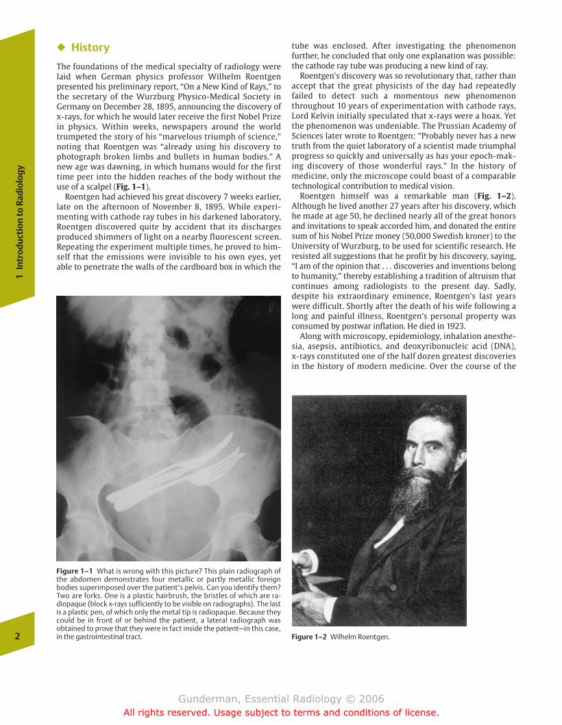
The foundations of the medical specialty of radiology werelaid when German physics professor Wilhelm Roentgen presented his preliminary report, “On a New Kind of Rays,” tothe secretary of the Wurzburg Physico-Medical Society inGermany on December 28, 1895, announcing the discovery ofx-rays, for which he would later receive the first Nobel Prizein physics. Within weeks, newspapers around the worldtrumpeted the story of his “marvelous triumph of science,”noting that Roentgen was “already using his discovery tophotograph broken limbs and bullets in human bodies.” Anew age was dawning, in which humans would for the firsttime peer into the hidden reaches of the body without theuse of a scalpel (Fig. 1–1).
Roentgen had achieved his great discovery 7 weeks earlier,late on the afternoon of November 8, 1895. While experi-menting with cathode ray tubes in his darkened laboratory,Roentgen discovered quite by accident that its dischargesproduced shimmers of light on a nearby fluorescent screen.Repeating the experiment multiple times, he proved to him-self that the emissions were invisible to his own eyes, yetable to penetrate the walls of the cardboard box in which the
tube was enclosed. After investigating the phenomenon further, he concluded that only one explanation was possible:the cathode ray tube was producing a new kind of ray.
Roentgen’s discovery was so revolutionary that, rather thanaccept that the great physicists of the day had repeatedlyfailed to detect such a momentous new phenomenonthroughout 10 years of experimentation with cathode rays,Lord Kelvin initially speculated that x-rays were a hoax. Yetthe phenomenon was undeniable. The Prussian Academy ofSciences later wrote to Roentgen: “Probably never has a newtruth from the quiet laboratory of a scientist made triumphalprogress so quickly and universally as has your epoch-mak-ing discovery of those wonderful rays.” In the history of medicine, only the microscope could boast of a comparabletechnological contribution to medical vision.
Roentgen himself was a remarkable man (Fig. 1–2). Although he lived another 27 years after his discovery, whichhe made at age 50, he declined nearly all of the great honorsand invitations to speak accorded him, and donated the entiresum of his Nobel Prize money (50,000 Swedish kroner) to theUniversity of Wurzburg, to be used for scientific research. Heresisted all suggestions that he profit by his discovery, saying,“I am of the opinion that . . . discoveries and inventions belongto humanity,” thereby establishing a tradition of altruism thatcontinues among radiologists to the present day. Sadly, despite his extraordinary eminence, Roentgen’s last yearswere difficult. Shortly after the death of his wife following along and painful illness, Roentgen’s personal property wasconsumed by postwar inflation. He died in 1923.
Along with microscopy, epidemiology, inhalation anesthe-sia, asepsis, antibiotics, and deoxyribonucleic acid (DNA), x-rays constituted one of the half dozen greatest discoveriesin the history of modern medicine. Over the course of the
2
1In
trod
ucti
on to
Rad
iolo
gy
Figure 1–1 What is wrong with this picture? This plain radiograph ofthe abdomen demonstrates four metallic or partly metallic foreign bodies superimposed over the patient’s pelvis. Can you identify them?Two are forks. One is a plastic hairbrush, the bristles of which are ra-diopaque (block x-rays sufficiently to be visible on radiographs). The lastis a plastic pen, of which only the metal tip is radiopaque. Because theycould be in front of or behind the patient, a lateral radiograph was obtained to prove that they were in fact inside the patient—in this case,in the gastrointestinal tract. Figure 1–2 Wilhelm Roentgen.
chapter 01_p1-38.qxd 12/1/05 3:18 PM Page 2
Gunderman, Essential Radiology © 2006All rights reserved. Usage subject to terms and conditions of license.

20th century, the medical specialty of radiology was born,and to Roentgen’s plain x-ray were added other modalitiessuch as fluoroscopy, contrast studies of the gastrointestinal(GI) tract and blood vessels, nuclear medicine, ultrasound,computed tomography, and magnetic resonance imaging. Because the discovery of x-rays was the work of a physicist, itis fitting that a discussion of medical imaging should beginwith a discussion of imaging physics.
� Visual Characteristics of Images
Contrast and Detail
From a physical point of view, an image exhibits two crucialcharacteristics, contrast and detail. The level of contrast between a structure and its background must be at least sev-eral percent if it is to be detected by the human eye. Through image postprocessing, rendered possible by computed radi-ography and digital radiography, it is often possible to adjustand optimize the level of contrast in an image and to performsuch manipulations as edge enhancement. The maximum detail detectable by the unaided human eye is �10 line pairsper millimeter. Each radiologic modality has a characteristicrange of detail or spatial resolution. In decreasing order, theyare plain radiography, fluoroscopy, computed tomography(CT), magnetic resonance imaging (MRI), ultrasound, and nuclear medicine (Fig. 1–3). Under ideal conditions, the de-
tail captured by plain radiography is so high that magnifica-tion enhances detail, as in the detection of microcalcificationsin mammography.
Noise
The term noise refers to a variety of factors that detract fromthe information contained in an image. Some amount ofnoise is inherent in every modality, but additional noise maybe added by the techniques used to generate or view the image. For example, ambient light in the viewing room decreases the signal-to-noise ratio; when the overhead lightsin the viewing room are turned on, many of the photonsstriking the observer’s retina no longer carry diagnostic infor-mation. In contrast, when the overhead lights are dimmedand the only source of light is a computer monitor or theviewbox on which a film is mounted, the signal-to-noise ratiois maximized. Radiologists work in darkened rooms not be-cause they fear the sun, but because they are attempting to maximize the signal-to-noise ratio.
� Three Modes of Image Production
There are three basic means by which radiologic images areproduced: transmission of energy, reflection of energy, andemission of energy.
Thre
e M
od
es o
f Im
age
Pro
du
ctio
n
3
Figure 1–3 (A) This child presented with unexplained hematochezia—blood in the stool. An image from a nuclear medicine technetium (Tc)99m pertechnetate scan demonstrates an abnormal focus of radiotraceruptake in the midabdomen, representing a Meckel’s diverticulum. Theanatomic detail and spatial resolution of this study are relatively poor,
but its functional imaging capability reveals a diagnosis that had eludedendoscopists, who cannot visualize much of the small bowel. The radio-tracer is taken up by gastric mucosa, which is often found in Meckel’sdiverticula. (B) A plain abdominal radiograph, by contrast, providesmuch better spatial resolution but does not reveal the diagnosis.
A B
chapter 01_p1-38.qxd 12/1/05 3:18 PM Page 3
Gunderman, Essential Radiology © 2006All rights reserved. Usage subject to terms and conditions of license.
Transmission Imaging
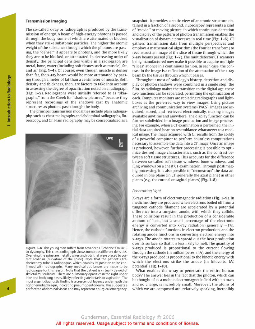
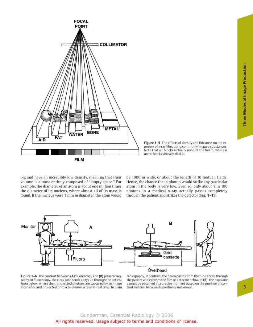
The so-called x-ray or radiograph is produced by the trans-mission of energy. A beam of high-energy photons is passedthrough the body, some of which are attenuated or blockedwhen they strike subatomic particles. The higher the atomicweight of the substance through which the photons are pass-ing, the “denser” it appears to photons, and the more likelythey are to be blocked, or attenuated. In decreasing order ofdensity, the principal densities visible in a radiograph aremetal, bone, water (including soft tissues such as muscle), fat,and air (Fig. 1–4). Of course, even though muscle is denserthan fat, the x-ray beam would be more attenuated by pass-ing through a meter of fat than a centimeter of muscle. Bothdensity and thickness, then, are factors to take into accountin assessing the degree of opacification noted on a radiograph(Fig. 1–5). Radiographs were initially referred to as “skia-graphs,” from the Greek for “shadow pictures,” because theyrepresent recordings of the shadows cast by anatomic structures as photons pass through the body.
The principal transmission modalities include plain radiogra-phy, such as chest radiographs and abdominal radiographs, flu-oroscopy, and CT. Plain radiography may be conceptualized as a
snapshot: it provides a static view of anatomic structure ob-tained in a fraction of a second. Fluoroscopy represents a kindof “movie,” or moving picture, in which continuous detectionand display of the pattern of photon transmission enables thevisualization of dynamic processes in real time (Fig. 1–6). CTgathers transmission data from multiple perspectives andemploys a mathematical algorithm (the Fourier transform) toreconstruct an image of the slice of tissue through which the x-ray beams passed (Fig. 1–7). The multidetector CT scannersbeing manufactured now make it possible to acquire multiple“slices” at once in a continuous fashion. In each case, the con-trast in the image is a reflection of the attenuation of the x-raybeam by the tissues through which it passes.
Throughout most of radiology’s history, detection and dis-play of photon shadows were combined in a single step: thefilm. As radiology makes the transition to the digital age, thesetwo functions can be separated, permitting the optimization ofeach. Computer monitors are replacing radiographs and light-boxes as the preferred way to view images. Using picturearchiving and communication systems (PACS), images are ac-quired, stored, and retrieved electronically, making imagesavailable anytime and anywhere. The display function can befurther subdivided into image production and image process-ing. For example, when a CT examination is performed, the ini-tial data acquired bear no resemblance whatsoever to a med-ical image. The image acquired with CT results from the abilityof a powerful computer to perform countless computationsnecessary to assemble the data into a CT image. Once an imageis produced, however, further processing is possible to opti-mize desired image characteristics, such as the contrast be-tween soft tissue structures. This accounts for the differencebetween so-called soft tissue windows, bone windows, andlung windows on a chest CT examination. Through postimag-ing processing, it is also possible to “reconstruct” the data ac-quired in one plane (in CT, generally the axial plane) in otherplanes (e.g., the coronal or sagittal planes) (Fig. 1–8).
Penetrating Light
X-rays are a form of electromagnetic radiation (Fig. 1–9). Inmedicine, they are produced when electrons boiled off from atungsten cathode filament are accelerated by a potential difference into a tungsten anode, with which they collide.These collisions result in the production of a considerableamount of heat, but a small percentage of the electronic energy is converted into x-ray radiation (generally �1%).Hence, the cathode functions in electron production, and therotating anode functions in converting electron energy into x-rays. The anode rotates to spread out the heat productionover its surface, so that it is less likely to melt. The quantity ofx-rays produced is proportional to the current flowingthrough the cathode (in milliamperes, mA), and the energy ofthe x-rays produced is proportional to the kinetic energy withwhich the electrons strike the anode (in kilovolts, kV, potential) (Fig. 1–10).
What enables the x-ray to penetrate the entire humanbody? The answer lies in the fact that the photon, which canbe thought of as a mobile electromagnetic field with no massand no charge, is incredibly small. Moreover, the atoms ofwhich we are composed are, relatively speaking, incredibly4
1In
trod
ucti
on to
Rad
iolo
gy
Figure 1–4 This young man suffers from advanced Duchenne’s muscu-lar dystrophy. This chest radiograph shows numerous different densities.Overlying the spine are metallic wires and rods that were placed to cor-rect scoliosis (curvature of the spine). Note that the patient’s tra-cheostomy tube is radiopaque, which enables its position to be con-firmed with radiographs. Many medical appliances are made to beradiopaque for this reason. Note that the patient is virtually devoid ofskeletal musculature. There are pulmonary opacities in the right upperlobe and both lung bases, likely reflecting atelectasis or aspiration. Themost urgent diagnostic finding is a crescent of lucency underneath theright hemidiaphragm, indicating pneumoperitoneum. This suggests aperforated abdominal viscus and may represent a surgical emergency.
chapter 01_p1-38.qxd 12/1/05 3:18 PM Page 4
Gunderman, Essential Radiology © 2006All rights reserved. Usage subject to terms and conditions of license.
Thre
e M
od
es o
f Im
age
Pro
du
ctio
n
5
Figure 1–5 The effects of density and thickness on the ex-posure of x-ray film, using commonly imaged substances.Note that air blocks virtually none of the beam, whereasmetal blocks virtually all of it.
Figure 1–6 The contrast between (A) fluoroscopy and (B) plain radiog-raphy. In fluoroscopy, the x-ray tube sends x-rays up through the patientfrom below, where the transmitted photons are captured by an imageintensifier and projected onto a television screen in real time. In plain
radiography, in contrast, the beam passes from the tube above throughthe patient and exposes the film or detector below. In (B), the exposurecannot be obtained at a precise moment based on the position of con-trast material because its position is not known.
big and have an incredibly low density, meaning that theirvolume is almost entirely composed of “empty space.” Forexample, the diameter of an atom is about one million timesthe diameter of its nucleus, where almost all of its mass isfound. If the nucleus were 1 mm in diameter, the atom would
be 1000 m wide, or about the length of 10 football fields.Hence, the chance that a photon would strike any particularatom in the body is very low. Even so, only about 1 in 100photons in a medical x-ray actually passes completelythrough the patient and strikes the detector (Fig. 1–11).
chapter 01_p1-38.qxd 12/1/05 3:19 PM Page 5
Gunderman, Essential Radiology © 2006All rights reserved. Usage subject to terms and conditions of license.
6
1In
trod
ucti
on to
Rad
iolo
gy
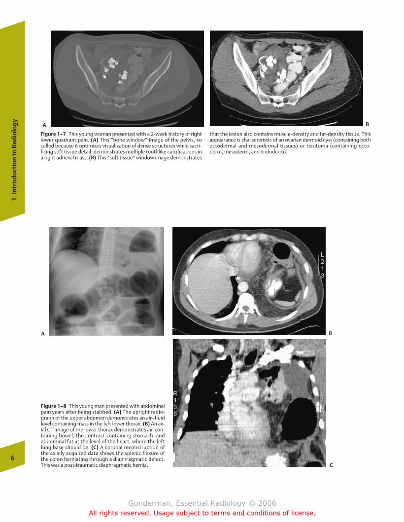
Figure 1–7 This young woman presented with a 2-week history of rightlower quadrant pain. (A) This “bone window” image of the pelvis, socalled because it optimizes visualization of dense structures while sacri-ficing soft tissue detail, demonstrates multiple toothlike calcifications ina right adnexal mass. (B) This “soft tissue” window image demonstrates
that the lesion also contains muscle-density and fat-density tissue. Thisappearance is characteristic of an ovarian dermoid cyst (containing bothectodermal and mesodermal tissues) or teratoma (containing ecto-derm, mesoderm, and endoderm).
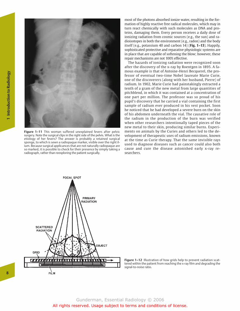
Figure 1–8 This young man presented with abdominalpain years after being stabbed. (A) The upright radio-graph of the upper abdomen demonstrates an air–fluidlevel containing mass in the left lower thorax. (B) An ax-ial CT image of the lower thorax demonstrates air-con-taining bowel, the contrast-containing stomach, andabdominal fat at the level of the heart, where the leftlung base should be. (C) A coronal reconstruction ofthe axially acquired data shows the splenic flexure ofthe colon herniating through a diaphragmatic defect.This was a post-traumatic diaphragmatic hernia.
A B
A B
C
chapter 01_p1-38.qxd 12/1/05 3:19 PM Page 6
Gunderman, Essential Radiology © 2006All rights reserved. Usage subject to terms and conditions of license.

As photons pass through the patient, they may be scattered. In the case of a scattered photon, the place on the detector that is exposed does not correspond to the locationof an anatomic structure in the patient. Hence scattered photons degrade the signal-to-noise ratio. Grids are com-monly employed to screen out scattered photons, whichemerge at an angle, although at the cost of some increase inpatient radiation exposure (Fig. 1–12).
Hazards of Ionizing Radiation
Each of the transmission imaging modalities utilizes x-rays, andtherefore subjects the patient to ionizing radiation. Ionizing ra-diation refers to electromagnetic emissions of sufficient energythat, when they strike molecules in the human body such ashydrocarbons, they may disrupt their structure. They do so bycolliding with atoms and causing the removal of one of theirelectrons, which causes the atom to become positively chargedand highly reactive. Because most of the human body is water,
Thre
e M
od
es o
f Im
age
Pro
du
ctio
n
7
Figure 1–9 The position of x-rays within the electromagnetic spectrumthat includes visible light. Note that ultrasound does not appear on thisspectrum, because it is not a form of electromagnetic radiation.
Figure 1–10 X-ray tube. (A) Rotating anode. (B) Rotor. (C) Cathode fila-ment. “Boiled off” electrons (e) are accelerated in a vacuum and collidewith the anode, producing x-rays.
chapter 01_p1-38.qxd 12/1/05 3:19 PM Page 7
Gunderman, Essential Radiology © 2006All rights reserved. Usage subject to terms and conditions of license.
most of the photons absorbed ionize water, resulting in the for-mation of highly reactive free radical molecules, which may inturn react chemically with such molecules as DNA and pro-teins, damaging them. Every person receives a daily dose ofionizing radiation from cosmic sources (e.g., the sun) and ra-dioisotopes in both the environment (e.g., radon) and the bodyitself (e.g., potassium 40 and carbon 14) (Fig. 1–13). Happily,sophisticated protective and reparative physiologic systems arein place that are capable of softening the blow; however, theserepair mechanisms are not 100% effective.
The hazards of ionizing radiation were recognized soonafter the discovery of the x-ray by Roentgen in 1895. A fa-mous example is that of Antoine-Henri Becquerel, the pro-fessor of eventual two-time Nobel laureate Marie Curie,one of the discoverers (along with her husband, Pierre) ofradium. In 1902, Marie Curie had painstakingly extracted atenth of a gram of the new metal from large quantities ofpitchblend, in which it was contained at a concentration ofone part per million. The professor was so proud of hispupil’s discovery that he carried a vial containing the firstsample of radium ever produced in his vest pocket. Soonhe noticed that he had developed a severe burn on the skinof his abdomen underneath the vial. The causative role ofthe radium in the production of the burn was verifiedwhen other researchers intentionally taped pieces of thenew metal to their skin, producing similar burns. Experi-ments on animals by the Curies and others led to the de-velopment of therapeutic uses of radium emissions, knownat the time as Curie therapy. That the same invisible raysused to diagnose diseases such as cancer could also bothcause and cure the disease astonished early x-ray re-searchers.
8
1In
trod
ucti
on to
Rad
iolo
gy
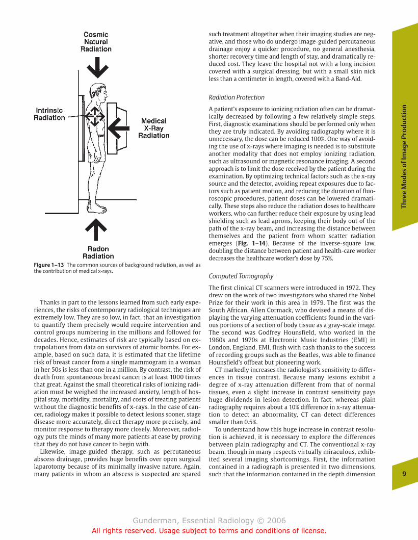
Figure 1–11 This woman suffered unexplained fevers after pelvicsurgery. Note the surgical clips in the right side of the pelvis. What is theetiology of her fevers? The answer is probably a retained surgicalsponge, to which is sewn a radiopaque marker, visible over the right il-ium. Because surgical applicances that are not naturally radiopaque areso marked, it is possible to check for their presence by simply taking aradiograph, rather than reexploring the patient surgically.
Figure 1–12 Illustration of how grids help to prevent radiation scat-tered within the patient from reaching the x-ray film and degrading thesignal-to-noise ratio.
chapter 01_p1-38.qxd 12/1/05 3:19 PM Page 8
Gunderman, Essential Radiology © 2006All rights reserved. Usage subject to terms and conditions of license.
Thanks in part to the lessons learned from such early expe-riences, the risks of contemporary radiological techniques areextremely low. They are so low, in fact, that an investigationto quantify them precisely would require intervention andcontrol groups numbering in the millions and followed fordecades. Hence, estimates of risk are typically based on ex-trapolations from data on survivors of atomic bombs. For ex-ample, based on such data, it is estimated that the lifetimerisk of breast cancer from a single mammogram in a womanin her 50s is less than one in a million. By contrast, the risk ofdeath from spontaneous breast cancer is at least 1000 timesthat great. Against the small theoretical risks of ionizing radi-ation must be weighed the increased anxiety, length of hos-pital stay, morbidity, mortality, and costs of treating patientswithout the diagnostic benefits of x-rays. In the case of can-cer, radiology makes it possible to detect lesions sooner, stagedisease more accurately, direct therapy more precisely, andmonitor response to therapy more closely. Moreover, radiol-ogy puts the minds of many more patients at ease by provingthat they do not have cancer to begin with.
Likewise, image-guided therapy, such as percutaneous abscess drainage, provides huge benefits over open surgical laparotomy because of its minimally invasive nature. Again,many patients in whom an abscess is suspected are spared
such treatment altogether when their imaging studies are neg-ative, and those who do undergo image-guided percutaneousdrainage enjoy a quicker procedure, no general anesthesia,shorter recovery time and length of stay, and dramatically re-duced cost. They leave the hospital not with a long incisioncovered with a surgical dressing, but with a small skin nickless than a centimeter in length, covered with a Band-Aid.
Radiation Protection
A patient’s exposure to ionizing radiation often can be dramat-ically decreased by following a few relatively simple steps.First, diagnostic examinations should be performed only whenthey are truly indicated. By avoiding radiography where it isunnecessary, the dose can be reduced 100%. One way of avoid-ing the use of x-rays where imaging is needed is to substituteanother modality that does not employ ionizing radiation,such as ultrasound or magnetic resonance imaging. A secondapproach is to limit the dose received by the patient during theexamination. By optimizing technical factors such as the x-raysource and the detector, avoiding repeat exposures due to fac-tors such as patient motion, and reducing the duration of fluo-roscopic procedures, patient doses can be lowered dramati-cally. These steps also reduce the radiation doses to healthcareworkers, who can further reduce their exposure by using leadshielding such as lead aprons, keeping their body out of thepath of the x-ray beam, and increasing the distance betweenthemselves and the patient from whom scatter radiationemerges (Fig. 1–14). Because of the inverse-square law,doubling the distance between patient and health-care workerdecreases the healthcare worker’s dose by 75%.
Computed Tomography
The first clinical CT scanners were introduced in 1972. Theydrew on the work of two investigators who shared the NobelPrize for their work in this area in 1979. The first was theSouth African, Allen Cormack, who devised a means of dis-playing the varying attenuation coefficients found in the vari-ous portions of a section of body tissue as a gray-scale image.The second was Godfrey Hounsfield, who worked in the1960s and 1970s at Electronic Music Industries (EMI) in London, England. EMI, flush with cash thanks to the successof recording groups such as the Beatles, was able to financeHounsfield’s offbeat but pioneering work.
CT markedly increases the radiologist’s sensitivity to differ-ences in tissue contrast. Because many lesions exhibit a degree of x-ray attenuation different from that of normal tissues, even a slight increase in contrast sensitivity payshuge dividends in lesion detection. In fact, whereas plain radiography requires about a 10% difference in x-ray attenua-tion to detect an abnormality, CT can detect differencessmaller than 0.5%.
To understand how this huge increase in contrast resolu-tion is achieved, it is necessary to explore the differences between plain radiography and CT. The conventional x-raybeam, though in many respects virtually miraculous, exhib-ited several imaging shortcomings. First, the informationcontained in a radiograph is presented in two dimensions,such that the information contained in the depth dimension
Thre
e M
od
es o
f Im
age
Pro
du
ctio
n
9
Figure 1–13 The common sources of background radiation, as well asthe contribution of medical x-rays.
chapter 01_p1-38.qxd 12/1/05 3:19 PM Page 9
Gunderman, Essential Radiology © 2006All rights reserved. Usage subject to terms and conditions of license.
is superimposed. Obtaining a second radiograph in the or-thogonal (right-angled) projection only compensates for thisto a minor degree. Second, soft tissue resolution by conven-tional radiography is very poor. We can distinguish to somedegree between air, fat, water (or soft tissue), bone, iodi-nated contrast agents, and metal, but further differentiationis very difficult or impossible. Third, the conventional radi-ograph is unable to distinguish between the differing densi-ties of the tissues through which the beam has passed. Onceit passes through a very dense substance, conventional radi-ographs make the entire thickness through which a portionof the beam has passed appear quite dense, or white, regard-less of the density of the tissue on either side of the densestructure.
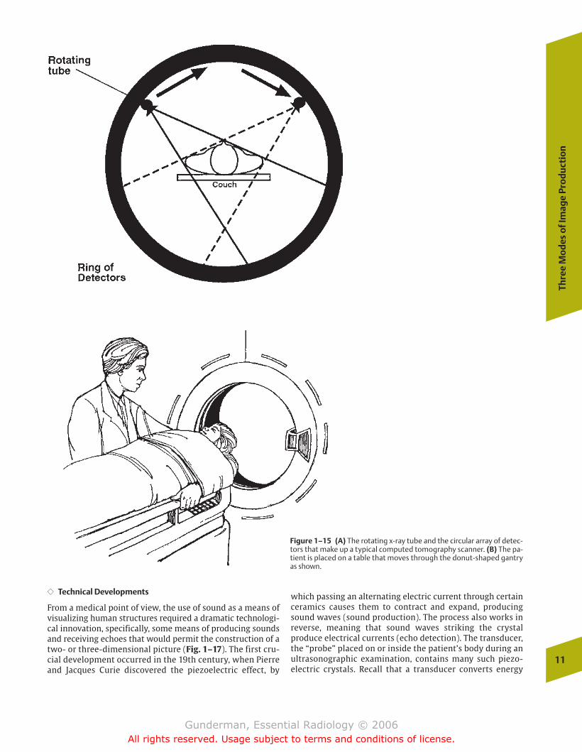
CT, on the other hand, is able to measure and display thevarying x-ray attenuations of the tissues in a section of thebody by passing x-rays through the section from many different angles. It then utilizes reconstruction algorithmsand the computational capacities of a computer to displaythe differing densities in a gray-scale image. In contemporaryCT scanners, a circular array of detectors around the patientacquires data as the x-ray tube rotates around the patient(Fig. 1–15). Sufficient data to image a single “slice” of thebody can be acquired in fractions of a second, and multiple“slices” can be obtained at once.
Hounsfield’s contributions are memorialized in the Hounsfieldscale, which is used to measure the x-ray attenuation valuesin CT scanning. Water is arbitrarily assigned a value of 0Hounsfield units (HU), air is –1000 HU, and dense corticalbone is 1000 HU. Also known as CT numbers, the respectiveattenuation values of many volume units within the patientare measured and used to construct the two-dimensionalimage. Measurements of attenuation values can also be usedto determine the density of a lesion. For example, a cysticstructure with a homogenous attenuation value of 0 HU rep-resents a simple water-filled cyst. A solid lesion with an at-tenuation value of –100 HU represents a fat-containing lesionsuch as a lipoma. In both cases, such lesions could be dis-missed as benign and would not require biopsy. Furthermore,we can optimize contrast in an area of interest by altering the
window width and window level settings at which the imagedata are displayed. Typically, the window level is set at 35 HUwhen examining the abdomen, above 100 when examiningbone, and at –700 when examining the air-filled lungs. Ineach case, a window width is then selected that optimizescontrast resolution of the type of structures being examined(Fig. 1–16).
Reflection Imaging
The radiologic modality that exemplifies reflection imaging isultrasound. As we shall see, ultrasound creates images notaccording to the density differences between various tissues,but by their acoustic differences. A very low-density struc-ture such as fat, which appears black on a radiograph, may bevery “echogenic” acoustically, and hence appear bright on asonogram.
Ultrasound
�� Auditory Diagnosis
The use of sound as a means of “visualization” far predatedthe evolution of the human species. Its most widely knownexample is the highly developed ultrasonic system of airborne navigation employed by bats, which enables them tomaneuver with precision even in the dark. The use of soundwaves as a medium of medical diagnosis extends at leastback to the time of the ancient Hippocratics, who recognizedthe importance of the sound of air and fluid sloshing about inthe thorax, which we today call the “succussion splash.” Themedical production of sound for diagnostic purposes beganin earnest when the 18th-century German physician LeopoldAuenbrugger, the son of a brewer, realized that the percus-sion used to assess the amount of beer remaining in barrelscould also be applied to patients, with various diseaseprocesses producing characteristic percussive findings (com-pare the tympanitic sound of a gas-distended abdomen to thedullness to percussion of the chest overlying consolidatedlung).
10
1In
trod
ucti
on to
Rad
iolo
gy
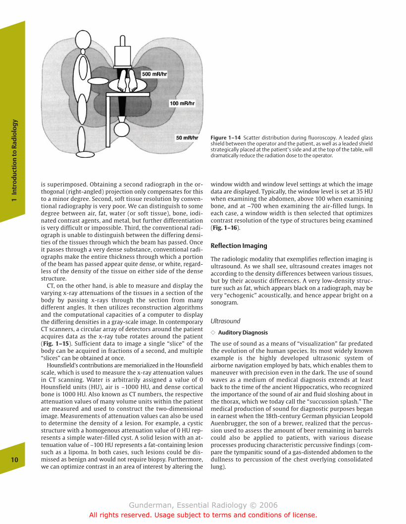
Figure 1–14 Scatter distribution during fluoroscopy. A leaded glassshield between the operator and the patient, as well as a leaded shieldstrategically placed at the patient’s side and at the top of the table, willdramatically reduce the radiation dose to the operator.
chapter 01_p1-38.qxd 12/1/05 3:19 PM Page 10
Gunderman, Essential Radiology © 2006All rights reserved. Usage subject to terms and conditions of license.
�� Technical Developments
From a medical point of view, the use of sound as a means ofvisualizing human structures required a dramatic technologi-cal innovation, specifically, some means of producing soundsand receiving echoes that would permit the construction of atwo- or three-dimensional picture (Fig. 1–17). The first cru-cial development occurred in the 19th century, when Pierreand Jacques Curie discovered the piezoelectric effect, by
which passing an alternating electric current through certainceramics causes them to contract and expand, producingsound waves (sound production). The process also works inreverse, meaning that sound waves striking the crystal produce electrical currents (echo detection). The transducer,the “probe” placed on or inside the patient’s body during an ultrasonographic examination, contains many such piezo-electric crystals. Recall that a transducer converts energy
Thre
e M
od
es o
f Im
age
Pro
du
ctio
n
11
Figure 1–15 (A) The rotating x-ray tube and the circular array of detec-tors that make up a typical computed tomography scanner. (B) The pa-tient is placed on a table that moves through the donut-shaped gantryas shown.
chapter 01_p1-38.qxd 12/1/05 3:19 PM Page 11
Gunderman, Essential Radiology © 2006All rights reserved. Usage subject to terms and conditions of license.
12
1In
trod
ucti
on to
Rad
iolo
gy
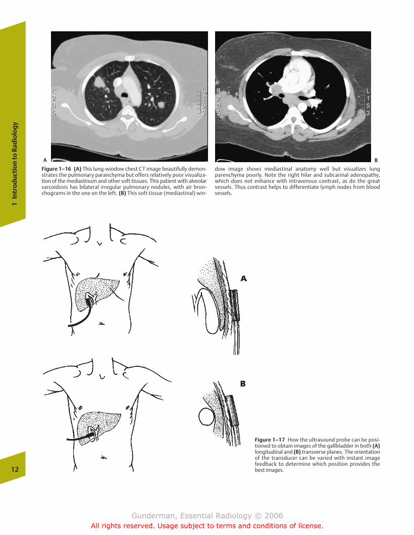
Figure 1–16 (A) This lung-window chest CT image beautifully demon-strates the pulmonary paranchyma but offers relatively poor visualiza-tion of the mediastinum and other soft tissues. This patient with alveolarsarcoidosis has bilateral irregular pulmonary nodules, with air bron-chograms in the one on the left. (B) This soft tissue (mediastinal) win-
dow image shows mediastinal anatomy well but visualizes lungparenchyma poorly. Note the right hilar and subcarinal adenopathy,which does not enhance with intravenous contrast, as do the great vessels. Thus contrast helps to differentiate lymph nodes from bloodvessels.
Figure 1–17 How the ultrasound probe can be posi-tioned to obtain images of the gallbladder in both (A)longitudinal and (B) transverse planes. The orientationof the transducer can be varied with instant imagefeedback to determine which position provides thebest images.
A B
chapter 01_p1-38.qxd 12/1/05 3:19 PM Page 12
Gunderman, Essential Radiology © 2006All rights reserved. Usage subject to terms and conditions of license.
from one form to another, just as the inner ear converts mechanical energy to electrical energy.
During World War II, naval powers made extensive use of ul-trasound, then known as SONAR (sound navigation and rang-ing), to track the movements of enemy submarines. Ultrasound is widely used today in industry, where echoeshelp to detect a variety of flaws in materials and construction.One of the best known examples occurs in the airline industry,where tiny, imperceptible cracks in the wings of an airplanecan be sonographically identified prior to catastrophic failure.
Although ultrasound now enjoys many medical applica-tions, its most common uses include the evaluation of thestructure and function of the heart via echocardiography, ob-stetrical ultrasound, and abdominal imaging (such as the detection of gallstones) (Fig. 1–18). The fact that it employsno ionizing radiation makes it especially good for imagingthe pelvis of a patient who is or might be pregnant.
�� Physics
Sound waves can be thought of as alternating bands of com-pression and rarefaction within the medium through whichthey are transmitted. A critical element in the preceding sen-tence is the fact that sound waves require a medium for theirtransmission; unlike visible light and x-rays, there is nosound in a vacuum. Because some media are denser than oth-ers, meaning that molecules are more tightly packed together, the speed of sound transmission varies by medium.Sound travels through air at a velocity of �330 m/s, whereas
sound in the soft tissues of the body travels at �1540 m/s.Hence the distance between the ultrasound transducer and a structure within tissue can be computed by multiplying 1540 m/s by the time it takes for the sound wave to return tothe transducer, then dividing by 2 (because the sound wavefirst travels out from and then back to the transducer).
�� Frequency
The frequency (often called pitch) of sound is measured inhertz (Hz) or cycles per second. The range of frequencies audible to the human ear extends from �20 to 20,000 Hz,with the greatest hearing acuity in the area of 4000 Hz, the approximate frequency of the human voice. Medical ultra-sonic frequencies, by contrast, are measured in millions ofhertz, or megahertz (MHz), and most equipment uses frequencies in the range of 2 to 15 MHz. The higher the frequency, the shorter the wavelength and the higher the energy of the sound.
�� Attenuation
Fortunately, the sound beam is not transmitted with 100% efficiency through tissues. Factors that cause the beam to be attenuated include reflection, scattering, and absorption. Inimaging, reflection is the critical factor, because it allows usto create images by collecting the echoes that return to thetransducer. The reflections themselves result from differ-ences in acoustic impedance between tissues (Fig. 1–19). Insome cases, the difference in acoustic impedance betweentwo tissues is so great that the entire ultrasound beam is re-flected from their interface, rendering it impossible to imagestructures. Examples of such interfaces include the interfacebetween the chest wall and the lung (air) and the interfacebetween muscle and bone cortex. This explains why ultrasound cannot be used to image aerated lung and bone.In contrast, the difference in acoustic impedance between
Thre
e M
od
es o
f Im
age
Pro
du
ctio
n
13
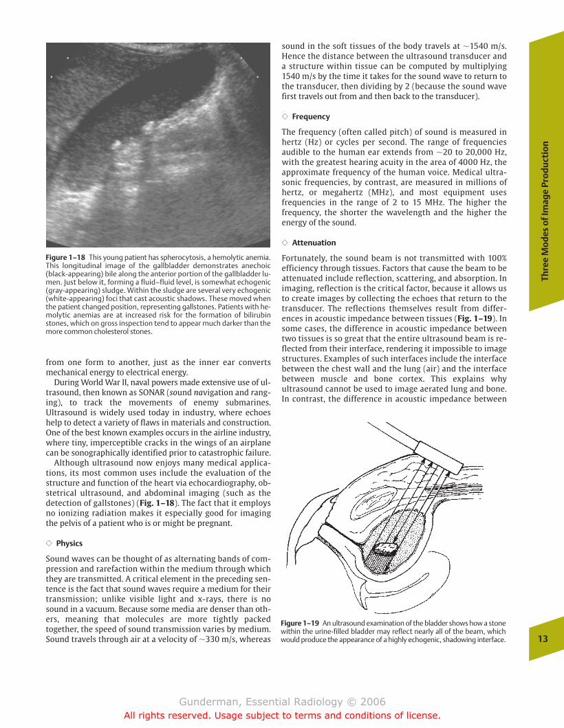
Figure 1–18 This young patient has spherocytosis, a hemolytic anemia.This longitudinal image of the gallbladder demonstrates anechoic(black-appearing) bile along the anterior portion of the gallbladder lu-men. Just below it, forming a fluid–fluid level, is somewhat echogenic(gray-appearing) sludge. Within the sludge are several very echogenic(white-appearing) foci that cast acoustic shadows. These moved whenthe patient changed position, representing gallstones. Patients with he-molytic anemias are at increased risk for the formation of bilirubinstones, which on gross inspection tend to appear much darker than themore common cholesterol stones.
Figure 1–19 An ultrasound examination of the bladder shows how a stonewithin the urine-filled bladder may reflect nearly all of the beam, whichwould produce the appearance of a highly echogenic, shadowing interface.
chapter 01_p1-38.qxd 12/1/05 3:19 PM Page 13
Gunderman, Essential Radiology © 2006All rights reserved. Usage subject to terms and conditions of license.
most soft tissue structures is very small, causing only �1% ofthe beam to be reflected (which causes enough echoes toform an image), but allowing most of the beam to be trans-mitted to deeper structures, where additional echoes canproduce an image of structures 10 to 20 cm deep, or evendeeper. The tiny differences in acoustic impedance within theparenchyma of organs such as the kidney or liver are re-sponsible for its gray-scale echotexture, or characteristicparenchymal appearance (Fig. 1–20).
�� Frequency and Attenuation
The frequency of sound used affects both the resolution andpenetrating power of the beam. The higher the frequency, thebetter the resolution, meaning that finer details in the struc-ture being inspected can be imaged. Higher frequency alsoentails less penetration power, meaning that only superficialstructures can be imaged. These principles are exemplified inthe selection of ultrasound transducers. Clinically, this meansthat when imaging superficial structures such as the carotidarteries or the testes, a high-frequency transducer should beused, in the range of 10 MHz or even higher. When imagingdeep structures such as the liver or the kidneys, especially inlarge patients, lower frequency transducers must be used,such as 3 or 5 MHz.
�� Imaging
As we have seen, the critical scientific breakthrough thatmade the development of clinical ultrasound instrumentspossible was the discovery of the piezoelectric crystal, whichcan be made to vibrate by an electric current and will
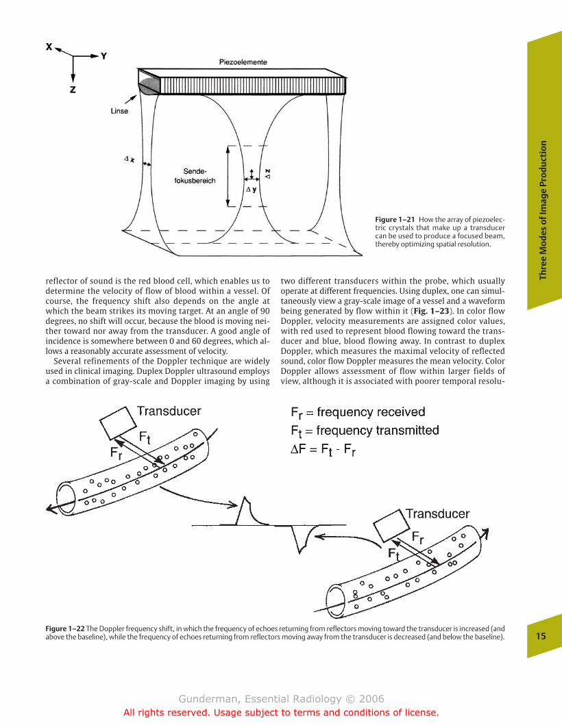
generate an electric current in response to mechanical vibra-tions to which it is subjected. By first passing a currentthrough the crystal, we can send out sound waves into tissue,and then by turning off the current and allowing the crystalto receive echoes generated by the tissues, thereby generat-ing electrical impulses, we can create a “picture” of the tis-sues. Most contemporary scanners are composed of arrays of64 to 200 transducers, which create an equal number of sep-arate beam components that can be used to focus and steerthe beam as a whole (Fig. 1–21). In real-time ultrasound, thepiezoelectric crystals can be alternated back and forth between the transmit and receive modes with sufficient fre-quency to generate 10 to 15 images per second, enabling almost instant feedback as the examiner adjusts the directionand other characteristics of the beam.
�� Doppler Ultrasound
The so-called Doppler effect, named after Johann Doppler,the Austrian physicist who described it, refers to the changein frequency of sound waves as their source moves toward oraway from the observer. Doppler ultrasound exploits the factthat the frequency of a reflected sound wave is affected bythe velocity of the object generating the echo, producing afrequency shift (Fig. 1–22). An object moving toward thetransducer will cause an increase in the frequency of the reflected sound, whereas an object moving away from thetransducer will produce a decrease in the received frequency.This is familiar to anyone who has ever stood at an intersec-tion as a train whistles past; just as the train passes by, thepitch of its whistle drops, due to the Doppler effect. In vascular Doppler imaging, the most important moving 14
1In
trod
ucti
on to
Rad
iolo
gy
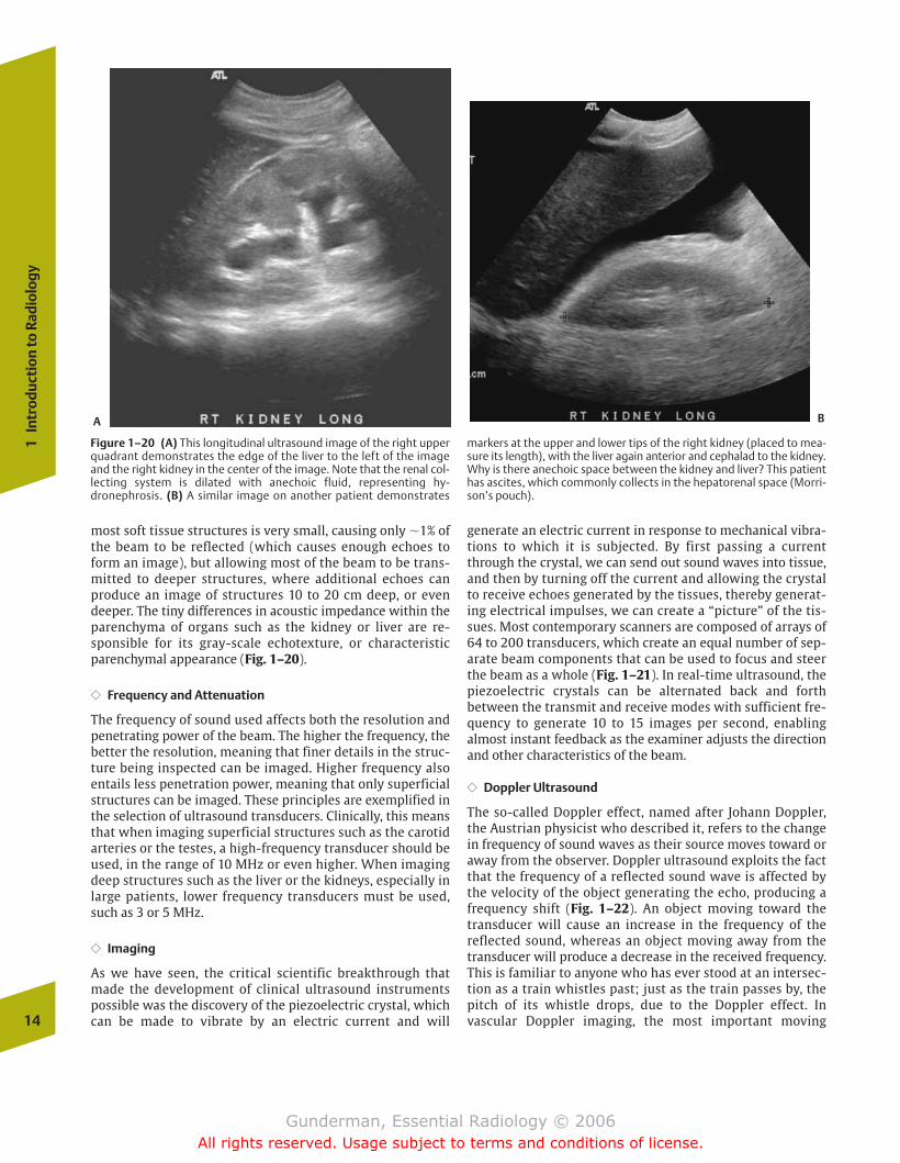
Figure 1–20 (A) This longitudinal ultrasound image of the right upperquadrant demonstrates the edge of the liver to the left of the imageand the right kidney in the center of the image. Note that the renal col-lecting system is dilated with anechoic fluid, representing hy-dronephrosis. (B) A similar image on another patient demonstrates
markers at the upper and lower tips of the right kidney (placed to mea-sure its length), with the liver again anterior and cephalad to the kidney.Why is there anechoic space between the kidney and liver? This patienthas ascites, which commonly collects in the hepatorenal space (Morri-son’s pouch).
A B
chapter 01_p1-38.qxd 12/1/05 3:19 PM Page 14
Gunderman, Essential Radiology © 2006All rights reserved. Usage subject to terms and conditions of license.
Thre
e M
od
es o
f Im
age
Pro
du
ctio
n
15
Figure 1–21 How the array of piezoelec-tric crystals that make up a transducercan be used to produce a focused beam,thereby optimizing spatial resolution.
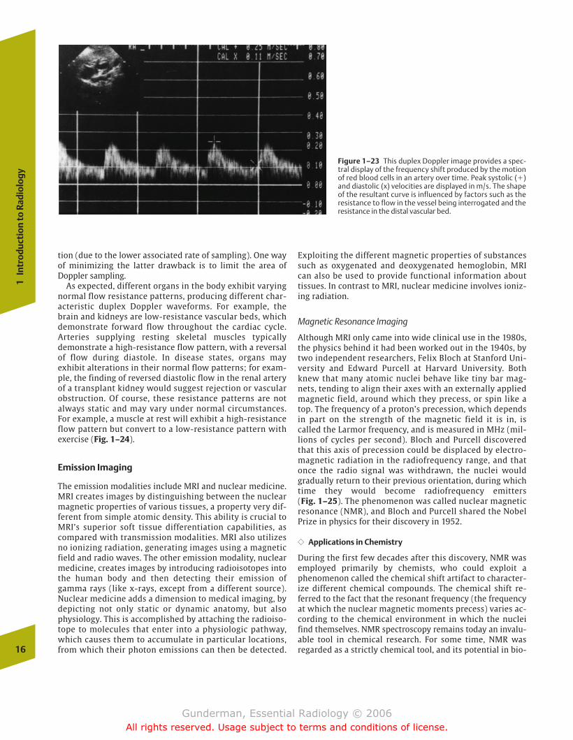
Figure 1–22 The Doppler frequency shift, in which the frequency of echoes returning from reflectors moving toward the transducer is increased (andabove the baseline), while the frequency of echoes returning from reflectors moving away from the transducer is decreased (and below the baseline).
reflector of sound is the red blood cell, which enables us todetermine the velocity of flow of blood within a vessel. Ofcourse, the frequency shift also depends on the angle atwhich the beam strikes its moving target. At an angle of 90degrees, no shift will occur, because the blood is moving nei-ther toward nor away from the transducer. A good angle ofincidence is somewhere between 0 and 60 degrees, which al-lows a reasonably accurate assessment of velocity.
Several refinements of the Doppler technique are widelyused in clinical imaging. Duplex Doppler ultrasound employsa combination of gray-scale and Doppler imaging by using
two different transducers within the probe, which usuallyoperate at different frequencies. Using duplex, one can simul-taneously view a gray-scale image of a vessel and a waveformbeing generated by flow within it (Fig. 1–23). In color flowDoppler, velocity measurements are assigned color values,with red used to represent blood flowing toward the trans-ducer and blue, blood flowing away. In contrast to duplexDoppler, which measures the maximal velocity of reflectedsound, color flow Doppler measures the mean velocity. ColorDoppler allows assessment of flow within larger fields ofview, although it is associated with poorer temporal resolu-
chapter 01_p1-38.qxd 12/1/05 3:19 PM Page 15
Gunderman, Essential Radiology © 2006All rights reserved. Usage subject to terms and conditions of license.
tion (due to the lower associated rate of sampling). One wayof minimizing the latter drawback is to limit the area ofDoppler sampling.
As expected, different organs in the body exhibit varyingnormal flow resistance patterns, producing different char-acteristic duplex Doppler waveforms. For example, thebrain and kidneys are low-resistance vascular beds, whichdemonstrate forward flow throughout the cardiac cycle. Arteries supplying resting skeletal muscles typicallydemonstrate a high-resistance flow pattern, with a reversalof flow during diastole. In disease states, organs may exhibit alterations in their normal flow patterns; for exam-ple, the finding of reversed diastolic flow in the renal arteryof a transplant kidney would suggest rejection or vascularobstruction. Of course, these resistance patterns are not always static and may vary under normal circumstances.For example, a muscle at rest will exhibit a high-resistanceflow pattern but convert to a low-resistance pattern withexercise (Fig. 1–24).
Emission Imaging
The emission modalities include MRI and nuclear medicine.MRI creates images by distinguishing between the nuclearmagnetic properties of various tissues, a property very dif-ferent from simple atomic density. This ability is crucial toMRI’s superior soft tissue differentiation capabilities, ascompared with transmission modalities. MRI also utilizesno ionizing radiation, generating images using a magneticfield and radio waves. The other emission modality, nuclearmedicine, creates images by introducing radioisotopes intothe human body and then detecting their emission ofgamma rays (like x-rays, except from a different source).Nuclear medicine adds a dimension to medical imaging, bydepicting not only static or dynamic anatomy, but alsophysiology. This is accomplished by attaching the radioiso-tope to molecules that enter into a physiologic pathway,which causes them to accumulate in particular locations,from which their photon emissions can then be detected.16
1In
trod
ucti
on to
Rad
iolo
gy
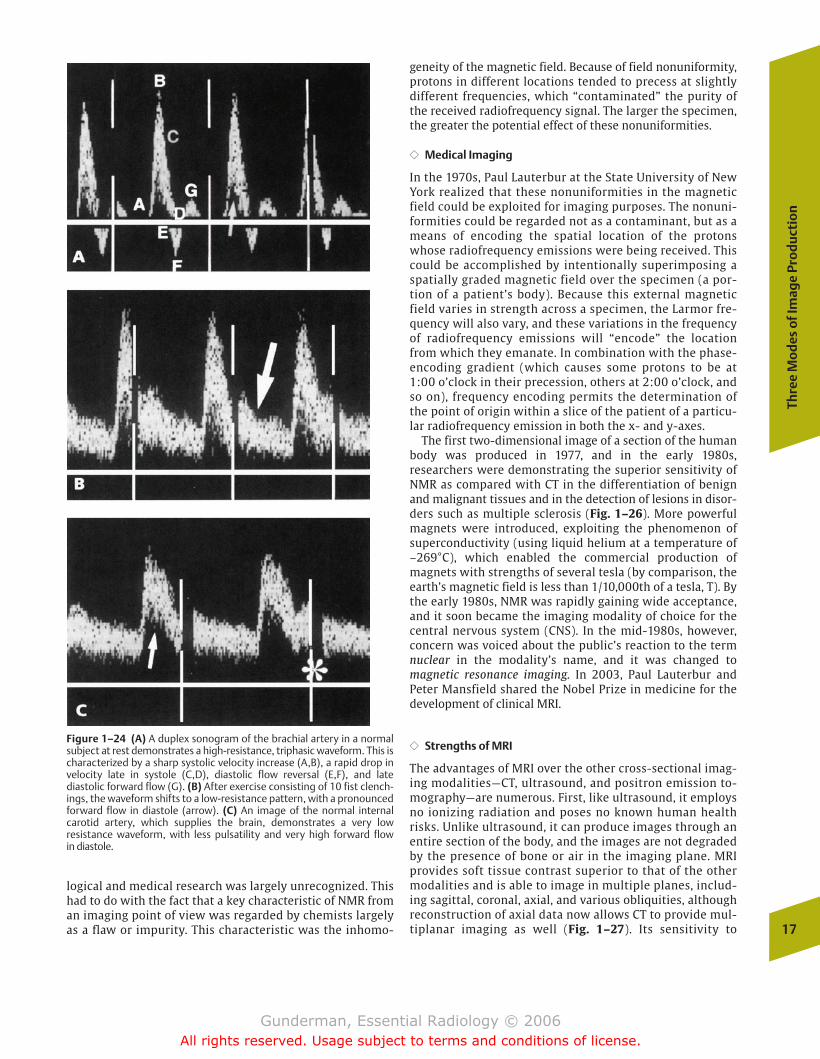
Figure 1–23 This duplex Doppler image provides a spec-tral display of the frequency shift produced by the motionof red blood cells in an artery over time. Peak systolic (�)and diastolic (x) velocities are displayed in m/s. The shapeof the resultant curve is influenced by factors such as theresistance to flow in the vessel being interrogated and theresistance in the distal vascular bed.
Exploiting the different magnetic properties of substancessuch as oxygenated and deoxygenated hemoglobin, MRIcan also be used to provide functional information abouttissues. In contrast to MRI, nuclear medicine involves ioniz-ing radiation.
Magnetic Resonance Imaging
Although MRI only came into wide clinical use in the 1980s,the physics behind it had been worked out in the 1940s, bytwo independent researchers, Felix Bloch at Stanford Uni-versity and Edward Purcell at Harvard University. Bothknew that many atomic nuclei behave like tiny bar mag-nets, tending to align their axes with an externally appliedmagnetic field, around which they precess, or spin like atop. The frequency of a proton’s precession, which dependsin part on the strength of the magnetic field it is in, iscalled the Larmor frequency, and is measured in MHz (mil-lions of cycles per second). Bloch and Purcell discoveredthat this axis of precession could be displaced by electro-magnetic radiation in the radiofrequency range, and thatonce the radio signal was withdrawn, the nuclei wouldgradually return to their previous orientation, during whichtime they would become radiofrequency emitters (Fig. 1–25). The phenomenon was called nuclear magneticresonance (NMR), and Bloch and Purcell shared the NobelPrize in physics for their discovery in 1952.
�� Applications in Chemistry
During the first few decades after this discovery, NMR wasemployed primarily by chemists, who could exploit a phenomenon called the chemical shift artifact to character-ize different chemical compounds. The chemical shift re-ferred to the fact that the resonant frequency (the frequencyat which the nuclear magnetic moments precess) varies ac-cording to the chemical environment in which the nucleifind themselves. NMR spectroscopy remains today an invalu-able tool in chemical research. For some time, NMR was regarded as a strictly chemical tool, and its potential in bio-
chapter 01_p1-38.qxd 12/1/05 3:19 PM Page 16
Gunderman, Essential Radiology © 2006All rights reserved. Usage subject to terms and conditions of license.
geneity of the magnetic field. Because of field nonuniformity,protons in different locations tended to precess at slightlydifferent frequencies, which “contaminated” the purity ofthe received radiofrequency signal. The larger the specimen,the greater the potential effect of these nonuniformities.
�� Medical Imaging
In the 1970s, Paul Lauterbur at the State University of NewYork realized that these nonuniformities in the magneticfield could be exploited for imaging purposes. The nonuni-formities could be regarded not as a contaminant, but as ameans of encoding the spatial location of the protonswhose radiofrequency emissions were being received. Thiscould be accomplished by intentionally superimposing aspatially graded magnetic field over the specimen (a por-tion of a patient’s body). Because this external magneticfield varies in strength across a specimen, the Larmor fre-quency will also vary, and these variations in the frequencyof radiofrequency emissions will “encode” the locationfrom which they emanate. In combination with the phase-encoding gradient (which causes some protons to be at1:00 o’clock in their precession, others at 2:00 o’clock, andso on), frequency encoding permits the determination ofthe point of origin within a slice of the patient of a particu-lar radiofrequency emission in both the x- and y-axes.
The first two-dimensional image of a section of the humanbody was produced in 1977, and in the early 1980s, researchers were demonstrating the superior sensitivity ofNMR as compared with CT in the differentiation of benignand malignant tissues and in the detection of lesions in disor-ders such as multiple sclerosis (Fig. 1–26). More powerfulmagnets were introduced, exploiting the phenomenon of superconductivity (using liquid helium at a temperature of–269°C), which enabled the commercial production of magnets with strengths of several tesla (by comparison, theearth’s magnetic field is less than 1/10,000th of a tesla, T). Bythe early 1980s, NMR was rapidly gaining wide acceptance,and it soon became the imaging modality of choice for thecentral nervous system (CNS). In the mid-1980s, however,concern was voiced about the public’s reaction to the termnuclear in the modality’s name, and it was changed to magnetic resonance imaging. In 2003, Paul Lauterbur and Peter Mansfield shared the Nobel Prize in medicine for thedevelopment of clinical MRI.
�� Strengths of MRI
The advantages of MRI over the other cross-sectional imag-ing modalities—CT, ultrasound, and positron emission to-mography—are numerous. First, like ultrasound, it employsno ionizing radiation and poses no known human healthrisks. Unlike ultrasound, it can produce images through anentire section of the body, and the images are not degradedby the presence of bone or air in the imaging plane. MRIprovides soft tissue contrast superior to that of the othermodalities and is able to image in multiple planes, includ-ing sagittal, coronal, axial, and various obliquities, althoughreconstruction of axial data now allows CT to provide mul-tiplanar imaging as well (Fig. 1–27). Its sensitivity to
Thre
e M
od
es o
f Im
age
Pro
du
ctio
n
17
Figure 1–24 (A) A duplex sonogram of the brachial artery in a normalsubject at rest demonstrates a high-resistance, triphasic waveform. This ischaracterized by a sharp systolic velocity increase (A,B), a rapid drop in velocity late in systole (C,D), diastolic flow reversal (E,F), and late diastolic forward flow (G). (B) After exercise consisting of 10 fist clench-ings, the waveform shifts to a low-resistance pattern, with a pronounced forward flow in diastole (arrow). (C) An image of the normal internalcarotid artery, which supplies the brain, demonstrates a very low resistance waveform, with less pulsatility and very high forward flow in diastole.
logical and medical research was largely unrecognized. Thishad to do with the fact that a key characteristic of NMR froman imaging point of view was regarded by chemists largelyas a flaw or impurity. This characteristic was the inhomo-
chapter 01_p1-38.qxd 12/1/05 3:19 PM Page 17
Gunderman, Essential Radiology © 2006All rights reserved. Usage subject to terms and conditions of license.

18
1In
trod
ucti
on to
Rad
iolo
gy
Figure 1–26 This young woman presented with blurry vision andleg weakness. (A) An axial head CT image demonstrates a smallarachnoid cyst in the posterior fossa but appears otherwise fairly un-remarkable. (B) In contrast, a T2-weighted MR image demonstrates
multiple bilateral foci of increased signal (bright) in the white mat-ter. The fact that the cerebrospinal fluid appears bright suggeststhat the image is T2-weighted. This patient suffers from multiplesclerosis.
A B
Figure 1–25 The basic principles behind MRI. (A)The magnetic moments of the protons are ran-domly oriented. (B) The protons have acquired anet magnetic moment due to their presence in thepowerful magnet of the MR scanner. (C) A radiofre-quency (RF) pulse has tipped the protons’ axis,around which they precess, or spin like a top. (D)The radio pulse emitter has been turned off, and theradiofrequency signals emitted by the protons asthey return to their state in (B) are measured andused to produce an image. N, north; S, south; D,detector.
motion enables the visualization of vascular structureswith or without the administration of contrast material.MRI spectroscopy provides important clinical benefitsthrough the in vivo characterization of chemical composi-tion and metabolic activity.
�� Weaknesses of MRI
MRI has certain weaknesses as well. As compared with theother imaging modalities, it is relatively expensive and notas widely available. Some patients cannot undergo MRI
chapter 01_p1-38.qxd 12/1/05 3:19 PM Page 18
Gunderman, Essential Radiology © 2006All rights reserved. Usage subject to terms and conditions of license.
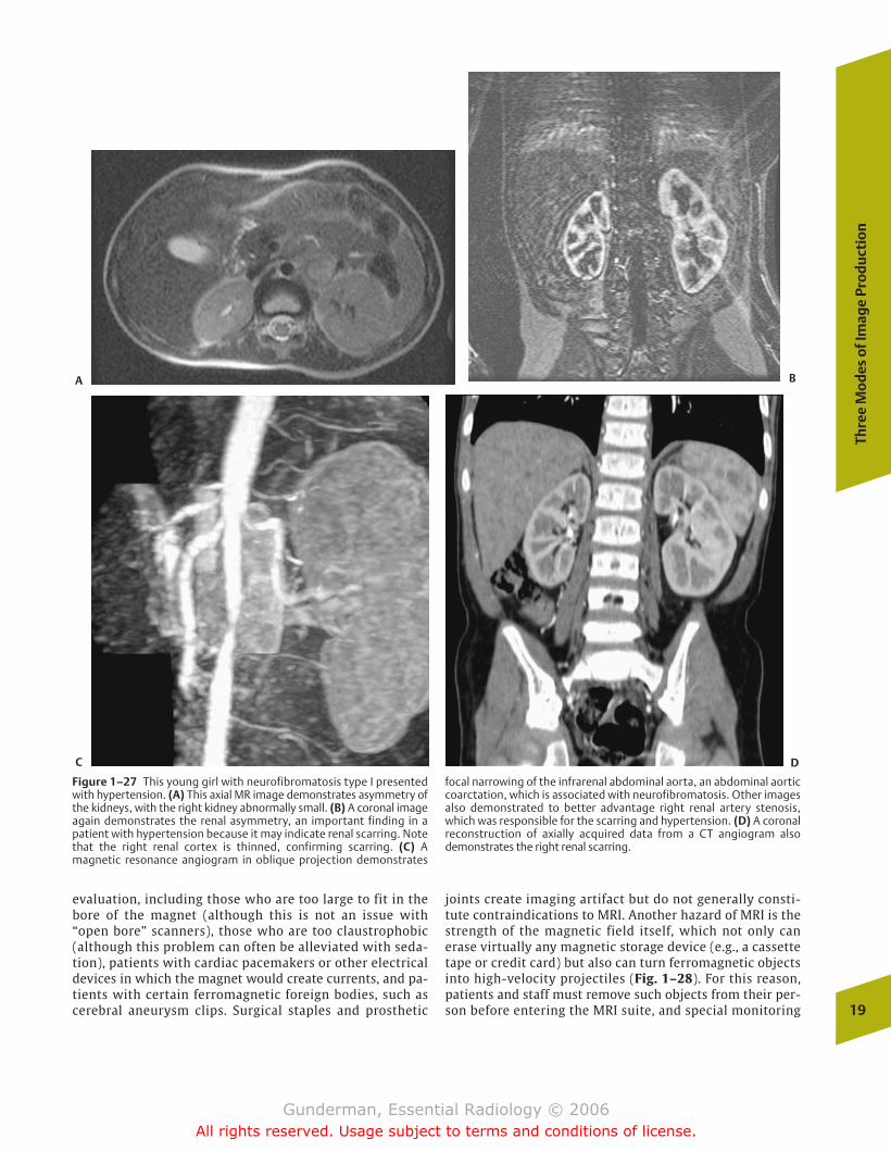
evaluation, including those who are too large to fit in thebore of the magnet (although this is not an issue with“open bore” scanners), those who are too claustrophobic(although this problem can often be alleviated with seda-tion), patients with cardiac pacemakers or other electricaldevices in which the magnet would create currents, and pa-tients with certain ferromagnetic foreign bodies, such ascerebral aneurysm clips. Surgical staples and prosthetic
joints create imaging artifact but do not generally consti-tute contraindications to MRI. Another hazard of MRI is thestrength of the magnetic field itself, which not only canerase virtually any magnetic storage device (e.g., a cassettetape or credit card) but also can turn ferromagnetic objectsinto high-velocity projectiles (Fig. 1–28). For this reason,patients and staff must remove such objects from their per-son before entering the MRI suite, and special monitoring
Thre
e M
od
es o
f Im
age
Pro
du
ctio
n
19
Figure 1–27 This young girl with neurofibromatosis type I presentedwith hypertension. (A) This axial MR image demonstrates asymmetry ofthe kidneys, with the right kidney abnormally small. (B) A coronal imageagain demonstrates the renal asymmetry, an important finding in a patient with hypertension because it may indicate renal scarring. Notethat the right renal cortex is thinned, confirming scarring. (C) A magnetic resonance angiogram in oblique projection demonstrates
focal narrowing of the infrarenal abdominal aorta, an abdominal aorticcoarctation, which is associated with neurofibromatosis. Other imagesalso demonstrated to better advantage right renal artery stenosis,which was responsible for the scarring and hypertension. (D) A coronalreconstruction of axially acquired data from a CT angiogram alsodemonstrates the right renal scarring.
A B
C D
chapter 01_p1-38.qxd 12/1/05 3:19 PM Page 19
Gunderman, Essential Radiology © 2006All rights reserved. Usage subject to terms and conditions of license.
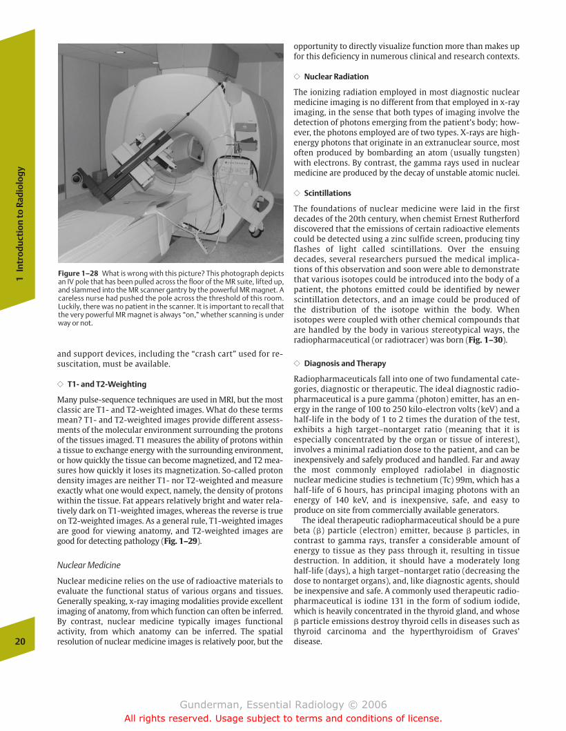
and support devices, including the “crash cart” used for re-suscitation, must be available.
�� T1- and T2-Weighting
Many pulse-sequence techniques are used in MRI, but the mostclassic are T1- and T2-weighted images. What do these termsmean? T1- and T2-weighted images provide different assess-ments of the molecular environment surrounding the protonsof the tissues imaged. T1 measures the ability of protons withina tissue to exchange energy with the surrounding environment,or how quickly the tissue can become magnetized, and T2 mea-sures how quickly it loses its magnetization. So-called protondensity images are neither T1- nor T2-weighted and measureexactly what one would expect, namely, the density of protonswithin the tissue. Fat appears relatively bright and water rela-tively dark on T1-weighted images, whereas the reverse is trueon T2-weighted images. As a general rule, T1-weighted imagesare good for viewing anatomy, and T2-weighted images aregood for detecting pathology (Fig. 1–29).
Nuclear Medicine
Nuclear medicine relies on the use of radioactive materials toevaluate the functional status of various organs and tissues.Generally speaking, x-ray imaging modalities provide excellentimaging of anatomy, from which function can often be inferred.By contrast, nuclear medicine typically images functional activity, from which anatomy can be inferred. The spatial resolution of nuclear medicine images is relatively poor, but the
opportunity to directly visualize function more than makes upfor this deficiency in numerous clinical and research contexts.
�� Nuclear Radiation
The ionizing radiation employed in most diagnostic nuclearmedicine imaging is no different from that employed in x-rayimaging, in the sense that both types of imaging involve thedetection of photons emerging from the patient’s body; how-ever, the photons employed are of two types. X-rays are high-energy photons that originate in an extranuclear source, mostoften produced by bombarding an atom (usually tungsten)with electrons. By contrast, the gamma rays used in nuclearmedicine are produced by the decay of unstable atomic nuclei.
�� Scintillations
The foundations of nuclear medicine were laid in the firstdecades of the 20th century, when chemist Ernest Rutherforddiscovered that the emissions of certain radioactive elementscould be detected using a zinc sulfide screen, producing tinyflashes of light called scintillations. Over the ensuingdecades, several researchers pursued the medical implica-tions of this observation and soon were able to demonstratethat various isotopes could be introduced into the body of apatient, the photons emitted could be identified by newerscintillation detectors, and an image could be produced ofthe distribution of the isotope within the body. When isotopes were coupled with other chemical compounds thatare handled by the body in various stereotypical ways, the radiopharmaceutical (or radiotracer) was born (Fig. 1–30).
�� Diagnosis and Therapy
Radiopharmaceuticals fall into one of two fundamental cate-gories, diagnostic or therapeutic. The ideal diagnostic radio-pharmaceutical is a pure gamma (photon) emitter, has an en-ergy in the range of 100 to 250 kilo-electron volts (keV) and ahalf-life in the body of 1 to 2 times the duration of the test,exhibits a high target–nontarget ratio (meaning that it is especially concentrated by the organ or tissue of interest), involves a minimal radiation dose to the patient, and can beinexpensively and safely produced and handled. Far and awaythe most commonly employed radiolabel in diagnostic nuclear medicine studies is technetium (Tc) 99m, which has ahalf-life of 6 hours, has principal imaging photons with anenergy of 140 keV, and is inexpensive, safe, and easy to produce on site from commercially available generators.
The ideal therapeutic radiopharmaceutical should be a purebeta (�) particle (electron) emitter, because � particles, incontrast to gamma rays, transfer a considerable amount of energy to tissue as they pass through it, resulting in tissue destruction. In addition, it should have a moderately longhalf-life (days), a high target–nontarget ratio (decreasing thedose to nontarget organs), and, like diagnostic agents, shouldbe inexpensive and safe. A commonly used therapeutic radio-pharmaceutical is iodine 131 in the form of sodium iodide,which is heavily concentrated in the thyroid gland, and whose� particle emissions destroy thyroid cells in diseases such asthyroid carcinoma and the hyperthyroidism of Graves’ disease.20
1In
trod
ucti
on to
Rad
iolo
gy
Figure 1–28 What is wrong with this picture? This photograph depictsan IV pole that has been pulled across the floor of the MR suite, lifted up,and slammed into the MR scanner gantry by the powerful MR magnet. Acareless nurse had pushed the pole across the threshold of this room.Luckily, there was no patient in the scanner. It is important to recall thatthe very powerful MR magnet is always “on,” whether scanning is underway or not.
chapter 01_p1-38.qxd 12/1/05 3:19 PM Page 20
Gunderman, Essential Radiology © 2006All rights reserved. Usage subject to terms and conditions of license.
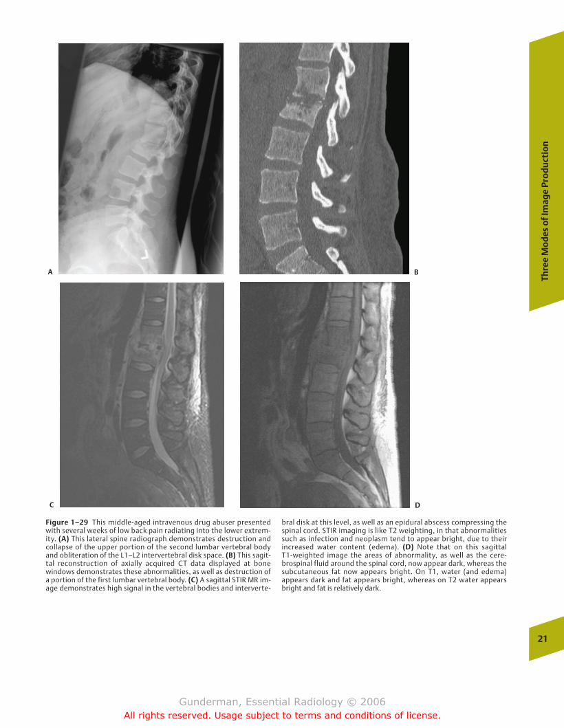
Thre
e M
od
es o
f Im
age
Pro
du
ctio
n
21
Figure 1–29 This middle-aged intravenous drug abuser presentedwith several weeks of low back pain radiating into the lower extrem-ity. (A) This lateral spine radiograph demonstrates destruction andcollapse of the upper portion of the second lumbar vertebral bodyand obliteration of the L1–L2 intervertebral disk space. (B) This sagit-tal reconstruction of axially acquired CT data displayed at bone windows demonstrates these abnormalities, as well as destruction ofa portion of the first lumbar vertebral body. (C) A sagittal STIR MR im-age demonstrates high signal in the vertebral bodies and interverte-
bral disk at this level, as well as an epidural abscess compressing thespinal cord. STIR imaging is like T2 weighting, in that abnormalitiessuch as infection and neoplasm tend to appear bright, due to their increased water content (edema). (D) Note that on this sagittal T1-weighted image the areas of abnormality, as well as the cere-brospinal fluid around the spinal cord, now appear dark, whereas thesubcutaneous fat now appears bright. On T1, water (and edema) appears dark and fat appears bright, whereas on T2 water appearsbright and fat is relatively dark.
A B
C D
chapter 01_p1-38.qxd 12/1/05 3:19 PM Page 21
Gunderman, Essential Radiology © 2006All rights reserved. Usage subject to terms and conditions of license.
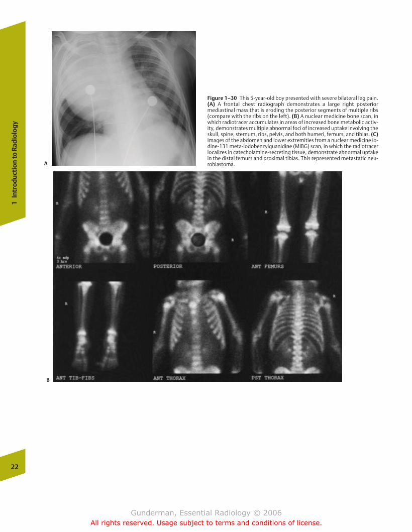
22
1In
trod
ucti
on to
Rad
iolo
gy
Figure 1–30 This 5-year-old boy presented with severe bilateral leg pain.(A) A frontal chest radiograph demonstrates a large right posterior mediastinal mass that is eroding the posterior segments of multiple ribs(compare with the ribs on the left). (B) A nuclear medicine bone scan, inwhich radiotracer accumulates in areas of increased bone metabolic activ-ity, demonstrates multiple abnormal foci of increased uptake involving theskull, spine, sternum, ribs, pelvis, and both humeri, femurs, and tibias. (C)Images of the abdomen and lower extremities from a nuclear medicine io-dine-131 meta-iodobenzylguanidine (MIBG) scan, in which the radiotracerlocalizes in catecholamine-secreting tissue, demonstrate abnormal uptakein the distal femurs and proximal tibias. This represented metastatic neu-roblastoma.A
B
chapter 01_p1-38.qxd 12/1/05 3:19 PM Page 22
Gunderman, Essential Radiology © 2006All rights reserved. Usage subject to terms and conditions of license.
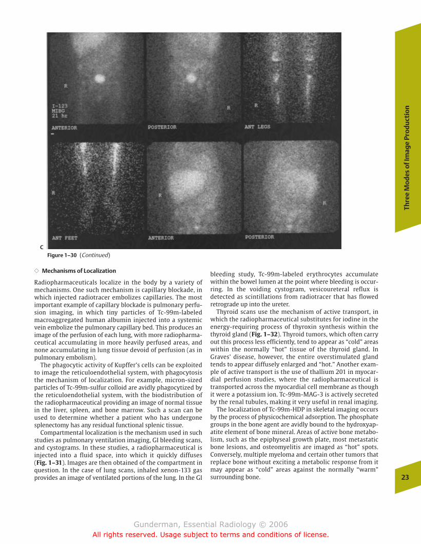
�� Mechanisms of Localization
Radiopharmaceuticals localize in the body by a variety ofmechanisms. One such mechanism is capillary blockade, inwhich injected radiotracer embolizes capillaries. The mostimportant example of capillary blockade is pulmonary perfu-sion imaging, in which tiny particles of Tc-99m-labeledmacroaggregated human albumin injected into a systemicvein embolize the pulmonary capillary bed. This produces animage of the perfusion of each lung, with more radiopharma-ceutical accumulating in more heavily perfused areas, andnone accumulating in lung tissue devoid of perfusion (as inpulmonary embolism).
The phagocytic activity of Kupffer’s cells can be exploitedto image the reticuloendothelial system, with phagocytosisthe mechanism of localization. For example, micron-sizedparticles of Tc-99m-sulfur colloid are avidly phagocytized bythe reticuloendothelial system, with the biodistribution ofthe radiopharmaceutical providing an image of normal tissuein the liver, spleen, and bone marrow. Such a scan can beused to determine whether a patient who has undergonesplenectomy has any residual functional splenic tissue.
Compartmental localization is the mechanism used in suchstudies as pulmonary ventilation imaging, GI bleeding scans,and cystograms. In these studies, a radiopharmaceutical is injected into a fluid space, into which it quickly diffuses (Fig. 1–31). Images are then obtained of the compartment inquestion. In the case of lung scans, inhaled xenon-133 gasprovides an image of ventilated portions of the lung. In the GI
bleeding study, Tc-99m-labeled erythrocytes accumulatewithin the bowel lumen at the point where bleeding is occur-ring. In the voiding cystogram, vesicoureteral reflux is detected as scintillations from radiotracer that has flowedretrograde up into the ureter.
Thyroid scans use the mechanism of active transport, inwhich the radiopharmaceutical substitutes for iodine in theenergy-requiring process of thyroxin synthesis within thethyroid gland (Fig. 1–32). Thyroid tumors, which often carryout this process less efficiently, tend to appear as “cold” areaswithin the normally “hot” tissue of the thyroid gland. InGraves’ disease, however, the entire overstimulated glandtends to appear diffusely enlarged and “hot.” Another exam-ple of active transport is the use of thallium 201 in myocar-dial perfusion studies, where the radiopharmaceutical istransported across the myocardial cell membrane as thoughit were a potassium ion. Tc-99m-MAG-3 is actively secretedby the renal tubules, making it very useful in renal imaging.
The localization of Tc-99m-HDP in skeletal imaging occursby the process of physicochemical adsorption. The phosphategroups in the bone agent are avidly bound to the hydroxyap-atite element of bone mineral. Areas of active bone metabo-lism, such as the epiphyseal growth plate, most metastaticbone lesions, and osteomyelitis are imaged as “hot” spots.Conversely, multiple myeloma and certain other tumors thatreplace bone without exciting a metabolic response from itmay appear as “cold” areas against the normally “warm” surrounding bone.
Thre
e M
od
es o
f Im
age
Pro
du
ctio
n
23
CFigure 1–30 (Continued)
chapter 01_p1-38.qxd 12/1/05 3:19 PM Page 23
Gunderman, Essential Radiology © 2006All rights reserved. Usage subject to terms and conditions of license.
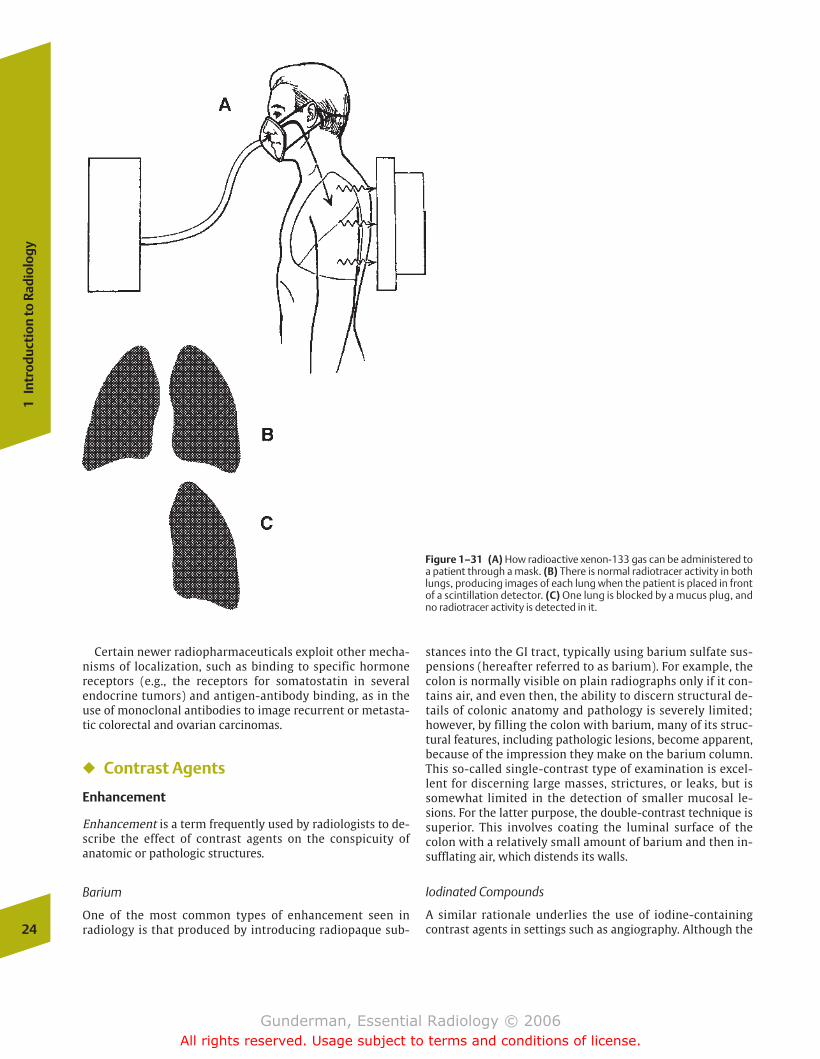
stances into the GI tract, typically using barium sulfate sus-pensions (hereafter referred to as barium). For example, thecolon is normally visible on plain radiographs only if it con-tains air, and even then, the ability to discern structural de-tails of colonic anatomy and pathology is severely limited;however, by filling the colon with barium, many of its struc-tural features, including pathologic lesions, become apparent,because of the impression they make on the barium column.This so-called single-contrast type of examination is excel-lent for discerning large masses, strictures, or leaks, but issomewhat limited in the detection of smaller mucosal le-sions. For the latter purpose, the double-contrast technique issuperior. This involves coating the luminal surface of thecolon with a relatively small amount of barium and then in-sufflating air, which distends its walls.
Iodinated Compounds
A similar rationale underlies the use of iodine-containingcontrast agents in settings such as angiography. Although the24
1In
trod
ucti
on to
Rad
iolo
gy
Figure 1–31 (A) How radioactive xenon-133 gas can be administered toa patient through a mask. (B) There is normal radiotracer activity in bothlungs, producing images of each lung when the patient is placed in frontof a scintillation detector. (C) One lung is blocked by a mucus plug, andno radiotracer activity is detected in it.
Certain newer radiopharmaceuticals exploit other mecha-nisms of localization, such as binding to specific hormone receptors (e.g., the receptors for somatostatin in several endocrine tumors) and antigen-antibody binding, as in theuse of monoclonal antibodies to image recurrent or metasta-tic colorectal and ovarian carcinomas.
� Contrast Agents
Enhancement
Enhancement is a term frequently used by radiologists to de-scribe the effect of contrast agents on the conspicuity ofanatomic or pathologic structures.
Barium
One of the most common types of enhancement seen in radiology is that produced by introducing radiopaque sub-
chapter 01_p1-38.qxd 12/1/05 3:19 PM Page 24
Gunderman, Essential Radiology © 2006All rights reserved. Usage subject to terms and conditions of license.
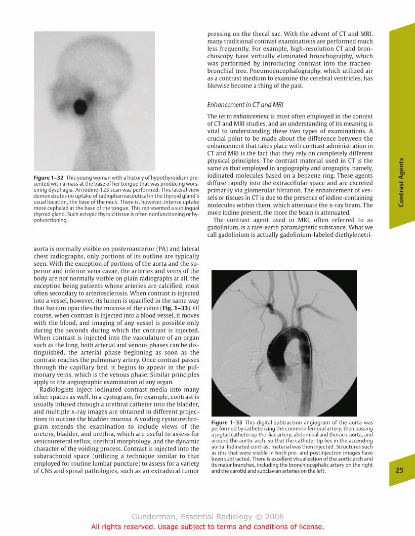
pressing on the thecal sac. With the advent of CT and MRI,many traditional contrast examinations are performed muchless frequently. For example, high-resolution CT and bron-choscopy have virtually eliminated bronchography, whichwas performed by introducing contrast into the tracheo-bronchial tree. Pneumoencephalography, which utilized airas a contrast medium to examine the cerebral ventricles, haslikewise become a thing of the past.
Enhancement in CT and MRI
The term enhancement is most often employed in the contextof CT and MRI studies, and an understanding of its meaning isvital to understanding these two types of examinations. A crucial point to be made about the difference between the enhancement that takes place with contrast administration inCT and MRI is the fact that they rely on completely differentphysical principles. The contrast material used in CT is thesame as that employed in angiography and urography, namely,iodinated molecules based on a benzene ring. These agentsdiffuse rapidly into the extracellular space and are excretedprimarily via glomerular filtration. The enhancement of ves-sels or tissues in CT is due to the presence of iodine-containingmolecules within them, which attenuate the x-ray beam. Themore iodine present, the more the beam is attenuated.
The contrast agent used in MRI, often referred to asgadolinium, is a rare-earth paramagnetic substance. What wecall gadolinium is actually gadolinium-labeled diethylenetri-
Co
ntr
ast
Ag
ents
25
Figure 1–32 This young woman with a history of hypothyroidism pre-sented with a mass at the base of her tongue that was producing wors-ening dysphagia. An iodine-123 scan was performed. This lateral viewdemonstrates no uptake of radiopharmaceutical in the thyroid gland’susual location, the base of the neck. There is, however, intense uptakemore cephalad at the base of the tongue. This represented a sublingualthyroid gland. Such ectopic thyroid tissue is often nonfunctioning or hy-pofunctioning.
Figure 1–33 This digital subtraction angiogram of the aorta was performed by catheterizing the common femoral artery, then passinga pigtail catheter up the iliac artery, abdominal and thoracic aorta, andaround the aortic arch, so that the catheter tip lies in the ascendingaorta. Iodinated contrast material was then injected. Structures suchas ribs that were visible in both pre- and postinjection images havebeen subtracted. There is excellent visualization of the aortic arch andits major branches, including the bronchiocephalic artery on the rightand the carotid and subclavian arteries on the left.
aorta is normally visible on posteroanterior (PA) and lateralchest radiographs, only portions of its outline are typicallyseen. With the exception of portions of the aorta and the su-perior and inferior vena cavae, the arteries and veins of thebody are not normally visible on plain radiographs at all, theexception being patients whose arteries are calcified, mostoften secondary to arteriosclerosis. When contrast is injectedinto a vessel, however, its lumen is opacified in the same waythat barium opacifies the mucosa of the colon (Fig. 1–33). Ofcourse, when contrast is injected into a blood vessel, it moveswith the blood, and imaging of any vessel is possible onlyduring the seconds during which the contrast is injected.When contrast is injected into the vasculature of an organsuch as the lung, both arterial and venous phases can be dis-tinguished, the arterial phase beginning as soon as the contrast reaches the pulmonary artery. Once contrast passesthrough the capillary bed, it begins to appear in the pul-monary veins, which is the venous phase. Similar principlesapply to the angiographic examination of any organ.
Radiologists inject iodinated contrast media into manyother spaces as well. In a cystogram, for example, contrast isusually infused through a urethral catheter into the bladder,and multiple x-ray images are obtained in different projec-tions to outline the bladder mucosa. A voiding cystourethro-gram extends the examination to include views of theureters, bladder, and urethra, which are useful to assess forvesicoureteral reflux, urethral morphology, and the dynamiccharacter of the voiding process. Contrast is injected into thesubarachnoid space (utilizing a technique similar to that employed for routine lumbar puncture) to assess for a varietyof CNS and spinal pathologies, such as an extradural tumor
chapter 01_p1-38.qxd 12/1/05 3:19 PM Page 25
Gunderman, Essential Radiology © 2006All rights reserved. Usage subject to terms and conditions of license.
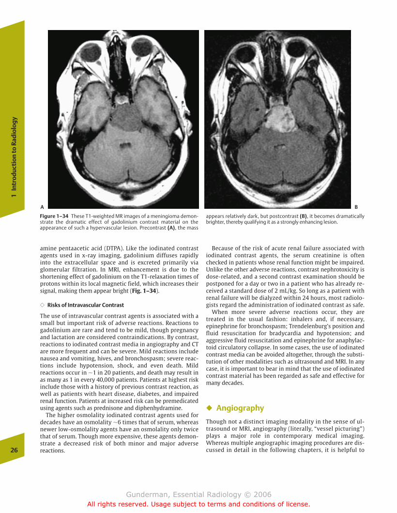
amine pentaacetic acid (DTPA). Like the iodinated contrastagents used in x-ray imaging, gadolinium diffuses rapidlyinto the extracellular space and is excreted primarily viaglomerular filtration. In MRI, enhancement is due to theshortening effect of gadolinium on the T1-relaxation times ofprotons within its local magnetic field, which increases theirsignal, making them appear bright (Fig. 1–34).
�� Risks of Intravascular Contrast
The use of intravascular contrast agents is associated with asmall but important risk of adverse reactions. Reactions togadolinium are rare and tend to be mild, though pregnancyand lactation are considered contraindications. By contrast,reactions to iodinated contrast media in angiography and CTare more frequent and can be severe. Mild reactions includenausea and vomiting, hives, and bronchospasm; severe reac-tions include hypotension, shock, and even death. Mild reactions occur in �1 in 20 patients, and death may result inas many as 1 in every 40,000 patients. Patients at highest riskinclude those with a history of previous contrast reaction, aswell as patients with heart disease, diabetes, and impairedrenal function. Patients at increased risk can be premedicatedusing agents such as prednisone and diphenhydramine.
The higher osmolality iodinated contrast agents used fordecades have an osmolality �6 times that of serum, whereasnewer low-osmolality agents have an osmolality only twicethat of serum. Though more expensive, these agents demon-strate a decreased risk of both minor and major adverse reactions.
Because of the risk of acute renal failure associated with iodinated contrast agents, the serum creatinine is oftenchecked in patients whose renal function might be impaired.Unlike the other adverse reactions, contrast nephrotoxicity isdose-related, and a second contrast examination should bepostponed for a day or two in a patient who has already re-ceived a standard dose of 2 mL/kg. So long as a patient withrenal failure will be dialyzed within 24 hours, most radiolo-gists regard the administration of iodinated contrast as safe.
When more severe adverse reactions occur, they aretreated in the usual fashion: inhalers and, if necessary, epinephrine for bronchospasm; Trendelenburg’s position andfluid resuscitation for bradycardia and hypotension; and aggressive fluid resuscitation and epinephrine for anaphylac-toid circulatory collapse. In some cases, the use of iodinatedcontrast media can be avoided altogether, through the substi-tution of other modalities such as ultrasound and MRI. In anycase, it is important to bear in mind that the use of iodinatedcontrast material has been regarded as safe and effective formany decades.
� Angiography
Though not a distinct imaging modality in the sense of ul-trasound or MRI, angiography (literally, “vessel picturing”)plays a major role in contemporary medical imaging.Whereas multiple angiographic imaging procedures are dis-cussed in detail in the following chapters, it is helpful to 26
1In
trod
ucti
on to
Rad
iolo
gy
Figure 1–34 These T1-weighted MR images of a meningioma demon-strate the dramatic effect of gadolinium contrast material on theappearance of such a hypervascular lesion. Precontrast (A), the mass
appears relatively dark, but postcontrast (B), it becomes dramaticallybrighter, thereby qualifying it as a strongly enhancing lesion.
A B
chapter 01_p1-38.qxd 12/1/05 3:19 PM Page 26
Gunderman, Essential Radiology © 2006All rights reserved. Usage subject to terms and conditions of license.
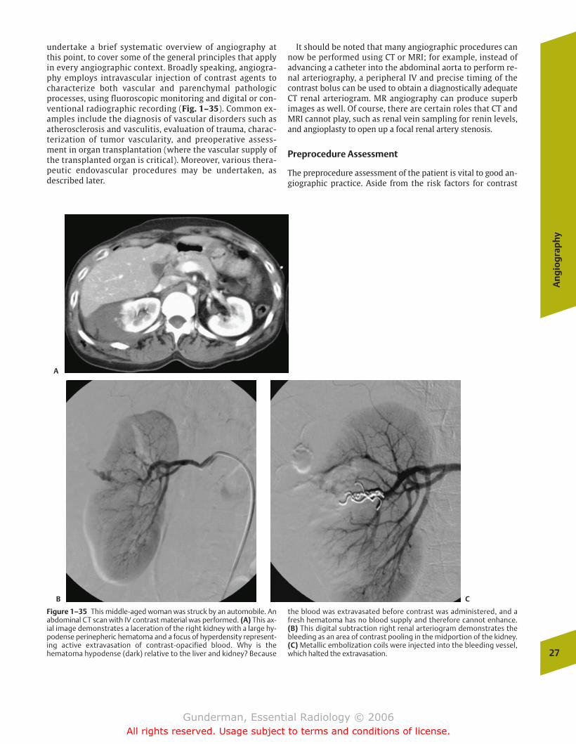
undertake a brief systematic overview of angiography atthis point, to cover some of the general principles that applyin every angiographic context. Broadly speaking, angiogra-phy employs intravascular injection of contrast agents tocharacterize both vascular and parenchymal pathologicprocesses, using fluoroscopic monitoring and digital or con-ventional radiographic recording (Fig. 1–35). Common ex-amples include the diagnosis of vascular disorders such asatherosclerosis and vasculitis, evaluation of trauma, charac-terization of tumor vascularity, and preoperative assess-ment in organ transplantation (where the vascular supply ofthe transplanted organ is critical). Moreover, various thera-peutic endovascular procedures may be undertaken, as described later.
It should be noted that many angiographic procedures cannow be performed using CT or MRI; for example, instead ofadvancing a catheter into the abdominal aorta to perform re-nal arteriography, a peripheral IV and precise timing of thecontrast bolus can be used to obtain a diagnostically adequateCT renal arteriogram. MR angiography can produce superbimages as well. Of course, there are certain roles that CT andMRI cannot play, such as renal vein sampling for renin levels,and angioplasty to open up a focal renal artery stenosis.
Preprocedure Assessment
The preprocedure assessment of the patient is vital to good an-giographic practice. Aside from the risk factors for contrast
An
gio
gra
phy
27
Figure 1–35 This middle-aged woman was struck by an automobile. Anabdominal CT scan with IV contrast material was performed. (A) This ax-ial image demonstrates a laceration of the right kidney with a large hy-podense perinepheric hematoma and a focus of hyperdensity represent-ing active extravasation of contrast-opacified blood. Why is thehematoma hypodense (dark) relative to the liver and kidney? Because
the blood was extravasated before contrast was administered, and afresh hematoma has no blood supply and therefore cannot enhance. (B) This digital subtraction right renal arteriogram demonstrates thebleeding as an area of contrast pooling in the midportion of the kidney. (C) Metallic embolization coils were injected into the bleeding vessel,which halted the extravasation.
A
B C
chapter 01_p1-38.qxd 12/1/05 3:19 PM Page 27
Gunderman, Essential Radiology © 2006All rights reserved. Usage subject to terms and conditions of license.
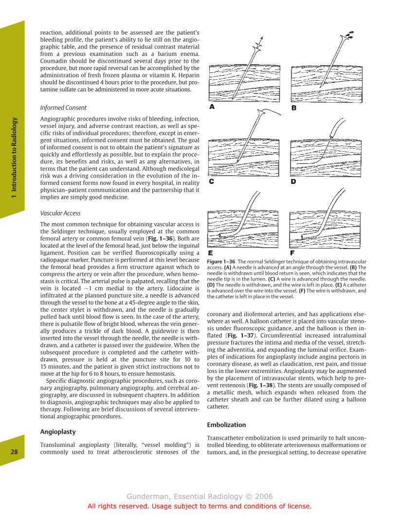
reaction, additional points to be assessed are the patient’sbleeding profile, the patient’s ability to lie still on the angio-graphic table, and the presence of residual contrast materialfrom a previous examination such as a barium enema.Coumadin should be discontinued several days prior to theprocedure, but more rapid reversal can be accomplished by theadministration of fresh frozen plasma or vitamin K. Heparinshould be discontinued 4 hours prior to the procedure, but pro-tamine sulfate can be administered in more acute situations.
Informed Consent
Angiographic procedures involve risks of bleeding, infection,vessel injury, and adverse contrast reaction, as well as spe-cific risks of individual procedures; therefore, except in emer-gent situations, informed consent must be obtained. The goalof informed consent is not to obtain the patient’s signature asquickly and effortlessly as possible, but to explain the proce-dure, its benefits and risks, as well as any alternatives, interms that the patient can understand. Although medicolegalrisk was a driving consideration in the evolution of the in-formed consent forms now found in every hospital, in realityphysician–patient communication and the partnership that itimplies are simply good medicine.
Vascular Access
The most common technique for obtaining vascular access isthe Seldinger technique, usually employed at the commonfemoral artery or common femoral vein (Fig. 1–36). Both are located at the level of the femoral head, just below the inguinalligament. Position can be verified fluoroscopically using a radiopaque marker. Puncture is performed at this level becausethe femoral head provides a firm structure against which tocompress the artery or vein after the procedure, when hemo-stasis is critical. The arterial pulse is palpated, recalling that thevein is located �1 cm medial to the artery. Lidocaine isinfiltrated at the planned puncture site, a needle is advancedthrough the vessel to the bone at a 45-degree angle to the skin,the center stylet is withdrawn, and the needle is graduallypulled back until blood flow is seen. In the case of the artery,there is pulsatile flow of bright blood, whereas the vein gener-ally produces a trickle of dark blood. A guidewire is theninserted into the vessel through the needle, the needle is with-drawn, and a catheter is passed over the guidewire. When thesubsequent procedure is completed and the catheter with-drawn, pressure is held at the puncture site for 10 to 15 minutes, and the patient is given strict instructions not tomove at the hip for 6 to 8 hours, to ensure hemostasis.
Specific diagnostic angiographic procedures, such as coro-nary angiography, pulmonary angiography, and cerebral an-giography, are discussed in subsequent chapters. In additionto diagnosis, angiographic techniques may also be applied totherapy. Following are brief discussions of several interven-tional angiographic procedures.
Angioplasty
Transluminal angioplasty (literally, “vessel molding”) is commonly used to treat atherosclerotic stenoses of the
coronary and iliofemoral arteries, and has applications else-where as well. A balloon catheter is placed into vascular steno-sis under fluoroscopic guidance, and the balloon is then in-flated (Fig. 1–37). Circumferential increased intraluminalpressure fractures the intima and media of the vessel, stretch-ing the adventitia, and expanding the luminal orifice. Exam-ples of indications for angioplasty include angina pectoris incoronary disease, as well as claudication, rest pain, and tissueloss in the lower extremities. Angioplasty may be augmentedby the placement of intravascular stents, which help to pre-vent restenosis (Fig. 1–38). The stents are usually composed ofa metallic mesh, which expands when released from thecatheter sheath and can be further dilated using a ballooncatheter.
Embolization
Transcatheter embolization is used primarily to halt uncon-trolled bleeding, to obliterate arteriovenous malformations ortumors, and, in the presurgical setting, to decrease operative28
1In
trod
ucti
on to
Rad
iolo
gy
Figure 1–36 The normal Seldinger technique of obtaining intravascularaccess. (A) A needle is advanced at an angle through the vessel. (B) Theneedle is withdrawn until blood return is seen, which indicates that theneedle tip is in the lumen. (C) A wire is advanced through the needle.(D) The needle is withdrawn, and the wire is left in place. (E) A catheteris advanced over the wire into the vessel. (F) The wire is withdrawn, andthe catheter is left in place in the vessel.
chapter 01_p1-38.qxd 12/1/05 3:19 PM Page 28
Gunderman, Essential Radiology © 2006All rights reserved. Usage subject to terms and conditions of license.
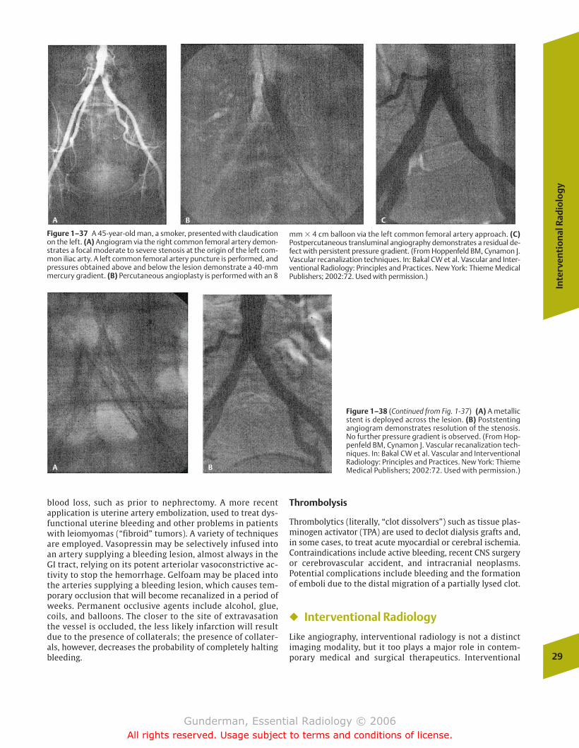
blood loss, such as prior to nephrectomy. A more recent application is uterine artery embolization, used to treat dys-functional uterine bleeding and other problems in patientswith leiomyomas (“fibroid” tumors). A variety of techniquesare employed. Vasopressin may be selectively infused intoan artery supplying a bleeding lesion, almost always in theGI tract, relying on its potent arteriolar vasoconstrictive ac-tivity to stop the hemorrhage. Gelfoam may be placed intothe arteries supplying a bleeding lesion, which causes tem-porary occlusion that will become recanalized in a period ofweeks. Permanent occlusive agents include alcohol, glue,coils, and balloons. The closer to the site of extravasationthe vessel is occluded, the less likely infarction will resultdue to the presence of collaterals; the presence of collater-als, however, decreases the probability of completely haltingbleeding.
Thrombolysis
Thrombolytics (literally, “clot dissolvers”) such as tissue plas-minogen activator (TPA) are used to declot dialysis grafts and,in some cases, to treat acute myocardial or cerebral ischemia.Contraindications include active bleeding, recent CNS surgeryor cerebrovascular accident, and intracranial neoplasms. Potential complications include bleeding and the formationof emboli due to the distal migration of a partially lysed clot.
� Interventional Radiology
Like angiography, interventional radiology is not a distinctimaging modality, but it too plays a major role in contem-porary medical and surgical therapeutics. Interventional
Inte
rven
tio
nal
Rad
iolo
gy
29
Figure 1–37 A 45-year-old man, a smoker, presented with claudicationon the left. (A) Angiogram via the right common femoral artery demon-strates a focal moderate to severe stenosis at the origin of the left com-mon iliac arty. A left common femoral artery puncture is performed, andpressures obtained above and below the lesion demonstrate a 40-mmmercury gradient. (B) Percutaneous angioplasty is performed with an 8
mm � 4 cm balloon via the left common femoral artery approach. (C)Postpercutaneous transluminal angiography demonstrates a residual de-fect with persistent pressure gradient. (From Hoppenfeld BM, Cynamon J.Vascular recanalization techniques. In: Bakal CW et al. Vascular and Inter-ventional Radiology: Principles and Practices. New York: Thieme MedicalPublishers; 2002:72. Used with permission.)
Figure 1–38 (Continued from Fig. 1-37) (A) A metallicstent is deployed across the lesion. (B) Poststentingangiogram demonstrates resolution of the stenosis.No further pressure gradient is observed. (From Hop-penfeld BM, Cynamon J. Vascular recanalization tech-niques. In: Bakal CW et al. Vascular and InterventionalRadiology: Principles and Practices. New York: ThiemeMedical Publishers; 2002:72. Used with permission.)
A B C
A B
chapter 01_p1-38.qxd 12/1/05 3:19 PM Page 29
Gunderman, Essential Radiology © 2006All rights reserved. Usage subject to terms and conditions of license.
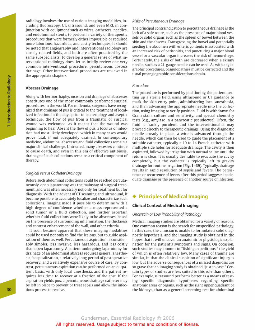
radiology involves the use of various imaging modalities, in-cluding fluoroscopy, CT, ultrasound, and even MRI, in con-junction with equipment such as wires, catheters, needles,and endoluminal stents, to perform a variety of therapeuticprocedures that were formerly either impossible or requiredmore laborious, hazardous, and costly techniques. It shouldbe noted that angiography and interventional radiology areclosely related fields, and both are often practiced by thesame subspecialists. To develop a general sense of what in-terventional radiology does, let us briefly review one verycommon interventional procedure, percutaneous abscessdrainage. Other interventional procedures are reviewed inthe appropriate chapters.
Abscess Drainage
Along with herniorrhaphy, incision and drainage of abscessesconstitutes one of the most commonly performed surgicalprocedures in the world. For millennia, surgeons have recog-nized that drainage of pus is critical to the treatment of local-ized infection. In the days prior to bacteriology and aseptictechnique, the flow of pus from a traumatic or surgicalwound was welcomed, as it meant that the wound was beginning to heal. Absent the flow of pus, a loculus of infec-tion had most likely developed, which in many cases wouldprove fatal, if not adequately drained. In contemporary medicine, abdominal abscesses and fluid collections remain amajor clinical challenge. Untreated, many abscesses continueto cause death, and even in this era of effective antibiosis,drainage of such collections remains a critical component oftherapy.
Surgical versus Catheter Drainage
Before such abdominal collections could be reached percuta-neously, open laparotomy was the mainstay of surgical treat-ment, and was often necessary not only for treatment but fordiagnosis. With the advent of CT scanning and ultrasound, itbecame possible to accurately localize and characterize suchcollections. Imaging made it possible to determine with ahigh degree of confidence whether a mass represented asolid tumor or a fluid collection, and further ascertainwhether fluid collections were likely to be abscesses, basedon the presence of surrounding inflammation, the thicknessand contrast enhancement of the wall, and other criteria.
It soon became apparent that these imaging modalitiescould be used not only to find the lesions, but to guide aspi-ration of them as well. Percutaneous aspiration is consider-ably simpler, less invasive, less hazardous, and less costlythan open laparotomy. A patient undergoing laparotomy fordrainage of an abdominal abscess requires general anesthe-sia, hospitalization, a relatively long period of postoperativerecovery, and a relatively expensive course of care. By con-trast, percutaneous aspiration can be performed on an outpa-tient basis, with only local anesthesia, and the patient re-quires less time to recover at a fraction of the cost. If theaspiration yields pus, a percutaneous drainage catheter maybe left in place to prevent or treat sepsis and allow the infec-tious process to resolve.
Risks of Percutaneous Drainage
The principal contraindication to percutaneous drainage is thelack of a safe route, such as the presence of major blood ves-sels or solid organs such as the spleen or bowel between theskin and the abscess. Transgressing the bowel and potentiallyseeding the abdomen with enteric contents is associated withan increased risk of peritonitis, and puncturing a major bloodvessel or a vascular organ increases the risk of hemorrhage.Fortunately, the risks of both are decreased when a skinnyneedle, such as a 21-gauge needle, can be used. As with angio-graphic procedures, coagulopathies must be corrected and theusual preangiographic considerations obtain.
Procedure
The procedure is performed by positioning the patient, set-ting up a sterile field, using ultrasound or CT guidance tomark the skin entry point, administering local anesthesia,and then advancing the appropriate needle into the collec-tion, using imaging to verify position. Fluid is withdrawn forGram stain, culture and sensitivity, and special chemistrytests (e.g., amylase in a pancreatic pseudocyst). Often, thefluid is frankly purulent, and the interventionalist may proceed directly to therapeutic drainage. Using the diagnosticneedle already in place, a wire is advanced through the needle, which can then be used to guide the placement of asuitable catheter, typically a 10 to 14 French catheter withmultiple side holes for adequate drainage. The cavity is thenaspirated, followed by irrigation with normal saline until thereturn is clear. It is usually desirable to evacuate the cavitycompletely, but the catheter is typically left to gravitydrainage for routine irrigation (Fig. 1–39). Typically, drainageresults in rapid resolution of sepsis and fevers. The persis-tence or recurrence of fevers after this period suggests inade-quate drainage or the presence of another source of infection.
� Principles of Medical Imaging
Clinical Context of Medical Imaging
Uncertain or Low Probability of Pathology
Medical imaging studies are obtained for a variety of reasons.One common reason is the search for unspecified pathology.In this case, the clinician is unable to formulate a solid diag-nostic hypothesis, and the imaging study is obtained in thehopes that it will uncover an anatomic or physiologic expla-nation for the patient’s symptoms and signs. On occasion,such studies may amount to “fishing expeditions,” the yieldof which is often relatively low. Many cases of trauma aresimilar, in that the clinical suspicion of significant injury islow, but the adverse consequences of a missed diagnosis areso grave that an imaging study is obtained “just in case.” Cer-tain types of studies are less suited to this role than others.For example, ultrasound performs better as a means of test-ing specific diagnostic hypotheses regarding specificanatomic areas or organs, such as the right upper quadrant orthe kidneys, than as a general screening test for abdominal30
1In
trod
ucti
on to
Rad
iolo
gy
chapter 01_p1-38.qxd 12/1/05 3:19 PM Page 30
Gunderman, Essential Radiology © 2006All rights reserved. Usage subject to terms and conditions of license.

pathology. This is true in part because the ultrasound beamcan only be directed at a relatively small portion of the pa-tient’s anatomy at a time, and surveying the entire abdomenis a time-consuming and laborious process. CT, on the otherhand, which naturally images the entire abdomen in a rela-tively short period of time, is usually better suited to thesearch for unspecified abdominal pathology (Fig. 1–40).
Known Diagnosis
Imaging studies play an important role even in cases wherethe diagnosis is known. From a surgeon’s point of view,imaging studies may prove immensely useful in surgicalplanning. For example, the surgeon planning to perform la-paroscopic cholecystectomy may wish to obtain a CT, ultra-sound, or MRI to visualize the anatomy of the biliary treeand rule out anomalies, such as aberrant ductal anatomy,that could produce postoperative complications. Similarly,angiographic studies are often obtained as part of a routinepresurgical workup in patients being evaluated as potentialorgan donors, to assess such factors as vascular and ductalanatomy.
Another important role of imaging in known diagnoses isthe staging of malignant neoplasms (Fig. 1–41). Prognosisand therapeutic protocols are powerfully affected by radio-logic staging of such neoplasms as lung cancer and
Hodgkin’s disease. Imaging also plays a major role in evalu-ating response to therapy. A chemotherapy protocol may beabandoned if imaging studies demonstrate continuedgrowth of a patient’s tumor; a significant reduction in tu-mor burden, in contrast, generally indicates that the currentregimen should be continued. In the case of interventionalradiology, imaging studies constitute an integral part oftherapy, as when ultrasound is used to guide percutaneousabscess drainage.
Confirming or Disconfirming a Hypothesis
Perhaps the two most important reasons to obtain animaging study are to confirm or disconfirm a diagnostic hy-pothesis. Consider the cases of two patients who present tothe emergency room with lower extremity swelling. Eachmay receive a lower extremity ultrasound examination torule out the presence of deep venous thrombosis (DVT), apotentially life-threatening condition associated with pul-monary embolism, but the reasoning behind the test ineach case may be radically different. In the case of a chroni-cally ill patient with a history of previous DVT who has re-cently stopped taking his or her anticoagulant medication,clinical suspicion of DVT may be very high. In this case, thestudy would likely be obtained primarily to confirm and lo-calize recurrent thrombosis before an inferior vena caval
Prin
cip
les
of M
edic
al Im
agin
g
31
Figure 1–39 CT was used to guide biopsy of this patient’s pelvic abscess. (A) Under CT guidance, a needle has been advanced from the anterior abdominal wall into the fluid collection. (B) A wire has nowbeen advanced through the needle, and the needle is withdrawn. (C) Acatheter with multiple side holes has been advanced over the wire, andthe wire withdrawn. Pus was aspirated through the catheter, which wasleft in place to drain over several days. It is important to send a sample ofthe aspirate for microbiological analysis including Gram stain and cul-ture and sensitivity so that appropriate antibiotic therapy can be administered.
A
C
B
chapter 01_p1-38.qxd 12/1/05 3:19 PM Page 31
Gunderman, Essential Radiology © 2006All rights reserved. Usage subject to terms and conditions of license.

32
1In
trod
ucti
on to
Rad
iolo
gy
Figure 1–41 This elderly man presented with lower abdominal pain. (A) This soft tissue window pelvic CT image demonstrates irregular en-largement of the prostate gland and irregular thickening of the posterior
wall of the urinary bladder. This was locally invasive adenocarcinoma ofthe prostate. (B) This bone-window image demonstrates an osteoblas-tic metastasis in the left ileum adjacent to the sacroiliac joint.
A B
Figure 1–40 This patient presented with fever and vague abdominalpain. An abdominal CT scan with oral and IV contrast was performed.(A) This axial image at the level of kidneys demonstrates a swollen right kidney with multiple areas of decreased parenchymal enhancement, a so-called striated nephogram. Also, there is mild hydronephrosis. (B) An
image at the level of the urinary bladder reveals the culprit: a kidneystone lodged in the distal right ureter, which was causing obstruction.Had the diagnosis of nephrolithiasis been clinically suspected, the examwould have been performed without IV contrast, because contrast material in the urinary tract can obscure a stone.
A B
filter is placed (Fig. 1–42). In another case, that of a previ-ously healthy patient with clinical signs of cellulitis, clinicalsuspicion may be quite low. In this scenario, the study is ob-tained to verify that no life-threatening pathology (DVT thatcould result in pulmonary embolism) is present before thepatient is sent home on antibiotics. In the former case, theimaging study confirms a diagnostic impression before inva-sive therapy is instituted, whereas in the latter its purpose isto “rule out” an unlikely but life-threatening pathology. Inboth cases, important clinical management decisions hang inthe balance.
This raises an important issue in radiology and the broaderarena of diagnostic reasoning. Except in the case of medical re-search or teaching, imaging studies should be performed only ifthey are likely to affect clinical management. Both cliniciansand radiologists should always remember that (1) no imagingstudy should be ordered unless it is likely to influence clinicalmanagement; that is, if clinical management is the samewhether the test is “positive” or “negative,” then the test shouldnot be performed; and (2) every imaging study should be per-formed and reported in such a way that its clinical utility ismaximized. The clinician’s job is to supply the radiologist with
chapter 01_p1-38.qxd 12/1/05 3:19 PM Page 32
Gunderman, Essential Radiology © 2006All rights reserved. Usage subject to terms and conditions of license.
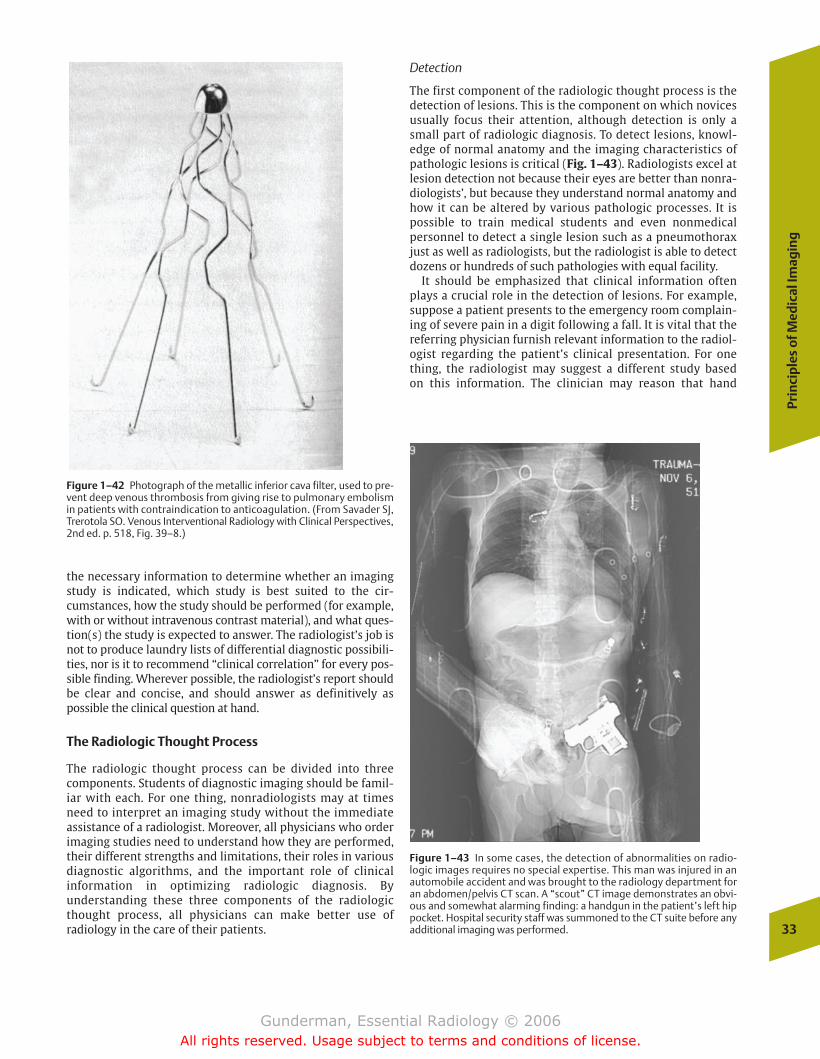
the necessary information to determine whether an imagingstudy is indicated, which study is best suited to the cir-cumstances, how the study should be performed (for example,with or without intravenous contrast material), and what ques-tion(s) the study is expected to answer. The radiologist’s job isnot to produce laundry lists of differential diagnostic possibili-ties, nor is it to recommend “clinical correlation” for every pos-sible finding. Wherever possible, the radiologist’s report shouldbe clear and concise, and should answer as definitively aspossible the clinical question at hand.
The Radiologic Thought Process
The radiologic thought process can be divided into threecomponents. Students of diagnostic imaging should be famil-iar with each. For one thing, nonradiologists may at timesneed to interpret an imaging study without the immediateassistance of a radiologist. Moreover, all physicians who orderimaging studies need to understand how they are performed,their different strengths and limitations, their roles in variousdiagnostic algorithms, and the important role of clinical information in optimizing radiologic diagnosis. By understanding these three components of the radiologicthought process, all physicians can make better use of radiology in the care of their patients.
Detection
The first component of the radiologic thought process is thedetection of lesions. This is the component on which novicesusually focus their attention, although detection is only asmall part of radiologic diagnosis. To detect lesions, knowl-edge of normal anatomy and the imaging characteristics ofpathologic lesions is critical (Fig. 1–43). Radiologists excel atlesion detection not because their eyes are better than nonra-diologists’, but because they understand normal anatomy andhow it can be altered by various pathologic processes. It ispossible to train medical students and even nonmedical personnel to detect a single lesion such as a pneumothoraxjust as well as radiologists, but the radiologist is able to detectdozens or hundreds of such pathologies with equal facility.
It should be emphasized that clinical information oftenplays a crucial role in the detection of lesions. For example,suppose a patient presents to the emergency room complain-ing of severe pain in a digit following a fall. It is vital that thereferring physician furnish relevant information to the radiol-ogist regarding the patient’s clinical presentation. For onething, the radiologist may suggest a different study based on this information. The clinician may reason that hand
Prin
cip
les
of M
edic
al Im
agin
g
33
Figure 1–42 Photograph of the metallic inferior cava filter, used to pre-vent deep venous thrombosis from giving rise to pulmonary embolismin patients with contraindication to anticoagulation. (From Savader SJ,Trerotola SO. Venous Interventional Radiology with Clinical Perspectives,2nd ed. p. 518, Fig. 39–8.)
Figure 1–43 In some cases, the detection of abnormalities on radio-logic images requires no special expertise. This man was injured in anautomobile accident and was brought to the radiology department foran abdomen/pelvis CT scan. A “scout” CT image demonstrates an obvi-ous and somewhat alarming finding: a handgun in the patient’s left hippocket. Hospital security staff was summoned to the CT suite before anyadditional imaging was performed.
chapter 01_p1-38.qxd 12/1/05 3:19 PM Page 33
Gunderman, Essential Radiology © 2006All rights reserved. Usage subject to terms and conditions of license.
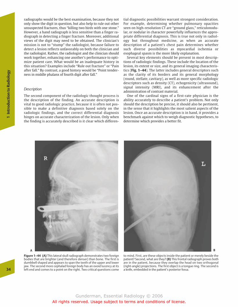
radiographs would be the best examination, because they notonly show the digit in question, but also help to rule out otherunsuspected fractures, thus “killing two birds with one stone.”However, a hand radiograph is less sensitive than a finger ra-diograph in detecting a finger fracture. Moreover, additionalviews of the digit may need to be obtained. The clinician’smission is not to “stump” the radiologist, because failure todetect a lesion reflects unfavorably on both the clinician andthe radiologist. Rather, the radiologist and the clinician shouldwork together, enhancing one another’s performance to opti-mize patient care. What would be an inadequate history inthis situation? Examples include “Rule out fracture” or “Painafter fall.” By contrast, a good history would be “Point tender-ness in middle phalanx of fourth digit after fall.”
Description
The second component of the radiologic thought process isthe description of the finding. An accurate description is vital to good radiologic practice, because it is often not pos-sible to make a definitive diagnosis based solely on the radiologic findings, and the correct differential diagnosishinges on accurate characterization of the lesion. Only whenthe finding is accurately described is it clear which differen-
tial diagnostic possibilities warrant strongest consideration.For example, determining whether pulmonary opacitiesseen on high-resolution CT are “ground glass,” reticulonodu-lar, or nodular in character powerfully influences the appro-priate differential diagnosis. This is true not only in radiol-ogy but throughout medicine, as when an accuratedescription of a patient’s chest pain determines whethersuch diverse possibilities as myocardial ischemia oresophageal spasm is the more likely explanation.
Several key elements should be present in most descrip-tions of radiologic findings. These include the location of thelesion, its extent or size, and its general imaging characteris-tics (Fig. 1–44). The latter includes general descriptors suchas the clarity of its borders and its general morphology(round, stellate, cavitary), as well as more specific radiologicdescriptors such as density (CT), echogenicity (ultrasound),signal intensity (MRI), and its enhancement after the administration of contrast material.
One of the cardinal signs of a first-rate physician is theability accurately to describe a patient’s problem. Not onlyshould the description be precise, it should also be pertinent,in the sense that it highlights the most salient aspects of thelesion. Once an accurate description is in hand, it provides abenchmark against which to weigh diagnostic hypotheses, todetermine which provides a better fit.
34
1In
trod
ucti
on to
Rad
iolo
gy
Figure 1–44 (A) This lateral skull radiograph demonstrates two foreignbodies that are brighter (and therefore denser) than bone. The first isdumbbell shaped and appears to span the teeth of the upper and lowerjaw. The second more cephalad foreign body has an ovoid lucency at itsleft end and comes to a point on the right. Two critical questions come
to mind. First, are these objects inside the patient or merely beside thepatient? Second, what are they? (B) This frontal radiograph proves bothare in the patient, because they overlap the head on two orthogonal(right-angle) projections. The first object is a tongue ring. The second isa knife, embedded in the patient’s posterior fossa.
A B
chapter 01_p1-38.qxd 12/1/05 3:19 PM Page 34
Gunderman, Essential Radiology © 2006All rights reserved. Usage subject to terms and conditions of license.
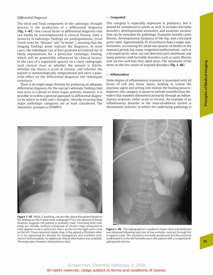
Differential Diagnosis
The third and final component of the radiologic thoughtprocess is the production of a differential diagnosis (Fig. 1–45). One crucial factor in differential diagnosis thatcan hardly be overemphasized is clinical history. Only aminority of radiologic findings are pathognomonic (fromGreek roots for “disease” and “to know”), meaning that theimaging findings alone indicate the diagnosis. In mostcases, the radiologist can at best generate an ordered list oflikely explanations for a particular radiologic finding,which will be powerfully influenced by clinical factors. In the case of a segmental opacity on a chest radiograph,such clinical clues as whether the patient is febrile,whether the illness is acute or chronic, and whether thepatient is immunologically compromised will exert a pow-erful effect on the differential diagnosis the radiologistconstructs.
There is no single magic formula for producing an adequatedifferential diagnosis for the myriad radiologic findings thatmay arise in a dozen or more organ systems; however, it ispossible to outline a general approach to differential diagno-sis by which to order one’s thoughts, thereby ensuring thatmajor pathologic categories are at least considered. Themnemonic acronym is CITIMITV.
�� Congenital
This category is especially important in pediatrics, but itshould be considered in adults as well. It includes heritabledisorders, developmental anomalies, and anatomic variantsthat can be mistaken for pathology. Examples include cysticfibrosis, developmental dysplasia of the hip, and a bicuspidaortic valve. Approximately 3% of newborns have a major mal-formation, accounting for about one quarter of deaths in theneonatal period, but many congenital malformations, such asa bicuspid aortic valve, are not detected until adulthood, andmany patients with heritable disorders such as cystic fibrosisnow survive well into their adult years. The remainder of theitems on this list consist of acquired disorders (Fig. 1–46).
�� Inflammation
Some degree of inflammatory response is associated with allforms of cell and tissue injury, helping to isolate the injurious agent and setting into motion the healing process;however, this category is meant to include noninfectious dis-orders that manifest themselves primarily through an inflam-matory response, either acute or chronic. An example of aninflammatory disorder in the musculoskeletal system isrheumatoid arthritis, in which the underlying pathology is Pr
inci
ple
s o
f Med
ical
Imag
ing
35
Figure 1–45 What, if anything, can we infer about the patient based onthe findings on this frontal chest radiograph? First, the absence of breastshadows suggests the patient is probably male. Overlying both mid-lungs are metallic artifacts composed of circular rings connected towhat appears to be a replica of a ship’s anchor on the right and a crosson the left. These represent nipple rings. Is the patient a Christian sailor,or is he expressing his distaste for evangelicals and maritime com-merce? Unfortunately, no additional clinical information was available.The lungs were, however, interpreted as clear.
Figure 1–46 This radiograph of a newborn’s lower chest and abdomenwas obtained following injection of low-osmolar contrast through theorogastric tube. The stomach is normally positioned, but the proximalsmall bowel is in the left hemothorax in this patient with a congenital di-aphragmatic hernia.
chapter 01_p1-38.qxd 12/1/05 3:19 PM Page 35
Gunderman, Essential Radiology © 2006All rights reserved. Usage subject to terms and conditions of license.
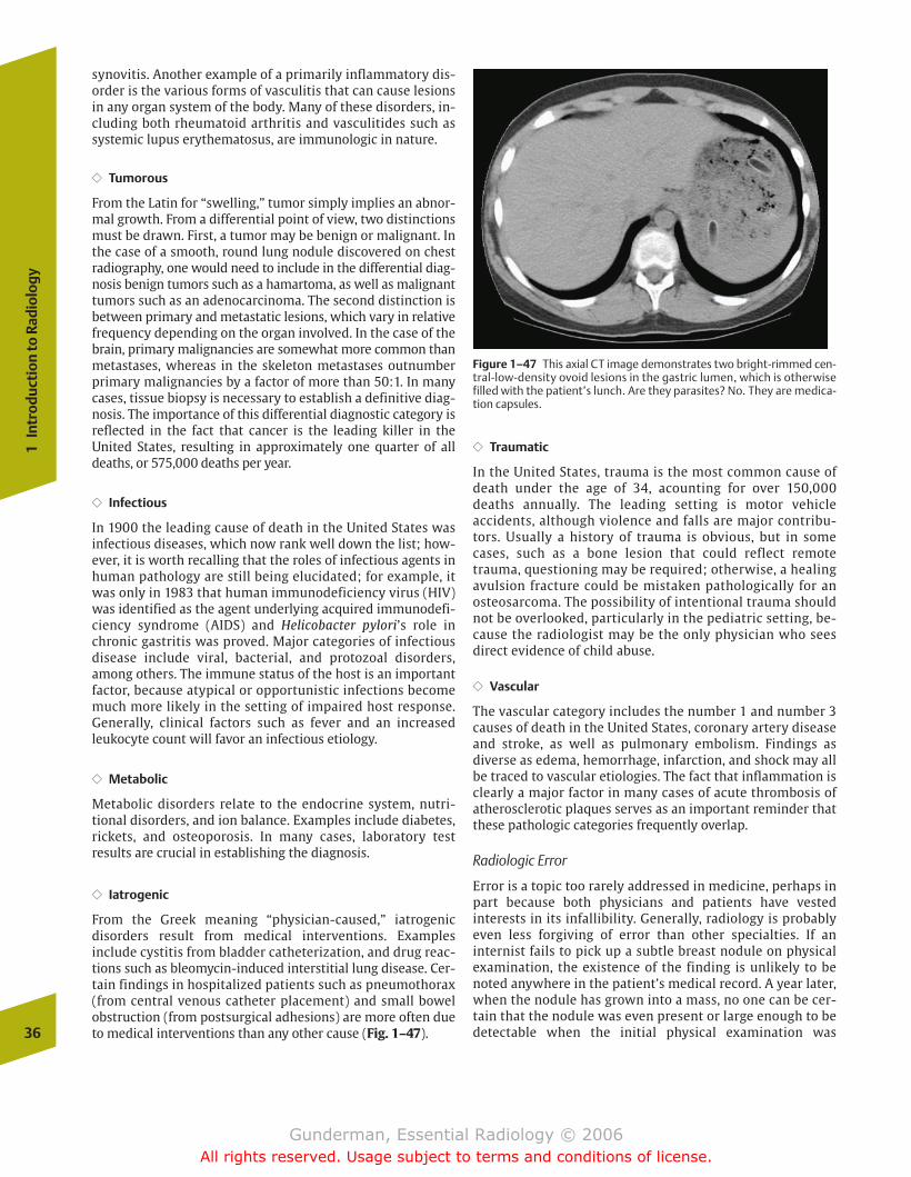
synovitis. Another example of a primarily inflammatory dis-order is the various forms of vasculitis that can cause lesionsin any organ system of the body. Many of these disorders, in-cluding both rheumatoid arthritis and vasculitides such assystemic lupus erythematosus, are immunologic in nature.
�� Tumorous
From the Latin for “swelling,” tumor simply implies an abnor-mal growth. From a differential point of view, two distinctionsmust be drawn. First, a tumor may be benign or malignant. Inthe case of a smooth, round lung nodule discovered on chestradiography, one would need to include in the differential diag-nosis benign tumors such as a hamartoma, as well as malignanttumors such as an adenocarcinoma. The second distinction isbetween primary and metastatic lesions, which vary in relativefrequency depending on the organ involved. In the case of thebrain, primary malignancies are somewhat more common thanmetastases, whereas in the skeleton metastases outnumberprimary malignancies by a factor of more than 50:1. In manycases, tissue biopsy is necessary to establish a definitive diag-nosis. The importance of this differential diagnostic category isreflected in the fact that cancer is the leading killer in theUnited States, resulting in approximately one quarter of alldeaths, or 575,000 deaths per year.
�� Infectious
In 1900 the leading cause of death in the United States wasinfectious diseases, which now rank well down the list; how-ever, it is worth recalling that the roles of infectious agents inhuman pathology are still being elucidated; for example, itwas only in 1983 that human immunodeficiency virus (HIV)was identified as the agent underlying acquired immunodefi-ciency syndrome (AIDS) and Helicobacter pylori’s role inchronic gastritis was proved. Major categories of infectiousdisease include viral, bacterial, and protozoal disorders,among others. The immune status of the host is an importantfactor, because atypical or opportunistic infections becomemuch more likely in the setting of impaired host response.Generally, clinical factors such as fever and an increasedleukocyte count will favor an infectious etiology.
�� Metabolic
Metabolic disorders relate to the endocrine system, nutri-tional disorders, and ion balance. Examples include diabetes,rickets, and osteoporosis. In many cases, laboratory test results are crucial in establishing the diagnosis.
�� Iatrogenic
From the Greek meaning “physician-caused,” iatrogenic disorders result from medical interventions. Examples include cystitis from bladder catheterization, and drug reac-tions such as bleomycin-induced interstitial lung disease. Cer-tain findings in hospitalized patients such as pneumothorax(from central venous catheter placement) and small bowelobstruction (from postsurgical adhesions) are more often dueto medical interventions than any other cause (Fig. 1–47).
�� Traumatic
In the United States, trauma is the most common cause ofdeath under the age of 34, acounting for over 150,000deaths annually. The leading setting is motor vehicle accidents, although violence and falls are major contribu-tors. Usually a history of trauma is obvious, but in somecases, such as a bone lesion that could reflect remotetrauma, questioning may be required; otherwise, a healingavulsion fracture could be mistaken pathologically for anosteosarcoma. The possibility of intentional trauma shouldnot be overlooked, particularly in the pediatric setting, be-cause the radiologist may be the only physician who seesdirect evidence of child abuse.
�� Vascular
The vascular category includes the number 1 and number 3causes of death in the United States, coronary artery diseaseand stroke, as well as pulmonary embolism. Findings as diverse as edema, hemorrhage, infarction, and shock may allbe traced to vascular etiologies. The fact that inflammation isclearly a major factor in many cases of acute thrombosis ofatherosclerotic plaques serves as an important reminder thatthese pathologic categories frequently overlap.
Radiologic Error
Error is a topic too rarely addressed in medicine, perhaps inpart because both physicians and patients have vested interests in its infallibility. Generally, radiology is probablyeven less forgiving of error than other specialties. If an internist fails to pick up a subtle breast nodule on physical examination, the existence of the finding is unlikely to benoted anywhere in the patient’s medical record. A year later,when the nodule has grown into a mass, no one can be cer-tain that the nodule was even present or large enough to bedetectable when the initial physical examination was 36
1In
trod
ucti
on to
Rad
iolo
gy
Figure 1–47 This axial CT image demonstrates two bright-rimmed cen-tral-low-density ovoid lesions in the gastric lumen, which is otherwisefilled with the patient’s lunch. Are they parasites? No. They are medica-tion capsules.
chapter 01_p1-38.qxd 12/1/05 3:19 PM Page 36
Gunderman, Essential Radiology © 2006All rights reserved. Usage subject to terms and conditions of license.
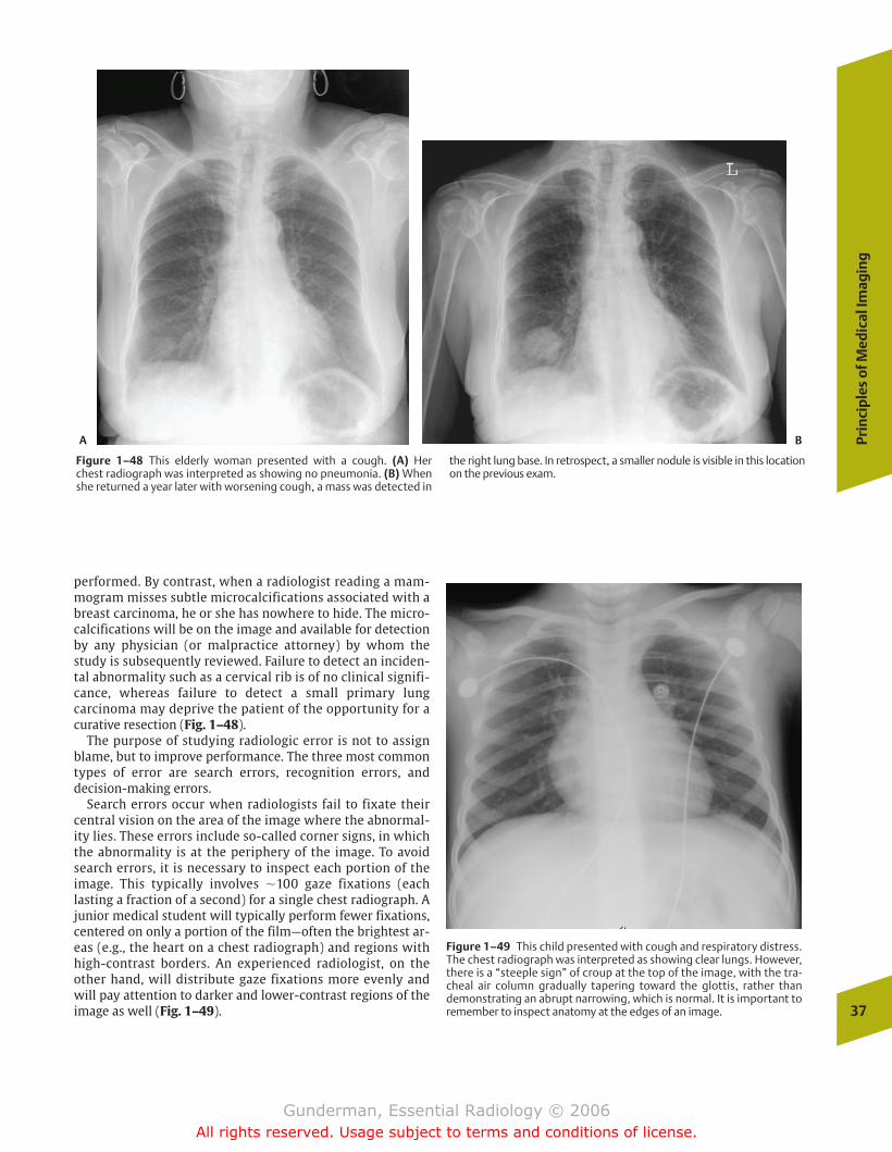
performed. By contrast, when a radiologist reading a mam-mogram misses subtle microcalcifications associated with abreast carcinoma, he or she has nowhere to hide. The micro-calcifications will be on the image and available for detectionby any physician (or malpractice attorney) by whom thestudy is subsequently reviewed. Failure to detect an inciden-tal abnormality such as a cervical rib is of no clinical signifi-cance, whereas failure to detect a small primary lung carcinoma may deprive the patient of the opportunity for acurative resection (Fig. 1–48).
The purpose of studying radiologic error is not to assignblame, but to improve performance. The three most commontypes of error are search errors, recognition errors, and decision-making errors.
Search errors occur when radiologists fail to fixate theircentral vision on the area of the image where the abnormal-ity lies. These errors include so-called corner signs, in whichthe abnormality is at the periphery of the image. To avoidsearch errors, it is necessary to inspect each portion of theimage. This typically involves �100 gaze fixations (each lasting a fraction of a second) for a single chest radiograph. Ajunior medical student will typically perform fewer fixations,centered on only a portion of the film—often the brightest ar-eas (e.g., the heart on a chest radiograph) and regions withhigh-contrast borders. An experienced radiologist, on theother hand, will distribute gaze fixations more evenly andwill pay attention to darker and lower-contrast regions of theimage as well (Fig. 1–49).
Prin
cip
les
of M
edic
al Im
agin
g
37
Figure 1–48 This elderly woman presented with a cough. (A) Her chest radiograph was interpreted as showing no pneumonia. (B) Whenshe returned a year later with worsening cough, a mass was detected in
the right lung base. In retrospect, a smaller nodule is visible in this locationon the previous exam.
A B
Figure 1–49 This child presented with cough and respiratory distress.The chest radiograph was interpreted as showing clear lungs. However,there is a “steeple sign” of croup at the top of the image, with the tra-cheal air column gradually tapering toward the glottis, rather thandemonstrating an abrupt narrowing, which is normal. It is important toremember to inspect anatomy at the edges of an image.
chapter 01_p1-38.qxd 12/1/05 3:19 PM Page 37
Gunderman, Essential Radiology © 2006All rights reserved. Usage subject to terms and conditions of license.
38
1In
trod
ucti
on to
Rad
iolo
gy
normality requires not so much visual acuity as visual mem-ory. The radiologist is comparing this image against a men-tal background composed of many thousands of similar vi-sual experiences, against which the finding either does ordoes not stand out. Recognition differs between differentpeople, depending on the depth and character of their pre-vious experience. To perform well at recognition requires anunderstanding of normal radiologic anatomy and the myr-iad ways in which various disease processes may manifestthemselves.
Decision-making errors may account for slightly over onehalf of all errors in radiologic diagnoses. In these errors, anabnormality is both scanned and recognized, but rejected as“noise” or a normal variant. Again, an experienced visualmemory and an understanding of anatomy and pathophysiol-ogy may serve as the crucial factors in avoiding such errors.In addition, clinical information may play an important rolein helping the radiologist to properly evaluate the signifi-cance of such findings.
One of the most important steps to improving radiologicperformance is taking care to search each image adequately.One of the most common errors in this regard has been called“satisfaction of search.” This is defined as the decreased proba-bility of finding additional abnormalities once an abnormalityhas been correctly identified. Once the radiologist has foundsomething wrong, he or she immediately launches into a dis-cussion of that abnormality, having prematurely terminatedthe search through the remainder of the image. This is an es-pecially common error among neophytes, who often have dif-ficulty finding any abnormality, and are so pleased with them-selves when they do that they stop looking further. Anotherpotential pitfall is the simple failure to devote adequate searchtime to each image. Of course, most radiological examinationsconsist of more than one image, and many, including mostcross-sectional imaging studies such as CT and MRI examina-tions, may contain dozens or even hundreds of images.
Recognition errors occur when an abnormality is scannedbut not appreciated as an abnormality. To recognize an ab-
chapter 01_p1-38.qxd 12/1/05 3:19 PM Page 38
Gunderman, Essential Radiology © 2006All rights reserved. Usage subject to terms and conditions of license.
� Anatomy and Physiology
� Imaging Modalities
RadiographyAngiographyComputed TomographyEchocardiographyNuclear CardiographyMagnetic Resonance Imaging
� Heart
PathologyCongenitalInfectiousInflammatoryVascular
Common Clinical Problems Congestive Heart FailurePulmonary Embolism
� Aorta
Anatomy and Physiology Pathology
AneurysmDissectionTrauma
2The Circulatory System: The Heartand Great Vessels
chapter 02_p39-67.qxd 12/1/05 3:24 PM Page 39
Gunderman, Essential Radiology © 2006All rights reserved. Usage subject to terms and conditions of license.
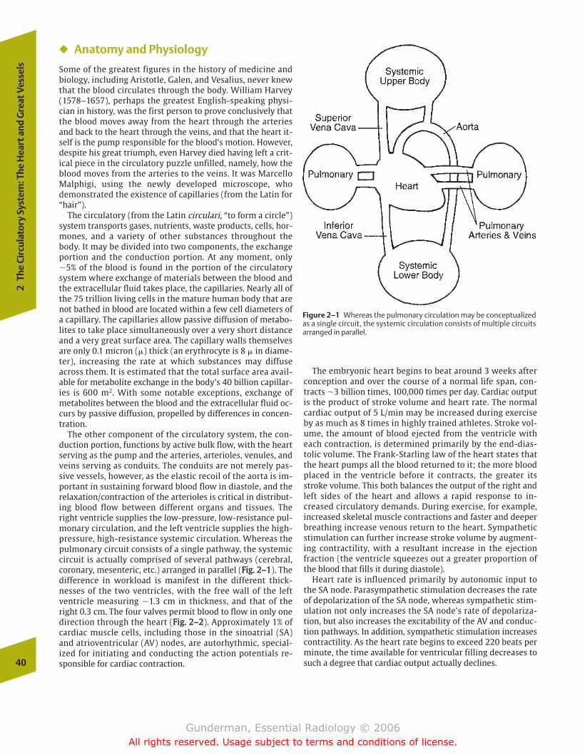
� Anatomy and Physiology
Some of the greatest figures in the history of medicine andbiology, including Aristotle, Galen, and Vesalius, never knewthat the blood circulates through the body. William Harvey(1578–1657), perhaps the greatest English-speaking physi-cian in history, was the first person to prove conclusively thatthe blood moves away from the heart through the arteriesand back to the heart through the veins, and that the heart it-self is the pump responsible for the blood’s motion. However,despite his great triumph, even Harvey died having left a crit-ical piece in the circulatory puzzle unfilled, namely, how theblood moves from the arteries to the veins. It was MarcelloMalphigi, using the newly developed microscope, whodemonstrated the existence of capillaries (from the Latin for“hair”).
The circulatory (from the Latin circulari, “to form a circle”)system transports gases, nutrients, waste products, cells, hor-mones, and a variety of other substances throughout thebody. It may be divided into two components, the exchangeportion and the conduction portion. At any moment, only�5% of the blood is found in the portion of the circulatorysystem where exchange of materials between the blood andthe extracellular fluid takes place, the capillaries. Nearly all ofthe 75 trillion living cells in the mature human body that arenot bathed in blood are located within a few cell diameters ofa capillary. The capillaries allow passive diffusion of metabo-lites to take place simultaneously over a very short distanceand a very great surface area. The capillary walls themselvesare only 0.1 micron (�) thick (an erythrocyte is 8 � in diame-ter), increasing the rate at which substances may diffuseacross them. It is estimated that the total surface area avail-able for metabolite exchange in the body’s 40 billion capillar-ies is 600 m2. With some notable exceptions, exchange ofmetabolites between the blood and the extracellular fluid oc-curs by passive diffusion, propelled by differences in concen-tration.
The other component of the circulatory system, the con-duction portion, functions by active bulk flow, with the heartserving as the pump and the arteries, arterioles, venules, andveins serving as conduits. The conduits are not merely pas-sive vessels, however, as the elastic recoil of the aorta is im-portant in sustaining forward blood flow in diastole, and therelaxation/contraction of the arterioles is critical in distribut-ing blood flow between different organs and tissues. Theright ventricle supplies the low-pressure, low-resistance pul-monary circulation, and the left ventricle supplies the high-pressure, high-resistance systemic circulation. Whereas thepulmonary circuit consists of a single pathway, the systemiccircuit is actually comprised of several pathways (cerebral,coronary, mesenteric, etc.) arranged in parallel (FFiigg.. 22––11). Thedifference in workload is manifest in the different thick-nesses of the two ventricles, with the free wall of the leftventricle measuring �1.3 cm in thickness, and that of theright 0.3 cm. The four valves permit blood to flow in only onedirection through the heart (FFiigg.. 22––22). Approximately 1% ofcardiac muscle cells, including those in the sinoatrial (SA)and atrioventricular (AV) nodes, are autorhythmic, special-ized for initiating and conducting the action potentials re-sponsible for cardiac contraction.
The embryonic heart begins to beat around 3 weeks afterconception and over the course of a normal life span, con-tracts �3 billion times, 100,000 times per day. Cardiac outputis the product of stroke volume and heart rate. The normalcardiac output of 5 L/min may be increased during exerciseby as much as 8 times in highly trained athletes. Stroke vol-ume, the amount of blood ejected from the ventricle witheach contraction, is determined primarily by the end-dias-tolic volume. The Frank-Starling law of the heart states thatthe heart pumps all the blood returned to it; the more bloodplaced in the ventricle before it contracts, the greater itsstroke volume. This both balances the output of the right andleft sides of the heart and allows a rapid response to in-creased circulatory demands. During exercise, for example,increased skeletal muscle contractions and faster and deeperbreathing increase venous return to the heart. Sympatheticstimulation can further increase stroke volume by augment-ing contractility, with a resultant increase in the ejectionfraction (the ventricle squeezes out a greater proportion ofthe blood that fills it during diastole).
Heart rate is influenced primarily by autonomic input tothe SA node. Parasympathetic stimulation decreases the rateof depolarization of the SA node, whereas sympathetic stim-ulation not only increases the SA node’s rate of depolariza-tion, but also increases the excitability of the AV and conduc-tion pathways. In addition, sympathetic stimulation increasescontractility. As the heart rate begins to exceed 220 beats perminute, the time available for ventricular filling decreases tosuch a degree that cardiac output actually declines.40
2Th
e Ci
rcul
ator
y Sy
stem
: The
Hea
rt a
nd G
reat
Ves
sels
Figure 2–1 Whereas the pulmonary circulation may be conceptualizedas a single circuit, the systemic circulation consists of multiple circuitsarranged in parallel.
chapter 02_p39-67.qxd 12/1/05 3:24 PM Page 40
Gunderman, Essential Radiology © 2006All rights reserved. Usage subject to terms and conditions of license.
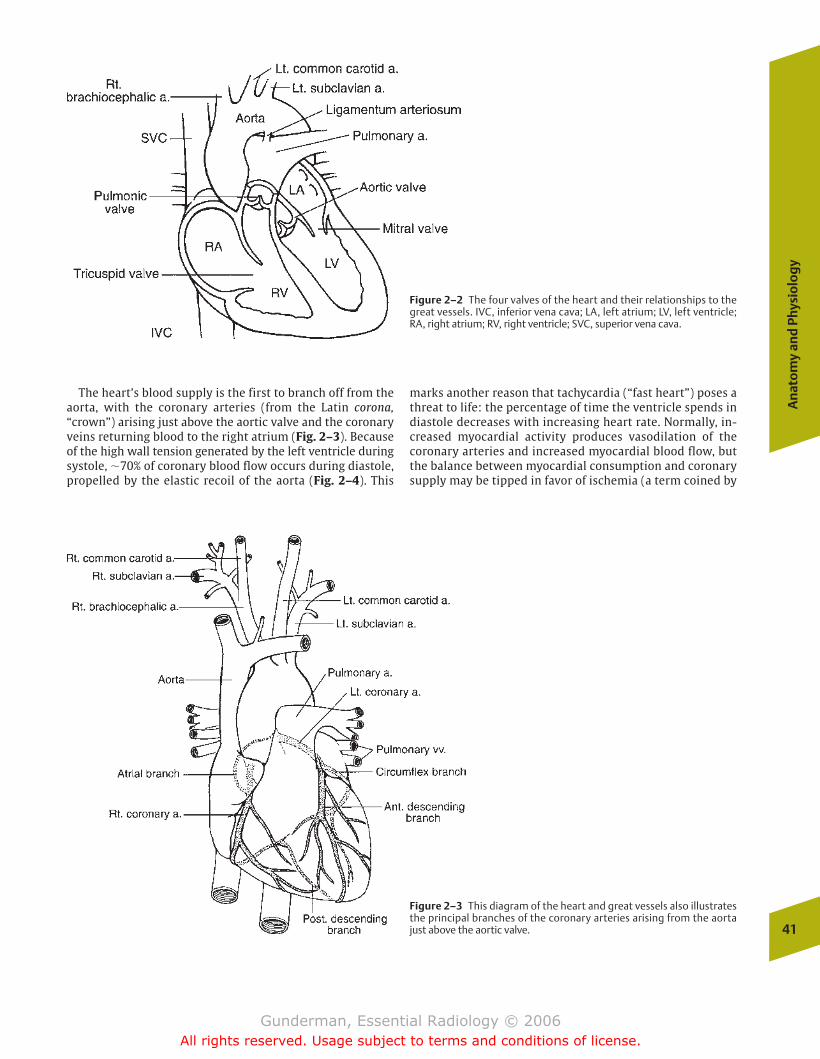
The heart’s blood supply is the first to branch off from theaorta, with the coronary arteries (from the Latin corona,“crown”) arising just above the aortic valve and the coronaryveins returning blood to the right atrium (Fig. 2–3). Becauseof the high wall tension generated by the left ventricle duringsystole, �70% of coronary blood flow occurs during diastole,propelled by the elastic recoil of the aorta (Fig. 2–4). This
marks another reason that tachycardia (“fast heart”) poses athreat to life: the percentage of time the ventricle spends indiastole decreases with increasing heart rate. Normally, in-creased myocardial activity produces vasodilation of thecoronary arteries and increased myocardial blood flow, butthe balance between myocardial consumption and coronarysupply may be tipped in favor of ischemia (a term coined by
An
ato
my
and
Phy
sio
log
y
41
Figure 2–2 The four valves of the heart and their relationships to thegreat vessels. IVC, inferior vena cava; LA, left atrium; LV, left ventricle;RA, right atrium; RV, right ventricle; SVC, superior vena cava.
Figure 2–3 This diagram of the heart and great vessels also illustratesthe principal branches of the coronary arteries arising from the aortajust above the aortic valve.
chapter 02_p39-67.qxd(Rev).qxd 2/15/07 9:38 PM Page 41
Gunderman, Essential Radiology © 2006All rights reserved. Usage subject to terms and conditions of license.
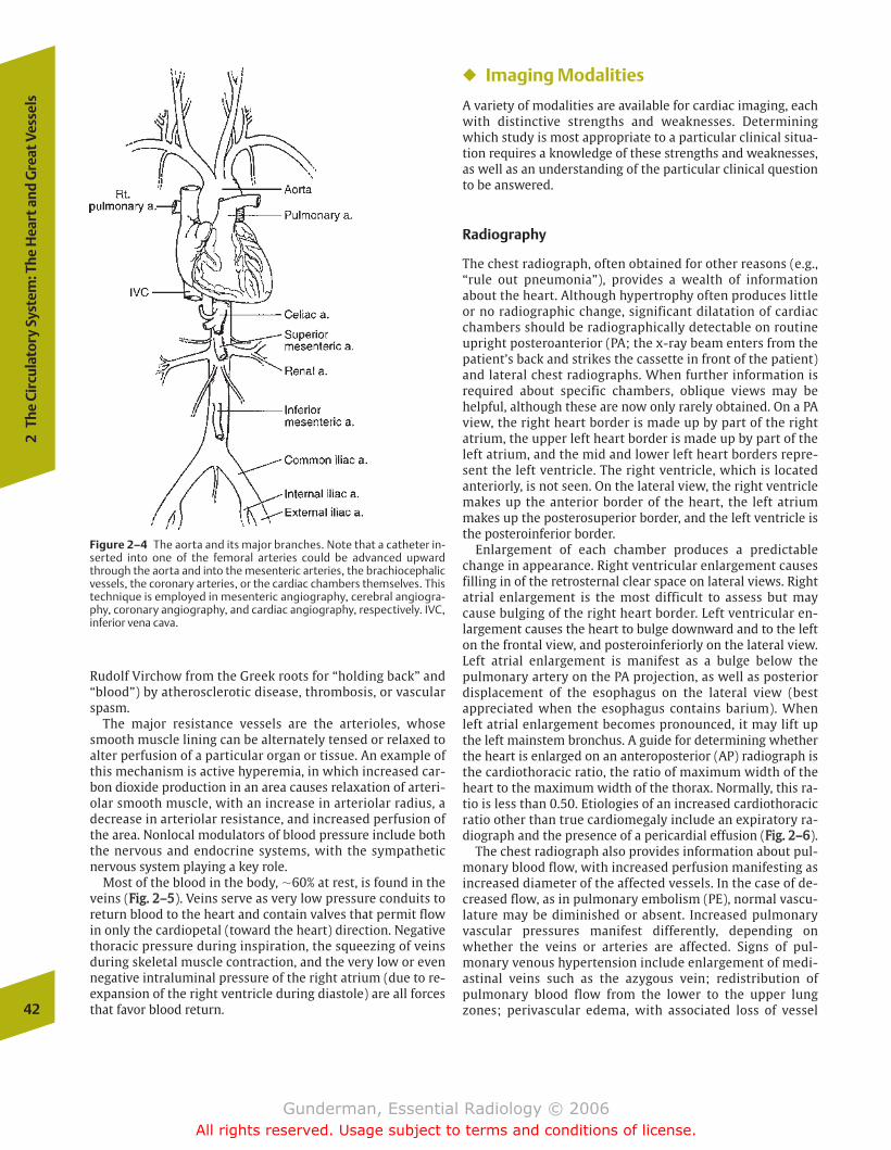
Rudolf Virchow from the Greek roots for “holding back” and“blood”) by atherosclerotic disease, thrombosis, or vascularspasm.
The major resistance vessels are the arterioles, whosesmooth muscle lining can be alternately tensed or relaxed toalter perfusion of a particular organ or tissue. An example ofthis mechanism is active hyperemia, in which increased car-bon dioxide production in an area causes relaxation of arteri-olar smooth muscle, with an increase in arteriolar radius, adecrease in arteriolar resistance, and increased perfusion ofthe area. Nonlocal modulators of blood pressure include boththe nervous and endocrine systems, with the sympatheticnervous system playing a key role.
Most of the blood in the body, �60% at rest, is found in theveins (FFiigg.. 22––55). Veins serve as very low pressure conduits toreturn blood to the heart and contain valves that permit flowin only the cardiopetal (toward the heart) direction. Negativethoracic pressure during inspiration, the squeezing of veinsduring skeletal muscle contraction, and the very low or evennegative intraluminal pressure of the right atrium (due to re-expansion of the right ventricle during diastole) are all forcesthat favor blood return.
� Imaging Modalities
A variety of modalities are available for cardiac imaging, eachwith distinctive strengths and weaknesses. Determiningwhich study is most appropriate to a particular clinical situa-tion requires a knowledge of these strengths and weaknesses,as well as an understanding of the particular clinical questionto be answered.
Radiography
The chest radiograph, often obtained for other reasons (e.g.,“rule out pneumonia”), provides a wealth of informationabout the heart. Although hypertrophy often produces littleor no radiographic change, significant dilatation of cardiacchambers should be radiographically detectable on routineupright posteroanterior (PA; the x-ray beam enters from thepatient’s back and strikes the cassette in front of the patient)and lateral chest radiographs. When further information isrequired about specific chambers, oblique views may behelpful, although these are now only rarely obtained. On a PAview, the right heart border is made up by part of the rightatrium, the upper left heart border is made up by part of theleft atrium, and the mid and lower left heart borders repre-sent the left ventricle. The right ventricle, which is locatedanteriorly, is not seen. On the lateral view, the right ventriclemakes up the anterior border of the heart, the left atriummakes up the posterosuperior border, and the left ventricle isthe posteroinferior border.
Enlargement of each chamber produces a predictablechange in appearance. Right ventricular enlargement causesfilling in of the retrosternal clear space on lateral views. Rightatrial enlargement is the most difficult to assess but maycause bulging of the right heart border. Left ventricular en-largement causes the heart to bulge downward and to the lefton the frontal view, and posteroinferiorly on the lateral view.Left atrial enlargement is manifest as a bulge below thepulmonary artery on the PA projection, as well as posteriordisplacement of the esophagus on the lateral view (bestappreciated when the esophagus contains barium). Whenleft atrial enlargement becomes pronounced, it may lift upthe left mainstem bronchus. A guide for determining whetherthe heart is enlarged on an anteroposterior (AP) radiograph isthe cardiothoracic ratio, the ratio of maximum width of theheart to the maximum width of the thorax. Normally, this ra-tio is less than 0.50. Etiologies of an increased cardiothoracicratio other than true cardiomegaly include an expiratory ra-diograph and the presence of a pericardial effusion (FFiigg.. 22––66).
The chest radiograph also provides information about pul-monary blood flow, with increased perfusion manifesting asincreased diameter of the affected vessels. In the case of de-creased flow, as in pulmonary embolism (PE), normal vascu-lature may be diminished or absent. Increased pulmonaryvascular pressures manifest differently, depending onwhether the veins or arteries are affected. Signs of pul-monary venous hypertension include enlargement of medi-astinal veins such as the azygous vein; redistribution ofpulmonary blood flow from the lower to the upper lungzones; perivascular edema, with associated loss of vessel42
2Th
e Ci
rcul
ator
y Sy
stem
: The
Hea
rt a
nd G
reat
Ves
sels
Figure 2–4 The aorta and its major branches. Note that a catheter in-serted into one of the femoral arteries could be advanced upwardthrough the aorta and into the mesenteric arteries, the brachiocephalicvessels, the coronary arteries, or the cardiac chambers themselves. Thistechnique is employed in mesenteric angiography, cerebral angiogra-phy, coronary angiography, and cardiac angiography, respectively. IVC,inferior vena cava.
chapter 02_p39-67.qxd 12/1/05 3:24 PM Page 42
Gunderman, Essential Radiology © 2006All rights reserved. Usage subject to terms and conditions of license.
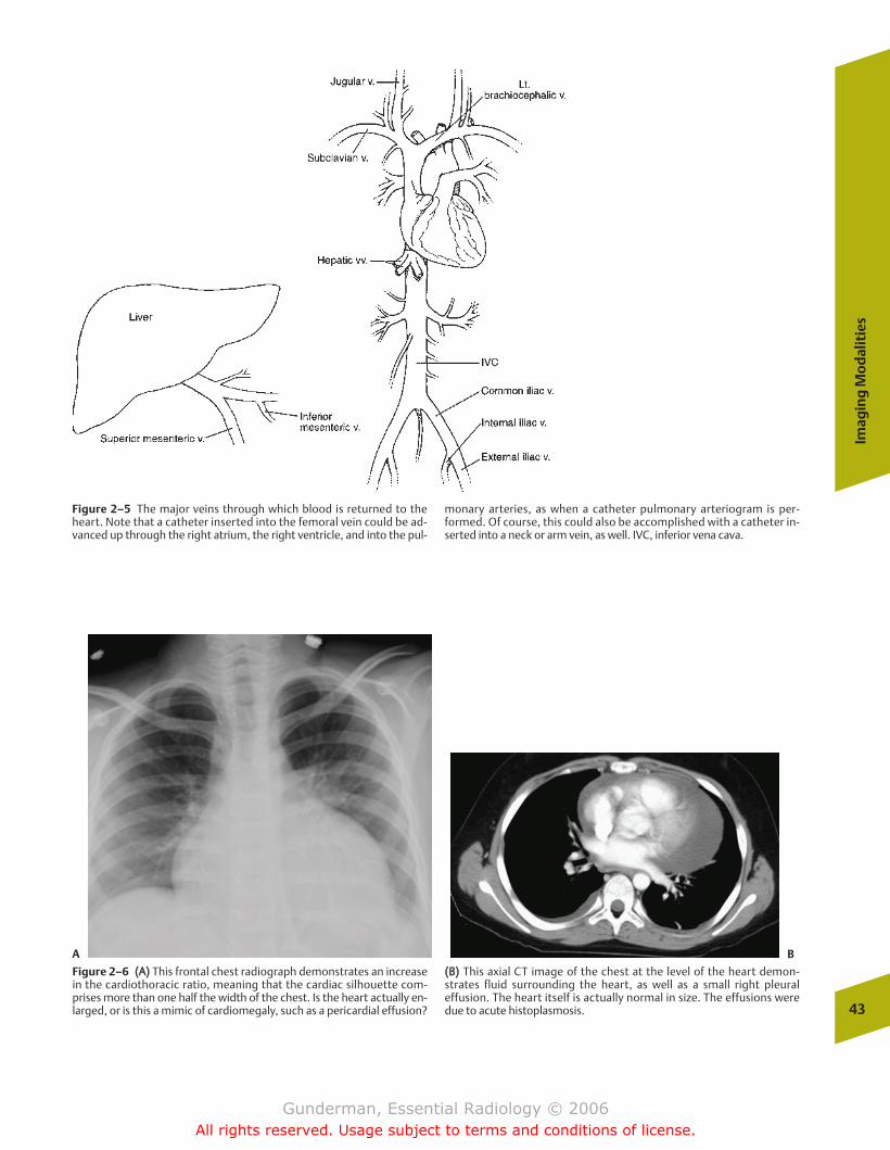
Imag
ing
Mo
dal
itie
s
43
Figure 2–5 The major veins through which blood is returned to theheart. Note that a catheter inserted into the femoral vein could be ad-vanced up through the right atrium, the right ventricle, and into the pul-
monary arteries, as when a catheter pulmonary arteriogram is per-formed. Of course, this could also be accomplished with a catheter in-serted into a neck or arm vein, as well. IVC, inferior vena cava.
A B
Figure 2–6 ((AA)) This frontal chest radiograph demonstrates an increasein the cardiothoracic ratio, meaning that the cardiac silhouette com-prises more than one half the width of the chest. Is the heart actually en-larged, or is this a mimic of cardiomegaly, such as a pericardial effusion?
((BB)) This axial CT image of the chest at the level of the heart demon-strates fluid surrounding the heart, as well as a small right pleuraleffusion. The heart itself is actually normal in size. The effusions weredue to acute histoplasmosis.
chapter 02_p39-67.qxd 12/1/05 3:24 PM Page 43
Gunderman, Essential Radiology © 2006All rights reserved. Usage subject to terms and conditions of license.
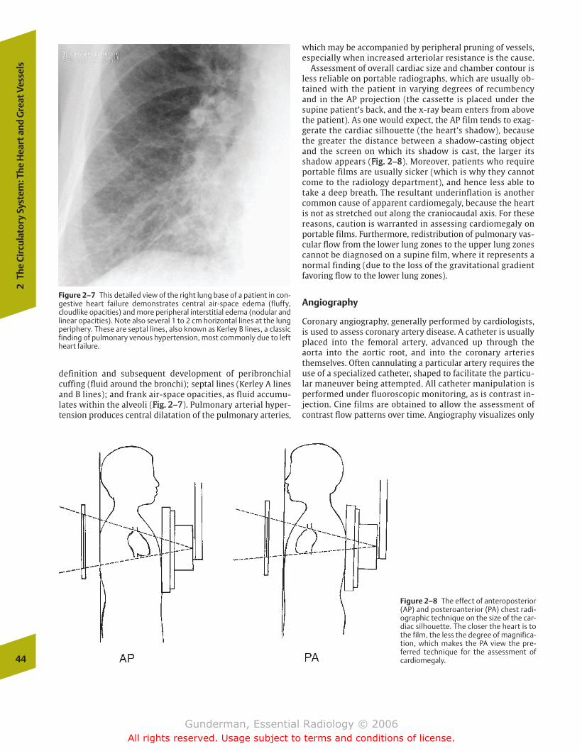
definition and subsequent development of peribronchialcuffing (fluid around the bronchi); septal lines (Kerley A linesand B lines); and frank air-space opacities, as fluid accumu-lates within the alveoli (FFiigg.. 22––77). Pulmonary arterial hyper-tension produces central dilatation of the pulmonary arteries,
which may be accompanied by peripheral pruning of vessels,especially when increased arteriolar resistance is the cause.
Assessment of overall cardiac size and chamber contour isless reliable on portable radiographs, which are usually ob-tained with the patient in varying degrees of recumbencyand in the AP projection (the cassette is placed under thesupine patient’s back, and the x-ray beam enters from abovethe patient). As one would expect, the AP film tends to exag-gerate the cardiac silhouette (the heart’s shadow), becausethe greater the distance between a shadow-casting objectand the screen on which its shadow is cast, the larger itsshadow appears (FFiigg.. 22––88). Moreover, patients who requireportable films are usually sicker (which is why they cannotcome to the radiology department), and hence less able totake a deep breath. The resultant underinflation is anothercommon cause of apparent cardiomegaly, because the heartis not as stretched out along the craniocaudal axis. For thesereasons, caution is warranted in assessing cardiomegaly onportable films. Furthermore, redistribution of pulmonary vas-cular flow from the lower lung zones to the upper lung zonescannot be diagnosed on a supine film, where it represents anormal finding (due to the loss of the gravitational gradientfavoring flow to the lower lung zones).
Angiography
Coronary angiography, generally performed by cardiologists,is used to assess coronary artery disease. A catheter is usuallyplaced into the femoral artery, advanced up through theaorta into the aortic root, and into the coronary arteriesthemselves. Often cannulating a particular artery requires theuse of a specialized catheter, shaped to facilitate the particu-lar maneuver being attempted. All catheter manipulation isperformed under fluoroscopic monitoring, as is contrast in-jection. Cine films are obtained to allow the assessment ofcontrast flow patterns over time. Angiography visualizes only
44
2Th
e Ci
rcul
ator
y Sy
stem
: The
Hea
rt a
nd G
reat
Ves
sels
Figure 2–7 This detailed view of the right lung base of a patient in con-gestive heart failure demonstrates central air-space edema (fluffy,cloudlike opacities) and more peripheral interstitial edema (nodular andlinear opacities). Note also several 1 to 2 cm horizontal lines at the lungperiphery. These are septal lines, also known as Kerley B lines, a classicfinding of pulmonary venous hypertension, most commonly due to leftheart failure.
Figure 2–8 The effect of anteroposterior(AP) and posteroanterior (PA) chest radi-ographic technique on the size of the car-diac silhouette. The closer the heart is tothe film, the less the degree of magnifica-tion, which makes the PA view the pre-ferred technique for the assessment ofcardiomegaly.
chapter 02_p39-67.qxd 12/1/05 3:24 PM Page 44
Gunderman, Essential Radiology © 2006All rights reserved. Usage subject to terms and conditions of license.
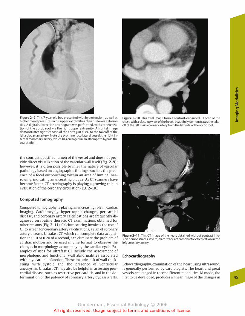
the contrast opacified lumen of the vessel and does not pro-vide direct visualization of the vascular wall itself (FFiigg.. 22––99);however, it is often possible to infer the nature of vascularpathology based on angiographic findings, such as the pres-ence of a focal outpouching within an area of luminal nar-rowing, indicating an ulcerating plaque. As CT scanners havebecome faster, CT arteriography is playing a growing role inevaluation of the coronary circulation (FFiigg.. 22––1100).
Computed Tomography
Computed tomography is playing an increasing role in cardiacimaging. Cardiomegaly, hypertrophic changes, pericardialdisease, and coronary artery calcifications are frequently di-agnosed on routine thoracic CT examinations obtained forother reasons (FFiigg.. 22––1111). Calcium scoring involves the use ofCT to screen for coronary artery calcifications, a sign of coronaryartery disease. Ultrafast CT, which can complete data acquisi-tion in 0.10 or 0.20 of a second, can eliminate the problem ofcardiac motion and be used in cine format to observe thechanges in morphology accompanying the cardiac cycle. Ex-amples of uses for ultrafast CT include the assessment ofmorphologic and functional wall abnormalities associatedwith myocardial infarction. These include lack of wall thick-ening with systole and the presence of ventricularaneurysms. Ultrafast CT may also be helpful in assessing peri-cardial disease, such as restrictive pericarditis, and in the de-termination of the patency of coronary artery bypass grafts.
Echocardiography
Echocardiography, examination of the heart using ultrasound,is generally performed by cardiologists. The heart and greatvessels are imaged in three different modalities. M mode, thefirst to be developed, produces a linear image of the changes in
Imag
ing
Mo
dal
itie
s
45
Figure 2–9 This 7-year-old boy presented with hypertension, as well ashigher blood pressures in his upper extremities than his lower extremi-ties. A digital subtraction arteriogram was performed, with catheteriza-tion of the aortic root via the right upper extremity. A frontal imagedemonstrates tight stenosis of the aorta just distal to the takeoff of theleft subclavian artery. Note the prominent collateral vessel, the right in-ternal mammary artery, which has enlarged in an attempt to bypass thecoarctation.
Figure 2–10 This axial image from a contrast-enhanced CT scan of thechest, with a close-up view of the heart, beautifully demonstrates the take-off of the left main coronary artery from the left side of the aortic root.
Figure 2–11 This CT image of the heart obtained without contrast infu-sion demonstrates severe, tram-track atherosclerotic calcification in theleft coronary artery.
chapter 02_p39-67.qxd 12/1/05 3:24 PM Page 45
Gunderman, Essential Radiology © 2006All rights reserved. Usage subject to terms and conditions of license.
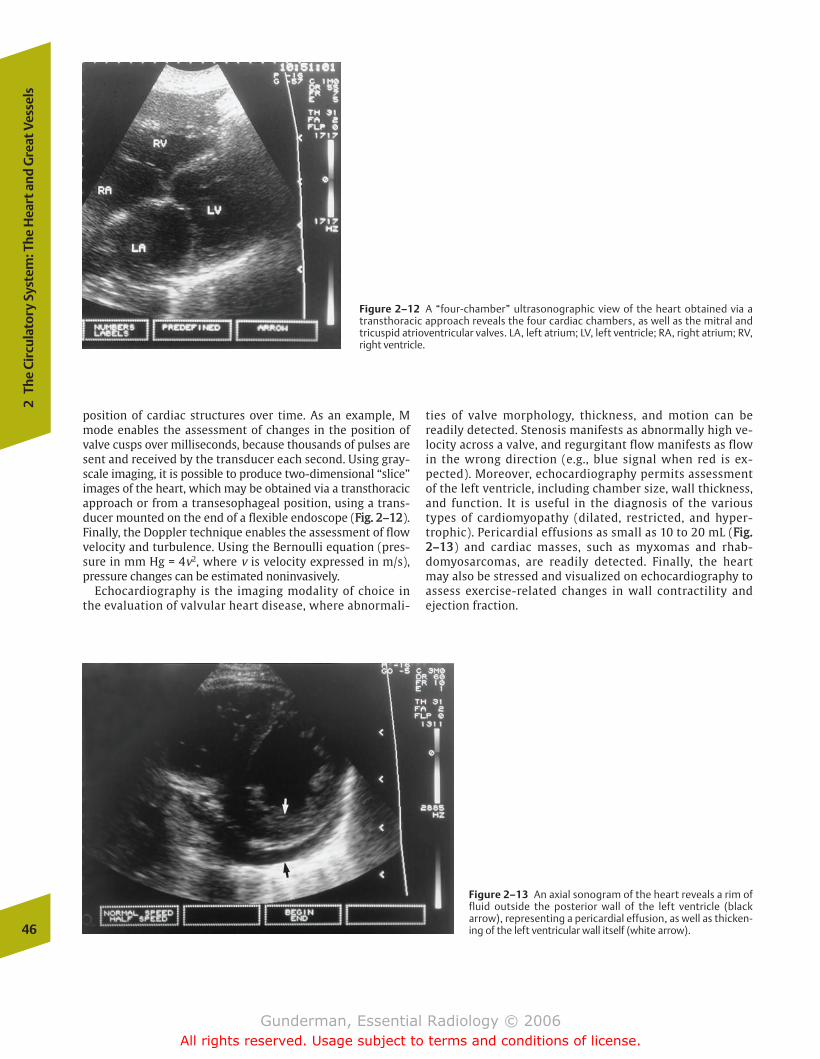
position of cardiac structures over time. As an example, Mmode enables the assessment of changes in the position ofvalve cusps over milliseconds, because thousands of pulses aresent and received by the transducer each second. Using gray-scale imaging, it is possible to produce two-dimensional “slice”images of the heart, which may be obtained via a transthoracicapproach or from a transesophageal position, using a trans-ducer mounted on the end of a flexible endoscope (FFiigg.. 22––1122).Finally, the Doppler technique enables the assessment of flowvelocity and turbulence. Using the Bernoulli equation (pres-sure in mm Hg = 4v2, where v is velocity expressed in m/s),pressure changes can be estimated noninvasively.
Echocardiography is the imaging modality of choice inthe evaluation of valvular heart disease, where abnormali-
ties of valve morphology, thickness, and motion can bereadily detected. Stenosis manifests as abnormally high ve-locity across a valve, and regurgitant flow manifests as flowin the wrong direction (e.g., blue signal when red is ex-pected). Moreover, echocardiography permits assessmentof the left ventricle, including chamber size, wall thickness,and function. It is useful in the diagnosis of the varioustypes of cardiomyopathy (dilated, restricted, and hyper-trophic). Pericardial effusions as small as 10 to 20 mL (FFiigg..22––1133) and cardiac masses, such as myxomas and rhab-domyosarcomas, are readily detected. Finally, the heartmay also be stressed and visualized on echocardiography toassess exercise-related changes in wall contractility andejection fraction.
46
2Th
e Ci
rcul
ator
y Sy
stem
: The
Hea
rt a
nd G
reat
Ves
sels
Figure 2–12 A “four-chamber” ultrasonographic view of the heart obtained via atransthoracic approach reveals the four cardiac chambers, as well as the mitral andtricuspid atrioventricular valves. LA, left atrium; LV, left ventricle; RA, right atrium; RV,right ventricle.
Figure 2–13 An axial sonogram of the heart reveals a rim offluid outside the posterior wall of the left ventricle (blackarrow), representing a pericardial effusion, as well as thicken-ing of the left ventricular wall itself (white arrow).
chapter 02_p39-67.qxd(Rev).qxd 1/17/06 8:51 AM Page 46
Gunderman, Essential Radiology © 2006All rights reserved. Usage subject to terms and conditions of license.
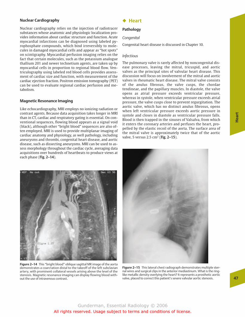
Nuclear Cardiography
Nuclear cardiography relies on the injection of radiotracersubstances whose anatomic and physiologic localization pro-vides information about cardiac structure and function. Acutemyocardial infarctions can be diagnosed using labeled py-rophosphate compounds, which bind irreversibly to mole-cules in damaged myocardial cells and appear as “hot spots”on scintigraphy. Myocardial perfusion imaging relies on thefact that certain molecules, such as the potassium analoguethallium 201 and newer technetium agents, are taken up bymyocardial cells in proportion to regional blood flow. Ven-triculography using labeled red blood cells provides assess-ment of cardiac size and function, with measurement of thecardiac ejection fraction. Positron emission tomography (PET)can be used to evaluate regional cardiac perfusion and me-tabolism.
Magnetic Resonance Imaging
Like echocardiography, MRI employs no ionizing radiation orcontrast agents. Because data acquisition takes longer in MRIthan in CT, cardiac and respiratory gating is essential. On con-ventional sequences, flowing blood appears as a signal void(black), although other “bright blood” sequences are also of-ten employed. MRI is used to provide multiplanar imaging ofcardiac anatomy and physiology, as well pathology, includinganeurysms and thrombi, congenital heart disease, and aorticdisease, such as dissecting aneurysms. MRI can be used to as-sess morphology throughout the cardiac cycle, averaging dataacquisitions over hundreds of heartbeats to produce views ateach phase (FFiigg.. 22––1144).
� Heart
Pathology
Congenital
Congenital heart disease is discussed in Chapter 10.
Infectious
The pulmonary valve is rarely affected by noncongenital dis-ease processes, leaving the mitral, tricuspid, and aorticvalves as the principal sites of valvular heart disease. Thisdiscussion will focus on involvement of the mitral and aorticvalves in rheumatic heart disease. The mitral valve consistsof the anulus fibrosus, the valve cusps, the chordaetendineae, and the papillary muscles. In diastole, the valveopens as atrial pressure exceeds ventricular pressure,whereas in systole, when ventricular pressure exceeds atrialpressure, the valve cusps close to prevent regurgitation. Theaortic valve, which has no distinct anulus fibrosus, openswhen left ventricular pressure exceeds aortic pressure insystole and closes in diastole as ventricular pressure falls.Blood is then trapped in the sinuses of Valsalva, from whichit enters the coronary arteries and perfuses the heart, pro-pelled by the elastic recoil of the aorta. The surface area ofthe mitral valve is approximately twice that of the aorticvalve, 5 versus 2.5 cm2 (FFiigg.. 22––1155).
Hea
rt
47
Figure 2–14 This “bright blood” oblique sagittal MR image of the aortademonstrates a coarctation distal to the takeoff of the left subclavianartery, with prominent collateral vessels arising above the level of thestenosis. Magnetic resonance imaging can display flowing blood with-out the use of intravenous contrast.
Figure 2–15 This lateral chest radiograph demonstrates multiple ster-nal wires and surgical clips in the anterior mediastinum. What is the ring-like metallic density overlying the heart? It represents a prosthetic aorticvalve, placed to correct this patient’s severe valvular aortic stenosis.
chapter 02_p39-67.qxd 12/1/05 3:25 PM Page 47
Gunderman, Essential Radiology © 2006All rights reserved. Usage subject to terms and conditions of license.
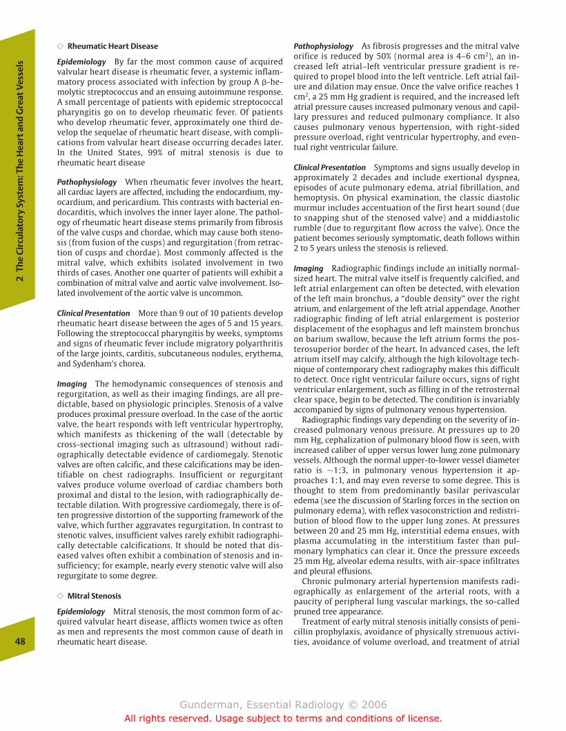
�� Rheumatic Heart Disease
Epidemiology By far the most common cause of acquiredvalvular heart disease is rheumatic fever, a systemic inflam-matory process associated with infection by group A �-he-molytic streptococcus and an ensuing autoimmune response.A small percentage of patients with epidemic streptococcalpharyngitis go on to develop rheumatic fever. Of patientswho develop rheumatic fever, approximately one third de-velop the sequelae of rheumatic heart disease, with compli-cations from valvular heart disease occurring decades later.In the United States, 99% of mitral stenosis is due torheumatic heart disease
Pathophysiology When rheumatic fever involves the heart,all cardiac layers are affected, including the endocardium, my-ocardium, and pericardium. This contrasts with bacterial en-docarditis, which involves the inner layer alone. The pathol-ogy of rheumatic heart disease stems primarily from fibrosisof the valve cusps and chordae, which may cause both steno-sis (from fusion of the cusps) and regurgitation (from retrac-tion of cusps and chordae). Most commonly affected is themitral valve, which exhibits isolated involvement in twothirds of cases. Another one quarter of patients will exhibit acombination of mitral valve and aortic valve involvement. Iso-lated involvement of the aortic valve is uncommon.
Clinical Presentation More than 9 out of 10 patients developrheumatic heart disease between the ages of 5 and 15 years.Following the streptococcal pharyngitis by weeks, symptomsand signs of rheumatic fever include migratory polyarthritisof the large joints, carditis, subcutaneous nodules, erythema,and Sydenham’s chorea.
Imaging The hemodynamic consequences of stenosis andregurgitation, as well as their imaging findings, are all pre-dictable, based on physiologic principles. Stenosis of a valveproduces proximal pressure overload. In the case of the aorticvalve, the heart responds with left ventricular hypertrophy,which manifests as thickening of the wall (detectable bycross-sectional imaging such as ultrasound) without radi-ographically detectable evidence of cardiomegaly. Stenoticvalves are often calcific, and these calcifications may be iden-tifiable on chest radiographs. Insufficient or regurgitantvalves produce volume overload of cardiac chambers bothproximal and distal to the lesion, with radiographically de-tectable dilation. With progressive cardiomegaly, there is of-ten progressive distortion of the supporting framework of thevalve, which further aggravates regurgitation. In contrast tostenotic valves, insufficient valves rarely exhibit radiographi-cally detectable calcifications. It should be noted that dis-eased valves often exhibit a combination of stenosis and in-sufficiency; for example, nearly every stenotic valve will alsoregurgitate to some degree.
�� Mitral Stenosis
Epidemiology Mitral stenosis, the most common form of ac-quired valvular heart disease, afflicts women twice as oftenas men and represents the most common cause of death inrheumatic heart disease.
Pathophysiology As fibrosis progresses and the mitral valveorifice is reduced by 50% (normal area is 4–6 cm2), an in-creased left atrial–left ventricular pressure gradient is re-quired to propel blood into the left ventricle. Left atrial fail-ure and dilation may ensue. Once the valve orifice reaches 1cm2, a 25 mm Hg gradient is required, and the increased leftatrial pressure causes increased pulmonary venous and capil-lary pressures and reduced pulmonary compliance. It alsocauses pulmonary venous hypertension, with right-sidedpressure overload, right ventricular hypertrophy, and even-tual right ventricular failure.
Clinical Presentation Symptoms and signs usually develop inapproximately 2 decades and include exertional dyspnea,episodes of acute pulmonary edema, atrial fibrillation, andhemoptysis. On physical examination, the classic diastolicmurmur includes accentuation of the first heart sound (dueto snapping shut of the stenosed valve) and a middiastolicrumble (due to regurgitant flow across the valve). Once thepatient becomes seriously symptomatic, death follows within2 to 5 years unless the stenosis is relieved.
Imaging Radiographic findings include an initially normal-sized heart. The mitral valve itself is frequently calcified, andleft atrial enlargement can often be detected, with elevationof the left main bronchus, a “double density” over the rightatrium, and enlargement of the left atrial appendage. Anotherradiographic finding of left atrial enlargement is posteriordisplacement of the esophagus and left mainstem bronchuson barium swallow, because the left atrium forms the pos-terosuperior border of the heart. In advanced cases, the leftatrium itself may calcify, although the high kilovoltage tech-nique of contemporary chest radiography makes this difficultto detect. Once right ventricular failure occurs, signs of rightventricular enlargement, such as filling in of the retrosternalclear space, begin to be detected. The condition is invariablyaccompanied by signs of pulmonary venous hypertension.
Radiographic findings vary depending on the severity of in-creased pulmonary venous pressure. At pressures up to 20mm Hg, cephalization of pulmonary blood flow is seen, withincreased caliber of upper versus lower lung zone pulmonaryvessels. Although the normal upper-to-lower vessel diameterratio is �1:3, in pulmonary venous hypertension it ap-proaches 1:1, and may even reverse to some degree. This isthought to stem from predominantly basilar perivascularedema (see the discussion of Starling forces in the section onpulmonary edema), with reflex vasoconstriction and redistri-bution of blood flow to the upper lung zones. At pressuresbetween 20 and 25 mm Hg, interstitial edema ensues, withplasma accumulating in the interstitium faster than pul-monary lymphatics can clear it. Once the pressure exceeds 25 mm Hg, alveolar edema results, with air-space infiltratesand pleural effusions.
Chronic pulmonary arterial hypertension manifests radi-ographically as enlargement of the arterial roots, with apaucity of peripheral lung vascular markings, the so-calledpruned tree appearance.
Treatment of early mitral stenosis initially consists of peni-cillin prophylaxis, avoidance of physically strenuous activi-ties, avoidance of volume overload, and treatment of atrial48
2Th
e Ci
rcul
ator
y Sy
stem
: The
Hea
rt a
nd G
reat
Ves
sels
chapter 02_p39-67.qxd 12/1/05 3:25 PM Page 48
Gunderman, Essential Radiology © 2006All rights reserved. Usage subject to terms and conditions of license.
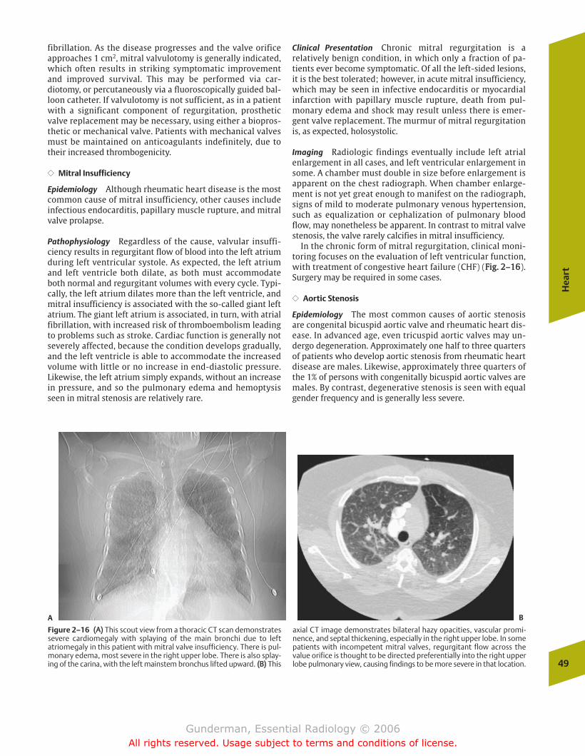
fibrillation. As the disease progresses and the valve orificeapproaches 1 cm2, mitral valvulotomy is generally indicated,which often results in striking symptomatic improvementand improved survival. This may be performed via car-diotomy, or percutaneously via a fluoroscopically guided bal-loon catheter. If valvulotomy is not sufficient, as in a patientwith a significant component of regurgitation, prostheticvalve replacement may be necessary, using either a biopros-thetic or mechanical valve. Patients with mechanical valvesmust be maintained on anticoagulants indefinitely, due totheir increased thrombogenicity.
�� Mitral Insufficiency
Epidemiology Although rheumatic heart disease is the mostcommon cause of mitral insufficiency, other causes includeinfectious endocarditis, papillary muscle rupture, and mitralvalve prolapse.
Pathophysiology Regardless of the cause, valvular insuffi-ciency results in regurgitant flow of blood into the left atriumduring left ventricular systole. As expected, the left atriumand left ventricle both dilate, as both must accommodateboth normal and regurgitant volumes with every cycle. Typi-cally, the left atrium dilates more than the left ventricle, andmitral insufficiency is associated with the so-called giant leftatrium. The giant left atrium is associated, in turn, with atrialfibrillation, with increased risk of thromboembolism leadingto problems such as stroke. Cardiac function is generally notseverely affected, because the condition develops gradually,and the left ventricle is able to accommodate the increasedvolume with little or no increase in end-diastolic pressure.Likewise, the left atrium simply expands, without an increasein pressure, and so the pulmonary edema and hemoptysisseen in mitral stenosis are relatively rare.
Clinical Presentation Chronic mitral regurgitation is arelatively benign condition, in which only a fraction of pa-tients ever become symptomatic. Of all the left-sided lesions,it is the best tolerated; however, in acute mitral insufficiency,which may be seen in infective endocarditis or myocardialinfarction with papillary muscle rupture, death from pul-monary edema and shock may result unless there is emer-gent valve replacement. The murmur of mitral regurgitationis, as expected, holosystolic.
Imaging Radiologic findings eventually include left atrialenlargement in all cases, and left ventricular enlargement insome. A chamber must double in size before enlargement isapparent on the chest radiograph. When chamber enlarge-ment is not yet great enough to manifest on the radiograph,signs of mild to moderate pulmonary venous hypertension,such as equalization or cephalization of pulmonary bloodflow, may nonetheless be apparent. In contrast to mitral valvestenosis, the valve rarely calcifies in mitral insufficiency.
In the chronic form of mitral regurgitation, clinical moni-toring focuses on the evaluation of left ventricular function,with treatment of congestive heart failure (CHF) (FFiigg.. 22––1166).Surgery may be required in some cases.
�� Aortic Stenosis
Epidemiology The most common causes of aortic stenosisare congenital bicuspid aortic valve and rheumatic heart dis-ease. In advanced age, even tricuspid aortic valves may un-dergo degeneration. Approximately one half to three quartersof patients who develop aortic stenosis from rheumatic heartdisease are males. Likewise, approximately three quarters ofthe 1% of persons with congenitally bicuspid aortic valves aremales. By contrast, degenerative stenosis is seen with equalgender frequency and is generally less severe.
Hea
rt
49
A B
Figure 2–16 ((AA)) This scout view from a thoracic CT scan demonstratessevere cardiomegaly with splaying of the main bronchi due to leftatriomegaly in this patient with mitral valve insufficiency. There is pul-monary edema, most severe in the right upper lobe. There is also splay-ing of the carina, with the left mainstem bronchus lifted upward. ((BB)) This
axial CT image demonstrates bilateral hazy opacities, vascular promi-nence, and septal thickening, especially in the right upper lobe. In somepatients with incompetent mitral valves, regurgitant flow across thevalue orifice is thought to be directed preferentially into the right upperlobe pulmonary view, causing findings to be more severe in that location.
chapter 02_p39-67.qxd 12/1/05 3:25 PM Page 49
Gunderman, Essential Radiology © 2006All rights reserved. Usage subject to terms and conditions of license.
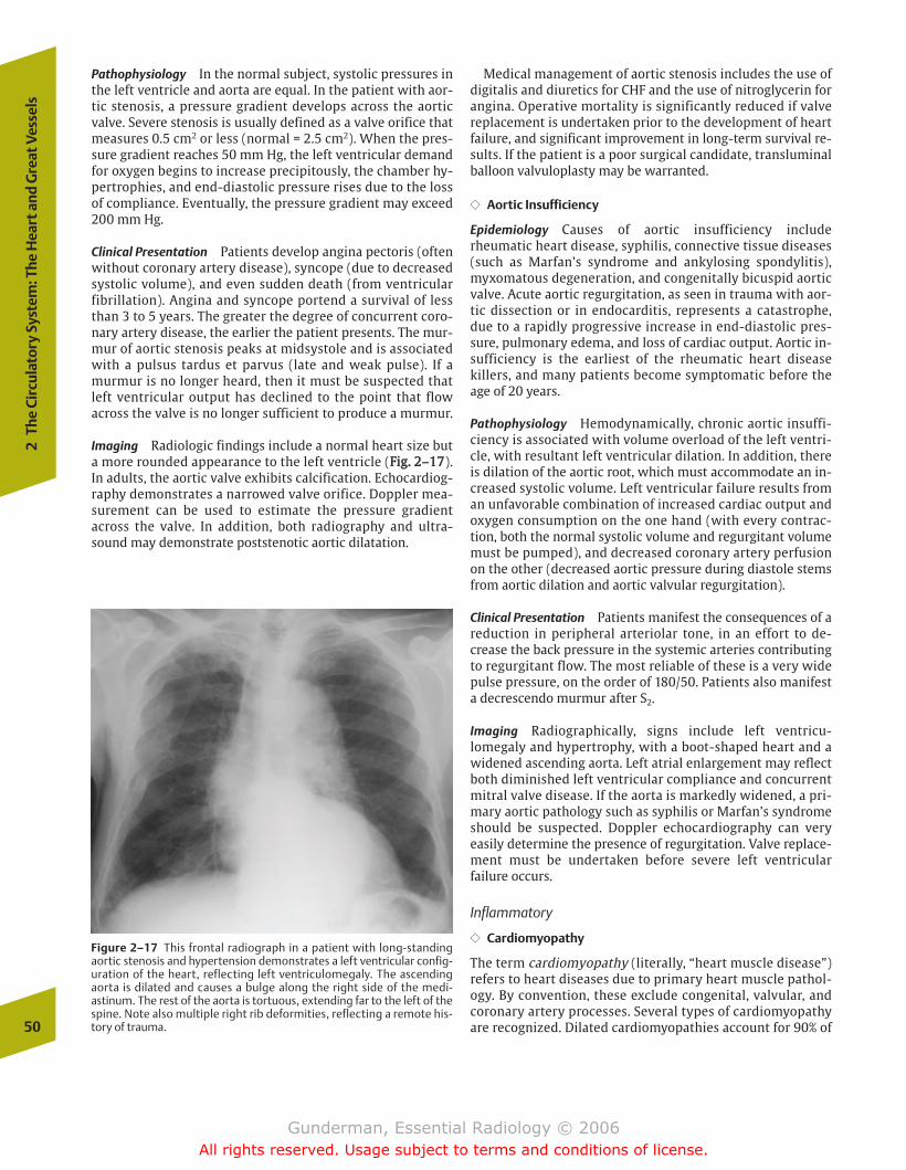
Pathophysiology In the normal subject, systolic pressures inthe left ventricle and aorta are equal. In the patient with aor-tic stenosis, a pressure gradient develops across the aorticvalve. Severe stenosis is usually defined as a valve orifice thatmeasures 0.5 cm2 or less (normal = 2.5 cm2). When the pres-sure gradient reaches 50 mm Hg, the left ventricular demandfor oxygen begins to increase precipitously, the chamber hy-pertrophies, and end-diastolic pressure rises due to the lossof compliance. Eventually, the pressure gradient may exceed200 mm Hg.
Clinical Presentation Patients develop angina pectoris (oftenwithout coronary artery disease), syncope (due to decreasedsystolic volume), and even sudden death (from ventricularfibrillation). Angina and syncope portend a survival of lessthan 3 to 5 years. The greater the degree of concurrent coro-nary artery disease, the earlier the patient presents. The mur-mur of aortic stenosis peaks at midsystole and is associatedwith a pulsus tardus et parvus (late and weak pulse). If amurmur is no longer heard, then it must be suspected thatleft ventricular output has declined to the point that flowacross the valve is no longer sufficient to produce a murmur.
Imaging Radiologic findings include a normal heart size buta more rounded appearance to the left ventricle (FFiigg.. 22––1177).In adults, the aortic valve exhibits calcification. Echocardiog-raphy demonstrates a narrowed valve orifice. Doppler mea-surement can be used to estimate the pressure gradientacross the valve. In addition, both radiography and ultra-sound may demonstrate poststenotic aortic dilatation.
Medical management of aortic stenosis includes the use ofdigitalis and diuretics for CHF and the use of nitroglycerin forangina. Operative mortality is significantly reduced if valvereplacement is undertaken prior to the development of heartfailure, and significant improvement in long-term survival re-sults. If the patient is a poor surgical candidate, transluminalballoon valvuloplasty may be warranted.
�� Aortic Insufficiency
Epidemiology Causes of aortic insufficiency includerheumatic heart disease, syphilis, connective tissue diseases(such as Marfan’s syndrome and ankylosing spondylitis),myxomatous degeneration, and congenitally bicuspid aorticvalve. Acute aortic regurgitation, as seen in trauma with aor-tic dissection or in endocarditis, represents a catastrophe,due to a rapidly progressive increase in end-diastolic pres-sure, pulmonary edema, and loss of cardiac output. Aortic in-sufficiency is the earliest of the rheumatic heart diseasekillers, and many patients become symptomatic before theage of 20 years.
Pathophysiology Hemodynamically, chronic aortic insuffi-ciency is associated with volume overload of the left ventri-cle, with resultant left ventricular dilation. In addition, thereis dilation of the aortic root, which must accommodate an in-creased systolic volume. Left ventricular failure results froman unfavorable combination of increased cardiac output andoxygen consumption on the one hand (with every contrac-tion, both the normal systolic volume and regurgitant volumemust be pumped), and decreased coronary artery perfusionon the other (decreased aortic pressure during diastole stemsfrom aortic dilation and aortic valvular regurgitation).
Clinical Presentation Patients manifest the consequences of areduction in peripheral arteriolar tone, in an effort to de-crease the back pressure in the systemic arteries contributingto regurgitant flow. The most reliable of these is a very widepulse pressure, on the order of 180/50. Patients also manifesta decrescendo murmur after S2.
Imaging Radiographically, signs include left ventricu-lomegaly and hypertrophy, with a boot-shaped heart and awidened ascending aorta. Left atrial enlargement may reflectboth diminished left ventricular compliance and concurrentmitral valve disease. If the aorta is markedly widened, a pri-mary aortic pathology such as syphilis or Marfan’s syndromeshould be suspected. Doppler echocardiography can veryeasily determine the presence of regurgitation. Valve replace-ment must be undertaken before severe left ventricularfailure occurs.
Inflammatory
�� Cardiomyopathy
The term cardiomyopathy (literally, “heart muscle disease”)refers to heart diseases due to primary heart muscle pathol-ogy. By convention, these exclude congenital, valvular, andcoronary artery processes. Several types of cardiomyopathyare recognized. Dilated cardiomyopathies account for 90% of50
2Th
e Ci
rcul
ator
y Sy
stem
: The
Hea
rt a
nd G
reat
Ves
sels
Figure 2–17 This frontal radiograph in a patient with long-standingaortic stenosis and hypertension demonstrates a left ventricular config-uration of the heart, reflecting left ventriculomegaly. The ascendingaorta is dilated and causes a bulge along the right side of the medi-astinum. The rest of the aorta is tortuous, extending far to the left of thespine. Note also multiple right rib deformities, reflecting a remote his-tory of trauma.
chapter 02_p39-67.qxd 12/1/05 3:25 PM Page 50
Gunderman, Essential Radiology © 2006All rights reserved. Usage subject to terms and conditions of license.
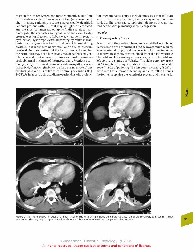
cases in the United States, and most commonly result fromtoxins such as alcohol or previous infection (most commonlyviral). In many patients, the cause is never clearly identified.Patients present with CHF that may be right- or left-sided,and the most common radiographic finding is global car-diomegaly. The ventricles are hypokinetic and exhibit a de-creased ejection fraction—a flabby, weak heart with systolicdysfunction. Hypertrophic cardiomyopathy, by contrast, man-ifests as a thick, muscular heart that does not fill well duringdiastole. It is most commonly familial or due to pressureoverload. Because portions of the heart muscle thicken butthe heart itself may not dilate, nearly 50% of patients may ex-hibit a normal chest radiograph. Cross-sectional imaging re-veals abnormal thickness of the myocardium. Restrictive car-diomyopathy, the rarest form of cardiomyopathy, causesdiastolic dysfunction (inability to dilate during diastole) andexhibits physiology similar to restrictive pericarditis (FFiigg..22––1188). As in hypertrophic cardiomyopathy, diastolic dysfunc-
tion predominates. Causes include processes that infiltrateand stiffen the myocardium, such as amyloidosis and sar-coidosis. The chest radiograph often demonstrates normalcardiac size with pulmonary venous congestion.
Vascular
�� Coronary Artery Disease
Even though the cardiac chambers are refilled with bloodevery second or so throughout life, the myocardium requiresits own arterial supply, and the heart is in fact the first organto receive freshly oxygenated blood from the left ventricle.The right and left coronary arteries originate in the right andleft coronary sinuses of Valsalva. The right coronary artery(RCA) supplies the right ventricle and the atrioventricularnode (in 90% of patients). The left coronary artery (LCA) di-vides into the anterior descending and circumflex arteries,the former supplying the ventricular septum and the anterior
Hea
rt
51Figure 2–18 These axial CT images of the heart demonstrate thick right-sided pericardial calcification of the sort likely to cause restrictivepericarditis. This may help to explain the reflux of intravascular contrast material into this patient’s hepatic veins.
chapter 02_p39-67.qxd 12/1/05 3:25 PM Page 51
Gunderman, Essential Radiology © 2006All rights reserved. Usage subject to terms and conditions of license.
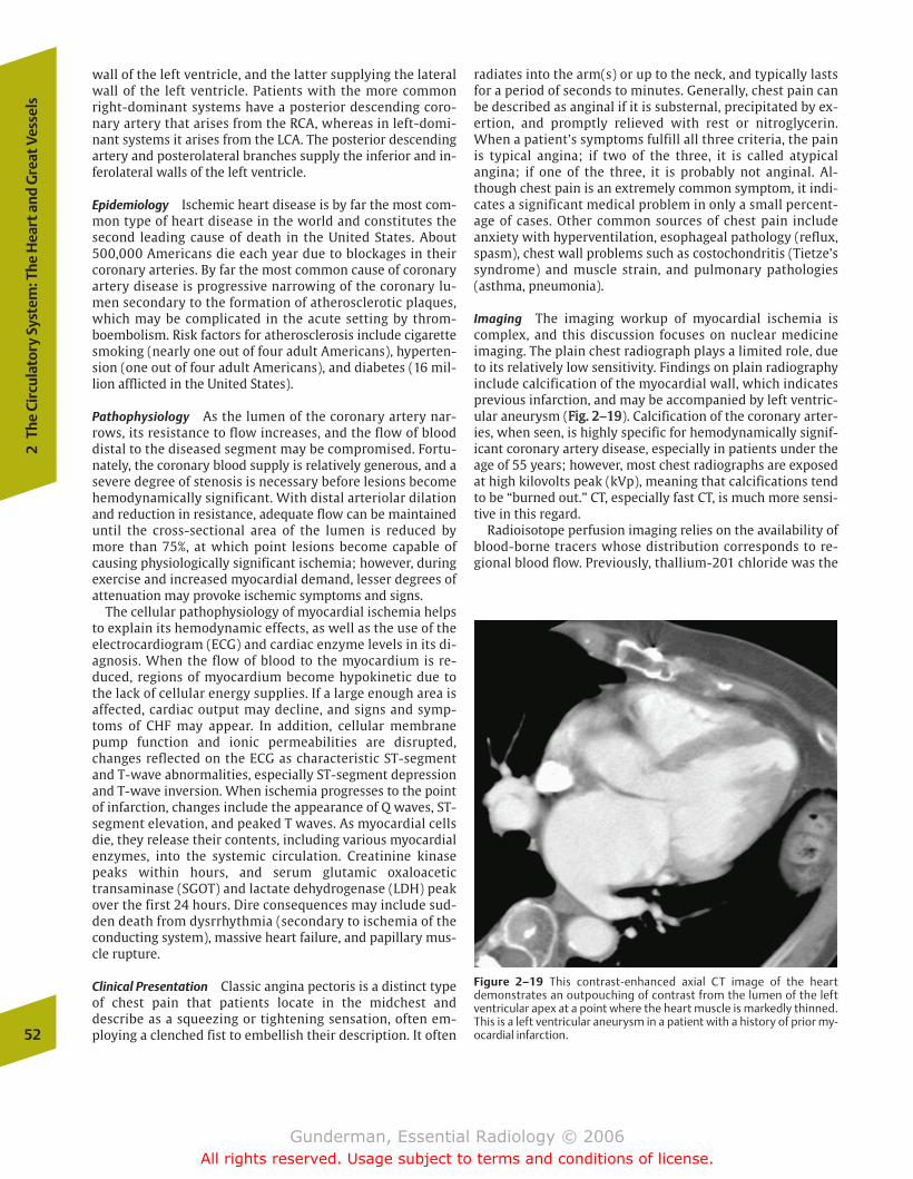
wall of the left ventricle, and the latter supplying the lateralwall of the left ventricle. Patients with the more commonright-dominant systems have a posterior descending coro-nary artery that arises from the RCA, whereas in left-domi-nant systems it arises from the LCA. The posterior descendingartery and posterolateral branches supply the inferior and in-ferolateral walls of the left ventricle.
Epidemiology Ischemic heart disease is by far the most com-mon type of heart disease in the world and constitutes thesecond leading cause of death in the United States. About500,000 Americans die each year due to blockages in theircoronary arteries. By far the most common cause of coronaryartery disease is progressive narrowing of the coronary lu-men secondary to the formation of atherosclerotic plaques,which may be complicated in the acute setting by throm-boembolism. Risk factors for atherosclerosis include cigarettesmoking (nearly one out of four adult Americans), hyperten-sion (one out of four adult Americans), and diabetes (16 mil-lion afflicted in the United States).
Pathophysiology As the lumen of the coronary artery nar-rows, its resistance to flow increases, and the flow of blooddistal to the diseased segment may be compromised. Fortu-nately, the coronary blood supply is relatively generous, and asevere degree of stenosis is necessary before lesions becomehemodynamically significant. With distal arteriolar dilationand reduction in resistance, adequate flow can be maintaineduntil the cross-sectional area of the lumen is reduced bymore than 75%, at which point lesions become capable ofcausing physiologically significant ischemia; however, duringexercise and increased myocardial demand, lesser degrees ofattenuation may provoke ischemic symptoms and signs.
The cellular pathophysiology of myocardial ischemia helpsto explain its hemodynamic effects, as well as the use of theelectrocardiogram (ECG) and cardiac enzyme levels in its di-agnosis. When the flow of blood to the myocardium is re-duced, regions of myocardium become hypokinetic due tothe lack of cellular energy supplies. If a large enough area isaffected, cardiac output may decline, and signs and symp-toms of CHF may appear. In addition, cellular membranepump function and ionic permeabilities are disrupted,changes reflected on the ECG as characteristic ST-segmentand T-wave abnormalities, especially ST-segment depressionand T-wave inversion. When ischemia progresses to the pointof infarction, changes include the appearance of Q waves, ST-segment elevation, and peaked T waves. As myocardial cellsdie, they release their contents, including various myocardialenzymes, into the systemic circulation. Creatinine kinasepeaks within hours, and serum glutamic oxaloacetictransaminase (SGOT) and lactate dehydrogenase (LDH) peakover the first 24 hours. Dire consequences may include sud-den death from dysrrhythmia (secondary to ischemia of theconducting system), massive heart failure, and papillary mus-cle rupture.
Clinical Presentation Classic angina pectoris is a distinct typeof chest pain that patients locate in the midchest anddescribe as a squeezing or tightening sensation, often em-ploying a clenched fist to embellish their description. It often
radiates into the arm(s) or up to the neck, and typically lastsfor a period of seconds to minutes. Generally, chest pain canbe described as anginal if it is substernal, precipitated by ex-ertion, and promptly relieved with rest or nitroglycerin.When a patient’s symptoms fulfill all three criteria, the painis typical angina; if two of the three, it is called atypicalangina; if one of the three, it is probably not anginal. Al-though chest pain is an extremely common symptom, it indi-cates a significant medical problem in only a small percent-age of cases. Other common sources of chest pain includeanxiety with hyperventilation, esophageal pathology (reflux,spasm), chest wall problems such as costochondritis (Tietze’ssyndrome) and muscle strain, and pulmonary pathologies(asthma, pneumonia).
Imaging The imaging workup of myocardial ischemia iscomplex, and this discussion focuses on nuclear medicineimaging. The plain chest radiograph plays a limited role, dueto its relatively low sensitivity. Findings on plain radiographyinclude calcification of the myocardial wall, which indicatesprevious infarction, and may be accompanied by left ventric-ular aneurysm (FFiigg.. 22––1199). Calcification of the coronary arter-ies, when seen, is highly specific for hemodynamically signif-icant coronary artery disease, especially in patients under theage of 55 years; however, most chest radiographs are exposedat high kilovolts peak (kVp), meaning that calcifications tendto be “burned out.” CT, especially fast CT, is much more sensi-tive in this regard.
Radioisotope perfusion imaging relies on the availability ofblood-borne tracers whose distribution corresponds to re-gional blood flow. Previously, thallium-201 chloride was the
52
2Th
e Ci
rcul
ator
y Sy
stem
: The
Hea
rt a
nd G
reat
Ves
sels
Figure 2–19 This contrast-enhanced axial CT image of the heartdemonstrates an outpouching of contrast from the lumen of the leftventricular apex at a point where the heart muscle is markedly thinned.This is a left ventricular aneurysm in a patient with a history of prior my-ocardial infarction.
chapter 02_p39-67.qxd 12/1/05 3:25 PM Page 52
Gunderman, Essential Radiology © 2006All rights reserved. Usage subject to terms and conditions of license.
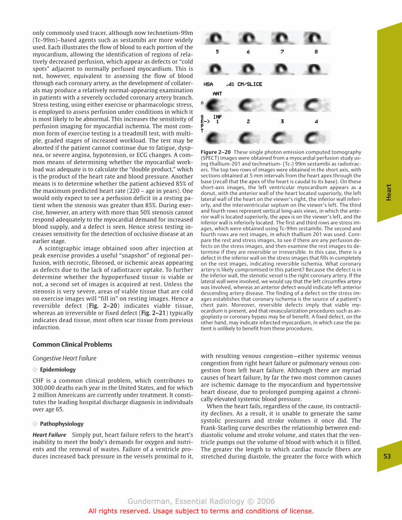
only commonly used tracer, although now technetium-99m(Tc-99m)–based agents such as sestamibi are more widelyused. Each illustrates the flow of blood to each portion of themyocardium, allowing the identification of regions of rela-tively decreased perfusion, which appear as defects or “coldspots” adjacent to normally perfused myocardium. This isnot, however, equivalent to assessing the flow of bloodthrough each coronary artery, as the development of collater-als may produce a relatively normal-appearing examinationin patients with a severely occluded coronary artery branch.Stress testing, using either exercise or pharmacologic stress,is employed to assess perfusion under conditions in which itis most likely to be abnormal. This increases the sensitivity ofperfusion imaging for myocardial ischemia. The most com-mon form of exercise testing is a treadmill test, with multi-ple, graded stages of increased workload. The test may beaborted if the patient cannot continue due to fatigue, dysp-nea, or severe angina, hypotension, or ECG changes. A com-mon means of determining whether the myocardial work-load was adequate is to calculate the “double product,” whichis the product of the heart rate and blood pressure. Anothermeans is to determine whether the patient achieved 85% ofthe maximum predicted heart rate (220 – age in years). Onewould only expect to see a perfusion deficit in a resting pa-tient when the stenosis was greater than 85%. During exer-cise, however, an artery with more than 50% stenosis cannotrespond adequately to the myocardial demand for increasedblood supply, and a defect is seen. Hence stress testing in-creases sensitivity for the detection of occlusive disease at anearlier stage.
A scintigraphic image obtained soon after injection atpeak exercise provides a useful “snapshot” of regional per-fusion, with necrotic, fibrosed, or ischemic areas appearingas defects due to the lack of radiotracer uptake. To furtherdetermine whether the hypoperfused tissue is viable ornot, a second set of images is acquired at rest. Unless thestenosis is very severe, areas of viable tissue that are coldon exercise images will “fill in” on resting images. Hence areversible defect (FFiigg.. 22––2200) indicates viable tissue,whereas an irreversible or fixed defect (FFiigg.. 22––2211) typicallyindicates dead tissue, most often scar tissue from previousinfarction.
Common Clinical Problems
Congestive Heart Failure
�� Epidemiology
CHF is a common clinical problem, which contributes to300,000 deaths each year in the United States, and for which2 million Americans are currently under treatment. It consti-tutes the leading hospital discharge diagnosis in individualsover age 65.
�� Pathophysiology
Heart Failure Simply put, heart failure refers to the heart’sinability to meet the body’s demands for oxygen and nutri-ents and the removal of wastes. Failure of a ventricle pro-duces increased back pressure in the vessels proximal to it,
with resulting venous congestion—either systemic venouscongestion from right heart failure or pulmonary venous con-gestion from left heart failure. Although there are myriadcauses of heart failure, by far the two most common causesare ischemic damage to the myocardium and hypertensiveheart disease, due to prolonged pumping against a chroni-cally elevated systemic blood pressure.
When the heart fails, regardless of the cause, its contractil-ity declines. As a result, it is unable to generate the samesystolic pressures and stroke volumes it once did. The Frank-Starling curve describes the relationship between end-diastolic volume and stroke volume, and states that the ven-tricle pumps out the volume of blood with which it is filled.The greater the length to which cardiac muscle fibers arestretched during diastole, the greater the force with which
Hea
rt
53
Figure 2–20 These single photon emission computed tomography(SPECT) images were obtained from a myocardial perfusion study us-ing thallium-201 and technetium- (Tc-) 99m sestamibi as radiotrac-ers. The top two rows of images were obtained in the short axis, withsections obtained at 5 mm intervals from the heart apex through thebase (recall that the apex of the heart is caudal to its base). On theseshort-axis images, the left ventricular myocardium appears as adonut, with the anterior wall of the heart located superiorly, the leftlateral wall of the heart on the viewer’s right, the inferior wall inferi-orly, and the interventricular septum on the viewer’s left. The thirdand fourth rows represent vertical long-axis views, in which the ante-rior wall is located superiorly, the apex is on the viewer’s left, and theinferior wall is inferiorly located. The first and third rows are stress im-ages, which were obtained using Tc-99m sestamibi. The second andfourth rows are rest images, in which thallium 201 was used. Com-pare the rest and stress images, to see if there are any perfusion de-fects on the stress images, and then examine the rest images to de-termine if they are reversible or irreversible. In this case, there is adefect in the inferior wall on the stress images that fills in completelyon the rest images, indicating reversible ischemia. What coronaryartery is likely compromised in this patient? Because the defect is inthe inferior wall, the stenotic vessel is the right coronary artery. If thelateral wall were involved, we would say that the left circumflex arterywas involved, whereas an anterior defect would indicate left anteriordescending artery disease. The finding of a defect on the stress im-ages establishes that coronary ischemia is the source of a patient’schest pain. Moreover, reversible defects imply that viable my-ocardium is present, and that revascularization procedures such as an-gioplasty or coronary bypass may be of benefit. A fixed defect, on theother hand, may indicate infarcted myocardium, in which case the pa-tient is unlikely to benefit from these procedures.
chapter 02_p39-67.qxd 12/1/05 3:25 PM Page 53
Gunderman, Essential Radiology © 2006All rights reserved. Usage subject to terms and conditions of license.
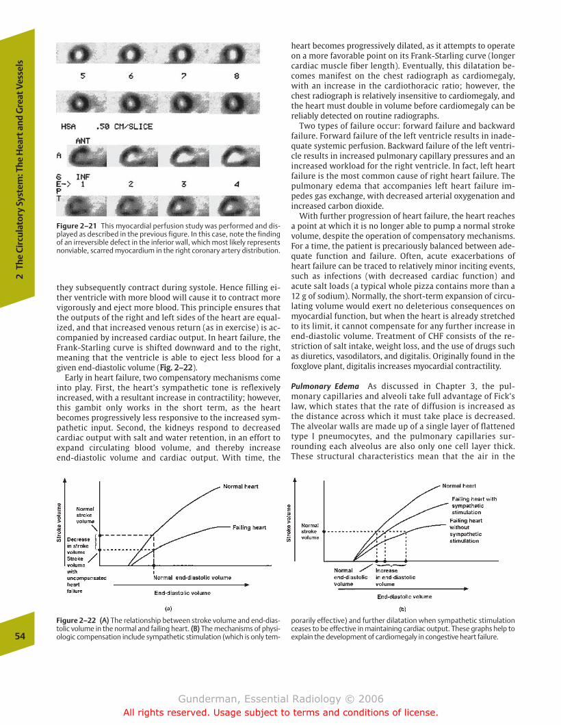
they subsequently contract during systole. Hence filling ei-ther ventricle with more blood will cause it to contract morevigorously and eject more blood. This principle ensures thatthe outputs of the right and left sides of the heart are equal-ized, and that increased venous return (as in exercise) is ac-companied by increased cardiac output. In heart failure, theFrank-Starling curve is shifted downward and to the right,meaning that the ventricle is able to eject less blood for agiven end-diastolic volume (FFiigg.. 22––2222).
Early in heart failure, two compensatory mechanisms comeinto play. First, the heart’s sympathetic tone is reflexivelyincreased, with a resultant increase in contractility; however,this gambit only works in the short term, as the heartbecomes progressively less responsive to the increased sym-pathetic input. Second, the kidneys respond to decreasedcardiac output with salt and water retention, in an effort toexpand circulating blood volume, and thereby increase end-diastolic volume and cardiac output. With time, the
heart becomes progressively dilated, as it attempts to operateon a more favorable point on its Frank-Starling curve (longercardiac muscle fiber length). Eventually, this dilatation be-comes manifest on the chest radiograph as cardiomegaly,with an increase in the cardiothoracic ratio; however, thechest radiograph is relatively insensitive to cardiomegaly, andthe heart must double in volume before cardiomegaly can bereliably detected on routine radiographs.
Two types of failure occur: forward failure and backwardfailure. Forward failure of the left ventricle results in inade-quate systemic perfusion. Backward failure of the left ventri-cle results in increased pulmonary capillary pressures and anincreased workload for the right ventricle. In fact, left heartfailure is the most common cause of right heart failure. Thepulmonary edema that accompanies left heart failure im-pedes gas exchange, with decreased arterial oxygenation andincreased carbon dioxide.
With further progression of heart failure, the heart reachesa point at which it is no longer able to pump a normal strokevolume, despite the operation of compensatory mechanisms.For a time, the patient is precariously balanced between ade-quate function and failure. Often, acute exacerbations ofheart failure can be traced to relatively minor inciting events,such as infections (with decreased cardiac function) andacute salt loads (a typical whole pizza contains more than a12 g of sodium). Normally, the short-term expansion of circu-lating volume would exert no deleterious consequences onmyocardial function, but when the heart is already stretchedto its limit, it cannot compensate for any further increase inend-diastolic volume. Treatment of CHF consists of the re-striction of salt intake, weight loss, and the use of drugs suchas diuretics, vasodilators, and digitalis. Originally found in thefoxglove plant, digitalis increases myocardial contractility.
Pulmonary Edema As discussed in Chapter 3, the pul-monary capillaries and alveoli take full advantage of Fick’slaw, which states that the rate of diffusion is increased asthe distance across which it must take place is decreased.The alveolar walls are made up of a single layer of flattenedtype I pneumocytes, and the pulmonary capillaries sur-rounding each alveolus are also only one cell layer thick.These structural characteristics mean that the air in the
54
2Th
e Ci
rcul
ator
y Sy
stem
: The
Hea
rt a
nd G
reat
Ves
sels
Figure 2–21 This myocardial perfusion study was performed and dis-played as described in the previous figure. In this case, note the findingof an irreversible defect in the inferior wall, which most likely representsnonviable, scarred myocardium in the right coronary artery distribution.
Figure 2–22 ((AA)) The relationship between stroke volume and end-dias-tolic volume in the normal and failing heart. ((BB)) The mechanisms of physi-ologic compensation include sympathetic stimulation (which is only tem-
porarily effective) and further dilatation when sympathetic stimulationceases to be effective in maintaining cardiac output. These graphs help toexplain the development of cardiomegaly in congestive heart failure.
chapter 02_p39-67.qxd 12/1/05 3:25 PM Page 54
Gunderman, Essential Radiology © 2006All rights reserved. Usage subject to terms and conditions of license.
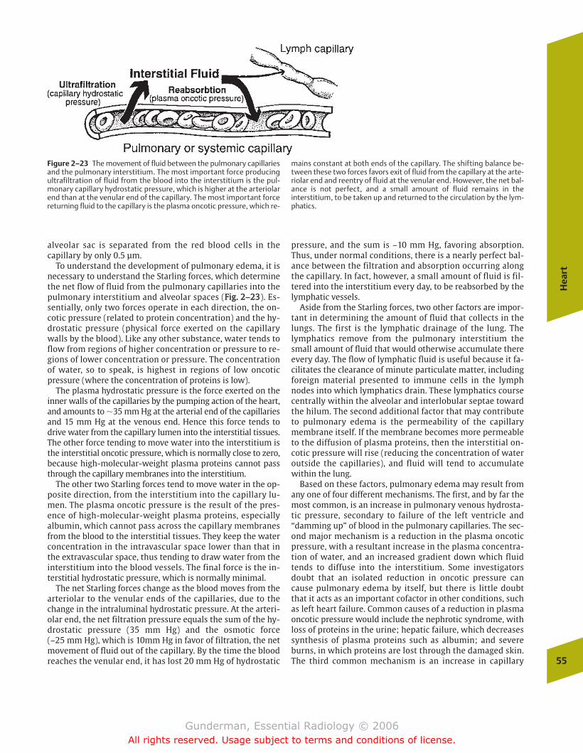
alveolar sac is separated from the red blood cells in thecapillary by only 0.5 µm.
To understand the development of pulmonary edema, it isnecessary to understand the Starling forces, which determinethe net flow of fluid from the pulmonary capillaries into thepulmonary interstitium and alveolar spaces (FFiigg.. 22––2233). Es-sentially, only two forces operate in each direction, the on-cotic pressure (related to protein concentration) and the hy-drostatic pressure (physical force exerted on the capillarywalls by the blood). Like any other substance, water tends toflow from regions of higher concentration or pressure to re-gions of lower concentration or pressure. The concentrationof water, so to speak, is highest in regions of low oncoticpressure (where the concentration of proteins is low).
The plasma hydrostatic pressure is the force exerted on theinner walls of the capillaries by the pumping action of the heart,and amounts to �35 mm Hg at the arterial end of the capillariesand 15 mm Hg at the venous end. Hence this force tends todrive water from the capillary lumen into the interstitial tissues.The other force tending to move water into the interstitium isthe interstitial oncotic pressure, which is normally close to zero,because high-molecular-weight plasma proteins cannot passthrough the capillary membranes into the interstitium.
The other two Starling forces tend to move water in the op-posite direction, from the interstitium into the capillary lu-men. The plasma oncotic pressure is the result of the pres-ence of high-molecular-weight plasma proteins, especiallyalbumin, which cannot pass across the capillary membranesfrom the blood to the interstitial tissues. They keep the waterconcentration in the intravascular space lower than that inthe extravascular space, thus tending to draw water from theinterstitium into the blood vessels. The final force is the in-terstitial hydrostatic pressure, which is normally minimal.
The net Starling forces change as the blood moves from thearteriolar to the venular ends of the capillaries, due to thechange in the intraluminal hydrostatic pressure. At the arteri-olar end, the net filtration pressure equals the sum of the hy-drostatic pressure (35 mm Hg) and the osmotic force (–25 mm Hg), which is 10mm Hg in favor of filtration, the netmovement of fluid out of the capillary. By the time the bloodreaches the venular end, it has lost 20 mm Hg of hydrostatic
pressure, and the sum is –10 mm Hg, favoring absorption.Thus, under normal conditions, there is a nearly perfect bal-ance between the filtration and absorption occurring alongthe capillary. In fact, however, a small amount of fluid is fil-tered into the interstitium every day, to be reabsorbed by thelymphatic vessels.
Aside from the Starling forces, two other factors are impor-tant in determining the amount of fluid that collects in thelungs. The first is the lymphatic drainage of the lung. Thelymphatics remove from the pulmonary interstitium thesmall amount of fluid that would otherwise accumulate thereevery day. The flow of lymphatic fluid is useful because it fa-cilitates the clearance of minute particulate matter, includingforeign material presented to immune cells in the lymphnodes into which lymphatics drain. These lymphatics coursecentrally within the alveolar and interlobular septae towardthe hilum. The second additional factor that may contributeto pulmonary edema is the permeability of the capillarymembrane itself. If the membrane becomes more permeableto the diffusion of plasma proteins, then the interstitial on-cotic pressure will rise (reducing the concentration of wateroutside the capillaries), and fluid will tend to accumulatewithin the lung.
Based on these factors, pulmonary edema may result fromany one of four different mechanisms. The first, and by far themost common, is an increase in pulmonary venous hydrosta-tic pressure, secondary to failure of the left ventricle and“damming up” of blood in the pulmonary capillaries. The sec-ond major mechanism is a reduction in the plasma oncoticpressure, with a resultant increase in the plasma concentra-tion of water, and an increased gradient down which fluidtends to diffuse into the interstitium. Some investigatorsdoubt that an isolated reduction in oncotic pressure cancause pulmonary edema by itself, but there is little doubtthat it acts as an important cofactor in other conditions, suchas left heart failure. Common causes of a reduction in plasmaoncotic pressure would include the nephrotic syndrome, withloss of proteins in the urine; hepatic failure, which decreasessynthesis of plasma proteins such as albumin; and severeburns, in which proteins are lost through the damaged skin.The third common mechanism is an increase in capillary
Hea
rt
55
Figure 2–23 The movement of fluid between the pulmonary capillariesand the pulmonary interstitium. The most important force producingultrafiltration of fluid from the blood into the interstitium is the pul-monary capillary hydrostatic pressure, which is higher at the arteriolarend than at the venular end of the capillary. The most important forcereturning fluid to the capillary is the plasma oncotic pressure, which re-
mains constant at both ends of the capillary. The shifting balance be-tween these two forces favors exit of fluid from the capillary at the arte-riolar end and reentry of fluid at the venular end. However, the net bal-ance is not perfect, and a small amount of fluid remains in theinterstitium, to be taken up and returned to the circulation by the lym-phatics.
chapter 02_p39-67.qxd 12/1/05 3:25 PM Page 55
Gunderman, Essential Radiology © 2006All rights reserved. Usage subject to terms and conditions of license.
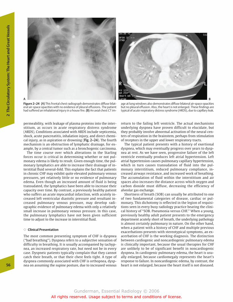
permeability, with leakage of plasma proteins into the inter-stitium, as occurs in acute respiratory distress syndrome(ARDS). Conditions associated with ARDS include septicemia,shock, acute pancreatitis, inhalation injury, and direct chemi-cal injury, as in aspiration or drowning (FFiigg.. 22––2244). The fourthmechanism is an obstruction of lymphatic drainage, for ex-ample, by a central tumor such as a bronchogenic carcinoma.
The time course over which alterations in the Starlingforces occur is critical in determining whether or not pul-monary edema is likely to result. Given enough time, the pul-monary lymphatics are able to increase their drainage of in-terstitial fluid several-fold. This explains the fact that patientsin chronic CHF may exhibit quite elevated pulmonary venouspressures, yet relatively little or no evidence of pulmonaryedema. Even though an increased amount of fluid is beingtransudated, the lymphatics have been able to increase theircapacity over time. By contrast, a previously healthy patientwho suffers an acute myocardial infarction, with acutely in-creased left ventricular diastolic pressure and resultant in-creased pulmonary venous pressure, may develop radi-ographic evidence of pulmonary edema with only a relativelysmall increase in pulmonary venous pressure. In this case,the pulmonary lymphatics have not been given sufficienttime to adjust to the increase in interstitial fluid.
�� Clinical Presentation
The most common presenting symptom of CHF is dyspnea(“bad breathing”). Dyspnea refers to a subjective sensation ofdifficulty in breathing. It is usually accompanied by tachyp-nea, an increased respiratory rate, but need not be in everycase. Dyspneic patients typically complain that they cannotcatch their breath, or that their chest feels tight. A type ofdyspnea commonly associated with CHF is orthopnea, dysp-nea on assuming the supine posture, due to increased venous
return to the failing left ventricle. The actual mechanismsunderlying dyspnea have proven difficult to elucidate, butthey probably involve abnormal activation of the neural cen-ters of respiration in the brainstem, perhaps from stimulationof receptors in the upper and lower respiratory tracts.
The typical patient presents with a history of exertionaldyspnea, which may eventually progress over years to dysp-nea at rest. As we have seen, progressive failure of the leftventricle eventually produces left atrial hypertension. Leftatrial hypertension causes pulmonary capillary hypertension,which in turn causes transudation of fluid into the pul-monary interstitium, reduced pulmonary compliance, in-creased airways resistance, and increased work of breathing.The accumulation of fluid within the interstitium and airspaces also increases the distance across which oxygen andcarbon dioxide must diffuse, decreasing the efficiency ofalveolar gas exchange.
Shortness of breath (SOB) can usually be attributed to oneof two fundamental categories of disease, cardiac or pul-monary. This dichotomy is reflected in the legion of requisi-tions seen in every busy radiology practice bearing the clini-cal history of “SOB. Pneumonia versus CHF.” When a young,previously healthy adult patient presents to the emergencydepartment acutely short of breath, the underlying pathologyis almost certainly pulmonary in nature. On the other hand,when a patient with a history of CHF and multiple previousexacerbations presents with stereotypical symptoms, an ex-acerbation of CHF is the working diagnosis. The distinctionbetween cardiogenic and noncardiogenic pulmonary edemais clinically important, because the usual therapies for CHFare unlikely to be of significant benefit in noncardiogenicdyspnea. In cardiogenic pulmonary edema, the heart is usu-ally enlarged, because cardiomegaly represents the heart’sresponse to failure. In noncardiogenic edema, by contrast, theheart is not enlarged, because the heart itself is not diseased.56
2Th
e Ci
rcul
ator
y Sy
stem
: The
Hea
rt a
nd G
reat
Ves
sels
A B
Figure 2–24 ((AA)) This frontal chest radiograph demonstrates diffuse bilat-eral air-space opacities with no evidence of pleural effusions. The patienthad suffered an inhalational injury in a house fire. ((BB)) An axial chest CT im-
age at lung windows also demonstrates diffuse bilateral air-space opacitiesbut no pleural effusion. Also, the heart is not enlarged. These findings aretypical of acute respiratory distress syndrome (ARDS), due to capillary leak.
chapter 02_p39-67.qxd 12/1/05 3:25 PM Page 56
Gunderman, Essential Radiology © 2006All rights reserved. Usage subject to terms and conditions of license.
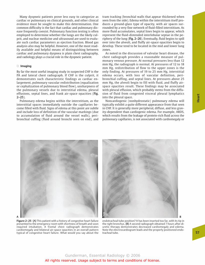
Many dyspneic patients prove less easy to categorize ascardiac or pulmonary on clinical grounds, and other clinicalevidence must be sought to make this determination. Onecommon difficulty is the fact that cardiac and pulmonary dis-ease frequently coexist. Pulmonary function testing is oftenemployed to determine whether the lungs are the likely cul-prit, and nuclear medicine and ultrasound are used to evalu-ate such cardiac parameters as ejection fraction. Blood gasanalysis also may be helpful. However, one of the most read-ily available and helpful means of distinguishing betweencardiac and pulmonary dyspnea is plain chest radiography,and radiology plays a crucial role in the dyspneic patient.
�� Imaging
By far the most useful imaging study in suspected CHF is thePA and lateral chest radiograph. If CHF is the culprit, itdemonstrates such characteristic findings as cardiac en-largement, pulmonary vascular redistribution (equalizationor cephalization of pulmonary blood flow), unsharpness ofthe pulmonary vessels due to interstitial edema, pleuraleffusions, septal lines, and frank air-space opacities (FFiigg..22––2255).
Pulmonary edema begins within the interstitium, as theinterstitial spaces immediately outside the capillaries be-come filled with fluid. Signs of edema at this point are subtleand include loss of definition of the vascular markings (dueto accumulation of fluid around the vessel walls), peri-bronchial cuffing (fluid around bronchi seen on end), and
tram tracking (bronchial walls that appear thickened whenseen from the side). Edema within the interstitium itself pro-duces a ground-glass type of opacity, with air spaces sur-rounded by a very fine network of fluid-filled interstitium. Asmore fluid accumulates, septal lines begin to appear, whichrepresent the fluid-distended interlobular septae in the pe-riphery of the lung (FFiigg.. 22––2266). Eventually, fluid begins to spillover into the alveoli, and fluffy air-space opacities begin todevelop. These tend to be located in the mid and lower lungzones.
As noted in the discussion of valvular heart disease, thechest radiograph provides a reasonable measure of pul-monary venous pressure. At normal pressures less than 12mm Hg, the radiograph is normal. At pressures of 12 to 18mm Hg, redistribution of flow to the upper zones is theonly finding. At pressures of 19 to 25 mm Hg, interstitialedema occurs, with loss of vascular definition, peri-bronchial cuffing, and septal lines. At pressures above 25mm Hg, the alveoli begin to fill with fluid, and fluffy air-space opacities result. These findings may be associatedwith pleural effusion, which probably stems from the diffu-sion of fluid from congested visceral pleural lymphaticsinto the pleural space.
Noncardiogenic (nonhydrostatic) pulmonary edema willtypically exhibit a quite different appearance from that seenin CHF. It is generally more peripheral, diffuse, and less grav-ity-dependent than cardiogenic edema. For example, ARDS,which results from the leakage of protein-rich fluid across thepulmonary capillaries, is not associated with cardiomegaly or
Hea
rt
57
A B
Figure 2–25 ((AA)) This patient with a history of congestive heart failurepresented to the emergency room with shortness of breath and soonrequired intubation. A frontal chest radiograph demonstratescardiomegaly and bilateral air-space opacities in an overall patterntypical of congestive heart failure. What would you say about the
endotracheal tube position? It has been inserted too far, with its tip inthe right bronchus. ((BB)) A second radiograph obtained 7 hours after di-uretic therapy demonstrates decreased cardiomegaly and edema.Note the electrocardiogram leads and the properly positioned endo-tracheal tube.
chapter 02_p39-67.qxd 12/1/05 3:25 PM Page 57
Gunderman, Essential Radiology © 2006All rights reserved. Usage subject to terms and conditions of license.
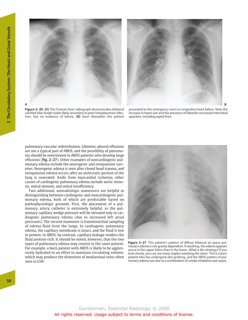
pulmonary vascular redistribution. Likewise, pleural effusionsare not a typical part of ARDS, and the possibility of pneumo-nia should be entertained in ARDS patients who develop largeeffusions (FFiigg.. 22––2277). Other examples of noncardiogenic pul-monary edema include the neurogenic and reexpansion vari-eties. Neurogenic edema is seen after closed head trauma, andreexpansion edema occurs after an atelectatic portion of thelung is reaerated. Aside from myocardial ischemia, othercauses of cardiogenic pulmonary edema include aortic steno-sis, mitral stenosis, and mitral insufficiency.
Two additional, nonradiologic maneuvers are helpful indistinguishing between cardiogenic and noncardiogenic pul-monary edema, both of which are predictable based onpathophysiologic grounds. First, the placement of a pul-monary artery catheter is extremely helpful, as the pul-monary capillary wedge pressure will be elevated only in car-diogenic pulmonary edema (due to increased left atrialpressures). The second maneuver is transbronchial samplingof edema fluid from the lungs. In cardiogenic pulmonaryedema, the capillary membrane is intact, and the fluid is lowin protein. In ARDS, by contrast, capillary leakage renders thefluid protein-rich. It should be noted, however, that the twotypes of pulmonary edema may coexist in the same patient.For example, a burn patient with ARDS is likely to be aggres-sively hydrated in an effort to maintain circulating volume,which may produce the distention of mediastinal veins oftenseen in CHF.
58
2Th
e Ci
rcul
ator
y Sy
stem
: The
Hea
rt a
nd G
reat
Ves
sels
A B
Figure 2–26 ((AA)) This frontal chest radiograph demonstrates bilateralcalcified hilar lymph nodes likely secondary to prior histoplasmosis infec-tion, but no evidence of failure. ((BB)) Soon thereafter the patient
presented to the emergency room in congestive heart failure. Note theincrease in heart size and the presence of bibasilar increased interstitialopacities, including septal lines.
Figure 2–27 This patient’s pattern of diffuse bilateral air-space pul-monary edema is not gravity dependent. If anything, the edema appearsworse in the upper lobes than in the bases. What is the etiology? If youlook closely, you can see many staples overlying the chest. This is a burnpatient who has undergone skin grafting, and the ARDS pattern of pul-monary edema was due to a combination of smoke inhalation and sepsis.
chapter 02_p39-67.qxd 12/1/05 3:25 PM Page 58
Gunderman, Essential Radiology © 2006All rights reserved. Usage subject to terms and conditions of license.
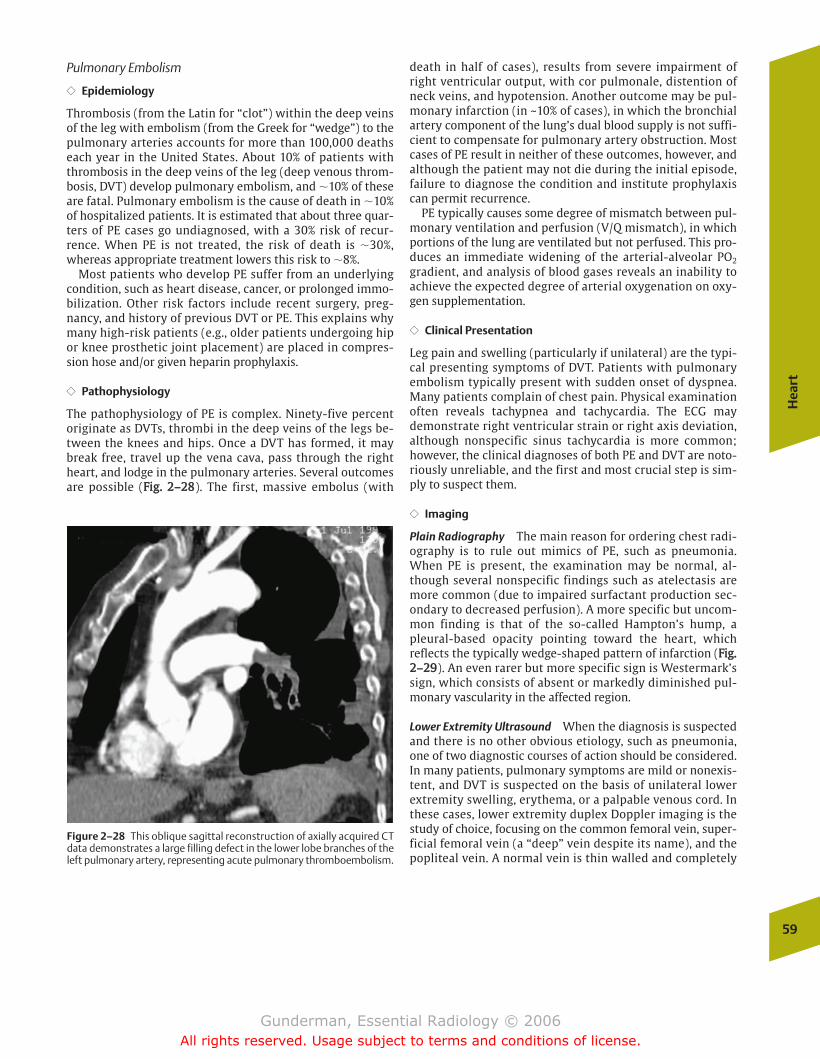
Pulmonary Embolism
�� Epidemiology
Thrombosis (from the Latin for “clot”) within the deep veinsof the leg with embolism (from the Greek for “wedge”) to thepulmonary arteries accounts for more than 100,000 deathseach year in the United States. About 10% of patients withthrombosis in the deep veins of the leg (deep venous throm-bosis, DVT) develop pulmonary embolism, and �10% of theseare fatal. Pulmonary embolism is the cause of death in �10%of hospitalized patients. It is estimated that about three quar-ters of PE cases go undiagnosed, with a 30% risk of recur-rence. When PE is not treated, the risk of death is �30%,whereas appropriate treatment lowers this risk to �8%.
Most patients who develop PE suffer from an underlyingcondition, such as heart disease, cancer, or prolonged immo-bilization. Other risk factors include recent surgery, preg-nancy, and history of previous DVT or PE. This explains whymany high-risk patients (e.g., older patients undergoing hipor knee prosthetic joint placement) are placed in compres-sion hose and/or given heparin prophylaxis.
�� Pathophysiology
The pathophysiology of PE is complex. Ninety-five percentoriginate as DVTs, thrombi in the deep veins of the legs be-tween the knees and hips. Once a DVT has formed, it maybreak free, travel up the vena cava, pass through the rightheart, and lodge in the pulmonary arteries. Several outcomesare possible (FFiigg.. 22––2288). The first, massive embolus (with
death in half of cases), results from severe impairment ofright ventricular output, with cor pulmonale, distention ofneck veins, and hypotension. Another outcome may be pul-monary infarction (in ~10% of cases), in which the bronchialartery component of the lung’s dual blood supply is not suffi-cient to compensate for pulmonary artery obstruction. Mostcases of PE result in neither of these outcomes, however, andalthough the patient may not die during the initial episode,failure to diagnose the condition and institute prophylaxiscan permit recurrence.
PE typically causes some degree of mismatch between pul-monary ventilation and perfusion (V/Q mismatch), in whichportions of the lung are ventilated but not perfused. This pro-duces an immediate widening of the arterial-alveolar PO2
gradient, and analysis of blood gases reveals an inability toachieve the expected degree of arterial oxygenation on oxy-gen supplementation.
�� Clinical Presentation
Leg pain and swelling (particularly if unilateral) are the typi-cal presenting symptoms of DVT. Patients with pulmonaryembolism typically present with sudden onset of dyspnea.Many patients complain of chest pain. Physical examinationoften reveals tachypnea and tachycardia. The ECG maydemonstrate right ventricular strain or right axis deviation,although nonspecific sinus tachycardia is more common;however, the clinical diagnoses of both PE and DVT are noto-riously unreliable, and the first and most crucial step is sim-ply to suspect them.
�� Imaging
Plain Radiography The main reason for ordering chest radi-ography is to rule out mimics of PE, such as pneumonia.When PE is present, the examination may be normal, al-though several nonspecific findings such as atelectasis aremore common (due to impaired surfactant production sec-ondary to decreased perfusion). A more specific but uncom-mon finding is that of the so-called Hampton’s hump, apleural-based opacity pointing toward the heart, whichreflects the typically wedge-shaped pattern of infarction (FFiigg..22––2299). An even rarer but more specific sign is Westermark’ssign, which consists of absent or markedly diminished pul-monary vascularity in the affected region.
Lower Extremity Ultrasound When the diagnosis is suspectedand there is no other obvious etiology, such as pneumonia,one of two diagnostic courses of action should be considered.In many patients, pulmonary symptoms are mild or nonexis-tent, and DVT is suspected on the basis of unilateral lowerextremity swelling, erythema, or a palpable venous cord. Inthese cases, lower extremity duplex Doppler imaging is thestudy of choice, focusing on the common femoral vein, super-ficial femoral vein (a “deep” vein despite its name), and thepopliteal vein. A normal vein is thin walled and completely
Hea
rt
59
Figure 2–28 This oblique sagittal reconstruction of axially acquired CTdata demonstrates a large filling defect in the lower lobe branches of theleft pulmonary artery, representing acute pulmonary thromboembolism.
chapter 02_p39-67.qxd 12/1/05 3:25 PM Page 59
Gunderman, Essential Radiology © 2006All rights reserved. Usage subject to terms and conditions of license.
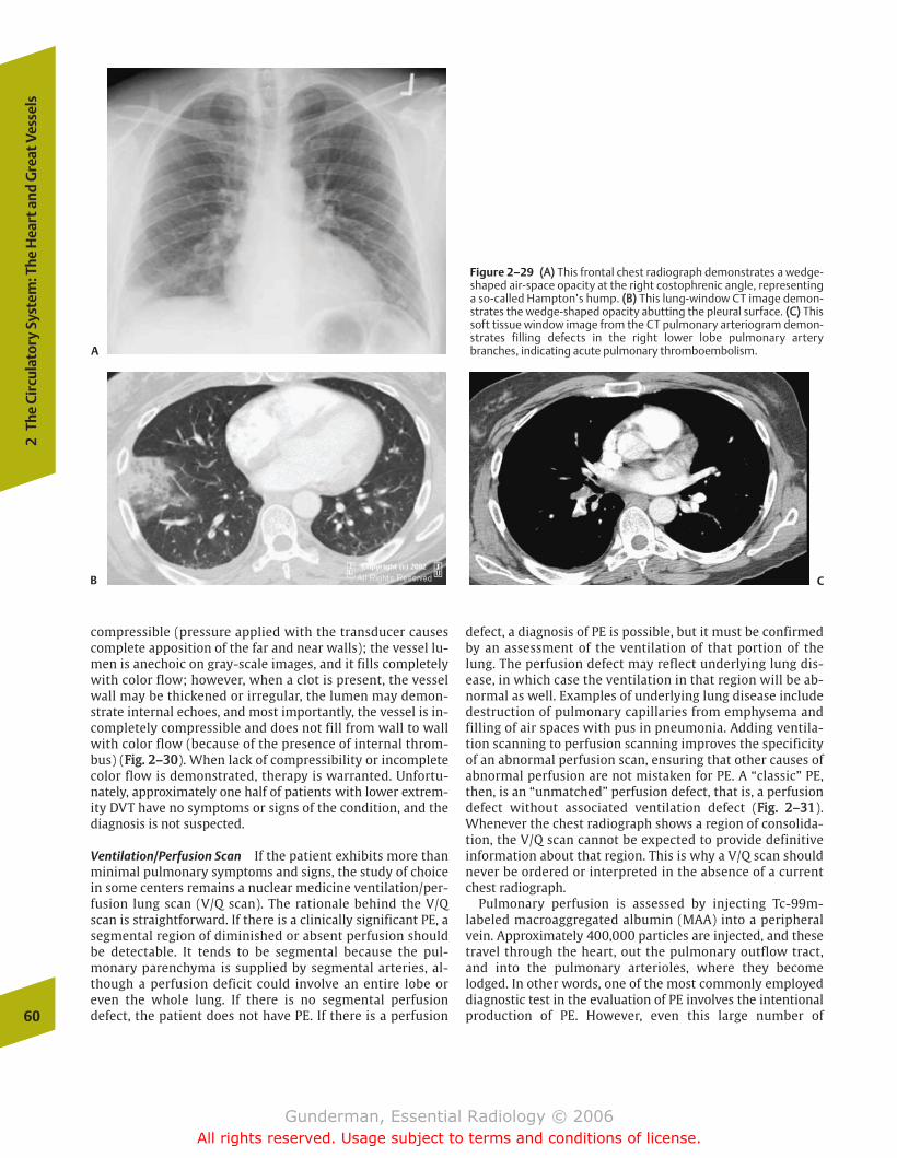
compressible (pressure applied with the transducer causescomplete apposition of the far and near walls); the vessel lu-men is anechoic on gray-scale images, and it fills completelywith color flow; however, when a clot is present, the vesselwall may be thickened or irregular, the lumen may demon-strate internal echoes, and most importantly, the vessel is in-completely compressible and does not fill from wall to wallwith color flow (because of the presence of internal throm-bus) (FFiigg.. 22––3300). When lack of compressibility or incompletecolor flow is demonstrated, therapy is warranted. Unfortu-nately, approximately one half of patients with lower extrem-ity DVT have no symptoms or signs of the condition, and thediagnosis is not suspected.
Ventilation/Perfusion Scan If the patient exhibits more thanminimal pulmonary symptoms and signs, the study of choicein some centers remains a nuclear medicine ventilation/per-fusion lung scan (V/Q scan). The rationale behind the V/Qscan is straightforward. If there is a clinically significant PE, asegmental region of diminished or absent perfusion shouldbe detectable. It tends to be segmental because the pul-monary parenchyma is supplied by segmental arteries, al-though a perfusion deficit could involve an entire lobe oreven the whole lung. If there is no segmental perfusiondefect, the patient does not have PE. If there is a perfusion
defect, a diagnosis of PE is possible, but it must be confirmedby an assessment of the ventilation of that portion of thelung. The perfusion defect may reflect underlying lung dis-ease, in which case the ventilation in that region will be ab-normal as well. Examples of underlying lung disease includedestruction of pulmonary capillaries from emphysema andfilling of air spaces with pus in pneumonia. Adding ventila-tion scanning to perfusion scanning improves the specificityof an abnormal perfusion scan, ensuring that other causes ofabnormal perfusion are not mistaken for PE. A “classic” PE,then, is an “unmatched” perfusion defect, that is, a perfusiondefect without associated ventilation defect (FFiigg.. 22––3311).Whenever the chest radiograph shows a region of consolida-tion, the V/Q scan cannot be expected to provide definitiveinformation about that region. This is why a V/Q scan shouldnever be ordered or interpreted in the absence of a currentchest radiograph.
Pulmonary perfusion is assessed by injecting Tc-99m-labeled macroaggregated albumin (MAA) into a peripheralvein. Approximately 400,000 particles are injected, and thesetravel through the heart, out the pulmonary outflow tract,and into the pulmonary arterioles, where they becomelodged. In other words, one of the most commonly employeddiagnostic test in the evaluation of PE involves the intentionalproduction of PE. However, even this large number of60
2Th
e Ci
rcul
ator
y Sy
stem
: The
Hea
rt a
nd G
reat
Ves
sels
A
B
Figure 2–29 ((AA)) This frontal chest radiograph demonstrates a wedge-shaped air-space opacity at the right costophrenic angle, representinga so-called Hampton’s hump. ((BB)) This lung-window CT image demon-strates the wedge-shaped opacity abutting the pleural surface. ((CC)) Thissoft tissue window image from the CT pulmonary arteriogram demon-strates filling defects in the right lower lobe pulmonary arterybranches, indicating acute pulmonary thromboembolism.
C
chapter 02_p39-67.qxd 12/1/05 3:25 PM Page 60
Gunderman, Essential Radiology © 2006All rights reserved. Usage subject to terms and conditions of license.
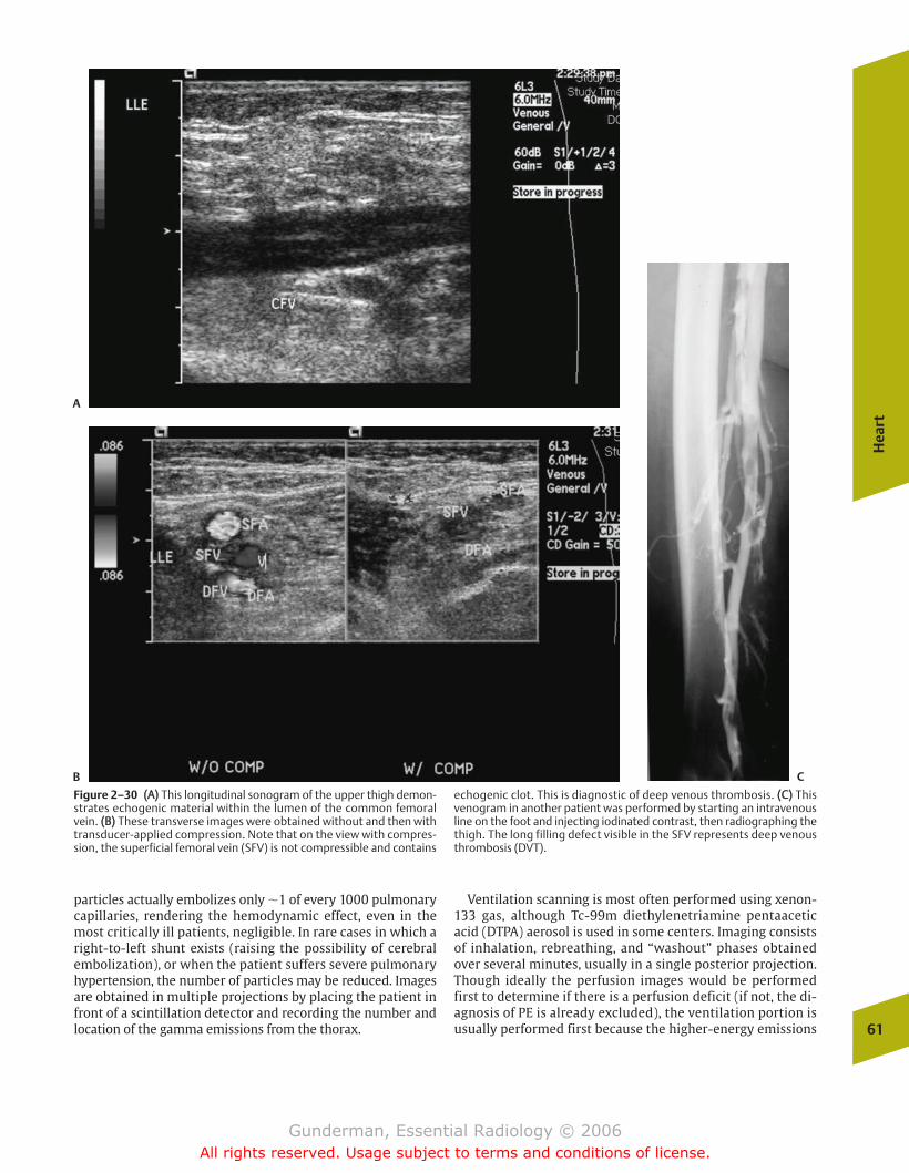
particles actually embolizes only �1 of every 1000 pulmonarycapillaries, rendering the hemodynamic effect, even in themost critically ill patients, negligible. In rare cases in which aright-to-left shunt exists (raising the possibility of cerebralembolization), or when the patient suffers severe pulmonaryhypertension, the number of particles may be reduced. Imagesare obtained in multiple projections by placing the patient infront of a scintillation detector and recording the number andlocation of the gamma emissions from the thorax.
Ventilation scanning is most often performed using xenon-133 gas, although Tc-99m diethylenetriamine pentaaceticacid (DTPA) aerosol is used in some centers. Imaging consistsof inhalation, rebreathing, and “washout” phases obtainedover several minutes, usually in a single posterior projection.Though ideally the perfusion images would be performedfirst to determine if there is a perfusion deficit (if not, the di-agnosis of PE is already excluded), the ventilation portion isusually performed first because the higher-energy emissions
Hea
rt
61
A
B C
Figure 2–30 ((AA)) This longitudinal sonogram of the upper thigh demon-strates echogenic material within the lumen of the common femoralvein. ((BB)) These transverse images were obtained without and then withtransducer-applied compression. Note that on the view with compres-sion, the superficial femoral vein (SFV) is not compressible and contains
echogenic clot. This is diagnostic of deep venous thrombosis. ((CC)) Thisvenogram in another patient was performed by starting an intravenousline on the foot and injecting iodinated contrast, then radiographing thethigh. The long filling defect visible in the SFV represents deep venousthrombosis (DVT).
chapter 02_p39-67.qxd 12/1/05 3:25 PM Page 61
Gunderman, Essential Radiology © 2006All rights reserved. Usage subject to terms and conditions of license.
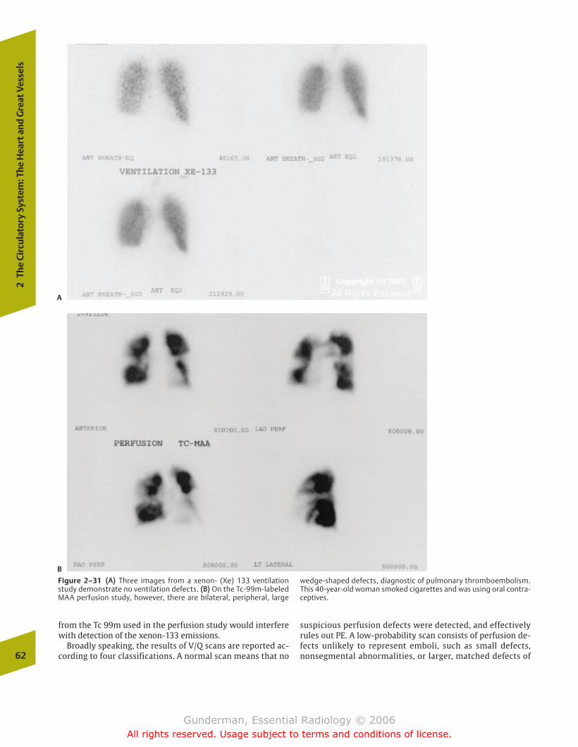
from the Tc 99m used in the perfusion study would interferewith detection of the xenon-133 emissions.
Broadly speaking, the results of V/Q scans are reported ac-cording to four classifications. A normal scan means that no
suspicious perfusion defects were detected, and effectivelyrules out PE. A low-probability scan consists of perfusion de-fects unlikely to represent emboli, such as small defects,nonsegmental abnormalities, or larger, matched defects of62
2Th
e Ci
rcul
ator
y Sy
stem
: The
Hea
rt a
nd G
reat
Ves
sels
A
B
Figure 2–31 ((AA)) Three images from a xenon- (Xe) 133 ventilationstudy demonstrate no ventilation defects. ((BB)) On the Tc-99m-labeledMAA perfusion study, however, there are bilateral, peripheral, large
wedge-shaped defects, diagnostic of pulmonary thromboembolism.This 40-year-old woman smoked cigarettes and was using oral contra-ceptives.
chapter 02_p39-67.qxd 12/1/05 3:25 PM Page 62
Gunderman, Essential Radiology © 2006All rights reserved. Usage subject to terms and conditions of license.
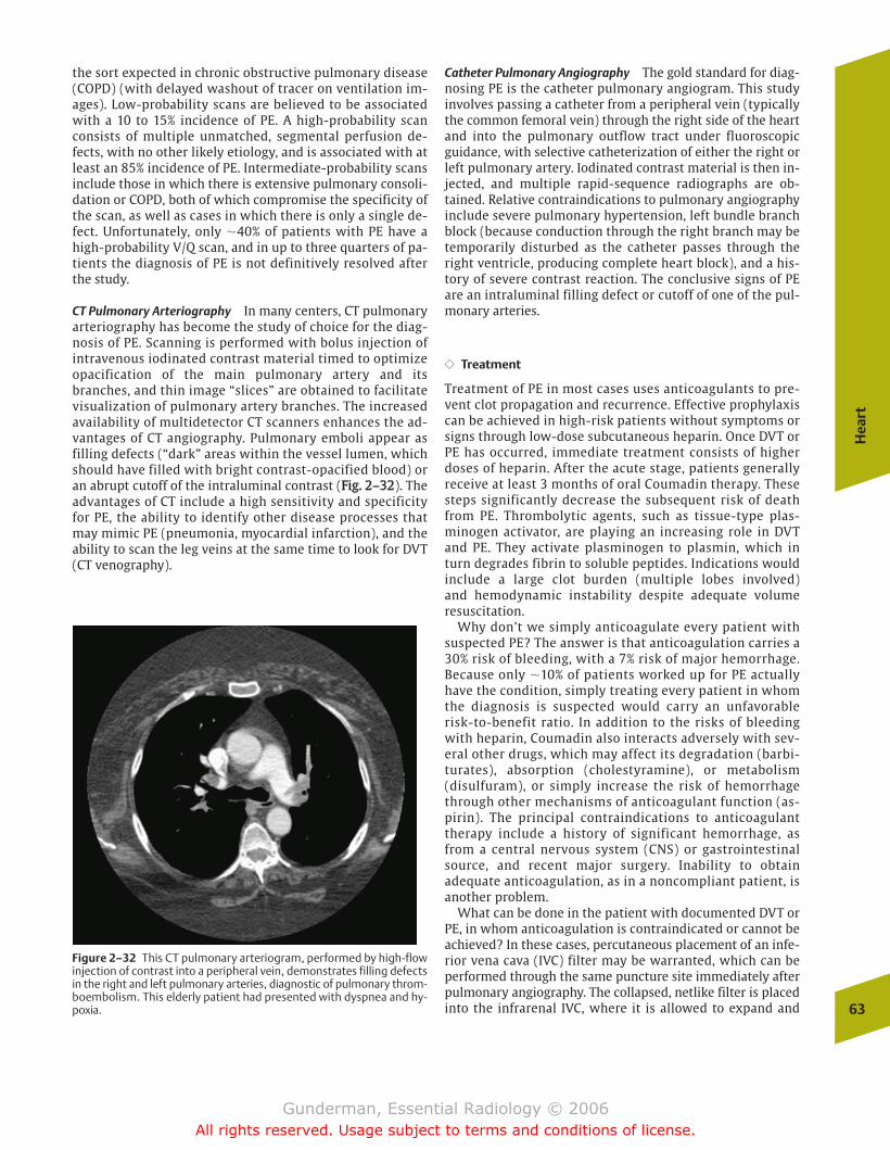
the sort expected in chronic obstructive pulmonary disease(COPD) (with delayed washout of tracer on ventilation im-ages). Low-probability scans are believed to be associatedwith a 10 to 15% incidence of PE. A high-probability scanconsists of multiple unmatched, segmental perfusion de-fects, with no other likely etiology, and is associated with atleast an 85% incidence of PE. Intermediate-probability scansinclude those in which there is extensive pulmonary consoli-dation or COPD, both of which compromise the specificity ofthe scan, as well as cases in which there is only a single de-fect. Unfortunately, only �40% of patients with PE have ahigh-probability V/Q scan, and in up to three quarters of pa-tients the diagnosis of PE is not definitively resolved afterthe study.
CT Pulmonary Arteriography In many centers, CT pulmonaryarteriography has become the study of choice for the diag-nosis of PE. Scanning is performed with bolus injection ofintravenous iodinated contrast material timed to optimizeopacification of the main pulmonary artery and itsbranches, and thin image “slices” are obtained to facilitatevisualization of pulmonary artery branches. The increasedavailability of multidetector CT scanners enhances the ad-vantages of CT angiography. Pulmonary emboli appear asfilling defects (“dark” areas within the vessel lumen, whichshould have filled with bright contrast-opacified blood) oran abrupt cutoff of the intraluminal contrast (FFiigg.. 22––3322). Theadvantages of CT include a high sensitivity and specificityfor PE, the ability to identify other disease processes thatmay mimic PE (pneumonia, myocardial infarction), and theability to scan the leg veins at the same time to look for DVT(CT venography).
Catheter Pulmonary Angiography The gold standard for diag-nosing PE is the catheter pulmonary angiogram. This studyinvolves passing a catheter from a peripheral vein (typicallythe common femoral vein) through the right side of the heartand into the pulmonary outflow tract under fluoroscopicguidance, with selective catheterization of either the right orleft pulmonary artery. Iodinated contrast material is then in-jected, and multiple rapid-sequence radiographs are ob-tained. Relative contraindications to pulmonary angiographyinclude severe pulmonary hypertension, left bundle branchblock (because conduction through the right branch may betemporarily disturbed as the catheter passes through theright ventricle, producing complete heart block), and a his-tory of severe contrast reaction. The conclusive signs of PEare an intraluminal filling defect or cutoff of one of the pul-monary arteries.
�� Treatment
Treatment of PE in most cases uses anticoagulants to pre-vent clot propagation and recurrence. Effective prophylaxiscan be achieved in high-risk patients without symptoms orsigns through low-dose subcutaneous heparin. Once DVT orPE has occurred, immediate treatment consists of higherdoses of heparin. After the acute stage, patients generallyreceive at least 3 months of oral Coumadin therapy. Thesesteps significantly decrease the subsequent risk of deathfrom PE. Thrombolytic agents, such as tissue-type plas-minogen activator, are playing an increasing role in DVTand PE. They activate plasminogen to plasmin, which inturn degrades fibrin to soluble peptides. Indications wouldinclude a large clot burden (multiple lobes involved) and hemodynamic instability despite adequate volumeresuscitation.
Why don’t we simply anticoagulate every patient withsuspected PE? The answer is that anticoagulation carries a30% risk of bleeding, with a 7% risk of major hemorrhage.Because only �10% of patients worked up for PE actuallyhave the condition, simply treating every patient in whomthe diagnosis is suspected would carry an unfavorablerisk-to-benefit ratio. In addition to the risks of bleedingwith heparin, Coumadin also interacts adversely with sev-eral other drugs, which may affect its degradation (barbi-turates), absorption (cholestyramine), or metabolism(disulfuram), or simply increase the risk of hemorrhagethrough other mechanisms of anticoagulant function (as-pirin). The principal contraindications to anticoagulanttherapy include a history of significant hemorrhage, asfrom a central nervous system (CNS) or gastrointestinalsource, and recent major surgery. Inability to obtainadequate anticoagulation, as in a noncompliant patient, isanother problem.
What can be done in the patient with documented DVT orPE, in whom anticoagulation is contraindicated or cannot beachieved? In these cases, percutaneous placement of an infe-rior vena cava (IVC) filter may be warranted, which can beperformed through the same puncture site immediately afterpulmonary angiography. The collapsed, netlike filter is placedinto the infrarenal IVC, where it is allowed to expand and
Hea
rt
63
Figure 2–32 This CT pulmonary arteriogram, performed by high-flowinjection of contrast into a peripheral vein, demonstrates filling defectsin the right and left pulmonary arteries, diagnostic of pulmonary throm-boembolism. This elderly patient had presented with dyspnea and hy-poxia.
chapter 02_p39-67.qxd 12/1/05 3:25 PM Page 63
Gunderman, Essential Radiology © 2006All rights reserved. Usage subject to terms and conditions of license.
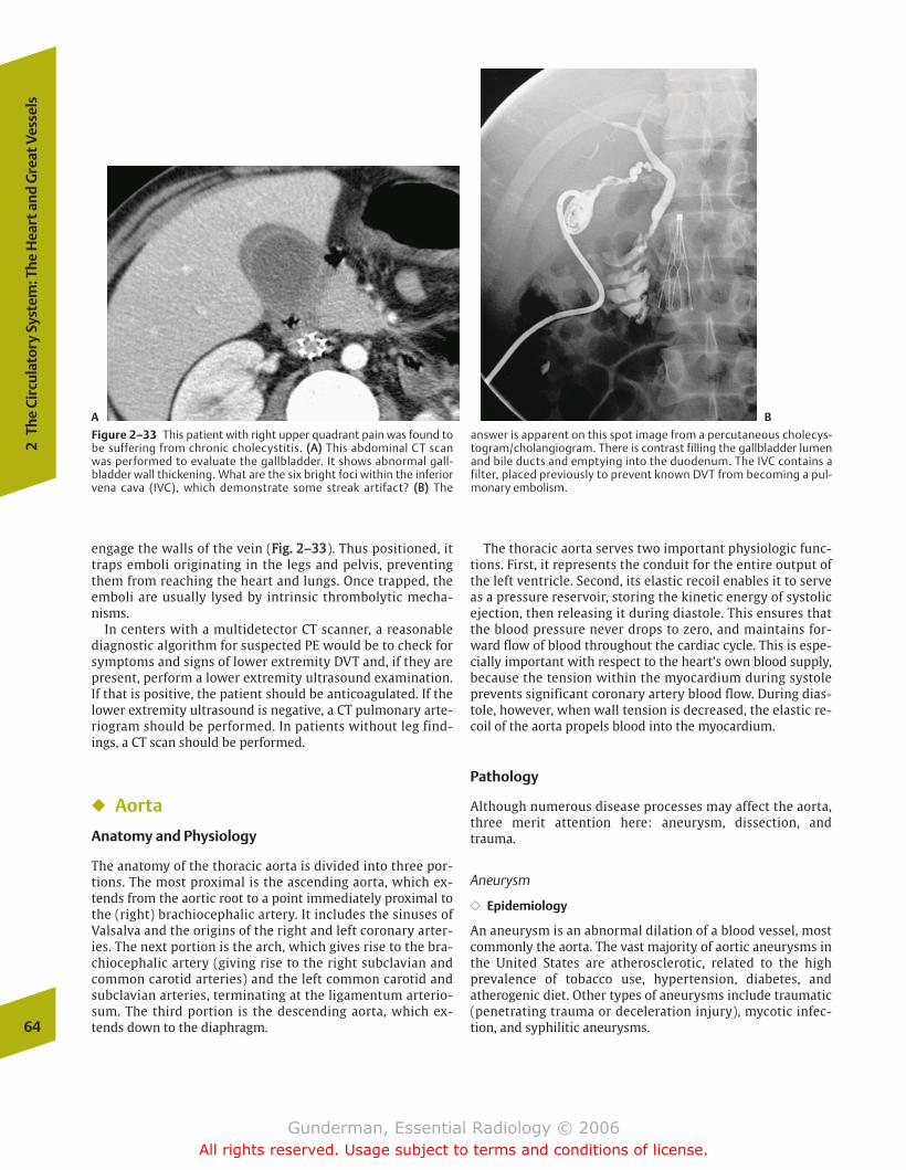
engage the walls of the vein (FFiigg.. 22––3333). Thus positioned, ittraps emboli originating in the legs and pelvis, preventingthem from reaching the heart and lungs. Once trapped, theemboli are usually lysed by intrinsic thrombolytic mecha-nisms.
In centers with a multidetector CT scanner, a reasonablediagnostic algorithm for suspected PE would be to check forsymptoms and signs of lower extremity DVT and, if they arepresent, perform a lower extremity ultrasound examination.If that is positive, the patient should be anticoagulated. If thelower extremity ultrasound is negative, a CT pulmonary arte-riogram should be performed. In patients without leg find-ings, a CT scan should be performed.
� Aorta
Anatomy and Physiology
The anatomy of the thoracic aorta is divided into three por-tions. The most proximal is the ascending aorta, which ex-tends from the aortic root to a point immediately proximal tothe (right) brachiocephalic artery. It includes the sinuses ofValsalva and the origins of the right and left coronary arter-ies. The next portion is the arch, which gives rise to the bra-chiocephalic artery (giving rise to the right subclavian andcommon carotid arteries) and the left common carotid andsubclavian arteries, terminating at the ligamentum arterio-sum. The third portion is the descending aorta, which ex-tends down to the diaphragm.
The thoracic aorta serves two important physiologic func-tions. First, it represents the conduit for the entire output ofthe left ventricle. Second, its elastic recoil enables it to serveas a pressure reservoir, storing the kinetic energy of systolicejection, then releasing it during diastole. This ensures thatthe blood pressure never drops to zero, and maintains for-ward flow of blood throughout the cardiac cycle. This is espe-cially important with respect to the heart’s own blood supply,because the tension within the myocardium during systoleprevents significant coronary artery blood flow. During dias-tole, however, when wall tension is decreased, the elastic re-coil of the aorta propels blood into the myocardium.
Pathology
Although numerous disease processes may affect the aorta,three merit attention here: aneurysm, dissection, andtrauma.
Aneurysm
�� Epidemiology
An aneurysm is an abnormal dilation of a blood vessel, mostcommonly the aorta. The vast majority of aortic aneurysms inthe United States are atherosclerotic, related to the highprevalence of tobacco use, hypertension, diabetes, andatherogenic diet. Other types of aneurysms include traumatic(penetrating trauma or deceleration injury), mycotic infec-tion, and syphilitic aneurysms.64
2Th
e Ci
rcul
ator
y Sy
stem
: The
Hea
rt a
nd G
reat
Ves
sels
A B
Figure 2–33 This patient with right upper quadrant pain was found tobe suffering from chronic cholecystitis. ((AA)) This abdominal CT scanwas performed to evaluate the gallbladder. It shows abnormal gall-bladder wall thickening. What are the six bright foci within the inferiorvena cava (IVC), which demonstrate some streak artifact? ((BB)) The
answer is apparent on this spot image from a percutaneous cholecys-togram/cholangiogram. There is contrast filling the gallbladder lumenand bile ducts and emptying into the duodenum. The IVC contains afilter, placed previously to prevent known DVT from becoming a pul-monary embolism.
chapter 02_p39-67.qxd 12/1/05 3:25 PM Page 64
Gunderman, Essential Radiology © 2006All rights reserved. Usage subject to terms and conditions of license.

�� Pathophysiology
Pathologically, there are two types of aneurysms. A trueaneurysm involves all three layers of the vessel wall (intima,media, and adventitia), whereas a false aneurysm consists ofa rupture of the vessel wall, with the hemorrhage containedby the adventitia (FFiigg.. 22––3344). Morphologically, aneurysmsmay be described as fusiform (circumferential dilation) orsaccular (eccentric outpouching).
The treatment of thoracic aortic aneurysms consists pri-marily of antihypertensive medications. If the patient issymptomatic, there has been a rapid increase in size, or theaorta is greater than 6 cm in diameter, surgical resection andvascular grafting are often performed. Why are largeaneurysms more worrisome? The answer hinges on the lawof Laplace, which states that the tension in the wall of a ves-sel is proportional to the transmural pressure multiplied bythe radius. Assuming the mean arterial pressure remains con-stant, the tension in the wall, the force promoting rupture, in-creases in direct relation to the radius. Hence, the larger thediameter of an aneurysm, the more likely it is to rupture. A 6 cm aneurysmal segment of ascending aorta has twice thewall tension of a healthy 3 cm segment.
�� Clinical Presentation
Most patients with thoracic aortic aneurysms are asympto-matic, but a small minority will present with symptoms suchas deep, diffuse chest pain, hoarseness, and even hemoptysisor hematemesis (secondary to communication with thetracheobronchial tree or esophagus).
�� Imaging
Several radiologic modalities are useful in assessing for thepresence of an aortic aneurysm. Patients with atheroscleroticaneurysms typically demonstrate plain radiographic signs ofadvanced atherosclerosis, including enlargement of the aorticsilhouette, and tortuosity and calcification of the aorta andother arteries, including the coronary arteries (FFiigg.. 22––3355).Enlargement of the aorta or a change in its contour can beassessed by comparison to previous films. Occasionally,
Ao
rta
65
Figure 2–34 The morphologic distinction between a true aneurysm(left) and a false aneurysm (right). Note that the true aneurysm involvesan outward bulge in all three layers of the vessel wall, whereas the falseaneurysm consists of a rupture of the vessel wall, with the hemorrhagecontained by the adventitia.
A
Figure 2–35 ((AA)) This man with chest pain and a falling hematocrit un-derwent heart transplantation the previous year. His chest radiographdemonstrates a large mass originating at the level of the aortic arch.
((BB)) A CT image at the level shows the large secular aneurysm extendingleftward from the aortic arch, with a large left pleural effusion. Theaneurysm was leaking blood into the chest.
B
chapter 02_p39-67.qxd 12/1/05 3:25 PM Page 65
Gunderman, Essential Radiology © 2006All rights reserved. Usage subject to terms and conditions of license.
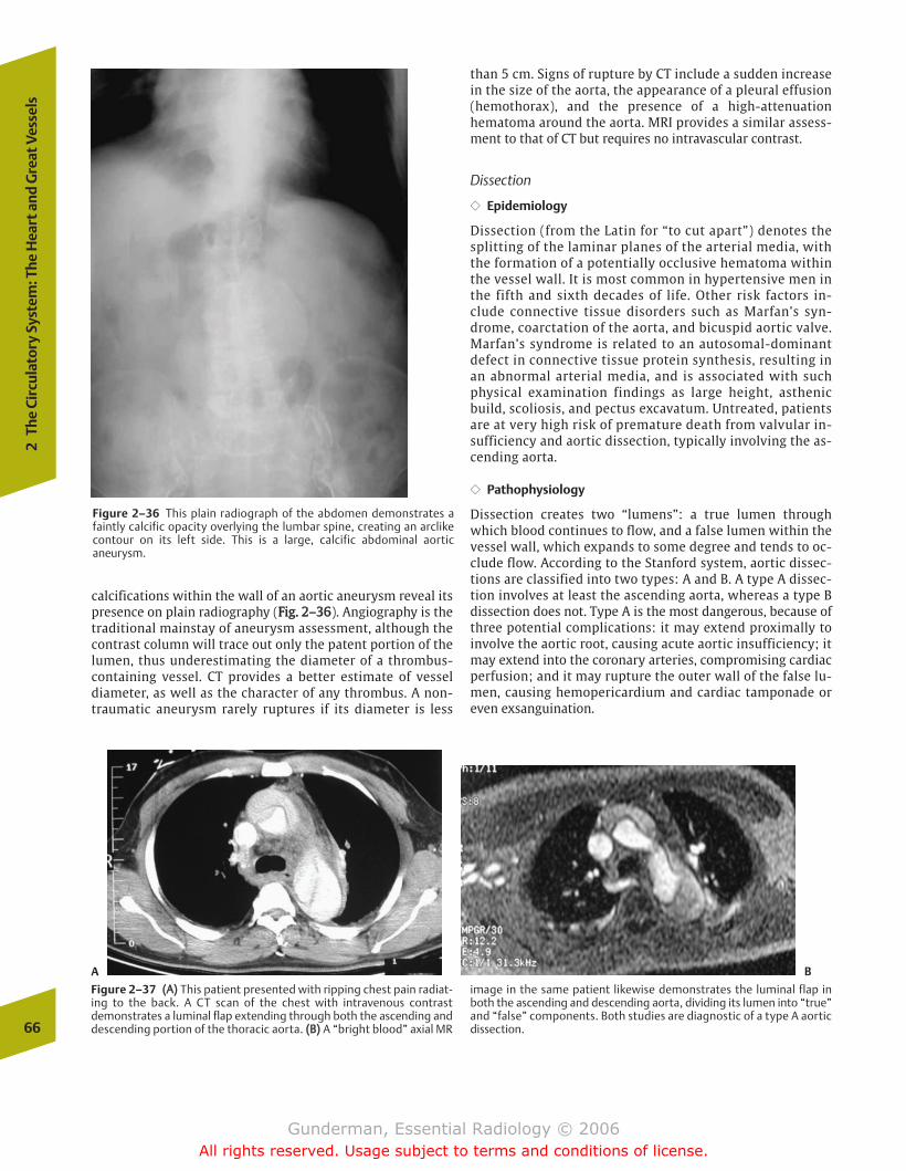
calcifications within the wall of an aortic aneurysm reveal itspresence on plain radiography (FFiigg.. 22––3366). Angiography is thetraditional mainstay of aneurysm assessment, although thecontrast column will trace out only the patent portion of thelumen, thus underestimating the diameter of a thrombus-containing vessel. CT provides a better estimate of vesseldiameter, as well as the character of any thrombus. A non-traumatic aneurysm rarely ruptures if its diameter is less
than 5 cm. Signs of rupture by CT include a sudden increasein the size of the aorta, the appearance of a pleural effusion(hemothorax), and the presence of a high-attenuationhematoma around the aorta. MRI provides a similar assess-ment to that of CT but requires no intravascular contrast.
Dissection
�� Epidemiology
Dissection (from the Latin for “to cut apart”) denotes thesplitting of the laminar planes of the arterial media, withthe formation of a potentially occlusive hematoma withinthe vessel wall. It is most common in hypertensive men inthe fifth and sixth decades of life. Other risk factors in-clude connective tissue disorders such as Marfan’s syn-drome, coarctation of the aorta, and bicuspid aortic valve.Marfan’s syndrome is related to an autosomal-dominantdefect in connective tissue protein synthesis, resulting inan abnormal arterial media, and is associated with suchphysical examination findings as large height, asthenicbuild, scoliosis, and pectus excavatum. Untreated, patientsare at very high risk of premature death from valvular in-sufficiency and aortic dissection, typically involving the as-cending aorta.
�� Pathophysiology
Dissection creates two “lumens”: a true lumen throughwhich blood continues to flow, and a false lumen within thevessel wall, which expands to some degree and tends to oc-clude flow. According to the Stanford system, aortic dissec-tions are classified into two types: A and B. A type A dissec-tion involves at least the ascending aorta, whereas a type Bdissection does not. Type A is the most dangerous, because ofthree potential complications: it may extend proximally toinvolve the aortic root, causing acute aortic insufficiency; itmay extend into the coronary arteries, compromising cardiacperfusion; and it may rupture the outer wall of the false lu-men, causing hemopericardium and cardiac tamponade oreven exsanguination.
66
2Th
e Ci
rcul
ator
y Sy
stem
: The
Hea
rt a
nd G
reat
Ves
sels
Figure 2–36 This plain radiograph of the abdomen demonstrates afaintly calcific opacity overlying the lumbar spine, creating an arclikecontour on its left side. This is a large, calcific abdominal aorticaneurysm.
B
Figure 2–37 ((AA)) This patient presented with ripping chest pain radiat-ing to the back. A CT scan of the chest with intravenous contrastdemonstrates a luminal flap extending through both the ascending anddescending portion of the thoracic aorta. ((BB)) A “bright blood” axial MR
image in the same patient likewise demonstrates the luminal flap inboth the ascending and descending aorta, dividing its lumen into “true”and “false” components. Both studies are diagnostic of a type A aorticdissection.
A
chapter 02_p39-67.qxd 12/1/05 3:25 PM Page 66
Gunderman, Essential Radiology © 2006All rights reserved. Usage subject to terms and conditions of license.
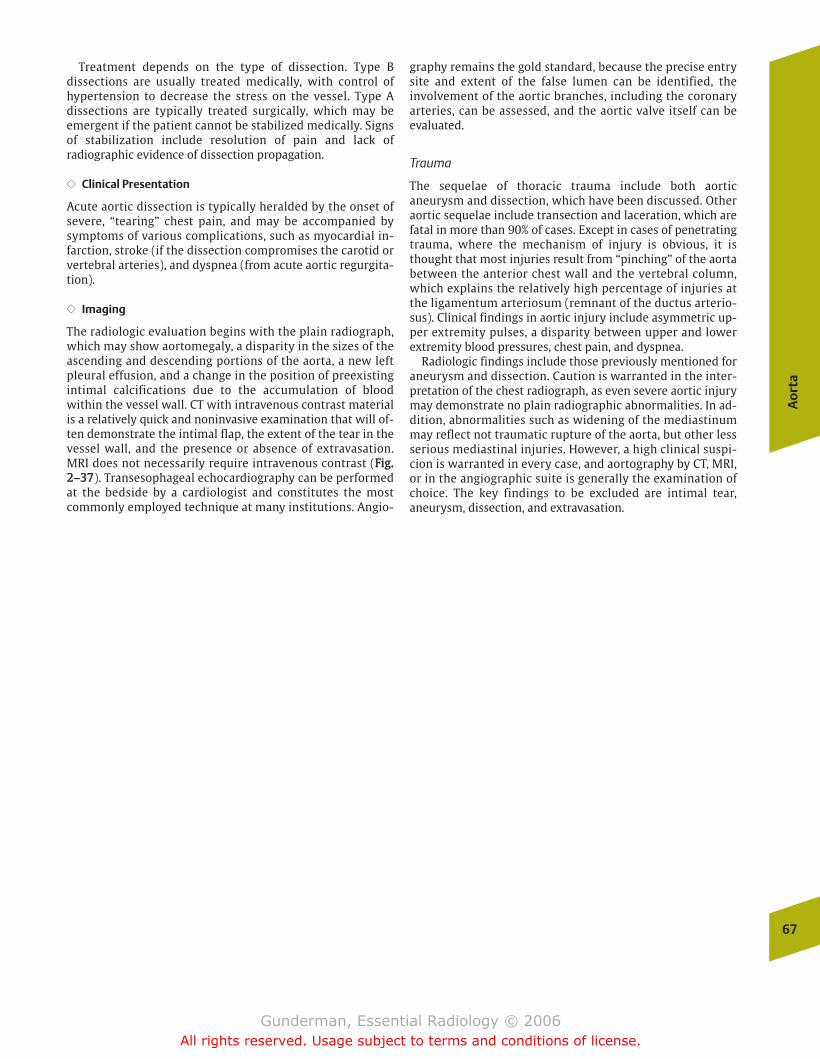
Treatment depends on the type of dissection. Type Bdissections are usually treated medically, with control ofhypertension to decrease the stress on the vessel. Type Adissections are typically treated surgically, which may beemergent if the patient cannot be stabilized medically. Signsof stabilization include resolution of pain and lack ofradiographic evidence of dissection propagation.
�� Clinical Presentation
Acute aortic dissection is typically heralded by the onset ofsevere, “tearing” chest pain, and may be accompanied bysymptoms of various complications, such as myocardial in-farction, stroke (if the dissection compromises the carotid orvertebral arteries), and dyspnea (from acute aortic regurgita-tion).
�� Imaging
The radiologic evaluation begins with the plain radiograph,which may show aortomegaly, a disparity in the sizes of theascending and descending portions of the aorta, a new leftpleural effusion, and a change in the position of preexistingintimal calcifications due to the accumulation of bloodwithin the vessel wall. CT with intravenous contrast materialis a relatively quick and noninvasive examination that will of-ten demonstrate the intimal flap, the extent of the tear in thevessel wall, and the presence or absence of extravasation.MRI does not necessarily require intravenous contrast (FFiigg..22––3377). Transesophageal echocardiography can be performedat the bedside by a cardiologist and constitutes the mostcommonly employed technique at many institutions. Angio-
graphy remains the gold standard, because the precise entrysite and extent of the false lumen can be identified, theinvolvement of the aortic branches, including the coronaryarteries, can be assessed, and the aortic valve itself can beevaluated.
Trauma
The sequelae of thoracic trauma include both aorticaneurysm and dissection, which have been discussed. Otheraortic sequelae include transection and laceration, which arefatal in more than 90% of cases. Except in cases of penetratingtrauma, where the mechanism of injury is obvious, it isthought that most injuries result from “pinching” of the aortabetween the anterior chest wall and the vertebral column,which explains the relatively high percentage of injuries atthe ligamentum arteriosum (remnant of the ductus arterio-sus). Clinical findings in aortic injury include asymmetric up-per extremity pulses, a disparity between upper and lowerextremity blood pressures, chest pain, and dyspnea.
Radiologic findings include those previously mentioned foraneurysm and dissection. Caution is warranted in the inter-pretation of the chest radiograph, as even severe aortic injurymay demonstrate no plain radiographic abnormalities. In ad-dition, abnormalities such as widening of the mediastinummay reflect not traumatic rupture of the aorta, but other lessserious mediastinal injuries. However, a high clinical suspi-cion is warranted in every case, and aortography by CT, MRI,or in the angiographic suite is generally the examination ofchoice. The key findings to be excluded are intimal tear,aneurysm, dissection, and extravasation.
Ao
rta
67
chapter 02_p39-67.qxd 12/1/05 3:25 PM Page 67
Gunderman, Essential Radiology © 2006All rights reserved. Usage subject to terms and conditions of license.
� Anatomy and Physiology
� Imaging
The Chest X-RayTechnical FactorsSearch PatternPulmonary Parenchymal PatternsClinical History
Other Imaging Modalities
� Airway
PathologyAsthmaChronic Obstructive Pulmonary Disease
� Pleura
PathologyPleural EffusionPneumothorax
� Mediastinum
Anatomy and ImagingPathology
Mediastinal Mass
� Lung
PathologyCongenitalInfectious TumorousInflammatoryMetabolicIatrogenicTraumaticVascular
3The Respiratory System
chapter 03_p68-111.qxd 12/1/05 3:30 PM Page 68
Gunderman, Essential Radiology © 2006All rights reserved. Usage subject to terms and conditions of license.
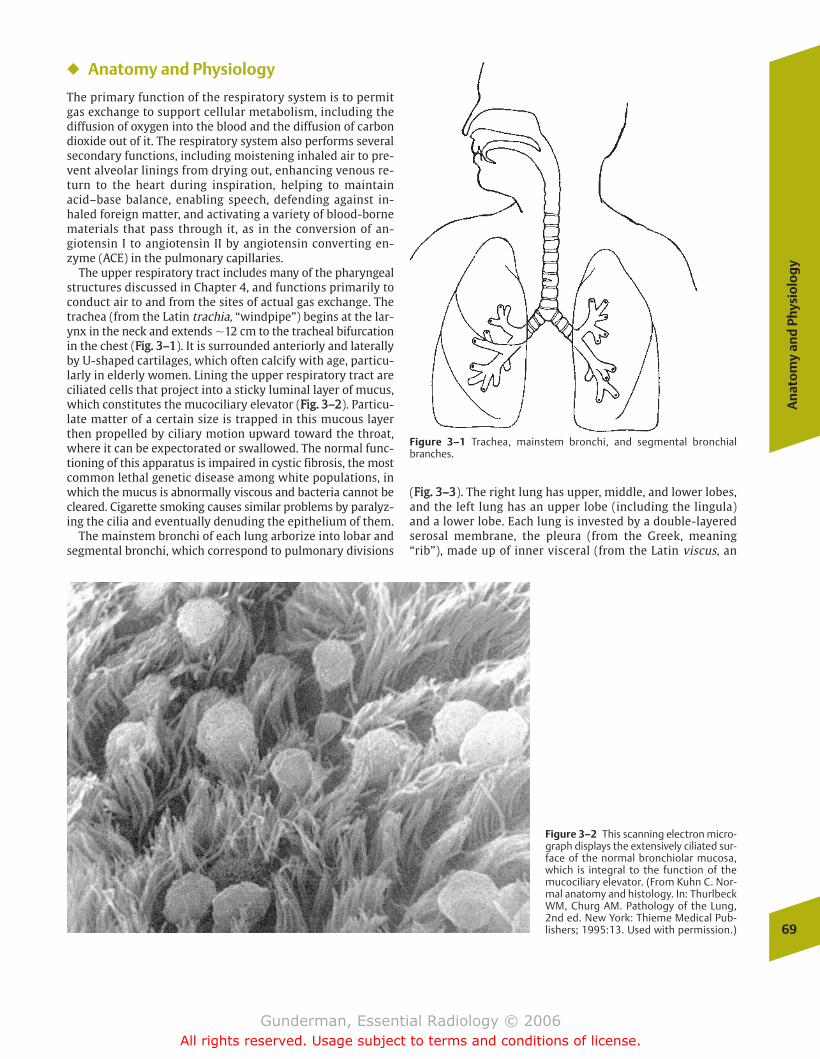
An
ato
my
and
Phy
sio
log
y
69
� Anatomy and Physiology
The primary function of the respiratory system is to permitgas exchange to support cellular metabolism, including thediffusion of oxygen into the blood and the diffusion of carbondioxide out of it. The respiratory system also performs severalsecondary functions, including moistening inhaled air to pre-vent alveolar linings from drying out, enhancing venous re-turn to the heart during inspiration, helping to maintainacid–base balance, enabling speech, defending against in-haled foreign matter, and activating a variety of blood-bornematerials that pass through it, as in the conversion of an-giotensin I to angiotensin II by angiotensin converting en-zyme (ACE) in the pulmonary capillaries.
The upper respiratory tract includes many of the pharyngealstructures discussed in Chapter 4, and functions primarily toconduct air to and from the sites of actual gas exchange. Thetrachea (from the Latin trachia, “windpipe”) begins at the lar-ynx in the neck and extends �12 cm to the tracheal bifurcationin the chest (FFiigg.. 33––11). It is surrounded anteriorly and laterallyby U-shaped cartilages, which often calcify with age, particu-larly in elderly women. Lining the upper respiratory tract areciliated cells that project into a sticky luminal layer of mucus,which constitutes the mucociliary elevator (FFiigg.. 33––22). Particu-late matter of a certain size is trapped in this mucous layerthen propelled by ciliary motion upward toward the throat,where it can be expectorated or swallowed. The normal func-tioning of this apparatus is impaired in cystic fibrosis, the mostcommon lethal genetic disease among white populations, inwhich the mucus is abnormally viscous and bacteria cannot becleared. Cigarette smoking causes similar problems by paralyz-ing the cilia and eventually denuding the epithelium of them.
The mainstem bronchi of each lung arborize into lobar andsegmental bronchi, which correspond to pulmonary divisions
(FFiigg.. 33––33). The right lung has upper, middle, and lower lobes,and the left lung has an upper lobe (including the lingula)and a lower lobe. Each lung is invested by a double-layeredserosal membrane, the pleura (from the Greek, meaning“rib”), made up of inner visceral (from the Latin viscus, an
Figure 3–1 Trachea, mainstem bronchi, and segmental bronchialbranches.
Figure 3–2 This scanning electron micro-graph displays the extensively ciliated sur-face of the normal bronchiolar mucosa,which is integral to the function of themucociliary elevator. (From Kuhn C. Nor-mal anatomy and histology. In: ThurlbeckWM, Churg AM. Pathology of the Lung,2nd ed. New York: Thieme Medical Pub-lishers; 1995:13. Used with permission.)
chapter 03_p68-111.qxd 12/1/05 3:30 PM Page 69
Gunderman, Essential Radiology © 2006All rights reserved. Usage subject to terms and conditions of license.
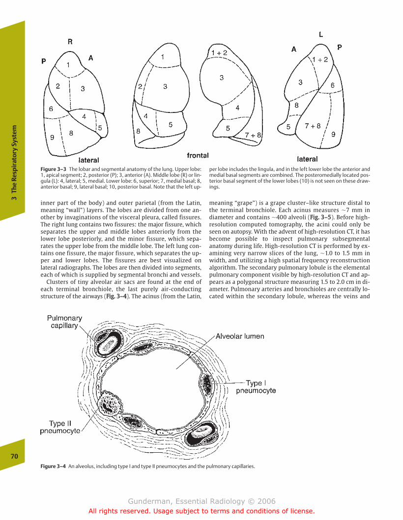
inner part of the body) and outer parietal (from the Latin,meaning “wall”) layers. The lobes are divided from one an-other by invaginations of the visceral pleura, called fissures.The right lung contains two fissures: the major fissure, whichseparates the upper and middle lobes anteriorly from thelower lobe posteriorly, and the minor fissure, which sepa-rates the upper lobe from the middle lobe. The left lung con-tains one fissure, the major fissure, which separates the up-per and lower lobes. The fissures are best visualized onlateral radiographs. The lobes are then divided into segments,each of which is supplied by segmental bronchi and vessels.
Clusters of tiny alveolar air sacs are found at the end ofeach terminal bronchiole, the last purely air-conductingstructure of the airways (FFiigg.. 33––44). The acinus (from the Latin,
meaning “grape”) is a grape cluster–like structure distal tothe terminal bronchiole. Each acinus measures �7 mm indiameter and contains �400 alveoli (FFiigg.. 33––55). Before high-resolution computed tomography, the acini could only beseen on autopsy. With the advent of high-resolution CT, it hasbecome possible to inspect pulmonary subsegmentalanatomy during life. High-resolution CT is performed by ex-amining very narrow slices of the lung, �1.0 to 1.5 mm inwidth, and utilizing a high spatial frequency reconstructionalgorithm. The secondary pulmonary lobule is the elementalpulmonary component visible by high-resolution CT and ap-pears as a polygonal structure measuring 1.5 to 2.0 cm in di-ameter. Pulmonary arteries and bronchioles are centrally lo-cated within the secondary lobule, whereas the veins and
70
3Th
e Re
spir
ator
y Sy
stem
Figure 3–3 The lobar and segmental anatomy of the lung. Upper lobe:1, apical segment; 2, posterior (P); 3, anterior (A). Middle lobe (R) or lin-gula (L): 4, lateral; 5, medial. Lower lobe: 6, superior; 7, medial basal; 8,anterior basal; 9, lateral basal; 10, posterior basal. Note that the left up-
per lobe includes the lingula, and in the left lower lobe the anterior andmedial basal segments are combined. The posteromedially located pos-terior basal segment of the lower lobes (10) is not seen on these draw-ings.
Figure 3–4 An alveolus, including type I and type II pneumocytes and the pulmonary capillaries.
chapter 03_p68-111.qxd 12/1/05 3:30 PM Page 70
Gunderman, Essential Radiology © 2006All rights reserved. Usage subject to terms and conditions of license.
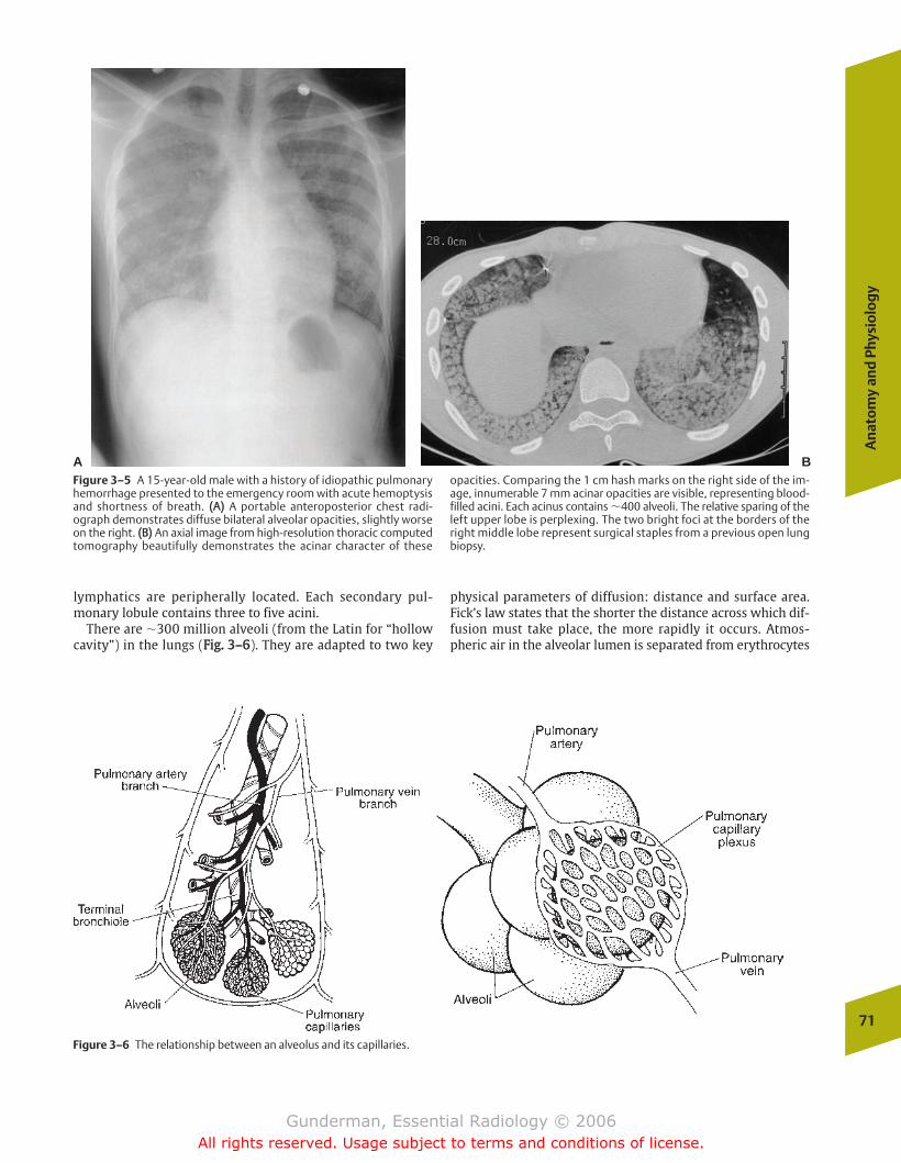
An
ato
my
and
Phy
sio
log
y
71
lymphatics are peripherally located. Each secondary pul-monary lobule contains three to five acini.
There are �300 million alveoli (from the Latin for “hollowcavity”) in the lungs (FFiigg.. 33––66). They are adapted to two key
physical parameters of diffusion: distance and surface area.Fick’s law states that the shorter the distance across which dif-fusion must take place, the more rapidly it occurs. Atmos-pheric air in the alveolar lumen is separated from erythrocytes
A BFigure 3–5 A 15-year-old male with a history of idiopathic pulmonaryhemorrhage presented to the emergency room with acute hemoptysisand shortness of breath. ((AA)) A portable anteroposterior chest radi-ograph demonstrates diffuse bilateral alveolar opacities, slightly worseon the right. ((BB)) An axial image from high-resolution thoracic computedtomography beautifully demonstrates the acinar character of these
opacities. Comparing the 1 cm hash marks on the right side of the im-age, innumerable 7 mm acinar opacities are visible, representing blood-filled acini. Each acinus contains �400 alveoli. The relative sparing of theleft upper lobe is perplexing. The two bright foci at the borders of theright middle lobe represent surgical staples from a previous open lungbiopsy.
Figure 3–6 The relationship between an alveolus and its capillaries.
chapter 03_p68-111.qxd 12/1/05 3:30 PM Page 71
Gunderman, Essential Radiology © 2006All rights reserved. Usage subject to terms and conditions of license.
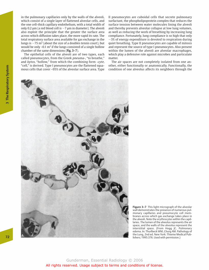
72
3Th
e Re
spir
ator
y Sy
stem
in the pulmonary capillaries only by the walls of the alveoli,which consist of a single layer of flattened alveolar cells, andthe one cell-thick capillary endothelium, with a total width ofonly 0.2 µm (a red blood cell is �7 µm in diameter). The alveolialso exploit the principle that the greater the surface areaacross which diffusion takes place, the more rapid its rate. Thetotal respiratory surface area available for gas exchange in thelungs is �75 m2 (about the size of a doubles tennis court), butwould be only ~0.1 m2 if the lungs consisted of a single hollowchamber of the same dimensions (FFiigg.. 33––77).
The epithelial cells of the alveoli are of two types, eachcalled pneumocytes, from the Greek pneuma-, “to breathe,”and kytos, “hollow,” from which the combining form -cyte,“cell,” is derived. Type I pneumocytes are the flattened squa-mous cells that cover ~95% of the alveolar surface area. Type
II pneumocytes are cuboidal cells that secrete pulmonarysurfactant, the phospholipoprotein complex that reduces thesurface tension between water molecules lining the alveoliand thereby prevents alveolar collapse at low lung volumes,as well as reducing the work of breathing by increasing lungcompliance. Fortunately, lung compliance is so high that only�3% of energy expenditure is devoted to respiration duringquiet breathing. Type II pneumocytes are capable of mitosisand represent the source of type I pneumocytes. Also presentwithin the lumen of the alveoli are alveolar macrophages,which play a defensive role against microbes and particulatematter.
The air spaces are not completely isolated from one an-other, either functionally or anatomically. Functionally, thecondition of one alveolus affects its neighbors through the
Figure 3–7 This light micrograph of the alveolarwall demonstrates the presence of numerous pul-monary capillaries and pneumocyte cell mem-branes across which gas exchange takes place inthe alveoli. Note the erythrocytes within the capil-laries. The lumen of the alveolus represents the airspace, and the walls of the alveolus represent theinterstitial space. (From Hogg JC. Pulmonaryedema. In: Thurlbeck WM, Churg AM. Pathology ofthe Lung, 2nd ed. New York: Thieme Medical Pub-lishers; 1995:376. Used with permission.)
chapter 03_p68-111.qxd 12/1/05 3:30 PM Page 72
Gunderman, Essential Radiology © 2006All rights reserved. Usage subject to terms and conditions of license.
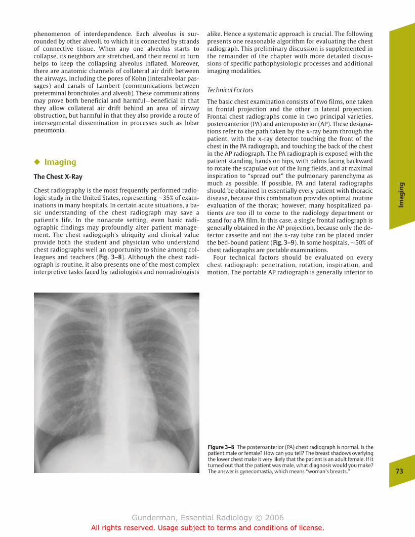
Imag
ing
73
phenomenon of interdependence. Each alveolus is sur-rounded by other alveoli, to which it is connected by strandsof connective tissue. When any one alveolus starts tocollapse, its neighbors are stretched, and their recoil in turnhelps to keep the collapsing alveolus inflated. Moreover,there are anatomic channels of collateral air drift betweenthe airways, including the pores of Kohn (interalveolar pas-sages) and canals of Lambert (communications betweenpreterminal bronchioles and alveoli). These communicationsmay prove both beneficial and harmful—beneficial in thatthey allow collateral air drift behind an area of airwayobstruction, but harmful in that they also provide a route ofintersegmental dissemination in processes such as lobarpneumonia.
� Imaging
The Chest X-Ray
Chest radiography is the most frequently performed radio-logic study in the United States, representing �35% of exam-inations in many hospitals. In certain acute situations, a ba-sic understanding of the chest radiograph may save apatient’s life. In the nonacute setting, even basic radi-ographic findings may profoundly alter patient manage-ment. The chest radiograph’s ubiquity and clinical valueprovide both the student and physician who understandchest radiographs well an opportunity to shine among col-leagues and teachers (FFiigg.. 33––88). Although the chest radi-ograph is routine, it also presents one of the most complexinterpretive tasks faced by radiologists and nonradiologists
alike. Hence a systematic approach is crucial. The followingpresents one reasonable algorithm for evaluating the chestradiograph. This preliminary discussion is supplemented inthe remainder of the chapter with more detailed discus-sions of specific pathophysiologic processes and additionalimaging modalities.
Technical Factors
The basic chest examination consists of two films, one takenin frontal projection and the other in lateral projection.Frontal chest radiographs come in two principal varieties,posteroanterior (PA) and anteroposterior (AP). These designa-tions refer to the path taken by the x-ray beam through thepatient, with the x-ray detector touching the front of thechest in the PA radiograph, and touching the back of the chestin the AP radiograph. The PA radiograph is exposed with thepatient standing, hands on hips, with palms facing backwardto rotate the scapulae out of the lung fields, and at maximalinspiration to “spread out” the pulmonary parenchyma asmuch as possible. If possible, PA and lateral radiographsshould be obtained in essentially every patient with thoracicdisease, because this combination provides optimal routineevaluation of the thorax; however, many hospitalized pa-tients are too ill to come to the radiology department orstand for a PA film. In this case, a single frontal radiograph isgenerally obtained in the AP projection, because only the de-tector cassette and not the x-ray tube can be placed underthe bed-bound patient (FFiigg.. 33––99). In some hospitals, �50% ofchest radiographs are portable examinations.
Four technical factors should be evaluated on everychest radiograph: penetration, rotation, inspiration, andmotion. The portable AP radiograph is generally inferior to
Figure 3–8 The posteroanterior (PA) chest radiograph is normal. Is thepatient male or female? How can you tell? The breast shadows overlyingthe lower chest make it very likely that the patient is an adult female. If itturned out that the patient was male, what diagnosis would you make?The answer is gynecomastia, which means “woman’s breasts.”
chapter 03_p68-111.qxd 12/1/05 3:30 PM Page 73
Gunderman, Essential Radiology © 2006All rights reserved. Usage subject to terms and conditions of license.
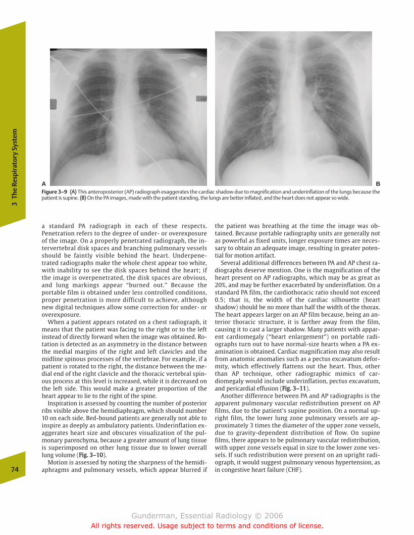
a standard PA radiograph in each of these respects.Penetration refers to the degree of under- or overexposureof the image. On a properly penetrated radiograph, the in-tervertebral disk spaces and branching pulmonary vesselsshould be faintly visible behind the heart. Underpene-trated radiographs make the whole chest appear too white,with inability to see the disk spaces behind the heart; ifthe image is overpenetrated, the disk spaces are obvious,and lung markings appear “burned out.” Because theportable film is obtained under less controlled conditions,proper penetration is more difficult to achieve, althoughnew digital techniques allow some correction for under- oroverexposure.
When a patient appears rotated on a chest radiograph, itmeans that the patient was facing to the right or to the leftinstead of directly forward when the image was obtained. Ro-tation is detected as an asymmetry in the distance betweenthe medial margins of the right and left clavicles and themidline spinous processes of the vertebrae. For example, if apatient is rotated to the right, the distance between the me-dial end of the right clavicle and the thoracic vertebral spin-ous process at this level is increased, while it is decreased onthe left side. This would make a greater proportion of theheart appear to lie to the right of the spine.
Inspiration is assessed by counting the number of posteriorribs visible above the hemidiaphragm, which should number10 on each side. Bed-bound patients are generally not able toinspire as deeply as ambulatory patients. Underinflation ex-aggerates heart size and obscures visualization of the pul-monary parenchyma, because a greater amount of lung tissueis superimposed on other lung tissue due to lower overalllung volume (FFiigg.. 33––1100).
Motion is assessed by noting the sharpness of the hemidi-aphragms and pulmonary vessels, which appear blurred if
the patient was breathing at the time the image was ob-tained. Because portable radiography units are generally notas powerful as fixed units, longer exposure times are neces-sary to obtain an adequate image, resulting in greater poten-tial for motion artifact.
Several additional differences between PA and AP chest ra-diographs deserve mention. One is the magnification of theheart present on AP radiographs, which may be as great as20%, and may be further exacerbated by underinflation. On astandard PA film, the cardiothoracic ratio should not exceed0.5; that is, the width of the cardiac silhouette (heartshadow) should be no more than half the width of the thorax.The heart appears larger on an AP film because, being an an-terior thoracic structure, it is farther away from the film,causing it to cast a larger shadow. Many patients with appar-ent cardiomegaly (“heart enlargement”) on portable radi-ographs turn out to have normal-size hearts when a PA ex-amination is obtained. Cardiac magnification may also resultfrom anatomic anomalies such as a pectus excavatum defor-mity, which effectively flattens out the heart. Thus, otherthan AP technique, other radiographic mimics of car-diomegaly would include underinflation, pectus excavatum,and pericardial effusion (FFiigg.. 33––1111).
Another difference between PA and AP radiographs is theapparent pulmonary vascular redistribution present on APfilms, due to the patient’s supine position. On a normal up-right film, the lower lung zone pulmonary vessels are ap-proximately 3 times the diameter of the upper zone vessels,due to gravity-dependent distribution of flow. On supinefilms, there appears to be pulmonary vascular redistribution,with upper zone vessels equal in size to the lower zone ves-sels. If such redistribution were present on an upright radi-ograph, it would suggest pulmonary venous hypertension, asin congestive heart failure (CHF).74
3Th
e Re
spir
ator
y Sy
stem
A BFigure 3–9 ((AA)) This anteroposterior (AP) radiograph exaggerates the cardiac shadow due to magnification and underinflation of the lungs because thepatient is supine. ((BB)) On the PA images, made with the patient standing, the lungs are better inflated, and the heart does not appear so wide.
chapter 03_p68-111.qxd 12/1/05 3:30 PM Page 74
Gunderman, Essential Radiology © 2006All rights reserved. Usage subject to terms and conditions of license.
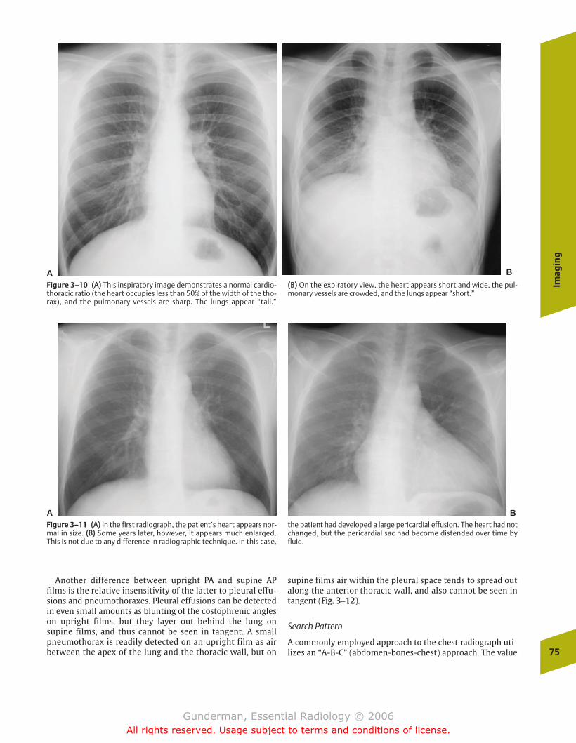
Imag
ing
75
Another difference between upright PA and supine APfilms is the relative insensitivity of the latter to pleural effu-sions and pneumothoraxes. Pleural effusions can be detectedin even small amounts as blunting of the costophrenic angleson upright films, but they layer out behind the lung onsupine films, and thus cannot be seen in tangent. A smallpneumothorax is readily detected on an upright film as airbetween the apex of the lung and the thoracic wall, but on
supine films air within the pleural space tends to spread outalong the anterior thoracic wall, and also cannot be seen intangent (FFiigg.. 33––1122).
Search Pattern
A commonly employed approach to the chest radiograph uti-lizes an “A-B-C” (abdomen-bones-chest) approach. The value
A B
Figure 3–10 ((AA)) This inspiratory image demonstrates a normal cardio-thoracic ratio (the heart occupies less than 50% of the width of the tho-rax), and the pulmonary vessels are sharp. The lungs appear “tall.”
((BB)) On the expiratory view, the heart appears short and wide, the pul-monary vessels are crowded, and the lungs appear “short.”
A BFigure 3–11 ((AA)) In the first radiograph, the patient’s heart appears nor-mal in size. ((BB)) Some years later, however, it appears much enlarged.This is not due to any difference in radiographic technique. In this case,
the patient had developed a large pericardial effusion. The heart had notchanged, but the pericardial sac had become distended over time byfluid.
chapter 03_p68-111.qxd 12/1/05 3:30 PM Page 75
Gunderman, Essential Radiology © 2006All rights reserved. Usage subject to terms and conditions of license.

of this approach, which puts the chest itself last, is the factthat it ensures that other easily overlooked areas outside thechest are inspected on each image. Key abdominal findingsthat should be sought out on chest radiographs include pneu-moperitoneum, gastrointestinal (GI) dilation (possibly indi-cating obstruction), and masses (FFiigg.. 33––1133). “Bones” standsfor both the osseous structures and their associated soft tis-sues. Examples of key osseous findings include rib fractures,vertebral compression fractures, and blastic (bone formingand hence white) or lytic (bone destroying and hence black)lesions, which might indicate infection or metastatic disease.Important findings in the soft tissues include evidence of aprevious mastectomy (missing breast shadow) and calcifica-tions in soft tissue tumors. In children, the chest radiographshould always be inspected for evidence of abuse, such as ribfractures (FFiigg.. 33––1144).
To ensure that easily overlooked structures within thechest are attended to, it is helpful to save the lungs for last. Agood place to begin is the airway. This includes inspection ofthe trachea and major bronchi for evidence of foreign bodies,displacement, or compression. Next, the pleural space shouldbe inspected, looking for processes such as pleural effusion,pleural plaque, pleural-based mass, and pneumothorax. The76
3Th
e Re
spir
ator
y Sy
stem
Figure 3–12 This young woman has cystic fibrosis and a right-sidedcentral venous catheter, with its tip in the superior vena cava. Note theincreased lung markings due to bronchiectasis, mycoid impactions, andincreased interstitial markings. What else does she have? A large rightpneumothorax. Note that the lung markings do not extend all the wayto the thoracic wall on the right side.
Figure 3–13 This upright chest radiograph demonstrates crescent-shaped lucencies under both hemidiaphragms. This is free intraperi-toneal gas, or “free air,” which rises up to the top of the peritoneal cavitywhen the patient is upright. Pneumoperitoneum is commonly due to re-cent surgery, but it may also indicate a ruptured abdominal viscus, suchas a perforated duodenal ulcer.
Figure 3–14 This infant’s chest radiograph demonstrates healing frac-tures of the posterolateral aspects of the right sixth and seventh ribs,secondary to child abuse. Had this finding been missed, the child mighthave been returned to the setting where the abuse was taking place,and even more severe injury might have resulted.
chapter 03_p68-111.qxd 12/1/05 3:30 PM Page 76
Gunderman, Essential Radiology © 2006All rights reserved. Usage subject to terms and conditions of license.
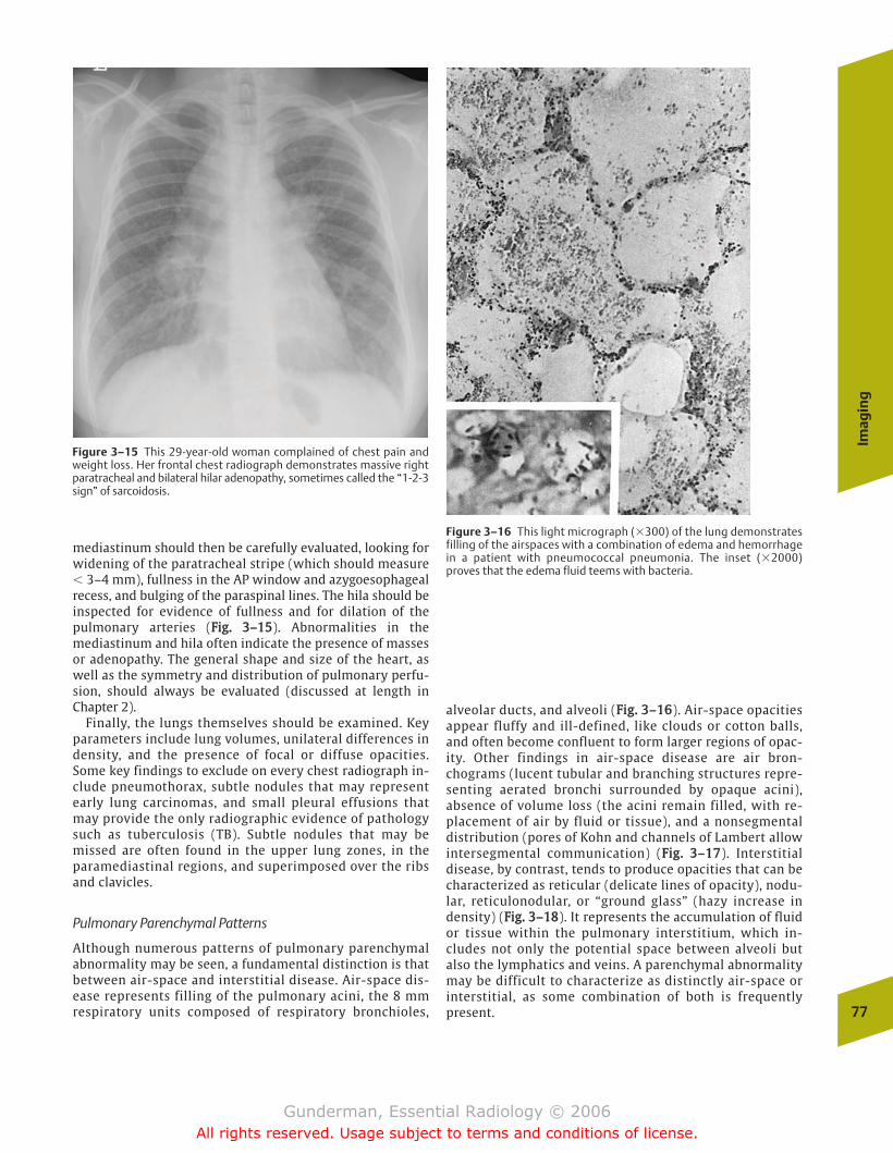
Imag
ing
77
mediastinum should then be carefully evaluated, looking forwidening of the paratracheal stripe (which should measure� 3–4 mm), fullness in the AP window and azygoesophagealrecess, and bulging of the paraspinal lines. The hila should beinspected for evidence of fullness and for dilation of thepulmonary arteries (FFiigg.. 33––1155). Abnormalities in themediastinum and hila often indicate the presence of massesor adenopathy. The general shape and size of the heart, aswell as the symmetry and distribution of pulmonary perfu-sion, should always be evaluated (discussed at length inChapter 2).
Finally, the lungs themselves should be examined. Keyparameters include lung volumes, unilateral differences indensity, and the presence of focal or diffuse opacities.Some key findings to exclude on every chest radiograph in-clude pneumothorax, subtle nodules that may representearly lung carcinomas, and small pleural effusions thatmay provide the only radiographic evidence of pathologysuch as tuberculosis (TB). Subtle nodules that may bemissed are often found in the upper lung zones, in theparamediastinal regions, and superimposed over the ribsand clavicles.
Pulmonary Parenchymal Patterns
Although numerous patterns of pulmonary parenchymalabnormality may be seen, a fundamental distinction is thatbetween air-space and interstitial disease. Air-space dis-ease represents filling of the pulmonary acini, the 8 mmrespiratory units composed of respiratory bronchioles,
alveolar ducts, and alveoli (FFiigg.. 33––1166). Air-space opacitiesappear fluffy and ill-defined, like clouds or cotton balls,and often become confluent to form larger regions of opac-ity. Other findings in air-space disease are air bron-chograms (lucent tubular and branching structures repre-senting aerated bronchi surrounded by opaque acini),absence of volume loss (the acini remain filled, with re-placement of air by fluid or tissue), and a nonsegmentaldistribution (pores of Kohn and channels of Lambert allowintersegmental communication) (FFiigg.. 33––1177). Interstitialdisease, by contrast, tends to produce opacities that can becharacterized as reticular (delicate lines of opacity), nodu-lar, reticulonodular, or “ground glass” (hazy increase indensity) (FFiigg.. 33––1188). It represents the accumulation of fluidor tissue within the pulmonary interstitium, which in-cludes not only the potential space between alveoli butalso the lymphatics and veins. A parenchymal abnormalitymay be difficult to characterize as distinctly air-space orinterstitial, as some combination of both is frequentlypresent.
Figure 3–15 This 29-year-old woman complained of chest pain andweight loss. Her frontal chest radiograph demonstrates massive rightparatracheal and bilateral hilar adenopathy, sometimes called the “1-2-3sign” of sarcoidosis.
Figure 3–16 This light micrograph (�300) of the lung demonstratesfilling of the airspaces with a combination of edema and hemorrhagein a patient with pneumococcal pneumonia. The inset (�2000)proves that the edema fluid teems with bacteria.
chapter 03_p68-111.qxd 12/1/05 3:30 PM Page 77
Gunderman, Essential Radiology © 2006All rights reserved. Usage subject to terms and conditions of license.
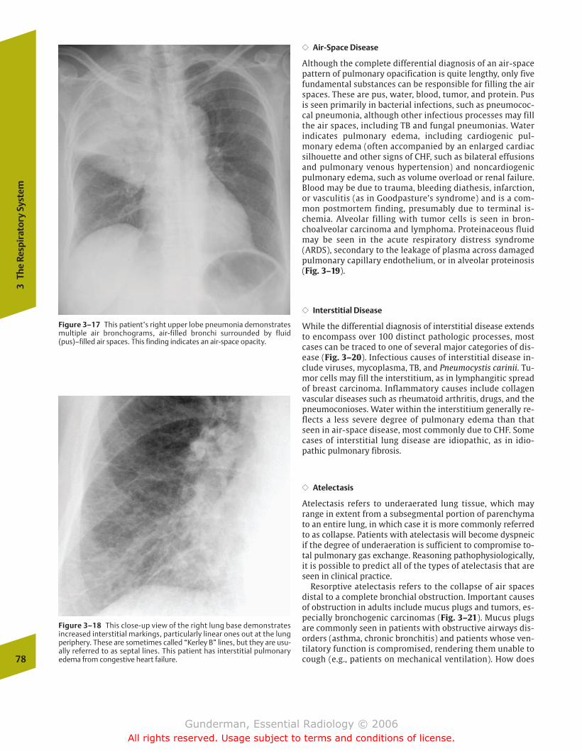
�� Air-Space Disease
Although the complete differential diagnosis of an air-spacepattern of pulmonary opacification is quite lengthy, only fivefundamental substances can be responsible for filling the airspaces. These are pus, water, blood, tumor, and protein. Pusis seen primarily in bacterial infections, such as pneumococ-cal pneumonia, although other infectious processes may fillthe air spaces, including TB and fungal pneumonias. Waterindicates pulmonary edema, including cardiogenic pul-monary edema (often accompanied by an enlarged cardiacsilhouette and other signs of CHF, such as bilateral effusionsand pulmonary venous hypertension) and noncardiogenicpulmonary edema, such as volume overload or renal failure.Blood may be due to trauma, bleeding diathesis, infarction,or vasculitis (as in Goodpasture’s syndrome) and is a com-mon postmortem finding, presumably due to terminal is-chemia. Alveolar filling with tumor cells is seen in bron-choalveolar carcinoma and lymphoma. Proteinaceous fluidmay be seen in the acute respiratory distress syndrome(ARDS), secondary to the leakage of plasma across damagedpulmonary capillary endothelium, or in alveolar proteinosis(Fig. 3–19).
�� Interstitial Disease
While the differential diagnosis of interstitial disease extendsto encompass over 100 distinct pathologic processes, mostcases can be traced to one of several major categories of dis-ease (Fig. 3–20). Infectious causes of interstitial disease in-clude viruses, mycoplasma, TB, and Pneumocystis carinii. Tu-mor cells may fill the interstitium, as in lymphangitic spreadof breast carcinoma. Inflammatory causes include collagenvascular diseases such as rheumatoid arthritis, drugs, and thepneumoconioses. Water within the interstitium generally re-flects a less severe degree of pulmonary edema than thatseen in air-space disease, most commonly due to CHF. Somecases of interstitial lung disease are idiopathic, as in idio-pathic pulmonary fibrosis.
�� Atelectasis
Atelectasis refers to underaerated lung tissue, which mayrange in extent from a subsegmental portion of parenchymato an entire lung, in which case it is more commonly referredto as collapse. Patients with atelectasis will become dyspneicif the degree of underaeration is sufficient to compromise to-tal pulmonary gas exchange. Reasoning pathophysiologically,it is possible to predict all of the types of atelectasis that areseen in clinical practice.
Resorptive atelectasis refers to the collapse of air spacesdistal to a complete bronchial obstruction. Important causesof obstruction in adults include mucus plugs and tumors, es-pecially bronchogenic carcinomas (Fig. 3–21). Mucus plugsare commonly seen in patients with obstructive airways dis-orders (asthma, chronic bronchitis) and patients whose ven-tilatory function is compromised, rendering them unable tocough (e.g., patients on mechanical ventilation). How does78
3Th
e Re
spir
ator
y Sy
stem
Figure 3–17 This patient’s right upper lobe pneumonia demonstratesmultiple air bronchograms, air-filled bronchi surrounded by fluid(pus)–filled air spaces. This finding indicates an air-space opacity.
Figure 3–18 This close-up view of the right lung base demonstratesincreased interstitial markings, particularly linear ones out at the lungperiphery. These are sometimes called “Kerley B” lines, but they are usu-ally referred to as septal lines. This patient has interstitial pulmonaryedema from congestive heart failure.
chapter 03_p68-111.qxd 2/15/07 9:52 PM Page 78
Gunderman, Essential Radiology © 2006All rights reserved. Usage subject to terms and conditions of license.
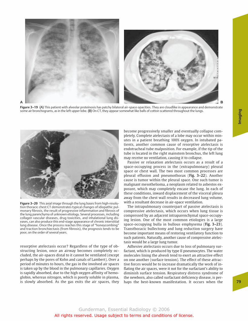
Imag
ing
79
resorptive atelectasis occur? Regardless of the type of ob-structing lesion, once an airway becomes completely oc-cluded, the air-spaces distal to it cannot be ventilated (exceptperhaps by the pores of Kohn and canals of Lambert). Over aperiod of minutes to hours, the gas in the involved air spacesis taken up by the blood in the pulmonary capillaries. Oxygenis rapidly absorbed, due to the high oxygen affinity of hemo-globin, whereas nitrogen, which is poorly soluble in plasma,is slowly absorbed. As the gas exits the air spaces, they
become progressively smaller and eventually collapse com-pletely. Complete atelectasis of a lobe may occur within min-utes in a patient breathing 100% oxygen. In intubated pa-tients, another common cause of resorptive atelectasis isendotracheal tube malposition. For example, if the tip of thetube is located in the right mainstem bronchus, the left lungmay receive no ventilation, causing it to collapse.
Passive or relaxation atelectasis occurs as a result of aspace-occupying process in the (extrapulmonary) pleuralspace or chest wall. The two most common processes arepleural effusion and pneumothorax (FFiigg.. 33––2222). Anothercause is tumor within the pleural space. One such tumor ismalignant mesothelioma, a neoplasm related to asbestos ex-posure, which may completely encase the lung. In each ofthese conditions, inward displacement of the visceral pleuraaway from the chest wall results in decreased lung volume,with a resultant decrease in air-space ventilation.
The intrapulmonary counterpart of passive atelectasis iscompressive atelectasis, which occurs when lung tissue iscompressed by an adjacent intraparenchymal space-occupy-ing lesion. One of the most common etiologies is a largespace-occupying bulla in bullous emphysema (FFiigg.. 33––2233).Transthoracic bullectomy and lung reduction surgery havebecome important means of restoring ventilatory function tosuch patients. Naturally, another cause of compressive atelec-tasis would be a large lung tumor.
Adhesive atelectasis occurs due to loss of pulmonary sur-factant, which is produced by type II pneumocytes. The watermolecules lining the alveoli tend to exert an attractive effecton one another (surface tension). The effect of these attrac-tive forces would be to increase dramatically the work of in-flating the air spaces, were it not for the surfactant’s ability todiminish surface tension. Respiratory distress syndrome ofthe newborn, also called surfactant deficiency disease, is per-haps the best-known manifestation. It occurs when the
Figure 3–19 ((AA)) This patient with alveolar proteinosis has patchy bilateral air-space opacities. They are cloudlike in appearance and demonstratesome air bronchograms, as in the left upper lobe. ((BB)) On CT, they appear somewhat like balls of cotton scattered throughout the lungs.
A B
Figure 3–20 This axial image through the lung bases from high-resolu-tion thoracic chest CT demonstrates typical changes of idiopathic pul-monary fibrosis, the result of progressive inflammation and fibrosis ofthe lung parenchyma of unknown etiology. Several processes, includingcollagen vascular diseases, drug toxicities, and inhalational lung dis-eases, can also produce this end-stage appearance of chronic interstitiallung disease. Once the process reaches this stage of “honeycombing”and traction bronchiectasis (from fibrosis), the prognosis tends to bepoor, on the order of several years.
chapter 03_p68-111.qxd 12/1/05 3:30 PM Page 79
Gunderman, Essential Radiology © 2006All rights reserved. Usage subject to terms and conditions of license.
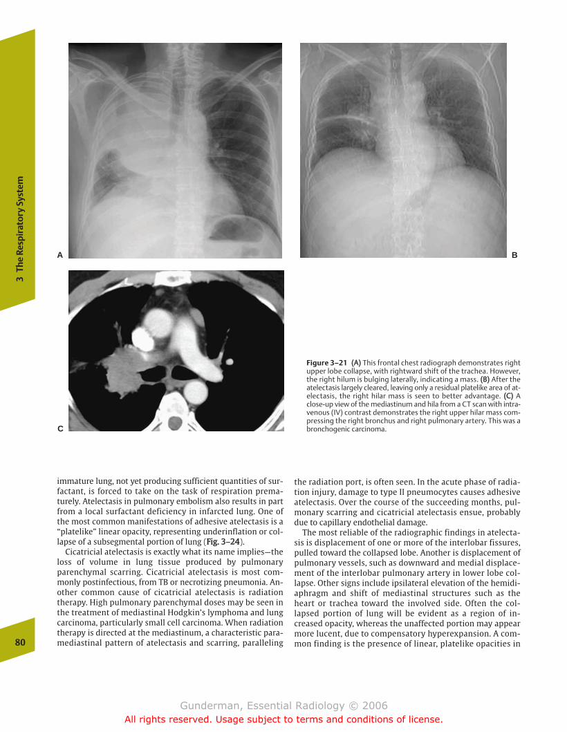
immature lung, not yet producing sufficient quantities of sur-factant, is forced to take on the task of respiration prema-turely. Atelectasis in pulmonary embolism also results in partfrom a local surfactant deficiency in infarcted lung. One ofthe most common manifestations of adhesive atelectasis is a“platelike” linear opacity, representing underinflation or col-lapse of a subsegmental portion of lung (FFiigg.. 33––2244).
Cicatricial atelectasis is exactly what its name implies—theloss of volume in lung tissue produced by pulmonaryparenchymal scarring. Cicatricial atelectasis is most com-monly postinfectious, from TB or necrotizing pneumonia. An-other common cause of cicatricial atelectasis is radiationtherapy. High pulmonary parenchymal doses may be seen inthe treatment of mediastinal Hodgkin’s lymphoma and lungcarcinoma, particularly small cell carcinoma. When radiationtherapy is directed at the mediastinum, a characteristic para-mediastinal pattern of atelectasis and scarring, paralleling
the radiation port, is often seen. In the acute phase of radia-tion injury, damage to type II pneumocytes causes adhesiveatelectasis. Over the course of the succeeding months, pul-monary scarring and cicatricial atelectasis ensue, probablydue to capillary endothelial damage.
The most reliable of the radiographic findings in atelecta-sis is displacement of one or more of the interlobar fissures,pulled toward the collapsed lobe. Another is displacement ofpulmonary vessels, such as downward and medial displace-ment of the interlobar pulmonary artery in lower lobe col-lapse. Other signs include ipsilateral elevation of the hemidi-aphragm and shift of mediastinal structures such as theheart or trachea toward the involved side. Often the col-lapsed portion of lung will be evident as a region of in-creased opacity, whereas the unaffected portion may appearmore lucent, due to compensatory hyperexpansion. A com-mon finding is the presence of linear, platelike opacities in80
3Th
e Re
spir
ator
y Sy
stem
Figure 3–21 ((AA)) This frontal chest radiograph demonstrates rightupper lobe collapse, with rightward shift of the trachea. However,the right hilum is bulging laterally, indicating a mass. ((BB)) After theatelectasis largely cleared, leaving only a residual platelike area of at-electasis, the right hilar mass is seen to better advantage. ((CC)) Aclose-up view of the mediastinum and hila from a CT scan with intra-venous (IV) contrast demonstrates the right upper hilar mass com-pressing the right bronchus and right pulmonary artery. This was abronchogenic carcinoma.
A B
C
chapter 03_p68-111.qxd 12/1/05 3:30 PM Page 80
Gunderman, Essential Radiology © 2006All rights reserved. Usage subject to terms and conditions of license.
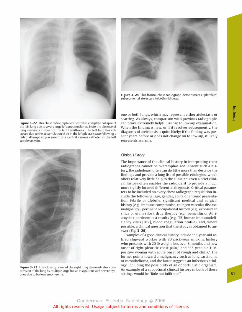
Imag
ing
81
one or both lungs, which may represent either atelectasis orscarring. As always, comparison with previous radiographscan prove extremely helpful, as can follow-up examination.When the finding is new, or if it resolves subsequently, thediagnosis of atelectasis is quite likely; if the finding was pre-sent years before or does not change on follow-up, it likelyrepresents scarring.
Clinical History
The importance of the clinical history in interpreting chestradiographs cannot be overemphasized. Absent such a his-tory, the radiologist often can do little more than describe thefindings and provide a long list of possible etiologies, whichoffers relatively little help to the clinician. Even a brief clini-cal history often enables the radiologist to provide a muchmore tightly focused differential diagnosis. Critical parame-ters to be included on every chest radiograph requisition in-clude the following: age, gender, acute or chronic presenta-tion, febrile or afebrile, significant medical and surgicalhistory (e.g., immune compromise, collagen vascular disease,malignancy), pertinent occupational history (e.g., exposure tosilica or grain silos), drug therapy (e.g., penicillin or Adri-amycin), pertinent test results (e.g., TB, human immunodefi-ciency virus [HIV], blood coagulation profile), and, wherepossible, a clinical question that the study is obtained to an-swer (Fig. 3–25).
Examples of a good clinical history include “55-year-old re-tired shipyard worker with 80 pack-year smoking historywho presents with 20 lb weight loss over 3 months and newonset of right pleuritic chest pain,” and “35-year-old HIV-positive woman with acute onset of cough and chills.” Theformer points toward a malignancy such as lung carcinomaor mesothelioma, and the latter suggests an infectious etiol-ogy, including the possibility of an opportunistic organism.An example of a suboptimal clinical history in both of thesesettings would be “Rule out infiltrate.”
Figure 3–22 This chest radiograph demonstrates complete collapse ofthe left lung due to a very large left pneumothorax. Note the absence oflung markings in most of the left hemithorax. The left lung has col-lapsed due to the accumulation of air in the left pleural space following afailed attempt at placement of a central venous catheter in the leftsubclavian vein.
Figure 3–23 This close-up view of the right lung demonstrates com-pression of the lung by multiple large bullae in a patient with severe dys-pnea due to bullous emphysema.
Figure 3–24 This frontal chest radiograph demonstrates “platelike”subsegmental atelectasis in both midlungs.
chapter 03_p68-111.qxd 2/15/07 9:52 PM Page 81
Gunderman, Essential Radiology © 2006All rights reserved. Usage subject to terms and conditions of license.
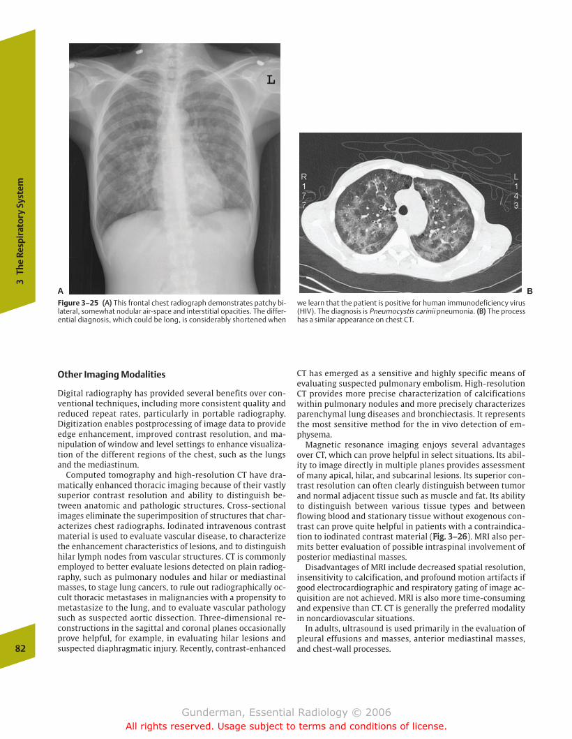
Other Imaging Modalities
Digital radiography has provided several benefits over con-ventional techniques, including more consistent quality andreduced repeat rates, particularly in portable radiography.Digitization enables postprocessing of image data to provideedge enhancement, improved contrast resolution, and ma-nipulation of window and level settings to enhance visualiza-tion of the different regions of the chest, such as the lungsand the mediastinum.
Computed tomography and high-resolution CT have dra-matically enhanced thoracic imaging because of their vastlysuperior contrast resolution and ability to distinguish be-tween anatomic and pathologic structures. Cross-sectionalimages eliminate the superimposition of structures that char-acterizes chest radiographs. Iodinated intravenous contrastmaterial is used to evaluate vascular disease, to characterizethe enhancement characteristics of lesions, and to distinguishhilar lymph nodes from vascular structures. CT is commonlyemployed to better evaluate lesions detected on plain radiog-raphy, such as pulmonary nodules and hilar or mediastinalmasses, to stage lung cancers, to rule out radiographically oc-cult thoracic metastases in malignancies with a propensity tometastasize to the lung, and to evaluate vascular pathologysuch as suspected aortic dissection. Three-dimensional re-constructions in the sagittal and coronal planes occasionallyprove helpful, for example, in evaluating hilar lesions andsuspected diaphragmatic injury. Recently, contrast-enhanced
CT has emerged as a sensitive and highly specific means ofevaluating suspected pulmonary embolism. High-resolutionCT provides more precise characterization of calcificationswithin pulmonary nodules and more precisely characterizesparenchymal lung diseases and bronchiectasis. It representsthe most sensitive method for the in vivo detection of em-physema.
Magnetic resonance imaging enjoys several advantagesover CT, which can prove helpful in select situations. Its abil-ity to image directly in multiple planes provides assessmentof many apical, hilar, and subcarinal lesions. Its superior con-trast resolution can often clearly distinguish between tumorand normal adjacent tissue such as muscle and fat. Its abilityto distinguish between various tissue types and betweenflowing blood and stationary tissue without exogenous con-trast can prove quite helpful in patients with a contraindica-tion to iodinated contrast material (FFiigg.. 33––2266). MRI also per-mits better evaluation of possible intraspinal involvement ofposterior mediastinal masses.
Disadvantages of MRI include decreased spatial resolution,insensitivity to calcification, and profound motion artifacts ifgood electrocardiographic and respiratory gating of image ac-quisition are not achieved. MRI is also more time-consumingand expensive than CT. CT is generally the preferred modalityin noncardiovascular situations.
In adults, ultrasound is used primarily in the evaluation ofpleural effusions and masses, anterior mediastinal masses,and chest-wall processes.82
3Th
e Re
spir
ator
y Sy
stem
A BFigure 3–25 ((AA)) This frontal chest radiograph demonstrates patchy bi-lateral, somewhat nodular air-space and interstitial opacities. The differ-ential diagnosis, which could be long, is considerably shortened when
we learn that the patient is positive for human immunodeficiency virus(HIV). The diagnosis is Pneumocystis carinii pneumonia. ((BB)) The processhas a similar appearance on chest CT.
chapter 03_p68-111.qxd 12/1/05 3:30 PM Page 82
Gunderman, Essential Radiology © 2006All rights reserved. Usage subject to terms and conditions of license.
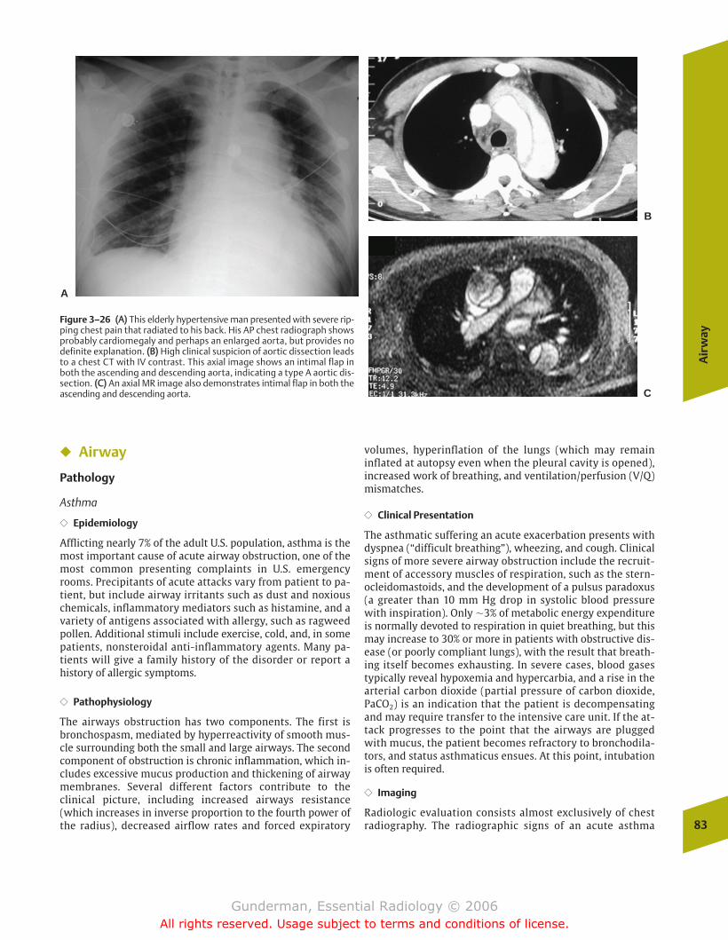
Air
way
83
� Airway
Pathology
Asthma
�� Epidemiology
Afflicting nearly 7% of the adult U.S. population, asthma is themost important cause of acute airway obstruction, one of themost common presenting complaints in U.S. emergencyrooms. Precipitants of acute attacks vary from patient to pa-tient, but include airway irritants such as dust and noxiouschemicals, inflammatory mediators such as histamine, and avariety of antigens associated with allergy, such as ragweedpollen. Additional stimuli include exercise, cold, and, in somepatients, nonsteroidal anti-inflammatory agents. Many pa-tients will give a family history of the disorder or report ahistory of allergic symptoms.
�� Pathophysiology
The airways obstruction has two components. The first isbronchospasm, mediated by hyperreactivity of smooth mus-cle surrounding both the small and large airways. The secondcomponent of obstruction is chronic inflammation, which in-cludes excessive mucus production and thickening of airwaymembranes. Several different factors contribute to theclinical picture, including increased airways resistance(which increases in inverse proportion to the fourth power ofthe radius), decreased airflow rates and forced expiratory
volumes, hyperinflation of the lungs (which may remaininflated at autopsy even when the pleural cavity is opened),increased work of breathing, and ventilation/perfusion (V/Q)mismatches.
�� Clinical Presentation
The asthmatic suffering an acute exacerbation presents withdyspnea (“difficult breathing”), wheezing, and cough. Clinicalsigns of more severe airway obstruction include the recruit-ment of accessory muscles of respiration, such as the stern-ocleidomastoids, and the development of a pulsus paradoxus(a greater than 10 mm Hg drop in systolic blood pressurewith inspiration). Only �3% of metabolic energy expenditureis normally devoted to respiration in quiet breathing, but thismay increase to 30% or more in patients with obstructive dis-ease (or poorly compliant lungs), with the result that breath-ing itself becomes exhausting. In severe cases, blood gasestypically reveal hypoxemia and hypercarbia, and a rise in thearterial carbon dioxide (partial pressure of carbon dioxide,PaCO2) is an indication that the patient is decompensatingand may require transfer to the intensive care unit. If the at-tack progresses to the point that the airways are pluggedwith mucus, the patient becomes refractory to bronchodila-tors, and status asthmaticus ensues. At this point, intubationis often required.
�� Imaging
Radiologic evaluation consists almost exclusively of chestradiography. The radiographic signs of an acute asthma
Figure 3–26 ((AA)) This elderly hypertensive man presented with severe rip-ping chest pain that radiated to his back. His AP chest radiograph showsprobably cardiomegaly and perhaps an enlarged aorta, but provides nodefinite explanation. ((BB)) High clinical suspicion of aortic dissection leadsto a chest CT with IV contrast. This axial image shows an intimal flap inboth the ascending and descending aorta, indicating a type A aortic dis-section. ((CC)) An axial MR image also demonstrates intimal flap in both theascending and descending aorta.
A
B
C
chapter 03_p68-111.qxd 12/1/05 3:30 PM Page 83
Gunderman, Essential Radiology © 2006All rights reserved. Usage subject to terms and conditions of license.
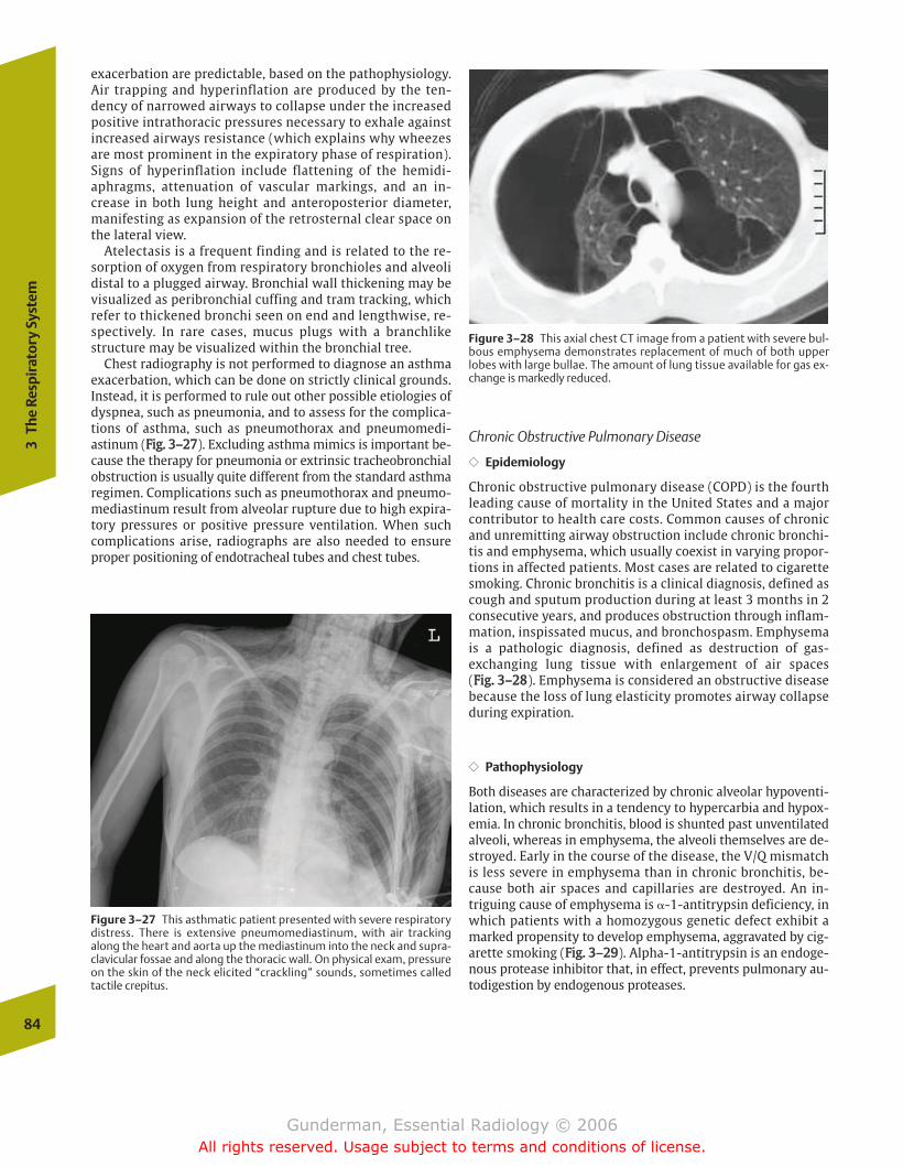
exacerbation are predictable, based on the pathophysiology.Air trapping and hyperinflation are produced by the ten-dency of narrowed airways to collapse under the increasedpositive intrathoracic pressures necessary to exhale againstincreased airways resistance (which explains why wheezesare most prominent in the expiratory phase of respiration).Signs of hyperinflation include flattening of the hemidi-aphragms, attenuation of vascular markings, and an in-crease in both lung height and anteroposterior diameter,manifesting as expansion of the retrosternal clear space onthe lateral view.
Atelectasis is a frequent finding and is related to the re-sorption of oxygen from respiratory bronchioles and alveolidistal to a plugged airway. Bronchial wall thickening may bevisualized as peribronchial cuffing and tram tracking, whichrefer to thickened bronchi seen on end and lengthwise, re-spectively. In rare cases, mucus plugs with a branchlikestructure may be visualized within the bronchial tree.
Chest radiography is not performed to diagnose an asthmaexacerbation, which can be done on strictly clinical grounds.Instead, it is performed to rule out other possible etiologies ofdyspnea, such as pneumonia, and to assess for the complica-tions of asthma, such as pneumothorax and pneumomedi-astinum (FFiigg.. 33––2277). Excluding asthma mimics is important be-cause the therapy for pneumonia or extrinsic tracheobronchialobstruction is usually quite different from the standard asthmaregimen. Complications such as pneumothorax and pneumo-mediastinum result from alveolar rupture due to high expira-tory pressures or positive pressure ventilation. When suchcomplications arise, radiographs are also needed to ensureproper positioning of endotracheal tubes and chest tubes.
Chronic Obstructive Pulmonary Disease
�� Epidemiology
Chronic obstructive pulmonary disease (COPD) is the fourthleading cause of mortality in the United States and a majorcontributor to health care costs. Common causes of chronicand unremitting airway obstruction include chronic bronchi-tis and emphysema, which usually coexist in varying propor-tions in affected patients. Most cases are related to cigarettesmoking. Chronic bronchitis is a clinical diagnosis, defined ascough and sputum production during at least 3 months in 2consecutive years, and produces obstruction through inflam-mation, inspissated mucus, and bronchospasm. Emphysemais a pathologic diagnosis, defined as destruction of gas-exchanging lung tissue with enlargement of air spaces (FFiigg.. 33––2288). Emphysema is considered an obstructive diseasebecause the loss of lung elasticity promotes airway collapseduring expiration.
�� Pathophysiology
Both diseases are characterized by chronic alveolar hypoventi-lation, which results in a tendency to hypercarbia and hypox-emia. In chronic bronchitis, blood is shunted past unventilatedalveoli, whereas in emphysema, the alveoli themselves are de-stroyed. Early in the course of the disease, the V/Q mismatchis less severe in emphysema than in chronic bronchitis, be-cause both air spaces and capillaries are destroyed. An in-triguing cause of emphysema is �-1-antitrypsin deficiency, inwhich patients with a homozygous genetic defect exhibit amarked propensity to develop emphysema, aggravated by cig-arette smoking (FFiigg.. 33––2299). Alpha-1-antitrypsin is an endoge-nous protease inhibitor that, in effect, prevents pulmonary au-todigestion by endogenous proteases.
84
3Th
e Re
spir
ator
y Sy
stem
Figure 3–27 This asthmatic patient presented with severe respiratorydistress. There is extensive pneumomediastinum, with air trackingalong the heart and aorta up the mediastinum into the neck and supra-clavicular fossae and along the thoracic wall. On physical exam, pressureon the skin of the neck elicited “crackling” sounds, sometimes calledtactile crepitus.
Figure 3–28 This axial chest CT image from a patient with severe bul-bous emphysema demonstrates replacement of much of both upperlobes with large bullae. The amount of lung tissue available for gas ex-change is markedly reduced.
chapter 03_p68-111.qxd 12/1/05 3:30 PM Page 84
Gunderman, Essential Radiology © 2006All rights reserved. Usage subject to terms and conditions of license.

Pleu
ra
85
�� Clinical Presentation
Although both disorders are chronic and unremitting, pa-tients tend to present during exacerbations, generally pre-cipitated by upper respiratory infections (with increasedsputum production and bronchospasm), episodes of CHF, oreven pulmonary embolism. Patients with chronic bronchi-tis are especially likely to be chronically colonized bybacteria, probably due to a combination of defective mu-cociliary clearance and impaired immune response. Pul-monary function testing in chronic bronchitis reveals aprominent deficit in forced expiratory volume, and inemphysema a loss of diffusing capacity (measured withcarbon monoxide).
�� Imaging
The chest radiograph is insensitive in the diagnosis of chronicbronchitis and emphysema, and many patients with clinicallydiagnosed COPD will have normal chest radiographs. Radio-graphy is employed primarily to assess complications ofthese disorders, such as pneumonia, pneumothorax (thin-walled bullae may rupture into the pleural space), and lungcancer (both emphysema and bronchogenic carcinoma aretobacco-related); however, the chest radiograph can suggestthe diagnosis.
Radiographic signs suggestive of chronic bronchitis includebronchial thickening, such as peribronchial cuffing and tramtracking, and there is often a diffuse but nonspecific increase
in lung markings. Plain radiographic findings in emphysemainclude hyperinflation with flattening of the diaphragms andexpansion of the retrosternal air space, diffuse lucency fromdestruction of lung tissue, and bullae (thin-walled cysts leftin the wake of lung destruction).
Because pulmonary artery hypertension is often a featureof COPD, prominent central pulmonary arteries may be notedin both chronic bronchitis and emphysema. High-resolutionCT is the most sensitive in vivo technique available in detect-ing and characterizing the morphologic changes of emphy-sema.
� Pleura
Pathology
Pleural Effusion
�� Epidemiology
Pleural effusion is the abnormal accumulation of fluid be-tween the visceral and parietal layers of the pleura. Strictlyspeaking, a pleural effusion is not a disease, but a sign of dis-ease that usually requires further diagnostic evaluation. Sta-tistically, the most common causes of pleural effusions are, indescending order of frequency, congestive heart failure (CHF),bacterial pneumonia, malignancy (especially lung and breastcancer), pulmonary embolism, viral pneumonia, and cirrhosisof the liver.
Figure 3–29 This middle-aged man presented with progressively increasing dyspnea.The patient had smoked cigarettes for many years. ((AA)) A lateral view of the chestshows marked hyperexpansion, with flattening of the hemidiaphragms and wideningof the retrosternal clear space (the space between the sternum and the heart/greatvessels). ((BB)) On CT there is severe diffuse destruction of lung tissue with bulla forma-tion. The patient had �-1-antitrypsin deficiency.A
B
chapter 03_p68-111.qxd 12/1/05 3:30 PM Page 85
Gunderman, Essential Radiology © 2006All rights reserved. Usage subject to terms and conditions of license.
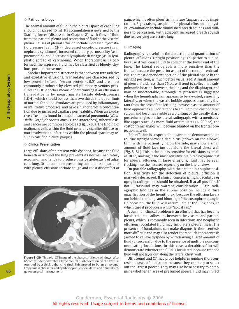
�� Pathophysiology
The normal amount of fluid in the pleural space of each lungshould not exceed 15 mL. Its accumulation is governed by theStarling forces (discussed in Chapter 2), with flow of fluidfrom the parietal pleura and resorption of fluid at the visceralpleura. Causes of pleural effusion include increased hydrosta-tic pressure (as in CHF), decreased oncotic pressure (as innephrotic syndrome), increased capillary permeability (as inpneumonia), and decreased lymphatic drainage (as in lym-phatic spread of carcinoma). When thoracentesis is per-formed, the aspirated fluid may be classified as bloody, chy-lous, purulent, or serous.
Another important distinction is that between transudativeand exudative effusions. Transudates are characterized bylow protein (effusion/serum protein � 0.5) and are mostcommonly produced by elevated pulmonary venous pres-sures in CHF. Another means of determining if an effusion istransudative is by measuring its lactate dehydrogenase(LDH), which should be less than two thirds the upper limitof normal for blood. Exudates are produced by inflammatoryor infiltrative processes, and have a higher protein concentra-tion due to increased capillary permeability. When an exuda-tive effusion is found in an adult, bacterial pneumonia (Kleb-siella, Staphylococcus aureus, and anaerobes), tuberculosis,and cancer are common etiologies (FFiigg.. 33––3300). The finding ofmalignant cells within the fluid generally signifies diffuse tu-mor involvement. Infections within the pleural space may re-sult in calcified pleural plaques.
�� Clinical Presentation
Large effusions often present with dyspnea, because the fluidbeneath or around the lung prevents its normal inspiratoryexpansion and tends to produce passive atelectasis of adja-cent lung. Other common presenting complaints in patientswith pleural effusions include cough and chest discomfort or
pain, which is often pleuritic in nature (aggravated by inspi-ration). Signs raising suspicion for pleural effusion on physi-cal examination include diminished breath sounds and dull-ness to percussion, with adjacent increased breath soundsdue to overlying atelectatic lung.
�� Imaging
Radiography is useful in the detection and quantitation ofpleural effusions. Upright positioning is superior to supine,because it will cause fluid to collect at the lower end of thelung. The lateral radiograph is more sensitive than thefrontal, because the posterior aspect of the costophrenic sul-cus, the most dependent portion of the pleural space in theupright position, is much better visualized. A small amountof pleural fluid, less than 75 cc, will tend to collect in a sub-pulmonic location, between the lung and the diaphragm, andmay be undetectable, although its presence is suggestedwhen the hemidiaphragm appears to be elevated, especiallylaterally, or when the gastric bubble appears unusually dis-tant from the base of the left lung; however, as the amount offluid approaches 100 cc, it tends to spill into the costophrenicsulcus, and becomes visible as a blunting of the usually sharpposterior angles on the lateral radiograph, with a meniscus-like appearance. As more fluid accumulates (� 200 cc), thecostophrenic angles will become blunted on the frontal pro-jection as well.
If an effusion is suspected but cannot be demonstrated onroutine upright views, a decubitus (“down on the elbow”)film, with the patient lying on the side, may show a smallamount of fluid layering out along the lateral chest wall (FFiigg.. 33––3311). This technique is sensitive for effusions as smallas 10 cc, making it the most sensitive plain radiographic testfor pleural effusion. In large effusions, fluid may be seentracking into the fissures, especially on the lateral view.
On portable radiography, with the patient in a supine posi-tion, sensitivity for the detection of pleural effusion ismarkedly decreased. If clinical concern is high, decubitus orupright radiographs should be obtained, if at all possible. Ifnot, ultrasound may warrant consideration. Plain radi-ographic findings in the supine position include diffuseopacification of the hemithorax, because the effusion layersout behind the lung, and blunting of the costophrenic angle.On occasion, the fluid will accumulate at the lung apex, inwhich case it produces a white “apical cap.”
A common clinical problem is an effusion that has becomeloculated due to adhesions between the visceral and parietalpleura, which is commonly seen in infectious and neoplasticeffusions. Loculated fluid may simulate a pleural mass. Thepresence of loculations can make diagnostic thoracentesismore difficult and may also render therapeutic thoracentesis(aimed to relieve dyspnea by withdrawing a large amount offluid) unsuccessful, due to the presence of multiple noncom-municating loculations. In this case, a decubitus film willdemonstrate whether the fluid is loculated, because trappedfluid will not layer out along the lateral chest wall.
Ultrasound and CT may prove helpful in guiding thoracen-tesis in cases of loculation, because they can help to selectout the largest pocket. They may also be necessary to deter-mine whether an area of presumed pleural fluid may in fact86
3Th
e Re
spir
ator
y Sy
stem
Figure 3–30 This axial CT image of the chest (soft tissue windows) afterIV contrast demonstrates a large pleural fluid collection on the left sur-rounded by a thick enhancing rind. This proved to be an empyema.Empyema is characterized by fibrinopurulent exudates and generally re-quires surgical management.
chapter 03_p68-111.qxd 12/1/05 3:30 PM Page 86
Gunderman, Essential Radiology © 2006All rights reserved. Usage subject to terms and conditions of license.

Pleu
ra
87
consist, at least in part, of collapsed lung or a soft tissuemass. Imaging guidance increases the probability of obtain-ing fluid and decreases the rate of complications, such as he-patic or splenic laceration, pulmonary hemorrhage, andpneumothorax. In the case of a diagnostic tap, what shouldbe done with the fluid? Because the range of possible etiolo-gies for effusions is fairly broad, pleural fluid should be rou-tinely sent for chemistry, cell count and differential, cultureand sensitivity, Gram’s stain, acid-fast bacilli, and cytology.
Pneumothorax
�� Epidemiology
Pneumothorax, the presence of air within the pleural space,may occur spontaneously, or it may result from trauma. Ahigh percentage of pneumothoraces in hospitalized patientsare iatrogenic, occurring in such situations as central venouscatheter placement (FFiigg.. 33––3322).
�� Pathophysiology
In the setting of penetrating trauma, pneumothorax may re-sult from the introduction of air through the chest wall. If thewound does not seal itself, there is a leakage of air throughthe chest wall and into the pleural space, creating a so-calledsucking chest wound. In this situation, the negative intratho-racic pressure created with each inspiration causes additionalair to enter the pleural space, which may rapidly produce atension pneumothorax. The continued accumulation of air inthe pleural space causes complete collapse of the affectedlung, with a shift of the mediastinum toward the contralat-eral side (FFiigg.. 33––3333). Death may rapidly ensue, largely due tothe compromise of venous return to the heart from distortionof normal mediastinal anatomy, as well as V/Q mismatchingand hypoxemia. Blunt trauma may cause pneumothoraxwhen a rib punctures the pleura or when tracheobronchialrupture results. The latter condition is associated with
pneumomediastinum and persistence of pneumothorax evenafter chest tube placement.
Spontaneous pneumothorax may be idiopathic or related topreexisting lung disease. Idiopathic pneumothorax typicallyoccurs in men in the third or fourth decades, especially in tall
A BFigure 3–31 ((AA)) On the frontal chest radiograph there is blunting of theleft costophrenic angle, as compared with the right. ((BB)) On the left lat-eral decubitus view, the effusion “layers out” along the left lateral chest
wall, indicating that it is free flowing. The effusion appears as a whitestripe along the left lung just inside the ribs.
FIgure 3–32 This frontal chest radiograph is typical of acutely ill or in-jured patients, in that there are many wires crossing the patient (electro-cardiogram leads), and positioning is poor. A left subclavian central linewas just placed, the tip of which is at the level of the lower superior venacava. There is a left pneumothorax, with the edge of the opacified leftlung paralleling the left chest wall.
chapter 03_p68-111.qxd 12/1/05 3:30 PM Page 87
Gunderman, Essential Radiology © 2006All rights reserved. Usage subject to terms and conditions of license.
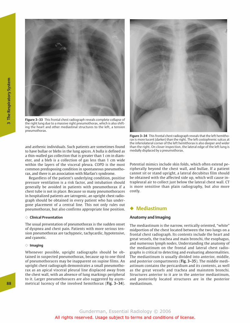
and asthenic individuals. Such patients are sometimes foundto have bullae or blebs in the lung apices. A bulla is defined asa thin-walled gas collection that is greater than 1 cm in diam-eter, and a bleb is a collection of gas less than 1 cm widewithin the layers of the visceral pleura. COPD is the mostcommon predisposing condition in spontaneous pneumotho-rax, and there is an association with Marfan’s syndrome.
Regardless of the patient’s underlying condition, positivepressure ventilation is a risk factor, and intubation shouldgenerally be avoided in patients with pneumothorax if achest tube is not in place. Because so many pneumothoracesin hospitalized patients are iatrogenic, an upright chest radio-graph should be obtained in every patient who has under-gone placement of a central line. This not only rules outpneumothorax, but also confirms appropriate line position.
�� Clinical Presentation
The usual presentation of pneumothorax is the sudden onsetof dyspnea and chest pain. Patients with more serious ten-sion pneumothorax are tachypneic, tachycardic, hypotensive,and cyanotic.
�� Imaging
Whenever possible, upright radiographs should be ob-tained in suspected pneumothorax, because up to one thirdof pneumothoraces may be inapparent on supine films. Anupright chest radiograph demonstrates a small pneumotho-rax as an apical visceral pleural line displaced away fromthe chest wall, with an absence of lung markings peripheralto it. Larger pneumothoraces are also suggested by asym-metrical lucency of the involved hemithorax (FFiigg.. 33––3344).
Potential mimics include skin folds, which often extend pe-ripherally beyond the chest wall, and bullae. If a patientcannot sit or stand upright, a lateral decubitus film shouldbe obtained with the affected side up, which will cause in-trapleural air to collect just below the lateral chest wall. CTis more sensitive than plain radiography, but also morecostly.
� Mediastinum
Anatomy and Imaging
The mediastinum is the narrow, vertically oriented, “white”midportion of the chest located between the two lungs on afrontal chest radiograph. Its contents include the heart andgreat vessels, the trachea and main bronchi, the esophagus,and numerous lymph nodes. Understanding the anatomy ofthe mediastinum on the frontal and lateral chest radio-graphs is critical to detecting and evaluating abnormalities.The mediastinum is usually divided into anterior, middle,and posterior compartments (FFiigg.. 33––3355). The middle medi-astinum contains the pericardium and its contents, as wellas the great vessels and trachea and mainstem bronchi.Structures anterior to it are in the anterior mediastinum,and posteriorly located structures are in the posteriormediastinum.88
3Th
e Re
spir
ator
y Sy
stem
Figure 3–33 This frontal chest radiograph reveals complete collapse ofthe right lung due to a massive right pneumothorax, which is also shift-ing the heart and other mediastinal structures to the left, a tensionpneumothorax.
Figure 3–34 This frontal chest radiograph reveals that the left hemitho-rax is more lucent (darker) than the right. The left costophrenic sulcus atthe inferiolateral corner of the left hemithorax is also deeper and widerthan the right. On closer inspection, the lateral edge of the left lung ismedially displaced by a pneumothorax.
chapter 03_p68-111.qxd 12/1/05 3:30 PM Page 88
Gunderman, Essential Radiology © 2006All rights reserved. Usage subject to terms and conditions of license.
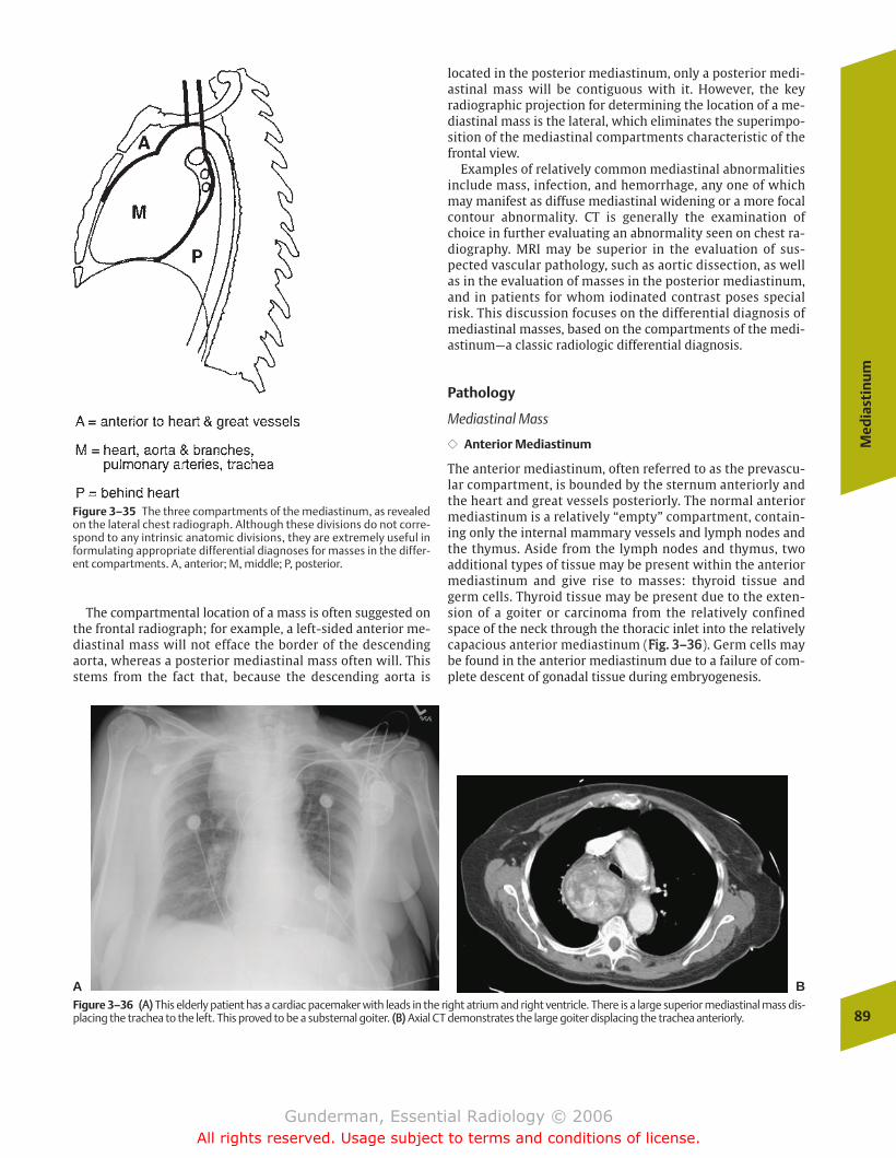
Med
iast
inu
m
89
The compartmental location of a mass is often suggested onthe frontal radiograph; for example, a left-sided anterior me-diastinal mass will not efface the border of the descendingaorta, whereas a posterior mediastinal mass often will. Thisstems from the fact that, because the descending aorta is
located in the posterior mediastinum, only a posterior medi-astinal mass will be contiguous with it. However, the keyradiographic projection for determining the location of a me-diastinal mass is the lateral, which eliminates the superimpo-sition of the mediastinal compartments characteristic of thefrontal view.
Examples of relatively common mediastinal abnormalitiesinclude mass, infection, and hemorrhage, any one of whichmay manifest as diffuse mediastinal widening or a more focalcontour abnormality. CT is generally the examination ofchoice in further evaluating an abnormality seen on chest ra-diography. MRI may be superior in the evaluation of sus-pected vascular pathology, such as aortic dissection, as wellas in the evaluation of masses in the posterior mediastinum,and in patients for whom iodinated contrast poses specialrisk. This discussion focuses on the differential diagnosis ofmediastinal masses, based on the compartments of the medi-astinum—a classic radiologic differential diagnosis.
Pathology
Mediastinal Mass
�� Anterior Mediastinum
The anterior mediastinum, often referred to as the prevascu-lar compartment, is bounded by the sternum anteriorly andthe heart and great vessels posteriorly. The normal anteriormediastinum is a relatively “empty” compartment, contain-ing only the internal mammary vessels and lymph nodes andthe thymus. Aside from the lymph nodes and thymus, twoadditional types of tissue may be present within the anteriormediastinum and give rise to masses: thyroid tissue andgerm cells. Thyroid tissue may be present due to the exten-sion of a goiter or carcinoma from the relatively confinedspace of the neck through the thoracic inlet into the relativelycapacious anterior mediastinum (FFiigg.. 33––3366). Germ cells maybe found in the anterior mediastinum due to a failure of com-plete descent of gonadal tissue during embryogenesis.
Figure 3–35 The three compartments of the mediastinum, as revealedon the lateral chest radiograph. Although these divisions do not corre-spond to any intrinsic anatomic divisions, they are extremely useful informulating appropriate differential diagnoses for masses in the differ-ent compartments. A, anterior; M, middle; P, posterior.
A BFigure 3–36 ((AA)) This elderly patient has a cardiac pacemaker with leads in the right atrium and right ventricle. There is a large superior mediastinal mass dis-placing the trachea to the left. This proved to be a substernal goiter. ((BB)) Axial CT demonstrates the large goiter displacing the trachea anteriorly.
chapter 03_p68-111.qxd 12/1/05 3:31 PM Page 89
Gunderman, Essential Radiology © 2006All rights reserved. Usage subject to terms and conditions of license.
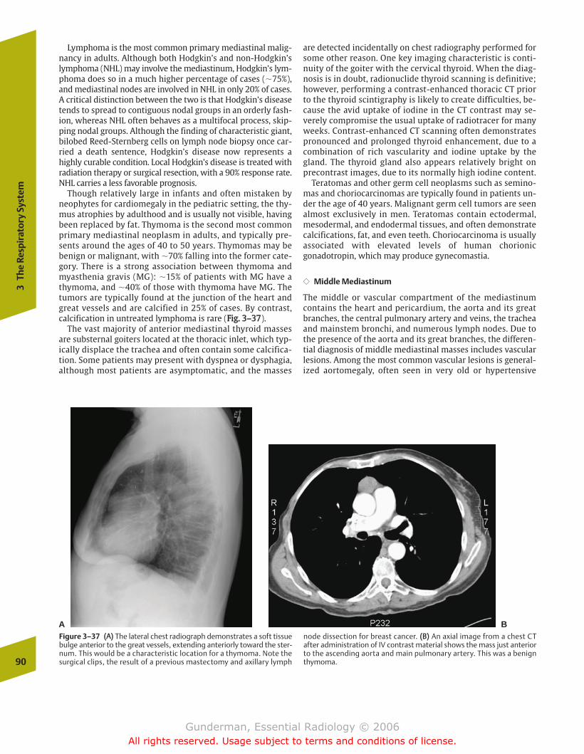
Lymphoma is the most common primary mediastinal malig-nancy in adults. Although both Hodgkin’s and non-Hodgkin’slymphoma (NHL) may involve the mediastinum, Hodgkin’s lym-phoma does so in a much higher percentage of cases (�75%),and mediastinal nodes are involved in NHL in only 20% of cases.A critical distinction between the two is that Hodgkin’s diseasetends to spread to contiguous nodal groups in an orderly fash-ion, whereas NHL often behaves as a multifocal process, skip-ping nodal groups. Although the finding of characteristic giant,bilobed Reed-Sternberg cells on lymph node biopsy once car-ried a death sentence, Hodgkin’s disease now represents ahighly curable condition. Local Hodgkin’s disease is treated withradiation therapy or surgical resection, with a 90% response rate.NHL carries a less favorable prognosis.
Though relatively large in infants and often mistaken byneophytes for cardiomegaly in the pediatric setting, the thy-mus atrophies by adulthood and is usually not visible, havingbeen replaced by fat. Thymoma is the second most commonprimary mediastinal neoplasm in adults, and typically pre-sents around the ages of 40 to 50 years. Thymomas may bebenign or malignant, with �70% falling into the former cate-gory. There is a strong association between thymoma andmyasthenia gravis (MG): �15% of patients with MG have athymoma, and �40% of those with thymoma have MG. Thetumors are typically found at the junction of the heart andgreat vessels and are calcified in 25% of cases. By contrast,calcification in untreated lymphoma is rare (FFiigg.. 33––3377).
The vast majority of anterior mediastinal thyroid massesare substernal goiters located at the thoracic inlet, which typ-ically displace the trachea and often contain some calcifica-tion. Some patients may present with dyspnea or dysphagia,although most patients are asymptomatic, and the masses
are detected incidentally on chest radiography performed forsome other reason. One key imaging characteristic is conti-nuity of the goiter with the cervical thyroid. When the diag-nosis is in doubt, radionuclide thyroid scanning is definitive;however, performing a contrast-enhanced thoracic CT priorto the thyroid scintigraphy is likely to create difficulties, be-cause the avid uptake of iodine in the CT contrast may se-verely compromise the usual uptake of radiotracer for manyweeks. Contrast-enhanced CT scanning often demonstratespronounced and prolonged thyroid enhancement, due to acombination of rich vascularity and iodine uptake by thegland. The thyroid gland also appears relatively bright onprecontrast images, due to its normally high iodine content.
Teratomas and other germ cell neoplasms such as semino-mas and choriocarcinomas are typically found in patients un-der the age of 40 years. Malignant germ cell tumors are seenalmost exclusively in men. Teratomas contain ectodermal,mesodermal, and endodermal tissues, and often demonstratecalcifications, fat, and even teeth. Choriocarcinoma is usuallyassociated with elevated levels of human chorionicgonadotropin, which may produce gynecomastia.
�� Middle Mediastinum
The middle or vascular compartment of the mediastinumcontains the heart and pericardium, the aorta and its greatbranches, the central pulmonary artery and veins, the tracheaand mainstem bronchi, and numerous lymph nodes. Due tothe presence of the aorta and its great branches, the differen-tial diagnosis of middle mediastinal masses includes vascularlesions. Among the most common vascular lesions is general-ized aortomegaly, often seen in very old or hypertensive
90
3Th
e Re
spir
ator
y Sy
stem
A BFigure 3–37 ((AA)) The lateral chest radiograph demonstrates a soft tissuebulge anterior to the great vessels, extending anteriorly toward the ster-num. This would be a characteristic location for a thymoma. Note thesurgical clips, the result of a previous mastectomy and axillary lymph
node dissection for breast cancer. ((BB)) An axial image from a chest CTafter administration of IV contrast material shows the mass just anteriorto the ascending aorta and main pulmonary artery. This was a benignthymoma.
chapter 03_p68-111.qxd 12/1/05 3:31 PM Page 90
Gunderman, Essential Radiology © 2006All rights reserved. Usage subject to terms and conditions of license.
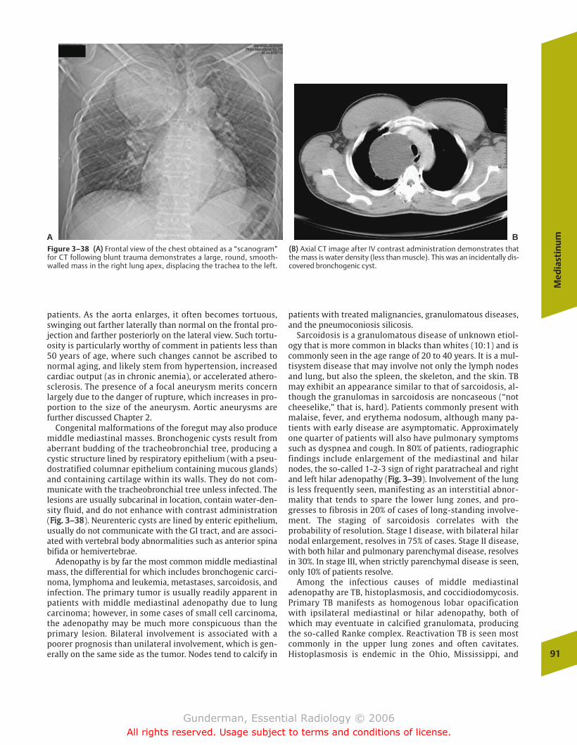
Med
iast
inu
m
91
patients. As the aorta enlarges, it often becomes tortuous,swinging out farther laterally than normal on the frontal pro-jection and farther posteriorly on the lateral view. Such tortu-osity is particularly worthy of comment in patients less than50 years of age, where such changes cannot be ascribed tonormal aging, and likely stem from hypertension, increasedcardiac output (as in chronic anemia), or accelerated athero-sclerosis. The presence of a focal aneurysm merits concernlargely due to the danger of rupture, which increases in pro-portion to the size of the aneurysm. Aortic aneurysms arefurther discussed Chapter 2.
Congenital malformations of the foregut may also producemiddle mediastinal masses. Bronchogenic cysts result fromaberrant budding of the tracheobronchial tree, producing acystic structure lined by respiratory epithelium (with a pseu-dostratified columnar epithelium containing mucous glands)and containing cartilage within its walls. They do not com-municate with the tracheobronchial tree unless infected. Thelesions are usually subcarinal in location, contain water-den-sity fluid, and do not enhance with contrast administration(FFiigg.. 33––3388). Neurenteric cysts are lined by enteric epithelium,usually do not communicate with the GI tract, and are associ-ated with vertebral body abnormalities such as anterior spinabifida or hemivertebrae.
Adenopathy is by far the most common middle mediastinalmass, the differential for which includes bronchogenic carci-noma, lymphoma and leukemia, metastases, sarcoidosis, andinfection. The primary tumor is usually readily apparent inpatients with middle mediastinal adenopathy due to lungcarcinoma; however, in some cases of small cell carcinoma,the adenopathy may be much more conspicuous than theprimary lesion. Bilateral involvement is associated with apoorer prognosis than unilateral involvement, which is gen-erally on the same side as the tumor. Nodes tend to calcify in
patients with treated malignancies, granulomatous diseases,and the pneumoconiosis silicosis.
Sarcoidosis is a granulomatous disease of unknown etiol-ogy that is more common in blacks than whites (10:1) and iscommonly seen in the age range of 20 to 40 years. It is a mul-tisystem disease that may involve not only the lymph nodesand lung, but also the spleen, the skeleton, and the skin. TBmay exhibit an appearance similar to that of sarcoidosis, al-though the granulomas in sarcoidosis are noncaseous (“notcheeselike,” that is, hard). Patients commonly present withmalaise, fever, and erythema nodosum, although many pa-tients with early disease are asymptomatic. Approximatelyone quarter of patients will also have pulmonary symptomssuch as dyspnea and cough. In 80% of patients, radiographicfindings include enlargement of the mediastinal and hilarnodes, the so-called 1-2-3 sign of right paratracheal and rightand left hilar adenopathy (FFiigg.. 33––3399). Involvement of the lungis less frequently seen, manifesting as an interstitial abnor-mality that tends to spare the lower lung zones, and pro-gresses to fibrosis in 20% of cases of long-standing involve-ment. The staging of sarcoidosis correlates with theprobability of resolution. Stage I disease, with bilateral hilarnodal enlargement, resolves in 75% of cases. Stage II disease,with both hilar and pulmonary parenchymal disease, resolvesin 30%. In stage III, when strictly parenchymal disease is seen,only 10% of patients resolve.
Among the infectious causes of middle mediastinaladenopathy are TB, histoplasmosis, and coccidiodomycosis.Primary TB manifests as homogenous lobar opacificationwith ipsilateral mediastinal or hilar adenopathy, both ofwhich may eventuate in calcified granulomata, producingthe so-called Ranke complex. Reactivation TB is seen mostcommonly in the upper lung zones and often cavitates.Histoplasmosis is endemic in the Ohio, Mississippi, and
A BFigure 3–38 ((AA)) Frontal view of the chest obtained as a “scanogram”for CT following blunt trauma demonstrates a large, round, smooth-walled mass in the right lung apex, displacing the trachea to the left.
((BB)) Axial CT image after IV contrast administration demonstrates thatthe mass is water density (less than muscle). This was an incidentally dis-covered bronchogenic cyst.
chapter 03_p68-111.qxd 12/1/05 3:31 PM Page 91
Gunderman, Essential Radiology © 2006All rights reserved. Usage subject to terms and conditions of license.
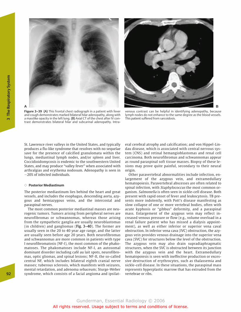
St. Lawrence river valleys in the United States, and typicallyproduces a flu-like syndrome that resolves with no sequelaesave for the presence of calcified granulomata within thelungs, mediastinal lymph nodes, and/or spleen and liver.Coccidioidomycosis is endemic to the southwestern UnitedStates, and may produce “valley fever” when associated witharthralgias and erythema nodosum. Adenopathy is seen in�20% of infected individuals.
�� Posterior Mediastinum
The posterior mediastinum lies behind the heart and greatvessels, and includes the esophagus, descending aorta, azy-gous and hemiazygous veins, and the intercostal andparaspinal nerves.
The most common posterior mediastinal masses are neu-rogenic tumors. Tumors arising from peripheral nerves areneurofibromas or schwannomas, whereas those arisingfrom the sympathetic ganglia are usually neuroblastomas(in children) and gangliomas (FFiigg.. 33––4400). The former areusually seen in the 20 to 40 year age range, and the latterare usually seen before age 20 years. Both neurofibromasand schwannomas are more common in patients with typeI neurofibromatosis (NF-I), the most common of the phako-matoses. The phakomatoses include NF-I, an autosomaldominant disorder including café au lait spots, neurofibro-mas, optic gliomas, and spinal lesions; NF-II, the so-calledcentral NF, which includes bilateral eighth cranial nervemasses; tuberous sclerosis, which manifests with seizures,mental retardation, and adenoma sebaceum; Sturge-Webersyndrome, which consists of a facial angioma and ipsilat-
eral cerebral atrophy and calcification; and von Hippel-Lin-dau disease, which is associated with central nervous sys-tem (CNS) and retinal hemangioblastomas and renal cellcarcinoma. Both neurofibromas and schwannomas appearas round paraspinal soft tissue masses. Biopsy of these le-sions may prove quite painful, secondary to their neuralorigin.
Other paravertebral abnormalities include infection, en-largement of the azygous vein, and extramedullaryhematopoiesis. Paravertebral abscesses are often related tospinal infection, with Staphylococcus the most common or-ganism. Salmonella is often seen in sickle-cell disease. Bothpresent with rapid onset of fever and leukocytosis. TB pre-sents more indolently, with Pott’s disease manifesting asslow collapse of one or more vertebral bodies, often withacute kyphosis or “gibbus” deformity, and a paraspinalmass. Enlargement of the azygous vein may reflect in-creased venous pressure or flow (e.g., volume overload in arenal failure patient who has missed a dialysis appoint-ment), as well as either inferior or superior vena cavalobstruction. In inferior vena cava (IVC) obstruction, the azy-gous vein provides venous drainage into the superior venacava (SVC) for structures below the level of the obstruction.The azygous vein may also drain supradiaphragmaticstructures, when the SVC is obstructed between its junctionwith the azygous vein and the heart. Extramedullaryhematopoiesis is seen with ineffective production or exces-sive destruction of erythrocytes, such as thalassemia andsickle-cell disease. In these situations, the paraspinal massrepresents hyperplastic marrow that has extruded from thevertebrae or ribs.92
3Th
e Re
spir
ator
y Sy
stem
Figure 3–39 ((AA)) This frontal chest radiograph in a patient with feverand cough demonstrates marked bilateral hilar adenopathy, along witha masslike opacity in the left lung. ((BB)) Axial CT of the chest after IV con-trast demonstrates bilateral hilar and subcarinal adenopathy. Intra-
venous contrast can be helpful in identifying adenopathy, becauselymph nodes do not enhance to the same degree as the blood vessels.This patient suffered from sarcoidosis.
A B
chapter 03_p68-111.qxd 12/1/05 3:31 PM Page 92
Gunderman, Essential Radiology © 2006All rights reserved. Usage subject to terms and conditions of license.
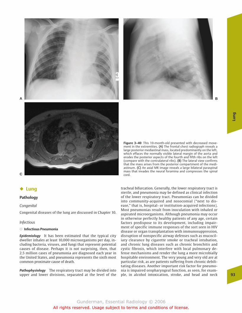
Lun
g
93
Figure 3–40 This 10-month-old presented with decreased move-ment in the extremities. ((AA)) The frontal chest radiograph reveals alarge posterior mediastinal mass, located predominantly on the left,which effaces the normally visible lateral margin of the aorta anderodes the posterior aspects of the fourth and fifth ribs on the left(compare with the contralateral ribs). ((BB)) The lateral view confirmsthat the mass arises from the posterior compartment of the medi-astinum. ((CC)) An axial MR image reveals a large bilateral paraspinalmass that invades the neural foramina and compresses the spinalcord.
A B
C
� Lung
Pathology
Congenital
Congenital diseases of the lung are discussed in Chapter 10.
Infectious
�� Infectious Pneumonia
Epidemiology It has been estimated that the typical citydweller inhales at least 10,000 microorganisms per day, in-cluding bacteria, viruses, and fungi that represent potentialcauses of disease. Perhaps it is not surprising, then, that 2.5 million cases of pneumonia are diagnosed each year inthe United States, and pneumonia represents the sixth mostcommon proximate cause of death.
Pathophysiology The respiratory tract may be divided intoupper and lower divisions, separated at the level of the
tracheal bifurcation. Generally, the lower respiratory tract issterile, and pneumonia may be defined as clinical infectionof the lower respiratory tract. Pneumonias can be dividedinto community-acquired and nosocomial (“next to dis-ease,” that is, hospital- or institution-acquired infections).Most pneumonias result from inoculation with inhaled oraspirated microorganisms. Although pneumonia may occurin otherwise perfectly healthy patients of any age, certainfactors predispose to its development, including impair-ment of specific immune responses of the sort seen in HIVdisease or organ transplantation with immunosuppression,disruption of nonspecific airway defenses such as mucocil-iary clearance by cigarette smoke or tracheal intubation,and chronic lung diseases such as chronic bronchitis andcystic fibrosis, which interfere with local pulmonary de-fense mechanisms and render the lung a more microbiallyhospitable environment. The very young and very old are atparticular risk, as are patients suffering from chronic debili-tating diseases. Another important risk factor for pneumo-nia is impaired oropharyngeal function, as seen, for exam-ple, in alcohol intoxication, stroke, and head and neck
chapter 03_p68-111.qxd 12/1/05 3:31 PM Page 93
Gunderman, Essential Radiology © 2006All rights reserved. Usage subject to terms and conditions of license.
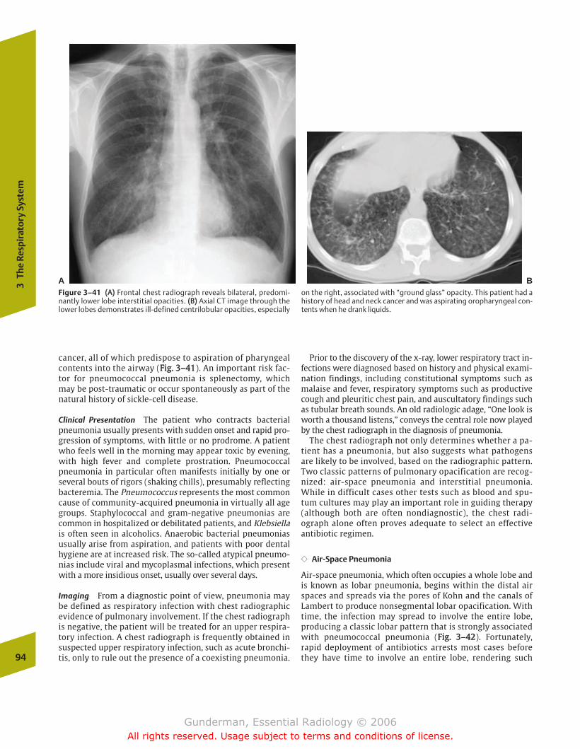
cancer, all of which predispose to aspiration of pharyngealcontents into the airway (FFiigg.. 33––4411). An important risk fac-tor for pneumococcal pneumonia is splenectomy, whichmay be post-traumatic or occur spontaneously as part of thenatural history of sickle-cell disease.
Clinical Presentation The patient who contracts bacterialpneumonia usually presents with sudden onset and rapid pro-gression of symptoms, with little or no prodrome. A patientwho feels well in the morning may appear toxic by evening,with high fever and complete prostration. Pneumococcalpneumonia in particular often manifests initially by one orseveral bouts of rigors (shaking chills), presumably reflectingbacteremia. The Pneumococcus represents the most commoncause of community-acquired pneumonia in virtually all agegroups. Staphylococcal and gram-negative pneumonias arecommon in hospitalized or debilitated patients, and Klebsiellais often seen in alcoholics. Anaerobic bacterial pneumoniasusually arise from aspiration, and patients with poor dentalhygiene are at increased risk. The so-called atypical pneumo-nias include viral and mycoplasmal infections, which presentwith a more insidious onset, usually over several days.
Imaging From a diagnostic point of view, pneumonia maybe defined as respiratory infection with chest radiographicevidence of pulmonary involvement. If the chest radiographis negative, the patient will be treated for an upper respira-tory infection. A chest radiograph is frequently obtained insuspected upper respiratory infection, such as acute bronchi-tis, only to rule out the presence of a coexisting pneumonia.
Prior to the discovery of the x-ray, lower respiratory tract in-fections were diagnosed based on history and physical exami-nation findings, including constitutional symptoms such asmalaise and fever, respiratory symptoms such as productivecough and pleuritic chest pain, and auscultatory findings suchas tubular breath sounds. An old radiologic adage, “One look isworth a thousand listens,” conveys the central role now playedby the chest radiograph in the diagnosis of pneumonia.
The chest radiograph not only determines whether a pa-tient has a pneumonia, but also suggests what pathogensare likely to be involved, based on the radiographic pattern.Two classic patterns of pulmonary opacification are recog-nized: air-space pneumonia and interstitial pneumonia.While in difficult cases other tests such as blood and spu-tum cultures may play an important role in guiding therapy(although both are often nondiagnostic), the chest radi-ograph alone often proves adequate to select an effectiveantibiotic regimen.
�� Air-Space Pneumonia
Air-space pneumonia, which often occupies a whole lobe andis known as lobar pneumonia, begins within the distal airspaces and spreads via the pores of Kohn and the canals ofLambert to produce nonsegmental lobar opacification. Withtime, the infection may spread to involve the entire lobe,producing a classic lobar pattern that is strongly associatedwith pneumococcal pneumonia (FFiigg.. 33––4422). Fortunately,rapid deployment of antibiotics arrests most cases beforethey have time to involve an entire lobe, rendering such94
3Th
e Re
spir
ator
y Sy
stem
A BFigure 3–41 ((AA)) Frontal chest radiograph reveals bilateral, predomi-nantly lower lobe interstitial opacities. ((BB)) Axial CT image through thelower lobes demonstrates ill-defined centrilobular opacities, especially
on the right, associated with “ground glass” opacity. This patient had ahistory of head and neck cancer and was aspirating oropharyngeal con-tents when he drank liquids.
chapter 03_p68-111.qxd 12/1/05 3:31 PM Page 94
Gunderman, Essential Radiology © 2006All rights reserved. Usage subject to terms and conditions of license.
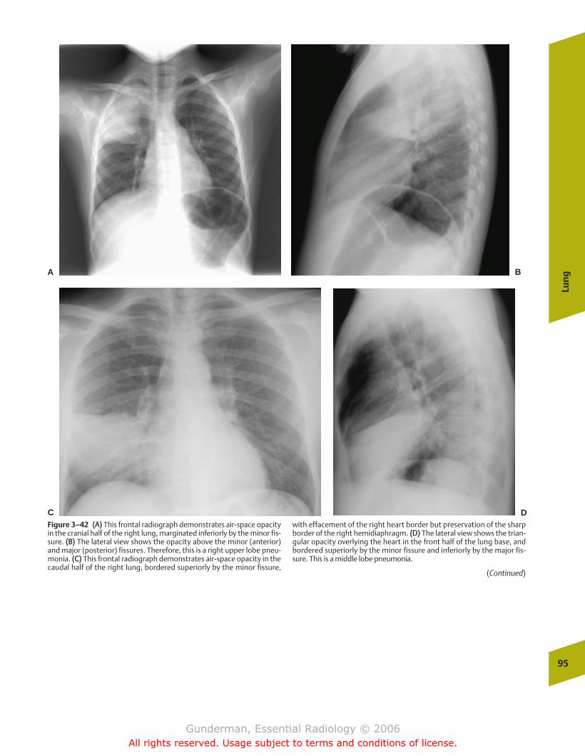
Lun
g
95
A B
C DFigure 3–42 ((AA)) This frontal radiograph demonstrates air-space opacityin the cranial half of the right lung, marginated inferiorly by the minor fis-sure. ((BB)) The lateral view shows the opacity above the minor (anterior)and major (posterior) fissures. Therefore, this is a right upper lobe pneu-monia. ((CC)) This frontal radiograph demonstrates air-space opacity in thecaudal half of the right lung, bordered superiorly by the minor fissure,
with effacement of the right heart border but preservation of the sharpborder of the right hemidiaphragm. ((DD)) The lateral view shows the trian-gular opacity overlying the heart in the front half of the lung base, andbordered superiorly by the minor fissure and inferiorly by the major fis-sure. This is a middle lobe pneumonia.
(Continued)
chapter 03_p68-111.qxd 12/1/05 3:31 PM Page 95
Gunderman, Essential Radiology © 2006All rights reserved. Usage subject to terms and conditions of license.
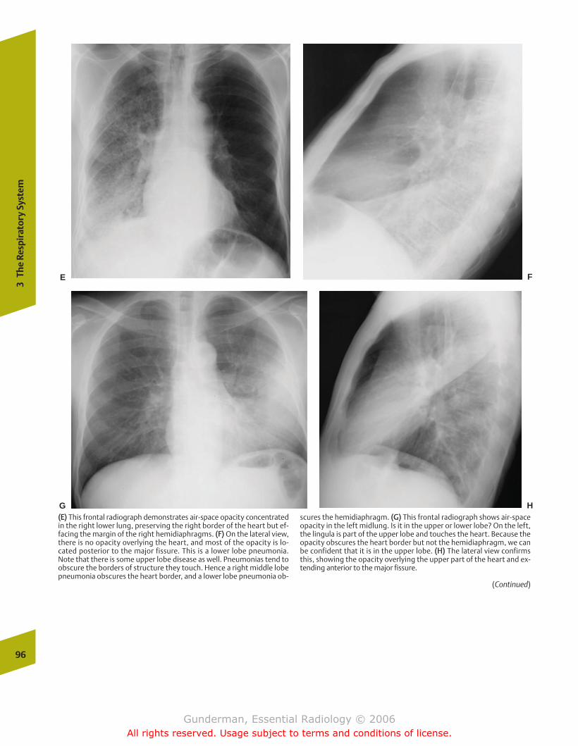
96
3Th
e Re
spir
ator
y Sy
stem
E F
G H((EE)) This frontal radiograph demonstrates air-space opacity concentratedin the right lower lung, preserving the right border of the heart but ef-facing the margin of the right hemidiaphragms. ((FF)) On the lateral view,there is no opacity overlying the heart, and most of the opacity is lo-cated posterior to the major fissure. This is a lower lobe pneumonia.Note that there is some upper lobe disease as well. Pneumonias tend toobscure the borders of structure they touch. Hence a right middle lobepneumonia obscures the heart border, and a lower lobe pneumonia ob-
scures the hemidiaphragm. ((GG)) This frontal radiograph shows air-spaceopacity in the left midlung. Is it in the upper or lower lobe? On the left,the lingula is part of the upper lobe and touches the heart. Because theopacity obscures the heart border but not the hemidiaphragm, we canbe confident that it is in the upper lobe. ((HH)) The lateral view confirmsthis, showing the opacity overlying the upper part of the heart and ex-tending anterior to the major fissure.
(Continued)
chapter 03_p68-111.qxd 12/1/05 3:31 PM Page 96
Gunderman, Essential Radiology © 2006All rights reserved. Usage subject to terms and conditions of license.
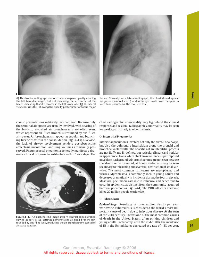
classic presentations relatively less common. Because onlythe terminal air spaces are usually involved, with sparing ofthe bronchi, so-called air bronchograms are often seen,which represent air-filled bronchi surrounded by pus-filledair spaces. Air bronchograms appear as tubular and branch-ing lucencies within the consolidation (FFiigg.. 33––4433). Likewise,the lack of airway involvement renders postobstructiveatelectasis uncommon, and lung volumes are usually pre-served. Pneumococcal pneumonia generally manifests a dra-matic clinical response to antibiotics within 1 or 2 days. The
chest radiographic abnormality may lag behind the clinicalresponse, and residual radiographic abnormality may be seenfor weeks, particularly in older patients.
�� Interstitial Pneumonia
Interstitial pneumonia involves not only the alveoli or airways,but also the pulmonary interstitium along the bronchi andbronchoalveolar walls. The opacities of an interstitial processare not fluffy and ill-defined, but reticular (linear) and nodularin appearance, like a white chicken-wire fence superimposedon a black background. Air bronchograms are not seen becausethe alveoli remain aerated, although atelectasis may be seensecondary to thickening and eventual obstruction of small air-ways. The most common pathogens are mycoplasma andviruses. Mycoplasma is commonly seen in young adults anddecreases dramatically in incidence during the fourth decade.Most viral pneumonias are due to influenza, and hence tend tooccur in epidemics, as distinct from the community-acquiredbacterial pneumonias (FFiigg.. 33––4444). The 1918 influenza epidemickilled 20 million people worldwide.
�� Tuberculosis
Epidemiology Resulting in three million deaths per yearworldwide, tuberculosis is considered the world’s most im-portant cause of death due to infectious disease. At the turnof the 20th century, TB was one of the most common causesof death in the United States, often striking children andyoung adults. Fortunately, until the mid-1980s, the incidenceof TB in the United States decreased at a rate of �3% per year,
Lun
g
97
I J((II)) This frontal radiograph demonstrates air-space opacity effacingthe left hemidiaphragm, but not obscuring the left border of theheart, indicating that it is located in the left lower lobe. (( JJ)) The lateralview confirms this, showing the opacity posteroinferior to the major
fissure. Normally, on a lateral radiograph, the chest should appearprogressively more lucent (dark) as the eye travels down the spine. Inlower lobe pneumonia, the reverse is true.
Figure 3–43 An axial chest CT image after IV contrast administrationviewed at soft tissue settings demonstrates air-filled bronchi sur-rounded by pus-filled lung, producing the air bronchograms typical ofair-space opacities.
chapter 03_p68-111.qxd 12/1/05 3:31 PM Page 97
Gunderman, Essential Radiology © 2006All rights reserved. Usage subject to terms and conditions of license.
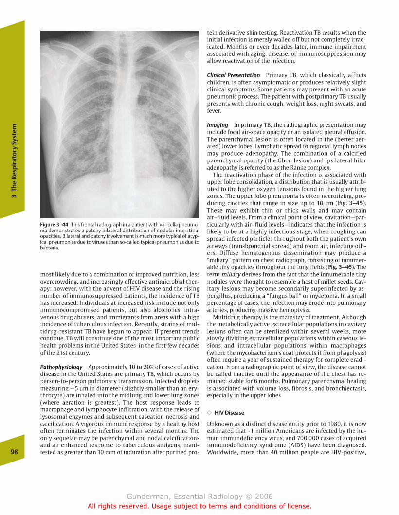
most likely due to a combination of improved nutrition, lessovercrowding, and increasingly effective antimicrobial ther-apy; however, with the advent of HIV disease and the risingnumber of immunosuppressed patients, the incidence of TBhas increased. Individuals at increased risk include not onlyimmunocompromised patients, but also alcoholics, intra-venous drug abusers, and immigrants from areas with a highincidence of tuberculous infection. Recently, strains of mul-tidrug-resistant TB have begun to appear. If present trendscontinue, TB will constitute one of the most important publichealth problems in the United States in the first few decadesof the 21st century.
Pathophysiology Approximately 10 to 20% of cases of activedisease in the United States are primary TB, which occurs byperson-to-person pulmonary transmission. Infected dropletsmeasuring �5 µm in diameter (slightly smaller than an ery-throcyte) are inhaled into the midlung and lower lung zones(where aeration is greatest). The host response leads tomacrophage and lymphocyte infiltration, with the release oflysosomal enzymes and subsequent caseation necrosis andcalcification. A vigorous immune response by a healthy hostoften terminates the infection within several months. Theonly sequelae may be parenchymal and nodal calcificationsand an enhanced response to tuberculous antigens, mani-fested as greater than 10 mm of induration after purified pro-
tein derivative skin testing. Reactivation TB results when theinitial infection is merely walled off but not completely irrad-icated. Months or even decades later, immune impairmentassociated with aging, disease, or immunosuppression mayallow reactivation of the infection.
Clinical Presentation Primary TB, which classically afflictschildren, is often asymptomatic or produces relatively slightclinical symptoms. Some patients may present with an acutepneumonic process. The patient with postprimary TB usuallypresents with chronic cough, weight loss, night sweats, andfever.
Imaging In primary TB, the radiographic presentation mayinclude focal air-space opacity or an isolated pleural effusion.The parenchymal lesion is often located in the (better aer-ated) lower lobes. Lymphatic spread to regional lymph nodesmay produce adenopathy. The combination of a calcifiedparenchymal opacity (the Ghon lesion) and ipsilateral hilaradenopathy is referred to as the Ranke complex.
The reactivation phase of the infection is associated withupper lobe consolidation, a distribution that is usually attrib-uted to the higher oxygen tensions found in the higher lungzones. The upper lobe pneumonia is often necrotizing, pro-ducing cavities that range in size up to 10 cm (FFiigg.. 33––4455).These may exhibit thin or thick walls and may containair–fluid levels. From a clinical point of view, cavitation—par-ticularly with air–fluid levels—indicates that the infection islikely to be at a highly infectious stage, when coughing canspread infected particles throughout both the patient’s ownairways (transbronchial spread) and room air, infecting oth-ers. Diffuse hematogenous dissemination may produce a“miliary” pattern on chest radiograph, consisting of innumer-able tiny opacities throughout the lung fields (FFiigg.. 33––4466). Theterm miliary derives from the fact that the innumerable tinynodules were thought to resemble a host of millet seeds. Cav-itary lesions may become secondarily superinfected by as-pergillus, producing a “fungus ball” or mycetoma. In a smallpercentage of cases, the infection may erode into pulmonaryarteries, producing massive hemoptysis.
Multidrug therapy is the mainstay of treatment. Althoughthe metabolically active extracellular populations in cavitarylesions often can be sterilized within several weeks, moreslowly dividing extracellular populations within caseous le-sions and intracellular populations within macrophages(where the mycobacterium’s coat protects it from phagolysis)often require a year of sustained therapy for complete eradi-cation. From a radiographic point of view, the disease cannotbe called inactive until the appearance of the chest has re-mained stable for 6 months. Pulmonary parenchymal healingis associated with volume loss, fibrosis, and bronchiectasis,especially in the upper lobes
�� HIV Disease
Unknown as a distinct disease entity prior to 1980, it is nowestimated that ~1 million Americans are infected by the hu-man immundeficiency virus, and 700,000 cases of acquiredimmunodeficiency syndrome (AIDS) have been diagnosed.Worldwide, more than 40 million people are HIV-positive,98
3Th
e Re
spir
ator
y Sy
stem
Figure 3–44 This frontal radiograph in a patient with varicella pneumo-nia demonstrates a patchy bilateral distribution of nodular interstitialopacities. Bilateral and patchy involvement is much more typical of atyp-ical pneumonias due to viruses than so-called typical pneumonias due tobacteria.
chapter 03_p68-111.qxd 12/1/05 3:31 PM Page 98
Gunderman, Essential Radiology © 2006All rights reserved. Usage subject to terms and conditions of license.
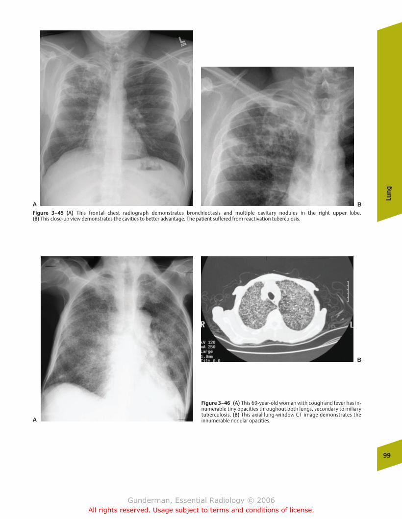
Lun
g
99
Figure 3–45 ((AA)) This frontal chest radiograph demonstrates bronchiectasis and multiple cavitary nodules in the right upper lobe. ((BB)) This close-up view demonstrates the cavities to better advantage. The patient suffered from reactivation tuberculosis.
A B
Figure 3–46 ((AA)) This 69-year-old woman with cough and fever has in-numerable tiny opacities throughout both lungs, secondary to miliarytuberculosis. ((BB)) This axial lung-window CT image demonstrates theinnumerable nodular opacities.A
B
chapter 03_p68-111.qxd 12/1/05 3:31 PM Page 99
Gunderman, Essential Radiology © 2006All rights reserved. Usage subject to terms and conditions of license.
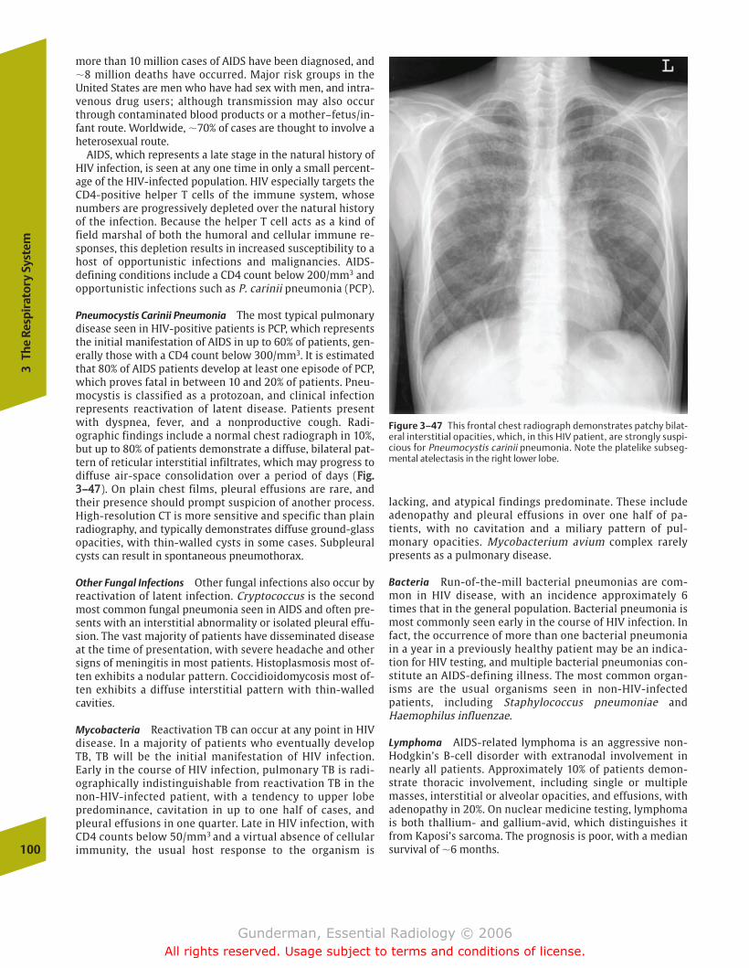
more than 10 million cases of AIDS have been diagnosed, and�8 million deaths have occurred. Major risk groups in theUnited States are men who have had sex with men, and intra-venous drug users; although transmission may also occurthrough contaminated blood products or a mother–fetus/in-fant route. Worldwide, �70% of cases are thought to involve aheterosexual route.
AIDS, which represents a late stage in the natural history ofHIV infection, is seen at any one time in only a small percent-age of the HIV-infected population. HIV especially targets theCD4-positive helper T cells of the immune system, whosenumbers are progressively depleted over the natural historyof the infection. Because the helper T cell acts as a kind offield marshal of both the humoral and cellular immune re-sponses, this depletion results in increased susceptibility to ahost of opportunistic infections and malignancies. AIDS-defining conditions include a CD4 count below 200/mm3 andopportunistic infections such as P. carinii pneumonia (PCP).
Pneumocystis Carinii Pneumonia The most typical pulmonarydisease seen in HIV-positive patients is PCP, which representsthe initial manifestation of AIDS in up to 60% of patients, gen-erally those with a CD4 count below 300/mm3. It is estimatedthat 80% of AIDS patients develop at least one episode of PCP,which proves fatal in between 10 and 20% of patients. Pneu-mocystis is classified as a protozoan, and clinical infectionrepresents reactivation of latent disease. Patients presentwith dyspnea, fever, and a nonproductive cough. Radi-ographic findings include a normal chest radiograph in 10%,but up to 80% of patients demonstrate a diffuse, bilateral pat-tern of reticular interstitial infiltrates, which may progress todiffuse air-space consolidation over a period of days (FFiigg..33––4477). On plain chest films, pleural effusions are rare, andtheir presence should prompt suspicion of another process.High-resolution CT is more sensitive and specific than plainradiography, and typically demonstrates diffuse ground-glassopacities, with thin-walled cysts in some cases. Subpleuralcysts can result in spontaneous pneumothorax.
Other Fungal Infections Other fungal infections also occur byreactivation of latent infection. Cryptococcus is the secondmost common fungal pneumonia seen in AIDS and often pre-sents with an interstitial abnormality or isolated pleural effu-sion. The vast majority of patients have disseminated diseaseat the time of presentation, with severe headache and othersigns of meningitis in most patients. Histoplasmosis most of-ten exhibits a nodular pattern. Coccidioidomycosis most of-ten exhibits a diffuse interstitial pattern with thin-walledcavities.
Mycobacteria Reactivation TB can occur at any point in HIVdisease. In a majority of patients who eventually developTB, TB will be the initial manifestation of HIV infection.Early in the course of HIV infection, pulmonary TB is radi-ographically indistinguishable from reactivation TB in thenon-HIV-infected patient, with a tendency to upper lobepredominance, cavitation in up to one half of cases, andpleural effusions in one quarter. Late in HIV infection, withCD4 counts below 50/mm3 and a virtual absence of cellularimmunity, the usual host response to the organism is
lacking, and atypical findings predominate. These includeadenopathy and pleural effusions in over one half of pa-tients, with no cavitation and a miliary pattern of pul-monary opacities. Mycobacterium avium complex rarelypresents as a pulmonary disease.
Bacteria Run-of-the-mill bacterial pneumonias are com-mon in HIV disease, with an incidence approximately 6times that in the general population. Bacterial pneumonia ismost commonly seen early in the course of HIV infection. Infact, the occurrence of more than one bacterial pneumoniain a year in a previously healthy patient may be an indica-tion for HIV testing, and multiple bacterial pneumonias con-stitute an AIDS-defining illness. The most common organ-isms are the usual organisms seen in non-HIV-infectedpatients, including Staphylococcus pneumoniae andHaemophilus influenzae.
Lymphoma AIDS-related lymphoma is an aggressive non-Hodgkin’s B-cell disorder with extranodal involvement innearly all patients. Approximately 10% of patients demon-strate thoracic involvement, including single or multiplemasses, interstitial or alveolar opacities, and effusions, withadenopathy in 20%. On nuclear medicine testing, lymphomais both thallium- and gallium-avid, which distinguishes itfrom Kaposi’s sarcoma. The prognosis is poor, with a mediansurvival of �6 months.100
3Th
e Re
spir
ator
y Sy
stem
Figure 3–47 This frontal chest radiograph demonstrates patchy bilat-eral interstitial opacities, which, in this HIV patient, are strongly suspi-cious for Pneumocystis carinii pneumonia. Note the platelike subseg-mental atelectasis in the right lower lobe.
chapter 03_p68-111.qxd 12/1/05 3:31 PM Page 100
Gunderman, Essential Radiology © 2006All rights reserved. Usage subject to terms and conditions of license.
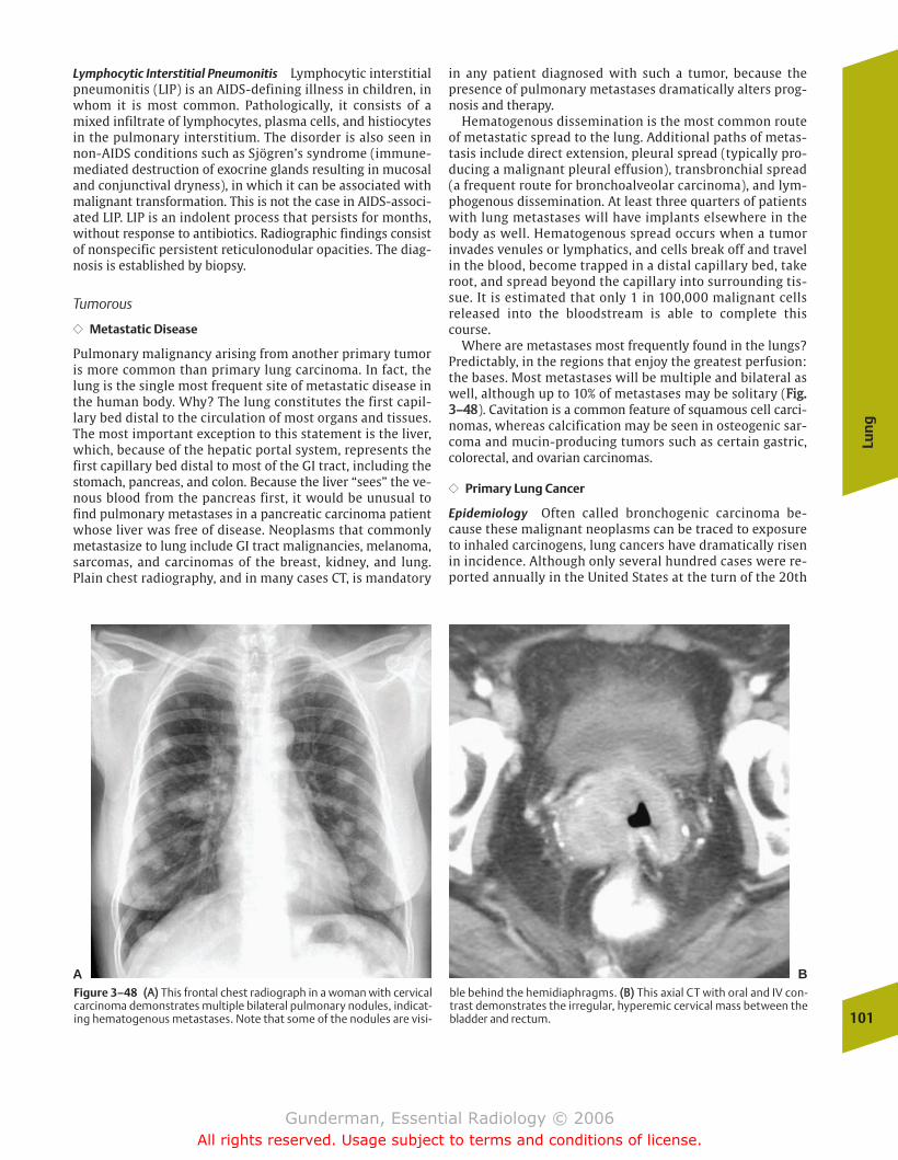
Lymphocytic Interstitial Pneumonitis Lymphocytic interstitialpneumonitis (LIP) is an AIDS-defining illness in children, inwhom it is most common. Pathologically, it consists of amixed infiltrate of lymphocytes, plasma cells, and histiocytesin the pulmonary interstitium. The disorder is also seen innon-AIDS conditions such as Sjögren’s syndrome (immune-mediated destruction of exocrine glands resulting in mucosaland conjunctival dryness), in which it can be associated withmalignant transformation. This is not the case in AIDS-associ-ated LIP. LIP is an indolent process that persists for months,without response to antibiotics. Radiographic findings consistof nonspecific persistent reticulonodular opacities. The diag-nosis is established by biopsy.
Tumorous
�� Metastatic Disease
Pulmonary malignancy arising from another primary tumoris more common than primary lung carcinoma. In fact, thelung is the single most frequent site of metastatic disease inthe human body. Why? The lung constitutes the first capil-lary bed distal to the circulation of most organs and tissues.The most important exception to this statement is the liver,which, because of the hepatic portal system, represents thefirst capillary bed distal to most of the GI tract, including thestomach, pancreas, and colon. Because the liver “sees” the ve-nous blood from the pancreas first, it would be unusual tofind pulmonary metastases in a pancreatic carcinoma patientwhose liver was free of disease. Neoplasms that commonlymetastasize to lung include GI tract malignancies, melanoma,sarcomas, and carcinomas of the breast, kidney, and lung.Plain chest radiography, and in many cases CT, is mandatory
in any patient diagnosed with such a tumor, because thepresence of pulmonary metastases dramatically alters prog-nosis and therapy.
Hematogenous dissemination is the most common routeof metastatic spread to the lung. Additional paths of metas-tasis include direct extension, pleural spread (typically pro-ducing a malignant pleural effusion), transbronchial spread(a frequent route for bronchoalveolar carcinoma), and lym-phogenous dissemination. At least three quarters of patientswith lung metastases will have implants elsewhere in thebody as well. Hematogenous spread occurs when a tumorinvades venules or lymphatics, and cells break off and travelin the blood, become trapped in a distal capillary bed, takeroot, and spread beyond the capillary into surrounding tis-sue. It is estimated that only 1 in 100,000 malignant cellsreleased into the bloodstream is able to complete thiscourse.
Where are metastases most frequently found in the lungs?Predictably, in the regions that enjoy the greatest perfusion:the bases. Most metastases will be multiple and bilateral aswell, although up to 10% of metastases may be solitary (FFiigg..33––4488). Cavitation is a common feature of squamous cell carci-nomas, whereas calcification may be seen in osteogenic sar-coma and mucin-producing tumors such as certain gastric,colorectal, and ovarian carcinomas.
�� Primary Lung Cancer
Epidemiology Often called bronchogenic carcinoma be-cause these malignant neoplasms can be traced to exposureto inhaled carcinogens, lung cancers have dramatically risenin incidence. Although only several hundred cases were re-ported annually in the United States at the turn of the 20th
Lun
g
101
A BFigure 3–48 ((AA)) This frontal chest radiograph in a woman with cervicalcarcinoma demonstrates multiple bilateral pulmonary nodules, indicat-ing hematogenous metastases. Note that some of the nodules are visi-
ble behind the hemidiaphragms. ((BB)) This axial CT with oral and IV con-trast demonstrates the irregular, hyperemic cervical mass between thebladder and rectum.
chapter 03_p68-111.qxd 12/1/05 3:31 PM Page 101
Gunderman, Essential Radiology © 2006All rights reserved. Usage subject to terms and conditions of license.
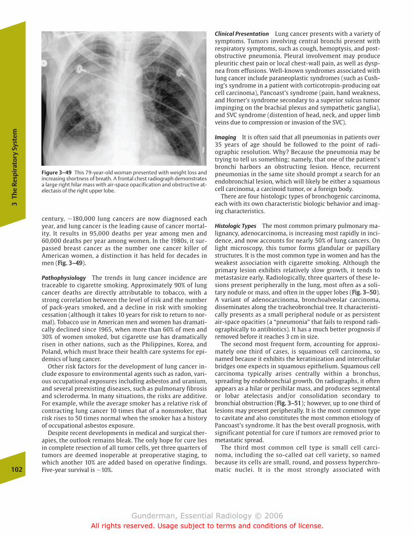
century, �180,000 lung cancers are now diagnosed eachyear, and lung cancer is the leading cause of cancer mortal-ity. It results in 95,000 deaths per year among men and60,000 deaths per year among women. In the 1980s, it sur-passed breast cancer as the number one cancer killer ofAmerican women, a distinction it has held for decades inmen (FFiigg.. 33––4499).
Pathophysiology The trends in lung cancer incidence aretraceable to cigarette smoking. Approximately 90% of lungcancer deaths are directly attributable to tobacco, with astrong correlation between the level of risk and the numberof pack-years smoked, and a decline in risk with smokingcessation (although it takes 10 years for risk to return to nor-mal). Tobacco use in American men and women has dramati-cally declined since 1965, when more than 60% of men and30% of women smoked, but cigarette use has dramaticallyrisen in other nations, such as the Philippines, Korea, andPoland, which must brace their health care systems for epi-demics of lung cancer.
Other risk factors for the development of lung cancer in-clude exposure to environmental agents such as radon, vari-ous occupational exposures including asbestos and uranium,and several preexisting diseases, such as pulmonary fibrosisand scleroderma. In many situations, the risks are additive.For example, while the average smoker has a relative risk ofcontracting lung cancer 10 times that of a nonsmoker, thatrisk rises to 50 times normal when the smoker has a historyof occupational asbestos exposure.
Despite recent developments in medical and surgical ther-apies, the outlook remains bleak. The only hope for cure liesin complete resection of all tumor cells, yet three quarters oftumors are deemed inoperable at preoperative staging, towhich another 10% are added based on operative findings.Five-year survival is �10%.
Clinical Presentation Lung cancer presents with a variety ofsymptoms. Tumors involving central bronchi present withrespiratory symptoms, such as cough, hemoptysis, and post-obstructive pneumonia. Pleural involvement may producepleuritic chest pain or local chest-wall pain, as well as dysp-nea from effusions. Well-known syndromes associated withlung cancer include paraneoplastic syndromes (such as Cush-ing’s syndrome in a patient with corticotropin-producing oatcell carcinoma), Pancoast’s syndrome (pain, hand weakness,and Horner’s syndrome secondary to a superior sulcus tumorimpinging on the brachial plexus and sympathetic ganglia),and SVC syndrome (distention of head, neck, and upper limbveins due to compression or invasion of the SVC).
Imaging It is often said that all pneumonias in patients over35 years of age should be followed to the point of radi-ographic resolution. Why? Because the pneumonia may betrying to tell us something; namely, that one of the patient’sbronchi harbors an obstructing lesion. Hence, recurrentpneumonias in the same site should prompt a search for anendobronchial lesion, which will likely be either a squamouscell carcinoma, a carcinoid tumor, or a foreign body.
There are four histologic types of bronchogenic carcinoma,each with its own characteristic biologic behavior and imag-ing characteristics.
Histologic Types The most common primary pulmonary ma-lignancy, adenocarcinoma, is increasing most rapidly in inci-dence, and now accounts for nearly 50% of lung cancers. Onlight microscopy, this tumor forms glandular or papillarystructures. It is the most common type in women and has theweakest association with cigarette smoking. Although theprimary lesion exhibits relatively slow growth, it tends tometastasize early. Radiologically, three quarters of these le-sions present peripherally in the lung, most often as a soli-tary nodule or mass, and often in the upper lobes (FFiigg.. 33––5500).A variant of adenocarcinoma, bronchoalveolar carcinoma,disseminates along the tracheobronchial tree. It characteristi-cally presents as a small peripheral nodule or as persistentair-space opacities (a “pneumonia” that fails to respond radi-ographically to antibiotics). It has a much better prognosis ifremoved before it reaches 3 cm in size.
The second most frequent form, accounting for approxi-mately one third of cases, is squamous cell carcinoma, sonamed because it exhibits the keratinization and intercellularbridges one expects in squamous epithelium. Squamous cellcarcinoma typically arises centrally within a bronchus,spreading by endobronchial growth. On radiographs, it oftenappears as a hilar or perihilar mass, and produces segmentalor lobar atelectasis and/or consolidation secondary tobronchial obstruction (FFiigg.. 33––5511); however, up to one third oflesions may present peripherally. It is the most common typeto cavitate and also constitutes the most common etiology ofPancoast’s syndrome. It has the best overall prognosis, withsignificant potential for cure if tumors are removed prior tometastatic spread.
The third most common cell type is small cell carci-noma, including the so-called oat cell variety, so namedbecause its cells are small, round, and possess hyperchro-matic nuclei. It is the most strongly associated with102
3Th
e Re
spir
ator
y Sy
stem
Figure 3–49 This 79-year-old woman presented with weight loss andincreasing shortness of breath. A frontal chest radiograph demonstratesa large right hilar mass with air-space opacification and obstructive at-electasis of the right upper lobe.
chapter 03_p68-111.qxd 12/1/05 3:31 PM Page 102
Gunderman, Essential Radiology © 2006All rights reserved. Usage subject to terms and conditions of license.
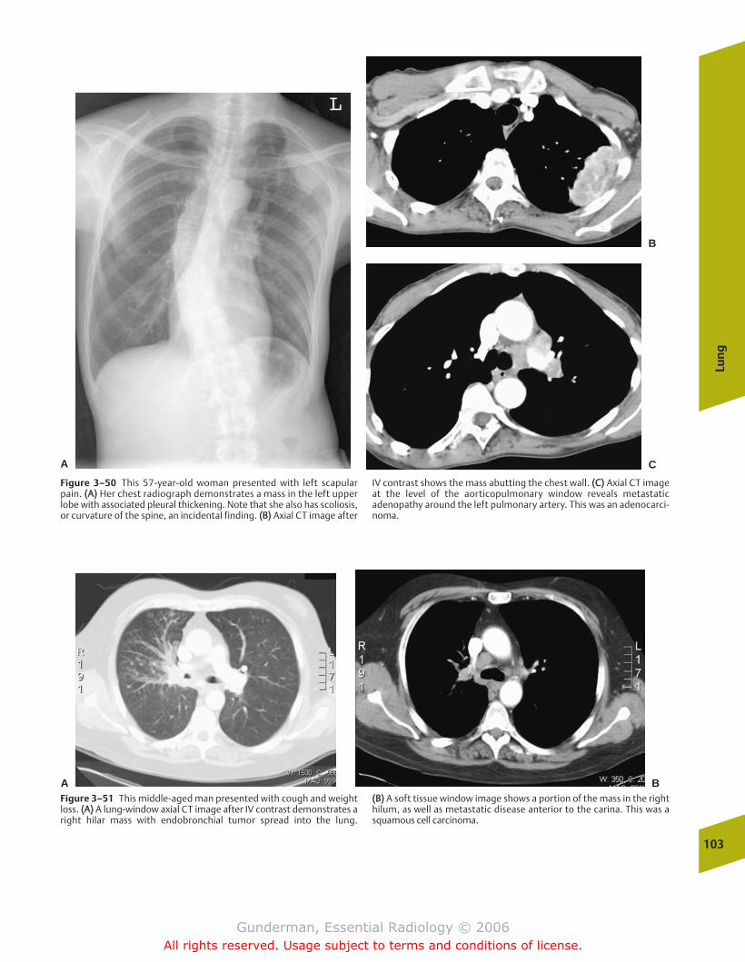
Lun
g
103
Figure 3–50 This 57-year-old woman presented with left scapularpain. ((AA)) Her chest radiograph demonstrates a mass in the left upperlobe with associated pleural thickening. Note that she also has scoliosis,or curvature of the spine, an incidental finding. ((BB)) Axial CT image after
IV contrast shows the mass abutting the chest wall. ((CC)) Axial CT imageat the level of the aorticopulmonary window reveals metastaticadenopathy around the left pulmonary artery. This was an adenocarci-noma.
A C
B
A BFigure 3–51 This middle-aged man presented with cough and weightloss. ((AA)) A lung-window axial CT image after IV contrast demonstrates aright hilar mass with endobronchial tumor spread into the lung.
((BB)) A soft tissue window image shows a portion of the mass in the righthilum, as well as metastatic disease anterior to the carina. This was asquamous cell carcinoma.
chapter 03_p68-111.qxd 12/1/05 3:31 PM Page 103
Gunderman, Essential Radiology © 2006All rights reserved. Usage subject to terms and conditions of license.

cigarette smoking. Small cell carcinoma most often pre-sents as a large, central mass and is very likely to bemetastatic at the time of detection, with 80% of patientsdemonstrating extrathoracic metastatic disease. It is asso-ciated with significant degrees of mediastinal and hilaradenopathy in most cases (FFiigg.. 33––5522). Paradoxically, whilesmall cell carcinoma exhibits the best response to radia-tion and chemotherapy, it also has the shortest mediansurvival, �1 to 2 years.
Large cell lung carcinoma most often presents as a large,peripheral mass. Unfortunately, it exhibits the worst combi-nation of biological behaviors, growing rapidly and metasta-sizing early. However, its prognosis remains more favorablethan that of small cell carcinoma.
Solitary Pulmonary Nodule One of the classic differential diag-noses in radiology is that of the solitary pulmonary nodule(SPN). SPNs are defined as single pulmonary lesions measur-ing less than 3 cm in diameter, and at least 150,000 of theselesions are biopsied or excised each year. In descending orderof frequency, the most likely etiologies for a solitary noduleare granuloma (TB, histoplasmosis, etc.), bronchogenic carci-noma, carcinoid tumor, and metastasis. The best morphologicpredictor of benignity is central calcification. Other radiologiccharacteristics that favor benignity include small size (al-though every 6 cm lung cancer was once a 1 cm tumor, and
104
3Th
e Re
spir
ator
y Sy
stem
AFigure 3–52 This middle-aged woman presented with weight loss. ((AA))Initial radiograph reveals a large left hilar mass and left upper lobe at-electasis. ((BB)) After chemotherapy and radiation therapy, the tumor has
shrunk dramatically, and the left upper lobe is largely reinflated. Despitethis gratifying response to treatment, the prognosis in small cell carci-noma is very poor.
B
this criterion should not influence diagnostic workup), well-defined borders (although many lung cancers are well-de-fined), and patterns of calcification, such as complete, lami-nated, or “popcorn” calcification (the latter indicating ahamartoma) (FFiigg.. 33––5533). The fact that carcinomas may arisein preexisting granulomas means that this criterion must beapplied with caution. An additional criterion is the patient’sage. Nodules in patients younger than 35 years of age rarelyrepresent carcinomas. On the other hand, a nodule in a 60-year-old heavy smoker is much more likely to represent alung cancer.
Where possible, the single most important determinationto be made in the evaluation of an SPN is whether the nod-ule is a new or changing finding. If it has been stable formore than 2 years, it is almost certainly benign. The key todetermining change is the review of previous chest radi-ographs. A time-consuming, worrisome, and expensivediagnostic workup can often be completely avoided if anodule is found to have been present for years. Generally, alesion that has been stable in size for 2 years can be diag-nosed as benign, because the typical doubling time of aprimary lung malignancy is �120 days; however, changes insize may be subtle; a lesion that doubles in volumeincreases in diameter by only �25%, indicating thataccurate measurements are critical in assessing for change(FFiigg.. 33––5544).
chapter 03_p68-111.qxd 12/1/05 3:31 PM Page 104
Gunderman, Essential Radiology © 2006All rights reserved. Usage subject to terms and conditions of license.
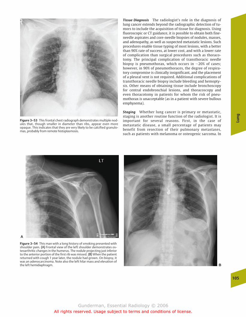
Tissue Diagnosis The radiologist’s role in the diagnosis oflung cancer extends beyond the radiographic detection of tu-mors to include the acquisition of tissue for diagnosis. Usingfluoroscopic or CT guidance, it is possible to obtain both fine-needle aspirates and core-needle biopsies of nodules, masses,and adenopathy, as well as suspected metastatic lesions. Suchprocedures enable tissue typing of most lesions, with a betterthan 90% rate of success, at lower cost, and with a lower rateof complication than surgical procedures such as thoraco-tomy. The principal complication of transthoracic needlebiopsy is pneumothorax, which occurs in �20% of cases;however, in 90% of pneumothoraces, the degree of respira-tory compromise is clinically insignificant, and the placementof a pleural vent is not required. Additional complications oftransthoracic needle biopsy include bleeding and hemopty-sis. Other means of obtaining tissue include bronchoscopy for central endobronchial lesions, and thoracoscopy and even thoracotomy in patients for whom the risk of pneu-mothorax is unacceptable (as in a patient with severe bullousemphysema).
Staging Whether lung cancer is primary or metastatic,staging is another routine function of the radiologist. It isimportant for several reasons. First, in the case ofmetastatic disease, a small percentage of patients maybenefit from resection of their pulmonary metastases,such as patients with melanoma or osteogenic sarcoma. In
Lun
g
105
Figure 3–53 This frontal chest radiograph demonstrates multiple nod-ules that, though smaller in diameter than ribs, appear even moreopaque. This indicates that they are very likely to be calcified granulo-mas, probably from remote histoplasmosis.
A
B
Figure 3–54 This man with a long history of smoking presented withshoulder pain. ((AA)) Frontal view of the left shoulder demonstrates os-teoarthritic changes in the humerus. The nodule projecting just inferiorto the anterior portion of the first rib was missed. ((BB)) When the patientreturned with cough 1 year later, the nodule had grown. On biopsy, itwas an adenocarcinoma. Note also the left hilar mass and elevation ofthe left hemidiaphragm.
chapter 03_p68-111.qxd 12/1/05 3:31 PM Page 105
Gunderman, Essential Radiology © 2006All rights reserved. Usage subject to terms and conditions of license.
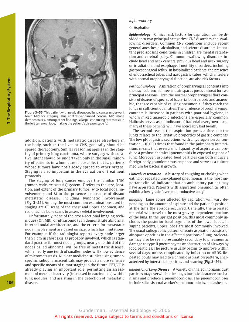
addition, patients with metastatic disease elsewhere inthe body, such as the liver or CNS, generally should bespared thoracotomy. Similar reasoning applies in the stag-ing of primary lung carcinoma, where surgery with cura-tive intent should be undertaken only in the small minor-ity of patients in whom cure is possible, that is, patientswhose tumors have not already spread to other organs.Staging is also important in the evaluation of treatmentprotocols.
The staging of lung cancer employs the familiar TNM (tumor-node-metastasis) system. T refers to the size, loca-tion, and extent of the primary tumor; N to local nodal in-volvement; and M to the presence or absence of distantmetastatic disease, including lymphatic involvement (FFiigg.. 33––5555). Among the most common examinations used instaging are CT scans of the chest and upper abdomen, andradionuclide bone scans to assess skeletal involvement.
Unfortunately, none of the cross-sectional imaging tech-niques (CT, MRI, or ultrasound) can demonstrate abnormalinternal nodal architecture, and the criteria for metastaticnodal involvement are based on size, which has limitations.For example, if the radiologist reports every node largerthan 1 cm in short axis as probably involved, which is stan-dard practice for most nodal groups, nearly one third of thenodes called abnormal will be free of metastatic disease,while nearly one tenth of smaller nodes will show evidenceof micrometastasis. Nuclear medicine studies using tumor-specific radiopharmaceuticals may provide a more sensitiveand specific means of tumor staging in the future. PET/CT isalready playing an important role, permitting an assess-ment of metabolic activity (increased in carcinomas) withinlung nodules, and assisting in the detection of metastaticdisease.
Inflammatory
�� Aspiration
Epidemiology Clinical risk factors for aspiration can be di-vided into two principal categories: CNS disorders and swal-lowing disorders. Common CNS conditions include recentgeneral anesthesia, alcoholism, and seizure disorders. Impor-tant predisposing conditions in children are mental retarda-tion and cerebral palsy. Common swallowing disorders in-clude head and neck cancers, previous head and neck surgeryor irradiation, and esophageal motility disorders, includinggastroesophageal reflux. In hospitalized patients, the presenceof endotracheal tubes and nasogastric tubes, which interferewith normal oropharyngeal function, are also risk factors.
Pathophysiology Aspiration of oropharyngeal contents intothe tracheobronchial tree and air spaces poses a threat for twoprincipal reasons. First, the normal oropharyngeal flora con-sists of dozens of species of bacteria, both aerobic and anaero-bic, that are capable of causing pneumonia if they reach thelungs in sufficient quantities. The virulence of oropharyngealcontents is increased in patients with poor oral hygiene, inwhom mixed anaerobic infections are especially common.Halitosis serves as an indicator of bacterial overgrowth, andmany of these patients will have noticeably bad breath.
The second reason that aspiration poses a threat to thelungs relates to the irritative properties of gastric contents.The low pH of gastric secretions, with a hydrogen ion concen-tration �10,000 times that found in the pulmonary intersti-tium, means that even a small quantity of aspirate can pro-duce a profuse chemical pneumonitis in exposed regions oflung. Moreover, aspirated food particles can both induce aforeign-body granulomatous response and serve as a culturemedium for bacterial growth.
Clinical Presentation A history of coughing or choking wheneating or repeated unexplained pneumonias is the most im-portant clinical indicator that an ambulatory patient mayhave aspirated. Patients with aspiration pneumonitis oftenexhibit a low-grade fever and productive cough.
Imaging Lung zones affected by aspiration will vary de-pending on the amount of aspirate and the patient’s positionat the time the episode occurred. Generally, the aspiratedmaterial will travel to the most gravity-dependent portionsof the lung. In the upright position, this most commonly in-cludes the posterior basal segments of the lower lobes. Insupine patients, upper lobes are most commonly involved.The usual radiographic pattern of acute aspiration consists ofair-space opacities in the affected portions of lung. Atelecta-sis may also be seen, presumably secondary to pneumoniticdamage to type II pneumocytes or obstruction of airways byfood particles. The picture usually begins to improve withinseveral days, unless complicated by infection or ARDS. Re-peated bouts may lead to a chronic aspiration pattern, char-acterized by interstitial opacities and scarring (FFiigg.. 33––5566).
Inhalational Lung Disease A variety of inhaled inorganic dustparticles may overwhelm the lung’s intrinsic clearance mecha-nisms and produce a pneumoconiosis. The pneumoconiosesinclude silicosis, coal worker’s pneumoconiosis, and asbestos-106
3Th
e Re
spir
ator
y Sy
stem
Figure 3–55 This patient with newly diagnosed lung cancer underwentbrain MRI for staging. This contrast-enhanced coronal MR imagedemonstrates, among other findings, a large, enhancing metastasis inthe left temporal lobe, making the patient’s disease stage IV.
chapter 03_p68-111.qxd 12/1/05 3:31 PM Page 106
Gunderman, Essential Radiology © 2006All rights reserved. Usage subject to terms and conditions of license.
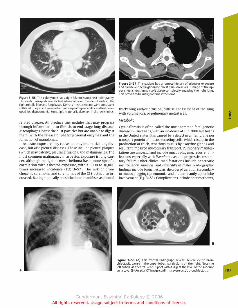
related disease. All produce tiny nodules that may progressthrough inflammation to fibrosis to end-stage lung disease.Macrophages ingest the dust particles but are unable to digestthem, with the release of phagolysosomal enzymes and theformation of granulomas.
Asbestos exposure may cause not only interstitial lung dis-ease, but also pleural diseases. These include pleural plaques(which may calcify), pleural effusions, and malignancies. Themost common malignancy in asbestos exposure is lung can-cer, although malignant mesothelioma has a more specificcorrelation with asbestos exposure, with a 5000 to 10,000times increased incidence (FFiigg.. 33––5577). The risk of bron-chogenic carcinoma and carcinomas of the GI tract is also in-creased. Radiographically, mesothelioma manifests as pleural
thickening and/or effusion, diffuse encasement of the lungwith volume loss, or pulmonary metastases.
Metabolic
Cystic fibrosis is often called the most common fatal geneticdisease in Caucasians, with an incidence of 1 in 2000 live birthsin the United States. It is caused by a defect in a membrane iontransport protein of mucus-secreting cells, which results in theproduction of thick, tenacious mucus by exocrine glands andresultant impaired mucociliary transport. Pulmonary manifes-tations are universal and include mucus plugging, recurrent in-fections, especially with Pseudomonas, and progressive respira-tory failure. Other clinical manifestations include pancreaticinsufficiency, sinusitis, and infertility in males. Radiographicfindings include bronchiectasis, disordered aeration (secondaryto mucus plugging), pneumonia, and predominantly upper lobeinvolvement (FFiigg.. 33––5588). Complications include pneumothorax,
Lun
g
107
Figure 3–56 This elderly man had a right hilar mass on chest radiography.This axial CT image shows calcified adenopathy and low-density in both theright middle lobe and lung bases. Density measurements were consistentwith lipid. The patient was inadvertently aspirating mineral oil and had devel-oped lipoid pneumonia. Some lipid material is also seen in the lower lobes.
Figure 3–57 This patient had a remote history of asbestos exposureand had developed right-sided chest pain. An axial CT image of the up-per chest shows lumpy soft tissue completely encasing the right lung.This proved to be malignant mesothelioma.
A
B
Figure 3–58 ((AA)) This frontal radiograph reveals severe cystic bron-chiectasis, worse in the upper lobes, particularly on the right. Note theleft subclavian central venous port with its tip at the level of the superiorvena cava. ((BB)) An axial CT image confirms severe cystic bronchiectasis.
chapter 03_p68-111.qxd 12/1/05 3:31 PM Page 107
Gunderman, Essential Radiology © 2006All rights reserved. Usage subject to terms and conditions of license.
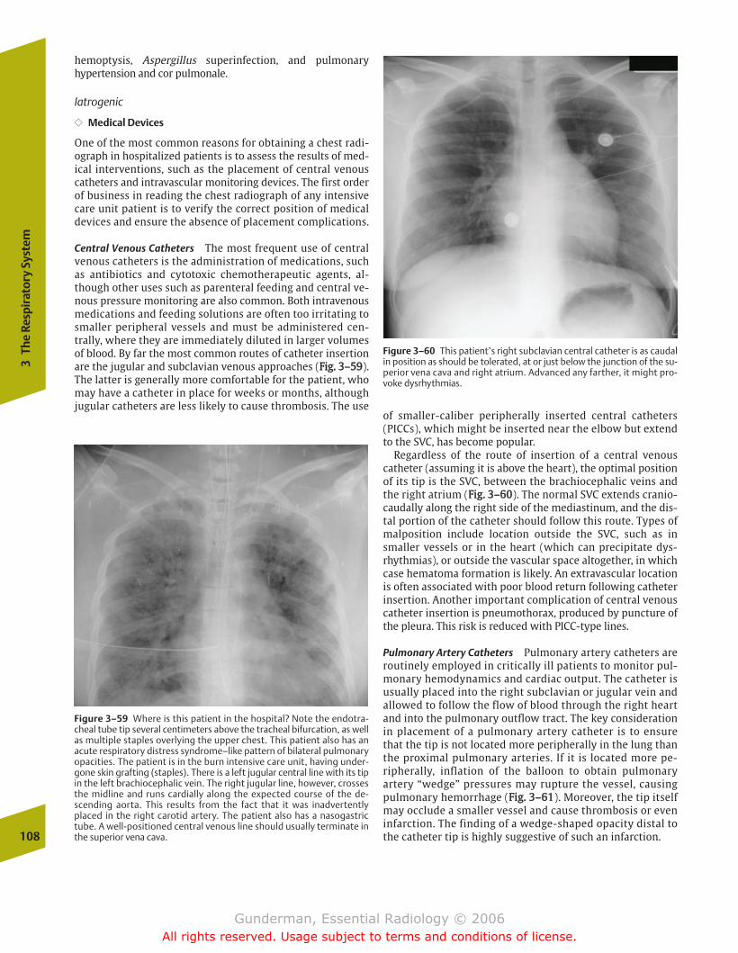
hemoptysis, Aspergillus superinfection, and pulmonaryhypertension and cor pulmonale.
Iatrogenic
�� Medical Devices
One of the most common reasons for obtaining a chest radi-ograph in hospitalized patients is to assess the results of med-ical interventions, such as the placement of central venouscatheters and intravascular monitoring devices. The first orderof business in reading the chest radiograph of any intensivecare unit patient is to verify the correct position of medicaldevices and ensure the absence of placement complications.
Central Venous Catheters The most frequent use of centralvenous catheters is the administration of medications, suchas antibiotics and cytotoxic chemotherapeutic agents, al-though other uses such as parenteral feeding and central ve-nous pressure monitoring are also common. Both intravenousmedications and feeding solutions are often too irritating tosmaller peripheral vessels and must be administered cen-trally, where they are immediately diluted in larger volumesof blood. By far the most common routes of catheter insertionare the jugular and subclavian venous approaches (FFiigg.. 33––5599).The latter is generally more comfortable for the patient, whomay have a catheter in place for weeks or months, althoughjugular catheters are less likely to cause thrombosis. The use
of smaller-caliber peripherally inserted central catheters(PICCs), which might be inserted near the elbow but extendto the SVC, has become popular.
Regardless of the route of insertion of a central venouscatheter (assuming it is above the heart), the optimal positionof its tip is the SVC, between the brachiocephalic veins andthe right atrium (FFiigg.. 33––6600). The normal SVC extends cranio-caudally along the right side of the mediastinum, and the dis-tal portion of the catheter should follow this route. Types ofmalposition include location outside the SVC, such as insmaller vessels or in the heart (which can precipitate dys-rhythmias), or outside the vascular space altogether, in whichcase hematoma formation is likely. An extravascular locationis often associated with poor blood return following catheterinsertion. Another important complication of central venouscatheter insertion is pneumothorax, produced by puncture ofthe pleura. This risk is reduced with PICC-type lines.
Pulmonary Artery Catheters Pulmonary artery catheters areroutinely employed in critically ill patients to monitor pul-monary hemodynamics and cardiac output. The catheter isusually placed into the right subclavian or jugular vein andallowed to follow the flow of blood through the right heartand into the pulmonary outflow tract. The key considerationin placement of a pulmonary artery catheter is to ensurethat the tip is not located more peripherally in the lung thanthe proximal pulmonary arteries. If it is located more pe-ripherally, inflation of the balloon to obtain pulmonaryartery “wedge” pressures may rupture the vessel, causingpulmonary hemorrhage (FFiigg.. 33––6611). Moreover, the tip itselfmay occlude a smaller vessel and cause thrombosis or eveninfarction. The finding of a wedge-shaped opacity distal tothe catheter tip is highly suggestive of such an infarction.108
3Th
e Re
spir
ator
y Sy
stem
Figure 3–59 Where is this patient in the hospital? Note the endotra-cheal tube tip several centimeters above the tracheal bifurcation, as wellas multiple staples overlying the upper chest. This patient also has anacute respiratory distress syndrome–like pattern of bilateral pulmonaryopacities. The patient is in the burn intensive care unit, having under-gone skin grafting (staples). There is a left jugular central line with its tipin the left brachiocephalic vein. The right jugular line, however, crossesthe midline and runs cardially along the expected course of the de-scending aorta. This results from the fact that it was inadvertentlyplaced in the right carotid artery. The patient also has a nasogastrictube. A well-positioned central venous line should usually terminate inthe superior vena cava.
Figure 3–60 This patient’s right subclavian central catheter is as caudalin position as should be tolerated, at or just below the junction of the su-perior vena cava and right atrium. Advanced any farther, it might pro-voke dysrhythmias.
chapter 03_p68-111.qxd 12/1/05 3:31 PM Page 108
Gunderman, Essential Radiology © 2006All rights reserved. Usage subject to terms and conditions of license.
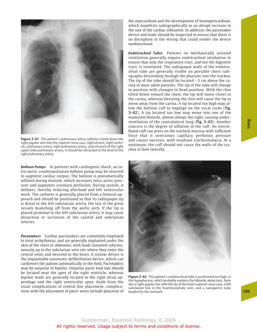
Balloon Pumps In patients with cardiogenic shock, an in-tra-aortic counterpulsation balloon pump may be insertedto augment cardiac output. The balloon is pneumaticallyinflated during diastole, which increases intra-aortic pres-sure and augments coronary perfusion. During systole, itdeflates, thereby reducing afterload and left ventricularwork. The catheter is generally placed from a femoral ap-proach and should be positioned so that its radiopaque tipis distal to the left subclavian artery, the last of the greatvessels branching off from the aortic arch. If the tip isplaced proximal to the left subclavian artery, it may causedissection or occlusion of the carotid and subclavianarteries.
Pacemakers Cardiac pacemakers are commonly employedto treat arrhythmias, and are generally implanted under theskin of the chest or abdomen, with leads tunneled subcuta-neously up to the subclavian vein site where they enter thecentral veins and descend to the heart. A similar device isthe implantable automatic defibrillation device, which cancardiovert the patient automatically in the field. Pacemakersmay be unipolar or bipolar. Unipolar pacer lead tips shouldbe located near the apex of the right ventricle, whereasbipolar leads are generally located in the right atrial ap-pendage and the right ventricular apex. Aside from theusual complications of central line placement, complica-tions with the placement of pacer wires include puncture of
the myocardium and the development of hemopericardium,which manifests radiographically as an abrupt increase inthe size of the cardiac silhouette. In addition, the pacemakerdevice and leads should be inspected to ensure that there isno disruption in the wiring that could render the devicenonfunctional.
Endotracheal Tubes Patients on mechanically assistedventilation generally require endotracheal intubation toensure that only the respiratory tract, and not the digestivetract, is ventilated. The radiopaque walls of the endotra-cheal tube are generally visible on portable chest radi-ographs descending through the pharynx into the trachea.The tip of the tube should be located �5 cm above the ca-rina in most adult patients. The tip of the tube will changein position with changes in head position. With the chintilted down toward the chest, the tip will move closer tothe carina, whereas elevating the chin will cause the tip tomove away from the carina. A tip located too high may al-low the balloon cuff to impinge on the vocal cords (FFiigg..33––6622). A tip located too low may move into one of themainstem bronchi, almost always the right, causing under-ventilation of the contralateral lung (FFiigg.. 33––6633). Anotherconcern is the degree of inflation of the cuff. An overin-flated cuff can press on the tracheal mucosa with sufficientforce that it overcomes capillary perfusion pressure and causes necrosis, with resultant tracheomalacia. At aminimum, the cuff should not cause the walls of the tra-chea to bow laterally.
Lun
g
109
Figure 3–61 This patient’s pulmonary artery catheter travels down theright jugular vein into the superior vena cava, right atrium, right ventri-cle, pulmonary artery, right pulmonary artery, and a branch of the rightupper lobe pulmonary artery. It should be retracted to the level of theright pulmonary artery.
Figure 3–62 This patient’s endotracheal tube is positioned too high, inthe hypopharynx, which probably explains the bibasilar atelectasis. Notealso a right jugular line with the tip at the lower superior vena cava, a leftsubclavian line in the brachiocephalic vein, and a nasogastric tubeheaded for the stomach.
chapter 03_p68-111.qxd 12/1/05 3:31 PM Page 109
Gunderman, Essential Radiology © 2006All rights reserved. Usage subject to terms and conditions of license.
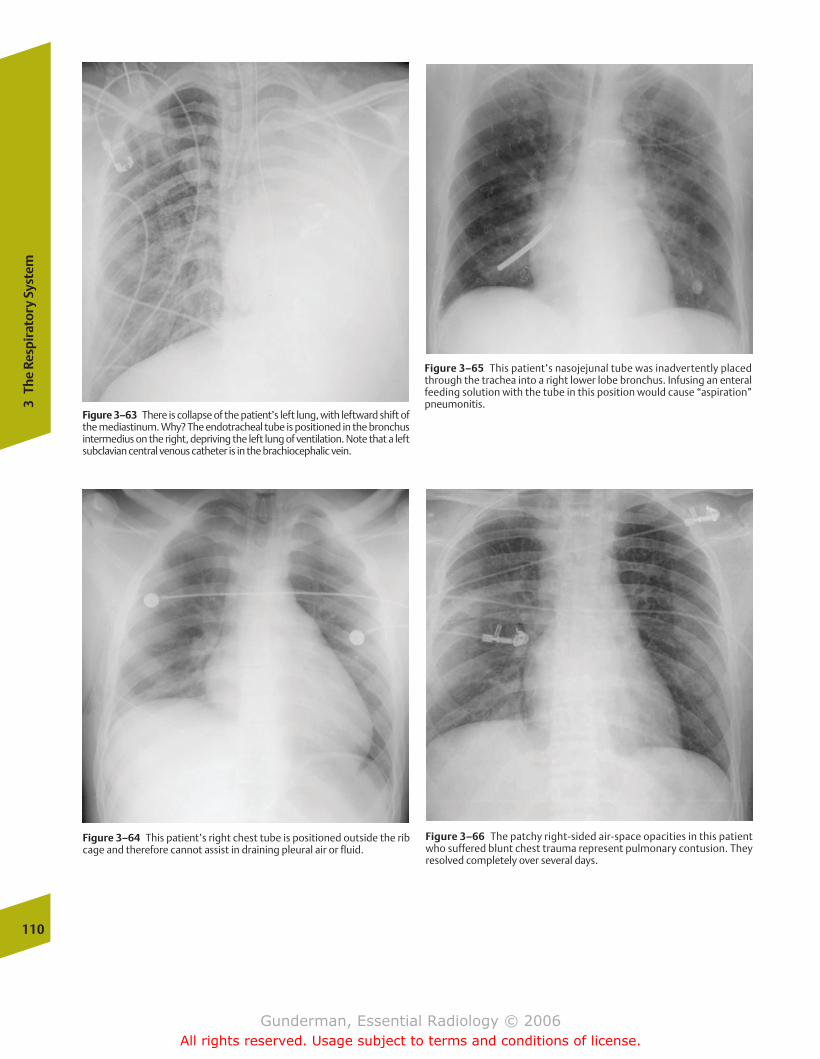
110
3Th
e Re
spir
ator
y Sy
stem
Figure 3–63 There is collapse of the patient’s left lung, with leftward shift ofthe mediastinum. Why? The endotracheal tube is positioned in the bronchusintermedius on the right, depriving the left lung of ventilation. Note that a leftsubclavian central venous catheter is in the brachiocephalic vein.
Figure 3–64 This patient’s right chest tube is positioned outside the ribcage and therefore cannot assist in draining pleural air or fluid.
Figure 3–65 This patient’s nasojejunal tube was inadvertently placedthrough the trachea into a right lower lobe bronchus. Infusing an enteralfeeding solution with the tube in this position would cause “aspiration”pneumonitis.
Figure 3–66 The patchy right-sided air-space opacities in this patientwho suffered blunt chest trauma represent pulmonary contusion. Theyresolved completely over several days.
chapter 03_p68-111.qxd 12/1/05 3:31 PM Page 110
Gunderman, Essential Radiology © 2006All rights reserved. Usage subject to terms and conditions of license.
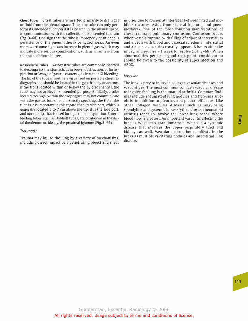
Chest Tubes Chest tubes are inserted primarily to drain gasor fluid from the pleural space. Thus, the tube can only per-form its intended function if it is located in the pleural space,in communication with the collection it is intended to drain(FFiigg.. 33––6644). One sign that the tube is improperly positioned ispersistence of the pneumothorax or hydrothorax. An evenmore worrisome sign is an increase in pleural gas, which mayindicate more serious complications, such as an air leak fromthe tracheobronchial tree.
Nasogastric Tubes Nasogastric tubes are commonly insertedto decompress the stomach, as in bowel obstruction, or for as-piration or lavage of gastric contents, as in upper GI bleeding.The tip of the tube is routinely visualized on portable chest ra-diographs and should be located in the gastric body or antrum.If the tip is located within or below the pyloric channel, thetube may not achieve its intended purpose. Similarly, a tubelocated too high, within the esophagus, may not communicatewith the gastric lumen at all. Strictly speaking, the tip of thetube is less important in this regard than its side port, which isgenerally located 5 to 7 cm above the tip. It is the side port,and not the tip, that is used for injection or aspiration. Entericfeeding tubes, such as Dobhoff tubes, are positioned in the dis-tal duodenum or, ideally, the proximal jejunum (FFiigg.. 33––6655).
Traumatic
Trauma may injure the lung by a variety of mechanisms,including direct impact by a penetrating object and shear
injuries due to torsion at interfaces between fixed and mo-bile structures. Aside from skeletal fractures and pneu-mothorax, one of the most common manifestations ofchest trauma is pulmonary contusion. Contusion occurswhen vessels rupture, with filling of adjacent interstitiumand alveoli with blood and associated edema. Interstitialand air-space opacities usually appear ~6 hours after theinjury, and require �1 week to resolve (FFiigg.. 33––6666). Whenabnormalities persist beyond that point, considerationshould be given to the possibility of superinfection andARDS.
Vascular
The lung is prey to injury in collagen vascular diseases andvasculitides. The most common collagen vascular diseaseto involve the lung is rheumatoid arthritis. Common find-ings include rheumatoid lung nodules and fibrosing alve-olitis, in addition to pleuritis and pleural effusions. Likeother collagen vascular diseases such as ankylosingspondylitis and systemic lupus erythematosus, rheumatoidarthritis tends to involve the lower lung zones, whereblood flow is greatest. An important vasculitis affecting thelung is Wegener’s granulomatosis, which is a systemicdisease that involves the upper respiratory tract andkidneys as well. Vascular destruction manifests in thelungs as multiple cavitating nodules and interstitial lungdisease.
Lun
g
111
chapter 03_p68-111.qxd 12/1/05 3:31 PM Page 111
Gunderman, Essential Radiology © 2006All rights reserved. Usage subject to terms and conditions of license.
� The Digestive Tract
OropharynxAnatomy and PhysiologyImaging
EsophagusAnatomy and PhysiologyImaging
StomachAnatomy and PhysiologyImaging
DuodenumAnatomy and PhysiologyImaging
Mesenteric Small BowelAnatomy and PhysiologyImaging
Large IntestineAnatomy and PhysiologyImaging
Basic Patterns of Gastrointestinal Tract AbnormalitiesFilling DefectsPolypsMassesIntrinsic Wall AbnormalitiesExtraluminal ProjectionsDistentionNarrowing
Select PathologiesEsophagusStomachSmall BowelColon and Rectum
� The Solid Organs of Digestion
Search PatternSelect Pathologies
LiverPancreas
� Abdominal Trauma
DiagnosisDiagnostic Peritoneal LavageComputed Tomography
4The Digestive System
chapter 04_p112-146.qxd 12/1/05 3:35 PM Page 112
Gunderman, Essential Radiology © 2006All rights reserved. Usage subject to terms and conditions of license.
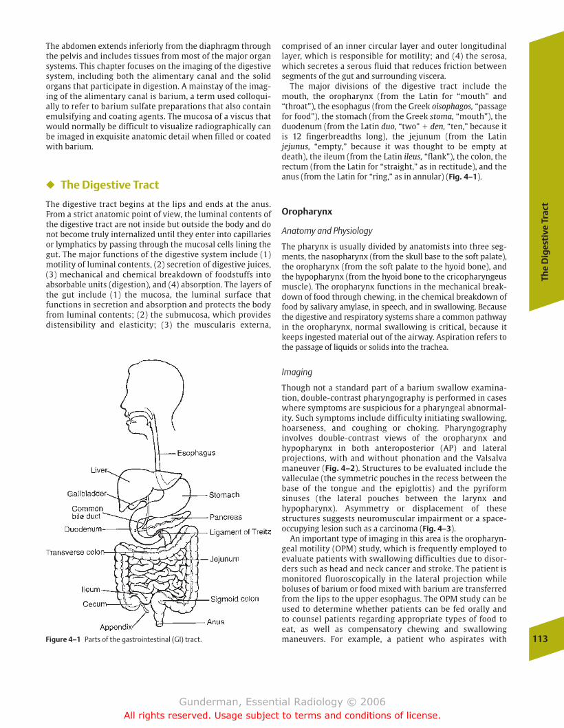
The
Dig
esti
ve T
ract
113
The abdomen extends inferiorly from the diaphragm throughthe pelvis and includes tissues from most of the major organsystems. This chapter focuses on the imaging of the digestivesystem, including both the alimentary canal and the solid organs that participate in digestion. A mainstay of the imag-ing of the alimentary canal is barium, a term used colloqui-ally to refer to barium sulfate preparations that also containemulsifying and coating agents. The mucosa of a viscus thatwould normally be difficult to visualize radiographically canbe imaged in exquisite anatomic detail when filled or coatedwith barium.
� The Digestive Tract
The digestive tract begins at the lips and ends at the anus.From a strict anatomic point of view, the luminal contents ofthe digestive tract are not inside but outside the body and donot become truly internalized until they enter into capillariesor lymphatics by passing through the mucosal cells lining thegut. The major functions of the digestive system include (1)motility of luminal contents, (2) secretion of digestive juices,(3) mechanical and chemical breakdown of foodstuffs intoabsorbable units (digestion), and (4) absorption. The layers ofthe gut include (1) the mucosa, the luminal surface that functions in secretion and absorption and protects the bodyfrom luminal contents; (2) the submucosa, which providesdistensibility and elasticity; (3) the muscularis externa,
comprised of an inner circular layer and outer longitudinallayer, which is responsible for motility; and (4) the serosa,which secretes a serous fluid that reduces friction betweensegments of the gut and surrounding viscera.
The major divisions of the digestive tract include themouth, the oropharynx (from the Latin for “mouth” and“throat”), the esophagus (from the Greek oisophagos, “passagefor food”), the stomach (from the Greek stoma, “mouth”), theduodenum (from the Latin duo, “two” � den, “ten,” because itis 12 fingerbreadths long), the jejunum (from the Latin jejunus, “empty,” because it was thought to be empty atdeath), the ileum (from the Latin ileus, “flank”), the colon, therectum (from the Latin for “straight,” as in rectitude), and theanus (from the Latin for “ring,” as in annular) (Fig. 4–1).
Oropharynx
Anatomy and Physiology
The pharynx is usually divided by anatomists into three seg-ments, the nasopharynx (from the skull base to the soft palate),the oropharynx (from the soft palate to the hyoid bone), andthe hypopharynx (from the hyoid bone to the cricopharyngeusmuscle). The oropharynx functions in the mechanical break-down of food through chewing, in the chemical breakdown offood by salivary amylase, in speech, and in swallowing. Becausethe digestive and respiratory systems share a common pathwayin the oropharynx, normal swallowing is critical, because itkeeps ingested material out of the airway. Aspiration refers tothe passage of liquids or solids into the trachea.
Imaging
Though not a standard part of a barium swallow examina-tion, double-contrast pharyngography is performed in caseswhere symptoms are suspicious for a pharyngeal abnormal-ity. Such symptoms include difficulty initiating swallowing,hoarseness, and coughing or choking. Pharyngography involves double-contrast views of the oropharynx and hypopharynx in both anteroposterior (AP) and lateral projections, with and without phonation and the Valsalvamaneuver (Fig. 4–2). Structures to be evaluated include thevalleculae (the symmetric pouches in the recess between thebase of the tongue and the epiglottis) and the pyriform sinuses (the lateral pouches between the larynx and hypopharynx). Asymmetry or displacement of these structures suggests neuromuscular impairment or a space-occupying lesion such as a carcinoma (Fig. 4–3).
An important type of imaging in this area is the oropharyn-geal motility (OPM) study, which is frequently employed toevaluate patients with swallowing difficulties due to disor-ders such as head and neck cancer and stroke. The patient ismonitored fluoroscopically in the lateral projection while boluses of barium or food mixed with barium are transferredfrom the lips to the upper esophagus. The OPM study can beused to determine whether patients can be fed orally and to counsel patients regarding appropriate types of food to eat, as well as compensatory chewing and swallowing maneuvers. For example, a patient who aspirates with Figure 4–1 Parts of the gastrointestinal (GI) tract.
chapter 04_p112-146.qxd 12/1/05 3:35 PM Page 113
Gunderman, Essential Radiology © 2006All rights reserved. Usage subject to terms and conditions of license.
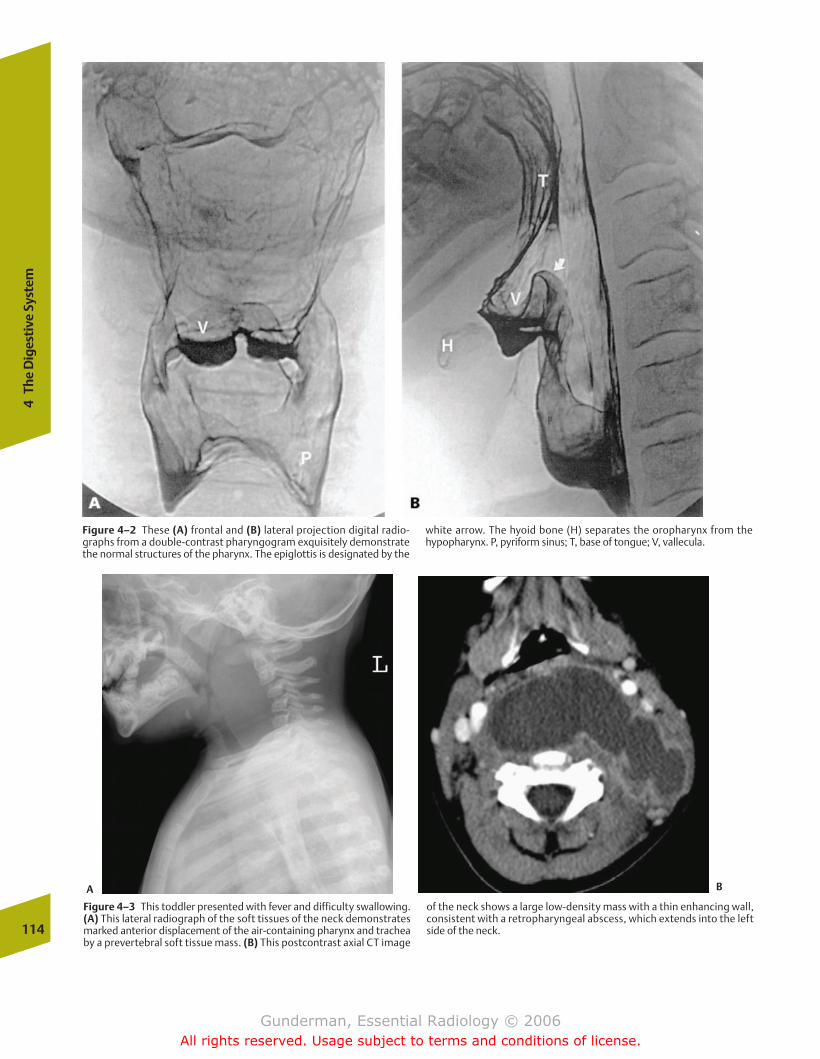
114
4Th
e D
iges
tive
Sys
tem
Figure 4–2 These (A) frontal and (B) lateral projection digital radio-graphs from a double-contrast pharyngogram exquisitely demonstratethe normal structures of the pharynx. The epiglottis is designated by the
white arrow. The hyoid bone (H) separates the oropharynx from the hypopharynx. P, pyriform sinus; T, base of tongue; V, vallecula.
Figure 4–3 This toddler presented with fever and difficulty swallowing.(A) This lateral radiograph of the soft tissues of the neck demonstratesmarked anterior displacement of the air-containing pharynx and tracheaby a prevertebral soft tissue mass. (B) This postcontrast axial CT image
of the neck shows a large low-density mass with a thin enhancing wall,consistent with a retropharyngeal abscess, which extends into the leftside of the neck.
A B
chapter 04_p112-146.qxd 12/1/05 3:35 PM Page 114
Gunderman, Essential Radiology © 2006All rights reserved. Usage subject to terms and conditions of license.
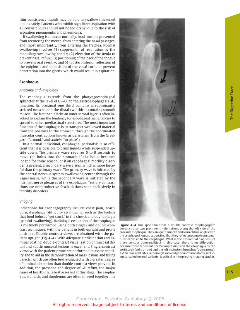
The
Dig
esti
ve T
ract
115
thin-consistency liquids may be able to swallow thickenedliquids safely. Patients who exhibit significant aspiration withall consistencies should not be fed orally, due to the risk ofaspiration pneumonitis and pneumonia.
If swallowing is to occur normally, food must be preventedfrom reentering the mouth, from entering the nasal passages,and, most importantly, from entering the trachea. Normalswallowing involves (1) suppression of respiration by themedullary swallowing center; (2) elevation of the uvula toprevent nasal reflux; (3) positioning of the back of the tongueto prevent oral reentry; and (4) posteroinferior reflection ofthe epiglottis and apposition of the vocal cords to preventpenetration into the glottis, which would result in aspiration.
Esophagus
Anatomy and Physiology
The esophagus extends from the pharyngoesophagealsphincter at the level of C5–C6 to the gastroesophageal (GE)junction. Its proximal one third contains predominantly striated muscle, and the distal two thirds contains smoothmuscle. The fact that it lacks an outer serosal layer is often in-voked to explain the tendency for esophageal malignancies tospread to other mediastinal structures. The most importantfunction of the esophagus is to transport swallowed materialfrom the pharynx to the stomach, through the coordinatedmuscular contractions known as peristalsis (from the Greekperi-, “around,” and stallein, “to place”).
In a normal individual, esophageal peristalsis is so effi-cient that it is possible to drink liquids while suspended up-side down. The primary wave requires 5 to 9 seconds tomove the bolus into the stomach. If the bolus becomeslodged for some reason, or if an esophageal motility disor-der is present, a secondary wave arises, which is more force-ful than the primary wave. The primary wave is initiated bythe central nervous system swallowing center through thevagus nerve, while the secondary wave is initiated by theintrinsic nerve plexuses of the esophagus. Tertiary contrac-tions are nonproductive fasciculations seen exclusively inmotility disorders.
Imaging
Indications for esophagography include chest pain, heart-burn, dysphagia (difficulty swallowing, such as the feelingthat food boluses “get stuck” in the chest), and odynophagia(painful swallowing). Radiologic evaluation of the esophagusis routinely performed using both single- and double-con-trast techniques, with the patient in both upright and pronepositions. Double-contrast views are obtained with the pa-tient upright (Fig. 4–4). With adequate air distention and lu-minal coating, double-contrast visualization of mucosal de-tail and subtle mucosal lesions is excellent. Single-contrastviews with the patient prone are performed to assess motil-ity and to aid in the demonstration of mass lesions and fillingdefects, which are often best evaluated with a greater degreeof luminal distention than double-contrast views provide. Inaddition, the presence and degree of GE reflux, the majorcause of heartburn, is best assessed at this stage. The esopha-gus, stomach, and duodenum are often imaged together in a
Figure 4–4 This spot film from a double-contrast esophagogramdemonstrates two prominent indentations along the left side of theproximal esophagus. They are quite smooth and form obtuse angles withthe esophageal lumen, suggesting that they reflect pressure from struc-tures extrinsic to the esophagus. What is the differential diagnosis ofthese contour abnormalities? In this case, there is no differential, because these represent normal impressions on the esophagus by theaortic arch (solid arrow) and the left mainstem bronchus (open arrow).As this case illustrates, a thorough knowledge of normal anatomy, includ-ing so-called normal variants, is critical in interpreting imaging studies.
chapter 04_p112-146.qxd 12/1/05 3:35 PM Page 115
Gunderman, Essential Radiology © 2006All rights reserved. Usage subject to terms and conditions of license.
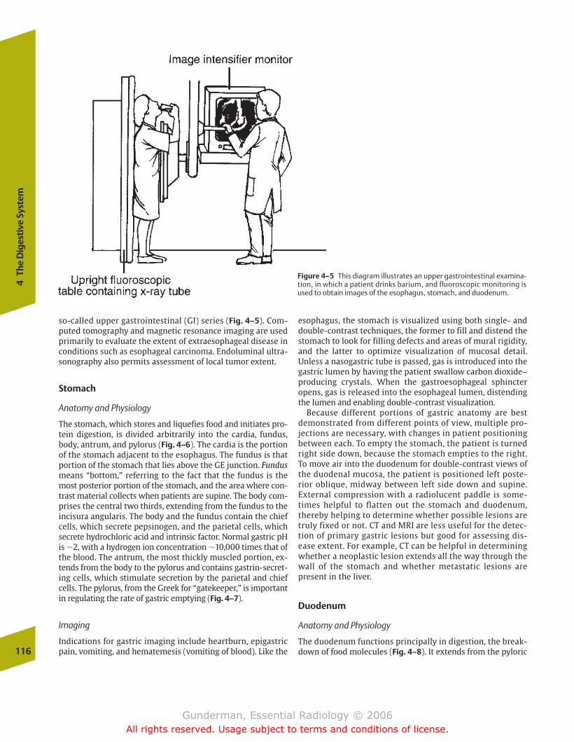
so-called upper gastrointestinal (GI) series (Fig. 4–5). Com-puted tomography and magnetic resonance imaging are usedprimarily to evaluate the extent of extraesophageal disease inconditions such as esophageal carcinoma. Endoluminal ultra-sonography also permits assessment of local tumor extent.
Stomach
Anatomy and Physiology
The stomach, which stores and liquefies food and initiates pro-tein digestion, is divided arbitrarily into the cardia, fundus,body, antrum, and pylorus (Fig. 4–6). The cardia is the portionof the stomach adjacent to the esophagus. The fundus is thatportion of the stomach that lies above the GE junction. Fundusmeans “bottom,” referring to the fact that the fundus is themost posterior portion of the stomach, and the area where con-trast material collects when patients are supine. The body com-prises the central two thirds, extending from the fundus to theincisura angularis. The body and the fundus contain the chiefcells, which secrete pepsinogen, and the parietal cells, whichsecrete hydrochloric acid and intrinsic factor. Normal gastric pHis �2, with a hydrogen ion concentration �10,000 times that ofthe blood. The antrum, the most thickly muscled portion, ex-tends from the body to the pylorus and contains gastrin-secret-ing cells, which stimulate secretion by the parietal and chiefcells. The pylorus, from the Greek for “gatekeeper,” is importantin regulating the rate of gastric emptying (Fig. 4–7).
Imaging
Indications for gastric imaging include heartburn, epigastricpain, vomiting, and hematemesis (vomiting of blood). Like the116
4Th
e D
iges
tive
Sys
tem
Figure 4–5 This diagram illustrates an upper gastrointestinal examina-tion, in which a patient drinks barium, and fluoroscopic monitoring isused to obtain images of the esophagus, stomach, and duodenum.
esophagus, the stomach is visualized using both single- anddouble-contrast techniques, the former to fill and distend thestomach to look for filling defects and areas of mural rigidity,and the latter to optimize visualization of mucosal detail. Unless a nasogastric tube is passed, gas is introduced into thegastric lumen by having the patient swallow carbon dioxide–producing crystals. When the gastroesophageal sphincteropens, gas is released into the esophageal lumen, distendingthe lumen and enabling double-contrast visualization.
Because different portions of gastric anatomy are bestdemonstrated from different points of view, multiple pro-jections are necessary, with changes in patient positioning between each. To empty the stomach, the patient is turnedright side down, because the stomach empties to the right.To move air into the duodenum for double-contrast views ofthe duodenal mucosa, the patient is positioned left poste-rior oblique, midway between left side down and supine.External compression with a radiolucent paddle is some-times helpful to flatten out the stomach and duodenum,thereby helping to determine whether possible lesions aretruly fixed or not. CT and MRI are less useful for the detec-tion of primary gastric lesions but good for assessing dis-ease extent. For example, CT can be helpful in determiningwhether a neoplastic lesion extends all the way through thewall of the stomach and whether metastatic lesions arepresent in the liver.
Duodenum
Anatomy and Physiology
The duodenum functions principally in digestion, the break-down of food molecules (Fig. 4–8). It extends from the pyloric
chapter 04_p112-146.qxd 12/1/05 3:35 PM Page 116
Gunderman, Essential Radiology © 2006All rights reserved. Usage subject to terms and conditions of license.
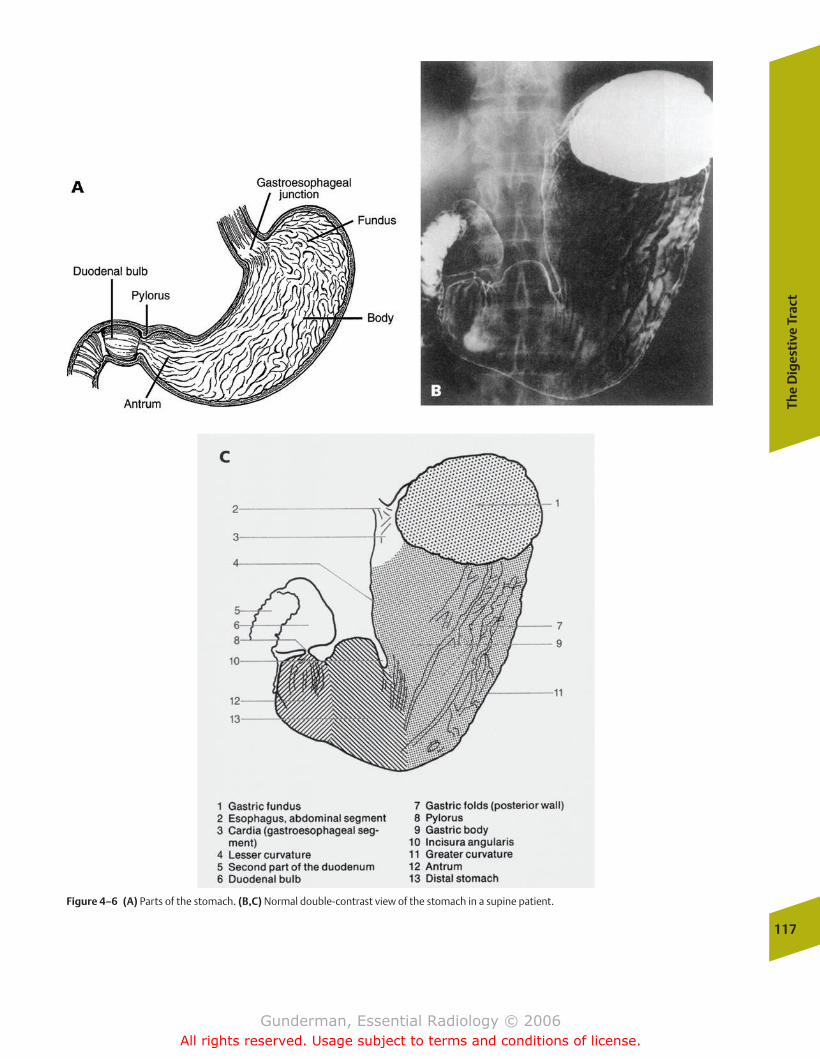
The
Dig
esti
ve T
ract
117
Figure 4–6 (A) Parts of the stomach. (B,C) Normal double-contrast view of the stomach in a supine patient.
chapter 04_p112-146.qxd 12/1/05 3:35 PM Page 117
Gunderman, Essential Radiology © 2006All rights reserved. Usage subject to terms and conditions of license.
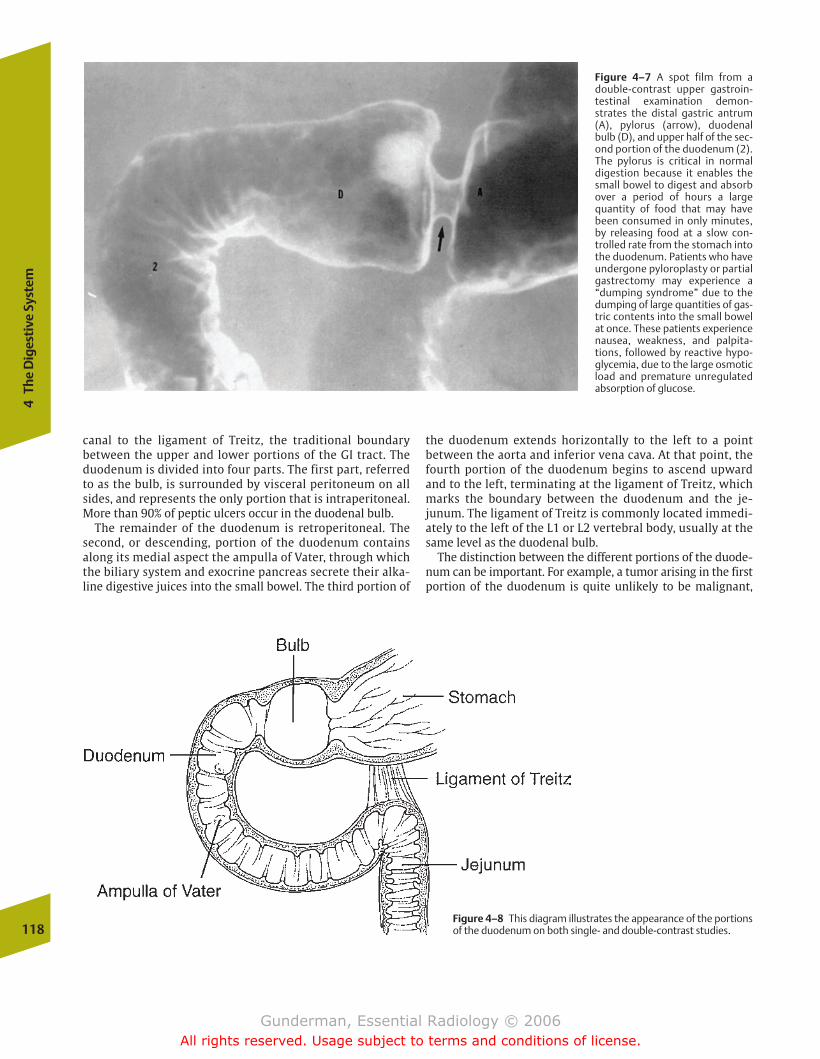
118
4Th
e D
iges
tive
Sys
tem
canal to the ligament of Treitz, the traditional boundary between the upper and lower portions of the GI tract. Theduodenum is divided into four parts. The first part, referredto as the bulb, is surrounded by visceral peritoneum on allsides, and represents the only portion that is intraperitoneal.More than 90% of peptic ulcers occur in the duodenal bulb.
The remainder of the duodenum is retroperitoneal. Thesecond, or descending, portion of the duodenum containsalong its medial aspect the ampulla of Vater, through whichthe biliary system and exocrine pancreas secrete their alka-line digestive juices into the small bowel. The third portion of
the duodenum extends horizontally to the left to a point between the aorta and inferior vena cava. At that point, thefourth portion of the duodenum begins to ascend upwardand to the left, terminating at the ligament of Treitz, whichmarks the boundary between the duodenum and the je-junum. The ligament of Treitz is commonly located immedi-ately to the left of the L1 or L2 vertebral body, usually at thesame level as the duodenal bulb.
The distinction between the different portions of the duode-num can be important. For example, a tumor arising in the firstportion of the duodenum is quite unlikely to be malignant,
Figure 4–7 A spot film from adouble-contrast upper gastroin-testinal examination demon-strates the distal gastric antrum(A), pylorus (arrow), duodenalbulb (D), and upper half of the sec-ond portion of the duodenum (2).The pylorus is critical in normal digestion because it enables thesmall bowel to digest and absorbover a period of hours a largequantity of food that may havebeen consumed in only minutes,by releasing food at a slow con-trolled rate from the stomach intothe duodenum. Patients who haveundergone pyloroplasty or partialgastrectomy may experience a“dumping syndrome” due to thedumping of large quantities of gas-tric contents into the small bowelat once. These patients experiencenausea, weakness, and palpita-tions, followed by reactive hypo-glycemia, due to the large osmoticload and premature unregulatedabsorption of glucose.
Figure 4–8 This diagram illustrates the appearance of the portionsof the duodenum on both single- and double-contrast studies.
chapter 04_p112-146.qxd 12/1/05 3:35 PM Page 118
Gunderman, Essential Radiology © 2006All rights reserved. Usage subject to terms and conditions of license.
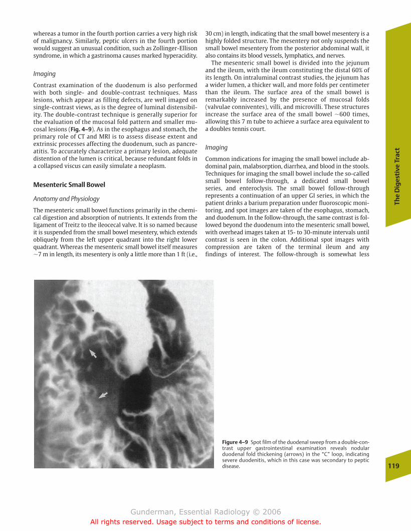
The
Dig
esti
ve T
ract
119
whereas a tumor in the fourth portion carries a very high riskof malignancy. Similarly, peptic ulcers in the fourth portionwould suggest an unusual condition, such as Zollinger-Ellisonsyndrome, in which a gastrinoma causes marked hyperacidity.
Imaging
Contrast examination of the duodenum is also performedwith both single- and double-contrast techniques. Mass lesions, which appear as filling defects, are well imaged onsingle-contrast views, as is the degree of luminal distensibil-ity. The double-contrast technique is generally superior forthe evaluation of the mucosal fold pattern and smaller mu-cosal lesions (Fig. 4–9). As in the esophagus and stomach, the primary role of CT and MRI is to assess disease extent and extrinsic processes affecting the duodenum, such as pancre-atitis. To accurately characterize a primary lesion, adequatedistention of the lumen is critical, because redundant folds ina collapsed viscus can easily simulate a neoplasm.
Mesenteric Small Bowel
Anatomy and Physiology
The mesenteric small bowel functions primarily in the chemi-cal digestion and absorption of nutrients. It extends from theligament of Treitz to the ileocecal valve. It is so named becauseit is suspended from the small bowel mesentery, which extendsobliquely from the left upper quadrant into the right lowerquadrant. Whereas the mesenteric small bowel itself measures�7 m in length, its mesentery is only a little more than 1 ft (i.e.,
30 cm) in length, indicating that the small bowel mesentery is ahighly folded structure. The mesentery not only suspends thesmall bowel mesentery from the posterior abdominal wall, italso contains its blood vessels, lymphatics, and nerves.
The mesenteric small bowel is divided into the jejunumand the ileum, with the ileum constituting the distal 60% ofits length. On intraluminal contrast studies, the jejunum hasa wider lumen, a thicker wall, and more folds per centimeterthan the ileum. The surface area of the small bowel is remarkably increased by the presence of mucosal folds(valvulae conniventes), villi, and microvilli. These structuresincrease the surface area of the small bowel �600 times, allowing this 7 m tube to achieve a surface area equivalent toa doubles tennis court.
Imaging
Common indications for imaging the small bowel include ab-dominal pain, malabsorption, diarrhea, and blood in the stools.Techniques for imaging the small bowel include the so-calledsmall bowel follow-through, a dedicated small bowel series, and enteroclysis. The small bowel follow-through represents a continuation of an upper GI series, in which the patient drinks a barium preparation under fluoroscopic moni-toring, and spot images are taken of the esophagus, stomach,and duodenum. In the follow-through, the same contrast is fol-lowed beyond the duodenum into the mesenteric small bowel,with overhead images taken at 15- to 30-minute intervals untilcontrast is seen in the colon. Additional spot images with compression are taken of the terminal ileum and any findings of interest. The follow-through is somewhat less
Figure 4–9 Spot film of the duodenal sweep from a double-con-trast upper gastrointestinal examination reveals nodular duodenal fold thickening (arrows) in the “C” loop, indicating severe duodenitis, which in this case was secondary to peptic disease.
chapter 04_p112-146.qxd 12/1/05 3:35 PM Page 119
Gunderman, Essential Radiology © 2006All rights reserved. Usage subject to terms and conditions of license.
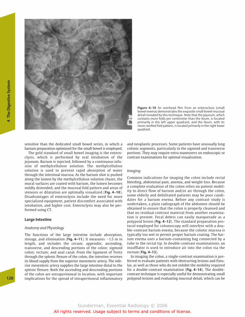
sensitive than the dedicated small bowel series, in which a barium preparation optimized for the small bowel is employed.
The gold standard of small bowel imaging is the entero-clysis, which is performed by oral intubation of the jejunum. Barium is injected, followed by a continuous infu-sion of methylcellulose solution. The methylcellulose solution is used to prevent rapid absorption of waterthrough the intestinal mucosa. As the barium shot is pushedalong the lumen by the methylcellulose solution chaser, themural surfaces are coated with barium, the lumen becomesmildly distended, and the mucosal fold pattern and areas ofstenosis or dilatation are optimally visualized (Fig. 4–10).Disadvantages of enteroclysis include the need for morespecialized equipment, patient discomfort associated withintubation, and higher cost. Enteroclysis may also be per-formed using CT.
Large Intestine
Anatomy and Physiology
The functions of the large intestine include absorption, storage, and elimination (Fig. 4–11). It measures �1.5 m inlength, and includes the cecum; appendix; ascending, transverse, and descending portions of the colon; sigmoidcolon; rectum; and anal canal. From the ligament of Treitzthrough the splenic flexure of the colon, the intestine receivesits blood supply from the superior mesenteric artery. The infe-rior mesenteric artery supplies the large intestine distal to thesplenic flexure. Both the ascending and descending portionsof the colon are extraperitoneal in location, with importantimplications for the spread of intraperitoneal inflammatory
and neoplastic processes. Some patients have unusually longcolonic segments, particularly in the sigmoid and transverseportions. They may require extra maneuvers on endoscopic orcontrast examinations for optimal visualization.
Imaging
Common indications for imaging the colon include rectalbleeding, abdominal pain, anemia, and weight loss. Becausea complete evaluation of the colon relies on patient mobil-ity to direct flow of barium and/or air through the colon,some elderly and debilitated patients may be poor candi-dates for a barium enema. Before any contrast study is undertaken, a plain radiograph of the abdomen should be obtained to ensure that the colon is properly cleansed andthat no residual contrast material from another examina-tion is present. Fecal debris can easily masquerade as apolypoid lesion (Fig. 4–12). The standard preparation pro-tocol employed for colonoscopy will interfere with a dou-ble-contrast barium enema, because the colonic mucosa istypically too wet to permit proper barium coating. The bar-ium enema uses a barium-containing bag connected by atube to the rectal tip. In double-contrast examinations, aninsufflator is used to introduce air into the colon via therectum (Fig. 4–13).
In imaging the colon, a single-contrast examination is pre-ferred to evaluate patients with obstructing lesions and fistu-las, as well as those who do not exhibit the mobility requiredfor a double-contrast examination (Fig. 4–14). The double-contrast technique is especially useful for demonstrating smallpolypoid lesions and evaluating mucosal detail, which can be120
4Th
e D
iges
tive
Sys
tem
Figure 4–10 An overhead film from an enteroclysis (smallbowel enema) demonstrates the exquisite small bowel mucosaldetail revealed by this technique. Note that the jejunum, whichcontains more folds per centimeter than the ileum, is locatedprimarily in the left upper quadrant, and the ileum, with itsmore rarefied fold pattern, is located primarily in the right lowerquadrant.
chapter 04_p112-146.qxd 12/1/05 3:35 PM Page 120
Gunderman, Essential Radiology © 2006All rights reserved. Usage subject to terms and conditions of license.
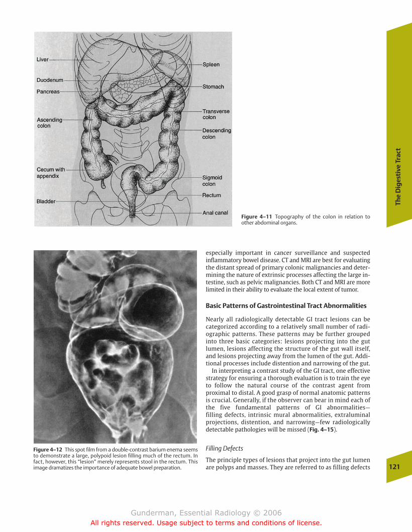
The
Dig
esti
ve T
ract
121
Figure 4–11 Topography of the colon in relation toother abdominal organs.
Figure 4–12 This spot film from a double-contrast barium enema seemsto demonstrate a large, polypoid lesion filling much of the rectum. Infact, however, this “lesion” merely represents stool in the rectum. Thisimage dramatizes the importance of adequate bowel preparation.
especially important in cancer surveillance and suspected inflammatory bowel disease. CT and MRI are best for evaluatingthe distant spread of primary colonic malignancies and deter-mining the nature of extrinsic processes affecting the large in-testine, such as pelvic malignancies. Both CT and MRI are morelimited in their ability to evaluate the local extent of tumor.
Basic Patterns of Gastrointestinal Tract Abnormalities
Nearly all radiologically detectable GI tract lesions can be categorized according to a relatively small number of radi-ographic patterns. These patterns may be further groupedinto three basic categories: lesions projecting into the gut lumen, lesions affecting the structure of the gut wall itself,and lesions projecting away from the lumen of the gut. Addi-tional processes include distention and narrowing of the gut.
In interpreting a contrast study of the GI tract, one effectivestrategy for ensuring a thorough evaluation is to train the eyeto follow the natural course of the contrast agent from proximal to distal. A good grasp of normal anatomic patternsis crucial. Generally, if the observer can bear in mind each ofthe five fundamental patterns of GI abnormalities—filling defects, intrinsic mural abnormalities, extraluminalprojections, distention, and narrowing—few radiologically detectable pathologies will be missed (Fig. 4–15).
Filling Defects
The principle types of lesions that project into the gut lumenare polyps and masses. They are referred to as filling defects
chapter 04_p112-146.qxd 12/1/05 3:35 PM Page 121
Gunderman, Essential Radiology © 2006All rights reserved. Usage subject to terms and conditions of license.
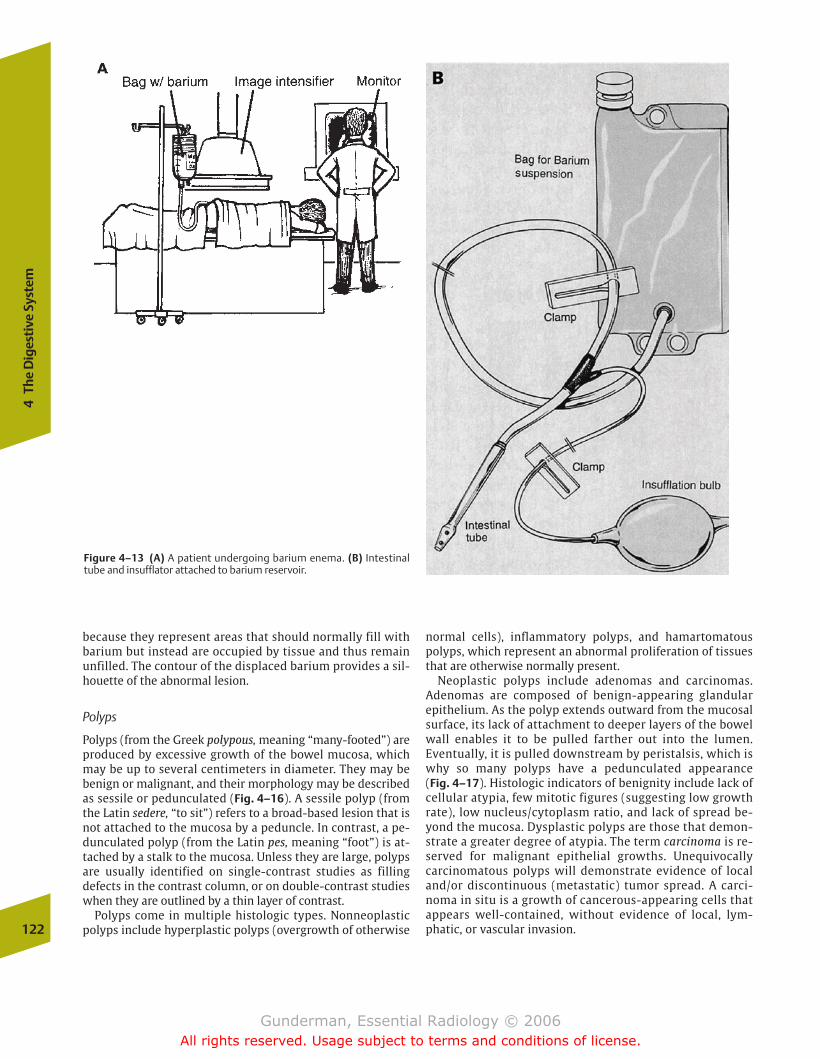
because they represent areas that should normally fill withbarium but instead are occupied by tissue and thus remainunfilled. The contour of the displaced barium provides a sil-houette of the abnormal lesion.
Polyps
Polyps (from the Greek polypous, meaning “many-footed”) areproduced by excessive growth of the bowel mucosa, whichmay be up to several centimeters in diameter. They may bebenign or malignant, and their morphology may be describedas sessile or pedunculated (Fig. 4–16). A sessile polyp (fromthe Latin sedere, “to sit”) refers to a broad-based lesion that isnot attached to the mucosa by a peduncle. In contrast, a pe-dunculated polyp (from the Latin pes, meaning “foot”) is at-tached by a stalk to the mucosa. Unless they are large, polypsare usually identified on single-contrast studies as filling defects in the contrast column, or on double-contrast studieswhen they are outlined by a thin layer of contrast.
Polyps come in multiple histologic types. Nonneoplasticpolyps include hyperplastic polyps (overgrowth of otherwise
normal cells), inflammatory polyps, and hamartomatouspolyps, which represent an abnormal proliferation of tissuesthat are otherwise normally present.
Neoplastic polyps include adenomas and carcinomas. Adenomas are composed of benign-appearing glandular epithelium. As the polyp extends outward from the mucosalsurface, its lack of attachment to deeper layers of the bowelwall enables it to be pulled farther out into the lumen.Eventually, it is pulled downstream by peristalsis, which iswhy so many polyps have a pedunculated appearance (Fig. 4–17). Histologic indicators of benignity include lack ofcellular atypia, few mitotic figures (suggesting low growthrate), low nucleus/cytoplasm ratio, and lack of spread be-yond the mucosa. Dysplastic polyps are those that demon-strate a greater degree of atypia. The term carcinoma is re-served for malignant epithelial growths. Unequivocallycarcinomatous polyps will demonstrate evidence of localand/or discontinuous (metastatic) tumor spread. A carci-noma in situ is a growth of cancerous-appearing cells thatappears well-contained, without evidence of local, lym-phatic, or vascular invasion.122
4Th
e D
iges
tive
Sys
tem
Figure 4–13 (A) A patient undergoing barium enema. (B) Intestinaltube and insufflator attached to barium reservoir.
chapter 04_p112-146.qxd 12/1/05 3:35 PM Page 122
Gunderman, Essential Radiology © 2006All rights reserved. Usage subject to terms and conditions of license.
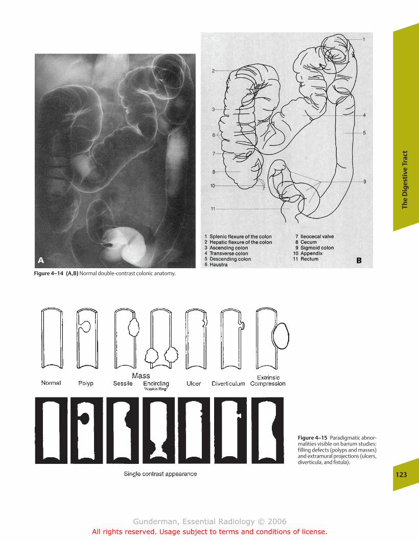
The
Dig
esti
ve T
ract
123
Figure 4–14 (A,B) Normal double-contrast colonic anatomy.
Figure 4–15 Paradigmatic abnor-malities visible on barium studies:filling defects (polyps and masses)and extramural projections (ulcers,diverticula, and fistula).
chapter 04_p112-146.qxd 12/1/05 3:35 PM Page 123
Gunderman, Essential Radiology © 2006All rights reserved. Usage subject to terms and conditions of license.
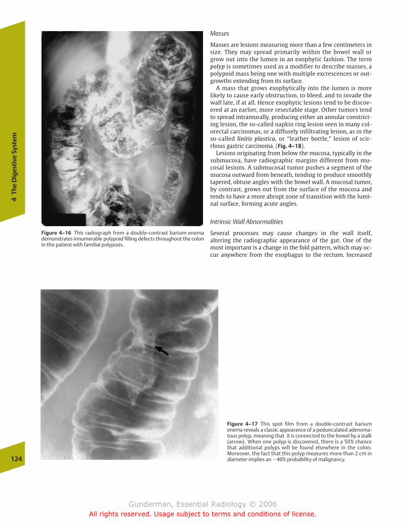
124
4Th
e D
iges
tive
Sys
tem
Masses
Masses are lesions measuring more than a few centimeters insize. They may spread primarily within the bowel wall orgrow out into the lumen in an exophytic fashion. The termpolyp is sometimes used as a modifier to describe masses, apolypoid mass being one with multiple excrescences or out-growths extending from its surface.
A mass that grows exophytically into the lumen is morelikely to cause early obstruction, to bleed, and to invade thewall late, if at all. Hence exophytic lesions tend to be discov-ered at an earlier, more resectable stage. Other tumors tendto spread intramurally, producing either an annular constrict-ing lesion, the so-called napkin ring lesion seen in many col-orectal carcinomas, or a diffusely infiltrating lesion, as in theso-called linitis plastica, or “leather bottle,” lesion of scir-rhous gastric carcinoma. (Fig. 4–18).
Lesions originating from below the mucosa, typically in thesubmucosa, have radiographic margins different from mu-cosal lesions. A submucosal tumor pushes a segment of themucosa outward from beneath, tending to produce smoothlytapered, obtuse angles with the bowel wall. A mucosal tumor,by contrast, grows out from the surface of the mucosa andtends to have a more abrupt zone of transition with the lumi-nal surface, forming acute angles.
Intrinsic Wall Abnormalities
Several processes may cause changes in the wall itself, altering the radiographic appearance of the gut. One of themost important is a change in the fold pattern, which may oc-cur anywhere from the esophagus to the rectum. Increased
Figure 4–16 This radiograph from a double-contrast barium enemademonstrates innumerable polypoid filling defects throughout the colonin this patient with familial polyposis.
Figure 4–17 This spot film from a double-contrast barium enema reveals a classic appearance of a pedunculated adenoma-tous polyp, meaning that it is connected to the bowel by a stalk(arrow). When one polyp is discovered, there is a 50% chancethat additional polyps will be found elsewhere in the colon.Moreover, the fact that this polyp measures more than 2 cm indiameter implies an �40% probability of malignancy.
chapter 04_p112-146.qxd 12/1/05 3:35 PM Page 124
Gunderman, Essential Radiology © 2006All rights reserved. Usage subject to terms and conditions of license.

The
Dig
esti
ve T
ract
125
prominence or thickening of the folds typically reflects eitheran inflammatory process (e.g., gastritis or enteritis), edema, orinfiltration by cells or cellular products (Fig. 4–19). Edema is byfar the most common cause and may result from any of the
usual physiologic forces that cause interstitial fluid accumula-tion, including ischemia, congestive heart failure, and hypopro-teinemia. Infiltration of the gut wall, manifesting as both thick-ening and rigidity, may result from lymphoma or amyloidosis.
Figure 4–18 (A) This elderly man presented with weight loss and earlysatiety. A single-contrast upper GI exam demonstrates a long segment offixed circumferential narrowing and mucosal irregularity of the entire gas-tric body in this patient with a “leather bottle” gastric adenocarcinoma.(B) This CT image from another patient with the same lesion demon-strates marked thickening of the gastric wall. Such lesions can be missedon endoscopy due to their submucosal location if deep biopsies are nottaken.
Figure 4–19 Spot film from asmall bowel series demonstratesmarked thickening of the folds inthis segment of small bowel (arrows). The differential diagno-sis of fold thickening includescauses of submucosal edema suchas ischemia and enteritis, submu-cosal tumor such as lymphoma,and submucosal hemorrhagefrom such causes as coagulopa-thy. However, in this patient with aclinical history of malabsorption,etiologies such as Whipple diseaseand celiac sprue are more likely. Inthis case, active sprue was the cul-prit. Sprue reflects an intoleranceto the gluten found, for example,in wheat.
chapter 04_p112-146.qxd 12/1/05 3:35 PM Page 125
Gunderman, Essential Radiology © 2006All rights reserved. Usage subject to terms and conditions of license.
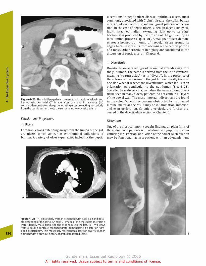
126
4Th
e D
iges
tive
Sys
tem
ulcerations in peptic ulcer disease; aphthous ulcers, mostcommonly associated with Crohn’s disease; the collar-buttonulcers of ulcerative colitis; and malignant patterns of ulcera-tion. In the case of peptic ulcers, a benign ulcer usually ex-hibits intact epithelium extending right up to its edge, because it is produced by the erosion of the gut wall by an intraluminal process (Fig. 4–20). A malignant ulcer demon-strates a heaped-up mound of irregular tissue around itsedges, because it results from necrosis of the central portionof a mass. Other criteria of benignity are considered in thediscussion of peptic ulcers in Chapter 6.
�� Diverticula
Diverticula are another type of lesion that extends away fromthe gut lumen. The name is derived from the Latin devertere,meaning “to turn aside” (as in “divert”). In the presence ofthese lesions, the barium in the gut lumen literally turns toone side when it reaches the diverticulum, which it fills in anorientation perpendicular to the gut lumen (Fig. 4–21). So-called false diverticula, including the usual colonic diver-ticula seen in many elderly patients, do not contain all layersof the bowel wall. The most important diverticula are foundin the colon. When they become obstructed by inspissatedluminal material, the result may be inflammation, infection,and even perforation. Colonic diverticula are further dis-cussed in the diverticulitis section of Chapter 6.
Distention
One of the most commonly sought findings on plain films ofthe abdomen in patients with obstructive symptoms such asvomiting is distention, or dilation of the bowel. Such dilationmay be functional, as in a patient with an adynamic ileus
Figure 4–20 This middle-aged man presented with abdominal pain andhemoptysis. An axial CT image after oral and intravenous (IV) contrast demonstrates a large penetrating ulcer projecting posteriorlyfrom the gastric antrum. Note the surrounding low-density edema.
Figure 4–21 (A) This elderly woman presented with back pain and possi-ble dissection of the aorta. An axial CT image of the chest demonstrates awater-density mass displacing the esophagus to the left. (B) Two viewsfrom a double-contrast esophagogram demonstrate a posterior right-sided diverticulum. This most likely represented a traction diverticulum ina patient with a previous history of granulomatous disease.
A
B
Extraluminal Projections
�� Ulcers
Common lesions extending away from the lumen of the gutare ulcers, which appear as extraluminal collections of barium. A variety of ulcer types exist, including the peptic
chapter 04_p112-146.qxd 12/1/05 3:35 PM Page 126
Gunderman, Essential Radiology © 2006All rights reserved. Usage subject to terms and conditions of license.
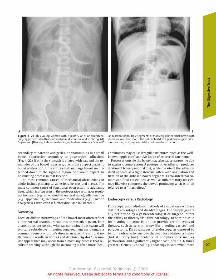
The
Dig
esti
ve T
ract
127
Figure 4–22 This young woman with a history of prior abdominalsurgery presented with abdominal pain, distention, and vomiting. (A)Supine and (B) upright abdominal radiographs demonstrate a “stacked”
appearance of multiple segments of markedly dilated small bowel withnumerous air–fluid levels. The patient had developed postsurgical adhe-sions causing a high-grade distal small bowel obstruction.
A B
secondary to narcotic analgesics, or anatomic, as in a smallbowel obstruction secondary to postsurgical adhesions (Fig. 4–22). If only the stomach is dilated with gas, and the re-mainder of the bowel is gasless, one might suspect a gastricoutlet obstruction. If the entire small and large bowel are dis-tended down to the sigmoid region, one would expect an obstructing process in that location.
The most common causes of mechanical obstructions inadults include postsurgical adhesions, hernias, and masses. Themost common cause of functional obstruction is adynamicileus, which is often seen in the postoperative setting, or result-ing from pain (e.g., an obstructive ureteral stone), inflammation(e.g., appendicitis), ischemia, and medications (e.g., narcoticanalgesics). Obstruction is further discussed in Chapter 6.
Narrowing
Focal or diffuse narrowings of the bowel most often reflecteither normal anatomic structures or muscular spasm. Trueanatomic lesions persist, whereas narrowing from spasm willtypically subside over minutes. Long-segment narrowing is acommon sequela of Crohn’s disease, in which transmural in-flammation results in fibrosis and stricture (Fig. 4–23). A sim-ilar appearance may occur from almost any process that re-sults in scarring, although the narrowing is often more focal.
Carcinomas may cause irregular strictures, such as the well-known “apple core” annular lesion of colorectal carcinoma.
Processes outside the bowel may also cause narrowing dueto extrinsic compression. A postoperative adhesion producesdilation of bowel proximal to it, while the site of the adhesionitself appears as a tight stenosis, often with angulation andfixation of the adhesed bowel segment. Extra-intestinal tu-mors and fluid collections, as well as inflammatory masses,may likewise compress the bowel, producing what is oftenreferred to as “mass effect.”
Endoscopy versus Radiology
Endoscopic and radiologic methods of evaluation each havedistinct advantages and disadvantages. Endoscopy, gener-ally performed by a gastroenterologist or surgeon, offersthe ability to directly visualize pathology, to obtain tissuefor histologic diagnosis, and to provide certain types oftherapy, such as sclerotherapy (for bleeding varices) andpolypectomy. Disadvantages of endoscopy, as opposed tobarium radiography, include the need for sedation, a higher(but still very low) incidence of complications such as perforation, and significantly higher cost (often 3–6 timesgreater). Generally speaking, endoscopy is somewhat more
chapter 04_p112-146.qxd 12/1/05 3:35 PM Page 127
Gunderman, Essential Radiology © 2006All rights reserved. Usage subject to terms and conditions of license.
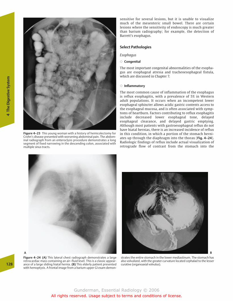
128
4Th
e D
iges
tive
Sys
tem
Figure 4–24 (A) This lateral chest radiograph demonstrates a largeretrocardiac mass containing an air–fluid level. This is a classic appear-ance of a large sliding hiatal hernia. (B) This elderly patient presentedwith hemoptysis. A frontal image from a barium upper GI exam demon-
strates the entire stomach in the lower mediastinum. The stomach hasalso volvulized, with the greater curvature located cephalad to the lessercurative (organoaxial volvulus).
A B
Figure 4–23 This young woman with a history of hemicolectomy forCrohn’s disease presented with worsening abdominal pain. The abdom-inal radiograph from an enteroclysis procedure demonstrates a longsegment of fixed narrowing in the descending colon, associated withmultiple sinus tracts.
sensitive for several lesions, but it is unable to visualizemuch of the mesenteric small bowel. There are certain lesions where the sensitivity of endoscopy is much greaterthan barium radiography; for example, the detection of Barrett’s esophagus.
Select Pathologies
Esophagus
�� Congenital
The most important congenital abnormalities of the esopha-gus are esophageal atresia and tracheoesophageal fistula,which are discussed in Chapter 7.
�� Inflammatory
The most common cause of inflammation of the esophagusis reflux esophagitis, with a prevalence of 5% in Westernadult populations. It occurs when an incompetent loweresophageal sphincter allows acidic gastric contents access tothe esophageal mucosa, and is often associated with symp-toms of heartburn. Factors contributing to reflux esophagitisinclude decreased lower esophageal tone, delayedesophageal clearance, and delayed gastric emptying. Although most patients with gastroesophageal reflux do nothave hiatal hernias, there is an increased incidence of refluxin this condition, in which a portion of the stomach herni-ates up through the diaphragm into the thorax (Fig. 4–24).Radiologic findings of reflux include actual visualization ofretrograde flow of contrast from the stomach into the
chapter 04_p112-146.qxd 12/1/05 3:35 PM Page 128
Gunderman, Essential Radiology © 2006All rights reserved. Usage subject to terms and conditions of license.

The
Dig
esti
ve T
ract
129
Figure 4–25 This double-contrast esophagogram in a patient withlong-standing reflux esophagitis demonstrates a weblike stenosis of thelower cervical esophagus that required endoluminal dilation to relievesymptoms of dysphagia.
esophagus, thickening of esophageal folds, ulcerations, andfocal strictures (Fig. 4–25). Another common cause ofesophagitis, which is associated with postinflammatorystricture formation, is chemical ingestion, especially causticagents such as lye. The strictures associated with lye inges-tion are typically fusiform and long, often involving thewhole esophagus.
Achalasia is an acquired esophageal motor disorder, char-acterized by failure of the lower esophageal sphincter to relax, secondary to degeneration of the myenteric plexus ofthe esophagus (Auerbach’s plexus). Most cases manifest idio-pathically in young adults, who present with dysphagia andweight loss. Secondary achalasia results from Chagas’ disease,in which Trypanosoma cruzi destroys the myenteric plexus.Radiologic findings include absence of normal peristalsis,dilation, and a persistent beaklike tapering of the distal
esophagus, often associated with an air–fluid level due to the inability of the esophagus to empty (Fig. 4–26). Complica-tions include aspiration, which manifests acutely as pneumo-nia and chronically as interstitial lung disease, as well assquamous cell carcinoma.
�� Tumorous
Both benign and malignant tumors are seen in the esopha-gus. By far the most common benign tumor is the leiomyoma,a smooth muscle tumor that is usually asymptomatic andtypically presents as a smooth intramural mass.
Figure 4–26 This woman complained of gradually worsening dyspha-gia. An upright chest radiograph obtained during a barium esopha-gogram demonstrates a severe, fusiform dilation of the esophagus witha “bird’s beak” narrowing at the gastroesophageal junction. Note also atiny diverticulum extending upward from the gastric cardia, as well asthe scoliosis of the spine.
Esophageal malignancies account for 6% of GI cancers, butthey cause a greater proportion of deaths, due to their ten-dency to present at an advanced stage. The most commonmalignant tumor of the esophagus worldwide is squamouscell carcinoma, arising in the mucosal layer of stratifiedsquamous epithelium. In the United States, squamous cellcarcinomas account for about one half of esophageal malig-nancies, and they are more common in men (M:F � 4:1) andblacks (black:white � 4:1). Risk factors include alcohol andtobacco abuse, as well as medical conditions such as lyestricture and achalasia. The usual finding on barium swal-low is a polypoid, stenotic mass in the mid- or distal esoph-agus that may be ulcerated. The tumor is typically advancedat diagnosis, with local spread to the trachea, aorta, or peri-cardium; lymphatic metastases to the mediastinal andceliac nodes; and hematogenous dissemination, especiallyto the liver. The primary lesion is best imaged by bariumesophagography, while CT and MRI are used primarily instaging (Fig. 4–27).
An esophageal tumor of rapidly increasing incidence isadenocarcinoma, which now constitutes one half of primaryesophageal malignancies in the United States. It is associated
chapter 04_p112-146.qxd 12/1/05 3:35 PM Page 129
Gunderman, Essential Radiology © 2006All rights reserved. Usage subject to terms and conditions of license.
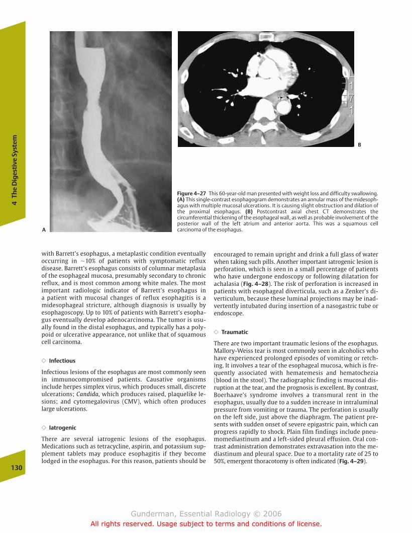
with Barrett’s esophagus, a metaplastic condition eventuallyoccurring in �10% of patients with symptomatic reflux disease. Barrett’s esophagus consists of columnar metaplasiaof the esophageal mucosa, presumably secondary to chronic reflux, and is most common among white males. The mostimportant radiologic indicator of Barrett’s esophagus in a patient with mucosal changes of reflux esophagitis is amidesophageal stricture, although diagnosis is usually byesophagoscopy. Up to 10% of patients with Barrett’s esopha-gus eventually develop adenocarcinoma. The tumor is usu-ally found in the distal esophagus, and typically has a poly-poid or ulcerative appearance, not unlike that of squamouscell carcinoma.
�� Infectious
Infectious lesions of the esophagus are most commonly seenin immunocompromised patients. Causative organisms include herpes simplex virus, which produces small, discreteulcerations; Candida, which produces raised, plaquelike le-sions; and cytomegalovirus (CMV), which often produceslarge ulcerations.
�� Iatrogenic
There are several iatrogenic lesions of the esophagus. Medications such as tetracycline, aspirin, and potassium sup-plement tablets may produce esophagitis if they becomelodged in the esophagus. For this reason, patients should be
encouraged to remain upright and drink a full glass of waterwhen taking such pills. Another important iatrogenic lesion isperforation, which is seen in a small percentage of patientswho have undergone endoscopy or following dilatation forachalasia (Fig. 4–28). The risk of perforation is increased inpatients with esophageal diverticula, such as a Zenker’s di-verticulum, because these luminal projections may be inad-vertently intubated during insertion of a nasogastric tube orendoscope.
�� Traumatic
There are two important traumatic lesions of the esophagus.Mallory-Weiss tear is most commonly seen in alcoholics whohave experienced prolonged episodes of vomiting or retch-ing. It involves a tear of the esophageal mucosa, which is fre-quently associated with hematemesis and hematochezia(blood in the stool). The radiographic finding is mucosal dis-ruption at the tear, and the prognosis is excellent. By contrast,Boerhaave’s syndrome involves a transmural rent in theesophagus, usually due to a sudden increase in intraluminalpressure from vomiting or trauma. The perforation is usuallyon the left side, just above the diaphragm. The patient pre-sents with sudden onset of severe epigastric pain, which canprogress rapidly to shock. Plain film findings include pneu-momediastinum and a left-sided pleural effusion. Oral con-trast administration demonstrates extravasation into the me-diastinum and pleural space. Due to a mortality rate of 25 to50%, emergent thoracotomy is often indicated (Fig. 4–29).
130
4Th
e D
iges
tive
Sys
tem
Figure 4–27 This 60-year-old man presented with weight loss and difficulty swallowing.(A) This single-contrast esophagogram demonstrates an annular mass of the midesoph-agus with multiple mucosal ulcerations. It is causing slight obstruction and dilation ofthe proximal esophagus. (B) Postcontrast axial chest CT demonstrates the circumferential thickening of the esophageal wall, as well as probable involvement of theposterior wall of the left atrium and anterior aorta. This was a squamous cell carcinoma of the esophagus.A
B
chapter 04_p112-146.qxd 12/1/05 3:35 PM Page 130
Gunderman, Essential Radiology © 2006All rights reserved. Usage subject to terms and conditions of license.
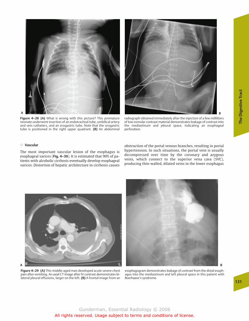
The
Dig
esti
ve T
ract
131
Figure 4–28 (A) What is wrong with this picture? This prematureneonate underwent insertion of an endotracheal tube, umbilical arteryand vein catheters, and an orogastric tube. Note that the orogastrictube is positioned in the right upper quadrant. (B) An abdominal
radiograph obtained immediately after the injection of a few millilitersof low-osmolar contrast material demonstrates leakage of contrast intothe mediastinum and pleural space, indicating an esophageal perforation.
A B
Figure 4–29 (A) This middle-aged man developed acute severe chestpain after vomiting. An axial CT image after IV contrast demonstrates bi-lateral pleural effusions, larger on the left. (B) A frontal image from an
esophagogram demonstrates leakage of contrast from the distal esoph-agus into the mediastinum and left pleural space in this patient withBoerhaave’s syndrome.
A B
�� Vascular
The most important vascular lesion of the esophagus isesophageal varices (Fig. 4–30). It is estimated that 90% of pa-tients with alcoholic cirrhosis eventually develop esophagealvarices. Distortion of hepatic architecture in cirrhosis causes
obstruction of the portal venous branches, resulting in portalhypertension. In such situations, the portal vein is usuallydecompressed over time by the coronary and azygous veins, which connect to the superior vena cava (SVC), producing thin-walled, dilated veins in the lower esophagus
chapter 04_p112-146.qxd 12/1/05 3:35 PM Page 131
Gunderman, Essential Radiology © 2006All rights reserved. Usage subject to terms and conditions of license.
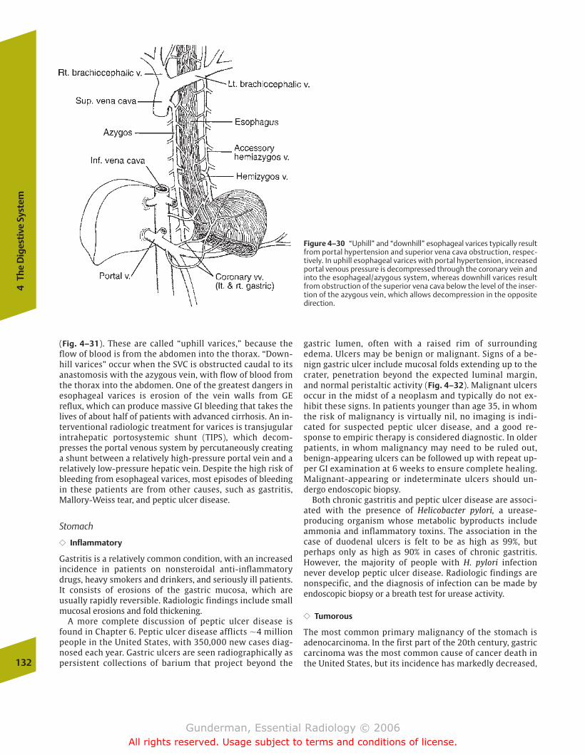
(Fig. 4–31). These are called “uphill varices,” because theflow of blood is from the abdomen into the thorax. “Down-hill varices” occur when the SVC is obstructed caudal to itsanastomosis with the azygous vein, with flow of blood fromthe thorax into the abdomen. One of the greatest dangers inesophageal varices is erosion of the vein walls from GE reflux, which can produce massive GI bleeding that takes thelives of about half of patients with advanced cirrhosis. An in-terventional radiologic treatment for varices is transjugularintrahepatic portosystemic shunt (TIPS), which decom-presses the portal venous system by percutaneously creatinga shunt between a relatively high-pressure portal vein and arelatively low-pressure hepatic vein. Despite the high risk ofbleeding from esophageal varices, most episodes of bleedingin these patients are from other causes, such as gastritis,Mallory-Weiss tear, and peptic ulcer disease.
Stomach
�� Inflammatory
Gastritis is a relatively common condition, with an increasedincidence in patients on nonsteroidal anti-inflammatorydrugs, heavy smokers and drinkers, and seriously ill patients.It consists of erosions of the gastric mucosa, which are usually rapidly reversible. Radiologic findings include smallmucosal erosions and fold thickening.
A more complete discussion of peptic ulcer disease isfound in Chapter 6. Peptic ulcer disease afflicts �4 millionpeople in the United States, with 350,000 new cases diag-nosed each year. Gastric ulcers are seen radiographically aspersistent collections of barium that project beyond the
gastric lumen, often with a raised rim of surroundingedema. Ulcers may be benign or malignant. Signs of a be-nign gastric ulcer include mucosal folds extending up to thecrater, penetration beyond the expected luminal margin,and normal peristaltic activity (Fig. 4–32). Malignant ulcersoccur in the midst of a neoplasm and typically do not ex-hibit these signs. In patients younger than age 35, in whomthe risk of malignancy is virtually nil, no imaging is indi-cated for suspected peptic ulcer disease, and a good re-sponse to empiric therapy is considered diagnostic. In olderpatients, in whom malignancy may need to be ruled out, benign-appearing ulcers can be followed up with repeat up-per GI examination at 6 weeks to ensure complete healing.Malignant-appearing or indeterminate ulcers should un-dergo endoscopic biopsy.
Both chronic gastritis and peptic ulcer disease are associ-ated with the presence of Helicobacter pylori, a urease-producing organism whose metabolic byproducts includeammonia and inflammatory toxins. The association in thecase of duodenal ulcers is felt to be as high as 99%, but perhaps only as high as 90% in cases of chronic gastritis.However, the majority of people with H. pylori infectionnever develop peptic ulcer disease. Radiologic findings arenonspecific, and the diagnosis of infection can be made byendoscopic biopsy or a breath test for urease activity.
�� Tumorous
The most common primary malignancy of the stomach isadenocarcinoma. In the first part of the 20th century, gastriccarcinoma was the most common cause of cancer death inthe United States, but its incidence has markedly decreased,132
4Th
e D
iges
tive
Sys
tem
Figure 4–30 “Uphill” and “downhill” esophageal varices typically resultfrom portal hypertension and superior vena cava obstruction, respec-tively. In uphill esophageal varices with portal hypertension, increasedportal venous pressure is decompressed through the coronary vein andinto the esophageal/azygous system, whereas downhill varices resultfrom obstruction of the superior vena cava below the level of the inser-tion of the azygous vein, which allows decompression in the oppositedirection.
chapter 04_p112-146.qxd 12/1/05 3:35 PM Page 132
Gunderman, Essential Radiology © 2006All rights reserved. Usage subject to terms and conditions of license.
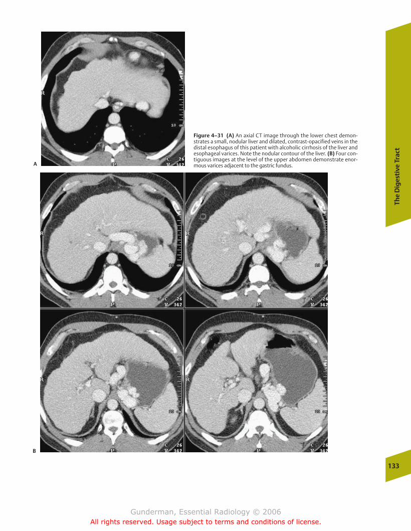
The
Dig
esti
ve T
ract
133
Figure 4–31 (A) An axial CT image through the lower chest demon-strates a small, nodular liver and dilated, contrast-opacified veins in thedistal esophagus of this patient with alcoholic cirrhosis of the liver andesophageal varices. Note the nodular contour of the liver. (B) Four con-tiguous images at the level of the upper abdomen demonstrate enor-mous varices adjacent to the gastric fundus.A
B
chapter 04_p112-146.qxd 12/1/05 3:35 PM Page 133
Gunderman, Essential Radiology © 2006All rights reserved. Usage subject to terms and conditions of license.
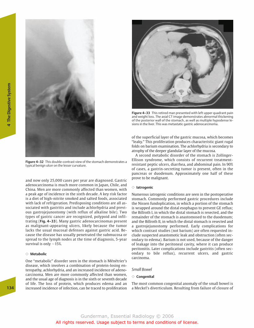
134
4Th
e D
iges
tive
Sys
tem
and now only 25,000 cases per year are diagnosed. Gastricadenocarcinoma is much more common in Japan, Chile, andChina. Men are more commonly affected than women, witha peak age of incidence in the sixth decade. A key risk factoris a diet of high-nitrite smoked and salted foods, associatedwith lack of refrigeration. Predisposing conditions are all as-sociated with gastritis and include achlorhydria and previ-ous gastrojejunostomy (with reflux of alkaline bile). Twotypes of gastric cancer are recognized, polypoid and infil-trating (Fig. 4–33). Many gastric adenocarcinomas presentas malignant-appearing ulcers, likely because the tumorlacks the usual mucosal defenses against gastric acid. Be-cause the disease has usually penetrated the submucosa orspread to the lymph nodes at the time of diagnosis, 5-yearsurvival is only �15%.
�� Metabolic
One “metabolic” disorder seen in the stomach is Ménétrier’sdisease, which involves a combination of protein-losing en-teropathy, achlorhydria, and an increased incidence of adeno-carcinoma. Men are more commonly affected than women,and the usual age of diagnosis is in the sixth or seventh decadeof life. The loss of protein, which produces edema and an increased incidence of infection, can be traced to proliferation
Figure 4–32 This double-contrast view of the stomach demonstrates atypical benign ulcer on the lesser curvature.
Figure 4–33 This retired man presented with left upper quadrant painand weight loss. The axial CT image demonstrates abnormal thickeningof the posterior wall of the stomach, as well as multiple hypodense le-sions in the liver. This was metastatic gastric adenocarcinoma.
of the superficial layer of the gastric mucosa, which becomes“leaky.” This proliferation produces characteristic giant rugalfolds on barium examination. The achlorhydria is secondary toatrophy of the deeper glandular layer of the mucosa.
A second metabolic disorder of the stomach is Zollinger-Ellison syndrome, which consists of recurrent treatment-resistant peptic ulcers, diarrhea, and abdominal pain. In 90%of cases, a gastrin-secreting tumor is present, often in thepancreas or duodenum. Approximately one half of theseprove to be malignant.
�� Iatrogenic
Numerous iatrogenic conditions are seen in the postoperativestomach. Commonly performed gastric procedures includethe Nissen fundoplication, in which a portion of the stomachis wrapped around the distal esophagus to prevent GE reflux;the Billroth I, in which the distal stomach is resected, and the remainder of the stomach is anastomosed to the duodenum;and the Billroth II, in which the distal stomach is resected anda gastrojejunostomy performed. Early complications forwhich contrast studies (not barium) are often requested in-clude suspected anastomotic leak and obstruction (often sec-ondary to edema). Barium is not used, because of the dangerof leakage into the peritoneal cavity, where it can produceperitonitis. Later complications include gastritis (often sec-ondary to bile reflux), recurrent ulcers, and gastric carcinoma.
Small Bowel
�� Congenital
The most common congenital anomaly of the small bowel isa Meckel’s diverticulum. Resulting from failure of closure of
chapter 04_p112-146.qxd 12/1/05 3:35 PM Page 134
Gunderman, Essential Radiology © 2006All rights reserved. Usage subject to terms and conditions of license.
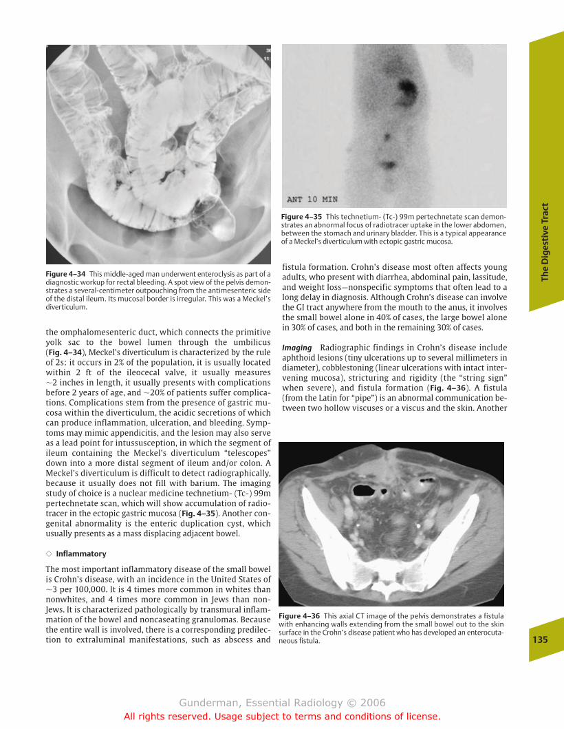
The
Dig
esti
ve T
ract
135
Figure 4–34 This middle-aged man underwent enteroclysis as part of adiagnostic workup for rectal bleeding. A spot view of the pelvis demon-strates a several-centimeter outpouching from the antimesenteric sideof the distal ileum. Its mucosal border is irregular. This was a Meckel’s diverticulum.
the omphalomesenteric duct, which connects the primitiveyolk sac to the bowel lumen through the umbilicus (Fig. 4–34), Meckel’s diverticulum is characterized by the ruleof 2s: it occurs in 2% of the population, it is usually locatedwithin 2 ft of the ileocecal valve, it usually measures �2 inches in length, it usually presents with complicationsbefore 2 years of age, and �20% of patients suffer complica-tions. Complications stem from the presence of gastric mu-cosa within the diverticulum, the acidic secretions of whichcan produce inflammation, ulceration, and bleeding. Symp-toms may mimic appendicitis, and the lesion may also serveas a lead point for intussusception, in which the segment ofileum containing the Meckel’s diverticulum “telescopes”down into a more distal segment of ileum and/or colon. AMeckel’s diverticulum is difficult to detect radiographically,because it usually does not fill with barium. The imagingstudy of choice is a nuclear medicine technetium- (Tc-) 99mpertechnetate scan, which will show accumulation of radio-tracer in the ectopic gastric mucosa (Fig. 4–35). Another con-genital abnormality is the enteric duplication cyst, whichusually presents as a mass displacing adjacent bowel.
�� Inflammatory
The most important inflammatory disease of the small bowelis Crohn’s disease, with an incidence in the United States of�3 per 100,000. It is 4 times more common in whites thannonwhites, and 4 times more common in Jews than non-Jews. It is characterized pathologically by transmural inflam-mation of the bowel and noncaseating granulomas. Becausethe entire wall is involved, there is a corresponding predilec-tion to extraluminal manifestations, such as abscess and
Figure 4–35 This technetium- (Tc-) 99m pertechnetate scan demon-strates an abnormal focus of radiotracer uptake in the lower abdomen,between the stomach and urinary bladder. This is a typical appearanceof a Meckel’s diverticulum with ectopic gastric mucosa.
fistula formation. Crohn’s disease most often affects youngadults, who present with diarrhea, abdominal pain, lassitude,and weight loss—nonspecific symptoms that often lead to along delay in diagnosis. Although Crohn’s disease can involvethe GI tract anywhere from the mouth to the anus, it involvesthe small bowel alone in 40% of cases, the large bowel alonein 30% of cases, and both in the remaining 30% of cases.
Imaging Radiographic findings in Crohn’s disease includeaphthoid lesions (tiny ulcerations up to several millimeters indiameter), cobblestoning (linear ulcerations with intact inter-vening mucosa), stricturing and rigidity (the “string sign”when severe), and fistula formation (Fig. 4–36). A fistula(from the Latin for “pipe”) is an abnormal communication be-tween two hollow viscuses or a viscus and the skin. Another
Figure 4–36 This axial CT image of the pelvis demonstrates a fistulawith enhancing walls extending from the small bowel out to the skinsurface in the Crohn’s disease patient who has developed an enterocuta-neous fistula.
chapter 04_p112-146.qxd 12/1/05 3:35 PM Page 135
Gunderman, Essential Radiology © 2006All rights reserved. Usage subject to terms and conditions of license.
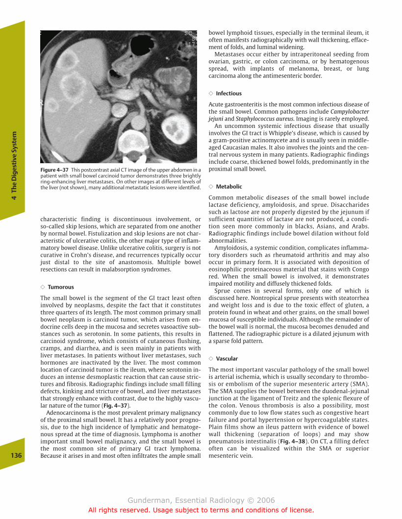
characteristic finding is discontinuous involvement, or so-called skip lesions, which are separated from one anotherby normal bowel. Fistulization and skip lesions are not char-acteristic of ulcerative colitis, the other major type of inflam-matory bowel disease. Unlike ulcerative colitis, surgery is notcurative in Crohn’s disease, and recurrences typically occurjust distal to the site of anastomosis. Multiple bowel resections can result in malabsorption syndromes.
�� Tumorous
The small bowel is the segment of the GI tract least often involved by neoplasms, despite the fact that it constitutesthree quarters of its length. The most common primary smallbowel neoplasm is carcinoid tumor, which arises from en-docrine cells deep in the mucosa and secretes vasoactive sub-stances such as serotonin. In some patients, this results incarcinoid syndrome, which consists of cutaneous flushing,cramps, and diarrhea, and is seen mainly in patients withliver metastases. In patients without liver metastases, suchhormones are inactivated by the liver. The most common location of carcinoid tumor is the ileum, where serotonin in-duces an intense desmoplastic reaction that can cause stric-tures and fibrosis. Radiographic findings include small fillingdefects, kinking and stricture of bowel, and liver metastasesthat strongly enhance with contrast, due to the highly vascu-lar nature of the tumor (Fig. 4–37).
Adenocarcinoma is the most prevalent primary malignancyof the proximal small bowel. It has a relatively poor progno-sis, due to the high incidence of lymphatic and hematoge-nous spread at the time of diagnosis. Lymphoma is anotherimportant small bowel malignancy, and the small bowel isthe most common site of primary GI tract lymphoma. Because it arises in and most often infiltrates the ample small
bowel lymphoid tissues, especially in the terminal ileum, itoften manifests radiographically with wall thickening, efface-ment of folds, and luminal widening.
Metastases occur either by intraperitoneal seeding fromovarian, gastric, or colon carcinoma, or by hematogenousspread, with implants of melanoma, breast, or lung carcinoma along the antimesenteric border.
�� Infectious
Acute gastroenteritis is the most common infectious disease ofthe small bowel. Common pathogens include Campylobacterjejuni and Staphylococcus aureus. Imaging is rarely employed.
An uncommon systemic infectious disease that usually involves the GI tract is Whipple’s disease, which is caused bya gram-positive actinomycete and is usually seen in middle-aged Caucasian males. It also involves the joints and the cen-tral nervous system in many patients. Radiographic findingsinclude coarse, thickened bowel folds, predominantly in theproximal small bowel.
�� Metabolic
Common metabolic diseases of the small bowel include lactase deficiency, amyloidosis, and sprue. Disaccharidessuch as lactose are not properly digested by the jejunum ifsufficient quantities of lactase are not produced, a condi-tion seen more commonly in blacks, Asians, and Arabs. Radiographic findings include bowel dilation without fold abnormalities.
Amyloidosis, a systemic condition, complicates inflamma-tory disorders such as rheumatoid arthritis and may also occur in primary form. It is associated with deposition ofeosinophilic proteinaceous material that stains with Congored. When the small bowel is involved, it demonstrates impaired motility and diffusely thickened folds.
Sprue comes in several forms, only one of which is discussed here. Nontropical sprue presents with steatorrheaand weight loss and is due to the toxic effect of gluten, a protein found in wheat and other grains, on the small bowelmucosa of susceptible individuals. Although the remainder ofthe bowel wall is normal, the mucosa becomes denuded andflattened. The radiographic picture is a dilated jejunum witha sparse fold pattern.
�� Vascular
The most important vascular pathology of the small bowelis arterial ischemia, which is usually secondary to thrombo-sis or embolism of the superior mesenteric artery (SMA).The SMA supplies the bowel between the duodenal-jejunaljunction at the ligament of Treitz and the splenic flexure ofthe colon. Venous thrombosis is also a possibility, mostcommonly due to low flow states such as congestive heartfailure and portal hypertension or hypercoagulable states.Plain films show an ileus pattern with evidence of bowelwall thickening (separation of loops) and may show pneumatosis intestinalis (Fig. 4–38). On CT, a filling defectoften can be visualized within the SMA or superior mesenteric vein.136
4Th
e D
iges
tive
Sys
tem
Figure 4–37 This postcontrast axial CT image of the upper abdomen in apatient with small bowel carcinoid tumor demonstrates three brightlyring-enhancing liver metastases. On other images at different levels ofthe liver (not shown), many additional metastatic lesions were identified.
chapter 04_p112-146.qxd 12/1/05 3:35 PM Page 136
Gunderman, Essential Radiology © 2006All rights reserved. Usage subject to terms and conditions of license.
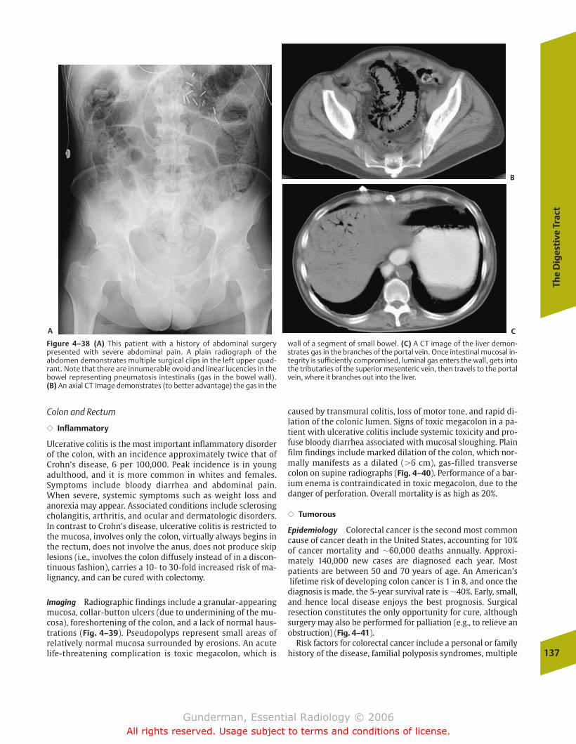
The
Dig
esti
ve T
ract
137
Figure 4–38 (A) This patient with a history of abdominal surgery presented with severe abdominal pain. A plain radiograph of the abdomen demonstrates multiple surgical clips in the left upper quad-rant. Note that there are innumerable ovoid and linear lucencies in thebowel representing pneumatosis intestinalis (gas in the bowel wall). (B) An axial CT image demonstrates (to better advantage) the gas in the
wall of a segment of small bowel. (C) A CT image of the liver demon-strates gas in the branches of the portal vein. Once intestinal mucosal in-tegrity is sufficiently compromised, luminal gas enters the wall, gets intothe tributaries of the superior mesenteric vein, then travels to the portalvein, where it branches out into the liver.
A
B
C
Colon and Rectum
�� Inflammatory
Ulcerative colitis is the most important inflammatory disorderof the colon, with an incidence approximately twice that ofCrohn’s disease, 6 per 100,000. Peak incidence is in youngadulthood, and it is more common in whites and females.Symptoms include bloody diarrhea and abdominal pain.When severe, systemic symptoms such as weight loss andanorexia may appear. Associated conditions include sclerosingcholangitis, arthritis, and ocular and dermatologic disorders.In contrast to Crohn’s disease, ulcerative colitis is restricted tothe mucosa, involves only the colon, virtually always begins inthe rectum, does not involve the anus, does not produce skiplesions (i.e., involves the colon diffusely instead of in a discon-tinuous fashion), carries a 10- to 30-fold increased risk of ma-lignancy, and can be cured with colectomy.
Imaging Radiographic findings include a granular-appearingmucosa, collar-button ulcers (due to undermining of the mu-cosa), foreshortening of the colon, and a lack of normal haus-trations (Fig. 4–39). Pseudopolyps represent small areas ofrelatively normal mucosa surrounded by erosions. An acutelife-threatening complication is toxic megacolon, which is
caused by transmural colitis, loss of motor tone, and rapid di-lation of the colonic lumen. Signs of toxic megacolon in a pa-tient with ulcerative colitis include systemic toxicity and pro-fuse bloody diarrhea associated with mucosal sloughing. Plainfilm findings include marked dilation of the colon, which nor-mally manifests as a dilated (�6 cm), gas-filled transversecolon on supine radiographs (Fig. 4–40). Performance of a bar-ium enema is contraindicated in toxic megacolon, due to thedanger of perforation. Overall mortality is as high as 20%.
�� Tumorous
Epidemiology Colorectal cancer is the second most commoncause of cancer death in the United States, accounting for 10%of cancer mortality and �60,000 deaths annually. Approxi-mately 140,000 new cases are diagnosed each year. Most patients are between 50 and 70 years of age. An American’slifetime risk of developing colon cancer is 1 in 8, and once thediagnosis is made, the 5-year survival rate is �40%. Early, small,and hence local disease enjoys the best prognosis. Surgical resection constitutes the only opportunity for cure, althoughsurgery may also be performed for palliation (e.g., to relieve anobstruction) (Fig. 4–41).
Risk factors for colorectal cancer include a personal or familyhistory of the disease, familial polyposis syndromes, multiple
chapter 04_p112-146.qxd 12/1/05 3:35 PM Page 137
Gunderman, Essential Radiology © 2006All rights reserved. Usage subject to terms and conditions of license.
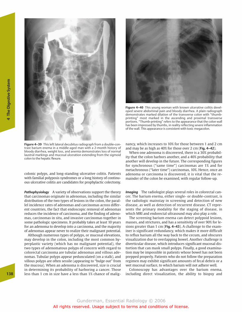
138
4Th
e D
iges
tive
Sys
tem
Figure 4–40 This young woman with known ulcerative colitis devel-oped severe abdominal pain and bloody diarrhea. A plain radiographdemonstrates marked dilation of the transverse colon with “thumb-printing” most marked in the ascending and proximal transverse portions. “Thumb-printing” refers to the appearance that the colon wallhas been impressed by thumbs, in reality reflecting severe inflammationof the wall. This appearance is consistent with toxic megacolon.
nancy, which increases to 10% for those between 1 and 2 cmand may be as high as 40% for those over 2 cm (Fig. 4–42).
When one adenoma is discovered, there is a 30% probabil-ity that the colon harbors another, and a 40% probability thatanother will develop in the future. The corresponding figuresfor synchronous (“same time”) carcinomas are 1% and formetachronous (“later time”) carcinomas, 10%. Hence, once anadenoma or carcinoma is discovered, it is vital that the re-mainder of the colon be examined, with regular follow-up.
Imaging The radiologist plays several roles in colorectal can-cer. The barium enema, either single- or double-contrast, isthe radiologic mainstay in screening and detection of newdisease, as well as detection of recurrent disease. CT repre-sents the primary modality for the staging of disease, inwhich MRI and endorectal ultrasound may also play a role.
The screening barium enema can detect polypoid lesions,masses, and strictures, and has a sensitivity of over 90% for le-sions greater than 1 cm (Fig. 4–43). A challenge to the exam-iner is significant redundancy, which makes it more difficultto reflux barium all the way back to the cecum, and obscuresvisualization due to overlapping bowel. Another challenge isdiverticular disease, which introduces significant mucosal dis-tortion that can mask small polyps. Finally, a good examina-tion may be impossible in patients whose bowel has not beenprepped properly. Patients who do not follow the preparationregimen may exhibit significant amounts of fecal debris or awet mucosal surface, to which barium will not adhere well.
Colonoscopy has advantages over the barium enema, including direct visualization, the ability to biopsy and
Figure 4–39 This left lateral decubitus radiograph from a double-con-trast barium enema in a middle-aged man with a 2-month history ofbloody diarrhea, weight loss, and anemia demonstrates loss of normallaustral markings and mucosal ulceration extending from the sigmoidcolon to the hepatic flexure.
colonic polyps, and long-standing ulcerative colitis. Patientswith familial polyposis syndromes or a long history of continu-ous ulcerative colitis are candidates for prophylactic colectomy.
Pathophysiology A variety of observations support the theorythat carcinomas originate in adenomas, including the similardistribution of the two types of lesions in the colon, the paral-lel incidence rates of adenomas and carcinomas across differ-ent countries, the fact that endoscopic removal of adenomasreduces the incidence of carcinoma, and the finding of adeno-mas, carcinomas in situ, and invasive carcinomas together insome pathologic specimens. It probably takes at least 10 yearsfor an adenoma to develop into a carcinoma, and the majorityof adenomas appear never to realize their malignant potential.
Although numerous types of polyps, or mucosal elevations,may develop in the colon, including the most common hy-perplastic variety (which has no malignant potential), thetwo types of adenomatous polyps of concern with regard tocolorectal carcinoma are tubular adenomas and villous ade-nomas. Tubular polyps appear pedunculated (on a stalk), andvillous polyps are often sessile (appearing to “bulge out” fromthe mucosa). When an adenoma is discovered, size is crucialin determining its probability of harboring a cancer. Thoseless than 1 cm in size have a less than 1% chance of malig-
chapter 04_p112-146.qxd 12/1/05 3:35 PM Page 138
Gunderman, Essential Radiology © 2006All rights reserved. Usage subject to terms and conditions of license.
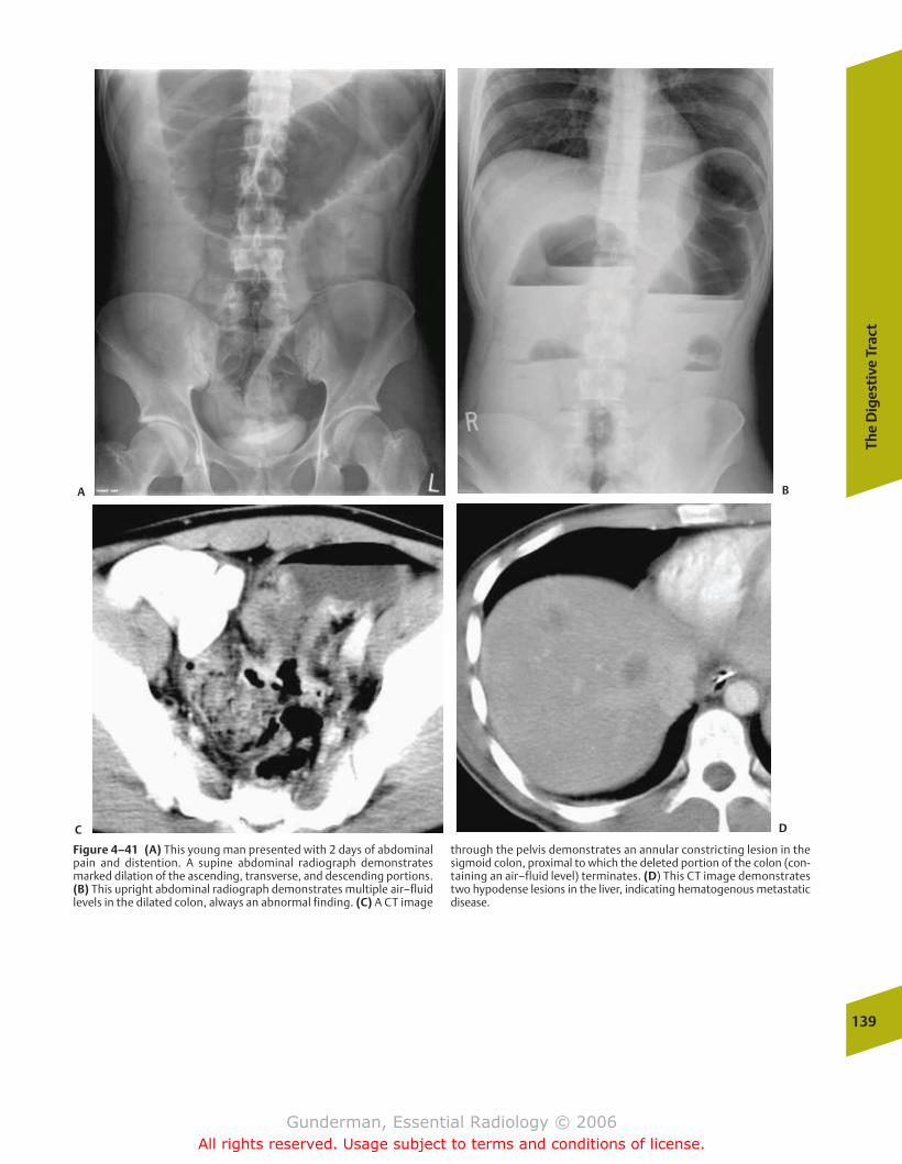
The
Dig
esti
ve T
ract
139
Figure 4–41 (A) This young man presented with 2 days of abdominalpain and distention. A supine abdominal radiograph demonstratesmarked dilation of the ascending, transverse, and descending portions.(B) This upright abdominal radiograph demonstrates multiple air–fluidlevels in the dilated colon, always an abnormal finding. (C) A CT image
through the pelvis demonstrates an annular constricting lesion in thesigmoid colon, proximal to which the deleted portion of the colon (con-taining an air–fluid level) terminates. (D) This CT image demonstratestwo hypodense lesions in the liver, indicating hematogenous metastaticdisease.
A B
C D
chapter 04_p112-146.qxd 12/1/05 3:35 PM Page 139
Gunderman, Essential Radiology © 2006All rights reserved. Usage subject to terms and conditions of license.
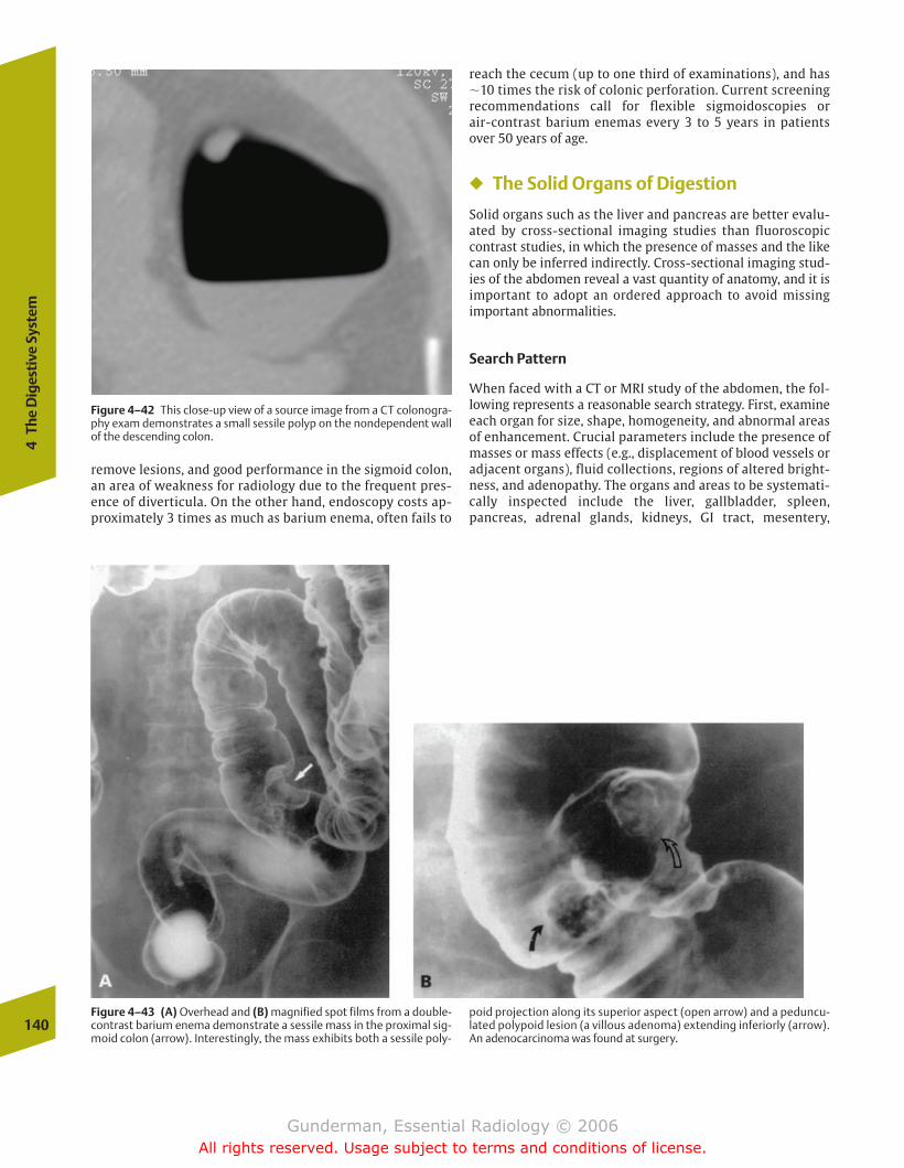
reach the cecum (up to one third of examinations), and has �10 times the risk of colonic perforation. Current screeningrecommendations call for flexible sigmoidoscopies or air-contrast barium enemas every 3 to 5 years in patientsover 50 years of age.
� The Solid Organs of Digestion
Solid organs such as the liver and pancreas are better evalu-ated by cross-sectional imaging studies than fluoroscopiccontrast studies, in which the presence of masses and the likecan only be inferred indirectly. Cross-sectional imaging stud-ies of the abdomen reveal a vast quantity of anatomy, and it isimportant to adopt an ordered approach to avoid missing important abnormalities.
Search Pattern
When faced with a CT or MRI study of the abdomen, the fol-lowing represents a reasonable search strategy. First, examineeach organ for size, shape, homogeneity, and abnormal areasof enhancement. Crucial parameters include the presence ofmasses or mass effects (e.g., displacement of blood vessels oradjacent organs), fluid collections, regions of altered bright-ness, and adenopathy. The organs and areas to be systemati-cally inspected include the liver, gallbladder, spleen, pancreas, adrenal glands, kidneys, GI tract, mesentery,
140
4Th
e D
iges
tive
Sys
tem
Figure 4–42 This close-up view of a source image from a CT colonogra-phy exam demonstrates a small sessile polyp on the nondependent wallof the descending colon.
Figure 4–43 (A) Overhead and (B) magnified spot films from a double-contrast barium enema demonstrate a sessile mass in the proximal sig-moid colon (arrow). Interestingly, the mass exhibits both a sessile poly-
poid projection along its superior aspect (open arrow) and a peduncu-lated polypoid lesion (a villous adenoma) extending inferiorly (arrow).An adenocarcinoma was found at surgery.
remove lesions, and good performance in the sigmoid colon,an area of weakness for radiology due to the frequent pres-ence of diverticula. On the other hand, endoscopy costs ap-proximately 3 times as much as barium enema, often fails to
chapter 04_p112-146.qxd 12/1/05 3:35 PM Page 140
Gunderman, Essential Radiology © 2006All rights reserved. Usage subject to terms and conditions of license.
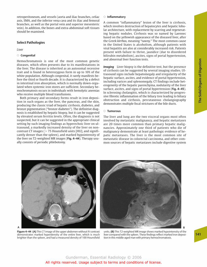
The
Solid
Org
ans
of D
iges
tio
n
141
retroperitoneum, and vessels (aorta and iliac branches, celiacaxis, SMA, and the inferior vena cava and its iliac and femoralbranches, as well as the portal vein and superior mesentericvein). In addition, the bones and extra-abdominal soft tissuesshould be examined.
Select Pathologies
Liver
�� Congenital
Hemochromatosis is one of the most common genetic diseases, which often presents due to its manifestations inthe liver. The disease is inherited as an autosomal recessivetrait and is found in heterozygous form in up to 10% of thewhite population. Although congenital, it rarely manifests be-fore the third or fourth decade. It is characterized by a defectin intestinal iron absorption, which is normally down-regu-lated when systemic iron stores are sufficient. Secondary he-mochromatosis occurs in individuals with hemolytic anemiaswho receive multiple blood transfusions.
Both primary and secondary forms result in iron deposi-tion in such organs as the liver, the pancreas, and the skin,producing the classic triad of hepatic cirrhosis, diabetes, andbronze pigmentation (“bronze diabetes”). The definitive diag-nosis is established by hepatic biopsy, but it can be suggestedby elevated serum ferritin levels. Often, the diagnosis is notsuspected, but it can be suggested in the appropriate clinicalsetting by such imaging findings as hyperechoic liver on ul-trasound, a markedly increased density of the liver on non-contrast CT images (� 75 Hounsfield units [HU], and signifi-cantly denser than the spleen), and marked hypointensity ofthe liver on T2-weighted MR images (Fig. 4–44). Therapy usu-ally consists of periodic phlebotomy.
�� Inflammatory
A common “inflammatory” lesion of the liver is cirrhosis,which involves destruction of hepatocytes and hepatic lobu-lar architecture, with replacement by scarring and regenerat-ing hepatic nodules. Cirrhosis was so named by Laennecbased on the yellowish appearance of the diseased liver, afterthe Greek kirrhos, meaning “tawny.” The most common causein the United States is alcoholism, although patients with viral hepatitis are also at considerably increased risk. Patientspresent with failure to thrive, jaundice (due to disorderedbilirubin metabolism), ascites, signs of portal hypertension,and abnormal liver function tests.
Imaging Liver biopsy is the definitive test, but the presenceof cirrhosis can be suggested by several imaging studies. Ul-trasound signs include hepatomegaly and irregularity of thehepatic surface, ascites, and evidence of portal hypertension,including varices and splenomegaly. CT findings include het-erogeneity of the hepatic parenchyma, nodularity of the liversurface, ascites, and signs of portal hypertension (Fig. 4–45).In sclerosing cholangitis, which is characterized by progres-sive fibrotic inflammation of the biliary tree leading to biliaryobstruction and cirrhosis, percutaneous cholangiographydemonstrates multiple focal strictures of the bile ducts.
�� Tumorous
The liver and lung are the two visceral organs most ofteninvolved by metastatic malignancy, and hepatic metastasesare 20 times more common than primary hepatic malig-nancies. Approximately one third of patients who die ofmalignancy demonstrate at least pathologic evidence of he-patic metastases. The liver is the most common site ofmetastatic disease in colorectal carcinoma, and other com-mon sources of hepatic metastases include digestive system
Figure 4–44 (A) This CT image of the upper abdomen without IV contrastdemonstrates marked hyperdensity of the entire liver, which is muchbrighter than the spleen, and had a measured density of 100 Hounsfield
units. (B) This T2-weighted MR image shows marked hypointensity of theliver compared with the spleen. These findings reflect marked iron deposi-tion in this middle-aged man with primary hemochromatosis.
A B
chapter 04_p112-146.qxd 12/1/05 3:35 PM Page 141
Gunderman, Essential Radiology © 2006All rights reserved. Usage subject to terms and conditions of license.
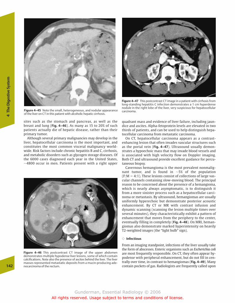
sites such as the stomach and pancreas, as well as thebreast and lung (Fig. 4–46). As many as 15 to 20% of suchpatients actually die of hepatic disease, rather than theirprimary tumor.
Although several primary malignancies may develop in theliver, hepatocellular carcinoma is the most important, andconstitutes the most common visceral malignancy world-wide. Risk factors include chronic hepatitis B and C, cirrhosis,and metabolic disorders such as glycogen storage diseases. Ofthe 6000 cases diagnosed each year in the United States,�4800 occur in men. Patients present with a right upper
quadrant mass and evidence of liver failure, including jaun-dice and ascites. Alpha-fetoprotein levels are elevated in twothirds of patients, and can be used to help distinguish hepa-tocellular carcinoma from metastatic carcinoma.
On CT, hepatocellular carcinoma appears as a contrast-enhancing lesion that often invades vascular structures suchas the portal vein (Fig. 4–47). Ultrasound usually demon-strates a hypoechoic mass that may invade blood vessels andis associated with high velocity flow on Doppler imaging.Both CT and ultrasound provide excellent guidance for percu-taneous biopsy.
Cavernous hemangioma is the most prevalent nonmalig-nant tumor, and is found in �5% of the population (F:M � 4:1). These lesions consist of collections of large vas-cular channels containing slow-moving blood. The principalreason to be concerned about the presence of a hemangioma,which is nearly always asymptomatic, is to distinguish itfrom a more sinister process such as a hepatocellular carci-noma or metastasis. By ultrasound, hemangiomas are usually uniformly hyperechoic but demonstrate posterior acoustic enhancement. By CT or MR with contrast infusion and dynamic scanning (scanning the lesion multiple times overseveral minutes), they characteristically exhibit a pattern ofenhancement that moves from the periphery to the center,eventually filling in completely (Fig. 4–48). On MRI, heman-giomas also demonstrate marked hyperintensity on heavilyT2-weighted images (the “light bulb” sign).
�� Infectious
From an imaging standpoint, infections of the liver usually takethe form of abscesses. Enteric organisms such as Escherichia coliare most frequently responsible. On CT, they often appear hy-podense with peripheral enhancement, but do not fill in cen-trally over time, in contrast to hemangiomas (Fig. 4–49). Manycontain pockets of gas. Radiologists are frequently called upon142
4Th
e D
iges
tive
Sys
tem
Figure 4–46 This postcontrast CT image of the upper abdomendemonstrates multiple hypodense liver lesions, some of which containcalcifications. Note also the presence of ascites behind the liver. The livermasses represented metastatic deposits from a mucin-producing ade-nocarcinoma of the rectum.
Figure 4–47 This postcontrast CT image in a patient with cirrhosis fromlong-standing hepatitis C infection demonstrates a 1 cm hyperdensenodule in the right lobe of the liver, very suspicious for hepatocellularcarcinoma.Figure 4–45 Note the small, heterogeneous, and nodular appearance
of the liver on CT in this patient with alcoholic hepatic cirrhosis.
chapter 04_p112-146.qxd 12/1/05 3:35 PM Page 142
Gunderman, Essential Radiology © 2006All rights reserved. Usage subject to terms and conditions of license.

The
Solid
Org
ans
of D
iges
tio
n
143
Figure 4–48 This middle-aged woman underwent an ultrasound exam for suspected gallbladder disease. (A) On ul-trasound, large, hyperechoic mass was found in the posterioraspect of the right lobe of the liver. (B) Serial MR images aftergadolinium contrast infusion show progressive peripheral-to-central enhancement of the lesion, consistent with a cav-ernous hemangioma.A
B
to drain such lesions percutaneously. In combination with an-tibiotic therapy, this usually results in complete resolution.
Pancreas
�� Congenital
The two most frequent congenital pancreatic anomalies arepancreas divisum and annular pancreas. Pancreas divisum results from lack of normal fusion of the dorsal and ventralpancreatic buds during embryogenesis, with the result that
the main pancreatic drainage occurs through the minorpapilla (located proximal to the papilla of Vater). It isthought that this orifice is often too small to accommodatethe full volume of pancreatic exocrine secretions, resultingin obstruction and recurrent pancreatitis. Annular pancreasresults from abnormal migration of the ventral pancreas,causing pancreatic encirclement of the duodenum and resul-tant obstruction. Both of these conditions are best imagedwith magnetic resonance cholangiopancreatography (MRCP)or endoscopic retrograde cholangiopancreatography (ERCP),
chapter 04_p112-146.qxd 12/1/05 3:35 PM Page 143
Gunderman, Essential Radiology © 2006All rights reserved. Usage subject to terms and conditions of license.
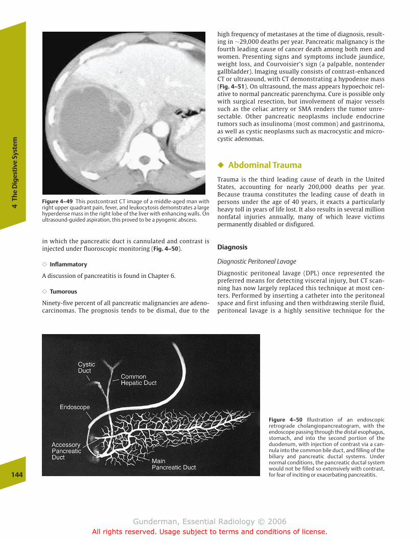
high frequency of metastases at the time of diagnosis, result-ing in �29,000 deaths per year. Pancreatic malignancy is thefourth leading cause of cancer death among both men andwomen. Presenting signs and symptoms include jaundice,weight loss, and Courvoisier’s sign (a palpable, nontendergallbladder). Imaging usually consists of contrast-enhancedCT or ultrasound, with CT demonstrating a hypodense mass(Fig. 4–51). On ultrasound, the mass appears hypoechoic rel-ative to normal pancreatic parenchyma. Cure is possible onlywith surgical resection, but involvement of major vesselssuch as the celiac artery or SMA renders the tumor unre-sectable. Other pancreatic neoplasms include endocrinetumors such as insulinoma (most common) and gastrinoma,as well as cystic neoplasms such as macrocystic and micro-cystic adenomas.
� Abdominal Trauma
Trauma is the third leading cause of death in the UnitedStates, accounting for nearly 200,000 deaths per year. Because trauma constitutes the leading cause of death in persons under the age of 40 years, it exacts a particularlyheavy toll in years of life lost. It also results in several millionnonfatal injuries annually, many of which leave victims permanently disabled or disfigured.
Diagnosis
Diagnostic Peritoneal Lavage
Diagnostic peritoneal lavage (DPL) once represented thepreferred means for detecting visceral injury, but CT scan-ning has now largely replaced this technique at most cen-ters. Performed by inserting a catheter into the peritonealspace and first infusing and then withdrawing sterile fluid,peritoneal lavage is a highly sensitive technique for the
144
4Th
e D
iges
tive
Sys
tem
Figure 4–49 This postcontrast CT image of a middle-aged man withright upper quadrant pain, fever, and leukocytosis demonstrates a largehyperdense mass in the right lobe of the liver with enhancing walls. Onultrasound-guided aspiration, this proved to be a pyogenic abscess.
Figure 4–50 Illustration of an endoscopic retrograde cholangiopancreatogram, with the endoscope passing through the distal esophagus,stomach, and into the second portion of the duodenum, with injection of contrast via a can-nula into the common bile duct, and filling of the biliary and pancreatic ductal systems. Under normal conditions, the pancreatic ductal systemwould not be filled so extensively with contrast,for fear of inciting or exacerbating pancreatitis.
in which the pancreatic duct is cannulated and contrast isinjected under fluoroscopic monitoring (Fig. 4–50).
�� Inflammatory
A discussion of pancreatitis is found in Chapter 6.
�� Tumorous
Ninety-five percent of all pancreatic malignancies are adeno-carcinomas. The prognosis tends to be dismal, due to the
chapter 04_p112-146.qxd 12/1/05 3:35 PM Page 144
Gunderman, Essential Radiology © 2006All rights reserved. Usage subject to terms and conditions of license.
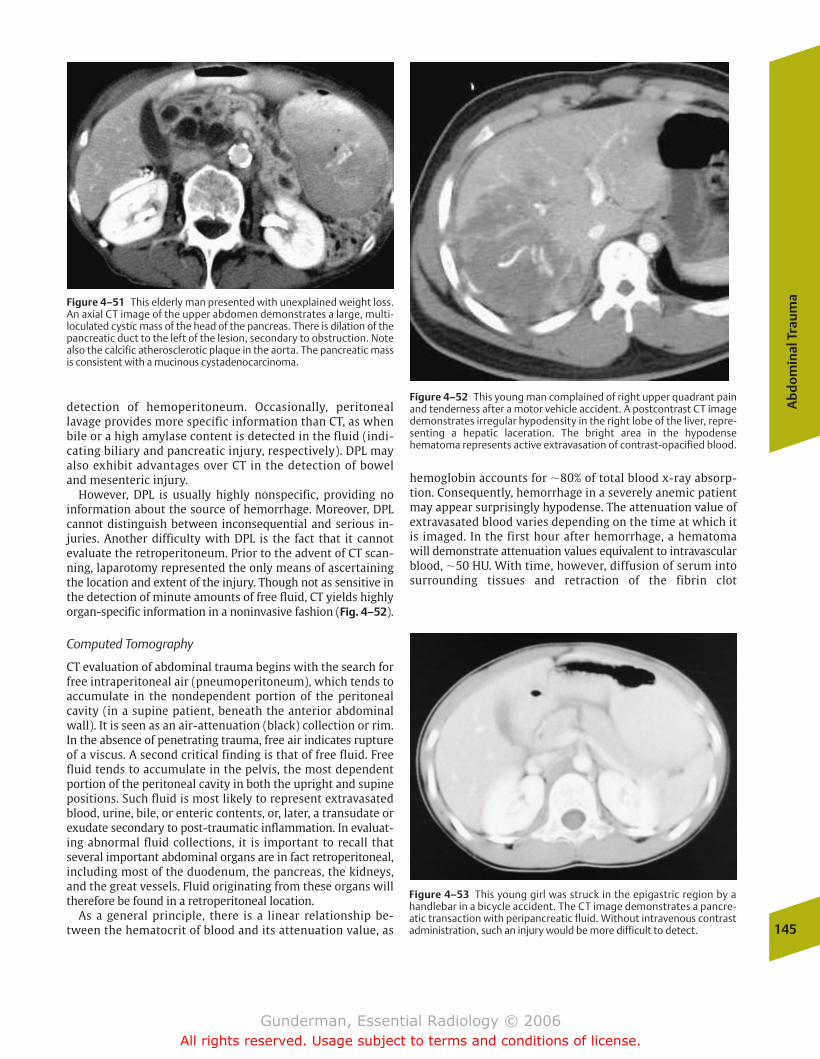
Ab
do
min
al T
rau
ma
145
hemoglobin accounts for �80% of total blood x-ray absorp-tion. Consequently, hemorrhage in a severely anemic patientmay appear surprisingly hypodense. The attenuation value ofextravasated blood varies depending on the time at which itis imaged. In the first hour after hemorrhage, a hematomawill demonstrate attenuation values equivalent to intravascularblood, �50 HU. With time, however, diffusion of serum intosurrounding tissues and retraction of the fibrin clot
detection of hemoperitoneum. Occasionally, peritoneallavage provides more specific information than CT, as whenbile or a high amylase content is detected in the fluid (indi-cating biliary and pancreatic injury, respectively). DPL mayalso exhibit advantages over CT in the detection of boweland mesenteric injury.
However, DPL is usually highly nonspecific, providing no information about the source of hemorrhage. Moreover, DPLcannot distinguish between inconsequential and serious in-juries. Another difficulty with DPL is the fact that it cannotevaluate the retroperitoneum. Prior to the advent of CT scan-ning, laparotomy represented the only means of ascertainingthe location and extent of the injury. Though not as sensitive inthe detection of minute amounts of free fluid, CT yields highlyorgan-specific information in a noninvasive fashion (Fig. 4–52).
Computed Tomography
CT evaluation of abdominal trauma begins with the search forfree intraperitoneal air (pneumoperitoneum), which tends toaccumulate in the nondependent portion of the peritonealcavity (in a supine patient, beneath the anterior abdominalwall). It is seen as an air-attenuation (black) collection or rim.In the absence of penetrating trauma, free air indicates ruptureof a viscus. A second critical finding is that of free fluid. Freefluid tends to accumulate in the pelvis, the most dependentportion of the peritoneal cavity in both the upright and supinepositions. Such fluid is most likely to represent extravasatedblood, urine, bile, or enteric contents, or, later, a transudate orexudate secondary to post-traumatic inflammation. In evaluat-ing abnormal fluid collections, it is important to recall thatseveral important abdominal organs are in fact retroperitoneal,including most of the duodenum, the pancreas, the kidneys,and the great vessels. Fluid originating from these organs willtherefore be found in a retroperitoneal location.
As a general principle, there is a linear relationship be-tween the hematocrit of blood and its attenuation value, as
Figure 4–51 This elderly man presented with unexplained weight loss.An axial CT image of the upper abdomen demonstrates a large, multi-loculated cystic mass of the head of the pancreas. There is dilation of thepancreatic duct to the left of the lesion, secondary to obstruction. Notealso the calcific atherosclerotic plaque in the aorta. The pancreatic massis consistent with a mucinous cystadenocarcinoma.
Figure 4–52 This young man complained of right upper quadrant painand tenderness after a motor vehicle accident. A postcontrast CT imagedemonstrates irregular hypodensity in the right lobe of the liver, repre-senting a hepatic laceration. The bright area in the hypodensehematoma represents active extravasation of contrast-opacified blood.
Figure 4–53 This young girl was struck in the epigastric region by ahandlebar in a bicycle accident. The CT image demonstrates a pancre-atic transaction with peripancreatic fluid. Without intravenous contrastadministration, such an injury would be more difficult to detect.
chapter 04_p112-146.qxd 12/1/05 3:35 PM Page 145
Gunderman, Essential Radiology © 2006All rights reserved. Usage subject to terms and conditions of license.
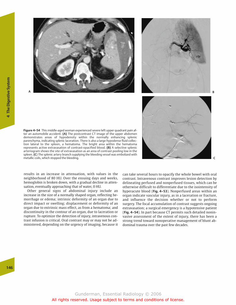
146
4Th
e D
iges
tive
Sys
tem
results in an increase in attenuation, with values in theneighborhood of 80 HU. Over the ensuing days and weeks,hemoglobin is broken down, with a gradual decline in atten-uation, eventually approaching that of water, 0 HU.
Other general signs of abdominal injury include an increase in the size of a normally shaped organ, reflecting he-morrhage or edema; intrinsic deformity of an organ due todirect impact or swelling; displacement or deformity of anorgan due to extrinsic mass effect, as from a hematoma; anddiscontinuity in the contour of an organ, due to laceration orrupture. To optimize the detection of injury, intravenous con-trast infusion is critical. Oral contrast may or may not be ad-ministered, depending on the urgency of imaging, because it
Figure 4–54 This middle-aged woman experienced severe left upper quadrant pain af-ter an automobile accident. (A) The postcontrast CT image of the upper abdomendemonstrates areas of hypodensity within the normally enhancing splenicparenchyma, indicating splenic laceration. There is also a large hypodense fluid collec-tion lateral to the spleen, a hematoma. The bright area within the hematoma represents active extravasation of contrast-opacified blood. (B) A selective splenic arteriogram shows the site of extravasation as an area of contrast pooling low in thespleen. (C) The splenic artery branch supplying the bleeding vessel was embolized with metallic coils, which stopped the bleeding.
A B
C
can take several hours to opacify the whole bowel with oralcontrast. Intravenous contrast improves lesion detection bydelineating perfused and nonperfused tissues, which can beotherwise difficult to differentiate due to the isointensity ofhyperacute blood (Fig. 4–53). Nonperfused areas within anorgan indicate vascular injury, as in a laceration or fracture,and influence the decision whether or not to performsurgery. The focal accumulation of contrast suggests ongoingextravasation; a surgical emergency is a hypotensive patient(Fig. 4–54). In part because CT permits such detailed nonin-vasive assessment of the extent of injury, there has been astrong trend toward nonoperative management of blunt ab-dominal trauma over the past few decades.
chapter 04_p112-146.qxd 12/1/05 3:35 PM Page 146
Gunderman, Essential Radiology © 2006All rights reserved. Usage subject to terms and conditions of license.
� Anatomy and Physiology
� Imaging
Intravenous UrographyNuclear Medicine
Blood FlowGlomerular FiltrationCollecting System Drainage
Other Modalities
� Kidney
PathologyCongenitalInfectiousTumorousInflammatoryTraumaticVascular
� Ureter
PathologyCongenital
� Bladder
PathologyInfectiousTumorous
� Common Clinical Problems
HematuriaAcute Renal FailureAcute Flank Pain
Urolithiasis
� Adrenal Glands
Anatomy and PhysiologyPathology
Tumorous
5The Urinary Tract
chapter 05_p147-171.qxd 12/1/05 3:43 PM Page 147
Gunderman, Essential Radiology © 2006All rights reserved. Usage subject to terms and conditions of license.

148
5Th
e U
rina
ry T
ract
� Anatomy and Physiology
The kidneys are paired retroperitoneal organs contained withinthe anterior and posterior renal (from the Latin renes, “kid-neys”) fasciae, also known as Gerota’s fasciae. Between the an-terior and posterior renal fasciae lies not only the kidney itself, but also the adrenal gland, the proximal portion ofthe collecting system and ureter, and the renal pedicle, including the renal artery, the renal vein, and lymphatics. Approximately two thirds of kidneys are supplied by a singlerenal artery, and multiple renal veins are seen in approximatelyone third of cases. Because the left renal vein must cross themidline to reach the inferior vena cava (IVC), it is approximately3 times longer than the right renal vein, which makes the leftkidney the preferred organ for renal transplantation. Moreover,because the left renal vein receives the left gonadal vein, a leftrenal cell carcinoma with ipsilateral renal vein thrombosis willcommonly present with left scrotal swelling. The right renalvein typically drains directly into the IVC.
The adult kidneys normally measure �3.5 lumbar vertebralbody heights, or �12 cm, in length. Plain radiography rou-tinely overestimates their length due to magnification,whereas ultrasound often underestimates their length due todifficulties in imaging the kidney in its longest plane. The leftkidney is normally positioned 1 to 2 cm higher than the right.The renal axes parallel those of the psoas muscles, with thelower poles positioned more laterally than the upper poles.
The kidneys excrete metabolic waste products, regulate saltand water balance, and modulate plasma pH through theproduction of urine. From the 1700 L of blood flowingthrough the kidneys every day, 1 L of urine is produced. Theproduction of urine involves three processes: filtration, secre-tion, and reabsorption. These processes are performed by thenephron, the functional unit of the kidney (Fig. 5–1). Eachkidney contains �1 million nephrons. The nephron begins inthe glomerulus (from the Latin glomerule, “a round knot”),
a spherical tuft of capillaries 100 times more permeable thancapillaries elsewhere, across which fluid is filtered into Bow-man’s capsule. From there, the filtrate passes through theproximal convoluted tubule, Henle’s loop, the distal convo-luted tubule, and into the collecting duct. In addition to forming urine, the kidney performs important endocrinefunctions. For example, the juxtaglomerular apparatus secretes renin in response to a fall in blood pressure, activat-ing the renin–angiotensin–aldosterone system, which in turn increases sodium reabsorption in the distal tubules. Anotherimportant hormone secreted by the kidneys is erythropoi-etin, which stimulates red blood cell production. The kidneysalso help to convert vitamin D to its active form. Conse-quences of renal failure include uremia, metabolic acidosis,hyperkalemia, disordered regulation of sodium, phosphate,and calcium balance, hypertension, anemia, and immunecompromise.
Crucial urinary tract structures evaluated on imaging stud-ies include the renal vasculature, the cortical and medullaryportions of the parenchyma, the pyramids, the calyces, thepelvis, the ureters, the bladder, and the urethra (Fig. 5–2).The outer renal cortex (from the Latin for “bark of a tree”)consists of the glomeruli and the proximal and distal convo-luted tubules. The inner medulla (Latin for “marrow”) con-sists of the collecting tubules and Henle’s loops. The medullais made up of several medullary pyramids, which are cradledby the cup-shaped calyces (Latin for “outer covering” or“pod”) of the collecting system. Each kidney contains �12 ca-lyces. The calyces join together to form infundibula (Latin for“funnel”), which drain into the renal pelvis (Latin for “basin”).
The pelvis joins the ureter (from the Greek ourein, “to urinate”) at the ureteropelvic junction (UPJ), a common siteof obstruction. The ureters contain circular and longitudinallayers of smooth muscle that actively propel urine toward thebladder by peristalsis. The bladder can accommodate between 300 and 600 mL in the normal adult. It is bounded
Figure 5–1 (A) The major structures of the kidney that are assessed on imaging studies. (B) The major structures of the nephron.
chapter 05_p147-171.qxd 12/1/05 3:43 PM Page 148
Gunderman, Essential Radiology © 2006All rights reserved. Usage subject to terms and conditions of license.
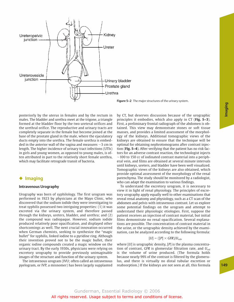
Imag
ing
149
posteriorly by the uterus in females and by the rectum inmales. The bladder and urethra meet at the trigone, a triangleformed at the bladder floor by the two ureteral orifices andthe urethral orifice. The reproductive and urinary tracts arecompletely separate in the female but become joined at thebase of the prostate gland in the male, where the ejaculatoryducts empty into the urethra. The female urethra is embed-ded in the anterior wall of the vagina and measures �3 cm inlength. The higher incidence of urinary tract infections (UTIs)in girls and young women, as opposed to young males, is of-ten attributed in part to the relatively short female urethra,which may facilitate retrograde transit of bacteria.
� Imaging
Intravenous Urography
Urography was born of syphilology. The first urogram wasperformed in 1923 by physicians at the Mayo Clinic, who discovered that the sodium iodide they were investigating totreat syphilis possessed two intriguing properties: (1) it wasexcreted via the urinary system, and therefore passedthrough the kidneys, ureters, bladder, and urethra; and (2)the compound was radiopaque. However, sodium iodide produced relatively poor opacification, and displayed othershortcomings as well. The next crucial innovation occurredwhen German chemists, seeking to synthesize the “magicbullet” for syphilis, linked iodine to a pyridine ring. Althoughtheir invention proved not to be the magic bullet, their organic iodine compounds created a magic window on theurinary tract. By the early 1930s, physicians were relying onexcretory urography to provide previously unimaginable images of the structure and function of the urinary system.
The intravenous urogram (IVU; often called an intravenouspyelogram, or IVP, a misnomer) has been largely supplanted
by CT, but deserves discussion because of the urographicprinciples it embodies, which also apply in CT (Fig. 5–3).First, a preliminary frontal radiograph of the abdomen is ob-tained. This view may demonstrate stones or soft tissuemasses, and provides a limited assessment of the morphol-ogy of the kidneys. Additional tomographic views of the kidneys are obtained to ensure that the technique will be optimal for obtaining nephrotomograms after contrast injec-tion (Fig. 5–4). After verifying that the patient has no risk fac-tors for an adverse contrast reaction, the technologist injects�100 to 150 cc of iodinated contrast material into a periph-eral vein, and films are obtained at several minute intervalsuntil kidneys, ureters, and bladder have been well visualized.Tomographic views of the kidneys are also obtained, whichprovide optimal assessment of the morphology of the renalparenchyma. The study should be monitored by a radiologist,who can adapt the examination to various findings.
To understand the excretory urogram, it is necessary toview it in light of renal physiology. The principles of excre-tory urography apply equally well to other examinations thatreveal renal anatomy and physiology, such as a CT scan of theabdomen and pelvis with intravenous contrast. Let us exploresome potential findings on the urogram and attempt to understand their physiologic etiologies. First, suppose the patient receives an injection of contrast material, but initialfilms demonstrate no renal opacification. Several explana-tions are possible. The concentration of contrast material inthe urine, or the urographic density achieved by the exami-nation, can be analyzed according to the following formula:
[U] � ([P] � GFR)/Uvol,
where [U] is urographic density, [P] is the plasma concentra-tion of contrast, GFR is glomerular filtration rate, and Uvol
is the volume of urine produced. (The formula holds because nearly 99% of the contrast is filtered by the glomeru-lus, and there is virtually no distal tubular excretion orreabsorption.) If the kidneys are not seen at all, this formula
Figure 5–2 The major structures of the urinary system.
chapter 05_p147-171.qxd 12/1/05 3:43 PM Page 149
Gunderman, Essential Radiology © 2006All rights reserved. Usage subject to terms and conditions of license.
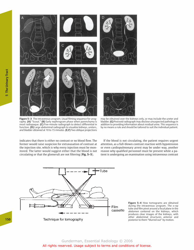
150
5Th
e U
rina
ry T
ract
indicates that there is either no contrast or no blood flow. Theformer would raise suspicion for extravasation of contrast atthe injection site, which is why every injection must be mon-itored. The latter would suggest either that the blood is notcirculating or that the glomeruli are not filtering (Fig. 5–5).
If the blood is not circulating, the patient requires urgent attention, as a full-blown contrast reaction with hypotensionor even cardiopulmonary arrest may be under way, another reason why qualified personnel must be present while a pa-tient is undergoing an examination using intravenous contrast
Figure 5–3 The intravenous urogram. Usual filming sequence for urog-raphy. (A) “Scout.” (B) Early nephrogram phase when parenchyma ismost radiopaque. (C) Five-minute radiograph to detect differential infunction. (D) Large abdominal radiograph to visualize kidneys, ureters,and bladder obtained at 10 to 15 minutes. (E,F) Two oblique projections
may be obtained over the kidneys only, or may include the ureter andbladder. (G) Postvoid radiograph may disclose unsuspected pathology inaddition to providing information about residual urine. This sequence isby no means a rule and should be tailored to suit the individual patient.
Figure 5–4 How tomograms are obtainedduring the intravenous urogram. The x-raytube and film pivot around a focal plane in theabdomen centered on the kidneys, which produces clear images of the kidneys, withother abdominal structures anterior and posterior to them “blurred out” by motion.
chapter 05_p147-171.qxd 12/1/05 3:43 PM Page 150
Gunderman, Essential Radiology © 2006All rights reserved. Usage subject to terms and conditions of license.
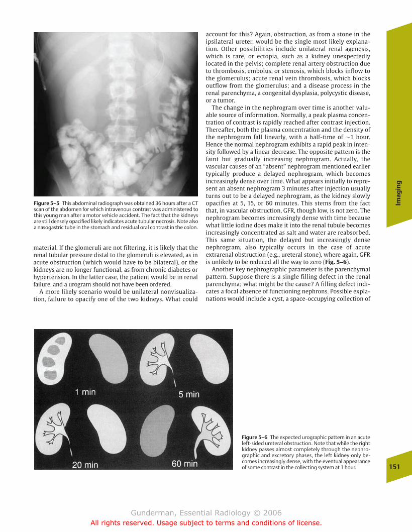
Imag
ing
151
account for this? Again, obstruction, as from a stone in the ipsilateral ureter, would be the single most likely explana-tion. Other possibilities include unilateral renal agenesis,which is rare, or ectopia, such as a kidney unexpectedly located in the pelvis; complete renal artery obstruction dueto thrombosis, embolus, or stenosis, which blocks inflow tothe glomerulus; acute renal vein thrombosis, which blocksoutflow from the glomerulus; and a disease process in the renal parenchyma, a congenital dysplasia, polycystic disease,or a tumor.
The change in the nephrogram over time is another valu-able source of information. Normally, a peak plasma concen-tration of contrast is rapidly reached after contrast injection.Thereafter, both the plasma concentration and the density ofthe nephrogram fall linearly, with a half-time of �1 hour.Hence the normal nephrogram exhibits a rapid peak in inten-sity followed by a linear decrease. The opposite pattern is thefaint but gradually increasing nephrogram. Actually, the vascular causes of an “absent” nephrogram mentioned earliertypically produce a delayed nephrogram, which becomes increasingly dense over time. What appears initially to repre-sent an absent nephrogram 3 minutes after injection usuallyturns out to be a delayed nephrogram, as the kidney slowlyopacifies at 5, 15, or 60 minutes. This stems from the factthat, in vascular obstruction, GFR, though low, is not zero. Thenephrogram becomes increasingly dense with time becausewhat little iodine does make it into the renal tubule becomesincreasingly concentrated as salt and water are reabsorbed.This same situation, the delayed but increasingly densenephrogram, also typically occurs in the case of acute extrarenal obstruction (e.g., ureteral stone), where again, GFRis unlikely to be reduced all the way to zero (Fig. 5–6).
Another key nephrographic parameter is the parenchymalpattern. Suppose there is a single filling defect in the renalparenchyma; what might be the cause? A filling defect indi-cates a focal absence of functioning nephrons. Possible expla-nations would include a cyst, a space-occupying collection of
Figure 5–5 This abdominal radiograph was obtained 36 hours after a CTscan of the abdomen for which intravenous contrast was administered tothis young man after a motor vehicle accident. The fact that the kidneysare still densely opacified likely indicates acute tubular necrosis. Note alsoa nasogastric tube in the stomach and residual oral contrast in the colon.
Figure 5–6 The expected urographic pattern in an acuteleft-sided ureteral obstruction. Note that while the rightkidney passes almost completely through the nephro-graphic and excretory phases, the left kidney only be-comes increasingly dense, with the eventual appearanceof some contrast in the collecting system at 1 hour.
material. If the glomeruli are not filtering, it is likely that therenal tubular pressure distal to the glomeruli is elevated, as inacute obstruction (which would have to be bilateral), or thekidneys are no longer functional, as from chronic diabetes orhypertension. In the latter case, the patient would be in renalfailure, and a urogram should not have been ordered.
A more likely scenario would be unilateral nonvisualiza-tion, failure to opacify one of the two kidneys. What could
chapter 05_p147-171.qxd 12/1/05 3:43 PM Page 151
Gunderman, Essential Radiology © 2006All rights reserved. Usage subject to terms and conditions of license.
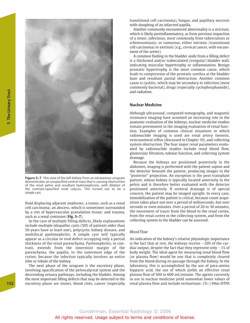
152
5Th
e U
rina
ry T
ract
transitional cell carcinoma), fungus, and papillary necrosiswith sloughing of an infarcted papilla.
Another commonly encountered abnormality is a stricture,which is likely postinflammatory, as from previous impactionof a stone; infectious, most commonly from tuberculosis orschistosomiasis; or tumorous, either intrinsic (transitionalcell carcinoma) or extrinsic (e.g., cervical cancer, with encase-ment of the ureter).
A common finding in the bladder aside from a filling defectis a thickened and/or trabeculated (irregular) bladder wall,indicating muscular hypertrophy or inflammation. Benignprostatic hypertrophy is the most common cause, whichleads to compression of the prostatic urethra at the bladderbase and resultant partial obstruction. Another commoncause is cystitis, which may be secondary to infection (mostcommonly bacterial), drugs (especially cyclophosphamide),and radiation.
Nuclear Medicine
Although ultrasound, computed tomography, and magneticresonance imaging have assumed an increasing role in theanatomic evaluation of the kidneys, nuclear medicine studiesremain preeminent in the imaging evaluation of renal func-tion. Examples of common clinical situations in which radionuclide imaging is used are renal artery stenosis, vesicoureteral reflux (discussed in Chapter 10), and collectingsystem obstruction. The four major renal parameters evalu-ated by radionuclide studies include renal blood flow,glomerular filtration, tubular function, and collecting systemdrainage.
Because the kidneys are positioned posteriorly in the abdomen, imaging is performed with the patient supine andthe detector beneath the patient, producing images in the“posterior” projection. An exception is the post-transplantpatient, whose kidney is typically located anteriorly in thepelvis and is therefore better evaluated with the detector positioned anteriorly. If ureteral drainage is of special concern, the patient may be imaged upright. In every case, immobilization of the patient is critical, because count acqui-sition takes place not over a period of milliseconds, but overseconds or even minutes. Over a period of 20 to 30 minutes,the movement of tracer from the blood to the renal cortex,from the renal cortex to the collecting system, and from thecollecting system to the bladder can be assessed.
Blood Flow
An indication of the kidney’s relative physiologic importanceis the fact that at rest, the kidneys receive �20% of the car-diac output, despite the fact that they represent only �1% ofbody weight. The ideal agent for measuring renal blood flow(or plasma flow) would be one that is completely clearedfrom the blood during its passage through the kidney. In thelaboratory, this is accomplished by the use of para-aminohippuric acid, the use of which yields an effective renalplasma flow of 500 to 600 mL/minute. The agents currentlyin use in nuclear medicine yield somewhat lower values ofrenal plasma flow and include technetium- (Tc-) 99m-DTPA
Figure 5–7 This view of the left kidney from an intravenous urogramdemonstrates an unopacified central mass that is causing obstruction of the renal pelvis and resultant hydronephrosis, with dilation of the contrast-opacified renal calyces. This turned out to be a simple cyst.
fluid displacing adjacent nephrons; a tumor, such as a renalcell carcinoma; an abscess, which is sometimes surroundedby a rim of hypervascular granulation tissue; and trauma,such as a renal contusion (Fig. 5–7).
In the case of multiple filling defects, likely explanationsinclude multiple idiopathic cysts (50% of patients older than50 years have at least one), polycystic kidney disease, andmultifocal pyelonephritis. A simple cyst will typically appear as a circular or oval defect occupying only a partialthickness of the renal parenchyma. Pyelonephritis, in con-trast, extends from the innermost margin of theparenchyma, the papilla, to the outermost edge of the cortex, because the infection typically involves an entirelobe or lobule of the kidney.
The next phase of the urogram is the excretory phase, involving opacification of the pelvocalyceal system and the descending urinary pathways, including the bladder. Amongthe most important filling defects that may be detected in theexcretory phase are stones, blood clots, cancer (especially
chapter 05_p147-171.qxd 12/1/05 3:43 PM Page 152
Gunderman, Essential Radiology © 2006All rights reserved. Usage subject to terms and conditions of license.
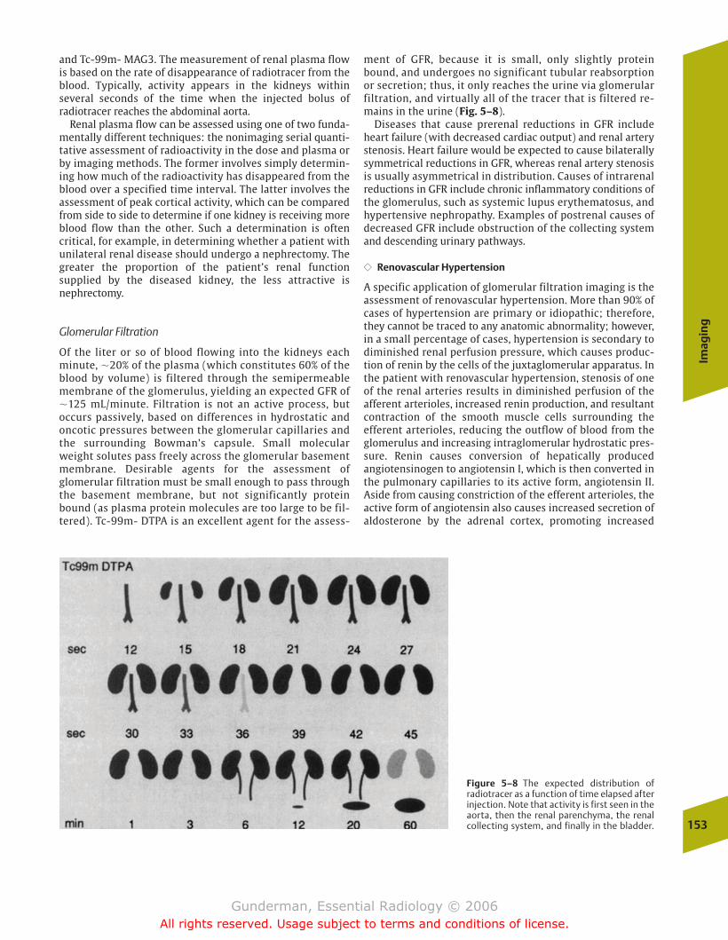
Imag
ing
153
and Tc-99m- MAG3. The measurement of renal plasma flowis based on the rate of disappearance of radiotracer from theblood. Typically, activity appears in the kidneys within several seconds of the time when the injected bolus of radiotracer reaches the abdominal aorta.
Renal plasma flow can be assessed using one of two funda-mentally different techniques: the nonimaging serial quanti-tative assessment of radioactivity in the dose and plasma orby imaging methods. The former involves simply determin-ing how much of the radioactivity has disappeared from theblood over a specified time interval. The latter involves theassessment of peak cortical activity, which can be comparedfrom side to side to determine if one kidney is receiving moreblood flow than the other. Such a determination is often critical, for example, in determining whether a patient withunilateral renal disease should undergo a nephrectomy. Thegreater the proportion of the patient’s renal function supplied by the diseased kidney, the less attractive isnephrectomy.
Glomerular Filtration
Of the liter or so of blood flowing into the kidneys eachminute, �20% of the plasma (which constitutes 60% of theblood by volume) is filtered through the semipermeablemembrane of the glomerulus, yielding an expected GFR of�125 mL/minute. Filtration is not an active process, but occurs passively, based on differences in hydrostatic and oncotic pressures between the glomerular capillaries andthe surrounding Bowman’s capsule. Small molecularweight solutes pass freely across the glomerular basementmembrane. Desirable agents for the assessment ofglomerular filtration must be small enough to pass throughthe basement membrane, but not significantly proteinbound (as plasma protein molecules are too large to be fil-tered). Tc-99m- DTPA is an excellent agent for the assess-
ment of GFR, because it is small, only slightly proteinbound, and undergoes no significant tubular reabsorptionor secretion; thus, it only reaches the urine via glomerularfiltration, and virtually all of the tracer that is filtered re-mains in the urine (Fig. 5–8).
Diseases that cause prerenal reductions in GFR includeheart failure (with decreased cardiac output) and renal arterystenosis. Heart failure would be expected to cause bilaterallysymmetrical reductions in GFR, whereas renal artery stenosisis usually asymmetrical in distribution. Causes of intrarenalreductions in GFR include chronic inflammatory conditions ofthe glomerulus, such as systemic lupus erythematosus, andhypertensive nephropathy. Examples of postrenal causes ofdecreased GFR include obstruction of the collecting systemand descending urinary pathways.
�� Renovascular Hypertension
A specific application of glomerular filtration imaging is theassessment of renovascular hypertension. More than 90% ofcases of hypertension are primary or idiopathic; therefore,they cannot be traced to any anatomic abnormality; however,in a small percentage of cases, hypertension is secondary todiminished renal perfusion pressure, which causes produc-tion of renin by the cells of the juxtaglomerular apparatus. Inthe patient with renovascular hypertension, stenosis of oneof the renal arteries results in diminished perfusion of the afferent arterioles, increased renin production, and resultantcontraction of the smooth muscle cells surrounding the efferent arterioles, reducing the outflow of blood from theglomerulus and increasing intraglomerular hydrostatic pres-sure. Renin causes conversion of hepatically produced angiotensinogen to angiotensin I, which is then converted inthe pulmonary capillaries to its active form, angiotensin II.Aside from causing constriction of the efferent arterioles, theactive form of angiotensin also causes increased secretion ofaldosterone by the adrenal cortex, promoting increased
Figure 5–8 The expected distribution of radiotracer as a function of time elapsed afterinjection. Note that activity is first seen in theaorta, then the renal parenchyma, the renalcollecting system, and finally in the bladder.
chapter 05_p147-171.qxd 12/1/05 3:43 PM Page 153
Gunderman, Essential Radiology © 2006All rights reserved. Usage subject to terms and conditions of license.
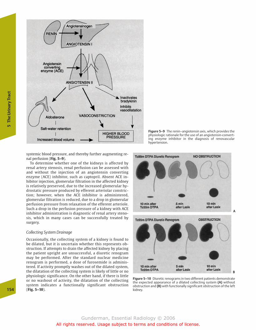
154
5Th
e U
rina
ry T
ract
systemic blood pressure, and thereby further augmenting re-nal perfusion (Fig. 5–9).
To determine whether one of the kidneys is affected by renal artery stenosis, renal perfusion can be assessed withand without the injection of an angiotensin converting enzyme (ACE) inhibitor, such as captopril. Absent ACE in-hibitor injection, glomerular filtration in the affected kidneyis relatively preserved, due to the increased glomerular hy-drostatic pressure produced by efferent arteriolar constric-tion; however, when the ACE inhibitor is administered,glomerular filtration is reduced, due to a drop in glomerularperfusion pressure from relaxation of the efferent arteriole.Such a drop in the perfusion pressure of a kidney with ACEinhibitor administration is diagnostic of renal artery steno-sis, which in many cases can be successfully treated bysurgery.
Collecting System Drainage
Occasionally, the collecting system of a kidney is found tobe dilated, but it is uncertain whether this represents ob-struction. If attempts to drain the affected kidney by placingthe patient upright are unsuccessful, a diuretic renogrammay be performed. After the standard nuclear medicinerenogram is performed, a dose of furosemide is adminis-tered. If activity promptly washes out of the dilated system,the dilatation of the collecting system is likely of little or nophysiologic significance. On the other hand, if there is littleor no washout of activity, the dilatation of the collectingsystem indicates a functionally significant obstruction (Fig. 5–10).
Figure 5–9 The renin–angiotensin axis, which provides thephysiologic rationale for the use of an angiotensin-convert-ing enzyme inhibitor in the diagnosis of renovascular hypertension.
Figure 5–10 Diuretic renograms in two different patients demonstratethe expected appearance of a dilated collecting system (A) without obstruction and (B) with functionally significant obstruction of the left kidney.
A
B
chapter 05_p147-171.qxd 12/1/05 3:43 PM Page 154
Gunderman, Essential Radiology © 2006All rights reserved. Usage subject to terms and conditions of license.
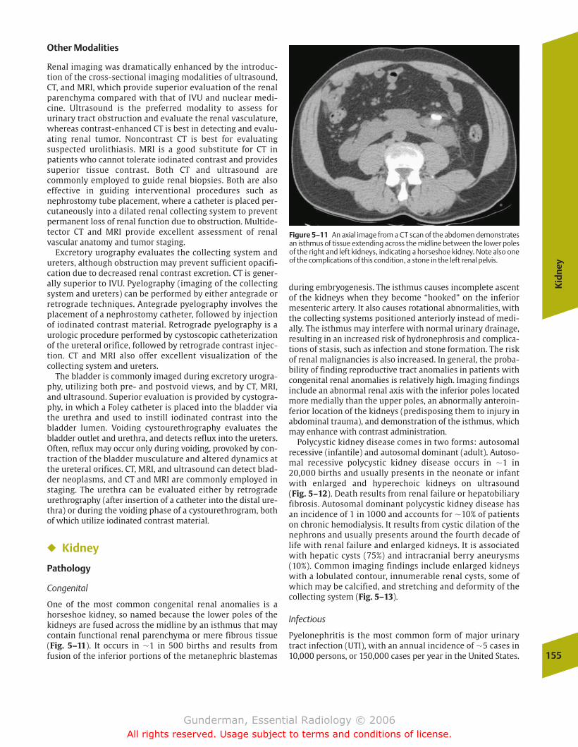
Kid
ney
155
Other Modalities
Renal imaging was dramatically enhanced by the introduc-tion of the cross-sectional imaging modalities of ultrasound,CT, and MRI, which provide superior evaluation of the renalparenchyma compared with that of IVU and nuclear medi-cine. Ultrasound is the preferred modality to assess for urinary tract obstruction and evaluate the renal vasculature,whereas contrast-enhanced CT is best in detecting and evalu-ating renal tumor. Noncontrast CT is best for evaluating suspected urolithiasis. MRI is a good substitute for CT in patients who cannot tolerate iodinated contrast and providessuperior tissue contrast. Both CT and ultrasound are commonly employed to guide renal biopsies. Both are also effective in guiding interventional procedures such asnephrostomy tube placement, where a catheter is placed per-cutaneously into a dilated renal collecting system to preventpermanent loss of renal function due to obstruction. Multide-tector CT and MRI provide excellent assessment of renal vascular anatomy and tumor staging.
Excretory urography evaluates the collecting system andureters, although obstruction may prevent sufficient opacifi-cation due to decreased renal contrast excretion. CT is gener-ally superior to IVU. Pyelography (imaging of the collectingsystem and ureters) can be performed by either antegrade orretrograde techniques. Antegrade pyelography involves theplacement of a nephrostomy catheter, followed by injectionof iodinated contrast material. Retrograde pyelography is aurologic procedure performed by cystoscopic catheterizationof the ureteral orifice, followed by retrograde contrast injec-tion. CT and MRI also offer excellent visualization of the collecting system and ureters.
The bladder is commonly imaged during excretory urogra-phy, utilizing both pre- and postvoid views, and by CT, MRI,and ultrasound. Superior evaluation is provided by cystogra-phy, in which a Foley catheter is placed into the bladder viathe urethra and used to instill iodinated contrast into thebladder lumen. Voiding cystourethrography evaluates thebladder outlet and urethra, and detects reflux into the ureters.Often, reflux may occur only during voiding, provoked by con-traction of the bladder musculature and altered dynamics atthe ureteral orifices. CT, MRI, and ultrasound can detect blad-der neoplasms, and CT and MRI are commonly employed instaging. The urethra can be evaluated either by retrogradeurethrography (after insertion of a catheter into the distal ure-thra) or during the voiding phase of a cystourethrogram, bothof which utilize iodinated contrast material.
� Kidney
Pathology
Congenital
One of the most common congenital renal anomalies is ahorseshoe kidney, so named because the lower poles of thekidneys are fused across the midline by an isthmus that maycontain functional renal parenchyma or mere fibrous tissue(Fig. 5–11). It occurs in �1 in 500 births and results from fusion of the inferior portions of the metanephric blastemas
during embryogenesis. The isthmus causes incomplete ascentof the kidneys when they become “hooked” on the inferiormesenteric artery. It also causes rotational abnormalities, withthe collecting systems positioned anteriorly instead of medi-ally. The isthmus may interfere with normal urinary drainage,resulting in an increased risk of hydronephrosis and complica-tions of stasis, such as infection and stone formation. The riskof renal malignancies is also increased. In general, the proba-bility of finding reproductive tract anomalies in patients withcongenital renal anomalies is relatively high. Imaging findingsinclude an abnormal renal axis with the inferior poles locatedmore medially than the upper poles, an abnormally anteroin-ferior location of the kidneys (predisposing them to injury inabdominal trauma), and demonstration of the isthmus, whichmay enhance with contrast administration.
Polycystic kidney disease comes in two forms: autosomalrecessive (infantile) and autosomal dominant (adult). Autoso-mal recessive polycystic kidney disease occurs in �1 in20,000 births and usually presents in the neonate or infantwith enlarged and hyperechoic kidneys on ultrasound (Fig. 5–12). Death results from renal failure or hepatobiliaryfibrosis. Autosomal dominant polycystic kidney disease hasan incidence of 1 in 1000 and accounts for �10% of patientson chronic hemodialysis. It results from cystic dilation of thenephrons and usually presents around the fourth decade oflife with renal failure and enlarged kidneys. It is associatedwith hepatic cysts (75%) and intracranial berry aneurysms(10%). Common imaging findings include enlarged kidneyswith a lobulated contour, innumerable renal cysts, some ofwhich may be calcified, and stretching and deformity of thecollecting system (Fig. 5–13).
Infectious
Pyelonephritis is the most common form of major urinarytract infection (UTI), with an annual incidence of �5 cases in10,000 persons, or 150,000 cases per year in the United States.
Figure 5–11 An axial image from a CT scan of the abdomen demonstratesan isthmus of tissue extending across the midline between the lower polesof the right and left kidneys, indicating a horseshoe kidney. Note also oneof the complications of this condition, a stone in the left renal pelvis.
chapter 05_p147-171.qxd 12/1/05 3:43 PM Page 155
Gunderman, Essential Radiology © 2006All rights reserved. Usage subject to terms and conditions of license.
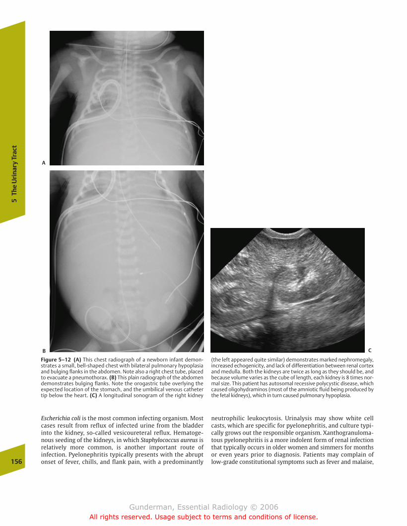
156
5Th
e U
rina
ry T
ract
Escherichia coli is the most common infecting organism. Mostcases result from reflux of infected urine from the bladderinto the kidney, so-called vesicoureteral reflux. Hematoge-nous seeding of the kidneys, in which Staphylococcus aureus isrelatively more common, is another important route of infection. Pyelonephritis typically presents with the abruptonset of fever, chills, and flank pain, with a predominantly
neutrophilic leukocytosis. Urinalysis may show white cellcasts, which are specific for pyelonephritis, and culture typi-cally grows out the responsible organism. Xanthogranuloma-tous pyelonephritis is a more indolent form of renal infectionthat typically occurs in older women and simmers for monthsor even years prior to diagnosis. Patients may complain oflow-grade constitutional symptoms such as fever and malaise,
Figure 5–12 (A) This chest radiograph of a newborn infant demon-strates a small, bell-shaped chest with bilateral pulmonary hypoplasiaand bulging flanks in the abdomen. Note also a right chest tube, placedto evacuate a pneumothorax. (B) This plain radiograph of the abdomendemonstrates bulging flanks. Note the orogastric tube overlying the expected location of the stomach, and the umbilical venous catheter tip below the heart. (C) A longitudinal sonogram of the right kidney
(the left appeared quite similar) demonstrates marked nephromegaly,increased echogenicity, and lack of differentiation between renal cortexand medulla. Both the kidneys are twice as long as they should be, andbecause volume varies as the cube of length, each kidney is 8 times nor-mal size. This patient has autosomal recessive polycystic disease, whichcaused oligohydraminos (most of the amniotic fluid being produced bythe fetal kidneys), which in turn caused pulmonary hypoplasia.
A
B C
chapter 05_p147-171.qxd 12/1/05 3:43 PM Page 156
Gunderman, Essential Radiology © 2006All rights reserved. Usage subject to terms and conditions of license.

Kid
ney
157
and urinalysis is typically positive for white cells and protein-uria. There is a high incidence of large, branching “staghorn” calculi, and cultures usually grow out E. coli or Proteus.
Most patients with uncomplicated pyelonephritis do not require imaging and are treated with antibiotics based ontheir clinical presentation and laboratory findings; however,if a patient fails to respond within 3 days, or if an underlying condition such as diabetes or a known urinary tract stone ispresent, an imaging study is indicated to rule out predispos-ing conditions such as obstruction and complications such as
abscess. Imaging studies are normal in many patients, although an especially suggestive finding is a striatednephrogram on IVU or CT (Fig. 5–14). CT with IV contrast ismore sensitive than ultrasound in the detection of parenchy-mal inflammation, although sensitivity is approximatelyequal for the detection of abscesses, and ultrasound has theadvantage that it requires no intravenous contrast material.MRI, which also requires no contrast material to demon-strate pyelonephritis and its complications, is playing agrowing role.
Figure 5–13 (A) This axial image from an abdominal CT scan after infu-sion of intravenous (IV) contrast demonstrates bilateral nephromegalyand innumerable bilateral renal cysts in this patient with autosomal
dominant polycystic disease. (B) This longitudinal renal sonogram in an-other patient with autosomal dominant polycystic kidney diseasedemonstrates large cysts occupying much of the renal parenchyma.
Figure 5–14 This patient presented with flank pain and high fever. (A) This axial image from an abdominal CT scan after IV contrast admin-istration demonstrates a swollen right kidney with a striated pattern ofcontrast enhancement. Note the dilation of the right renal pelvis.
(B) An image at the level of the bladder base demonstrates a calculus inthe right ureterovesical junction, which was causing the right hy-dronephrosis and predisposed the right kidney to infection.
A B
A B
chapter 05_p147-171.qxd 12/1/05 3:43 PM Page 157
Gunderman, Essential Radiology © 2006All rights reserved. Usage subject to terms and conditions of license.
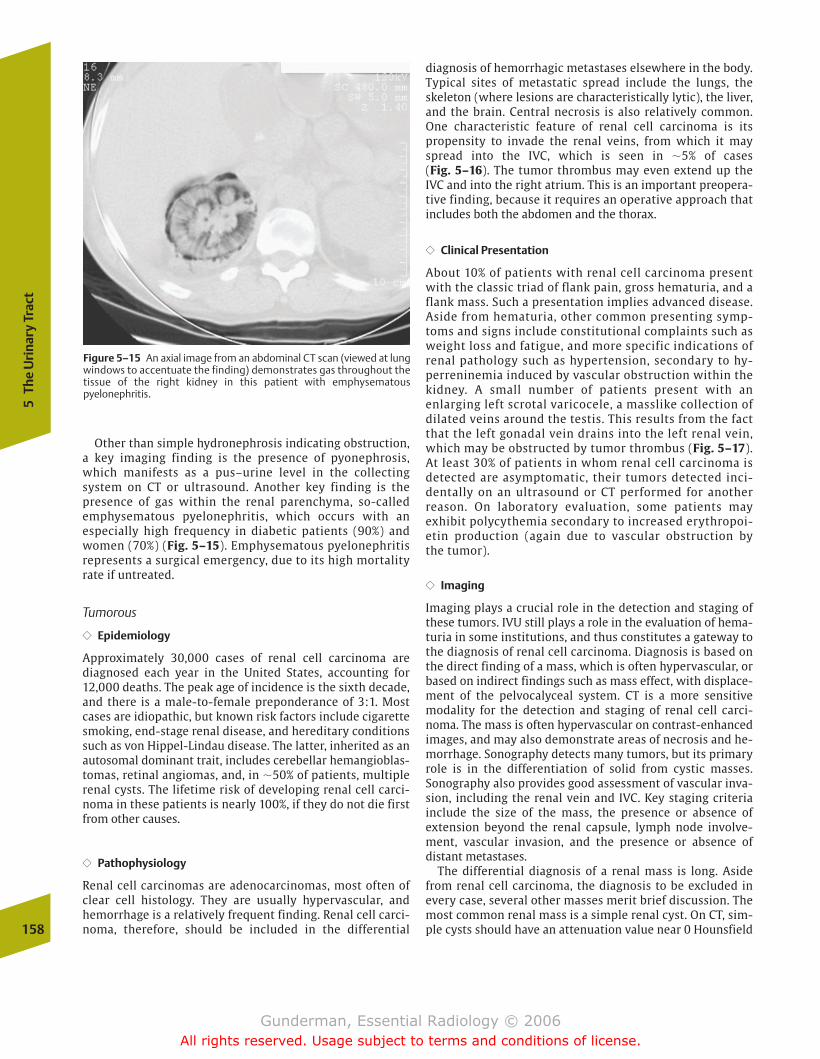
158
5Th
e U
rina
ry T
ract
diagnosis of hemorrhagic metastases elsewhere in the body.Typical sites of metastatic spread include the lungs, theskeleton (where lesions are characteristically lytic), the liver,and the brain. Central necrosis is also relatively common.One characteristic feature of renal cell carcinoma is itspropensity to invade the renal veins, from which it mayspread into the IVC, which is seen in �5% of cases (Fig. 5–16). The tumor thrombus may even extend up theIVC and into the right atrium. This is an important preopera-tive finding, because it requires an operative approach thatincludes both the abdomen and the thorax.
�� Clinical Presentation
About 10% of patients with renal cell carcinoma presentwith the classic triad of flank pain, gross hematuria, and aflank mass. Such a presentation implies advanced disease.Aside from hematuria, other common presenting symp-toms and signs include constitutional complaints such asweight loss and fatigue, and more specific indications of renal pathology such as hypertension, secondary to hy-perreninemia induced by vascular obstruction within the kidney. A small number of patients present with an enlarging left scrotal varicocele, a masslike collection ofdilated veins around the testis. This results from the factthat the left gonadal vein drains into the left renal vein,which may be obstructed by tumor thrombus (Fig. 5–17).At least 30% of patients in whom renal cell carcinoma isdetected are asymptomatic, their tumors detected inci-dentally on an ultrasound or CT performed for anotherreason. On laboratory evaluation, some patients may exhibit polycythemia secondary to increased erythropoi-etin production (again due to vascular obstruction by the tumor).
�� Imaging
Imaging plays a crucial role in the detection and staging ofthese tumors. IVU still plays a role in the evaluation of hema-turia in some institutions, and thus constitutes a gateway tothe diagnosis of renal cell carcinoma. Diagnosis is based onthe direct finding of a mass, which is often hypervascular, orbased on indirect findings such as mass effect, with displace-ment of the pelvocalyceal system. CT is a more sensitivemodality for the detection and staging of renal cell carci-noma. The mass is often hypervascular on contrast-enhancedimages, and may also demonstrate areas of necrosis and he-morrhage. Sonography detects many tumors, but its primaryrole is in the differentiation of solid from cystic masses.Sonography also provides good assessment of vascular inva-sion, including the renal vein and IVC. Key staging criteria include the size of the mass, the presence or absence of extension beyond the renal capsule, lymph node involve-ment, vascular invasion, and the presence or absence of distant metastases.
The differential diagnosis of a renal mass is long. Asidefrom renal cell carcinoma, the diagnosis to be excluded inevery case, several other masses merit brief discussion. Themost common renal mass is a simple renal cyst. On CT, sim-ple cysts should have an attenuation value near 0 Hounsfield
Figure 5–15 An axial image from an abdominal CT scan (viewed at lungwindows to accentuate the finding) demonstrates gas throughout thetissue of the right kidney in this patient with emphysematouspyelonephritis.
Other than simple hydronephrosis indicating obstruction,a key imaging finding is the presence of pyonephrosis,which manifests as a pus–urine level in the collecting system on CT or ultrasound. Another key finding is thepresence of gas within the renal parenchyma, so-called emphysematous pyelonephritis, which occurs with an especially high frequency in diabetic patients (90%) andwomen (70%) (Fig. 5–15). Emphysematous pyelonephritisrepresents a surgical emergency, due to its high mortalityrate if untreated.
Tumorous
�� Epidemiology
Approximately 30,000 cases of renal cell carcinoma are diagnosed each year in the United States, accounting for12,000 deaths. The peak age of incidence is the sixth decade,and there is a male-to-female preponderance of 3:1. Mostcases are idiopathic, but known risk factors include cigarettesmoking, end-stage renal disease, and hereditary conditionssuch as von Hippel-Lindau disease. The latter, inherited as an autosomal dominant trait, includes cerebellar hemangioblas-tomas, retinal angiomas, and, in �50% of patients, multiplerenal cysts. The lifetime risk of developing renal cell carci-noma in these patients is nearly 100%, if they do not die firstfrom other causes.
�� Pathophysiology
Renal cell carcinomas are adenocarcinomas, most often ofclear cell histology. They are usually hypervascular, and hemorrhage is a relatively frequent finding. Renal cell carci-noma, therefore, should be included in the differential
chapter 05_p147-171.qxd 12/1/05 3:43 PM Page 158
Gunderman, Essential Radiology © 2006All rights reserved. Usage subject to terms and conditions of license.
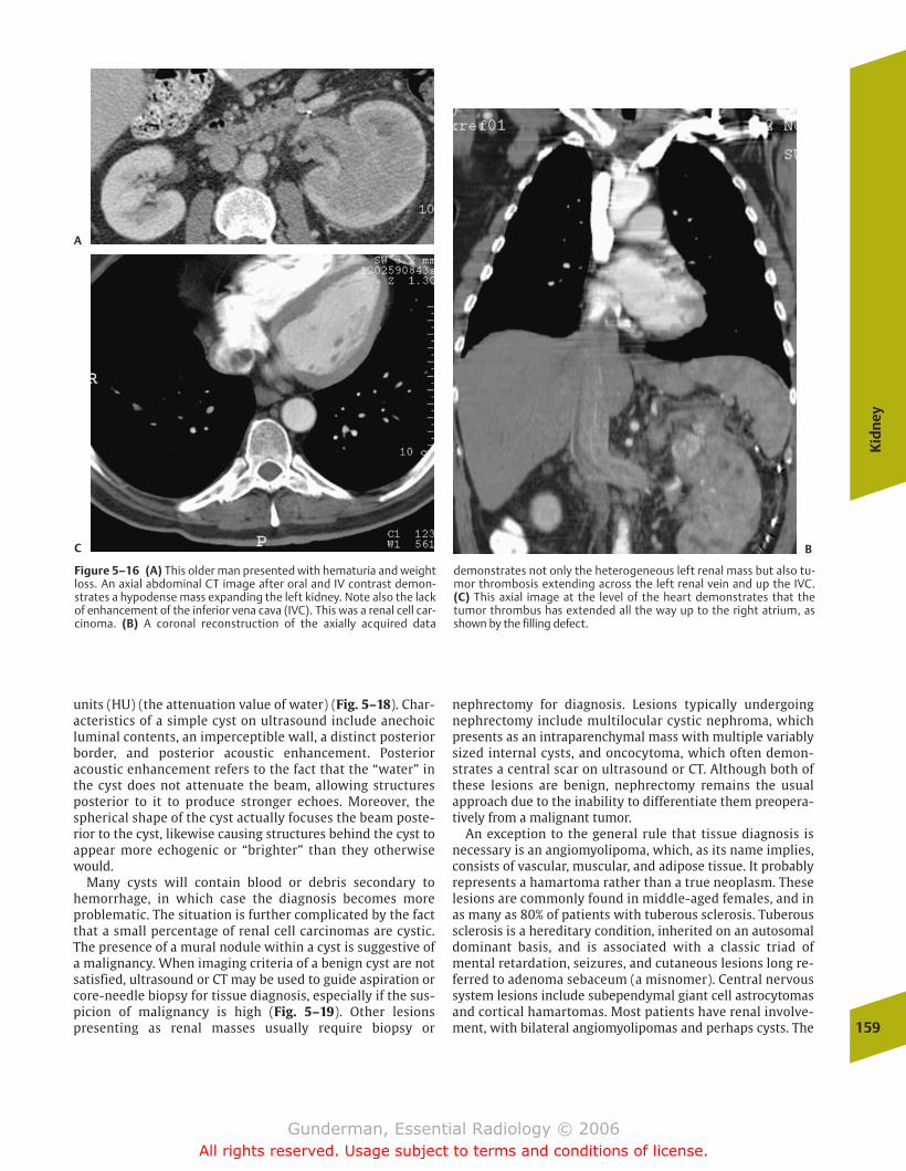
Kid
ney
159
units (HU) (the attenuation value of water) (Fig. 5–18). Char-acteristics of a simple cyst on ultrasound include anechoic luminal contents, an imperceptible wall, a distinct posteriorborder, and posterior acoustic enhancement. Posterioracoustic enhancement refers to the fact that the “water” inthe cyst does not attenuate the beam, allowing structuresposterior to it to produce stronger echoes. Moreover, thespherical shape of the cyst actually focuses the beam poste-rior to the cyst, likewise causing structures behind the cyst toappear more echogenic or “brighter” than they otherwisewould.
Many cysts will contain blood or debris secondary to hemorrhage, in which case the diagnosis becomes moreproblematic. The situation is further complicated by the factthat a small percentage of renal cell carcinomas are cystic.The presence of a mural nodule within a cyst is suggestive ofa malignancy. When imaging criteria of a benign cyst are notsatisfied, ultrasound or CT may be used to guide aspiration orcore-needle biopsy for tissue diagnosis, especially if the sus-picion of malignancy is high (Fig. 5–19). Other lesions presenting as renal masses usually require biopsy or
nephrectomy for diagnosis. Lesions typically undergoingnephrectomy include multilocular cystic nephroma, whichpresents as an intraparenchymal mass with multiple variablysized internal cysts, and oncocytoma, which often demon-strates a central scar on ultrasound or CT. Although both ofthese lesions are benign, nephrectomy remains the usual approach due to the inability to differentiate them preopera-tively from a malignant tumor.
An exception to the general rule that tissue diagnosis isnecessary is an angiomyolipoma, which, as its name implies,consists of vascular, muscular, and adipose tissue. It probablyrepresents a hamartoma rather than a true neoplasm. Theselesions are commonly found in middle-aged females, and inas many as 80% of patients with tuberous sclerosis. Tuberoussclerosis is a hereditary condition, inherited on an autosomaldominant basis, and is associated with a classic triad of mental retardation, seizures, and cutaneous lesions long re-ferred to adenoma sebaceum (a misnomer). Central nervoussystem lesions include subependymal giant cell astrocytomasand cortical hamartomas. Most patients have renal involve-ment, with bilateral angiomyolipomas and perhaps cysts. The
Figure 5–16 (A) This older man presented with hematuria and weightloss. An axial abdominal CT image after oral and IV contrast demon-strates a hypodense mass expanding the left kidney. Note also the lackof enhancement of the inferior vena cava (IVC). This was a renal cell car-cinoma. (B) A coronal reconstruction of the axially acquired data
demonstrates not only the heterogeneous left renal mass but also tu-mor thrombosis extending across the left renal vein and up the IVC. (C) This axial image at the level of the heart demonstrates that the tumor thrombus has extended all the way up to the right atrium, asshown by the filling defect.
A
BC
chapter 05_p147-171.qxd 12/1/05 3:43 PM Page 159
Gunderman, Essential Radiology © 2006All rights reserved. Usage subject to terms and conditions of license.
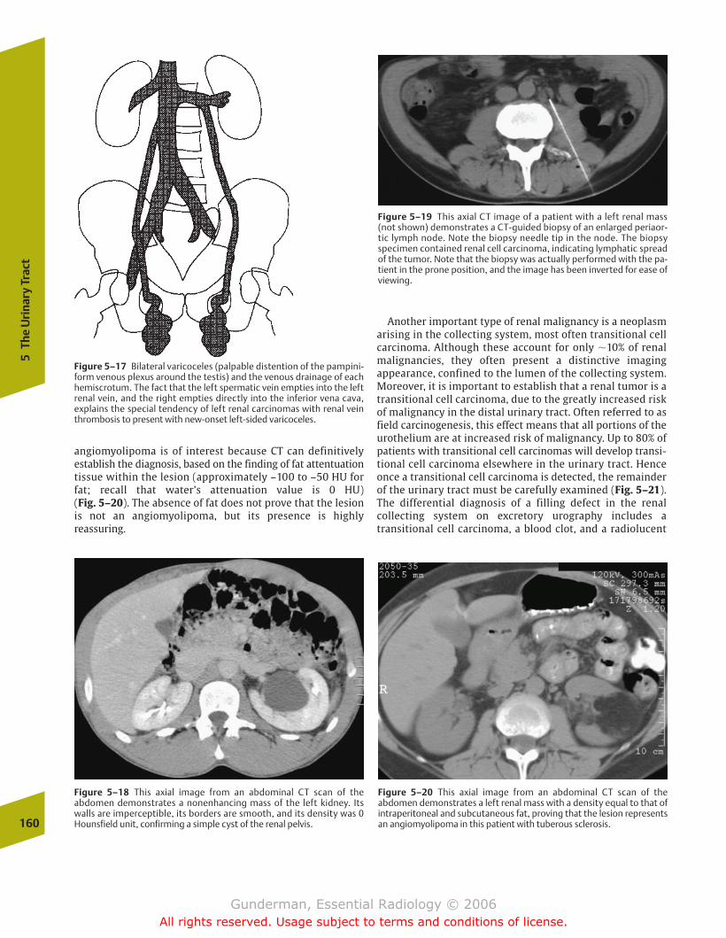
160
5Th
e U
rina
ry T
ract
Another important type of renal malignancy is a neoplasmarising in the collecting system, most often transitional cellcarcinoma. Although these account for only �10% of renalmalignancies, they often present a distinctive imaging appearance, confined to the lumen of the collecting system.Moreover, it is important to establish that a renal tumor is atransitional cell carcinoma, due to the greatly increased riskof malignancy in the distal urinary tract. Often referred to asfield carcinogenesis, this effect means that all portions of theurothelium are at increased risk of malignancy. Up to 80% ofpatients with transitional cell carcinomas will develop transi-tional cell carcinoma elsewhere in the urinary tract. Henceonce a transitional cell carcinoma is detected, the remainderof the urinary tract must be carefully examined (Fig. 5–21).The differential diagnosis of a filling defect in the renal collecting system on excretory urography includes a transitional cell carcinoma, a blood clot, and a radiolucent
Figure 5–17 Bilateral varicoceles (palpable distention of the pampini-form venous plexus around the testis) and the venous drainage of eachhemiscrotum. The fact that the left spermatic vein empties into the leftrenal vein, and the right empties directly into the inferior vena cava, explains the special tendency of left renal carcinomas with renal veinthrombosis to present with new-onset left-sided varicoceles.
Figure 5–18 This axial image from an abdominal CT scan of the abdomen demonstrates a nonenhancing mass of the left kidney. Itswalls are imperceptible, its borders are smooth, and its density was 0Hounsfield unit, confirming a simple cyst of the renal pelvis.
angiomyolipoma is of interest because CT can definitively establish the diagnosis, based on the finding of fat attentuationtissue within the lesion (approximately –100 to –50 HU forfat; recall that water’s attenuation value is 0 HU) (Fig. 5–20). The absence of fat does not prove that the lesionis not an angiomyolipoma, but its presence is highly reassuring.
Figure 5–19 This axial CT image of a patient with a left renal mass(not shown) demonstrates a CT-guided biopsy of an enlarged periaor-tic lymph node. Note the biopsy needle tip in the node. The biopsyspecimen contained renal cell carcinoma, indicating lymphatic spreadof the tumor. Note that the biopsy was actually performed with the pa-tient in the prone position, and the image has been inverted for ease ofviewing.
Figure 5–20 This axial image from an abdominal CT scan of the abdomen demonstrates a left renal mass with a density equal to that ofintraperitoneal and subcutaneous fat, proving that the lesion representsan angiomyolipoma in this patient with tuberous sclerosis.
chapter 05_p147-171.qxd 12/1/05 3:43 PM Page 160
Gunderman, Essential Radiology © 2006All rights reserved. Usage subject to terms and conditions of license.

Kid
ney
161
calculus, although many other lesions, such as a sloughed renal papilla, are also possible.
Inflammatory
A wide variety of insults can, by the final common pathwayof inflammation, produce the sonographic finding of dif-fusely hyperechoic kidneys. Common etiologies includeglomerulosclerosis from hypertension or diabetes, infec-tious glomerulonephritis, infantile polycystic kidney disease, and acquired immunodeficiency syndrome (AIDS)–related nephropathy (Fig. 5–22). When the kidneys are notonly echogenic but shrunken, the disease is chronic in na-ture, having had time to destroy renal tissue, and the pa-
tient will invariably suffer from some degree of chronic renal insufficiency. If the kidneys are asymmetrical in sizeand echogenicity, a unilateral process, such as reflux-re-lated pyelonephritis or renal vein thrombosis, should besuspected.
Traumatic
Renal trauma is being managed in an increasingly conservativefashion. Imaging plays a crucial role in identifying the 80 to90% of patients whose injuries do not require surgery. Minor injuries include hematomas, small lacerations, and small in-farctions. Major injuries include renal rupture or masceration,vascular thrombosis, and renal pedicle avulsion. In the severely traumatized, unstable patient, a “one-shot” IVU issometimes performed in the emergency room; contrast opaci-fication of both kidneys rules out arterial thrombosis and pedi-cle avulsion. The study of choice to evaluate the trauma patientwith possible renal injury is a contrast-enhanced CT scan,which evaluates not only the renal parenchyma and vascula-ture, but also the integrity of the collecting system and ureter(Fig. 5–23).
Vascular
Several renovascular disorders have been discussed in thenuclear medicine imaging section. Renal papillary necrosisis an additional vascular disorder that may be seen in patients with histories of flank pain, obstruction, or UTI.Papillary necrosis results from focal ischemia in the papil-lary portions of the renal pyramids, a region of relativelytenuous arterial supply. Common etiologic factors include diabetes mellitus, sickle-cell disease, infection, and heavyanalgesic use.
Figure 5–21 (A) This axial CT image demonstrates a heterogeneouslyenhancing mass of the left renal collecting system that is causing somehydronephrosis. (B) On an image of the pelvis, there is also an enhanc-
ing nodule of the posterior bladder wall. Both were transitional cell carci-nomas in this 60-year-old woman with abdominal pain and microscopichematuria.
Figure 5–22 This longitudinal sonogram demonstrates a veryechogenic right kidney behind the liver. Normally, except in infants, thekidneys should be less echogenic than the liver and spleen. In this case,both kidneys were much more echogenic, which was due to acquiredimmunodeficiency syndrome (AIDS) nephropathy.
A B
chapter 05_p147-171.qxd 12/1/05 3:43 PM Page 161
Gunderman, Essential Radiology © 2006All rights reserved. Usage subject to terms and conditions of license.
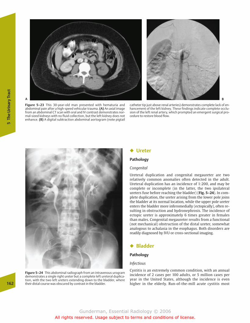
162
5Th
e U
rina
ry T
ract
� Ureter
Pathology
Congenital
Ureteral duplication and congenital megaureter are two relatively common anomalies often detected in the adult.Ureteral duplication has an incidence of 1:200, and may becomplete or incomplete (in the latter, the two ipsilateralureters fuse before reaching the bladder) (Fig. 5–24). In com-plete duplication, the ureter arising from the lower pole joinsthe bladder at its normal location, while the upper pole ureterenters the bladder more inferomedially (ectopically), often re-sulting in obstruction and hydronephrosis. The incidence ofectopic ureter is approximately 6 times greater in femalesthan males. Congenital megaureter results from a functional(not mechanical) obstruction of the distal ureter, somewhatanalogous to achalasia in the esophagus. Both disorders arereadily diagnosed by IVU or cross-sectional imaging.
� Bladder
Pathology
Infectious
Cystitis is an extremely common condition, with an annualincidence of 2 cases per 100 adults, or 5 million cases peryear in the United States, although the incidence is evenhigher in the elderly. Run-of-the-mill acute cystitis most
Figure 5–23 This 30-year-old man presented with hematuria and abdominal pain after a high-speed vehicular trauma. (A) An axial imagefrom an abdominal CT scan with oral and IV contrast demonstrates nor-mal-sized kidneys with no fluid collection, but the left kidney does notenhance. (B) A digital subtraction abdominal aortogram (note pigtail
catheter tip just above renal arteries) demonstrates complete lack of en-hancement of the left kidney. These findings indicate complete occlu-sion of the left renal artery, which prompted an emergent surgical pro-cedure to restore blood flow.
Figure 5–24 This abdominal radiograph from an intravenous urogramdemonstrates a single right ureter but a complete left ureteral duplica-tion, with the two left ureters extending down to the bladder, wheretheir distal course was obscured by contrast in the bladder.
A B
chapter 05_p147-171.qxd 12/1/05 3:43 PM Page 162
Gunderman, Essential Radiology © 2006All rights reserved. Usage subject to terms and conditions of license.
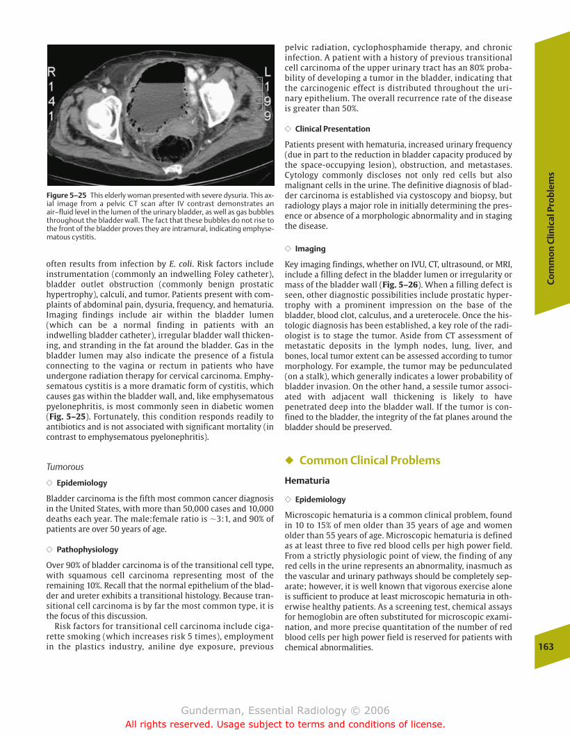
Co
mm
on
Clin
ical
Pro
ble
ms
163
often results from infection by E. coli. Risk factors include instrumentation (commonly an indwelling Foley catheter),bladder outlet obstruction (commonly benign prostatic hypertrophy), calculi, and tumor. Patients present with com-plaints of abdominal pain, dysuria, frequency, and hematuria.Imaging findings include air within the bladder lumen(which can be a normal finding in patients with an indwelling bladder catheter), irregular bladder wall thicken-ing, and stranding in the fat around the bladder. Gas in thebladder lumen may also indicate the presence of a fistula connecting to the vagina or rectum in patients who have undergone radiation therapy for cervical carcinoma. Emphy-sematous cystitis is a more dramatic form of cystitis, whichcauses gas within the bladder wall, and, like emphysematouspyelonephritis, is most commonly seen in diabetic women(Fig. 5–25). Fortunately, this condition responds readily toantibiotics and is not associated with significant mortality (incontrast to emphysematous pyelonephritis).
Tumorous
�� Epidemiology
Bladder carcinoma is the fifth most common cancer diagnosisin the United States, with more than 50,000 cases and 10,000deaths each year. The male:female ratio is �3:1, and 90% ofpatients are over 50 years of age.
�� Pathophysiology
Over 90% of bladder carcinoma is of the transitional cell type,with squamous cell carcinoma representing most of the remaining 10%. Recall that the normal epithelium of the blad-der and ureter exhibits a transitional histology. Because tran-sitional cell carcinoma is by far the most common type, it isthe focus of this discussion.
Risk factors for transitional cell carcinoma include ciga-rette smoking (which increases risk 5 times), employmentin the plastics industry, aniline dye exposure, previous
pelvic radiation, cyclophosphamide therapy, and chronicinfection. A patient with a history of previous transitionalcell carcinoma of the upper urinary tract has an 80% proba-bility of developing a tumor in the bladder, indicating thatthe carcinogenic effect is distributed throughout the uri-nary epithelium. The overall recurrence rate of the diseaseis greater than 50%.
�� Clinical Presentation
Patients present with hematuria, increased urinary frequency(due in part to the reduction in bladder capacity produced bythe space-occupying lesion), obstruction, and metastases. Cytology commonly discloses not only red cells but also malignant cells in the urine. The definitive diagnosis of blad-der carcinoma is established via cystoscopy and biopsy, butradiology plays a major role in initially determining the pres-ence or absence of a morphologic abnormality and in stagingthe disease.
�� Imaging
Key imaging findings, whether on IVU, CT, ultrasound, or MRI,include a filling defect in the bladder lumen or irregularity ormass of the bladder wall (Fig. 5–26). When a filling defect isseen, other diagnostic possibilities include prostatic hyper-trophy with a prominent impression on the base of the bladder, blood clot, calculus, and a ureterocele. Once the his-tologic diagnosis has been established, a key role of the radi-ologist is to stage the tumor. Aside from CT assessment ofmetastatic deposits in the lymph nodes, lung, liver, andbones, local tumor extent can be assessed according to tumormorphology. For example, the tumor may be pedunculated(on a stalk), which generally indicates a lower probability ofbladder invasion. On the other hand, a sessile tumor associ-ated with adjacent wall thickening is likely to have penetrated deep into the bladder wall. If the tumor is con-fined to the bladder, the integrity of the fat planes around thebladder should be preserved.
� Common Clinical Problems
Hematuria
�� Epidemiology
Microscopic hematuria is a common clinical problem, foundin 10 to 15% of men older than 35 years of age and womenolder than 55 years of age. Microscopic hematuria is definedas at least three to five red blood cells per high power field.From a strictly physiologic point of view, the finding of anyred cells in the urine represents an abnormality, inasmuch asthe vascular and urinary pathways should be completely sep-arate; however, it is well known that vigorous exercise aloneis sufficient to produce at least microscopic hematuria in oth-erwise healthy patients. As a screening test, chemical assaysfor hemoglobin are often substituted for microscopic exami-nation, and more precise quantitation of the number of redblood cells per high power field is reserved for patients withchemical abnormalities.
Figure 5–25 This elderly woman presented with severe dysuria. This ax-ial image from a pelvic CT scan after IV contrast demonstrates anair–fluid level in the lumen of the urinary bladder, as well as gas bubblesthroughout the bladder wall. The fact that these bubbles do not rise tothe front of the bladder proves they are intramural, indicating emphyse-matous cystitis.
chapter 05_p147-171.qxd 12/1/05 3:43 PM Page 163
Gunderman, Essential Radiology © 2006All rights reserved. Usage subject to terms and conditions of license.
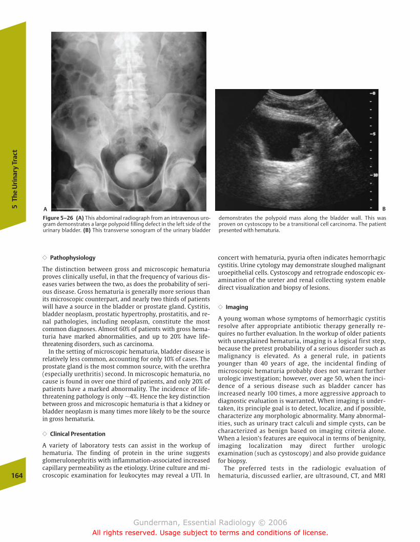
164
5Th
e U
rina
ry T
ract
�� Pathophysiology
The distinction between gross and microscopic hematuriaproves clinically useful, in that the frequency of various dis-eases varies between the two, as does the probability of seri-ous disease. Gross hematuria is generally more serious thanits microscopic counterpart, and nearly two thirds of patientswill have a source in the bladder or prostate gland. Cystitis,bladder neoplasm, prostatic hypertrophy, prostatitis, and re-nal pathologies, including neoplasm, constitute the mostcommon diagnoses. Almost 60% of patients with gross hema-turia have marked abnormalities, and up to 20% have life-threatening disorders, such as carcinoma.
In the setting of microscopic hematuria, bladder disease isrelatively less common, accounting for only 10% of cases. Theprostate gland is the most common source, with the urethra(especially urethritis) second. In microscopic hematuria, nocause is found in over one third of patients, and only 20% ofpatients have a marked abnormality. The incidence of life-threatening pathology is only �4%. Hence the key distinctionbetween gross and microscopic hematuria is that a kidney orbladder neoplasm is many times more likely to be the sourcein gross hematuria.
�� Clinical Presentation
A variety of laboratory tests can assist in the workup ofhematuria. The finding of protein in the urine suggestsglomerulonephritis with inflammation-associated increasedcapillary permeability as the etiology. Urine culture and mi-croscopic examination for leukocytes may reveal a UTI. In
concert with hematuria, pyuria often indicates hemorrhagiccystitis. Urine cytology may demonstrate sloughed malignanturoepithelial cells. Cystoscopy and retrograde endoscopic ex-amination of the ureter and renal collecting system enabledirect visualization and biopsy of lesions.
�� Imaging
A young woman whose symptoms of hemorrhagic cystitisresolve after appropriate antibiotic therapy generally re-quires no further evaluation. In the workup of older patientswith unexplained hematuria, imaging is a logical first step,because the pretest probability of a serious disorder such asmalignancy is elevated. As a general rule, in patientsyounger than 40 years of age, the incidental finding of microscopic hematuria probably does not warrant furtherurologic investigation; however, over age 50, when the inci-dence of a serious disease such as bladder cancer has increased nearly 100 times, a more aggressive approach to diagnostic evaluation is warranted. When imaging is under-taken, its principle goal is to detect, localize, and if possible,characterize any morphologic abnormality. Many abnormal-ities, such as urinary tract calculi and simple cysts, can becharacterized as benign based on imaging criteria alone.When a lesion’s features are equivocal in terms of benignity,imaging localization may direct further urologic examination (such as cystoscopy) and also provide guidance for biopsy.
The preferred tests in the radiologic evaluation of hematuria, discussed earlier, are ultrasound, CT, and MRI
Figure 5–26 (A) This abdominal radiograph from an intravenous uro-gram demonstrates a large polypoid filling defect in the left side of theurinary bladder. (B) This transverse sonogram of the urinary bladder
demonstrates the polypoid mass along the bladder wall. This wasproven on cystoscopy to be a transitional cell carcinoma. The patientpresented with hematuria.
A B
chapter 05_p147-171.qxd 12/1/05 3:43 PM Page 164
Gunderman, Essential Radiology © 2006All rights reserved. Usage subject to terms and conditions of license.
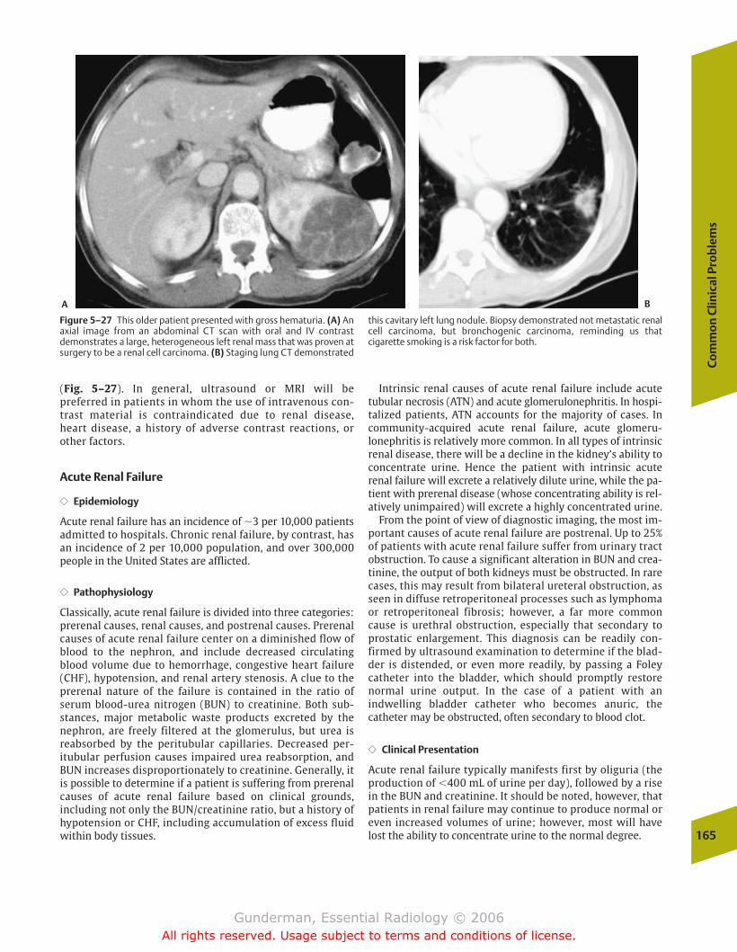
Co
mm
on
Clin
ical
Pro
ble
ms
165
(Fig. 5–27). In general, ultrasound or MRI will be preferred in patients in whom the use of intravenous con-trast material is contraindicated due to renal disease, heart disease, a history of adverse contrast reactions, or other factors.
Acute Renal Failure
�� Epidemiology
Acute renal failure has an incidence of �3 per 10,000 patientsadmitted to hospitals. Chronic renal failure, by contrast, hasan incidence of 2 per 10,000 population, and over 300,000people in the United States are afflicted.
�� Pathophysiology
Classically, acute renal failure is divided into three categories:prerenal causes, renal causes, and postrenal causes. Prerenalcauses of acute renal failure center on a diminished flow ofblood to the nephron, and include decreased circulatingblood volume due to hemorrhage, congestive heart failure(CHF), hypotension, and renal artery stenosis. A clue to theprerenal nature of the failure is contained in the ratio ofserum blood-urea nitrogen (BUN) to creatinine. Both sub-stances, major metabolic waste products excreted by thenephron, are freely filtered at the glomerulus, but urea is reabsorbed by the peritubular capillaries. Decreased per-itubular perfusion causes impaired urea reabsorption, andBUN increases disproportionately to creatinine. Generally, itis possible to determine if a patient is suffering from prerenalcauses of acute renal failure based on clinical grounds, including not only the BUN/creatinine ratio, but a history ofhypotension or CHF, including accumulation of excess fluidwithin body tissues.
Intrinsic renal causes of acute renal failure include acutetubular necrosis (ATN) and acute glomerulonephritis. In hospi-talized patients, ATN accounts for the majority of cases. Incommunity-acquired acute renal failure, acute glomeru-lonephritis is relatively more common. In all types of intrinsicrenal disease, there will be a decline in the kidney’s ability toconcentrate urine. Hence the patient with intrinsic acute renal failure will excrete a relatively dilute urine, while the pa-tient with prerenal disease (whose concentrating ability is rel-atively unimpaired) will excrete a highly concentrated urine.
From the point of view of diagnostic imaging, the most im-portant causes of acute renal failure are postrenal. Up to 25%of patients with acute renal failure suffer from urinary tractobstruction. To cause a significant alteration in BUN and crea-tinine, the output of both kidneys must be obstructed. In rarecases, this may result from bilateral ureteral obstruction, asseen in diffuse retroperitoneal processes such as lymphomaor retroperitoneal fibrosis; however, a far more commoncause is urethral obstruction, especially that secondary toprostatic enlargement. This diagnosis can be readily con-firmed by ultrasound examination to determine if the blad-der is distended, or even more readily, by passing a Foleycatheter into the bladder, which should promptly restore normal urine output. In the case of a patient with an indwelling bladder catheter who becomes anuric, thecatheter may be obstructed, often secondary to blood clot.
�� Clinical Presentation
Acute renal failure typically manifests first by oliguria (theproduction of �400 mL of urine per day), followed by a risein the BUN and creatinine. It should be noted, however, thatpatients in renal failure may continue to produce normal oreven increased volumes of urine; however, most will havelost the ability to concentrate urine to the normal degree.
Figure 5–27 This older patient presented with gross hematuria. (A) Anaxial image from an abdominal CT scan with oral and IV contrastdemonstrates a large, heterogeneous left renal mass that was proven atsurgery to be a renal cell carcinoma. (B) Staging lung CT demonstrated
this cavitary left lung nodule. Biopsy demonstrated not metastatic renalcell carcinoma, but bronchogenic carcinoma, reminding us that cigarette smoking is a risk factor for both.
A B
chapter 05_p147-171.qxd 12/1/05 3:43 PM Page 165
Gunderman, Essential Radiology © 2006All rights reserved. Usage subject to terms and conditions of license.
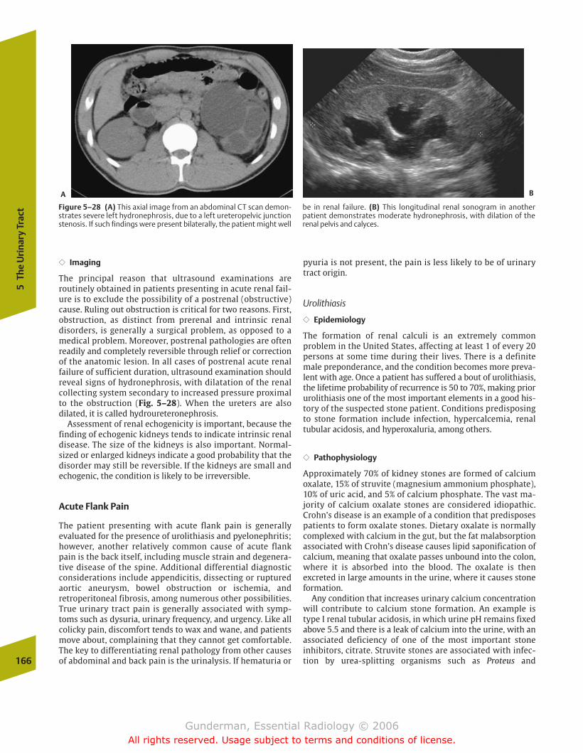
166
5Th
e U
rina
ry T
ract
�� Imaging
The principal reason that ultrasound examinations are routinely obtained in patients presenting in acute renal fail-ure is to exclude the possibility of a postrenal (obstructive)cause. Ruling out obstruction is critical for two reasons. First,obstruction, as distinct from prerenal and intrinsic renal disorders, is generally a surgical problem, as opposed to amedical problem. Moreover, postrenal pathologies are oftenreadily and completely reversible through relief or correctionof the anatomic lesion. In all cases of postrenal acute renalfailure of sufficient duration, ultrasound examination shouldreveal signs of hydronephrosis, with dilatation of the renal collecting system secondary to increased pressure proximalto the obstruction (Fig. 5–28). When the ureters are also dilated, it is called hydroureteronephrosis.
Assessment of renal echogenicity is important, because thefinding of echogenic kidneys tends to indicate intrinsic renaldisease. The size of the kidneys is also important. Normal-sized or enlarged kidneys indicate a good probability that thedisorder may still be reversible. If the kidneys are small andechogenic, the condition is likely to be irreversible.
Acute Flank Pain
The patient presenting with acute flank pain is generallyevaluated for the presence of urolithiasis and pyelonephritis;however, another relatively common cause of acute flankpain is the back itself, including muscle strain and degenera-tive disease of the spine. Additional differential diagnosticconsiderations include appendicitis, dissecting or rupturedaortic aneurysm, bowel obstruction or ischemia, andretroperitoneal fibrosis, among numerous other possibilities.True urinary tract pain is generally associated with symp-toms such as dysuria, urinary frequency, and urgency. Like allcolicky pain, discomfort tends to wax and wane, and patientsmove about, complaining that they cannot get comfortable.The key to differentiating renal pathology from other causesof abdominal and back pain is the urinalysis. If hematuria or
pyuria is not present, the pain is less likely to be of urinarytract origin.
Urolithiasis
�� Epidemiology
The formation of renal calculi is an extremely common problem in the United States, affecting at least 1 of every 20 persons at some time during their lives. There is a definitemale preponderance, and the condition becomes more preva-lent with age. Once a patient has suffered a bout of urolithiasis,the lifetime probability of recurrence is 50 to 70%, making priorurolithiasis one of the most important elements in a good his-tory of the suspected stone patient. Conditions predisposingto stone formation include infection, hypercalcemia, renaltubular acidosis, and hyperoxaluria, among others.
�� Pathophysiology
Approximately 70% of kidney stones are formed of calciumoxalate, 15% of struvite (magnesium ammonium phosphate),10% of uric acid, and 5% of calcium phosphate. The vast ma-jority of calcium oxalate stones are considered idiopathic.Crohn’s disease is an example of a condition that predisposespatients to form oxalate stones. Dietary oxalate is normallycomplexed with calcium in the gut, but the fat malabsorptionassociated with Crohn’s disease causes lipid saponification ofcalcium, meaning that oxalate passes unbound into the colon,where it is absorbed into the blood. The oxalate is then excreted in large amounts in the urine, where it causes stoneformation.
Any condition that increases urinary calcium concentrationwill contribute to calcium stone formation. An example istype I renal tubular acidosis, in which urine pH remains fixedabove 5.5 and there is a leak of calcium into the urine, with anassociated deficiency of one of the most important stone inhibitors, citrate. Struvite stones are associated with infec-tion by urea-splitting organisms such as Proteus and
Figure 5–28 (A) This axial image from an abdominal CT scan demon-strates severe left hydronephrosis, due to a left ureteropelvic junctionstenosis. If such findings were present bilaterally, the patient might well
be in renal failure. (B) This longitudinal renal sonogram in another patient demonstrates moderate hydronephrosis, with dilation of the renal pelvis and calyces.
A B
chapter 05_p147-171.qxd 12/1/05 3:43 PM Page 166
Gunderman, Essential Radiology © 2006All rights reserved. Usage subject to terms and conditions of license.

Co
mm
on
Clin
ical
Pro
ble
ms
167
Pseudomonas, with an increase in urine pH. Struvite stonesmay become particularly large, forming a cast of the collectingsystem, and are then referred to as staghorn calculi. As dis-tinct from the other major types of stones, uric acid stones areoften radiolucent. They are associated with low urine pH,which decreases the solubility of uric acid. Common predis-posing conditions include gout, hemolytic anemia, and myelo-proliferative disorders, the latter two secondary to cell lysis.
The management of urolithiasis begins with adequate hydration and analgesia, generally employing narcotics. At least80% of stones will pass spontaneously, and no further interven-tion is required. Virtually all stones less than 0.5 cm in diameterpass without any medical or surgical assistance. Those larger than1 cm usually require surgical removal. This is often accomplishedvia ureteroscopically guided crushing and extraction of the stone.Extracorporeal shock-wave lithotripsy relies on the use of focusedshock waves to pulverize stones without surgery. Complicationsof stones include infection due to stasis, calyceal perforation, andthe development of chronic obstruction, with associated loss ofnephrons and irreversible loss of renal function.
�� Clinical Presentation
Urolithiasis is the most common cause of both acute urinary tract obstruction and acute flank pain. Renal colic
refers to spasms of intense pain that begin in the region ofthe flank and radiate into the groin. The pain results fromspasms of ureteral smooth muscle, generated by theureter’s attempt to overcome the distention and increasedintraluminal pressure caused by obstruction. Other com-mon presenting symptoms include urinary urgency and fre-quency. The differential diagnosis of an obstructing lesionin the urinary tract includes blood clot, tumor, sloughedpapilla, and extrinsic compression.
�� Imaging
Imaging may begin with a high-quality abdominal plain film,which will often reveal a calculus (Fig. 5–29). Stones must gen-erally measure at least 2 mm in diameter and contain some cal-cium to be visible by plain film. Ureteral calculi tend to lodge atone of three positions: the uteropelvic junction (UPJ; the pelvicbrim), and the ureterovesical junction (UVJ), the latter beingthe most frequent (Fig. 5–30). In the appropriate clinical set-ting, the finding of a calculus in the distribution of the urinarytract, particularly at one of these locations, is strongly sugges-tive of urolithiasis. Mimics of urinary calculi include gallstones,phleboliths, and calcified mesenteric lymph nodes.
Intravenous urography is still employed in some centers inthe evaluation of stones, and in such settings many stones arefirst detected on the “scout” film (precontrast administration)
Figure 5–29 This middle-aged woman presented with several monthsof low back pain. (A) A longitudinal sonogram of the right kidneydemonstrates severe hydronephrosis. (B) A longitudinal sonogram ofthe left kidney demonstrates even more severe hydronephrosis. Whatis the most common cause of bilateral hydronephrosis? In men, the answer would be a prostatic mass causing bladder outlet obstruction,
most often benign prostatic hyperplasia. In women, a pelvic masswould be more likely, but in this case urolithiasis was the culprit. (C) This plain radiograph demonstrates bilateral stones in the expectedlocations of the ureters. The one on the right is just lateral to the fourthlumbar vertebra, and the one on the left is just above the sacroiliacjoint.
A
B C
chapter 05_p147-171.qxd 12/1/05 3:43 PM Page 167
Gunderman, Essential Radiology © 2006All rights reserved. Usage subject to terms and conditions of license.
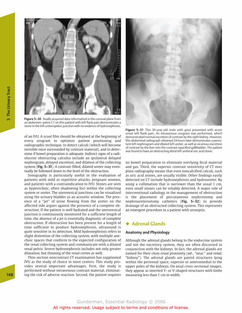
168
5Th
e U
rina
ry T
ract
of an IVU. A scout film should be obtained at the beginning ofevery urogram to optimize patient positioning and radiographic technique, to detect calculi (which will becomeinvisible once surrounded by contrast material), and to deter-mine if bowel preparation is adequate. Indirect signs of a radi-olucent obstructing calculus include an ipsilateral delayednephrogram, delayed excretion, and dilation of the collectingsystem (Fig. 5–31). A contrast-filled, dilated ureter may even-tually be followed down to the level of the obstruction.
Sonography is particularly useful in the evaluation of patients with mild or repetitive attacks, pregnant women,and patients with a contraindication to IVU. Stones are seenas hyperechoic, often shadowing foci within the collectingsystem or ureter. The uterovesical junctions can be visualizedusing the urinary bladder as an acoustic window. The pres-ence of a “jet” of urine flowing from the ureter on the affected side argues against the presence of a complete ob-struction. If the patient is well hydrated and the uterovesicaljunction is continuously monitored for a sufficient length oftime, the absence of a jet is essentially diagnostic of completeobstruction. If obstruction has been present for a length oftime sufficient to produce hydronephrosis, ultrasound isquite sensitive in its detection. Mild hydronephrosis refers toslight distention of the collecting system, with multiple ane-choic spaces that conform to the expected configuration ofthe renal collecting system and communicate with a dilatedrenal pelvis. Severe hydronephrosis includes not only greaterdilatation, but thinning of the renal cortex as well.
Thin-section noncontrast CT examination has supplantedIVU as the study of choice in most centers. This study pro-vides several important advantages. First, the study is performed without intravenous contrast material, eliminat-ing the risk of adverse reaction. Second, the patient requires
Figure 5–30 Axially acquired data reformatted in the coronal plane froman abdomen–pelvis CT on this patient with left flank pain demonstrates astone in the left ureteropelvic junction with no evidence of hydronephrosis.
Figure 5–31 This 30-year-old male with gout presented with acute onset left flank pain. An intravenous urogram was performed, whichdemonstrated normal excretion of contrast by the right kidney. However,this abdominal radiograph obtained 24 hours later demonstrates a persis-tent left nephrogram and dilated left ureter, as well as vicarious excretionof contrast by the liver into the contrast-opacified gallbladder. The patientwas found to have an obstructing distal left ureteral uric acid stone.
no bowel preparation to eliminate overlying fecal materialand gas. Third, the superior contrast sensitivity of CT overplain radiography means that even noncalcified calculi, suchas uric acid stones, are usually visible. Other findings easilydetected on CT include hydronephrosis and hydroureter. Byusing a collimation that is narrower than the usual 1 cm,even small stones can be reliably detected. A major role of interventional radiology in the management of obstruction is the placement of percutaneous nephrostomy andnephroureterostomy catheters (Fig. 5–32) to providedrainage of an obstructed collecting system. This representsan emergent procedure in a patient with urosepsis.
� Adrenal Glands
Anatomy and Physiology
Although the adrenal glands belong to the endocrine systemand not the excretory system, they are often discussed inconjunction with the kidneys. In fact, the adrenal glands arenamed for their close renal proximity (ad-, “near,” and renal,“kidney”). The adrenal glands are paired structures lyingwithin the perirenal space, superior or anteromedial to theupper poles of the kidneys. On axial cross-sectional images,they appear as inverted Y- or V-shaped structures with limbsmeasuring less than 1 cm in width.
chapter 05_p147-171.qxd 12/1/05 3:43 PM Page 168
Gunderman, Essential Radiology © 2006All rights reserved. Usage subject to terms and conditions of license.
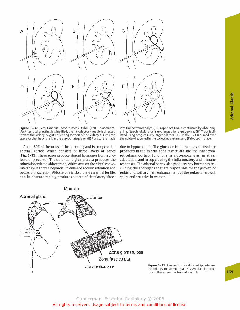
Ad
ren
al G
lan
ds
169
Figure 5–32 Percutaneous nephrostomy tube (PNT) placement. (A) After local anesthesia is instilled, the introductory needle is directedtoward the kidney. Slight deflecting motion of the kidney assures theoperator that he or she is in the appropriate plane. (B) Puncture is made
into the posterior calyx. (C) Proper position is confirmed by obtainingurine. Needle obdurator is exchanged for a guidewire. (D) Tract is di-lated using progressively larger dilators. (E) Finally, PNT is placed overthe guidewire, coiled in the collecting system, and (F) locked in place.
Figure 5–33 The anatomic relationship betweenthe kidneys and adrenal glands, as well as the struc-ture of the adrenal cortex and medulla.
About 80% of the mass of the adrenal gland is composed ofadrenal cortex, which consists of three layers or zones (Fig. 5–33). These zones produce steroid hormones from a cho-lesterol precursor. The outer zona glomerulosa produces themineralocorticoid aldosterone, which acts on the distal convo-luted tubules of the nephrons to enhance sodium retention andpotassium excretion. Aldosterone is absolutely essential for life,and its absence rapidly produces a state of circulatory shock
due to hypovolemia. The glucocorticoids such as cortisol areproduced in the middle zona fasciculata and the inner zonareticularis. Cortisol functions in gluconeogenesis, in stressadaptation, and in suppressing the inflammatory and immuneresponses. The adrenal cortex also produces sex hormones, in-cluding the androgens that are responsible for the growth ofpubic and axillary hair, enhancement of the pubertal growthspurt, and sex drive in women.
chapter 05_p147-171.qxd 12/1/05 3:43 PM Page 169
Gunderman, Essential Radiology © 2006All rights reserved. Usage subject to terms and conditions of license.

170
5Th
e U
rina
ry T
ract
Global adrenal cortical hypofunction is called Addison’sdisease and is associated with hyperkalemia and hypona-tremia, hypoglycemia, and poor response to stress. Mostcases are thought to be autoimmune in etiology, although bilateral infarction or hemorrhage may also be responsible.Conn’s syndrome refers to hyperaldosteronism. It manifestswith hypertension and hypokalemia, and most often resultsfrom an isolated, hormonally active adrenal adenoma (Fig. 5–34). Cushing’s syndrome refers to excess glucocorti-coid secretion and manifests with truncal obesity, hyperten-sion, muscle atrophy, cutaneous striae, and amenorrhea.Most cases result from bilateral adrenal hyperplasia, which in90% of cases is due to a corticotropin-secreting pituitary adenoma (Cushing’s disease); 10% of cases are due to anadrenocortical carcinoma.
The adrenal medulla is composed of modified postgan-glionic sympathetic neurons, which release their “neuro-transmitter” directly into the circulation under sympatheticstimulation. Its greatest product is epinephrine. Levels of epi-nephrine in the blood may rise by as much as 300 times under severe stress, preparing the patient for the so-calledfight-or-flight response.
Figure 5–34 This patient presented with hypertension and hypokalemia. An axial CT image of the abdomen demonstrates a 4 cmheterogeneous right adrenal mass, an aldosteronoma.
Figure 5–35 Axial T1 (A) and T1 fat-suppression (B) images of a rightadrenal mass demonstrate high signal on T1 that drops on the fat-suppression image, indicating a fat-containing adrenal myelipoma. (C)An axial CT image demonstrates that the lesion is fat density.
A B
C
chapter 05_p147-171.qxd 12/1/05 3:43 PM Page 170
Gunderman, Essential Radiology © 2006All rights reserved. Usage subject to terms and conditions of license.
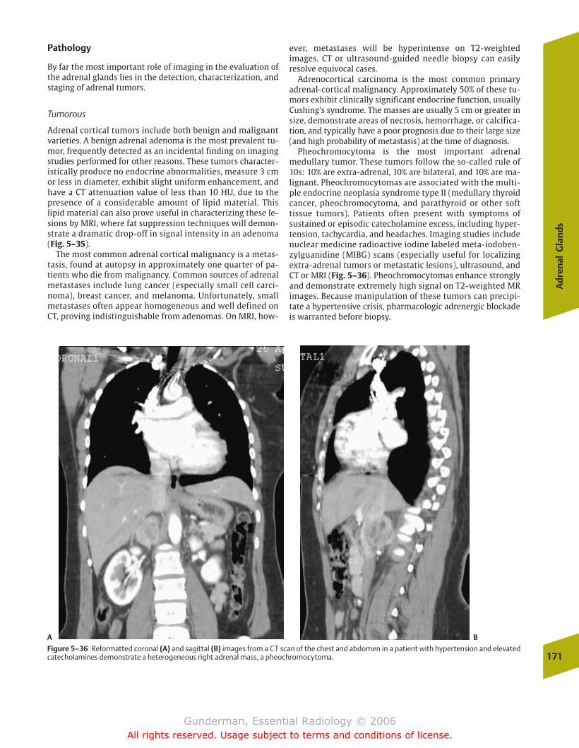
Ad
ren
al G
lan
ds
171
Pathology
By far the most important role of imaging in the evaluation ofthe adrenal glands lies in the detection, characterization, andstaging of adrenal tumors.
Tumorous
Adrenal cortical tumors include both benign and malignantvarieties. A benign adrenal adenoma is the most prevalent tu-mor, frequently detected as an incidental finding on imagingstudies performed for other reasons. These tumors character-istically produce no endocrine abnormalities, measure 3 cmor less in diameter, exhibit slight uniform enhancement, andhave a CT attenuation value of less than 10 HU, due to thepresence of a considerable amount of lipid material. Thislipid material can also prove useful in characterizing these le-sions by MRI, where fat suppression techniques will demon-strate a dramatic drop-off in signal intensity in an adenoma(Fig. 5–35).
The most common adrenal cortical malignancy is a metas-tasis, found at autopsy in approximately one quarter of pa-tients who die from malignancy. Common sources of adrenalmetastases include lung cancer (especially small cell carci-noma), breast cancer, and melanoma. Unfortunately, smallmetastases often appear homogeneous and well defined onCT, proving indistinguishable from adenomas. On MRI, how-
ever, metastases will be hyperintense on T2-weighted images. CT or ultrasound-guided needle biopsy can easily resolve equivocal cases.
Adrenocortical carcinoma is the most common primaryadrenal-cortical malignancy. Approximately 50% of these tu-mors exhibit clinically significant endocrine function, usuallyCushing’s syndrome. The masses are usually 5 cm or greater insize, demonstrate areas of necrosis, hemorrhage, or calcifica-tion, and typically have a poor prognosis due to their large size(and high probability of metastasis) at the time of diagnosis.
Pheochromocytoma is the most important adrenalmedullary tumor. These tumors follow the so-called rule of10s: 10% are extra-adrenal, 10% are bilateral, and 10% are ma-lignant. Pheochromocytomas are associated with the multi-ple endocrine neoplasia syndrome type II (medullary thyroidcancer, pheochromocytoma, and parathyroid or other soft tissue tumors). Patients often present with symptoms of sustained or episodic catecholamine excess, including hyper-tension, tachycardia, and headaches. Imaging studies includenuclear medicine radioactive iodine labeled meta-iodoben-zylguanidine (MIBG) scans (especially useful for localizingextra-adrenal tumors or metastatic lesions), ultrasound, andCT or MRI (Fig. 5–36). Pheochromocytomas enhance stronglyand demonstrate extremely high signal on T2-weighted MRimages. Because manipulation of these tumors can precipi-tate a hypertensive crisis, pharmacologic adrenergic blockadeis warranted before biopsy.
Figure 5–36 Reformatted coronal (A) and sagittal (B) images from a CT scan of the chest and abdomen in a patient with hypertension and elevatedcatecholamines demonstrate a heterogeneous right adrenal mass, a pheochromocytoma.
A B
chapter 05_p147-171.qxd 12/1/05 3:43 PM Page 171
Gunderman, Essential Radiology © 2006All rights reserved. Usage subject to terms and conditions of license.
� Critical Radiographic Signs
PneumoperitoneumPneumatosis IntestinalisHepatic Gas
� Pathology
AbscessPeptic Ulcer Disease
EpidemiologyPathophysiologyClinical PresentationImaging
Acute CholecystitisEpidemiologyPathophysiologyClinical PresentationImaging
PancreatitisEpidemiologyPathophysiologyClinical PresentationImaging
Diverticular DiseaseEpidemiologyPathophysiologyClinical PresentationImaging
AppendicitisEpidemiologyPathophysiologyClinical PresentationImaging
Bowel ObstructionEpidemiologyPathophysiologyClinical PresentationImaging
6The Acute Abdomen
chapter 06_p172-191.qxd 12/1/05 4:00 PM Page 172
Gunderman, Essential Radiology © 2006All rights reserved. Usage subject to terms and conditions of license.
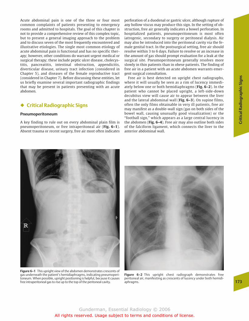
Cri
tica
l Rad
iog
rap
hic
Sig
ns
173
Acute abdominal pain is one of the three or four most common complaints of patients presenting to emergencyrooms and admitted to hospitals. The goal of this chapter isnot to provide a comprehensive review of this complex topic,but to present a general imaging approach to the problemand to discuss seven of the most frequently encountered andillustrative etiologies. The single most common etiology ofacute abdominal pain is functional and has no specific ther-apy; however, other conditions do warrant urgent medical or surgical therapy; these include peptic ulcer disease, cholecys-titis, pancreatitis, intestinal obstruction, appendicitis, diverticular disease, urinary tract infection (considered inChapter 5), and diseases of the female reproductive tract(considered in Chapter 7). Before discussing these entities, letus briefly examine several important radiographic findingsthat may be present in patients presenting with an acute abdomen.
� Critical Radiographic Signs
Pneumoperitoneum
A key finding to rule out on every abdominal plain film ispneumoperitoneum, or free intraperitoneal air (Fig. 6–1). Absent trauma or recent surgery, free air most often indicates
perforation of a duodenal or gastric ulcer, although rupture ofany hollow viscus may produce this sign. In the setting of ob-struction, free air generally indicates a bowel perforation. Inhospitalized patients, pneumoperitoneum is most often iatrogenic, secondary to surgery or peritoneal dialysis. Airmay also be introduced into the peritoneal cavity via the fe-male genital tract. In the postsurgical setting, free air shouldresolve within 3 to 6 days. Failure to resolve or an increase inthe amount of gas should prompt evaluation for a leak at thesurgical site. Pneumoperitoneum generally resolves moreslowly in thin patients than in obese patients. The finding offree air in a patient with an acute abdomen warrants emer-gent surgical consultation.
Free air is best detected on upright chest radiographs,where it will usually be seen as a rim of lucency immedi-ately below one or both hemidiaphragms (Fig. 6–2). In thepatient who cannot be placed upright, a left-side-down decubitus view will cause air to appear between the liverand the lateral abdominal wall (Fig. 6–3). On supine films,often the only films obtainable in very ill patients, free airmay manifest as a double-wall sign (gas on both sides of thebowel wall, causing unusually good visualization) or the“football sign,” which appears as a large central lucency inthe abdomen (Fig. 6–4). Free air may also outline both sidesof the falciform ligament, which connects the liver to theanterior abdominal wall.
Figure 6–1 This upright view of the abdomen demonstrates crescents ofgas underneath the patient’s hemidiaphragms, indicating pneumoperi-toneum. When possible, upright positioning is helpful, because it causesfree intraperitoneal gas to rise up to the top of the peritoneal cavity.
Figure 6–2 This upright chest radiograph demonstrates free peritoneal air, manifesting as crescents of lucency under both hemidi-aphragms.
chapter 06_p172-191.qxd 12/1/05 4:00 PM Page 173
Gunderman, Essential Radiology © 2006All rights reserved. Usage subject to terms and conditions of license.
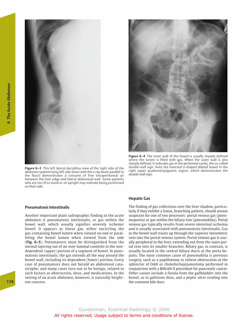
Pneumatosis Intestinalis
Another important plain radiographic finding in the acuteabdomen is pneumatosis intestinalis, or gas within thebowel wall, which usually signifies severely ischemicbowel. It appears as linear gas, either encircling the gas-containing bowel lumen when viewed on end or paral-leling the bowel lumen when viewed from the side (Fig. 6–5). Pneumatosis must be distinguished from thenormal layering out of air over luminal contents in the non-dependent (upper) portion of a segment of bowel. In pneu-matosis intestinalis, the gas extends all the way around thebowel wall, including its dependent (lower) portion. Everycase of pneumatosis does not herald an abdominal cata-strophe, and many cases turn out to be benign, related tosuch factors as obstruction, ileus, and medications. In thesetting of an acute abdomen, however, it naturally height-ens concern.
Hepatic Gas
The finding of gas collections over the liver shadow, particu-larly if they exhibit a linear, branching pattern, should arousesuspicion for one of two processes: portal venous gas (pneu-moportia) or gas within the biliary tree (pneumobilia). Portalvenous gas typically results from severe intestinal ischemiaand is usually associated with pneumatosis intestinalis. Gasin the bowel wall tracks up through the superior mesentericvein into the portal venous system. Portal venous gas is usu-ally peripheral in the liver, extending out from the main por-tal vein into its smaller branches. Biliary gas, in contrast, isusually located in the central biliary ducts at the porta he-patis. The most common cause of pneumobilia is previoussurgery, such as a papillotomy to relieve obstruction at thesphincter of Oddi or choledochojejunostomy performed inconjunction with a Billroth II procedure for pancreatic cancer.Other causes include a fistula from the gallbladder into thebowel, as in gallstone ileus, and a peptic ulcer eroding intothe common bile duct.174
6Th
e A
cute
Abd
omen
Figure 6–3 This left lateral decubitus view of the right side of theabdomen (patient lying left side down with the x-ray beam parallel tothe floor) demonstrates a crescent of free intraperitoneal airbetween the liver edge and lateral abdominal wall. Some patientswho are too ill to stand or sit upright may tolerate being positionedon their side.
Figure 6–4 The inner wall of the bowel is usually sharply definedwhere the lumen is filled with gas. When the outer wall is also sharply defined, it indicates gas in the peritoneal cavity, the so-calleddouble-wall sign. Note the inverted U-shaped dilated bowel in theright upper quadrant/epigastric region, which demonstrates the double-wall sign.
chapter 06_p172-191.qxd 12/1/05 4:00 PM Page 174
Gunderman, Essential Radiology © 2006All rights reserved. Usage subject to terms and conditions of license.
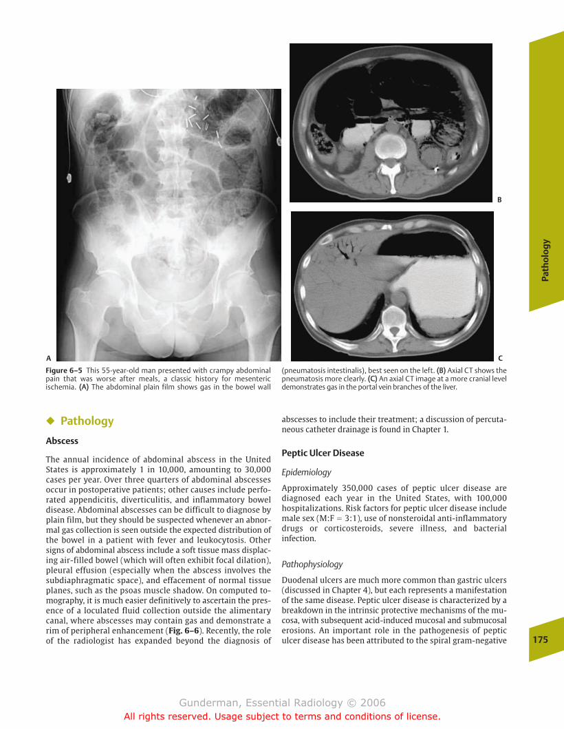
Path
olo
gy
175
� Pathology
Abscess
The annual incidence of abdominal abscess in the UnitedStates is approximately 1 in 10,000, amounting to 30,000cases per year. Over three quarters of abdominal abscessesoccur in postoperative patients; other causes include perfo-rated appendicitis, diverticulitis, and inflammatory boweldisease. Abdominal abscesses can be difficult to diagnose byplain film, but they should be suspected whenever an abnor-mal gas collection is seen outside the expected distribution ofthe bowel in a patient with fever and leukocytosis. Othersigns of abdominal abscess include a soft tissue mass displac-ing air-filled bowel (which will often exhibit focal dilation),pleural effusion (especially when the abscess involves thesubdiaphragmatic space), and effacement of normal tissueplanes, such as the psoas muscle shadow. On computed to-mography, it is much easier definitively to ascertain the pres-ence of a loculated fluid collection outside the alimentarycanal, where abscesses may contain gas and demonstrate arim of peripheral enhancement (Fig. 6–6). Recently, the roleof the radiologist has expanded beyond the diagnosis of
abscesses to include their treatment; a discussion of percuta-neous catheter drainage is found in Chapter 1.
Peptic Ulcer Disease
Epidemiology
Approximately 350,000 cases of peptic ulcer disease are diagnosed each year in the United States, with 100,000 hospitalizations. Risk factors for peptic ulcer disease includemale sex (M:F � 3:1), use of nonsteroidal anti-inflammatorydrugs or corticosteroids, severe illness, and bacterial infection.
Pathophysiology
Duodenal ulcers are much more common than gastric ulcers(discussed in Chapter 4), but each represents a manifestationof the same disease. Peptic ulcer disease is characterized by abreakdown in the intrinsic protective mechanisms of the mu-cosa, with subsequent acid-induced mucosal and submucosalerosions. An important role in the pathogenesis of peptic ulcer disease has been attributed to the spiral gram-negative
Figure 6–5 This 55-year-old man presented with crampy abdominalpain that was worse after meals, a classic history for mesenteric ischemia. ((AA)) The abdominal plain film shows gas in the bowel wall
(pneumatosis intestinalis), best seen on the left. ((BB)) Axial CT shows thepneumatosis more clearly. ((CC)) An axial CT image at a more cranial leveldemonstrates gas in the portal vein branches of the liver.
A C
B
chapter 06_p172-191.qxd 12/1/05 4:00 PM Page 175
Gunderman, Essential Radiology © 2006All rights reserved. Usage subject to terms and conditions of license.
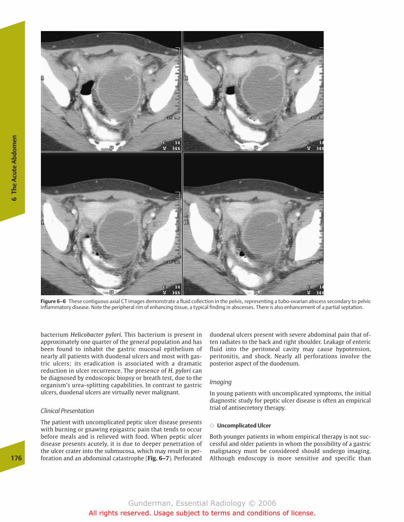
bacterium Helicobacter pylori. This bacterium is present inapproximately one quarter of the general population and hasbeen found to inhabit the gastric mucosal epithelium ofnearly all patients with duodenal ulcers and most with gas-tric ulcers; its eradication is associated with a dramatic reduction in ulcer recurrence. The presence of H. pylori canbe diagnosed by endoscopic biopsy or breath test, due to theorganism’s urea-splitting capabilities. In contrast to gastriculcers, duodenal ulcers are virtually never malignant.
Clinical Presentation
The patient with uncomplicated peptic ulcer disease presentswith burning or gnawing epigastric pain that tends to occurbefore meals and is relieved with food. When peptic ulcerdisease presents acutely, it is due to deeper penetration ofthe ulcer crater into the submucosa, which may result in per-foration and an abdominal catastrophe (Fig. 6–7). Perforated
duodenal ulcers present with severe abdominal pain that of-ten radiates to the back and right shoulder. Leakage of entericfluid into the peritoneal cavity may cause hypotension, peritonitis, and shock. Nearly all perforations involve the posterior aspect of the duodenum.
Imaging
In young patients with uncomplicated symptoms, the initialdiagnostic study for peptic ulcer disease is often an empiricaltrial of antisecretory therapy.
�� Uncomplicated Ulcer
Both younger patients in whom empirical therapy is not suc-cessful and older patients in whom the possibility of a gastricmalignancy must be considered should undergo imaging. Although endoscopy is more sensitive and specific than 176
6Th
e A
cute
Abd
omen
Figure 6–6 These contiguous axial CT images demonstrate a fluid collection in the pelvis, representing a tubo-ovarian abscess secondary to pelvicinflammatory disease. Note the peripheral rim of enhancing tissue, a typical finding in abscesses. There is also enhancement of a partial septation.
chapter 06_p172-191.qxd 12/1/05 4:00 PM Page 176
Gunderman, Essential Radiology © 2006All rights reserved. Usage subject to terms and conditions of license.
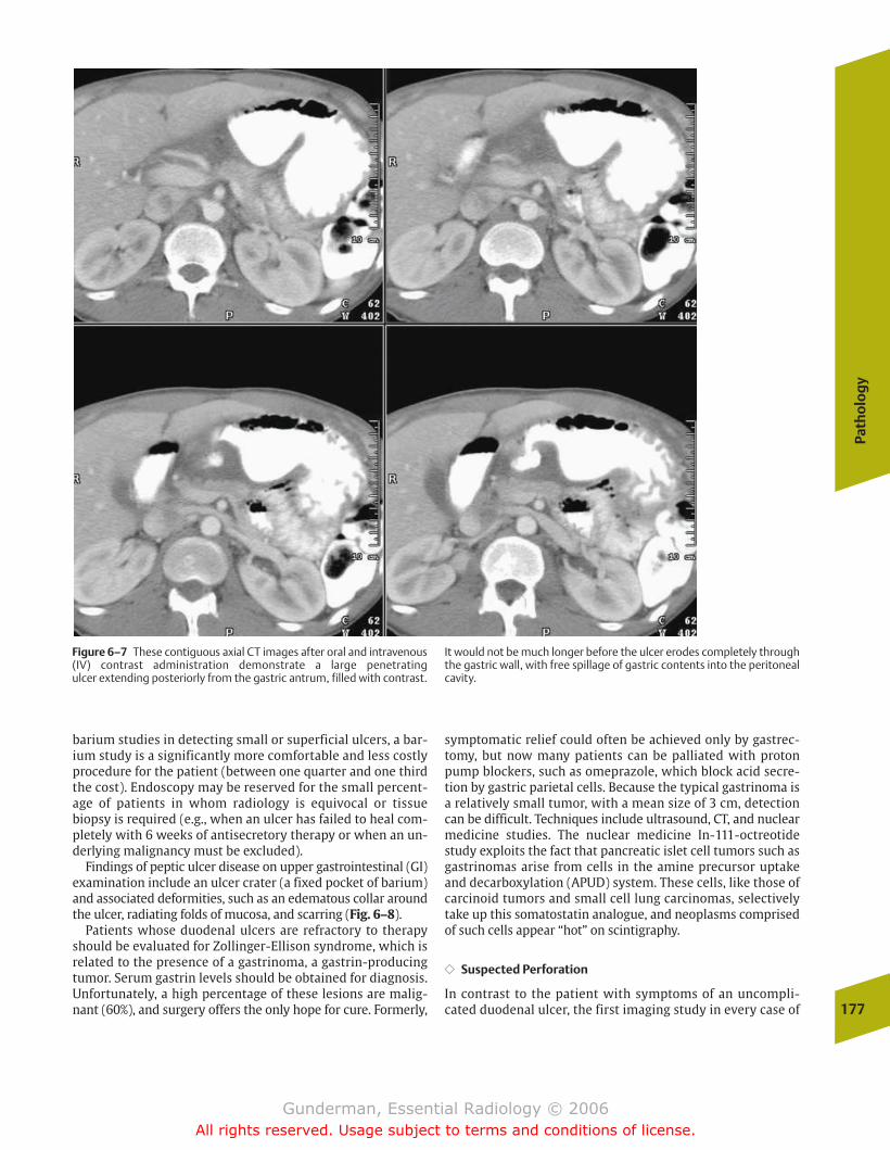
Path
olo
gy
177
barium studies in detecting small or superficial ulcers, a bar-ium study is a significantly more comfortable and less costlyprocedure for the patient (between one quarter and one thirdthe cost). Endoscopy may be reserved for the small percent-age of patients in whom radiology is equivocal or tissuebiopsy is required (e.g., when an ulcer has failed to heal com-pletely with 6 weeks of antisecretory therapy or when an un-derlying malignancy must be excluded).
Findings of peptic ulcer disease on upper gastrointestinal (GI)examination include an ulcer crater (a fixed pocket of barium)and associated deformities, such as an edematous collar aroundthe ulcer, radiating folds of mucosa, and scarring (Fig. 6–8).
Patients whose duodenal ulcers are refractory to therapyshould be evaluated for Zollinger-Ellison syndrome, which isrelated to the presence of a gastrinoma, a gastrin-producingtumor. Serum gastrin levels should be obtained for diagnosis.Unfortunately, a high percentage of these lesions are malig-nant (60%), and surgery offers the only hope for cure. Formerly,
symptomatic relief could often be achieved only by gastrec-tomy, but now many patients can be palliated with protonpump blockers, such as omeprazole, which block acid secre-tion by gastric parietal cells. Because the typical gastrinoma isa relatively small tumor, with a mean size of 3 cm, detectioncan be difficult. Techniques include ultrasound, CT, and nuclearmedicine studies. The nuclear medicine In-111-octreotidestudy exploits the fact that pancreatic islet cell tumors such asgastrinomas arise from cells in the amine precursor uptakeand decarboxylation (APUD) system. These cells, like those ofcarcinoid tumors and small cell lung carcinomas, selectivelytake up this somatostatin analogue, and neoplasms comprisedof such cells appear “hot” on scintigraphy.
�� Suspected Perforation
In contrast to the patient with symptoms of an uncompli-cated duodenal ulcer, the first imaging study in every case of
Figure 6–7 These contiguous axial CT images after oral and intravenous(IV) contrast administration demonstrate a large penetrating ulcer extending posteriorly from the gastric antrum, filled with contrast.
It would not be much longer before the ulcer erodes completely throughthe gastric wall, with free spillage of gastric contents into the peritonealcavity.
chapter 06_p172-191.qxd 12/1/05 4:00 PM Page 177
Gunderman, Essential Radiology © 2006All rights reserved. Usage subject to terms and conditions of license.
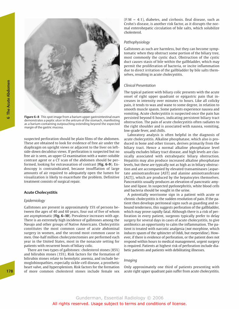
suspected perforation should be plain films of the abdomen.These are obtained to look for evidence of free air under thediaphragm on upright views or adjacent to the liver on left-side-down decubitus views. If perforation is suspected but nofree air is seen, an upper GI examination with a water-solublecontrast agent or a CT scan of the abdomen should be per-formed, looking for extravasation of contrast (Fig. 6-9). En-doscopy is contraindicated, because insufflation of largeamounts of air required to adequately open the lumen for visualization is likely to exacerbate the problem. Definitivetreatment consists of surgical repair.
Acute Cholecystitis
Epidemiology
Gallstones are present in approximately 15% of persons be-tween the ages of 40 and 60 years, four out of five of whomare asymptomatic (Fig. 6–10). Prevalence increases with age.There is an extremely high incidence of gallstones among theNavajo and other groups of Native Americans. Cholecystitisconstitutes the most common cause of acute abdominalsurgery in women, and the second most common cause inmen. One-half million cholecystectomies are performed eachyear in the United States, most in the nonacute setting for patients with recurrent bouts of biliary colic.
There are two types of gallstones: cholesterol stones (85%)and bilirubin stones (15%). Risk factors for the formation ofbilirubin stones relate to hemolytic anemia, and include he-moglobinopathies, especially sickle-cell disease, a prostheticheart valve, and hypersplenism. Risk factors for the formationof more common cholesterol stones include female sex
(F:M � 4:1), diabetes, and cirrhosis. Ileal disease, such asCrohn’s disease, is another risk factor, as it disrupts the nor-mal enterohepatic circulation of bile salts, which solubilizecholesterol.
Pathophysiology
Gallstones as such are harmless, but they can become symp-tomatic when they obstruct some portion of the biliary tree,most commonly the cystic duct. Obstruction of the cysticduct causes stasis of bile within the gallbladder, which maypermit the proliferation of bacteria, or incite inflammationdue to direct irritation of the gallbladder by bile salts them-selves, resulting in acute cholecystitis.
Clinical Presentation
The typical patient with biliary colic presents with the acuteonset of right upper quadrant or epigastric pain that in-creases in intensity over minutes to hours. Like all colickypain, it tends to wax and wane to some degree, in relation tosmooth muscle spasm. Some patients experience nausea andvomiting. Acute cholecystitis is suspected once the pain haspersisted beyond 6 hours, indicating persistent biliary tractobstruction. The pain of acute cholecystitis often radiates tothe right shoulder and is associated with nausea, vomiting,low-grade fever, and chills.
Laboratory analysis is often helpful in the diagnosis ofacute cholecystitis. Alkaline phosphatase, which also is pro-duced in bone and other tissues, derives primarily from thebiliary tract. Hence a normal alkaline phosphatase levelusually excludes biliary tract disease, and high levels are clas-sically associated with extrahepatic biliary obstruction.Hepatitis may also produce increased alkaline phosphataselevels, but these are typically not as high as in biliary obstruc-tion and are accompanied by elevated transaminases (aspar-tate aminotransferase [AST] and alanine aminotransferase[ALT]), which are produced by the hepatocytes themselves.Pancreatitis usually produces an elevation of pancreatic amy-lase and lipase. In suspected pyelonephritis, white blood cellsand bacteria should be sought in the urine.
A potentially worrisome sign in a patient with acute orchronic cholecystitis is the sudden resolution of pain. If the pa-tient then develops peritoneal signs such as guarding and re-bound tenderness, this suggests perforation of the gallbladder,which may prove rapidly fatal. Although there is a risk of per-foration in every patient, surgeons typically prefer to delaysurgery for several days in cases of acute cholecystitis, to giveantibiotics an opportunity to calm the inflammation. The pa-tient is treated with narcotic analgesia (not morphine, whichinduces spasm of the sphincter of Oddi, but meperidine). How-ever, if there is evidence of perforation, or the patient does notrespond within hours to medical management, urgent surgeryis required. Patients at highest risk of perforation include dia-betic patients and patients with debilitating illnesses.
Imaging
Only approximately one third of patients presenting withacute right upper quadrant pain suffer from acute cholecystitis.178
6Th
e A
cute
Abd
omen
Figure 6–8 This spot image from a barium upper gastrointestinal examdemonstrates a peptic ulcer in the antrum of the stomach, manifestingas a barium-containing outpouching extending beyond the expectedmargin of the gastric mucosa.
chapter 06_p172-191.qxd 12/1/05 4:00 PM Page 178
Gunderman, Essential Radiology © 2006All rights reserved. Usage subject to terms and conditions of license.

Path
olo
gy
179
A patient with right upper quadrant pain and a history consistent with acute cholecystitis may be suffering from anyone of several common conditions. The differential diagnosisincludes hepatitis, pancreatitis, peptic ulcer disease, and evenpyelonephritis or pneumonia. It is important to ascertain thesource of the patient’s pain because, although acute cholecys-titis is often managed surgically, the usual treatments forthese other conditions are nonsurgical.
Plain films of the chest and abdomen are often helpful.First, they help to rule out pneumonia or evidence of freeintraperitoneal air, which would indicate perforation of aviscus and a surgical emergency. Second, the plain film willdemonstrate gallstones in approximately 15% of cases;when stones are found, the probability of a biliary etiologyincreases.
�� Ultrasound
The imaging study of first choice in suspected acute cholecys-titis is ultrasonography, which is more than 95% sensitive and
specific for the detection of gallstones. Stones are found in 90to 95% of patients with acute cholecystitis. Although thepresence of gallstones does not prove that the patient has inflammation secondary to obstruction, the absence of stonesis strong evidence against it. Stones appear rounded andechogenic, casting acoustic shadows, and, if lying in the gall-bladder lumen, move with changes in patient position (be-cause they are suspended in bile) (Fig. 6–11). Stones lodgedin the bile duct are not mobile. Another corroborative findingis biliary dilatation, either intra- or extrahepatic, which oc-curs once the biliary tract has been obstructed for a period ofhours. The finding of an impacted stone in a dilated cysticduct or common bile duct virtually assures the diagnosis.
To increase the specificity of ultrasound for the detection ofacute cholecystitis, two additional findings should be present: a positive sonographic Murphy’s sign (maximumtenderness is elicited directly over the gallbladder) and thick-ening of the gallbladder wall, indicating edema. The thick-ness of the wall of a normal gallbladder should measure 3mm or less (Fig. 6–12).
Figure 6–9 These contiguous axial CT images demonstrate an air-filled duodenal lumen with an air-containing outpouching representing a perforated duodenal ulcer. This is one of the more serious complications of peptic duodenitis.
chapter 06_p172-191.qxd 12/1/05 4:00 PM Page 179
Gunderman, Essential Radiology © 2006All rights reserved. Usage subject to terms and conditions of license.
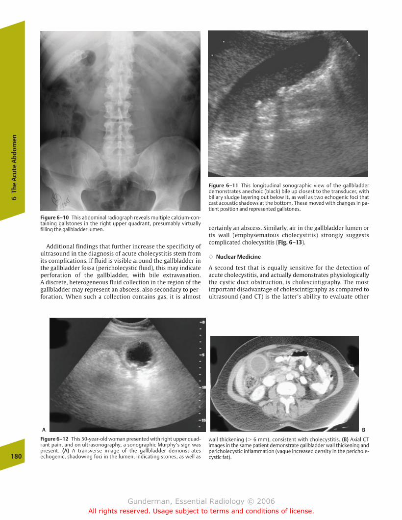
Additional findings that further increase the specificity ofultrasound in the diagnosis of acute cholecystitis stem fromits complications. If fluid is visible around the gallbladder inthe gallbladder fossa (pericholecystic fluid), this may indicateperforation of the gallbladder, with bile extravasation. A discrete, heterogeneous fluid collection in the region of thegallbladder may represent an abscess, also secondary to per-foration. When such a collection contains gas, it is almost
certainly an abscess. Similarly, air in the gallbladder lumen orits wall (emphysematous cholecystitis) strongly suggestscomplicated cholecystitis (Fig. 6–13).
�� Nuclear Medicine
A second test that is equally sensitive for the detection ofacute cholecystitis, and actually demonstrates physiologicallythe cystic duct obstruction, is cholescintigraphy. The mostimportant disadvantage of cholescintigraphy as compared toultrasound (and CT) is the latter’s ability to evaluate other
180
6Th
e A
cute
Abd
omen
Figure 6–10 This abdominal radiograph reveals multiple calcium-con-taining gallstones in the right upper quadrant, presumably virtuallyfilling the gallbladder lumen.
Figure 6–11 This longitudinal sonographic view of the gallbladderdemonstrates anechoic (black) bile up closest to the transducer, withbiliary sludge layering out below it, as well as two echogenic foci thatcast acoustic shadows at the bottom. These moved with changes in pa-tient position and represented gallstones.
Figure 6–12 This 50-year-old woman presented with right upper quad-rant pain, and on ultrasonography, a sonographic Murphy’s sign waspresent. ((AA)) A transverse image of the gallbladder demonstratesechogenic, shadowing foci in the lumen, indicating stones, as well as
wall thickening (� 6 mm), consistent with cholecystitis. ((BB)) Axial CT images in the same patient demonstrate gallbladder wall thickening andpericholecystic inflammation (vague increased density in the perichole-cystic fat).
A B
chapter 06_p172-191.qxd 12/1/05 4:00 PM Page 180
Gunderman, Essential Radiology © 2006All rights reserved. Usage subject to terms and conditions of license.
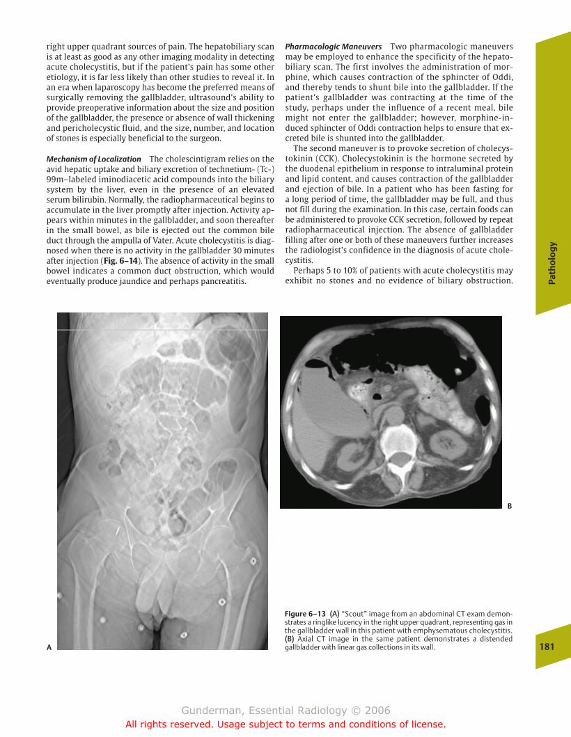
Path
olo
gy
181
right upper quadrant sources of pain. The hepatobiliary scanis at least as good as any other imaging modality in detectingacute cholecystitis, but if the patient’s pain has some otheretiology, it is far less likely than other studies to reveal it. Inan era when laparoscopy has become the preferred means ofsurgically removing the gallbladder, ultrasound’s ability toprovide preoperative information about the size and positionof the gallbladder, the presence or absence of wall thickeningand pericholecystic fluid, and the size, number, and locationof stones is especially beneficial to the surgeon.
Mechanism of Localization The cholescintigram relies on theavid hepatic uptake and biliary excretion of technetium- (Tc-)99m–labeled iminodiacetic acid compounds into the biliarysystem by the liver, even in the presence of an elevatedserum bilirubin. Normally, the radiopharmaceutical begins toaccumulate in the liver promptly after injection. Activity ap-pears within minutes in the gallbladder, and soon thereafterin the small bowel, as bile is ejected out the common bileduct through the ampulla of Vater. Acute cholecystitis is diag-nosed when there is no activity in the gallbladder 30 minutesafter injection (Fig. 6–14). The absence of activity in the smallbowel indicates a common duct obstruction, which wouldeventually produce jaundice and perhaps pancreatitis.
Pharmacologic Maneuvers Two pharmacologic maneuversmay be employed to enhance the specificity of the hepato-biliary scan. The first involves the administration of mor-phine, which causes contraction of the sphincter of Oddi,and thereby tends to shunt bile into the gallbladder. If thepatient’s gallbladder was contracting at the time of thestudy, perhaps under the influence of a recent meal, bilemight not enter the gallbladder; however, morphine-in-duced sphincter of Oddi contraction helps to ensure that ex-creted bile is shunted into the gallbladder.
The second maneuver is to provoke secretion of cholecys-tokinin (CCK). Cholecystokinin is the hormone secreted bythe duodenal epithelium in response to intraluminal proteinand lipid content, and causes contraction of the gallbladderand ejection of bile. In a patient who has been fasting for a long period of time, the gallbladder may be full, and thusnot fill during the examination. In this case, certain foods canbe administered to provoke CCK secretion, followed by repeat radiopharmaceutical injection. The absence of gallbladderfilling after one or both of these maneuvers further increasesthe radiologist’s confidence in the diagnosis of acute chole-cystitis.
Perhaps 5 to 10% of patients with acute cholecystitis mayexhibit no stones and no evidence of biliary obstruction.
Figure 6–13 ((AA)) “Scout” image from an abdominal CT exam demon-strates a ringlike lucency in the right upper quadrant, representing gas inthe gallbladder wall in this patient with emphysematous cholecystitis.((BB)) Axial CT image in the same patient demonstrates a distended gallbladder with linear gas collections in its wall.A
B
chapter 06_p172-191.qxd 12/1/05 4:00 PM Page 181
Gunderman, Essential Radiology © 2006All rights reserved. Usage subject to terms and conditions of license.
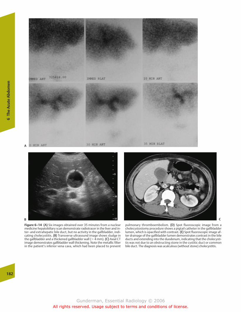
182
6Th
e A
cute
Abd
omen
Figure 6–14 ((AA)) Six images obtained over 35 minutes from a nuclearmedicine hepatobiliary scan demonstrate radiotracer in the liver and in-ter- and extrahepatic bile duct, but no activity in the gallbladder, indi-cating cholecystitis. ((BB)) Transverse ultrasound image shows sludge inthe gallbladder and a thickened gallbladder wall (� 4 mm). ((CC)) Axial CTimage demonstrates gallbladder wall thickening. Note the metallic filterin the patient’s inferior vena cava, which had been placed to prevent
pulmonary thromboembolism. ((DD)) Spot fluoroscopic image from acholecystostomy procedure shows a pigtail catheter in the gallbladderlumen, which is opacified with contrast. ((EE)) Spot fluoroscopic image af-ter drainage of the gallbladder lumen demonstrates contrast in the bileducts and extending into the duodenum, indicating that the cholecysti-tis was not due to an obstructing stone in the cystitic duct or commonbile duct. The diagnosis was acalculous (without stone) cholecystitis.
A
B C
chapter 06_p172-191.qxd 12/1/05 4:00 PM Page 182
Gunderman, Essential Radiology © 2006All rights reserved. Usage subject to terms and conditions of license.
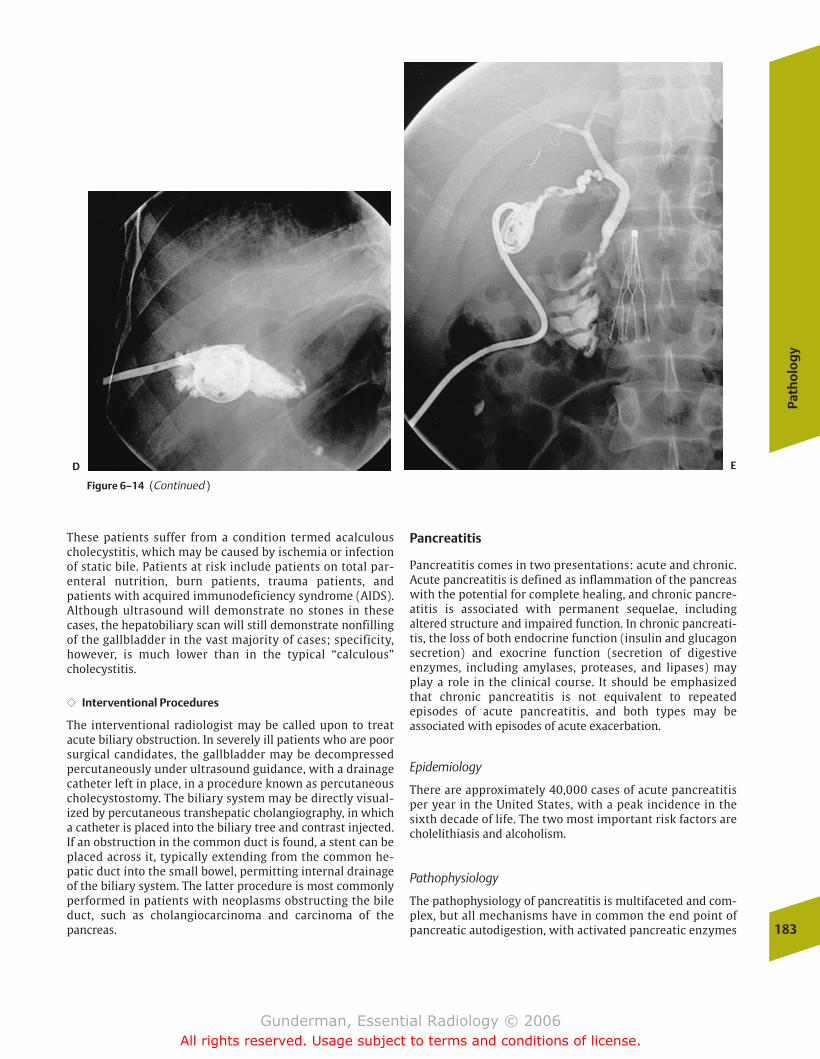
Path
olo
gy
183
These patients suffer from a condition termed acalculouscholecystitis, which may be caused by ischemia or infectionof static bile. Patients at risk include patients on total par-enteral nutrition, burn patients, trauma patients, and patients with acquired immunodeficiency syndrome (AIDS).Although ultrasound will demonstrate no stones in thesecases, the hepatobiliary scan will still demonstrate nonfillingof the gallbladder in the vast majority of cases; specificity,however, is much lower than in the typical “calculous”cholecystitis.
�� Interventional Procedures
The interventional radiologist may be called upon to treatacute biliary obstruction. In severely ill patients who are poorsurgical candidates, the gallbladder may be decompressedpercutaneously under ultrasound guidance, with a drainagecatheter left in place, in a procedure known as percutaneouscholecystostomy. The biliary system may be directly visual-ized by percutaneous transhepatic cholangiography, in whicha catheter is placed into the biliary tree and contrast injected.If an obstruction in the common duct is found, a stent can beplaced across it, typically extending from the common he-patic duct into the small bowel, permitting internal drainageof the biliary system. The latter procedure is most commonlyperformed in patients with neoplasms obstructing the bileduct, such as cholangiocarcinoma and carcinoma of thepancreas.
Pancreatitis
Pancreatitis comes in two presentations: acute and chronic.Acute pancreatitis is defined as inflammation of the pancreaswith the potential for complete healing, and chronic pancre-atitis is associated with permanent sequelae, including altered structure and impaired function. In chronic pancreati-tis, the loss of both endocrine function (insulin and glucagonsecretion) and exocrine function (secretion of digestive enzymes, including amylases, proteases, and lipases) mayplay a role in the clinical course. It should be emphasizedthat chronic pancreatitis is not equivalent to repeatedepisodes of acute pancreatitis, and both types may be associated with episodes of acute exacerbation.
Epidemiology
There are approximately 40,000 cases of acute pancreatitisper year in the United States, with a peak incidence in thesixth decade of life. The two most important risk factors arecholelithiasis and alcoholism.
Pathophysiology
The pathophysiology of pancreatitis is multifaceted and com-plex, but all mechanisms have in common the end point ofpancreatic autodigestion, with activated pancreatic enzymes
Figure 6–14 (Continued )
D E
chapter 06_p172-191.qxd 12/1/05 4:00 PM Page 183
Gunderman, Essential Radiology © 2006All rights reserved. Usage subject to terms and conditions of license.

escaping from the ductal system and lysing the tissue of thepancreas and adjacent structures. The fact that the pancreaslacks a capsule tends to facilitate the spread of the inflamma-tory process.
Alcohol ingestion is a more common factor in men,whereas cholelithiasis is more common in women. Gallstonepancreatitis results from impaction of a gallstone in the distalcommon bile duct, after the point of entry of the pancreaticduct, with resultant obstruction of pancreatic secretion. Alco-holic pancreatitis may stem from inspissation of secretions inthe pancreatic ductal system, secondary to the increased concentration of secretions associated with alcohol consumption. It is also known that alcohol causes activationof intracellular digestive enzymes in the pancreatic acini.Other causes include pancreas divisum, trauma (including iatrogenic), penetrating ulcer, hyperlipoproteinemia, and various drugs. Alcoholism is the most prominent cause ofchronic pancreatitis.
Clinical Presentation
Patients experiencing an acute attack present with severe abdominal pain that radiates through to the back, peritonealsigns, and fever. They may exhibit respiratory distress withatelectasis and effusions, subcutaneous fat necrosis (mani-festing as purple skin lesions), and saponification of serumcalcium (precipitation of calcium soaps in fat necrosis), withresultant signs and symptoms of hypocalcemia. In severecases, patients may present in shock, with renal failure anddisseminated intravascular coagulation.
The diagnosis of acute pancreatitis is best made clinically,based on the constellation of history, physical signs, and lab-oratory findings. Classic laboratory findings include elevations of serum amylase and lipase, with the latter being
the more specific of the two, because the salivary glands, fallopian tubes, and lungs also synthesize amylase.
Imaging
�� Acute Pancreatitis
Imaging is usually performed in cases where the diagnosis isuncertain or to detect complications and assess prognosis. Inthe acute setting, CT is the study of choice, providing a com-prehensive assessment of the gland itself and the surround-ing tissues (Fig. 6-15). In many cases, the gland appears nor-mal, which does not exclude the diagnosis. Common findingsinclude diffuse or focal swelling of the gland, heterogeneity,poor definition, fluid collections, and thickening of thepararenal fascia.
One of the most important complications of acute pancreati-tis, seen in 10% of cases, is a pancreatic pseudocyst. A pancre-atic pseudocyst is a fluid collection surrounded by a fibrouscapsule (Fig. 6–16). It is not a true cyst because it does not havean epithelial lining. A significant percentage of pseudocysts willnot resolve spontaneously. Pseudocysts are often seen not onlywithin the pancreas but also in the lesser sac (between thepancreas and stomach) and in the left pararenal space, poten-tial spaces with which the gland itself is continuous.
Abscess, a rarer but more serious condition, develops in ap-proximately 1 in 20 cases and increases the risk of mortality.Abscesses are often recognized by the presence of gas and re-quire urgent drainage. Patients whose hematocrits are fallingshould be suspected of an even rarer condition, hemorrhagicpancreatitis. Pseudoaneurysm formation or rupture may pre-sent in a similar way. Ultrasound is useful in following up oncomplications and in guiding therapeutic interventions, suchas the drainage of fluid collections.
184
6Th
e A
cute
Abd
omen
Figure 6–15 ((AA)) Axial CT image demonstrates severe inflammation ofthe pancreas, which is enlarged and shows very indistinct margins. ((BB)) Double-contrast view of the gastric antrum and duodenum demon-
strates marked irregular spiculation of the mucosal folds in the thirdand fourth portion of the duodenum, secondary to the adjacent pancreatitis.
A B
chapter 06_p172-191.qxd 12/1/05 4:00 PM Page 184
Gunderman, Essential Radiology © 2006All rights reserved. Usage subject to terms and conditions of license.
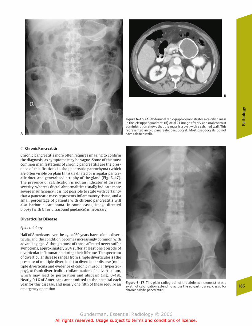
Path
olo
gy
185
�� Chronic Pancreatitis
Chronic pancreatitis more often requires imaging to confirmthe diagnosis, as symptoms may be vague. Some of the mostcommon manifestations of chronic pancreatitis are the pres-ence of calcifications in the pancreatic parenchyma (whichare often visible on plain films), a dilated or irregular pancre-atic duct, and generalized atrophy of the gland (Fig. 6–17).The presence of calcification is not an indicator of diseaseseverity, whereas ductal abnormalities usually indicate moresevere insufficiency. It is not possible to state with certaintythat a pancreatic mass represents inflammatory tissue, and asmall percentage of patients with chronic pancreatitis willalso harbor a carcinoma. In some cases, image-directedbiopsy (with CT or ultrasound guidance) is necessary.
Diverticular Disease
Epidemiology
Half of Americans over the age of 60 years have colonic diver-ticula, and the condition becomes increasingly common withadvancing age. Although most of those affected never suffersymptoms, approximately 20% suffer at least one episode ofdiverticular inflammation during their lifetime. The spectrumof diverticular disease ranges from simple diverticulosis (thepresence of multiple diverticula) to diverticular disease (mul-tiple diverticula and evidence of colonic muscular hypertro-phy), to frank diverticulitis (inflammation of a diverticulum,which may lead to perforation and abscess) (Fig. 6–18).Nearly 0.1% of Americans are admitted to the hospital eachyear for this disease, and nearly one fifth of these require anemergency operation.
Figure 6–16 ((AA)) Abdominal radiograph demonstrates a calcified massin the left upper quadrant. ((BB)) Axial CT image after IV and oral contrastadministration shows that the mass is a cyst with a calcified wall. Thisrepresented an old pancreatic pseudocyst. Most pseudocysts do nothave calcified walls.
Figure 6–17 This plain radiograph of the abdomen demonstrates aswath of calcification extending across the epigastric area, classic forchronic calcific pancreatitis.
A
B
chapter 06_p172-191.qxd 12/1/05 4:00 PM Page 185
Gunderman, Essential Radiology © 2006All rights reserved. Usage subject to terms and conditions of license.
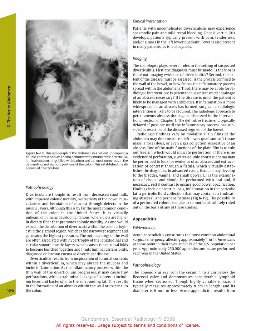
Figure 6–18 This radiograph of the abdomen in a patient undergoing adouble-contrast barium enema demonstrates innumerable diverticula,luminal outpouchings filled with barium and air, most numerous in thedescending and sigmoid portions of the colon. This established the di-agnosis of diverticulosis.
Clinical Presentation
Patients with uncomplicated diverticulosis may experiencespasmodic pain and mild rectal bleeding. Once diverticulitisdevelops, patients typically present with pain, tenderness,and/or a mass in the left lower quadrant. Fever is also presentin many patients, as is leukocytosis.
Imaging
The radiologist plays several roles in the setting of suspecteddiverticulitis. First, the diagnosis must be made: Is there or isthere not imaging evidence of diverticulitis? Second, the ex-tent of the disease must be assessed: Is the process confined tothe wall of the bowel, or how far has the inflammatory processspread within the abdomen? Third, there may be a role for ra-diologic intervention: Is percutaneous or transrectal drainageof an abscess necessary? If the disease is mild, the patient islikely to be managed with antibiotics. If inflammation is morewidespread, or an abscess has formed, surgical or radiologicintervention is likely to be required. The radiologic approach topercutaneous abscess drainage is discussed in the interven-tional section of Chapter 1. The definitive treatment, typicallydelayed if possible until the inflammatory process has sub-sided, is resection of the diseased segment of the bowel.
Radiologic findings vary by modality. Plain films of the abdomen may demonstrate a left lower quadrant soft tissuemass, a focal ileus, or even a gas collection suggestive of anabscess. One of the main functions of the plain film is to ruleout free air, which would indicate perforation. If there is noevidence of perforation, a water-soluble contrast enema maybe performed to look for evidence of an abscess and extrava-sation of contrast through a fistula, which virtually estab-lishes the diagnosis. In advanced cases, fistulae may developto the bladder, vagina, and small bowel. CT is the examina-tion of choice and should be performed with oral and, if necessary, rectal contrast to ensure good bowel opacification.Findings include diverticulosis, inflammation in the pericolicfat, a pericolic fluid collection that may contain air (indicat-ing abscess), and perhaps fistulae (Fig 6-19). The possibilityof a perforated colonic neoplasm cannot be absolutely ruledout on the basis of any of these studies.
Appendicitis
Epidemiology
Acute appendicitis constitutes the most common abdominalsurgical emergency, affecting approximately 1 in 14 Americansat some point in their lives, and 0.1% of the U.S. population peryear. Approximately 250,000 appendectomies are performedeach year in the United States.
Pathophysiology
The appendix arises from the cecum 1 to 2 cm below theileocecal valve and demonstrates considerable lymphoid tissue when sectioned. Though highly variable in size, it typically measures approximately 8 cm in length, and its diameter is 6 mm or less. Acute appendicitis results from 186
6Th
e A
cute
Abd
omen
Pathophysiology
Diverticula are thought to result from decreased stool bulk,with impaired colonic motility, overactivity of the bowel mus-culature, and herniation of mucosa through defects in themuscle layers. Although this is by far the most common condi-tion of the colon in the United States, it is virtually unheard of in many developing nations, where diets are higherin dietary fiber that promotes colonic motility. As one wouldexpect, the distribution of diverticula within the colon is high-est in the sigmoid region, which is the narrowest segment andgenerates the highest pressures. The outpouchings of the wallare often associated with hypertrophy of the longitudinal andcircular smooth muscle layers, which causes the mucosal foldsto become bunched together and limits luminal distensibility,diagnosed on barium enema as diverticular disease.
Diverticulitis results from inspissation of luminal contentswithin a diverticulum, which may abrade the mucosa and incite inflammation. As the inflammatory process within thethin wall of the diverticulum progresses, it may cause tinyperforations, with extraluminal leakage of contents (includ-ing feces and bacteria) into the surrounding fat. This resultsin the formation of an abscess within the wall or external tothe colon.
chapter 06_p172-191.qxd 12/1/05 4:00 PM Page 186
Gunderman, Essential Radiology © 2006All rights reserved. Usage subject to terms and conditions of license.
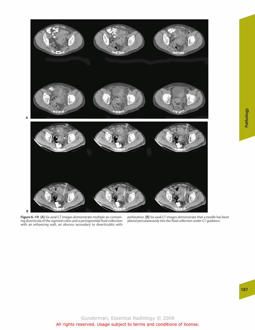
Path
olo
gy
187
Figure 6–19 ((AA)) Six axial CT images demonstrate multiple air-contain-ing diverticula of the sigmoid colon and a perisigmoidal fluid collectionwith an enhancing wall, an abscess secondary to diverticulitis with
perforation. ((BB)) Six axial CT images demonstrate that a needle has beenplaced percutaneously into the fluid collection under CT guidance.
A
B
chapter 06_p172-191.qxd 12/1/05 4:00 PM Page 187
Gunderman, Essential Radiology © 2006All rights reserved. Usage subject to terms and conditions of license.
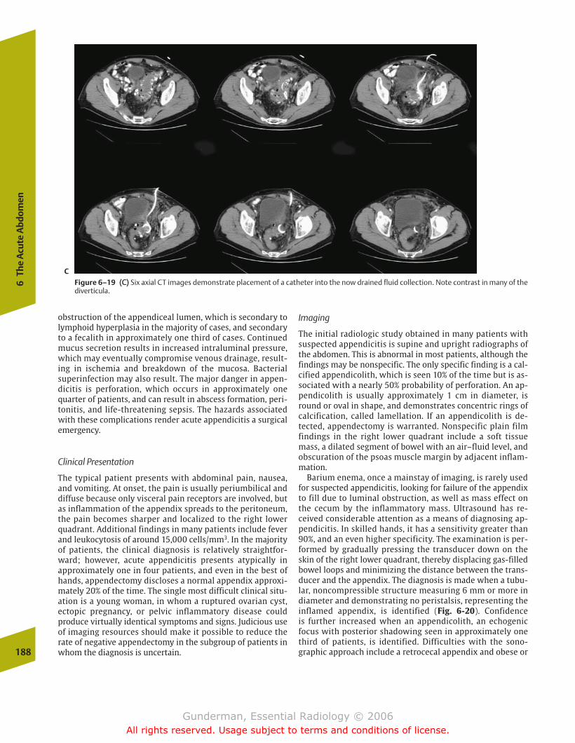
obstruction of the appendiceal lumen, which is secondary tolymphoid hyperplasia in the majority of cases, and secondaryto a fecalith in approximately one third of cases. Continuedmucus secretion results in increased intraluminal pressure,which may eventually compromise venous drainage, result-ing in ischemia and breakdown of the mucosa. Bacterial superinfection may also result. The major danger in appen-dicitis is perforation, which occurs in approximately onequarter of patients, and can result in abscess formation, peri-tonitis, and life-threatening sepsis. The hazards associatedwith these complications render acute appendicitis a surgicalemergency.
Clinical Presentation
The typical patient presents with abdominal pain, nausea,and vomiting. At onset, the pain is usually periumbilical anddiffuse because only visceral pain receptors are involved, butas inflammation of the appendix spreads to the peritoneum,the pain becomes sharper and localized to the right lowerquadrant. Additional findings in many patients include feverand leukocytosis of around 15,000 cells/mm3. In the majorityof patients, the clinical diagnosis is relatively straightfor-ward; however, acute appendicitis presents atypically in approximately one in four patients, and even in the best ofhands, appendectomy discloses a normal appendix approxi-mately 20% of the time. The single most difficult clinical situ-ation is a young woman, in whom a ruptured ovarian cyst,ectopic pregnancy, or pelvic inflammatory disease could produce virtually identical symptoms and signs. Judicious useof imaging resources should make it possible to reduce therate of negative appendectomy in the subgroup of patients inwhom the diagnosis is uncertain.
Imaging
The initial radiologic study obtained in many patients withsuspected appendicitis is supine and upright radiographs ofthe abdomen. This is abnormal in most patients, although thefindings may be nonspecific. The only specific finding is a cal-cified appendicolith, which is seen 10% of the time but is as-sociated with a nearly 50% probability of perforation. An ap-pendicolith is usually approximately 1 cm in diameter, isround or oval in shape, and demonstrates concentric rings ofcalcification, called lamellation. If an appendicolith is de-tected, appendectomy is warranted. Nonspecific plain filmfindings in the right lower quadrant include a soft tissuemass, a dilated segment of bowel with an air–fluid level, andobscuration of the psoas muscle margin by adjacent inflam-mation.
Barium enema, once a mainstay of imaging, is rarely usedfor suspected appendicitis, looking for failure of the appendixto fill due to luminal obstruction, as well as mass effect onthe cecum by the inflammatory mass. Ultrasound has re-ceived considerable attention as a means of diagnosing ap-pendicitis. In skilled hands, it has a sensitivity greater than90%, and an even higher specificity. The examination is per-formed by gradually pressing the transducer down on theskin of the right lower quadrant, thereby displacing gas-filledbowel loops and minimizing the distance between the trans-ducer and the appendix. The diagnosis is made when a tubu-lar, noncompressible structure measuring 6 mm or more in diameter and demonstrating no peristalsis, representing theinflamed appendix, is identified (Fig. 6-20). Confidence is further increased when an appendicolith, an echogenicfocus with posterior shadowing seen in approximately onethird of patients, is identified. Difficulties with the sono-graphic approach include a retrocecal appendix and obese or188
6Th
e A
cute
Abd
omen
Figure 6–19 ((CC)) Six axial CT images demonstrate placement of a catheter into the now drained fluid collection. Note contrast in many of thediverticula.
C
chapter 06_p172-191.qxd 12/1/05 4:00 PM Page 188
Gunderman, Essential Radiology © 2006All rights reserved. Usage subject to terms and conditions of license.
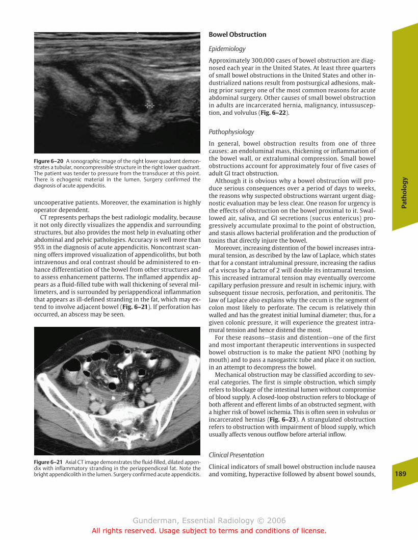
Path
olo
gy
189
uncooperative patients. Moreover, the examination is highlyoperator dependent.
CT represents perhaps the best radiologic modality, becauseit not only directly visualizes the appendix and surroundingstructures, but also provides the most help in evaluating otherabdominal and pelvic pathologies. Accuracy is well more than95% in the diagnosis of acute appendicitis. Noncontrast scan-ning offers improved visualization of appendicoliths, but bothintravenous and oral contrast should be administered to en-hance differentiation of the bowel from other structures andto assess enhancement patterns. The inflamed appendix ap-pears as a fluid-filled tube with wall thickening of several mil-limeters, and is surrounded by periappendiceal inflammationthat appears as ill-defined stranding in the fat, which may ex-tend to involve adjacent bowel (Fig. 6–21). If perforation hasoccurred, an abscess may be seen.
Bowel Obstruction
Epidemiology
Approximately 300,000 cases of bowel obstruction are diag-nosed each year in the United States. At least three quartersof small bowel obstructions in the United States and other in-dustrialized nations result from postsurgical adhesions, mak-ing prior surgery one of the most common reasons for acuteabdominal surgery. Other causes of small bowel obstructionin adults are incarcerated hernia, malignancy, intussuscep-tion, and volvulus (Fig. 6–22).
Pathophysiology
In general, bowel obstruction results from one of threecauses: an endoluminal mass, thickening or inflammation ofthe bowel wall, or extraluminal compression. Small bowelobstructions account for approximately four of five cases ofadult GI tract obstruction.
Although it is obvious why a bowel obstruction will pro-duce serious consequences over a period of days to weeks,the reasons why suspected obstructions warrant urgent diag-nostic evaluation may be less clear. One reason for urgency isthe effects of obstruction on the bowel proximal to it. Swal-lowed air, saliva, and GI secretions (succus entericus) pro-gressively accumulate proximal to the point of obstruction,and stasis allows bacterial proliferation and the production oftoxins that directly injure the bowel.
Moreover, increasing distention of the bowel increases intra-mural tension, as described by the law of Laplace, which statesthat for a constant intraluminal pressure, increasing the radiusof a viscus by a factor of 2 will double its intramural tension.This increased intramural tension may eventually overcomecapillary perfusion pressure and result in ischemic injury, withsubsequent tissue necrosis, perforation, and peritonitis. Thelaw of Laplace also explains why the cecum is the segment ofcolon most likely to perforate. The cecum is relatively thinwalled and has the greatest initial luminal diameter; thus, for agiven colonic pressure, it will experience the greatest intra-mural tension and hence distend the most.
For these reasons—stasis and distention—one of the firstand most important therapeutic interventions in suspectedbowel obstruction is to make the patient NPO (nothing bymouth) and to pass a nasogastric tube and place it on suction,in an attempt to decompress the bowel.
Mechanical obstruction may be classified according to sev-eral categories. The first is simple obstruction, which simplyrefers to blockage of the intestinal lumen without compromiseof blood supply. A closed-loop obstruction refers to blockage ofboth afferent and efferent limbs of an obstructed segment, witha higher risk of bowel ischemia. This is often seen in volvulus orincarcerated hernias (Fig. 6–23). A strangulated obstructionrefers to obstruction with impairment of blood supply, whichusually affects venous outflow before arterial inflow.
Clinical Presentation
Clinical indicators of small bowel obstruction include nauseaand vomiting, hyperactive followed by absent bowel sounds,
Figure 6–20 A sonographic image of the right lower quadrant demon-strates a tubular, noncompressible structure in the right lower quadrant.The patient was tender to pressure from the transducer at this point.There is echogenic material in the lumen. Surgery confirmed the diagnosis of acute appendicitis.
Figure 6–21 Axial CT image demonstrates the fluid-filled, dilated appen-dix with inflammatory stranding in the periappendiceal fat. Note thebright appendicolith in the lumen. Surgery confirmed acute appendicitis.
chapter 06_p172-191.qxd 12/1/05 4:00 PM Page 189
Gunderman, Essential Radiology © 2006All rights reserved. Usage subject to terms and conditions of license.
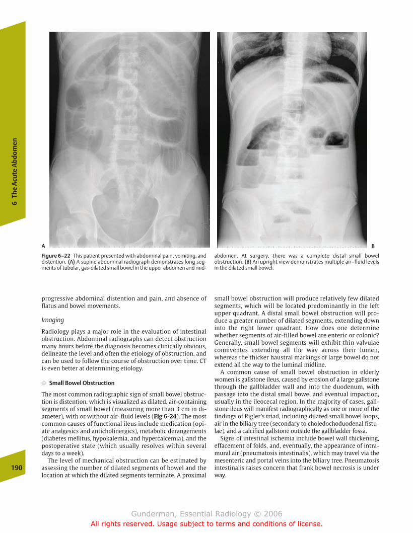
progressive abdominal distention and pain, and absence offlatus and bowel movements.
Imaging
Radiology plays a major role in the evaluation of intestinalobstruction. Abdominal radiographs can detect obstructionmany hours before the diagnosis becomes clinically obvious,delineate the level and often the etiology of obstruction, andcan be used to follow the course of obstruction over time. CTis even better at determining etiology.
�� Small Bowel Obstruction
The most common radiographic sign of small bowel obstruc-tion is distention, which is visualized as dilated, air-containingsegments of small bowel (measuring more than 3 cm in di-ameter), with or without air–fluid levels (Fig 6-24). The mostcommon causes of functional ileus include medication (opi-ate analgesics and anticholinergics), metabolic derangements(diabetes mellitus, hypokalemia, and hypercalcemia), and thepostoperative state (which usually resolves within severaldays to a week).
The level of mechanical obstruction can be estimated byassessing the number of dilated segments of bowel and thelocation at which the dilated segments terminate. A proximal
small bowel obstruction will produce relatively few dilated segments, which will be located predominantly in the leftupper quadrant. A distal small bowel obstruction will pro-duce a greater number of dilated segments, extending downinto the right lower quadrant. How does one determinewhether segments of air-filled bowel are enteric or colonic?Generally, small bowel segments will exhibit thin valvulaeconniventes extending all the way across their lumen,whereas the thicker haustral markings of large bowel do notextend all the way to the luminal midline.
A common cause of small bowel obstruction in elderlywomen is gallstone ileus, caused by erosion of a large gallstonethrough the gallbladder wall and into the duodenum, withpassage into the distal small bowel and eventual impaction,usually in the ileocecal region. In the majority of cases, gall-stone ileus will manifest radiographically as one or more of thefindings of Rigler’s triad, including dilated small bowel loops,air in the biliary tree (secondary to choledochoduodenal fistu-lae), and a calcified gallstone outside the gallbladder fossa.
Signs of intestinal ischemia include bowel wall thickening,effacement of folds, and, eventually, the appearance of intra-mural air (pneumatosis intestinalis), which may travel via themesenteric and portal veins into the biliary tree. Pneumatosisintestinalis raises concern that frank bowel necrosis is underway.
190
6Th
e A
cute
Abd
omen
Figure 6–22 This patient presented with abdominal pain, vomiting, anddistention. ((AA)) A supine abdominal radiograph demonstrates long seg-ments of tubular, gas-dilated small bowel in the upper abdomen and mid-
abdomen. At surgery, there was a complete distal small bowel obstruction. ((BB)) An upright view demonstrates multiple air–fluid levelsin the dilated small bowel.
A B
chapter 06_p172-191.qxd 12/1/05 4:00 PM Page 190
Gunderman, Essential Radiology © 2006All rights reserved. Usage subject to terms and conditions of license.
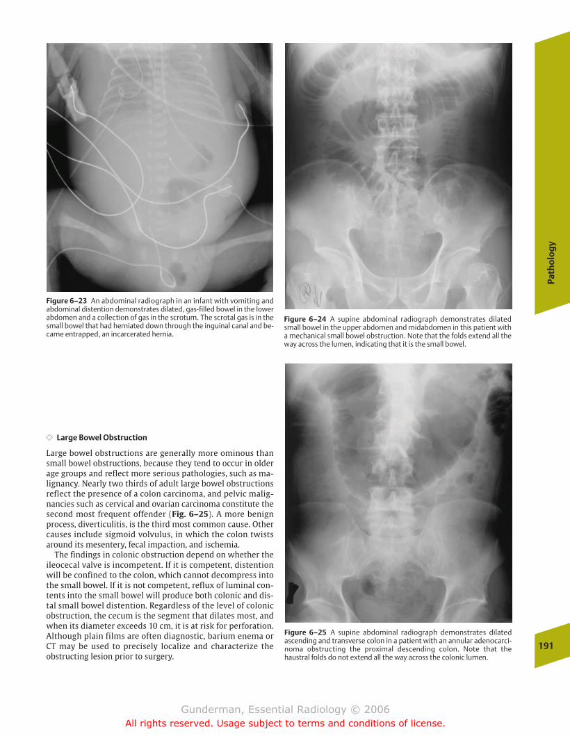
Path
olo
gy
191
�� Large Bowel Obstruction
Large bowel obstructions are generally more ominous thansmall bowel obstructions, because they tend to occur in olderage groups and reflect more serious pathologies, such as ma-lignancy. Nearly two thirds of adult large bowel obstructionsreflect the presence of a colon carcinoma, and pelvic malig-nancies such as cervical and ovarian carcinoma constitute thesecond most frequent offender (Fig. 6–25). A more benignprocess, diverticulitis, is the third most common cause. Othercauses include sigmoid volvulus, in which the colon twistsaround its mesentery, fecal impaction, and ischemia.
The findings in colonic obstruction depend on whether theileocecal valve is incompetent. If it is competent, distentionwill be confined to the colon, which cannot decompress intothe small bowel. If it is not competent, reflux of luminal con-tents into the small bowel will produce both colonic and dis-tal small bowel distention. Regardless of the level of colonicobstruction, the cecum is the segment that dilates most, andwhen its diameter exceeds 10 cm, it is at risk for perforation.Although plain films are often diagnostic, barium enema orCT may be used to precisely localize and characterize the obstructing lesion prior to surgery.
Figure 6–23 An abdominal radiograph in an infant with vomiting andabdominal distention demonstrates dilated, gas-filled bowel in the lowerabdomen and a collection of gas in the scrotum. The scrotal gas is in thesmall bowel that had herniated down through the inguinal canal and be-came entrapped, an incarcerated hernia.
Figure 6–24 A supine abdominal radiograph demonstrates dilatedsmall bowel in the upper abdomen and midabdomen in this patient witha mechanical small bowel obstruction. Note that the folds extend all theway across the lumen, indicating that it is the small bowel.
Figure 6–25 A supine abdominal radiograph demonstrates dilated ascending and transverse colon in a patient with an annular adenocarci-noma obstructing the proximal descending colon. Note that the haustral folds do not extend all the way across the colonic lumen.
chapter 06_p172-191.qxd 12/1/05 4:00 PM Page 191
Gunderman, Essential Radiology © 2006All rights reserved. Usage subject to terms and conditions of license.
� Female Reproductive System: Breasts
Anatomy and PhysiologyPathology
Breast Cancer
� Female Reproductive System: Pelvis
Anatomy and PhysiologyPathology
Pelvic Masses
� Pregnancy
Anatomy and PhysiologyImaging
First TrimesterSecond and Third Trimesters
� Male Reproductive System
Anatomy and PhysiologyPathology
ScrotumProstate
7The Reproductive System
chapter 07_p192-219.qxd 12/1/05 4:09 PM Page 192
Gunderman, Essential Radiology © 2006All rights reserved. Usage subject to terms and conditions of license.
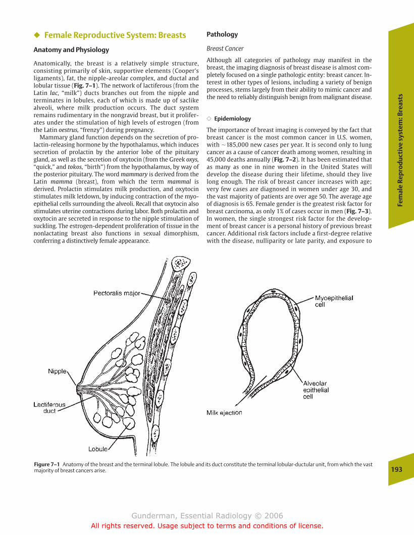
Fem
ale
Rep
rod
uct
ive
syst
em: B
reas
ts
193
� Female Reproductive System: Breasts
Anatomy and Physiology
Anatomically, the breast is a relatively simple structure, consisting primarily of skin, supportive elements (Cooper’sligaments), fat, the nipple-areolar complex, and ductal andlobular tissue (Fig. 7–1). The network of lactiferous (from theLatin lac, “milk”) ducts branches out from the nipple and terminates in lobules, each of which is made up of saclikealveoli, where milk production occurs. The duct system remains rudimentary in the nongravid breast, but it prolifer-ates under the stimulation of high levels of estrogen (fromthe Latin oestrus, “frenzy”) during pregnancy.
Mammary gland function depends on the secretion of pro-lactin-releasing hormone by the hypothalamus, which inducessecretion of prolactin by the anterior lobe of the pituitarygland, as well as the secretion of oxytocin (from the Greek oxys,“quick,” and tokos, “birth”) from the hypothalamus, by way ofthe posterior pituitary. The word mammary is derived from theLatin mamma (breast), from which the term mammal is derived. Prolactin stimulates milk production, and oxytocinstimulates milk letdown, by inducing contraction of the myo-epithelial cells surrounding the alveoli. Recall that oxytocin alsostimulates uterine contractions during labor. Both prolactin andoxytocin are secreted in response to the nipple stimulation ofsuckling. The estrogen-dependent proliferation of tissue in thenonlactating breast also functions in sexual dimorphism,conferring a distinctively female appearance.
Pathology
Breast Cancer
Although all categories of pathology may manifest in thebreast, the imaging diagnosis of breast disease is almost com-pletely focused on a single pathologic entity: breast cancer. In-terest in other types of lesions, including a variety of benignprocesses, stems largely from their ability to mimic cancer andthe need to reliably distinguish benign from malignant disease.
�� Epidemiology
The importance of breast imaging is conveyed by the fact thatbreast cancer is the most common cancer in U.S. women,with �185,000 new cases per year. It is second only to lungcancer as a cause of cancer death among women, resulting in45,000 deaths annually (Fig. 7–2). It has been estimated thatas many as one in nine women in the United States will develop the disease during their lifetime, should they livelong enough. The risk of breast cancer increases with age;very few cases are diagnosed in women under age 30, andthe vast majority of patients are over age 50. The average ageof diagnosis is 65. Female gender is the greatest risk factor forbreast carcinoma, as only 1% of cases occur in men (Fig. 7–3).In women, the single strongest risk factor for the develop-ment of breast cancer is a personal history of previous breastcancer. Additional risk factors include a first-degree relativewith the disease, nulliparity or late parity, and exposure to
Figure 7–1 Anatomy of the breast and the terminal lobule. The lobule and its duct constitute the terminal lobular-ductular unit, from which the vastmajority of breast cancers arise.
chapter 07_p192-219.qxd 12/1/05 4:09 PM Page 193
Gunderman, Essential Radiology © 2006All rights reserved. Usage subject to terms and conditions of license.
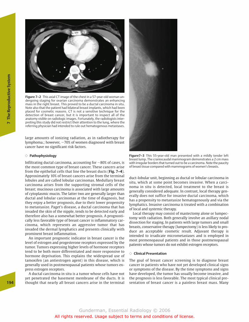
large amounts of ionizing radiation, as in radiotherapy forlymphoma.; however, �70% of women diagnosed with breastcancer have no significant risk factors.
�� Pathophysiology
Infiltrating ductal carcinoma, accounting for �80% of cases, isthe most common type of breast cancer. These cancers arisefrom the epithelial cells that line the breast ducts (Fig. 7–4).Approximately 10% of breast cancers arise from the terminallobules and are called lobular carcinomas. Medullary breastcarcinoma arises from the supporting stromal cells of thebreast; mucinous carcinoma is associated with large amountsof cytoplasmic mucin. The latter two are generally larger thanductal and lobular carcinomas at the time of diagnosis, butthey enjoy a better prognosis, due to their lower propensityto metastasize. Paget’s disease, a ductal carcinoma that hasinvaded the skin of the nipple, tends to be detected early andtherefore also has a somewhat better prognosis. A prognosti-cally less favorable type of breast cancer is inflammatory car-cinoma, which represents an aggressive tumor that has invaded the dermal lymphatics and presents clinically withprominent breast inflammation.
An important prognostic indicator in breast cancer is thelevel of estrogen and progesterone receptors expressed by thetumor. Tumors expressing higher levels of hormone receptorstend to be both more differentiated and more responsive tohormone deprivation. This explains the widespread use of tamoxifen (an antiestrogen agent) in this disease, which isgenerally used in postmenopausal patients whose tumors ex-press estrogen receptors.
A ductal carcinoma in situ is a tumor whose cells have notyet penetrated the basement membrane of the ducts. It isthought that nearly all breast cancers arise in the terminal
duct-lobular unit, beginning as ductal or lobular carcinoma insitu, which at some point becomes invasive. When a carci-noma in situ is detected, local treatment to the breast is generally considered adequate. In contrast, local therapy gen-erally does not suffice for invasive ductal carcinoma, whichhas a propensity to metastasize hematogenously and via thelymphatics. Invasive carcinoma is treated with a combinationof local and systemic therapy.
Local therapy may consist of mastectomy alone or lumpec-tomy with radiation. Both generally involve an axillary nodaldissection for staging. In patients with large tumors and smallbreasts, conservative therapy (lumpectomy) is less likely to pro-duce an acceptable cosmetic result. Adjuvant therapy is intended to irradicate micrometastases and is employed inmost premenopausal patients and in those postmenopausalpatients whose tumors do not exhibit estrogen receptors.
�� Clinical Presentation
The goal of breast cancer screening is to diagnose breast cancer in patients who have not yet developed clinical signsor symptoms of the disease. By the time symptoms and signshave developed, the tumor has usually become invasive, andthe prognosis is less favorable. The most typical clinical pre-sentation of breast cancer is a painless breast mass. Many194
7Th
e Re
prod
ucti
ve S
yste
m
Figure 7–2 This axial CT image of the chest in a 57-year-old woman un-dergoing staging for ovarian carcinoma demonstrates an enhancingmass in the right breast. This proved to be a ductal carcinoma in situ.Note also that the patient had bilateral breast implants, which had beenplaced for cosmetic reasons. CT is not a sensitive technique for the detection of breast cancer, but it is important to inspect all of theanatomy visible on radiologic images. Fortunately, the radiologists inter-preting this study did not restrict their attention to the lung, where thereferring physician had intended to rule out hematogenous metastases.
Figure7–3 This 55-year-old man presented with a mildly tender leftbreast lump. The craniocaudal mammogram demonstrates a 2 cm masswith irregular borders that turned out to be a carcinoma. Note the paucityof breast tissue compared with mammograms of women’s breasts.
chapter 07_p192-219.qxd 12/1/05 4:09 PM Page 194
Gunderman, Essential Radiology © 2006All rights reserved. Usage subject to terms and conditions of license.
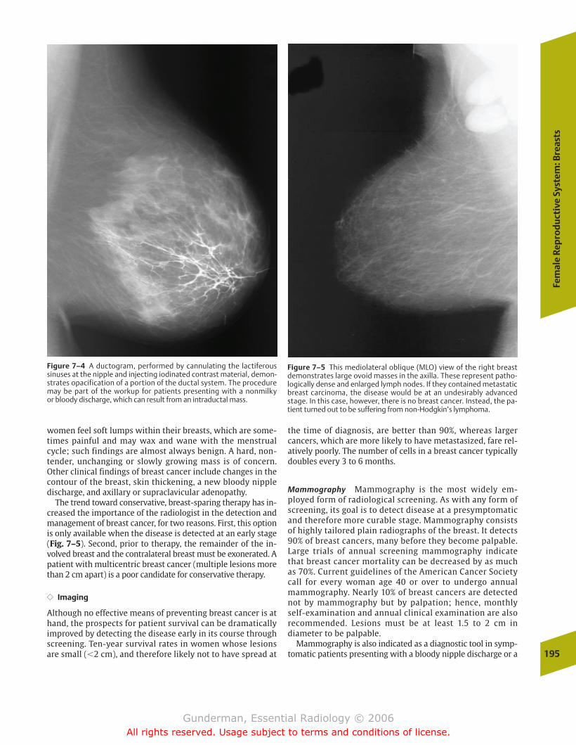
Fem
ale
Rep
rod
uct
ive
Syst
em: B
reas
ts
195
women feel soft lumps within their breasts, which are some-times painful and may wax and wane with the menstrual cycle; such findings are almost always benign. A hard, non-tender, unchanging or slowly growing mass is of concern.Other clinical findings of breast cancer include changes in thecontour of the breast, skin thickening, a new bloody nippledischarge, and axillary or supraclavicular adenopathy.
The trend toward conservative, breast-sparing therapy has in-creased the importance of the radiologist in the detection andmanagement of breast cancer, for two reasons. First, this optionis only available when the disease is detected at an early stage(Fig. 7–5). Second, prior to therapy, the remainder of the in-volved breast and the contralateral breast must be exonerated. Apatient with multicentric breast cancer (multiple lesions morethan 2 cm apart) is a poor candidate for conservative therapy.
�� Imaging
Although no effective means of preventing breast cancer is athand, the prospects for patient survival can be dramaticallyimproved by detecting the disease early in its course throughscreening. Ten-year survival rates in women whose lesionsare small (�2 cm), and therefore likely not to have spread at
the time of diagnosis, are better than 90%, whereas largercancers, which are more likely to have metastasized, fare rel-atively poorly. The number of cells in a breast cancer typicallydoubles every 3 to 6 months.
Mammography Mammography is the most widely em-ployed form of radiological screening. As with any form ofscreening, its goal is to detect disease at a presymptomaticand therefore more curable stage. Mammography consistsof highly tailored plain radiographs of the breast. It detects90% of breast cancers, many before they become palpable.Large trials of annual screening mammography indicatethat breast cancer mortality can be decreased by as muchas 70%. Current guidelines of the American Cancer Societycall for every woman age 40 or over to undergo annualmammography. Nearly 10% of breast cancers are detectednot by mammography but by palpation; hence, monthlyself-examination and annual clinical examination are alsorecommended. Lesions must be at least 1.5 to 2 cm in diameter to be palpable.
Mammography is also indicated as a diagnostic tool in symp-tomatic patients presenting with a bloody nipple discharge or a
Figure 7–4 A ductogram, performed by cannulating the lactiferous sinuses at the nipple and injecting iodinated contrast material, demon-strates opacification of a portion of the ductal system. The proceduremay be part of the workup for patients presenting with a nonmilky or bloody discharge, which can result from an intraductal mass.
Figure 7–5 This mediolateral oblique (MLO) view of the right breastdemonstrates large ovoid masses in the axilla. These represent patho-logically dense and enlarged lymph nodes. If they contained metastaticbreast carcinoma, the disease would be at an undesirably advancedstage. In this case, however, there is no breast cancer. Instead, the pa-tient turned out to be suffering from non-Hodgkin’s lymphoma.
chapter 07_p192-219.qxd 12/1/05 4:09 PM Page 195
Gunderman, Essential Radiology © 2006All rights reserved. Usage subject to terms and conditions of license.
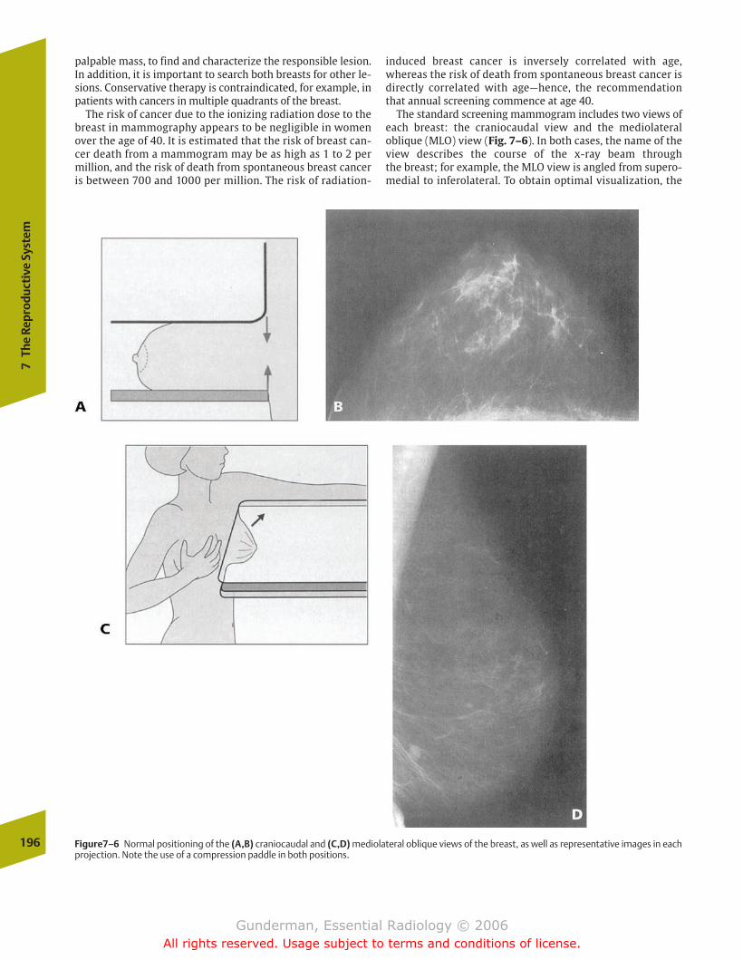
palpable mass, to find and characterize the responsible lesion.In addition, it is important to search both breasts for other le-sions. Conservative therapy is contraindicated, for example, inpatients with cancers in multiple quadrants of the breast.
The risk of cancer due to the ionizing radiation dose to thebreast in mammography appears to be negligible in womenover the age of 40. It is estimated that the risk of breast can-cer death from a mammogram may be as high as 1 to 2 permillion, and the risk of death from spontaneous breast canceris between 700 and 1000 per million. The risk of radiation-
induced breast cancer is inversely correlated with age,whereas the risk of death from spontaneous breast cancer isdirectly correlated with age—hence, the recommendationthat annual screening commence at age 40.
The standard screening mammogram includes two views ofeach breast: the craniocaudal view and the mediolateraloblique (MLO) view (Fig. 7–6). In both cases, the name of theview describes the course of the x-ray beam through the breast; for example, the MLO view is angled from supero-medial to inferolateral. To obtain optimal visualization, the
196
7Th
e Re
prod
ucti
ve S
yste
m
Figure7–6 Normal positioning of the (A,B) craniocaudal and (C,D) mediolateral oblique views of the breast, as well as representative images in eachprojection. Note the use of a compression paddle in both positions.
chapter 07_p192-219.qxd 12/1/05 4:09 PM Page 196
Gunderman, Essential Radiology © 2006All rights reserved. Usage subject to terms and conditions of license.
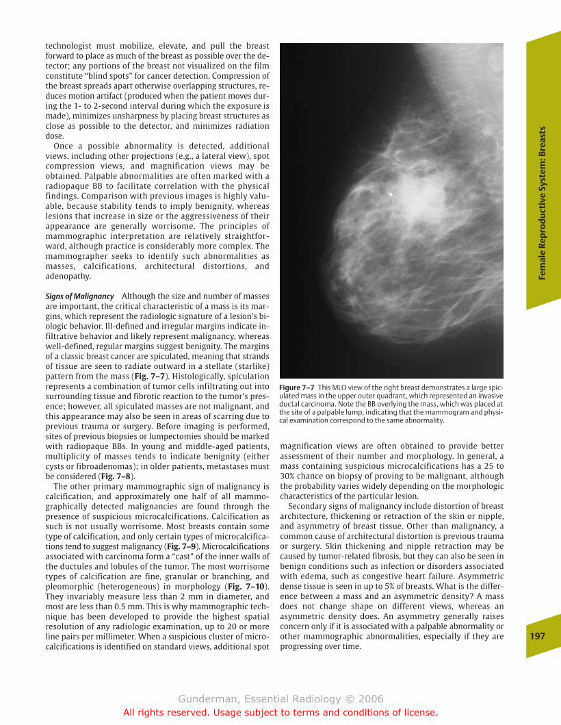
Fem
ale
Rep
rod
uct
ive
Syst
em: B
reas
ts
197
technologist must mobilize, elevate, and pull the breast forward to place as much of the breast as possible over the de-tector; any portions of the breast not visualized on the filmconstitute “blind spots” for cancer detection. Compression ofthe breast spreads apart otherwise overlapping structures, re-duces motion artifact (produced when the patient moves dur-ing the 1- to 2-second interval during which the exposure ismade), minimizes unsharpness by placing breast structures asclose as possible to the detector, and minimizes radiationdose.
Once a possible abnormality is detected, additionalviews, including other projections (e.g., a lateral view), spotcompression views, and magnification views may be obtained. Palpable abnormalities are often marked with aradiopaque BB to facilitate correlation with the physicalfindings. Comparison with previous images is highly valu-able, because stability tends to imply benignity, whereas lesions that increase in size or the aggressiveness of theirappearance are generally worrisome. The principles ofmammographic interpretation are relatively straightfor-ward, although practice is considerably more complex. Themammographer seeks to identify such abnormalities asmasses, calcifications, architectural distortions, andadenopathy.
Signs of Malignancy Although the size and number of massesare important, the critical characteristic of a mass is its mar-gins, which represent the radiologic signature of a lesion’s bi-ologic behavior. Ill-defined and irregular margins indicate in-filtrative behavior and likely represent malignancy, whereaswell-defined, regular margins suggest benignity. The marginsof a classic breast cancer are spiculated, meaning that strandsof tissue are seen to radiate outward in a stellate (starlike)pattern from the mass (Fig. 7–7). Histologically, spiculationrepresents a combination of tumor cells infiltrating out into surrounding tissue and fibrotic reaction to the tumor’s pres-ence; however, all spiculated masses are not malignant, andthis appearance may also be seen in areas of scarring due toprevious trauma or surgery. Before imaging is performed,sites of previous biopsies or lumpectomies should be markedwith radiopaque BBs. In young and middle-aged patients,multiplicity of masses tends to indicate benignity (eithercysts or fibroadenomas); in older patients, metastases mustbe considered (Fig. 7–8).
The other primary mammographic sign of malignancy iscalcification, and approximately one half of all mammo-graphically detected malignancies are found through thepresence of suspicious microcalcifications. Calcification assuch is not usually worrisome. Most breasts contain sometype of calcification, and only certain types of microcalcifica-tions tend to suggest malignancy (Fig. 7–9). Microcalcificationsassociated with carcinoma form a “cast” of the inner walls ofthe ductules and lobules of the tumor. The most worrisometypes of calcification are fine, granular or branching, andpleomorphic (heterogeneous) in morphology (Fig. 7–10).They invariably measure less than 2 mm in diameter, andmost are less than 0.5 mm. This is why mammographic tech-nique has been developed to provide the highest spatial resolution of any radiologic examination, up to 20 or moreline pairs per millimeter. When a suspicious cluster of micro-calcifications is identified on standard views, additional spot
magnification views are often obtained to provide better assessment of their number and morphology. In general, amass containing suspicious microcalcifications has a 25 to30% chance on biopsy of proving to be malignant, althoughthe probability varies widely depending on the morphologiccharacteristics of the particular lesion.
Secondary signs of malignancy include distortion of breastarchitecture, thickening or retraction of the skin or nipple,and asymmetry of breast tissue. Other than malignancy, acommon cause of architectural distortion is previous traumaor surgery. Skin thickening and nipple retraction may becaused by tumor-related fibrosis, but they can also be seen inbenign conditions such as infection or disorders associatedwith edema, such as congestive heart failure. Asymmetricdense tissue is seen in up to 5% of breasts. What is the differ-ence between a mass and an asymmetric density? A massdoes not change shape on different views, whereas an asymmetric density does. An asymmetry generally raisesconcern only if it is associated with a palpable abnormality orother mammographic abnormalities, especially if they areprogressing over time.
Figure 7–7 This MLO view of the right breast demonstrates a large spic-ulated mass in the upper outer quadrant, which represented an invasiveductal carcinoma. Note the BB overlying the mass, which was placed atthe site of a palpable lump, indicating that the mammogram and physi-cal examination correspond to the same abnormality.
chapter 07_p192-219.qxd 12/1/05 4:09 PM Page 197
Gunderman, Essential Radiology © 2006All rights reserved. Usage subject to terms and conditions of license.
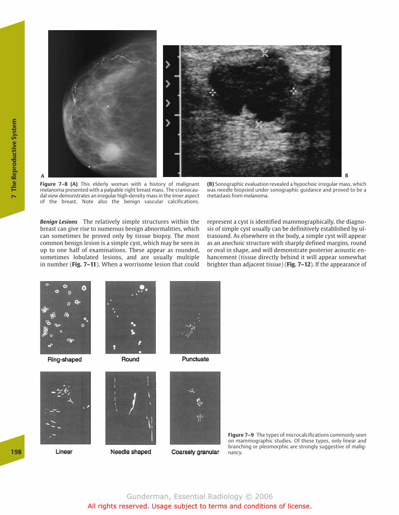
represent a cyst is identified mammographically, the diagno-sis of simple cyst usually can be definitively established by ul-trasound. As elsewhere in the body, a simple cyst will appearas an anechoic structure with sharply defined margins, roundor oval in shape, and will demonstrate posterior acoustic en-hancement (tissue directly behind it will appear somewhatbrighter than adjacent tissue) (Fig. 7–12). If the appearance of
198
7Th
e Re
prod
ucti
ve S
yste
m
Figure 7–8 (A) This elderly woman with a history of malignantmelanoma presented with a palpable right breast mass. The craniocau-dal view demonstrates an irregular high-density mass in the inner aspectof the breast. Note also the benign vascular calcifications.
(B) Sonographic evaluation revealed a hypochoic irregular mass, whichwas needle biopsied under sonographic guidance and proved to be ametastasis from melanoma.
Figure 7–9 The types of microcalcifications commonly seenon mammographic studies. Of these types, only linear andbranching or pleomorphic are strongly suggestive of malig-nancy.
Benign Lesions The relatively simple structures within thebreast can give rise to numerous benign abnormalities, whichcan sometimes be proved only by tissue biopsy. The mostcommon benign lesion is a simple cyst, which may be seen inup to one half of examinations. These appear as rounded,sometimes lobulated lesions, and are usually multiple in number (Fig. 7–11). When a worrisome lesion that could
A B
chapter 07_p192-219.qxd 12/1/05 4:09 PM Page 198
Gunderman, Essential Radiology © 2006All rights reserved. Usage subject to terms and conditions of license.
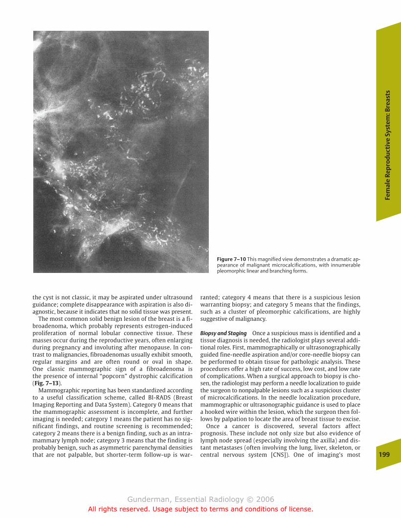
Fem
ale
Rep
rod
uct
ive
Syst
em: B
reas
ts
199
ranted; category 4 means that there is a suspicious lesionwarranting biopsy; and category 5 means that the findings,such as a cluster of pleomorphic calcifications, are highlysuggestive of malignancy.
Biopsy and Staging Once a suspicious mass is identified and atissue diagnosis is needed, the radiologist plays several addi-tional roles. First, mammographically or ultrasonographicallyguided fine-needle aspiration and/or core-needle biopsy canbe performed to obtain tissue for pathologic analysis. Theseprocedures offer a high rate of success, low cost, and low rateof complications. When a surgical approach to biopsy is cho-sen, the radiologist may perform a needle localization to guidethe surgeon to nonpalpable lesions such as a suspicious clusterof microcalcifications. In the needle localization procedure,mammographic or ultrasonographic guidance is used to placea hooked wire within the lesion, which the surgeon then fol-lows by palpation to locate the area of breast tissue to excise.
Once a cancer is discovered, several factors affect prognosis. These include not only size but also evidence oflymph node spread (especially involving the axilla) and dis-tant metastases (often involving the lung, liver, skeleton, orcentral nervous system [CNS]). One of imaging’s most
Figure 7–10 This magnified view demonstrates a dramatic ap-pearance of malignant microcalcifications, with innumerablepleomorphic linear and branching forms.
the cyst is not classic, it may be aspirated under ultrasoundguidance; complete disappearance with aspiration is also di-agnostic, because it indicates that no solid tissue was present.
The most common solid benign lesion of the breast is a fi-broadenoma, which probably represents estrogen-inducedproliferation of normal lobular connective tissue. Thesemasses occur during the reproductive years, often enlargingduring pregnancy and involuting after menopause. In con-trast to malignancies, fibroadenomas usually exhibit smooth,regular margins and are often round or oval in shape. One classic mammographic sign of a fibroadenoma is the presence of internal “popcorn” dystrophic calcification (Fig. 7–13).
Mammographic reporting has been standardized accordingto a useful classification scheme, called BI-RADS (BreastImaging Reporting and Data System). Category 0 means thatthe mammographic assessment is incomplete, and furtherimaging is needed; category 1 means the patient has no sig-nificant findings, and routine screening is recommended;category 2 means there is a benign finding, such as an intra-mammary lymph node; category 3 means that the finding isprobably benign, such as asymmetric parenchymal densitiesthat are not palpable, but shorter-term follow-up is war-
chapter 07_p192-219.qxd 12/1/05 4:09 PM Page 199
Gunderman, Essential Radiology © 2006All rights reserved. Usage subject to terms and conditions of license.
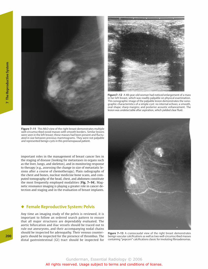
important roles in the management of breast cancer lies inthe staging of disease (looking for metastases in organs suchas the liver, lungs, and skeleton), and in monitoring responseto therapy (e.g., assessing the change in size of metastatic le-sions after a course of chemotherapy). Plain radiographs ofthe chest and bones, nuclear medicine bone scans, and com-puted tomography of the head, chest, and abdomen constitutethe most frequently employed modalities (Fig. 7–14). Mag-netic resonance imaging is playing a greater role in cancer de-tection and staging and in the evaluation of breast implants.
� Female Reproductive System: Pelvis
Any time an imaging study of the pelvis is reviewed, it is important to follow an ordered search pattern to ensurethat all major structures are dependably evaluated. The aortic bifurcation and iliac vessels should be traced out torule out aneurysms, and their accompanying nodal chainsshould be inspected for adenopathy. Their venous counter-parts should be inspected for the presence of thrombus. Thedistal gastrointestinal (GI) tract should be inspected for
200
7Th
e Re
prod
ucti
ve S
yste
m
Figure 7–11 This MLO view of the right breast demonstrates multiplewell-circumscribed ovoid masses with smooth borders. Similar lesionswere seen in the left breast; these masses had been present and fluctu-ated in size between previous mammograms. They were not palpableand represented benign cysts in this premenopausal patient.
Figure7–12 A 48-year-old woman had noticed enlargement of a massin her left breast, which was readily palpable on physical examination.This sonographic image of the palpable lesion demonstrates the sono-graphic characteristics of a simple cyst: no internal echoes; a smooth,oval shape; sharp margins; and posterior acoustic enhancement. The lesion was undetectable after aspiration, which yielded clear fluid.
Figure 7–13 A craniocaudal view of the right breast demonstrates benign vascular calcifications as well as two well-circumscribed massescontaining “popcorn” calcifications classic for involuting fibroadenomas.
chapter 07_p192-219.qxd 12/1/05 4:09 PM Page 200
Gunderman, Essential Radiology © 2006All rights reserved. Usage subject to terms and conditions of license.
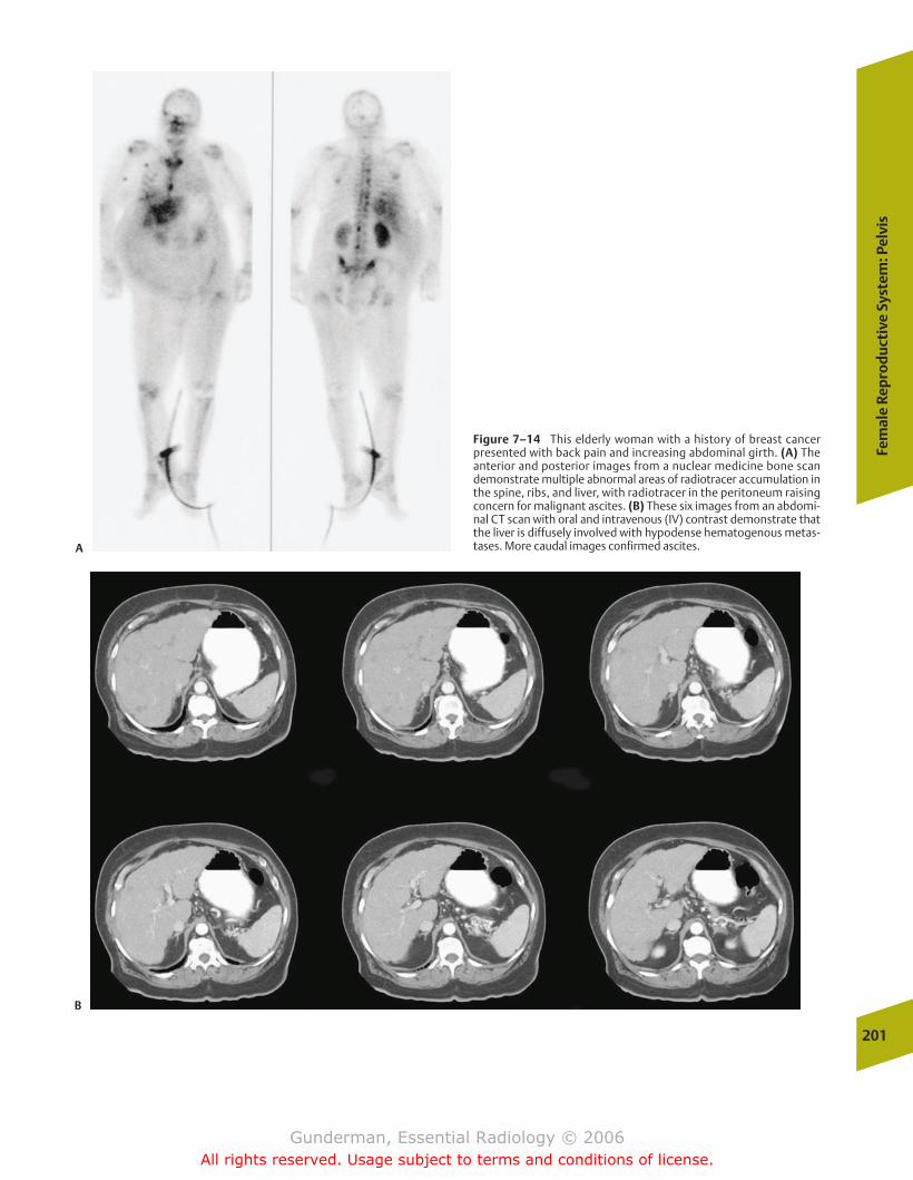
Fem
ale
Rep
rod
uct
ive
Syst
em: P
elvi
s
201
Figure 7–14 This elderly woman with a history of breast cancer presented with back pain and increasing abdominal girth. (A) Theanterior and posterior images from a nuclear medicine bone scandemonstrate multiple abnormal areas of radiotracer accumulation inthe spine, ribs, and liver, with radiotracer in the peritoneum raisingconcern for malignant ascites. (B) These six images from an abdomi-nal CT scan with oral and intravenous (IV) contrast demonstrate thatthe liver is diffusely involved with hypodense hematogenous metas-tases. More caudal images confirmed ascites.A
B
chapter 07_p192-219.qxd 12/1/05 4:09 PM Page 201
Gunderman, Essential Radiology © 2006All rights reserved. Usage subject to terms and conditions of license.
202
7Th
e Re
prod
ucti
ve S
yste
m
masses and mural abnormalities, as well as for the presenceof surrounding ascites. The urinary tract, including the dis-tal ureters and bladder, should be evaluated for masses,mural abnormalities, and evidence of obstruction. As al-ways, bones and soft tissues should be inspected. In a malepatient, special areas of attention include the size, shape,and tissue characteristics of the prostate gland, as well asthe condition of periprostatic tissues. In a female patient,attention should be directed to the size, shape, and positionof the uterus, cervix, and adnexa (from the Latin for “ap-pended to”).
Anatomy and Physiology
The female pelvis contains the vagina, the cervix, theuterus, and the paired oviducts and ovaries (Fig. 7–15). Themuscular, expansile vagina (from the Latin for “sheath”)serves both as the female organ of copulation and the birthcanal. The cervix (from the Latin for “neck”) is the distalportion of the uterus that projects into the vagina and rep-resents the site from which cells are scraped in a “Pap test”(after George Papanicolaou) in an effort to detect cervicalcancer at an early stage. The muscular, thick-walled uterusis responsible both for housing the developing embryo/fe-tus during gestation and for expelling it during parturition(from the Latin parere, “to bring forth,” from which theword parity is derived). The oviducts function to collect theovum (from the Latin for “egg”) from the ovary at ovula-tion, as the site of fertilization, and as the conveyors of thefertilized egg to the uterus. The ovaries perform the two ex-pected gonadal (from the Greek gone, “seed”) functions, ga-metogenesis (ovum production) and the secretion of sexhormones.
The female reproductive tract performs a greater variety offunctions than its male counterpart. These include gametoge-nesis, receiving sperm, transporting both sperm and ova tothe site of fertilization, transporting the fertilized ovum (zygote) to its endometrial site of implantation, sheltering andnourishing the developing fetus (with the aid of the placenta)until it can survive outside the mother’s body, and parturition.
Female reproductive anatomy and physiology exhibit a notable cyclicity. In the male, gonadotropin secretion andspermatogenesis are pulsatile over hours but otherwise essentially constant, whereas female sex hormones displaywide swings, and normally only one ovum is produced eachmenstrual cycle. In the first half of the menstrual cycle, theovarian follicle secretes estrogens and low levels of proges-terone; in the second half, after a surge in leutinizing hor-mone levels stimulates ovulation, the corpus luteum (Latinfor “yellow body”) secretes estrogen and high amounts ofprogesterone to prepare the uterus for implantation. If fertil-ization does not occur, the corpus luteum involutes, and thethickened uterine lining is sloughed at menstruation. Imag-ing findings such as the number and size of follicles in theovaries, the presence of free fluid in the pelvic cul-de-sac (theperitoneal extension into the space between the uterus andrectum), and the thickness of the endometrial stripe are allhormonally mediated and markedly variable, depending onthe phase of the menstrual cycle.
Pathology
Rather than attempt to review all categories of disease thatmay afflict each of the female pelvic organs in turn, this sec-tion focuses on several common clinical presentations andthe role of imaging in their evaluation.
Pelvic Masses
�� Clinical Data
Palpable pelvic masses are a common clinical problem. In hos-pitalized patients of both genders, a distended urinary blad-der is the most common culprit. In women, the most commoncause of a pelvic mass is an enlarged uterus. In women of re-productive age, pregnancy is the most likely explanation,whereas leiomyomata are the most prevalent when post-menopausal patients are included. The next most commoncause of a mass in the female pelvis is an ovarian cyst.
To evaluate a pelvic mass, certain aspects of the clinicalhistory are crucial. The first question to be answered is sim-ply whether the patient is pregnant. Pregnancy constitutesthe single most common cause of pelvic masses in womenunder the age of 35. The second crucial bit of clinical data arethe patient’s age, because the likelihood of various lesions,both malignant and benign, varies dramatically depending onthe age at presentation. Additional data that must be avail-able if a pelvic mass is to be adequately evaluated include thedate of the last menstrual period, hormone use, previoussurgery, and any symptoms the patient is experiencing.
�� Imaging
Ultrasound is by far the most important radiologic modalityin the evaluation of the pelvis, and alone is adequate to char-acterize more than 90% of lesions (Fig. 7–16). The crucialquestions to be addressed by the sonographer include thefollowing: Which anatomic structure is involved? What arethe imaging characteristics of the lesion? How is it changingover time? The most common pelvic masses, aside frompregnancy, include uterine leiomyomata (“fibroids”), ovariancysts, pelvic inflammatory disease, endometriosis, and can-cers of the ovary and uterus (Fig. 7–17). This discussion is organized around the different anatomic points of origin ofpelvic masses.
�� Adnexal Masses
A variety of benign processes may produce adnexal masses.The two most important categories of disease are “medical”(nonsurgical) conditions such as physiologic cysts and infec-tious and inflammatory processes and “surgical” processes,for which urgent surgical intervention should be considered.
“Medical” Adnexal Masses Among the physiologic cysts, themost common are the follicular cysts. These typically arise ei-ther from failure of a follicle to involute after ovulation or ananovulatory cycle. Follicular cysts also represent the mostcommon cause of an ovarian mass in the neonate and can betraced to maternal estrogen stimulation. In most cases, theyappear round and anechoic, fulfilling the sonographic criteria
chapter 07_p192-219.qxd 12/1/05 4:09 PM Page 202
Gunderman, Essential Radiology © 2006All rights reserved. Usage subject to terms and conditions of license.

Fem
ale
Rep
rod
uct
ive
Syst
em: P
elvi
s
203
Figure 7–15 (A) Diagram depicting the close proximity of other phys-iologic systems (e.g., urinary and digestive systems) to the female reproductive organs. Multiple systems must be borne in mind when a
patient presents with pelvic symptoms. (B) Sagittal and (C) coronalviews of the key anatomic structures of the female reproductive system.
chapter 07_p192-219.qxd 12/1/05 4:09 PM Page 203
Gunderman, Essential Radiology © 2006All rights reserved. Usage subject to terms and conditions of license.

of a simple cyst; however, they may be complicated at anyage by hemorrhage and commonly present with pain. Thepresence of internal hemorrhage gives them a heterogeneousechotexture on ultrasound. The next most prevalent physio-logic cyst is a corpus luteum cyst, typically formed by hemor-rhage into the corpus luteum after ovulation. These are usually larger than follicular cysts and often measure 5 to 10cm in diameter. They are most common in the first months ofpregnancy. High levels of human chorionic gonadotropin(HCG) may produce a theca lutein cyst, which is the largest ofall ovarian cysts and may measure up to 20 cm in diameter.The finding of a theca lutein cyst should raise suspicion foreither multiple gestations or gestational trophoblastic dis-ease (hydatidiform mole or choriocarcinoma). Each of these
lesions may have the appearance of a simple or complex cyst,and the differentiation must be based on clinical grounds(Fig. 7–18).
Infectious causes of pelvic masses include nongynecologicprocesses such as appendicitis and diverticulitis, which cansometimes be distinguished from gynecologic processes on thebasis of absence of both cervical motion tenderness and puru-lent vaginal discharge. Pelvic inflammatory disease is the mostcommon gynecologic cause. Risk factors include young age, history of previous salpingitis, and use of an intrauterine device. Patients may present with pain, vaginal discharge, ab-normal bleeding, or peritoneal signs, depending on the stage of infection. Ultrasound is used primarily in assessing for signs ofadvanced disease. Visible oviducts are abnormal, and in hy-204
7Th
e Re
prod
ucti
ve S
yste
m
Figure 7–16 These (A) longitudinal and (B) transverse ultrasound im-ages of the pelvis demonstrate the normal sonographic appearance of thepelvic structures. (A) 1, filled urinary bladder; 2, uterus; 3, cervix; 4,
vagina; 5, rectum. (B) 1, filled urinary bladder; 2, uterus; 3, right ovary; 4,left ovary; 5, colon. (C) The planes in which images are normally obtained.Image A was obtained in plane I, and image B was obtained in plane V.
chapter 07_p192-219.qxd 12/1/05 4:09 PM Page 204
Gunderman, Essential Radiology © 2006All rights reserved. Usage subject to terms and conditions of license.
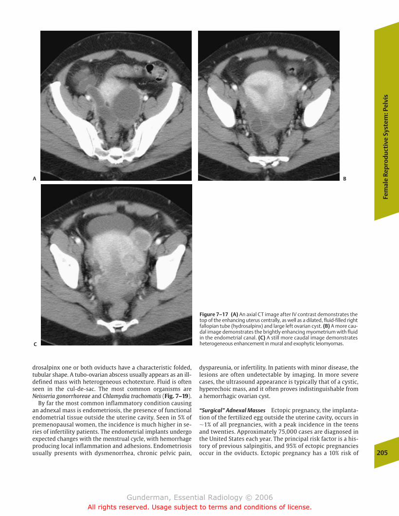
Fem
ale
Rep
rod
uct
ive
Syst
em: P
elvi
s
205
drosalpinx one or both oviducts have a characteristic folded,tubular shape. A tubo-ovarian abscess usually appears as an ill-defined mass with heterogeneous echotexture. Fluid is oftenseen in the cul-de-sac. The most common organisms are Neisseria gonorrhoreae and Chlamydia trachomatis (Fig. 7–19).
By far the most common inflammatory condition causingan adnexal mass is endometriosis, the presence of functionalendometrial tissue outside the uterine cavity. Seen in 5% ofpremenopausal women, the incidence is much higher in se-ries of infertility patients. The endometrial implants undergoexpected changes with the menstrual cycle, with hemorrhageproducing local inflammation and adhesions. Endometriosisusually presents with dysmenorrhea, chronic pelvic pain,
dyspareunia, or infertility. In patients with minor disease, thelesions are often undetectable by imaging. In more severecases, the ultrasound appearance is typically that of a cystic,hyperechoic mass, and it often proves indistinguishable froma hemorrhagic ovarian cyst.
“Surgical” Adnexal Masses Ectopic pregnancy, the implanta-tion of the fertilized egg outside the uterine cavity, occurs in�1% of all pregnancies, with a peak incidence in the teensand twenties. Approximately 75,000 cases are diagnosed inthe United States each year. The principal risk factor is a his-tory of previous salpingitis, and 95% of ectopic pregnanciesoccur in the oviducts. Ectopic pregnancy has a 10% risk of
Figure 7–17 (A) An axial CT image after IV contrast demonstrates thetop of the enhancing uterus centrally, as well as a dilated, fluid-filled rightfallopian tube (hydrosalpinx) and large left ovarian cyst. (B) A more cau-dal image demonstrates the brightly enhancing myometrium with fluidin the endometrial canal. (C) A still more caudal image demonstratesheterogeneous enhancement in mural and exophytic leiomyomas.
A B
C
chapter 07_p192-219.qxd 12/1/05 4:09 PM Page 205
Gunderman, Essential Radiology © 2006All rights reserved. Usage subject to terms and conditions of license.
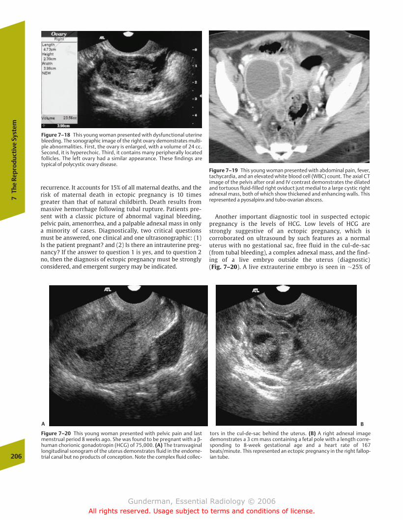
recurrence. It accounts for 15% of all maternal deaths, and therisk of maternal death in ectopic pregnancy is 10 timesgreater than that of natural childbirth. Death results frommassive hemorrhage following tubal rupture. Patients pre-sent with a classic picture of abnormal vaginal bleeding,pelvic pain, amenorrhea, and a palpable adnexal mass in onlya minority of cases. Diagnostically, two critical questionsmust be answered, one clinical and one ultrasonographic: (1)Is the patient pregnant? and (2) Is there an intrauterine preg-nancy? If the answer to question 1 is yes, and to question 2no, then the diagnosis of ectopic pregnancy must be stronglyconsidered, and emergent surgery may be indicated.
Another important diagnostic tool in suspected ectopicpregnancy is the levels of HCG. Low levels of HCG arestrongly suggestive of an ectopic pregnancy, which is corroborated on ultrasound by such features as a normaluterus with no gestational sac, free fluid in the cul-de-sac(from tubal bleeding), a complex adnexal mass, and the find-ing of a live embryo outside the uterus (diagnostic) (Fig. 7–20). A live extrauterine embryo is seen in �25% of
206
7Th
e Re
prod
ucti
ve S
yste
m
Figure 7–20 This young woman presented with pelvic pain and lastmenstrual period 8 weeks ago. She was found to be pregnant with a β-human chorionic gonadotropin (HCG) of 75,000. (A) The transvaginallongitudinal sonogram of the uterus demonstrates fluid in the endome-trial canal but no products of conception. Note the complex fluid collec-
tors in the cul-de-sac behind the uterus. (B) A right adnexal imagedemonstrates a 3 cm mass containing a fetal pole with a length corre-sponding to 8-week gestational age and a heart rate of 167beats/minute. This represented an ectopic pregnancy in the right fallop-ian tube.
Figure 7–18 This young woman presented with dysfunctional uterinebleeding. The sonographic image of the right ovary demonstrates multi-ple abnormalities. First, the ovary is enlarged, with a volume of 24 cc.Second, it is hyperechoic. Third, it contains many peripherally locatedfollicles. The left ovary had a similar appearance. These findings are typical of polycystic ovary disease.
Figure 7–19 This young woman presented with abdominal pain, fever,tachycardia, and an elevated white blood cell (WBC) count. The axial CTimage of the pelvis after oral and IV contrast demonstrates the dilatedand tortuous fluid-filled right oviduct just medial to a large cystic rightadnexal mass, both of which show thickened and enhancing walls. Thisrepresented a pyosalpinx and tubo-ovarian abscess.
A B
chapter 07_p192-219.qxd 12/1/05 4:09 PM Page 206
Gunderman, Essential Radiology © 2006All rights reserved. Usage subject to terms and conditions of license.
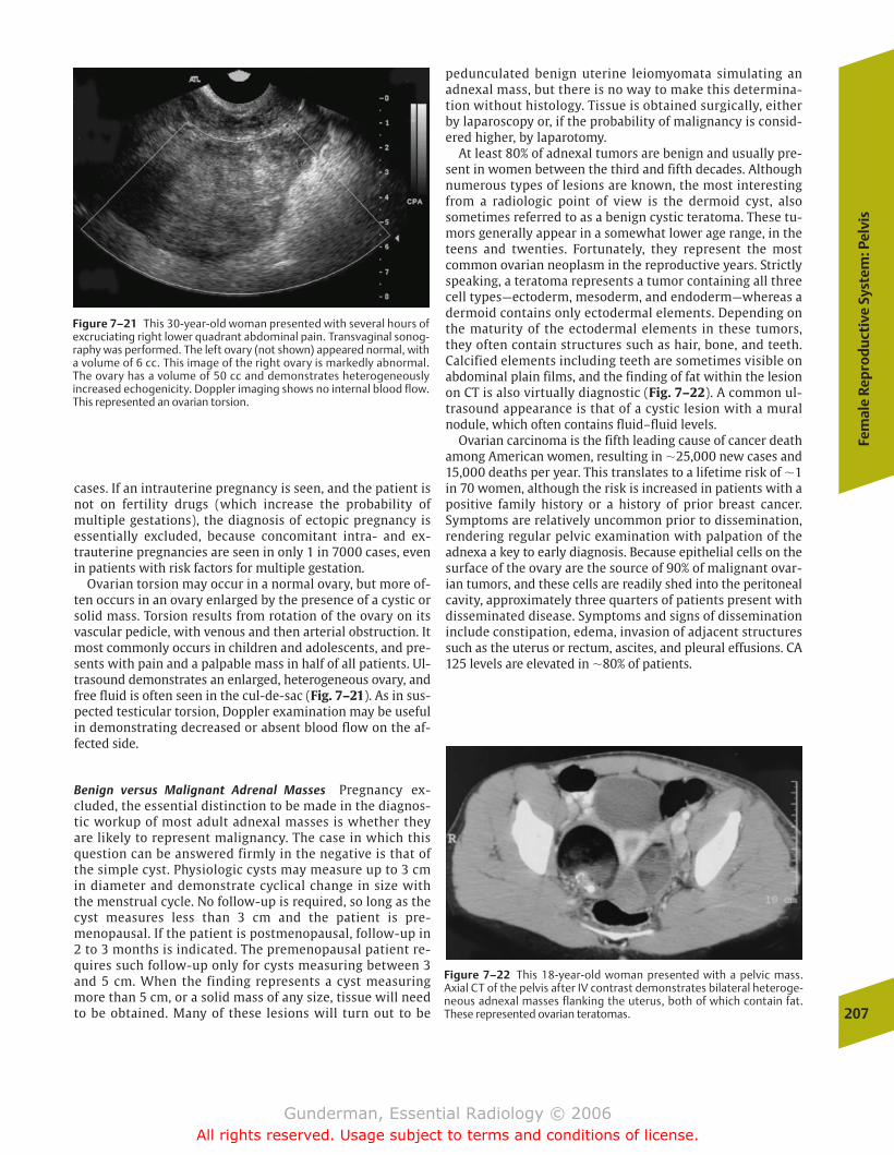
Fem
ale
Rep
rod
uct
ive
Syst
em: P
elvi
s
207
Figure 7–21 This 30-year-old woman presented with several hours ofexcruciating right lower quadrant abdominal pain. Transvaginal sonog-raphy was performed. The left ovary (not shown) appeared normal, witha volume of 6 cc. This image of the right ovary is markedly abnormal.The ovary has a volume of 50 cc and demonstrates heterogeneously increased echogenicity. Doppler imaging shows no internal blood flow.This represented an ovarian torsion.
cases. If an intrauterine pregnancy is seen, and the patient isnot on fertility drugs (which increase the probability of multiple gestations), the diagnosis of ectopic pregnancy is essentially excluded, because concomitant intra- and ex-trauterine pregnancies are seen in only 1 in 7000 cases, evenin patients with risk factors for multiple gestation.
Ovarian torsion may occur in a normal ovary, but more of-ten occurs in an ovary enlarged by the presence of a cystic orsolid mass. Torsion results from rotation of the ovary on itsvascular pedicle, with venous and then arterial obstruction. Itmost commonly occurs in children and adolescents, and pre-sents with pain and a palpable mass in half of all patients. Ul-trasound demonstrates an enlarged, heterogeneous ovary, andfree fluid is often seen in the cul-de-sac (Fig. 7–21). As in sus-pected testicular torsion, Doppler examination may be usefulin demonstrating decreased or absent blood flow on the af-fected side.
Benign versus Malignant Adrenal Masses Pregnancy ex-cluded, the essential distinction to be made in the diagnos-tic workup of most adult adnexal masses is whether theyare likely to represent malignancy. The case in which thisquestion can be answered firmly in the negative is that ofthe simple cyst. Physiologic cysts may measure up to 3 cmin diameter and demonstrate cyclical change in size withthe menstrual cycle. No follow-up is required, so long as thecyst measures less than 3 cm and the patient is pre-menopausal. If the patient is postmenopausal, follow-up in2 to 3 months is indicated. The premenopausal patient re-quires such follow-up only for cysts measuring between 3and 5 cm. When the finding represents a cyst measuringmore than 5 cm, or a solid mass of any size, tissue will needto be obtained. Many of these lesions will turn out to be
pedunculated benign uterine leiomyomata simulating an adnexal mass, but there is no way to make this determina-tion without histology. Tissue is obtained surgically, eitherby laparoscopy or, if the probability of malignancy is consid-ered higher, by laparotomy.
At least 80% of adnexal tumors are benign and usually pre-sent in women between the third and fifth decades. Althoughnumerous types of lesions are known, the most interestingfrom a radiologic point of view is the dermoid cyst, alsosometimes referred to as a benign cystic teratoma. These tu-mors generally appear in a somewhat lower age range, in theteens and twenties. Fortunately, they represent the mostcommon ovarian neoplasm in the reproductive years. Strictlyspeaking, a teratoma represents a tumor containing all threecell types—ectoderm, mesoderm, and endoderm—whereas adermoid contains only ectodermal elements. Depending onthe maturity of the ectodermal elements in these tumors,they often contain structures such as hair, bone, and teeth.Calcified elements including teeth are sometimes visible onabdominal plain films, and the finding of fat within the lesionon CT is also virtually diagnostic (Fig. 7–22). A common ul-trasound appearance is that of a cystic lesion with a mural nodule, which often contains fluid–fluid levels.
Ovarian carcinoma is the fifth leading cause of cancer deathamong American women, resulting in �25,000 new cases and15,000 deaths per year. This translates to a lifetime risk of �1in 70 women, although the risk is increased in patients with apositive family history or a history of prior breast cancer.Symptoms are relatively uncommon prior to dissemination,rendering regular pelvic examination with palpation of theadnexa a key to early diagnosis. Because epithelial cells on thesurface of the ovary are the source of 90% of malignant ovar-ian tumors, and these cells are readily shed into the peritonealcavity, approximately three quarters of patients present withdisseminated disease. Symptoms and signs of disseminationinclude constipation, edema, invasion of adjacent structuressuch as the uterus or rectum, ascites, and pleural effusions. CA125 levels are elevated in �80% of patients.
Figure 7–22 This 18-year-old woman presented with a pelvic mass. Axial CT of the pelvis after IV contrast demonstrates bilateral heteroge-neous adnexal masses flanking the uterus, both of which contain fat.These represented ovarian teratomas.
chapter 07_p192-219.qxd 12/1/05 4:09 PM Page 207
Gunderman, Essential Radiology © 2006All rights reserved. Usage subject to terms and conditions of license.
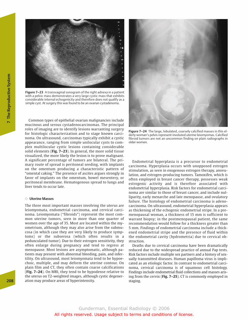
Common types of epithelial ovarian malignancies includemucinous and serous cystadenocarcinomas. The principalroles of imaging are to identify lesions warranting surgeryfor histologic characterization and to stage known carci-noma. On ultrasound, carcinomas typically exhibit a cysticappearance, ranging from simple unilocular cysts to com-plex multilocular cystic lesions containing considerablesolid elements (Fig. 7–23). In general, the more solid tissuevisualized, the more likely the lesion is to prove malignant.A significant percentage of tumors are bilateral. The pri-mary route of spread is peritoneal seeding, with implantson the omentum producing a characteristic pattern of“omental caking.” The presence of ascites argues strongly infavor of implants on the omentum, bowel mesentery, orperitoneal membrane. Hematogenous spread to lungs andliver tends to occur late.
�� Uterine Masses
The three most important masses involving the uterus areleiomyomata, endometrial carcinoma, and cervical carci-noma. Leiomyomata (“fibroids”) represent the most com-mon uterine tumors, seen in more than one quarter ofwomen over the age of 35. Most are located within the my-ometrium, although they may also arise from the submu-cosa (in which case they are very likely to produce symp-toms) or the subserosa (which often results in apedunculated tumor). Due to their estrogen sensitivity, theyoften enlarge during pregnancy and tend to regress atmenopause. Most lesions are asymptomatic, although pa-tients may present with abnormal bleeding, pain, and infer-tility. On ultrasound, most leiomyomata tend to be hypoe-choic, multiple, and may deform the uterine contour. Onplain film and CT, they often contain coarse calcifications(Fig. 7–24). On MRI, they tend to be hypodense relative tothe uterus on T2-weighted images, although cystic degener-ation may produce areas of hyperintensity.
Endometrial hyperplasia is a precursor to endometrial carcinoma. Hyperplasia occurs with unopposed estrogenstimulation, as seen in exogenous estrogen therapy, anovu-lation, and estrogen-producing tumors. Tamoxifen, which isoften employed in breast cancer therapy, possesses weakestrogenic activity and is therefore associated with endometrial hyperplasia. Risk factors for endometrial carci-noma are similar to those of breast cancer, and include nul-liparity, early menarche and late menopause, and ovulatoryfailure. The histology of endometrial carcinoma is adeno-carcinoma. On ultrasound, endometrial hyperplasia appearsas thickening of the echogenic endometrial stripe. In a pre-menopausal woman, a thickness of 15 mm is sufficient towarrant biopsy; in the postmenopausal patient, the samerecommendation would follow for a thickness greater than5 mm. Findings of endometrial carcinoma include a thick-ened endometrial stripe and the presence of fluid withinthe endometrial cavity (hydrometria) due to cervical ob-struction.
Deaths due to cervical carcinoma have been dramatically reduced due to the widespread practice of annual Pap tests.Risk factors include multiple sex partners and a history of sex-ually transmitted diseases. Human papilloma virus is impli-cated as an etiologic factor. In contrast to endometrial carci-noma, cervical carcinoma is of squamous cell histology.Findings include endometrial fluid collections and masses aris-ing from the cervix (Fig. 7–25). CT is commonly employed instaging.208
7Th
e Re
prod
ucti
ve S
yste
m
Figure 7–24 The large, lobulated, coarsely calcified masses in this el-derly woman’s pelvis represent involuted uterine leiomyomas. Calcifiedfibroid tumors are not an uncommon finding on plain radiographs inolder women.
Figure 7–23 A transvaginal sonogram of the right adnexa in a patientwith a pelvic mass demonstrates a very large cystic mass that exhibitsconsiderable internal echogenicity and therefore does not qualify as asimple cyst. At surgery this was found to be an ovarian cystadenoma.
chapter 07_p192-219.qxd 12/1/05 4:09 PM Page 208
Gunderman, Essential Radiology © 2006All rights reserved. Usage subject to terms and conditions of license.
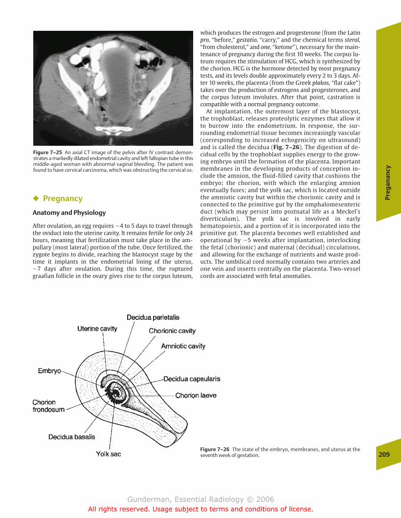
Preg
anan
cy
209
Figure 7–25 An axial CT image of the pelvis after IV contrast demon-strates a markedly dilated endometrial cavity and left fallopian tube in thismiddle-aged woman with abnormal vaginal bleeding. The patient wasfound to have cervical carcinoma, which was obstructing the cervical os.
� Pregnancy
Anatomy and Physiology
After ovulation, an egg requires �4 to 5 days to travel throughthe oviduct into the uterine cavity. It remains fertile for only 24hours, meaning that fertilization must take place in the am-pullary (most lateral) portion of the tube. Once fertilized, thezygote begins to divide, reaching the blastocyst stage by thetime it implants in the endometrial lining of the uterus, �7 days after ovulation. During this time, the rupturedgraafian follicle in the ovary gives rise to the corpus luteum,
which produces the estrogen and progesterone (from the Latinpro, “before,” gestatio, “carry,” and the chemical terms sterol,“from cholesterol,” and one, “ketone”), necessary for the main-tenance of pregnancy during the first 10 weeks. The corpus lu-teum requires the stimulation of HCG, which is synthesized bythe chorion. HCG is the hormone detected by most pregnancytests, and its levels double approximately every 2 to 3 days. Af-ter 10 weeks, the placenta (from the Greek plakos, “flat cake”)takes over the production of estrogens and progesterones, andthe corpus luteum involutes. After that point, castration iscompatible with a normal pregnancy outcome.
At implantation, the outermost layer of the blastocyst,the trophoblast, releases proteolytic enzymes that allow itto burrow into the endometrium. In response, the sur-rounding endometrial tissue becomes increasingly vascular(corresponding to increased echogenicity on ultrasound)and is called the decidua (Fig. 7–26). The digestion of de-cidual cells by the trophoblast supplies energy to the grow-ing embryo until the formation of the placenta. Importantmembranes in the developing products of conception in-clude the amnion, the fluid-filled cavity that cushions theembryo; the chorion, with which the enlarging amnioneventually fuses; and the yolk sac, which is located outsidethe amniotic cavity but within the chorionic cavity and isconnected to the primitive gut by the omphalomesentericduct (which may persist into postnatal life as a Meckel’sdiverticulum). The yolk sac is involved in earlyhematopoiesis, and a portion of it is incorporated into theprimitive gut. The placenta becomes well established andoperational by �5 weeks after implantation, interlockingthe fetal (chorionic) and maternal (decidual) circulations,and allowing for the exchange of nutrients and waste prod-ucts. The umbilical cord normally contains two arteries andone vein and inserts centrally on the placenta. Two-vesselcords are associated with fetal anomalies.
Figure 7–26 The state of the embryo, membranes, and uterus at theseventh week of gestation.
chapter 07_p192-219.qxd 12/1/05 4:09 PM Page 209
Gunderman, Essential Radiology © 2006All rights reserved. Usage subject to terms and conditions of license.
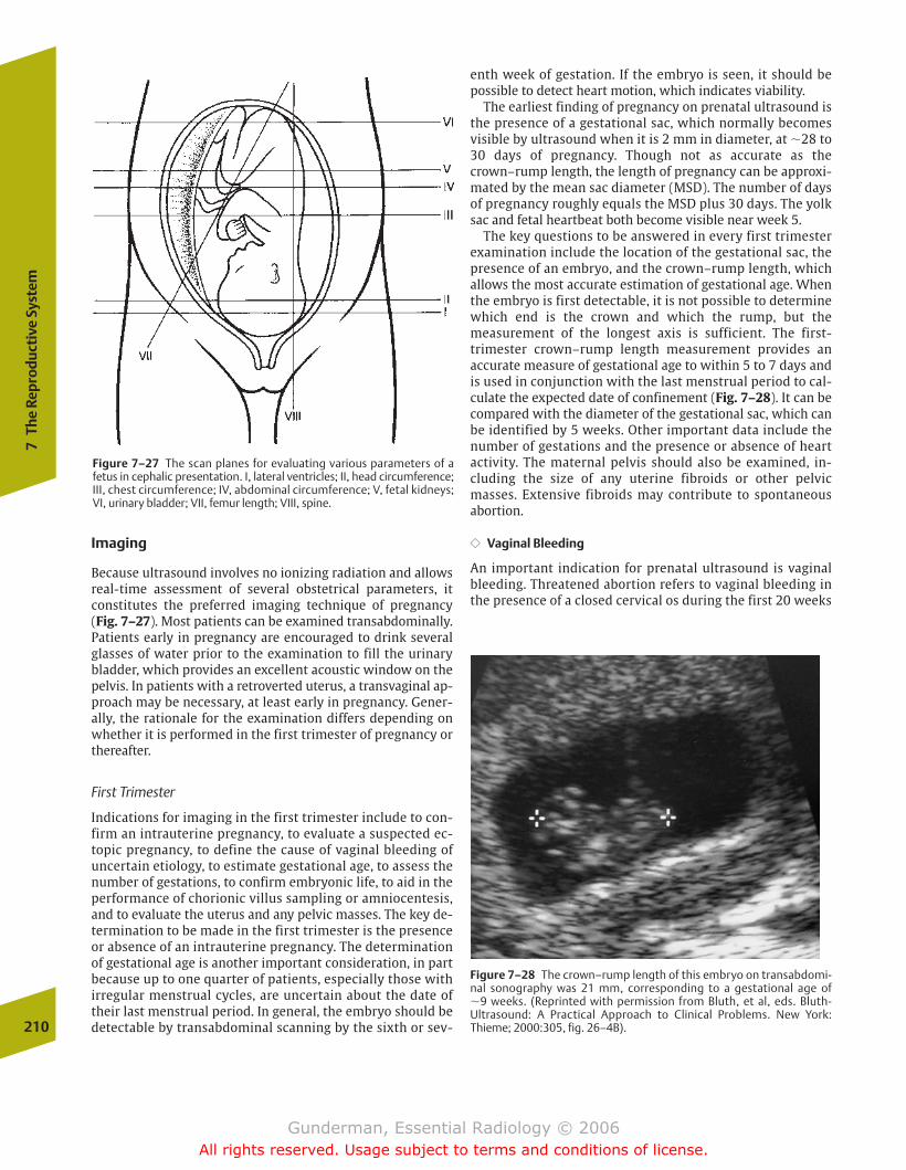
Imaging
Because ultrasound involves no ionizing radiation and allowsreal-time assessment of several obstetrical parameters, it constitutes the preferred imaging technique of pregnancy (Fig. 7–27). Most patients can be examined transabdominally.Patients early in pregnancy are encouraged to drink severalglasses of water prior to the examination to fill the urinarybladder, which provides an excellent acoustic window on thepelvis. In patients with a retroverted uterus, a transvaginal ap-proach may be necessary, at least early in pregnancy. Gener-ally, the rationale for the examination differs depending onwhether it is performed in the first trimester of pregnancy orthereafter.
First Trimester
Indications for imaging in the first trimester include to con-firm an intrauterine pregnancy, to evaluate a suspected ec-topic pregnancy, to define the cause of vaginal bleeding ofuncertain etiology, to estimate gestational age, to assess thenumber of gestations, to confirm embryonic life, to aid in theperformance of chorionic villus sampling or amniocentesis,and to evaluate the uterus and any pelvic masses. The key de-termination to be made in the first trimester is the presenceor absence of an intrauterine pregnancy. The determinationof gestational age is another important consideration, in partbecause up to one quarter of patients, especially those withirregular menstrual cycles, are uncertain about the date oftheir last menstrual period. In general, the embryo should bedetectable by transabdominal scanning by the sixth or sev-
enth week of gestation. If the embryo is seen, it should bepossible to detect heart motion, which indicates viability.
The earliest finding of pregnancy on prenatal ultrasound isthe presence of a gestational sac, which normally becomesvisible by ultrasound when it is 2 mm in diameter, at �28 to30 days of pregnancy. Though not as accurate as thecrown–rump length, the length of pregnancy can be approxi-mated by the mean sac diameter (MSD). The number of daysof pregnancy roughly equals the MSD plus 30 days. The yolksac and fetal heartbeat both become visible near week 5.
The key questions to be answered in every first trimesterexamination include the location of the gestational sac, thepresence of an embryo, and the crown–rump length, whichallows the most accurate estimation of gestational age. Whenthe embryo is first detectable, it is not possible to determinewhich end is the crown and which the rump, but the measurement of the longest axis is sufficient. The first-trimester crown–rump length measurement provides an accurate measure of gestational age to within 5 to 7 days andis used in conjunction with the last menstrual period to cal-culate the expected date of confinement (Fig. 7–28). It can becompared with the diameter of the gestational sac, which canbe identified by 5 weeks. Other important data include thenumber of gestations and the presence or absence of heartactivity. The maternal pelvis should also be examined, in-cluding the size of any uterine fibroids or other pelvicmasses. Extensive fibroids may contribute to spontaneousabortion.
�� Vaginal Bleeding
An important indication for prenatal ultrasound is vaginalbleeding. Threatened abortion refers to vaginal bleeding inthe presence of a closed cervical os during the first 20 weeks
210
7Th
e Re
prod
ucti
ve S
yste
m
Figure 7–28 The crown–rump length of this embryo on transabdomi-nal sonography was 21 mm, corresponding to a gestational age of �9 weeks. (Reprinted with permission from Bluth, et al, eds. Bluth-Ultrasound: A Practical Approach to Clinical Problems. New York:Thieme; 2000:305, fig. 26–4B).
Figure 7–27 The scan planes for evaluating various parameters of a fetus in cephalic presentation. I, lateral ventricles; II, head circumference;III, chest circumference; IV, abdominal circumference; V, fetal kidneys;VI, urinary bladder; VII, femur length; VIII, spine.
chapter 07_p192-219.qxd 12/1/05 4:09 PM Page 210
Gunderman, Essential Radiology © 2006All rights reserved. Usage subject to terms and conditions of license.
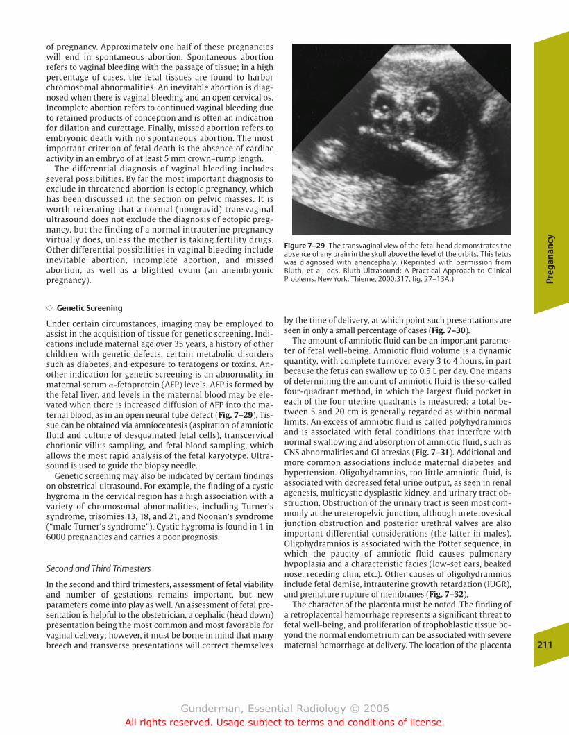
Preg
anan
cy
211
Figure 7–29 The transvaginal view of the fetal head demonstrates theabsence of any brain in the skull above the level of the orbits. This fetuswas diagnosed with anencephaly. (Reprinted with permission fromBluth, et al, eds. Bluth-Ultrasound: A Practical Approach to Clinical Problems. New York: Thieme; 2000:317, fig. 27–13A.)
of pregnancy. Approximately one half of these pregnancieswill end in spontaneous abortion. Spontaneous abortionrefers to vaginal bleeding with the passage of tissue; in a highpercentage of cases, the fetal tissues are found to harborchromosomal abnormalities. An inevitable abortion is diag-nosed when there is vaginal bleeding and an open cervical os.Incomplete abortion refers to continued vaginal bleeding dueto retained products of conception and is often an indicationfor dilation and curettage. Finally, missed abortion refers toembryonic death with no spontaneous abortion. The mostimportant criterion of fetal death is the absence of cardiac activity in an embryo of at least 5 mm crown–rump length.
The differential diagnosis of vaginal bleeding includesseveral possibilities. By far the most important diagnosis to exclude in threatened abortion is ectopic pregnancy, whichhas been discussed in the section on pelvic masses. It isworth reiterating that a normal (nongravid) transvaginalultrasound does not exclude the diagnosis of ectopic preg-nancy, but the finding of a normal intrauterine pregnancyvirtually does, unless the mother is taking fertility drugs.Other differential possibilities in vaginal bleeding includeinevitable abortion, incomplete abortion, and missed abortion, as well as a blighted ovum (an anembryonic pregnancy).
�� Genetic Screening
Under certain circumstances, imaging may be employed toassist in the acquisition of tissue for genetic screening. Indi-cations include maternal age over 35 years, a history of otherchildren with genetic defects, certain metabolic disorderssuch as diabetes, and exposure to teratogens or toxins. An-other indication for genetic screening is an abnormality inmaternal serum �-fetoprotein (AFP) levels. AFP is formed bythe fetal liver, and levels in the maternal blood may be ele-vated when there is increased diffusion of AFP into the ma-ternal blood, as in an open neural tube defect (Fig. 7–29). Tis-sue can be obtained via amniocentesis (aspiration of amnioticfluid and culture of desquamated fetal cells), transcervicalchorionic villus sampling, and fetal blood sampling, which allows the most rapid analysis of the fetal karyotype. Ultra-sound is used to guide the biopsy needle.
Genetic screening may also be indicated by certain findingson obstetrical ultrasound. For example, the finding of a cystichygroma in the cervical region has a high association with avariety of chromosomal abnormalities, including Turner’ssyndrome, trisomies 13, 18, and 21, and Noonan’s syndrome(“male Turner’s syndrome”). Cystic hygroma is found in 1 in6000 pregnancies and carries a poor prognosis.
Second and Third Trimesters
In the second and third trimesters, assessment of fetal viabilityand number of gestations remains important, but new parameters come into play as well. An assessment of fetal pre-sentation is helpful to the obstetrician, a cephalic (head down)presentation being the most common and most favorable forvaginal delivery; however, it must be borne in mind that manybreech and transverse presentations will correct themselves
by the time of delivery, at which point such presentations areseen in only a small percentage of cases (Fig. 7–30).
The amount of amniotic fluid can be an important parame-ter of fetal well-being. Amniotic fluid volume is a dynamicquantity, with complete turnover every 3 to 4 hours, in partbecause the fetus can swallow up to 0.5 L per day. One meansof determining the amount of amniotic fluid is the so-calledfour-quadrant method, in which the largest fluid pocket ineach of the four uterine quadrants is measured; a total be-tween 5 and 20 cm is generally regarded as within normallimits. An excess of amniotic fluid is called polyhydramniosand is associated with fetal conditions that interfere withnormal swallowing and absorption of amniotic fluid, such asCNS abnormalities and GI atresias (Fig. 7–31). Additional andmore common associations include maternal diabetes andhypertension. Oligohydramnios, too little amniotic fluid, isassociated with decreased fetal urine output, as seen in renalagenesis, multicystic dysplastic kidney, and urinary tract ob-struction. Obstruction of the urinary tract is seen most com-monly at the ureteropelvic junction, although ureterovesicaljunction obstruction and posterior urethral valves are alsoimportant differential considerations (the latter in males).Oligohydramnios is associated with the Potter sequence, inwhich the paucity of amniotic fluid causes pulmonary hypoplasia and a characteristic facies (low-set ears, beakednose, receding chin, etc.). Other causes of oligohydramniosinclude fetal demise, intrauterine growth retardation (IUGR),and premature rupture of membranes (Fig. 7–32).
The character of the placenta must be noted. The finding ofa retroplacental hemorrhage represents a significant threat tofetal well-being, and proliferation of trophoblastic tissue be-yond the normal endometrium can be associated with severematernal hemorrhage at delivery. The location of the placenta
chapter 07_p192-219.qxd 12/1/05 4:09 PM Page 211
Gunderman, Essential Radiology © 2006All rights reserved. Usage subject to terms and conditions of license.
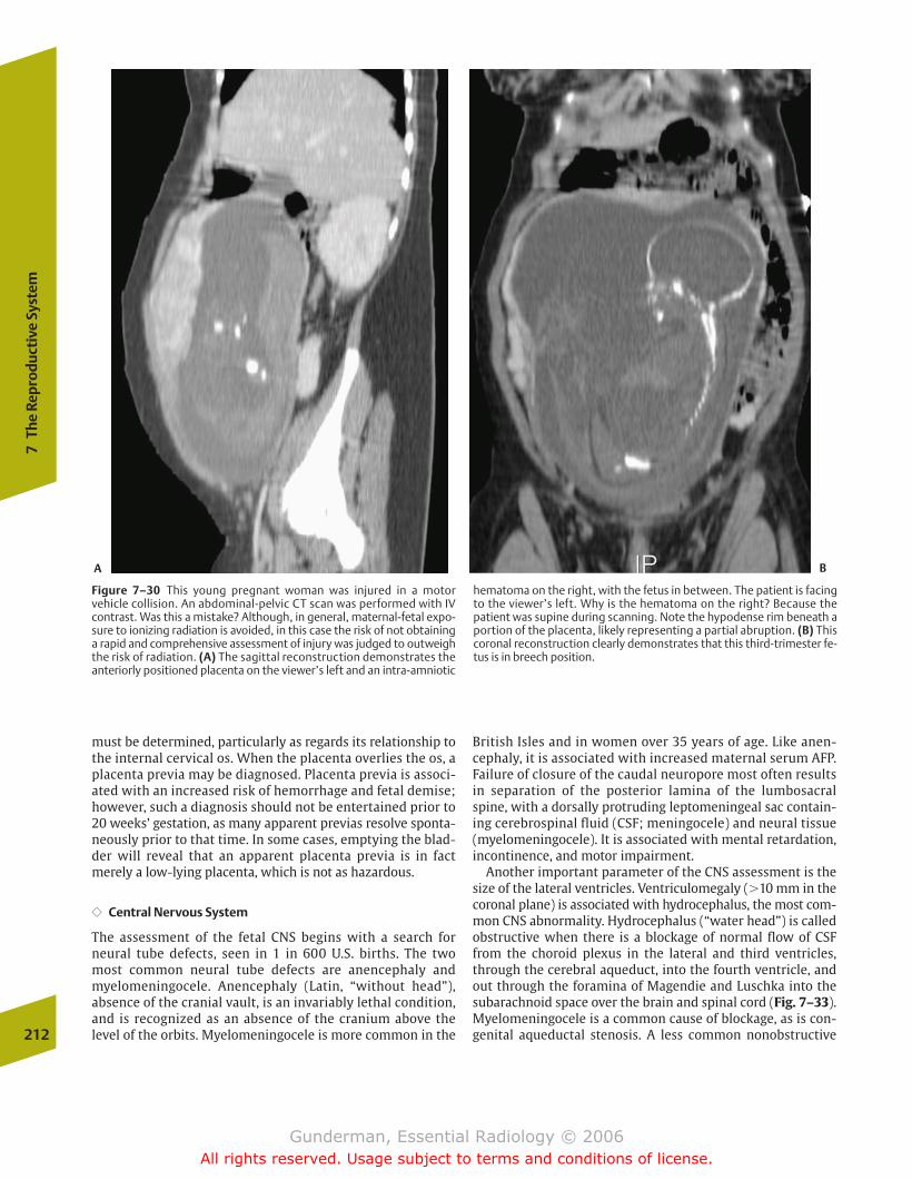
must be determined, particularly as regards its relationship tothe internal cervical os. When the placenta overlies the os, aplacenta previa may be diagnosed. Placenta previa is associ-ated with an increased risk of hemorrhage and fetal demise;however, such a diagnosis should not be entertained prior to20 weeks’ gestation, as many apparent previas resolve sponta-neously prior to that time. In some cases, emptying the blad-der will reveal that an apparent placenta previa is in factmerely a low-lying placenta, which is not as hazardous.
�� Central Nervous System
The assessment of the fetal CNS begins with a search forneural tube defects, seen in 1 in 600 U.S. births. The two most common neural tube defects are anencephaly andmyelomeningocele. Anencephaly (Latin, “without head”), absence of the cranial vault, is an invariably lethal condition,and is recognized as an absence of the cranium above thelevel of the orbits. Myelomeningocele is more common in the
British Isles and in women over 35 years of age. Like anen-cephaly, it is associated with increased maternal serum AFP.Failure of closure of the caudal neuropore most often resultsin separation of the posterior lamina of the lumbosacralspine, with a dorsally protruding leptomeningeal sac contain-ing cerebrospinal fluid (CSF; meningocele) and neural tissue(myelomeningocele). It is associated with mental retardation,incontinence, and motor impairment.
Another important parameter of the CNS assessment is thesize of the lateral ventricles. Ventriculomegaly (�10 mm in thecoronal plane) is associated with hydrocephalus, the most com-mon CNS abnormality. Hydrocephalus (“water head”) is calledobstructive when there is a blockage of normal flow of CSFfrom the choroid plexus in the lateral and third ventricles,through the cerebral aqueduct, into the fourth ventricle, andout through the foramina of Magendie and Luschka into thesubarachnoid space over the brain and spinal cord (Fig. 7–33).Myelomeningocele is a common cause of blockage, as is con-genital aqueductal stenosis. A less common nonobstructive212
7Th
e Re
prod
ucti
ve S
yste
m
Figure 7–30 This young pregnant woman was injured in a motor vehicle collision. An abdominal-pelvic CT scan was performed with IVcontrast. Was this a mistake? Although, in general, maternal-fetal expo-sure to ionizing radiation is avoided, in this case the risk of not obtaininga rapid and comprehensive assessment of injury was judged to outweighthe risk of radiation. (A) The sagittal reconstruction demonstrates theanteriorly positioned placenta on the viewer’s left and an intra-amniotic
hematoma on the right, with the fetus in between. The patient is facingto the viewer’s left. Why is the hematoma on the right? Because the patient was supine during scanning. Note the hypodense rim beneath aportion of the placenta, likely representing a partial abruption. (B) Thiscoronal reconstruction clearly demonstrates that this third-trimester fe-tus is in breech position.
A B
chapter 07_p192-219.qxd 12/1/05 4:09 PM Page 212
Gunderman, Essential Radiology © 2006All rights reserved. Usage subject to terms and conditions of license.
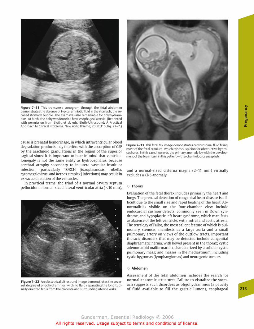
Preg
anan
cy
213
Figure 7–31 This transverse sonogram through the fetal abdomendemonstrates the absence of typical amniotic fluid in the stomach, the so-called stomach bubble. The exam was also remarkable for polyhydram-nios. At birth, the baby was found to have esophageal atresia. (Reprintedwith permission from Bluth, et al, eds. Bluth-Ultrasound: A Practical Approach to Clinical Problems. New York: Thieme; 2000:315, fig. 27–7.)
Figure 7–32 An obstetrical ultrasound image demonstrates the sever-est degree of oligohydramnios, with no fluid separating the longitudi-nally oriented fetus from the placenta and surrounding uterine walls.
Figure 7–33 This fetal MR image demonstrates cerebrospinal fluid fillingmost of the fetal cranium, which raises suspicion for obstructive hydro-cephalus. In this case, however, the primary anomaly lay with the develop-ment of the brain itself in this patient with alobar holoprosencephaly.
cause is prenatal hemorrhage, in which intraventricular blooddegradation products may interfere with the absorption of CSFby the arachnoid granulations in the region of the superiorsagittal sinus. It is important to bear in mind that ventricu-lomegaly is not the same entity as hydrocephalus, becausecerebral atrophy secondary to in utero vascular insult or infection (particularly TORCH [toxoplasmosis, rubella, cytomegalovirus, and herpes simplex] infections) may result inex vacuo dilatation of the ventricles.
In practical terms, the triad of a normal cavum septum pellucidum, normal-sized lateral ventricular atria (�10 mm),
and a normal-sized cisterna magna (2–11 mm) virtually excludes a CNS anomaly.
�� Thorax
Evaluation of the fetal thorax includes primarily the heart andlungs. The prenatal detection of congenital heart disease is dif-ficult due to the small size and rapid beating of the heart. Ab-normalities visible on the four-chamber view include endocardial cushion defects, commonly seen in Down syn-drome, and hypoplastic left heart syndrome, which manifestsas absence of the left ventricle, with mitral and aortic atresia.The tetralogy of Fallot, the most salient feature of which is pul-monary stenosis, manifests as a large aorta and a small pulmonary artery on views of the outflow tracts. Importantthoracic disorders that may be detected include congenital diaphragmatic hernia, with bowel present in the thorax; cysticadenomatoid malformation, characterized by a solid or cysticpulmonary mass; and masses in the mediastinum, includingcystic hygromas (lymphangiomas) and neurogenic tumors.
�� Abdomen
Assessment of the fetal abdomen includes the search for normal anatomic structures. Failure to visualize the stom-ach suggests such disorders as oligohydramnios (a paucityof fluid available to fill the gastric lumen), esophageal
chapter 07_p192-219.qxd 12/1/05 4:09 PM Page 213
Gunderman, Essential Radiology © 2006All rights reserved. Usage subject to terms and conditions of license.
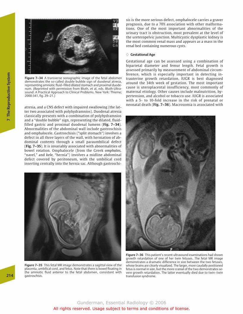
atresia, and a CNS defect with impaired swallowing (the lat-ter two associated with polyhydramnios). Duodenal atresiaclassically presents with a combination of polyhydramniosand a “double bubble” sign, representing the dilated, fluid-filled gastric and proximal duodenal lumens (Fig. 7–34). Abnormalities of the abdominal wall include gastroschisisand omphalocele. Gastroschisis (“split stomach”) involves a defect in all three layers of the wall, with herniation of ab-dominal contents through a small paraumbilical defect (Fig. 7–35). It is invariably associated with abnormalities ofbowel rotation. Omphalocele (from the Greek omphalos,“navel,” and kele, “hernia”) involves a midline abdominaldefect covered by peritoneum, with the umbilical cord inserting centrally into the hernia sac. Although gastroschi-
214
7Th
e Re
prod
ucti
ve S
yste
m
Figure 7–36 This patient’s recent ultrasound examinations had showngrowth retardation of one of her twin fetuses. The fetal MR imagedemonstrates a dramatic difference in size between the two fetuses,whose brains are clearly visualized. The larger, more caudally positionedfetus is normal in size, but the more cranial of the two demonstrates se-vere growth retardation. The latter eventually died due to twin–twintransfusion syndrome.
Figure 7–34 A transverse sonographic image of the fetal abdomendemonstrates the so-called double bubble sign of duodenal atresia, representing amniotic fluid–filled dilated stomach and proximal duode-num. (Reprinted with permission from Bluth, et al, eds. Bluth-Ultra-sound: A Practical Approach to Clinical Problems. New York: Thieme;2000:341, fig. 29–21.)
Figure 7–35 This fetal MR image demonstrates a sagittal view of theplacenta, umbilical cord, and fetus. Note that there is bowel floating inthe amniotic fluid anterior to the fetal abdomen, consistent with gastroschisis.
sis is the more serious defect, omphalocele carries a graverprognosis, due to a 70% association with other malforma-tions. One of the most important abnormalities of the urinary tract is obstruction, most prevalent at the level ofthe ureteropelvic junction. Multicystic dysplastic kidney isthe most common renal mass and appears as a mass in the renal bed containing numerous cysts.
�� Gestational Age
Gestational age can be assessed using a combination of biparietal diameter and femur length. Fetal growth is assessed primarily by measurement of abdominal circum-ference, which is especially important in detecting in-trauterine growth retardation. IUGR is best diagnosedaround the 34th week of gestation. The most importantcause is uteroplacental insufficiency, most commonly ofmaternal etiology. Other causes include malnutrition, hy-pertension, and alcohol or tobacco use. IUGR is associatedwith a 5- to 10-fold increase in the risk of prenatal orneonatal death (Fig. 7–36). Macrosomia is associated with
chapter 07_p192-219.qxd 12/1/05 4:09 PM Page 214
Gunderman, Essential Radiology © 2006All rights reserved. Usage subject to terms and conditions of license.
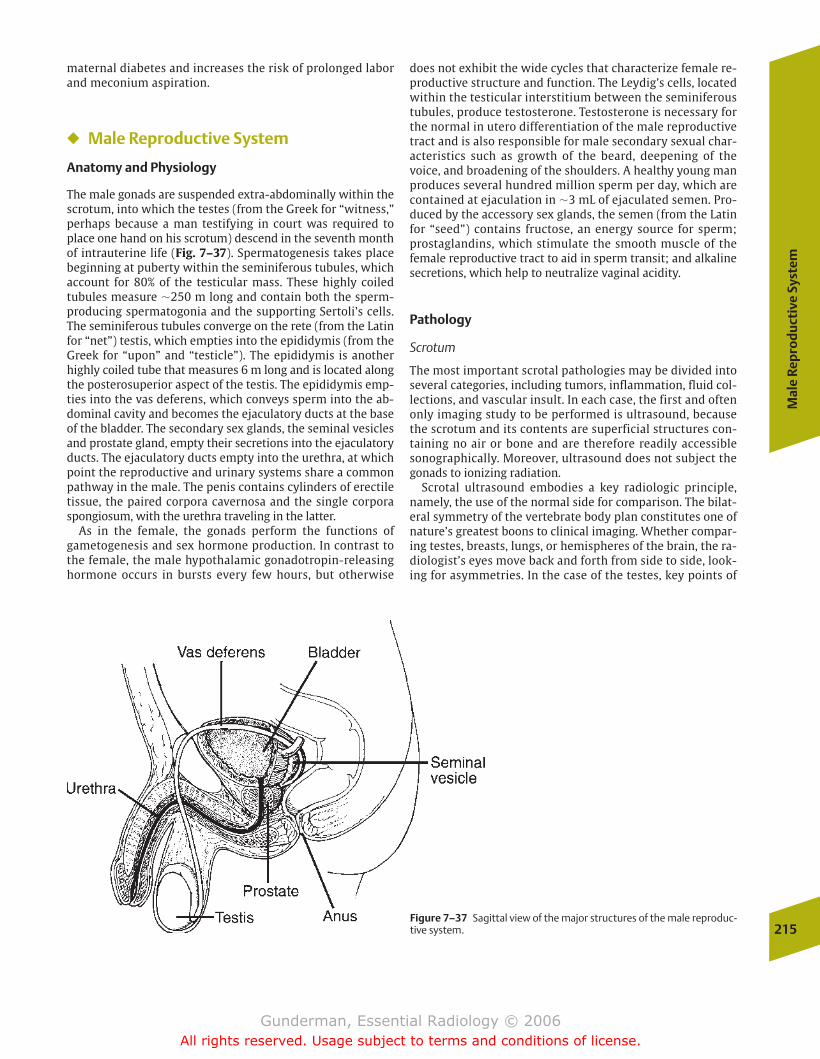
Mal
e Re
pro
du
ctiv
e Sy
stem
215Figure 7–37 Sagittal view of the major structures of the male reproduc-tive system.
maternal diabetes and increases the risk of prolonged laborand meconium aspiration.
� Male Reproductive System
Anatomy and Physiology
The male gonads are suspended extra-abdominally within thescrotum, into which the testes (from the Greek for “witness,”perhaps because a man testifying in court was required toplace one hand on his scrotum) descend in the seventh monthof intrauterine life (Fig. 7–37). Spermatogenesis takes placebeginning at puberty within the seminiferous tubules, whichaccount for 80% of the testicular mass. These highly coiledtubules measure �250 m long and contain both the sperm-producing spermatogonia and the supporting Sertoli’s cells.The seminiferous tubules converge on the rete (from the Latinfor “net”) testis, which empties into the epididymis (from theGreek for “upon” and “testicle”). The epididymis is anotherhighly coiled tube that measures 6 m long and is located alongthe posterosuperior aspect of the testis. The epididymis emp-ties into the vas deferens, which conveys sperm into the ab-dominal cavity and becomes the ejaculatory ducts at the baseof the bladder. The secondary sex glands, the seminal vesiclesand prostate gland, empty their secretions into the ejaculatoryducts. The ejaculatory ducts empty into the urethra, at whichpoint the reproductive and urinary systems share a commonpathway in the male. The penis contains cylinders of erectiletissue, the paired corpora cavernosa and the single corporaspongiosum, with the urethra traveling in the latter.
As in the female, the gonads perform the functions of gametogenesis and sex hormone production. In contrast tothe female, the male hypothalamic gonadotropin-releasinghormone occurs in bursts every few hours, but otherwise
does not exhibit the wide cycles that characterize female re-productive structure and function. The Leydig’s cells, locatedwithin the testicular interstitium between the seminiferoustubules, produce testosterone. Testosterone is necessary forthe normal in utero differentiation of the male reproductivetract and is also responsible for male secondary sexual char-acteristics such as growth of the beard, deepening of thevoice, and broadening of the shoulders. A healthy young manproduces several hundred million sperm per day, which arecontained at ejaculation in �3 mL of ejaculated semen. Pro-duced by the accessory sex glands, the semen (from the Latinfor “seed”) contains fructose, an energy source for sperm;prostaglandins, which stimulate the smooth muscle of the female reproductive tract to aid in sperm transit; and alkalinesecretions, which help to neutralize vaginal acidity.
Pathology
Scrotum
The most important scrotal pathologies may be divided intoseveral categories, including tumors, inflammation, fluid col-lections, and vascular insult. In each case, the first and oftenonly imaging study to be performed is ultrasound, becausethe scrotum and its contents are superficial structures con-taining no air or bone and are therefore readily accessiblesonographically. Moreover, ultrasound does not subject thegonads to ionizing radiation.
Scrotal ultrasound embodies a key radiologic principle,namely, the use of the normal side for comparison. The bilat-eral symmetry of the vertebrate body plan constitutes one ofnature’s greatest boons to clinical imaging. Whether compar-ing testes, breasts, lungs, or hemispheres of the brain, the ra-diologist’s eyes move back and forth from side to side, look-ing for asymmetries. In the case of the testes, key points of
chapter 07_p192-219.qxd 12/1/05 4:09 PM Page 215
Gunderman, Essential Radiology © 2006All rights reserved. Usage subject to terms and conditions of license.
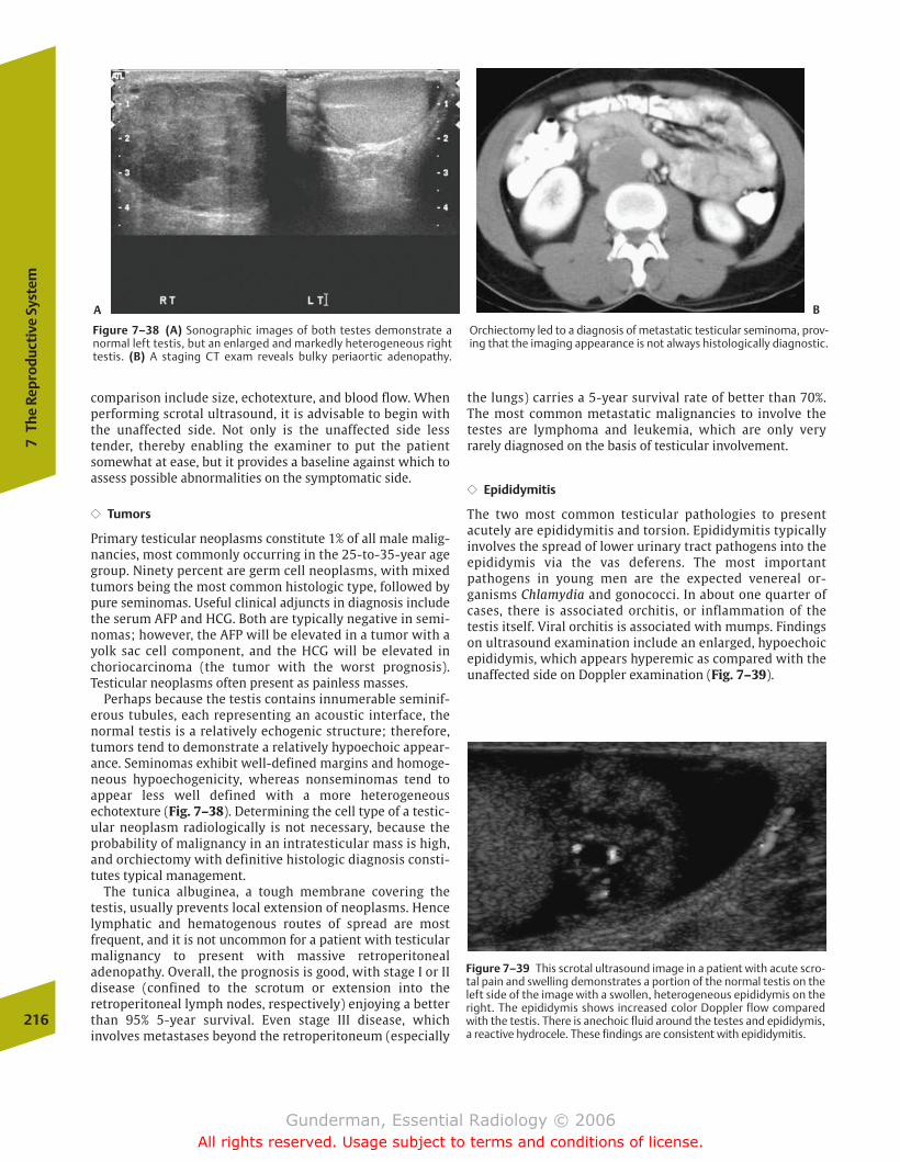
comparison include size, echotexture, and blood flow. Whenperforming scrotal ultrasound, it is advisable to begin withthe unaffected side. Not only is the unaffected side less tender, thereby enabling the examiner to put the patientsomewhat at ease, but it provides a baseline against which toassess possible abnormalities on the symptomatic side.
�� Tumors
Primary testicular neoplasms constitute 1% of all male malig-nancies, most commonly occurring in the 25-to-35-year agegroup. Ninety percent are germ cell neoplasms, with mixedtumors being the most common histologic type, followed bypure seminomas. Useful clinical adjuncts in diagnosis includethe serum AFP and HCG. Both are typically negative in semi-nomas; however, the AFP will be elevated in a tumor with ayolk sac cell component, and the HCG will be elevated inchoriocarcinoma (the tumor with the worst prognosis). Testicular neoplasms often present as painless masses.
Perhaps because the testis contains innumerable seminif-erous tubules, each representing an acoustic interface, thenormal testis is a relatively echogenic structure; therefore,tumors tend to demonstrate a relatively hypoechoic appear-ance. Seminomas exhibit well-defined margins and homoge-neous hypoechogenicity, whereas nonseminomas tend to appear less well defined with a more heterogeneous echotexture (Fig. 7–38). Determining the cell type of a testic-ular neoplasm radiologically is not necessary, because theprobability of malignancy in an intratesticular mass is high,and orchiectomy with definitive histologic diagnosis consti-tutes typical management.
The tunica albuginea, a tough membrane covering thetestis, usually prevents local extension of neoplasms. Hencelymphatic and hematogenous routes of spread are most frequent, and it is not uncommon for a patient with testicularmalignancy to present with massive retroperitonealadenopathy. Overall, the prognosis is good, with stage I or IIdisease (confined to the scrotum or extension into theretroperitoneal lymph nodes, respectively) enjoying a betterthan 95% 5-year survival. Even stage III disease, which involves metastases beyond the retroperitoneum (especially
the lungs) carries a 5-year survival rate of better than 70%.The most common metastatic malignancies to involve thetestes are lymphoma and leukemia, which are only veryrarely diagnosed on the basis of testicular involvement.
�� Epididymitis
The two most common testicular pathologies to presentacutely are epididymitis and torsion. Epididymitis typicallyinvolves the spread of lower urinary tract pathogens into theepididymis via the vas deferens. The most importantpathogens in young men are the expected venereal or-ganisms Chlamydia and gonococci. In about one quarter ofcases, there is associated orchitis, or inflammation of thetestis itself. Viral orchitis is associated with mumps. Findingson ultrasound examination include an enlarged, hypoechoicepididymis, which appears hyperemic as compared with theunaffected side on Doppler examination (Fig. 7–39).
216
7Th
e Re
prod
ucti
ve S
yste
m
Figure 7–39 This scrotal ultrasound image in a patient with acute scro-tal pain and swelling demonstrates a portion of the normal testis on theleft side of the image with a swollen, heterogeneous epididymis on theright. The epididymis shows increased color Doppler flow comparedwith the testis. There is anechoic fluid around the testes and epididymis,a reactive hydrocele. These findings are consistent with epididymitis.
Figure 7–38 (A) Sonographic images of both testes demonstrate a normal left testis, but an enlarged and markedly heterogeneous righttestis. (B) A staging CT exam reveals bulky periaortic adenopathy.
Orchiectomy led to a diagnosis of metastatic testicular seminoma, prov-ing that the imaging appearance is not always histologically diagnostic.
A B
chapter 07_p192-219.qxd 12/1/05 4:09 PM Page 216
Gunderman, Essential Radiology © 2006All rights reserved. Usage subject to terms and conditions of license.
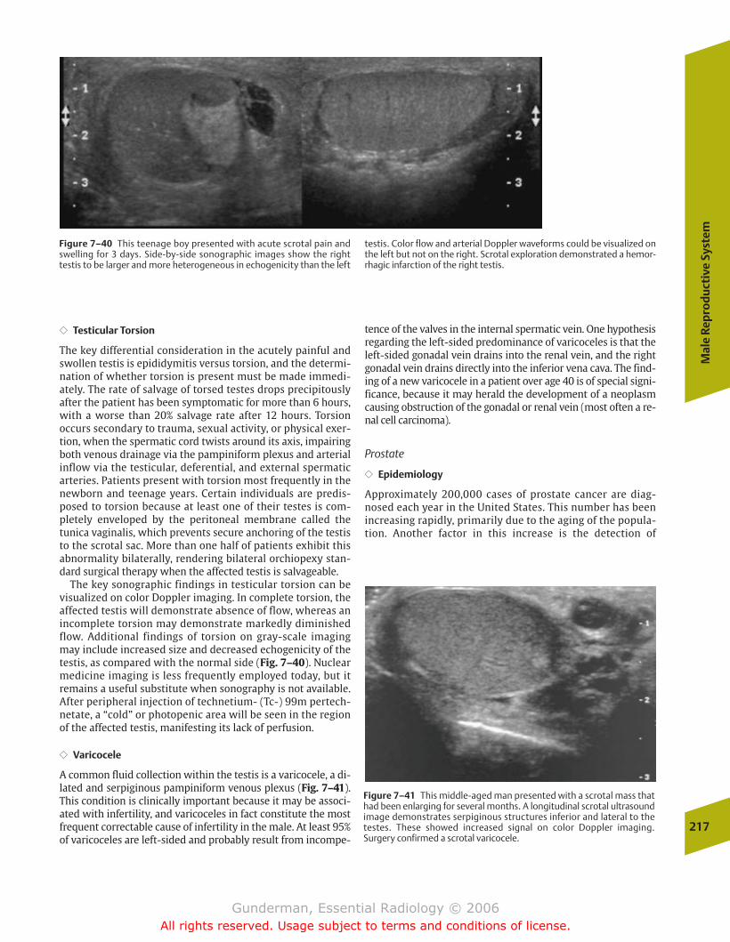
Mal
e Re
pro
du
ctiv
e Sy
stem
217
Figure 7–40 This teenage boy presented with acute scrotal pain andswelling for 3 days. Side-by-side sonographic images show the righttestis to be larger and more heterogeneous in echogenicity than the left
testis. Color flow and arterial Doppler waveforms could be visualized onthe left but not on the right. Scrotal exploration demonstrated a hemor-rhagic infarction of the right testis.
�� Testicular Torsion
The key differential consideration in the acutely painful andswollen testis is epididymitis versus torsion, and the determi-nation of whether torsion is present must be made immedi-ately. The rate of salvage of torsed testes drops precipitouslyafter the patient has been symptomatic for more than 6 hours,with a worse than 20% salvage rate after 12 hours. Torsion occurs secondary to trauma, sexual activity, or physical exer-tion, when the spermatic cord twists around its axis, impairingboth venous drainage via the pampiniform plexus and arterialinflow via the testicular, deferential, and external spermaticarteries. Patients present with torsion most frequently in thenewborn and teenage years. Certain individuals are predis-posed to torsion because at least one of their testes is com-pletely enveloped by the peritoneal membrane called the tunica vaginalis, which prevents secure anchoring of the testisto the scrotal sac. More than one half of patients exhibit thisabnormality bilaterally, rendering bilateral orchiopexy stan-dard surgical therapy when the affected testis is salvageable.
The key sonographic findings in testicular torsion can bevisualized on color Doppler imaging. In complete torsion, theaffected testis will demonstrate absence of flow, whereas anincomplete torsion may demonstrate markedly diminishedflow. Additional findings of torsion on gray-scale imagingmay include increased size and decreased echogenicity of thetestis, as compared with the normal side (Fig. 7–40). Nuclearmedicine imaging is less frequently employed today, but itremains a useful substitute when sonography is not available.After peripheral injection of technetium- (Tc-) 99m pertech-netate, a “cold” or photopenic area will be seen in the regionof the affected testis, manifesting its lack of perfusion.
�� Varicocele
A common fluid collection within the testis is a varicocele, a di-lated and serpiginous pampiniform venous plexus (Fig. 7–41).This condition is clinically important because it may be associ-ated with infertility, and varicoceles in fact constitute the mostfrequent correctable cause of infertility in the male. At least 95%of varicoceles are left-sided and probably result from incompe-
tence of the valves in the internal spermatic vein. One hypothesisregarding the left-sided predominance of varicoceles is that theleft-sided gonadal vein drains into the renal vein, and the rightgonadal vein drains directly into the inferior vena cava. The find-ing of a new varicocele in a patient over age 40 is of special signi-ficance, because it may herald the development of a neoplasmcausing obstruction of the gonadal or renal vein (most often a re-nal cell carcinoma).
Prostate
�� Epidemiology
Approximately 200,000 cases of prostate cancer are diag-nosed each year in the United States. This number has beenincreasing rapidly, primarily due to the aging of the popula-tion. Another factor in this increase is the detection of
Figure 7–41 This middle-aged man presented with a scrotal mass thathad been enlarging for several months. A longitudinal scrotal ultrasoundimage demonstrates serpiginous structures inferior and lateral to thetestes. These showed increased signal on color Doppler imaging.Surgery confirmed a scrotal varicocele.
chapter 07_p192-219.qxd 12/1/05 4:09 PM Page 217
Gunderman, Essential Radiology © 2006All rights reserved. Usage subject to terms and conditions of license.
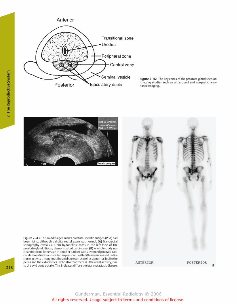
218
7Th
e Re
prod
ucti
ve S
yste
m
Figure 7–43 This middle-aged man’s prostate-specific antigen (PSA) hadbeen rising, although a digital rectal exam was normal. (A) Transrectalsonography reveals a 1 cm hypoechoic mass in the left lobe of theprostate gland. Biopsy demonstrated carcinoma. (B) A whole-body nu-clear medicine bone scan in another patient with advanced prostate can-cer demonstrates a so-called super-scan, with diffusely increased radio-tracer activity throughout the axial skeleton as well as abnormal foci in thepelvis and the extremities. Note also that there is little renal activity, dueto the avid bone uptake. This indicates diffuse skeletal metastatic disease.
Figure 7–42 The key zones of the prostate gland seen onimaging studies such as ultrasound and magnetic reso-nance imaging.
A
B
chapter 07_p192-219.qxd 12/1/05 4:10 PM Page 218
Gunderman, Essential Radiology © 2006All rights reserved. Usage subject to terms and conditions of license.
Mal
e Re
pro
du
ctiv
e Sy
stem
219
urgency. Unfortunately, these same symptoms are associatedwith BPH, which is seen to some degree in most men as theyage. A distinguishing feature that tends to favor malignancyis a relatively abrupt change in symptoms. The two mostwidely employed screening methods are serum assays forPSA and digital rectal examination. Digital rectal examina-tion, performed by inserting a gloved finger into the rectumand palpating the prostate gland along the anterior rectalwall, is relatively sensitive but nonspecific. Findings worri-some for malignancy include a firm, asymmetrical mass or anirregularly enlarged gland.
Benign processes in the differential diagnosis of prostatecarcinoma include BPH, which involves the transitional zone,and prostatitis, which generally causes the entire gland to be-come boggy, swollen, and edematous. The most common or-ganism is Escherichia coli.
It is not uncommon for patients to present with metastaticdisease, which manifests with such symptoms as impotence(due to disruption of neurovascular structures), as well asback pain and bone pain (due to skeletal metastases). Approx-imately 80% of patients with metastatic disease exhibit onlybone involvement, but other sites include lymph nodes, liver,and lung.
�� Imaging
Imaging findings that support the diagnosis of prostate carci-noma depend on the modality employed. Transrectal ultra-sound findings include one or more hypoechoic nodules inthe peripheral zone, mass effect on surrounding tissues, andasymmetric enlargement of the gland (Fig. 7–43). On T2-weighted MR images, cancers typically appear as hy-pointense (dark) lesions amid the relatively brightparenchyma of the peripheral zone. Ultimately, the diagnosisis established by biopsy, and ultrasound has the advantagethat it readily guides biopsy of suspicious lesions via a trans-rectal route.
clinically occult disease through screening programs. Prostatecancer is the second leading cause of cancer death in men, re-sulting in �43,000 deaths per year, second only to lung can-cer; however, the toll of prostate cancer in years of life lost ismuch less than that of breast cancer, due to the fact that ittypically kills at a much later age; in the United States, breastcancer is responsible for over 100 years of life lost per100,000 people under the age of 65, whereas prostate canceris responsible for less than 10.
�� Pathophysiology
An understanding of the anatomy of the prostate gland iscritical in interpreting imaging studies, because differentpathologic processes tend to arise in different portions of thegland (Fig. 7–42). The prostate gland surrounds the urethraat the base of the bladder and contains the junction point be-tween the urethra and ejaculatory ducts. Approximatelythree fourths of the gland is located in the peripheral zone,which surrounds the remainder of the gland posterolaterally.Most prostate cancers arise here, and 95% of these malignan-cies are adenocarcinomas. The transitional zone, which surrounds the urethra, constitutes only 5% of the gland, butrepresents the site of benign prostatic hyperplasia (BPH), andhence may enlarge markedly.
The workup of a newly diagnosed patient generally in-cludes measurements of serum alkaline phosphatase andliver function tests, as well as chest radiographs, bone scan,and abdominal and pelvic CT. MRI or transrectal ultrasound ismore accurate than CT in assessing local extension of the dis-ease. In patients presenting with an elevated prostate-spe-cific antigen (PSA), transrectal ultrasound is often employedto guide biopsy of the gland.
�� Clinical Presentation
The clinical presentation of prostate cancer includes symp-toms such as urinary frequency, nocturia, and urinary
chapter 07_p192-219.qxd 12/1/05 4:10 PM Page 219
Gunderman, Essential Radiology © 2006All rights reserved. Usage subject to terms and conditions of license.

� Anatomy and Physiology
� Imaging Modalities
� Pathology
CongenitalAchondroplasiaThanatophoric DysplasiaOsteopetrosis
InfectiousOsteomyelitisSeptic Arthritis
TumorousMetastasesPrimary Bone Tumors
InflammatoryOsteoarthritisRheumatoid ArthritisSeronegative Spondyloarthropathies
MetabolicAcromegalyChronic Renal FailureCrystalopathies: GoutCrystalopathies: PseudogoutHydroxyapatite Deposition Disease
TraumaticJoint InjuryFracture: Extremity TraumaFracture: Cervical Spine
Vascular
8The Musculoskeletal System
chapter 08_p220-256.qxd 12/1/05 4:13 PM Page 220
Gunderman, Essential Radiology © 2006All rights reserved. Usage subject to terms and conditions of license.
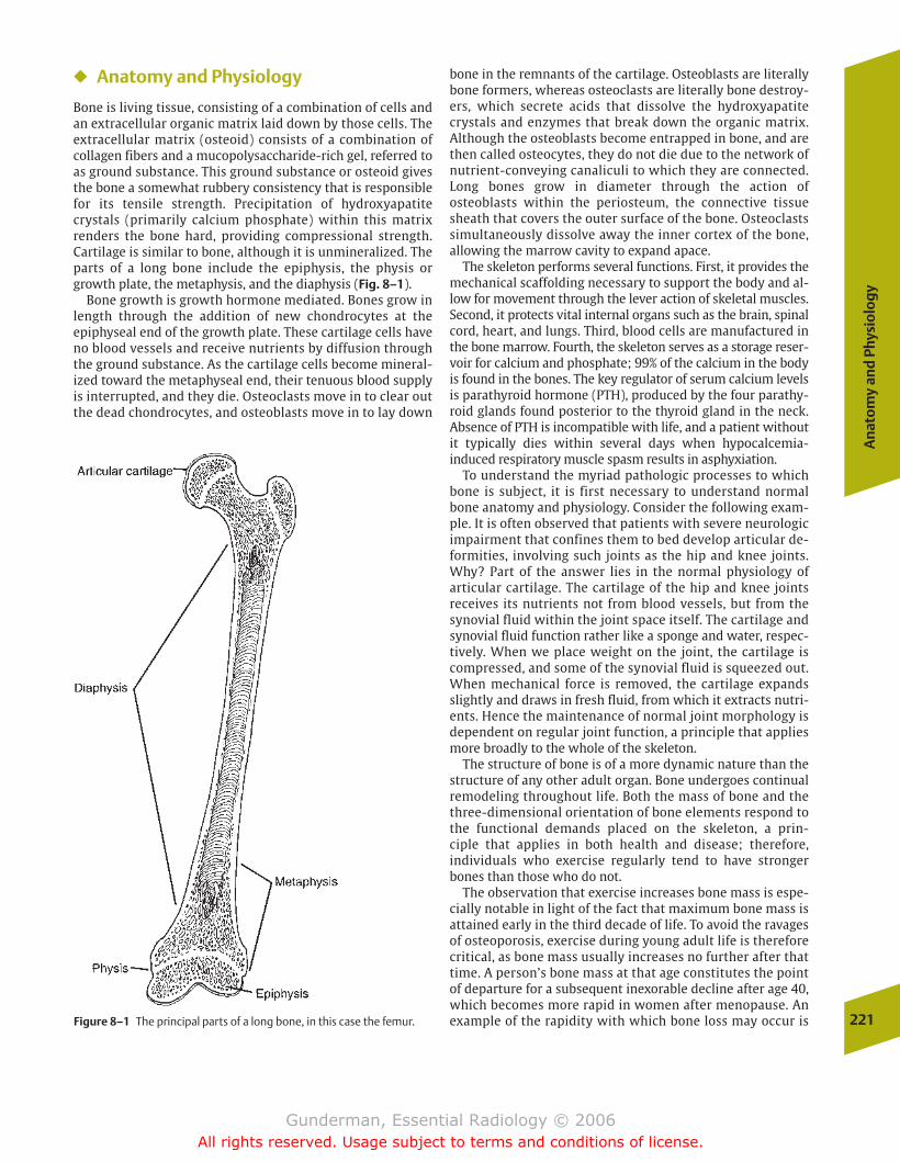
An
ato
my
and
Phy
sio
log
y
221
� Anatomy and Physiology
Bone is living tissue, consisting of a combination of cells andan extracellular organic matrix laid down by those cells. Theextracellular matrix (osteoid) consists of a combination ofcollagen fibers and a mucopolysaccharide-rich gel, referred toas ground substance. This ground substance or osteoid givesthe bone a somewhat rubbery consistency that is responsiblefor its tensile strength. Precipitation of hydroxyapatite crystals (primarily calcium phosphate) within this matrixrenders the bone hard, providing compressional strength.Cartilage is similar to bone, although it is unmineralized. Theparts of a long bone include the epiphysis, the physis orgrowth plate, the metaphysis, and the diaphysis (Fig. 8–1).
Bone growth is growth hormone mediated. Bones grow inlength through the addition of new chondrocytes at the epiphyseal end of the growth plate. These cartilage cells haveno blood vessels and receive nutrients by diffusion throughthe ground substance. As the cartilage cells become mineral-ized toward the metaphyseal end, their tenuous blood supplyis interrupted, and they die. Osteoclasts move in to clear outthe dead chondrocytes, and osteoblasts move in to lay down
bone in the remnants of the cartilage. Osteoblasts are literallybone formers, whereas osteoclasts are literally bone destroy-ers, which secrete acids that dissolve the hydroxyapatitecrystals and enzymes that break down the organic matrix. Although the osteoblasts become entrapped in bone, and arethen called osteocytes, they do not die due to the network ofnutrient-conveying canaliculi to which they are connected.Long bones grow in diameter through the action of osteoblasts within the periosteum, the connective tissuesheath that covers the outer surface of the bone. Osteoclastssimultaneously dissolve away the inner cortex of the bone,allowing the marrow cavity to expand apace.
The skeleton performs several functions. First, it provides themechanical scaffolding necessary to support the body and al-low for movement through the lever action of skeletal muscles.Second, it protects vital internal organs such as the brain, spinalcord, heart, and lungs. Third, blood cells are manufactured inthe bone marrow. Fourth, the skeleton serves as a storage reser-voir for calcium and phosphate; 99% of the calcium in the bodyis found in the bones. The key regulator of serum calcium levelsis parathyroid hormone (PTH), produced by the four parathy-roid glands found posterior to the thyroid gland in the neck.Absence of PTH is incompatible with life, and a patient withoutit typically dies within several days when hypocalcemia-induced respiratory muscle spasm results in asphyxiation.
To understand the myriad pathologic processes to whichbone is subject, it is first necessary to understand normalbone anatomy and physiology. Consider the following exam-ple. It is often observed that patients with severe neurologicimpairment that confines them to bed develop articular de-formities, involving such joints as the hip and knee joints.Why? Part of the answer lies in the normal physiology of articular cartilage. The cartilage of the hip and knee joints receives its nutrients not from blood vessels, but from thesynovial fluid within the joint space itself. The cartilage andsynovial fluid function rather like a sponge and water, respec-tively. When we place weight on the joint, the cartilage iscompressed, and some of the synovial fluid is squeezed out.When mechanical force is removed, the cartilage expandsslightly and draws in fresh fluid, from which it extracts nutri-ents. Hence the maintenance of normal joint morphology isdependent on regular joint function, a principle that appliesmore broadly to the whole of the skeleton.
The structure of bone is of a more dynamic nature than thestructure of any other adult organ. Bone undergoes continualremodeling throughout life. Both the mass of bone and thethree-dimensional orientation of bone elements respond tothe functional demands placed on the skeleton, a prin-ciple that applies in both health and disease; therefore, individuals who exercise regularly tend to have strongerbones than those who do not.
The observation that exercise increases bone mass is espe-cially notable in light of the fact that maximum bone mass isattained early in the third decade of life. To avoid the ravagesof osteoporosis, exercise during young adult life is thereforecritical, as bone mass usually increases no further after thattime. A person’s bone mass at that age constitutes the pointof departure for a subsequent inexorable decline after age 40,which becomes more rapid in women after menopause. Anexample of the rapidity with which bone loss may occur isFigure 8–1 The principal parts of a long bone, in this case the femur.
chapter 08_p220-256.qxd 12/1/05 4:13 PM Page 221
Gunderman, Essential Radiology © 2006All rights reserved. Usage subject to terms and conditions of license.
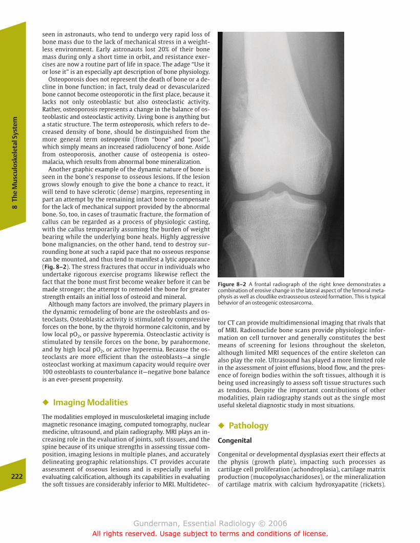
seen in astronauts, who tend to undergo very rapid loss ofbone mass due to the lack of mechanical stress in a weight-less environment. Early astronauts lost 20% of their bonemass during only a short time in orbit, and resistance exer-cises are now a routine part of life in space. The adage “Use itor lose it” is an especially apt description of bone physiology.
Osteoporosis does not represent the death of bone or a de-cline in bone function; in fact, truly dead or devascularizedbone cannot become osteoporotic in the first place, because itlacks not only osteoblastic but also osteoclastic activity.Rather, osteoporosis represents a change in the balance of os-teoblastic and osteoclastic activity. Living bone is anything buta static structure. The term osteoporosis, which refers to de-creased density of bone, should be distinguished from themore general term osteopenia (from “bone” and “poor”),which simply means an increased radiolucency of bone. Asidefrom osteoporosis, another cause of osteopenia is osteo-malacia, which results from abnormal bone mineralization.
Another graphic example of the dynamic nature of bone isseen in the bone’s response to osseous lesions. If the lesiongrows slowly enough to give the bone a chance to react, itwill tend to have sclerotic (dense) margins, representing inpart an attempt by the remaining intact bone to compensatefor the lack of mechanical support provided by the abnormalbone. So, too, in cases of traumatic fracture, the formation ofcallus can be regarded as a process of physiologic casting,with the callus temporarily assuming the burden of weightbearing while the underlying bone heals. Highly aggressivebone malignancies, on the other hand, tend to destroy sur-rounding bone at such a rapid pace that no osseous responsecan be mounted, and thus tend to manifest a lytic appearance(Fig. 8–2). The stress fractures that occur in individuals whoundertake rigorous exercise programs likewise reflect thefact that the bone must first become weaker before it can bemade stronger; the attempt to remodel the bone for greaterstrength entails an initial loss of osteoid and mineral.
Although many factors are involved, the primary players inthe dynamic remodeling of bone are the osteoblasts and os-teoclasts. Osteoblastic activity is stimulated by compressiveforces on the bone, by the thyroid hormone calcitonin, and bylow local pO2, or passive hyperemia. Osteoclastic activity isstimulated by tensile forces on the bone, by parahormone,and by high local pO2, or active hyperemia. Because the os-teoclasts are more efficient than the osteoblasts—a single osteoclast working at maximum capacity would require over100 osteoblasts to counterbalance it—negative bone balanceis an ever-present propensity.
� Imaging Modalities
The modalities employed in musculoskeletal imaging includemagnetic resonance imaging, computed tomography, nuclearmedicine, ultrasound, and plain radiography. MRI plays an in-creasing role in the evaluation of joints, soft tissues, and thespine because of its unique strengths in assessing tissue com-position, imaging lesions in multiple planes, and accuratelydelineating geographic relationships. CT provides accurateassessment of osseous lesions and is especially useful in evaluating calcification, although its capabilities in evaluatingthe soft tissues are considerably inferior to MRI. Multidetec-
tor CT can provide multidimensional imaging that rivals thatof MRI. Radionuclide bone scans provide physiologic infor-mation on cell turnover and generally constitutes the bestmeans of screening for lesions throughout the skeleton, although limited MRI sequences of the entire skeleton canalso play the role. Ultrasound has played a more limited rolein the assessment of joint effusions, blood flow, and the pres-ence of foreign bodies within the soft tissues, although it isbeing used increasingly to assess soft tissue structures suchas tendons. Despite the important contributions of othermodalities, plain radiography stands out as the single mostuseful skeletal diagnostic study in most situations.
� Pathology
Congenital
Congenital or developmental dysplasias exert their effects atthe physis (growth plate), impacting such processes as cartilage cell proliferation (achondroplasia), cartilage matrixproduction (mucopolysaccharidoses), or the mineralizationof cartilage matrix with calcium hydroxyapatite (rickets).
222
8Th
e M
uscu
losk
elet
al S
yste
m
Figure 8–2 A frontal radiograph of the right knee demonstrates a combination of erosive change in the lateral aspect of the femoral meta-physis as well as cloudlike extraosseous osteoid formation. This is typicalbehavior of an osteogenic osteosarcoma.
chapter 08_p220-256.qxd 12/1/05 4:13 PM Page 222
Gunderman, Essential Radiology © 2006All rights reserved. Usage subject to terms and conditions of license.
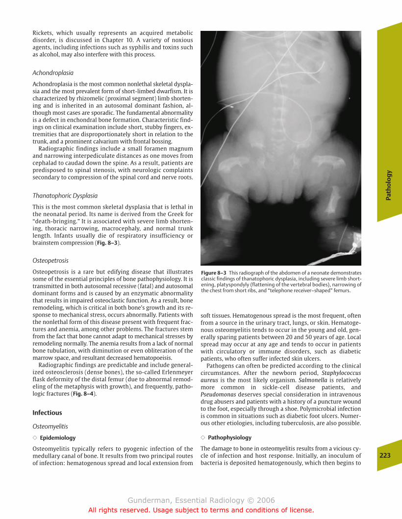
Path
olo
gy
223
Rickets, which usually represents an acquired metabolic disorder, is discussed in Chapter 10. A variety of noxiousagents, including infections such as syphilis and toxins suchas alcohol, may also interfere with this process.
Achondroplasia
Achondroplasia is the most common nonlethal skeletal dyspla-sia and the most prevalent form of short-limbed dwarfism. It ischaracterized by rhizomelic (proximal segment) limb shorten-ing and is inherited in an autosomal dominant fashion, al-though most cases are sporadic. The fundamental abnormalityis a defect in enchondral bone formation. Characteristic find-ings on clinical examination include short, stubby fingers, ex-tremities that are disproportionately short in relation to thetrunk, and a prominent calvarium with frontal bossing.
Radiographic findings include a small foramen magnumand narrowing interpediculate distances as one moves fromcephalad to caudad down the spine. As a result, patients arepredisposed to spinal stenosis, with neurologic complaintssecondary to compression of the spinal cord and nerve roots.
Thanatophoric Dysplasia
This is the most common skeletal dysplasia that is lethal inthe neonatal period. Its name is derived from the Greek for“death-bringing.” It is associated with severe limb shorten-ing, thoracic narrowing, macrocephaly, and normal trunklength. Infants usually die of respiratory insufficiency orbrainstem compression (Fig. 8–3).
Osteopetrosis
Osteopetrosis is a rare but edifying disease that illustratessome of the essential principles of bone pathophysiology. It istransmitted in both autosomal recessive (fatal) and autosomaldominant forms and is caused by an enzymatic abnormalitythat results in impaired osteoclastic function. As a result, boneremodeling, which is critical in both bone’s growth and its re-sponse to mechanical stress, occurs abnormally. Patients withthe nonlethal form of this disease present with frequent frac-tures and anemia, among other problems. The fractures stemfrom the fact that bone cannot adapt to mechanical stresses byremodeling normally. The anemia results from a lack of normalbone tubulation, with diminution or even obliteration of themarrow space, and resultant decreased hematopoeisis.
Radiographic findings are predictable and include general-ized osteosclerosis (dense bones), the so-called Erlenmeyerflask deformity of the distal femur (due to abnormal remod-eling of the metaphysis with growth), and frequently, patho-logic fractures (Fig. 8–4).
Infectious
Osteomyelitis
�� Epidemiology
Osteomyelitis typically refers to pyogenic infection of themedullary canal of bone. It results from two principal routesof infection: hematogenous spread and local extension from
Figure 8–3 This radiograph of the abdomen of a neonate demonstratesclassic findings of thanatophoric dysplasia, including severe limb short-ening, platyspondyly (flattening of the vertebral bodies), narrowing ofthe chest from short ribs, and “telephone receiver–shaped” femurs.
soft tissues. Hematogenous spread is the most frequent, oftenfrom a source in the urinary tract, lungs, or skin. Hematoge-nous osteomyelitis tends to occur in the young and old, gen-erally sparing patients between 20 and 50 years of age. Localspread may occur at any age and tends to occur in patientswith circulatory or immune disorders, such as diabetic patients, who often suffer infected skin ulcers.
Pathogens can often be predicted according to the clinicalcircumstances. After the newborn period, Staphylococcus aureus is the most likely organism. Salmonella is relativelymore common in sickle-cell disease patients, andPseudomonas deserves special consideration in intravenousdrug abusers and patients with a history of a puncture woundto the foot, especially through a shoe. Polymicrobial infectionis common in situations such as diabetic foot ulcers. Numer-ous other etiologies, including tuberculosis, are also possible.
�� Pathophysiology
The damage to bone in osteomyelitis results from a vicious cy-cle of infection and host response. Initially, an inoculum ofbacteria is deposited hematogenously, which then begins to
chapter 08_p220-256.qxd 12/1/05 4:13 PM Page 223
Gunderman, Essential Radiology © 2006All rights reserved. Usage subject to terms and conditions of license.
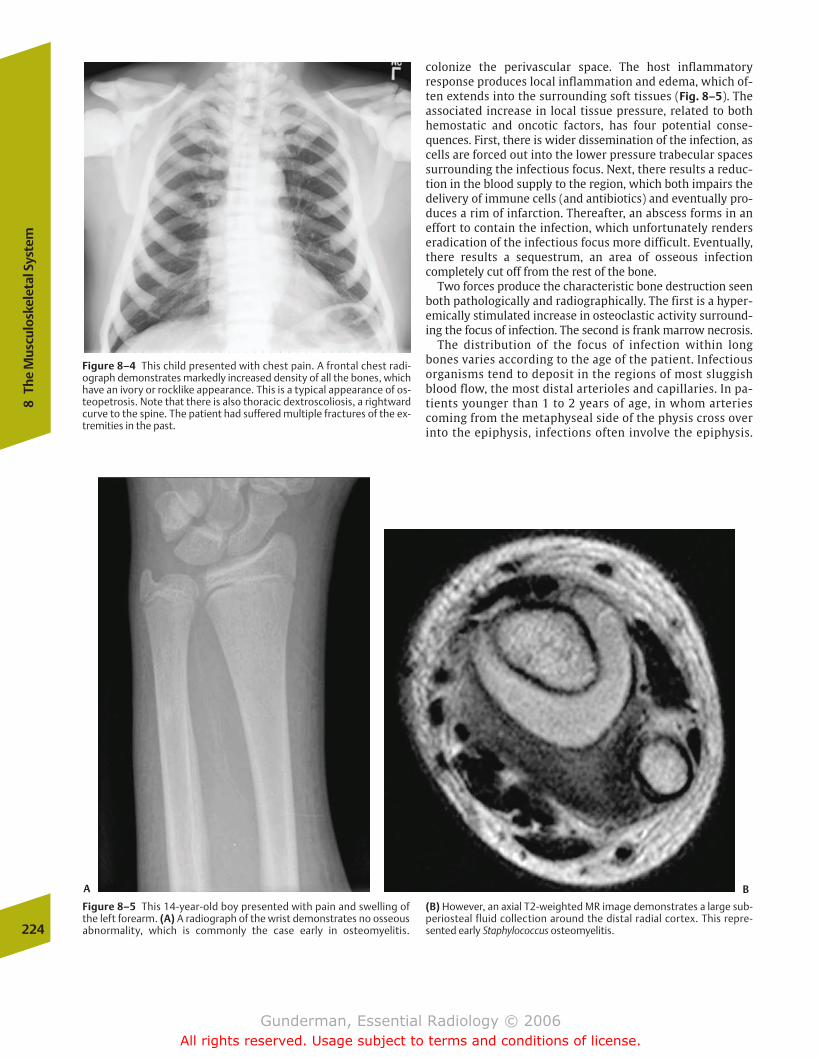
colonize the perivascular space. The host inflammatory response produces local inflammation and edema, which of-ten extends into the surrounding soft tissues (Fig. 8–5). Theassociated increase in local tissue pressure, related to both hemostatic and oncotic factors, has four potential conse-quences. First, there is wider dissemination of the infection, ascells are forced out into the lower pressure trabecular spacessurrounding the infectious focus. Next, there results a reduc-tion in the blood supply to the region, which both impairs the delivery of immune cells (and antibiotics) and eventually pro-duces a rim of infarction. Thereafter, an abscess forms in aneffort to contain the infection, which unfortunately renderseradication of the infectious focus more difficult. Eventually,there results a sequestrum, an area of osseous infection completely cut off from the rest of the bone.
Two forces produce the characteristic bone destruction seenboth pathologically and radiographically. The first is a hyper-emically stimulated increase in osteoclastic activity surround-ing the focus of infection. The second is frank marrow necrosis.
The distribution of the focus of infection within longbones varies according to the age of the patient. Infectiousorganisms tend to deposit in the regions of most sluggishblood flow, the most distal arterioles and capillaries. In pa-tients younger than 1 to 2 years of age, in whom arteriescoming from the metaphyseal side of the physis cross overinto the epiphysis, infections often involve the epiphysis.
224
8Th
e M
uscu
losk
elet
al S
yste
m
Figure 8–4 This child presented with chest pain. A frontal chest radi-ograph demonstrates markedly increased density of all the bones, whichhave an ivory or rocklike appearance. This is a typical appearance of os-teopetrosis. Note that there is also thoracic dextroscoliosis, a rightwardcurve to the spine. The patient had suffered multiple fractures of the ex-tremities in the past.
Figure 8–5 This 14-year-old boy presented with pain and swelling ofthe left forearm. (A) A radiograph of the wrist demonstrates no osseousabnormality, which is commonly the case early in osteomyelitis.
(B) However, an axial T2-weighted MR image demonstrates a large sub-periosteal fluid collection around the distal radial cortex. This repre-sented early Staphylococcus osteomyelitis.
A B
chapter 08_p220-256.qxd 12/1/05 4:13 PM Page 224
Gunderman, Essential Radiology © 2006All rights reserved. Usage subject to terms and conditions of license.
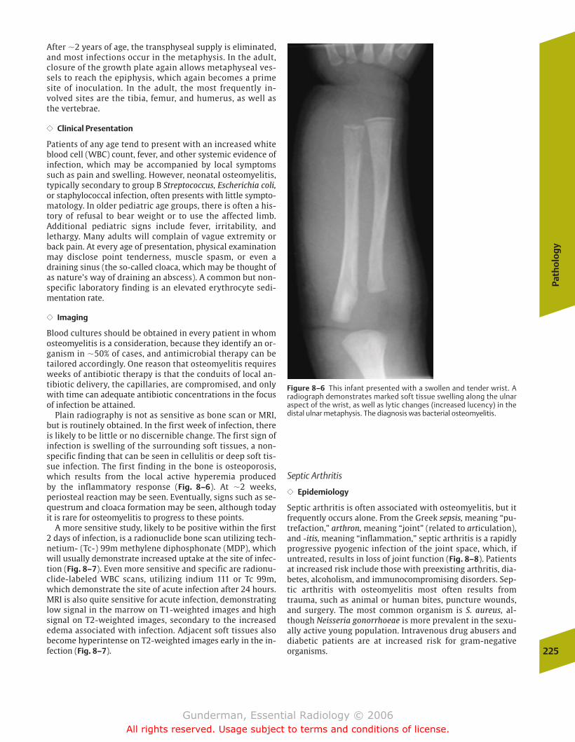
Path
olo
gy
225
After �2 years of age, the transphyseal supply is eliminated,and most infections occur in the metaphysis. In the adult,closure of the growth plate again allows metaphyseal ves-sels to reach the epiphysis, which again becomes a primesite of inoculation. In the adult, the most frequently in-volved sites are the tibia, femur, and humerus, as well asthe vertebrae.
�� Clinical Presentation
Patients of any age tend to present with an increased whiteblood cell (WBC) count, fever, and other systemic evidence ofinfection, which may be accompanied by local symptomssuch as pain and swelling. However, neonatal osteomyelitis,typically secondary to group B Streptococcus, Escherichia coli,or staphylococcal infection, often presents with little sympto-matology. In older pediatric age groups, there is often a his-tory of refusal to bear weight or to use the affected limb. Additional pediatric signs include fever, irritability, andlethargy. Many adults will complain of vague extremity orback pain. At every age of presentation, physical examinationmay disclose point tenderness, muscle spasm, or even adraining sinus (the so-called cloaca, which may be thought ofas nature’s way of draining an abscess). A common but non-specific laboratory finding is an elevated erythrocyte sedi-mentation rate.
�� Imaging
Blood cultures should be obtained in every patient in whomosteomyelitis is a consideration, because they identify an or-ganism in �50% of cases, and antimicrobial therapy can betailored accordingly. One reason that osteomyelitis requiresweeks of antibiotic therapy is that the conduits of local an-tibiotic delivery, the capillaries, are compromised, and onlywith time can adequate antibiotic concentrations in the focusof infection be attained.
Plain radiography is not as sensitive as bone scan or MRI,but is routinely obtained. In the first week of infection, thereis likely to be little or no discernible change. The first sign ofinfection is swelling of the surrounding soft tissues, a non-specific finding that can be seen in cellulitis or deep soft tis-sue infection. The first finding in the bone is osteoporosis,which results from the local active hyperemia produced by the inflammatory response (Fig. 8–6). At �2 weeks, periosteal reaction may be seen. Eventually, signs such as se-questrum and cloaca formation may be seen, although todayit is rare for osteomyelitis to progress to these points.
A more sensitive study, likely to be positive within the first2 days of infection, is a radionuclide bone scan utilizing tech-netium- (Tc-) 99m methylene diphosphonate (MDP), whichwill usually demonstrate increased uptake at the site of infec-tion (Fig. 8–7). Even more sensitive and specific are radionu-clide-labeled WBC scans, utilizing indium 111 or Tc 99m,which demonstrate the site of acute infection after 24 hours.MRI is also quite sensitive for acute infection, demonstratinglow signal in the marrow on T1-weighted images and highsignal on T2-weighted images, secondary to the increasededema associated with infection. Adjacent soft tissues alsobecome hyperintense on T2-weighted images early in the in-fection (Fig. 8–7).
Septic Arthritis
�� Epidemiology
Septic arthritis is often associated with osteomyelitis, but itfrequently occurs alone. From the Greek sepsis, meaning “pu-trefaction,” arthron, meaning “joint” (related to articulation),and -itis, meaning “inflammation,” septic arthritis is a rapidlyprogressive pyogenic infection of the joint space, which, ifuntreated, results in loss of joint function (Fig. 8–8). Patientsat increased risk include those with preexisting arthritis, dia-betes, alcoholism, and immunocompromising disorders. Sep-tic arthritis with osteomyelitis most often results fromtrauma, such as animal or human bites, puncture wounds,and surgery. The most common organism is S. aureus, al-though Neisseria gonorrhoeae is more prevalent in the sexu-ally active young population. Intravenous drug abusers anddiabetic patients are at increased risk for gram-negative organisms.
Figure 8–6 This infant presented with a swollen and tender wrist. A radiograph demonstrates marked soft tissue swelling along the ulnar aspect of the wrist, as well as lytic changes (increased lucency) in thedistal ulnar metaphysis. The diagnosis was bacterial osteomyelitis.
chapter 08_p220-256.qxd 12/1/05 4:13 PM Page 225
Gunderman, Essential Radiology © 2006All rights reserved. Usage subject to terms and conditions of license.
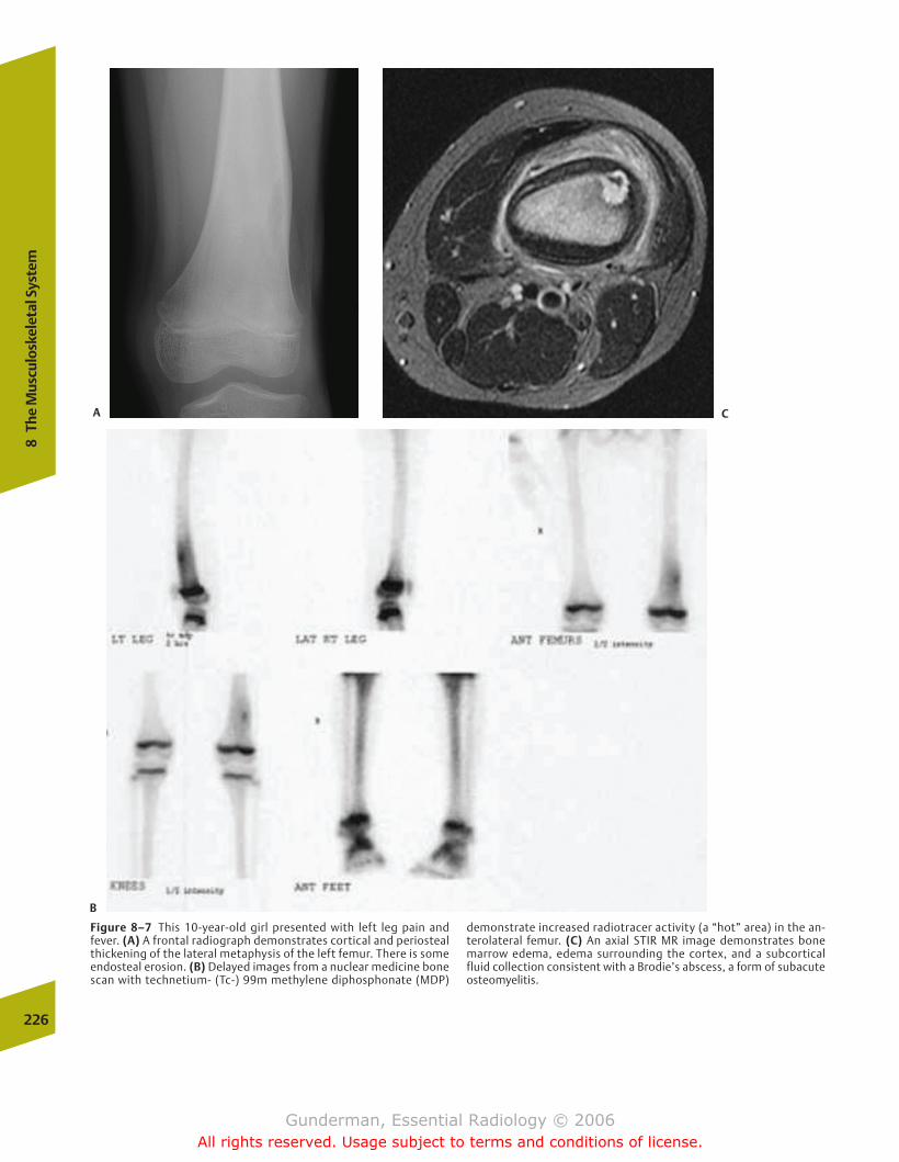
226
8Th
e M
uscu
losk
elet
al S
yste
m
Figure 8–7 This 10-year-old girl presented with left leg pain andfever. (A) A frontal radiograph demonstrates cortical and periostealthickening of the lateral metaphysis of the left femur. There is someendosteal erosion. (B) Delayed images from a nuclear medicine bonescan with technetium- (Tc-) 99m methylene diphosphonate (MDP)
demonstrate increased radiotracer activity (a “hot” area) in the an-terolateral femur. (C) An axial STIR MR image demonstrates bonemarrow edema, edema surrounding the cortex, and a subcorticalfluid collection consistent with a Brodie’s abscess, a form of subacuteosteomyelitis.
A C
B
chapter 08_p220-256.qxd 12/1/05 4:13 PM Page 226
Gunderman, Essential Radiology © 2006All rights reserved. Usage subject to terms and conditions of license.
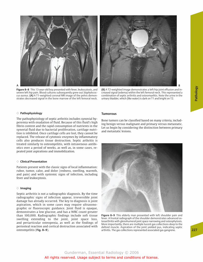
Path
olo
gy
227
�� Pathophysiology
The pathophysiology of septic arthritis includes synovial hy-peremia with exudation of fluid. Because of this fluid’s highfibrin content and the rapid consumption of nutrients in thesynovial fluid due to bacterial proliferation, cartilage nutri-tion is inhibited. Once cartilage cells are lost, they cannot bereplaced. The release of cytotoxic enzymes by inflammatorycells also produces tissue destruction. Septic arthritis istreated similarly to osteomyelitis, with intravenous antibi-otics over a period of weeks, as well as, in some cases, re-peated joint aspirations and immobilization.
�� Clinical Presentation
Patients present with the classic signs of local inflammation:rubor, tumor, calor, and dolor (redness, swelling, warmth,and pain) and with systemic signs of infection, includingfever and leukocytosis.
�� Imaging
Septic arthritis is not a radiographic diagnosis. By the time radiographic signs of infection appear, irreversible jointdamage has already occurred. The key to diagnosis is jointaspiration, which in some cases may require ultrasono-graphic or fluoroscopic guidance. Joint fluid is opaque,demonstrates a low glucose, and has a WBC count greaterthan 100,000. Radiographic findings include soft tissueswelling extending to the joint, joint space loss, and periarticular osteopenia, as well as the findings of periosteal reaction and cortical destruction associated with osteomyelitis (Fig. 8–9).
Tumorous
Bone tumors can be classified based on many criteria, includ-ing benign versus malignant and primary versus metastatic.Let us begin by considering the distinction between primaryand metastatic lesions.
Figure 8–8 This 13-year-old boy presented with fever, leukocytosis, andsevere left hip pain. Blood cultures subsequently grew out Staphylococ-cus aureus. (A) A T1-weighted coronal MR image of the pelvis demon-strates decreased signal in the bone marrow of the left femoral neck.
(B) A T2-weighted image demonstrates a left hip joint effusion and in-creased signal (edema) within the left femoral neck. This represented acombination of septic arthritis and osteomyelitis. Note the urine in theurinary bladder, which (like water) is dark on T1 and bright on T2.
Figure 8–9 This elderly man presented with left shoulder pain andfever. A frontal radiograph of the shoulder demonstrates advanced os-teoarthritis with glenohumeral joint space narrowing and osteophytosis.More importantly, there are multiple lucent gas collections deep to thedeltoid muscle. Aspiration of the joint yielded pus, indicating septicarthritis. The gas collections represented associated gas gangrene.
A B
chapter 08_p220-256.qxd 12/1/05 4:13 PM Page 227
Gunderman, Essential Radiology © 2006All rights reserved. Usage subject to terms and conditions of license.

lumbar spine, pelvis, and proximal femur the first capillary beds reached by blood-borne tumor cells (Fig. 8–11).
Although the most frequent carcinomas may metastasizeto virtually any location, certain sites tend to suggest particu-lar types of primary lesions. When metastatic lesions arefound in the distal extremities, particularly the hands andfeet, bronchogenic carcinoma is the most likely culprit. Themost common tumors to affect the skull are multiplemyeloma and carcinomas of the lung and breast. Breast can-cer is also the most likely culprit when metastatic lesions arefound in the axial skeleton, and accounts for approximatelythree quarters of spine metastases.
�� Clinical Presentation
Clinically speaking, bone metastases may represent the firstindication of a malignancy, although the vast majority of patients in whom metastatic skeletal lesions are found haveknown primary tumors. Clinical signs of skeletal metastasesinclude hypercalcemia and the syndrome known as hyper-trophic pulmonary osteoarthropathy (HPO). HPO consists ofclubbing of the digits, periosteal reaction, and pain. Approxi-mately 1 in 20 patients with bronchogenic carcinoma devel-ops the syndrome (Fig. 8–12).
Bone metastases typically present in one of two ways. Painis the most common presentation, seen in most patients, andthe other is pathologic fracture. Although from one point ofview all fractures are by definition “pathologic,” the termrefers to fractures that take place through preexisting bonelesions, which weaken the bone and predispose it to mechan-ical disruption. Obviously, the bone lesions most likely to de-velop pathologic fractures are those in the weight-bearingskeleton, and the most prevalent sites are the spine and thefemur. Approximately 5 to 10% of all patients with skeletalmetastases eventually develop a pathologic fracture. One keyrole of the radiologist, once metastatic lesions have been detected, is to determine which lesions are at significant riskfor fracture, so that prophylactic measures can be instituted,such as radiating the lesion or decreasing the mechanicalload on the bone.
�� Imaging
Radiologic indicators of an increased risk of pathologic frac-ture include destruction of more than 50% of bone cortex(with a 60–70% risk of fracture), lesions of 3 cm or greater inthe proximal femur, and an appropriately positioned lesionthat continues to cause pain even after radiotherapy. Lesionsthat involve substantially less than 50% of the cortex producepathologic fractures in less than 20% of cases. Although everymetastatic lesion would, in theory, eventually become largeenough to cause a fracture, most patients with metastaticdisease will die of other consequences of their malignancybefore this occurs.
Lytic versus Blastic Although metastases can have virtuallyany appearance, certain metastatic lesions tend to exhibitcharacteristic radiographic patterns. For example, breast andprostate carcinoma should be at the top of any differential forblastic (sclerotic) lesions, whereas renal cell and thyroid car-cinoma characteristically exhibit a lytic appearance. Another228
8Th
e M
uscu
losk
elet
al S
yste
m
Figure 8–10 This elderly man with a history of lung cancer presentedwith right hip pain. A frontal radiograph of the pelvis demonstrates alarge lytic lesion in the proximal right femoral diaphysis. This was ametastasis from the patient’s lung cancer. The lesion is large enoughand involves a sufficient amount of the cortex to increase the risk ofpathologic fracture.
Metastases
�� Epidemiology
Bone metastases are �50 to 100 times more frequent thanprimary bone malignancies. The finding of even a singleskeletal metastatic lesion is of immense clinical significance,because it indicates that the primary tumor cannot be surgi-cally resected for cure.
�� Pathophysiology
Hematogenous dissemination is the most frequent route bywhich metastatic cells reach the skeleton. Most metastatic lesions appear in multiples, because multiple cells from theprimary tumor tend to gain access to the bloodstream. Atruly solitary bone lesion has only a 1 in 10 chance of repre-senting a metastatic process (Fig. 8–10).
What percentage of cancer patients develop bone metas-tases? The lung and the liver, and not the skeleton, are infact the two most common sites of metastatic spread. Yetthe rich blood supply of the skeleton’s hematopoietic tissues explains why approximately one third of all cancerpatients eventually develop bone metastases. The rich sinu-soidal bed of the marrow capillaries, with its large gaps between endothelial cells, presents a very hospitable envi-ronment for wayward tumor cells. This explains whymetastatic lesions are much more common in bone than in,for example, the soft tissues surrounding the bone, such asmuscle, tendons, ligaments, and fat.
Of all skeletal metastases in adults, more than 80% can betraced to one of five primary malignant sources: prostate,breast, lung, kidney, and thyroid. Prostate carcinoma accountsfor more than one half of all skeletal metastases in men, asdoes breast carcinoma in women. Of these, prostate carci-noma has a special anatomic propensity to metastasize tobone. Its venous drainage through Batson’s plexus renders the
chapter 08_p220-256.qxd 12/1/05 4:13 PM Page 228
Gunderman, Essential Radiology © 2006All rights reserved. Usage subject to terms and conditions of license.
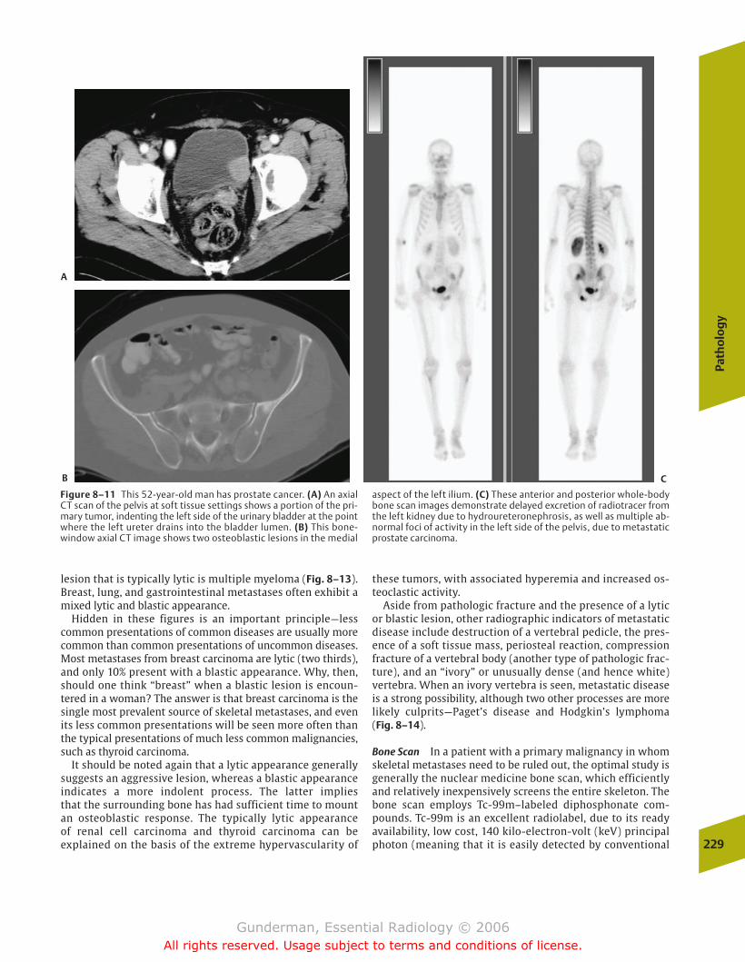
Path
olo
gy
229
lesion that is typically lytic is multiple myeloma (Fig. 8–13).Breast, lung, and gastrointestinal metastases often exhibit amixed lytic and blastic appearance.
Hidden in these figures is an important principle—lesscommon presentations of common diseases are usually morecommon than common presentations of uncommon diseases.Most metastases from breast carcinoma are lytic (two thirds),and only 10% present with a blastic appearance. Why, then,should one think “breast” when a blastic lesion is encoun-tered in a woman? The answer is that breast carcinoma is thesingle most prevalent source of skeletal metastases, and evenits less common presentations will be seen more often thanthe typical presentations of much less common malignancies,such as thyroid carcinoma.
It should be noted again that a lytic appearance generallysuggests an aggressive lesion, whereas a blastic appearanceindicates a more indolent process. The latter implies that the surrounding bone has had sufficient time to mountan osteoblastic response. The typically lytic appearance of renal cell carcinoma and thyroid carcinoma can be explained on the basis of the extreme hypervascularity of
these tumors, with associated hyperemia and increased os-teoclastic activity.
Aside from pathologic fracture and the presence of a lyticor blastic lesion, other radiographic indicators of metastaticdisease include destruction of a vertebral pedicle, the pres-ence of a soft tissue mass, periosteal reaction, compressionfracture of a vertebral body (another type of pathologic frac-ture), and an “ivory” or unusually dense (and hence white)vertebra. When an ivory vertebra is seen, metastatic diseaseis a strong possibility, although two other processes are morelikely culprits—Paget’s disease and Hodgkin’s lymphoma (Fig. 8–14).
Bone Scan In a patient with a primary malignancy in whomskeletal metastases need to be ruled out, the optimal study isgenerally the nuclear medicine bone scan, which efficientlyand relatively inexpensively screens the entire skeleton. Thebone scan employs Tc-99m–labeled diphosphonate com-pounds. Tc-99m is an excellent radiolabel, due to its readyavailability, low cost, 140 kilo-electron-volt (keV) principalphoton (meaning that it is easily detected by conventional
Figure 8–11 This 52-year-old man has prostate cancer. (A) An axialCT scan of the pelvis at soft tissue settings shows a portion of the pri-mary tumor, indenting the left side of the urinary bladder at the pointwhere the left ureter drains into the bladder lumen. (B) This bone-window axial CT image shows two osteoblastic lesions in the medial
aspect of the left ilium. (C) These anterior and posterior whole-bodybone scan images demonstrate delayed excretion of radiotracer fromthe left kidney due to hydroureteronephrosis, as well as multiple ab-normal foci of activity in the left side of the pelvis, due to metastaticprostate carcinoma.
A
B C
chapter 08_p220-256.qxd 12/1/05 4:13 PM Page 229
Gunderman, Essential Radiology © 2006All rights reserved. Usage subject to terms and conditions of license.
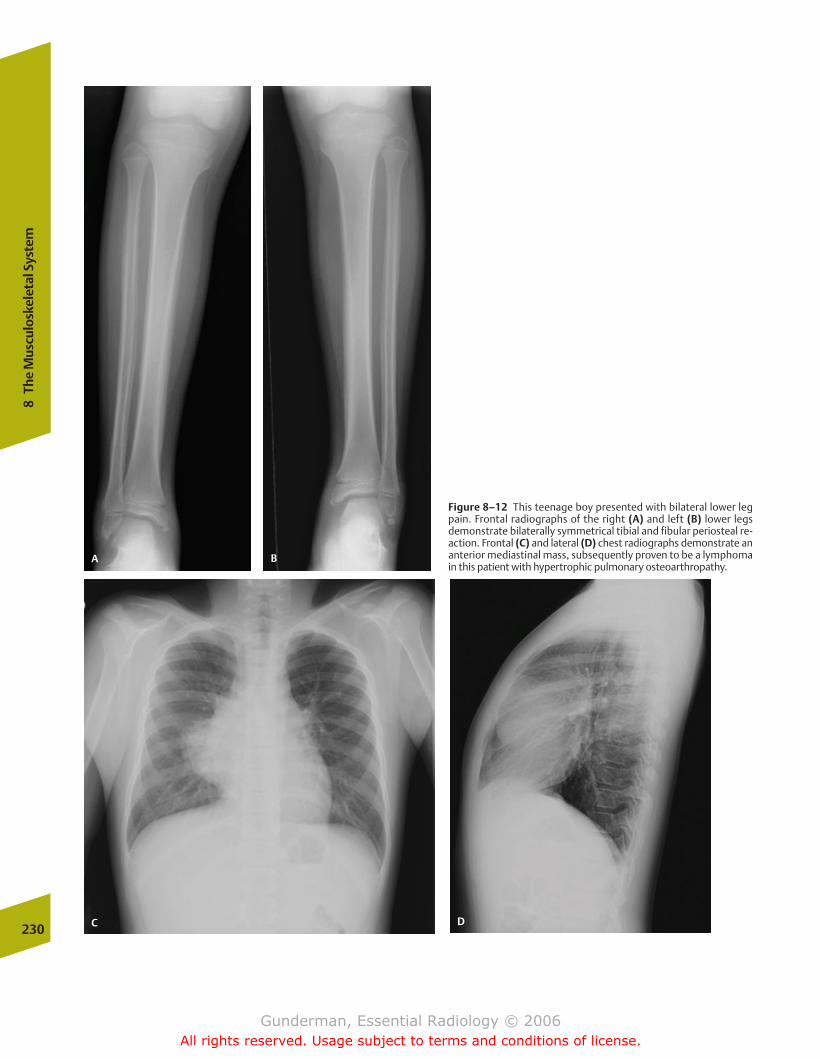
230
8Th
e M
uscu
losk
elet
al S
yste
m
Figure 8–12 This teenage boy presented with bilateral lower legpain. Frontal radiographs of the right (A) and left (B) lower legsdemonstrate bilaterally symmetrical tibial and fibular periosteal re-action. Frontal (C) and lateral (D) chest radiographs demonstrate ananterior mediastinal mass, subsequently proven to be a lymphomain this patient with hypertrophic pulmonary osteoarthropathy.
A B
C D
chapter 08_p220-256.qxd 12/1/05 4:13 PM Page 230
Gunderman, Essential Radiology © 2006All rights reserved. Usage subject to terms and conditions of license.
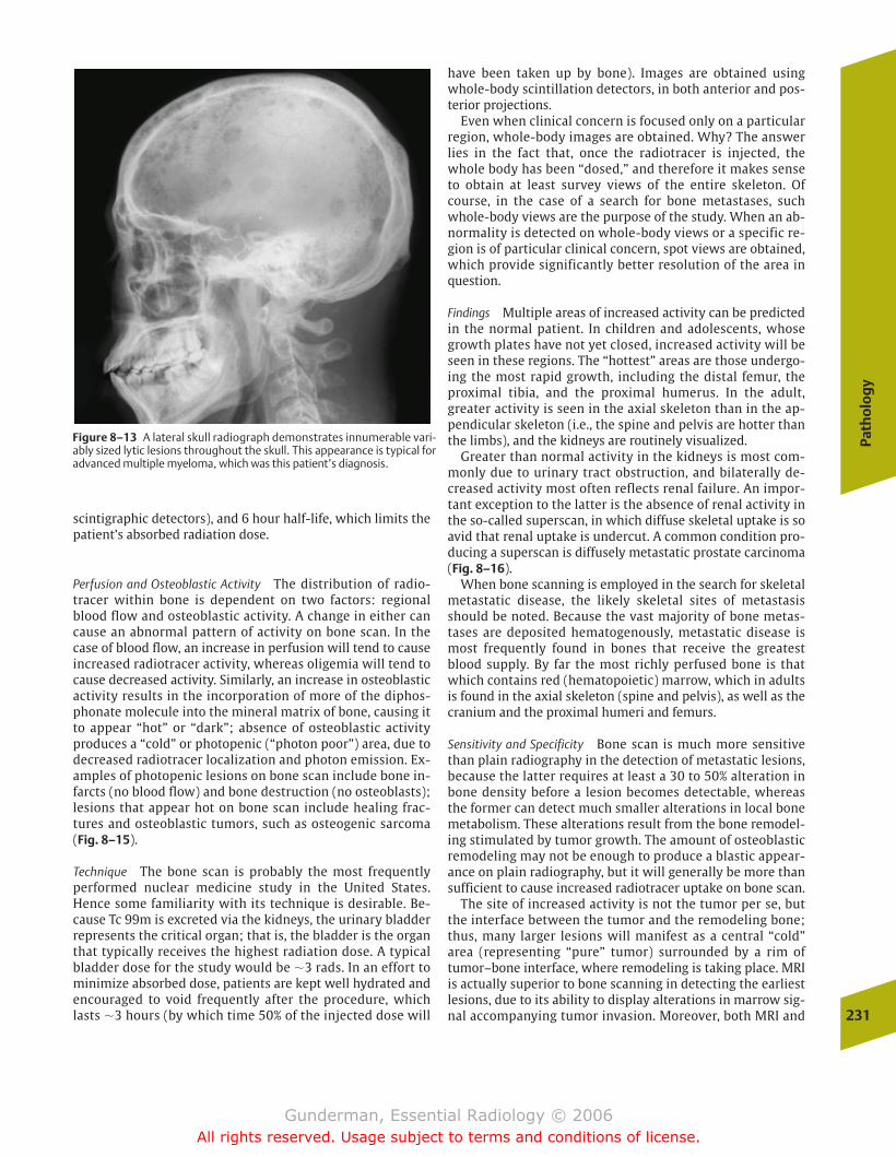
Path
olo
gy
231
scintigraphic detectors), and 6 hour half-life, which limits thepatient’s absorbed radiation dose.
Perfusion and Osteoblastic Activity The distribution of radio-tracer within bone is dependent on two factors: regionalblood flow and osteoblastic activity. A change in either cancause an abnormal pattern of activity on bone scan. In thecase of blood flow, an increase in perfusion will tend to causeincreased radiotracer activity, whereas oligemia will tend tocause decreased activity. Similarly, an increase in osteoblasticactivity results in the incorporation of more of the diphos-phonate molecule into the mineral matrix of bone, causing itto appear “hot” or “dark”; absence of osteoblastic activityproduces a “cold” or photopenic (“photon poor”) area, due to decreased radiotracer localization and photon emission. Ex-amples of photopenic lesions on bone scan include bone in-farcts (no blood flow) and bone destruction (no osteoblasts);lesions that appear hot on bone scan include healing frac-tures and osteoblastic tumors, such as osteogenic sarcoma(Fig. 8–15).
Technique The bone scan is probably the most frequentlyperformed nuclear medicine study in the United States.Hence some familiarity with its technique is desirable. Be-cause Tc 99m is excreted via the kidneys, the urinary bladderrepresents the critical organ; that is, the bladder is the organthat typically receives the highest radiation dose. A typicalbladder dose for the study would be �3 rads. In an effort tominimize absorbed dose, patients are kept well hydrated andencouraged to void frequently after the procedure, whichlasts �3 hours (by which time 50% of the injected dose will
have been taken up by bone). Images are obtained usingwhole-body scintillation detectors, in both anterior and pos-terior projections.
Even when clinical concern is focused only on a particularregion, whole-body images are obtained. Why? The answerlies in the fact that, once the radiotracer is injected, thewhole body has been “dosed,” and therefore it makes senseto obtain at least survey views of the entire skeleton. Ofcourse, in the case of a search for bone metastases, suchwhole-body views are the purpose of the study. When an ab-normality is detected on whole-body views or a specific re-gion is of particular clinical concern, spot views are obtained,which provide significantly better resolution of the area inquestion.
Findings Multiple areas of increased activity can be predictedin the normal patient. In children and adolescents, whosegrowth plates have not yet closed, increased activity will beseen in these regions. The “hottest” areas are those undergo-ing the most rapid growth, including the distal femur, theproximal tibia, and the proximal humerus. In the adult,greater activity is seen in the axial skeleton than in the ap-pendicular skeleton (i.e., the spine and pelvis are hotter thanthe limbs), and the kidneys are routinely visualized.
Greater than normal activity in the kidneys is most com-monly due to urinary tract obstruction, and bilaterally de-creased activity most often reflects renal failure. An impor-tant exception to the latter is the absence of renal activity inthe so-called superscan, in which diffuse skeletal uptake is soavid that renal uptake is undercut. A common condition pro-ducing a superscan is diffusely metastatic prostate carcinoma(Fig. 8–16).
When bone scanning is employed in the search for skeletalmetastatic disease, the likely skeletal sites of metastasisshould be noted. Because the vast majority of bone metas-tases are deposited hematogenously, metastatic disease ismost frequently found in bones that receive the greatestblood supply. By far the most richly perfused bone is thatwhich contains red (hematopoietic) marrow, which in adultsis found in the axial skeleton (spine and pelvis), as well as thecranium and the proximal humeri and femurs.
Sensitivity and Specificity Bone scan is much more sensitivethan plain radiography in the detection of metastatic lesions,because the latter requires at least a 30 to 50% alteration inbone density before a lesion becomes detectable, whereasthe former can detect much smaller alterations in local bonemetabolism. These alterations result from the bone remodel-ing stimulated by tumor growth. The amount of osteoblasticremodeling may not be enough to produce a blastic appear-ance on plain radiography, but it will generally be more thansufficient to cause increased radiotracer uptake on bone scan.
The site of increased activity is not the tumor per se, butthe interface between the tumor and the remodeling bone;thus, many larger lesions will manifest as a central “cold”area (representing “pure” tumor) surrounded by a rim of tumor–bone interface, where remodeling is taking place. MRIis actually superior to bone scanning in detecting the earliestlesions, due to its ability to display alterations in marrow sig-nal accompanying tumor invasion. Moreover, both MRI and
Figure 8–13 A lateral skull radiograph demonstrates innumerable vari-ably sized lytic lesions throughout the skull. This appearance is typical foradvanced multiple myeloma, which was this patient’s diagnosis.
chapter 08_p220-256.qxd 12/1/05 4:13 PM Page 231
Gunderman, Essential Radiology © 2006All rights reserved. Usage subject to terms and conditions of license.
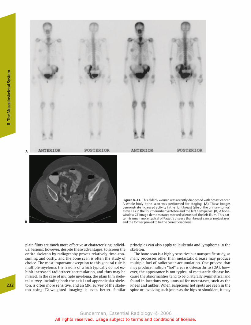
plain films are much more effective at characterizing individ-ual lesions; however, despite these advantages, to screen theentire skeleton by radiography proves relatively time-con-suming and costly, and the bone scan is often the study ofchoice. The most important exception to this general rule ismultiple myeloma, the lesions of which typically do not ex-hibit increased radiotracer accumulation, and thus may bemissed. In the case of multiple myeloma, the plain film skele-tal survey, including both the axial and appendicular skele-ton, is often more sensitive, and an MRI survey of the skele-ton using T2-weighted imaging is even better. Similar
principles can also apply to leukemia and lymphoma in theskeleton.
The bone scan is a highly sensitive but nonspecific study, asmany processes other than metastatic disease may producemultiple foci of radiotracer accumulation. One process thatmay produce multiple “hot” areas is osteoarthritis (OA); how-ever, the appearance is not typical of metastatic disease be-cause the abnormalities tend to be bilaterally symmetrical andfound in locations very unusual for metastases, such as theknees and ankles. When suspicious hot spots are seen in thespine or involving such joints as the hips or shoulders, it may
232
8Th
e M
uscu
losk
elet
al S
yste
m
Figure 8–14 This elderly woman was recently diagnosed with breast cancer.A whole-body bone scan was performed for staging. (A) These imagesdemonstrate increased activity in the right breast (site of the primary tumor)as well as in the fourth lumbar vertebra and the left hemipelvis. (B) A bone-window CT image demonstrates marked sclerosis of the left ilium. This pat-tern is much more typical of Paget’s disease than breast cancer metastases,and the former proved to be the correct diagnosis.
A
B
chapter 08_p220-256.qxd 12/1/05 4:13 PM Page 232
Gunderman, Essential Radiology © 2006All rights reserved. Usage subject to terms and conditions of license.
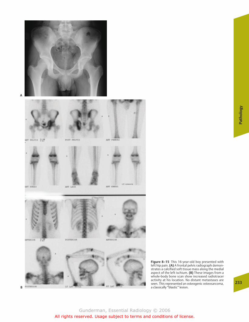
Path
olo
gy
233
Figure 8–15 This 16-year-old boy presented withleft hip pain. (A) A frontal pelvis radiograph demon-strates a calcified soft tissue mass along the medialaspect of the left ischium. (B) These images from awhole-body bone scan show increased radiotraceractivity at his location. No distant metastases areseen. This represented an osteogenic osteosarcoma,a classically “blastic” lesion.
A
B
chapter 08_p220-256.qxd 12/1/05 4:13 PM Page 233
Gunderman, Essential Radiology © 2006All rights reserved. Usage subject to terms and conditions of license.
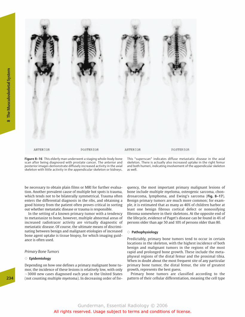
be necessary to obtain plain films or MRI for further evalua-tion. Another prevalent cause of multiple hot spots is trauma,which tends not to be bilaterally symmetrical. Trauma oftenenters the differential diagnosis in the ribs, and obtaining agood history from the patient often proves critical in sortingout whether metastatic disease or trauma is responsible.
In the setting of a known primary tumor with a tendencyto metastasize to bone, however, multiple abnormal areas ofincreased radiotracer activity are virtually diagnostic ofmetastatic disease. Of course, the ultimate means of discrimi-nating between benign and malignant etiologies of increasedbone agent uptake is tissue biopsy, for which imaging guid-ance is often used.
Primary Bone Tumors
�� Epidemiology
Depending on how one defines a primary malignant bone tu-mor, the incidence of these lesions is relatively low, with only�3000 new cases diagnosed each year in the United States(not counting multiple myetoma). In decreasing order of fre-
quency, the most important primary malignant lesions ofbone include multiple myeloma, osteogenic sarcoma, chon-drosarcoma, lymphoma, and Ewing’s sarcoma (Fig. 8–17). Benign primary tumors are much more common; for exam-ple, it is estimated that as many as 40% of children harbor atleast one benign fibrous cortical defect or nonossifying fibroma somewhere in their skeletons. At the opposite end ofthe lifecycle, evidence of Paget’s disease can be found in 4% ofpersons older than age 50 and 10% of persons older than 80.
�� Pathophysiology
Predictably, primary bone tumors tend to occur in certain locations in the skeleton, with the highest incidence of bothbenign and malignant tumors in the regions of the mostrapid and prolonged bone growth. These include the meta-physeal regions of the distal femur and the proximal tibia.When in doubt about the most frequent site of any particularprimary bone tumor, the distal femur, the site of greatestgrowth, represents the best guess.
Primary bone tumors are classified according to the pattern of their cellular differentiation, meaning the cell type234
8Th
e M
uscu
losk
elet
al S
yste
m
Figure 8–16 This elderly man underwent a staging whole-body bonescan after being diagnosed with prostate cancer. The anterior andposterior images demonstrate diffusely increased activity in the axialskeleton with little activity in the appendicular skeleton or kidneys.
This “superscan” indicates diffuse metastatic disease in the axialskeleton. There is actually also increased uptake in the right femurand both humeri, indicating involvement of the appendicular skeletonas well.
chapter 08_p220-256.qxd 12/1/05 4:13 PM Page 234
Gunderman, Essential Radiology © 2006All rights reserved. Usage subject to terms and conditions of license.
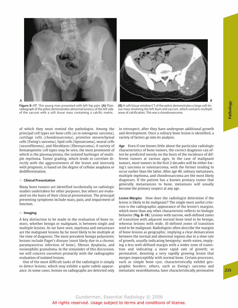
Path
olo
gy
235
of which they most remind the pathologist. Among the principal cell types are bone cells (as in osteogenic sarcoma),cartilage cells (chondrosarcoma), primitive mesenchymalcells (Ewing’s sarcoma), lipid cells (liposarcoma), neural cells(neurofibroma), and fibroblasts (fibrosarcoma). A variety ofhematopoietic cell types may be seen, the most prominent ofwhich is the plasmacytoma, the isolated harbinger of multi-ple myeloma. Tumor grading, which tends to correlate di-rectly with the aggressiveness of the lesion and inverselywith prognosis, is based on the degree of cellular anaplasia ordedifferentiation.
�� Clinical Presentation
Many bone tumors are identified incidentally on radiologicstudies undertaken for other purposes, but others are evalu-ated on the basis of their clinical presentation. The principalpresenting symptoms include mass, pain, and impairment offunction.
�� Imaging
A key distinction to be made in the evaluation of bone tu-mors, whether benign or malignant, is between single andmultiple lesions. As we have seen, myeloma and metastasesare the malignant lesions by far most likely to be multiple atthe time of diagnosis. The most prevalent benign polyostoticlesions include Paget’s disease (most likely due to a chronicparamyxovirus infection of bone), fibrous dysplasia, andeosinophilic granuloma. In the remainder of this discussion,we will concern ourselves primarily with the radiographicevaluation of isolated lesions.
One of the most difficult tasks of the radiologist is simplyto detect lesions, which may exhibit a quite subtle appear-ance. In some cases, lesions on radiographs are detected only
in retrospect, after they have undergone additional growthand development. Once a solitary bone lesion is identified, avariety of factors go into its analysis.
Age Even if one knows little about the particular radiologiccharacteristics of bone tumors, the correct diagnosis can of-ten be predicted merely on the basis of the incidence of dif-ferent tumors at various ages. In the case of malignant tumors, most tumors in the first 2 decades will be either Ew-ing’s sarcoma or osteosarcoma, with the former tending tooccur earlier than the latter. After age 40, solitary metastases,multiple myeloma, and chondrosarcoma are the most likelydiagnoses. If the patient has a known primary tumor thatgenerally metastasizes to bone, metastasis will usually become the primary suspect at any age.
Lesion Margins How does the radiologist determine if the lesion is likely to be malignant? The single most useful crite-rion is the radiographic appearance of the lesion’s margins,which more than any other characteristic reflects its biologicbehavior (Fig. 8–18). Lesions with narrow, well-defined zonesof transition with adjacent normal bone tend to be benign,whereas lesions with wide, ill-defined zones of transitiontend to be malignant. Radiologists often describe the marginsof bone lesions as geographic, implying a clear demarcationbetween the normal and abnormal regions due to a slow rateof growth, usually indicating benignity; moth-eaten, imply-ing a less well-defined margin with a wider zone of transi-tion and indicating a more rapid rate of growth; or permeative, denoting a very rapidly growing lesion thatmerges imperceptibly with normal bone. Certain processes,such as simple bone cyst, characteristically exhibit geo-graphic borders; others, such as Ewing’s sarcoma andmetastatic neuroblastoma, have characteristically permeative
Figure 8–17 This young man presented with left hip pain. (A) Plain radiograph of the pelvis demonstrates abnormal lucency of the left sideof the sacrum with a soft tissue mass containing a calcific matrix.
(B) A soft tissue window CT of the pelvis demonstrates a large soft tis-sue mass involving the left ilium and sacrum, which contains multipleareas of calcification. This was a chondrosarcoma.
A B
chapter 08_p220-256.qxd 12/1/05 4:13 PM Page 235
Gunderman, Essential Radiology © 2006All rights reserved. Usage subject to terms and conditions of license.
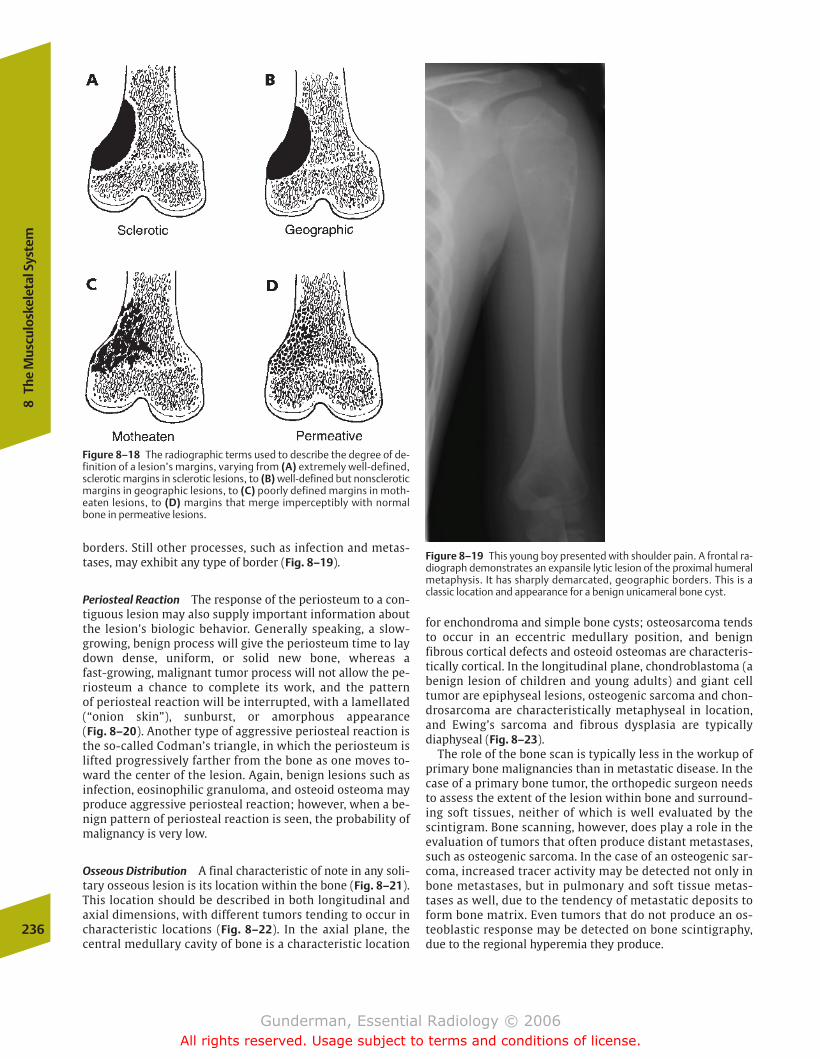
borders. Still other processes, such as infection and metas-tases, may exhibit any type of border (Fig. 8–19).
Periosteal Reaction The response of the periosteum to a con-tiguous lesion may also supply important information aboutthe lesion’s biologic behavior. Generally speaking, a slow-growing, benign process will give the periosteum time to laydown dense, uniform, or solid new bone, whereas a fast-growing, malignant tumor process will not allow the pe-riosteum a chance to complete its work, and the pattern of periosteal reaction will be interrupted, with a lamellated(“onion skin”), sunburst, or amorphous appearance (Fig. 8–20). Another type of aggressive periosteal reaction isthe so-called Codman’s triangle, in which the periosteum islifted progressively farther from the bone as one moves to-ward the center of the lesion. Again, benign lesions such asinfection, eosinophilic granuloma, and osteoid osteoma mayproduce aggressive periosteal reaction; however, when a be-nign pattern of periosteal reaction is seen, the probability ofmalignancy is very low.
Osseous Distribution A final characteristic of note in any soli-tary osseous lesion is its location within the bone (Fig. 8–21).This location should be described in both longitudinal andaxial dimensions, with different tumors tending to occur incharacteristic locations (Fig. 8–22). In the axial plane, thecentral medullary cavity of bone is a characteristic location
for enchondroma and simple bone cysts; osteosarcoma tendsto occur in an eccentric medullary position, and benign fibrous cortical defects and osteoid osteomas are characteris-tically cortical. In the longitudinal plane, chondroblastoma (abenign lesion of children and young adults) and giant cell tumor are epiphyseal lesions, osteogenic sarcoma and chon-drosarcoma are characteristically metaphyseal in location,and Ewing’s sarcoma and fibrous dysplasia are typically diaphyseal (Fig. 8–23).
The role of the bone scan is typically less in the workup ofprimary bone malignancies than in metastatic disease. In thecase of a primary bone tumor, the orthopedic surgeon needsto assess the extent of the lesion within bone and surround-ing soft tissues, neither of which is well evaluated by thescintigram. Bone scanning, however, does play a role in theevaluation of tumors that often produce distant metastases,such as osteogenic sarcoma. In the case of an osteogenic sar-coma, increased tracer activity may be detected not only inbone metastases, but in pulmonary and soft tissue metas-tases as well, due to the tendency of metastatic deposits toform bone matrix. Even tumors that do not produce an os-teoblastic response may be detected on bone scintigraphy,due to the regional hyperemia they produce.
236
8Th
e M
uscu
losk
elet
al S
yste
m
Figure 8–18 The radiographic terms used to describe the degree of de-finition of a lesion’s margins, varying from (A) extremely well-defined,sclerotic margins in sclerotic lesions, to (B) well-defined but nonscleroticmargins in geographic lesions, to (C) poorly defined margins in moth-eaten lesions, to (D) margins that merge imperceptibly with normalbone in permeative lesions.
Figure 8–19 This young boy presented with shoulder pain. A frontal ra-diograph demonstrates an expansile lytic lesion of the proximal humeralmetaphysis. It has sharply demarcated, geographic borders. This is aclassic location and appearance for a benign unicameral bone cyst.
chapter 08_p220-256.qxd 12/1/05 4:13 PM Page 236
Gunderman, Essential Radiology © 2006All rights reserved. Usage subject to terms and conditions of license.
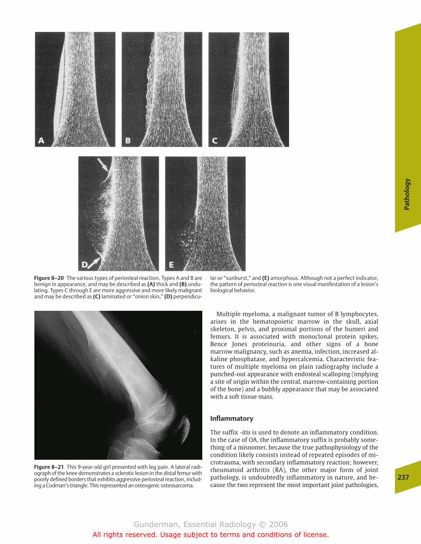
Path
olo
gy
237
Multiple myeloma, a malignant tumor of B lymphocytes,arises in the hematopoietic marrow in the skull, axial skeleton, pelvis, and proximal portions of the humeri and femurs. It is associated with monoclonal protein spikes, Bence Jones proteinuria, and other signs of a bone marrow malignancy, such as anemia, infection, increased al-kaline phosphatase, and hypercalcemia. Characteristic fea-tures of multiple myeloma on plain radiography include apunched-out appearance with endosteal scalloping (implyinga site of origin within the central, marrow-containing portionof the bone) and a bubbly appearance that may be associatedwith a soft tissue mass.
Inflammatory
The suffix -itis is used to denote an inflammatory condition.In the case of OA, the inflammatory suffix is probably some-thing of a misnomer, because the true pathophysiology of thecondition likely consists instead of repeated episodes of mi-crotrauma, with secondary inflammatory reaction; however,rheumatoid arthritis (RA), the other major form of jointpathology, is undoubtedly inflammatory in nature, and be-cause the two represent the most important joint pathologies,
Figure 8–20 The various types of periosteal reaction. Types A and B arebenign in appearance, and may be described as (A) thick and (B) undu-lating. Types C through E are more aggressive and more likely malignantand may be described as (C) laminated or “onion skin,” (D) perpendicu-
lar or “sunburst,” and (E) amorphous. Although not a perfect indicator,the pattern of periosteal reaction is one visual manifestation of a lesion’sbiological behavior.
Figure 8–21 This 9-year-old girl presented with leg pain. A lateral radi-ograph of the knee demonstrates a sclerotic lesion in the distal femur withpoorly defined borders that exhibits aggressive periosteal reaction, includ-ing a Codman’s triangle. This represented an osteogenic osteosarcoma.
chapter 08_p220-256.qxd 12/1/05 4:13 PM Page 237
Gunderman, Essential Radiology © 2006All rights reserved. Usage subject to terms and conditions of license.
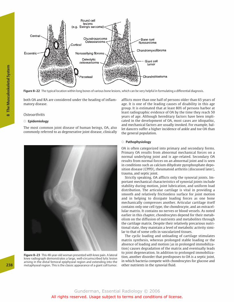
both OA and RA are considered under the heading of inflam-matory disease.
Osteoarthritis
�� Epidemiology
The most common joint disease of human beings, OA, alsocommonly referred to as degenerative joint disease, clinically
afflicts more than one half of persons older than 65 years ofage. It is one of the leading causes of disability in this agegroup. It is estimated that at least 80% of persons harbor atleast radiographic evidence of OA by the time they reach 50years of age. Although hereditary factors have been impli-cated in the development of OA, most cases are idiopathic,and mechanical factors are usually invoked. For example, bal-let dancers suffer a higher incidence of ankle and toe OA thanthe general population.
�� Pathophysiology
OA is often categorized into primary and secondary forms.Primary OA results from abnormal mechanical forces on anormal underlying joint and is age-related. Secondary OA results from normal forces on an abnormal joint and is seenin conditions such as calcium dihydrate pyrophosphate depo-sition disease (CPPD), rheumatoid arthritis (discussed later),trauma, and septic joint.
Strictly speaking, OA afflicts only the synovial joints. Im-portant mechanical characteristics of synovial joints includestability during motion, joint lubrication, and uniform loaddistribution. The articular cartilage is vital in providing asmooth and relatively frictionless surface for joint motionand in helping to dissipate loading forces as one bone mechanically compresses another. Articular cartilage itselfcontains only one cell type, the chondrocyte, and an extracel-lular matrix. It contains no nerves or blood vessels. As notedearlier in this chapter, chondrocytes depend for their metab-olism on the diffusion of nutrients and metabolites throughthe cartilage matrix. Despite their relatively precarious nutri-tional state, they maintain a level of metabolic activity simi-lar to that of some cells in vascularized tissues.
The cyclic loading and unloading of cartilage stimulatesmatrix synthesis, whereas prolonged stable loading or theabsence of loading and motion (as in prolonged immobiliza-tion) causes degradation of the matrix and eventually leadsto joint degeneration. In addition to prolonged immobiliza-tion, another disorder that predisposes to OA is a septic joint,in which bacteria compete with chondrocytes for glucose andother nutrients in the synovial fluid.238
8Th
e M
uscu
losk
elet
al S
yste
m
Figure 8–22 The typical location within long bones of various bone lesions, which can be very helpful in formulating a differential diagnosis.
Figure 8–23 This 48-year-old woman presented with knee pain. A lateralknee radiograph demonstrates a large, well-circumscribed lytic lesionarising in the distal femoral epiphyseal region and extending into themetaphyseal region. This is the classic appearance of a giant cell tumor.
chapter 08_p220-256.qxd 12/1/05 4:13 PM Page 238
Gunderman, Essential Radiology © 2006All rights reserved. Usage subject to terms and conditions of license.
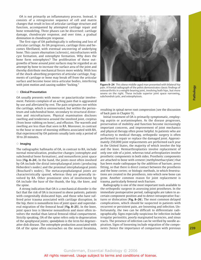
Path
olo
gy
239
OA is not primarily an inflammatory process. Instead, itconsists of a retrogressive sequence of cell and matrixchanges that result in loss of articular cartilage structure andfunction, accompanied by attempted cartilage repair andbone remodeling. Three phases can be discerned: cartilagedamage, chondrocyte response, and over time, a gradualdiminution in chondrocyte response.
The first sign of OA pathologically is softening and loss ofarticular cartilage. As OA progresses, cartilage thins and be-comes fibrillated, with eventual uncovering of underlyingbone. This causes eburnation (sclerosis), microfractures withcyst formation, and osteophyte formation. Why does thebone form osteophytes? The proliferation of these out-growths of bone around joint surfaces may be regarded as anattempt by bone to increase the surface area of the joint andthereby distribute mechanical forces more widely. With lossof the shock-absorbing properties of articular cartilage, frag-ments of cartilage or bone may break off from the articularsurface and become loose intra-articular bodies, interferingwith joint motion and causing sudden “locking.”
�� Clinical Presentation
OA usually presents with mono- or pauciarticular involve-ment. Patients complain of an aching pain that is aggravatedby use and alleviated by rest. The pain originates not withinthe cartilage, which is uninnervated, but within the perios-teum and subchondral bone, secondary to structural distor-tion and microfractures. Physical examination disclosesswelling and tenderness around the involved joint, crepitus(from bone rubbing on bone), and effusion. The warmth andswelling are less than that seen in RA. Moreover, in contrastto the hour or more of morning stiffness associated with RA,that experienced by OA patients usually lasts only a period of10 to 20 minutes.
�� Imaging
The radiographic hallmarks of OA, in contrast to RA, includenormal mineralization, productive changes (osteophyte andsubchondral bone formation), and nonuniform joint spaceloss (Fig. 8–24). In the hand, the joints most often involvedby OA include the distal interphalangeal joints (producingHeberden’s nodes) and the proximal interphalangeal joints(Bouchard’s nodes). The metacarpophalangeal joints arecharacteristically spared, whereas they are generally in-volved by RA. Other prominent sites of involvement by OA include the base of the thumb, the hip, the knee, and the spine.
A strong indication that OA is a mechanical disorder is thefact that the risk of OA is increased in obese patients, patientswith congenitally dislocated hips, and those who have suf-fered prior trauma associated with cartilage disruption. Inthe hip, there is nonuniform loss of joint space and superolat-eral migration of the femoral head (Fig. 8–25). In the knee,joint space loss is likewise nonuniform and more often in-volves the medial than lateral femoral-tibial compartment.Strictly speaking, OA of the spine refers only to degenerationof the apophyseal joints; spondylosis is the term for degener-ative disk disease. The osteophyte production associated withOA of the spine often encroaches on the neural foramina,
resulting in spinal nerve root compression (see the discussionof back pain in Chapter 9).
Initial treatment of OA is primarily symptomatic, employ-ing aspirin or acetaminophen. As the disease progresses,preservation of mobility and function become increasinglyimportant concerns, and improvement of joint mechanicsand physical therapy often prove helpful. In patients who arerefractory to medical therapy, orthopedic surgery is oftenperformed to repair or replace the damaged joint. Approxi-mately 250,000 joint replacements are performed each yearin the United States, the majority of which involve the hipand the knee. Hemiarthroplasties involve replacement ofonly one side of a joint, whereas total arthroplasties involveprosthetic components in both sides. Prosthetic componentsare attached to bone with cement (methylmethacrylate) thathas been made radiopaque by the addition of barium; pressfitting, so that there is direct contact between the prosthesisand the bone cortex; or biologic methods, in which fenestra-tions are created in the prosthesis, into which new bone cangrow. Another common reason for joint replacement istrauma, particularly femoral neck fracture.
Radiography is one of the most important tools available tothe orthopedic surgeon in assessing joint prostheses. In theimmediate postoperative period, radiographs are taken to as-certain component position and to detect intraoperative frac-tures or dislocation (Fig. 8–26). The most common delayedcomplications, which should be suspected in patients withrecurrent or persistent pain, are loosening and infection. Un-fortunately, the two can be difficult to differentiate radi-ographically. Signs especially suspicious for infection includeirregular periostitis, poorly marginated lucencies, and sinustracts. The presence of infection can be verified by needle as-piration. Signs of loosening include migration of the compo-nents (hence the importance of comparison with previous
Figure 8–24 This obese middle-aged man presented with bilateral hippain. A frontal radiograph of the pelvis demonstrates classic findings ofosteoarthritis in a weight-bearing joint, involving both hips, but moresevere on the right. These include superior joint space narrowing, subchondral cysts, and osteophytosis.
chapter 08_p220-256.qxd 12/1/05 4:13 PM Page 239
Gunderman, Essential Radiology © 2006All rights reserved. Usage subject to terms and conditions of license.

radiographs), fracture of the cement or prosthesis, andwidening of the prosthesis–cement interface. Additionalcomplications include profuse heterotopic bone formation,dislocation, and stress fractures.
Rheumatoid Arthritis
�� Epidemiology
Afflicting �1% of the population, RA is a major source of dis-ability in the United States. Women are afflicted approximately3 times as often as men, and in 80% of cases the onset of symp-toms occurs between the ages of 35 and 50. Although geneticsusceptibility is a definite factor, environmental factors appearalso to play a role. Some patients develop only mild symptomsthat spontaneously and completely remit, whereas others suf-fer profound systemic sequelae and marked joint deformities.Most patients experience a course somewhere between thesetwo extremes. If RA persists for more than a decade, more thanfour of five patients will have some degree of joint deformity.
�� Pathophysiology
The pathophysiology of RA is the subject of debate. Immunephenomena are clearly implicated. More than two thirds of adultRA patients exhibit circulating rheumatoid factor, which consistsof autoantibodies reactive with the Fc portion of immunoglobu-lin G (IgG). It has been hypothesized that complexes of circulat-ing rheumatoid factor and IgG may be the inciting factors in syn-ovial inflammation. However, rheumatoid factor may also bepresent in systemic lupus erythematosus (SLE), sarcoidosis, andinfectious mononucleosis, among other disorders. Early inflam-matory changes of RA include synovial hypervascularity, edema,and cellular infiltration (Fig. 8–27). Synovial inflammation andassociated hyperemia induce osteoclastic activity, resulting inbone “washout” around joints seen on radiographs as juxta-ar-ticular osteoporosis. With time, the synovium hypertrophies, aprocess called pannus formation. This synovial proliferation
240
8Th
e M
uscu
losk
elet
al S
yste
m
Figure 8–25 The important morphologic differences between (A) rheumatoid arthritis (RA) and (B) osteoarthritis (OA). Note that OAinvolves little or no loss of mineralization, osteophyte formation, and
nonuniform loss of joint space. RA, in contrast, involves juxta-articularosteoporosis, periarticular erosions, and an absence of productivechanges (osteophytes).
Figure 8–26 This 33-year-old man with a long history of vasculitis resulting in bilateral avascular necrosis of the hips underwent placementof bilateral hip prostheses, which have a normal appearance.
chapter 08_p220-256.qxd 12/1/05 4:13 PM Page 240
Gunderman, Essential Radiology © 2006All rights reserved. Usage subject to terms and conditions of license.
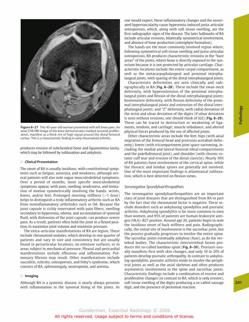
Path
olo
gy
241
produces erosion of subchondral bone and ligamentous laxity,which may be followed by subluxation and ankylosis.
�� Clinical Presentation
The onset of RA is usually insidious, with constitutional symp-toms such as fatigue, anorexia, and weakness, although sev-eral patients will also note vague musculoskeletal symptoms.Over a period of months, more specific musculoskeletalsymptoms appear, with pain, swelling, tenderness, and limita-tion of motion symmetrically involving the hands, wrists,knees, and/or feet. Prolonged morning stiffness (�1 hour)helps to distinguish a truly inflammatory arthritis such as RAfrom noninflammatory arthritides such as OA. Because thejoint capsule is richly innervated with pain fibers, swellingsecondary to hyperemia, edema, and accumulation of synovialfluid, with distension of the joint capsule, can produce severepain. As a result, patients often hold the joint in a flexed posi-tion, to maximize joint volume and minimize pressure.
The extra-articular manifestations of RA are legion. Theseinclude rheumatoid nodules, which develop in one quarter ofpatients and vary in size and consistency but are usuallyfound in periarticular locations, on extensor surfaces, or inareas subject to mechanical pressure. Pleural and pericardialmanifestations include effusions and inflammation. Pul-monary fibrosis may result. Other manifestations includevasculitis, scleritis, osteoporosis, and Felty’s syndrome, whichconsists of RA, splenomegaly, neutropenia, and anemia.
�� Imaging
Although RA is a systemic disease, it nearly always presentswith inflammation in the synovial lining of the joints. As
one would expect, these inflammatory changes and the associ-ated hypervascularity cause hyperemia-induced juxta-articularosteoporosis, which, along with soft tissue swelling, are thefirst radiographic signs of the disease. The later hallmarks of RAinclude articular erosions, bilaterally symmetrical involvement,and absence of bone production (osteophyte formation).
The hands are the most commonly involved region where,following symmetrical soft tissue swelling and juxta-articularosteoporosis, RA produces characteristic erosions in the “bareareas” of the joints, where bone is directly exposed to the syn-ovium because it is not protected by articular cartilage. Char-acteristic locations include the entire carpal compartment, aswell as the metacarpophalangeal and proximal interpha-langeal joints, with sparing of the distal interphalangeal joints.
Characteristic deformities are seen clinically and radi-ographically in RA (Fig. 8–28). These include the swan-neckdeformity, with hyperextension of the proximal interpha-langeal joints and flexion of the distal interphalangeal joints;boutonniere deformity, with flexion deformity of the proxi-mal interphalangeal joints and extension of the distal inter-phalangeal joints; and “Z” deformity, with radial deviation ofthe wrist and ulnar deviation of the digits (if ulnar deviationis seen without erosions, one should think of SLE) (Fig. 8–29).These can be traced to destruction or weakening of liga-ments, tendons, and cartilage; muscle imbalance; and alteredphysical forces produced by the use of affected joints.
Other characteristic areas include the feet, hips (with axialmigration of the femoral head and protrusio acetabuli defor-mity), knees (with tricompartment joint space narrowing, in-cluding the medial and lateral femoral-tibial compartmentsand the patellofemoral joint), and shoulder (with chronic ro-tator cuff tear and erosion of the distal clavicle). Nearly 50%of RA patients have involvement of the cervical spine, whilethe thoracic and lumbar spines are generally not involved.One of the most important findings is atlantoaxial subluxa-tion, which is best detected on flexion views.
Seronegative Spondyloarthropathies
The seronegative spondyloarthropathies are an importantclass of joint diseases that are distinguished from RA in partby the fact that the rheumatoid factor is negative. These in-clude disorders such as ankylosing spondylitis and psoriaticarthritis. Ankylosing spondylitis is far more common in menthan women, and 95% of patients are human leukocyte anti-gen (HLA)–B27 positive. Around age 20, patients begin to notethe insidious onset of back stiffness and pain. Radiographi-cally, the initial site of involvement is the sacroiliac joint, butthe process gradually progresses to involve the entire spine.The sacroiliac joints eventually ankylose (fuse), as do the ver-tebral bodies. The characteristic intervertebral fusion pro-duces the so-called bamboo spine (Fig. 8–30). Psoriasis usu-ally manifests first with skin changes, and only 10 to 20% ofpatients develop psoriatic arthropathy. In contrast to ankylos-ing spondylitis, psoriatic arthritis tends to involve the periph-eral joints as well as the axial skeleton and often producesasymmetric involvement in the spine and sacroiliac joints.Characteristic findings include a combination of erosive andproliferative changes (in contrast to RA, which is only erosive),soft tissue swelling of the digits producing a so-called sausagedigit, and the presence of periosteal reaction.
Figure 8–27 This 45-year-old woman presented with left knee pain. Anaxial STIR MR image of the knee demonstrates marked synovial prolifer-ation, manifest as a thick rim of high signal around the distal femoralcortex. This is a characteristic finding in early rheumatoid arthritis.
chapter 08_p220-256.qxd 12/1/05 4:13 PM Page 241
Gunderman, Essential Radiology © 2006All rights reserved. Usage subject to terms and conditions of license.
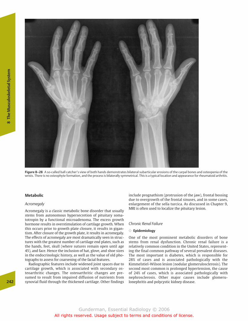
Metabolic
Acromegaly
Acromegaly is a classic metabolic bone disorder that usuallystems from autonomous hypersecretion of pituitary soma-totropin by a functional microadenoma. The excess growthhormone results in overstimulation of cartilage growth. Whenthis occurs prior to growth plate closure, it results in gigan-tism. After closure of the growth plate, it results in acromegaly.The effects of acromegaly are most dramatically seen in struc-tures with the greatest number of cartilage end plates, such asthe hands, feet, skull (where sutures remain open until age45), and face. Hence the inclusion of hat, glove, and shoe sizesin the endocrinologic history, as well as the value of old pho-tographs to assess for coarsening of the facial features.
Radiographic features include widened joint spaces due tocartilage growth, which is associated with secondary os-teoarthritic changes. The osteoarthritic changes are pre-sumed to result from impaired diffusion of nutrients fromsynovial fluid through the thickened cartilage. Other findings
include prognathism (protrusion of the jaw), frontal bossingdue to overgrowth of the frontal sinuses, and in some cases,enlargement of the sella turcica. As discussed in Chapter 9,MRI is often used to localize the pituitary lesion.
Chronic Renal Failure
�� Epidemiology
One of the most prominent metabolic disorders of bonestems from renal dysfunction. Chronic renal failure is a relatively common condition in the United States, represent-ing the final common pathway of several prevalent diseases.The most important is diabetes, which is responsible for 28% of cases and is associated pathologically with the Kimmelstiel-Wilson lesion (nodular glomerulosclerosis). Thesecond most common is prolonged hypertension, the causeof 24% of cases, which is associated pathologically withnephrosclerosis. Other major causes include glomeru-lonephritis and polycystic kidney disease.242
8Th
e M
uscu
losk
elet
al S
yste
m
Figure 8–28 A so-called ball catcher’s view of both hands demonstrates bilateral subarticular erosions of the carpal bones and osteopenia of thewrists. There is no osteophyte formation, and the process is bilaterally symmetrical. This is a typical location and appearance for rheumatoid arthritis.
chapter 08_p220-256.qxd 12/1/05 4:13 PM Page 242
Gunderman, Essential Radiology © 2006All rights reserved. Usage subject to terms and conditions of license.
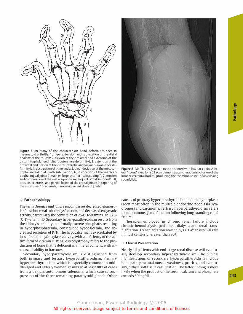
Path
olo
gy
243
�� Pathophysiology
The term chronic renal failure encompasses decreased glomeru-lar filtration, renal tubular dysfunction, and decreased enzymaticactivity, particularly the conversion of 25-OH-vitamin D to 1,25-(OH)2-vitamin D. Secondary hyper-parathyroidism results fromthe kidney’s inability to normally excrete phosphate, resultingin hyperphosphatemia, consequent hypocalcemia, and in-creased secretion of PTH. The hypocalcemia is exacerbated byloss of renal 1-hydroxylase activity, with a deficiency of the ac-tive form of vitamin D. Renal osteodystrophy refers to the pro-duction of bone that is deficient in mineral content, with in-creased liability to fractures.
Secondary hyperparathyroidism is distinguished from both primary and tertiary hyperparathyroidism. Primary hyperparathyroidism, which is especially common in mid-dle-aged and elderly women, results in at least 80% of casesfrom a benign, autonomous adenoma, which causes sup-pression of the three remaining parathyroid glands. Other
causes of primary hyperparathyroidism include hyperplasia(seen most often in the multiple endocrine neoplasia syn-dromes) and carcinoma. Tertiary hyperparathyroidism refersto autonomous gland function following long-standing renalfailure.
Therapies employed in chronic renal failure includechronic hemodialysis, peritoneal dialysis, and renal trans-plantation. Transplantation now enjoys a 1-year survival ratein most centers of greater than 90%.
�� Clinical Presentation
Nearly all patients with end-stage renal disease will eventu-ally develop secondary hyperparathyroidism. The clinicalmanifestations of secondary hyperparathyroidism includebone pain, proximal muscle weakness, pruritis, and eventu-ally, diffuse soft tissue calcification. The latter finding is morelikely when the product of the serum calcium and phosphateexceeds 50 mg/dL.
Figure 8–29 Many of the characteristic hand deformities seen inrheumatoid arthritis. 1, hyperextension and subluxation of the distalphalanx of the thumb; 2, flexion at the proximal and extension at thedistal interphalangeal joint (boutonniere deformity); 3, extension at theproximal and flexion at the distal interphalangeal joint (swan-neck de-formity); 4, destruction of bone ends; 5, ulnar deviation at the metacar-pophalangeal joints with subluxation; 6, dislocation of the metacar-pophalangeal joints (“main en lorgnette” or “telescoping”); 7, erosionand compression of the metacarpophalangeal joints (“ball in socket”); 8,erosion, sclerosis, and partial fusion of the carpal joints; 9, tapering ofthe distal ulna; 10, sclerosis, narrowing, or ankylosis of joints.
Figure 8–30 This 49-year-old man presented with low back pain. A lat-eral “scout” view for a CT scan demonstrates characteristic fusion of thelumbar vertebral bodies, producing the “bamboo spine” of ankylosingspondylitis.
chapter 08_p220-256.qxd 12/1/05 4:13 PM Page 243
Gunderman, Essential Radiology © 2006All rights reserved. Usage subject to terms and conditions of license.
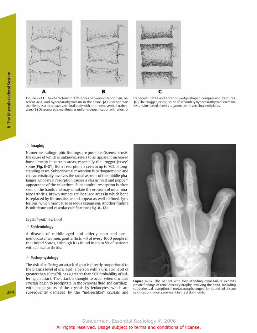
�� Imaging
Numerous radiographic findings are possible. Osteosclerosis,the cause of which is unknown, refers to an apparent increasedbone density in certain areas, especially the “rugger jersey”spine (Fig. 8–31). Bone resorption is seen in up to 70% of long-standing cases. Subperiosteal resorption is pathognomonic andcharacteristically involves the radial aspects of the middle pha-langes. Endosteal resorption causes a classic “salt and pepper”appearance of the calvarium. Subchondral resorption is oftenseen in the hands and may simulate the erosions of inflamma-tory arthritis. Brown tumors are localized areas in which boneis replaced by fibrous tissue and appear as well-defined, lyticlesions, which may cause osseous expansion. Another findingis soft tissue and vascular calcifications (Fig. 8–32).
Crystalopathies: Gout
�� Epidemiology
A disease of middle-aged and elderly men and post-menopausal women, gout afflicts �3 of every 1000 people inthe United States, although it is found in up to 5% of patientswith clinical arthritis.
�� Pathophysiology
The risk of suffering an attack of gout is directly proportional tothe plasma level of uric acid; a person with a uric acid level ofgreater than 10 mg/dL has a greater than 90% probability of suf-fering an attack. The attack is thought to occur when uric acidcrystals begin to precipitate in the synovial fluid and cartilage,with phagocytosis of the crystals by leukocytes, which are subsequently damaged by the “indigestible” crystals and 244
8Th
e M
uscu
losk
elet
al S
yste
m
Figure 8–31 The characteristic differences between osteoporosis, os-teomalacia, and hyperparathyroidism in the spine. (A) Osteoporosismanifests as a biconcave vertebral body with prominent vertical trabec-ulae. (B) Osteomalacia manifests as uniform deossification with a loss of
trabecular detail and anterior wedge-shaped compression fractures.(C) The “rugger jersey” spine of secondary hyperparathyroidism mani-
fests as increased density adjacent to the vertebral end plates.
Figure 8–32 This patient with long-standing renal failure exhibits classic findings of renal osteodystrophy involving the hand, includingsubperiosteal resorption of metacarpophalangeal joints and soft tissuecalcifications, most prominent in the distal thumb.
chapter 08_p220-256.qxd 12/1/05 4:13 PM Page 244
Gunderman, Essential Radiology © 2006All rights reserved. Usage subject to terms and conditions of license.
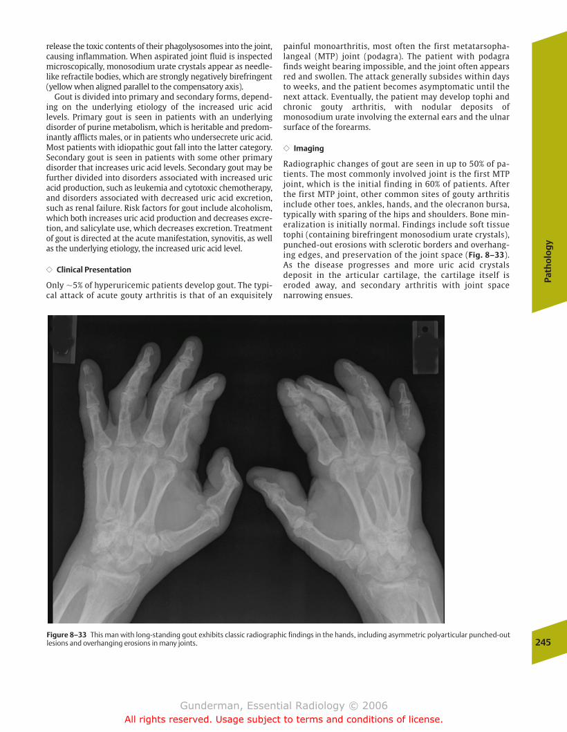
Path
olo
gy
245
release the toxic contents of their phagolysosomes into the joint,causing inflammation. When aspirated joint fluid is inspectedmicroscopically, monosodium urate crystals appear as needle-like refractile bodies, which are strongly negatively birefringent(yellow when aligned parallel to the compensatory axis).
Gout is divided into primary and secondary forms, depend-ing on the underlying etiology of the increased uric acid levels. Primary gout is seen in patients with an underlying disorder of purine metabolism, which is heritable and predom-inantly afflicts males, or in patients who undersecrete uric acid.Most patients with idiopathic gout fall into the latter category.Secondary gout is seen in patients with some other primarydisorder that increases uric acid levels. Secondary gout may befurther divided into disorders associated with increased uricacid production, such as leukemia and cytotoxic chemotherapy,and disorders associated with decreased uric acid excretion,such as renal failure. Risk factors for gout include alcoholism,which both increases uric acid production and decreases excre-tion, and salicylate use, which decreases excretion. Treatmentof gout is directed at the acute manifestation, synovitis, as wellas the underlying etiology, the increased uric acid level.
�� Clinical Presentation
Only �5% of hyperuricemic patients develop gout. The typi-cal attack of acute gouty arthritis is that of an exquisitely
painful monoarthritis, most often the first metatarsopha-langeal (MTP) joint (podagra). The patient with podagrafinds weight bearing impossible, and the joint often appearsred and swollen. The attack generally subsides within daysto weeks, and the patient becomes asymptomatic until thenext attack. Eventually, the patient may develop tophi andchronic gouty arthritis, with nodular deposits ofmonosodium urate involving the external ears and the ulnarsurface of the forearms.
�� Imaging
Radiographic changes of gout are seen in up to 50% of pa-tients. The most commonly involved joint is the first MTPjoint, which is the initial finding in 60% of patients. Afterthe first MTP joint, other common sites of gouty arthritisinclude other toes, ankles, hands, and the olecranon bursa,typically with sparing of the hips and shoulders. Bone min-eralization is initially normal. Findings include soft tissuetophi (containing birefringent monosodium urate crystals),punched-out erosions with sclerotic borders and overhang-ing edges, and preservation of the joint space (Fig. 8–33).As the disease progresses and more uric acid crystals deposit in the articular cartilage, the cartilage itself iseroded away, and secondary arthritis with joint space narrowing ensues.
Figure 8–33 This man with long-standing gout exhibits classic radiographic findings in the hands, including asymmetric polyarticular punched-outlesions and overhanging erosions in many joints.
chapter 08_p220-256.qxd 12/1/05 4:13 PM Page 245
Gunderman, Essential Radiology © 2006All rights reserved. Usage subject to terms and conditions of license.
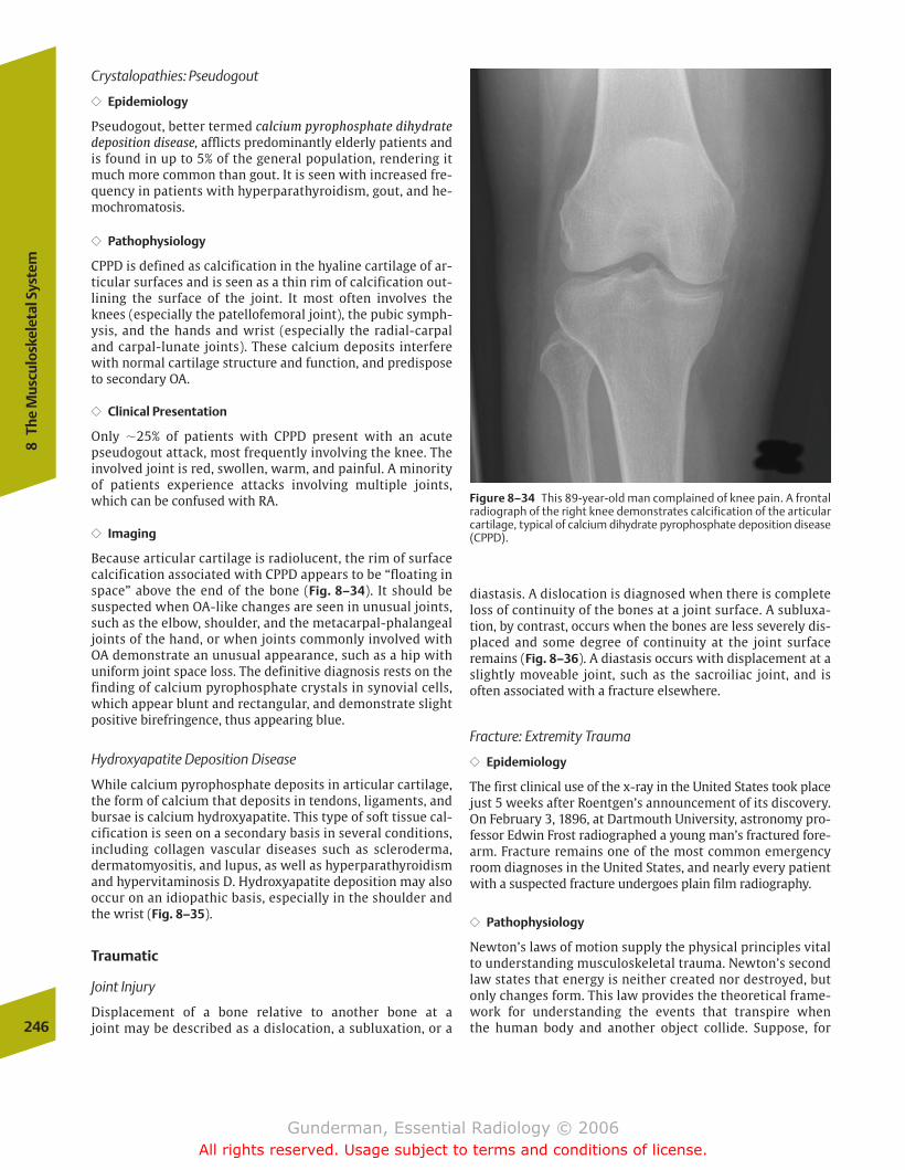
Crystalopathies: Pseudogout
�� Epidemiology
Pseudogout, better termed calcium pyrophosphate dihydratedeposition disease, afflicts predominantly elderly patients andis found in up to 5% of the general population, rendering itmuch more common than gout. It is seen with increased fre-quency in patients with hyperparathyroidism, gout, and he-mochromatosis.
�� Pathophysiology
CPPD is defined as calcification in the hyaline cartilage of ar-ticular surfaces and is seen as a thin rim of calcification out-lining the surface of the joint. It most often involves theknees (especially the patellofemoral joint), the pubic symph-ysis, and the hands and wrist (especially the radial-carpaland carpal-lunate joints). These calcium deposits interferewith normal cartilage structure and function, and predisposeto secondary OA.
�� Clinical Presentation
Only �25% of patients with CPPD present with an acutepseudogout attack, most frequently involving the knee. Theinvolved joint is red, swollen, warm, and painful. A minorityof patients experience attacks involving multiple joints,which can be confused with RA.
�� Imaging
Because articular cartilage is radiolucent, the rim of surfacecalcification associated with CPPD appears to be “floating inspace” above the end of the bone (Fig. 8–34). It should besuspected when OA-like changes are seen in unusual joints,such as the elbow, shoulder, and the metacarpal-phalangealjoints of the hand, or when joints commonly involved withOA demonstrate an unusual appearance, such as a hip withuniform joint space loss. The definitive diagnosis rests on thefinding of calcium pyrophosphate crystals in synovial cells,which appear blunt and rectangular, and demonstrate slightpositive birefringence, thus appearing blue.
Hydroxyapatite Deposition Disease
While calcium pyrophosphate deposits in articular cartilage,the form of calcium that deposits in tendons, ligaments, andbursae is calcium hydroxyapatite. This type of soft tissue cal-cification is seen on a secondary basis in several conditions,including collagen vascular diseases such as scleroderma,dermatomyositis, and lupus, as well as hyperparathyroidismand hypervitaminosis D. Hydroxyapatite deposition may alsooccur on an idiopathic basis, especially in the shoulder andthe wrist (Fig. 8–35).
Traumatic
Joint Injury
Displacement of a bone relative to another bone at a joint may be described as a dislocation, a subluxation, or a
diastasis. A dislocation is diagnosed when there is completeloss of continuity of the bones at a joint surface. A subluxa-tion, by contrast, occurs when the bones are less severely dis-placed and some degree of continuity at the joint surface remains (Fig. 8–36). A diastasis occurs with displacement at aslightly moveable joint, such as the sacroiliac joint, and is often associated with a fracture elsewhere.
Fracture: Extremity Trauma
�� Epidemiology
The first clinical use of the x-ray in the United States took placejust 5 weeks after Roentgen’s announcement of its discovery.On February 3, 1896, at Dartmouth University, astronomy pro-fessor Edwin Frost radiographed a young man’s fractured fore-arm. Fracture remains one of the most common emergencyroom diagnoses in the United States, and nearly every patientwith a suspected fracture undergoes plain film radiography.
�� Pathophysiology
Newton’s laws of motion supply the physical principles vitalto understanding musculoskeletal trauma. Newton’s secondlaw states that energy is neither created nor destroyed, butonly changes form. This law provides the theoretical frame-work for understanding the events that transpire when the human body and another object collide. Suppose, for 246
8Th
e M
uscu
losk
elet
al S
yste
m
Figure 8–34 This 89-year-old man complained of knee pain. A frontalradiograph of the right knee demonstrates calcification of the articularcartilage, typical of calcium dihydrate pyrophosphate deposition disease(CPPD).
chapter 08_p220-256.qxd 12/1/05 4:13 PM Page 246
Gunderman, Essential Radiology © 2006All rights reserved. Usage subject to terms and conditions of license.
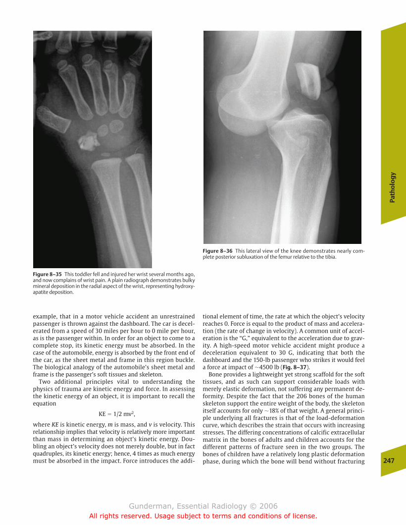
Path
olo
gy
247
example, that in a motor vehicle accident an unrestrainedpassenger is thrown against the dashboard. The car is decel-erated from a speed of 30 miles per hour to 0 mile per hour,as is the passenger within. In order for an object to come to acomplete stop, its kinetic energy must be absorbed. In thecase of the automobile, energy is absorbed by the front end ofthe car, as the sheet metal and frame in this region buckle.The biological analogy of the automobile’s sheet metal andframe is the passenger’s soft tissues and skeleton.
Two additional principles vital to understanding thephysics of trauma are kinetic energy and force. In assessingthe kinetic energy of an object, it is important to recall theequation
KE � 1/2 mv2,
where KE is kinetic energy, m is mass, and v is velocity. Thisrelationship implies that velocity is relatively more importantthan mass in determining an object’s kinetic energy. Dou-bling an object’s velocity does not merely double, but in factquadruples, its kinetic energy; hence, 4 times as much energymust be absorbed in the impact. Force introduces the addi-
tional element of time, the rate at which the object’s velocityreaches 0. Force is equal to the product of mass and accelera-tion (the rate of change in velocity). A common unit of accel-eration is the “G,” equivalent to the acceleration due to grav-ity. A high-speed motor vehicle accident might produce adeceleration equivalent to 30 G, indicating that both thedashboard and the 150-lb passenger who strikes it would feela force at impact of �4500 lb (Fig. 8–37).
Bone provides a lightweight yet strong scaffold for the softtissues, and as such can support considerable loads withmerely elastic deformation, not suffering any permanent de-formity. Despite the fact that the 206 bones of the humanskeleton support the entire weight of the body, the skeletonitself accounts for only �18% of that weight. A general princi-ple underlying all fractures is that of the load-deformationcurve, which describes the strain that occurs with increasingstresses. The differing concentrations of calcific extracellularmatrix in the bones of adults and children accounts for thedifferent patterns of fracture seen in the two groups. Thebones of children have a relatively long plastic deformationphase, during which the bone will bend without fracturing
Figure 8–35 This toddler fell and injured her wrist several months ago,and now complains of wrist pain. A plain radiograph demonstrates bulkymineral deposition in the radial aspect of the wrist, representing hydroxy-apatite deposition.
Figure 8–36 This lateral view of the knee demonstrates nearly com-plete posterior subluxation of the femur relative to the tibia.
chapter 08_p220-256.qxd 12/1/05 4:13 PM Page 247
Gunderman, Essential Radiology © 2006All rights reserved. Usage subject to terms and conditions of license.
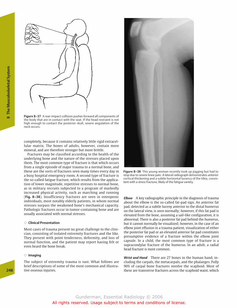
completely, because it contains relatively little rigid extracel-lular matrix. The bones of adults, however, contain moremineral, and are therefore stronger but more brittle.
Fractures may be classified according to the health of theunderlying bone and the nature of the stresses placed uponthem. The most common type of fracture is that which occursfrom a single episode of major trauma to a normal bone, andthese are the sorts of fractures seen many times every day ina busy hospital emergency room. A second type of fracture isthe so-called fatigue fracture, which results from the applica-tion of lower magnitude, repetitive stresses to normal bone,as in military recruits subjected to a program of markedly increased physical activity, such as marching and running (Fig. 8–38). Insufficiency fractures are seen in osteopenic individuals, most notably elderly patients, in whom normalstresses surpass the weakened bone’s mechanical capacity.Pathologic fractures occur in tumor-containing bone and areusually associated with normal stresses.
�� Clinical Presentation
Most cases of trauma present no great challenge to the clini-cian, consisting of isolated extremity fractures and the like.They present with point tenderness, deformity, and loss ofnormal function, and the patient may report having felt oreven heard the bone break.
�� Imaging
The subject of extremity trauma is vast. What follows arebrief descriptions of some of the most common and illustra-tive osseous injuries.248
8Th
e M
uscu
losk
elet
al S
yste
m
Figure 8–37 A rear-impact collision pushes forward all components ofthe body that are in contact with the seat. If the head restraint is nothigh enough to contact the posterior skull, severe angulation of theneck occurs.
Figure 8–38 This young woman recently took up jogging but had tostop due to severe knee pain. A lateral radiograph demonstrates anteriorcortical thickening and a subtle horizontal lucency of the tibia, consis-tent with a stress fracture, likely of the fatigue variety.
Elbow A key radiographic principle in the diagnosis of traumaabout the elbow is the so-called fat-pad sign. An anterior fatpad, detected as a subtle luceny anterior to the distal humeruson the lateral view, is seen normally; however, if this fat pad iselevated from the bone, assuming a sail-like configuration, it isabnormal. There is also a posterior fat pad behind the humerus,but it cannot normally be visualized; however, in the case of anelbow joint effusion in a trauma patient, visualization of eitherthe posterior fat pad or an elevated anterior fat pad constitutespresumptive evidence of a fracture within the elbow joint capsule. In a child, the most common type of fracture is asupracondylar fracture of the humerus. In an adult, a radialhead fracture is most common.
Wrist and Hand There are 27 bones in the human hand, in-cluding the carpals, the metacarpals, and the phalanges. Fully90% of carpal bone fractures involve the scaphoid. Most ofthese are transverse fractures across the scaphoid waist, which
chapter 08_p220-256.qxd 12/1/05 4:13 PM Page 248
Gunderman, Essential Radiology © 2006All rights reserved. Usage subject to terms and conditions of license.
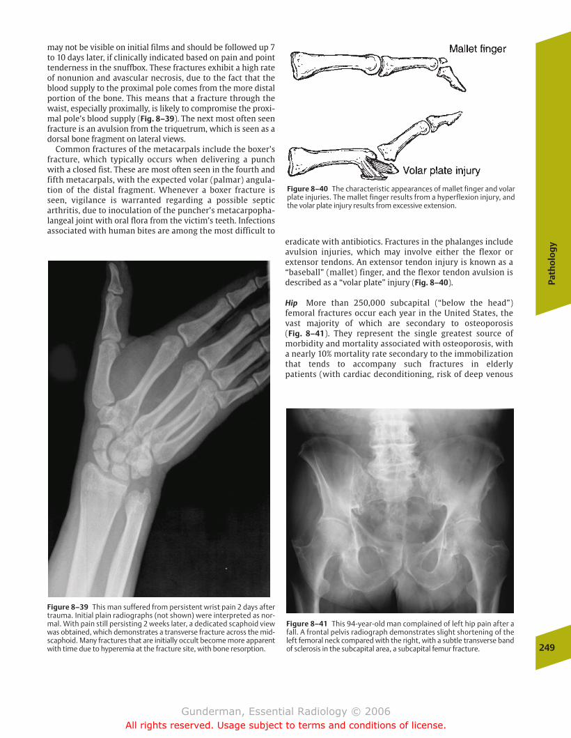
Path
olo
gy
249
may not be visible on initial films and should be followed up 7to 10 days later, if clinically indicated based on pain and pointtenderness in the snuffbox. These fractures exhibit a high rateof nonunion and avascular necrosis, due to the fact that theblood supply to the proximal pole comes from the more distalportion of the bone. This means that a fracture through thewaist, especially proximally, is likely to compromise the proxi-mal pole’s blood supply (Fig. 8–39). The next most often seenfracture is an avulsion from the triquetrum, which is seen as adorsal bone fragment on lateral views.
Common fractures of the metacarpals include the boxer’sfracture, which typically occurs when delivering a punchwith a closed fist. These are most often seen in the fourth andfifth metacarpals, with the expected volar (palmar) angula-tion of the distal fragment. Whenever a boxer fracture isseen, vigilance is warranted regarding a possible septicarthritis, due to inoculation of the puncher’s metacarpopha-langeal joint with oral flora from the victim’s teeth. Infectionsassociated with human bites are among the most difficult to
eradicate with antibiotics. Fractures in the phalanges includeavulsion injuries, which may involve either the flexor or extensor tendons. An extensor tendon injury is known as a“baseball” (mallet) finger, and the flexor tendon avulsion isdescribed as a “volar plate” injury (Fig. 8–40).
Hip More than 250,000 subcapital (“below the head”)femoral fractures occur each year in the United States, thevast majority of which are secondary to osteoporosis (Fig. 8–41). They represent the single greatest source of morbidity and mortality associated with osteoporosis, with a nearly 10% mortality rate secondary to the immobilizationthat tends to accompany such fractures in elderly patients (with cardiac deconditioning, risk of deep venous
Figure 8–39 This man suffered from persistent wrist pain 2 days aftertrauma. Initial plain radiographs (not shown) were interpreted as nor-mal. With pain still persisting 2 weeks later, a dedicated scaphoid viewwas obtained, which demonstrates a transverse fracture across the mid-scaphoid. Many fractures that are initially occult become more apparentwith time due to hyperemia at the fracture site, with bone resorption.
Figure 8–40 The characteristic appearances of mallet finger and volarplate injuries. The mallet finger results from a hyperflexion injury, andthe volar plate injury results from excessive extension.
Figure 8–41 This 94-year-old man complained of left hip pain after afall. A frontal pelvis radiograph demonstrates slight shortening of theleft femoral neck compared with the right, with a subtle transverse bandof sclerosis in the subcapital area, a subcapital femur fracture.
chapter 08_p220-256.qxd 12/1/05 4:13 PM Page 249
Gunderman, Essential Radiology © 2006All rights reserved. Usage subject to terms and conditions of license.
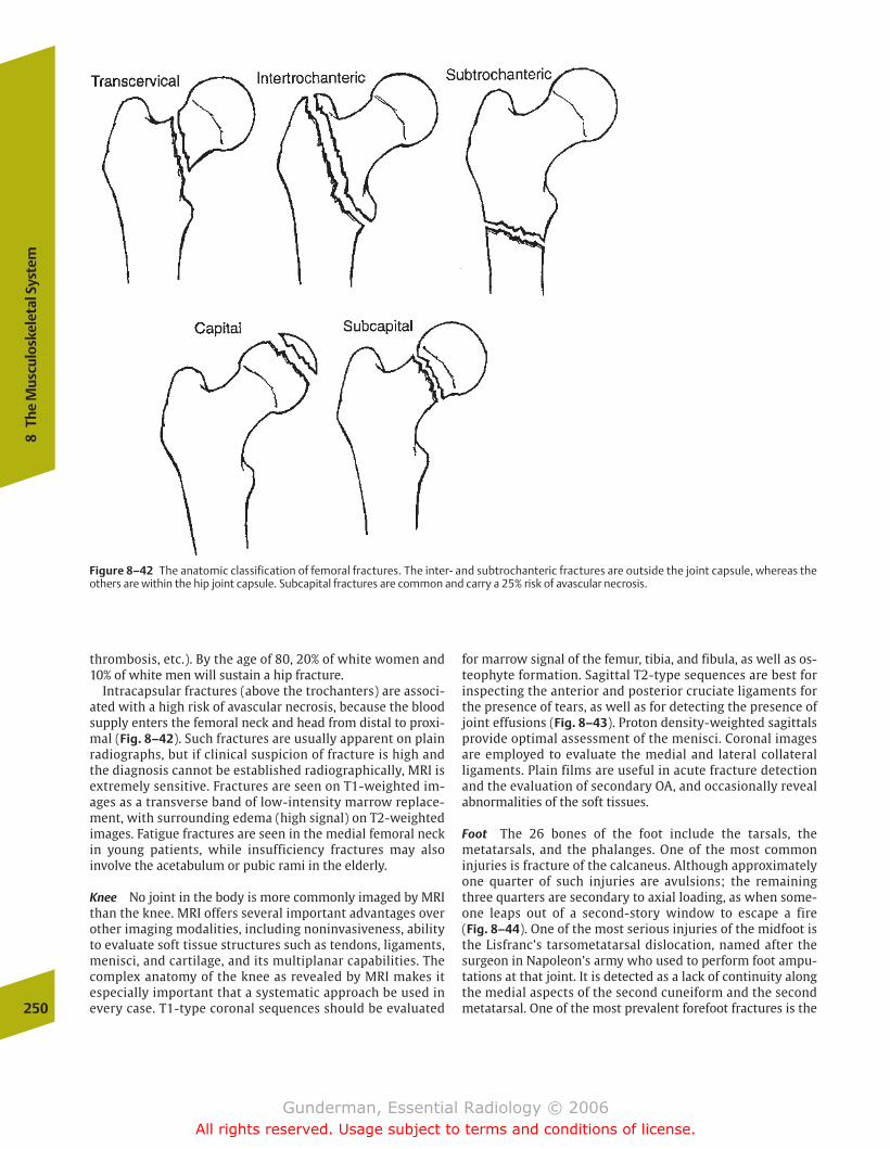
thrombosis, etc.). By the age of 80, 20% of white women and10% of white men will sustain a hip fracture.
Intracapsular fractures (above the trochanters) are associ-ated with a high risk of avascular necrosis, because the bloodsupply enters the femoral neck and head from distal to proxi-mal (Fig. 8–42). Such fractures are usually apparent on plainradiographs, but if clinical suspicion of fracture is high andthe diagnosis cannot be established radiographically, MRI isextremely sensitive. Fractures are seen on T1-weighted im-ages as a transverse band of low-intensity marrow replace-ment, with surrounding edema (high signal) on T2-weightedimages. Fatigue fractures are seen in the medial femoral neckin young patients, while insufficiency fractures may also involve the acetabulum or pubic rami in the elderly.
Knee No joint in the body is more commonly imaged by MRIthan the knee. MRI offers several important advantages overother imaging modalities, including noninvasiveness, abilityto evaluate soft tissue structures such as tendons, ligaments,menisci, and cartilage, and its multiplanar capabilities. Thecomplex anatomy of the knee as revealed by MRI makes it especially important that a systematic approach be used inevery case. T1-type coronal sequences should be evaluated
for marrow signal of the femur, tibia, and fibula, as well as os-teophyte formation. Sagittal T2-type sequences are best forinspecting the anterior and posterior cruciate ligaments forthe presence of tears, as well as for detecting the presence ofjoint effusions (Fig. 8–43). Proton density-weighted sagittalsprovide optimal assessment of the menisci. Coronal imagesare employed to evaluate the medial and lateral collateral ligaments. Plain films are useful in acute fracture detectionand the evaluation of secondary OA, and occasionally revealabnormalities of the soft tissues.
Foot The 26 bones of the foot include the tarsals, themetatarsals, and the phalanges. One of the most common injuries is fracture of the calcaneus. Although approximatelyone quarter of such injuries are avulsions; the remainingthree quarters are secondary to axial loading, as when some-one leaps out of a second-story window to escape a fire (Fig. 8–44). One of the most serious injuries of the midfoot isthe Lisfranc’s tarsometatarsal dislocation, named after thesurgeon in Napoleon’s army who used to perform foot ampu-tations at that joint. It is detected as a lack of continuity alongthe medial aspects of the second cuneiform and the secondmetatarsal. One of the most prevalent forefoot fractures is the250
8Th
e M
uscu
losk
elet
al S
yste
m
Figure 8–42 The anatomic classification of femoral fractures. The inter- and subtrochanteric fractures are outside the joint capsule, whereas theothers are within the hip joint capsule. Subcapital fractures are common and carry a 25% risk of avascular necrosis.
chapter 08_p220-256.qxd 12/1/05 4:13 PM Page 250
Gunderman, Essential Radiology © 2006All rights reserved. Usage subject to terms and conditions of license.
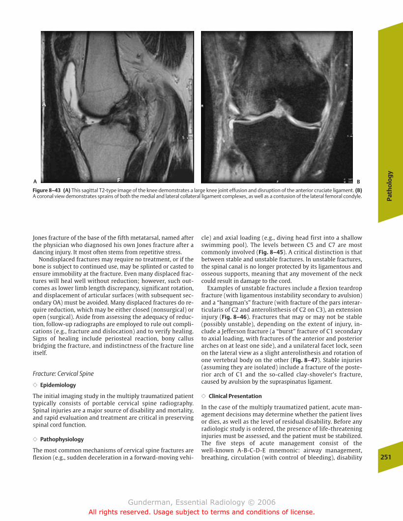
Path
olo
gy
251
Jones fracture of the base of the fifth metatarsal, named afterthe physician who diagnosed his own Jones fracture after adancing injury. It most often stems from repetitive stress.
Nondisplaced fractures may require no treatment, or if thebone is subject to continued use, may be splinted or casted toensure immobility at the fracture. Even many displaced frac-tures will heal well without reduction; however, such out-comes as lower limb length discrepancy, significant rotation,and displacement of articular surfaces (with subsequent sec-ondary OA) must be avoided. Many displaced fractures do re-quire reduction, which may be either closed (nonsurgical) oropen (surgical). Aside from assessing the adequacy of reduc-tion, follow-up radiographs are employed to rule out compli-cations (e.g., fracture and dislocation) and to verify healing.Signs of healing include periosteal reaction, bony callusbridging the fracture, and indistinctness of the fracture lineitself.
Fracture: Cervical Spine
�� Epidemiology
The initial imaging study in the multiply traumatized patienttypically consists of portable cervical spine radiography.Spinal injuries are a major source of disability and mortality,and rapid evaluation and treatment are critical in preservingspinal cord function.
�� Pathophysiology
The most common mechanisms of cervical spine fractures areflexion (e.g., sudden deceleration in a forward-moving vehi-
cle) and axial loading (e.g., diving head first into a shallowswimming pool). The levels between C5 and C7 are mostcommonly involved (Fig. 8–45). A critical distinction is thatbetween stable and unstable fractures. In unstable fractures,the spinal canal is no longer protected by its ligamentous andosseous supports, meaning that any movement of the neckcould result in damage to the cord.
Examples of unstable fractures include a flexion teardropfracture (with ligamentous instability secondary to avulsion)and a “hangman’s” fracture (with fracture of the pars interar-ticularis of C2 and anterolisthesis of C2 on C3), an extensioninjury (Fig. 8–46). Fractures that may or may not be stable(possibly unstable), depending on the extent of injury, in-clude a Jefferson fracture (a “burst” fracture of C1 secondaryto axial loading, with fractures of the anterior and posteriorarches on at least one side), and a unilateral facet lock, seenon the lateral view as a slight anterolisthesis and rotation ofone vertebral body on the other (Fig. 8–47). Stable injuries(assuming they are isolated) include a fracture of the poste-rior arch of C1 and the so-called clay-shoveler’s fracture,caused by avulsion by the supraspinatus ligament.
�� Clinical Presentation
In the case of the multiply traumatized patient, acute man-agement decisions may determine whether the patient livesor dies, as well as the level of residual disability. Before anyradiologic study is ordered, the presence of life-threateninginjuries must be assessed, and the patient must be stabilized.The five steps of acute management consist of the well-known A-B-C-D-E mnemonic: airway management,breathing, circulation (with control of bleeding), disability
Figure 8–43 (A) This sagittal T2-type image of the knee demonstrates a large knee joint effusion and disruption of the anterior cruciate ligament. (B)A coronal view demonstrates sprains of both the medial and lateral collateral ligament complexes, as well as a contusion of the lateral femoral condyle.
A B
chapter 08_p220-256.qxd 12/1/05 4:13 PM Page 251
Gunderman, Essential Radiology © 2006All rights reserved. Usage subject to terms and conditions of license.
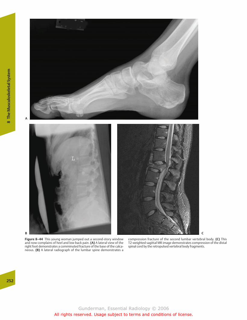
252
8Th
e M
uscu
losk
elet
al S
yste
m
Figure 8–44 This young woman jumped out a second-story windowand now complains of heel and low back pain. (A) A lateral view of theright foot demonstrates a comminuted fracture of the base of the calca-neous. (B) A lateral radiograph of the lumbar spine demonstrates a
compression fracture of the second lumbar vertebral body. (C) This T2-weighted sagittal MR image demonstrates compression of the distalspinal cord by the retropulsed vertebral body fragments.
A
B C
chapter 08_p220-256.qxd 12/1/05 4:13 PM Page 252
Gunderman, Essential Radiology © 2006All rights reserved. Usage subject to terms and conditions of license.
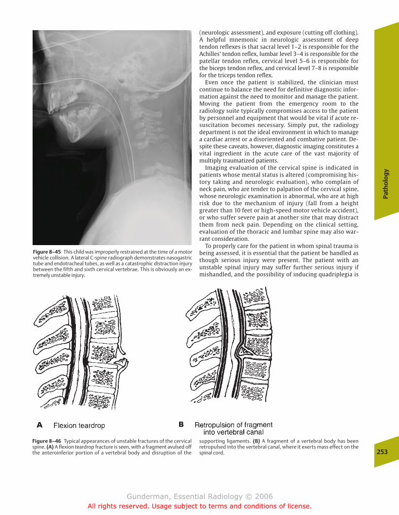
Path
olo
gy
253
(neurologic assessment), and exposure (cutting off clothing).A helpful mnemonic in neurologic assessment of deep tendon reflexes is that sacral level 1–2 is responsible for theAchilles’ tendon reflex, lumbar level 3–4 is responsible for thepatellar tendon reflex, cervical level 5–6 is responsible for the biceps tendon reflex, and cervical level 7–8 is responsiblefor the triceps tendon reflex.
Even once the patient is stabilized, the clinician must continue to balance the need for definitive diagnostic infor-mation against the need to monitor and manage the patient.Moving the patient from the emergency room to the radiology suite typically compromises access to the patientby personnel and equipment that would be vital if acute re-suscitation becomes necessary. Simply put, the radiology department is not the ideal environment in which to managea cardiac arrest or a disoriented and combative patient. De-spite these caveats, however, diagnostic imaging constitutes avital ingredient in the acute care of the vast majority of multiply traumatized patients.
Imaging evaluation of the cervical spine is indicated inpatients whose mental status is altered (compromising his-tory taking and neurologic evaluation), who complain ofneck pain, who are tender to palpation of the cervical spine,whose neurologic examination is abnormal, who are at highrisk due to the mechanism of injury (fall from a heightgreater than 10 feet or high-speed motor vehicle accident),or who suffer severe pain at another site that may distractthem from neck pain. Depending on the clinical setting,evaluation of the thoracic and lumbar spine may also war-rant consideration.
To properly care for the patient in whom spinal trauma isbeing assessed, it is essential that the patient be handled asthough serious injury were present. The patient with an unstable spinal injury may suffer further serious injury ifmishandled, and the possibility of inducing quadriplegia is
Figure 8–45 This child was improperly restrained at the time of a motorvehicle collision. A lateral C-spine radiograph demonstrates nasogastrictube and endotracheal tubes, as well as a catastrophic distraction injurybetween the fifth and sixth cervical vertebrae. This is obviously an ex-tremely unstable injury.
Figure 8–46 Typical appearances of unstable fractures of the cervicalspine. (A) A flexion teardrop fracture is seen, with a fragment avulsed offthe anteroinferior portion of a vertebral body and disruption of the
supporting ligaments. (B) A fragment of a vertebral body has beenretropulsed into the vertebral canal, where it exerts mass effect on thespinal cord.
chapter 08_p220-256.qxd 12/1/05 4:14 PM Page 253
Gunderman, Essential Radiology © 2006All rights reserved. Usage subject to terms and conditions of license.

sufficient justification for always erring on the side of over-protection. The patient should be transported with a cervicalcollar in place, and immobilized on a long spine board, andthe patient and the board are moved as a unit until seriousinjury is radiographically ruled out.
�� Imaging
The initial view obtained is generally a cross-table lateral,with the patient lying supine in a cervical collar. Once the cer-vical spine has been “cleared” by a combination of this viewand clinical findings, additional radiographs are necessary tofully exclude injury. These include an additional lateral view,an anteroposterior view, an open-mouth odontoid view, andtwo supine obliques, making a total of five films in a completecervical spine series. In some cases, CT examination of thecervical spine may be indicated. Many trauma patients willundergo CT scanning of the head to rule out intracranial in-jury in any case, and it is simple to add on axial images of thecervical spine. This may be especially helpful in patients inwhom standard views are unsatisfactory, as when superimpo-sition of shoulder structures compromises views of the lowercervical spine. Moreover, CT is helpful in better delineatingequivocal findings on plain films and in further evaluating theextent of definite injuries detected by plain radiography.
The key to evaluating the cervical spine is to approach theradiograph systematically. Many systems are possible, andthe following is but one example. Here is a seven-step check-list to employ in evaluating the cross-table lateral view. Al-though this list is by no means complete, it suffices to ruleout most serious injuries in the acute setting.
1. Count the number of vertebrae. A good cross-table lateralview should display all seven cervical vertebrae, as well asthe upper portion of the T1 vertebral body. Often theshoulder obscures the lower cervical spine, and a “swim-mer’s view” must be obtained (the arm closest to the filmis extended cranially, as though the patient were reachingto retrieve an object from a high shelf). Just as one wouldnot “clear” a patient’s chest after listening to only onelung, one must not “clear” the cervical spine unless thewhole cervical spine has been adequately visualized. Al-though C2 is the single most commonly fractured vertebrain the cervical spine, approximately three fourths of cervi-cal spine fractures involve the lower levels, and adequatevisualization is essential in ruling these out. To assess ade-quate visualization, begin counting below the base of theskull at C1, then count downward.
2. Assess the curvature of the spine. The normal cervicalspine is slightly lordotic (convex anteriorly). If this lordosisis exaggerated or lost, it may indicate ligamentous injury,although poor positioning or muscle spasm occurs morecommonly.
3. Assess vertebral alignment. Four lines drawn along theaxis of the cervical spine should demonstrate smooth,gentle curves (Fig. 8–48). These include the anterior verte-bral line, the posterior vertebral line, the spinolaminalline, and the posterior spinal line. Any irregularity in anyof these lines should raise suspicion for a fracture or dislo-cation. Because the spinal cord is housed between theposterior vertebral line and the spinolaminal line, an
254
8Th
e M
uscu
losk
elet
al S
yste
m
Figure 8–47 This lateral C-spine radiograph demonstrates anterolisthe-sis of C2 on C3, a classic finding in a “hangman’s” fracture.
Figure 8–48 This sagittal reformat of axially acquired CT data demon-strates anterolisthesis of the fifth cervical vertebra on the sixth vertebra,which was associated with locking of the facet joint.
chapter 08_p220-256.qxd 12/1/05 4:14 PM Page 254
Gunderman, Essential Radiology © 2006All rights reserved. Usage subject to terms and conditions of license.
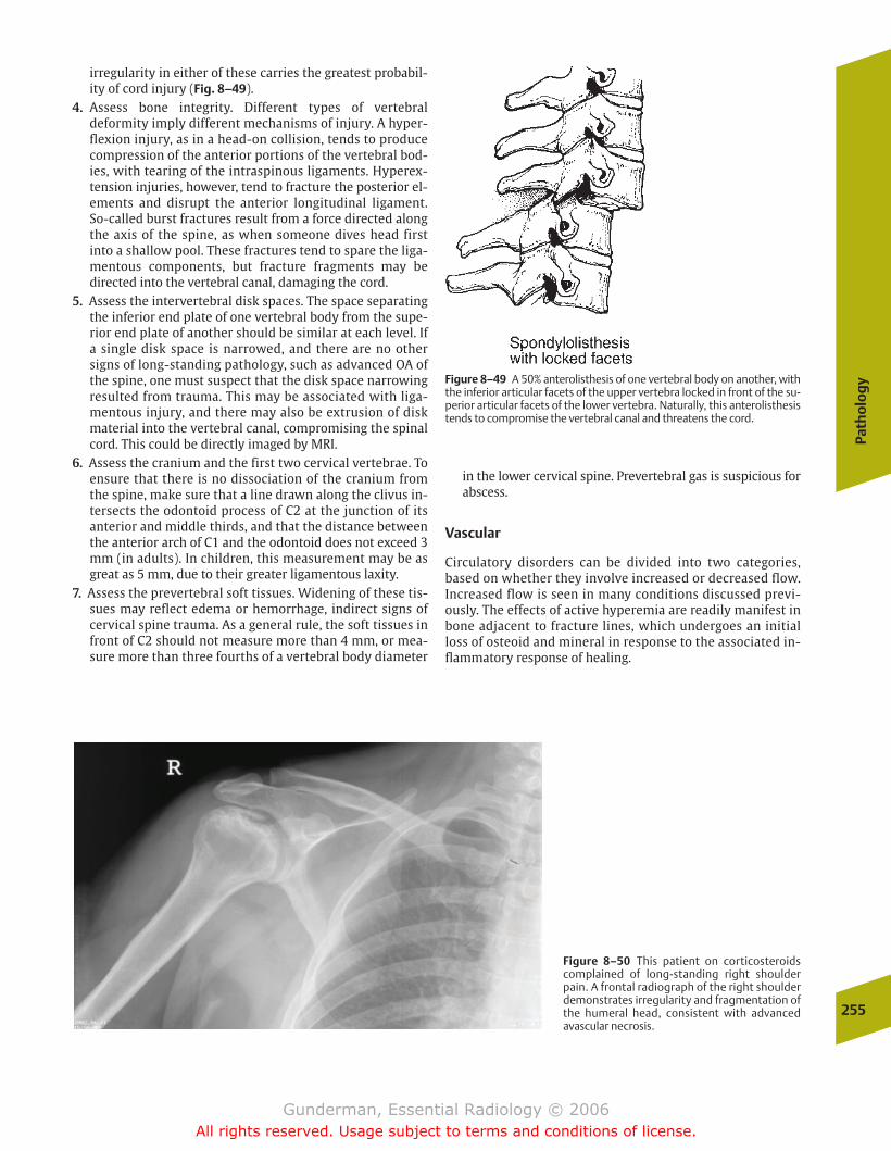
Path
olo
gy
255
Figure 8–49 A 50% anterolisthesis of one vertebral body on another, withthe inferior articular facets of the upper vertebra locked in front of the su-perior articular facets of the lower vertebra. Naturally, this anterolisthesistends to compromise the vertebral canal and threatens the cord.
Figure 8–50 This patient on corticosteroidscomplained of long-standing right shoulderpain. A frontal radiograph of the right shoulderdemonstrates irregularity and fragmentation ofthe humeral head, consistent with advancedavascular necrosis.
irregularity in either of these carries the greatest probabil-ity of cord injury (Fig. 8–49).
4. Assess bone integrity. Different types of vertebral deformity imply different mechanisms of injury. A hyper-flexion injury, as in a head-on collision, tends to producecompression of the anterior portions of the vertebral bod-ies, with tearing of the intraspinous ligaments. Hyperex-tension injuries, however, tend to fracture the posterior el-ements and disrupt the anterior longitudinal ligament.So-called burst fractures result from a force directed alongthe axis of the spine, as when someone dives head firstinto a shallow pool. These fractures tend to spare the liga-mentous components, but fracture fragments may be directed into the vertebral canal, damaging the cord.
5. Assess the intervertebral disk spaces. The space separatingthe inferior end plate of one vertebral body from the supe-rior end plate of another should be similar at each level. Ifa single disk space is narrowed, and there are no othersigns of long-standing pathology, such as advanced OA ofthe spine, one must suspect that the disk space narrowingresulted from trauma. This may be associated with liga-mentous injury, and there may also be extrusion of diskmaterial into the vertebral canal, compromising the spinalcord. This could be directly imaged by MRI.
6. Assess the cranium and the first two cervical vertebrae. Toensure that there is no dissociation of the cranium fromthe spine, make sure that a line drawn along the clivus in-tersects the odontoid process of C2 at the junction of itsanterior and middle thirds, and that the distance betweenthe anterior arch of C1 and the odontoid does not exceed 3mm (in adults). In children, this measurement may be asgreat as 5 mm, due to their greater ligamentous laxity.
7. Assess the prevertebral soft tissues. Widening of these tis-sues may reflect edema or hemorrhage, indirect signs ofcervical spine trauma. As a general rule, the soft tissues infront of C2 should not measure more than 4 mm, or mea-sure more than three fourths of a vertebral body diameter
in the lower cervical spine. Prevertebral gas is suspicious forabscess.
Vascular
Circulatory disorders can be divided into two categories,based on whether they involve increased or decreased flow.Increased flow is seen in many conditions discussed previ-ously. The effects of active hyperemia are readily manifest inbone adjacent to fracture lines, which undergoes an initialloss of osteoid and mineral in response to the associated in-flammatory response of healing.
chapter 08_p220-256.qxd 12/1/05 4:14 PM Page 255
Gunderman, Essential Radiology © 2006All rights reserved. Usage subject to terms and conditions of license.
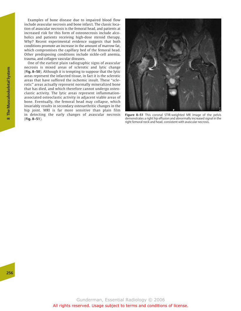
256
8Th
e M
uscu
losk
elet
al S
yste
m
Figure 8–51 This coronal STIR-weighted MR image of the pelvisdemonstrates a right hip effusion and abnormally increased signal in theright femoral neck and head, consistent with avascular necrosis.
Examples of bone disease due to impaired blood flow include avascular necrosis and bone infarct. The classic loca-tion of avascular necrosis is the femoral head, and patients atincreased risk for this form of osteonecrosis include alco-holics and patients receiving high-dose steroid therapy.Why? Recent experimental evidence suggests that both conditions promote an increase in the amount of marrow fat,which compromises the capillary bed of the femoral head.Other predisposing conditions include sickle-cell anemia,trauma, and collagen vascular diseases.
One of the earliest plain radiographic signs of avascularnecrosis is mixed areas of sclerotic and lytic change (Fig. 8–50). Although it is tempting to suppose that the lyticareas represent the infarcted tissue, in fact it is the scleroticareas that have suffered the ischemic insult. These “scle-rotic” areas actually represent normally mineralized bonethat has died, and which therefore cannot undergo osteo-clastic activity. The lytic areas represent inflammation-associated osteoclastic activity in adjacent viable areas ofbone. Eventually, the femoral head may collapse, which invariably results in secondary osteoarthritic changes in thehip joint. MRI is far more sensitive than plain film in detecting the early changes of avascular necrosis (Fig. 8–51).
chapter 08_p220-256.qxd 12/1/05 4:14 PM Page 256
Gunderman, Essential Radiology © 2006All rights reserved. Usage subject to terms and conditions of license.
� Anatomy and Physiology
� Imaging
Choice of ModalityComparison of T1- and T2-Weighted MRIContrast Enhancement in CT and MRISearch Pattern in MRI
� Pathology
CongenitalPhakomatoses
InflammatoryMultiple Sclerosis
TumorousExtra-axial NeoplasmsIntra-axial NeoplasmsEpilepsy
InfectiousMeningitisAbscessEncephalitisParasitic InfectionsHuman Immunodeficiency Virus
TraumaticSubdural HematomaEpidural HematomaIntracerebral Contusions and HematomasDiffuse Axonal Injury
VascularStroke
Low Back PainCervical Disk Disease and Spondylosis
9Neuroimaging
chapter 09_p257-295.qxd 12/1/05 4:18 PM Page 257
Gunderman, Essential Radiology © 2006All rights reserved. Usage subject to terms and conditions of license.
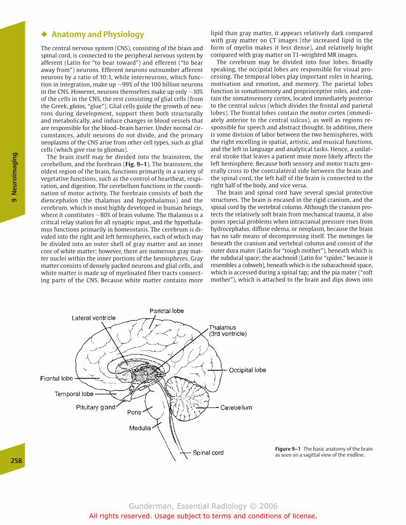
� Anatomy and Physiology
The central nervous system (CNS), consisting of the brain andspinal cord, is connected to the peripheral nervous system byafferent (Latin for “to bear toward”) and efferent (“to bearaway from”) neurons. Efferent neurons outnumber afferentneurons by a ratio of 10:1, while interneurons, which func-tion in integration, make up �99% of the 100 billion neuronsin the CNS. However, neurons themselves make up only �10%of the cells in the CNS, the rest consisting of glial cells (fromthe Greek, gloios, “glue”). Glial cells guide the growth of neu-rons during development, support them both structurallyand metabolically, and induce changes in blood vessels thatare responsible for the blood–brain barrier. Under normal cir-cumstances, adult neurons do not divide, and the primaryneoplasms of the CNS arise from other cell types, such as glialcells (which give rise to gliomas).
The brain itself may be divided into the brainstem, thecerebellum, and the forebrain (Fig. 9–1). The brainstem, theoldest region of the brain, functions primarily in a variety ofvegetative functions, such as the control of heartbeat, respi-ration, and digestion. The cerebellum functions in the coordi-nation of motor activity. The forebrain consists of both the diencephalon (the thalamus and hypothalamus) and thecerebrum, which is most highly developed in human beings,where it constitutes �80% of brain volume. The thalamus is acritical relay station for all synaptic input, and the hypothala-mus functions primarily in homeostasis. The cerebrum is di-vided into the right and left hemispheres, each of which maybe divided into an outer shell of gray matter and an innercore of white matter; however, there are numerous gray mat-ter nuclei within the inner portions of the hemispheres. Graymatter consists of densely packed neurons and glial cells, andwhite matter is made up of myelinated fiber tracts connect-ing parts of the CNS. Because white matter contains more
lipid than gray matter, it appears relatively dark comparedwith gray matter on CT images (the increased lipid in theform of myelin makes it less dense), and relatively brightcompared with gray matter on T1-weighted MR images.
The cerebrum may be divided into four lobes. Broadlyspeaking, the occipital lobes are responsible for visual pro-cessing. The temporal lobes play important roles in hearing,motivation and emotion, and memory. The parietal lobesfunction in somatosensory and proprioceptive roles, and con-tain the somatosensory cortex, located immediately posteriorto the central sulcus (which divides the frontal and parietallobes). The frontal lobes contain the motor cortex (immedi-ately anterior to the central sulcus), as well as regions re-sponsible for speech and abstract thought. In addition, thereis some division of labor between the two hemispheres, withthe right excelling in spatial, artistic, and musical functions,and the left in language and analytical tasks. Hence, a unilat-eral stroke that leaves a patient mute more likely affects theleft hemisphere. Because both sensory and motor tracts gen-erally cross to the contralateral side between the brain andthe spinal cord, the left half of the brain is connected to theright half of the body, and vice versa.
The brain and spinal cord have several special protectivestructures. The brain is encased in the rigid cranium, and thespinal cord by the vertebral column. Although the cranium pro-tects the relatively soft brain from mechanical trauma, it alsoposes special problems when intracranial pressure rises fromhydrocephalus, diffuse edema, or neoplasm, because the brainhas no safe means of decompressing itself. The meninges liebeneath the cranium and vertebral column and consist of theouter dura mater (Latin for “tough mother”), beneath which isthe subdural space; the arachnoid (Latin for “spider,” because itresembles a cobweb), beneath which is the subarachnoid space,which is accessed during a spinal tap; and the pia mater (“softmother”), which is attached to the brain and dips down into
258
9N
euro
imag
ing
Figure 9–1 The basic anatomy of the brainas seen on a sagittal view of the midline.
chapter 09_p257-295.qxd 12/1/05 4:18 PM Page 258
Gunderman, Essential Radiology © 2006All rights reserved. Usage subject to terms and conditions of license.
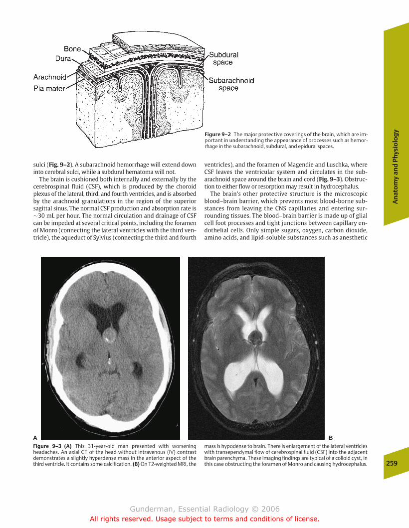
sulci (Fig. 9–2). A subarachnoid hemorrhage will extend downinto cerebral sulci, while a subdural hematoma will not.
The brain is cushioned both internally and externally by thecerebrospinal fluid (CSF), which is produced by the choroidplexus of the lateral, third, and fourth ventricles, and is absorbedby the arachnoid granulations in the region of the superiorsagittal sinus. The normal CSF production and absorption rate is�30 mL per hour. The normal circulation and drainage of CSFcan be impeded at several critical points, including the foramenof Monro (connecting the lateral ventricles with the third ven-tricle), the aqueduct of Sylvius (connecting the third and fourth
ventricles), and the foramen of Magendie and Luschka, whereCSF leaves the ventricular system and circulates in the sub-arachnoid space around the brain and cord (Fig. 9–3). Obstruc-tion to either flow or resorption may result in hydrocephalus.
The brain’s other protective structure is the microscopicblood–brain barrier, which prevents most blood-borne sub-stances from leaving the CNS capillaries and entering sur-rounding tissues. The blood–brain barrier is made up of glialcell foot processes and tight junctions between capillary en-dothelial cells. Only simple sugars, oxygen, carbon dioxide,amino acids, and lipid-soluble substances such as anesthetic
An
ato
my
and
Phy
sio
log
y
259
Figure 9–2 The major protective coverings of the brain, which are im-portant in understanding the appearance of processes such as hemor-rhage in the subarachnoid, subdural, and epidural spaces.
Figure 9–3 (A) This 31-year-old man presented with worseningheadaches. An axial CT of the head without intravenous (IV) contrastdemonstrates a slightly hyperdense mass in the anterior aspect of thethird ventricle. It contains some calcification. (B) On T2-weighted MRI, the
mass is hypodense to brain. There is enlargement of the lateral ventricleswith transependymal flow of cerebrospinal fluid (CSF) into the adjacentbrain parenchyma. These imaging findings are typical of a colloid cyst, inthis case obstructing the foramen of Monro and causing hydrocephalus.
A B
chapter 09_p257-295.qxd 12/1/05 4:18 PM Page 259
Gunderman, Essential Radiology © 2006All rights reserved. Usage subject to terms and conditions of license.
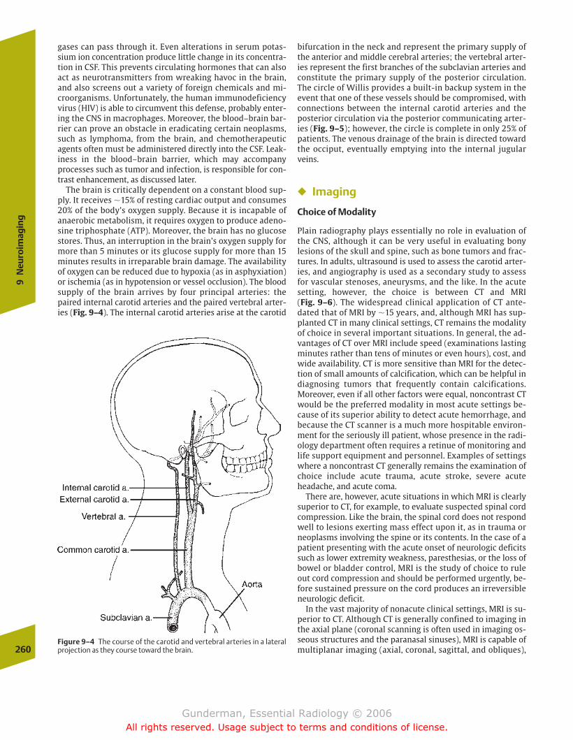
gases can pass through it. Even alterations in serum potas-sium ion concentration produce little change in its concentra-tion in CSF. This prevents circulating hormones that can alsoact as neurotransmitters from wreaking havoc in the brain,and also screens out a variety of foreign chemicals and mi-croorganisms. Unfortunately, the human immunodeficiencyvirus (HIV) is able to circumvent this defense, probably enter-ing the CNS in macrophages. Moreover, the blood–brain bar-rier can prove an obstacle in eradicating certain neoplasms,such as lymphoma, from the brain, and chemotherapeuticagents often must be administered directly into the CSF. Leak-iness in the blood–brain barrier, which may accompanyprocesses such as tumor and infection, is responsible for con-trast enhancement, as discussed later.
The brain is critically dependent on a constant blood sup-ply. It receives �15% of resting cardiac output and consumes20% of the body’s oxygen supply. Because it is incapable ofanaerobic metabolism, it requires oxygen to produce adeno-sine triphosphate (ATP). Moreover, the brain has no glucosestores. Thus, an interruption in the brain’s oxygen supply formore than 5 minutes or its glucose supply for more than 15minutes results in irreparable brain damage. The availabilityof oxygen can be reduced due to hypoxia (as in asphyxiation)or ischemia (as in hypotension or vessel occlusion). The bloodsupply of the brain arrives by four principal arteries: thepaired internal carotid arteries and the paired vertebral arter-ies (Fig. 9–4). The internal carotid arteries arise at the carotid
260
9N
euro
imag
ing
Figure 9–4 The course of the carotid and vertebral arteries in a lateralprojection as they course toward the brain.
bifurcation in the neck and represent the primary supply ofthe anterior and middle cerebral arteries; the vertebral arter-ies represent the first branches of the subclavian arteries andconstitute the primary supply of the posterior circulation.The circle of Willis provides a built-in backup system in theevent that one of these vessels should be compromised, withconnections between the internal carotid arteries and theposterior circulation via the posterior communicating arter-ies (Fig. 9–5); however, the circle is complete in only 25% ofpatients. The venous drainage of the brain is directed towardthe occiput, eventually emptying into the internal jugularveins.
� Imaging
Choice of Modality
Plain radiography plays essentially no role in evaluation ofthe CNS, although it can be very useful in evaluating bony lesions of the skull and spine, such as bone tumors and frac-tures. In adults, ultrasound is used to assess the carotid arter-ies, and angiography is used as a secondary study to assessfor vascular stenoses, aneurysms, and the like. In the acutesetting, however, the choice is between CT and MRI (Fig. 9–6). The widespread clinical application of CT ante-dated that of MRI by �15 years, and, although MRI has sup-planted CT in many clinical settings, CT remains the modalityof choice in several important situations. In general, the ad-vantages of CT over MRI include speed (examinations lastingminutes rather than tens of minutes or even hours), cost, andwide availability. CT is more sensitive than MRI for the detec-tion of small amounts of calcification, which can be helpful indiagnosing tumors that frequently contain calcifications.Moreover, even if all other factors were equal, noncontrast CTwould be the preferred modality in most acute settings be-cause of its superior ability to detect acute hemorrhage, andbecause the CT scanner is a much more hospitable environ-ment for the seriously ill patient, whose presence in the radi-ology department often requires a retinue of monitoring andlife support equipment and personnel. Examples of settingswhere a noncontrast CT generally remains the examination ofchoice include acute trauma, acute stroke, severe acuteheadache, and acute coma.
There are, however, acute situations in which MRI is clearlysuperior to CT, for example, to evaluate suspected spinal cordcompression. Like the brain, the spinal cord does not respondwell to lesions exerting mass effect upon it, as in trauma orneoplasms involving the spine or its contents. In the case of apatient presenting with the acute onset of neurologic deficitssuch as lower extremity weakness, paresthesias, or the loss ofbowel or bladder control, MRI is the study of choice to ruleout cord compression and should be performed urgently, be-fore sustained pressure on the cord produces an irreversibleneurologic deficit.
In the vast majority of nonacute clinical settings, MRI is su-perior to CT. Although CT is generally confined to imaging inthe axial plane (coronal scanning is often used in imaging os-seous structures and the paranasal sinuses), MRI is capable ofmultiplanar imaging (axial, coronal, sagittal, and obliques),
chapter 09_p257-295.qxd 12/1/05 4:18 PM Page 260
Gunderman, Essential Radiology © 2006All rights reserved. Usage subject to terms and conditions of license.

and these multiplanar capabilities can be further customizedto answer specific questions about the extent of lesions andtheir impact on adjacent structures (Fig. 9–7).
MRI provides greater differentiation of gray and white mat-ter structures, is more sensitive for the detection of subacuteand chronic bleeds, and generally provides a more detailedand precise view of anatomic structures. MRI can be used todetermine the structure and patency of vascular structureswith greater sensitivity than CT, and even without the use ofintravascular contrast agents. CT is relatively poor at visualiz-ing soft tissue structures surrounded by or adjacent to largeamounts of bone, such as the inferior temporal lobes, whichproduce so-called streak artifact, whereas MRI is immune tothis problem. Situations in which MRI generally representsthe study of choice include suspected tumor or infection,nonacute trauma, seizures, chronic headache, and dementia.
When faced with the decision of which neuroimagingstudy to order, the physician should consider consulting a ra-diologist; however, in the vast majority of cases, the follow-ing guidelines should hold. If the process in question beganless than 48 hours prior to imaging, noncontrast CT is a logi-cal starting point. If the findings suggest a tumor or abscess,consider contrast infusion, which will increase the sensitivitydue to the differential enhancement patterns of normal andabnormal tissues. If concern for vascular pathology such asstroke is high, contrast should probably be withheld, becauseextravasated iodinated contrast may increase edema in thevicinity of the lesion, exacerbating mass effect on surround-ing normal parenchyma. If the process is older than 48 hours,
Imag
ing
261
Figure 9–5 The major vessels of the intracranial circulation, includingthe circle of Willis.
Figure 9–6 This frontal image from a bilateral internal carotid arteryangiogram provides some indication of how far neuroimaging has pro-gressed since the 1970s. This patient suffered from chronic bilateral sub-dural hematomas, which can be seen displacing the enhancing vessels ofthe cerebral parenchyma inferiomedially, away from the inner table ofthe skull. Prior to the advent of computed tomography, angiographyrepresented a primary modality in the diagnosis of such lesions, thepresence of which could be inferred by the displacement of normal ves-sels. Today, however, the diagnosis of a subdural hematoma can be ren-dered much more rapidly, inexpensively, and with less risk via a CT scan(or MRI).
chapter 09_p257-295.qxd 12/1/05 4:18 PM Page 261
Gunderman, Essential Radiology © 2006All rights reserved. Usage subject to terms and conditions of license.
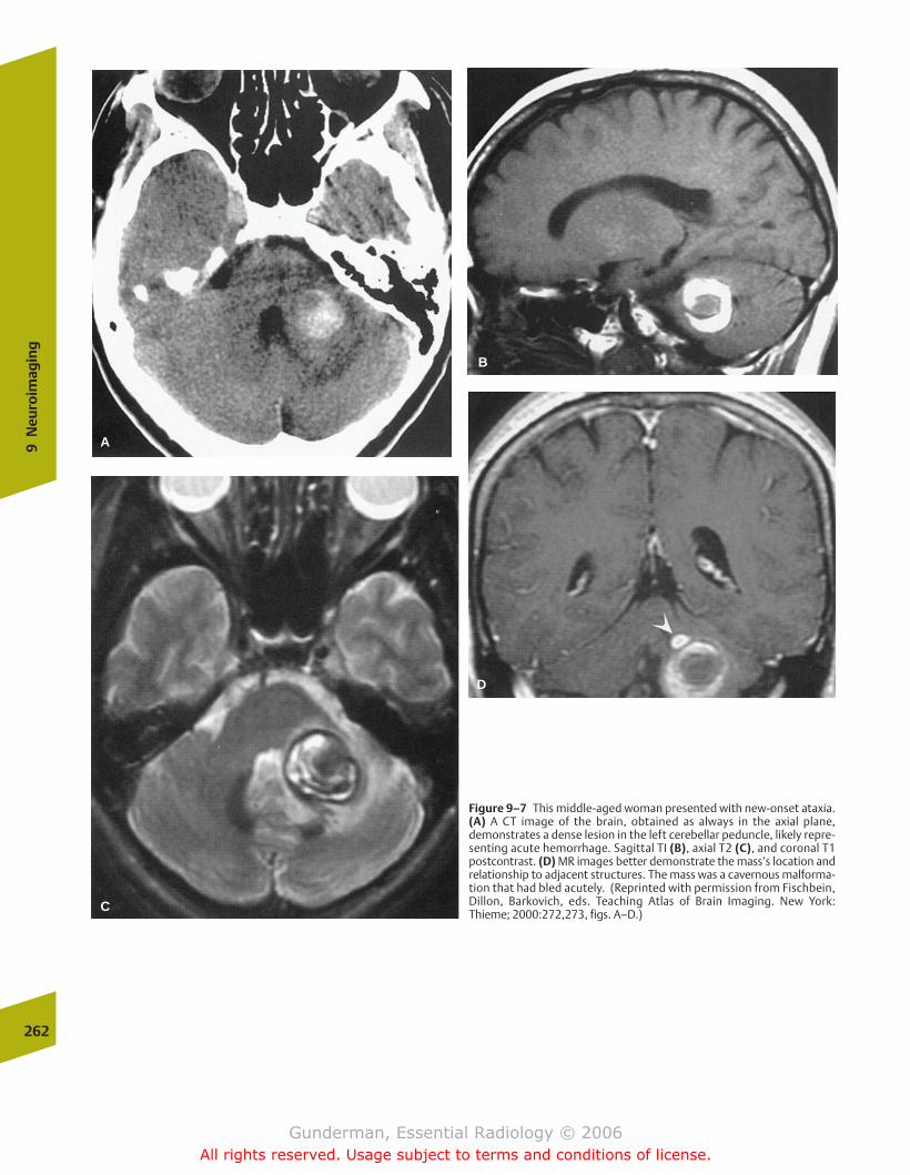
262
9N
euro
imag
ing
Figure 9–7 This middle-aged woman presented with new-onset ataxia.(A) A CT image of the brain, obtained as always in the axial plane,demonstrates a dense lesion in the left cerebellar peduncle, likely repre-senting acute hemorrhage. Sagittal TI (B), axial T2 (C), and coronal T1postcontrast. (D) MR images better demonstrate the mass’s location andrelationship to adjacent structures. The mass was a cavernous malforma-tion that had bled acutely. (Reprinted with permission from Fischbein,Dillon, Barkovich, eds. Teaching Atlas of Brain Imaging. New York:Thieme; 2000:272,273, figs. A–D.)
D
B
C
A
chapter 09_p257-295.qxd 12/1/05 4:18 PM Page 262
Gunderman, Essential Radiology © 2006All rights reserved. Usage subject to terms and conditions of license.
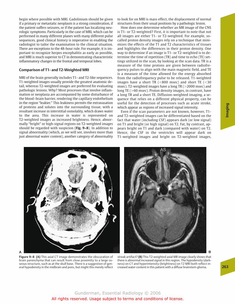
begin where possible with MRI. Gadolinium should be givenif a primary or metastatic neoplasm is a strong consideration, ifthe patient suffers seizures, or if the patient has localizing neu-rologic symptoms. Particularly in the case of MRI, which can beperformed in many different planes with many different pulsesequences, good clinical history is imperative in enabling theradiologist to tailor the examination to the clinical situation.There are exceptions to the 48-hour rule. For example, it is im-portant to recognize herpes encephalitis as early as possible,and MRI is much superior to CT in demonstrating characteristicinflammatory changes in the frontal and temporal lobes.
Comparison of T1- and T2-Weighted MRI
MRI of the brain generally includes T1- and T2-like sequences.T1-weighted images usually provide the greatest anatomic de-tail, whereas T2-weighted images are preferred for evaluatingpathologic lesions. Why? Most processes that involve inflam-mation or neoplasia are accompanied by some disturbance ofthe blood–brain barrier, rendering the capillary endotheliumin the region “leakier.” This leakiness permits the extravasationof proteins and solutes into the surrounding tissue, with a resultant increase in interstitial osmolality, which draws waterto the area. This increase in water is represented on T2-weighted images as increased brightness. Hence, abnor-mally “bright” or high-signal regions on T2-weighted imagesshould be regarded with suspicion (Fig. 9–8). In addition tosignal abnormality (which, as we will see, involves more thanjust abnormal water content), another category of abnormality
to look for on MRI is mass effect, the displacement of normalstructures from their usual positions by a pathologic lesion.
How does one determine whether an MR image of the CNSis T1- or T2-weighted? First, it is important to note that notall images are either T1- or T2-weighted. For example, so-called proton density images rely on a technique that mini-mizes the effects of the T1 and T2 characteristics of tissuesand highlights the differences in their proton density. Oneway to determine if an image is T1- or T2-weighted is to de-termine the time of repetition (TR) and time to echo (TE) set-tings utilized in the scan, by looking at the scan data. TR is ameasure of the time protons are given between radiofre-quency pulses to align with the main magnetic field, and TEis a measure of the time allowed for the energy absorbedfrom the radiofrequency pulse to be released. T1-weightedimages have a short TR (�800 msec) and short TE (�30msec). T2-weighted images have a long TR (�2000 msec) andlong TE (�60 msec). Proton density images, in contrast, havea long TR and a short TE. Diffusion-weighted imaging, a se-quence that relies on a different physical property, can beuseful for the detection of processes such as acute stroke,which appear as regions of increased signal intensity.
Even if the scan parameters are not known, however, T1-and T2-weighted images can be differentiated based on thefact that water (including CSF) appears dark (or low signal)on T1 and bright (or high signal) on T2. Fat, by contrast, ap-pears bright on T1 and dark (compared with water) on T2.Hence, the CSF in the ventricles will appear dark on T1-weighted images and bright on T2-weighted images,
Imag
ing
263
Figure 9–8 (A) This axial CT image demonstrates the obscuration ofbrain parenchyma that can result from close proximity to a large os-seous structure, such as at the skull base. There is a suggestion of gen-eral hypodensity in the midbrain and pons, but might this merely reflect
streak artifact? (B) This T2-weighted axial MR image clearly shows thatthere is abnormal increased signal in this region. The hypodensity (dark-ness) on CT and hyperintensity (brightness) on T2 MRI both reflect in-creased water content in this patient with a diffuse brainstem glioma.
A B
chapter 09_p257-295.qxd 12/1/05 4:18 PM Page 263
Gunderman, Essential Radiology © 2006All rights reserved. Usage subject to terms and conditions of license.
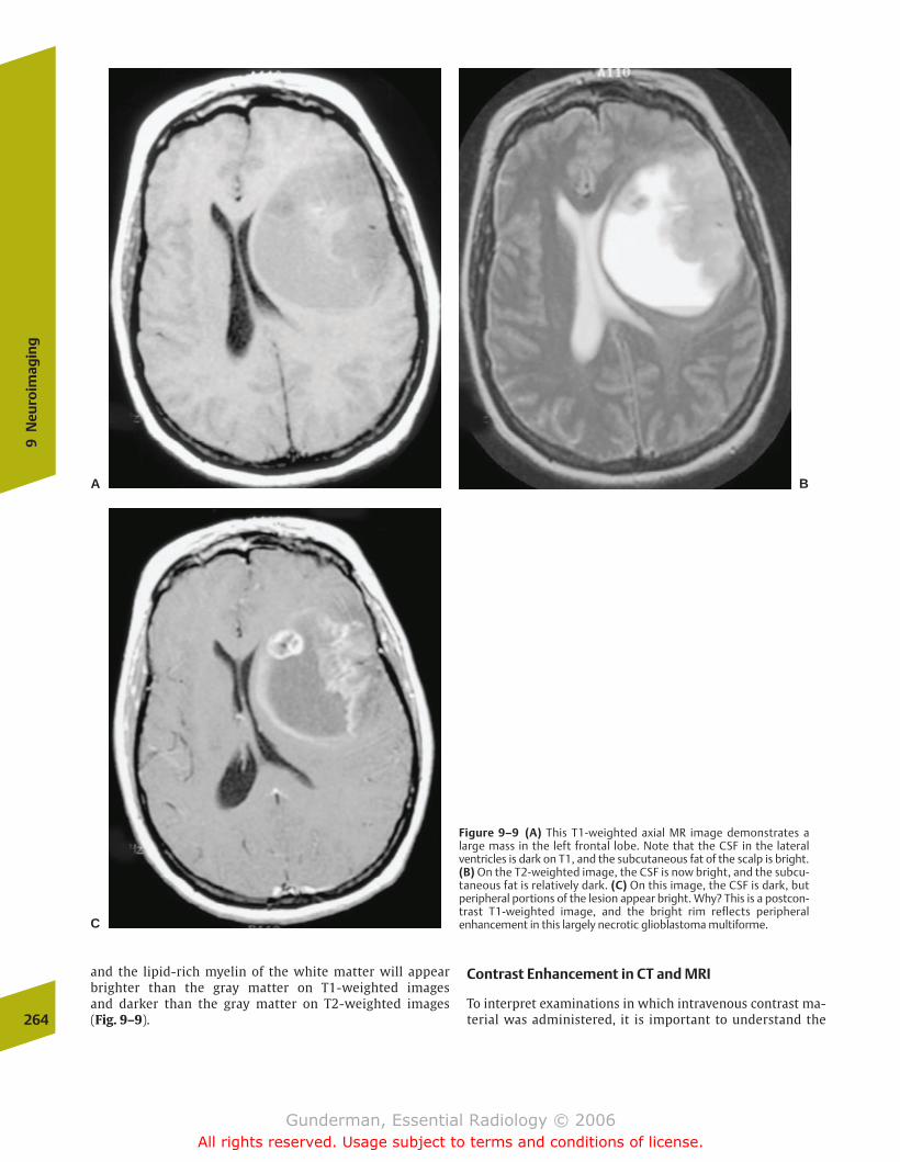
and the lipid-rich myelin of the white matter will appearbrighter than the gray matter on T1-weighted images and darker than the gray matter on T2-weighted images (Fig. 9–9).
Contrast Enhancement in CT and MRI
To interpret examinations in which intravenous contrast ma-terial was administered, it is important to understand the264
9N
euro
imag
ing
Figure 9–9 (A) This T1-weighted axial MR image demonstrates alarge mass in the left frontal lobe. Note that the CSF in the lateralventricles is dark on T1, and the subcutaneous fat of the scalp is bright.(B) On the T2-weighted image, the CSF is now bright, and the subcu-taneous fat is relatively dark. (C) On this image, the CSF is dark, but peripheral portions of the lesion appear bright. Why? This is a postcon-trast T1-weighted image, and the bright rim reflects peripheralenhancement in this largely necrotic glioblastoma multiforme.
A B
C
chapter 09_p257-295.qxd 12/1/05 4:18 PM Page 264
Gunderman, Essential Radiology © 2006All rights reserved. Usage subject to terms and conditions of license.
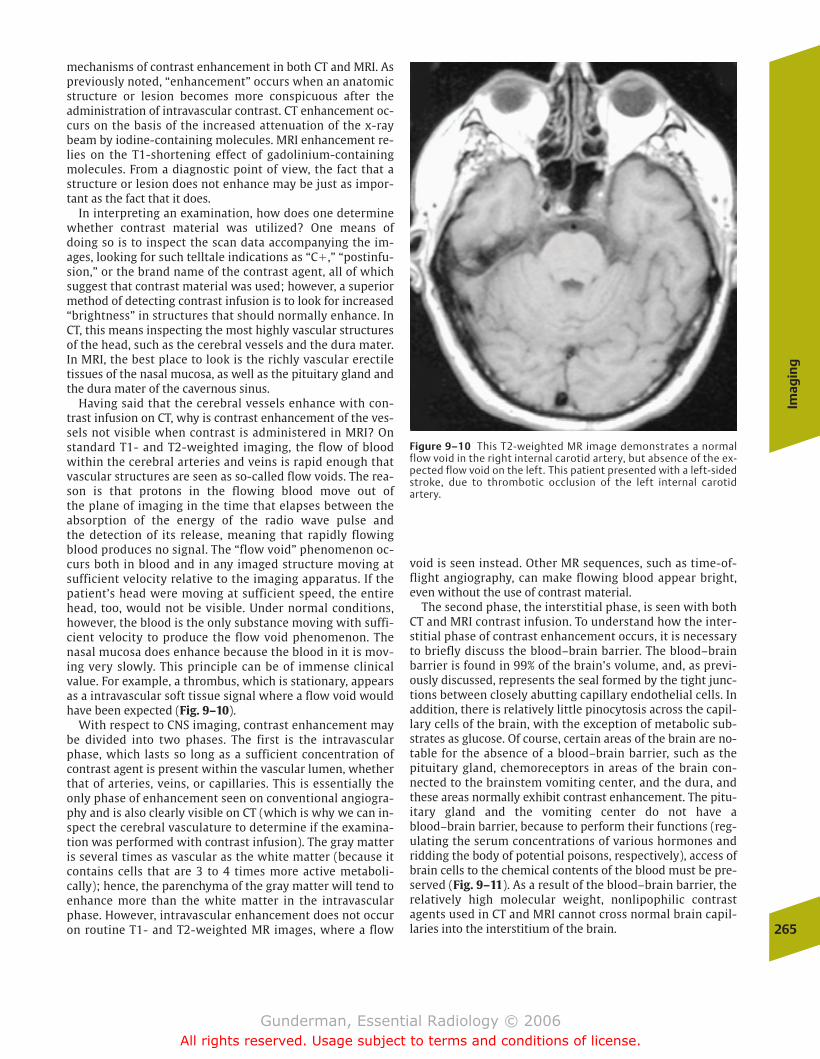
mechanisms of contrast enhancement in both CT and MRI. Aspreviously noted, “enhancement” occurs when an anatomicstructure or lesion becomes more conspicuous after theadministration of intravascular contrast. CT enhancement oc-curs on the basis of the increased attenuation of the x-raybeam by iodine-containing molecules. MRI enhancement re-lies on the T1-shortening effect of gadolinium-containingmolecules. From a diagnostic point of view, the fact that astructure or lesion does not enhance may be just as impor-tant as the fact that it does.
In interpreting an examination, how does one determinewhether contrast material was utilized? One means of doing so is to inspect the scan data accompanying the im-ages, looking for such telltale indications as “C�,” “postinfu-sion,” or the brand name of the contrast agent, all of whichsuggest that contrast material was used; however, a superiormethod of detecting contrast infusion is to look for increased“brightness” in structures that should normally enhance. InCT, this means inspecting the most highly vascular structuresof the head, such as the cerebral vessels and the dura mater.In MRI, the best place to look is the richly vascular erectiletissues of the nasal mucosa, as well as the pituitary gland andthe dura mater of the cavernous sinus.
Having said that the cerebral vessels enhance with con-trast infusion on CT, why is contrast enhancement of the ves-sels not visible when contrast is administered in MRI? Onstandard T1- and T2-weighted imaging, the flow of bloodwithin the cerebral arteries and veins is rapid enough thatvascular structures are seen as so-called flow voids. The rea-son is that protons in the flowing blood move out of the plane of imaging in the time that elapses between the absorption of the energy of the radio wave pulse and the detection of its release, meaning that rapidly flowingblood produces no signal. The “flow void” phenomenon oc-curs both in blood and in any imaged structure moving atsufficient velocity relative to the imaging apparatus. If thepatient’s head were moving at sufficient speed, the entirehead, too, would not be visible. Under normal conditions,however, the blood is the only substance moving with suffi-cient velocity to produce the flow void phenomenon. Thenasal mucosa does enhance because the blood in it is mov-ing very slowly. This principle can be of immense clinicalvalue. For example, a thrombus, which is stationary, appearsas a intravascular soft tissue signal where a flow void wouldhave been expected (Fig. 9–10).
With respect to CNS imaging, contrast enhancement maybe divided into two phases. The first is the intravascularphase, which lasts so long as a sufficient concentration ofcontrast agent is present within the vascular lumen, whetherthat of arteries, veins, or capillaries. This is essentially theonly phase of enhancement seen on conventional angiogra-phy and is also clearly visible on CT (which is why we can in-spect the cerebral vasculature to determine if the examina-tion was performed with contrast infusion). The gray matteris several times as vascular as the white matter (because itcontains cells that are 3 to 4 times more active metaboli-cally); hence, the parenchyma of the gray matter will tend toenhance more than the white matter in the intravascularphase. However, intravascular enhancement does not occuron routine T1- and T2-weighted MR images, where a flow
void is seen instead. Other MR sequences, such as time-of-flight angiography, can make flowing blood appear bright,even without the use of contrast material.
The second phase, the interstitial phase, is seen with bothCT and MRI contrast infusion. To understand how the inter-stitial phase of contrast enhancement occurs, it is necessaryto briefly discuss the blood–brain barrier. The blood–brainbarrier is found in 99% of the brain’s volume, and, as previ-ously discussed, represents the seal formed by the tight junc-tions between closely abutting capillary endothelial cells. Inaddition, there is relatively little pinocytosis across the capil-lary cells of the brain, with the exception of metabolic sub-strates as glucose. Of course, certain areas of the brain are no-table for the absence of a blood–brain barrier, such as thepituitary gland, chemoreceptors in areas of the brain con-nected to the brainstem vomiting center, and the dura, andthese areas normally exhibit contrast enhancement. The pitu-itary gland and the vomiting center do not have ablood–brain barrier, because to perform their functions (reg-ulating the serum concentrations of various hormones andridding the body of potential poisons, respectively), access ofbrain cells to the chemical contents of the blood must be pre-served (Fig. 9–11). As a result of the blood–brain barrier, therelatively high molecular weight, nonlipophilic contrastagents used in CT and MRI cannot cross normal brain capil-laries into the interstitium of the brain.
Imag
ing
265
Figure 9–10 This T2-weighted MR image demonstrates a normalflow void in the right internal carotid artery, but absence of the ex-pected flow void on the left. This patient presented with a left-sidedstroke, due to thrombotic occlusion of the left internal carotidartery.
chapter 09_p257-295.qxd 12/1/05 4:18 PM Page 265
Gunderman, Essential Radiology © 2006All rights reserved. Usage subject to terms and conditions of license.

If contrast agents cannot cross the blood–brain barrier, ofwhat use are they in diagnostic imaging? The answer is that,although they cannot cross the blood–brain barrier when it isintact, they can cross it when it is disrupted. Generally speak-ing, the blood–brain barrier is disrupted by acute inflamma-tion (as in demyelinating diseases such as multiple sclerosis,where chemical mediators increase capillary permeability),neoplasm (where the capillaries formed in conjunction withthe growing tumor possess an abnormal endothelium), infec-tion (which produces inflammation), and ischemia (whichdamages the endothelial cells of capillaries along with theparenchymal cells). In these cases, contrast leaks out of de-fective vessels into the interstitium, and the surroundingparenchyma demonstrates enhancement (Fig. 9–12).
Different pathologic processes tend to produce characteris-tic patterns of enhancement.
Search Pattern in MRI
To ensure that common and important abnormalities arenot missed, it is helpful to develop an ordered approach tothe brain. In MRI, images are usually obtained in sagittal,axial, and coronal dimensions. Beginning with the midlinesagittal view, examine the corpus callosum (the major con-nection between the two cerebral hemispheres, subject topartial or complete agenesis in several conditions), theaqueduct of Sylvius (connecting the third and fourth ven-tricles, and associated with hydrocephalus in aqueductal
266
9N
euro
imag
ing
Figure 9–11 This coronal T1-weighted MR image at the sellar regionwas obtained after gadolinium–pentetic acid (DTPA) infusion. It demon-strates a hypointense mass in the right lobe of the pituitary gland. This isa pituitary microadenoma. Why is it less intensely enhanced (darker)than the normal left lobe? Because the normal pituitary gland lacks ablood–brain barrier and enhances more intensely than the tumor.
Figure 9–12 (A) This 5-year-old boy presented with new-onset seizure,having complained for several days of headache and low-grade fever. Hisaxial T1-weighted MR image appears unremarkable. (B) After adminis-tration of IV contrast, however, multiple nodular areas of abnormal en-hancement are visible at gray-white matter junctions. The diagnosis is
miliary tuberculosis. Different pathologic processes tend to producecharacteristic patterns of enhancement. (Reprinted with permissionfrom Fischbein, Dillon, Barkovich, eds. Teaching Atlas of Brain Imaging.New York: Thieme, TK:165, figs. B,C.)
A B
chapter 09_p257-295.qxd 12/1/05 4:18 PM Page 266
Gunderman, Essential Radiology © 2006All rights reserved. Usage subject to terms and conditions of license.
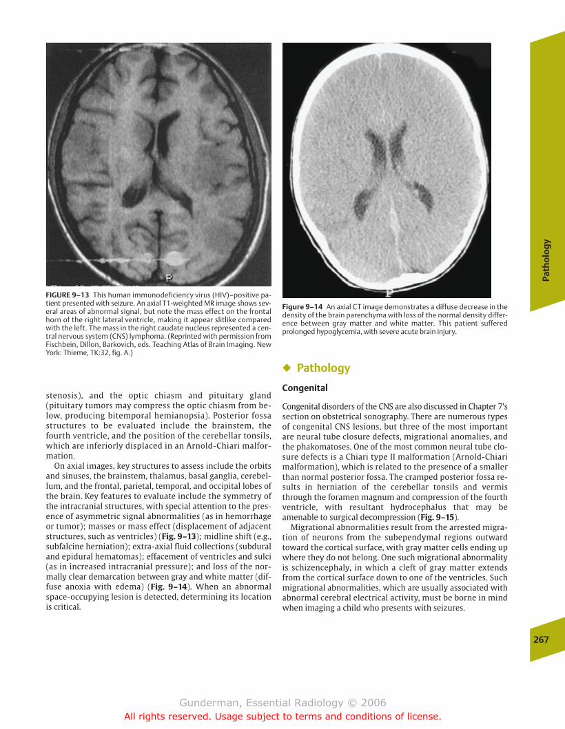
stenosis), and the optic chiasm and pituitary gland(pituitary tumors may compress the optic chiasm from be-low, producing bitemporal hemianopsia). Posterior fossastructures to be evaluated include the brainstem, thefourth ventricle, and the position of the cerebellar tonsils,which are inferiorly displaced in an Arnold-Chiari malfor-mation.
On axial images, key structures to assess include the orbitsand sinuses, the brainstem, thalamus, basal ganglia, cerebel-lum, and the frontal, parietal, temporal, and occipital lobes ofthe brain. Key features to evaluate include the symmetry ofthe intracranial structures, with special attention to the pres-ence of asymmetric signal abnormalities (as in hemorrhageor tumor); masses or mass effect (displacement of adjacentstructures, such as ventricles) (Fig. 9–13); midline shift (e.g.,subfalcine herniation); extra-axial fluid collections (subduraland epidural hematomas); effacement of ventricles and sulci(as in increased intracranial pressure); and loss of the nor-mally clear demarcation between gray and white matter (dif-fuse anoxia with edema) (Fig. 9–14). When an abnormalspace-occupying lesion is detected, determining its locationis critical.
� Pathology
Congenital
Congenital disorders of the CNS are also discussed in Chapter 7’ssection on obstetrical sonography. There are numerous typesof congenital CNS lesions, but three of the most importantare neural tube closure defects, migrational anomalies, andthe phakomatoses. One of the most common neural tube clo-sure defects is a Chiari type II malformation (Arnold-Chiarimalformation), which is related to the presence of a smallerthan normal posterior fossa. The cramped posterior fossa re-sults in herniation of the cerebellar tonsils and vermisthrough the foramen magnum and compression of the fourthventricle, with resultant hydrocephalus that may beamenable to surgical decompression (Fig. 9–15).
Migrational abnormalities result from the arrested migra-tion of neurons from the subependymal regions outwardtoward the cortical surface, with gray matter cells ending upwhere they do not belong. One such migrational abnormalityis schizencephaly, in which a cleft of gray matter extendsfrom the cortical surface down to one of the ventricles. Suchmigrational abnormalities, which are usually associated withabnormal cerebral electrical activity, must be borne in mindwhen imaging a child who presents with seizures.
Path
olo
gy
267
FIGURE 9–13 This human immunodeficiency virus (HIV)–positive pa-tient presented with seizure. An axial T1-weighted MR image shows sev-eral areas of abnormal signal, but note the mass effect on the frontalhorn of the right lateral ventricle, making it appear slitlike comparedwith the left. The mass in the right caudate nucleus represented a cen-tral nervous system (CNS) lymphoma. (Reprinted with permission fromFischbein, Dillon, Barkovich, eds. Teaching Atlas of Brain Imaging. NewYork: Thieme, TK:32, fig. A.)
Figure 9–14 An axial CT image demonstrates a diffuse decrease in thedensity of the brain parenchyma with loss of the normal density differ-ence between gray matter and white matter. This patient sufferedprolonged hypoglycemia, with severe acute brain injury.
chapter 09_p257-295.qxd 12/1/05 4:18 PM Page 267
Gunderman, Essential Radiology © 2006All rights reserved. Usage subject to terms and conditions of license.
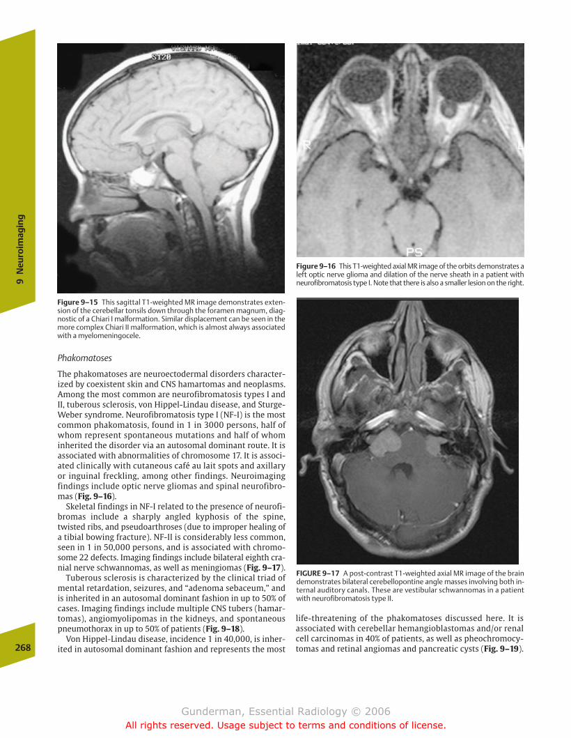
Phakomatoses
The phakomatoses are neuroectodermal disorders character-ized by coexistent skin and CNS hamartomas and neoplasms.Among the most common are neurofibromatosis types I andII, tuberous sclerosis, von Hippel-Lindau disease, and Sturge-Weber syndrome. Neurofibromatosis type I (NF-I) is the mostcommon phakomatosis, found in 1 in 3000 persons, half ofwhom represent spontaneous mutations and half of whominherited the disorder via an autosomal dominant route. It isassociated with abnormalities of chromosome 17. It is associ-ated clinically with cutaneous café au lait spots and axillaryor inguinal freckling, among other findings. Neuroimagingfindings include optic nerve gliomas and spinal neurofibro-mas (Fig. 9–16).
Skeletal findings in NF-I related to the presence of neurofi-bromas include a sharply angled kyphosis of the spine,twisted ribs, and pseudoarthroses (due to improper healing ofa tibial bowing fracture). NF-II is considerably less common,seen in 1 in 50,000 persons, and is associated with chromo-some 22 defects. Imaging findings include bilateral eighth cra-nial nerve schwannomas, as well as meningiomas (Fig. 9–17).
Tuberous sclerosis is characterized by the clinical triad ofmental retardation, seizures, and “adenoma sebaceum,” andis inherited in an autosomal dominant fashion in up to 50% ofcases. Imaging findings include multiple CNS tubers (hamar-tomas), angiomyolipomas in the kidneys, and spontaneouspneumothorax in up to 50% of patients (Fig. 9–18).
Von Hippel-Lindau disease, incidence 1 in 40,000, is inher-ited in autosomal dominant fashion and represents the most268
9N
euro
imag
ing
Figure 9–15 This sagittal T1-weighted MR image demonstrates exten-sion of the cerebellar tonsils down through the foramen magnum, diag-nostic of a Chiari I malformation. Similar displacement can be seen in themore complex Chiari II malformation, which is almost always associatedwith a myelomeningocele.
Figure 9–16 This T1-weighted axial MR image of the orbits demonstrates aleft optic nerve glioma and dilation of the nerve sheath in a patient withneurofibromatosis type I. Note that there is also a smaller lesion on the right.
FIGURE 9–17 A post-contrast T1-weighted axial MR image of the braindemonstrates bilateral cerebellopontine angle masses involving both in-ternal auditory canals. These are vestibular schwannomas in a patientwith neurofibromatosis type II.
life-threatening of the phakomatoses discussed here. It is associated with cerebellar hemangioblastomas and/or renalcell carcinomas in 40% of patients, as well as pheochromocy-tomas and retinal angiomas and pancreatic cysts (Fig. 9–19).
chapter 09_p257-295.qxd 12/1/05 4:18 PM Page 268
Gunderman, Essential Radiology © 2006All rights reserved. Usage subject to terms and conditions of license.
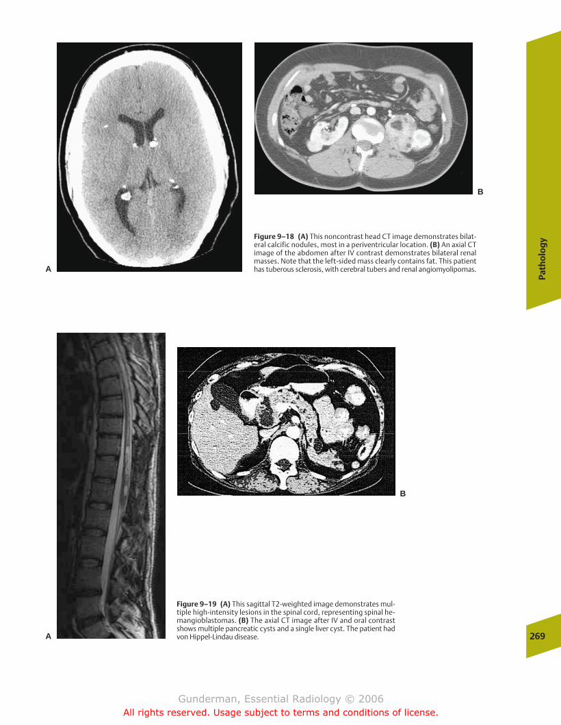
Path
olo
gy
269
Figure 9–18 (A) This noncontrast head CT image demonstrates bilat-eral calcific nodules, most in a periventricular location. (B) An axial CTimage of the abdomen after IV contrast demonstrates bilateral renalmasses. Note that the left-sided mass clearly contains fat. This patienthas tuberous sclerosis, with cerebral tubers and renal angiomyolipomas.A
B
Figure 9–19 (A) This sagittal T2-weighted image demonstrates mul-tiple high-intensity lesions in the spinal cord, representing spinal he-mangioblastomas. (B) The axial CT image after IV and oral contrastshows multiple pancreatic cysts and a single liver cyst. The patient hadvon Hippel-Lindau disease.A
B
chapter 09_p257-295.qxd 12/1/05 4:18 PM Page 269
Gunderman, Essential Radiology © 2006All rights reserved. Usage subject to terms and conditions of license.

Sturge-Weber syndrome involves ipsilateral capillary an-giomas of the face (port-wine nevus of the first division ofthe trigeminal nerve) and the cerebral hemisphere. Imagingfindings include a highly characteristic pattern of unilateralcurvilinear calcification that follows the convolutions of thebrain, better detected on CT than MRI (Fig. 9–20).
Inflammatory
Multiple Sclerosis
�� Epidemiology
Multiple sclerosis (MS) is a relatively common disorder, afflict-ing �350,000 Americans, two thirds of whom are women.Each year, �10,000 new cases are diagnosed, most frequentlyin patients between the ages of 20 and 40 years. Curiously, MSis virtually unknown in arctic and tropical climates, and ismost common in the temperate regions of Europe and theUnited States, although the risk profile of adults depends noton where they live now, but where they spend their first 15years. Unfortunately, a significant percentage of patients,approximately one third, eventually develop severe disability,including the loss of ambulation, and two thirds of patientseventually lose their jobs due to the disease; however, it is notassociated with a large increase in mortality, and the averagepatient lives with the disease for 40 years.
�� Pathophysiology
Multiple sclerosis belongs to a major class of neurologicdiseases, the demyelinating diseases. In contrast to the
dysmyelinating diseases, such as adrenoleukodystrophy, inwhich the myelin that is produced is abnormal, the demyeli-nating disorders are associated with the subsequent destruc-tion of initially normal myelin. Normally, the axons of theCNS are enveloped along their course by spiraled layers of themyelin sheath, which are produced by oligodendrogliocytes(while myelin in the peripheral nervous system is the prod-uct of Schwann’s cells). Myelin sheaths with interveningnodes of Ranvier permit saltatory conduction of axonal im-pulses, which renders conduction through myelinated fibers�50 times faster than that through nonmyelinated ones.Myelin also allows conservation of energy, by permittingsodium–potassium pump action to be largely restricted tothe nodes of Ranvier.
At least half of the weight of the white matter of the CNS ismade up of myelin, which helps to explain why demyelinatingdiseases are seen to affect predominantly the white matter. Inmultiple sclerosis, immune-mediated destruction of myelin oc-curs anywhere in the CNS, producing a protean array of symp-toms. The etiology of this attack is unknown, although geneticsappears to play a role, as monozygotic twins have an �25% rateof concordance. The disease is defined clinically as multiple CNSlesions separated in time and space; this correlates pathologi-cally with the presence of multiple separate sclerotic plaquesdemonstrating loss of oligodendrogliocytes and myelin, with anaccumulation of antibody-producing plasma cells.
�� Clinical Presentation
Symptoms are correlated with the function of the affectedwhite matter. Common sites of involvement include the opticnerves, the periventricular cerebral white matter, and thecervical spinal cord. Optic nerve lesions are associated withblurred vision and blindness. On physical examination, pa-tients demonstrate upper motor neuron signs such as hyper-reflexia, as well as other long-track signs such as a positiveBabinski’s sign. The clinical course is characterized by alter-nating periods of remission and relapse, which may or maynot eventuate in residual symptoms. Diagnostic tests otherthan imaging include examination of CSF for so-calledoligoclonal bands of immunoglobulin G (IgG), the use of elec-trophysiologic evoked potentials to measure the delayed con-duction velocities associated with demyelination, and bloodtests to rule out multiple sclerosis mimics.
�� Imaging
MRI has revolutionized the diagnosis of multiple sclerosis. Inclinically confirmed cases, MRI demonstrates lesions over 90%of the time, whereas CT is positive in the minority of cases, andevoked potentials and oligoclonal bands are positive in fewerthan 70%. The most sensitive images are heavily T2-weightedMR sequences, in which plaques typically appear as round oroval lesions of increased signal intensity, especially in theperiventricular and deep white matter regions (Fig. 9–21).
Often, lesions will be seen to radiate out perpendicularlyfrom the lateral ventricles. Such an appearance is not specificto multiple sclerosis, however, and can be seen in other de-myelinating disorders such as Lyme disease. As the diseaseprogresses, global cerebral atrophy, atrophy of the corpus cal-losum, and increased iron deposition are seen.270
9N
euro
imag
ing
Figure 9–20 An axial CT image demonstrates left-hemispheric atrophyand gyriform calcification in the posterior aspect of the left cerebralhemisphere in this patient with Sturge-Weber syndrome.
chapter 09_p257-295.qxd 12/1/05 4:18 PM Page 270
Gunderman, Essential Radiology © 2006All rights reserved. Usage subject to terms and conditions of license.
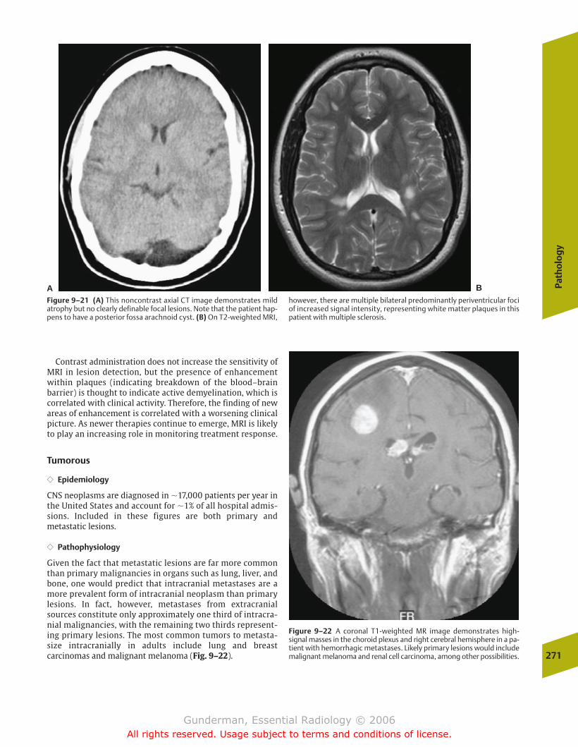
Contrast administration does not increase the sensitivity ofMRI in lesion detection, but the presence of enhancementwithin plaques (indicating breakdown of the blood–brainbarrier) is thought to indicate active demyelination, which iscorrelated with clinical activity. Therefore, the finding of newareas of enhancement is correlated with a worsening clinicalpicture. As newer therapies continue to emerge, MRI is likelyto play an increasing role in monitoring treatment response.
Tumorous
�� Epidemiology
CNS neoplasms are diagnosed in �17,000 patients per year inthe United States and account for �1% of all hospital admis-sions. Included in these figures are both primary andmetastatic lesions.
�� Pathophysiology
Given the fact that metastatic lesions are far more commonthan primary malignancies in organs such as lung, liver, andbone, one would predict that intracranial metastases are amore prevalent form of intracranial neoplasm than primarylesions. In fact, however, metastases from extracranialsources constitute only approximately one third of intracra-nial malignancies, with the remaining two thirds represent-ing primary lesions. The most common tumors to metasta-size intracranially in adults include lung and breastcarcinomas and malignant melanoma (Fig. 9–22).
Path
olo
gy
271
AFigure 9–21 (A) This noncontrast axial CT image demonstrates mild atrophy but no clearly definable focal lesions. Note that the patient hap-pens to have a posterior fossa arachnoid cyst. (B) On T2-weighted MRI,
however, there are multiple bilateral predominantly periventricular fociof increased signal intensity, representing white matter plaques in thispatient with multiple sclerosis.
B
Figure 9–22 A coronal T1-weighted MR image demonstrates high-signal masses in the choroid plexus and right cerebral hemisphere in a pa-tient with hemorrhagic metastases. Likely primary lesions would includemalignant melanoma and renal cell carcinoma, among other possibilities.
chapter 09_p257-295.qxd 12/1/05 4:18 PM Page 271
Gunderman, Essential Radiology © 2006All rights reserved. Usage subject to terms and conditions of license.
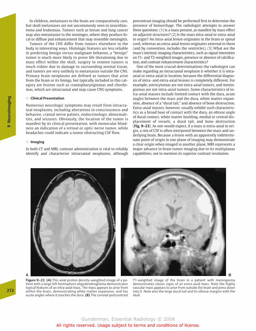
In children, metastases to the brain are comparatively rare,but skull metastases are not uncommonly seen in neuroblas-toma and leukemias. Tumors such as breast and lung cancermay also metastasize to the meninges, where they produce fo-cal or diffuse pial enhancement that may resemble meningitis.
Tumors of the CNS differ from tumors elsewhere in thebody in interesting ways. Histologic features are less reliablein predicting benign versus malignant behavior, a “benign”tumor is much more likely to prove life threatening due tomass effect within the skull, surgery to remove tumors ismuch riskier due to damage to surrounding normal tissue,and tumors are very unlikely to metastasize outside the CNS.Primary brain neoplasms are defined as tumors that arisefrom the brain or its linings, but typically included in this cat-egory are lesions such as craniopharyngiomas and chordo-mas, which are intracranial and may cause CNS symptoms.
�� Clinical Presentation
Numerous neurologic symptoms may result from intracra-nial neoplasms, including alterations in consciousness andbehavior, cranial nerve palsies, endocrinologic abnormali-ties, and seizures. Obviously, the location of the tumor ismanifest by its clinical presentation, with monocular blind-ness an indication of a retinal or optic nerve tumor, whileheadaches could indicate a tumor obstructing CSF flow.
�� Imaging
In both CT and MRI, contrast administration is vital to reliablyidentify and characterize intracranial neoplasms, although
precontrast imaging should be performed first to determine thepresence of hemorrhage. The radiologist attempts to answerthree questions: (1) Is a mass present, as manifest by mass effecton adjacent structures? (2) Is the mass intra-axial or extra-axialin origin? An intra-axial lesion originates in the brain or spinalcord, whereas an extra-axial lesion originates external to them(and by convention, includes the ventricles). (3) What are themass’s intrinsic imaging characteristics, such as signal intensitieson T1- and T2-weighted images, presence or absence of calcifica-tion, and contrast enhancement characteristics?
One of the most crucial determinations the radiologist canmake regarding an intracranial neoplasm is whether it is intra-axial or extra-axial in location, because the differential diagno-sis of intra- and extra-axial lesions is completely different. Forexample, astrocytomas are not extra-axial tumors, and menin-giomas are not intra-axial tumors. Some characteristics of in-tra-axial masses include limited contact with the dura, acuteangles between the mass and the dura, white matter expan-sion, absence of a “dural tail,” and absence of bone destruction.Extra-axial masses, however, usually exhibit such characteris-tics as a broad base of contact with the dura, an obtuse angleof dural contact, white matter buckling, medial or central dis-placement of vessels, a dural tail, and bone destruction (Fig. 9–23). As one would expect, if a mass is extra-axial in ori-gin, a rim of CSF is often interposed between the mass and un-derlying brain. Because a lesion with an apparently indetermi-nate point of origin in one plane of imaging may demonstratea clear origin when imaged in another plane, MRI represents amajor advance in brain tumor imaging due to its multiplanarcapabilities, not to mention its superior contrast resolution.
272
9N
euro
imag
ing
A BFigure 9–23 (A) This axial proton density-weighted image of a pa-tient with a large left hemisphere oligodendroglioma demonstratestypical features of an intra-axial mass. The mass appears to arise fromwithin the brain, demonstrating white matter expansion, and hasacute angles where it touches the dura. (B) The coronal postcontrast
T1-weighted image of the brain in a patient with meningiomademonstrates classic signs of an extra-axial mass. Note the highlyvascular mass appears to arise from outside the brain and press downinto it. Note also the large dural tail and its obtuse margins with theskull.
chapter 09_p257-295.qxd 12/1/05 4:18 PM Page 272
Gunderman, Essential Radiology © 2006All rights reserved. Usage subject to terms and conditions of license.
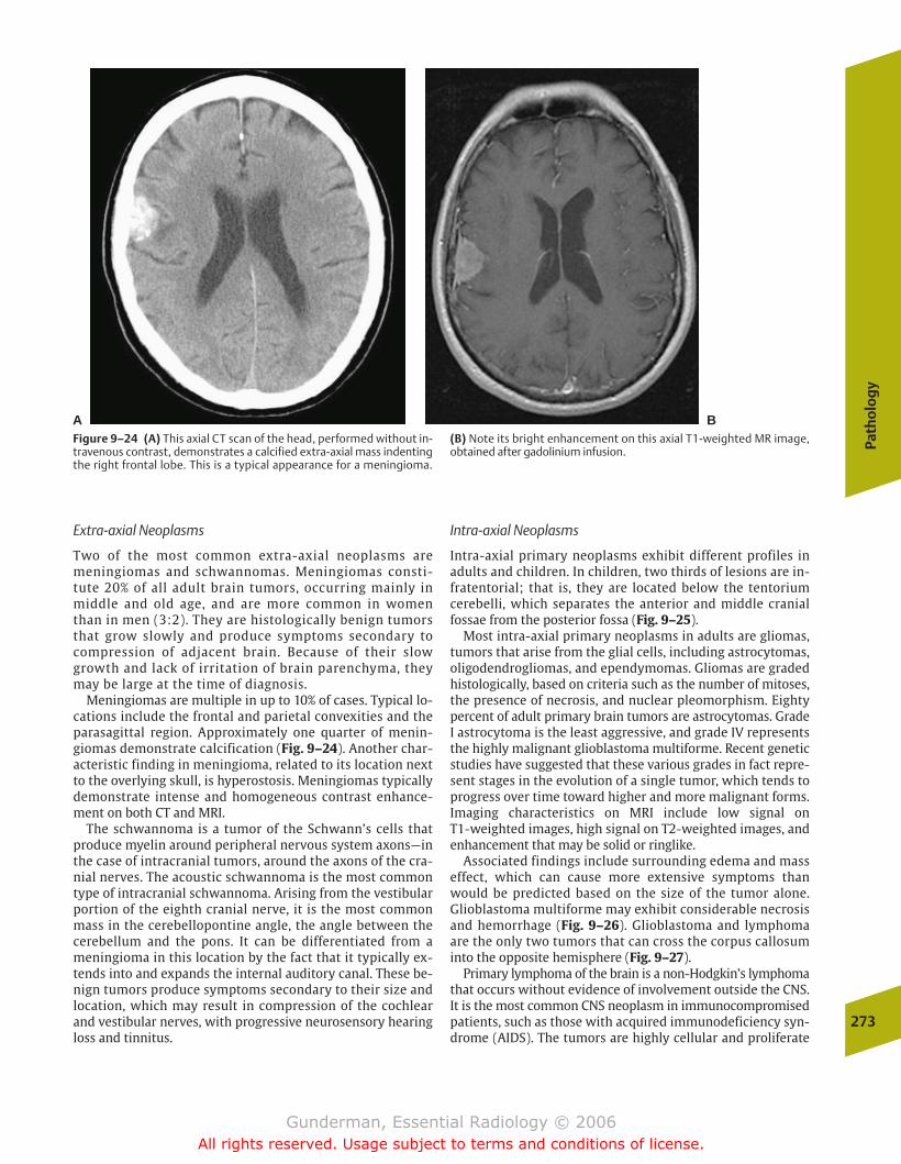
Extra-axial Neoplasms
Two of the most common extra-axial neoplasms aremeningiomas and schwannomas. Meningiomas consti-tute 20% of all adult brain tumors, occurring mainly inmiddle and old age, and are more common in womenthan in men (3:2). They are histologically benign tumorsthat grow slowly and produce symptoms secondary tocompression of adjacent brain. Because of their slowgrowth and lack of irritation of brain parenchyma, theymay be large at the time of diagnosis.
Meningiomas are multiple in up to 10% of cases. Typical lo-cations include the frontal and parietal convexities and theparasagittal region. Approximately one quarter of menin-giomas demonstrate calcification (Fig. 9–24). Another char-acteristic finding in meningioma, related to its location nextto the overlying skull, is hyperostosis. Meningiomas typicallydemonstrate intense and homogeneous contrast enhance-ment on both CT and MRI.
The schwannoma is a tumor of the Schwann’s cells thatproduce myelin around peripheral nervous system axons—inthe case of intracranial tumors, around the axons of the cra-nial nerves. The acoustic schwannoma is the most commontype of intracranial schwannoma. Arising from the vestibularportion of the eighth cranial nerve, it is the most commonmass in the cerebellopontine angle, the angle between thecerebellum and the pons. It can be differentiated from ameningioma in this location by the fact that it typically ex-tends into and expands the internal auditory canal. These be-nign tumors produce symptoms secondary to their size andlocation, which may result in compression of the cochlearand vestibular nerves, with progressive neurosensory hearingloss and tinnitus.
Intra-axial Neoplasms
Intra-axial primary neoplasms exhibit different profiles inadults and children. In children, two thirds of lesions are in-fratentorial; that is, they are located below the tentoriumcerebelli, which separates the anterior and middle cranialfossae from the posterior fossa (Fig. 9–25).
Most intra-axial primary neoplasms in adults are gliomas,tumors that arise from the glial cells, including astrocytomas,oligodendrogliomas, and ependymomas. Gliomas are gradedhistologically, based on criteria such as the number of mitoses,the presence of necrosis, and nuclear pleomorphism. Eightypercent of adult primary brain tumors are astrocytomas. GradeI astrocytoma is the least aggressive, and grade IV representsthe highly malignant glioblastoma multiforme. Recent geneticstudies have suggested that these various grades in fact repre-sent stages in the evolution of a single tumor, which tends toprogress over time toward higher and more malignant forms.Imaging characteristics on MRI include low signal on T1-weighted images, high signal on T2-weighted images, andenhancement that may be solid or ringlike.
Associated findings include surrounding edema and masseffect, which can cause more extensive symptoms thanwould be predicted based on the size of the tumor alone.Glioblastoma multiforme may exhibit considerable necrosisand hemorrhage (Fig. 9–26). Glioblastoma and lymphomaare the only two tumors that can cross the corpus callosuminto the opposite hemisphere (Fig. 9–27).
Primary lymphoma of the brain is a non-Hodgkin’s lymphomathat occurs without evidence of involvement outside the CNS.It is the most common CNS neoplasm in immunocompromisedpatients, such as those with acquired immunodeficiency syn-drome (AIDS). The tumors are highly cellular and proliferate
Path
olo
gy
273
A BFigure 9–24 (A) This axial CT scan of the head, performed without in-travenous contrast, demonstrates a calcified extra-axial mass indentingthe right frontal lobe. This is a typical appearance for a meningioma.
(B) Note its bright enhancement on this axial T1-weighted MR image,obtained after gadolinium infusion.
chapter 09_p257-295.qxd 12/1/05 4:18 PM Page 273
Gunderman, Essential Radiology © 2006All rights reserved. Usage subject to terms and conditions of license.
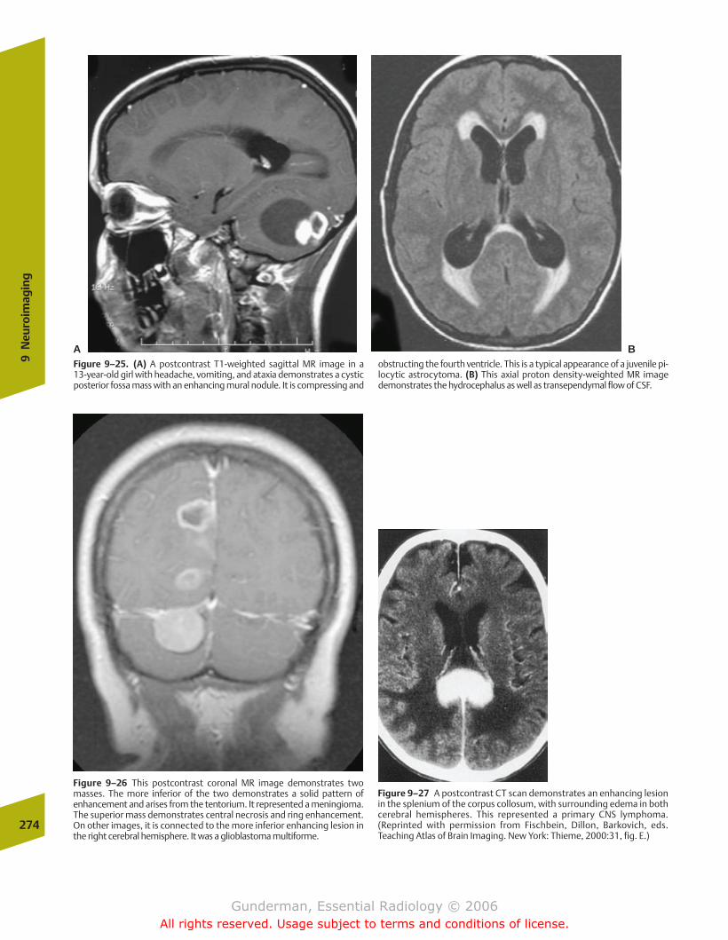
274
9N
euro
imag
ing
A BFigure 9–25. (A) A postcontrast T1-weighted sagittal MR image in a 13-year-old girl with headache, vomiting, and ataxia demonstrates a cysticposterior fossa mass with an enhancing mural nodule. It is compressing and
obstructing the fourth ventricle. This is a typical appearance of a juvenile pi-locytic astrocytoma. (B) This axial proton density-weighted MR imagedemonstrates the hydrocephalus as well as transependymal flow of CSF.
Figure 9–26 This postcontrast coronal MR image demonstrates twomasses. The more inferior of the two demonstrates a solid pattern ofenhancement and arises from the tentorium. It represented a meningioma.The superior mass demonstrates central necrosis and ring enhancement.On other images, it is connected to the more inferior enhancing lesion inthe right cerebral hemisphere. It was a glioblastoma multiforme.
Figure 9–27 A postcontrast CT scan demonstrates an enhancing lesionin the splenium of the corpus collosum, with surrounding edema in bothcerebral hemispheres. This represented a primary CNS lymphoma.(Reprinted with permission from Fischbein, Dillon, Barkovich, eds.Teaching Atlas of Brain Imaging. New York: Thieme, 2000:31, fig. E.)
chapter 09_p257-295.qxd 12/1/05 4:18 PM Page 274
Gunderman, Essential Radiology © 2006All rights reserved. Usage subject to terms and conditions of license.
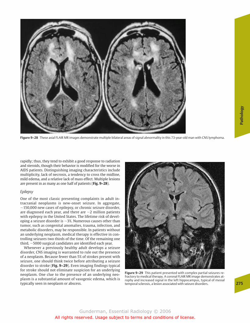
Path
olo
gy
275
rapidly; thus, they tend to exhibit a good response to radiationand steroids, though their behavior is modified for the worse inAIDS patients. Distinguishing imaging characteristics includemultiplicity, lack of necrosis, a tendency to cross the midline,mild edema, and a relative lack of mass effect. Multiple lesionsare present in as many as one half of patients (Fig. 9–28).
Epilepsy
One of the most classic presenting complaints in adult in-tracranial neoplasms is new-onset seizure. In aggregate,�150,000 new cases of epilepsy, or chronic seizure disorder,are diagnosed each year, and there are �2 million patientswith epilepsy in the United States. The lifetime risk of devel-oping a seizure disorder is �3%. Numerous causes other thantumor, such as congenital anomalies, trauma, infection, andmetabolic disorders, may be responsible. In patients withoutan underlying neoplasm, medical therapy is effective in con-trolling seizures two thirds of the time. Of the remaining onethird, �5000 surgical candidates are identified each year.
Whenever a previously healthy adult develops a seizuredisorder, CNS imaging is warranted to rule out the presenceof a neoplasm. Because fewer than 5% of strokes present withseizure, one should think twice before attributing a seizuredisorder to stroke (Fig. 9–29). Even imaging findings typicalfor stroke should not eliminate suspicion for an underlyingneoplasm. One clue to the presence of an underlying neo-plasm is a substantial amount of vasogenic edema, which istypically seen in neoplasm or abscess.
Figure 9–28 These axial FLAIR MR images demonstrate multiple bilateral areas of signal abnormality in this 73-year-old man with CNS lymphoma.
Figure 9–29 This patient presented with complex partial seizures re-fractory to medical therapy. A coronal FLAIR MR image demonstrates at-rophy and increased signal in the left hippocampus, typical of mesialtemporal sclerosis, a lesion associated with seizure disorders.
chapter 09_p257-295.qxd 12/1/05 4:18 PM Page 275
Gunderman, Essential Radiology © 2006All rights reserved. Usage subject to terms and conditions of license.
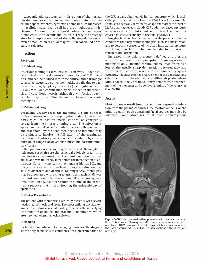
Vasogenic edema occurs with disruption of the normalblood–brain barrier, with movement of water into the inter-cellular space, whereas cytotoxic edema implies increasedintracellular water due to cell injury, as might occur in is-chemia. Although the surgical objective in many tumor cases is to debulk the lesion, surgery for epilepsyaims for complete removal of the epileptogenic lesion, aseven a small lesion residual may result in continued or re-current seizures.
Infectious
Meningitis
�� Epidemiology
Infectious meningitis accounts for �1 in every 1000 hospi-tal admissions. It is the most common form of CNS infec-tion, and can be divided into three clinical and pathologiccategories: acute superative meningitis, usually due to bac-terial infection; lymphocytic (aseptic) meningitis, which isusually viral; and chronic meningitis, as seen in tuberculo-sis and coccidiodomycosis, although any infectious agentcan be responsible. This discussion focuses on acute meningitis.
�� Pathophysiology
Organisms usually reach the meninges via one of threeroutes: hematogenously in septic patients, direct invasion inpostsurgical or post-traumatic settings, or contiguousspread from the sinuses or middle ear. The infection isspread via the CSF, which circulates between the pia materand arachnoid layers of the meninges. The infection maydisseminate to involve the full extent of the meningealmembranes. Hydrocephalus may be precipitated by a com-bination of congestion of venous sinuses and postinflamma-tory fibrosis.
The pneumococcus, meningococcus, and Haemophilus influenzae (or H. flu) are the principal etiologic organisms.Pneumococcal meningitis is the most common form inadults and was uniformly fatal before the introduction of an-tibiotics. Currently, mortality may range as high as 30%, andmany survivors are left with neurologic residua such asseizure disorders and deafness. Meningococcal meningitismay be associated with a characteristic skin rash. H. flu wasthe most common in children, although this is changing withimmunization against more common strains of the organ-ism, a practice that is also affecting the epidemiology ofepiglottitis.
�� Clinical Presentation
The patient with meningitis classically presents with severeheadache, stiff neck, and fever. The most striking physical ex-amination finding is nuchal rigidity, reflecting the underlyinginflammation of the pia and arachnoid membranes, whichare stretched when the neck is flexed.
�� Imaging
Bacterial meningitis is not an imaging diagnosis. The diagno-sis can only be made with confidence through examination of
the CSF, usually obtained via lumbar puncture, which is typi-cally performed at or below the L2–L3 level, because thespinal cord typically terminates at approximately the level ofL1. A spinal tap reveals cloudy CSF under increased pressure,an increased neutrophil count and protein level, and de-creased glucose, secondary to bacterial glycolysis.
Imaging is often obtained to rule out the presence of otherconditions that may mimic meningitis, such as a mass lesion,and to detect the presence of increased intracranial pressure,which might preclude lumbar puncture due to the danger oftranstentorial herniation.
Increased intracranial pressure is defined as a pressureabove 200 mm water in a supine patient. Signs suggestive ofmeningitis on CT include cerebral edema, manifested as aloss of the usually sharp demarcation between gray andwhite matter, and the presence of communicating hydro-cephalus, which appears as enlargement of the ventricles andeffacement of the basilar cisterns. Although post-contrast MRI is not routinely obtained, it may demonstrate enhance-ment of the meninges and ependymal lining of the ventricles(Fig. 9–30).
Abscess
Most abscesses result from the contiguous spread of infec-tion from the paranasal sinuses, the mastoid air cells, or themiddle ear, although dental and facial sources may also beinvolved. Some abscesses result from hematogenous
276
9N
euro
imag
ing
Figure 9–30 This 3-year-old patient presented with fever and obtunda-tion. This coronal T1-weighted MR image after administration ofgadolinium-DTPA demonstrates thickening and intense enhancement ofthe basal cisterns and sylvian fissures in this patient with tuberculousmeningitis.
chapter 09_p257-295.qxd 12/1/05 4:18 PM Page 276
Gunderman, Essential Radiology © 2006All rights reserved. Usage subject to terms and conditions of license.
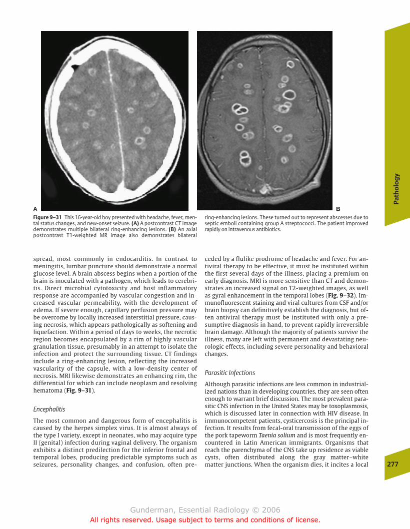
spread, most commonly in endocarditis. In contrast tomeningitis, lumbar puncture should demonstrate a normalglucose level. A brain abscess begins when a portion of thebrain is inoculated with a pathogen, which leads to cerebri-tis. Direct microbial cytotoxicity and host inflammatory response are accompanied by vascular congestion and in-creased vascular permeability, with the development ofedema. If severe enough, capillary perfusion pressure maybe overcome by locally increased interstitial pressure, caus-ing necrosis, which appears pathologically as softening andliquefaction. Within a period of days to weeks, the necroticregion becomes encapsulated by a rim of highly vasculargranulation tissue, presumably in an attempt to isolate theinfection and protect the surrounding tissue. CT findingsinclude a ring-enhancing lesion, reflecting the increasedvascularity of the capsule, with a low-density center ofnecrosis. MRI likewise demonstrates an enhancing rim, thedifferential for which can include neoplasm and resolvinghematoma (Fig. 9–31).
Encephalitis
The most common and dangerous form of encephalitis iscaused by the herpes simplex virus. It is almost always ofthe type I variety, except in neonates, who may acquire typeII (genital) infection during vaginal delivery. The organismexhibits a distinct predilection for the inferior frontal andtemporal lobes, producing predictable symptoms such asseizures, personality changes, and confusion, often pre-
ceded by a flulike prodrome of headache and fever. For an-tiviral therapy to be effective, it must be instituted withinthe first several days of the illness, placing a premium onearly diagnosis. MRI is more sensitive than CT and demon-strates an increased signal on T2-weighted images, as wellas gyral enhancement in the temporal lobes (Fig. 9–32). Im-munofluorescent staining and viral cultures from CSF and/orbrain biopsy can definitively establish the diagnosis, but of-ten antiviral therapy must be instituted with only a pre-sumptive diagnosis in hand, to prevent rapidly irreversiblebrain damage. Although the majority of patients survive theillness, many are left with permanent and devastating neu-rologic effects, including severe personality and behavioralchanges.
Parasitic Infections
Although parasitic infections are less common in industrial-ized nations than in developing countries, they are seen oftenenough to warrant brief discussion. The most prevalent para-sitic CNS infection in the United States may be toxoplasmosis,which is discussed later in connection with HIV disease. Inimmunocompetent patients, cysticercosis is the principal in-fection. It results from fecal-oral transmission of the eggs ofthe pork tapeworm Taenia solium and is most frequently en-countered in Latin American immigrants. Organisms thatreach the parenchyma of the CNS take up residence as viablecysts, often distributed along the gray matter–white matter junctions. When the organism dies, it incites a local
Path
olo
gy
277
A BFigure 9–31 This 16-year-old boy presented with headache, fever, men-tal status changes, and new-onset seizure. (A) A postcontrast CT imagedemonstrates multiple bilateral ring-enhancing lesions. (B) An axialpostcontrast T1-weighted MR image also demonstrates bilateral
ring-enhancing lesions. These turned out to represent abscesses due toseptic emboli containing group A streptococci. The patient improvedrapidly on intravenous antibiotics.
chapter 09_p257-295.qxd 12/1/05 4:18 PM Page 277
Gunderman, Essential Radiology © 2006All rights reserved. Usage subject to terms and conditions of license.
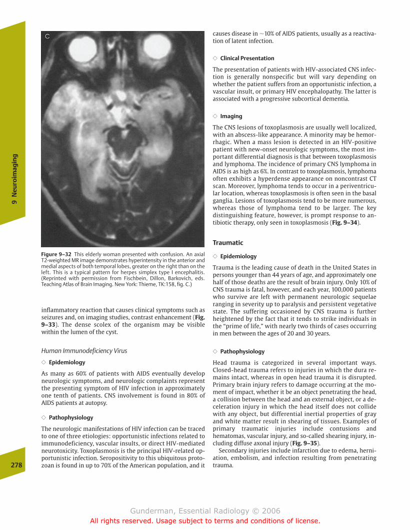
inflammatory reaction that causes clinical symptoms such asseizures and, on imaging studies, contrast enhancement (Fig.9–33). The dense scolex of the organism may be visiblewithin the lumen of the cyst.
Human Immunodeficiency Virus
�� Epidemiology
As many as 60% of patients with AIDS eventually developneurologic symptoms, and neurologic complaints representthe presenting symptom of HIV infection in approximatelyone tenth of patients. CNS involvement is found in 80% ofAIDS patients at autopsy.
�� Pathophysiology
The neurologic manifestations of HIV infection can be tracedto one of three etiologies: opportunistic infections related toimmunodeficiency, vascular insults, or direct HIV-mediatedneurotoxicity. Toxoplasmosis is the principal HIV-related op-portunistic infection. Seropositivity to this ubiquitous proto-zoan is found in up to 70% of the American population, and it
causes disease in �10% of AIDS patients, usually as a reactiva-tion of latent infection.
�� Clinical Presentation
The presentation of patients with HIV-associated CNS infec-tion is generally nonspecific but will vary depending onwhether the patient suffers from an opportunistic infection, avascular insult, or primary HIV encephalopathy. The latter isassociated with a progressive subcortical dementia.
�� Imaging
The CNS lesions of toxoplasmosis are usually well localized,with an abscess-like appearance. A minority may be hemor-rhagic. When a mass lesion is detected in an HIV-positivepatient with new-onset neurologic symptoms, the most im-portant differential diagnosis is that between toxoplasmosisand lymphoma. The incidence of primary CNS lymphoma inAIDS is as high as 6%. In contrast to toxoplasmosis, lymphomaoften exhibits a hyperdense appearance on noncontrast CTscan. Moreover, lymphoma tends to occur in a periventricu-lar location, whereas toxoplasmosis is often seen in the basalganglia. Lesions of toxoplasmosis tend to be more numerous,whereas those of lymphoma tend to be larger. The keydistinguishing feature, however, is prompt response to an-tibiotic therapy, only seen in toxoplasmosis (Fig. 9–34).
Traumatic
�� Epidemiology
Trauma is the leading cause of death in the United States inpersons younger than 44 years of age, and approximately onehalf of those deaths are the result of brain injury. Only 10% ofCNS trauma is fatal, however, and each year, 100,000 patientswho survive are left with permanent neurologic sequelaeranging in severity up to paralysis and persistent vegetativestate. The suffering occasioned by CNS trauma is furtherheightened by the fact that it tends to strike individuals inthe “prime of life,” with nearly two thirds of cases occurringin men between the ages of 20 and 30 years.
�� Pathophysiology
Head trauma is categorized in several important ways.Closed-head trauma refers to injuries in which the dura re-mains intact, whereas in open head trauma it is disrupted.Primary brain injury refers to damage occurring at the mo-ment of impact, whether it be an object penetrating the head,a collision between the head and an external object, or a de-celeration injury in which the head itself does not collidewith any object, but differential inertial properties of grayand white matter result in shearing of tissues. Examples ofprimary traumatic injuries include contusions andhematomas, vascular injury, and so-called shearing injury, in-cluding diffuse axonal injury (Fig. 9–35).
Secondary injuries include infarction due to edema, herni-ation, embolism, and infection resulting from penetratingtrauma.278
9N
euro
imag
ing
Figure 9–32 This elderly woman presented with confusion. An axial T2-weighted MR image demonstrates hyperintensity in the anterior andmedial aspects of both temporal lobes, greater on the right than on theleft. This is a typical pattern for herpes simplex type I encephalitis.(Reprinted with permission from Fischbein, Dillon, Barkovich, eds.Teaching Atlas of Brain Imaging. New York: Thieme, TK:158, fig. C.)
chapter 09_p257-295.qxd 12/1/05 4:18 PM Page 278
Gunderman, Essential Radiology © 2006All rights reserved. Usage subject to terms and conditions of license.
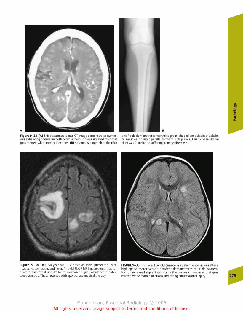
Path
olo
gy
279
A BFigure 9–33 (A) This postcontrast axial CT image demonstrates numer-ous enhancing nodules in both cerebral hemispheres situated mainly atgray matter–white matter junctions. (B) A frontal radiograph of the tibia
and fibula demonstrates many rice grain–shaped densities in the skele-tal muscles, oriented parallel to the muscle planes. This 57-year-old pa-tient was found to be suffering from cysticercosis.
Figure 9–34 This 54-year-old HIV-positive man presented withheadache, confusion, and fever. An axial FLAIR MR image demonstratesbilateral somewhat ringlike foci of increased signal, which representedtoxoplasmosis. These resolved with appropriate medical therapy.
FIGURE 9–35 This axial FLAIR MR image in a patient unconscious after ahigh-speed motor vehicle accident demonstrates multiple bilateral foci of increased signal intensity in the corpus collosum and at gray matter–white matter junctions, indicating diffuse axonal injury.
chapter 09_p257-295.qxd 12/1/05 4:18 PM Page 279
Gunderman, Essential Radiology © 2006All rights reserved. Usage subject to terms and conditions of license.
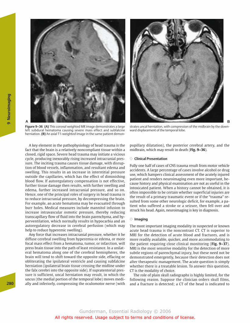
A key element in the pathophysiology of head trauma is thefact that the brain is a relatively noncompliant tissue within aclosed, rigid space. Severe head trauma may initiate a viciouscycle, producing inexorably rising increased intracranial pres-sure. The inciting trauma causes tissue damage, with disrup-tion of blood vessels, inflammation, and resultant edema andswelling. This results in an increase in interstitial pressureoutside the capillaries, which has the effect of diminishingblood flow. If autoregulatory compensation is not effective,further tissue damage then results, with further swelling andedema, further increased intracranial pressure, and so on.Hence, one of the principal roles of surgery in head trauma isto reduce intracranial pressure, by decompressing the brain.For example, an acute hematoma may be evacuated throughburr holes. Medical measures include mannitol infusion toincrease intravascular osmotic pressure, thereby reducingtranscapillary flow of fluid into the brain parenchyma, and hy-perventilation, which normally results in hypocarbia and anautoregulatory decrease in cerebral perfusion (which mayhelp to reduce hyperemic swelling).
Any force that increases intracranial pressure, whether it bediffuse cerebral swelling from hyperemia or edema, or morefocal mass effect from a hematoma, tumor, or infarction, willpress brain tissue into the path of least resistance. In a unilat-eral hematoma along one of the cerebral hemispheres, thebrain will tend to shift toward the opposite side, effacing orobliterating the ipsilateral ventricle and causing subfalcineherniation (ipsilateral brain tissue crossing the midline underthe falx cerebri into the opposite side). If supratentorial pres-sure is sufficient, uncal herniation may result, in which theuncus (the medial portion of the temporal lobe) moves medi-ally and inferiorly, compressing the oculomotor nerve (with
pupillary dilatation), the posterior cerebral artery, and themidbrain, which may result in death (Fig. 9–36).
�� Clinical Presentation
Fully one half of cases of CNS trauma result from motor vehicleaccidents. A large percentage of cases involve alcohol or druguse, which hampers clinical assessment of the acutely injuredpatient and renders neuroimaging even more important, be-cause history and physical examination are not as useful in theintoxicated patient. When a history cannot be obtained, it isoften impossible to be certain whether superficial injuries arethe result of a primary traumatic event or if the “trauma” re-sulted from some other neurologic deficit, for example, a pa-tient who suffered a stroke or a seizure, then fell over andstruck his head. Again, neuroimaging is key in diagnosis.
�� Imaging
The most important imaging modality in suspected or knownacute head trauma is the noncontrast CT. CT is superior toMRI for the detection of acute blood and fractures, and ismore readily available, quicker, and more accommodating tothe patient requiring close clinical monitoring (Fig. 9–37).MRI is the most sensitive modality for the detection of moresubtle regions of parenchymal injury, but these need not bedemonstrated emergently, because their detection does notalter therapeutic management. The acute question is simplywhether there is a treatable lesion. To answer this question,CT is the modality of choice.
The role of plain skull radiographs is highly limited, for thefollowing reason. Suppose the clinician orders skull films,and a fracture is detected; a CT of the head is indicated to280
9N
euro
imag
ing
Figure 9–36 (A) This coronal weighted MR image demonstrates a largeleft subdural hematoma causing severe mass effect and subfalcineherniation. (B) An axial T1-weighted image in the same patient demon-
strates uncal herniation, with compression of the midbrain by the down-ward displacement of the temporal lobe.
A B
chapter 09_p257-295.qxd 12/1/05 4:18 PM Page 280
Gunderman, Essential Radiology © 2006All rights reserved. Usage subject to terms and conditions of license.
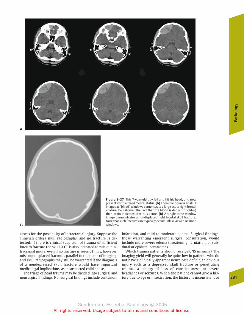
assess for the possibility of intracranial injury. Suppose theclinician orders skull radiographs, and no fracture is de-tected; if there is clinical suspicion of trauma of sufficientforce to fracture the skull, a CT is also indicated to rule out in-tracranial injury, even if no fracture is seen. CT may, however,miss nondisplaced fractures parallel to the plane of imaging,and skull radiographs may still be warranted if the diagnosisof a nondepressed skull fracture would have importantmedicolegal implications, as in suspected child abuse.
The triage of head trauma may be divided into surgical andnonsurgical findings. Nonsurgical findings include contusion,
infarction, and mild to moderate edema. Surgical findings,those warranting emergent surgical consultation, wouldinclude more severe edema threatening herniation, or sub-dural or epidural hematomas.
Which trauma patients should receive CNS imaging? Theimaging yield will generally be quite low in patients who donot have a clinically apparent neurologic deficit, an obviousinjury such as a depressed skull fracture or penetratingtrauma, a history of loss of consciousness, or severeheadaches or seizures. When the patient cannot give a his-tory due to age or intoxication, the history is inconsistent or
Path
olo
gy
281
Figure 9–37 This 7-year-old boy fell and hit his head, and nowpresents with altered mental status. (A) These contiguous axial CTimages at “blood” windows demonstrate a large acute right frontalepidural hematoma. The fact that the blood is denser (brighter)than brain indicates that it is acute. (B) A single bone-windowimage demonstrates a nondisplaced right frontal skull fracture.Note that such fractures are typically occult unless viewed on bonewindows.
A
B
chapter 09_p257-295.qxd 12/1/05 4:18 PM Page 281
Gunderman, Essential Radiology © 2006All rights reserved. Usage subject to terms and conditions of license.

unreliable, or physical examination is deemed unreliable dueto factors such as intoxication, seizure, or associated injuries,most clinicians will choose to scan the patient; however, be-fore radiological evaluation takes place, the patient must bestabilized, and at least a single lateral view of the cervicalspine should be obtained to rule out spinal instability or in-jury to the cord. The cervical spine may be further evaluatedby CT at the same time the head is scanned. Following is abrief discussion of some of the most frequent and importantimaging findings in acute head trauma.
Subdural Hematoma
Young patients typically develop subdural (below the dura)hematomas secondary to motor vehicle accidents, whereasthose in older patients typically result from falls. The mortal-ity rate associated with these injuries is high, at least 50%,and only one fifth of those who survive can expect to recoverfully. Subdural hematomas may result from closed or openinjury, with tearing of bridging veins and bleeding into thepotential space between the dura mater and pia arachnoidmembranes. Because this space is interrupted by the falxcerebri, these hematomas do not cross the midline, but theywill cross sutures, to which only the overlying dura is adher-ent. Because they are not bounded by sutures, they tend tospread out over the underlying hemisphere, giving them anelongated, crescentic shape (Fig. 9–38).
Because acutely extravasated blood is usually high attenua-tion (bright) on CT, acute subdural hemorrhages are generallyeasily detected; however, some subdural hematomas may beisodense, and a careful search must be made for midlineshift, ventricular distortion, and sulci that do not extend allthe way to the apparent brain surface. What could make anacute subdural hematoma isodense? The density of acutelyextravasated blood is related to the concentration of redblood cells. Hence, erythrocyte-poor blood (as in anemia) ordilution of blood (as with CSF if the arachnoid membrane istorn) may render the hematoma isodense.
Epidural Hematoma
Approximately 90% of epidural (above the dura) hematomasresult from temporal bone fracture, with tearing of the mid-dle meningeal artery or veins. The resultant blood collectionstrips the dural membranes from the inner table of the skull;hence the name epidural. As in subdural hematoma, patientsmay exhibit a so-called lucid interval after the injury beforedeteriorating, during which time intracranial pressure hasnot yet increased sufficiently to impair consciousness. Pa-tients are usually younger than those suffering subduralhematomas, and because many of these bleeds are self-lim-ited and the patients have a greater neurologic resiliency, theprognosis is not as poor. These hematomas cannot cross su-tures (unless there is diastasis or “opening up” of the suturesecondary to fracture), and for this reason the blood is moretightly contained and tends to assume a “biconvex” or “lens”shape, meaning that, in contrast to the subdural hematoma,the collection bulges inward toward the brain (Fig. 9–39).
Intracerebral Contusions and Hematomas
Both contusions and hematomas result from regions ofparenchymal hemorrhage, with accumulation of blood. Theterm hematoma is used to describe a well-defined, homoge-neous density collection of blood; contusion refers to a lesionof mixed density with less clearly defined margins. These le-sions are most often found in the anterior frontal and tempo-ral lobes, where the brain is accelerated against bone in afrontal impact (Fig. 9–40).
A clue to the presence of both is extracranial swelling, whichindicates the site of impact. When the hemorrhage is on thesame side of the brain as the impact, the lesion is called a coup(French for “blow”) injury, whereas when it is opposite the impact, it is called a contrecoup (“opposite the blow”) injury. With time, these lesions become isodense and thenhypodense, and are eventually replaced by an area ofencephalomalacia.
Diffuse Axonal Injury
Diffuse axonal injury is the principal cause of persistent comaimmediately following trauma and is the primary lesion re-sponsible for poor long-term outcome in head trauma pa-tients. The injury results from disruption of axonal fibers bydeceleration forces, typically at gray matter–white matterinterfaces, because the gray matter is more gelatinous in282
9N
euro
imag
ing
Figure 9–38 This elderly patient experienced mental status changestwo days after head trauma. This non-contrast CT image demonstrates alarge right crescent-shaped extra axial fluid collection extending alongthe right cerebral hemisphere. It contains both hypodense (dark) andhyperdense (bright) fluid, the former representing chronic blood andthe latter acute blood. Note the severe mass effect, with leftward dis-placement of the midline and effacement of the right lateral ventricle.This was an acute chronic subdural hematoma.
chapter 09_p257-295.qxd 12/1/05 4:18 PM Page 282
Gunderman, Essential Radiology © 2006All rights reserved. Usage subject to terms and conditions of license.
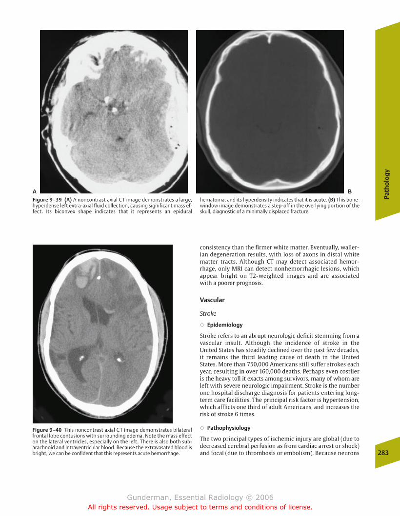
consistency than the firmer white matter. Eventually, waller-ian degeneration results, with loss of axons in distal whitematter tracts. Although CT may detect associated hemor-rhage, only MRI can detect nonhemorrhagic lesions, whichappear bright on T2-weighted images and are associatedwith a poorer prognosis.
Vascular
Stroke
�� Epidemiology
Stroke refers to an abrupt neurologic deficit stemming from avascular insult. Although the incidence of stroke in theUnited States has steadily declined over the past few decades,it remains the third leading cause of death in the UnitedStates. More than 750,000 Americans still suffer strokes eachyear, resulting in over 160,000 deaths. Perhaps even costlieris the heavy toll it exacts among survivors, many of whom areleft with severe neurologic impairment. Stroke is the numberone hospital discharge diagnosis for patients entering long-term care facilities. The principal risk factor is hypertension,which afflicts one third of adult Americans, and increases therisk of stroke 6 times.
�� Pathophysiology
The two principal types of ischemic injury are global (due todecreased cerebral perfusion as from cardiac arrest or shock)and focal (due to thrombosis or embolism). Because neurons
Path
olo
gy
283
Figure 9–39 (A) A noncontrast axial CT image demonstrates a large,hyperdense left extra-axial fluid collection, causing significant mass ef-fect. Its biconvex shape indicates that it represents an epidural
hematoma, and its hyperdensity indicates that it is acute. (B) This bone-window image demonstrates a step-off in the overlying portion of theskull, diagnostic of a minimally displaced fracture.
A B
Figure 9–40 This noncontrast axial CT image demonstrates bilateralfrontal lobe contusions with surrounding edema. Note the mass effecton the lateral ventricles, especially on the left. There is also both sub-arachnoid and intraventricular blood. Because the extravasated blood isbright, we can be confident that this represents acute hemorrhage.
chapter 09_p257-295.qxd 12/1/05 4:18 PM Page 283
Gunderman, Essential Radiology © 2006All rights reserved. Usage subject to terms and conditions of license.

in the adult generally do not divide, the damage caused by astroke is irreversible; however, strokes are sometimes pre-ceded clinically by so-called transient ischemic attacks (TIAs),neurologic deficits that completely resolve within 24 hours,and many other strokes pursue a stuttering course; therefore,although completed strokes are not amenable to therapy (ex-cept rehabilitation), preventive measures such as carotidendarterectomy and anticoagulation may be indicated inpatients who have suffered a TIA, and therapeutic maneuverssuch as heparinization and even thrombolysis may be war-ranted in some patients whose stroke is not completed.
Clinically, the site of stroke can often be discerned on thebasis of the patient’s neurologic deficit. The most commonlocation of stroke is in the middle cerebral artery (MCA)distribution, which supplies the bulk of the frontal, tempo-ral, and parietal lobes (Fig. 9–41). Patients with MCAstrokes may present with contralateral hemiplegia andhemianesthesia, and when the dominant hemisphere (usu-ally the left) is involved, aphasia. The anterior cerebralartery (ACA) supplies portions of the frontal and parietallobes, especially along the midline. ACA occlusion maycause contralateral foot and leg weakness. The posteriorcerebral artery (PCA), or vertebrobasilar system, suppliesthe cerebellum, the occipital lobes, the thalamus, and theupper midbrain, through which most of the brain’s inputand output pass. Even a small infarction in some portionsof the PCA territory may produce catastrophic conse-quences, including apnea, coma, cranial nerve deficits, andmajor motor and sensory deficits.
�� Imaging
Stroke versus Another Process Imaging has several criticalroles in stroke, all related to its pathophysiology and therapy.One often underappreciated role of imaging is to determinewhether the patient’s neurologic deficit may stem from someprocess other than stroke. It is not uncommon for patients tobe referred for head CT scans with the history of “Stroke—rule out hemorrhage,” who turn out to be suffering from non-vaso-occlusive processes, such as a subdural hematoma, tu-mor, or encephalitis. Although this occurs in only a minorityof patients, all patients with suspected stroke deserve imag-ing to rule out such mimics, some of which can be highlytreatable. Other unusual disease processes that may “mimic”conventional stroke are vasculitis, coagulopathies, and ve-nous occlusion; these are called mimics because, eventhough they cause cerebral infarction, their management isoften quite different from that of the typical thrombotic orembolic arterial occlusion.
One of the key criteria for the diagnosis of stroke is the cor-respondence between the region of abnormality and a knownvascular territory. If the region of altered attenuation andmass effect does not correspond to such distributions as theMCA, ACA, or PCA, some other process should be suspected,such as venous obstruction or global ischemia. In the lattercase, edema and subsequent encephalomalacia may be seenbilaterally in so-called watershed regions between vascularterritories, such as between the MCA and ACA, or the MCAand PCA. Moreover, arterial occlusion should produce a284
9N
euro
imag
ing
Figure 9–41 The arterial territories of the brain, as visualized on axial, coronal, and sagittal views.
chapter 09_p257-295.qxd 12/1/05 4:18 PM Page 284
Gunderman, Essential Radiology © 2006All rights reserved. Usage subject to terms and conditions of license.
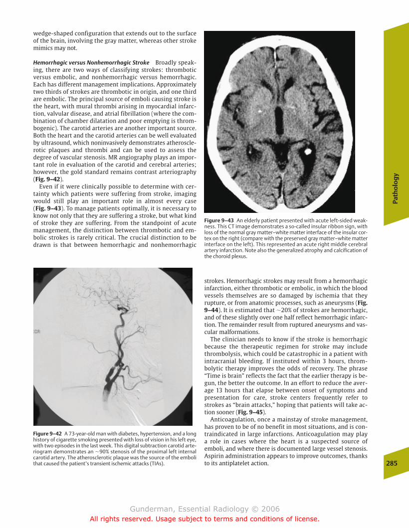
wedge-shaped configuration that extends out to the surfaceof the brain, involving the gray matter, whereas other strokemimics may not.
Hemorrhagic versus Nonhemorrhagic Stroke Broadly speak-ing, there are two ways of classifying strokes: thromboticversus embolic, and nonhemorrhagic versus hemorrhagic.Each has different management implications. Approximatelytwo thirds of strokes are thrombotic in origin, and one thirdare embolic. The principal source of emboli causing stroke isthe heart, with mural thrombi arising in myocardial infarc-tion, valvular disease, and atrial fibrillation (where the com-bination of chamber dilatation and poor emptying is throm-bogenic). The carotid arteries are another important source.Both the heart and the carotid arteries can be well evaluatedby ultrasound, which noninvasively demonstrates atheroscle-rotic plaques and thrombi and can be used to assess the degree of vascular stenosis. MR angiography plays an impor-tant role in evaluation of the carotid and cerebral arteries;however, the gold standard remains contrast arteriography(Fig. 9–42).
Even if it were clinically possible to determine with cer-tainty which patients were suffering from stroke, imagingwould still play an important role in almost every case (Fig. 9–43). To manage patients optimally, it is necessary toknow not only that they are suffering a stroke, but what kindof stroke they are suffering. From the standpoint of acutemanagement, the distinction between thrombotic and em-bolic strokes is rarely critical. The crucial distinction to bedrawn is that between hemorrhagic and nonhemorrhagic
strokes. Hemorrhagic strokes may result from a hemorrhagicinfarction, either thrombotic or embolic, in which the bloodvessels themselves are so damaged by ischemia that theyrupture, or from anatomic processes, such as aneurysms (Fig.9–44). It is estimated that �20% of strokes are hemorrhagic,and of these slightly over one half reflect hemorrhagic infarc-tion. The remainder result from ruptured aneurysms and vas-cular malformations.
The clinician needs to know if the stroke is hemorrhagicbecause the therapeutic regimen for stroke may includethrombolysis, which could be catastrophic in a patient withintracranial bleeding. If instituted within 3 hours, throm-bolytic therapy improves the odds of recovery. The phrase“Time is brain” reflects the fact that the earlier therapy is be-gun, the better the outcome. In an effort to reduce the aver-age 13 hours that elapse between onset of symptoms andpresentation for care, stroke centers frequently refer tostrokes as “brain attacks,” hoping that patients will take ac-tion sooner (Fig. 9–45).
Anticoagulation, once a mainstay of stroke management,has proven to be of no benefit in most situations, and is con-traindicated in large infarctions. Anticoagulation may play a role in cases where the heart is a suspected source ofemboli, and where there is documented large vessel stenosis.Aspirin administration appears to improve outcomes, thanksto its antiplatelet action.
Path
olo
gy
285
Figure 9–42 A 73-year-old man with diabetes, hypertension, and a longhistory of cigarette smoking presented with loss of vision in his left eye,with two episodes in the last week. This digital subtraction carotid arte-riogram demonstrates an �90% stenosis of the proximal left internalcarotid artery. The atherosclerotic plaque was the source of the embolithat caused the patient’s transient ischemic attacks (TIAs).
Figure 9–43 An elderly patient presented with acute left-sided weak-ness. This CT image demonstrates a so-called insular ribbon sign, withloss of the normal gray matter–white matter interface of the insular cor-tex on the right (compare with the preserved gray matter–white matterinterface on the left). This represented an acute right middle cerebralartery infarction. Note also the generalized atrophy and calcification ofthe choroid plexus.
chapter 09_p257-295.qxd 12/1/05 4:18 PM Page 285
Gunderman, Essential Radiology © 2006All rights reserved. Usage subject to terms and conditions of license.
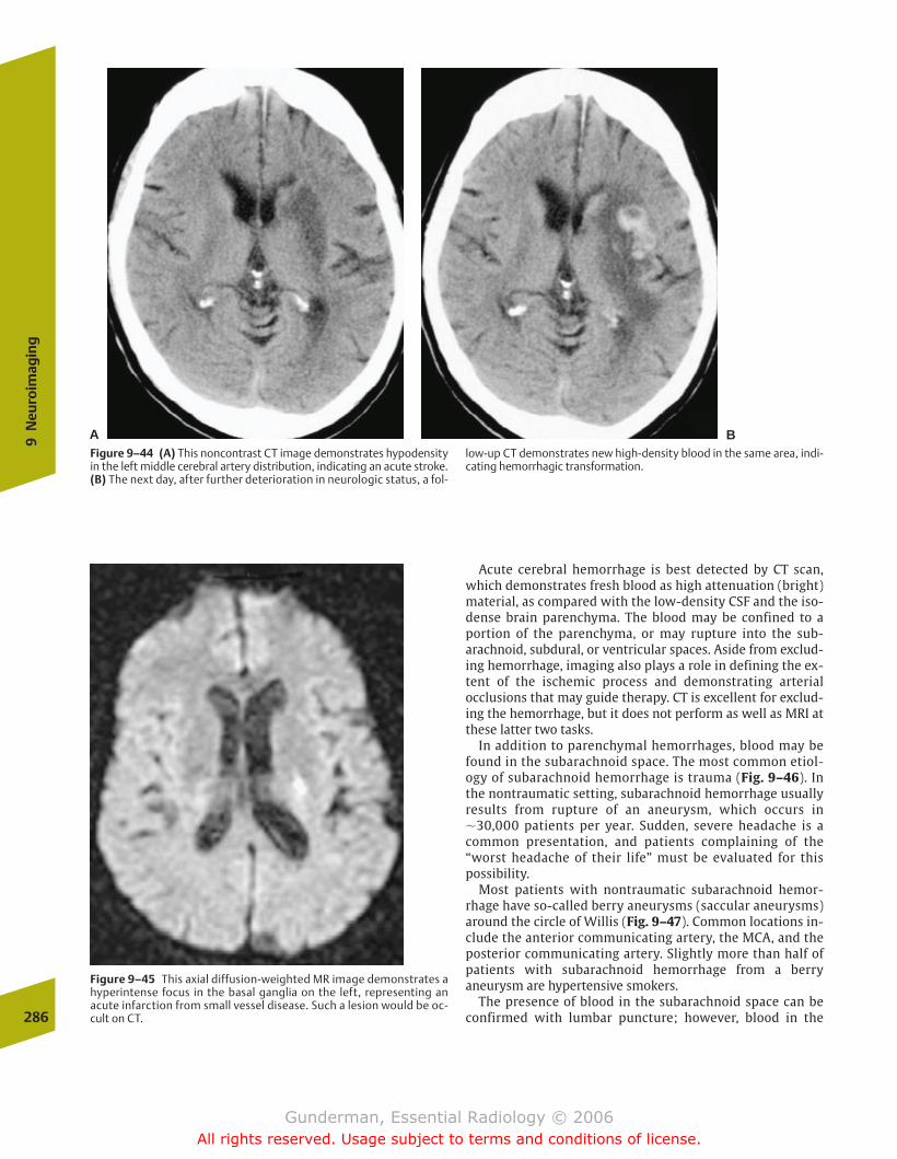
Acute cerebral hemorrhage is best detected by CT scan,which demonstrates fresh blood as high attenuation (bright)material, as compared with the low-density CSF and the iso-dense brain parenchyma. The blood may be confined to aportion of the parenchyma, or may rupture into the sub-arachnoid, subdural, or ventricular spaces. Aside from exclud-ing hemorrhage, imaging also plays a role in defining the ex-tent of the ischemic process and demonstrating arterialocclusions that may guide therapy. CT is excellent for exclud-ing the hemorrhage, but it does not perform as well as MRI atthese latter two tasks.
In addition to parenchymal hemorrhages, blood may befound in the subarachnoid space. The most common etiol-ogy of subarachnoid hemorrhage is trauma (Fig. 9–46). Inthe nontraumatic setting, subarachnoid hemorrhage usuallyresults from rupture of an aneurysm, which occurs in�30,000 patients per year. Sudden, severe headache is acommon presentation, and patients complaining of the“worst headache of their life” must be evaluated for thispossibility.
Most patients with nontraumatic subarachnoid hemor-rhage have so-called berry aneurysms (saccular aneurysms)around the circle of Willis (Fig. 9–47). Common locations in-clude the anterior communicating artery, the MCA, and theposterior communicating artery. Slightly more than half ofpatients with subarachnoid hemorrhage from a berryaneurysm are hypertensive smokers.
The presence of blood in the subarachnoid space can beconfirmed with lumbar puncture; however, blood in the286
9N
euro
imag
ing
Figure 9–45 This axial diffusion-weighted MR image demonstrates ahyperintense focus in the basal ganglia on the left, representing anacute infarction from small vessel disease. Such a lesion would be oc-cult on CT.
Figure 9–44 (A) This noncontrast CT image demonstrates hypodensityin the left middle cerebral artery distribution, indicating an acute stroke.(B) The next day, after further deterioration in neurologic status, a fol-
low-up CT demonstrates new high-density blood in the same area, indi-cating hemorrhagic transformation.
A B
chapter 09_p257-295.qxd 12/1/05 4:18 PM Page 286
Gunderman, Essential Radiology © 2006All rights reserved. Usage subject to terms and conditions of license.
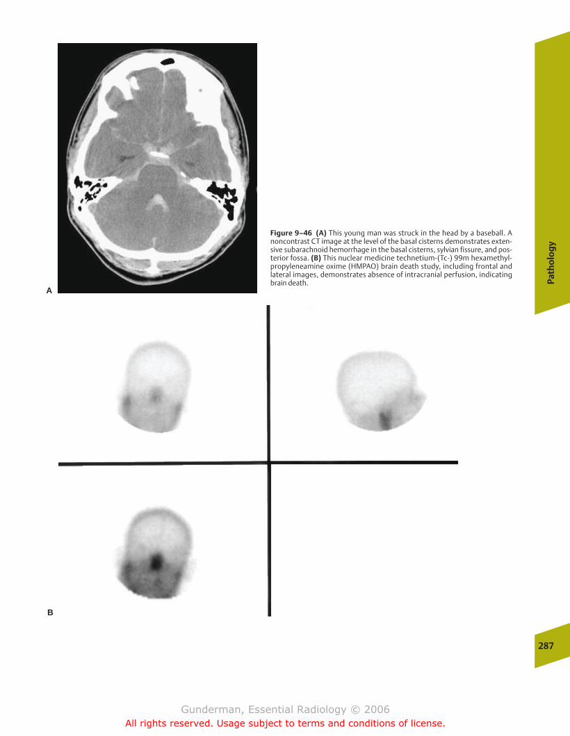
Path
olo
gy
287
A
B
Figure 9–46 (A) This young man was struck in the head by a baseball. Anoncontrast CT image at the level of the basal cisterns demonstrates exten-sive subarachnoid hemorrhage in the basal cisterns, sylvian fissure, and pos-terior fossa. (B) This nuclear medicine technetium-(Tc-) 99m hexamethyl-propyleneamine oxime (HMPAO) brain death study, including frontal andlateral images, demonstrates absence of intracranial perfusion, indicatingbrain death.
chapter 09_p257-295.qxd 12/1/05 4:18 PM Page 287
Gunderman, Essential Radiology © 2006All rights reserved. Usage subject to terms and conditions of license.
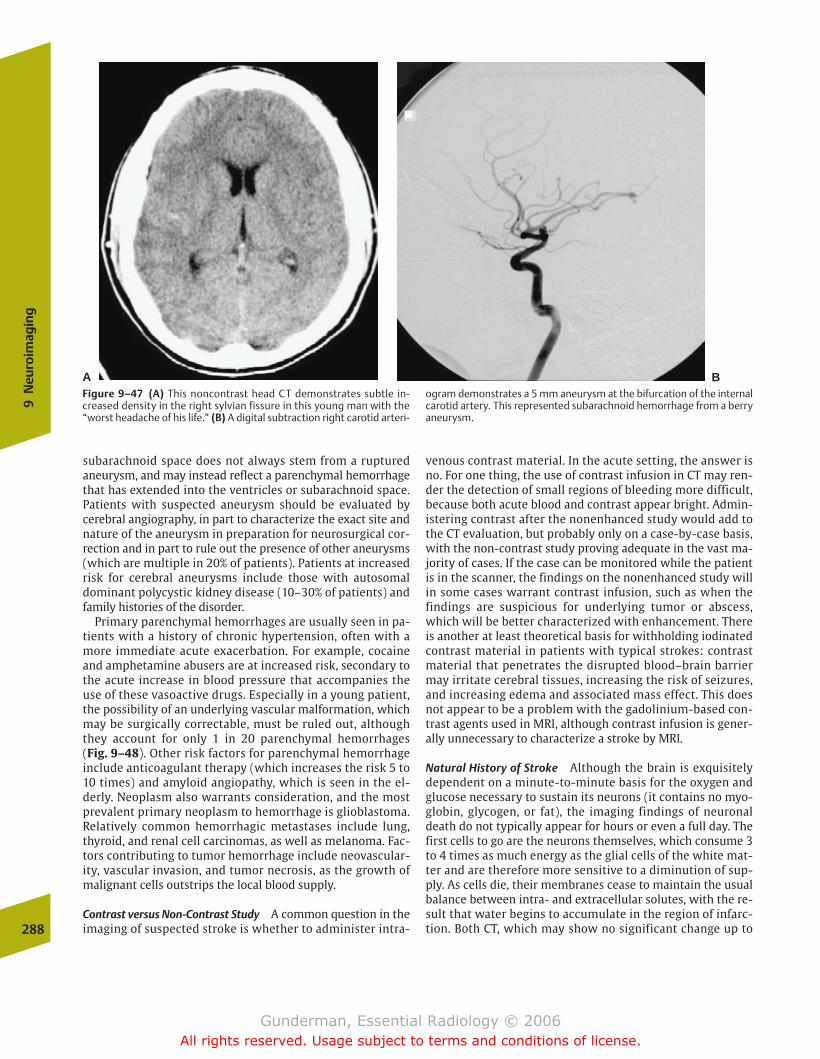
subarachnoid space does not always stem from a rupturedaneurysm, and may instead reflect a parenchymal hemorrhagethat has extended into the ventricles or subarachnoid space.Patients with suspected aneurysm should be evaluated bycerebral angiography, in part to characterize the exact site andnature of the aneurysm in preparation for neurosurgical cor-rection and in part to rule out the presence of other aneurysms(which are multiple in 20% of patients). Patients at increasedrisk for cerebral aneurysms include those with autosomaldominant polycystic kidney disease (10–30% of patients) andfamily histories of the disorder.
Primary parenchymal hemorrhages are usually seen in pa-tients with a history of chronic hypertension, often with amore immediate acute exacerbation. For example, cocaineand amphetamine abusers are at increased risk, secondary tothe acute increase in blood pressure that accompanies theuse of these vasoactive drugs. Especially in a young patient,the possibility of an underlying vascular malformation, whichmay be surgically correctable, must be ruled out, althoughthey account for only 1 in 20 parenchymal hemorrhages (Fig. 9–48). Other risk factors for parenchymal hemorrhageinclude anticoagulant therapy (which increases the risk 5 to10 times) and amyloid angiopathy, which is seen in the el-derly. Neoplasm also warrants consideration, and the mostprevalent primary neoplasm to hemorrhage is glioblastoma.Relatively common hemorrhagic metastases include lung,thyroid, and renal cell carcinomas, as well as melanoma. Fac-tors contributing to tumor hemorrhage include neovascular-ity, vascular invasion, and tumor necrosis, as the growth ofmalignant cells outstrips the local blood supply.
Contrast versus Non-Contrast Study A common question in theimaging of suspected stroke is whether to administer intra-
venous contrast material. In the acute setting, the answer isno. For one thing, the use of contrast infusion in CT may ren-der the detection of small regions of bleeding more difficult,because both acute blood and contrast appear bright. Admin-istering contrast after the nonenhanced study would add tothe CT evaluation, but probably only on a case-by-case basis,with the non-contrast study proving adequate in the vast ma-jority of cases. If the case can be monitored while the patientis in the scanner, the findings on the nonenhanced study willin some cases warrant contrast infusion, such as when thefindings are suspicious for underlying tumor or abscess,which will be better characterized with enhancement. Thereis another at least theoretical basis for withholding iodinatedcontrast material in patients with typical strokes: contrastmaterial that penetrates the disrupted blood–brain barriermay irritate cerebral tissues, increasing the risk of seizures,and increasing edema and associated mass effect. This doesnot appear to be a problem with the gadolinium-based con-trast agents used in MRI, although contrast infusion is gener-ally unnecessary to characterize a stroke by MRI.
Natural History of Stroke Although the brain is exquisitelydependent on a minute-to-minute basis for the oxygen andglucose necessary to sustain its neurons (it contains no myo-globin, glycogen, or fat), the imaging findings of neuronaldeath do not typically appear for hours or even a full day. Thefirst cells to go are the neurons themselves, which consume 3to 4 times as much energy as the glial cells of the white mat-ter and are therefore more sensitive to a diminution of sup-ply. As cells die, their membranes cease to maintain the usualbalance between intra- and extracellular solutes, with the re-sult that water begins to accumulate in the region of infarc-tion. Both CT, which may show no significant change up to 288
9N
euro
imag
ing
A BFigure 9–47 (A) This noncontrast head CT demonstrates subtle in-creased density in the right sylvian fissure in this young man with the“worst headache of his life.” (B) A digital subtraction right carotid arteri-
ogram demonstrates a 5 mm aneurysm at the bifurcation of the internalcarotid artery. This represented subarachnoid hemorrhage from a berryaneurysm.
chapter 09_p257-295.qxd 12/1/05 4:18 PM Page 288
Gunderman, Essential Radiology © 2006All rights reserved. Usage subject to terms and conditions of license.
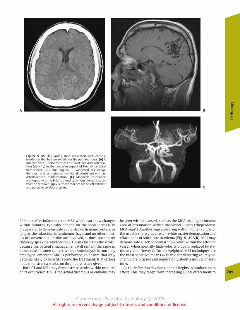
24 hours after infarction, and MRI, which can show changeswithin minutes, typically depend on the local increase inbrain water to demonstrate acute stroke. In many centers, aslong as the infarction is nonhemorrhagic and no other mim-ics of conventional stroke are involved, it does not matterclinically speaking whether the CT scan elucidates the stroke,because the patient’s management will remain the same ineither case. In some centers where thrombolysis is routinelyemployed, emergent MRI is performed, to ensure that onlypatients likely to benefit receive the treatment. If MRI doesnot demonstrate a stroke, no thrombolytics are given.
Both CT and MRI may demonstrate stroke within minutesof its occurrence. On CT the actual thrombus or embolus may
be seen within a vessel, such as the MCA, as a hyperintensearea of attenuation within the vessel lumen (“hyperdenseMCA sign”). Another sign appearing within hours is a loss ofthe usually sharp gray matter–white matter demarcation andeffacement of sulci, due to edema (Fig. 9–49A,B). MRI maydemonstrate a lack of normal “flow void” within the affectedvessel, when normally high-velocity blood is replaced by sta-tionary clot. Newer diffusion-weighted MRI techniques arethe most sensitive means available for detecting acutely is-chemic brain tissue and require only about a minute of scantime.
As the infarction develops, edema begins to produce masseffect. This may range from increasing sulcal effacement to
Path
olo
gy
289
Figure 9–48 This young man presented with chronicheadaches that had worsened over the past few hours. (A) Anoncontrast CT demonstrates an area of increased attenua-tion (density) in the posterior aspect of the left cerebralhemisphere. (B) This sagittal T1-weighted MR imagedemonstrates serpiginous low signal, consistent with anarteriovenous malformation. (C) Magnetic resonanceangiography using bright-blood technique demonstratesthat the arterial supply is from branches of the left anteriorand posterior cerebral arteries.
A B
C
chapter 09_p257-295.qxd 12/1/05 4:18 PM Page 289
Gunderman, Essential Radiology © 2006All rights reserved. Usage subject to terms and conditions of license.

290
9N
euro
imag
ing
Figure 9–49 A 60-year-old woman presented with an 8-hour history ofleft hemiparesis and facial droop. (A) An axial image from a noncontrastCT scan at the level of the basilar cisterns demonstrates a subtle findingsometimes seen in early stroke; namely, a hyperdense cerebral artery—inthis case, the right middle cerebral artery (MCA; arrow). This so-calledhyperdense artery sign is due to the presence of in situ or embolicthrombus within the vessel lumen. Its equivalent on magnetic reso-nance imaging would be the absence of the expected flow void withinthe vessel. (B) Another image from the same study, near the level of theforamen of Monro, demonstrates subtle loss of gray matter–white mat-ter demarcation and effacement of sulci in the right cerebral hemisphereas compared with those on the left. (C) An axial image from a scan sev-
eral days later demonstrates prominent cerebral edema in the territoryof the right MCA. The edema is causing mass effect on the frontal hornof the right lateral ventricle, as well as a shift of midline structures suchas the third ventricle to the left. (D) An axial CT image obtained 10 dayspostevent demonstrates continued edema and mass effect in the rightMCA distribution, but there has been interval appearance of high-density regions, indicating hemorrhage. (E) An axial CT image 14 weekspostevent reveals that the right-sided edema has completely subsided,and that the infarcted brain parenchyma has been almost completely re-placed by CSF density fluid. The frontal horn of the right lateral ventricleis now larger than its left counterpart, a phenomenon called ex vacuo dilation.
more severe manifestations such as subfalcine or uncal her-niation. In general, the larger the region of brain infarcted,the greater the peak mass effect observed during the thirdthrough seventh days postevent (Fig. 9–49C). In an effort tocombat acute cerebral swelling, mannitol (which increases
intravascular oncotic pressure, and therefore tends to drawwater back into the intravascular space) and hyperventilation(which causes arteriolar smooth muscle contraction, andtherefore decreases intravascular hydrostatic pressure) maybe employed. Between �3 to 10 days postevent, the risk of
chapter 09_p257-295.qxd 12/1/05 4:18 PM Page 290
Gunderman, Essential Radiology © 2006All rights reserved. Usage subject to terms and conditions of license.
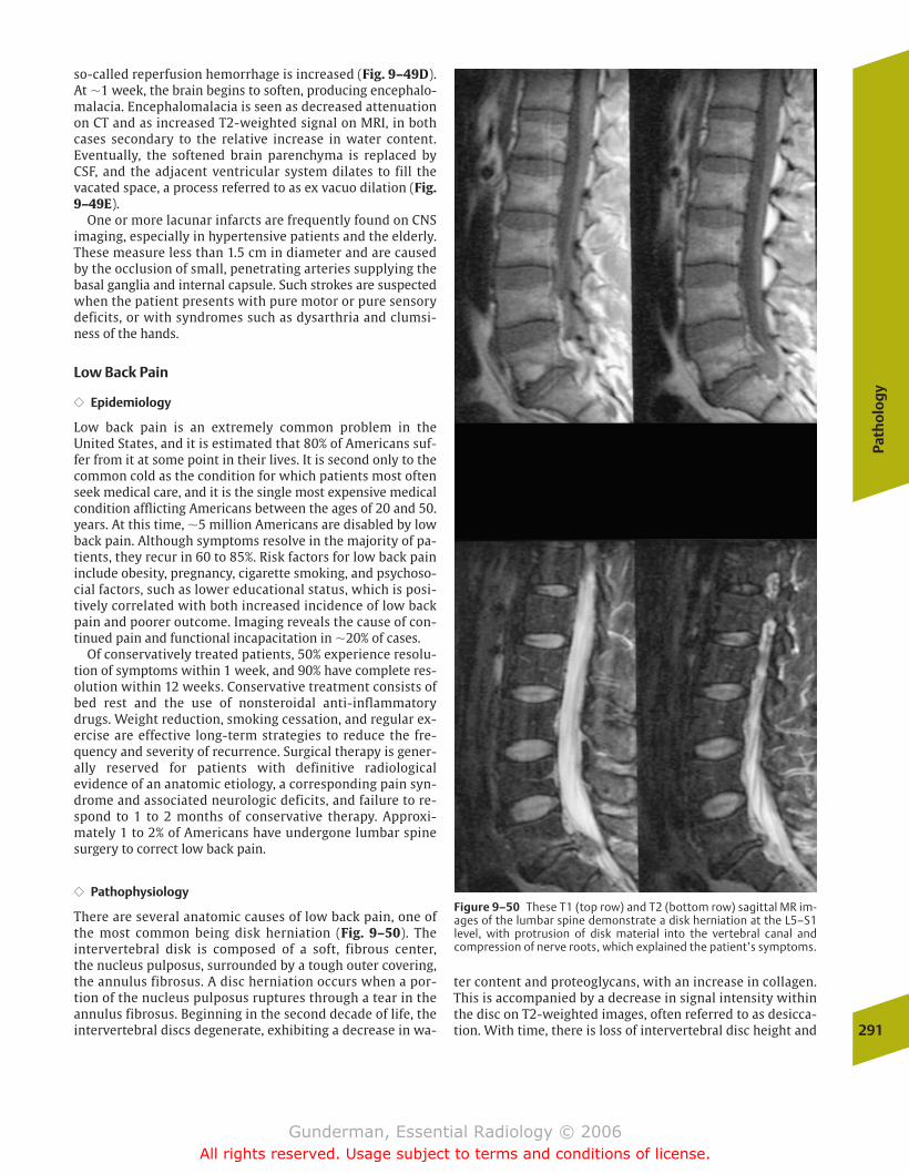
so-called reperfusion hemorrhage is increased (Fig. 9–49D).At �1 week, the brain begins to soften, producing encephalo-malacia. Encephalomalacia is seen as decreased attenuationon CT and as increased T2-weighted signal on MRI, in bothcases secondary to the relative increase in water content.Eventually, the softened brain parenchyma is replaced by CSF, and the adjacent ventricular system dilates to fill thevacated space, a process referred to as ex vacuo dilation (Fig.9–49E).
One or more lacunar infarcts are frequently found on CNSimaging, especially in hypertensive patients and the elderly.These measure less than 1.5 cm in diameter and are causedby the occlusion of small, penetrating arteries supplying thebasal ganglia and internal capsule. Such strokes are suspectedwhen the patient presents with pure motor or pure sensorydeficits, or with syndromes such as dysarthria and clumsi-ness of the hands.
Low Back Pain
�� Epidemiology
Low back pain is an extremely common problem in theUnited States, and it is estimated that 80% of Americans suf-fer from it at some point in their lives. It is second only to thecommon cold as the condition for which patients most oftenseek medical care, and it is the single most expensive medicalcondition afflicting Americans between the ages of 20 and 50.years. At this time, �5 million Americans are disabled by lowback pain. Although symptoms resolve in the majority of pa-tients, they recur in 60 to 85%. Risk factors for low back paininclude obesity, pregnancy, cigarette smoking, and psychoso-cial factors, such as lower educational status, which is posi-tively correlated with both increased incidence of low backpain and poorer outcome. Imaging reveals the cause of con-tinued pain and functional incapacitation in �20% of cases.
Of conservatively treated patients, 50% experience resolu-tion of symptoms within 1 week, and 90% have complete res-olution within 12 weeks. Conservative treatment consists ofbed rest and the use of nonsteroidal anti-inflammatorydrugs. Weight reduction, smoking cessation, and regular ex-ercise are effective long-term strategies to reduce the fre-quency and severity of recurrence. Surgical therapy is gener-ally reserved for patients with definitive radiologicalevidence of an anatomic etiology, a corresponding pain syn-drome and associated neurologic deficits, and failure to re-spond to 1 to 2 months of conservative therapy. Approxi-mately 1 to 2% of Americans have undergone lumbar spinesurgery to correct low back pain.
�� Pathophysiology
There are several anatomic causes of low back pain, one ofthe most common being disk herniation (Fig. 9–50). The intervertebral disk is composed of a soft, fibrous center, the nucleus pulposus, surrounded by a tough outer covering,the annulus fibrosus. A disc herniation occurs when a por-tion of the nucleus pulposus ruptures through a tear in theannulus fibrosus. Beginning in the second decade of life, theintervertebral discs degenerate, exhibiting a decrease in wa-
Path
olo
gy
291
Figure 9–50 These T1 (top row) and T2 (bottom row) sagittal MR im-ages of the lumbar spine demonstrate a disk herniation at the L5–S1level, with protrusion of disk material into the vertebral canal andcompression of nerve roots, which explained the patient’s symptoms.
ter content and proteoglycans, with an increase in collagen.This is accompanied by a decrease in signal intensity withinthe disc on T2-weighted images, often referred to as desicca-tion. With time, there is loss of intervertebral disc height and
chapter 09_p257-295.qxd 12/1/05 4:18 PM Page 291
Gunderman, Essential Radiology © 2006All rights reserved. Usage subject to terms and conditions of license.
bulging of the disk material against the anulus fibrosus. Ifthe anulus remains intact, there can be no herniation, butwith time, fissures and frank tears may form in the anulus,permitting the disk material to protrude beyond the columnof the vertebral bodies, where it may impinge on the spinalcord or nerve roots. The pain of a herniated disk is thoughtto result from the impingement of the disk material on thereceptors of the anulus fibrosus or posterior longitudinal lig-ament, which runs along the posterior margin of the verte-bral bodies.
In the lumbar spine, a disk herniation may impinge on anynerve root still within the neural canal at that level (recallingthat the cord itself generally terminates between T11 and L1).In the typical case, a disk herniation will cause symptomsone level below the disk, so that an L4–L5 herniation willcause an L5 radiculopathy (from the same Latin root as theword radical, meaning “root”). A typical presentation wouldbe a history of back pain with more recent unilateral pain ra-diating down the leg in the distribution of the sciatic nerve,called sciatica. Physical examination reveals the level, withthe L4 root responsible for the knee jerk, whereas the anklejerk is at S1. More than 90% of lumbar disk herniations occurat the L4–L5 or L5–S1 levels.
The distinction between a posterior disk herniation and alateral disk herniation is often difficult or impossible to makeon purely clinical grounds. Only �1 in 20 disk herniations islateral, but failure to diagnose a lateral disk on imaging couldcause the surgeon to operate at the wrong level. Consider, forexample, a patient with clinical symptoms referable to theL4–L5 level. By far the most common etiology of such symp-toms would be a posterior disk herniation causing compres-sion of the L5 nerve root; however, a lateral disk at the L5–S1level could cause identical symptoms and result in failed backsurgery if the surgeon were to operate based on clinical crite-ria alone. In other words, a lateral L5–S1 disk herniation mayproduce clinical signs and symptoms identical to a posteriorL4–L5 herniation.
The second major offender in low back pain is spondylosis,also referred to as degenerative disease or osteoarthritis ofthe spine (although the latter is a misnomer and should bereserved for degenerative change at the apophyseal jointsonly). It is more common than herniated disk; although ap-proximately one third of asymptomatic individuals have atleast one herniated disk, virtually every person has some de-gree of spondylosis by their later years. The back pain ofspondylosis is usually of an aching nature and is exacerbatedby prolonged standing or walking. Plain films may be used todiagnose lumbar spondylosis, but myelography, CT, or MRI isnecessary to assess the degree of spinal stenosis and nerveroot compression.
�� Imaging
MRI has dramatically enhanced spine imaging, due to its su-perior tissue resolution, multiplanar imaging capabilities,noninvasive nature, and freedom from the artifact producedby bone in CT. T1-weighted images provide the best informa-tion about spinal anatomy, including the cord, whereas
T2-weighted images (in which CSF is bright) provide a myelo-graphic effect that is excellent for assessing both cord andnerve root compression and intrinsic cord lesions. A goodsearch pattern for assessing the spine begins with sagittal se-quences. Standard parameters, such as vertebral body anddisk space height and vertebral alignment, should be as-sessed, as well as the signal of the bone marrow (whichshould be bright on T1 due to fat). The cord itself should beinspected for abnormalities in caliber or signal, and to ensurethat it ends at or about the usual L1 level. On both sagittaland axial images, the neural foramina should be examined torule out encroachment by osteophytes or disk material on thenerve roots.
Two types of disk abnormalities are seen on imaging, an-nular bulges and herniations (Fig. 9–51). An annular bulge isa broad extension of the disk beyond the vertebral end plate.This is a prominent finding in patients older than age 20 andis most often asymptomatic. A herniation is a focal protrusionof the disk material through the anulus fibrosus, which mayextend into the vertebral canal, the neural foramen, or evenextraforaminally, a so-called far-lateral herniation. When theherniated fragment of disk material becomes detached fromthe disk, it is referred to as a free fragment, which, if it mi-grates superiorly or inferiorly, may cause misleading clinicalsigns at a level above or below the actual herniation (Fig. 9–52).
Spondylosis manifests radiographically as osteophyte for-mation at the vertebral end plates and facet joints, whichmay encroach on both the vertebral canal, causing cord im-pingement, and the neural foramina, causing radiculopathy.Additional factors in a spondylosis syndrome include hyper-trophy and ossification of the posterior longitudinal ligamentand ligamentum flavum, which tend to compress the thecalsac in an anteroposterior dimension, and congenital spinalstenosis, or “short pedicle syndrome,” which makes the canalnarrower to begin with and therefore decreases neurologictolerance for any degree of compromise. Spinal stenosis is acomponent of achondroplasia, the most common form ofdwarfism.
In some cases, low back pain and radiculopathy may betraced to spondylolysis, a congenital or acquired defect in thepars interarticularis of the vertebral body, which appears onoblique radiographs as a break in the neck of the “Scottie dog”discussed below. Spondylolysis is often compounded byspondylolisthesis, which frequently occurs at the L5–S1 level,and represents the displacement of one vertebral body on an-other (Fig. 9–53). Such slippage tends to compromise the verte-bral canal and is usually treated with a combination of posteriordecompression laminectomy and posterior vertebral fusion.
Failed back surgery occurs in 10 to 40% of patients. Com-mon causes of failed back surgery syndromes include recur-rent or residual herniation, arachnoiditis, and spinal stenosis.Postoperative imaging plays an important role in patientswith recurrent or residual symptoms. For example, eitherdisk material or scar tissue may impress on the thecal sac ornerve roots. If the compression is due to disk material, thepatient is often reoperated. Scar is generally not reoperated.The two can be distinguished based on their imaging charac-
292
9N
euro
imag
ing
chapter 09_p257-295.qxd 12/1/05 4:18 PM Page 292
Gunderman, Essential Radiology © 2006All rights reserved. Usage subject to terms and conditions of license.
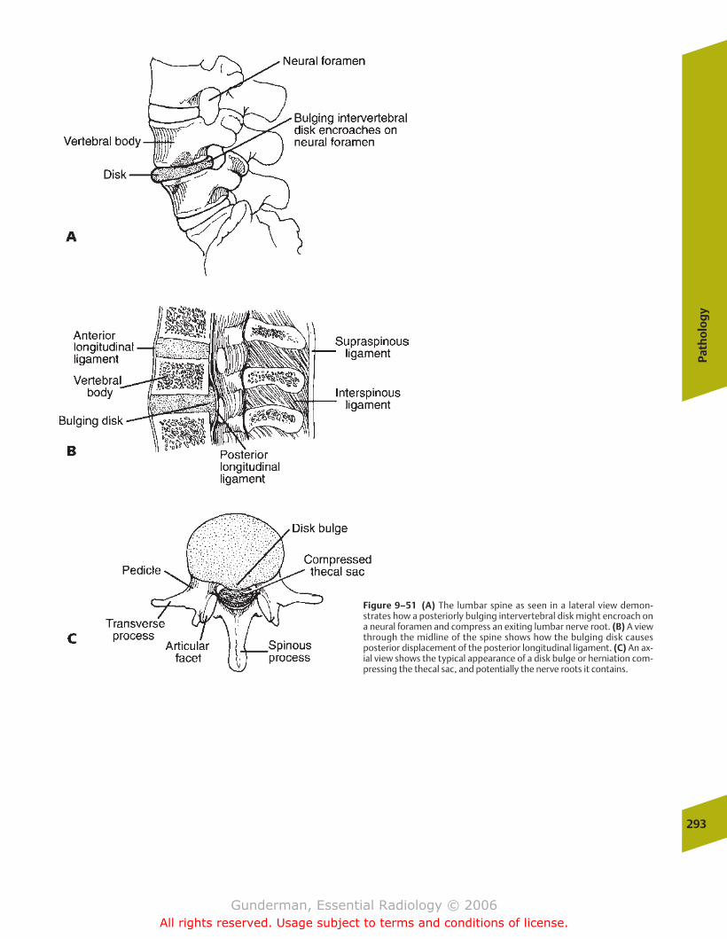
Path
olo
gy
293
Figure 9–51 (A) The lumbar spine as seen in a lateral view demon-strates how a posteriorly bulging intervertebral disk might encroach ona neural foramen and compress an exiting lumbar nerve root. (B) A viewthrough the midline of the spine shows how the bulging disk causesposterior displacement of the posterior longitudinal ligament. (C) An ax-ial view shows the typical appearance of a disk bulge or herniation com-pressing the thecal sac, and potentially the nerve roots it contains.
chapter 09_p257-295.qxd 12/1/05 4:18 PM Page 293
Gunderman, Essential Radiology © 2006All rights reserved. Usage subject to terms and conditions of license.
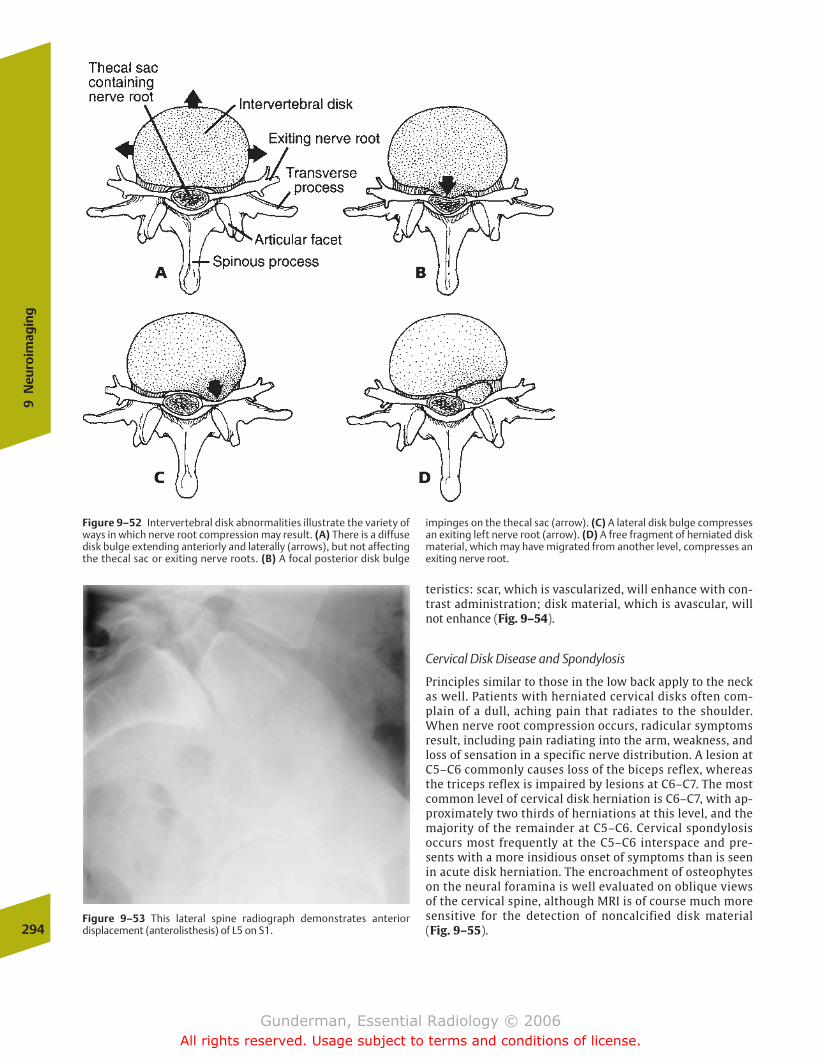
teristics: scar, which is vascularized, will enhance with con-trast administration; disk material, which is avascular, willnot enhance (Fig. 9–54).
Cervical Disk Disease and Spondylosis
Principles similar to those in the low back apply to the neckas well. Patients with herniated cervical disks often com-plain of a dull, aching pain that radiates to the shoulder.When nerve root compression occurs, radicular symptomsresult, including pain radiating into the arm, weakness, andloss of sensation in a specific nerve distribution. A lesion atC5–C6 commonly causes loss of the biceps reflex, whereasthe triceps reflex is impaired by lesions at C6–C7. The mostcommon level of cervical disk herniation is C6–C7, with ap-proximately two thirds of herniations at this level, and themajority of the remainder at C5–C6. Cervical spondylosisoccurs most frequently at the C5–C6 interspace and pre-sents with a more insidious onset of symptoms than is seenin acute disk herniation. The encroachment of osteophyteson the neural foramina is well evaluated on oblique viewsof the cervical spine, although MRI is of course much moresensitive for the detection of noncalcified disk material(Fig. 9–55).294
9N
euro
imag
ing
Figure 9–52 Intervertebral disk abnormalities illustrate the variety ofways in which nerve root compression may result. (A) There is a diffusedisk bulge extending anteriorly and laterally (arrows), but not affectingthe thecal sac or exiting nerve roots. (B) A focal posterior disk bulge
impinges on the thecal sac (arrow). (C) A lateral disk bulge compressesan exiting left nerve root (arrow). (D) A free fragment of herniated diskmaterial, which may have migrated from another level, compresses anexiting nerve root.
Figure 9–53 This lateral spine radiograph demonstrates anteriordisplacement (anterolisthesis) of L5 on S1.
chapter 09_p257-295.qxd 12/1/05 4:19 PM Page 294
Gunderman, Essential Radiology © 2006All rights reserved. Usage subject to terms and conditions of license.
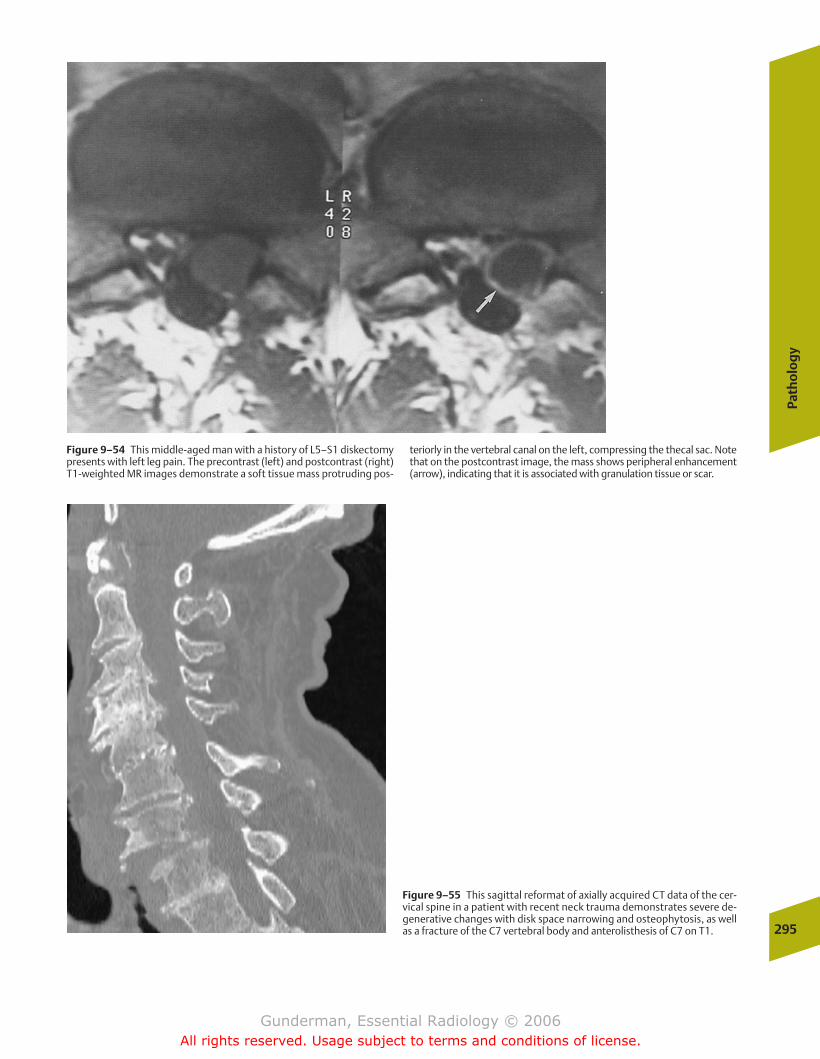
Path
olo
gy
295
Figure 9–54 This middle-aged man with a history of L5–S1 diskectomypresents with left leg pain. The precontrast (left) and postcontrast (right)T1-weighted MR images demonstrate a soft tissue mass protruding pos-
teriorly in the vertebral canal on the left, compressing the thecal sac. Notethat on the postcontrast image, the mass shows peripheral enhancement(arrow), indicating that it is associated with granulation tissue or scar.
Figure 9–55 This sagittal reformat of axially acquired CT data of the cer-vical spine in a patient with recent neck trauma demonstrates severe de-generative changes with disk space narrowing and osteophytosis, as wellas a fracture of the C7 vertebral body and anterolisthesis of C7 on T1.
chapter 09_p257-295.qxd 12/1/05 4:19 PM Page 295
Gunderman, Essential Radiology © 2006All rights reserved. Usage subject to terms and conditions of license.

� Imaging
� Pathology
Circulatory SystemCongenital Heart Disease
Respiratory SystemNeonatal Respiratory DistressChildhood Respiratory Distress
Nervous SystemNeonatal Intracranial Hemorrhage
AbdomenAcute AbdomenMasses
Musculoskeletal SystemDevelopmental Dysplasia of the HipTraumaRicketsChild Abuse
Urinary TractInfection
10Pediatric Radiology
chapter 10_p296-326.qxd 12/1/05 4:22 PM Page 296
Gunderman, Essential Radiology © 2006All rights reserved. Usage subject to terms and conditions of license.
Path
olo
gy
297
The purpose of this chapter is not to survey all of pediatricradiology, but to explore some of the most common or illus-trative pediatric medical and surgical pathologies, and to review some of the principal anatomic, physiologic, andpathologic differences between children and adults. Perhapsthe most critical lesson of pediatrics is that children arepoorly served if treated as miniature adults—a principle thatapplies in every area of pediatric imaging.
� Imaging
Several special characteristics of pediatric patients createspecial challenges and opportunities in pediatric imaging.One of the most important challenges is the need to preventavoidable exposure to ionizing radiation. Although there is nodefinite evidence that the low levels of radiation exposure associated with diagnostic imaging produce adverse geneticor somatic effects, both experience with populations exposedto relatively high levels of radiation (Hiroshima and Nagasaki,Japan) and theoretical models of deoxyribonucleic acid (DNA)damage would suggest that the hazards of radiation exposureare greater at earlier ages. In practical terms, limiting exposure means reducing x-ray tube current, utilizing inter-mittent rather than continuous fluoroscopic monitoring,shielding radiosensitive tissues such as the gonads andbreasts, and, whenever possible, choosing imaging modalitiesthat do not involve ionizing radiation.
Another challenge faced by pediatric imaging is the need toimmobilize the patient. Infants and young children typicallycannot understand or comply with instructions to remainstill, and they may be frightened and upset by the unfamiliarenvironment of the radiology department and its equipment.Not only lengthier examinations such as nuclear medicine,magnetic resonance imaging, and computed tomography, buteven relatively quick procedures such as chest and bone radi-ographs require that the patient be still during data acquisi-tion. In the case of a chest radiograph, the exposure may lastonly a split second, whereas nuclear medicine and MRI pro-cedures may in some cases require 1 hour or more. When theprocedure is brief, a parent can often restrain the child byholding the arms and/or legs. In addition, immobilization de-vices such as boards or “papoose” wraps may be used. Whenthe examination requires more time, sedation may be neces-sary. Generally, children younger than several months of ageare immobilized, and those between several months and 4 to5 years require sedation for longer examinations. Children atrisk for airway obstruction or with central nervous systemdisorders may not be eligible for conscious sedation and in-stead require general anesthesia and mechanical ventilation.
An imaging modality particularly well suited to infants andyoung children is ultrasound, which exhibits several impor-tant advantages. First, ultrasound involves no ionizing radia-tion, and there are no known risks to health associated withdiagnostic sonography. Second, patients are often smallenough that a surprisingly great extent of the body is accessi-ble to sonographic imaging. The fact that the infantile calvar-ium is not completely closed renders ultrasound a key neuroimaging modality early in life. Third, although patients
may occasionally complain that the ultrasound transducer“tickles,” sonography involves no pain and can be comfort-ably performed in real time, thus making patient restraintand sedation generally unnecessary. Of course, several struc-tures such as aerated lung and subcortical bone remain inaccessible to ultrasound, as in the adult.
� Pathology
Circulatory System
Congenital Heart Disease
�� Epidemiology
Congenital heart disease is found in 1% of newborns. The twomost common forms are bicuspid aortic valve and mitralvalve prolapse (discussed in Chapter 2). These are generallyasymptomatic in the pediatric patient.
�� Pathophysiology
Fetal circulatory patterns differ markedly from those seen after birth (Fig. 10–1). The principal difference stems fromthe fact that the fetus is not breathing air, but acquires all ofits oxygen and disposes of all of its carbon dioxide throughthe placenta and the maternal circulation. Two bypasses inthe fetal circulation—the foramen ovale, an opening in the interatrial septum, and the ductus arteriosus, which connectsthe left pulmonary artery to the proximal descending aorta—serve to redirect blood flow away from the fetal lungs. Duringin utero life, the collapsed lungs manifest a high resistance toflow, and right heart pressures are higher than left heartpressures. As a result, blood is shunted through both thesebypasses into the systemic circulation, where it either supplies systemic tissues or enters the umbilical artery and returns to the placenta. Beginning at birth, the combinationof lung expansion and ventilation causes pulmonary vascularresistance to fall; once it falls lower than systemic resistance,shunts resulting from such lesions as a patent ductus arterio-sus, atrial septal defect, or ventricular septal defect will shiftfrom right to left to left to right.
�� Clinical Presentation
A critical clinical discriminator in congenital heart disease iscyanosis (from the Greek kyanos, “blue”). Acyanotic diseaseimplies that there is a left-to-right shunt, with oxygen-saturated blood being shunted back to the lungs. Cyanosisimplies a right-to-left shunt or admixture lesion (e.g., a trun-cus arteriosus, in which the right and left ventricles emptyinto a single vessel), in which desaturated blood is enteringthe systemic circulation. Lesions that commonly present inthe first few weeks of life include hypoplastic left heart syn-drome and transposition of the great arteries. Hypoplasticleft heart syndrome presents within a few days of birth withcongestive heart failure (CHF), and closure of the ductus arte-riosus during the first week commonly results in cardiogenicshock and death. Transposition of the great arteries consistsof origination of the aorta from the right ventricle and
chapter 10_p296-326.qxd 12/1/05 4:22 PM Page 297
Gunderman, Essential Radiology © 2006All rights reserved. Usage subject to terms and conditions of license.

origination of the pulmonary artery from the left ventricle.This situation creates two separate circulations and is incom-patible with life unless lesions such as atrial or ventricularseptal defects permit mixing. This is the most common lesionto present with cyanosis in the first 24 hours of life.
�� Imaging
Classically, cardiac catheterization represented the definitivemeans of diagnosing congenital heart disease. Today noninva-sive modalities such as echocardiography and MRI are playingan increasing role. A key role of the radiologist is plain film di-agnosis. Perhaps the single most important parameter in plainfilm diagnosis is pulmonary perfusion. Broadly speaking, pul-monary perfusion may be decreased, normal, or increased(Fig. 10–2). Other important features that can be employed inconjunction with pulmonary perfusion to arrive at a diagnosisinclude chamber enlargement, the appearance of the aortaand pulmonary vein, and soft tissue and bone changes (suchas rib notching in coarctation of the aorta).
Decreased pulmonary perfusion, manifested by small pulmonary vessels and radiolucent lungs, generally implies
an obstruction to right ventricular outflow. An important eti-ology is tetralogy of Fallot. This consists of an obstructedright ventricular outflow tract, right ventricular hypertrophy,a ventricular septal defect, and an aorta overriding the inter-ventricular septum. It is associated with a right aortic arch inone quarter of cases, and the heart often exhibits a boot-shaped appearance, due to right ventricular enlargement. Aless common but classic radiographic appearance is seen inEbstein’s anomaly, which is a form of right-sided cardiac ob-struction associated with diminished pulmonary circulationand massive right atriomegaly, producing a “box-shaped”heart (Fig. 10–3).
Normal pulmonary vascularity often implies uncompli-cated valvular disease or coarctation of the aorta. Types ofvalve disease include pulmonic stenosis and congenital aorticstenosis. Pulmonic stenosis may produce right ventricular hypertrophy and prominence of the main pulmonary artery;aortic stenosis generally causes left ventricular hypertrophyand CHF. Coarctation of the aorta is most often of the juxta-ductal type, with narrowing of the aorta at or just belowthe ductus arteriosus, and generally does not present until later childhood. It is commonly associated with a bicuspid 298
10Pe
diat
ric
Radi
olog
y
FIGURE 10–1 The major structures of the fetal circulation. Note thatthe foramen ovale and the ductus arteriosus represent major routes bywhich the pulmonary circulation is bypassed.
chapter 10_p296-326.qxd 12/1/05 4:22 PM Page 298
Gunderman, Essential Radiology © 2006All rights reserved. Usage subject to terms and conditions of license.
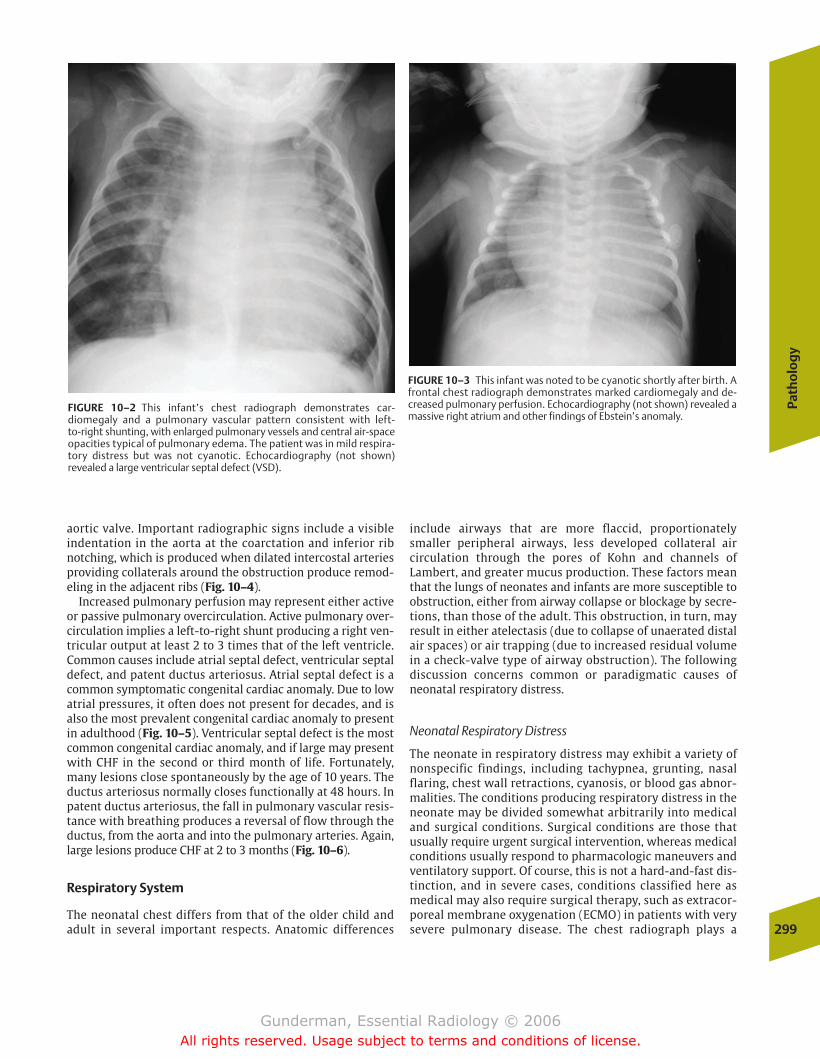
Path
olo
gy
299
aortic valve. Important radiographic signs include a visible indentation in the aorta at the coarctation and inferior ribnotching, which is produced when dilated intercostal arteriesproviding collaterals around the obstruction produce remod-eling in the adjacent ribs (Fig. 10–4).
Increased pulmonary perfusion may represent either activeor passive pulmonary overcirculation. Active pulmonary over-circulation implies a left-to-right shunt producing a right ven-tricular output at least 2 to 3 times that of the left ventricle.Common causes include atrial septal defect, ventricular septaldefect, and patent ductus arteriosus. Atrial septal defect is acommon symptomatic congenital cardiac anomaly. Due to lowatrial pressures, it often does not present for decades, and isalso the most prevalent congenital cardiac anomaly to presentin adulthood (Fig. 10–5). Ventricular septal defect is the mostcommon congenital cardiac anomaly, and if large may presentwith CHF in the second or third month of life. Fortunately,many lesions close spontaneously by the age of 10 years. Theductus arteriosus normally closes functionally at 48 hours. Inpatent ductus arteriosus, the fall in pulmonary vascular resis-tance with breathing produces a reversal of flow through theductus, from the aorta and into the pulmonary arteries. Again,large lesions produce CHF at 2 to 3 months (Fig. 10–6).
Respiratory System
The neonatal chest differs from that of the older child andadult in several important respects. Anatomic differences
include airways that are more flaccid, proportionatelysmaller peripheral airways, less developed collateral air circulation through the pores of Kohn and channels of Lambert, and greater mucus production. These factors meanthat the lungs of neonates and infants are more susceptible to obstruction, either from airway collapse or blockage by secre-tions, than those of the adult. This obstruction, in turn, mayresult in either atelectasis (due to collapse of unaerated distalair spaces) or air trapping (due to increased residual volumein a check-valve type of airway obstruction). The followingdiscussion concerns common or paradigmatic causes ofneonatal respiratory distress.
Neonatal Respiratory Distress
The neonate in respiratory distress may exhibit a variety ofnonspecific findings, including tachypnea, grunting, nasalflaring, chest wall retractions, cyanosis, or blood gas abnor-malities. The conditions producing respiratory distress in theneonate may be divided somewhat arbitrarily into medicaland surgical conditions. Surgical conditions are those thatusually require urgent surgical intervention, whereas medicalconditions usually respond to pharmacologic maneuvers andventilatory support. Of course, this is not a hard-and-fast dis-tinction, and in severe cases, conditions classified here asmedical may also require surgical therapy, such as extracor-poreal membrane oxygenation (ECMO) in patients with verysevere pulmonary disease. The chest radiograph plays a
FIGURE 10–2 This infant’s chest radiograph demonstrates car-diomegaly and a pulmonary vascular pattern consistent with left-to-right shunting, with enlarged pulmonary vessels and central air-spaceopacities typical of pulmonary edema. The patient was in mild respira-tory distress but was not cyanotic. Echocardiography (not shown) revealed a large ventricular septal defect (VSD).
FIGURE 10–3 This infant was noted to be cyanotic shortly after birth. Afrontal chest radiograph demonstrates marked cardiomegaly and de-creased pulmonary perfusion. Echocardiography (not shown) revealed amassive right atrium and other findings of Ebstein’s anomaly.
chapter 10_p296-326.qxd 12/1/05 4:22 PM Page 299
Gunderman, Essential Radiology © 2006All rights reserved. Usage subject to terms and conditions of license.
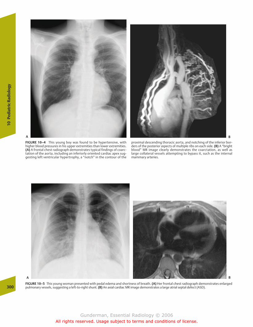
300
10Pe
diat
ric
Radi
olog
y
FIGURE 10–4 This young boy was found to be hypertensive, withhigher blood pressures in his upper extremities than lower extremities.(A) A frontal chest radiograph demonstrates typical findings of coarc-tation of the aorta, including an inferiorly oriented cardiac apex sug-gesting left ventricular hypertrophy, a “notch” in the contour of the
proximal descending thoracic aorta, and notching of the inferior bor-ders of the posterior aspects of multiple ribs on each side. (B) A “brightblood” MR image clearly demonstrates the coarctation, as well as large collateral vessels attempting to bypass it, such as the internal mammary arteries.
FIGURE 10–5 This young woman presented with pedal edema and shortness of breath. (A) Her frontal chest radiograph demonstrates enlarged pulmonary vessels, suggesting a left-to-right shunt. (B) An axial cardiac MR image demonstrates a large atrial septal defect (ASD).
A B
A B
chapter 10_p296-326.qxd 12/1/05 4:22 PM Page 300
Gunderman, Essential Radiology © 2006All rights reserved. Usage subject to terms and conditions of license.

Path
olo
gy
301
crucial role in differentiating between medical and surgicalconditions. Moreover, it is vital in distinguishing between dif-ferent disorders within each of these categories—a distinctionthat further powerfully influences therapy.
�� Medical Condition: Surfactant Deficiency
Epidemiology Surfactant deficiency disease (SDD) is themost common cause of neonatal respiratory distress, seen in30,000 to 50,000 infants per year in the United States. Itnearly always occurs in premature infants, with a positivecorrelation between the degree of prematurity and the prob-ability of developing SDD.
Pathophysiology The pathophysiology of SDD centers on adeficiency of pulmonary surfactant, which normally lowersthe surface tension of the alveolar air sacs. Alveolar surfacetension results from the fact that the water moleculeslining the alveolar air sacs (without which the diffusion ofgases could not occur) are more strongly attracted to one an-other than to the air above them in the alveolar sacs. This ex-erts a double effect: (1) the liquid layer resists any force that
tends to increase its surface area, making the alveolus harderto inflate; and (2) the water molecules try to get as close to-gether as possible, which tends to collapse the alveolus. As aresult of these forces, the compliance of the lung, which isdefined as the change in lung volume produced per unit forceof inflation, decreases.
Surfactant is produced by type II pneumocytes, which canbe differentiated microscopically from type I pneumocytes bytheir cuboidal shape and the fact that they contain lamellarinclusion bodies. Surfactant molecules are normally inter-posed between water molecules lining the alveoli. Theylower the overall cohesive force between these molecules,because the attractive force between water molecules andsurfactant molecules is very low. When surfactant suppliesare deficient, alveolar surface tension is dramatically in-creased, with the result that the amount of muscular workrequired to snap them open at inspiration is considerablygreater. Moreover, surfactant deficiency increases the recoilforces of the alveoli and promotes their tendency to collapseat expiration.
Unfortunately, alveolar atelectasis tends to set in motion avicious cycle of alveolar hypoxia and decreased pulmonaryperfusion. Atelectatic air spaces become hypoxic, which inturn leads to acidosis in the affected portion of the lung. Thisacidosis, in turn, leads to a reflex decrease in local pulmonaryperfusion, which then exacerbates hypoxia and initiates another turn of the cycle; therefore, the short-term keys tomaintaining adequate gas exchange are aerating collapsed airspaces and supplying supplementary oxygen.
The clinical result of surfactant deficiency is a neonate whois rapidly exhausted by the work of breathing. The child de-velops diffuse atelectasis, which in turn tips the balance ofthe Starling forces in favor of pulmonary edema. Proteina-ceous material gradually builds up along the lining of the airsacs (hence the alternative name hyaline membrane disease)(Fig. 10–7). Because surfactant production, which is not nec-essary during in utero life, does not begin until �24 weeksgestation, low birth weight infants are at higher risk, withnearly two thirds of those less than 1000 g developing somedegree of SDD. Two thirds of affected neonates are male, whoalso are more often severely affected.
Clinical Presentation Clinically, neonates with SDD exhibitchest wall retractions, because the infant recruits accessorymuscles of respiration in an effort to generate greater nega-tive intrathoracic pressures; cyanosis, due to lower oxygensaturation; grunting, indicative of the increased work ofbreathing; tachypnea, which results from the attempt tomaintain adequate ventilation in the face of lower tidal vol-umes; and expiratory grunting, the result of the effort toopen up collapsed alveoli. Of course, such findings can beseen in a variety of pulmonary pathologies, and the chestradiograph is crucial in helping to establish the correct diag-nosis of SDD. This is especially true in older prematureneonates, for example, those weighing 1500 g, whose risk ofdeveloping SDD is only 16%. The probability of developingSDD can be assessed based on measurement of thelecithin–sphingomyelin ratio, which is decreased in infantsat risk.
FIGURE 10–6 This infant presented with respiratory distress but wasnot cyanotic. A frontal chest radiograph demonstrates two electrocar-diogram (ECG) leads and, more inferiorly, a metallic snap on the pa-tient’s clothing. More importantly, there is cardiomegaly, enlarged pul-monary vessels, and central air-space opacification consistent withpulmonary edema. The differential diagnosis would include VSD, ASD,and patent ductus arteriosus (PDA), among other possibilities. Echocar-diography (not shown) demonstrated a PDA.
chapter 10_p296-326.qxd 12/1/05 4:22 PM Page 301
Gunderman, Essential Radiology © 2006All rights reserved. Usage subject to terms and conditions of license.
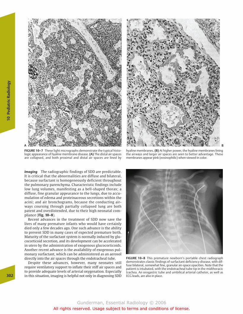
Imaging The radiographic findings of SDD are predictable.It is critical that the abnormalities are diffuse and bilateral,because surfactant is homogeneously deficient throughoutthe pulmonary parenchyma. Characteristic findings includelow lung volumes, manifesting as a bell-shaped thorax; adiffuse, fine granular appearance to the lungs, due to accu-mulation of edema and proteinaceous secretions within theacini; and air bronchograms, because the conducting air-ways coursing through partially collapsed lung are bothpatent and overdistended, due to their high neonatal com-pliance (Fig. 10–8).
Recent advances in the treatment of SDD now save thelives of many premature infants who would have certainlydied only a few decades ago. One such advance is the abilityto prevent SDD in many cases of expected premature birth.Maturity of the surfactant system is normally induced by glu-cocorticoid secretion, and its development can be acceleratedin utero by the administration of exogenous glucocorticoids.Another recent advance is the availability of exogenous pul-monary surfactant, which can be administered as an aerosoldirectly into the air spaces through the endotracheal tube.
Despite these advances, however, many neonates still require ventilatory support to inflate their stiff air spaces andto provide adequate levels of arterial oxygenation. Especiallyin this situation, imaging is helpful not only in diagnosing SDD302
10Pe
diat
ric
Radi
olog
y
FIGURE 10–7 These light micrographs demonstrate the typical histo-logic appearance of hyaline membrane disease. (A) The distal air spacesare collapsed, and both proximal and distal air spaces are lined by
hyaline membranes. (B) At higher power, the hyaline membranes liningthe airways and larger air spaces are seen to better advantage. Thesemembranes appear pink (eosinophilic) when viewed in color.
FIGURE 10–8 This premature newborn’s portable chest radiographdemonstrates classic findings of surfactant deficiency disease, with dif-fuse bilateral, somewhat fine, granular air-space opacities. Note that thepatient is intubated, with the endotracheal tube tip in the midthoracictrachea. An orogastric tube and umbilical arterial catheter, as well asECG leads, are also in place.
A B
chapter 10_p296-326.qxd 12/1/05 4:22 PM Page 302
Gunderman, Essential Radiology © 2006All rights reserved. Usage subject to terms and conditions of license.
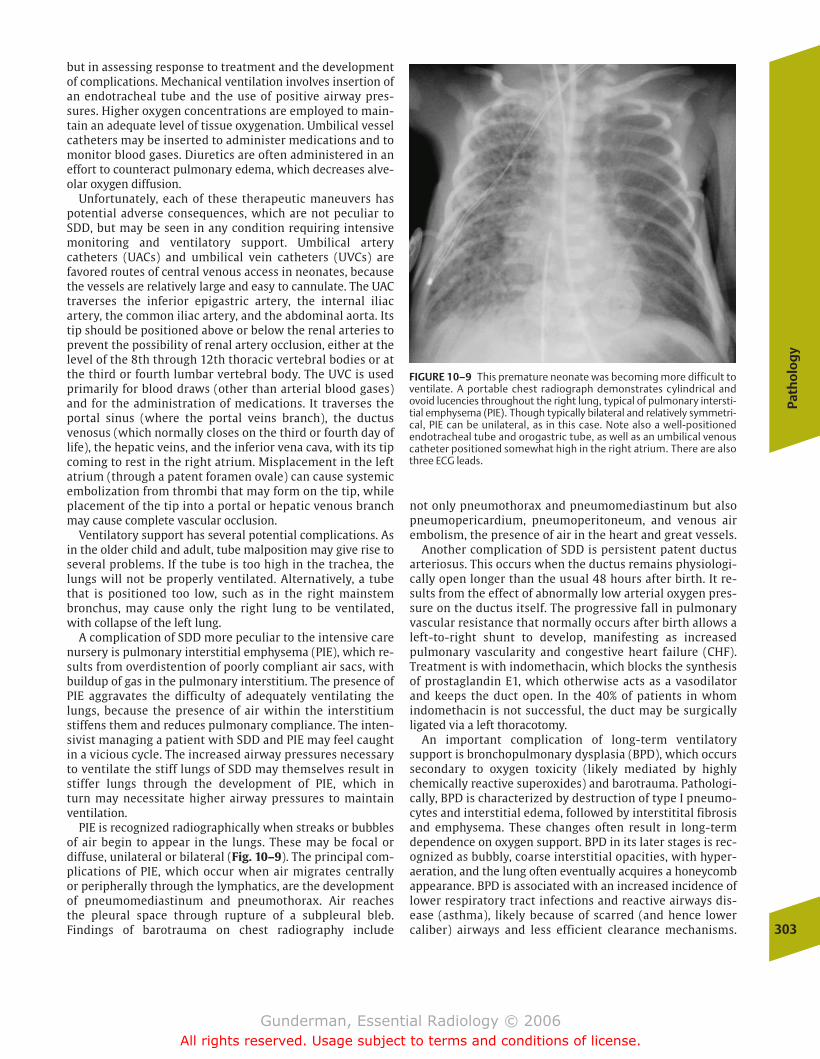
Path
olo
gy
303
but in assessing response to treatment and the developmentof complications. Mechanical ventilation involves insertion ofan endotracheal tube and the use of positive airway pres-sures. Higher oxygen concentrations are employed to main-tain an adequate level of tissue oxygenation. Umbilical vesselcatheters may be inserted to administer medications and tomonitor blood gases. Diuretics are often administered in aneffort to counteract pulmonary edema, which decreases alve-olar oxygen diffusion.
Unfortunately, each of these therapeutic maneuvers haspotential adverse consequences, which are not peculiar toSDD, but may be seen in any condition requiring intensivemonitoring and ventilatory support. Umbilical arterycatheters (UACs) and umbilical vein catheters (UVCs) are favored routes of central venous access in neonates, becausethe vessels are relatively large and easy to cannulate. The UACtraverses the inferior epigastric artery, the internal iliacartery, the common iliac artery, and the abdominal aorta. Itstip should be positioned above or below the renal arteries toprevent the possibility of renal artery occlusion, either at thelevel of the 8th through 12th thoracic vertebral bodies or atthe third or fourth lumbar vertebral body. The UVC is usedprimarily for blood draws (other than arterial blood gases)and for the administration of medications. It traverses theportal sinus (where the portal veins branch), the ductusvenosus (which normally closes on the third or fourth day oflife), the hepatic veins, and the inferior vena cava, with its tipcoming to rest in the right atrium. Misplacement in the leftatrium (through a patent foramen ovale) can cause systemicembolization from thrombi that may form on the tip, whileplacement of the tip into a portal or hepatic venous branchmay cause complete vascular occlusion.
Ventilatory support has several potential complications. Asin the older child and adult, tube malposition may give rise toseveral problems. If the tube is too high in the trachea, thelungs will not be properly ventilated. Alternatively, a tubethat is positioned too low, such as in the right mainstembronchus, may cause only the right lung to be ventilated,with collapse of the left lung.
A complication of SDD more peculiar to the intensive carenursery is pulmonary interstitial emphysema (PIE), which re-sults from overdistention of poorly compliant air sacs, withbuildup of gas in the pulmonary interstitium. The presence ofPIE aggravates the difficulty of adequately ventilating thelungs, because the presence of air within the interstitiumstiffens them and reduces pulmonary compliance. The inten-sivist managing a patient with SDD and PIE may feel caughtin a vicious cycle. The increased airway pressures necessaryto ventilate the stiff lungs of SDD may themselves result instiffer lungs through the development of PIE, which in turn may necessitate higher airway pressures to maintainventilation.
PIE is recognized radiographically when streaks or bubblesof air begin to appear in the lungs. These may be focal or diffuse, unilateral or bilateral (Fig. 10–9). The principal com-plications of PIE, which occur when air migrates centrallyor peripherally through the lymphatics, are the developmentof pneumomediastinum and pneumothorax. Air reachesthe pleural space through rupture of a subpleural bleb. Findings of barotrauma on chest radiography include
not only pneumothorax and pneumomediastinum but alsopneumopericardium, pneumoperitoneum, and venous air embolism, the presence of air in the heart and great vessels.
Another complication of SDD is persistent patent ductusarteriosus. This occurs when the ductus remains physiologi-cally open longer than the usual 48 hours after birth. It re-sults from the effect of abnormally low arterial oxygen pres-sure on the ductus itself. The progressive fall in pulmonaryvascular resistance that normally occurs after birth allows aleft-to-right shunt to develop, manifesting as increased pulmonary vascularity and congestive heart failure (CHF).Treatment is with indomethacin, which blocks the synthesisof prostaglandin E1, which otherwise acts as a vasodilatorand keeps the duct open. In the 40% of patients in whom indomethacin is not successful, the duct may be surgicallyligated via a left thoracotomy.
An important complication of long-term ventilatory support is bronchopulmonary dysplasia (BPD), which occurssecondary to oxygen toxicity (likely mediated by highlychemically reactive superoxides) and barotrauma. Pathologi-cally, BPD is characterized by destruction of type I pneumo-cytes and interstitial edema, followed by interstitital fibrosisand emphysema. These changes often result in long-termdependence on oxygen support. BPD in its later stages is rec-ognized as bubbly, coarse interstitial opacities, with hyper-aeration, and the lung often eventually acquires a honeycombappearance. BPD is associated with an increased incidence oflower respiratory tract infections and reactive airways dis-ease (asthma), likely because of scarred (and hence lowercaliber) airways and less efficient clearance mechanisms.
FIGURE 10–9 This premature neonate was becoming more difficult toventilate. A portable chest radiograph demonstrates cylindrical andovoid lucencies throughout the right lung, typical of pulmonary intersti-tial emphysema (PIE). Though typically bilateral and relatively symmetri-cal, PIE can be unilateral, as in this case. Note also a well-positioned endotracheal tube and orogastric tube, as well as an umbilical venouscatheter positioned somewhat high in the right atrium. There are alsothree ECG leads.
chapter 10_p296-326.qxd 12/1/05 4:22 PM Page 303
Gunderman, Essential Radiology © 2006All rights reserved. Usage subject to terms and conditions of license.
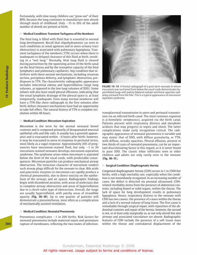
Fortunately, with time many children can “grow out” of theirBPD, because the lung continues to manufacture new alveolithrough much of childhood. Only �15 to 20% of the adultnumber of alveoli are present at birth.
�� Medical Condition: Transient Tachypnea of the Newborn
The fetal lung is filled with fluid that is essential to normallung development. Recall that oligohydramnios (as seen insuch conditions as renal agenesis and in utero urinary tractobstruction) is associated with pulmonary hypoplasia. Tran-sient tachypnea of the newborn (TTN) occurs when there isinadequate or delayed clearance of this fluid at birth, result-ing in a “wet lung.” Normally, fetal lung fluid is cleared during parturition by the squeezing action of the birth canalon the fetal thorax and by the resorptive capacity of the fetallymphatics and pulmonary capillaries. Any condition that in-terferes with these normal mechanisms, including cesareansection, precipitous delivery, and lymphatic obstruction, pre-disposes to TTN. The characteristic radiographic appearanceincludes interstitial edema and hyperinflation (large lungvolumes, as opposed to the low lung volumes of SDD). Someinfants will also have small pleural effusions, indicating thatthe usual lymphatic drainage of the pleural space is, at leasttemporarily, inadequate. Even many normal newborns willhave a TTN-like chest radiograph in the first minutes afterbirth, before clearance mechanisms have had an opportunityto take full effect. The natural history of TTN is complete res-olution within 48 hours.
�� Medical Condition: Meconium Aspiration
Meconium is the term for the normal neonatal bowel contents and is composed primarily of desquamated mucosalepithelial cells and bile salts. It usually has a greenish appear-ance and is evacuated within �6 hours after birth; however,it may be evacuated in utero in response to perinatal stress,most likely as a vagal response. Approximately 20% of preg-nancies have meconium-stained fluid, but only �1 in 20meconium-stained neonates develops meconium aspirationsyndrome. The syndrome arises when meconium is aspiratedbelow the level of the vocal cords, with predictable conse-quences. Meconium particles can produce mechanical airwayobstruction. The tenacious character of meconium renderssuch airway plugs difficult for the neonate to clear. Bile acidsand pancreatic enzymes in meconium can rapidly produce achemical pneumonitis, due to direct toxicity on the epithe-lium of the airways and air spaces. Radiographic findings begin with disordered aeration, with areas of atelectasis dueto complete airway obstruction and areas of hyperinflationdue to a check-valve type of obstruction. Overall, the lungsare usually hyperinflated, with patchy areas of strandlikeopacity (Fig. 10–10). Up to one quarter of patients willdemonstrate a pneumothorax, most often as a complicationof mechanically assisted ventilation.
�� Medical Condition: Neonatal Pneumonia
Pneumonia complicates �1 in 200 births. Risk factors forneonatal pneumonia include maternal sepsis and prematurerupture of membranes, reflecting the two routes of infection:
transplacental transmission in utero and perinatal transmis-sion via an infected birth canal. The most common organismis �-hemolytic streptococci, acquired via the birth canal. Patients present with respiratory distress and metabolic acidosis that may progress to sepsis and shock. The lattercomplications make early recognition critical. The radi-ographic appearance of neonatal pneumonia is variable andmay mimic that of SDD, with diffuse granularity, or TTN,with diffuse, streaky opacities. Pleural effusion, present intwo thirds of cases of neonatal pneumonia, can be an impor-tant discriminating factor in this regard, as it is never foundin pure SDD. The classic lobar infiltrates seen in olderchildren and adults are only rarely seen in the neonate (Fig. 10–11).
�� Surgical Condition: Diaphragmatic Hernia
Congenital diaphragmatic hernia (CDH) occurs in 1 in 2500 livebirths, with a high mortality rate, especially when the condi-tion is not immediately recognized. In an increasing number ofcases, the defect is detected via prenatal ultrasound. CDH-related morbidity stems from the presence of abdominal con-tents, including bowel or solid organs, within the thorax. Thelack of space for lung development results in pulmonary hypoplasia. Hence, respiratory distress in the neonate withCDH has two causes: the presence of a mass within the thoraxand a lack of a normal volume of lung tissue. The first cause isremediable through surgical repair, with reposition of the ab-dominal contents and repair of the hernia; however, the secondis not, or at least only marginally so, as not only alveoli but alsoairways and associated vasculature are absent. Radiographicfeatures of CDH include the presence of a soft tissue masswithin the thorax and contralateral displacement of the 304
10Pe
diat
ric
Radi
olog
y
FIGURE 10–10 A frontal radiograph of a post-term neonate in whommeconium was suctioned from below the vocal cords demonstrates hy-perinflated lungs with patchy bilateral nodular and linear opacities radi-ating outward from the hila. This is a typical appearance of meconiumaspiration syndrome.
chapter 10_p296-326.qxd 12/1/05 4:22 PM Page 304
Gunderman, Essential Radiology © 2006All rights reserved. Usage subject to terms and conditions of license.
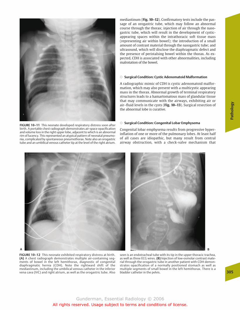
Path
olo
gy
305
mediastinum (Fig. 10–12). Confirmatory tests include the pas-sage of an orogastric tube, which may follow an abnormalcourse through the thorax; injection of air through the naso-gastric tube, which will result in the development of cystic-appearing spaces within the intrathoracic soft tissue mass (representing air within bowel); the introduction of a smallamount of contrast material through the nasogastric tube; andultrasound, which will disclose the diaphragmatic defect andthe presence of peristalsing bowel within the thorax. As ex-pected, CDH is associated with other abnormalities, includingmalrotation of the bowel.
�� Surgical Condition: Cystic Adenomatoid Malformation
A radiographic mimic of CDH is cystic adenomatoid malfor-mation, which may also present with a multicystic appearingmass in the thorax. Abnormal growth of terminal respiratorystructures leads to a hamartomatous mass of glandular tissuethat may communicate with the airways, exhibiting air orair–fluid levels in the cysts (Fig. 10–13). Surgical resection ofthe abnormal lobe is curative.
�� Surgical Condition: Congenital Lobar Emphysema
Congenital lobar emphysema results from progressive hyper-inflation of one or more of the pulmonary lobes. At least halfof all cases are idiopathic, but many result from central airway obstruction, with a check-valve mechanism that
FIGURE 10–11 This neonate developed respiratory distress soon afterbirth. A portable chest radiograph demonstrates air-space opacificationand volume loss in the right upper lobe, adjacent to which is an abnormalrim of lucency. This represented an atypical pattern of neonatal pneumo-nia, complicated by spontaneous pneumothorax. Note also an orogastrictube and an umbilical venous catheter tip at the level of the right atrium.
FIGURE 10–12 This neonate exhibited respiratory distress at birth.(A) A chest radiograph demonstrates multiple air-containing seg-ments of bowel in the left hemithorax, diagnostic of congenital diaphragmatic hernia (CDH). Note the rightward shift of the mediastinum, including the umbilical venous catheter in the inferiorvena cava (IVC) and right atrium, as well as the orogastric tube. Also
seen is an endotracheal tube with its tip in the upper thoracic trachea,as well as three ECG wires. (B) Injection of low-osmolar contrast mate-rial through the orogastric tube in another patient with CDH demon-strates opacification of a normally positioned stomach as well as multiple segments of small bowel in the left hemithorax. There is abladder catheter in the pelvis.
A B
chapter 10_p296-326.qxd 12/1/05 4:22 PM Page 305
Gunderman, Essential Radiology © 2006All rights reserved. Usage subject to terms and conditions of license.

allows the lobe to fill during inspiration but prevents emptying at expiration. In decreasing order of frequency, themost commonly affected lobes are the left upper lobe, theright middle lobe, and the right upper lobe. The lesion char-acteristically presents as an opacity in the first few days oflife, due to impaired emptying of lung fluid; thereafter, it presents as a hyperlucent, hyperexpanded lobe, which causescontralateral shift of the mediastinum.
�� Surgical Condition: Tracheoesophageal Fistula
Esophageal atresia (EA) and tracheoesophageal fistula (TEF)both represent anomalies in the development of the primi-tive foregut, which normally separates during the fifthweek of life into the esophagus and trachea. These anom-alies occur in �1 in 2500 live births. EA may be suggestedby a prenatal ultrasound showing polyhydramnios, sec-ondary to the inability of the fetus to ingest normal quanti-ties of amniotic fluid. EA and TEF are suggested postnatallyby the development of coughing, choking, and cyanosis inthe first day of life. Most commonly, attempted passage of anasogastric tube and subsequent chest radiograph revealthe tube ending in a blind pouch in the upper chest. Thepresence of gas within the bowel proves that there is a dis-tal esophageal-tracheal communication. Although manyanatomic types are possible, the most common involves ablind esophageal pouch with a more distal fistula betweenthe trachea and esophagus. A gasless abdomen indicatesthat the second most prevalent anatomic type is likely pre-sent, with no communication between the trachea andesophagus (pure EA). In a small percentage of cases, theesophagus is patent, but there is a fistula connecting it tothe trachea (Fig. 10–14).306
10Pe
diat
ric
Radi
olog
y
FIGURE 10–13 This newborn was diagnosed with a left lung mass. (A) Afrontal chest radiograph demonstrates a large mixed cystic and solid leftlung mass with rightward shift of the mediastinum. (B) The coronal
reformat of axially acquired CT data again demonstrates the mixed cys-tic and solid character of the mass. At surgery, the pathologic findings confirmed cystic adenomatoid malformation.
FIGURE 10–14 This patient developed recurrent choking with feedingsafter surgical repair of an esophageal atresia with tracheoesophageal fistula. The right lateral fluoroscopic spot image of the upper medi-astinum was obtained after injection of barium contrast material intothe esophagus through an oroesophageal tube. Above the level of theesophageal anastomosis, which demonstrates some narrowing and irregularity, there is opacification of a recurrent tracheoesophageal fistula, as well as the trachea itself, which is seen in double-contrastview. The line overlying the trachea is a central venous catheter. Whichdirection is the patient facing? Because the trachea is anterior to theesophagus, the patient is facing the viewer’s left.
A B
chapter 10_p296-326.qxd 12/1/05 4:22 PM Page 306
Gunderman, Essential Radiology © 2006All rights reserved. Usage subject to terms and conditions of license.

Path
olo
gy
307
Childhood Respiratory Distress
Many of the conditions that cause respiratory distress in theadult manifest similarly in children. These include such com-mon disorders as asthma and pneumonia; however, there arethree common, community-acquired childhood respiratoryconditions that deserve special mention. These are foreignbody aspiration, croup, and epiglottitis.
�� Foreign Body Aspiration
Airway foreign bodies represent a common cause of respiratorydistress, particularly between ages 6 months and 4 years, whenchildren characteristically put objects in their mouths. In con-trast to croup and epiglottitis, there is generally no history ofantecedent infectious symptoms, and the child presents withacute stridor, wheezing, and cough. As expected, foreign bodiesfollow the path of least resistance through the tracheobronchialtree, and most lodge in the right mainstem bronchus or itsbranches. Foreign bodies that are not removed may result inlong-term complications such as recurrent pneumonias, he-moptysis, and bronchial stenosis, and bronchoscopic removal isgenerally indicated. Most aspirated foreign bodies are not ra-diopaque. Common radiographic findings include unilateral airtrapping and hyperinflation due to a check-valve type of obstruction, and less commonly, atelectasis from complete ob-struction (Fig. 10–15). It is uncommon to visualize the foreignbody directly, because most are radiolucent. By obtaining inspi-ratory and expiratory films, or by observation of breathing un-der fluoroscopy, it is possible to increase diagnostic confidence.The nonobstructed lung will be able to empty normally,whereas the obstructed lung will not. Therefore, on an expira-tory film the mediastinum will shift away from the side of theforeign body.
�� Croup
Croup, more descriptively referred to as acute laryngotra-cheobronchitis, represents the most common cause of upperairway obstruction in children. It is most commonly seen inthe 6-month-to-3-year age group. The principal infectious or-ganisms in croup include parainfluenza virus and respiratorysyncytial virus. Although it involves the entire upper airway,the critical zone of airway narrowing is the immediate sub-glottic region, �1 cm below the larynx, due to the fact thatloose mucosal attachment in this region permits excessiveedematous narrowing. Patients present with a barky coughand stridor. The classic finding on a frontal radiograph is a ta-pered narrowing of the trachea in the subglottic region, pro-ducing a “V” configuration of airway narrowing (Fig. 10–16).The critical reason for obtaining radiographs is not to diag-nose croup, which is generally a self-limited process of several days’ duration, but to exclude other more worrisome entities such as foreign body aspiration and epiglottitis.
�� Epiglottitis
Epiglottitis represents an acutely life-threatening condition,because it may result in sudden and complete airway ob-struction with asphyxiation. Children suspected of sufferingfrom this condition should not be moved, and no maneuversthat might compromise breathing should be performed untilpersonnel and equipment capable of airway intervention andmanagement are present. If it is necessary to obtain radi-ographs, a portable unit should be used. Epiglottitis mostcommonly occurs between 3 and 6 years of age and is mostoften due to Haemophilus influenzae, although widespreadimmunization against H. flu is altering this. Patients presentwith a history of fever, dysphagia, drooling, and sore throat.
FIGURE 10–15 This young child presented with abrupt onset respira-tory distress. A frontal chest radiograph (with ECG leads in place)demonstrates severe hyperinflation of the right lung with leftward shiftof the mediastinum. This is highly suggestive of a right bronchial foreignbody, although none is seen. At bronchoscopy, a piece of apple was removed from the right mainstem bronchus.
FIGURE 10–16 This young child presented with respiratory distress. Afrontal radiograph demonstrates no pneumonia, but there is a graduallytapering of the subglottic trachea, producing the so-called steeple signof croup.
chapter 10_p296-326.qxd 12/1/05 4:22 PM Page 307
Gunderman, Essential Radiology © 2006All rights reserved. Usage subject to terms and conditions of license.

The classic radiographic and pathologic finding is thickeningof the aryepiglottic folds, which manifests as a thumblikethickening of the epiglottis on lateral views of the neck softtissues (Fig. 10–17).
Nervous System
Neonatal Intracranial Hemorrhage
�� Epidemiology
Infants born prior to 32 weeks’ gestation suffer a markedlyincreased risk of intracranial hemorrhage and ischemia.Twenty-five percent of infants less than 1500 g develop in-tracranial hemorrhage, and it develops to some degree in upto two thirds of infants at 28 to 32 weeks’ gestation. Suchevents can prove catastrophic, because infants so affectedmay suffer permanent and severe neurologic sequelae.
The occurrence of intracranial hemorrhage is linked to several risk factors. Antepartum factors include the medicalcondition of the mother, involving such risk factors as tox-emia, diabetes, heart disease, and other factors predisposingto premature birth. The most effective medical response tointracranial hemorrhage is the prevention of premature birth.Intrapartum factors include abnormal fetal presentation andprolonged labor. Postpartum events associated with increased risk include respiratory distress, cardiopulmonaryabnormalities, infection, and hemolysis.
�� Pathophysiology
To understand why premature infants are at risk for intracra-nial hemorrhage, it is necessary to understand the special developmental neuroanatomy of neonates. As one would pre-dict, the areas of the brain most vulnerable to ischemic insultare the zones with the highest metabolic rate. In the neonate,these include the zones characterized by the highest rates ofneural proliferation, maturation, and myelination, includingthe cerebellum, the basal ganglia, and the periventricularwhite matter. An area of special risk is the germinal matrix,located near the head of the caudate nucleus (Fig. 10–18).The germinal matrix is the subventricular and ventriculararea of proliferation of neuronal and glial precursors. Cellsmigrate from this subependymal location out into the cortex.Of special note is the fact that this area is richly vascularizedand has little supporting stroma; thus, any microscopic inter-ruption of vascular integrity would tend not to be well con-tained and likely to develop into macroscopic hemorrhage.Germinal matrix hemorrhage is more prevalent in very pre-mature infants and rare in those of 40 weeks’ gestation, be-cause the germinal matrix becomes less and less prominentover the last 12 weeks of gestation and virtually disappearsby term.
The pathophysiology of the condition centers on the autoregulation of cerebral blood flow. This autoregulation isdisrupted in the premature newborn, who is less adept thana full-term infant at maintaining constant cerebral perfusionpressure in the face of changing arterial pressure. Moderateto severe asphyxia is the disrupting factor, rendering cere-bral blood flow pressure-passive. This “pressure passivity” isthe key to understanding the apparently paradoxical devel-opment of both ischemic and hemorrhagic injury, and in experimental models predicts the later development of ultrasonographically detectable hemorrhage. In normal in-fants, cerebral blood flow is independent of arterial pressureover a wide pressure range. When arterial pressure is re-duced, flow can be maintained by lowering cerebrovascularresistance. When hypertension obtains, arteriolar constric-tion is induced. In the distressed newborn, small decreasesin arterial pressure lead to a significant decrease in cerebralblood flow, which, if sustained, eventuates in ischemic in-jury. This situation is further aggravated by hypoxemia. Inhypertension, increased pressure is transmitted unimpededto the walls of the capillary bed, with an associated in-creased risk of hemorrhage. Thus, the key pathophysiologicfactor is a change in blood pressure, and management fo-cuses on reducing distress and maintaining stable pressures.
Several other factors are critical to understanding why intracranial hemorrhage constitutes such a thorny problem.The prevention of asphyxia is a key strategy, yet the birthprocess itself can be likened to an asphyxial insult. Asphyxianormally leads first to hypertension, then later to hypoten-sion, perhaps due to depletion of cardiac carbohydrate stores.Abrupt increases in arterial pressure are a fact of life in thefirst few days, accompanying even handling, feeding, andother routine activities. A second such factor is arterial PaCO2(partial pressure of carbon dioxide in arterial blood), which isa major regulator of intracranial vascular resistance at all stages of life. High PaCO2 causes vasodilation and is associated with increased incidence of germinal matrix
308
10Pe
diat
ric
Radi
olog
y
FIGURE 10–17 Though typically a pediatric diagnosis, epiglottitis canbe seen even in adults. This middle-aged woman presented with severeodynophagia (painful swallowing) and high fever. A lateral soft tissue radiograph of the neck demonstrates the classic “thumb sign” ofepiglottic swelling.
chapter 10_p296-326.qxd 12/1/05 4:22 PM Page 308
Gunderman, Essential Radiology © 2006All rights reserved. Usage subject to terms and conditions of license.
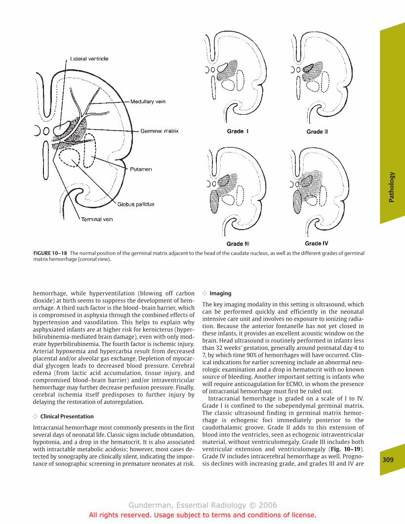
Path
olo
gy
309
hemorrhage, while hyperventilation (blowing off carbondioxide) at birth seems to suppress the development of hem-orrhage. A third such factor is the blood–brain barrier, whichis compromised in asphyxia through the combined effects ofhypertension and vasodilation. This helps to explain why asphyxiated infants are at higher risk for kernicterus (hyper-bilirubinemia-mediated brain damage), even with only mod-erate hyperbilirubinemia. The fourth factor is ischemic injury.Arterial hypoxemia and hypercarbia result from decreasedplacental and/or alveolar gas exchange. Depletion of myocar-dial glycogen leads to decreased blood pressure. Cerebraledema (from lactic acid accumulation, tissue injury, andcompromised blood–brain barrier) and/or intraventricularhemorrhage may further decrease perfusion pressure. Finally,cerebral ischemia itself predisposes to further injury by delaying the restoration of autoregulation.
�� Clinical Presentation
Intracranial hemorrhage most commonly presents in the firstseveral days of neonatal life. Classic signs include obtundation,hypotonia, and a drop in the hematocrit. It is also associatedwith intractable metabolic acidosis; however, most cases de-tected by sonography are clinically silent, indicating the impor-tance of sonographic screening in premature neonates at risk.
�� Imaging
The key imaging modality in this setting is ultrasound, whichcan be performed quickly and efficiently in the neonatal intensive care unit and involves no exposure to ionizing radia-tion. Because the anterior fontanelle has not yet closed inthese infants, it provides an excellent acoustic window on thebrain. Head ultrasound is routinely performed in infants lessthan 32 weeks’ gestation, generally around postnatal day 4 to7, by which time 90% of hemorrhages will have occurred. Clin-ical indications for earlier screening include an abnormal neu-rologic examination and a drop in hematocrit with no knownsource of bleeding. Another important setting is infants whowill require anticoagulation for ECMO, in whom the presenceof intracranial hemorrhage must first be ruled out.
Intracranial hemorrhage is graded on a scale of I to IV.Grade I is confined to the subependymal germinal matrix.The classic ultrasound finding in germinal matrix hemor-rhage is echogenic foci immediately posterior to the caudothalamic groove. Grade II adds to this extension ofblood into the ventricles, seen as echogenic intraventricularmaterial, without ventriculomegaly. Grade III includes bothventricular extension and ventriculomegaly (Fig. 10–19).Grade IV includes intracerebral hemorrhage as well. Progno-sis declines with increasing grade, and grades III and IV are
FIGURE 10–18 The normal position of the germinal matrix adjacent to the head of the caudate nucleus, as well as the different grades of germinalmatrix hemorrhage (coronal view).
chapter 10_p296-326.qxd 12/1/05 4:22 PM Page 309
Gunderman, Essential Radiology © 2006All rights reserved. Usage subject to terms and conditions of license.

associated with large increases in morbidity and mortality.Between 40 and 50% of infants with grade IV hemorrhagesuffer severe neurologic impairment, and more than threequarters of infants with grades I and II hemorrhage developonly mild or no neurologic impairment.
Periventricular leukomalacia is another common finding inischemic injury, which results from ischemic damage to thedeep white matter of the hemispheres. It manifests initiallyas areas of edema or hemorrhage, followed eventually by cystic lesions (porencephaly), giving the brain an appearancethat may resemble Swiss cheese (Fig. 10–20).
Abdomen
Acute Abdomen
Several acute abdominal processes are unique to the pediatric population, or at least occur predominantly in in-fants and children. To determine which process is involved ina particular patient, several extraradiologic factors are criti-cal. First is the patient’s age. Pediatric patients are predis-posed to certain conditions at certain points in their development. For example, conditions such as necrotizingenterocolitis (NEC), meconium ileus, and bowel atresias willpresent in the first few days of extrauterine life, while hyper-trophic pyloric stenosis presents around the age of 1 month, and it would be somewhat unusual to see intussus-ception in the first few months of life. Additional factors include whether the patient is infected (fever, leukocytosis),310
10Pe
diat
ric
Radi
olog
y
FIGURE 10–19 This near full-term neonate suffered an unexplaineddrop in hematocrit. (A) A sagittal sonogram of the right cerebral hemi-sphere demonstrates echogenic hematoma in the posterior portion ofthe lateral ventricle. (B) An axial CT image demonstrates bulky acute
hematoma in the right lateral ventricle, as well as some acute blood layering out in the posterior horn on the left. This represents a Grade IIIgerminal matrix hemorrhage.
FIGURE 10–20 This now 15-month-old child was born at 30 weeks’ gestation. The axial fluid-attenuation inversion recovery (FLAIR) MR im-age demonstrates bilateral hemispheric atrophy and periventricular cys-tic changes typical of periventricular leukomalacia.
A B
chapter 10_p296-326.qxd 12/1/05 4:22 PM Page 310
Gunderman, Essential Radiology © 2006All rights reserved. Usage subject to terms and conditions of license.
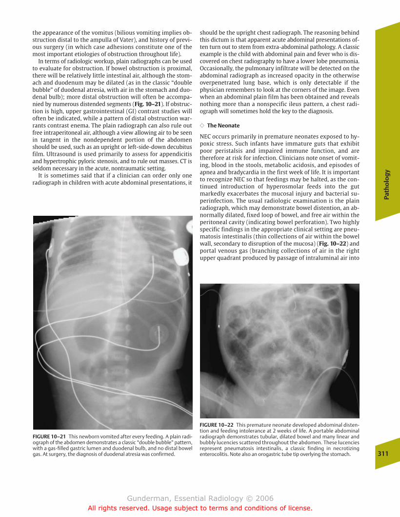
Path
olo
gy
311
the appearance of the vomitus (bilious vomiting implies ob-struction distal to the ampulla of Vater), and history of previ-ous surgery (in which case adhesions constitute one of themost important etiologies of obstruction throughout life).
In terms of radiologic workup, plain radiographs can be usedto evaluate for obstruction. If bowel obstruction is proximal,there will be relatively little intestinal air, although the stom-ach and duodenum may be dilated (as in the classic “doublebubble” of duodenal atresia, with air in the stomach and duo-denal bulb); more distal obstruction will often be accompa-nied by numerous distended segments (Fig. 10–21). If obstruc-tion is high, upper gastrointestinal (GI) contrast studies willoften be indicated, while a pattern of distal obstruction war-rants contrast enema. The plain radiograph can also rule outfree intraperitoneal air, although a view allowing air to be seenin tangent in the nondependent portion of the abdomenshould be used, such as an upright or left-side-down decubitusfilm. Ultrasound is used primarily to assess for appendicitisand hypertrophic pyloric stenosis, and to rule out masses. CT isseldom necessary in the acute, nontraumatic setting.
It is sometimes said that if a clinician can order only oneradiograph in children with acute abdominal presentations, it
should be the upright chest radiograph. The reasoning behindthis dictum is that apparent acute abdominal presentations of-ten turn out to stem from extra-abdominal pathology. A classicexample is the child with abdominal pain and fever who is dis-covered on chest radiography to have a lower lobe pneumonia.Occasionally, the pulmonary infiltrate will be detected on theabdominal radiograph as increased opacity in the otherwiseoverpenetrated lung base, which is only detectable if thephysician remembers to look at the corners of the image. Evenwhen an abdominal plain film has been obtained and revealsnothing more than a nonspecific ileus pattern, a chest radi-ograph will sometimes hold the key to the diagnosis.
�� The Neonate
NEC occurs primarily in premature neonates exposed to hy-poxic stress. Such infants have immature guts that exhibitpoor peristalsis and impaired immune function, and aretherefore at risk for infection. Clinicians note onset of vomit-ing, blood in the stools, metabolic acidosis, and episodes ofapnea and bradycardia in the first week of life. It is importantto recognize NEC so that feedings may be halted, as the con-tinued introduction of hyperosmolar feeds into the gutmarkedly exacerbates the mucosal injury and bacterial su-perinfection. The usual radiologic examination is the plainradiograph, which may demonstrate bowel distention, an ab-normally dilated, fixed loop of bowel, and free air within theperitoneal cavity (indicating bowel perforation). Two highlyspecific findings in the appropriate clinical setting are pneu-matosis intestinalis (thin collections of air within the bowelwall, secondary to disruption of the mucosa) (Fig. 10–22) andportal venous gas (branching collections of air in the rightupper quadrant produced by passage of intraluminal air into
FIGURE 10–21 This newborn vomited after every feeding. A plain radi-ograph of the abdomen demonstrates a classic “double bubble” pattern,with a gas-filled gastric lumen and duodenal bulb, and no distal bowelgas. At surgery, the diagnosis of duodenal atresia was confirmed.
FIGURE 10–22 This premature neonate developed abdominal disten-tion and feeding intolerance at 2 weeks of life. A portable abdominal radiograph demonstrates tubular, dilated bowel and many linear andbubbly lucencies scattered throughout the abdomen. These lucenciesrepresent pneumatosis intestinalis, a classic finding in necrotizing enterocolitis. Note also an orogastric tube tip overlying the stomach.
chapter 10_p296-326.qxd 12/1/05 4:22 PM Page 311
Gunderman, Essential Radiology © 2006All rights reserved. Usage subject to terms and conditions of license.
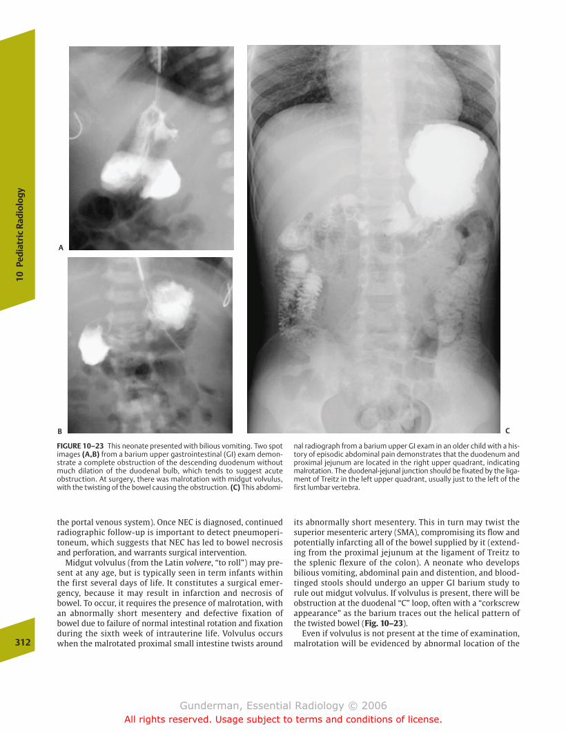
the portal venous system). Once NEC is diagnosed, continued radiographic follow-up is important to detect pneumoperi-toneum, which suggests that NEC has led to bowel necrosisand perforation, and warrants surgical intervention.
Midgut volvulus (from the Latin volvere, “to roll”) may pre-sent at any age, but is typically seen in term infants withinthe first several days of life. It constitutes a surgical emer-gency, because it may result in infarction and necrosis ofbowel. To occur, it requires the presence of malrotation, withan abnormally short mesentery and defective fixation ofbowel due to failure of normal intestinal rotation and fixationduring the sixth week of intrauterine life. Volvulus occurswhen the malrotated proximal small intestine twists around
its abnormally short mesentery. This in turn may twist thesuperior mesenteric artery (SMA), compromising its flow andpotentially infarcting all of the bowel supplied by it (extend-ing from the proximal jejunum at the ligament of Treitz tothe splenic flexure of the colon). A neonate who develops bilious vomiting, abdominal pain and distention, and blood-tinged stools should undergo an upper GI barium study torule out midgut volvulus. If volvulus is present, there will beobstruction at the duodenal “C” loop, often with a “corkscrewappearance” as the barium traces out the helical pattern ofthe twisted bowel (Fig. 10–23).
Even if volvulus is not present at the time of examination,malrotation will be evidenced by abnormal location of the312
10Pe
diat
ric
Radi
olog
y
FIGURE 10–23 This neonate presented with bilious vomiting. Two spotimages (A,B) from a barium upper gastrointestinal (GI) exam demon-strate a complete obstruction of the descending duodenum withoutmuch dilation of the duodenal bulb, which tends to suggest acute obstruction. At surgery, there was malrotation with midgut volvulus,with the twisting of the bowel causing the obstruction. (C) This abdomi-
nal radiograph from a barium upper GI exam in an older child with a his-tory of episodic abdominal pain demonstrates that the duodenum andproximal jejunum are located in the right upper quadrant, indicatingmalrotation. The duodenal-jejunal junction should be fixated by the liga-ment of Treitz in the left upper quadrant, usually just to the left of thefirst lumbar vertebra.
A
B C
chapter 10_p296-326.qxd 12/1/05 4:22 PM Page 312
Gunderman, Essential Radiology © 2006All rights reserved. Usage subject to terms and conditions of license.
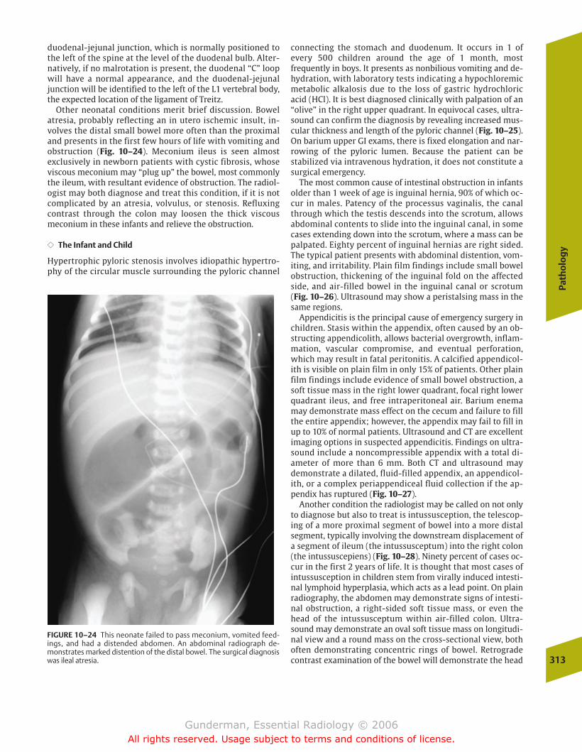
Path
olo
gy
313
duodenal-jejunal junction, which is normally positioned tothe left of the spine at the level of the duodenal bulb. Alter-natively, if no malrotation is present, the duodenal “C” loopwill have a normal appearance, and the duodenal-jejunaljunction will be identified to the left of the L1 vertebral body,the expected location of the ligament of Treitz.
Other neonatal conditions merit brief discussion. Bowelatresia, probably reflecting an in utero ischemic insult, in-volves the distal small bowel more often than the proximaland presents in the first few hours of life with vomiting andobstruction (Fig. 10–24). Meconium ileus is seen almost exclusively in newborn patients with cystic fibrosis, whoseviscous meconium may “plug up” the bowel, most commonlythe ileum, with resultant evidence of obstruction. The radiol-ogist may both diagnose and treat this condition, if it is notcomplicated by an atresia, volvulus, or stenosis. Refluxingcontrast through the colon may loosen the thick viscousmeconium in these infants and relieve the obstruction.
�� The Infant and Child
Hypertrophic pyloric stenosis involves idiopathic hypertro-phy of the circular muscle surrounding the pyloric channel
connecting the stomach and duodenum. It occurs in 1 ofevery 500 children around the age of 1 month, most frequently in boys. It presents as nonbilious vomiting and de-hydration, with laboratory tests indicating a hypochloremicmetabolic alkalosis due to the loss of gastric hydrochloricacid (HCl). It is best diagnosed clinically with palpation of an“olive” in the right upper quadrant. In equivocal cases, ultra-sound can confirm the diagnosis by revealing increased mus-cular thickness and length of the pyloric channel (Fig. 10–25).On barium upper GI exams, there is fixed elongation and nar-rowing of the pyloric lumen. Because the patient can be stabilized via intravenous hydration, it does not constitute asurgical emergency.
The most common cause of intestinal obstruction in infantsolder than 1 week of age is inguinal hernia, 90% of which oc-cur in males. Patency of the processus vaginalis, the canalthrough which the testis descends into the scrotum, allowsabdominal contents to slide into the inguinal canal, in somecases extending down into the scrotum, where a mass can bepalpated. Eighty percent of inguinal hernias are right sided.The typical patient presents with abdominal distention, vom-iting, and irritability. Plain film findings include small bowelobstruction, thickening of the inguinal fold on the affectedside, and air-filled bowel in the inguinal canal or scrotum(Fig. 10–26). Ultrasound may show a peristalsing mass in thesame regions.
Appendicitis is the principal cause of emergency surgery inchildren. Stasis within the appendix, often caused by an ob-structing appendicolith, allows bacterial overgrowth, inflam-mation, vascular compromise, and eventual perforation,which may result in fatal peritonitis. A calcified appendicol-ith is visible on plain film in only 15% of patients. Other plainfilm findings include evidence of small bowel obstruction, asoft tissue mass in the right lower quadrant, focal right lowerquadrant ileus, and free intraperitoneal air. Barium enemamay demonstrate mass effect on the cecum and failure to fillthe entire appendix; however, the appendix may fail to fill inup to 10% of normal patients. Ultrasound and CT are excellentimaging options in suspected appendicitis. Findings on ultra-sound include a noncompressible appendix with a total di-ameter of more than 6 mm. Both CT and ultrasound maydemonstrate a dilated, fluid-filled appendix, an appendicol-ith, or a complex periappendiceal fluid collection if the ap-pendix has ruptured (Fig. 10–27).
Another condition the radiologist may be called on not onlyto diagnose but also to treat is intussusception, the telescop-ing of a more proximal segment of bowel into a more distalsegment, typically involving the downstream displacement ofa segment of ileum (the intussusceptum) into the right colon(the intussuscepiens) (Fig. 10–28). Ninety percent of cases oc-cur in the first 2 years of life. It is thought that most cases ofintussusception in children stem from virally induced intesti-nal lymphoid hyperplasia, which acts as a lead point. On plainradiography, the abdomen may demonstrate signs of intesti-nal obstruction, a right-sided soft tissue mass, or even thehead of the intussusceptum within air-filled colon. Ultra-sound may demonstrate an oval soft tissue mass on longitudi-nal view and a round mass on the cross-sectional view, bothoften demonstrating concentric rings of bowel. Retrogradecontrast examination of the bowel will demonstrate the head
FIGURE 10–24 This neonate failed to pass meconium, vomited feed-ings, and had a distended abdomen. An abdominal radiograph de-monstrates marked distention of the distal bowel. The surgical diagnosiswas ileal atresia.
chapter 10_p296-326.qxd 12/1/05 4:22 PM Page 313
Gunderman, Essential Radiology © 2006All rights reserved. Usage subject to terms and conditions of license.
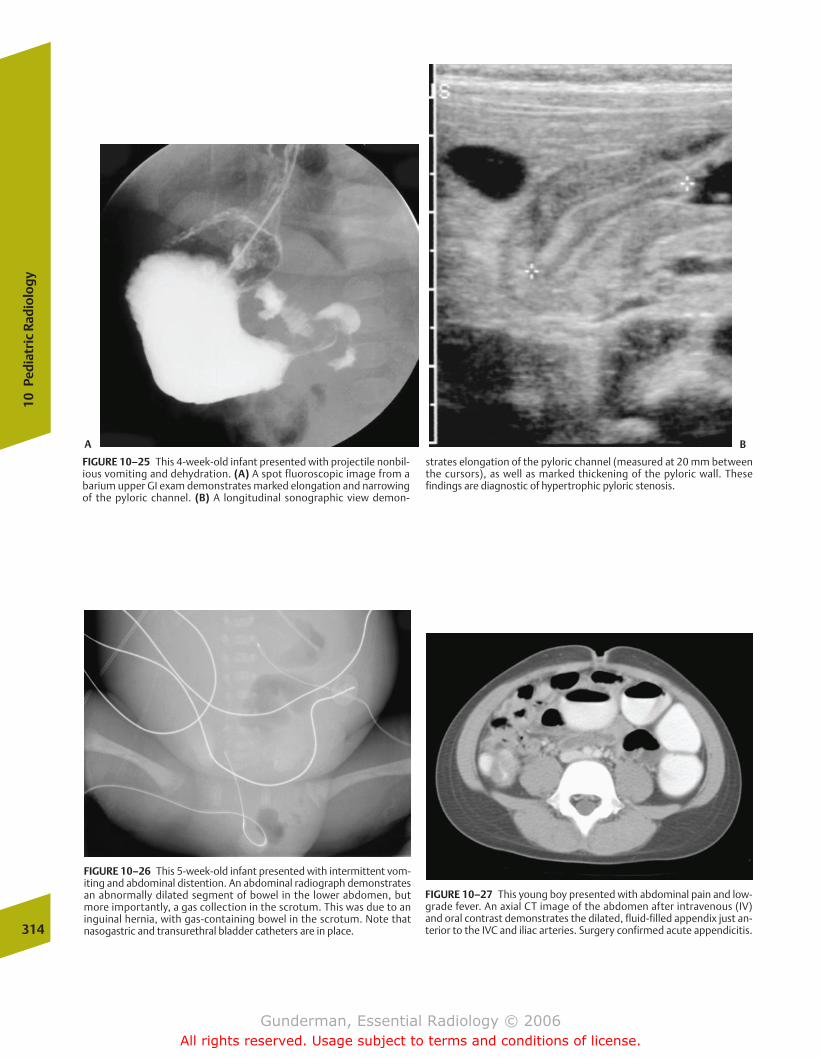
314
10Pe
diat
ric
Radi
olog
y
FIGURE 10–25 This 4-week-old infant presented with projectile nonbil-ious vomiting and dehydration. (A) A spot fluoroscopic image from abarium upper GI exam demonstrates marked elongation and narrowingof the pyloric channel. (B) A longitudinal sonographic view demon-
strates elongation of the pyloric channel (measured at 20 mm betweenthe cursors), as well as marked thickening of the pyloric wall. These findings are diagnostic of hypertrophic pyloric stenosis.
FIGURE 10–26 This 5-week-old infant presented with intermittent vom-iting and abdominal distention. An abdominal radiograph demonstratesan abnormally dilated segment of bowel in the lower abdomen, butmore importantly, a gas collection in the scrotum. This was due to an inguinal hernia, with gas-containing bowel in the scrotum. Note that nasogastric and transurethral bladder catheters are in place.
FIGURE 10–27 This young boy presented with abdominal pain and low-grade fever. An axial CT image of the abdomen after intravenous (IV)and oral contrast demonstrates the dilated, fluid-filled appendix just an-terior to the IVC and iliac arteries. Surgery confirmed acute appendicitis.
A B
chapter 10_p296-326.qxd 12/1/05 4:22 PM Page 314
Gunderman, Essential Radiology © 2006All rights reserved. Usage subject to terms and conditions of license.

Path
olo
gy
315
of the intussusceptum as a filling defect within the intussus-cepiens. In addition to diagnosis, pressure from retrogradeflow of contrast or air will often reduce the intussusception(Fig. 10–29). There is a 5% risk of recurrence. The only con-traindications to radiologic reduction are signs of perforation,such as free air, and symptoms of peritonitis.
Masses
�� Wilms’ Tumor
Epidemiology The most prevalent solid abdominal mass ofchildhood, which is also the most common renal cancer ofchildhood, is Wilms’ tumor, of which �400 cases per year arereported in the United States. It also represents the fourthmost common childhood malignancy, after leukemia, centralnervous system neoplasms, and neuroblastoma. The meanage of presentation in Wilms’ tumor is 3 years, and 85% ofcases present before the age of 6 years.
Pathophysiology Also known as nephroblastoma, Wilms’ tu-mor arises from the primitive metanephric blastema and istypically centered in the renal cortex, sparing the collectingsystem. Roughly 1 in 10 tumors presents bilaterally, whichseems to be associated with a better prognosis. Another im-portant prognostic factor is the histology of the tumor, with85% of tumors exhibiting a favorable triphasic pattern (con-sisting of primitive blastema, stroma, and epithelial cells),while 15% of tumors are anaplastic, an unfavorable pattern.
Wilms’ tumor is associated with several syndromes, includ-ing sporadic aniridia, hemihypertrophy, Beckwith-Wiedemann syndrome (macroglossia, organomegaly, andomphalocele), and Drash syndrome (pseudohermaphro-ditism, glomerulonephritis, and nephrotic syndrome). In ad-dition, it appears with increased frequency in horseshoe andfused kidneys.
Clinical Presentation Presenting complaints typically consistof a rapidly enlarging, painless abdominal mass, without sys-temic symptoms. A minority of patients demonstrate micro-scopic hematuria.
Imaging Ultrasound constitutes the first line of imaging, be-cause it provides quick and reliable detection as well as thebest assessment of the degree of vascular invasion. ManyWilms’ tumors will involve the renal vein and inferior venacava, some actually extending into the heart. Sonographyusually reveals a large mass, with internal areas of necrosisand hemorrhage, arising from the kidney and displacing ad-jacent abdominal structures. CT typically demonstrates awell-defined, low-attenuation mass with heterogeneous en-hancement (Fig. 10–30). Only �15% of Wilms’ tumorsdemonstrate calcifications. Treatment usually consists ofsurgery and chemotherapy, with radiation therapy reservedfor more advanced tumors that are not totally resectable orhave metastasized hematogenously. Despite the rapid growthof Wilms’ tumor, the prognosis is generally favorable, withoverall survival approaching 90%.
FIGURE 10–28 Anatomy of intussusception. The lower cross-sectional diagram explains the “target” sign of intussusception by ultrasound.
chapter 10_p296-326.qxd 12/1/05 4:22 PM Page 315
Gunderman, Essential Radiology © 2006All rights reserved. Usage subject to terms and conditions of license.

�� Neuroblastoma
Epidemiology Neuroblastoma is the second most commonintra-abdominal malignancy of childhood. Approximately70% of neuroblastomas arise in the abdomen, with over 40%originating in the adrenal gland, while the chest, neck, andpelvis represent other sites. At 2 years, the mean age of thisneoplasm is slightly lower than that of Wilms’ tumor, andthree quarters of patients present before age 5 years.
Pathophysiology The tumor arises from neural crest tissueeither in the adrenal gland or somewhere along the sympa-thetic chain. Neuroblastoma is at the malignant end of aspectrum of tumors ranging to the intermediate grade gan-glioneuroblastoma and the benign ganglioneuroma. Someneuroblastomas spontaneously differentiate into these moremature forms. They also occasionally exhibit the extraordi-nary property of undergoing spontaneous regression, even invery advanced disease. In contrast to Wilms’ tumor, neurob-
lastoma has fewer and less syndromic associations; however,it does sometimes exhibit certain clinical constellations of metastatic spread. Orbital ecchymosis and proptosis so-called raccoon eyes, often occur in combination with aprimary adrenal tumor and extensive skeletal involvement,especially the skull, which is called Hutchinson’s syndrome.The “blueberry muffin” syndrome is associated with multi-ple skin metastases.
Clinical Presentation Patients typically present with large abdominal masses and metastatic disease. In addition, 70%will have systemic symptoms, including hypertension, hyper-glycemia, tachycardia, and other signs of increased cate-cholamine production. Hence, laboratory analysis usually reveals increased urine levels of vanillylmandelic acid or homovanillic acid. A minority of patients will present withparaneoplastic effects, including the so-called dancing eyesand dancing feet syndrome.316
10Pe
diat
ric
Radi
olog
y
FIGURE 10–29 This 2-year-old boy presented with intermittent abdominalpain over several days, now with bloody stools. (A) The abdominal radiographshows a possible partial small bowel obstruction with a soft tissue mass in theright lower quadrant. An air-contrast enema was performed to assess for intussusception. (B) A fluoroscopic spot view of the right lower quadrantdemonstrates a soft tissue filling defect in the cecum, typical for an ileocolicintussusception. (C) After successful air reduction, the filling defect has disap-peared, and there is free reflux of air into the small bowel.
A B
C
chapter 10_p296-326.qxd 12/1/05 4:22 PM Page 316
Gunderman, Essential Radiology © 2006All rights reserved. Usage subject to terms and conditions of license.
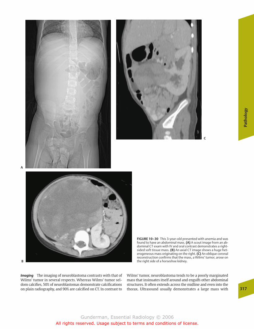
Path
olo
gy
317
Imaging The imaging of neuroblastoma contrasts with that ofWilms’ tumor in several respects. Whereas Wilms’ tumor sel-dom calcifies, 50% of neuroblastomas demonstrate calcificationson plain radiography, and 90% are calcified on CT. In contrast to
Wilms’ tumor, neuroblastoma tends to be a poorly marginatedmass that insinuates itself around and engulfs other abdominalstructures. It often extends across the midline and even into thethorax. Ultrasound usually demonstrates a large mass with
FIGURE 10–30 This 3-year-old presented with anemia and wasfound to have an abdominal mass. (A) A scout image from an ab-dominal CT exam with IV and oral contrast demonstrates a right-sided soft tissue mass. (B) An axial CT image shows a huge het-erogeneous mass originating on the right. (C) An oblique coronalreconstruction confirms that the mass, a Wilms’ tumor, arose onthe right side of a horseshoe kidney.
A
B
C
chapter 10_p296-326.qxd 12/1/05 4:22 PM Page 317
Gunderman, Essential Radiology © 2006All rights reserved. Usage subject to terms and conditions of license.
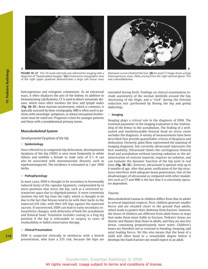
heterogeneous and echogenic echotexture. As an extrarenalmass, it often displaces the axis of the kidney. In addition todemonstrating calcifications, CT is used to detect metastatic dis-ease, which most often involves the liver and lymph nodes (Fig. 10–31). Bone marrow involvement, which is common, istypically assessed by bone scintigraphy. MRI is often used in pa-tients with neurologic symptoms, in whom intraspinal involve-ment must be ruled out. Prognosis is best for younger patientsand those with a nonabdominal primary tumor.
Musculoskeletal System
Developmental Dysplasia of the Hip
�� Epidemiology
Once referred to as congenital hip dislocation, developmentaldysplasia of the hip (DDH) is seen most frequently in white infants and exhibits a female to male ratio of 5:1. It can also be associated with neuromuscular diseases, such asmyelomeningocele. The incidence is estimated at 1 per 1000births.
�� Pathophysiology
In most cases, DDH is thought to be secondary to hormonallyinduced laxity of the capsular ligaments, compounded by inutero positions that stress the hip, such as a restricted in-trauterine space due to oligohydramnios. It more commonlyinvolves the left hip than the right, which is thought to bedue to the fact that fetuses tend to lie with their backs to thematernal left side, with their left hips against the maternalsacrum. If uncorrected, DDH can lead to early secondary os-teoarthritic changes, with deformity of both the acetabulumand femoral head. Treatment includes casting in a frog-legposition if the hip is relocatable or surgery in cases of irreducibility or failed conservative therapy.
�� Clinical Presentation
DDH is suspected clinically in newborns with a breech presentation, who have a 25% risk, because the hips are
extended during birth. Findings on clinical examination in-clude asymmetry of the normal skinfolds around the hip,shortening of the thigh, and a “click” during the Ortolani reduction test (performed by flexing the hip and gently abducting).
�� Imaging
Imaging plays a critical role in the diagnosis of DDH. The essential parameter in the imaging evaluation is the relation-ship of the femur to the acetabulum. The finding of a well-seated and nondislocatable femoral head on stress views excludes the diagnosis. A variety of measurements have beendescribed that provide quantifiable criteria of dysplasia anddislocation. Formerly, plain films represented the mainstay ofimaging diagnosis, but currently ultrasound represents thebest modality. Ultrasound shows the cartilaginous femoralhead and acetabulum without ionizing radiation or the ad-ministration of contrast material, requires no sedation, andcan evaluate the dynamic function of the hip joint in realtime (Fig. 10–32); however, ultrasound is optimal only up to6 months of age; after that point, ossification of the hip struc-tures interferes with adequate beam penetration. One of thedisadvantages of ultrasound as compared with other modali-ties such as CT and MRI is the fact that it is extremely opera-tor dependent.
Trauma
Musculoskeletal trauma in children differs from that in adultsin several important respects. First, children generate smallerforces and are situated closer to the ground than adults,which tends to protect their skeletons from fracture; however,the bones of children are different from adult bones in waysthat make them more liable to fracture. Pediatric bones areshorter and thinner than those in adults, and they are also lessdense, containing proportionately more water. Children’sbones are therefore not as resistant to bending, torquing, andaxial loading forces. Yet this also means that the bone of achild will often bend to a remarkable degree before it develops the frank fracture one would expect in an adult.
318
10Pe
diat
ric
Radi
olog
y
FIGURE 10–31 This 10-week-old male was referred for imaging with adiagnosis of “hepatosplenomegaly.” (A) A transverse sonographic viewof the right upper quadrant demonstrates a large soft tissue mass
(between cursors) behind the liver. (B) An axial CT image shows a largeheterogeneous mass, likely arising from the right adrenal gland. Thiswas a neuroblastoma.
A B
chapter 10_p296-326.qxd 12/1/05 4:22 PM Page 318
Gunderman, Essential Radiology © 2006All rights reserved. Usage subject to terms and conditions of license.
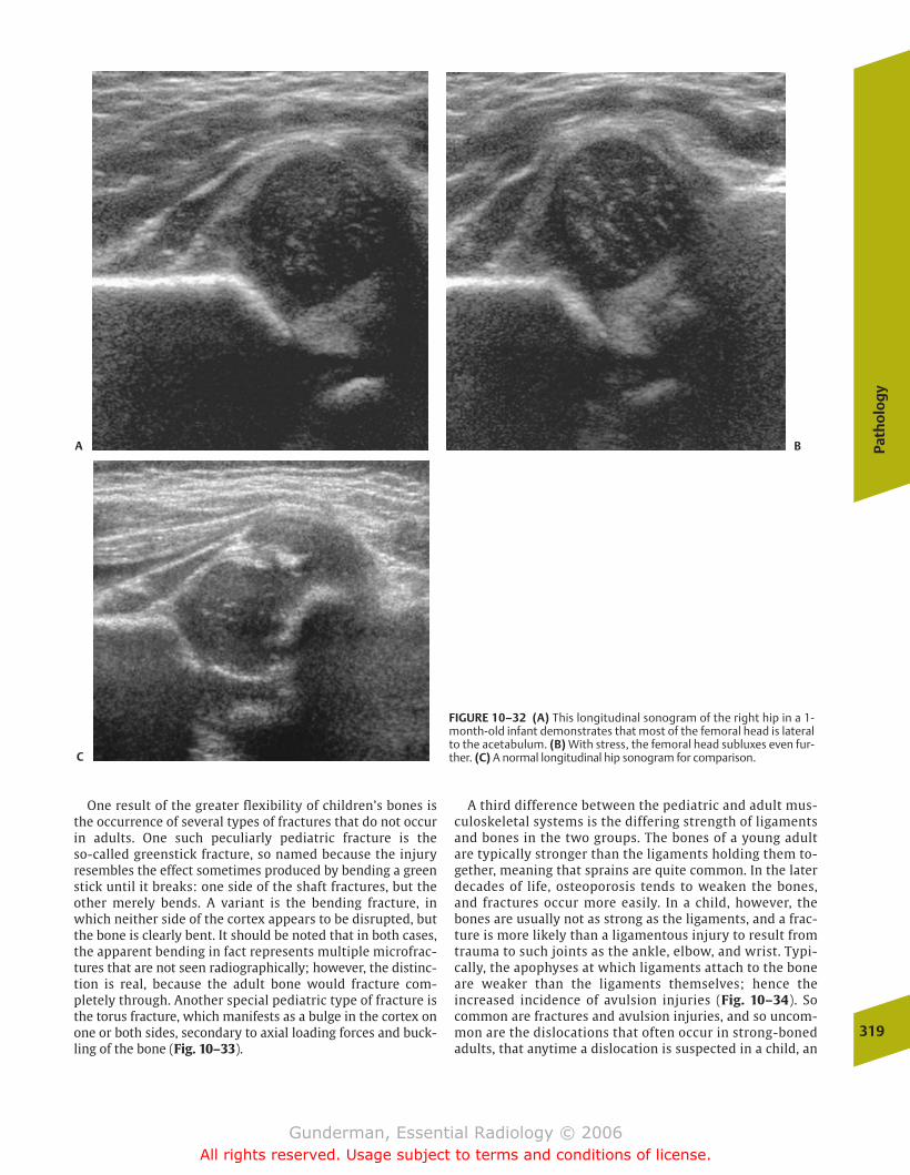
Path
olo
gy
319
One result of the greater flexibility of children’s bones isthe occurrence of several types of fractures that do not occurin adults. One such peculiarly pediatric fracture is the so-called greenstick fracture, so named because the injury resembles the effect sometimes produced by bending a greenstick until it breaks: one side of the shaft fractures, but theother merely bends. A variant is the bending fracture, inwhich neither side of the cortex appears to be disrupted, butthe bone is clearly bent. It should be noted that in both cases,the apparent bending in fact represents multiple microfrac-tures that are not seen radiographically; however, the distinc-tion is real, because the adult bone would fracture com-pletely through. Another special pediatric type of fracture isthe torus fracture, which manifests as a bulge in the cortex onone or both sides, secondary to axial loading forces and buck-ling of the bone (Fig. 10–33).
A third difference between the pediatric and adult mus-culoskeletal systems is the differing strength of ligamentsand bones in the two groups. The bones of a young adultare typically stronger than the ligaments holding them to-gether, meaning that sprains are quite common. In the laterdecades of life, osteoporosis tends to weaken the bones,and fractures occur more easily. In a child, however, thebones are usually not as strong as the ligaments, and a frac-ture is more likely than a ligamentous injury to result fromtrauma to such joints as the ankle, elbow, and wrist. Typi-cally, the apophyses at which ligaments attach to the boneare weaker than the ligaments themselves; hence the increased incidence of avulsion injuries (Fig. 10–34). Socommon are fractures and avulsion injuries, and so uncom-mon are the dislocations that often occur in strong-bonedadults, that anytime a dislocation is suspected in a child, an
FIGURE 10–32 (A) This longitudinal sonogram of the right hip in a 1-month-old infant demonstrates that most of the femoral head is lateralto the acetabulum. (B) With stress, the femoral head subluxes even fur-ther. (C) A normal longitudinal hip sonogram for comparison.
A B
C
chapter 10_p296-326.qxd 12/1/05 4:22 PM Page 319
Gunderman, Essential Radiology © 2006All rights reserved. Usage subject to terms and conditions of license.
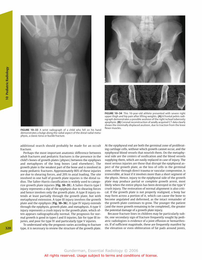
additional search should probably be made for an occultfracture.
Perhaps the most important anatomic difference betweenadult fractures and pediatric fractures is the presence in thechild’s bones of growth plates (physes) between the epiphysesand metaphyses of the long bones (and elsewhere). Thegrowth plate is the weakest part of the bone and is involved inmany pediatric fractures. Approximately 80% of these injuriesare due to shearing forces, and 20% to axial loading. The siteinvolved in one half of growth plate injuries is the distal ra-dius. The Salter-Harris classification is widely used to catego-rize growth plate injuries (Fig. 10–35). A Salter-Harris type Iinjury represents a slip of the epiphysis due to shearing forcesand hence involves only the growth plate. A type II injury ex-tends at least partially through the growth plate, but withmetaphyseal extension. A type III injury involves the growthplate and the epiphysis (Fig. 10–36). A type IV injury extendsthrough the epiphysis, growth plate, and metaphysis. A type Vinjury represents a crush injury to the growth plate, which of-ten appears radiographically normal. The prognosis for nor-mal growth is good in types I and II injuries, fair for type III in-juries, and poor for type IV and particularly type V injuries.
To understand why the prognosis varies according to fracturetype, it is necessary to review the structure of the growth plate.
At the epiphyseal end are both the germinal zone of proliferat-ing cartilage cells, without which growth cannot occur, and theepiphyseal blood vessels that nourish them. On the metaphy-seal side are the centers of ossification and the blood vesselssupplying them, which are easily replaced in case of injury. Themost serious injuries are those that disrupt the epiphyseal as-pect of the growth plate, as the loss of cells in the germinalzone, either through direct trauma or vascular compromise, isirreversible, at least if it involves more than a short segment ofthe physis. Hence, injury to the epiphyseal side of the growthplate may produce partial or complete growth arrest, mostlikely when the entire physis has been destroyed in the type Vcrush injury. The restoration of normal alignment is also criti-cal. If the growth plate is not properly realigned, a bony barmay form across a portion of it, which can cause the bone tobecome angulated and deformed, as the intact remainder ofthe growth plate continues to grow. The younger the patient(and the more growth remaining to be completed), the greaterthe potential damage of a growth plate injury.
Because fracture lines in children may be particularly sub-tle, one secondary sign of fracture frequently sought by pedi-atric radiologists is evidence of a joint effusion or hemarthro-sis. If of sufficient magnitude, these are frequently manifest bythe elevation or even obliteration of fat pads around joints,320
10Pe
diat
ric
Radi
olog
y
FIGURE 10–33 A wrist radiograph of a child who fell on his handdemonstrates a bulge along the radial aspect of the distal radial meta-physis, a classic torus or buckle fracture.
FIGURE 10–34 This 16-year-old athlete presented with severe right upper thigh and hip pain after lifting weights. (A) A frontal pelvis radi-ograph demonstrates a possible avulsion of the right ischeal tuberosityapophysis. (B) Coronal reconstruction of axially acquired CT data clearlyshows the minimally displaced avulsion, due to traction from the kneeflexor muscles.
chapter 10_p296-326.qxd 12/1/05 4:22 PM Page 320
Gunderman, Essential Radiology © 2006All rights reserved. Usage subject to terms and conditions of license.
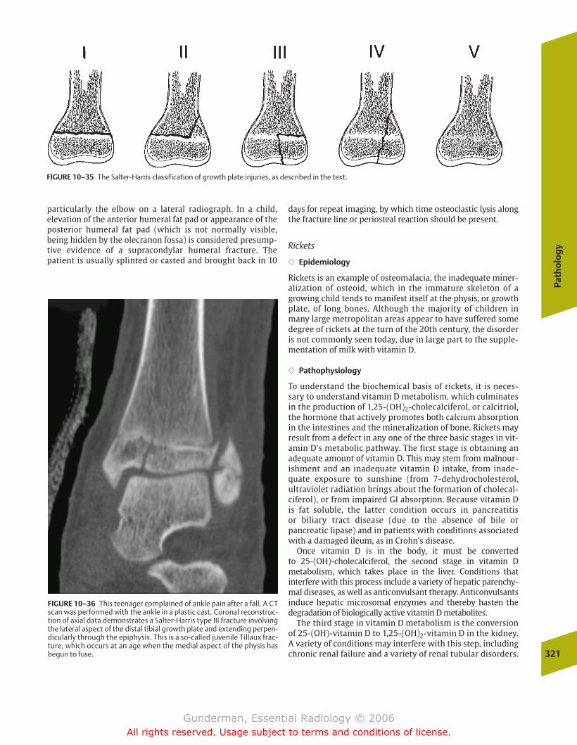
Path
olo
gy
321
particularly the elbow on a lateral radiograph. In a child, elevation of the anterior humeral fat pad or appearance of theposterior humeral fat pad (which is not normally visible, being hidden by the olecranon fossa) is considered presump-tive evidence of a supracondylar humeral fracture. The patient is usually splinted or casted and brought back in 10
days for repeat imaging, by which time osteoclastic lysis alongthe fracture line or periosteal reaction should be present.
Rickets
�� Epidemiology
Rickets is an example of osteomalacia, the inadequate miner-alization of osteoid, which in the immature skeleton of agrowing child tends to manifest itself at the physis, or growthplate, of long bones. Although the majority of children inmany large metropolitan areas appear to have suffered somedegree of rickets at the turn of the 20th century, the disorderis not commonly seen today, due in large part to the supple-mentation of milk with vitamin D.
�� Pathophysiology
To understand the biochemical basis of rickets, it is neces-sary to understand vitamin D metabolism, which culminatesin the production of 1,25-(OH)2-cholecalciferol, or calcitriol,the hormone that actively promotes both calcium absorptionin the intestines and the mineralization of bone. Rickets mayresult from a defect in any one of the three basic stages in vit-amin D’s metabolic pathway. The first stage is obtaining anadequate amount of vitamin D. This may stem from malnour-ishment and an inadequate vitamin D intake, from inade-quate exposure to sunshine (from 7-dehydrocholesterol, ultraviolet radiation brings about the formation of cholecal-ciferol), or from impaired GI absorption. Because vitamin D is fat soluble, the latter condition occurs in pancreatitis or biliary tract disease (due to the absence of bile or pancreatic lipase) and in patients with conditions associatedwith a damaged ileum, as in Crohn’s disease.
Once vitamin D is in the body, it must be converted to 25-(OH)-cholecalciferol, the second stage in vitamin D metabolism, which takes place in the liver. Conditions that interfere with this process include a variety of hepatic parenchy-mal diseases, as well as anticonvulsant therapy. Anticonvulsantsinduce hepatic microsomal enzymes and thereby hasten thedegradation of biologically active vitamin D metabolites.
The third stage in vitamin D metabolism is the conversionof 25-(OH)-vitamin D to 1,25-(OH)2-vitamin D in the kidney.A variety of conditions may interfere with this step, includingchronic renal failure and a variety of renal tubular disorders.
FIGURE 10–35 The Salter-Harris classification of growth plate injuries, as described in the text.
FIGURE 10–36 This teenager complained of ankle pain after a fall. A CTscan was performed with the ankle in a plastic cast. Coronal reconstruc-tion of axial data demonstrates a Salter-Harris type III fracture involvingthe lateral aspect of the distal tibial growth plate and extending perpen-dicularly through the epiphysis. This is a so-called juvenile Tillaux frac-ture, which occurs at an age when the medial aspect of the physis hasbegun to fuse.
chapter 10_p296-326.qxd 12/1/05 4:22 PM Page 321
Gunderman, Essential Radiology © 2006All rights reserved. Usage subject to terms and conditions of license.
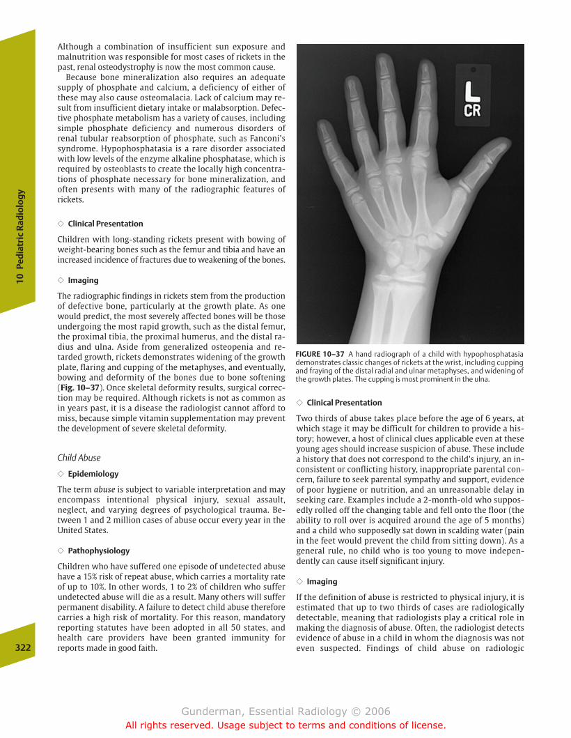
Although a combination of insufficient sun exposure andmalnutrition was responsible for most cases of rickets in thepast, renal osteodystrophy is now the most common cause.
Because bone mineralization also requires an adequatesupply of phosphate and calcium, a deficiency of either ofthese may also cause osteomalacia. Lack of calcium may re-sult from insufficient dietary intake or malabsorption. Defec-tive phosphate metabolism has a variety of causes, includingsimple phosphate deficiency and numerous disorders of renal tubular reabsorption of phosphate, such as Fanconi’ssyndrome. Hypophosphatasia is a rare disorder associatedwith low levels of the enzyme alkaline phosphatase, which isrequired by osteoblasts to create the locally high concentra-tions of phosphate necessary for bone mineralization, and often presents with many of the radiographic features of rickets.
�� Clinical Presentation
Children with long-standing rickets present with bowing ofweight-bearing bones such as the femur and tibia and have anincreased incidence of fractures due to weakening of the bones.
�� Imaging
The radiographic findings in rickets stem from the productionof defective bone, particularly at the growth plate. As onewould predict, the most severely affected bones will be thoseundergoing the most rapid growth, such as the distal femur,the proximal tibia, the proximal humerus, and the distal ra-dius and ulna. Aside from generalized osteopenia and re-tarded growth, rickets demonstrates widening of the growthplate, flaring and cupping of the metaphyses, and eventually,bowing and deformity of the bones due to bone softening(Fig. 10–37). Once skeletal deformity results, surgical correc-tion may be required. Although rickets is not as common asin years past, it is a disease the radiologist cannot afford tomiss, because simple vitamin supplementation may preventthe development of severe skeletal deformity.
Child Abuse
�� Epidemiology
The term abuse is subject to variable interpretation and mayencompass intentional physical injury, sexual assault, neglect, and varying degrees of psychological trauma. Be-tween 1 and 2 million cases of abuse occur every year in theUnited States.
�� Pathophysiology
Children who have suffered one episode of undetected abusehave a 15% risk of repeat abuse, which carries a mortality rateof up to 10%. In other words, 1 to 2% of children who sufferundetected abuse will die as a result. Many others will sufferpermanent disability. A failure to detect child abuse thereforecarries a high risk of mortality. For this reason, mandatory reporting statutes have been adopted in all 50 states, andhealth care providers have been granted immunity for reports made in good faith.
�� Clinical Presentation
Two thirds of abuse takes place before the age of 6 years, atwhich stage it may be difficult for children to provide a his-tory; however, a host of clinical clues applicable even at theseyoung ages should increase suspicion of abuse. These includea history that does not correspond to the child’s injury, an in-consistent or conflicting history, inappropriate parental con-cern, failure to seek parental sympathy and support, evidenceof poor hygiene or nutrition, and an unreasonable delay inseeking care. Examples include a 2-month-old who suppos-edly rolled off the changing table and fell onto the floor (theability to roll over is acquired around the age of 5 months)and a child who supposedly sat down in scalding water (painin the feet would prevent the child from sitting down). As ageneral rule, no child who is too young to move indepen-dently can cause itself significant injury.
�� Imaging
If the definition of abuse is restricted to physical injury, it isestimated that up to two thirds of cases are radiologically detectable, meaning that radiologists play a critical role inmaking the diagnosis of abuse. Often, the radiologist detectsevidence of abuse in a child in whom the diagnosis was noteven suspected. Findings of child abuse on radiologic 322
10Pe
diat
ric
Radi
olog
y
FIGURE 10–37 A hand radiograph of a child with hypophosphatasiademonstrates classic changes of rickets at the wrist, including cuppingand fraying of the distal radial and ulnar metaphyses, and widening ofthe growth plates. The cupping is most prominent in the ulna.
chapter 10_p296-326.qxd 12/1/05 4:22 PM Page 322
Gunderman, Essential Radiology © 2006All rights reserved. Usage subject to terms and conditions of license.
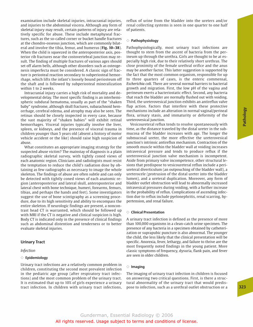
Path
olo
gy
323
examination include skeletal injuries, intracranial injuries,and injuries to the abdominal viscera. Although any form ofskeletal injury may result, certain patterns of injury are rela-tively specific for abuse. These include metaphyseal frac-tures, such as the so-called corner or bucket handle fracturesat the chondro-osseous junction, which are commonly bilat-eral and involve the tibia, femur, and humerus (Fig. 10–38).When the child is squeezed in the anteroposterior axis, pos-terior rib fractures near the costovertebral junction may re-sult. The finding of multiple fractures of various ages shouldset off alarm bells, although other disorders such as osteoge-nesis imperfecta must be considered. A classic sign of frac-ture is periosteal reaction secondary to subperiosteal hemor-rhage, which lifts the infant’s loosely bound periosteum offthe shaft and is followed by subperiosteal mineralizationwithin 1 to 2 weeks.
Intracranial injury carries a high risk of mortality and de-velopmental delay. The most specific finding is an interhemi-spheric subdural hematoma, usually as part of the “shakenbaby” syndrome, although skull fractures, subarachnoid hem-orrhage, cerebral edema, and atrophy may also be seen. Theretinas should be closely inspected in every case, becausethe vast majority of “shaken babies” will exhibit retinal hemorrhages. Visceral injuries typically involve the liver,spleen, or kidneys, and the presence of visceral trauma inchildren younger than 5 years old (absent a history of motorvehicle accident or the like) should raise high suspicion ofabuse.
What constitutes an appropriate imaging strategy for thesuspected abuse victim? The mainstay of diagnosis is a plainradiographic skeletal survey, with tightly coned views ofeach anatomic region. Clinicians and radiologists must resistthe temptation to reduce the child’s radiation dose by ob-taining as few radiographs as necessary to image the wholeskeleton. The findings of abuse are often subtle and can onlybe detected with tightly coned views of each anatomic re-gion (anteroposterior and lateral skull, anteroposterior andlateral chest with bone technique, humeri, forearms, femurs,tibias, and perhaps the hands and feet). Some investigatorssuggest the use of bone scintigraphy as a screening proce-dure, due to its high sensitivity and ability to encompass theentire skeleton. If neurologic findings are present, a noncon-trast head CT is warranted, which should be followed upwith MRI if the CT is negative and clinical suspicion is high.Body CT is indicated only in the presence of clinical findingssuch as abdominal distention and tenderness or to betterevaluate skeletal injuries.
Urinary Tract
Infection
�� Epidemiology
Urinary tract infections are a relatively common problem inchildren, constituting the second most prevalent infectionin the pediatric age group (after respiratory tract infec-tions) and the most common problem of the urinary tract.It is estimated that up to 10% of girls experience a urinarytract infection. In children with urinary tract infections,
reflux of urine from the bladder into the ureters and/orrenal collecting systems is seen in one quarter to one halfof patients.
�� Pathophysiology
Pathophysiologically, most urinary tract infections arethought to stem from the ascent of bacteria from the per-ineum up through the urethra. Girls are thought to be at es-pecially high risk, due to their relatively short urethras. Theclose proximity of the female urethral orifice and the anusmay be another factor. This latter suggestion is supported bythe fact that the most common organism, responsible for upto three quarters of cases, is the enteric commensal, Escherichia coli. There are several normal barriers to bacterialgrowth and migration. First, the low pH of the vagina andperineum exerts a bacteriostatic effect. Second, any bacteriathat reach the bladder are normally flushed out with voiding.Third, the ureterovesical junction exhibits an antireflux valveflap action. Factors that interfere with these protectivemechanisms include an alteration in normal vaginal/perineal flora, urinary stasis, and immaturity or deformity of theureterovesical junction.
Vesicoureteral reflux tends to resolve spontaneously withtime, as the distance traveled by the distal ureter in the sub-mucosa of the bladder increases with age. The longer thesubmucosal ureter, the more effective the ureterovesicaljunction’s intrinsic antireflux mechanism. Contraction of thesmooth muscle within the bladder wall at voiding increasesintravesical pressure and tends to produce reflux if theureterovesical junction valve mechanism is incompetent.Aside from primary valve incompetence, other structural le-sions that predispose to vesicoureteral reflux include a peri-ureteral diverticulum (an outpouching of the bladder wall), aureterocele (protrusion of the distal ureter into the bladderlumen), and a ureteral duplication. Moreover, any form ofbladder outlet obstruction will lead to abnormally increasedintravesical pressures during voiding, with a further increasein the probability of reflux. Complications of ascending infec-tion due to reflux include pyelonephritis, renal scarring, hy-pertension, and renal failure.
�� Clinical Presentation
A urinary tract infection is defined as the presence of morethan 100,000 organisms in a clean-catch urine specimen. Thepresence of any bacteria in a specimen obtained by catheteri-zation or suprapubic puncture is also abnormal. The youngerthe child, the less likely that the clinical presentation will bespecific. Anorexia, fever, lethargy, and failure to thrive are themost frequently noted findings in the young patient. Moreclassic symptoms of frequency, dysuria, flank pain, and feverare seen in older children.
�� Imaging
The imaging of urinary tract infection in children is focusedon answering two critical questions. First, is there a struc-tural abnormality of the urinary tract that would predis-pose to infection, such as a urethral outlet obstruction or a
chapter 10_p296-326.qxd 12/1/05 4:22 PM Page 323
Gunderman, Essential Radiology © 2006All rights reserved. Usage subject to terms and conditions of license.
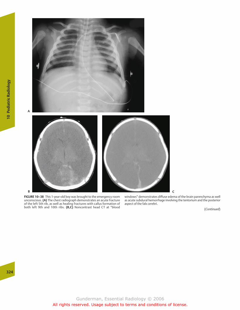
324
10Pe
diat
ric
Radi
olog
y
FIGURE 10–38 This 1-year-old boy was brought to the emergency roomunconscious. (A) The chest radiograph demonstrates an acute fractureof the left 5th rib, as well as healing fractures with callus formation ofboth left 9th and 10th ribs. (B,C) Noncontrast head CT at “blood
windows” demonstrates diffuse edema of the brain parenchyma as wellas acute subdural hemorrhage involving the tentorium and the posterioraspect of the falx cerebri.
(Continued)
A
B C
chapter 10_p296-326.qxd 12/1/05 4:22 PM Page 324
Gunderman, Essential Radiology © 2006All rights reserved. Usage subject to terms and conditions of license.
Path
olo
gy
325
Figure 10–38 (Continued) (D,E) Images of the knees from a skeletalsurvey demonstrate bucket handle fractures of the distal femurs.(F,G) Bone-window CT images more clearly demonstrate the acute(no callus) and chronic (callus formation) rib fractures with subpe-
riosteal hemorrhages at the site of the acute fracture. Fundoscopicexam also revealed retinal hemorrhages. Eighteen months after thechild’s death from the injuries, a parent was convicted of recklesshomicide.
D E
F G
chapter 10_p296-326.qxd 12/1/05 4:22 PM Page 325
Gunderman, Essential Radiology © 2006All rights reserved. Usage subject to terms and conditions of license.
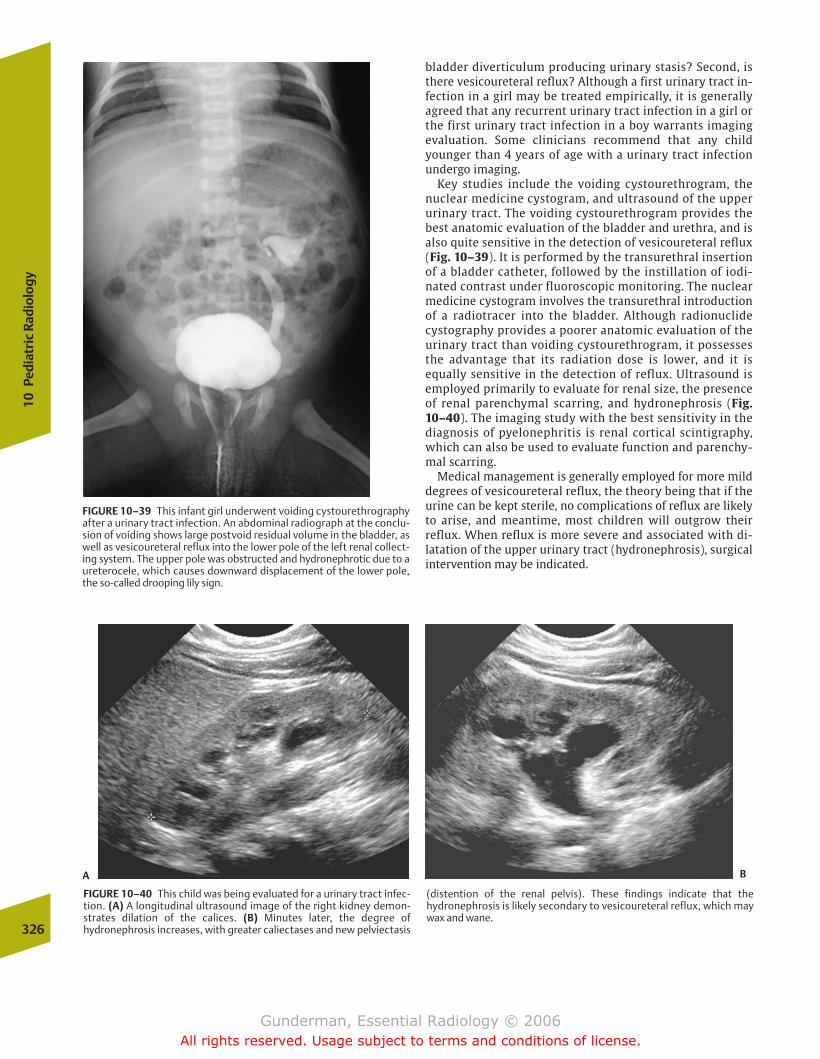
326
10Pe
diat
ric
Radi
olog
y
bladder diverticulum producing urinary stasis? Second, isthere vesicoureteral reflux? Although a first urinary tract in-fection in a girl may be treated empirically, it is generallyagreed that any recurrent urinary tract infection in a girl orthe first urinary tract infection in a boy warrants imagingevaluation. Some clinicians recommend that any childyounger than 4 years of age with a urinary tract infectionundergo imaging.
Key studies include the voiding cystourethrogram, thenuclear medicine cystogram, and ultrasound of the upperurinary tract. The voiding cystourethrogram provides thebest anatomic evaluation of the bladder and urethra, and isalso quite sensitive in the detection of vesicoureteral reflux (Fig. 10–39). It is performed by the transurethral insertionof a bladder catheter, followed by the instillation of iodi-nated contrast under fluoroscopic monitoring. The nuclearmedicine cystogram involves the transurethral introductionof a radiotracer into the bladder. Although radionuclidecystography provides a poorer anatomic evaluation of theurinary tract than voiding cystourethrogram, it possessesthe advantage that its radiation dose is lower, and it isequally sensitive in the detection of reflux. Ultrasound isemployed primarily to evaluate for renal size, the presenceof renal parenchymal scarring, and hydronephrosis (Fig.10–40). The imaging study with the best sensitivity in thediagnosis of pyelonephritis is renal cortical scintigraphy,which can also be used to evaluate function and parenchy-mal scarring.
Medical management is generally employed for more milddegrees of vesicoureteral reflux, the theory being that if theurine can be kept sterile, no complications of reflux are likelyto arise, and meantime, most children will outgrow their reflux. When reflux is more severe and associated with di-latation of the upper urinary tract (hydronephrosis), surgicalintervention may be indicated.
FIGURE 10–39 This infant girl underwent voiding cystourethrographyafter a urinary tract infection. An abdominal radiograph at the conclu-sion of voiding shows large postvoid residual volume in the bladder, aswell as vesicoureteral reflux into the lower pole of the left renal collect-ing system. The upper pole was obstructed and hydronephrotic due to aureterocele, which causes downward displacement of the lower pole,the so-called drooping lily sign.
FIGURE 10–40 This child was being evaluated for a urinary tract infec-tion. (A) A longitudinal ultrasound image of the right kidney demon-strates dilation of the calices. (B) Minutes later, the degree of hydronephrosis increases, with greater caliectases and new pelviectasis
(distention of the renal pelvis). These findings indicate that the hydronephrosis is likely secondary to vesicoureteral reflux, which maywax and wane.
A B
chapter 10_p296-326.qxd 12/1/05 4:22 PM Page 326
Gunderman, Essential Radiology © 2006All rights reserved. Usage subject to terms and conditions of license.

AppendixNormal Cross-Sectional Anatomy
chapter Appendix.qxd 12/1/05 4:34 PM Page 327
Gunderman, Essential Radiology © 2006All rights reserved. Usage subject to terms and conditions of license.
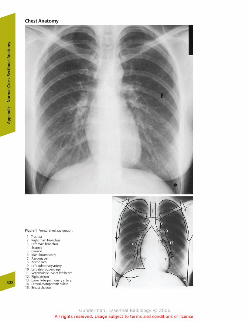
328
Ap
pen
dix
No
rmal
Cro
ss-S
ecti
on
al A
nat
om
y
Figure 1 Frontal chest radiograph.
1. Trachea2. Right main bronchus3. Left main bronchus4. Scapula5. Clavicle6. Manubrium sterni7. Azygous vein8. Aortic arch9. Left pulmonary artery
10. Left atrial appendage11. Ventricular curve of left heart12. Right atrium13. Lower lobe pulmonary artery14. Lateral costophrenic sulcus15. Breast shadow
Chest Anatomy
chapter Appendix.qxd 12/1/05 4:34 PM Page 328
Gunderman, Essential Radiology © 2006All rights reserved. Usage subject to terms and conditions of license.
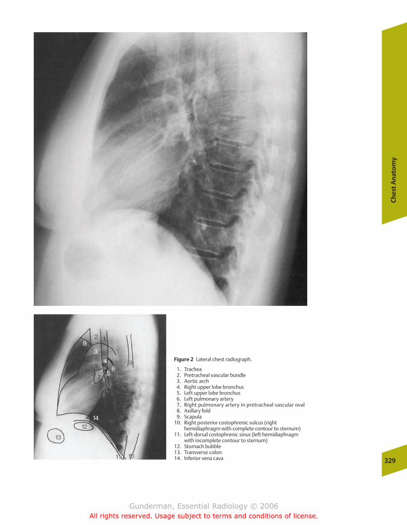
Ch
est
An
ato
my
329
Figure 2 Lateral chest radiograph.
1. Trachea2. Pretracheal vascular bundle3. Aortic arch4. Right upper lobe bronchus5. Left upper lobe bronchus6. Left pulmonary artery7. Right pulmonary artery in pretracheal vascular oval8. Axillary fold9. Scapula
10. Right posterior costophrenic sulcus (right hemidiaphragm with complete contour to sternum)
11. Left dorsal costophrenic sinus (left hemidiaphragm with incomplete contour to sternum)
12. Stomach bubble13. Transverse colon14. Inferior vena cava
chapter Appendix.qxd 12/1/05 4:34 PM Page 329
Gunderman, Essential Radiology © 2006All rights reserved. Usage subject to terms and conditions of license.
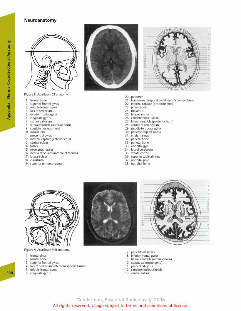
330
Ap
pen
dix
No
rmal
Cro
ss-S
ecti
on
al A
nat
om
y
Figure 3 Axial brain CT anatomy.
1. frontal bone2. superior frontal gyrus3. middle frontal gyrus4. falx of cerebrum5. inferior frontal gyrus6. cingulate gyrus7. corpus callosum8. lateral ventricle (anterior horn)9. caudate nucleus (head
10. insular lobe11. precentral gyrus12. internal capsule (anterior crus)13. central sulcus14. fornix15. postcentral gyrus16. interventricular foramen (of Monro)17. lateral sulcus18. claustrum19. superior temporal gyrus
20. putamen21. transverse temporal gyri (Heschl's convolution)22. internal capsule (posterior crus)23. pineal body24. thalamus25. hippocampus26. caudate nucleus (tail)27. lateral ventricle (posterior horn)28. vermis of cerebellum29. middle temporal gyrus30. parietooccipital sulcus31. straight sinus32. parietal bone33. parietal bone33. occipital gyri34. falx of cerebrum35. striate cortex36. superior sagittal sinus37. occipital pole38. occipital bone
Neuroanatomy
Figure 4 Axial brain MRI anatomy.
1. frontal sinus2. forntal bone3. superior frontal gyrus4. falx of cerebrum (interhemispheric fissure)5. middle frontal gyrus6. cingulate gyrus
7. pericallosal artery8. inferior frontal gyrus9. lateral ventricle (anterior horn)
10. corpus callosum (genu)11. precentral gyrus12. caudate nucleus (head)13. central sulcus
chapter Appendix.qxd 12/1/05 4:34 PM Page 330
Gunderman, Essential Radiology © 2006All rights reserved. Usage subject to terms and conditions of license.

14. claustrum15. postcentral gyrus16. putamen17. pellucid septum18. globus pallidus19. extreme capsule20. insular lobe21. external capsule22. thalamus23. internal capsule24. transverse temporal gyri (Heschl's convolutions)
25. superior temporal gyrus26. lateral sulcus27. lateral ventricle (posterior horn)28. corpus callosum (splenium)29. parietal bone30. parietooccipital sulcus31. straight sinus32. cuneus33. occipital gyri34. superior sagittal sinus35. occipital bone
Neu
roan
ato
my
331
Figure 5 Axial brain MRI anatomy.
1. frontal sinus2. ocular bulb3. crista galli4. lacrimal gland5. superior oblique muscle6. ethmoid labyrinth7. optic nerve8. lateral rectus muscle9. zygomatic bone
10. superior rectus muscle11. orbit12. gyrus13. sphenoid bone14. anterior cerebral artery15. temporal muscle16. middle cerebral artery17. superior temporal gyrus18. optic chiasm19. hypothalamus
20. uncus21. middle temporal gyrus22. cerebral peduncle23. posterior cerabral artery24. red nucleus25. aqueduct26. hippocampus27. cranial colliculus28. ambient cistern29. temporal bone30. Bichat's canal (cisterna venae magnae cerebri)31. inferior temporal gyrus32. lateral ventricle (temporal horn)33. cranial lobe of cerebellum34. straight sinus35. parietal bone36. calcarine sulcus37. occipital bone38. superior sagittal sinus
chapter Appendix.qxd 12/1/05 4:34 PM Page 331
Gunderman, Essential Radiology © 2006All rights reserved. Usage subject to terms and conditions of license.
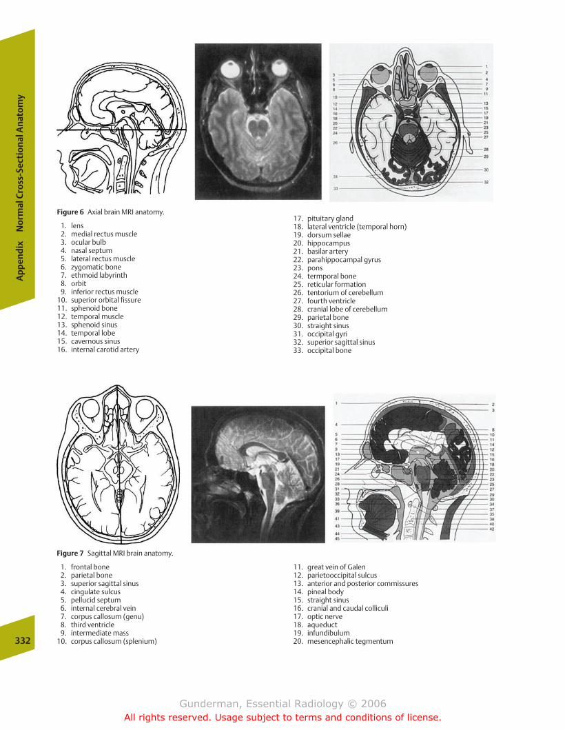
Figure 6 Axial brain MRI anatomy.
1. lens2. medial rectus muscle3. ocular bulb4. nasal septum5. lateral rectus muscle6. zygomatic bone7. ethmoid labyrinth8. orbit9. inferior rectus muscle
10. superior orbital fissure11. sphenoid bone12. temporal muscle13. sphenoid sinus14. temporal lobe15. cavernous sinus16. internal carotid artery
17. pituitary gland18. lateral ventricle (temporal horn)19. dorsum sellae20. hippocampus21. basilar artery22. parahippocampal gyrus23. pons24. termporal bone25. reticular formation26. tentorium of cerebellum27. fourth ventricle28. cranial lobe of cerebellum29. parietal bone30. straight sinus31. occipital gyri32. superior sagittal sinus33. occipital bone
332
Ap
pen
dix
No
rmal
Cro
ss-S
ecti
on
al A
nat
om
y
Figure 7 Sagittal MRI brain anatomy.
1. frontal bone2. parietal bone3. superior sagittal sinus4. cingulate sulcus5. pellucid septum6. internal cerebral vein7. corpus callosum (genu)8. third ventricle9. intermediate mass
10. corpus callosum (splenium)
11. great vein of Galen12. parietooccipital sulcus13. anterior and posterior commissures14. pineal body15. straight sinus16. cranial and caudal colliculi17. optic nerve18. aqueduct19. infundibulum20. mesencephalic tegmentum
chapter Appendix.qxd 12/1/05 4:34 PM Page 332
Gunderman, Essential Radiology © 2006All rights reserved. Usage subject to terms and conditions of license.
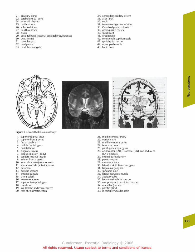
21. pituitary gland22. cerebellum' 23. pons24. ethmoid labyrinth25. basilar artery26. sphenoid sinus27. fourth ventricle28. clivus29. occipital bone (external occipital protuberance)30. uvula vermis31. nasopharynx32. hard palate33. medulla oblongata
34. cerebellomedullary cistern35. atlas (arch)36. uvula37. transverse ligament of atlas38. Odontoid process of axis39. genioglossus muscle40. spinal cord41. oropharynx42. semispinalis capitis muscle43. geniohyoid muscle44. mylohyoid muscle45. hyoid bone
Neu
roan
ato
my
333
Figure 8 Coronal MRI brain anatomy.
1. superior sagittal sinus2. superior frontal gyrus3. falx of cerebrum4. middle frontal gyrus5. parietal bone6. cingulate sulcus7. corpus callosum (body)8. caudate nucleus (head)9. inferior frontal gyrus
10. internal capsule (anterior crus)11. lateral ventricle (anterior horn)12. putamen13. pellucid septum14. external capsule15. lateral sulcus16. extreme capsule17. superior termporal gyrus18. claustrum19. insular lobe and insular cistern20. roof of chiasmatic cisten
21. middle cerebral artery22. optic chiasm23. middle temporal gyrus24. temporal bone25. parahippocampal gyrus26. oculomotor (CN II), trochlear (CN), and abducens
(CN VI) nerves27. internal carotid artery28. pituitary gland29. cavernous sinus30. lateral occipitotemporal gyrus31. trigeminal ganglion32. sphenoid sinus33. lateral pterygoid muscle34. auditory tube35. levator veli palatini muscle36. nasopharynx (constrictor muscle)37. mandible (ramus)38. parotid gland39. medial pterygoid muscle
chapter Appendix.qxd 12/1/05 4:34 PM Page 333
Gunderman, Essential Radiology © 2006All rights reserved. Usage subject to terms and conditions of license.
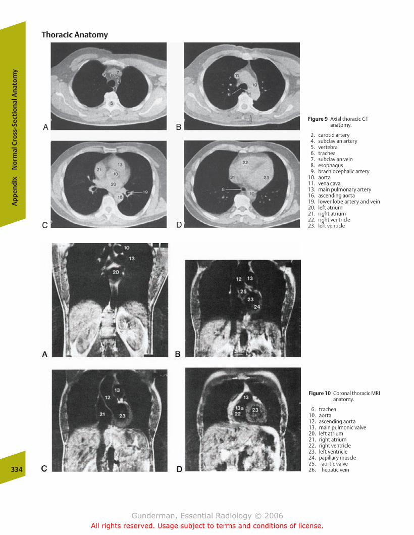
334
Ap
pen
dix
No
rmal
Cro
ss-S
ecti
on
al A
nat
om
y
Figure 9 Axial thoracic CTanatomy.
2. carotid artery4. subclavian artery 5. vertebra6. trachea7. subclavian vein8. esophagus9. brachiocephalic artery
10. aorta11. vena cava13. main pulmonary artery16. ascending aorta19. lower lobe artery and vein20. left atrium21. right atrium22. right ventricle23. left venticle
Figure 10 Coronal thoracic MRIanatomy.
6. trachea10. aorta12. ascending aorta13. main pulmonic valve20. left atrium21. right atrium22. right ventricle23. left ventricle24. papillary muscle25. aortic valve26. hepatic vein
Thoracic Anatomy
chapter Appendix.qxd 12/1/05 4:34 PM Page 334
Gunderman, Essential Radiology © 2006All rights reserved. Usage subject to terms and conditions of license.
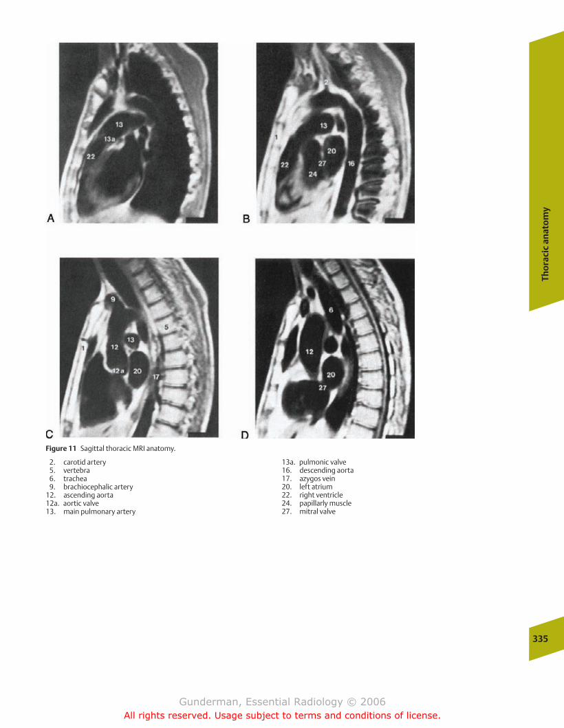
Tho
raci
c an
ato
my
335
Figure 11 Sagittal thoracic MRI anatomy.
2. carotid artery5. vertebra6. trachea9. brachiocephalic artery
12. ascending aorta12a. aortic valve13. main pulmonary artery
13a. pulmonic valve16. descending aorta17. azygos vein20. left atrium22. right ventricle24. papillarly muscle27. mitral valve
chapter Appendix.qxd 12/1/05 4:34 PM Page 335
Gunderman, Essential Radiology © 2006All rights reserved. Usage subject to terms and conditions of license.
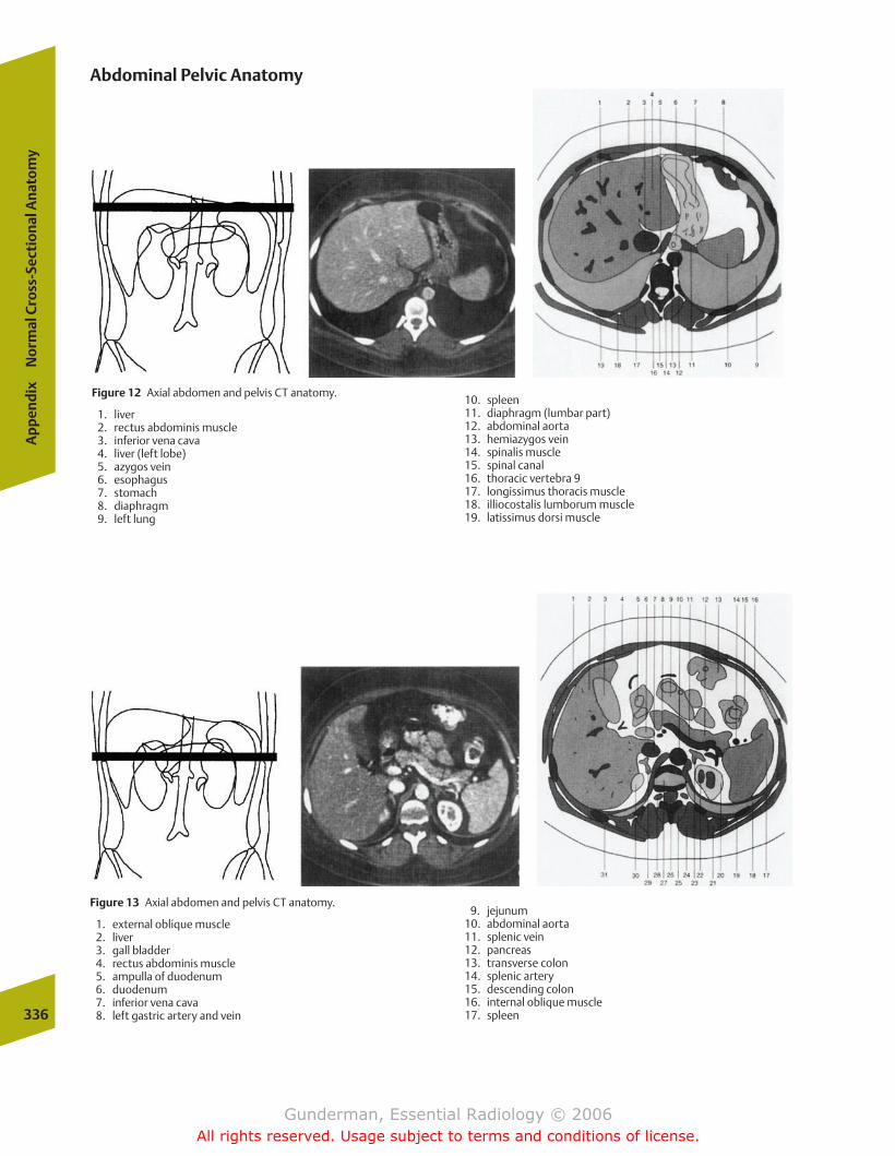
Figure 12 Axial abdomen and pelvis CT anatomy.
1. liver2. rectus abdominis muscle3. inferior vena cava4. liver (left lobe)5. azygos vein6. esophagus7. stomach8. diaphragm9. left lung
10. spleen11. diaphragm (lumbar part)12. abdominal aorta13. hemiazygos vein14. spinalis muscle15. spinal canal16. thoracic vertebra 917. longissimus thoracis muscle18. illiocostalis lumborum muscle19. latissimus dorsi muscle
336
Ap
pen
dix
No
rmal
Cro
ss-S
ecti
on
al A
nat
om
y
Abdominal Pelvic Anatomy
Figure 13 Axial abdomen and pelvis CT anatomy.
1. external oblique muscle2. liver3. gall bladder4. rectus abdominis muscle5. ampulla of duodenum6. duodenum7. inferior vena cava8. left gastric artery and vein
9. jejunum10. abdominal aorta11. splenic vein12. pancreas13. transverse colon14. splenic artery15. descending colon16. internal oblique muscle17. spleen
chapter Appendix.qxd 12/1/05 4:34 PM Page 336
Gunderman, Essential Radiology © 2006All rights reserved. Usage subject to terms and conditions of license.
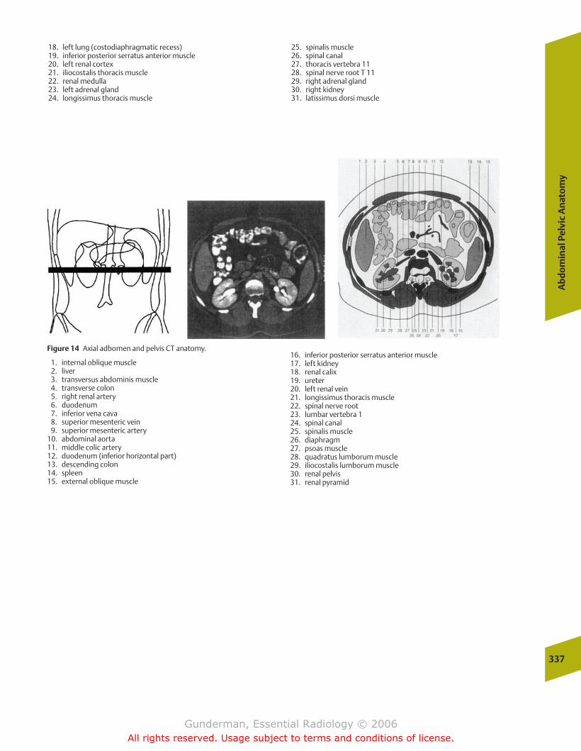
18. left lung (costodiaphragmatic recess)19. inferior posterior serratus anterior muscle20. left renal cortex21. iliocostalis thoracis muscle22. renal medulla23. left adrenal gland24. longissimus thoracis muscle
25. spinalis muscle26. spinal canal27. thoracis vertebra 1128. spinal nerve root T 1129. right adrenal gland30. right kidney31. latissimus dorsi muscle
Ab
do
min
al P
elvi
c A
nat
om
y
337
Figure 14 Axial adbomen and pelvis CT anatomy.
1. internal oblique muscle2. liver3. transversus abdominis muscle4. transverse colon5. right renal artery6. duodenum7. inferior vena cava8. superior mesenteric vein9. superior mesenteric artery
10. abdominal aorta11. middle colic artery12. duodenum (inferior horizontal part)13. descending colon14. spleen15. external oblique muscle
16. inferior posterior serratus anterior muscle17. left kidney18. renal calix19. ureter20. left renal vein21. longissimus thoracis muscle22. spinal nerve root23. lumbar vertebra 124. spinal canal25. spinalis muscle26. diaphragm27. psoas muscle28. quadratus lumborum muscle29. iliocostalis lumborum muscle30. renal pelvis31. renal pyramid
chapter Appendix.qxd 12/1/05 4:34 PM Page 337
Gunderman, Essential Radiology © 2006All rights reserved. Usage subject to terms and conditions of license.
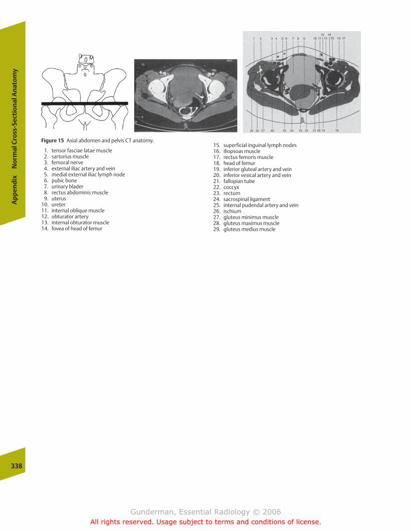
Figure 15 Axial abdomen and pelvis CT anatomy.
1. tensor fasciae latae muscle2. sartorius muscle3. femoral nerve4. external iliac artery and vein5. medial external iliac lymph node6. pubic bone7. urinary blader8. rectus abdominis muscle9. uterus
10. ureter11. internal oblique muscle12. obturator artery13. internal obturator muscle14. fovea of head of femur
15. superficial inguinal lymph nodes16. iliopsoas muscle17. rectus femoris muscle18. head of femur19. inferior gluteal artery and vein20. inferior vesical artery and vein21. fallopian tube22. coccyx23. rectum24. sacrospinal ligament25. internal pudendal artery and vein26. ischium27. gluteus minimus muscle28. gluteus maximus muscle29. gluteus medius muscle
338
Ap
pen
dix
No
rmal
Cro
ss-S
ecti
on
al A
nat
om
y
chapter Appendix.qxd 12/1/05 4:34 PM Page 338
Gunderman, Essential Radiology © 2006All rights reserved. Usage subject to terms and conditions of license.

Abdomenacute pain in. See Acute abdomenfetal, ultrasound evaluation, 213–214in pediatric patient
acute abdomen, 313, 314f–316f, 315masses, 315–318, 317f–318f
trauma to. See Abdominal traumaAbdominal trauma
diagnostic methodscomputed tomography, 145–146, 145f–146fperitoneal lavage, 144–145, 145f
incidence, 144Abortion
inevitable, 211missed, 211spontaneous, 211threatened, 210–211
Abscessin acute abdomen, 175, 176fin acute pancreatitis, 184central nervous system, 276–277drainage, 30, 31fparavertebral, posterior mediastinal, 92tubo-ovarian, 205, 206f
ACA (anterior cerebral artery), 284Acalculous cholecystitis, 183ACE. See Angiotensin converting enzymeAchalasia, esophageal, 129, 129fAchondroplasia, 223Acini, 70, 71fAcromegaly, 242Acute abdomen
etiology, 173abscess, 175, 176facute cholecystitis, 178–181, 180f–183f, 183appendicitis, 186, 188–189, 189fbowel obstruction, 189–191, 190f–191fdiverticular disease, 185–186, 186f, 187f–188fpancreatitis, 183–185, 184f–185fpeptic ulcer disease, 175–178, 177f–179f
in pediatric population, 310–311infants and children, 313, 314f–316f, 315neonatal, 311–313, 311f–313f
radiographic findings inhepatic gas, 174pneumatosis intestinalis, 174, 175fpneumoperitoneum, 173, 173f–174f
Acute respiratory distress syndrome, 56, 56fand congestive heart failure comparisons, 57–58, 58f
Acute tubular necrosis, 165Acyanotic heart disease, 297
Addison’s disease, 170Adenocarcinoma, 102, 103f
gastric, 132, 134, 134f“leather bottle,” 124, 125f
large bowel, 191, 191fsmall bowel, 136
Adenomaadrenal, 170, 170fcolorectal, 138, 139f
Adenoma sebaceum, 268, 269fAdenopathy, middle mediastinal, 91–92, 92fAdhesive atelectasis, 79–80, 81fAdnexal masses
benign vs. malignant, 207–208, 208f“medical,” 202, 204–205, 206f“surgical,” 205–207, 206f–207f
Adrenal adenoma, 170, 170fAdrenal cortex
hypofunction, 170tumors, 170f, 171zones, 169, 169f
Adrenal glandsanatomy and physiology, 168–170, 169f–134fand kidney relationship, 169ftumorous conditions, 170f, 171, 171f
Adrenal hyperplasia, bilateral, 170Adrenal medulla, 169, 169f, 170
tumor, 171, 171fAdrenocortical carcinoma, 171AFP ( -fetoprotein), 211, 212AIDS. See HIV diseaseAir particulate, inhalational lung disease and, 106–107, 107fAir sacs, alveolar, 70, 70fAir spaces, anatomy and function, 72–73Air-space disease, 78, 79f
pneumonia, 94, 95f–97f, 97Airway pathology
asthma, 83–84, 84fchronic obstructive pulmonary disease, 84–85, 84f–85f
Alanine aminotransferase, in acute cholecystitis, 178Alcoholism
and liver cirrhosis, 141, 142fpancreatitis and, 184
Aldosterone production, 169Aldosteronoma, 170, 170f
-fetoprotein, 211, 212ALT (alanine aminotransferase), in acute cholecystitis, 178Alveoli, 70, 70f, 71f
and capillary relationship, 71–72, 71f, 72fAmine precursor uptake and decarboxylation system, in peptic
ulcer disease differential diagnosis, 177
Index
Page numbers followed by f indicate figures.
Gunderman(Index).qxd 12/1/05 4:25 PM Page 339
Gunderman, Essential Radiology © 2006All rights reserved. Usage subject to terms and conditions of license.
Amniocentesis, 211Amniotic fluid, and fetal well-being, 211, 213fAmpulla of Vater, 118, 118fAmyloidosis, 136Anencephaly, 211, 211f, 212Aneurysm, aortic, 64–66, 65f–66fAngiography, 26–27, 27f
in angioplasty, 28, 29fcatheter pulmonary, 63coronary, 44–45, 45fin embolization, 28–29preprocedure assessment, 27–28, 28fin thrombolysis, 29
Angiomyolipoma, 159–160, 160fAngioplasty, transluminal, 28, 29fAngiotensin converting enzyme, 69
inhibition, 154Ankylosing spondylitis, 241Annular adenocarcinoma, 191, 191fAnnular pancreas, 143Anterior cerebral artery, 284Anterolisthesis
cervical spine, 254, 254flumbar spine, 292, 294f
Anteroposterior radiograph, 73, 74ffactors evaluated on, 73–74, 75fposteroanterior radiograph vs., 74–75, 75f
Anticoagulation, in stroke management, 285Antrum, gastric, 116, 117fAorta, 64–67
anatomy and physiology, 64aneurysm, 64–66, 65f–66fcoarctation, in neonate, 298–299, 300fdissection, 66–67, 66fmajor branches, 41, 42ftrauma to, 66–67, 66f
Aortic valveinsufficiency, 50and mitral valve compared, 47, 47fstenosis, 49–50, 50f
Aortomegaly, generalized, 90–91AP. See Anteroposterior radiographAppendicitis
in acute abdomen, 186, 188–189, 189fclinical presentation, 189epidemiology, 186imaging studies, 188–189, 189fpathophysiology, 186, 189in pediatric patient, 313, 314f
APUD (amine precursor uptake and decarboxylation) system, in pepticulcer disease differential diagnosis, 177
ARDS. See Acute respiratory distress syndromeAristotle, 40Arteries. See individually named arteriesArterioles, 42Arthritis
osteo-. See Osteoarthritispsoriatic, 241rheumatoid. See Rheumatoid arthritis
Asbestos exposure, inhalational lung disease and, 107, 107f
Aspartate aminotransferase, in acute cholecystitis, 178Aspergillus superinfection, in cystic fibrosis, 107Asphyxia, neonatal intracranial hemorrhage and, 308–309Aspiration
foreign body, in children, 307, 307fjoint, in septic arthritis diagnosis, 227, 227flung, 106–107, 107fmeconium, in newborn, 304, 304f
AST (aspartate aminotransferase), in acute cholecystitis, 178Asthma
clinical presentation, 83epidemiology, 83imaging studies, 83–84, 84fpathophysiology, 83
Atelectasis, 78–81adhesive, 79–80, 81fcicatricial, 80
passive or relaxation type, 79, 81fresorptive, 78–79, 80f
ATN (acute tubular necrosis), 165Atresia
duodenal, in fetal abdomen evaluation, 214, 214fin neonate
bowel, 313, 313fesophagus, 306, 306f
Atrial septal defect, 299, 300f, 301fAtrioventricular node, 40Attenuation, ultrasound, 13–14, 13f, 14fAuditory diagnosis, ultrasound, 10Aurenbrugger, Leopold, 11AV (atrioventricular) node, 40Avascular necrosis
femoral neck and head, 256, 256fhumeral head, 255f, 256risk after femoral fracture, 250, 250f
Avulsion injuryin children, 319, 320fto foot, 250
Azygous vein enlargement, 92
Back pain. See Low back painBackground radiation, sources, 8, 9fBalloon pumps, and iatrogenic lung disorders, 108, 109fBamboo spine, 241, 243fBarium contrast agent, 24
risk associated with, 26Barium enema
appendicitis diagnosis and, 188in colonoscopy, 120, 121f, 122fin colorectal cancer, 138–139, 140fin diverticular disease, 185, 186fpedunculated adenomatous polyp and, 122, 124fpolypoid filling defects and, 122, 124f
Barium injection, in enteroclysis, 120, 120fBarium swallow examinations
pharyngography, 113, 114fupper GI series, 116, 116f
Barrett’s esophagus, esophageal tumor and, 129–130, 130fBecquerel, Antoine-Henri, 8, 14–16, 15f–17fBenign prostatic hypertrophy, 219
in prostate cancer differential diagnosis, 219Bilateral adrenal hyperplasia, 170Biliary gas, 174Billroth procedures, iatrogenic gastric disorders following, 134Biopsy
breast, 199in prostate cancer diagnosis, 218f, 219
BI-RADS (Breast Imaging Reporting and Data System), 199“Bird’s beak” narrowing, at gastroesophageal junction,
129, 129fBladder, 148–149, 149f
in excretory urography, 155infectious conditions, 162–163, 163fpediatric, 326tumorous conditions, 163, 164f
Bladder carcinoma, 163, 164fBlastic lesions, in bone metastases, 228–229, 231f, 232fBleeding, first trimester, ultrasound evaluation, 210–211Bloch, Felix, 16Blood cultures, in osteomyelitis evaluation, 225Blood flow
cerebral, neonatal intracranial hemorrhage and, 308renal, 152–153
Blood supply, to brain, 260, 260fBlood-brain barrier, 259–260
neonatal intracranial hemorrhage and, 309vasogenic edema and, 276
Blood-urea nitrogen, in acute renal failure, 166Bone fragments, 239Bone metastases
clinical presentation, 228, 230fepidemiology, 228imaging studies, 228
bone scan, 229, 231–232, 233f–234f, 234. See also Bone scanslytic vs. blastic appearance, 228–229, 231f, 232f
340
Inde
x
Gunderman(Index).qxd 12/1/05 4:25 PM Page 340
Gunderman, Essential Radiology © 2006All rights reserved. Usage subject to terms and conditions of license.
lytic vs. blastic, 228–229, 231f, 232fand malignancy source, 228pathophysiology, 228, 228f, 229f
Bone remodeling, and tumor activity, 231–232Bone resorption, in chronic renal failure, 244, 244fBone scans
findings, 231, 234fmetastatic vs. primary malignancy, 229, 231, 235, 236perfusion and osteoblastic activity in, 231, 233fsensitivity and specificity, 231–232, 234technique, 231
Bone tumors, primarybenign vs. malignant, 235clinical presentation, 235epidemiology, 234, 235fimaging studies
age and, 235lesion margins, 235–236.236fosseous distribution, 236–237, 237f–238fperiosteal reaction, 236, 237f
pathophysiology, 234–235Bouchard’s nodes, 239Bowel atresia, neonatal, 313, 313fBowel obstruction
in acute abdomen, 189–191, 190f–191fpediatric, 311, 311f, 313, 314f, 315f
adynamic, 126–127, 127fclassification, 189clinical presentation, 189–190epidemiology, 189, 190fimaging studies, 190
large bowel, 191, 191fsmall bowel, 190, 191f
pathophysiology, 189, 191fBPH (benign prostatic hypertrophy), 219Brain
anatomy, 258–259, 258farterial territories, 284, 284fblood supply to, 260, 260fprotective coverings, 258–259, 259f
Brain trauma. See Head traumaBrainstem, anatomy, 258Breast, female
anatomy and physiology, 193, 193fasymmetric tissue in, 197calcifications in
“popcorn” benign, 199, 200fas sign of malignancy, 197, 198f–199f
cancer. See Breast cancerBreast cancer, 193
age at death and, 219clinical presentation, 194–195, 195fepidemiology, 193–194, 194fimaging studies, 195–200, 196f–201f. See also
Mammographypathophysiology, 194, 195fradiation-induced, 196
Breast Imaging Reporting and Data System, 199Breast self-examination, 195Breathing, in congestive heart failure, 56–57Bronchi, in respiratory system, 69–70, 69f, 70fBronchiolar mucosa, in respiratory system, 69, 69fBronchitis
chronic, 84. See also Chronic obstructive pulmonary diseasepediatric croup, 307, 307f
Bronchoalveolar carcinoma, 102. See also Lung cancerBronchogenic carcinoma, 101–102, 102f–104f, 104. See also Lung
cancerBronchogenic cysts, middle mediastinal, 91, 91fBronchopulmonary dysplasia, as surfactant deficiency disease
complication, 303–304Bucket handle fractures, 323, 323f–324fBUN (blood-urea nitrogen), in acute renal failure, 166
Calcificationsin breast
“popcorn” benign, 199, 200fas sign of malignancy, 197, 198f–199f
in chronic pancreatitis, 185, 185fsoft tissue, in chronic renal failure, 244, 244f
Calcium dihydrate pyrophosphate deposition disease, 238. See also Pseudogout
Calcium oxalate stones, in urolithiasis, 166Calculi, renal. See UrolithiasisCalyces, in urinary tract, 148Campylobacter jejuni infection, small bowel, 136Cancer
adrenocortical, 171bile duct, 183bladder, 163, 164fbreast. See Breast cancercervical, 208, 209fcolonic, 191, 191fcolorectal. See Colorectal cancerendometrial, 208gastrointestinal tract, 129–130, 130fhepatocellular, 142, 142flung. See Lung cancerovarian, 207prostate gland. See Prostate cancerrenal cell. See Renal cell carcinoma
Candida spp., esophageal infection, 130Capillaries, in circulatory system, 40Capillary membrane, in pulmonary edema, 55, 55fCarcinoma. See Cancer; individually named cancers
and neoplasmsCardia, gastric, 116, 117fCardiac imaging
angiography, 44–45, 45fchest radiography, 42, 43f, 44, 44fcomputed tomography, 45, 45fmagnetic resonance, 47, 47fnuclear cardiography, 47ultrasonographic, 45–46, 46f
Cardiac output, 40Cardiomyopathy, 50–51, 51fCarotid arteries, 260, 260fCarpal bone fractures, 248–249, 249fCartilage, cyclic loading and unloading mechanisms, 238Catheters
drainage with, surgical drainage vs., 30embolization and, 28–29and iatrogenic lung disorders, 108, 109fin nephroureterostomy, 168, 169fuse in neonates, 303
Caudate nucleus, and neonatal germinal matrix hemorrhage, 308, 309fCavernous hemangioma, hepatic, 142, 143fCCK (cholecystokinin), for acute cholecystitis, 181Cecum, in bowel obstruction
large bowel, 191perforation, 189
Central nervous systemanatomy and physiology, 258–260, 258f–261fcongenital disorders, 267–268, 268f–270f, 270fetal, ultrasound assessment, 212–213, 213fimaging modalities, 260–261, 261f, 262f, 263
contrast enhancement, 264–266, 265f–266fMRI search pattern, 266–267, 267fT1- and T2-weighted MRI compared, 263–264, 263f–264f
infectious conditions, 276–278, 276f–279finflammatory conditions, 270–271, 271fand low back pain, 291–292, 291f, 293f–295f, 294trauma to, 278, 279f–283f, 280–283tumorous conditions, 271–276vascular disorders, 283–286, 284f–290f, 288–291
Central venous cathetersand iatrogenic lung disorders, 108, 108fin neonates, 303
Cerebellum, 258Cerebral hemorrhage
in pediatric patients. See Intracranial hemorrhagein stroke, 286
Cerebrospinal fluid, 259, 259fCNS tumors and, 272fetal, 212–213, 213fmeningitis and, 276
Inde
x
341
Gunderman(Index).qxd 12/1/05 4:25 PM Page 341
Gunderman, Essential Radiology © 2006All rights reserved. Usage subject to terms and conditions of license.
Cerebrovascular accident. See StrokeCerebrum, anatomy, 258Cervical carcinoma, 208, 209fCervical disk disease, 294, 295fCervical spine fractures
clinical presentation, 251, 253–254epidemiology, 251imaging studies, 254–255, 254f–255fmanagement, 251, 253–254pathophysiology, 251, 253f–254f
Chemical applications, MRI, 16–17Chest radiography
circulatory system, 42, 43f, 44, 44fpulmonary embolism, 59, 60f
in neonatal respiratory distress, 299, 301fprojections used in, 73–75, 74f–75f. See also Anteroposterior
radiograph; Posteroanterior radiographrespiratory system, 73, 73f
clinical history and, 81, 82fpulmonary parenchymal patterns, 77–81, 77f–81fsearch pattern, 75–77, 76f–77ftechnical factors, 73–75, 74f–76f
Chest tubes, and iatrogenic lung disorders, 110f, 111CHF. See Congestive heart failureChiari type II malformation, 267, 268fChild abuse
clinical presentation, 322epidemiology, 322imaging studies, 322–324, 323f–324fpathophysiology, 322
Children. See also Neonateacute abdomen in, 313, 314f–316flymphocytic interstitial pneumonitis in, 101musculoskeletal disorders in
child abuse and, 322–324, 323f–324fdevelopmental dysplasia of hip, 318, 319frickets, 321–322, 322ftraumatic injury, 318–321, 320f–321f
neuroblastoma in, 316–318, 318frespiratory distress in, conditions causing,
307–308, 307f–308fWilms’ tumor in, 315, 317f
Chlamydia spp. infection, epididymitis and, 216, 216fChlamydia trachomatis infection, pelvic, 205, 206fCholangiocarcinoma, 183Cholangitis, sclerosing, 141Cholecystitis, acute
acalculous, 183in acute abdomen, 178–181, 180f–183f, 183clinical presentation, 178complicated, 180, 181femphysematous, 180, 181fepidemiology, 178, 180fimaging studies, 178–179
interventional procedures, 183nuclear medicine, 180–181, 182f–183fultrasound, 179–180, 180f
pathophysiology, 178Cholecystokinin, for acute cholecystitis, 181Choledochojejunostomy, as cause of hepatic gas, 174Cholescintigraphy, in acute cholecystitis diagnosis, 180–181,
182f–183flocalization mechanisms, 181, 182f–183f
Chondroblastoma, location in bone, 236Chondrosarcoma, 235f
location in bone, 236Choriocarcinoma
anterior mediastinal, 89testicular, 216
Chorion, 209, 209fChorionic villus sampling, 211Chromosomal abnormalities, 211Chronic obstructive pulmonary disease
clinical presentation, 85epidemiology, 84, 84fimaging studies, 85pathophysiology, 84, 85f
Cicatricial atelectasis, 80
Cigarette smoking, respiratory system and, 69Ciliated cells, in respiratory system, 69, 69fCircle of Willis, 260, 261fCirculation. See also Circulatory system
fetal, 298, 298fintracranial, 260, 261fpulmonary vs. systemic, 40, 40f
Circulatory system, 40–67anatomy and physiology, 40–42, 40f–43faorta in. See Aortaheart in. See Heartimaging modalities, 42–46, 43f–46fin pediatric patient, 297–299, 298f–301f
Cirrhosis, liver, 141, 142fCITIMITV mnemonic, in radiologic differential diagnosis, 35–36, 35f, 36fClay-shoveler’s fracture, 251Clinical history, in respiratory system evaluation, 81, 82fCoccidioidomycosis, middle mediastinal adenopathy in, 92Colic, renal, 167Colitis, ulcerative, 137, 138fCollagen vascular disease, in lung, 111Collecting system drainage, renal, 154, 154fColon. See also Large intestine
carcinoma, 191, 191finflammatory conditions, 137, 138fnormal double-contrast imaging, 123ftopography, 121ftumors, 137–140, 139f, 140f
Colonic motility, diverticular disease and, 186Colonoscopy
barium enema for, 120, 122fin colorectal cancer, 139–140indications for, 120preparation protocol for, 120
Color Doppler imagingepididymitis, 216, 216ftesticular torsion, 217, 217fvaricocele, 217, 217f
Colorectal cancerepidemiology, 137–138, 139fimaging studies, 138–140, 140fpathophysiology, 138, 140f
Computed tomography, 9–10, 11f–12fin abdominal trauma, 145–146, 145f–146f
and diagnostic peritoneal lavage compared, 144–145, 145fin appendicitis diagnosis, 189, 189fbenign cystic ovarian teratoma, 207, 207fin cardiac imaging, 45, 45fcentral nervous system
contrast enhancement, 264–266, 265f–266fevaluation, 260–261, 261f, 262f, 263
in cervical disk disease, 294, 295fin cervical spine fracture assessment, 248f, 254CNS abscess, 276–277diffuse axonal injury, 283diverticula, 126, 126f
sigmoid colon, 186, 187f–188fin encephalitis, 277enhancement in, 25–26
central nervous system, 264–266, 265f–266fintravascular contrast risk, 26
head trauma, 280–282, 281fkidney, 155in lung imaging, 70–71, 71fmediastinal masses, 89
anterior, 90in meningitis, 276in multiple sclerosis diagnosis, 270, 271fmusculoskeletal system, 222in pediatric patients, neuroblastoma, 317–318, 318fpheochromocytoma, 171, 171fpneumothorax, 88in pulmonary arteriography, 63, 63fradiography vs., 4, 6frespiratory system, 82, 83fin stroke, 285f, 286, 287f, 288–289, 290f, 291thin-section noncontrast, in urolithiasis evaluation, 168ulcers in gut, 126, 126f
342
Inde
x
Gunderman(Index).qxd 12/1/05 4:25 PM Page 342
Gunderman, Essential Radiology © 2006All rights reserved. Usage subject to terms and conditions of license.
Conduction portion, in circulatory system, 40Congenital disorders
central nervous system, 267–268, 268f–270f, 270esophageal, 128liver, 141, 141fmusculoskeletal system, 222–223, 223f, 224fin radiologic differential diagnosis, 35, 35frenal, 155, 156f–157fsmall bowel, 134–135, 135fureteral, 162, 162f
Congenital heart disease, neonatalclinical presentation, 297–298epidemiology, 297imaging studies, 298–299, 299f–301fpathophysiology, 297, 298f
Congenital lobar emphysema, in neonate, 305–306Congestive heart failure
clinical presentation, 56–57epidemiology, 53heart failure in, 53–54, 54fimaging studies, 57–58, 57f–58fneonatal, 297pathophysiology, 53–56, 54f–56fpulmonary edema in, 54–56, 55f, 56f
Conn’s syndrome, 170Consent, informed, for angiography, 28Contrast, in images, 3, 3fContrast agents, 24–26
barium, 24iodinated compounds, 24–25, 25frisks associated with, 26in urine, 149
Contrast enhancementagents for, 24–25in central nervous system imaging, 264–266, 265f–266fin CT and MRI, 25–26defined, 25–26
Contrecoup injury, 282Contusions, intracerebral, 282, 283fCOPD. See Chronic obstructive pulmonary diseaseCormack, Allen, 9Corner fractures, 323, 323f–324fCorner signs, radiologic error and, 37Coronary arteries, 41, 41fCoronary artery disease, 51–53
clinical presentation, 52epidemiology, 52imaging studies, 52–53, 52f–54fpathophysiology, 52
Corpus luteumcyst, 204in pregnancy, 209
Corticotropin-secreting pituitary adenoma, 170Cortisol production, 169Coup injury, 282CPPD (calcium dihydrate pyrophosphate deposition disease), 238. See
also PseudogoutCreatinine, in acute renal failure, 166Crohn’s disease, 135
calcium oxalate stones in, 166radiographic findings in, 135–136, 135f
Croup, 307, 307fCrown-rump length, ultrasound measurement in first trimester, 210,
210fCryptococcus spp. infection, lung involvement in HIV disease, 100Crystalopathies. See Gout; PseudogoutCSF. See Cerebrospinal fluidCT. See Computed tomographyCurie, Jacques, 11Curie, Marie, 8Curie, Pierre, 8, 11Cushing’s disease, 170Cushing’s syndrome, 169Cyanosis, neonatal, 297–298Cyst(s)
breast, 198–199, 200fbronchogenic, middle mediastinal, 91, 91fcorpus luteum, in pelvis, 204
dermoid, pelvic, 207, 207ffollicular, in pelvis, 202, 204pseudocysts, in acute pancreatitis, 184, 185fsimple bone, location, 236theca lutein, pelvic, 204
Cystadenocarcinoma, ovarian, 208, 208fCystic adenomatoid malformation, in neonate, 305, 306fCystic fibrosis, 107–108, 107fCystic hygroma, chromosomal anomalies associated with, 211Cysticercosis, central nervous system involvement in,
277–278, 279fCystitis, 162–163
emphysematous, 163, 163fhemorrhagic, 164
Cytomegalovirus infection, esophageal, 130Cytotoxic edema, 276
Decidua, 209, 209fDecision-making errors, radiologic, 38Deposition diseases
calcium pyrophosphate, 238. See also Pseudogouthydroxyapatite, 246, 247f
Diagnosisauditory, ultrasound and, 10differential, radiological approach to, 35–36, 35f, 36f
Diagnostic imagingconfirming or disconfirming hypothesis, 31–33, 33finterpretation. See also Search pattern strategy
describing findings, 34, 34fdetecting lesions, 33–34, 33fdifferential diagnosis in, approach to, 35–36, 35f, 36ferrors, 36–38, 37f
in known diagnosis, 31, 32fin uncertain or low probability pathology, 30–31, 32f
Diagnostic peritoneal lavage, 144–145, 145fDiaphragmatic hernia, neonatal, 304–305, 305fDiastasis, joint, 246, 246fDifferential diagnosis, radiological approach to, 35–36,
35f, 36fDiffuse axonal injury, 282–283Digestion, solid organs of, 140. See also Liver; PancreasDigestive tract
duodenum, 116, 118–119, 118f, 119fesophagus, 115–116, 115f, 116ffunctions, 113large intestine, 120–121, 120f–123flayers, 113major divisions, 113, 113fmesenteric small bowel, 119–120, 120foropharynx, 113, 114f, 115stomach, 116, 117f–118f
Digital rectal examination, in prostate cancer diagnosis, 219Disk herniation, lumbar spine, 292, 294fDislocation, joint, 246, 246fDissection, aortic, 66–67, 66fDistal radiography, respiratory system, 82Distention
bowel obstruction and, 189gastrointestinal tract, 126–127, 127f
Diuretic renograms, renal collecting system and, 154, 154fDiverticula, 126, 126f
sigmoid colon, 186, 187f–188fDiverticular disease
in acute abdomen, 185–186, 186f, 187f–188fclinical presentation, 186epidemiology, 185, 186fimaging studies, 186, 187f–188fpathophysiology, 186
Diverticulitis, 185, 186imaging studies, 186, 187f–188flarge bowel obstruction and, 191, 191f
Diverticulosis, 185Doppler, Johann, 14Doppler ultrasound, 14–16, 15f–17f
color. See Color Doppler imaging“Double bubble” sign
in fetal abdomen evaluation, 214, 214fin neonatal acute abdomen, 311, 311f
Ind
ex
343
Gunderman(Index).qxd 12/1/05 4:25 PM Page 343
Gunderman, Essential Radiology © 2006All rights reserved. Usage subject to terms and conditions of license.
Double-contrast imagingin colonoscopy, 120–121, 121f, 123fin diverticular disease, 185, 186fduodenum, 119, 119fin esophagography, 115, 115f, 126f, 128fgastric, 116, 134fin pharyngography, 113, 114f
Double-wall sign, in pneumoperitoneum, 173, 174f“Downhill” esophageal varices, 132, 132fDPL (diagnostic peritoneal lavage), 144–145, 145fDrainage
abscess, 30, 31fcatheter vs. surgical, 30renal collecting system, 154, 154f
“Dumping syndrome,” 118fDuodenum
anatomy and physiology, 116, 118–119, 118fatresia, in fetal abdomen evaluation, 214, 214fimaging, 119, 119finvolvement in peptic ulcer disease, 175–176
Duplex Doppler ultrasound, 15–16, 16f, 17fDural tail, extra-axial mass and, 272, 272fDust particles, inorganic, inhalational lung disease and, 106–107, 107fDyspnea, in congestive heart failure, 56–57
Ebstein’s anomaly, 298, 299fEchocardiography, 45–46, 46fECMO (extracorporeal membrane oxygenation), 299Ectopic pregnancy, 205–207, 206fEdema
cytotoxic, 276pulmonary. See Pulmonary edemavasogenic, 276
Effusion, pleural. See Pleural effusionEjaculatory ducts, 215Elbow fracture, 248Electromagnetic radiation, 4, 7fEmbolism, pulmonary. See Pulmonary embolismEmbolization, transcatheter, 28–29Embryo. See also Fetus
anatomy and physiology, 209, 209fultrasound evaluation, indications for, 210, 210f
Emission imagingmagnetic resonance, 16, 18f
chemical applications, 16–17medical applications, 17, 18fstrengths, 17–18, 19fT1- and T2-weighting, 20, 21fweaknesses, 18–20, 20f
nuclear medicine, 20diagnostic and therapeutic, 20, 22f–23flocalization mechanisms, 23–24, 24f–25fradiation, 20scintillations, 20, 22f
Emphysema, 84. See also Chronic obstructive pulmonary diseasecongenital lobar, in neonate, 305–306pulmonary interstitial, as surfactant deficiency disease complication,
303, 303fEmphysematous cholecystitis, 180, 181fEmphysematous cystitis, 163, 163fEmphysematous pyelonephritis, 158, 158fEncephalitis, 277, 278fEnchondroma, location in bone, 236Endometrial carcinoma, 208Endometrial hyperplasia, 208Endometriosis, 205Endoscopic retrograde cholangiopancreatography, 143–144, 144fEndoscopy, vs. radiology, in gastrointestinal tract evaluation, 127–128Endotracheal tubes, and iatrogenic lung disorders, 109, 109f–110fEnergy, and radiologic images
emission. See Emission imagingreflection. See Reflection imagingtransmission. See Transmission imaging
Enteroclysis, small bowel imaging, 120, 120fEpididymis, 215Epididymitis, 216, 216fEpidural hematoma, 282, 283fEpiglottis, evaluation, 113, 114f
Epiglottitis, in children, 307–308, 308fEpilepsy, 275–276, 276fEpinephrine release, 170Epithelial cells, alveolar, 72ERCP (endoscopic retrograde cholangiopancreatography), 143–144, 144fErlenmeyer flask deformity, 223Error, radiologic, 36–38, 37fErythrocytes, alveoli and, 71–72, 72fEscherichia coli infection
hepatic, 142–143, 144fin osteomyelitis, 225pediatric urinary tract, 325prostate gland, 219renal, 156–157
Esophagitis, reflux, 128–129, 128f–129fEsophagography
double-contrast, 115, 115f, 126f, 128findications for, 115single-contrast, 115
Esophagus, 115–116, 115f, 116fatresia in neonate, 306, 306fcongenital abnormalities, 128iatrogenic lesions, 130, 131finfectious conditions, 130inflammatory conditions, 128–129, 128f, 129ftrauma to, 130, 131ftumorous conditions, 129–130, 130fvarices, 131–132, 132f, 133fvascular lesions, 131–132, 132f, 133f
Ewing’s sarcoma, location in bone, 236Exchange portion, in circulatory system, 40Excretory urography, 149–150, 151f, 155Extra-axial neoplasms, central nervous system,
273, 273fExtracorporeal membrane oxygenation, 299, 309Extraluminal projections, gut wall, 126, 126fExtremity fractures
classification, 248, 248fclinical presentation, 248epidemiology, 246imaging studies
elbow, 248foot, 250–251, 252fhip, 249–250, 249f–250fknee, 250, 251fwrist and hand, 248–249, 249f
pathophysiology, 246–248, 248fphysics, 246–247, 248f
Failed back surgery syndromes, 292, 295fFallot, tetralogy of, 213False aneurysm, aortic, 65, 65fFalse diverticula, 126, 126fFatigue fracture, 248, 248f
femoral, 250Fat-pad sign, in elbow trauma, 248Fecal debris, in colon, 120, 121fFeet, rheumatoid arthritis in, 241Female reproductive system
breasts, 193–200, 194f–201fpelvis, 200, 202–208, 203f–209fpregnancy and. See Pregnancy
Femoral fractures, 249–250, 249fclassification, 250f
Fetus, 211abdomen evaluation in, 213–214, 214fabortion and, 210–211blood sampling in, 211circulation in, 298, 298fCNS assessment in, 212–213, 213fgestational age. See Gestational agepresentation, assessment of, 211, 212fthorax evaluation in, 213ultrasound evaluation
in first trimester, 210–211, 210f, 211fin second and third trimesters, 211–215, 212f–214f
Fibroadenoma, breast, 199, 200f“Fibroids.” See Uterine leiomyomata
344
Inde
x
Gunderman(Index).qxd 12/1/05 4:25 PM Page 344
Gunderman, Essential Radiology © 2006All rights reserved. Usage subject to terms and conditions of license.
Fibrous dysplasia, location in bone, 236Fick’s law of diffusion, 71–72Fight-or-flight response, 170Filling defects
gastrointestinal tract, 121–122, 123fpolypoid, 124f
urinary tract, 152Fistula, tracheoesophageal, in neonate, 306, 306fFLAIR MRI, brain
in epilepsy, 275fin HIV disease, 279fin neonatal periventricular leukomalacia, 310ftraumatic injury, 279f
Flank pain, acute, 166urolithiasis and, 166–168, 168f–169f
Flexion teardrop fracture, cervical spine, 251, 253fFluoroscopy
scatter distribution during, 9, 10fvs. radiography, 4, 5f
Fold thickening, gut wall, 125, 125fFollicular cysts, pelvic, 202, 204Foot fracture, 250–251, 252f“Football sign,” in pneumoperitoneum, 173, 174fForamen(ina)
of Magendie and Luschka, 212, 213f, 259of Monro, 259f
Forebrain, anatomy, 258Foreign body aspiration, in children, 307, 307fFractures
cervical spineclinical presentation, 251, 253–254epidemiology, 251imaging studies, 254–255, 254f–255fpathophysiology, 251, 253f–254f
extremitiesclassification, 248, 248fclinical presentation, 248epidemiology, 246imaging studies
elbow, 248foot, 250–251, 252fhip, 249–250, 249f–250fknee, 250, 251fwrist and hand, 248–249, 249f
pathophysiology, 246–248, 248fphysics, 246–247, 248f
pathologic. See Pathologic fracturesin pediatric patients, 318–321, 320f–321f. See also Child abuse;
individual types of fracturesFrank-Starling law, 40Free intraperitoneal air, detection, 173, 173f–174fFrequency, ultrasound, 13, 14Frontal lobes, 258Frost. Edwin, 246Fundus, gastric, 116, 117fFungal infections, lung involvement in HIV disease, 100, 100f
Galen, 40Gallbladder
fistula, hepatic gas and, 174perforation, 178, 180
Gallstone ileus, in bowel obstruction, 190Gallstone pancreatitis, 184Gallstones. See Cholecystitis, acuteGanglioma, posterior mediastinal, 92, 93fGas, in acute abdomen
within bowel wall, 174, 175ffree intraperitoneal air, 173–174fgallbladder lumen, 180, 181fwithin gastric lumen, 311, 311fhepatic, 174
Gas exchange, in respiratory system, 69Gastric adenocarcinoma, “leather bottle,” 124, 125fGastric body, 116, 117fGastric emptying, 116, 118fGastric imaging, 116, 117f–118f
indications for, 116Gastric ulcer, in peptic ulcer disease, 175–176
Gastritis, 132Gastroenteritis, acute, 136Gastroesophageal junction, 115
“bird’s beak” narrowing at, 129, 129fGastroesophageal reflux, 128–129, 128f–129fGastrointestinal tract abnormalities
barium studies, 123fdistention, 126–127, 127fendoscopy vs. radiology evaluation, 127–128extraluminal projections, 126, 126fextramural projections, 123ffilling defects, 121–122, 123f, 124fintrinsic wall, 124–125, 125fmasses, 124, 125fnarrowing, 127, 128fobstruction, 126–127, 127fpolyps, 122, 123f, 124f
Gastroschisis, in fetal abdomen evaluation, 214, 214fGaze fixations, radiologic error and, 37Gender differences
gastric adenocarcinoma, 134gonadal physiology, 215Ménétrier’s disease, 134pancreatitis, 184renal cell carcinoma, 158
Genetic screening, in first trimester, 211Germ cell neoplasms
anterior mediastinal, 89, 90testicular, 216
Germinal matrix hemorrhage, neonatal, 308, 309fGestational age, ultrasound estimation, 214–215, 214f
in first trimester, 210, 210fGestational trophoblastic disease, 204Giant cell tumor, location in bone, 236, 238fGlomerular filtration, 153–154, 153f, 154fGlomerulosclerosis, nodular, 242Glucocorticoid secretion, excessive, 170Goiter, anterior mediastinal, 89, 89fGonococcus spp. infection, epididymitis and, 216, 216fGout
clinical presentation, 245epidemiology, 244imaging studies, 245, 245fpathophysiology, 244–245
Graafian follicle, 209Gray matter, 258Great vessels. See also Aorta
and heart valves relationship, 40, 41fGreenstick fracture, in children, 319Growth plate injuries, classification of, 320, 321fGut wall
extraluminal projections, 126, 126fintrinsic abnormality, 124–125, 125f
Haemophilus influenzae infectionepiglottitis and, 307meningitis and, 276
Handfracture to, 248–249, 249fosteoarthritis in, 239rheumatoid arthritic deformities in, 241,
242f–243f“Hangman’s” fracture, cervical spine, 251, 254fHarvey, William, 40HCG. See Human chorionic gonadotropinHead trauma
clinical presentation, 280diffuse axonal injury, 282–283epidemiology, 278hematomas, 282, 282f–283fimaging studies, 280–282, 281fpathophysiology, 278, 279f–280f, 280
Heartembryonic, 40failure, 53–54, 54f. See also Congestive heart failureinfectious conditions, 47–50, 49f–50finflammatory conditions, 50–51, 51fvascular conditions, 51–53, 52f–54f
Ind
ex
345
Gunderman(Index).qxd 12/1/05 4:25 PM Page 345
Gunderman, Essential Radiology © 2006All rights reserved. Usage subject to terms and conditions of license.
Heart rate, 40Heart valves, 40. See also individually named valves
and great vessels relationship, 40, 41fHeberden’s nodules, 239Helicobacter pylori, and peptic ulcer disease, 132, 176Hematogenous osteomyelitis, 223Hematoma
epidural, 282, 283fintracerebral, 282, 283fsubdural, 282, 282f
Hematopoiesis, extramedullary, 92Hematuria
clinical presentation, 164epidemiology, 163imaging studies, 164–165, 165fpathophysiology, 164
Hemiarthroplasty, in osteoarthritis, 239Hemochromatosis, 141, 141fHemorrhage
intracranial. See Intracranial hemorrhageretinal, in child abuse, 323–324retroplacental, 211–212in stroke, 285–286, 285f–289f, 288subarachnoid. See Subarachnoid hemorrhage
Hemorrhagic cystitis, 164Hepatic gas, in acute abdomen, 174Hepatocellular carcinoma, 142, 142fHernia
diaphragmatic neonatal, 304–305, 305finguinal, in pediatric patient, 313, 314f
Herpes simplex virus, esophageal infection, 130Hip
developmental dysplasia, 318, 319ffracture, 249–250, 249f–250fosteoarthritis in, 239, 239f, 240frheumatoid arthritis in, 241
Hippel-Lindau disease, renal cell carcinoma and, 158Hippocrates, 10Histoplasmosis, middle mediastinal adenopathy in, 91–92HIV disease, 98, 100
blood-brain barrier and, 260central nervous system involvement, 278, 279flung infections in, 100–101, 100fpediatric lung involvement, 101
HLA (human leukocyte antigen), spondyloarthropathy and, 241Hodgkin’s lymphoma, anterior mediastinal involvement in, 90Horseshoe kidney, 155, 155fHounsfield, Godfrey, 9Hounsfield units, 10
renal cell carcinoma, 158–159, 160fHPO (hypertrophic pulmonary osteoarthropathy), 228, 230fHU. See Hounsfield unitsHuman chorionic gonadotropin
ectopic pregnancy and, 206in pregnancy, 209theca lutein cyst and, 204
Human immunodeficiency virus. See HIV diseaseHuman leukocyte antigen, spondyloarthropathy and, 241Hyaline membrane disease. See Surfactant deficiency diseaseHydrocephalus, 212, 213f, 259, 259f
in Chiari type II malformation, 267, 268fHydronephrosis
in pyelonephritis, 158ultrasound detection in pediatric patient, 325f, 326
Hydroureteronephrosis, in acute renal disease, 166Hydroxyapatite deposition disease, 246, 247fHygroma, cystic, chromosomal anomalies associated with, 211Hyperaldosteronism, 170, 170f“Hyperdense MCA sign,” 289, 290fHyperemia, in rheumatoid arthritis, 240, 241Hyperparathyroidism, in chronic renal failure, 243
vs. osteoporosis and osteomalacia, 244, 244fHyperplasia
bilateral adrenal, 170endometrial, 208
Hypertension, renovascular, 153–154, 154fHypertrophic pulmonary osteoarthropathy, 228, 230fHyperuricemia, gout in, 245
Hypopharynx, evaluation, 113, 114fHypoplastic left heart syndrome, 297
Iatrogenic disordersesophageal, 130, 131fgastric, 134lung, 108–109, 108f–110f, 111in radiologic differential diagnosis, 36, 36f
Ileum, 119, 120fIleus. See Bowel obstructionImages
interpretation of. See also Search pattern strategydescription of findings, 34, 34fdetection of lesions, 33, 33fdifferential diagnosis, 35–36, 35f, 36f
production modes, 3–24by emission, 16–24, 18f–25fby refection, 10–16, 12f–17fby transmission, 4–10, 4f–6f
visual characteristics, 3, 3fImmobilization devices, for pediatric imaging, 297Immunoglobulin G, rheumatoid arthritis and, 240Inevitable abortion, 211Infection(s)
bladder, 162–163, 163fcentral nervous system, 276–278, 276f–279fesophageal, 130heart valves, 47–50, 49f–50fliver, 142–143, 144flung, 93–101, 94f–100f. See also HIV disease; Pneumonia; Tuberculosismusculoskeletal system, 223–227, 224f–227fpediatric urinary tract, 325–326, 325fpelvic (gynecologic) masses caused by, 204–205, 206fin radiologic differential diagnosis, 36renal, 155–158, 157f–158fsmall bowel, 136TORCH, 213
Infectious pneumonia, 93–94, 94fInferior vena cava obstruction, 92Inflammation
central nervous system, 270–271, 271fcolon and rectum, 137, 138fdiverticular, 185, 186fesophageal, 128–129, 128f, 129fgastric, 132, 134fheart muscle involvement, 50–51, 51fkidney, 161, 161fliver, 141, 142flung aspiration and, 106–107, 107fmusculoskeletal system, 237–238
osteoarthritis, 238–240, 239f–240frheumatoid arthritis, 240–241, 241f–243fseronegative spondyloarthropathies, 24, 243f
pancreatic. See Pancreatitisin radiologic differential diagnosis, 35–36small bowel, 135–136, 135f
Informed consent, for angiography, 28Inguinal hernia, in pediatric patient, 313, 314fInhalational lung disease, 106–107, 107fInner medulla, in urinary tract, 148Inspiration, chest radiography and, 74Insufficiency
aortic valve, 50mitral valve, 49, 49f
Insufficiency fracture, 248Interpretation of images, 33–39. See also Search pattern strategy
description of findings in, 34, 34fdetection of lesions in, 33, 33fdifferential diagnosis in, 35–36, 35f, 36ferrors, 36–38, 37f
Interstitial disease, 78, 79fpneumonia, 97, 98fpulmonary emphysema, as surfactant deficiency disease
complication, 303, 303fInterventional radiology, 29–30
in acute cholecystitis, 183Intra-articular bodies, 239Intra-axial neoplasms, central nervous system, 273, 274f–275f, 275
346
Inde
x
Gunderman(Index).qxd 12/1/05 4:25 PM Page 346
Gunderman, Essential Radiology © 2006All rights reserved. Usage subject to terms and conditions of license.
Intracerebral contusions and hematoma, 282, 283fIntracranial hemorrhage
child abuse and, 323–324neonatal
clinical presentation, 309epidemiology, 308grading, 309–310, 310fimaging studies, 309–310, 310fpathophysiology, 308, 309f
Intramural tension, small bowel, 189Intrauterine growth retardation, 211, 214, 214fIntravenous urography, 149–152, 150f–152f
changes over time, 151, 151f“one-shot,” in renal trauma evaluation, 156parenchymal pattern in, 151–152, 152frisks associated with, 150–151in urolithiasis evaluation, 167–168, 168f
Intrinsic wall abnormality, gut, 124–125, 125fIntussusception, pediatric, 313, 315fIodinated compounds, as contrast agents, 24–25, 25f
risk associated with, 26Ionizing radiation
hazards, 7–9, 9fprotection, 9, 10f
Iron deposition, hepatic, 141, 141fIschemia, 42–43
intestinal, in bowel obstruction, 190IUGR (intrauterine growth retardation), 211, 214, 214f
Jefferson fracture, cervical spine, 251Jejunum, 119, 120fJoint aspiration, in septic arthritis diagnosis, 227, 227fJoint injury, 246, 246fJoint replacement surgery, in osteoarthritis, 239Jones fracture, to foot, 250
Kelvin, Lord, 2, 2fKidney. See also Renal entries
and adrenal gland relationship, 169fanatomy and physiology, 148, 148fblood flow to, 152–153collecting system drainage and, 154, 154fcomputed tomography, 155congenital anomalies, 155, 156f–157fglomerular filtration rate and, 153–154, 153f, 154fhorseshoe, 155, 155finfectious conditions, 155–158, 157f–158finflammatory conditions, 161, 161fmagnetic resonance imaging, 155nuclear medicine and, 54f, 152–154, 153ftrauma to, 161, 162ftumorous conditions, 158–161, 159f–161fvascular disorders, 161
Kidney stones. See UrolithiasisKimmelstiel-Wilson lesion, 242Knee
fracture, 250, 251frheumatoid arthritis in, 241
Kohn, pores of, 73
Lactase deficiency, 136Lambert, canals of, 73Laplace’s law, intramural tension and, 189Large cell carcinoma, lung, 102, 104, 104fLarge intestine. See also Colon
anatomy and physiology, 120, 120fimaging, 120–121, 120f–123f. See also Colonoscopyobstruction, 191, 191f
Larmor frequency, MRI, 16Laryngotracheobronchitis, acute, 307, 307fLauterbur, Paul, 17Law of Laplace, intramural tension and, 189“Leather bottle” gastric adenocarcinoma, 124, 125fLeft ventricle, fetal, 212, 213fLeiomyomata, uterine, 202, 205f, 208Lesion margins, in primary bone tumor evaluation, 235–236, 236fLeukomalacia, periventricular neonatal, 310f, 320Leydig cells, 215
Ligament of Treitz, 118, 118fLight micrography
alveolar wall, 72, 72fsurfactant deficiency disease, 301, 302f
Linitis plastica, 124, 125fLIP (lymphocytic interstitial pneumonitis), in children, 101Lisfranc’s tarsometatarsal dislocation, 250Liver
congenital anomalies, 141, 141finfectious conditions, 142–143, 144finflammatory conditions, 141, 142fsearch pattern strategy, 140–141tumors, 141–142, 142f
Localization mechanisms, nuclear medicine, 23–24, 24f–25fLow back pain
central nervous system and, 291–292, 291f, 293f–295f, 294cervical disk disease, 294, 295fepidemiology, 291imaging studies, 292, 293f–295f, 294pathophysiology, 291–292, 291fspondylosis, 294, 295f
Lumbar spine, pain in. See Low back painLung
circulation, systemic circulation vs., 40, 40fedema. See Pulmonary edemaembolism. See Pulmonary embolismiatrogenic conditions, 108–109, 108f–110f, 111infectious conditions, 93–101, 94f–100finflammatory conditions, 106–107, 107flobar and segmental anatomy, 69–70, 70flymphatic drainage, in pulmonary edema, 55, 55fmetabolic diseases, 107–108, 108ftrauma to, 110f, 111tumorous conditions, 101–106, 101f–106f. See also Lung cancerunderaeration. See Atelectasisvascular diseases, 111
Lung cancerclinical presentation, 102differential diagnosis, 104, 105fepidemiology, 101–102, 102fhistologic types, 102, 103f–104f, 104imaging studies, 102pathophysiology, 102staging, 105–106, 106ftissue diagnosis in, 105TNM staging system in, 106
Lung diseasecarcinoma. See Lung cancerinhalational, 106–107, 107fmetastatic, 101, 101fvascular, 111
Lymphocytic interstitial pneumonitis, in children, 101Lymphoma, AIDS-related, lung involvement in, 100Lymphoma, anterior mediastinal, 90, 90fLytic lesions, in bone metastases, 228–229, 231f, 232f
Macrosomia, 214–215Magnetic resonance angiography
in central nervous system evaluation, 260–261, 261f, 262f, 263contrast enhancement, 264–266, 265f–266fsearch pattern, 266–267, 267fT1- and T2-weighted images compared, 263–264, 263f–264f
in stroke, 285, 285fMagnetic resonance cholangiopancreatography, 143Magnetic resonance imaging. See also FLAIR MRI; Nuclear magnetic
resonancebasic principles, 16, 18fin cardiac imaging, 47, 47fchemical applications, 16–17CNS abscess, 276–277diffuse axonal injury, 283in encephalitis, 277enhancement in, 25–26
intravascular contrast risk, 26kidney, 155in low back pain evaluation, 292in mediastinal abnormality evaluation, 89medical applications, 17, 18f
Ind
ex
347
Gunderman(Index).qxd 12/1/05 4:25 PM Page 347
Gunderman, Essential Radiology © 2006All rights reserved. Usage subject to terms and conditions of license.
Magnetic resonance imaging (Continued)in meningitis, 276in multiple sclerosis diagnosis, 271musculoskeletal system, 222in osteomyelitis evaluation, 225, 226fin pediatric patients, neuroblastoma, 318pheochromocytoma, 171respiratory system, 82, 83fstrengths, 17–18, 19fin stroke, 289, 291T1- and T2-weighting, 20, 21fvs. bone scan, in bone metastases, 231–232, 234weaknesses, 18–20, 20f
Male reproductive systemanatomy and physiology, 215, 215fprostate gland, 217, 218f, 219scrotal pathology, 215–217, 216f–217f
Mallet finger injury, 249, 249fMallory-Weiss tear, esophageal, 130, 131fMalphigi, Marcello, 40Mammography
benign lesions, 198–199, 200fbiopsy and staging, 199–200, 201findications for, 195–196malignant lesions, 197, 197f–199f
Margins, spiculated, as mammographic sign of malignancy, 197, 197fMatrix synthesis, osteoarthritis and, 238–239MCA. See Middle cerebral arteryMean sac diameter, ultrasound measurement in first trimester, 210Mechanical bowel obstruction, classification, 189Meckel’s diverticulum, 134–135, 135fMeconium aspiration, in newborn, 304, 304fMeconium ileus, neonatal, 313Mediastinum
anatomy and imaging, 88–89, 89fmasses in
anterior (prevascular compartment), 89–90, 89f–90fmiddle (vascular compartment), 90–92, 91f–92fposterior, 92, 93f
Medical devices, iatrogenic lung disorders and, 108–109, 108f–110f, 111.See also individual medical devices
Medical imaging. See also Diagnostic imagingclinical context for, 30–33, 32–33fMRI origins and, 17, 18fradiologic thought process in, 33–38, 33f–37f
Megaureter, congenital, 162Membranes, premature rupture, 211, 213fMEN (multiple endocrine neoplasia) syndrome type II, 171Ménétrier’s disease, 134Meningitis
clinical presentation, 276epidemiology, 276imaging studies, 276, 276fpathophysiology, 276
Meningococcus spp. infection, 276Mesenteric small bowel, 119–120, 120fMetabolic disorders
gastric, 134lung, 107–108, 107fin radiologic differential diagnosis, 36small bowel, 136
Metacarpal bone fractures, 249, 249fMeta-iodobenzylguanidine scans, in pheochromocytoma, 171Metaphyseal fractures, 323Metastatic disease
adrenal cortical, 171to brain, 271–272, 271fhepatic, 141–142, 142fin mammographic evaluation, 197, 198fmusculoskeletal system. See Bone metastasesin prostate cancer differential diagnosis, 219small bowel, 136testicular, 216
Metatarsophalangeal joint, gout in, 245MIBG (meta-iodobenzylguanidine) scans, in pheochromocytoma,
171Middle cerebral artery, 284
in stroke, 289, 290f, 291
Midgut volvulus, neonatal, 312, 312fMigrational abnormalities, 267Missed abortion, 211Mitral valve
and aortic valve compared, 47, 47finsufficiency, 49, 49fstenosis, 48–49
Morphine, for acute cholecystitis, 181Motility, oropharyngeal, 113, 115Motion, chest radiography and, 74Motor vehicle accidents
fractures suffered incervical spine, 247, 248f, 251, 253fphysics, 247
head trauma in, 278, 279f, 280MRCP (magnetic resonance cholangiopancreatography), 143MRI. See FLAIR MRI; Magnetic resonance imagingMSD (mean sac diameter), ultrasound measurement in first trimester,
210Mucocillary elevator, in respiratory system, 69, 69fMulticystic kidney disease, in fetal abdomen evaluation, 214Multiple endocrine neoplasia syndrome type II, 171Multiple myeloma
bone scanning in, 237imaging studies, 232, 235
Multiple sclerosisclinical presentation, 270epidemiology, 270imaging studies, 270–271, 271fpathophysiology, 270
Murphy’s sign, in gallbladder evaluation, 179, 180fMusculoskeletal system
anatomy and physiology, 221–222, 221f, 222fbone and soft tissue composition, 247–248congenital conditions, 222–223, 223f, 224fimaging modalities, 222infectious conditions, 223–227, 224f–227finflammatory conditions, 237–238
osteoarthritis, 238–240, 239f–240frheumatoid arthritis, 240–241, 241f–243fseronegative spondyloarthropathies, 241, 243f
metabolic conditionsacromegaly, 242chronic renal failure, 242–244, 244fgout, 244–245, 245fhydroxyapatite deposition disease, 246pseudogout, 246, 246f
in pediatric patientchild abuse, 322–324, 323f–324fdevelopmental dysplasia of hip, 318, 319frickets, 321–322, 322ftrauma, 318–321, 320f–321f
trauma tofractures. See Fracturesjoint injury, 246, 247f
tumorous conditions, 227–237, 228f–238fvascular disorders and, 255–256, 255f–256f
Mycobacterium spp. infection, in HIV disease, 100Myelomeningocele, 212
developmental dysplasia of hip and, 318
Nasogastric tubes, and iatrogenic lung disorders, 110f, 111Necrosis
acute tubular, 165avascular. See Avascular necrosisrenal papillary, 161
Necrotizing enterocolitis, neonatal, 311–312, 311fNeisseria gonorrhoeae infection
pelvic, 205, 206fin septic arthritis, 225
Neonatecongenital heart disease in
clinical presentation, 297–298epidemiology, 297imaging studies, 298–299, 299f–301fpathophysiology, 297, 298f
cyanosis in, 297–298intracranial hemorrhage in, 308–310, 309f–310f
348
Inde
x
Gunderman(Index).qxd 12/1/05 4:25 PM Page 348
Gunderman, Essential Radiology © 2006All rights reserved. Usage subject to terms and conditions of license.
ovarian mass in, 202, 204respiratory distress in, conditions causing, 298, 301
congenital lobar emphysema, 305–306cystic adenomatoid malformation, 305, 306fdiaphragmatic hernia, 304–305, 305fmeconium aspiration, 304, 304fpneumonia, 304, 305fsurfactant deficiency, 301–304, 302f–303ftracheoesophageal fistula, 306, 306ftransient tachypnea, 304
Nephrogram, changes over time, 151, 151fparenchymal pattern, 151–152, 152f
Nephron, anatomy and physiology, 148, 148fNephroureterostomy, catheter placement in, 168, 169fNervous system, neonatal, 308–310, 309f–310fNeural tube defects, 212, 267
screening for, 211, 211fNeuroblastoma
in pediatric patientclinical presentation, 316epidemiology, 316imaging studies, 317–318, 318fpathophysiology, 316
posterior mediastinal, 92Neurofibroma, posterior mediastinal, 92Neurofibromatosis
posterior mediastinal masses in, 92type I, 268, 268ftype II, 268, 268f
Neurogenic tumors, posterior mediastinal, 92, 93fNeuroimaging modalities
choosing, 260–261, 261f–262f, 263contrast enhancement, 264–266, 265f–266fsearch pattern in MRI, 266–267, 267fT1- and T2-weighted MRI compared, 263–264, 263f–264f
Neurologic assessment, in cervical spine fracture, 251Newborn. See NeonateNewton’s laws of motion, fractures and, 246–247, 248fNissen fundoplication, iatrogenic gastric disorders following, 134NMR. See Nuclear magnetic resonanceNodular glomerulosclerosis, 242Nodule, solitary pulmonary, 104, 105fNoise, in imagesNon-Hodgkin’s lymphoma, anterior mediastinal involvement in, 90Noonan’s syndrome, 211Nuclear cardiography, 47Nuclear magnetic resonance, 16–17
chemical applications, 16–17medical applications, 17, 18f
Nuclear medicine, 20in acute cholecystitis diagnosis, 180–181, 182f–183f
localization machanisms, 181, 182f–183fpharmacologic maneuvers, 181, 184
diagnostic and therapeutic, 20, 22f–23flocalization mechanisms, 23–24, 24f–25fmusculoskeletal system, 222. See also Bone scansin osteomyelitis evaluation, 225, 226fradiation, 20scintillations, 20, 22f
Oat cell carcinoma, lung, 102, 104, 104fObstruction
acute biliary, 183bowel. See Bowel obstructiongastrointestinal tract, 126–127, 127f. See also Bowel obstructioninferior vena cava, 92large bowel, 191, 191fpediatric bladder, 326small bowel. See Small bowel obstructionsuperior vena cava, 92urinary tract. See Urinary tract obstruction
Oddi, sphincter of. See Sphincter of OddiOligohydramnios, and fetal well-being, 211, 213fOliguria, in acute renal failure, 165“Omental caking,” cystadenocarcinoma and, 208Omphalocele, in fetal abdomen evaluation, 214OPM (oropharyngeal motility), 113, 115Oropharyngeal motility, 113, 115
Oropharynx, 113, 114f, 115Osseous distribution, in primary bone tumor evaluation, 236–237, 238fOsteoarthritis
bone scan specificity and, 232, 234clinical presentation, 239epidemiology, 238imaging studies, 239–240, 239f–241fpathophysiology, 238–239and rheumatoid arthritis, morphological differences between,
239, 240ftreatment, 239
Osteoblastic activity, bone scans and, 231, 233fOsteogenic sarcoma
bone scanning in, 236location in bone, 236
Osteoid osteomas, location in bone, 236Osteomalacia
in children. See Ricketshyperparathyroidism vs., in chronic renal failure, 244, 244f
Osteomyelitisclinical presentation, 225epidemiology, 223hematogenous, 223imaging studies, 225, 225f, 226fpathophysiology, 223–225, 224f
Osteopetrosis, 223, 224fOsteophyte production, in osteoarthritis, 238–239
spinal, 239Osteophytosis, 239, 239fOsteoporosis, hyperparathyroidism vs., in chronic renal failure,
244, 244fOsteosarcoma, location in bone, 236Ovary
benign cystic teratoma, 207, 207fcarcinoma, 207cystadenocarcinoma, 208, 208fepithelial malignancies, 208, 208ftorsed, 207, 207f
Ovumfertilization, 209implantation, 209
PA. See Posteroanterior radiographPacemakers, and iatrogenic lung disorders, 109PACS (picture archiving and communication systems), 4Pain, acute abdominal. See Acute abdomenPalpation
in breast mass detection, 195, 197in pelvic mass evaluation, 202
Pancreascongenital anomalies, 143–144, 144fInflammatory conditions. See Pancreatitissearch pattern strategy, 140–141tumorous conditions, 144, 145f
Pancreatitisacute
defined, 183imaging studies, 184, 184f–185f
in acute abdomen, 183–185, 184f–185fchronic
defined, 183imaging studies, 185, 185f
clinical presentation, 184epidemiology, 183pathophysiology, 183–184
Papillary necrosis, renal, 161Parasitic infections, central nervous system involvement,
277–278, 279fParavertebral abscesses, posterior mediastinal, 92Parenchymal abnormalities, pulmonary patterns, 77–81, 77f–81f. See
also Air-space disease; Atelectasis; Interstitial diseaseParenchymal hemorrhage, in stroke, 288, 289fParticulate, in air, inhalational lung disease and, 106–107, 107fPassive atelectasis, 79, 81fPatent ductus arteriosus, 299, 301fPathologic fractures, 248
in bone metastases, 228in osteopetrosis, 223, 224f
Ind
ex
349
Gunderman(Index).qxd 12/1/05 4:25 PM Page 349
Gunderman, Essential Radiology © 2006All rights reserved. Usage subject to terms and conditions of license.
PCA (posterior cerebral artery), 284Pediatric patients
abdomenacute abdomen, 310–313, 311f–316f, 315masses, 315–318, 317f–318f
congenital heart disease in, 297–299, 298f–301fimaging challenges, 297musculoskeletal system, 318–324, 319f–324fnervous system, 308–310, 309f–310foropharyngeal evaluation in, 113, 114frespiratory system, 299, 301–308, 302f–308f
Pelvic inflammatory disease, 204–205, 206fPelvic masses
clinical data, 202imaging studies, 202, 204f–205f
adnexal. See Adnexal massesuterine, 208, 208f–209f
infectious causes, 204–205, 206fPelvis, 148
female, 200, 202anatomy and physiology, 202, 203fmasses in, 202–208, 204f–209f. See also Pelvic masses
ureteral calculi and, 167Penetration, chest radiography and, 74Penis, 215, 215fPeptic ulcer disease, 132
in acute abdomen, 175–178, 177f–179fclinical presentation, 176, 177fepidemiology, 175imaging studies
in suspected perforation, 177–178, 179fin uncomplicated ulcer, 176–177, 178f
pathophysiology, 175–176Percutaneous drainage, risk in, 30Percutaneous nephrostomy tube placement, 168, 169fPercutaneous transhepatic cholangiography, 183Perforation
cecal, in bowel obstruction, 189suspected, in peptic ulcer disease, 177–178, 179f
Perfusionbone scans and, 231, 233fpulmonary, in congenital heart disease diagnosis, 298–299,
299f–301fPeriosteal reaction, in primary bone tumor evaluation, 236, 237fPeripherally inserted central catheters, and iatrogenic lung disorders,
108Peristalsis, esophageal, 115Peritoneal seeding, cystadenocarcinoma and, 208Periventricular leukomalacia, neonatal, 310f, 320Phakomatoses, 268, 268f–270f, 270
posterior mediastinal masses in, 92Pharyngography, double-contrast, 113, 114fPheochromocytoma, 171, 171fPhotons, x-rays and, 4–5, 7, 8fPhysics, ultrasound, 13PICCs (peripherally inserted central catheters), and iatrogenic lung dis-
orders, 108Picture archiving and communication systems, 4Pituitary adenoma, corticotropin-secreting, 170Placenta, 209
and fetal well-being, 211–212Placenta previa, 212Plain radiography, 4, 4f–5f
in central nervous system evaluation, 260in musculoskeletal system evaluation, 222in osteoarthritis assessment, 239–240, 240fin osteomyelitis evaluation, 225, 225f, 226fin pediatric patient
bowel obstruction evaluation, 311, 311fcongenital heart disease diagnosis, 298–299, 299f–301f
pneumothorax, 88, 88fvs. bone scan, in bone metastases, 232, 234
Pleural effusionclinical presentation, 86epidemiology, 85imaging studies, 86–87, 87fin neonatal pneumonia, 304pathophysiology, 86, 86f
Pneumatosis intestinalis, in acute abdomen, 174, 175fPneumobilia, 174Pneumococcus spp. infection, meningitis and, 276Pneumoconioses, 106–107, 107fPneumocystis carinii pneumonia, 100, 100fPneumonia
air-space, 94, 95f–97f, 97bacterial, in HIV disease, 100in HIV disease, 100infectious, 93–94, 94finterstitial, 97, 98fneonatal, 304, 305fP. carinii, 100, 100f
Pneumonitis, lymphocytic interstitial, in children, 101Pneumoperitoneum, radiographic findings in acute abdomen, 173,
173f–174fPneumoportia, 174Pneumothorax
clinical presentation, 88epidemiology, 87, 87fimaging studies, 88, 88fpathophysiology, 87–88, 88f
PNT (percutaneous nephrostomy tube) placement, 168, 169fPodagra, 245Polycystic kidney disease, 155, 156f
autosomal, 155, 157fPolycystic ovary disease, 206fPolyhydramnios, and fetal well-being, 211, 213fPolyostotic lesions, benign, 235Polyps, gastrointestinal tract, 122, 123f
carcinomatous, 122neoplastic, 122, 124fnonneoplastic, 122
Posterior cerebral artery, 284Posteroanterior radiograph, 73, 74f
anteroposterior radiograph vs., 74–75, 75ffactors evaluated on, 73–74, 75f
Potter sequence, 211Pott’s disease, 92Pregnancy. See also Fetus
aborted, 210–211anatomy and physiology, 209, 209fectopic, 205–207, 206fultrasound imaging in, 210, 210f
first trimester, 210–211, 210f, 211fsecond and third trimesters, 211–215, 212f–214f
Prostate cancerage at death and, 219clinical presentation, 219epidemiology, 217, 219imaging studies, 218f, 219pathophysiology, 217, 218f, 219
Prostate glandcarcinoma. See Prostate cancerin male urinary tract, 149, 149fzones, 218f, 219
Prostate-specific antigen, in prostate cancer diagnosis, 218f, 219Prostatitis, in prostate cancer differential diagnosis, 219Prosthesis, joint replacement surgery, 239Proteus spp. infection
renal, 156–157struvite stone formation and, 166–167
PSA (prostate-specific antigen), in prostate cancer diagnosis, 218f, 219
Pseudocysts, in acute pancreatitis, 184, 185fPseudogout
clinical presentation, 246epidemiology, 246imaging studies, 246, 246fpathophysiology, 246
Pseudomonas spp. infectionin cystic fibrosis, 107in osteomyelitis, 223struvite stone formation and, 167
Pseudopolyps, colorectal, 137, 138fPsoriatic arthritis, 241Pulmonary artery catheters, and iatrogenic lung disorders, 108, 109fPulmonary edema, 54–56, 55f, 56f
350
Inde
x
Gunderman(Index).qxd 12/1/05 4:25 PM Page 350
Gunderman, Essential Radiology © 2006All rights reserved. Usage subject to terms and conditions of license.
Pulmonary embolismclinical presentation, 59epidemiology, 59imaging studies, 59–63, 60f–63fpathophysiology, 59, 59ftreatment, 63–64, 64f
Pulmonary interstitial emphysema, as surfactant deficiency diseasecomplication, 303, 303f
Pulmonary perfusion, in congenital heart disease diagnosis, 298–299,299f–301f
Pulmonary valve, 47Purcell, Edward, 16Pyelonephritis, 155–158, 157f–158f
emphysematous, 158, 158fxanthogranulomatous, 156
Pyloric stenosis, hypertrophic, in pediatric patient, 310, 313, 314fPylorus, gastric
anatomy, 116, 117fgastric emptying and, 116, 118f
Pyonephrosis, in pyelonephritis, 158Pyriform sinuses, evaluation, 113, 114f
Radiationbreast cancer induced by, 196electromagnetic, 4, 7fexposure in pediatric population, 297ionizing. See Ionizing radiationnuclear, 20scatter, 9, 10f
Radiography. See also Plain radiographycomputed tomography vs., 4, 6fenergy transmission and, 4, 4f–6ffluoroscopy vs., 4, 5fpenetrating light and, 4–5, 7, 7f–8fand x-ray discovery, 2
Radiologic error, 36–38, 37fRadiology
endoscopy vs., in gastrointestinal tract evaluation, 127–128historical perspectives, 2–3interpretation of images. See also Search pattern strategy
components, 33–36, 33f–35ferrors, 36–38, 37f
interventional, 29–30Radionuclide bone scan, in osteomyelitis evaluation, 225, 226fRadiopharmaceuticals
diagnostic and therapeutic, 20, 22f–23flocalization mechanisms, 23–24, 24f–25f
Recognition errors, radiologic, 38Rectum
inflammatory conditions, 137, 138ftumors, 137–140, 139f, 140f
Reflection imaging, 10–16, 12f–17f. See also UltrasoundReflux, gastroesophageal, 128–129, 128f–129fReflux esophagitis, 128–129, 128f–129fRelaxation atelectasis, 79, 81fRenal calculi. See UrolithiasisRenal cell carcinoma
clinical presentation, 158, 160fepidemiology, 158imaging studies, 158–161, 160f–161fpathophysiology, 158, 159f
Renal colic, 167Renal failure
acuteclinical presentation, 165epidemiology, 165imaging studies, 166, 166fpathophysiology, 165
chronicclinical presentation, 243epidemiology, 242imaging studies presentation, 244, 244fpathophysiology, 243
Renal mass, differential diagnosis, 158–161, 160f–161fRenal papillary necrosis, 161Renal perfusion, 154Renal tubular acidosis, 166Renin-angiotensin axis, 153–154, 154f
Renovascular disorders, 161Renovascular hypertension, 153–154, 154fReproductive system
female. See Female reproductive systemmale. See Male reproductive system
Resorptive atelectasis, 78–79, 80fRespiratory distress
in adults. See Acute respiratory distress syndromein infants and children, 307–308, 307f–308fin neonates, 298, 301
congenital lobar emphysema, 305–306cystic adenomatoid malformation, 305, 306fdiaphragmatic hernia, 304–305, 305fmeconium aspiration, 304, 304fpneumonia, 304, 305fsurfactant deficiency, 301–304, 302f–303ftracheoesophageal fistula, 306, 306ftransient tachypnea, 304
Respiratory system, 69–111airway pathology, 83–85, 84f–85f. See also Asthma; Chronic
obstructive pulmonary diseaseanatomy and physiology, 69–73, 69f–72fimaging modalities, 73–82, 73f–83flung pathology, 93–111, 94f–110fmediastinum
anatomy and imaging, 88–89, 89fpathology, 89–92, 89f–93f
in pediatric patients, 299and respiratory distress, conditions causing. See Respiratory distress
pleural pathology, 85–88, 86f–88f. See also Pleural effusion;Pneumothorax
Retinal hemorrhage, in child abuse, 323–324Retroplacental hemorrhage, 211–212Rheumatic heart disease, 48Rheumatoid arthritis
clinical presentation, 240–241epidemiology, 240imaging studies, 241, 242f–243flung involvement in, 111osteoarthritis and, morphological differences between, 239, 240fpathophysiology, 240–241, 241f
Rheumatoid factor, rheumatoid arthritis and, 240Rheumatoid nodules, 241Rickets
clinical presentation, 322epidemiology, 321imaging studies, 322, 322fpathophysiology, 321–322
Risk factorsbladder carcinoma, 163, 164fcervical carcinoma, 208, 209fcolorectal cancer, 137–138ectopic pregnancy, 205endometrial carcinoma, 208intravascular contrast agents, 26pancreatitis, 183pelvic inflammatory disease, 204percutaneous drainage, 30renal cell carcinoma, 158
Roentgen, Wilhelm, 2, 2f, 246Rotation, chest radiography and, 74“Rugger jersey” spine, 244, 244fRutherford, Ernest, 20
SA (sinoatrial) node, 40Sacroiliac joint, spondyloarthropathy and, 241, 243fSalmonella spp. infection
in osteomyelitis, 223spinal, posterior mediastinal mass and, 92
Salter-Harris classification, growth plate injuries, 320, 321fSarcoidosis, middle mediastinal involvement in, 91, 92f
staging, 91Sarcoma, osteogenic. See Osteogenic sarcomaScaphoid bone fractures, 248–249, 249fScar tissue, failed back surgery and, 292, 295fScatter radiation, 9, 10fSchwannoma, posterior mediastinal, 92Scintillations, nuclear medicine, 20, 22f
Ind
ex
351
Gunderman(Index).qxd 12/1/05 4:25 PM Page 351
Gunderman, Essential Radiology © 2006All rights reserved. Usage subject to terms and conditions of license.

Sclerosing cholangitis, 141“Scout” film
in abdominal CT, acute cholecystitis, 181fin intravenous urography, 150f
urolithiasis evaluation, 167–168in spondyloarthropathy, 241, 243f
Screening recommendationscolorectal cancer, 140in first trimester, 211mammography, 196–197, 196f
Scrotumfluid collection in. See Varicoceleand testicular pathology. See Testisultrasound imaging, 215–216
SDD. See Surfactant deficiency diseaseSearch errors, radiologic, 37–38, 37fSearch pattern strategy
chest radiography, 75–77, 76f–77fneuroimaging, 266–267, 267fpancreas and liver, 140–141
Seldinger technique, vascular access in angiography, 28, 28fSelf-examination, breast, 195Semen, 215Seminiferous tubules, 215, 215fSeminomas, 216, 216fSeptic arthritis
clinical presentation, 227epidemiology, 225, 227fimaging studies, 227, 227fpathophysiology, 227
Seronegative spondyloarthropathies, 241, 243fSertoli cells, 215Sex hormones production, 169“Shaken baby” syndrome, 323–324Shortness of breath, in congestive heart failure, 56–57Shoulder, rheumatoid arthritis in, 241Sickle cell disease, paraspinal masses in, 92Sigmoid colon, diverticula in, 186, 187f–188fSignal-to-noise ratio, 7, 8fSingle-contrast imaging
colonoscopy, 120duodenum, 119esophagography, 115gastric, 116
Sinoatrial node, 40“Skiagraphs,” 4SMA (superior mesenteric artery), ischemic, 136, 137fSmall bowel
congenital anomaly, 134–135, 135finfectious conditions, 136inflammatory conditions, 135–136, 135fmetabolic disorders, 136tumorous conditions, 136, 136f
Small bowel imagingfold thickening, 125, 125fmesenteric, 119–120, 120f
Small bowel obstructionimaging studies, 190, 191fpathophysiology, 189, 191f
Small cell carcinoma, lung, 102, 104, 104fSOB (shortness of breath), in congestive heart failure,
56–57Solid organs, of digestion, 140. See also Liver; PancreasSolitary pulmonary nodule, 104, 105fSONAR, 13Sperm production, 215Spermatogenesis, 215Sphincter of Oddi
in acute cholecystitis, 181hepatic gas and, 174
Spinal cord, 258Spine
ankylosing spondylitis, 241, 243fosteoarthritis in, 239rheumatoid arthritis in, 241“rugger jersey,” 244, 244f
SPN (solitary pulmonary nodule), 104, 105fSpondyloarthropathies, seronegative, 241, 243f
Spondylolisthesiswith locked facets, 254–255, 255flumbar spine, 292, 294f
Spondylosis, 239, 292, 294, 295fimaging studies, 292
Spontaneous abortion, 211Sprue, 136Squamous cell carcinoma, lung, 102Staging
breast cancer, 199–200, 201flung cancer, 105–106, 106fsarcoidosis, 91
Staphylococcus aureus infectionin osteomyelitis, 223in septic arthritis, 225, 227fsmall bowel, 136spinal, posterior mediastinal mass and, 92
Starling forcesin pulmonary edema, 55, 55fin surfactant deficiency disease, 301
Stasis, bowel obstruction and, 189“Steeple sign,” in croup, 307–308, 308fStenosis
aortic valve, 49–50, 50fmitral valve, 48–49
Stomachanatomy, 116, 117fbody, 116, 117fiatrogenic conditions, 134inflammatory conditions, 132, 134fmetabolic disorders, 134tumorous conditions, 132, 134, 134f
Streptococcus group B infection, in osteomyelitis, 225Strictures
esophageal, 129, 129furogenital, 152
Strokeepidemiology, 283imaging studies
contrast vs. noncontrast, 288for diagnosis, 284–285hemorrhagic vs. nonhemorrhagic stroke,
285–286, 285f–289f, 288natural history, 288–291, 290fpathophysiology, 283–284, 284f
Stroke volume, 40Struvite stones, in urolithiasis, 166–167Sturge-Weber syndrome, 270, 270f
posterior mediastinal involvement in, 92Subarachnoid hemorrhage, 259
in stroke, 286, 287f–288fSubdural hematoma, 282, 282fSubluxation, joint, 246, 246fSuperior mesenteric artery, ischemic, 136, 137fSuperior vena cava
esophageal varices and, 131–132, 132fobstruction, 92
Surfactant deficiency diseaseclinical presentation, 301complications, 303–304, 303fepidemiology, 301imaging studies, 302, 302fpathophysiology, 301, 302ftreatment, 302–303
Surgeryas cause of hepatic gas, 174failed, low back pain and, 292, 295fin urolithiasis, 167
Surgical drainagecatheter drainage vs., 30
Swallowing disorders, lung aspiration in, 107Swan-neck deformity, in hand, 241, 243fSylvius, aqueduct of, 259Synovial joints
osteoarthritis and, 238rheumatoid arthritis and, 240–241, 241f
Systemic lupus erythematosus, rheumatoid arthritis vs., 240, 241
352
Inde
x
Gunderman(Index).qxd 12/1/05 4:25 PM Page 352
Gunderman, Essential Radiology © 2006All rights reserved. Usage subject to terms and conditions of license.
T1- and T2-weighting, MRI, 20, 21fcentral nervous system, 263–264, 263f–264fdiffuse axonal injury, 283in encephalitis, 277femoral fractures, 250head trauma, 280fknee fractures, 250, 251fin low back pain evaluation, 291f, 292in multiple sclerosis diagnosis, 270, 271fin osteomyelitis evaluation, 225, 226fin stroke, 291vs. bone scan, in bone metastases, 232
Tachycardia, 42Taenia solium infection, central nervous system involvement,
277–278, 279fTB. See TuberculosisTechnetium-99m-labeled compounds
for bone scans, 231in hemorrhagic stroke, 286, 287fin osteomyelitis evaluation, 225, 226f
Teratomasanterior mediastinal, 89benign cystic ovarian, 207, 207f
Testis, 215, 215fepididymitis, 216, 216ffluid collection in. See Varicoceletorsed, 217, 217ftumors, 216, 216f
Testosterone, 215Tetralogy of Fallot, 213Thalamus, 258Thanatophoric dysplasia, 223, 223fTheca lutein cyst, pelvic, 204Thin-section noncontrast computed tomography, in urolithiasis
evaluation, 168Thorax, fetal, ultrasound evaluation, 213Threatened abortion, 210–211Thrombolysis, 29“Thumb sign,” epiglottic swelling, 308fThymoma, anterior mediastinal involvement in, 90, 90fThyroid masses, anterior mediastinal, 89TIAs (transient ischemic attacks), 284TIPS (transjugular intrahepatic portosystemic shunt), 132Tissue plasminogen activator, 29TNM staging system, in lung cancer, 106TORCH infections, 213Torsion
ovarian, 207, 207ftesticular, 217, 217f
Torus fracture, in children, 319, 320ftPA (tissue plasminogen activator), 29Trachea, in respiratory system, 69, 69fTracheoesophageal fistula, in neonate, 306, 306fTranscatheter embolization, 28–29Transient ischemic attacks, 284Transient tachypnea of the newborn, 304Transitional cell carcinoma
bladder, 163, 164frenal, 160–161, 161f
Transjugular intrahepatic portosystemic shunt, 132Transluminal angioplasty, 28, 29fTransmission imaging, 4–10, 4f–6f
computed tomography, 9–10, 11f–12fionizing radiation
hazards, 7–9, 9fprotection, 9, 10f
penetrating light, 4–5, 7, 7f–8fTransrectal ultrasound, in prostate cancer diagnosis,
218f, 219Trauma
abdominal. See Abdominal traumato aorta, 66–67, 66fbone metastases and, 234to central nervous system, 278–283. See also Head traumaesophageal, 130, 131fto kidney, 161, 162fto lung, 110f, 111to musculoskeletal system
in children, 318–321, 320f–321ffractures. See Fracturesjoint injury, 246, 247f
in radiologic differential diagnosis, 36Treitz, ligament of, 118, 118fTriquetrum bone fractures, 249Trisomy, 211True aneurysm, aortic, 65, 65fTTN (transient tachypnea of the newborn), 304Tuberculosis
clinical presentation, 98epidemiology, 97–98imaging studies, 98, 99fmiddle mediastinal adenopathy in, 91pathophysiology, 98reactivation type, in HIV disease, 100
Tuberous sclerosis, 268, 269fposterior mediastinal involvement in, 92
Tubo-ovarian abscess, 205, 206fTubular necrosis, acute, 165Tumor(s)
adrenal gland, 170f, 171, 171fbladder, 163, 164fbone remodeling and, 231–232central nervous system, 271–273, 271f–275f,
275–276clinical imaging studies, 272, 272fclinical presentation, 272epidemiology, 271epilepsy, 275–276, 276fextra-axial, 273, 273fintra-axial, 273, 274f–275f, 275pathophysiology, 271, 271f, 272
colorectal, 137–140, 139f, 140fesophageal, 129–130, 130fgastric, 132, 134, 134fgastrointestinal, 124, 125fliver, 141–142, 142flung
bronchogenic carcinoma, 101–102, 102f–104f, 104diagnosis, 105metastatic, 101, 101fsolitary pulmonary nodule, 101–102, 102f–104f, 104, 105fstaging, 105–106, 106f
musculoskeletal systemmetastatic lesions, 228–234, 228f–234f. See also Bone metastasesprimary lesions, 234–237, 235f–238f. See also Bone tumors,
primaryneurogenic, posterior mediastinal, 92, 93fpancreatic, 144, 145fin radiologic differential diagnosis, 36renal, 158–161, 159f–161fsmall bowel, 136, 136ftesticular, 216, 216f
Tunica albuginea, 216Turner’s syndrome, 211
Ulcerative colitis, 137, 138fUlcers, in gut, 126, 126fUltrasound
in acute cholecystitis diagnosis, 179–180, 180fin acute renal disease, 166, 166fin appendicitis diagnosis, 188–189, 189fattenuation, 13–14, 13f, 14fauditory diagnosis and, 10in cardiac imaging, 45–46, 46fDoppler, 14–16, 15f–17ffrequency, 13, 14lower extremity, in pulmonary embolism, 59–60, 61fmusculoskeletal system, 222in pediatric patients, 297
hydronephrosis detection, 325f, 326neonatal Intracranial hemorrhage, 309–310, 310fneuroblastoma, 317–318, 318fWilms’ tumor, 315, 317f
pelvicfor mass detection, 202, 204f–205fin pelvic inflammatory disease, 204–205, 206f
Ind
ex
353
Gunderman(Index).qxd 12/1/05 4:25 PM Page 353
Gunderman, Essential Radiology © 2006All rights reserved. Usage subject to terms and conditions of license.
Ultrasound (Continued)physics, 13in pregnancy, 210
first trimester, 210–11, 210f, 211fsecond and third trimesters, 211–215, 212f–214f
renal tumors, 158–159, 160frespiratory system, 82scrotum, 215–216technical developments, 11, 12, 12f, 13ftesticular torsion, 217, 217ftransrectal, in prostate cancer diagnosis, 218f, 219ureteral duplication, 162fin urolithiasis evaluation, 168uterine leiomyoma, 208, 208fvaricocele, 217, 217f
Umbilical artery catheters, in neonates, 303Umbilical cord, 209Umbilical vein catheters, in neonates, 303“Uphill” esophageal varices, 132, 132f, 133fUPJ. See Ureteropelvic junctionUpper gastrointestinal series
duodenum, 119, 119fesophagus, 116, 116fmesenteric small bowel, 119–120, 120fin peptic ulcer disease
suspected perforation, 178, 179funcomplicated ulcer, 177, 178f
Ureter, 148, 149fcongenital anomalies, 162, 162fduplication
pediatric, 326ultrasound, 162, 162f
Ureterocele, pediatric, 326Ureteropelvic junction, 148, 149f
ureteral calculi at, 167, 168fUreterovesical junction, 149f
ureteral calculi at, 167, 168fUrethra
female, 149male, 149, 149f, 215, 215f
Uric acid crystals, in gout, 244–245Urinary tract. See also Adrenal glands; Bladder; Kidney; Ureter
anatomy and physiology, 148–149, 148f, 149fcommon clinical problems, 163–168, 165f–169fintravenous urography, 149–152, 150f–152fnuclear medicine and, 152–154, 153f, 154fin pediatric patient, 325–326, 325f
Urinary tract infectionsin females, 149, 325in pediatric patients, 325–326, 325fpyelonephritis, 155–158, 157f–158f
Urinary tract obstructionacute renal failure and, 165pediatric, 326urolithiasis and, 167
Urine, contrast agents in, 149Urography, intravenous. See Intravenous urographyUrolithiasis
clinical presentation, 167epidemiology, 166imaging studies, 167–168, 168f–169fmanagement, 167pathophysiology, 166–169
Uterine leiomyomata, 202, 205f, 208, 208fUTIs. See Urinary tract infectionsUVJ. See Ureterovesical junction
Vaginal bleeding, first trimesterdifferential diagnosis, 211ultrasound evaluation, 210–211
Valleculae, evaluation, 113, 114fValvular heart disease
aortic. See Aortic valvemitral. See Mitral valverheumatic, 48
Varices, esophageal, 131–132, 132f, 133fVaricocele, scrotal, 217, 217f
bilateral, 158, 160fVas deferens, 215, 215fVascular access, in angiography, 28, 28fVascular disorders
central nervous system, 283–286, 284f–290f, 288–291coronary, 51–53, 52f–54fesophageal, 131–132, 132f, 133fin lung, 111musculoskeletal system and, 255–256, 255f–256fin radiologic differential diagnosis, 36renal, 161small bowel, 136, 137f
Vasogenic edema, 276Vater, ampulla of, 118, 118f
in acute cholecystitis, 181Veins, in circulatory system, 42, 42fVentilation/perfusion scan, in pulmonary embolism,
60–63, 62fVentilatory support, neonatal, complications of, 303, 303fVentricular septal defect, 298, 299f, 301fVentriculomegaly, fetal, 212, 213fVertebral arteries, 260, 260fVertebral fractures, cervical spine. See Cervical spine fracturesVesalius, 40Vesicoureteral reflux, 325–326Virchow, Rudolf, 42Vitamin D metabolism, in rickets, 323–324Voiding cystourethrogram, in pediatric patient, 325f, 326Volar plate injury, 249, 249fVolvulus, neonatal midgut, 312, 312fvon Hippel-Lindau disease, 268, 269f
posterior mediastinal involvement in, 92
Whipple’s disease, 136White blood cell count
in osteomyelitis, 225in septic arthritis, 227
White matter, 258Willis, circle of, 260, 261fWilms’ tumor
clinical presentation, 315epidemiology, 315imaging studies, 315, 317fpathophysiology, 315
Wrist fracture, 248–249, 249f
Xanthogranulomatous pyelonephritis, 156X-ray film, exposure, factors affecting, 4, 5fX-ray tube, 4, 7f
rotating, 10, 11fX-rays, 4, 4f–5f
discovery, 2electromagnetic spectrum, 4, 7fpenetrating light, 4–5, 7, 7f–8f
Yolk sac, 209, 209f
“Z” deformity, in hand, 241, 242f–243fZollinger-Ellison syndrome, 134
in peptic ulcer disease differential diagnosis, 177Zona fasciculata, 169, 169fZona glomerulosa, 169, 169fZona reticularis, 169, 169f
354
Inde
x
Gunderman(Index).qxd 12/1/05 4:25 PM Page 354
Gunderman, Essential Radiology © 2006All rights reserved. Usage subject to terms and conditions of license.