
DOCUMENT'RESUME ED 226 207 Radiology Technician, 10 ...
519
DOCUMENT'RESUME ED 226 207 CE 035 107 TITLE Radiology Technician, 10-5. Military Curriculum Materials for Vocational and Technical Education. INSTITUTION Air Force Training Command, Sheppard AFB, Tex.; Ohio State Univ., Columbus. National Center for Research in Vocational Education. SPONS AGENCY Office of Education (DHEW), Washington, D.C. PUB DATE 78 NOTE 521p. PUB TYPE Guides Classroom Use Materials (For Learner) (051) EDRS PRICE MF02/PC21 Plus Postage. DESCRIPTORS *Allied Health Occupations Education; Autoinstructional Aids; Behavioral Objectives; High Schools; Individualized Instruction; Learning Activities; Pacing; Postsecondary Education; *Radiologic Technologists; *Radiology; Secondary Education; Tests; Textbooks IDENTIFIERS Military Curriculum Project ABSTRACT These five'volumes of student materials for a secondary/postsecondary level course in radiology technology comprise one of a 'lumber of military-developed curriculum packages selected for adaptation to vocational instruction and curriculum development in a civilian setting. The purpose stated for the course is to provide the theory portiox.of technician advanced training in radiology. The course contsins useful information for a beginning student in radiology but is intended for advanced, on-the-job learning for students with prior training in the field. Each volume contains several chapters consisting of several learning objectives with text, text exercises, and an answer key to exercises. A volume review exercise with questions keyed to the text is provided, but no answers are available. The volumes cover these topics: radiographic fundamentals, osteology and positioning, special techniques (mammography, obstetrical radiography, tomography, and stereoscopic radiography), special procedures (contrast studies of the digestive, urogenital, respiratory, cardiovascular, and nervous systems), and general information and administration (muscular, integumentary, and endocrine systems;field radiography; and radiation therapy). (YLB) *********************************************************************** Reproductions supplied by EDRS are the best that can be made from the original document. ***********************************************************************
-
Upload
khangminh22 -
Category
Documents
-
view
0 -
download
0
Transcript of DOCUMENT'RESUME ED 226 207 Radiology Technician, 10 ...

DOCUMENT'RESUME
ED 226 207 CE 035 107
TITLE Radiology Technician, 10-5. Military CurriculumMaterials for Vocational and Technical Education.
INSTITUTION Air Force Training Command, Sheppard AFB, Tex.; OhioState Univ., Columbus. National Center for Researchin Vocational Education.
SPONS AGENCY Office of Education (DHEW), Washington, D.C.PUB DATE 78NOTE 521p.PUB TYPE Guides Classroom Use Materials (For Learner)
(051)
EDRS PRICE MF02/PC21 Plus Postage.DESCRIPTORS *Allied Health Occupations Education;
Autoinstructional Aids; Behavioral Objectives; HighSchools; Individualized Instruction; LearningActivities; Pacing; Postsecondary Education;*Radiologic Technologists; *Radiology; SecondaryEducation; Tests; Textbooks
IDENTIFIERS Military Curriculum Project
ABSTRACTThese five'volumes of student materials for a
secondary/postsecondary level course in radiology technology comprise
one of a 'lumber of military-developed curriculum packages selectedfor adaptation to vocational instruction and curriculum developmentin a civilian setting. The purpose stated for the course is toprovide the theory portiox.of technician advanced training inradiology. The course contsins useful information for a beginningstudent in radiology but is intended for advanced, on-the-joblearning for students with prior training in the field. Each volumecontains several chapters consisting of several learning objectiveswith text, text exercises, and an answer key to exercises. A volumereview exercise with questions keyed to the text is provided, but noanswers are available. The volumes cover these topics: radiographicfundamentals, osteology and positioning, special techniques(mammography, obstetrical radiography, tomography, and stereoscopicradiography), special procedures (contrast studies of the digestive,urogenital, respiratory, cardiovascular, and nervous systems), andgeneral information and administration (muscular, integumentary, andendocrine systems;field radiography; and radiation therapy).
(YLB)
***********************************************************************Reproductions supplied by EDRS are the best that can be made
from the original document.***********************************************************************
...11 _ opqa....#11
.1
U.S DEPARTMENT OF EDUCATIONNATIONAL INSTITUTE OF EDUCATION
RESOURCES INFORMATION
CENTER (ERIC)
The dOCument has been reproduced asrecemed horn the person or otgandahOnonspnattng ItKnot chanctes have been made to disprovereproducbon cluahty
Poets ot vtew ot opmiuns stated lc thts duk,u
mem do not necessarda represent ofhoal NIE
position or pottcy
"PERMISSION TO REPRODUCE THISMATERIAL HAS BEEN GRANTED BY
To THE EDUCATIONAL RESOURCESINFORMATION CENTER (ERIC)."
........!
NITTJTARY CURRIZAMMATERIALS
The military-developed curriculum materials in this course
package were selected by the National Center for Research in
Vocational Education Military Curriculum Project for dissent-
ination'to the six regional Cbrriculum Coordination Centers and
other instructional materials agencies. _The purpose of
disseminating these courses was to make curriculum materials
developed by the military more accessible to vocational
educators in the civilian setting.
The course materials were acquired, evaluated by 'project
staff and practitioners in the field, and prepared for
dissemination. Materials which were speci'fic to the military'
were deleted, copyrighted materials were either omitted or appro-
val for their use was obtained. These course packages contain
curriculum resource materials whidh can be adapted to support
vocational instruction and curriculum development.
4;1
t '1
The National CenterMission Statement
The National Center for Research inVocational Education's mission is to increase
the ability of diverse agencies, institutions,and organizations to solve educational prob-lems relating to individual career planning,preparation, and progression. The NationalCenter fulfills its mission by:
Generating knowledge through research
Developing educational programs andproducts
Evaluating individual program needsand outcomcs
Installingeducational programs andproducts
Operating information systems andservices
Conducting leadership development and
training programs
FOR FURTHER INFORMATIO'N ABOUTMilitary Curriculum Materials
WRITE OR CALLProgram lolormatioq Of liceIhe National Center for Research in Vocational
EducationThe Ohio State University1960 Kenny Road, Columbus, Ohio 43210Telephone: 614/406.3655 or Toll Free 000/
848.4815 within the continental U.S.(except Ohio)
Military CurriculumMaterials for
Vocational andTechnical Education
information and FieldServices Division
The I !ahem! Center for nefv.,11tCh
in Voc4onal Education
6
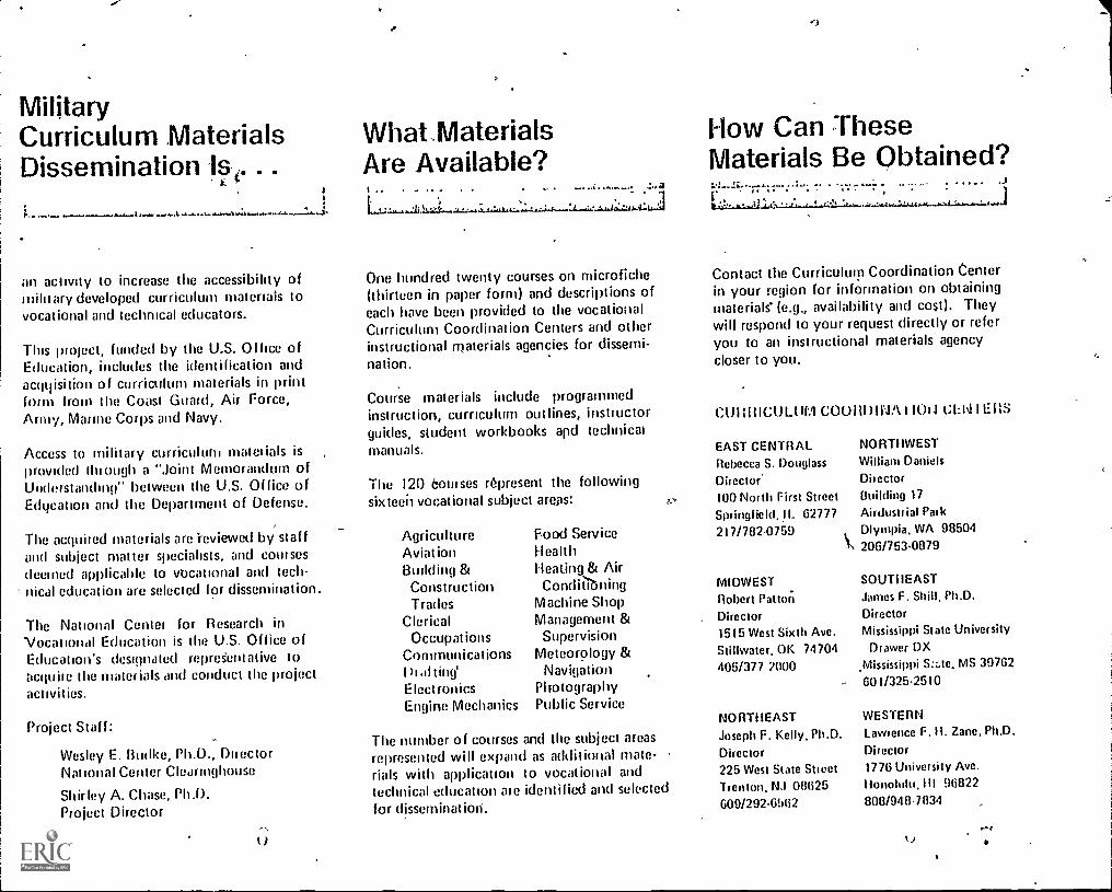
MilitaryCurriculum MaterialsDissemination Is . . .
an activity to increase the accessibility ofmilitary developed curriculum materials tovocational and technical educators.
This luoject, funded by the U.S. Of (ice ofEducation, includes the identification andacqqisition of curriculum materials in printform from the Coast Guard, Air Force,Army, Marine Corps and Navy.
Access to military curriculuni matt:dais isprovided tlti ough a "Joint Memorandum ofUnderstanding" between the U.S. Office ofEdilcation and the Department of Defense.
The acquiied materials are -reviewed by staffand subject matter specialists, and cow sesdeeined applicable to vocational and tech-nical education are selected for dissemination
The National Centel for Research inVocational Education is the U.S. Office ofEducation's designated repreSent alive toacquile the materials and conduct the projectactivities.
Project Staff:
Wesley E. f3udke, Ph.D., DuectorNational Center Clearinghouse
Shirley A. Chase, Ph.D.Project Director
I)
What,MaterialsAre Available?
One hundred twenty courses on microfiche(thirteen in paper form) and descriptions ofeach have been provided to the vocationalCurriculum Coordination Centers and otherinstructional materials agencies for dissemi-nation.
Course materials include programmedinstruction, curnculum outlines, instiuctorguides, student workbooks apd technicalmanuals.
The 120 6otirses represent the followingsix tech vocational subject areas:
AgricultureAviationBuilding &ConstructionTrades
ClericalOccupat ions
Communications
ElectronicsEngine Mechanics
Food ServiceHealthHeating & AirCondioning
Machine ShopManagement &Supervision
Meteorology &Navigation
PhotographyPublic Service
The number of courses and the subject areasrepresented will expand as additional mate-rials with application to vocational andtechnical education ate identified and selectedfor dissemination.
How Can TheseMaterials Be Obtained?
<
Contact the Curriculum Coordination Centerin your region for information on obtainingmaterials (e.g., availability and cost). Theywill respond to your request directly or referyou to an instructional materials agencycloser to you.
CUI1HICULUM COURDINA 1100 CIA I E RS
EAST CENTRAL NORTHWEST
Rebecca S. Douglass William Daniels
Director' Dir ector
100 North First Street Building 17
Springlield.11. 62777 Airdustrial Park
217/782-0759 Olympia, WA 90504206/753-0879
MIDWESTRobert PattaiDirector1515 West Sixth Ave.Stillwater. OK 747044051377 7000
NORTHEASTJoseph F. Kelly. Ph.D.
Director225 West State StreetTrenton. NJ 08625609/292-6962
SOUTI1EASTJames F. Shill, Ph.D.
DirectorMississippi State University
Drawer DXJVIississippi S:z.te, MS 39762
601/325-2510
WESTERNLawrence F. II. Zane, Ph.D.
Director1776 University Ave.Ilonolutu.111 96022000/948-7034
14,
RADIOLOGY TECHNICIAN
Table'of Contents .
Course Description
Volume 1
Radiographic Fundamentals - Text material
Volume Review Exercise
Volume 2
Osteology And Positioninf- Text materialVolume Review Exercise
Volume 3
Special Techniques - Text material
Volume Review Exercise
Volume 4
Special Procedures - Text material
Volume Review Exercise
Volume 5
General Information And Administration -,
Text materialVolume Review Exercise
List of Changes
Correspondence Course 10-5
Page 1
Page 3. Page 125
Page,139Page 228
Page 240Pdge 330
Page 342Page 450
Page 463
Page 508
Page 517

RADIOLOGY TECHNIQIANCorrespondenceCourse 105
Developed by:
United States Air Force
Development andReview Dates.
Unknown
Occupational Area:Health
Cost: Print Pages:
521
Availability:Military Curriculum Project. The Centerfor Vocational Education. 1960 KennyRd., Columbus, OH 43210
Suggested Background:
Previous experience in biology, physiology, and radiology
Target Audiences:
Grades 12-14
Organization or Materials:
Criterion objectives, text, exercises, answers, volume review exercises
Type of Instruction: cIndividualized, self-paced
Type of Ma'terials: No. of Pages: AverageCI:Implosion Time:
Volume 1 Radiographic Fundamentals 119 Flexible
Volume Review Exercise 14
Volume 2 Osteology and Positioning 86 - Flexible
Volume Review Exercise12
Volume 3 Special Techniques 88 Flexible
Volume Review Exercises 12
Volume 4 Special Procedures 104 Flexible
Volume Review Exercise 13
Volume 5 General Information and Administration 40 Flexible
Volume Review Exercise9
Supplementary Materials Required:
None
CC" C14514 it''`,Tritle,tc4S'' ' Expires July 1, 1978
dourse De'sc;Iption
This course was designed to provide the theory portion of Tet.hnician (advanced) training in radiology. It should accompany laboratory work oron-the-iob assignments. This course follows the Apprentice (semi-skilled) and Speciaiist (skilled) levels in this career but contains review materialsfrom both. The job duties outlined for this pdsition are:
Operates X-say equipmentAssists in fluoroscopic examinationsAssists radiologist in treatment of d4ease by radiation therapyEnforces health-protective measuresSupervises radiology
The course is divided into five volumes each containing several chapters. Each chapter consists of several learning objectives with text, ieviewexercises and answers.
Volume 1 Radiographic Fundan4entals discusses fundamentals of X-ray production, the primary beam, exposure devices, film,film holders, and darkrooms; control of film quality; and environmental safety.
Volume 2 Osteology and Positioning describes the osteology of the extremities, vertebral column, ribs, sternum, skull, facialboneseand paranasal sinuses.
V oiume 3 Special Techniques covers mammography, obstetrical radiography, tomography, stereoscopic radiography, localizationof foreign bodies, scenograph y. and arthrogrephy, bedside and surgical radiography, and film duplication and subtraction.
Volume 4 Special Procedures discusses contrast studies of the digestive, urogenital systems, respiratory systems, cardiovescularsystems, and the nervous system.
Volume 5, General Information and Administration covers the muscular, Integumentary, and endocrine systems, field radiography ,and radiation therapy. The chapter on the radiology career field, and the chapter on'supervision, training, supply, andgeneral radiology administration were deleted because they referred to specific military procedures and organization.
This course contains useful information for a beginning student in radiology, but was designed for advanced on the lob learning f or students whohave completed somo prior training in the field, The course is designed for student self-study with criterion objectives, coded text, and criteriontests and answers. The volume review exercises are keyed to.the objectives but no answers are provided.
AI%
C141:::C14 rer voatiorri toucxner. U

I
/
.1;
/
9037001 7504
tDC 90370
...
e -
r 4 \
4
RADIOLOGY TECIIICIANI
(AFSC 90370) ,
.,
Volume 1
Radiographic Fundameiltals
Extension eourse InstituteAir University
1 A.
4
\,
VA5,141MA4VVINIMAYINWYNINWM4MIAVIAMNIONVIAWAN
1,
v

a
a
' PREPARE!) BYSCHOOL OF HEALTH CARE SCIENCES, USAF (ATC)
SHEPPARO AIR FORCE SASE, TEXAS
..
EXTENSION COURSE INSTITUTE, GUNTER AIR FORCE STATION, ALABAMAft
THIS PUBLICATION HAS BEEN REVIEWED AND APPROVED SY COMPETENT PERSONNEL OF THE PREPARING COMMANDIN ACCORDANCE WITH CURRENT DIRECTIVES ON DOCTRINE, POLICY, ESSENfiALITY, PROPRIETY, AND QUALITY.
1 z

PrefaceIN THE VERY early days of radiology, all of the mechanical work was done by the
physician who owned the equipment. He positioned the patient, operated the X-ray
generator, made the exposures, and processed the photographic plates. Naturally, thisoperation restricted the number of patients he could examine in a day's time. Oneenterprising physician reasoned that if he could train a layman to do the mechanicalwork, he would he free to handle the purely professional work of the science. He hired a
manthe first techniCianand taught him how to operate the generatorand process
the films. Unfortunately; because of a lack of inkirmation on the subject, he neglected
to train the man in tile basic fundamentals of the science. Such primary concepts as thetheory of X-ray production, beam restriction, and protection against ionizing ,radiation were not include in the "technician's" training. This exclusion of nowvital
fundamental information had dire results. Loth technician and radiologist, ignorant of
the consequences, worked in the primary beam, and consequently, wereoverexposedsome to the point that the radiation crippled them.
Radiology today has evolved into a highly technical Science. Because of this,knowledge of the fundamentals of our field becomes more and more important to you.
Without a good fundamental background, you cannot understand and apply the new
concepts and therefore provide the best patient care.
This volume of the CDC is devoted to the basic fundamentalsof radiology. Some of
the irtlormation may seem familiar to you since we have included selected reviewmaterial from the Phase I and the Phase II Air Force training programs. You will also
discover thrmghout this volume and the complete CDC many references to quality
control, with which you will become more and more involved throughout your career.
If you have questions on the accuracy or currency of the subject matter of this text,
or recommendations for its improvement, send them to Schookof- Health CareSciences, MST, Sheppard AFB TX 76311. NOTE: Do not use thesuggestion program
to submit corrections for typographical or other errors.
If you have questions on course enrollment or administration, or on any of ECI's
instructional aids (Your Key to Career Development, Behavioral Objective Exercises,
Volume Review Exercise, and Course Examination), consult your education officer,training officer, or NCO, as appropriate. If he can't answer yourquestions, send them
to ECI, Gunter AFS AL 16118, preferably on ECI Form 17, Student Request for
Assistance.
This volume is valued at 36 hours (12 points).
Material in this volume is technically accurate, adequate, and current as of January
1975.
UI
Contents
Chapter
Preface
Page
iii
1 Fundamentals of X-ray Production 1
2 The Primary Beam 40
3 Exposure Devices 50
4 Film, Film Holders, and Darkroom 65
5 Control of Film Quality 83
6 Environmental Safety 96
Answers for Exercises 113
..,
IV
1-, 't

CHAPTER 1
NOTE: In this volume, the subject matter is developed by a series ol Learning Objectives.Each of these carries a 3-digit number and is in boldface type. Each sets a learning goal for you.The text that follows the objective gives you the information y ou need to reach that goal. Theexercises :ollowing the information give you a check on your achievement. When you completethem, see if your answers match those in the back of this volume. If your response to anexercise is incorrect, review the objective and its text.
Fundamentals of X-ray Production
IN ORDER TO BECOME a competent radiologictechnologist you must understand the equipmentwith which you arc working. It is true that you canproduce a radiograph, perharf§ an excellent one,without understanding the operation of the X-raymachine. But w hat action would you take, forexample. if you have occasion to make several high-load exposures in rapid succession. Could youdetermine if the exposures exceed the maximumlimits of your X-ray tube". Would you even considerchecking the tube rating chart at all? These are someof the things that separate the radiologictechnologist from someone you no doubt haveheard referred to as a "button pusher."
You are not expected to learn all the complexitiesof X-ray machine operation. On the contrary, mostof this chapter is limited to factors that affect eitherthe speed or the number of electrons that interactwith the tube target to produce X-radiation. Keep inmind as y ou study this chapter that factors whichaffect the electron ultimately affect the quality orquantity k phot on energy and number of photons perunit area) of the X-radiation.
1-1. Fundamentals of Electricity
All the effects of electricity can be explained byassuming the existence of a minute particle calledthe electron. Using the electron theory, scientists areable to make discoveries and predictions thatceemed impossible only a few years ago. Theelectron is not only the basis of design for allelectr;cal equipment; it is also directly connected tothe production of X-radiation, as mentioned in theintroduction to this chapter. We begin our study ofthe electron with a review of electrical current.
001. Define electrical current and list three factorsthat influence electron movement in a conductor.
Basic Theory of Electrical Current. The flow or
movement of electrons through a conductorconstitutes an electrical current. What causeselectrons to flow through a conductor? Refer tofigure I-I where two containers of water arcconnected by a pipe. Obviously the water will flowfrom left to right until we have the same amount ofwater in both containers. If we compare the drops ofwater with electrons, then we could say that thecontainer on the left has a surplus of electrons. andthe container on the right has a shortage ofelectrons. Since electrons have a negative charge, wecould also say that the container on the left is
negative and the one on the right is positive. Thisdifference between electrostatic charges is an
important factor that affects the movement ofelectrons in a conductor.
Whenever we have opposite charges, we also havea difference in potential, and it is this difference inpotential that is required to produce electron flow ina conductor. Again refer to figure I-I. Once we havethe same water level in both containers, water willstop flowing because there is no longer a differencein potentialor, in the case of electrons, we couldsay we have like charges.
The flow of water from one container to the otherin figure 1-1 is also influenced by the characteristicsof the pipe connecting the two. This is easy tounderstand if you imagine how replacing the pipewith one having a smaller diameter would slow themovement of water from one container to another.In case of an electrical current, electron flow islikewise affected by the amount of resistance of theconductor or of other devices present in the circuit.
Exercises (001):
I. Define electrical 'Current.

short one, assuming that the two conductors areotherwise equal. In other words, the resistance of aconductor is proportional to its length.
Another factor affecting conductor resistance isits cross-sectional area. The greater the cross-sectional area, the lower the resistance; the sniallerthe cross-sectional area, the greater the resistance. Alarge cross-sectional area provides a larger spacethrough which the electrons move; consequently,fewer electron collisions result. If we compare theresistance of two conductors, one with twice thecross-sectional area of the other, the largerconductor offers only one-fourth as much resistanceas does the smaller One.
The final factor affecting the resistance of aconductor is its temperature. For most materials,the hotter the material, the more resistance it offersto an electrical current; and the colder the material,the less resistance it offers to the electrical current.This effect comes about because a change in thetemperature of a material changes its molecularactivity. The effect of temperature upon resistance isthe least important of the four factorsmaterial,length, cross-sectional area, and temperaturethatcontrol resistance.
Exercises (005):
I. Assuming all other factors are equal, do twocurrent-carrying wires made of differentmaterials offer the same resistance to currentflow?
2. Assuming all other factors are equal, doescopper offer more or less resistance than iron?Does aluminum offer more or less resistancethan copper?
3. If a 3-foot conductor offers 6 fl resistance, howmuch resistance does a 1-foot conductor offer, ifall other factors are equal?
4. Why is the resistance of a conductor influencedby conductor length?
5. If a conductor's resistance is 2 fl, how muchresistance is present in a conductor with twice thecross-sectional area if all other factors are equal?
6. Does conductor temperature affect itsresistance? If so, does a high temperatureincrease or decrease resistance?
7. Of the factors discussed that affect conductorresistance, which one is least important?
006. Using the formul*s derived from Ohm's law,find the following circuit values: (1) current ifvoltage and resistance are given, (2) resistance ifvoltage and current are given, and (3) voltage ifcurrent and resistance are given.
Ohm's Law. To this point, our discussions ofcurrent, voltage, and resistance have mostly dealtwith the relative values of those elements. Now, let'ssee how we can determine the specific values of anyone of the three elements when .we know what theother two values are.
The relationships between current, voltage, andresistance are expressed in Ohm's law. The lawstates: "In a DC circuit, current varies directly withthe voltage and inversely with the resistance." If weknow two of the three values, we can, by using theformulas derived from Ohm's law, determine theother value. The formulas are as follows:
Current: 1=-7
Resistance: R = -.1
Voltage: E=IX R
An easy way to remember these formulas is by theuse of the chart in figure 1-2. To use these formulas,cover the letter symbol for the value you are tryingto determine. For instance, if you cover up the E, allyou have left is IX R. Therefore, in order to find thevoltage, your formula is E= IXR. Now, if you wantto solve for current, you cover up /. This will leaveyou with I-. There fore, if you want to calculatethe
current, your formula would be I= . If you need
the formula for resistance, just cover up the R andyou will get the formula R= Now, let's see how
/Ohm's law is applied to a simple electrical circuit.
4.
o

11 you look at the circuit in figure 1-3 , you will sec
that we hide a battery, whichJtoicshall assume isproviding 6 volts. 1 he lamp haE.al resistance ot 2ohms when the switch is closedgind the problem is
to find thc current. Since we are looking for current,
we use the formula I= When we substitute the6
two known values for E and R, we have .6 .
2Therefore. / = , or, 1= 3 amps. Even though we
2now know all the values in this circuit, let's use theformula for practice to prove each value. First, let's
solve the R, the formula for which is R6Substituting values, we have R= : or, R = 2 ohms.3
To solve for E, the formula is E= I X R. Therefore,
E = 3 X 2; or, E = 6 volts.
Exercises (006):
1 What is the resistance in a circuit if the voltage is110 volts and the current is 5 amperes?
2. What is the voltage in a circuit if the current is 2amperes and the resistance is 55 ohms?
Figure 1-2. The Ohm's law chart.
3. What is the current in a circuit if the voltage is 12volts and the resistance is 4 ohms?
0117. Given a schematic of a circuit showing variouscomponent symbols, identify the symbols shown.
. of Circuit Components. For simplicityand -.ye space, symbols of circuit componentsare used rather than pictures. While it is notnecessary for you to identify all componentsymbols, you will,need to identify some of the mostcommon symbols used throughout this chapter. ln
6V 2 IL
Figure 1 3 A simple DC circuit.
5

OHM METER
AMMETER
VOLTMETER
i
LAMP
-/NAAAAt-
FIXED RESISTOR
CONNECTED WIRES
SWITCH
FUSE
or
CROSSED OVER WIRES
10-1\Airr--
VARIABLE RESISTOR
±BAT TERY GROUND
Figure I -4. Some common circuit component symbols.

addition. this knowledge will aid you considerablyin interpreting other technical literature. Figure 1-4shows the common circuit symbols you shouldknow. (NOTE: When a battery symbol is used, thebattery voltage is sometimes written alongside thesymbol.)
Exercises (007):
Figure 1-5 is a circuit schematic showing I I
commonly used component symbols. Opposite theappropriate numbers below, write the name of eachcomponent symbolized in figure 1-5.
Figure 1-5. Objective 007, exercises 1 through 1 1.
1.
2.3.
4,
5.
, 6.7.
8.9,
10.
I I.
008. Given a schematic of a series circuit, includingtotal voltage and individual resistor values, find thecurrent at various points in the circuit, the totalresistance of the circuit, and the voltage drop acrosseach resistor.
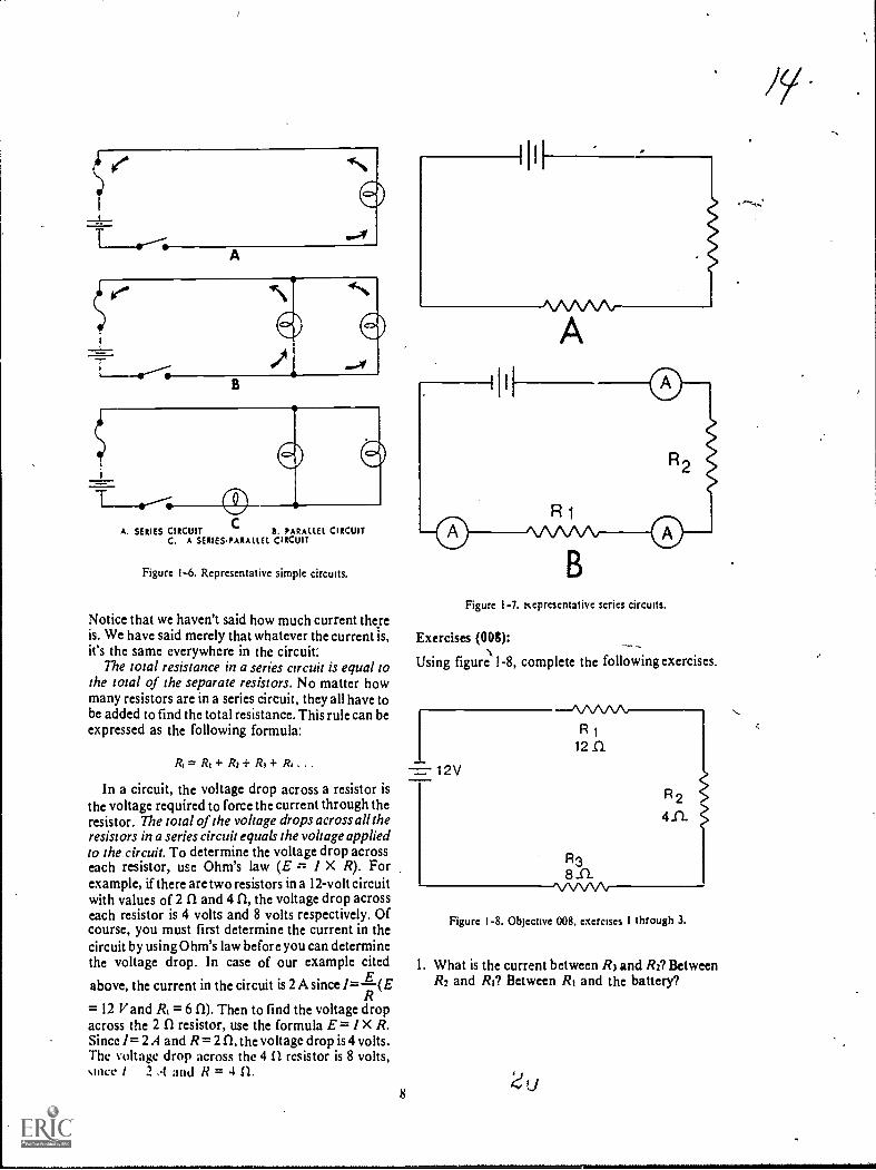
Basic Electrical Circuits. Electrical circuits areclassified according to the way their components arearranged or connected. The three types of circuitsare series, parallel, and series-parallel. See figure I-6.
Seriec circuit. A series circuit is one in which thecomponents are connected end to end and there is
7
only one path for the current. See ft gure l-7,A,which shows three electrical devices connected inseries.
Now, let's discuss the behavior of current,resistance, and voltage in a series circuit. Current isthe simplest, so let's consider it first, with the aid offigure 1-7,B. If we close the switch, completing thecircuit, the three ammeters should show the amountof current at various points in the circuit. All theammeters should read the same amount of current.This is the first important thing to remember abouta series circuit: Current is the same at all points in aseries circuit. This is sometimes expressed informula form as:
TotalCurrent
equals
= it =
Currentthrough /21
equalsCurrent
through /21
It doesn't matter how many resistors you have. Ifthere were five resistors in the circuit, the formulawould be:
h= 11= Is= 14= Is
(
CA. SERIES CIRCUIT B. PARALLEL CIRCUIT
C. A SERIES.PARALLEL CIRCUIT
Figure 1-6. Representative simple circuits.
Notice that we haven't said how much current thereis. We have said merely that whatever the current is,it's the same everywhere in the circuit:
The total resistance in a series circuit is equal tothe total of the separate resistors. No matter howmany resistors are in a series circuit, they all have tobe added to find the total resistance. This rule can beexpressed as the following formula:
A = R1+ R: + R3+ R1 . . .
In a circuit, the voltage drop across a resistor isthe voltage required to force the current through theresistor. The total of the voltage drops across all theresistors in a series circuit equals the voltage appliedto the circuit. To determine the voltage drop acrosseach resistor, use Ohm's law (E = I X R). Forexample, if there are two resistors in a 12-volt circuitwith values of 2 II and 4 CI, the voltage drop acrosseach resistor is 4 volts and 8 volts respectively. Ofcourse, you must first determine the current in thecircuit by using Ohm's law before you can determinethe voltage drop. In case of our example cited
Eabove, the current in the circuit is 2 A since /=(ER
= 12 V and 1?1 = 6 CI). Then to find the voltage dropacross the 2 CI resistor, use the formula E = 1 X R.Since I= 2 A and R= 2 a the voltage drop is 4 volts.The voltage drop across the 4 n resistor is 8 volts,since / 2 .1 and li = 4 IL
8
,
Figure 1-7. Kepresentative series circuits.
Exercises MP:
Using figur1e 1-8, complete the following exercises.
I= 1 2V
--/\.A.AA.A,R 1
12 SI
R38 ..C1
1.A./\/V\i
R 2
411.
Figure 1-8. Objecnve 008. exercises I through 3.
1. What is the current between R3 and R2? BetweenR2 and Ri? Between RI and the battery?
ti
,..
t

2. What is the total resistance in the circuit?
3. What is the voltage drop across RI? Across R2?Across R3?
009. Given a schematic of a parallel circuit,including the total voltage and individual resistancevalues, find the voltage at various points within thecircuit, the current through each resistor, and thetotal resistance of the circuit.
Parallel circuit. It is often necessary to connectelectrical devices in a circuit so that the total voltageis applied across each device. A circuit in which twoor more devices are connected across a commonpower source is called a parallel circuit. Let'sexamine the behavior of voltage, current, andresistance in a parallel circuit.
Note in figure 1-9 that points a, b, c, and d areconnected and arc one point electrically. Similarly,points e, 1, g, and h comprise another electricalpoint. Since the applied voltage appears betweenpoints a and e, the same voltage appears betweenpoints b and f and between points c and g, as well asbetween points d and h. So it can be said that whenresistors are connected in parallel across a voltagesource, each resistor has the same voltage applied toit. although the currents may differ depending uponthe values of resistance. The voltage in a parallelcircuit may, therefore, be expressed mathematicallyas follows:
& = Ei = E2 =
where Ei is the applied voltage, El is the voltageacross RI, E2 across R2, and E3 across R3.
The current. on the other hand, divides amongthe various branches in a parallel circuit in a mannerdepending upon the resistance of each branch. In aparallel circuit, branches with low resistance drawmore current than branches with high resistance.Therefore, the current in the circuit may beexpressed mathematically as follows:
Figure 1-9 A parallel DC circuit
9
1, = + 12+ h
where h is the total current and /I, 12, and 13 are thecurrentathrough RI, R2, and R3 respectively.
The total resistance in a parallel circuit is alwaysless than the lowest resistance in thaircuit. Thereare several methods to compute the resistance;however, the reciprocal method will belhe only onediscussed here. As a rule, we can say that theeffective resistance of parallel resistors is equal tothe reciprocal of the sum of the reciprocals.Although this may sound complicated, it is not.Let's look at the formula:
I 1
R, R2 R2
Suppose the values of the resistors above are RI 1ohm, R2 2 ohms, and R3 2 ohms. Substituting theresistance values in the formula we find:
1
Ri
+1
I
2 2
1 2 1 1
R. 7 2 2
1 4
R, 2
I _ 2R,
1 2
2 R1= 1 or /it = 0.5
Therefore, the total resistance in this parallel circuitwould be 0.5 ohm.
Exercises (009):
Using figure 1-10, complete the following exercises.
12V
R1-
3n
R2
211
R 3
inR4
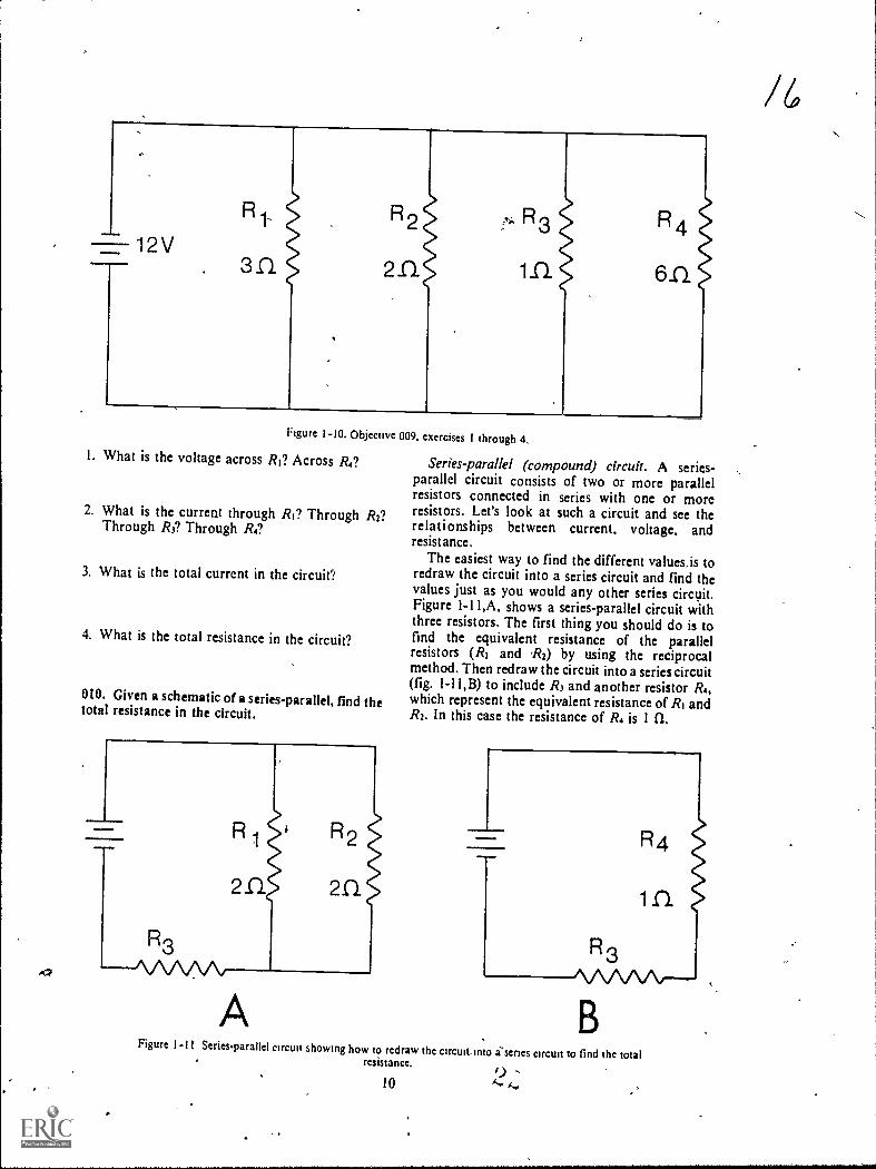
Figure 1-10. Objective 009. exercises I through 4.
1. What is the voltage across Ri? Across R4?
2. What is the current through RI? Through R2?Through R3? Through R4?
3. What is the total current in the circuit"!
4. What is the total resistance in the circuit?
010. Given a schematic of a series-parallel, find thetotal resistance in the circuit.
Series-parallel (compound) circuit. A series-parallel circuit consists of two or more parallelresistors connected in series with one or moreresistors. Let's look at such a circuit and see therelationships between current, voltage, andresist ance.
The easiest way to find the different values,is toredraw the circuit into a series circuit and find thevalues just as you would any other series circuit.Figure 1-11,A, shows a series-parallel circuit withthree resistors. The first thing you should do is tofind the equivalent resistance of the parallelresistors (R, and R2) by using the reciprocalmethod. Then redraw the circuit into a series circuit(fig. 1-11,B) to include R3 and another resistor R4,which represent the equivalent resistance of Ri andR2. In this case the resistance of R. is 1 n.
R1
2n.
R2
2.0.
=Mom* R4
inR3
A
R3AAAAA.---
BFigurc I-11 Series-parallel circuit showing how to redraw the circuit, into i'scries circuit to find thc total
resistance. 9 .10
/6
Exercise (010):
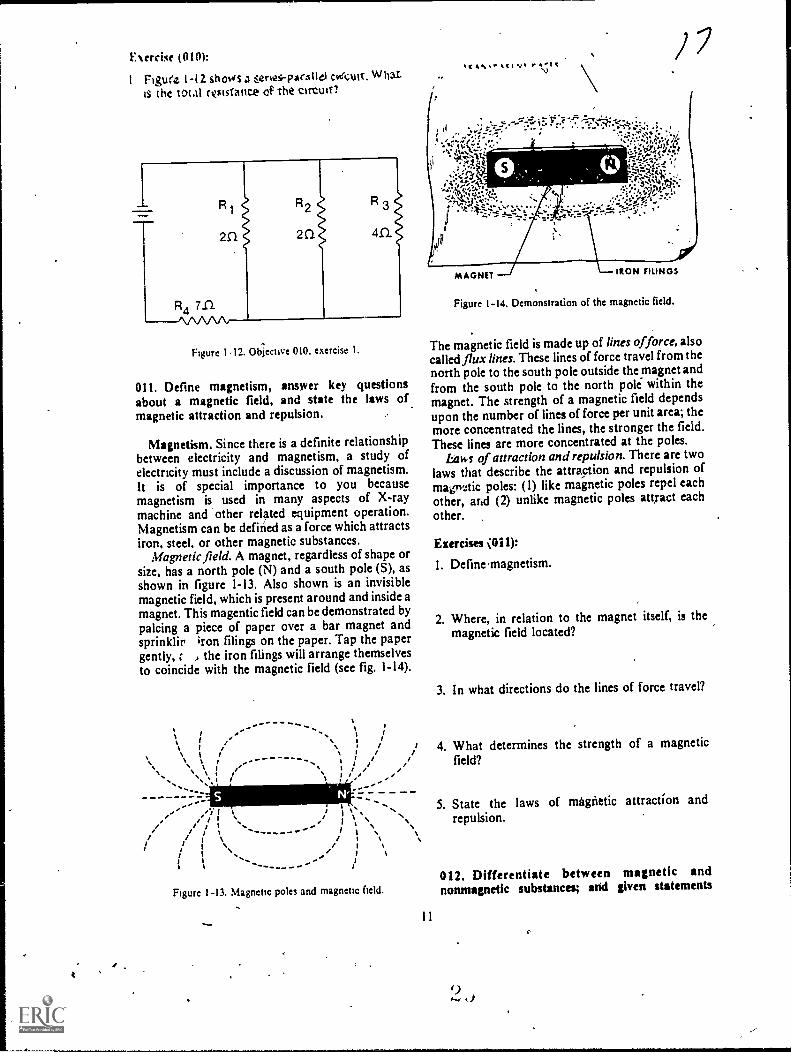
1 Figure I -12 shows a ,:eries-parxtle1 cveCult. Whatis tht total roisiance op the cirtwo
R R2 R 3
2C1 2 Cl an
Figure 112. obiective 010. exercise I.
011. Define magnetism, answer key questionsabout a magnetic field, and state the laws ofmagnetic attraction and repulsion.
Magnetism. Since there is a definite relationshipbetween electricity and magnetism, a study ofelectricity must include a discussion of magnetism.It is of special importance to you becausemagnetism is used in many aspects of X-raymachine and other related equipment operation.Magnetism can be defined as a force which attractsiron, steel, or other magnetic substances.
Magnetic field. A magnet, regardless of shape orsize, has a north pole (N) and a south pole (S), asshown in figure 1-13. Also shown is an invisiblemagnetic field, which is present around and inside amagnet. This magentic field can be demonstrated bypalcing a piece of paper over a bar magnet andsprinklir iron filings on the paper. Tap the papergently, , the iron filings will arrange themselvesto coincide with the magnetic field (see fig. 1-14).
.....I ''--
.._ ,i i I
N \ I I\ % .... ..... ". . . .\ \ I\ \ I li..... .,\ I I
jYI t// I
/ Os
, - \1 s. - )/ /
I I I \ / I \I I \ / I %
I I/ I l
I Is
I I II
S.
Figure 1-13. Magnetic poles and magnetic field.
11
%14, r4.it
IRON FILINGS
Figure 1-14. Demonstration of the magnetic field.
The magnetic field is made up of lines offorce, alsocalled flux lines. These lines of force travel from thenorth pole to the south pole outside the magnet andfrom the south pole to the north pole within themagnet. The strength of a magnetic field dependsupon the number of lines of force per unit area; themore concentrated the lines, the stronger the field.These lines are more concentrated at the poles.
Laws of attraction and repulsion. There are twolaws that describe the attraction and repulsion ofmagrictic poles: (1) like magnetic poles repel eachother, and (2) unlike magnetic poles attract each
other.
Exercises 011):
I. Define magnetism.
2. Where, in relation to the magnet itself, is themagnetic field located?
3. In what directions do the lines of force travel?
4. What determines the strength of a magneticfield?
5. State the laws of magnetic attraction andrepulsion.
012. Differentiate between magnetic andnonmagnetic substances; and given statements

pertaining to magnetic dipoles and the relationshipbetween magnetic dipoles and the magnetic field,indicate which are true and which are &1st.
Magnetic and nonmagnetic substances. Allmatter is affected to some extent by a magnetic field.Substances strongly attracted by a magnetic fieldare called "magnetic substances," and substancesnot noticeably affected by a magnetic field aregenerally classified as "nonmagnetic substances."Iron and steel are examples of strongly magneticmaterials, while wood, copper, and glass arenonmagnetic.
Magnetic materials consist of millions of tinyelementary magnets, called magnetic dipoles ormagentic domains, which are molecular or atomicin size. When these dipoles are arranged at randomin an unmagnetized bar of iron or steel (fig. I-15,A),the cumulative magnetic strength of the dipoles isneutralized. If a magnetizing force is applied to theiron bar, the dipoles become aligned so that all theirnorth poles point in one direction and all their southpoles point in the opposite direction (fig. 1-15,B).With the dipoles aligned in this manner, theirmagnetic strengths are combined, and lines of force,or a magnetic field, results. The bar is thenmagnetized. The direction of travel of the lines offorce in and around this magnet is established,based upon the alignment of the poles of themagnetic dipoles. See figure 1-15,C.
G-9GbG--
cboiq66(box
Figure I - 15. Iron bar showing arrangement of magnetic dipolesbefore and after application of a magnewing force. Also showni% the rdationship between dipole alignment and direction al
hnes ol force.
Exercises (012):
I. What is the difference between magnetic andnonmagnetic substances?
0
2. Give two examples of a magnetic material andthree examples of a nonmagnetic material.
Indicate whether the following statements are trueor false.
T F 3.
T F 4.
T F 5.
In an unmagnetized magnetic material, themagnetic dipoles are arranged in a randompattern.Uniform alignment of magnetic dipolesresults in an external magnetic field.Direction of travel of lines of force isdetermined by the dirtction of alignment ofthe magnetic dipoles.
013. Show the relationship between a current-carrying conductor and the electromagnetic fieldaround the conductor.
Electromagnetism. If a current is passed througha wire conductor, a magnetic fields similar to themagnetic field of a bar magnet is created around theconductor. This magnetic field is sometimes calledan electromagnetic field.
Relationships between conductors and magneticfields. The lines of force around a straight,current-carrying conductor are circular and at right anglesto the direction of current flow (see fig. 1-16). Themagnetic field in this case does not have a north orsouth pole.
If a current-carrying conductor is formed into aloop or coil, as illustrated in figure 1-17, the lines offorce pass through the inside of the coil, as shown.As a result, a north pole is created on one end of the
MAGNETICFIELD'-
commaimaimagaii
N T
hgure I 16 Electromagnetic held around a straight currentcarrying conductor9
(

Figure 1-17 Ekctromagnetic field around a sIngle wireSconductor loop
loop and a south pole on the other. The direction ofthe lines of force is thesame as that of a bar magnetwith the inside of the coil representing the magnetic
bar.If the wire conductor is formed into many loops,
as shown in figure 1-18, the lines of force around theIndividual loops combine to form a larger andstronger magnetic field. A north and a south polearc then established at opposite ends of the coil.
The direction of the lines of force around aconductor depends upon the direction of currentflow and can be determined by using the left-handrule, as shown in figure I-19e If the left hand isplaced around a conductor so that the thumb pointsin the direction of current flow, the lines of force
Figure I -18 Electromagnetic field around a mre conductorformed mto seseral loops
travel in the same direction as the fingers. Referagain to figure 1-18 and imagine placing your lefthand at various noints Rthe coil, and you can seethe validity of this-rule.
Exereiss (013):
1. What condition must exist for a magnetic field tobt created around a wire conductor?
2. Does ,polarity exist, in the magnetic field of astraight conductor? If not, what can 1394one tocreate a north and a south pole within themagnetic field?
3. Where are the north and sotith poles located withrespect to a current-carrying coil?
4. What determines the direction of travel of themagnetic lines of forc'e around a conductor?
5. Ekplain the left-hand rule for determining thedirection of travel of the lines of force around aconductor?
014. List the three factOrs influencing the magneticstrength of a coil, and in each case explain therelationship between the influential factor and-themagnetic strength.
C>
Factors influencing the magnetic strength of acall. When a conductor is wound into a coil, thelines of force around each loop combine with thosefrom other loops to form one magnetic field. ftfollows that the more loops or turns per unit areaor we can say the more turns per inchthe stronger
, the field.As the current through the conductor increases,
so does the number of lines of force around theconductor; consequently, a higher current alsoproduces a stronger magnetic field.
Another factor that influences the magneticstrength of a coil is the insertion of an iron core inthe center of the coil. The iron core affects themagnetic strength for two reasons: (1)the core itselfbecomes magnetizied, and its magnetic strength isadded to that of the coil and (2) the core provides aneasier- pathway fdr the lines of force to travel; thusthe lines of forwoncentrate themselves within thecore. Soft iron is usually used as core materialbecause it has a high permeability, which
13

Magnetic Field
Current
Figure 1-19. Left-hand rule for determining the direction of lines of force around a Conductor.
determines the ability of a material to cnriduct otconcentrate lines of force. (NOTE: Soft iron alsohas low retentivity. Retentivity is a characteristicthat determines the ability of a substance to remainmagnetized after the current is turned off. Lowretentivity is necessary ifor precise control of anelectromagnetic field.)
Exercises (014):
In exercises I through 3 below, list three factorsinfluencing the magnetic strength of a coil. Aftereach factor, explain how it affects the magneticstrength.
1.
2.
L015. Given statements pertaining to the centeringeffect of an iron core within a current-carrying coiland its applications, indicate which ue true and
which are false. If you indicate "false," explain youransWer.
Iron core centering effect. The iron core we havediscussed is useful in the.construction of variouselectrical devices. Its usefulness is attributed partlyto a phenomenon known as the "centering effect?'Due to this phenomenon, an iron core, wheninserted into a current-carrying coil, automaticallycenters itself to the length of the coil. Also, if thecore is suspended off center inside a coil withoutcurrent, the core will center itself if current isapplied to the coil. The centering effect is used inseveral electrical applications, such as solenoids,magnetic locks, and circuit breakers.
Id
Exercises (015):
indicate whether the following statements are trueor false. If you indicate"false," explain your answer.
T F I. Due to the centering effect, if an iron core issuspended within a coil without current,the core automatically centers itself to thelength of the coil.
c2

T F 2. The centering effect is used in theconstruction of magnetic locks, circuitbreakers, and solenoids.
016. State a characteristic and an application of anelectromagnet and the principle of relay operation.
Electromagnets and relays. If an iron core isinstalled in a fixed position within a coil, the deviceis known as an electromagnet. A frequent use of anelectromagnet is in a relay. While relays are of manydifferent sizes and shapes, they all operate on theprinciple that an electromagnet attracts, magneticsubstances (usually iron). Let's examine the parts ofa simple relay and a simple relay-controlled circuit.
Figure 1-20 shows the parts of a relay: (1) aninsulated coil of wire wrapped around an iron coreand (2) a pivoting iron bar. When current isintroduced into the coil, a magnetic field is created,represented by the broken lines. This attracts thepivoting bar. The iron bar can be used to close oropen a circuit; consequently, a relay can benormally open or normally closed.
A relay can also be used to remotely control aneighboring circuit, such as the one seen in figure I-21. When.the switch is closed in the relay circuit, amagnetic field is created, which is represented by thebroken lines. The iron bar in the adjacent circuit isattracted to the iron core and closes the adjacentcircuit. If the switch is then opened in the relay
--
circuit, the magnetic field around the coil collapses,allowing the spring to open the adjacent circuit.
Exercises (016):
In the exercises below, fill in each blank space withone or two words, as appropriate.
Figure 1-20. The parts of a relay.
SPRING
/SOFTIRONBAR
RELAY CIRCUIT/
SWITCH
Figure 1-21. A simple relay controlled circuit.
15
SPRINGSTEEL
LAMP

I The iron core in an electromagnet is in aposition within the coil.
2. A major use of an electromagnet is in a
3 The principle of operation for a relay is that anelectromagnet attracts sub-stances.
4 In a relay the contacts are closed or opened dueto the attraction between the andthe iron bar.
5. If a relay-controlled adjacent circuit is closedwhen current is flowing in the coil of theelectromagnet, the adjacent circuit is
by action.
017. Explain the operation of moving coil meters.
Moving coil meters. We now turn our attention tometers and meter movements, although we are stillactually discussing electromagnetism, since it is thiseffect of current flow upon which most meteroperations arc based. (NOTE: Other effects ofelectricity are used to detect the presence or amountof electricity; however, our discussion is limited tometer operation based upon the electromagneticeffect.) The most common type of meter movementis the permanent-magnet, moving-coil movement,used in the d'Arsonval meter (fig. 1-22).
Basically, the operation of the meter is as follows:Direct current is introduced into several turns of
SCALE
copper wire wound around the moving coil. Thecurrent produces a magnetic field around the coil,which reacts with the magnetic field formed by thepermanent magnet. The coil, which has become anelectromagnet, turns on its axis as its poles attemptto repel like poles of the permanent magnet. Anindicating needle mounted on the coil reads thedegrees of rotation on the scale. The more currentthat passes through the coil, the greater is therepulsion or needle deflection, and thus the higherthe reading on the scale.
Meters with permanet-magnet; moving-coilmovement are used in X-ray machines to measuresuch values as line voltage, kVp, mA, and mM.
Exercises (017):
I. On what electrical current effect are most meteroperations based?
2. What is the most frequent type of metermovement?
3. List the types of magnets in the d'Arsonvalmeter
PERMANENT MAGNET
I i 11109
CURRENT
411146:7;
ENTERS HERE
II POLE PIECES
111 MOVING COIL
CURRENTLEAVES HERE
40.611'ligeolialM1111111.4.0.
LINEAR SCALE
A
ALUMINUM BOBBIN
A THE LINEAR SCALE & THE PERMANENT-MAGNET,MOVING.COIL MECHANISM
Figure 1-22. A d'Arsonval meter.
16L)
SPRING
c2 01.
4. What causes the moving coil to rotate in ad'Arsonval meter?
018. Compare electron movement in alternatingeurrent to electron movement in direct current.
Alternating Current Characteristics. Up to thispoint in this chapter, our discussions of current flowhave been related to direct current, where electronscontinuously flow in one direction through a circuit.Electron movement in alternating current (AC), onthe other hand, is bidirectional; that is, electronsmove first in one direction and then reverseilemselves and move in the opposite direction.
Keep in mind as you study AC that the electrons stillmove from negative to positive just as they do in DCsince polarity also constantly changes.
Exercises (018):
Match the type of current in column B with thedescription of electron movement in column A byplacing the letter of the column B item in theappropriate space in column A. Each column B item
may be used once or more than once. Also, bothcolumn B items may match a single column A item.
Column A Column B
1 Electrons only move from a. AC.negative to positne, b DC.
2. Electron movementconstantly changesdirections.
3. In a given circuit, electronsmove through the wireconductor in the same
direction.
900
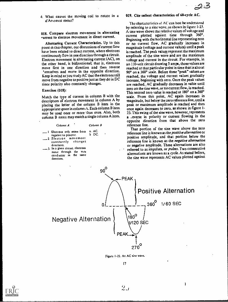
019. Cite salient characteristics of 60-cycle AC.
Thc characteristics ot AC can hest be understoodby referring to a sine wave, as shown in figure 1-23.A sine wave shows the relative values of voltage andcurrent plotted against time through 3600.Beginning with the horizontal line representing zeroor no current flow, AC gradually increases inmagnitude (voltage and current values) until a peakis reached. The peak values represent the maximumamplitude of the sine wave and are the maximumvoltage and current in the circuit. For example, inan 110-volt circuit drawing 5 amps, those values arereached at that particular point in time that is also at900 on a 3600 scale. Before these "peak" values arereached, the voltage and current values graduallyincrease, beginning with zero. Once the peak valuesare reached, AC gradually decreases in value untilzero on the sine wave, or no current flow, is reached.This second zero value is reached at 180° on a 360°scale. From this point, AC again increases inmagnitude, but below the zero reference line, until apeak or maximum amplitude is reached and thenonce again decreases to zero, as shown in figure 1-23. This swing of the sine wave, however, representsa .everse in polarity or current flowing in theopposite direction from that above the zeroreference line.
That portion of the sine wave above the zeroreference line is known as the positive alternationorpositive amplitude, and that portion below thereference line is known as The negative alternationor negative amplitude. These alternations are alsoreferred to asimpulses, or pulses. Two consecutivealternations are known as a cycle. As stated before,the sine wave represents AC values plotted against
PEAK
Negative Alternation
Positive Alternationo
360 1/60 SEC
180°1/120 SEC
o270
Figure 1-23. An AC sine wave.
17

time. In the case of 110-volt household current,there are 60 cycles per second. This means that 60cycles or 120 alternations occur in I second. Thenumber of cycles occurring in a second is referred toas the AC frequency. For our purposes in this CDC,we will deal mostly with 60-cycle AC, althoughmuch higher frequencies are used in other fields.
Exercises (019):
I. At what point in time during a cycle does thepolarity of 60-cycle AC change?
2. During an AC cycle, is current continuouslyflowing in one direction or another? Explain.
3. How long does it take for 60-cycle AC to buildfrom zero to the maximum current and voltagevalues?
4. How many alternations occur in one cycle?
5. How many pulses occur in one-half cycle?
MOVEMENT
A
6. What is AC frequency?
020. Define electromagnetic induction arid answerkey questions pertaining to the methods of inducingEMF in a conductor.
Electromagnetic Induction. If a conductor ismoved through a magnetic field and cuts the lines offorce or flux, as illustrated in figure 1-24,A, an EMFis induced in the conductor. By the same token, ifthe conductor is stationary and the magnet moves,as illustrated in figure 1-24,B, an EMF is alsoinduced in the conductor. This process of producingan EMF from the re'ative motion between aconductor and magnetic field is calledelectromagnetic induction. Accordingly, there arethree requirements for electromagnetic induction:(I) a conductor, (2) a magnetic field, and (3) relativemotion.
The magnitude of the induced EMF dependsupon the number of lines of force cut per unit time;the greater this number, the higher the inducedEMF. Two ways of increasing the induced EMFare: (1) to increase the relative motion or speed atwhich the lines of force are cut and (2) to increasethe strength of the magnetic field. The magnitude ofthe induced EMF also depends upon the number ofconductors in which the EMF is induced; the moreconductorsor as we shall see when we discusstransformers, the more turns in a coilthe higherthe induced EMF.
MOVEMENT
F1o.
Figure 1-24. Ekctromagnctic induction.
18 3.)
CONDUCTOR
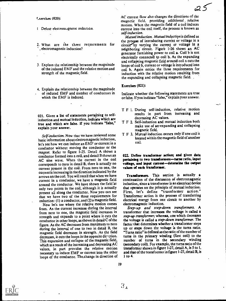
r..xercises (020):
I Define electromagnetic induction.,.
2. What are (he three requirements for, electromagnetic induction?
3. Explain the relationship between the magnitudeof the induced EMF and the relative motion andstrength of the magnetic field.
4. Explain the relationship between the magnitudeof induced EMF and number of conductors inwhich the EMF is induced.
021. Given a list of statements pertaining to self-
induction and mutual induction, indicate which aretrue and which are false. If you indicate "false,"explain your answer.
Self-induction. Now that we have reviewed somebasic information about electromagnetic induction,let's see how we can induce an EMF or current in aconductor without moving the conductor or themagnet. Refer to figure 1-25. Detail A shows aconductor formed into a coil, and detail B shows anAC sine wave. When the current in the coilcorresponds to zero in detail B, there is actually nocurrent present in the coil. From zero to one, the
current is increasing in the direction indicated by the
arrows on the coil. You will recall that when we havecurrent in a conductor, we have a magnetic fieldaround the conductor. Wc have shown the field 'at
only two points in the coil, although it is actuallypresent all along the conductor. Now you can seethat we have two of the three requirements forinduction: (1) a conductor, and (2) a magnetic field.
Now let's see where the relative motion comesfrom. As the current increases during the intervalfrom zero to one, the magnetic field increases instrength and expands to a point where it cuts theconductor in other loops, as shown in detail C of thefigure. As the AC decreases from maximum to zeroduring the interval of one to two in detail B, themagnetic field decreases in strength. As the fielddecreases, it cuts the loops in the opposite dir-ction.This expansion and collapse of the magnetic field,which is a result of the increasing and decreasing ACvalues, in part provides the relative motionnecessary to induce EMF or current into the otherloops of the conductor. Thechange in direction of
AC current flow also changes the directions of themagnetic lidd, providing additional relativemotion. When the magnetic field of a coil inducescurrent into the coil itself, the process is known asself-induction.
Mutual induction. Mutual induction is defined asthe progus of introducing current or voltage in acircuiny varying 'the current or voltage In aneighboring' circuit. Figure 1-26 shows an ACgenerator furnishing power to coil a. Coil b is notelectrically connected to coil b. As the expandingand collapsing magnetic field around coil a cuts theloops of coil b, current or voltage is introduced intocoil b. Again notice the three requirements forinduction with the relative motion resulting fromthe expanding and collapsing magnetic field.
Exercises (021):
Indicate whether the following statements are trueor false. If you indicate "false," explain your answer.,
T F I. During self-induction, relative motionresults in part from increasing anddecreasing AC values.
T F 2. Self-induction and mutual induction bothmake use of an,expanding and collapsingmagnetic field.
T F 3. Mutual induction occurs only if one coil islocated within the magnetic field of anothercoil.
022. Define transformer action; and given datapertaining to two trandormenturnwratio, inputvoltage, and input currentdetermine the animavalues of each transformer.
Transformers. This section is actually a
continuation of the discussion of electromagneticinduction, since a transformer is an electrical devicethat operates on the principle of mutual induction.First, let's define "transformer action."Transformer action is the process of transferringelectrical energy from one circuit to another byelectromagnetic induction.
Step-up and step-down transformers. Atransformer that increases the voltage is called astep-up transformer; whereas, one which decreasesthe voltage is called a step-down transformer. Thefactor that determines whether a transformer stepsup or steps down the voltage is the turns ratio."Turns ratio" is defined as the ratio of the number ofturns in the primary winding (first coil) to thenumber of turns in the secondary winding(secondary coil). For example, the turns ratio of thetransformer shown in figure 1-27, detail A, is 5 to 1,and that of the transformer in figure 1-27, detail B, is1 to 4.
19
3 i

t
Q6
B
Figure I 25. Self-induction.
20
..,

Figure I -26. Mutual induction.
Now let's consider transformer actions. Whateffect does the turns ratio have on the transformeroutput? The ratio of thc transformer input to the
output is the same as the turns ratio, provided the
transformer is 100 percent efficient. (NOTE:Transformers are not 100 percent efficient, but forease of calculation-we.will consider them to be.) Inother words, an input of 10 volts applied to the
primary of the transformer in detail A, will induce 2volts in the secondary. Therefore, this is an example
of a step-down transformer. Contrariwise, an inputof 10 volts applied to the primary of the transformershown in detail B will result in an output of 40 voltsfrom the secondary. So detail B is an example of a
step-up transformer. No matter what voltage weapply to the primary of the transformer in detail A,the output is one-fifth of the input (assuming we
stay within the voltage limits of the transformer).
10 TURNSPRIMARY
A
c.27With the transformer shown in detail B, theOutpuiis four times the input. This shows that the turnsratio determines the step-up or step-down ratio of atransformer.
Now, let's see what happens to the current. Wefind that a transformer that increases the voltage bya given ratio decreases the current by the same ratio.In other words, if we apply 10 volts at 10 amps to thepyimary of a I to 10 step-up transformer, as shownin figure 1-28, detail A, the voltage in the secondarywill be 100 volts and the current will be I amp. If thetransformer is a step-down transformer, as shown infigure 1-28, detail B, the curcent in the secondarywill be increased by the samcratio that the voltage isdecreased.
Exercises (022):
I. Define "transformer action."
2. What is the output voltage and amperage from atransformer using the following information:Input voltage - 110 volts; input amperage - 5amps; transformer ratio - 10 to 1?
3. What is the output voltage and amperage from atransformer using the Vollowing information:Input voltage - 220 volts; input amperage - 3amps; transformer ratio - Ito 3?
023. State the purpose and bask operation pf anautotransformer and explain "red-lining."
2 TURNSPRIMARY
SECONDARY
2 'URNS
Figure I - 27 Transformer turns ratio,
21
SECoNDARY8 TURNS

lOy10A 100V 100V
1A
A
i. STEP.UP 5. STEP.DOWN
Figure 1-28. Transformer turns ratio.
Autotransformers. As a radiologic technologist,you are concerned with three transformers. By nowyou are familiar with the step-up and step-downtransformers. The third type, and probably the mostimportant one to you, is the autotransformer. Theautotransformer is the most commonly used andmost efficient method of varying the kilovoltageoutput of the high tension transformer in the X-raymachine. Consider for a moment a transformerconsisting of one continuous winding on a long,laminated iron core. When voltage is applied acrossonly one section of it, voltage will be induced in theturns that are not connectedMirectly to the line inthe same way that voltage is induced in thesecondary coil of a conventional transformer.lnfact, the section across which the line voltage isapplied is called the primary, and the balance of thewinding is called the secondary.
If the voltage is measured across various sectionsof a typical autotransformer, a situation like that infigure 1-29 may be present. A series of taps orconnections to the different turns provides aconvenient method of getting a wide variety ofvoltages to apply to the primary of the high tensiontransformer. In the circuit shown in figure 1-29 (thiscircuit has a constant number of volts per turn), thefollowing voltages could be acquired by setting theselector switch on the various taps:
Tap #1-50 volts.Tap #2-100 volts.Tap #3-150 volts.Tap #4-200 volts.
The same results can be obtained by connectingthe line to a number of selected taps and leaving theoutput connected to a given pair of taps, as in figure1-30. In actuality, autotransformers are usually Figure I 30.
22
INPUT 10 0VOLTS
SELECTOR
0 .44V-42
OUTPUTVOLTS
Figure 1-29 Autotransformer circuitconstant volts per turn.
SELECTOR
INPUT 100VOLTS
AUTO-TRANSFORMERCIRCUIT - VARIARLEVOLTS PER TURN
OUTPUT50 100 VOLTS
Autotransformer circuit variable volts per turn.

provided with many taps in the primary as well asthe secondary circuit, with the result that you havean almost unlimited choice ofvoltage outputs. Theautotransformer becomes in this way the basicregulatory source of all the supply voltages neededfor operating the many components of the X-raygenerator.
If you will look at figure 1-31, you will see thatone side of the supply line is connected through aline voltage compensator control. You adjust thiscontrol on your X-ray control panel to obtain apredetermined reading on the line voltage indicatoror line voltage compensator meter. This meter,sometimes referred to as a "red-line meter" (theprocess oradjusting the line voltage compensator is
sometimes referred to as "red-lining the machine")is con nected across a few turns on theautotransformer and is an indication of the volts perturn in the transformer. When this miter is correctlyadjusted, you are assured that the output of theainotransformer will always be the same between agiven set of taps, regardless of the line voltages, ifyour machine is not red-lined, your exposure will belighter or darker than normal, since voltage acrossthe X-ray tube is not consistent with the setting onyour control panel.
This compensated, voltage is picked off by themajor and minor k,Vp selectors (which you adjuston the X-ray machine control panel) and supplied tothe primary of the high tension transformer. In
figure 1-31 the selector marked MAJOR isconnected to a series of taps, between which therearc relatively large differences in voltage. Theselector marked MINOR gives you small voltage
LINE VOLTAGE
COMPENSATOR
0 Yll&"LINE VOLTAGE
COMPENSATOR METER. N
LINE
0.2gchanges. Usually there are 10 steps on the minorselector that give you the same change in voltage asgoing from one step to the next on the majorselector. With a combination of 10 major and 10
minor steps you can get 100 different output,voltages.
Exercises (023): '
I. Why is an autotransformer used in an X-raymachine?
2. What is meant by "red-lining" a machine?
3. If an X-ray machine is not red-lined, how andwhy is the film exposure affected?
4. What parts of the autotransformer should beadjusted to control the voltage supplied to thehigh tension transformer, and on which side ofthe autotransformer are they lcicated?
024. Given a list of waveforms across various X-raytubes, match each with related factors, such as ACpower, type of rectification, X-ray production, anduse of negative alternations.
MAJOR
HT
Figure 1-31 Autotransforrner circuitdual selectors.
23

Rectification. Rectification is the process ofconverting AC power to pulsating DC. Thisconversion is necessary in the X-ray machinebecause X-ray tubes are designed to operate onpulsating DC Our discussion of rectification isbased on the resulting waveforms across the X-raytube. We will consider the waveforms from twoaspects single-phase and three-phase X-raygenerators.
First of all, let's briefly review single-phase andthree:phase AC. You will recall our discussion ofthe AC sine wave when we discussed the waverepresenting the AC v oltage and current values. Thesine wave of 60-cycle AC consists of a single wavethat occurs during 1, 60 second or one cycle. Thattype of AC is called single-phase AC, and an X-raymachine operating from single-phase AC is called asingle-phase generator. Three-phase AC, on theother hand, consists of three sine waves per cycleseparated by 120°, as shown in figure 1-32, whichalso shows a comparison with single-phase AC. AnX-ray machine designed to operate on three-phaseAC is called a three-phase generator.
You will also recall that the sine waves below thezero reference line (negative alternations) representcurrent flowing in the opposite direction from thoseabove the line. Rectification consists of reroutingthese negative alternations so that they travel in thesame direction as the positive alternations, or in thecase of older, small-capacity, single-phasegenerators, the negative alternation is eliminatedaltogether.
Single-phase waveforms. As pr e v i o u slymentioned, rectification in some of the older X-raymachines, mostly portable units operating onsingle-phase AC, consists of eliminating thenegative alternation These are either self-rectifiedor half-wave rectified units. The resulting waveformacross the X-ray tube, referred to as one-pulse, is
LU
>
4120 SEC
180 1/60 SEC 360°°
TIME
SINGLE-PHASE AC
3shown in figure 1-33. You can see f:om the figurethat voltage is only applied across the X-ray tubefor half of a given time period. For example; duringa period of 1/60 second, voltage occurs for 1/ 120second. During the other 1/ 120 second, there is novoltage and no X-ray production.
A two-pulse waveform, also shown in figure 1-33,is produced in a single-phase generator, using full-wave, bridge rectification. Many old, as well as new,X-ra% iilachines use full-wave rectification. Withthis type of rectification, the negative alternation isrerouted in the same direction as the positivealternation, and this produces two pulses per cycleacross the X-ray tube. In comparison with a one-pulse waveform, the two-pulse produces twice asmuch radiation in a given time period if all otherfactors are equal.
Three-phase waveforms. A three-phase X-raygenerator produces either six pulses or twelve pulsesper cycle across the X-ray tube, depending upon thetype of transformer. Both of these are illustrated infigure 1-33. If a three-phase generator produces asix-pulse waveform, the negative alternations areredirected in the same direction as the positivealternations. In the case of a six-pulse waveform,the negative alternations are redirected and in caseof twelve-pulses, the six-pulses are doubled bymeans of a special transformer that produces aphase shift in the secondary winding. This results inan additional 1:1,2( pul::es of current when rectifiedthree more positive and three more negative pulsesacross the X-ray tube, all in the same direction.
Exercises (024):
Match the wavefo:m in column B with theappropriate response in column A by placing theletter of the column B item in the space provided incolumn A. Each column B item may be used once or
1.1.1
0
TIME
1/60 SEC 360°
THREE-PHASE AC
IFIne t: Single pilaw and thicc.phase
24

A( POWU SCOUICE
SINGLE PHASE
ONE PULSE
1,40 SEC
144sEE PHA 5E
TWO PULSE
SIX.PUESE
1/40 SEC
TWELvE.PutSE
VOLTAGEIIPME
100%
TIME
TIME ..`44. 1/4 SEC
1"V-N,VVVVY^r1.,r'rtz,
100%
N
N. N.
'N.'N
1"-'' 13 5%
AIME ""'"'-'41.". 1/10 SEC
,
Figure 1-33. Comparison of waveforms produced byt different types of;rectification.
it is 100 percent for,One- and tWo-pulse, 13.5 percentfor six-pulse, and only 3.4 percent for twcive-pulse.Voltage ripple, /as you have probably alreadydetermined fioin the figure, is the differencebetween the peak voltage and the minimum voltageof each pulse/ To put this in perspective, refer tofigure 1-34, yhich shows a wave pattern produced in
a single-phase, two-pulse generator and anotherproduced in a three-phase, twelve-pulse generator.With the two-pulse wave, the voltage rises to a peak
and then falls to zero (100 percent ripple). This riseand fall of the voltage causes the speed of theelectrons across the X-ray tube, an important factor
in X-ray . production, to vary accordingly.Consequently, if 100 kVp is applied to the X-raytube, the kinetic energy Of the electrons theoreticallyranges from zero when the voltage is at zero, to 100keV when the voltage vatue is at its peak. As youknow, keV, stands for kiioelectron volts and is aunit of energy. The twelve-pulse wave from a three-phase gnerator does not drop to zero. As statedearlier, it only drops 3.4 percent below peak value.
As a result, the kinetic energy of the electrons onlydropG 3.4 percent below the peak kV value. In otherwords, the kinetic energy of the electrons (at 100
kVp) in a twelve-pulse system theoretically ranges
more than once. In addition, two or more column B
items may match a single column A entry.
Column .4 Column B
_ I Single-phase AC._ 2. Self-rectification.
3 Three-phase AC.4 Produces X-rays only half of a
gwen time period.5 Three negative alternations per
cycle are directed across the X-ray tube.
6. X-ray production is twice thatof one-pulse for a given timeperiod.
7 Negative alternation iseliminated.
_8 Six negative alternations percycle are directed across the X-ray tube.
a. One-pulse.b. Two-pulse.c. Six-pulse.d. Twelve-pulse.
025. Relate average electron energies to X-ray tulie
waveforms.
Effect of waveform on average electron energy.
Look again at figure 1-33 and notice the voltage
r;prlo for t he four voltage patterns. As you can see,
1
25

MAXMIMUM ENERGY MO KEW
mortiisE vicE iiANGE1,4 it MORON (NM./
MMMUM ENERGY 0
TIME
S.
MAXMUM ENERGY 1100 MI
1/120 SEC
TIME
IWEIVE KASE
NEAR CONSTANT
ELECTION ENERGY
1 1 2 0 SEC
Figure 1-34 Comparison betueen electron energies of 2-pulseand 12-pulse v.aeforms.
from 96.6 keV to 100 keV. This means that theaverage kinetic energy imparted to the electrons ismuch higher in the twelve-pulse system than in thetwo-pulse system. Following this sarrit line ofreasoning, you can see that the average electronenergies of one-pulse and six-pulse waveforms alsovary according to the voltage ripple.
Exercises (025):
1. Explain the connection between waveform andvoltage ripple.
5. Compare the average electron kinetic energies ofone-pulse and six-pulse waveforms.
026. Relate electron energy to photon energy, andcompare the average photon energies and the beam-penetrating power of single- and three-phasegeneratorS.
Effect of average electron energy on photonenergy. We can determine the significance of thehigher average kinetic energy of the electrons byexamining the effect of electron energy on photonenergy. When low-speed (low-energy) electronsstrike the target in an X-ray tube their energies areconverted either into heat or into low-energyphotons. Consequently, since a single-phasegenerat or produces comparatively more low-energyelectrons, it also produces a greater proportion oflow-energy photons than does a three-phasegenerator. The greater proportion means that theaverage photon energy is less in a, single-phasegenerator. Low-energy photons -from the target ofan X-ray tube are absorbed either by filtration or bythe patient. In either case. they usually serve nouseful purpose in diagnostic radiology since they donot reach the film and contribute to the exposure.
The penetrating power or quality of a beam of X-rays is governed by average photon energy; in athree-phase beam the average photon energy isgreater than in single-phase, assuming that bothsystems are operqef,r at equal peak kilovoltages.Notice that the qualitative difference in the twobeams is in average photon energy. Both systemsdo, in fact, produce low-energy photons. Thedifference is in the proportion.
Exercises (026):
I. What is the relationship between electron energyand photon energy?
2. What important factor in the production of X-rays does voltage ripple affect? 2. How do the average photon energies of single-
phase and three-phase X-ray beams compare?
3. What type of generator produces the highestaverage electron energies?
4. Compare the average el-ectron kinetic energies ofsix-pulse and twelve-pulse waveforms.
3. What type of X-ray generator produces a morepenetrating beam of X-rays (assuming both areoperated at equal peak kilovoltages)?
027. Compare the beam intensities of a single-phase and a three-phase generator, and explain thereason for ihe difference.
26 u

Comparison of beam intensities between single-phase and three-phase generators. The intensity ofan X-ray beam is greater with a three-phasegenerator than with a single-phase system for agiven tube current. Therefore, the twelve-pulsesystem produces a given amount of radiation in amuch shorter period of time than does the two-pulse'system. Figure 1-35 shows two-pulse and twelve-
pulse waveforms. Notice that image-formingradiation is only produced at certain times with two-pulse. At other times, either no radiation at all is
produced (when the sine wave is at zero value) orradiation is produced that has insufficient energy to
1 ..
1
1
i
1
1
i
reach the film. The twelve-pulse wave continuouslyproduces image-forming radiation because of its'near constant voltage level.
33
Exercises (027):
1. How does the intensity of an X-ray beam from asingle-phase generator compare to that of athree-phase generator if both are operated atequal tube current?
I I
1 I1
1 I
I
I
1 TIMEI
I i
I IMAGE FORMING It RADIATION I
1 I
II I
i IMAGE FORMI NG 1 1
i RADIATION
-NON-IMAGE
FORMING RADIATION
TIME
w
............... ,46. Il1
iI
1
IMAGE FORMING .RADIATION --7----11
Figure I -35. Comparison of time periods ofsingte-phase and three-phase when Image forming radiation isproduced.
ii,
. ' 27
. I X
c
,
r

2. Why is there a difference between the beamintensities as described in exercise #1 above?
028. Convert the kVp used on a three-phase unit foruse on a single-phase unit, and explain why theconversion is made with the kVp.
Technique conversion factor between single- andthree-phase generators. The ar erage energy level ofthe beam of radiation produced by a three-phaseunit is higher than that produced by a single-phaseunit when both are adjusted for the same peak kV.Therefore, to produce radiographs with the samegeneral scale of contrast, it is necessary to use higherkVp with the single-phase unit. For a given mAstation. it requires approximately twice as muchexposure time for a single-phase unit as for a three-phase (twelve-pulse) unit. Therefore, it is morelogical to make .the technique compensation withkVp rather than with mAs. Increasing the (single-phase) kVp by 15 percent increases the averageenergy of the beam to a point where the single-phaseunit produces radiographs of approximately thesame scale of contrast (and density) as thoseproduced by the three-phase unit, using the samemA and time. (mAs) factors. In addition, theincrease in kVp tends to keep the absorbed dose ofthc patient to a minimum.
Exercises (028);
1. If 92 kVp is used for an exposure on a three-phase unit, what k Vp should be used for the sameexposure on' a single-phase unit (assuming allother factors are equal)?
2. Why is the exposure conversion in exercise #1above made with the kVp rather than with someother exposure factor?
029. Compare the X-ray tube capacity for a single-phase and z three-phase generator.
Comparison of X-ray tube capacities betweensingle- and three-phase generators. X-ray tubecapacity is greater in a three-phase system for shortexposures. One reason for the increased tubecapacity is that the heat is spread over a larger areaon the target. Figure 1-36 shows two rotatingtargets. Assume that each is subjected to anexposure of 1, 60 second. Target A is exposed by asingle-phase, two-pulse system, while target B isexposed by a three-phase, twelve-pulse system.Target A shows two "hot spots" which correspond
28
to the peak of the two pulses produced at 1160second. Therefore, the point heat buildup at these"hot spots" determines the maximum capacity ofthe tube on a short exposure. Target B, on the otherhand, shows no "hot spots" due to point heatbuildup. The absence of the "hot spots" results in amore even thermal load. 1g/this manner the anodedisk is funy exploited fr. X-ray production. Theincreased thermal capacity for X-ray tubes operatedon three-phase is increased only for exposures lessthan one-half second rom one-half to 1 second,the ratings are approx ate the same as for single-phase. Above 1 seco d, the ratings are usuallygreater for X-ray tubes perated on single-phase.
Exercises (029):
I. For exposures less than one-half second, an X-ray tube operated with what type of generatorwill have greater capacity? Why?
2. How do single- and three-phase tube capacitiescompare for exposures of one-half to 1 second? .
3. How do single- and three-phase tube -apacitiescompare for exposures greatcr than 1 second?
1-2. X-Ray Tubes
X-ray tubes have undergone considerable changein the past few years. Some of the changes includesmaller focal spots, higher capacity, and shorterexposure times. In this section we will discuss theseand other aspects of X-ray tubes, as well as tube-rating charts. We will also provide a brief review ofthe parts of an X-ray tube.
030. Show the influence of the X-ray tu '1) athodean overall tube operation.
Tube considerations. Our discussion of the X-."ray tube itself begins with the cathode. With newerX-ray tubes, the cathode is becoming more andmore importalit in overall tube operation..
The catho9. The cathode consists of the filamentinclosed in a molybdenum or nickel alloy focusingcup. The purpose of the focusing cup is to"aim" theelectrons at a specific area on the anode. Thefilament, when heated to incandescence, is thesource of free electrons that interact with the tubetarget to produce X-radiation. As the filamentbecomes heated, freed ,electrons form a cloudaround the filament (this is known as thermionicemission). The length of the filament, along with the
3 4

TIME 10."
-
rr'mmTIME -Le-
33'
A
Fgure F-36. Comparison of point heat buildup
size and shape of the focusing cup. influences the
size of the focal spot. Most X-ray tubes have twofilaments and therefore two focal spots. -One
filament is large or long, and the other is small. Thisarrangement increases the capabilities of the X-raytube. The small focal spot is designed to give
maximum detail, but its operating time is limitedbecause of the great amount of heat that is
generated in the small area of the target when hightechniques are used. Therefore, to spread the heatover a larger area, a large filament is included. Thislarge filament allows you to increase the techniqueswithin certain limits, yet not damage the targetthrough overheating. When the large focal spot is
used, the heat spreads over a larger surface area ofthe target and is dissipated at a faster rate than whenthe small focal spot is used.
An X-ray tube filament is made of tungsten, andthe life of the filament is determined in part by thelength of time it is maintained in a "boost"condition. By "boost," we mean the short period oftime before exposure when the filament is heated to
between single- and three-phase generators.
the required emission temperature. The boostcondition begins when you depress the STAND-BYor ROTOR button of your exposure switch. Thecondition also automatically begins when youdepress the EXPOSURE button. Thc tendency oftungsten to vaporize at high temperatures, with theresultant deposit of the vaporized tungsten on theglass wall of the tube, causes erratic tube operationand eventual permanent damage. For this reason, it
is obvious that you should not use the STAND-BYbutton unless absolutely necessary and then use itonly for a short time.
Exercises (030):
1. What is the purpose of the focusing cup in an X-
ray tube?
29
I

2. From what part of the cathode are the freeelectrons emitted?
3. What filament characteristic affects the size ofthe focal spot?
4. If your exposure for a particular radiograph isrelatively high, which tube filament would youprobably be using?
5. Explain the "boost" condition.
6 What action should you take to presentvaporization of the filament?
031. Answer key questions pertaining to the X-raytube anode.
The anode. The X-ray tube anode contains thetarget in which the electrons interact with the targetmaterial to produce X-radiation. The anode ispositively charged with respect to the cathode andthereby provides the difference in potentialnecessary to set the free electrons in rapid motion.The target itself is usually made of tungstenalthough some of the newer targets are constructedof a rhenium-tungsten alloy that makes them moreresistant to surface etching at high temperatures.Tungsten is used because of its high melting pointand high atomic number.
The actual focal spot is that area of the targetbombarded by the electrons (see fig. 1-37). Its sizesignificantly affects the heat-loading capacitythelarger it is, the greater the heat-loading capacity. Itssize is determined in part by a combination of threefactors: the size and shape of the filament, the sizeand shape of the focusing cup, and the angle of thetarget surface. The effective focal spot is the focalspot as it appears from directly beneath the tube atright angles to the electron stream (see fig. 1-37). Itssize is very important because it significantly affectsthe detail on a radiograph. (Focal spot size anddetail are discussed at lengthin Chapter 2.) The sizeof the effective focal spot is determined in part bythe size of the actual focal spot and the angle of thetarget surface.
As you can see from the previous paragraph, formaximum effectiveness we need an X-ray tube withan actual focal spot large enough to permit thenecessary heat loading and an effective focal spot
30
FOCUSING CUP
ACTUAL FOCAL SPOT
EFFECTIVE FOCAL SPOT -
Figure 1 -37. Actual and effective focal spots.
small enough to produce optimum detail. This isaccomplished in part by the application of the linefocus principle. For the purpose of line focus, the X-ray tube is designed so that the electrons bombard arectangular area on the target surface. A specifictarget angle then produces an effective focal spotthat is approximately square and much smaller thanthe actual focal spot. Figure 1-38 shows twodifferent targets with angles of 20° and 400 . As youcan see, both targets produce effective focal spots ofequal size, but the actual focal spot at 200 is larger.Consequently, the 200 target produces a relativelylarge actual and a relatively small effective focalspot.
In actual practice, targets are usually angled lessthan 200, some as little as 7°, which further aids inobtaining high heat loading and optimum detail.However, targets with small angles may create aproblem that is not significant with larger angles.The problem is in the area of X-ray coverage, or, putanother way, the area that the X-ray beam will
20* 40*
Figure I 38 Comparison ot focal spots of different targetangles
3.6

cover. For example, a target with a 10° angle at a 40-inch FED covers only a 14-inch-square area, and a
angle only covers a 9.5-inch-square field.Obs iouslyese tubes cannot be used to radiographan AP abdomen at 40 inches since the beam will notcover the entire abdomen. Tubes of this type can beused effectively, however, where X-ray coverage isnot so critical as is the requirement for good detail,as in an angiographic room, where the beam willcover smaller films in automatic film changers. A12° target is the smallest angle that adequatelycovers a 14- by 17-inch film at a 40-inch FFD.
One recent development in tube focal spots is abiased focal spot. Due to the inherent design of X-ray tubes. electrons striking the target have atendency to concentrate on the outer sides, resultingin more X-ray photons being produced at thoselocations. In effect, this situation produces twosources of X-ray photons, which may producedouble images on the film. The double image isparticularly a problem if small vessel magnificationradiographs are being performed. To overcome theproblem. a negative bias voltage is applied to thecathode. which concentrates the electrons more inone spot on the target, thus providing a singlesource of X-ray photons,
Exercises (031):
I. What anode condition causes the free electronsto be set in motion?
2. In what part of the X-ray tube are X-rayphotons produced?
3. ,Vh is tungsten used as target material?
4 Of Mut significance is the actual focal spot'
5 Name two factors vhich affect the size of theeffectiye focal spot.
.6 Explain the line-locus principle.
31
S7. Explain the relationship between target angle
and film coverage.
8. What is the smallest target angle that covers a 14-by I7-inch film at a 40-inch FFD?
9. What type of focal spot is advantageous whenperforming small vessel magnificationradiographs and why?
032. Give two advantages of a grid-controlled X-ray tubt, and explain the factors that produce theseadvantages.
Grid-controlled tube. To prevent relay damagedue to arcing, an X-ray exposure is normallysynchronized to the line voltage so that it begins andends when the sine wave is at zero value. Using thissystem ir a single-phase generator, the shortestexposure possible is I/ 120 second, since the sinewave reaches zero value every l 120 second. With agrid-controlled tube, the exposure is alsosynchronized with the line voltage, but it does notnecessarily begin and end at zero value. It can besynchronized to a particular portion of the sinewave. Figure 1-39 shows two waveforms withexposures of 1/120 second on a conventionallytimed tube and 1/360 second on a grid-controlledtube. Since the conventional exposure should beginand end at zero value, it must encompass onecomplete pulse. On the other hand, the grid-controlled exposure indicated here includes only themiddle third of the pulse. Even shorter exposuresare possible with grid-controlled tubes, and thismakes them desirable for examinations requiringvery short exposures. When a grid-controlled, shortexposure is used, as in figure 1-39, the radiationdose to the patient is reduced. The reduction occursbecause the exposure can be short enough so that itdoes not include the portions of the wave that onlyproduce low energy photons. The patient's dose isalso reduced when a grid-controlled tube is usedwith cinefluorography because X-rly productioncan be synchronized with the camera shutter. Thesynchronization reduces patient exposure becauseX-rays are only produced when the shutter is open.
Exercises (032):
In the exercises below, name two advantages of
,14,)

ii
TIMECONVENTIONAL TUBE
1.1/3601rsSe
TIMEGRIDCONTROLLED TUBE
Figure 1-39 Comparison ot exposure times betweena conventional and grid-controlled tube.
using a grid-controlled X-ray tube and after each,explain why the advantage is realized.
2.
033. Given selected exposure factors (mA, kVp,and sec), calculate the number of heat units perexposure.
Tube Rating Charts. How long will an X-ray tubelast? Primarily, this depends on how well you takecare of it. X-ray tubes are well constructed andprovide years of useful service if properly used.When we say "property used," we mean operatedwithin the exposure limits that are established bythe manufacturer and that are expressed in tube-rating charts. We will discuss several types of tube-rating charts and how to use them after we havereviewed the calculation of heat units.
Heat units. The maximum exposure limits for aparticular tube are based on the amount of heatgenerated in the tube. This heat buildup is expressedin heat units (H.U.). FLU. are the product of kVp Xm .ek in single-phase generators. The formula is%%men
32
EL U. = kVp?< mA x see
For example, the number of H.U. generatea by anexposure of 75 kVp, 100 mA, and I/ 2 sec is 3,750since:
FLU. = kVp X mA X sec= 75 X 100 X 1/2= 7,500 X 1/2= 1750
The number of H.U. generated by an exposure ina three-phase generator is found by multiplying thethree previously mentioned exposure factors by1.35. For example, to find the H.U., using 70 kVp,100 mA, and 1/ 2 sec in a three-phase generator,proceed as follows:
FLU. = kVp X mA X sec X 1.35= 70 X,100 X 1/2 X L35= 3.500 X 135= 4.725
Exercises (033):
I. How many H.U. are generated by a single-phasegenerator, using 200 mA, 80 kVp, and 1/ 10 sec?
2. How many H.U. are generated by a three-phasegenerator, using 300 mA, 1/ 20 sec, and 74kVp?
034. Given two different types of single-exposure,tube-rating charts, determine: (1) the maximum mAif the kVp and sec are given; (2) the maximum kVp ifmA and sec are given; (3) the maximum sec if mAand kVp are given; and (4) whether or not threeexposures are safe.
Single-exposure rating chart. One type of single-exposure, tube-rating chart is shown in figure 1-40.It is used to prevent damage to the tube from a singleexposure and works as follows: Suppose you wishto use 100 kVp and 1/ 5 sec for an exposure and youwant to find the maximum mA that can safely beused with those factors. Find where the 100 kVp linecrosses the 1;5 sec line on the chart. From thatpoint, move horizontally to the left and check themA scale. In this case, it falls between 150 and 175mA, which means the 150 mA station is the highestthat can be used with WO kVp and 1;5 sec. You canalso find highest k Vp or sec for a ^:ven exposure byusing the same procedure.
You can also check an exposure against the chartto detcrmine w hether or not the exposure is safe.For example. suppose you wish to use 125 mA. 1
35

=,
"0
114
12S
H
IS
SI
NOINIIIIINIlerkilirda
El
Irak lifilli10E23
Nk NIS
SIir -5- .7 -r r 7 I 2 3 " 2 SIS " 31
MAXIMUM EXPOSURE TIME IN SECONDS
39scc, and 100 kVp. Notice in figure 1-44) that 25 mAintersects the 100 kVp line slightly to the right of 1sec (between 1 and 2 sec). This tells you that usingthese factors, an exposure time of a little more than1 sec is permitted; therefore, the exposure is safe.
Another type of single-exposure, tube-ratingchart is shown in figure 1-41. To find the maximummA you can use, for example, 110 kVp (PKV on thechart) and 0.1 sec, simply find 110 kVp on the leftmargin. Move horizontally to the 0.1 sec column,and read the maximum mA, which in this case is190. Use a similar procedure to determine themaximum kVp or exposure time and to determinewhether or not an exposure is safe.
Figure 1-40. Single-exposure, tube-rating chart.
,
EXPOSURE TIME IN SECONDS
UP TO 0.01 0.02 0.05 0.1 0.2 0.5 1 2 5 10 20
PKV MAXIMUM CURRENT IN MA
50 220 220 220 220 220 220 220 220 220 220 170
60 270 270 270 270 270 270 270 270 230 190 150
70 320 320 300 290 290 270 250 230 190 160 130
30 270 270 260 260 250 240 220 200 170 145 110
90 240 240 230 230 220 210 200 1S0 150 130 100
100 210 210 210 200 200 190 ISO 160 140 115 90
110 190 190 190 190 180 170 160 150 125 105 SO
125 170 170 170 160 160 150 145 130 110 90 72
150 145 145 140 140 135 130 120 110 95 75 60
Figure 1-41. Single-exposure, tube-rating chart.
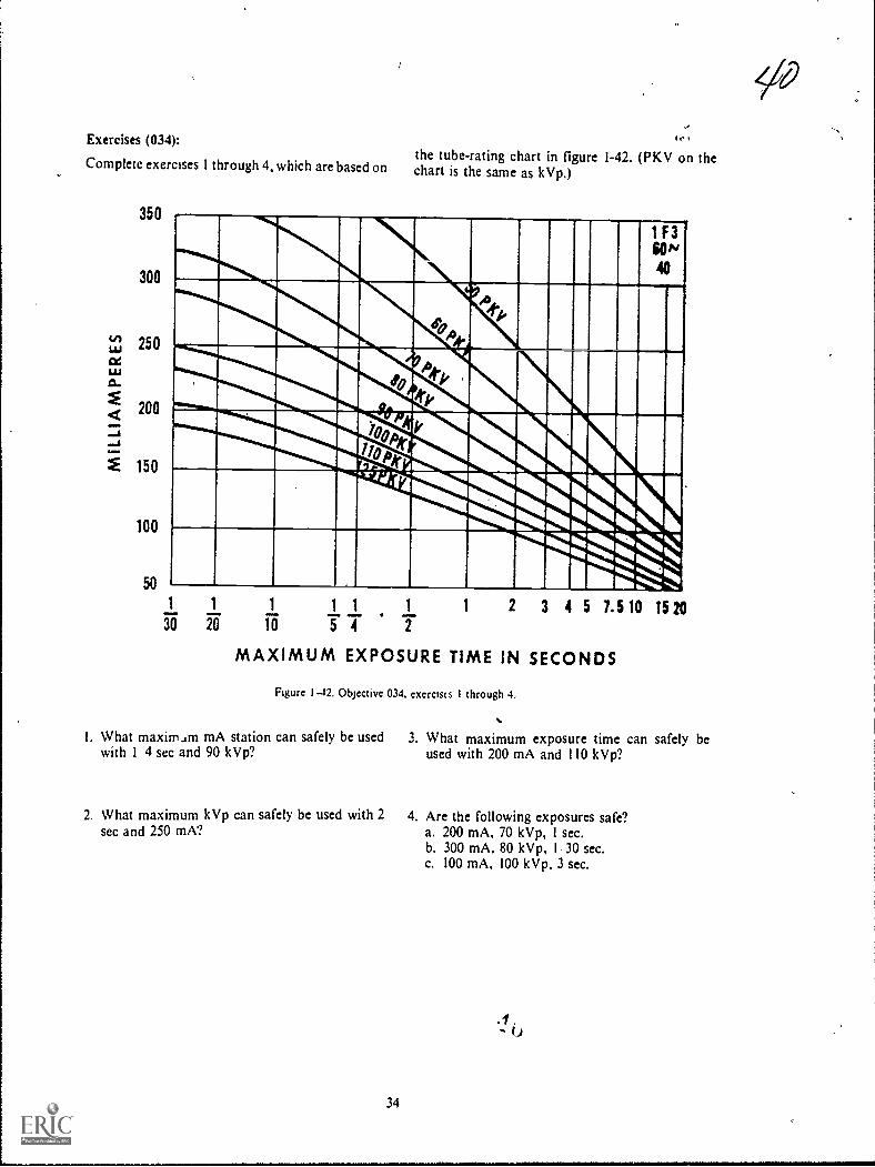
Exercises (034):
Complete exercises 1 through 4, which are based on
350
300
150
100
the tube-rating chart in figure 1-42. (PKV on thechart is the same as kVp.)
14E11111 III1111
ARM1 1 1 1 1 1
20 Ta 5 T IMAXIMUM EXPOSURE TIME IN SECONDS
1 2 3 4 5 1.5 10 15 20
Figure I 12, Objective 034, exerclus I through 4,
I. What maximam mA station can safely be used 3. What maximum exposure time can safely bewith 1 4 sec and 90 kVp? used with 200 mA and 110 kVp?
2. What maximum kVp can safely be used with 2sec and 250 mA?
34
4. Are the following exposures safe?a. 200 mA, 70 kVp, 1 sec.b. 300 mA, 80 kVp, 1 30 sec.c. 100 mA, 100 kVp, 3 sec.

41
Complete exercises 5 through 8, based on the tube-rating chart in figure 1-43. (PKV on the chart is thesame as kVp.)
EXPOSURE TIME IN SECONDS
UP TO 0.01 0.02 0.05 0.1 0.2 0.5 1 2 5 10 20
PKV MAXIMUM CURRENT IN MA
50 220 220 220 220 220 220 220 210 190 160 140
60 210 210 210 200 200 190 190 180 160 140 115
70 180 180 180 170 170 170 160 150 135 120 100
80 160 160 150 150 150 150 145 135 120 105 85
90 140 140 140 140 135 130 125 120 105 95 75
100 130 130 125 125 125 120 1. 110 95 85 70
110 115 115 115 115 110 110 105 100 85 75 64
125 100 100 100 100 100 95 90 85 75 68 56
150 85 85 85 85 80 80 75 72 64 56 46
Figure 1-43. Objective 034, exercises 5 through 8.
5. What maximum mA can safely be used with 100kVp and 2 sec?
6. What maximum kVp can safely be used with 0.01sec and 100 mA?
7. What maximum exposure time can safely beused with 70 kVp and 180 mA?
8. Are the following exposures safe?a. 150 kVp, 0.2 sec, 100 mA.b. 60 kVp, 5 sec, 160 mA.c. 100 kVp, 0.01 sec, 160 mA.
035. Given an angiographic rating chart andvarious applicable exposure data, determinewhether or not the exposures are safe.
Angiogiaphic rating chart. Figure 1-44 is anexample of an angiographic rating chart designed toallow you to determine whether or not the totalnumber of exposures for an angiographicexamination exceeds the maximum limits of thetube. Suppose your radiologist desires to performan angiogram and wants two exposures per secondfor 2 seconds, a total of four exposures. Theexposure factors are 1,000 mA, 1/ 10 sec, and 90kVp. First, find the product of mA, sec, and kVp,which is 9,000. Find two exposures per second onthe left margin of the chart; move across thatcolumn to 9,000 (the maximum load per exposure).Then move up to the total number of exposures,which in this case is two. This means that only twoexposures can be madeso the examination cannotbe performed under the described conditions.
TOTAL NUMBER OF EXPOSURES
EXPOS.PER SEC
2 5 10
MAXIMUM LOAD IN
20 30
PKV X MA X SEC
40 50
PER EXPOSURE
60
00
1 16500 13800 11400 9000 7400 6400 5700 5000
a 9000 8800 7000 5700 5000 4400 4000 3700
3 6200 5600 5000 4300 3800 3400 3200 3000
4 4800 4400 3900 3400 3100 2850 2650 2500
5 3900 3600 3300 2900 2650 2450 2300 2150
6 3200 3000 2800 2500 2300 2150 2000 1900
8 2500 2350 2200 2000 1850 1750 1650 1550
10 2050 1900 1800 1650 1550 1460 1380 1320
12 1700 1600 1550 1420 1320 1260 1200 1160
I
Figure 1-44. Angtographic rating chart.
35

Exercises (035):
Using the angiographic rating chart in figure 1-45,
determine whether or not each of the followinggroups of exposure data can be used for anangiogram.
TOTAL NUMBER OF EXPOSURES
EXPOS.PER SEC
2 5
MAXIMUM LOAD
10
IN
20 30
PKV X MA X SEC
40 50
PER EXPOSURE
60
(*)
1 10800 9600 8400 7000 6000 5300 4800 4400
2 5700 5200 4700 4100 3700 3400 5200 3000
3 3800 3600 3300 3000 2800 2600 2450 2300
2950 2800 2650 2400 2200 2100 2000 1900
5 2400 2300 2150 2000 1850 1750 1650 1600
6 2000 1900 1800 1700 1600 1500 1460 1400
1500 1460 1400 1320 1260 1200 1160 1120
10 1220 1180 1140 1080 1040 1000 960 940
12 1020 1000 960 920 880 840 320 800
Figure 1-45. Objective 035, exercises 1 through 3.
1. 300 mA, 1, 30 sec, 120 kVp, eight exposures persecond for 5 seconds.
2. 500 mA, 1, 20 sec, 80 kVp, four exposures persecond for 13 seconds.
3. 1000 mA, 1/ 10 sec, 96 kVp, one exposure persecond for 6 seconds.
036. Given two cooling charts (anode and housing)and selected exposure data, answer key questionspertaining to: (1) the correlation between the chartsand' data and (2) the heat dissipation rate of thecharts.
Cooling cOrts. There are two types of coolingcharts: the anode-cooling chart and the housing-cooling chart. The anode chart shows the maximumnumber of H.U. the anode can store, and thehousing chart shows the maximum number of H.U.the tube housing can store. Both charts also showthe heat dissipation rate. Let's see how to use thecharts, beginning with the anode-cooling chart.
Figure 1-46 shows an anode-cooling chart thatcan store a maximum of 300,000 H.U. (a relativelyhigh capacity anode). Suppose that during anangiogram or a cine examination the total H. U.applied to the anode is 200,000, and it is necessary torepeat the examination without significant delay. Ifthe examination were repeated immediately, there
36
would be a total of 400,000 H.U. generated by thetwo examinations-100,000' H.U. more than theanode can store. In this case, to prevent damage tothe tube, you would have to allow the anode to coolto 100,000 H.U. before the examination could berepea ted. Find the cooling time betweenexaminations by following the cooling curve from200,000 H.U. to 100,000 FLU., which in figure 1-46is about 51/2 minutes. So this examination can berepeated every 51/2 minutes.
The anode-cooling chart also tells you therelationship between fluoroscopic tithe and anodeH.U. storage. For example, if the fluoroscopic kVpis 100 and the MA is 2, the H.0 . /sec input is 200.According to figure 1-46, 200 H.U./sec onlysubjects the anode to about 50,000 H.U. at the endof 15 minutes of continuous fluoroscopic time,allowing for the cooling that occurs during the 15minutes. In figure 1-46, all of the H.U./sec inputsexcept 1,200 are safe for indefinite,. fluoroscopybecause they do not subject the anode to the 300,000H.U. maximum. The input of 1,200 H.U./sec,however, can only be used for 15 minutes because atthat time; 300,000 H.U. are stored in the anode.Additional fluoroscopy can then be performed afteran appropriate cooling time according to thecooling curve, as described earlier.
The housing-cooling chart, shown in figure 1-47,shows the maximum H.U. that can be stored in thetube housing. Notice that the tube housing storesmore H.U. than the anode in figure 1-46 (both ofthese charts are for the same tube). Also, notice thatthe heat dissipation rate without the air circulator isconsiderably less than that of the anode in figure 1-46. To see the difference in the heat dissipation rate,notice that the anode in figure 1-46 dissipates
4 2_
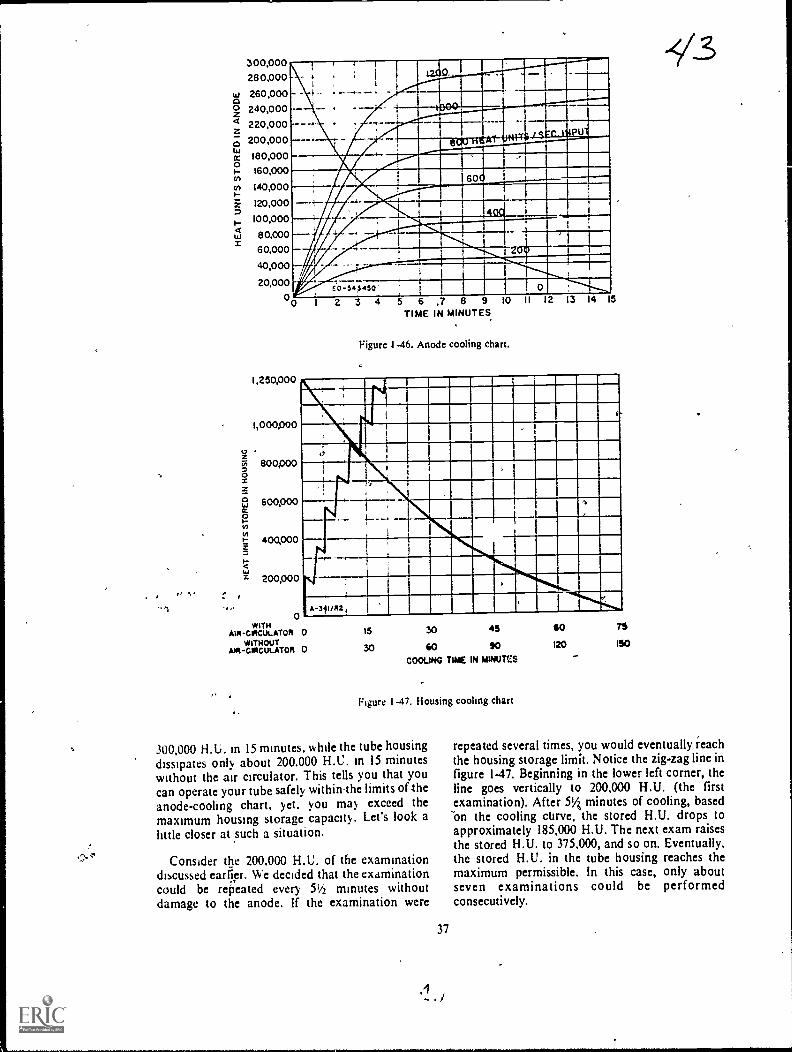
300,00028 0,000
260,000240,000220,000200,000180,000160,000
140,000
120,000
100,000
8 0,000
60,000
40,000
20,0000
4
.....dial11111111WM Illa ME°
OPOILLILIME
PTV 4111111(.111.1.111111111"M./ 4VII I ipp-I ..60 1111.1111110....
MIMI--:- --=NWMillmm
I
iritalkainil.mmmr.M.7timenomt-
I. 0 Elamc o -543 4 50 '
1,250,000
1,000,000
8001)00
600,000
400,000
200,000
0WITH
AIR -CRCUt. ATOR 0WITHOUT
Aot-coicuLATO4 0
2 3 4 5 6TIME
,7 8 9IN MINUTES
1
Figure 1-46. Anode cooling chart.
I I 13 4
15 30 45
30 40 90COOLING TIME IN MINUTCS
Figure I -47. Housing cooling chart
300,000 H.U. in 15 minutes, while the tube housingdissipates only about 200.000 H.C. in 15 minuteswithout the air circulator. This tells you that youcan operate your tube safely within,the limits of-theanode-cooling chart. yet. you may exceed themaximum housing storage capacity. Let's look alittle closer at such a situation.
Consider the 200.000 H.U. of the examinationdiscussed caller. We decided that the examinationcould be repeated every 51/2 minutes withoutdamage to the anode. If the examination were
37
60
120 ISO
repeated several times, you would eventually reachthe housing storage limit. Notice the zig-zag line infigure 147. Beginning in the lower left corner, theline goes vertically to 200,000 FLU. (the firstexamination). After 514 minutes of cooling, basedOn the cooling curve, the stored H.U. drops toapproximately 185,000 H.U. The next exam raisesthe stored H.U. to 375,000, and so on. Eventually,the stored H.U. in the tube housing reaches themaximum permissible. In this case, only aboutseven examinations could be performedconsecutively.
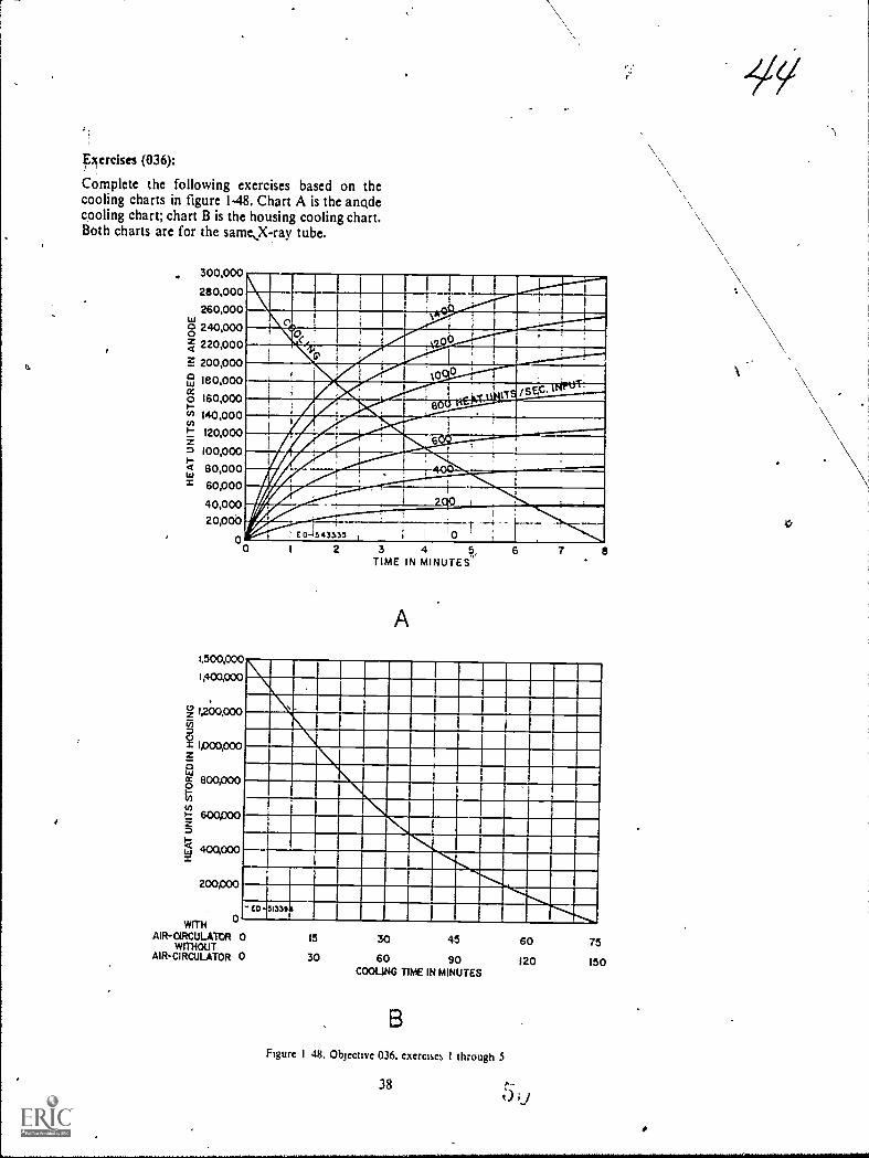
xercises (036):
Complete the following exercises based on thecooling charts in figure 1-48. Chart A is the anodecooling chart; chart B is the housing cooling chart.Both charts are for the same,X-ray tube.
300,000
280,000260,000
8 240,0001 220,000F. 200,000
180,000
160,000Po 140,000P 120,000
I 00pooit 80,000
60,000
40,00020,000
00
MI MIIMMOMk 0 IIIIMMMIllMmommilimpairimii,
1111..s"ImirAMIMMINIIMMEnzawwwIMIIMMIM1011111111111101WAIIIM1101111MIN
IlmwiaLITIN
E"..fill!2...011
_....SAS1
11A711111111111=1VW"' .. 'MINIMt0 1
1,500,000
1,400,000
1,200,000(71
g 4000,000
0 800,000
t: &mooS-)-g ammo
WITHAIR-aRCULATtil
WITHOUTAIN-CIRCULATOR
0
2 3 4 6,TIME IN MINUTES'
A
6 7
ILINIIMIII MINIM.WWII
.1NIMMILlIMIMIIIIMIIM1111111=1110110MMEMBINMININIIIMINIMMIIIMIMIN
IN INXIMINIME=NM 1111111MININN MIEMIR=LIM 1111E11111111110 15 30 45 60 750 30 60 90 120 150
COOLING TIME IN MINUTES
Figure I 48, Objective 036, exercises I through $
38

I. II you perform an examination that generates140.000 11 U.. how many minutes of cooling, if
any. must you allow before repeating theexamination once?
2. If you perform an examination that generates220.000 H.U., how many minutes of cooling, ifany. must you allow before repeating theexamination? ,
,
0
I
,
4
39
3. How long canperformed, using
4. How lot% can,performed. using
-Y5---fluoroscopy be continuously5 mA at 120 kVp?
-
fluoroscopy be continuouslyan input of 1,400 H.U./sec?
5. If an examination generates 400,000 H.U., howmany such examinations can be performed, if theminimum cooling time is allowed betweenexaminatiops, before exceeding the housingstorage capacity? The X-ray tube has no aircirculator.
7t,

CHNPTER 2
t
The Primary Beam
QUALITY CONTROL is one of the mostimportant aspects of a well-coordinated, efficientradiology department. In this chapter we willdiscuss the principles that affect the use of X-radiation and that tie in directly with qualitycontrol. We will concentrate on a review of thepritdary beam and Show it affects the radiographicimage. By understanding these principles andcharacteristics, control of image quality becomes areality. To achieve this objective, we will begin bydiscussing the chdracteristics of the primary beam.Principally important here are the elements calledquality and quantity. Following the discussion ofprimary beam characteristics, you can apply yourknowledge to the studY of projection factors. Theseexplanations will enable you to better understandhow to formualte techniques and further imptovequality control on the job.
2-1. Inherent Characteristics of thePrimary Beam
The nature of the Primary beam is evaluated bytwo factors, "quality" and "quantity." These are theterms by which you denote both penetrating abilityand intensity of the X-ray beam. Let's begin ourdiscussion with beam quality.
037. Given a list of statements pertaining to thequality of the primary beam, indicate which are trueand which are false. If you indicate "false," explainyour answer.
Quality. When we speak of the "quality" of theprimary beam, we actually mean the ability of thebeam to penetrate matter or, more specifically,human tissue. A high-quality beam is one withrelatively high penetrating power, and a low-qualitybeam is one with low penetrating power. Youshould understand the penetrating power of theprimary beam because a certain amount of X-rayphotons must penetrate the part and reach the film,to provide sufficient density and the desired degreeof contrast. You can produce good diagnosticradiographs by using more penetration than isnecessary, but if you use less than necessary, theradiograph will not be diagnostic. Consequently, we
40
c
'can say that for all practical purposes there is aminimum degree of penetration required for eachbody part. We cannot tell you precisely what therequirements are for each body part. They dependon several factors, including part size, pathology,and machine output.
"Wavelength" is another term associated withbeam quality. The shorter the wavelengths of the X;ray photons, the greater the penetrating power. Abeam of X-radiation is composed of many photonswith varying wavelengths; hence it is aheterogeneous beam.
Since the energy of a photon is directly related toits wavelength, "energy" is yet another term closelyassociated with beam suality. The higher the energyof a photon, the shorter its wavelength. Keep inmind that although we-may speak of the energy orwavelength of a single X-ray photon, there aremillions of photons in a beam of X-radiation withdifferent wavelengths or energies. Therefore, theaverage or mean energy, or wavelength, is theimportant factor.
How do you alter the quality of the primarybeam? Obviously, by changing the kVp setting onyour control panel. How does the kVp affect beamquality? If you increase the kVp on your controlpanel, you increase the energies of the electronsacross the X-ray tube. Suppose you apply 80 kVpacross the X-ray tube. Theoretically, the energies ofthe electrons range fram 1 to 80 keV. (This rangewould be in a single-phase generator only. In athree-phase generator, the maximum electronenergy would be the same, but the minimum energywould be higher, as discussed in Chapter 1.) The
1
energies of the photons produced as the electronsinteract with the target also range from 1 to 80 keV.Now suppose you apply 100 kVp across the X-raytube. The electron energy range and the photonenergy range increase proportionately.Consequently, the average energy of a beam of X-radiation is determined by the average energy of theelectrons striking the target.
Exercises (037):
Indicate whether the following statements are trueor false. If you indicate "false," explain your answer.
SA

T F I.
I F 2.
T F 3.
T F 4.
F 5.
T F 6.
T F 7.
T F 8.
T F 9.
Quality of the primary beam denotespenetrative ability.Good visualization of a body part occurs if
the part absorbs all photons which strike it.Practically speaking, penetration of a partmust sheet or exceed a definite minimum.A highly energetic beam of X-radiation has
relatively high-quality.Photons with long wavelengths haverelatively low energy.The average energy of a beam of X-radiation, depends upon the number of
photons present.You can regulate the penetration ability ofthe primary beam by adjusting the kVp
selector.An increase in kVp increases the minimumelectron energy across the X-ray tube.If the average electron energy is lowered,the average photon energy is also lowered.
i038. Define beam quantity and given a list of thrfactors affecting beam quantity, match the factaswith appropriate definitive statements or phrases.
Quantity. The "quantity," or as it is usually calledintensity, of a beam of X-radiation at a given FF0can be defined as "the characteristic which affectsthe density on a radiograph." Intensity of theprimary beam is a measure of the numbert,ofphotons per unit area in combination with the meanenergy of the photons.
How do you control the intensity of the primarybeam? To understand this, let's go back once againto the electrons which travel from the filament in theX-ray tube to the target. An increase in mA resultsin a higher filament temperature and more electronsavailable to traverse the tube for interaction. Themore electrons interacting with the target, the morephotons produced. Further, the increase in thenumber of photons is porportionate to the increasein the number of electrons. For example, if thenumber of electrons is increased, the number ofphotons, Snd consequently the intensity, is
increased. Since mA, as discussed in Chapter 1,regulates the amount of electrons, you can see howadjusting the mA regulates the intensity of theprimary beam.
Varying the exposure time is another way toregulate the number of electrons interacting withthe target. Suppose 100 mA is applied to the X-raytube for I , 10 sec. If the exposure time is increased toI I 5 sec, electrons are emitted from the filament atthe same rate, but the period of time during whichthey are emitted is twice as long (1 5 -i 1110 = 2). Ineffect, this change in the exposure time doubles thenumber of electrons interacting with the target andconsequently doubles the number of photonsproduced.
41
Another way to control the intensity is with thekVp. While mA and exposure time control intensityby regulating the number of photons produced, kVpcontrols intensity by affecting the number ofphotons produced and by regulating the meanenergy of the photons. As discussed earlier, if thekVp is increaSed, the energy of the electrons isincreased. This increase in electron energy alsoincreases the number of interactions and thereforeincreases the number of photons emitted from thetarget. A change of plus or minus 15 percent of thekVp amounts to the same change in intensity asdoubling or halving the mA or exposure time.
As with the penetrating power of the beam, wherewe were not concerned with the energy of aparticular electron, we are not concerned here withthe specific number of photons. The relativeintensity is the important issue.
Exercises (038):
I. In your own words, explain,what is meant bybeam quantity. /
Match the quantity factor in column B with theappropriate statement or phrase in column A byplacing the letter of the column B factgLin theappropriate space in column A. Each cbrumn Bfactor may be used once, more lhan once, or not atall. In addition, more than one column B factor maymatch a single entry in column A.
Column A Column B
2. If doubled. this factor doubles a. mA.the beam intensity. b. FFD.
3. Affects both the number and c. Exposure time.energy level of the photons. d. kVp.
4. A 15 percent increase in thisfactor doubles the intensity.
....._5. Decreases intensity bydecreasing the number ofelectrons available forinteraction.
6. Affects intensity by affectingduration of electron emission.
7. Affects the number of electronsor photons per unit time.
8. Regulates beam quantity at aspecific distance from the X-raytube.
9. If halved, this factor halvesAheintensity.
039. State the inverse square law, and show itseffect on the Intensity of the X-ray beam.
Inverse square law. In the preceding paragraphswe discussed beam intensity at a specific distance

from the target. According to the inverse square lawthe intensity of the primary beam is not the same atvarious distances from the target of the X-ray tube.The inverse square law states that fhe intensity ofradiation in the primary beam is inverselyproportional to the square of the distance from thetarget. This means that as the distancc from thc tubeincreases, the intensity of the beam decreases. If thedistance is .doubled, the intensity decreases to one-fourth. By the same token, if the distance is halved,the intensity increas\es four times. This variation inintensity is a result of the divergence of the beamand can best be understood by referring to figure 2-1. Notice that the primary beam at 72 inches coversan area 4 times as great as at 36 inches because of itsdivergence. For comparative purposes, let's assumethat the blocks in the figure measure 1 square inch,and the intensity at 36 inches is 20 X-ray photonsper square inch, or 80 photons, for blocks 1, 2, 3, and4. At 72 inches, because of the divergence of thebeam, the 80 photons are now spread over 16 squareinches, or 5 photons per square inch. Thus, theintensity is reduced to one-fourth at twice thedistance. Note that when we discuss variations inintensity according to the inverse square law, we areonly speaking of the number of photons. Photonenzrgy does not enter into the picture.
Exercises (039):
I. State the inverse square law.
2. The intensity of the primary beam at 36 inchesfrom the target is 200 photons per square inch.What is the intensity at 18 inches from the target?
/At 72 inches from the target?
3. Does the inverse square law affect beam intensityby affecting the number of photons emitted fromthe target? Explain your answer.
4. What is the conne..tion, if any, between theinverse square law and photon energy?
040. Give the term used to describe the variation ofintenstiy of the primary X-ray beam along the axisof the X-ray tube, and indicate the cause of thisvariation and the relationship between intensity andthe distance from the central ray (CR).
Anode Heel Effect. The anode heel effectidentifies the phenomenon which produces avariation in intensity of the radiation within the
42
I IIfI I
I II
I II . II
I II I
I
36.
--__ 72"
Figure 2-1. The primary beam and the inverse square law,
primary beam along the longitudinal axis of the X-ray tube. Using the CR as our starting point, let's seehow the intensity varies.
When we move away from the CR on the anodeside, we find that the intensity becomes Vss and lessthe farther we go. Contrariwise, when we moveaway from the CR on the cathode side, we find thebeam becoming more intense than it was in the CRarea, or on the anode side. The area of increasedintensity is limited, however, and, as we continue tomove in the direction of the cathode, we find thatthe intensity again decreases. The intensitypercentages at different angles of emission of a 200anode are illustrated in figure 2-2. Keep in mind thatthe variation in intensity is only along thelongitudinal axis of the X-ray tube. There is novariation atOng the transverse axis.
The variation in intensity is due to the angle of theanode. Some photons are emitted from within the
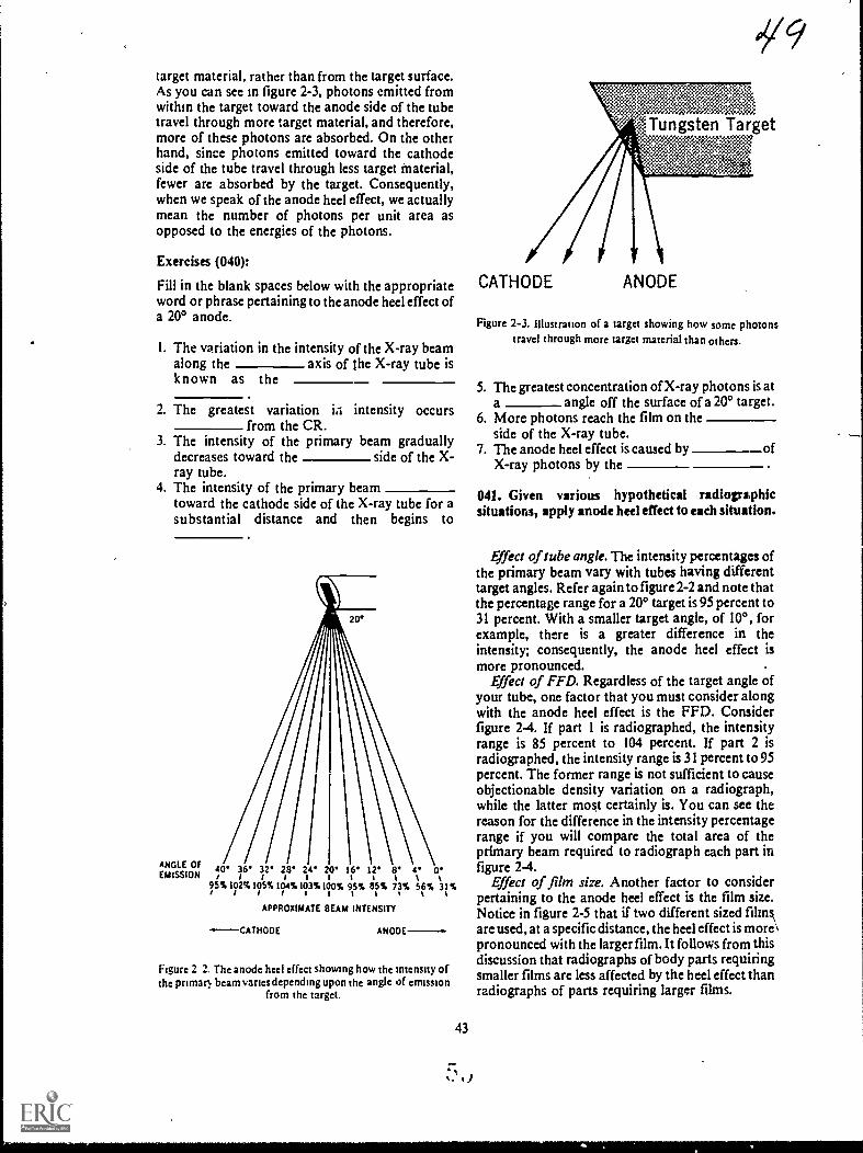
target material, rather than from the target surface.As you can see in figure 2-3, photons emitted fromwithin the target toward the anode side of the tubetravel through more target material, and therefore,more of these photons are absorbed. On the otherhand, since photons emitted toward the cathodeside of the tube travel through less target Material,fewer are absorbed by the target. Consequently,when we speak of the anode heel effect, we actuallymean the number of photons per unit area asopposed to the energies of the photons.
Exercises (040):
Fill in the blank spaces below with the appropriateword or phrase pertaining to the anode heel effect ofa 20° anode.
1. The variation in the intensity of the X-ray beamalong the axis of the X-ray tube isknown as the
2. The greatest variation iii intensity occursfrom the CR.
3. The intensity of the primary beam graduallydecreases toward the side of the X-ray tube.
4. The intensity of the primary beamtoward the cathode side of the X-ray tube for asubstantial distance and then begins to
ANGLE OFEMISSION
20*
\40* 36* 32'/1111
95%102%105%/111128* 24 20
104%103%100%
16*it95%11%%
12'
85%
8*tt73%
4*
56%
0*t31%
t
APPROXIMATE EIEAM INTENSITY
.--CATHODE ANODE-.
Figure 2 2. Thc anode heel effect showing how thc intensity ofthc primatl beam variesdepending upon thc angle of emission
from thc target.
43
019
,Tungsten Target7:3nsz, *::-:::g
..;
CATHODE ANODE
Figure 2-3. Illustration of a target showing how some photonstravel through morc target material than othcrs.
5. The greatest concentration of X-ray photons is ata angle off the surface of a 20° target.
6. More photons reach the film on theside of the X-ray tube.
7. The anode heel effect is caused by ofX-ray photons by the
041. Given various hypothetical radiographicsituations, apply anode heel effect to each situation.
Effect of tube angle. The intensity percentages ofthe primary beam vary with tubes having differenttarget angles. Refer again to figure 2-2 and note thatthe percentage range for a 200 target is 95 percent to31 percent. With a smaller target angle, of 10°, forexample, there is a greater difference in theintensity; consequently, the anode heel effect ismore pronounced. .
Effect of FFD. Regardless of the target angle ofyour tube, one factor that you must consider alongwith the anode heel effect is the FFD. Considerfigure 2-4. If part 1 is radiographed, the intensityrange is 85 percent to 104 percent. If part 2 isradiographed, the intensity range is 31 percent to 95percent. The former range is not sufficient to causeobjectionable density variation on a radiograph,while the latter mos,t certainly is. You can see thereason for the difference in the intensity percentagerange if you will compare the total area of theprimary beam required to radiograph each part infigure 2-4.
Effect of film size. Another factor to considerpertaining to the anode heel effect is the film size.Notice in figure 2-5 that if two different sized Minsarc used, at a specific distance, the heel effect is more\pronounced with the larger film. It follows from thisdiscussion that radiographs of body parts requiringsmaller films are less affected by the heel effect thanradiographs of parts requiring larger films.
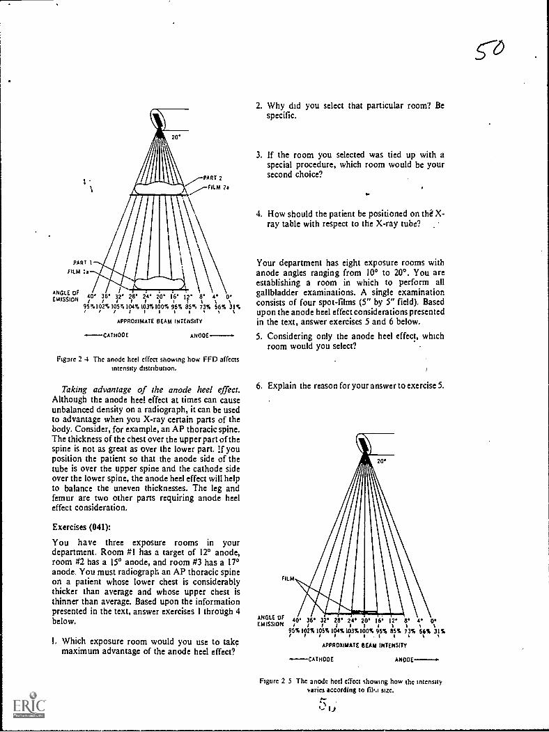
I
PART 1
FILM Is
ANGLE OFEMISSION
PART 2
FILM ?a
40/
36*/
32'IIIIIII%28' 24' 20' 16' 12' 8' 4. 0'95%102%105%104%103%100%1 / / Sottl%%%95% 85% 73% 56% 31%
APPROXIMATE BEAM INTENSITY
-.----CATHOOE ANOOE
Figure 2 4 The anode heel effect showing how FED affectsIntensity distribution.
Taking advantage of the anode heel effect.Although the anode heel effect at times can causeunbalanced density on a radiograph, it can be usedto advantage when you X-ray certain parts of thebody. Consider, for example, an AP thoracic spine.The thickness of the chest over the upper part of thespine is not as great as over the lower part. lf youposition the patient so that the anode side of thetube is over the upper spine and the cathode sideover the lower spine, the anode heel effect will helpto balance the uneven thicknesses. The leg andfemur are two other parts requiring anode heeleffect consideration.
Exercises (041):
You have three exposure rooms in yourdepartment. Room #1 has a target of 12° anode,room #2 has a 15° anode, and room #3 has a 17°anode. You must radiograph an AP thoracic spineon a patient whose lower chest is considerablythicker than average and whose upper chest isthinner than average. Based upon the informationpresented in the text, answer exercises 1 through 4below.
I. Which exposure room would you use to takemaximum advantage of the anode heel effect?
2. Why did you select that particular room? Bespecific.
3. If the room you selected was tied up with aspecial procedure, which room would be yoursecond choice?
..
4. How should the patient be positioned on tli X-ray table with respect to the X-ray tube?
Your department has eight exposure rooms withanode angles ranging from 10° to 200. You areestablishing a room in which to perform allgallbladder examinations. A single examinationconsists of four spot-films (5" by 5" field). Basedupon the anode heel effect considerations presentedin the text, answer exercises 5 and 6 below.
5. Considering only the anode heel effect, whichroom would you select?
6. Explain the reason for your answer to exercise 5.
FILM
ANGLE OF 40' 36'EMISSION/ /95%102%II/St32'
/105%
28' 24' 20' 16' 12' 13' e 0'iiim%104%103%100% 95% 85% 73% 56% 31%
I I %
APPROXIMATE BEAM INTENSITY
-CATMOOE ANO0E-.
Figure 2 5 The anode heel effect showing how the intensityvaries according to film size.
0.-.c., u
co

A por.able AP radiograph is made of a leg using a30-inch FFD and a 17° targct. Later the same dayanother AP radiograph ts made in the radiologydepartment using a 40-1nch FFD and also a 17°target. Based upon the information presented in thetext, answer exercises 7 through 8 below.
7. How should the leg have been positioned tocompensate for the difference between the sizc ofthe upper and lower portions?
8. Assuming the radiographs were made using thesame relatie exposure. which radiograph wouldshow the greater difference betw een the densitiesof the upper and lower portions of the leg?
2-2. The Primary Beam and Its Projection ofthe Radiographic Image
We continue our study of the primary beam withthe geometric factors that affect the quality of aradiographic image. Specifically, the factors arefocal spot size and the relationships between thetube, part, and film. We will study these factorsunder the headings of focal spot size, magnification,and distortion.
042. Given a list of statements pertaining to therelationship between focal spot size and detail,indicate which are true and which are false. If youindicate "false," explain your answer.
Focal Spot Size. No doubt you have heard manytimes that you should use the smallest focal spotpossible. You use the smallest focal spot to producebetter detail .on a radiograph and the "possible"means to use it when the exposure does not exceedthe heat-loading capacity. We will deal with the heatcapacity a little later. For now, let's look a littlecloser at the detail.
Focal spot size and detail. Why does a small focalspot produce better detail than a larger one? Toanswer that question refer to figure 2-6. Notice wehave drawings of three focal spots projecting anImage. Illustration A shows the focal spot as a pointsource of the X-ray photons. Illustration B
represents a small focal spot, and illustration Crepresenb a large f ocal spot. Notice we did not referto the point source as a small focal spot because wehave no focal spots that small in radiology. Theyusually range from 0.3 to 2.0 mm. We show thepoint sour...e merely to illustrate the difference ir. theprojection of the image.
Notwe that all edges of the part in drawing A,figure 2-6. are projected to one spot on the film
45
while in drawings B and C each edge is projected to adifferent spot. The rcason each edge is projected to adifferent spot is that the edge is projected byphotons from many points within the target. Forsimplicity, we have shown in figure 2-6 only thephotons from each side of the target, whichdetermine the maximum area of penumbra. Whenthe border of a part is projected in this manner, it iscalled penumbra and has a "fuzzy" or "unsharp"appearance. The more penurfibra present, the moreunsharp the image, or we can also say the less thedetail.
As you can see, there is less penumbra present onthe image of the part projected by the smaller focalspot. A smaller focal spot causes less penumbrabecause the edges are projected by photons fromfewer point sources.
Refer to figure 2-6,B and C, once again and noticethe difference between the amount of penumbrafrom the anode side of the tube to the cathode side.As you can see, the amount is greater on the cathodeside. What does this difference mean? First of all, itmeans that the edge of the part on the anode side isbeing radiographed with a smaller focal spot thanthe edge on the cathode side. Of course, theimportant aspect of this discussion is thatradiographs have better (focal-spot) detail on theanode side. The farther toward the anode side, thebettcr the detail; and the farther toward the cathodeside, the worse the detail. Figure 2-7 gives you anidea of the relative focal spot sizes in the center andat both edges of the beam. The one in the centerrepresents the size listed on your tube-rating chart.
Exercises (042):
Indicate whether the following statements are trueor false. If you indicate "false," explain your answcr.
T F 1.
T F 2.T F 3.T F 4.
T F 5.
Better detail is obtained using a large focalspot.A large focal spot produces less penumbra.The more penumbra, the better the detail.Penumbra is greatest on the anode side ofthe tube.Radiographs have better detail on theanode side of the tube, due to the distancefrom the target.
043. Given hypothetical tube capacity data andsituations requiring application of the data, applythe correct dats to each situation snd explain thereasons for your actions.
Focal spot size and heat-loading capacity. Itwould seem from the preceding discussion that youshould always use the small focal spot on your X-ray machine. After all, it produces better detail, anddetail on a radiograph is very important. However,

there is a considerable difference between the heat-loading capacity of different-sized focal spots. Asmall focal spot will not tolerate high exposures; infact, you would quickly damage your X-ray tube ifyou used the small focal spot for all exposures.Check the exposure factors against the tube-ratingchart. If the rating chart shows the exposurc to bewithin the maximum rating of the small focal spot,and if some other limiting factor, such as partmotion, does not preclude use of the small focalspotuse it.
Exercises (043):
Suppose that the X-ray tubes in your two exposurerooms have the following focal spots. Furthersuppose that the maximum single exposure capacityis also as stated below.
Exposure room "1:0.2 mm - 100 mA, 78 kVp, 1 4 sec1.5 mm - 300 mA, 110 kVp, 1 1 2 sec
Exposure room #2:0.5 nun - 200 mA, 80 kVp, 1 2 sec2.0 mm - 500 mA. 120 kVp. 2 sec
I. Which exposure room could provide the leastpenumbra on a radiograph? The most?
0,
2. Which focal spot(s) should you use toradiograph a lateral lumbar spine, using 100 mAat 110 kVp?
3 Suppose your radiologist asks you to establishprocedures to perform a magnificationradiograph of all wrists with a possible fracturednavicular. He stresses the importance of keepingpenumbra to a minimum. What action wouldyou take, and why, concerning the exposureroom and focal spot to use for the examination?
FILM FILM .)PENUMBRA
Figure 2 6 Projection of penumbra as a r,!sult of focal spot size
's
FILM }N'PENUMBRA

Figure 2 7 Focal spot sizes as seen from differentparts of the X-ray field
044. Given selected descriptions of clinicalradiographic situations, answer key questionsconcerning the effects of FFD and part-filmdistance upon the situations.
Magnification. Magnification should normallybe kept to a minimum so that the part is projected asnear as possible to its actual size. This is importantto the radiologist's interpretation because increasedmagnification increases the penumbra on aradiograph, causing less clarity of the image. Inaddition, enlargement of some body parts is a signof disease. If the part is magnified because of theprojection, the radiologist may have difficultymaking a diagnosis.
Factors affecting magnification. Basically twofactors affect magnification: FFD and part-filmdistance. If you make two radiographs of aparticular body part, using the same part-filmdistance and different FFDs. the radiograph withthe longer FFD will show less magnification. Toillustrate how FFD affects magnification, refer tofigure 2-8, where we have illustrated the same sizepart projected by three different FFDs. Notice thata more divergent beam projects the part on the film
47
at the short FFD. It is this greater divergence whichincreases the magnification.
Part-film distance also has a pronounced effecton magnification if the FFD remains constant.Notice in figure 2-9 that three parts of equal size areprojected by the same FFD. The only difference is inthe part-film distance. Part A, which is farther fromthe film, is magnified most, while parts B and C,w hich are nearer the film, are magnifiedprogressively less. Magnification due to an increasein part-film distance occurs for the same basicreason as magnification from decreased FFDthatis, the part is projected by a more divergent beam.
Practical applications of FFD and part-filmdistance. As you know, the FFDs used in yourdepartment under routine conditions areestablished by your radiologist. Also, the part-film
FFD FILM
Figure 2-8. How a variation in FFD affects magnification ona radiograph.
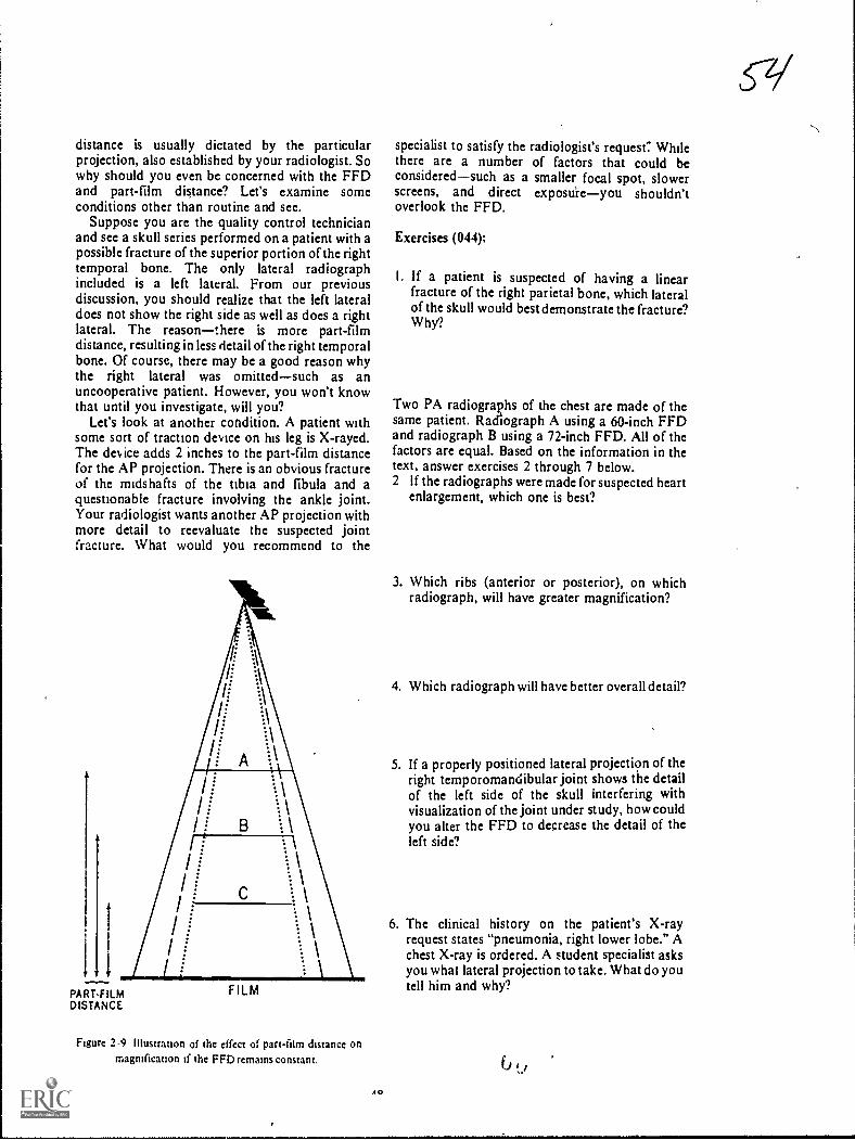
distance is usually dictated by the particularprojection, also established by your radiologist. Sowhy should you even bc concerned with the FFDand part-film distance? Let's examine someconditions other than routine and see.
Suppose you are the quality control technicianand see a skull series performed on a patient with apossible fracture of the superior portion of the righttemporal bone. The only lateral radiographincluded is a left lateral. From our previousdiscussion, you should realize that the left lateraldoes not show the right side as well as does a rightlateral. The reasonthere is more part-filmdistance, resulting in less detail of the right temporalbone. Of course, there may be a good reason whythe right lateral was omittedsuch as anuncooperative patient. However, you won't knowthat until you investigate, will you?
Let's look at another condition. A patient withsome sort of traction device on his leg is X-rayed.The dev ice adds 2 inches to the part-film distancefor the AP projection. There is an obvious fractureof the midshafts of the tibia and fibula and aquestionable fracture involving the ankle joint.Your radiologist wants another AP projection withmore detail to reevaluate the suspected jointfracture. What would you recommend to the
1.1
PART.FILMDISTANCE
FILM
Figure 2-9 illustranon of the effect of part-film distance onmagnification if the FFD remains constant.
AO
specialist to satisfy the radiologist's request': Whilethere are a number of factors that could beconsideredsuch as a smaller focal spot, slowerscreens, and direct exposuieyou shouldn'toverlook the FFD.
Exercises (044);
I. If a patient is suspected of having a linearfracture of the right parietal bone, which lateralof the skull would best demonstrate the fracture?Why?
Two PA radiographs of the chest are made of thesame patient. Radiograph A using a 60-inch FFDand radiograph B using a 72-inch FFD. All of thefactors are equal. Based on the information in thetext, answer exercises 2 through 7 below.2 If the radiographs were made for suspected heart
enlargement, which one is best?
3. Which ribs (anterior or posterior), on whichradiograph, will have greater magnification?
4. Which radiograph will have better overall detail?
5. If a properly positioned lateral projection of theright temporomandibular joint shows the detailof the left side of the skull interfering withvisualization of the joint under study, how couldyou alter the FFD to decrease the detail of theleft side?
6. The clinical history on the patient's X-rayrequest states "pneumonia, right lower lobe." Achest X-ray is ordered. A student specialist asksyou what lateral projection to take. What do youtell him and why?
çq

7. Due to conditions beyond his control, a studentspecialist performs a portable radiograph of afemur with more than normal part-film distance.There is too much penumbra on the radiograph.What FFD change could you recommend todecrease the penumbra? Why?
045. Answer key questions pertaining, toradiographic distortion.
Distortion. A part is said to be distorted when it isnot projected on the film in its true shape. As ageneral rule, you should try to keep distortion to aminimum on your radiographs so that the part willappear in its normal shape. Thus, the radiologistcan more easily recognize an abnormality.However, at times, deliberate distortion is necessaryto project a part away from superimposedstructures, as we will discuss later in this section.
CR-part-film relationships. The relationshipsbetween the CR, the plane of the part, am' he planeof the film affect distortion. Specifically, the planeof the part and the plane of the film must be parallel,and the CR must be perpendicular to minimizedistortion. Notice in figure 2-10 the radiographs of a2- by 2-inch square. Radiograph A was made underthe above conditions. Radiograph B was made withthe CR angled 40°. The plane of the square and filmwere parallel. Radiograph C was made with thesquare angled 40°. The CR was perpendicular to thefilm. Radiograph D was made with the film angled400. The CR was perpendicular to the square. Asyou can see, the shape of the square varies. Thisshould indicate to you the importance of the CR-part-filen relationship. Incidentally, the square hadtwo "fractures." Can you see them on allprojections?
Acceptable distortion. There are times whendistortion is permissible, even necessary. Asexample is the inferosuperior or axial projection ofthe clavicle. Distortion is necessary in this case todemonstrate the clavicle free from superimpositionof the ribs.
Exercises (045):
I. What is the general rule regarding distortion on aradiograph?
4t-i
cC
Z'47;ti.
Me*
Figure 2-10. Radiographs of a radiopaque 2- by 2-inch squareshowing how tube angle and nonparallel part and film cause
distortion on a radiograph.
3. How should the CR be directed, with respect tothe part and film, to prevent distortion?
4. If the long axis of the femur is placed at a 35°angle to the plane of the film and the CR isperpendicular to the film, would the femur bedistorted on the radiograph?
2. Is distortion ever acceptable? Explain your 5. What relationship must exist I, Itween the partanswer. and film to prevent distortion?
49

CHAPTER 3
Exposure Devices
EARLY IN THE history of radiography, thepioneers in the field became aware of a seriousproblem affecting film exposures. The problem wasfilm fog due to scatter radiation. To ov ercome thiscondition, certain devices were developed, whichare referred to as exposure dev ices. Initially anduntil a few years ago, cones, cylinders, and,diaphragms w ere used extensively to restrict thebeam of X-radiation and thereby reduce film fog.Howe er, these dev ices have more or less given wayto collimatorsthe topic of the first section of thischapter.
Another important exposure device used toreduce film fog is the grid. Many refinements havebeen made in grids since they were introduced. Forexample, it is no longer sufficient -or a technician, tomerely know that a grid reduces scatter radiation.Some grids reduce scatter better than others and thekVp range ev en affects scatter "clean-up" to acertain extent. We begin our discussion of exposurewith collimators.
3-1. Collimators
046. Given a list of statements pertaining to thefunctions of a collimator, indicate which are trueand which are false. If you indicate "false," explainyour answer.
Functions of a Collimator. A collimator beam-restricting device is used for precisely thatpurooseto restrict the size of the primary beam.As y ou know, you should always restrict the size ofthe primary beam to the smallest size possible andstill include the part under study in the X-ray field.If you think you have heard that last statementbefore, r.o doubt you have, and you will hear itagain and again. Using a small X-ray field isimportant for two reasons: ,(1) it reduces theexposure to the patient and (2) it reduces film fogdue to scatter radiation. (We will discuss beam sizeand patient exposure in Chapter 6.)
One of the major causes of film fog is scatterradiation that reaches the film. The amount of%utter radiation produced by an X-ray beam iselated tt the sue 01 the X-1.1) 1 lekl. Rel er t 1 ;pre
3-1, whei e we have illustrated the same body part
50
projected by both a large and a small X-ray field.For a part of this size, we need only a relatively smallfilm area. If the primary beam is restricted to onlythat portion of the X-ray film needed, as in drawingA, you can see that there is a certain amount ofscatter radiation reaching the film. However, if thebeam is enlarged so that it covers a larger area, asseen in drawing B, there is an increase in the scatterradiation reaching the film. Notice that the increasein scatter reaching the film not only occurs on theparts of the film that do not record the image, but italso occurs directly over the image itself. The reasonfor this is that some scatter radiation is emitted atacute angles with respect to the film.
There are many applications of a small cone field.Let's look at one examination and see how a smallcone field may affect the outcome. Suppose the partshown in figure 3-1 is a gallbladder. Furthersuppose that the concentration of contrast mediumin the gallbladder is less than it should be for onereason or another. Because of the minimalconcentration of the contrast medium, there is littlecontrast between the gallbladder and thesurrounding structures. If you use alarge cone field,you further reduce the contrast by increasing thefilm fog. But if you use a small cone field, contrast isincreasedperhaps enough to adequatelydemonstrate the gallbladder. The difference incontrast could be sufficient to permit diagnosis of,for example, gallbladder stones. Otherwise, thepatient may have to be rescheduled for anotherexamination.
Exercises (046):
Indicate whether the following statements are trueor false. If you indicate "false," explain your answer.
T F I. A beam-restricting device reduces theintensity of the primary beam.
T F 2. You should use the smallest size X-ray fieldconsistent with the requirements of theexamination.
T F 3. A small X-ray field reduces patientexposure.
r F 4. A small X-ray field increases contrast.1 1 5. You ean reduce scatter radiation by using a
larger X-ra) 1 ield.
3'6
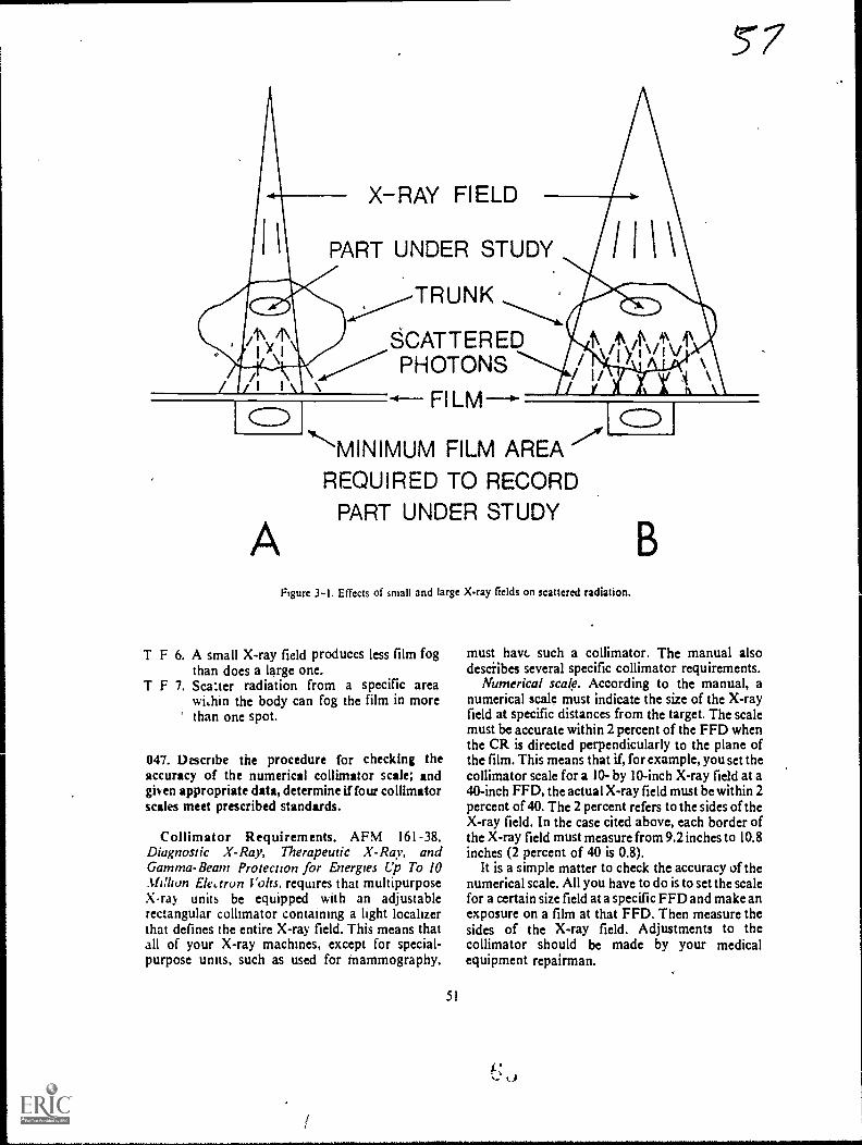
X-RAY FIELD
PART UNDER STUDY
SCATTEREDPHOTONS
A
MINIMUM FILM AREAREQUIRED TO RECORD
PART UNDER STUDY
Figure 3-1, Effects of small and large X-ray fields on scattered radiation.
T F 6. A small X-ray field produces less film fogthan does a large one.
T F 7. Sca:ter radiation from a specific areawi,hin the body can fog the film in morethan one spot.
047. Describe the procedure for checking theaccuracy of the numerical collimator scale; andgiven appropriate data, determine if four collimatorscales meet prescribed standards.
Collimator Requirements. AFM 161-38,Diagnostic X-Ray, Therapeutic X-Ray, andGamma-Beam Protection for Energies Up To 10Million Elearon Volts, requires that multipurposeX-ray units be equipped with an adjustablerectangular collimator containing a light localizerthat defines the entire X-ray field. This means thatall of your X-ray machines, except for special-purpose units, such as used for tnammography,
51
must have such a collimator. The manual alsodescribes several specific collimator requirements.
Numerical scale. According to the manual, anumerical scale must indicate the size of the X-rayfield at specific distances from the target. The scalemust be accurate within 2 percent of the FFD whenthe CR is directed perpendicularly to the plane ofthe film. This means that if, for example, you set thecollimator scale for a 10- by 10-inch X-ray field at a40-inch FFD, the actual X-ray field must be within 2percent of 40. The 2 percent refers to the sides of theX-ray field. In the case cited above, each border ofthe X-ray field must measure from 9.2 inches to 10.8inches (2 percent of 40 is 0.8).
It is a simple matter to check the accuracy of thenumerical scale. All you have to do is to set the scalefor a certain size field at a specific FFD and make anexposure on a film at that FFD. Then measure thesides of the X-ray field. Adjustments to thecollimator should be made by your medicalequipment repairman.
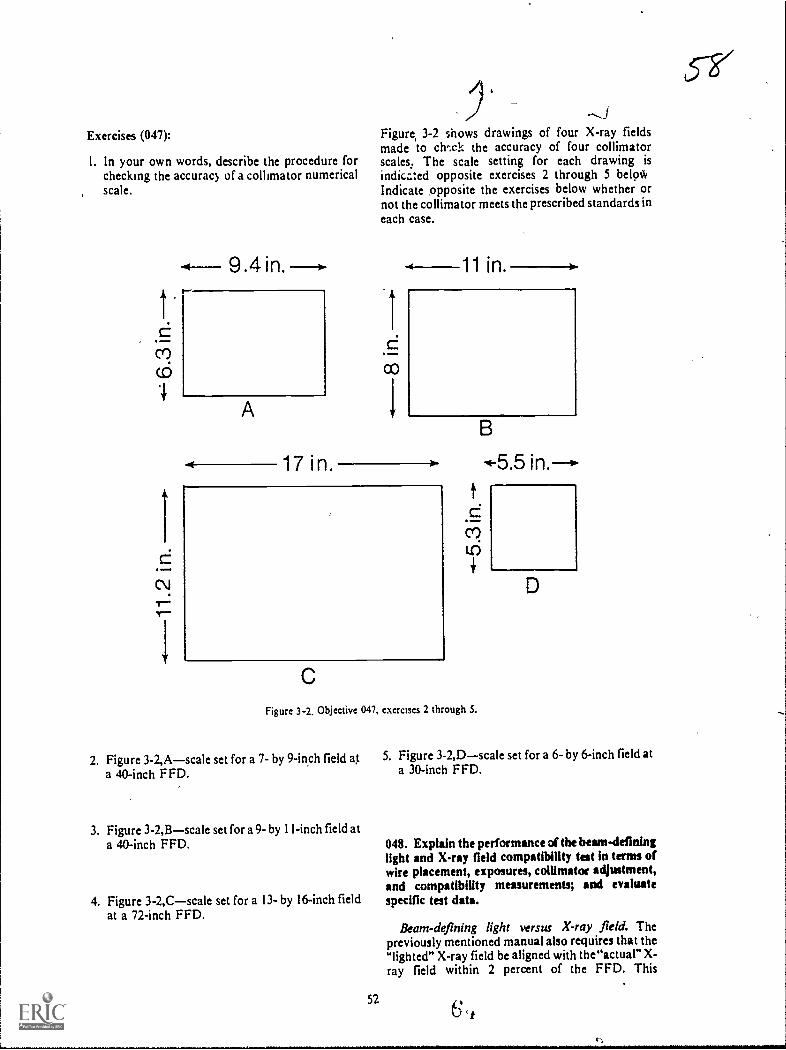
Exercises (047):
I. In your own words, describe the procedure forchecking the accuracy of a collimator numericalscale.
c7)
9.4 in. --I.
A
17 i n.
,JFigure, 3-2 shows drawings of four X-ray fieldsmade to chwk the accuracy of four collimatorscales. The scale setting for each drawing is
indica:ed opposite exercises 2 through 5 beloWIndicate opposite the exercises below whether ornot the collimator meets the prescribed standards ineach case.
1 in.
Figure 3-2. Objective 047, exercises 2 through 5.
2. Figure 3-2,Ascale set for a 7- by 9-inch field at 5. Figure 3-2,Dscale set for a 6- by 6-inch field at
a 40-inch FFD. a 30-inch FFD.
3. Figure 3-2,Bscale set for a 9- by I I-inch field ata 40-inch FFD.
4. Figure 3-2,C--scale set for a 13- by 16-inch fieldat a 72-inch FFD.
048. Explain the performance of the heam4eflninglight and X-ray field compatibility test in terms ofwire placement, exposures, collimator adjustment,and compatibility measurements; and evaluatespecific test data.
Beam-defining light versus X-ray field. Thepreviously mentioned manual also requires that thelighted" X-ray field be aligned with the"actual" X-ray field within 2 percent of the FFD. This
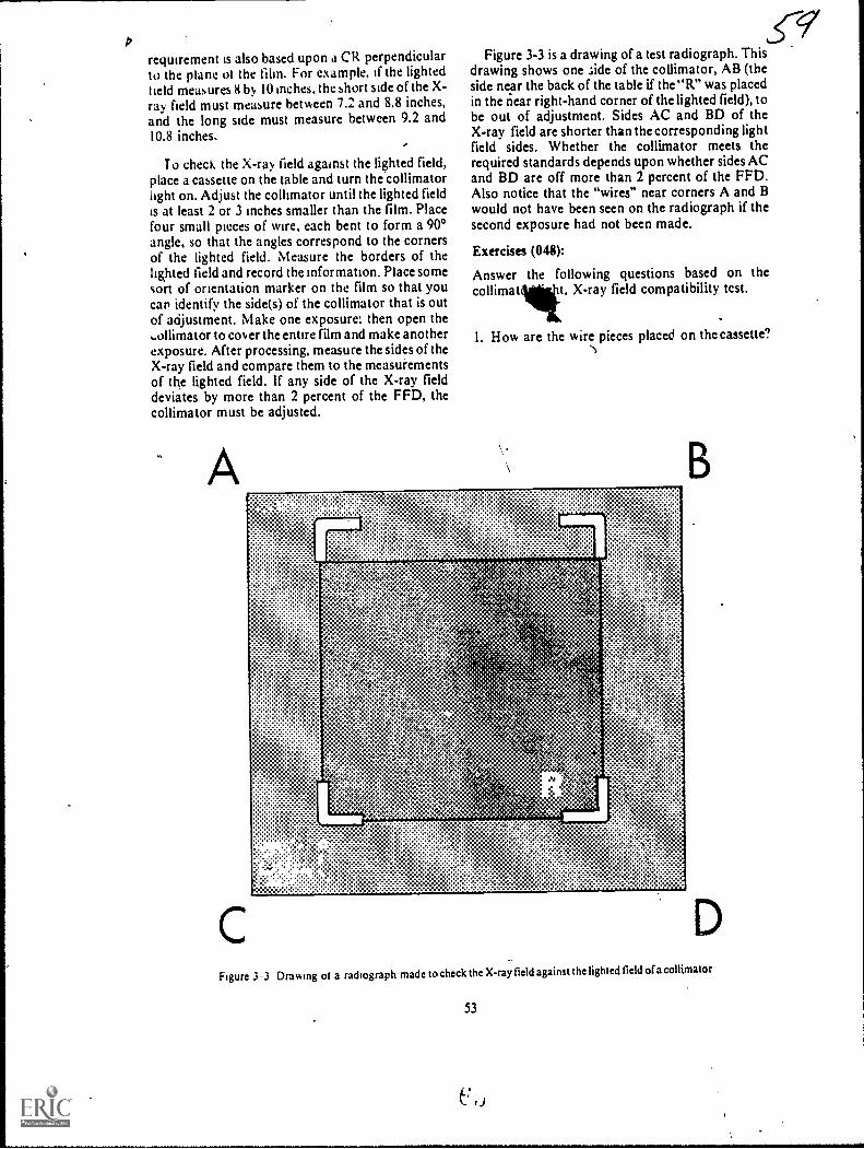
/2
requirement is also based upon a CR perpendicularto the plane ol the film. For example, if the lightedheld measures 8 by 10 inches, the short side of the X-ray field must measure between 7.2 and 8.8 inches,and the long side must measure between 9.2 and10.8 inches. '
To check the X-ray field against the lighted field,place a cassette on the table and turn the collimatorlight on. Adjust the collimator until the lighted fieldis at least 2 or 3 inches smaller than the film. Placefour small pieces of wire, each bent to form a 900angle, so that the angles correspond to the cornersof the lighted field. Measure the borders of thelighted field and record the information. Place someson of orientation marker on the film so that youcar identify the side(s) of the collimator that is outof adjustment. Make one exposure: then open theollimator to cover the entire film and make anotherexposure. After processing, measure the sides of theX-ray field and compare them to the measufementsof the lighted field. If any side of the X-ray fielddeviates by more than 2 percent of the FFD, thecollimator must be adjusted.
A
c
,c9"Figure 3-3 is a drawing of a test radiograph. This
drawing shows one side of the collimator, AB (theside near the back of the table if the "R" was placedin the near right-hand corner of the lighted field), tobe out of adjustment. Sides AC and BD of theX-ray field are shorter than the corresponding lightfield sides. Whether the collimator meets therequired standards depends upon whether sides ACand BD are off more than 2 percent of the FFD.Also notice that the "wires" near corners A and Bwould not have been seen on the radiograph if thesccond exposure had not been made.
Exercises (048):
Answer the following questions based on thecollimat t, X-ray field compatibility tcst.
1. How are the wire pieces placed on thecassette?
^
B
Figure 3-3 Drawing ot a radiograph made to check the X-ray field against the lighted field of a collimator
53
C 0
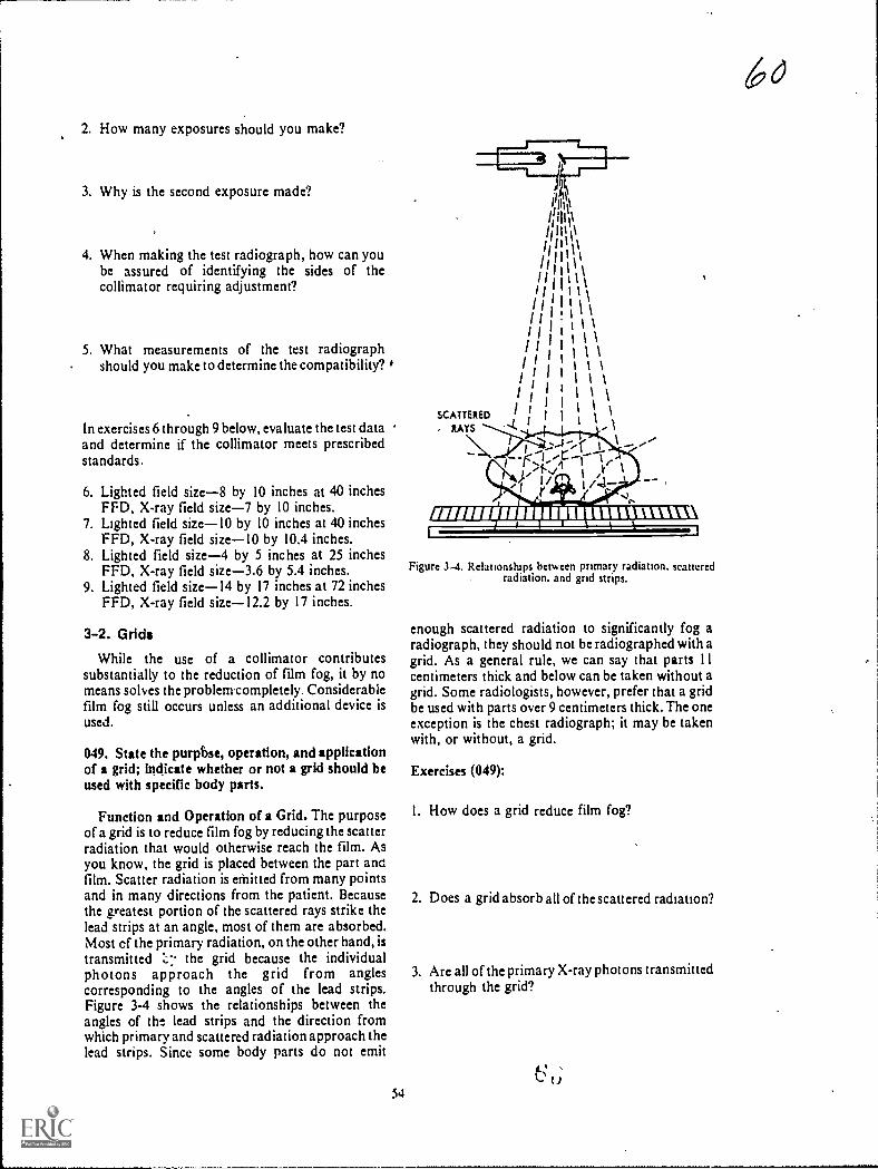
2. How many exposures should you make?
3. Why is the second exposure made?
4. When making the test radiograph, how can yoube assured of identifying the sides of thecollimator requiring adjustment?
5. What measurements of the test radiographshould you make to determine the compatibility?
In exercises 6 through 9 below, evaluate the test dataand determine if the collimator meets prescribedstandards.
6. Lighted field size-8 by 10 inches at 40 inchesFM. X-ray field size-7 by 10 inches.
7. Lighted field sizeI0 by 10 inches at 40 inchesFFD, X-ray field sizeI0 by 10.4 inches.
8. Lighted field size-4 by 5 inches at 25 inchesFFD. X-ray field size-3.6 by 5.4 inches.
9. Lighted field sizeI4 by 17 inches at 72 inchesFFD, X-ray field sizeI2.2 by 17 inches.
3-2. Grids
While the use of a collimator contributessubstantially to the reduction of film fog, it by nomeans sohes the problenrcompletely. Considerabiefilm fog still occurs unless an additional device isused.
049. State the purpbse, operation, and applicationof a grid; indicate whether or not a grid should beused with specific body parts.
Function and Operation of a Grid. The purposeof a grid is to reduce film fog by reducing the scatterradiation that would otherwise reach the film. ASyou know, the grid is placed between the part anofilm. Scatter radiation is ethitted from many pointsand in many directions from the patient. Becausethe greatest portion of the scattered rays strike thelead strips at an angle, most of them are absorbed.Most cf the primary radiation, on the other hand, istransmitted the grid because the individualphotons approach the grid from anglescorresponding to the angles of the lead strips.Figure 3-4 shows the relationships between theangles of the lead strips and the direction fromwhich primary and scattered radiation approach thelead strips. Since some body parts do not emit
54
SCATTERED
, LAYS
,-1-,/ ,v I
r //
ismusurminumnumt=11
Figure 3-4. Rdationships between primary radiation. scatteredradiation, and grid strips.
enough scattered radiation to significantly fog aradiograph, they should not be radiographed with agrid. As a general rule, we can say that parts I Icentimeters thick and below can be taken without agrid. Some radiologists, however, prefer that a gridbe used with parts over 9 centimeters thick. The oneexception is the chest radiograph; it may be takenwith, or without, a grid.
Exercises (049):
I. How does a grid reduce film fog?
2. Does a grid absorb all of the scattered radiation?
3. Are all of the primary X-ray photons transmittedthrough the grid?
t).
6O

4 Why is absorption of scattered radiation by agrid greater than its absorption of primaryradiation?
Match the normal grid application in column B withthe appropriate body part in column A by placingthe letter of the column B item beside the number ofthe column A item. Each application may be usedonce or more than once.
qlwnn 4 C o all n 8
5 SKullh M.rist7 Lumbar spine
Pehis_ 9 Elbou_ 10 Os calcis._ 1 I Chest.
a. GridNongrid
c Either grid or nongrid.
050. Differentiate between grid ratio and gridradius.
Grid Design. There are many different grids onthe market today. Some are designed to be usedunder specific conditions. In order for you to use thegrid that best fits your particular needs, it isnecessary to be awareozif the elements of grid design.
Grid ratio. The height of a lead strip in relation tothe width of the space between two strips is calledthe grid ratio (see fig. 3-5). Ratio is not directlyrelated to the thickness of the grid or to the numberof lines (lead strips) per inch. Consequently, a thinand a thick grid can have the same ratio, and an M-ime grid can have the same ratio as a 100-line grid.
Each grid has a specified ratio, and it can usuallybe found on the tube side of the grid. Common gridratios are 4: I. 5:1, 8:1, 12:1, and 16:1. Grid ratio isimportant to you because it affects not only theefficiency of the grid but Also the tube alignment.
Grid radius. In some grids, the lead strips areparallel to each other: such a grid is called a parallelor unfocused grid. In others. the lead strips areangled: these grids are said to be focused:
a In an unfocused grid, if imaginary linesparallel to the lateral surfaces of the strips wereextei.ded. they would never meet. In other words,there is no point at which the imaginary lines wouldcome together. Figure 3-6 represents an unfocusedgnd. Note that all the stn ps are perpendicular to theplane of the grid and that the lead strips are parallelwith each other.
h When the lead strips in the grid are inclined atprogresskely larger angles farther from the centerstrip, the grid is said to be focused. A focuse.a gr,idhas a grid radius which is the distance from the
Figure 3-5. Examples of grid ratios.
center of the grid to a point where the planes of thelead strips would meet. Figure 3-7 shows a cross-section of a focused grid, and figure 3-8 shows thegrid radius.
The^ grid radius is important to you because itaffects your FFD. A grid usually has a radiusspecified on its tube sidealthough on some gridsthe FFD range is specified instead of the ratio.
Exercises (050):
Match the grid design characteristic in column Bwith the appropriate statement in column A byplacing the letter of the column B item in theappropriate space in column A. Each column B itemmay be used once or more than once. In addition,both column B items may match a single column Astatement.
Column 4
I. Affects grid efficiency._ 2. A focused grid has one._ 3. An unfocused grid has one._ 4. A specified dktance._5. Affects FFD.
6. Affects tube alignmeni._ 7. Pertains to height of a lead sirip
and interspace._8. Lead strips art not parallel.
Column B
a. Grid ranob. Grid radius.
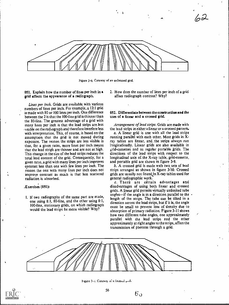
Figure 3-6. Cutaway of an unfocused grid.
051. Explain how the number of lines per inch in agrid affects the appearance of a radiograph.
Lines per inch. Grids are availabk with variousnumbers of lines per inch. For example, a 12:1 gridis made with 80 or 100 lines per inch. One differencebetween the 2 is that the 100-line grid is thinner thanthe 80-line. The greatest advantage of a grid withmany lines per inch is that the lead strips are less.v Bible on the radiograph and therefore interfere lesswith interpretation. This, of course, is based on theassumption that the grid is not moved duringexposure. The reason the strips are less visible isthat, for a given ratio, more lines per inch meansthat the lead strip's are thinner and are not as high.This change in the size of the lead strips reduces thetotal lead content of the grid. Consequently, for agiven ratio, a grid with many lines per inch improvescontrast less than one with few lines per inch. Thereason the one with many lines per inch does notimproe contrast as much is that less scatteredradiation is absorbed.
Exercise's (051):
I. If two radiographs of the same part are made,one using 8:1, 80-line, and the other using 8:1,100-line, stationary grids, on which radiographwould the lead strips be more visible? Why?
2. How does the number of lines per inch of a gridaffect radiograph contrast? Why?
052. Differentiate between the construction and theuses of linear and a crossed grid.
Arrangement of lead strips. Grids are made withthe lead strips in either a linear or a crossed pattern,
a. A linear grid is one with all the lead stripsrunning parallel with each other. Most grids in X-ray tables are linear, and. the strips always runli)ngitudinally. Linear grids are also available ingrid-cassettes and as regular portable grids. Thedirections of the lead strips with respect to thelongitudinal axis of the X-ray table, grtd-cassette,and portable grid are shown in figure 3-9.
b. A crossed grid is made with two sets of leadstrips arranged as shown in figure 3=10. Crossedgrids are usually not foundjn X-ray tables used forgeneral radiographic wprk.
c. There are certain advantages anddisadvantages of using both linear and crossedgrids. A linear grid permits virtually unlimited tubeanglesif the angle is in a direction parallel to thelength of the strips. The tube can be tilted in adirection across the lead strips, but if it is, the anglemust be small to prevent loss of density due toabsorption of primary radiation. Figure 3-11 showshow two different tube angles, one approximatelyparallel with the lead strips and the otherapproximately at right angles to the strips, affect thetransmission of photons through a grid.
hgure 3-/, Cutawa!, oc a focum.d
56
6a-

GRID
RADIUS
Figure 3-8. Grid radius.
Since a cross grid is actually made up of twosuperimposed linear grids, its effective ratio is abouttwice its nominal ratio. For example, an 8:1 crossed
grid has an effective ratio of about 16:1.
Exercises (052):
Match the grid in column B with the appropriatestatement or phrase in column A by placing theletter of the column B item in the appropriate spacein column A. Each column B item may be used onceor more than once. In addition, both column Bitems may match a single column A item.
Column 4
I In X.ray tables_ 2. In grid-cassettes
3 Should be used v.ith large tubeangles.
_ 4 Has higher effective ratio5 Use is more limited_ 6 Portable grid.
053. Given a list of statements pertaining to thepurpose, operation, and exposure requirements ofBuckys, indicate which are true and which are false.If you indicate "false," explain your answer.
Column B
a. Linear.b. Crossed.
Grid Movement As you know, if the patient
57
6 3
EXTENDEDPLANES OF
LEAD STRIPS
FOCUSED GRID
moves during an exposure, the part being .radiographed is blurr.t.J or not well visualized. Ifmovement is cons:jerabie and the part is smallenough, the part is .orripletely obliterated. Such is
the case when a grid is used in a Potter-Buckydiaphragm, a device named after its inventors,which moves the grid during exposure. Movementof the grid blurs out thc lead strips that wculdotherwise appear on the film with a stationary grid.Grid lines, as you know, can interfere withinterpretation of a radiograph.
Bucky operation. In order for a Potter-Buckydiaphragm (hereafter called a Bucky) to preventgrid lines on a radiograph, movement of the deviceor grid must satisfy the following threerequirements: ( I) motion must be smooth and even,(2) movement must start before the exposure, and(3) movement must continue until after theexposure stops.
Types of Buckys. Buckys can be classified asmoving, as reciprocating, or as recipromatie.
A moving Bucky is one in which the grid onlymoves in one direction during a single exposure.lt isthen manually cocked before the next exposure.The speed of movement is determined by a timer,which also is manually set. When using this type ofBucky, be sure to cock the device before each
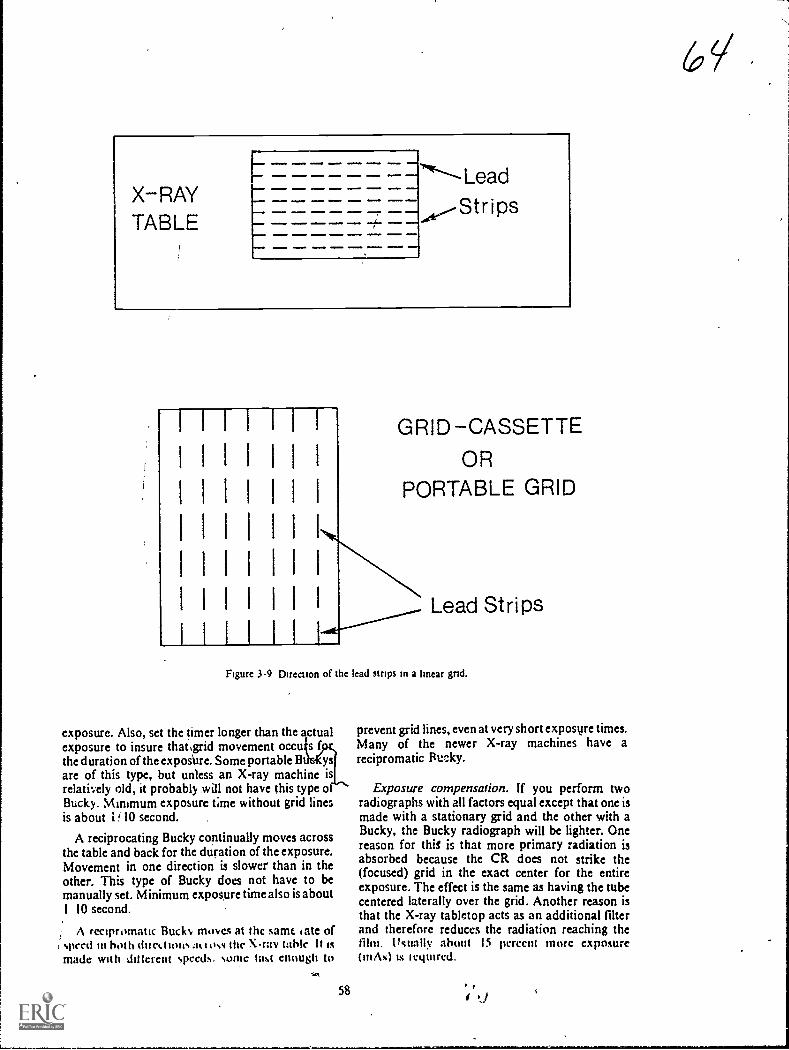
X-RAYTABLE
ammo a
...a.... --- --,1
GRID -CASSETTE
OR
PORTABLE GRID
Lead Strips
Figure 3-9 Direction of the lead stnps in a linear gnd.
exposure. Also, set the timer longer than the actualexposure to insure that4rid movement occu s fthe duration of the exposUre. Some portable B ysare of this type, but unless an X-ray machine isrelatively old, it probably mill not have this type oBuck). Minimum exposure time without grid linesis about 1 10 second.
A reciprocating Bucky cominually moves acrossthe table and back for the duration of the exposure.Movement in one direction is slower than in theother. This type of Bucky does not have to bemanually set. Minimum exposure time also is about1 10 second.
A recipromatic Bucks, moves at thc same late of, speed in both duct I tons.it t oss thc X-ray table It Ismade with ail (crept speeds. some last enough to
58
prevent grid lines, even at very short exposure times.Many of the newer X-ray machines have arecipromatic RtnAcy.
Exposure compensation. If you perform tworadiographs with all factors equal except that one ismade with a stationary grid and the other with aBucky, the Bucky radiograph will be lighter. Onereason for thiS is that more primary radiation isabsorbed because the CR does not strike the(focused) grid in thc exact center for the entireexposure. The effect is the same as having the tubecentered laterally over the grid. Another reason isthat the X-ray tabletop acts as an additional filterand therefore reduces the radiation reaching thefilm. Usually about 15 percent more exposure(iMs) ts tequircd.

.11011100
MEIMe.wile
1 1 1
I 111.A 1 1 1 I I
1 1 1 401/a I- I1
1.11iIIMP 1 1 IIMO 1 0 I
1
WISION.0 16IINE. 1 MINIMUM 1.1114I
eloMIOaI
1- I I itIO Hiwa
I
1.1 1 WI.O*IND I 1 i 1OMMMINN I
111 1 1.H .1MEMMI aMOD
1 I 1
elmONMO
11
OII110
.11
OMEN.
.11111M.
Fgiure 3-10. Direction of the lead strips in a crossed grid.
6( I
Figure 3-11 Relationship between direction of tube antoe and direction of lead strips, showing thedifference between the absorption of primary radiation.
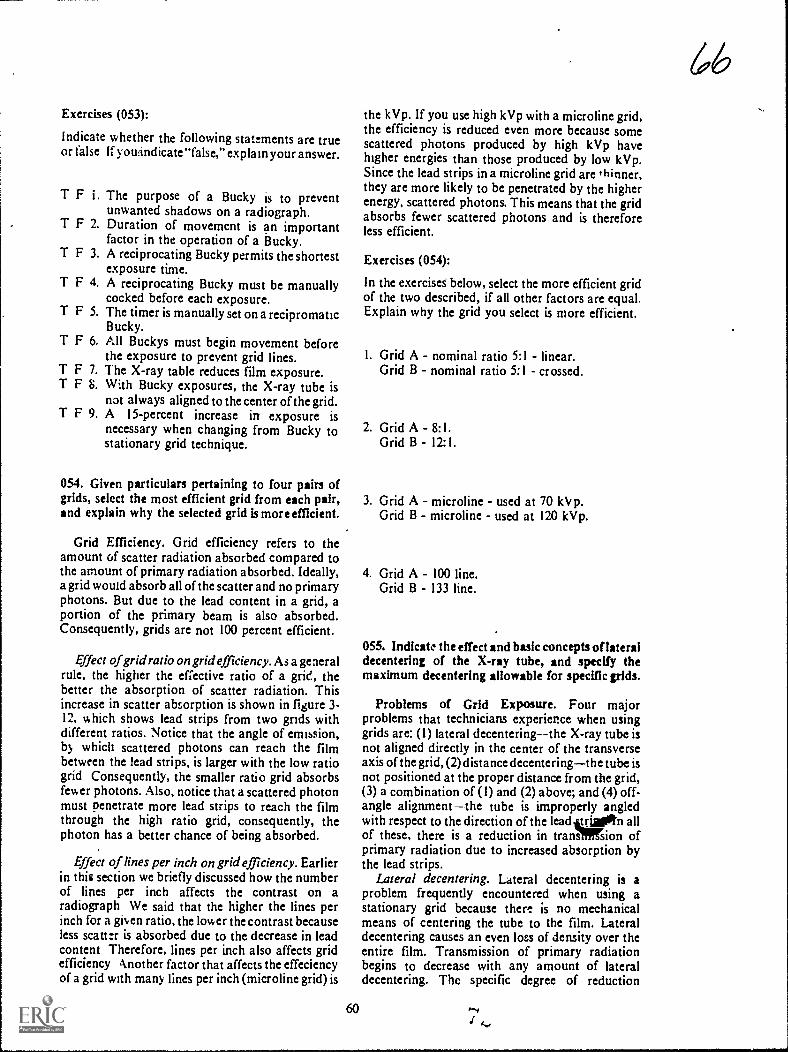
Exercises (053):
Indicate whether the following statements are trueor false If youAndicate "false," explain your answer.
T F i. The purpose of a Bucky is to preventunwanted shadows on a radiograph.
T F 2. Duration of movement is an importantfactor in the operation of a Bucky.
T F 3. A reciprocating Bucky permits the shortestexposure time.
T F 4. A reciprocating Bucky must be manuallycocked before each exposure.
T F S. The timer is manually set on a recipromaticBucky.
T F 6. All Buckys must begin movement beforethe exposure to prevent grid lines.
T F 7. The X-ray table reduces film exposure.T F 8. With Bucky exposures, the X-ray tube is
not always aligned to the center of the grid.T F 9. A 15-percent increase in exposure is
necessary when changing from Bucky tostationary grid technique.
054. Given particulars pertaining to four pairs ofgrids, select the most efficient grid from each pair,and explain why the selected grid Is more efficient.
Grid Efficiency. Grid efficiency refers to theamount of scatter radiation absorbed compared tothe amount of primary radiation absorbed. Ideally,a grid would absorb all of the scatter and no primaryphotons. But due to the lead content in a grid, aportion of the primary beam is also absorbed.Consequently, grids are not 100 percent efficient.
Effect of grid ratio on grid efficiency. As a generalrule, the higher the effective ratio of a grid, thebetter the absorption of scatter radiation. Thisincrease in scatter absorption is shown in figure 3-12, which shows lead strips from two grids withdifferent ratios. Notice that the angle of emission,by which scattered photons can reach the filmbetween the lead strips, is larger with the low ratiogrid Consequently, the smaller ratio grid absorbsfewer photons. Also, notice that a scattered photonmust penetrate more lead strips to reach the filmthrough the high ratio grid, consequently, thephoton has a better chance of being absorbed.
Effect of lines per inch on grid efficiency. Earlierin this section we briefly discussed how the numberof lines per inch affects the contrast on aradiovraph We said that the higher the lines perinch for a gi,,,en ratio, the lower the contrast becauseless scatt:r is absorbed due to the decrease in leadcontent Therefore, lines per inch also affects gridefficiency Another factor that affects the effeciencyof a grid with many lines per inch (microline grid) is
60
the kVp. If you use high kVp with a microline grid,the efficiency is reduced even more because somescattered photons produced by high kVp havehigher energies than those produced by low kVp.Since the lead strips in a microline grid are thinner,they are more likely to be penetrated by the higherenergy, scattered photons. This means that the gridabsorbs fewer scattered photons and is thereforeless efficient.
Exercises (054):
In the exerciseS below, select the more efficient gridof the two described, if all other factors are equal.Explain why the grid you select is more efficient.
I. Grid A - nominal ratio 5:1 - linear.Grid B - nominal ratio 5:1 - crossed.
2. Grid A - 8:1.Grid B - 12:1.
3. Grid A - microline - used at 70 kV p.Grid B - microline - used at 120 kVp.
4. Grid A - 100 line.Grid B - 133 line.
055. IndIcatt, the effect and basic concepts oflateraldecentering of the X-ray tube, and specify themaximum decentering allowable for specific grids.
Problems of Grid Exposure. Four majorproblems that technicians experience when usinggrids are: (I) lateral decentering--the X-ray tube isnot aligned directly in the center of the transverseaxis of the grid, (2) distance decenteringthe tube isnot positioned at the proper distance from the grid,(3) a combination of (I) and (2) above; and (4) off-angle alignmentthe tube is improperly angledwith respect to the direction of the lead tjn allof these, there is a reduction in tranallffsion ofprimary radiation due to increased absorption bythe lead strips.
Lateral decentering. Lateral decentering is aproblem frequently encountered when using astationary grid because there is no mechanicalmeans of centering the tube to the film. Lateraldecentering causes an even loss of density over theentire film. Transmission of primary radiationbegins to decrease with any amount of lateraldecentering. Thc specific degree of reduction
66
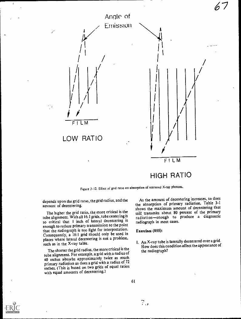
V/1/
//
II /
/
FILM
/
Angle ofz Emission
4.
//
LOW RATIO
1
I 1
I '
1
1
1
I
I
I
I//
//
//
/
FILM
HIGH RATIO
Figure 3-12. Effect of grid ratio on absorption of scattered X-ray photons.
depends upon the grid ratio, the wrid radius, and the
amount of decentering.
The higher the grid ratio, the more critical is thetube alignment. With all 16:1 grids, tube centering is
so critical that 1 inch of lateral decentering isenough to reduce primary transmission to the point
that the radiograph is too light for interpretation.Consequently, a 16:1 grid should only be used inplaces where lateral decentering is not a problem,
such as in the X-ray table.
The shorter the grid radius, the morecritical is the
tube alignment. For example. agrid with a radius of
40 inches absorbs approximately twice as muchprimary radiation as does a grid with a radius of 72
inches. (This is based on two grids of equal ratioswith equal amounts of decentering.)
61
i 7
As the amount of decentering increases, so does
the absorption of primary radiation. Table 3-1shows the maximum amount of decentering thatstill transmits about 80 percent of the primaryradiationenough to produce a diagnosticradiograph in most cases.
Exercises (055):
1. An X-ray tube is laterally decentered over a grid.How does this condition affect the appearance ofthe radiograph?

I
TABLE 3-1
MAXIMUM LATERAL DECENTERING WITHOUT SIGNIFICANT LOSS OF PRIMARY RADIATION
.
Grid Ratio Grid RadiusMaximum Decentering
(in inches)- _5:1
......
40
,--2
72 3
8:1 40 172 2
12:1 40 072 1
16:1 40 072
2. Two radiographs are made, using 8:1 and 5:1grids, with 1 inch of lateral decentering in eachradiograph. Which radiograph shows less loss ofradiographic density if all the other factors areequal?
3. How does the grid radius affect radiographicdensity in the presence of lateral decentering?
/4. How much lateral decentering is permitted using
a 8:1, 40-inch, focused grid?
5. How much lateral decentering is permitted usinga 16:1, 72-inch, focused grid?
6. Which of these two grids permiis the most lateraldecentering without significant loss of density-8:1, 40-inch, focused, or 5:1, 72-inch, focused?
056. Relate focus-grid distance to grid radius andradiographic density.
Distance decentering. Distance decentering refersto the use of a focus-grid distance which is more or
less than the grid radius. The result on theradiograph is a reduction in the primary radiationtoward the lateral edges of the beam with little or noeffect on the central portion of the primary beam.The specific loss of primary radiation depends uponthe amount of decentering, the grid ratio, and thedirection (near or far) of the decentered tube.
The loss of primary radiation increases as thedistance between the grid radius and the X-ray tubeincreases. There is a certain amount of tolerance forthis type of decentering. The tolerance dependspartly upon the grid ratio. A grid with a high ratiowill not tolerate as much distance decentering as willa grid with a low ratio. Also, there is more toleranceif the distance from the X-ray tube to the grid isgreater than the grid radius and less tolerance if thedistance from' the X-ray tube to the grid is less thanthe grid radius.
When we speak of "tolerance," we mean themaximum amount of decentering which stillproduces sufficient density to produce a diagnosticradiograph. Some grids have a specified focal range,such as 30 inches to 40 inches. This means you can
0 use any focus-grid distance in that range withoutexperiencing significant loss of primary radiation.
Some grids do not come with a specified focalrange.Only the grid radius is specified. In cases suchas this, you should get in touch with themanufacturer and obtain his recommendations,although you can determine the relative tolerance ofvarious grids by making experimental exposuresand determining at what focus-grid distancessignificant loss of primary radiation (density)occurs.
6K/

Exercises (056):
I If a radiograph is made using a 35-inch focus-grid distance and a grid with a focal range of 36to 44 Inches. how does this condition affect theappearance of the radiograph?
1
o radiographs are made using a 40-inchfocused grid. A 48-inch focus-grid distance isused with one radiograph and a 32-inch focus-grid distance is used with the other. Whichradiograph shows the greater change in
appearance if all other factors are equal?Explain.
3. How does grid ratio affect the loss of primaryradiation due to distance decentering?
4. flow can you determine the focal range of a grid
if it is not specified?
X-Ray Tube
Grid Radius
11111111111111111111111111111
Loss ofDensity
Near NormalDensity
057. Given descriptions of the density distributionof two radiographs, specify the cause of thedifference in distribution.
Lateral decentering plus distance decentering.When lateral and distance decentering occurtogether during the same radiograph, they areunique in that they produce a radiograph with a loss
of density on only one lateral margin of the film. Ifthe X-ray tube is misaligned in both directions andthe focus-grid distance is greater than the gridradius, the lateral margin of the film beneath thetube is underexposed. If the focus-grid distance isless than the grid radius, the lateral margin of thefilm remote from the tube is underexposed. See
figure 3-13.
Exercises (057):
1. A radiograph shows uneven density, Thedensityon side A of the radiograph is greater than thedensity on side B. Based on the information in
the text, what is the probable cause(s) of thevariation?
Grid
Film
iiGr id Radius/ \
X-Ray Tube /
Near NormalDensity
Figure 313. Effect of lateral decentering plus distance decentering on film density.
63
Loss ofDensity

2. A radiograph shows uneven density. The densityon side A of the radiograph is less than thedensity on side B. Based on the information inthe text, what is the probable cause(s) of thevariation?
058. Specify the maximum tube angle allowedacross the grid strips for various grids; describe theappearance of the radiograph if the maximumangles are exceeded.
Off-angle alignment. If the X-ray tube isexcessively angled across the lead strips, there is aneven, noticeable loss of density over the entire film.The amount of loss depends upon the degree of theangle and grid ratio. The maximum (approximate)angles which still produce adequate film exposurefor specific grids are as follows:5:1, 8'; 8:1, 60; 12:1,3'; and 16:1, 1°.
I. What maximum tube angles are permitted acrossthe grid strips for the following grids?
a. 5:1.
b. 8:1.
c. 12:1.
d. 16:1.
2. If the angles indicated in exercise #1 above areExercises (058): exceeded, what is the result on the radiographs?
61

CHAPTER 4
Film, Film Holders, and Darkroom
AS YOU ACHIEVE your "7 level" and advance ingrade you will become more and more involved inthe selection of films and film holders for use in yourdepartment. In this chapter we will present somegeneral information about these two items to assistyou in your selections, as well as other informationto help you use them effectively.
Our discussion of darkrooms will cover thechemistry, the evaluation, and the standardizationof processing systems.
4-1. X-Ray Film
In this section we will discuss the composition of
an X-ray film, the types of film, and filmcharacteristics.
059. Given a list of statements pertaining to thecomposition of an X-ray.film, match each with theappropriate film layer.
Composition of an X-ray Film. An X-ray filmconsists of a base, two subcoatings, an emulsion onboth sides, and a protective coating. (See fig. 4-I,)
The base. The base consists of either celluloseacetate or polyester and serves as a support for theemulsion and subcoating. 1 t also provides theproper degree of stiffness for easy handling 'Filmswith a cellulose acetate base work quite well inmanual processing and in some of the slowerautomatic processors. However. in 90-second,automatic processors where high temperatures are,used. they have a tendency to slip and cause themachines to jam. This occurrence is attributed tothe absorption of fluids by the cellulose acetatebase. Polyester, as base material, provides morestrength in thinner form thAn does cellulose acetateand will not absorb fluids Consequently, polyester-base film is more compatible with the hightemperatures used in 90-second processors.
The subcoating The subcoating is a thin layer ofadhesme material used to attach the emulsion to thefilm base.
The emulsion. Basically. the emulsion is
composed of gelatin and silver bromide crystals.The latent image and visible image are formed in the
tilm emulsion.The protective coaung. A thin, transparent
material is coated over the emulsion to protect it
during handling and storage.
65
Exercises (059):
Match the X-ray film layer in column B with theappropriate statement in column A by placing theletter of the column B item in the space provided incolumn A. Each column B item may be used once ornot at all.
Column A
I. Located between the emulsionand base.
2. Should not be used in 90-secondprocessors.
3. Helps prevent damage to theemulsion.
4. Can withstand hightemperature processing.
5. Gelatin and silver bromide.
Column B
a. Base (celluloseacetate).
b. Base (polyester).c. Subcoating.d. Emulsion.e. Gelatin.f. Protective coating.
060. Given a list of statements pertaining to thethree types of X-ray films, match each with theappropriate film.
Types of X-ray Film. Many different types of film
are used in the radiology field. All of these can becombined into the two major groups known asscreen and nonscreen films. These two groupingsinclude every film type except dental, which has afew peculiarities of its own. Dental films are alsodiscussed since you will, at times, use them.
Screen film. Screen film is manufactured to beespecially sensitive to the blue-violet light emittedfrom intensifying screens. The purpose in usingthese screens is to amplify the effects of X-radiation,as will be explained in more detail throughout thischapter. Screen film contains a smaller amount ofsilver than does nonscreen film; this factor peimitsscreen film to be processed faster than nonscreenfilm. Most radiographic examinations areaccomplished using screen film with intensifyingscreens; however, screen film can be used withoutintensifying screens. w hen used without screens,these films require considerably more exposure.
Nonscreen film. Nonscreen film is designed to beespecially sensitive to the direct action of X-rays.When used in this manner, it provides excellentradiographic detail. Generally speaking, it is
intended for use only on smaller body parts, such as
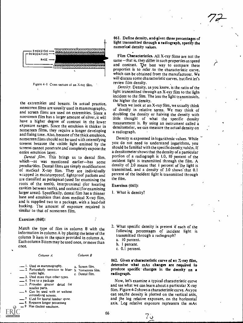
EMULSION --suscomING ---"'
BASE
41 41 41 O.
oo oo oo o . o o ......
Figure 4-1 Cross section of an X-ray film.
the extremities and breasts. In actual practice,nonscreen films are usually used in mammography,and screen films are used on extremities. Since anonscreen film has a larger amount of silver, it willhave a higher degree of contrast in the lowerexposure ranges. Since the emulsion is thicker innonscreen films, they require a longer developingand fixing time. Also, because of the thick emulsion,nonscreen films should not be used with intensifyingscreens because the visible light emitted by thescreens cannot penetrate and completely expose theentire emulsion layer.
Dental film. This brings us to dental film,which--as was mentioned earlierhas somepeculiarities. Dental films are simply modificationsof medical X-ray film. They are individuallywrapped in moistureproof, lightproof packets andare classified as periapical (used for examining theroots of the teeth), interproximal (for locatingcavities between teeth), and occlusal (for examininglarger areas). Specifically, dental film has a thinnerbase and emulsion than does medical X-ray film,and is supplied two to a package, with a lead-foilbacking. The amount of exposure required issimilar to that of nonscreen film.
Exercises (060):
Match the type of film in column B with theinformation in column A by placing the letter of thecolumn Et item in the space provided in column A.Each column B item may be used once, or more thano nce.
Column A Column B
L Used in mammography.2. Particularly sensitive to blue-
iolet light.3. Used more than other types.4, Two to a package
_5. Provides greater detail forsmaller parts.
6 Can be used with or withoutinttnsifying screens.
7 li4ed for lateral lumbar spine.8. Requires longer processing
_9 Has thicker emulsion.
a. Screen film.b Nonscreen film.C. Dental film.
66
061. Define density, and-given three percentages oflight transmitted through a radiograph, specify thenumerkal density values.
Film Characteristks. All X-ray films are not thesame that is, they differ in such properties as speedand contrast. T.he best way to compare theseproperties is to refer ,to the characteristic curve,which can be obtained from the manufacturer. Wewill discuss some characteristic curves, but first let'sreview film density.
Density. Density, as you know, is the ratio of thelight transmitted through an X-ray film to the lightincident to the film. The less the light transmissien,the higher the density.
When we look at an X-ray film, we usually thinkof density in relative terms. We may think ofdoubling the density or halving the density withlittle thought of what the specific densitymeasurement is. By using an instrument called adensitometer, we can measure the actual density ona radiograph.
Density is expressed in logarithmic values. Whileyou, do not need to understand logarithms, youshould be familial- with the specific densityyaltf:s. Ifa densitometer shows that the density of a partiCularportion of a radiograph is 1.0, 10 percent of theincident light is transmitted through the film. Adensity of 2.0 means that 1 percent of The light istransmitted, and a density of 3.0 shows' that 0.1percent of the incident light is transmitted throughthe film.
Exercises (061):
I. What is density?
2. What specific density is present if each of thefollowing percentages of incident light istransmitted through a radiograph?a. 10 percent.b. 1 percent.c. 0.1 percent.
062. Given rcharacteristic curve of an X-ray film,determine what mAs changes are required toproduce specific- changes in the density on aradiograph.
Now, let's examine a typical characteristic curveand see what we can learn about a particular X-rayfilm. Figure 4-2 shows a characteristic curve. As youcan see,the density is plotted on the vertical aids,and the log relative exposure, on the horizontalaxis. Log relative exposure represents the mAs
'702-

required to produce a specific change in the density.An increase of 0.3 on the exposure scale representsdouble the mAs and a decrease of 0.3 represents halfthe mAs. For example, if 10 mAs produces a densityof 1.1, 20 rnAs will produce a density of 1.8 (notice
3.5
3.0
2.5
0.5
the broken lines). Keep in mind that the log relatiVc
exposure scale is relative. You can apply any mAsvalue to the scale. One hundred mAs produces a,density of 1.1; then 200 mAs is required to produce a
density of 1.8, according to the curve in figure 4-2.
SHOULDER
1.8I1It
BODY
. 11 - - - - - - - -1
Iii
TOE
II 1
i II 1
I 1
1 1
1 1
mi. 1
1 1
1 sa,
.
0.5 1.0 1.5 2.0 2.5 3.0 3.5
LOG RELATIVE EXPOSURE
Figure 4-2. A characteristic curve.
67
°73
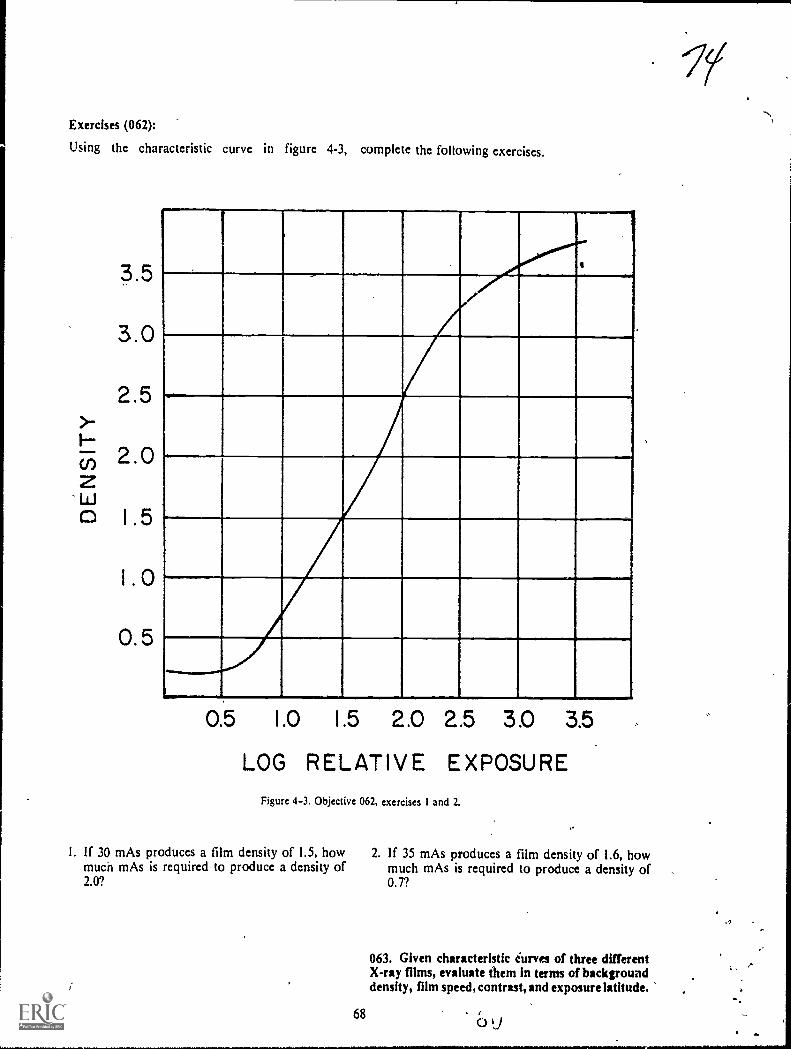
Exercises (062):
Using the characteristic curve in figure 4-3, complete the following exercises.
3.5
3.0
2 5.-F.--
(,) 2.0z0 1 5
o
0.5
0.5 1.0 1.5 2.0 2.5 3.0 3.5
LOG RELATIVE EXPOSUREFigure 4-3. Objective 062, exercises I and 2.
I. If 30 mAs produces a film density of 1.5, howmuch mAs is required to produce a density of2.0?
68
2. If 35 mAs produces a film density of 1.6, howmuch mAs is required to produce a density of0.7?
063. Given characteristic iurves of three differentX-ray films, evaluate them in terms of backgrounddensity, film speed, contrast, and exposure latitude.

Background densitj. All X-ray films have acertain amount of background density. also calledinherent film fog. This density is preseht after
processing even if the film is une..posed. Todetermine the background density of a film, refer tothe toe of the characteristic curve ahd note thedensity at zero exposure. The film represented in
figure 4-2 shows a background density of 0.2. As arule, a background density of over 0.2 is excessive.
Film speed. The response of a radiographic filmto exposure is called film sensitivity or film speed. A"last" film requires less exposure to produce aspecific density than does a "slow" film. Since a fast
film requires less exposure, it permits shorterexposure times, subjects the X-ray tu to fewerheat units per exposure. and reduces t radiationdose to the patient. Fast films, how ver, usuallysacrifice some detail due to the incre4ed size octhesil% er bromide crystals in the emulsion, whichcauses a "grainy" appearance on the radiographs.
3.5
3.0
Film speeds are not expressed in numericalvalues; therefore you must compare the relativespeeds of different films by referring to thecharacteristic curves. Thc relative speed of a film isindicated by the left to right position of thecharacteristic curve on the graph. The farther to theleft the curve is !mated, the faster the speed. Thefarther .to the rightthe slower the speed.
Contrast and exposure latitude. You can alsodetermine the relative film contrast and exposurelatitude by evaluating the characteristic curves.Both are indicated by the slope of the curve. A morevertical slope indicates higher contrast and lesseXposure latitude, and a more gradual slopeindicates lower contrast and more exposurelatitude.
Exercises (063):
Complete the following exercises based on thc threecharacteristic curves shown in figuro- 4-4.,
'
1.0
. 0.5
0.5 1.0 1.5 2.0 2.5 3.0 3.5
LOG RELATIVE EXPOSUREFigure 4-4 Objective 063, exercises I through 8.
69
J.

I. Which film has the highest background density?2. Which film(:), if any, has too much background
density?3. Which film is the slowest?4. Which film would exposl your patients to the
least radiation? .-
5. Which film would cause the most strain on yourX-ray tube?
6. Which film exhibits the highest contrast?7. Which film pro, ides the most exposure latitude?8. Which film sacrifices the most detail?
4-2. Intensifying Screens
Our discussion of intensifying screens includestheir purpose, construction, significance of thephosphor, and finally the procedures forperforming screen-film contact and screen lag tests.
064. State the purpose of intensifying Fcreens; listthe four layers of an intensifying screen, and give thepurpose of each.
Purpose of Intensifying Screens. As you know,intensifying screens reduce the exposure necessaryto produce the desired density on a radiograph.They reduce the exposure by converting the radiantenergy (X-ray photons) to visible light, which thenexposes the X-ray film.
Construction of Screens. An intensifying screenconsists of your layers of materialthe base, thereflecting material, the phosphor, and the protectivecoating.
.Base The base is a sheet of cardboard or similarm'hkerial that supports the rest of the screen.
Reflecting material. The reflecting material is athin layer of substance that reflects the light photonsemitted away from the film, back toward the film.
Phosphor. The phosphor is the chemical thatemits visible light when exposed to X-rays.
Protective coating. The protective coating is athin layer of plastic that prevents the buildup ofstatic, protects the phosphor, and permits the screento be cleantd without damage to the phosphor.
Exercises (064):
I. What is the purpose,of intensifying screens?
2. List the four layers ofan intensifying screen andgive the purpose of each layer.
065. Indicate the relationship between theintensifying screen phosphor and screencharacteristics.
-:n
..
Phosphor Significance. The layer of phosphor inan intensifying screen is usually made up of crystalsof calcium tungstate. When X-ray photons strikethese crystals,' the crystals emit visible light in theblue-violet range of the spectrum. X-ray filmsdesigned for use with intensifying screens areparticularly sensitive to the blue-violet light.
Screen speed. Depending upon the size of thescreen crystals and the thickness of the layer of thecrystals, intensifying screens are classifiedaccording to their speeds. The speed reflects thesensitivity of the phosphor layer to X-radiation."Slow," "medium," and "fast," are common screenspeeds, although different manufacturers applyother terms to their screens. The faster the screens,obviously the less exposure needed to produce agiven density on a radiograph. As a rule, largecrystals and a thick layer provide a fast screen, whilesmall crystals and a thin layer reduce the speed ofthe screen.
Detail. On the surface it would seem that highspeed screens are best since hey permit shorterexposure times, less strain on the X-ray !lib,: per .exposure, and less radiation to the patient.However, these advantages are realized only bysacrificing detail on the radiographs. Allintensifying screens reduce the detail on aradiograph below that obtained from direct filmexposure, and this reduction in detail is increased as!lie speed of the screens increases.
Notice in figure 4-5 that we havt shownillustrations of two layers of crystals of differentthicknesses. Notice that the visible light from someof the phosphor crystals from the thick layer is morediffused because the crystals are farther from thefilm. The greater diffusion results in moreoverlapping of the areas under exposure and,consequently, less image clarity.
Figure 4-6 also compares the diffusion of-thelight, but between large and small crystals. There ismore overlapping of the light from the large crystalsbecause they emit more light than the small crystals.
Exercises (065):,
I. Describe the connection between screen spectral'emission and film sensitivity.
2.,, Of the three screen speeds listed in the text, whichone requires the least exposure for a specific .
examination? The highest exposure?
3. Of the three screens listed in the text, which oneprovides the best detail? The least?
'76

CALCIUM TUNGSTATE CRYSTALS
-----PHOSPHOR
FILM
7 7
DIFFUSIONOF LIGHTFROM CRYSTAO
Figure 4 $ Caomparison of light diffusion between thick and thin layers of screen phosphor.
4. in your own w ords. explain the relattonshipbetween crystal size. layer thickness, and detail.
5. Why do crystal size and layer thickness affect
detail?
066. Given a list of statements pertaining to ascreen-film contact test, indicate which are true and
which are false. If you indicate "false," explain your
answer.
Screen-Film Contact. Screens must be in close,
even contact with the film; otherwise, the film will
have a fuzzy appearance, and there will be a definite
loss of detail The detail loss is due to the increased
light diffusion from the crystals because they are
farther from the film. See figure 4-7. Poor screen-
film contact is generaliy caused by screen warpage
resulting from moisture, loose fitting due to broken
hinges. improper spring tension in the latches,
uneven surface caused by a foreignobject under the
screen, or defective cassette frames. You can test the
screen-film contact quickly and easily in this way:
place a pieze of wiremesh on the outside of a loaded
cassette and make a flash exposure at about 5 mAs
and 40 kVp. After developing, inspect the image of
SMALLCRYSTALS
the wire mesh. If the contact is good, the image will
be sharp and clearly defined throughout the surface
of the film. If it is podr, the outline will be fuz.zy,
with varying degrees of unsharpness. Figure 4-8
shows two wire mesh images. The one on the left
exhibits good contact; the one on the right, poor
contact. Although the poor contact in the figure is
throughout the film, this may not necessarily be the
case. Poor screen contact can occur in only a small
area in the cassette, such as the center. Regardless of
the size of the area involved, if it causes a significant
loss of detail, the cassette must be repaired or
replaced.
Exercises (066):
T F I. A screen-film contact test is made todetermine if there is an increase in detail.
T F 2. Poor screen-film contact results in less iightdiffusion from the phosphor crystals.'
T F 3. To perform a screen-film contact test,fmake a radiograph of a piece of wire mesh.
T F 4. Unsharp areas on a test radiographindicate good screen-film contact.
067. Given descriptions of the results of three
screen lag tests, evaluate the resnits and deermine if
screen lag is present.
Screen Lag. One requirement of good screens is
LARGECRYSTALS
Figure 46. Companson of Itglit diffusion between large and small phosphor crystals.
71
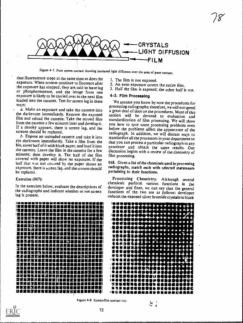
-a--CRYSTALS...0---LIGHT DIFFUSION
Figure 4-7, Poor screen contact showing increased light diffusion over the area of poor contact.
that fluorescence stops at the same time as does theexposure. When screens continue to fluoresce afterthe exposure has stopped, they arc said to have lagor phosphorescence, and the image from oneexposure is likely to be carried over to the next filmloaded into the cassette. Test for screen lag in theseways:
a. Make an exposure and take the cassette intothe darkroom immediately. Remove the exposedfilm and reload the cassette. Take the second filmfrom the cassette a few minutes later and develop it.If a density appears, there is screen lag, and thescreens should be replaced.
b. Expose an unloaded cassette and take it intothe darkroom immediately. Take a film from thebin, cover half of it with black paper, and load it intothe cassette. Leave the film in the cassette for a fewminutes; then develop it. The half of the filmcovered with paper will show no exposure. If thehalf that %k as not covcred by the paper shows anexposure, there is screen lag, and the screens shouldbe replaced.
Exercises (067):
In the exercises below, evaluate the descriptions ofthe radiographs and indicate whether or not screenlag is present.
114111111111111111191111111IMIEN11111111111111111111111111110.)111111111111111111111111011111111111111111118111111
11211111111111111111111111111111181111111111111111111111111
221181311118111111111111111111111111111111111.11111111N111111111111111111111111111111111111111111111114111111181111711a1111111111111118111111111811111111111111
11111111111191111199111111111111111111111111111111111NIRIMOVI111111111111111111181111111111111.11111111111112a1M110111111111111911131111111111191111111111IDONSIISSIIIIIIIIMM1111111111101111111111IN21111111111111161111111111111111111111611161111111111111samanalmamillisammussalesaamemiamessamounsummsimemommeamennommeSallieliellialliNal1111111112111116N118101111111111111111111191111111111111121111unnesonsiessammumnam1121111112a111121111211111111111111ENSIIIIIIIIM2111/11/11101111111111111(111811111111111111111/11111IIMINIMINE1111111111111111111111110111111111111111111111.34106111111111111MINIII=11118111111110111131011111111111111MIINEIM111111111151
I. The film is not exposed.2. An even exposure covers the entire film.3. Half the film is exposed; the other half is not.4-3. Film Processing
We assume you know by now the procedures forprocessing radiographs; therefore, we will not spenda great deal of time on the procedures. Most of thissection will be devoted to evaluation andstandardization of film processing. We will showyou how to spot some processing problems evenbefore the problems affect the appearance of theradiograph. In addition, we will discuss ways tostandardize all the processors in your department sothat you can process a particular radiograph in anyprocessor and obtain the same results. Ourdiscussion begins with a review of the chemistry offilm processing.
068. Given a list of the chemicals used in processingradiographs, match each with selected statementspertaining to their functions.
Processing Chemistry. Although severalchemicals perform various functions in thedeveloper and fixer, we can say that the generalfunctions of the - two are as follows: developerreduces the exposed silver bromide crystals to black
teowevire.111.104110111110*
se0941941.11)119,111111see1119.41111111009110***SO**1410*140iseeptiliaSit0111110111eattill11111
'119111109111**ells**
4444+****14.4**-* *-+-**-4,
4-0-** 4-* + -4* ++-44-4t 4 . +.
+44+4.-4 4, I-4,- 4-1 4.+.4.41t- 41- 4,4--+- 4
4,- e. ....- .;.4.-4- -4. * 4- s 4
+ Pc 4 4 l 34-* it. * 4 4 4 - 40 -440-14-4-*.44*'s
44. 4-** 4 * *4-+ + 4,-* +-* +
4- 4-** *44++4
41101.114111111101 essAling.4111414/40qh saeInseeimesseausei040,011111101M0110110111 99
111111/4111011:1111111011/0411111SS 110111.911911.11911111.191161010IscsaassairearlikallDansill
*4-
hgure 4-8. Screen-film contact test,
72

metallic silver, fixer removes the unexposed silverbromide crystals from the fdm.
Manual developer.. Basically, manual developerconsists of four agents: (1) activator, (2) reducers,(3) restrainer, and (4) preservative:
a. Sodiuin carbonits, also called the activator oraccelerator, provides the alkaline base needed toactivate the other chemicals. it also causes the filmemulsion to swell and soften, permitting access tothe exposed silver bromide by other chemicals.
b. Metol and hydroquinone are known as thereducing agents. Together they reduce the exposedsilver bromide crystals to black metallic silver.Metol acts quickly on the crystals and builds thegray tones of the image. Its action is unpiedictableabove 75° F. Hydroquinone is slower acting thanmetol. It builds up the black tones of the image, andtherefore brings out the film contrast.Hydroquinone does not function effectively below60 ° F. Manual developer should be maintained at68° F. because of the sensitivity of these twochemicals.
c. Potassium bromide is the restrainer in thedeveloper. It limits the action of the reducing agentsto prevent development of the unexposed silverbromide crystals. If a film isleft in the developer toolong, the reducers will override the restrainer anddevelop the unexposed crystals, resulting it!,chemical fog. An important point to rememberthat bromine, rhich is a byproduct of thedevelopment proess, also acts as a reducing agent.It continues to build up throughout the life of thedeveloper; consequently, there is no need to addpotassium bromide to the replenisher.
d. Sodium sulfite is the "preservative" in thedeveloper. Its purpose is to prevent rapid oxidationof the chemistry and thereby prolong the life of thedeveloper.
Automatic developer. Basically, the automaticdeveloper chemistry is the same as manualdeveloper. Two chemicals, sodium carbonateandsodium sulfite, serve the same functions. Potassiumbromide also serves the same function, but is calledthe starter solution. The starter is obtainedseparately from the automatic developer; whereas,the potassium bromide is included as part of themanual developer package. As with manualdv.eloper, potassium bromide is not included inautomatic developer replenisher. Two otherdifferences between the developers are as follows:
a. Metal cannot be used in automatic processorssince the developer temperature is higher than 75°F. usually 800 tO 100° F. Phenidone in automaticdeveloper performs the same function as metol inmanual developer. Hydroquinone is present inautomatic developer and serves the same functionas in manual developer.
b. Automatic developer contains a "hardener"gluteraldehyde. The purpose of this chemical is to
73
9'control the swelling of the emulsion and thereby tohelp prevent transport problems and damage to theemulsion by the transport rollers.
Fixer. The fixer in both manual and automaticchemistry contains four basic agents: (1) acidifier,(2) clearing agent, (3) hardener, and (4)preservative. The preservative is the same chamical,sodium sulfite, and serves the same function as inthe developer.
a. Acetic acid, the acidifier, serves two functions:(1) it stops development b: neutralizing the alkalinedeveloper solution and (2) it provides the acidityrequired for the other chemicals to function.
b. The clearing agent in the fixer is eitherammonium thiosulfate or sodium thiosulfate. Itremoves the unexposed silver bromide crystals fromthe film emulsion by dissolving them into solutionas silver salts. Once the film is cleared, it can besafely exposed to light.
c. The hardener in the fixer is either aluminumchloride, potassium alum, or chrome alum. Itshrinks and hardens the emulsion so that it can behandled without damage.
Exercises (068):
Match the processing chemical in column B with theappropriate statement in column A by placing theletter of the column B chemical in the spaceprovided in column A. Each column B item may beused once, more than once, or not at all. In addition,more than one column B item may match a singlecolumn A statement.
Column A Column B
I. Turns the exposed silver a. Potassium dum.b. Metol.c. Sodium
thiosulfate.d. Gluteraldehyde.e. Sodium car-
bonate.Hydroquinone.Potassiumbromide.
h. Sodium sulfite.Phenidone.
j. Acetic acid.k. Ammonium
thiosulfatc.I. Aluminum
chloride.
bromide crystals to blackmetallic silver.
2. Prevents chemical fog bylimiting the action of thereducing agents.
_ 3. Hardening agent in thedeveloper.
4. Starter solution.5. Removes unexposed crystals
from film emulsion._ 6. Manual developing
temperature is based on these._ 7. Permits reducing agents' entry
to the exposed silver bromidecrystals.
8. Hardens the film emulstori,inthe fixer.
9. Prevents oXidation ofi thechemistry.
_10. Developer agent not added toreplenishes.
II. Doesn't work properly bdow60° F.
12. Reducing agent(s1 whkh zredependable when temperatureis above 75° F.
1.
g.
069. State a common cause of inconsistent qualityin radiographs, and briefly explain the p7ocedurefor evaivating processors.
Evaluation of Film Processing. As you know, theproduction of high-quality radiographs isimportant in a radiology department. Equallyimportant is the consistent production ofradiographs of high-quality. Several factors affectthe consistency of the radiographs, and some ofthem are explained elsewhere in this volume. One ofthe most common causes of inconsistent quality ofradiographs is that film processing varies from dayto day and from one processor to another.
To identify the variations before they affect theradiographs or to prevent the variations altogether,you should check each processor daily, using asensi:ometric film strip. Basically, the procedure isas follows: the film strip is exposed to light so that aseries of densities are recorded on the film. Afterprocessing, the densities of ccrtain density stepsarcdetermined with a densitometer and recorded on achart.
Exercises (069):
I. What is a common cause of inconsistent qualityradiogaphs?
2. Briefly explain the procedure for evaluatingprocessors.
070. Answer key questions pertaining to thesensitometer and radiographic film whenconducting a processor evaluation test.
Sensitometer. The first requirement forevaluating processors is to expose the filmstripswith a device capable of producing repeated equalexposures from one day to the next. Such a device iscalled a sensitometer. Using a sensitometer, you canbe assured that the filmstrips receive equalexposures; consequently, a variation in film densitycan be accurately traced to the processor. Youshouldn't expose the filmstrips with a radiographicunit because there are usually minor, day-to-dayvariations in machine output.
Commercial ser itometers are available, but onecan be made at a relatively small cost. One"homemade" sensitometer is described in an articlewritten by Trout, Kelly, and Anderson inRadlolcgic Technology, Volume 43, No. 1, 1971,pp. 15-19.
The precedure for exposing the radiographic filmin the sensitometer is relatively simple and dependsupon the device employed. Keep in mind that youshould eliminate as many variable factors as
74
possible in order to accurately evaluate yourprocessing systems. It follows that you shouldreserve one box of radiographic film for theevaluation to prevent minor variations from onebox of film to another from affecting the filmdensities. Also, expose a fresh film daily andimmediately process it, since prolonged periodsbetween exposure and processing may also affectthe resulting film densities. If you have more thanone processor, cut the film into strips after exposureand process a filmstrip in each processor. Be sure toidentify the processor on the film strip.
Exercises (070):
1 When exposing radiographic films to evaluateprocessors, why is it better to use a sensitometerrather than a radiographic unit?
2. Why is it important to take your films from thesame box?
3. How long after exposure should you process thefilmstrips? Why?
071. Given a chart showing densities obtained fromfilmstrips processed in thret different processon,evaluate the chart and answer key questionspertaining to the test data and results.
Evaluating filmstrips. Evaluation of thefilmstrips is, of course, the most important aspect ofthe operation. We will discuss this aspect from twostandpoints: (1) using a densitometer and (2)without using a densitometer.
A filmstrip exposed in a sensitometer, afterhaving been processed, appears similar to aradiogr2 ph of a step wedge; that is, there is a seriesof density steps. With a densitometer you measurespecific density steps of the filmstrip to determinefilm density, contrast, and base fog. Let's look at atypical filmstrip and see how to determine thesefactors.
First of all, to measure the density, select a densitystep between 0.9 and 1.2. These densities are locatedon the portion of the characteristic curve that ismost sensitive to changes in processing. Let'sassume the density step that suits our needs is 1.0.This means that every day you measure the densityof that same step. The next step is to rocord theinformation on a chart like the one illustrated infigure 4-9. Notice on the chart that the densityrcmains near 1.0 and relatively stable until theseventh day, when it begins to drop steadily. Noticealso the broken lines a; densities of 0.8 and 1.2.
L () /
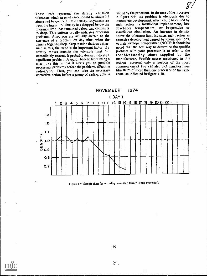
These lines represent the density variationtolerance, which in most cases shoold be about 0.2above and below thc normal density. . As you can seefrom the figure, the density has dropped below thetolerance limit, has remained below, and continuesto drop. This pattern usually indicates processorproblems. Also, you are actually alerted to theexistence of a problem on day nine, when thedensity began to drop. Keep in mind that, on a chartsuch as this, the trend is the important factor. If adensity moves outsidc the tolerable limit butimmediately returns, it probably doesn't indicate asignificant problem. A major benefit from using achart like this is that it alerts you to possibleprocessing problems before the problems affect theradiographs. Thus, you can take the necessary
.correetive action before a group of radiographs is
1.3
I. 2
1.1>-
O. 8
0.7
ruined by the processor. In the case of the processorin figure 4-9, thc problem is obviously due toincomplete development, which could be eaused bysuch factors as insufficient replenishment, lowdeveloper temperature, or inoperative orinsufficient circulation. An increase in densityabove the tolerance limit indicates such factors asexcessive development caused by strong solutions,or high developer temperattfre. (NOTE: It should benoted that the best way to determine the specificproblem with your processor is to refer to thetroubleshooting chart supplied by themanufacturer. Possible causes mentioned in thissection represent only a portion of the mostcommon ones.) You can also plot densities fromfilm strips of more than one processor on the samechart, as indicated inligure 4-10.
NOVEMBER 1974
( DAY )
2 3 4 5 6 7 8 9 10 11 12 13 14 15 16 17 18 19 20 21 22 -
--
Figure 4-9. Sample chart for recording processor density (single processor).

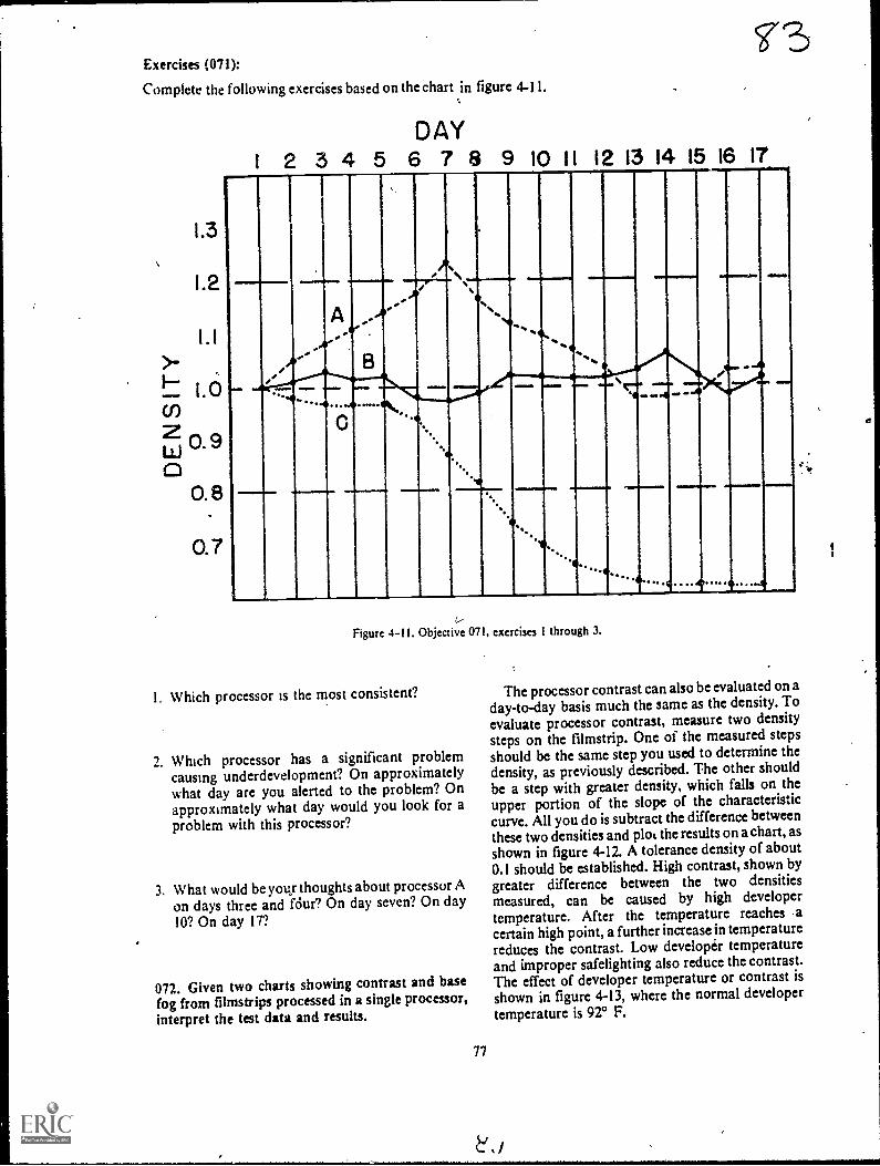
Exercises (071):
Complete the following exercises based on theChart in figure 4-11.
1.3
1.2
0.7
DAY1 2 3 4 5 6 7 8 9 10 11 12 13 14 15 16 17
, ,
'I
-
,
A--
.........o
e.,.
..
.9
v
.......
%ie..
am..
_-
41/
............
...............,4
..............
... . .41>6.,.
Figure 4-11. Objective 071, exercises 1 through 3.
I. Which processor is the most consistent?
1. Which processor has a significant problemcausing underdevelopment? On approximatelywhat day are you alerted to the problem? Onapproximately what day would you look for aproblem with this processor?
3. What would be you- thoughtsabout processor Aon days three and fdur? On day seven? On day10? On day 17?
072. Given two charts showing contrast and basefog from filmstrips processed in a single processor,interpret the test data and results.
77
The processor contrast can also be evaluated on aday-to-day basis much the same as the density. Toevaluate processor contrast, measure two density
steps on the filmstrip. One of the measured stepsshould be the same step you used to determine thcdensity, as previously described. The other shouldbe a step with greater density, which falls on theupper portion of the slope of the characteristiccurve. All you do is subtract the difference betweenthese two densities and ploL the results on a chart, asshown in figure 4-12. A tolerance density of about0.1 should be established. High contrast, shown by
greater difference between the two densitiesmeasured, can be caused by high developertemperature. After the temperature reaches -acertain high point, a further increase in temperaturereduces the contrast. Low developer temperatureand improper safelighting also reduce the contrast.The effect of developer temperature or contrast isshown in figure 4-13, where the normal developertemperature is 92° F.

1 .80
1 1.75u)<cci_ 1.70200 1.65
II
1.60
1.55
1.85
1.80
ini 1 .75<cc 1.701.-2o 1.65c.,
1.60
1.55
DAY1 2 3 4 5 6 7 8 9 10 11 12
www.....
001MI Eird elIAND
1=111,1110 Wel
Figure 4-12. Sample contrast chart.
DEVELOPER TEMPERATUREELT° 88089090°91 92' 93° 94°95° 96° 97° sr
.
....
Ii_Figure 413. Chart showing the effect of developer temperature on contrast.
*J ti78
,
fil
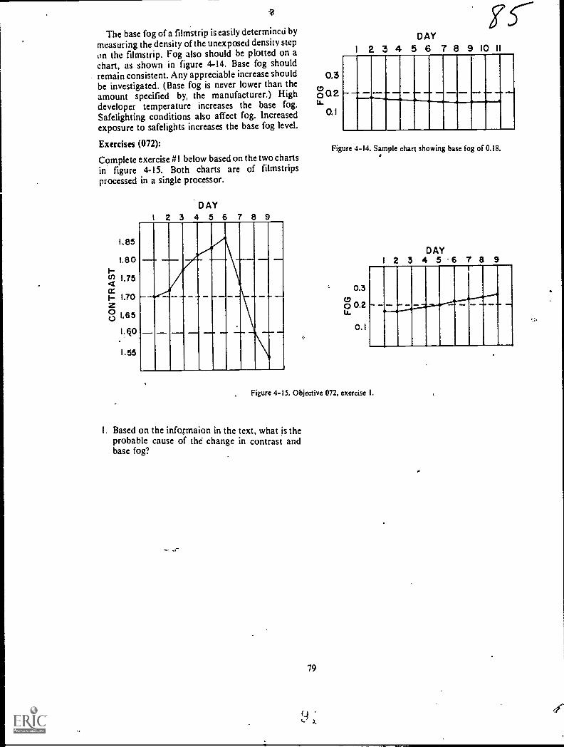
15---1
The base fog of a filmstrip is easily determined by
measuring the density of the unexposed density stepon the filmstrip. Fog also should be plotted on achart, as shown in figure 4-14. Base fog shouldremain consistent. Any appreciable increase shouldbe investigated. (Base fog is never lower than theamount specified by, the manufacturer.) Highdeveloper temperature increases the base fog.Safelighting conditions also affect fog. Increasedexposure to safelights increases the base fog level.
Exercises (072):
Complete exercise #1 below based on the two chartsin figure 4-15. Both charts are of filmstripsprocessed in a single processor.
1.85
1.80Iu) 1.754cc1 1.70Z00 1.65
D AY
2 3 4 5 6 7 8 9
0.5to0 Q 2LA.
0. 1
DAY
1 2 3 4 5 6 7 8 9 10 11
_. ..-.-...-,....,..........., .... ...- ..... .....
Figure 4-14. Sample chart showing base fog of 0.18..*
c 0.300 0.2Lt.
0.1
DAY1 2 3 4 5 6 7 8 9
Figure 4-15. Objective 072, exercise I.
1, Based on the infosmaion in the text, what is theprobable cause of the change in contrast andbase fog?
79
x.
o
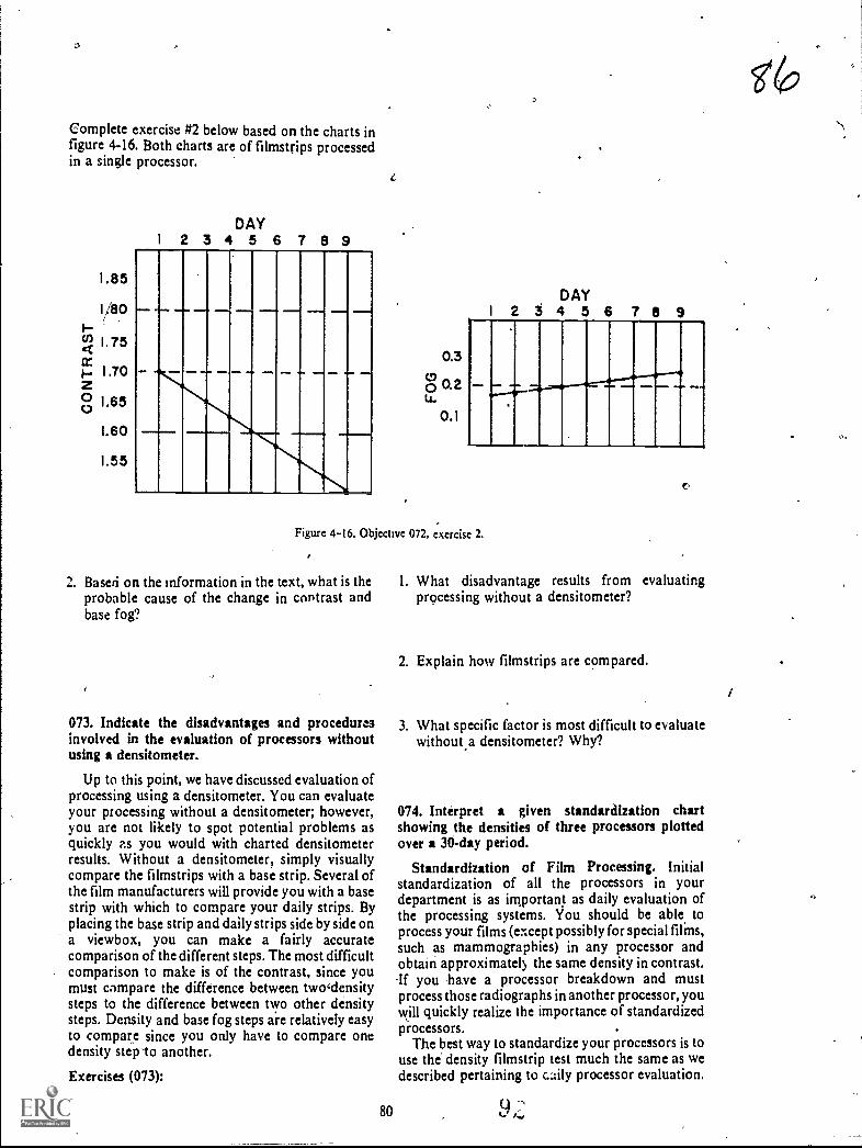
Complete exercise #2 below based on the charts infigure 4-16. Both charts are of filmstrips processedin a single processor.
1.85
1/80
W 1 75
L60
1.55
DAY2 3 4 5 6 7 8 9
1
0.3
o 0.2u.
0.1
DAY2 5 4 5 6 T 6 9
Figure 4-16. Objective 072, exercise 2.
2. Based on the information in the text, what is theprobable cause of the change in contrast andbase fog?
073. Indicate the disadvantages and proceduresinvolved in the evaluation of processors withoutusing a densitometer.
Up to this point, we have discussed evaluation ofprocessing using a densitometer. You can evaluateyour processing without a densitometer; however,you are not likely to spot potential problems asquickly as you would with charted densitometerresults. Without a densitometer, simply visuallycompare the filmstrips with a base strip. Several ofthe film manufacturers will provide you with a basestrip with which to compare your daily strips. Byplacing the base strip and daily strips side by side ona viewbox, you can make a fairly accuratecomparison of the different steps. The most difficultcomparison to make is of the contrast, since youmust compare the difference between twodensitysteps to the difference between two other densitysteps. Density and base fog steps are relatively easyto compare since you only have to compare onedensity step -to another.
Exercises (073):
80
(7?
1. What disadvantage results from evaluatingprocessing without a densitometer?
2. Explain how filmstrips are compared.
3. What specific factor is most difficult to evaluatewithout,a densitometer? Why?
074. Interpret a given standardization chartshowing the densities of three processors plottedover a 30-day period.
Standardization of Film Processing. Initialstandardization of all the processors in yourdepartment is as important as daily evaluation ofthe processing systems. You should be able, toprocess your films (except possibly for special films,such as mammographies) in any processor andobtain approximately the same density in contrast.-If you have a processor breakdown and mustprocess those radiographs in another processor, youwill quickly realize the importance of standardizedprocessors.
The best way to standardize your processors is touse the' density filmstrip test much the same as wedescribed pertaining to cily processor evaluation.

0.7
DAY
2 3 4 5 6 7 8 9 10 11 12
11111111111111111111111i ON,
...M.Sfirli.lullIMIIIIII....11111/
19 20 21 22 23 24 25 26 27 28 29 30
,
11111111111111M1111111111111111111111111111Peraff11111111111111MIN
Figuie 4-17. 30-day processor standardization chart.
Use the strifis and plot the data on charts fora'pproximately 1 month before making anydecisions about differences between processors.
To standardize processor density, measure adensity step which falls between densities 0.9 and 1.2as explained before. Plot the results on a chart for 30days. The average density for the time period shouldvary no more than 0.2 of the density step, aspreviously explained. For example, if the densitystep used is-.1.0, the plotted density line shouldremain between densities of 0.8 and 1.2. In
addition, the average densities of differentprocessors should be within a dens itx of 0.2 of eacho her. Figure 4-17 shows a sample 30-day chart mnthr rocessors. Processor B is good. Processors Aand B are separated,by a density of about 0,5, whichis too much variation. A and B are also above andbelow the 0.2 tolerance respectively; consequently,both ui these processors should be aligned so thattheir density is closer to that of processor A and adensity of 1.0.
When, ,you have variations between yourprocesso&,such as seen in figure 4-17, there areseveral things you should check. The first possiblecause of the variations is that the processor is not
81
f.:74
being operated according to the manufacturer'srecommendations. Underdevelopment can be
caused by such factors as low replenishment ritesand low developer temperature. Such factors ashigh developer temperature and replenishmentrates are common causes of overdevelopment.Another possible cause of overdevelopme.ut, withresulting increascd density, is high developerimmersion time. !mmersion time can increase in anautomatic processor if the transport gears, rollers;
or motor are not operating smoothly. Find out fromthe manufacturer's brochure what the immersiontinie should be for your processor. Check the actualimmersion time, using a timing device, and notewhen the leading edge of a film enters and exits the
developer solution.
If after checking all the possible causes ofprocessor Variation indicated in the manufacturer'sbrochure, you can find'no reason for the variation,increase the developer time slightly to increase thedensity or decrease the time to decrease the density.Do not make major changet in the developing timewithout first consulting a processor and chemistrymanufactuter's representative for advice.

Exercises (074):
Figure 4-18 is an example of a processorstandardization chart, showing the 30-day densitiesof three processors (A, B, and C). A density step of
1.3
1.2
I.1
1.0
W 0.9
0.8
1.0 was measured. Based upon the informationpresented in the text, complete the followingexercises:
DAY
1 2 3 4 5 6 7 8 9. 10 II 12
mumNM IIa r--
_11-----11-INK.
Eir----
ir-"Rsaaa 11
19 20 21 22 23 24 25 26 27 29 29 30
1111111111111111111111
1111111MINE111111
illiamo
Figure 4-18. Objective 074, exercises 1 through 5.
1. Which processor is likely to produce the lightest 4. Which processor(s) should be checked for
radiogra phs? possible problem(s)?
2. Which processor(s), if any, shows excessivevariation from the measured density step?
3. Are the densities of any two processors separated 5. When troubleshooting the processor(s) youby triore than the maximum allowable amount? indicated in exercise #4 above, What are threeIf so, which ones? possible causes of the problem(s)?
82

Control of Film Quality
IN PREVIOUS chapters . of this volume wediscussed .ome of the factors that affect the qualityof a radiograph. We discussed such things as thegeometrical factors, beam restrictors, grids, andfilm processing. Now it is time to turn our attentionto the exposure factors. Basically, we will bediscussing two factorsmAs and kVp. Althoughwe will review some material that you are familiarwith, we will concentrate on problems you will faceas a quality control technician. We begin thischapter with a close look at density and contrast.Next we discuss the mathematical concepts ofexposure and finally exposure systems.
5-1. Density
We have already discussed several factors thatcontrol film density, such as intensifying screens,FFD, and film processing. As a general rule,however, these factors, oncc established, remainconstant. We make most of the changes in filmdensity by altering the kVp or mAs simply because itis more convenient to change them than to changethe other factors. Keep in mind that this discussionon film density pertains to correcting the initialexposure of a radiograph. In other words, we willdeal with things you need to know as a qualitycontrol technician.
075. Given a list of statements pertaining to therecognition of radiographs with correct density,indicate which are true and which are false. If youindicate "hate," explain your answer.
Acceptable Radiographk Density. Before youcan determine whether a radiograph has too little ortoo much density, obviously you must first be ableto recognize the correct density on the radiograph.How do you do this? One way would be to measurethe average density on each radiograph with adensitometer. Since an average density of 1.5 isabout right for most radiographs, you could easilydetermine if it is correct by using a densitometer. Ofcourse, we know this is not practical, so we must,look for another way.
Density of specific structures. Unfortunately,there is no quick and easy way to learn what acorrectly exposed radiograph looks like because
83
CHAPTER S
there are no clear-cut guidelines. Experience isperhaps the best teacher of all. One impoitant factoris for you to know and recognize the specificstructures that should be deFhonstrated on theradiograph. It is obvious that/you cannot evaluatethe density of a structure if you cannot first locate it.Let's take an example. An AP radiograph of thelumbar spine and an AP abdomen are taken todemonstrate different structures. Since the spineradiograph is taken to demonstrate the lumbarvertebrae, the density of those vertebrae would beimportant. But other structures are more importanton the abdominal radiograph, such as the renal andpsoas shadows, bowel pattern, etc. What all Of thismeans is that evaluation of radiographic densitybegins with recognition of the structurerinfolved.
Radiologists and density. Another importantfactor (perhaps we should say "an importantperson") that must be considered when evaluatingfilm density is your radiologist. Some radiologistslike radiographs with more density than do others.In fact, the same radiologist may want differentradiographic densities from one examination toanother. For example, he may want his skullradiographs a little darker than normal, or his chestradiographs a little lighter than normal. Westrongly advise you to sit with yoUrradiologisras heinterprets radiographs to learn what he likes anddislikes in terms of &tufty.
Exercises (075):
Indicate whether the following statements are trueor false. If you indicate"false," explain your answer.
T F I. The average density on most radiographsshould be about 1.5.
T F 2. Experience is not advantageous inrecognizing correct radiographic density.
T F 3. Knowing and recognizing specificstructures can help you to recognize correctradiographic density.
T F 4. Two identical projections of the same bodypart may require different densities.
T 5, Density requirements vary fromradiologist to radiologist.

076., State significant features of the procedures for6 changing the density on a radiograph.
How To .Change the Density on a Radiograph.We base our discusion of changing film density owthe assumption that minimum amounts of mAs andkVp are. inecessary to produce a diagnosticradiograph.of a particuiar part. In other words, iftoo little mAs is used for a skull radiograph, noincrease in k Vp can compensate. If too little kVp isused, no incease in mAs can compensate.
Let's assume that you have a radiograph withincorrect image density. How do you change thedensity? As previously mentioned, the most logicalfactors to change are the kVp and mAs. As a generalrule, for most density corrections you shouldchange only one of the factors when possible. Thiswill reduce the posssibility of error, and you willlearn through experience how the factors separatelyaffect the radiograph.
Most improperly exposed radiographs in adepartment that has good technique charts havesufficient kVp or mAs to be diagnosdc. In casessuch as this, you can either change the kVp or mAs.to correct the density. One thing you should alWayskeep in mind is that the way radiographic contrast isaffected depends upon what you change. We willdiscuss'contrast later in this chapter.
When evaluating a radiograph to determine howto correct the density, it is a good idea to alsoconsider the kVp and mAs used. By doing this, youare more likely to make the right decision. Let's lookat an example. Suppose a radiograph of the skullshows good background density. Good backgrounddensity can be an indication of sufficient mAs.Further suppose there is not sufficient imagedensity, which means that the structures are toolight for clear demonstration. This could be anindication of insufficient kVp. If, after evaluatingthe exposure factors used, you find the kVp usedwas below normal, you can almost be certain thatmore kVp is required. Suppose that in another skullradiograph the structures are demonstrated but arenot dark enough, and the background density isinsufficient. If a review of the exposure factorsshows low mAs, the mAs probably should beincreased.
If a radiograph is overexposed, it is usually moredifficult to determine the cause. A carefulevaluation of the exposure used is often the bestcourse of action. As you no doubt have assumedby now, there are few clear-cut rules to follow withregard to changing the kVp or mAs or both whenaltering film density. In addition to the informationalready presented here, the best advice we can giveyou is to take advantage of every opportunity toleal a how kVp and mAs affect a radiograph. If youmake a change to improve a radiograph, checktheresults. This will help you considerably. Ybu mayeven want to keep a log of some of the cases so thatyou can review them collectively. .
84
Exercises (076):
Answer the following questions or fill in the blankspaces as appropriate.
1. To produce a radiograph you must tisea amount of mAs and kVp.
2. To change the density or a particular radiographyou normally should change either or
but not3. Why should you change only one factor to
change density?
4. Do good technique charts provide moreflexibifity in changing density? Explain.
5. Name three factors you should consider whendeciding whether to change density with mAs orkVp.
6. Background density can be an indication ofsufficient or too little
7. It is easier to determine the cause of anradiograph than the cause of one which is
8. A good way to learn how the changes you maketo a technique affect radiographic density is to
the of your work.
077. State the basic relationship between mM,kVp, and radiographic density.
mAs-density, felationship. Y ou have no doubtheard many times that you should double the mAsto double the radiographic density and halve themAs to halve the density. Let's see if this is true.Figure 5-1 shows the characteristic curves of twodifferent X-ray films. Notice in curve A that achange from 1.0 to 2.0 in the density requires achange of from 10 to 18 mAs. In curve B, an increasein mAs from 15 to 48 is required to increase thedensity from 1.0 to 2.0. As you can see from thesetwo characteristic curves, the rule previouslymentioned is not completely accurate. The best wayfor you to determine what change in mAs willdouble or halve the density is to refer to thecharacteristic curNe of your particular brand of film.For most X-ray films, the mAs-density relationshipis near enough to the previously mentioned rule touse it. Such is the case with curve A in figure 5-1. Asa rule, in this CDC we will base the discussions oftechnique compensations on such films.
It should also be noted that around the shoulderand toe of the characteristic curve the changes in
f9 I )
o

3.5
3.0
2.5
2.0
1.5
1.0
'0.5
C.
..
7---
A
,
8 16 32 64 128 2564IIIIIII0.3 0.6 0.9 1.2 1.5 1.8 2.1 2.4
LOG RELATIVE EXPOSURE
Figure 5-1. Characteristic curves of two different brands of X-ray films.
relative exposure are considerably different fromthe changes along the slope of the curve. Notice incurve A, figure 5-1, that when a film is very dark,with an average density, for example, of 3.4 halvingthe mAs (from 128 to 64) reduces the density only byapproximately 0.1.
k Vp-density relationship. As you know, thecharacteristic curve of an X-ray film shows therelationship between the mAs and density.Unfortunately it does not reveal the relationshipbetween kVp and density. Therefore, we are leftwith a rule-of-thumb to follow when we alter thekVp to correct the density on a radiograph. The ruleis actually based on the relationship between kVpand mAs. Since we know from our characteristic
85
curve the relationship between mAs and density, wccan predict the relationship between kVp anddensity.
The rule is to add 15 percent of the kVp to doublethe density and subtract 15 percent of the kVp tohalve the density. Subtraction of 15 percent of thekVp represents a decrease of 50 percent in the mM,and addition of 15 percent of the kVp is the same asdoubling the mM. This rule-of-thumb is based onthe assumption that the characteristic curve of yourX-ray film is similar to curve A in figure 5-1thatis, doubling or halving the mAs approximatelydoubles or halves the density.
Exercises (079):

1. How can you determine the exact rnAs changerequired to make a specific change in the filmdensity?
2. If the average density on a radiograph is very low(around 0.3), what relative mAs change,compared to a density of 1.5, is required tosignificantly increase the density?
4*
3. For most X-ray films, how should you alter themAs to double and halve the average density on aradiograph?
4. For most X-ray films, how should you alter thekVp to double and halve the average density on aradiograph?
5-2. Contrast
Our discussion of contrast includes a definition ofcontrast, a description of the types of contrast, thefactors affecting it, and finally how it is controlled.-
078. Define contrast, and given descriptions ofthree radiographs, compare their contrastproperties.
Definition and Types of Contrast. Contrast isdefined as "the visible difference in density betweenthe areas or structures on a radiograph." A goodexample of the absence of contrast is a film that hasbeen exposed to room light and processed. Only onedensity is present; consequently, there is nocontrast. Contrast is classified as either "short-scale" or "long-scale."
Short-scale contrast. If the number of usefuldensities on a radiograph is small, and the changefrom one density to another is abrupt, theradiograph is said to have short-scale contrast. Thistype of contrast is also referred to as high contrast.See figure 5-2.
Long-scale contrast. If the number of usefuldensities on a radiograph is large and there is littlechange from one density to another, the radiographis said to have long-scale contrast. This type ofcontrast is also referred to as low contrast. Seefigure 5-3.
Relative properties of contrast. You shouldrealize by now that there is no definite lineseparating the two types of contrast. Contrast is arelative measure of the difference between densitieson a radiograph. A particular radiograph mayexhibit short-scale contrast when compared to
86
Figure 5-2. Short scale or high contrast.
another, but its scale of contrast may be long whencompared to a third radiograph.
Exercises (078):
1. Define radiographic contrast.
Suppose there are three radiographs of the samepart with different scales of contrast. Elevendifferent densities can be seen on radiograph A withlittle change from one density to the next. Only fivedifferent densities can be visualized on radiograph Bwith considerable change from one density to thenext. Radiograph C shows eight different densitieswith proportional changes between densities. Basedon the information presented in the text, answerexercises 2 through 6 below.2. Which of the three radiographs has the lowest
contrast?
3. Which of the radiographs has the highestcontrast?
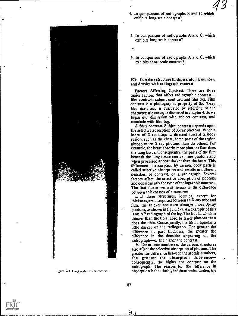
Figure 5-3. Long scak or low contrast.
87
434. In comparison, of radiographs B and C, which
exhibits long-scale contrast?
5. In comparison of radiographs A and C, whichexhibits long-scale contrast?
6. In comparison of radiographs A and C, whichexhibits short-scale contrast?
079. Correlate structure thickness, atomic number,and density with radiograph contrast.
Factors Affecting Confrut. There are threemajor factors that affect radiographic contrastfilm contrast, subject contrast, and film fog. Filmcontrast is a photographic property of the X-rayfilm itself and is evaluated by referring to thecharacteristic curve, as discussed in chapter 4. So webegin our discustion with subject contrast, andconclude with film fog.
Subject contrast. Subject contrast depends uponthe selective absorption of X-ray photons. When abeam of X-radiatiou is directed toward a. bodyregion, such as the chest, some parts of the regionabsorb more X-ray photons than do others. Forexample, the heart absorbs more photons than doesthe lung tissue. Consequently, the parts of the filmbeneath the lung tissue receive more photons andwben processed appear darker than the heart. Thisdifference in absorption by various body parts iscalled selective absorption and results in differentdensities, or contrast, on a radiograph. Severalfactors affect the selective absorption of photonsand consequently the type of radiogaphic contrast.The first factor we will discuss is the differencebetween thicknesses of structures:
a. If three structures, identical except forthickness, are interposed between an X-ray tube andfilm, the thicker structure absotbs more X-rayphotons, as shown in figure 5-4. An example of thisis an AP radiograph of the leg. The fibula, which isthinner than the tibia, absorbs fewer photons thandoes the tibia. Consequently, the fibula appears alittle darker on the radiograph. The greater thedifference in part thickness, the geater thedifference in the densities appearing on theradiographor the higher the contrast.
b. The atomic numbers of the various structuresalso affect the selective abwrption of photons. Thegreater the difference between the atomic numbers,the greater the absorption differenceconsequently, the higher the contrast on theradiograph. The reasoU\ for the difference inabsorption is that the higherkhe atomic number, the

PHOTONS PHOTONSIN OUT
rt1Vvril.,
PHOTONS PHOTONSIN OUT
-.".4W011.4NX`
M./11N,%NW
Figure 5-4. Comparison of the difference between absorption of photons by structures with differentthicknesses.
greater is the absorption because of thephotoelectric effect. The atomic numbers for bone,muscle, and fat are approximately 12 7.5, and 6respectively. You can see why there is relatively highcontrast between bone and muscle or between boneand fat, while there is relatively low contrastbetween muscle and fatty tissue.
c. The difference between the densities ofstructures is another factor that affects the selectiveabsorption of photons. By "density" we mean thenumber of atoms per unit area. The greater thedifference between the densities, the greater thedifference in absorptionconsequently, the higherthe radiographic contrast.
Exercises (079):
1. Generally speaking, how do these three factors=structure thickness, atomic number, anddensityaffect the contrast on a radiograph? e
2. Suppose you take two AP radiographs of the leg(tibia and fibula)one of the proximal leg andone of the distal leg. With all other factorsremaining the same, on which radiograph wouldthere be less contrast between the tibia andfibula? Why?
3. If you take a radiograph of a part containingmuscle, fat, and bone, which of the threestructures absorbs the most photons? The least?Why?
Three radiographs are made. Radiograph A showsbone and muscle, radiogaph B shows bone andfatty tissue, and radiograph C shows muscle andfatty tissue. All other factors, kVp, and thickness ofstructures are equal. Based on the information inthe text, answer exercises 4, 5, and 6 below.4. Which radiograph exhibits the highest contrast?5. Which radiograph exhibits the lowest contract?
88
6. The less the difference between structure density,the the contrast on the radiograph.
080. Given descriptions of three raw.lographs,determine the relative kVp used for each sad selectthe one exhibiting the highest contrast.
The most important factor to youmootimportant because you have direct controlthataffects the selective absorptions of photons is tlwpenetrative ability of the primary beam. Whetherwe say "penetrative ability" or "wavekngth" or"energy," it all boils down to the kVp selected on thecontrol panel.
Let's see how kVp affects the selective absorptionand contrast on a radiograph. Figure 5-5 shows twoequal parts, exposed to two differem bairns ofX:radiation. As shown, 10 photons approach eachstep. Suppose that at 40 kVp 2 photons reaCh thefilm beneath step #1, and 5 photo s. reach the filmbeneath step #2. This would Blow that step #1transmits 40 percent fewer photons than dole step#2. If the kVp is increased to 80, more photonspenetrate both steps as shows, but there is a greaterincrease in the transmission through step #2 than instep #1. We show four photons reaching the filmAhrough step #1 and nine photons through step #2.In this case, step #1 transmits 44 percent fewerphotons than does step #2. This polygamy changein the selectiit absorption of photons results in aproportionate change in the contrast on aradiograph.
The specific type of contrast that high or low kVpproduces should also be obvious to you by now.Refer apin to figure 5-5. W we consider the densityof each step on the film to be a result of the numberof photons transmitted through the step, therewould be a greater difference between the densitiesof the steps at 40 kVp than at 80 kVp. This greaterdifference, of course, means higher contrut.
Exercises (080):
Three radiographs are made of a chest, using 50, 80,and 100 kVp. The mAs is vuied to compensate forthe kVp difference, and all other factors remain thesame. The densities of the ribs and the lung timeare as foNows:
1 u

Radiograph A - rib density 1.0 -lung density 2.7Radiograph B - rib density 1.2 -lung density 2.3Radiograph C - rib density 1.5 -lung-density 1.8
Based on the information presented in the text andthe above data, complete the following exercises.
1. With which radiograph was the 100 kVp used?2. With which radiograph was 80 kVp used?3. With which radiograph was 50 kVp used?4. Which radiograph exhibits the highest contrast
between the ribs and lungs?
081. Define "film fog," and indicate the eifect offilm fog on radiographic contrast.
Fog. Film fogwhether caused by scatterradiation, by improper processing, or by exposureof the film to either light or to radiation leaks--;reduces contrast on a radiograph. Since we havepreviously discussed ways to reduce film fog _in.other chapters of this VOlume, our aiscussion here islimited to an explanation of what fog is and of howit affects contrast and demonstration of certainstructures.
"Film fog" is a density on a radiograph that is notcaused by deliberate film exposure. Ideally, imagedensity and the variations in image density(contrast) are caused by selective absorption of
0X-ray photons. Fog density, on the other hand, isnot selective in nature. It usually appears evenlydistributed over thc entire film.
Because of its even distribution, the fog on aradiograph completely obscures some structuresand makes others difficult to see. To illustrate howfog affects a radiograph, figure 5-6 shows threedrawings, representing radiographs of a step wedge.Drawing A shows no appreciable fog. Drawing Brepresents the addition of a layer of density.Drawing C shows yet another layer of density. If
40 kVp
10
10
2 5
80 kVp
10
10
4 9
Figure 5-5. Illustration showing how kVp affects the seleetweabsorption of Xray photons.
89
1
2
3
4
5
A
Figure 5-6. The effect of fog upon contrast and visualizationof structures.
you compare the three drawings, you can see howthe contrast has been lowered. Notice also that somesteps that were easily distinguished in drawing Abegin to "disappear" as fog is added. A goodexample is the loss of contrast between steps 4 and 5in drawing C. You can no longer see any contrastbetween the two. The reason the structuresdisappear is that oncc a certain density is reached,our eyes can no longer pick up differences betweendensities.
Exercises (081):
1. What is film fog?
4,:
2. Specifically, how does the addition of fog affectthe contrast on a radiograph?
3. How can the addition of fog to a radiographcause some structures to disappear?
082. Given the kVp and mAs values used on aradiograph, change the factors to both raise andlower the contrast of the radiograph.
How to Change Contrast on a Radiograph. Thereare times when your radiologist wants a "properlyexposed" radiograph repeated with more, or withless, contrast. By "properly exposed," we mean the

radiograph has the correct average density. Youshould realize by now that to change the contrast,you should change the kVpincrease the kVp tolower the contrast and lower the kVp to increase the
contrast. In addition, you must make acompensatory change in the mAs to maintain thecorrect density.
You may have heard in the past that you canincrease the kVp by 10, halve the mAs, and end upwith two radiographs equal in Overall density. This"rule" is based on the assumption that densitychanges on a linear scale if changes are made in thekVp. This assumption is inaccurate. Changes indensity resulting from changes in kVp arenonlinear. Therefore, to make a specific change infilm density by changing the kVp, you must use apercentage of the kVp.
A good rule of thumb to follow is to increase thekVp by 15 percent and halve the mAs or lower thekVp by 15 percent and double the mAs. For mostbrands of radiographic film, these changes willmaintain the same approximate density on aradiograph while changing the contrast.
Exercises (082):
A radiograph is made using 80 kVp and 40 mAs.Use this data and the information presented in thetext to complete the following exercises.
I. What would be the new mAs and kVp if thecontrast needs to be lowered?
2. What would be the new mAs and kVp if thecontrast needs to be raised?
5-3. Mathematical Concepts of RadiographicExposure
It would be convenient if we could use the sameexposure factors for each examination. Forexample, if all skull radiographs were performed onpatients who could cooperate and maintain thepositions with ease, we would have few problems.But we know that it doesn't happen that way. Weoften radiograph skulls on patients who areseriously injured, or on patients intoxicated to thepoint where they cannot cooperate, or even on smallchildren. For some of these patients we must changefrom our routine exposure factors to prevent partmotion. Although this section is short, theinformation should enable you to makecompensations to your exposure (mA, mAs; sec, orFFD) by calculation, rather than by guesswork.
083. Apply the mA-sec formula to two sets ofexposure factors and calculate the new mA if the
exposure time is changed and calculate the newexposure time if the mA is changed.
mA and Exposure Time. As you know, mA andexposure time directly influence radiographicdensity. The time of exposure, however, hasadditional significance when patient motion, eithervoluntary or involuntary, must be controlled toobtain optimum detail. Motion is one of the greatestdeterrents to good radiographic detail. Whether themotion is voluntary, as in pediatric cases,controlled, as in respiration,or involuntary, as inperistalsis of the organs (ureters- or bowel), beatingof the heart, or muscle spasmsyou must considermotion when you select the exposure factors to beused. The correct combination of sec and mA is oneof your most effective means of controllingundesirable motion and thus enhancing imagedetail.
Expressed mathematically, the mA-secrelationship is mAi :mA2 : :sec2 :seci. To maintaina given film density, the mA required is inverselyproportional to the time of exposure, when all otherfactors are kept constant. .
Now let's apply this to a working situation.Suppose your standard technique for a lateral skullis 100 mA at 1/ 10 sec. Further, suppose there is achange from the normal working situation; forexample, that as a result of trauma received in anautomobile accident, the patient is semiconsciousand unable to cooperate fully. Motion due torespiration and possibly to muscle spasm hasbecome a factor to consider. In an effort to reducethis motion, you can reduce the normal exposuretime. Let's say you want to reduce the exposure timeto 1/ 20 sec. By applying the mathematical formulafor mA and sec, you are able to derive the new mArequired. Consider the following;
mAI :m42: :sec: .seci
100:x:: 1120: 1/10
1/20 x= 10
x = 200
Consequently, your new mA is 200.You can also find your new exposure time if, for
example, you want to change the mA station. Usethe same formula stated above.
Exercises (083):
-.1
I. Suppose your technique chart calls for 50 mAand 1/10 sec for a particular radiograph.Yourpatient is uncooperative and you wish to use1/30 sec. What is your new mA?
90
q6

Caa2. Suppose your" technique chart calls for 600 mA
and 1;40 sec and you wish to use the small focalspot that has a 150 mA output. What is your newexposure time?
084. Applying the appropriate formula to five setsof exposure factors, determine the new mAs, mA,exposure time, or FFD.
FFD and Density. As we have disiussed before,X-rays diverge from, the focal spot, traveling instraight lines. Thus, the X-ray beam covers anincreasingly larger area as the FFD increases andvice versa. This change in field size, however, resultsin a change in the number of photons per unit area,providing all other factors remain constant. WhenFFD increases, radiographic density decreases; andas the FFD decreases, film density increases. Inorder to maintain the desired density, then, thequantity of radiation producedcan be manipulatedto compensate for changes in FFD. Since mAscontrols the total quantity of X-rays produced,appropriate changes in this factor can be made tomaintain film density and compensate for changesin FFD.
This proportional relationship betweedmAs andFFD can be best expressed in a mathematicalformula, which is referred to as the m As-distanceformula. A verbal reading of the formula would be: (The original mAs (mAsi) to the new mAs (mAs2) asthe original FFD sq2uared (FFD12) is to the newFFD squared (FFD2 ). You can determine any oneof the four factors by using this formula.
A practical application of this formula is asfollows: Suppose the technique chart normallyspecifies a technique of 10 mAs using a 72-inchFFD; however, because of equipment limitationsand the patient's condition, you are unable to obtainthe recommended FFD, but instead must use a 36-inch FFD. What new mAs factor will be required tomaintain the original film density? Let's substitutethe known technique values into the formula:
mAsi . :FF1,12 :FFD22
10 x: 722 . 362
10 r:. 5184 : 1296
5184 x = 12960
x = 2.5
Therefore, your new mAs would be 2.5.Since mAs is the product of mA times exposure
time, this same formula represents the mA-distance'or time-distance relationships. All you have to do isto substitute mA or seconds for the mAs andproceed as usual with the formula. Although youwill hare to use the mAs-distance formula to
91
97determine certain technique changes, you :an makea few changes without using the formula. Just keepin mind that twice the distanc requires four timesthe exposure, and that hal the distance requiresone-fourth the exposure.
Exercises (084):
I. What will your new mAs be if your original mAswas 12.5 at a 40-inch FFD and yoU wish tochange the FFD to 48 inches?
2. If your technique chart calls for 10 mAs at a 40-inch FFD and you wish to reduce the mAs to 2.0,what is your new FFD?
3. Suppose your technique chart calls for I/ 60 secat a 36-inch FFD and you wish to change your.time to 1/40 sec. What is your new FFD?
4. What will your new mA be at a 36-inch HD ifyour old mA was 100 at a 72-inch FFD?
5. What is your exposure time at a 36-inch FFD ifat 72 inches it is 1/5 sec?
5-4. The Standardization of ExposureTechniques
In order to insure consistent film quality and toprovide accur4e guides for the selection of allexposure techniques, each radiology section shouldhave a standard system of exposure factors. Theestablishment of such a system is one of the greatestchallenges confronting technicians, although it is aproblem that could be solved easily if a universallycorrect exposure technique fon each part could beprescribed. But, unfortunately, a universaltechnique is not possible because of severalvariables, includingzthe output and the capacity ofX-ray machines, the types of exposure devices, thespeeds of films and screens, and the preferences ofradiologists. Because of these variables, you must beable to prepare and correct your own standardsystem of exposure factors. This section is intendedto help you do so.
085. Name four requirements of an exposuresystem and explain how each is met.
Requirements of a Standard Exposure System. Astandard system of exposure techniques must meet
these four basic requirements:- (I) it must produceconsistent results; (2) it must provide adequateexposure of the film; ,(3) it must possess a certaindegree of flexibility; and (4) it must provide for thedesired range of contrast.
Consistent results. One requirement of anexposure system is that it must produce consistentresults. By consistent results we mean, for example,that two chest radiographs taken of the same patient2 months apart will appear the samethe samecontrast and density. This is very important in caseswhere followup radiographs are performed to checkprogression or regression of pathologicalconditions.
To produce consistent radiographs from one dayto the next, you must have technique charts unlessyou are the only technician in your department andhave a "pushbutton" memory. In addition, alltechnicians in the department must use the charts.The purpose oftechnique charts Es' defeated if sometechnicians are allowed to use their "own"techniques.
Sufficient exposure of film. In order to producesatisfactory density, a technique must provide foradequate exposure of the film. This requires properselections 'Of both mAs and kVp. First, there mustbe enough radiation in the primary beam to crelitesilver deposits on the film. Therefore, a minimummAs value ,. must be established for each part.Secondly, if the primary radiation is to reach thefilm, the part must be adequately penetrated. Eventhough the quantity of the beam is sufficient, theimage cannot be projected on the film if the partabsorbs too much or all of the primary beam. Itfollows that a minimum kVp value must also beestablished for each part.
Flexibility. Because exposure techniques must befrequently changed to compensate for theconditions of patients, for differences in accessorydevices, and for other factors, a system of exposuretechniques shOuld be reasonably flexible. Forexample, a basic technique selected at the highestkVp on your control panel would not permit anincrease; and on the other hand, a techniqueselected at the minimum kVp would not permit areduction. This means that the mAs and the kVpmust be kept within a range from which either maybe increased or decreased.
Desired contrast range. Any system of techniquesmust be able to produce the preferred range ofcontrast within the capabilities and limitations ofthe machines and other equipment. Of course, thekVp range is the basic determining factor here.
Exercises (085):
In exemises I through 4 below, name fourrequirements of an exposure system and tell howyou can help insure that each requirement is met.
92
0
2.
3.
4.
086. Cite specific facts about variable kVptechniques.
Types of Exposure Systems. In modernradiography three basic types of exposure systemsare in general use: variable kVp techniques, fixedkVp techniques, and high kVp techniques, whichcan be classified as variable or fixed kVp.
Variable kVp techniques. Under the variable kVptechniques system, the mAs remains constant foreach part, and .the kVp is varied according to,partthickness in centimeters. For this reason, it issometimes referred to as a tissue-thicknesstechnique. Onc disadvantage of this exposuresystem is that the contrast varies slightly because thekVp changes from one examination to another.However, it is a popular system and relatively easyto apply.
Let's see how to build a variable k /p techniquechart. Suppose you decide that for an ayerage-sizedadult 20 mAs is sufficient to produce adequateexposure of the film and in combination with thenecessary kVp produces the desired scale ofcontrast. All you need do is to determine the kVp foreach centimeter thickness of the skull. For example,suppose you determine by trial and error that theexposure factors of 20 mAs and 80 kVp produce thedesired density and contrast for a PA skull thatmeasures 18 cm along the CR. Chart all theinformation on a working chart. From this startingpoint, you can perhaps establish thekVp/centimeter relationship for othermeasurements of the skull. You may have to add orsubtract 2 kVp for each centimeter change. If so,you would use 82 kVp for 19 cm, 78 kVp for 17cm, and so on. Keep in mind that the centimetermeasurement is through the path,of the CR for eachprojection of the skull.
The two kVp change for each centimeter of partthickness given in the example above may. .or maynot work for some body parts. Usually, kVpchanges of from one to four are made, dependingupon the part and the kVp rangethe greatestchange per centimeter is required when high kVp isused and for denser parts.

Once you determine the correct exposure factorsfor each part, construct a technique chart, post itnear the control panel, and insist that everyone Useit. Any type of chart can be constructed as long as,itprovides the necessary information. Figure 5-7shows how the example we discussed might look on 6.
a technique chart.You can also construct a plus factor technique
chart that permits you to determine the correct kVo 7.
without referring to the chart for everymeasurement. Let's take our example of the skullagain. Eighty kVp is used for 18 cm. Multiply the cmthickness by twowhich gives you 36. Subtract 36from 80 (your kVp at 18 cm). This gives you a plusfactor of 44 for all projections of the skull. Nowwhen you measure the CR for a projection of theskull, all you have to do is double the cm thickness,add the plus factor, and you have your kVp.Expressed as a formula, tIte plus factor-kVprelationship for this example looks like this:
5 How do you determine the starting technique fora given measurement of a part?
kVp = 2 X cm + 44
,= 2% 18 + 44
= 36 + 44
= 80
Keep in mind that the plus factor is determined froma good working exposure and may vary from part topart.
Exercises (086):
Complete the following exercises pertaining tovariable kVp techniques by filling in the blankspaces with one word or by answering the questions,as appropriate.
I. The same is used for each part.2. What determines the kVp for each radiograph?
3. What is a disadvantage of this type of exposuresystem?
4. Give one advantage of this exposure system.
Part Protection Grid Screens FF0 MAS
Skull Al I 1 2 1 HiSpeed 40" 20
When you vary the kVp for parts larger orsmaller than average, a kVp change fromto per centimeter is usually necessary.What is tlie advantage of using the plus factor todetermine kVp?
8. What is the kVp for a projection if the partmeasures 20 cm and the plus factor is 38?
9. What is the plus factor for an examination if 64kVp is used for 12 cm?
087. Given a list of statements pertaining to fixedkVp techniques, indicate which are true and whichare fellse. If you indicate "false," explain youranswer.
Fixed kiip techniques. An exposure system thatis rapidly becoming more popillar involves fixedkVp techniques. Under thissystem,the kVp remainsconstant for a particular part, while the mAs isvaried. The kVp is established on the basis of itssatisfactory penetration of that part. The mAs isselected to provide satisfactory density for eachpart, according to its Average thickness incentimeters. For parts smaller or larger than theaverage, the mAs is variedgenerally, it is raised orreduced in increments of 25 percent. Fixed kVptechniques, when properly corrected and workedout to the desired mAs refinements, have oneoutstanding advantage: they provide consistentcontrast for all examinations of a particular partbecause the kVp is constant. The one majordisadvantage is the amount of time and effort ittakes to prepare these techniques. In order toestablish the mAs selections, it is necessary to keepaccurate records of all radiographs; the record ofeach should indicate the exposure factors used, thepart thickness, and the results of the exposure. Only
in this way can techniques be corrected and
Figure 5-7. An example of technique chart format.
93
Remarks
MeasureCR

t.
finalized. Weeks, perhaps months, are required todo this.
Exercises (087):
Indicate whether the following statementspertaining to fixed kVp techniques are true or false.If you indicate "false," explain your answer.
T F I. kVp is constant for each part.T F 2. nTAs varies depending upon the size of the\
'part.T F 3. A change from 40 to 50 mAs fot a larger
part is appropriate.T F 4. Contrast is consistent for all body parts.T F 5. These techniques are tasy to prepare.
088. Explrin what is meant by high ,,kiptechniques, and list three advantages of their use.
High kVp techniques. High kVp techniques arebasically high kVp-low mAs exposures and can beapplied to either variable kVp or fixed kVpexposure systems. How high is high kVp? Actuallyit depends upon whom you ask. The bestexplanation of the matter is that high kVp is thehighest kVp you can use and still produce gooddiagnostic radiographs that satisfy your radiologist.It could be 80 kVp for one examination and 120 foranother.
High kVp is used in many radiology dcpartmentsfor the following reasons: (1) there is less absorptionof photons by the patient, (2) the target of the X-raytube is subjected to fewer heat units per exposure,and (3) there is greater exposure latitude.
Exercises (088):
I. What are high kVp techniques?
2. List th:ee advantages of high kVp techniques.
089. Given various specific situations when it isnecessary to make changes in the 'exposure to
compensate for factors such as use of a differentgrid, use of an extension cylinder, the presence of a,cast, or patient's ige, specify the change in exposurefactor to be made.
Compeniating Factors. No exposure syttem iscomplete without a list of compensation factors toapply when you must make changes4n the exposurebecause of a different grid, the presence ofa cast, theuse of an extension cylinder, 'or the patient's age.Table, 5-4 shows these compensation factors.
Exercises (089):
Complete the following exercises, stating thecompensatiori factor to be used in each specificsituation.I. If your kVp is 75 with a 8:1 grid and you wishlo. change to a 5:1 grid, wharis your new kVp?
94
2. If your kVp is 92 with a 5:1 grid and you wish tochange to a 12:1 grid, what is your new kVp?
3. If your kVp is 120 with a 16:1 grid and you wishto change to a 5:1 grid, what is your new kVp?
4 If a cast was applied to a patient'S leg 18 hoursago, how much mAs should you use on the leg ifthe mAs without the cast is 10?
5. By what percentage should you increase the mAswhen using an, extension cylinder?
6. What percentage of the adult mAs should youuse for the following patients?a. Birth to 1 year.b. Six to 9 years.c. Over 55 years.
/60.01
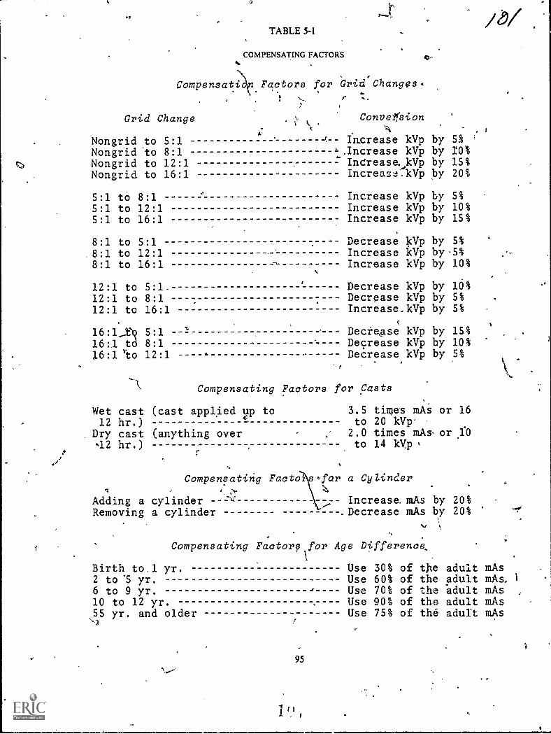
TABLE54
COMPENSATING FACTORS
Compensatin Factors for Grid Changes.
Grid Change
Nongrid to 5:1Nongrid 'to 8:1Nongrid to 12:1Nongrid to 16:1
'
ConveirsionA
Ingrease kVp by,Increase kVp byIntrease, kVp byIncreaskVp 12'Y
,
51 '
10%15%20%
5:1 tO 8:1 Increase kVp by 5%
5:1 to 12:1 Increase kVp by 10%5:1 to 16:1 Increase kVp by 15%
8:1 to 5:1 Decrease 15Vp by 5%
8:1 to 12:1 Increase kVp by .5%
8:1 to 16:1 Increase kVp by 10%
12:1 to 5:1. Decrease kVp by 16%12:1 to 8:1 Decrease kVp by 5%
12:1 to 16:1 Increase_kVp by 5%
16:1_Dq 5:1 DecteAse kVp by 15%
16:1 to 8:1 Decrease kVp by 10%
16:1 'eto 12:1 1. Decrease kVp by 5%
Compensating Factors for Casts
Wet cast (cast applied up to12 hr.)
Dry cast (anything over42 hr.)
3.5 times mAito 20 kVp'
2.0 times mAs.to 14 kVp
Compensating Facto s for a CyZinder
Increase mAs by 20%.Decrease mAs by 20%
Adding a cylinderRemoving a cylinder
or 16
or ,1:0
Compensating Factory for Age Difference,
weir'
Birth to.1 yr. Use 30% of t)le adult mAs2 to '5 yr. Use 60% of the adult mAs,
6 to 9 yr. Use 70% of the "adult mAs10 to 12 yr. Use 90% of the adult mAs55 yr. and older Use 75% of the adult mAs
95
11111111iMa
CHAPTER 6
Environmental Safety
AS AN X-RAY TECHNICIAN you operateelaborate electrical as well as radiation-producingequipment. This equipment, if not operatedproperly, can be extremely dangerous to you and toyour patients. In this chapter, we will define some ofthe specific problem areas associated with electricaland radiation hazards. We will also providesolutions where posiible to help you preventelectrical shock and overexposure to ionizingradiation to you and your patients.
this chapter consists of four sections'. The firstsection pertains to electrical hazards andprotection. In the second section we will discussradiation hazards and protection for the patient.After that, ways to protect you, the technician, willbe covered. Finally, we will discuss the USAFFilmBadge Program.
6-1. Electrical Anards and trOtactfon
As you know, radiology departments are full ofelectrical devicesfrom the viewing room to thedarkroom to the exposure room. Where electricaldevices are present, so is the possibility of anelectrical fire or electrical shock. You can helpreduce electrical hazards by using commonsenseand following recommended safety precautions.Let's begin our study of electrical hazards 'andprotection with a discussion of four factors affectingthe severity of an electrical shock.
090. Name and explain briefly four factorsaffecting the severity of electrical shock.
aFactors Affecting Severity of Electrical Shock.
Electrocution, as performed in prisons, uses about 9:amperes. Obviously, this amount is far more thanthe minimum needed to cause a lethal shock. Whatis the, minimum amount of current required toelectrocute a person? The amount variesconsiderably because there are at least fourimportant factors involved:
a. The person involved and his state of health.An elderly person or one in poor health is more apt,to expetience the effects of electrical current.
h. The part of the body involved. Vital organs, inparticular the heart or brain, are more susceptible toelectrical current tem are, for eiample, the legs andarms.
c. The time of exposure. The lerigth of time theperson is exposed is also an important
-c96
codsideration. Obviously, the longer the exposure,the greater the effect:
d. The,type of current. DC is more dangeroitsthan AC. As a general rule, we are concerned withAC in our radiology departments although DC ispresent ;.:1 some instances.
Exerches (090):
In exqcises I through 4 below, name and brieflydescribe r-iur factors affecting the amount ofcurrent Which can cause electrocution.
2.
3.
4.
091. Given a list of statements pertaining to the useof fuses, indicate which are true and which are false.If you indicate "false," explain your answer.
Fuses. As you know, a fuse is a protective device.What does it protect? Not you. Not your patient. Itprotects the circuit. It is simply a device that will"burn out" and stop the flow of current when themaximum rating of the fuse is exceeded. Because ofthis, we can also say a fuse protects the equipment orstructure from damage due to high current or fire..The size of a particular fuse is based uPon theamount of current in ampere3 that the circuit isdesigned to handle; for this reason, it should not hereplaced with a fuse of higher rating.
A typical experience. Let's look at a situation thatperhaps occurs all .too often. A 15-amperefuseblows in your home. You replace it -and it blowsagain. This time you replace it with one rated at 25amperes. Goodthe 25-ampere fuse doesn't blow,and all is well, at least for the time being.
11,)
70-1-

Figure 6-1. Pictorial drawing of an electrical circuit.
A few weeks later, it's a rainy weekend and a goodtime to get some work done at uund the hthise. Yourwife is ironing, one child is watching TV, another isusing the toaster, and you arc using the vacuumcleaner. Suddenly the house is on fire. You barelymanage to get everyone out of the burning houseAs you watch your home go up in flames, you ask."What happened?"
Let's investigate. Figure 6-1 is a picture of theelectrical circuit at the time the fire started. Figure 6-2 is a schematic of that circuit. Since we have aparallel circuit, the source voltage is applied acrosseach device. Therefore, we can use Ohm's law tocalculate the current through each leg and then addthe individual currents to get the total current:
It =
I3 =
I. =
E =
=
=
=
110
11
110
11
110
55
110
44
= 10 amperes
= 10 amperes
= 2 amperes
= 2.5 amperes
RI
ER:
ER3
ER.
II = 11 -1- h + h + h = 10 + 10 + 2 + 2.5= 24,5 ampere-.-
25 Ampere Fuse
Do you see what happened? The 15-ampeN fusethat was supposed to protect the circuit would haveburned out when the current exceeded 15 amperes.The 25-ampere fuse did not burn out whei% the safecurrent vaiue was exceeded. This caused the wiresinside the wail, which are designed to safely conductonly 15 amperes, to get red hot and set the house onfire.
Perhaps you think this example wasoverdramatized. Not at all. Fires caused by currentoverload happen every day, and all too frequentlythe cause is a "do-it-yourself' type of person whoknows just enough to get himself into trouble.
A similar situation can occur in your radiologydepartment. There are various fuses in yourelectrical equipment that can "blow" out. While it isa simple matter to replace a burned-out fuse withone of equal rating, that is not the proper course ofaction in all cases. Usually when a fuse blows, thereis a reason, and the reason should be determined.There may be a short in the wiring or other defectcausing the increased current in the circuit. Thecircuit should be checked to determine the cause ofthe blown fuse before the fuse is replaced.Therefore, we recommend that you have the fusereplaced by a medical equipment repairman so thathe can determine the cause and make the necessaryrepairs.
The personnel hazard. Now, let's find out why a4:n.se that is capable of protecting the wiring or theequipment cannot protect you. Figure 6-3 illustrates
Figure 6-2. Schematic of an electrical circuit.
97

15 Ampere Fuse
Figure 6-3. Representative parallel circuit.
a parallel circuit protected by a 15-ampere fuse. Thetotal current in this circuit is h+ 12+ h = 14.5amperes. As you can see, we are within the safe limitfor the circuit. Figure 6-4 demonstrates the identicalcircuit, but with your body forming an additionalparallel connection. The electrical resistance of yourbody, measured from hand to hand, varies from lessthan 5,000 to over 20,000 ohms. This resistancedepends upon whether your hands are dry or wet. Ifyou are sweaty, the resistance goes downconsiderably, because salt is a good conductor. Forexample, let's assume that your body has aresistance of 11,000 ohms, so .the circuit formedwould look like that in figure 6-5, with the resistanceof your body represented by R4. By adding I + /2+h+ 14, we find the total current to be 14.51 amperes.You can see that this is still within the safe limits ofthe fuse. Therefore, the fuse would not burn out, butthe 0.01 ampere ofcurrent thn ugh your body couldelectrocute you!
Exercises (091):
Ind.ate whether the follow ing statements are trueor false. If you indicate"false," explain your answer.
T F 1. A fuse is designed to stop the flow ofelectrical current if the fuse rating isexceeded.
T F 2. Fuses protect machine operators fromelectrical shock.
15 Ampere Fuse
T F 3.
T F 4.
T F 5.
T F 6.
Fire can result from incompatability of thefuse and circuit wiring.A fuse protects a patient from electricalshock.Replacing a fuse with one of a higher ratingis permitted as a temporary measure or aRoverloaded circuit.If a fuse burns out in your X-ray machine,you should replace it with one of equalrating and report the incident to yourmedical equipment repairman. You maycontinue to use the machine.
T F 7. Contact with an electrical circuit can beNal even if the circuit is properly fused.
092. State the purpose, value, and effect ofgrounding an electrical appliance in givensituations, and cite related safety practices.
Grounding. One of the most important, if not themost important, consideration concerningprotection for both you and your patient fromelectrical shock is proper grounding of thezquipment. How does grounding protect you andthe patient? Let's see.
A typical electrical appliance. Figure 6-6,A,shows the relationships between the power wires,ground wire, and the exposed housing of an
` electrical machine. Notice that the housing isisolated from the wiring. The obvious reason forthis is so that the machine operator will not be
IFigure 6 4 Rcpreccuminc paralkl circuit with human body added al gme &mem
98

, 15 Ampere Fuse
Figure 6-5, Representatice parallel circuit with ohmic value of human body computed,
shocked whcn he touches the housing. In figure 6-
6,B, we have shown an electrical conrectionbetween the hot wire and the housing. Thiconnection could be due to worn insulation of thehot wire or to various other reasons. Now there is a
possibility of current in the housing of ,themachinethe part that you come in contact with
when you operate the machine. However, chances
are you still would not be "shocked" when touchingthe machine because the current, which divides at
the "defect," is routed through the ground wire andto "earth" ground. The reason the current flows toearth is that the ground wire offers less resistancethan your bodythe current takes the path of least
resistance.So far we don't have much of a problem. Even
though there is a defect in the machine wiring, ourground is working properly, so the machine isrelatively safe. But, suppose the machine is notgrounded. Maybe there was no three-prong outletavailable, and the ground prong of the power cordwas removed so that the plug would fit into the two-
prong outlet. Now there is no ground wireno easypathway to route the current away from themachine housing and operator (see fig. 6-6,C).However, you still probably would not receive asignificant electrical shock because you still do notoffer an easy path for the current. Your body is most
likely at the same potential as the machine.The next variable we will add to this hypothetical
situation is for you, the operator, to come in contact
with another piece of electrical equipment whiletouching the housing of the initial machine (see fig.
6-6,D). Now the picture has changed considerably.You have connected your body to ground potential.A circuit is formed from the housing of the initialmachine, through your body, through the housingof the second machine, and out the ground wire.You definitely are going to receive an electricalshockthe severity of which depends upon thefactors previously discussed. Electrocution is, of
course, always possible if the conditions are right.
(NOTE: If the initial appliance had been properlygroundt.d, the current would actually "have a
99
io<
choice" of flowing through you to earth or throughits own ground wire to earth. The easiest pathwaywould still be through its own ground wire because
of your skin resistance.)From the above discussion it is obvious that
electrical equipment must be grounded, and itusually isat least at the time of purchase.However, power plugs become old and defective(loose or bent); power cords and other outside wiresbecome frayed or cracked. Some people use"cheater plugs" to adapt a three-prong plug to atwo-prong outlet; and some even cut the groundprong off the power plug.
Do not use electrical equipment if defects arepresent as we have described. In addition, do notalter power plugs, do not use"cheater adapters," ordo anything else that would interfere with thegrounding of your machine.
Make a habit of checking the powerplugs, power
cords, or any other outside wiring about yourequipment often. This is especially important ifappliances are often moved, thereby increasing thepossibility of damage. If you find any defects in apiece of equipment, do not use it. Call yourmedical
equipment repairman.
Exercises (092);
1. According to the text, what is one of the mostimportant safeguards to protect you and yourpatients from electrical shock?
2. What electrical relationship exists between the
circuitry and housing of an electrical appliance in
good ripair?'Why?"
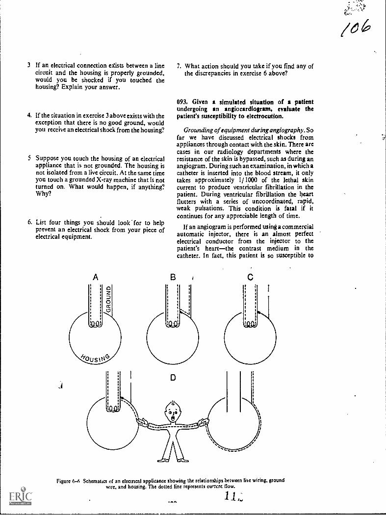
3 If an electrical connection eXists between a linecircuit and the housing is properly grounded,would you be shocked if you touched thehousing? Explain your answer.
4. If the situation in exercise 3 above exists with theexception that there is no good ground, wouldyou receive an electrical shock from the housing?
5 Suppose you touch the housing of an electricalappliance that is not grounded. The housing isnot isolated from a live circuit. At the same timeyou touch a grounded X-ray machine that is notturned on. What would happen, if anything?Why?
6. List four things you should look for to helpprevent an electrical shock from your piece ofelectrical equipment.
A
7. What action should you take if you find any ofthe discrepancies in exercise 6 above?
093. Given a simulated situation of a patientundergoing an angiocardiogram, evaluate thepatient's susceptibility to electrocution.
Grounding of equipment during angiogrophy.Sofar we have discussed electrical shocks fromappliances through contact with the skin. There arecases in our radiology departments where theresistance of the skin is bypassed, such as during anangiogram. During such an examination, in which acatheter is inserted into the blood stream, it onlytakes approximately 1/ 1000 of the lethal skincurrent to produce ventricular fibrillation in thepatient. During ventricular fibrillation the heartflutters with a series of uncoordinated, rapid,weak pulsations. This condition is fatal if itcontinues for any appreciable length of time.
If an angiogram is performed using a commercialautomatic injector, there is an almost perfectelectrical conductor from the injector to thepatient's heartthe contrast medium in thecatheter. In fact, this patient is so susceptible to
Figure 6-6 Schematics of an ekcmcal applicance showing the relationships between live wiring, groundwire, and housing. The dotted line represents cumm flow.
11ONA
/616'
71.
electrocutin that we do not even need a defect in thewiring to utroduce a fatal current into his bloodstream. He can even be dlectrocuted by leakagecurrent from an injector in good repair. Leakagecurrent is an undesirable flow of current through orover the surface of an insulating material.
Let's look at a simulated situation and see wherethe danger comes from. Assume that the electricalmachine we discussed in objective number 092 is anautomatic injector and we are performing anangiocardiogram. The patient is naturally lying onthe X-ray table and film changer, which aregrounded. Already he is a prime candidate for anelectrical shock because he is grounded. Let's alsoassume that the injector is grounded. By groundedwe mean, of course, that it is properly plugged into agrounded outlet and that there are no wiring defectsor other defects.
From our previous discussion in objective 092, itwould seem that the patient is still safe fromelectrical shockeven though he is grounded. Nowwe will create the problem. The X-ray machine andthe outlet supplying the injector are not grounded tothe same ground potential. Because they are notgrounded to a common ground, they may not be atthe same potential. The difference in potentialbetween the X-ray table or film changer and injectormay be only a few volts. If the leakage from theinjector to the contrast medium is, for example, 100
microamps, enough current can flow from theinjector through the contrast medium in thtcatheter to the patient's heart to be fatal because theX-ray table and injector are not at the samkpotential. One hundred microamps is not very muchcurrent, but it is enough to cause ventricularfibrillation in this patient.
"Exercises (093):
A patient who is about to have an angiocardiogram:s lying on the X-ray table and film changer. Anautomatic injector is in position and connected to acatheter which is inserted into the patient's arm andfilled with a contrast medium. Based upon theinformation presented in the text, answer thefollowing questions.
I. How much relative resistance does the patient'sbody offer to current flow? Why?
- 2. What fraction of the lethal skin current canelectrocute this patient?
3. Is there any danger to the patient if the injectordoes not contain any wiring defects? Explain.
101
/c. 74. What electrical conductor exists between the
injector and patient? Is the conductor a goodone?
5. Comment on the ground status of the patient.Does this ground increase the possibility ofcurrent flow through the patient?
6. If the injector and film changer are not at thesame ground potential, is this dangerous to thepatient? Explain.
094. List ways you can help create an electricallysafe atmosphere for an angiographic patient.
How can you help protect your patient fromelectrical shock and possible electrocution? The firstthing to do is to make sure that all the electricalequipment in the room is grounded to the sameground potential. This must be done by the medicalequipment repairman. He may need to rewire theentire room so as to create an equipotentialgrounding system. Once the system is established,never ground a piece of equipment to anything else.This includes things like water pipes, which may noteven be a good ground under normal conditionslecause nonconductive conduit is sometimes usedbelow the ground.
Because of its importance we will repeat herewhat we discussed earlier. Do not alter the powerplugs, wiring, or anything else affecting theequipment ground. In addition, check all supportequipment items in which the% skin resistance isbypassed. Insure that such items (examiniag lamps,film changers, etc.) are grounded through the um ofthree-prong, heavy-duty line plugs. And finallybefore each examination inspect the equipment forfrayed line cords, broken plugs, deterioratedinsulation, or Other equipment defects.
Exercises (094):
In exercises 1 through 4 below, list four ways youcan help create an ekctrically safe atmosphere foran angiographic patient.
1.
2.
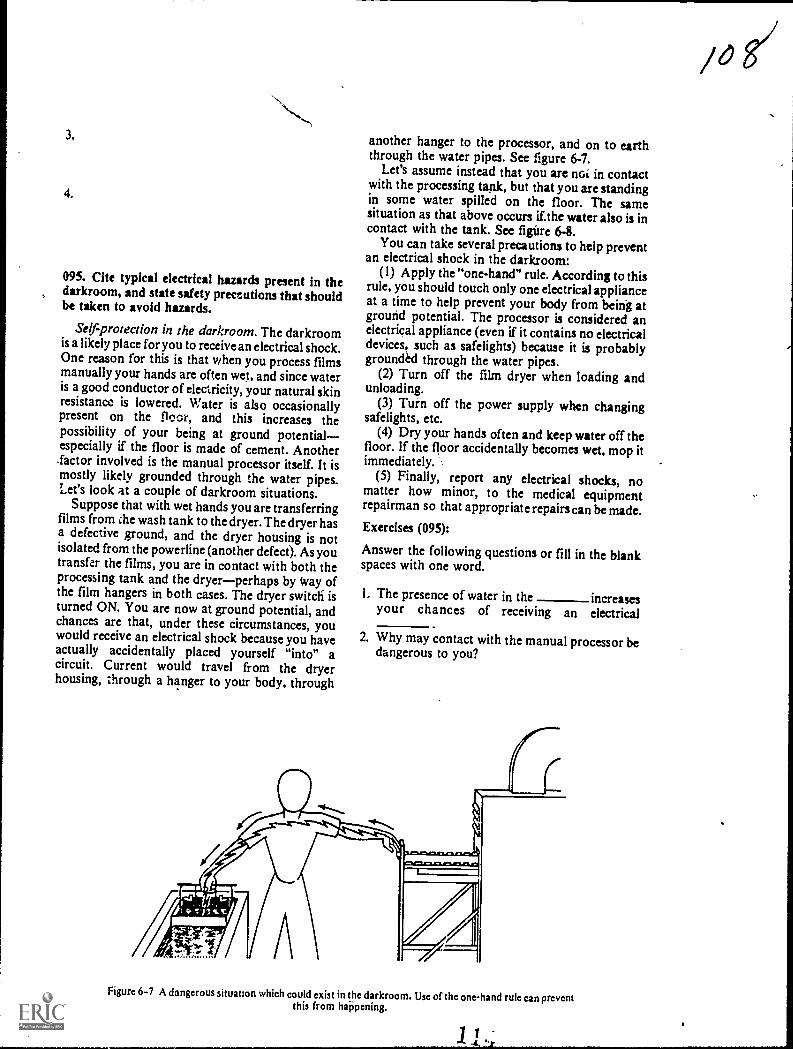
3.
4.
095. Cite typical electrical hazards present in thedarkroom, and state safety preceutions that shouldbe taken to avoid hazards.
Self-protection in the darkroom. The darkroomis a likely place for you to receive an electrical shock.One reason for this is that when you process filmsmanually your hands are often wet, and since wateris a good conductor of electricity, your natural skinresistance is lowered. Water is also occasionallypresent on the floor, and this increases thepossibility of your being at ground potentialespecially if the floor is made of cement. Another.factor involved is the manual processor itself. It ismostly likely grounded through the water pipes.Let's look at a couple of darkroom situations.
Suppose that with wet hands you are transferringfilms from ihe wash tank to the dryer. The dryer hasa defective ground, and the dryer housing is notisolated from the powerline (another defect). As youtransfer the films, you are in contact with both theprocessing tank and the dryerperhaps by Way ofthe film hangers in both cases. The dryer switch' isturned ON. You are now at ground potential, andchances are that, under these circumstances, youwould receive an electrical shock because you haveactually accidentally placed yourself "into" acircuit. Current would travel from the dryerhousing, through a hanger to your body, through
another hanger to the processor, and on to earththrough the water pipes. See figure 6-7.
Let's assume instead that you are noi in contactwith the processing tank, but that you are standingin some water spilled on the floor. The samesituation as that above occurs if.the water also is incontact with the tank. See figure 6-8.
You can take several precautions to help preventan electrical shock in the darkroom:
(1) Apply the "one-hand" rule. According to thisrule, you should touch only one electrical applianceat a time to help prevent your body from being atground potential. The processor is considered anelectrical appliance (even if it contains no electricaldevices, such as safelights) because it is probablygrounded through the water pipes.
(2) Turn off the film dryer when loading andunloading.
(3) Turn off the power supply when changingsafelights, etc.
(4) Dry your hands often and keep water off thefloor. If the floor accidentally becomes wet, mop itimmediately.
(5) Finally, report any electrical shocks, nomatter how minor, to the medical equipmentrepairman so that appropriate repairs can be made.Exercises (095):
Answer the following questions or fill in the blankspaces with one word.
I. The presence of water in the increasesyour chances of receiving an electrical
2. Why may contact with the manual processor bedangerous to you?
Figure 6-7 A dangerous situatlon which could exist in the darkroom. Use of the one-hand rule can preventthis from haPpening.

Figure 6 8. A dangerous situation which could exist in the darkroom. This can be avoided by keeping thedarkroom floor dry.
3 Suppose y ou are transferring films from thewash tank to the dryer and are in contact withboth units. Is this condition potentiallydangerous? Explain.
4. To be potentialy dangerous, contact betweenyou and the processor need not be direct but canbe through processing or onthe
5. What,is the "one-hand" rule, and how can usingthe rule help protect you from electrical shock?
6. Before loading the film dryer, you shouldit
7. What action should you take in the darkroomrelative to water on the floor or wet hands?
096. Given a list of statements pertaining to first aidprocedures for a patient suffering from severeelectrical shock, indicate which are true and whichare false. If you indicate "false," explain youranswer.
First Aid for Electrical-Shock Victims. When aperson comes into contact with a w ire carrying
/ 0 9
electricity, many things can happen. Sometimes, thevictim is "frozen" to the circuit, or he may beknocked off his feet. If both voltage and current arehigh and the victim is in position to provide a goodpath to ground, the results can be fatal.
Eliminating the source. If someone does comeinto contact with a.hot wire and is either frozen tothe circuit or knocked,unconscious, turn the powerOFF as quickly as possibk. If the switch is not closeat hand or you cannot immediately find it, doz:t.....--N,jwaste time looking. Remove the victim fropt eelectrical source with a dry wooden Ole, dryclothing, rope, parachute cord, or any othermaterial that does not conduct electricity. If you useclothing, rope, or a cord, make it into a loop and putit over a foot, leg, or arm to drag the victim off theelectrical source. Be careful not to make contactbetween the victim and any part of your body, oryou, also, will become a victim. Severe electricalshock usually causes the victim to stop breathing, soartificial respiration must be initiated as soon as thevictim is free from the electrical source.
Artificial (mouth-to-mouth) respiration. Thesuccess of mouth-to-mouth respiration oftendepends upon how soon it is started. Don't wastetime moving the victim to an ideal location, anddon't wait for mechanical equipment. To begin,place the victim on his back, use your fingers to clearhis mouth and throat of any foreign matter, andmake certain he hasn't swallowed his tongue. Next,
103

tilt his head backward so that he is more or less in a"sword-swallowing" position. This will insure thathis neck is not kinked and that there is a clearpassage into his lungs. Then, approach the victimfrom his side and hold his lower jaw up by puttingyour ringers under his chin and your thumb on hislower teeth. Finally, use your hand to close the airpassages in the victim's nose. See figure 6-9, Take adeep breath and cover his open mouth with yourown until there is an airtight seal. Blow forcefullyinto his mouth until his chest expands. This shouldbe done quite forcibly with adults but rather gentlywith children. Watch his chest as you expire. Afterthe victim's chest rises, remove your mouth from hisand allow him to exhale by himself. Repeat thisaction 12 to 20 times a minute. You may find thatyou are breathing faster than normal in order to getenough air for yourself. Actually, humans use onlyabout 25 percent of the oxygen they inhale, so thevictim is getting all he needs. Continue in a rhythmicmanner and without interruption until the victimeither starts breathing or is pronounced dead by adoctor.
Closed-chest heart compression. If the patient'sheart has also stopped beating, you must performclosed-chest heart compression in addition tomouth-to-mouth respiration, and again it must bestarted immediately after the power supply has beenturned off or after the patient is removed from thesource of electricity.
1. Thrust head backward
To perform closed-chest heart compression,kneel beside the patient, place the heel of one handon the lower end of his sternum and your other handon top. See figure 6-10. Press downward with bothhands at the rate of one compression per second.The sternum should depress 11/2 or 2 inches. Liftyour hands after each compression to permit thesternum to return to its normal position.
If two persons are available, one should performmouth-to-mouth respiration, and one shouldperform closed-chest heart compression. If you arealone repeat 2 good breaths for every 15compressions of the sternum.
Exercises (096):
Indicate whether the following statements are trueor false. If you indicate "false,ipplain your answer.
T F
T F
T F
0
1. When confronted with an unconsciouselectrical shock victim, the first thing youshould consider is turning off the powersupply.
2. You can be electrocuted yourself bytouching someone who is in contact with alive wire.
3. You should separate an unconsciousperson from a live wire with the first thingyou can get your hands on.
\
3. Pinch nostrils 4. Blow into patient's mouth
Figure 6-9. Mouth-to-mouth respiration.
104
t

Figure 6-10. Closed-chest heart compression.
T F 4. Mouth-to-mouth respiration and closed-chest heart compression should be startedimmediately as soon as the victim isseparated from the electrical current.
T F 5. The position of the victim's head is notimportant for closed-chest heartcompression or mouth-to-mouthrespiration.
T F 6. Your mouth should form an airtight sealover the victim's mouth during mouth-to-mouth respiration.
T F 7. When performing mouth-to-mouthrespiration, you should normally force airinto the patient's lungs about 15 to 20times a minute.
T F 8. The sternum should be depressed 2 to 21hinches during closed-chest heartcompression.
T F 9. The sternum should normally bedepressed 60 times a minute duringclosed-chest heart compression.
T F 10. If you are performing mouth-to-mouthrespiration and closed-chest heartcompression simultaneously on a patient,you should repeat cycles of 2 breathsfollowed by 15 compressions of thesternum.
6-2. Radiation Hazards and Protection forPatients
In times past, protecting our patient fromexcessive radiation exposure has received too littleemphasis. We usually think about protectingourselves, but some of us do not realize that ourpatient deserves equal consideration. As a 7 level,your responsibilities incfease considerably in thisarea. You must not only use the appropriate safetyprecautions, but you must also insure thatpersonnel under your supervision do likewise.
A good portion of this section is taken from AFM161-38. For further information concerningradiation hazards and protection, refer to thismanual
097. Indicate the purpose, types, and use offiltration of an X-ray bum.
Protective Filtration. We begin our discussionabout patient protection with protective filtration.As you know, adequate filtration of the primarybeam is one of the bestways to reduce the patient'sexposure to radiation. Let's see how it works.
Reduction of low-energy photons. A beiin ofX-radiation is made up of photons with grEgiesranging from the kVp setting used to ne ero.Many of these photons in the low-energy range areabsorbed by the patient's skin and other bodytissues. These "soft" photons contribute nothingwhatsoever to the film exposure. All they do isincrease the patient's exposure, which we obviouslydo not want. We cannot prevent the low-energyphotons from being produced in the target of theX-ray tube, but we can remove most of them beforethey reach the patient. We do this by filtering theprimary beam.
Types offiltration. The filters placed between thetarget and patient are broken down into two types,inherent and added. The first, inherent filtration, isthat filtration provided by the tube housing. Youactually have no control over this filter since it is apermanent part of the X-ray tube. However, youshould be aware of the aluminum equivalency of theinherent filter for each of your X-ray machines. It isusually 0.5 mm unless the tube has a berylliumwindow. When such is the case, it is normally 0.3mm. If you are not sure of the amount, check withthe tube manufacturer. The second, addedfiltration, mikes up the remainder of the totalfiltration in the X-ray beam. This type of filtrationis simply what we would add to the port of theX-ray tube. Inherent filtration plus added filtrationequals total filtration.
Minimum filtration requirements. You musthave a minimum amount of total filtration in theX-ray beam. The minimum aluminum equivalencydepends upon the operating kVp and is shownbelow:
kVp
Below 5050 to 70Above 70
Minimum Total Filtration
0.5 mm aluminum1.5 mm aluminum2.5 mm aluminum
For example, when you use 80 kVp, you must have a
total of 2.5 mm aluminum filtration.How filtration increases the mean energy of the
beam. In figure 6-11 we have shown the energydistribution of four beams of X-radiation plottedagainst the intensity of the beams. Progressivelymore filtration is added, beginning with the topadded filtration curve. Notice that the morefiltration added, the fewer the number of low-energy photons, and the less the minimum photonenergy of the beam. Consequently, by adding
105
1 1
/1/

20 40 60 80 100 120 140
ENERGY: Kilo-electron volts (KEy)
Figure 6-11. Filtration of X-ray photons.
filtration, we are increasing the mean energy of theX-ray beam.
Exercises (097):
1. What happens to the low-energy photons whichdo not reach the X-ray film?
2. How does filtration lower the patient's exposure?
3. What is inherent filtration? How much isnormally provided in an X-ray tube?
4. If an X-ray tube has 0.3 mm aluminumequivalency of inherent filtration, how manymillimeters of aluminum should be added tooperate the tube at 26 kV p?
5. How much total filtration should be in the X-raybeam if 65 kVp is used?
106
160 180 200
6. If the inherent filtration of an X-ray tube is 0.3mm, how many millimeters of aluminum shouldbe added to operate the tube at 120 kVp?
7. How does filtration of the beam of X-rayphotons increase the beam's mean energy?
098. State three ways in which high kVp techniquesreduce patient exposure.
High kVp Techniques. We have just discussedhow filtration reduces patient exposure byincreasing the mean energy of the primary beam. Itis not practical, however, to increase the filtrationvery much beyond the minimum requirements tofurther reduce patient exposure. The reason for thisis that filters work well up to a certain point, butthen reduction in patient exposure with morefiltration diminishes rapidly.
There is another way to reduce patient exposureby increasing the mean energy of the beam simplyby using high kVp techniques. By high kVp we donot mean 100 kVp or 150 kVp. We mean the highestkVp that produces a radiograph which satisfies yourradiologist. As you know, the higher the kVp, thelonger the scale of contrast; but your initial concernis providing radiographic contrast consistent withyour radiologist's desires. So whatever kVp rangeyou use, remember it must first satisfy theradiologist.
%AI

Let's look at a typical examination of the knee. Ifyou presently use 60 to 70 kVp, you may very well beable to increase the kVp to 80 to 90 and stillmaintain satisfactory contrast. Eighty to 90 kVp isnot considered high, but it is higher than youpreviously had used, and you have taken a positivestep in reducing exposure to your patient.
Aside from reducing patient exposure byincreasing the mean energy of the beam, high kVpworks in two other ways to reduce patient exposure:(1) it permits shorter exposure timeswhich helpsprevent repeat examinations due to part motion and(2) it also provides more exposure latitude, whichalso helps to prevent repeat examinations due toincorrect exposure factors. Of course, any actionthat reduces the repeat radiographs also helps tokeep patient exposure to a minimum.
Exercises (098):
In the exercises below, write down three ways highkVp techniques reduce patient exposure.
2.
3.
099. List two ways that proper collimation reducespatient exposure, and indicate the basic procedurefor checking the collimation of a radiograph.
ination. One of the best ways to keep patientexposure to a minimum is by restricting the primarybeam to the smallest area consistent with the clinicalrequirements. Exposure of the patient toradiation in areas beyond the part under study is in'most cases inexcusable, since collimators have afield-size scale as well as a lighted X-ray field. Thereis no excuse to open the collimator wide open for aradiograph. There is likewise no excuse to open thecollimator beyond the size of the film. In fact, inmost cases you should use an X-ray field smallerthan the film.
Checking for collimation is an important part ofyour quality control duties. For most radiographsyou should see the outer limits of the X-ray field onthe film. We emphasize "for most radiographs"because at times, due to the size of the patient, forexample, it is necessary to use an X-ray field tocover the entire fdm. This is the exception, however,and not the rule.
It is difficult to say, for example, that allradiographs should have a 1-inch unexposed border
107
113around the sides. Film size, patient size, and the partbeing radiographed are some factors that should betaken into consideration. The important issue isthat you should see the outer limits of the field. Ifyou do not see a border around the film, you aren'tsure whether the X-ray field extends 1 inch or 10inches beyond the film.
In addition to increasing patient exposure, a largeX-ray field increases the scatter radiation to thefilm, thereby increasing film fog. As you know,excessive film fog on a radiograph can cause it to berepeated.
Exercises (099):
1. Give two ways that proper collimation reducespatient exposure.
2. As a general rule, what should you look for on aradiograph to insure proper c011imation?
3. If you do not see any indications of collimationon a radiograph, what can you assume about thesize of the X-ray field?
4. What size unexposed border should you see onthe edges of a radiograph?
100. Name several examinations in which gonadalshielding can be used, and specify two precautionsto take when using the shielding.
Gonadal Shielding. To prevent needless exposureof the patient's gonads, you should cover them withpieces of lead-rubber shielding material. Forexample, gonadal shielding can be used for hipexaminations if you are careful with the placementof the shield. You can also shield the gonads offemur and lumbar spine examinations of male andfemale patients and abdomen, intravenouspyelogram, sacrum, and coccyx studies of malepatients.
The most important consideration when usinggonadal shielding is to make sure the shield is notsuperimposed over the part under study. Inaddition, do not use gonadal shielding as asubstitute for adequate beam collimation. Use theshield in addition to collimation.

Exercises (100):
I. Name three examinations where gonadalshielding can be used on male and femalepatients.
2. Name four examinations where gonadalshielding can be used on male patients only.
3. What two precautions should be consideredwhen using gonadal shielding?
101. Show the effect and use of high-speed screensand films to reduce patient exposure.
High-Speed Screens and Films. Using high-speedintensifying screens and X-ray films can also reducepatient exposure to radiation by lowering theexposure necessary to produce the radiograph.Keep in mind that there is a loss of detail when high-speed films and screens are used. So this is a decisionthat should be made by your radiologist. If he iswilling to accept the detail loss to reduce patientexposure, then by all means use high-speed filmsand screens.
At times it may be advantageous to use high-speed screens for most examinations and to use themedium or slow-speed for ra.liographs of partsrequirmg maximum detail such as the mastoids. Incases such as this, make sure that the cassettes areplainly identified so that, for example, high-speedexposure factors are not used with slow-speedscreens.
Exercises (101):
I. Why is patient exposure reduced if high-speedintensifying screens and films are used?
2. What must be sacrificed if you use high-speedintensifying screens and films?
3. How can you maintain good screen detail forsome examinations and keep patient exposure toa minimum for others?
Film Processing. A common cause of excessivepatient exposure is improper film development. Toillustrate how film development affects patientexposure, we have shown, ain figure 6-12, thecharacteristic curves of three identical filmsprocessed under different condifions. Film A wasdeveloped as recommended , by the filmmanufacturer for a period of 5 minutes at 68 F.Film B was developed under the same conditionsbut for only 3 minutes. Film C also was dev2lopedunder the same conditions but for only 11/2 minutes.Now, let's analyze the results of figure 6-12. At thebottom of the curve, you will notice that the logrelative exposure is in increments of 0.3 and, also,that each increment of '0.3 is equivalent to doublingthe mAs. Next, assume that your radiologist wantsfilms taken at a certain kilovoltage with a maximumdensity of 2.0. To reach this density, film A wouldneed'll mAs, film B would require 40 mAs, and filmC approximately 270 mAs. Can you now see whyproper developing becomes so very impatant inreducing radiation dosage to the patient? The filmdeveloped at 11/2 minutes requires 24 times theexposure of film A.
Exercises (102):
I. According to figure 6-12, what developing timerequires the most exposure to produce a specificdensity?
2. According to figure 6-12, what developing timerequires the greatest patient exposure to producea particular radiograph?
3. What can you conclude from the discussionabout developing time vs. patient exposure?
4. What developing time should you use for all yourradiographs?
Radiation Hazards and Protection forTechnicians
Good working habits', commonsense, and properrespect for ionizing radiation are very important inradiation protection. With present day knowledgeand the vast amount of protective resources at yourdisposal, there is absolutely no reason for you to
102. Given characteristic curves of three identical even closely approach th maximum permissibleX-ray films, relate developing time to patient dose. If proper precautionary measures areexposure. practiced daily, the risk involved in being an X-ray
Inc)

4.
3 I)
5 1.5
1 0
0 5
0 3
Ii... A;
cb'
1
4'
"4
6$@
i
1
c).
Or.
,. T
%
\`11
L 1-1-
r
1
0.3 0.6 0 9 1 2 1 5 1 8 2 1
LOG RELATIVE EXPOSURE
2 4 2 7 3 0
2 4 8 16 32 64 128 256 512 1024
RELATIVE MAS
Figure 6-12, Characteristic'eurves of several identical films.
technologist is very small, when compared to otherrisks, such as driving a car and crossing the street.The steps necessary to keep your exposure at aminimum can be divided into two categories: ( I)those that protect you from the primary beam and(2) those that protect you from scatter radiation.
103. List four rules to follow to protect yourselffrom exposure to radiation.
Protection from the Primary Beam,. Protectingyourself from primary radiation is very simple: donot expose any part of your body to the primarybeam. This means that during exposure you shouldnever hold a patient or cassette, or in any other waysubject yourself to primary radiation. In addition,you should not allow another technician to performthese tasks. If assistance is needed to obtain aradiograph on uncooperative patients, use someonewho is not occupationally exposed to ionizingradiation.
Protect ion from Scatter hadiation. Although theintensity of scatter radiation is less than primaryradiation (for a given technique), the radiationhazard to the technician is perhaps greater withscatter. The reason for this is that scatter radiationcan reach virtually all parts of the exposure roomwhile the primary beam is restricted to an area thatis much smaller by comparison. Therefore, while itis a simple matter to remain clear of the primarybeam, it is somewhat more difficult to elude scatterradiation. Following are some general rules toadhere to.
//s
Standing behind a." protective- barrier. Alwaysremain behind a protective barrier whermaking anexposure. Control booths are designed so that thetechnologist will not be exposed to any radiationthat has scattered only once. In other words, theradiation must scatterat least twice before it reachesyou. Use the lead impregnated glass windoiv toobserve the patient. Do not defeat the purpose ofthe control booth by leaning out from ehind thebarrier to ruke the exposure.
Using distance for protection. Distance is aneffective means to reduce exposure. Since radiationintensity decreases as the distance from the sourceincreases, exposure can be reduced by staying as farfrom the source as possible. This rule is particularlyimportant to remember when taking portableradiographs, where protective barriers are usuallynot available.
Protection 'during fluoroscopy. Duringfluoroscopy be sure to wear a protective apron.When you are not needed to assist the radiologist,remain in the control booth.
&etches (103):
In exercises 1 through 4 below, list four rules tofollow to protect yourself from exposure to
radiation.1100
109

-
2.
3.
4.
8-4. The Personnel Dosimeter
The purpose of the USAF personnel dosimeter isto measure and record the accumulative dose of -ionizing radiation to radiation workers likeyourself. In addition to recording the exposurereceived, the dosimeter can prevent euessiveexposures by determining that a radiation leak" orother hazard exists, before the hazard becomesdangerous. Let's begin our discussion with yourresponsibilities concerning th&dosimeter. (NOTE:This section is based on AFR 161-28, PersonnelDosimetry Prbgram and the USAF MasterRadiation Exposure Registry. Refer .to thAsregulation for.additional information concerningthe dosimetrY,program.)
104. Identify your responsibilities pertaining to theUSAF Personnel Dosimetry Program.
Supervisor Responsibilities. Mir responsibilitiesconcerning this program are fairly simplebutimportant ones. Ifyou are acting in the capacity of asupervisor, you must see to it that cach person underyour supervision is thoroughly indoctrinated in theproper us "the dosimeter. When a new technicianis assigned to your department, go oVer theprocedures with him. Do not assume that he alreadyknows how and when to wear the dosimeter justbecause he has been in radiology for some time.
Technician Responsibilities. If you are not actingas a supervisor, you are responsible for the properuse of the dosimeter issued to you. The best.reasonfor you to use the dosimeter properly is that it mightprevent a significant dose of radiation to you. Inother words, you are the one who benefits from thedosimetry program, so act accordingly.
Exercises (104):
Explain your responsibilities, both as a technicianand 'as a supervisor, pertaining to the dosimetryprogram.
I. Supervisor responsibilities.
2. Technician responsibilities.
105. Given a list of statements pertaining towearing and handling of the dosimeter, indicatewhich are.true and which are faise. If you indicate"false," 'explain your answer.
Wearing ind Handling the Dosimeter. There arecertain problems that we will discuss that involveboth the wearing and .the handling of dosimeters.Our discussion will-include dosimeter choice, whenand where they are to be wont, and storage areas.
Chest dosimeter. The regular chest dosimeter(film badge) is worn below the shoulders and abovethe waist on the outside of the clothing. If you weara lead apron, wear the dosimeter beneath the apronbut still outside the clothing. The film must faceoutward from the body with the clip on.the holderfacing towaid the body. This dosimeter, which wewill call the chest dosimeter, is worn at all timesduring radiography, therapy, or fluoroscopy tomeasure whole-body exposure.
Flouroscopic dosimeter. In addition to tbe chestdosimeter', you must wear an additional dosimeterduring flurorscopy. Wear this fluoroscopicdosimeter only on your front collar outside tbeprotective apron. Its purpose is to assess theradiation exposure to the head and to the lens of theeye.
Localized ex'postire dosimeters. Additionaldosneters can be worn in certain situations, asdurrng fluoroscopy, to assess localized exposures,such as to the neck or forearm: When wearing theseadditional dosimeters, be sure to wear the otherrequired dosimeters.
Keep in mind that each dosimeter has a specificpurpbse. Consequently, during a specific reportingperiod, yOu shouldn't interchange the dosimeters.For example, the chest dosimeter should not beworn on other areas of the body. Also, if a dosimeteris used to record exposure to a localized area, itmust not be worn at any other body site unless thedosimeter film is changed.
Where to wear the dosimeters. You must clip onthe dosimeter(s) before entering the working areaand remove it when leaving. TIA working area, asfar as radiology departments are concerned, is tiieentire department. This means that you can wearthe dosimeters anywhere inside the department.This also means that you cannot wear the dosimeteroutside the departifient. Except, of course, you canwear the dosimeter outside the department whenperforming portable radiographs.
Dosimeter storage area. While dosimcters are notbeing worn, they must be stored in a storage areadesignated by the commander of the facility. The
/76

storage area should be near to, but outside, theradiation area. Radiation area in this case refers tothe exposuretherapy rooms. For convenience, itis advisable to locate the storage area near theentrance of the department, thereby encouragingtechnicians tp deposit or remove the dosimeter asthey leave or enter the department.
Identifying the dosimeters. To insure that eachtechnician wears only his own-dosimeter, it shouldcontain some individual identification, with thecorresponding identification placed at a givenlocation on a dosimeter storage rack. Do notpermanently 'inscribe the identification on thedosimeter. Use embossing tape or other similarmeans to identify the dosimeter. You can identifythe dosimeter fin the front surface as long as thesmall window is not covered. To cover the windowmay cause false (lower than normal) readings.
Exercises (105):
Indicate whether the following statementspertaining to wearing and handling the dosimeterare true or false. If you indicate "false," explain youranswer.
T F I. The chest dosimeter can be worn attachedto a shirt pocket.
I l 1
T F 2. The chest dosimeter can be worn attachedto the belt.
T F 3. The chest dosimeter is not worn duringfluoroscopy.
T F 4. At least two dosimeters must be wornduring fluoroscopy.
T F S. During fluoroscopy, one dosimeter isworn beneath the apron, and one is wornoutside the apron.
T F 6. The fluoroscopic dosimeter assesseswhole-body exposure.
T F 7. When wearing a localized exposuredosimeter, you do not have to wear thechest dosimeter.
T F 8. The fluoroscopic dosimeter can be used toassess exposure to the hands.
T F 9. You cannot wear a dosimeter outside theradiology department.
T F 10. Dosimeters can be stored in an exposureroom.
T F U. Individual identificatin of dosimetersshould be made on the dosinieter and onthe storage rack.
T 'F 12. Identification should not be placed on thefront of the dosimeter.
T F 13. At least three dosimeters must be worn tomeasure whole-body exposure.

CHAPTER 1
Reference:
ANSWERS TO EXERCISES
001 - I. The flow of electrons through a conductor.001 - 2. Difference between electrosiatic charges, difference in
potential, and resistance.
002 - I. An insulator is a poor conductor of electricity, aconductor is a good conductor of electricity, and asethiconductor is neither a good conductor nor a goodinsulator.
002 - 2. Conductor.002 - 3. Semiconductor.002 - 4. Insulator.002 - 5. Semiconductor.002 - 6, Conductor.002 - 7 Conductor.
003 - 1 T.003 - 2. T.003 - 3. F Under the conditions described, -0.33 ampere of
current is flowing.003 - 4. F. The symbol 1 refers to the intensity of current, or
amperes.003 - 5. T003 - 6. T
- 7. F They are the same,433 - 8. F Voltage can exist between two positive charges if
one is more positive than the other.003 y F Current flows from negative to positive.003 - 10 T
004 - I The opposition to current flow.004 - 2 Ohm.004 - 3. That amount which allows exactly I ampere of current
to flow when I vplt is applied across the resistance.004 - 4. R = 4 M.
005 - I. No.005 - 2. Less; more.005 - 3. 2 M.005 - 4. Resistance depends upon the number of electron
collisions, and the length of a conductor influences thenumber of collisions;0.5M005 - 5.
005 - 6 Yes: increase.005 - 7 Temperature
006-1W6-2.006-3
007 - 1
007 - 2.007 - 3.007 - 4.007 - 5.007 - 6.007 -007 - S.007 - 9.007 - 10.007 - 11
22 M.110 volts.3 amperes.
Crossed over wires.Connected wires.Battery.Lamp.Fixed resistorVoltmeter.Switch.Ground.Ammeter.Fuse.Variable resistor
008 I. 0 5 A; 0 5 A: 0 5 A004 - 2. 24 (1.004 - 3 6 , 2 . 4 V009 - I. 12 . 12 V009-2. 4 A. 6 A; 12 A. 2 A009 - 3 24 A.009 - 4 05fl
113
010-1. 7.8 M.
Explanation: I
R2 RII 1
4
= 0.8 r. = equivalent resistanceof the thrft parallel
- resistances
7 fl + 0.8 fl = 7.8
011 - 1. A force that attracts iron, steel, or other magneticsubstances.
011 - 2. Around and inside the magnet.011 - 3. Outside the magnet: from the north pole to the south
pole. Inside the magnet: from the south pole to thenorth pole.
011 - 4. Concentration of lines of force.011 - 5. Like poles repel each other. Unlike poles attrack each
other.
012 - I. Magnetic substances are strongly affected by amagnetic field; nonmagnetic substances arc notnoticeably affected.
012 - 2. Magnetic: iron and steel. Nonmagnetic: wood, copper,and glau.
off:i T.012 - 4. T.012 - 5. T.
013 - I. Current flow must be present through theconductor.013 - 2. No. Form the wire into one or morc loops.013 - 3. At each end of the coil.013 - 4. The direction of current flow.013 - 5. Place the left hand around the conductnr with the
thumb pointing in the direction of current flow. Linesof force travel in the same direction as the fingers.
014 - I. The number of coil turns per inch. The higher thenumber of turns, the stronger the field.
014 - 2. Current through the conductor. The higher thecurrent, the stronger the field.
014 - 3. Iron core. The core itself becomes magnetized, and itsstrength is added to that of the coil; and the core.strengthens the field because lines of fo rce concentratethemselves in the core.
015-1. T.
015-1 T.
016-1.
016-/W6-1W6-4.016-i
Fixed.Relay.Magnetic.Electromagnet; privoting.Opened; spring-.
017 - I. Electromagnetic effect.017 - 2. Permanent magnet, moving-coil movement.017 - 3. Two-permanent and electromagnet.017 - 4. When current is introduced into the coil, the poles of
the electromagnet attempt to repel the same poles ofthe permanent magnet.
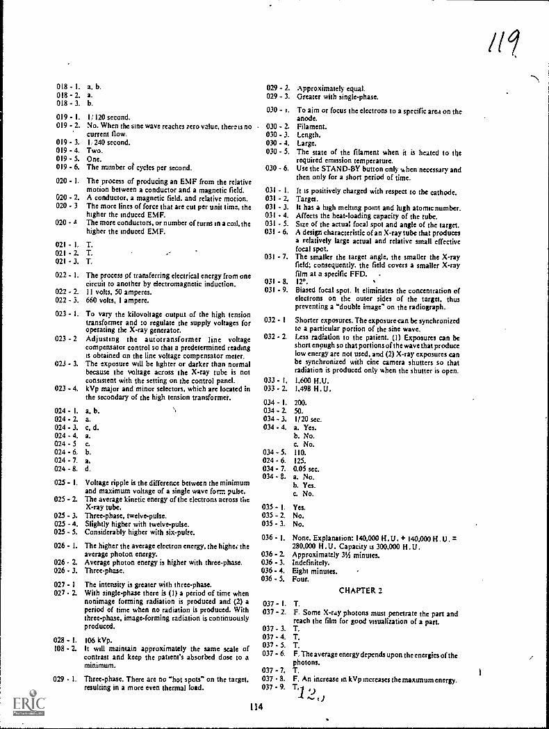
018 - I.018 - 2.018 - 3.
a, b.a.b.
019 - 1. 1/ 120 second.019 - 2. No. When the sine wave reaches zero value, therc is no
current flow.019 - 3. 1, 240 second.019 - 4. Two.019 - 5. One.019 - 6. The number of cycles per second.
020 - I. The process of producing an EMF from the rthtivemotion between a conductor and a magnetic field.
020 - 2. A conductor, a magnetic field, and relative motion.020 - 3 The more lines of force that are cut per unit time, the
higher the induced EMF.020 - A The more conductors, or number of turns in a coil, the
higher the induced EMF.
021 1, T.021 - 2. T.021 - 3. T.
022 - I. The process of transferring electrical energy from onecircuit to another by electromagnetic induction.
022 - 2. I I volts. 50 amperes.022 - 3. 660 volts, 1 ampere.
023 - I. To vary the kilovoltage output of the high tensiontransformer and to regulate the supply voltages foroperating the X-ray generator.
023 - 2 Adjusting the aut4otransformer line voltagecompensator control so that a predetermined readingis obtained on the line voltage compensator meter.
023 - 3. The exposure will be lighter or darker than normalbecause the voltage across the X-ray tube is notconsistent with the setting on the control panel.
023 - 4. kVp major and minor selectors, which are located inthe secondary of the high tension transformer.
024 - I.024 - 2.024 - 3.024 - 4.024 - 5024 - 6,024 - 7.024 - 8.
a, b.a.c, d.a.c.b.a.d.
025 - I. Voltage ripple is the difference between the minimumand maximum voltage of a single wave form pulse.
025 - 2. The average kinetic energy of the electrons acrou theX-ray tube.
025 - 3. Three-phase, twelve-pulse.025 - 4. Slightly higher with twelve-pulse.025 - 5. Considerably higher with six-pube.
026 - I. The higher the average electron energy, the higher theaverage photon energy.
026 - 2. Average photon energy is higher with threephase.026 - 3. Three-phase.
027 - 1 The intensity is greater with three-phase.027 2. With single-phase there is (1) a period of time when
nonimage forming radiation is produced and (2) aperiod of time when no radiation is produced. Withthree-phase, image-forming radiation is continuouslyproduced.
028 - L 106 kVp.108 - 2. It will maintain approximately the same scale of
contrast and keep the patient's absorbed dose to aminimum.
029 I. Three-phase. There are no "hot spots" on the target,resulting in a more even thermal load.
029 - 2. Approximately equal,029 - 3. Greater with single-phase.
030 - I. To aiM or focus the electrons to a specific area on theanode.
030 - 2. Filament.030 - 3. Length.030 - 4. Large.030 - 5. The state of the filament when it is heated to the
required emission temperature.030 - 6. Use the STAND-BY button only when necessary 2nd
then only for a short period of time.
031 - I. It is positively charged with respect to the cathode.031 - 2. Target.031 - 3. It has a high melting point and lugh atomic number.031 - 4. Affects the heat-loading capacity of the tube.031 - 5. Size of the actual focal spot 2nd angk of the target.031 6. A design characteristic of an X-ray tube that produces
a relatively large actual and relative small effectivefocal spot.
031 - 7. The smaller the target angle, the smaller the X-rayfield: consequently, the field covers a smaller Xrayfilm at a specific FFD.
031 - 8. 120.031 - 9. Biased focal spot. It eliminates the concentration of
electrons on the outer sides of the target, thuspreventing a "double image" on the radiograph.
032 - 1 Shorter exposures. The exposure can be synchronizedto a particular portion of the sine wave.
032 - 2. Less radiation to the patient. (I) Exposures can beshort enough so that portions of the wave that producelow energy are not used. and (2) X-ray exposures canbe synchronized with eine camera shutters so thatradiation is produced only when the shutter is open.
033 - 14 1.600 H.U.033 - 2. I.498 H. .
034 - I.034 - 2.034 - 3.034 - 4.
034024034034
035035035
036
036036036036
- 5.- 6.- 7.
8.
200.50.1/20 sec.a. Yes.b. No.c. No.110.125.
0.05 sec.a. No.h. Yes.c. No.
- I. Yes.- 2. No.- 3. No.
- I. None. Explanation: 140.000 H. U . + 140.000280.000 H.U. Capacity is 300.000 H.U.
- 2. Approximately 31/2 minutes.- 3. Indefinitely.- 4. Eight minutes.- 5. Four.
CHAPTER 2
037 - I. T.037 - 2. F. Some Xray photons must penetrate the part 2nd
reach the film for good visualization of a part.037 - 3. T.037 - 4. T.037 - 5. T.037 - 6. F. The average energy depends upon the energies of thr
photons.037 - 7. T.037 8. F. An increase in kVp increases the maximum energy.037 - 9. T.1 9
114

038 - I. The characteristic of the primary beam that affectsradiographic density. It is a measure of the number ofphotons per unit area in combination with the meanenergy of the photons.
038 - 2. a. c.038 - 3, d.03g - 4 d.
a. c.- 6. c.- 7 a
Olg - 8. a. c. d.038 - 9 a. c.
019 - I. The intensity 01 radiation in the primary beam isinsersfly proportional to the square of the distancefrom the target.
039 - 2. 800, 50.039 - 3, No. Intensity as affected by the inserse square law has
nothing to do with thc nitinber of photons emittedfrom the target. It is concerned with the number ofphotons per unit area.
039 - 4. There is no connection between the two.
040 -040 - 2.
' 040 - 3.040 - 4.040 - 5040 - 6040 - 7.
Longitudinal: anode heel effect.Farthest.Anode.Increases; decrease.32.Cathode.Absorption; target material.
041 - I. Room #I.041 - 2. Since the difference between the bins of the uppe. and
lov.cr portions of the thoracic spine is greater thannormal. you would neecL the tube with the greatestsariation in intensity to balance out thc density on theradiograph. The 12° pros ides the greatest variation.
041 3, Room #2.041 4. With his head toward the anode side of the tube.041 5. Any of the rooms could be selected.041 6. For spot-films of the gallbaldder you would only use
the small central portion of the X-rays. field. Thevariation in intensity forsuch a small area is negligible.
041 - 7 With the ankle toward the anode.041 - 8. The portable. At a 30-inch FFD, thc beam intensity
vanes more.
042 1 F A small focal spot gives better detail.042 2. F A large focal spot produces more penumbra.042 3. F The more penumbra. the worse the detail.042 - 4 F. Penumbra is greatest on the cathode side042 5, F. Radiographs do have better detail on the anode
side. but the reason has nothing to do with distancefrom the target. That portion is projected by a"smaller focal spot.
043 1 Room #1. Room #2.043 2. The 1.5 mm in room #1 because it is the smallest of tiie
four able to withstand the exposure.043 - 3 Your initial thought should be on the smallest focal
spot you have available (0.2 mm in exposure room #1)since detail is most important on this examination. Ifthe exposure factors do not exceed the rating of the9.2-mm focal spot. it should be used. If you cannotsafely use the 0.2 min, check the exposure against thenext largest focal spot (0.5 mm in room #2) and so onuntil you find the smallest focal spot that canwithstand the exposure. Remember, even thoughdetail as important. not to exceed the maximum ratingof the tube rating chart.
o44 - 1 The right lateral. The part-film distance for the rightside would be less than for the right side; therefore,there would be less magnification and better detail ofthe right parietal bone.
IOW044 - 2. Radiograph B.044 - 3. The posterior ribs of radiograph A.044 - 4. Radiograph B.044 - 5. You could decrease the FFD. A shorter FFD increases
magnification and therefore decreases detail.044 - 6. The right lateral. It places the right lower lobe closer to
the film, thereby providing better detail of that area.044 - 7. An increase in FFD. Increased FFD increases detail.
045 - L Keep it to a minimum, but use it when necessary.045 - 2. Yes. At times distortion is necessary to project a part
clear of superimposed structures.045 - 3. To the part, perpendicularly to the plane of the part
and the plane of the film.045 - 4. Yes.045 - 5. The plane of the part must be paraUel with the plane of
the film.
CHAPTER 3
046 - 1. F. A beam-restricting device reduces the size of theprimary beam.
046 - 2. T.046 - 3. T.046 - 4. T.046 - 5. F. You can reduci scatter by using a smaller X-ray
field.046 - 6. T.046 - 7. T.
047 - I. Set the scale to a specific field size at a specific FFD.Make an exposure. Measure the X-ray field andcompare it to the scale setting.
047 - 2. Yes.047 - 3. No.047 - 4. No.047 - 5. No.
048 - I. Place the 900 angles of the four wires so that theycorrespond to the four corners of the lighted field.
048 - 2. Two.048 - 3. To insure visualization of the wire pieces.048 - 4. By placing an orientation marker on the radiograph.
048 - 5. Measure the sides of the lighted field and the sides of
the X-ray field.048 - 6. No.048 - 7. Yes.048 - 8. Yes.048 - 9. No.
049 - I. By absorbing most of the scattered radiation before it
reaches the film.049 - 2. No, but it absorbs the greatest portion.049 - 3. No, a smaU portion is absorbed.049 - 4. Because of the angles at which they approacn the grid.
Primary radiation approaches at angles the same as the
lead strips, while scattered radiation approaches the
strips at acute angles.049 - 5. a.
049 - 6. b.
049 - 7. a.049 - 8. a.049 - 9. b.049 - 10. b.049 - I I. c.
050 - I.050 - 2.050 - 3.050 - 4.050 - 5.050 - 6.050 - 7.050 - 8.
115
9 t )
a.
a, b.a.b.b.a.
a.
b.

051 - I. The radiograph made with the 8:1, 100-line grid,because the strips are thinner and are not 23 high.
051 - 2. The more lines per inch, the lower the contrast: lessscattered radiation is absorbed because there is lesslead in the grid.
052 - I.052 - 2.052 - 3.052 - 4.052 - 5.052 - 6.
a.
a, b.a.b.b.a, b.
053 - 1. T.053 - 2. T053 - 3. F. A rempromatic Bucky permits the shortest exposure
time.053 - 4. F A moving Bucky must be manually cocked before
each exposure.053 - 5. F. The timer is manually set on a moying Bucky.053 - 6. T.053 - 7. T.053 - 8. T.053 - 9. F. A 15-percent increase is necessary when changing
from stationary grid to Bucky technique.
054 - I. Grid B. A higher ratio grid absorbs more scatter. Theeffective ratio of grid B is 10:1.
054 - 2. Grid B. A higher ratio absorbs more scatter.054 - 3. Grid A. A greater proportion of the scatter is absorbed
at 70 kVp because scattered radiation at 120 kVp ismore likely to penetrate the lead strips and reach the111m.
054 - 4. Grid A. Less scatter is absorbed because there is lesslead in the grid.
055 - I. It CM an even loss of density over the film.055 - 2. The radiograph made with the 5:1 grid.055 - 3. A grid with a long grid radius reduces density less than
does a grid with a short radius.055 - 4. One inch.055 - 5. None.055 - 6. The 5:1, 72-inch, focused grid.
056 - !. There is a loss of density on the lateral margins of thefilm.
056 - 2. The radiograph using the 32-inch focus-grid distancebecause the loss of primary radiation and density isgreater with "near" decentering than with "far"¢ering.
056 - 3. A high-ratio grid causes greater loss of primaryradiation than does 2 low ratio grid.
056 - 4. Max.: experimental exposures 2nd note the focus-griddistances where significant loss of primary radiation(density) occurs.
057 - I. Two conditions could cause the variation. There couldbe far-distance decentering with lateral ¢eringover side B or near-distance decentering with lateraldecentering over side A.
057 - 2. Two conditions could cause the variation. There couldbe far-distance decentering with lateral decenteringover side A or near-distance decentering with lateraldecentering over side B.
058 - 1. a. 8°.b. 6°.c. 3°.d. 1°.
058 - 2. An even loss of density over the film.
CHAPTER 4
059 - 1. c.059 - 2. a.059 - 3. f.
116
059 - 4. b.059 - 5. d.
060 - I. b.060 - 2. a.060 - 3. a.060 - 4. c.
060 - 5. b.060 - 6. a.060 - 7. 2.060 - 8. ,b.060 - 9. b.
061 - I. The ratio of light transmitted through 2 film to theincident light.
061 - 2. a. I.b. 2.c. 3.
062 - I.062 - 2.
60 mAs.8.75 mAs.
063 - 1. A.063 - 2. A, B.063 - 3. C.063 - 4. A.063 - 5. C.060 - 6. A.063 - 7. C.063 - 8. A.
064- I. To reduce the exposure necessary to produce thedesired radiographic density.
064 - 2. a. Base-support.b. Reflecting material-reflects light photons, emitted
away from the film, back toward the film.c. Phosphor-emits visible light when exposed to
X-rays.d. Protective coating-prevents static, protects the
phosphor, and permits cleaning.
065 - I. Screen films are especially sensitive to blue-violet fight,which is emitted by intensifying screens.
065 - 2. Fast. Slow.065 - 3. Slow. Fast.065 - 4. The larger the size of the crystals and the thicker the
layer, the less the detail.065 - 5. Large crystals and 2 thick layer CMGs more light
diffusion, which in turn causes overlapping of the areasunder study.
066 - I. F. The test is made to determine if there is a 1033 ofdetail.
066 - 2. F. It results in more light diffusion.066 - 3. T.066 - 4. F. Unsharp areas indicate poor screen-film contact.
067 - I.067 - 2.067 - 3.
068-i.068 - 2.068 - 3.068 - 4.068 - 5.068 - 6.068 - 7.068 - 8.068 - 9.068 - 10.068 - 1 I.068 - 12.
No.Yes.Yes.
b, f,g.d.g.c, k.b, f.e.
I, 2.h.
g.
f.f, I.
069 - I. Variation of film processing from one day to the nextand from one processor to another.
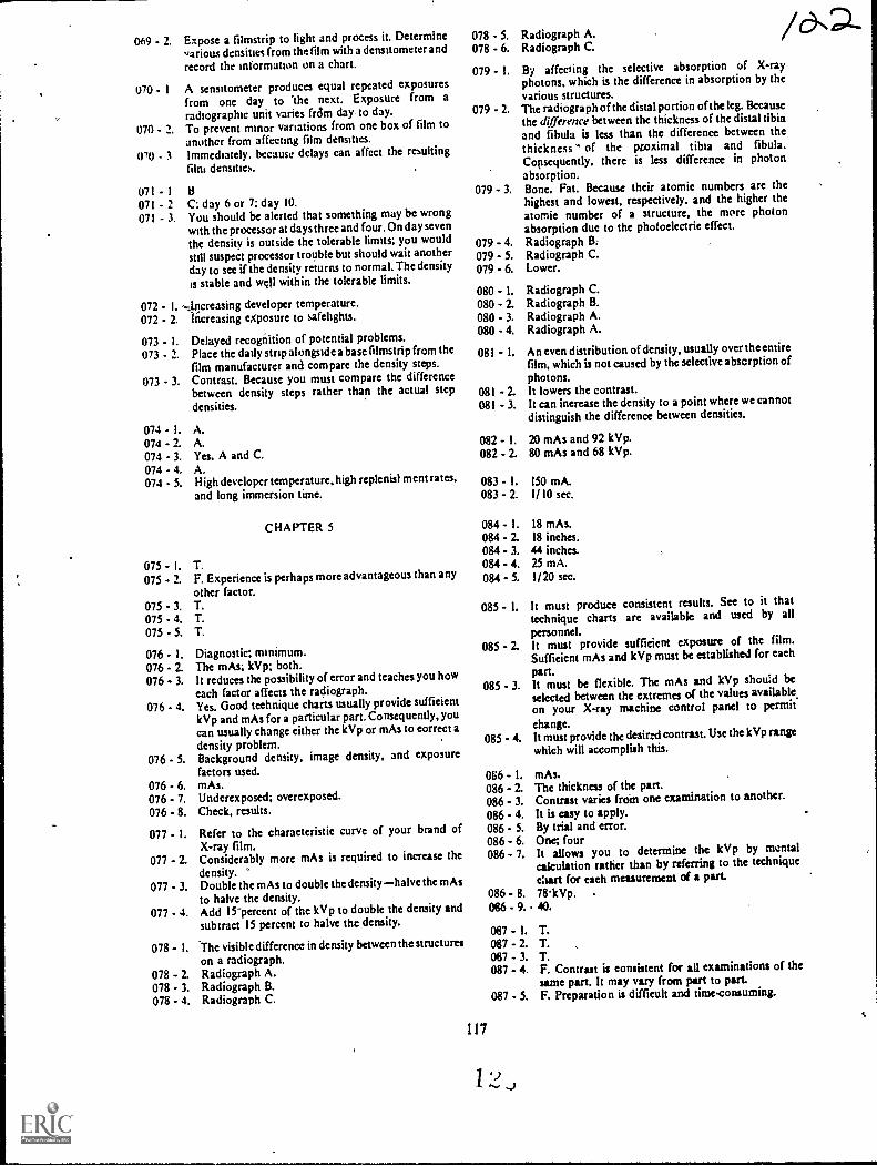
069 - 2. Expose a filmstrip to light and process it. Determinevarious densities from the film with a densnometer and
record the information on a chart.
070 - I A sensitometer produces equal repeated exposuresfrom one day to The next. Exposure from aradiographic unit varies tram day, to day.
070 - 2. To prevent minor variations from one box of film toanother from affecting film densities.
070 - Immediately, because delays can affect the resulting
film densities.
071 - I B071 - 2 C; day 6 or 7: day 10.071 - 3. You should be alerted that something may be wrong
with the processor at days three and four.On day seven
the density is outside the tolerable limits; you wouldstill suspect processor trouble but should wait anotherday to see if the density returns to normal. The densityis stable and well within the tolerable limits.
072 - developer temperature.072 - 2. increasing eXposure to safelights.
073 - I. Delayed recognition of potential problems.073 - 2. Place the daily strip alongside a base filmstrip from thc
film manufacturer and compare the density steps.073 - 3. Contrast. &Cause you must compare the difference
between density steps rather than the actual stepdensities.
074 - I. A.074 - 2. A.074 - 3. Yes. A and C.074 - 4. A.074 - 5. High developer temperature, high replenist ment rates,
and long immersion time.
CHAPTER 5
075 1. T.075 2. F. Experience is perhaps more advantageous than any
other factor.075 1 T.075 - 4. T.075 - 5. T.
076 - I. Diagnostic; minimum.076 - 2. The mAs; kVp; both.076 - 3. It reduces the possibility of error and teaches you how
cach factor affects the radiograph.076 - 4. Yes. Good technique charts usually provide sufficient
kVp and mAs for a particular part. Consequently, youcan usually change either the kVp or mAs to correct a
density problem.076 - 5. Background density, image density, and exposure
factors used.076 - 6. mAs.076 - 7. Underexposed; overexposed.076 - 8. Check, results.
077 - I. Refer to the characteristic curve of your brand ofX-ray film.
077 - 2. Considerably more mAs is required to increase thedensity. "
077 3. Double the mAs to double the density-halve the mAsto halve the density.
077 - 4. Add 15-percent of the kVp to double the density and
subtract 15 percent to halve the density.
078 - I. The visible difference in density between the structureson a radiograph.
078 - 2. Radiograph A.078 - 3. Radiograph B.078 - 4. Radiograph C.
117
078 S.
078 - 6.Radiograph A.Radiograph C.
079 I. By affecting thc selective absorption of X-rayphotons, which is the difference in absorption by thevarious structures.
079 - 2. The radiograph of the distal portion of the leg. Becausethe difference between the thickness of the distal tibiaand fibula is less than the difference between thethickness of the Noximal tibia and fibula.Consequently. there is less difference in photonabsorption.
079 3. Bone, Fat. Because their atomic numbers are thehighest and lowest, respectively, and the higher theatomic number of a structure, the more photonabsorption due to the photoelectric effect.
079 - 4. Radiograph B.079 - 5. Radiograph C.079 - 6. Lower.
080 - I. Radiograph C.080 2. Radiograph B.080 - 3. Radiograph A.080 - 4. Radiograph A.
081 I. An even distribution of density, usually over the entirefilm, which is not caused by the selective absorption ofphotons.
081 - 2. lt lowers the contrast.081 - 3. lt can increase the density to a point where we cannot
distinguish the difference between densities.
082 - 1. 20 mAs and 92 kVp.082 2. 80 mAs and 68 kVp.
083 - I. 150 mA.083 - 2. 1/10 sec.
084 - I. 18 mAs.084 - 2. 18 inches.084 - 3, 44 inches.084 4. 25 mA.084 - 5. 1/20 sec.
085 - I. lt must produce consistent results. See to it thattechnique charts are available and used by allpersonnel.
085 - 2. It must provide sufficient exposure of the film.Sufficient mAs and kVp must be established for each
part.085 - 3. lt must be flexible. The mAs and kVp shou:d be
selected between the extremes of the values available,on your X-ray machine control panel to permit
change.085 - 4. lt must provide the desired contrast.Use the kVp range
which will accomplish this.
086 1. mAs.086 - 2. The thickness of the part.086 - 3. Contrast varies frcirn one examination to another.
086 - 4. lt is easy to apply.086 - 5. By trial and error.086 - 6. One; four086 - 7. lt allows you to determine the kVp by mental
calculation rather than by referring to the technique
elan for each measurement of a part.086 - 8. 78.kVp.086 - 9. 40.
087 - 1. T.087 - 2. T. ,
087 - 3. T.087 - 4. F. Contrast is consistent for all examinations of the
same part. lt may vary from part to part.087 - 5. F. Preparation is difficult and time-coinuming.

088 - I. Low mAs and high kVp (the highest kVp which willproduce radiogaphs to satisfy your radiologist).
088 - 2. Lower patient dosage, less heat units per exposure tothe X-ray tube target, and geater exposure latitude.
089 - I.089 - 2.089 - 3.089 - 4.089 - 5.089 - 6.
71 kVp.100 kVp.102 kVp.20 mAs.20 percent.a. 30 percent.b. 70 percent.c. 75 percent.
CHAPTER 6
090 - I. The person involved and his state of health. An elderlyperson or someone in poor health is particularlysusceptible.
090 2. Part of the body involved. The heart or brain areespecially susceptible.
090 - 3. Time of exposure. The longer theexposure, the greaterthe effect.
090 - 4. Type of current. DC is more dangerous than AC.
091 - 1. T.091 2. F. A fuse is designed to protect the electrical circuit.091 - 3. T.091 - 4. F. Same as exercise 2 above.091 - 5. F. Replacing a fuse with one of a higher rating is
NEVER permitted.091 - 6. F. Have the medical equipment repairman replace the
fuse and find out the cause of the blown fuse beforeusii z'the machine.
091 - 7. T.
092 - I. Proper grounding of the equipment.092 - 2. the housing is isolated from the electrical circuits. To
prevent current from being introduced into thehousing.
092 - 3 Probably not. The current returns to earth through theground wire because it is the path of least resistance.
092 - 4. Probably not.092 5. You would be shocked. Because you connected
yourself between the circuit in the initial appliance andground potential, you now are part of a completedcircuit, and current would easily flow through yourbody.
092 - 6. a. Loose, bent, or otherwise defective power plugs.b. Frayed or cracked power cords or other outside
electrical wires.c. The use of "cheater plugs."d. Missing gound prong on the power plug.
092 - 7. Do not use the piece of equipment. Report the findingto a medical equipment repairman.
093 - I. Very little. Because the resistance of the skin isbypassed by the catheter.
093 - 2. One one-thousandth.093 - 3. Yes. There is danger from leakage current, which can
exist even if no wiring defects are present.093 - 4. The contrast medium in the catheter. Yes.093 - 5. The patient is grounded through the film changer
and/ or X-ray table. Yes.093 - 6. Yes. Because there may be a difference in potential
between the injector and film changer, which couldcause current to flow through the patient.
094 - I. Insure that all the electrical equipment in the room isgrounded to the same ground potential. Have theroom rewired if necessary.
118
094 - 2. Do not alter power plugs:wiring, or anything affectingthe equipment ground.
094 - 3. Have heavy duty, threeway line plugs installed on allpower cords.
094 - 4. Inspect the equipment before each examination forfrayed line cords, broken plugs, deterioratedinsulation, or other equipment defects.
095 I. Darkroom; shock.095 - 2. The tank is probably grounded, and when in cdntact
with it, you are at ground potential.095 - 3. Yes. Because you have placed yourself into a circuit
and are subject to shock if the dryer wiring is defective.095 - 4. Hangers; water; floor.095 - 5. Touching only one electrical appliance at a time. It can
help prevent your body from being at groundpotential.
095 - 6. Turn; off.095 - 7. Keep water mopped up from the floor, and keep your
hands as dry as possible.
096 - 1. T.096 - 2. T.096 - 3. F. You must make sure the object you use to separate
him from the source is nonconductive. Dry wood,clothing, rope, a blanket, or other similar materialsshould be used.
096 - 4. T.096 - 5. F. The head position is not important for closed-chest
heart compression, but is important for mouth-to-mouth. During mouth-to-mouth the head should bein the "sword-swallowing" position.
096 - 6. T.096 - 7. T.096 - 8. F. It should be depressed PA to 2 inches.096 - 9. T.096 - 10. T.
097 - I. They are absorbed by the patient.097 - 2. By removing a good portion of the low-energy
photons.097 - 3 Filtration built-into the X-ray tube. It is usually from
0.3 mm to 0.5 mm aluminum equivalency, dependingupon the type of tube.
097 - 4. 0.2 mm.097 - 5. 1.5 mm.097 - 6. 2.0 mm.097 - 7. By reducing the number of low-energy photons and ihe
minimum photon energy.
098 - I. They increase the mean energy_orthe beam.098 2. They permit a short exposure time, thereby reducing
repeat radiographs becauie of part motion.098 - 3. They provide more exposure latitude, which reduces
repeat radiographs due to the use of incorrect exposurefactors.
099 - I. It limits the area of exposure to that necessary tovisualize the part under study. It prevents repeatradiogaphs due to excessive film fog.
1.39 - 2. The outer limits of the X-ray field.099 - 3. Only that it was larger than the film. The collimator
could have been wide open.099 - 4. There is no particular size. It depends upon the film
size, patient size, and part under study. The Importantthing is for you to see a border of some size on mostradiographs.
100 I. Hips, femurs, and lumbar spines.100 - 2. Abdomens, intravenous pyelograms, sacrum, and.
coccyx.100 - 3. Make sure the shield does not interfere with the
examination, and do not substitute the shield forproper beam collimation.
/013

WI - 1 Less exposure is required to produce the radiograph.101 - 2. Some detail.101 - 3 Use medium or slow screens for body parts requiring
maximum detail and high-speed screens for otherradiographs.
102 - L C.102 - 2. C. '-102 - 3. rhc shorter the deseloping time. the greater the
patient exposure.102 - 4. rhe time recommended by the film manufacturer.
101 - I. Ncser expose yourseif to the primary beam.103 - 2. Always remain behind a protective barner when
making an exposure.103 - 3. Stay as far away from the radianon source as possible.103 - 4. Wear a protective apron during fluoroscopy.
104 - I. Insure that all personnel under your supervision arethoroughly indoctrinated In the proper use of thedosimeter.
104 - 2. You are responsible for the proper use of thedosimeter.
105 - 1. T.105 - 2. F. The belt is at waist level and the dosimeter is worn
above the waist.105 - 3. F. It is worn during fluoroscopy beneath the protective
apron.105 - 4. T.105 - 5. T.105 - 6. F. It assesses exposure to the head and lens of the eye.105.- 7. F. It ts worn in addition to the other dosinmters.105 - 8. F. Dosimeteli are used only for the purpost specified
and at the location specified.105 - 9. F. As a general rule this is true, but you must wrar your
dosimeter when performing portable radiographs.105 - 10. F. They must be stored outside a radiation area.105 - I I. T.105 - 12. F. The identification can be placed on the front as long
as the window is not covered.105 - 13. F. The chest dosimeter only is used to measure whole-
body exposure.
119
1 t.)
AU CAITS,AL. (751942 )1So
/ca
1.MATCH ANSWERSHEET TO THISSTOP- EXERCISE NUM-BER.
2. USE NUMBER 1 ORNUMBER 2 PENCIL.
90370 01 21EXTENSION COURSE INSTITUTE
VOLUME REVIEW EXERCISERADIOGRAPHIC FUNDAMtNTALS
Carefully read the following:
DO'S:
1. Check the "course," "volume,"' and "form" numbers from the answer sheetaddress tab against the "VRE answer sheet identification number" in therighthand column of the shipping list. If numbers do not match, take actionto return the answer sheet and the shipping list to ECI immediately with a
note of explanation.
2. Note that numerical sequence on answer sheet alternates across from column
to column. '
3. Use a medium sharp #1 or #2 black lead pencil for marking answer sheet.
4. Circle the correct answer in this test booklet. After you are sure of youranswers, transfer them to the answer sheet. If you have to change an answeron the answer sheet, be sure that the erasure is 'complete. Use a clean eraser. ,
But try to avoid any erasure on the answer sheet if at all possible.
5. Take action to return entire answer sheet to ECI.
6. Keep Volume Review Exercise booklet for review and reference.
7. If mandatorily enrolled student, process questions or comments through your
unit trainer or OJT supervisor.If voluntarily enrolled student, send questions or comments to ECI on ECIForm 17.
DON'TS:
1. Don't use answer sheets other than one furnished specifically for each review
exercise.
2. Don't mark on the answer sheet except to fill in marking blocks. Doublemarks or excessive markings which overflow marking blocks will register as
errors.
3. Don't fold, spindle, staple, tape, or mutilate the answer sheet.
4. Don't use ink or any marking other than a #1 or #2 black lead pencil.
NOTE: NUMBERED LEARNING OBJECTIVE REFERENCES ARE USEDON THE VOLUME REVIEW EXERCISE. In parenthesis after eachitem number on the VRE is the Learning Objective Number where theanswer to that item can be located. When answering the items on theVRE, refer to the Learning Objectives indicated by these Numbers. TheVRE results will be sent to you on a postcard which will list the actualVRE items you missed. Go to the VRE booklet and locate the LearningObjective Numbers for the items missed. Go to the text and carefullyreview the areas covered by these references. Review the entire VRE againbefore you take the closed-book Course Examination.
1/6
Multiple Choice
1. (001) The movement of electrons through a conductor constitutes an electrical
a. charge.
b. current.
c. voltage.
d. resistance.
2. (002) Material A has one valence electron, material B has three valence,electrons, and material C has four valence electrons. classify the materials
as conductors, semiconductors, or insulators.
a. A--conductor;b. A--conductor;c. A--insulator;d. A--insulator;
B--semiconductor; C--insulator.
B--conductor; C--semiconductor.B--semiconductor; C--conductor.
B--conductor; C--semiconductor.
3. (003) The standard symbol used for voltage is
c. R.
d. P.
(t. (004) In the Value "10Q," the "10" refers to the amount of resistance (R)
indicated and the symbol "Q" is read
a. "amps."b. "ohms."
c. "volts."d. "watts."
5. (005) The resistance of a wire conductor as computed for a circuit depends
on all of the following except
a. temperature. c. type of insulation.
b. length. d. crossrsectional area.
6. (006) How much resistance is present in a circuit if the voltage is 220 and
the current is 10 amperes?
a. 0.04Q.
b. 22a.
c 210Q.d. 2,220Q.
7. (007) If, on a schematic of an electrical circuit, a number is shown alongside
a symbol of a battery, the number represents the
a. battery voltage.
b. battery current.
c. number of cells.
d. number of circuit components.
8. (008) All of the following are basic electrical circuits except
a. resistance-parallel. c. parallel.
b. series-parallel. d. series.
9. (009) The reciprocal method is one of several for determining the
a. total current in a series circuit.
b. effective voltage in a parallel circuit.
c. effective resistance in a parallel circuit.
d. total voltage in a series-parallel circuit.
2

10. (010) Redrawing a circuit before making calculations is an effective and easV
method to
a. fizod the total resistance in a series.parallel circuit.
b. determine the voltage drop across several resistors.
c. determine the total current in a complicated circuit.
d. find the voltage and current values of a parallel circuit.
11. (011) The strength of a magnetic field depends upon the
a. location of the poles.
b. relative size of the ends of the bar.
c. number of lines of force per unit area.
u. direction of travel of the lines of force.
12. (012) In an unmagnetized iron bar, the magnetic dipoles of the material are
a. arranged at random.
b. pointed toward the periphery.
c. molecular in size and have no north or south poles.
d. arranged so that their north poles point in one direction.
13. (013) A straight, current-carrying conductor has a magnetic field
a. with few lines of force.
b. only if the current is DC.
c. with no north or south poles.
d. which does not expand or collapse.
14. (014) All of the following factors affect the strength of the magnetic field
of a coil except the
a. iron core. c. turns per inch.
b. retentivity. d. current-magnitude.
15. (015) The "centering effect" of an iron core is best described as
a. the centering of a lead core to a current-carrying coil.
D. an iron core not remaining inside a current carrying coil.
c. an iron core is inside a wire coil,that cannot be removed unless
current is applied to the coil.
d- a core suspended inside a wire coil, with current causing'the core to
center itself to the length of the coil.
16. (016) A relay operates on the principle that
a. electromagnetism increases current flow.
b. arcing in high-voltage circuits is dangerous.
c. an electromagnet attracts magnetic substances.
d. a current-carrying coil has two magnetic fields if the current is AC.
17. (017) The coil in a permanent-magnet, moving-coil meter is caused to' rotate
by the
a. coil bar attracted to the north pole.
b. magnetic field of the needle repelling the electromagnetic south pole.
c. poles of an electromagnet opposing the poles of a permanent magnet.
d. permanent magnet aligning itself with the magnetic field of the4electro-
magnet.

18. (018) Which one of the following statements best compares current flow of ACto that of DC?
a. AC flows from negative to positive; DC flows from positive to negative.b. Both flow from negative to positive; AC constantly changes directions.c. Both flow from positive to negative; direction cf flow is the same.d. DC constantly changes in value; AC does not.
19. (019) The sine wave of AC is a good representation of the
a. actual current plotted aginst time.b. actual voltage plotted through 3600.c. changing values plotted against time.d. specific voltage and current values in relation to the rests,tance.
20. (020) Which one of the factors listed below is not a requirement forelectromagnetic induction?
a. Conductor. c. Magnetic field.b. Iron core. d. Relative motion.
21. (021) Mutual and self-induction occur without moving the conductor due to
a. movement of the iron core.b. the consistent value of DC.c. the expanding and collapsing magnetic field.d. the high current generated inIthe wire coil.
22. (022) Transformer action can be defined as the process of
a. conducting current and,voltage in an AC circuit. .
b. reducing voltage and current values by mutual indiletion.c. increasing the electrical energy ir a circuit by self-induction.d. transferring electrical energy fron one circuit to another by electro-
,magnetic induction.
23. (023) Improper adjustment of the line voltage compensator on the auto-transformer may result in
a. lower tube capacity. c,. AC across the X-ray tube.b. inaccuracy of the timer. d. light or dark radiographs.
24. (024) Three-phase AC produces how many pulses per cycle aCross the X-ray tube?
a. One or two. c. Two or twelve.b. Six or twelve. d. One, two, or sik.
25. (025) Which rme of the following statements pertains to the relationshipbetween voltage waveform and electron energy?
a. Twelve-pulse produces higher maximum electron energy than does six-pulse.b. Twelve-pulse produces higher average electron energy than does two-pulse.c. One-pulse produces higher average electron energy than does two-pulse.d. Six-pulse produces higher maximum electron energy than does two-pulse.
26. (026) Average photon energy from a airee-phase generator is higher than thatfrom a single-phase generator because in the former
a. the current is lower.b. the current is higher.c. the peak voltage is higher.d. average electron energy is higher.
41
1

I7. (027) The intensity of the X-ray beam is higher from a three-phase generatorthan that from a single-phase generator when equal tube currents are used becat...e
a. image-forming radiation is continuously produced.
b. low-energy photons are continuously produced.
c. high-energy photons are produced three-fourths of a given time period.
d. non-image-forming radiation is produced only at the bottom of the wave.
28. (028) If 100 kVp is used for a radiograph on a three-phase machine, what kVp
should be used for the same radiograph on a single-phase-machine?
a. 85.
b. 90.
c. 115.
d. 120.
29. (029) How does tube capacity compare between single-phase and three-phasetubes for exposure times between one-half and one second?
a. Lower with three-phase.b. .Higher with three-phase.c. They are approximately equal.
d. Lower with three-phase when low tube voltage is used.,
30. (030) Use of the STAND-BY button on the exposure switch should be kept to a
minimum in order to
a. reduce off-focus radiation.b. prevent heat buildup in the anode.
c. reduce surface etching of the target.
d. prevent vaporization of the tube filament.
31. (031) Which one of the following is considered the chief advantage of an X-ray
tube with a biased focal spot?
a. Exposures are grid controlled.b. It.permits higher heat loading.
c. Accumulative heat units are lower.
d. It prevents a double image'on the film.
32. (032) Two advantages of a grid-controlled X-ray tube are
a. short exposures and lower patient dosage.,
b. short exposures and lower photon energies.
c. less heat units per exposure and higher photon energies.
d. more detail on an angiogram and lower photon energies..;"
33. (033) How-many heat units are generated in a three-phase generator if the
exposure factors are 100 mA, 1 sec, and 85 kVp?
a. 850.
b. 8,500.
c. 11,10C.
d. 11,47S.
34. (034) Which one of the following can be determined form a single-exposure tube
rating.chart?
a. mA and kVp only.
b. Heat units only.c. mA, kVp, and seconds.
d. kVp and seconds and heat units.
5
"/c72F
o
35. (035) You are required to use an angiographic rating chart to determine whetheror not the total number of exposures per angiographic examination exceeds'themaximum limits of the tube. You have this data available from your radio-,logist: 4 exposures per second, for 13 seconds. The exposure 'factors are500 mA, 1/20 sec, and 80 kVp. Which statement below is not a correct procedure?
a. Use 2000 as the maximum load per exposure.b. Move up to the .total number of allowable exposures.c. Find 5rexposures per second on the left margin of chart.d. Move across that column to the maximum load per exposure.
36. (036) On an anode cooling chart, you find the cooling time between examinationsby
a. comparing the mAs with the kVp.b. looking at'the readings along the left margin.c. following the cooling curve and correlating the curve with the horizontal
scale. ,d. i'lloring the correct cooling curveXthen performing a calculation, and
folidwing ancTher curve before taking a second reading.
37. (037) What should be adjusted on the X-ray machine control panel to change thepenetrative ability of the X-ray beam?
a. mA. c. mAs.b. kVp, d. Exposure time.
A
,38. (038) Which of the folfowing X-ray machine controls should be used to alterthe number of photons per squari inch iri the X-ray beam?
a. mA and kVp only.b. mA and exposure time only.c. mA, kVp, and exposure time.d. kVp, exposure time, and line voltage compensator.
39. (039) The inverse square law affects the primary beam by
a. eliminating the low-energy photons.b. regulating the mean energy of the beain.c. affecting the number of photons.per unit apea. %
d. increasing the intensity on the cathode side of.the tube.z
O. (040) The anode heel effect is caused when!,
a. target material absorbs photons.b. some photons have less energy than others.c. a small focal spot emits a heterogeneous beam.d. a large focal spot provides greater variation in beam intensity.
,p',341. (041) Which.of the following anode angles provides the gr test variation in
beam intensity?
a. 10°.
b. 12°.
c. 15°.
d. 17°.
42. (042) Which of the following focal spots should be used to provide the bestdetail?
a. 0.3 mm.b. 0.5 mm.
a
c. 1.5 mm.
d. 2.0 mm.
6 136

/ 3 /43. (043) The factor most important when deciding what focal spot to use with a
particular examiinaton is the.
a. necessity of detail. o. contrast scale desired.b. capacity of the tube. d. number of exposures required.
44. (044) If a radiograph of the knee shows too much magnification, which one ofthe following changes could be made to decrease the magnification?
a. Decrease the FFr. o. Decrease the exposure.b. Increase the FFD. d. Increase the part-film distance.
45. (045) Why should distortion be kept to a minimum on a radiograph?
a. Interpretation is easier.b. Distortion decreases penumbra.c. Linear fractures are obscured.d. Enlargement of a part can indicate pathology.
46. (046) A practical way to provide contrast between the gallbladder andsurrounding structures is to
a. decrease the contrast.b. increase the filtration.c. double the size of the projected area.d. use a collimator to restrict the field size.
47. (047) AFM 161-38 requires that all X-ray machines have a collimator except
a. therapeutic units. c. special-purpose units.b. multipurpose units. d. general-purpose units.
46. (046) A required collimator must be adjusted if any side of an X-ray fielddeviates by more than what percent of the FFD?
a. 2.
b. U.
c. 6.
d. 10.
49. (049) Which one of the following body parts may normally be radiographed withor without a grid?
a. Chest.b. Wrist.
c. Skull.d. Pelvis.
50. (050) The grid radius is of importance primarily because of its effect on the
a. FFD.
b. tube alignment.c. efficiency of the grid.d. height of lead strips and interspaces.
51. (051) The greatest advantage of a grid with many lines per inch is that thelead strips are less visible on the radiograph and therefore
a. give better constrast.b. have more lead content.o. interfere less with interpretation.d. can be safely moved during exposure.
7

402.52. (052) The use of a crossed grid as compared to a linear grid
a. has an unlimited usage.b. has less lead in the grid.c. has an effective ratio twice its nominal ratio.d. permits the tube to be angled in unlimited ways.
53. (053) Normally, the type of grid to use to prevent grid lines at very shortexposure times would be a
a. moving Potter-Bucky. c. recipromatic Potter-Bucky.b. Potter-Bucky of any type. d. reciprocating Potter-Bucky.
511. (054) Grid efficiency refers to the amount of scatter radiation absorbed
compared to the amount of
a. photon scatter. c. lateral decentering used.b. microline grid exposure. d. primary radiation absorbed.
55. (055)_ Lateral decentering of an X-ray tube causes
a. a fog over the decentered area.b. an even fog over the entire radiograph,c. an even loss of radiographic density over the near side of the film.d. an even loss of radiographic density over the entire film.
56. (056) Which one of the following actions should be taken to determine thetolerance of grids if fncal ranges are not specified by the manufacturer?
a. Apply more kVp.b. Increase the mAs.
c. Use a densitometer.d. Obtain the manufacturer's reccmmeniations.
57. (057) If a grid radiograph shows a loss of density on one lateral margin ofthe film, which of the following types of decentering was likely present atthe time of exposure?
a. Focus decentering.
b. Lateral decentering only.c. Distance decentering only.d. Lateral and distance decentering.
59. (058) Select the maximum tube angle which can be allowed if you desire toavoid a noticeable loss of density over the entire radiograph in a case wherethe grid ratio is 16:1,
a. 1°. c. 6°.5. 3o. d. 8°.
59 (059) Which one of the following indicates that the composition of the X-rayfilm has been especially adapted for use in 90-second processors?
a. Polyester base. c. Cellulose acetate base.
b. Two subcoatings. d. Emulsion on one side only.
63. (060) Which type of X-ray film provides excellent detail for small parts and
because of its thick emulsion requires longer processing?
a. Dental only. c. Nonscreen.
b. Screen only. d. Both dental and screen.
8
6l. (061) A densitometer shows that part "X" of a radiograph has a dens_ty of1.0, while part 2X" has a density of 3.0. Which statement below compares theincident light tbansmitted through "X" to the incident light transmitted throughInt'?
a. 1 percent to 3 percent. c. 0.1 percent to 10 percent.
b. 3 percent to 1 percent. d. 10 percent to 0.1 percent.
62. (062) Which one statement below is typical of the characteristic curve of anX-ray film used to determine the specific mAs changes necessary to raise or
lower a radiograph density?
a. Density is plotted on the horizontal axis.
b. Log relative exposure is plotted on the vertical axis.
c. Values of mAs that can be applied to the scale are limited.
d. The horizontal axis, "log relative exposure," represents the mAs required
to change density.
63. (063) The inherent film fog, as determined from reference to the toe of thefilm's characteristic curve and judged on a general basis, is excessive if it
exceeds a density of
a. 0.2
b. 1.0.
c. 1.5.
d. 2.0.
64. (084) The name of the layer of material of an intensifying screen designed to
expose the film is called a
a. base. c. protective coa*tg.
b. phosphor. d. reflecting material.
65. (065) As the speed of intensifying screens become higher, there is a resultant
a. decrease in the life of the X-ray tube.
b. reduction in radiographic detail and clarity.
c. increase in the transmission of radiation to the patient.
d. increase in radiographic-exposure time necesbary for clarity.
66. (066) A part of the process of making a valid screen-film-contact test
consists in inspection of a
a. wire mesh image. c. densitometer reading.
b. voltmeter reading. d. thickness-gauge measurement.
67. (067) If, during a valid screen-lag test, half of the film is found to be
exposed while the other half is not, it may be concluded that
a. screen lag is present.
b. screen lag is not present.
c. fluorescence stopped at the time of esposure.
d. no evaluation can be made without the name of the test.
68. (OH) Exposed crystals in films are changed to black metallic silver during
film processing by
a. sodium sulfite.b. phenidone, metol, and hydroquinone.
c. potassium alum and sodium carbonate.
d. gluteraldehyde, acetic acid, and sodium thiosulfate.
9
69. (069) To insure consistent high-quality production of radiographs, eachprocessor should be checked daily using a
a. cleaning agent.b. voltmeter only.c. densitometer only.d. sensitometric film strip, a densitometer, and a recording chart.
70. (070) One requirement pertaining to the use of the sensitometer and radiographicfilm while conducting a processor evaluation test includes
a. reserving one box of film for the evaluation.b. substitution of a radiographic unit for a sensitometer.c. exposing film every two days and processing as a matter of convenience.d. insuring all procedures remain the same.
,71. (071) To measure the density in evaluating filmstrips, a density step between0.9 and 1.2 is selected because these densities
a. cover the average normal densities.b. comprise the allowable upper limits of densities.c. comprise the allowable lower limits of densities.d. are located on the portion of the characteristic curve most sensitive to
changes in processing.
72. (072) The base fog of a filmstrip is easily measured by
a. the contrast of two exposed steps.b. looking at the manufacturer's specifications.c. the density of the unexposed density step.d. increasing the developer temperature to a high value.
72. (073) If processing is accomplished without using a densitometer, the mostdifficult comparison to make is of
a. density. c. contrast.b. base fog. d. base fog coupled with density.
74. (074) Underdevelopment that permits variations between processors can be causedby such factors as
a. low replenishment rates. c. low fixer immersion time.b. high replenishment rates. d. high developer temperature.
75. (075) As measured with a densitometer, the average density for most radiographsshould be approximately
a. 0.5. c. 2.5.
b. 1..5. d. 25.
76. (076) To change density with kVp or mAs, all of the following should be
considered except
a. image density.P. background density.c. exposure factors used.d. 'increase mAs if too little kVp is used.
10
77. (077) The most reliable and accurate way to determine the exact mAs change
required to make a specific change in the film density is to
a. use a rule of'thumb.
b. make mathematical calculations.
c. double or halve the mAs to double or halve the density.
d. refer to the characteristic curve of the brand of X-ray film used.
78. (078) In radiology, "the visibledifference in density between areas or
structures on a radiograph" is defined as
a. contrast.c. long-scale contrast.
b. high contrast. d. short-scale contrast.
79. (079) The three factors--structurethickness, atomic number, and density--
affect the contrast on a radiograph by
a. eliminating film fog.
b. negating the affects of film contrast.
c. affecting the selective absorption of the photons.
d. shortening the exposure time thereby affecting selective absorption.
80. (080) The one most important factor affecting the selective absorption and
contrast on a radiograph is best designated as
a. energy.c. penetrative ability.
b. wavelength.d. kVp selected on the control panel.
81. (081) Film fog, as it occurs on radiographs to reduce their contrast, is
caused by all of the following except
a. scatter radiation.
b. improper processing.
c. deliberate film exposure.
d. exposure of the film to either light or to radiation leaks.
82. (082) A radiograph made with 100 kVp and 30 mAs is properly exposed but lacks
contrast. Which of the following valuesshould be used to produce a second
radiograph that is equal in overall density to the first with proper contrast?
a. 50 kVp and 60 mAs. c. 110 kVp and 15 mAs.
b. 85 kVp and 60 mAs. d. 115 kVp and 15 mAs.
83. (083) The mA-sec formula that you should use in your computation to control
undesirable motion and thus enhance image detail is
a. mA2:mAl::sec2:sec1.
b. mAimr11,2::sec2:sec .
c. mAl:seci::mA2:2122.
d. mA23Al::sec2:secl.
84. (084) A technique chart may specify a technique of 14 mAs using a 56-inch FFD;
however, if because of limitations, it may become necessary to use a 28-inch FFD.
Such a requirement will then necessitate a new mAs of
a. 2.5.
b. 3.5.
c. 7.0.
d. 56.
85. (085) Which one of the following four basic requirements for establishing a
s'..andard system of exposure factors would be sought in keeping both the mAs
and the kVp within a range from which either may be increased or decreased?
a. Flexibility.c. Desired contrast range.'
b. Consistent results. d. Sufficient exposure of film.
11

86. (086) One absolute requirement for use of a chart employing variable kVptechniques is to
a. also vary the mAs.b. insist that no two individuals use the same chart.c. know the part thickness in centimeters along the path of the CR.d. make a two.kVp change for each centimeter of part change, without exception.
87 (087) All of the following are descriptive of the "fixed" kVp technique excett
a. contrast is consistent for all body parts.b. the system is fast falling into disrepute.c. mAs varies depending upon the size of the part.d. a change from 40 to 50 mAs for a larger part is appropriate.
88 (088) All of the following statements list advantages of using high kVptechniques except
a. there is greater exposure latitude.b. there is.less absorption of photons by patient.c. X-ray tube is subjected to fewer heat units per exposure.d. the time and effort it takes to prepare the chart used is negligible.
89. (089) Changes of exposure necessitated by the presence of a cast or thepatient's age require reference to tabular data called
a. compensatory factors. c. collective factors.b. compensation factors. d. collateral factors.
O. (090) The amount of current constituting a lethal shock varies with all of
the following except
a. type of current. c. age of the patient.b. ionizing radiation. d. part of body involved.
91. (091) A burned out fuse in an X-ray machine should be replaced
a. by one of the same rating. c. with one of a higher rating.b. with one of a lower rating. d. by a medical equipment repairman.
92. (092) An important safeguard to protect service personnel and patients fromelectrical shock in case radiology equipment shorts the operating current tothe housing is to
a. properly ground the equipment.b. replace the fuse with a smaller one.c. rely on the fuse for adequate protection.d. touch both its housing and another grounded piece of equipment
simultaneously.
93. (093) During angiography, in which a catheter is inserted into the blood strear,what measure of the lethal skin current is required to produce ventricular fib-rillátion?
a. 1/10.
b. 1/100.
12
c. 1/1,000.d. 1/10,000.

/3 794. (094) An electrically safe atmosphere for an angiographic patient can be
created by
a. using nonconductive contrast media.
b. grounding all electrical equipment to metal water pipes.
c. using only three-prong, heavy-duty line plugs when cords are frayed.
d. grounding all electrical equipment to the same ground potential.
95. (095) An effective precaution to help prevent electrical shock while manually
processing films in the darkroom is to
a. not turn the dryer switch ON.
b. work with dry hands and on a dry floor.
c. always simultaneously contact the processing tank and the dryer.
d. make certain the dryer housing is not isolated from the power line.
96. (096) If another person accidently comes into contact with a hot wire and is
thereby knocked unconscious and frozen to the circuit, the very first action
tc te taken is
a. turn the power OFF.
t. seek additional help.phone for a physician.
c. pull the victim from the electrical source.
97. (097) Filtration of the X-ray beam lowers the patient's exposure by removing
a. mosf of the medium energy photons.
b. the aluminum equivalency of the tube.
c. all of the low-energy photons and consequently lowering the patient's
absorbed dose.
d. a portion of the law-energy photons and consequently increasing the mean
energy of the primary beam.
19. (098) High kVp techniques reduce patient exposure in all of the following
ways except to
a. increase the mean energy of the beam.
t. lengthen the scale of contrast.
:. provide more exposure latitude.
d. permit shorter exposure times.
9. Cne of the two ways that proper collimation reduces patient's exposure
is tnat it
a. standardizes a 2-inch unexposed border around the sides.
L. increases the area of exposure to include significant adjacent areas.
c. increases film fog, making the X,rays themselves less 1..cnetrating.
d. limits the area of exposure to that necessary for visualizing the part
under study.
100. (100 All of the following are important to prevent needless exposure of a
patient's gonads excect
a. careful shielding for hip examinations.
use of shielding in addition to collimation.
c. covering them with lead-rubber shielding material.
placement of shield to insure superimposing over part under study.
13

101. (101) High-speed films and screens reduce patient's exposure to radiationcoupled with a
a. detail loss.b. contrast loss.c. gain in exposure time.d. resultant increase in film fog.
102. (102) From an examination of characteristic curves that relate developing timeto patient's exposure, it is possible to conclude that the shorter the ceveloping
time the
a. less the patient's exposure.b. greater the patient's exposure.c. less need there is for shielding.d. less effect it has on the patient's absorbed dose.
103. (103) All of the following are valid rules for protecting oneself againstradiation except
a. remaining behind a protective barrier.
b. wearing a protective apron during fluoroscopy.
c. staying as far away from the radiaton source as possible.d. occasionally exposing oneself to the primary beam since scatter is
usually less hazardous.
104. (104) Technician responsibilities include
a. repair of issued/dosimeters.b. proper use of the dosimeter issued by a supervisor.
c. routine recording of levels for the personnel dosimeter.
d. checking levels and conditions of issued personnel dosimeters.
105. (105) If a dosimeter is used to record exposure to a localized area, what
must be done before it can be worn at any other body site"'
a. Replace it.b. Change the dosimeter film.c. Recalibrate it for accuracy.
d. Record the localized exposure.
14
Li

90370 02 7503
CDC 90370
RADIOLOGY TECHNICIAN
(AFSC 90370)
N. Volume 2
Osteology and Positioning
1.1.1MIMIAM1.141A1.1.1.1.1AIMIMANIA, IAIMIAIMIAIMMYMINIAINIAIANW
'( f*
AIMM41404INMWIWWWWIAMOWWWWWWWMIMIANWAVIMNIMIAWMIAIIMM
0 Extension Course Institute
Air University / 6
Preface
WH A T DOES IT take to produce a diagnostic radiograph? Exact technique? Perfectprocessing? Proper film holder? Good equipment? As you know, it takes all of thesefactors, plus another very important oneproper positioning. All of the other factorscan be perfect, but if the positioning isn't correct, the radiograph may not bediagnostic As a "five level" you have, no doubt, taken your share of radiographs andrealize the importance of proper positioning techniques. You are probably also awareof the fact that osteology and positioning go hand in hand. The ability with which youposition the patient is directly related to your knowledge and application of osteology.
As you a4yance to the "7 level," you will become more and more involved in qualitycontrol. YouWt have to evaluate radiographs and decide whether or not they arediagnostic. If they are not, you must recommend the proper corrective measures to betaken. It is obvious that you will not be able to perform positioning quality controlsatisfactorily unless you have a good working knowledge of osteology and can applythe correct ositioning techniques.
This volume is designed to provide you with information to aid you in qualitycontrol. We will include almost a complete review of ,the osteology because of itsimportance. Our review of the standard positions will be limited because you should beable to perform them competently already. We will present, in detail, some frequentlyused special or additional positions. We will also provide you with additionalinformation about the radiograph to help you evaluate the quality of a radiograph asrelated to positioning.
We do not recommend that you repeat all radiographs that were improperlypositioned. There are other considerations, such as patient dosage, time element, andthe amount of information revealed by the initial radiograph. We do recommend thatyou discuss quality control in detail with your radiologist. Get to know what he likesand dislikes and then repeat or accept the radiographs based on his preferences.
If you have questions on the accuracy or currency of the subject matter of this text,or recommendations for its improvement, send them to School of Health CareSciences, MST, Sheppard A FB TX 76311. NOTE: Do not use the suggestion programto submit corrections for typographical or other errors.
If you have questions on course enrollment or administration, or on any of ECI'sinstructional aids (Your key to Career Development, Behavioral Objective Exercises,Volume Review Exercise, and Course Examination), consult your education officer,training officer, or NCO, as appropriate. If he can't answer your questions, send themto ECI, Gunter AFS AL 36118, preferably on ECI Form 17, Student Request forAssistance.
This volume is valued at 24 hours (8 points).
Material in this volume is technically accurate, adequate, and current as of October1974.
Hi
a
Contents
Chapter
Preface
Page
iii
I Osteology of the Extremities 1
2 Osteology of the Vertebral Column,the Ribs, and the Sternum 27
3 Osteology of the Skull, the FacialBones, and the Paranasal Sinuses 37
4 Positioning of the Extremities 45
5 Positioning of the VertebralColumn, Ribs, and Chest 56
6 Positioning of the Skull 64
Answers for Exercises 79
a
-

/VgCHAPTER I
NOTE: In this volume, the subject matter is developed by a series of Learning Objectives.Each of these carries a 3-digit number and is in boldface type. Each sets a learning goal for you.The text that follows the objective gives you the Information you need to reach that goal. Theexercises following the information give you a check on your achievement. When you completethem, see if your imswers match those in the back of this volume. If your response to anexercise is incortect, review the objective and its text.
Osteoiogy of the Extremities
WE BEGIN OUR STUDY of osteology with theextremities. Some of the information in this chapterwill, no doubt, seem "old" to you because youshould already have a good working knowledge ofthe material. Since you have performed manyradiographs of the extremities, you must also realizeby now that the effectiveness of your positioning isdirectly related to your knowledge of anatomy.Therefore, our, review of the basic osteology isreasonably complete. We will also present more thedetailed osteology that you need to perfiarm at the 7level.
In this 'chapter, we will discuss anatomicalreference terms, body planes, the lower extremity,including the pelvic girdle, and the upper extremity,including the shoulder girdle.
1-1. Body Planes and Anatomical ReferenceTerms
In addition to the specific anatomy, you must alsoknow the relationships of the various parts. Theimaginary planes of the body are important so,before we discuss the osteology of the extremities,let's quickly review some anatomical referenceterms and the body planes.
200. Identify the relative locations of various partsof the body by correctly indicating whether selectedstatements, pertaining to the location of the parts,are true or false. If you indicate"false," explain youranswer.
Anatomical Reference Terms. To avoid anymisunderstanding and confusion in describing thelocation of anatomical structures, we will use the
standard body position as a point of reference. ThisgenerallY accepted standard position is called the"normal anatomical position" or "anatomicalposition." This position is assumed when the body isstanding erect, the arms are hanging at the sides,and the palms of the hands are turned forward (seefig 1-i). When you use anatomical reference terms,you must visualize the body in this position.
"Anterior" and 'ventral" refer to the front of thebody; "posterior" and "dorsal," to the back. Theseterms may also be used to indicate relative positionswithin the body. For the hands, however, "palmar"is used instead of anterior. In describing the, fee,t,"plantar" refers to the sole and "dorsal" to the tippersurface. In describing the anterior surface of theforearm and hand, the term "wilar" can be used.
"Medial" refers to structures located nearer themidline of the body; "lateral," to those nearer theside. For example, the tibia is medial to the fibula,and the fibula is lateral to the tibia. These terms mayalso be used to identify surfaces of 4riousstructures. Far example, the thumb and little fingerare located on the lateral and medial aspects Of the
hand respectively.
"Superior" refers to a position above a particularreference point; "inferior," to a position below areference point. The thoracic vertebrae are superiorto the lumbar vertebrae, and the lumbar vertebraeare inferior to the thoracic vertebrae.
"Proximal" means nearer the attachment of alimb or nearest the point of origin. "Distal" refers toa position remote from the point of atfachment,orfarthest from the point of origin. For example, theshoulder joint is in the proximal arm, and the wristjoint is in the distal arm.
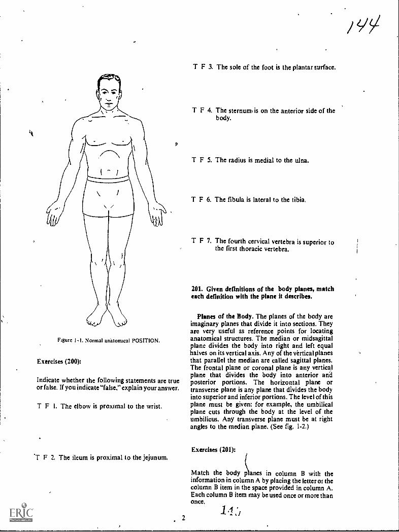
Figure I. Normal anatomical POSITION.
Exercises (200):
Indicate whether the following statements are trueor false. If you indicate "false," explain your answer.
T F I. The elbow is proximal to the wrist.
F 2. The ileum is proximal to the jejunum.
2
T F 3. The sole of the foot is the plantar surface.
T F 4. The sternum is on the anterior side of thebody.
T F 5. The radius is medial to the ulna.
T F 6. The fibula is lateral to the tibia.
T F 7. The fourth cervical vertebra is superior tothe first thoracic vertebra.
201. Given definitions of the body planes, matcheach definition with the plane it describes.
Planes of the Body. The planes of the body areimaginary planes that divide it into sections. Theyare very useful as reference points for locatinganatomical structures. The median or midsagittalplane divides the body into right and left equalhalves on its vertical axis. Any of the virtical planesthat parallel the median are called sagittal planes.The frontal plane or coronal plane is any verticalplane that divides the body into anterior andposterior portions. The horizontal plane ortransverse plane is any plane that divides the bodyinto superior and inferior portions. The level of thisplane must be given: for example, the umbilicalplane cuts through the body at the level of theumbilicus. Any transverse plane must be at rightangles to the median plane. (See fig. 1-2.)
Exercises (201):
Match the body planes in column B with theinformation in column A by placing the letter oi thecolumn B item in the space provided in column A.Each column B item may be used once or more thanonce.
/

Column 4
I Do ides the right half at thebody into medial and Literalportions.
2. Disides the bod) betoeenthe sternum and spine
3 Disides the body into tooequal halves._ 4 Separates the umbilicusfrom the sternum
5 Is perpendicular to thecenter of the film for an kPlumbar spine.
a
b.C.
d.
Figure I -2. Planes of the body.
Column B
Median or midsagit-tal.Sagittal.Frontal or coronal.Horizontal ortransverse.
1-2. The Lower Extremity
This section will CON er the toes and foot, the ankle,the leg, the knee and patella, the femur, and thepelvic girdle.
3
luJ
202. Given a list of statements pertaining to thename, location, description, and number of bonesand joint3 of the toes and foot, indicate whieh aretrue and which are false. (If you indicate "false,"explain your answer.)
The Toes and Foot. The bones of the foot form anarch which; in an architectural sense, stronglyresembles the old stone arches. The arch iscomprised of wedges, cubes, and long, relativelystraight sections, all of which join with each other toprovide structural strength and inobility. Theskeleton of the foot consists of three partsthephalanges, the metatarsals, and the tarsal bones.Refer to figure 1-3 as you study the tocs and foot.

Cal c..an e.us
Talus
Navieular
First-Cu.rielf or rt..,
Sec. o ric3.Cuneifor rrt
Tarsals(Posterior Sec.)
CuboidThird
\-Cune.iform
z sals(Mi1i. Seotion)
? Phal a ricte s(Anter io r Section)
Na.vic/ular First- Me-tat-a.? s al
Cesic-caneu.s -17.1us r Curs. f-o
Figure 1-3. Skeleton of the toes and foot.
15
Nh

Phalanges. The phalanges of the toes arearranged and identified in the same manner as arethe phalanges of the hand. Each is composed of abody, a head, and a base. The tip of each distalphalanx terminates as the ungual tuberosity, or tuft.Each toe has three phalanges, except the first, whichhas only two. The phalanges of the first toe join inthis way: the distal phalanx joins proximally withthe distal end of the proximal phalanx, and theproximal phalanx joins the distal end of the first
metatarsal.
The phalanges of the lesser toes join in much thesame way as !those of the first toe. The proximalportions, or bases, of the distal phalanges articulatewith the distal portion, or heads, of the middlephalanges. The bases of the middle phalangesarticulate with the heads of the proximal phalanges.
' The bases of the proximal phalanges, in turn,articulate with the heads of the metatarsals.
Memarsals. The sole and lower instep areformed by the metatarsal bones, which are classifiedas short bones and are identified by the numbers onethrough five from the medial to the lateral sides.Each bone has a body, a base, and a head. Themetatarsals join distally with the correspondingproximal phalanges of the toes, and proximally theyjoin thc tarsal bones as follows:
a. The first metatarsal joins the distal end of thefirst cuneiform and the medial surface of the secondmetatarsal.
b. The second metatarsal joins the medial surfaceof the first cuneiform, the distal ends of the secondand third cuneiforms, and the lateral and medialsurfaces of the first and third metatarsalsrespectively.
c. The third metatarsal joins the distal end of thethird cuneiform, the lateral surface of the secondmetatarsal, and the medial surface of the fourthmetatarsal.
d. The fourth metatarsal joins the distal end of:he cuboid, the lateral surface of the thirdmetatarsal, and the medial surface of the fifthmetatarsal.
e. The fifth metatarsal joins the distal end of thecuboid and the lateral surface of the fourthmetatarsal.
Tarsals. The tarsals, which are described below,make up the posterior part of the foot and part ofthe ankle. Because of their shape, they are classifiedas irregular bones. Some of them, like the carpals,are often referred to by more than one name.
The first. second. and third cuneiform bones arewedge shaped. They are located directly behind the
5
A/7first, second, and third metatarsals, and in front ofthe navicular. They are numbered from the medialto the lateral side.
The cuboid is on the lateral aspect of the foot,directly behind the fourth and fifth metatarsalbones.
The navicular (tarsal scaphoid) is on the medialside of the foot, directly behind the cuneiformbones.
The talus (astragalus), through which the bodyweight is transmitted to the foot, is the secondlargest tarsal. It is located behind the navicular andslightly higher than the other tarsals. The talus has ahead, a neck, and a body. The head is directedslightly medially and upward to articulate with thenavicular. The superior, portion of the body, is asmooth, trochlea-like surface, which articulateswith the tibia. The inferior surface has two smoothsurfaces, which articulate with the calcaneus. Adeep groove, the sulcus tali, separates the smooths urfaces.
The calcaneus (os calcis), the largest of the tarsalboncs, is located on the extreme posterior portion ofthe foot, beneath the talus. The superior surface ofits anterior two-thirds supports the talus andreceives the body weight transmitted from the talus.The posterior one-third forms the heel. Thecalcaneal tuberosity lies on the posterioi part of theinterior surface. It is slightly depressed iiii the middleand runs to both sides to form the lateral and medialprocesses. A projection on the superoanterior partof the medial calcaneal surface is called thesustentaculum tali.
Exercises (202):
In the following exercises, indicate whether thefollowing statements are true or false (explain falsestatements).
T F 1. There are 14 phalanges in the toes.
T F 2. The third toe has two phalanges.
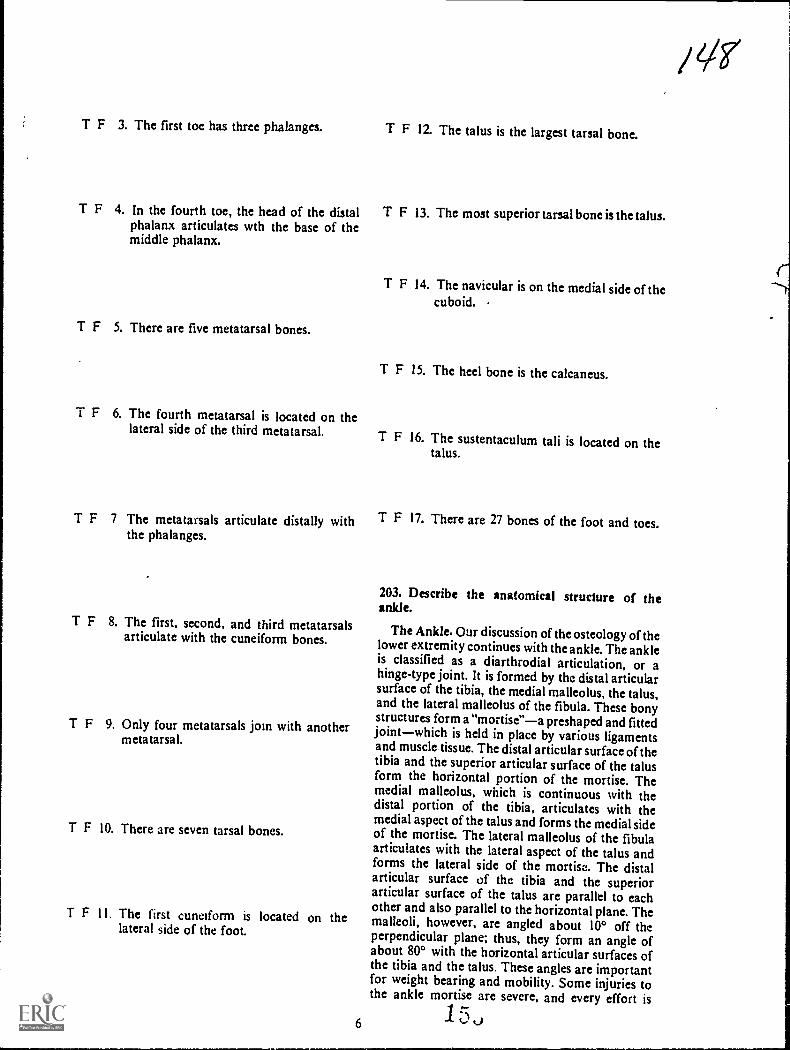
T F 3. The first toe has three phalanges. T F 12. The talus is the largest tarsal bone.
T F 4. In the fourth toe, the head of the distal T F 13. The most superior tarsal bone is the talus.phalanx articulates wth the base of themiddle phalanx.
T F 5. There are five metatarsal bones.
T F 6. The fourth metatarsal is located on thelateral side of the third metatarsal.
T F 14. The navicular is on the medial side of thecuboid.
T F 15. The heel bone is the calcaneus.
T F 16. The sustentaculum tali is located on thetalus.
T F 7 The metatarsals articulate distally with T F 17. There are 27 bones of the foot and toes.the phalanges.
T F 8. The first, second, and third metatarsalsarticulate with the cuneiform bones.
T F 9. Only four metatarsals join with anothermetatarsal.
T F 10. There are seven tarsal bones.
T F 1 I. The first cuneiform is located on thelateral side of the foot.
6
203. Describe the anatomical structure of theankle.
The Ankle. Our discussion of the osteology of thelower extremity continues with the ankle. The ankleis classified as a diarthrodial articulation, or ahinge-type joint. It is formed by the distal articularsurface of the tibia, the medial malleolus, the talus,and the lateral malleolus of the fibula. These bonystructures form a "mortise"a preshaped and fittedjointwhich is held in place by various ligamentsand muscle tissue. The distal articular surface of thetibia and the superior articular surface of the talusform the horizontal portion of the mortise. Themedial malleolus, which is continuous with thedistal portion of the tibia, articulates with themedial aspect of the talus and forms the medial sideof the mortise. The lateral malleolus of the fibulaarticulates with the lateral aspect of the talus andforms the lateral side of the mortise. The distalarticular surface of the tibia and the superiorarticular surface of the talus are parallel to eachother and also parallel to the horizontal plane. Themalleoli, however, are angled about 100 off theperpendicular plane: thus, they form an angle ofabout 80° with the horizontal articular surfaces ofthe tibia and the talus. These angles are importantfor weight bearing and mobility. Some injuries tothe ankle mortise are severe, and every effort is

made to maintain these angles during the treatmentof the injuries. Figure 1-4 illustrates the ankle joint,and figure 1-5 illustrates the angles formed by theankle mortise.
Exercises (203):
I. What three major bones make up the ankle joint?
2. On which bone is the medial malleolus?
3. On which bone is the lateral malleolus?
4. Why are the angles formed by the ankle mortiseimportant?
5. What type of joint is the ankle?
Tibia
ANTERIOR A5PECT
Fibula
LATERAL ASPECT
TibiaFibula
Talus
Figure I 4. The ankle joint.
7
204. Name, locate, ind describe the anatomicalparts of the leg.
The Leg. The leg consists of two bonesthe tibiaand the fibula. We shall consider each separately,starting with the tibia. Using figure 1-6 as areference will help you understand the descriptions.
The tibia. The larger of the two bones, commonlycalled the shin bone, is the tibia, located on themedial side of the leg. It has a shaft and two ends.The distal end of the'tibia is much smaller than theproximal end. The inferior surface is smooth andarticular, and the medial surface extends downwardto form the medial malleolus.
The shaft of the tibia is somcwhat triangular withthree surfaces and three borders. The anterior crest,or border, which runs from just above the tibialtuberosity to the anterior margin of the medialmalleolus, can be easily located by palpation. Themedial border begins at the posterior portion of themedial condyle and extends downward to theposterior portion of the medial malleolus. Thelateral border, often referred to as the interosseouscrest, begins in front of the articular surface of thefibular head and extends down the bone. Themedial surface is smooth and slightly convexed; thelateral surface is narrower than the medial. We candescribe the posterior surface best if We divide it intothirds. The proximal third ends in the popliteal line.The middle third has a vertical ridge which starts atthe popliteal line and gradually becomes indistinctas it descends. The distal third is smooth.
The major parts of the proximal tibia are thesuperior articular surface, the medial and lateralcondyles, the intercondylar eminence, and the tibialtuberosity. The superior articular surface has twosmooth articular surfaces which are separated by agroove. The smooth surface on the medial side is thesuperior surface of the medial condyle. Thecorresponding lateral surface is the superiorarticular surface of the lateral condyle. Both of thesesurfaces articulate with the condyles of the femur toform the knee joint. The grooves that separatethese surfaces are the anterior and posteriorintercondyloid fossae. Located in the middle of theintercondyloid fossa is the intercondyloid eminenceor spine of the tibia. Just below the condyles,anteriorly, is the tibial tuberosity, which serves asthe attachment place for the patellar ligament. Theposterior surface of the proximal tibia contains thepostcrior intercondylid fossa. On the posteriorsurface of the medial condyle a deep groove runstransversely, and on the posterior surface of thelateral condyle is an articular surface for the head ofthe fibula.
The fibula. The fibula, the smaller of the two legbones, is located on the lateral side of the leg, whereit acts as a split for the tibia. It also serves as anattachment place for muscles and forms the lateralportion of the ankle joint. Like the tibia, it has ashaft and two ends. The distal end of the fibula is

Axis of tibial shaft and talus1
1
1
I-
Approx. 800
\
\
1
\..i........m....1==.A.\'../'- I 1
Lrz.\.: 7'-9A.#-.1 90° \ ...../.7\11.
I It i t\ \ Approx. 80-
-------.1,...
\ \
Parallel axis of adjoiningarticular margins of tibiaand talus
1 /I
I iParallel axis adjoining articular marginsof medial malleolus and talus
I i IParallel axis of adjoining articularof lateral malleolus and talus
Figure 1-5. The angles formed by the ankle mortise.
shaped somewhat like a pyramid and contains thelateral malleolus, which extends downward tocomplete the ankle mortise.
The shaft of the fibula has four borders and foursurfaces. The anterior portion is divided into theanterolateral and anteromedial borders. Theanterolateral border begins, proximally, in front ofthe fibular head and runs distally for about half thelength of the bone. The anteromedial border, oftencalled the interosseous crest, begins just below thefibular head and runs distally, parallel with theanterolateral border, for the proximal one-third ofthe bone The posterior portion of the shaft is alsodivided into two borders, the posterolateral and theposteromedial. The posterolatcral border begins
8
margins
just above the fibular styloid process and extendsdownward to the posterior portion of the lateralmalleolus. The posteromedial border, often calledthe oblique line, begins at the medial side of thefibula and extends obliquely downward to theinterosseous crest. The anterior surface is betweenthe anteromedial and anterolateral borders. Theposterior surface is between the posterolateral andposteromedial borders.
The upper expanded end of the fibular headarticulates with the fibular articular surface of thelateral condyle of the tibia. However, the head of thefibula does not enter into the formation of the kneejoint. The styloid process is that portion of the headthat rises into a point above the articular surface.
1 Ct... 0
/ 5".'

PfrOmmAt
intrLori.SAIir Erslintnc.aMsdia II Ihrrtart.ilylar ,.. tatcri Inter,,i.J41 ir
Erninrinca ---.. E n ,upl. ...lir Ar.cAt. S.:1..5y _ Suptrior Art...Akar Suffaceof Mo41.I Cf,11/14. .1 later.% evitclyle
Mcdiril CrKtyla " "LaParal Condy1t.Tibitsi 7 mbarosity --- SI. yloid Process
T11,1
Mtha%
A nt Iir Groot-.Lateral Smrt-ata
u Ct. I
Mr4ial Borde.
Media MaIllutu,
Exercises (204):
PROXIMALInterxondy tar
latral Int crcondllar...... ans.
ArriGulaf auftat01- Lat....1 Condyle.
trat ConflyloStylotd PrOLa
mslot ...it BorderPo tarot....4,AI
int .. Crist Bards*,
fArit,latral Surf-aceAnt.... Surf-actAntarorriedia13urtact.
USAAO. tNtANTERIOR yaw
artrot Molicolua
ENOErnincnc.r.Madtal Inte.re.Oridii tar
tBupTeinOr Acr'tic.illar Surtax*.01- Martial CndytaMathol Condyle.
PostarornartiI Brder
Postortsir Surtat.e.I
Lt,.t Matia0Ius
/51
Prximal Third
Pop111-641 tine
Mid4la Third
Disral Third
DISTAL ENDPOSTERIOR VIEW
Nadia% Mallaolu
Figure 1-6. Bones of the leg.
7. What is the most distal portion of the fibula?
I. What two bones comprise the leg?
2. Which leg bone is smallest?
3. What is the most distal portion of the tibia?
4. What is another name for the lateral border ofthe tibia?
5. Name the five major parts of the proximal tibia.
6. Where does the patellar ligament attach to thetibia?
9
8 Is the head of the fibula on the proximal or
distal end?
9. Where is the fibular styloid process located?
10. With what bone does the proximaj4ortion ofthe fibular articulate?
205. Given a list of the parts of the knee and patella,match each with an appropriate descriptivestatement or phrase.
The -Knee and Patella. The knee is classified as acharthrodial (hinge-type) joint. It consists, basically,of the proximal articular surface of the tibia, thedistal articular surfaces of the femur, and thepatella. The tibio-femoral articulations, though, arethe parts most generally considered to be the
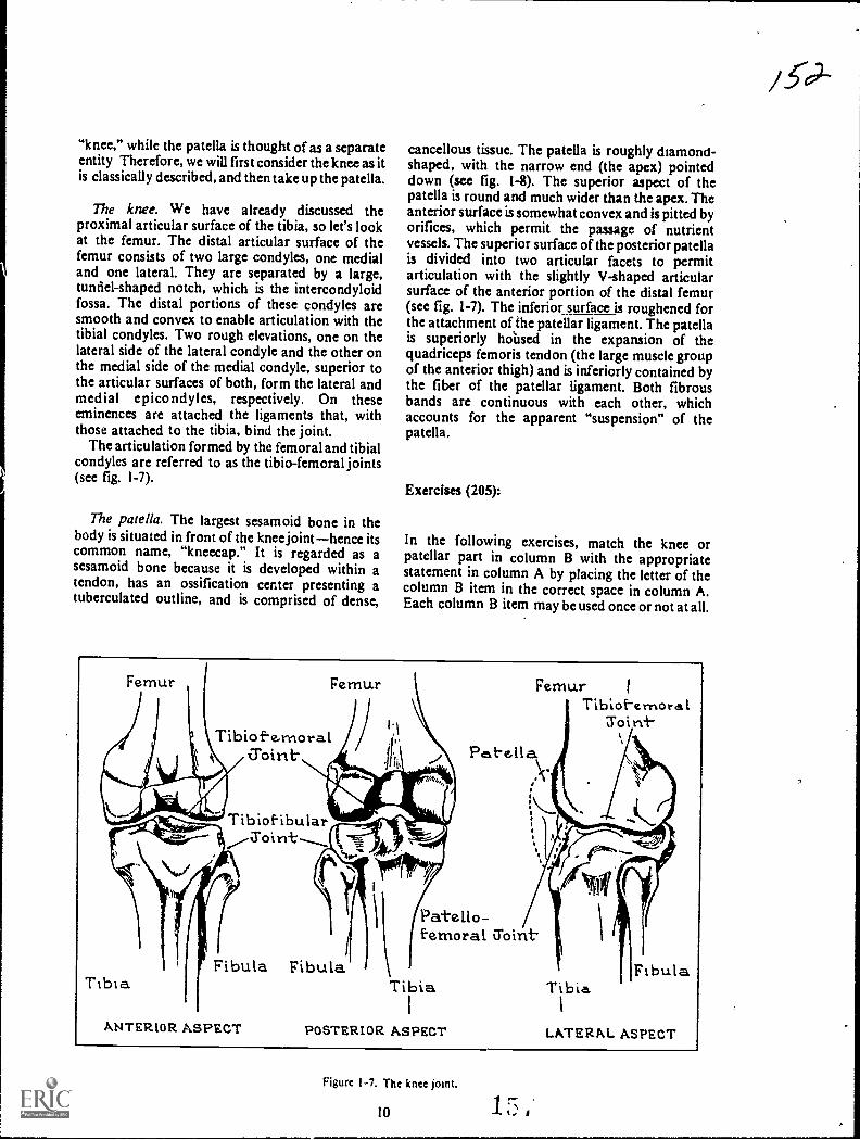
"knee," while the patella is thought of as a separateentity Therefore, we will first consider the knee as itis classically described, and then take up the patella.
The knee. We have already discussed theproximal articular surface of the tibia, so let's lookat the femur. The distal articular surface of thefemur consists of two large condyles, one medialand one lateral. They are separated by a large,tunnel-shaped notch, which is the intercondyloidfossa. The distal portions of these condyles aresmooth and convex to enable articulation with thetibial condyles. Two rough elevations, one on thelateral side of the lateral condyle and the other onthe medial side of the medial condyle, superior tothe articular surfaces of both, form the lateral andmedial epicondyles, respectively. On theseeminences are attached the ligaments that, withthose attached to the tibia, bind the joint.
The articulation formed by the femoral and tibialcondyles are referred to as the tibio-femoral joints(see fig. 1-7).
The patella. The largest sesamoid bone in thebody is situated in front of the knee jointhence itscommon name, "kneecap." It is regarded as asesamoid bone because it is developed within atendon, has an ossification center presenting atuberculated outline, and is comprised of dense,
cancellous tissue. The patella is roughly diamond-shaped, with the narrow end (the apex) pointeddown (see fig. 1-8). The superior aspect of thepatella is round and much wider than the apex. Theanterior surface is somewhat convex and is pitted byorifices, which permit the passage of nutrientvessels. The superior surface of the posterior patellais divided into two articular facets to permitarticulation with the slightly V-shaped articularsurface of the anterior portion of the distal femur(see fig. 1-7). The inferior_ surface is roughened forthe attachment of the patellar ligament. The patellais superiorly hoilsed in the expansion of thequadriceps femoris tendon (the large muscle groupof the anterior thigh) and is inferiorly contained bythe fiber of the patellar ligament. Both fibrousbands are continuous with each other, whichaccounts for the apparent "suspension" of thepatella.
Exercises (205):
In the following exercises, match the knee orpatellar part in column B with the appropriatestatement in column A by placing the letter of thecolumn B item in the correct space in column A.Each column B item may be used once or not at all.
Femur Femur
Tibiof-e,moral
Tibia
Tibiof-ibularSoirrt.
Fibula Fibula
ANTERIOR ASPECT
FemurTibioi-ernoral
roiri-
Pat-ella
Patello-femoral Z'oint
Tira
POSTERIOR ASPECT
FibulaTibia
1
LATERAL ASPECT
Figure 1-7. The knee joint.
10

Arte.x
ANTERIOP. VIEW
Knee
Column A
_ I. Between the femoral con-dyles.
_ 2. Diarthrodial or hinge-type_ 3. Articulates whh medial
tibial condyle.4. Elevation on lateral side of
femoral condyle.
Patella
_5. Inferior portion.6. Joins with femur.
_ 7 Receives nutrients.
a.b.c.
d.C.
tatcbr al/Ss
POSTERIOR VIEW
Figure 1-8. The patella.
Column B
Knee joint.Intercondyloid fossa.Femoral condyle.Condylar notch.Epicondyle.
a. Articular facet.b. Anterior surface.c. V-shaped articular
surface.d. Apex.
206. Name, locate, and describe the anatomicalparts of the femur.
The Femur. The femur, or thigh bone, extendsfrom the knee joint to the hip joint. From the hipjoint, the femur is directed somewhat medially andpo3teriorly so that, at the knee joint, it is near thecenter of gravity for the body. The femur, classifiedas a long bone, consists of a shaft and two ends. Wehave already discussed the distal end so let's turn tothe shaft.
Shaf t. The shaft is the long, rounded portion ofthe bone that extends from the intertrochantericcrest, proximally, to just above the epicondyles,distally. It is broader at the ends than in the middleand is widest at the distal end.
The posterior surface of the shaft contains thelinea aspera, a rough prominence that occupies themiddle one-third. Several less prominent ridgesextend above it; below it, two prominent ridgesextend downward to form the triangle on the distalportion of the posterior femoral shaft. The areawithin the triangle, deriving tits name from thepopliteal artery, is called the popliteal space.
11
Proximal end. This part consists of'the head, theneck, the greater trochanter, and the lessertrochanter. The lesser trochanter is a small, roundedprominence on the lower portion of the femoralneck. The greater trochanter is a large, palpable,irregular prominence, which extends outward andslightly backward from the junction of the femoralneck with the femoral shaft. The intertrochantericcrest is the ridge of bone that extends obliquelydownward from the greater trochanter to the lessertrochanter.
The neck is the constricted portion that unites thehead with the body of the femur, and the head is theupper, rounded, expanded area that joins with theacetabulum to form the hip joint. Near the center ofthe head is an ovoid depression called the foveacapitis where the ligamentum teres attaches. Thefemur is shown in figure 1-9.
Exercises (206):
I. Name the rough area on the posterior middlethird of the femur.
2. Give the configuration and location of thepopliteal space.
3. On which sidc (anterior or posterior) of,thefemur is the intertrochanteric crest locatid?
4. In what direction(s) does,the neck of the femurextend from the femoral body?

Nec.k
PROXIMAL END PROXIMAL END
Lesse.rTroc.hani-e.r
MedialEpicoriclyle.MdiCone Lyle.
DISTAL ENDANTERIOR VIEW
Crreat-erTrochante.r
Patellar Sure-aceLateral Epicondyle
L.a.1-e.ra.l Cortdyle
Figure 1-9. The femur.
1
Head
Ncr.c.k
LesserT r o h a t-
1ntert o chanter ieCrest
Popliteal Spac.e.
It-c1.7ercondylotdFossa.Media.IEpicondyle
ConclyleDISTAL END
POSTERIOR VIEW
5. What part of the femur helps form the hip joint? 207. Given a iist of statements pertaining to theinnominate bones and pelvis, indicate which aretrue and which are false. If you indicatefalse," youmust explain your answer.
The Pelvic Girdlo. The pelvic girdle consists of thetwo innorninate, or hip, bones; the pelvis; thesacrum; and the coccyx. It also provides fivzarticular surfaces consisting of both hips, bothsacrioliac joints, and the symphysis pubis. We willinvestigate the bony parts first, and then thearticulations.
The innominate bones. Each inuominate bone,commonly called the hip bone, is formed by thefusion of what were once three separate bones. In
, 6. Can the greatet trochanter be palpated?
7 Name the depression on the center of the femoralhead.
12 1 rN.
s'Y

Erie adult skeleton. the tuo innommate bones formthe anterior and lateral %%ails of thepelvic girdle (see
tig 1-10).
The upper portion of the innominate bone is theilium. Its major components and landmarks are: thebody. the ala. the iliac fossa. the articular surface,
the ihac crest. the anterosuperior iliac spine (ASIS).the anteroinferior iliac spine (AIIS), the
posterosuperiol iliac spine (PSIS). theposteroinferior iliac spine ( PUS). and the greatersciatic notch.
a. The body of the ilium is the thick part of thebone just above the acetabulum.
h The ala (from a Latin word meaning "Wing") isthe winglike portion of the ilium.
L. The iliac fossa is a large area on the insidesurface of the ala -bounded by the iliac crestsuperiorly and by the arcuate line inferiorly.
d. The articular surface, often , called theauncular surface because of its "ear" shape, is thatpart of the internal alar surface that articulates witht he..orresponding articular surface of the sacrum toform the sacrioliac joint.
e. The crest of the ilium (iliac crest) is the upper,curv4 bordei of the ala.
/ The easily palpable anterosuperior iliac spineis the bony prominence !anted where the iliac crestjoins the rest of the ante:-ior iliac border.
The anteroinferior iliac spine is a bonyprominence located on anterior border at a levelabout 1 inch lower than the anterosuperior iliacspine.
h The efOsterosuperior iliac spine is the bonyprominence located where the iliac crest joins therest, of the posterior border.
i. The posteroinferior iliac spine is the bonyprominence directly below the posterosuperior iliacspine on the posterior border.
j. The greater sciatic notch is a large notch justbelow the posterior inferior iliac spine.
k. The ilium forms part of the acetabulum.
The ischium is the lower posterior part of theinnominate bone. Its major parts and landmarks arethe body. the ischial spine, the lesser seiatic notch,the superior rams, the ischial tuberosity, and theinferior ramus.
a. The body of the ischium is the thick part of thebone directly behind and below the acetabulum. Italso forms part of the acetabulum.
b. The ischial spine is a pointed prominenceextending backward and medially from theposterior surface.
c. The lesser sciatic notch is a small notch justhdow tbe Ischia) spine
d I he !milli% is th:it pa,1 ol the }
descends from the m,hial bodye The ischial tuherosity is the large expanded
part located at the posterior surface of the ramus.
13
The pubis forms the lower anterior part or dieinnominate bone. lb major parts and landmarks aicthe body, the superior ramus. the pubic tubercle, theiliopectineal eminence, the obturator crest, and theinferior ramus.
a. rhe body makes part of the antenoi portion ofthe acetabulum.
b. The superior ramus is somewhat triangularshaped and extends upward and backuard from thepubic body to the acetabulum.
c. The pubic tubercle. often called the oubicspine, is a small prominence located on the. upperborder of the pubic body.
d. The iliopectineal eminence, sometimes culledthe iliopubic eminence, is a rough ettinencemarking the fusion site of the ilium and the pans.
e. The obturator crest is the lower border of thesuperior ramus and extends from the pubic tubercleto the lower margin of the iliopectineal eminence infront of the acetabular notch. It is part oi theobturator foramen.
f The inlet ior ratnus is the part of the bonethatextends dow nuard from the pubic body to pin theramus of the ischium.
g. The obturator foratnen is a large hole bemceitthe ischium and the, pubic bones.
h. The pubic arch is the arch formed by theramus of the ischium and the inferior ramus of thepubis as they extend upward and join at the inferimaspect of the symphysis pubis. It is usually a broad.rounded curve in the female and a much smaller,narrower. inverted, V-shaped angle in the male.
I. The acetabulum is the cup-shaped depressionthat riceives the head of the femur in forming thehip Ant.
The pelvis. The pelvis is formed by theinnominate bones, the sacrum, and the coccyx. Theoval, bony ridge on the inner pelvic surface is thepelvic brim. It begins at the superior border of thesymphysis publis and extends upward on both sidecalong the superior rami .of the pubis and theiliopectineal lines until it meets at the center of thesacral promontory.
The false pelvis, often called the major or greaterpelvis, is the part of the lower abdomen bounded bythe pelvic brim and by the alae of the ilia on thesides. The true pelvis, also called the minor or lesserpelvis, is bounded by the pelvic brim above, thesacrum and coccyx behind, and the symphysis pubisin front. These structures form the pelvic inlet andoutlet. (See fig. 1-1L)
Focercicc% (201)
Indicate whether thc following statemenfs are no..or false. If you ind icate"false." explain y our answei

Iliac Crest
Iliac TuberosityPosterior SuperiorIliac Spine
Posterior InferiorIliac Spin.
Greater Sciatic
/C6Iliac Fossa
- ----------
Anterior_Suporior's. Iliac Spin.
Body of Ischiurn.Ischial Spine
Lesser Sciatic Notch
Ramus of Ischium
Obturotor Foromen
Ischial Tuberosity
Anterior InferiorIliac Spine
Body of Ilium
IliopectinealEminence
\Body of PubisSuperidr Romus of Pubis
Pubic Tubercle
Obturator Crest
Inferior Ramus of Pubis
Anterior SuperiorIliac Spine
A. MEDIAL
,Iliac Crest4-si
PosteriorSuperiorIliac Spine
Body of Ilium
Anterior Inferior!hoc Spine
Body of Pubis
Posterior Inferioriliac Spine
Greoter Sciotic .Notch
Body of lschiumIschiol Spine
Lesser Sctotic Notch
Iliopectineol EminenceSuperior Rarnusof the Pubis
Obturdtor Crest
Pubic Tubercle
Inferior Ramus ofthe Pubis
Obturator Foramen
B. LATERAL
Romus of Ishium
Ischiol Tuberosity
Figure 1-10. The innominate bone. 1 t3 j_
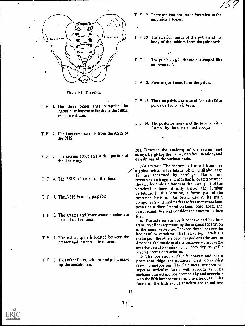
Figure 1-11. The pelvis.
T F I. The three bones that comprise ,theinnominate bones are the ilium, the pubis,and the ischium.
T F 2. The iliac crest extends from the AS1S tothe PUS.
T f. 3. The sacrum articulates with a portion ofthe iliac wing.
T F 4. The PSIS is located on the ilium.
T F 5. TheASIS is easily palpable.
/C7T F 9. There are two obturator foramina in the
innominate bones.
T F 10. The inferior ramus of the pubis and thebody of the ischium form the pubic arch.
T F 11. The pubic arch in the male is shaped likean inverted V.
T F 12. Four major bones form the pelvis.
T F 13. The true pelvis is separated from the falsepelvis by the pelvic brim.
T F 14. The posterior margin of the false pelvis isformed by the sacrum and coccyx.
Mi. Describe the anatomy of the sacrum andcoccyx by giving the name, number, location, anddescription of the various parts.
The sacrum. The sacrum is formed from five/..- atypical individual vertebrae, which, until about age
18, arc separated by cartilage. The sacrumresembles a triangular wedge and is located betweenthe two innominate bones at the lower part of thevertebral column directly below the lumbarvertebrae. In this location, it forms part of theposterior limit of the pelvic cavity, Its maincomponents and landmarks are its anterior surface,posterior surface, lateral surfaces, base, apex, andsacral canal. We will consider the anterior surfacefirst.
a. The anterior surface is concave and has fourtransverse lines representing the original separationof the sacral vertebrae. Between these lines are thebodies of the vertebrae. The first, or top, vertebra isthe largest; the others become smaller as the sacrumdescends. On the sides of the transverse lines are theanterior sacral foramina; which provide passage forseveral nerves and arteries.
b. The posterior surface is convex and has aprominent ridge, the midsacral crest, descendingfroal its midportion. The first sacral vertebra hassuperior articular facets with smooth articularsurfaces that extend posteromedially and articulatewith the fifth lumbar vertebra. The inferior articularfacets of the fifth sacral vertebra are round and
T F 6. The greater and lesser sciatic notches arelocated on the ilium.
T F 7. The ischial spine is located betweer. thegreater and lesser sciatic notches.
T F 8. Part of the ilium, ischium, and pubis makeup the acetabulum.
15
1 t.
/".

extend downward to articulate with the articularprocesses of the first coccygeal vertebra. Laterally,!ruin ihe uticular crest, are the posterior sacralforamina
c I fie lateral surfaces, in regard to the posteriorportion. have bilateral ear-shaped, articularNurfaces, which join with the ilia to form 'thesaeroihae joints As the lateral surfaces descend,the become narrower towards the extreme tip of
ie lateral surface or the inferolateral angle.d I he base ol the sacrum is formed by the
riacc of the first sacral vertebra and hasCriee part, a ry,edle part and two lateral surfaces.The middle part eonsists of an ox al articular surfaceop the hod\ uf the first %ertebra. This area has animportant bony landmark caned the promontory.The two lateral surfaces of the sacral base, oftencalled tAe ala of the sacrum, are represented by theiused costal and transverse processes.
9. The apex is the inferior part of the sacrum thatloins with the coccyx.
I. The sacral canal is located near the posteriorpart of the sacrum and extends from the first to thefifth vertebra. It is formed by the posterior aspect ofthe sacral vertebral bodies and the fusion of thelaminae and spinous processes (see fig. 1-12).
The coccyx. The coccyx, conimonly called thetailbone, is the last segment of the vertebrae in thevertebral column and is generally formed by thefusions of four atypical vertebrae, It has an anteriorsurface, a posterior surface, a base, and an apex,shown infigure 1-13. s
a. The anterior surface resembles the anteriorsurface of the sacrum because it is concave and hasthree transverse lines that mark the formerseparations between the coccygeal vertebrae.
h. The posterior surface of the coccyx resembles.in miniature, the posterior surface of the sacrum.Extending upward from the coccygeal base are thecoccygeal cornua, which join the sacral cornua otthe sacral apex.
c. The base is the superior surface of the firstcoccygeal vertebra and joins with the apex of thesacrum.
d. The apex is the extreme distal tip of the lastcoccygeal vertebra.
Exercises (208):
Answer the following questions or fill in the blanksas appropriate.
I. How many sacral vertebrae are there?
2. Which sacral vertebra is the largest? Thesmallest?
3. The midsacral crest is located on theside of the sacrum.
!SacralForamen
; Transverse.Lr
Prothon-tory Articular Processesoc
1
Articular Process
Anterior
Body Of- First-5a.cral Veri`r
See,oncl
Third.
Fourth
View Sa.c.r al Cariat,
Art-icularProcess
Articular Process----7--Tr ansverse Process
Pr ornontorCostal Process
MIcisacralsCrcst-
Sacral COT rtua
Lateral VwArticular Process
Transverse Proccs
Base Of- Sacr urn
Cost-al Proce.ss
Figure 1-12 1 he sacrum.
16 1
45-

7
"--"-,.....,
\ /37Col. r\Li.
Art-iculaA--esWith. Sacrum
Ape.xAni-erior View
First- TransverseLine
SecorldInso
, 7
ThirdAp ex
Lal-er a.1 View
Figure 1 13. The coccyx.
4. With what vertebra does the superior ,articular 12. The superior portion of the first coccygeal
tacets of the sacrum articulate? vertebra is called the _and the inferior tip
of the fourth coccygeal vertebra is called the
5. With what vertebra does the inferior articularfacets of the fifth sacral vertebra arti ;ulate?
6. The lateral surfaces of the sacrum articulatew ith the _ to form the
7. What is the sacral promontory and where is it
located?
8. ,Where is the sacral canal located with respect to
the sacral body?
9. How man) coccygeal vertebra are there?
10 What are the transverse lines of the coccyx?
I I. What are the two bony projections that extendsuperiorly from the coccygeal base?
17
1-3. The Upper Extremity; .
The upper extremity includes the fingers and thehand, the wrist, the forearm, the elbow, thehumerus, and the shoulder girdle.
209. Characterize the anatomy of the fingers, hand,and wrist by giving the name, number, location, anddescriPtion of the various parts.
The Fingers and the Hind. Nineteen bones, whenunited, form the fingers and hand. They are divided
,ato two groupsthe phalanges, which form thefingers, and the metacarpals, which form the palm.We will investigate the phalanges first.
7he phalanges. Each digit has three phalanges,except the thumb, which has two. Each phalanx hasa body, a head or distal end, and a base or proximalend. The phalanges are not named but are identifiedby their location and number, counted from thethumb to the little finger (see fig. 1-14). Forexample, the phalanx of the thUmb nearest the palm
is the proxim4ealanx of the first digit; the middlephalanx of the middle finger is the middle phalanx,third digit; an'd the distal phalanx of the little finger
is the distal phalanx, fifth digit. The distal phalanges
are distinguished by their small size and by theungual tuberosity (or tuft) at their distal ends.
The metacarpals. The five .metacarpals are thelonger bones that form the palm of the hand. Eachhas a body, a head or distal end, and a base orproximal end. The metacarpals do not have names,
.,
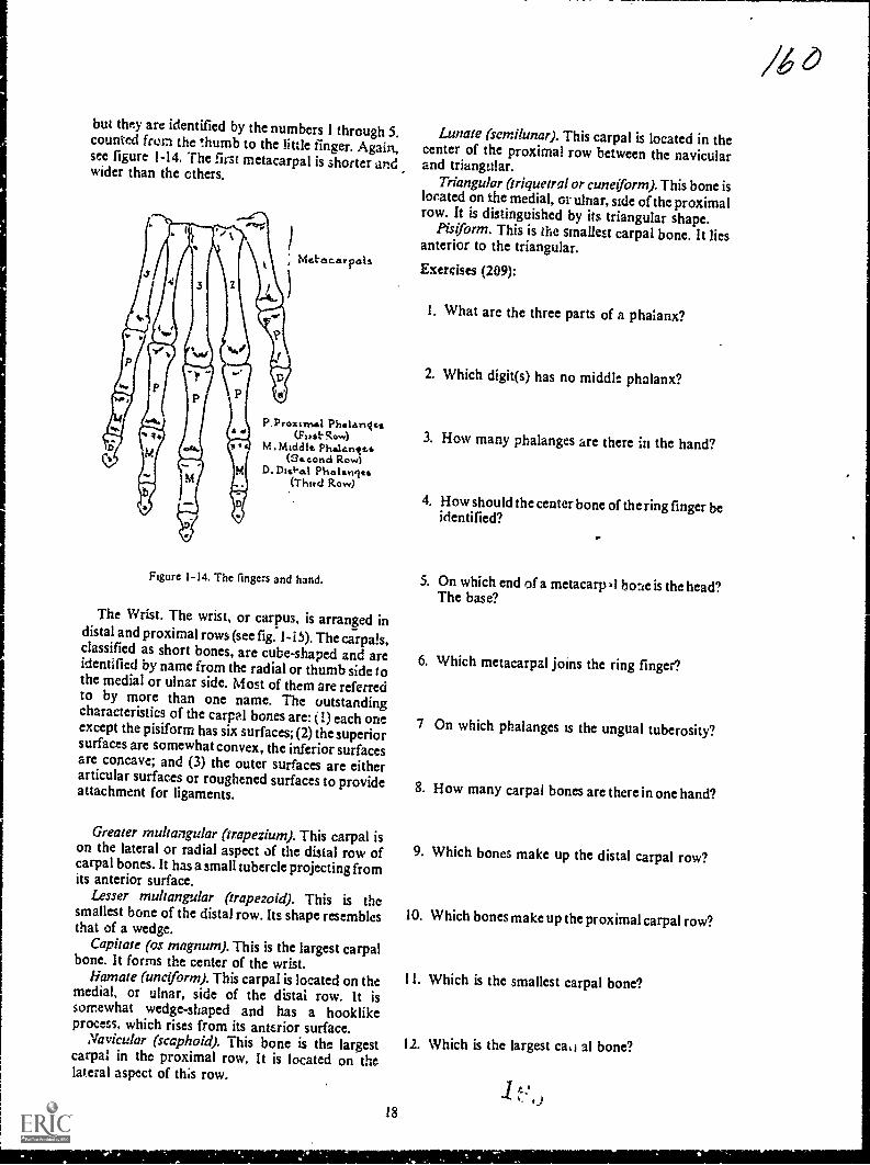
but they are identified by the numbers I through 5.counted from the thumb to the little finger. Again,see figure 1-14. The first metacarpal is shorter andwider than the others.
Met'escar pals
P.Proximal PhalanIca(Fits.t.Row)
M.Middic Phalantzs(34.cond Row)
D-Dis*.8.1 Phalanits(Third Row)
Figure 1-14. The fingers and hand.
The Wrist. The wrist, or carpus, is arranged indistal and proximal rows (see fig. 1-i 5). The carpals,classified as short bones, are cube-shaped and areidentified by name from the radial or thumb side tothe medial or ulnar side. Most of them are referredto by more than one name. The outstandingcharacteristics of the carpal bones are: (I) each oneexcept the pisiform has six surfaces; (2) the superiorsurfaces are somewhat convex, the inferior surfacesare concave; and (3) the outer surfaces are eitherarticular surfaces or roughened surfaces to provideattachment for ligaments.
Greater rnultangular (trapezium). This carpal ison the lateral or radial aspect of the distal row ofcarpal bones. It has a small tubercle projecting fromits anterior surface.
Lesser multangular (trapezoid). This is thesmallest bone of the distal row. Its shape resemblesthat of a wedge.
Capitate (os magnum). This is the largest carpalbone. It forms the center of the wrist.
liamate (unciforrn). This carpal is located on themedial, or ulnar, side of the distal row. It issomewhat wedge-shaped and has a hooklikeprocess, which rises from its anterior surface.
Navicular (scaphoid). This bone is the largestcarpal in the proximal row. It is located on thelateral aspect of ths row.
18
Lunate (semilunar). This carpal is located in thecenter of the proximal row between the navicularand triangular.
Triangular (triquetral or cuneiform). This bone islocated on the medial, or ulnar, side of the proximalrow. It is distinguished by its triangular shape.
Pisiform. This is the smallest carpal bone. It liesanterior to the triangular.
Exercises (209):
I. What arc the three parts of a phalanx?
2. Which digit(s) has no middle phalanx?
3. How many phalanges are there in the hand?
4. How should the center bone of the ring finger beidentified?
S. On which end of a metacarp al bone is the head?The base?
6. Which metacarpal joins the ring finger?
7 On which phalanges is the ungual tuberosity?
8. How many carpal bones are there in one hand?
9. Which bones make up the distal carpal row?
10. Which bones make up the proximal carpal row?
11. Which is the smallest carpal bone?
12. Which is the largest ca,1 al bone?

RADIUS
ULNA
CAPITATE
NAVICULAR
LESSER MULTANGULAR
GREATER MULTANGULAR
LUNATE
TRIANGULAR
,--PISIFORM
HAMATE
Figure 1-15. The wrist.
210. Given a list of the parts and descriptions of the
two bonei of the forearm, match each, with theappropriate bone.
The Forearm. The forearm extends from thewrist to the elbow and consists of two bones, theulna and the radius. We will consider the ulna first.Coordinate your reading of this material by locatingthe forearm features in figure 1-16.
The ulna. the ulna, located on the medial side ofthe forearm, is classified as a long bone with a shaftand both distil and proximal ends. It tapers fromthe proximal tq the distal ends, and the distal endbends laterally to form a slight bow. The distal endis much smaller than the proximal end and has twooutstanding landmarksthe head and the-styloidprocess. The shaft, somewhat roundcd at itsproximal end, becqmes increasingly smaller towardits distal end. A rough wedge on the lateral aspect isthe interosseous border, to which the interosseousmembrane is attached. On the proximal end arethese prominent landmarks: the radial notch, theoblong depression on the lateral side of thecoronoid process; the coronoid process, a large,pyramidal projection from the anterior surface; thesemilunar notch, the arched depression extendingbetween the olecranon and the coronoid processes;and the olecranon process, a large, curvedeminence.
The radius. The radius, aIso shown in figure 1-16,
is the lateral bone of the forearm and, like the ulna,
19
t)
te/
is a long bone with a shaft and both distal andproximal ends. In contrast to the ulna, it tapersfrom the distal to the proximal end. Prominentlandmarks on the distal end are the ulnar notchasmall depression on the medial sideand thestyloid processa conical projection of bone on thelateral side. The shaft becomes larger as itapproaches the distal end and has a slight lateralcurvature. The interosseous crest forms the sharpmedial side of the shaft. The proximal end consistsof the radial tuberositylocated on the medial sideof the neck; the neckthe round, smooth,constricted part distal to the head; and the headacup-shaped, disclike structure adapted forarticulation with the capitulum of the humerus.
Exercises (210):
Match the forearm bone in column B with relatedinformation in column A by placing the letter of thecolumn B item in the space provided in column A.Each column B item may be used once or more thanonce.
..Column A
I. Larger distal end._2. Coronoid process.3. Radial notch.
4. Semilunar notch.5. Radial tuberosity.
6. Olecranon process._ 7. Medial bone.
Column B
a. Radius.b. Ulna.

Bermhaner
PROXIMAL tr40reOXINM. END Claceaoan
Cr earInre 'osseous
Sty lord Pfoccs
VILta_
WeedIlotnt.achr
Pro.:cas
Intel...sealCrest-
Ulna. Notch
. ro...
Radoa ll_r_la
St PO,C1Proc..ss
Head
..-..0.
/Radial NoezhRachel IIrci*
-Corano.dPr oLe.%
Corrtotd 7--.0 Head Head
Nack.
\ NeckProcess 'TR:bd.:410.y
RachalTubcrosity
Dtst M. ENDANTERIOR VIEW
=rat ENDPOSTERIOR VIEW
Figure 1-16. The forearm.
211. Given a list of statements pertaining to theelbow, indicate which are true and which are false. Ifyou indicate "false," you must explain your answer.
The Elbow. The elbow is formed by thearticulation of the proximal portions of the ulnaand radius and the distal portion of the humerus.Since we have already discussed the proximal radiusand ulna, let's look at the distal humerus.
The distal portion of the humerus. The flared,distal end of the humerus presents five surfaceslateral, medial, anterior, posterior, and inferior--which in one way or another help form the elbow.The anteroinferior surface is comprised of thearticular surface. This surface is divided into twoparts by a slight ridge. The medial aspect is formedby the trochlea, which is a deep depression betweentwo well-marked borders. The lateral portionconsists cf the capitulum a smooth, roundedeminence, marked by a slight groove on its medialaspect Directly above and posterior to thecapitulum is the radial fossa, a small, smoothdepression Medial to this fossa and directly aboveand behind the trochlea is the coronoid fossa. Themedial aspect of the distal humerus is formed by themedial epicondyle This is a tubercular eminence,larger and more prominent than its lateralcounterpart, to which are attached various
20
ROA.0aAL END
OisC. tenonSIkneturutNotchkach.at
Head NtchNeck.
Rados,Tubatoatty
Int.cras ssssso dcr
Redtus Illn
Head--
SryIo4Process
srm. ENDLATERAL VIEW
ligaments, tendons, and muscles. The lateralepicondyle, though it serves the same purpose, issmaller. The posterior portion of the distal humerusis identified by a deep depressionthe olecranonfossajust above the posterior aspect of thetrochlea. This fossa, the trochlea, the capitulum,and both coronoid and radial fossae are covered bya synovial membrane. They form the superioraspect of the articular capsule of the elbow (see fig.1-17).
The elbow joint. The elbow is formed by thecombined articulation of the ulna and radius andthe articulation of both of these bones with thehumerus. The head of the radius articulates with theradial notch on the lateral aspect of the coronoidprocess. An articulation is also formed by thecapitulum and the fovea, on the superior surface ofthe radial head. The trochlea articulates with thesem il unar notch of the ulna. In extremehyperflexion, the medial margin of the radial head isreceived by the radial fossa on the anterior surfaceof the distal humerus and the tip of the coronotdprocess is feceived by the coronoid fossa. Inextension, the olecranon process is received by theolecranon fossa. Both epicondy les give attachmentto the ligaments which bind the joint together (seefig. 1-18).

MechatEpcondyte.
Zoronosdrossa
Trochien
Racital,Vossah...%
Lat-e.ratEptcondyle
Captt-tatt-rrt
DtSTNL ENDMITERIOR VIEW
Otee.ranonFossaMcd1,..a
hgure I 17. The distal end of the humerus.
5,21.rulumar Rot,h
1 iS 1h:dbo %
21
--It Cc u%tit-ct
DIs'l AL ENDPOSTERIOR VIEW
& 3
Exercises (211):
Indicate whether the following statements are trueor false. If you indicate"false," explain your answer.
T F I. The olecranon fossa is located on theanterior side of the humerus.
T F 2. The coronoid fossa is located on theanterior side of the humerus.
T F 3. The radial fossa is located on the medialside of the humerus.
T F 4. The lateral epicondyle is more prominentthan the medial.
T F 5. The deep depression on the posteriorsurface of the humerus is the trochlea.
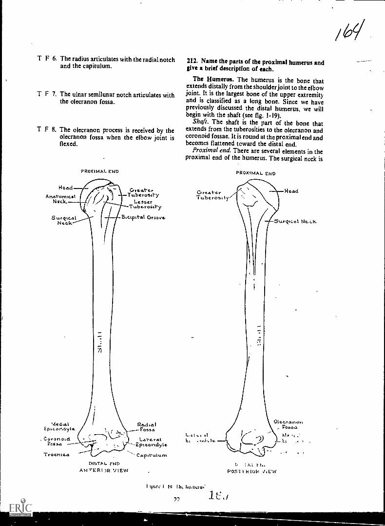
T F 6. The radius articulates with the radial notchand the capitulum.
T F 7. The ulnar semilunar notch articulates withthe olecranon fossa.
T F 8. The olecranon process is received by theolecranon fossa when the elbow joint isflexed.
Head
AnatomicalNeck.
Surckte.alNeok
PROXIMAL ENDr
MechalEpicondylc
Cry t !Lt.- Gt.Tuberosity
LesserTubc.rosity
Biespitat Ortlaver
Pa,c1 ta IFosses
. Caronoid Late.ratFossa -2pieoridyle
--,Trocrite.a Capituium
DlbTA L. PM)AN-rERI )R VIEW
212. Name the parts of the proximal humerus andgive a brief description of each.
The Humerus. The humerus is the bone thatextends distally from the shoulder joint to the elbowjoint. It is the largest bone of the upper extremityand is classified as a long bone. Since we havepreviously discussed the distal humerus, we willbegin with the shaft (see fig. 1-19).
Shaft. The shaft is the part of the bone thatextends from the tuberosities to the olecranon andcoronoid fossae. It is round at thc proximal end andbecomes flattened tcward the distal end.
Proximal end. There are several elements in theproximal end of the humerus. The surgical neck is
PROXIMM.. END
b : M. F N.POSI I 1-tIOR JEW
Ilpse 1 19 111,. Ii11.11011N.
72
1
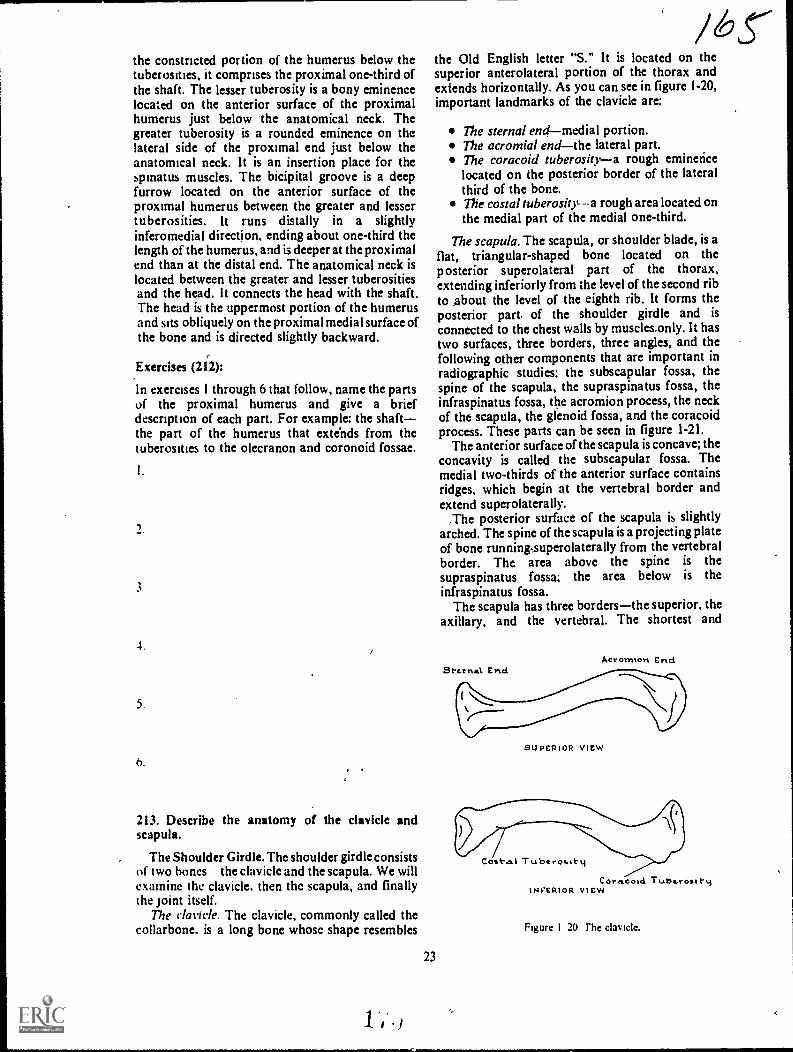
the constricted portion of the humerus below thetuberosities, it comprises the proximal one-third ofthe shaft. The lesser tuberosity is a bony eminencelocated on the anterior surface of the proximalhumerus just below the anatomical neck. Thegreater tuberosity is a rounded eminence on thelateral side of the proximal end just below theanatomical neck. It is an insertion place for thespinatus muscles. The bicipital groove is a deepfurrow located on the anterior surface of theproximal humerus between the greater and lessertuberosities. It runs distally in a slightlyinferomedial direction, ending about one-third thelength of the humerus, and is deeper at the proximalend than at the distal end. The anatomical neck islocated between the greater and lesser tuberositiesand the head. It connects the head with the shaft.The head is the uppermost portion of the humerusand sits obliquely on the proximal medial surface ofthe bone and is directed slightly backward.
Exercises (212):
In exercises I through 6 that follow, name the partsof the proximal humerus and give a briefdescription of each part. For example: the shaftthe part of the humerus that extends from thetuberosities to the olecranon and coronoid fossae.
3
4.
5.
6.
213. Describe the anatomy of the clavicle andscapula.
The Shoulder Girdle. The shoulder girdle consistsof two hones the clavicle and the scapula. We willexamine the clavicle, then the scapula, and finallythe joint itself.
The clavicle. The clavicle, commonly called thecollarbone. is a long bone whose shape resembles
23
the Old English letter "S." It is located on thesuperior anterolateral portion of the thorax andextends horizontally. As you can see in figure 1-20,important landmarks of the clavicle are:
The sternal endmedial portion.The acromial endthe lateral part.The coracoid tuberositya rough eminencelocated on the posterior border of the lateralthird of the bone.The costal tuberositya rough area located onthe medial part of the medial one-third.
The scapula. The scapula, or shoulder blade, is aflat, triangular-shaped bone located on theposterior superolateral part of the thorax,extending inferiorly from the level of the second ribto about the level of the eighth rib. It forms theposterior part of the shoulder girdle and is
connected to the chest walls by muscles.only. It hastwo surfaces, three borders, three angles, and thefollowing other components that are important inradiographic studies: the subscapular fossa, thespine of the scapula, the supraspinatus fossa, theinfraspinatus fossa, the acromion process, the neckof tht scapula, the glenoid fossa, and the coracoidprocess. These parts can be seen in figure 1-21.
The anterior surface of the scapula is concave; theconcavity is called the subscapular fossa. Themedial two-thirds of the anterior surface containsridges, which begin at the vertebral border andextend superolaterally.
,The posterior surface of the scapula is slightlyarched. The spine of the scapula is a projecting plateof bone running,superolaterally from the vertebralborder. The area above the spine is thesupraspinatus fossa; the area below is theinfraspinatus fossa.
The scapula has three bordersthe superior, theaxillary, and the vertebral. The shortest and
Aeronnon End
SUPERIOR VIEW
Cost-e.1 Tubt rosttti
Coracold Tube.rosItytNVERIOR view
Figure I 20 The clavicle.
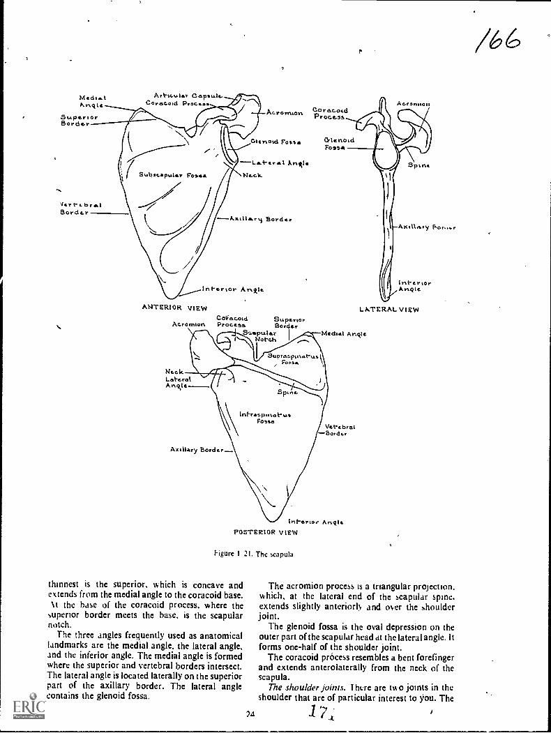
MedieIArict
SuperiorBordor
Vert-e. PrelBorder
Art-tr....ler Capsule.Corocoid Procese
CoracoidAc.ronmort.Proce...ss
Glertoid Fosse
r Arietle
Ne.c1s.
---Xxillrery Border
Interior AmAle
ANTERIOR VIEWCoeacold Superior
Acromion Proce5e Borde,S-aptsler I
Notch
NeckLateralA not e
CrlehoidFossa
Ac.rontiori
Spine
Axilletry
InteriorAngie.
LATERAL VIEW
Mechel Ariolc
\Int-respihot-usFom,o
Axillary Border.
Vet-tbraiBorder
Inf-erior AnoIePOSTERIOR VIEW
higure 1 21. The capula
thinnest is the superior, which is concave andextends from the medial angle to the coracoid base.Nt the base of the coracoid process, where the
superior border meets the base, is the scapularnotch.
The three angles frequently used as anatomicallandmarks are the medial angle, the lateral angle,and the inferior angle. The medial angle is formedwhere the superior and vertebral borders intersect.The lateral angle is located laterally on the superiorpart of the axillary border. The lateral anglecontains the glenoid fossa.
The acromion process is a triangular projection.which, at the lateral end of the scapular spine,extends slightly anteriorly and over the shoulderjoint.
The glenoid fossa is the oval depression on theouter part of the scapular head at the lateral angle. ltforms one-half of the shoulder joint.
The coracoid process resembles a bent forefingerand extends anterolaterally from the neck of thescapula.
The shoulder joints. I ht:re are two joints in theshoulder that are of particular interest to jiou. The
24 1st-
/6
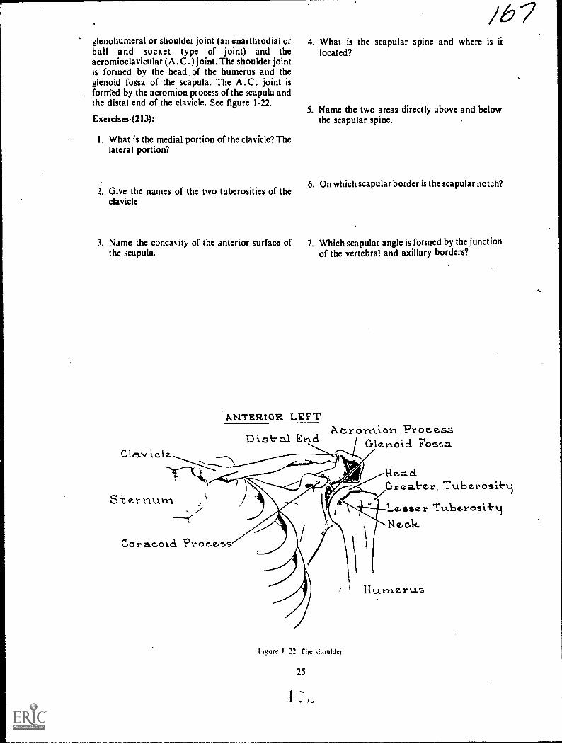
glenohumeral or shoulder joint (an enarthrodial orball and socket type of joint) and theacromioclavicular (A .0 . ) joint. The shoulder jointis formed by the head of the humerus and theglenokl fossa of the scapula. The A.C. joint isfornied by the acromion process of the scapula andthe distal end of the clavicle. See figure 1-22.
Exerci3es.(213):
I. What is the medial portion of the clavicle? Thelateral portion?
/6 74. What is the scapular spine and where is it
located?
5. Name the two areas directly above and belowthe scapular spine.
2. Give the names of the two tuberosities of the6. On which scapular border is the scapular notch?
clavicle.
3. Name the concaity of the anterior surface of 7. Which scapular angle is formed by the junctionthe scapula. of the vertebral and axillary borders?
ANTERIOR LEFT
E Foss.aClavicle. ---............s....---
-'-`,
Sternuxn
A.crornion Process
Hea.d.Great.er, Tuberosit.t.i
1--.Lesser Tu.berosi+.4Ne.ok
Cora.coici Process
Figure I 22 rhe shoulder
25
14 U-1"11.4Z.1"t1S
8. Give the name of the large process that is I I. What type of joint is the glenohumeral joint?located at the latetal portion of the scapularspine.
9. Name the oval depression at the lateral scapular 12. What two parts of the shoulder form theangle.shoulder joint?
10. What is the name of the projection that extends 13. What two parts of the shoulder form the A .C.anterolaterally from the neck of the scapula? joint?
/69CHAPTER 2
Osteology of thiVerfebral Column, the Ribs, and theSternum
OUR STUDY of osteology continues with thevertebral column, the ribr, and the sternum. As withthe extremities, we will present a somewhatcomplete review of the basic osteology. We will alsodiscuss some material that will help you perform thequality control fiptetions mentioned in the prefaceto this volume. We will begin our discussion withthe vertebral column.
2-1. The Vertebral Column
Practically speaking, the spine is divided into fiveanatomic areas, each consisting of a specific numberof vertebrae (see fig. 2-1). The most superior area isthe cervical region, containing seven vertebrae. Thethoracic spine is directly inferior to the cervicalregion and consists of 12 vertebrae. The thirdportion of the colpmn is ths, lumbar region;composed of five vertebrae. Continuing down thespine, we see that the sacrum is one irregularvertebra, as is the coccyx at the lower end of thecolumn. The sacrum and coccyx were discussed inChapter I.
214. Describe the anatomical parts of the lumbarspine.
The Lumbar Spine. Five typical vertebraecomprise the lumbar spine. They fit together toform the forward lumbar curve of the lower back.As you can see in figure 2-2, they are identified bynumber, from top to bottom. Characteristically, thelumbar are the largest of the typical vertebrae buthave neither transverse foramina nor articularfacets on their bodies. We will examine the partsthat make up one of these vertebrae.
The body. This anatomic element forms theanterior part of a lumbar vertebra and is somewhatkidney shaped. In general, the body is roundedanteriorly and flattened posteriorly. The superior,inferior, and posterior surfaces are concave.
The pedtcles. The pedicles extend posteriorly asshort, bony projections on both sides of theposterior surface of the vertebral body. Theyconnect the remaining vertebral parts with thebody.
The laminae. These bony projections extendposteromechally from the pedicles to complete thevertebral arch by connecting the transverseprocesses to the spinous process. The vertebral archis the largest part of the vertebral foramen, which
consists, of the pedicles, the articular, spinous, andtransverse processes, and the laminae.
The articular processes. There are four articularprocessestwo superior and two inferior. Thesuperior processes are located at the junction of thepedicles and the laminae. From here, they extendupward an& face post&omedially. In turn, theinferior processes project doWnward from thejunction' and face anterolaterally to join with thesuperior articular process of the adjoining vertebra.
The spinous process. This is a single, bonyprojection attached to the vertebral arch. It extendsposteriorly from the midpoint of the lamin'aejunction.
The transverse processes. These processes arisefrom the pedicle-laminae junctions L-2, andL-3, and from the pedicle-body junctions in L-4 andL-5. They are directed horizontally and slightlybackward.
The intervertebral discs. The ihtervertebral discsare the 5hock absorbers for the vertebral column.Though they are integral parts of all sections of thespine, we will discuss them now and you can applythis knowledge to the discussions that follow. Eachdisc is comp osed of an outer layer offibrocartilaginous material, called annulus fibrosus,and an inner area containing the pulpy substance,nucleus pulposus. The discs are extremely elasticand provide the cushioning effect needed to,
preclude or limit the transmission of shock from oneend of the spine to the other.
The joints. Lumbar intervertebral joints are, forall practical purposes, of the same basicconstruction as those of the cervical and thoracicregions. Refer to figure 2-3 as you read.
The ntervertebral joints are located between thebodies of typical vertebrae. The articular surfaces ofeach vertebral body join the intervertebral discs toform amphiarthrodial joints. Apophyseal orinterarticular joints are formed by ,the inferiorarticular processes of one vertebra in articulationwith the superior articular processes of the vertebradirectly below it. The lumbosacral (sacrovertebral)joint is the point of union between the fifth lumbarvertebra and the sacrum.
27

1,
Figure 2-1. The spine.
PedioleTransverse
NProcessSuper ior Inf-e.rior
Art-lcular Surf-ace ArHc.ular SurhaceSpirtous Pr oc.ess
SUPERIOR VIEW
LarnirlaSpinousProc,ess
Inf-e'rior ArticuAar Surf-aceL A.-rEitm. VIEW
Figure 2-2. The lumbar spine.
0 0
1
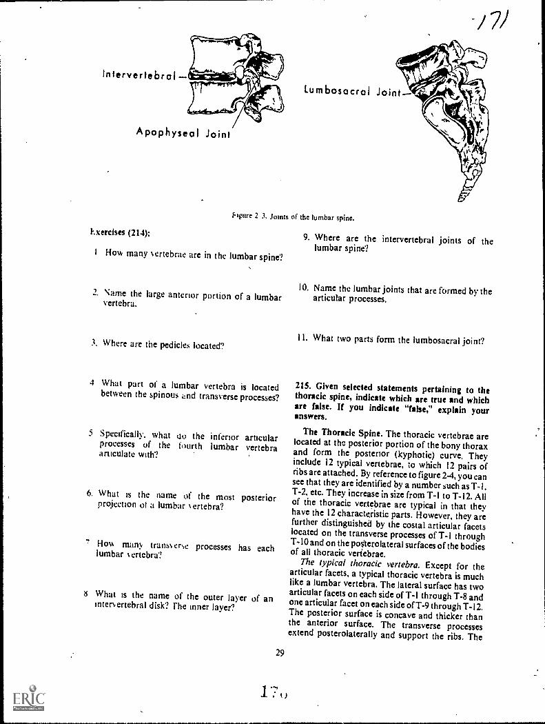
intervertebral
Apophyseol Joint
Exercises (214):
/ 71
Lumbosocrol Joint
Nure 2 3. Joints of the lumbar spine.
I How many ertebrae are in the lumbar spine?,
2. Name the large anterior portion of a lumbarvertebra.
3. Where are the pedicles located?
4 What part of a lumbar vertebra is locatedbetween the spinous and transverse processes?
5 Specifically, what oo the inferior articularprocesses of the fourth lumbar vertebraarticulate with?
6. What is the name of the most posteriorprojection ol a lumbar N ert eb ra?
7 Hov, man>, trans% erse processes has eachlumbar 1.ertebra?
8 What is the name of the outer layer of aninter. ertebral disk? rhe inner layer?
29
9. Where are the intervertebral joints of thelumbar spine?
10. Name the lumbar joints that are formed by thearticular processes.
1 1. What two parts form the lumbosacral joint?
215. Given selected statements pertaining to thethoracic spine, indicate which are true and whichare false. If you indicate "false," explain youranswers.
The Thoracic Spine. The thoracic vertebrae arelocated at the posterior portion of the bony thoraxand form the posterior (kyphotic) curve. Theyinclude 12 typical vertebrae, to which 12 pairs ofribs are attached. By reference to figure 2-4, you cansee that they are identified by a number such as T-1.T-2, etc. They increase in size from T-1 to T-12. Allof the thoracic vertebrae are typical in that theyhave the 12 characteristic parts. However, they arefurther distinguished by the costal articular facetslocated on the transverse processes of T-1 throughT-10 and on the posterolateral surfaces of the bodiesof all thoracic veriebrae.
The typical thoracic vertebra. Except for thearticular facets, a typical thoracic vertebra is muchlike a lumbar vertebra. The lateral surface has twoarticular facets on each side of T-1 through T-8 andone articular facet on each side of T-9 through T-I2.The posterior surface is concave and thicker thanthe anterior surface. The transverse processesextend posterolaterally and support the ribs. The
1 ---,
I. : i )
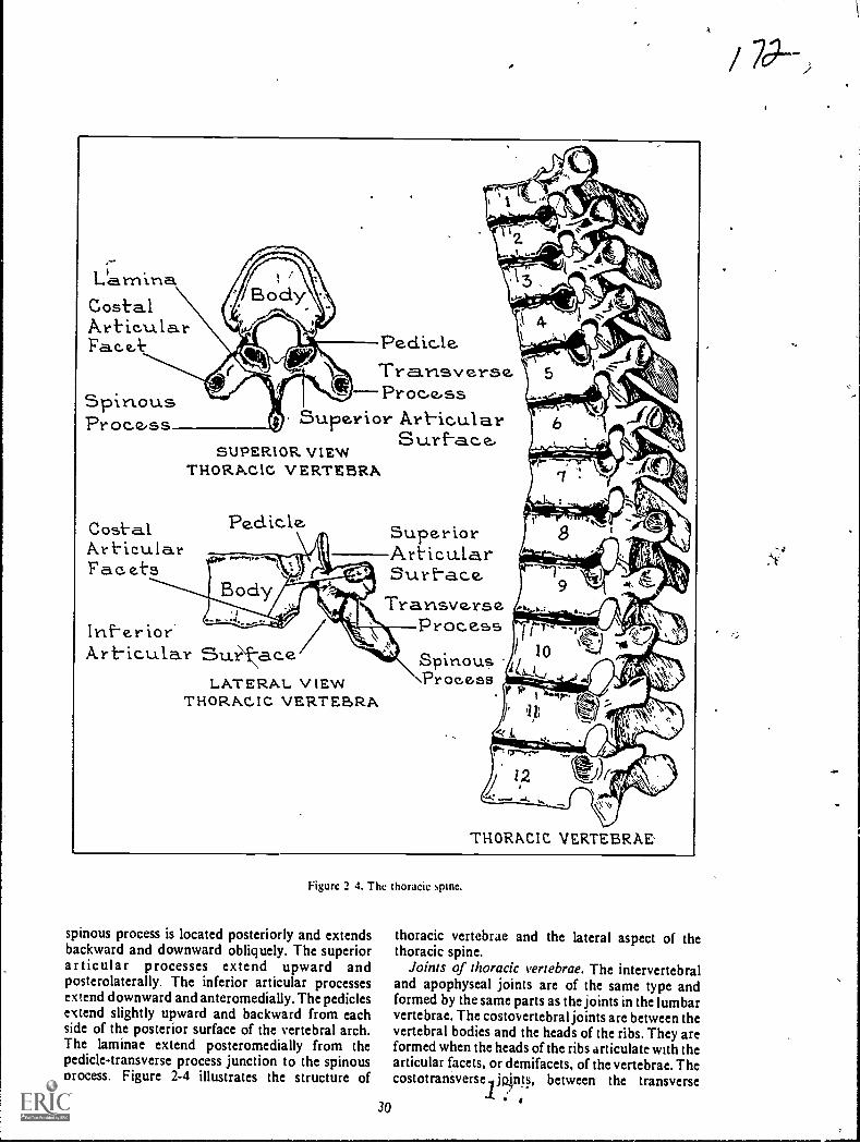
,L'arnina
Costal.ArticularFace.k. Peak, le.
Transverse.Procss
Superior Art-icularSurf-a.c.e,
SUPERIOR VIEWTHORACIC VERTEBRA%
SpinousProc.e,ss
Cost-alArt-icula.rFac.ets
Peclicle. SuperiorArticularSurf-ace,
TransverseProc.essInf-e.rior
Art-icular Su.rLATERAL VIEW
THORACIC VERTEBRA
Spinous\Process
Figure 2 4. The thoracic spine.
spinous process is located posteriorly and extendsbackward and downward obliquely. The superiorarticular processes extend upward andposterolaterally. The inferior articular processesextend downward and anteromedially. The pediclesextend slightly upward and backward from eachside of the posterior surface of the vertebral arch.The laminae extend posteromedially from thepedicle-transverse process junction to the spinousprocess. Figure 2-4 illustrates the structure of
30
THORACIC VERTEBRAE'
thoracic vertebrae and the lateral aspect of thethoracic spine.
Joints of thoracic vertebrae. The intervertebraland apophyseal joints are of the same type andformed by the same parts as the joints in the lumbarvertebrae. The costovertebral joints are between thevertebral bodies and the heads of the ribs. They areformed when the heads of the ribs articulate with thearticular facets, or demifacets, of the vertebrae. Thecostotraniverse jp.int, between the transverse

processes of the vertebrae and the tuberclues of theribs. are formed when the articular facets of thetransverse processes join the tubercles of the ribs.This articulation is not present on the last twovertebrae (see fig. 2-5).
Intervertebrol Joint
Costovertebrol JointCostotronsverse Joint
hgure 2 I. Joinb of the thoracic spine.
Exercises (215):
lnd:ate whether the following statements are trueIf ) ou indicate"false." explain your answer.
F I. There are 12 thoraeic vertebrae.
T I 2. Costal articular facts are located on thetransverse plocesses of all thoracicvertebrae.
I l- All of the thoracic vertebrae bodies h.eatleast.one articular facet.
I I 4. A thoracic vertebra is considerablydifferent from a lumbar vertebra.
F 5. The heads of the ribs join the thoracicvertebra at the costovertebral joints. '
T F
T F
6. Costotransverse joints are present on thefirst 10 thoracic vertebrae.
7. Thoracic vertebrae have no apophysealjoints.
216. Prove that you can describe the anatomicalparts of the cervical spine by filling in the blankspaces in a series of sentences.
The Cervical Spine. Seven cervical vertebraemake up the cervical spine. Because of some
j23peculiarities in the consuuction of certain of thesevertebrae, we will briefly discuss thrir differences.Follow the dilcussion by noting the describedciiaractcristics in figure 2-6.
first mvical vertebra. The first vertebra may bedescribed a-3 beitig atypical, because it has no bodyor. spinous process but has a larger vertebralforamen than does a typical vertebra. This vertebrais called the atlas, beeause it supports t he head as the
-mythological Atlis supported the earth. It is roundand has an anterior arch, a posterior arch, aposterior tubercle, two lateral masses, two stiperiorarticular, facets, two inferior articular facets, andtwo transverseprocesses.
Second cervical vertebra. The second cervicalvertebra is also atypical, because it has the odontoidprocess (a rounded, perpendicular piece of bonethat ariles from its body); The name for thisvettebra is :4axis," because it serves as the pivot
-point for the atlas.Cervical vertebrae 3 through 7. The remainder of
the vertebrae are , similar to each other inconstruction. However, .their bodies are smallerthan the bodies Orthoracic or lumbar vertebrae.Since each of them has k2 parts, each is considered atypital vertebras though all have characteristicspeculiar to cervical vertebrae. Each one (includingthe atlas and axis) has a foramen in each transverseprocess, through-'which veins, arteries, and nerves
1 pass. Such transverse processes arc found only inthe cervical vertebrae. Another peculiarcharacteristic is the bifid (divided into two parts)spinous proceis. The seventh cervical vertebra isparticularly distinctive in.that its spinous process islong, bifurcated, and extends farther outward thanthe spinous prxrcess the..other cervical vertebrae.
Joints of cervical vertebrae. The joints of thecervical vertebrae ar the atlanto-occipital joints(atlas aild occipital bon0; the atlanto-axis joint(atlas and axis), the intervertebral joints, and theinterarticular joints. The atlanto-occipital joint islormed by the iuperior articplar surfaces of the atlasin articulatiOn with the coridyles of the occipitalbone.oitheskull. the atlanto-axial articulation isformed by the atlas and axis. Thc intervertebral andatioPhyseal joitits are similar to those of otheryertebiae (see fig. 2-7).
Exercises (216):
in the exercises.that follow, fill in the blank spaceswith one or two words as apprópriate.
3.1
1. The' is the lust cervical vertebra.
Z The is the second cervical vertebra.

At-le-s)
At-y.ptealt Vertebrate
'43 11
k' TypicalVert-tbrae,
CERVICAL VERTEBRAE
TransverseProae.s. Trecnsverse
Foramen
Arerior Tubercle.. Ahrertor Arch
...3uperlor Lett-eralArl-icuLar MassSurface:
Art-ter lot-Tuberc.le
Transve.rseForame,n
TroinsverseProcessInt-tr.:or
-Odottt-oid ProLicssSu.periorArt-tc.ufiar
virt-ace.
Body
SpttlouR Proc.ess
SUPERIOR VIEW OP AXIS
Super:or Art-ic.ular Surf-a6c,
Foserior ArchPott.-ertor Tubercle.
as.IPERIOR VIEW OF ATLAS
Supert:4- Ar+ic..ularSurf-etc..e./ Posterior Arch
Pof.t.t:iorInterior Art ic.u.la.r
Su.rf-e4cLATER.A.L. v IEW OF ATLAS
Trarrsv ers e r'or a me
Spirious.-=`-'
Trans'verse Inf-ctr:orSu.-?-ace.Proc.ess.
LATERAL VIEW OF AXIS
Odooid Procesy.
Transverse. Proc.esb
Art-ieula.r Surf-a.ecANTERIOR VIEW Or AXIS
cerywai 5pire.
3. L .Nical vertebrae have transverse 7. Cavicai spinous processes areforamina.
4 :hi: has no spulous process.
5 The odonto:d proles's is part of the
6 The eel-deal vertebra lin the longestNpinous process. 10 cervical vertebrae are considered
atypical.
8. The atlas articulates with the - bone toform the _ joints.
9. The at:as articulates with the axis to form theioint,

Candy les of Occipital
AtlantaOccipital JointSup. Attic. SurfacesAtlas Pivot JointAxis
Arthrodiol Joints
JOINTS OF CERWCAL VERTEBRAE
Intervertebra I Joint Apophyseal Joint
Figule 2-7. Joints of the cervical spine.
2-2. The Ribs and the Sternum
Fhc area described as the ribs and the sternumincludes the sest:ral parts of the sternum and theman!, types of joints invo.ved.
217. List the three groups of ribs, give the numberof ribs in each group, and explain each
classification.
The Ribs. The ribs are curved, flat bones thatform most of the posterior and anterior structureand all of the !ateral structure of the bony thorax.Usuall!,. there are 12 ribs on eaCh side of the medianplane of the thorax. extending from the 1st throughthe 12th thoracic vertebra. As you can see in figure2-8. ribs are identified by number and by the side ofthe body in which they are located. The first sevenpairs are considered true ribs. They are attached tocartilage, which joins directly to thc sternum. Theremaining five pairs are considered false ribs. Thecostal cartilage does not articulate directly with thesternum. Ribs 8. 9. and 10 articulate anteriorly withthe costal cartilage of the ribs directly above them.Because they do not articulate anteriorly, ribs 11and 12 are frequently called floating ribs.
Exercises (217):
In exercises 1 t hrough 3 beloss list the three groups01 ribs. gie the number of ribs in each group. andexplain wh !. they are classified as such.
33
2.
3.
218. Describe the anatomical parts of thesternum.
The Sternum. The sternthn, commonly called thebreastbone, is long and flat and is located almostvertically at the midanterior part of the thoraciccage. The major parts and landmarks of the sternumare the manubrium, the body. the sternal angle, andthe xiphoid process. The parts of the sternum areillustrated in figure 2-9.
Manubrium. The manubrium of the sternum isabout 2 inches long and is the uppermost part of thesternum. It is thick and broad superiorly, andbecomes narrower as it descends toward the body ofthe sternum. The superior surface contains thesuprasterrrl notch. often called the manubrialnotch. On both sides of this notch are the clavicularnotches. where the clasicles articulate with themanubrium.
.1 Li I

2
First-ThoracicVer-l-ebra
4*.1111111mba-00
True Ribs- 1-7False Ribs - 8-12Float-in Ribs- ll -12
Manubrturn Of- St-ernum
T9ptcal Rtb5-3,4,5 6,79Afrigical Ribs- 1,2..10, !I 12
9
8
to Last ThoracicVert-ebra
IZ
St-ernurn
Xiphoicl Process
hgurc 2 8 The nti
Supraster nalNotch
Clavicular Notch`N4
Facet for 1stcostal carttla,seDemif-accts f-or 2nci
cartilageB Facet tor 3rci
er ----cost-al c.art-tlaie; 0 Facet for 4th
ca.rtilaicD Facet' tor 5th
"*.--costal cart-ilackeFacct bt-hcostal cart-ilac%e.
-Detruf-ac.et for 7thcostal carttlaqe
anuhrturnTransverseRic lie-I
Ricte - Z12.ide -3
XiprioidProc.ess
Martu.br turn
AKTERIOR. VIEW
Art-tc.uiar surt'ace("or tvic
Facet or 1st."---c.ostal cartilaie
ft,VA-2rdJ
Srd
4th
oL-hwrin 7th
LATERM. VIEW
Figure 2 9 The ,,ternum.I S.
34
Xtphotd Proccss

The body, or gladiolus. The body of the sternum,also called the corpus, is about 4 inches long. Thesuperior part of the body articulates with theinferior part of the manubrium. On each lateralborder of the body are articular facets for ribs 2through 7.
Sternal angle. The sternal angle, also called theangle of Louis, is formed by the articulation of theinferior border of the manubrium with the superiorborder of the sternal body.
Xiphoid process. The xiphoid, or ensiform,process forms the distal portion of the sternum. It isthe smallest and thinnest of the three major sternalcomponents and remains cartilaginous untiladvanced adulthood. Its posterior surface continueswith the posterior surface of the sternal body, andeach of its superolateral borders has a demifacet.
Exercises (218):
I. What is the name of the upper portion of thesternum?
/ 7 72. What are the names of the three notches of the
upper portion of the sternum?
3, Name the angle formed by the sternal body andmanubrium.
4. In what part of the sternum is the xiphoidprocess?
219. Given a list of the joints of the ribs and thesternum, match each with an appropriatedescriptive statement.
Joints of the. Ribs and the Sternum. We havealready discussed the costovertebral andcostotransverst joints, so let's examine the otherjoints of the ribs and sternum. Refer to figure 2-10 tosee these joints.
Sternoolavic.ula.r
St er no tnartub r Lal
Cost-o5t-ernal
Xiphtst-crnast oit
lrst-erthondreal Soirst-s
Cos-t-overtebral TointCost-ot-reansverse
0
t.)
Figure 2-10. The costal joints.
35

Costosternal joints. Only the true ribs areinvolved in the costosternal joints, which areformed by the articulation of the costal cartilage ofthe ribs with the sternum Only the first costosternaljoint is synarthrodial, all of the others arediarthrodial joints.
Interchondral joints. The costal cartilage of ribs6, 7, 8. 9, and 10 articulate with each other to formthe interchondral joints.
Costochondral joints. These joints are formed bythe costal cartilage in articulation with the sternalends of the ribs.
Sternociavicular joints.. The sternoclavicularjoints are formed by the sternal ends of the claviclesin articulation with the clavicular notches of themanubrium.
Sternomanubrial joint. The sternomanubrialjoint is formed by the inferior surface of themanubrium in articulation with the superior surfaceof the sternal body to form an amphiarthrodialjoint. Although the manubrium remains stationary,the sternal body is able to move anteriorly and
posteriorly. This movement is important in themechanics of respiration.
Xiphisternal joint. The xiphisternal joint is'formed by the superior surface of the xiphoidprocess in articulation w ith the inferior surface ofthe sternal body.
Exercises (219):
Match the joints in column B with the appropriatestatement in column A by placing the letter of thecolumn B item in the space provided in column A.Each column B item may be used once or not at all.
Column ,-I
_ I Anterior ends of rills ar-ticulate `A ith costal cartilage
_ 2. Sternal bod and ,ciphoidprocess join.
3 Manubrium loins siti, sternal hoc4.
4. Costal cartilage 01 ribs in ar-ticulation viith each othcr
_ 5 Costal caNlage ol trtc lb,joins vi ith sternumClolical articulates %taliilaiinhpum
Column 8
a Costosternal jointsh I nterchondral toints
Costotian.,joints.( ostochondral ;mins
e Sternoinanub, at
Whisternal jointStcroo,lasi,idat
Costo ci ichraI ni
12%

CHAPTER 3
Osteology of the Skull, the Facial Bones, and theParanasal Sinuses
PE.RHARS_NO other bony body parts are asdifficult to demonstrate radiographically as arecertain parts of the skull. The main reason for thedifficulty is the many os erly ing structures. Manyexaminations require precise angulations of thesisull. film, and CR. Evaluating the quality of skullradiographs is also difficult because of overlyingstructures. It is difficult both to position the skullproperly and to evaluate the quality of theradiographs without a good working knowledge ofosteofv
Our study of osteology ,:ontinues in this chapterith the cranium. tacil hones, and paranasal
sinuses.
3-1. The Cranium
In our discussion 01 toe cranium. we will examinethe cranial bones and the cranial sutures, junctions,and fontanelles.
220. Name, locate, 2nd describe the eight bones ofthe cranium.
F he cranium has eight bones- one frontal. twoparietal. ts o temporal. one occipital, one sphenoid,and one ethmoid. Use foldout I in rhe back of thisolume as a reference w tide you study.
Frontal Bone. Fhe frontal bone is the forehead,the anterior root of the cranium. the superior part ofthe orbits. a pa-rt ot the nose. and the anterior floorof the cranial fossa. In itself, it has two majorparts the squamosal and the orbital. Thesquamosal part of the frontal bone makes up theforehead. Its outstanding parts are the frontaleminences, t he supraorbital foramina, the
gomatic processes. the nasal process. the frontalsinuses. (discussed later in this chapter). and thesagittal sulcus, the frontal eminences are large,rounded, bony elev ations .oca ted on each side of theanterior midline above the supraorbital ridges. Thesupraorbital ridges are the prominent bony ridgesthat form the upper anterior boundaries of theorbits and also mark the Junction of the squamosaland orbital portions of the frontal bone. They canhe easily felt under the eyebrows. The supraorbitalforamina are the small holes that pros ide passagetor the supraorbital nerve and the blood vessels. The/y gomatic processes are prominent bony processeson the lateral parts ot the supraorbital ridges,.onnecting the frontal .ind ry gori.dtic bones. The
37
1
nasal process is the piece of bone projectingdownward and forward and extending from thenasion. It supports the bridge of the nose. Thesagittal sulcus, a vertical groove on the internalsurface of the frontal bone, is formed by the fusionsite of the original two parts of the frontal bone. Theorbital portions of the frontal bone, which make upthe superior parts of the orbits, are thin, triangularplates.
Parietal Bones. The two parietal bones make upmost of the lateral walls and the roof of the cranium.In front, they unite with the frontal bone, and ontop, they unite with each other. The anterior,superior, and posterior borders are serrated forarticulation with the frontal, parietal, and occipitalbones. Inferiorly. they articulate with the temporaland sphenoid bones.
Temporal Bones. The two temporal bones formpart of the inferolateral walls of the cranium,bilaterally. The parts of these bones that deservespecial consideration arc the mastoid processes, thepetrous ridges, the styloid processes, the tympanicportions, the mandibular fossae, and the zygomaticprocesses.
Mastoid processes. These large, tionyprominences are located on the inferoposterior partof each temporal bone, directly behind eachexternal auditory meatus (EAM). They contain aircells of different sizes and shapes called mastoid
cells.Petrous ridges. These are the pyramidal wedges
cf bone that form the part of the cranial basebetween the sphenoid and occiptal bones. They alsohouse the inner ear.
Sty loid processes. The styloid processes are longSlender projections extending forward anddownward from the inferior part of the temporalbones.
Tympank portions. Lying anterior to the
mastoid processes and directly above the styloidprocesses, their anteroinferior portions make up thesuperior part of the Mandibular fossae.
Vandibularfossae. These depressions are locatedin the anteroinferior portion of the tympanic partsof the temporal bones. They are also part of thetemporomandibular joints, since they providearticulation for the condyloid processes of themandible.

Zygomatic processes. These processes are slenderbony projections extending anteriorly from theinferior aspects of the temporosquamosal areas justabove each external auditory meatus (EA M). Theiranterior ends are serrated for articulation with thezygomatic processes of the zygomatic bones,forming the zygomatic arches.
Occipital Bone. The occipital bone, which makesup part of the roof and the posteroinferior portionof the cranium, has these outstanding parts: theforamen ,magnum, the external and internal:occipital protuberances, and the occipital condyles.
Foramen magnum. This foramen is a largeopening in the base or the occipital bone, throughwhich the lower parts of the medulla oblongata andspinal cord pass to the spinal column.
External occipital protuberance. The externaloccipital protuberance (EOP) is a bony prominencelocated in the middle of the area where the occipitalbone curves inward to form the posterior portion ofthe cranial base. This prominence may be easily felt.
Internal occipital protuberance. The internaloccipital protuberance is located on the internalsurface of the occipital bone in the same area as theexternal protuberance, and marks the junction ofthe four divisions of the occipital bone.
Occipital condyles. These condyles, lying on eachside of the foramen magnum on the externalsurfac,:. are oval-shaped, smooth, bonyprominences, which articulate with the superiorarticular surfaces of the atlas. The skull joins thevertebral column at this point.
Sphenoid Bone. The sphenoid bone is located atthe base of the crahium where it makes up themiddle portion of the cranial floor. Its major partsare the body, the optic foramina, the sella turcica,the anterior and posterior clinoid processes, thegreat wings, and the lesser wings.
Body. The body of the sphenoid bone is themiddle part, hollowed out to form two sphenoidsinuses, which lie directly behind the nose.
Optic foramina. These two foramina, one on eachside, are located at the anterolateral part of the bodyof the sphenoid bone. Through these holes, the opticnerves and vessels leave the cranial vault and' enterthe orbits.
Sella turcica. This "Turkish saddle," located onthe superior surfa'ce of the body of the sphenoidhone, is a saddle-shaped depression on which thepituitary gland is situated.
Clinoid processes. These bony projections arisefrom the lesser wings and dorsum sella respectively.rhey bend backward and forward over the sellaturcica to form a partial protective roof over thepituitary gland.
Great wings. These wings extend laterally fromthe sides of the body. They form part of the floor ofthe cranium, a small part of its lateral walls justanterior to the temporal bones. and the posteriorpart of the lateral walls of the orbits.
Lesser wings. These wings lie anterior to the sellaturcica, and are thin, triangular pieces of bone thatextend laterally from the body. Part of theposteriorroof of the orbits is formed by theirinferior surface.
Ethmoid Bone. The ethmoid bone, the smallest ofthe cranial bones, is located behind the bridge of thenose and forms part of the anterior base of thecranium and the orbits. Its major parts are thecribriform plate, the crista galli, the perpendicularplate.
Cribriform plate. The plate has a vast number offoramina (cribriform foramina) through which theolfactory nerves (nerves of smell) pass to enter thenasal cavity. Articulating with the ethmoid notch ofthe frontal bone, this plate forms the roof of thenasal cavity.
Crista galli. This bony projection, shaped like ashark's fin, extends upward frOm the cribriformplate. It is the attachment for the anterior brain.
Perpendicular plate. This thin, bony projectionextends downward from the inferior surface of thecribriform plate and forms part of the nasal septum.
Exercises (220):
I. What bones make up the cranial roof?
2. Which bone forms the superior portion ol theorbits'?
3. Name the foramen that is located on theanterior portion of the frental bone, just abovethe orbits.
4. Which portion of the frontal bone makes up theforehead?
5. Describe the sagittal sulcus of the frontal bone.
6. What bone(s) join posteriorly with the occipitaland anteriorly with the frontal'?
7. The mastoid process is part of what bone?

S. Name the pyramidal wedges of bone that arepart of the temporal bones.
9. What part of the temporal bone helps form thetemporomandibular joint?
10. On which bone is the tympanic portion?
II. Name the large foramen in the occipital bone.
I 2. With what part( s) of the occipital bone does thefirst cervical %ertebra articulate?
13. What palpable bon) prominence is located onthe occipital bone?
14. What bone makes up the mid-portion of thefloor of the cranium?
15. Through what foramina do the optic nerves andIessels enter the orbits?
16. In what specific loLation is the pituitary gland?
17. What processes located on the sphenoid bonepartially protect the pituitary gland?
18. The great and lesser wings are part of whatbone?
19 Which is the smallest cranial bone?
20. What portion of the ethmoid bone forms theroof of the nasal cavit)?
39
ir/21. Give the specific location of the cristi galli.
22. What is the thin projection extending inferiorlyfrom the bottom of the cribriform plate?
221. Given a list of the cranial sutures, match eachwith the bones that unite to form them.
The Cranial Sutures. The cranial sutures are asfollows:
(1) Coronal suturethe frontal bone inarticulation with the parietal bones.
(2) Sagittal suturethe two parietal bones inarticulation with each other.
(3) Lambdoidal suturethe occipital bone. inarticulation with the parietal bones.
(4) Squamosal suturethe temporal bone inarticulation with the parietal bone.
(5) Sphenosquamosal suturethe sphenoidbone in articulation with the temporal bone.
(6) Sphenofrontal suturethe sphenoid bone inarticulation with the frontal bone.
(7) Sphenoparietal suturethe sphenoid bone in.articulation with the parietal bone.
(8) Occipitornastoidal sutureth- occipitalbone in articulation with the mastoid process of thetemporal bone.
(9) Parietornastoidal suturethe parietal bonein articulation With the mastoid process of thetemporal bone:
Exercises (221):
Match the cranial suture in column B with thebones, in column A, that unite to form it. Place theletter of the column B item in the space provided incolumn A. Each column B item may be used once ornot at all.
Column A
Ocdpital-parietals. a.
Column B
Sphenoparietal.2. Parietals. b. Parietomastoidal.3. Occipital-mastoid process. C. Lambdoidal.4. Frontal-parietals. d. Sagittal.5. Temporal-parietal. e. Sphenosquamosal.6. Sphenoid-temporal. 1. Squamosal._7. Parietal-sphenoid, g.
h.Sphenofrontal.Corona!,Occipitomastoidal.
222. Given a list of the cranial junctions, matcheach with (1) the sutures that unite to form them,and (2) the corresponding cranial fontaneHes.
Cranial Junctions. The cranial junctions are asfollows:
(1) The bregmathe anterior junction of thecoronal and sagittal sutures.

(2) The lambdathe posterior junction of thesagittal and lambdoidal sutures.
(3) The asterion the posterolateral junction ofthe lambdoidal, squamosal, occipitomastoidal, andparietomastoidal sutures.
(4) The pterionthe anterolateral junction ofthe squamosal, sphenosquamosal, sphenofrontal,and sphenoparietal sutures.
Cranial Fontanelles. The cranial fontanelles areholes in the cranium at several junctions of thecranial bones. Usually, they are found only ininfants and represent the future sites of the cranialjunctions. The ossification of the fontanelles usuallyis complete at 2 years of age. There are six1ontanellesone anterior, one posterior, twoanterolateral, and two posterolateral.
The anterior fontanelle. Often called the frontalfontanelle, the anterior fontanelle is located wherethe two parietal bones join the frontal bone.Usually, it is the future site of the bregma and is thelast fontanelle to ossify.
The posterior fontanelle. Often called theoccipital fontanelle, the posterior fontanelle islocated where the two pat ietal bones join theoccipital bone. It is the future site of the lambda.
The anterolateral fontanelles. Often called thesphenoidal fontanelles, the anterolateral fontanellesare located bilaterally at the junction of the parietalbones with the sphenoid and frontal bones. They arethe future sites of the pterion.
The posterolateral fontanelles. Often called themastoid fontanelles, the posterolateral fontanellesare located bilaterally at the junction of the parietalbone with the mastoid process of the temporal boneand the occipital bone. They are the future site of theasterion.
Exercises (222):
Match the cranial junctions in column B (I) with thesutures in column A that form them, and (2) withthe corresponding cranial fontanelles in column A.Place the letter of the column B item in the spaceprovided in column A. Each cblumn B item may beused only once in each part.
Colwnn
Sutures
1 Squamosal. >phcno>quamo,al.,phcnoparletal
tornast coda L. ,quarno+allambdoldal. parictornaNtoidai
t.i fambdosdaigi coronal
1
4
5
o
s
Ifauanelles
po.tcrolateralAnteroiateral\ ntertor
P.)%ter:or
Column B
a Aqerionh I3regrna( I ambda.(I Pk:non
3-2. The FaclM Bones
The facial bones are the maxilla, lacrimal,zygomatic, palatine, nasal, inferior nasal conchae,vomer, and mandible.
223. Given a list of statements pertaining to thefacial bones, state whether they are true or false. Ifyou believe they are false, explain your answer.
The following bones make up the facial portion ofthe skulltwo maxillae, two lacrimal bones, twozygomatic bones, two palatine bones, two nasalbones, two inferior nasal conchae, one vorner, andone mandible. The maxillae, the zygomatic bones,and the mandible form most of the facial contour.See foldout 1 at the back of this volume.
Maxillae. The maxillae form the upper jaw andhold the upper teeth in place. They meet and fuseatthe anterior borders of the face and in the midline.Also, they form part of the medial floor of theorbits, the medial part of the infraorbital ridge, thelateral parts of the nasal fossa, and the anterior partof the roof of the mouth. Each maxilla consists ofthe body, the frontal process, the infraorbitalforamen, the infraorbital margin, the zygomaticprocess, the palatine process, the anterior nasal'spine, and the alveolar process.
The body comprises most of the bone and has alarge cavity, the antrum of Highmore, whichcontains the maxillary sinus. The frontal process ofthe maxilla extends upward to form part of thelateral border of the nose And the medial portion olthe jnfraorbital margin. The infraorbital margin is
anteroinferior margin of the orbit formed partlyfby the maxilla. The infraorbital foramen is a smallhole just below the center of the infraorbital margin%through which the intraorbital nerves and vesselspass to the cheeks. The zygomatic process extendslaterally from the body and articulates with themaxillary process of the zygoma. The palatineprocess is a horizontal plate of bone extendingmedially to meet the corresponding bone of theother side to form the anterior part of the roof of themouth and the floor of the nose. The anterior nasalspine is a sharp projection of bone on the lower partof the midanterior surface of the maxilla. Thealveolar process is the portion of the maxilla thatcontains the cavities of different sizes and shapeswhich hold the teeth of the upper jaw.
Lacrimal. These are the smallest and mostdelicate bones of the facial skeleton. They arelocated bilaterally to form a small portion of theanteromedial part of the orbital walls. They alsohouse the "tear" ducts.
Zygomatic. The two / gomatic or malar bones.often called the cheek hones. are located at thesuperolateral aspect of the face bilaterai'v and formthe prominent portion ol the cheeks and part of theorbits. The parts of each bone that deserveconsideration are the frontosphenoidal, orbital,maxillary, and temporal processes. The
1 %.*40

frontosphenoidal process is the part that articulateswith the zygomatic process of the frontal bone. i heorbual process is the part that extends mediallyfrom the infraorbital margin to form part of thefloor and lateral walls of the orbits. Thc lateral partof the infraorbital margin is formed by the anteriorportion of the orbital process of the zygoma. Themaxillary process is the part that articulates with therygomatic process of the maxilla. Ilse temporalprocess is the long, narrow projection that.articulates with the zygomatic process of thetemporal bone to form the zygomatic arches.
Palafine. The palatine bones are small L-shapedbones located behind the nose. The perpendicularpart of each bone forms part of thc lateral wall of thenasal cavity. The horizontal part of each articulateswith the corresponding horizontal part of the otherpalatine to form the posterior part of the roof of themouth.
Nasal. Two nasal bones form the bridge of thenose and articulate above with the nasal notch of thefrontal bone; they project anterioinferiorly fromthis junction. Laterally, they articulate with thefrontal processes of the maxillae.
Inferior Nasal Conchae. The inferior nasalcOnchae, also called the inferior turbinate bones, arelong, thin bones located along the lateral walls ofthe nasal cavity.
Vomer. The omer. a flat, thin bone, forms theposterioinferior part of the nasal septum and islocated behind and below the perpendicular plate ofthe ethmoid bone. The upper border of its anteriorpart articulates with the inferior surfaces of theperpendicular plate of the ethmoid bone. The lowerpart of the anterior border articulates with thecartilage of the nasal septum.
Mandible: In the mandible, which makes .up thelower jaw and houses the lower teeth, these areasshould be studied:
Body. The body, the curved part of the bone, isshaped like a horseshoe extending from onemandibular angle to the other.
Symphysis. The symphysis, or symphysis menti,is the anterior part of the body where the two L-shaped halves fuse together early in life--usuallyduring the second year.
Vental foramen. The mental foramina arelocated about 11:: inches on each side of the
mphysis menti below the level of the secondpremolar (bicuspid) tooth on the anterior surface ofthe body of the mandible.
.tngk. The angles of the mandible are therounded areas of the lower jaws where thehorizontal part of the body bends upward to analmost vertical position. They are located bilaterallyat the posterioinferior part of the Mandible andmark the junctions of the body and the rami.
Ramus. The rams of the mandible are those partsot the bone extending upward at about 45°,1rom the
4!
angles of the mandible at the posterior aspects of thebone, bilaterally. 0
Mandibular foramen. The mandibular foraminaare holes at the center of the medial surface of eachramus. .
Coronoid process. The coronoid processesextend from the superoanterior border of the rami.
Condyloid proCess. The condyloid processes arebony projections extending from thesuperoposterior borders of the rami. Each processhas two partsthe neck and the condyle.
Mandibular notch. the mandibular notches arethe semicircular, or half-moon, depressionsbetween the coronoid and condyloid processes ofthe rami.
Exercises (223):
Indicate whether the following statements are trueor false. If you indicate false, explain your answer.
T F I. There are 14 facial bones.
,
T F 2. The bones that form the upper jaw arc themaxillae. (!)
T F 3. The antium of HighmOre is in thezygoma.
T F 4. The infraorbital foramen is part of themaxilla.
iT F 5. The two palatine processes of the maxillae
help form the upper margin of the nasalcavity.
T F 6. The lacrimals are small bones that form asmall portion of the orbital walls.
T F 7. The prominent portions of the cheeks areformed by the two maxillary bones.
T F 8. The frontosphenoidal process of thezygoma articulates with the zygomaticprocess of the frontal bone.
i
..,

T F 9. The zygomatic, arches are forined entirelyby the zygomatic bones.
T F ,:10. The palatine bones form the posteriorportion of the roof of the mouth.
T F 11 There are two nasal bones that form thebridge of the nose.
F 12. 'The inferior nasal conChae are locatedalong the medial walls,Of the orbits.
F F 13 The Vorner forms part of the nasal septum.
T F 14 The area between the mandibular angles isthe mandibular body.
r F 15. The symphysis of the mandible is laterallylocated with respect to the mentalforamen.
T F 16. There is only one mental foramen.
T F 17. The mandibular angle is located betweenthe corocoid and condyloid processes.
E 18. The mandibular foramina are located onthe rami.
F 19. The, condyloid prOcess is anterior to thecoronoid process.
I ;"' 20, The intercondylar notch is locatedbetween the coronoid process and thecondyloid process.
3-3. The Paranasal Sinuses
There are four paranasal sinus categories: thefrontal sinuses, the maxillary sinuses, the ethmoidalsinuses, and the sphenoidal sinuses.
c224. Match each of the four paranasal sinuses witha statement giving its location or other description.
The paranasal sinuses are cavities, normally filledwith air, in the frontal, maxillary, ethmoid, andsphenoid bones. Their location, of course, isresponsible for their names--frontal, maxillary.ethmoid I, and sphenoidal sinuses. For ourdiscussion, we will begin by briefly describing each.
The Front l Sinuses. These cavities are betweenthe inner and outer tables of the frontal bone, in anarea just above the bridge of the nose. These sinuses-are highly irregular in shape and size, extendingupward, backward, and laterally fronra more or lesscentral point just above and behind the bridge of thenose. They are separated by a thin, bony septum.which very often deviates from one side to the other.They are lined with mucous membrane, and eachcavity communicates with the nasal caN ity on itsside by means of the frontonasal duct (see fig. 3-1).
42
FRONYAL SINUSES
Figure 3 I trontal sinuses,

The Maxillary Sinuses. Thcse are large,phyramidal cavities contained in the maxillae. Theycommunicate to the nasal cavity through two smallorifices in the superomedial aspects of each antrum.The floor of each cavity is formed by the alveolarprocesses of the maxillae, and if the sinuses are ofaverage size, this floor is on a level with the floor ofthe nose. The maxillary sinuses, like the frontals,
vary in size and configuration, even in the samepatient. Both cavities are lined by a mucoperiostealmembrane, which is continuous with that of thenasal cavity. See figure 3-2. /
MAXILLARY SINUSES
Figure 3 2 The ma \ diary sinuses.
The Ethmoidal Sinuses. These sinuses form themedial wall of each orbit as well as the superiorportion of the nose on either side. The air cells of theethmoids vary in number and size. There may bemany small cavities or fewer large cavities. Theanterior ethmoidal cells communicate with themiddle nasal meatus. The posterior cells, located atthe back of the nasal fossa, communicate With thesuperior meatus. The ethmoidal ceUs are lined bymucoperiosteal membrane continuous with that ofthe nasal cavity. See figure 3-3.
43
FI-s"
ETHMOIDAL SINUSES
Figure 3 3. The ethmoidal sinuses.
The Sphenoidal Sinuses. The sphenoidal sinusesare directly posterior to the ethmoidal sinuses. Theyare a pair of cavities in the body of the sphenoidbone, separated from each other by a bony septum.This septum is rarely perpendicular to the base ofthe body, but is bent to one side or the other. Thisaccounts for the asymmetrical appearance of thesinuses. In many cases they are continuous with theethmoidal sinuses. The sphenoids are lined by amucoperiosteal membrane that is continuous withthat of the nasal cavity. They communicate withthat cavity through the s'phenoethmoidal recess,situated high in the posterior aspect of the nasalcavity (see fig. 3-4),
Exercises (224):
Match ea& column A statement about theparanasal sinuses with the correct sinuses in columnB. Place the letter of the column B sinus in the spaceprovided in column A. Each column B item may beused once or more than once.

' SPHENOIDAL aNUSES
Figure 3 4 rhe sphenoidal sinuses
44
Colunin
I. Located above and behind thcbridge ol the nose
2. Communiczite %%ith nasal ca%it.%means of the trontoipsal duct
_3. Located below the orbits.4. Located posterior to the
ethmoidals.5. Form the medial %% ol the whits.6. Communicate %%it h nasal ea% ity 1)
means ot the sphenoethntoidalrecess.
,
Column B.
Ethmonlal.h, Maxillar%.c. Frontal.d, Sphenoidal.
'Mr

Positioning of the Extremities,
OUR DISCUSSION of positioning begins with theextremities. As we mentioned in the preface to thist.olume. we will not discuss all of the standardpositions. Neither will we discuss all ihe minordetails associated with thc positions that we include.We will, however, review some of the importantpoints about selected standard projections,,and theanatomy demonstrated by these selectedprojections. as well as some additional projections.We will also present certain information that willhelp you evaluate selected radiographs and performthe duties of a quality control technician.
4-1. The Lower Extremity
Our discussion of the lower extremity includesthe toes, foot, caleaneus, ankle. knee and patella,ard the hip. We will begin with the toes, foot, andcalcaneus.
225. Given a written ascription of an APprojection of the ftiot, evaittate the projection andradiograph and determine whether they reflectproper procedures and/,or meet prescribedstandards.
The Toes, Foot, aid Calcaneus. Someproject:ons of the toes, foot, and calcaneus offer nospecial problems either in positioning or inealuating the radiographs. Therefore, ourdiscussion is limited to selected projections of thesethree parts.
Rms. When the plantar surface of the foot is incontact with the film. as for an AP projection of thetoes, the phalanges are parallel with the film.Consequently, the interphalangeal joints areperpendicular. In order to properly demonstrate theinterphalangeal joints, -direct the CRperpendicularly through the joint spaces. If not, theangle of the,CR causes the articular surfaces of eachintcrphalangeal joint to appear superimposed overeach other on the radiograph. The superimpositioncan obscure a minute abnormality in that areamaking correct interpretation difficult.
Foot. When the foot is in position for an APprojection, the metatarsals form a 15° angle withthe film. If a vertical CR is used. the metatarsals willappear foreshortened on the radiogaph. The otheralternative is to direct the CR perpendicularly to thelong axis of the metatarsals. Obiowity, this slightlelongates tho3e bones. but the eldn'gation in this
proides a more diagtostic radiograph.
45
11'
C.HAPTER 4
The talus and calcaneus are dot adequatelydemonstrated on the AP projection Of the foot dueto superimposition of other structures. When thetalus is to be demonstrated, include an APradiograph of the ankle.
Exercises (225):
An AP projection of the foot (including the, toes) ismade with the CR angled 150 cephalic. Based on theinformation in the text, answer the items below.
I. Will the radiograph adequately demonstrate thethird toe?
2. What specific areassof the third toe, if any, willnot appear ckar and diagnostic?
3. What correction(s) should be made, daily in theprojection to provide an AP radiograph thatcleary demonstrates the proximalinterphalangeal joint of the third toe?
4. Will the metatarsals appear distorted? If so. inwhat way?
5. Is the CR angle correct to demonstrate themetatarsals? If not, what should it be.
6. Which tarsal bones will be adequatelydemonstrated?
226. Describethe weight-bearing projections of thefoot and the inferosuperior projection of the ankle,and name the anatomy demonstrated by theradiograPhs.
Weight-bearing projections of the foot arc takento show the relationships between the bones of thefoot with the patient standing. The laterals are taken

specifically for the longitudiallarch to demonstratepes cav us (exaggerated height of the arch) and pesplanus (lowering of the arch).
Your radiologist evaluates these radiographsunder the assumption that the patient's weight isevenly distributed on the feet. Consequently, youshould keep even weight distribution in mind whenyou make the radiographs. One wa to help insureequal weight distribution is to stress its importanceto the patient. In addition, you should have thepatient remain in the same position for bothcomparison radiographs. This is no problem for theA Ps because you can take both feet simultaneously.For the laterals, if you have no commercial or"homemade" bench forjhis purpose, simply havethe patient stand on two items of equal height(books will work nicely). Place two films verticallybetween the support items and feet with a sheet ofprotective lead between the films. Using a
horizontal CR, expose one foot, swing the tubearound and expose the other.
Cakaneus. Although the entire calcaneus cannotbe demonstrated by the inferosupenor projection.most of it can be demonstrated if you use the correctfoot position and CR angulation. The ankle shouldbe flexed until the plantar surface of the foot isperpendicular to the film. A 40° CR angled towardthe head projects the calcaneus away from overlyingstructures so that it can be demonstrated to the levelof the trochlear process and sustentacul um tali. Thetalocaneal articulation also is visualized. If theproper position and CR angulation are not used, thecalcaneus will appear foreshortened and more of theanterior portion will not be visualized because of thesuperimposition of other structures.
Exercises (226):
I Why are lateral weight-bearing projections of thefeet made'
2. V h is t important to ha% e the patient maintainequal weight distribution on his feet duringexposure tor weight-bearing projections of theteet!
3 Give two ways to help insure equal weightdistribution dunng radiography of weight-bearing projections of the feet.
4 A hat porti n of the calcaneus is notdemonstrated by the infetosupenor projection:
5. Specifically. how much of the calcaneus shouldbe dem onst rated by t he inferosuperiorprojection?
6. What two specific positioning factors areimportant in taking an inferosuperior projectionof the calcaneus?
7. If the procedures indicated in item 6 above arenot followed, how is the radiograph likely toshow the calcaneus?
227. Given written descriptions of certainprojections and radiographs of the ankle, evaluatethem for compliance with prescribed proceduresand standards, recommend corrective mcasures ifnecessary.
The Ankle. While most of the bony structures ofthe ankle are well demonstrated on the AP andlateral projections. a portion of the lateral malleolusis not well demonstrated because of itssuperimposition over the talus. Since most ankleinjuries involve the lateral malleolus. it is importantto provide at least one radiograph that projects themalleolus clear of overlying structures. If properlyperformed, the 45° medial oblique does this.
Perhaps. the most common error made inpositioning the ankle for the medial obliqueprojection is failing to Ilex the ankle joint as muchas nossible. If the joint is extended (the normalreiaxed position of the ankle w hen the patient issitting or lying on the table) the calcaneus is pulledup and under the lateral malleolus. The resultingsuperimposition on the radiograph obsiouslymakes interpretation difficult.
Stress that AP projections of the ankle joint aremade to diagn-Jse a tear of the medial or lateralligamert by show ing a w idening of the joint space ofthe side in question. The complete stress seriesconsists of the following projections: A standardAP. and AP with forced inversion, and an AP withforced eversion. The ankle must remain in the APposition for the stress studies. and the foot isforcibly turned medially for one projection andlaterally for the other. file procedure for turning thefoot depends upon your radiologist because theexamination may be quite painful. One method is tohave another person (other than radiologypersonnel) hold the foot in position during theexposure. Another method is to hae the patienthold his foot in position with a traction straparound the ball of the foot. In either case, the anklemust be held in position by some external force

Exercises (227):
I Only AP and lateral radiographs are performedon an ankle with an injured distal fibula. Basedupon the information presented in the text, is theexamination comprehensive? Explaiu youranswer and indicate corrective measures neededif any.
If a medi.al oblique projection of the ankle showsthe lateral malleolus superimposed over thecaleaneus. what is fhe probable cause and howshould it be corrected?
414
Indicate whether the folic ,ing statements are trueor false.. If you indicate "false." explain . our answer.
T F Stress projections If the ankle are used todiagnose a ligamentous tear.
P The entire stress ankle examinationconsists of two AP projectionsforcedinversion and forced eversion.
F 5. Applying stress to the ankle joint can bepainful to the patent.
r F 6. For stress projections. an external forcemust be applied to hold the ankle inposition.
228. Given a list of statements pertaining toselected projections and radiographs of the kneeand patella. indicate which are true and which arefalse. If you indicate "false." you must explain youranswer.
The Knee and Patella. To check an AP projectionof the knee for the proper position, look at .negeneral appearance of the structures and the jointspace. If the knee is in the true AP position, thewidth of the spaces between the femoral condylesand the tibial condyles be equal. Check thelateral for the proper amount of rotation by notingthe femoral condyles they should be
superimposed oer each other. Naturally. the T Fmedial condyle will be slightl!, larger than the lateralbecause of magnification. In addition. the spacebetween the patella and the femoral condyles should
be visualized. Also, on the lateral, the angle formedby the leg and femur should be approximately 1350.
The tunnel projection of the knee is made todemonstrate the intercondylar eminence (spine) ofthe tibia and the intercondyloid fossa. Theprojection can be made in a number of ways, but wewill discuss only one methodHomblad'sposition. To perform this tunnel projection. havethe patient kneel on the table so that the 1:g isparalle! to the table surface. He should then leanforward until the femur forms a 700 angle with thetable. Direct the CR perpendicularly to theintercondyloid fossa. Be sure to place the leg in thetrue PA. position.
The axial projection of the patella (also called"sunrise" and "tangential") is made to demonstratevertical fractures .of th.e patella and thefemoropatellar joint. A good axial projection showsthe patella projected away from the femur with aclear demonstration of the joint space. In the case ofan injury to thepatella, a transverse fracture shouldbe ruled out before an axial projection is performed.The fragments may be displaced by the acute flexionof the knee.Exercises (228):
Indicate whether the following statements are tureor false. If you indicate "false," explain your answer.T F I. Superimposition Of the femoral condyles
is one indication of correct knee rotationfor the lateral projection.
T F 2. The knee should be flexed 135° for thelateral projection.
T F 3. The width of the spaces between thefemoral condyles should be checked for aproperly positioned AP knee projection.
T F
T F
47
4. The tunnel projection of the knee is takento demonstrate vertical fractures of thepatella.
5. The Homblad projection of the knee istaken with the femur forming a 110° anglewith the leg.
6. For the Homblad projection of the knee,the CR and femur form a 20° angle.
gt7
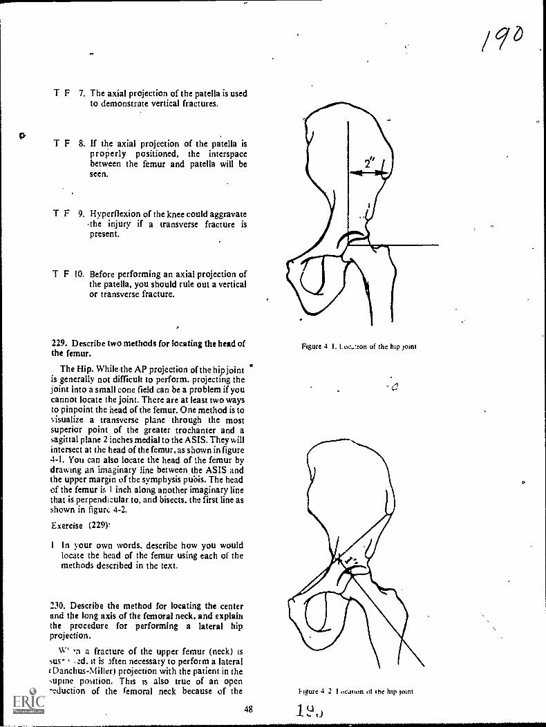
T F 7. The axial projection of the patella is usedto demonstrate vertical fractures.
T F 8. If the axial projection of the patella isp rope rly positioned, the interspacebetween the femur and patella will beseen.
T F 9. Hyperflexion of the knee could aggravatethe injury if a transverse fracture ispresent.
T F 10. Before performing an axial projection ofthe patella, you should rule out a verticalor transverse fracture.
229. Describe two methods for locating the head ofthe femur.
The Hip. WhileThe AP projection of the hip jointis generally not difficult to perform. projecting theJoint into a small cone field can be a problem if youcannot locate the joint. There are at least two waysto pinpoint the head of the femur. One method is tovisualize a transverse plane through the mostsuperior point of the greater trochanter and asagittal plane 2 inches medial to the ASIS. They willintersect at the head of the femur, as shown in figure4-1. You can also locate the head of the femur bydrawing an imaginary line between the ASIS andthe upper margin of the symphysis pubis. The headof the femur is I inch along another imaginary linethat is perpendicular to, and bisects, the first line asshown in figurt, 4-2.
Exercise (229).
I In your own words, describe how you wouldlocate the head of the femur using each of themethods described in the text.
230. Describe the method for locating the centerand the long axis of the femoral neck, and explainthe procedure for performing a lateral hipprojection.
W i a fracture of the upper femur (neck) issus- ad. it is )ften necessary to perform a lateralI Danchus-Miller) projection with the patient in thesupine position. This is also true of an open-eduction of the femoral neck because of the
48
Figure 4 I. Loe,.:ion of the hip pint
Figure 4 2 1 ocation 01 the hip pint
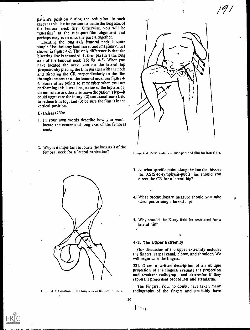
patient's position during the reduction. In suchcases as this, it is important to locate the long axis ofthe femoral neck first. Otherwise. you will be"guessing" at the tube-part-film alignment andperhaps may even miss the part altogether.
Locating the long axis femoral neck is quitesimple. Use the bony landmarks and imaginary linesshown in figure 4-2. The only difference is that thebisecting,line is extended. It then parallels the longaxis of the femoral neck (sii fig. 4-3). When youhave located the neck. you do the lateral hipprojectionby placing the film parallel with the neckand directing the CR perpendicularly to the filmthrough the center of the femoral neck. See figure 4-4. Some other points to remember when you areperforming this lateral projection of the hip are: (1)do not rotate or otherwise move the patient's legitcould aggravate the injury. (2) use a small cone fieldto reduce film fog, and (3) be sure the film is in thevertical position.
Exercises (230):
I. In your own words describe how you wouldlocate thc center and long axis of the femoralneck.
Wt:y is it important to locate the long axis of thefemoral neck for a lateral projection?
. ti. 4 I OCation !nc long ..1 h, 14,1, r,,t,
49
/ 9/
Figure 4 4 Relatmships ot tube-part and film for lateral htp.
3. At what specific point along the line that bisectsthe ASIS-to-symphysis-pubis line should youdirect,the CR for a lateral hip?
4.c What precautionary measure should you takewhen performing a lateral hip?
5. Why should the X-ray field be restricted for alateral hip?
4-2. The Upper Extremity
Our discussion of thc upper extremity includesthe fingers, carpal canal, elbow, and shoulder. Wewill begin with the fingers.
231. Given a written description of an obliqueprojection of the fingers, evaluate the projectionand resultant radiograph and determine if theyrepresent prescribed procedures and standards.
The Fingers. You, no doubt, have taken manyradiographs of the fingers and probably have

noticed the large number of small chip fracturesnear the interphalangeal joint spaces. While the PAand lateral projections are,important in diagnosingthese fractures, the oblique is equally importantbecause it can reveal a fracture not seen on the othertwo radiographs.
The problem with the obliqut is that it sometimesis not performed as it should be; consequently, afracture may be missed. To demonstrate theinterphalangeal joint spaces properly, the fingersmust be positioned so that the joint spaces areperpendicular to the film. If not, there will be anoverlapping of the articular surfaces of thephalanges and possibly of a "hidden" fracture.Notice the difference between the interphalangealjoints infigures 4-5 and 4-6. In figure 4-5,she fingersare parallel with the film; in figure 4-6, they are not.
Ile fingers can be positioned to properlydemonstrate the areas referred to in a number ofways so long as they are supported to prevent partmotion. One good device to use is a polyfoam stepwedge, illustrated in figure 4-7. This step wedge canbe made from any radiolucent material and can alsobe used for oblitiue projections of the hand andwrist.
Exercises (231):
An oblique radiograph of the ring finger is madewith the finger forming a 35° angle with the table.Based on the information presented in the text,answer items i through 4 below.
Figure 4-5. Oblique radiograph of the fingers showing good1.1sualinuon of the interphalangeal joints,
I. What is the relationship between theinterphalangeal joint spaces and the film?
2. Is the CR directed precisely through the jointspaces?
-ge
Figure 4-6 Oblique radiograph of the fingers bhoingsuperimposition of the articular surfaces of the interphalangeal
joints.
Eigure 4-7. The pol} foam step %%edge
1 LI
/ 1910Q--

c.<
3. How will the articular surfaces of eachinterphalangeal joint appear on the radiograph?
4. Is the finger properly positioned?
An oblique radiograph of the ring finger is thadewith the use of a polyfoam step wedge seen in figure4-7. Based on the information in the text, answeritems '4 through 8 ,below.
5. Is the finger parallel to the film? Figure 4-88. Position of the hand for visualization of the carpalcanal.
6. What relationship exis. between The joint spacesand the film?
7. H ow will the articular surfaces of theinterphalangeal joints appear on the radiograph?
8. Of the two oblique prosctions mentioned in theexercises above, which one is preferred? Why?
232. Complete statements describing the procejureforperforming a projection of the carpal canal. andnarne the bony structures demonstrated on theradiograph.
hgure 4 $A Position thc hand for isuahranon of the ::arpal
51
-said& .1
;It
Figure 4-9. Radiograph of the carpal canal.
, The Carpal Canal. The carpal canal is theanterior concavity of the wrist formed by the carpalbones. Because of the concave surface, it is difficult
to visualize, by the standard projections, the volaraspect of some of the structures. The Gaynor-Hartprojection can reveal or confirm fractures of thepisiform, triangular, capitate, harnulus process ofthe hamate, and the greater and lesser multangulars.
To perform the Gaynor-Hart projection, have thepatient extend the wrist as much as possible so thatthe long axis is vertical or near vertical. To supportthe forearm, place a three-quarter inch radiolucentpad under the wrist. Rotate the hand slightly towardthe radial side of the wrist to separate the hamulusprocess and pisiform. Direct the CR through thecarpal canal at an angle of 300 (from vertical). Seefigures 4-8A, 4-8B, and 4-9.
Exercises (232):
Fill in the blanks below with the appropriate word,or answer the questions as indicated.
I. Demonstrating the aspect of somecarpal bones by standard projections is difficultbecause of the of the surface.
2. Fractures of what parts can be visualized orconfirmed by the Gaynor-Hart projection?
3. The long axis of the hand should beor near vertical for the Gaynor-Hart projection.
4. A pad placed beneath the wrist to demonstratethe carpal canal supports the
It, 5. When performing the carpal canal projection,the is away from the
side of the wrist to provide anunobstructed view- of the and
233. Given written descritions of selectedprojections and radiographs of the elbow, evaluatethem and determine whether they representprescribed procedures and standards; recommendcorrective actions if necessary.
The Elbow. Our discussion of the elbow centersaround some of the common errors made inperforming the standard projections and in theresulting radiograph. We will also discuss someadditional projections used to dmonstrate specificareas around the elbow.
AP projection. The AP projection of the elbowshould be made with the hand supinated. anyamount of pronation rotates the elbow medially anddemonstrates an oblique projectionthe amountdepends upon the degree bf pronation. A sandbagplaced across the patient's hand prevents him frominadvertently pronating the hand.
Lateral projection. To obtain a true lateralprojection of the elbow, there are a few things tokeep in mind. Iri addition to the elbow, place thewrist and hand in the lateral position. If the hand ispronated you may not be able to detect thedifference on the radiograph but the head of theradius is not in the lateral position. This could resultin a missed fracture of the radial head.
.6.0306
When the elbow is in position for the lateral, theforearm is normally angled slightly downward,which causes' the distal numerus to rotate. Theradiograph will show the medial epicondyleextending posteriorly from the distal humerus. Youcan correct this rotation of the humerus easily b)elevating the fdrearm slightly (about I inch).
For a specific demonstration of the radial head,'four' laterals can be made with the hand in thevarious positions shown in figure 4-10.
Oblique projection. The medial obliqueprojection of the elbow demonstrates a near lateralview of the coronoid process clear of overlyingstructures. The elbow should be rotated 400 to 45°.Too little rotation of the elbow does not turn thecoronoid near enough to lateral. Consequently, it isseen "on end" or almost as it appears on the AP.Too much rotation of the elbow pariially obscuresthe coronoid process because the radial head issuperimposed.
The lateral oblique is a good projection fordemonstrating the radial head. Part rotation is 450 .
Be sure to keep the elbow joint extended tor theexposure.
Jones projection. Jones' projection of the elbowis taken to demonstrate the olqtranon process. It isalso used instead of the AP Otojection when theelbow is hypedlexed because of injury or treatment.Figure 4-11 shows the Jones' projection. Notice thatthe hand and wrist have been rotated so that thethumb is on the lateral side of the patient's shoulder..
Exerdses (233):
An AP radiograph of the elbow skows slight medialobliquity. Based on the information in the text.answer items 1 and 2 below.
I. What is the probable cause of the obliquity'
2 What should you recommend to the speclahstto correct the position?
3 A lateral radiograph of the elbow shows themedial epicondyle on the posterior side of thehumerus. Is this a true lateral? If not. hovvshould it be corrected?
A patient is positioned for a lateral elbow with the,olar surface of the hand flat on the table. Based onthe information in the text. ansvver items 4 through6 beim; .

a
F.e.me 4 :(; se nand and arm for multiple radial head laterals.
4 Is the position correct'
5. What could be missed on the. radiograph andhy?
How should the position he correcte0?
7. To demonstrate a fracture of the radial heachlateral projections can be made
with the in different position5.
Two medial oblique radiographs a tine etbow aremade. Radiograph A shows the coracoid processprutected almost in the AP position. Radiograph Bshows the coracoid process supenmposed over theradial head. Based on the information presented idthe text. answer items 8 and 9 below,
53
8. What is wrong with the position on radiographA? How shotfld it be corrected?
9. What is wrong with the position on radiographB? How should it be corrected?
10. A 45° lateral oblique projection can be used todemonstrate the
234. Given three Tadiographs oU a dry humerus,classify them as neutral, external, or internalrotation.
Rotation Projections of the Shoulder. Classifyingthe rotation radiographs of the shoulder is simply amatter of recognizing the position of the proximalhumerus. We will discuss three such positionsdesignated as internal. external, apd neutralrotation. As you study these positions, keep in mind

1
AJ
A
A, PositionB. Projection
Figure 4- II Jones projection of the'elbow
54
that ihe degree of arm rotation in your departmentdepends upon your radiologist and may oy may notbe the same as described here. However, you shouldhave little trouble adapting the information wepresent here to any rotation projection of -theshoulder.
Neutral rotation. When a line through thehumeral epicondyles is parallel to the table top, thehumerus is in the neutral or AP position. In thisposition, the lesser tuberosity is shownsuperimposed over the humerus a little toward themedial side. The head of the humerus is seen in theoblique position since it extends posteromediallyfrom the humerus. The greater tuberosity is shownon the lateral side, although not so prominently asin the external rotation position.
External rotation. In this position, a line throughthe epicondyles forms a 43° angle with the table top.The greater tuberosity and humeral head are seen inprofile and consequently well visualized. You canalso see the depression of the anatomical neckbetween the greater tuberosity and head. The lessertuberosity is superimposed over the lateral portionof the humerus.
Internal rotation, when the arm is internallyrotated so that a line through the epicondyles formsa 45° angle w.ith the table top, the arm is In internalrotation. When this is the case, only the superiorportion of the head is well visualized, since therotation moves most of the head behind the otherstructures. The lesser tuberosity is shown in profileon the medial side of the humerus. The greatertuberosity is superimposed over other structures inthe approximate center of the humerus.
Exercises (234):
Figure 4-12 shows three radiographs of a dryhumerus. Study them and classify them as netural.external, or internal rotation. Write your answersbelow.
I. Radiograph A
2. Radiograph B
3. Radiograph C
2 t )
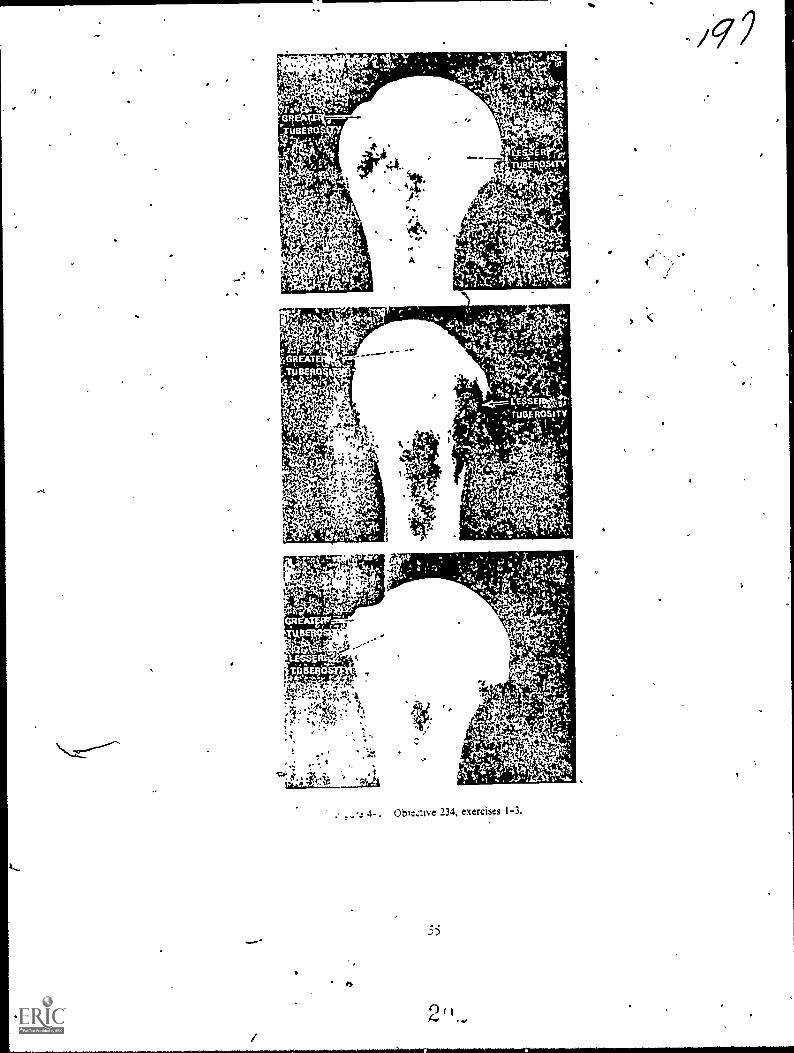
11.
Oble:ive 234, exercises I-3,

CHAri,TER 5
Positioning of the Vertebral Column, Ribs, and Chest
WE WILL CONTINUE the subject of positioningwith a discussion of the vertebral column, ribs, andchest. As we did in Chapter 4, we will omit most ofthe relatisely simple projections, which cause nospecial problems, and include informatioh'concerning selected radiographs to help youdetermine the position. or rather the "improper"position, used. We w ill begin with the cervical spine.
5-1. The Cervical Spine
Our concerns in this section are the "open mouth"and oblique projections of the cervical spineprojections that often are not performed as theyshould be. In addition, we will describe theprocedures to use in X-raying the cervical spine of alitter patient.
235. Given' written descriptiofis of four APradiographs of the atlas mid axis, evaluate theradiographs and determine whether they meetprescribed procedures and standards; indicatecorrective measures if necessary.
Atlas and Axis (Open Mouth). This projection istaken to demonstrate the atlas and axis in the APposition. For this projection, usually called an"open mouth odontoid" the patient's head must beprecisely positioned; otherwise, the atlas and axisare not projected, clear of overlying structures. Toposition the patient, have him open his mouth asv.tele as possible and adjust his head so that a linethrough the inferior edge of the upper incisors andthe inferior border of the mastoid tip isperpendicular to the film. Use a vertical CR. Sincethe position is uncomfortable for *the patient, besure to have everything else ready so that you canmake the exposure quickly. Also:have the patientsay "Ah" during the exposure to prevent anymovement of the jaw and to fix the 'tongue in .thefloor of the mouth. The shadow of the tongue is thenprojected below the vertebrae under study and doesnot interfere with the detail. As usual, foreNaminations in this area. have the patient removeany dentures he might ha e.
I. sually, when the patient is improperlypositioned for this projecoon. it is because his headis either flexed too little or too much. The result isthe superimposition of the base of the skull orincisors (depending upon the direction in which the
imaginary line is tilted) 'over the structures understudy. You can easily check the position on theradiograph by noting the lower margins of theupper incisors and the base of the skull. If the baseof the skull is lower than the incisors, the head is
extended too much. If the two parts are resersed.the head is not extended:enough. At times. althoughthe head is tilted correctly and the incisors and baseare in the same vertical !inc.., there is stillsuperimposition over the bertebrae. When such isthe case, nothing can be done to irnprose thkprojection.
Exercises (235):
Fbur AP "open mouth" radiographs of the atlas andaxis are made:
Radiograph A shows the lower margins of theupper incisors superimposed over the area understudy. The base of the skull is projected above theupper incisors.
Radiograph B shows the base of the skullsuperimposed over the vertebrae. The lowermargins of the upper incisors are projected abosethe base of the skull.
Ricliograph C' shows the base of the skull.and thelower margins of the upper incisors supeQmposedover each other. Both of these structures areprojected above the atlas. A dense shadosv.representing the tongue. is stlpernnposed (ACT theaxis.
Radiograph D shows the base of the skull andlower margins of the upper incisors superimposedover each other. Both of these structures aresuperimposed over the atlas and odontoid process:
Based upon the information presented in the text.answer the following questions about eaChradiograph.*
Is the radiograph properly positioned? It notwhat is specifically wrong sv ith the po'sn ion and hoshould it be corrected? f
I. Radiograph A.
2 (,)
41.

1.
2, Radiograph B., «
3. Radiograph C.
4. Radiograph D.
236. State the purpose of the oblique projections ofthe cervical spine, and answer key questions aboutthem.
Oblique Projections of the Cervical Spine. Theusual reason for making oblique projections of thecervical spine is to show the intervertebralforamina. although the pedicles are also seen, aswell as the other cervical structures. The formainaopen from the vertebrae at a 450 angle off bothanterolateral aspects of the vertebrae. They alsoopen slightly downward. 15° to 200. from thevertebrae.
Obliques of the cervical spine can be taken erector recumbent as well as with, or w ithout a grid. Alsoanterior or posterior obliques can be taken. Thesedensions rest with your radiologist. Keep in mmdthat the intervertebral foramina open f:om theanterolateral aspects of the vertebrae: the:efore.'posterior obliques demonstrate the formainafarthest from the film and anterior obliques showthe foramina nearest the film.
To position the patient for an oblique projection,rotate the entire body 45- to coincide with theopened foramina. 1 urn 'the median plane of thehead slightly more than 45° from ifs positionperpendicular to the film to prevent thesuperimposition of the ramus of the mandible overthe spine. Direct the CR to the fourth cervicalertebra so that it coincides with the mfertorly
angled opening of tht foramina. The CR is anefedeither in a caudad or cephalic direction. aependingon whether the oblique is anterior or posterior.
Exercises (236):
I For what specific rea.on are obliques of thecerv kcal spine usuall made
2, Mi hich oblique projectiorus) demonstrates thestructures indicated m aem I abov e. on theright side.of the ertebrae! On the left side oi theertebrae?
)9,73. What is the specific part rotation and CR
angulation for a right posterior oblique of thecervical spine? For a right anterior oblique?
4. If an oblique radiograph of the cervical spineshow the ramus of the-mandible superimposedover the vertebrae, what should you do toeliminate this superimposition on a subsequentradiograph?
237. With specific information about a patientbrought to the radiology department on i litter,answer key questions about the types of projectionsand positions that will demonstrate his cervicalvertebrae.
Cervical Spine' Projections on a Litter Patient.When we speak of a "litter" patient in this case; wemean a patient who has injured his cervical spineand is on a stretcher or litter, usually in the supineposition. This type of patient must be handled verycarefully to prevent further injury andcomplications, such as a severed spinal cord.
When a patient is to be radiographed in thiscondition, the.first thing you should do is to make across-table lateral of the cervical spine withoutmoving the patient to the X-ray /able, or changinghis position on the litter. Show the radiograph to theradiologist or attending physician before doinganything else. This is very important because thephysician may. after seeing the initial film. not wantto moye the patient at all until he is placed intraction.
Now, suppose the initial cross-table lateral doesnot show any.abnormality. Your next course ofaction is determined by the physician. He may directyou to make AP and oblique projections with thepatient still on the litter or to move the patient to thetable for the remaining radiographs.
If the physician wants you to perform theremaining radiographs with the patient on the litter,he may want you to perform only an AP and let him
look at the radiograph before going on with theobliques. If he wants obliques, you can easilyperform them with the patient supine. All you haveto do is place a cassette under the patienesspine anddirect the CR 15° to 20° cephalically and 45'mticlially. In other words, the CR is directed throughthe inter% ertebral foramina as for conventionalobliques. except that the tube is angled 45° insteadof the patient. Ask the physician to supervise thelifting of the patient for the film placement. If it isnot possible for the patient to move himself, be surethat the physician understands what you must do toplace the film under the patient's neck. He can thentell you exactly how he wants you to lift the patient
If the physician wants you to move the patient tothe X-ray table for the remaining radiographs,again ask his supervision or guidance in moving thepatient. You can perform the obliques on the tableas on the litter, but you will have to remove the gridto prevent grid cutoff dee to the 45° angle of thetube.
Exercises (237):
I. A patient is brought to the radiology departmenton a litter in the supine position. The physiciansuspects a fracture of C4. Describ the initialprojection you should perform and why.
2. The cross-table lateral on the patient in item #1above shows a fracture of C4. What is your nextcourse of action, if any?
3. How much part rotation. if any, and what CRangulation and direction, if any, :,hould you usefor oblique projections on the patient in item #1above?
4; What should you do to prevent grid cutoff ifyouare performing the obliques on the X-ray tableon the patient in item #1 above?
5. Before moving or lifting the patient in item #1above or adjusting his position, what actionshould you take? .
5-2. The Lumbar Spine
AP and PA projections of the lumbar spineusually cause technicians few problems. Therefore,we will limit our discussion to the oblique andlateral projections.
238. Eveluat., certain characteristics of specificoblique projections and radiographs of the lumbarspine.
Oblique Projections of the Lumbar Spine. Theoblique projections of the lumbar spine are usuallytaken to demonstrate the apophyseal joints and thepars interarticularis. You will remember that theapophyseal joints are formed by the superiorarticular process of one vertebra and the inferiorarticular process of the next lower vertebra. Thesejoints open from the posterolateral portions of bothsides of the vertebrae at about a 45° angle. Usually,
58
the joints can be visualized if the patient is rotated45° in either the anterior or posterior obliquepositions. However, the exact degree of angulationmay vary from patient to patient, and after havingseen the initial 45° radiographs, you may have torotate the patient to some other angle to make thejoint spaces visible. In fact, the ,degree of patientrotation is the most common positioning errormade in performing these obliques, even when thejoints arc situated at a 45° angle. You cal1 determinewhether the patient has been rotated 45° from theAP or from the PA position by looking at themedial portion of the transverse process, seen onend as a dense circular area with a lucent center. Ifthe joint spaces are not visualized and the medialportion of the transverse process is toward theanterior portion of the vertebral body, the patient isnot rotated enough from the supine position. If themedial portion of the transverse process is towardthe posterior portion of the vertebral body, thepatient is rotated too much. This bony landmarkshould be in the approximate center of the vertebralbody. In addition, the width of that, structurechanges with different amounts of body rotation.See figure 5-1. The pars interarticularis is the bonysegment between the superior and inferior articularprocesses. If you can see the apophyseal joints onthe radiograph, good visualization of the parsinterarticularis is more or less automatic.
As we previously mentioned, posterior oranterior obliques of the iumbar spine can be made,depending upon your radiologist's preference. Ifposterior obliques are made, the joints and "pars"nearest the film are visualized. With anteriorobliques, those farthest from the film are seen.
Exercises (238):
Three oblique radiographs of the :umbar spine aremade. Radiograph A shows the medial portions ofthe transverse processes projected in the horizontalcenter of the vertebral bodies. Radiograph B showsthe same structures projected toward the posteriorportions of the bodies. Radiograph C shows themprojected toward the anterior portions of thebodies. The relative (horizontal) widths of theprocesses are: Radiograph A medium, radiographBnarrow; radiograph Cwide. Based upon theinformation presented in the text, answer exercises1 through 5 below.
It
I. Which radiograph shows app6ximately 45°rotation?
2. Which radiograph shows more than 45°rotation?
2 '.1 0

el` :4q
TRANSVERSEPROCESSES
c:310 /
44.
Figure 5- I Three left posterior obkque racmgriphs of dried lumbar vertebrae showing how body. .otation
affects isualization of the apophyseal jomts. A a correctly rotated. B is rotated too much. C is not rotated
enough.
3. Which radiograph shows less than 450 rotation?
4. Which radiograph is most likely to demonstratethe pars interarticulzris?
5. If radiograph A does not demonstrate theapophyseal joints, what can you assume about:he joints?
6. A right posterior oblique of the lumbar spine iscorrectly made. Which (right or left) apophysealjoints are demonstrated?
59
7. A left anterior oblique of the lumbar spine iscorrectly made. What pars interarticularis (right
or left) are demonstrated?
239. Given a list of statements pertaining to theIntend projection of the lumbar spine, indicatewhich are true and which are false. If you indkate"false," explain your answer.
Lateral Projection of the Lumbar Spine. A goodlateral projection of the lumbar spine must show theinterspaces between the vertebral bodies clearlywithout the superimposition of the superior andinferior articular surfaces, the interspaces aresometimes difficult to demonstrate because thelumbar spine has a tendency to "sag" (becomecurved) when the patient is in the lateral recumbentposition. As a result, the long axis of the spine is notparallel with the film, and the interspaces are notperpendicular to the film. Consequently, on the

lateral radiograph there may be an overlapping ofthe articular surfaces of the vertebral bodies overthe inters paces.
The degree of the curvature of the spine dependsupon the physical characteristics of the patient. Thecurvature of a patient with a relatively small waistand wide hips is greater than with a patient whosewaist and hips are more nearly the same size. Thelong axis of the spine in a female usually sags morethan that of a male because of the greater differencebetween her waist and hips. In certain patients, thesize of the waist and hips is the same, and the longaxis of the spine is actually parallel to the film whenthe patient is in the lateral recumbent position.
Usually, the best results are obtained if you use avertical CR for the lateral lumbar projection. Thismeans that you may have to place enoughradiolucent material under the lumbar spine abovethe iliac crest and under the lower thoracic vertebraeto bring the long axis of the spine parallel with thetable. 'Of course, some patients require morematerial than others because the degree of the spinalcurvature varies. You can tell if the spine is parallelwith the table by checking this alignment on thepatient's back.
Instead of placing the spine parallel with the table,some technicians prefer to angle the CR caudally tocompensate for the curvature of the spine. Thedegree of angulation depends upon the degree ofcurvature. A patient whose spine is nearly parallelwith the table requires the least CR angulation.Usually, the average angle for male patients is 5°and for female patients 8°, for the reasonsmentioned above.
Although, the problems stemming from 'thehorizontal alignment of the vertebrae are perhapsthe most difficult to overcome with the laterallumbar projections, there are two other commonerrors made in the positioning. The first is failing tosuperimpose the knees and legs. This can causeanterior or posterior rotation of the vertebrae.Whether the rotation is anterior or posteriordepends upon, and is consistent with, the relativeposition of the dependent leg. The second error isfailing to elevate the dependent knee to hip level,which can cause anterior rotation of the vertebrae.
Exercises (239):
Listed below are several statements pertaining tothe lateral projection of the lumbar spine. Indicatewhich are true and which are false. If you indicate"false." explain your answer.
F I. Normall, better radiogaphs result if thelateral is taken with the lor g axis of thespine parallel witn the film.
60
T F 2. The intervertebral spaces must beperpendicular to the film.
T F 3. An angled CR is used in conjunction with aparallel spine-film relationship.
T F 4. In the lateral recumbent position, lumbar"sag" is usually greater in male patients.
T F S. If you use a vertical CR, you always have tobuild up the spine:
-
T F 6. The amount of material used to bring thespine parallel w ith the film depends uponthe patient's ph} sical characteristics.
T F The appearance of the intervertebral spaceson the radiograph is an indication of thecorrectness of the position.
T F 8. Superimposing the knees and legs canreduce the possibility of anterior, posteriorrotation.
T F 9. To help prevent posterior rotation. youshould elevate the dependent knee to niplevel.
5-3. The Thoracic Spine, Ribs, and Chest
In this section, we will discuss the obliqueprojections of the thoracic spine, the ribswithspecial emphasis on their relationships with thediaphragmand the PA cheststrictly adiscussion on quality control. We v. ill begin witn;heobliques of the thoracic spine.
240. Correlate the poSition of the patient with thestructures to be shown on the radiograph in obliqueprojections of the thoracic spine.
Oblique Projections of the Thoracic Spine. Theoblique projections of the thoracic spine are usuallytaken to demonstrate the apophyseal joints. Thesejoint spaces appear opened if they are seen at anangle of 20° from the vertical with the patient in the
I
i
lateral recumbent position. If the patient is in thisposition, and the side remote from the film isrotated 200 forward, the joints nearest the film aredemonstrated. If his elevated side is rotatedbackward 20°, the joints farthest from the film arevisualized. For example, if the patient is in the rightlateral recumbent position and his left side is rotatedforward, the joints of the right side of the spine arevisualized. If his left side is rotated backward, theleft apophyseal joints are seen.
Whether you use anterior or posterior obliquesdepends upon your radiologist. There is a littledifference in the part-film distance between thedifferent types of obliques. so you shouldn't mixthem. Comparing the sides is more difficult if theobliques are mixed. Also, be sure to elevate thelumbar and lower thoracic areas to place thethoracic spine parallel with the film.
Exercises (240):
1. If the patient is supine on the table, how manydegrees should his left side be rotated away fromthe table to demonstrate the apophyseal joints onthe left side? On the right side?
2. If a left posterior oblique is performed of thethoracic spine (median plane forms a 70° anglewith the table), which apophyseal .oints (right orleft) are demonstrated?
3. If a left posterior oblique is performed of thethoracic spine, what other oblique should beperformed?
241. Answer key questions about the technique andpurpose of rib projections, and select from a list ofrespiratory phases the ones you would use in
specific situations.
The Ribs. Some minor fractures of the ribs are, attimes, difficult to demonstrate radiographically.One reason for this is that the overlying lungmarkings sometimes obscure the fracture site.Another reason is that some ribs lie above and somebelow the diaphragm. For the latter reason, it isdifficult to select the proper technique for the ribsnear the diaphragm unless you are sure of theirlocation with respect to the diaphragm. As youknow. ri bs below the diaphragm requireconsiderably more exposure than those above.
Diffusion of lung markings. The shadows of thelung markings can be diffused in extreme cases by
using the shallow breathing technique during theexposure. The shallow breathing technique requires
% 2 ' 6,1j
a longer exposure. Usually it covers two or threerespiratory phases. Be sure to stress to the patientthe importance of breathing smoothly andotherwise remaining perfectly still. Don't use theshallow breathing technique on a patient whoserespiration is labored.
Rib-diaphragm relationship. You can alsoovercome the problem with the diaphragm byadjusting the patient's position and respiratoryphase to place the injured ribs either above or belowthe diaphragm. Let's examine the rib-diaphragmrelationships of an average-sized patient. First.posterior ribs one through eight are nomdlyentirely above the diaphragm on full inspiration.Posterior ribs eleven and twelve are normallyentirely below the diaphragm on full expiration orinspiration. Consequently, there is no difficultywith technique when you are X-raying these tenpairs of posterior ribs. Posterior ribs nine and tennormally appear below the diaphragm on fullexpiration, and should be radiographed in thatposition because shadows of lung markings are lessof a problem.
Anterior ribs one through six are usually entirelyabove the diaphragm on full inspiration and shouldbe radiographed in that position. Anterior ribsseven and eight ,are partially above and partiallybelow the diaphragm on inspiration or expiration.Ribs nine and ten extend very little into the anteriorportion of the chest, and those parts that do eXtendinto the anterior portion are usually below thediaphragm. Ribs eleven and tweleve do not extendinto the anterior chest at all. Anterior ribs seventhrough ten are isualized better below thediaphragm with full expiration.
The axillary portions of ribs one through eightshould be radiographed in full inspiration above thediaphragm. Ribs nine and ten should bereadiographed below the diaphragm on e:.piration.
As we previously mentioned. the aboverelationships are those of an ai.erage-sized patient.The level of the diaphragm is somewhat lower in atall, thin patient and higher in a short, heavypatient. For these two extremes, add or subtract onerib from the figures gi%en aboe. depending uponthe level of the diaphragm. For example. on anaverage-sized patient. X-ray axillary ribs onethrough eight above the diaphragm on inspirationand ribs nine and ten below the diaphragm onexpiration. If the patient is short and heavy, youshould X-ray axillary ribs one through seven abbvethe diaphragm on inspiration and ribs eight throughten below the diaphragm on expiration. If thepatient is tall and thin. X-ray axillary ribs onethrough nine above the diaphragm on inspirationand the tenth axillary rib below the diaphragm onexpiration. Apply this same line of reasoning to theanterior and posterior ribs.
Rib projections. The projections required for thevarious ribs depend upon your radiologist. Usually,a standard PA chest ::, taken on all patients with rib

injuries to rule out damage to the underlying lungstructures.
Exercises (241):
1. Why is the breathing technique used during ribradiography?
2. List three factors to remember when using thebreathing technique.
3. Why should a PA chest be performed on apatient with a suspected rib fracture?
Column A, below, is a list of ribs or groups g.,f ribs invarious-sized patients. Column B shows threedifferent respiratory phase considerations with thecorresponding location of the ribs. Match theaspiratory phase and rib location in column B thatyou would use to X-ray the ribs in column A byplacing the letter of the column B item in theappropriate space in column A. Each column B itemmay be used once or more than once.
lumn A Column B
Posterior Ribs
_ 4. Seven and eight (averagepatient)._ 5 Eleven and twelve (averagepatient).
_ 6. Eight through ten (short.heavy patient).On: thruugn nine ( tall. thinpatient).
_ 8 Nine and ten (averagepatient).
Anterior Ribs
_ 9. Four through six (averagepatient).
_ 10. Seven through nine (short.heavy patient).
I I. Six and seven (short. heavypatient).
12. Six and seven (tall, thinpatient).
11 Seven and eight (averagepatient).
Axillarv Ribs
14 Seven and eight (ai,eragepatient).
_ 15 Nine (average patient).16. Seven (short, heavy
patient).17 Eight (short, heavy
patient).18. Eight and nine ( tall thin
patient).
a. Inspiration (above).b. Expiration (below).C. Inspiration or expira-
tion (below).
62
242. Given descriptions of selected PA chestradiographs or positions, evaluate them anddetermine if they were properly positioned; if theywere not properly positioned, recommendcorrective measures.
PA Chest. The PA projection of the chest is, nodoubt, performed more often than any other singleradiograph. You perform them on many patientswho are not even sick, for example, as part of aroutine physical. Because you perform so many ofthese examinations and also because the patientsare in good physical condition, you may sometimesforget the importance of the PA chest.
We assume you already know the properprocedure for performing this examination.Therefore, we will base our discussion on qualitycontrol. You must be able to evaluate theradiograph and determine whether or not thepatient is properly positioned.
Position of the shoulders. One of the mostcommon errors made in performing the PA chest isfailure to "rotate," "roll," or "push" the patient'sshoulders forward. If this is not done, the scapulaeare superimposed over the upper lateral lung fields.The superimposition can very well obscure a lesionor other abnormality.
Some technie'-ns feel that, if an AP projection ismade of the cl s during a bedside examination,it is not necessa. y to consider the scapulae. This isnot true. If the patient's condition permits, theshadows should be eliminted just as on the PAprojection.
Rotation. Another common error made is failingto position the chest with the median planeperpendicular to the film. If the median plane is notperpendicular, some structures are hidden, some artdistorted, and the true relationships betweenstructures are not maintained.
To check for rotation of the chest, start with thesternoclavicular joints. They should appear (hesame. Rotation of the chest usually produces an -asymmetrical appearance. In addition, one of thejoints may be obscured by the spine; or if it is seen, itis superimposed over the spine. In this case theprojection of the other joint is slightly lateral to itsnormal location with the visualization of thecorresponding side of the manubrium. When this isthe case, it is easy to determine the direction of therotation. If the left joint is projected laterally, thepatient's left side is rotated away from the film. Theopposite rotation of the chest causes a similarappearance of the right sternoclavicular joint.
The location of the spinous processes of thevertebrae can also be used to check the rotation ofthe chest. Normally, they should appear in thecenter of the vertebrae. Since the processes arelocated on the posterior surfaces of the vertebrae,they move in the opposite direction of the rotation.Be sure to check several continuous vertebrae. The
ozi
deviation of a single spinous process is notuncommon in a properly positioned chest.
Locating the heart shadow with respect to thespine is another factor that can show patientrotation on a PA chest. Normally, the right balderof the heart, the right atrium, lies slightly to the rN:149f the spine on the PA projection. If you can see the's
TIMright spinal border without the heart superimposed,it can be an indication of chest rotation toward theleft side. This is easy to understand if you visualizethe heart located in the anterior chest and imaginerotating the chest into a slight right-anterior,oblique position. The heart obviously movestoward the patient's left side.
Inspiration. The number of ribs visualized abovethe diaphragm indicates the degree of inspiration bythe patient during exposure. Some radiologists liketo count anterior ribs, while others count posteriorrib's. In either case, count them in the righthemithorax. Also. the particular portion of the ribmust be entirely above the diaphragm.
When you count posterior ribs, be careful whenyou begin the,count. The tendency is to miss the firstrib and begin with the second. Most radiologistsrequire nine posterior ribs or six anterior ribs asproof of a full inspiration chest.
Generally, problems with full inspiration chestfilms on adults are limited tc obese patients. If theyarc allowed to inspire twice before the exposure,with -the film made on the second inspiration, thedegree of inspiration is usuaNy greater.
Exercises (242):
I A PA radiograph of the chest shows densenonpathological shadows superimposed over thesuperolateral lung fields. What is the probablecause of the shadows?
-T. The right sternoclavicular joint on a PA chestradiograph is projected to the right of the spine.The left sternoclavicular spine is not visualized.Does this chest appearance indicate improper
:positioning? If so, how should the position becorrected?
63
2
3. A PA chest radiograph shows a symmetricalappearance of the sternoclavicular joints. Is thechest properly positioned? If not, how should theposition be corrected?
4. A PA chest radiograph shows the spinousprocesses of T1 through T7 shifted to the left.Specifically, what does the shift indicate? Howshould it be corrected?
5. The right border of the thoracic spihe is clearlyseen without the superimposition of the heart ona PA radiograph of the chest. Does this indicaterotation? If so, how should the position bechanged to correct the rotation?
6. A ?A radiograph of the chest shows eightposterior ribs projected above the diaphragm. Isthis a good inspiratory film? If not, how manyposterior ribs should be seen?
7. A PA radiograph of the chest shows five anteriorribs above the diaphragm. Is this a goodinspiratory film? If not, how many anterior ribsshould be seen?

CHAPTER 6
Positionin,g of the Skull
WHILE IT IS relatis ely easy to produce diagnosticradiographs of many parts of the body, the skull andits contents present some problems not encounteredwith other body structures. Perhaps, the greatestreason for the problems is that the skull must bepositioned precisely. There is not as much marginfor error. lf, for example, the rotation of skull is offas little as 50, the structure under study may not bedemonstrated on the radiograph. You must be "onthe money," so to speak, to product.. consistentdiagnostic radiographs of the skull and its contents.
It is not practical to present in this CDC theseldom-used projections of the skull. They areavailable in commercial publications found in mostAir Force hospitals. We will present most of theprojections that are used every day. These are the sixbasic skull projections; the positions of themastoids, petrous ridges, and internal auditorymeati; the ofitic foramina; the zygomatic arches; thenasal bones; and the temporomandibular joints. Wewill begin with the six basic skull projections.
6-1. Basic Projections of the Skull
The six basic skull projections are. lateral, PA,A P , Waters', submentovertical, andserticosubmental. These projections are used todemonstrate many different structures and areperformed frequently, as you know. Normally, thebasic position is the same, regardless of the structureexamined.
243. In a hypothetical situation, specify how youshould position the patient for various lateralprojections of the skull, and answer key questionsabout performing lateral projections.
Lateral Projection. Perhaps. you have noticed onoccasion that cross-table lateral projections of theskull us uall demonstrate the skull in the true lateralpusition. rhis is understandable because, with thepatient in the supine position. It is relatively easy toadjust his head so that the median plane is parallelwith the ertical X-ray film.
Most lateral prOjections. as you know. areperformed w ith the patient in the semiproneposition. and it is with this position that sometechnicians have problems. The problems usuallystem from tw o factors. First, it is almost impossibleto position some patients properly without
64
elevating the head on some radiolucent material orelevating the patient's chest and shoulders so thatthe cervical spine is parallel with the film. Second, itis difficult for some technicians to "eyeball" theskull and determine whether it is in the properposition.
So that you can better understand how to copewith these problems, we should first define fourimproper skull positions.
a. Anterior or posterior rotation. The skull isrotated so that the face is either too close to, or toofar away from, the table (see fig. 6-1).
b. Superior or inferior longitudinal angulation.The skull is tilted so that the top of the head is eithertoo close to, or too far away from, the table (see fig.6-2). Usually, with a thin patient, the top of the headis tilted away from the table, and, with an obesepatient, it is tilted toward the table.
It is easier to prevent longitudinal angulation ofthe head than to prevent anterior or posteriorrotation. The reason for this is that there are twosimple ways to check the position. One is to use arectangular piece of cardboard 3" x 8". Lay thelonger edge of the cardboard on the table in front ofthe face and check the upper edge with the medianplane. Adjust the position of the head until theupper edge of the cardboard is parallel w ith themedian plane, as shown in figure 6-3. It is helpful tohave on hand several pieces of cardboard ofdifferent widths because it is easier to check thealignment if the upper edge of the cardboard is thesame height as the median plane. You may have toelevate the top portion of the head or elevate thepatient's chest and shoulders to achieve the correctposition.
Another way to check the longitudinal position otthe head is to stand the cardboard on end and see itthe interpupillary line is vertical with r spect to thelongitudinal plane of the table. as show n in figure 6-4. If not, correct tit: position of the head. To checkthe position of the head with respect to anterior orposterior rotation, position yourself at the end otthe X-ray table and check the position of the headusing the same piece of cardboard. as seen in figure6-5. Rotate the head until the median plane isparallel with the table. Remember. y ou must checkthe head for anterior or posterior rotation from thisposition.
21,

POSTERIOR ROTATIONANTERIOR ROTATION
Figure 6-1. Anterior and posterior rotation of the lateral skull.
INFERIOR LONGITUDINALANGULATION
SUPERIOR-LONGITUDINALANGULATION
Figure 6-2. Sui,erior and inferiorlongitudinal angulation of the lateral skull.
Figure 6-3. Photograph demonstrating the use of a rectangular
piece of cardboard to align the median plane of the skull parallelwith the film.
65
10.40.11..._..
Figure 6-4. Photograph demonstrating the use of a rectangular
piece of cardboard to align the interpupillary line perpendicularto the film,

Figure 6-5. Photograph demonstrating the use of a rectangularpiece of cardboard to align the median plane of the skull parallel
with the film.
Center the midpoint of the film and direct the CR.to the sella turcica if the examination is fornoatraumfitic reasons. This is very importantbecame the radiologist may have difficultyevaluating the sella turcica if it is projected withdivergent rays. The sella is located at a point three-quarters of an inch anterosuperiorly to the externalauditory meatus. For trauma, center the film anddirect the CR to the center of the skull. Manyradiographs of the skull and facial bones are madewith the head in the true lateral position. Fourexamples are as follows:
(1) Sella turcicause a small cone field.(2) Sinusescenter the midpoint of the film and
the CR to the outer canthus of the eyetake ailsinuses with the patient erect to demonstrate fluidlevels.
(3) Nasal bonestake both laterals.(4) Facial bonescenter the film to the zygoma.
Exercises (243):
Below in column A are listed the true lateral andfour near lateral position of the skull. In column Bare list,NI five descriptions of the median plane of theskull Malch the description in column B with theposition in column A by placing the letter of thecolumn B item in the appropriate space in columnA Each column B item may be used once.
Column .4 Column B
1 True lateral. a. Parallel with the_ 2. Anterior rotation. table.3 Posterior rotation. b. Superior portion4. Superior angulation. farther from table.5. Inferior angulation. c. If extended, intersects
with table above thetop of head.
d. Anterior portionnearer the table.
e. If extended, intersectswith table behindhead.
6. What positioning errors are you most likely tomake when you are aligning the skull for thelateral? What errors are you least likely tomake? Why?
7. In your own words, explain how you shouldposition the skull in the true lateral position. Bespecific. Tell what you would check and howyou would go about it.
8. If the history on the X-ray request said"headaches," where should the CR be directedfor the lateral skill? Why?
9. For a lateral projection of the sinuses, where isthe film centered and to what point is the CRdirected?
10. Name four examinations, other than a regularskull radiograph, that require the skull to bepositioned in the true lateral position.
244. Given a list 'of six pairs of structuresdemonstrated on a lateral projection of the skull,indicate whether they can show anterior orposterior rotation, superior or inferior longitudinalangulation, or both.
To check the lateral radiograph of the skull forthe true lateral position, there are several bonystructures to look for. Refer to figure 6-6 as wediscuss them. The orbital plates of the frontal boneand the lesser wings of the sphenoid bone appear onthe radiograph as solid, dense lines extending frombehind the frontal sinuses to just anterior to the sellaturcica. These dense lines should appearsuperimposed over each other when the skull is inthe true lateral position. If they are separated, theskull is angled longitudinally.
The anterior borders of the middle fossa (thegreater wings of the sphenoid) should also appearsuprimposed over each other. If not, the skull isrotated anteriorly or posteriorly. These bordersappear as a curved, dense line extendingsuperoinferiorly about 1 inch anterior to the sellaturcica.
The bilateral anterior and posterior clinoidprocesses of the sella turcica also should besuperimposed. Depending on the direction of the
N, 066 14.1 .)
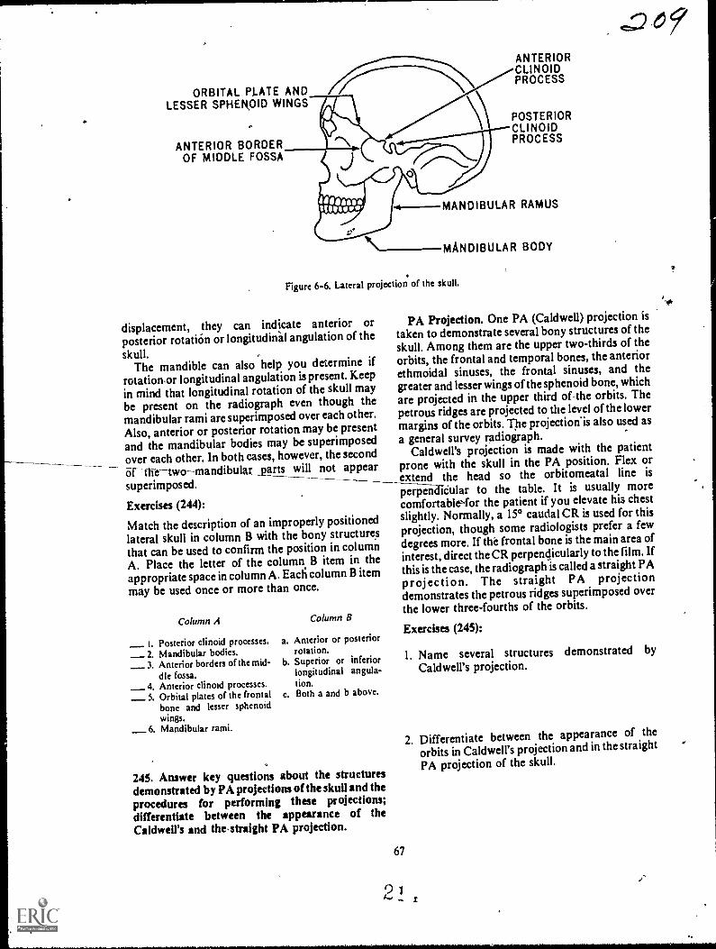
ORBITAL PLATE ANDLESSER SPHEROID WINGS
ANTERIOR BORDEROF MIDDLE FOSSA
ANTERIORCLINOIDPROCESS
POSTERIORCLINOIDPROCESS
MANDIBULAR RAMUS
\--MANDIBULAR BODY
Figure 6-6. Lateral projection of the skull.
displacement, they can indicate anterior orposterior rotation or longitudidal angulation of the
skull.The mandible can also help you determine if
rotation,or longitudinal angulation is present. Keep
in mind that longitudinal rotation of the skull maybe present on the radiograph even though themandibular rami are superimposed overeach other.
Also, anterior or posterior rotation may be presentand the mandibular bodies may be superimposed
_ over each other. In both cases, however, the second6rth-etwomandibular _parts will not appearsuperimposed. --Exercises (244):
Match the description of an improperly positionedlateral skull in column B with the bony structuresthat can be used to confirm the position in columnA. Place the letter of the column B item in theappropriate space in column A. Ead column B itemmay be used once or more than once.
Column A
Posterior clinoid processes. a.
_ 2. Mandibular bodies._ 3. Anterior borders of the mid- b.
dle fossa._ 4. Anterior clinoid processes._ 5. Orbital plates of the frontal c.
bone and lesser sphenoidwings.
_6. Mandibular rami.
Column B
Anterior or posteriorrotation.Superior or inferiorlongitudinal angula-tion.Both a and b above.
245. Answer key questions about the structuresdemonstrated by PA projections of the skull and theprocedures for performing these projections;
differentiate between the appearance of theCaldwell's and the,straight PA projection.
67
2
E=D61
PA Projection. One PA (Caldwell) projection istaken to demonstrate several bony structures of theskull. Among them are the upper two-thirds of theorbits, the frontal and temporal bones, the anteriorethmoidal sinuses, the frontal sinuses, and thegreater and lesser wings of the sphenoid bone, whichare projected in the upper third of the_orbits. Thepetrous ridges are projected to the level of the lowermargins of the orbits. The projection'is also used as
a general survey radiograph.Caldwell's projection is made with the patient
prone with the skull in the PA position. Flex orextend the head so the orbitomeatal line is
peri-3-eaCieular to the table. It is usually morecomfortableNfor the patient if you elevate his chestslightly. Normally, a 15° caudal CR is used for thisprojection, though some radiologists prefer a fewdegrees more. If the frontal bone is the main area ofinterest, direct the CR perpendicularly to the film. If
this is the case, the radiograph is called a straight PA
projection. The straight PA projectiondemonstrates the petrous ridges superimposed overthe lower three-fourths of the orbits.
Exercises (245):
1. Name several structures demonstrated by
Caldwell's projection.
2. Differentiate between the appearance of the
orbits in Caldwell's projection and in the straight
PA projection of the skull.
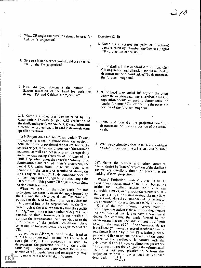
3. What CR angle and direction should be used forCaldwell's projection?
4. Give one instance when you should use a verticalCR for the PA projection?
5. How do you determine the amount offlexion extension of the head for both thestraight PA and Caldwell's projections?
246. Name six structures demonstrated by theChamberlain-Towne's (angled CR) projection ofthe skull, and specify the correct CR angulation anddirection, or projection, to be used in demonstratingspecific structures.
AP Projection. One AP (Chamberlain-Towne)projection is taken to demonstrate the occipitalbone, the posterior portion of the parietal bones, thepetrous ridges, the posterior portion of the foramenmagnum, as well as other structures. It is especiallyuseful in diagnosing fractures of the base of theskull. Depending upon the specific anatomy to bedemonstrated and the rad igist's preference, thecaudal CR varies from . to 60°. Usually, todemonstrate the structures mentioned above, thetube is angled 3V to 350 . To demonstrate the entireforamen magnum and jugular foramina, angle theCR 50' to 600. This greater CR angle also can showbasilar skull fractures.
When we speak of the tube angle for thisprojection, we actually mean the angle formed bythe CR and the orbitomeatal line. The standardposition of the head for this projection requires theorbitomeatal line to be perpendicular to the film.When such is the case, we can say that the specificCR angle used is a certa:n number of degrees fromertical. At times, however. it is not possible to
position the orbitomeatal line perpendicular tothetilm because of the palient's condition. Thesesituations require a compensatory adjustment of theCR.
Sometimes an AP projection of the skull is takenwith the orbitorneatal line and the CR vertical(straight A P). This projeCtion is used todemonstrate the posterior portion of the cranialauIt only. It does not demonstrate the inferiorportion of the occipital bone and consequently, maynot demonstrate a basilar skull fracture.
Exercises (246):
I. Name six structures (or pairs of structures)demonstrated by Chamberlain-Towne's (angledCR) projection of the skull.
2. If the skull is in the standard AP position. v. hatCR angulation and direction should be tAed todemonstrate the petrous ridges? To demonstratethe foramen magnum?
3. If the head is extended 10° beyond the pointwhere the orbitomeatal kne is vertical. IA hat CRangulation should be used to demonstrate thejugular foramina? To demonstrate the poste;portion of the foramen magnum?
4. Name and describe the projection used zodemonstrate the posterior portion of the cranialvault.
5. What projection described in the text should notbe used to demonstrate a basilar skull fracture '
247. Name the sinuses and other structuresdemonstrated by Waters' projection of the skull andanswer key questions about the procedures formaking Waters projection.
Waters' Projection. Waters' projection of theskull demonstrates most of the facial bones. theorbits, the maxillary sinuses% the frontal amiethmoidal sinuses, and atious other structures It -the best position tor demonstrating the maxflarsinuses and. while the ethmoidal and frontal sinuse,are somewhat distorted. they are fairly well seen
One of the most common errors made inpositioning the patient is the improper alignment ofthe orbitomeatal line. If you have a commercialdevice for checking the angle formed b!. theorbitomeatal line and the table, it is not too diff icultto obtain the required 37- If no commercial deeeis available, you can cut a piece of cardboard like thcone shown in use in figure 6-7 Place it alongside thepatient and flex or extend the head until the upperborder of the cardboard is parallel with theorbitomeatal line. This derice eliminates guessworkon your part by precisdy aligning the orbitomeatalline. It is not good practice to perform thisprojection without a device such as we ha edescri bed. 2 N
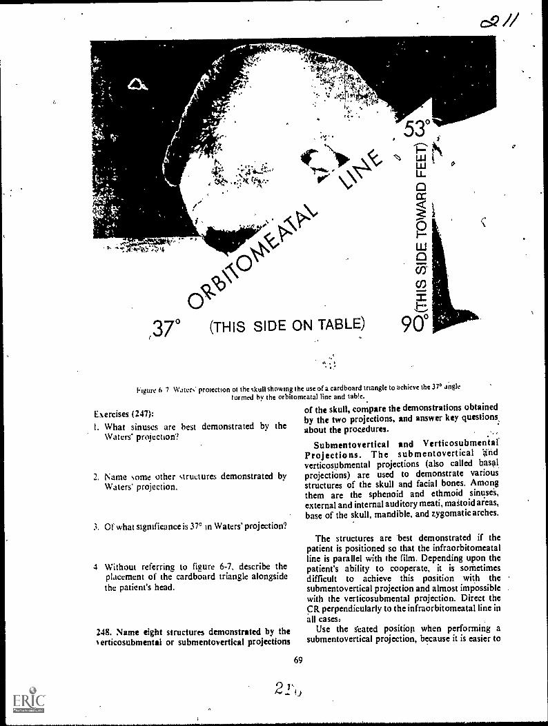
4,
,4?!.
W.14 ritkA'
ir.""), 0 (THIS SIDE ON TABLE)
ELIJ
L
co
900
Figure h 7 Waters protection ot the skull showing the use of a cardboard tnangk to achieve the 370 a*ngk
tormed by the orbitomeatal line and tab!e..
of the skull, compare the demonstrations obtainedby the two projections, and answer key questions,about the procedures.
Submentovertical and VerticosubmentalProjections. The submentovertical n d
verticosubmental projections (also called basal2. Name some other structures demonstrated by projections) are used to demonstrate various
Waters projection. structures of the skull and facial bones. Amongthem are the sphenoid and ethmoid sinusei,external and internal auditory meati, maStoid areas,base of the skull, mandibk, and zygomatic arches.
Exercises (247):
I. What sinuses are best demonstrated by theWaters' projection?
3. Of what sigrnficance is 3r in Waters' projection?
4 Without referring to figure 6-7. describe theplacement of the cardboard triangle alongsidethe patient's head.
248. Name eight structures demonstrated by theerticosubmental or submentovertical projections
69
21*,,
The structures are best demonstrated if thepatient is positioned so that the infraorbitomeatalline is parallel with the film. Depending upon thepatient's ability to cooperate, it is sornetimesdifficult to achieve this position with thesubmentovertical projection and almost impossiblewith the verticosubmental projection. Direct theCR perpendicularly to the infraorbitomeatal line inall casesa
Use the s'eated position when performing asubmentovertical projection, because it is easier to
0

achieve the desired position of the head, and it isusually more comfortable for the patient (see fig. 6-8). If you use the recumbent position, elevate thetrunk on pillows or pads. Figure 6-9 shows theverticosubmental projection.
Exercises (248):
I. Name eight structures or pairs of structures thatare demonstrated by the verticosubmental orsubmentovertical projections of the skull.
--.)11N"
pJ 4.A 1(?.. .
A....N. c./.2r,
Ai
Figure 6-8 Submentovertical projection of the skull (seatedposition).
Figure 6 9. Verticosubrnental projection of the skull.
2. Which of the two projections discussed in thetext best demonstrates the stfuctures in exercise#1 above? ,
3. How should the submentovertical projcction beaccomplished and why?
4. What is the CR-orbitomeatal line relationshipfor all basilar projections?
6-2. Mastoids and internal Auditory Canals
There are many projections that demonstrate themastoids and internal auditOry canals. Some of thebasic projections of the skull, such as Chamberlain-Tow ne's and the submentovertical alreadydiscussed, demonstrate them and are used invarious departments. In addition to the basic skullprojections, we will discuss Law's, Stenvers',Arcelin's, Mayer's, and Schuller's projections.
249. Give some significant features about thetechniques ft,r increasing details in the radiographsof the mastogds and internal auditory canals.
Standard Procedures. Before you stu0 thespecific projections, we should examine somestandard procedures to follow with all "mastoid"projections. Always tape the patient's ears forwardon oblique and lateral projections to prevent thesuperimposition of soft tissue shadow over the areaunder study. The structures are somewhat difficultto demonstrate in the first place and, even thoughthe shadow cast by the ear is minimal, it is enough toreduce the detail.
The standard rule to cone down to the smallestfield size.possible is very important. Film fog due toexcessive secondary and scatter radiation isparticularly detrimental to film detail where suchsmall structures as in the mastoid area areexamined.
Use the small focal spot to provide better detailwhen possible. If the patient is comfortable in hisposition and you have his head properlyimmobilized, the longer exposure will not be aproblem.
Some radiologists prefer to use medium or slowspeed screens for these examinations to furtherincrease detail. Since slower screens.increase theradiation dose to the patient, they should be usedonly at the direction of the radiologist.
2 14. 4
AP-

Exercises (249):. ,
1. Why should the patient's ears be taped forwardfor oblique and lateral projections?
2. A cone field of what relative size should be usefiand why?
,
3. When can you use a small focal spot and the
resultant long exposure?
4. Should you decide what type of screens to use? If
not, who should?
,7
250. Given selected statements pertaining to thethree Law's projections, match each with thespecifie projection to which it relates.
Law's Projection. There are three differentmethods for performing Law's projection. All threedemonstrate basically the same structures and theparticular method used in your department dependsupon your radiologist's preference.
The first projection, which we will call the "tube-tilt" projection, is made with the head in the truelateral position. Adjust the head so that theinfraorbitomeatal line is parallel with the long axis
,
CR
,of the film on all Law's projections. Angle the,CR150 toward the feet and 15° toward the face (see fig.6-10). Direct the CR to a point about two inchessuperior to, and two inches posterior .to, theexternal auditory meatafarthest from the film. TheCR should exit from the skull at the lower mastoidprocess.'This projection should not be taken with agrid because the 15° angle toward the face is acrossthe lead strips and causes considerable grid cutoff.Consequently, the ;Ise of a small cone field to reducesecondary and scatter radiation takes on added
significance.,
The second projection, which we will call the"combination tube-tilt, part-rotation" projection, ismade with' the CR angled 15° caudad and the facerotated 15° toward the table (see fig. 6-11). Theangle of the part eliminates the requirement to anglethe tube toward the face. It also permits the use of agrid, since the CR is not directed across the lead.
strips as in the baste projection. This position is alsoa little more comfortable for the patient than thetube-tilt projection because the head is in a morenatural, relaxed position, preventing part motionon the fadiograph.
The third projection, which we will call the "part-rotation" projection, is made with the CR verticaland the head rotated 15° toward the face and tilted15° longitudinally toward the feet, as seen in figure6-12. This positibn is the most confortable of thethree for the patient. Obviously, the vertical CRpresents no grid cutOff problems.
..
Exercises (250): .
Match the Law's projection in column B with theappropriate staternent in column A by placing theletter of the column B projection in the appropriatespace in column A. Each column B item may beused once or more than once.
CR
Figure 6-10. Law's "tube-tilt" prpiection.
71
2 1
i
1
,

CR
Figure 6-11. Law's "combination tube-tilt. part-rotation" projection.
Colutnn
_ 1 Vertical CR a.2 Do not use a yid.
_ 3 Small cone field most im-portant.
_ 4 CR angled 15° caudad_ 5. Face rotated 15° toward
table_ 6 Double angle of head.
7 Tube angled 15° caudad and15 toward face.
)i Most comfortable torpatient.
_ 9 Least comfortable forpatient
Figure 6-12. Law's "pait-rotation" projection.
Column B
Tube-tilt method.Combination tube-tilt. part-rotationmethod.Part-rota,tionmethod.
251. Gi%en descriptions of hypothetical clinicalsituations requiring Stenvers' and Arcelin'sprojections, answer selected questions about theposifion and procedures, required.
Stenvers' and Arcelin's Projections. TheSterners' and Arcelin's projections are similar inthat they are made with the petrous ridge parallelVr it h the film. Before we discuss the actual positions.first look at the petrous ridges as they are situated inthe three types of skulls. Refer to figure 6-13 as youstudy.
72
Notice the overall shape of each skull. Thebrachycephalic skull is short from front to back andwide from side to side. Also, notice the angle thatthe petrous ridges form with the median pla-,e-55°. The mesocephalic skull is the most common oraverage type with the petrous ridges forming a 45°angle with the median plane. The third and last skulltype, the dolichocephalic. is long from front to backand narrow from side to side. The petrous ridges inthis skull form the most acute angle. 36°. of thethree.
As you can imagine, to place the petrous ridgesparallel with the film. you must consider the type ofskull with which you are dealing. In all cases, rotatethe face to the left to examine the right petrous ridgeand rotate the face in the opposite direct:on todemonstrate the left petrous ridge.
Now, back to the Sterners' and Arcelin'sprojections. Both are made with the head rotated sothat the petrous ri,ige being examined is parallelv.ith the film. Also. the infraorbitomeatal line isparallel with the transverse axis of the film for bothprojections. Stenvers' projection is made with thepatient prone (PA projection) with the CR angled12° cephalic. Place the patient in the supine position(AP projection) for the Arcelin projec .on and anglethe tube 10° caudad.
2 1 ,

BRACHYCEPHALIC MESOCEPHALIC DOLICHOCEPHALIC
Figure 6-13. The types and shapes of skulls, showing the angles formed 6y the median plane and petrousridges. "
Exercises (251):
A patient with a brachycephalic skull requires arepeat Arcelin's projection of the right petrousridge. Based on the information in the text, answerexercises 1 through 4 below.
1. Is the projection PA or AP?
2. What is the CR angulation and direction?
3. In what direction is the face rotated?
7. In what direction is the face rotated?
8. How many degrees is the head rotated?
A patient with a dolichocephalic skull requiresStenvers' projections of both petrous ridges. Based
upon the infonnationcpresented in the text, answerexercises 9 through 12.
9. In which direction is the face rotated toradiograph the right petrous ridge?
4. How many degrees is the head rotated? 10. In which direction is the face rotated toradiograph the left petrous ridge?
A patient with a mesocephalic skull requires arepeat Stenvers projection of the left petrous ridge.Based upon the information presented in the text,answer exercises 5 through 8 below.
5. Is the projection PA or AP?
6. What is tile CR angulation and direction?
73
2 4,0
I I. How manydemonstrate
12. How manydemonstrate
degrees is the head rotated tothe left petrous ridge?
degrees is the head rotated tothe right petrous ridge?
252. Given a list of characteristics pertaining toMayer's or Schuller's projections, match each with
the appropriate projection.

Mayer's and Schuller's Projections. Mayer'sprojection is made with the patient supine. Positionthe head so that the face is rotated 45° toward themastoids under study. Flex the chin so that theinfraorbitomeatal line is parallel with the transverseaxis of the film. Direct the CR through the externalauditory meatus of the side (lower) being examined,at an angle of 45° caudad.
For Schuller's projection, place the head in thetrue lateral position. Flex the chin so that theinfraorbitomeatal line is parallel with the transverseaxis of the film. Direct the CR 25° caudally throughthe external auditory meatus of the side nearest thefilm (the side being examined).
Exercises (252):
Match the projection in column B , with the-,characteristic in column A by placing the letter ofthe column B projection in the appropriate space incolumn A. Each column B item may be used morethan once. In addition, both column B items mayapply to a single characteristic in column A.
Column A
I. Lateral._ 2. CR 25° caudad.
3 Oblique.4. lnfraorbitorneatal line parallel with
transverse axis of film._5 CR 45° caudad._6. 450 rotation of head._7., Side being examined is nearest the
film
Column B
a. Mayer's.b. Schuller's.
6-3. Optic Foramina, Zygomatic Arches, andNasal Bones
In this last section of' your volume, we willemphasize some special procedures and significant
C R
points in the performance of projections of opticforamina, zygomatic arches, and nasal bones.
253.c;Compare the PA and AP Rhese projections ofthe optic foramina as to their demonstration of theoptic foramen and the degree and direction of therotation of the patient's head.
Optic Foramina. Rhese's projection of the opticforamina is usually made with the patient prone. Itcan be made with the patient supine if he cannotassume the prone position. If this is the case, there isan increase of about 2 inches in the part-filmdistance and resultant magnification on theradiograph.
To perform Rhese's projection (PA) have thepatient rest his head on the nose and the zygoma andchih of the side under study. Rotate the posteriorportion of the head toward the side under studyuntil the median plane forms a 53° angle with thtplane of the film or a 37° angle with a vertical plane.Adjust the head until the acanthiomeatal line isperpendicular to the plane of the film. Center thefilm to the inferolateral quadrant of the lower orbit.Direct a vertical CR to the center of the film (seefigure 6-14).
With the patient supine, the AP projection ismade in the same way. The main differencesbetween the two projections is the magnificationmentioned earlier. With the patient supine, theposterior portion of the head is also rotated towardthe side under study.
Exercises (253):
I. Which projection, PA or AP, shows the opticforamen magnified and why?
Figure 6-14. The Rhese projection of the opuc foramina .
2 9
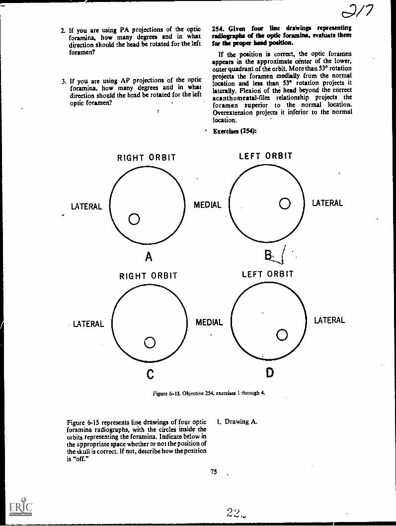
2. If you are using PA projections of the opticforamina, how many degrees and in whatdirection should the head be rotated for the leftforamen?
3. If you are using AP projections of the opticforamina, how many degrees and in whatdirection should the head be rotated for the leftoptic foramen?
LATERAL
LATERAL
RIGHT ORBIT
A
RIGHT ORBIT
c;/7254. Given four line driwinp representingradiographs of tbe optic foramina, evaluate themfor tbe proper bead position.
If the position is correct, the optic foramenappears in the approximate center of the lower,outer quadrant of the orbit. More than 530 rotationprojects the foramen medially from the normallocation and less than 530 rotation projects itlaterally. Flexiori of the head beyond the correctacanthomeatal-film relationship projects theforamen superior to the normal location.Overextension projects it inferior to the normallocation.
' Exercises (254):
MEDIAL
MEDIAL
LEFT ORBIT
F3,,(LEFT ORBIT
D
Figure 6-15. Objective 254, exercises 1 through 4.
Figure 6-15 represents line drawings of four optic 1. Drawing A.foramina radiographs, with the circles inside theorbits representing the foramina. Indicate below inthe appropriate space whether or not the position ofthe skull is correct. If not, describe how the positionis "off."
75
LATERAL
LATERAL

2. Drawing B.
3. Drawing C.
4. Drawing D.
255. Point out significant features of the procedurefor radiographing the zygomatic arches.
Zygomatic Arches. You will recall that thesubmentovertical and verticosubmental (basal)projections demonstrate the zygomatic arches. Attimes, one of these projections reveals eachzygomatic arch clear of superimposed structuresand no further studies are required. Sometimes,however, the arches do not protrude enough from
,
r
i
,
the side of the face to be visualized simultaneouslyon a basal projection. When this is the case, theyshould be radio,graphed one at a time.
To demonstrate the arches individually, useeither the basic verticosubmental or thesubmentovertical projection. Tilt the top of thehead about 15° away from the arch under study forboth projections. We can also say "tilt the mandibletoward the side under study." Notice that we said"tilt the head." This does not mean to rotate thehead. To illustrate the difference refer to figure 6-16.Detail A is an inferior view of the skull. Detail Bshows the skull rotated 150. Notice that therelationships between the zygomatic arches/and theskull do not change. Detail C shows the top of thehead tilted 15° toward the right side. Thismovement throws the left zygomatic arch fartheraway from the ,side of the head allowingvisualization of ffie entire structure withoutsuperimposition.
Be sure to direct the CR perpendicularly to theinfraorbitomeatal line, which should be parallelwith the film. The line is parallel with the zygomaticarch and if the CR-infraorbitomeatal line
i
IFigure 6-16 nferior views of the skull showing the proper method to throw the zygornthe skull.
2 9ic arch awqy from
,
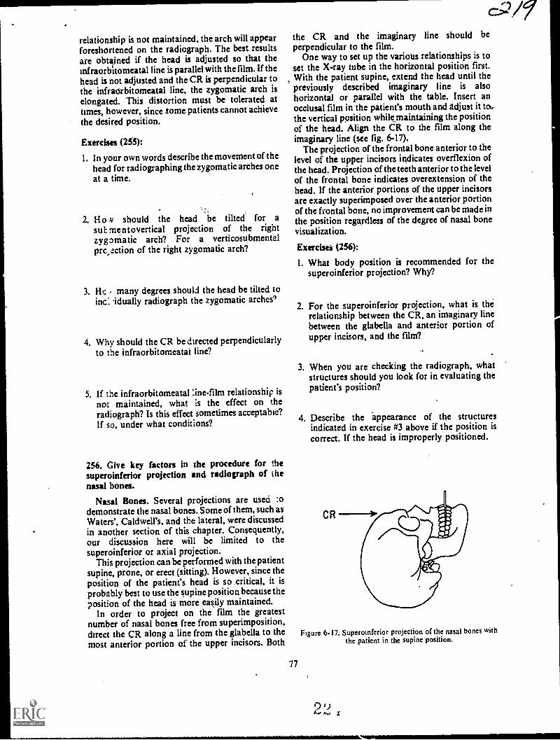
relationship is not maintained, the arch will appearforeshortened on the radiogaph. The best resultsare obtarined if the head is adjusted so that theinfraorbitomeatal line is parallel with the film. If thehead is not adjusted and the CR is perpendicular tothe infraorbitomeatal line, the zygomatic arch iselongated. This distortion must be tolerated attimes, however, since some patients cannot achievethe desired position.
E x ercises (255):
1. In your own words describe the movement of thehead for radiographing the zygomatic arches oneat a time.
2. H o ,v should the head be tilted for asub mentovertical projection of the rightzygomatic arch? For a verticosubmentalprc,ection of the right zygomatic arch?
3. Hc , many degrees should the head be tilted toinc: idually radiograph the zygomatic arches')
4. Why should the CR be directed perpendicularlyto the infraorbitomeatal line?
5. If the infraorbitomeatal :ine-fihn relationship is
not maintained, what is the effect on theradiograph? Is this effect sometimes acceptable?If so, under what conditions?
256. Give key factors in the procedure for thesuperoinferior projection and radiograph of thenasal bones.
Nasal Bones. Several projections are used :odemonstrate the nasal bones. Some of them, such asWaters', Caldwell's, and the lateral, were discussedin another section of this chapter. Consequently,our discussion here will be limited to thesuperoinferior or axial projection.
This projection can be performed with the patientsupine, prone, or erect (sitting). However, since theposition of the patient's head is so critical, it isprobably best to use the supine position because theposition of the head is more easily maintained.
In order to project on the film the greatestnumber of nasal bones free from superimposition,direct the CR along a line from the glabella to themost anterior portion of the upper incisors. Both
c..;2/9'the CR and the imaginary line should beperpendicular to the film.
One way to set up the various relationships is toset the X-ray tube in the horizontal position first.With the patient supine, extend the head until thepreviously described imaginary line is alsohorizontal or parallel with the table. Insert anocclusal film in the patient's mouth and adjust it to .the vertical ppsition whikmaintaining the positionof the head. Align the CR to the film along theimaginary line (see fig. 6-17).
The projection of the frontal bone anterior to thelevel of the upper incisors indicates overflexion ofthe head. Projection of the teeth anterior to the levelof the frontal bone indicates overextension of thehead. If the anterior portions of the upper incisorsare exactly superimposed over the anterior portionof the frontal bone, no improvement can be made inthe position regardless of the degree of nasal bonevisualization.
77
Ex ercisess (256):
1. What body position is recommended for thesuperoinferior projection? Why?
2. For the superoinferior projection, what is the'relationship between the CR, an imaginary linebetween the glabella and anterior portion ofupper incisors, and the film?
3. When you are checking the radiograph, whatstructures should you look for in evaluating thepatient's position?
4. Describe the appearance of the structuresindicated in exercise #3 above if the position iscorrect. If the head is improperly positioned.
Figure 6-17. Superoinfenor projection of the nasal bones withthe patient in the supine position.
2.2.0
ANSWERS FOR EXERCISES
CHAPTER 1
Reference:
200 - I. T.200 - 2. F. The ileum is distal to the jejunum.200 - 3. T.200 - 4. T,200 - 5. F. The radius is lateral to the ulna.200 - 6. T.200 - 7. T.
201 - I.201 - 2.201 - 3201 - 4.201 -5.
b.C.
a.
d.a.
202 - 1. T.202 2. F. The third toe has three phalanges.202 - 3. F. The first toe has only two phalanges.202 - 4. F. The base of the distal phalanx articulates with the
head of the middle phalanx in the fourth toe.202 - 5. T.202 - 6. T.202 - 7. T.202 - 8. T.202 - 9. F. Each metatarsal joins with another metatarsal.202 - O. T.202 - 1 1. F. The first cuneiform is on the medial side.
202 - 12. F. The calcaneus is the largest tarsal bone
202 - 13. T.202 - 14. T.202 - 15. T.202 - 16. F. The sustentaculum is on the calcaneus.
202 - 17 F. There are 26 bones of the foot and toes.
203 - I. Talus, tibia, and fibula.203 - 2. Tibia.203 - 3. Fibula.203 - 4. They are important for weight bearing and mobility
and attempts are made to maintain them duringtreatment of injuries.
203 - 5. Diarthrodial or hinge-type.
204 - I. Tibia, fibula.204 - 2. Fibula.204 - 3. Medial malleolus.204 - 4. Interosseous crest.204 - 5. Superior articular surface, medial and lateral
condyles, intercondylar eminence, tibial tuberosity.
204 - 6. On the tibial tuberosity.204 - 7. Lateral malleolus.204 - 8. Proximal.204 - 9. On the fibular head.204 - 10. The tibia.
205 - I.205 - 2.205 - 3.205 - 4205 - 5.205 - 6.205 - 7,
b.a.
C.
e.d.a.b.
206 I. Linea aspera.206 - 2. A triangular-shaped area on the posterior side of the
distal femur.
79
,27
206 - 3. Posterior.206 - 4. Superior and medial.206 - 5. Head.206 - 6. Yes.206 - 7. Fovea capitis.
207 - 1. T.207 - 2. F. The iliac crest extends from the ASIS to the PSIS.207 - 3. T.207 - 4. T.207 - 5. T.207 - 6. F. The lesser sciatic notch is located on the ischium.207 - 7. T.207 - 8. T.207 - 9. T.207 - 10. F. The pubic arch is formed by the inferior ramus of
the pubis and the ramus of the ischium.207 - 1 I. T.207 - 12. T.207 - 13. T.207 - 14. F. The sacrum and coccyx form the posterior margin
of the true pelvis.
208 - I. Five.208 - 2. The first. The fifth.208 - 3. Posterior.208 - 4. The fifth lumbar.208 - 5. The first coccygeal.208 - 6. Ilia, sacroiliac joints.,208 - 7. An oval articular surface on the body of the first sacral
vertebra.208 - 8. Posteriorly.208 - 9. Four.208 - 10. Lines that mark the former separations of the
coccygeal vertebrae.208 - II. Coccygcal cornua.208 - 12. Base, apex.
209 - I. Body, base. head.209 2. The first (thumb).209 - 3. Fourteen.209 - 4. Middle phalanx. fourth digit.209 - 5. Distal. proximal.209 - 6. Fourth.209 - 7. Distal.209 - 3. Eight.209 - 9. Greater and lesser multangulars, capjtate, hamate.
209 - 10. Navicular, lunate, triangular, pisiform.
209 - 11. Pisiform.209 - 12. Capitate.
210 - I.210 - 2.210 - 3.210 - 4.210 - 5.210 - 6.210 - 7.
a.b.b.b.a.
b.b.
211 - I. F. The olecranon fossa is on'the postertol'hinnerus.
211 - 2. T.211 - 3. F. The radial fossa is on the lateral humerus.211 - 4. F. The medial epicondyle ts more prominent.211 - 5. F. The deep depression is the olecranon fossa.
211 - 6. T.211 - 7. F. The semilunar notch articulaies with thc trochlea.

211 - 8. F. The olecranon process fits into the olecranon fossawhen the elbow is extended.
212 - I. Surgical neck-the constricted portion of the humerusbelow the tuberosities.
212 - 2. Lesser tuberosity-bony eminence -,on the anteriorsurface.
212 - 3. Greater tuberosity-rounded eminence on the lateralside.
212 - 4. Bicipital groove-deep furrow between thetuberosities.
212 - 5. Anatomical neck-the portion that connects the headwith the shaft.
212 6. Head-uppermost portion.
213 = I. Sternal end. acromial end.213 - 2. Coracoid tuberosity and costal tuberosity.213 - 3. Subscapular fossa.213 - 4. A projecting plate of bone that extends superlaterally
from the vertebral border on the posterior side.213 - 5. Above-supraspinatus fossa.
Below-infraspinatus fossa.213 - 6. Superior border.213 - 7. Inferior angle.213 - 8. Acromion process.213 - 9. Glenoid fossa.213 - 10. Coracoid process.213 - II. Enarthrodial or ball and socket.213 - 12. The head of the humerus and the glenold fossa of the
scapula.213 - 13. The acromion process of the scapula and the distal end
of the clavicle.
214 -214 - 2.214 - 3.214 - 4,214 - 5.
214 - 6.214 -214 - 8.214 - 9.214 - 10.214 - 1 I.
CHAPTER 2
Five.Body.Posterior to the sides.of the vertebral body.Lamina.The superior articular processes of the fifth lumbarvertebra. 1
Sptnous process.Two.Annulus fibrosus, nucleus pulposus.Between the bodies of the vertebrae.Apophyseal joints.The fifth lumbar vertebra and the sacrum.
215 - 1. T.215 - 2. F. Costal articular facets are only located on the
transverse processes of T-I through T-10.215 - 3. T.215 - 4. F. They are very much alike except for the articular
facets.215 - 5. T.215 -46. T.215 - 7 F. Thoracic ertebrae have apophyseal joints.
216 - 1. Atlas.216 - 2. Axis.216 - 3. All.216 - 4 Atlas.216 - 5. Axis.216 - 6. Seventh.216 - 7. Bifid.216 - 8. Occipital. atlanto-occipital.216 - 9 Atlanto-axial.216 - 10. Two.
217 - L True-14 ribs (7 pairs)-they are attached to cartilagethat joins directly wtth the sternum.
217 2. False-6 rtbs-(3 pairs)-they are attachcd tocartilage that does not join directly with the sternum
217 - 3. Eloating-4 ribs (2 patrs)-they do not articulateantertorly with anything.
Z2_.
218 - I. Manubrium.218 - 2. The suprasternal or manubrial notch, and the
clavicular notches.218 - 3. Sternal angle, or angle of Louis.218 - 4. Distal part.
219 - 1.219 - 2.219 - 3.219 - 4.219 - 5.219 - 6.
d.f.e.
b.a.
g.
CHAPTER 3
220 - I. Frontal, parietals, occipital.220 - 2. Frontal.220 - 3. Supraorbital foramen.220 - 4. Squamosal.220 - 5. It is a vertical groove on the internal surface, formed by
the fuston of the or:ginal two parts of the frontal bone.220 - 6. Parietals.220 7. Temporal.220 - 8. Petrus ridges.220 - 9. Mandibular fossa.220 - 10. Temporal.220 - 1 1. Foramen magnum.220 - 12. Occipital condyles.220 - 13. External occipital protuberance (EOP).220 - 14. Sphenoid.220 - 15. Optic foramina.220 - 16. On the sella turcica.220 - 17. Anterior and posterior chnold processess.220 - 18. Sphenoid.220 - 19. Ethmoid.220 - 20. Cribriform plate.220 - 21. On the superior portion of the cribrtform plate of the
ethmoid.220 - 22. Perpendicular plate.
221 - L221 - 2.221 - 3.221 - 4.221 - 5.221 - 6.22L- 7.
222 - I.222 - 2.222 - 3.222 - 4.222 - 5.222 - 6.222 - 7.222 - 8.
c.d.
h.I.e,
a.
d.a.c.b.a.
d.b.c.
223-L T.223 - 2. T.223 - 3. F. The antrum ot Highmore is in the maxilla.223 - 4. T223 - 5. F The palatine processes form the anterior part of the
roof of the mouth and the floor ot the nasal cavity.223 - 6. T.223 - 7. F The prominent pornons of the cheeks are formed by
the zygomattc bones.223 - 8. T.223 - 9. F The zygomatic arches are tormed by both the
zygomatic and temporal bones.223 - 10. T.223 - 1 I. T.223 - 12. F The inferior nasal conchae are located along the
lateral vs alls ot the nasal eaNrity223 - 13. T
80 2,,

223 - 14. T.223 - 15. F. The symphysis is medially located with respect to
the mental foramen.223 - 16. F. There are two mental foramina.223 - 17. F. The mandibular angle is located at the junction of
the body and ramus.223 - 18. T.223 - 19. F. The condyloid process is posterior to the coronoid
process.223 - 20. F. The mandibular notch is located between the
cornoid process and the condyloid process.
224 - I.224 - 2.224 - 3.274 - 4.274 - 5.224 - 6.
C.
c.b.d.a.d.
CHAPTER 4
225 - I No.225 - 2. Articular surfaces of the interphalangeal joints.225 - 3. Use a vertical CR.275 - 4. Yes. Slightly elongated.225 - 5. Yes.225 - 6. Cuneiforms; cuboid. and navicular.
276 - I. To demonstrate pes cavus and pes planus.
226 - 2. The radiologist assumes that the films were taken with
equal weight distribution when he interprets theradiographs. If they are not, his diagnosis may be
incorrect.226 - 3. Stress to the patient the importance of equal weight
distribution. Leave the patient in the same position for
both radiographs.226 - 4 The anterior portion.276 - 5. To the level of the trochlear process andsustentaculum
tali.226 - 6 Flex the ankle so that the plantar surface of the foot is
perpendicular to the film. Angle the CR 400 toward the
head.226 - 7. It will appear foreshortened. and less of it will be seen
227 - I No, The r1/2P and lateral projections do not project the
entire lateral malleolus cleisr of overlying structures..Amedial oblique should be performed,
227 - 2, Extension of the ankle. Flex the ankle joint as much as
possible.227 - 3. T.227 - 4 F The entire stress examination consists of the two .AP
stress projections plus one standard AP,
227 - 5 T.227 - 6 T.
228 - 1 T228 - 2. F The knee should be flexed onl) 45° The angle
tormed by the leg and femur is 135°228 - 3 F The width of the spaces between the femoral
condyles and the tibial condyles should be checked
228 - 4 F The tunnel projection demonstrates the tibialintercondylar eminence and femoral intercondyloid
lossa.228 - 5 T228 - 6. T.228.7. T228 - 8, T228 - 9 T228 - 10 F You should rule out only a trans% erse fracture, The
axial projection will rule out a sertical fracture.
229 - I First method-Palpate the most superior point of the
greater trochanter and sisualize a transserse planethrough that point. Palpate the ASIS ana visualize a
sagittal plane 2 inches medial to it. Localize the head of
2- 2- 2,
the femur at the point where the two planes meet.Second method-Palpate the AS1S and upper marginof the svmohysts" pubis. Imagine a second line.perpendicular to the middle of firstline. Localize thehead of the femur I inch along the second line.
230 - I. Palpate the ASIS and upper margin of the symphysispubis. Imagine a line connecting them. Imagine asecond line bisecting and perpendicular to the first line.The second line reprdents the long axis of the femoralneck.
230 - 2. To prevent "guessing" at the tube-part-film alignment.
230 - 3. Three inches from the ASIS-to-symphysis line.230 - 4. Don't rotate or otherwise move the leg.230 - 5. To reduce film fog.
231 - I. The joint spaces are at an angle to the film.23 - 2. No.231 - 3. Superimposed over each other.231 - 4. No.231 - 5. Yes.231 - 6, The joint spaces are perpendicular to the film.
231 - 7, Clear and free of overlying structures.231 - S. The second one (using the step wedge). Because the
articular surfaces will appear free of overlyingstructures and not superimposed over each other.
232 - I. Volar. concavity.232 - 2. Pisiform. triangular. capitate. hamulus process, and
greater and lesser multangulars.Vertical.Forearm.
232 - 3.232 - 4.232 - 5. Hand, rotated. ulnar. hamulus process. pisiform.
233 - I. A minor degree of pronation of the hand.
233- 2. Place a sandbag across the patients' hand.233 - 3. No. Elevate the forearm slightly.233 - 4. No.233 - 5. A fracture ot the radial head. The radiograph will not
show the radial head in the lateral position.233 - 6. Place the hand in the lateral position,233 - 7, Four. hand.233 - 8, Too little rotation. Rotate the elbow 40° to 45°
233 - 9. Too much rota,ion Rotate the elbow 40° to 450
233 - 10. Radial head.
234 - I.234 - 2.234 - 3.
Neutral.Internal.External.
CHAPTER 5
235 - I. No. The head is flexed he)ond the point where the
incisor-base line is perpendicular to the film. Extendthe head until the imaginal-) line is perpendicular.
235 - 2. No The head is extended be)ond the point where the
incisor-base line IS perpendicular to the film Flex thehead until the imaginar) bne is perpendicular.
235 - 3 No the imaginer) line IS aligned as required. hut thetongue is positioned too high in the mouth Has e the
patient sa) "Ah" during the exposure to lower thetongue shadow below the atlas and axis.
235 - 4 Yes. (NOTE. Esen though the tw o structures aresuperimposed oser the atlas and odontoid process,they. the incisors and base, are in the same serticalplane. Consequent!). thic position is as good as it can
be.)
236 - I. To demonstrate the inters etebral foramina,236 - 2. Lcft posterior oblique and right anterior oblique.
Right posterior oblique and lett anterior oblique236 - 3 Part rotation-45' CR angulation -15" to 20'
cephalic. Part rotation 45° CR angulation-15° to20° caudal.
.236 - 4. Rotate the median plane ot the skull shghtly more than450 from perpendicular.
237 I. The first film should be a cross-table lateral Make awahout moving the patient at all. The reasons for thisaction are to help determine whether the injuryrequires traction before moving the patient, and todetermtne the course of action for the remainingradiographs.
237 - 2. Take no acticn until the radiologist physician tells youwhat he wants next.
237 - 3. No part rotation on this patient. Angk the CR 150 to20° cephalic and 45° medially.
237 - 4. Remove the grid.237 - 5 Discuss the moyements needed with the
radiologist/ physician. Ask him to supervise themovements if possible. If he cannot remain, ask himfor specific instructions on moving the patient.
238 - I. Radiograph A.238 - 2. Radiograph B.238 - 3. Radiograph C.238 - 4. Radiograph A.238 - 5. The joints do not open at a 45° angle.238 - 6. Right.238 - 7. Right.
239 - 1. T.239 - 2. F The intervetebral spaces should be perpendicular to
the film. They do not have to be. You can compensateby using an angkd CR.
239 - 3. F. An angled CR is used with lumbar "sag" in whichthe long axis of the spine is not parallel with the film,
239 - 4. F. It is usually greater in female pattents.239 - 5. F In some pattents the spine is already parallel, and
there is no "sag" in the recumbent position.239 - 6. T.239-7. T.239 - 8, T.239 9. F. Elevating the dependent kg helps prevent anterior
rotation.
240 - 1.
240 - 2.240 - 3.
241 - I.
241 2.
24
242424242424242424242424242424
- 3.- 4.
5.
- 6..
70°. 110°.Right.Right posterior oblique.
To prevent the shadows of lung markings fromobIcuring a fracture.Use an exposure long enough to cover two or threerespiratory phases. Stress w the pattent the need tobreathe smoothly and otherwise hold perfectly still.Do not use the technique if the patknt's breathing islabored.To rule out damage to the lungs.a.c.b.a.
- 8. b.- 9. a.- 10. b.
11. b.12. a.
- 13. b.14. a.15. b.
- 116.a.
- 7 b
18. a.
242 - I. The scapulae were not rolled forward during theexamination.
242 - 2. Yes. Rotate the nght side of the pattent's chest backtoward the film.
242 - 3. Yes. the chest is properly positioned.
7-2
242 - 4. Rotation in the left antenor oblique position. Rotatethe right side of the patient's chest back toward thefilm.
242 - 5. Yes. Rotate the patient's left side back toward the film.242 - 6. No. Nine.242 - 7. No. Six.
CHAPTER 6
243-I, a.243 - 2. d.243 - 3. e.
243 - 4. c.243 - 5. b.243 - 6. Antertor or posterior rotation. Superior or inferior
angulanon. There are two ways to check the skull forlongitudinal angulation and only one way to check forrotation.
243 - 7. Your answer to this exercise should reflect theimportance of aligning the median plane parallel withthe film. You should also use some type of device, suchas the piece of cardboard. to help you align the skull.since. "eyeballing" the alignment is subject to error. Inadditioh, you should mention the fact that you mustcheck the alignment of the skull from two positions: infront of the patient's face, and at the end of the tableabove the top of the patient's head.
243 - 8. Three-fourths of an inch anterosupenorly to theexternal auditory meatus. That is the location of thesella turcica and the sella must be projected withperpendkular rays (CR) to permit interpretation.
243 - 9. The outer canthus of the eye.243 - 10. Sella turcka, sinuses, nasal bones, and facial bones.
244 - I.244 - 2.244 - 3.244 - 4.244 - 5.244 - 6.
c.b.a.C.
b.a.
245 - I. Upper two-thirds of the orkiits, frontal and temporalbones, anterior ethmoidal sinuses, frontal sinuses, andwings of the sphenoid.
245 - 2. , In Caldwell's, the greater and ksser wings of thesphenoid are projected in the upper third of the orbits.In the straight PA. the petrous ridges are projectedover the lower three-fourths of the orbits.
245 - 3. 15° caudad or as specified by the radiologist.245 - 4. When the examination is performed to visualize the
frontal bone.245 - 5, When the orbitomeatal line is perpendicular to the
film, the flexiontextension is correct.
246 - I. Occipital bone, posterior parietal bones. petrousridges, foramen magnum. jugular foramen.
246 - 2. 300 to 35° caudad. 50° to 600 caudad.246 - 3. 40° to 45°. 60° to 70°.246 - 4. Straight AP with the orbitomeatal line and CR
vertical.246 - 5. Straight AP.
247 - I. Maxillary.247 - 2. Facial bones, orbits. frontal sinuses, and ethmoidal
sinuses.247 - 3. It is the angle formed by the orbitomeatal line and the
table when the flexion, extension of the head is correct.247 4. The triangk should be placed so that its shortest side
is perpendicular to the table, the side opposae the 53°angle is,flat on the table, and the hypotenuse parallelsthe orbitomeatal line.
248 - I. Sphenoid and ethmoid sinuses, external and internalauditory meati, mastoids, base of the skull mandible,and zygomanc arches.
82 2 2
248 - 2. Submentovertical.24 x - 3 With the patient seated. It is easier to place the
infraorbitomeatal line parallel with the film and theposition Is more comfortable for the patient.
24x - 4, The CR b alw a>. perpendicular to the infra.orbitomeatal line.
:49 I. To present a loss ot detail due to the shadow castby the
cars.249 2. Small, to present loss of detail because ofsecondary
radiation,249 - 1 When the patient is comfortable and his head is
properly immobilired.249 - 4 No. The radiologist.
250 I.250 2
250 3.
250 4250 - 5250 6.250 . 7250 - 8250 - 9,
:31 I.251 2.
251 - 3.251 4
251 5
251 6,
251 7
251 8.251 - 9,251 10.
251 - 1 I.
251 12.
:52 I
252 - 2252 - 3252 - 4252 - 5.252 . 6.252 7
10 cuudad.To the left35'PA12' cephalic,To the right45.ro the left.To the right,54,541
h.b.
J.a. b
83
253 1. AP. The foramen is farther from the film.
253 - 2. The head should be rotated so that the median plane
forms a 53° :ogle with the plane of the film or a 37°
angle with a vertical plane. For the left foramen rotate
the posterior portion of the head to the left.
253 3. The head should be rotated so that the median plane
forms a 53° angle with the plane of the film or a 37°
angle with a vertical plane. For the right foramen
rotate thc posterior portion of the head to the right.
c=cD41
254 - I. The position is correct the optic foramen is projected
in the lower outer quadrant of the orbit.
254 - 2. The position is incorrectindicated by projection ot
the optic foramen above the normal location. The head
is overflexed.254 3. The position is incorrectindicated by projection of
the optic foramen medial to its normal location. Themedian plane forms an angle of more than 53° with the
plane of the film.254 4. The position is correctthe optic foramen is projected
in the loner outer quadrant of the orbit.
255 - I. The head is tilted. This means the head is moved so thatthe mandible goes in one lateral direction and the top
of the head in the other.255 2. The mandible is tilted to the right or the top of the head
is tilted to the left. Same answer.255 - 3. 15°.255 - 4. To prevent foreshortening the arch.255 - 5. Elongation of the arch. Yes. When the patient cannot
assume a position with the infraorbitomcatal lineparallel with the film.
256 - I. Supine. 1 he patient can maintain the desired position
most easily,256 2. The CR is directed along the imaginary line. Both arc
perpendicular to the film.256 - 3. The antcrior portion of the frontal bone and thc
anterior edge of upper incisors.256 - 4. They should be exactly superimOosed over each other
if the position is correct- If not, one of thc structures is
anterior or posterior to the other.
9 9t
AU GAFS.AL.(751733 )1800
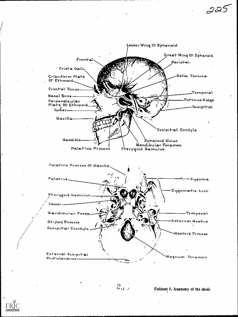
Frontal
Crista Galli
tribritorrn PlateOf- Ethrnotd
Front-al Sinus
Lesser Wins Of- Siohenold
cpa
Great- Wins Of- Sphenoid
PricbL-
Nasal BonePerpendic.ularPlat-e Of- Ethrnoid
Voriler
Maxilla
Mandible
Process
Palat-ine Process Of. Maxtha
Pa lat-Ine
P-ermsoid Hcirnulus
Vorner
Mandibular Fos 6a
tiloui.ProcessOc.c.Lpxt-al
TemporalP trous Ridse
Occipit-al
Occipit-al Conciyle
Sphenoid SinusMandibular Foramen
Pterysold garnulus
NV.
Exl-ernal °cc-Tit-alProt-uberatice
Zmsoma
ZiAomat-tc. i\rc.h
Ternpora.1
External Meatus
Mastoid Process
Fora.men
Foldout L Anatomy of the skull.
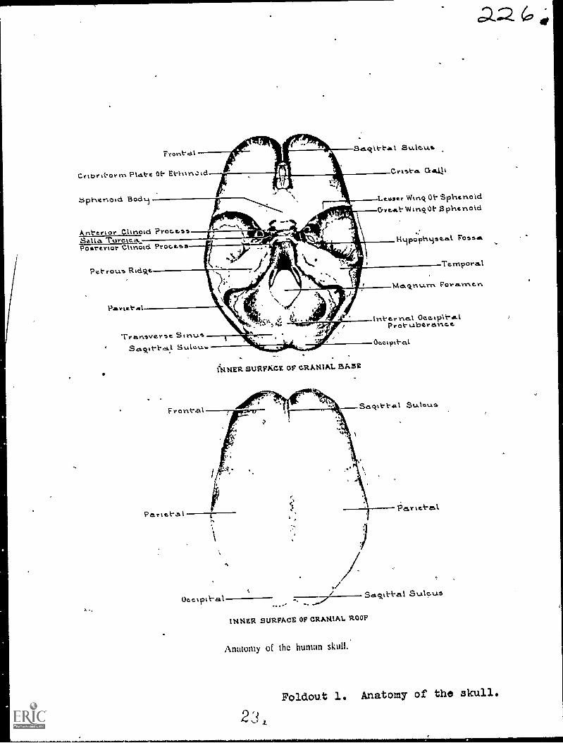
Front-alSa.q11-tal Sulc.u.s
Crist-a.
Lebser Wing Oh SphenoidCrreeit-W0E-$phenoid
Crtbri-orrn PLAI-e 0t- Erd6phenoid Bodm
Ant-ertor Clinotd 'ProcessSella TuroteaPosterlor Clinotd Proceos
Pet rouo Rtdske
Partel-Al
Treinsver5e SinusSulev.1.
I:14NER SURFKCE OF CRANIAL BASE
F056111.
Ternpora.I
Ma.ckni..i.rn Foramen.
Int-er nal OcokplheelProt-uberanee
Oeetpi}-al
Ueeiptk-al Sagit-t-al StAlo.u.s
INNER SURFACE OF CRANIAL ROOF
Anatomy of the human skull..
Foldout 1. Anatomy of the skull.
23,

Pariet-alTemporalSphenoid
Et-hrnoidLavirnalZonaièPerpendicularPlate Of E-t-hmoid
Front-al Eminenc.e.Supraorbit-al"ForamenSupraorbil-al Ridsde
Nasa.l'Middle Conc.ha.Inferior Concha
Ment-al Foramen
Neaseil
Et-hmoidLacrimal
ZycAoma
Ant-criorNasal Spins.
oz emporawv
t
ParietaLl
./
Merit-alForan-tert
Infraorbit-a.1Forarnen
Inkerior Concha
Syrnpl-ty7As MtrtL
Tympanic Port-ionExt-ernal OtaIProl-uberesnce.
Mastoid ProcessS.1.31oicl Process
Condyloid Proc.e...ssMandibular ArtAle
Mandibular Nol-e.hCorortoid Procosss
Foldout lo Anatomy of the skull

LMATCH ANSWIERSHEET TO THISSTOP- EXERCISE NUM-BER.
90370 02 21-
CQ-Gi2. USE NUMBER 1 OR
NUMBER 2 PENCIL.
EXTENSION COURSE INSTITUTEVOLUME REVIEW EXERCISE
OSTEOLOGY AND POSITIONING
Carefully read the following:
DO'S:
1. Check the "course," "volume," and "form" numbers from the answer sheetaddress tab against the "VRE answer sheet identification number" in therighthand column of the. shipping list. If numbers do not match. take actionto return the answer sheet and the shipping list to ECI immec tately with anote of explanation.
2. Note that numerical sequence on answer sheet alternates across from column
to column.
3. Use a medium sharp #1 or #2 black lead penal for marking answer sheet.
4. Circle the correct answer in this test booklet. After you are sure of your
answers, transfer them to the answer sheet. If yotlhave to changean answeron the answer sheet, be sure that the erasure is. complete. Use a clean eraser.
But try to avoid any erasure on the answer sheet if at all possible.
5. Take_ action to return entire answer sheet to ECI.
6. Keep Volume Review Exercise booklet for review and reference.
7. If mandatorily enrolled student, process questions or comments through your
unit trainer or OJT supervisor.If voluntarily enrolled student, send questions or comments to ECI on ECI
Form 17:
DON'TS:
1. bou't use answer sheets other than one furnished specifically for each review
exercise.
2. Don't mark on the answer sheet except to fill in marking blocks. Double
marks or excessive markings which overflow marking blocks will register as
MOM
3. Don't fold, spindle, staple, tape, or mutilate the answer sheet.
4. Don't use ink or any marking other than a #1 or #2 black lead pencil.
NOTE: NUMBERED LEARNING OBJECTIVE REFERENCES ARE USED
ON THE VOLUME REVIEW EXERCISE. In parenthesis after eachitem number on the VRE is the Learning Objective Number where the
answer to that item can be located. When answering_ the items on the
VRE, refer to the Learning Objectives indicated by these Numbers. TheVIIE results will be sent to you on a postcard which will list the actualVRE items you missed. Go to the VRE booklet and locate the Learning
Objective Numbers for the items missed. Go to the text and carefullyreview the areas covered by these references. Review the entire VRE again
before you take The closed-hook Course Examination.
AD. /6-3-
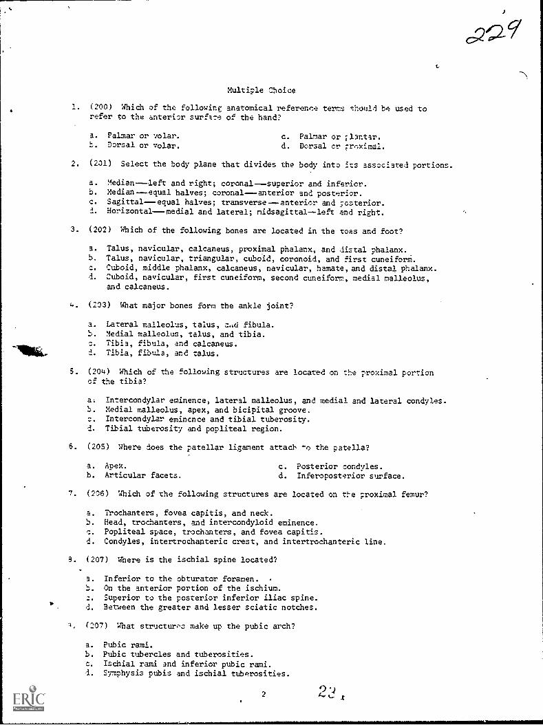
Multiple Choice
1. (200) Which of the following anatomical reference terms should be used torefer to the anterior surflce of the hand?
a. Palmar or volar. c. Palmar or Elantar.t. Dorsal or volar. d. Dorsal cr Froximal.
2. (201) Select the body plane that divides the body into its associated portions.
a. Medianleft and right; coronalsuperior and inferior.b. Medianequal halves; coronal---anterior and posterior.c. Sagittalequal halves; transverseanterior and posterior..1. Horizontalmedial and lateral; midsagittal--left and right.
3. (202) Which of the following bones are located in the toes and foot?
3. Talus, navicular, calcaneus, proximal phalanx, and distal phalanx.b. Talus, navicular, triangular, cuboid, coronoid, and first cuneiforM.c. Cuboid, middle phalanx, calcaneus, navicular, hamate,and distal phalanx.d. Cuboid, navicular, first cuneiform, second cuneiform, medial malleolus,
and calcaneus.
4 (203) What major bones form the ankle joint?
3. Lateral malleolus, talus, fibula.b. Medial malleolus, talus, and tibia.:. Tibia, fibula, and calcaneus.d. Tibia, fibula, and talus.
5. (204) Which of the following structures are located on the proximal portionof the tibia?
a. Intercondylar eminence, lateral malleolus, and medial and lateral condyles.b. Medial malleolus, apex, and bicipital groove.c. Intercondylar eminence and tibial tuberosity.d. Tibial tuberosity and popliteal region.
6. (205) Where does the patellar ligament attach -o the patella?
a. Apex. c. Posterior condyles.b. Articular facets. d. Inferoposterior surface.
7. (206) Which of the following structures are located on te ;roximal femur?
a. Trochanters, fovea capitis, and neck.S. Head, trochanters, and intercondyloid eminence.
Popliteal space, trochanters, and fovea capitis.d. Condyles, intertrochapteric crest, and intertrochanteric line.
9. (207) Where is the ischial spine located?
a. Inferior to the obturator foramen. -
b. Cm the anterior portion of the ischium.Superior to the posterior inferior iliac spine.
d. Between the greater and lesser sciatic notches.
1. (207) What structures make up the pubic arch?
a. Pubic rami.b. Pubic tubercles and tuberosities.c. Ischial rami and inferior pubic rami.d. Symphysis pubis and ischial tuberosities.
2
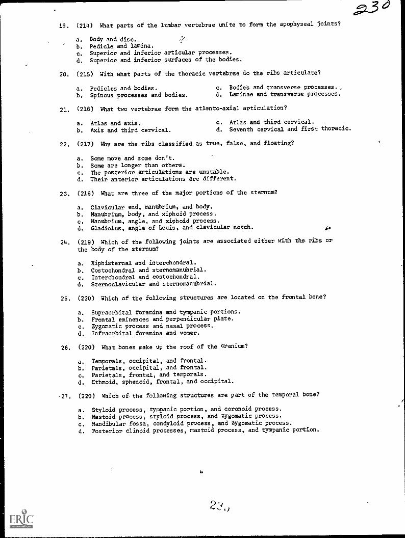
19. (214) What parts of the lumbar vertebrae unite to form the apophyseal joints?
a. Body and disc.1.7
b. Pedicle and lamina.c. Superior and inferior articular processes.
d. Superior and inferior surfaces of the bodies.
20. (215) With what parts of the thoracic vertebrae do the ribs articulate?
a. Pedicles and bodies. c. Bodies and transverse processes. ,
b. Spinous processes and bodies. d. Laminae and transverse processes.
21. (216) What two vertebrae form the atlanto-axial articulation?
a. Atlas and axis. c. Atlas and third cervical.
b. Axis and third cervical. d. Seventh cervical and first thoracic.
22. (217) Why are the ribs classified as true, false, and floating?
a. Some move and some don't.b. Some are longer than others.c. The posterior articulations are unstable.d. Their anterior articulations are different.
23. (218) What are three of the major portions of the sternum?
a. Clavicular end, manubrium, and body.
b. Manubrium, body, and xiphoid process.
c. Manubrium, angle, and xiphoid process.
d. Gladiolus, angle of Louis, and clavicular notch. fe
24. (219) Which of the following joints are associated either with the ribs or
the body of the sternum?
a. Xiphisternal and interchondral.b. Costochondral and sternomanubrial.
c. Interchondral and costochondral.
d. Sternoclavicular and sternomanubrial.
25. (220) Which of the following structures are located on the frontal bone?
a. Supraorbital foramina and tympanic portions.
b. Frontal eminences and perpendicular plate.c. Zygomatic process and nasal process.
d. Infraorbital foramina and vomer.
26. (220) What bones make up the roof of the cranium?
a. Temporals, occipital, and frontal.
b. Parietals, occipital, and frontal.
c. Parietals, frontal, and temporals.
d. Ethmoid, sphenoid, frontal, and occipital.
,27. (220) Which of-the following structures are part of thn temporal bone?
a. Styloid process, tympanic portion, and coronoid process.
b. Mastoid process, styloid process, and zygomatic process.
c. Mandibular fossa, condyloid process, and zygomatic process.
d. Posterior clinoid processes, mastoid process, and tympanic portion.
4
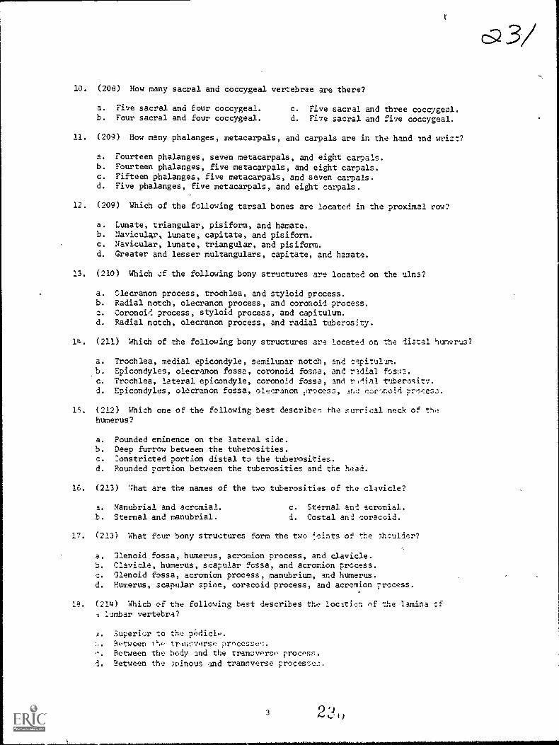
a 3/10. (208) How many sacral and coccygeal vertebrae are there?
a. Five sacral and four coccygeal. c. Five sacral and three coccygeal.b. Four sacral and four coccygeal. d. Five sacral and five coccygeal.
11. (209) How many phalanges, metacarpals, and carpals are in the hand and wrist?
a. Fourteen phalanges, seven metacarpals, and eight carpals.b. Fourteen phalanges, five metacarpals, and eight carpals.c. Fifteen phalanges, five metacarpals, and seven carpals.d. Five phalanges, five metacarpals, and eight carpals.
12. (209) Which of the following tarsal bones are located in the proximal row?
a. Lunate, triangular, pisiform, and hamate.b. Navicular, lunate, capitate, and pisiform.c. Navicular, lunate, triangular, and pisiform.d. Greater and lesser multangulars, capitate, and hamate.
13. (210) Which cf the following bony structures are located on the ulna?
a. Slecranon process, trochlea, and styloid process.b. Radial notch, olecranon process, and coronoid process.c. Coronoid process, styloid process, and capitulum.d. Radial notch, olecranon process, and radial tuberosity.
14. (211) Which of the following bony structures are located on the distal humerus?
a. Trochlea, medial epicondyle, semilunar notch, and capitulum.,b. Epicondyles, olecranon fossa, coronoid fossa, and radial fossa.c. Trochlea, lateral epicondyle, coronoid fossa, and rzlial tuberosity.d. Epicondyles, olecranon fossa, olecranon ,)rocess, corr,noid
15. (212) Which one of the following best describe-, the surrical neck ofhumerus?
a. Pounded eminence on the lateral side.b. Deep furrow between the tuberosities.c. :onstricted portion distal to the tuberosities.d. Pounded portion between the tuberosities and the head.
16. (213) :11.at are the names of the tdo tuberosities of the clavicle?
a. Manubrial and acromial. c. Sternal and acromial.b. Sternal and manubrial. d. Costal an2 coraccid.
17. (213) What four bony structures form the two ,..)i.nts of the shculder?
a. Glenoid fossa, humerus, acromion process, and clavicle.b. Clavicle, humerus, scapular fossa, and acromion process.c. Glenoid fossa, acromion process, manubrium, and humerus.d. Humerus, scapular spioe, coracoid process, and acromion process.
Ie. (214) Which of the following best describes the location of the lamina sflumbar vertebra?
a. 3uperior to the pedic1R-.
.?etween I trinov.trse procesl:e.Petween the body and the tranoverso procPsn.
d. Between the ;vinous and transverse processe.
3
oc2 ea28. (220) Where is the pituitary gland located?
a. On the sella turcica.b. On the tympanic portion.
c. Superior to the crista galli.
d. Behind the posterior clinoid processes.
29. (220) Which of the following descriptions best identifies the location of the
crista galli?
a. 'In the roof of the nasal cavity.b. Extends upward from the cribriform plate.
c. Posterior to the anterior clinoid processes.
d. Extends downward from the perpendicular plate.
30. (221) The coronal suture is located between the
a. occipital amd.parietals. c. temporal and sphenoid.
b. parietals and sphenoid. d. frontal and parietals.
31. (222) What two fontanelles, when ossified, become the bregma and laneda?
a. Both anterolaterals. c. Anterior and posterior.
b. Both posterolaterals. d. Anterior and right posterolateral.
32. (223) Which of the following structures are located on the maxilla?
a. Inferior turbinate, anterior nasal spine, and zygomatic arch.b. Infraorbital foramen, anterior nasal spine, and temporal process.
c. Infraorbital foramen, zygomatic process, and palatine process.
d. Anterior nasal spine, orbital process, and perpendicular plate.
33. (223) With what bones do the nasal bones articulate?
a. Frontal and maxillae. c. Maxillae and zygomatic.
b. Frontal and zygomatic. d. Zygomatic and lacrimal.
34. (223) Where are the inferior nasal conchae located?
a. Below the vomer.
b. Posterior to the nasal bones.
c. Along the medial walls of the orbits.
d. Along the lateral walls of the nasal cavity.
35. (223) What thrce structures are located on the superior portion of the mandible?
a. Coronoid process, mandibular notch, and ramus.
b. Condyloid process, coronoid process, and ramus.
c. Condyloid process, coronoid process, and mandibular notch.
d. Condyloid process, intercondylar notch, and mandibular angle.
36. (224) What sinuses have the alveolar processes as their floor?
a. Frontal. c. Ethmoidal.
b. Maxillary. d. Sphenoidal.
5
37. (225) At what angle and for what reason should the central ray be directed foran AP projectionof the metatarsals?
a. 15° cephalic for a fracture and vertical for a foreign body.
b. Vertical because the metatarsals are parallel with the film.c. 15° cephalic because the metatarsals form the same angle with the film.
d. Either 15° cephalic or vertical depending upon the portion of themetatarsals requiring visualization.
38. (225) What tarsal bones are not adequately demonstrated on an AP projectionof the foot?
a. Calcaneus only. c. Talus and navicular.b. Talus and calcaneus. d. Third cuneiform and calcaneus.
39. (226) An inferosuperior projection of the calcaneus is made with the plantarsurface of the foot perpendicular to the film and the CR angled 40° cephalic.
How much of the calcaneus would be deomonstrated?
a. Approximately the posterior half.
b. To the posterior margin of the talocalcaneal joint.c. The entire calcaneus except for the most superior portion.
d. To the level of the trochlear process and sustentaculum tali.
40. (226) Why is it important to properly position the calcaneus and use thecorrect CR angulation for the inferosuperior projection?
a. It prevents foreshortening.b. It increases the magnification.c. Injuries to the heel are usually serious.
d. Fractures of the calcaneus are particularly difficult to demonstrate.
41. (227) Why should a medial oblique projection be included during an examination
of the ankle?
a. It demonstrates the talocalcaneal joint.b. It provides clear demonstration of the lateral malleolus.
c. It provides clear demonstration of the medial malleolus.d. Most fractures of the ankle are demonstrated only by the oblique projection.
42. (227) What projections should be performed for a,stress examination of the
ankle joint?
a. AP with forced inversion and AP with forced eversion only.
b. Standard AP, lateral, and oblique plus AP with forced eversion.
c. Standard AP, lateral, and oblique plus AP with forced inversion.
d. Standard AP, AP with forced inversion, and A? with forced eversion.
43. (228) A tunnel projection of the knee is taken to demonstrate which of the
following bony structures?
a. Intercondylar eminence and intercondyloid fosse.
b. Intercondylar eminence and patella.
c. Intercondyloid fosse and patella.
d. Femoral condyles and epicondyles.
44. (228) How should the leg and femur be positioned with rospect to the X-ray
table for Homblad's projection of the knee?
a. Leg and femur parallel.b. Leg ---parallel; femur---forms a 200 angle.
c. Leg ---parallel; femur---forms a 70° angle.
d. Leg---slightly elevated; femur --forms a 200 angle.
6 2 `1
45 . (228) Which of the following instructions should be used to locate the head
of the femur?
a. Select a point where a transverse plane through the symphysis pubis interseacs
a sagittal plane 2 inches medial to the ASIS intersect.
b. Select a point where a transverse plane through the most superior point
of the greater trochanter intersects a sagittal plane 2 inches medial
to the ASIS.
c. Imagine a line connecting the ASIS to the symphysis pubis.; imagine another
line which is perpendicular to and bisects the first line. Select a
point 3 inches along the second line.
d. Imagine a line connecting the symphysis pubis to the greater trochanter;
imagine another line which bisects the first line. Select a point 2
inches along the second line.
46. (230) An imaginary line connects the ASIS and symphysis pubis. Another
imaginary line is perpendicular to and bisects the first line. The second lire
a. passes through the greater trochanter.
b. is parallel to the long axis of the femoral shaft.
c. is used as a reference for film placement during a lateral hip projection.
d. is parallel with the CR for an axial projection of the intertrochanteric
crest.
47. (231) Why should the third finger be positioned parallel with the film for
an oblique projection?
a. It superimposes the articular surfaces.
b. It demonstrates the interphalangeal joint spaces.
c. It projects the nutrient artery canal in profile.
d. A hairline fracture of the middle phalanx is easier to demonstrate.
48. (232) Why should the hand be rotated slightly toward the radial side for
a Gaynor-Hart projection of the carpal canal?
a. It elongates the greater multangular.
b. The radial styloid process is better visualized.
c. It projects the hamulus process and pisiform free from superimposition.d. The canal is slightly rotated with respect to the palmar surface of the hand.
48. (233) If a lateral projection of the elbow is made with the hand pronated,
how will the radiograph be affected?
a. The coronoid process will be superimposed over the radial tuberosity.
b. The head of the radius will not be in the lateral position.
c. The semilunar notch will not be visualized.
d. The olecranon process will appear unclear.
50. (233) A medial oblique projection of the elbow is made to demonstrate thecoronoid process. The radiograph shows the coronoid process superimposedover the radial head. .How can the superimposition be eliminated on asubsequent oblique projection?
a. Rotate the elbow 10° more than the original1 rotation.b. Use a 25° lateral oblique position.c. Rotate the elbow 40° to 45°.d. Flex the elbow slightly.

51. (233) Instead of an AP projection, which of the following radiographs shouldbe made of an elbow which is hyperflexed because of injury or treatment?
a. Extension AP. c. Lateral oblique.b. Medial oblique. d. Jones' projection.
52. (234) Which of the following structures are visualized better on the externalthan on the neutral or internal rotation radiograph of the shoulder?
a. Humeral head and lesser tuberosity.b. Humeral head and greater tuberosity.c. Bicipital groove and lesser tuberosity.d. Bicipital groove and greater tuberosity.
53. (235) An AP (open4louth odontoid) radiograph of the atlas and axis shows theupper incisors projected below the level of the base of the skull andsuperimposed over the atlas. What action should be taken to correct thepatient's pbsition on a subsequent radiograph?
a. Flex the head 100 if possible--if not, angle the CR 10° caudally.b. Extend the head 10° if possible--if not, angle the CR 10° cephalically.c. Flex the head--the amount depending upon the distance between the lower
edge of the upper incisors and the base of the skull.d. Extend the head--the amount depending upon the distance between the lower
edge of the upper incisors and the base of the skull.
54. (236) How many degrees should the patient be rotated'and how should the CRbe directed to perform oblique projections of the cervical spine?
a. Body rotation --45°; CR--15° to 20°,cephalic for posterior obliques andcaudad for anterior obliques.
b. Body rotation --45°; CR--15° to 20° cephalic for anterior obliques andcaudad for posterior obliques.
c. Body rotation--90°; CR--20° cephalic.d. Body rotation--90°; CR--20° caudad.
55. (237) When performing oblique projections of the cervical spine on a supinepatient suspected of having a fracture, what CR angulation should you use?
a. 90° lateral and 300 caudad.b. 450 medial and 15° to 20° caudad.c. 45° medial and 15° to 20° cephalic.d. 90° lateral and 30° to 40° cephalic.
56. (238) An initial oblique radiograph of the lumbar spine shows the medialportions of the transverse processes projected over the anterior portionsof the vertebral bodies. Most likely, visualization of the pars interarticularisis
a. poor because the patient is rotated less than 45°.b. poor because the patient is rotated more than 45°.c. good because the patient is rotated the appropriute amount:d. good because visualization of the pars interarticularis is not affected
by patient rotation.
57. (239) Best results are obtained if a lateral projection of the lumbar spine ismade employing which of the follwoing factors?
a. An angled CR and an elevated pelvis.b. An angled CR and a small amount of lumbar "sag."c. A perpendicular CR and the intervertebral spaces parallel with th'e film.d. A perpendicular CR and the long axis of the spine parallel with tha film.
8

58. (239) If an angled CR is used for the lateral projection of the luMbar spine,
the direction and the average amount of the angulationds
a. caudad--8° for males and 50 for females.
b. caudad--50 for males and 8° for females.
c. cephalic --100 for males and 5° for females.
d. cephalic --5° for males and 10° for females.
59. (240) Which one of the following positions demonstrates the right apophyseal
joints of the thoracic spine?
a. From the right lateral recumbent position the patient's left side is
rotated anteriorly 20°.b. From the left lateral recumbent position the patient's right side is
rotated anteriorly 20°.
c. From the supine position the patient's right side is rotated upward 45°.
d. From the supine position the patient's left side is rotated upward 45°.
60. (241) When performing radiographs of the ribs, the breathing technique is
used.to
a. reduce part motion.b. increase visualization.
c. eliminate the heart shadow.
d. compensate for the superimposition of the diaphragm.
61. (241) Which of the following ribs of a short, heavy patient should be
radiographed below the diaphragm on expiration?
a. Posterior ribs ten through twelve; axillary ribs six and seven.
b. Posterior ribs six and seven; anterior ribs five and six.
c. Posterior ribs eight through ten; axillary ribs eight and nine.
d. Posterior ribs eleven and twelve; anterior ribs five and six.
62. (242) When checking the spinous processes for rotation of a PA Chest, why
should several continuous vertebrae be evaluated?
a. Thoracic vertebrae are atypical.
b. Deviation of a single spinous process indicates the CR is not horizontal.
c. The spinous process of the third thoracic vertebra is usually deviated.
d. It is comon for one spinous process to be deviated in a properly
positioned chest.
63. (242) A PA chest radiograph shows slight rotation with the left side of the
chest away from the film. How would the following structures most likely
appear?
a. Heart --shifted to the left; right sternoclavicular joint --superimposed
over the spine.
b. Heart--shifted to thp right; left sternoclavicular joint --superimposed
over the spine.
c. Heart--shifted to the left; left sternoclavicular joint --superimposed
over the spine.
d. Heart --shifted to the right; right sternoclavicular joint --superimposed
over the spine.
64. (242) A full inspiratory PA chest is normally the visualization of how many
ribs?
a. Eight posteSior or eight anterior.
b. Nine posterior or nine anterior.
c. Ten posterior or seven anterior.
d. Nine posterior or six anterior.0
9

c>1.3 7
65. (243) If a lateral radiograph of the skull shows slight anterior rotation,which one of the following descriptionS best relates the position of themedian plane of the head when the radiograph was made?
a. It was parallel with the film.b. The anterior portion was nearer the table.c. If extended, it intersected with thp table above the head.d. If extended, it intersected with the table behind the head.
66. (243) To what point should the CR be directed for a lateral skull if theexamination is being performed'as part of a workup for headaches?
a. Three-fourths 9f an inch anterosuperiorly to the external auditory meatus.b. One and one-half inches posterosuperiorly to the external auditory meatus.c. To the external auditory meatus.d. To the center of the skull.
67. (244) If the dense lines made by the orbital plates of the frontal bone andthe lesser wings of the sphenoid appear separated on a lateral radiograph ofthe skull, what skull position(s) is indicated?
a. True lateral.b. Anterior angulation.c. Anterior or posterior rotation.d. Superior or inferior lon5:1tudinal angulation.
63. (245) Where are the petrous ridges projected on Caldwell's radiograph ofthe skull?
a. Over the maxillary sinuses.b. In the middle of the orbits.c. Slightly superior to the supraorbital ridges.d. To the level of the lower margins of the orbits.
69. (245) A straight PA projection of the skull, rather than a Caldwell projection,should be performed when the
a. greater wings of the sphenoid are under study.b. patient cannot tolerate the supine position.c. frontal bone is specifically to be demonstrated.d. examination is performed under portable conditions.
70. (246) If an AP projection of the skull is being made, what CR angulation anddirection should be used to demonstrate the entire foramen magnum?
a. 500 to 60° caudad. c. 30° cephalic.b. 30° to 35° caudad. d. 15° cephalic.
71. (247) How should the orbitomeatal line be positioned for Waters' projectionof the skull?
a. Perpendicular to the film.b. So that it form a 37° angle with the table.c. So that it forms a 23° angle with the table.d. Parallel with the transverse axis of the film.
72. (248) Best results are obtained with a submentovertical projection if the
a. orbitomeatal line is parallel with, and the CR is perpendicular to, the film.b. head is tilted 15° toward the side under study, and the CR is angled
laterally 5°.c. infraorbitomeatal line is parallel with, and the CR is perpendicular to,
the film.d. median plane is perpendicular to the film, and the CR is perpendicular to
the infraorbitomeatal line.10

73. (249) The ears should be taped forward for certain projections of the
mastoids because
a. the positioning is more difficult.
b. extraneous shadows reduce detail.
c. less secondary radiation is produced.
d. it is more comfortable for the patient.
74. (250) What CR angulation(s) anddirection(s) should be used for Law's
projection, tube-tilt method?
a. 23° cephalic.b. 300 to 35° caudad.
c. 15° toward the face and 15° caudad.
d. 15° toward the occiput and 15° caudad.
75. (251) When a Stenver's pryjection isbeing performed, if the patient has a
brachycephalic skull, in what direction and how many degrees should the
head be rotated to demonstrate the right petrous ridge?
a. The face is rotated to the left 35°.
b. Ihe face is rotated to the left 45°.
c. The posterior portion of the skull is rotated to the left 45°.
d. The posterior portion of the skull is rotated to the right 54°.
76. (252) If Mayer's projection is being performed, what CR angulation and
direction and what part rotation and direction should be used?
a. CR--25° caudad; face rotated 30° toward side under study.
b. CR--10° caudad; face rotated 30° away from side under study.
c. CR--45° caudad; face rotated 45° toward side under study.
d. CR--12° cephalic; face rotated 45° away from side under study.
77. (253) If the Rhese's projection of the right optic foramen is being performea,
in what direction and how many degrees should the head be rotated from
the PA position?
a. Rotate the face to the left 45°.
b. Rotate the face to the right 53°.
c. Rotate the posterior portion of the head to the left 370
d. Rotate the posterior portion of the head to the right 370
78. (254) If the head is properly positioned for the Rhese's projection of the
optic foramen, where should the structure appear on the radiograph?
a. In the middle of the lower, outer quadrant of the orbit.
b. In the upper, outer quadrant of the orbit.
c. Just inferior to the petrous ridge.
d. In the center of the orbit.
79. (255) If the basic submentoverticalprojection is used to demonstrate only
the left zygomatic arch, whatprocedure should be used to project the
structure away from the side of the head?
a. Direct the CR perpendicularly to the orbitomeatal line.
b. Tilt the top of the head to the right 15°.
c. Tilt the top of the head to the left 15°.
d.'
Direct the CR 20° medially.
11
9, )
3

80. (256) If a superoinferior projection of the nasal bones is being performed,what structures should be positioned in the same plane to allow maximumvisualization of them?
a. The glabella and acanthion.b. The supraorbital ridge and acanthion.c. The glabella and anterior portion of the upper incisors.d. The anterior border of the nasql bones and the anterior portion of the
upper incisors.
2.i
12

,
90370 03 7505
CDC 90370eV
RADIOLOGY TECHNICIAN
(AFSC 90370),
Volume 3
Special Techniques
o*
ANAWANWANWAWNYWANAVVWNWAMWAMIMWM1ANAMON.14NMANNANNWVANYWMAMWOM 414WAYMMWANNWAWWVIWAWAWMNIAMANINNIAMAWINAMAANWIMMAV
Extension Course Institute
Air University
c94/
Preface,
THIS VOLUME of your CDC training is devoted to 8 chapters'consisting of 10 types
of radiographic eiaminations we have called special techniques. As we mentionthroughout the volume, the exact procedures used depend mostly upOn the preference
of your radiologist, although some other factors alio influence the procedures used.
You may not be performing some of these examinations in your radiology depart-
ment at present-Also, you may not have performed any of theni in the past. These cir-
cumstances should not lessen .your desire to learn, however, because at one time or
another during your Air Force career you will be required to perform and supenisethe performance of ,these special techniques.
If you have questions on the accuracy or currency of the subject matter of this text,
or recommendations for its improvement, send them to School of Health CareSciences/MST, Sheppard AFB TX 76311. NOTE: Do not use the suggestion program
to submit corrections for typographical or other erms.If you have questions on course enrollment or administration, or on any of ECI's
instructional aids (Your Key to Career Development, Behavioral Objective Exercises,
Volume Review Exercise, and Course Examination), consult your education officer,training officer, or NCO, as appropriate. If he can't answer your questions, send them
to Ea, Gunter AFS AL 36118, preferably on ECI Form 17, Student Requat for
Assistance.This volume is valued at 27 hours (9 points).Material in this volume is technically accurate, adequate, and carrent as of Decem-
ber 1974.

Contonts
Chapter
I
Preface
Mammography
Page
iii
,I
2 Obstetrical Radiography 11
3 Tomography 23
4 Stereoscopic Radiography 38
5._ Localization of Foreign Bodiest 50
6 Scanography and Arthrography 60
7 Bedside and Surgical Radiography 67
8 Film Duplication and Subtraction 76
Answers for Exercises 83
iv
11

41111
CHAPTER I
NOTE: In this vohune, the snbject matter is developed by a series of Learning Objectives. Each ofthese carries a 3-digh number and is in boldface type. Each sets a learning goal for you. The textthat follows the objective gives yoa the information you need to reach that goal. The exercisesfollowing the information give you a check on your achievement. When you complete them, see if
your answers match those in the back of this volume. If your response to an exercise is incorrect,review the objective and its text.
:
Mammography
INTRAMAMMARf masses, such as carcinoma,were once detectable only by palpation, andidentifiable only via biopsy. In many cases, by thetime they were detected, the masses were so largethat radical mastectomy was the only course oftherapeutic action, and metastasis had alreadyoccurred. Today with proper mammographictechniques, some of these masses can beradiographically demonstrated in an early stage.Consequently, at times, treatment can be initiated ata time when it will do the most good.
As is the case with mosCradiographicexaminations, an understanding of the anatomyinvolved is necessary in order to produce goodmammograms. Therefore, we begin our discussionwith a review of the anatomy of the breast.Following that, we will discuss some of thetechnical aspects of producing good mammograms.
1-1. Anatomical Considerations of the Breast
, Functionally, the female breasts are accessoryglands of the reproductive system. From a structuralpoint of view, they are made up of various types oftissue in varying amounts depending upon the ageand obstetrical condition of the patient.
400. Given a list of selected anatomical parts of abreast, match each with an appropriatedescriptive statement or phrase in another list.
External Structure of the Breast. The surfacelandmarks of the breast include the nipple and theareola (see fig. I-1). The nipple is perforated by 15-to 20-minute ducts. The areola is the highlypigmented area surrounding the nipple.
Internal Structure of the Breast. Our discussionof the internal structure of the breast is mainlyconcerned with the three types of breast tissue andthe retromammary space. See figure 1-2.
IWO
fibrous tissue. Fibrous breast tissue consists oftwo layers of fascia, suspensory ligaments, and anirregularly pitted framework for the glandulartissue. The fascia layers, superficial and deep, arejoined and completely house the mammary gland.The suspensory ligaments are vertical bands ofelastic fibrous tissue and connect the deep layer offascia with the skin. The remainder of the fibrous
NIPPLE
I AREOLA
Figure I-1. Breast showing the nipple and areola.
,..2i/.3
I

LACTFEROUS TUBULE
_
PECTORAL MUSCLE
FATTY TISSUE
GUNDULAR TISSUE
RETROMAMMARY SPACE
gq51
FMROGLANOUUR TISSUE
FIBROUS TISSUE
Figure 1-2. Internal structure of the breast.
tissue comprises the honeycombed framework forthe mammary gland.
Glandular tissue. The glandular tissue (mammarygland) consists of 15 to 20 lobes, each of which iscomposed of numerbus lobules. All areinterconnected by the lactiferous ducts, which forma distinct network. The tiny ducts from the lobules,called terminal ducts or acini, empty into the largermain ducts. These in turn empty into the lactiferoustubules that extend from each lobe into the nipple.
Fatty tissue. Fatty (adipose) tissue completelysurrounds, and is distributed in, the glandular tissuein varying amounts depending upon the patient'sage and obstetrical condition.
Retromammary space. Between the posteriorportion of the mammary gland and the pectoralmuscle is the retromammary space. This space isradiographically significant, as we shall see later inthis chapter.
Exercises (400Match the breast structure in column B with the ap-propriate statement or phrase in column A by plac-ing the letter of the column B structure in the spaceprovided in column A. Each column B item may beused once, more than once, or not at all. In addi-tion, more than one column B item may match asingle column A entry.
Colwnn A
_ 1 External land-marks.
2 Composed ofnumerous lobules
3 Fascia.4 Surrounds and is
distributed inmammary gland.
5 Extend from Ilan-
a.
d.e.f.
g.h.
Column B
Nipple.,Fatty tissue.Glandular tissue.Arcola.Fibrous tissue.Terminal ducts.Lactiferous tubules.Retromammary space.Lactiferous ducts.
2
Column A
FATTY TISSUE
dular lobes to nip-ple._ 6 Between mammarygland and chestwall.
7 Suspensory liga-ments.
401. Specify the relative densities of the threetypes of breast tissue, and name the type requiringthe least exposure and the type requiring the mostexposure, assuming all other factors are equal.
Structural Variations of the &east. The densityof the breast and, consequently, the exposurerequired depends in part upon the ratio offibroglandular (fibrous and glandular) tissue tofatty tissue. Fibrous tissue and glandular tissue areapproximately equal in densities while fatty tissue isthe least dense of the three types of breast tissue.The more fibroglandular tissue there is in thebreast, in relation to the amount of fatty tissue, thegreater the density of thebreast.
The breasts usually undergo a gradual change intissue ratio from the adolescent years to thepostmenopausal years. This gradual change is thebasis for categorizing the breasts into one of the fivefollowing types. See figure 1-3.
Adolescent breast. The adolescent (virginal)breast has a rudimentary ductal system and consistsmainly of fibroglandular tissue.
Mature breast. In the =tine breast, there is anincreasing amount of adipose tissue and acorresponding decrease in fibroglandular tissue.
2

Lactating breast. During pregnancy, hormonalstimulation causes an increase in the size of thebreast. Glandular tissue grows and replaces much ofthe fat. As a result, the lactating, or milk-producing, stage compares with the adolescentbreast in terms of density.
Menopausal breast. As a woman approaches andpasses through menopause, there is a furtherincrease in adipose tissue, with little fibroglandular
tissue present.Atrophic breast. Al this stage, adipose tissue has
completely replaced the fibroglandular tissue. Theatrophic breast is less dense than any of the,others.
r/
Exercises (401):
1. What are the relative densities of the three types' of breast tissue?
2. Assuming all other factors are equal, what typeof breast requires the least exposure and why?
3. Assuming all othei factors are equal, whattype(s) of breast require(s) the most exposure?
ADOLESCENT MATURE
fiC,...,
/2-7..
72/
\ 11
\
MENOPAUSE
\ /LACTATION
ATROPHY
Figure 1.3. Structural variationa of the breast.
3
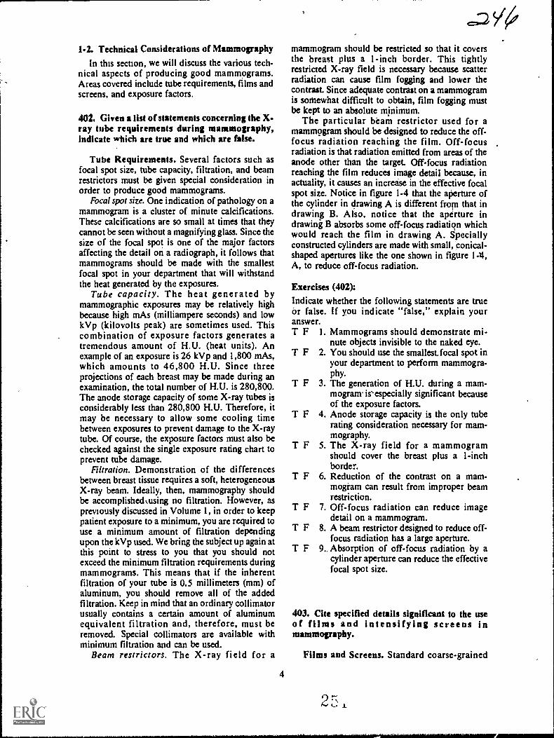
1-2. Technical Considerations of Mammography
In this section, we will discuss the various tech-nical aspects of producing good mammograms.Areas covered include tube requirements, films andscreens, and exposure factors.
402. Given a list of statements concerning the X-ray tube requirements durhig mammography,indicate which are true and whkh are false.
Tube Requirements. Several factors such asfocal spot size, tube capacity, filtration, and beamrestrictors must be given special consideration inorder to produce good mammograms.
Focal spot size. One indication of pathology on amammogram is a cluster of minute calcifications.These calcifications are so small at times that theycannot be seen without a magnifying glass. Since thesize of the focal spot is one of the major factorsaffecting the detail on a radiograph, it follows thatmammograms should be made with the smallestfocal spot in your department that will withstandthe heat generated by the exposures.
Tube capacity. The heat generated bymammographic exposures may be relatively highbecause high mAs (milliampere seconds) and lowkVp (kilovolts peak) are sometimes used. Thiscombination of exposure factors generates atremendous amount of H.U. (heat units). Anexample of an exposure is 26 kVp and 1,800 mAs,which amounts to 46,800 H.U. Since threeprojections of each breast may be made during anexamination, the total number of H.U. is 280,800.The anode storage capacity of some X-ray tubes isconsiderably less than 280,800 H.U. Therefore, itmay be necessary to allow some cooling timebetween exposures to prevent damage to the X-raytube. Of course, the exposure factors must also bechecked against the single exposure rating chart toprevent tube damage.
Filtration. Demonstration of the differencesbetween breast tissue requires a soft, heterogeneousX-ray beam. Ideally, then, mammography shouldbe accomplishedoising no filtration. However, aspreviously discussed in Volume 1, in order to keeppatient exposure to a minimum, you are required touse a minimum amount of filtration dependingupon the kVp used. We bring the subject up again atthis point to stress to you that you should notexceed the minimum filtration requirements duringmammograms. This means that if the inherentfiltration of your tube is 0.5 millimeters (mm) ofaluminum, you should remove all of the addedfiltration. Keep in mind that an ordinary collimatorusually contains a certain amount of aluminumequivalent filtration and, therefore, must beremoved. Special collimators are available withminimum filtration and can be used.
Beam restrictors. The X-ray field for a
4
mammogram should be restricted so that it coversthe breast plus a I -inch border. This tightlyrestricted X-ray field is necessary because scatterradiation can cause film fogging and lower thecontrast. Since adequate contrast on a mammogramis somewhat difficult to obtain, film fogging mustbe kept to an absolute minimum.
The particular beam restrictor used for amammogram should be designed to reduce the off-focus radiation reaching the film. Off-focusradiation is that radiation emitted from areas of theanode other than the target. Off-focus radiationreaching the film reduces image detail because, inactuality, it causes an increase in the effective focalspot size. Notice in figure 1-4 that the aperture ofthe cylinder in drawing A is different from that indrawing B. Also, notice that the aperture indrawing B absorbs some off-focus radiation whichwould reach the film in drawing A. Speciallyconstructed cylinders are made with small, conical-shaped apertures like the one shown in figure 1-4,A, to reduce off-focus radiation.
Exercises (402):
Indicate whether the following statements are trueor false. If you indicate "false," explain youranswer.T F 1. Mammograms should demonstrate mi-
nute objects invisible to the naked eye.T F 2. You should use the smallest.focal spot in
your department to perform mammogra-phy.
T F 3. The generation of H.U. during a mam-mogram is'especially significant becauseof the exposure factors.
T F 4. Anode storage capacity is the only tuberating consideration necessary for mam-mography.
T F 5. The X-ray field for a mammogramshould cover the breast plus a 1-inchborder.
T F 6. Reduction of the contrast on a mam-mogiam can result from improper beamrestriction.
T F 7. Off-focus radiation can reduce imagedetail on a mammogram.
T F 8. A beam restrictor designed to reduce off-focus radiation has a large aperture.
T F 9. Absorption of off-focus radiation by acylinder aperture can reduce the effectivefocal spot size.
403. Cite specified details significant to the useof films and intensifying screens inmammovaphy.
Films and Screens. Standard coarsc-grained
2 , x
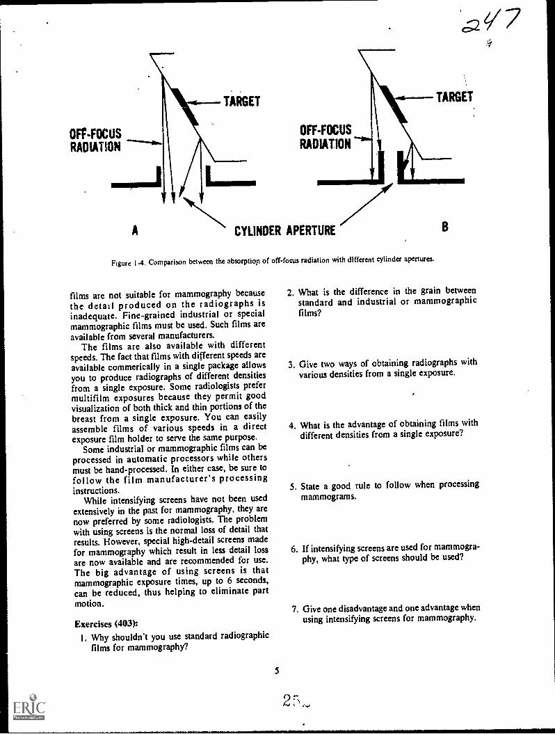
OFF-FOCUSRADIATION
A
TARGET TARGET
LIMN.
OFF-FOCUS
RADIATION
CYLINDER APERTURE
Figure 1.4. Comparison between the absorption of off-focus radiation with different cylinder apertures.
films are not suitable for mammography because 2. What is the difference in the grain between
the detail produced on the radiographs is standard and industrial or mammographicinadequate. Fine-grained industrial or special films?mammographic films must be used. Such films areavailable from several manufacturers.
The films are also available with differentspeeds. The fact that films with different speeds areavailable commerically in a single package allows 3. Give two ways of obtaining radiographs with
you to produce radiographs of different densities various densities from a single exposure.
from a single exposure. Some radiologists prefermultifilm exposures because they permit goodvisualization of both thick and thin portions of thebreast from a single exposure. You can easilyassemble films of various speeds in a direct 4. What is the advantage of obtaining films with
exposure film holder to serve the same purpose. different densities from a single exposure?
Some industrial or mammographic films can be
processed in automatic processors while othersmust be hand-processed. In either case, be sure tofollow the film manufacturer's processinginstructions.
5. State a good rule to follow when processing
While intensifying screens have not been used mammograms.
extensively in the past for mammography, they arenow preferred by some radiologists. The problemwith using screens is the normal loss of detail thatresults. However, special high-detail screens madefor mammography which result in less detail loss 6. If intensifying screens are used for mammogra-
are now available and are recommended for use. phy, what type of screens should be used?
The big advantage of using screens is thatmammographic exposure times, up to 6 seconds,can be reduced, thus helping to eliminate partmotion. 7. Give one disadvantage and one advantage when
Exercises (403):using intensifying screens for mammography.
I. Why shouldn't you use standard radiographicfilms for mammography?
5
!;.4
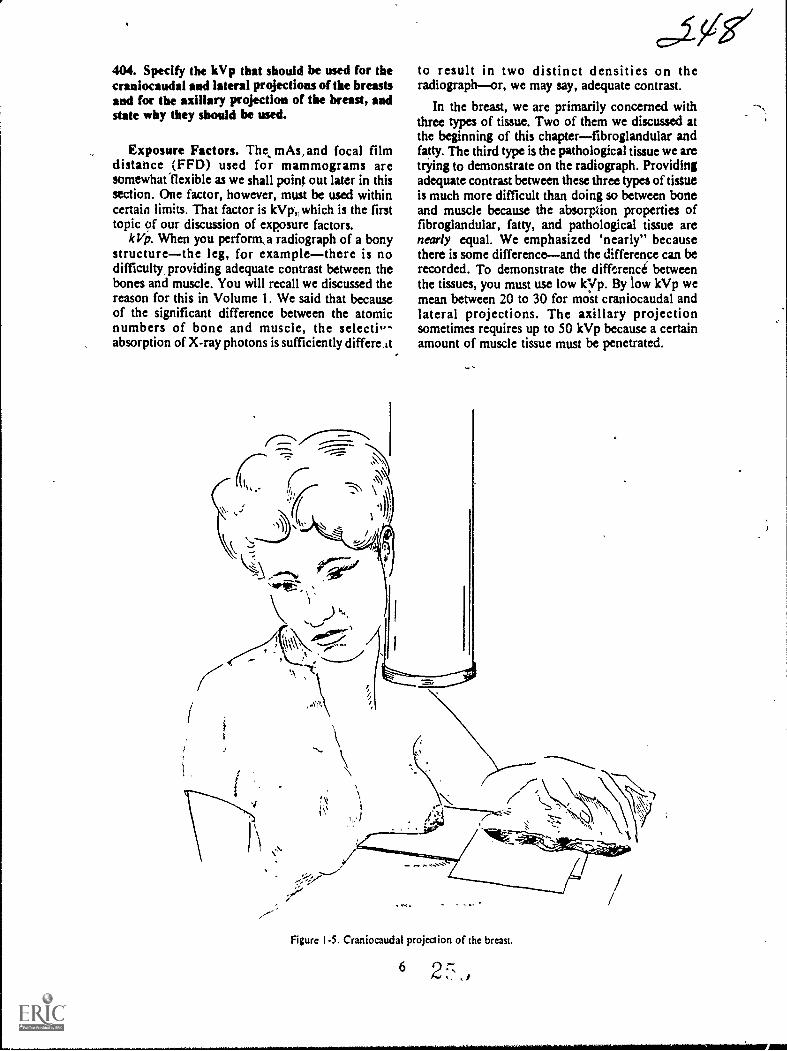
404. Specify the kVp that should be used for thecraniocaudal and lateral projections of the breastsand for the axillary projection of the breast, andstate why they should be used.
Exposure Factors. The, mAs,and focal filmdistance (FFD) used for mammograms aresomewhatfiexible as we shall point out later in thissection. One factor, however, must be used withincertain limits. That factor is kVp which is the firsttopic of our discussion of exposure factors.
IcVp. When you perforna radiograph of a bonystructurethe leg, for examplethere is nodifficultr providing adequate contrast between thebones and muscle. You will recall we discussed thereason for this in Volume 1. We said that becauseof the significant difference between the atomicnumbers of bone and muscle, the selecti,absorption of X-ray photons is sufficiently differe At
to result in two distinct densities on theradiographor, we may say, adequate contrast.
In the breast, we are primarily concerned withthree types of tissue. Two of them we discussed atthe beginning of this chapterfibroglandular andfatty. The third type is the pathological tissue we aretrying to demonstrate on the radiograph. Providingadequate contrast between these three types of tisttteis much more difficult than doing so between boneand muscle because the absorption properties offibroglandular, fatty, and pathological tissue arenearly equal. We emphasized 'nearly" becausethere is some differenceand the difference can berecorded. To demonstrate the difference betweenthe tissues, you must use low kyp. By tow kVp wemean between 20 to 30 for most craniocaudal andlateral projections. The axillary projectionsometimes requires up to 50 kVp because a certainamount of muscle tissue must be penetrated.
Figure 1.5. Craniocaudal projection of the breast.
62 f,": , )

FILM
TABLE
A
fli , /oVel
TABLE
FILM
mir
Figure I-A Relationships between breast, film. and X-ray table,
Exercises (404):1. What kVp should be used for the craniocaudal
and lateral projections of the breasts? Why? -
2. What kVp should be used for the axillary pro-jection of the breast? Why?
405. Cite key features relating to the selection ofmAs and FFD for mammographic examinations.
mAs and Focal Film Distance. The specificmAs and FFD you use depend upon several factors.The mAs and FFD are also closely related to eachother since they both affect the quantity of radiationreaching till film.
One factor that obviously affects the mAs neededis the speed of the film. Some slow fine-grainedfilms require up to 1,800 mAs for the properamount of blackening, while others do not need asmuch. The use of intensifying screens obviouslyreduces the mAs required.
When establishing the mAs, you must alsoconsider the individual mA and time values.Exposure time should be kept as short as possiblesince part motion is the most common cause ofdetail loss on mammograms. A long exposure usedwith a small mA station increases the possibility ofrepeat examinations due to part motion. If the smallfocal spot on your unit requires a long exposure tofulfill the mAs requirement, it is probably better touse a larger focal spot and sacrifice some detail thanto continuously repeat examinations because of partmotion.
7
If you must use a large focal spot, the loss ofdetail can be partially offset by using a relativelylong FFD. By'a long FFD, in this case we mean upto 40 inches. The FFD range for mammograms is
normally 20 to 40 inches, The specific distance youuse depends in part on your radiologist'spreference. Some radiologists prefer to use nearly40 inches for all mammograms because this reducesthe skin dose to the patient; however, th- long FFDrequires more exposure due to the inverse squarelaw. While a short FFD can reduce the exposure, itresults in a lois of detail due to increasedmagnification. Naturally, a short FFD increases theskin dose to the Patient.
Exercises (405):1. Name three factors affecting the mAs needed
for a mammographic examination.
1. AMP
TABLE
FILif
Figure 1-7. Craniocaudal projection showing film curvedagainst the chest wall.
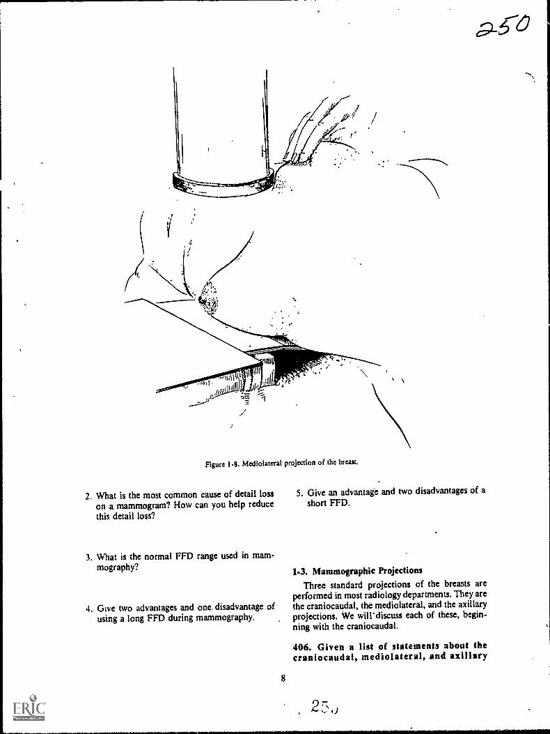
I/
Figure 1-8. Mediolateral projection of the breast.
2. What is the most common cause of detail losson a mammogram? How can you help reducethis detail loss?
3. What is the normal FFD range used in mam-mography?
4. Give two advantages and one disadvantage ofusing a long FFD during mammography.
5. Give an advantage and two disadvantages of ashort FF1).
1-3. Mammographic ProjectionsThree standard projections of the breasts are
performed in most radiology departments. They arethe craniocaudal, the mediolateral, and the axillaryprojections. We will' discuss each of these, begin-.
ning with the craniocaudal.
8
406. Given a list of statements about thecraniocaudal, mediolateral, and axillary

projections of the breast, indicate which are trueand which are false.
Craniocaudal Projection. The craniocaudalprojection is made with the patient seatedat the endof the X-ray table, as shown in figure 1-5. Thebteist should be positioned so that it is in profileand lies flat on the film, as seen in figure 1-6,A. Elevate the film or adjust the chair so that-thepatient does not have to raise or lower her chest toachieve the position. ghe muit be seatedcomfortably; otherwise, she may not be able tomaintain the position, and part motion is likely tooccur. The patient's chest wall should be in contactwith the end of the table to help stabilize herposition. Figures 1-6, B, and 1-6, C, show the filmpositioned too low and too high respectively.
Position the film so that it is against the chestwall. The film position is important because theposterior portion of the breast may not bevisualized if the film is improperly placed. Someradiologists prefer the film holder curved down, asseen in figure 1-7. Bending the film has theadvantage that the entire breast is visualized but theposterior portion (base) is Somewhat distorted dueto the angle of that edge of the film.
Make sure that the skin is not wrinkled or foldedin any way. These conditions may obscure orsuggest pathology and must be avoided. Also besure that the nipple is in profile. Retraction of thenipple on the radiograph could be an indication ofpathology.
Position the patienVs arm on the side of thebreast being radiographed so that it is relaxed on
1:
Figure 1-9. Axillary projection of the breast.
9 2,

the table, as shown in figure 1-5. This allows thefull weight of the breast to lie on the film and helpsto insure good part-film contact. Also, the hand canbe used to maintain the film holder firmly againstthe chest wall.
One common problem with the craniocaudalprojection is that structures superior to the breastare superimposed over the base of the breast. Thesestructures are the clavicle, tclavicular andsupraclavicular tissue, and glandular tissue of theupper outer quadrant of the breast. Thesuperimposed shadows can best be eliminated byhaving the patient sit straight in, her chair and bypulling her shoulders back. Inspection of theposition from above can help you to adjust theshoulders to .eliminate the shadows.
Mediolateral Projection. The mediolateralprojection is made with the patient in the lateralrecumbent position, as seen in figure 1-8. The filmis elevated two to three inches from the table, asshown, and placed under the patient so that thechest wall is included on the radiograph. Inclusionof the chest wall helps to insure ddmonstration ofthe retromammary space, which visualizes only onthis projection.
Rotate the patient so that the breast lies flat onthe film and the nipple is in profile to preventsimulation of nipple retraction. Have the patientretract the opposite breast to prevent itssuperimposition over the breast beingradiographed. Disregard for these two procedures isa common mistake with this projection.
Axillary Projection. Make the axillaryprojection with the patient positioned as showirinfigure 1-9. Place the patient's arm at a 900 angle tothe body. Rotate her until the tail of the breast is inprofileusually 15° to 30°. Place the film flat on
10
the table and align it to include the axillary area,tail of the breast, and upper outer quadrant.
Exercises (406):
Indicate whether the following statements are trueor false. If you indicate "false," explain youranswer.T F
T F
T F
1. The breast is positioned so that the nippleis in profile only on the craniocaudalprojection.
2. The end of the X-ray table can be used toadvantage to prevent part motion on thecraniocaudal projection.
3. Distortion of the posterior portion of thebreast is caused by bending the filmagainst the chest wall on the craniocaudalprojection.
T F 4. Firm contact between the film and chestwall is not important on the craniocaudalprojection.
T F 5. Failure to position the breast so that thenipple is in profile could simulatepathology on the radiolgraph.
T F 6. Dense structures supentnposed over thebase of the breast may bean indication ofimproper positioning.
T F 7. The axillary projection demonstrates thetail of the breast.
T F 8. Unwanted shadows can be eliminated onthe mediolateral projection by retractionof the opposite breast.
T F 9. The amount of rotation of the patient forthe axillary projection depends upon therelative position of the upper outer quad-rant.
T F IO. The mediolateral projection is the onlyradiograph which demonstrates the retro-mammary space.

Obstatrical Radiography
SUCH PHYSICAL factors as unnatural fetalposition, incompatibility of fetal and pelvic signs,and displacement of the placenta, can sometimespresent serious obstetrical problems. As you know,evaluation of these complications usually includesradiographic examinations.
Our study of these examinations includesfctography, placentography, and pelvimetry. Webegin this chapter with a general discussion ofradiation protection for all obstetricalexaminations. Following that we will discuss eachexamination separately.
2-h Radiation Protection for ObstetrkalPatients
You are aware that all patients should be pro-tected from ionizing radiation as much as possible.However, obstetrical patients require special con-sideration as we shall point out in this section.
407. Answer key questions relating to protecting(the obstetrical patient from radiation, patiente?tposure, and fetal motion.
The Importance of Protecting the ObstetricalPatient from Ionizing Radiation.- Ionizingradiation, such as that produced by your X-raymachines; can cause irreversible alterations in thecellular structure of organic tisstre. Two types oftissue are highly susceptible to alteration. These twotypes, gonadal and immature growing tissues, arepresent in obstetrical patients. Since it is not knownprecisely how much radiation causes permanentdamage to these tissues, you should make everyeffort to insure that exposure to your obstetricalpatients is kept as low as possible.
Patient Positioning. Probably the most commoncause of excmive exposure to the patientoand fetusis repeat examinations due to improper positioning.The position of the patient for an obstetricalexamination, particularly pelvimetry projections,niust be "on the money" so to-speak. Slight rotationor ingulation can prevent accurate evaluation of the
.2 5-3CHAPTER 2
radiographs. Be sure to follow the prescribedpositioning procedures.
Fetal Motion. Another common cause ofexcessive patient exposure is repeat examinationsdue to movement of the fetus during exposure.There are several actions you can take to preventfetal motion on the radiographs. One such action isto ask the patient, to inform you when there is nonoticeable fetal movement. Also, have the patientl5rekthe deeply several times and suspendrespiration on inhalation before the exposure.Repeated deep breaths hyperaerate the maternalblood and aid in controlling fetal motion.
A short exposure time also should be used toprevent fetal motion. Naturally, the specificexposure time used in your department dependsupon several factors, including machine capacity,screen speed, and grid ratio. The point is to use theshortest exposure time possible.
Exposure Factors. Naturally, high mAs andkVp values also contribute to excessive patientexposure. High-speed screens and films should be .used so that the mAs and kVp can be kept relativelylow. High kVrtechniques also reduce patientexposure and should be used as long as the contrastproduced satisfies your radiologist. Finally,exposure techniques should be proven and reliableto prevent dark or light radiographs.
Exercises oon1. Why is protection of an obstetrical patient from
ionizing radiation especially important?
2. Why is obstetrical patient positioning so criti-cal?
3. What is probably the most common cause ofexcessive exposure to obstetrical patients?
2 7, ki
4. Explain three ways fetal motion can be reducedon an obstetrical radiograph.
5. How can exposure factors (other than exposuretime) be used to advantage in reducing patientexposure?
2-2. FetographyFetography, or a fetogram, is accomplished to
demonstrate the fetus. In this section, we will dis-cuss some general radiographic considerations per-taining to fetography and the procedures involved.
408. Given a list of statements about fetography,indicate which are true and which are false.
General Fetographic Considerations.Fetography is performed to detect the presence of afetus. its age, position, or general condition.Multiple pregnancies are also demonstrated on afetogram.
presence of the fetus. A fetogram may beperformed to determine whether or not a patient ispregnant. Radiographic indication of pregnancy is,of course, visualization of the fetal skeleton.Usually the first visible parts of the skeleton are theossification centers for the vertebral bodies, whichappear in a curved row. These ossification centersare usually visible at 12 to 16 weeks.
.The fetal tissue is more susceptible to alterationby ionizing radiation at this early stage than it islater in the pregnancy. Consequently, it is extremelyimportant for you to produce a good radiograph thefirst,time to avoid the added fetal exposure due to a.repeat study. Good detail and sufficient contrast areimportant because the ossification centers arcnormally superimposed over the sacrum and fifthlumbar vertebra.
One final word about the presence of theossification centers. When you are performingquality control duties, look for the vertebraeroutinely when evaluating other radiographs madeof the pelvic area of procreative patients. You couldpossibly prevent the newly formed fetus fromreceiving excessive exposure. This situation caneasily occur if the physician does not know that hispatient is pregnant.
Fetal age. A fetogram is sometimes performed todetermine the approximate age of the fetus. Severalparts of the skeleton can be evaluated to estimatematuration. Accurate evaluation of these partsdepends upon the detail and contrast on theradiograph. Some of the skeletal parts are difficultto identify even on a high-quality radiograph.
12
.c,CTherefore, films of the highest quality are veryimportant in estimating fetal age.
The presence of the distal femoral and proximal,tibial -epiphyses are an indication of the age of thefetus. They usually appear at the 36th week ofpregnancy. Other skeletal parts and the time ofappearance are: semicircular canals, 20th week;parietal bones, 20th to 24th week; calcaneus, 20thweek; talus, 24th week; cuboid, 40th week; and thefemoral head, 40th week in some females. We donot provide you with this information to help youestimate the age of the fetus because yourradiologist interprets the radiographs. We mentionthem to stress the importance of high-qualityradiographs, since most of the parts are relativelysmall.
General condition of the fetus. A fetogram is alsotaken to evaluate various conditions of the fetus aswell as to determine fetal presence and fetal age-.These conditions include hydrocephalus(characterized by enlargement of the skull),anencephaly (absence of the skull), and deformedextremities or other parts of the fetal skeleton.
Death of fetus.Fetal death can also be diagnosedon a fetogram. Gas in the fetal circulatory system isa sign of fetal death. The gas usually appears as athin line of radiolucencywhich is very difficult todemonstrate unless the fetogram is of the highestquality. Overlapping of the bones of the skull isanother indication of fetal death if the patient is notin labor. ,
Exercises (408):Indicate whether the following statements are trueor false. If you indicate "false," explain youranswer.
T F 1. Visualization of the fetal vertebrae is nor-mally the first radiographic indication ofpregnancy.
T F 2. Radiographic visualization of the fetuscan occur as early as the 20th week.
T F 3. Exposure of the fetus to radiation isequally dangerous whether the fetogramis performed at 14 or at 36 weeks into thepregnancy.
T F 4. Superimposition of other structures overthe fetus is of no concern if a fetogram isperformed to detect pregnancy.
T F 5. Technicians have no need to recognize afetus in its early stages ur. a radiographunless the radiograph is performed todetect pregnancy.
T F 6. Evaluation of fetal age on a radiographrequires a high-quality film.
T F 7. Distal fenioral and proximal tibialepiphyses appear on the fetus at the 36thweek of pregnancy.
T F 8. Small bones located in the foot, skull,
2, ,, /

CR
FILM
Figure 2-1. AP fetogram.
and hip of the fetus can indicate the ageof the fetus.
T F 9. Demonstration of the bones of the skull isnot necessary when fetal death issuspected.
T F 10. A fetogram taken to diagnose fetal deathmust be capable of demonstrating a thinradiolucent line representing gas in thefetal circulatory system.
T F 11. Anencephaly of the fetus is leen on theradiograph as an enlarged fetal skull.
409. Supply missIng key words in a Hst ofstatements about the performance of fitographicprojections.
Projections for Fetography. We cannot tell you
CR
what specific projections you should take whenperforming a fetogram since different radiologistsand obstetricians require different projections. Wewilt, however, provide you with the procedures forthe most commonly used projections.
APfetogrum. Perform the AP projection in muchthe same way that you would perform an APabdomen. See figure 2-1. Center the film for allfetograms to the iliac crests. If the radiograph is-taken to detect the presence 9f the fetus, be sure toinclude the symbhysis pubis since the newlyformed fetut may lie low in the pelvis.
PA fetogram. The PA projection is usuallyconsidered better than the AP in terms of detailbecause the fetus is closer to the film on.the PA. Ifthe PA is taken to detect pregnancy, include thesymphysis pubis for the reason stated above.
There are two ways to position the patient forPA projection. One method is to have her supportherself on her knees and forearms and lower herabdomen until the anterior portion of her abdomenis slightly depressed by the tabletop. See figure 2-2.This position causes little discomfort to the patientif performed correctly. Before Using this PAprojection, be sure-to demonstrate the position ofthe patient.
Another way to position the patient for a PAprojection is to 'place some supportive material,such as pillows, foam positioning blocks, orblankets so that they will be beneath her chest,extreme lower pelvis, and lower extremities. Seefigure 2-3. In other words, the only area that is notsupported is that area over the film. The film iscentered to the iliac crest. The height of the supportmaterial depends upon the forward extension of thepatient's abdomen. If the proper amount of materialis used, the patient's abdomen is slightly depressedby the X-ray table.
Oblique projections. Normally, an AP or PAprojection is sufficient to evaluate the fetus. Thereare times when a diagnosis cannot be made from
FILM
Figure 2-2. PA fetogram (without support material).

FILM
Figure 2-3. PA fctogram (using support material),
either of these two projections because the skeletalparts in question are superimposed over the spine.When this is the case, an oblique projection may berequested by the radiologist. A posterior oblique isusually made if the initial projection is AP, and ananterior oblique is usually made if the initialprojection is PA. In either case, the degree ofobliquity is determined by the radiologist from theinitial radiograph. Be sure to properly support yourpatient during the obliques to aid in her comfortand to prevent part-motion on the radiograph. Theanterior oblique is sometimes called the "positionof comfort" because the patient's abdomen shifts tothe side and does not support her weight.
Exercises (409):Fill in each blank space below with one or two keywords.
1. The fetographic projection you perform de-pends upon the requirements of theand of the
2. You should center the film to thewhen performing a fetogram.
3. If a fetogram is performed to diagnose preg-nancy. the should beincluded in the film.
4. Part-film distance is greater on the _____ thanon the projection.
5 A PA fetogram can be performed with thepatient supporting herself on herand
6. The projection supportmaterial should be demonstrated to the patient.
7. The patient's abdomen is slightly depressed bythe table v.hen performing the
projection.8. If an AP fetogram is made initially, a
subsequent projection is probably aoblique.
14
c.Is"69: The degree of fcr an
oblique fetogram depends upon informationderived from the or the
10. The anterior obliqUe is sometimes called theof
PlacentographyPlacentography or a placentogram is performed
to localize the placenta. We will briefly describe theplacenta, discuss the reason for performing a pla-centogram, and examine the procedures involved...
410. Specify the approximate dimensions of theplacenta, its normal location, and a locationwhere it can complicate delivery.
Description and Normal Location of thePlacenta. The placenta is a soft tissue massmeasuring approximately 20 centimeters indiameter and 5 centimeters in thickness. Itestablishes communication between the mother andchild by means of the umbilical cord. The placentais normally located on the anterior or posterioruterine walL
Purpose of Placentograpk. A placentogram is
performed to diagnose a ci..:dicion known asplacenta praevia, a rather serious deliverycomplication. When this complication is present,the placenta has developed in the lower segment ofthe uterus.
Exercises (410):
1. What are the approximate dimensions of theplacenta?
2. Where is the placenta normally located?
3. Where is the placenta located when it can com-plicate delivery?
411. Briefly discuss two important factors toconsider when performing a lateralplacentogram, and state how they should be dealtwhit.
Radiographic Considerations. Normally, whenplacenta praevia is susi-.cted, a lateral projection is
2 iq

initially performed since the placenta can bevisualized on the lateral in about 90 percent of thecases. If the lateral fails to demonstrate the placentaor shows it locavtd in the lower uterus, an APprojection may be performed.
Lateral projection. While the lateralplacentogram on the surface seems simple enoughto perform, there are a couple of important factorsto consider. One factor that must be considered isthat the placenta is a mass of tissue and is nearlyequal in density to various other surroundinatissues. Consequently, a soft-tissue techniquerer-atively low kVp and high mAsshould be used tovisualize the placenta. The specific 'techniqueshould be established after consultation with yourradiologist since low kVp and high mAs cause arelatively high absorbed radiation dose to themother and child.
Another important factor to consider is that thethickness of the maternal abdomen in the lateralposition varies considerably, from the posterior tothe anterior liortions. Obviously, you could taketwo radiographs, using different techniques, toprovide the same density over the entire abdomen,but that would expose the patient to twice as muchradiation as is actually neededso two exposuresare ruled out. The best course of action is tocompensate for the different thicknesses so that oneexposure provides the same density over the entirefilm.
Exercise (411):
I. Name two important factors to consider whenperforming a lateral placentogram. In eachcase, briefly explain how the factors should bedealt with.
412. Explain methods of compensating for theuneven thickness of the maternal abdomen.
There are several ways to compensate for thedifference in the thickness of the tnaternalabdomen. One way is to construct a wedge filter tobe placed either in the tube port or taped to thecollimator. The filter is relatively thick on one endand gradually diminishes to a thin edge on the otherend. Place the filter in the primary beam so that thethick edge is over the thinner anterior portionof theabdomen and the thin edge is over the thickerposterior portion of the abdomen. You Couldachieve the same compensating effect by placing afilter between the patient and the film, but \ thisplacement would increase the exposure to thepatient and fetus. Consequently, it should not beused.
A wedge-shapied compensating filter can be
15
0.25made from several materials, including aluminum,copper, and barium sulfate. Barium sulfate can bemixed with simple ffiolding clay or petrolatum toprovide the proper consistency. The thickness ofthe filter depends in part upon your machineoutput. However, a layer of barium paste 2.0 mmthick, decreasing to practically no thickness, spreadover a 0.5 mm piece of aluminum, may be expectedto provide good compensation.
You can also use' a flat piece of aluminumbetween 1 and 3 mm,thick as a filter by placing it inthe primary beam over the anterior half of theabdomen. The best place to locate this filter is onthe bottom of the Collimator.
You can also compensate for the differences inthe thicknesses of the abdomen by constructing aspecial cassette to be used only for a lateralplacentogram. Simply cut a pair of fast-speedscreens and a pair of slow-speed screens in half,lengthwise. Mount the screens in a cassette so thathalf the film is exposed by the fast screens and theother half is exposed by the slow screens. Whenusing this cassette, position the "fast" half of thecassette under the posterior portion of theabdomen.
The simplest way to compensate for the thicknessdifferences is to place a 7- by 17-inch piece ofopaque paper inside the cassette so that it coversone-half of the film on one side only. This allowsthat portion of the film to be exposed by one screen,while the other half of the film is exposed by twoscreens. Place the covered portion of the film underthe anterior portion of the abdomen.
Exercises (412):1. How should a wedge filter be placed in the pri-
mary beam with respect to the abdomen?
2. Name three materials which can be used toconstruct a wedge filter.
3. Briefly explain how to make a wedge filterfrom barium sulfate.
4. How can a plain, flat piece of aluminum beused as a placentographie filter?
5. How many pairs of what speeds of intensifyingscreens are needed to construct a specialcassette to use for a lateral placentogram?
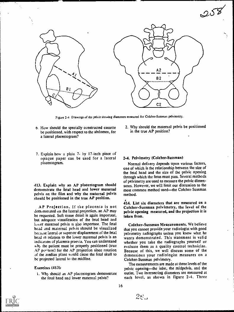
Figure 2-4 Drawings of the pelvis showing diameters measured for Co lcher-Sussman pelvimetry.
6. How should the specially constructed cassettebe positioned, with respect to the abdomen, fora lateral placentogram?
7. Explain how a plain 7- by 17-inch piece ofopaque paper can be used for a lateralplacentogram.
413. Explain why an AP placentogram shoulddemonstrate the fetal head and lower maternalpelvis on the film and why the maternal pelvisshould be positioned in the true AP position.
AP Projection. If the placenta is notdemonstrated on the lateral projection, an AP maybe requested. Soft tissue detail is again important,but adequate visualization of the fetal head andlower maternal pelvis is also important. The fetalhead and maternal pek is should be visualizedbecause lateral or superior displacement of the fetalhead in relation to the lower maternal pelvis is anindication of placenta praevia. You can understandwhy the patient must be properly positioned (trueAP po4'tion) for the AP projection since rotationOf the median plane would cause the fetal skull tobe projected lateral to the midline.
Exercises (413):
I. Why should an AP placentogram demonstratethe fetal head and lower maternal pelvis?
16
2. Why should the maternal pelvis be positionedin the true AP position?
2-4. Pelvimetry (Colcher-Sussman)Normal delivery depends upon various factors,
one of which is the relationship between the size ofthe fetal head and the size of the pelvic openingthrough which the fetus must pass. Several methodsof pelvimetry are used to measure the pelvic dimen-sions. However, we will limit our discussion to themost common method usedthe Colcher-Sussmanmethod.
4114. List six diameters that are measured on aColcher-Sussman pelvimetry, the level of thepelvic opening measured, and the projection it istaken from.
Colcher-Sussman Measurements. We believethat you cannot provide your radiologist with goodpelvimetry radiographs unless you know what hewants demonstrated. This statement is validwhether you take the radiographs yourself orevaluate them as a quality control technician.Because of this, we will discuss some of thedimensions your radiologist measures on aColcher-Sussman pelvimetry.
The measurements are made at three levels of thepelvic openingthe inlet, the midpelvis, and theoutlet. Two intersecting diameters are measured ateach level, as shown in figure 2-4. Three
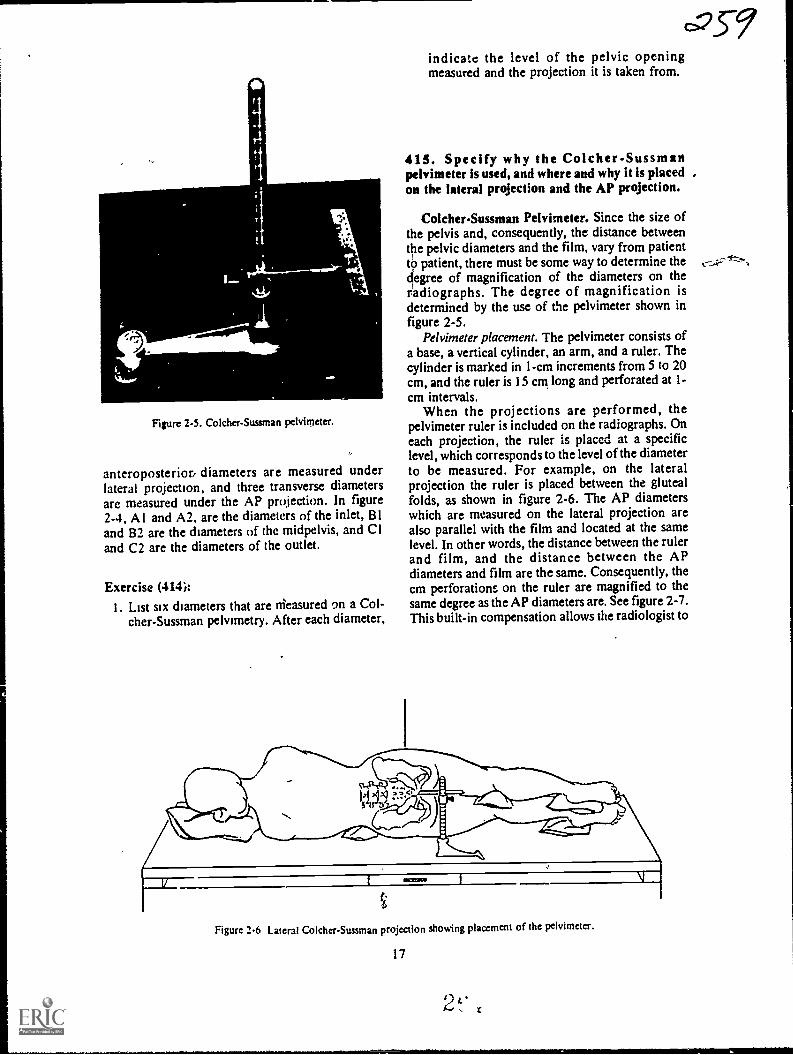
Figure 2-5. Co lcher-Sussman pelvimeter.
anteroposteriori diameters are measured underlateral projection, and three transverse diametersare measured under the AP projection. In figure2-4, Al and A2, are the diameters of the inlet, 81and 82 are the diameters of the midpelvis, and CIand C2 are the diameters of the outlet.
Exercise (414):I. List six diameters that are nieasured t)n a Col-
cher-Sussman pelvimetry. After each diameter,
c=35-9indicate the level of the pelvic openingmeasured and the projection it is taken from.
41 5. Specify why the Colcher-Sussmattpelvimeter is used, and where and why it is placed ,on the lateral projection and the AP projection.
Colcher-Sussman Pelvimeter. Since the size ofthe pelvis and, consequently, the distance betweenthe pelvic diameters and the film, vary from patientto patient, there must be some way to determine thedegree of magnification of the diameters on theradiographs. The degree of magnification isdetermined by the use of the pelvimeter shown infigure 2-5.
Pelvimeter placement. The pelvimeter consists ofa base, a vertical cylinder, an arm, and a ruler. Thecylinder is marked in 1-cm increments from 5 to 20cm, and the ruler is 15 cm long and perforated at 1-cm intervals.
When the projections are performed, thepelvimeter ruler is included on the radiographs. Oneach projection, the ruler is placcd at a specificlevel, which corresponds to the level of the diameterto be measured. For example, on the lateralprojection the ruler is placed between the glutealfolds, as shown in figure 2-6. The AP diameterswhich are measured on the lateral projection arealso parallel with the film and located at the samelevel. In other words, the distance between the rulerand film, and the distance between the APdiameters and film are the same. Consequently, thecm perforations on the ruler are magnified to thesame degree as the AP diameters are. See figure 2-7.This built-in compensation allows the radiologist to
Figure 2-6 Lateral Colcher-Sussman projection showing placement of the pelvimeter.
17
Cr...r"

LEVEL OFAP DIAMETERS
AND-0-PERFORATED
RULER
CR
SNOOD =11 IMO
DISTANCE BETWEENAP DIAMETERS AND FILM
AND DISTANCEBETWEEN RULER AND FILM
ARE EQUAL
I
FILM
Figure 2-7. Illustration showing equal magnification of AP diameters and perforated ruler on the lateral
Colcher-Sussman projection.
LEVEL OFTRANSVERSE
DIAMETERSAND ---°- I
PERFORATED
RULERI DISTANCE BETWEEN
$116111p0.S.TRANSVERSE DIAMETERSAND FILM AND DISTANCE
BETWEEN RULER AND FILM
ARE EQUAL
-CR
MINIM/ OIIII .1111111111 IVISINIP .11.1110
ISCHIALTUBEROSITY/
FILM
Figur: 2-8 Illustration showing equal magnification of the transverse diameters and perforated ruler on
the AP Colcher-Sussman projection.
18
21....., ti
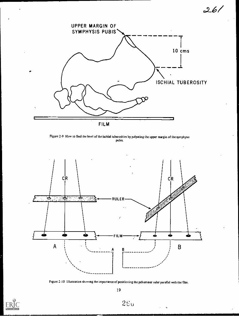
UPPER MARGIN OFSYMPHYS1S PUBISN,
I10 cms
I\ISCHIAL TUBEROSITY
1 1
FILM
Figure 2-9 How to find the level of the ischial tuberosities by palpating the upper margin of the symphysispubis.
..............
Figure 2-10 illustration showing the importance of positioning the pelvimeter ruler parallel with the film.
19
2 "',...d 0

determine the actual diameters even though they aremagnified on the radiographs.
For the same reason described above, the ruler isplaced on the AP projection to coincide with thelevel of the transverse diameters. Specifically, thelevel corresponds to the level of the ischialtuberosities, as seen in figure 2-8. In actualpractice, the exact level of the ischial tuberosities issomewhat difficult to palpate. The level can befound more simply by palpating the upper(antcrior) margin of the symphysis pubis and settingthe perforated ruler 10 cm below that margin, asseen in figure 2-9.
Exercises (415):
I. Why is the Colcher-Sussman pelvimeter used?
2. At what specific location is the pelvimeterplaced on the, lateral projection and why?
RULER
FILM
3. At what specific level is the pelvimeter placedon the AP projection and why?
4. Describe a simple method for determining theplacement of the pelvimeter on the AP projec-tion.
416. Given specific situations describingpositioning of the Pelvimeter, explain how andwhy these positions would affect interpretation ofthe radiographs.
Importance of pelvimeter placement. To insureaccurate evaluation of the maternal pelvis, thepelvimeter must be positioned so that the ruler isparallel with the film. If not, the distances betweenthe ruler "dots" on the radiograph are shortened.Notice in figure 2-10 that the distances between the
A
Figure 2-11. Illustration showing the importance of positioning the ruler at the prescribed level of thepelvis.
.
20
2

ANTEROPOSTERIORDIAMETERS OF:
INLET
MID-PELVIS SYMPHYSIS PUBIS
/
Figure 2-12. Superimposition of the femurs over the symphysis pubis due to flexion of the femurs.
dots on the films are not the same. The dotsprojected by the ruler in detail B are closer togetherthan those in drawing A, even though the part-filmdistance is approximately the same. This is due toforeshortening. of the ruler. You can see how anonparallel ruler and film could result in a highercentimeter count for each pelvic diameter and,consequently, the assumption that the diameters arelonger than they actually are. The film interpretermight assume that the pelvis is large enough fornormal delivery when it may not be.
The pelvimeter must also be placed at thespecified level of the pelvis to insure accurateevaluation of the pelvic dimensions. Notice infigure 2-11 that we have illustrated three rulersradiographed, each with a different part-filmdistance. Consider detail B in the figure torepresent the correct level of the ruler for an APprojection. Also, consider details A and C torepresent the same AP projections of the samepatient but with the ruler higher and lower thannormal. Notice that the distances between dots are
not the same. This is obviously due to the differencebetween the magnification caused by the variedpart-film distance. If the ruler is closer to the filmthan the prescribed distance, the effect onevaluation of the diameters is the same as if theruler and film are not parallel. If the ruler is fartherfrom the film, the diameters are presumed to be
shorter than they actually are, and this could lead to
21
the assumption that the pelvis is inadequate fordelivery when, in actuality, it may be adequate.
Exercises (416):
1. If, on a lateral projection, the pelvimeter is notplaced parallel with the film, how would thiscondition affect evaluation of the pelvis andwhy?
2. If, on a lateral projection, the pelvimeter is
placed parallel to the film, above the level be-tween the gluteal folds, how would this condi-tion affect evaluation of the pelvis and why?
3. If on an AP projection, the pelvimeter is placedparallel to the film, 7 cm below the uppermargin of the symphysis, how would this con-dition affect evaluation/ of the transversediameters and why?

417. Name three common mistakes made whenpositioning a patient for an AP Colcher-Sussmanprojection, and state how each mistake affectsevaluation of the radiograph and how themistakes can be avoided.
Common Problems with the AP Projection.Although the AP Co lcher-Sussman projection isnormally easier to perform, there are some mistakesthat are commonly made by technicians.
Rotation of the pelvis. One common error madewhen positioning the patient for the AP projectionis failure to position her so that the median plane isperpendicular to the table. This.condition results ina rotated pelvis, which, in turn, obscures the ischialspines and prevents accurate measurement of thetransverse diameter of the midpelvis. Also, accuratemeasurement of the other transverse diameters is
made difficult. Check for rotation by measuring theheight of the anterior superior iliac spinestheyshould be equidistant from the table. Also check thegreater trochantersthey should also beequidistant from the table.
Missing ruler. The 14- by 17-inch cassette shouldbe centered 1 I /2 inches above the symphysis pubisfor the AP projection. This centering point allowsample space on the lower margin of the film toinclude the ruler. Some technicians have a tendencyto center the film higher; consequently, the ruler isnot included on the radiograph. Of course, if theruler is not present, the magnification of thetransverse diameters cannot be determined and theradiograph is of no ,use.
Overexposure. Overexposure of the radiographoccurs occasionally because some techniciansmeasure the abdomen through the thickest portionrather than through the CR where it should be
measured. A dark radiograph may prevent theradiologist from identifying the bony landmarksbetween which he measures the transversediameters.
Exercise (417):
1. a. Name three common mistakes made whenpositioning a patient for an AP Colcher-Sussman projection; b. explain how each
mistake affects the evaluation of theradiograph: and c. tell how the mistakes canbe avoided.
22
418. Name two common mistakes made whenpositioning a patient for a lateral Colcher-Suuman projection, and state how the mistakesaffect evaluation of the radiograph and how themistakes min avoided;
-Common Problems With the LateralProjection. As a general rule, mistakes are Morecommonly made with the lateral Colcher-Sussmanprojection than with the PA. Let's discuss the
errors.Anterior rotation of the pelvis. Perhaps the most
common mistake made on the lateral is failure toposition the pelvis in the true lateral position. Morespecifically, the pelvis is usually rotatedanteriorlythat is, with the side nearer the tuberotated anteriorly. Obviously the rotation shortensthe AP pelvic diameters and results in lowmeasurements. This problem is not especiallycommon when the lateral projection is taken erect.When the radiograph is taken with the patientrecumbent, she has a natural tendency to assume thepreviously described position because of the weightof her abdomen. Consequently, careful attentionmust be given to the patient's position for thisprojection. Elevate the anterior portiem of theabdomen slightly with a wedge-shaped sponge, andsuperimpose her legs exactly. Also, placesupportive material between her knees and anklesto help achieve the true lateral position
Inadequate visualization of the symphysis pubis.Another common error made when the patient is
positioned for the lateral is flexion of the femurs tothe point where they superimpose the symphysis
pubis. Notice in figure 2-12 that the radiologistwould have difficulty determining the anterior ends
of the AP diameters of the inlet and midpelvis if thesymphysis pubis is not visualized, since those twodiameters extend to the posterior border of thesymphysis pubis. To avoid this condition, extend
the femurs when performing the lateral projection.
Exercise (418):1. a. Name two mistakes commonly made when
positioning the patient for a lateral Colcher-Sussman projection; b. explain how themistakes affect evaluation of the radiograph;and c. tell how the mistakes can be avoided.
2t*
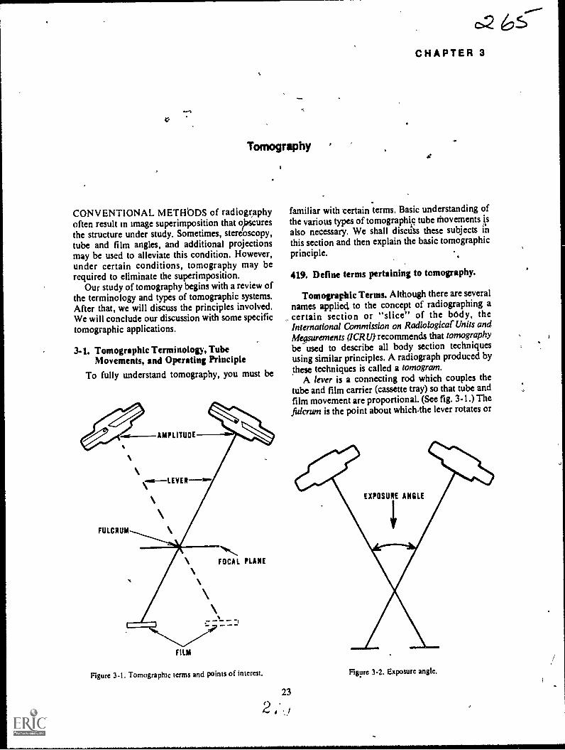
*
Tomography
CONVENTIONAL METHbDS of radiographyoften result in image superimposition that oiracuresthe structure under study. Sometimes, stereoscopy,tube and film angles, and additional projectionsmay be used to alleviate this condition. However,under certain conditions, tomography may berequired to eliminate the superimposition.
Our study of tomography begins with a review ofthe terminology and types of tomographic systems.After that, we will discuss the principles involved.We will conclude our discussion with some specifictomographic applications.
3.1. Tomographic Terminology, TubeMovements, and Operating Principle
To fully understand tomography, you must be
AMPLITUDE
FULCRUM
FOCAL PLANE
FILM
Figure 3-1. Tomograpluc terms and points of interest.
CHAPTER 3
familiar with certain terms. Basic understanding ofthe various types of tomographiic tube thovementsalso necessary. We shall discuss these subjects inthis section and then explain the basic tomographicprinciple.
419. Define terms pertaining to tomography.
Tomographic Terms. Although there are severalnames applied to the concept of radiographing a
, certain section or "slice" of the body, theInternational Commission on Radiological' Units anditleFurements (ICRU) recommends that tomographybe used to describe all body section techniquesusing similar principles. A radiograph produced bythese techniques is called a tomogram.
A lever is a connecting rod which couples thetube and film carrier (cassette tray) so that tube andfilm movement are proportional. (See fig. 3-1.) Thefulcrum is the point about which4he lever rotates or
EXPOSURE ANGLE
Figure 3-2. Exposure angle.
pivots. When you perform a tomogram, you adjustthe fulcrum to correspond to the layer or plane tobe radiographed. (See fig. 3-1.)
The focal plane (fig. 3-1) is the layer of the bodywhich appears sharpest on the tomogram. You arefamiliar with the term blurring. In tomo hy, theterm represents the unsharp body ar tside(above or below) the focal plane.
Amplitude is the distance the tube travels uringthe exposure--expressed in inches. See figure 3-1.Rate is the speed of tube travelusually expressedin inches per second.
E.rposure angle is the angle, in degrees, of thetube travel during exposure. (See fig. 3-2.)
Zonography is tomography with a small exposureangleless than 10°.
Exercises (419):
Define the following tomographic terms.
1. Tomography.
2. Tomogram.
3. Lever.
4. Fulcrum.
5. Focal plane.
6. Blurring.
24
0,2167. Amplitude.
8. Rate.
9. Exposure angle.
10. Zonography.
420. Given a figure showing seven tomographictube movements, identify each movement byname.
Tomographic Tube Movements. The specificmovement of the X-ray tube during tomographydepends upon the type of system employed. Thesimplest and most common tube movement islinear. During a linear tomogram, the tube.moves ina straightline.
A circular tube movement is a movement in acomplete circle. An elliptical movementmovesalong an oblong circular path. A hypocycloidalmovement is pretzel-like. Random movementfollows no specific pattern. Spiral tube movementcircles toward a central point. Finally, a sinusoidaltube movement follows a wavy line.
Exercises (420):Identify the tomographic tube movements in figure3-3 by writing the name of the movement oppositethe appropriate letter below.
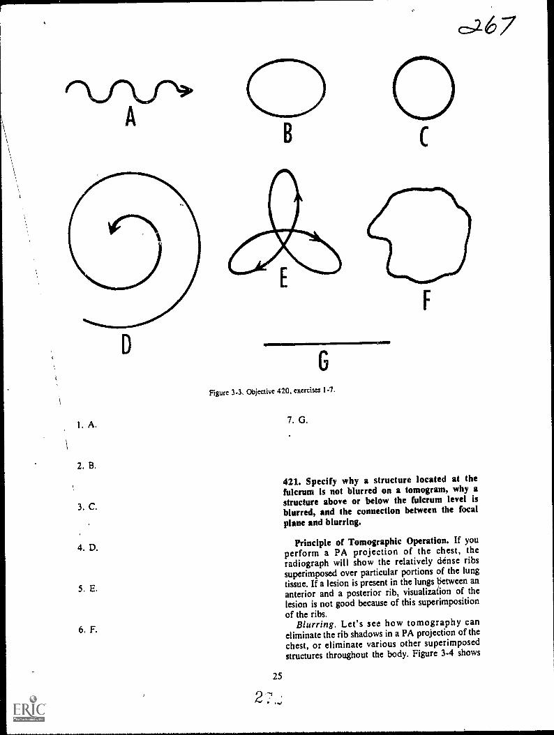
I
2. B.
3. C.
4. D.
5. E.
6. F.
&.6.7
G
Figure 3-3. Objective 420, exercism 1-7.
2
25
v ,
7. G.
111111111
421. Specify why a structure located at thefulcrum is not blurred on a tomogram, why astructure above or below the fulcrum level isblurred, and the connection between the focal
plane and blurring.
Principle of Tomographic Operation. If youperform a PA projection of the chest, theradiograph will show the relatively dense ribssuperimposed over particular portions of the lungtissue. If a lesion is present in the lungs tietween ananterior and a posterior rib, visualization of thelesion is not good because of this superimpositionof the ribs.
Blurring. Let's see how tomography caneliminate the rib shadows in a PA projection of the
chest, or eliminate various other superimposedstructures throughout the body. Figure 3-4 shows
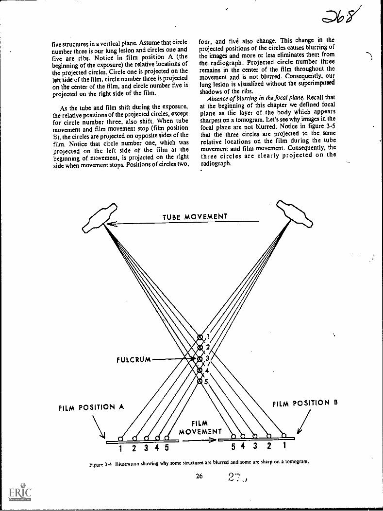
five structures in a vertical plane. Assume that circlenumber three is our lung lesion and circles one andfive are ribs. Notice in film position A (thebeginning of the exposure) the relative locations ofthe projected circles. Circle one is projected on theleft side of the film, circle number three is projectedon the center of the film, and circle number five isprojected on the right side of the film.
As the tube and film shift during the exposure,the relative positions of the projected circles, exceptfor circle number three, also shift. When tubemovement and film movement stop (film positionB), the circles are projected on opposite sides of thefilm. Notice that circle number one, which wasprojected on the left side of the film at thebeginning of movement, is projected on the rightside when movement stops. Positions of circles two,
o6,s/four, and five' also change. This change in theprojected positions of the circles causes blurring ofthe images and more or less eliminates them fromthe radiograph. Projected circle number threeremains in the center of the film throughout themovement and is not blurred. Consequently, ourlung lesion is visualized without the superimposedshadows of the ribs.
Absence of blurring in the focal plane. Recall thatat the beginning of this chapter we defined focalplane as tfie layer of the body which appearssharpest on a tomogram. Let's see why images in thefocal plane are not blurred. Notice in figure 3-5that the three circles are projected to the samerelative locations on the film during the tubemovement and film movement. Consequently, thethree circles are clearly projected on theradiograph.
TUBE MOVEMENT
FULCRUM
FILM POSITION A FILM POSITION B
1 2 3 4 5
FILMMOVEMENT..-----> 543 2
Figure 3.4 Illustrauon showing why some structures are blurred and some are sharp on a tomogram.
26 2 .

TUBE MOVEMENT
11M11 =ND FOCAL PLANE
1 2
FILM POSITION A
1 2 3
FILM POSITION B
FILM MOVEMENT
Figure 3-5. Illustration showing why structures located in the focal plane are not blurred.
Exercises (421):
I. Why is a structure located at the fulcrum notblurred on a tomogram?
2. Why is a structure located above or below thefulcrum level blurred on a tomogram?
\
I Explain the connection between the focal planeand blurring.
3-2. Section ThicknessNow that we have studied the reasons for the
sharp and blurred images on a tomogram, let's dis-

BLURRED STRUCTURES
FOCAL PLkNE - SHARP STRUCTURES-) 10- MM SECTION
BLURRED STRUCTURES
Figure 3-6. Diagram of section thickness.
cuss the thickness of the section aril /the factorsaffecting it.
422. Supply key words in a list of statementsconcerning section thickness and the effect ofexposure angle on section thickness.
Description of Section Thickness. When youperform a tomograrn, you actually radiograph alayer or section of the body. Generally speaking,everything above and below the section is blurred tothe extent that it is not visualized. hractuality, thereare no definite lines between the sharp and theblurred images. The degree of blurring graduallyincreases as the distance from the focal planeincreases. By thesame token, sharpness increases asthe distance from the focal plane decreases.
For all practical purposes, it may be said thatthere are lines that divide the images that are sharpenough for interpretation from those that are tooblurred for interpretation. The portion of the bodybetween those lines is called the section thickneSs.Notice that in figure 3-6 we have illustrated aspecificsection thickness of 10 mm. All strictureswithin the 10-mm section are considered sharp,while those outside the section are consideredunsharp. Naturally, the focal plane is located in thecenter of the section thickness.
Exposure Angle and Section Thickness. Thethickne,., of the section is not the same for alltomogi ann. Basically, the thickness of the sectiondepenas 'Ton the exposure angle used for theexamination. Notice in figure 3-7 that we haveillustrated tube movements through two differentexposure angies. in detail A, the movement of theprojected dots on the film is considerably less thanthe movement of the dots in detail B. Consequently,there is less blurring with the small exposure anglein detail A. Or, we can also say that the section isthicker with the small exposure angle.
Exercises (422):Fill in the blank spaces in the statements below withappropriate words.
I. A tomogram records athe body.
28
2. For all practical purposes, there are definitelines which bound the
3. Structures located within a 5-mm section are. while those located outside the
section are4. A large exposure angle causes
blurring than does a small angle.5; A small exposure angle produces a
section than does a large angle.
423. Given a list of stateMents about the factorsaffecting exp6sure angle, indicate which are trueand which are false.
Factors Affecting Exposure Angle. Fourfactors affect the expsisure angle:
FFD. If the amplitude is constant, a long FFDproduces -a thicker section than does a short FFD.Notice in figure 3-8 that both detail A and B showthe same amplitude, but due to the differencebetween the FFDs, the exposure angle is alsodifferent.
Amplitude. If the FFD is constant, a shortamplitude produces a thicker section than does along amplitude. Details A and B in figure 3-9 bothshow the same FFD. The exposure angle is smallerin detail A because of the short amplitude.
Distance of a structure from the focal plane. So farwe have discussed the two factors, FFD andamplitude, that affect the exposure angle pertainingto different tomographic exposures. Now let's lookat a single exposure and see how the angle changes.Notice in figure 3-10 that the three structures, A, B,and C are projected by different exposure angles,that vary by the number of degrees shown in thefigure. Since angle A is greater than angle B,structure A is blurred to a greater extent thanstructure B. Consequently, we can deduce that thefarther a structure is from the focal plane, the moreit is blurred.
Distance of a structure from the film. Keeping witha single exposure, the farther a structure is from thefilm the greater the angle and, consequently, the
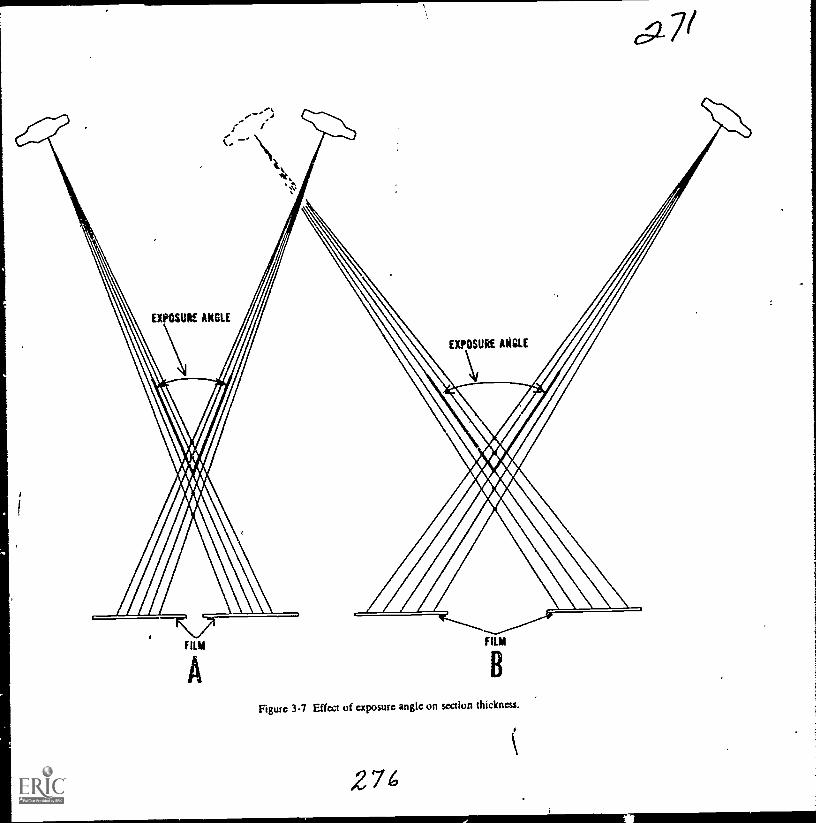
FILM
B
Ftgure 3-7 Effect of exposure angle on section thickness.
274c
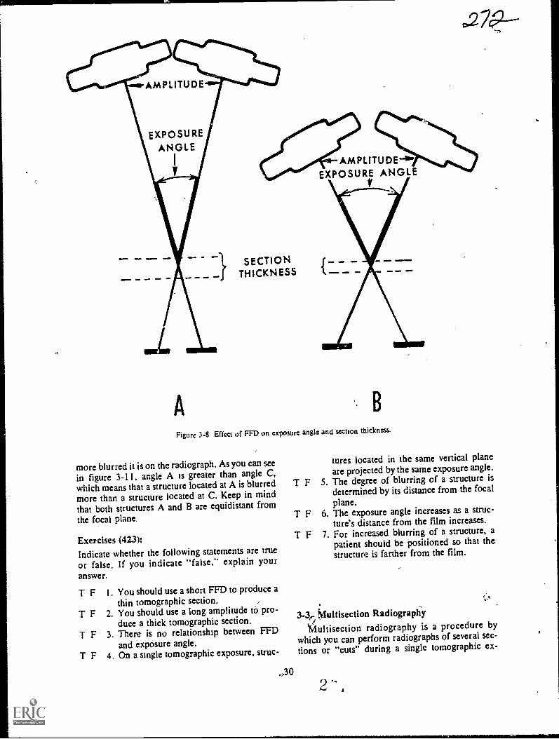
AMPLITUDE-4°wEXPOSURE ANGLE
V
A
SECTIONTHICKNESS
B
Figure 3-8 Effect of FFD on exposure angle and section thickness.
more blurred it is on the radiograph. As you can seein figure 3-11. angle A is greater than angle C,which means that a structure located at A is blurredmore than a structure located at C. Keep in mindthat both structures A and B are equidistant from
the focal plane.
Exercises (423):Indicate whether the following statements are true
or false. If you indicate "false," explain youranswer.
T F
T F
T F
T F
I . You should use a short FFD to produce athin tomographic section. .
2. You should use a long amplitude tà pro-duce a thick tomographic section.
3. There is no relationship between FFDand exposure angle.
4. On a single tomographic exposure, struc-
.,3 0
tures located in the same vertical planeare projected by the same exposure angle.
T F 5. The degree of blurring of a structure isdetermined by its distance from the focal
plane.T F 6. The exposure angle increases as a struc-
ture's distance from the film increases.
T F 7. For increased blurring of a structure, apatient should be positioned so that thestructure is farther from the film.
3-3,, Muitisection RadiograpiiyiMultisection radiography is a procedure by
which you can perform radiographs of several sec-
tions or "cuts" during a single tomographic ex-
`rsr
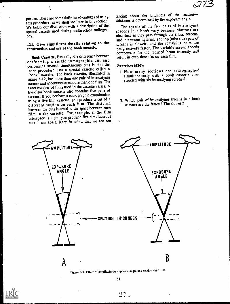
posure. There are some definite advantages of usingthis procedure, as we shall see later in this section.
We begin our discussion with .a description of thespecial cassette used during multisection radiogra-
phy.
424. Give significant details relating to theconstmetion and use of the book cassette.
Book Cassette. Basically, the difference betweenperforming a single tomographic cut andperforming several simultaneous cuts is that thelatter procedure uses a special cassette called a"book" cassette. The book cassette, illustrated infigure 3-12, has more than one pair of intensifyingscreens and accommodates more than one film. Theexact number of films used in the cassette varies. Afive-film book cassette also contains five pairs ofscreens. If you perform a tomographic examinationusing a -five-film cassette, you produce a cut of adifferent sec,tion on each film. The distancebetween the cuts is equal to the space between each
film in the cassette. For.example, if the filminterspace is 1 cm, you produce five simultaneous
cuts 1 cm apart. Keep in mind that we are not
AMPLITUDE
EXPuSUREANGLE
t273talking about the thickness of the sectionthickness is determined by the exposure angle.
The speeds of the five pairs of intensifyingscreens in a book vary because photons areabsorbed as they pass through the films, screens,and interspace mfterial. The top (tube side) pair ofscreens is slowest, and the remaining pairs areprogressively faster. The variable screen speedscompensate for the reduced beam intensity andresult in even densities on each film.
Exercises (424):1. How many sections are radiographed
simultaneously with a book cassette con-structed with six intensifying screens?
2. Which pair of intensifying screens in a bookcassette are the fastest? The slowest?
+6--SECTION THICKNESS
AMPLITUDE
EXPOSUREANGLE
ma .111 11.111
Figure 3-9. Effect of amplitude on exposure angle and section thickness.
31
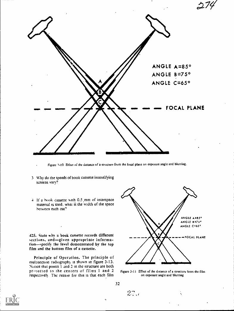
OEM SEIM 11111111
ANGLE A=85°ANGLE 8=75°ANGLE C=65°
FOCAL PLANE
Figure 1-10 Effect a the distance of a structure from the focal plane on exposure angle and blurring.
3 Why do the speeds of book cassette intensifyingscreens vary?
4 If a hook cassette with, 0.5.mm of interspacematerial is used, what is the width of the spacebetween each cue'
425. state h), a book cassette records differentsections, andgiven appropriate informs-tionspecif) the level demonstrated by the topfilm and the bottom film of a cassette.
Principle of Operation. The principle ofmultisection radiograph) is shown in figure 3-13.Nouce ihat points 1 and 2 in the structure are bothpr,liected to the centers of films 1 and 2respective!) The reason for this is that each film
4WD ONO ONO 0011, ONI
ANGLE A=85°ANGLE 6=75°ANGLE C=65°
Figure 3-11
32
PLANE
Effcct of thc distance of a structure from the filmon exposure angle and blurring

ct=v7
SECTIONLEVEL
(CMS)
9.5-9.0----8.5-8.0----7.5-7.0-.-6.5-6.0-5.5-.5.0 -4.5-
____>6.5 CMS6.0 CMS
INTERSPACE MATERIAL
Figure 3-12. A book cassette.
STRUCTURE
..
\-- -FULCRUM (FOCAL PLANE). 1
FILM I VIM BOOK CASSETTEFILM 2
0.5 CM
Figure 3-13, Principle of mulusection radiography.
33
2 ,, i
/

has, in effect, its own fulcrum due to the spacebetween the films.
The top film in the book cassette demonstratesthe section corresponding to the fulcrum you set on
your machine indicator. The second film from thetop demonstrates the level below the fulcrum; thethird film demonstrates the third level; etc.
Exercises (425):I. Why does a book cassette record different sec-
tions?
l
2. If a book cassette containing five films and with1.0 cm of interspace material is used with afulcrum setting of 15 cm, what level isdemonstrated by the top film of the cassette?
The bottom film? .
426. Answer key questions about the use and theadvantages and disadvantages of the book cassettein multisection radiography.
Advantages and Disadvantages. As is true inmany areas of radiology, the use of multisectionradiography versus single film tomography variesfrom one radiologist to another. Some radiologistsuse the book cassette regularly, while others do notuse it at all. We will discuss the advantages first, andthen the disadvantages.
Advantages. If you make five simultaneous cutswith a book cassette, the patient's dose is less than if
you make five individual cuts. Keep in mind,however, that more exposure is required for a bookcassette than for a single-film 'tomogram using aconventional cassette. This is because the exposurefor the book is determined by the speed of the toppair of screens, which is usually very slow.Consequently, patient exposure using the five-filmbook is more than one-fifth of the exposure fromfive single cuts. .
The X-ray tube is subjected to fewer total heatunits when a book cassette is used. Obviously, thisreduction is due to the relatively low book exposurecompared to the combined exposures of theindividual exposures.
An advantage which has significance in a busydepartment is the reduction in the examinationtime. Depending upon the number of films in thebook, it can prevent tying up an exposure room fora long time since, at times, many cuts are needed ofa single structure. .
Disadvantages. The lower films in a book cassettereproduce a smaller amount of good detail than do
34
the upper films. Obviously, this variation in detail 2-7 Coresults from the variation in the intensifying screenspeed. The lower screens are faster; consequently,detail is not as good. '
The fact that the lower films also are subjected tomore scattered radiation than are the upper filmsproduces uneven film contrast from one film toanother. Both the interspace material and theintensifying screens scatter photons that strike thefilms. Therefore, the bottom film receives thegreatest number of scattered photons.
Exercises (426):1. Why is the X-ray tube subjected to fewer total
heat units when a book cassette is used?
2. If a three-film book cassette is used in lieu ofthree single cuts, is the exposure to the patientone-third as much? Why?
3. How does the use of the book cassette affect ex-
amination time?
4. List and explain two disadvantages of using thebook cassette.
3-4. Exposure Factors and Positioning
In this section, we will discuss the difference be-tween conventional exposures and tomographic ex-posures of the same parts. We will also discuss therelationships between amplitude, rate, and ex-posure time in linear tomography. We will con-clude this chapter with a brief discussion oftomographic positioning.
427. Compare tomographic exposures withconventional exposures.
-Tomographic Exposures Versus Conventional
Exposures. A tomographic exposure normallyshould be greater than an exposure of aconventional radiograph, assuming that all otherfactors, such as projection, part, FFD, etc., ateequal. We can best illusvate the reason for thedifference with the diagrams in figure 3-14.Diagram A represents a conventional radiographwith a perpendicular CR, while diagrams B and Crepresent tomography with a small and a largeexposure angle. Compare the different thicknesses
s>
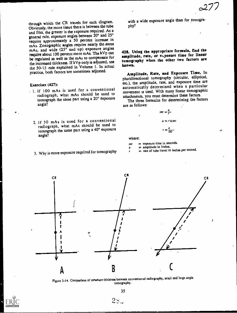
through which the CR travels for each diagram.Obviously, the more tissue there is between the tubeand film, the greater is the exposure required. As a
general rule, exposure angles between 20° and 25°require approximately a 50 percent increase inmAs. Zonographic angles require nearly the samemAs, and wide (25° and up) exposure anglesrequire about 100 percent more mAs. The kVp canbe regulated as well as the mAs to compensate forthe increased thickness. If kVp only is adjusted, usethe 50-15 rule explahied in Volume 1. In actualpractice, both factors 'are sometimes adjusted.
Exercises (427):
- 1. If 100 mAs is used for a conventionalradiograph, what mAs should be used totomograph the same part using a 20° exposure
angle?
2. If 50 mAs is used for a conventionalradiograph, what mAs should be used totomograph the same part using a 40° exposure
angle?
3. Why is more exposure required for tomography
C R
(
A
0277with a wide exposure angle than for zonogra-
phy?
423. Using the appropriate formula, find theamplitude, rate, or ekposure time for lineartomography when the other two factors areknown.
Amplitude, Rate, and Exposure Time. Inpluridirectional tomography (circular, elliptical,etc.), the amplitude, rate, and exposure time areautomaticaily determined when a particularmovement is used. With many linear tomographicattachments, you must determine these factors.
The three formulas for determining the factors
are as follows:a
sec =
a = rXsec
af =SeC
where:sec = exposure time in seconds.
a = amplitude in inches.r = rate of tube travel in inches per second.
C RC R
B
///
Figure 3-14. Comparison of structure thickness between conventional radiography, small and large angle
tomography.
35
0 ,...'I... -... *

t;a1 /6
Figure 3-15. Correct and incorrect patient positions for tomography of the sternum.
For example, if the amplitude is 15 and the rateis 10, the exposure time is 1.5 seconds since
asec =r
15
10
= 1.5
Exercises (428):
Using the appropriate formula, find the factor(amplitude, rate, or exposure time) missing fromeach exercise below.
1. Amplitude: 12 inches.Rate: 4 inches per second.
2. Rate: 2 inches per second.Sec: 4.
3. Amplitude: 20 inches.Sec: 4.
36
429. Given a list of statements abouttomographic positioning, indicate which are trueand which are false.
Positioning. For maximum blurring ofunwanted structures, the X-ray tube should travel atright angles-to the structures longitudinal axis. Forthis reason, blurring is particularly effective whenusing pluridirectional tube movements because thetube moves in many djrections and in most casescrosses the longitudinal axis.
Since tube movement in linear tomography is inone direction only, it is important that the patientbe positioned, when possible, so that thelongitudinal axes of the parts to be blurred are atright angles to the tube movement. Such a positionis not always possible, as we shall see in thefollowing example.
If you perform a PA tomogram of the sternumand position the patient as shown in figure 3-15,A,the longitudinal axis of the thoracic spine is in thesame ditection as the tube travelconsequently, thespine is not effectively blurred. If you position thepatient as seen in figure 3-15,B, the spine is blurredbecause it is correctly oriented to the .tube travel,but the longitudinal axes ofthe ribs ate in the samedirection as those of tube travel; the ribs are thennot effectively blurred,. The solution to thisdilemma is to position the patient at a 25° to 35°angle on the table (3-15,C).
2
Mil.N.MM111.1.11111.1M

o
Exercises (429):
Indicate whether the following statements arc true
or false. If you indicate "false," explain youranswer. ,
T F I. Pluridirectional tube movements producebetter blurring than does a linear move-
ment.
c.2T F 2. Patient positioning is important with
linear tomography.
T .- 3. For maximum plurring, a part's longitu-dinal axis should be positioned at a rightangle to linear tube movement.
T F 4. The sternum should not be positioned ata right angle to linear tube movement.
4
a

CHAPTER 4
Stereoscopic Radiography
ALTHOUGH THE use of stereoscopicradiography as a iliagnostic aid has diminishedsomewhat over the past several years, manyradiologists still use it. Some use the examinationroutinely for certain body parts. Others limit its useto special cases when conventional radiogilaphs donot reveal adequate information or when right-angle radiographs arc not possible.
Because stereoscopic radiography is usedsparingly in some departments, we, as technicians,have a tendency to become stale in .sothe of theapplications. Therefore, our discussion includes acomprehensive review of iche tube shift.
As a quality sontrol tedhnician, one of yourduties related to stereoscopic films is to insure thatthe radiographs are performed correctly and, infact, demonstrate the third dimension. You shouldevaluate radiographs before sending them to yourradiologist. To evaluate the films, you must be ableto orient them properly for viewing. Because of thisrequirement, we will discuss orientation andviewing procedures in depth. Our discussion begins
with ,the tube shift.
4-1. Tube ShiftIn--this section, we will study the amount and
direction of the tube shift for stereoscopic radiogra-phy. (NOTE: "Steroscopic radiography" differsfrom "stereoscopic fluoroscopy," as the names im-
ply. Steroscopic fluoroscopy is not discussed in this
chapter.)Several methods have been established for deter-
is..mining the amount of tube shift. Some are quite in-volyed, requiring various calculations,or referenceto a chart for each examination. The methoddescribed herels simple to apply and produces ex-cellent stereoscopic films if applied correctly.
430. Given selected data (CR, FFD, and tubeshift) about stereoscopic radiography, indicatewhether or not the data reflects properprocedures.
Amount of Tube. Shift. The Vra:r tube should
38
6-1-bC)
be shifted 10 percent of the FFD for allstereoscopic examinations. By tube shift, we meanthe total shift and not the distance on each' side ofcenter. Usually, the tube is shifted one-half thedistance on either side of center, as shown in figure4-I,A. However, you can also shift the tube theentire distance to onb,de, as seen in figure 4-1,B.
The CR can be directed perpendicularly to the
film, as seen in figure 4-1, or it can be angled to thecenter of the film. To illustrate the reason why youcan use an angled CR, we have shown, in figure4-2, the tube shift distance and the FFD to scale-1to 10. Notice e broken lines, which represent theportions of th primary beam that strike the centerof the film fo each tube position. The anglesformed by the brokenJjnes and CR are 3° each. Theangle formed by these broken lines as they convergeto the center of the film is. 6°. These angles remainconstant at any FFD as long as the tube-shift, FFDratio is I to 10.
Accordingly, you can perform stereoscopicradiographs by angling the tube 3° to the center ofthe film after the tube is.shifted the proper amountto each side of center, as shown in figure 4-3,A.You can also make the first exposure with the tubecentered as for a normal radiograph, then shift thetube 10 percent of the FFD in either direction, andangle the CR 6° to the center of the film. (See fig.
4-3,B.)
Exercises (430):Indicate (yes or no) whether or not the CR, tubeshift, and FFD data in exercises 1-4 below reflect
proper stereoscopic procedures.
1. FFD 72 inches: CR shifted 3.5 inches fromnormal tube position for the first exposure and3.5 inches froth the normattube position in theopposite direction for the second exposure. CRis perpendicular to film for both ex-posures
2. FFD 36 inches: First exposure made with CRperpendicular to film and in normal tube posi-tion. Second exposure made with CR shifted

A1
1
1
1
NORMALTUBE POSITION
I
I
1
1
1
1
40"1
1
1
i
I
1
1
1
1
Y
fiii PART
asorms FILM
A
NORMALTUBE POSITION
A1
1
I
I
/ I
I
I
I
I
I
40"
,23/
1
I
1
I
I
1
1
1
Y
0 PART
FILM
Figure 4-1 Tube shifts for stereoscopy (perpendicular CR).
3.6 inches from normal tube position and an-gled 30 toward part.
3. FFD 40 inches: First exposure made with CRperpendicular to film from normal tube posi-tion. Second exposure made with tube shifted2.0 inches to one side and angled 6° towardpart .
4. FFD 60 inches: First exposure made with CRshifted 3.0 inches from normal tube positionand angled 3° toward part. Second exposuremade with CR shifted 3.0 inches from normaltube position in opposite direction anddirected perpendicularly to film
39
B
431. Give significant details relating to thedirection of tube shift for stereoscopicradiographs.
Direction of Tube Shift. For a goodstereoscopic effect, the tube must be shifted at rightangles to the predominant lines of the part beingradiographed. For example, the predominant linesof the femur are along its longitudinal axis;therefore, shift the tube across the longitudinal axisor crosswise. Use the same shift direction for alllong bones. (See fig. 4-4.)
The tube is shifted across the predominant linesof a part because that is the direction which
2 ...,. 1)
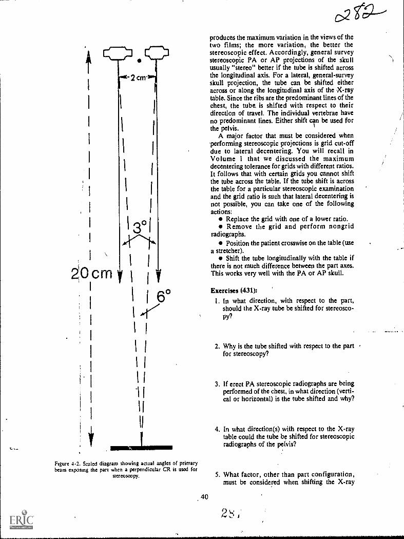
-2cm.
I I
1
1
1 I
I
13°1
ZOcrn y1
y
I 6°I 47
1
1
produces the maximum variation in the views of thetwo films; the more variation, the better thestereoscopic effect. Accordingly, general surveystereoscopic PA or AP projections of the skullusually "stereo" better if the tube is shifted acrossthe longitudinal axis. For a lateral, general-surveyskull projection, the tube can be shifted eitheracross or along the longitudinal axis of the X-raytable. Since the ribs are the predominant lines of thechest, the tube. is shifted with respect to theirdirection of travel. The individual vertebrae haveno predominant lines. Either shift can be used forthe pelvis.
A major factor that must be considered when'performing stereoscopic projections is grid cut-offdue to lateral decentering. You will recall inVolume 1 that we discussed the maximumdecentering tolerance for grids with different ratios.It follows that with certain grids you cannot shiftthe tube across the table. If the tube shift is acrossthe table for a particular stereoscopic examinationand the grid ratio is such that lateral decentering isnot possible, you can take one of the followingactions:
Replace the grid with one of a lower ratio.Remove the grid and perform nongrid
radiographs.Position the patient crosswise on the table (use
a stretcher).Shift the tube longitudinally with the table if
there is not much difference between the part axes.This works very well with the PA or AP skull.
Exercises (431):
1. In what direction, with respect to the part,should the X-ray tube be shifted for stereosco-py?
2. Why is the tube shifted with respect to the part -
for stereoscopy?
3. If erect PA stereoscopic radiographs are beingperformed of the chest, in what direction (verti-cal or horizontal) is the tube shifted and why?
4. In what direction(s) with respect to the X-raytable could the tube be shifted for stereoscopicradiographs of the pelvis?
Figure 4.2. Scaled diagram showing actual angles of primarybeam exposing the part when a perpendicular CR is used for
stereoscopy. 5. What factor, other than part configuration,must be considered when shifting the X-ray
40
2 ,
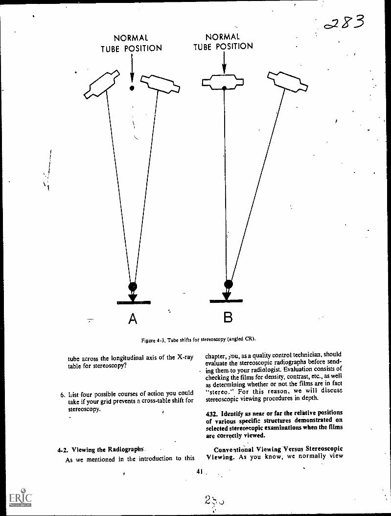
a
NORMALTUBE POSITION
A
NORMALTUBE POSITION
Figure 4-3. Tube shifts for stereoscopy (angled CR).
tube across the longitudinal axis of the X-raytable for stereoscopy?
6. List -four possible courses of action you couldtake if your grid prevents a cross-table shift forstereoscopy.
4-2. Viewing the Radiographs'.As we mentioned in the introduction to this
41
chapter, you, as a quality control technician, shouldevaluate the stereoscopic radiographs before send-ing them to your radiologist. Evaluation consists ofchecking the films for density, contrast, etc., as wellas determining whether or not the films are in fact"stereo." For this reason, we will discussstereoscopic viewing procedures in depth.
432. Identify as near or far the relittive positionsof various specific structures demonstrated onselected stereoscopic examinations when the filmsare correctly viewed.
Conveitional Viewing Versus StereoscopicViewing. As you know, we normally view
2
Z°3

Figure 4-4 Prom direction of tube shift for steroscopicradiographs of a long bone.
conventional radiographs from the film side of thepatient. For example, when viewing a PA chest, yousee the chest from the front with the patient's rightside on your left side. When viewing stereoscopicradiographs, you should view them from the tubeside of the patient rather than from the film side. Inthe case of the PA chest, the anterior ribs andsternum should appear farther from you than thespine or posterior .ribs. View lateral stereoscopicprojections also from the tube sides. Right-lateralstereoscopic radiographs of the skull should showthe right side of the skull farther from you than isthe left side, when viewed correctly.
Exercises (432):
In the following exercises, indicate whether thespecific structures listed are visualized near or farfrom you when the stereoscopic examination listedis viewed correctly.
I. PA chestthe thoracic spine.
2. AP pelvisthe coccyx.
3. PA skullthe orbits.
4. Right lateral chestthe right ribs.
5. Left lateral skullthe right orbit.
433. Given a figure presenting photographs offour radiographs, indicate whether you areviewing the radiographs from the tube side of thepatient or from the film side.
Determining the Tube Side of StereoscopicRadiographs. Before you can correctly viewstereoscopic examinations, the first thing you mustdo is to determine the tube side of the radiographs.Obviously, the tube side is the same for both filmsso the tube side of one is the same as the tube side ofthe other.
It is relatively easy to determine the tube side of aradiograph if you know whether the projection isAP faiellA, and whether a lateral is right or left.Simply consider your eyes as being in the samerelative position as the X-ray tube when the film istaken. For example, if you have a PA chestradiograph, the tube "saw" the patient's back;consequently, you are also looking at the patient'sback if his right side (the R marker on the film) ison your right side.
If you have a right-lateral radiograph of theskull, you know the right side of the patient's skullwas down, or nearer the film. The tube "saw" theleft side of the skull. Obviously, if you look at theleft side of a patient's skull, his face is to your left.
Exercises (433):Indicate wilether you are viewing the radiographs infigure 4-5 t.om the tube side or from the film sideof the patient.

I. Figure 4-5,A--PA projection.
2. Figure 4-5,B--PA projection.
3. Figure 4-5,C---AP projection.
4. Figure 4-5,D----AP projection.
Figure 4-5. Objective 433, exercises 1-4.
43
434. Given drawings of two superimposed pairsof stereoscopic radiographs, indicate thedirection of tube shift for each pair.
Deterthining the Direction of the Tube Shift.The next thing you must do before viewingstereoscopic films is determine the direction of thetube shift. The direction is either longitudinal ortransverse across die part or film.
The simplest way to determine the tube shiftdirection is to place the films together so that theimages are superimposed, as illustrated in figure4-6. Two edges "f each film, A and B in the figure,will be even, while the opposite edges, C and D inthe figure, will not be even. The direction of thetube shift is parallel with the even edges, as shownin figure 4-6.
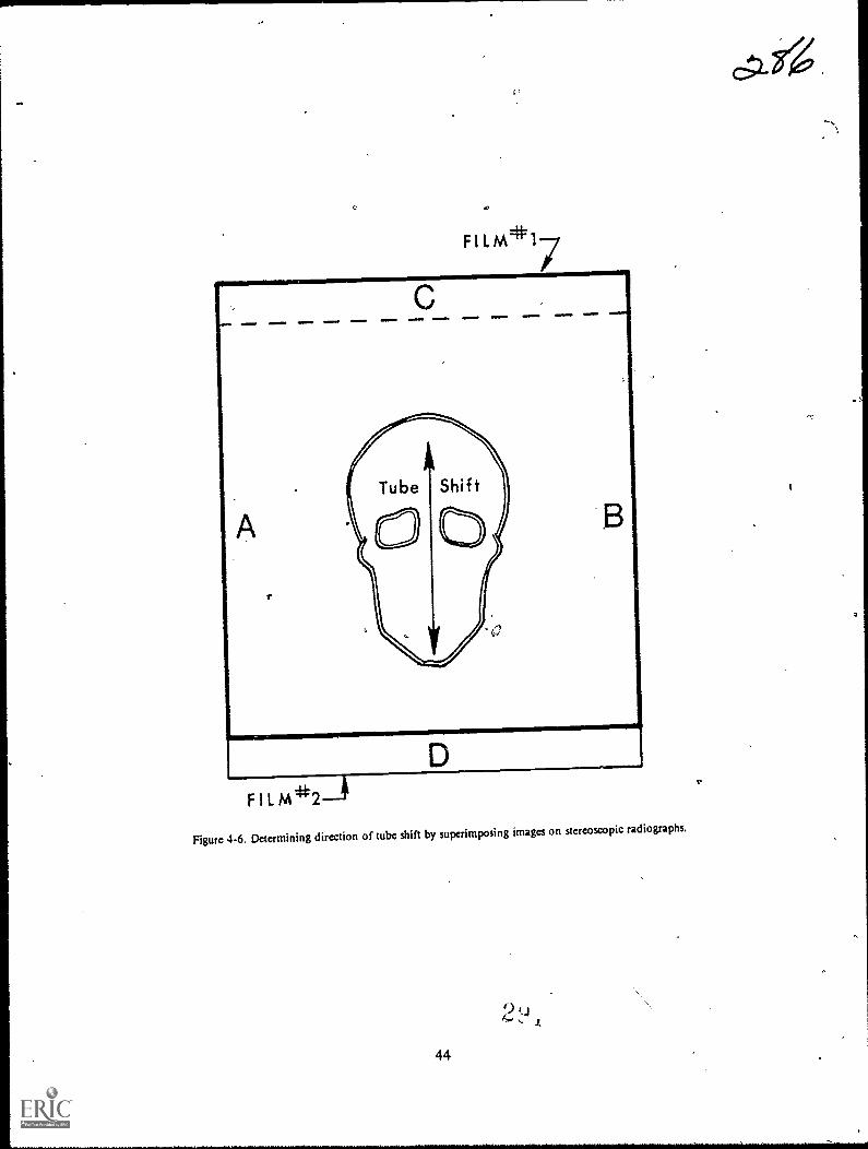
F 1 L M*17
F I L
Figure 4-6. Determining direction of tube shift by superimposing images on stereoscopic radiographs.
9,
44
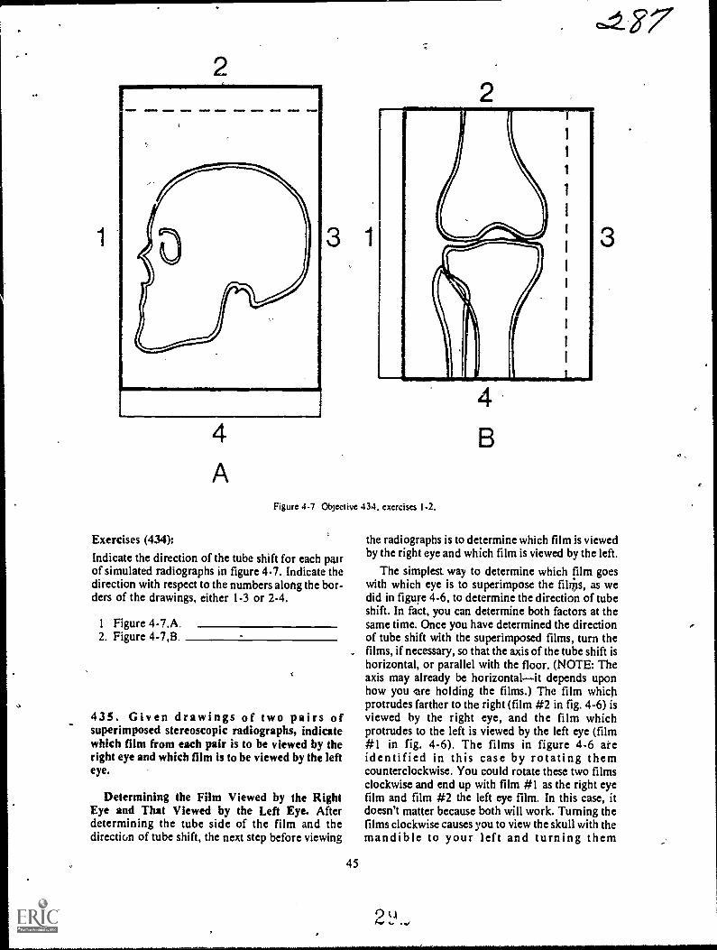
4
A
3 1
Figure 4-7 Objective 434. exercises 1-2.
Exercises (434):
Indicate the direction of the tube shift for each pa.irof simulated radiographs in figure 4-7. Indicate thedirection with respect to the numbers along the bor-ders of the drawings, either 1-3 or 2-4.
1 Figure 4-7.A2. Figure 4-7,B
435. Given drawings of two pairs ofsuperimposed stereoscopic radiographs, indicatewhich film from each pair is to be viewed by theright eye and which film is to be viewed by the lefteye.
Determining the Film Viewed by the RightEye and That Viewed by the Left Eye. Afterdetermining the tube side of the film and thedirection of tube shift, the next step before viewing
45
3
the radiographs is to determine which film is viewedby the right eye and which film is viewed by the left.
The simplest. way to determine which film goeswith which eye is to superimpose the filips, as wedid in figure 4-6, to determine the direction of tubeshift. In fact, you can determine both factors at thesame time. Once you have determined the directionof tube shift with the superimposed films, turn thefilms, if necessary, so that the axis of the tube shift ishorizontal, or parallel with the floor. (NOTE: Theaxis may already be horizontalit depends uponhow you ore holding the films.) The film whichprotrudes farther to the right (film #2 in fig. 4-6) isviewed by the right eye, and the film whichprotrudes to the left is viewed by the left eye (film#1 in fig. 4-6). The films in figure 4-6 areidentified in this case by rotating themcounterclockwise. You could rotate these two filmsclockwise and end up with film #1 as the right eyefilm and film #2 the left eye film. In this case, itdoesn't matter because both will work. Turning thefilms clockwise causes you to view the skull with themandible to your left and turning them
2 LI

counterclockwise you view it with the mandible toyour right. If the shift were across the long axis ofthe part, the direction in which you rotate the film issignificant because one direction has the "paticht
standing on his head.
Exercises (435):
Using figure 4-8, indicate which film of each pair isviewed by the right eye and which film is viewed by
the left eye.
FILM*1
FILM*2
Figure 4-8. Objective 435. exercises 1-2.
I. Figure 4-8,A (rotate counterclockwise).
2. Figure 4-8,B.
436. Supply details that are significant in cross-eyed stereoscopic viewing and in placir.g films forthis method of viewing.
-Cross-Eyed Stereoscopic Viewing. We havediscussed three preliminary steps that you must
46
accomplish before Viewing stereoscopicradiographs. They are determination of: (1) thetube side of the films, (2) the direction of tube shift,and (3) which Math viewed by each eye: Now youshould be ready to place the films on the viewboxesfor viewing. We will discuss tv,,o methods forviewing the radiographsthe cross-eyed andmirror methods.
Principle of crpss-eyed stereoscopy. Sometechnicians can perform cross-eyed stereoscopy and
some, cannot. Usually, those who view stereoradiographs by crossing their eyes can do so as aresult of considerable practice. Some technicians,however, cannot view radiographs with this methodeven with practice. Our purpose in including thismcthod in this CDC is to familiarize you with this
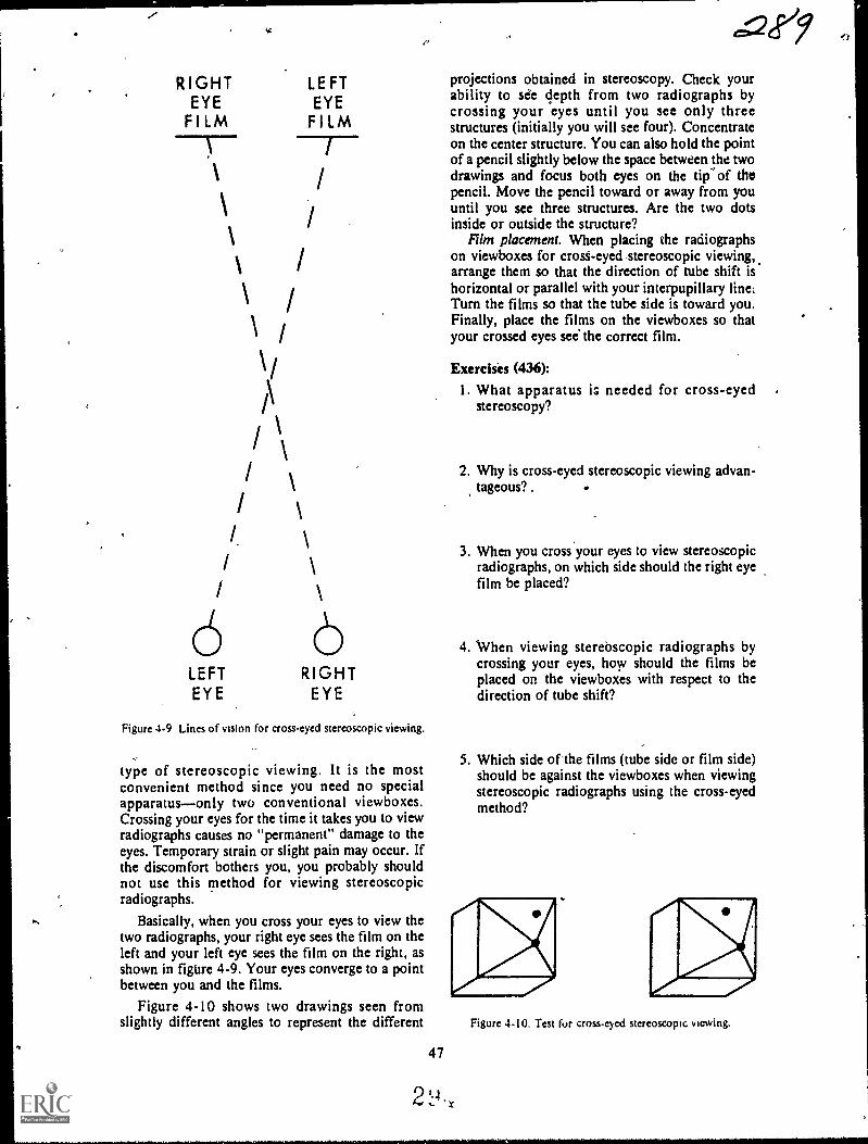
RIGHTEYE
FILM
/
I
I.
\
LEFTEYEFILM
6 6LEFT RIGHTEYE EYE
Figure 4-9 Lines of vision for cross-eyed stereoscopic viewing.
type of stereoscopic viewing. It is the mostconvenient method since you need no specialapparatusonly two conventional viewboxes.Crossing your eyes for the time it takes you to viewradiographs causes no "permanent" damage to theeyes. Temporary strain or slight pain may occur. Ifthe discomfort bothers you, you probably shouldnot use this method for viewing stereoscopicradiographs.
Basically, when you cross your eyes to view thetwo radiographs, your right eye sees the film on theleft and your left eye sees the film on the right, asshown in figure 4-9. Your eyes converge to a pointbetween you and the films.
Figure 4-10 shows two drawings seen fromslightly different angles to represent the different
47
e=Qeey
projections obtained in stereoscopy. Check yourability to see depth from two radiographs bycrossing your eyes until you see only threestructures (initially you will see four). Concentrateon the center structure. You can also hold the pointof a pencil slightly below the space between the twodrawings and focus both eyes on the tip' of thepencil. Move the pencil toward or away from youuntil you see three structures. Are the two dotsinside or outside the structure?
Film placement. When placing the radioigaphson viewboxes for crost-eyed stereoscopic viewing,arrange them so that the direction of tube shift ishorizontal or parallel with your interpupillary line.Turn the films so that the tube side is toward you.Finally, place the films on the viewboxes so thatyour crossed eyes see the correct film.
Exercises (436):
1. What apparatus is needed for cross-eyedstereoscopy?
2. Why is cross-eyed stereoscopic viewing advan-tageous? .
3. When you cross your eyes to view stereoscopicradiographs, on which side should the right eyefilm be placed?
4. When viewing sterebscopic radiographs bycrossing your eyes, how should the films beplaced on the viewboxes with respect to thedirection of tube shift?
5. Which side of'the films (tube side or film side)should be against the viewboxes when viewingstereoscopic radiographs using the cross-eyedmethod?
Figure 4-10. Test fur cross-eyed stereoscopic viewing.
...falr".
437. Given drawings of two pairs of stereoscopicradiographs, indicate whether or not each pair isproperly placed for 'viewing with single anddouble mirror devices.
Mirror Stereoscopic Viewing. While manyradiologists and technicians view stereoscopicradiographs by crossing their eyes, moststereoscopic- viewing is performed by mirrordevices. Several types of devices are_available, and
they all work basically the same. The mirrori arearrangedso that your right eycsseesthe film on yourright and your left eye sees the film on your left.
,
Consequently, film placement with respect to right
or left is opposite from that of cross-eyedstereoscopy. The orientation of the tube Iflft axis isthe same as with cross-eyed stereosco y.
Whether you place the films on the viewboxes
with the tube sides toward you depends upon thenumber of mirrors in the device for each eye. Someviewing devices use one mirror for each eye. In this
case, place the films so that the tube sides are awayfrom you or against the viewboxes. Other devicesthat use two mirrors for each eye require the filmsto be ellaced with the tube sides toward you.
M;

RIGHT 'EYE FILM
a 9/LEFT EYE FILM
PA ,STEREO' PROJECTIONS, LEFT HIP
TUBE SHIFT 1110.-
LEFT EYE FILM RIGHT EYE FILM
LEFT LATERAL STEREO PROJECTIONS
TUBE SHIFT
Figure 4.11. Objective 437, exercises 1.2.
Exercises (437):
I. Are the two films in figure 4-11 ,A, correctlyplaced for stereoscopic viewing with a doublemirror device? If not, why?
49
2. Are the two films*: figure 4-11,B, correctlyplaced for stereoscopic viewing with a singlemirror device? If not, why?
CHAPTER 5
Localization of foreign Bodies
ALMOST EVERY FOREIGN body, whether abroken needle in the foot or a tiny particle in theeye, must be surgically removed, from the patient.Your specific job depends upon the location of theforeign body. You m4 only be required to performthe radiographs or you may have t..) determine theexact location octhe foreign body.
In this chapter, we will discuss methods for,,localizing foreign bodies in the extremities, in the
trunk, and in the eye.
5-1. Localizing Foreign Bodies in theExtremitiei
A foreign body in an extremity its usuallylocalized by the mr.view method.
438. Explain significant factors relating to thetwo-view method of foreign body localization.
General Procedure. Basically, the two-viewmethod of foreign body localization consists oftaking an AP or a PA and lateral projection of theaffected part with some sort of marker placed oneach film to serve as a reference point. While theprocedure seems simple, enough, the physician mayhave difficulty finding and removing the foreignbody unless you perform the procedure properly.
Importance of Proper Positioning. As wementioned, AP or PA and lateral projectionsshould be taken, rather than any two projections atright angles to each other. The reason for this is thatthe physician determines the location of the foreignbody pand the best route for removing it bycomparing the radiographs to visual inspection ofthe part. The position of the part (during hisinspection) and the position of the part when theradiograph is made must be the same. The physiciancan easily examine the part in the AP, PA, or lateralpositions, but he may not be able to duplicate thepositions of the radiographs if they are obliques.
The Orientation Marker. The two radiographicprojections readily demonstrate the location of theforeign body with respect to the anterior/posterioror medial/lateral surfaces of the part. In order to
50
precisely localize the foreign body proximally/dis-tally, it is usually necessary to include an orienta-tion marker on each radiograph.
Placing the marker on the entrance wound. Someradiologists prefer a small metallic marker such asthe letter "X" or "0" 'taped directly over theentrance woundif one is visible. Both projectionsare made with the marker in place. The mainproblem with this marker placement is that theforeign body may be superimposed over the markeron one projection and, therefore, indistinguishableon the radiograph., Placing the marker on the film holder. The most
common placement of the orientation marker cisdirectly on the film holder in the same tra4verseplane as the entrance wound. In this case, themarker is usually an arrow, located lo that it doesnot superimpose any tissue, and pointed toward thewound. The arrow is used on both projections.
If an entrance wound is not visible, make a markon the patient's skin near the suspected location ofthe foreign body, and align an arrow on the filmholder as described above.
Exercises (438):1. What projections should be made to localize a
foreign body in the extremities?
2. Is it sufficient to perform any two projections atright angles to each other to localize a foreignbody in the extremities? Explain your answer.
3. Why should an orientation marker be includedon the radiograph when localizing a foreignbody in an extremity?
4. Describe three ways to include an orientationmarker on the film when localizing a foreignbody in an extremity.
2`,14

APPARENT SKIN ,MARKING
C R
-4--r---CORRECT SKIN MARKING SITE
FLUOROSCOPIC SCREEN
,293
TABLE TOPFLUaROSCOPIC SHUTTER
mar ,
Figure 3-1. Illustration showing how ihe skin may 14 incorrectly marked if the CR is not'used to localize aforeign body. c.--;`,
SKIN MARKING SITE
FLUOROSCOPIC SCREEN
TABLE TOP/R FLUOROSCOPIC SHUTTER
Figure 5-2. Illustration showing the proper CR alignment when locating a foreign body by fluoroscopy.
51

..S-2..Lolalizing Foreign Bodies in the Trunk.
A foreign body in the trunk is usually localizedby, using the single triangulation method. With thismethod, you determine the depth of the foleifin
° body beneath the surface. We will discuss the pro-.cedure for performing the radiograph first and thenthe procedure for calculating the depth.
439. Given a list of itatements about Iheprocedure for performing the radiogriph, usingthe single triangulation method of localizing aforeign body, indicate which are true and whichare false. ..
Radi'ographic Procedure. Basically, theprocedure for determining the depth of the foreignbody consists of double exposing the film so thatthe foreign body appears twice oh the radiograph.
Marking the skin. The first step is to locate theforeign body with respect to its medial/lateral,superior/inferior location. Determine this locationby fluoroscoping the patient. Place 'a mark okthepatient's skin directly over the foreign body. Yourmark tells the surgeon that the foreign body is,,,directly below. If you do not use the CR of thefluoroscopic beam.to locate the foreign body, yourmark on the skin will not be accurate.
Notice in figure 5-1 that the central portion ofthe beam is not used to project the foreign body onthe film. Therefore, the skin marking site is notcorrectly indicated. In figure 5-2, the CR is used toproject the foreign body, ana the skin is correctly
25.4 mm
marked. (NOTE: In the case of the foreignshown in figures 5-1 and 5-2, the error causes
*mark to lie over the end of the foreign body ratthan otter the center as itshoulcr. If the foreign bois small, the apparent skin marking site in.figure 5-1could miss the foreign ,body altogether.) The bestway to avoid incorrectly marking the skin is tocollimate to a small cone field (slightly larger thanthe'foreign body) and center the foreign body insidethe X-ray field.
Performing 'the radiograph. The next step is toperform the radiograph. Center the tube, patient,and film so that the CR is perpendicular to thecenter of the film, and passes through the skin markand foreign body. Record the exact 'FFD and theexact distance from the patient's skin (mark on skin)to the film. (NOTE: The depth` of the foreign bodyis determined in millimeters. You can either recordall measurements in mm or convert them tomillimeters later during the calculation.) Make anexposure using half the normal mAs. Shift the tubelongitudinally 6 to 8 inches. Record the exact
amount of tube shift. Make another exposure usingthe same technique. Process the radiograph.
-
Exercises (439):Indicate which of the' following statements are trueand which are false. If you indicate "false," explainyour answer. .
T F 1. The only significance of the skin !hark isthit it tells the surgeon that the foreignliody lies directly below. .
,I)
FOREJoN BODY .
I
Figure 5.3. One correct way to nleasure the image shift,r
2.(1 452 .. .
!
\

E
D
.1
AB = TUBE 51-II FT
AF = FFD
CF = SKIN-FILMDISTANCE
EF = I.MAGE SHIFT
DF = FOREIGN BODY-FILM DISTANCE
CD= FOREIGN BODY. DEPTH
Figure 5-4 Geometrical relattopships of tube-skin-foreign bodyand image.
0.2.93-,
T F 2, The two images of the foreign body ap-pear medial/lateral to each other on theradiograph..
T F 3.-Collimation of the primary beam is notiMportant dufing the fluoroscopic pro-dedure.
"I' F 4. Both radiographic exposures are madewit the tame mAs.
T F 5. A tube shift of 7 inches during radiogra-phy Ls correct.
T F 6.' The FFD, *in-film distance, tube shiftdistancg and tube-skin distance arcrecorded.
T F 7. Neither foreign body image is projectedwith the CR.
440. Given drawings of two radiographs, each'showing a foreign body and the related
ladiographic data, calculate'the depth of eachforeign body.
Calculation Procedure. Now that you havemade the radiograph, let's see how to calculate thedepth of the foreign body. Your radiograph willshow two images of the foreign body due to the tubeshift. Measure the distance between any two similarpoints of the foreign body. In figure 5-3, thedistance is 25.4 mm.
1
Conversion to millimeters. The next step is toconvert the following measurements tomillimeters-1 inch = 25.4 mm. Themeasuremensts are demonstrated geometrically infigure 5-4: 1
A
IS image shift measured on film = 25.4 mm.FFD recorded earlier - 40 inches = 1016 mm.TS tube shift recorded earlier - 6 inches = 152.4
mm.SFD skin-film distance recorded earlieit 10 inches
= 254 mm.
Determining the foreign body to film distance.
After you convert all measurements to millimeters,fnd the foreign body to film distance (FBFD) byusing the following formula:
53
el 00
IS x FFDFBFD The-Tosr-
5ubstituting our figures, we see that'lc 25.4 X 10¹⁶FBFD- 25.4 + 152.4'
25806.4177.8
= 145
,.
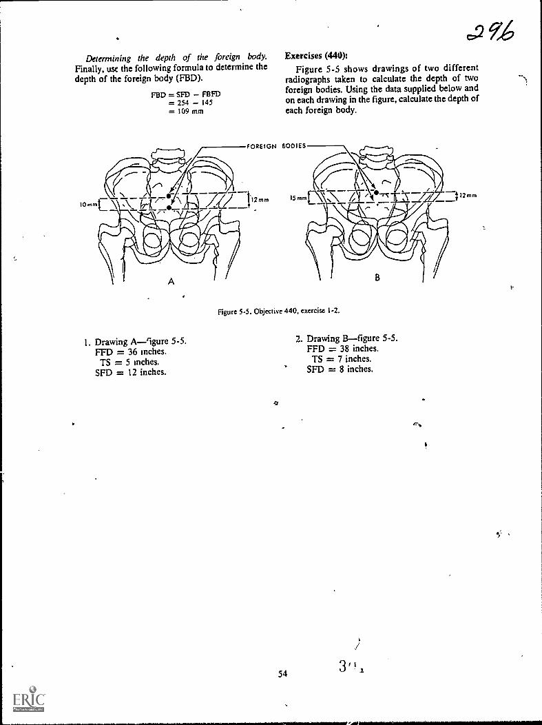
.2 9,46Determining the depth of the foreign body. Exercises (440):
Finally, usc the following formula to determine the Figure 5-5 shows drawings of two differentdepth of the foreign body (FBD). radiographs taken to calculate the depth of two
foreign bodies. Using the data supplied below andon each drawing in the figure, calculate the depth ofeach foreign body.
10mm
FBD = SFD FBFD= 254 145= 109 mm
FOREIGN BODIES
I. Drawing A-9gure 5-5.FFD = 36 inches.TS = 5 Inches.
SFD = 12 inches.
Figure 5-5. Objective 440. exercise 1-2.
4
,
54
2. Drawing Bfigure 5-5.FFD = 38 inches.TS = 7 inches.
SFD = 8 inches.
/
12 mm

Figure 5-6, Sweet's localizer.
5-3. Localizing Foreign Bodies in the EyeThere-are many different methods for localizing
foreign bodies within the eye. All of the methods, ifperformed correctly, are quite accurate. Themethod you use in your department depends uponthe preference of your radiologist.
In this section, we will discuss the Sweet'smethod for determining the exact location of aforeign body in the eye. We begin with a review ofthe parts of the Sweet's localizer.
441. Given a photograph of a Sweet's localizer,identify key parts by name and by function.
Sweet's Localizer. The Sweet's localizer shown:a figure 5-6 is positioned near the patient'saffected eye during the two exposures. Let'sexamine the key parts of the localizer. Refer tofigure 5-6 as we discuss the parts.
55
.27.,
I
Base. The heavy metal base (D) supports theeutire unit.
Vertical arm. The vertical arm (E) is supportiveand allows for adjustment of the horizontal arm.
Horizontal arm. The horizontal arm (H) issupportive and adjusts to properly align the ball.
Ball and cone. The bail (A) and cone (B) areprojected onto the radiographs and serve asreference points for localization of the foreignbody.
Sighting notches. Two sighting notches (C) helpyou visually align the ball to the center of thecornea.
Set screw. The set screw (G) allows the horizontalarm to be raised or lowered so that the ball can bepositioned correctly in relation to the patient's eye.
Trigger release. The trigger release (F) causes theball and cone to move back exactly 10 mm from thepatient's eye.
3'
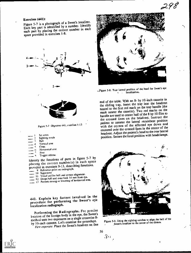
Exercises (441):Figure 5-7 is a photograph of a Sweet's localizer.
Each key part is identified by a number. Identify
each part by placing the correct number in each
space provided in exercises 1-8.
4 :
2
3 aw- 114T-Z-44; AV 7
.!"
-r 4
5
Figure 5-7 Objective 441. exercises 1-13
-- 1 Set screw
: Sighting notch; Ball4 Vertical arm
Cone,Horizontal armBaseTrigger release.
Identity the functions of parts in figure 5-7 by
plactng the correct number(s) in each spaceprovtded in exercises 9-13, describing functions.
9 Reference point on radiograph.
10 Supportive_ 11 Visual aid for ball and cornea alignment.
12 Drops ball and cone back 10 mm from eye.
13 Permits raising or lowering of horizontal arm.
442. Explain key factors involved in theprocedure for performing the Sweet's eye
localizatitm radiograph.
Performing the Radiographs. For precise
location of the foreign body in the eye, the Sweet's
method uses two exposures on a single crosswise 8-
by 10-Inch cassette. Let's examine the procedufe.
Pint exposure. Place the Sweet's headrest on dne
56
4,Figure 5-8. True lateral position of the head for Sweet% eye
localization.
end of the table. With an 8- by 10-inch cassette in
the sliding tray, insert the tray into the headrest
tunnel to the first red mark on the tray handle (the
mark nearer the cassette). Two red marks on the
handle are used to center half of the 8 by 10 film to
the crossed lines on the headrest. Instruct the
patient to assume the lateral recuinbent position
with the cornea of the affected eye down and
centered over the crossed lines in the center of the
headrest. Adjust the patient's head to the true lateral
position. Secure the head position with headclamps.
Figure 5-9. Using the sighting notches to align, the ball of the
5weet's localizer to the center of the cornea.
3 I
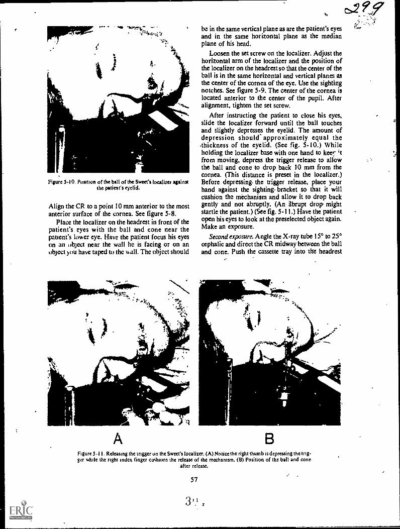
pipmw
Figure 5-10. Position of the ball of the Sweet's localizer againstthe patients eyelid.
Align the CR to a point 10 mm anterior to the mostanterior surface of the cornea. See figure 5-8.
Place the localizer on the headrest in front of thepatient's eyes with the ball and cone near thepatient's lower eye. Have the patient focus his eyeson an object near the wall he is facing or on anobject you have taped to the wall. The object should
be in the same vertical plane as are the patient's eyesand in the same horizontal plane as the medianplane of his head.
Loosen the set screw on the localizer. Adjust thehorizontal arm of the localizer and the position ofthe localizer on the headrest so that the center of theball is in the same horizontal and vertical planes asthe center of the cornea of the eye. Use the sightingnotches. See figure 5-9. The center of the cornea islocated anterior to the center of the pupil. Afteralignment, tighten the set screw.
After instructing the patient to close his eyes,slide the localizer forward until the ball touchesand slightly depresses the eyelid. The amount ofdepression should- approximately equal the.thickness of the eyelid. (See fig. 5-10.) Whileholding the localizer base with one hand to keer 'tfrom moving, depress the trigger release to allowthe ball and cone to drop back 10 mm from thecornea. (This distance is preset in the localizer.)Before depressing, the trigger release, place yourhand against the sighting. bracket so that it willcushion the mechanism and allow it to drop backgently and not abruptly. (An Abrupt drop, mightstartle the patient.) (See fig. 5-11.) Have the patientopen his eyes to look at the preselected object again.Make an exposure.
Second exposure. Angle the X-ray tube 15° to 25°cephalic and direct the CR midway between the balland cone. Push the cassette tray into the headrest
11..
jeguitimra. -.N11400)Na.
Figure 5-11. Rekasing thc trigger on the Sweet's localizer. (A) Notice the right thumb is depressing the trig-ger while the right Index linger cushions the release of the mechanism. (B) Position of the ball and cone
after release.
57
3

tunnel to the second red mark on the tray handle.Make another exposure.
Exercises (442):Answer the following questions pertaining to theprocedure for performing Sweet's eye localization
radiograph.I. How many films arc used and how many ex-
posures are made?
2. How is each half of the film centered to theheadrest?
3. In what position is the patient's head placed forboth exposures?
4. To what specific points is the CR directed foreach exposure?
5. What is the relationship between the locationof the object on which the patient focuses hiseyes and the location of the patient's eyes?
6. What is the relationship between the ball of thelocalizer and the patient's affected eye just be-fore you slide the localizer toward the patient's
eye?
7. How much should the ball depress the eyelid?.
8. Do you depress the trigger release before orafter the patient opens his eyes?
9. What distance does the ball and cone movewhen the trigger release is depressed?
10. What precaution should be taken beforedepressing the trigger release?' Why?
58
gdOI I. What tube angle in what direction is used for
the second exposure?- .
443. Answer key questions" about factorsdeserving special attention during the Sweet's ey*
procedure.
Special Considerations. You and I both knowthat some radiographic examinations are notcritical. For example, it would be difficult to tellwhether the CR was directed to the fifth, sixth, orseventh theiracic vertebra for a particular PA chestif the cone field were not visible on the film.However, positioning errors must be avoided whenperforming the Sweet's method of localization. Youmust provide radiographs which allow theradiologist to determine the exact location of theforeign bodythis means careful attention to thedetails of the examination. It is easy to understandthe necessity of precise localization of the foreignbody if you realize that the tissues of the eye areparticularly susceptible to damage. Consequently, ifthe ophthalmologist knows the precise location ofthe foreign body, he has a better chance ofremoving it without additional damage to the eye.
Patient cooperation. When the information on theradiographs is plotted to determine the foreignbody's location, it is done so under the assumptionthat the patient's eye is looking straight2' ,. dwhen the ball is aligned to the cornea and
ooth exposures are made. This position of the
eye requires complete cooperation from the patient.Perhaps the best way to insure his cooperation is
to explain the details of the procedure to him. Tellhim exactly what you are going to do and in whatorder. It is rather difficult for the patient tomaintain the position of the eye in the first place. Itis more difficult if he is apprehensive.
Preparation and speed. As previously mentioned,it is difficult for the patient to maintain the correctposition of theeye. Keep in mind that he has a pieceof foreign material in his eye and is no doubtuncomfortable and experiencing pain. The quicker
you accomplish the examination, the moresuccessful it will be.
Prepare everything in advance. For example, setthe technique and decide what tube angle you willuse for the second exposure. Once you start theexamination, act quickly. It is advisi:ble to useanother technician to assist you to reduce theexamination time. If you use an assistant, make surethat he knows what he is supposed to do and when
to do it.CR alignment. Correct alignment of the CR is
especially important during the Sweet'sexamination. The ball and cone and their
3 i-1,)
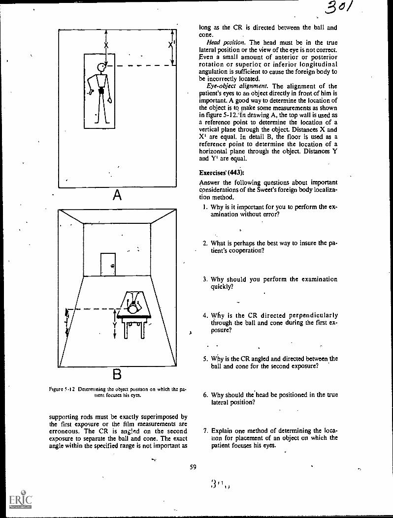
1
A
..
_
BFigure 5.12 Determining the object position on which tha pa-
tient focuses his eyes.
supporting rods must be exactly superimposed bythe first exposure or the film measurements areerroneous. The CR is ang!ed on the secondexposure to separate the ball and cone. The exactangle within the specified range is not important as
"V
59
3long as the CR is directed between the ball andcone.
Head position. The head must be in the truelateral position or the view of the eye is not correct.Even a small amount of anterior or posteriorrotation or superior or inferior longitudinalangulation is sufficient to cause the foreign body tobe incorrectly located.
Eye-object alignment. The alignment of thepatient's eyes to an object directly in front of him isimportant. A good way to determine the location ofthe object is to tnake some measurements as shownin figure 5-12.1n drawing A, the top wall is used asa reference point to determine the location of avertical plane through the object. Distances X andX' are equal. In detail B, the floor is used as areference point to determine the location of ahorizontal plane through the object. Distances Yand Y' are equal.
Exercises' (443):
Answer the following questions about importantconsiderations of the Sweet's foreign body localiza-tion method.
I. Why is it important for you to perform the ex-amination without error?
2. What is perhaps the best way to insure the pa-tient's cooperation?
3. Why should you perform the examinationquickly?
4. Why is the CR directed perpendicularlythrough the ball and cone during the first ex-posure?
5. Why is the CR angled and directed between theball and cone for the second exposure?
6. Why should the head be positioned in the truelateral position?
7. Explain one method of determining the loca-tion for placement of an object on which thepatient focuses his eyes.
.4 , I., g )
-
d
t`UArTgn
Scanography and Arthrography
YOU WILL RECALL that we have referred tomagnification of a part several times in this CDC.As a rule our discussions have been concerned withreducing magnification to a minimum. The firstsection of 'his chapter, scanography, is basicallymore uf tele samethat is, reducing magnificationof a part, although we go about it in a differentmanner.
The second section deals with arthrography, aprocedure that may be classified as a specialexamination in some departments because of itsinfrequent accomplishment. We begin ourdiscussion with the purposes of scanography.
6-1. ScanographyThrough the years, scanography has been per-
formed by one of two methods: the slit or spotmethods. The slit method involves movement of thetube during exposure. Moving the tube requireseither a technician to physically move it along thelong axis of the bone or a system of pulleys and ca-bles that does this. Both of these conditions presentcertain problems not encountered with spotscanographyand since you can produce any typeof scanogram using the spot method, we will discuss
only the spot method in this CDC.
444. State two specific purposes of scanography.
Purposes of Scanography. A scanogram is
performed to determine the length of long bones. Itmay be performed to determine the numericallength of a long bone such as the tibia, femur, orhumerus. An examination to determine thelongitudinal dimension provides the radiologistwith a radiograph to measure the actual length ofthe bone. At times, depending on what specificinformation the orthopedist wants, the radiographneed not show the numerical dimension of thebone. It only has to demonstrate the relative lengthof one bone as compared with that of the oppositebone. An example is the length of the right femur ascompared to that of the left femur.
60
Exercise (444):I. What are two specific purposes of scanogra-
phy?
445. Compare the CR-part-film alignment andpart magnification of a conventional radiographand a scanogram of a long bone.
Principles of Scanography. As we mentionedbefore, magnification is reduced to a minimumduring scanography. Of course, you usually try tokeep magnifidation to a minimum during mostradiographic examinations, so reducingmagnification is nothing new. However, since we
want to produce a radiograph that shows the actualor relative length of a bone, we cannot demonstratethe length simply by "keeping the part-film-distanceto a minimum" and "using the longest practicalFFD."
If you perform a conventional radiograph of along bonethe humerus, for exampletherelationships between the CR and humerus andbetween the CR and film are like those shown infigure 61,A. Notice that the length of the imageprojected on the film is considerably larger than theactual length of the bone. The magnification isobviously caused by the divergence of the primarybeam. In general survey radiographs such as this, acertain amount of magnification is acceptable.When you perform a scanogram, however, unless
you virtually eliminate the magnification, actual-Nine -nieasurement is not possible, and relativebone measurements are difficult. If you make two
exposures of the long bone diagrammed in figure6-1,A, and direct the CR perpendicular to each end
of the bone and the ilm, as shown in figure 6-1,B,the length of the projected image is the same as theactual bone length. Consequently, to eliminate themagnification resulting from the divergence of theprimary beam, you simply use that portion of the
3,1

LONG' BONE
r+-ACTUAL LENGTH-oi
PROJECTEDLENGTH
FILM
)3 03
..4__PROJECTEDACTUAL LENGTH
Figure 6-1. Comparison of the magnification of a long bone during conventional radiography andsdnography.
primary beam with no divergence, the CR, andmake separate exposures of each end of the bone.
Exercises (445):
I. What is the difference, if any, between the CR-part-film alignment during a conventional anda scanographic projection of a'slong bone?
2. What is the relative difference between the
61
magnification of a long bone radiographed byconventional means and by scanography?
3. Explain the reason(s) for the difference sug-gested in exercise #2 above.

9
53 I
$55 It._,4
.40 .. sh,
57 4N%
58
Figure 6.2 Drawing of a scanogram of the femur.
446. Given a list of statements about theprocedures for performing scanograms, indicatewhich are true and which ire false.
Scanographic Procedures. There are severalways to produce spot scanograms. The particularmethod you use depends upon the desires of yourradiologist and, usually, of the orthopedist. Also,the procedure depends upon whether the actual orrelative length of the bone is desired.
Actual length. There are two ways to perform ascanogram showing the actual numerical length of abone. One method requires the use of a ruler, scaledin centimeters and constructed so that the scalemarks and numerical values are demonstrated onthe radiograph. Such a ruler is availablecommercially and is called a Bell-Thompson ruler.It is 100 cm long and requires an increase of 10kVp, since it is radiopaque. Let's look at ascanogram of the femur and see how the ruler isused:
a. Suppose a scanogram showing the actuallength of the femur is to be performed. Tape theruler to the table along the centerline. Position thepatient for an AP projection (all scanographicprojections are AP) so that his femur is directlyover the ruler. Be sure that the ruler markingsextend to each end of the femur as they should withall bones. Center the top half of film to the superior
62
30zmargin of the femur. Collimate to an X-ray fieldsmaller than half the film so that the entire X-rayfield is visible. Align the CR perpendicularly to thecenter of the top half of the film. Make an exposure.Moving only the Bucky tray and tube, center thebottom half of the film to the knee joint and alignthe CR perpendicularly to the center of the bottomhalf of the film. Make another exposure. Thisradiograph will appear similar to the drawing infigure 6-2. Notice that only two sections'of the rare seen on the film, but from the radiograptieradiologisr can determine the actual length offemur.
If the length of the entire leg is desired, use thesame basic procedure. Project the hip joint on thetop third of the film, the knee joint on the middlethird, and the ankle joint on the bottom third.
You can also do a scanogram of both legs on thesame film, using either three or six exposures. Usingthree exposures, tape the ruler to the centerline ofthe table as before. Position the patient for APprojections of both legs on one film. Open thecollimator wide enough to include both similarjoints on each third of the film and direct the CR tothe center of the table. Using six exposures, tape aruler under each leg and use an X-ray field smallenough to project the six joints individually on thefilm. As is true with all scanograms, do not movethe ruler or patient between exposures. Naturally,when six exposures of the legs are made, the tubemust be shifted,,off the grid center for eachexposure, requiring consideration and/orcompensation for,grid cutoff.
b. You can demonstrate the actual length ofcertain long bones without using a ruler if the entirelength of the bone or leg can be projected on asingle film without moving the film. With mostchildren you can usually project the femur or tibiaon a 14-by 17-inch film. You can also project theentire leg on a 14-by 17-inch film with some verysmall children. Simi* collimate to the joint andmake an exposure of each joint, moving only the X-ray tube. No ruler is needed because the bone is not"shortened" by moving the film as is the case withthe ruler. The length of the bone is determined bymeasuring directly with a centimeter ruler.
Relative length. The relative length of long bones(usually the legs) is determined easily without aruler. Simply follow the procedure for projectingboth legs on one film, using three or six exposures.This procedure is usually performed. with thepatient erect.
Exercises (446):Indicate whether the following statements are trueor false. If you indicate "false," explain youranswer.T F 1. Because the Bell-Thompson ruler is

0
1
1
1
A LONG BONE
FILM
1
I
PROJECTED LENGTH
- - ACTUAL LENGTH --
Figure 6-3. Effect of misaligned scanographic CR on measujement of the bone length.
radiolucent, it1should be used with a 10percent increase in I:Vp.
T F 2. You can perform a scanogram to deter-mine the actual length of a long ,boneeither with or without a Bell-Thompsonruler.
T F 3. A single Bell-Thompson ruler cannot beused to perform an actual lengthscanogram of the leg on a I4-by 17-Inchcassette if the leg measures 110 cm fromthe proximal femur to the distal tibia.
T F 4. The ruler, patient, film, or tube shouldnot be moved between scanographic ex-posures.
T F 5. Lateral scanographic projectiops arefre-quently performed.
T F 6. If the Bell-Thompson ruler is used for ascanogram, the markings should extendto each end of the bone.
T F 7. A scanogram of both legs can be per-formed using three or six tube positions.
T F 8. The actual length of ari adult femur canbe determined on a scanogram using afilm shorter than the femur.
T F 9. The number of exposures for a
..
I
63
,
scanogram depends upon the number ofmajor joints present.
T F 10. Two Bell-Thompson rulers are used toperform an actual length scanogram ofadult legs on a single I4-by 17-inch film.
T F 11. You can perform an actual lengthscanogram of an adult femur on a 10-
by 12-inch film without a Bell-
Thompson ruler. .
T F 12. An actual length scanogram of a longbone taken without the presence of aBell-Thompton ruler will show the twoends of the bone separated by an unex-pos'ed area.
T F 13. A Bell-Thompson ruler need not be usedfor a relative length scanogram.
447. Given descriptions of three scanograms,answer key questions about the CR alignment ormagnification of the bones. .
Quality Control Considerations. When you
A,

evaluate scanograms from a quality control p6int ofview, pay special attention to where the CR wasdirected. Notice in figure 6-3 that we show a CR of
a scanogram incorrectly directed to points awayfrom the ends of the bone. The result is that 'thelength of the image is smaller than that of the bone
due to the divergence of the primary beam. If the,CR were directed to points A and B in thz figure,the image woukl b'e longer than the bone, for the
same reasonThe best way toiLermine where the CR ivas
directed is to find the centers of each X-ray field onthe film: Obviously, you can only locate the CR ifthe X-ray field is smaller than that portion of thefilm on which the image is projected. If'you cannotsee the borders of the X-ray field, you cannot besure whIre the CR was directed. Some techniciansfeel that as long as they mask off the unusedportions of the film, the alignment of the CR is notimportant. Masking is important to reduce film fog
due to scattered radiation; however. propermasking in combination with the correct CRalignment helps to insure a diagnostic examination.
Exercises (447):Seanogram A is made of an adult tibia on an 8- by
10-inch film. Both the upper and Jower halves of
the film show X-ray fields completely visualized(all borders are seen). Both X-ray fields are 4inches square. The proximal edge of the tibia. is lo-
cated one-half inch from the top border of the up-per X-ray field. The distal edge of the tibia is lo-cated one-half inch from the bottom border pf the
lower X-ray field.Scanogram Ei is made on an adult femur on a 10- by
I 2-inch film. Both the upper and lower halves of
the film show X-ray fields completely visualized
(all bo rs are seen). Both X-ray fields are 5inches luare. The proximal edge femur is located2.'/2 inches from the top border and 2'/2 inches fromthe bottom border of the upper X-ray field. Thedistal edge of the femur is located in thc same rela-
tive location in thklower X-ray field.Scanogram C is made of an adult femur on a 10- by
12-inch film. Only three borders of the X-ray field'(which measures 7 inches across) on the upper halfof the film are seen. The upper border is missingfrom the film. The proximal edge of die femur is lo-cated 4 inches from the center of the film. Thelower X-ray field is completely visualized and
measures 4 inches high by 7 inches across. The dis-
tal edge of the femur is located 2 inches from thebottom border of the X-ray field.,
On the basis of the descriptions of scanograms A, B,and C above, answer the following questions con-
cerning the CR alignment or projected length of the
bone.
64
I. Which scanogram(s), if any, was (were) takenwith the correct CR alignment?
2. Which scanogram(s), if any, projects (project)an image of the bone that is shorter than its ac-
tual length?
3. Which scanogram(s), if any: projects (project)an image ofi the bone that is longer than its ac-tual length? -
4. Briefly discuss the CR alignment for each X-ray field on scanogram C.
6=2. ArthrographyArthrography, as the name implies, is
radiographic examination of the soft tissue struc-
tures inside a joint space. The procedures for per-
forming an arthrogram vary considerably fromplace to' place. Consequently, some of the informa-
tion presented here is-general in nature.Arthrograms are performed of several joints, in-cluding the ankle, knee, hip, elbow, and shoulder.
Most commonly, arthrography is performed of theknee; therefore, our discussion in this section islimited to the knee. We begin with a review of theanatomy demonstrated by a knee arthrogram. Aeterthat, we will discuss the preparation and injectionprocedurek and, finally, radiographic procedures.
448. Given a list of structures located inside theknee joint, demonstrated by an arthrogram,match each with statements about their locationand function in inother list.
Anatomical Considerations of tin Knee. As
you know, bony structure's about the knee arenormally Well demonstrated on conventional kneeradiographs. Certain soft tissue structures, however,
are only visualized on an arthrogram. Let's discuss
the soft tissue structures.Menisci. The menisci are two cartilaginous pads,
each of which is located between the medial orlateral femoral condyle and the medial or lateralsuperior articular surface of the tibia. Dependingon their relative locations, the menisci are referred
to as the medial or lateral meniscus. The menisci act
as shock absorbers in the knee joint.Collateral ligaments. There are two collateral
3 1

ligaments. The fibular collateral runs superoinfe-riorly along the,fibular side of the knee. It attachessuperiorly to the lateral femoral condyle and in-feriorly to the head; of the fibula. The tibial col-lateral ligament also runs superoinferiorly, butalong the tibial side of the knee. It attachessuperiorly the medial femoraj condyle and to theproximal rledial surface of the tibia inferiorly.Both collaural ligaments prevent medial or lateralmovement of the joint.
Cruciate itgurnents. The cruciate ligaments,antcrior and posterior, provide anterior orposterior stability of the knee joint. The anteriorcruciate attaches anteriorly to the intercondylareminence of the tibia, runs posteriorly and laterallythrough the femoral intercondylar fossa, andattaches to the posterior part of the medial surfaceof the lateral femoral condyle. The posteriorcruciatc ligament attaches to the posteriorintercondylar fossa of the tibia, runs anteriorly andmedially through the femoral intercondylar fossa,and attaches to the anterior part of the medialsurface of the medial femoral condyle.
Exercises (448):
Match the knee joint structures in column B withthe correct statements describing the location andfunction of the structures in column A by placingthe letter of the column B strutture in the space pro-vided in column A. Each column B letter may be
used once, or more than once.
Column A
Location
Extends from headof fibula to lateralfemoral condyle.
Runs through thefemoral intercondylar fossa.Extends superoin.feriorly along themedial side of theknee
4 Located betweenthe medial femoralcondyle and tne.dial. superior artic.ular surface oftibia._ 5 Attaches to intercondylar eminenceof tibia.
6 Attaches to posted.or intercondylarfossa Of tibia.
Function
7 Maintains anterioror posterior stabili.ty
8 Prevents medial orlateral movementof the knee joint.
ab.
c.
Coltunn 8
Mcniscus.Collateral ligament.Cruciate ligament.
Function
9 Acts as a shock-ab.sorber.
449. Answer key questions about patientpreparation and injection procedures involvedduring an arthrogram of the knee.
Patient Preparation and Injection. The patientpreparation and injectidb procedures involvedduring an arthrogram of the knee vary from oneradiologist to another. Therefore, we will provideyou with some general guideline's to help you assistmost radiologists, no matter what their preferencesare.
Patient prepara4ion. Shave the lateral surface ofthe patient's knee joint and clean and prepare theskin, as directed by your radiologist. Surgical soap,alcohol, zephiran chloride, tincture of iodine; or acombination 'of these items may be used. Then,drape the area with sterile towels or sheets.
Injection procedures. The radiologist usuallyinjects a local anesthetic to deaden the injectionsite. He then injects the contrast medium into thejoint space. A water soluble positive contiastmedium is used. If a pneumoarthrogram is to beperformed, *oxygen, or carbon dioxide may beinjected. If a positive medium is used, he willprobably inject about 10 to 15 cc of the solution. Ifjoint effusion i present, more contrast medium isusually injected (up to twice the normal amount);otherwise, dilution will prevent a vied study frombeing performed. .The radiologist also normallyattempts to aspirate as much fluid as possible whenjoint effusion is present to keep dilution of themedium to a minimum. The amount of negativemedium injected may be 20 cc or more if apneumoarthrogram or double contrast study isperformed.
After covering the injection site with sterilegauze, the radiologist usually massages the knee todistribute the contrast medium throughout the jointspace. He may also allow the patient to stand andwalk to provide distribution of the medium. Someradiologists also wrap the knee tightly with an acebandage to force the contrast medium out of thequadriceps pouch onto the surfaces of the menisci.When an ace bandage is used, it should be removedbefore the lateral radiographs of the knee are madein order to permit visualization of the quadricepspouch.
Exercises (449):
1. 'Briefly explain how the knee is prepared for in-
jection during an arthrogram.
65
3 1
3 47

2. What type of positive contrast media is injectedinto the knee joint?
3. a. How many centimeters of positive contrastmedium would you normally need for anerthrogram? b. How many centimeters would1you need if joint effusion is present?
4. What type(s) of negative contrast medium maybe injected into the knee joint?
5. wny dues the radiologist aspirate the fluidwhen joint effusion is present?
6. Name three ways in which the contrast mediummay be distributed throughout the knee jointafter injection.
7. If the knee is wrapped in an ace bandage, whenshould it be removed? Why?*
450. Given a list of statements about theprocedures for performing the radiographs duringan arthrogram of the knee, indicate which are trueand which are false.
Radiographic Considerations. Several differentprojections and types of radiographs are performedof the knee during an arthrogram. They vary fromradiologist to radiologist. Tomograms, stereoscopicradiographs, as well as standard AP, PA, lateral,and oblique radiographs are accomplished.Obliques may be performed with various degrees ofrotationfor example, 30245, 60, and 75. Usually,the CR is angled 30 caudad for the AP projections(including posterior obliques) and 6° cephalic for
66
the PA projections (including anterior oblique's) toopen the joint space. If a pneumoarthrogram ordouble contrast study is performed, 'some on all ofthe projectiods are usually made with% horizontalCR to take adVantage of the rising air.
Speed is essential. The contast medium injectedinto the joint capsule is eventually absorbed.AbsOrption begins within a short time Atterintroduction, and the entire injection can disappearfrom the joint capside within 30 minutes. It is
obvious that you should work quickly to performthe radiographs before this happens. You must alsomake sure that the positions, exposure factors, etcv,are correct the first time since you may not haveenough time to relieat the radiographs. If numerousradiographs-are to be taken with various positions,it may be advisable to use an assistant to reduce theexamination time.
Marking the joint space. To properly demonstratethe necessary structures, it is important that youdirect the CR through the joint space whenperforming the radiographs. Since some sort ofbandage is usually applied to the knee after theinjection, it is difficult for you to determine theexact location of the joint. It is usually best to havethe radiologist mark the joint space underfluoroscopy after the, bandage is applied. If variousprojections are to be made, a line drawn around thecircumference of the knee is helpful.
Exercises (450):
Indicate whether the following statements are trueor false. If you indicate "false," explain youranswer.
T F
T F
T FT F
T F
T F
T F
1. The projections and types of radiographsvary from radiologist to radiologist.
2. The PA and AP projections are,usuallytaken with a vertical CR to take advan-tage Of the rising air.
3. Standard 45° obliques are always made.4. Speed is important to prevent undue pa-
tient discoMfort.5. Perhaps you should use an assistant if
many radiographs are to be made.6. The CR must be directed through the
joint space.7. You can estimate the exact location of the
joint space if the knee is wrapped in abandage.
3 1 AJ

Bedside and Surgical Radiography
IN VARIOUS PARTS of this CDC, we havediscussed safety for obvious reasons. We evendevoted an entire chapter* the topic in Volume 1-2In additon, you will find 1bat we will refer to thisimportant' subject again in some of the discussionsthat follow
Perhaps in no other phase of radiology is safetyso important as during bedside and surgicalradiography. These examinations bring togethermost of the safety hazards with which you mustcontendhazards which present such dangerousconditions as explosion, fire, electrical shock,overexposure to radiation, and contamination. Dueto these conditions, this chapter will deal mainlywith the safety hazards of bedside and surgicalexaminations. We will also briefly discuss ths typesof mobile units and some general radiographicconsiderations. We begin with the three types ofmobile units.
7-1. Mobile X-Ray UnitsMany different brands of mobile X-ray units are
on the market today, and several of them can befound at hospitals throughoutthe Air Force. In thissection, we will not discuss specific operational in-structions for mobile units since it would be im-practical to study all of the different units. Instead,we will present a general discussion of mobile units,the importance of grounding your unit, and the useof mobile units in an explosive atmosphere. Webegin our discussion with the three types of mobileX-ray units.
451. Given the three types of mobile X-ray unitsin one list, match each with an appropriatedescriptive statement or phrase in another list.
Types of Mobile X-Ray Units. Three types ofmobile X-ray units are in use at present. They are:(I) the type found in most Air Force hospitals,which we will call standard, (2) capacitor-discharge, and (3) battery-powered.
Standard. A standard mobile unit uses directpower line current during the exposure, as opposed
CHAPTER 7
to a capacitor-discharge or battery-powered unit,which in effect uses "stored" current. Some of theseunits aperate only on 110-volt circuits, someoperate on 110- or 220,volt circuits, while others
.operate only on 220-volt circuits.'Other than the power supply, the most significant
difference between the standard units is in theoutput, which covers a wide range. ,Maximtims of50 mA and less than 100 kVp are generallyconsidered too low for use in a hospital thatperforms fretoent portable examinations. A unitcapable of delivering 110 mA and 100 or motekVp is quite necessary in such a hospital.
Capacitor-discharge. A capacitor-dischargemobile unit noi-mally uses a 110-volt power supply.It differs from the units mentioned previously inthat a charge period, usually of a few seconds, mustprecede each exposure. During these few secdnds, acharge of electrical current builds up in themachine. A ready or charge light usually indicateswhen the charge is completed and, therefore,indicates that the unit is ready for exposure.
Since the capacitor-discharge unit in effectt"stores" an electrical Charge, it offers*additionalmachine output when compared to andther similarunit operating on aihl 0-volt circuit buf withoutcapacitor-discharge align.
Battery-powered. A battery-powered mobile unitreceives its power supply from nickel-cadmiumbattery cells in the unit; therefore, the unit iscordless. Typically', when the cells are fullycharged, they can deliver electrical chargessufficient to produce exposures totaling 10,000mAs at 110 kVpr, Recharging is accomplishedsimply through a 110-volt outlet. The rechargingperiod depends upon the amount of discharge, butit is usually less than 8 hours.
The cordless feature of a battery-powered unit isobviously a significant advantage. Y9o, are notlimited to using the unit only where a Power outletis available. The natural bother accompanying theuse of a cord is also eliminated. In addition, themachine output is not affected by variances in theline voltage or a significant voltage drop.when along power cord is used.
67

Another advantage of a battery-powered unit isthat the waveform across the X-ray tube is similar to,that of a three-phase, 12-pulse, X-ray generator inthat it is near constant. Thusl the effective capacityof the unit is higher than the stated capacity,perhaps by as much as 50 percent.
VIM Ises (451):
Match ihe type of mobile X-ray Unit in column Bwith the apvropriate phrase or statement in columnA hy placing the letter of the column B unit in thespace provided in column A. Each column B itemmay be used once or more than once. In addition,more than one column B item may match a singlecolumn A entry. e
Column A
1 Effective capacityexceeds statedmpacity.
2. Near constant waveform.
3 Must be chargedbefore each ex-posure.
4, Found in most AirForce hospitals.
$ Usually operateson 110.volt powersupplyOperates on 110-volt or 220-volteiroult
7 U.cs storcdpwher8 A single charge
permits many ex.post]I'M
9. Can be used wherea power outlet isnot accessible.
10 Output covers awide range.
11 Recharge from a110-volt line.
12 Uses direct powerline current.
13 Eliminates linevoltage variations.
Column B
a. Standard.b. Capacitor-discharge.c. Battery.powered.
452. List some specific conditions that mayexist during a mobile, bedside radiographicexamination which could came electrical shockto you and your petient, snd specify two measuresthat will help to prevent this.
Grounding of Mobile Units. You will recall thatwe discussed grounding of electrical equipment inChapter 6 of Volume 1. We discussed some generalaspects of grounding as well as specificcircumstances involving angiographic anddarkroom equipment. Let us now look at some
aspects of grounding as it applies to mobile X-rayunits.
There is danger of an electrical shock to bothyou and your patient if your mobile unit is notproperly grounded. Let's discuss a typical situationand see why a properly grounded unit is necessary.Suppose that you are performing a bedsideradiograph. You have the mobile unit positioned sothat the unit itself is in contact with the patietiesbednot an uncommon occurrence. There is adefect in the wiring in your unit so that the machinehousing is not isolated from the circuitry. Ofcourse, you are in danger of receiving an electricalshock because you naturally come in contact withthe machine. But what about the patient? Is he indanger also?
Suppose that the patient's hospital bed iselectrically oPerated and that it contains a wiringdefect similar to that of your machine and isproperly grounded. Now let's establish one moreconditionthe patient is in contact one way oranother with the metal framework of the. be0. Nowyou can see that the- patient is situated in anelectrical circuit from your machine .o ground.You can also see that, under the conditionsdescribed above, your patient is in extreme dangerof receiving an electrical shock.
We realize that the situation described aboveinvolves a lot of "ifs" and the chances of itsoccurring are not great. But when you consider thepossible resultsa seriously ill patient to whom aminor electrical shock could be fatalyou cannotbe too careful about preventing such a situation.
In Chapter 6 of Volume 1 we discussed ways toinsure proper grounding to an electrical appliance.Since those procedures apply to your portable unit,we will not repeat them here. We would, however,like to make one final point about performing abedside radiograph. If at all possible, do notconnect the patient into a potential electrical circuitby establishing a connection between your machineand his bed.
Exerdses (452):1. On the basis of information presented in the
text, list in any order the specific conditionsthat may be present during a mobile, bedside,radiographic examination which could subjectyou and your,patient to elecnical shock.
2. State two ways you can help to prevent you oryour patient from receiving electrical shock asa result of the conditions given in the above ex-ercise.
68 3

3/I
Figure 7-1. Explosionproof plug and its receptacle.
%explosive agent is being used, and for a short timeafter use is discontinued.
Explosionproof unit. An explosionproof mobileunit is a mobile unit that has been manufactured toreduce the possibility of sparking, arcing, or anyother occurrence in the machine that could.cause anexplosiori. All mobile units are not explosionproof Ifyou are not sure w6ether your unit is, contact themanufacturer or a representative and find out.
A unit that is not explosionproof must not beused in an explosive atmosphere, for obviousreasons. If your unit is not explosionproof andradiographs are required during surgery, votishould contact the anesthetist or anesthesiologistand be sure that he knows about the machine.
Changing of explosive conditions. At times, theperson administering the anesthetic may havereason to change agents during the operation.Consequently, even though the operation beginsunder a nonexplosive agent, an explosiveatmosphere may exist later in the operation. Youcan see how this condition could change your rolein using a unit that is not explosionproof. Also, attimes the cperation may begin under an explosiveagent and it may be necessa6 to change to anonexplosive agent. In fact, this change issometimes made forthe purpose of permitting
453. Answer key Ruestions about the conditionsthat constitute an explosive atmosphere and aboutthe use of a mobile X.ray unit in such anatmosphere.
Use of a Mobile Unit in an ExplosiveAtmosphere. It is extremely dangerous to use amobile X-ray unit in the operating room if anexplosive gas is being used and the unit is notexplosionproof. Is your mobile unit.explosion-proof? Are explosive gases used in the operatingrooms in your hospital? If you cannot answer eitherof these questions, this portion of this chaptershould interest you. Let's begin by discussing an ex-plosive atmosphere.
Explosive atmosphere. Certain agents (gasses)used during surgery are highly explosivemeaningsimply that they may explode if exposed to a sparkor flame. Cyclopropane is an explosive agent. Etheris another. Both of these agents are used in someAir Force hospitals. Both agents are used as ageneral anesthetic. In addition, ether is sometimesused to "prep" the patient's skin before surgery.Consequently, even though ether may not be used asa general anesthetic, it may still be present in theoperating room. An explosive atmosphere isconsidered to be a room or an area in which an
69
a
3 2.
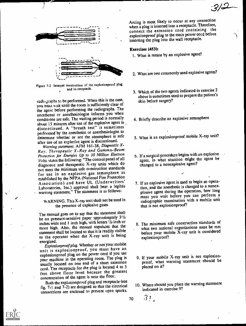
Figure 7-2 lnterrial construction of the explosionproof plugand its receptacle.
radiographs to be performed. When this is the case,
you must %kith until the room is sufficiently clear ofthe agent before performing the radiographs. Theanesthetist or anesthesiologist informs you whenconditions are safe. The waiting period is normallyabout 15 minutes after use of the explosive agent is.
discontinued. A "breath test" is sometimesperformed"by the anesthetist or anesthesiologist todetermine whether or not the atmosphere is safe
after use of an ezplosh,e agent is discontinued.Warning statement. AFM 161-38, Diagnostic X-
Ray. Therapeutic X-Ray and Gamma-BeamProtection for Energies Up to 10 Million Electron
Volts, states the following: "The control panel of all
diagnostic and therapeutic X-ray units which donot meet the minimum safe construction standards
for use in an explosive gas atmosphere asestablished by the NFPA (National Fire ProtectionAssociation) and have UL (Underwriters'Laboratories, Inc.) approval shall bea'r a legible
warning statement." The statement is as follows:
WARNING. This X-ray unit shall not be used in
the presence of explosive gases,
The manual goes on to say that thc: statement shall
be on pressure-sensitive paper approximately 31/2inches wide and I inch high, with letters Winch ormore high. Also, the manual supuihtes that thestatement shalt be located so that it is readily visible
to the operator when the X-ray unit is beingenergized.
Explosionproofplug. Whether or not your mobile
unit is explosionproof, you must have anexplosionproof plug on the power cord if you use
your machine in the operating room. The plug isusually located on one end of a short extensioncord. The receptacle for the plug is located 4 to 5
feet above floor level because the greatestconcentration of the agent is near the floor.
Both the explosionproof plug and receptacle (see
7-1 and 7-2) arc designed so that the electricalconnections are enclosed to prevent open sparks.
V-.amm
Arcing is most likely to occur at any connection
when a plug is inserted into a receptacle. Therefore,
connect the extension cord containing theexplosionproof plug to the main power cord before
inserting the plug into the wall receptacle.
Exercises (453):1. What is meant by an explosive agent?
2. What are two commonly used explosive agents?
3. Which of the two agents indicated in exercise 2
above is sometimes used to prepare the patient's
skin before surgery?
4. Briefly describe an explosive atmosphere.
5. What is an explosionproof mobile X-ray unit?
6. If a surgical procedure begins with an explosive
agent, in what situation might the agent bechanged to a nonexplosive agent?
7. If an explosive agent is used to begin an opera-tion,,and the anesthetic is changed to a nonex-plosive agent during the operation, how longmust you wait before you can perform aradiographic examination with a mobile unit
that is not explosionproof?
8. The minimum safe construction standards ofwhat two national organizations must be met
before your mobile X-ray unit is considered
explosionproof?
9. If your mobile X-ray unit is not explosion-proof, what warning statement should beplaced on it?
10. Where should you place the warning statementindicated in exercise 9?
70 3 /
11. What type and what size paper should you use,and what minimum height should you make theletters for the warning statement indicated inexercise 9 above?
12. When should you have an explosionproof plugon the end of your mobile unit power cord?
13. Why is the explosionproof receptacle located 4to 5 feet above the floor?
14. How do the explosionproof plug andreceptacle prevent open sparks?
15. Why should you plug the extension cordcontaining the explosionproof plug to the mainpower cord of your mobile unit beforeplugging the explosionproof plug into the wallreceptacle?
7-2.. Bedside RadiographyN ou no doubt have performed many bedside ex-
aminations, so you should know by now that youusually have to draw upon your knowledge and ex-perience with the use of grids, film holders, ex-posure factors, etc., to produce good bedsideradiographs. Consequently, we will not discussthose general aspects of bedside radiography. In-stead, we will concentrate our study on a few areasthat we believe are generally overlooked by manytechniciansareas that include minimum source toskin distance, protective apron requirements, andradiography of a patient receiving oxygen therapyand radiography of a cardiac patient.
454. Specify the minimum SSD you should usewhen accomplishing a mobile radiograph and theminimum lead equivalent of a protective apronworn when performing this radiograph.
SSD and Protective Apron Requirements.While these requirements are included under theheading of bedside radiography, they apply to allmobile radiography. At times when you performmobile radiographs, it is not possible to achieveyour normal FFD. These situations are broughtabout by several conditions beyond your control,
71
,3/3such as the presence of casts, traction devices, andother patient care apparatus. In thesecircumstances, you may reduce the FFD to thatnecessary, as long as the SSD (source to skindistance) is not less than 12 inches. The SSD is, ofcourse, the distance from the focal spot to thepatient's skin. This minimum SSD is required byAFM 161-38. This manual also requires you towear a protective apron of at least 0.25 mm leadequivalent.
Exercises (454):
I. What is the minimum SSD that you should usewhen accOmplishing a mobile radiograph?
2. What should be the minimum lead equivalentof a protective apron worn when performing amobile radiograph?
455. Supply key words in a series of statementsabout the performance of radiographs on a patientreceiving oxygen therapy.
Radiographing a Patient Receiving OxygenTherapy. While oxygen itself is not combustible, itsupports combustion to the extent that pure oxygencan cause a flash fire if a source of ignition is
present. For this reason, you must take specialprecautions when performing radiographicexaminations on a patient receiving oxygen therapy.
In most cases, the oxygen can and should beturned off for a short time while you are performingthe examination. Of course, you do not remove theoxygen supply or restart itthis is done by a nurseor other responsible ward personnel. When thepatient's condition permits, the oxygen should beturned off during the examination.
If the oxygen is to be turned off and the oxygentent rem-wed for the examination, be sure to makeall the nect..!!?7; preparations in advance.Preparations such as setting the control panel,positioning the tube and film, and instructing thepatient can be performed in advance so that thepatient can be returned to oxygen therapy as quicklyas possible. You should also work quickly.
If the patient's condition is so critical that theoxygen cannot be turned off at all, and if theexamination to be performed is a chest filmwhichit usually isthe oxygen tent can be draped onlyaround the patient's head, leaving the chest areafree.

Exercises (455):
Fill in each blank in the statements below with oneor two appropriate words.
1. Oxygen supports2. Pure oxygen can cause a
if a source of ignition is present.3. Usually when your are radiographing a patient
receiving oxygen therapy, the oxygen supplycan and should be
4. In the situation indicated above, you do not_or the oxygen supply.
5. It is,permissible to radiograph a patient whileoxygen therapy is being administered onlywhen his prevents removal of theoxygen.
6 Preparing and work-ing can reduce the time a patient isdeprived of pure oxygen.
7 lithe oxygen cannot be turned off, it is possibleto diape the oxygen around the
to perform a chestradiograph.
456. Given a list of four bedside chest projectionsof a cardiac patient, match each with anappropriate descriptive statement given inanother list.
Radiographing a Cardiac Patient. Numerousbedside radiographs are made of a cardiac patientwhosc condition is such that merely moving him toand from a stretcher may jeopardize his recovery.There are at least tbur ways to accomplish a chestfilm on this patient. The procedure you usegenerally depends upon the amount of movementthe patient is allowed or that he can tolerate.
Erect PA. 72-inch chest. When performing abedside chest radiograph on a cardiac patient, yourfirst thought should be directed toward a PA chesttaken at a 72-inch FFD with the patient erect. Thisradiograph, of course, can be as diagnostic from apositional point of view as a routine PA chestperformed in the radiology department under idealconditions.
The procedurc for performing this chestradiograph is simple: the patient sits on the side ofthe bed, holding the vertical cassette in front of hischest. Usc a horizontal CR.
Before performing this procedure, make sure bychecking with the nurse or physician that it is
permissible for the patient to assume this position.Erect or semierect AP chat. If the patient cannot
assume thc position described above, you shouldconsider performing an AP chest with the head endof the hospital bed elevated. Elevate the head of thebed to bring the patient to a sitting position. Then
72
place the film behind the patient and direct ahorizontal CR. from a distance of 72 inches to thevertical film.
At times it may not be possible, due to thepatient's condition, to elevate the bed to bring thepatient's chest to the erect position, but it may bepermissible to elevate it, say, 45°. Although thisprojection is not as good as the erect AP, this APprojection provides a semierect radiograph and Isbetter than using the supin position. You may notbe able to use a 72-inch FFD because the CR mustbe angled down from horizontal so that it isperpendicular to the tilted film.
Supine AP chest. If it is not possible to positionthe patient for any of the projections describedabove, then perform a supine AP chest. Simplyslide a cassette under the patient's back and use avertical CR. Lower the hospital bed to provide thegreatt FFD possible (which will be considerablyless than 72 inches) so that magnification is kept toa minimum. This projection requires the leastpatient movement.
Exercises (456):
Match the bedside chest projection of a cardiac pa-tient in column B with the correct statement in col-umn A by placing the letter of the column B item inthe space provided in column A. Each column Bitcm may be used once or more than once. In addi-tion, more than one column B item may match asingle column A entry.
Colwnn A Column
I Lower the patient'sbod to reduce mag-nification.
2. Patient holds thecassette.
1 Its use dependsupon the patient'scondition.
4. X-ray film is verti-cal.
5. CR is neitherhorizontal nor ver-tical.
6. Provides bestradiograph.
7. Performed whenpatient's conditionprecludes the otherthree projections.
8. Provides the leastmagnification ofthe chest.
9. If the patient'smovement is notrestricted, this pro-jection should beperformed.
10. Requires the leastmovement of thcpatient.
a. PA, erect.b. AP, erect.c. AP, semierect.d. AP, supinc.
7-3. Surgical RadiographyAs was the case in the section on bedside
radiography, we will not discuss the specific ex-posure factors, grid use, etc., during surgicalradiography. We will focus our study on the wear-ing of surgical clothing, cleaning your mobile unit,and your general actions inside the operating room.After tha, we will examine some general guidelinesthat apply to the performance of the radiographicexaminations.
457. State why special clothing is worn in theoperating room, why nylon or similar materialsshould not be worn in the operating room, andhow you are connected to ground when properlywearing operating room shoe covers.
Surgical Clothing. To reduce the amount ofbacteria introdiked into the t perating room and toprevent the buildirp of static electricity, you mustchange into special surgical clothing.
General clothing. The special clothing includes ashirt and trousers, or dress, cap, and mask. Theshirt, trouscrs, and dress are usually made of cottonto prevent the buildup of static electricity. The capand mask may be made of cotton, or they may bethe disposable type. Since nylon or similarmaterials may cause static electricity,undergarments made of these materials should notbe worn in the operating ruom.
Shoe covers.You must also wear special shoecovers when in the operating room. These shoecovers serve two purposes. One purpose is the sameas that already mentioned for the remainder of thcsurgicai clothingthey reduce the amount ofbacteria introduced into the operating room. Thesecond purpose is to prevent the buildup of staticelectricity. The covers perform the latter functionby grounding you. There are several types of covers,and all of them have a conductive sole to which isattached a conductive suap. The end of the strap isinserted inside your sock so that it is in contact withyour slcnthus grounding you. Some operatingrooms use a device that tests you to determinewhether or not you are properly grounded.
Operating room policies. Due to the preference ofthe chief of surgery, the physical arrangement of thesurgical suite, and other variables', clothing policiesmay vary from one hospital to another. For thisreason, you, as a technician or supervisor, shouldinsure that you and your personnel understand theprocedures used in your hospital, and should seethat they arc carried out properly.
Exercisei (457):
I. Why must special surgical clothing be worn in
the operating room?
73
2. Why shouldn't you wear nylon or similar un-dergarments in the operating room?
3. How are you connected to ground whenproperly wearing operating room shot covers?
4. Give two specific factors that may causeclothing policies to vary from one hospital toanother.
458. Explain why and how your mobile unitshould be cleaned before it is taken into anoperating room, list three areas about the unitrequiring special attention while they are beingcleaned, and state why the special attention isnecessary.
Cleaning the Mobile Unit. In keeping with ourprevious discussion of, reducing the bacteriaintroduced into the operating room, it follows thatyou must clean your mobile unit before taking itinside. This cleaning should consist of thoroughlywiping the entire unit down with hand towelssoaked in an antiscptic solution provided byoperating room personnel.
Contrary to what many technicians believe,sufficient cleaning of your portable unit isimportant. This is not too difficult to understandwhen you consider that the tube head is usuallypositioned directly over the operative site. Eventhough the site is usually covered with sterile drapeswhen you perform your radiographs, particles ofdust falling from your tubehead may contaminatethe sterile area. Some surgeons prefer that you coverthe tubehead with a sterile pillow case or sheet ofclear plastic after the machine is cleaned. This, ofcourse, reduces the danger of contamination. Clearplastic may be preferable because it permitsvisualization of the light field from your collimator.
Other parts of your mobile unit requiring specialattention during the cleaning procedure are thewheels and power cord. These, of course, areprobably the dirtiest parts since they are repeatedlyin contact with the floor.
Exercises (458):
I. Why should your mobile unit be cleaned beforeit is taken into an operating room?

2. How should your mobile unit be ckaned be-e> fore it is taken into the operating room?
3. List three areas about your Mobile unit requir-ing special attention when being cleaned, andin each case specify why attention to these areasis important.
4. After wiping your mobile unit down, how canyou further prevent contamination of theoperating site?
459. Name five persons or parts of the operatingroom in the sterile area and three persons or parts
in the nonsterile area.
Actions Inside the Operating Room. During"open" surgery, the operating room is consideredto be divided into two areas: sterile and nonsterile.
Sterile area. The sterile area is concentratedabout the operating site. Included in this area is acertain portion of the patient, the surgeon and hisimmediate assistants, the surgical instruments, andthe tables, trays, and stands containing theinstruments.
Nonsterile area. The nonsterile area includes theanesthetist, you and your mobile unit, and,variousother portions of the operating room. As you areperforming the radiographic examination, yourmain interest insofar as contamination is concerned
is to keep from contaminating or contacting anypart of the sterile area. It is usually good practice toextend the horizontal tube arm as far as possible sothat when the tubehead is positioned over thepatient, the remainder of the unit is remote from the
table.
Exercises (459hI. Name five persons or parts of the operating
room in the sterile area.
2. Name three persons or parts of the operatingroom in the nonsterile area.
74
460. Point out significant factors affecting theperformance of radiographic examinations in theoperating room.
Performing the Examination. Numeroussurgical procedures require radiographic support. Itwould be impractical to discuss all of them in thisCDC. Instead, we will only discuss some or themost common procedures, as well as some genera(considerations that apply.
Speed. Surgeons and anesthetists oranesthesiologists like to accomplish surgery asquickly as possible so that the patient remains underthe influence of the anesthetic for a minimum time.During some surgical procedures, the surgeoncannot continue until he examines the radiographs.This means that you should act quickly whenperforming the radiographic examination andreturn from your darkroom with the radiographs asquickly as possible.
You can, of course, reduce the delay caused byfilm processing by using Polaroid films and the ,accompanying processor. While you cannot usethese films for all examinations, you can use themfor many, especially open and closed reductions of
the extremities.Accuracy. Whenever you must repeat a
radiograph made in the operating room due to thequality of the film, you are, in effect, increasing thekngth of the operation. Accordingly, the patientremains under the anesthetic for a longer time.Exposure and 'positioning are critical'. Incorrectexposure is the most common reason for repeatradiographs made in the operating room. Incorrector incomplete technique charts contribute' to theproblem at times, so try to maintain correct,complete mobile-unit charts. Incorrectly estimatingthe thickness of the part also leads to incorrectexposure. Measure the patient, if possible. It is notmuch of a problem to measure the patient the daybefore the surgery if the operation isscheduledand many are scheduled in advance.
Scout film. Since many radiographs are repeatedbecause of incorrect exposure, a scout film shouldbe accomplished when possible. Naturally, a scoutfilm need not be made for open or closedreductions of the extremities (excluding the hip).
For a hip-nailing procedure, when a lateralprojection (Danlius-Miller described in Chapter 4,Volume 2) is required, yOu should always performa scout film and leave the mobile unit in place oncethe scout is accomplished. Also, for certainabdominal radiographs, such as an 'operativecholangiogram, you should always perform a scout
film.Aligning the Xlray tube to the grid At times, it
may be difficult to align the X-ray tube tothe grid
so that grid cut-off dueto lateral decentering isprevented. The reason for the difficulty is that,
3 9 L

because of the extent to which the patient is draped,you may not be able to tell where the center of the,grid is located. (NOTE: This discussion is based onthe assumption that you perform a properly alignedscout film for an operative cholangiogram, forexample, and remove the unit from the immediateviciaity of the patient, thereby necessitatingrecentcring the tube to the grid for the remainingradiographs.) One way to help prevent grid cut-offis to use a grid with a lower ratio, which, asdiscussed in Voluthe 1 , increases the tolerableamount of lateral decentering.
Some technicians prefer to mark the location ofthe wheels on the floor when performing the scoutfilm, so that they can return the mobile unit to thesame location. Naturally, the position of the X-raytube with respect to the grid must be correct for thescout radiograph if this procedure is to be helpful.
Exercises (460):
I. Why is it important for you to complete aradiographic examination in the operatingroom quickly and accurately?
2. How can you reduce the delay caused by filmprocessing when reductions of the extremitiesare accomplished?
(3/73. What is the most common cause of repeat
radiographs in the operating room? What canyou do to help prevent these repeats?
4. Name two surgical procedures requiring ascout film.
5. Why is it sometimes difficult to align the X=ray _tube to the grid when performing radiographsin the operating room?
6. How can you increase the lateral decenteringtolerance of the grid when perfoiming a gridradiograph in the operating room?
7. Describe one way to properly align the tube tothe grid for a later radiograph if they were pro-perly aligned for the scout film.
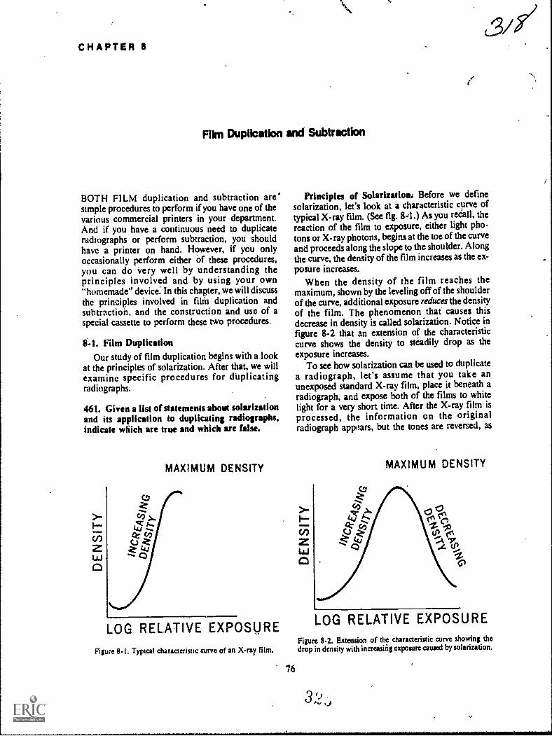
CHAPTER 8
Fikn Duplication and Subtraction
BOTH FILM duplication and subtraction are'simple procedures to perform if you have one of thevarious commercial printers in your department.And if you have a continuous need to duplicateradiographs or perform subtraction, you shouldhave a printer on hand. However, if you onlyoccasionally perform either of these procedures,you can do Very well by understanding theprinciples involved and by using your own"homemade" device. In this chapter, we will discussthe principles involved in film duplication andsubtraction, and the construction and use of aspecial cassette to perform these two procedures.
8-1. Film DuplicationOur study of film duplication begins with a look
at the principles of solarization. After that, we willexamine specific procedures for duplicatingradiographs.
461. Given a list of statements about solarizationand its application to duplicating radiographs,indkate whkh are true and wMch are false.
MAXIMUM DENSITY
LOG RELATIVE EXPOSURE
Figure 8-1. Typical characteristic curve of an X-ray film.
76
Principles of Solarization. Before we definesolarization, let's look at a characteristic curve oftypical X-ray film. (See fig. 8-1) As you reCall, thereaction of the film to exposure, either light pho-tons or X-ray photons, begins at the toe of the curveand proceeds along the slope to the shoulder. Alongthe curve, the density of the film increases as the ex-posure increases.
When the density of the film reaches themaximum, shown by the leveling off of the shoulderof the curve, additional exposure reduces the densityof the film. The phenomenon that causes thisdecrease in density is called solarization. Notice infigure 8-2 that an extension of the characteristiccurve shows the density to steadily drop as theexposure increases.
To see how solarization can be used to duplicatea radiograph, let's assume that you take anunexposed standard X-ray film, place it beneath aradiograph, and expose both of the films to whitelight for a very short time. After the X-ray film is
processed, the information on the originalradiograph appears, but the tones are reversed, as
MAXIMUM DENSITY
LOG RELATIVE EXPOSUREFigure 8-2. Extension of the characteristic curve showing thedrop in density with increuing exposure caused by solarization.
3 ')A.,

<3. LIGHT RAYS,
RADIOGRAPH ---5.-310=Eil=icimili
UNEXPOSED-la-X-RAY FILM
ili=111111L-31111=211111
NM MI NM NM
f 4.
Figure 8-3. Comparison of the densities of a duplicated image using exposures in the characteristic curveand solafization ranges.
shown in figure 8-3,A. The black areas appearwhite, and the white areas appear black. This imagereversal is due to the amount of exposure in thecharacteristic curve range where more exposureprovides greater density. If both films are subjectedto considerably more light, as shown in figure8-3,B, the processed film shows the image of theoriginal radiograph duplicated so that the blackareas are black and the white areas are white. Thereason for the exact tonal duplication is that thelight exposure in now in the solarization range,where greater exposure to the film causes lessdensity. Consequently, solarization allows you tocopy a radiograph showing exact tonal duplication.
You can copy a radiograph by following thegeneral pl-ocedure just discussed, using eithersunlight or artificial, light. Howei,er, the duplicatewould not provick good detail because a standardX-ray film does not reproduce detail sufficientlyduring solarization due to the composition of the
bupikating Film. Most film manufacturersmake a duplicating film to be used specifically forcopying radiographs, and you should use this typeof film. Duplicating film differs from standard X-ray film in that it has emulsion on one side only,and the emulsion is already solarized. Thesesponseof the emulsion to exposure can be compared to astandard X-ray film that has been pre-exposed tothe maximum density or to the shoulder portion ofits characteristic curve.
Most brands Of duplicatitig film are designed to
77
be exposed with ultraviolet light, but some aredesigned to t;oe exposed by white light. In eithercase, use the recommended light source.
Exercises (461):
Indicate whether the following statements are trueor false. If you indicate "false," explain youranswer.
T F I. An increase in exposure always increasesfilm density.
T F 2. Solarization can cause a high exposure toproduce low density.
T F 3. If a radiograph is duplicated using a stan-dard X-ray film, the amount of exposuredetermines the tonal relationships.
T F 4. If a radiograph is duplicated using a stan-dard X-ray film, and the reproducedtones are the same as those of theradiograph, solarization did not in-fluence the outcome of the tones.
T F 5. Duplicating radiographs using standardX-ray film produce good detail on theduplicate.
T F 6. Radiographs should be copied onduplicating film.
T F 7. Duplicating film responds to exposure inthe same way as conventional X-ray filmdoes.
T F 8. Solarized duplicating film should be usedwith the exposure source for which it isdesigned.
3 P)

462. Answer key *Moos about the procedurefor dupiicatiag radiographs.
Duplicating a Radiograph. Now let's discms a
procedure for duplicating a radiograph. The firstitem you will need, other than a duplicating film, is
a spacial cassette.
GI s front cassette. The special cassette you will
need can easily be constructed from ,a standardcassette. (A single 14 by 17 cassette will be
'sufficient but you can thake one for each sizev .radiograph that you copy.) Simply remove the
bakelite front of the cassette and replace it with atransparent sheet of regular glass or plexiglass andremove the intensifying sireeps. Keep the glassclean and do no.. allciw it to become scratched, sinceglass that is soiled and scratched causes artifacts on
the duplicate.To load the cassette, place the radiograph to be
copied in the cassette first so that it is in contactwith the glass front. Place the duplicating film inthe cassette with the emulsion against theradiographthe emulsion is on the "dull", not the"glossy" side of the film. Close, even contact mustexist between both films when the cassette is closed
to prevent loss of detail.Light source. As mentioned before', you should
use the type of light (ultraviolet or white)recommended by the manufacturer. Fluorescent orincandescent lamps may be used. Good results canbe obtained by using an ordinary radiographicviewbox. Ultraviolet lamps can be obtained that can
be used in your viewbox, and, in case of white lightsensitive duplicating films, the viewbox can be used
with the standard fluorescent lamps. You can also
use certain incandescent lamps emitting white light
as recommended by the film manufacturer.Exposure time and source to film distance.
Exposure time and source-to-film distance areclosely related to each other since the intensity ofthe light diminishes as the source-to-film distanceincreases. Exposure time is usually in theneighborhood of a few seconds, while the source-to-film distance may reach to 40 inches. Each filmmanufacturer makes specific recommendationspertaining to these two factorsfollow them.
Evaluation of the duplicate. Although you shouldinitialty follow the manufacturer's recommended
expos re time, do not hesitate to vary yourexposulç,if the duplicates are not satisfactory.Certain actors such as line voltage and processing
may necessitate different exposures. Keep in mind
that excessive exposure produces a light image andinsufficient exposure produces a dark image.Obviously, this is due to the solarized duplicatingfilm. Accordingly, you can also produce a duplicatewith more or less density than the original byvarying the exposure time.
78
Exercises (462):1. Explain how a special cassette is made from a
standard cassette.
2. Why should the cassette front be kept clean andfree of scratch marks?
3. How should the two films (radiograph andduplicating film) be placed in the cassette?
4. Why should there be close, even contact be-tween the radiograph and duplicating film?
5. What type of light source should be used to ex-
pose the cassette?
6. What specific exposure time and source-to-filmdistance should you use?
7. If a duplicate of a radiograph is too dark, howcan the exposure be corrected on a subsequentduplicate?
8. If a radiograph is initially too light, can youproduce a duplicate which is darker? How?
8-2. SubtractionSubtraction is a procedure that eliminates un-
wanted shadows from a radiograph. Specifically,the technique is usually used to eliminate all of theanatomical structures from an angiogram, leaving
only an image of the contrast-filled vessels. Several
methods of subtraction have been developed andused sucessfully, including electronic subtractionusing television pickup tubes that display the vessels
on a monitor. Subtraction fluoroscopy also is being
performed with some success.As stated in the introduction to this chapter, this
method of subtraction is meant for the departmentthat only occasionally performs the tech-niquealthough the basic principles apply to most
3 'd/set)

4.
0:3
A1
cFigure 8-4. The process of subtraction.
79
B
321
o,
c%
,

commonly used methods. We begin our discussionwith a look at the principles of subtraction.
463. Supply keit worth in a series of statementsabout the principles involved in the subtractionprocess.
Principles of Subtraction. BaSically, subtractionremoves the unwanted shadows from a radiographby reducing or eliminating the contrast betweenthose shadows. To illustrate how the contrast isaffected, we have assembled some drawings infigure 8-4. Assume that drawing A represents asmut film taken before the injection of the contrastmedium during an angiogram. The figures in thedrawing would represent the bony structures.(NOTE: In actuality, the bony structures would berepresented by more than the two densities shown.)In drawing B we have added three more structuresthat represent the contrasf-filled vessels on anangiogram.
Drawing C represents a negative of the scout filmand is called the subtraction mask. The tones of themask are reversed from those of the scoutthat is,
the dark areas on the scout are light on the mask, 'and the light areas on the scout are dark on themask. The large circle, which was gray on the scoutfilm, is also gay on the mask.
Now if we superimpose films B and C, the
appearance resembles drawing D in the figureadark background with the contrast-filled vesselsappearing alone and light. Thus, the bony structuresthat may interfere with the interpretation of thevessels are canceled out or "subtracted" from the
angiogram.As mentioned before, 'the unwanted shadows are
removed by reducing or eliminating the contrast.Think for a minute about what happens to thedensities. The dark structures or areas become darkwhen superimposed over the light structures.Likewise, gray structures superimposed over graystructures become dark. The contrast-filled vessels
that are included only on the angiogram remainvisible. Consequently, except for the contrastbetween the vessels and the remaining darkbackground, the contrast on the angiogram is moreor less eliminated.
Exercises (463):Insert an appropriate word in each of the followingblank spaces in the statements below concerning theprinciples of subtraction.
I...Subtraction removes structures that mayinterfere with interpretation by or
the between thosestructures.
2. The is considered areverse tonal copy of the scout film.
322--3. Gray structures on the scout film are
on the mask.4. Superimposition of the and
produces high contrast betweenthe contrast -filled vessels and background.
5. The mask, in effect, causes the backgroundaround the contrast-filled vessels to appear
6. Structures are subtracted because theof each structure become equal.
464. Give selected details significant to theprocedure for performing subtraction.
Performing Subtraction. Let us now diicuss asimple -method for performing subtraction. Theonly equipment you will need for this method is asupply of subtraction film, a 10- or 15-wattincandescent light bulb, and a glass-front cassette(the same as the one used to duplicate radiographs).We will begin wiii a closer look at the scout film.
Scout film. One of the key factors that influencesthe degree of subtraction achieved is whether or notthere is part-motion between the scout film and theangiogram. Good subtraction of the structures canbe achieved only if the structures on the mask andangiogram (except for the vessels) Are exactlysuperimposed. If the patient moves between thescout and angiogram, you will .not be able toprecisely superimpose the structures,. For thisreason, subtraction is usually accomplished inconjunction with an examination performed withan automatic film changer, where the time lapsebetween the scout film and the angiogram isminimal, thereby reducing the possibility of patientmovement.
Obviously, there will be times when the patientdoes move even when you use an automaticchanger. Movement may be simply due to,thepatient's condition or it may be due to the feeling heexperiences as the contrast material is injected.When movement occurs that prevents you fromsuperimposing/all of die structuies, try tosuperimpose 41 6se in the area of greatest interestand forget a ut the rest.
Mask. To make the subtraction mask, place the
scout film in,the special cassette against the glassfront, then put the subtraction film in the cassettewith the emulsion (dull) side against the scout.Expose the cassette 40 a 10- or 15-.wattincandescent light bulb at a distance of 6 feet.Exposure time usually ranges from 2 to 30 seconds,depending upon the brand of film, the intensity ofthe light, and the density of the scout film.
Another key factor in the subtraction process is
whether or not the differences between the densities

agz3on the scout -are maintained on the mask. Forexample, if the densities of two bony structures on ascout film are 1.-5 and 0.5, the density ratio is 3 to1. To eliminate the contrast between thosestructures, their respective densities on the maskmust exist in a ratio of 1 to 3for example, 0.5 and1.5.
Abtraction print. So far we havz only discussedsuperimposing the mask and the angiogram on aviewbox so that the radiologist can interpret theresults directly. Some radiologists may prefer tomake a subtraction print of che results.
To make the print, place the superimposed maskand angiogram (taped together) in the specialcassette with the mask against the glass. Place eithera standard X-ray film or a subtraction film on topof the angiogram. The standard film usually resultsin higher contrast. If a subtraction film is used,place its emulsion side against the angiogram.Expose the film to, the same light source at thesamedistance as before. Exposure time is determined bytrial and error, but you will need a longer exposurethan when you made the mask because you nowhavetwo films between it and the light source. Thesubtraetion print produced in this manner willreveal the contrast-filled vessels to be dark against alight backgrdund.
Exercises (464):
1. Why is it important that there be no part mo-tion between the scout film and the angiogram?
N.1. 3. If Part motion occurs between the scout filmand the angiogram, what action should youtake when performing the subtraction?
4. How do you rtiake the subtraction mask?
5. What relationship must exist between the densi-lies of the structures on tile scout,film and thedensities of the structures on the mask (otherthan reverse tones)?
6. On what types of film can a subtraction print bemade?
7. What films are placed inside the special cassetteto make a subtraction print and in what order?
8. Why do you need more exposure when makingthe print than when making the mask?
2. Why is subtraction usually accomplished for 9. How do the tones of the subtraction print com-examinations performed with an automatic pare with those seen when the mask andfilm changer? angiogram are viewed directly?
Reference:400 . I.400 2.400 - 3.400 - 4.400 - 5.400 6.400 - 7.
401 I.
401 - 2.401 - 3,
CHAPTER I
ANSWERS FOR EXERCISES
Fibrous and glandular (fibroglandular) tissue areabout equal: fatty tissue is the least dense of thethree types.Atrophic, because it consists entirely of fatty tissue,Adolescent and lactating.
402 - . T.402 - 2. F. While this statement is partially true, it is in-
complete. Remember the focal-spot must also be
able to withstand the heat generated by the ex-
posures.402 - 3. T.402 - 4. F. The single exposure rating of the tube must also
be considered.402 - 5. T.402 6. T.402 - 7. T.402 - 8. F. It has a small aperture.402 9. T.
403 - I. The detail produced on the radiographs is inadequate.
403 - 2. Standard films are coarsegrained, while industrialor mammographic films are fine-grained.
403 - 3. Obtain commercial film packages or comEne filmsof various speeds in a direct exposure holder.
403 - 4, It permits good visualization of both thick and thinportions of the breast from a single exposure.
403 - 5. Process them according to the film manufacturer'sinstructions.
403 6. High detail screens madc especially for mammogra-phy.
403 7. A disadvantage is loss of detail; an advantage is
reduction of part motion.
404 I. Twenty to 30 since the absorption properties offibroglandular, fatty, and pathological tissue arcnearly equal. The low kVp range is necessary toprovide adequate contrast on the radiograph.
404 - 2. Up to 50. A certain amount of muscle tissue mustbe penetrated.
405 - I. FFD, film speed, and whether or not intensifyingscreens are used.
405 - 2. Part motion. By ing the shortest exposure timepossible.
405 - 3. Twenty to 40 inches.405 - 4. Advantages are: (1) increased 'detail and (2) lower
patient skin .dose. Disadvantage requires more ex-posure.
405 - 5. Advantage requires less exposure. Disadvantages:(1) detail loss due to increased magnification and(2) higher skin dose to the patient.
406 - I. /F. On the craniocaudal and the mediolateral pro-jections.
406 - 2. T.406 3. T.406 - 4. F. Firm contact is important so that the posterior
portion of the breast is included on the film.406 - 5. T.406 6. T.406 - 7. T..406 - 8. T.406 - 9. F. It depends upon the relative position ofthe tail
of the breast.406 10. T.
CHAPTER 2
407 - I. Two types of tissue (gonadal and immature grow.ing) which are highly susceptible to irreversiblealteration from exposure to ionizing radiation arepresent in the patient.
407 2. Improper positioning can prevent accurate evalua-tion of the radiographs.
407 - 3. Repeat examinations due to improper positioning.
, 407 4. (I) Ask the patient to inform you when there is nonoticeable fetal motion, (2) have the patientbreathe deeply several times and suspend respira-tion on inhalation before the exposure, and (3) use
the shorteit exposure time possible.407 - 5. Use highspeed screens and films, use high kVp and
low mAs, and use reliable exposure techniques.
83
:3''
408 I. T.408 2. F. Visualization can occur as early as 12 weeks.
408 3. F. Exposure is more dangerous at 14 weeks.
408 4. F. Superimposition of the sacrum and fifth lumbz.r
vertebra is important.408 5. F. Technicians do need to recognize a fetus on all
radiographs taken of the pelvic area on procreative
3,z
408 - 6.408 7.408 - 8408 - 9.
408 - 10.408 - I I.
409 - 1409 - 2.409 - 3.409 - 4.409 - 5.409 - 6.409 - 7409 - 8.409 - 9409 - 10.
410 - I.410 - 2.410 - 3.
411 - 1
patients. Sometimes a physician does not know thathis patient is pregnant, and you can prevent ex-cessive exposure to the new fetus by identifying thefetal skeleton on other radiographs.T.T.T.F. Demonstration ofthe fetal skull bones is impor-tant because overlapping of the bones can be a signof fetal death.T.F Anencephaly is absende of the skull.
Radiologist; obstetrician.Iliac crests.Symphysis pubis.AP: PA.Knees: forearms.PA; without.PA.Posterior.Obliquity: PA: AP.Position; comfort.
Twenty cm ir diameter and 5 cm thick.On the anterior or posterior uterine wall.In the lower segment of the uterus.
(1) The density of the placenta is nearly equal toother surrounding tissues. Use soft tissue tech.niquerelatively high mAs and low kVp. Discussthe technique with the radiologist since it results ina relatively high absorbed dose to the mother and
child. (2) The thickness of the abdomen in thelateral position varies fron the posterior to the an-terior portions. Difference in thickness must becompcnsated for so that the entire film shows thesame density.
417 - I With the thick portion over the anterior abdomen.412 - 2 Aluminum, copper, and barium sulfate.412 . 3. Mix thc barium sulfate with molding clay or
petrolatum. Spread over a 0.5 .mm piece ofaluminum so that the filter is 2.0 mm thick on oneend and tapers to almost no thickness of barium onthe other end.
412 - 4 By placing a piece 1 to 3 mm thick in the primarybeam over the anterior half of the abdomen.
412 . 5 Two. Fast and slow.412 - 6, With the fast screens under the posterior portion of
the abdomen.412 - 7, Place the paper inside the cassette so that it covers
one-half of the film on one side only. Place thecovered portion of the film undcr the anterior porktion of the abdomen.
413 . I. The relationship between these two structures isevaluated for placenta praevia.
413 - 2. Rotation of the pelvis projects the fetal hcad lateralto the midline.
AP diameterinlet; lateral projection.AP diametermidpelvis: lateral projection.AP diameteroutlet: lateral projection.Transverse diameter inlet: AP projection.Transverse diameter midpelvis; AP projec.tion.Transverse diameter outlet; AP projection.
415 - 3. At the same level as the ischial tuberosities. Thelevel is the same as that of the transverse pelvicdiameters.
415 - 4. Palpate the upper margin of the symphysis pubis.and set the perforated ruler 10 cm below thatmargin.
416 - I. It would cause the AP pelvic diameters to measurelonger than they actually are: consequently, thepelvis may be judged to be-adequate for delivery.and may not actually be adequate. Evaluation ofthe klvis is inaccurate because the spaces betweenthe rdler dots are magnified less than they shouldbe.
416 - 2. It would cause the AP diameters to measure shorterthan they actually are, which could cause the pelvisto be judged inadequate for delivery, although itmay actually be adequate. The mistaken diagnosis iscaused by the spaces between the ruler dots beingmagnified more than they should be.
416 - 3. Same answer as for exercise #1 (above) except thatthe transverse diameters, instead of the AP
-diameters, are affected.
417 - I. a. (I) Failure to properly align the pelvis.(2) Obscures the Ischial spines and prevents
accurate measurement of the transversediameter of the midpelvisalso makesother transverse measurements difficult.
(3) Adjust the median plane perpendicular tothe table.
b. (1) Failure to include the ruler on the film.(2) Magnification of the transverse diameters
cannot be determined and the radiographis of no use.
(3) Center the film Ph-inches above thesymphysis pubis.
c. (I) Overexposure of the film.(2) May prevent identification of bony land-
marks between which transverse diametersare measured.
(3) Measure through the CR.
419 . I.419 - 2.419 .
419 4.4,? I To determine the degree of magnification of the 419 - S.
pelvic diameters.415 . 2. Between the gluteal folds. The level is the same as 419 - 6.
that of the AP pelvic diarrders.
84
,)
(I) Positioning the patient so that the pelvis isanteriorly misted.
(2) Shortens AP pelvic diameters and resultsin low measurements.
Perform tht lateral erect or elevate the anterioraedomen., superimpose the legs exactly, andplace supportive material between the knees andankles.(I) guperimposing the femurs over the sym-
physis pubis.(2) Anterior ends of the AP diameters are not
visualized.(3) Extend the femurs.
CHAPTER 3
Radiography of sections of the body.Radiograph produced by tomographyA connecting rod which couples the tube and filmcarrier (cassette tray).The point about which the lever rotates or pivots.Body layer which appears sharpest on thetomogram.Unsharp body arca outside (above or below) thefocal plane.
419 - 7419 8.
419 - 9.419 - 10.
420 I.420 - 2.420 3.420 - 4,420 - 5.420 - 6.420 - 7.
421 - I.
421 - 2.
421 3.
422 - 1422 - 2422 - 3422 - 4422 - 5
423 -423 - 2.423 . 3.
423 - 4.
423 - 5423 - 6.423 - 7
424 - I.424 - 2.424 - 3
424 4.
425 - I.
425 2
426 - I.
426 - 2.
426 - 3426 - 4.
427 - I
427 - 2427 - 3.
428 I.428 - 2.428 - 3.
Distance in inches the tube travels during exposure. 429 - 1.Speed of tube travel (usually expressed in inches per 429 2.second). 429 - 3.Angle in degrees of the tube travel during exposure. 429 - 4.Tomography with a small exposure angle-lessthan 10*.
Sinusoidal..
Circular.Spiral. 430 - I.Hypocycloidal.Random.
430430
- 2.- 3.
Linear. 430 - 4.
Its relative position on the film is the same 431 - I
it throughout the exposure. 431 - 2.
Its relative position on the film shifts during the ex.posure.Objects located in the focal plane are not blurredbecause their relative positions on the film do notchange during tbe exposure.
431
431
- 3
- 4.431 - 5.431 - 6.
Layer: section.Section thickness.Sharp; unsharp.More.Thicker.
T.F. A long amplitude produces a thin section.F. There is. (The longer the FFD at a given 432 - I.amplitude, the less the exposure angle.) 432 - 2.F The structure:, are projected by different ex- 432 - 3.posure angles. The farther a structure is from the 432 4.focal plane, the greater the exposuce angle. 432 - 5.T.T. 433 - I.T. 433 - 2.
433 - 3.Thrm. 433 4.Bottom (remote from tube). Top (nearest the tube).Photons are absorbed as they pass through the films. 434 I.screens, and interspace material. Variable speedscreens compensate for the absorption.
434 - 2.
0.5 mm. 435 - I.435 - 2.
Each film has, in effect, its own fulcrum due to thespace between the films. 436 - I.15 cm. 11 cm. 436 - 2.
Because of the relatively low book exposure com- 436 3.
pared to the combined exposures of the individualexposures.
436 - 4
No. because the exposure required for the book ismore than that required for a single exposure due tothe speed of the top pair of intensifying screens.
436 - 5.
437 - I
It reduces it.(1) The lower films provide less good detail than
the upper films because the lower intensifyingscreens are faster.
(2) Contrast is reduced on the lower films becausemore scattered photons are present.
Approximately 150 mAs.Approximately 100 mAs.The tissue thickness is greater due to the angle of thetube.
Sec = 3.Amplitude = 8 inches.Rate = 5 inches per second.
85
T.T.T.T.
CHAPTER 4
No.No.No.No.
At right angles to the predominant lines of the part.Because this produces the maximum variation inthe two views; the more variation, the better thestereoscopic effect.Vertical, because the ribs are the predominant lines,and they lie horizontally.Either across or with the longitudinal axis.Decentering tolerance for the grid.(I) Replace the grid with one of a lower ratio.(2) Remove the grid and perform nongrid
radiographs.(3) Position the patient crosswise on the table (use
a stretcher).(4) Shift the tube longitudinally with the table if
there is not much difference between the partaxes.
Near.Far.Far.Far.Near.
Tube side.Film side.Tube side.Film side.
2.4.1-3.
Right eye-film #2: left eyo-Rn #1.Right eye-filin #I; left eye film #2.
Two conventional viewboxes.It is the most convenient method because no specialapparatus is required.Left.The direction of tube shift is parallel with your in-terpupillary line.Film side.
No. The films are reversed from their correct posi-tions-the right eye film should be on the right sideand the left eye film should be on the left side.
437 - 2. No. The tube sides are toward you; they should beagainst the viewboxes.
CHAPTER 5
438 I. AP or PA and lateral.438 - 2. No. The physician determines the location of the
foreign body by examining the part while it is in theposition it was in when the radiographs were made.

He can duplicate exactly the AP, PA, or lateralpositions. However, he may not beable to duplicateoblique projections.
438 - 3. It enables the physician to determine the preciseproximsl/distal location of the foreign body.
438 - 4. (I ) Tape a metallic marker such as an "X" or "0"directly ov= the entrance wound, if one isvisible.
(2) Place an arrow diicctly an the film holder inthe same transverse plane, pointing to theentrance wound. The arrow should not be
superimposed over any tissue.(3) Make a mark on the patient's skin if an
entrance wound is not visible and aliin an ar-row on the holder as described above.
439 - I. F. You also center the film and align the CR to the
mark.439 - 2. F. They appear superior/inferior to each other
since the tube is shifted longitudinally.439 - 3. F. Collimation is important. The primary beam
should be reduced to a size slightly larger than theforeign body to insure correct placement of the skinmark.
439 - 4. T.439 - 5. T.439 - 6. F. The tubeskin distance need not be recorded.439 - 7 F. The first exposure uses the CR to project the
image. The second exposure does not.
440 - I.440 - 2.
441 - I.441 - 2.441 - 3.441 4.441 - 5.441 - 6.441 7441 - 8.441 - 9441 10.441 -441 12.441 - 13
FBD = 238 mm (IS = 10 mm).FBD = 128 mm (IS = mm).
7.2.4.5.3.8.
6.3. 4I, 5. 8.2.6.7.
442 . I I: 2.442 2 The tray is inserted into the headrest tunnel to the
red mark nearer the cassette for the first exposureand to the second red mark for the second ex-posure.
442 . 3 True lateral.442 - 4. First exposure-I0 mm anterior to the most an-
terior surface of the cornea or to the ball on the
localizer. Second exposure-midway between theball and cone.
442 - S. The object should be in the same vertical plane asthe patient's eyes and in the same horizontal planeas the median plane of his head.
442 - 6 The center of the ball is in the same vertical andhorizontal planes as the center of the pupil and/orcornea.
442 - 7 Approximately the thickness of the eyelid.442 - 8 Before.442 . 9 10 mm.
442 . 10 Cushion the mechanism with your hand and allowit to drop back gently to prevent the abrupt returnof the mechanism from startling the patient.
442 - 11 15° to 25 cephalic.
443 . I It allows the radiologist to determine the exactlocation of the foreign body. This enables the
86
ophthalmologist to know the exact location 9f thebody and remove it with less chance of additionaldamage to the eye.
443 - 2. Explain the details of the examination td him.443 - 3. The patient is probably uncomfortable and ex-
periencing eye pain due to the presence of theforeign body. The quicker you perform the ex-amination, the more successful it will be.
443 - 4. The ball and cone and their supporting rods Mt*be exactly superimposed on the radiograph.
443 - 5. The ball and cone must be separated on theradiograph.
443 - 6. The foreign body localization may be incorrect.443 - 7. Measure the distances from the patient's eyes to the
wall located beyond the top of his head, and fromhis eyes to the floor. Transpose those distances tothe wall in front of the patient's face.
CHAPTER 6
444 - I. (I) To determine the numerical length of a longbone.
(2) To determine the relative lengths of two op-posite bones.
445 - I. The CR is perpendicular to the film in both cases.For a conventional radiograph, the CR is directedto the middle of the part and film. For ascanogram, the CR is directed to each end of the
bone.445 - 2. The bone is magnified on the conventional
radiograph: it is projected actual size on thescanogram.
445 - 3. The ends of the bone are projected by divergentportions of the primary beam on the conventionalradiograph and by the CR (nondiverging temn) onthe scanogram.
446 - I. F. Because it is radiopaque, the kVp should beraised by 10.
446 - 2. T.446 - 3. T.446 - 4. F. The ruler and patient should never be moved,
but the film may be moved, depending upon themethod employed and if the tube is almao shiftedbetween exposures.
446 - 5. F All scanograms are accomplished by AP projec-tions.
446 - 6. T.446 - 7. T.446 8. T.446 - 9 T.446 10. T.446 - II F. When performing an actual length scanogram
without a ruler, the film must be long enough toproject the entire length of the bone. The entirefemur cannot be projected on a 10- by 12-inch
44o 12. T.446 13 T.
447 . B (C may also bc correct, but you cannot tell fromthe information provided.)
447 2. None. (C may project a shorter image. but you can-not tell from the information provided.)
447 - 3. A. (C may also project a shorter image. bat youcannot tell from the information provided.)
447 - 4. The CR for the lower X-ray field is aligned cor-rectly. You cannot make any conclusions about the
3

448 - I.448 - 2.448 - 3.448 - 4.448 - 5.448 - 6.448 7.
448 - 8.448 - 9.
CR alignment for` the upper field because you can-not see the entire X-ray field. For all you know, thefield may measure 10 or 15 inches from top to bot-tom.
b.C.
b.
a.
C.
C.
C.
b.a.
449 I. The lateral surface is shaved. The skin is cleanedand prepared, as directed by your radiologist.Surgical soap, alcohol. zephiran chloride, tinctureof iodine, or a combination of these items may beused. The area is draped with sterile towels orsheets.
449 - 2. Water soluble.449 - 3. a. 10 to I5 cc. b. 20 to 30 cc.449 - 4. Air, oxygen, or carbon dioxide.449 - 5. To keep dilution of the contrast medium to a
minimum.449 - 6 (I) By massaging the knee.
(2) By allowing the patient to stand and walkaround.
(3) By wrapping the knee in an ace bandage.449 - 7. Before the lateral radiographs, are made in order to
permit visualization of the quadriceps pouch.
450 - I. T.450 . 2. F. The PA and AP are usually taken with a 6°
cephalic and a 3' caudal angle, respectively, toopen the joint space.
450 . 3. F Obliques of 30'. 45', 60'. or 75' may be made.450 .4. F Speed is important to accomplish the
radiographs before the contrast medium disappearsfrom the joint capsule.
450 - 5. T.450 6. T.450 - 7 F It is difficult to determine the exact location of
the joint space. You should have your radiologistmark the space under fluoroscopy.
451 - I.451 2.451 - 3.451 - 4.451 - 5.451 6.451 - 7451 8.451 - 9451 - 10451 11
451 - 12451 13
452
CHAPTER,7
c.
c.
a.
b.a.
b. c.
a
b. ca
(5)
452 - 2. (1)(2)
lar to that of your machine and is properlygrounded.The patient is in contact with the metal frame-work of his bed.Properly ground your mobile unit.Do not radiograph a bedside patient with yourmobile unit in contact with his bed.
453 I. An agent which could explode if exposed to a sparkor flame.
453 - 2. Cyclopropane and ether.453 - 3. Ether.453 - 4. A room or an area in which an explosive agent is
being used, and for a short time after use is con-tinued.
453 - 5. A mobile unit that has been manufactured to reducethe possibility of sparking, arcing, or any other oc-currence that could cause an explosion.
453 - 6. This change might be made in order to permitradiographs to be accomplished.
453 - 7. When informed by the anesthetist oranesthesiologist that conditions are safe. Thisusually occurs about 15 minutes after use of the ex-plosive agent has been discontinued.
453 - 8. (1) NFPA (National Fire protection Associa-tion).
(2) UL (Underwriters' Laboratories, Inc.).453 9. WARNING: This X-ray unit shall not be used in
the presence of explosive gases.453 - 10. On the control panel of the unit where it will be
readily visible to the operator when he energizes theunit.
453 - II. Pressure sensitive paper which is approximately 31/2inches wide and I inch high. The letters should beoneeighth of an inch or more high.
453 12. When using the unit in the operating room.453 - 13. Because the greatest concentration of the agent is
near the floor.453 - 14. They are designed so that the electrical connections
are enclosed.453 15. Arcing is most likely to occur at any connection
when a plug is inserted into a receptacle.
454 - I. 12 inches.454 - 2. 0.25 mm.
455 - 1.455 - 2.455 - 3.455 - 4.455 - 5.455 - 6.455 - 7.
Combustion.Flash fire.Turned off.Remove: restart.Condition.In advance; quickly.Tent: patient's head.
456 1. d.456 - 2. a.
456 - 3. a. b. c. d.456 - 4, a. b.456 5. c.456 - 6. a.456.7. d.456 - 8. a. b.456 9. a.
456 - 10. d.
457 - I. To reduce the amount of bacteria introduced intothe operating room and to prevent the buildup ofstatic electricity.They may cause static electricity.Through a conductive strap (which is in contactwith your skin) attached to the conductive sole ofthe covers.
- 1 (1) The patient's bed is electrically operated.(2) Your mobile unit is in contact with the bed. 457 2.(3) A wifing defect exists in your unit so that the
unit housing is not isolated from the circuitry.457 3.
(4) The patient's bed also has a wiring defect simi-
87

457 4. The preference of the chief of surgery and the physi-cal arranganent of the surgical wile.
458 - 1. To reduce the bacteria introduced into the operat-ing room.
458 - 2. By thoroughly wng it down with hand towelssoaked in an anti's:9de solution provided byoperating room personnel.
4511 3, (I) Tube head-it is usually positioned directlyover the operating site. -
Wheels-they are espedally dirty because oftheir repeated contact with the floor.Power cord-k is especially dirty bemuse ofits repeated contact with the floor.
458 4. Cover the tubehead with a sterile pillovicase orOwe of clear plastic.
(2)
(3)
459 1. (I)(2)(3)(4)(5)
459 2. (I)(2)(3)
Surgeon.Surgeon's immediate assistants.Part of patient.Surgical instruments.Tables, trays, and stands containing instru-ments.Anesthetist.You,Your mobile unit.
460 - I. To help reduce the overall operation time and,therefore, the amount of the time the patient isunder the influence of the anesthetic.
460 - 2. . By using Polaroid films and thc accompanying pro-cessor.
460 - 3. Incorrect exposure. Maintain correct, complete,mobile-unit technique charts. Measure the patient ifpossible. Perform a scout film, if possible (exceptfor most reduction radiograpla of the extremities).
460 - 4. Hip nailing when a lateral projection is requiredand an operative cholangiogram.
460 - 5. The patient is draped to such an extent that you maynot be able to tell exactly where the center of thegrid is located.
460 - 6. Use a grid with a lower ratio.460 7. Mark the locations of the wheels of the mobile unit
on the floor when performing the scout film. Later,return the wheels to the same marks.
CHAPTER 8
461 - I. F. An increase in exposure increases film densityonly to the point (shoulder portion of the charac-teristic curve) where maximum density is reached.After_that, additional exposure decreases density.
461 - 2. T.461 - 3. T.461 4. F. Solarization did influence the outcome because
the same tones were duplicated. If opposite tones
Au ;Ars,At.(152151)1soo 88
L.-3°2ghad occurred on the duplicate, solarization wouldhave had no influence on the outcome.
461 - 5. F. Becaves of its composition, standard X-ray filmdoes not proditce a duplicate with good detail.
461 6. T.461 - 7. P. Duplicating film responds differently. The more
exposure, the less the density, because the emulsionis solarized.
461 - 8. T.
462 - 1. Remove the bakelite front and replace it with asheet of transparent glass or plesiglass. Remove theintensifying screens.
461 - 2. Glms that is soiled and scratched causes artifaas onthe duplicate.
462 - 3. Place the radiograph in first so that it is against theglass front of the cassette. Place the duplicating filmin next with the "dull" side against the radiograph.
462 4. To prevent loss of detail.462 - 5. Ultraviolet or white, depending upon the recom-
, mendation of the manufacturer.462 - 6. As recommended by the film manufacturer.462 7. By increasing the exposure.462 - 8. Yes. Use less than the normal exposure.
463 1.463 2.463 3.463 4.463 5.463 - 6.
Reducing; eliminating; contrast.Subtraction mask.Gray.Angiogram; mask.Dark.Densities.
464 1. Motion prevents exact superimposition of themask and angiogram. Good subtraction of thestructures occurs only if the structures on the maskand angiogram (except the vessels) are exactlysuperimposed.
464 2. Part motion is least likely to occur because of theshort time between the scout film and theangiogram.
464 - 3. Try to superimpose the structures in the area ofgreatest interest.
464 4. (I ) Place the scout film in the special cassetteagainst the glass front.
(2) Place the subtraction film in the cassette withthe "dull" emulsion side against the scout.
(3) Expose the cassette to a 10. or 15-watt incan-descent light bulb at a distance of 6 feet. (Ex-posure time is usually 2 to 30 seconds, de-pending upon the brand of film, the intensityof the light, and the density of the scout film.)
464 - 5. The differences between the densities must be thesame:
464 - 6. A standard X-ray film or a subtraction film.464 - 7. (I) Mask-against glass front.
(2) Angiogram-taped to the rnask.(3) X-ray film or subtraction film.
464 8. You now have two films in front of the unexposedfilm.
464 9. They are reversed.

STOP-I. MATCH ANSWER
SHEET TO THISEXERCISE NUM.BER.
2. USE NUMBER 1 ORNUMBER 2 PENCIL.
90370 03 21EXTENSION COURSE INSTITUTE
VOLUME REVIEW EXERCISE
SPECIAL TECHNIQUESCarefully read the following:
DO'S:
1. Check the "course," "volume," and "form" numbers from the answer sheetaddress tab against the "VRE answer sheet identification number" in therighthand column of the shipping list. If numbers do not match, take actionto return the answer sheet and the shipping list to ECI immediately with anote of explanation.
2. Note that numerical sequence on answer sheet alternates across from columnto column.
3. Use a medium sharp #1 or #2 black lead pencil for marking answer sheet.
4. Circle the correct answer in this test booklet. After you are sure of youranswers, transfer them to the answer sheet. If you have to change an answeron the answer sheet, be sure that the erasure is complete. Use a clean eraser.But try to avoid any erasure on the answer sheet if at all possible.
5. Take action to return entire answer sheet to ECI.
6. Keep Volume Review Exercise booklet for review and reference.
7. If mandatorily enrolled student, process questions or comments through yourunit trainer or OJT supervisor.If voluntarily enrolled student, send questions or comments to ECI on ECIForm
DON'TS:
I. Don't use answer sheets other than one furnished specifically for each review
exercise.
2. Don't mark on the answer sheet except to fill in marking blocks. Doublemarks or exCessive markings which overflow marking blocks will register as
errors..
3. Don't fold, spindle, staple, tape, or mutilate the answer sheet.
4. Don't use ink or any marking other than a #1 or #2 black lead pencil.
NOTE: NUMBERED LEARNING OBJECTIVE REFERENCES ARE USEDON THE VOLUME REVIEW EXERCISE. In Parenthesis after eachitem number on the VRE is the Learning Objective Number where theanswer to that item can be located. When answering the items on theVRE, refer to the Learning Objectives indicated by these Numbers. TheVRE results will be sent to you on a postcard which will list the actual
VRE items you missed. Go to the VRE booklet and locate the Learning
Objective Numbers for the items missed. Go to the text and carefully
review the areas covered by these references. Review the entire VRE againbefore you take the closed-book Course Examination.
1
330
330
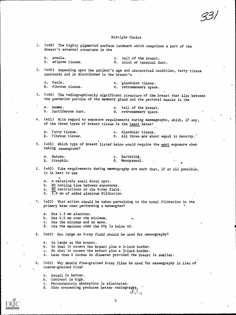
.53/
Multiple Choice
1. (400) The highly pigmented surface landmark which comprises a part of thebreast's external structure is the
a. areola. c. tail of the breast.b. adipose tissue. d. acini or terminal duct.
2. (400) Depending upon the patient's age and obstetrical condition, fatty tissuesurrounds and is distributed in the breast's
a. facia. c. 'glandular tissue.b. fibrous tissue. d. retromammary space.
3. (400) The radiographically significant structure of the breast that lies betweenthe posterior portion of the mammary gland and the pectoral muscle is the
a. mamma. c. tail of the breast.b. lactiferous duct. d. retromammary space.
L. (401) With regard to exposure requirements during mammagraphs, which, if any,of the three types of breast tissue is the least dense?
a. Fatty tissue. c. Glandular tissue.b. Fibrous tissue. d. All three are'about equal in density.'
5. (401) Which type of breast listed below would require the most exposure whentaking mammograms?
a. Mature. c. Lactating.b. Atrophic. d. Menopausal.
6. (402) Tube requirements during mammography are such that, if at all possible,it is best to use
a. a relatively small focal spot.b. NO cooling time between exposures.c. NO restrictions on the X-ray field.d. 2.0 mm of added aluminum filtration.
7. (402) What action should be taken pertaining to the total filtration in theprimary beam when performing a mammogram?
a. Use 1.5 mm aluminum.b. Use 0.5 mm over the minimum.c. Use the minimum and no more.d. Use the maximum when the kVp is below 50.
8. (402) How large an X-ray field should be used for mammography?
a. As large as the breast.b. So that it covers the breast plus a 1-inch border.c. So that it covers the breast plus a 2-inch border.d. Less than 6 inches in diameter provided the breast is smaller.
9. (403) Why should fine-grained X-ray films be used for mammography in lieu ofcoarse-grained film?
a. Detail is better.b. Contrast is high.c. Photoelectric absorption is eliminated.d. Slow processing produces better radiograpp. '
2

10. (403) Why should a multifilm exposure be used for mammography?
1. Less kVp is,roquired.
b. A single film maj be fogged.
c. Pathological processes are radiopaque.
J. Both thick and thin portions are visualized.
11. (404) Why should low kVp be used for a mammogram?
J.
b.
d.
Low kVp lowers the contrast. .Absorption properties of the fibroglandular,
nearly equal.Muscle and fatty tissue absorb equal amountsAtomic numbers of fibroglandular, fatty, andsame.
fatty, and pathologicaltissues
of low energy photons.pathological tissues are the
12. (404) Which of the following mammographic projections requires the highest
kVp and why?
a. Axillary because muscle tissue is involve.
b. Craniocaudal because the thickness is greatest '
c. Mediolateral because the thickness is greatest.
d. Mediolateral because the retromammary space is demonstrated.
13. (405) If you must use a large focal spot for mammography, what action could
be taken to improve the detail?
a. Increase the FFD. c. *Reduce the kVp by four.
, b. Decrease the FFD. d. Use intensifying screens.,
14. (406) Why should the breast be positioned so that the nipple is in profile?
a. It reduces skin folds.
b. Skin thickening is demonstrated better.
c. Retraction of the nipple could be a pathological sign.
d. Many lesions are located immediately posterior to the nipple.
15. (406) Why should the patient be instructed to sit straight and pull her
shoulders back for the craniocaudal projection of the breast?
a. It places the nipple in profile.
b. It reduces the part film distance.c. It demonstrates the tail of the breast. ,
d. It eliminates unwanted shadows on the radiographs.1'
16. (407) Why is it extremely important for you to keep radiation exposure of
obstetrical patients to a minimum?
a. Low energy photons increase the patient's absorbed dose.
b. The fetus can only tolerate seven roentgens of exposure.
c. Growing and gonadal tissues are highly suspectible to alteration.
d. High kVp techniques encourage absorption due to the photoelectric effect.
17. (407) What is the most common cause of excessive radiation exposure to an
obstetrical patient and fetus?
a. High absorbed dose due to high kVp.
b. High exposures due to part thickness.
c. Repeat radiographs due to fetal motion.
d. Repeat radiographs due to improper positioning.
3

18. (407) Why should you use high-speed screens and films when radiographingobstetrical patients?
a. They improve the contrast:b. They reduce patients' exposure.c. They provide greater exposure latitude.d. They lend themselves to technique compensation.
19. (408) Why is it imPortant for you to identify early pregnancy signs on aradiograph?
a. Nurse clinicians are not trained to interpret radiographs.b. Physician assistants are not trained to interpret radiographs.c. To assist a new obstetrician in,detecting pregnancy.d. To prevent excessive exposure to the fetus if the physician does not know
his patient is pregnant.
20. (409) Which of the following fetographic projections usually provides thebest detail and why?
a. PA because part film distance is reduced.b. AP because patients' comfort helps eliminate part motion.c. Anterior oblique because the fetal head is seen in profile.d. Posterior oblique because the distal femoral epiphyses are projected clear
of the spine.
21. (411) What two '-actors must be given special attention when performing lateralplacentography?
a. FFD and grid radius.b. Photon energy and focal spot size.c. Size of the placenta and tube filtration.d. Density of the placenta and thickness of the abdomen.
22. (412) If a filter that covers half of the primary beam is used for a lateralplacentogram, over which portion of the abdomen should it be placed and why?
a. Anterior to provide even film density.b. Posterior to provide even film density.c. Anterior because the placenta is usually located there.d. Posterior because the placenta is usually located there.
23. (415) Why is the pelvimeter'used for the Colcher-Sussman pelvimetry?
a. It projects the fetal head in actual size.b. It prevents distortion of the ischial spines.c. It allows the degree of magnification to be determined.d. It provides the radiologist with the means to determine the part film
distance.
24. (416) If the ruler is not placed parallel with the film during a Colcher-Sussman projection, how, if in any way, are the measurementsaffected?
a. They are not affected.b. They are higher than normal.c. They are lower than normal.d. They are higher on the AP and lower on the lateral.
4
333
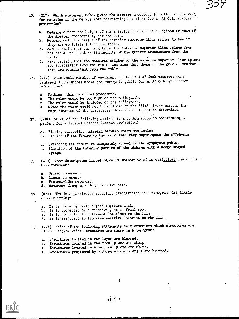
25. (217) Which statement below gives the correct procedure to follow in checking
for rotation of the pelvis when positioning a patient for an AP Colcher-Sussman
projection?
a. Measure either the height of the anterior superior iliac spines or that of
the greater trochanters, but not both.
b. Measure only the height of the anterior superior iliac spines to see if
they are equidistant from the table.
c. Make certain that the heights of the anterior superior iliac spines from
the table are equal to the beights of the greater trochanters from the
table.d. Make certain that the measured heights of the anterior superior iliac spines
are equidistant from the table, and also that those of the greater trochan-
ters are equidistant from the table.
26. (417) What would result, if anything, if the 14 X 17-inch cassette were
centered 4 1/2 inches above the symphysis publis for an AP Colcher-Sussmanprojection?
a. Nothing, this is normal procedure.
b. The ruler would be too high on the radiograph.
c. The ruler would be included on the radiograph.
d. Since the ruler would not be included on the film's lower margin, the
magnification of the transverse diameters could not be determined.
27. (418) Which of the following actions is a common error in positioning a
patient for a lateral Colcher-Sussman projection?
a. Placing supportive material between knees and ankles.
b. Flexion of the femurs to the point that they superimpose the symphysis
pubis.
c. Extending the femurs to adequately visualize the symphysis pubis.
d. Elevation of the anterior portion of the abdomen with a wedge-shaped
sponge.
28. (420) What description listed below is indicative of an elliptical tomographic-
tube movement?
a. Spiral movement.b. Linear movement.c. Pretzel-like movement.
d. Movement along an oblong circular path.
29. (421) Why is a particular structure demonstrated on a tomogram with little
or no blurring?
a. It is projected with a good exposure angle.
b. It is projected by a relatively small focal spot.
c. It is projected to different locations on the film.
d. It is projected to the same relative location on the film.
30. (421) Which of the following statements best describes which structures are
blurred and/or which structures are sharp on a tomogram?
a. Structures located in the layer are blurred.
b. Structures located in the focal plane are sharp.
c. Structures located in a vertical plane are sharp.
d. Structures projected by a large exposure angle are blurred.
5

31. (422) What relationship exists between exposure angle and section thickness?
a. A large exposure angle produces a thin section.b. A small exposure angle produces a thin section.c. Exposure angle and section thickness are not related.d. A 5-degree change in exposurg angle produces a 0.5-mm change in section
thickness.
32. (423) Structures A, B, and C are located in the same vertical plane of a bodyarea. Structure B is at the same level as the fulcrum. Structure A is 1 cmfarther from the film than structure B. Structure C is 0.5 cm closer to thefilm than structure B. Which of the listed structures is blurred most on atomogram if any, and why?
a. Blurring is equal.b. C because the exposure angle is least.c. A because the exposure angle is greatest.d. B because the exposure angle is greatest.
33. (424) Why is each pair of intensifying screens in a book cassette of adifferent speed?
a. Top screens require more exposure.b.. Beam intensity is reduced by the cassette.c. Photon transmission is affected by the inverse square law.d. Visualization of different levels require different film densities.
34. (426) Why is the exposure needed for a three-film book cassette greater thanone-third of that needed for a single film tomogram taken under the sameconditions?
a. The three films of the book cassette demonstrate deeper structures.b. Book cassette exposure is determined by the speed of the top, slow screens.c. Book cassette exposure is determined by the speed of the bottom, fast
screens.d. The book cassette front (bakelite material) is thicker than a conventional
cassette.
35. (426) Which of the following statements best describes the detail andcontrast of tomograms made in a book cassette?
a. Detail and contrast are similar on all films.b. Detail is poor and contrast is low on the upper films. .
c. Detail is poor and contrast is low on the lower films.d. Detail is good and contrast is high on the lower filts.
36. (428) What is the tomographic amplitude if the rate is 2 inches per secondand the exposure :ime is 4 seconds?
a. 2 inches.b. 8 inches.
c. 2°.d. go.
37. (429) If a linear tomogram is being performed, at what angle should thesternum be positioned with respect to the longitudinal axis of the X-ray tableand why?
a, 90° because of the spine. c. 300 to 45° because of the spine and ribs.h. 45° because of the ribs. d. 250 to 35° because of the spine and ribs.
38. (430) Which of the following tube angles, if any, can be used for stereoscopy?
a. 6° only.b. 3° only.
c. 3° or 60.d. The tube should not be angled.
6

33639. (431) In what direction should the X-ray tube be shifted for stereoscopic PA
chest radiographs and why?
a. Along the longitudinal axis because lung tissue is radiolucent.
b. Along the longitudinal axis because the ribs are the predominant lines.
c. Along the transverse axis because the spine forms the predominant line.
d. Along the transverse axis because each lung forms a predominant line.
40. (432) Which of the following statements best describes the appearance of therelated structures when you correctly view stereoscopic PA radiographs of the
chest?
a. The image appears in three dimenelons.b. The anterior ribs appear nearer to you than does the sternum.
c. The heart appears nearer to you than do the posterior ribs.
d. The anterior.ribs appear farther from you than do the posterior ribs.11
41. (433) A PA chest radiograph (A) is on a viewbox witll the patient's right side
on your right side. Another radiograph (B), a left lateral radidgraph of theskull, is on another viewbox with the patient's facial bones on your right side
and his posterior skull on your left side. Which of the following statements
best describes your view of the radiographs?
a. You are viewing the tube side of both radiographs.
b. You are viewing the'Tilm side of both radiographs.
c. You are viewing the tube side of radiograph A and the film side of
radiograph B.d. you are viewing the tube si e of radiograph B and the film side of radiograph
A.
42. (435) Theoimages of two stereoscopic radiographs are superimposed, and the
radiographs are positioned so that the direction of the tube shift is parallel
with the floor. The radiograph seen by your right eye during stereoscopic
viewing is the one farthest to the
a. top. c. right.
b. left. d. bottom. ce 5
43. (436-437) How do you place the stereosdopic radiographs on the viewboxes with
respect to the tube side of the film, before viewing stereoscopic radiographs
by both the cross-eyed and single-mirror methods?'
a. Tube side toward you for both methods.
b. Tube side against the viewbox for both methods.c. Cross-eyed-tube side toward you; single-mirror-tube side against viewbox.
d. Cross-eyed-tube side against viewbox; single-mirror-tube side toward you.
44. (438) What projections should you normally make to id the physician
localizing a localizing a foreign body in the extremitist?
a. AP only.
b. PA only.
c. Lateral only.
d. AP or PA and lateral.
45. (439) Which statement below correctly relates to a radiographic procedure used
in the single triangulation method of localizing a foreign body in the trunk?
a. Mark the skin after performing the radiograph.
b. The depth of the foreign body is measured directly on a flucroscopic beam.
c. Basically, the depth is determined because the foreign body appears twice
on the radiograph.d. Collimate to a large cone field several times larger than the foreign body
to correctly mark the skin.
7

33746. (441) What parts of Sweet's localizer are projegted onto the radiographs,
thereby serving as reference points for localization of a foreign body in theeye?
a. Ball and cone. c. Horizontal and vertical arms.b. Sighting notches. d. Set screw and trigger release.
47. (442) How many films are used, and how many exposures are made when localizinga foreign body using Sweet's method?
a. One film and two exposures.b. Two films and one exposure.c. Two films\and two exposures.d. One or more films and one or more exposures.
48. (442) As a part of the Sweet's eye localization process, slide the localizerforward until the ball
a. nearly depresses the open eyelid.b. comes within 10 mm of the closed eyelid.c. depresses the closed eyelid one thickness.d. contacts, but does not depress, the closed eyelid.
49. (444) A scanogram is performed to determine which of the following measurements?
a. Length of a fracture.b. The length of the spine.c. Actual and relative lengths of long bones.d. The depth of a foreign body and biparietal diameter.
50. (445) When a scanogram is being performed, the X-ray tube is aligned withrespect to what portion(0 of the part?
a. Ends.b. Middle.
c. Lateral borders.d. Proximal portion only.
51. (446) What determines the number of exposures made during a scanogram?
a. Length of the bone./b. Number of related joints.c. Purpose of the examination.d. Degree of magnification necessary.
52. (446) When performing a radiograph to compare the length of the right leg tothat of the left, which of the following statements applies?
a. A Bell-Thompson ruler must be used.b. A Bell-Thompson ruler need not be used.c. AP and lateral projections must be made.d. The patient should be in the supine position.
53. (447) When evaluating a scanogram from a quality control point of view, youcan determine whether or not the projected size of a bone is the same as itsactual size by
a. comparing one side with the other.b. making an estimate directly from the patient.c. evaluating the distortion of the ruler markings.d. noting the relationship between the CR and the end of the part.
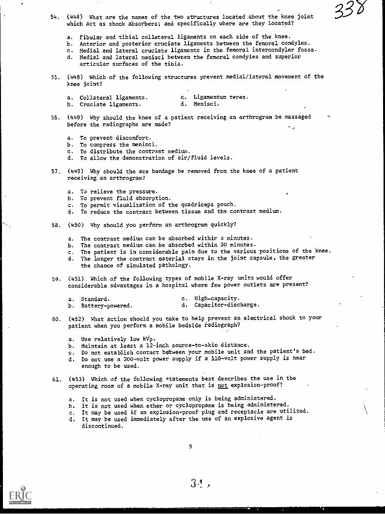
54. (448) What are the names of the two structures located about the knee jointwhich act as shock absorbers; and specifically where are they located?
a. Fibular and tibial collateral ligaments on each side of the knee.
b. Anterior and posterior cruciate ligaments between the femoral condyles.c. Medial and lateral cruoiate ligaments in the femoral intercondyler fossa.d. Medial and lateral menisci between the femoral condyles and superior
articular surfaces of the tibia.
55. (448) Which of the following structures prevent medial/lateral movement of the
knee joint?
a. Collateral ligaments. c. Ligamentum teres.
b. Cruciate ligaments. d. Menisci.
56. (449) Why should the knee of a patient receiving an arthrogram be massagedbefore the radiographs are made?
a. To prevent discomfort.b. To compress the menisci.c. To distribute the contrast medium.d. To allow the demonstration of air/fluid levels.
57. (449) Why should the ace bandage be removed from the knee of a patientreceiving an arthrogram?
a. To relieve the pressure.b. To prevent fluid absorption.
c. To permit visualization of the quadriceps poucll.
d. To reduce the contrast between tissue and the contrast medium.
58. (450) Why should you perform an arthrogram quickly?
to
a. The contrast medium can be absorbed withir 3 minutes.
b. The contrast medium can be absorbed within 30 minutes.
C. The patient is in considerable pain due to the various positions of the knee.d. The longer the contrast material stays in the joint capsule, the greater
the chance of simulated pathology.
59. (451) Which of the following types of mobile X-ray units would offerconsiderable advantages in a hospital where few power outlets are present?
a. Standard. c. High-capacity.
b. Battery-powered. d. Capacitor-discharge.
60. (452) What action should you take to help prevent an electrical shock to your
patient when you perform a mobile bedside radiograph?
a. Use relatively low kVp.
b. Maintain at least a 12-inch source-to-skin distance.
c. Do not establish contact between your mobile unit and the patient's bed.
d. Do not use a 200-volt power supply if a 110-volt power supply is near
enough to be used.
61. (453) Which of the following qtatements best describes the use in theoperating room of a mobile X-ray unit that is not explosion-proof?
a. It is not used when cyclopropane only is being administered.b. It is not used when ether or cyclopropane is being administered.c. It may be used if an explosion-proof plug and receptacle are utilized.d. It may be used immediately after the use of an explosive agent is
discontinued.
9
3 1 .
3-31

62. (453) Whether or not an explosive atmosphere exists in the operating roomdepends upon the
a. type of anesthetic or preparation agent in use.b. amount of explosive agent administered to the patient..c. classification of the operation (open or closed reduction).d. type of mobile X-ray unit used to perform the radiographic examination.
63. (453) How should the operator of a mobile X-ray unit be assured that the unitis not explosion-proof? J
a.
b.
C.
d.
By checking the manufacturer's instruction book.By locating a warning statement on the unit that is visible asthe unit.
By checking the power cord for the Underwriters' Laboratories,ofg gpaldoivn:l AFM 161-38, Diagnostic X-ray, Therapeutic X-ray andProtection for Energies 2p.to 10 Million Electron Volts.
3
he energizes
Inc., seal
Gamma-Beam
64. (454) What minimums of the source-to-skin distance (SSD) and lead equivalencyof the protective apron should be used when performing mobile radiographs?
a. SSD--12 inches; lead equivalent--0.25 mm.b. SSD-15 inches; lead equivalent--0.50 mm.c. SSD--18 inches; lead equivalent-0.75 mm.d. SSD--18 inches; lead equivalent--1.00 mm.
65. (455) What action should be taken when a patient receiving oxygen therapy isbeing radiographed?
a. The oxygen should be turned off if the patient's condition permits.b. The oxygen may be left on if yourmobile unit is properly grounded.c. The oxygen may be left on if the radiograph to be performed is a chest film.d. The oxygen should be turned off, and all preparations should be made in
advance.
66. (456) Which of the followinaedside chest radiographs should be made of acardiac patient if his condition is such that only minimal movement ispermitted?
a. AP erect. c. AP supine.b. PA erect. d. 41° semierect.
67 (457) Why are special articles of clothing worn into the operating room?
a. They reduce the introduction of bacteria only.b. They prevent the buildup of static electricity only.c. They offer a color code for the sterile and nonsterile areas.d. They reduce the introduction of bacteria and prevent the buildlp of static
electricity.
68 (458) Why should the mobile X-ray unit be cleaned before taking it into theoperating room?
a. To prevent contamination of the sterile area.b. Only to prevent the buildup of static electricity.c. Only to reduce the amount of bacteria taken into the room.d. To reduce the amount of bacteria taken into the room and to prevent the
buildup of static electricity.
10

69. (458) Which of the following parts of your mobile unit requires specialattention when the unit is cleaned prior to taking it into the operating room
and why?
a. Control panel because dust may cause arcing of the contacts.
b. Power cord because it gets dirtier than any other part of the unit.
c. Wheels because they contact a large portion of the operating room floor.
d. Tube head because it may be positioned directly above the operating site.
'C. (460) Why are speed and accuracy on your part important when radiographing a
2atient undergoing surgery?
a. You could cause the surgeon to use the wrong sutures.
b. You could prevent "suture closure" if you take too long.
c. You may affect the anesthetist's decision as to which type of agent to use.
d. You may lengthen the amount of time the patient must remain under the
influence of the anesthetic.
(460) With which o e following operative radiographic examinations should
a scout film be made?
a. Hip nailing.b. Open reduction of the knee.
c. Closed reduction of the tibia.
d. Closed reduction of the distal humerus.
72. (461) Which of the following statements best describes the phenomenon known
as solarization?
a. Exposure is not logarithmic.
b. Density is unrelated to exposure.c. Increasing exposure increases film density.
d. Increasing exposure decreases film density.
73. (461) If a radiograph is copied using standard X-ray film, the exact or reverse
duplication of the tones depends upon what factor?
a. The amount of exposure. c. The type of light source.
b. The speed of the film. d. The density of the radiograph.
74. (461) How does duplicating film differ from standard X-ray film?
a. It is already solarized.
b. It reacts to'light.c. It produces dark shadows.d. It is not available in various sizes.
75. (462) What supplies would you need to convert a conventional cassette into
one that can be used to duplicate radiographs?
a. Two sheets of clear glass.
b. A sheet of clear glass or plexiglass.c. A pair of slow-speed intensifying screens.d. A sheet of clear glass, and a pair of light-sensitive intensifying screens.
76. (462) If a duplicate of a radiograph is too dark, how should you alter the
exposure on a subsequent 0..Kalicate?
a. Use a larger bulb. c. Decrease the exposure time.
b. Increase the distance. d. Increase the exposure time.
11
3 1

77. (463) How does the subtraction process remove unwanted structures from anangiogram?
a. It lowers the overall density of the structures.b. It eliminates the contrast between the structures.c. It decreases the densities of the contrast-filled vessels.d. It reduces the contrast between the vessels and the background.
78. (463) Which of the following statements best describes the subtraction mask?
a. It is made from the angiogram.b. It cannot be used more than once.c. Its tones are reversed from that of the scout film.d. It shows the same structures as does the angiogram.
79. (464) How should the subtraction film be placed into the special cassette toproduce the mask?
a. Place the emulsion side against the scout.b. Place the glossy side against the angiogram.c. Place the emulsion side against the antiogram.d. Place the glossy side against the subtraction print.
80. (406) What amount of rotation should be used for the axillary projection of thebreast?
a. 45°.
b. 10 to 300.c. Until the nipple is in profile.d. Until the deltoid muscle contacts the film.
1WAVV141111.14S1414.1411411110i
90370 04 7506
CDC 90370
RADIOLOGY TECHNICIAN
(AFSC 90370)
Volume 4
Special Procedures
msswysinwAinstninmimtwwnwininwAwtniwwv P4,4,...
'+1
t...S.S..... ...
I '..\MVIANIAVANWAWAVVIMSIAMMANNAWMAVIMMANWNiNVMAYLVNAAWMAAVVAM ANW
Extension Course Institute
Air University
3 1...

PREPARED BYSCHOOL OF HEALTH CARE SCIENCES, USAF (ATC)
SHEPPARD AIR FORCE BASE. TEXAS
,.,
3 0
EXTENSION COURSE INSTITUTE. GUNTER AIR FORCE STATION. ALABAMA
THIS PUBLICATION HAS BEEN REVIEWED AND APPROVED BY COMPETENT PERSONNELOF THE pREPARING COMMAND IN ACCORDANCE WITH CURRENT DIRECTIVES
ON DOCTRINE, POLICY. ESSENTIALITY, PROR5I5Y, AND QUALITY
°
Preface
EXAMINATIONS of the five body system:: have historically been referred toas special procedures. As we point out repeatedly in this volume, the exactprocedures carried out during these examinations depend a great deal uponyour radiologist's preference. That iseach radiologist has his own particularmethod of performing the examination. This does not imply that someprocedures are superior to others. It merely means that each radiologist hashis own way to arrive at an accurate diagnosis of a patient's condition.Accordingly, this volume deals mostly with procedures that are general innature. Hopefully, this information will allow you to adapt quickly to theexamination regardless of the circumstances involved.
The five body systems :.-iclude the digestive, urogenital, respiratory,cardiovascular, and nervous. In each chapter we first discuss the anatomyinvolved. After that we discuss various aspects of the studies to help youbetter perform your role as a technician in assisting with these examinations.
If yoot have questions on the accuracy or currency of the subject matter ofthis text, or recommendations for its improvement, send them to School ofHealth Care Sciences/MST, Sheppard AFB TX 76311. NOTE: Do not usethe suggestion program to submit corrections for typographical or othererrors.
If you have questions on course enrollment or adminiitration, or on anyof ECI's instructional aids (Your Key to Career Development, StudyReference Guides, Learning Objective Exercises, Volume Review Exercise,and Course Examination), consult your education officer, training officer, orNCO, as appropriate. If he can't answer your questions, send them to ECI,Gunter AFS AL 36118, preferably on ECI Form ,17, Student Request forAssistance.
This volume is valued at 33 hours (11 points).Material in this volume is technically accurate, adequate, and current as of
December 1974.

c
C ontents
Chapter
Page3
Preface iii
1 Contrast Studies of the Digestive System 1
2 Contrast Studies of the Urogenital System 39
3 Contrast Study of the Respiratory System 57
4 Contrast Studies of the Cardiovascular System 65
5 C9ntrast Studies of the Nervous System ....... . . . 84
Answers for Exercises 97
iv
3e/c
CHAPTER 1
NOTE: In this volume, the subject matter is developed by a series of Learning Objectives.Each of these carries a 3-digit number and is in boldface type. Each sets a learning goal foryou. The text that follows the objective gives you the information you need to reach thatgoal. The exercises following the information give you a check on your achievement. Whenyou complete them, see if your answers match those in the back of this volume. If yourresponse to an exercise is incorrect, review the objective and its text.
Contrast Studies of the Digestive System
CONVERSION of food to chemical nutrient),usable by the body, occurs in the digestivesystem. Consequently, malfunction of any ofthe system components results in impairmentof the digestive process. When the degree ofimpairment is sufficient, medical and/orsurgical intervention is necessary. Generally,the first step in such professional treatmentrequires radiographic examination of theaffeeted system component. Since you areinvolved in preparing the equipment for andwill assist with such procedures, you musthave at least a basic knowledge of the organsin the digestive system, how they function,the matenals used to make them radiopaque,the radiographic equipment, and how theequipment is generally used. Therefore, thischapter is a discussion of these factors as theyapply to representative parts of the digestivesystem.
1-1. Anatomy and Physiology of theDigestive System
The digestive system consists of thealimentary tract or canal and the accessoryorgans of digestion. The alimentary tract is 28to 32 feet long and concists of the mouth, thepharynx, the esophagus. the stomach. thesmall bowel, the large bowel, the rectum, andthe anus. The accessory digestive organs arethe salivary glands, the liver, the gallbladder,and the pancreas. We begin our study of thedigestive system with the mouth.
600. Name the structures and the bonescomprising the roof of the mouth and pointout the role of the posterior roof of themouth during the swallowing process.
1
The Mouth. Although the mouth, or oralcavity, is made up of various structures,including the teeth, mandible, cheeks, lips,and tongue, our discussion iz priinarilydirected toward the roof of the mouth andthe salivary glands.
Roof of the mouth. The roof of the mouthis formed by the hard and the soft palates.The stationary hard palate, forming theanterior portion of the roof of the mouth, ismade up of the maxillae and palatine bones,which are covered by mucous membranes.The hard palate joins posteriorly with the softpalatea fold of mucous membrane whichencloses muscular fibers, vessels, mucousglands, 3nd nerves. The soft palate, normallypendatrf, elevates during the process ofswallowing to separate the nasal cavity andnasopharynx from the oral cavity andoropharynx. (See' fig. 1-1.)
Exercises (600):1. What two structures (other than bones)
make up the roof of the mouth?
2. What two pairs of bones comprise theanterior portion of the roof of the mouth?
3. What effect does elevation of the softpalate during the swallowing process haveon the nasal and oral cavities and thepharynx?
31/-

CHEEK
MAXILLA
PALA TINEBONES
SOFTPALA TE
TEETH
MANDIBLE
Figure 1-1. Side view of the oral cavity and ajoining areas.
601. Given a list of the salivary glands, matcheach with an appropriate statement or phraserelating to its location, size, number, ductalsystem, or function.
Salivary glands. Three pairs of salivaryglands are located about the oral cavity. (Seefig. 1-2.) They are the parotid, submaxillary,and sublingual glands (see fig. 1-2). Each Ofthese glands secretes saliva into the mouth.The parotids, which are the largest of thesalivary glands, are located in thesuperior-posterior aspect of each cheek, below
347
and in front of each ear. By means ofStenson's duct, parotid secretions arechanneled through the muscles of each cheekinto the mouth, through a small openingadjacent to each upper second molar. Thesubmaxillary (also called submandibular)glands are located near the anteromedialaspect of each mandibular angle.Submaxillary gland secretions reach themouth by way of Wharton 's duct, which,opensinto the mouth on each side of the frenulumof the tongue. The sublingual glands, smallestof the three, are located beneath the mucousmembrane of 'he floor of the mouth
2 3 r 41,

immediately on each side of the midline.Saliva from each sublingual gland empties intoseveral small excretory ducts called the ductsof Rivinus. Some of the ducts of Rivinus jointo form the duct of Bartholin, which emptiesinto Wharton's duct. Some empty directlyinto Wharton's duet, while others emptydirectly into the mouth on either side of thefrenulum of the tongue.
Exercises (601):Match the salivary gland in column B with theappropriate statement or phrase in column Aby placing the letter of the column B item inthe space provided in column A. Each column
B item may be used once, or more than once.In addition, more than one column B itemmay match a single column A entry.
Column A1. Smallest salivary
gland.2. Empties via Sten-
son's diuct.3. Located an tero-
inferior to the ear.4. Secretes saliva.5.Communicates
with Wharton'sduct.
6. Located most in-feriorly.
7. Empties into themouth on eitherside of the fren-
l.,<7.:
Column Ba. Submaxillary.b. Parotid.c. Sublingual.
SUBLINGUALGLAND
SUBMAXILLARYGLAND
PAROTIDDUCT
PAROTID
GLAND
THYROID CARTILAGE
TRACHEA
ESOPHAGUS
1100101f
Figure I -2. Salivary glands and related structures.
3
3 5.)
St,

NASAL CAVITY
SOFTPALATE
Column A
ulum of thetongue.
8. Empties into themouth near theupper second mo-lar.
9. Empties via theduct of Bartholin.
_10. Empties via theducts of Rivinus.
11. Located beneaththe mucous mem-brane of the floorof the mouth.
_12. Largest salivarygland.
Figure 1-3. The pharynx.
31,q
PHARYNX
ESOPHAGUS
602. Given a list of statements pertaining tothe structure, function, and radiographicsignificance of the pharynx and esophagus,indicate which are true and which are false. Ifyou indicate false, you must explain youranswer.
The Pharynx. The pharynx is a tubelikestructure, approximately 12 cm long,extending from the inferior portion of theskull to the level of the sixth cervical vertebra.(See fig. 1-3.) It is continuous with the nasalcavity anteriorly and the esophagus inferiorly.The pharynx is divided into three parts: (1)
435

THORACIC AORTA
3.5-0
Figure 1-4. Anterior view of the esophagus and related structures.
the nasopharynx, (2) the oropharynx, and (3)the laryngopharynx.
Nasopharynx. The curved nasopharynx isthe proximal pqrtion of the pharynx, whichserves as an air passage from the nasal cavityto the oropharynx. It extends distally to theinferior margin of the soft palate.
Oropharynx. The oropharynx extends fromthe soft palate to the hyoid bone. It iscommon to both the digestive and respiratorysystems because it serves as an air passagefrom the nasopharinx to the larynx and as afood passage f...Jm the oral cavity to thelary ngopharynx.
Laryngopharynx. The laryngopharynxextends from the oropharynx to the level ofthe sixth cervical vertebra and the cricoidcartilage, where it becomes the esophagus.
Radiographic considerations. Generallyspeaking, the nasopharynx and oropharynxcan be adequately demonstrated on asoft-tissue lateral projection because they arenormally filled with air. The laryngopharynx,however, is usually visualized radiographically
5
after the introduction of a contrast mediumbecause it is not a normal air passage.
The Esophagus. The esophagus is the
LESSER CURVATURE
1NCISURA
ANGULARIS
SULCUS
INTERMEDIUS
GREATER CURVATURE
. Figure 1-5. Greater and lesser curvaturesof .the stomach.
35,)
portion of the digestive system whereperistalsis begins; it connects the pharynx tothe stomach. It is approximately 25 cm longand from 10 to 30 mm in diameter. (See fig.1-4.) As seen from the front, it appears as a"lazy S." It begins in the midline and inclinesslightly to the left, back to the right, and thento the left again where it enters the stomachat the level of the eleventh thoracic vertebra.As seen from the side, it follows thecurvatures of the lower cervical and thoracicspines. Notice in figure 1-4 that the esophagusis in close proximity to the aorta. Theesophagus is also located along the posteriorborder of the heart. You can see how thelocation of the esophagus with respect to theaorta and heart can be used to advantage toradiographically demonstrate certainaormalities of those two structures. If theesophagus is filled with a contrast medium, anenlarged heart or an aortic aneurysm mayshow a portion of the esophagus displacedfrom its normal location.
Exercises (602):Indicate which of the following statementspertaining to the structure and functions ofthe pharynx and esophagus are true andwhich are false. If you indicate "false,"explain your answer.
T F 1. The pharynx is approximately 12 cmlong.
T F 2. The nasopharynx is the middleportion of the pharynx.
T F 3. Food and air passes throughlaryngopharynx.
T F
T F
T F 6.
4. The most distal portion ofpharynx is the laryngopharynx.
the
the
5. The nasophdryrix and oropharynxcan be demonstrated on a lateral.radiograph because of the presenceof air.
The laryngopharynx is usually
557demonstrated on a radiograph afterintroduction of a contrast medium.
T F 7. The laryngopharynx is continuous,with the proximal esophagus.
T F 8. The esophagus is appruximately 30cm long.
T F 9. The esophagus, after beginning inthe midline, curves first to the left,back to the right, and back again tothe left.
T F 10. The esophagus is located anterior tuthe heart.
T F 11. AbnormalitieS of the heart and aortamay clLplace the normal courbe ofthe esophagus.
603. Provide the names or locations of keystomach structures and give the shapes andlocations of the stomach according to bodyhabit-is.
The Stomach. The stomach is the mostdilated portion of the digestive system andextends from the esophagus ,to the smallintestine.
General structure. The stomach has twomain borders or curvatures: (1) the greatercurvature, and (2) the lesser curvature. (See
1-5.).The greater curvature is the larger ofthe two and eontains a slight groove called thesulcus intermedim. .The lesser curvature, thesmallei, is loeated on the right side of thestomach and contains a well-defined nukh,the incisura angularis.
There are two openings in the stomach, asshown in figure 1-6. The proimal opening atthe junction of the esophagus is the cardiacorifice, which normally lies at the leVel of theeleventh thoracic vertebra about 1 inch to the
6 3:;,

ESOPHAGUS,,...,FUNDUS
,g_C----
CARDIAC ORIFICE
.BODY
PYLORIC ORIFICE /, ,
t
r ,, g,h,
--;-
RUGAE
DUODENUM
PYLORUSFigure 16. The stomach.
left of the lateral sternal border. The loweropening, which communicates with the smallintestine, is the pyloric orifice. It normallylies about 1 to 2 inches to the right of themidline at the level of the upper border of thefirst lumbar vertebra.
The stomach proper is divided into threeparts: (1) the fundus, (2) the pylorus, and (3)the body. The fundus is the dome-shapedportion lying directly beneath the lefthemidiaphrnm. It extends inferiorly to atransverse plane passing through the cardiacorifice. The pylorus is the distal portion of
i
t.
the stomach, and the term "body" identifiesthe remainder. Thick folds, called rugae, arelocated throughout the internal surface of thestomach. The rugae are most prominent whenthe stomach is empty and t4...nd to flatten outwhen it is distended. The relationship of thestomach to surrounding abdominal structurescan be seen in figure 1-7.
Locations and shapes of the stomach. Oneof the problems technicians face whenradiographing the stomach is to include the.entire structure on a 10- x 12-inch film. Theproblem is due to the various locations of the

/
i-
It,
Gall- ,bladdeti ,
,
1' t
..'Cli .alitiii.1 ., .tvi
1Ir ,
..0,,, ,I
,
,
Spleen
1
,
Transverse\Colon
Figure 1-7. Location of the stomach in relation to otaer abdominal structures.
stomach. We cannot teach you preciselywhere to center your film and patient to
I consistently "hit" the stornach with a 10- x/ 12-inch--that comes only With experience. We
will, however, review the relative location ofthe stomach to provide you with thebasicinformation needed to radiograph the
stomach. The location and shape of thestomach varies, depending upon the bodyhabitus of the patient. (See fig. 1-8.)
a. Detail A in the figure shows anindividual with the sthenic or average build.The esophagus of this individual joins thestomach at the level of the xyphoid process,
8 ei --0 -.)(.. ...)
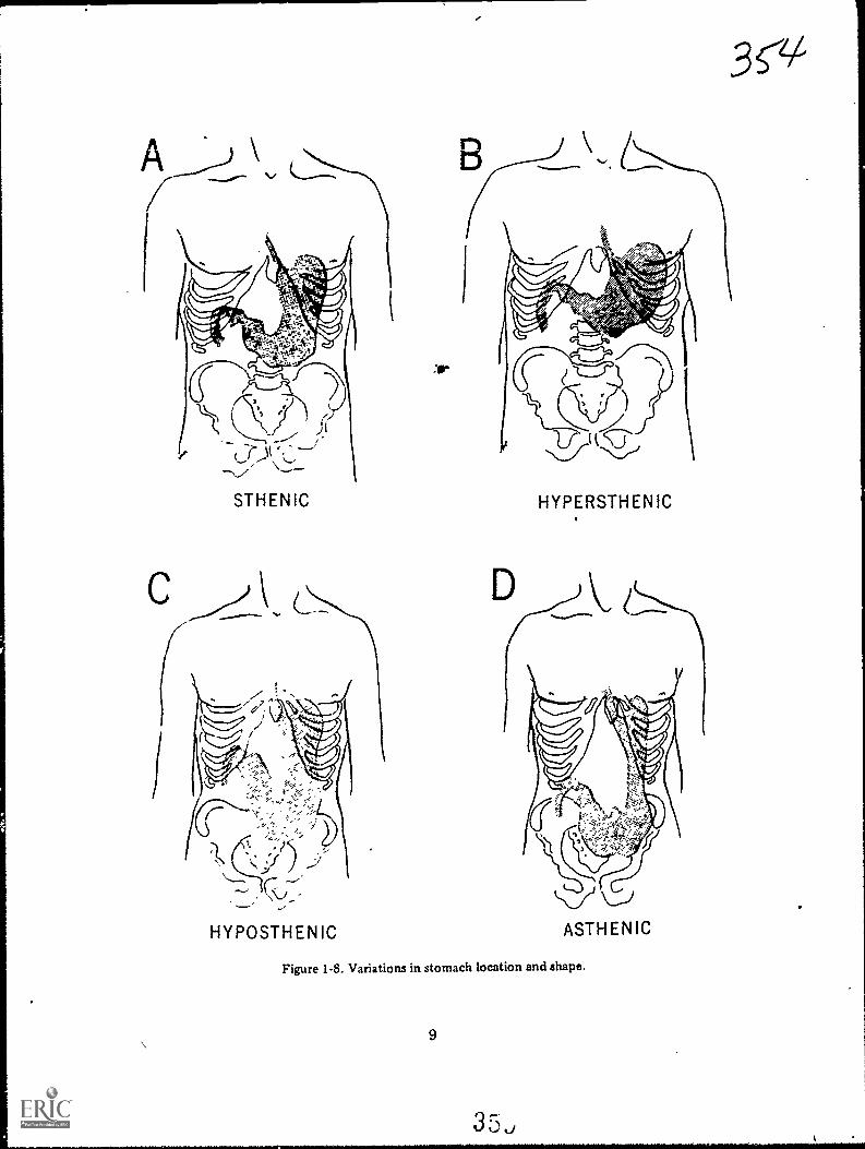
\
HYPOSTHENIC
30-
HYPERSTHENIC
Figure 1-8. Variations in stomach location and shape.
9

while the most inferior portion of the greatercurvature is at the level of the iliac crests.
b. The hypersthenic, or obese, individual isshown in figure 1-8,B. His stomach is almosthorizontally situated and lies highest in theabdomen. Usually, the heavier the individualisthe more horizontal the position of thestomach.
c. The hyposthenic (fig. 1-8,C) individualis more slender than the sthenic individual.His stomach is "J-" or "fishhook-shaped" andlies low in the abdomen. The niost inferiorportion of the greater curvature extends 2 to4 inches below the level of the iliac crests.
d. The asthenic individual is shown infigure 1-8,D. The "J-shaped" stomach is lower,in the abdomen than in the hyposthenicindividual. This stomach location is normallyfound in thin elderly patients who have losttheir normal muscle tone.
Exercises (603):
1. What stomach curvature is the largest?The smallest?
2. Where is the ulcus intermedius located?
3. What notch is located on the lessercurvature?
4. What are the names and locations of thetwo stomach openings?
5. Name the three subdivisions of thestomach and indicate which is theproximal, the middle, and the distalportion.
DUODENAL BULB
Figure 1-9. The duodenuQ j.) !

HEPATICFLEXURE
ASCENDINGCOLON
1544.6"."
'14
,...4004w
ILEOCECALVALVE
CECUM
4
4".
TRAN
ILEUM
,44: 40 Al yip
t-TE
;
SPLENICFLEXURE
DESCENDINGCOLON
.A7
N
SIGMO(DCOLON ,/
Figure 1-10. The large bowel.
11
3
Th
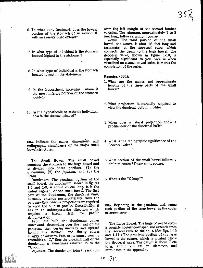
6. To what bony landmark does the lowestportion of the stomach of an individualwith an average build extend?
7. In what type of individual is the stomachlocated highest in the abdomen?
8. In what type of individual is the stomachlocated lowest in the abdomen?
9. In the hyposthenic individual, where isthe most inferior portion of the stomachlocated?
10. In the hyposthenic or asthenic individual,how is the stomach shaped?
604. Indicate the names, dimensicins, andradiographic significance of the major smallbowel structures.
The Small Bowel. The small bowelconnects the stomach to the large bowel andis divided into three portions: (1) theduodenum, (2) the jejunum, and (3) theileum.
Duodenum. The proximal p9rtion of thesmall bowel, the duodenum, shown in figures1-7 and 1-9, is about 25 cm long. It is thewidest segment of the small bowel. The firstpart of the duodenum, the duodenal bulb,normally extends posterolaterally from thepylorusthus oblique projections are requiredto view the bulb in profile. OccasiOnally, itlies in an anteroposterior direction whichrequires a lateral (left) for profiledemonstration.
From the bulb, the duodenum curvesdownward, descending over the head of thepancreas, then curves medially and upwardbehind the stomach, and finally curvessharply downward. Part of its course roughlyresembles a "C," thus the proximal half of theduodenum is sometimes referred to as the"C-loop."
Jejunum. The duodenum joins the jejunum
12
over the left margin of the second lumbarvertebra. The jejumum, approximately 7 to 8feet long, follows a random course.
Ileum. The third portion of the smallbowel, the ileum, is abot 16 feet long andterminates at the ileocecal valve, whichconnects the ileum to the large bowel. Theileocecal valve, shown in figure 1-10, isespecially significant to you because whenvisualized on a small bowel series, it marks thecompletion of the series.
Exercises (604):1. What are the names and approximate
lengths of the three parts of the smallbowel?
2. What projection is, normally required toview the duodenal bulb in p-Jfile?
3. When does a lateral projection show aprofile view of the duodenal bulb?
4. What is the radiographic significance of theileotecal valve?
5. What section of the small bowel follows adefmite course? Describe its course.
6. What is the "C-loop"?
605. Beginning at the proximal end, nameeach portion of the large bowel in the orderof appearance.
The Large Bowel. The large bowel or colonis roughly horseshoe-shaped and extends fromthe ileocecal valve to the anus. (See figs. 1-10and 1-11.) The proximal portion of the largebowel is the cecum, which is located belowthe ileocecal valve. The cecum is about 7 cmlong, about 7.5 cm in diameter, andterminates in the appendix.

Figure 1-11. The rectum and anus.
.4scending colon. The ascending colon is
that portion of the colon above the level ofthe ileocecal valve. It extends upward fromthe junction of the ileum and cecum, alongthe right side of the abdomen, and to theinferior surface of the liver. At this point itcurves forward and medially to form thehepatic flexure.
Transverse colon. The transverse colonextends across the abdomen from the hepaticflexure to the spleen. It passes over thedescending segment of the duodenum, thepancreas, and the inferior margin of thestomach. sAt the level of the spleen it curvesforward and inferiorly to form the splenicflexure.
13
3sjs/
1
;
Descending colon. The descending coloneXtends downward from the splenic flexure tothe iliac fossa. From this point, it usuallyfollows the inferomedial curvature of theileum and joins sirith the sigmoid colon.
Sigmoid colon. The sigmoid colon is"S-shaped," and dips into the pelvis, curvinggently downward and toward the midline.Then it curves sharply upward and is slightlyinclined toward the sacrum. At about thelevel of the first sacral segment it curves
4posteriorly and joins with the rectum.Rectum and anus. The rectum extends
downward, lies between the bladder and thecoccyx, and joins with the anal canal, whichterminates in the anus.
3 .3
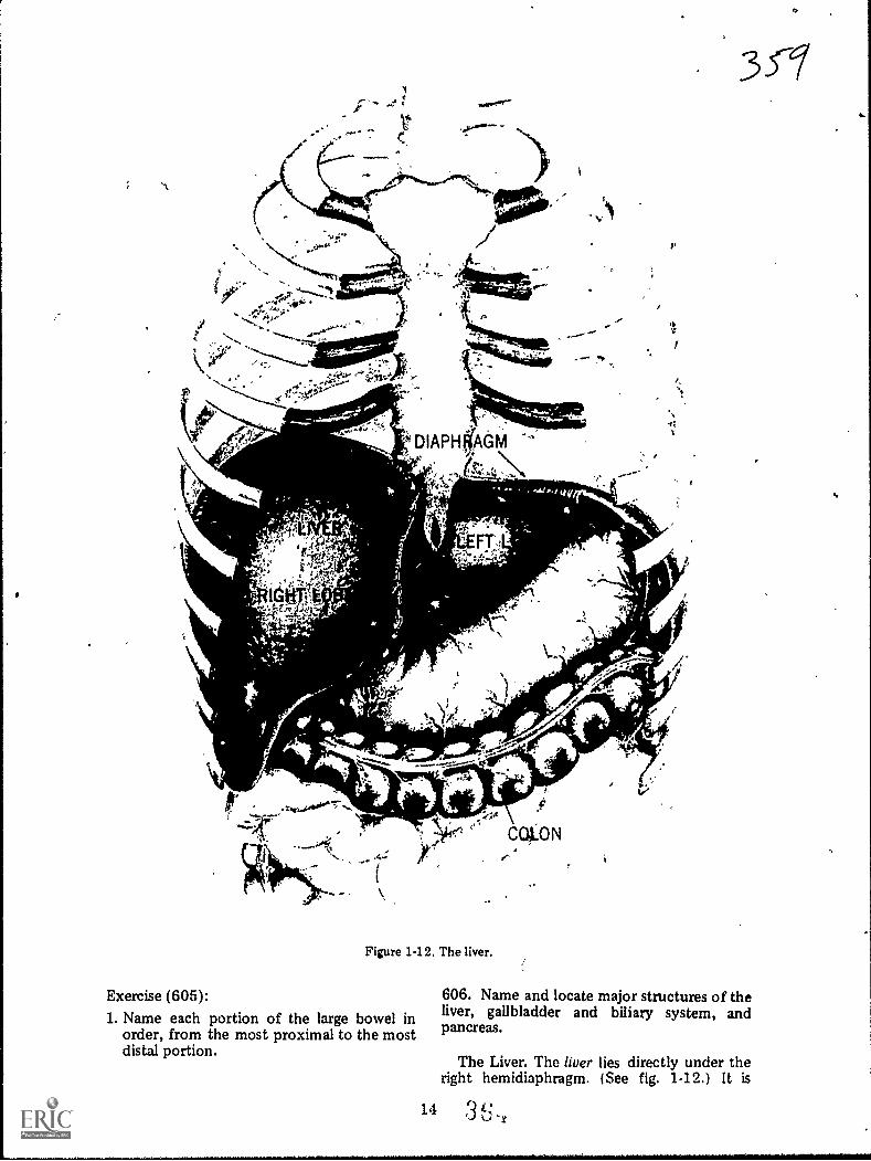
'A
Figure 1-12. The liver.
Exercise (605):1. Name each portion of the large bowel in
order, from the most proximal to the mostdistal portion.
14
3 CT
,
606. Name and locate major structures of theliver, gallbladder and biliary system, andpancreas.
The Liver. The liver lies directly under theright hemidiaphragm. (See fig. 1-12.) It is
L.!3L.,,r
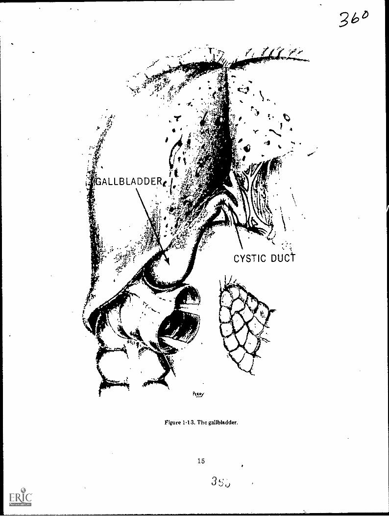
Figure 1-13. The gallbladder.
15
3 t:...., ,,,
*
3 b 4

"el&
Gallbladder
361
Cystic Duct
11
11
HepaticRadicals ;
soifia
19b
CommoiiHepatic Dat
CommonBile Duct
Duodenum
" 4
Pancreatic Duct
Figure 1-14. The biliary ductal system.
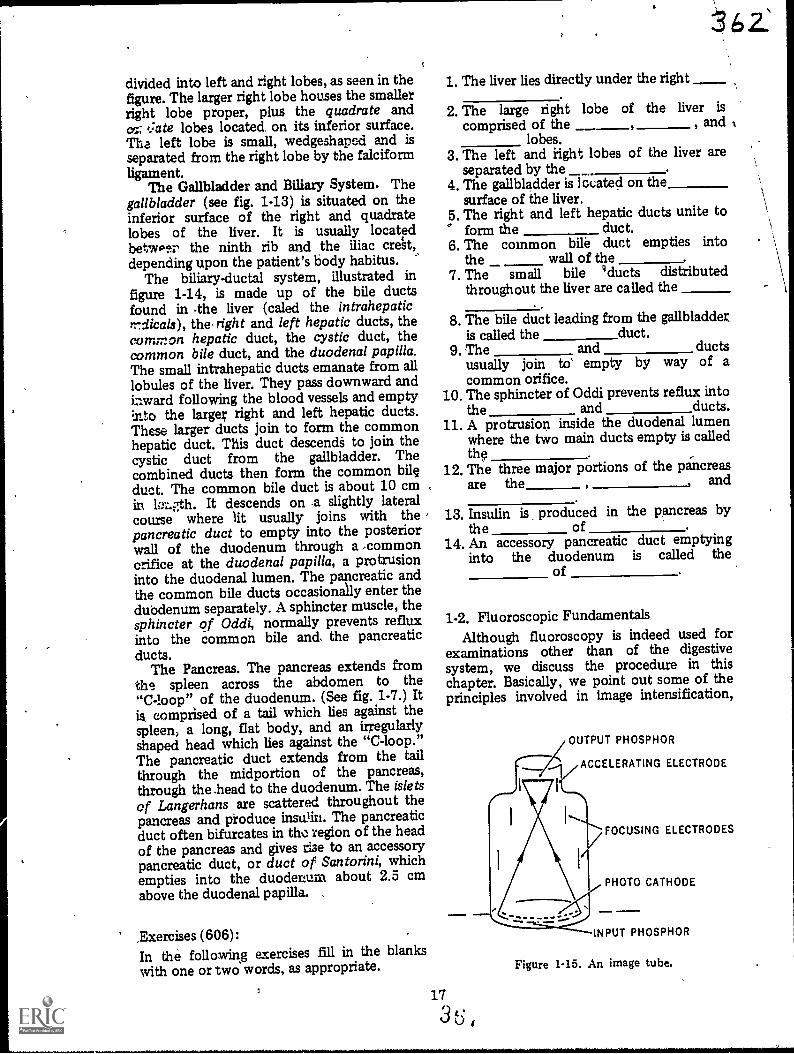
divided into left and right lobes, as seen in thefigure. The larger right lobe houses the smallerright lobe proper, plus the quadrate andcc.; t.:ate lobes located. on its inferior surface.The left lobe is small, wedgeshaped and isseparated from the right lobe by the falciformligament.
The Gallbladder and Biliary System. Thegallbladder (see fig. 1-13) is situated on theinferior surface of the right and quadratelobes of the liver. It is usually locatedbetwper the ninth rib and the iliac crett,depending upon the patient's body habitus. '
The biliary-ductal system, illustrated infigure 1-14, is made up of the bile ductsfound in 4he liver (caled the intrahepaticYrdicals), the- right and left hepatic ducts, thecommon hepatic duct, the cystic duct, thecommon bile duct, and the duodenal papilla.The small intrahepatic ducts emanate from alllobules of the liver. They pass downward andiaward following the blood vessels and emptyInto the larger right and left hepatic ducts.These larger ducts join to form the commonhepatic duct. This duct descendS to join thecystic duct from the gallbladder. Thecombined ducts then form the common bileduct. The common bile duct is about 10 cmin hth. It descends on -a slightly lateralcourse where lit usually joins with the ,pancreatic duct to empty into the posteriorwall of the duodenum through a 'commonorifice at the duodenal papilla, a protrusioninto the duodenal lumen. The pancreatic andthe common bile ducts occasionally enter theduodenum separately. A sphincter muscle, thesphincter of Oddi, normally prevents refluxinto the common bile and. the pancreaticducts.
The Pancreas. The pancreas extends fromths spleen across the abdomen to the"C-loop" of the duodenum. (See fig. 1-7.) Itis comprised of a tail which lies against thespleen, a long, flat body, and an irregularlyshaped head which lies against the "C-loop."The pancreatic duct extends from the tailthrough the midportion of the pancreas,through the .head to the duodenum. The isletsof Langerhans are scattered throughout thepancreas and produce insulin. The pancreaticduct often bifurcates in the region of the headof the pancreas and gives rise to an accessorypancreatic duct, or duct of Santorini, whichempties into the duodenum about 2.5 cmabove the duodenal papilla.
,Exercises (606):In the following exercises fill in the blankswith one or two words, as appropriate.
17
1. The liver lies directly under the right
2. The large right lobe of the liver is
comprised of the , andlobes.
3. The left and right lobes of the liver areseparated by the
4. The gallbladder is located on thesurface of the liver.
5. The right and left hepatic ducts unite to° form the duct.6. The common bile duct empties into
the wall of the7. The small bile gducts distributed
throughout the liver are called the
8. The bile duct leading from the gallbladder_is called the duct.
9. The and ductsusually join to' empty by way of acommon orifice.
10. The sphincter of Oddi prevents reflux intothe and ducts.
11. A protrision inside the duodenal lumenwhere the two main ducts empty is calledthe
12. The three major portions of the pancreasare the and
13. Insulin is produced in the pancreas bythe of .
14. An accessory pancreatic duct emptyinginto the duodenum is called the
of
1-2. Fluoroscopic FundamentalsAlthough fluoroscopy is indeed used for
examinations other than of the digestivesystem, we discuss the procedure in thischapter. Basically, we point out some of theprinciples involved in image intensification,
OUTPUT PHOSPHOR
ACCELERATING ELECTRODE
3 t: ,
FOCUSING ELECTRODES
PHOTO CATHODE
INPUT PHOSPHOR
Figure 1-15. An image tube.

cine, television, and videotape recording. Letus begin with a look at the principles involvedin image intensification.
607. Give the purpose and explain the basicoperation of an image tube.
---Image Intensification. Image
intensification, as you know, intensifies oramplifies the brightness of a fluoroscopicimage. The basic component is the imageintensifier or image tube. The tube is a largeelectron vacuum tube whichcontains an inputphosphor, photocathode, ' accelerating andfocusing electrodes, and an output phosphor,as shown in figure 1-15. Generally, theoperation ,of the image 'tube is as follows:X-ray photons strike the input phosphor,causing it to emit light photons. The lightphotons strike the photocathode and cause itto emit photoelectrons. A potential differencebetween the photocathode and acceleratingelectrode propels the electrons toward theopposite end of the tube. The electrons,focused by the focusing electrodes, strike theoutput phosphor and are converted back tolight photons. Thus, the fluoroscopic image isconverted from X-ray photons to lightphotons to electrons and back to lightphotons.
Exercises (607):1. What is the purpose of the image tube?
2. In your own words explain the basicoperation of an image tube.
608. Relate minification gain and flux gain tofluoroscopic image brightness; givenappropriate data, determine the brightnessgain of an image tube.
Gain in image brightness. As we mentionedbefore, the image tube increases thebrightness of the fluoroscopic image. Theamount of increase (brightness gain) isdetermhied by multiplying the minificationgain by the flux gain.
Minification gain is realized by the
34.4.3
reduction in the size of the image from theinput phosphor to the output phosphor.Minification is easy to understand if youimagine the image displayed by the inputphosphor being reduced to the size of theoutput phosphor, but yet containing the sametotal amount of lightconsequently, thebrightness of the image is increased becausethe light is more concentrated.
Since the sizes of the input and outputphosphors are responsible for minification, itfollows that the amount of gain is determinedby the ratio of the size of the input phosphorto that of the output phosphor. The formulafor determining minification gain is:
Minification gain =(d1)2
(d2)2
Where d1 = diameter of input phosphor, d2 =diameter of output phosphor. For example: ifthe diameter of the input phosphor is 7 inchesand the diameter of the output phosphor is 2inches, the brightness of the fluoroscopicimage is increased 12.25 times because
Minification gain =
=
=
72
2249
412.25
Flux gain in an image tube is caused byincreasing the energies of the electrons acrossthe tube. The greater the electron energy as itstrikes the output phosphor, the more lightphotons emittedconsequently, the greaterthe increase in image brightness. High voltageapplied to the accelerating electrode (up to 30kVp) accelerates the electrons sufficiently toprovide an increase in brightness of 35 to 50times.
Exercises (608):1. Explain how rninification increases the
brightness of'the fluoroscopic image.
2. Explain how flux gain increases thebrightness of the fluoroscopic image.
3. What is the brightness gain of an imagetube if the diameters of the input and
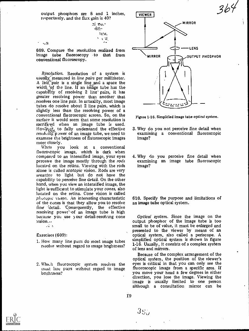
output phosphors are 8 and 1 inches,respectively, and the flux gain is 40?
11 Tio.,
609. Compare the resolution realized fromimage tube fluoroscopy to that fromconVentional fluoroscopy.
R,esolption. Resolution of a system isusually, measured in line pairs per millimeter.A linVt'pair is a single line and a space thewidth:of the line. If an irrihge tube has the .capallity of resolving 2 line' pairs, it hasgreater resolving power than another thatresolves one line pair. In actuality, most imagetubes do resolve about 2 line pairs, which isslightly less than the resolving power of aconventional fluoroscopic screen. So, on thesurface it would seem that some resolution issacrificed when an age tube is used.Ilow-eR, to fully understand the effectiveresuly ifirpower of an image tube, we need toexamine the brightness of fluoroscopic imagesmore closely.
Whe'n you look at a conventionalfluoroscopic image, which is dark whencompared to an intensified image, your eyesperceive the image mostly through the rodslocated on the retina. Viewing with the rodsalone is called scotopic vision. Rods are verysensitive to light but do not have thecapability to perceive fine detail. On the otherhand, when you view an intensified image, thelight is-sufficient to stimulate your cones, alsolocated on the retina. Cone vision is calledpholvoc t.bion. An interesting characteristicof the cones is that they allow you to resolvefine- '`detail. 'consequently, the effectiveresolving power\ of an image tube is highbecause you use our detail-resolving conevision.--
Exercises (609):1. How many line pairs do most Image tubes
resolve without regard to image bnghtness?
2. Which fluoroscopic system resolves themust lint pairs without regard to imagebnghtness?
97,-LENSMIRROR _)
I
OUTPUT PHOSPHOR
Figure 1-16. Simplified image tube optical system.
3. Why do you not perceive fine detail whenexamining a conventional fluoroscopicimage?
4. Why do you perceive fine detail whenexamining an image tube fluoroscopicimage?
610. Specify the purpose and limitations ofan image tube optical system.
Optical system. Since the image on theoutput phosphor of the image tube is toosmall to be of value, it must be enlarged andpresented to the viewer by means of anoptical system, also called a periscope. Asimplified optical system is shown in figure1-16. Usually, it consists of a complex systemof lens and mirrors.
Because of the complex arrangement of theoptical system, the position of the viewer'seyes is critical in that you can only see thefluoroscopic image from a specific area. Ifyou move your head a few degrees in eitherdirection, you lose the image. Viewing theimage is usually limited to one personalthough a consultation mirror can be
3 k:

FILM
611. Answer key questions pertaining to thefield sizes and resolution of image tubes.
Image tube rating. Image tubes are ratedaccording to the diameter of the inputphosphorwhich usually ranges from 5 to 9inches. The significance of the rating is thesize of the body area viewed through thetube. A 9-inch tube is normally used whenlarge body areas are fluoroscoped."If smallareas are normally fluoroscoped, a small tubeis usually used because it has betterresolution. This increase in resolution over alarge diameter image tube is largely due todistortion of the image at the periphery. Thedistortion is caused by the divergence of theelectrons Es they approach the outputphosphor, and the farther from the center ofthe output phosphor, the greater thedistortion. Consequently, there is maredistortion or deltail loss on a large tube:
Some image intensifiers, .called dual field
CAMERA
OBJECTIVELENS
IMAGEINTENSIFIER
TUBE
X-RAYTABLE
to
i
CAMERA LENS
PARTIAL REFLECTINGMIRliOR 957. LIGHTTRANSMISSION
SLIDING MIRROR
FIELD LENS
rr
obtained for most image tubes, whicn allows asecond person to view the image. When such amirror is used, the second observer's positionis equally as critical as that of the first.
Exercises (610):1. What is the purpose of the image tube
optical system?
2. What is the maximum number of viewerspermitted with an image tube opticalsystem?
3. Briefly discuss the position of the viewer'shead when he is using an image tube.
r
I
MOTOR
X-RAYCONTROL
HIGHVOLTAGE
TRANSFORMER
Figure 1-17. Image tubecine system.
MIRROR
VIEWINGMIRROR

tubes, can be operated in two modesforexample, a 6-inch or 9-inch mode. The modecan be changed quickly hy the fluoroscopistto accOmmodate the examination.
A particular tube size, 5-inch for example,does not mean that the fluoroscopic imagewill reveil an anatomiml area 6 inches indiameter. Keep in mind that the image isslightly magnified when displayed on theinpue phosphor due to the divergence of theprimary beam. Therefore, an image tAibeshows an area slightly smaller than its rating.
Exercises (611):1. If an image tube is rated at 7 inches, to
what specifically does the 7 inches refer?
2. What -is the difference between theresolution of a 6-nich image tube from thatof a 9-inch tube? Explain.
3. What is a dual field image tube?
4. Why is the maximum body areademonstrated by an 8-inch image tubeslightly less than 8 inches in actualdiameter?
612. Give the background and generaloperating procedures involved in
cinefluorography.
Cine. Cine or cinefluorography can be63scribed simply as the process of recordingmotion pictures or movies of the fluoroscopicimage. Although cine was used experimentallybefore the image tube was introduced, itsapplications were severely limited because ofthe tremendous amount of radiationnecessary to produce a fluoroscopic imagebright enough for recording. The radiationdose to the patient was considered to beexcessive. With the arrival of the image tube,the fluoroscopic image could easily berecorded with a low radiation dose to thepatient.
21.
Generally speaking, the eine camera is
attached to the image-tube housing so thatthe Camera lens picks up the fluoroscopicimage from the output phosphor. In actuality,a highly complex system of lens and mirrors isinterposed between the output phosphor andeine film. There is, one part of the system thatwe would like to mentionthe beam splitter.The beam splitter is a special mirror commonto both the direct optical viewing system andthe eine recording system. (See fig. 1-17.) It isdesigned to reflect about 5 to '10 percent ofthe light to the viewer and transmit 90percent to 95 percent of the light to the cinecamera. The small percentage of light mayseem insufficient to allow the fluoroscopicimage to be viewed through the periscope.However, because the amount of radiationneeded for eine recording is about 10 timesthat needed for image tube fluoroscopywithout eine, the increased radiationbrightens the image sufficiently.
In figure 1-17, the partial reflecting mirror(beam splitter) is blocked by the fullyreflective sliding mirror when cine is notrequired, reflecting the entire light beam tothe viewer.
Exercises (612):1. Why was eine originally used sparingly?
2. What event alleviated the problem facedwith early cine?
3. Describe the beam splitter and its
significance.
4. Why is the very sroall percentage of lightreflected to the viewer sufficient forviewing during eine?
613. Given a list of statements pertaining tothe operation of a eine camera, indicate whichare tr.le and which are false.
Cline camera. Although a cinefluorographiccamera is similar to a regular motion picture

APERTURE
Figure 1-18. Cine camera aperture and shutter.
camera, manufacturers have designed special'cine cameras. From an operational point ofview they are all similar. The cine film isexposed by light entering the camera throughthe lens and through the aperture, which canbe rectangularly shaped, as seen in figure1-18, or square. The camera shutter, alsoshown inpthe figure, is simply a disc that has aportion &it out. The shutter rotates to opent6 aperture when the film isin position forthe exposure of a frame and to close theaperture when the film is advanced. Thepulldown mechanism advances the filmintermittently while the pressure platemaintains close contact between the film andaperture during exposure. (See fig. 1-19.)
One of the problems with some cinesystems is that' X-radiation creating thefluoroscopic image is continuous. Bycontinuous we mean that X-radiation isproduced when the aperture is closed as wellas when it is open. With a single-phasegenerator this causes some frames of the filmto receive more exposure than others, thusresulting in uneven densities on the frames.Continuous X-ray production with athree-phase generator eliminates the unevendensities. However, continuous X-rayproduction with both types of generatorsexposes the patient to about twice theradiation needed for filming because theradiation exposure when the shutter is closeddoes not contribute to the exposures of theframes. The solution to the radiation dosageproblem is the use of a grid-controlled tubewhich has the capability to synchronize theX-ray exposure to the shuttei-open phase ofcamera operation. (A grid-controlled tube is
36' 7discussed in chapter 1, volume I.) When theshutter and X-ray tube are synchronized, thepatient only receives radiation exposureduring the shutter-open phase.
Since the X-ray exposure is intermittent, asdescribed above, the fluoroscopic image asviewed through the periscope during cinerecording usually displays some degree offlicker. However, it does not interfere withmonitoring of the fluoroscopic image.
Exercises (613):
Indicate whether the following statementspertaining to the operation of a eine cameraare true or false. If you indicate "false,"explain your answer.T F 1. A cine camera is similar to a regular
motion picture camera.
F 2. The rotating disc, which opens andcloses the aperture, is the pulldownmechanism.
T F 3. The cine film is advanced past theaperture by the pullde wmmechanism.
T F 4. Close, even contact between the film
PRESSURE PLATE
1
Figure 1-19. Cine camera showing the pulldownmechanism, pressure plate, and aperture.
f.)
22

and aperture dunng exposure isaccomplished by the shutter.
r F 5. Continuous X-ray produL lion resultsin uneven frame densities when athree-phase generator is used.
I F 6. For the most efficient use of theX-radiation during cine, theX-radiation should be produced onlywhen the shutter is open.
I F 7. The use of a grid-controlled tube, ineffect, can reduce the radiationreceived by a patient during cine.
T F S. Synchronization of the X-ray tubeand cine camera shut.er usuallyproduces flicker of the fluoroscopicimage.
61 1. Compare the 'qualities of different eine
Cine filrn. Both 16-mm and 35-mm filmsare used for cinefluorography. The choice ofwhich type to use rests with your radiologist.Some radiologists feel that 35-mm has higherresolving capabilities because there is lessquantum mottle. Quantum mottle resultswhen the number of X-ray photons per unitarea is low, causing a significant unevendistnbution of the photons projecting theimage. Since 35mm film requires a higherexposure, this statistical fluctuation of theX-ray photons is less significant than thatwith 16-mm film.
Another generally accepted way to evaluatethe resolution capabilities of a cine recordingsystem s to consider the resolving power ofthe v,eakest part of the system. During einethe "weakest link" in the resolution chain isnormally the image tube itself. Cine filmshave the capability to ftsolve many more linepairs than image tubes. Therefore, this wouldseem to indicate that the type of cine filmused does not affect resolution.
23
The above discussion is not meant to implythat all 35-mm cine films, for example, appearthe same when processed and projected forviewing.'Films differ in such characteristics ascontrast. speed. and graininess. Ideally.. a einefilm should exhibit high contrast, be fast, andcontain fine grains. In actual practice,however, the best of these threecharacteristics is not found in one type offilth. For example, a fast film with highcontrast usually contains large grains whichreduce detail. This t,-pe of film, however,would also result in a lower radiation dose tothepatient because of its speed.
Exercises (614):1. What is quanhim mottle?
2. How does quantum mottle affectresolution?
3. What cine film, 16-mm-eor 35-mm, has lessquantum mottle and why?
4. According to the "weakest link" theory,what cine film should be used for the bestpossible resolution? Why?
5. If you use high speed cine film with highcontrast properties, what must yousacrifice?
6. If you use fine-grained, fast cine film, whattype of contrast (high or low) would beexhibited?
61 5. Indicate t he advantages anddisadvantages of television and videotaperecording.
Television and Videotape Recording. Oneof the biggest problems with image tubefluoroscopy is the restriction placed on the

fluoroscopist. As we mentioned before, hemust maintain his head in a restricted positionwith respect to the periscope in order to viewthe image. Also, as mentioned before, thenumber of viewers is restricted. Televisionmonitoring of the fluoroscopic imagealleviates these problems. With television thefluoroscopist views the fluoroscopic image ona monitor similar to a regular commercialtelevision set. Therefore, the position of hishead is not critical. Also, several persons canview the monitor simultaneously. In fact,additional monitors can be located andviewed outside the fluoroscopic room. Youcan see the obvious advantage in teachingsituations.
Television does have some drawbacks. Onemajor disadvantage is the added expense forpurchase and maintenance. Televisionequipment is quite expensive and, due to thecomplexity of the components, requires highcost maintenance. Another disadvantage isthat the quality of the fluoroscopic image ispoorer than that from dilect periscopeviewing. This loss of detail, however, is oflittle consequence for many fluoroscopicexaminations.
Television also permits videotape recordingof the fluoroscopic image. When videotape isused, the fluoroscopic image can be replayedon a monitor instantly; whereas, with cine thefilm must be processed before viewing.Significance of the "instant replay" is that theradiologist can determine immediatelywhether or not he has recorded theinformation he desires. Thus, the examinationcan be repeated without delay if it is notsatisfactory.
The videotape image is of relatively poorquality when compared with cine. However,this problem is easily alleviated by using cinerecording in addition to videotape recordinli.
Exercises (615):1. What advantage does the television monitor
have over periscope viewing?
2. What are the disadvantages of televisionfluoroscopy?
3. Give one. advantage and one disadvantageof videotape recording.
361
1-3. Contrast Study PreparationsNow that we have discussed the anatomy
and physiology of the digestive system andfluoroscopic fundamentals, we turn ourattention to two general aspects of contraststudies of the digestive system. Topics includepatient preparation and contrast media.
616. Indicate why patient preparation isimportant and specify how instructions areadministered.
P a ti en t Preparation. The specificpreparatory instructions you give to yourpatients scheduled for a contrast stucl ufsome part of the digestive system dependupon the desires of your radiologist. Theimportant feature, of the instructions is thatthey should result in the part uncle, ,tudy orrelated structures being free fr(-.1 food,liquids, gas, or fecal material. The obutmsreason for the preparation is that preserwe ofthe materials ttentionefl may result indifficulties in interpretation dui. to"confusing" shackws seen during t1uuros«lpyor on the radiogranhs.
Your role in pit aring the patieli. is ustiall!,limited tu him with detailed,written mstructions. Prepar2 the instrti,:forms and neces:-.try supplies. Su& alb Pills,suppositunes. etc.. in advance so that allpatients receivn,..; the same exat.:nialionreceive the same i.i:,tructions nu inat:-technician sci.t.u, '*.s him. The nunsshould be clec.2 so that the patientunderstands exat.::y what he is to do andwhen he is to dj, .:. If you proiade him with alaxative, include in the instrictiuns t:.! natureof its action. If the examination calls furingestion of selected foods, specify Cle fovdsallowed. Do n,.; simply state in the
-:-instructions for .tim to remain (n a lowresidue diet for t:iree da. Use. be sure toinclude the phone numbka ol ourdepartment on tl'e instructi)n form so thatthe patient can quickly contact you ifquestions anse.
When the patieLt arrives fur hisexamination, it is usually a good idea to ask ifhe followed the instructions given him. Forexample, he may forget and eat breakfast onthe morning of his upper gastrointestinal Ulfseries. If you can identify this situation beforethe radioloOst begins fluoroscopy, you vansave everyone concerned from wasting theirtime, because the radiologist almost alwayscancels the examination. Also, if the pills yougave the barium enema tliEl patient "didn't
243
work," the radiologist may request a flat plateof, the abdomen before fluoroscopy to checkfor gas and fecal material in the colon.
Exercises (616):1. Why is it important for the patient to be
properly prepared before an examinationof certain parts of the digestive system?
2. List five key points to remember when youprepare patient instructions.
3. How and why should you follow up on thepatient's preparation?
617. Indicate the types, uses, and preparationprocedures pertaining to the contrast mediused for the digestive system.
Contrast Media. There are ev e ra 1 types.arleands of contrast media used during contrast
aiamation of the diges..ve system. Likemany other aspects of radiolov, yourradiologist uses the contrast medium thatpioi ides him with the Jiagnostic informationcon:..stent ,vith the requirements of thexan .nation. The specific contrast medium
us( d depencis upon your radiologist; however,wt.. provide you with J o m e generalinformation about the types of media.
Barium sulfate preparations. Barium sulfatepreparations are available under manydifferent brand names. Some examples areBarosperse, Barotrast, Colonatrast, Oratrast,Esophotrast, Micropaque. E-Z-Paque, andSol-O-Pak. Depending upon how supplied,they are used for visualization of the pharynx,esophagus, stomach, small oowel, and colon.Commercial paste or cream preparations areused for examination of the pharynx andesophaps. ['his and other banum sulfatepastk S charactenstically adhere to the mucosafor a long penod of time and help you to'catt,h- the medium in the nght area. Other
lJanum sulfate preparations are suppliedusually in powder form and are mixed withwater before use. Some are prepackaged indisposable banum enema kits. When mixing
.370these preparations with water, mix the exactproportions desired by your radiologist.
Some barium sulfate powders aremicronized and ionized so that they stay insuspension longer. When mixing preparations,such as this, do not use a mechanical mixer ormetal spoon, or mix them in a metalcontainer because the mete can provide aconducting pathway that results inneutralization of the ionized particles. Thiswould also neutralize the suspension propertyof the powder and cause the powder to settleout of suspension quicker. Some settling doesoccur in most preparations if allowed to standmore than a few minutes. Therefore, youshould stir the preparations immediatelybefore use if they have been allowed to standfor that period of time.
Alternate digestive system media. OralHypaque and Gastrografin are examples ofcontrast Media that are sometimes used forexaminations of parts of the digestive systemwhen a barium sulfate preparation iscontraindicated. They are supplied in powderor liquid form. The powder is simply mixedwith water before use. These types of contrastmedia are usually selected for use by yourradiologist if a perforation is suspected.
Cholecystopaques. Contrast medianormally used to examine the gallbladder andbiliary tree are sometimes calledcholecystopaques. Some eximples of oralcholecystopaques used to examine thegallbladder are Bilopaque, Oragrafin, andTelepaque. They are supplied in tablet,capsule, or powder (to be mixed with water).An example of an injectable cholecystopaqueused for intravenous cholecystography orintravenous cholangiography is Cholografin.Operative, T-tube, and transhepaticcholangiograrns are usually perforn.ed, using awater soluble injectable medium, such asHypaque or Renografin.
Other types of media. Two other types ofcontrast media are frequently used toexamine portions of the digestive system. Airis used for a double contrast study of thecolon. Air (carbon dioxide) is also introducedinto the stomach by means of a carbonatedbeverage to provide an air contrast study ofthe fundus. An oily contrast medium, suchosPantopaque, or a water soluble injectable,such as Hypaque, is normey used to visualizethe salivary ducts during a sialogram.
As mentioned previously, your radiologistdetermines the contrast medium used in yourdepartment. One example of why he makesthis decision is in case of a patient with asuspected tracheo-esophageal fistula. If acontrast medium is introduced into the
25
3 7
esophagus, it may end up in the lungs. Certaintypes of contrast material may be dangerousto the patient if introduced into the lungs.Consequently, in case of a tracheo-esophagealfistula, a contrast medium introduced into theesophagus must be safe with respect to thelungs. In recent years, studies have shown thatcontrast materials other than those normallyused in the past may be better suited for thisexamination. Therefore, we cannotoverempliaitethe importance of yourradiologist deciding upon the contrastmedium.
Exercises (617):1. What is the radiographic significance of
commercial barium sulfate cream or pastepreparations?
2. What proportions should you use whenmixing barium sulfate with water?
3. What type of barium sulfate powder shouldnot be prepared for administratively using amechanical mixer, metal spoon, or metalcontainer and why?
4. What action should you take immediatelybefore using a barium sulfate preparation ifit has been allowed to stand for a fewminutes? Why?
5. If barium sulfate is contraindicated for usein the digestive system of a patient, whattwo brands of media can be considered byyour radiologist?
6. Why should a patient be n a carbonatedbcverage during an upper G eries?
7. A patient is suspected having atracheo-esophageal fistula. What does thistell you about the contrast medium used todemonstrate the abnormality?
.921
8. Who selects the contrast medium for anexamination, such as in exercise number 7above?
1-4. Radiographic ConsiderationsIn this, the final section of this chapter, we
discuss various radiogaphic aspects of thedifferent contrast studies of the digestivesystem. We begin w:th sialography.
618. Answer key questions pertaining to theperformance of a sialograrh.
Sialography. The salivary ductal systems1'are demonstrated by injecting a contrastmedium into the main duct of each gland thatopens into the mouth. As a general rule, theprocedure is a simple oneyour radiologistinjects the contrast medium and you performthe necessary radiographs. Some radiologistsprefer to fluoroscope the gland underexamination and make spot films.
Special supplies. While the supplies ...tied fora sialogram vary from one radiologist toanother, the following are frequently used:
a. A small probe to locate and explore themain duct.
b. A small bore polyethylene catheter orblunt needle through which to inject thecontrast material.
c. A small syringe (2.5 or 5 cc capacity)with which to inject the contrast material.
d. A local anesthetic, injectable or viscous,to anesthetize the area about the main ductopening.
e. A lemon, cut in quarters. The lemonsometimes serves two purposes: (1) tostimulate the gland so that the duct openingcan be easily located due to the discharge ofsaliva, . and (2) to evacuate the contrastmaterial after the initial "filled" radiographsare obtained. (Note: A postevacuationradiograph is usually made to check thedegee of evacuation.) If the contrast materialis not completely evacuated before thepatient leaves the department, the radiologistmay ask the patient to continue stimulationof the gland for 1 to 3 days through the useof lemon slices, lemon juice, or chewing gum.
Sialographic projections. The specificprojections used for a sialogram, as a generalrule, depend upon the particular gland underexamination.
26 :3

Figure 1-20. Inferosuperior or intraoral projection ofthe sublingual and anteromedial portions of the
submaxillary glands.
a. A tangential projection, eitheranteroposterior (AP) or posteroanterior (PA),is usually made if the parotid gland is beingexamined. The gland is located approximatelyhalfway between the anterior and posteriorsurfaces of the patient so part-film distance is
the same for each projection. Adjust the headuntil :he infraorbitomeatal line isperpendicular to the film. Rotate the patient'sface 25 to 350 toward the side beingexamined or until the parotid area isperpendicular to the film. Direct the C.R.perpendicularly to the film.
b. A "straight" lateral projection can bemade to visualize either of the three salivaryglands. Extend the head slightly and positionthe skull in the true lateral position with thegland under examination nearest the film.Direct the C.R.. perpendicularly through theappropriate gland to the Center of the film.Various other lateral projections aresometimes made, depending upon yourradiologist's desires. He may prefer a lateralwith the patient's face rotated 15° downward(toward the tabletop) to visualize the parotidgland. Also, true lateral positions of the skullwith the C.R. directed 10° to 30° cephalic aresometimes made to demonstrate eithersalivary gland. ,
c. The entire sublingtial gland areas areusually demonstrated by using aninferosuperior or intraoral projection. Simplyplace an occlusal film as far into the patient'smouth as possible without causing unduediscomfort, and direct a horizontal C.R. tothe center of the portion of the film in the .
...
27
patient's mouth. (See fig. 1-20.) A portion ofthe submaxillary gland can also bedemonstrated by this projection.
Exercises (618):1. Why is a small probe used when
performing a sialogramr
2. In place of a small bore polyethylenecatheter, what can be used to introducethe conast material?
3. Why is a lemon necessary in performing asialogram?
4. What salivary glands are demonstrated onthe straight lateral projection?
5. Should a tangential PA or a tangential Al'projection be made of the parotid gland?
\6. What approximate degree of rotation
should be used for a tangential projectionof the parotid gland?
7. What 4 gland is probably beingdemonstrated if a lateral projection ismade with the patient's face rotated 15degrees downward?
8. What gland is entirely demonstrated withthe intraoral projection?
9. If an AP tangential projection of the rightparotid gland is being performed, in whatdirection is the patient's face rotated?
10. What range and direction of C.R.angulation is used for lateral projectionsof the salivary glands?
3 72--
619. Indicate major procedures and arió-usinfluential factors pertaining to c.mtrastradiography of the pharynx and esophagus.
The Pharynx and Esophagus. Contraststudies of the pharynx and esophagus, withthe exception of "heart" esophagrarns, areusually made after fluoroscopy. In manycases, the radiologist makes spot films orrecords the parts using cine. Our discussion isdirected toward ways to "catch" the contrastmedia during post-fluoro radiography and theprojections that are usually made.
Pharynx. Examinations of the pharynx.(oropharynx and laryngopharynx) usingbarium sulfate are somewhat difficult to makebecause the bolus very quickly descendsthrough the area during deglutition (the act ofswallowing). This causes many technicians tobe "late" with their exposure. Also, thepatient may not respond promptly to yourinstruction to swallow, which can cause youto make the exposure too early. One of thebest ways to time the exposure to coincidewith the barium-filled pharynx is to watch thepatient's thyroid cartilage (Adam's apple).During deglutition the thyroid cartilage movesup and forward and then relaxes back to itsnormal position when the process iscompleted. Make your exposure immediatelywhen the cartilage reaches its mostanterosuperior position. At that instant, theoropharynx and laryngopharynx are usuallyfilled with barium. The posterior portion ofthe oral cavity is also well visualized at thepeak of the swallowing process.
Esophagus. Most radiographic examinationsof the esophagus are made after thefluoroscopic phase of an upper GI series andto demonstrate enlargement of the heart.
Some radiologists have included, in theroutine of post-fluoro, upper GI films, aradiograph of the entire esophagus. Usually,the projection is made with the patientrecumbent in the right anterior oblique(RAO) position because the position presentsa larger space between the heart and spineand, consequently, permits a moreunobstructed view of the lower esophagus.The entire esophagus can usually bedemonstrated filled with barium if the patientis allowed to drink the liquid barium througha straw continuously (drinking esophagram),beginning four or five seconds before theexposure. Of course, the exposure can bemade after the patient swallows a singlemouthful of liquid or paste barium, but thechance of demonstrating the entire esophagusfilled with barium is lost. A commercially
28
prepared barium paste usually shows theoutline of the entire esophagus, due to thespecial coating characteristics of the medium,but the entire esophagus is usually not filled.
Radiographic projections of the esophagusto demonstrate enlargement of thern heartshould be made with the patient erect, at a72-inch distance, and after full inspiration.One reason for these conditions is that thevisible size of the heart is evaluated on theradiographs in addition to possibledisplacement of the esophagus as a result ofheart enlargement. Also, the pulmonarystructures are evaluated because pulmonarychanges may occur with heart enlargement.
Four projections of the chest with theesophagus outlined with the contrast mediumare usually madeposteroanterior (PA), leftanterior oblique (LAO), RAO, and left lateral.The left lateral is made as opposed to theright to minimize the part (heart) filmdistance and the resulting magnification. Thedegree of rotation for the obliques variesslightly among radiologists; however, theRAO is usually 45° while the rAo isnormally 55 to 65. The reason the obliquity isdifferent for each oblique is that, since theheart is located somewhat to the Idt of themidline, the LAO requires more rotation toproject the heart clear of the spine.
You can obtain better results if you usebarium paste for the heart seriesspecificallya commercial piste with special coatingproperties. Most radiologists can evaluate theesophagus as long as it is outlined by the pasterather than being filled by the liquid barium.The exact timing of the exposure is largely amatter of personal preference on the part ofthe technician. It also depends on thethickness of the paste and cooperation of thepatient. Some technicians ask the patient toswallow a mouthful of paste and immediatelytake a breaththe exposure is then madeimmediately after the breath or after a delayof 1 to 4 seconds. The time lapse dependsupon the thickness of the paste. Othertechnicians have* the patient swallow onemouthful of paste, give him another to hold,and then repeat the above procedure. Thefirst mouthful increases the possibility forgood esophageal coating.
There are two other factors _you shouldkeep in mind while performing; thisexamination. First, the PA ekpostire shouldbe increased slightly over the niirmal PA chestexposure to permit vi§uiliiatinn of the loweresophagus through the superitnposed heart.Second, displacement of the esophagus by thegreat vessels is usually evaluated so it isimportant to outline the middle third of the
.3

esophagus as well as the distal third. Someradiologists do not care about thedemonstration of the proximal third when aheart series is performed.
Exercises (619):
1. Why is it difficult to producebarium-filled radiographs of the pharynx?
2. Explain one way to synchronize yourexposure with the act of swallowing toradiograph the contrast-filled pharynx.
3. Why is the esophagram performed inconjunction with an upper GI seriesusually performed with the patient in theRAO position?
4. Describe the drinking esophagram.
5. How does the drinking esophagramradiograph differ from the"single-swallow" or "paste" radiographsin the visualization of the esophagus?
6. Why should esophagrams for heartevaluation be made with the patient erect,at a 72-inch FFD, and on-full inspiration?
7. Why is a left lateral esophagramperformed instead of a right lateral for aheart series?
8. Why is the LAO heart series, radiographrotated more than the RAO?
9. What type of barium sulfate preparationproduces the best results for a heartseries?
29
j
37V10. What three factors influence timing of the
exposure during a heart series?
11. Why should the PA heart series radiographbe made with a slight increase in exposureover a normal PA chest?
12. Why is it important to visualize themiddle third of the esophagus during aheart series?
620. Cite fundamentals of hypotonicduodenography and describe the projectionsused for an upper GI series.
The Stomach and Duodenum.EXamination of the stomach and duodenum,as you know, is made by a combination offluoroscopy with cine or spot filming, and"followup" or "overhead" films.
Delay in gastric evacuation. At timesduring the fluoroscopic phase of theexamination, the contrast medium is slow toempty into the duodenum preventingvisualization of the all-importlit duodenalbirlb and the remainder of the duodenum. Ifthe radiologist elects to have the patient waitoutside the exposure room so that the nextpatient may ,be examined, he, the radiologist,may ask you to have the patient lie down tospeed up the evacuation of the stomach.When the situation arises, have the patient lie
in either the right anterior oblique or rightlateral position. It is in these positions thatperistalsis is maximal due to the influence ofgravity.
Hypotonic duodenography. Hypotonicduodenography is examination of theduodenum without interference fromperistalsis. It enables the radiologist to moreeffectively evaluate the mucosa of theduodenum. The examination may beaccomplished in conjunction with a standardupper GI series. The patient- is given aninjection of pro-banthine or .a similar drugwhich temporarily decreases the tone of thewalls and dilates the duodenum.
The examination may also be scheduledseparately in which case the barium may beintroduced by means of a tube or by oral
<
ingestion. The drug is always administedafter the contrast medium. The radiologist,may or may not require followup films.However, he almost always records theduodenum by using spot films or cine.
A side effect stemming from the injectionof pro-banthhie is loss of control of thevoluntary muscles, including control of therespiratory muscles. If this condition occurs,artificial respiration must be administereduntil the effects of the drug have subsided.Copsequently, your emergency traycontaining resuscitation equipment should bereadily available.
Projections. The specific followupprojections you accomplish during an upperGI series vary from one radiologist to another.Five such projections are commonlyperformed. We discuss them from the aspectof the anatomy demonstrated. The duodenumis demonstrated fairly well in most of theprojections with the exception of the bulb, aswill be noted.
a. The PA projection shows the generalcontour of the stomach and duodenal bulb. Iftaken erect, it also reveals the true size, shape,and relative position of the stomach.
b. The left posterior oblique (LPO) showsan air contrast view of the body, pylorus, andduodenal bulb. The fundus is shown filledwith barium.
c. The RAO, on all patients except forthe hypersthenic individual, provides the bestdemonstration of the pylorus and duodenalbulb. The degree of obliquity required topresent the pylorus and bulb in profile (whichshows them best) depends upon the size,shape, and position of the stomach. Someradiologists request a standard 45° obliquewhile others want two or more obliques withvarying degrees of rotation. Your radiologistmay also request two radiographs made withthe patient in the same oblique position totake advantage of the maximal peristalsis inthat position.
d. The right lateral projection provides aprofile view of the pylorus and duodenal bulbin a hypersthenic individual because thoseparts are usually aligned in an anteroposteriordirection. This patient is sometimes referredto as having a "posterior bulb."
e. The erect left lateral is the bestprojection to show the relationship betweenthe stomach and retrogastric structures.
c.
Exercises (620):In the following exercise pertaining to anupper GI series, fill in the blank spaces withone or two words, as appropriate.
1. The oblique . andpositions should be
used to promote gastric evacuationbecause is Maximum.
2. A hypotonic duodenal examination4 permits better evaluation of the duodenal
3. The drug u sed in hypotonicduodenography decreases the tone of the
of the duodenum.A. In hypotonic duodenography the
introduction of the alwaysprecedes the introduction of the .
5. The drug used in hypotonicduodenography may cause loss of controlof the , necessitating
until the drug effectsubsides.
6. The projection of the stomachand duodenum reveals an air contrast viewof the stomach (except for the fundus)and duodenal bulb.
7. The RAO presents the liest view of theand on
most individuals. 0
8. Two identical right anterior obliqueprojections may be made to takeadvantage of
9. For a patient with a posterior bulb, aprofile view of the bulb is obtained with a
projection.10. The erect left lateral projection is best to
demonstrate the relaionship between thestomach and .
621. Differentiate among the four methodsof contrast examinations of the small bowel.
The Small Bowel. There are four methodsby which contrast examination of the smallbowel is performed. They are: (1) frequentinterval method, (2) cold isotonic salinemethod, (3) intubation method, and (4)retrograde method.
Frequent interval method. The frequentinterval method is often done in conjunctionwith an upper GI series. The barium is simplyfollowed on 14 x 17 PA or AP radiographstaken at specific 'intervalsusually 30minutes. Some radiologists inspect each filmimmediately so that they can examine thepatient under fluoroscopy if a suspicious areais present. The last 14 x 17 radiograph takenis the first one that shows the head of thecolumn of barium in the large bowel. At thattime the radiologist usually examines thepatient fluoroscopically to evaluate andperhaps make spot films of the ileocecal valve.
30
37C
i
In. addition to demonstrating structuralvariations of the small bowel, the frequentinterval method is also used to evaluate themotility of the small bowel. The radiologistdetermines the time it takes for the stemachto empty and the time required for thebarium to reach the colon. Consequently, youshould include time markers on theradiographs. In addition, include the stomachon the radiographs at least until it is empty.
Cold isotonic saline method. The coldisotonic saline method involves mixing thebarium powder with cold isotonic salineinstead of plain water. The saline hastensst omach evacuation and motility through thesmall intestine. The barium may be mixedwith saline as described above, or it may bemixed in the conventional manner, in whichcase the saline is given later. If thisexamination is performed in conjunction withan upper GI series, the latter procedureshould be followed with the saline given tothe patient after comPletion of the standard
- upper GI followup films. In place of saline,plain cold water irTy also be used to shortenstomach evacuation and small bowel transittime. The water may be given nt variousintervals throughout the examination, or itmax be given only after completion of thefollotvup films.
If a considerable amount of saline or wateris given, the contrast medium tends tobecome diluted; consequently, some contrastand detail are lost. However, this method doesreduce the transit time considerably, allowing
the barium to reach the colon quickerthusreducing the overall time for the examination.Also, the radiologist can more readily followthe head of the column of bariumfluoroscopically. The reason for this is thatthe barium moves fast enough to make itpractical for him to monitor most or all of thebarium movement to the colon. Naturally,'with this method, normal stomach evacuationand transit time cannot be evaluated.
Intubation method. If the contrast mediumcannot be administered orally as in the twopreviously described methods, it may be giventhrough a tube introduced into the smallbowel from above. The intubation has adefinite advantage over all other types ofsmall bowel examinations in that the contrastmedium can be introduced directly into asmall bowel segment. This allows visualizationof the segment under study withouthiterference from other portions of the smallbowel because of superimposition.
Retrograde method. Most rarely performedis the retrograde method, also called refluxmethod, of small bowel examination. The
31
3
contrast medium is introduced by a bariumenema. The reflux of the contrast mediumthrough the ileocecal valve enables the smallbowel to be demonstrated. This method isusually used to detect organic filling defects.
Exercises (621):Match the method of small bowelexamination in column B with theappropriate statement or phrase in column Aby placing the letter of the column B item inthe space provided in column A. Each columnB item may be used once or more than once.
Column A1. Evaluates small
bowel motility!2. Depends upon re-
flux._ 3. Medium is intro-
duced directly intoa small bowel seg-ment.
4. Medium passesrapidly throughthe small bowel.
5. Requires timemarkers.
6. Used to detect or-- ganic filling de-fects.
7. Permits study of asmall bowel seg-ment without in-terference from su-perimposition.
8. Uses bariumenema.
9. Makes use of coldwater.
10 Hastens stomachevacuation.
_11. Include stomachon radiographs un-til it is empty.
Column Ba. Frequent interval
method.b. Cold isotonic saline
method.c. Intubation method.d. Retrograde method.
622. Specify fundamental proceduresinvolved in air-contrast studies of the colon.
The Large Bowel. Examination of the largebowel varies from one radiologist to another.Basically,, two types of examinations areperformedthe 6ariuin enema and thedouble-contrast or air-contrast study. As ageneral rule, the air-contrast study is
performed by one of two methodsdirect ortwo-stage.
Direct and two-stage air-contrast studies.The -direct air-contrast study is performedsimultaneously with the barium enema. Arelatively small amount of barium sulfate is
3X7

377 I
introduced into the colon, followed by air.The major difference between the direct andtwo-stage methods is that with the directmethod the barium is not evacuated beforethe air is introduced. Naturally, the directmethod requires equipment that allows youto switch immediately from barium to airduring fluoroscopy. If your department usesan irrigating can or similar set-up, includingcertain disposable enema kits, as the bariumcontainer, you will haveto rig a Y-connectorto the tubing so that alr or barium' can beintroduced into the colon. Some disposablekits are especially designed for directair-contrast studies eliminating therequirement for a special connector.
Another special type of device that allowsdirect air-contrast studies is the pneumocolon.The pneumocolon consists of a wide-mouthedbottle which has a specially designed lidassembly incorporating two tubular channelsand a triangular-shaped support. One of thechannels serves as an inlet and the other as anoutlet, with respect to the inside of thebottle. Air pressUfe I's' built up withiii the'bottle by pumping air into it by means of theattached hand pump. When sufficient air
pressure is built up within the bottle and theclamp on the outlet tube is opened, thebarium preparation flows into the colon as aresult of the air pressure in the bottle. Forbarium flow to take place, however, theorifice of the outlet channel must besubmerged in the liquid. This is done byplacing the bottle so that the long side of thetriangular support is down, as shown in figure1-21. To introduce air into the colon, simplyturn the bottle so that either of the two shortsides of the triangular support is down. Thesepositions remove the orifice of the outletchannel from the liquid and place it in the airspace above the level of the liquid. (See fig.1-22.)
The two-stage method of air-contrastexaminations is performed as follows: After astandard barium enema, the patient evacuatesthe contrast medium and is returned to thetable. Air is then introduced into the colon,usually by means of a single tube to which isattached an enema tip and air bulb.
Exercises (622):1. What is the major difference between the.
TIP
Figure 121. Position of thr"Pneumocolon" for the introduction of the barium.
32 ,r4

Figure 1-22. Position of the "Pneumocolon" for the introduction of air.
direct and two-stage methods of preparation of the barium liquid for colon
air-contrast studies of the colon? examinations, indicate which are true andwhich are false.
2. The equipment for introducing the contrastmedia during a direct air-contrast studymust differ from that of a two-stage studyin what way?
3. Does the pneumocolon provide theflexibility indicated in exercise number 2above?
4. Does the pneurnocolon use air pressure orgravity to introduce the liquid?
5. What is the position of the triangularsupport of the pneumocolon to introducebarium? To introduce air?
623. Given a list of statements pertaining to
33
Preparation of the barium solution. Youshould always prepare the barium sulfate for a
colon examination according to yourradiologist's desires. Most radiologists like thetemperature of the liquid to be about 85°while others like it slightly warmer. A few ofthem want the temperature to heconsiderably colder, about 41°F. Naturally, ifthis low temperature .is desired, you willeither have to mix the prOaritiotriii'advance-and refrigerate it, or mix, the barium sulfatewith refrigerated water. In either case, toinsure the correct temperature, use a
thermometer rather than estimate thetemperature. Also keep in mind that thetemperature of a solution that is allowed tostand at room temperatures for a long, periodof time will either increase if it is ,around41°F or decrease if around 85°F. In view ofthe changing temperature, it is usually best tomix the solution immediately before eachexamination. However, if this procedure isnot possible, maintain the correcttemperature by allowing the solutioncontainer to remain in water of thecorresponding temperature.

The thickness of the barium sulfatesolution for a colon examination also varies.The ratio of barium sulfate to water ranges
. from 1 part barium to 4 to 8 parts water byvolume. As far as you are concerned, theimportant factor is for you to consistentlymix the thickness your radiologist wants. Thismeans that you should have a reliable meansof measuring both parts of the mixture sothat the thickness can be repeated day afterday. Also, ykou should use a hydrometer tospot check the specific gravity and thereforethe thickness of the preparation. Somehydrometers cannot be used for this purposesince they are not scaled in the appropriaterange. Special hydrometers are available,however, that are made especially to test thespdcific gravity of barium sulfatepreparations. Of course, the specific gravityyou use depends upon local policy.
Several other points you should keep inmind when preparing the solution are asfollows: .
a. Except when using a prepackagedbarium enema kit, pour the barium sulfateinto th.e water rather than the other woaround. This prevents some of the powderfrom sticking to the container and therebyreducing the thickness of the preparation.
b. Except when using a prepackaged kit,mix the two parts of the mixture in anothercontainer to reduce the possibility of the tubebecoming clogged by settled barium. Pour themixture into the container from which it isadministered immediately before use.
a. "Bleed" the tubing immediately beforeyou insert the rectal tip, to remove the air.
_This step serves two purposes: (1) it tells youwhether or not the solution runs freelythrough the tube, and (2) it prevents the air inthe tube from being introduced into the colonahead of the barium. Air introduced in thismanner can interfere with good visualizationof the colon.
Exercises (623):Indicate whether the following statementspertaining to preparation of the barium liquidfor colon examinations are true or false. Ifyou indicate "false," explain your answer.T F 1. The temperature of the liquid should ,
always be 85°F.
T F 2. You should use a thermometer toeheek the temperature of the liquid .
rather than estimate it.
34
T F 3. To help insure the correct liquidtemperature,, you should always mixit immediately before use.
T F 4. The barium sulfate preparation isusually mixed at a ratio of one partbarium to 4 to 8 parts water byvolume.
T F 5. You should use a hydrometer tospot-check the thickness of yourbarium preparation. ,
T F 6. You should pour the water intobarium powder rather than pourpowder,into the water.
thethe
T F 7. You should mix the preparation' in aseparate container except when usinga prepackaged kit.
T F 8. "Bleeding the tube" prevents air-lock.
624. Provide specific facts about theprojections taken of contrast colonexaminations.
Projections. The follow-up projectionstaken in conjunction with a colonexamination may consist of a standard"routine" or the radiologist may vary themaccording to his fluoroscopic findings. Ineither case, there are several that areperformed. As a general rule, the 14- x17-inch film should be centered to the iliaccrest for all projections except those indicatedbelow. Also, when alarge patient is examined,it is very difficult and sometimes impossibleto include the entire colon .on a single film.When such is the case, use two films crosswiseinstead of one lengthwise for the AP or PA.Oftentimes, you can include the entire colonon the obliques when it is not possible to doso on the PA or AP.
.....--,
_.57

When performing air-contrast radiographs,you should rotate the patient 360° beforeperforming each radiograph to recoat thewalls of the colon with the barium. Forexample: if the patient is supine and you wishto perform a right lateral decubitus, rotatehim 3600 to the supine position beforeturning him on his right side for the decubitusprojection. .
PA, AP, and 45 degree anterior or posterioroblique projections are frequently made ofthe colon. On the PA and AP radiographs, thehepatic and splenic flexures and the sigmoidcolon are usually not seen well because theloops are overlapped. The LPO or RAOusually provides an unobstructed view of thesplenic flexure and sigmoid colon while theRPO or LAO does the same for the hepaticflexure.
A lateral projection of the rectum is alsofrequently performed. For this projection,align the patient so that a coronal plane 2inches posterior to the midaxillary line iscentered to the midline of the table. Directthe C.R. perpendicularly through a point onthe coronal plane 2 inches superior to thesymphysis pubis.
The sigmoid colon and rectum are alsodemonstrated by placing the patient in theLPO position and directing the C.R. 2 inchesmedial to the right (elevated)anterior-superior iliac spine at an angle of 30degrees to 35 degrees toward the head. Also,the supine position is used with the same C.R.angulation and direction or the prone positionwith a caudally angled C.R. (also 30° to 35° ).
The Chassard-Lapine projection also
C.R.
Figure 1-23. Chassard-Lapine projection.
35
demonEtrates the sigmoid colon and rectum.(See flg. 1-2;3.) Seat the patient on the side ofthe table and have him abduct his femurs sothey will not interfere with the flexion of hisbody. Have him lean forward as far as possibleand hold his ankles for support. Direct theC.R. perpendicularly through the midline ofthe lumbosacral region at the level of thegreater txochanters to the center of the film.The exposure for this" projection should beapproximately the same as that required for alateral projection of the rectum.
As a rule, some projections of theair-contrast study are performed with ahorizontal C.R. to demonstrate the air/fluidlevels. Both lateral decubitus projections arealmost always included. Also, erect .AP or PAprojecEons are usually performed. Keep inmind that even though the thickness of anabdomen is the same, you should reduce yourexposure slightly from normal whenperforming air-contrast projections because ofthe radiolucency of the air.
Exercises (624):1. Where should 14- x 17-inch cassettes be
centered for most colon radiographs?
2. What action should you take with regardto the AP or PA projection of the colonon a large patient that is being examined?
. hy should the patient be rotated 3600fore performing each radiograph of the
colon during an air-contrast examination?
4. What parts of the colon are not visualizedon the AP or PA projection?
5. What oblique projection(s) provides anunobstructed view of the splenic flexureand sigmoid colon? The hepatic flexure?
6. How should the patient and C.R. bealigned for a lateral rectum?
7. List three positions in which the C.R. is
3..
-' c 1'.
3 YD
angled that demonstrate the sigmoidcolon and rectum. Give the angle anddirection of the C.R. for each.
8. What part(s) of the colon is demonstratedon the Chassard-Lapine projection?
9e;What relative exposure should be used forthe Chassard-Lapine projection?
10. Why are some air-contrast radiographs ofthe colon taken with a horizontal C.R.?
11. What relative exposure should be used forair-contrast projections cf e colon?Why?
625. Answer key questions pertaining to theperformance of an oral cholecystogram.
G a II bl add er and Biliary System.Examination of the gallbladder is usuallyaccomplished by an oral cholecystograma'.though occasionally it can be demonstratedby the intravenous injection of contrastmedium. The biliary ductal system isexamined either by intravenous, T-tube,transhepatic, or operative cholangiography.
Oral cholecystography. The gallbladder islocated anywhere from the level of the righteighth rib to well below the iliac crest on theright side. Also, with regard to itsmedialjlateral location, it is superimposedover the spine, located near the lateral wall ofthe abdomen or anywhere in between. Theprecise location depends for the most part onthe patient's body habitus. In a hypersthenicindividual, it is usually located high in theabdomen toward the lateral wall; while in theasthenic or hyposthenic individual, it isusually located lower, and nearer the spine. Inaddition, the gallbladder "moves" from onelocation to another as you change thepatient's position to perform the variousradiographs.
With the exception of the scout film,radiographs of the gallbladder should be made
36
3%)
with a small cone field, no larger than 6inches by 6 inches. Consequently, you can seethat it is important for you to properly locatethe gallbladder with the 'scout film so thatyou can perform the remainder of theradiographs with the gallbladder -properlycentered in the small cone field.
Most radiologists require ah initial PA 10- x12-inch scbtut film of .the gallbladder area: ThePA proje4ion. is better than the AP becausethe gallbladder is located more towrqd theanterior surface of the abdomen. Center asagittal plane midway between the midlineand the abdominal wall to the center of thetable. Adjust the centor of the film to thelevel of the 10th posteribr rib. Sometechnicians like to leave the patient and tubein position while the scout film is beingprocessed. After inspection of the scout, theymake a mark on the patient's back directlyover the gallbladder; using the lighted conefield as a reference. Other technicians preferto tape a line of lead numbers or letters overthe patient's spine and determine the locationof the gallbladder with respect to the _leadmarkers. It doesn't matter how you Ideate thegallbladder as long as you can accuratelyproject it in a small cone field whenperforming the remaining radiographs.
If the gallbladder is not seen on the 10 x 12scout film, the most probable cause is that itdid not visualize. However, rarely it is locatedoutside the area covered.by the film. It can belocated on the patient's left side, and whilethis possibility is remote, some radiologistsrequire a 14- x 17-inch film of the entireabdomen before terminating the examinationto evaluate that possibility. Also, theradiologist sometimes likes to see, in case of anonvisualized gallbladder, whether or notcontrast medium is in the stomach, smallbowel, or large bowel. Occasionally, thepatient does not take his pills at theprescribed time. If he took them just beforecoming to the radiology department, theconcentration of medium can readily be seenin the stomach. The presence or absence ofthe contrast medium in the bowel can providethe radiologist with additional informationabout the nature of contrast mediumabsorption into the blood stream.
Depending upon the desires of yourradiologist, various projections are performedof the gallbladder after the scout film. Atleast one projection, erect or right lateraldecubitus, is made with a horizontal C.R. fortwo reasons:, (1) small stones heavier than bilemay gravitate to the dependent portion of thegallbladder and therefore be visualized morereadily due to concentration, and (2) small

stones lighter than bile have a tendency tostratify, also increasing the possibility of theirvisualization. The stratification is due to thefact that bile layers out according to thespecific gravity. Small radiolucent stones floatat the surface of a specific bile layer,depending upon the relative specific gravity.Keep in mind that with both the erect anddecubitus projections the gallbladder will"drop" slightly, requiring you to adjust yourcentering.point. On the erect, it usually movesinferiorly 2 to, 4 inches, while on thedecubitus it moves laterally 1 to 2 inches.
Other projections of the gallbladder aresupine LAO, and RPO. (NOTE: The erectprojection mentioned "before may be takenwith the patient in the LAO or RPO position:In fact, because the gallbladder normallyshifts closer to the spine in the erect position,some radiologists prefer that an oblique erectprojection be made to avoid superimpositionover the spine.) The oblique projections areusually made routinely with 45 degrees ofobliquity.
One of the problems you must overcomewhen performing a gallbladder series is thesuperimposition of gas over the gallbladder.Radiologists usually require at least oneprojection with the gallbladder free ofoverlying gas. If the routine projections revealoverlying gas, PA or oblique projections madewith the patient in the Trendelenburgposition may-be the answer. Also, recumbentor erect obliques made with the patientrotated more or less than 450 may project thegallbladder free of gas.
To check the function of the gallbladder, afatty meal is given to the patient and one finalradiograph is made afterwards. If the originalradiographs reveal stones in the gallbladder,some radiologists do not want a fatty meal
given to the patient. Since ingestion of fattyfoods precipitates the flow of bile to theduodenum, one or more of the gallbladderstones may also leave the gallbladder andbecome lodged in the cystic or common bile
duct. This condition is dangerous to thepatient and sometimes requires immediatecorrective surgery.
Exercises (625):1. The gallbladder is usually located witliin
what mediolateral and superoinferiorboundaries?
2. Where is the gallbladder located in a
37
hypersthenic individual? In a hyposthenic Iindividual?
3. What maximum size cone field should beused for all gallbladder radiographs exceptthe scout film?
4. Where should you center the 12 x 12 filmfor a gallbladder scout film?
5. Although there are several ways to locateand mark the gallbladder, what is yourmost important concern?
6. What is the most probable cause of a"missing" gallbladder on a 10 x 12 scoutfilm?
7. Why might you perform a 14 x 17radiograph of a patient with a suSpectednonvisualized gallbladder?
8. Why should at least one projection of thegallbladder be made with a horizontalC.R.?
9. How many inches does the gallbladder"drop" for a decubitus projection? For anerect projection?
10. Why should the erect gallbladderradiograph be made with the patient inthe oblique position?
11. Give two ways to rid the gallbladder ofoverlying gas shadows.
12. Why should you withhold the fatty mealfrom ^ patient whose films demonstrategallstones?
626. Differentiate between themethods of cliolangiography.
3 .e3
various Transhepatic, operative, and T-tubecholangiography. These three types ofcholangiograms are made by introducing thecontrast medium directly into the binaryducts. All of them demonstrate the ductsmore clearly than the intravenous methodbecause the contrast medium is notsignificantly diluted. Specific procedures forthese three vary from place to place.
The contrast medium for the transhepaticexamination is introduced into the ducts bymeans of a needle about 11 or 12 cm inlength. The needle is passed from the anteriorsurface of the abdomen through the liver intothe appropriate biiary duct. While thisexamination is sometimes performed in theradiology department, it is frequentlyperformed in the operating room just prior tosurgery.
An operative cholangiogram is performedduring a cholecystectomy. It may be donebefore or after the gallbladder is removed(usually after). The contrast medium isinjected directly into the biiary ducts.
A T-tube cholangiogram is performed byintroducing the contrast medium directly intothe biiary ducts by means of a T-tube left inplace after a cholecystectomy.
Intravenous cholecystography andcholangiography. The gallbladder and biiaryductal system can be examined byintravenous introduction of a contrastmedium, such as Cholografin, especiallydesigned to be secreted by the liver. Thecontrast medium usually appears in the bilewithin 10 to 15 minutes after injection andmaximum filling of the gallbladder is reachedin 2 to 21/2 hours. The intravenousexamination may be performed to visualizethe gallbladder or ductal system or both. Ifthe gallbladder is to be examined, it is done soby using the oral cholecystographicprojections previously described aftermaximum filling has been reached. If thegallbladder fails to visualize in a reasonableperiod of time, sometimes it can bedemonstrated on a film taken 24 hours later.
If the examination is primarily acholanglogam, a series of radiographs aremade usually with the patient in the RPOposition rotated 15°. This oblique position isused because it clears the distal end of thecommon bile duct from superimposition overthe spine, which occurs if the patient is in the"straight" AP position.
After a scout film to determine whether ornot gas and fecal material may precludevisualization of the bile ducts, a radiograph isusually made 10 to 15 minutes after injectionand thereafter every 10 or 15 minutes or stl.Actually, the radiologist usually iuspects eachradiograph and tells you when to make thenext radiograph. When he determines that theducts are adequately visualized, he may askfor tomograms, which usually demonstratethe ducts better than the plain radiographs.Since the major ducts are locatedapproximately midway between the anteriorand posterior surfaces of the abdomen, thecuts should be in that vicinity. The specificcuts, of course, depend upon your radiologist,but usually they cover an area from 1 to 2 cmabove to 1 to 2 cm below the level of thebiliary ducts.
38
Exercises (626):Match the type of cholangiogram in column Bwith the appropriate statement or phrase incolumn A by placing the letter of the columnB item in the space provided in column A.Each column B item may be used once ormore than once. In addition more Ulan onecolumn B item may match a single column Aitem.
Column A1. Medium is injected
directly into ducti.2. Perfo,rmed during sur-
gery.3. Performed after chon
lecystectomy.4. Performed in the
operating room.5. May also demonstrate
the gallbladder.6. Usually requires RPO
radiographs.
Column Ba. Intravenous.b. T-tu be.c. Operative.d. Transhepatic.
5--
Contrast Stue!as of the Urogenftal System
THE UROGENITAL system consists of theurinary as well as the reproductive organs,Malfunction of any component of thiscomplex system may result in permanentdamage or, in the case of the urinary organs,even .death. Consequently, early and accuratediagnosis of such maladigs is esser.tial forsurgical or medical correctilon. As a rule, suchdiagnosis involves radiological examination of
r% the affected component. Since you arerequired to assist with these examinations,you must be familiar with the structure andfunction of the organs involved, and alsoversed in theprocedural steps employed toradiologically demonstrate them. We beginthis chapter with a look at the anatomy andphysiology of the urinary system. After thatwe dQcuss the all-important contrast mediareactions and some emergency equipment,followed by the IVP, cystograin, andcystourethrogram. Finally, we discuss theanatomy and radiographic considerations ofthe female reproductive system.
2-1. Anatomy and Physiology of theUrinary System
The urinary system is vital to life in that itprovides a means for collecting wasteproducts from the bloodstream, filtrating andstoring these products, and excreting thewaste. Major portions of the urinary systemare the kidneys, ureters, bladder, and urethra.
627. Given a list of statements pertaining tothe anatomy and physiology of the kidneys,indicate which are true and which are false.
The Kidneys. The bean-shaped kidneys arethe pnncipal organs of the urinary system.They are situated in the retroperitoneal space,high in the posterior aspect of the abdominalcavity, and on either side of the vertebral
39
3
CHAPTER 2 3.547
column. Each is about 11 cm long, 5 to 7 cmwide, and 2.5 to 3 cm thick.
Surrounding structures. The superiormargins of the kidneys are approximatelylevel with the 12th thoracic vertebra. Theirinferior margins are usually aligned with thethird lumbar vertebra. The top of pe leftkidney is situated -slightly higher than is theorgan on the right. (NOTE: This is the usuallocation of the kidneys when the patient is
supine. When he is erect, these organs descenda bit.) Figure 2-1 illustrates the relationshipbetween the urinary system, the spine, thepelvis; and the rib cage.
Since the kidneys are retroperitonealstructures, they are posterior to most otherabdominal organs. The liver, for example,covers the greater portion of the anteriorsurface of the right kidney, and thedescending portion of the duodenum covers asmall segment of the medial aspect of thissurface. The hepatic flexure and a portion ofthe transverse colon cover the remaininginferior portion. The spleen covers most ofthe anterior surface of the left kidney, whilethe posterior gastric wall covers a portion ofthe superior aspect of this surface. Theposterior pancreatic surface overlies themedial midsection. The jejunum covers theinferomedial surface of this kidney, and theinferolateral tip is covered by the transversecolon.
Not all of the abdominal structures lieanterior to the kidneys. For instance, theadrenal glands are situated on the medial andsuperior aspects of the uPper portions of bothorgans. These glands are part of the endocrinesystem and serve no urinary function.
The diaphragm covers the superior renalsurfaces and a portion of the posteriorsurfaces. The 12th rib usually overlies bothkidneys. Occasionally, the 11th rib alsqoverlies the upper aspect of each kidney. Theremainder of both organs is covered bymusculature and fatty tissue. The medical

6. Ni- .4"."17.tollenis
r ar;--' 4TUtflhI tn.
URETER
BLADDER ,/
Q3
(i ' -
,
1
'\`-
a differential diagnosis of adrenal or renalcortical tumor masses is sought. Figuies 2-2and 2-3 illustrate the structures of the kidney.Refer to these figures as we discuss the renalcomponents.
The cortex or )outer layer contains theglomeruli and convoluted tubules which formthe nephron or functional unit of the kidney.There are about one million nephron units ineach kidney. The medullary layer of renaltissue is inside the, cortex and contains thecollecting tubules, which begin the passage forurine. The collecting tubules converge to forma series of conical masses, the renal pyramids,which number from 8 to 18.
The renal sinus is an expanded extension ofthe hilum. It forms the central cavity of thekidney and houses the minor calyces, majorcalyces, and the renal pelvis.
KIDNEY The minor calyces are a group of small,cup-shaped tubes numbering from 4° to 13.They are situated along the outer curvature ofthe sinus and are in close contact with the
fj. apices of the pyramids. (NOTE: The minorcalyces actually surround one or more of thepapillae extending through the surface of theapices.) The minor calyces, after receiving theurine from the apices of the pyramids, extendinto the central portion of the renal sinus fora short distance, and then join to form themajor calyces. These major structures are 2 or3 short, wide tubes, which extend further intothe renal sinus and then join to form thefunnel-shaped renal pelvis. This structureleaves the kidney through.the hilum, curvesdownward, and joins with the ureter. Theminor calyces, major calyces, and renal pelvisare continuous with each other.Figure 24. The kidneys, ureters, and bladder.
portions are close to the psoas major muscles,the central sections are just anterior to thequadratus lumbomm muscle, and theinferolateral aspects are covered by thesacrospinalis muscles. Laterally, the renalorgans are cushioned by layers of fatty tissue,which lie between thein and the lateral wallsof the abdomen.
Kidney structure. The medial surfaces ofthe kidneys are concave. This portion of eachkidney houses the renal hila, through whichthe renal arteries enter the kidneys and wherethe renal veins and renal pelves exit. All othersurfaces of the renal organs are completelycovered by a layer of fatty tissue referred toas the "perirenal-fat pad." This fatty tissueserves as a shock absorber and a temperaturecontrol device for the 'kidneys. It also servesto separate the adrenal glands from the renalorgans, a fact which becomes significant when
40
VEIN
HUM
ARTERY
m(OuttA
toeuxPYIA/A10
OftVIS
CALYX
Figure 22. The structures of the kidney.

.,
RENAL SINUS
,....)N--..,...--...............
CONVOLUTED TUBULES i L.
Figure 2-3:Renal sinus and nephron unit.
Exercises (627):T F 1. The kidneys are located in the
retroperitoneal space.
T F 2. The kidneys are approximately 11cm long, 5 to 7 cm wide, and 2.5 to4 cm thick.
T F 3. The left kidney is located moresuperiorly than the right.
/T F 4. The tops of the kidneys are
approximately level with the 12ththoracic vertebra.
T F 5. Portions of the stomach, the small
41
,e,
bowel and the large bowel overliethe kidneys.
,
T F 6. The adrenal glands are located onthe inferior surface of each kidney.
T F 7. The 11th and 12th ribs alwaysoverlie the kidneys.
T F 8. The medial portion of the kidneythrough which various structuresenter and exit the kidneys is therenal pelvis.
T F 9. The perirenal-fat pad separates the .
adrenal glands from the kidneys.
'3 ( i

T F 10. The outer layer of the kidneycontaining the nephron unit ie thecortex.
T F 11, The collecting tubules converge toform the renal pyramids.
T F 12. The minor calyces receive urine fromthe apices of, the pyramids.
T F 13. ImMediately after leaving the minorcalyces, urine flows into the renalpelvis.
T F 14. The renal pelvis conveys urineoutside the)ddney proper.
628. Specify, significant features of theureters.
The Ureters. The ureters are twq hollow,musculomembranous tubes which join withthe renal pelvis and extend to thepostero-irtferior surface of the urinarybladder. These structures are 28 to 34 cmlong, are of variable diameter, and arecomprised of abdominal and pelvic portions.
Juncture of the distal renal pelves and theproximal ureters occurs in the region betweenand just anterior to the transverse processes ofthe Etrst and second lumbar vertebrae. Theabdominal portions paSs downward, over themedial surfaces of the psKas major muscles,and behind the peritoneum, to the pelvicbrim, and cross the wings of the sacrum justmedial to the sacroiliac joints. -
The pelvic portions of the ureters properfollow the general curvature of the pelvis.They curve forward and medially at about thelevel of the ischial spines, pass through theperitoneum, and join the urinary bladder inthe region of the trigone. Figure 2-1 illustratesthe ureters proper in relation to the Iddneys,vertebral column, pelvis, and urinary bladder.
Each ureter is .comPrised of three layers orcoats: (1) a fibrous coat, (2) a muscularmiddle coat, and (3) an inner mucous coat.
421
35 '7The fibroui. layei [(1) .above] is continuouswith the renal tunic which forms the floor ofthe renal sinus. The muscular middle coat [(2)above] is* itself formed by three layers ofmuscle tissue. The outer muscle layer is madeup of longitudinal fibers, the middle laYer ofcircular fibers, and the inner layer of fibersthat are generally longitudinal in direction.This muscular structure [(2) above] is quitesimilar to that found in the alimentary tractand is respensiktle for ureteral peristalsis. Themucosel inner coat [(3) above] extends frointhe renal papillae, which it surroundf., to themucous membrane lining of the urinarybladder, with which it is continuods.
Exercises (628):1. Each ureter is about how many centimeters
long?
2. What are the names of the two portions ofthe ureters?
3. Where do the renal pelves join withureters?
4. What ureteral portion passes through theperitoneum?
5. Which ureteral layer is responsible forureterai peristalsis?
6. What types(s) and arrangements of tissuecomprise the layer or coat suggested inexercise number 5 above?
629. Provide structural details of the bladderand urethra.
The Etladder. The "storage area" bf theurinary system is formed by the urinarybladder. This structure is a hollow,

(-4 ,
Musculomembranous sac located in thelower,anterior portion of the true pelvis.
Naturally, the precise location of thebladder will vary in, accordance with theamount of fluid . it. contains. Generallyspeaking,- the inferior portion is situatedbehind the symphysis pubis; whilelhe .entirebladder is anterior to the rectum, andunderneath the peritoneum.
The urinary bladder wall is comprised of anexternal serous coat, three layers of muscletissue, a submucous coat, and amucous-membrane lining. The outer layer ofmuscle tissue is comprised of longitudinalfibers, the Middle layer of circular fibers, andthe inner layer of still more longitudinalfibers. This muscular arrangement allows forfree expansion of the bladder during thefilling process. As the bladder fills, thesuperior surface rises into the abdominalcavity rounding off the posterior and lateralborders. As a rule, the bladder is consideredmoderately full when it contains 500 cc ofurine. (However, in certain cases 2,000 cc,and more, have been removed from the
This experience illustrates theexpansive abilities of -thee urinary bladder.)The mucosa congsts orloose folds (similar tothe rugal folds of the stomach), which allowthis membrane to stretch as the muscularwalls expand. The urinary bladder and itscomponent structures are depicted in figure2-4 .
The trigone is a triangular area in thepostero-inferior bladder wall. Its structure is
basically the same as that described for theremainder of the bladder, but the musculatureis not as expansive as is that of other segmentsof the bladder wall, and the mucosal lining isalways smooth. The distal ends of the ureterspierce the wall of the trigone in the upper,outer regions, pass through the tissue on aninferomedial coarse for about 2 cm, andterminate in the ureteral orifices. When thebladder is empty, these openings are about2.5 cm apart, but when the sac is full, theyare about 5 cm apart. This fact illustrates thedegree and direction of trigonal expansion. Asthe trigone stretches with the remainder ofthe bladder during filling, its musculaturetightens on the distal ureteral ends, thusclamping them off and preventingregurgitation, or reflux, of urine into theureters. The trigone also houses the internalurethral orifice. This crescent-shaped apertureis located in the apex of the trigone, whichforms the most inferior portion of thebladder. The circular muscle fibers of thefloor of the bladder are concentrated aroundthe internal urethral orifice, thus forming the
43
'4
4
URETERAL
ORIFICES
TRIGONE
-.11f INTERNAL URETHRAL4
URETHRA ORIFICE
Figure 2-4. The urinary bladder.
internal urinary sphincter. This layer ofconcentrically arranged muscle fiberscontracts to close the urethral orifice, and onrelaxation opens it.
The Urethra. The urethra is a hollow,narrow tube which extends from the bladderto the external surface of the body. The maleurethra is ahout 20 cm (8 inches) long and iscomprised of prostatic, membranous, andcavernous portions. The prostatic urethra isthe widest and most dilatable IS'ortion of thetube It extends downward for- about 3 cmand passes through the prostate gland. Thisgland lies directly below and close to theexternal surface of the bladder floor. Themembranous portion of the urethra is theshortest and least dilatable segment of thetube. It extends antero-inferiorly from theunder surface of the prostate to the bulb ofthe urethra, a distance of about 1.25 cm. Thecavernous portion of the urethra, usuallyabout 15 cm in length, extends from itsjuncture with the membranous segment,throuei the penis to the external urethralorifice. It first passes upward to the front ofthe symphysis pubis, and then downwardthrough the penis.
The female urethra is much shorter andstraighter than that of the male. It extendsfrom the internal urethral orifice downwardand forward, for a distance of about 4 cm (11/2inches). As a rule, the female urethra is ofuniform diameter and, since it is imbedded inthe anterior vaginal wall, is relativelyimm ovable.

Exercises (629):1. What relationship exists between t.he
location of the bladder and the.symphysispubis and rectunW
I I
2. What four components or coats compriseth'e wall of the bladder?
3. How does the bladder acCommodateincreases in volume?
4. What is the trigone?
5. What is t.he difference between t.hemusculature of the trigone and otherbladder walls?
6. Where do t.he ureters enter the bladder?
7. Explain what occurs and when to preventreflux of urine into the ureters.
8. What is the third opening into thetrigone?4.
9. What function does the internal urinarysphincter serve?
10. Name the three portions of the maleurethra.
11. What gland lies directly below the malebladder floor?
12. What is the longest portion of the maleurethra?
3
13. About how long is the female urethra?
2-2. Reactions to Contrast Media'As you know, there is danger of your
patient reacting to the contrast media injectedinto his bloodstream. The reaction may bemild with little or no consequences, or it maybe severe and result in death. We _include ourdiscussion of reactions in this portion of theCDC because in most radiology departments,the intravenous pyelogram (IVP) is theexamination most commonly performed inwhich reaction is possible. Keep in mindhowever that a reaction may occur anytimecontrast media is injected into the patient.
Our study of reactions begins with a lookat the signs and symptoms of different typesof reactions. After t.hat, we will discuss theemergency tray and somespecific Vmergency
- ,
44
items.
630. Indicate ,important fasttoAssociatedwith the detection and evaluation of reactionsio injections of contrast media.
Detection and Evaluation of Reactions.The signs and symptoms that may beexhibited by the patient during or after theinjection of a contrast medium vary,depending upon the type and severity of thereaction. Your prima- concern is to be ableto recognize a possible serious reaction andadvise your radiologist immediately so that hecan begin treatment. Of course, if the patientreacts to the contrast Medium during theinjection, your radiologist is present toevaluate the patient's condition because he,the radiologist, makes the injection. However,once the injection is finished, your radioiogistnormally returns to his office, leaving you toobserve the patient while performing theradiographs. Now, let's look at how the signsand symptoms vary accolng to the type ofreaction.
Technique reactions. Local signs andsymptomsthat is, ttiose located at or neart.he injection siteare sometimes referred toas technique reactions. For example, pain atthe injection site is sometimes caused byinfiltration of the contrast material into thetissues adjacent to the blood vessel. Theinfiltration., or extravssation as it is sometimescalledh, is quite painful and can last for 10 or
,4

15 minutes until the contrast material isabsorbed and removed from the area.Infiltration of blood can also cause pain at thesite, but it usually is not as painful as theinfiltration of the contrast material. Eithertype of infiltration can cause a noticeableelevation of the skin or "hematoma." Burningand numbness at the site of injection or alongthe upper arm are also considered techniquereactions and disappear within a few minutes.Technique reactions, such as these describedare usually not serious in nature.
Hemodynamic reactions. A reaction is saidto be hemodynamic-if it is precipitated by themovement involved in circulation of theblood. Some of the hemodynamic reactionsmay be temporary in nature, subsiding after afew seconds or a few minutes, and others maybe severe enouili to endanger the patient'slife. The important point to remember is thatthe mild reactions may be initialmanifestations of more Severe reactions.Therefore, just because you have seen thesemild reactions subside in the past, do notassume that they,are not important. Two mildreactions are a feeling of warmth and flushing(redness of the face and neck). These usuallydisappear quickly. More severe cardiovascularhemodynamic reactions include an increase inblood pressure (hypertension), a -drop inthood pressure (hypotension), weak rapidpulse, irregular pulse, cor in case of cardiacarrest, no pulse at all. Others are cyanosis andunconsciousness.
Anaphylactic reactions. Anaphy lac ticreactions result when the patient is allergic tothe contrast medium. As with hemodynamicreactions, they can be mild or severe. Also,mild reactions are initial manifestations of themore severe reactions. Signs and symptoms ofanaphylactic reactions include urticaria(hivesj, which are elevated patches on the skinthat are more red or more pale than thesurrounding skin. Generalized itching alsomay occur, which may or may not beaccompanied by urticaria. Tightness in thechest, sneezing and wheezing (audiblebreathing) also may be present.
Breathing difficulties or irregularities maybe presentsuch as labored breathing, andhigh or low respiration rates. Also, breathingmay cease altogether. Watery or reddenedeyes are two other signs of anaphylacticreactions.
Other reactions. Nausea with or without...vmiting may occur after injection of thecontrast medium. Anxiety, headache,dizziness, and trembling may also be present.
Evaluation .of reactions. As mentionedbefore, your radiologist initiates treatment if
45
it becomes necessary during a reaction. Wealso mentioned that your radiologist may notbe (in the room when a reaction occurs. Thisleaves you with the decision of when tonotify him or whether or not to notify him atall because, as mentioned before, some of thereactions are of brief duration. Unfortunately,there are no concrete answers to thesequestions. We can say that if such signs andsymptoms as urticaria, hypotension,hypertension, difficulty in breathing,abnormal pulse, cyanosis, or equally severereactions occur, you should notify himimmediately. But whether you should notifyhim the instant your patient sneezes or has amild technique reaction is something youshould work out with him. He may want tobe called if the patient exhibits any sign orsymptom of a reaction. In any event an initialMild sign or symptom should alert you to thefact that- a more severe reaction may beimminent, and you should observe the patientmore closely for following events.
Exercises (630):1. What is your primary, concern associated
with reactions to contrast media?
2. What type of reaction is caused byinfiltration of contrast material or bloodinto the surrounding tissues?
3. Name four signs or symptoms that are-shown by the patient during a reaction ofthe type indicated by exercise number 2above.
4. Is a hemodynamic reaction always seriousin nature? Is it always mild in nature?
5. Warmth and flushing are two mildhemodynamic reactions. Give their possiblerelationship to more severe reactions.
6. List seven serious hemodynamic reactioni.
3 4 tj
39)
7. List ten anaphylactic reactions.
8. Briefly discuss the question of whether,and when, you should notify yourradiologist of the patient's condition if heis reacting to the contrast medium.
631. Give the important guidelines forestablishing and maintaining an emergencytray.
Emergency Equipment. Every radiologydepartment using injectable contrast mediamust have on hand the appropriate equipmentto treat a severe react*. Usually called anemergency tray, the sPecifiC items ofequipment are decided by your radiologist,and we discuss some of them later; however,there are significant features of the tray itselfthat we should discuss.
The emergency tray. First of all theequipment should be assembled on a singlecart with rollers. The reason for havingeverything together is so that it is readilyavailable. Remember, You cannot afford towaste time,Jooking for a drug or laryngoscopewhen the need arises., (NOTE: If yourradiologist elects to use some of the largeritems, such as a large oxygen cylinder or aportable suction apparatus (also on rollers),obviously you cannot assemble these items on .a single cart. The important issue is that youshould assemble everything possible together.)The cart should have raft; so that it can beeasily moved from one room to another,depending upon where the injection takesplace.
The equipment should be placed neatly andorderly on the cart so that each item can bequickly located. One good way to accomplish.this is to secure a piece of some type of foamrubber, at least 2 inches thick, on the topshelf of the cart. Then cut out depressions inthe material to correspond with the sizes ofyour small items, such es syringes, needles,drugs, etc. Thus these small items remain inthe sime location on the cart, permittingquicker location when needed. Also, you canquickly spot a missing item during your dailyinventory. Large items of equipment, such asthe AMBU and intravenous fluids, can beplaced on the bottom shelf of the cart.
391As previously suggested, the emergency
equipment should be inventoriect daily toinsure that the necessary items are available.Preferably, the inventory should beconducted the first thing in the morningbefore any examinations_ are sarted. -At thetime of inventory, the expiration date,ihouldalso be checked on such items as locallyassembled packs, drugs, etc. Also, you shouldtest such items as the laryngoscope light(batteries don't last forever), the suctionapparatus (plug it in and check for suction.atthe end of the hose), and the amount ofoxygen remaining in the bottle.
You should attach to the cart a list of theitems available so that someone unfsuniliarwith the contents can quickly dethrmine fsparticular item is available. The list can alsoserve as a checklist for inventory/inspectionprocedures.
One final word about the emergency cart:insure that everyone involved, knows: (1)what items are available and (2) where they..are located. Remember, speed in locating theproper item is essential during a severereaction.
Exercises (631):1. Why should your emergency items be
assembled together in one specificlocatiOn?
2. Why should your emergency items beassembled on a cart with rollers?
3. Why ,should specific items be arrangedneatly and .orderly on your emergencytray?
4. How often should your emergency items beinventoried?
5. In addition to checking on the availabilityof iteihs, what other checks should theinventory include? n,
6,,r Why is it important that all personnel befamiliar with the,specific emergency itemsavailable and theirprecise location?
46 3 ,

Figure 2.5. Pediatric and adult AMBU resuscitators.
632. Indicate the purposes and use of theAMBU and laryngoscope.
Specific equipment. As previouslymentioned, your radiologist decides whititems of equipment are included in youremergency setup. However, some items aretypically required in most departments.
a. The AMBU msuscitator, shown in figure2-5, is commonly included in an emergencytray. The resuscitator is available in bothpediatric and adult sizes. It is used to provideair or oxygen to patients if spontaneousbreathing stops or if breathing is difficult. Thesteps for using the AMBU are as follows:(NOTE: You should not attempt to useequipment, such as the AMBU until you havereceived sufficient on-the-job training andthen only as part of a preconceived plan withyour radioloest.)
(1) Tilt the patient's head back and lift hisjaw forward.
(2) Hold the mask firmly against his facewith your thumb and index finger, keepinghis chin and head back with your other threefingers.
(3) Inflate his lungs by squeezing the bagwith your other hand. Watch his chest rise.
(4) Release the bag and let the patientexhale. The bag will automatically rill forthenext inflation. Repeat every threesecondsone second for inhalationtwoseconds for exhalation.
The patient can receive oxygen through theAMBU as well as room air. Simply connect anoxygen hose to the input nipple located at theend of the bag. Obviously, you must insure
47
beforehand that you have an oxygen hosethat will fit the nipple. The AMBU suctionpump, shown in figure 2-6, is supplied withthe resuscitator. It is used to remove blood.11111111, or othest imam titatolial fr.mt Uta ailp4Ssiage. Opera tluit of Ilse punkt" itot I Irelatively simple. You Will need a catheter(not supplied with the pump) to attach to theadapter end of the hose that leads to thecollection bottle. You do not insert thecatheter into the patient, but you can operatethe pump simply by depressing the bellowsone-third to one-half the way down with yourfoot. Maintain a constant rhythm with yourfoot.
b. Sometimes dueng a severe reaction thepatient's larynx closes, and the patient cannotbreathe. When such is the case, an anesthetistor physician must insert an endotracheal tubethrough the mouth into the trachea. Theendotracheal tube is inserted with the use of alaryngoscope. The laryngoscope is a deviceconsisting of a detachable blade mounted on abattery-containing handle. Also included is asmall bulb which permits the physician to seethe laryngeal area. As a rule, once theendotracheal tube is inserted, resuscitation isperformed with the AMBU. The mouthpieceof the AMBU slips off so that the opening canbe fitted to an adapter. that connects theAMBIJ to the endotracheal tube. Be sure tohave such an adapter available, along, withvarious sizes of laryngoscope blades andendotracheal tubes.
Figure 2-6. AMBU foot-operated suction pump.
qc

Exercises (632):- 1. What is thepurpose of an AMBU?
2. Under what conditions should you use anAMBU?
3. Expiain the procedure for using an AMBU.
4. How is oxygen administered through anAMBU?
5. What item of equipment (not supplied) isneeded to use the AMBU suction pump?
6. How should the bellows of the AMBUsuction pump be operated?
7. Give one use of a laryngoscope.
8. Why should your laryngoscope kit containan adapter?
9. Should your laryngoscope kit have morethan one blade and tube?
2-3. Radiography of the Urinary SystemWe now turn our attention to radiographic
examinations of the urinary system. Weinclude the following examinations:intravenous pyelography, cystography, andcystourethrography.
633. Show the dosage and alternate injectionsites for an IVP performed on a child.
Intravenous Pyelography. The specificprocedures involved during an IVP, like manyother radiographic examinations vary fromplace to place. However, some aspects of the
313examination are common, and we discussthose as well as other leu seldom usedprocedures.
Contrast medium dosage. The usual adult(14 years and older) dose of the contrastmedium is 30 to 60 cc. For children under 14,the dpse varies depending upon the patient'sweight or age. Some contrast mediamanufacturers recommend 0.5 cc perkilogram (kg) of body weight. One kg equals2.2 pounds. Consequently, if the Patients'sweight is 40 pounds, the dose is 9 cc because40 = 18 and 18 X 0.5 = 9. Some
manufacturers recommend a specific dose,depending upon the child's age. Usually thedose in either case is from 0.5 to 1.0 cc per kgof body weight. When preparing the mediumfor injection, prepare the amount requestedby your radiologist. However, because heusually follows the recommendations of themanufacturer in the case of children, youshould be prepared to provide him with theliterature. Also, keep in mind that you mustweigh the child in advance because scales arenot usually available in the radiologydepartment.
Administration of the contrast medium. Attimc:s (usually with small children) when theradiologist cannot inject the contrast mediuminto a blood vessel, he can introduce itsubcutaneously over 'each scapula orintramuscularly into each gluteal muscle. Asindicated, equal amounts of the medium areintroduced into two sites. He may or may notmix the contrast medium with equal amountsof sterile water for injection.
Exercises (633):1. The amount of gontrast medium injected
for an IVP on a is based uponhis weight or
2. If the patient's weight is used to determinethe dosage, the dose usually ranges from
to per ofbody weight.
3. I f the m an u f a c tu r er's brochurerecommends 1.0 cc of contrast medium perkilogram of weight, a child weighing 50pounds would receive cc.
4. Where may the radiologist inject thecontrast medium into a child other thaninto a vessel?
634. Provide pertinent facts abcoil theimportance of, and performance of, an IVPscout fdm.
483
Scout film. A scout film of the abdomen isalways performed before the contrast mediumis injected for an IVP. Before performing thescout, have the patient completely empty hisbladder for two reasons: (1.) It preventsdilution of the contrast material in thebladder and thereby allows betterdemonstration of the bladder, and (2) itreduces the possibility of rupturing thedistended bladder if ureteral compression isapplied.
The scout film serves several purposes. Firstof all, it allows the radiologist to determinewhether or not the patient is adequately"cleaned out." If thepatient has considerablegas and fecal material in his bowel, theexamination may not be diagnostic, becausethe contrast medium in the urinary tract maybe obscured. Secondly, it allows theradiologist to see a urinary tract stone orother abnormality that can be obscured bythe contrast medium. The scout film alsoenables you to check your exposure andpositioning and make the necessaryadjustments on the subsequent radiographs.Centering the film is especially importantduring an IVP because you must include thesuperior portion of the symphysis pubis andthe upper margins of the kidneys. This isusually not a problem with an average-sizedindividual. Simply center the 14 x 17 cassetteto the iliac crests. However, on a large patientyou may not be able to include the necessaryanatomy on a single radiograph. This is whereyou can use the scout film to advantage. Itmay be necessary for you to center the 14 x17 three or four inches higher than normaland use a 10 x 12 cassette centered 2 inchesabove the symphysis pubis to include thelower pelvis. Since this procedure obviouslyincreases the patient's radiation doseconsiderably, be sure to check it out withyour radiologist.
When performing the sCogniln and allother AP projections of the kidneys during anIVP, some radiologist§ prefer/ that you flexthe patients' knees to place the lower back incontact with the table as you would for an APlumbar spine. Also, he may want you toelevate the head and shoulders slightly on oneor two pillows. By doing so, you place thelong axes of the kidneys as near as possibleparallel with the plane of the film and reduceth&z distortion on the radiograph.
Exercises (634):1. Why should the bladder be emptied before
performing an IVP scout film?
49
3.7y2. Briefly discuss the purposes of thA IVP
scout film.
3. What two upper and lower anatomical areasmust you include on the IVP scout film?
4. How can you minimize distortion of thekidneys on the IVP scout film?
635. Answer key questions pertaining to theperformance of IVP radiographs.
Other projections and procedures. Once thecontrast medium is injected, variousprojections and procedures can be performed.Usually radiographs are made at timedintervals, beginning 5 minutes after thecompletion of the injection. Posteriorobliques of the kidneys are sometimesperformed at 10 or 15 minutes frominjection, in which case you should use a 10 x12 cassette crosswise. For the obliques, rotatethe patient 25° to 30° and center the lowermargin of the film 2 to 4 inches above theiliac crests. Obliques are also taken of theentire system, which of course indicates a 14x 17 film instead of a 10 x 12. A postvoidingerect film is usually taken to check forgravitational emptying of the renal calycesand pelves and to evaluate the mobility of thekidneys. Also, a postvoiding AP projection ofthe bladder area is sometimes performed onmales to reveal enlargement of the prostategland and to check bladder retention of bothsexes. Before voiding, provide the patientwith a container covered with gauze if aurinary stone is suspected. The urine alwaysshould be stiained in this case and if, afterinspecting the gauze you find a stone, reportit to your radiologist.
Some radiologists feel that they can betteroutline the renal pelves and calyces bycompressing the ureters and thus restrictingthe flow of contrast material into the bladder.This purpose is accomplished by usingcompression across the upper pelvis at thelevel of the anterosuperior iliac spines.Compression is usually applied aftercompletion of the injection and released at aspecified time after one or more radiographs

are made. A radiograph can also be made afew seconds after release of the compressionto visualize the contrast-filled ureters.Compression can be applied in a number ofways although you usually use thecompression band supplied with your X-rayunit. Some radiologists like to use. a bloodpressure cuff underneth the compressionband. After the band is tightened until it is"snug" the cuff is inflated a specified amount,usually from 90 to 110 mm of mercury. Usinga device, such as this is advantageous becausethe amount of pressure on the ureters can berepeated from one examination to another.You can also place a foam rubber pad orother positioning aid under the compressionband and tighten the band to compress theureters.
If the patient cannot tolerate thecompression, and many patients cannot, thepurpose of the compression can be partiallysatisfied by using the Trendelenburg position(10° to 20°). This position retards the flow ofthe contrast medium into the bladder due tothe countereffects of gravity. Whenperforming radiographs with the patient sopositioned, be sure to angle the tube caudallythe same degree to whiCh the table is tilted toprevent distortion.
Exercises (635):
1. If you perform obliques of the kidneys,how many degrees should you rotate thepatient?
2. Give two reasons for performing apostvoiding erect radiograph.
3. Why should a postvoiding radiograph bemade of the bladder?
4. What patients should be instructed to straintheir urine?
5. What advantages are realized by usingcompression before performing radiographsof the bladder area?
6. Where should the compression be applied?
7. Why is it advantageous to applycompression with a blood pressure cuff?
8. If a blood pressure cuff is used to applycompression, to what extent should thecuff be inflated?
9. If the patient cannot tolerate compression,what alternate procedure may be used toachieve the desired effect?
636. Specify the purpose of administering acarbonated beverage to a child receiving anIVP and the amount of beverageadministered.
Pediatric intravenous pyelography. One ofthe problems associated with an IVP on apediatric patient 8 years of age and under isthat pieparation of the gastrointestinal tract isdifficult or clinically contraindicated. As aresult, gas and fecal shadows can overlie thekidneys and obscure the contrast medium.This problem is easily solved by giving thepatient a carbonated beverage which distendsthe stomach with gas. Distentiow of thestomach displaces the bowel downward sothat it no longer overlies the kidneys. Also,the excellent contrast produced between theresulting gas bubbles in the stomach and themedium-filled kidneys provides even betterdemonstration of the kidneys than if thepatient was properly prepared in the firstplace. Usually, 2 ounces of beverage is givento an infant and 12 ounces to a child 8 yearsold, with proportionate amounts for aget inbetween.
Exercises (636):
1. How does the ingestion of a carbonatedbeverage improve visualization of the ,
kidneys during an IVP on a child? .
50
`i
2. How many ounces of carbonated beverageare given to children undergoing IVPs?
637. Indicate the purpose and generalprocedures used during a hypertensive IVP.
Hypertensive intravenous pyelography. Ahypertensive IVP is performed to determinewhether or not hypertension is caused bystenosis (narrowing) of a renal artery. Ifstenosis is present in a renal,artery, excretionof the contrast material by the kidney of theaffected artery can be delayed whencompared with the opposite kidney. Toevaluate the difference between theappearance and concentration of contrastmaterial in the kidneys, the medium isinjected rapidly into the vascular system, afterwhich radiographs are taken at 30 second to 1minute intervals for about 5 minutes.
Following the prescribed number of films,a "urea washout" study should also beperformed. The study is accomplished by theinfusion of a mixture of saline and urea, asubstance which promotes the secretion ofurine. Radiographs are made at 5 or 10minute intervals to determine if the contrastmaterial "washes out" of one kidney fasterthan the other.
Exercises (637):1. What specific vascular abnormality may be
indicated by a hypertensive IVP?
2. If the condition indicated in exercisenumber 1 is present, how could it besuggested on a hypertensive IVP?
3. At what relative speed is the contrastmedium injvcted for a hypertensive IVP,and at wh4 intervals are radiographs made?
4. What is a "urea washout"?
51
4f
3%638. Given a list of statements pertainmg tothe performance of a cystogram andcystourethrogram, indicate which are true andwhich are false.
Cystography and Cystourethrography.Cystograms and cystourethrograms are madeby the retrdgrade introduction of a negativeor positive contrast medium into the bladder.(An incidental cystogram is obtainecrwlen anintravenous pyelogram is performed, but theamount and concentration of the contrastmaterial is insufficient for a complete study.)The positive contrast medium used is either adiluted injectable urographic medium or anoninjectable medium made specifically forthese studies. Oxygen, carbon dioxide, or airis used for the negative medium during acystogram.
G eneral considerations. The exactprocedures for performing a cystogram orcystourethrogram vary. Most radiologists,however, monitor the filling phase to insurethat the bladder is sufficiently filled but notoverfilled. Some radiologists perform all filmsduring fluoroscopy with spot films, cine, etc.,while others film only the 'urethra in thatmanner and include "overhead" radiographsfor the bladder. In either case, voiding filmsof the urethra are almost always performed
del fluoroscopy.-ojections. Usually, you are required to
p.arform several projections of the bladderduring a cystogram. In all cases, center thefilm to the level of the soft tissue depressionimmediately above the most prominent pointof the greater trochanter.
a. When performing the AP projection,extend the patient's legs to arch thelumbosacral spine. In this position thelumbosacral spine is arched and the pubicbones are tilted downward, which helps toproject the symphysis pubis caudally andaway from superimposition over the neck ofthe bladder. Also, for the same reason, anglethe C.A-:--5° caudally. It there is a loss of thenormal lumbar lordosis when the' patient'slegs are extended, angle the C.R. 15° to 200caudally. An additional AP projection issometimes made to examine the distal uretersin case of reflux. Tilt the table so that thepatient is in the Trendelenburg position-15°to 20°and use a vertical C.R. In thisposition, the filled bladder moves superiorlyand usually permits an unobstructed view ofthe distal ureters.
b. For the oblique project:nns.otate thepatient 400 to 600, depending upon yourradiologist's preference. These projections are

taken to provide oblique views of the bladderproper and also to reveal reflux of thecontrast medium into the distal ureters.
C. A PA projection of the bladder issometimes made to project,the prostate glandabove the symphysis pubig. Angle the C.R.200 to 25° toward the head. It should enterthe patient about 1 inch distal to the tip ofthe coccyx and exit slightly above thesymphysis pubis.
d. Lateral projections of the bladder aretaken to demonstrate the anterior andposterior bladder walls.
e. The Chassard-Lapine projectiondescribed in chapter 1 of this volume is alsooccasionally used to demonstrate theposterior bladder wall and the distal ureters incase of reflux.
Chain cystourethrography. A chaincystourethrogram is sometimes performed onfemales to evaluate the anatomicalrelationships between the bladder,urethrovesical junction, urethra, and urethralorifice. One end of a metallic bead chain isintroduced into the bladder while the otherend remains outside taped to the patient'sthigh. The bladder is also filled with a positivecontrast medium. Usually, you will berequired to make two radiographs an APand a lateralwhile the patient is performingValsalva's maneuver and thg)same projectionsrepeated without the ', bianeuver. Mostcommonly the radiographs are taken with thepatient erect.
Exercises (638):Indicate whether the following statementspertaining to the performance of cystographyand chain cystourethrography are true orfalse. If you indicate "false," you mustexplain your answer.T F 1. The contrast medium may be
negative or positive.
T F 2. Fluoroscopy is almost always usedwhen making voiding films.
T F 3. Radiographs of the bladder shouldbe centered to the level of thegreater trochanter.
T F 4. Extension of the legs for an AP
cystogram removesshadows from theexamination.
-3) 7unwanted
area under
T F 5. The C.R. should always be angled15° to, 200 caudally for an APcystogram.
T F 6. An AP projection of the bladderwith the patient in theTrendelenburg position-15° to20°may demonstrate the distalureters.
T F 7. The C.R. for the projection inexercise number 6 above isperpendicular to the film.
TF 8. AP and obliques andChassard-Lapine, projections mayreveal reflux into the distal ureters.
T F 9. If a ?A prostate projection is made,the C.R. is angled 20° to 25°cephalic.
T'F 10. Lateral and Chassard-Lapineprojections demonstrate theposterior bladder wall.
T F 11. A chain cystourethrogram is
perform ed to evaluate theanatomical relationships between thebladder and urethral structures.
T F 12. During a chain cystourethrogram,supine AP and lateral radiographs areusually made.
T F 13. Chain c ystourethrographicprojections usually are made withand without Valsalva's maneuver.
54 I ),...
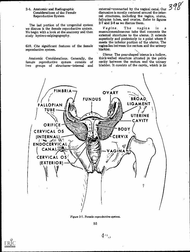
2-4. Anatomic and RadiogaphicConsiderations of the FemaleReproductive System
The last portion of the urogenital systemwe discuss is the female reproductive system.We begin with a look at the anatomy and thenstudy hystero-salpingography.
639. Cite significant features of the femalereproductive system.
Anatomic Considerations. Generally, thefemale reproductive system consists oftwo groups of structuresinternal and
externalconnected by the vaginal canal. Ourdiscussion is mostly centered around the inter-nal structures, including the vagina, uterus,fallopian tubes, and ovaries. Refer to figures2-7 and 2-8 as we discuss them.
Vagina. The vagina is amusculomembranous tube that connects theexternal structures to the uterus. It extendssuperiorly and posteriorly to a point where itmeets the inferior portion of the uterus. Thevagina lies between the rectum and the urinarybladder.
Uterus. The pear-shaped Uterus is a hollow,thick-walled structure situated n the pelviscavity between the rectum and 'the urinarybladder. It consists of the cervix, which is its
OVARY
FUN DUS
FALLOPIAN"TUBE
ORIFICE
CERVICAL OS(INTERNAL);
/ "%N.ENDOCERVICAL I
( CAN
CERVICAL OS(EXTERIOR)
BROAD,LIGAMENT
5. 37
UTERINECAVITY
BODY
CERVIX
Figure 2-7. Female reproductive system.
53
II
ggi
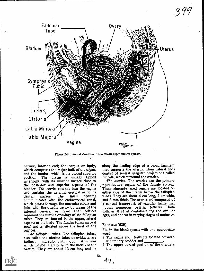
FallopianTube
111:\lAt
SymphysisPubis
Urethro
Clitoris
Labia Minora
Labia Majora
Figure 2-8. Internal structure of the female ieproductive system.
narrow, interior end; the corpus or body,which comprises the major bulk of the organ;and the fundus, which is its curved supiriorposition. The uterus is usually tippedanteriorly, with its anterior surface close tothe posterior and superior aspecth of thebladder. The cervix extends into the vaginaand contains the external cervical os in itsdistal surface. The small openingcommunicates with the endocervical canal,which passes through the muscular cervix andjoins with the uterine cavity by means of theinternal cervical os. Two small orificesrepresent the uterine opengs of the fallopiantubes. They are housed in the upper, lateralaspects of the body. The fundus forms an ovalroof and is situated above the level of theorifices.
The fallopian tubes. The fallopian tubes,also called the uterine tubes or oviducts, arehollow, musculomembranous structureswhich extend laterally from the uterus to theovaries. They are about 12 cm long and lie
54
39g
along the leading edge of a broad ligamentthat supports the uterus. Their lateral endsconsist of several irregular projections calledfimbria, which surround the ovaries.
The ovaries. The ovaries are the primaryreproductive organs of the female system.These almond-shaped organs are located oneither side of the uterus below the fallopiantubes. They are about 4 cm long, 2 cm wide,and 8 mni thick. The ovaries are comprised ofa central framework of vascular tissue thathouses numerous ovarian follicles. Thesefollicles serve as containers for the ova, oreggs, and appear in varying stages of maturity.
Exercises (639):Fill in the blank spaces with one appropriateword.1. The vagina and uterus are located between
the urinary bladder and2. The upper curved portion of the uterus is
the
4
3. The opening of the fallopian tubes into theuterus occurs in the upperaspects of the
4. The fallopian tubes extendfrom the uterus and are aboutcm long.
5. Several , intle up the distalends of the fallopian tubes and surroundthe .
6. The almond-shaped ovaries areapproximately cm long,cm wide, and mm thick.
640. Indicate the purpose and proceduresused for a hysterosalpingogram and a Rubin'stest.
Radiographic Considerations. Whilehysterosalpingography is performed for otherreasons, it is usually done to determinewhether or not the fallopian tubes are patent(open or unobstructed). Patency of the tubesis evaluated as part of a sterility "workup." Ifthe tubes are patent the positive contrastmedium passes through them and "spills" intothe peritoneal cavity and visualizes as_sneh nnthe radiographs.
Aside from a hysterosalpingogram, aRubin's test is sometimes conducted by thegynecologist to determine patency of thefallopian tubes. Usually performed in thegynecology department, carbon dioxide isintroduced into the tubes under pressure andpatency is determined by the amount ofresistance. If the tubes are open the carbondioxide, like the positive corit,rast medium,spills into the peritoneal cavity. Sometimesthe gynecologist elects to document thepresence of air in the peritoneal cavity with aradiograph. You should perform a routineerect PA chest or erect AP abdomen toinclude the diaphragms just as you would todemonstrate "free air" under any othercircumstances. Since the carbon dioxide isabsorbed rather quickly, you should performthe radiograph as soon as possible.
Patient preparation. A hysterosalpingogramis usually performed 7 to 8 days aftercompletion of menstruation. The colon mayor may not be cleared of gas or fecal materialon the evening before, or the day of, theexamination, depending upon the preferencesof the radiologist and gynecologist. In anyevent, have the patient void before she
\N
assumes her position on the X-ray table toreduce the possibility of a filled bladderimpinging upon the fallopian tubes. The filledbladder may also present an extraneous denseshadow which might interfere withvisualization of the contrast medium.
Preparing for the examination. If an oilycontrast medium is used for the examination,it should be warmed to body temperature sothat it will flow more freely. One majorconsideration to keep ',11 mind is that whenthe contrast medium is injected inuterus and fallopian tubes, it is done so uconsiderable pressure, which causes thepatient a lot of pain. After you perform theradiographs, the gynecologist removes thepressure, which relieves the pain. It followsthat you should perform your radiographs asquickly as possible. For this reason, werecommend that two technicians perform theradiographs to save time. Precisely whichtechnician does what during the examinationis something you should decide as long as youminimize the time required to perform theradiographs.
For the same reason mentioned above, youshould assemble the necessary cassettes withthe identification markers (R, L, CCs, etc)already taped on the cassette. Changing thesemarkers between radiographs is inexcusable inthis case because you are actually prolongingthe patient's discomfort.
Performing the radiographs. As a rule, onlyAP and posterior oblique projections areperformed during a hysterosalpingogram. Use10 x 12 inch cassettes crosswise, centered to apoint 2, inches superior to the symphysispubis. A delayed AP projection (up to 24hours) is sometimes made to check forspillage if it is not present immediately.
55
her
...
Exercises (640):1. Why is a hysterosalpingogram usually
performed?
2. Why is a Rubin's test performed?
3. If a patient arrives in the radiologydepartment for a radiograph immediatelyafter a Rubin's test, what is the likelyreason for the film and what radiographshould you make?
i
t--
t.
a. Why should the patient void before ahysterosalpingogram?
5. Why should an oily contrast medium bewarmed to body temperature before ahysterosalpingogram?
-
6. How can you minimize the period of timethe gynecologist maintains the pressureinjecting the contrast medium andconsequently the patient's discomfort?
7. Where should you center the film for thehysterosalpingographic projections?
I
..,
%
I

Contrast Study of the Respiratory System
(AS YOU KNOW, the chest is perhaps morefrequently X-rayed than any other portion ofthe body. While most abnormalities of thechest are evaluated by standard radiography,it is necessary at times to introduce a contrastmedium into the lungs to better visualize thestructures via bronchography.
We begin our study of the respiratorysystem with a close look at the anatomyinvolved. After that, we examine the variousmethods used to inttoduce the contrastmedium, and finallythe procedures involvedin the bronchogra itself.
3-1. Anatomic Considerations of theRespiratory System
In this discussion, we examine the anatomyof the respiratory system from the larynx tothe alveolar sacs.
641. Provide information about significantfeatures of the larynx, trachea, and primarybronchi.
Laryt v The larynx (see fig. 3-1),sometir s called the voice box, is located inthe upper anterior portion of the neckextending from the fourth to the sixthcervical vertebrae. It serves as a passage of airbetween the oropharynx and the trachea andis located immediatvly anterior to thelaryngeal pharynx. The larynx is suspendedfrom the hyoid bone .ind is made up ofvarious structures including the thyroid andcricoid cartilages. The epiglottis guards theentrance of the larynx, preventing food fromentering the trachea during the act ofswallowing.
Trachea. The trachea (see fig. 3-2) is oftencalled the windpipe. It is a roundedcartilaginous tube about 41/2 inches long arid isocated in front of the esophagus. It extendsrom the larynx to the level of the superior
CHAPTER 3
4160--
border of the fifth thoracic vertebra, where itbifurcates into the 'right and left mainbronchi. The internal walls of the trachea arelined with mucosa. The innermost surface ofthis mucosa is composed of stratified, ciliatedepithelium, while its deeper portion iscomposed of a looser meshwork of connectivetissue containing the mucous glands, nerves,and blood vessels. The mucosal cilia, alongwith the mucous secretions, filter any inhaleddust particles and move them upward to thepharynx. The external surface consists ofpartial, C-shped cartilaginous rings,embedded in fibrous tissue to give the tracheaits rigidity. The C-shaped rings openposteriorly, leaving gaps which are covered bystrips of muscular tissue to form a flatposterior surface where the trachea overliesthe esophagus,
Primary Bronchi. At its inferior aspect, thetrachea branches into two smaller tubestutright and the left .primary bronchiwhichsimilar in construction to the trachea. Onebronchus goes to the right lung, the other tothe left.
Right bronchus. The right bronchusconsists of from six to eight cartilaginot&rings which are smaller than, but otherwiseidentical to, those of the trachea. It enters theright lung at the level of the fifth thoracicvertebra. It is shorter, wider, and morevertical in position than the left bronchus.
Left bronchus. The left bronchus is smallerin diameter and longer than the right
57
LARYNX
EPIGLOTTIS
THYROID CARTILAGE
CRICOID CARTILAGE
Figure 3-1. The larynx.
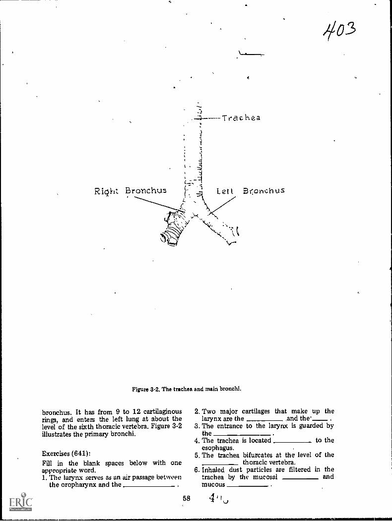
Right Bronchus Lett Br:onchUS
Figure 3-2. The trachea and main bronchi.
bronchus. It has from 9 to 12 cartilaginousrings, and enters the left lung at about thelevel of the sixth thoracic vertebra. Figure 3-2illustrates the primary bronchi.
Exercises (641):Fill in the blank spaces below with oneappropriate word.1. The laryn.x serves as an air passage between
the oropharynx and the
2. Two major cartilages that make up thelarynx are the and the'____
3. The entrance to the larynx is guarded bythe
4. The trachea is located to theesophagus.
5. The trachea bifurcates at the level of thethoracic vertebra.
6. Inhaled dust particles are filtered in thetrachea by the mucosal andmucous

7. The rigidity of the trachea is provided byC-shaped which open
8. The trachea divides into theand
primary bropchi.9. The primary bronchus enters
the lung at a slightly lowerthoracic level than does thebronchus.
LEGEND:
4/Sec-and ary broAohi of (let Iverl0 Secondary bronchl' of: left lung
TR.rt i a ry 1:,ronchi of nght lungTe rtiand b r on ch i of left lun
Bror.obioles
-
if /Yft1P-1
;0.
642, Indicate the anatomical structures andphysiological features of the bronchial tree.
The Bronchial Tree. The main bronchibifurcate wIthin the lungs to form thebronchial tree. You can relate the textualdescriptions to the illustrations in figure 3-3.
Secondary bronchi. The first branch fromthe primary bronchi is the secondary, or
alwatalveolar sac
,
)-7
Figure 33. The bronchial tree.
59

lobar, bronchi. The right lung has threesecondary bronchi, the left has two. There isone secondary bronchus for each lobe.
Tertiary bronchi. The secondary bronchiare further divided into tertiary, or segmental,bronchi. The right lung usually contains 10tertiary bronchi, one for eachbronchopulmonary segment. The left lung haseight .tertiary bronchi and eightbronchopulmonary segments.
Bronchioles. Next in order of subdivisionare the bronchioles (little bronchi) whichenter the lung tissues. To this point, thebronchi and their subdivisions are composedof fibrous tissue and resemble the C-shapedcartilaginous rings of the trachea and theprimary bronchi. But when the bronchibecomes bronchioles, their diameter isdecreased to 1 mm or less and the cartilage isno longer seen. Each bronchiole peqetratesdeeper into the lung tissue, where it dividesinto several ducts called the alyeplar ducts.
Atria. Next in the'subdivision are the atria,which are irregularly shaped, elongated airsacs continuous with the alveolar ducts. Fromthe atria, the alveolar sacs continue thesubdivisions. 1
Alveoli. Finally, the alveoli- are reached.These are minute, cup-shaped air cells thatproject from the walls of the bronchioles,alveolar ducts, atria, and alveolar sacs, andwhich become more numerous at the terminalportion of the respiratory system. Theyconsist of a very delicate, thin layer ofepithelial tissue and are surrounded by anetwork of capillaries. It is here, where thealveoli are close to the bloodstream, that thegases are exchanged through diffusion.
Exercises (642):1. How many secondary branches are in the
left lung? 1,n the right lung?
2. What is another name for the secondarybronchi?
3. What is the next subdivision after thesecondary bronchi?
4. At what point do the C-shapedcartilaginous rings of the bronchi cease toexist?
5. What ducts appear immediately after thebronchioles?
6. From what pulmonary structures does theexchange of gases occur in the lungs?
643. Name, locate, and show significantfeatures of the lungs.
The Lungs. The lungs, shown in figure 3-4,are located on both sides of the mediastinum,where they occupy the right and left portionsof the thoracic cavity. Each extends fromabout,?to 11/2 inches above the clavicle to thesuperior border of the diaphragm. They areseparated from each other by themediastinum, which contains the heart,esophagus, part of th.e trachea, the greatvessels, primary bronchi, and many othersmaller structures. The root of each lungconnects the lung, trachea, and heart andcontains the pulmonary artery and vein,bronchus, bronchial arteries and veins, neives,lymphatics, and lymph nodes. The arteries,veins, and nerves enter and leave the lung at apoint called the hilum, a triangular depressionon the inner medial surface of each lung.
The lungs are composed of a light, porousand spongy, elastic tissue. Each resembles aninverted cone in shape and consists of anapex, base, costal and mediastinal surfaces,lobes and fissures, and a bronchial tree. Theapex is rounded and extends to about 1 to 11/2inches above the level of the sternoclavicularjoints, bilaterally.
The lung base, or diaphragmatic surface,consists of a broad, cdricaved, inferior Yertthat rests on the convex superior surface ofthe diaphragm. Because it covers the rightlobe of the liver, the base of the'rightlung hasa deeper concavity than the left.
The interlobar (oblique) fissure divides theleft lung into two partsL-a superior (upper)lobe and ah inferior (lower) lobe; the latter isthe larger of the two. The right lung has threelobes. An interlobar fissure, similar to that ofthe left lung, separates the inferior lobe frOmthe middle and superior lobes. A horizontalfissure at the level of the fourth costalcartilage makes a wedge-shaped middle lobebetween the inferior and superior lobes.
60'Li
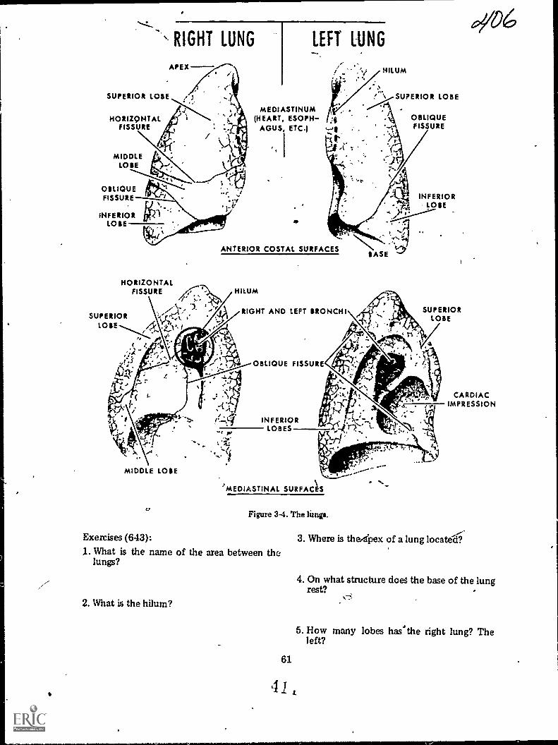
SUPERIOR LOSE
HORIZONTALFISSURE
RIGHT LUNG
APEX
MIDDLELOSE
OBLIQUEFISSURE
INFERIOR irkLOSE
LEFT LUNG
MEDIASTINUM(HEART, ESOPH- 3
AGUS, ETC.) :
IKt , -
HILUM
% SUPERIOR LOBE
ANTERIOR COSTAL SURFACES
HORIZONTALFISSURE /1:7. HILUM
SUPERIOR .
LOSE AVfZ
.
RIGHT AND LEFT BRONCHI
MIDDLE LOSE
4,
OBLIQUE FISSURE
INFERIORLOBES
t.
OBLIQUEFISSURE
INFERIORlOSE
SASE1
SUPERIORLOBE
CARDIACIMPRESSION
'MEDIASTINAL SURFAC1S
Figure 3-4. The limp.
Exercises (643):
1. What is the name of the area between thelungs?
2. What is the hilum?
61
41
3. Where is thedpex of a lung located'.
4. On what structure does the base of the lungrest?
5. How many lobes has'the right lung? Theleft?

6. What structures mark the divisions of thelobes of the lungs?
3-2. Methods of Introducing theContrast Medium
There are at least four methods forintroducing the contrast medium into thelungs for a ,,bronchiogram. The particularmethod used depends primarily upon thepersonal preference of the radiologist and theage and condition of the patient. The fourmethods are: (1) intratracheal intubation, (2)supraglottic, (3) intraglottic, and (4)cricothyroid .
644. Differentiate between the four methodsof introducing the contrast medium during abronchogram.
Intratracheal Intubation Method. Theintratracheal intubation method is perhapsthe most commonly used method forintroducing the contrast .medium into thelungs. The tube or catheter is inserted eitherthrough the mouth or, most commonly,through the nasal cavity into the tracheaduring the first stage in the procedure.Then, under fluoroscopic control, theradiologist directs the tube into the specificarea he wishes to examine. A syringe filledwith contrast medium is then connected tothe tube and the medium is introduced underfluoroscopic control. One advantage of thismethod is that it offers selective visualizationof a particular portiOn of the bronchial tree.
Supraglottic Method. The supraglotticmethod also called the "drip" method is theoldest and sometimes considered to be theleast effective. The contrast medium isdripped, from a syringe fitted with a cannula,onto the back of the tongue where it flowsinto the trachea and lung fields. Onedisadvantage is that some of the contrastmedium is swallowed and appears in theesophagus, possibly causing confusingshadows on the radiographs.
Intraglottic Method. The intraglotticmethod is similar to the supraglottic method.Instead of dripping the contrast medium ontothe back of the tongue, the radiologistintroduces it directly into the glottic using asyringe fitted with a long, curved laryngealcannula.
Cricothyroid Method. In the cricothyroidmethod a needle is inserted directly into thetrachea between the cricoid and thyroidcartilages. The contrast medium can beintroduced through the needle or into acatheter that has replaced the needle. In caseof the catheter, selective visualization of aportion of the bronchial tree is also possible.One major advantage with,this method is thatsince the upper larynx is bypassed, the patientmay not be as likely to cough, which caninterfere with the examination. This methodalso seems to be the most popular withpatients.
Exercises (644):Match the bronchographic method of contrastmedia introduction in column B with theappropriate statement in column A by placingthe letter of the column B item in the spaceprovided in column A. Each column B itemmay be used once or more than once. Inaddition, more than one column B item maymatch a single column A entry.
Column A1. Requires the inser-
tion of a needle.2. Used most often.3. Requires a catheter.4. Permi ts selective
visualization of a spe-cific part.
5. May be least effec-tive.
_6. Uses a long, curvedlaryngeal cannula.
7 May provide confus-ing shadows of a con-trast-filled esophagus.
8. Reduces the patient'surge to cough.
9. Most popular withpatients.
Column Ba. Intratracheal intub-
ation.b. Sapraglottic.c. Intraglottic.d. Cricothyroid.
3-3. Performing the BronchograrnAs far as you are concerned, the
bronchogam is a fairly simple examinationwhich involved nothing more than providingassistance, as needed, to the radiologist duringvarious phases of the examination and thenperforming the post-fluoro radiographs. Someof your minor tasks, however, are importantL th to the success of the examination and tothe welfare of the patient. We begin thissection concerning the performance of thebronchogram with a look at one of the majorproblems, coughing.
62 4 1
)0
645. Relate coughing by the patient to thesuccess of a bronchogram and show howcdughing affects your role during abronchogram.
Coughing. When the contras', material isintroduced into the patient's bronchial tree,he has a strong urge to coughthe morecontrast material, the stronger the urge. Thisis a natural reflex action caused by irritationof the air passages by the material. If thepatient coughs excessively during theexamination, the examination may not besuccessful for two reasons. First, he maycough up the contrast material. Second,coughing may create a condition known asperipheral flood, in which the contrastmaterial fills the minute air passages in theperiphery, resulting in some difficulty ininterpretation.
What can you do to help prevent thepatient from coughing? In the first place, ycushould carefully explain the entireexamination to him. Tell him exactly what isgoing to happen and when it will occur. Stressto him that he must try to refrain fromcoughing. If he feels the urge to cough; heshould institute rapid, shallow breathing or"pant," which sometimes suppresses the urgeto cough.
As mentioned before, the more contrastmaterial in the patient's lungs, the stronger isthe urge to cough. This means that when theexamination nears completion and the entireamount of contrast material has beenintroduced, the patient's urge to cough isstrongest. This is the time during which youwill be performing the post-fluororadiographs. Consequently, you must actquickly. It is best if two technicians performthe radiographs to further minimize the time.
Exercises (645):1. What is the overall effect that
coughing by a patieritbronchography could haveexamination?
excessiveduring
on the
2. Give two reasons for your answer toexercise number 1 above.
3. How can you, by instructing or informingthe patient, possibly help prevent him fromcoughing excessively?
63
4. What action should you take whileperforming the post-fluoro radiographs tohelp insure that the examination is notunsuccessful due to coughing?
646. Indicate the procedures for performingpost-fluoro bronchographic radiographs.
Projections and Exposure. When theradiologist finishes the fluoroscopic phase ofthe examination, you perform the post-fluororadiographs. Depending upon local policy, theradiographs are made with the patientrecumbent on the X-ray table or erect in frontof an upright cassette holder.
Both sides of the chest can be examinedsimultaneously, but more often only one sideis examined on a given day. The projectionsyou perform depend upon the side examined.Usually, a minimum of three radiographs aremadePA or AI', oblique, and lateral;however, this depends upon local policy.Anterior or posterior oblique projections canbe made. If the right lung is examined andyour radiologist wants posterior obliques,take a RPO. Take the opposite posterioroblique if the left side is examined. If yourradiologist wants anterior obliques and theleft side is examined, take an RAOtake theopposite anterior oblique if the right side isexamined. All of these obliques demonstratethe lung field in question free ofsuperimposition by the spine.
If only one side is examined, the correctlateral, of course, is the one that places thepart under examination closer to the film. Ifboth sides are being examined, a lateralprojection after both sides are filled is notnormally accomplished becausesuperimposition of the two sides obscuresstructural details. However, a lateral of thefirst side filled with contrast material isusually accomplished before the opposite sideis filled.
The exposure for the projections describedshould be increased slightly over thatnormally used for the lungs. The reason forthe increase is to demonstrate those portionsof the lung fields superimposed by the heart,and to demonstrate the trachea and primarybronchi which are superimposed over thespine. The exposure should be raised byapproximately 5 to 10 percent of the kvp.

Exercises (646):Answer the following exercises pertaining tothe projections made after fluoroscopy duringa bronchogam.1. What minimum number of projections are
usually made? What are they?
2. If only the right lung is being examined,what oblique projection should you make?
3. If only the left lung is being examined,what oblique projection should you make?
4. Why is a particular oblique necessary?
5. If both lungs are being examined (rightlung first), how many laterals will youprobably make and why?
6. If your answer to the first part of exercisenumber 5 above was one, which lateralwould you make? If your answer was two,which lateral would you make first?
7 Why is it necessary to increase the exposureover that normally required for lungradiographs?
64
647. Briefly discuss the care of thebronchographic patient after the examinationis finished, in terms of his coughing up thecontrast material and ingestion of food orwater.
Aftercare of the Patient. Once theexamination is terminated, provide thepatient with an emesis basin and instruct himto cough gently to remove the contrastmaterial from his lungs, keeping him underobservation until he leaves the radiologydepartment. Be sure to stress that he is tocough gently because to cough harshly forcesthe contrast medium into the alveoli, in whichcase it can only be eliminated by absorption.
Also, of major importance is the fact thatthe patient's throat remains anesthetized for anumber of hours following the examination.Because of this condition, he must not haveanything to eat or drink until the anesthesiahas worn off because, instead of the materialbeing swallowed, it can be aspirated into thelungs.
Exercises (647):1. Explain how the patient should be
instructed to cough up the contrastmaterial r fter the bronchogram and why.
2. How long after the examination should thebronchographic patient be refused water orfood and why?
pgq

Contrast Studies of the Cardiovascular System
BLOOD IS circulated throughout the body bythe circulatory or cardiovascular system.Occlusion, perforation, or disease of thebIood-carrying vessels or of the heart produceserious and often permanent damage. Notonly are the components of the cardiovascularsystem affected, but so are the organs andstructures dependent upon them for bloodsupply. Prompt medical or surgicalintervention is often required to correctanomalous conditions. Rarely, however, issuch treatment initiated until accurate,comprehensive diagnostic tests have beencompleted. These tests include completeradiologic examination of the heart or of theaffected vasculature. The procedures involvedin this type of examination constituteangiography and are the subject of ourdiscussion. Our study is conducted in twoparts. The first portion concerns the physicalstructure of the cardiovascular system. Thesecond part deals with various angiographicconsiderations including the contrast media,techniques of introducing the, contrast media,forming catheters, and a brief look at someofthe special equipment.
4-1. Anatomic Considerations
The cardiovascular system is comprised ofblood, the heart, the arteries, the capillaries,and the veins. We begin our discussion withthe blood and heart.
648. Name and give the locations of majorstructures associated with the heart.
The Blood. Blood is a thick, somewhatsticky fluid, the viscosity of which is nearlyfive times that of water. Basically red in color,it is almost scarlet in the arteries and crimsonin the veins. On microscopic examination,
65
CHAPTER 4
blood is found to consist of numerousdifferentitated cells and fluid plasma.
The Heart. The heart is a hollow, muscularstructure. As shown in figure 4-1, it is roughlycone-shaped and is situated above thediaphragm and between the lungs. The broadbase is uppermost and centered to themidline. The narrow apex, or lower end, islocated well to the left of the midline. Theheart consists of a musculomembranousframework, blood-containing cavities orchambers, and specialized valves and orifices.We consider these components in the ordergiven.
The fibromuscular structures. The cardiacwall or framework consists of three layers oftissue. These include the epicardium, themyocardium, and the endocardium (See fig.4-1.)
The epicardium comprises the outer layerof cardiac tissue. It is a double-layered,sac-like structure which completely covers themyocardium, or heart muscle. The outer layerof the epicardium is called the pericardium.
The myocardium is a large, hollow,mustular structure which forms the bulk ofthe heart and gives.rise to the interventricularand atrioventricular septa or partitions. Theinterventricular septum extends from theapex upward to the base, thus forming theright and left sides of the heart. Theatrioventricular septa divide the hearthorizontally. They are much smaller andthinner than the interventricularseptum, andhouse two of the heart valves.
The endocardium, or lining of the heart, isthe innermost layer of cardiac tissue. Itcompletely covers the internal surfaces of themyocardium and gives rise to the heart valves.
The chambers, valves, and orifices. Thefour large cavities formed by theinterventricular septum and theatrioventricular septa are referred to as the"chambers of the heart." These include theatria, which form the upper chambers, and

PULMONARY ARTERY
PULMONARYVEINS
AORTA
PULMONARY ARTERY
SUPERIORVIKA' CAVA
,.9
PULMONARYSEMILUNAR VALVE
RIGHTATRIUM
TRICUSPIDVALVE
'N PULMONARYVEINSl'.-]
LEFT ATRIUM
IIICUSPID VALVE
MYOCARDIUM
LEFT VENTRICLE
ENDOCARDIUM
EPICARDIUM
PERICARDIUM
INFERIORVENA CAVA
PW
Figure 4-1. The heart.
the ventricles, which comprise the lower ones.These chambers, as well as the cardiac valvesand orifices, are illustrated in figure 4-1. Referto this illustration to familiarize yourself withthese cardiac components.
The right atrium receives blood from allparts of the body except the lungs via thesuperior and inferior vena cave. The tricuspidvalve is located between the right atrium andthe right ventricle.
The right ventricle forms the rightinferolateral aspect of the heart. It is a largecavity and gives rise to the pulmonary artery,which exits through an orifice in its superioraspect. This exit is guarded by the pulmonarysemilunar valve, which consists of three cuspsarising from the epithelial lining of thepulmonary artery.
AORTIC SEMILUNAR VALVE
f
The left atrium, smallest of the chambersof the heart, forms the left supralateral aspectof the cardiac organ. It receives the fourpulmonary veins from the lungs, via fourorifices in its posterolateral surface, andempties into the left ventricle by means of theleft atrioventricular, or bicuspid (mitral)valve. This valve is comprised of two cuspsarising from the endocardium.
The /eft ventricle forms the leftinferolateral aspect of the heart. It is as largeas its counterpart on the right and gives rise tothe aorta. This large artery exits through anorifice in the superior aspect of the leftventricle. The exit is guarded by the semilunarvalve of the aorta (aortic valve), which iscomprised of the same type tissue andexhibits the same type of structure as thepulmonary semilunar valve.
r

Exercises (648):
1. Describe the locations of the base andapex of the heart.
2. What are the names and relative locationsof the three main layers of the heart wall?
3. What is the name of the outer layer of theepicardium?
4. What dividing partition separates the heartinto right and left portions?
5. In what direction does the atrioventricularsepta divide the heart?
6. From what heart chamber does thepulmonary artery rise?
7. Where is the tricuspid valve located?
8. Where is the mitral valve located?
9. Which heart chamber receives blood fromthe lungs?
10. Which heart chamber(s) pumps bloodthrough the aortic semilunar valve?
11. Which heart chamber receives blood frommost of the body?
649. Name and locate key arteries about thechest, neck, and head.
67
The Arterial System. Blom.' is transported..from the heart to the various organs,structures, and tissues of the body by anextensive network of arteries and arterioles.The large, centrally located aorta forms thetrunk, and its ramifications, such as thesubclavian, renal, and iliac arteries, form thebranches.
The aorta. The first major vessel to beconsidered is the aorta. As you can see, infigure 4-2, this vessel arises from the superioraspect of the left ventricle. It first ascendsobliquely and somewhat anteriorly to theright, forming a segment referred to as the"ascending" aorta. The vessel then curvesposteriorly and to the left, to form the aorticarch. The aorta then descends behind theheart, along the left side of the anteriorsurface of the vertebral column, and to thediaphragm. This portion of the vessel isreferred to as the "descending," or thoracic,aorta.
In figure 4-2, note that the aortic arch givesoff three large branches. The first twobranches off the aorta are the small right andleft coronary arteries which supply the heartmuscle with blood. The first of these is theinnominate artery. As illustrated, this vjessel,which is about 4 to 5 cm long, asbendsobliquely to about the level of the rightsternoclavicular articulation. At this point itsplits to form the right subclavian and theright common carotid arteries.
Arteries of the head and neck. The arteriesthat carry blood to the cervical and cranialregions arise from the aortic arch, theinnominate and the subclavians. As seen infigure 4-2, the ascending vessels include theleft and right common carotids and theyvertebral arteries. The ,left common carotidarises from the highest point of the aorticarch and ascends through the superior portionof the mediastinum into the neck. Itscounterpart on the right passes directly intothe neck from its point of origin at thebifurcation of the innominate artery. Onceinto the cervical, region, the appearance andconfiguration of the carotid arteries and theirramifications are essentially identical.Therefore, we consider only those vesselssupplying one side of the neck, face, andhead. The same is true of the vertebralarteries.
'rhe cervical portion of the carotid arteryascends obliquely through the neck to a pointjust about level with the superior aspect ofthe thyroid cartilage. Here it separates,forming internal and external branches.
The external carotid aktery curves laterallyand then ascends along.the side of the neck. It
4 1
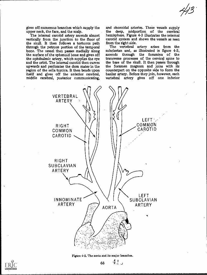
gives off numerous branches which supply theupper neck, the face, and the scalp.
The internal carotid artery ascends almostvertically from the junction to the floor ofthe skull. It then follows a tortuous paththrough the petrous portion of the temporalbone. The vessel then passes medially alongthe surface of the sphenoid bone and gives offthe ophthalmic artery, which supplies the eyeand the orbit. The internal carotid then curvesupwards and perforates the dura mater in theregion of the sella turcica. It then bends uponitself and gives off the anterior cerebral,middle cerebral, posterior communicating,
VERTEBRALARTERY
RIGHTCOMMON iCAROTID
and choroidal arteries. These vessels supplythe deep, midportion of the cerebralhemisphere. Figure 4-3 illustrates the internalcarotid system and shows the vessels as seenfrom the right side.
The vertebral artery arises from thesubclavian and, as illustrated in figure 4-3,ascends through the foramina of thetransverse processes of the cervical spine tothe base of the skull. It then passes throughthe foramen magnum and joins with itscounterpart on the opposite side to form thebasilar artery. Before they join, however, eachvertebral artery gives off one inferior
RIGHTSUBCLAVIAN
ARTERY
LEFT*/C MCAR,OTID
INNOMINATEARTERY
LEFTSUBCLAVIAN
ARTERY
Figure 4-2. The aorta and its major branches.
68 4

POSTERIOR COMMUNICATING
/. SUPERFICIAL
TEMPORALI
BASILAR'
\OCCIPITAL \
r UINTERNAL CAROTID
1
EXTERNAL CAROTID
VERTEBRAL
ARTERIORCEREBRAL
OPTH.ALMIC
) MIDDLE--.--V CEREBRAL
(
/,------)) ANTERIOR/-----' CHOROIDAL
J-i...<_.
EXTERNALMAXILLARY
RIGHT COMMON CAROTID
Figure 4-3. The arterial system of the neck and head.
cerebellar artery. These vessels pass throughthe foramen magnum and serve to nourish thelower portion of the hind brain. The basilarartery, usually a midline structure, ascends onan anteriorly angled course to a point about 1cm posterior to the dorsum sellae. Here itgives off several branches which supply thecerebellum and the posterior aspects, of thecerebral hemispheres. The basilai arteryterminates in the posterior cerebral arteries.
The carotid and vertebral systems arejoined, at the base of the brain, by the circleof Willis. Figure 4-4 illustrates the appearanceand structural arrangement of this juncture.Notice that the majority of the circle isformed by branches from the carotid system.The anterior cerebral arteries are joined bythe anterior communicating arteries to formthe anterior portion of the circle, while the
internal carotid and the middle cerebralarteries form the majority of its lateralaspects. The posterior portion of the circle isformed by the posterior communicating andposterior cerebral arteries and is the terminalend of the basilar artery.
Exercises (649):
Fill in the blank spaces below with one or twoappropriate words.
1. The arises from the upperportion of the left ventricle.
2. To the point where the aorta curvesposteriorly, it is known as the
aorta.3. The posterior curvature of the aorta is
called the aortic
69
41
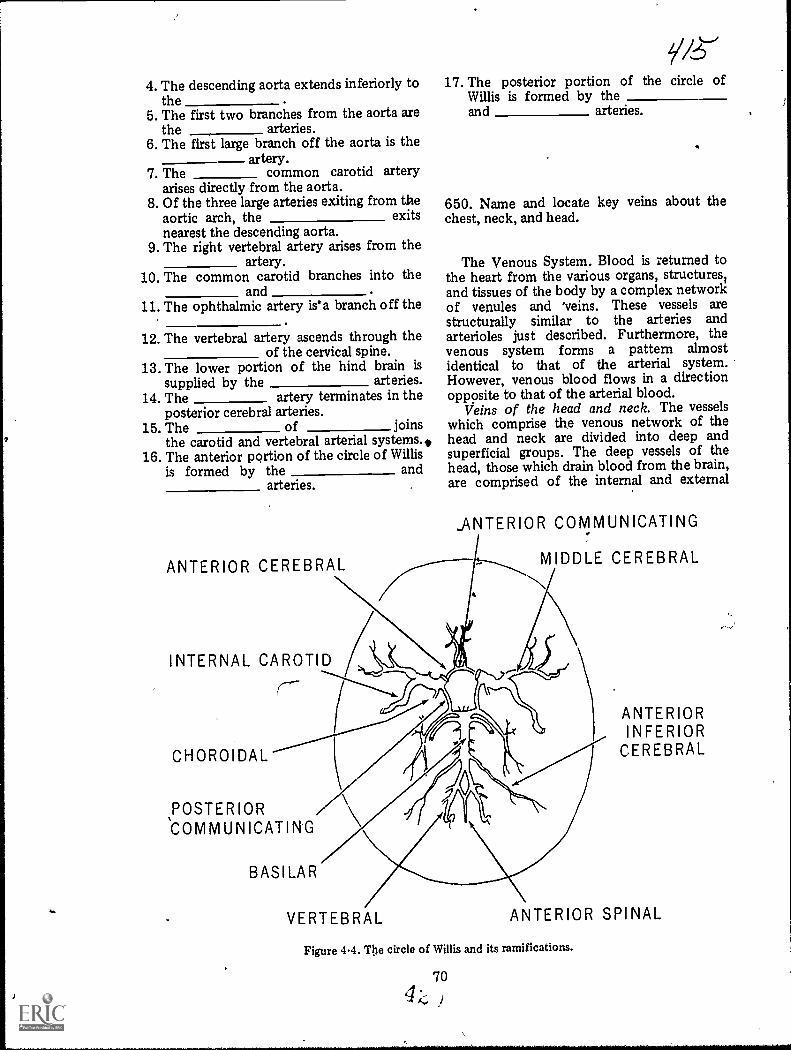
i
7
,
4. The descending aorta extends inferiorly tothe
5. The first two branches from the aorta arethe arteries.
6. The first large branch off the aorta is theartery.
7. The common carotid arteryarises directly from the aorta.
8. Of the three large arteries exiting from theaortic arch, the exitsnearest the descending aorta.
9. The right vertebral artery arises from theartery.
10. The common carotid branches into theand .
11. The ophthalmic artery is'a branch off the,
posterior cerebral arteries.15. The of joins
the carotid and vertebral arterial systems.,16. The anterior portion of the circle of Willis
is formed by the andarteries. ,
12. The vertebral artery ascends through theof the cervical spine.
13. The lower portion of the hind brain issupplied by the arteries.
14. The artery terminates in the
ANTERIOR CEREBRAL
INTERNAL CAROTID
(---
CHOROIDAL
POSTERIOR
BASILAR
17. The posterior portion of the circle ofWillis is formed by theand arteries.
.
650. Name and locate key veins about thechest, neck, and head.
The Venous System. Blood is returned tothe heart from the various organs, structures1and tissues of the body by a complex networkof venules and 'veins. These vessels arestructurally similar to the arteries andarterioles just described. Furthermore, thevenous system forms a pattern almostidentical to that of the arterial system.However, venous blood flows in a directionopposite to that of the arterial blood.
Veins of the head and neck. The vesselswhich comprise the venous network of thehead and neck are divided into deep andsuperficial groups. The deep vessels of thehead, those which drain blood from the brain,are comprised of the internal and external
_ANTERIOR COMMUNICATING
-----...,--..,,
MIDDLE CEREBRAL
..
i
VERTEBRAL
ANTERIORINFERIOR
CEREBRAL
ANTERIOR SPINAL
Figure 4-4. The circle of Willis and its ramifications.
70

SUPERIOR SAGITTAL SINUS
INFERIORSAGITTAL SINUS
SUPERIGR. CEREBRAL
STRIOTHALMIC
SEPTAL
VEIN OF TROLARD
GREAT CEREBRAL /VEIN OF GALEN
STRAIGHT SINUSr(
SUPERIOR \PETROSAL SINUS
INFERIORPETROSAL SINUS \ N.
TRANSVERSE SINUS
INTERNAL JUGULAR
VERTEBRAL
INFERIORCEREBRAL
MIDDLECEREBRAL
CAVERNOUSSiNUS
PLEXUS
PTERYGOIDEUS
INTERNALMAXILLARY
N,EXTERNAL JUGUL'AR
Figure 45. The venous system of the neck and head.
,cerebral veins, the superior and inferior,cerebellar veins, and the dural sinuses. Referto figure 4-5 as we discuss these vessels.
The internal cerebral vessels, which emptythe deep, midportion of the cerebralhemispheres, are the striothalmic (terminal)vein, the internal cerebral vein, and the greatcerebral vein of Galen. The external cerebralvessels include the superior, middle, andinferior cerebral veins and the anastomoticveins of Trolard and Labbe. These veinsempty the upper, mid, and basilar surfaces ofthe hemispheres. The cerebellar veins drainblood from the hind brain. All of these vesselsempty into the dural sinuses. As you can see,these large vessels completely surround thebrain. The superior and inferior sagittalsinuses lie along the margins of the falx
71
cerebri (a fibrous, curtainlike structure whichseparates the superior aspeots of the cerebralhemispheres). They are joined by the straightsinuses, into which the great vein of Galenempties. These sinuses join in the region ofthe internal occipital protuberance and formthe confluens of the sinuses. The right andleft transverse sinuses extend inferolaterallyfrom this junction. They pass along the innersurface of the occiput and give rise to theinferior and superior petrosal and basilarsinuses. The latter gives rise to the sigmoidsinuses which empty into the internal jugularveins. There4ire no valves in these thin-walledvenous structures or sinuses.
The superficial veins of the head, illustratedin figure 4-6, arise from the scalp and face.They describe a pattern similar to that of the

external carotid arterial system and, for themost part, empty into the external jugularveins. As you can see, the occipital vein doesnot empty into either of the jugular vessels,but passes down the posterior aspect of theneck to join with the deep cervical andvertebral vessels. The anterior facial veinempties into both of the large neck veins.
The venous vessels of the neck consist ofthe internal jugular veins (which are thelargest), the external jugulars (and theirramifications), the vertebral veins, and thedeep cervical vessels. As illustrated in figure4-5, the vertebral vein originates at the base ofthe skull and passes downward thrcugh theforamina in the transverse processes of thecervical spine. Thus, it follows a courseclosely approximating that of the vertebralartery. This vein empties into the subclavianvein.
The deep cervical vein arises from the
suboccipital region and passes downward andforward to join with the vertebral vein in itsdistal reaches. The deep cervical receives theoccipital vein and tributaries from the venousplexuses surrounding the cervical vertebrae.
The external jugular veins, as shown infigure 4-6, ,commence near the angles of themandible. They descend along the lateral ,
aspects of the neck to about the level of theclavicles where they empty into thesubclavian veins. The external jugulars receivetributaries from the smaller anterior andposterior external jugular veins, from thesuperior veins of the base of the neck andscapula, and also from a large communicatingbranch from the internal jugulars.
The internal jugular veins arise from thesigmoid sinuses, pass through the jugularforamina in the floor of the skull, anddescend, almost vertically, to join with thesubclavian veins. These large vessels receive
SUPERFICIAL TEMPORAL
FRONTAL
OCCIPITAL
INTERNAL JUGULAR
EXTERNAL JUGULAR
Figure 4-6. Veins of the held and neck.
72
ANTERIORFACIAL
COMMON FACIAL

branches from the comnum facial, lingual,pharyngeal, and the superior and middlethyroid veins. Although their primaryfunction is to drain blood from the brain,they also receive and carry off blood from theface and the structures of the neck.
The subclavian vein extends medially, fromthe first rib to the sternal end of the clavicle.It lies anterior and inferior to the subclavianartery and receives several tributaries,including the external juqular vein. Thesubclavian joins with the internal jugular toform the innominate vein.
Veins of the thomx. The venous system ofthe thorax and mediastinum is comprised ofthe inferior vena cave, the tributaries of thesevessels, and the pulmonary veins. Theinnominate veins are formed by the union ofthe internal jugular and subclavian veins.These junctures take place behind the sternalends of the clavicles. The short, right veindescends along a sharply angled couise toabout the level of the cartilagenous portion ofthe first rib and the lateral aspect of themanubrium. Here it is joined by the moreobliquely situated and longer, leftinnominate. The bilateral innominate veinsunite to form the superior vena cava.
Exercises (650):1. Name three veins that empty the c1cep
midportion of the cerebral hemispheres.
2. What portions of the cerebral hemispheresare emptied by the cerebral andanastomotic veins of Trolard and Labbe?
3. What large vessels completely surroundthe brain?
4. Where are the superior and inferiorsagittal sinuses locaN 1?
5. Into what vein does the sigmoid sinusempty?
6. Are the transverse and basilar sinusesconsidered deep or superficial drainagechannels?
73
7. Does the occipital vein empty int6 theexternal jugular vein?
8. Where does the vertebral vein originate?
9. Where does the vertebral vein empty?
10. With ,that vein does the deep cervical veinjoin distally?
11. Where does the external jugular veinoriginate?
12. Into what vein does the external jugularempty?
. The subclavian and internal jugular veins;Unite to form what.vein?
What vein results from the union of thmnominate veins?
4-2. ;Iingiographic Considerations
Radiography of the vascular system, orangiography, while basically aimed toward thesame results, is perforrned in many differentways. .A simple angitigram consists of a'needle and syringe" injection into an
extremital vessel after which a singleradiograph is made showing the vessel underexamination. Or, an angiogram can beperformed after a catheter is passed into acoronary artery using a sophisticatedapparatus that triggers the injection andfilming procedures at a Specific phase of theheart beat. In addition, there is Igride variancein the manner in which a specific angiogram isperformed from one hospital to another.
Due to the dissimilarity of specificprocedures and techniques, we only present
4 9
you with information that is basic and generalin nature. Keep in mind that many technicalaspects of radiography, such as those relatedto exposure, FFD, tube rating, etc, have beenpresented in volume one of this CDC andapply to angiography as well as otherradiographic examinations." We begin this section wAh a discussion ofangiogaphic contrast media. After that irediscuss aspects, such as introductorytechniques, forming catheters, film changersand automatic injectors.
651. Indicate the uses and adverse effects ofangiographic contrast media and brieflydiscuss the importance of good diagnosticangiograms in relation to the contrast mediadosage.
Contrast Media. Angiographic contrastmedia are similar and often identical to thoseused for intravenous urographythat is, theyare injectable organic iodides. (Injectable inthis case means that they can be injected intothe vascular system.)
Concentration and dosage. Theconcentration of the contrast medium, or wemight say the opacity,. is determined by theamount of iodine it containsbecause iodineis the substance that absorbs the X-rayphotons and outlines the vessels under study.Highly concentrated media are used toprevent excessive dilution due to the highvolume of blord found in the heart and largevessels. Moderately concentrated media areused where blood volume does notsignificantly dilute the medium. Dilution ofthe contrast medium can also be prevented byinjecting a relatively high dose.
Adverse effects. Contrast mediaadministered during angiography can causereactions similar to those discussed in chapter2 of this volume. Also, due to the higherconcentration of some angiographic mediaand the rapid rate in which it is injected, thegreater is the chance of a serious reaction.
Another increased hazard associated withthe injection of angiographic contrast media isthat certain sensitive areas are moresusceptible to reaction when the contrastmedium is introduced directly into them. Forexample, during a renal arteriogram, themedium is either introduced directly into therenal artery or it is introduced into the aortajust proximal to the renal artery.Consequently, this medium reaches thekidneys in a more concentrated form than ifit were injected into the arm for an IVP.
Thus, the danger of damage to the kidneytissue is greater. The heart and the brain areother areas where direct introduction of themedium poses potential dangers.
Due to the dangers', from directintroduction of the contrast Medium, there isa limit to the amount of contrast mediumthat can be introduced into the sensitive areasduring one examination. Why is thisimportant to you? We ll,, consider a renalarteriogram where the first injections of thecontrast material were in vain because theradiographs were technically inadeqpate.Your radiologist may have to delay the nextinjection to allow possible hemodynamicdisturbances to subside. In fact, it is possiblethat he may have to cancel the examinationaltogether for that day if more than oneinjection is carried out without adequateradiographs. Keep in mind that scimeangiograms are traumatic procedures for thepatient, so you must take all the necessaryprecautions to see that good, diagnosticradiographs are produced the first timelestthe entire procedure be repeated. Naturally, adelay in the diagnosis of the patient'scondition may also result.
Exercises (651):1. How is excessive dilution of the contrast
medium overcome for angiogaphicstudies?
2. Give three reasons why angiographiccontrast media increases the chance of aserious reaction.
3. Briefly discuss the importance of A
performing good diagnostic angiograms thefirst time.
652. Compare the three methods forintroducing the contrast medium during anangiogram.
Introductory Techniques and Devices.Refined methods and, in certain instances,sophisticated injck.tion devices are used tointroduce contrast material into the
744 9
v as c u lature. The techniques includupercutaneous injection, selectivecatheterization, and a combination of thesecalled percutaneous-selective catheterization,or Seldinger's technique.
Percutaneous injection. Percutaneoussimply means "through the skin." Thistechnique is performed by passing a spinal,abdominal, or hypodermic needle through theskin, the subcutaneous and muscle tissue, andinto the vessel to be demonstrated. Thetwo-part spinal needle is more often used.One part consists of a hub and cannula, andthe other is a trocar. The slender trocar has avery sharp point, while the cannula is usuallyblunted. The trocar is passed through thecannula and does the cutting. Once into thevessel, it is removed and the dull cannula isleft in place. Thus, the arterial or venous wallsare not subjected to any more damage than isabsolutely necessary. A syringe filled withphysiological saline is then attached to thehub of the needle, either directly or by meansof tubing and an adapter. This salt watersolution is injected by hand in the standardmanner. It serves to clear the cannula and thearea around its tip of debris resulting frompassage through the vessel wall. Following theinjection of saline, another syringe filled withmoderately concentrated contrast material isattached to the needle in the same manner.Again, injection is made by hand in thestandard manner. Percutaneous injection isusually restricted to procedures that requireonly small amounts of contrast material.Thus, it is generally employed for carotid,femoral, and peripheral angiography, and venacavography.
Se le c tive catheterization. Selectivecatheterization involves the passage of a long,thin-walled catheter through an artery or veininto the heart or aorta. A surgical cutdown isperformed to expose the vessel through whichthe catheter is to be threaded. As a rule, thefemoral artery (below .the inguinal ring), theantecubital vein, or the brachial artery are thevessels exposed. The vessel is incised and thecatheter inserted and threaded to the desiredposition under fluorocconic control. When itis in place, the catheter utured to the vesseland the surrounding tissue. The incision isthen closed and dressed. Acontrast-medium-filled syringe is attached tothe exposed end of the catheter by anadapter, and injection can be made by hand.However, the procedures for which thistechnique is employed usually require largeamounts of highly concentrated material.Consequently, automatic pressure injectorsare more often used to force the medium
75
through the catheter and into the structuresto be visualized. Selective catheterization canbe used for angiocardiography, thoracicaortogaphy, coronary arteriography, thoracicaortography, coronary arteriography, lumbaraortography. and selected abdominalarteriography.
Pe rc u ta n eous-selective ieterization.Percutaneous-selective theterization(Seldinger's technique) is a .mbination ofthe techniques just describe-1. This techniqueinvolves percutaneous inset in of a specialneedle into the lumen of a particular vessel(usually the femoral artery, just below theinguinal ring) followed by selectivecatheterization. The needle, rather than asurgically exposed vessel, serves as theintroduction site fc the catheter. The needleconsists of either two or three parts. It isinserted into the vessel, and physiologicalsaline is injected in the same manner and forthe same reasons as described for the standardpercutaneous injection. A special, veryflexible guide wire is then passed through theneedle and into the lumen of the vessel. Thewire is threaded, under fluoroscopic control,through the vasculature to the desiredposition. When it is in place, the needle isremoved and a long, thin-walled catheter ispassed over the guide wire, through thepuncture site, and into the lumen of thevessel. From there it is . threaded underfluoroscopic control through the vasculatureto the desired position. The guide wire is thenremoved and the position of the catheter isfluoroscopically rechecked. Heparinized saline(a solution of heparin, an anticoagulant, andphysiological saline) is usually injected byhand to preclude obstruction of the cathetertip because of the blood clotting. Injection ofcontrast material is made either by hand or byautomatic pressure injector.Percutaneous-selective catheterization iswidely used for abdominal arteriography andaortography.
Exercises (652):Match the method for introducingangiographic contrast media in column B withthe appropriate statement in column A byplacing the letter of the column B item in thespace provided in column A. Each column Bitem may be used once or more than once. Inaddition, more than one column B item maymatch a single column A item.
Column A Column B1. Uses a catheter. a. Percutaneous injec-2. Catheter is passed tion.
over a guide wire.
4 9 0
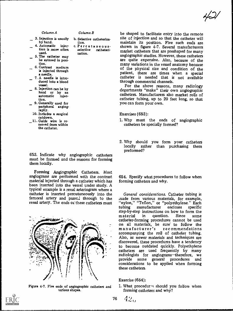
--_
_
Column A
3. Injection is usuallyby hand.
4. Automatic injec-tion is more oftenused.
5. The catheter maybe sutured in posi-tion.
6. Contrast mediumis injected througha needle.
7. A needle is intro-duced into a bloodveuel.
8. Injection can be byhand or by anautomatic injec-tion.
9. Generally used forperipheral angiog-raphy.
10. Includes a surgicalcutdown.
_11. Guide wire is re-moved from withinthe catheter.
Column B
b. Selective catheteriza-tion.
c.Percutaneous-selective catheteri-zation.
653. Indicate why angiographic cathetersmust be formed and the reasons for formingthem locally.
Forming Angiographic Catheters. Mostangiograms are performed with the contrastmaterial injected through a catheter which hasbeen inserted into the vessel under study. Atypical example is a renal arteriogran where acatheter is inserted percutaneously into thefemoral artery and passe.: through to therenal artery. The ends or these catheters must
Figure 4-7. Five ends of angiographic catheters andvarious shapes.
76
be shaped to facilitate entry into the remotesite of injection and so that the catheter willmaintain its position. Five such ends areshown in figure 4-7. Several manufacturersmarket catheters that are preshaped for manyangiographic studies. However, these cathetersare quite expensive. Also, because of themany variations in the vessel anatomy becauseof the physical size and condition of thepatient, there are times when a specialcatheter is needed that is not availablethrough commercial channels.
For the above reasons, many radiologydepartments "make" their own angiographiccatheters. Manufacturers also market rolls ofcatheter tubing, up to 20 feet long, so thatyou can form your own.
Exercises (653):1. Why must the ends of angiographic
catheters be specially formed?
2. Why should you form your catheterslocally rather than purchasing thempreformed?
654. Specify what procedures to follow whenforming catheters and why.
General considerations. Catheter tubing ismade from various materials, for example,"nylon," "Teflon," or "polyethylene." Eachtubing manufacturer encloses specificstep-by-step instructions on how to form thematerial in question. Since somecatheter-forming procedures cannot be usedon all materials, be sure to follow themanufacturer's recommendationsaccompanying the roll of catheter tubing.Also, as newer materials and techniques arediscovered, these procedures have a tendencyto become outdated quickly. Polyethylenecatheters are used frequently by manyradiologists for angiogramstherefore, weprovide some general procedures andconsiderations to be applied when formingthese catheters.
Exercise (654):1. What procedur,s should you follow when
forming catheters and why?
4 9

Figure 4-8. Position of the catheter over a beaker ofboiling water before tapering.
655. Indicate why the end of an angiographicpolyethylene catheter must be tapered, theprocedures used for tapering, and theresulting specifications.
Tapering the tip of the catheter. If thecatheter is to be inserted into a vessel over aguide wire, and most of them are, its tip mustbe tapered. The reason it must be tapered isto permit the catheter to be easily passed overthe guide wire as it, the catheter, enters thewall of the vessel. Tapering the catheterreduces the thickness of its walls as well as itsinternal diameter. The internal diameter ofthe tapered tip must fi t snugly over the guide
wire but must not be so tight that it preventspassage of the catheter over the wire. (NOTE:Always wear surgical gloves when handlingcatheter tubing to prevent the natural oilsfrom your skin from adhering to the catheter.Also, the gloves must be free of powder.Unpowdered commercial gloves are available
Figure 4-10. Cutting the short end of the taperedsection with a scalpel blade.
but you can also rinse the powder offstandard gloves. This procedure is to preventthe powder from adhering to the catheter.)
To taper the end of a polyethylenecatheter, hold a small section near the end ofthe tubing above a small flame or above abeaker of boiling water, as shown in figure4-8. Rotate the catheter until the exposedsection softens from the heat of the flame orfrom the steam. Stretch the tubing by pullingagainst the softened section with your fingersuntil the diameter of the softened section issufficiently reduced. See figure 4-9.Immediately immerse the softened section incold water until it hardens. Cut the short endof the catheter off with a sharp razor orscalpel blade, as shown in figure 4-10. Thelength of the tapered section depends uponthe examination to be performed and yourradiologist's preferenceusually it is less than2 cm. To insure that the internal diameter ofthe tapered segment is correct, pass thetapered section over the guide wirethe same
Figure 4-9. Showing the tapered section of tubingafter it has been softened and stretched.
77
Figure 4-11. Close-up of a tapered catheter.
4 9
ea-2

size as that used with the catheter. It shouldfit the guide wire, as previously described.Some techniques taper the end of the catheterwith the guide wire in place, which is morelikely to make the internal diameter of thecatheter compatible with the diameter of theguide wire. If you do not use the guide wire, acommon error in stretching the catheter is tomake the internal diameter too small forpassage over the guide wire. However, thisproblem is usually overcome with practice.After you are satisfied that the tapered endand guide wire are compatible, smooth thecut end of the tapered section with emorypaper (specifically, that recommended by themanufacturer) by brushing toward the end.The tapered end should appear approximatelylike that shown in figure 4-11, except for itslength, which varies.
Exercises (655):1. Why should the end of an angiographic
catheter be tapered?
2. Briefly discuss the type of gloves to wearwhen handling catheter tubing and whygloves are worn.
3. Briefly explain the procedure for stretchingthe catheter.
4. How should the stretched section of thecatheter be hardened?
5. How long should the tapered section beafter it is cut?
6. How should you test the compatibility ofthe internal diameter of the catheter andthe guide wire?
7. What results should you achieve with thetechnique indicated in exercise number 6above?
2/4,23
8. Until you are experienced in stretching thecatheter tubing, how can you keep fromstretching the catheter excessively, therebymaking its internal diameter too small?
9. How should you smooth the tip of thetapered section?
656. Give necessary details pertaining to theprocedure for forming the end section of apolyethylene catheter.
Forming the end section of the catheter.After you have tapered the , end of thecatheter, the next step is to form or shape theend of the catheter. You can either use a"forming wire" commercially supplied,preshaped or straight, or a guide wire. Thestraight forming wire and the guide wire allowyou to shape the catheter to your radiologist'sspecifications. If you use a preshaped formingwire, simply insert it into the catheter. Theend section of the catheter will, of course,take on the shape of the wire. Rotate thecatheter over heat as before or immerse it inhot water, above 140°F, until it softens. Donot immerse the tapered end of the catheterinto the water because its thin walls willbecome damaged. After the catheter softens,immediately immerse it in cold water until ithardens. After hardening, the catheter willthen remain shaped as was the wire. If thecatheter does not retain the shape of the wire,you probably did not allow it to softensufficiently.
If you use a straight-forming wire or aguide wire to shape the tubing, simply insertthe guide wire, shape the wire and tubing asdesired and carry out the procedure describedabove. If you use the guide wire, use the endnot inserted into the patientbecause thatend is more stiff than the other and retains itsshape better. Figure 4-12 shows a preshapedforming wire along with a catheter shapedfrom that wire.
Exercises (656):1. List three types of wires that are used to
form the end section of the catheter.
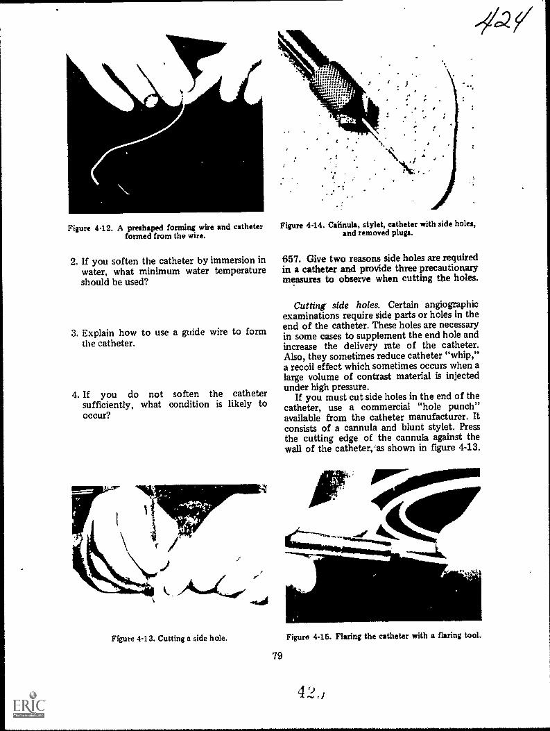
Figure 4-12. A preshaped forming wire and catheterformed from the wire.
2. If you soften the catheter by immersion inwater, what minimum water temperatureshould be used?
3. Explain how to use a guide wire to formthe catheter.
4. If you do not soften the cathetersufficiently, what condition is likely tooccur?
Figure 4-14. Caiinula, stylet, catheter with side holes,and removed plugs.
--4.2
657. Give two reasons side holes are requiredin a catheter and provide three precautionarymeasures to observe when cutting the holes.
Cutting side holes. Certain angiographicexaminations require side parts or holes in theend of the catheter. These holes are necessaryin some cases to supplement the end hole andincrease the delivery rate of the catheter.Also, they sometimes reduce catheter "whip,"a recoil effect which sometimes occurs when alarge volume of contrast material is injectedunder high pressure.
If you must cut side holes in the end of thecatheter, use a commercial "hole punch"available from the catheter manufacturer. Itconsists of a cannula and blunt stylet. Pressthe cutting edge of the cannula against thewall of the catheter, as shown in figure 4-13.
)11
Figure 413. Cutting a side hole. Figure 4-15. Flaring the catheter with a flaring tool.
79
4 9.., .1
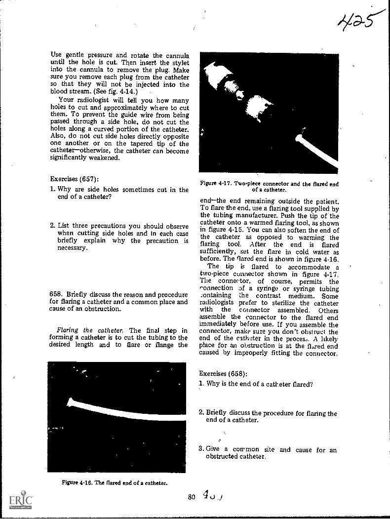
Use gentle pressure and rotate the cannulauntil the hole is cut. Then insert the styletinto the cannula to remove the plug. Makesure you remove each plug from the catheterso that they will not be injected into theblood stream. (See fig. 4-14.)
Your radiologist will tell you how manyholes to cut and approximately where to cutthem. To prevent the guide wire from beingpassed through a side hole, do not cut theholes along a curved portion of the catheter.Also, do not cut side holes directly oppositeone another or on the tapered tip of thecatheterotherwise, the catheter can becomesignificantly weakened.
Exercises (657):
1. Why are side holes sometimes cut in theend of a catheter?
2. List three precautions you should observewhen cutting side holes and in each casebriefly explain why the precaution isnecessary.
658. Briefly discuss the reason and procedurefor flaring a catheter and a common place andcause of an obstruction.
Flaring the catheter. The final step informing a catheter is to cut the tubing to thedesired length and to flare or flange the
Figure 4-16. The flared end of a catheter.
Figure 4-17. Two-piece connector and the flared endof a catheter.
endthe end remaining outside the patient.To flarethe end, use a flaring tool supplied bythe tubing manufacturer. Push the tip of thecatheter onto a warmed flaring tool, as shownin figure 4-15. You can also soften the end ofthe catheter as opposed to warming theflaring tool. After the end is flaredsufficiently, set the flare in cold water asbefore. The flared end is shown in figure 4-16.
The tip is flared to accommodate atwo-piece connector shown in figure 4-17.The connector, of course, permits theconnection of a syringe or syringe tubing:ontaining the contrast medium. Someradiologists prefer to sterilize the catheterwith the cold-lector assembled. Othersassemble the connector to the flared endimmediately before use. If you assemble theconnector, make sure you don't obstruct theend of the cathoter in the proces.. A likelyplace for an obstruction is at the fl.red endcaused by improperly fitting the connector.
Exercises (658):1. Why is the end of a catheter flared?
2. Briefly discuss the procedure for flaring theend of a catheter.
3. Give a common site and cause for anobstructed catheter.

659. Describe the sterilization procedures touse for angiographic catheters.
Sterilizing angiographic catheters. Beforesterilizing the catheters, be sure to read andfollow the manufacturer's recommendations.Polyethylene, on which our entire discussionof catheter forming is based, cannot beautoclaved and chemical -immersionsterilization is not recommended. This leavesgas sterilization as the only method. Also, donot use gas sterilized polyethylene for a fewdays after sterilization.
Some "Teflon" catheters can be safelysterilized using any approved procedureincluding autoclaving as long as the autoclavetemperature does not exceed 250° F.
Exercises (659):1. What instructions should be followed to
sterilize angiographic catheters?
2. What is the only method to use whensterilizing polyethylene catheters?
3. Certain "Teflon" catheters can beautoclaved at what maximum temperature?
660. Compare major features of the threetypes of automatic film changers.
Au tom atic Film Changers. Mostangiographic examinations requireradiographs made with an automatic filmchanger. Conceivably cine or video tapesystems could perfonn the same function ofrecording several "pictures" of contrast filledvessels per second but both of these systemsdo not reproduce the fine detail needed forthese studies. We first examine the types ofchanges and then some of the uses andproblems encountered. .
Types of automatic changers. Several typesof automatic film changers are on thecommercial market and found in Air Forcehospitals. Basically, they can be broken downinto three categories: (1) the cassette changer,(2) the roll film changer, and (3) the cut filmchanger.
81
Historically, the cassette changer was thefirst automatic changer to receive extendeduse in angiography and it is still used for someangiograms with excellent results. One of theproblems encountered with a cassette changeris that it is not as reliable mechanically as theother two types. There is a tendency for theunit to jam, especially after the cassettes areused repeatedly and become worn ordamaged. Another problem is that it cannotachieve the rapid change rate that can beachieved by others. The relatively slow ratelimits the use of this type of changer toangiograms that do not require several filmsper second.
Another significant problem encounteredwith a cassette changer not present with rollor cub film changers is that, due to the weightof the cassettes as they are transferred fromone point to another, the unit has a tendencyto vibrate. Obviously, this vibration can causeslight movement of the' patient and result inmotion on the radiographs. As a rule themotion is most striking on a projection, suchas the AP skull where the part is relativelyunstable. If vibration of your cassette changerresults in part motion, you should use anextension band on the X-ray table to supportthe head instead of resting the head directlyon the changer.
The roll film changer is somewhat of animprovement over the cassette changer in thatmore radiographs can be made per second.This improvement results from the fact thatmechanical movement of film on a roll iseasier to accomplish than that of cassettes.This type of changer is more reliablemechanically than other types. The fact thatthe film is rolled, however, does not lenditself to the economical use of film. Betweenexaminations, a new leader must be insertedinto the receiving magazine, which results inwasted film. Also, the end of a roll may alsohave to be discarded if it is not long enoughto accommodate the next examination,resulting in a further waste of film. The rollfilm changer does not experience thevibration of a cassette changer.
The cut film changer solves some of theproblems of both-the other types of changers.Single sheets of film are advanced instead ofcassettes or a roll. This type of changer canproduce more films per second, prevent filmwaste, and of course reduce vibration causedby the movement of heavy cassettes.
Exercises (660):Match the type of film changer in column Bwith the Qppropriate statement in column A
IF
4 3,

by placing the letter of the column B item inthe space provided in column A. Each columnB item may be ased once, or more than once.In addition, more than one column B itemmay match a single column A item.
Column Ba. Cassette changer.b. Roll film changer.c. Cut film changer.
Column A1. Hu a tendency to vi-
brate._2.Most reliable,
mechanically.3. Has slowest filming
rate.4. Wastes film.5. Least reliable me-
chanically.6. Has high filming rate
with little film waste.7. Little vibration.
44.
661. Indicate the advantages of a see-throughfilm changer.
One recent improvement in automatic filmchangers is the "see-through" changer. Thisimprovement allows the use of an image tubepositioned so that the area can befluoroscopically monitored simultaneouslywith the filming, Not only does this allow theradiologist to monitor the area with televisionbut it allows the injection to be recorded onvideo tape. The advantage of the video taperecording is that the tape can be played backimmediately enabling the radiologist toquickly determine whether or not theexamination is successful. Otherwise, he mustwait until the "changer" radiographs areprocessed.
Exercise (661):1. What are the advantages of a see-through
film changer?
662. Give two advantages and two problemspertaining to biplane film changer operation;indicate corrective measures necessary toovercome the problems.
Biplane changer operation. If two X-raytubes are used to simultaneously make AP orPA and lateral radiographs, the examination isa biplane study. One obvious advantage of
82
-5427biplane studies is the reduction in the dosageof contrast mediumthe patient receives onedose for a biplane study, but he receives -twodoses for separate studies. Another advantage,the most significant one, is that theradiologist can study the structures moreaccurately if right angle studies are madesimultaneously.
One of the major problems you willencounter during a biplane examination is thepresence of scatter radiation causing film fog.Since you have two X2,ray beams exposing thepatient, scatter radiation is approximatelytwice normal. One solution to this problem ofexcessive scatter is to use two crossed grids(described in volume 1). At times, however,you cannot use two crossed grids. Forexample, if one of the two projections, suchas the AP cerebral 'angiogram, requires anangled C.R., you cannot use a crossed griddue to the absorption of primary radiation.
Even though you use two crossed grids, andcollimate properly, film fog will be slightlymore evident than during single planeoperation. Consequently, the exposure youuse for a biplane projection should be slightlyless than that used for the same projectionduring a single !plane study. The reducedexposure is necessary to maintain the samefilm density from one examination to thenext. Consequently, you will have to use alinear grid for the AP. You can Use a crossedgrid for the lateral in this case because theC.R. is perpendicular to the grid. Precisecollimation of both beams to the parts understudy is absolutely necessary during biplaneoperation to'reduce the scatter radiation.
Another problem sometimes encounteredwith a biplane cerebral angiogram is the lossof detail due to the large part-film distance onthe lateral. Depending on the type of changeryou have, you may not be able to achieveclose contact between the side of the patient'shead and the changer. This condition resultsin soine detail lossthe amount dependingupon the part-film distance present. Tocompensate for the increase in part-filmdistance, increase the FFDperhaps to 72inches if the part-film distance is considerable.
Exercises (662):
1. What are two advantages of biplane filmchanger operation?
2. List two problems encountered duringbiplane filmig. In each case, indicate howthe problems can be overcome.
663. Briefly discuss the primaryconsiderations requiring your attention whenusing an automatic injector.
Automatic Injectors. Automatic injectorsare highly sophisticated devices that introducelarge amounts (up to 100 ccs) of contrastmedia into the blood system under greatpressure (up to 1000 pounds per square inch).Several different models are used throufenoutAir Force hospitals, and, although they allserve the purpose, the operating principlesand instructions vary.
As far as you are concerned, there are twomajor areas of concern pertaining to aninjector. The first is that you must completelyunderstand the operation of your particularinjector. Whis means that you will have tostudy the manufacturer's operatinginstructions in detail until you understand allaspects of theoperation.
The second concern was discussed involume 1, but, because of its importance, wereview the particulars here. When an injectoris connected to a catheter, which is inserted
83
into the blood stream, it only takesapproximately 1/1000 of the lethal skincurrent to produce ventricular fibrillation inthe patient. The reason for this is because theresistance of the skin is bypassed by thecontrast medium in the catheter. Thesignificance of this condition is that a verysmall amount of leakage current from aninjector, even in good repair, can electrocutethe patient. As explained in volume 1, youmust insure that the injector, X-ray table, andother electrical appliances in the room aregrounded to the same ground potential toreduce the possibility of the patient becomingelectrccutad.
Exercises (663):1. Briefly discuss your role in the operation of
an automatic injector.
2. Briefly discuss the electrical hazard presentwhen an automatic injector is used and givethe necessary precaution. '

CHAPTER 5
Contrast Studies of the Nervous System
*
ALL OF OUR specialized senses (sight,hearing, smell, taste, and touch) as well as ourorganic functions (respiration, circulation,digestion, etc.) are governed by a complexneural network which is referred to as the"nervous system." Actually, this network iscomprised of two major components, thecentral and the peripheral nervous systems.The latter is further divided to include theautonomic nervous systems. Since, however,we are concerned on'; with the centralsystem, this portion of our discussion islimited to central nervous system structures;for example, the brain, spinal cord, meninges,and the ventricular system. The brain isencased by the cranial bones, and the spinalcord is surrounded by the bony structures ofthe vertebral coluMn. Further protection isafforded by three layers of membranoustissuethe meningeswhich completely investboth the brain and the cord. Thecerebrospinal fluid flows through this closedand continuous system to cushion the brain inits solid vault. In order to examine eachsection of the system in more detail, weconsider them separately and in conjunctionwith the 'radiographic procedures used tovisualize theni. We begin with a study of themyelogram.
54. MyelographyAs you know the special radiographic
procedure employed to demonstrateabnormalities of the spinal cord is referred toas a myelogram. Essentially, the procedureinvolves introduction of a heavy, viscidcontrast material into the spinal portion ofthe subarachnoid space. This injection isfollowed by fluoroscopic observation andradiographic recording of the contrast mediaflow around the spinal cord.
664. Name, locate, and describe major partsof the spinal cord. '
Anatomic Considerations. The spinal cordis the longest and most inferiorly situatedportion of the CNS. Essentially, it provides ameans of communication between the brainand the nerve fibers connecting to the variousparts of the body.
External structure of the spinal cord. Asyou can see in figure 54, the spinal cord is anextension of the brain stem. It joins themedulla oblongata in the region of the firstcervical vertebra and then descends through
MEDULLA OBLONGATA
CONUS MEDULLARIS
FILUM TERMINALE
844 ,1.1,.....,
CISTERNA MAGNA
\r' CAUDA EQUINA
%
Figure 5-1. The spinal cord.
\\
\\

DORSAL.NERVE ROOT
VENTRALNERVE ROOT
DORSAL MEDIAN SULCUS
DORSALLATERAL SULCUS
CENTRALC*ANAL
VENTRALLATERAL SULCUS
VENTRALMEDIAN FISSURE
Figure 52. The dorsal and the ventral sulci.
the spinal canal to about the level of the firstor second lumbar vertebra. The cord isapproximately 42 to 45 centimeters long,about 1 centimeter in diameter, and isroughly cylindrical. It terminates in a sharplyconstricted cone called the conus medullaris.The filum terminate, a- slender filament,extends from the apex of the conus to thefirst coccygeal segment where it is attached tothe osseous tissue of the vertebral column.
The anterior, a ventral surface of the cord,is scored by a relatively deep fissure. Thiscentrally situated depression is called theventral median fissure. The posterior, ordorsal surface, is scored by a similar but muchshallower depression called the dorsal medialsulcus. These major depressions divide thecord into lateral halves. Each half is furtherscored by two shallow furrows, referred to asthe dorsal lateral sulcus and ventral lateralsulcus, respectively. Figure 5-2 illustrates thelocation of these grooves. The dorsal nerveroots pass through the dorsal lateral sulci andprovide the posterior connection between thespinal nerve and the central portion of thecord. The ventral nerve roots pass through theventzal lateral sulci and serve to connect theanterior portion of the central part of thecord with the spinal nerve. Figure 5-3illustrates the appearance of the nerve rootsemanating from their respective Su lci andjoining to form the spinal nerves.
The spinal cord gives off 31 pairs of spinalnerves. As you can see in figtire 5-1, thecervical and thoracic nerves exit. transverselyfrom the cord and those on the lumbar regiondetcend almost vertically from the conus
85
medullaris. Thus, the lumbar and sacral nervesdescend individually from the conus to theirrespective points. This region, which extendsfrom about the second lumbar vertebra to thesecond sacral segment, is referred to as thecauda equina, which means "horses tail." It isso named because the vertically situatedlumbar and sacral nerves resemble the coarsehair in the tail nf a horse. The spinal cord andcauda equina are completely invested by threelayers of membranous tissue that we willdiscuss later in this chapter.
Internal structure of the spinal cord.Generally speaking, the inner portion of thespinal cord is comprised of an H-shapedcolumn of gray matter and fiber tracts ofwhite matter shown by the dark-shaded H andthe lighter shaded material in figure 5-2. Thegray matter forms the core of the cord and issurrounded by the white matter. B9th tYPesof tissue are continuous with that of themedulla oblongata. The cross section throughthe cord shows tht structural relationshipbetween the core a4fi its surrounding tissue.
ARACHNOIDMEMBRANE
Figure 5-3. The 'nerve roots emanating from theirsulci.
430
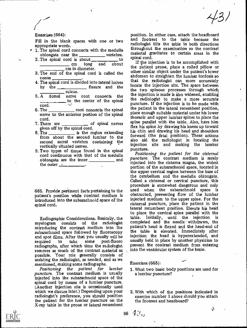
Exercises (664):Fill in the blank spaces with one or twoappropriate words.
o 1. The spinal cord connects with the medullaoblongata near the vertebra.
2. The spinal cord is about tocm long and about
cm in diameter.3. The end of the spinal cord is called the
conus4. The spinal cord is divided into lateral halves
by the fissure and thesulcus.
5. A dorsal nerve root connects theto the center of the spinal
cord.6. The root connects the spinal
nerve to the anterior portion of the spinalcord.
7. There are of spinal nervesgiven off by the spinal cord.
8. The is the region extendingfrom about the second lumbar to thesecond sacral vertebra containing thevertically situated nerves.
9. Two types of tissue found in the spinalcord continuous with that of the medullaoblongata are the inner andthe outer
665. Provide pertinent facts pertaining to thepatient's position while contrast medium isintroduced into the subarachnoid space of thespinal cord.
Radiographic Considerations. Basically, themyelogram consists of the radiologistintroducing the contrast medium into thesubarachnoid space followed by fluoroscopyand spot films. After that you usually will berequired to take some post-fluororadiographs, after which time the radiologistremoves as much of the contrast material aspossible. Your role generally consists ofassisting the radiologist, as needed, and as wementioned, making some radiographs.
Positioning the patient for lumbarpuncture. The contrast medium is usuallyinjected into the subarachnoid space of thespinal cord by means of a lumbar puncture.(Another injection site is occasionally usedwhich we discuss later.) Depending upon yourradiologist's preference, you should positionthe patient for the lumbar puncture on theX-ray table in the prone or lateral recumbent
431position. In either case, attach the headboardand footrest to the table because theradiologist tilts the table in both directionsthroughout the examination so the contrastmaterial gravitates to certain areas in thespinal cord.
If the injection is to be accomplished withthe patient prone, place a rolled pillow orother similar object under the patient's lowerabdomen to straighten the lumbar lordosis sothat the radiologist can more accuratelylocate the injection site. The space betweenthe two spinous processes through whichthe injection is made is also widened, enablingthe radiologist to make a more accuratepuncture. If the injection is to be made withthe patient in the lateral recumbent position,place enough suitable material under his lowerthoracic and upper lumbar spines to.place thespine parallel with the table. Also, have himflex his spine .by drawing his knees up towardhis chin and drawing his head and shouldersforward (the fetal position). These actionsalso aid the radiologist in locating theinjection site and making the lumbarpuncture.
Positioning the patient for the cisternalpuncture. The contrast medium is rarelyinjected into the cisterna magna, the widestportion of the subarachnoid space, located inthe upper cervical region between the base ofthe cerebellum and the medulla oblongata.Called a cisternal or cervical puncture, thisprocedure is somewhat dangerous and onlyused when the subarachnoid space isobstructed, preventing flow of the lumbarinjected medium to the upper spine. For thecisternal puncture, place the patient in thelateral recumbent position. Elevate his headto place the cervical spine parallel with thetable. Initially, until the injection iscompleted and the needle withdrawn, thepatient's head is flexed and the head-end ofthe table is elevated. Immediately afterinjection the head is hyperextended, andusually held in place by another physician toprevent the contrast medium from enteringinto the ventricular system of the brain.
Exercises (665):1. What two basic body positions are used for
a lumbar puncture?
2. With which of the positions indicated inexercise number 1 above should you attachthe footrest and headboard?
86 ..1,

3. Why should you elevate the patient's lowerabdomen for a prone lumbar puncture?
4. \Thy should the lower thoracic and upperlumbar vertebrae be elt.vati d for a laterallumbar puncture?
5. Describe the fetal position.
6. When is the cisternal puncture used in placeof the lumbar puncture?
assistance. He will ask you to compress theveins of the neck on one or both sides andrelease the pressure upon his signal. Yourradiologist will demonstrate the gxactcompression si$1 and procedure. Sometimeswhen the veirm are compressed, the pressureof the cerebrospinal fluid rises qtickly if thereis no obstruction. When the pressure isreleased, the pressure also drops quickly. If anobstruction is present, the pressure is usuallynot affected by the compression or release ofthe compression.
Exercises (666):1. Briefly describe the test for intraspinal
pressure using a Rubin's manometer.
7. What basic body position is used for the 2. j3riefly describe the Queckenstedt sign.cisternal puncture?
8. What is the position of the patient's headand the table during a cisternal punctureinjection?
9. Why is the patient's head hyperextendedimmediately after the cisternal injection iscompleted?
666. Briefly describe the intraspinal pressuretest using a manometer and the Queckenstedtsign.
Testing for intraspinal pressure. At times,the radiologist elects to check the amount offluid pressure within the subarachnoid spacebefore injecting the contrast material.Consequently, you should always have aRubin's manometer available. The radiologistsimply connects this device to the stopcockand allows cerebrospinal fluid to flow into thecalibrated glass tube. The height to which thefluid rises indicates the amount of pressurewithin the subarachnoid space.
Also, he can look for the Quechenstedt signthat indicates whether or not there is anobstruction or block in the vertebral canal.For this procedure the radiologist needs your
87
667. Discuss the two dangers to the patientduring a myelogram in terms of theconsequences, and cite typical precautionarymeasures.
Injection of the contrast medium andfluoroscopy. Once the preliminary proceduresare over, the radiologist injects the contrastmedium. After that he replaces the stylette inthe needle and covers the needle with a steriledressing. The needle is left in place so that thecontrast material can be removed when theexamination is over. As, indicated before,during a cisternal puncture the needle isremoved after injection of the medium. Inthis case the medium is removed through asecond puncture.
If the upper thoracic or cervical spinalcanals are examined, an additional technicianmay be required to rea:ntain the patient'shead in an elevated and hyrerextendedposition during fluoroscopy irri until themedium is removed. Also, the patient's headmust not be permitted to chop ilelow levelof the spine. As indicated earlier, is toprevent the contrast medium frehn enteringthe ventricles of the brain.
The patient is usually placed i; tht! proneposition for fluoroscopy, ng theprotruding needle Letween the patib: pineand the fluoroscopic apparatus. At .,Lis timeyou must lock the vertical . djustwent of Lie
fluoroscopic unit in place so that it cannot beaccidently lowered to contact the needle. Thisevent could result in the needle being driveninto the spinal nerves, causing permanentparalysis of a portion of the patient's loweranatomy. Of course, your .radiologist is alsoaware of the dangers involved with theprotruding needle. However, because of thepossible consequence, if both you and yourradiologist "double-check" each other, thechance of farther insertion of the needle isminimized.
The fluorosOpic apparatus can bepositively secured to prevent accidentalcontact with the needle by means of acommercial myeldgraphic stop madeespecially to be used with certain X-raymachines. It is simply a metal bar whichattaches to the fluoroscopic unit andmaintains a certain amount of space betweenthe unit and tabletop. This is the best methodto use because it does not rely on a "lock"that can become defective.
Post-fluoro projections. When theradiologist terminates the fluoroscopy, he willmore than likely require you to performcertain radiographs. There are two importantfactors to keep in mind while performing theradiographs. The first is that the needle is stillpresent in the patient's back and must beprevented from contacting' anything. Thesecond is that the patient's head must not bepermitted to drop below the level of thespine. If the contrast medium is in thethoracic or cervical spines, the hyperextensionof the head must also be maintained.
The specific projection you make willdepend upon your radiologist's fluoroscopic^findings. However, PA, anterior oblique, andstandard or cross-table lateral radiographs canbe made. Obviously, you will not perform APand posterior obliques due to the presence ofthe needle.
Exercises (667):1. With respect to the patient's head, what
precautions may have to be takenthroughout the myelogram and why?
2. With respect to the protruding needle, whatprecautions should be taken and why?
88
-5035-2. Pneumoencephalography and
Ventriculography
The brain is the largest and most complexpart of the central nervous system. It isencased' by the cranial bones and is dividedinto lobes for anatomical purposes. In thissection, we discuss these characteristics of thebrain and then consider the applicableradiographic procedures.
668. Name and describe significant parts ofthe cerebrum and the ventricular system ofthe brain.
Anatomic Considerations. As you can seein figure 5-4, the brain consists of thecerebrum, or forebrain; the midbrain; thecerebellum, or hind brain; and the brain stem.Let's look at them.
The cerebrum. The egg-shaped cerebrum isthe largest component of the brain. As youcan see in figure 5-5, it is dividedlongitudinally by a deep cleft called thelongitudinal fissure: The two parts arereferred to as hemispheres. Notice that thesurfaces of these hemispheres are comprisedof foltied ridges (convolutions) called gyri.The gyri are separated from each other byshallow furrows called sulci. Six of the sulci,three in each hemisphere, are deeper than theothers and serve to segment the cerebrum.These segments are referred to as lobes. Fourof the lobes are named for the cranial boneswhich cover them, while the fifth is called theinsula.
The convoluted surface of the hemispheresis comprised of gray matter (so-called becauseof its color). This gray matter spreads over aninner mass of specialized fibrous tissue calledwhite matter (once again, after its color).
The midportion of the cerebrum housesfour irregularly shaped, interconnectedcavities referred to as ventricles (see fig. 5-6).The ventricles are lined with delicate tissueswhich secrete the lymph-like cerebrospinalfluid that fills the veltricles and theintracranial and spinal portions of thesubarachnoid space. Each lateral ventricle(there are two) is comprised of a centralportion, or body, and three appendagesreferred to as the anterior, posterior, andinferior horns. The majority of the body,including the anterior and posterior horns, issituated directly below the corpus callosum.The anterior horn extends into the frontallobe and the posterior horn into the occipitallobe. Each lateral ventricle communicateswith the third ventricle by a channel calledthe foramen of Monro.
4 `4t_

CEREBRUM PARIETAL LOBE
FRONTAL LOBE
TEMPORAL LOBE
MIDBRAIN
..,
-mr.,.........
OCCIPITALLOBE
CEREBELLUM
BRAIN STEM
CEREBRAL PEDUNCLES
PONS
MEDULLA OBLONGATA
Figure 6-4. The component parts of the brain.
The third ventncie is situated in themidline, directly below he mi,dial aspects ofthe lateral ventncles. It is housed betwee., themasses of the thalamus, and itsantenor-inferior portion extends downwardthrough the hypothalamus. The thirdventncle consists of a central portion fromwhich irregularly shaped projections extendposteriorly and antero-inferiorly. Theposterior portion is situated above the pinealbody and, thus, is referred to as thesuprapmeal recess. The third ventricle
89
CEREBELLUM
,Y3V
communicates with the fourth ventriclethrough the aqueduct of Sylvius.
The rhomboid, or diamond-shaped fourthventricle, is a midline structure situated in thespace between the cerebelli.m and the brainstem. Its posterior aspect is formed by theconcavity between cerebellar hemispheres.The fourth ventricle L continuous with thecentral canal of the spinal cord, which is theconstricted inferior portion of the cavity.Other than the aqueduct of Sylvius there arethree openings into the fourth ventriclethe

LONGITUDINAL FISSURE
LEFT HEMISPHERE RIGHT HEMISPHERE
///CENTRAL SULCUS
TRANSVERSE FISSURE
LATERAL FISSURE ---- CEREBELLUM
CEREBELLAR NOTCH
Anterior Horn
Figure 5-5. Relative positions of brain structures.
Body
Posterior Horn
Foramenof Monro
ThirdVentricle
FourttVentricle
Aqueduct ofSylvius
Figure 56. Ventricles of the brain.
90 4
Inferior Horn

foramen of Magendie and two foramina oiLuschka. The ventricle communicates withthe cisterna magna through the foramen ofMagendie and with the subarachnoid cisternsthrough the two foramina of Luschka.
Exercises (668):Fill 1-1 the blank spaces with one or moreappropriate words.
1. The largest component of the brain is the
2. The cerebrum is divided intoand hemispheres by the
3. The folded ridges on the surfaces of thecerebrum are called .
4. The names of the five cerebral lobesa re
, , and
5. The outer layer of cerebral tisi.ut isreferred to as .._____.
6. Cerebrospinal fluid m secreted by the four
7. The two large -wishbone-sh., )ed"ventricles are the .
8. The foramina of Monro connectthe ventricles to the
9. The posterior portion of the thit7iiventncle is known as the
10. The fourth ventricle communicates withthe third ventricle by the way of the
11. The fourth ventricle communicates withthe cisterna magna by way of the
669. Name and locate significant features ofthe cerebellum and brain stem.
The cerebellum. The cerebellum, secondlargest component of the brain, is situatedbeneath the posterior aspect of the cerebrum(the occipital lobe). The cerebellum iscompnsed of a central stalk. called the vermis,and two hemispheres. The hemispheres areseparated from the cerebrum by a deep cleft,called the transverse fissure. Their superioraspects are also separated from each other bya shallower vertical cleft, referred to as thecerebellar notch.
The brain stem. The midbrain, pons, andmedulla oblongata are referred to as the
91
"brain stem." As you can see in figure 5-4,these structures are united and are situatedanterior to the cerebellum. (The medullaoblongata is actually continuous with thespinal cord, but for our purposes, we considerthese structures as separate entities.)
The midbrain is a short, constrictedsegment connecting the pons and cerebellumwith the cerebrum. The cerebral pedunclescarry impulses between the cerebrum andspinal cord.
.The pons (see fig. 5-4) is a large bulbous
mass of fiber tracts situated below themidbrain, anterior to the cerebellum, andsuperior to the medulla oblongata. It iscomprised primarily of white matter,although it does house the nuclei of fourcranial nerves in its central portion.
The medulla oblongata (see fig. 5-4), oftenreferred to as "the bulb," is actually anenlarged area of the spinal cord. It is situatedbelow the pons and just above the foramenmagnum. The anterior surface of the medullaoblongata is comprised of two bundles offibers called the pyramids. The posterioraspects of the medulla houses two majornuclei which receive the fibers from the whitecolumns of the spinal cord below and thethalamus and cerebellum above.
Exercises (669):1. Where is the cerebellum located with
respect to the cerebrum?
2. What are the names of the three basic partsof the cerebellum?
3 What are the three parts of the brain stem?
4. What parts of the midbrain carry impulsesbetween the spinal cord and cerebrum?
5. Where is the medulla oblongata located?
6. What are the pyramids?
4
p,3,

670. Provide significant features of themeninges and subarachnoid space.
The meninges. The brain and spinal cordare completely covered by three layers ofmembranous tissue which are referred tocollectively as the meninges. They arecomprised of the pia mater, arachnoidmembrane, and the dura meter.
The pia mater is the innermost portion ofthe meninges. It is a highly vascularmembrane which very closely covers the brainand spinal cord. The intracranial portion ofthe pia covers the gyri of the cerebrum andcerebellum; dips down into sulci of bothstructures; extends into the transversecerebral fissure; forms the tela choroidea ofthe third ventricle, and, in part, the choroidplexuses of the lateral and fourth ventricles;and covers the outer surfaces of the corpuscallosum, hypothalamus, mamillary bodies,pons, and medulla oblongata. The spinalportion of the pia mater is somewhat thickerthan the intracranial portion. It completelyencircles the cord and is closely adherent toit. The tissues of the pia completely fill themedian fissure and form a sturdy band alongits ventral margins. The pia extends into thefilum terminate and blends with the duramater (outer meningeal membrane) in theregion of the second sacral segment where itjoins the peritoneum.
The term "arachnoid" literally meansspiderlike. Its use in connection with themeninges refers to the similarity between aspider's web and the delicate structure of themiddle meningeal membrane. As you can seein figure 5-3, the arachnoid is situatedbetween the pia mater and the dura mater. Itloosely envelopes both brain and spinal cord.The arachnoid, unlike the pia, does not dipdown into the sulci of the cerebrum andcerebellum. The arachnoid membrane is notclosely adherent to the pia mater but isseparated from it by the subarachnoid space.Cerebrospinal fluid, produced by theventricular system, is circulated through thisspace. The subarachnoid space is not uniformin depth; the wide deep regions are referred toas cisterns. The three principal cisterns arelocated in the vicinity of the cerebralpeduncles, the junction of the pons, and themedulla oblongata, and the inferior surface ofthe cerebellum and the brain stem. The spinalportion of the arachnoid loosely invests thecord and terminates in the distal reaches ofthe cauda equina.
The dura mater is the outermost meningP.almembrane. Comprised of tough, fibrous
92
tissue, the dura completely covers the outersurfaces of the brain and spinal cord. Itsintracranial portion is comprised of twolayers. The outer, periosteal layer, is in directcontact with the inner surfaces of the cranialbones. The smooth inner, or meningeal layer,overlies the arachnoid membrane. Both layersof the dura are joined except in the placeswhere the dural sinuses pass between them.The meningeal layer of the dura is separatedfrom the arachnoid membrane by the shallowsubdural space. This space is similar to thatfound between the visceral and parietal layersof the pleura. It contains a small amount offluid to prevent adhesion and friction.
The subarachnoid space. As previouslydescribed, the subarachnoid space iscontinuous around the brain and spinal cord,and is divided into intracranial and spinalportions. It is not uniform in depth. The deepspaces in the intracranial portion are referredto as cisterns and surround the base and stemof the brain. The largest of these is thecisterna magna. It actually forms a funnelaround the base of the cerebellum and themedulla oblongata.
Exercises (670):
Fill in the blank spaces with one or twoappropriate words.
1. The three layers of tissue surrounding thebrain and spinal cord are called the
2. The inner meningeal layer is the3. The thicker portion of the inner
meningeal layer is in the area.4. The inner meningeal layer blends with the
outer layer near thevertebra.
5. The middle meningeal layer isthe membrane.
6. The space between the middle and innermeningeal layers is calledthe space.
7. The space indicated in exercise number 6above contains
8. Wide, deep portions of the subarachnoidspace are called
9. The subarachnoid space ends in the distalportion of the
10. The outer meningeal layer is called the
11. The two layers of the outer meningealmembrane are joined everywhere exceptin the locations of the
12. The space between the middle and outermeningeal larrs is called the
13. The largest cistern is the
4 .12. 6,
z/3
671. Compare pneumoencephalography withventriculography.
Radiographic Considerations.Pneumonencephalography a n dventriculography, also called intracranialpneumography, are two examinationsperformed to visualize the ventricles of thebrain filled with a contrast medium. Basically,the examinations are similar with respect tothe projections made after the medium isintroduced. However, there is a considerabledifference between the two to that point.
Comparison of pneumoencephalographyand uentriculography. The entirepneumoencephalographic procedure isaccomplished in the radiology department.The examination usually begins with patientseated with his forehead resting against anupright filming device, such as a head unit,upright X-ray table, or other upright bucky.He can be strapped into a specialpneumoencephalographic chair, or if one isnot available, he can be seated astride astandard straight-backed chair. The physicianusually makes a lumbar puncture (rarely acisternal puncture) and, after removing asmall amount of spinal fluid, replaces it withair, carbon dioxide, or oxygen. Since air rises,the negative contrast medium ascends thespinal cord and for the most part enters theventricular system of the brain. (A smallamount of medium also enters thesubarachnoid spaces of the brain.)
The surgeon then asks for an AP or lateralprojection or both to determine whether ornot the contrast medium does, in fact, reachthe ventricular system. Make these initialprojections without moving the patientexcept to turn his head for the lateral, if it isnecessary to do so. After inspecting theradiographs, the surgeon usually administersmore contrast medium and asks for additionalscout films. When he is satisfied that theventricles are sufficiently filled, he will askyou to perform the standard projections.
The contrast medium for theventriculogram is introduced in the operatingroom; consequently, you may be required toperform the scout films there with theportable unit. After the patient is
anesthetized, the surgeon, using a specialtrephine saw which is used to remove acircular disc of bone, makes a small hole oneach side of the skull (usually called trephineopenings). If the patient is an infant, the holesmay not be necessary due to the open suturesor anterior fontanel. The surgeon then insertsa needle through each opening into the lateral
93
ventricles and replaces a certain amount ofthe spinal fluid with the same type of contrastmedia used for pneumoencephalography. Ifthe surgeons want scout films, an AP or PAand cross-table lateral projections are usuallymade. After inspecting the radiographs, thesurgeon can introduce more of the contrastmedium; or he can remove the needles, dressthe wounds, and have the patient transferredto the radiology department for theradiographs.
Exercises (671):Match the radiographic examination incolumn B with the appropriate statement incolumn A by placing the letter of the columnB item in the space provided in column A.Each column B item may be used once ormore than once. In addition, both column Bitems may match a sirigle
Column A1. First radiographs are
made with the pa-tient upright.
.2 The contrast mediumis introduced throughtrephine openings.
-3 The contrast me-dium, during intro-duction, rises into theVentricles.
4. The examination vi-sualizes the ventriclesof the brain.
5. Some contrast me-dium enters the sub-arachnoid space ofthe brain.
6. Patient is seated forintroduction of themedium.
_ 7. Scout films include across-table lateral.
8. Contrast medium isintroduced directlyinto the lateral ventri-cles.
column A entry.Column B
a. Pneumoen cephalo-graphy.
b. Ventriculography.
672. Give essential facts pertaining to thewelfare of the patient and the importance ofpatient cooperation and technician speedduring intracranial pneumography.
Preliminary considerations. Intracranialpneumography is perhaps the most hazardousand uncomfortable neuroradiologicalprocedure you will perform. In addition, thesuccess of the examination depends, to a great

extent, on the speed and exactness by whichyou perform the radiographs. Following theseconsiderations, we discuss some preliminaryaspects and thoughts which will help youperform your part in the examination.
During intracranial pneumography, thepatient is likely to experience conditions,such as hypotension, headaches, restlessness,nausea or vomiting. Also, a more severecondition, such as respiratory arrest, canoccur. Accordingly, you should have theappropriate emergency equipment available.If your emergency supplies are on a cart, aswe discussed in chapter 2, it should bpbrought into the room. Specifically, suchitems as the AMBU, oxygen, suctionapparatus, laryngoscope, blood pressure cuff,and intravenous fluids might be needed.Hypotension is a common condition and forthat reason some surgeons want the patient's'blood pressure monitored throughout theexamination. Some physicians also want thepatient's legs wrapped tightly with elasticbandages to minimize fluctuations in theblood pressure.
Due to the discomfort of the patient, it isoften difficult to achieve the desired headpositions for the radiographs. In fact, theaccuracy of the positions is usually directlyrelated to the extent to which the patientcooperates. Therefore, you should make apositive attempt to inspire his' cooperationand confidence. As we have mentioned severaltimes before, one way to gain the patient'shelp is to explain the examination to him inadvance. Stress the importance of theaccuracy of the positions and describe eachposition to him. Throughout the examination,show that you are visibly and activelyconcerned with his A mfort and well being.Praise him after each projection. Keep inmind that the degree to which he cooperatesdepends, in part, upon your actionsso actaccordingly.
Another consideration to which you shouldgive thought is to perform the radiographsquickly. One obvious reason for this is thepatient's discomfort. The quicker you finishthe radiographs, the quicker he can return tothe comfort of his bed and beginrecuperation. Another reason speed isessential is that absorption of the contrastmedium begins almost immediately.Therefore, if you take too long to performthe radiographs, the amount of the mediumremaining may be insufficient to adequatelyvisualize the structures.
A minimum of two technicians shouldperform the radiographs during intracranialpneumography for the reasons stated above.
i3gAlso, make sure that you have enoughcassettes or grid cassettes available tocomplete the examination without delay.
Exercises (672):1. List six possible adverse effects that the
patient might experience duringintracranial pneumography.
2. List six emergency treatment items thatshould be readily available.
3. Why should the patient's legs be bound?
4. Why should you gain the patient'sconfidence and cooperation?
5. How can you help gain the patient'sconfidence and cooperation?
6. Why should you perform the radiographsquickly?
673. Answei key questions pertaining to theprojections made during intracranialpneumography.
Projections. The projections you willperform during intracranial pneumographydepend upon the nreference of yourradiologist and surgeon and the reasons forwhich the examination is performed. Most ofthe projections will be performed with themedian plane either perpendicular or parallelto the film. These relationships are veryimportant to the correct diagnosis of a spaceoccupying lesion. If the relationships are notmaintained, a space occupying lesion may beobscured or the outline of the ventricles maysimulate a lesion that does not exist.
Most radiologists want you to perform twoor more projections from a basic headposition without moving the patient. For
example; if from the brow-down position hewants a PA with a vertical C.R. and a lateralwith a horizontal C.R., perform bothprojections without moving the patient'shead. (NOTE: He may require two or threePAs made from the brow-down position withdifferent C.R. angles and a horizontal lateral.Likewise, perform all of these projectionswithout moving the patient.) The reason forthis is so he can evaluate the anatomy fromright angle aspects without a change in thedistribution of the medium. Since themedium may shift its position with but littlepatient movement, the only way to satisfy theradiologist's desire is to take both projectionswith the patient maintaining his position.
As a rule, several projections are made ofthe airfilled ventricles by changing theposition of the patient's head and theorientation of the C.R.. Several radiographsare needed because the surgeon does notcompletely fill the ventricular system witn thecontrast medium. He only fills a portion ofthe system. Therefore, to visualize the four,ventricles 'and related structures, it is
necessary to make several projections afterthe contrast medium shifts its position.
Usually, you will employ four basic headpositions to obtain the radiographs: (1)brow-up, (2) brow-down, (3) stanthrri lateral,and (4) extension. At least tw-. andsometimes more, projections are made fromeach position.
In the brow-up position, the patient issupine on the table with his median planeperpendicular to the table. Also, adjust hisorbitomeatal lines perpendicular to the table.Several radiographs can be made from thisposition including an AP projection with theC.R. vertical and directed midway betweenthe hairline and supraorbital ridge, and APprojections with the C.R. angled up to 30degrees caudally and up to 10 degrees towardthe head. A lateral projection using ahorizontal C.R. (cross-table lateral) is also
made with the patient in the brow-upposition, in which case you should d;r^ct theC.R. to a point just superior to the superiorborder of the ear. The C.R. should beperpendicular to, and the median planeparallel with, the film. The ii terpupillary lineshould also be perpendicular to the film.
The brow-down position is similar to thebrow-up except that the patient is proneinstead of supine. The orientation of themedian plane and orbitomeatal lines are thesame as in the brow-up position. Someradiologists want you to elevate the head-end
95
of the table 100 before placing the patient inthe brow-down position and to keep itelevated for all the brow-down projections.The reason for the elevated table is to preventthe escape of air from certain criticallocations within the ventricular anatomy.Brow-down radiographs include a PA with theC.R. vertical and passing througii a transverseplane 2 inches superior to the external,auditory meatus. A PA projection with theC.R. angled 25° cephalic and entering at theexternal occipital protuberance is alsoperformed. A cross-table lateral projection isalso made using the same guidelines as for thelateral brow-up projection.
With the standard lateral position, the headis positioned as you would for a "routine"lateral skull (semiprone), with the medianplane parallel with, and the interpupillary lineperpendicular to, the film. Adjust the verticalC.R. so that it enters one and one-half inchescranial to the external auditory meatus. Bothlaterals are usually made. AP or PAprojections may also be made with the patientin this position, using a horizontal C.R.. Besure the C.R. is perpendicular to the film.
Extension of the head refers to a positionsimilar to that used for an inferosuperiorprojection of the skull. The patient is supineon the table with his head either hanging offthe end of the table with the vertex resting ona support, or his shoulders are elevated to theextent that the vertex can be placed on theX-ray table itself. The head must be extendedand positioned so that the orbitomeatal line ishorizontal. A lateral projection with ahorizontal C.R. is usually made from thisposition. Direct the C.R. througii the sellaturcica.
Sometimes the third and fourth ventriclecan only be demonstrated with a lateraltomogram. While this tomogram can be madewith a tomographic apparatus, at times theapparatus cannot be used due to the positionof the patient's head. For example, someradiologists want the tomogram uprightimmediately after the injection during apneumoencephalogram. If you cannot use thetomographic apparatus, perform anautotomogram as follows: Position the headso that the median plane is parallel with, andthe interpupillary line is perpeniicular to, thefilm. The film itself is vertical and the C.R. ishorizontally directed to a point 1 inchanterior to, and 1 inch superior to theexternal auditory meatus. Have the patientrock his head gently through a 100 arc as ifshaking his head "no." Usinghis forehead asthe pivot point, use a 21/2-second exposure.
4

Exercises (673):1. Why is it important to position the head
with the proper median plane to film-relationships?
2. Why should some radiogaphs be madewithout moving the patient's headbetween exposures?
3. Why are sevaal projections made bychanging the patient's head position andthe orientation of the C.R..?
4. How is the orbitomeatal line and median, plane positioned for the brow-up
positions and brow-down positions?
5. To what part of the patient should theC.R. be directed for an AP projection(vertical C.R.) made with the patient inthe brow-up position?
6. To what part of the patient should theC.R. be directed for horizontal lateralsmade with the patient in the brow-up orbrow-down position?
-#17. Why should the head-end of the table be
elevated 10° while the patient is in thebrow-down position?
8. To what part of the patient is the C.R.directed for lateral projections made witha vertical C.R..?
9. Briefly describe the extension position ofthe head.
10 What projection is usually made from theextension position?
11. Why is a lateral tomogram sometimesperformed?
12. To what part of the patient is the C.R.directed for a lateral autotomogam?
13. What is the position of the patient's headwith r :spect to the film for anautotomogram?
14. How should the patient move his headduring an autotomogram?

r-
ANSWERS FOR EXERCISES
CHAPTER 1
Reference:600 - 1. Hard and soft palates.600 - 2, Maxillae and palatines.600 - 3. Elevation of the soft palate separates the
nasal cavity and nasopharynx from the oralcavity and oropharynx.
601 - 1.601 2.601 - 3.601 - 4.601 - 5.601 - 6.601 - 7.601 t601 - 9.601 - 10.601 11.601 12.
602 - 1
602 2.602 - 3
602 - 4.602 - 5.602 - 6.602 - 7.602 - 8.602 - 9.602 - 10.602 - 11.
C.
b.b.a, b, c.a, C.a.a, c.
C.
C.
C.
b.
T.F. It is the proximal portion,F. Food and air pass through thepharynx.T.T.T.T.F. It Li approximately 25 cm long.T.F. It is posterior to the heart.T.
604 - 2. Oblique.604 - 3. When the bulb lies in an anteroposterior
direction.604 - 4. It marks, the end of a small bowel series
when it is visualized on a radiograph.604 - 5. Duodenum. Posterolaterally from the pylo-
rus. Curves downward and descends overthe head of the pancreas, curves mediallyand upward behind the stomach and finallycurves sharply downward.
604 - 6. The proximal half of the duodenum.
605 - 1. Cecum, ascending colon, hepatic flexure,transverse colon, splenic flexure, descend-ing colon, sigmoid colon, rectum, analcanal, and anus.
606 - 1. Hemidiaphragm.606 - 2. Right; quadrate; caudate.606 - 3. Falciform ligament.606 - 4. Inferior.606 - 5. Common hepatic.606 - 6. Posterior; duodenum.606 - 7. Intrahepatic radicals.606 - 8. Cystic.606 - 9. Common bile; pancreatic.
oro- 606 - 10. Common bile; pancreatic.606 - 11. Duodenal papilla.606 - 12. Tail, body, head.606 - 13. Islets of Langerhans.606 - 14. Dnct of Santorini.
603 - 1. Greater curvature. Lesser curvature.603 - 2. On the greater curvature.603 3. Incisura angularis.603 - 4. (1) Cardiac orifice - lies at the level of the
eleventh thoracic vertebra 1 inch to the leftof the lateral sternal border. (2) Pyloricorifice 1 to 2 inches to the right of themidline at the level of the upper border ofthe first lumbar vertebra.
603 - 5. (1) Fundus - proximal. (2) Body - middle.(3) Pylorus - distal.
603 - 6. The iliac crests.603 - 7. Hypersthenic or obese.603 - 8. Asthenic.603 9. Two to 4 inches below the level of the iliac
crests.603 - 10. Like a
604 - 1. Duodenum, 25 cm; jejunurn, 7 to 8 feet;and ileum, 16 feet.
97
607 - 1. To intensity or amplify the brightness ofthe fluoroscopic image.
607 - 2. (1) X-rays strike the input phosphor caus-ing it to emit light photons. (2) The lightphotons strike the photocathode causing itto emit photoelectrons. (3) The electronsare accelerated and focused so that theystrike the output phosphor where they areconverted to light photons.
608 - 1. Minification increases the brightness of thefluoroscopic image because the image dis-played by the output phosphor is smallerthan that of the input phosphor. Eventhough both phosphors contain the sametotal amount of light, the brightness of theoutput image is greater because the light ismore concentrated.
608 - 2. The energies of the electrons across thetube are increased. The higher the electronenergies, the more light photons emittedwhen the electrons strike the output phos-phor.
608 - 3. Answer: 2,560.
/fzf-
Explanation: Minification gain(d1 )2
(d2)264
1
64Brightness gain , minification gain x fluxgain a 64 x 40
.3 2,560
609 - 1. Two.609 - 2. Conventional fluoroscopy.609 - 3. You see the image with the rods on your
retina (scotopic vision). Rods are verysensitive to light but cannot perceive finedetail.
609 - 4. You see the image with the cones on yourretina (photopic vision). Cones allow youto resolve fine detail.
610 1. To enlarge and present the image to theviewer.
61 0 - 2. Two.610 - 3. It must be in a specific area. If the head if
moved only a few degreea, the viewercannot see the fluoroscopic image.
611 - 1. The diameter of the input phosphor.611 - 2. The 9-inch tube shows less detail around
the periphery because of the distortioncaused by the divergence of the electrons asthey approach the output phosphor.
611 - 3. One in which the mode can be quicklychanged by the fluoroscopist.
611 - 4. The image is slightly magnified on theinput phospher due to the divergence ofthe primary beam.
612 - 1. It required an excessive dose of radiation tothe patients.
612 - 2. The arrival of the image tube.612 3. A special mirror designed to reflect 5
percent to 10 percent of the light from theoutput phosphor to the viewer and trans-mit the remaining 90 percent to 95 percentof ti e light to the cine camera.
612 - 4. The increased radiation required for cineincreases the brightneu of the image.
613 - 1. T.613 - 2. F. It is the shutter.613 - 3. T.613 - 4. F. It is accomplished by the pressure plate.613 - 5. F. It results in uneven frame densities
when a angle-phase generator is used.61 3 - 6. T.613 7. T.613 8. T.
614 1. The statistical fluctuation of the X-rayphotons.
614 - 2. The less the quantum mottle, the greaterthe resolution.
614 - 3. 35-mm because it requires a higher expo-sure.
614 - 4. It doesn't matter. Because al eine filmshave higher resolution capabi ity than
. image tubes.614 5. Detail.614 6. Low.
W615 - 1. The position-of the viewer's head is not
critical. Also, several persons can view theimage simultaneously and monitors mayalso be placed outside the fluoroscopicroom to be viewed by students andothers.
615 - 2. Expense in purchase and upkeep. Thefluoroscopic image lacks the quality of animage tube.
615 - 3. (1) Advantage - instant replay. (2) Disad-vantage - the video tape image lacks thequality of cine image.
616 1. The presence of food, liquids, gas. or fecalmaterial may result in difficulties in inter-pretation due to confusing shadows.
616 - 2. (1) Keep them consistent for the sameexamination. (2) Make them clear and easyto understand. (3) If a laxative is included,provide the nature of its action. (4) Specifygoods allowed. (5) Include the phone num-ber of your department.
616 - 3. Ask the patient if he followed the instruc-tions before he is readied for the examina-tion. You can save all persons concerned alot of time.
617 - 1. They adhere to the mucosa of the pharynxand esophagus for a long time, allowingyou to better "catch" the medium in theright area.
617 - 2. That specified by your radiologist.617 - 3. Micronized and ionized powder. The metal
can provjde a conducting pathway andresult in neutralization of the ionized parti-cles. Also, the suspension property of thepowder can be neutralized, causing thepowder to settle out of suspension quicker.
617 - 4. Restir the preparation because some set-tling occurs in most preparations.
617 - 5. Oral Hypaque and Gastrografin.617 6. To provide an air-contrast study of the
fundus of the storhach.617 - 7. It must be safe with respect to the lungs.617 - 8. Your radiologist.
618 - 1. To locate and explore the main salivaryduct.
618 - 2. Blunt needle.618 3. (1) To stimulate the gland, permitting the
duct opening to be located due to thedischarge of saliva. (2) To evacuate thecontrast material after the filled radio-graphs are made.
618 - 4. All of them.618 - 5. Either PA or AP.618 - 6. From 256 to 30 or until the area is
perpendicular to the film.618 - 7. The parotid.618 8. Sublingual.618 - 9. To the right.618 - 10. From 10' to 30' cephalic.
619 - 1. The barium descends very quickly duringthe act of swallowing, and the patient cannot respond promptly to your instructionto "swallow."
619 - 2. Observe the patient's thyroid cartilage dur-ing the act of swallowing. When it reachesits most anterosuperior position, makeyour exposure.
619 - 3. It permits a more unobstructed view of thedistal esophagus.
98 4.1

619 4. The patient continuously drinks liquid bar-ium from a straw. The exposure is madeafter 4 to 5 seconds of drinking.
619 - 5. The drinking esophagram usually shows theentire esophagus filled with barium. Theothers do not.
619 - 6. The visible size of the heart and pulmonarystructures are also evaluated.
619 - 7. To minimize magnification of the heart.619 8. It requires more rotation to project the
heart clear of the spine because the heart isslightly to the left of the midline.
619 - 9. Co.nmercial barium paste with special coat-ing characteristics.
619 10. (1) Personal preference, (2) thickness ofthe medium, and (3) cooperation of thepatient.
619 - 11. To permit visualization of the lower esoph-agus through the superimposed shadow ofthe heart.
619 - 12. To evaluate displacement of the esophagusby the great vemels of the heart.
620 - 1.620 - 2.620 3.620 4.620 5620 6.620 7.520 - 8.620 9.620 - 10
621621621621621621621621621621621
Right anterior; right lateral; peristalsis.Mucosa.Walls.Cdntrast medium; drug.Respiratory muscles; artificial respiration.LPO.Pylorus; duodenal bulb.Maximum peristalsis.Right lateral.Retrogastric structures.
o.
- 5. a.6. d7 c.
d.9. b.
10. h.11. a.
8
622 - 1. During the direct method, barium is intro-duced followed by air. During the two-stage method the barium is partially evacu-ated before air is introduced.
622 - 2. It must allow you to switch immediatelyfrom barium to air.
622 - 3. Yes.622 - 4, Air pressure.622 - 5. The long side is down. One of the two
short sides is down.
623 1 F. The temperature is as specified by yourradiologist and may be 41 F, about 85F,or warmer.
623 - 2. T.623 3. F. You should mix it immediately before
use whenever possible, but you may not beable to do so always. The important factorto remember is that you must maintain theliquid at the correct temperature until use.
623 4. T.623 - 5 T.623 6. F. The opposite is true.723 - 7. T.693 R. F. It tells you whether or not the solution
runs freely and prevents air from being
99
introduced into the colon ahead of thebarium.
624 - 1. To the iliac crest.624 - 2. Take two films crosswise instead of a single
film lengthwise.624 - 3. To recoat the walls of the colon with
barium.624 - 4. Splenic flexure, hepatic flexure, and sir
moid colon.624 - 5. LPO or RAO. RPO or LAO.624 - 6. Center a corona! plane 2 inches posterior to
the midaxillary line to the center of thetable. Direct the C.R. perpendicularlythrough a point on the coronal plane 2inches superior to the symphysis pubis.
624 - 7. (1) LPO-C.R. 30 to 35' cephalic.(2) AP-C.R. 30' to 35° cephalic.(3) PA-C.R. 30° to 35° caudad.
624 - 8. bigmoici colon and rectum.624 - 9. Approximately the same as that for a
lateral rectum.624 - 10. To demonstrate air/fluid levels.624 - 11. Less than normal because of the radio-
lucency of the air.
625 1. From the spine to the lateral abdominalwall and from the right eighth rib to theiliac crest.
625 - 2. High in the abdomen near the lateral wall.Low in the abdomen near the spine.
625 - 3. 6 x 6 inches.625 4. At the level of the 10th posterior rib,
midway between the spine and lateralabdominal wall.
625 - 5. To be able to accurately project the gall-bladder in a small cone field.
625 6. Nonvisualization.625 - 7. To make sure the gallbladder is not on the
opposite side and to check the stomach,small bowel, and large bowel for thecontrast medium.
625 - 8. To visualize concentrated stones heavierthan bile than gravitate to the dependentportion of the gallbladder; and to visualizelayered stones that are lighter than bile.
625 - 9. One to 2 inches; 2 to 4 inches.625 - 10. To prevent its superimposition over the
spine.625 - 11. Use PA or oblique Trendelenburg positions
and obliques with more or less than 45degrees of rotation.
625 12. The stones may leave the gallbladder, be-coming lodged in the cystic or commonbile duct.
626 -626626 -626 -626 -626
627627 -627 -627 -
41
1. b,.c, d.2. c.3. b.4. c. d.5. a.6. a.
CHAPTER 2
1. T.2. F. 2.5 to 3 cm thick.3. T.4. T.

627 - 5. T.627 - 6. F. They are located on the superior and
medial aspects of the upper portions of thekidneys.
627 7. F. The 12th usually does so, the 11th onlyoccasionally.
627 8. F. The renal hilum.627 - 9. T.627 10. T.627 - 11. T.627 12. T.627 - 13. F. After leaving the minor calyces, it flows
into the major calyces.627 14. T.
628 - 1. 28 to 34.628 - 2. Abdominal and pelvic.628 3. Anterior to the transverse processes of the
first and second lumbar vertebrae.628 - 4. Pelvic.628 - 5. Middle (muscular).628 - 6. (1) Longitudinal fibers, (2) circular fibers,
and (3) longitudinal fibers.
629 1. The inferior portion of the bladder isposterior to the symphysis pubis. Theentire bladder is anterior to the rectum.
629 - 2. (1) External serous coat; (2) muscle tissue;(3) submucous coat; and (4) mucous-membrane lining.
629 - 3. By expansion of the muscular walls.629 4. A triangular area in the postero-inferior
bladder wall.629 - 5. It (the trigone) is not as expansive.629 6. in the upper, outer regions of the trigone.629 - 7. As the bladder fills and stretches, the
trigone stretches and clamps the distal endsof the ureters.
629 - 8. Internal urethral orifice.629 - 9. It opens and closes the urethral orifice.629 - 10. Prostatic, membranous, and cavernous.629 - 11. Prostate.629 - 12. Cavernous.629 - 13. 4 cm.
630 - 1. To be able to recognize a possible seriousreaction and advise your radiologist imme-diately._
630 - 2. Technique reaction.630 - 3. (1) Pain at the injection site; (2) hema-
toma; (3) burning at the injection site oralong the upper arm; and (4) numbness atthe injection site or along the upper arm.
630 - 4. No. No.630 - 5. They may be initial manifestations of more
severe reactions.630 - 6. (1) Hypertension; (2) hypotension; (3)
weak, rapid pulse; (4) irregular pulse; (5)cardiac arrest; (6) cyanosis; and (7) uncon-sciousness.
630 - 7. (1) Urticaria (hives); (2) tightness of thechest; (3) sneezing; (4) wheezing; (C) itch-ing; (6) watery or reddened eyes; (7)labored breathing; (8) high respiration rate;(9) low respiration rate; and (10) absenceof respiration.
630 8. To begin with, keep in mind that we areonly referring to the "mild" reactions withthis question. You should always notifyyour radiologist immediately if the patientis experiencing a severe reaction. Whetheror when you call him for other than severeconditions is something you should discuss
with hirn. He may want to be notified ofany reaction or he may not.
631 - 1. So they will be readily available.631 - 2. So the equipment can be easily transported
from one room to another.631 - 3. So they can be quickly located. It also
helps you to spot a "missing" item duringinventory..
631 - 4. Daily.631 - 5. (1) Expiration dates; (2) laryngoscope
light; (3) proper operation of the suctionapparatus; and (4) oxygen supply. ,
631 - 6. So they can locate them quickly.
632 1. To provide air or oxygen to patients ifbreathing stops or is difficult.
632 - 2. After proper OJT and as part of a preconceived plan with your radiologist.
632 - 3. (1) Tilt the patient's head back 'and lift hisjaw forward; (2) hold the mask firmlyagainst his face with your thumb and indexfingers, keeping his chin and head backwith your other three fingers; (3) squeezethe bag with your other hand; (4) releasethe bag and let the patient exhale. Repeatevery three secondrrone second for inhala-tion, two secorids for exhalation.
632 - 4. By connecting an oxygen hose to the inputnipple of the AMBU.
632 - 5. A catheter.632 6. Depress them with your foot one-third to
onehalf down-maintain a constantrhythm with your foot.
632 7. To insert an endotracheal tube.632 - 8. To connect the AMBU to the endotracheal
tube.632 - 9. Yes.
633 - 1. Child; age.633 - 2. 0.5 cc; 1.0 cc; kilogram.633 - 3. 23.633 - 4. Over each scapula or into each gluteal
muscle.
634 1.
634 2.
634 - 3.
634 - 4.
635 - '1.635 2.
635 - 3.
635 4.
It prevents dilution of the contrast me-dium, allowing better visualization of thebladder, and it reduces the chance of aruptured bladder during compression be-cause of distention.(1) It allows the radiologist to check for gasand fecal material which may interfere withthe examination; (2) it provides the radio-logist the chance to see a stone or otherabnormality that may be obscured later bythe contrast medium; and (3) it enablesyou to check your exposure and position-ing.The upper margins of the kidneys andsuperior portion of the symphysis pubis.(1) Have the patient flex his knees to placethe lower back in contact with the table,and (2) elevate the patient's head andshoulders slightly.
25 to 30 degrees.To evaluate gravitational emptying of thecalyces and pelves and to evaluate themobility of the kidneys.To check bladder retention in males andfemales and to reveal prostate enlargementin males.Those suspected of having a urinary stone.

635 - 5. Better outlining of the renal calyces andpelves and better demonstration of theureters.
635 6. Acrou the upper pelvis at the level of theanterosuperior iliac spines.
635 - 7. So that the pressure is consistent from theexamination to the next.
635 8. From 90 to 110 min of mercury.635 - 9. Place the patient in the Trendelenburg
position-10° to 200.
636 - 1. (1) It distends the stomach with gas,displacing the bowel downward and awayfrom the kidneys; and (2) it providesexcellent contrast between the kidneys andgas bubble in the stomach.
636 2. Two ounces to an infant-12 ounces to an8-year old and proportionate amounts forages in between.
637 - 1. Narrowing of a renal artery.637 2. Visualization of the contrast material may
be delayed when compared to that of theopposite kidney.
637 - 3. Rapid injection-radiographs are made at30-second to lminute intervals.
637 - 4. Part of a hypertensive IVP performed todetermine if the contrast medium "washesout" of one kidney faster than the other.
638 - 1. T.638 - 2. T.638 - 3. F. They should be centered to the level of
the depression above the greater trochanter.
638 - 4. T.638 5. F. Only when there is a loss of the normal
lumbar lordosis. Otherwise, angle the tube5° caudally.
638 6. T.638 7. F. It is vertical-and strikes the film at a
15° to 20° angle.638 - 8. T.638 9. T.638 10. T.638 - 11. T.638 12. F. The radiographs are usually made erect.638 - 13. T.
639 -639 -639639 -639 -639 -
1. Rectum.2. Fundus.3. Lateral; body.4. Laterally; 12.5. Fimbria; ovaries.6. 4;2;8.
640 - 1. To evaluate Werey of the fallopian tubesin cases of sterility.
640 2. Same an.!r as in exercise number 1above.
640 3. The reason is most likely to document thepresence of air (carbon dioxide) in theperitoneal cavity. Do an erect chest orabdomen to include the diaphragms.
640 4. To reduce the possibility of a filled bladderimpinging upon the fallopian tubes and toprevent the bladder shadow from interfer-ing with visualization of the contrast me-dium.
640 5. So that it flows lore freely.640 6. (1) Use two technicians; (2) prepare the
cassettes with markers in advance; and (3)work quickly.
101
-W6640 7. Two inches superior to the symphysis
pubis.
641 - 1.641 2.641 - 3.641 - 4.641 - 5.641 - 6.641 7.641 - 8.641 9.
642 1:642 - 2.642 - 3.642 - 4.642 5.642 - 6.
643 - 1.643 - 2.
643 - 3.
643 - 4.643 - 6.643 6.
644 - 1.644 - 2.644 - 3,644 - 4.644 - 5.644 - 6.644 - 7.644 8.644 - 9.
645 - 1.645 - 2.
645 - 3.
645 - 4.
646 - 1.646 - 2.646 - 3.646 - 4.
646 - 5.
646 6.
646 - 7.
CHAPTER 3
Trachea.Cricoid; thyroid.Epiglottis.Anttrior.Fifth.Cilia; secretions.Rings; posteriorly.Right; left.Left; left; right.
Two. Three.Lobar bronchi.Tertiary or segmental bronchi.After the tertiary bronchi.Alveolar ducts.Alveoli.
Mediastinum.A triangular depression on the inner medialsurfaces of each lung where the bloodvessels and nerves enter and leave the lung.One to VA inches above the level of thesternoclavicular joint, bilaterally.The diaphragm.Three. Two.Fiuures.
d.a.a.a, d.b.c.b.d.d.
The examination may not be successful.(1) The patient may cough up the contrastmaterial. (2) Coughing may create peri-pheral flooding, which results in difficultyin interpretation.(1) Explain the examination to him. (2)Stress the importance of his not coughing.(3) Instruct him to pant if he feels the urgeto cough.Use two technicians and work quickly.
Three. PA or AP, lateral, and oblique.RPO or LAO.LPO or RAO.To project the lung free from superimposi-tion by the spine.One. Because a lateral with both sides filledis not diagnostic due to superimposition.The right lateral. (Your answer should havebeen one.)To demonstrate: (1) those portions of thelung superimposed by the heart, and (2)the trachea and primary bronchi superim-posed by the spine.
647 - 1. He should be instructed to cough gently.Harsh coughing can cause the contrast

material to go into the alveoli. Once there,it can only be eliminated by absorption.
647 2. Until the throat anesthesia has worn offbecause the material can be aspirated intothe lungs rather than swallowed.
CHAPTER 4
648 - 1. Base - uppermost portion, in the midline.Apex lower portion, to the left of themidline.
648 - 2. (1) Epicardium, outer layer; (2) myocar-dium, middle layer; and (3) endocardium,inner layer.
648 3. Pericardium.648 4. Interventricular septum.648 5. Horizontally.648 - 6. Right ventricle.648 - 7. Between the right atrium and the right
ventricle.648 8. Between the left atrium and the left ventri-
cle.648 - 9. Left atrium.648 - 10. Left ventricle.648 - 11. Right atrium.
649 1.649 - 2.649 - 3.649 - 4.649 5.649 6.649 - 7.649 - 8.649 - 9.649 - 10.co - 11.649 - 12.649 - 13.649 14.649649 16.649 17.
Aorta.Ascending.Arch.Diaphragm.Coronary.Innominate.Left.Left subclavian.Right sUbclavian.Internal carotid; external carotid.Internal carotid.Transverse processes.Iriferior cerebellar.Basilar.Circle of Willis.Anterior cerebral; anterior communicating.Posterior communicating, posterior cerebral.
650 1. Striothalmic, internal cerebral, and greatcerebral vein of Galen.
650 - 2. Upper, mid, and basilar portions.650 - 3. Dural sinuses.650 - 4. Along the margineof the falx cerebri.650 - 5. Internal jugular.650 - 6. Deep.650 - 7. No.650 - 8. At the base of ttib skull.650 9. Into the subclavian vein.650 - 10. Vertebral vein.650 11. Near the angle of the mandible.650 - 12. Subclavian.650 13. Innotninate.650 - 14. Superior vena cave.
651 - 1. By using moderate to high concentrations(iodine content) and a relatively high dose.
651 - 2. (1) The medium is of a higher concentra-tion. (2) The medium is injected at a morerapid rate. (3) The medium is introduceddirectly into areas containing susceptibletissue.
651 3. Because of the dangers from direct intro-duction of the contrast medium, unlimitedamounts cannot be introduced directly intocertain areas. Consequently, the examina-tion may have to be delayed or cancelledfor the day if the radiographs are notadequate because the radiologist may haveto allow a period of time to allow possiblehemodynamic disturbances to subside.
652 - 1.652 2.662 - 3.652 4.652 - 5.652 - 6.652 - 7.652 8.652 - 9.652 - 10.652 - U.
b, c.C.
a.b.b.a.a, c.b, c.a.b.c.
653 - 1. To facilitate entry into the remote site ofinjection and so that the catheter willmaintain its position.
653 2. To reduce the expense involved, and toallow you to form catheters specifically foran anatomical condition for which a pre-formed commercial catheter is not availa-ble.
654 -
655
655
655 -
655 -655
655 -655 -
655 -653 -
656 -
656 -656 -
656 -
657
657 -
1. Those of the tt4bing manufacturer. Becausedifferent materials require different proce-dures and these techniques may becomeoutdated quickly.
1. To facilitate passage of the catheter overthe guide wire into the wall of the vessel,
2. The gloves should be powder free. They areworn to prevent the natural oils from yourskin from adhering to the catheter.
3. Rotate a small section of the tubing nearthe end over a small flame or beaker ofboiling water until it softens. Stretch thesoftened section until the desired degree oftaper is achieved.
4. By placing it in cold water.Depends, upon your radiologist's desires-usually less than 2 cm.
6.. Pass the tapered,end over the guide wire.7. The tapered end should fit snugly over the
guide wire but it must be loose enough toallow passage of the catheter over the wire.
8. Stretch it with the guide wire in place.9. By brushing with emory paper, as recom-
mended by the manufacturer.
1. (1) Preshaped forming wire; (2) straightforming wire; and (3) guide wire.
2. 140°F.3. Insert the stiff end-the end not introduced
into the patient-into the catheter. Shapethe wire and catheter as required. Softenthe catheter over heat or in hot water. Coolin cold water. Remove the guide wire.
4. The catheter will not retain the propershape.
1. To increase the delivery rate and reducecatheter whip.
2. (1) Remove each plug from the catheter-.so it will not be introduced into thepatient's blood stream. (2) Do not cut the

holes along a curved portion of the cathe-ter-to prevent the guide wire from beingpassed through a side hole. (3) Do not cutthe holes directly opposite one another oron the tapered tip-to prevent the catheterfrom being weakened.
658 - 1. To accommodate a connector which per-mits adaptation to a syringe or syringe tubefor injection.
658 - 2. (1) Warm the flaring tool or soften the tipof the catheter. (2) Push the tip against thetip of the flaring tool. (3) Cool the flaredend in cold water.
658 - 3. At the flared end-because of improperassembly of the connector.
659 - 1 Those of the manufacturer.659 - 2. Gas.659 3. 250* F.
660 -660 -660 -660 -660 -660 -660 -
1 a.2. b.3. a.
b.a.c,
I.5.6.7. b. c,
661 - 1. (1) Provides simultaneous fluoroscopicmonitoring and filming; and (2) allowsvideo tape recording of the injection, per-mitting immediate evaluation of the exami-nation.
662 - 1. (1) Reduced dosage of contrast medium,and (2) more accurate interpretation.
662 - 2. (1) Film fog because of scatter radiation.Use crossed grids except for projectionsusing an angled C.R.. Collimate the beamsto the parts under study. Reduce theexposure from that normally used forsingle plane operation (2) Loss of detailbecause of the large part-film distance on alateral cerebral angiogram. Increase theFFD up to 72 inches.
663 - 1. You should become completely familiarwith the operation of the injector bystudying the manufacturer's instruction,before attempting to use it.
663 2 The contrast medium in the catheter over-comes the patient's normal skin resistanceand can cause the patient to be electro-cuted from a small amount of leakagecurrent from the injector. Make sure all
electrical appliances in the room aregrounded to a common ground.
CHAPTER 5
664 1 First cervical.664 - 2. Forty-two; forty-five; one.664 :3 Medullans.664 4. Ventral median; dorsal medial.664 5. Spinal nerve.664 - 6. Ventral nerve.664 7. :3 1 pairs.
103
664 - 8. Cauca equine.664 - 9. Gray matter; white matter.
665 1. Prone and lateral recumbent.665 - 2. Both.665 - 3. To straighten the lumbar lordosis which
helps the radiologist to more accuratelylocate the injection site and perform amore accurate puncture.
665 - 4. To place the spine parallel with the tablefor the same reasons as indicated in theanswer to exercise number 3 above.
665 - 5. The patient is lateral recumbent with hisknees drawn up toward his chin and hisshoulders drawn forward.
665 - 6. When there is an obstruction in the subara-chnoid space.
665 - 7. Lateral recumbent.665 - 8. The head is flexed and the head-end of the
table is elevated.665 - 9. To prevent the contrast medium from
entering the ventricles of the brain.
666 - 1. The manometer is connected to.the spinalfluid through a stopcock allowing the fluidto flow into the calibrated tube. The heightof the fluid in the tubes indicates thepressure.
666 2. A means to indicate whether or not anobstruction is present in vertebral canal.The veins on one or both sides of the neckare compressed and released. If an obstruc-tion is present, the intraspinal pressure isnot affected. If an obstruction is notpresent, the pressure rises quickly duringcompression and drops quickly during re-lease.
667 - 1. It may be necessary for a technician tomaintain the patient's head in a hyperex-tended positica. Albo, the patient's headmust not be .mowed to drop below thelevel of the spine. This is to prevent thecontrast medium from entering the ventri-cles 2nd is usually accomplished only whenthe upper thoracic or cervical spinal canalsare being demonstrated.
667 - 2. You muat lock the vertical fluoroscopicadjustment in place or better still use amyelographic stop to prevent contact be-tween the fluoroscopic unit and needleThroughout the examination keep the nee-dle in mind so that it is not accidentlytouched. Do not perform AP or posterioroblique projections. If the needle is driveninto the spinal nerves, permanent paralysisof a portion of the patient's lower anatomycould result.
668 - 1. Cerebrum.668 - 2. Left; right; longitudinal fissure.668 - 3. Gyri.668 - 4. Frontal, parietal, temporal, occipital, and
insula.668 - 5. Grey matter.668 6. Ventricles.66b 7. Laterals.668 - 8. Lateral; third.668 - 9. Suprapineal recess.668 - 10. Aqueduct of Sylvius.668 - 11. Foramen of Magendie.
669 - 1. Beneath the occipital lobe.

669 - 2. Vermis, and two hemispheres.669 - 3. (1) Midbrain; (2) pons; and (3) medulla
oblongata.669 - 4. Cerebral peduncles.669 - 5. Below the pons, above the foramen mag-
num.669 - 6. Two bundles of fibers located on the
anterior surface of the medulla oblongata.
670 - 1.670 - 2.670 - 3.670 - 4.670 - 5.670 - 6.670 - 7.670 - 8.670 - 9.670 - 10.670 - 11.670 - 12.670 - 13.
Meninges.Pia meter.Spinal.Second sacral.Arachnoid.Subarachnoid.CerebrOspinal fluid.Cisterne.Cauda equine.Dura meter.Dural sinuses.Subdural space.Cistern& magna.
671 - 1. a.671 - 2. b.671 - 3. a.671 - 4. a, b.671 - 5. b.671 - 6. a.671 7. a.671 - 8. b 'I671 - 9. b.
672 - 1. Hypotension, headaches, restlessness, nau-N,,,.. see, vomiting, and respiratory arrest.
672 - 2. AMBU, oxygen, suction apparatus, laryngo-scope, blood pressure cuff, and intravenousfluids.
672 - 3. To' minimize fluctuations in the bloodpressure.
672 - 4. It lit difficult to obtain the desired headpositions without the cooperation of thepatient.
AU CAFS.ALA.(752825)1500 104
672 - 5. (1) Explain the examination to him. (2)Stress the importance of the accuracy ofthe positions. (3) Show that you are visiblyand actively concerned with his comfort
. and well being.672 - 6. (1) The examination is uncomfortable for
the patient. (2) Absorption of the contrastmedium begins almoit immediately.
673 - 1. A space occupying lesion may be ob-scurred, or simulated if one does not exist.
673 - 2. To allow the radiologist to evaluate theanatomy from right angle aspects without achange in the distribution of the contrastmedium.
673 - 3. The ventricles are not completely filledwith the contrast medium-consequently tovisualize the entire ventricular system, themedium must be shifted throughout thesystem.
673 - 4. Perpendicular to the table.673 - 5. Midway between the hairline and supraor-
bital ridge.673 - 6. To a point superior to the superior border
of the ear.673 - 7. To prevent air (contrast medium) from
escaping from critical ventricular locations.673 - 8. One and one-half inches cranial to the
external auditory meatus.673 - 9. Patient supine, vertex of head on a support
off the end of the table or on the tableitself. Orbitomeatal line is horizontal.
673 - 10. Lateral with a horizontal C.R..673 - 11. To demonstrate the third and fourth ventri-
cles.673 - 12. A point 1 inch anterior to, and 1 inch
superior to, the external auditory meatus.673 - 13. Median plane is parallel with, and the
interpupillary line is perpendicular to, thefilm.
673 - 14. Using his forehead as a pivot point, herocks his head gently through a 10 arc, asif shaking his head "no."
1.MATCH ANSWERSHEET TO THISSTOP- EXERCISE NUMBER.
90370 04 23.
2. USE NUMBER 1 ORNUMBER 2 PENCIL.
EXTENSION COURSE INSTITUTEVOLUME REVIEW EXERCISE
SPECIAL PROCEDURES
Carefully read the following:
DO'S:
I. Check the "course," "volume," and "form" numbers from the answer sheet
address tab against the "VRE answer sheet identification number" in therighthand column of the shipping list. If numbers do not match, take actionto return the answer sheet and the shipping list to ECI immediately with a
note of explanation.
2. Note that numerical sequence on answer sheet alternates across from column
to column.
3. Use a medium sharp #1 or #2 black lead pencil for marking answer sheet.
4. Circle the correct answer in this test booklet. After you are sure of youranswers, transfer them to the answcr sheet. If you have to change an answeron the answer sheet, be sure that the erasure is complete. Use a clean eraser.But try to avoid any erasure on the answer sheet if at all possible.
5. Take action to return entire answer sheet to ECL
6. Keep Volume Review Exercise booklet for review and reference.
7. If mandatorily enrolled student, process questions or comments through your
unit trainer or OJT supervisor.If voluntarily enrolled student, send questions or comments to ECI on ECI
Form 17.
DON'TS:
I. Don't use answer sheets other than one furnished specifically for each review
exercise.
2. Don't mark on the answer sheet except to fill in marking blocks. Doublemarks or excessive markings which overflow marking blocks will register as
errors. ....3. Don't fold,,sgindle, staple, tape, or mutilate the answer sheet.
4. Don't use ink or any marking other than a #1 or #2 black lead pencil.
NOTE: NUMBERED LEARNING OBJECTIVE REFERENCES ARE USEDON THE VOLUME REVIEW EXERCISE. In parenthesis after eachitem number on the VRE is the Learning Objective Number where theanswer to that item can be located. When answering the items on the
VRE, refer to the Learning Objectives indicated by these Numbers. TheVRE results will be sent to you on a postcard which will list the actualVRE items you missed. Go to the VRE booklet and locate the LearningObjective Numbers for the items missed. Go to the text and carefullyreview the areas covered by these references. Review the entire VRE again
before you take the closed-book Course Examination.
3.
45u
/6-8-
Multiple Choice
1. (600) Which of the following structures make up the roof of the mouth?
a. Maxillae, palatine bones, and zygomatics.b. Lacrimals, palatine bones, and soft palate.c. Hard palate, soft palate, and nasal septum.d. Hard palate, soft palate, and maxillae and palatine bones.
2. (601) How many pairs of salivary glands are located about the oral cavity?
a. 1. c. 3.b. 2. d. 4.
3. (601) Which of the following salivary ducts empties saliva from the parotidgland?
a. Stenson's. c. Duct of Rivinus.b. Wharton's d. Duct of Bartholin.
4 (602) Which of the following structures serves as a passage for both food andair?
a. Oropharynx. c. Laryngopharynx.b. Nasopharynx. d. Proximal esophagus.
5. (603) The sulcus intermedius is located on the
a. medial margin of the C-loop.b. lesser curvature of the stomach.c. greater curvature of the stomach.d. inferior portion of the duodenal bulb.
6. (603) In what type of individual is the stomach located highest in theabdomen?
a. Sthenic. c. Hyposthenic.b. Asthenic. d. Hypersthenic.
7. (604) The portion of the small bowel commonly referred to as the C-loop is the
a. distal third of the jejunum.b. proximal half of the duodenum.c. proximal portion of the duodenal bulb.d. distal half of the duodenum and proximal jejunum.
B. (605) Which of the following portions of the large bowel are presented, inorder, from the ileum to distal?
a. Sigmoid colon, rectum, and anal canal.b. Rectum, sigmoid colon, and anal canal.c. Cecum, transverse colon, and hepatic flexure.d. Transverse colon, hepatic flexure, and descending colon.
9. (606) Which of the following structures prevents reflux into the common bileand pancreatic ducts?
a. Duodenal papilla. c. Sulcus intermedius.b. Sphincter of Oddi. d. Pancreatic stop-valve.
10. (606) What is the name of the accessory duct which branches from the pancreaticduct and enters the duodenum?
a. Duodenal duct. c. Duct of Langerhans.b. Duct of Santorini. d. Common hepatic duct.
2
4 t)

11. (608) The brightness gain of an amplified image may be determined by
a. adding minification gain to input gain.
b. subtracting output loss from input gain.
c. subtracting flux gain from phosphor gain.
d. multiplying minification gain by flux gain.
12. (608) Flux gain in an image tube is realized by
a. accelerating the electrons. c. focusing the electrons.
D. accelerating the photons. d. focusing the photons.
13. (611) What is the major advantage of a dual field image tube?
a. It provides a larger fluoroscopic field.
b. The fluoroscopic image is slightly magnified.
c. It reveals two fluoroscopic images simultaneously.
d. The mode can be quickly changed to accommodate the examination.
14. (613) If the X-rev tube used with a single phase generator during cine record-ing continuosly produces radiation, which of the following conditions is
likely to occur?
a. Erratic frame speed. c. Overexposed film strips.
b. Uneven frame densities. d. Underpenetrated film strips.
15. (613) What is the major advantage of synchronizing the X-ray exposure with
the shutter during cine recording?
a. Film contrast is improved.b. Film density is more even.
c. The image is free from flicker.
d. The patient receives less radiation.
16. (614) As a rule, cine film can resolve
a. more line pairs than an image tube.
b. fewer line pairs than an image tube.
c. fewer line pairs than a cine camera.
d. the same line pairs as an image tube.
17. (615) An advantage of television monitoring of the fluoroscopic image versus
periscope viewing is that
a. only one person at a time can view the image.
b. the position of the viewer's head is not critical.
c. the process is less expensive than is periscopic viewing.
d. the videotape recordings of the television process excels the quality
of an image tube.
18. (615) A major drawback of television as compared to imag tube fluoroscopy
is the
a. lack of replay.b. expense involved.c. criticality of the patient's head position.
d. need for monitors outside the fluoroscopic room.
3
4
gC.3
19. (6i6) If the patient is improperly prepared for a contrast examination of thedigestivc, system, the oresnce of food, liquids, gas, or fecal material woullmore likely cause which one of the following results?
3. Excessive part contrast. c. Difficult interpretations.b. Revision of instructions. d. Improper use of the contrast medium.
20. (617) Barium sulfate paste or cream preparations are used as a contrast mediumfor examination c.4 the pharynx and esophagus because of tneir cnaracteri,tiz
a. adhering t) mucosa. c. neutralizing acidity.b. adhering to Vie bone. d. settling out of suspension.
21. (617) If you aere to allow micronized and ionized barium sulfate powders tocontact metal wh4le mixing, a likely result would be
a. prolongation o: the mixture's useful life.b. prevention of the settling-out property.c. lengthening the time of suspension.d. a loss of the suspension property.
22. (618) A small probe is used in sialography for the purpose of
a. locating and exploring the mouth's main ducts.b. anesthetizing the area around the duct's openings.c. injecting contrast material into the main ducts of the mouth.d. stimulating the glands so that the duct location is made easier.
23. (618) The radiologist instructs a patient that has been subjected to asialogram to continue the use of lemon juice for from one to three days forthe purpose of
a. locating main glands.b. evacuating the contrast material.c. overcoming the effects of fatigue.d. removing an obstruction in a minor duct.
24. (619) Examinations of the pharynx using barium sulfate are best if theexposure is made at the instant that the
a. patient has been instructed to swallow.b. patient begins to drink barium through a straw.c. patient's Adams's apple begins to move anteriorly.d. patient's Adam's apple reaches its most anterosuperior position.
25. (619) While making the four projections of the chest for the heart serieswith the esophagus outlined with barium paste, what relationship is establishedfor the PA exposure as compared to a normal PA chest exposure?
a. Remains the same. c. Increased slightly.b. Decreased slightly. d. Must be greatly decreased.
26. (620) Resuscitation equipment should be readily available during hypotonicduodenography to administer artificial respiration in case
a. control of the voluntary muscles is lost.b. patient faints because of hyperoxygenation.c. mucosa of the duodenum becomes oversaturated.d. the contrast meaium does not pass into the duodenum causing obstructive
anoxia.
L
4

27. (620) An erect PA projection accomplished during an upper OT series wou4dspecifically VoyeAl the
a. profile view a the pylorus and the duodenal.b. stomach's relative position, and its true size and shape.c. relationship between the stomach and the retrogastric structures,d. air-contrast view of the stomach's body, the pylorus, and the duodenal bulb.
28. (621) What methcd of contrast examination employs a substitute for the waterwith which the barium powder is mixed, thereby hastening stomach evacuationand motility?
a. Intubation. c. Frequent interval.b. Retrograde. d. Cold isotonic saline.
29. (621) What method of contrast examination of the small bowel is used to detectorganic filling defects by introduction of a barium enema?
a. Intubation. c. Frequent interval.b. Retrograde. d. Cold isotonic saline.
30. (622) The pneumocolon is used in direct air-contrast studies of the colon tointroduce both air and barium. What is the position of its triangular supportto introduce barium?
a. Any side down. c. Both short sides down.b. Long side down. d. Either short side divin.
31. (623) A correct step in the preparation of the barium liquid for colonexamination is to
a. never mix before use,b. pour water into the barium powder.c. prevent air-lock by bleeding the tube.d. use a hydrometer to spot check the thickness of the barium preparation.
32. (624) To recoat the walls of a patient's colon while performing air-contrastradiographs, before performing each radiograph, you should
a. rotate him 3600. c. have him turn over.
b. rotate him 180°. d. have him hold his ankles.
33. (624) Because of the radiolucency of the air, the relative exposure that shouldbe used for air-contrast projections of the colon is
a. normal.b. less than normal.c. more than normal.d. varied, dependent on other factors.
34. (625) The gallbladder in a hypersthenic individual is usually located
a. superimposed over the spine.b. low in the abdomen near the spine.c. at the level of the right eighth rib.d. high in the abdomen near the lateral wall.
5
4
35. (625) If routine projections reveal overlying gas over the gallbladder, oneway to alleviate the situation is to make PA or oblique projections with thepatient in the
a. erect position.b. recumbent position.c. Trendelenburg position.d. same original position after a "fatty meal" has been given him.
36. (626) Which of the following methods of cholangiography fits all of thefollowing: Is performed during a cholecystectomy, usually after the gallbladderis removed, and the contrast media is injected directly into the biliary ducts?
a. T-tube. c. Intravenous.b. Operative. d. Transhepatic.
37. (628) Both ureters are collectively about how long?
a. 9 to 10 feet. c. 28 to 34 inches.b. 56 to 68 cm. d. 28 to 34 cm.
38. (629) Which is the only statement below that refers to a normal, moderatelyfull bladder?
a. Contains approximately 500 cc of urine.b. Its ureteral-orifice openings are about 2.5 cm apart.c. Its relative location is the same as it was when empty.d. Its muscular arrangement keeps its size constant, whether full or empty.
39. (630) Filtration of contrast material or of blood into the surrounding tissuesat or near the injection site is referred to as what type of reaction?
a. Hematoma. c. Hemodynamic.b. Technique. d. 'Anaphylactic.
40. (630) After injection of a contrast material, a patient's reactions include:urticaria, accompanied bj itching; wheezing; and by watery eyes. It is morelikely that this reaction is caused by
a. allergy to the contrast material.b. infiltration of contrast material.c. movement Involving blood circulation.d. any one, or all, of the above causes.
41. (631) All statements that follow concern the importance of establishing andmaintaining an emergency tray. Which statement is of prime importance?
a. A checklist is essential.b. The cart must be on rollers.c. Necessary items must be available when and where needed.d. All equipment must be assembled on one cart and inventoried.
42. (633) A manufacturer recommends a contrast medium dosage for its product of0.5 cc per kilogram of body weight. If your radiologist asks you to followthat recommendation and prepare a dose for a 9-year old child weighing 60 lbs.,what is the correct dosage?
a. 7.5 cc.
b. 13.6 cc.
6
c. 30.0 cc.d. 66.5 cc.
43. (634) Before injecticn of contrast medium for an IVP. perform a scout film for .
all of the following except to
a. decrease radiation danger.b. determine if patient is radiologically "clean."
c. make necessary preadjustments concerning exposure and positioning.
d. discover abnormalities that might later become obscured by the contrast
media.
44. (635) Under what circumstances would a patient be provided with a gauze-covered
container as a part of the postvoiding projection?
a. In case a urinary stone is suspected.
b. To evaluate the mobility of the kidneys.
c. To increase the amount of pressure on the ureters.
d. To check for gravitational emptying of the renal calyces.
45. (636) In the performance of IVP radiographs, how can the purpose of compression
be partially satisfied for those patients who cannot tolerate compression of
the ureters?
a. Substitute a foam-rubber pad.
b. Substitute a blood-pressure cuff.
c. Use the Trendelenburg position-10° to 200.
d. Do not angle the tube caudally to the table tilt.
46. (636) How much carbonated water would normally be given to an 8-year child
as a part of an IVP if you desire to provide better demonstration?
a. 2 ounces. c. 12 grams.
b. 2 grams. d. 12 ounces.
47. (637) At what time intervals should contrast material be injected into the
vascular system and radiographs made to determine whether or not hypertension
is caused by stenosis of a renal artery?
a. One time only.
b. One minute intervals for 10 minutes.
c. One-half of 1 minute intervals for about 5 minutes.
d. The interval is not importantbut a time duration of 5 minutes is.
48. (638) In the performance of cystography and chain cystourethrography, good
procedure dictates that the
a. contrast medium must always be negative.
b. voiding films of the urethra are usually performed under fluoroscopy.
c. CR should, in all cases, be angled 15° to 200 caudally for an AP cystogram.
d. radiographs of the bladder should be centered to the level of the greater
trochanger.
49. (639) The curved superior portion of the uterus is the
a. cervix.b. fundus.
c. ovaries.d. oviducts.
50. (639) Normal fallopian tubes extend laterally from the uterus to the ovaries
and are about how long?
a. 8 mm.
b. 12 cm.
7
c. 2 to 4 cm.
d. 1 foot.
Y.
),(57
51. (640) Hysterosalpingography and a Rubin's test are both performed to determinepatency of the
a. cervix.b. vagina.
c. bladder,d. fallopian tubes.
52. (640) When possible, two technicians should perform radiographs that requirecontrast material to be injected into the uterus and fallopian tubes to
a. lessen the patient's discomfort.b. provide more accurate radiographs.c. assist the examiner with the injection.d. reduce the scatter exposure to one technician.
53. (641) The larynx is suspended from the
a. trachea. c. laryngeal pharynx.b. hyoid bone. d. fourth cervical vertebra.
54. (642) Another name for that part of the bronchial tree called the secondary
bronchi is
a. lobar bronchi.b. tertiary bronchi.c. segmental bronchitd. bronchioles, alveoli, or atria.
55. (642) In what structure of the bronchial tree does the exchange of gasesthrough diffusion occur?
a. Atria.
b. Alveoli.
c. Bronchioles.d. Tertiary bronchi.
5E. (643) The area between the lungs that separates them from each other is called
the
a. fissure. c. mediastinum.
b. lung base. d. diaphragmatic surface.
57. (644) Which is the most commonly used method of introducing contrast mediuminto the lungs and offers selective visualization of a desired portion of the
bronchial tree?
a. Cricothyroid. c. Intratracheal intubation.
b. Supraglottic only. d. Supraglottic and intraglottic.
58. (644) What method of introducing contrast media as a part of a bronchogramemploys a needle inserted dil.:.5ctly into the trachea as a part of the process?
a. Intraglottic. c. Supraglottic.
b. Cricothyroid. d. Intratracheal intubation.
59. (645) What end result may result from peripheral flood if the patient coughsexcessively during a bronchogram?
a. Vomitus. c. Loss of contrast media.
b. Cephalalgia. d. Difficulty in interpretation.
48

60. (645) As a part of a patient's briefing in regard to coughing during a
bronchogram, what preventive measure should he take if he feels an urge to cough?
a. Pant (take rapid, shallow, breaths).b. Perform the Val Salve maneuver.
c. Take long, deep breaths.d. Ignori the urge.
61. (647) For what period of time should food and liquids be withheld from a
patient who has received a bronchogram and why?
a. 4 hours to prevent aspiration into the lungs.
b. 8 hours to prevent dilution of the contrast medium.
c. Until the patient coughs up the medium to prevent floculation.
d. Until the anesthesia has worn off to prevent aspiration into the lungs.
62. (648) The viscosity of blood is approximately how many times that of water?
a. 1/3.b. 3.
c. 5.
d. 10.
63. (648) The broad base of the heart is uppermost and, in respect to the midline,
is located in the
a. center. c. well to the left.
b. to the right. d. well to the right.
64. (649) What arteries are the first two branches off the aortic arch and serve
to supply the heart muscle with blood?
a. Carotid. c. Pulmonary.
b. Coronary. d. Subclavian:
65. (649) At the base of the brain, the carotid and vertebral systems join and
form a juncture commonly known as
a. Robinson's circle. c. the circle of Willis.
b. the circle of Weber. d. the circle of Haller.
66. (650) The part of the venous network of the head and neck that empties the
upper, mid, and basilar surfaces of the hemispheres includes the anastomatic
a. veins of Trolard and Labbe. c. external and internal jugulars.
b. veins of Willis and Galen. d. cerebellar veins.
67. (650) The larger vein that results from the union of the bilateral innominate
veins is the
a. subclavian.b. internal juguiar.
c. superior vena cava.
d. inferior vena cava.
68. (651) Besides the use of highly concentrated media, the dilution of the
contrast medium can be prevented in diagnostic angiograms by injecting
a. no iodine.b. a high dose.c. less iodine.d. a low-iodine dose over a prolonged period of time.
9
4

69. (651) One reason that contrast media, administered during angiography,increases the chance of a serious reaction is that it normally is injected
a. without iodine.b. at a slow rate.c. at a rapid rate.d. in relatively low concentrations.
70. (652) Which of the three methods (if any) for introducing angiographic contrastmedia employs all the following techniques at times: Uses a catheter; auto-matic injection is more often used; catheter may be sutured in position;injection may be by hand or by automatic injection; includes a surgicalcountdown?
a. None of the three.b. Percutaneous injection.c. Selective catheterization.d. Percutaneous-selective catheterization.
71. (652) Which of the three methods for introducing angiographic contrast mediaemploys all the following techniques at times: Uses a catheter; catheter ispassed over a guide wire; a needle is introduced into a blood vessel; injectionmay be by hand or by automatic injection; guide wire is removed from withinthe catheter?
a. All three methods.b. Percutaneous injection.c. Selective catheterization.d. Percutaneous-selective catheterization.
72. (653) The soundest reason for a radiology department forming an angiographiccatheter locally would be because of
a. normal anatomical variations.b. facilitating entry into remote sites of injection.c. necessity for maintaining the catheter's position of injection.d. nonavailability of a suitable commercial catheter at an economical price.
73. (654) What procedures should be followed when forming angiographic cathetersand why?
a. Those used to form nylon catheters because nylon is the only material used.b. Those of the manufacturer because preformed catheters are correctly shaped.c. Those of the manufacturer because the procedures have a tendency to become
outdated quickly.d. Those used to form polyethylene catheters because nylon responds to heat
the same as polyethylene.
74. (655) The tip of an angiographic polyethylene catheter must be correctlytapered so that the catheter can be inserted into a vessel
a. remotely.b. with softened end.c. snugly over a guide wire.d. and maintain its position after entry.
75. (655) How long should the "tapered" section of an angiographic polyethylenecatheter be after it is cut?
a. 2 cm.
b. 2 inches.c. Usually less than 2 cm.d. Less than 2 cm in all cases.
44'10
76. (656) In forming the end section ofa polyethylene catheter, if you do not
soften the catheter sufficiently, the catheter willA
a. remain shaped as the wire.
b. not retain the shape of the wire.
c. whip from a recoil effect.
d. increase its normal delivery rate.
77. (658) The end of a'catheter is flared so that it will
a. penetrate easier.b. sterilize properly.
c. retain its shape properly.
d. permit connection of a syringe (or syringe tube) for injection.
78. (659) The best method of sterilizing polyethylene angiographic catheters is to
a. autoclave them.b. use a chemical-immersion method.c. autoclave them with 2000 F. or lower temperatures.
d. use only gas sterilization, followed by a delay of a few days.
79. (660) Which type of film changer, if any, has a high-filming rate with but
little film waste?
a. No type listed below satisfies both requirements.
b. The roll film changer.c. The cut film changer.
d. The cassette changer.
80. (662) The most significant advantage of biplane studies resulting from biplane
film changer operation is that
a. the patient receives less dosage.
b. the lack of scatter radiation causes film fog.
c. the radiologist can more accurately study the structures.
d. only one X-ray tube is used,.thereby lowering operating costs.
81. (662) A problem sometimes encountered with a lateral biplane cerebral angiogram
is the
a. increase in exposure necessary.
b. right angle studies are made simultaneously.
c. reduction in patient dosage reduces scatter.
d. loss Of detail due to the large part film distance.
82. (663) The greatest hazard when using an automatic injector is
a. electrocution of patient.
b. sanitation involved in injection. ,
c. operational instructionp unknown.
d. great pressures developpd during injection.
83. (664) What two structures divide the spinal cord into lateral halves?
a. Ventral lateral sulcus
b. Ventral lateral sulcus
c. Ventral median fissured. Ventral median fissure
and nerve root.and spinal nerve.and dorsal medial sulcus.and dorsal lateral sulcus
11
4 L,
60
46/84. (664) Thirty-one pairs of spinal nerves exit from the spinal sections in what
,.directions?
a. Cervical and thoracictransversely; lumbar and sacral-.vertically.b. Cervicalvertically; thoracic and lumbartransversely.C. Cervical, thorecic, and lumbarvertically; sacral transversely.d. Cervical thoracic and lumbar--transversely; sacral and coccygeal...-vertically.
85. (665) Contrast material is being introduced into the subarachnoid space usinga spinal puncture with the patient prone. A rolled pillow or similar objectis placed under the patient's lower abdomen because it
a. straightens the lumbar lordosis.b. makes the patient more comfortable.c. reduces the spaces between the spinous processes.d. allows the medium to gravitate to the presacral area.
86. (665) What action shovld be taken to prevent the contrast material fromentering the ventricular system of the brain during a cisternal puncture?
a. Elevate the foot end of the table 15°.b. Immediately after injection, hyperflex the head.c. Immediately after injection, hyperextend the head.d. Maintain hyperextension of the head during and after the injection.
87. (666) The radiologist will ask to compress the patient's blo4 vessels alongthe side of the patient's neck during a lumbar'puncture to
a. locate the cisterna magna.b. test for the normal circulation time.c. test for an obstruction in the vertebral canal.d. measure the exact amount of cerebrospinal fluid.
88. (667) Why should you insure that the vertical adjustment of the fluoroscopicunit is locked in place during the fluoroscopic phase of a myelogram perforthedby lumbar puncture?
a. Short FFD results in increased magnification with a subsequent loss ofdetail.
b. Gravitation of the medium may result in increased intraspinal pressure.c. Infection of the puncture site could occur if contact is made with the unit.d. Accidental lowering of the unit could result in permanent paralysis of the
patient's lower anatomy.
89. (667) Which of the following post-fluoro projections should not be made duringa myelogram performed with a lumbar puncture?
a. Standard laterals.b. Cross-table laterals.
c. AP and posterior obliques,d. PA and anterior obliques.
90. (668) What structure divides the cerebrum into two hemispheres?
a. Gyrus.b. Major sulcus.
c. Transverse fissure.d. Longitudinal fissure.
91. (668) What structure(s) secrete cerebrospinal fluii?
a. Ventricles.b. Spinal canal.
c. Hypothalamus.d. Corpus callosum.

92. (669) What three structures comprise the brain stem?
a. Medulla oblongata, pons, and vermis.b. Midbrain, cons, and medulla oblongata.c. Midbrain, cerebrum, and spinal canal.d. Cerebellum, cerebrum, and occipital lobe.
93. 69) What portions of the midbrain carry impulses between the cerebrum andspinal cord?
a. Meninges. c. Cerebral pvvamids.b. Central stalks. d. Cerebral peduncles.
94. (670) Which of the following statements best describes the pia mater?
a. It contakns a periosteal layer.b. It is the outermost meningeal layer.c. It closely covers the brain and spinal cord.d. It lies between the arachnoid membrane and the dura mater.
95. (670) What are the wide deep regions of the subarachnoid space called?
a. Cisterns. c. Dural sinuses.b. Dura cavities. d. Subarachnoid cavities.
96. (671) Pnenmoencephalography and ventriculography are similar examinations inthat
a. they are performed to examine the ventricles.b. the contrast medium is introduced through trephine openings.c. the first radiographs are made with the patient upright.d. the contrast medium is introduced by lumbar or cisternal puncture.
97. (672) The patient's legs should be wrapped with elastic bandages duringintracranial pneumography to
a. prevent injuries.b. reduce the intraspinal pressure.c. immobilize him for the radiographs.d. minimize fluctuations in the blood pressure.
98. (672) Why should intracranial pneumographic radiographs be performed quickly?
a. Tne protruding needle is a potential hazard.b. The contrast medium disappears within 10 minutes.c. Evaporation of spinal fluid decreases contrast,d. Absorption of the contrast medium begins almost immediately.
99. 673) Why should two or more intracranial pneumographic projections be madewithout moving the patient's head?
a. To evaluate the anatomy from two angles without changing the distributionof the medium.
S. To prevent discomfort to the patient since head movement causes him somepain.
c. To allow the contrast medium to completely fill the ventricle under examina-tion.
d. To determine whether or not vertical absorption is present.
1CO. (573) An autotomogram should be performed during intracranial pneumographyto visualize the
a. lateral ventricles. c. foramen of Magendie.b. foramina of Mr>nro. d. third and fourth ventricles.
13
02/60-2
41
90370 05 7505
CDC 90370
RADIOLOGY TECHNICIAN
(AFSC 90370)
Volume 5
General Information and Administration
Extension Course Institute
Air University
ci/6-g
/b'C
Preface
IF WE WERE to attempt to briefly describe a radiology technician, we could
possibly say that he has the technical, administrative, and si pervisory
know-how to efficiently run a radiology department. The first four volumes
of this CDC have mostly been orientated toward the technical aspects. The
first three chapters of this volume conclude our technical discussions. They
include: (1) the muscular, integumentary, and endocrine systems; (2) field
radiography, and (3) radiation therapy. Chapter 4 provides you with a look
at the radiology career field. Chapter 6 deals with administration and
supervision. It is generally an accepted fact that administration andsupervision cannot be fully learned from a text. The text must becomplemented with the necessary on-the-job experiences. Therefore, we will
attempt to provide you with enough basic information so that together with
your OJT and experiences, you may smoothly make the transition from a
5-level specialist to a 7-level technician.If you have questions on the accuracy or currency of the subject matter of
this text, or recommendations for its improvement, send them to the School
of Health Care Sciences/MST, Sheppard AFB TX 76311.
If you have questions on course enrollment or administration, or on any
of ECI's instructional aids (Your Key to Career Development, Study
Reference Guide, Behavioral Objective Exercises, Volume Review Exercise,
and Course Examination), consult your education officer, training officer, or
NCO, as appropriate. If he can't answer your questions, send them to ECI,
Gunter AFS AL 36118, preferably on ECI Form 17, Student Request for
Assistance.This volume is valued at 24 hours (8 points).Material in this volume is technically accurate, adequate. and current as of
January 1975.
Iii
I
Contents
Page
Preface ill
Chapter
1 Muscular, Integumentary, andEndocrine Systems 1
2 Field Radiography 10
3 Radiation Therapy 27
4 The Radiology Career Field 37
5 Supervision, Training, Supply, andGeneral Radiology Administration 45
Answers for Exercises 75
iu
PO

CHAPTER 1
NOTE: In this volume, the subject matter is developed by a series of Learning Objectives.
Each of these carries a 3-digit number and is in boldface type. Each sets a learning goal for
you. The text that follows the objective gives you the information you need to reach that
goal. The exercises following the information give you a check on your achievement. When
you complete them, see if your answers match those in the back of this vohime. If your
response to an exercise is incorrect, review the objective and its text.
Muscular, Integumentary, and Endocrine Systems
IN VOLUMES 2 and 4 of this CDC wediscussed the anatomy and physiology of tneskeletal system and the five basic bodysystems related to special procedures. rillschapter concludes our study of anatomy andphysiology. It includes three sections coveringthe muscular, the integumentary, and theendocrine systems. No study of anatomy andphysiology is complete without a look atthese three systems. As you will see, they areas vital to life as any of the major organspreviously studied. We begin with themuscular system.
1-1. Muscular SystemMost physiological activities of the body
can be related to movement produced by themuscles. Generally, we can exercise voluntarycontrol over some movements, such as the actof -walking, while other movements, such asthe heartbeat, are precipitated by conditionsnot under our voluntary control. Ourdiscussion of the muscular system includes alook at the three types of muscular tissue,some skeletal muscle characteristics, andfmally a study of some specific skeletalmuscles.
800. Given the three types of musculartissue, identify each in terms of location,function, or appearance of the tissue.
Types of Muscular Tissues. All of themuscles found in the human body can beclassified into one of three types: (1) skeletal,(2) smooth, or (3) cardiac.
Skeletal. By far, most of the muscles in the
1
body are classified as skeletal. In fact, theyalone constitute about 40 percent of the bodyweight. Skeletal muscles are so designatedbecause they are attached to bones. They arealso sometimes referred to as voluntarymuscles because we exercise conscious controlover them. As suggested in the introductionto this section, the act of walking results fromvoluntary control over our muscles. In thiscase, we regulate the movements of our legsby consciously and voluntarily influencing theactions of certain leg muscles. Skeletalmuscles are also sometimes called striatedmuscles due to their microscopic appearance.When magnified, a skeletal muscle fiberappears to be composed of alternate light anddark parallel stripes.
Smooth. The second type of muscle tissueis classified as smooth. This type of tissue iscomposed of spindle-shaped fibers which donot appear to have striations or stripes whenexamined microscopically. Smooth musclesare sometimes termed visceral musclesbecause they are located primarily in the wallsof various body organs, such as the stomachand the bowel. These muscles are stimulatedby impulses from the autonomic nervoussystem, which, in case of the structuresmentioned, conduct the peristaltic action.The walls of blood vessels also containsmooth muscle fibers which account for thedilatation and constriction of the vessels.Since smooth muscles are stimulated byself-controlling impulses, they are sometimescalled involuntary muscles.
Cardiac. Cardiac muscle tissue, as the nameimplies, makes up only the walls of the heart.Heart muscles microscopically appear similarto the skeletal muscles in that they arestriated. Their actionscontraction and
1767

17
SUPRAGLENOID TUBEROSITY(O-rigin)
TENDONS of ORIGIN
LONG HEAD
BODY or BELLY
Aig
PROCESS(origin)
TENDON of INSERTION vs .sity,111'
RADIAL TUBEROSITY-4)(insertion)
Figure 11. The major parts of a typical skeletal musclethe bideps brachii.
2

relaxationare responsible for the "pumping"action of the heart which circulates bloodthroughout the body. Naturally, cardiacmuscle fibers are mvoluntarily controlled.
Exercises (800):Match the type of muscle tissue in column Bwith the appropriate statement or word incolumn A by placing the letter of the column3 item in the space provided in column A.Each column B item may be used once ormore than once. In addition, more than onecolumn B item may match a single column Aentry.
Column A Column B1. Responsible for a. Skeletal.
- pumping blood to b. Smooth.the lungs. c. Cardiac.
2. Cannot be 6on-sciously activated.
3. Microscopically ap-pears striated.
4. Voluntarily con-trolled.
5 Visceral.6. Peristalsis.7. R esponsible for
arm movement.8. Comprises the
heart muscle.9. Attaches to the hu-
merus.10. Comprises almost
half of the bodyweight
801. Identify by name, location, andattachment the parts of skeletal muscles ingeneral and the biceps brachii in particular.
Parts of Skeletal Muscles. Skeletal musclesare composed of three basic parts: (1) thebody, (2) the origin, and (3) the insertion.(See fig. 1-1.) The body or belly is the largemiddle portion of the muscle. The origin isthe proximal point of attachment, located onthe relatively more fixed anatomic4structure. The inéertwn is the distal point ofattachment, located on the more movablestructure. The biceps brachiil illustrated infigure 1-1, among other functions flexes theelbow. The distal portion of that muscle isattached to the forearm which is moremovable during elbow flexion than theproximal structure of originin this case thescapula. Notice that the biceps brachii hastwo points of origin, since the proximalportion is split into two divisions. When such
3
is the case, each division is sometimes referredto as a head. Also, notice that the muscletissue itself terminates in a tendon whichconnects the muscle to the points of originand insertion. NOTE: In actuality, the originand insertion of a skeletal muscle isfunctionally interchangeable. For example, ifyou chin yourself on a horizontal bar, the actincludes flexion of the elbOws,- but yourforearms are relatively stationary while theremainder of your body moves, This,situationwould reverse the origin and insertion of thebiceps brachii. For general descriptivepurposes, however, the origin is the proximalportion and the insertion is the distal portion.
Exercises (801):1. What are the names of the three basic parts
of a skeletal muscle?
2. What is the origin of a skeletal muscle? Theinsertion?
3. Where, specifically, . is the origin of thebiceps brachii?
4. If a skeletal muscle is divided into two ormore proximal portions, what are theportions called?
802. Identify actions of the skeletal musclesin general and certain arm muscles inparticular.
Skeletal Muscle Action.,. The human bodyhas more than 400 skeletal muscles; theyfunction in groups to provide varying degreesof movements. Groups arranged so that theyoppose each other are called antagonisticmuscle groups. Their antagonistic actions areaccomplished, for example, by flexors inopposition to extensors. An example of suchaction is the flexion and extension of theelbow. As the biceps brachii contract., thetriceps brachii relaxes and flexion of theelbow occurs; reversely, as the triceps brachiicontracts, the biceps brachii relaxes and
extension of the elbow occurs. During elbowflexion the triceps brachii is the antagonist ofthe biceps brachii. These combined actions ofantagonistic muscles provide smooth,coordinated movements and help to regulateand stop the movements.
In most inctances more than one musclecrosses and regulates the movement of aparticular joint. However, certain muscles areprimarily responsible for the movement andare called prime movers. A single muscle orgroup of muscles may be primarilyresponsible for the movement. In case offlexion of the elbow, the biceps brachii, thebrachialis, and the brachioradialis allcontribute to the movement. The bicepsbrachii and the brachialis are primarilyresponsible for the movement while thebrachioradialis is considered an agonist. Anagonistic muscle, then, is one which aids aprime mover. We can also say that anantagonistic muscle is one which opposes aprime mover.
In addition to prime movers, agonists andantagonists, there are also synergistic muscles.These muscles stabilize joints so that theprime mover and the agonist functionefficiently. Referring once again to elbowflexion, as the appropriate muscles act to flexthe joint, certain muscles about the shouldermust contract to stabilize the arm so thatflexion ocCurs in the desired direction orplane. Such stabilizing muscles are said to besynergistic.
Exercises (802):
Indicate whether the following statements aretrue or false. If you indicate "false," explainyour answer.T F 1. A group of muscles that "flexes or
extends a particular part is called anagonistic muscle group.
T F 2. Although antagonistic muscles workagainst each other, their combinedefforts effect desirable musclemovements.
T F 3. A particular muscle may be classifiedas both an antagonist and a primemover.
T F 4. An agonistic miiscle is a prime mover.
T F 5. Prime movers and agonistic musclesmay provide identical movements.
T F 6. The brachioradialis muscle isconsidered a prime mover.
T F 7. Synergistic muscles are those thatstabilize a part during movement.
803. Given a list of eight skeletal muscles,identify each by origin, insertion, or action.
Origin, Insertion, and Action of SpecificSkeletal Muscles. At this point we willconclude our discussion of the MuScularsystem with a -close look at some of theskeletal muscles'. We will examine eight suchmuscles in terms of their origin, indertion, andaction.
Serratus anterior. The serratus anterior is athin muscle situated between the ribs and thescapula. It originates on the lateral aspects ofthe first eight ribs and inserts into thevertebral border of the scapula. Its majorfunctionis to rotate the scapula.
Trapezius. The trapezius is the largeposterior muscle of the neck and shoulder.Anatomically, it is broken down into theupper middle and lower portions. The originsof the trapezius extend from the externaloccipital protuberance down the nuchalligament and along the spinous processes ofthe thoracic vertebrae. The insertions includethe lateral one-third of the clavicle, thevertebral border of the scapula, and the baseof the scapula spine. Actions of the trapeziusinclude rotation and adduction of the scapula.It also draws the scapula cranially ordownward.
Deltoid. The deltoid is the large fan-shapedmuscle on the apex of the shoulder. Itoriginates from the lateral portion of theclavicle, the acromion process of the scapula,and the spine of the scapula. The delt.-Admuscle inserts into the deltoid tuberosity,located approximately in the middle of the
4

shaft of the humerus. Actiong of the deltoidare flexion, extension, and abduction of theann.
Pectoralis major. The pectoralis major(commbnly called the breast muscle)originates from the medial portion of theclavicle and the first six costal cartilages. Itinserts into the edge of the bicipital groove ofthe humerus and contributes to adduction,medial rotation, and extension of the arm.
Psoas major. The psoas major muscle, oftenseen on abdominal radiographs, originatesfrom the transverse processes and bodies ofthe lumbar vertebrae and inserts into thelesser trochanter of the femur. It flexes thethigh, flexes the lumbar vertebral column andbends it laterally.
Quadriceps femoris. The quadricepsfemoris are considered to be the largest andmost powerful group of muscles in the body.Located on the anterior thigh, the musclegroup originates from the anterior superioriliac spine, and from the lateral surface, thelower medial surface, and the uppertwo-thirds of the anterolateral surfaces.of thefemur. They insert into the tibial tuberosity.The actions of the quadriceps femoris includethigh flexion, and knee extension.
Gastrocnemius. The gastrocnemiuslocated on the posterior portion of the lowerleg and originates from the posterior portionof each femoral condyle. It inserts into theposterior surface of the calcaneus by way ofthe Achilles tendon. Actions include plantarflexion of the foot, extension of the kneejoint, and flexion of the knee joint.
Exercises (803):Match the skeletal muscles iircolumn B withthe appropriate insertion, origin, or action incolumn A by placing the letter of the columnB item in the space provided in column A.Each column B item may be used once, morethan once, or not at all. In addition, morethan one column B item may match a singlecolumn A entry.
Column A Column BOrigin
1 Femoral condyles. a. Serratus anterior.2. First six costal cartib. Trapezius.
lages. c. Deltoid.3. Clavicle. d. Pectoralis major.4. Lumbar vertebrae. e. Psoas major.5 Thoracic vertebrae. f. Quadriceps femor-6. Anterior superior iliac is.
spine. g. Gastrocnemius.
InsertionMidportion of humer-us.
_8. Proximal portion ofhumenis.
5
4/7/Column AInsertion
9. Posterior calcaneus.10. Tibial tuberosity.11. Lesser trochanter.
Action12. Plantar flexion of
foot._13. Knee extension.
14. Thigh flexion.15. Rotation of the scap-
ula.16. Flexion or extension
of arm.
1-2. Integumentary SystemThe integumentary system, or skin, not
only covers mpst visible parts of the body,but is associated with several body functions.It protects the deeper tissues from injury anddehydration, and (unless the skin i broken) itprevents the entrance of bacteria-producingmicroorganisms. The skin, along with some ofits appendages, helps to regulate bodytemperature through the dilatation andconstriction of its blood vessels. Anotherimportant function is the elimination ofcertain waste products. In this section we willdiscuss the structure of the skin as well as itsappendages.
804. Given a list of the layers of the skin,identify each in terms of location, function,name, or characteristic.
Structure of the Skin. The skin iscomposed of two principal layers: the outerlayer or epidermis, and the inner layer ordermis. Each principal layer is subdivided intostructural sublayers.
The epidermis. The epidermis contains noblood vessels or lymph vessels and consists offive structural sublayers. From external tointernal they are: (1) stratum corneum, (2)stratum lacidum, (3) stratum granulosum, (4)stratum spinosum, and (5) stratum basale.
The external layer of the epidermis, orstratum corneum, varies in thickness,depending upon the amount of trauma towhich it is subjected. Accordingly, it isthickest over the palms and soles and thinnestover well-protected areas of the body. Thestratum corneum is composed of cells whichare continuously dying and sloughing off.
The second layer of the epidermis is calledthe stratum lucidum, so named because of its
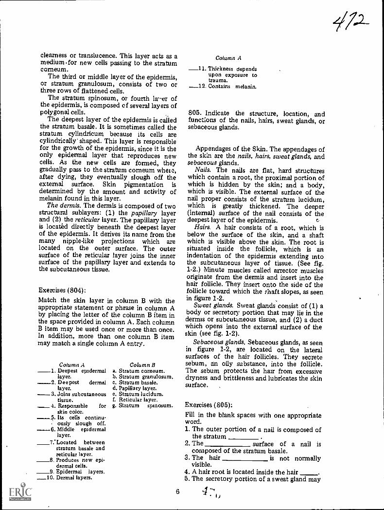
clearness or translucence. This layer acts as amedium .for new cells passing to the stratumcorneum.
The third or middle layer of the epidermis,or stratum granulosum, consists of two orthree rows of flattened cells.
The stratum spinosum, or fourth laer ofthe epidermis, is composed of several layers ofpolygonal cells.
The deepest layer of the epidermis is calledthe stratum basale. It is sometimes called thestratum cylindricum because its cells arecylindrically' shaped. This layer is responsiblefor the gowth of the epidermis, since it is theonly epidermal layer that reproduces newcells. As the new cells are formed, theygradually pass to the stratum corneum wheie,after dying, they eventually slough off theexternal surface. Skin pigmentation isdetermined by the amount and activity ofmelanin found in this layer.
The dermis. The dermis is composed of twostructural sublayers: (1) the papillary layerand (2) the reticular layer. The papillary layeris located directly beneath the deepest layerof the epidermis. It derives its name from themany nipple-like projections which arelocated on the outer surface. The outersurface of the reticular layer joins the innersurface of the papillary layer and extends tothe subcutaneous tissue.
Exercises (804):
Match the skin layer in column B with theappropriate statement or phrase in column Aby placing the letter of the column B item inthe space provided in column A. Each columnB item may be used once or more than once.In addition, more than one column B itemmay match a single column A entry.
Column A1. Deepest epidermal
layer.Deepest dermallayer.
----3 Joins subcutaneoustissue.Responsible forskin color.Its cells continu-
, ously slough off.6 Middle epidermal
layer.7 'Located between
stratum basale andreticular layer.Produces new epidermal cells.
_9 Epidermal layers.10. Dermal layers.
a.b.c.d.e.1.
g.
Column BStratum corneum.Stratum granulosum.Stratum basale.Papillary layer.Stratum lucidum.Reticular layer.Stratum spinosum.
Column A
_11. Thickness dependsupon exposure totrauma.
_12. Contains melanin.
805. Indicate the structure, location, andfunctions of the nails, hairs, sweat glands, orsebaceous glands.
Appendages of the Skin. The appendages ofthe skin are the nails, hairs, sweat glands, andsebaceous glands.
Nails. The nails are flat, hard structureswhich contain a root, the proximal portion ofwhich is hidden by the skin; and a body,which is visible. The external surface of thenail proper consists of the stratum lucidum,which is greatly thickened. The deeper(internal) surface of the nail consists of thedeepest layer of the epidermis.
Hairs. A hair consists of a root, which isbelow the surface of the skin, and a shaftwhich is visible above the skin. The root issituated inside the follicle, which is anindentation of the epidermis extending intothe subcutaneous layer of tissue. (See fig.1-2.) Minute muscles called arrector musclesoriginate from the dermis and insert into thehair follicle. They insert onto the side of thefollicle toward which the ?haft slopes, as seenin figure 1-2.
Sweat glands. Sweat glands consist of (1) abody or secretory portion that may lie in thedermis or subcutaneous tissue, and (2) a ductwhich opens into the external surface of theskin (see fig. 1-2).
Sebaceous glands. Sebaceous glands, as seenin figure 1-2, are located on the lateralsurfaces of the hair follicles. They secretesebum, an oily substance, into the follicle.The sebum protects the hair from excessivedryness and brittleness and lubricates the skinsurface.
Exercises (805):Fill in the blank spaces with one appropriateword.1. The outer portion of a nail is composed of
the stratum2. The surface of a nail is
composed of the stratum basale.3. The hair is not normally
visible.4. A hair root is located inside the hair5. The secretory portion of a sweat gland may
6 4
17-1-

BLOOD VESSELARRECTOR MUSCLE
4/7-3
DUCT OF SWEATGLAND
SEBACEOUS GLAND
HAIR FOLLICLE
BODY OF SWEATGLAND
Figure 1-2. The epidermis, dermis, subcutaneous tissue, and appendages of the skin.
lie in thetissue.
6. A sebaceous gland :creteswhich the skin surface.
or 806. Given a list of the endocrine glands,identify each by function or characteristic.
1-3. The Endocrine System
The glands of internal secretion arecommonly called "ductless" or endocrineglands because they secrete their hormonesdirectly into the blood stream. (Other glandswhich secrete their products onto the bodysurface or into a body cavity are sometimesreferred to as "duct" or "exocrine" glands.)The hormones secreted by the endocrineglands are important because they controlmany of our life processes.
In this section we will discuss the locationand functions of the following endocrineglands: the thyroid, the parathyroid, thethymus, the adrenat, the pituitary, the pineal,the pancreas, and the gonads. Refer to figure103 as we discuss their locations.
7
Thyroid Gland. The thyroid gland islocated in the anterior portion of the neckjust below the level of the thyroid cartilage. Itcontains two lobes, the left and right, whichare connected by a strip of tissue called theisthmus. The upper portions of each lobefollow the general contour of the lateralportions of the thyroid cartilage, whichtogether with the thin isthmus give thethyroid a "butterfly" appearance. Thehormone thyroxin is secreted by the thyroidgland. Thyroxin controls growth anddevelopment of the body by regulating thebody metabolism.
Parathyroid Glands. The four parathyroidglands are located two on each lateral thyroidlobealthough their composition andfunction are completely independent of thethyroid gland. They appear as small oval discsaveraging about 6 mm in length and 3.5 mmin width. The parathyroids secreteparahormone, which regulates the calciumcontent in the blood and the general calcificmetabolic state in the body.

Thymus. The thymus is located in theanterior portion of the upper mediastinumoverlying the trachea and the major bloodvessels arising from the heart. The thymus islarger in small children and undergoes agradual reduction in size with age. It isthought that the gland secretes a substancethat directs the production of antibodies thatfight infections in the body.
Adrenal. The two adrenal glands located onthe medial and superior aspects of the/upperportions of each kidney consist of an outersection, the cortex, and an inner section, themedulla. The cortex produces severaldifferent corticosteroids which regulate salt,water, carbohydrate, protein, and fatmetabolism. The medulla secretes adrenalin(epinephnne) and norepinephrine, which
THYROID
enable us to mobilize our body resources intimes of emergency or stress.
Pituitary. The pituitary 'gland, sometimescalled the "master" gland because it controlsthe secretions of various other glands, islocated in the sella turcica. It is about the sizeof a "pea" and is comprised of an anteriorand a posterior lobe. The anterior lobedominates the functions of the pituitary bysecreting hormones which affect many bodyprocesses. The following are examples ofsome of these hormones and their actions:
SomatotrophinInfluences growth ofbody tissues.
ThyrotropinInfluences the thyroidgland, causing it to secrete its hormone.
GonadotropinStimulates the gonads.
PINEALBODY
,,
4-2.".0_,...--11'ir:-.---,----. .1...:s 0
,(..,.,J,
\
PITUITARY
PARATHYROID\
o
cQ,cii
THYMUS
ADRENAL
PANCREAS
OVARY(FEMALE).
TESTIS_ (MALE)
..
.:
Figure 1-3. Locations of the endocrine glands.
8
f7/7'
i

AdrenotropinStimulates the adrenalglands.
An extract obtained from the posteriorpituitary lobe acts upon certain muscle fibers,causing them to contract.
PineaL The pineal body is located justposterior and superior to the pituitary, as seenin figure 1-3. The secretions and functions ofthe pineal are still somewhat uncertain.
Pancreas. The pancreas is considered to beboth an exocrine and endocrine gland. -Itsexocrine function is the production ofpancreatic juices for the chemical digestion offats, carbohydrates, and proteins, which itempties into the duodenum. Its endocrinefunction is the secretion of insulin in the tinyisland-like cells called the "Isles ofLangerhans." Insulin regulates the sugarmetabolism of the body.
Gonads. The gonads are the female ovariesand the male testes.
Ovaries. The ovaries produce severalestrogens, which are hormones affectingdevelopment of the secondary sexcharacteristics. Estrogens also affect thereproduetive functions of the female. Oneestrogen, progesterone, primarily functions toprepare the uterus for implantation .of afertilized ovum.
Testes2The testes ploduce androgens whichare hormo.nes affecting development of thesecondary sex characteristics and maintenance
of the reproductive functions. Two suchhormones are androsterone and testosterone.
Exercises (806):Match the endocrine glands in column B withthe appropriate statement or phrases incolumn A by placing the letter of the columnB item in the space provided in column A.Each column B item may be used once, morethan once, or not at all.
Column A1. Produce testoster-
one.2 Secretes insulin.3. Master gland.4 Secretes adrenalin.5. Controls body de-
velopment.6. Shaped like a but-
terfly.7. Larger in small
children.8. Secretes
adrenotropin.9. Functions both as
endocrine andexocnne gland.
10. Produce progester-one.
11. Producescorticosteroids.
12. Four in number.13. Produces
androsterone.14. Regulates calcific
metabolism.
4 7,)
Column B-a. Thyroid.b. Parathyroid.c. Thymus.d. Adrenal.e. Pituitary.f. Pineal.g. Pancreas,h. Ovaries,i. Testes.
1

1
CHAPTER 2
Field Radiography
IN ADDITION to "fixed" medical facilities,the Air Force maintains several field hospitalscalled Air Transportable Hospitals (ATH).These field hospitals are designed to beairlifted to almost any location and becomeoperational in a matter of hours after arrival.Training in the operation of a field hospitalcomes from periodic exercises in which theequipment is transported to a site near thebase, unpacked, assembled, inventoried,operated, repacked, and returned to ,thestorage area. If you are assigned to one ofthese field hospitals, your primary job,obviously, is to set up and operate theradiology section. Most likely you will not beassigned to the ATHthat is, you will not berequired to participate in a combat or otheremergency deploymentuntil you havereceived appropriate taining through theexercises mentioned above. However, due tounusual circumstances, you could possiblyparticipate in actual operation of the hospitalwithout prior onthe-job training.
e
i
This chapter is designed to familiarize youwith some of the equipment with which youwill be working in an ATH. Keep in mind thateach major item of equipment comes withcomplete step-by-step illustrated mstructionsthat show you how to assemble, operate, anddisassemble the items. Unless you haveworked repeatedly with these items, be sureto refer to the instructions.
This chapter consists of two sections. Inthe first section we will discuss the assemblyof the two major items you will find in yourfield radiology section. The second sectionconsists of operation of the X-ray apparatusand some specific guidelines about filmprocessing.
I2-1. Assembly of Equipment
The two major items of equipment you willbe concerned with are the radiographic tableand .the 50/100 mA X-ray. apparatus. Webegin with the assembly-of the table.
A'
Tdble Front
Figure 2-1. Front view of the field X-ray table completely assembled.
104 0 j
MN
.
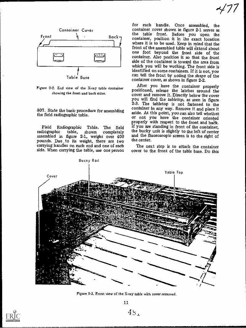
Container CoverFront Back
4-1
M4
Table Base
Figure 2-2. End view of the X-ray table containershowing the front and back sides.
807. State the basic procedure for assemblingthe field radiographic table.
Field Radiographic Table. The fieldradiographic table, shown completelyassembled in figure 2-1, weighs over 400pounds. Due to its weight, there are twocarrying handles on each end and one of eachside. When carrying the table, use one person
Bucky Rail
-V77for each handle. Once assembled, thecontainer cover shown in figure 2-1 serves asthe table front. Before you open thecontainer, position it in ale exact locationwhere it is to be used. Keep in mind that thefront of the assembled table will ektend aboutone foot beyond the front side of thecontainer. Also position it so that the frontside of the container is toward the area fromwhich you will be working. The front side isidentified on some containers. If it is not, youcan tell the front by noting the shape of thecontainer cover, as shown in figure 2-2.
After you have the container properlypositioned, release the latches around thecover and remove it. Directly below the coveryou will find the tabletop, as seen in figure2-3. The tabletop is not fastened to thecontainer in any way. Remove it and place itaside. At this point, you can also tell whetheror not you have the container orientedproperly with respect to the front and bak.If you are standing in front of the container,the bucky unit is slightly to the left of centerand the fluoroscopic screen is to the right ofthe center.
The next step is to attach the containercover to the front of the table base. Do this
-",4; .; --vt;1.'4.
Figure 2-3. Front view of the X-ray table with cover removed.
11
4 L

Vertical Tube Mast
fluoroscor ScreenBucky Unit
t
.16
Figure 2-4. Back view of the X-ray table showing the cover attached to the table base.
Assembly Instructions
Ir
.
Bucky Rail
Wing Bolt
Figure 2 5. Bitel, view of the X-rav table showing the bucky rail inserted into the end braces.
4 ....,
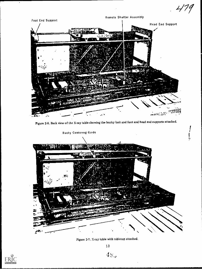
Foot End SupportRemote Shutter Assembly
_ Agftilitirs..Head End Support
Figure 2-6. Back view of the ray table showing the bucky Unit and foot and head end supports attached.
Bucky Centering Guide
111F-1-----1110W*
rru
.4.1;
ssawri.""r"s'-.
- *
-"'"*.
Figure 2-7. X-ray table with tabletop attached.
13
-"1111:411111
\

by releasing the end braces on the inside ofthe cover and attaching the braces to thefront of the base using the wing bolts, asshown in figure 2-4. Notice that figure 2-4shows the assembly from thebackconsequently, the fluoroscopic screen isto the left, and the bucky unit is slightly tothe right of center.
After securing the table front using thewing bolts, remove the bucley rail from theinside of the tabletop and insert it into thetop back edges of the end braces, as shown infigure 2-5. Also notice in figure 2-5 that theassembly instructions are located on theinside of the container cover.
Next, remove the bucky unit and foot andhead end supports, and attach them, as shownin figure 2-6. Then slide the metal grooves onthe sides of the tabletop over the rollers onthe foot-end support. Slide the tabletop tothe head-end support and attach it to thehead-end support using the two wing bolts(fig. 2-7),
Remove the vertical mast from thecontainer and insert it into the mastreceptacle located in the right, near corner ofthe base (as you look from the back). (See fig.
2-8.) Release the cloth straps and unfold orraise the mast. Lock the two sections of themast together using the hinge lock, shown infigure 2-9. A V-shaped slot and vertical lock,also seen in figure 2-8, are present on theswivel arm support, located on the verticalmast. This slot receives the swivel armcontaining the X-ray tube and collimator,fluoroscopic screen, etc. The vertical lock willnot stabilize the swivel arm support until theentire unit has been assembled and iscounterbalanced by the weight of the swivelarm, X-ray tube, etc. If the swivel arm is notproperly stabilized, it may be pulled abruptlyupward, damaging the top of the verticalinst, or injuring your hand. Therefore, donot attempt to lower the swivel-arm supportuntil assembly is complete. Also, when youdisassemble the unit, be sure to raise theswivel-arm support all the way to the topbefore removing the individual parts.
Finally, remove the swivel arm,fluoroscopic screen and fluoroscopic shutters.Insert the swivel arm into the V-shaped slot.(See fig. 2-10.) Attach the fluoroscopic screenand fluoroscopic shutters to the swivel arm. Ifyou are using the 15 mA X-ray apparatus,attach the tube to the swivel arm, as shown in
Vertical Mast
4.11
,t
c*,
Figure 2-8. Xray table with vertical mast in place.
1 A 4

,.0.
,
V-Shaped Slot
-g--- Vertical Lock
Figure 29. The vertical mast.
15
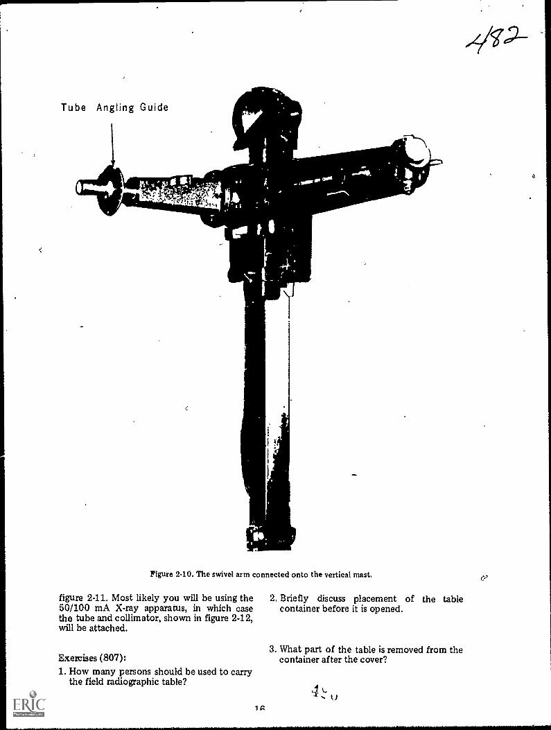
Tube Angling Guide
Figure 240. The swivel arm connected onto the vertical mast.
figure 2-11. Most likely you will be using the 2. Briefly discuss placement of the table50/100 mA X-ray apparatus, in which case container before it is opened.the tube and collimator, shown in figure 2-12,will be attached.
Exercises (807):1. How many persons should be used to carry
the field radiographic table?
1 g
3. What part of the table is removed from thecontainer after the cover?
41.)
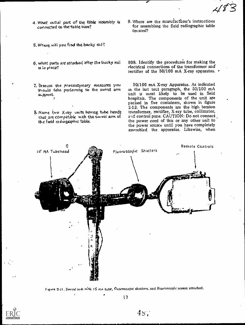
4. What intrial part of the tzble assembly is 9. Where are the manuiactbrer's instructionsconnected co the-table base? for assembling the field radiographic table
located?
5. Where. win youfrnd the backy rail?
6. vihat parts are arias:bed after the bucky rail 808. Identify the procedures for making thets la place? electrical connections of the transformer and
rectifier of the 50/100 mA X-ray apparatus. v.
7.. DIscuss the preeautloaary measures yOU 50/100 mA X-ray Apparatus. As indicatedshould take pertaining -cc) the swivel arm in the last text paragraph, the 50/100 mAsupp.0 rt. unit is most likely to be used in field
, hospitals. The components of the unit arepacked in five containers, shown in figure2-13. The components are the high tension
9. Name two X-ray units having tube heeds transformer, rectifier, X-ray tube, collimator,that are Coo-PO.6We with theswivel arm d and control pane. CAUTION: Do not connectthe field ra di ogsaph ic table, the power cord of this or any other unit to
the power source until you have completelyassembled the apparatus. Likewise, when
IS- MA Tubehea...d
Remote ControlsfiLtoroscoic Shutters
.4.
Tr/
'
""41111i2
e's
Flu,* 2,1 t .Switral arch w;lh 15 ,n4 tube, fh<orcscopic shutters. and fluoroscopic screen attached.
17

50/100 MA Tube Head
pa
0
Rif
Cables
Collimator
Figure 2-12. 50/100 mA tube and collimator co^)itered to 1*.e ;lent
disassembling any unit, make sure youdisconnect the main power supply first.
Transformer. The high-tension transformer,which must be used with this apparatus, is ina steel tank, which has been inserted into asteel-fabricated shipping chest. Thetransformer should always be shipped in theupright position. If laid on its side for a longperiod of time, it will lose some of its oil. Anair breather is incorporated in the top of .the
transformer to alb, tor Oxo,Insion of di, oildue to heat. Tim transformer contains a shottcable, one end of which is preconnenteddirectly tu the transformer. The free end &Athe cable contains a 10-pole, rectangular makplug. If you do not use the rectifkr, irbert ta10-pole piug into the appropriate recepta.a..located oil the back of the ct ntrol pant".1There is only ont receptack un the cuntiolpanel whit h acconimodates a 10-pokis labeled TRANS RECT.
18 4
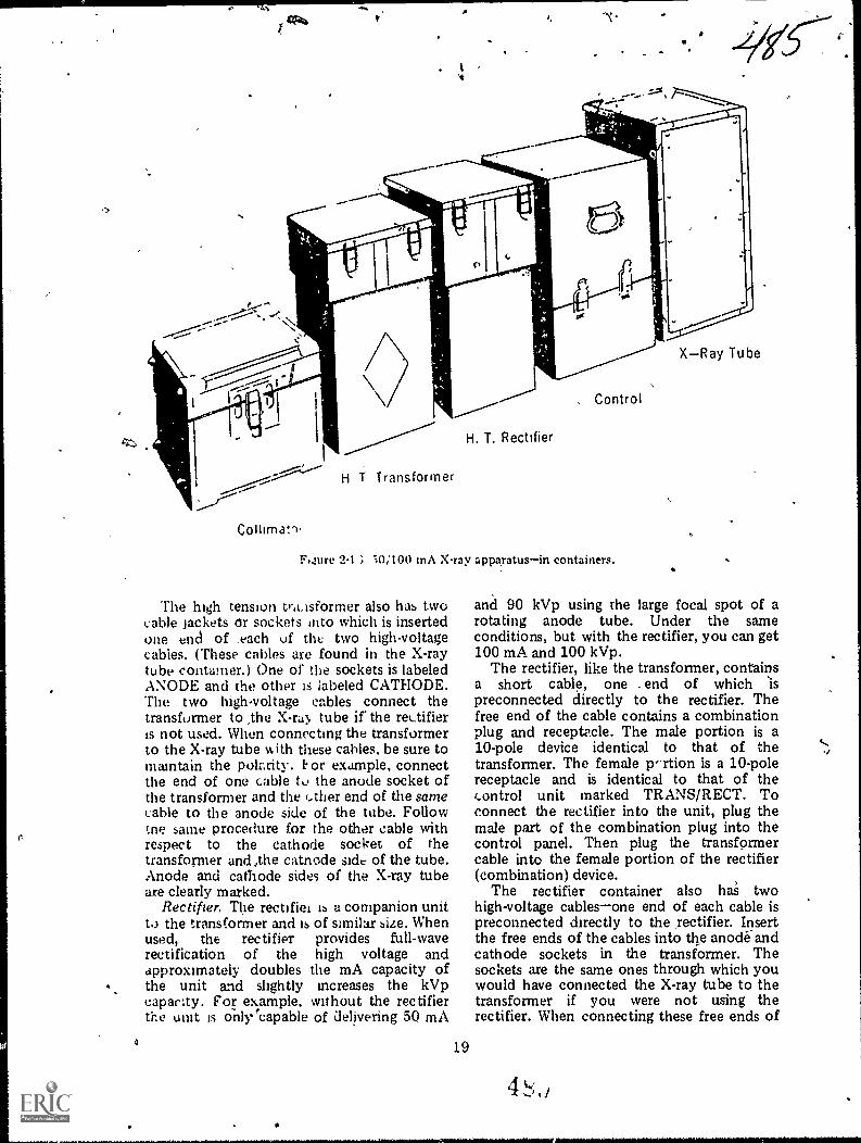
H T Transformer
H. T. Rectifier
. Control
; -)0;100 inA Xray apparatusin containers.
The high tension tr,eisforrner also has twocable Jackets or sockets into which is insertedone end of _each uf the two high-voltagecables. (These cables are found in the X-raytube contamer.) One of the sockets is labeledANODE and the other is labeled CATHODE.The two high-voltage cables connect thetransformer to ,the X-ru, tube ir the rectifieris not used. When connecting the transformerto the X-ray tube IA ith these cables, be sure tomaintain the polarity. 1. or example, connectthe end of one cable to the anode socket ofthe transformer and the ether end of the samecable to the anode side of the tube. Followthe same procedure for the other cable withrespect to the cathode socket of thetransforiner and ,the catnode side of the tube.Anode and cathode sides of the X-ray tubeare clearly marked.
Rectifier. The rectifiei ib a companion unitto the transformer and is of similar size. Whenused, the rectifier provides full-waverectification of the high voltage andapproximately doubles the mA capacity ofthe unit and slightly increases the kVpcapacity. For example, without the rectifierthe unit is onlVeapable of delivering 50 mA
19
XRay Tube
and 90 kVp using the large focal spot of arotating anode tube. Under the sameconditions, but with the rectifier, you can get100 mA and 100 kVp.
The rectifier, like the transformer, containsa short cable, one . end of which sis
preconnected directly to the rectifier. Thefree end of the cable contains a combinationplug and receptacle. The male portion is a10-pole device identical to that of thetransformer. The female p-rtion is a 10-polereceptacle and is identical to that of thecontrol unit marked TRANS/RECT. Toconnect the rectifier into the unit, plug themale part of the combination plug into thecontrol panel. Then plug the transformercable into the female portion of the rectifier(combination) device.
The rectifier container also has twohigh-voltage cablesone end of each cable ispreconnected directly to the rectifier. Insertthe free ends of the cables into the anode-andcathode sockets in the transformer. Thesockets are the same ones through which youwould have connected the X-ray tube to thetransformer if you were not using therectifier. When connecting these free ends of
4 L'

the rectifier cables to the transformer,polarity is not important--that is, either endmay be inserted into either socket.
This leaves you, with one final step inconnecting the 'rectifier into the unitthat is,to , conhect the rectifier to the X-ray tubecontainer. You do This with the high-voltagecables found in the X-ray tube containerthesame cables with which you woiild haveconnected the transformer to the X-ray tubeif the rectifier were not used. The rectifier,like the transformer, lias two 5cable socketsmarked CATHODE and ANODE. Once again,polarity is important. Connect the cathodesocket to the cathode side of the table, usingthe same cable. likewise, connect the anodesocket to the anode side of the X-ray tube,using the other cable.
'11
Exercises (808):Indicate whether the following statementspertaining to the procedure for performingthe electrical connections uf the transformerand rectifier of the 50/100 InA X-rayapparatus are true or false. If you indicate"false," explain your answer.
T F I . You shoukl not connect the powercord of this unit to the power sourceuntil the apparatus is completelyassem bled.
T F 2. You should disconnect the powercord .b'efore disassembling the unit.
T F 3. The 50/100 apparatus may be usedwithout connecting either thetransformer or rectifierbut notboth.
T F 4. The cable sockets of the transformerare used to connect the transformerto the X-ray tube or to the controlunit.
T F 5. The freeend of the transformercable connects to the control unit ifyou do not use the rectifiei.
n "
T F
T F
T F
T F
6. You must maintain polarity betweentilt, transformer and X-ray fube.i
7. You must maintain polarity betweenthe transformer and rectifier. / ,
8. Connecting the rectifier into thecircuit approximately doubles theunit's mA capacity.
9. You need NOT maintain polaritybetween the rectifier and the X-raytube.
T F 10. If the rectifier is connected into tAecircuit, the free end of thetransformer cable should 'beconnected directly to the controlpanel.
809. Briefly state the procedure forassembling the control unit stand; list andindicate the purpose of each of thereceptacles located on the back of the controlunii.
X-ray tube, collimator, and control unit.The control unit and the other cablesnecessary to connect 'the 50100 mA unit arein the same container. Unfasten the drawbolts. remove the top cover of the control-unit container, and Piece the cover on theground with the open end up. Remove thecontrol panel from the lower section of thecontainer and take out the electrical cables.Set the bottom portion of the chest open endup on the top of the inverted top section andfasten them together with the draw bolts.Place the control unit on top of the stackedcontainer stand. as shown in figure 244. Asyou can see in the figure, there are fivereceptacles on the back of the control unit.From the left, the first receptacle (TUBE) isused to connect the control unit to the X-raytube and collimator. The tube end of thecable contains two plugsone plugs into thetube head above the blower, and the other
,
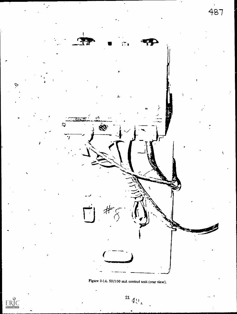
4S-7
Figure 2-14. 50/100 mA control unit (rear view).
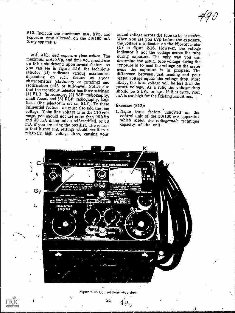
812. Indicate the maiimum mA, kVp, andexposure time allowed., on the 50/100 mAX-ray apparatus.
kVp, and exposure time values. Themaximum mA; kVp, and time you should useon this unit dePend upon several factors. Asyou can see in figure 2-16, the techniqueselector (I)) indicates various maximums,depending on such factors as anodecharacteristics. (stationary or rotating) andrectification (self- or full-wave). Notice alsothat the technique selector has three settings:(1) FLRfluoroscopy, (2) RSFradiography,small focus, and (3) RLFradiography, largefocus (the selector is set on RLF). To theseinfluential factors; we must also add the linevoltage. If the line voltage is in the 110-voltrange, you should not,use more than 90 kVpand 30 mA if the unit is self-rectified, or 58mA if you are using the rectifier. The reasonis that higher mA settings Would, result in arelatively high voltage drop, causing your
11111l MIA
0
't
0
e0
actual voltage acros s. the tube to be excessive.When you set you kVp before the exposure,the.voltage is indicated on the kilovolt meter(C)' in figure 2-16. However, the voltageindicator is not the voltage across the tubeduring exposure. The only way you candetermine the actual tube voltage during theexposure is to read the voltage on the meterwhile the exposure is in progress. Thedifference between, that reading and yourpreset voltage equals the voltage drop. Mostlikely, the tube voltage will be less than thepreset s voltage. As a rule, the voltage, dropshould be 5 kVp or lvs. If it is more, your,mA is too high for the existing conditions. ,
Exercises (812):1. Name three factors indicated' oi, the
control unit of the 50/100 mA apparatuswhich affect the radiographic techniquecapacity of the unit.
0
ki\ 0,
Figure 2.16. Control paneltop vie*.
244 (-,t
0 ,

2. Regardless of the information provided onthe control panel, what maximum mA andkVp values should be used on a 110-voltpower line?
3. Why are the limitations indicated inexercise #2 (above) necessary?
4. How do you determine your voltage dropacross the X-ray tube?
5. If the voltage drop is more than 5 kVp,what does the condition indicate?
813. Indicate the procedures for adjustingand evaluating the mA on the 50/100 mAcontrol panel.
Adusting the mA. There are four parts ofthe control panel in figure 2-16 that must beconsidered when adjusting or selecting yourmA for an exposure: (1) the mA meter (K);(2) the mA adjuster (F); (3) the filament scale(G); and (4) the filament check switch (E).The mA meter has two scalesthe top scale
' shows the radiographic mA, and the bottomscale shows the fluoroscopic mA. The meteronly reads the mA under load (during theexposure). Also, both scales have a reddanger-zone areado not operate the mA inthese zones. The mA adjuster simply adjuststhe mA. The filament scale (lower scale onthe meter) allows you to adjust the mAwithout making an exposure, since the mAmeter reads the mA only during exposure.The filament check switch merely activatesthe filament scale.
Basically, the mA is adjusted or selected asfollows: Let's assume you have your machinered-lined, and the technique selector is set onradiography. Turn the mA adjuster to itslowest settingfully counterclockwiseandset the kVp selector to a low value. Set theradiogaphic timer to 3 or 4 seconds. Make anexposure. Immediately after the exposurebegins, turn the mA adjuster clockwise untilthe mA reaches a specified valueforexample, 30 mA. Keep in mind that the mA
25
meter registers only under load; therefore,you will have to make the adjustment ratherquickly. You could use a longer exposure, butthis might also overload the tube. If you mustuse more than one exposure, allow a shortperiod for the anode to cool. After you havethe mA adjusted to our example of 30 mA,depress and hold the filament check switchand check the filament scale. Let's assume theneedle registers 5.5. Release the filamentcheck switch, and the needle will return toindicate the preset kVp value. At this point,you can repeat the procedure and find thefilament scale values for other mA values.You might end up with a working filamentchart like the following:
Filament Scale mA
2.5 103.0 154.0 205.5 30
Now suppose you are ready to beginX-raying patients and you want to use 30 mAfor your first patient. All you have to do isdepress and hold the filament check switchand turn the mA adjuster until the needleindicates 5.5 on the filament scale. Releasethe filament check switch, and your exposurewill be made at 30 mA. If you want to me 20mA, turn the mA adjuster until the needlereads 4.0 on the filament scale, andao on.
Exercises (813):1. What is the significance of the red zones on
the mA meter?
2. When does the mA meter reflect thecorrect mA?
3. What is the purpose of the filament checkswitch?
4. Assume that you have just set up yourmachine in thc field and have it properlyred-lined with the technique selector onradiography. You want to fmd the filamentscale value that indicates 25 mA. How doyou go about it?

5. How can you build yourself a workingfilament chart?
6. Suppose your filament chart is as follows.
Filament Scale nut3.5 255.& 406.5 50
Further suppose you want to use 50 mAfor a radiogaph.
Explain how you set the correct mA on thecontrol unit.
814. State the names and characteristics ofthe three types of Polaroid films, and indicatehow to correct improperly exposed Polaroidradiographs.
Polaroid Processing. The Polaxoid processorand special film allow you to processradiographs in as little as 10 seconds withoutthe use of a darkroom and "wet" processingtanks. This type of processing is particularlyuseful in the field, where facilities for wetprocessing are limited. At this point in yourtraining, you should know how to load thespecial cassette and process the film. Also,detailed step-by-step instructions for theseprocedures are included with the unit ifreview is necessary. Consequently, ourdiscussion is mostly concernec: ..ith the filmitself.
Types or Polaroid films. Currently thesetypes of the special film are available: (1)1001, (2) 3000X, and (3) TLX. The 1001 and3000X are processed for 60 seconds and 10seconds, respectively. The TLX is processedfor 45 seconds. After processing, the 1001and 300X are viewed by reflected light muchthe same as you would view a photographicprint because the image is present on a paperbase. The TLX, on the other hand, Eva- bnviewed by the same means as the rah ,wotypes, or it may be viewed by transmitted
26
light using a viewbox. Both viewing methodsare possible because the film base is made ofpolyester.
Exposure considerations. The radiographic-image recorded on the special film is theopposite from that recorded on conventionalfilm. By "opposite," we mean that lit ispositive rather than negative. Consequently,bone appears dark on a light background. Thesignificance is that an overexposed imageappears too light while an underexposedimage appears too dark. This, of course, isopposite from the appearances ofoverexposed and underexposed conventionalradiographs and requires opposite exposurecorrections. When making these corrections,do so tw altering the mAs rather than thekVp
As a rule, film contrast is somewhat loweron Polaroid film than on conventional film.The :ow co-Arast is an inherent characteristicof the film and to some degree must betolerated. r..I.,wever, in specific cases wherehigh contrast is desired, you can partiallyoffset thP film characteristic by using lowkVp as long as adequate penetration anddensity are not sacrificed.
Exercises (814):1. Name the three types of Polaroid film.
2. For what period of time should each typeof Polaroid film be processed?
3. How may you view each type of Polaroidfilm?
4. If a Polaroid radiograph is too dark, howwould you correct the exposure on asubsequent radiograph?
5. How can you increase the contrast on aPolaroid radiogaph?

Radiation Therapy
AS FAR AS you are concerned, radiationtherapy is limited to X-ray therapythat is,treatment of diseases using X-rays, as opposedto treatment using gamma or other types ofradiation. X-rays, as yvu know, are producedwhen high-speed electrons interact with atarget, whereas gamma radiation, alphaparticles, and beta particles are products ofthe decay of radioactive nuclides. The use ofnuchdes or isotopes for treatment is part ofthe job description of AFSC 909X0 NuclearMedicine Specialist/Technician.
If you are assigned to one of the larger AirForce hospitals where radiation therapy isprovided, you may be required to work in thetherapy section. Chances are you may havebeen exposed to some practical training intherapy procedures as a result of your PhaseII trammg. Therefore, you should realize bynow that your role is somewhat differentfrom that of a diagnostic technician. Intherapy, you are more of an assistant to theradiologist; wherees when performing mostdiagnostic exaniinations you are "on yourown,- so to speak.
Specific theraputic procedures, likediagnostic procedures, varydepending uponthe equipment in use and the radiologist'sapproach to the treatment. For these reasons,this chapter will be generally oriented towardprinciples rather than specific procedur7
3-1. Introduction toRadiation Therapy
In this section we will discuss the basis andpurpose of radiation therapy and somegeneral terms.
815. Give the basis and purpose of radiationtherapy.
Basis and Purpose of Radiation Therapy.Penetration and ionization are two important
27
00'3CHAPTER 3
characteristics of radiation which make ituseful in the treatment of disease. Sinceradiation can penetrate body tissues, itobviously has the capability to reach intoareas where pathological processes may exist.When radiation is directed toward an area ofthe body containing pathology, ionizationsoccur in the normal, as well as the abnormal,tissues. The ionizations produce biologicalchanges in both normal and abnormal cells.These, biological changes, in part, damage orcontrol the growth of both types of cells;however, the response to the radiation is notentirely the same. As a rule, abnormal cellsare more sensitive to radiation than normalcells. Radiation therapy is based on thisdifferential response of cells to radiation. Bycarefully subjecting the cells to radiation,radiologists aim to damage or control thegrowth of abnormal cells; while, at the sametime, they aim to spare the surroundingnormal or healthy cells.
Exercises (815):1. What is the basis of radiation therapy?
2. What is the purpose of radiation therapy?
816. Differentiate between benign andmalignant tumors.
Tumors. The word "tumor" encompasses abroad spectrum of growths. Generally, we cancategorize all tumors as benign or malignant.
Benign. A benign tumor is one that existsonly in its immediate site of growth. It is
usually enclosed in a capsule that prevents itfrom spreading to a remote site. Benigntumors are, for the most part, less dangerousbecause they can be totally removed bysurgery. In some cases, however, they canbecome dangerous. An example of adangerous benign tumor is one growing andspreading in the region of the brain. Havingno room to expand, it damages thesurrounding brain tissues as it gows. Benigntumors are usually not treated with radiation.
Malignant. A malignant tumor is a growththat may cause damage at the place where itfirst appears; and it may spread to otherlocations within the body, also causingdamage to the remote sites. This "spreading"of a malignant tumor is called metastasis. Theinitial growth is called a primary tumor, whilea growth resulting from metastasis is called asecondary or metastatic tumor. Mostradiation therapy is directed towardmalignant tumors.
Tumors may spread by one of threemethods: (1) direct local spread, (2) by wayof the lymphatic system, or (3) by way of thecirculatory system. Direct local spread impliesthat the tumor grows directly from its originalsite and invades surrounding organs or tissues.When a tumor spreads by way of thelymphatic system, tumor cells. enter thelymphatic system and are carried along thelymphatic ducts, and either become lodged ina duct or in a lymph node, where a secondarytumor is formed. Tumor cells may also movefrom the secondary tumor and form othersecondary tumors. Malignant tumorsspreading by way of the circulatory system doso in a manner similar to those spreadingthrough the lymphatic system. In this case,secondary tumors may form in virtually anyof the body tissues, although certainmetastatic sites are more common thanothers.
Exercises (816):Match the type of tumor in column B withthe appropriate statement or phrase incolumn A by placing the letter of the columnB item in the space provided in column A.Each column B item may be used once ormore than once. In addition, both column Bitems may match a single column A entry.
Column A Column B1. Growth. a. Benign.2. May cause damage at b. Malignant.
remote location.3. More dangerous.4. Enclosed in a retain-
ing shell.5. Secondary lesion.
6. Moves via the circula-, tory system.
7. Radiation therapy isusually directed to-ward this type.
8. Causes damage by di-rect local spread.
,
817. Name and briefly assess two factorsinfluencing the success of tumor treatment byradiation and identify the two types ofradiation treatment.
Types of Tumor Treatment. Not allmalignant tumors can be successfully treatedwith radiation therapy. The success of thetreatment depends upon several factors. Oneof the influential factors is the' sensitivity ofthe tumor tissue to radiationsome tissues aremore sensitive, or radiosensitive; others areless sensitive, or radioresistant. The moresensitive the tumor, the greater the chance forsuccessful treatment. Another factorinfluencing the outcome of the treatment isthe stage of development in which treatmentis initiated. Early treatment increases thechance for success. Generally, treatmc,.: oftumors can be classified as "radical" or"palliative."
Radical. Radical treatment of a tumormeans that an attempt is made to cure thepatient. By "cure," we mean that for 5 yearsfrom the time of treatment the patientremains alive and well with no sign of thedisease.
Palliative. Palliative treatment is reservedfor those patients whose condition hasdeteriorated to the point where a cure is notpossible. The treatment is usually orientedtoward the patient's symptoms and may be ofsignificance in reducing pain or enhancingsome basic function, such as breathing orswallowing, if a tumor interferes with thatfunction.
Exercises (817):1. Name two factors influencing the success
of radiation treatment. In each case brieflydiscuss how the treatment is effected.
2. What is radical treatment?
28, i,

3. When is the patient considered to be cured?
4. What is palliative treatment?
818. Given written descriptions of threecombination therapy filters, indicate whetheror not the order of the filters is correct; ifincorrect, state the conwpences.
Filtration. Filters are used in therapy forthe same basic reason as they are used indiagnostic radiologythat is, to remove thelong wavelength or low-energy photons. Inthe case of the radiographs, the low-energyphotons increase the dosage to the patientand do not contribute to the exposure of thefilm. In the case of therapy, they increase thepatient's skin dose and do not contribute tothe treatment of the pathological process.Most commonly tin (Sn), copper (Cu), andaluminum (Al) are used as filters fortherapyindividually or in variouscombinations.
When using a combination of filters, alwaysplace the material with the highest atomicnumber closer to the tube. The reason is thatthe higher the atomic number of the material,the higher the energies of the characteristicphotons emitted by that material. Highenergy characteristic radiation may reach thepatient and increase his skin dosage whileoffering little toward treatment of a tumor.For example, if a combination of copper andaluminum are used, copper with the highestatomic number emits characteristic photonswith higher energies than those of aluminum.By placing the two filter layers so that thecopper is nearer the tube, copper'scharacteristic photons are absorbed by thealuminum. The characteristic photons emittedfrom the aluminum possess too little energyto reach the patient and are absorbed in air. Acommon therapy made up of a combinationof copper, aluminum, and tin is called aThoraeus filter. Tin has a higher atomicnumber than copper or aluminum.
Exercises (818):Below are listed three descriptions ofcombination therapy filters. Indicate whetheror not the order of the filters is correct. If the
29
Jarorder is incorrect, briefly discuss theconsequences of the arrangement.1. 1 mm aluminum + 0.5 mm copper. The
layer of aluminum is placed toward thepatient with the copper nearer the tube.
2. The sa filter materials as in exercise 1above h the copper toward the patient.
3. 1 mm aluminum + 1 mm tin + 1.5 mmcopper. aluminum is nearest thepatient, and the tin is nearest the tube.
3-2. Dosage CalculationFactois
Dosage calculations are based on factorsthat may be measured directly in the primarybeam, or indirectly by using a phantom. Thefirst factor that we will consider is thedetermination of the quality of the therapybeam. After that, we will proceed with thecalculation of the dosage.
819. Define the term that describes thequality of a therapy beam, and apply it tocompute the value of given beams.
Beam Quality. Generally, in diagnosticradiology we think of the quality of theprimary beam in terms of the kVp setting onthe machine. For example, we know that 85kVp adequately penetrates certain bodys tr u c tu r es and produces diagnosticradiographs of those structures. In therapy, itis not practical to describe the quality of thebeam in terms of the kVp alone because thevariations between the output of differentmachines, using the same kVp, is sufficient toproduce beams with different treatmentpotentials.
The quality of a therapy beam is usuallydescribed in terms of its ability to penetratesome material of known composition. Thispenetrability is expressed as the beam's"half-value layer." The half-value layer is thethickness of some standard material requiredto reduce the intensity of a beam to one-halfits original value.
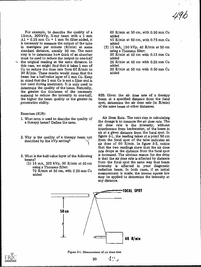
For example, to describe the quality of a15-mA, 200-kVp, X-ray beam with a 3. mmAl + 0.25 mm Cu + 1 mm Sn filter added, itis necessary to measure the output of the tubein roentgens per minute (R/min) at somestandard distance, usually 50 cm. The nextstep is to determine how thick of an absorbermust be used to reduce the output to one-halfthe original reading at the same distance. Inthis case, we might find that it takes 1 mm ofCu to_reduce the dose rate from 60 R/min to30 R/min. These results would mean that thebeam has a half-value layer of 1 mm Cu. Keepin mind that the 1 mm Cu is not a filter and isnot used during treatment. It is only used todetermine the quality of the beam. Naturally,the greater the thickness of the necessarymaterial to reduce the intensity to one-half,the higher the beam quality or the greater itspenetrative ability.
Exercises (819):1. What term is used to describe the quality of
a therapy beam? Define the term.
2. Why is the quality of a therapy beam Rotdescribed by the kVp setting?
3. What is the half-value layer of the followingbeams?(1) 15 mA, 200 kVp, 90 R/min at 50 cm
using a Thoraeus filter:75 R/min at 50 cm, with 0.25 mm Cuadded
60 R/min atadded45 R/min atadded
(2) 15 mA, 150using a Thora30 R/min atadded20 R/min atadded20 R/min atadded
50 cm, with 0.50 mm Cu
50 cm, with 0.75 mm Cu
kVp, 40 R/min at 50 cmeus filter:40 cm with 0.15 mm Cu
40 cm with 0.25 mm Cu
50 cm with 0.50 mm Cu
820. Given the air dose rate of a therapybeam at a specified distance from the focalspot, determine the air dose rate (in R/min)of the same beam at other distances.
Air Doie Rate. The next step in calculatingthe dosage is to measure the air dose rate. Theair dose rate is the intensity, withoutinterference from backscatter, of the beam inair at a given distance from the focal spot. Infigure 3-1, the reading taken at a point 50 cmfrom the focal spot of the tube indicates anair dose of 60 R/min. In figure 3-2, noticethat the two readings show that the air doserate drops as the distance from the focal spotis increased. The obvious reason for the dropis that the air dose rate is affected by distancefrom the focal spot the same way that beamintensity is affected in your diagnosticradiation beam. In both cases, if an initialmeasurement is made, the inverse square lawmay be applied to determine the intensity atany distance.
Figure 3-1. Measurement of air dose rate.
-30 1
FOCAL SPOT
60 R min
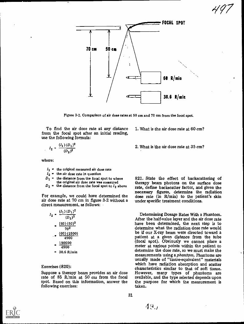
-'?q7
61 Rhitin
30.6 Rhuin
Figure 3-2. Comparison of air dose rates at 50 cm and 70 cm from the focal spot.
To find the air dose rate at any distancefrom the focal spot after an initial reading,use the following formula:
(Ii) (D1)2
where:
12Di = the distance from the focal spot to where
the original air dose rate was measuredD2 = the distance from the focal spot to /2 above
(D2 )2
the original measured air dose ratethe air dose rate in question
For example, we could have determined theair dose rate at 70 cm in figure 3-2 without adirect measurement, as follows:
(4) (D1)212
(D2)2
(60) (50)2702
(60)(2500)4900
1500004900
= 30.6 FtImin
Exercises (820):Suppose a therapy beam provides an air doserate of 85 R/min at 50 cm from the focalspot. Based on this information, answer thefollowing exercises:
31
1. What is the air dose rate at 60 cm?
2. What is the air dose rate at 35 cm?
821. State the effect of backscattering oftherapy beam photons on the surface doserate, define backscatter factor, and given thenecessary figures, determine the radiitiondose rate (in R/min) to the patient's skinunder specific treatment conditions.
Determining Dosage Rates With a Phantom.After the half-value layer and the air dose ratehave been determined, the next step is todetermine what the radiation dose rate wouldbe if our X-ray beam were directed toward apatient at a given distance from the tube(focal spot). Obviously we cannot place ameter at various points within the patient todetermine the dose rate, so we must make themeasurements using a phantom. Phantoms areusually made of "tissue-equivalent" materialswhich have radiation absorption and scattercharacteristics similar to that of soft tissue.However, many types of phantoms areavailable, and the type selected depends uponthe purpose for which the measurement istaken.

\
-----------
OA
itOist
SOW tett
Fig,ttle to be33. Ctossesectiun view of a tortiot ih s patient Witte, by vachation.
-
111. 31 was
Viorce 3-4. Iviesoveraerit of withthe sovface dose tate a. phaatoo.
SS
e
,

SOURCE
Figure 3-5. The effect of backscatter.
ECTOR
Assume that figure 3-3 represents across-section of a patient lying on a treatmenttable. The focal spot-to-skin, distance (FSD),also called the source to skin distance (SSD),is 50 cm. Using the available informationprovided by the measured half-value layer andair dose rate, it is necessary to determine theradiation dose to be delivered to: (1) the skin,(2) the tumor lying at a certain depth beneaththe skin, and (3) nearby organs lying above orbelow the tumor. To make the necessarymeasurements, let us replace the patient infigure 3-3 with a phantom, as seen in figure3-4.
Effect of backscatter on surface dose rate.The surface dose rate, in effect, is the same asthe skin dose. Assume that the surface doserate of our phantom measures 81 R/min at'50cm from the tube, as shown in figure 3-4. Thisreading is 21 R/min above the air dose rate of60 R/min which we measured earlier. Howcan this difference be explained?
The difference is due to backscattering ofphotons from Compton interactions occurringin the phantom. Figure 3-5 shows a photonfrom the primazy beam not falling on thedetector probe (hence, would not beregistered in an air dose reading) but
. interacting by Compton scattering at point P,after which the scattered photon is redirected
33
toward the meter probe. Multiple scatteringsof this type are responsible for the increasedreading of 81 R/min at the surface from the60 R/min air dose rate.
The backscatter factor is expressed as theratio of the surface dose rate to the air doserate as follows:
surface &vie rateBackscatter factor dote ate
In this case
Backscatter factor8160
... 1.35
Normally, charts are accomplished showingthe backscatter factor for therapy beams withdifferent half-value layers and treatmentareas. (The next text segment explains theeffect of these two factors on the backscatterfactor.) To determine the surface dose (skindose) rate from such a chart, simply use thefollowing formula:
Surface dose rate = backscatter factor X airdose rate
Exercises (821):1. How does the backscattering of therapy
beam photons affect the surface dose rate?
2. What is the backscatter factor?
3. What is the dose rate to the patient's skinfor each of the two following therapybeams?(1) Half-value layer 1.2 mm Cu, 10 x 10
cm treatment field, air dose rate 65R/min, backscatter factor 0.90.
(2) 'Half-value layer 1 mm Ctr, 8 x,.8.-cmtreatment field, air dose rate 45R/min, backscatter factor 0.75.
822. Indicate how beam quality and field sizeaffect backscatter.
Effect of beam quality on bachscatter. Thebackscatter is not always 1.35 but varies ascertain conditions change. The amount of

.2 1 2 3
Figure 3-6. Relationship between the backscatter factor and beam quality for a 10 x 10 cmtreatment field.
backscatter present depends on the quality ofthe beam, which, in turn, affects depth ofpenetration and the scattering angleprobability. Notice in figure 3-6 thatpenetration of low energy beams into thephantom minimizes the backscatter factoror
Soo
put another way, the limited penetrationreduces the amount of scatter redirectedtoward the measuring probe. Consequently,the backscatter factor is low. As the half-valuelayer increases, the backscatter factor alsoincreases because the deeper penetration of
Figure 37. Relationship between beam quality and volume of scatter. ALow quality beamwith small scattor volume. BHigh quality beam with large scatter volume.
QA
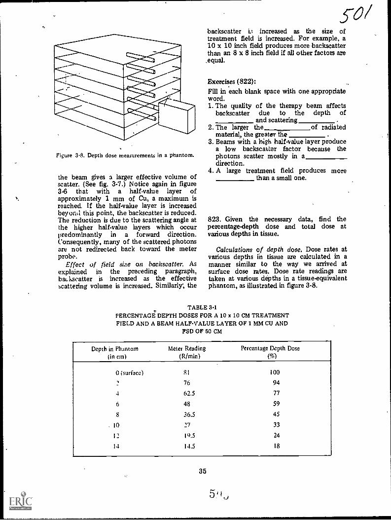
Figure 3-8. Depth dose measurements in a phantom.
the beam gives a larger effective volume ofscatter. (See fig. 3-7.) Notice again in figure3-6 that with a half-value layer ofapproximately 1 mm of Cu, a maximum isreached. If the half-value layer is increasedbey oral this point, the backscatter is reduced.The reduction is due to the scattering angle atthe higher half-value layers which occurpredominantly in a forward direction.Consequently, many of the scattered photonsare not redirected back toward the meterprobe.
Effect of field size on hachscatter. Asexplained in the preceding paragraph,baLkscatter is increased as the effectivescattering volume is increased. Similarly; the
backscatter i.; increased as the size oftreatment field is increased. For example, a10 x 10 inch field produces more backscatterthan an 8 x 8 inch field if all other factors are
,equal.
Exercises (822):Fill in each blank space with one appropriateword.1. The quality of the therapy beam affects
bac ksc atter due to the depth ofand scattering
2. The larger the of radiatedmaterial, the greater the
3. Beams with a high half-value layer producea low backscatter factor because thephotons scatter mostly in adirection.
4. A large treatment field produces morethan a small one.
823. Given the necessary data, find thepercentage-depth dose and total dose atvarious depths in tissue.
Calculations of depth dose. Dose rates atvarious depths ih tissue are calculated in amanner similar to the way we arrived atsurface dose rates. Dose rate readings aretaken at various depths in a tissue-equivalentphantom, as illustrated in figure 3-8.
TABLE 3-1PERCENTAGE DEPTH DOSES FOR A 10 x 10 CM TREATMENTFIELD AND A BEAM HALF-VALUE LAYER OF 1 MM CU AND
FSD OF 50 CM
Depth in Phantom(in cm)
Meter Ruding(R/min)
Percentage Depth Dose
(%)
0 (surface) 81 100
76 94
4 62.5 77
6 48 59
8 36.5 45
10 27 33
12 19.5 24
14 14.5 18
35
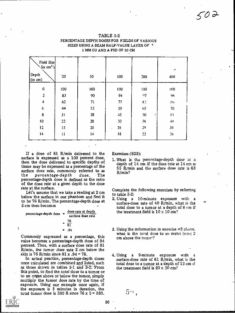
TABLE 3-2PERCENTAGE DEPTH DOSES FOR FIELDS OF VARIOUS
SIZES USING A BEAM HALFVALUE LAYER OF I,1 MM CU AND A FSD OF 50 CM
\Field Size(in cm2)
Depth(in cm)
"20 50 100 200
--
400
0 100 100 100 100 100
2 83 90 94 07 98
4 62 71 77
6 44 52 59 65 70
8 31 38 45 50 5;
10 -y-) 28 33 38 44
12 15 20 24 29 34
14 ll 14 18 __-r) 26
If a dose of 81 R/min delivered to thesurface is expressed as a 100 percent dose,then the dose delivered to specific depths of,tissue may be expressed as a percentage of thesurface dose rate, commonly referred to asthe percentage-depth dose. Thepercentage-depth dose is defined as the ratioof the dose rate at a given depth to the doserate at the surface.
Let's assume that we take a reading at 2 cmbelow the surface in our phantom and find itto be 76 R/min. The percentage-depth dose at2 cm then becomes .
dose rate at depthsurface dose ratepercentagedepth dose
7681
= .94
Commonly expressed as a percentage, thisvalue becomes a percentage-depth dose of 94percent. Thus, with a surface dose rate of 81R/min, the tumor dose rate 2 cm below theskin is 76 R/min since 81 x .94 = 76.
In actual practice, percentage-depth dosesonce calculated are combined and listed, suchas those shown in tables 3-1 aric-r3=2:Froznthis point, to find the total dose to a tumor orto an organ above or below the tumor, simplymultiply the tumor dose rate by the time ofexposure. Using our example once again, ifthe exposure is 5 minutes in duration, thetotal tumor dose is 380 R since 76 x 5 = 380.
36
Exercises (823):1. What is the percentage-depth dose at a
depth of 14 cm if the dose rate at 14 cm is55 R/mM and the surface dose rate is 63R/min?
Complete the following exercises by referringto table 3-2:2. Using a 10-minute exposure with a
surface-dose rate of 40 R/min, what is thetotal dose to a tumor at a depth of 6 cni ifthe treatment field is 10 x 10 cm?
3. Using the information in exercise :=2 above.what is the total dose to an organ lyms4 2cm above the tumo-?
4. Using a 9-minute exposure with asurface-dose rate of 61 R/mM, what is thetotal dose to a tumor at a depth of 12 cm ifthe treatment field is 20 x 20 cm?
0
co
17

#.
,
MODIFICATIONS%
0
R? 6 3>- 7/ of thii publication has (have) been deleted in
'adapting this material for inclusion in the "Trial Implementation of a
Nuclei System to Provide Military Curriculum Materials for Use in Vocational
and Tchnfcal Education." Deleted material involves extensive use of,
i
military forms, procedures, systems, atc. and was not considered apPropriate
i
for use in vocational and technical education.,c--
\.....__
.,
..
J
III
..
. T.
3
#

,
..
1
ANSWERS FOR EXERCISES *
CHAPTER 1 804 - 6. b.804 7. d.804 - 8. c.
Reference: 804 - 9. a, b, c, e, g.800 - 1. c. 804 - 10. d, f.800 - 2. b, c: 804 T 11. a.800 - 3. a, c. 804 - 12. c.800 - 4. a.800 5. b. 806 - 1. lucidum.800 - 6. b. 805 - 2. deeper (internal).800 - 7. a. 806 - 3. root.800 8. c. 806 - 4. follicle.800 - 9. a. 806 - 5. dermis; subcutaneous.800 - 10. a. 806 - 6. sebum; lubricates.
801 - 1. Body, origin, and insertion. 806 - 1. i.801 - 2. The proximal point of attachment located 806 2. g.
on the more fixed structure. 806 - 3. e.The distal point of attachment located on 806 - 4. d.the more movable structure. 806 - 5. a.
801 - 3.- It has two-the supraglenoid tuberosity and 806 - 6. a.the coracoid process. 806 - 7. c.The radial tuberosity. 806 - 8. e.
801 - 4. Heads. 806 - 9. g.806 - 10. h.
802 - 1. F. It is called an antagonistic muscle group. 806 - 11. d.802 2. T. 806 - 12. b.802 - 3. T. 806 - 13. i.802 - 4. F. It supports a prime mover. 806 - 14. b.802 - 5. T.802 6. F. It is an agonistic muscle.802 - 7. T.
803 - 1. g.803 - 2. d.803 - 3. c, d.803 - 4. e.d03 5. b.803 - 6. f.803 - 7. c.803 - 8. d.803 - 9. g.803 - 10. f.803 - 11. e.803 - 12. g.803 - 13. f, g.803 - 14. e, f.803 - 15. b.803 - 16., c, d.
804 - 1. c.804 - 2. f.804 - 3. f.804 4. c.8(14 - 5. a.
.1
, 75
CHAFFER 2
Reference:807 - 1. Six.807 - 2. Place it exactly where it will be used, with
the front side of the container about onefoot short of where you want the front ofthe assembled table. Identify the front sideof the table tiy noting the shape of thecontainer cover.
807 - 3. The tabletop.807 - 4. The container cover.807 - 5. Attached to the insitle of the tabletop.807 - 6. Bucky unit and foot and head end sup-
ports.807 7. Do not lower the suppoit unik it is
counterbalanced by adding the swivel arm,X-ray tube, etc. Before disassembling theunit, raise the support to the fop of thevertical mast before removing the swivelarm, etc.
807 - 8. 15 mA X-ray apparatus and 60/100 mAX-ray apparatus. %
807 9. On the inside of the container cover.
A
5' I ()

808 - 1. T.808 - 2. T.808 - 3. F. It may be used without the rectifier but
cannot be used without the transformer.808 - 4. F. They are used to connect the
transformer to the Xray tube or to .therectifier.
808 - 5. T.808 - 6. T.808 - 7. F. You need not maintain polarity between
the two.80E( - 8. T.808 - 9. F. You must maintain polarity between the
. two.808 - 10. F. It should be connected to the combina-
tion plug of the short rectifier cable, whichin turn is connected directly to the controlpanel.
809 - 1. Place the bottom portion of the controlunit chest with the open-endup on top ofthe inverted top section of the chest andfasten them together using the draw bolts.
809 - 2. (1) TUBE-Connects the control unit tothe X-ray tube and collimator.
(2) FT. SW.-Connects the control unit tothe fluoroscopic foot switch.
(3) BUCKY-Connects the control unit tothe table bucky,
(4) LINE-Connects the control unit tothe main power sdurce.
(5) TRANS/RECT-Connecta the controlunit to the transformer or transformerand rectifier.
810 - 1. The generator must be properly groundedand the plug and receptacle must be ingood repair.
810 - ,2. (1) By connecting the "pigtail" to a gener-ator grounding rod. (2) By connecting the."pigtail" to adother grounding rod (3 feetlong) inserted at least 21/4 feet into theground near the, connection between thetwo power cables.
811 - 1. 250. If it is set lower than the incomingline voltage, some of Ihe control unitcir-uits may be damaged.
811 - 2. Imi.lediately, turn the main switch OFF andset thp line adjuster to 250.
811 - 3. Depreu and hold the line check switch andturn the line adjuster until the kilovoltmeter reads in the red area.
812 - 1. (1) Anode characteristics (stationary orrotating).(2) Retification (self- or full-wavc):(3) Foildspot size (large or small focus).
812 2. 30 mA-90 kVp, if selfrectified; and 58mA-90 kVp, if full-wave rectified (if youare using the rectifier).
812 3. yo prevent an exceuive voltage drop ..Lrossthe X-ray tube.
812 4. Make an exposure and read the voltageindicated on the kilovolt meter duringexposure. Subtract that amount from thepreset voltage.
812 - 5. Your mA is too high for the existingconditions.
813 - 1. The mA should not be operated in thoseareas.
8 1 3 - 2. Under load (during exposure).
roc813 - 3. It activates the filament scale.813 - 4. (1) Turn the mA selector fully counter-
clockwise.(2) Set the radiographic timer at 3 to 4seconds.(3) While making an exposure, turn themA adjuster clockwise until the mA (topscale) reads 25.(4) After the exposure ends, depress andhold the filament check switch and readthe value on the filament scale.
813 - 5. Repeat the procedure indicated in exercise#4 (above), finding the filament scalevalues for various mA readings. Record theinformation.
813 - 6. (1) Depreu and hold the filament checkswitch.(2) Turn the mA adjuster until the needleon the filament scale reads 6.5.(3) Release the filament check switch. \
814 - 1. 1001, 3000X, and TLX.814 - 2. 1001-10 seconds; 3000X-60 seconds;
TLX-45 seconds.814 - 3. 1001-by reflected light.
3000X-by reflected light.TLX-by reflected or transmitted light.
814 - 4. increase the mAs.814 - 6. Use low kVp as long as adequate penetra-
tion and density are not sacrificed.
CHAPTER 3
Reference:815 - 1. The differential response in cells to
radiation-abnormal cells are more sensitiveto radiation than normal cells.
815 - 2. To damage or control the growth of abnor-mal cells and to spare the surroundingnormal cells.
816 -816816 =816 -816 -816 -816 -816 -
1. a, b.2. b.3. b.4. a.5. b.6. b.7. b.8. a, b.
817 - 1. (1) Sensitivity of the tumor tiuue. Treat-ment, of radiosensitive tumors is moresuccessful than treatment of radioresistanttumors.
.(2) Stage of tumor development whentreatment is initiated. Early treatment im-prover r he chance for succeu.
817 - 2. Treatment aimed at curing the patient.817 3. When he remains alive for 5 years after
treatment with no evidbnce of the disease.817 - 4. Symptomatic treatment of a patient whose
condition cannot be cured:
818 - 1. Correct.818 2. Incorrect. The characteristic radiation emit-
ted by the copper may have sufficientenergy to reach the patient, thereby in-creasing his skin dc but not substantiallyaiding in the treatment.Correct.
76
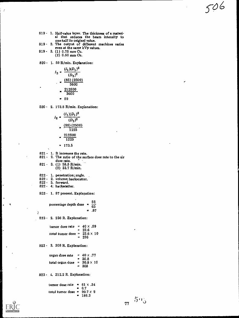
819 - 1. Half-value layer. The thickness of a materi-al that reduces the beam intensity toone-half its original value.
819 - 2. The output of different machines varieseven at the same kVp values.
819 - 3. (1) 0.75 mm Cu.(2) 0.50 mm Cu.
820 - 1. 59 R/min. Explanation:
2(D2 )2
(85) (2500)3600
2125003600
= 59
320 - 2. 173.5 R/min. Explanation:
(II )(DI )212 (D2)2
(85) (2500)1225
2125001225
= 173..5
821 - 1. It increases the rate.821 - 2. The ratio of the surface dose rate to the air
dose rate.821 - 3. (1) 58.5 R/min.
(2) 33.7 R/min.
822 - 1. penetration; angle.822 2. volume; backscatter.822 - 3. forward.822 - 4. backscatter.
823 - 1. 87 percent. Explanation:
. percentage depth dose5563
= .87
823 - 2. 236 R. Explanation:
tumor dose rate = 40 x .59= 23.6
total tumor dose = 23.6 x 10= 236
823 - 3. 308 R. Explanation:
organ dose rate = 40 x .77= 30.8
total organ dose = 30.8 x 10= 308
823 - 4. 212.2 R. Explanation:
tumor dose rate = 61 x .34= 0.7
total tumor dose = 20.7 x 9= 186.3
77

S-67
MODIFICATIONS
'7 4 cff) of this publication has (have) been deleted in
adapting this material for inclusion in the "Trial Implementation of a
Model System to Provide Military Curriculum Materials for Use in Vocational
and Technical Education." Deleted material involves extensive use of
military forms, procedures, systems, etc. and was not considered appropriate
for use in vocational and technical education.

STOP-1.MATCH ANSWER
SHEET TO THISEXERCISE NUM.BER.
90370 05 21
2. USE NUMBER 1 ORNUMBER 2 PENCIL.
EXTENSION COURSE INSTITUTEVOLUME REVIEW EXERCISE
GENERAL INFORMATION AND ADMINISTRATION
Carefully read the following:
DO'S:
I. Check the "course," "volume," and "form" numbers from the answer sheetaddress tab against the "VRE answer sheet identification number" in therighthand column of the shipping list. If numbers do not match, take actionto return the answer sheet and the shipping list to ECI immediately with anote of explanation.
2. Nose that numerical sequence on answer sheet alternates across from columnto column.
3. Use a medium sbarp #1 or #2 black lead pencil for marking answer sheet.
4. Circle the correct answer in this, test booklet. After you are sure of youranswers, transfer them to the answer sheet. If you have to change an answeron the answer sheet, be sure that the erasure is complete. Use a clean eraser.But try to avoid any erasure on the answer sheet if ai all possible.
5. Take action to return entire answer sheet to ECI.
6. Keep Volume Review Exercise booklet for review and reference.
7. If mandatorily enrolled student, process questions or comments through yourunit trainer or OJT supervisor.If voluntarily enrolled student, send questions or comments to ECI on ECI
Form 17.
DON'TS:
1. Don't use answer sheets other than one furnished specifically for each review
exercise.
2. Don't mark on the answer sheet except to fill in marking blocks. Double
marks or excessive markings which overflow marking blocks will register as
errors.
3. Don't fold, spindle, staple, tape, or mutilate the answer sheet.
4. Don't use ink or any marking other than a #1 or #2 black lead pencil.
NOTE: NUMBERED LEARNING OBJECTIVE REFERENCES ARE USEDON THE VOLUME REVIEW EXERCISE. In parenthesis after eachitem number on the VRE is the Learning Objective Number where theanswer to that item can be located. When answering the items on theVRE, refer to the Learning Objectives indicated by these Numbers. TheVRE results will be sent to you on a postcard which will list the actualVRE items you missed. Go to the VRE booklet and locate the LearningObjective Nwnbers for the items missed. Go to the text and carefullyreview the areas covered by these references. Review the entire VRE againbefore you take the closed-book Course Examination.
1

Multiple Choice
1. (800) Which muscle tissue microscopically examined is striated, voluntarilycontrolled, responsible for leg movement, and comprises about 80 pounds ofweight for a 200-pound individual?
a. Skeletal alone. c. Both smooth and skeletal.b. Both smooth and cardiac. d. Both cardiac and skeletal.
2. (801) That part of a skeletal muscle located between its proximal and distalpoints of attachment is generally described as its
a. insertion.b. origin.
c. body.d. head.
3. (801) If, in human anatomy, the proximal portion of a skeletal muscle splitsitself into two divisions before it attaches to a more fixed anatomicalstructure, each division of the muscle is sometimes referred to as
a. a head.b. a body.
c. an insertion.d. a distal origin.
4 (802) Which of the following muscles, at some time during extension and flexionof the elbow, perform antagonistic actions and thereby provide coordinatedmovements?
a. Brachialis and the bracioradialis.b. Triceps brachii and the brachialis.c. Biceps brachii and the triceps brachii.d. Brachioradialis and the triceps brachii.
5. (802) During flexion of the elbow, which skeletal muscle is considered anagonist?
a. Brachialis. c. Triceps brachii.b. Biceps brachii. d. Brachioradialis.
6. (802) Stabilizing muscles, located about the shoulder, contract during elbowflexion so that the elbow movement occurs in the desired direction and plane.These muscles are therefore said to be
a. agonistic. c. antagonistic.b. synergistic. d. prime movers.
t7. (803) Which skeletal muscle has its insertion at the proximal portion of the
humerus?
a. Deltoid. c. Pectoralis major.b. Psoas major. d. Quadriceps femoris.
8. (803) Which skeletal muscle has its origin in the anterior superior iliacspine?
a. Gastrocnemius. c. Serratus anterior.b. Pectoralis major. d. Quadriceps femoris.
9. (803) The gastrocnemius skeletal muscle is responsible for
a. thigh flexion.b. plantar flexion of the foot.c. rotation of the scapula.d. flexion or extension of the arm.
2
r-0 1
.. ,t_
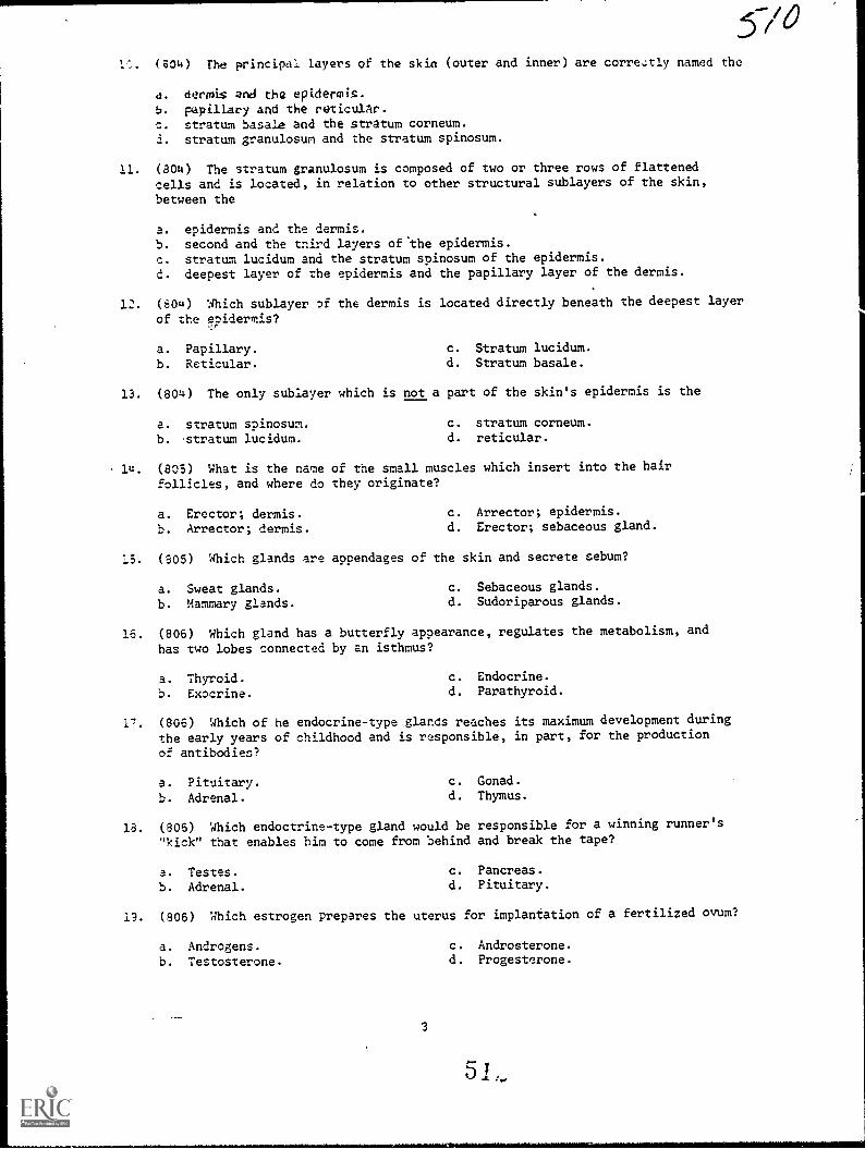
L. (804) The principal layers of the skin (outer and inner) are corretly named the
4. derrni$ and the epidermis.
b. papillary and the reticulAr.c. stratum basale and the stratum corneum.i. stratum granulosum and the stratum spinosum.
11. (804) The stratum granulosum is composed of two or three rows of flattenedcells and is located, in relation to other structural sublayers of the skin,
between the
a. epidermis and the dermis.b. second and the third layers of *the epidermis.
c. stratum lucidum and the stratum spinosum of the epidermis.d. deepest layer of the epidermis and the papillary layer of the dermis.
12. (804) Which sublayer of the dermis is located directly beneath the deepest layer
of the eoidermis?f
a. Papillary. c. Stratum lucidum.
b. Reticular. d. Stratum basale.
13. (804) The only sublayer which is not a part of the skin's epidermis is the
a. stratum spinosum. c. stratum corneum.
b. 'stratum lucidum. d. reticular.
14. (805) What is the name of the small muscles which insert into the hairfollicles, and where do they originate?
a. Erector; dermis. c. Arrector; epidermis.
b. Arrector; dermis. d. Erector; sebaceous gland.
15. (805) Which glands are appendages of the skin and secrete sebum?
a. Sweat glands. c. Sebaceous glands.
b. Mammary glands. d. Sudoriparous glands.
16. (806) Which gland has a butterfly appearance, regulates the metabolism, and
has two lobes connected by an isthmus?
a. Thyroid. c. Endocrine.
b. Exocrine. d. Parathyroid.
17. (806) Which of he endocrine-type glands reaches its maximum development duringthe early years of childhood and is responsible, in part, for the production
of antibodies?
a. Pituitary.b. Adrenal.
c. Gonad.d. Thymus.
18. (806) Which endoctrine-type gland would be responsible for a winning runner's"kick" that enables him to come from behind and break the tape?
a. Testes.b. Adrenal.
c. Pancreas.d. Pituitary.
13. (806) Which estrogen prepares the uterus for implantation of a fertilized ovum?
a. Androgens. c. Androsterone.
b. Testosterone. d. Progesterone.
3

20. (807) To properly lift a field radiographic table, each person grasping ahandle must lift at least
a. 66 2/3 lbs. c. 133 1/3 lbs.b. 100 lbs. d. 200 lbs.
21. (807) If a filed radiographic table is properly lifted, there is a total ofhow many persons holding a total of how many handles?
a. Enough to easily lift 400 lbs.b. Three persons lifting 6 handles.c. Four persons lifting 8 handles.d. Six persons lifting 6 handles.
22. (807) The manufacturer's instructions for assembling the field radiographictable are located on the
a. swivel arm.b. tabletop's underside.c. inside of the container cover.d. outside of the container cover.
23. (808) Field hospital personnel should never connect the power cord of the50/100 mA X-ray apparatus to the power source until the
a. ammeter is connected.b. apparatus is completely assembled.c. apparatus is completely disassembled.d. trnisformer oil has been drained and replaced.
24. (808) Under no circumstances can the 50/100 mA X-ray be used without connecting
a. the rectifier.b. the transformer.c. both the rectifier and the power cord.d. both the transformer and the rectifier.
25. (808) If you desire to double the 50/100 mA X-ray apparatus' capacity, youshould electrically reconnect the circuit to include the
a. rectifier. c. transformer.b. X-ray tube. d. control unit.
26. (808) In making the electrical connections of the 50/100 mA X-ray apparatus,it is not of prime importance that correct polarity be established between the
a. X-ray tube and the transformer or rectifier.b. transformer and the X-ray tube.c. rectifier and the transformer.d. rectifier and the X-ray tube.
27. (809) The purpose of the middle receptacle on the back of the control-unitstand is to connect the control unit with the
a. main power source. c. X-ray tube and collimator:b. fluoroscopic floor switch. d. bucky of the radiographic table.
28. (809) Of the five electrical receptacles found on the back of the control unit,the one that connects the unit to the main power source is the
a. TUBE.
b. LINE.
4
c. BUCKY.d. FT. SW.
5
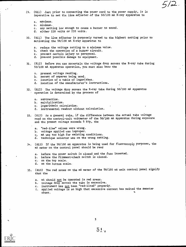
29. (811) Just prior to connecting the power cord to the power supply, it isimperative to set the line adjuster of the 50/100 mA X-ray apparatus to
a. maximum.
o. minimum.c. any setting low enough to cause a buzzer to sound.
d. either 110 volts or 220 volts.
30. (811) The line adjuster is purposely turned to the highest setting prior toactivating the 50/100 mA X-ray apparatus to
a. reduce the voltage setting to a minimum value.b. check the operation of a buzzer circuit.c. prevent certain injury to personnel.d. prevent possible damage to equipment.
31. (812) Before you can ascertain the voltage drop across the X-ray tube during50/100 mA apparatus operation, you must also know the
a. present voltage reading.b. amount of amperes being used.c. location of a table of logarithms.d. location of the manufacturer's instructions.
32. (812) The voltage drop across the X-ray tube during 50/100 mA apparatusoperation is determined by the process of
a. subtraction.
b. multiplication.c. logarithmic calculation.d. instrumental readout without calculation.
33. (812) As a general rule, if the difference between the actual tube voltageread on the control-unit voltmeter of the 50/100 mA apparatus during exposure
and the preset voltage exceeds 5 kVp, the
a. "red-line" values were wrong.
b. voltage applied was improper.
c. mA was too high for existing conditions.d. technique selector was on the wrong setting.
34. (813) If the 50/100 mA apparatus is being used for fluoroscopic purposes, the
mA meter on the control panel should be read
a. before the power switch is closed and the fuse inserted.
b. before the filament-check switch is closed.
c. on the top scale.d. on the bottom scale.
35. (813) The red zones on the mA meter of the 50/100 mA unit control panel signify
that the
a. mA should not be operated in red areas.
b. voltage drop across the tube is excessive.
c. instrument has not been "red-lined" properly.d. applied voltage is so high that excessive current has melted the ammeter
shunt.
5
5 1
542

1/4)41. (816) All the statements concerning benign tumors are true except they
c/e3
36. (813) The mA meter on the 50/100 mA unit control panel reads the mA only whenthe
a. unit is overloaded.b. unit is under load.c. applied MAs is in the red-zone areas.d. mA adjuster is being used and the filament check switch is simultaneously
closed.
37. (313) Assume you have set up the 50/100 mA apparatus in the field and properlyprepared a filament chart, as follows:
Filament Scale mA
3.5 255.5 406.5 50
You desire to use a 40 mA for a radiograph. Which of the following stepsdo you perform first?
a. Turn the mA adjuster until the needle on the filament scale reads 5.5.b. Set the radiographic timer to 5 1/2 seconds.c. Depress and hold the filament check switch.d. Release the filament check switch.
38. (814) Which, if any, of the three currently available types of Polaroid specialfilm requires the least amount of time for processing?
a. 3000X.b. 1001.c. TLX.
d. They all are processed for equal lengths of time.
39. (814) After processing a polarized radiograph, it definitely appears too dark.What change should you make in 50/100 mA apparatus in the field to correct theexposure on subsequent radiographs?
a. Decrease the applied voltage. c. Decrease the mAs.b. Increase the processing time. d. Increase the mAs.
40. (814) To increase the contrast on a Polaroid radiograph, along with certainother considerations, you should use
a. low kVp. c. high kVp.b. high mAs. d. low mAs.
a. can become dangerous.b. usually are treated with radiation.c. usually are enclosed in capsules.d. exist only in the immediate site of growth and can be removed by surgery.
42. (817) Radical treatment of a tumor means that
a. the tumor is radioresistant.b. the patient's cure is considered improbable.c. an attempt is made to cure the patient.d. the patient will experience 5 years of no further trouble.
6

43. (817) Palliative treatment for a tumor is not expected to
a. significantly reduce pain.
b. enhance some basic function.
c. effect a cure lasting 5 years or more.
d. be orientated toward the patient's symptoms.
44. (818) You are to perform tumor therapy using a combination filter composedof tin, copper, and aluminum. The safest metal to place neare3t to the patient's
skin is
a. aluminum, because of its porosity.
b. aluminum, because of its atomic weight.
c. tin, because of its malleability and flexibility.d. copper, because of its atomic number and conductivity.
45 (818) You are to perform tumor therapy using a Thoraeus filter. The order in
which they should be placed near the tube to reduce patient skin dosage is
a. tin and aluminum. c. aluminum, copper, and tin.
b. copper and aluminum. d. tin, copper, and aluminum.
46. (819) In regard to the quality of a therapy beam, its "half-value layer"
expresses the beam's
a. absorption rate. c. ability to penetrate.
b. absolute effect. d. filtration capability.
47. (819) Given the following data. Beam: 15 mA, 200 kVp, 80 R/min at 50 cm using
a Thoraeus filter with these results:
60 R/min at 50 cm, with 0.25 mm Cu added.50 R/min at 50 cm, with 0.50 mm Cu added.40 R/min at 50 cm, with 0.75 C4 added.
What is the beam's qual' y, measured in half-wave layer?
a. 0.75 mm Cu. c. 0.375 mm Cu.
b. 0.50 mm Cu. d. 0.25 mm Cu.
48. (819) If a beam were produced with 15 mA, 200 kVp, 50 R/min at 50 cm, using a
Thoraeus filter, what would be the half-value layer, using the following data:
40 R/min at 50 cm with 0.10 mm Cu added.30 R/min at 50 cm with 0.15 mm Cu added.25 R/min at 40 cm with 0.25 mm Cu added.25 R/min at 50 cm with 0.30 mm Cu added.
a. 0.10 mm Cu. c. 0.30 mm Cu.
b. 0.15 mm Cu. d. Either 0.25 or 0.30 mm Cu.
I1(D
1)
2
49. (820) Using the formula 12 , f a therapy beam provides an air-dose
(D2
)
2i
rate of 75 R/min at 50 cm from the focal spot, what should the air-dose rate
be at 25 cm?
a. 37.5 R/min. c. 150 R/min.
b. 300 R/min. d. 18.75 R/min.
7
1
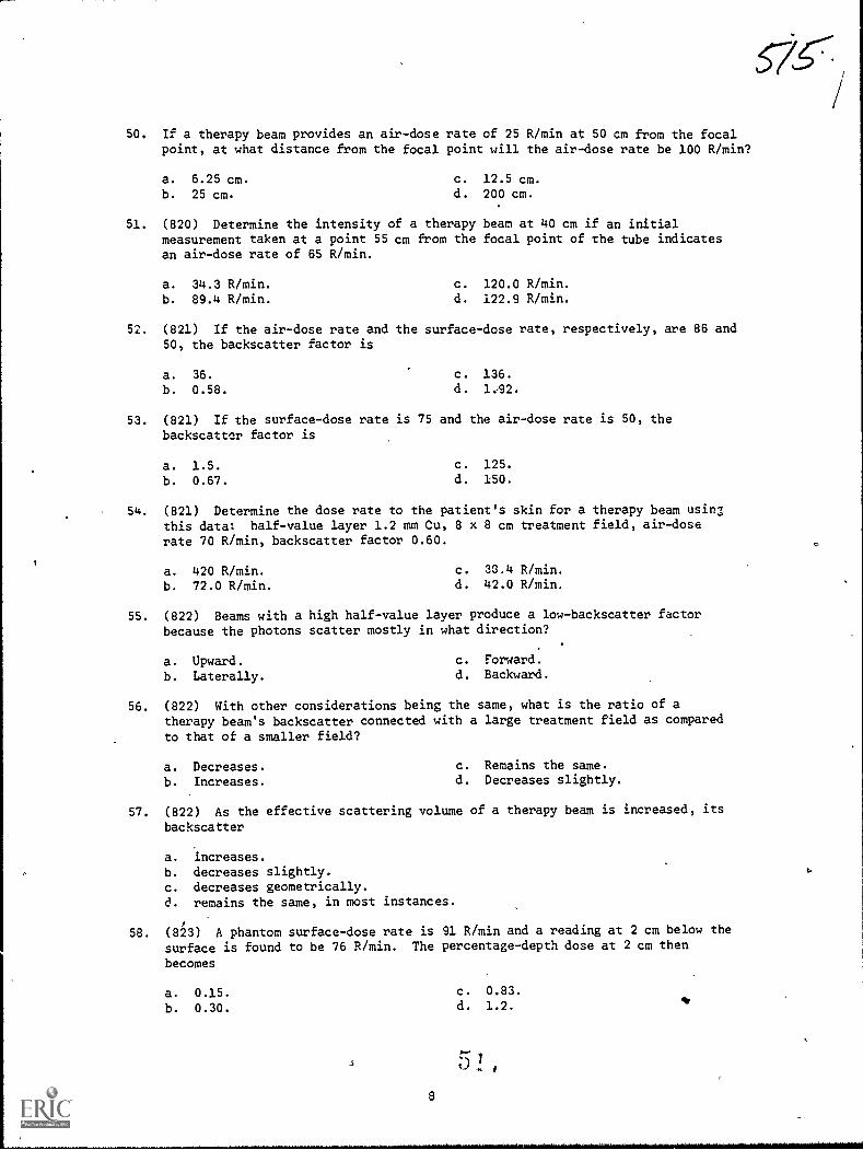
50. If a therapy beam provides an air-dose rate of 25 R/min at 50 cm from the focalpoint, at what distance from the focal point will the air-dose rate be 100 R/min?
a. 6.25 cm.
b. 25 cm.
c. 12.5 cm.d. 200 cm.
51. (820) Determine the intensity of a therapy beam at 40 cm if an initialmeasurement taken at a point 55 cm from the focal point of the tube indicatesan air-dose rate of 65 R/min.
a. 34.3 R/min. c. 120.0 R/min.
b. 89.4 R/min. d. 122.9 R/min.
52. (821) If the air-dose rate and the surface-dose rate, respectively, are 86 and50, the backscatter factor is
a. 36.
b. 0.58.
c. 136.
d. 1,92.
53. (821) If the surface-dose rate is 75 and the air-dose rate is 50, thebackscatter factor is
a. 1.5
b. 0.67.
c. 125.
d. 150.
54. (821) Determine the dose rate to the patient's skin for a therapy beam using
this data: half-value layer 1.2 mm Cu, 8 x 8 cm treatment field, air-doserate 70 R/min, backscatter factor 0.60.
a. 420 R/min. c. 36.4 R/min.
b. 72.0 R/min. d. 42.0 R/min.
55. (822) Beams with a high half-value layer produce a low-backscatter factorbecause the photons scatter mostly in what direction?
a. Upward. c. Forward.
b. Laterally. d. Backward.
56. (822) With other considerations being the same, what is the ratio of atherapy beam's backscatter connected with a large treatment field as compared
to that of a smaller field?
a. Decreases. c. Remains the same.
b. Increases. d. Decreases slightly.
57. (822) As the effective scattering volume of a therapy beam is increased, its
backscatter
a. increases.
b. decreases slightly.c. decreases geometrically.d. remains the same, in most instances.
58. (823) A phantom surface-dose rate is 91 R/min and a reading at 2 cm below the
surface is found to be 76 R/min. The percentage-depth dose at 2 cm then
becomes
a. 0.15.
b. 0.30.
c. 0.83.
d. 1.2.
\
MODIFICATIONS
.0 9 /I/ of this publication has (have) been deleted in,
adapting this material for inclusion in the "Trial Implementation of a,
Model System to Provide Military Curriculum Materials for Use in Vocational
and Tvchntcal Education." Deleted material involves extensive use of,
military forms, procedures, systems, etc. and was not considered appropriate
for use in vocational and technical education.
I
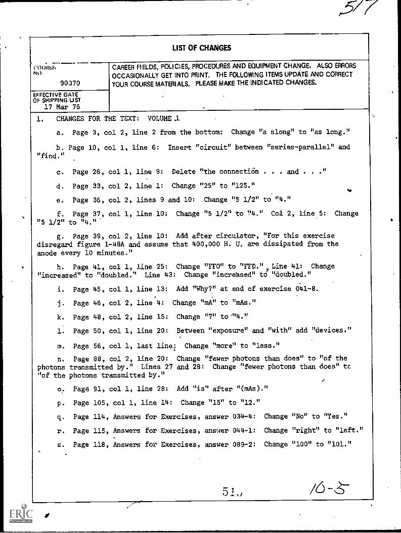
15/7
LIST OF CHANGES
CO(JI1SF.Nt).
90370
EFFECTIVE DATEOF SHIPPING UST
17 Mar 76
CAREER FIELDS, POLICIES, PROCEDURES AND EQUIPMENT CHANGE. ALSO ERRORS
OCCASIONALLY GET INTO PRINT. THE FOLLOWING ITEMS UPDATE AND CORRECT
YOUR COURSE MATERIALS. PLEASE MAKE THE INDICATED CHANGES.
1. CHANGES FOR THE TEXT: VOLUME .1
a. Page 3, col 2, line 2 from the bottom: Change "a slong" to "as long."
b. Page 10, col 1, line 6: Insert "circuit" between "series-parallel" and"find."
c. Page 26, col 1, line 9: Delete "the connectiOn . . . and . . ."
d. Page 33, col 2, line 1: Change "25" to "125."
e. Page 36, col 2, lines 9 and 10: Change "5 112" to'"4."
f. Page 37, col 1, line 10: Change "5 1/2" to "4." Coi 2, line 5: Change
"5 1/2" to "4."'
g. Page 39, col 2, line 10: Add after circulator, "For this exercisedisregard figure 1-48A and assume that 400,000 H. U. are dissipated from the
anode every 10 minutes."
h. Page 41, col 1, line 25: Change "FFO" to "FFD." Line 41: Change
"increased" to "doubled." Line 43: Change "increased" to "doubled."
i. Page 45, col 1, line 13: Add "Why?" at end of exercise 041-8.
j. Page 46, col 2, line 4: Change "mA" to "mAs."
k. Page 48, col 2, line 15: Change "7" tom4."
1. Page 50, col 1, line 20: Between "exposure" and "with" add "devices."
m. Page 56, col 1, last linei Change "more" to "less."
n. Page 88, col 2, line 20: Change "fewer photons than does" to "of the
photons transmitted by." Lines 27 and 28: Change "fewer photons than does" tc
"of the photons transmitted by."
0. Page 91, col 1, line 28: Add "is" after "(mAs)."
p. Page 105, col 1, line 14: Change "15" to "12."
q. Page 114, Answers for Exercises, answer 034-4: Change "No" to "Yes."
r. Page 115, Answers for Exercises, answer 044-1: Change "right" to "left."
s. Page 118, Answers for Exercises, answer 089-2: Change "100" to "101."
51,1 /6 -8--

COURSFNO
90370
EFFECTIVE DATEOF SHIPPING LIST
17 Mar 76
LIST OF CHANGES
CAREER FIELDS, POLICIES, PROCEDURES AND EQUIPMENT CHANGE. ALSO ERRORS
OCCASIONALLY GET INTO PRINT. THE FOLLOWING ITEMS UPDATE AND CORRECT
YOUA COURSE MATERIALS. PLEASE MAKE THE INDICATED CHANGES.
2. CHANGES FOR THE TEXT: VOLUME 2
a. Page' 7, col 2, line 4' from the boom: Change "split" to "splint."
b. Page 37, col 1, line 13: Change "facil" to "facial."
es.c. TI.Oge.46, cal 1, line 31: Ch,Inge "talocaneal" to "talocalcaneal." Col 2,
line 33:9"'Delete "that."
d. Page 57, col 1, line 11: Change "formaina" to "foramina." Line 22: Change
"formaina" "foramina."
e. Page 58, col 1, line 11: Change "describ" to "describe."
f. Page 79, Answers for Exercises, answer 202-16: After "sustentacul=" add
"tali."*
3. CHANGES FOR THE TEXT: VOLUME 3
a. Page 4, col 2, line 22: Change "A" to "B."
b. Page 60, col 2, line 21: Change "61" to'"6-1."
c. Page 84,mao1 2, Answers for Exercises, answer 418-1, line 5: Change "b"
to "(3)." Answer 418-1, line 9: Change "c" to "b."
4. CHANGES FOR THE TEXT: VOLUME 5
a. Page 20, col 1, line 12: Before the word "cable" delete 115-." Line 15:
Change "table" to "tube."
b. Page 29, col 1, line 8 from the bottom: After "therapy" add "filter is."
c. Page 69, col 2, line 5 from the bottom: Change the SSAN from "236-56-56-56"
to "236-56-56-66."
d. Page 72, fig 578, line 1: In the space after ANATOMIC FIELD NUMBER add
"40."
5. CHANGE FOR THE VOLUME REVIEW EXERCISE: VOLUME
The following questions are no longer scored and need not be answered;
80, 89 and 95.
No
90370
EFFECTIVE OATEOF SNIPPING LIST
17- Mar 76
LIST OF CHANGES
:CA-R-EER AELOS, POLICIES. PRaEDURES AND EQUIPMENT CHANGE. ALSO ERRORS
OCCASIONALLY GET INTO PRINT. THE FOLLOWING ITEM,S UPDATE AND CORRECT
YOUR COURSE MATERIALS. PLEASE MAKE THE INDICATED CHANGES.
6. CHANGE FOR THE VOLUME REVIEW EXERCISE: VOLUME 2
1
The following questions are no longer scored and need not be
12, 39 and 45.
7. CHANGE FOR THE VOLUME REVIEW EXERCISE: VOLUME 4
Question 37 is no longer scored and need not Le answered.
9 Z
answered: