A material-performance-based database for FRC and RC ...
16
A material-performance-based database for FRC and RC elements under shear loading Estefanı ´a Cuenca . Antonio Conforti . Fausto Minelli . Giovanni A. Plizzari . Juan Navarro Gregori . Pedro Serna Received: 20 June 2017 / Accepted: 29 December 2017 / Published online: 12 January 2018 Abstract The shear strength of elements reinforced by fibres is predicted by Codes using formulations generally developed from a limited set of test results. In fact, only few of available test results are combined with a material mechanical characterization, allowing to evaluate and compare the different performances of Fibre Reinforced Concretes (FRC). To address this problem, a material-performance-based shear data- base for FRC elements and their related reference samples in Reinforced Concrete (RC, with and without web reinforcement) is presented herein, merging the experiences carried out in the last decade at the University of Brescia and at the Universitat Polite `c- nica de Vale `ncia. The database is composed by 171 specimens: 93 in FRC and 78 in RC with or without web reinforcement. For FRC elements, the post- cracking resistance (f R,1 and f R,3 ) is also given according to EN 14651 standard. The evaluation of the shear database was also carried out, discussing the influence of the different factors affecting the shear strength both in FRC and RC samples. Finally, the two formulations suggested by Model Code 2010 for FRC elements are compared against the database results in order to shed new light on code requirements. Keywords Steel fibres Macro-synthetic fibres Fibre reinforced concrete Shear Shear database Model code 2010 List of symbols a Shear span A p Area of prestressing steel A s Longitudinal reinforcement area b w Web width CMOD Crack mouth opening displacement E. Cuenca (&) Universitat Polite `cnica de Vale `ncia, Valencia, Spain e-mail: [email protected] Present Address: E. Cuenca DICA - Department of Civil and Environmental Engineering, Politecnico di Milano, Milan, Italy A. Conforti F. Minelli G. A. Plizzari DICATAM - Department of Civil, Environmental, Architectural Engineering and Mathematics, University of Brescia, Brescia, Italy e-mail: [email protected] F. Minelli e-mail: [email protected] G. A. Plizzari e-mail: [email protected] J. Navarro Gregori P. Serna ICITECH - Concrete Science and Technology Institute, Universitat Polite `cnica de Vale `ncia, Valencia, Spain e-mail: [email protected] P. Serna e-mail: [email protected] This is a post-peer-review, pre-copyedit version of an article published in Materials and Structures (2018) 51:11. The final authenticated version is available online at: https://doi.org/10.1617/s11527-017-1130-7
-
Upload
khangminh22 -
Category
Documents
-
view
1 -
download
0
Transcript of A material-performance-based database for FRC and RC ...
A material-performance-based database for FRC and RC elements under shear loading
Estefanıa Cuenca . Antonio Conforti . Fausto Minelli . Giovanni A. Plizzari .Juan Navarro Gregori . Pedro Serna
Received: 20 June 2017 / Accepted: 29 December 2017 / Published online: 12 January 2018
Abstract The shear strength of elements reinforced
by fibres is predicted by Codes using formulations
generally developed from a limited set of test results.
In fact, only few of available test results are combined
with a material mechanical characterization, allowing
to evaluate and compare the different performances of
Fibre Reinforced Concretes (FRC). To address this
problem, a material-performance-based shear data-
base for FRC elements and their related reference
samples in Reinforced Concrete (RC, with and without
web reinforcement) is presented herein, merging the
experiences carried out in the last decade at the
University of Brescia and at the Universitat Politec-
nica de Valencia. The database is composed by 171
specimens: 93 in FRC and 78 in RC with or without
web reinforcement. For FRC elements, the post-
cracking resistance (fR,1 and fR,3) is also given
according to EN 14651 standard. The evaluation of
the shear database was also carried out, discussing the
influence of the different factors affecting the shear
strength both in FRC and RC samples. Finally, the two
formulations suggested by Model Code 2010 for FRC
elements are compared against the database results in
order to shed new light on code requirements.
Keywords Steel fibres � Macro-synthetic fibres �Fibre reinforced concrete � Shear � Shear database �Model code 2010
List of symbols
a Shear span
Ap Area of prestressing steel
As Longitudinal reinforcement area
bw Web width
CMOD Crack mouth opening displacement
E. Cuenca (&)
Universitat Politecnica de Valencia, Valencia, Spain
e-mail: [email protected]
Present Address:
E. Cuenca
DICA - Department of Civil and Environmental Engineering,
Politecnico di Milano, Milan, Italy
A. Conforti � F. Minelli � G. A. PlizzariDICATAM - Department of Civil, Environmental,
Architectural Engineering and Mathematics, University of
Brescia, Brescia, Italy
e-mail: [email protected]
F. Minelli
e-mail: [email protected]
G. A. Plizzari
e-mail: [email protected]
J. Navarro Gregori � P. SernaICITECH - Concrete Science and Technology Institute,
Universitat Politecnica de Valencia, Valencia, Spain
e-mail: [email protected]
P. Serna
e-mail: [email protected]
This is a post-peer-review, pre-copyedit version of an article published in Materials and Structures (2018) 51:11. The final authenticated version is available online at: https://doi.org/10.1617/s11527-017-1130-7
d Effective depth
dg Maximum aggregate size
Es Modulus of elasticity of longitudinal
reinforcement
Ep Modulus of elasticity of prestressing steel
fc Cylinder compressive concrete strength
fck Characteristic value of cylinder
compressive concrete strength
fct Mean value of tensile concrete strength
fFtu Ultimate residual strength according to
Model Code 2010
FM Failure mode (S = shear; SY = shear after
longitudinal rebar yielding; WS = web-
shear; F = flexure)
fR,1 Residual flexural tensile strength
corresponding to CMOD = 0.5 mm
fR,3 Residual flexural tensile strength
corresponding to CMOD = 2.5 mm
MEd Applied moment
NEd Applied axial force
Vc Shear strength provided by concrete
Vc,F Shear strength provided by fibre reinforced
concrete
VEd Applied shear force
Vf Fibre volume fraction
VR,max Shear force at shear compression failure
Vs Shear strength provided by web
reinforcement
Vu Shear strength
Vu,FRC Shear strength of FRC elements
Vu,RS Shear strength of reference samples
Vu/
Vu,code
Model safety factor
wu Maximum crack opening accepted in
structural design
z Internal lever arm
cc Strength reduction factor according to
Eurocode 2 and Model Code 2010
ex Longitudinal strain calculated at mid-depth
of d
h Angle of inclination of shear cracks
q Longitudinal reinforcement ratio
qw Web reinforcement ratio
rp Compressive stress due to effective
prestress
1 Introduction
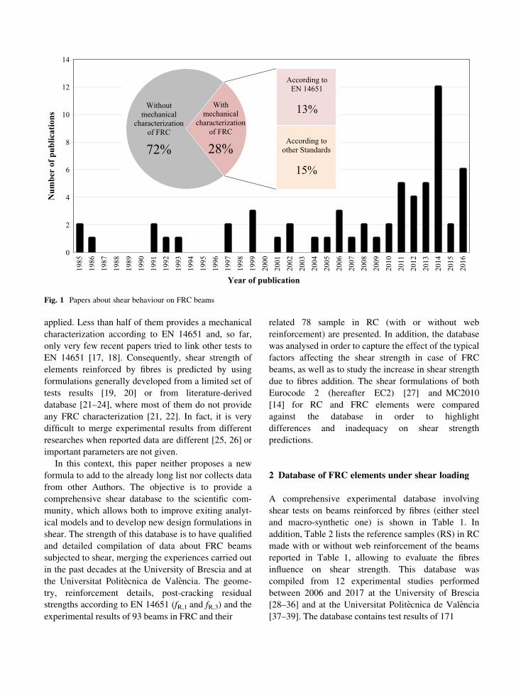
The use of fibres as shear reinforcement in ReinforcedConcrete (RC) beams was mainly studied during thepast three decades, even if the majority of thesestudied was carried out in the 2000s (Fig. 1). Fibressubstantially enhance the shear strength and deforma-
tion capacity of structural elements [1, 2] in eithervibrated [3–9] or self-compacting concrete [10, 11];fibres also proved to be very effective in extrudedconcrete members [12]. Therefore, the effectiveness offibres in enhancing the shear resistance is widelyrecognized in the scientific community. So far, thelargest number of these studies dealt with steel fibres[3–6, 8–12] even if there was a recent growing intereston macro-synthetic ones [7].
Recent design guidelines allow to use fibres asshear reinforcement [13–15]. RILEM TC 162-TDF[13] proposed pioneer guidelines where fibre contri-bution to shear resistance was added to the concreteone as a separate term (based on post-cracking
residual strengths). In other research studies, fibresand concrete contributions are generally not
considered as additional terms since fibres markedly
influence the typical mechanisms of shear transferpresent in RC element (especially aggregate
interlock); Fiber Rein-forced Concrete (FRC) can beconsidered as a unique composite material
characterized by significant tough-ness properties aftercracking (due to the bridging effect of fibres). Thisconcept was adopted in the recent Model Code 2010(hereafter MC2010) [14], where the positive effect offibres in shear is consid-ered as an enhancement ofconcrete contribution. The latter was modelled inMC2010 by two different analytical equations (well-discussed in the following sections) based on the post-cracking residual strength provided by FRC, evaluatedaccording to EN 14651 [16]. Consequently, a material
mechanical character-ization of FRC is required byMC2010.
Figure 1 shows the number of publications (in-dexed papers) with experimental results from sheartests on FRC elements in the last 30 years (between1985 and 2016). It can be observed that the majority ofexperimental tests (72%) was carried out withoutproviding any FRC mechanical characterization (onlyfibre type and amount are given), making difficult theuse of these results by researchers. Only 28% ofpapers provides post-cracking mechanical propertiesof FRC, even if different characterization methods
were
related 78 sample in RC (with or without web
reinforcement) are presented. In addition, the databasewas analysed in order to capture the effect of the typicalfactors affecting the shear strength in case of FRCbeams, as well as to study the increase in shear strengthdue to fibres addition. The shear formulations of bothEurocode 2 (hereafter EC2) [27] and MC2010
[14] for RC and FRC elements were compared
against the database in order to highlight
differences and inadequacy on shear strength
predictions.
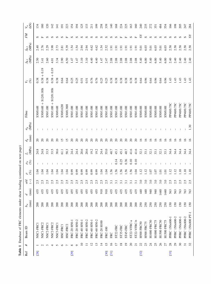
2 Database of FRC elements under shear loading
A comprehensive experimental database involving
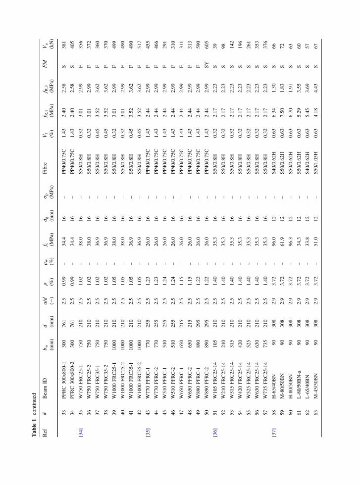
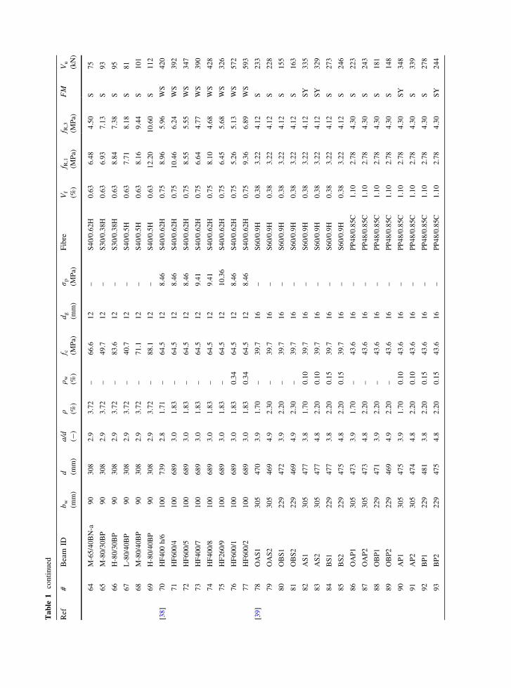
shear tests on beams reinforced by fibres (either steeland macro-synthetic one) is shown in Table 1. In
addition, Table 2 lists the reference samples (RS) in RCmade with or without web reinforcement of the beams
reported in Table 1, allowing to evaluate the fibresinfluence on shear strength. This database was
compiled from 12 experimental studies performed
between 2006 and 2017 at the University of Brescia[28–36] and at the Universitat Politecnica de Valencia[37–39]. The database contains test results of 171
0
2
4
6
8
10
12
14
1985
1986
1987
1988
1989
1990
1991
1992
1993
1994
1995
1996
1997
1998
1999
2000
2001
2002
2003
2004
2005
2006
2007
2008
2009
2010
2011
2012
2013
2014
2015
2016
Num
ber
of p
ublic
atio
ns
Year of publication
Without mechanical
characterization of FRC
72%
According to EN 14651
13%
According to other Standards
15%
With mechanical
characterization of FRC
28%
Fig. 1 Papers about shear behaviour on FRC beams
applied. Less than half of them provides a mechanical
characterization according to EN 14651 and, so far,only very few recent papers tried to link other tests toEN 14651 [17, 18]. Consequently, shear strength ofelements reinforced by fibres is predicted by usingformulations generally developed from a limited set oftests results [19, 20] or from literature-derived
database [21–24], where most of them do not provideany FRC characterization [21, 22]. In fact, it is verydifficult to merge experimental results from differentresearches when reported data are different [25, 26] orimportant parameters are not given.
In this context, this paper neither proposes a newformula to add to the already long list nor collects datafrom other Authors. The objective is to provide acomprehensive shear database to the scientific com-
munity, which allows both to improve exiting analyt-ical models and to develop new design formulations inshear. The strength of this database is to have qualifiedand detailed compilation of data about FRC beams
subjected to shear, merging the experiences carried outin the past decades at the University of Brescia and atthe Universitat Politecnica de Valencia. The geome-
try, reinforcement details, post-cracking residual
strengths according to EN 14651 (fR,1 and fR,3) and theexperimental results of 93 beams in FRC and their
Table
1DatabaseofFRC
elem
ents
under
shearloading(continued
onnextpage)
Ref
#Beam
IDbw
(mm)
d (mm)
a/d
(-)
q (%)
qw
(%)
f c (MPa)
dg
(mm)
rp
(MPa)
Fibre
Vf
(%)
f R,1
(MPa)
f R,3
(MPa)
FM
Vu
(kN)
[28]
1NSC1-FRC1
200
435
2.5
1.04
–24.8
20
–S30/0.6H
0.38
2.50
2.40
S134
2NSC1-FRC2
200
435
2.5
1.04
–24.8
20
–S30/0.6H
?S12/0.18St
0.38?
0.19
3.41
2.76
F180
3NSC2-FRC1
200
435
2.5
1.04
–33.5
20
–S50/1.0H
0.38
2.60
2.29
S120
4NSC2-FRC2
200
435
2.5
1.04
–33.5
20
–S50/1.0H
?S12/0.18St
0.38?
0.19
4.01
3.98
S142
5NSC3-FRC1
200
435
2.5
1.04
–38.6
20
–S30/0.6H
0.38
3.34
2.73
S141
6HSC-FRC1
200
435
2.5
1.04
–61.1
15
–S30/0.62H
0.64
2.90
2.81
S191
7HSC-FRC2
200
435
2.5
1.04
–58.3
15
–S30/0.38H
0.64
6.50
5.39
F223
[29]
8FRC-20H50-1
200
455
2.5
0.99
–24.4
20
–S50/1.0H
0.25
1.47
1.54
S154
9FRC-20H50-2
200
455
2.5
0.99
–24.4
20
–S50/1.0H
0.25
1.47
1.54
S194
10
FRC-40H50-1
200
455
2.5
0.99
–20.6
20
–S50/1.0H
0.51
3.10
2.94
S125
11
FRC-40H50-2
200
455
2.5
0.99
–20.6
20
–S50/1.0H
0.51
3.10
2.94
S133
12
FRC-60H50-1
200
455
2.5
0.99
–19.2
20
–S50/1.0H
0.76
4.40
4.62
S211
13
FRC-60H50-2
200
455
2.5
0.99
–19.2
20
–S50/1.0H
0.76
4.40
4.62
S199
14
FRC-20H100
200
910
2.5
1.04
–24.4
20
–S50/1.0H
0.25
1.47
1.54
S258
[30]
15
FRC-100
200
910
2.5
1.04
–55.0
20
–S50/1.0H
0.25
2.47
2.52
S339
[31]
16
FRC
200
435
3.1
1.56
–40.7
20
–S50/1.0H
0.38
2.08
1.91
S140
17
ST22-FRC
200
435
3.1
1.56
0.14
45.1
20
–S50/1.0H
0.38
2.08
1.91
S168
18
ST35-FRC
200
435
3.1
1.56
0.25
45.1
20
–S50/1.0H
0.38
2.08
1.91
F224
19
ST45-FRC
200
435
3.1
1.56
0.36
40.7
20
–S50/1.0H
0.38
2.08
1.91
F225
20
ST22-V
FRC-a
200
435
3.1
1.56
0.10
41.6
20
–S50/1.0H
0.38
2.08
1.91
S163
21
ST22-V
FRC-b
200
435
3.1
1.04
0.10
41.6
20
–S50/1.0H
0.38
2.08
1.91
F160
[32]
22
H500FRC50
250
440
3.0
1.12
–32.1
16
–S50/0.8H
0.64
5.40
5.01
SY
240
23
H500FRC75
250
440
3.0
1.12
–33.1
16
–S50/0.8H
0.96
6.00
6.03
S235
24
H1000FRC50
250
940
3.0
1.07
–32.1
16
–S50/0.8H
0.64
5.40
5.01
S272
25
H1000FRC75
250
940
3.0
1.07
–33.1
16
–S50/0.8H
0.96
6.00
6.03
S351
26
H1500FRC50
250
1440
3.0
1.01
–32.1
16
–S50/0.8H
0.64
5.40
5.01
S484
27
H1500FRC75
250
1440
3.0
1.01
–33.1
16
–S50/0.8H
0.96
6.00
6.03
S554
[33]
28
PFRC150x600-1
150
563
2.5
1.12
–34.4
16
–PP40/0.75C
1.43
2.40
2.58
S166
29
PFRC150x600-2
150
563
2.5
1.12
–34.4
16
–PP40/0.75C
1.43
2.40
2.58
S198
30
PFRC150x800-1
150
763
2.5
1.10
–34.4
16
–PP40/0.75C
1.43
2.40
2.58
S205
31
PFRC150x800-2
150
763
2.5
1.10
–34.4
16
–PP40/0.75C
1.43
2.40
2.58
S247
32
PFRC150x800PT-1
150
763
2.5
1.10
–34.4
16
1.30
PP40/0.75C
1.43
2.40
2.58
SY
284
Table
1continued
Ref
#Beam
IDbw
(mm)
d (mm)
a/d
(-)
q (%)
qw
(%)
f c (MPa)
dg
(mm)
r p (MPa)
Fibre
Vf
(%)
f R,1
(MPa)
f R,3
(MPa)
FM
Vu
(kN)
33
PFRC300x800-1
300
761
2.5
0.99
–34.4
16
–PP40/0.75C
1.43
2.40
2.58
S381
34
PFRC300x800-2
300
761
2.5
0.99
–34.4
16
–PP40/0.75C
1.43
2.40
2.58
S405
[34]
35
W750FRC25-1
750
210
2.5
1.02
–38.0
16
–S50/0.8H
0.32
3.01
2.99
F356
36
W750FRC25-2
750
210
2.5
1.02
–38.0
16
–S50/0.8H
0.32
3.01
2.99
F372
37
W750FRC35-1
750
210
2.5
1.02
–36.9
16
–S50/0.8H
0.45
3.52
3.62
F360
38
W750FRC35-2
750
210
2.5
1.02
–36.9
16
–S50/0.8H
0.45
3.52
3.62
F370
39
W1000FRC25-1
1000
210
2.5
1.05
–38.0
16
–S50/0.8H
0.32
3.01
2.99
F499
40
W1000FRC25-2
1000
210
2.5
1.05
–38.0
16
–S50/0.8H
0.32
3.01
2.99
F490
41
W1000FRC35-1
1000
210
2.5
1.05
–36.9
16
–S50/0.8H
0.45
3.52
3.62
F490
42
W1000FRC35-2
1000
210
2.5
1.05
–36.9
16
–S50/0.8H
0.45
3.52
3.62
F517
[35]
43
W770PFRC-1
770
255
2.5
1.23
–26.0
16
–PP40/0.75C
1.43
2.44
2.99
F455
44
W770PFRC-2
770
255
2.5
1.23
–26.0
16
–PP40/0.75C
1.43
2.44
2.99
F466
45
W510PFRC-1
510
255
2.5
1.24
–26.0
16
–PP40/0.75C
1.43
2.44
2.99
F291
46
W510PFRC-2
510
255
2.5
1.24
–26.0
16
–PP40/0.75C
1.43
2.44
2.99
F310
47
W650PFRC-1
650
215
2.5
1.15
–26.0
16
–PP40/0.75C
1.43
2.44
2.99
F311
48
W650PFRC-2
650
215
2.5
1.15
–26.0
16
–PP40/0.75C
1.43
2.44
2.99
F313
49
W890PFRC-1
890
295
2.5
1.22
–26.0
16
–PP40/0.75C
1.43
2.44
2.99
F590
50
W890PFRC-2
890
295
2.5
1.22
–26.0
16
–PP40/0.75C
1.43
2.44
2.99
SY
605
[36]
51
W105FRC25-14
105
210
2.5
1.40
–35.3
16
–S50/0.8H
0.32
2.17
2.23
S39
52
W210FRC25-14
210
210
2.5
1.40
–35.3
16
–S50/0.8H
0.32
2.17
2.23
S98
53
W315FRC25-14
315
210
2.5
1.40
–35.3
16
–S50/0.8H
0.32
2.17
2.23
S142
54
W420FRC25-14
420
210
2.5
1.40
–35.3
16
–S50/0.8H
0.32
2.17
2.23
S196
55
W525FRC25-14
525
210
2.5
1.40
–35.3
16
–S50/0.8H
0.32
2.17
2.23
S261
56
W630FRC25-14
630
210
2.5
1.40
–35.3
16
–S50/0.8H
0.32
2.17
2.23
S353
57
W735FRC25-14
735
210
2.5
1.40
–35.3
16
–S50/0.8H
0.32
2.17
2.23
S376
[37]
58
H-65/40BN
90
308
2.9
3.72
–96.0
12
–S40/0.62H
0.63
6.34
1.30
S66
59
M-80/50BN
90
308
2.9
3.72
–61.9
12
–S50/0.62H
0.63
7.50
1.83
S72
60
H-80/50BN
90
308
2.9
3.72
–96.3
12
–S50/0.62H
0.63
6.70
1.91
S63
61
L-80/50BN-a
90
308
2.9
3.72
–34.3
12
–S50/0.62H
0.63
5.29
3.55
S60
62
L-65/40BN
90
308
2.9
3.72
–33.8
12
–S40/0.62H
0.63
5.45
3.69
S57
63
M-45/50BN
90
308
2.9
3.72
–51.0
12
–S50/1.05H
0.63
4.18
4.43
S67
Table
1continued
Ref
#Beam
IDbw
(mm)
d (mm)
a/d
(-)
q (%)
qw
(%)
f c (MPa)
dg
(mm)
rp
(MPa)
Fibre
Vf
(%)
f R,1
(MPa)
f R,3
(MPa)
FM
Vu
(kN)
64
M-65/40BN-a
90
308
2.9
3.72
–66.6
12
–S40/0.62H
0.63
6.48
4.50
S75
65
M-80/30BP
90
308
2.9
3.72
–49.7
12
–S30/0.38H
0.63
6.93
7.13
S93
66
H-80/30BP
90
308
2.9
3.72
–83.6
12
–S30/0.38H
0.63
8.84
7.38
S95
67
L-80/40BP
90
308
2.9
3.72
–40.7
12
–S40/0.5H
0.63
7.71
8.18
S81
68
M-80/40BP
90
308
2.9
3.72
–71.1
12
–S40/0.5H
0.63
8.16
9.44
S101
69
H-80/40BP
90
308
2.9
3.72
–88.1
12
–S40/0.5H
0.63
12.20
10.60
S112
[38]
70
HF400h/6
100
739
2.8
1.71
–64.5
12
8.46
S40/0.62H
0.75
8.96
5.96
WS
420
71
HF600/4
100
689
3.0
1.83
–64.5
12
8.46
S40/0.62H
0.75
10.46
6.24
WS
392
72
HF600/5
100
689
3.0
1.83
–64.5
12
8.46
S40/0.62H
0.75
8.55
5.55
WS
347
73
HF400/7
100
689
3.0
1.83
–64.5
12
9.41
S40/0.62H
0.75
6.64
4.77
WS
390
74
HF400/8
100
689
3.0
1.83
–64.5
12
9.41
S40/0.62H
0.75
8.10
4.68
WS
428
75
HF260/9
100
689
3.0
1.83
–64.5
12
10.36
S40/0.62H
0.75
6.45
5.68
WS
326
76
HF600/1
100
689
3.0
1.83
0.34
64.5
12
8.46
S40/0.62H
0.75
5.26
5.13
WS
572
77
HF600/2
100
689
3.0
1.83
0.34
64.5
12
8.46
S40/0.62H
0.75
9.36
6.89
WS
593
[39]
78
OAS1
305
470
3.9
1.70
–39.7
16
–S60/0.9H
0.38
3.22
4.12
S233
79
OAS2
305
469
4.9
2.30
–39.7
16
–S60/0.9H
0.38
3.22
4.12
S228
80
OBS1
229
472
3.9
2.20
–39.7
16
–S60/0.9H
0.38
3.22
4.12
S155
81
OBS2
229
469
4.9
2.30
–39.7
16
–S60/0.9H
0.38
3.22
4.12
S163
82
AS1
305
477
3.8
1.70
0.10
39.7
16
–S60/0.9H
0.38
3.22
4.12
SY
335
83
AS2
305
477
4.8
2.20
0.10
39.7
16
–S60/0.9H
0.38
3.22
4.12
SY
329
84
BS1
229
477
3.8
2.20
0.15
39.7
16
–S60/0.9H
0.38
3.22
4.12
S273
85
BS2
229
475
4.8
2.20
0.15
39.7
16
–S60/0.9H
0.38
3.22
4.12
S246
86
OAP1
305
473
3.9
1.70
–43.6
16
–PP48/0.85C
1.10
2.78
4.30
S223
87
OAP2
305
473
4.8
2.20
–43.6
16
–PP48/0.85C
1.10
2.78
4.30
S243
88
OBP1
229
471
3.9
2.20
–43.6
16
–PP48/0.85C
1.10
2.78
4.30
S181
89
OBP2
229
469
4.9
2.20
–43.6
16
–PP48/0.85C
1.10
2.78
4.30
S148
90
AP1
305
475
3.9
1.70
0.10
43.6
16
–PP48/0.85C
1.10
2.78
4.30
SY
348
91
AP2
305
474
4.8
2.20
0.10
43.6
16
–PP48/0.85C
1.10
2.78
4.30
S339
92
BP1
229
481
3.8
2.20
0.15
43.6
16
–PP48/0.85C
1.10
2.78
4.30
S278
93
BP2
229
475
4.8
2.20
0.15
43.6
16
–PP48/0.85C
1.10
2.78
4.30
SY
244
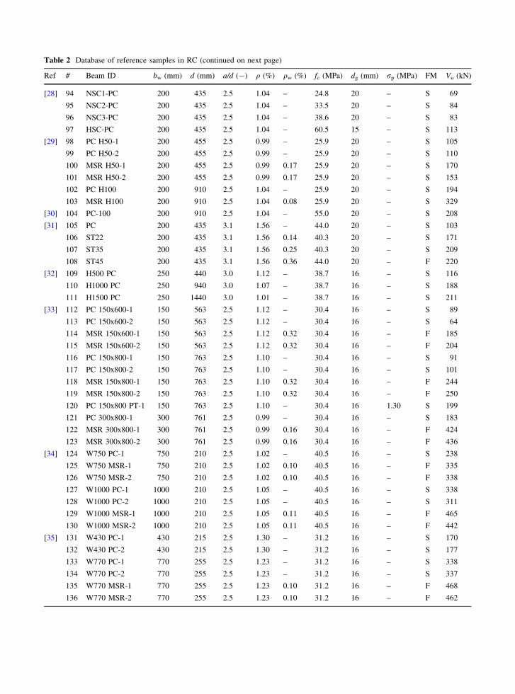
Table 2 Database of reference samples in RC (continued on next page)
Ref # Beam ID bw (mm) d (mm) a/d (-) q (%) qw (%) fc (MPa) dg (mm) rp (MPa) FM Vu (kN)
[28] 94 NSC1-PC 200 435 2.5 1.04 – 24.8 20 – S 69
95 NSC2-PC 200 435 2.5 1.04 – 33.5 20 – S 84
96 NSC3-PC 200 435 2.5 1.04 – 38.6 20 – S 83
97 HSC-PC 200 435 2.5 1.04 – 60.5 15 – S 113
[29] 98 PC H50-1 200 455 2.5 0.99 – 25.9 20 – S 105
99 PC H50-2 200 455 2.5 0.99 – 25.9 20 – S 110
100 MSR H50-1 200 455 2.5 0.99 0.17 25.9 20 – S 170
101 MSR H50-2 200 455 2.5 0.99 0.17 25.9 20 – S 153
102 PC H100 200 910 2.5 1.04 – 25.9 20 – S 194
103 MSR H100 200 910 2.5 1.04 0.08 25.9 20 – S 329
[30] 104 PC-100 200 910 2.5 1.04 – 55.0 20 – S 208
[31] 105 PC 200 435 3.1 1.56 – 44.0 20 – S 103
106 ST22 200 435 3.1 1.56 0.14 40.3 20 – S 171
107 ST35 200 435 3.1 1.56 0.25 40.3 20 – S 209
108 ST45 200 435 3.1 1.56 0.36 44.0 20 – F 220
[32] 109 H500 PC 250 440 3.0 1.12 – 38.7 16 – S 116
110 H1000 PC 250 940 3.0 1.07 – 38.7 16 – S 188
111 H1500 PC 250 1440 3.0 1.01 – 38.7 16 – S 211
[33] 112 PC 150x600-1 150 563 2.5 1.12 – 30.4 16 – S 89
113 PC 150x600-2 150 563 2.5 1.12 – 30.4 16 – S 64
114 MSR 150x600-1 150 563 2.5 1.12 0.32 30.4 16 – F 185
115 MSR 150x600-2 150 563 2.5 1.12 0.32 30.4 16 – F 204
116 PC 150x800-1 150 763 2.5 1.10 – 30.4 16 – S 91
117 PC 150x800-2 150 763 2.5 1.10 – 30.4 16 – S 101
118 MSR 150x800-1 150 763 2.5 1.10 0.32 30.4 16 – F 244
119 MSR 150x800-2 150 763 2.5 1.10 0.32 30.4 16 – F 250
120 PC 150x800 PT-1 150 763 2.5 1.10 – 30.4 16 1.30 S 199
121 PC 300x800-1 300 761 2.5 0.99 – 30.4 16 – S 183
122 MSR 300x800-1 300 761 2.5 0.99 0.16 30.4 16 – F 424
123 MSR 300x800-2 300 761 2.5 0.99 0.16 30.4 16 – F 436
[34] 124 W750 PC-1 750 210 2.5 1.02 – 40.5 16 – S 238
125 W750 MSR-1 750 210 2.5 1.02 0.10 40.5 16 – F 335
126 W750 MSR-2 750 210 2.5 1.02 0.10 40.5 16 – F 338
127 W1000 PC-1 1000 210 2.5 1.05 – 40.5 16 – S 338
128 W1000 PC-2 1000 210 2.5 1.05 – 40.5 16 – S 311
129 W1000 MSR-1 1000 210 2.5 1.05 0.11 40.5 16 – F 465
130 W1000 MSR-2 1000 210 2.5 1.05 0.11 40.5 16 – F 442
[35] 131 W430 PC-1 430 215 2.5 1.30 – 31.2 16 – S 170
132 W430 PC-2 430 215 2.5 1.30 – 31.2 16 – S 177
133 W770 PC-1 770 255 2.5 1.23 – 31.2 16 – S 338
134 W770 PC-2 770 255 2.5 1.23 – 31.2 16 – S 337
135 W770 MSR-1 770 255 2.5 1.23 0.10 31.2 16 – F 468
136 W770 MSR-2 770 255 2.5 1.23 0.10 31.2 16 – F 462
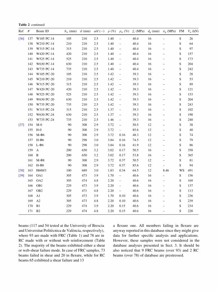
beams (117 and 54 tested at the University of Bresciaand Universitat Politecnica de Valencia, respectively),where 93 are made with FRC (Table 1) and 78 are inRC made with or without web reinforcement (Table2). The majority of the beams exhibited either a shearor web-shear failure mode. In case of FRC samples, 73beams failed in shear and 20 in flexure, while for RCbeams 65 exhibited a shear failure and 13
a flexure one. All members failing in flexure areanyway reported in this database since they might givedata for further specific analysis and applications.However, these samples were not considered in thedatabase analyses presented in Sect. 3. It should bealso noticed that 9 FRC beams (over 93) and 2 RCbeams (over 78) of database are prestressed.
Table 2 continued
Ref # Beam ID bw (mm) d (mm) a/d (-) q (%) qw (%) fc (MPa) dg (mm) rp (MPa) FM Vu (kN)
[36] 137 W105 PC-14 105 210 2.5 1.40 – 40.4 16 – S 26
138 W210 PC-14 210 210 2.5 1.40 – 40.4 16 – S 64
139 W315 PC-14 315 210 2.5 1.40 – 40.4 16 – S 97
140 W420 PC-14 420 210 2.5 1.40 – 40.4 16 – S 157
141 W525 PC-14 525 210 2.5 1.40 – 40.4 16 – S 173
142 W630 PC-14 630 210 2.5 1.40 – 40.4 16 – S 204
143 W735 PC-14 735 210 2.5 1.40 – 40.4 16 – S 242
144 W105 PC-20 105 210 2.5 1.42 – 39.3 16 – S 28
145 W210 PC-20 210 210 2.5 1.42 – 39.3 16 – S 53
146 W315 PC-20 315 210 2.5 1.42 – 39.3 16 – S 89
147 W420 PC-20 420 210 2.5 1.42 – 39.3 16 – S 121
148 W525 PC-20 525 210 2.5 1.42 – 39.3 16 – S 153
149 W630 PC-20 630 210 2.5 1.42 – 39.3 16 – S 204
150 W735 PC-20 735 210 2.5 1.42 – 39.3 16 – S 243
151 W315 PC-24 315 210 2.5 1.37 – 39.3 16 – S 102
152 W630 PC-24 630 210 2.5 1.37 – 39.3 16 – S 190
153 W735 PC-24 735 210 2.5 1.46 – 39.3 16 – S 240
[37] 154 M-0 90 308 2.9 3.72 – 50.5 12 – S 38
155 H-0 90 308 2.9 3.72 – 85.6 12 – S 40
156 M-U6 90 308 2.9 3.72 0.16 48.3 12 – S 74
157 H-U6 90 298 3.0 3.84 0.16 74.5 12 – S 79
158 L-U6 90 298 3.0 3.84 0.16 41.9 12 – S 86
159 A 200 650 3.2 3.02 0.17 50.5 16 – S 358
160 B 200 650 3.2 3.02 0.17 53.8 16 – S 365
161 M-U8 90 308 2.9 3.72 0.37 50.5 12 – S 81
162 H-U8 90 308 2.9 3.72 0.37 85.6 12 – S 94
[38] 163 H600/3 100 689 3.0 1.83 0.34 64.5 12 8.46 WS 491
[39] 164 OA1 305 473 3.9 1.70 – 40.6 16 – S 156
165 OA2 305 474 4.8 2.20 – 40.6 16 – S 169
166 OB1 229 473 3.9 2.20 – 40.6 16 – S 137
167 OB2 229 471 4.8 2.20 – 40.6 16 – S 113
168 A1 305 473 3.9 1.70 0.10 40.6 16 – S 236
169 A2 305 473 4.8 2.20 0.10 40.6 16 – S 239
170 B1 229 474 3.9 2.20 0.15 40.6 16 – S 234
171 B2 229 474 4.8 2.20 0.15 40.6 16 – S 220
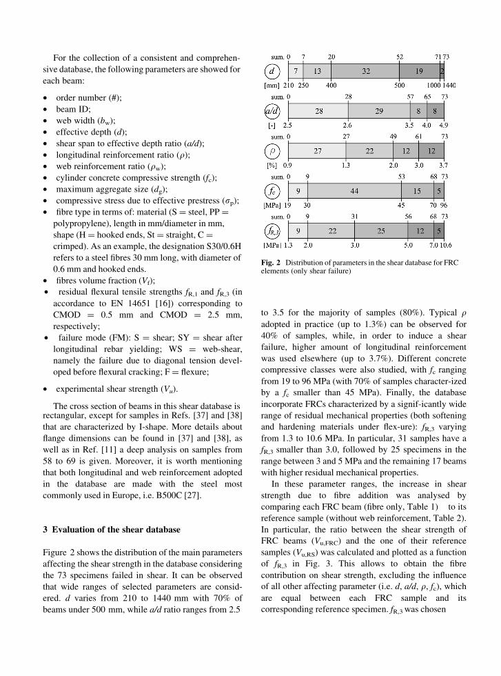
For the collection of a consistent and comprehen-
sive database, the following parameters are showed for
each beam:
• order number (#);• beam ID;• web width (bw);• effective depth (d);• shear span to effective depth ratio (a/d);• longitudinal reinforcement ratio (q);• web reinforcement ratio (qw);• cylinder concrete compressive strength (fc);• maximum aggregate size (dg);• compressive stress due to effective prestress (rp);• fibre type in terms of: material (S = steel, PP =
polypropylene), length in mm/diameter in mm,
shape (H = hooked ends, St = straight, C =crimped). As an example, the designation S30/0.6Hrefers to a steel fibres 30 mm long, with diameter of0.6 mm and hooked ends.
• fibres volume fraction (Vf);
• residual flexural tensile strengths fR,1 and fR,3 (in
accordance to EN 14651 [16]) corresponding toCMOD = 0.5 mm and CMOD = 2.5 mm,
respectively;
• failure mode (FM): S = shear; SY = shear afterlongitudinal rebar yielding; WS = web-shear,
namely the failure due to diagonal tension devel-oped before flexural cracking; F = flexure;
• experimental shear strength (Vu).
The cross section of beams in this shear database isrectangular, except for samples in Refs. [37] and [38]that are characterized by I-shape. More details aboutflange dimensions can be found in [37] and [38], aswell as in Ref. [11] a deep analysis on samples from58 to 69 is given. Moreover, it is worth mentioning
that both longitudinal and web reinforcement adoptedin the database are made with the steel most
commonly used in Europe, i.e. B500C [27].
3 Evaluation of the shear database
Figure 2 shows the distribution of the main parameters
affecting the shear strength in the database consideringthe 73 specimens failed in shear. It can be observedthat wide ranges of selected parameters are consid-ered. d varies from 210 to 1440 mm with 70% ofbeams under 500 mm, while a/d ratio ranges from 2.5
Fig. 2 Distribution of parameters in the shear database for FRC elements (only shear failure)
to 3.5 for the majority of samples (80%). Typical q adopted in practice (up to 1.3%) can be observed for 40% of samples, while, in order to induce a shear failure, higher amount of longitudinal reinforcement was used elsewhere (up to 3.7%). Different concrete compressive classes were also studied, with fc ranging from 19 to 96 MPa (with 70% of samples character-ized by a fc smaller than 45 MPa). Finally, the database incorporate FRCs characterized by a signif-icantly wide range of residual mechanical properties (both softening and hardening materials under flex-ure): fR,3 varying from 1.3 to 10.6 MPa. In particular, 31 samples have a fR,3 smaller than 3.0, followed by 25 specimens in the range between 3 and 5 MPa and the remaining 17 beams with higher residual mechanical properties.
In these parameter ranges, the increase in shear strength due to fibre addition was analysed by comparing each FRC beam (fibre only, Table 1) to its reference sample (without web reinforcement, Table 2). In particular, the ratio between the shear strength of FRC beams (Vu,FRC) and the one of their reference samples (Vu,RS) was calculated and plotted as a function of fR,3 in Fig. 3. This allows to obtain the fibre contribution on shear strength, excluding the influence of all other affecting parameter (i.e. d, a/d, q, fc), which are equal between each FRC sample and its corresponding reference specimen. fR,3 was chosen
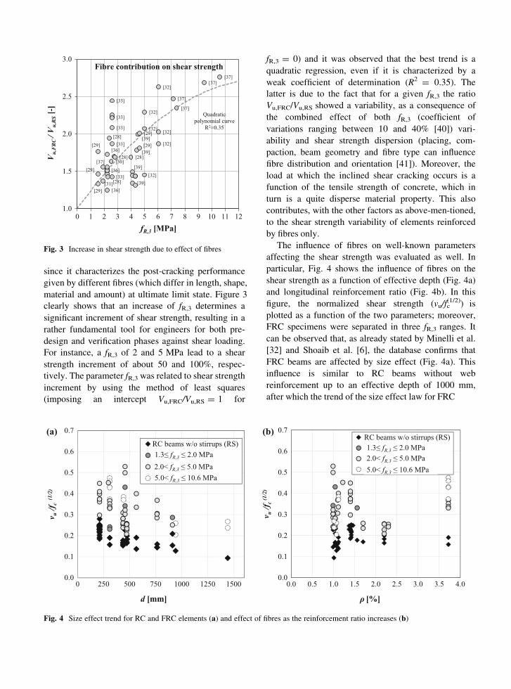
fR,3 = 0) and it was observed that the best trend is a quadratic regression, even if it is characterized by a weak coefficient of determination (R2 = 0.35). The latter is due to the fact that for a given fR,3 the ratio Vu,FRC/Vu,RS showed a variability, as a consequence of the combined effect of both fR,3 (coefficient of variations ranging between 10 and 40% [40]) vari-ability and shear strength dispersion (placing, com-
paction, beam geometry and fibre type can influence fibre distribution and orientation [41]). Moreover, the load at which the inclined shear cracking occurs is a function of the tensile strength of concrete, which in turn is a quite disperse material property. This also contributes, with the other factors as above-men-tioned, to the shear strength variability of elements reinforced by fibres only.
The influence of fibres on well-known parameters affecting the shear strength was evaluated as well. In particular, Fig. 4 shows the influence of fibres on the shear strength as a function of effective depth (Fig. 4a) and longitudinal reinforcement ratio (Fig. 4b). In this figure, the normalized shear strength (vu/fc
(1/2)) is plotted as a function of the two parameters; moreover, FRC specimens were separated in three fR,3 ranges. It can be observed that, as already stated by Minelli et al.[32] and Shoaib et al. [6], the database confirms that FRC beams are affected by size effect (Fig. 4a). This influence is similar to RC beams without web reinforcement up to an effective depth of 1000 mm, after which the trend of the size effect law for FRC
[28] [28]
[29]
[29]
[29]
[30]
[31]
[32]
[32]
[32]
[32]
[32]
[32]
[33]
[33]
[33]
[33]
[36]
[36]
[36]
[37]
[37]
[37]
[37][37]
[39]
[39]
[39]
[39]
[28]
[28][29]
[29]
[33]
1.0
1.5
2.0
2.5
3.0
0 1 2 3 4 5 6 7 8 9 10 11 12
Fibre contribution on shear strength
fR,3 [MPa]
V u,F
RC /
V u,R
S[-
]
Quadratic polynomial curve
R2=0.35
Fig. 3 Increase in shear strength due to effect of fibres
since it characterizes the post-cracking performance given by different fibres (which differ in length, shape, material and amount) at ultimate limit state. Figure 3 clearly shows that an increase of fR,3 determines a significant increment of shear strength, resulting in a rather fundamental tool for engineers for both pre-design and verification phases against shear loading. For instance, a fR,3 of 2 and 5 MPa lead to a shear strength increment of about 50 and 100%, respec-tively. The parameter fR,3 was related to shear strength increment by using the method of least squares (imposing an intercept Vu,FRC/Vu,RS = 1 for
fr115.0<
(a) (b)
0.0
0.1
0.2
0.3
0.4
0.5
0.6
0.7
0 250 500 750 1000 1250 1500
ν u/f c
(1/2
)
d [mm]
0.0
0.1
0.2
0.3
0.4
0.5
0.6
0.7
0.0 0.5 1.0 1.5 2.0 2.5 3.0 3.5 4.0
ν u/f c
(1/2
)
ρ [%]
RC beams w/o stirrups (RS)1.3≤ fR,3 ≤ 2.0 MPa2.0< fR,3 ≤ 5.0 MPa
fR,3 ≤ 10.6 MPa
RC beams w/o stirrups (RS)1.3≤ fR,3 ≤ 2.0 MPa2.0< fR,3 ≤ 5.0 MPa5.0< fR,3 ≤ 10.6 MPa
Fig. 4 Size effect trend for RC and FRC elements (a) and effect of fibres as the reinforcement ratio increases (b)
differs and it seems that a lower bound is reached (horizontal asymptote). Comparing the three perfor-mance ranges shown in Fig. 4a, it can be also observed that the decrease in the shear at failure is similar up to 1000 mm, underlining that the post-cracking perfor-mance of FRC does not significantly change the size effect law. Consequently, building codes could con-sider this positive effect of fibres in beams character-ized by effective depth greater than 1000 mm, while classical RC size effect law can be applied for FRC elements with d B 1000 mm. When considering the longitudinal reinforcement ratio, an increment of q causes a similar increase of ultimate shear strength in both RC and FRC elements, even for higher values of fR,3. This trend is also similar between the different FRC considered. Therefore, the longitudinal rein-forcement influence on the shear strength seems not to clearly change from RC to FRC elements and its effects are comparable. The positive influence on the shear strength of the longitudinal reinforcement ratio is due to the increase in crack width for q reduction that causes a decrease in the shear transferred across the inclined crack by dowel action and aggregate interlock. Similarly to q, either fc or a/d influence resulted comparable both in RC and FRC samples. These database analysis underline that fibres mainly increase the shear strength of elements by transferring stresses across inclined shear cracks and by enhancing aggregate interlock mechanism [42–44].
4 Comparison with design equations of EC2and MC2010
The shear strength predictions of two different analytical models recently included in MC2010 and developed for FRC beams were evaluated against the experimental results presented in the database. In addition, the provisions of their base models were also analysed against the reference samples listed in Table 2. In order to make this comparison more significant, the shear strength were calculated by assuming strength reduction factors (cc for EC2 and MC2010) equal to 1 and the mean values of the material mechanical properties. The mean value of tensile strength fct was evaluated according to Eq. 5.1-3a (fct ¼ 0:3 � fckð Þ2=3) and 5.1-3b (fct ¼ 2:12 � ln½1þ 0:1 � fck þ 8 MPað Þ ) of� MC2010 for concrete charac-terized by fck B 50 MPa and fck [ 50 MPa,
respectively. The characteristic value of the concrete compressive strength was calculated as fck ¼ fc � 8 MPa according to Eq. 5.1-1 of MC2010. In case of MC2010 shear models, when required, the control section was considered at a location d from load point.
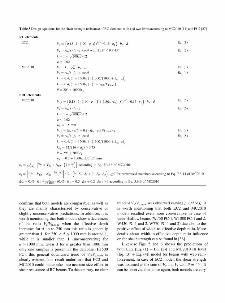
Table 3 summarize the shear formulations of these models for the prediction of the shear strength resistance (express in terms of SI units). Concerning FRC, the first model (Eq. (5) in Table 3) was built on the base formulation of EC2 (Eq. (1) in Table 3) [45] and it considers the fibre contribution by modifying the longitudinal reinforcement ratio. To the contrary, the second one (Eq. (7) in Table 3) was derived from the base formulation of MC2010 (Eq. (3) in Table 3)[46], which in turn is linked to the Modified Compression Field Theory [47]. Both formulations consider the fibre contribution not as a separate addendum but as an enhancement of the concrete contribution, as well as they adopt an ultimate residual tensile strength (fFtu). In case of Eq. (5), MC2010 suggests to estimate fFtu by a simplified linear model based on fR,1 and fR,3 (EN 14651), while in case of Eq. (7) it is suggested to evaluate it by direct tensile tests (without specifying the type of tensile tests). Since no direct tensile tests were carried out for any of the database series, the simplified linear model based on fR,1 and fR,3 (EN 14651) has been also applied in case of Eq. (7). Recent publications discussed also the possible influence of using the simplified linear model (fR,1 and fR,3) on Eq. (7) [17, 48]. Amin et al. [17] studying steel FRC showed that that MC2010 simpli-
fied linear model might overestimate fFtu, with direct consequence on the accuracy of the shear model [48]. Consequently, it should be noticed that the evaluation of Eq. (7) against database results could be also affected by the use of the simplified linear model for estimating fFtu.
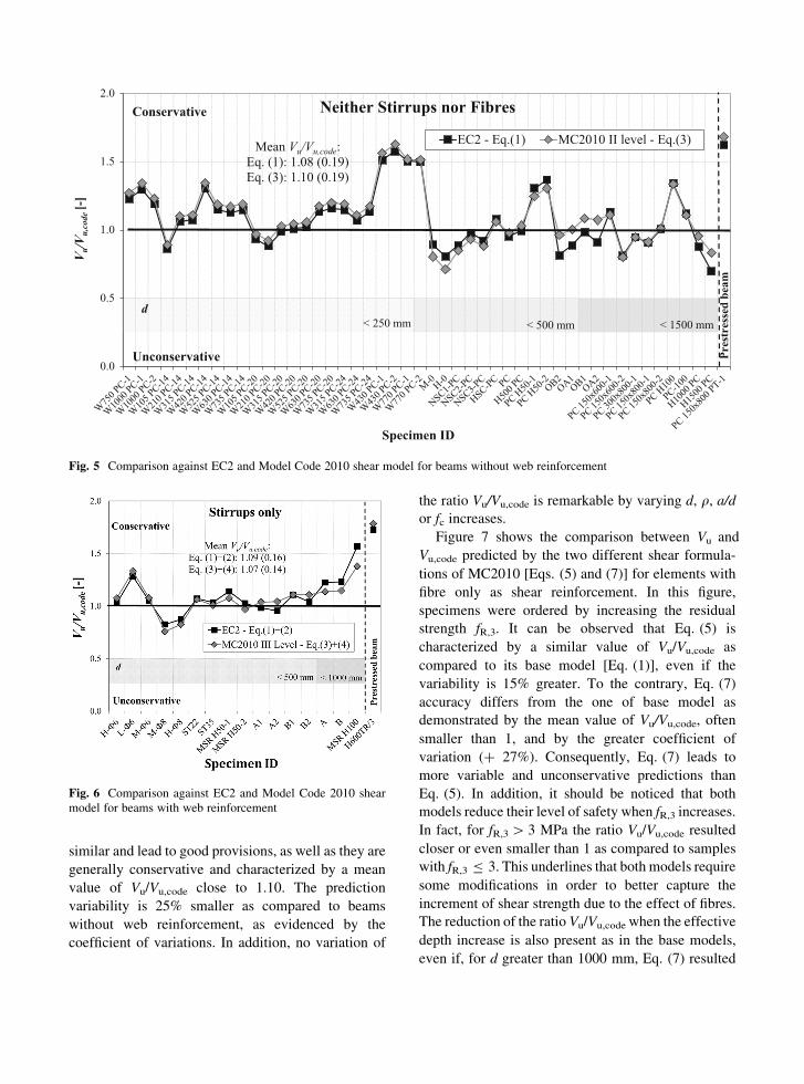
Figure 5 shows the comparison between the exper-imental and the ultimate shear strength predicted by the base models of EC2 (Eq. (1)) and MC2010 II level (Eq. (3)) for RC elements without web reinforcement. In this figure, specimens were ordered by increasing effective depth. It can be observed that both base models lead to good and very similar strength predictions. The mean value of the model safety factor Vu/Vu,code resulted in both case greater than the unity, i.e. 1.08 and 1.10 for EC2 and MC2010 model with coefficient of variation equal to 0.19. This
confirms that both models are comparable, as well as
they are mainly characterized by conservative or
slightly unconservative predictions. In addition, it is
worth mentioning that both models show a decrement
of the ratio Vu/Vu,code when the effective depth
increase: for d up to 250 mm this ratio is generally
greater than 1, for 250\ d B 1000 mm is around 1,
while it is smaller than 1 (unconservative) for
d[ 1000 mm. Even if for d greater than 1000 mm
only one samples is present in the database (H1500
PC), this general downward trend of Vu/Vu,code is
clearly evident; this result underlines that EC2 and
MC2010 could better take into account size effect in
shear resistance of RC beams. To the contrary, no clear
trend of Vu/Vu,code was observed varying q, a/d or fc. It is worth mentioning that both EC2 and MC2010 models resulted even more conservative in case of wide-shallow beams (W750 PC-1, W1000 PC-1 and 2, W430 PC-1 and 2, W770 PC-1 and 2) due also to the positive effect of width-to-effective depth ratio. More details about width-to-effective depth ratio influence on the shear strength can be found in [36].
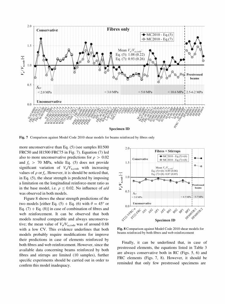
Likewise Figs. 5 and 6 shows the predictions of both EC2 [Eq. (1) ? Eq. (2)] and MC2010 III level [Eq. (3) ? Eq. (4)] model for beams with web rein-forcement. In case of EC2 model, the shear strength was assumed as the sum of Vc and Vs with h = 45�. It can be observed that, once again, both models are very
Table 3 Design equations for the shear strength resistance of RC elements with and w/o fibres according to MC2010 [14] and EC2 [27]
RC elements
EC2 Vc ¼ 0:18 � k � 100 � q � fcð Þ1=3þ0:15 � rp� �
� bw � d Eq. (1)
Vs ¼ As=s � fy � z � cot h with 21:8� � h� 45� Eq. (2)
k ¼ 1þffiffiffiffiffiffiffiffiffiffiffiffiffi200=d
p� 2
q B 0.02
MC2010 Vc ¼ kv �ffiffiffiffifc
p� bw � z Eq. (3)
Vs ¼ As=s � fy � z � cot h Eq. (4)
kv ¼ 0:4= 1þ 1500exð Þ � 1300= 1000þ kdg � z� �� �
kv ¼ 0:4= 1þ 1500exð Þ � 1� VEd=VR;max
� �
h ¼ 20� þ 10000exFRC elements
MC2010 Vc;F ¼ 0:18 � k � 100 � q � 1þ 7:5fFtu=fctð Þ � fcð Þ1=3þ0:15 � rp� �
� bw � d Eq. (5)
Vs ¼ As=s � fy � z Eq. (6)
k ¼ 1þffiffiffiffiffiffiffiffiffiffiffiffiffi200=d
p� 2
q B 0.02
wu ¼ 1:5 mm
Vc;F ¼ kv �ffiffiffiffifc
pþ 0:8 � fFtu � cot hð Þ � bw � z Eq. (7)
Vs ¼ As=s � fy � z � cot h Eq. (8)
kv ¼ 0:4= 1þ 1500exð Þ � 1300= 1000þ kdg � z� �� �
kdg ¼ 32= 16þ dg� �
� 0:75
h ¼ 29� þ 7000exwu ¼ 0:2þ 1000ex � 0:125 mm
ex ¼ 12�Es �As
� MEd
zþ VEd þ NEd � 1
2� De
z
� �h iaccording to Eq. 7.3-16 of MC2010
ex ¼ MEd
zþ VEd þ NEd �
zp�epð Þz
� �= 2 � zs
z� Es � As þ zp
z� Ep � Ap
� �h i� 0 for prestressed members according to Eq. 7.3-14 of MC2010
fFtu ¼ 0:45 � fR1 � wu
2:5 mm � 0:45 � fR1 � 0:5 � fR3 þ 0:2 � fR1ð Þ� 0 according to Eq. 5.6-6 of MC2010
similar and lead to good provisions, as well as they are
generally conservative and characterized by a mean
value of Vu/Vu,code close to 1.10. The prediction
variability is 25% smaller as compared to beams
without web reinforcement, as evidenced by the
coefficient of variations. In addition, no variation of
the ratio Vu/Vu,code is remarkable by varying d, q, a/d or fc increases.
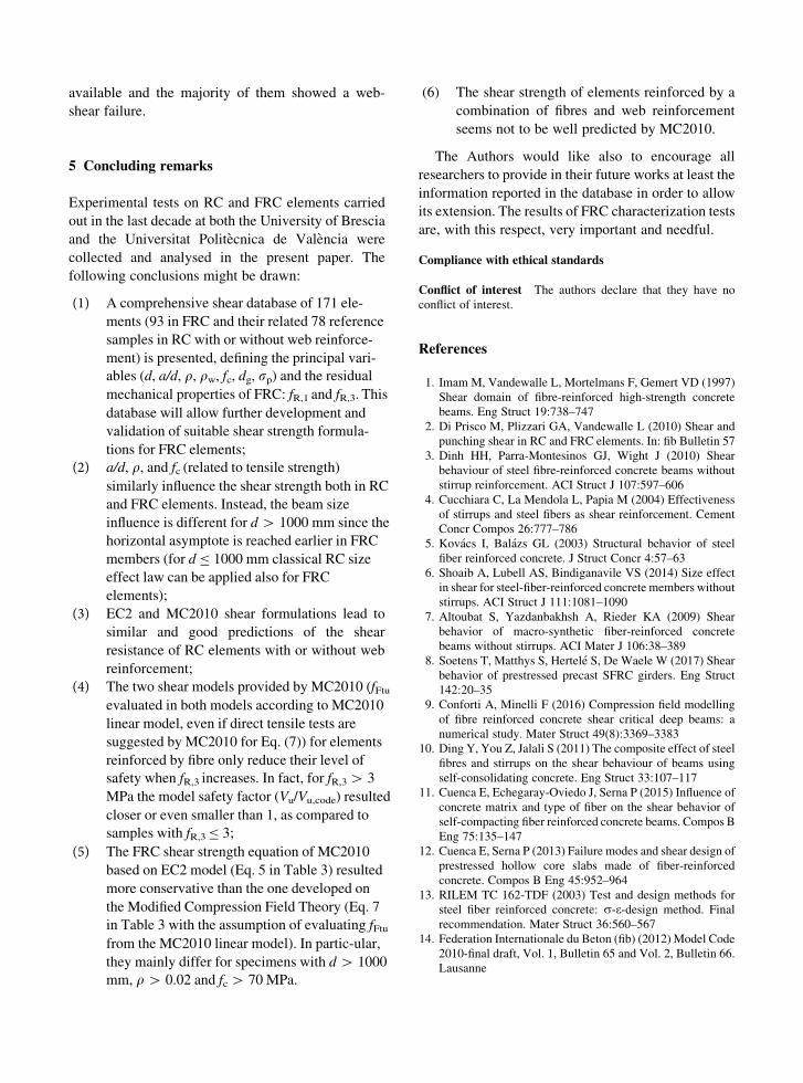
Figure 7 shows the comparison between Vu and Vu,code predicted by the two different shear formula-
tions of MC2010 [Eqs. (5) and (7)] for elements with fibre only as shear reinforcement. In this figure, specimens were ordered by increasing the residual strength fR,3. It can be observed that Eq. (5) is characterized by a similar value of Vu/Vu,code as compared to its base model [Eq. (1)], even if the variability is 15% greater. To the contrary, Eq. (7) accuracy differs from the one of base model as demonstrated by the mean value of Vu/Vu,code, often smaller than 1, and by the greater coefficient of variation (? 27%). Consequently, Eq. (7) leads to more variable and unconservative predictions than Eq. (5). In addition, it should be noticed that both models reduce their level of safety when fR,3 increases. In fact, for fR,3 [ 3 MPa the ratio Vu/Vu,code resulted closer or even smaller than 1 as compared to samples with fR,3 B 3. This underlines that both models require some modifications in order to better capture the increment of shear strength due to the effect of fibres. The reduction of the ratio Vu/Vu,code when the effective depth increase is also present as in the base models, even if, for d greater than 1000 mm, Eq. (7) resulted
0.0
0.5
1.0
1.5
2.0V u
/Vu,
code
[-]
Specimen ID
Neither Stirrups nor Fibres
EC2 - Eq.(1) MC2010 II level - Eq.(3)
Conservative
Unconservative Pres
tres
sed
beam
< 250 mm < 500 mm < 1500 mmd
Mean Vu/Vu,code:Eq. (1): 1.08 (0.19)Eq. (3): 1.10 (0.19)
Fig. 5 Comparison against EC2 and Model Code 2010 shear model for beams without web reinforcement
Fig. 6 Comparison against EC2 and Model Code 2010 shear
model for beams with web reinforcement
more unconservative than Eq. (5) (see samples H1500 FRC50 and H1500 FRC75 in Fig. 7). Equation (7) led also to more unconservative predictions for q [ 0.02 and fc [ 70 MPa, while Eq. (5) does not provide significant variation of Vu/Vu,code with increasing values of q or fc. However, it is should be noticed that, in Eq. (5), the shear strength is predicted by imposing a limitation on the longitudinal reinforce-ment ratio as in the base model, i.e. q B 0.02. No influence of a/d was observed in both models.
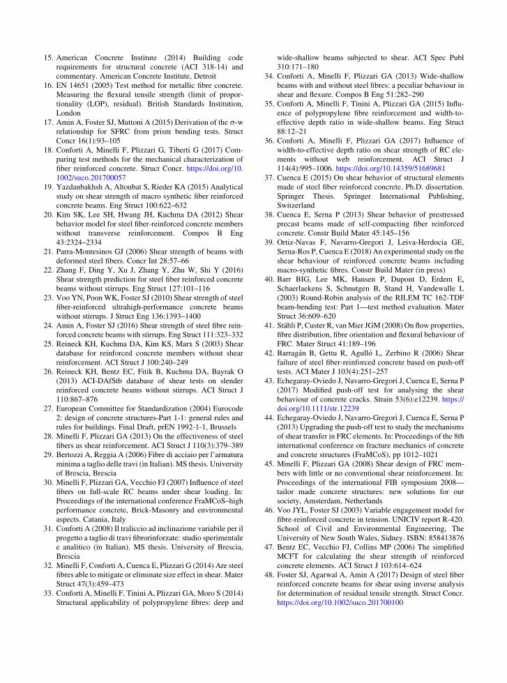
Figure 8 shows the shear strength predictions of the two models [either Eq. (5) ? Eq. (6) with h = 45� or Eq. (7) ? Eq. (8)] in case of combination of fibres and web reinforcement. It can be observed that both models resulted comparable and always unconserva-tive; the mean value of Vu/Vu,code was of around 0.88 with a low CV. This evidence underlines that both models probably require modifications for improve their predictions in case of elements reinforced by both fibres and web reinforcement. However, since the available data concerning beams reinforced by both fibres and stirrups are limited (10 samples), further specific experiments should be carried out in order to confirm this model inadequacy.
0.0
0.5
1.0
1.5
2.0V u
/ V u
,cod
e [-
]
Specimen ID
Fibres onlyMC2010 - Eq.(5)MC2010 - Eq.(7)
Conservative
Unconservative
Prestressed beams
< 2.0 MPa < 3.0 MPa < 5.0 MPa < 10.6 MPa 2.5-6.2 MPafR,3
Mean Vu/Vu,code:Eq. (5): 1.08 (0.22)Eq. (7): 0.93 (0.26)
Fig. 7 Comparison against Model Code 2010 shear models for beams reinforced by fibres only
0.0
0.5
1.0
1.5
2.0
V u/V
u,co
de [-
]
Specimen ID
Fibres + StirrupsMC2010 - Eq.(5)+(6)MC2010 - Eq.(7)+(8)Conservative
Unconservative
Prestressed beams
fR,3
< 2.0 MPa < 4.5 MPa 5-7 MPa
Mean Vu/Vu,code:Eq. (5)+(6): 0.89 (0.06)Eq. (7)+(8): 0.87 (0.05)
Fig. 8 Comparison against Model Code 2010 shear models for beams reinforced by both fibres and web reinforcement
Finally, it can be underlined that, in case of prestressed elements, the equations listed in Table 3 are always conservative both in RC (Figs. 5, 6) and FRC elements (Figs. 7, 8). However, it should be reminded that only few prestressed specimens are
available and the majority of them showed a web-
shear failure.
5 Concluding remarks
Experimental tests on RC and FRC elements carried
out in the last decade at both the University of Brescia
and the Universitat Politecnica de Valencia were
collected and analysed in the present paper. The
following conclusions might be drawn:
(1) A comprehensive shear database of 171 ele-ments (93 in FRC and their related 78 reference samples in RC with or without web reinforce-ment) is presented, defining the principal vari-ables (d, a/d, q, qw, fc, dg, rp) and the residual mechanical properties of FRC: fR,1 and fR,3. This database will allow further development and validation of suitable shear strength formula-
tions for FRC elements;
(2) a/d, q, and fc (related to tensile strength) similarly influence the shear strength both in RC and FRC elements. Instead, the beam size influence is different for d [ 1000 mm since the horizontal asymptote is reached earlier in FRC members (for d B 1000 mm classical RC size effect law can be applied also for FRC elements);
(3) EC2 and MC2010 shear formulations lead to similar and good predictions of the shear resistance of RC elements with or without web reinforcement;
(4) The two shear models provided by MC2010 (fFtu
evaluated in both models according to MC2010 linear model, even if direct tensile tests are suggested by MC2010 for Eq. (7)) for elements reinforced by fibre only reduce their level of safety when fR,3 increases. In fact, for fR,3 [ 3 MPa the model safety factor (Vu/Vu,code) resulted closer or even smaller than 1, as compared to samples with fR,3 B 3;
(5) The FRC shear strength equation of MC2010 based on EC2 model (Eq. 5 in Table 3) resulted more conservative than the one developed on the Modified Compression Field Theory (Eq. 7 in Table 3 with the assumption of evaluating fFtu
from the MC2010 linear model). In partic-ular, they mainly differ for specimens with d [ 1000 mm, q [ 0.02 and fc [ 70 MPa.
(6) The shear strength of elements reinforced by a
combination of fibres and web reinforcement
seems not to be well predicted by MC2010.
The Authors would like also to encourage all
researchers to provide in their future works at least the
information reported in the database in order to allow
its extension. The results of FRC characterization tests
are, with this respect, very important and needful.
Compliance with ethical standards
Conflict of interest The authors declare that they have no
conflict of interest.
References
1. Imam M, Vandewalle L, Mortelmans F, Gemert VD (1997)
Shear domain of fibre-reinforced high-strength concrete
beams. Eng Struct 19:738–747
2. Di Prisco M, Plizzari GA, Vandewalle L (2010) Shear and
punching shear in RC and FRC elements. In: fib Bulletin 57
3. Dinh HH, Parra-Montesinos GJ, Wight J (2010) Shear
behaviour of steel fibre-reinforced concrete beams without
stirrup reinforcement. ACI Struct J 107:597–606
4. Cucchiara C, La Mendola L, Papia M (2004) Effectiveness
of stirrups and steel fibers as shear reinforcement. Cement
Concr Compos 26:777–786
5. Kovacs I, Balazs GL (2003) Structural behavior of steel
fiber reinforced concrete. J Struct Concr 4:57–63
6. Shoaib A, Lubell AS, Bindiganavile VS (2014) Size effect
in shear for steel-fiber-reinforced concrete members without
stirrups. ACI Struct J 111:1081–1090
7. Altoubat S, Yazdanbakhsh A, Rieder KA (2009) Shear
behavior of macro-synthetic fiber-reinforced concrete
beams without stirrups. ACI Mater J 106:38–389
8. Soetens T, Matthys S, Hertele S, De Waele W (2017) Shear
behavior of prestressed precast SFRC girders. Eng Struct
142:20–35
9. Conforti A, Minelli F (2016) Compression field modelling
of fibre reinforced concrete shear critical deep beams: a
numerical study. Mater Struct 49(8):3369–3383
10. Ding Y, You Z, Jalali S (2011) The composite effect of steel
fibres and stirrups on the shear behaviour of beams using
self-consolidating concrete. Eng Struct 33:107–117
11. Cuenca E, Echegaray-Oviedo J, Serna P (2015) Influence of
concrete matrix and type of fiber on the shear behavior of
self-compacting fiber reinforced concrete beams. Compos B
Eng 75:135–147
12. Cuenca E, Serna P (2013) Failure modes and shear design of
prestressed hollow core slabs made of fiber-reinforced
concrete. Compos B Eng 45:952–964
13. RILEM TC 162-TDF (2003) Test and design methods for
steel fiber reinforced concrete: r-e-design method. Final
recommendation. Mater Struct 36:560–567
14. Federation Internationale du Beton (fib) (2012) Model Code
2010-final draft, Vol. 1, Bulletin 65 and Vol. 2, Bulletin 66.
Lausanne
15. American Concrete Institute (2014) Building code
requirements for structural concrete (ACI 318-14) and
commentary. American Concrete Institute, Detroit
16. EN 14651 (2005) Test method for metallic fibre concrete.
Measuring the flexural tensile strength (limit of propor-
tionality (LOP), residual). British Standards Institution,
London
17. Amin A, Foster SJ, Muttoni A (2015) Derivation of the r-wrelationship for SFRC from prism bending tests. Struct
Concr 16(1):93–105
18. Conforti A, Minelli F, Plizzari G, Tiberti G (2017) Com-
paring test methods for the mechanical characterization of
fiber reinforced concrete. Struct Concr. https://doi.org/10.
1002/suco.201700057
19. Yazdanbakhsh A, Altoubat S, Rieder KA (2015) Analytical
study on shear strength of macro synthetic fiber reinforced
concrete beams. Eng Struct 100:622–632
20. Kim SK, Lee SH, Hwang JH, Kuchma DA (2012) Shear
behavior model for steel fiber-reinforced concrete members
without transverse reinforcement. Compos B Eng
43:2324–2334
21. Parra-Montesinos GJ (2006) Shear strength of beams with
deformed steel fibers. Concr Int 28:57–66
22. Zhang F, Ding Y, Xu J, Zhang Y, Zhu W, Shi Y (2016)
Shear strength prediction for steel fiber reinforced concrete
beams without stirrups. Eng Struct 127:101–116
23. Voo YN, PoonWK, Foster SJ (2010) Shear strength of steel
fiber-reinforced ultrahigh-performance concrete beams
without stirrups. J Struct Eng 136:1393–1400
24. Amin A, Foster SJ (2016) Shear strength of steel fibre rein-
forced concrete beams with stirrups. Eng Struct 111:323–332
25. Reineck KH, Kuchma DA, Kim KS, Marx S (2003) Shear
database for reinforced concrete members without shear
reinforcement. ACI Struct J 100:240–249
26. Reineck KH, Bentz EC, Fitik B, Kuchma DA, Bayrak O
(2013) ACI-DAfStb database of shear tests on slender
reinforced concrete beams without stirrups. ACI Struct J
110:867–876
27. European Committee for Standardization (2004) Eurocode
2: design of concrete structures-Part 1-1: general rules and
rules for buildings. Final Draft, prEN 1992-1-1, Brussels
28. Minelli F, Plizzari GA (2013) On the effectiveness of steel
fibers as shear reinforcement. ACI Struct J 110(3):379–389
29. Bertozzi A, Reggia A (2006) Fibre di acciaio per l’armatura
minima a taglio delle travi (in Italian). MS thesis. University
of Brescia, Brescia
30. Minelli F, Plizzari GA, Vecchio FJ (2007) Influence of steel
fibers on full-scale RC beams under shear loading. In:
Proceedings of the international conference FraMCoS–high
performance concrete, Brick-Masonry and environmental
aspects. Catania, Italy
31. Conforti A (2008) Il traliccio ad inclinazione variabile per il
progetto a taglio di travi fibrorinforzate: studio sperimentale
e analitico (in Italian). MS thesis. University of Brescia,
Brescia
32. Minelli F, Conforti A, Cuenca E, Plizzari G (2014) Are steel
fibres able to mitigate or eliminate size effect in shear. Mater
Struct 47(3):459–473
33. Conforti A, Minelli F, Tinini A, Plizzari GA, Moro S (2014)
Structural applicability of polypropylene fibres: deep and
wide-shallow beams subjected to shear. ACI Spec Publ
310:171–180
34. Conforti A, Minelli F, Plizzari GA (2013) Wide-shallow
beams with and without steel fibres: a peculiar behaviour in
shear and flexure. Compos B Eng 51:282–290
35. Conforti A, Minelli F, Tinini A, Plizzari GA (2015) Influ-
ence of polypropylene fibre reinforcement and width-to-
effective depth ratio in wide-shallow beams. Eng Struct
88:12–21
36. Conforti A, Minelli F, Plizzari GA (2017) Influence of
width-to-effective depth ratio on shear strength of RC ele-
ments without web reinforcement. ACI Struct J
114(4):995–1006. https://doi.org/10.14359/51689681
37. Cuenca E (2015) On shear behavior of structural elements
made of steel fiber reinforced concrete. Ph.D. dissertation.
Springer Thesis. Springer International Publishing,
Switzerland
38. Cuenca E, Serna P (2013) Shear behavior of prestressed
precast beams made of self-compacting fiber reinforced
concrete. Constr Build Mater 45:145–156
39. Ortiz-Navas F, Navarro-Gregori J, Leiva-Herdocia GE,
Serna-Ros P, Cuenca E (2018) An experimental study on the
shear behaviour of reinforced concrete beams including
macro-synthetic fibres. Constr Build Mater (in press)
40. Barr BIG, Lee MK, Hansen P, Dupont D, Erdem E,
Schaerlaekens S, Schnutgen B, Stand H, Vandewalle L
(2003) Round-Robin analysis of the RILEM TC 162-TDF
beam-bending test: Part 1—test method evaluation. Mater
Struct 36:609–620
41. Stahli P, Custer R, vanMier JGM (2008) On flow properties,
fibre distribution, fibre orientation and flexural behaviour of
FRC. Mater Struct 41:189–196
42. Barragan B, Gettu R, Agullo L, Zerbino R (2006) Shear
failure of steel fiber-reinforced concrete based on push-off
tests. ACI Mater J 103(4):251–257
43. Echegaray-Oviedo J, Navarro-Gregori J, Cuenca E, Serna P
(2017) Modified push-off test for analysing the shear
behaviour of concrete cracks. Strain 53(6):e12239. https://
doi.org/10.1111/str.12239
44. Echegaray-Oviedo J, Navarro-Gregori J, Cuenca E, Serna P
(2013) Upgrading the push-off test to study the mechanisms
of shear transfer in FRC elements. In: Proceedings of the 8th
international conference on fracture mechanics of concrete
and concrete structures (FraMCoS), pp 1012–1021
45. Minelli F, Plizzari GA (2008) Shear design of FRC mem-
bers with little or no conventional shear reinforcement. In:
Proceedings of the international FIB symposium 2008—
tailor made concrete structures: new solutions for our
society, Amsterdam, Netherlands
46. Voo JYL, Foster SJ (2003) Variable engagement model for
fibre-reinforced concrete in tension. UNICIV report R-420.
School of Civil and Environmental Engineering, The
University of New South Wales, Sidney. ISBN: 858413876
47. Bentz EC, Vecchio FJ, Collins MP (2006) The simplified
MCFT for calculating the shear strength of reinforced
concrete elements. ACI Struct J 103:614–624
48. Foster SJ, Agarwal A, Amin A (2017) Design of steel fiber
reinforced concrete beams for shear using inverse analysis
for determination of residual tensile strength. Struct Concr.
https://doi.org/10.1002/suco.201700100