MODEL / UELDER - RC Bookcase
103
MARCH 1984 MODEL / $2.50 volume 14, number 146 UELDER
-
Upload
khangminh22 -
Category
Documents
-
view
0 -
download
0
Transcript of MODEL / UELDER - RC Bookcase

MARCH 1984M O D E L / $2.50
volume 14, number 146U E LD E R

INTRODUCES THE...The P _ 4 7 THUNDERBOLT
(Razorback Version)
1/6.3 SCALE(in complete kit form)
This legendary “ brute of an airplane", commonly referred to as the “ Jug", was the biggest and heaviest single engine fighter ever produced during World War II. Weighing in at over 21,000 lbs. and capable of a 2800 horsepower rating at 32,500 ft., the P-47 Thunderbolt flew at speeds well over 400 m.p.h. Between March 1943 and August 1945, the Thunderbolt flew nearly 550,000 sorties over Europe and the Pacific. The P-47 demanded the respect of both friend and foe alike. The tremendous firepower of eight, wing mounted .50 caliber machine guns, plus the ability to absorb substantial battle damage and still return safely to its home base guaranteed its place in world history.
SPECIFICATIONSWing Span............................................................................................ .. 80 in.Length...................................................................................................... 72 in.Wing A r e a .................................................................. Approx. 1200 sq. in.Wing Loading................................................................ 42-46 oz. per sq. ft.Ready-to-fly W eigh t............................. 22-24 lbs. (depending on power syMcm)
Power (2-bladed prop).......................... 35 or 50 Quadra or ComparablePower (4-bladed p ro p ).......................................................35 Quadra onlyChannels required.....................................................................6 w/retracts
With the release of the P-47 kit, Byron Originals makes it possible for you to recreate this famous W.W. II fighter in authentic 1/6.3 scale. The same proven technology, craftsmanship and production capabilities that brought you the 1/5 scale P-51 Mustang have been applied to the P-47. In fact, various design improvements and new innovations have been incorporated to further enhance this unique building and flying experience. Granted, the Byron P-47 of today may not help secure our freedom, but it will surely go down in history as one of model aviation’s most unique “ warbird” productions. Following are just a few of the many reasons why.
Rugged Factory Installed Gear Mounts Exclusive Plug-in Linkage SystemsPrecision injection molding methods produce unique plug-in wing panels
ottering numerous bencfils including structural integrity, weight savings, accurate assembly and greatly reduced building time. Aluminum wing spar/landing gear mounts are internally molded in each wing panel during injection process. Provisions for retractable landing gear, torque rods, hinges, pneumatic connectors and hinge cover material are accurately formed during this process as well.
The internal spar/gear mount assembly combines with the molded wing to form a light, yet extremely durable platform for anchoring the main
landing gear. Mounting Byron Originals' scale, retractable gear in the P-47 wings is a quick and simple operation requiring only four bolts.
There's much more to our plug-in concept than just transport and storage benefits. A unique linkage device permits the aileron, spoiler flap and elevator control linkages to automatically disengage when the wings and stabs are removed, and reconnect when they are inserted. Another innovation that makes our plug-in concept even more unique is a Quik-C onnect pneumatic fitting that makes it possible for the retract and air connections to separate as the wing is removed and reconnect upon assembly.

LATEST OF ITS WARBIRDS...
Superb Response Both in (he Air and on the GroundThe P-47 performs well at holh ends of the flight envelope. It exhibits very good aerobatic
qualities and exceptional speed. Due to the extra wide main gear stance, this warbird offers very stable ground handling characteristics during both landings and takeoffs.
For the ultimate in scale realism, Byron Originals offers an optional P-47 4-bladed prop reduction system. For more than three years, a similar power system developed for our P-51 has provided modelers round the world with the first truly successful method of swinging a scale 24” 4-bladed prop. Both this system and our special engine mount for direct drive power attach quickly and easily on factory installed bulkheads and formers.
Detailed Fiberglass Fuselage Features Factory Installed Formers.
f IMPROVED RETRACT DESIGN
State-of-the-art fiberglass capabilities arc vital to the production of (he P-47 as evidenced by the highly detailed fuselage and cowl. The fuselage formers (as shown in black in the above drawing) have been precisely jigged and glassed in position to ensure accurate assembly. Also shown in black is our extended engine mount used to secure 2-cycle engines for direct drive power. Removable cowl panels provide easy access to carburetor, etc.
VISA
Improved upper strut
New chrome sleeve im p ro ve shock absorption and scale appearance.
Ileavy-duiy steel uploek and pin.
Injection molded parts in authentic aircraft aluminum colors.
Clover strut, wheel axle tolerances.
Plug-in Wings for Convenient Transport and Storage
No other retractable gear offers the scale realism, durability and weight savings like that of the P-47's. This proven system, which was orginally designed for our earlier P-51 models, has been re-engineered to improve its appearance, performance and versatility. It is interchangeable with our latest P-51 gear and can be utilized in our other upcoming “ warbirds". An optional sequencing inner wheel door kit is also available for use in the P-47.
Item Order No.P -4 7 K it (landing genr not included).............................................................................. 6 1 3 0 1 1 0Accessories/OptionsScale retract gear (mainvoniy)..................................................................................... 6 1 3 0 1 1 1Pneumatic support equipment (Includes all pneumatic cquipmrm In operateretract, main gear)................................................................................................................... 6 1 3 0 1 1 2
The P-47's exclusive plug-in wings and horizontal stabs makes transporting and storing this large scale model a simple task; even for the owners of today's popular compact vehicles. Both the wings and slabs detach in a matter of seconds. Likewise, this plug-in concept enables you to have your Thunderbolt flight-ready in less than a minute. And the only tool required is a halldriver provided in the kit.
For detailed factory pricing and fast, factory direct delivery, call Byron Originals, Monday through Friday, 8 a.m. to 5 p.m. C .S .T .
(Send S2.00 for detailed info packet t
Custom retractable tail wheel assembly (include* strai, tire, wheel, retractunit & fastener*). . . ............................................................................................................. 6 1 3 0 1 1 3Sequencing, wheel door kit <ρ-«·7>......................................................... 6130114Main gear strut covers, left & right tp-*7>........................................... 6130115bxlended P-47 engine mount (tor direct drive, 2 cycle power o n ly )............ 6130116Spinner w/back plate & mt. boll......................................................... 6030307Prop adapter bolt, 5/16” , 24 Ih d ........................................................ 5930290Special 4-bladed prop reduction drive w /spinner...........................
(F o r 35 cc Quadra & P-47 only)
With engine........................................................................................ 6130117Less engine........................................................................................... 6130118
Byron Originals, P.O. Box 279, Ida Grove, Iowa 51445/712-364-3165

MARCHM ODEL S' BU ILD ER621 West Nineteenth St., Box 10335, Costa Mesa, CA 92627-0132
1984
volume 14, number 146 Phone: (714) 645-8830
FEATURES
STAFFTABLE OF CONTENTS E D ITO R /P U B LIS H E R
Wm. C. Northrop, Jr.G E N E R A L M A N A G E R
Anita NorthropW O R K B E N C H , Bill Northrop.............................................................................. 6
DEAR JAKE ......................................................................................................... 6
OVER THE C O U N T E R ................................................................................... 7
H A M IL T O N H A W K S FO U R -S TR O K E RALLY, cliff Tacie.................... 10
N IC K Z IR O L I SAU LN IER IN REVIEW , DomPalumbo.............................. 20
ELECTRIC PO W ER , Mitch Poling...................................................................... 22
V IN T A G E D A Y IN B R IT A IN , Peter Scott ....................................................... 24
FUEL LINES, JoeKlause......................................................................................... 26
PLUG SPARKS, John Pond .................................................................................. 27
R /C S O A R IN G , Bill Forrey.................................................................................. 32
H O W T O FLY PATTERN, Dick Hanson............................................................ 35
W O LF F -P A K TH R U S H IN REVIEW , EloyMarez..........................................36
BIG BIRDS, Al Alman.............................................................................................38
ACE D A T A M A S T E R A N D RF INTERFACE IN REVIEW , EloyMarez . 40
CHOPPER C H ATTER , Ray Hostetler................................................................. 42
PLANES A N ’ FACTS A N ’ C H IC K U M TR AC KS, FredLehmberg.............46
ELECTRO NICS C O R N E R , EloyMarez........................................................... 48
R /C A U T O NEW S, Dan Rutherford................................................. 52
R /C POW ER B O ATS, Jerry Dunlap................................................................... 54
H A N N A N 'S H A N G A R , Bill Hannan................................................................. 56
F/F SCALE, Fernando Ramos.................................................................................. 60
FREE FLIG H T, BobStalick......................................................................................64
CONSTRUCTION
A S S IS TA N T G E N E R A L M A N A G E RDawn Johnson
P R O D U C TIO N M A N A G E RBill Forrey
P R O D U C TIO N A R T IS T
Howard MillmanD R A W IN G S BY
AI PattersonA C C O U N T IN G D E P T. M A N A G E R
Michael Whitney S U B S C R IP TIO N S
Jo Anne Glenn
CONTRIBUTING EDITORSAl Alman Jerry Dunlap Bill Forrey Bill Hannan Dick Hanson Mike Hazel Ray Hostetler Ken Johnson Joe Klause
Eloy Marez Walt Mooney Mitch Poling John Pond Fernando Ramos Dan Rutherford John Smith Bob Stalick
ADVERTISINGREPRESENTATIVES
Bill NorthropHome Office, Costa Mesa
Al Novotnik4 Beverly PI., Norwalk, CT 06850
Bus. Phone (203) 847-7478M O D E L BUILDER (ISSN 0194 7079) is
p u b lis h e d m o n th ly by R C M B IN C .. 621 W e s t 1 9 th S t.. B ox 10335. C o s ta M e sa . C a lifo rn ia 92627-0132. P hone (714) 645-8830.
FABRE H Y D R A V IO N , Francis R e yn o ld s ...............................................................................14
C L O U D CRUISER O .T ., H arry Edw ard M o y e r ..................................................................30
RO TO R ISER , Ken W illa rd ..............................................................................................................44
N IEU PO R T-BEEC H B O S T O N IA N , W alt M o o n e y ..................................................49
H A N G IN THERE C O U P E D ’H IVER , Earl Schick ...................................................58
C O V E R : This month's cover models are the lovely Ms. Tiffany Mangis, a Business Administration major at Western Washington University, and Francis Reynold's rendition of the 1910 Henri Fabre Hydravion. The Hydravion is also this month's feature construction article, see page 14.
S ubscrip tions : $25.00 pe r year. $47.00 fo r tw o years. S ing le cop ies $2.50. S ubscrip tions o u ts id e the US (except A P O & FPO) $32.00 fo r o n e year o n ly . A ll pa ym ents m ust be in US fun ds , d ra w n o n a US bank .
C o p y r ig h t 1983 by R C M B IN C . A ll righ ts reserved. R e p ro d u c tio n w ith o u t pe rm is sion p ro h ib ite d .
C hange o f address n o tice s m ust be re ce ived six w eeks b e lo re d a te o f issue tha t new address takes e fte c t. Send o ld address w ith n e w : o ld labe l p re fe rre d . Post O ff ic e w ill no t fo rw a rd cop ies un less yo u pay extra postage. D up lic ate issues c a n n o t be sent.
Second c lass postage p a id at Costa Mesa. C a lifo rn ia , and a d d it io n a l o ffice s .
2 MODEL BUILDER

HOT COMPETITION OR JUST FOR THE FUN OF IT...
1st PLACEHANNO PRETTNER
1983 FAI F3A World Championsl^ Pensacola, Florida, U.S.A.
October 10-15, 1983 ^
WHEN IT COMES TO INSTANT GLUE...
AMERICAN “ HOT STUFFMADE
IS ALWAYS IN THE WINNERS CIRCLE!
AS USED BY WORLD CHAMPIONS HANNO PRETTNER LES MCDONALDFAI PATTERN WORLD CHAMP C/L STUNT WORLD CHAMPWOLFGANG MATT BOB HUNTFAI PATTERN WORLD CHAMP C/L STUNT WORLD CHAMP
PAST PAST
HS-4 ECONOMY 2 0Z. 9.95
HS-33 OZ. 3.95 HOT SH0T-
P.O. BOX 836, SIMI, CA 93062 · (805) 522-0062
HANNO “HOT STUFF” PRETTNER 3 TIME WORLD CHAMPION
— RADIO CONTROL AEROBATICS—
6 TIME WINNER—TOURNAMENT OF CHAMPIONS—
MARCH 1984 3

CHECK FLIGHT TIME AT SIG FIELDWe try to insure that Sig kit designs will perform reliably in the hands of our modeling customers. Many tests are performed before new kits are introduced and the models are flown regularly afterward. "Flyability” is a key characteristic of the Sig R/C line, some of which you see here.
CESSNA 150
$99.95
Engine: .40 · .50 Wing Span: 51 In.
FOAM CORE WING WITH WASHOUT
KIT KBRC-6
IDEAL FOR RC SPORT SCALE OR SPORT FLYING
KIT RC-35$59 95 KIT K8RC-4
P-51 MUSTANG
Engine: .50 - .60 Wing Span: 65 In.
FOR RC SPORT SCALE OR SPORT FLYING
Engine: .60 Wing Span: 64 In.
Engine: .35 - .45 Wing Span: 54 In. RC SPORT PATTERN MODEL
KIT RC-46
KADET JUNIORBALSA RIB CONSTRUCTION WING
Engine: .15 - .25 Wing Span: 48 In.
See your dealer first! If not available, call 800-247-5008 toll free for orders only. For mail rs under $10.00 add $1.50 postage. Over $10.00 postpaid. No C.O.D. Catalog 46 - $2.00
- - ^ m a n u f a c t u r in g c o . . . Montezuma, Iowa 50171
f JUST OFF THE PRESS
CATALOG 46THE
MODEEBVJ\EOER'SWSHBOO*
c a t a l o g
THE MODEL-BUILDER’S WISHBOOK!WITH MANY FULL COLOR PAGES AND HELPFUL HINTS FROM THE SIG FACTORY FLIERS
THOUSANDS OF ITEMS DESCRIBED AND PICTURED
KITSENGINES RC EQUIPMENT ACCESSORIES BALSA
M ostwCort PLYWOODGLUEDOPECOVERING MATERIAL ETC. ETC. ETC.
AN ENCYCLOPEDIA OF MODEL AVIATIONFULL COVERAGE OF SIG PRODUCTS PLUS THE FOLLOWING MODEL AIRCRAFT LINES.
A.D.C.AceAcme
DuBro F.A.I. (Zona) Fireball
KS S KSB L & R
Semco Slim Line Sonic Tronics
Aero Scale Flex-A-LiteAirtronics FoxAstro Flight FutabaBadger Gee Bee LineBanner GoldbergBreiten Granite StateBrown Junior GrumbacherCarolina Taffinder H.B. EnginesC.B. Associates Harry HigleyComet HayesCoverite Hot StuffCox JCMCraft Air JetcoDaCa JP ProductsDevcon J S ZDremel K S B
3M Company Spring AirMark's Models Sturdi BuiltMcDaniel's R/C SullivanMidwest Su-Pr-LineModel Products Tarno AeroNorth Pacific TatonePacer TelcoPeck Polymer Top FlitePerry Aeromotive Tornado PropsPettit TrexlerPrather Twinn-K (GloBee)Pro-Stripe VortacRam Walker. J.Robart Williams BrothersRocket City X-ActoScientific Zinger
GET YOUR COPY NOW AT YOUR NEARBY SIG DEALER OR IF HE CANNOT SUPPLY YOU, SEND
$2.00 FOR POSTPAID DELIVERY.

^sig=t BUY FROM AUTHORIZED SIG DEALERS sicirALABAMACULLMANChaney's R/C Hobby Supplies601 5th St S.WPH 205 734-2402HOMEWOODHomewood Toy A Hobby2830 S 18th StMOBILEDixie Hobby Crafts 3077 Dauphim Street MONTGOMERY Modelers Supply (Mail Order Catalog Sales)Box 7185 PH 205 263-2634 ALASKA ANCHORAGEAnchorage House ol Hobbies 604 C Street 272· 10434211 Spenard Road 3521 Ml View Drive 8225 Old Seward ANCHORAGE Diamond Center800 East Dimond BJvdSuite 136ARIZONAPHOENIXExeter Hobbies3285 E McDowell RdPHOENIXThe Hobby Bench19th Avenue & NorthernPHOENIXHobby BenchParadise Valley MaU4550 E Cactus RdSEDONAMy Hobby ShopSmith's CornerPH 602 282 1290TUCSONTucson Hobby Shop 4352 E Speedway WICKENBURG Lane's Toytand A Hobbies 81 N Valentine ARKANSAS FAYETTEVILLE Collier Air Crafts 1610 Foxhunter Road LITTLE ROCK Sherrill's House of Hobbies 3408 S University Ave Hall Pta/a Shopping Center PH 562 8230 NORTH LITTLE ROCK Madiio Hobby House4212 McArthur Drive CALIFORNIA BURBANKT A A Hobby Lobby 3512 W Victory Blvd COVINACovma Hobby Center 140 N Citrus PH 331 1910 EL CAJON Mike's Model Shop 229 East Mam FRESNOFresno Hobby A Crafts 3026 N Cedar Ave FULLERTON California Model Supply 1056 South Brookhursf HAWTHORNE Chuck's Model Shop 14106 Hawthorne Blvd LAKEWOOD Hobby Warehouse 4128 South Street LAKEWOOD Jet Hangar Hobbies 12554 Centralia Road PH,213 860-7612 LIVERMORE Hobby Haven 1756 First Street PH 416443 5828 LOMITAThe Flying Machine Model Ct 2441 S Narbonne Ave MT VIEWSan Antonio Hobby Shop Sears Shopping Center PH 415941 1278 NORTHRIDGE Smith Brothers 8941 Reseda Blvd SACRAMENTO Graphic Hobby House 2610 Marconi Ave SAN BERNARDINO Harper's Hobby Shop 222 No G St SAN FRANCISCO Franciscan Hobbies 1935 Ocean Avenue SAN JOSEChuck Sheldon s Hobby Shop3157 Alum RockSANTA BARBARAAtkins Hobbies14 W. Anapamu StreetPH 805 963 3404SANTA MONICAEvetfs Model Shop1636 Ocean Park BlvdPH 213-452-2720SANTA ROSAToy A Model711 Coddmgtown MallCOLORADOAURORATom Thumb Hobby Center 10718 E Colfax PH 303 361-6159 COLORADO SPRINGS Custom Hobbies 2813 E Platte Ave
GRAND JUNCTION Aero Rail Hobbies 1141 N 25th St Plaza 25GRAND JUNCTION The Hobby Hut 1125 27 N Ave CONNECTICUT BRISTOLBristol Hobby Center, Inc 641 Farmington Ave.Bristol Pla/a PH 583 7273 DANBURY The Hobby Center 366 Mam St GLASTONBURY Davis Hobbies Fox Run Mall NORWALK Al's Hobbies 54 Chestnut Hill Road WATERFORD Shoreline Cratt 5 Hayes St P 0 Box 222 PH 443 1458 FLORIDA CAPE CORAL A & j Models. Inc 1928 Del Prado Blvd CAPE CORAL Uncle Bob's Country Store
Hobby Supply 4730 D S E 15th Ave PH 813 9450900 CAPE CORAL Universal Hobbies 9801 W Sample INTERLACHEN Field's Hobby Shop Inc Strickland Road PO Box 1063 LEESBURG Top Value Hobby 2740 North Hwy 441-27 Fruitland Park Pla/a MELBOURNE Ernie's Hobby Shop 631 Apollo Blvd MIAMICrown Hobbies 7439 Coral Way MIAMIOrange Blossom Hobbies. Inc 1975 N W 36th Street ORLANDOBob's Hobby Center Inc7333 Lake Underh.il RoadPENSACOLABobe s Hobby House5719 North W StreetPLANTATIONUniversal Hobbies141 South State Road 7POMPANO BEACHTrade N Hobbies2159 S E 9th StPH 3059431997SARASOTAH A H Hobby Sales4121 S TamiamiSOUTH DAYTONAAce Hobbies2133 So Ridgwood AvePH 904 761-9780TAMPAFarmers Sundries A Hobbies4939 E BroadwayPH:813-248-3314GEORGIAALBANYLowell's1601 N Slappey Blvd PH 912 888 2095 MARIETTAComplete Model SupplyWestside Shopping Center806 Sandtown RoadROSWELLTommy's Hobbies1270 Alpharetta StBrannon SquareSMYRNAHobby Junction3260 South Cobb DriveHAWAIIHONOLULUHobbietat1423 Tenth AvenueILLINOISBELLVILLEWest Side Hobby2629 West Main StreetCHICAGOStanton Hobby Shop 4734 N Milwaukee Ave CRYSTAL LAKE Frank's Barber Toy A Hobbies 111-113 North Mam Street PH 815-459-0247 GLENVIEWKJipper's Toys A Hobbies 1314 Waukegan Road PH 312 724-2040 McHENRY The Hobby Hangar 5515 No Wilmot Road PH 312 497 3103 MURPHYSBORO RJ Hobby A Elec Center 1508 Walnut Street PH 618-687 1981 OAKLAWNPat's Hobbies A Cratts 5730 W 95th Street PH 424 6131 QUINCYQumcy Hobby Center 3632 Marne
ROCKFORD Rockford Hobbies. Inc 619 So Rockford Avenue WAUKEGAN Lake County Hobbies 37632 N Sheridan Road PH 312-662-4544 INDIANA INDIANAPOLIS Westside Hobby 5235 Rockville Road IOWACOUNCIL BLUFFS Bud's Hobbies A Cratts 133 W Broadway DES MOINES Iowa Service Company 2706 Beaver Ave WATERLOO Bob's R/C Supply 432 Ardmore KANSAS JUNCTION CITY RC Hobbies 107 W 7th St.KANSAS CITY R/C HOBBIES 5620 State Ave LIBERALMiller's Bike A Hobby Shop105 E SeventhSALINAMr HobbyKratt Manor1857 South 9thWICHITAThe Hobby Shop954 South OliverKENTUCKYLEXINGTONX Cell Models Inc347 Eastland Shopping Ctr.PH 606-254-2406LOUISIANABATON ROUGEHobby Towne3112 College Drive Suite A MANDEVILLE Mercury Hobbies Inc Rt 6 Box 734A METAIRIEM A M s Hobby Art A Cratt D r 5229 Veterans Blvd NEW ORLEANS Pet A Hobby Center 4035 Touro Street WESTWEGOClark's Hobby A Craft Center 729 Westbank Expressway MAINEWATERVILLEJFK Hobby A Cratt O r Inc.JFK MallWESTBROOKCastle s Hobby CenterRte 302 597 Bndgton RoadMARYLANDWALDORFDoug s Hobby ShopWaldorf Shoooer's WorldMASSACHUSETTSAMESBURYGoodwm's Photo A Hobby 30 Mam Street BOSTONEric Fuchs Hobbies 28 Fremont Street BURLINGTON Eric Fuchs Hobbies Burlington Mall CHICOPEE J A J Hobbies 133 Frontenac Street PH 413-592-1472 EAST LONGMEADOW 8iH's Hobby Supplies 600 N Mam Street PH 413 736-7711 FITCHBURGMcMannus Hobbies A Novel 633 Mam St.FRAMINGHAMFisher R-C17 Salmi RoadPEABODYEnc Fuchs HobbiesNorthshoce Shopping CenterWORCESTERRay's R/C Specialties12 Sherman StPH 757 5883WRENTHAMB's Tire A RfC Hobbes383 Burnt Swamp RoadPH: 617 384-8237MICHIGANANN ARBORRider's Hobby Shop115 W LibertyBATTLE CREEKHobby House1035 W Territorial RdPH 964 9105CADILLACThe Flight Center916 S MitchellCLAWSONNick's Pet A Hobby1139 W 14 Mile RoadCOLDWATERHobby Heaven7 S Monroe StreetPH 517 2765894DEARBORNJoe's Hobby Center7845 Wyoming AvePH 313-933-6567EAST DETROITJoe's Hobby Center17900 E 10 MilePH 313 733 8294
EAST LANSING Rider's Hobby Shop920 Trowbridge Road FARMINGTONJoe's Hobby Center. Inc.35203 Grand River Ave PH 313 4776266 FARWELLLockwood Aero A Hobby Shop 3060 N County Line Road FLINTRider's Hobby Shop 3012 Corunna Road KALAMAZOO Rider's Hobby Shop 3417 So Westnedge PONTIAC RC Hobbies921 Huron SAGINAWTait's Hobby Shop #2 C 326 Fashion Square Mall SAULTST MARIE Pinnacle Hobby Shop 129 E Portage Ave TAWAS CITYGreat Lakes Model A Mold Co 412 Margo Street TRAVERSE CITY Ray's Red «/Control Shop 517 So. Union PH 616-947 4949 UTICAHenderson's Hobbies 2441 Auburn WARRENProp Shop Hobbies 23044 Van Dyke 1 Block N of 9 Mile WYANDOLLE Stoner Hobby Center 145 Maple St PH 3132832355 MINNESOTA BLOOMINGTON Jolly's of Southtown 7935 Southtown Center CRYSTALCrystal Schwinn Cydery6324 Bass Lake RoadDULUTHCarrs Hobbies2014 West Superior StreetRICHFIELDHub Hobby Center16 W 66th StreetST PAULGulliver's1526 W LarpenteurST PAULMac's Models. Inc1326 N Rice StreetPH 612 489 6060MISSISSIPPIBILOXIChock's Hobbies502 Edgewater Gulf Dr C-3PH 601 388 6346OXFORDCreative Sources1010 Jackson AveMISSOURIGRANDVIEWFlo Mow Co700 Blue Ridge Ext.LEE'S SUMMITBlue Hilles Bike A Hike. Inc.229 S Mam ST CHARLES Mark Twain Hobby A Craft 1355 S 5thSt Charles Shopping CenterNEVADALAS VEGASJ.J t Hobby Den4972 S. Maryland Parkway#8RENOHigh Sierra Models 953 West Moorva Lane PH 702825 9098 NEW HAMPSHIRE KEENELeisure Time Hobbies 322 West Street LITTLETON Hobby Land 101 Union Street NEWINGTON Enc Fuchs Hobbits Fox Run Mall NEW JERSEY EDISONC J. R/C SUPPLY250 Plainfield AvePH (201) 9858660MARLTONHi Fly HobbiesRoute 70 A Cropwell RoadPH 609 983 8060MIDDLESEXMiddlesex Photo A Hobby Center730 Union AvenuePOMPTON PLAINSHobby Hut567 Route 23PH 201 835 2077RAMSEYHi Way Hobby House Route 17 RANDOLPH Carl's Hobby Center 508 Route 10 PH 2013664300 RED BANK Hobbymasters. Inc 62 White Street WAllINGTON Bednar/ Servicenter
R/C Hobby Supples 356 Mam Ave
NEW MEXICOALBUQUERQUE Valley Hobbies 4522 4th St. N W PH 505 345 9688 CARLSBAD The Sehettlers 1009 N Eighth St NEW YORK BROOKLYNBrooklyn's Model Masters 1307 Gravesend Neck Road PH 212 3399250 BROOKLYN Walt's Hobby Shop 7909 5th Ave PH 212-745-4991 DEPEWDepew Hobby Center 5866 Transit Road PH 684 5555 EAST ISLIP Hobby World 232 E Mam Street PH 516 277 4499 ELMSFORD Andy's Hobby Shop 36 Mam Street KINGSTON J A J's Hobbes. Inc 785 Broadway ROCHESTER Dan's Crafts A Things 352 Empire Bhrd.ROCHESTER G A G Hobbes 1339 Dewey Ave ROCHESTER Panco Hobbies 2676 East Ridge Road SYRACUSE Walt's Hobby A Craft 4300 W Genesee St UTICAAmerican Hobby A Sports 2107 Whitesboro Street PH 315724-4959 NORTH CAROLINA CHARLOTTERespcap Inc · Science Hobbies2615 Central AveEDENCoke's Fix it A Hobby ShopRt 2 Box 222PH 919-627-0166GREENSBOROSports A Hobbies Unlimited2144 Lawndale DriveLawndale Shopping CenterHENDERSONVILLEThe Hobby House1211 Asheville HwyPH 692 6683HIGH POINTBerme's Cratt A Hobbies. Inc2291 English RoadKINGKing R/COld Hwy 52PH 983 3969WINSTON SALEMThe Hobby Corner136D Oakwood DriveNORTH DAKOTAGRAND FORKSMcGiffms Hobbies Unlimited1228 9th Ave SPH 701-772-5311MINOTAeroplane Factory Hob by ShopMinot Inti AirportWILUSTONΓη-County Hobbies103 22nd St. WestOHIOBEAVERDAM Buckeye Hobby Shop 7940 Lugabill Road BERLIN HEIGHTS Daniel's Hobbies 36 Center Street CLEVELAND The Hobby House. Inc 800 Huron Road CLEVELAND National Hobby Inc 5238 Ridge Road FINDLAYJinx Model Supplies 721 Rockwell Ave LAKEWOOD Wings Hobby Shop Inc 17112 Detroit Ave PH 221 5383 LANCASTER Slater's IncPla/a Shopping Center 1141 N Memorial Drive LIMACallahan Hobbies 12.?9 E Elm St MANSFIELD Top Flite 15 N Mam MIDOLETOWN G A G Hobby Shop 1720 Central Ave PROSPECTLighthouse Hobby Supply Co.507 E. North StreetTOLEDOThe Hobby Stop4907 Summit StreetWAPAKONETADad's Toy Shop129 E. Auglaize StYOUNGSTOWNBoardman Hobby Center6820 Market StreetZANESVILLEThompson Radio Supplies 110 S 6th Streel
OKLAHOMAOKLAHOMA CITY Campbell's Hobby House 3500 N MacArthur TULSAHouse ot Hobbies 6914 E Admiral Place TULSAWings N Things 1350 Skelty Drive OREGON CORVALLIS Trump's (DJ's) Hobbies 1875 N W 9th St PH 503-753-7540 PORTLAND Strictly R/C7868 S W Capitol HighwayPENNSYLVANIABATHValley Crafts A Hobb*es 301-303 West Mam Street PH 215-837-9066 BATHDick Wetzel's Hobbies514 E Mam StPH 215-837 6681LANCASTERThe Flight BoxLancaster Shopping CenterLANSOALEPenn Valley Hobby D r 837 W Mam St LEHIGHTON Carpenter Hobbies Rt 5 Box 337 MILTONKreb's News land 83 Broadway NAZARETH Tramland U S A 105 Beividere Street READINGIron Horse Hobby House 60 South 6th St READING Otl s Hobbies 536 N 10th St WARMINSTER J C R/C Hobbies 13 York Road PH 215-672-5200 RHODE ISLAND EAST PROVIDENCE A A R Hobbies 56 Alice St PH 4014392754 SOUTH CAROLINA GREENVILLE The Great Escape Pleasantburg Shopping Center 1426 Laurens Road Ph 803 2358320 or 242 4229 MYRTLE BEACH Ed s Hobby Shop Hwy 501 Next to Fjnjoy
Sign Company TENNESSEE KNOXVILLETennessee Model HobbiesRt 62 Oak Ridge Hwy SotwayPH 615-482-2900NASHVILLEThe Toy Mart113 Graylynn DrivePH 615-883 1648TEXASARLINGTONThe Hobby Hub903 A Pioneer Parkway WestAUSTINJ A J Hobbies610 Kenn«ston DrCORPUS CHRIST ILeisure Time Hobbies1326 Airlm#DENTONYellowbird Hobbies117 W HickoryEL PASOHal's Hobby ShopNo. 57 Sunrise CenterPH 915-755 1914FORT WORTHMott s Hobby Shop7241 Grapevine HighwayPH 817-281-0921HARTLEYMark's Hobby Hut804 White StreetPH 806 365 4408HOUSTONClear Lake Models117 Cammo S Shopping D rPH 713-488-6315HURSTRoy s Hobby Shop 1309 Norwood SAN ANTONIO Clayton Hobbies 5707 E Mobud
WASHINGTONBELLEVUE R/C Model Shop 14020 NE 21st St PH 7479914 BELLINGHAM Hobby Hive 111 E Magnolia CASTLE ROCK Aero Motive Products 607 Spirit Lake Highway KENTKent Hobby 1313 W Meeker Suite 110. Meeker Mall PUYALLUP Firgrove Model Supply 10611 136th St East PH 8467675 SEATTLEWebster Supply Co 17818 Aurora Ave N TACOMABill s Hobby Town 14914 Pacific Ave PH 206 531-8111 WALLA WALLA Harley's R C Route 1. Box 277A PH 509 529-2618 WEST VIRGINIA CHARLESTON Fountain Hobby Center 200 W Washington St WISCONSIN MARSHFIELDMid-Wisconsin Hobby CenterNorlhway Mali503 E Ives StME ΝΟΜΟΝ IETrue Value Hardware1512 9th StreetL Mart Shopomg D r.MILWAUKEEAll In 1 HobbySouth Gate Mali333 So 27th StreetPH 41*645-4555MILWAUKEECasanova's Hobby1423 S MuskegoAvePH 41*672 2700WAUSAUPope's Hobby Land 640 South 3rd Ave
CANADABAWLF. ALBERTA B S P Transport Ltd Box 6PH 373-3953 CALGARY ALBERTA Hobby World Canada Box 968 Stn M CALGARY ALBERTA P M S Hobby Craft Calgary North Hill Centre WINNIPEG. MANITOBA Cellar Dweller Hobby Ltd 1354 Mam St PH 589 2037 WINNIPEG. MANITOBA Gooch s Hobbies 646 Portage Ave ST JOHN'S. NFLO Capitol Hobby Centre. Ltd 6 Freshwater Road DUNDAS ONTARIO Skycraft Hobbies Inc.139 York Road SCARBOROUGH, ONTARIO Toronto R/C Hobby 1869 Lawrence Ave E PH 416755 1766 WILLOWDALE ONTARIO Keith's Hobby Shop
r-πANCIENNE LORETTE QUEBECPasse Temps Phoenix 1459 Notre Dame PH 418-872 4113 ARVIDA QUEBEC LeModele Redu>t Enr 118 Mathias CP 341 PH 418548 2136 HAUTERIVE. QUEBEC Le Centre Du Modeiiste Allard 1223 Lestrat MONTREAL QUEBEC Can Air Hobbies 5850 Gouin Blvd Ouest PH 51*332 3565 SASKATOON SASKATCH Collins' Aero-Craft 238 First Ave North PH 652-4775 YORKTON. SASKATCH Radio Control Hobbies 39 Betts Ave
UTAHOREMMiniature Aircraft Prod 811 W 400 N SALT LAKE CITY Douglas Models P 0 Box 9276 2065 E 33rd South VERMONT SW ANTON The Hobby Shop RFD l Rt 7 PH 802 524 2715 VIRGINIA ANNANDALE Model Masters, Inc 6920 Braddock Rd RICHMOND The Hobby Center 1709 Willow Lawn Dr
AUSTRALIASYDNEY NSW Pyrmont 2009 Bunme*137 Pyrmont Street PH (02) 692-0694 ENGLANDNORFOLK. NR17 IDG Pegasus Models. Ltd Caston. Attleborough NEW ZEALAND INVERCARSILL Model Shop 55 Arcade Dee St PH 89439 VENEZUELA CARACAS 1070A Hobby World. C A (D«st ) Apartado Postal 75054 PH <02)34 33 02
DEALERS: Write For Details On How Your Name Can Appear In This Column

f r o m
B i l l
Northrop'*»v o r§€ b e n c h
• Lead iTime is a publishing term that defines the period of time from the beginning of work on any given issue until it reaches the newsstand and/or starts its trip to a subscriber's mailbox. Aside from the fact that it means we start an issue two months ahead of its publishing date (and three months ahead of its cover date), it also creates some odd circumstances. For instance. ..
It is December 13,1983, as I am sitting in my living room, 9:30 in the evening, writing this column. I’m thinking about the approaching holidays and also reminiscing about the past year. It's the normal time for this sort of thing, and I’m going to say a few words about . . . But then what happens?
This copy will go to the typesetter over the next few days. The type will then be proofed and returned to the typesetter for corrections. About a week from now, the pages of the magazine will be layed out, one-by-one, and when all is finished, they will go to a local graphics house, where each page of pasted up copy, photos, plans, etc. will be combined into single negatives, that, after proofing and correction (hopefully catching all errors) will be shipped off to the printer (early January). The printer will then begin the process of making metal plates, installing these on the presses, and then running the presses that transfer all this effort into printed magazine pages. About the 20th of January, the mailing and shipping process will begin.
So . . . What I am now writing on December 13,1983, if all goes well, you will be (are now) reading around the first of February, 1984! Kinda ridiculous, isn’t it? What’s even worse . . . if I had wanted you to read my year-end thoughts at the end of the year. I’d have had to write
them in early October, when I wasn’t in the mood to think about such things!
In recognition of the gist of the above meanderings. I’ll limit my reminiscing to one area . .. the letters of encouragement to maintain the editorial philosophies we have established with regard to content and coverage. One letter pretty much sums up the gist of all the others, and we’d like to take this occasion to present it to you and then simply thank some of the others who have written to us with similar thoughts. You have supplied the fuel that keeps this fire going.Dear Bill:
This is one of those letters that we carry around in our heads but never seem to put on paper or, as this proves, almost never.
I have been meaning for a long time to tell you that there are subscribers out in the world that do appreciate the care and craft that goes into Model Builder and take the time to notice the details, from your whimsical comments that you add while proofreading, to the careful re touch ing o f marginal halftones. Mechanically, your layouts are tight, carefully done, and information-dense. Your contributing editors are the best in the business.
But what I appreciate most as I enter the "Early Geezer” stage of my life, is
ADVICE FOR THE PROPWORN—By Jake
In response to the many cards and letters I have received over the last few months requesting clarification of some of the mdelling jargon used in this column, I have put together a small glossary of the most often misunderstood modelling terms. After all, the last thing I want to do is confuse anyone. Please read on and become an enlightened model builder!
JAKE’S GLOSSARY OF MODELLING TERMS
(Save for future reference.) Forward stick — Piece of 1/4 square in
the front part of the fuselage. Collective pitch — Plea for a charitable
contribution.
that you maintain and carry along the best traditions of modelling. Even the worst hackers among us can apprecialte the skill involved in, for example, indoor rubber scale even if we never try it ourselves. It occurs to me that since Walt has really retired and Bill Winter is your senior, that eventually only you will be left with the editorial and publishing skills and the sense of the history and tradition of modeling. A heavy responsibility!
lust one last comment. When I read Model Builder there is a sense that comes through that you must have happy shop out there, which is an uncommon blessing. Don’t change.
Thanks, Bob, and also thanks to:John Laughlin, Des Plaines, Illinois Tom Chipley, Rocky M ount. North
CarolinaWitold Kardys, West Hartford,
ConnecticutAllan Wehman, Ladson, South Carolina Douglas Foster, Taipei, Taiwan John Hankes, Verona, Wisconsin Bill Bishop, Poway, California Lew Holt, North Bend, Oregon Claude Powell, Ridge, Maryland Ray Shields, La Cygne, Kansas Bud Overn, Santa Ana California Sarah Jenkins, Reedville, Virginia
Continued on page 100
Tail boom — Baked bean aftermath.Epoxy fillet — Seafood dish served with
microballoons.Elevator horn — Used to warn other
elevators to get out of the way.Left wing — Wing panel on left side of
airplane.Right wing — Hockey position.Wheel collar — Worn by tires in the
priesthood.Carrier event — 100 Yard dash for
mailmen.A-7 Nordic — Scandinavian steak sauce.Quarter scale — 25<t Plastic ruler.Bulkhead — Term of endearment for a
pattern judge.Cuban 8 — Occupants of Florida-bound
Continued on page 100
6 MODEL BUILDER

OVER THE COUNTERv ^ .;.;. . . . . r. . .V;y.i iVnViYri riV<VHiVtVtV»’iViVriV;i iViVHV< iit-H-m i m u m m iti ι'ι ι ΓΓιϊ ι Γμ 1 1 iiV f
A ll material published in "Over the Counter" is quoted or paraphrased from press releases. furnished by the manufacturers and/or their advertising agencies, unless otherwise specified. The review and/or description of any product b y R/CMB does not constitute an endorsement of that product, nor any assurance as to its safety or performance by R/CMB.
• If it’s engines you are looking for. World Engines has ’em. Press releases received at Model Builder over the past month indicate that at least six engines in the World Engines lineup are new.
Starting with the smallest engines (by displacement) and working up to the BIG ones, we will attempt to give you a good idea of what each engine is and what it will do.
The SuperTigre Bull Ring 46 is a much improved update of the popular G21/46. This beefy engine features completely revamped technology throughout, starting with a full Schnuerle treatment of the porting system. The crankshaft lobe is cut away to aid fuel flow into the ports and the crank is supported by twin ball bearings. The conrod has bronze bushings at both ends and supports a single ring aluminum piston in a steel cylinder sleeve. This tapered cylinder liner provides a better fit and all but eliminates break in. The large finned cylinder head sits on top of the cylinder decreasing problems due to heat distortion. The new heavy-duty Mag IV carburetor and an enlarged muffler can complete this newly redesigned engine.
The Bull Ring 46 is sold as an R/C engine with carburetor, however a venturi and C/L needle valve are available for control line flying.
Next up, we have the new O.S. FS-90 four-stroke engine. It is the lastest and most powerful addition to the complete line of O.S. valve-breathing model power plants.
The FS-90 is very compact for an engine of this size, being physically only slightly larger than the two-stroke FSR- 90. Weight is only 22.7 ounces and the carburetor is tucked in close to the back of the crankcase to allow for tigh t firewall mountings.
The FS-90 has a displacement of 0.913 cubic inches with a 1.091-inch bore and
M RC 1/10-scale Subaru Brat
0.976-inch stroke. Our engine tests on five percent nitro fuel show the engine turning a 13-6 Zinger prop at 10,200 rpm and a 14-6 Zinger at 8800 rpm.
Like all the O.S. four-stroke engines, the FS-90 offers much enhanced fuel economy with low noise levels (lOldb with pressure fitting from one meter). This is well below FAI standards.
This engine is of particular interest to scale builders for its ability to deliver more torque to larger propellers at less rpm for more realistic scale like flying.
Getting up to the over one cubic inch displacement BIGgies, we come first to the newly released O.S. 108 FSR (also dubbed by O.S. the BX-1 and called the "Boxcar" here at World Engines). This is the largest two-stroke model engine ever produced by O.S. Max.
This new engine is based on the popular O.S. 90 FSR engine, using a slightly enlarged version of the 90 FSR crankcase (which all future 90 FSRs will also share). Full Schnuerle porting is used and the 108 FSR is equipped with the O.S. 7D carburetor. An oversize drive washer employs four screw-in pins giving the modeler the option of anchoring the prop with a four bolt arrangement or using just the drive and prop washers. (World Engines seriously recommends use of the pins as an added safety measure.) Engine weight is 750
Micro-Mark
Precision MiniatureToolsfor the Professional and Am dteu O af tsmdn/Modeim^Qer
Micro*Mark catalog of over 550 small tools.
grams or 26.5 ounces.Specifications include a displacement
of 1.088 cubic inches (17.83cc), a bore of 1.142 inches (29.0mm), a stroke of 1.063 inches (27.0mm) and a practical rpm range cited by O.S. as being from 2,000 to 16,000.
First testing of the 108 FSR records results of 9470 rpm on a 16-6 Zinger prop and 8055 rpm on an 18-6 Zinger. Both tests were conducted with five percent nitro and ten percent oil.
The new O.S. 108 FSR is an excellent choice for the scale modeler seeking maximum power from a two-cycle, ringed engine in a very compact size when compared to other available powerplants.
Filling the gap (actually bisecting the gap) between one and two cubic inch displacedment engines is the SuperTigre S-2500 model airplane engine.
The big brother to the SuperTigre S- 2000 has arrived at World Engines. This
Byron Originals 1/6.3-scale Thunderbolt. Ikon N'wst Corben Super Ace for Enya 90 four-cycle.
MARCH 1984 7

Northeast Aerodynamics B e l-A ir.
Charlie's R/C Goodies new Universal Charger.
new engine, theS-2500, is constructed on the same frame as the S-2000, but bored out from 1.2 cu. in. to 1.5 cu. in., with resulting gains in horsepower and rpm. SuperTigre reports the following rpm ratings:
TopFlite 18-6 .............. 8800 rpmTopFlite 18-8 .............. 7600 rpmTopFlite 20-8 .............. 6400 rpm
These figures are well within the range of chainsaw engines, at s ign ifican t savings in weight and size. The engine weight (all up, with mount and muffler) is 52 oz. A cast aluminum radial mount is included. Exhaust stack and can muffler are not included, however, both are available separately. The S-2500 is equipped w ith a SuperTigre Mag V automix carburetor, a large cast heat sink head and a sturdy, pinned drive washer. The crankshaft is supported front and rear by ball bearings, the conrod has bronze bushings at both ends, and the single ringed aluminum piston fits into a steel cylinder sleeve. The porting is a SuperTigre variant of
biplane. Ikon N ’wst
Charlie's R/C Goodies A A cell/charger combo.
Schnuerle, plus a third port.The SuperTigre S-2500 is an excellent
choice for the large scale modeler who needs an engine that can swing a large propeller with authority, but who still wants the advantages and convenience of a glow powered engine.
Clearing the two cubic-inch hurdle with the next engine is easy.
The Zenoah G38 Quartz, now being imported by World Engines, is a remarkably powerful new large scale model engine.
This 2.3 cubic inch power house turns an 18-8 Zinger prop at 8000 rpm, nearly 1000 rpm higher than a Quadra on the same prop. Manufactured by Komatsu Zenoah . . . a company that has been making all kinds of engines, including full-scale airplane engines, since World War I . . . the G38 Quartz features piston port induction, a double counter balanced crankshaft supported by dual ball bearings. The conrod is steel forged and
Honey Bee for .40 glow power.
uses needle bearings at both ends. The piston is aluminum die cast then machined and rides in a chrome plated cyli nder. A standard Walbro carbuetor is used.
The Zenoah is rated at 2.1 horsepower at 8000 to 8500 rpm by the manufacturer. Weight is four pounds two ounces. Its power, plus ease of starting and lack of vibration make it an excellent choice for large scale model aircraft.
The Zenoah G38 Quartz is sold less muffler, mount, and choke, however, all three are recommended, in stock, and available separately.
Finally,we come to the biggest of the BIG, the new Super Tartan Twin.
The Tartan Twin glow engine was the most popular choice of powerplant at the 1982 Tournament of Champions in Las Vegas, with nine out of 20 entrants choosing it to power their large scale, unlimited aerobatic airplanes.
Several of these engines were highly modified by Don Chapman of Dayton Ohio to produce significantly more power from the same basic frame. Results of this "hot rod" re-engineering of the Tartan Twin were passed on to the Tartan factory in Italy.
Now Tartan has incorporated these modifications into the new Super Tartan Twin glow engine. New features include a full Schnuerle treatment of the porting, a pyramid reed valve induction system and larger cylinder heads for increased cooling capacity. Weight of the engine is increased to four pounds, and the overall dimensions of the engine are increased slightly due to the larger cylinder heads.
Tartan’s own initial testson this engine
Kitronics Brite-Lite device simulates strobes, beacons. Kitronics Retieve-lt device locates downed plane, tests radio range.
8 MODEL BUILDER

World Engines new Super Tartan Tw in.
show a static thrust of 28.7 pounds on the ground with a Tartan 20-6 prop . . . this indicates that the Super Tartan is capable of pulling a 25 pound model straight up w ith ease. And the Las Vegas Contestants were using propellers with considerably more pitch than Tartan used in its testing (up to 20-10)
The new Super Tartan Twin is the perfect engine for the aerobatics enthusiast who seeks the ultimate in two-cycle glow engine performance.
A ll six of these new engines are available exclusively from: World Engines, 8960 Rossash Road, Cincinnati, OH 45236. Further information may be obtained directly from World Engines, telephone (513) 793-5900.
★ ★ ★Byron Originals P.O. Box 279, Ida
Grove, IA 51445, has just announced the availability of the second in a series of scale warbirds, the P-47 Thunderbolt (Razorback version) in 1/6.3 scale.
The P-47 follows the first of Byron’s warbirds, the P-51 Mustang, and sports some exciting engineering enhancements over the P-51. These enhancements include: (1) Byron’s exclusive plug-in wing system which allows easy transportation and instant setup; (2) a highly detailed, hand-laid fiberglass fuselage for max strength and mini weight; (3) factory installed fuselageand tail section formers for stronger bonding; (4) specially designed engine mount which allows secure fitting of most direct-drive two-stroke engines to two formers; (5) available, optional four- blade prop reduction system; (6) improved pneumatic retractsfor reliability, function , and appearance; (7) new landing gear featuring heavy-duty steel
World Engines O.S. FS .90 now modified.
lock pin, chrome plated sleeve for scale realism, close tolerance fit and increased lubricity for better shock absorption. All injection molded parts are reproduced in authentic aircraft aluminum colors.
As with other Byron Originals kits, even the most minute details are taken into consideration . . . all the way to including two vacuum formed templates to aid in marking out the diamond shaped cowl paint scheme.
For additional information, or to place an order, contact Bryon Originals at the above address or call (712) 364-3165.
★ ★ ★Attention R/C off-road car racers!
MRC has some exciting news for you.MRC-Tamiya pioneered the first truly
popular off-road electric cars. Now it brings you an innovative chassis design in its latest o ffering, the 1/10 scale Subaru Brat. A new engineering plastic makes up the chassis. The chassis houses the R/C equipment in and away from possible damage, and is laid out so that the motor battery is mounted on the bottom to keep a low center of gravity and provide easy access for changing the battery.
As with MRC’s other off-road cars, you get four-wheel independent suspension with a double wishbone and transverse coil spring, providing constant camber in front and rear trailing arms. Variable compression coil springs are adjustable fo r d iffe rent terrain conditions.
Another technological breakthrough is the use of hexagonal universal joints on the rear axles which deliver the power from the long-running Mabuchi RS-380 Motor with minimum loss.
A sealed gear box, steering servo saver, forward/reverse three-step speed control, adjustable front wheel caster angle, steel radius rods, and a rugged Nylon 66 front bumper round out this
World Engines Zenoah Quartz G38, 2.3 ci.
Wing-lt Model Prod. Wheel Thrust Bearings,
versatile kit.Pop your favorite two-channel R/C
system into the chassis, fit the superbly detailed injection-molded Brat body on top, and get ready for a new world of offroad enjoyment!
For further information on the Subaru Brat off-road R/C kit NO. 5838, contact your local hobby shop or Model Rectifier Corporation, 2500 Woodbridge Avenue, Edison, NJ 08817.
★ ★ ★Pacer Technology & Resources, Inc.,
1600 Dell Ave., Campbell, CA 95008, (408) 379-9701, has new refill bottles for both of its fabulous cyanoacrylate catalysts: the well-know Zip Kicker, and the relatively new Z-Foam Primer. Now you can obtain eight fluid ounces of either product to refill either your 1/2 oz or two-ounce pump spray bottles.
Save money. Don't throw away those bottles .. . refill them. The new 8 fl. oz. refills are available for $7.95 each at fine hobby stores throughout the country. Retailers may obtain supplies from their local distributor. Dealers and distribu-
World Engines O.S. 108 FSR, 1.08 ci. World Engines Super Tigre Bull Ring 46. World Engines Super Tigre S-2500, 1.5 ci.
MARCH 1984 9

HAMILTON HAWKS/
WORLD ENGINES FOUR-STROKE
RALLYBy CLIFF TACIE .. . Four-cycle engines are growing in popularity as modelers everywhere are discovering their many good qualities. The Rally is in its first year, and if this year's turnout is any indication, next year's Rally will be even bigger and better.
Quiet please . . . revolution in progress.
The quiet revolution is here now, and it’s making itself heard soft and clear. Just like the phrase “ Big is Better,” we can now say "Four-stroke is love at first sound!”
The Hamilton Hawks R/C Club held their first annual Four-Stroke Engine Rally over the weekend of October 1st and 2nd. Sponsored by World Engines, this was the first organized Four-stroke rally in the midwest area, and judging by this year’s turnout, it surely won't be the last!
When the advertising for the Rally indicated that the pre-entries would be cut off at 100, I felt the organizers may have been a little over optimistic. I was wrong! The Hawks cut o ff the preentries at 103, and of those, 81 showed up to fly at the meet, a remarkable showing for a first time event.
The Rally was held at the Hawks’ flying field, Joyce Park, in Hamilton, Ohio, about 30 miles north of Cincinnati. It looks like this club is doing something right. They’ve got themselves a great
A B O V E : The scale judges contemplate the merits of Duane Campbell's 40% size Pober Pixie . . . and appear to be 40% scale themselves! The model took second place in the scale event and first in Pilots' Choice, Best of Show. Kavan Tw in FK-50 powers the Pixie.
R IG H T: Kavan factory pilot Helmut Dressen- dorfer gives Duane a few pointers on the care and feeding of his Kavan Twin. The model even looks scale inside the cowling.
flying site in the midst of a huge park which features horseback riding, football and baseball fields, a rifle range, playground, picnicking, camping . . . you name it! The fly ing site is in a
V
First place in the Scale event went to Bob Karlsson and his scratch-built Grumman Wildcat The model features an intricate scale retracting gear and appears to have new life breathed into it with the new O.S. FS 1.20 four-cycle engine.
secluded area of the park, and to get to it you must drive along a meandering trail through a wooded area. The field itself is closely cropped grass with an oiled dirt runway.
The sensation was almost indescribable as we set up our models in the pits early Saturday morning to the quiet hum of models already in the air. It was almost eerie, seeing the airplanes flying around, but being barely able to hear them! This wasn’t going to be like any rally I'd been to before!
To say the turnout was great is an understatement. Fliers came from far and wide to attend this year's rally. Some of them came by themselves, as did Bob Karlsson of Delaware and Dick Konkle of Georgia, and still others came in large groups such as the Saginaw Valley R/C Club. Maxey and Hazel Sig-Hester traveled from Montezuma, Iowa, to campaign their Astro Hog and 1/4-scale Cub, and camped out at the field in their camper van. Alone or in a group, everyone who attended seemed to enjoy himself.
There certainly was no shortage of
10 MODEL BUILDER

A B O V E : Frank McVey, of Lexington, Kentucky, can be proud of his Stearman PT-17. Built from a Nick Ziroti kit, it weighs 6.75 lbs. O.S. FS .60.
Jerry Gardner, of Fort Smith, Arkansas, has the rare privilege of having his picture taken with B ELO W : Ron Taylor, Carroll, Ohio, brought thisthe Kavan family, Franz Kavan and his lovely daughter, Andrea. Jerry's Balsa U S A Der Jager beautiful Stampe bipe built from a Precedent k itbiplane seems to be a natural for the powerful FK-50 Kavan Tw in. A n O.S. FS 1.20 powers it; weight is 13.5 lbs.
activities at this rally. The Hawks had arranged for several "fun” type events for competition among the fliers. Timed Flight required the pilot to do his best to take off, fly around, and land exactly two minutes after his takeoff. Spot Landing was a one-foot square in which the main wheels had to end up on roll-out after landing (no throttle could be used after touching the ground). Draw Poker was, in essence, a touch-and-go contest. The pilot was to execute as many touch and go landings as he could in a three- minute time limit. He was then dealt one card for each touch and go from a shuffled deck from which he could select his best five-card poker hand.
In addition, there was a Simplified Standoff Scale event, whereby the models were judged for static points only using current AMA Standoff Scale rules. No flying points were awarded, but the model did have to fly at least once at the rally to qualify for the event.
Phantom judges from the Hawks watched the flying activities closely each day to award prizes for Best Save, Worst Crash, Most Realistic Flight, and Most Spectacular Maneuver. No one knew who the judges were, so the outcome wasn’t known until the end of the meet.
Finally, the Pilots’ Choice event was determined by a vote of the registered pilots. This year's winner of the Pilots’ Choice award was Duane Campbell, of Wapokoneta, Ohio, for his gorgeous 40% size Pober Pixie. Duane won a Kavan FK-50 four-stroke twin for this award, so now he has two of them! You see, his
One of two twin engine models present at the Rally was this B-25 belonging to Vic Scott, of Speedway, Indiana. It is powered by two O.S. .40 four-strokers. Built from Royal k it
MARCH 1984 11

One of the senior fliers present was 70 year-old Irvin Mount from Marion, Indiana, shown here with his Balsa USA Cub which he's scaled after his own full-size Cub. O.S. Gemini Tw in powers this 13-pound model.
Pixie is already powered by this impressive engine. Duane built the Pixie from E.A.A. plans, and it is a fine example of Duane’s excellent craftsmanship. At 30 pounds, it is very light for its 12-foot wingspan; the model is a very realistic flier; and il was most deserving of the award. The Pixie also won Duane an O.S. Max FS .40 four-stroke for second place in the Standoff Scale event with 91 points.
Speaking of the Scale event. Bob Karlsson walked off as the big winner here. Bob’s precision scale Grumman Wildcat took top honors with a static score of 94, for which Bob won a new
O.S. Max Gemini Twin 1.20 four-stroke. The Wildcat, at one time powered by a geared .60 two-cycle, is now sporting one of the new. powerful, O.S. Max FS 1.20. single-cylinder four-strokes, and features a scale retractable landing gear which seems to take forever to cycle. Bob was also awarded the Most Spectacular Maneuver lor his landing gear, and took home an O.S. Max FS .40 for this award.
As if that wasn’t enough, Bob’s Wildcat was voted second place in Pilots’ Choice and earned him yet another four-stroke engine, an O.S. Max FS .60! There’s no doubt Boh still had a big smile on his face
Carl Tuveson, South Bend, Indiana, gives his Sig Clipped Wing Cub a twist on the prop nut. This model is a very popular one with BIG Bird lovers. The O.S. FS 1.20 powers it through a great aerobatic routine with Carl at the controls.
A B O V E : Duane Campbell built this 30% size Baby Ace from scaled-down Mechanix Illustrated plans. O.S. Gemini Tw in powers it.
when he reached his home in Delaware (except for the moment somewhere around Colum bus, O h io , when he realized he had left his transmitter back at the contest!). Well deserved Bob, we’ll expect to see some new projects coming out of your stable to suit those new engines!
Things tended to get a little hectical times as some pilots were doing touch- and-goes for the Draw Poker event while others were sport flying, and still others were trying for the Timed Flight or Spot Landing event. . . all at the same time! Such was the case which won Maxey Hester the Bets Save award. Maxey was on his final approach to landing, and was nearly on the ground coming in from the left end of the field (the wind was coming from the right side), when a flier with a sport airplane
Dick Watz, Saginaw, Michigan, scratch-built this Waco 10 biplane. It weighs 9.5 lbs. and is
12 MODEL BUILDER
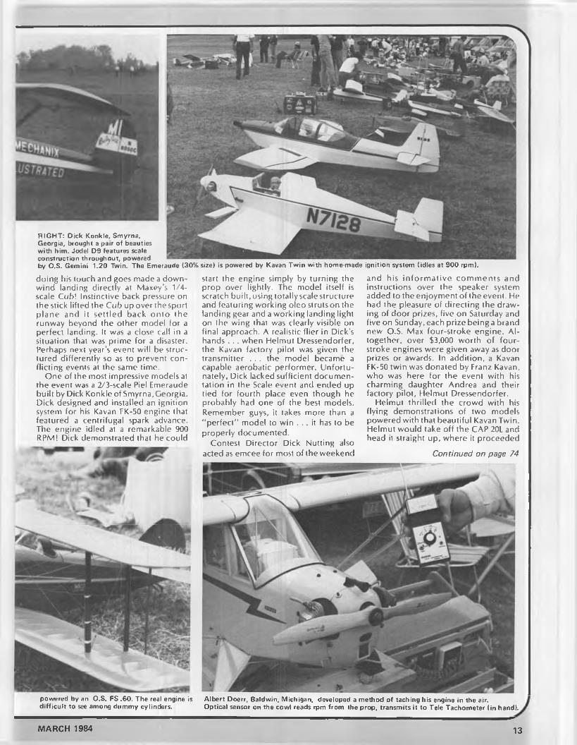
R IG H T: Dick Konkle, Smyrna,Georgia, brought a pair of beauties with him. Jodel D9 features scale construction throughout, powered by O.S. Gemini 1.20 Twin. The Emeraude (30% size) is powered by Kavan Tw in with home made ignition system (idles at 900 rpm).
doing his touch and goes made a downwind landing directly at Maxey’s 1/4- scale Cub! Instinctive back pressure on the stick lifted the Cub up over thesport plane and it settled back onto the runway beyond the other model for a perfect landing. It was a close call in a situation that was prime for a disaster. Perhaps next year's event will be structured differently so as to prevent conflicting events at the same time.
One of the most impressive models at the event was a 2/3-scale Piel Emeraude built by Dick Konkle of Smyrna, Georgia. Dick designed and installed an ignition system for his Kavan FK-50 engine that featured a centrifugal spark advance. The engine idled at a remarkable 900 RPM! Dick demonstrated that he could
powered by an O.S. FS .60. The real engine is difficult to see among dummy cylinders.
start the engine simply by turning the prop over lightly. The model itself is scratch built, using totally scale structure and featuring working oleo struts on the landing gear and a working landing light on the wing that was clearly visible on final approach. A realistic flier in Dick’s hands . . . when Helmut Dressendorfer, the Kavan factory pilot was given the transmitter . . . the model became a capable aerobatic performer. Unfortunately, Dick lacked sufficient documentation in the Scale event and ended up lied for fourth place even though he probably had one of the best models. Remember guys, it takes more than a "perfect” model to win . . . it has to be properly documented.
Contest Director Dick Nutting also acted as emcee for most of the weekend
and his in form ative comments and instructions over the speaker system added to the enjoyment of the event. He had the pleasure of directing the drawing of door prizes, five on Saturday and five on Sunday, each prize being a brand new O.S. Max four-stroke engine. Altogether, over $3,000 worth of four- stroke engines were given away as door prizes or awards. In addition, a Kavan FK-50 twin was donated by Franz Kavan, who was here for the event with his charming daughter Andrea and their factory pilot, Helmut Dressendorfer.
Helmut thrilled the crowd with his flying demonstrations of two models powered with that beautiful Kavan Twin. Helmut would take off the CAP 20L and head it straight up, where it proceeded
Continued on page 74
Albert Doerr, Baldwin. Michigan, developed a method of taching his engine in the air.Optical sensor on the cowl reads rpm from the prop, transmits it to Tele Tachometer (in hand).
MARCH 1984 13
Henri Fobre's Magnificent 1910
H V D R fM O N
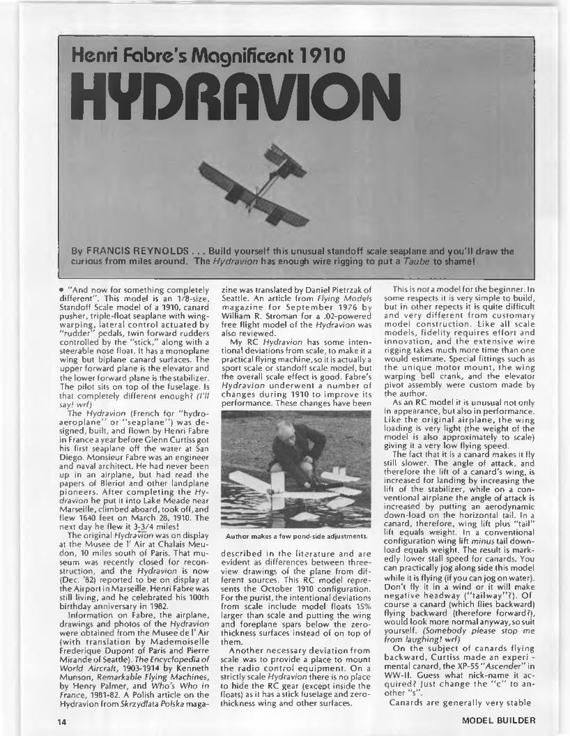
By FRANCIS REYNOLDS . . . Build yourself this unusual standoff scale seaplane and you'll draw the curious from miles around. The Hydravion has enough wire rigging to put a Taube to shame!
• “ And now for something completely different” . This model is an 1/8-size, Standoff Scale model of a 1910, canard pusher, triple-float seaplane with wingwarping, lateral control actuated by "rudder" pedals, twin forward rudders controlled by the "stick,” along with a steerable nose float. It has a monoplane wing but biplane canard surfaces. The upper forward plane is the elevator and the lower forward plane is the stabilizer. The pilot sits on top of the fuselage. Is that completely different enough? (I’ll say! wrf)
The Hydravion (French for “ hydroaeroplane” or “ seaplane” ) was designed, built, and flown by Henri Fabre in France a year before Glenn Curtiss got his first seaplane off the water at San Diego. Monsieur Fabre was an engineer and naval architect. He had never been up in an airplane, but had read the papers of Bleriot and other landplane pioneers. After completing the Hydravion he put it into Lake Meade near Marseille, climbed aboard, took off, and flew 1640 feet on March 28, 1910. The next day he flew it 3^3/4 miles!
The original Hydravion was on display at the Musee de Γ Air at Chalais Meu- don, 10 miles south of Paris. That museum was recently closed for reconstruction, and the Hydravion is now (Dec. '82) reported to be on display at the Airport in Marseille. Henri Fabre was still living, and he celebrated his 100th birthday anniversary in 1982.
Information on Fabre, the airplane, drawings and photos of the Hydravion were obtained from the Musee de Γ Air (with translation by Mademoiselle Frederique Dupont of Paris and Pierre Mirande of Seattle). The Encyclopedia of World Aircraft, 1903-1914 by Kenneth Munson, Remarkable Flying Machines, by Henry Palmer, and Who's Who in France, 1981-82. A Polish article on the Hydravion from Skrzydlata Polska maga
zine was translated by Daniel Pietrzak of Seattle. An article from Flying Models magazine for September 1976 by William R. Stroman for a .02-powered free flight model of the Hydravion was also reviewed.
My RC Hydravion has some intentional deviations from scale, to make it a practical flying machine, so it is actually a sport scale or standoff scale model, but the overall scale effect is good. Fabre’s Hydravion underwent a number of changes during 1910 to improve its performance. These changes have been
Author makes a few pond-side adjustments.
described in the literature and are evident as differences between three- view drawings of the plane from different sources. This RC model represents the October 1910 configuration. For the purist, the intentional deviations from scale include model floats 15% larger than scale and putting the wing and foreplane spars below the zerothickness surfaces instead of on top of them.
Another necessary deviation from scale was to provide a place to mount the radio contro l equipment. On a strictly scale Hydravion there is no place to hide the RC gear (except inside the floats) as it has a stick fuselage and zerothickness wing and other surfaces.
This is not a model for the beginner. In some respects it is very simple to build, but in other repects it is quite difficult and very d ifferent from customary model construction. Like all scale models, fide lity requires e ffo rt and innovation, and the extensive wire rigging takes much more time than one would estimate. Special fittings such as the unique motor m ount, the wing warping bell crank, and the elevator pivot assembly were custom made by the author.
As an RC model it is unusual not only in appearance, but also in performance. Like the original airplane, the wing loading is very light (the weight of the model is also approximately to scale) giving it a very low flying speed.
The fact that it is a canard makes it fly still slower. The angle of attack, and therefore the lift of a canard’s wing, is increased for landing by increasing the lift of the stabilizer, while on a conventional airplane the angle of attack is increased by putting an aerodynamic down-load on the horizontal tail. In a canard, therefore, wing lift plus "ta il" lift equals weight. In a conventional configuration wing lift minus tail download equals weight. The result is markedly lower stall speed for canards. You can practically jog along side this model while it is flying (if you can jog on water). Don’t fly it in a wind or it will make negative headway (“ ta ilway” ?). Of course a canard (which flies backward) flying backward (therefore forward?), would look more normal anyway,sosuit yourself. (Somebody please stop me from laughing! wrf)
On the subject of canards flying backward, Curtiss made an experi - mental canard, the XP-55 “ Ascender” in WW-II. Guess what nick-name it acquired? Just change the “ c” to another "s” .
Canards are generally very stable
14 MODEL BUILDER

MARCH 1984 15


Aerolite ribs can be hot-wired from a single sheet using a curved template.
Canard ribs and wing ribs cut from a circle of 3/16 Aerolite. Hardly any waste.
Aerolite ribs are pointed and sealed at both ends by notching and gluing.
airplanes, and this model is no exception. The huge aft fin overcomes the destabilizing effect of the small forward rudder, providing good directional stability Pitch stability is achieved by CC placement and by operating the forward lift surfaces at a higher angle of attack than the wing. Incidentally, no CG information was given in any of the historical data on the Hydravion, so I made a simple scale model glider and experimentally determ ined the CG requirements. Like conventional airplanes, the flight of canards gets squir- relly when the balance is too far aft. If you get the CG too far forward, you won’t have enough lift from the foreplanes to stall the wing for landings, so balance your model as indicated on the plan, or within a half-inch either side of the point shown. The ample dihedral of the original is retained on the model, providing good roll stability.
Wing warping for roll control is obsolete because modern airplane wings are much too stiff in torsion to permit its use. The structure and rigging of the Hydravion make wing warping easy on the RC model. Wing warping seems to scare off a lot of modelers. Don’t let it frighten you. It is a wonderful attention-getting feature on models of these ancient birds.
You will note from the plan that the wing warping lines pull the trailing edge
T o point and seal the ends of the ribs, put Zap or Hot Stuff in notch and close it by pushing end into a corner until the cyanoacrylate adhesive cures.
of the wing tips down (oppositely of course), but there are no lines to pull them back up. They are not needed, and were not provided on the full-scale Hydravion. The air load on the inner wing in a turn, and the slack wingwarping line on that side wash the inner wing out providing the equivalent of up aileron. Actually, some of the very early aileron-equipped planes were rigged the same way. I saw an early Bristol Boxkite biplane fly at Old Warden field north of London, which had horns and lines to pull the ailerons down, but none
to pull them back up. In the air, the airloads provide up aileron, but on the ground both ailerons hang straight down, looking like over-lowered flaps.
In addition to the unusual features already discussed, the rigging of this model always invites attention and comment. Most antique aeroplanes had some rigging, but the Hydravion may be the record holder for number of rigging lines. It is difficult to even get a count on the historical three-view drawings, but I counted 66 wires and lines on my RC model!
Here we see a finished float, a half-finished float, and a float pattern Aerolite (1/16) construction of float: score inside of bend, fold 90°,with the four tie points not yet installed. Zap inside of bend. Simple, quick, neat!
MARCH 1984 17

18 MODEL BUILDER

Canard, foreplane, and wing panels are framed and ready for covering. Author used carbon fiber T E , but 1/16 wire is recommended.
Panels in photo to the left are now covered . Note exposed truss- work spars. Coverite Micafilm (white) was used as covering.
Side view of fuselage framework. Radio compartment is open, battery Hydravion taxis by camera. Note that the nose float, forward rud-is installed behind seat, and elevator yoke is in place. ders, and elevator/canard are all yawed for the left turn.
Builders of sport and aerobatic RC biplane models usually stress the wing structure to stay in one piece without rigging, and they may or may not put on a little rigging for show. That practice can't be used here. Because of the zerothickness flight surfaces, the high aspect ratio wing, the stick fuselage, and the very light structure of this model, it would be as limp as a rag w ithout rigging. Every wire and line on the model is necessay to keep it in shape and to provide strength enough for flight. A time or two I was tempted to leave some particular wire off the model to simplify it, but a little analysis or testing soon showed me why Fabre put it there in the first place. A study of the various tensions and compressions in this airplane is fascinating.
You cannot use nylon rigging lines on this model. Nylon is much too stretchy. I used 20 pound test, seven-strand stainless steel fishing leader and some Kevlar line that I happened to have. Although you will put out quite a few bucks for all the Proctor turn-buckles and Proctor swage fittings in the rigging, don't try to do without them. Because of the general floppiness of the unsupported structure and the interaction between the various wires, it is next to impossible to rig it without turnbuckles or to get it true and with the proper incidences and float angles. Even with turnbuckles, rigging takes nearly as much time as building the structure (which is basically very simple).
Stranded stainless fishing leader is usually nylon jacketed. If you can’t find some without the jacket, beware that the
nylon tends to cause the wire to slip out of the crimped swage under load. To avoid this trouble, you can strip the nylon off the wires at the ends (which is time consuming), or do as I did and put a drop of CA into the swage just before swaging it flat with a pair of pliers. I could never get a zapped one to slip.
Don’t forget to secure both ends and the middle of each turnbuckle with fine soft wire as soon as you have it adjusted. Actually, the model won’t let you forget it, because if you leave an adjusted turnbuckle without securing it and go on to the next one, the one you left will usually back itself off while you are not looking. The amount of tension to put into the various guys and lines varies and
Continued on page 96
MARCH 1984
Sometimes the Hydravion skips across the water just before takeoff. Note "float prints" on water in above photo.
19

PRODUCTS IN USE
NICK ZIROLI’SM orain e S au ln ier NBy DOM PALUMBO . . . The Nick Ziroli Morane Saulnier N is a top quality k it and a top notch performer for beginner and expert alike.
• The Saulnier is being kitted by Nick Ziroli Models, 29 Edgar Drive, Smith- town, NY 11787, and is available via mail order or hobby shops for $43.95. This semiscale, three-channel, WW-I fighter is an ideal project for those of you who do not care to spend a lot of time building. It is also very easy to build so that even modelers with minimal experience will have no difficulty assembling the model. Full-size plans, complete with step-by-step instructions are provided with the kit. The model is extremely well engineered and comes complete with all materials necessary for construction. I found the partsfit, wood quality,and die cutting to be excellent.
The fuselage starts o ff as a “ slab- sided'' light plywood box structure which is very strong. The firewall is built in with just the right amount of down and right thrust for proper flight trim. There’s plenty of room inside for any standard radio and an eight ounce fuel tank. Formers and stringers are added to the plywood box and only the nose section requires sheeting w ith balsa to achieve the oval shape.
The wing goes together quickly and only the center section requires sheeting. The 1/2 x 1/4 spruce spars and plywood dihedral braces yield a very strong and surprisingly lightweight structure. Right and left panels can be built simultaneously over the plans and joined at the proper dihedral after assembly. Be sure to build in the recommended amount of washout to insure those scale-like, walking speed landings. One note of caution here.. . . check to make sure the wings are washed out symmetrically before, during, and after covering. With no leading edge sheeting, the wing panels are fairly flexible and easily twisted. Covering must therefore be applied carefully so as not to introduce asymmetry. Periodic checks of the amount of twist in each panel during the application of covering material are
ϊ ; · £ ' I\ : ■ : r''r- T J
& -
Dom Palumbo is all smiles after initial test flights proved very successful.
strongly recommended. The wing is held to the fuselage using dowels and rubberbands for simplicity.
The entire section of the fuselage above the wing is a molded ABS plastic piece. The machine gun is molded right into this piece so you don't even have to go out and buy one! The molded fuselage section is glued directly to the wing and I found that this part fit nearly perfectly with very little trimming. The cowl is also molded ABS, and is held on using four machine screws.
Tail surfaces consist of a solid balsa fin, rudder,subfinand elevators with a built- up stabilizer for lightness.
The model which I built was covered with flat grey Monokote. The black fin with skull and crossbones and the green nose were typical of the XIX Air Detachment of the Russian Imperial Army in 1915. Hobypoxy flat paint was used right over the M onokote in these areas. Decals furnished with the kit (until the current supply is depleted) include roundels for the wings and red, white, and blue striping for the rudder. (If this striping is used instead of the black with white skull and crossbones, the airplane should be finished in tan with a red or black or green nose.)
The all up weight of my model with a
20 MODEL BUILDER

novice fliers.
standard Enya .45 and Futaba S26 servos :is just over 4-1/2 pounds, and I only needed about one ounce of weight just behind the firewall to achieve the recommended CC location.
The Saulnier is a literal pleasure to fly. The rudder is ultra effective allowing for easy execution of stall turns, barrel rolls and spins. Low speed flight characteristics are outstanding, and it is almost
impossible to stall this airplane. My Enya .45 has much more power than is needed and any .35 to .40 engine would do very nicely. The model is rigged just right for smooth scale-like takeoffs and absolutely breathtakingly slow landings.
This model is an absolute must for the novice flier who is looking for something to fly which looks like an actual airplane and handles like a trainer. As a matter of
fact, the Saulnier is probably a better trainer than some of the models I’ve flown which are marketed as trainers. Don't let this turn you intermediate and expert fliers off, however, because a more realistic flying semiscale model· will be hard to come by, and if true-to scale flight performance is what you're after, Nick Ziroli's Saulnier delivers. ·
fThe fuselage is strong and simple to construct. It starts off as a The Saulnier has a molded ABS plastic cowl, wing fairing, andplywood box, then firewall, formers, and stringers are added on. machine gun. Seen here is the cowl and the radio installation.
MARCH 1984

[ 1 * 3 2 0 ( 3 1 ?By M ITCH POLING
• I th ink I'll start out this time by admitting to a couple of boo-boo’s. For some reason I have been goofing up on who does what lately, and I gave the wrong credit for the ideas on connectors in some previous columns. So, to Jack Dobbins, who sent me the info on the connectors, I humbly apologize for crediting Bill Gilchrist. The fact is that both of these men have sent in so many excellent ideas and information that I somehow got them confused. I really appreciate the great ideas that readers send in, they inspire me and help many others, and so I do like to give credit where credit is due. Thanks, Jack, and thanks to the many readers that come up with such good information.
Along the same line, I think Leonard Bedford would like everyone to know that his name is Leonard, not Larry, and again, I was to blame for the mixup. Larry Jolly, who is one of the best electric fliers around, has appeared so many times in this column that my typing fingers automatically type “ Larry", and Leonard got the brunt of it. Oh well, such are the problems of advancingage!
And now to get something right, Al Tabor sent an excellent info sheet on the Aptronics male and female headers that make such compact and strong connectors. The Aprtonics headers are much better than the Radio Shack ones, and are the ones I recommend to anyone
Johnny Luxor shows us his Curtiss Pusher F/F model. Johnny is a Flightmaster and an enthusiastic free flight modeler.
that wants to make tiny connectors that can handle the high amperage currents that we use in electric power.
At the time I wrote about them, I could find only one source, in Seattle. Al says he can get them in Denver from two suppliers for less than the Seattle price. Best of all, you can call Aprtonics toll free at (800) 792-0137 to find the name and telephone number of the Aptronics dealer near you! You can use either the 235 series or the 318 series which come in either solder plate or gold plate (gold is the best, but solder plate is fine) in the dual row configuration. I like the 36-pin configuration because it makes lots of connectors. You will want the .100 x .100 in. spacing (there is a .100 x .200 in. spacing also, but that makes connectors that I consider too big). So, there you have it, the information you need to get and make the most compact and the prettiest connectors you ever saw! Thanks, Al, for the tip!
I am often asked about how to get Sanyo batteries, and up till now, I have always recommended Astro or Leisure. However, they do not stock all the sizes of Sanyos, and you may wish to buy single cells rather than packs. Bernard Cawley needed some half sub-C (called
Radio Shack toggle that makes a great R/C on-off switch for electrics.
.550 Ah) cells for his Astro 020 in his Schoolboy, and wanted Sanyos because of their high power. He found them at Firgrove Model Supply, 10611 136th Street East, Puyallup, Washington 98373, phone (206) 845-7675.
After he had flown them, he called me up to share his excitement. Bernard feels that he is getting close to a thousand rpm more prop speed and a minute more duration compared to the stock Astro GE pack. This really makes his Schoolboy go!
When I heard that, I had to get a pack for myself, and contacted Bob Pfeiffer at Firgrove. He promptly sent me a set of batteries, and if the w inter weather around here ever lets up, my Schoolboy will be flying high too. Bob has excellent service, and a large variety of Sanyo sizes, so you might call him up or send an SASE to get prices and a list. The half sub- C cells are $4.50 each, which comes out less than the price for the original Astro pack. “ Soup up” your 020 schoolyard planes with Sanyos, you’ll like them! Jump over school buildings in a single bound, instead of winding up on the roof! Thanks Bernard, for the tip.
And now for a handy hint of my own! For increased reliability, I have gone almost entirely over to a servo operated toggle switch for motor on-off control (I have used push-push switches in the past).
A few columns back, I showed you how to make a slip-on sleeve from plastic tubing so that the toggle switches supplied with the electric systems could be used "as is". The small metal handles on these toggles must not be squeezed, crimped, or drilled because they are hollow and have a spring inside them which is vital for the function of the switch. The sleeve system works very well, and has been completely reliable for me, but it is bulky and is one more thing to have to fiddle with. Besides that, the toggles that come with the systems are very "stiff” , and the mini servos that I favor have to work hard to flip them. I don’t like to see that, it is tough on the servo internals, and runs down the re-
The Radio Shack push-pull toggle setup used by the author on his electrics. The handle is
22 MODEL BUILDER

Johnny Luxor's Fairchild 24 is powered by an 60-inch span.
ceiver battery pretty fast. As I use a small receiver battery (in the little ones, usually a 100 mah pack) this could get critical. So, I started to look for a toggle switch that had a "softer” action.
I found two toggle switches at Radio Shack which work just fine. The three terminal switch is part No. 275-662, the six terminal switch is No. 275-663. The three terminal switch is fine for the small planes, the six terminal would be the one to use for series-parallel high-low speed control; or if you wished, for very high currents with the switch wired in parallel so that half the current goes through two pins, half through the other two alongside them.
These switches have a bonus, not only are they much easier on the servo, but the handles are a tough molded plastic that is flattened and easily drilled. No
drilled with a 1/8 in. hole, then a 1/16 wire pushrod with wheel collars is installed.
Astro 05. Model has
Johnny Luxor sure has a stable full of electrics. L E F T : Curtiss Pusher with Astro 020 for F/F. R IG H T: Antoinette with VL-48 motor for F/F.
Another Johnny Luxor model, this one for free flight only, is an SE5. It spans 33 inches, has Astro 05 for power.
more sleeves! It makes a super simple and compact installation as the photos show. That’s what I like, a solution that takes care of two problems at once!
Roland Boucher, of Leisure Electronics, sent in quite a stack of information on his systems and his ideas for electric motors and models. Leisure is now im porting the Keller line of cobalt motors, which I have mentioned before as the prem ier motors in Europe. I ordered a Keller 25/12 ($110 retail) and, as usual with the Keller motors, I am totally impressed by the quality of the motor. The Keller motors are built for a lifetime of service, they are built right. I mean huge brushes with really hefty pigtail leads in metal brush holders with brass heat sinks, adjustable timing, an over 3/16-inch motor shaft with a perfectly machined flat in it for secure prop retention, excellent machining throughout, magnets so strong that you can feel
every turn of the armature, and a hefty prop holder that does not require any redrilling of the prop hub. Heinz Keller pays attention to the details, and the result is the Rolls Royce of e lectric motors. These motors are worth their price, and even more so when you consider that they just do not wear out. You will pay a lot more in replacing motors than you would for one Keller motor.
The 25/12 is just a little larger than the Astro 15 cobalt motor, weighs 9-1/2 ounces, and turns an 8x5 Top Flight nylon prop at 11,100 rpm (Accutach) at 15.0 amperes. It turns a 9x4 Cox black nylon prop at 10,300 rpm at 18 amperes, using a 12-cell, sub-C Sanyo pack. This makes it an ideal motor for any 15 size plane, or even a 20 if you want to try 14 cells (I haven’t yet). It will be flying in my float plane soon. I think that you will be
Continued on page 92
The Sanyo 1/2 sub-C pack (left) is all ready to go. Old Astro 020 power pack is used for comparison. Sanyo batteries from Firgrove, see text.
MARCH 1984 23

V I N T A G E D A Y
By PETER SCOTT . . .True to the spirit of SAM, the British annually hold a Vintage Day event which is dedicated to the proposition that Old Timers should be enjoyed in a non-competitive atmosphere. This report concentrates on the R/C models that were flown last August at the Old Warden airfield.
• Old Warden airfield, in the heart of rural England, is the home of the Shut- tleworth Collection of veteran and vintage aircraft . . . one of Europe's finest. It is also the scene of regular model aircraft events, principal of which are the two-day “ All Scale” weekend in mid-summmer, and the late-summer "Vintage Day” . Both events have mushroomed in size over recent years, attracting thousands of spectators, hundreds of models, and long lines to get in!
This year's Vintage Day, held on August 21, was blessed with weather conditions which warranted the annual modellers pilgrimage (a sort of MECA's Mecca), and the compact airfield itself was neatly compartmentalized to cater for R/C, F/F, and C/L interests. (This report features the R/C models only.)
Before launching into an analysisof the models, it has to be stated that this is one of those great British traditions . . . a non-competitive event. Just to be there is enough. True, a "general consensus" award for best all-around model was made, but this was quite incidental to the business of flying . . . or watching
. . .for fun. It must also be remembered that the “ Vintage Movement” in Britain has developed along somewhat d ifferent lines to that in the U.S. . .. space
A B O V E : A 9-foot scaled up C O 2 model is powered effortlessly by an Oliver Tiger twin diesel. BELO W : Same model up close.
L E F T : Oldest model at the meet was a Bowden designed Blue Dragon with original prewar Atom Minor 25 cc petrol engine.
limitations favor the R/C model, and (non) availability of "real" spark motors has encouraged glow conversions and the use of contemporary four-stroke motors. And . . . almost unique in Europe . . . is the continuing popularity of the diesel, not dieselized glows, but "real” diesel. It was in Britain, after
The beautiful A t Ease you see here was built by Arthur Fox, of Nottingham, and was powered by a Kalt 45 four-cycle engine.
We're sorry that the name of the builder of this model wasn't obtained, but the model is a Kiel Kraft Scorpion, O.S. .60 powered.
24
f
iMODEL BUILDER

One of several Mercury IV designs present belonged to Fred Barnsley. Saito .80 twin engine.
A B O V E : Bob Brightwell powered his O/T with a home-built 10 cc 4-stroke twin (glow or ign.).
BELO W : This heavyweight model needs plenty of muscle to get airborne. Model is a Veron Cardinal powered by M ills.75.
Dennis Bryant's Stentorian was powered by a spark converted Merco 35.
all, in the mid and late 40’s that these motors enjoyed their heyday. There are still a number of British manufacturers producing diesel engines from around0.8 cc (.049 ci) up to 5.0 cc (.30 ci),some of which have incorporated contemporary design philosophy, and yet others which are still delightfully uncomplicated. And that nostalgic smell of ether . . .
Back to the models. If Britain could be said to have had its own Ben Shereshaw, it must undoubtedly be Phil Smith . . . founder, chief driving force, and designer for the Veron model aircraft company. The affable Phil was at the Vintage Day meet, and must have been gratified to see so many of his designs around, in original or scaled-up form. His own original 1947 "Stentorian" was there, now (alas) a little battle worn, but serving as a monument to the elegance of post-war design. (Phil Smith also designed the first ducted-fan models ever to be kitted: FA86Sabre, Lavochkin, etc. . . . and this in the 50’s! His Jetex designs were also extremely popular in their day.)
The replica Stentorian flown by Dennis Bryant (himself one of Britain's leading R/C scale builders/flyers) was in this writer’s opinion one of the finest
models at the meet.Design influence ranged from the
ultra-streamlined, Kalt .45 powered, At Ease of Arthur Fox (1937 Zaic Yearbook), through the tail-less Manx Monarch of Michael Conrad (Aeromodeller 1950). The results were often beautiful (Fred Barnsley’s Saito .80 powered Mercury IV), immaculate (Ken Strokes' Super Buccaneer) or downright ugly (your correspondent’s 1935 Bowden Mouse). All were real models . . . not a hint of glassfiber or foam in sight, and all bore testimony to the skill of their builders. . . balsa butchering is not a dead art yet!
Covering materials encompassed the complete spectrum, from traditional doped silk through nylon, Coverite, Fabrikote, and Micafilm, to the increasingly popular Solartex (which both shrinks drum taught and adheres to undercambered ribs, as well as providing a good basis for a first-rate paint job).
Pylon models generally took a back seat, leaving the field to the graceful, slow-flying cabin models recalling the early 50's flying meets in Britain, but with one major exception . . . reliability. The use of contemporary four-stroke glows
Continued on page 82
Ken Stoke's Super Buccaneer was powered by O.S. .60 4-stroke. Immaculate Solartex skin!
MARCH 1984 25
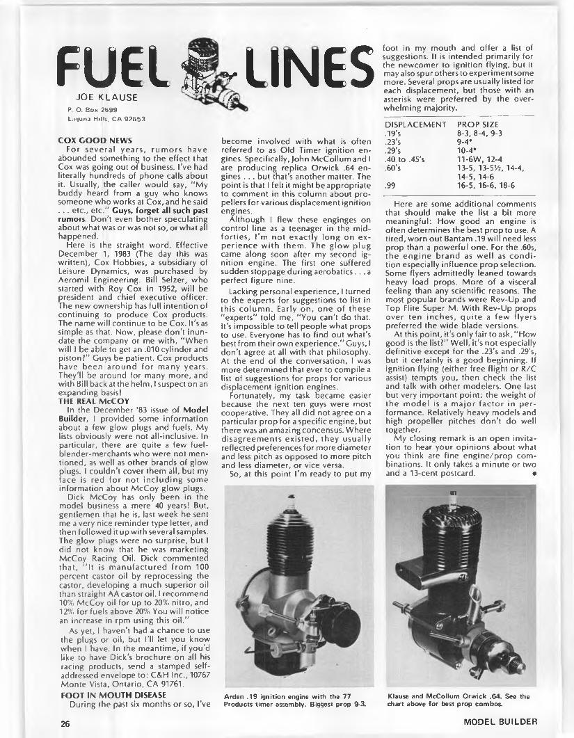
FUEL*JOE KLAUSE
P O. Box 2699L'Kjuna Hills, CA 92653
COX GOOD NEWSFor several years, rumors have
abounded something to the effect that Cox was going out of business. I’ve had literally hundreds of phone calls about it. Usually, the caller would say, “ My buddy heard from a guy who knows someone who works at Cox, and he said . . . etc., etc.” Guys, forget all such past rumors. Don't even bother speculating about what was or was not so, or what all happened.
Here is the straight word. Effective December 1, 1983 (The day this was written), Cox Hobbies, a subsidiary of Leisure Dynamics, was purchased by Aeromil Engineering. Bill Selzer, who started with Roy Cox in 1952, will be president and chief executive officer. The new ownership has full intention of continuing to produce Cox products. The name will continue to be Cox. It's as simple as that. Now, please don't inundate the company or me with, “ When will I be able to get an .010 cylinder and piston?” Guys be patient. Cox products have been around for many years. They'll be around for many more, and with Bill back at the helm, I suspect on an expanding basis!THE REAL McCOY
In the December ‘83 issue of Model Builder, I provided some information about a few glow plugs and fuels. My lists obviously were not all-inclusive. In particular, there are quite a few fuel- blender-merchants who were not mentioned, as well as other brands of glow plugs. I couldn't cover them all, but my face is red for not including some information about McCoy glow plugs.
Dick McCoy has only been in the model business a mere 40 years! But, gentlemen that he is, last week he sent me a very nice reminder type letter, and then followed it up with several samples. The glow plugs were no surprise, but I did not know that he was marketing McCoy Racing Oil. Dick commented that, “ It is manufactured from 100 percent castor oil by reprocessing the castor, developing a much superior oil than straight AA castor oil. I recommend 10% McCoy oil for up to 20% nitro, and 12% for fuels above 20% You will notice an increase in rpm using this oil.”
As yet, I haven't had a chance to use the plugs or oil, but I'll let you know when I have. In the meantime, if you’d like to have Dick’s brochure on all his racing products, send a stamped self- addressed envelope to: C&H Inc., 10767 Monte Vista, Ontario, CA 91761.FOOT IN MOUTH DISEASE
During the past six months or so, I’ve
-LINES. ,/xk
become involved with what is often referred to as Old Timer ignition engines. Specifically, John McCollum and I are producing replica Orwick .64 engines . . . but that’s another matter. The point is that I felt it might beappropriate to comment in this column about propellers for various displacement ignition engines.
Although I flew these enginges on control line as a teenager in the midforties, I ’m not exactly long on experience w ith them. The glow plug came along soon after my second ignition engine. The first one suffered sudden stoppage during aerobatics. . . a perfect figure nine.
Lacking personal experience, I turned to the experts for suggestions to list in this column. Early on, one of these "experts” told me, "You can’t do that. It’s impossible to tell people what props to use. Everyone has to find out what’s best from their own experience.” Guys, I don’t agree at all with that philosophy. At the end of the conversation, I was more determined that ever to compile a list of suggestions for props for various displacement ignition engines.
Fortunately, my task became easier because the next ten guys were most cooperative. They all did not agree on a particular prop for a specific engine, but there was an amazing concensus. Where disagreements existed, they usually reflected preferences for more diameter and less pitch as opposed to more pitch and less diameter, or vice versa.
So, at this point I’m ready to put my
Arden .19 ignition engine with the 77 Products timer assembly. Biggest prop 9-3.
foot in my mouth and offer a list of suggestions. It is intended primarily for the newcomer to ignition flying, but it may also spur others to experiment some more. Several props are usually listed for each displacement, but those with an asterisk were preferred by the overwhelming majority.
DISPLACEMENT PROP SIZE.19’s 8-3, 8-4, 9-3.23’s 9-4*.29’s 10-4*.40 to ,45’s 11-6W, 12-4.60’s 13-5, 13-5’/2, 14-4,
14-5, 14-6.99 16-5, 16-6, 18-6
Here are some additional comments that should make the list a bit more meaningful: How good an engine is often determines the best prop to use. A tired, worn out Bantam .19 will need less prop than a powerful one. For the .60s, the engine brand as well as condition especially influence prop selection. Some flyers admittedly leaned towards heavy load props. More of a visceral feeling than any scientific reasons. The most popular brands were Rev-Up and Top Flite Super M. With Rev-Up props over ten inches, quite a few flyers preferred the wide blade versions.
At this point, it’s only fair to ask, “ How good is tbe list?” Well, it’s not especially definitive except for the .23’s and .29’s, but it certainly is a good beginning. If ignition flying (either free flight or R/C assist) tempts you, then check the list and talk with other modelers. One last but very important point: the weight of the model is a major factor in performance. Relatively heavy models and high propeller pitches don’t do well together.
My closing remark is an open invitation to hear your opinions about what you think are fine engine/prop combinations. It only takes a minute or two and a 13-cent postcard. ·
in
Klause and McCollum Orwick .64. See the chart above for best prop combos.
26 MODEL BUILDER

1. Loren Schmidt gathers the pieces of his Yates Ten Foot model with help from Nicholau. Staben looks on. SAM 30 boys.
2. Would you believe the wind was so stiff that you could actually catch the model? Jim Kyncy's mechanic and Anderson Pylon.
nuespAmBy JOHN POND
• Most readers of this column w ill recognize the fact the columnist is contest oriented and for that reason, generally features reports of one or two contests. Of course, in the reporting of the results, certain names are bound to appear frequently with the attendant attachment of fame for their victories.
This columnist has always tried to acknowledge the contest director and the support people who so unselfishly devote their time so that others may enjoy the hobby of flying their models.
It is these very people who form the nucleus of clubs, generally being the “ spark plugs” or motivators of club activities. An excellent example of what we are talking about is Nick Nicholau of SAM Chapter 30.
Photo No. 1 shows Loren Schmidt with the wreckage of his Vates Ten Foot Model at the Salinas O/T meet. On the right is the ever present helper, contestant, etc., Nick Nicholau. To help build interest in models, Nicholau constructs many models to order for the members of SAM 30. This particular Yates model was also constructed by Nick. He has built about 50% of the models presently being used by SAM 30 members. This does not take into account the models
he has bu ilt fo r other SAM chapter members.
Most all of the SAM 30 meetings are held at Nick's home at 2329 Hall St., Marysville, CA 95901, w ith his wife, Neva, providing refreshments and any help needed. The development of camaraderie is the group's fo rte . . . fabulous!
When a contest is held, who is the CD? Who supervises? Naturally, Nick runs things, but the kudoes should go to his wife, Neva, who practically runs the desk by herself. What a dynamo of action. Naturally, she supplies the food at the noon time barbecue.
To top it off, in their “ spare time,” Nick and Neva put out a newsletter called thw "Fabulous Thirties.” This is truly the life blood of the club, the dissemination of all information.
It is to these type of people that we take our hats off, and we acknowledge w ith thanks the ir unselfish work on behalf of the old timer movement. Next time you are at your club meeting, look around. It won't take long to figure out who motivates the club. Only problem is that we need more of them!SAM 30 TEAM CONTEST
The SAM 30 meet held November 5th and 6th, was just plain lucky accord
5. When you say that Old Timer flying is a "laid back" type of competition, here is the picture to prove it. Timer and recorder on left, spectators watching.
3. The Kerswap craze has spread to Northern California. Jim Kyncy refuels his scaled version. (Photos 2 and 3 by Dowling.)
4. G uy "Speed" Hughes put an Emil Vollen- wieder magneto on his McCoy .60. It works great!
ing to Nicholau. Nick said he was ready to cancel the contest after a torrential downpour on Thursday and Friday, but darned if the weather didn’t clear up just in that particular locale of California.
Winds were rather high with a resulting low entry, but flying went on anyway. Noted at the barbecue this time was the "double patty” hamburgers! You don’t get those very often!
To properly describe the windy conditions, Photo No. 2 shows Jim Kyncy’s helper catching his Anderson Pylon. Penetration in the wind was so slow, catching a large gas model of that size was a cinch.
Probably the most popular O/T design to hit the modelers is the recently approved Kerswap, so named by its designer, Gil Robbins, by the noise is made when the model spiraled in. This model has been sensational in both Free Flight O/T and R/C Assist. Rules in radio control allow scaling, so all types have been produced.
As can be seen in Photo No. 3, the most popular size is the version for a Torpedo .29, this first being brought out by Bruce Norman of SAM 29. Si nee then, the craze for Kerswap designs has really taken off. The columnist might comment that the main reason for this is the extreme simplicity of construction, plus ease of flying and adjustments. Tough model to beat!
Photo No. 4 shows Guy “ Speed” Hughes' version of a McCoy .60 equipped with an E-V magneto as designed and built by Emil Vollenwieder. These mags work excellently and the spark is such that a fouled plug is a rarity. When that engine comes in, does that model go!!
We have been talking about it for years, but Photo No. 5 g raph ica lly illustrates the point of “ la id-back”
MARCH 1984 27
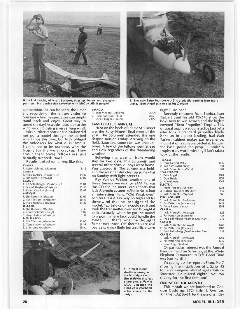
6. Jack Albrecht, of Kraft Systems, sizes up the air and the competition. His double-size Kerswap with McCoy .60 is potent!
7. The new Saito four-cycle .45 is gradually coming into more usage. Bob Angel put one in his Dallaire.
competition. As can be seen, the timer and recorder on the left are under no pressure while the spectators can simply stand back and enjoy. Great way to spend the day I As a side note, look at the wind sock indicating a very strong wind.
Nick further reports that Al Staben did not put a model through the barbed wire fence this time, but Nick obliged the onlookers for what Al is famous. Staben, not to be outdone, won the trophy for the worst crackup. How about that? Some fellows are just naturally talented! Haw!
Results looked something like this:CLASS A1. Loren Schmidl (Ranger) 6:12C U SS B1. Nick Sanford (Playboy, /r.) 14:202. Jim Kyncy (Kerswap) 13:05C U SS c1. Ed Solenberger (Playboy, 1r.) 21:002. Speed Hughes (Playboy) 16:103. Grant Gordon (Lanzo) 12:07ANTIQUE1. Jim Kyncy (Anderson) 30:002. Eut Tileston (Westerner) 25:393. Nick Nicholau (Dallarie) 25:22ELECTRIC1. Bill Burleson (Playboy) 9:492. Loren Schmidt (Wasp) 6:093. Augst Fabian (Playboy) 5:351/2A TEXACO1. Eut Tileston (Westerner) 30:002. Tom Vincent (Playboy) 27:173. Stan Lane (Playboy) 23:40
TEXACO1. Tom Vincent (Dallaire) 28:292. Harry Johnson (PB-2) 26:213. Speed Hughes (Yates) 24:47
SAM 49 FALL BIANNUALHard on the heels of the SAM 30 meet
was the Forty-Niners' final meet of the year. The columnist attended this one despite rain on Friday. Arriving on the field, Saturday, some rain was encountered. A few of the fellows went ahead and flew regardless of the threatening weather.
Believing the weather front would stay for two days, this columnist and several other SAM 29 boys went home. You guessed it! The contest was held, and the weather did clear up somewhat on Sunday with light breezes.
Ray Van de Walker, another one of those tireless workers for SAM 49, was the CD for the meet. Van reports that Jack Albrecht as seen in Photo No. 6, had an interesting flight. “ Old Weak-eyes" had his Class A Kerswap so high and far downwind that he lost sight of the model. Tad Sato said he could see it and took the transmitter over and brought it back. Actually, when he got the model to a point where Jack could handle the model . . . that's what he thought! Sometimes those Taft thermals are real bearcats. A max flight but an official zero
8. Interest is constantly growing in the Nostalgia event Jim Walston displays a rare one, a Hewitt 1/2A. Jim used the 1953 Zaic yearbook as his source for the design.
flight! Too bad!Recently returned from Florida, Ivan
Tarbert used his old PB-2 to show the boys how to win Texaco and the highly coveted “ Bent Propeller” Trophy. This unusual trophy was donated by Jack Jella who took a standard propeller blade bent up in a poor landing, had Walt Parker, cabinet maker par excellence, mount it on a suitable pedestal, lacquerthe base, polish the prop . . . voila! A trophy truly worth winning!! Let's take a look at the results:TEXACO1. Ivan Tarbert (PB-2) 11462. Tad Sato (Miss Philly) 9343. Jack Albrecht (Dallaire) 9091/2A TEXACO1. Bob Angel 16832. Don Hoyle 13203. Al Heilman 1002ELECTRIC1. Frank Heacox (Playboy) 1024Z Roland Boucher (Playboy) 8503. Jack Albrecht (Playboy) 566PURE ANTIQUE1. Jack Albrecht (Anderson) 15952. Pat Patterson (Anderson) 14243. Ernie Payne (Lanzo) 1393CLASS A1. Jack Albrecht (Kerswap) 8262. Pat Patterson (Kerswap) 4243. Fred Lehmberg (Feather Merchant) 210CLASS B1. Jack A lbrecht (Kerswap) 12602. Pat Patterson (Kerswap) 11003. Fred Lehmberg (Feather Merchant) 135CLASS C1. Jack A lbrecht (Kerswap) 12602. Pat Patterson (Kerswap) 12353. Ron Doig (Quaker) 840
Of particular interest was the Annual Banquet held on Saturday, at the White Elephant Restaurant in Taft. Good Time was had by all!!
Wrapping up the report is Photo No. 7 showing the installation of a Saito .45 four-cycle engine in Bob Angel’s Dallaire Sportster. He placed eighth. Not too shabby for the first time out!ENGINE OF THE MONTH
This month we are indebted to Gordon Codding, 3724 John L Avenue, Kingman, AZ 86401, for the use of a little-
28 MODEL BUILDER

9. L E F T : Ralph Turner, SAM 39 newsletter editor, flies free flight too. A Nostalgia design called The K id is the object of attention.10. A B O V E : Barney Onofri as he appeared in late 1937 with his Trenton Terror. Photo originally appeared in the Feb. 1938 A ir Trails magazine.
known engine by Kencraft Co., originally located at 225 N. Seventh St., Garden Grove, California. The engine is the 1947 Ken .60 racing engine converted to diesel.
This rather rare engine lasted only a short time. The engine was produced as an attempt to take advantage of the growing interest in diesel engines that has been generated by the English motors, Leon Shulman, and others.
As can be seen by the drawing when comparing it to the Ken .60 article appearing in the March 1981 issue of Model Builder, very few changes were made. As a matter of fact, the engine exterior is practically identical as is the inside, i.e., bore, stroke, displacement, etc. The head was replaced by a flat plate with all timer appurtenances removed. This did make for a slightly lighter engine by a half ounce, giving a total
weight of 15 ounces. Of course, there was the saving of the ignition system which was again between four and five ounces.
No performance figures are available on this engine. Even Gordon has to admit the engine has not been run in 25 years as it has been in the Smithsonian Museum all this time and just recently returned. This was the last gasp by the Kencraft Co., and shortly thereafter all production discontinued.THE GREAT NORTHWEST
We are always indebted to Bob Stalick, our M ode l Bu ilder “ Free F ligh t” columnist, as he faithfully sends out the Willamette Modelers Club newsletter known as “ WMC Patter". "Up thar in the trees” , free flight is a real chore as retrieval is always a problem. Then too, the weather is not always that great, but despite this, 32 contestants showed up for the Annual Old Timers Meet.
As Bob points out, “ Saturday was a nice day but featured winds in the five to eight miles per hour category. Those who waited until Sunday were sorely
12. SAM 39 Newsletter Editor Ralph Turner cranks up his Cumulus for an official flight as Jim Keck holds.
11. Winter 1938-39. Barney Onofri is flying ski equipped models. Great takeoffs and landings were experienced in the snow!
MARCH 1984 29

13. Under the heading: FA M O U S L A S T W ORDS . . . "N o w I'll show you how a Bombshell should fly !" Jack Ross.
16. Harry Albright's "go and return" Scientific Mercury. See text for whole story.
disappointed as winds of 15 mph were the standard of the day .. . along with, you guessed it, RAIN!”
It wasn’t until two o’clock that the first flights got off on Sunday. The Concourse d'Elegance (Beauty Event to you) was conducted by viewing the models in the canopies of the pickups parked in the immediate area.
Culling the results very quickly, we have the following:ANTIQUE1 . Clarence Bull (Quaker Flash)
2. E. Evenson (Clipper Mk I)CLASS C PYLON1. Bob Schafer (Albatross)2 Ray Chalker (Playboy)CLASS AB PYLON1. Tom Alden (Winged Yankee)2. Rod Russell (Ranger)IGNITION CABIN1. E. Evenson (Bombshell)2. Ed Lamb (Spook 72)TIME TARGET1. Dick Williamson (Miss America)2. Don Nordlund (Powerhouse)NOSTALGIA1. Ross Thompson (Spacer)2. Bill McDow (Zeek)3. Bill Giffen (Frisco Kid).020 REPLICA1. Bill Giffen (Foo-2-U-2)BROWN T.T.1. Bob Schafer (Red Zephyr)2. Clarence Bull (Quaker Flash)RUBBER1. D. Williamson2. Tom Alden GLOW COMBO1. D. Williamson (Slratostreak)2. Bill McDow (Zipper A)
Also of note is that the R/C events suffered rather heavily from the weather as only two entered the 1/2A Texaco Event and only one official posted in the O/T R/C event. Some days it doesn’t pay to sandbag!
14. Australian Old Tim er activity is really on 15. John Kenney, Greenwood, Miss., posesthe upswing. Colin Borthwick sends this shot with his O.S. .60 four-cycle poweredof his Quaker Flash. Powerhouse. Sure has a nice flying area!
NOSTALGIAReceived several photos from Harry
Murphy who is sparkplugging (Now there’s a new word! wrf) the Nostalgia event in the midwest. Among the snapshots was Photo No. 8, showing Jim Walston of Smyrna, Georgia seen at the CIA fall meet. (That’s quite a haul to Indiana.)
The Nostalgia event as conceived by Ralph Prey of the San Valeers has been picked up by the Central Indiana Aero- modellers (CIA). Harry Murphy, editor of the CIA "Informer” , has volunteered to work in close association with Ralph to plug up some of the loopholes now in
the present rules.On this end of things, this columnist
has spent about three weeks compiling a list of all model designs he could find from his very extensive library of Model Airplane News, Air Trails, Flying Models, Aviation Age, Aerom odeller, Model Aircraft and a host of other magazines. This has now been completed and the preliminary sent to "M u rf” and Ralph to look over. This should serve as the “ Bible” for Nostalgia designs.
Getting back to the shot of Jim Walston, the model is a rare Nostalgia design
Continued on page 82
OLD TIMER Model of the Month
CLOUD CRUISERDesigned by: Harry Edward MoyerDrawn by: Al NovotnikText by: Bill Northrop
• The Cloud Cruiser is a pretty parasol gas model that could easily pass for a semi-scale replica of a homebuilt. It was featured in the July 1937 issue of Model Airplane News, and it was designed by Harry Edward Moyer. The scale-like arrangement of the tail surfaces makes it a natural for three-channel radio control.
The model has one drawback; construction is a mixture of modern and old-time techniques that, if followed explicitly, would make it somewhat difficult to build. In accordance with our usual practice, we have not taken it upon ourselves to modify the plans to show how we might simplify construction. Better to show you the way it was and allow you to make your own changes. However, a few suggestions... FUSELAGE
Make a series of partial saw cuts on the top side of the bottom longerons, between stations A and B to facilitate making the sharp bend. Fill the cuts with CA (cyanoacrylate glue) while it's pinned down to build a side.
Install well-gussetted brass tubing in the lower fuselage to plug in the landing
gear wires. Forget shock travel.Substitute 1/4-inch ply for bulkhead
"A ” if you plan to use a modern engine mount instead of the beam arrangement.
Lots of luck w ith the compound curves in the outside top and bottom fuselage sheeting between stations "A ” and “ B"! More than likely the profile lines will be straight but this should not detract from the appearance.TAIL SURFACES
We’re happy w ith the aluminum tubing outline used on our quarter-scale Aeronca C-3 project, but if you prefer, laminated basswood strips or reed will do this job nicely.
Just use two 1/4 x 1/2 spars for the horizontal tail surface, instead of one, and as with the fin and rudder, make the stab spar of spruce and the elevator spars of balsa. Insert 1/8 ply gussets to provide mounting area for the control horns.
Use a stock R/C steerable tail wheel bracket for positive ground handling during taxi.WING(s)
The (s) is to imply that a one-piece wing may prove more practical, unless
Continued on page 100
30 MODEL BUILDER


Bruce Taylor's Mirage circles in a tight, low-level thermal over the grass field of a Winnipeg, Manitoba, park. Beautiful sight!
For the fliers of Winnipeg who are serious about slope soaring, it is a five hour drive to this site, Qu'Appelle Valley, Saskatchewan.
ΒΦ1
By BILL FORREY
• Sometimes the hardest part about writing tis column is not what to put in it, but how or where do I start. In this case I’ve decided to start with a little house cleaning (actually it's more like briefcase cleaning!). As I receive an average of anywhere from four to eight letters per month, not counting the scores of newsletters, things can get pretty piled up in a short time.
Some of the photos you see this month are a result of my foraging through my cluttered "purse.” (I can now sympathize with my wife.) I unearthed an envelope containing a three- page typewritten letter and several outstanding color photograghs all of which originated from the typewriter and camera of Jim Holland, of Winnipeg, Manitoba. For anyone who may nave never heard of this strange land, I would recommend that he or she turn his or her Rand McNally atlas to central Canada and gaze along the trans-Canadian Highway One to a point about 60 miles north of the northeast corner of North Dakota (that’salotta norths!).This is home to at least a dozen of Canada's premier soaring types, Jim Holland and Alex Reinhardt being two with whom I’ve had the pleasure of either meeting or corresponding. Alex was a member of the Canadian F3B team in York this past summer. . . Jim is no stranger to Model Builder as his interests in R/C soaring and indoor modeling have caused his
ideas to appear in both columns now.Briefly quoting from Jim’s letter of last
summer:" . . . Most of our flying is thermal
flying which we do at our local field. The field is actually one of the city’s parks which we have been given permission to use. Thermal activity is pretty good at the field, but we do get some days when all you get is sink. All in all, I think our field is darn good.
"As for slope flying, there is what I feel could be one of the best slope sites in the whole country. Mind you, it ’s not out our backdoor. You see, the slope is about a four to five hour drive from Winnipeg . . . in the next province to us in the west (Saskatchewan). The area is called Qu’Appelle Valley, and it has a slope face for just about every wind direction you can get. The average height of the (aces we fly o ff of is in the three hundred to three hundred fifty foot range with the highest face being close to three hundred and seventy-five feet h igh. . . not bad for the heart of the prairies of Canada. As it is very far away, going there usually means that it is a weekend trek for some serious slope soaring. Sometimes we are joined by some fe llow fliers from Regina, the capital city of Saskatchewan, and Rocan- ville, a town about a two-hour’s drive away from the slope."
Man, that is what I call dedication . . . there have only been two times in my soaring career that I’ve driven a car five hours or more just to fly my models. (I once drove eignt hours to observe the 1981 W orld Champs in Sacramento, however.) After taking a look at those beautiful slope sites, and after hearing that they are flyable with wind blowing from almost any direction, I am almost tempted to plan a vacation there myself! . .. With gliders, of course.
The other set of photos comes to this magazine from the state of Oklahoma, city of Midwest City. The donor is also no stranger to these pages as he is none other than John Dyal. I love John’s
Val Vre's Slope Ascender is put through its paces over the 350-foot slope face of Qu'Appelle Valley. Val designed and built the canard glider. He's been building and flying models since the early forties at least. Val flies power models also.
letters. Here is a man who wastes little energy on "foof” , as Dirty Dan Rutherford would say. The following is not an excerpt, it is the entire message, unedited by me or anyone else: “ 11 Oct '83. Mr. Forrey — More photos that may be of interest — 'Having fun is good for you.’ Co fly,” signed, John Dyal. I love it. Thanks for the contribution, John, we are interested.TOP FLITE METRICK MODS
The following letter was received by me at the Model Builder office back in September (that’s 1983, not ’82!). I think it will be of interest to anyone who may be contemplating the conversion of a box-stock, polyhedral Metrick into an aileron Metrick or any other kind of poly ship into an aileron ship. As there are no photos or illustrations to go along with this description, pay close attention to
John Dyal sends this photo of his friend, Ken Bryant and his Yardstick. The model has a yardstick for a tail boom . . . and a canopy that has blown off!
32 MODEL BUILDER

L E F T : Terry Troxel tosses his 50-inch Sky- walker over the slope above the Santa Ana River in Costa Mesa, Calif. A B O V E : Also at the slope was Skywalker designer, Dick Vader who flies slalom through the high weeds. R IG H T : Skywalker design is highly maneuverable, seen here performing a roll.
what J.L. Van Scoy, of Baton Rouge, Louisiana, has to say:
"/ thought you might be interested in a project that I recently completed. I have modified a Top Flite Metrick two- meter sailplane for ailerons. The modified ship flies extremely well. It is stable on launch, it flies very fast in search of thermals, and the turns have to be seen to be believed. M odifications were simple to make and added only about four ounces to the flying weight. My model finished at 36 ounces for a wing loading of 8.64 ounces per square foot.
" I began by building the center wing panels with one and one half degrees of dihedral angle. This is enough angle to prevent a 'droopy' look, but not enough to affect aileron performance. The tip panels were installed with no polyhedral angle. I used one quarter by one inch balsa trailing edge stock for the ailerons. The ailerons extend from the wing tip block to the root rib of the outboard wing section. I used a 1/8 by 1/4 spruce stringer for the rear edge of the modified wing section. It was sanded at the same angle as the aileron trailing edge stock. The ribs and bottom cap strips were cut and butted to the spruce rear edge. I then installed a 1/16 by 1/2 inch balsa strip on the top side flush with the rear o f the spruce rear edge. The top cap strips were butted to the 1/16 by 1/2 inch balsa strip. A triangular piece of 1/16 inch balsa was used for a smooth transition between the outboard and inboard wing sections. This completed the structural modifications to the wing.
"The only work remaining to complete the modification for ailerons was to install the servo, push rods, and linkages. I brought the aileron push rods out the top of the wing, and I sheeted that rib bay with 1/16 inch balsa. The rudder was mechanically coupled to the ailerons to provide smooth, coordinated turns. I adjusted the ailerons for about twice as much up movement as down, and this seems to give me excellent turning response without any detect
able reverse yaw."I didn’t know what to expect on the
first flight as I had never flown a sailplane with ailerons. The first launch was approached with extreme caution and a lot of apprehension. However, the modified Metrick was so stable on launch that I didn’t have to touch the controls on the way up. The plane was also easy to fly, and I had no trouble at all with the maiden flight.
“ I have flown the modified Metrick several times and have arrived at a trim and balance that suits me. The CC is located 1/2 inch behind the wing spar. About 1/2 ounce of weight was needed in the forward part of the battery compartment to achieve this balance. I have located the tow hook 5/8 inch back of the position shown on the plans. This gives a good steep launch angle and a higher launch than the original position.
"A ll in all, the m odified M etrick project has been a valuable learning experience (or me and has resulted in a good looking and superb flying sailplane."DICK VADER’S SKYWALKER
Just in case you think I'm making this up, I’ve included photos of what I think is the most fascinating little slope glider I’ve ever seen. The gentleman you see holding this little gem is Dick Vader . . .
Dick Vader has successfully designed and flown two versions of the Skywalker, this 50-incher and a 30-incher. Repairs evident
no, not Darth Vader. . . and no, he's no relation to George Lucas. The glider is called the Skywalker. Yes, this name was taken from the Star Wars epic. . . but the glider was given the name by Dick’s friends at the slope, he had nothing to do with its choice. It was a name that just stuck.
I became acquainted with this design soon after moving to Costa Mesa, California. Terry Troxel, who literally lives a stone’s throw from the slope overlooking the Santa Ana River, was first to show me its abililties (and his own!). I couldn’t believe my eyes. There wasn’t anything this little aerobatic slope ship couldn’t do . .. and it could do it al! in a mere puff of wind.
Close inspection of the Skywalker design reveals its simplicity. I believe its wing span is 50 inches and its root chord is about five. The wing is carved from solid balsa sheeting to a thin, highly cambered a irfo il. Jack Chambers is credited with the design of the seven or eight percent thick section. The carved and sanded wing is then fiberglassed in the center, and resined everywhere else without any F/G cloth. Believe it or not, there is enough strength imparted by the resin alone to allow the Skywalker to be one tough customer.
Breaks in the wing caused by crashes are very easy to repair . . . just pick up the pieces and five-minute epoxy them together. You could even use thick. Super ‘V Hot Stuff or Zap CA+. I’ve seen some pretty ratty lookin’ Skywalkers, and they just seemed to fly better with age.
The fuselages on these critters are of the pod and boom variety. The pod is fashioned out of foam and fiberglass. The foam is hollowed out for the two- channel receiver and servos. A 100 mah battery pack does the energizing from up in the nose. The boom is a fiberglass arrow shaft.
Tail surfaces are shaped from 1/8 sheet balsa and likewise coated with epoxy resin. Cellophane tape hinges are
33MARCH 1984

AIRFOIL OF THE MONTH C U R V E
OC 1/2C 1C
used for simplicity and lightness.My overall impression of the Sky-
walker is one of a small, knockabout, leave-it-in-your-car type of glider that you wouldn't hesitate to fly at any slope you might see while passing by on your way to . . . anywhere! You wouldn’t fear breaking it (it repairs too easily), you wouldn’t fear inadequate lift (you can throw this thing so high you almost don’t need any), and you could always expect to be challenged by this model's lim itless agility. Like John Dyal said earlier, "Having fun is good for you.”
The last I heard, Dick Vader was producing ready-to-fly Skywalkers for anyone interested. As of this moment I don’t have his price, address, or other particulars, but I do have his phone number. If you’ll write in. I’ll forward your message to him.AIRFOIL OF THE MONTH:SELIC 2091-101-83
This month I would like to take a breather from the many good multitask airfoils which have been appearing in this section of “ R/C Soaring” in order to present you with a section that is better suited to thermal or cross-country soaring.
In a recent letter from Michael Selig, an aerodynamics student at the University of Illinois, there was quite a bit of juicy information regarding the Eppler program, Michael’s early airfoil designs, and two relatively new airfoils which you will be seeing here and next month in "R/C Soaring."
As you are not likely to use Michael's a irfo ils w ithou t know ing if he is a
qualified, credible source, I am going to reproduce parts of his le tter below which, in a general way, should convince you that what we are getting here is the latest in low speed airfoil technology. We're not getting Florsheim 12D airfoil research, from this source!
Let’s let the man speak for himself:“ I have been working with the Eppler
Computer Program for the Design and Analysis of Low-Speed Airfoils for a year now, thanks to the guidance and enthusiasm of Assistant Professor Mark D. Maughmer of Aerospace Engineering at the Pennslyvania Stale University (formerly of the University of Illinois), and Professor Allen I. Ormsbee here at the University of Illinois. I feel that my new airfoil designs should prove to be very successful in competition.
"You might have asked yourself, 'What is the Eppler computer program?
This month's airfoil is another one from the computer of Michael Selig. This airfoil should be excellent for thermal duration or thermal cross-country flying. It has a very high coefficient of lift (above C[_ 1.2) at low Reynolds numbers with only moderate drag. As with all Selig airfoils, an SASE sent to M. Selig (address in text) will
secure coordinates.
The program is composed of three main routines which follow: (1) the design of an airfoil by prescribing the velocity distribution (potential flow) at certain angles of attack; (2) the analysis of the velocity d is tribu tion about a given a irfo il; (3) an a irfo il boundary layer analysis which yields the section characteristics . . . most importantly the lift and drag coefficients at various angles of attack. So what does all this mean? Basically, an airfoil can be tailored for a specific application and analyzed to determine its performance in a ‘computer wind tunnel.' Thus, the old ‘cut and try'approach of designingan airfoil by first drawing smooth lines, then testing it in a wind tunnel is becoming obsolete. In other words, airfoils designed by this analytical method are not ‘french curve specials’ (many of which are good!), and are redesigned again and again in order to optimize performance for a specific application without having to conduct laborious wind tunnel tests.
"/ should point out that the Eppler computer program, as currently written, cannot accurately account for the drag due to a laminar separation buble. At moderately high Reynolds numbers, those corresponding to the Reynolds numbers of a full-size sailplane, the
Continued on page 85
Another John Dyal photo from Oklahoma. This one of Charles Wilkinson and his Gryphon. Charles appears to be a "laid back" glider guider.Slopes with large, flat expanses of land out front are the best, little turbulence most of the time.
34 MODEL BUILDER

By DICK HANSON
• It’s 1984. and George Orwell’s stories no longer seem fantastic. For those of you who don't know, George Orwell wrote of a future world filled w ith electronic gadgets that watched everybody. Well, George screwed up just a bit because instead of a 1984 filled with gadgets watching people, we got a 1984 with the people watching gadgets.
That’s the trouble with forecasting the future. You can anticipate change, but the change often as not creates unexpected results.
The big question of FAI rules is pretty well resolved, but the question of future equipment must of course be resolved through actual application. This month I w ill attempt to list the equipment combinations that have a fair chance of working for both AMA and FAI rules. ENGINES
Any current .60 that is equipped with a good pipe/silencer and is turning a high efficiency prop (two or three blade) at about 10,000 to 13,000 rpm should meet noise requirements for FAI. plus furnish adequate power for most current AMA pattern designs weighing under 10 lbs. A mixture control is also desirable.
Four-cycle .90 and 1.2 cu. in. engines turning 11 to 14-inch propellers will
produce enough power to fly models of 700 to 900 square inches weighing from six to nine pounds. There is no noise problem here, but propeller availability is still a problem.
Gear drive .60 engines produce lots of power, but meeting noise requirements for FAI can be tough. We have a noise reduction program currently for this setup as we feel the advantages are, worth it.
The lone rotary engine on the market is the O.S. manufactured Wankel design. The new O.S. Wankel is very good, and mine turns a Zinger 9-6 at 14,000 rpm This engine is rated at 1.2 hp and has a usable rpm range of 3,000 to 20,000. The potential output of two of these engines using belts or gears to couple them is excellent. (Remember, it ’s only a .30!) You could conceivably get two horsepower at 9,000 propeller shaft rpm with very low vibration and noise levels! AIRFRAMES
Within the current crop of pattern models we see a few examples of very forgiving designs which will work nicely under FAI or AMA rules.
You don’t need to use an internal pipe arrangement to comply with noise requirements for FAI, but it does reduce noise and looks good.RETRACTS
Depending on the airframe design, use 'em. They have never been required, but the clean look they give is almost always desirable. Just use light retracts.TAIL DRAGGER VS. TRIKE GEAR
There are no take off or landing points for FAI flying, but AMA rules still make good ground handling necessary. Most flyers favor trike gear, but I’ve seen too many taildraggers properly set up to believe trikes have any real advantage. This includes windy weather flying conditions.
R E M O V A B L E T A IL W H E ELThis assembly allows the removal or tracking adjustment of the tail wheel assembly. It also provides the bottom hinge for the rudder.P A R TS L IS T1. 3/32 wheel collar; 2. maple block (Detail A); 3. 1/8 plywood plate; 4. 3/32 ID plastic tubing bushing.Epoxy collar into block with set screw pointed to rear for easy access.
RADIOSRule No. 1; Use your sponsor’s system
(if you have a sponsor). Rule No. 2; Don’t ever forget Rule No. 1. Seriously,
Continued on page 86
1
IN S TR U C TIO N S FOR M A K IN G L IG H T W E IG H T A IL E R O N S E R V O M O U N TS
1. Cut well in foam wing panel.2. Make ring mount from 1/8 plywood.3. Assemble and mount servo top just lower than surface of wing. Epoxy ring to foam.4. Iron on fabric to strengthen hole.5. Iron on film and slit as shown if servo removal is required.
MARCH 1984 35

P R O D U C T S IN U S E11
WO Iff-PAHi ■ -
By ELOY M AREZ. . . Eloy teams up with Kurt Stevens to give the Wolff-Pak Thrush a thorough review. If top quality kits are the only ones you'll build, the Thrush should be on your shopping list.
• It seems that one of the prime requirements for being a model magazine editor is the ability to talk people into doing things you don't have time to do yourself. To prove that he is a past master at just that, ole WCN had little trouble in talking yours truly and a friend, Kurt Stevens, in to accepting a Wolff-Pak Thrush kit to build and fly . . . and, "Oh yes, be sure to take a few pictures and tell me all about it,” which translates to, "Let’s tell our reader’s what you find out” !
Well, we found out a number of things, but first, let’s take a close look at theThrush. It is a low winger, a tail dragger, and is advertised as being designed for sport and fun flying. A .25 to .40 sized model, it spans 60 inches with a wing area of 540 square inches on a semi-symetrical a irfo il. The flying weight is listed as being from 3.0 to 4.5 pounds, and a three or four-channel R/C system is required. It is an all wood model constructed of machined balsa and plywood; assembly time is claimed to be four to six hours.
Two things are apparent as soon as you open the box. The first thing is a very pleasant surprise: both the quality and shaping of the wood is exceptional. I was reminded of the )ensen kits of years past. I once bu ilt a )ensen Q uick-F li and always remember it fondly as one of the finest balsa kits I ever built. There is a lensen company currently kitting an Ugly Slik, though I don’t know if it is the same Jensen or if the quality remains. Nevertheless, the Thrush wood is excellent, a fact that is not spoiled for you as construction proceeds, because things fit just as well as they look.
The second thing that is apparent, which you don’t discover until you give up looking for them, is that there are no plans. That’s right . . . no plans, though there is an excellent assembly manual, w ith step-by-step instructions and enough line drawings so that an experienced modeler will not require or miss the plans at all. However, by design
and by aerobatic characteristics, this is not a model that one would recommend as the first one ever, though it would be an excellent fo llow -up airplane for anyone.already experienced with a true trainer.
True to the aforementioned statement about assembly time, it took Kurt just under four hours to complete assembly of the model, which once again attests to the excellent fit of the pieces and the completeness of the instructions. Notice though, that we said assembly, which does not include covering or painting. The time required for that could be from hours to weeks, depending (of course) on the choice of materials, color schemes, and the skill of the modeler. We all know that applying a finish can be the lengthiest part of building any model. Personally, I have always wondered having heard that Rome wasn't built in a day, if that wasn’t so because of how long it took to paint it.
As easy to construct as the Thrush is, there are a few points worth mentioning for the benefit of the less experienced. Starting with first things first, installing a small engine, say a .25 to .35 will not present any problems, simply follow the instructions. The same is not true for all .40s, as we know that there
are long 40s and there are short ones, there are fat .40s and then there are skinny ones. They’ll all fit, though some will require more surgery to the nose pieces, including the engine mount, than others to get the engine as far back as required. A six-ounce tank is furnished, which may not be enough for some engines and some flyers, a larger one will not fit the available space. If you are starting from scratch on this project, I would recommend an engine in the .30 to .35 class as being easier to mount,and more suited to the fuel capacity. You may lose a little speed at the top end, but not much noticeable difference in any maneuvers.
A couple of points in reference to the radio installation are in order here. The model comes with all-wire pushrods, running in plastic support tubes. This will not present any problems in most cases, in fact, some of the R/C systems currently available w ill operate well under these conditions even with an internal antenna running in close proximity to the metal pushrods. However, not all systems will do so, and before you fly, be sure to make some antenna-less or antenna-down range tests, comparing the range with previously established distances. Any drastic reductions
MODEL BUILDER

call for investigation and more tests.Along the same lines, the music wire
pushrods call for some threaded couplers to be soldered at the ends for the installation of nylon clevises. This is no place for a Stick-Up; this is a place for silver solder . . . only! A soft solder connection, even a properly made one, is very liable to fail here, while a poorly made soft solder joint is definitely a time bomb. Said connections are used at
pitch and roll, but eliminating either rudder/tail wheel, or throttle from this type of airplane would severely limit its capabilities and enjoyment. In my book, this is definitely a four-channel airplane.
Most of the above suggestions come under the heading of “ different strokes for different folks," and I have been known to o ve rk ill to some degree during my building and radio installations. On the other hand.it is foolish to
the tail surfaces, the forward ends of the pushrods use something that in my opinion is just as bad as soft solder. Connections to the servo arms are made with those little pushrod connectors which are inserted into the servo arms, secured with plastic push-on buttons, and which hold the pushrod wires with set screws. These are fine for throttles and auxiliary controls, the loss of which is not generally fatal, but I cannot see gambling the life of any model on a set screw. Not when it takes as long to paint one as it did to paint Rome
Another recomendation we have comes in with the joining of the two piece elevator, which is done by gluing a length of 3/16 dowel between the two
ftieces. It'll work, but it could be a weak ink. True, the loss of one half of the
elevator is not going to be fatal, just annoying, but by replacing the dowel with a U-shaped piece of 3/32 wire inbedded into the elevators, you’ll save yourself that possible irritation.
Another radio installation suggestion, not only for the Thrush, but for all models of similar size, is the measurement of the available space between the fuselage mounted servos and the servo in the wing. On slender fuselage airplanes such as this one, you might run into some mechanical interferene without a little bit of planning ahead. As a general rule, mount the fuselage servos as far down, but not touching the bottom, as possible. The aileron servo should go as deep into the wing as the chord will allow. Even if ampleclearance seems to exist, when you first assemble the model with all the radio components in it, try all controls in all possible combinations of positions. Mechanical interference might occur only under certain servo movements.
There is some question in my mind about the use of a three-channel radio, as is advertised. No mention is made of which three controls should be used. As with most models, you basically control
The Thrush has clean, attractive lines, and very good handling.
lation of an instrument panel and pilot, if desired, should be done before the canopy is attached.
Even with all the interference from my hints, you’ve managed to get theThrush together in a short while, and I’ll bet you think you are now ready to go flying? Well . .. you are, only if you agree with me about not taking chances, and have already installed those short pieces of fuel tubing over all the clevises. You did? Good for you!
The flying instructions are important, don’t skip them. They will serve as a sort of check list of things which we all forget at one time or another, and they also give you the proper center of gravity, amounts of control surface throw, and even a few words about engine operation.
If you are an experienced tail dragger pilot, the Thrush will present no takeoff problems, and by lift-off time, you'll find that you have eased out all of the rudder and are back on the ailerons only. If this is your first one without a nosewheel.
lose an airplane over something preventable. Murphy's Law is still in effect, and given the chance, it ’ll come around and bite you right in the tail . .. uh . . . wheel!
The assembly instructions are liberally sprinkled with words like square, check, align, straight, etc. This is important, so heed them. Important also is the assembly of the wing, which requires that a beveled center ribs be properly identified and installed . . . who needs anhe- dral? One inch (on each side) of dihedral is recommended, be sure to test for it before the wing is joined. A piece of fiberglass is used to reinforce the wing center section. K & B’s recommendation of using toilet paper to soak up excess resin will save some sanding here. The wing is secured with a leading edge dowel, and 1/4-inch nylon screws. The instructions detail the method perfectly, though you will need a 1/4 x 20 tap to make the threads in the wing mounting blocks. They aren’t expensive, and once you haveone,you’ll find moreand more use for it.
The canopy installation has been simplified with the addition of a subfloor inside the plastic, which is then glued to the top of the fuselage. Painting or covering of this sub-floor, and instal
you are in for another lesson, though a quickly learned one. You’ll have to ease in the power, at the same time applying some right rudder and a bit of up to keep the tail on the ground. With the proper speed, rudder and elevator control are neutralized, and you are ready to fly. If you’ve reached the stage of flying automatically, this too w ill become automatic with half a dozen or so takeoffs.
In flight, it is a cute little bird, with clean lines and a snappy look to it. If you’ve built it true, and have the proper CG, it is capable of all of the basic maneuvers, and with proper entry, so as not to bleed off too much speed, some of the more advanced ones. The Thrush, like its namesake, makes no claims to being any sort of eagle, but you ’ll definitely have to fly it. and will enjoy doing so. ·
MARCH 1984 37

UJ3,9r LiJJ;JU3μ 2 <
By AL ALMAN
WHAT MAKES AN OWEE, DADDY?That’s the question put to me by 3-1/2
year-old Adam in an attempt to solve his owee problems. I know what he was after. .. a specific list of things that could hurt him. I guess he figured that once he knew what it was that would hurt, he’d know what to avoid for an owee-free life.
However, I definitely messed up his line of reasoning when I informed him that anything and everything was a potential owee maker; it was just that he had to be a lot more careful with some things than with others.
The point is that the same thing applies to us grownups, too. There’s been a lot said about flying safety. . . like being careful around whirling props, not smoking near your parked BIG Birds, and not flying over the pit or spectator area . . . but there seems to be far less said in the form of reminders about shop safety, especially when you figure that most everything we work with can really do a number on some part of us. Think about it, using resin or paint in a poorly ventilated area, forgetting to treat all power tools with utmost respect, not wearing some kind of mask when doing all that sanding . .. virtually everything in our workshops can hurt, maim, or worse. So, safety means more than having a fire extinguisher at the ready and using a manual pump at the flying field.
As this is the time of the year when most of us spend a lot of time in our workshops creating new and (hopefully) better flying machines, we tend togetlax
and lazy. Don't take any tool, or procedure, for granted! Don't become a statistic! Treat everything with the same respet you have for that big piece of lumber bolted on the front of your Quadra or Kawasaki. As Adam so wisely put it, “ Owees are not fun!” And this is especially true for us older types, whose skin and bones tear and break more easily . . . and then take so much longer to mend.IGNITION MODULE UPDATE
The feedback about the ignition modules mentioned back in the November, '83 "BIG Birds" has been much the same . . . that they work great.
Doug Mac Brien, the guy who peddles the BIG Quadra-powered Turbulent and Kingfisher plans, sez: “ Happy to report I got the points out and put in that little unit . . . flew it today, and the engine ran just beautiful. Think I picked up at least 100 rpm on the top end, and there was absolutely no missing even in full power dives."
But . . . all ain’t rosy, guys, ’cause a little gremlin has crept into the picture. These modules have what’s referrred to as an "anti-kick” engineered into them; they won’t spark at low speeds. It so happens that the older units I played with didn’t seem to cause any difficult hand-starting . . . but the newer ones do._They've improved this anti-kick thing, which is a definite safety feature . . . but certainly no help when starting by hand.
As always, there are alternatives to chew on; (1) use PK Products Super Starter and you’ll have a terrific running
engine that starts first time, every time; (2) in lieu of a Super Starter, an electric starter can also be used for no-sweat starts; or (3) do what Doug Mac Brien did. “ I had a little trouble starti ng. . . so I put new points back in, plus a switch, so that the points can be used for an easy hand-start . . . and then change over to the module for great flying. I’ve run it a number of times this way and it works fine. I think this is the way to go . . . the points will last ‘forever’ just using them for starting.”
I've included Doug's sketch showing how he wired up his little curcuit; he was nice enough to send it along.
Funny thing is that not everyone is having trouble hand-starting with the chip installed. A lthough easy, halfhearted flips are wasted energy, relatively easy hand-starts are being enjoyed with the conversion. I can’t put my finger on any one thing that would make this difference; guess everything has to be "just right" . . . the condition of the engine, the condition and gap of the plug, and, of course, the air gap. I have had a few letters and calls because, not being aware of the anti-k ick, some thought their modules were defective.
For all you latecomers, these ignition module/chips require only two connections (they eliminate the points and condenser on mag wheel equipped engines), and they enhance the running of your Quadra, Roper, Kioritz, etc. The chip electronically advances the spark about six degrees when the throttle is advanced, so you get a bit more on the top end, in addition to a better idle, a very crisp, positive response with no
L E F T : Doc Phil Poffenbarger really likes his .90 powered Zlin made from Ohio Superstar kit. Looks like Phil turns out good work, and it certainly looks like the Texas City Club has a great place to fly! A B O V E : Ikon N'wst latest: 82-inch, 9.5-pound, Corben Super Ace for the BIG four-cycle engines. Excellent flier, very aerobatic.
38 MODEL BUILDER
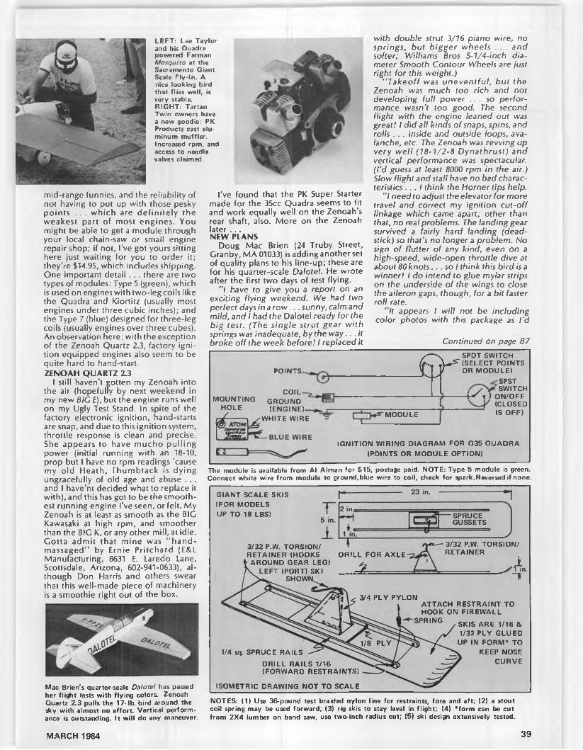
L E F T : Lee Taylor and his Quadra powered Farman Mosquito at the Sacramento Giant Scale Fly-In. A nice looking bird that flies well, is very stable.R IG H T: Tartan Tw in owners have a new goodie: PK Products cast aluminum muffler. Increased rpm, and access to needle valves claimed.
mid-range funnies, and the reliability of not having to put up with those pesky points . . . which are defin ite ly the weakest part of most engines. You might be able to get a module through your local chain-saw or small engine repair shop; if not. I've got yours sitting here just waiting for you to order it; they’re $14.95, which includes shipping. One important detail . .. there are two types of modules: Type 5 (green), which is used on engines with two-leg coils like the Quadra and Kiortitz (usually most engines under three cubic inches); and the Type 7 (blue) designed for three-leg coils (usually engines over three cubes). An observation here: with the exception of the Zenoah Quartz 2.3, factory ignition equipped engines also seem to be quite hard to hand-start.ZENOAH QUARTZ 2.3
I still haven’t gotten my Zenoah into the air (hopefully by next weekend in my new 8/C f), but the engine runs well on my Ugly Test Stand. In spite of the factory electronic ignition, hand-starts are snap, and due to this ignition system, throttle response is clean and precise. She appears to have mucho pulling power (initial running with an 18-10, prop but I have no rpm readings ’cause my old Heath, Thumbtack is dying ungracefully of old age and abuse . . . and I have'nt decided what to replace it with), and this has got to be the smoothest running engine I’ve seen, or felt. My Zenoah is at least as smooth as the BIG Kawasaki at high rpm, and smoother than the BIG K, or any other mill, at idle. Gotta admit that mine was "hand- massaged” by Ernie Pritchard (E&L Manufacturing, 8631 E. Laredo Lane, Scottsdale, Arizona, 602-941-0633), although Don Harris and others swear that this well-made piece of machinery is a smoothie right out of the box.
Mac Brian's quarter-scale Dalotel has passed her flight tests with flying colors. Zenoah Quartz Z 3 pulls the 1 7-lb. bird around the d<y with almost no effort. Vertical performance is outstanding. It will do any maneuver.
I’ve found that the PK Super Starter made for the 35cc Quadra seems to fit and work equally well on the Zenoah’s rear shaft, also. More on the Zenoah later . . .NEW PLANS
Doug Mac Brien (24 Truby Street, Granby, MA 01033) is adding another set of quality plans to his line-up; these are for his quarter-scale Dalotel. He wrote after the first two days of test flying.
" / have to give you a report on an exciting flying weekend. We had two perfect days in a row . . . sunny, calm and mild, and I had the Dalotel ready (or the big test. (The single strut gear with springs was inadequate, by the way.. .it broke off the week before! I replaced it
with double strut 3/76 piano wire, no springs, but bigger wheels . . . and softer; Williams Bros 5-1/4-inch diameter Smooth Contour Wheels are just right for this weight.)
" Takeoff was uneventful, but the Zenoah was much too rich and not developing full power . . . so performance wasn't too good. The second flight with the engine leaned out was great! I did all kinds of snaps, spins, and rolls . . . inside and outside loops, avalanche, etc. The Zenoah was revving up very well (18-Ί/2-8 Dynathrust) and vertical performance was spectacular. (I’d guess at least 8000 rpm in the air.) Slow flight and stall have no bad characteristics . . . I think the Horner tips help.
"I need to adjust the elevator for more travel and correct my ignition cut-off linkage which came apart; other than that, no real problems. The landing gear survived a fairly hard landing (dead- stick) so that's no longer a problem. No sign of flutter of any kind, even on a high-speed, wide-open throttle dive at about 80 knots.. .so I think this bird is a winner! I do intend to glue mylar strips on the underside of the wings to close the aileron gaps, though, for a bit (aster roll rate.
"It appears I will not be including color photos with this package as I ’d
Continued on page 87
P O IN TS θ ' *C O IL
M O U N T IN G G R O U N D H O L E (E N G IN E )—
W H IT E W IRE M O D U LE
SPD T SW ITCH (S E L E C T P O IN TS OR M O D U L E )
SPST SW ITCH
O N /O FF (C LO S ED IS O F F )
■W ,1 o,(C
IG N IT IO N W IR IN G D IA G R A M FOR Q35 Q U A D R A (P O IN TS OR M O D U L E O P TIO N )
The module is available from Al Alman for S15, postage paid. N O T E : Type 5 module is green. Connect white wire from module to ground,blue wire to coil, check for spark.Reversed if none.
G IA N T S C A LE SKIS (F O R M O D E LS UP T O 18 LBS)
3/32 P.W. TO R SIO N / R E T A IN E R (H O O K S
A R O U N D G EA R LE G ) (P O R T) SKI
SHOW N
D R IL L FO R A X L E
%
3/32 P.W. TO R S IO N / R E T A IN E R
11 in.τ
1/4 sq. SPRUCE R A ILS
D R IL L R A ILS 1/16 (F O R W A R D R E S TR A IN TS )
IS O M E TR IC D R A W IN G N O T T O S C A L E
3/4 P LY P Y LO NA T T A C H R E S T R A IN T T O H O O K O N F IR E W A L L
SPRING SK|S A R E 1/16 &
1/32 P LY G L U E D UP IN FOR M * T O
K EEP NOSE C U R V E
N O TE S : (1) Use 36-pound test braided nylon line for restraints, fore and aft; (2) a stout coil spring may be used forward; (3) rig skis to stay level in flight; (4) ’ form can be cut from 2X4 lumber on band saw, use two-inch radius cut; (5) ski design extensively tested.
MARCH 1984 39

'PRODUCTS IN USE---------------------------------------------------
f»C€ fi/C s DflTOMflBy ELOY MAREZ . . . Model Builder's "Electronics Corner" man shows us how he put together his own Datamaster and RF Interface using the Ace k it as the starting point. Modifications made to the stock units were kept to a minimum, and are not required. Get your gear in shape for summer!
• How would you like to have complete interchangeability between all of your servos, all having the exact same centering? How would you like all the channels in your transmitter, both main and trim controls, to also be at the some exact zero setting when they are mechanically centered?
If you fly more than one airplane with the same transmitter, how would you like to be able to take off each time with the correct, exact trim settings, and with the exact amount of travel required dialed into your low rate, and if you fly programmed maneuvers, with the exact amount of control surface deflection adjusted in . . . all before you take off. If this sounds like something you would like, read on, you need Ace R/C’s Datamaster and Datamaster RF Interface.
Even if you don’t fly different airplanes with one transmitter or have a fancy transmitter with all those buttons, the Datamster/lnterface can still simplify life for you. The present influx of inexpensive radios has been made possible by many things, one of them being the reduction of production and setup time by the manufacturers. As a result, some of the fine touches, such as transmitter channel to servo adjustment, and servo to servo adjustment, have suffered. I have personally tested one of these systems on which the difference between the servo with the greatest centering variation was as much as 50% of their travel. This is unacceptable, and is made more insulting by the fact that the system is advertised as having two servos which rotate in oposite directions so that the modeler can have interchangeability during installation. Without like centering, you have no interchangeability! These are m inor but frustrating discrepancies which can be corrected in half an hour with the help of a Datamaster and Interface. And you don’t have to be a Technician to do this . . . this digital instrument removes all of the mystery and reduces it down to simple mathematical and mechanical adjustments.
First, let’s review a bit. Your transmitter operates on a principle known as
40
The stock Ace Datamaster and RF Interface, both available in kit or assembled form.
The same unit above may be recased as you see here to incorporate internal power source and to blend in with existing equipment on your shelf. Unit on right uses thumb type switch.
pulse length modulation; the in te lligence being transmitted is contained in the length of an electronic pulse. This length is what you vary when you move a control stick or trim. Here in the U.S., the majority of our systems work on a one millisecond (1/1000th of a second) pulse, centered on 1.5 mS, with a plusor minus .5 mS variation for full throw. In other words, a 1.5mS pulse to the servo will cause it to center, and .5 mS or less will drive it to the end of its travel. Any percentage of the .5 mS will cause a corresponding percentage of travel in the servo.
The Datmaster, as first introduced by Ace R/C, is a device that plugs into the receiver’s output and digitally displays, in milliseconds, the pulse length and variation being generated within the transm itter. It also contains a servodriver, which you can set to the same values as those produced by the transmitter. You use this to center servos and to drive them during equipment installation in your models. While the Datamaster, as such, is an extremely valuable tool which can be used to correct all of the equipment deficiencies previously mentioned and to insure the correct transmitter to airplane control surface
relationships also mentioned, its use in the field is limited by having to unplug servos and plug it into the receiver.
The RF Interface remedies that; it consists of a wide band demodulator driving a receiver type decoder whose output’s are switch selected and fed to the Datamaster, all without any connections to the receiver. Only a simple, single, alligator clip connection to the transmitter antenna has to be made. Now we can more easily do all that trim and rate setting of the transmitter that we were talking about earlier.
Those of you who have previously purchased a Datamaster can simply aquire the RF Interface and marry the two, they are designed with that in mind. If you have just now been convinced, you can get both, either in kit form, or fully assembled and tested, from Ace R/C.
If you are joining a newRF Interfaceto an old Datamaster, brace yourself, it’s a terribly complicated job consisting of soldering three wires and mating the two cases with sticky tape. The instructions are simple and clear. . . which also describes the complete instructions for assembly from kits. They are one of the many things I enjoy about Ace R/C
MODEL BUILDER

STERRF INT€RFRC€
The Datamaster PC board consists mostly of ICs, with very few discrete components. Holes must be made as shown (*), No. 33 drill. 3/16 in. from edges.
The Interface board is even smaller and simpler. In the custom version, stick-on foam tape is used in mounting.
Diagram and photo of the new panel for the customized Datamaster and Interface. Note: dotted outline is made from 1/2-in. circles on 1-1/16 centers, then cut o u t Center cutout in panel for best appearance.All measurements in inches.
equipment, the others being that Ace designs are always modern and useful, and all of the components used are top quality. Don’t hesitate to go the kit route, even if your experience in electronics is minor. All that it really takes to build from an Ace kit is the ability to read and solder .. . and to own small soldering iron.
The detailed uses of the Datamaster and Interface are also explic itly explained in the instructions, and there is no need to repeat them here. I will only stress again that while this device is extremely useful to the R/C technician, the non-tech can also easily understand it and use it to great advantage.
Power to the Datamaster and Interface is any 4.8 to 6-volt source. When plugged into the receiver, the Datamaster draws its power requirements directly from the servo plug. When the Interface is used, without a connection
Continued on page 68
C H A R G ES O C K E T
Θ
O F F -C H A R G E /ON SW ITC H X
----- ASS------—33 Ohm,1/4 Watt ___
SPDT
Diagram of power and external-internal switch wiring. Resistor is omitted if receiver charger is to be used, see text, r e d W IRE All other wiring is stock. FROM 1C
B O A R D
LO N G S Y N C H PULSE
1 -2 MS
C H A N 1
4.8 VoltsX
L1
T O H O L E R IN D/M B O A R D
T O H O L E B IN D/M B O A R D W IRES T O O R IG IN A L H O L E S IN D/M B O A R D
E X T E R N A L -IN T E R N A L SW ITC H(B O T TO M V IE W )
1 -2 MS 1 -2 MS
- — " i r ------- H
C H A N 2 C H A N 3--------- E TC .
Simplified diagram of transmitted pulse train. The Datamaster/lnterface accurately measures the length of any pulse desired. Timing might vary slightly between different R/C system manufacturers.
MARCH 1984 41

By RAY HOSTETLER
CHOPPER CHATTER
• I was all set this morning to devote a column to my full-size helicopter flying that I did this past summer, but a number of other more pertinent things have come up that lead me to continue the series on trimming and training which has appeared in MB for the past few months.
The main impetusforthecontinuation comes from Andy Woitowicz of Timmins, Ontario, Canada. Andy and I have corresponded from time to time over the past year, as he was build ing a Competitor at about the same time as my review came out. His last letter included some nice photos of his modified tail rotor drive system and then some flying shots. Andy is a machinist by trade, so you can count on the workmanship in his Competitor being flawless.
At this point, Andy had a dozen flights on his Competitor, he was just getting it
dialed in and starting to feel confident in the whole system of helicopter, engine, and radio. As he hasn't done any forward flight yet, this was one of the main concerns in his letter. He writes:
"/ am still very much in the learning stages and have yet to experience forward flight. The prospect of forward flight is causing me some trepidation as I don’t really know what to expect. Particularly the transition from forward to hover. . .
"Getting back to forward flight for a moment, I wonder it if wouldn't be material for a future article. There may be a lot of people (loners) out there who have learned to hover quite nicely but are afraid to bite the bullet and go. If some sort of exercise could be practical, perhaps this would take some of the terror out of it . . . "
Thanks for your input, Andy. Hope to hear from you on your progress to for
ward flight in the near future. However, before I jump into the transition from hover to forward flight and return, I would like to include just a paragraph or two to pick up where I left off last month . . . on how to learn to hover once the ship has been trimmed out.HOVERING
Many, many words have been written on how to hold the beast over one spot. Personally, I feel there is very little you can read about. It's a matter of getting out and doing it through practice. There are only a few basic guidelines for the novice at this point:
1) Never let the helicopter get more than six inches off the ground. This will automatically give nice, short hops in the air, and should never result in a tip- over. It’s very easy to chop the throttle if it starts to get squirrelly . . . let the training gear keep it upright and absorb the touchdown. This means that you are concentrating mainly on throttle at the very first to keep the altitude low. It should only take a tankful or two to become completely at ease w ith the throttle.
This is also where ground effect really helps you out. Once the helicopter gets light on the skids, add just a touch more throttle, and it will automatically come up several inches off the ground. In all probability, it will bob up and down, scraping the ground here and there. No worry, it won’t hurt a thing. Once you find this spot you can almost forget about the throttle while you keep the helicopter over one spot with cyclic.
2) You can't learn to fly the cyclic and
Andy Woitowicz shows us how it's done . . . hovering, that is! Andy is fortunate to have such a beautiful flying site. Andy is ready for forward flight. See text
Andy Woitowicz's beautiful machine work is very evident in his Competitor's modified tail rotor drive system. The brass tube driveshaft is mated with a ball and pin universal joint.
New Robinson R-22 from California Model Imports. This model bears the paint scheme of the R-22 that the author soloed in a few years ago, N101WR. Watch for review of model next month.
Andy's Competitor in flight Note tube at front of skids . . . gives a touch of needed nose weight as well as providing extra lateral support on takeoffs and touchdowns.
42 MODEL BUILDER

Initial hovering practice: stand six to eight feet away from helicopter and off to one side.
Hovering practice which leads to forward flight. O nly very light wind allowed.
forget about the tail rotor, or vice-versa. The cyclic and tail rotor must be flown as a unit, because each affects the other. This was in earlier columns, but very quickly, when you give a tail rotor command, it changes the thrust of the tail rotor, which changes the translating tendency, which must be corrected with
Continued on page 89
The last 50 feet of the approach. Note how the angle of the fuselage to the ground decreases as the approach goes from 1 to 4.
MARCH 1984 43

I
You could call it a free flight, single rotor blade helicopter and you wouldn't be wrong. The Rotoriser is a model you should build when you are in the mood for something simple and exciting.• The Rotoriser is a free fligh t fun machine. It won’t win any contests, nor will it set any records, but you'll have more fun with it than you'll have with many other flying machines, simply because it’s easy to build, easy to launch and fly, and, by varying the trim tab on the stabilizer, you can get a wide variety of flight patterns.
The concept of the Rotoriser was developed orig inally by Charles W. McCutchen back in 1954. Various designs based on the concept have been published at times, principally in Euro-
ean magazines. The one which appears ere, with some minor modifications
which I have added, was designed by a young man in Florida. I saw the machine
in Vince Arias’ Hobby World, was intrigued, and figured that you would be equally fascinated by its flight capabilities.
The design concept is generally called the " McCutcheon Machine" after its inventor. However, I chose the name Rotoriser because, if you happen to get the .049 reed valve engine going backwards and try to fly it, you’ll soon find out that it's a “ Rotorooter." (Apologies to the sewer pipe cleaners, of course.) But you won’t do that .. . will you? CONSTRUCTING THE ROTORISER
Construction of the Rotoriser is so simple that you can build it in one evening and fly it the next day. So let’s make one.
First, assemble all of the various components in a convenient location near your workbench. The bill of materials lists what you will need.
Make the main rotor blade out of the piece of balsa which is 1/4x4x36 inches long. Shape the sheet into a flat-bottomed airfoil as shown in the full-size cross section on the plans.
Cut a slot in the center section of the main blade, 2-1/2x1-1/8.
Insert the end of the 1/4x1-1/8x20-1/2 inch hardwood motor arm into the slot on the main blade and glue it in place.
Reinforce this center section joint with a piece of 1/16x4x4-1/2 inch plywood, glued to the bottom. Then further strengthen it by covering that section
W hom p,Whomp,
WHOMP, WHOMP!
The Rotoriser gains rpm and altitude in a most unique way! Stand at a safe distance from this one, it's no toy!
ROTORISER BILL OF MATERIALS(All measurements in inches.)1/4x4x36 Balsa sheet (medium hard). 1/4x20-1/2x1-1/8 Hardwood (basswood, spruce or pine).1/4x24 Dowel.1/8x10x2 Blasa sheet (medium).3/16x12x1 Balsa sheet (medium).1/16x4x4-1/2 Plywood sheet.1/2x1-1/2x1-1/8 Hardwood. 2 pieces needed. 1/2-lnch wood screws. 4 needed.4-1/2x9 Piece of fiberglass cloth.Some epoxy, glue, and either strip lead or modeling clay for balance arm.
LAUNCH PADThree-foot stick.Three-inch nail.Wheel collar to fit nail, or washer to solder to nail.
44 MODEL BUILDER

Launching pad details. A nail with a wheel collar is taped to a three-foot broom handle.
Center section details. Note the rubber bands holding balance boom. No hole drilled y e t
Stabilizer is mounted on the end of the rotor blade. Trim tab is not yet cut out.
The business end showing the more difficult metal mount. Use a wooden mount!
with fiberglass cloth wrapped around it and resined in place.
Make the engine mount by gluing the 1/2x1-1/2x1-1/8 basswood blocks on the end of the motor arm. Shape them to the contour shown in the plans. (The photos show a metal mount, which is optional.
Con tinued on page 69

Editor's note: This is the third P & F& C T in an ongoing series which began with the August '83 and January '84 issues of Model Builder.
Conjectures, Prangs, Witch Doctors,and Thermals
• It is really raining pussy-cats an’ puppy dogs. My staunch co-workers are allegedly at work out in the hangar, but when I went out to check on the newest leaks that this rain has ferreted out they were crouched by the old potbelly (the stove, not me!) trading lies. Pausing, I overheard an interesting bit of conversation between these redoubted individuals. They often have some thought- provoking discussions, and I justify my eavesdropping by saying it improves my learning processes and pushes me up the learning scale a bit. Apparently, Chickums had just used the word “ conjecture” in a technical article he was writing for MB. Silli, often a very stuffy individual who likes to make much of little things, had taken exception to
Chickums' use of the word and asked him what he thought the word meant.
“ A conjecture is an assumption replied Chickums, craftily looking sideways at Silli. At Silli’s look of triumph, Chickums grinned, a shocking sight, for you know the stories about the lack of chicken’s teeth, and added, “ .. . based on scanty or conflicting data!” Silli, realizing he had been setup by Chickums, rallied in an admirable manner.
“ You know, of course,” he came back, “ that an archaic definition for the word was that it was the arrival to a conclusion based on omens. Actually, a better modern synonym for the word is guess.”
At this point they noticed my eavesdropping, and, giving me pointed looks, went back to their respective duties.
Feeling a little bit snubbed, I returned to the inner sanctum to mull over this bit of trivia.
The more I thought about what I heard in my eavesdropping, the more depressed I became. A great amount of model designs, choice of power and/or propellers, and adjustment of our creations to make them fly is by conjecture . . .and I can think of applications where the archaic definition that Silli offered really fits! The majority of present-day modelers don’t really understand why things happen the way they do. When something won’t work there is always someone handy to tell the unfortunate guy that he just built the wrong airplane, “ Buy a Super Shmoo and you won’t have this problem” . Many of tne modern kits will fly right off the board . . . providing they were built exactly per the instructions, were powered by the recommended engine, and were equipped with the proper hardware. Then the model will fly by itself.
I remember one model that normally flies like a dream and will make unusually tight circles dead-stick, a great feature for spot landings. This character's model would start into a turn, the opposite wing would drop as if it had been cut off, and the model would hook into the ground on opposite turn! After the local armchair experts had finished casting bones on the ground, and the last sand-pictures were completed, the guy still didn't know why his model would prang.
Examination showed everything was absolutely without warp and was true . . . too true, for the wings were without washout! The plans had even gone into detail on how much and where. When asked why he built it without washout, he said he had been told that he would lose lift, and he had his radio to make any flight corrections, anyway! The wing was designed w ith considerable d ihedral, and the outside wing, flying at a higher angle of attack because of the
46 MODEL BUILDER
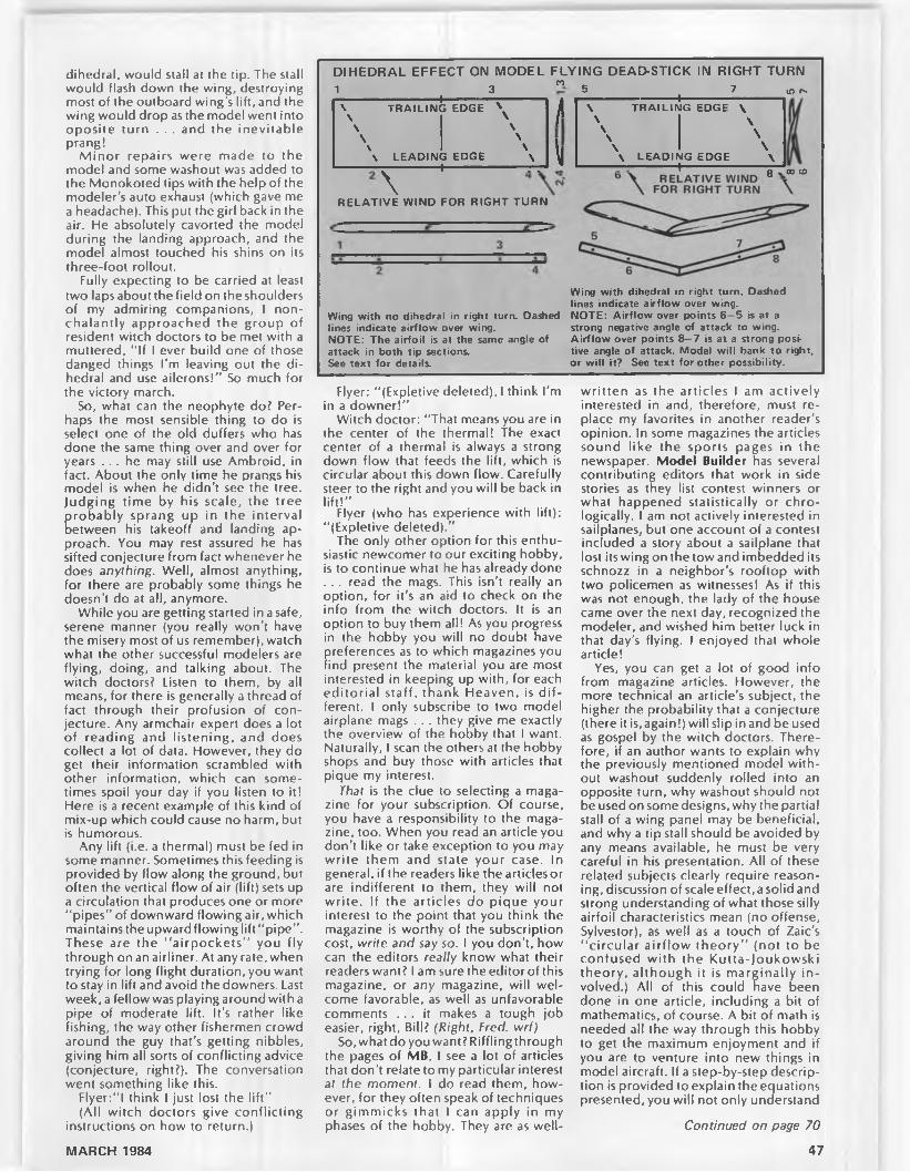
DIHEDRAL EFFECT ON MODEL FLYING DEAD-STICK IN RIGHT TURN1 3 " 5 7 m e-------------------------------------- '-------------------v----------------\ T R A IL IN G ED G E \ H
------------------------------------1\ T R A IL IN G ED G E \
\ \ / \ \\
\\
\\
\ \\ \ l \ \
\ L E A D IN G ED G E \ ------------ — T--------------------1------------------------------r - r 1 \J \ L E A D IN G E D G E \
------------- — ---------------- t ------------------------------r - 1
\g .03 ω
R E L A T IV E W IN D FOR R IG H T T U R N
Wing with no dihedral in right turn. Dashed lines indicate airflow over wing.N O T E : The airfoil is at the same angle of attack in both tip sections.See text for details.
Wing with dihedral in right turn. Dashed lines indicate airflow over wing.N O T E : Airflow over points 6— 5 is at a strong negative angle of attack to wing. Airflow over points 8— 7 is at a strong positive angle of attack. Model will bank to right, or will it? See text for other possibility.
dihedral, would stall at the tip. The stall would flash down the wing, destroying most of the outboard wing’s lift, and the wing would drop as the model went into oposite turn . . . and the inevitable prang!
M inor repairs were made to the model and some washout was added to the Monokoted tips with the help of the modeler’s auto exhaust (which gave me a headache). This put the girl back in the air. He absolutely cavorted the model during the landing approach, and the model almost touched his shins on its three-foot rollout.
Fully expecting to be carried at least two laps about the field on the shoulders of my admiring companions, I nonchalantly approached the group of resident witch doctors to be met with a muttered, “ If I ever build one of those danged things I'm leaving out the d ihedral and use ailerons!” So much for the victory march.
So, what can the neophyte do? Perhaps the most sensible thing to do is select one of the old duffers who has done the same thing over and over for years . . . he may still use Ambroid, in fact. About the only time he prangs his model is when he didn’t see the tree. Judging time by his scale, the tree
Crobably sprang up in the interval etween his takeoff and landing ap
proach. You may rest assured he has sifted conjecture from fact whenever he does anything. Well, almost anything, for there are probably some things he doesn’t do at all, anymore.
While you are getting started in a safe, serene manner (you really won’t have the misery most of us remember), watch what the other successful modelers are flying, doing, and talking about. The witch doctors? Listen to them, by all means, for there is generally a thread of fact through their profusion of conjecture. Any armchair expert does a lot of reading and listening, and does collect a lot of data. However, they do get their information scrambled with other information, which can sometimes spoil your day if you listen to it! Here is a recent example of this kind of mix-up which could cause no harm, but is humorous.
Any lift (i.e. a thermal) must be fed in some manner. Sometimes this feeding is provided by flow along the ground, but often the vertical flow of air (lift) sets up a circulation that produces one or more "pipes” of downward flowing air, which maintains the upward flowing lift "p ipe” . These are the “ airpockets” you fly through on an airliner. At any rate, when trying for long flight duration, you want to stay in lift and avoid the downers. Last week, a fellow was playing around with a pipe of moderate lift. It’s rather like fishing, the way other fishermen crowd around the guy that’s getting nibbles, giving him all sorts of conflicting advice (conjecture, right?). The conversation went something like this.
Flyer:"l think I just lost the lift”(All witch doctors give conflicting
instructions on how to return.)
Flyer: "(Expletive deleted), I think I’m in a downer!"
Witch doctor: "That means you are in the center of the thermal! The exact center of a thermal is always a strong down flow that feeds the lift, which is circular about this down flow. Carefully steer to the right and you will be back in lift!”
Flyer (who has experience with lift): "(Expletive deleted).’’
The only other option for this enthusiastic newcomer to our exciting hobby, is to continue what he has already done . .. read the mags. This isn't really an option, for it ’s an aid to check on the info from the witch doctors. It is an option to buy them all! As you progress in the hobby you will no doubt have preferences as to which magazines you find present the material you are most interested in keeping up with, for each editoria l staff, thank Heaven, is d ifferent. I only subscribe to two model airplane mags . .. they give me exactly the overview of the hobby that I want. Naturally, I scan the others at the hobby shops and buy those with articles that pique my interest.
That is the clue to selecting a magazine for your subscription. Of course, you have a responsibility to the magazine, too. When you read an article you don’t like or take exception to you may write them and state your case. In general, if the readers like the articlesor are indifferent to them, they will not write. If the articles do pique your interest to the point that you think the magazine is worthy of the subscription cost, write and say so. I you don’t, how can the editors really know what their readers want? I am sure the editor of this magazine, or any magazine, will welcome favorable, as well as unfavorable comments . . . it makes a tough job easier, right, Bill? (Right, Fred, wrf)
So, what do you want? Riffling through the pages of MB. I see a lot of articles that don’t relate to my particular interest af the moment. I do read them, however, for they often speak of techniques or gimmicks that I can apply in my phases of the hobby. They are as well-
w ritten as the articles I am actively interested in and, therefore, must replace my favorites in another reader’s opinion. In some magazines the articles sound like the sports pages in the newspaper. Model Builder has several contributing editors that work in side stories as they list contest winners or what happened statistically or chro- logically. I am not actively interested in sailplanes, but one account of a contest included a story about a sailplane that lost its wing on the tow and imbedded its schnozz in a neighbor’s rooftop with two policemen as witnesses! As if this was not enough, the lady of the house came over the next day, recognized the modeler, and wished him better luck in that day's flying. I enjoyed that whole article!
Yes, you can get a lot of good info from magazine articles. However, the more technical an article’s subject, the higher the probability that a conjecture (there it is,again!) will slip in and be used as gospel by the witch doctors. Therefore, if an author wants to explain why the previously mentioned model without washout suddenly rolled into an opposite turn, why washout should not be used on some designs, why the partial stall of a wing panel may be beneficial, and why a tip stall should be avoided by any means available, he must be very careful in his presentation. All of these related subjects clearly require reasoning, discussion of scale effect, a solid and strong understanding of what those silly airfoil characteristics mean (no offense, Sylvestor), as well as a touch of Zaic’s ‘ ‘circular airflow theory” (not to be confused with the Kutta-)oukowski theory, although it is marginally in volved.) All of this could have been done in one article, including a bit of mathematics, of course. A bit of math is needed all the way through this hobby to get the maximum enjoyment and if you are to venture into new things in model aircraft. If a step-by-step description is provided to explain the equations presented, you will not only understand
Continued on page 70
47MARCH 1984

By e l o y m a r e z
WIRE CONDUCTION PROBLEMSBack in the December 1983 issue, we
mentioned the problem of the voltage drop caused by the resistance found in the small wires common to R/Csystems. Said resistance increases with length, wuch as when the servos are installed out in the wings on large models, and long servo extensions are used. As I mentioned then, this is not an unrecognized problem amongst the R/C system and accessory manufacturers. Ralph Warner, of RAM (Radio Controlled Models, Inc.) has done a thorough study of the situation and reported his findings in a paper en titled : “ Warning, Big Models Require Big Wires.” Ralph tells it very well, so here is the unabridged, unedited version. Reed and heed!
"Have you had some unusual radio glitches as you maneuvered through various stunts? Are you suspicious that your servos are very sluggish when high loads are placed on them? Has your model crashed because it was unable to recover from a high air load maneuver?
"Radio and servo problems can be caused by the limited conducting ability of ‘standard’ 24 and 26-gauge hook up wire commonly used in our radio systems. Typical high power servos draw an amp or more at the start of their movement. Air loads from large surfaces, especially elevators, can easily double this amperage demand. Simultaneous servo operation places an additional load on the wires of the circuit. Distant servos automatically suffer current loss due to restriction through conducting wires. Current demand under air load
can be as high as eight amps."Our tests show the voltage available
through various gauges of quality, stranded hook up wire as shown below when using a standard 4.8 volt Ni-Cd pack and a two amp load in a servo circuit.Wire gauge
2624222018
1 foot4.64 volts 4.70 volts 4.73 volts4.76 volts4.77 volts
Length 3 feet4.37 volts 4.50 volts 4.61 volts 4.66 volts 4.73 volts
6 feet3.84 volts 4.20 volts 4.42 volts 4.54 volts 4.65 volts
"The conclusion is obvious. If you expect to get sufficient current through your system so that your servos will function as designed and voltage spikes won’t glitch your receiver, you must use at least 20-gauge wire throughout the system. This means that you need heavy wire starting at the cells in the receiver pack, heavy duty switch harness, and especially the wires going to distant servos. Don’t think that a high amp receiver pack will solve the probblem. Only sufficiently large wire is able to conduct the current to distant locations and/or supply high demand.
"If you feel that you haven’t suffered from any of the problems we described, don’t be misled. When your model is in that critica l, low level attitude that requires full servo power, that is the time your battery and wiring circuit won’t be able to deliver it.”TRANSMITTER NI-CD CONVERSION
I received a note from Tim Storey, St. Louis, Missouri, who writes:
"Though I have just recently gotten
my hands into Radio Control, I have ben reading your column in Model Builder fo r over a year. I have a couple of questions for you.
"I have two, two-channel radio systems. One is the Cox Sanwa two-channel, and the other is the Futaba FP-2CS. I immediately bought the airborne Ni- Cds for both, but neither of the respective companies offer a transmitter Ni-Cd conversion. I was wondering if there is any reason why I can't make up the battery packs myself? If I can, should they be 72-volt, or would 9.6 be enough? (Both use 12-volt alkaline battery packs.) If they should be 12-volt, how about a charger design?
" I’m pretty sure of the answers, but, to be on the safe side, I thought I better get some expert advice.”
I bet there are a lot of people out there with the same questions. Constantly changing alkalines is bothersome and costly.
Tim, you may be new to the hobby, but you are learning fast, such as to read MB and that Ni-Cds are definitely one of the things that lead to friendly skies! The subject is not new, having been covered before, though apparently before you developed the “ Electronics Corner’ ’ habit. Back in June '82, we heard from a reader whose Cox Sanwa Model 8020 transmitter was eating batteries, and he wrote in for some re lie f. A fter our answer, he did some testing on his own.
Continued on page 75
Five-cell, diode protected airborne battery pack suggested by Joe Utasi . . . pros and cons are discussed in the text.
Tw o ways, or means, to the same end . . . to power glow plugs from a twelve-volt DC source using 12-volt automotive light bulbs. The circuit on the left would use alligator clips to connect additional filaments, one on right would use Radio Shack D P D T switch, center O F F .
48 MODEL BUILDER


did start to push a little, flattening the wing didn't help enough but taking the wing off the car did. Everybody was interested in seeing how Associated’s latest handled . . . so after about 20 laps I let anybody that had experience with car racing run itforas long asthey liked. All I did was put more fuel in the tank every once in awhile. All enjoyed the car and were amazed at how forgiving it was with Brian Peterson getting in the most track time and also pushing the car around the fastest. With the rear tires worn down almost to the wheels, we finally pulled the RC500 off the track.
This marked the first time the RC500 was considered to be potentially a really fine race car. While I had won the Regionals that day with an Eagle in one of those races where taking any of the top three positions is a great achievement (at the end of the 100-lap main, Jerry Brower was one corner behind me, Zale Thompson was a corner behind him, and fourth place was within a lap), my car had been raced for a few months and was thoroughly dialed in, while the set up on the RC500 was little more than a guess that could surely be improved upon. (For example, a car that “ works” with no wing at all is off someplace, just as is one that requires a radically steep wing angle.)
Having seen all this, John was very anxious to race the RC500 at our last club race of the season. The car was left pretty much the same except for going back to one of Associated's GT Corvette bodies, resetting the ride height, plus dropping the gearing a little to 5.87:1.
Again we had a good day with the car, even though the finishing position wasn’t all that great. John had toadapt to a totally d ifferent transm itter (Kraft "staple-gun” ), and his style of pan car driving quite frankly did not suit the RC500 with its suspension chassis. He was used to a slightly pushy pan car which had decidedly weak brakes and not much motor. Trying to race the 500 with tactics that had proven successful with his old car just didn’t work too well. He would get down the straight quicker than his pan car, he would jump on the brakes, and the 500 would damn near stop dead, still short of the turn-in point for the next corner. With the car coasting to his usual turn-in mark, he would turn, but where his pan car would
After many hours of hard racing, the only signs of wear are the heads of the screws of the chassis. Black lower A arms allow the rear tires to wear flat.
push around the corner the 500 would just turn, usually right into the boards. Still, with all of the timing problems and everything else, he did qualify faster than he had ever before, and he was running high in the B Main when the bearings in the clutch grenaded.
This was our first out-and-out failure of any part on the car, but it was a biggie in that it ended our racing for the day. And it was somewhat expensive. The bearing set for the clutch sells for $28; if you count the one set that popped, another to replace it, and another set for a spare . . . any racer knows that if a part breaks once it is likely to do so again, and so he carries spares . . . it all adds up to $84!
As these clutch bearings are the only parts of the RC500 where we have had consistent breakage, it is only fair at this point to completely address the situation. While we have had several failures here, we have always caught it in time to save the day of racing (except for the first time, obviously). And thanks to Associated’s generosity, coupled with our desire to keep the DRT campaigning an RC500, the situation has not cost us any money.RC500 CLUTCH BELL MODS
You privateers better listen up! First, very carefully balance the clutch bell. There is only one balance I know of that is sensitive enough for this job, it is available from High-Point Products, and I have used one for years to balance airplane props. (Many of the better shops stock this balancer, try them first, or write to High-Point Products, 3013 Mary Kay Lane, Glenview, Illino is 60025; phone number (312) 272-8684.) It is very rare for me to include manufacturer’s addresses in this column, I figure they ought to be buying an ad to get the message out, but I wouldn’t trust any other balancer for this job . . . Get one.
Even with the trick balancer,you must do the job very ca re fu lly . I would strongly suggest that you contact your area’s best R/C boater for help. These guys are constantly balancing small- diameter boat props, sometimes even doing three-blade props which are particularly difficult. Associated offers no less than three clutch bells (!): stock, ventilated, and racing. We are using the racing version, although the ventilated number is OK. With the latter, do the required grinding on the exterior of the bell in the area where the slots have
The square-head K&B .21 has been tremendously reliable, and it is fresh enough to go another season. Excellent power, attractive pricing, reliability, parts availability, all are what makes this engine top choice for many.
been machined. All work is done very carefully, constantly rechecking balance. Even when we think we’re done, it is checked several more times. Hey, this thing spins at engine rpm in an event where a motor that turns “ only" 25,000 rpm on the straight is a real dog, and, as if that weren't enough, the slipping action of the teflon clutch shoes in the bell generates plenty of heat.
With the balancing act taken care of, just a little extra effort seems to ensure extended life from the bearings. Whenever you do a complete cleaning of the chassis, most especially if you use any kind of solvent or degreaser, pull the clutch bell off the flywheel to avoid trashing the lube in the bearing. I will admit here that we frequently clean our race cars, and while we are always careful with the degreaser, I suspect that we inadvertently were the cause of at least some of our troubles w ith the clutch. For what it's worth, the bearings in the clutch at the present time have five full races on them with no sign whatsoever of problems. A number of racers that I have talked to likewise report no problems in this area.
Back to our particular RC500, the previously mentioned race was the last of the season, so the car sat for a few months. While I am not sure of the various changes made over the winter, I believe we started the '83 season with Associated’s new shocks installed, a lightweight diff assembly, and the new high-mount, ball-link front, anti-roll bar. The club had switched to Can-Am racing, and Associated’s Porsche 30KL body was an obvious choice.
My boy Joshua was still in semi-retirement (the interests of 12 year olds can fluctuate somewhat!), so the RC500 was still a loaner. Dan Rome was interested in trying 1/8, having raced 1/12 previously, and he loved the car so much that by the next club race he had his own Associated 1/8 car. Dan made the B Main easily enough but took a couple of very hard shots to the rear, literally breaking the new shocks right off the car. I was worried about this at first, but further experience showed this to be nothing more than a freak happening. Incidentally, we were still running the rear shocks in the center of the chassis
Continued on page 72
The part to note here is the outboard shock mount kit which results in yet another big improvement in the handling of the RC500. Black plate is fiberglass, fits perfectly, is light and very tough.
MARCH 1984 53

R/C POWER BOATS
The author reviews the Aeromarine Laminates Challenger this month. The Challenger, seen here, features a scale deck and back hatch cover. K&B's new .67 Marine engine powers it.
By JERRY DUNLAP• This month’s column is actually somewhat of a continuation of my efforts last month. Most of last m on th ’s “ R/C Power Boats” was devoted to a review of the new K&B Manufacturing .67Marine. The actual review was provided by a friend who installed the K&B .67 Marine in his R/C Unlimited scale hydroplane. Since that article was submitted, I have had the oportunity to install the engine in a boat of my own and do a little running.
Actually, the boat isn’t my own design, it is the “ Challenger" Deep Vee 65 from Aeromarine Laminates, 77 Cedar St., Babylon, New York 11702. I originally contacted Aeromarine Laminates in the hope of testing their offshore tunnel boat. (You regular readers know my bias for that type of hull.) It turned out that the folks at Aeromarine Laminates had already provided a tunnel to another magazine for a review. I was asked if I’d consider doing something with their .65- size deep vee called the Challenger. As my next favorite type of hull after tunnels is vees, I gladly accepted the oportunity. I now had a boat to install that new K&B .67 Marine into and try my hand at “ big bore" model boating.
The Challenger is a scale model of a full-size deep vee that is built by an east coast boat firm. The folks at Aeromarine Laminates told me the name of the company, but I cannot remember that name just now. It’s not all that important anyway.
That the Challenger is scale looking is rather important to me as I prefer running boats that look like something which might actually exist.
After having raced 30-inch, .21-size deep vees for a number of years, it was somewhat of a shock to pull a 43.5-inch vee out of the shipping box and plop it on the workbench. I’m talking about a boat that is substantially larger thanwhat I’ve grown accustomed to running. The Challenger I received has a rich, dark red gel coated hull. I have no plans to paint this hull. The boat is constructed of fiberglass and polyester resin. The quality of the hull lay-up is excellent. A feature that I greatly appreciate is the prejoined hull and deck. I was also pleased to find that the plywood motor mount stringers were glassed into the hull.
Included with the hull was the Aeromarine Laminates radio box. This radio box is of fiberglass construction with a plexiglass lid. The box is designed for a large size boat. I elected to use my C&M Models radio box as I already had my radio equipment in that box. (The cost of this radio box is $19.95, not including seals or push rods.)
I was somewhat surprised to learn that no instructions were available for setting up the Challenger. At first I thought I’d
simply thrown the instructions away when I got rid of the shipping box. I later found out that Aeromarine Laminates was so busy making model boats they hadn’t gotten around to making instructions. For anyone who has ever installed hardware in a model deep vee, lack of instructions isn't all that big a deal. However, for the person rigging his first model boat, it’s rather nice to have something to refer to. I was informed that instructions would be available soon.
It is possible to obtain a hardware kit from Aeromarine Laminates for the Challenger. The hardware is selected for optimum performance, and much of it comes from Octura Models. The following items are provided in the hardware kit: motor mount, propeller, tail nut, drive dog, thrust bearing, shaft tube, shaft, universal joint, trim tabs, water outlet, tubing for water and fuel, engine mounting bolts, fuel tank, fuel filter, R/C links, starter belt, tuned pipe support material, bru-line waterproof seals, and strudder with bearings. That’s a pretty complete hardware kit. I don’t have a price for this hardware kit. Unless you have access to a good hobby shop, I'd suggest buying the hardware package. The hardware package can be ordered as either conventional drive or surface drive. I’d suggest you contact them directly for further information.
After saying all that about the hardware package they offer, let me tell you what I did in the way of hardware for my Challenger. Charlie Pottol, owner of Marine Specialities, Box 588, Saratoga, CA 95070, agreed to provide the necessary hardware after some long distance arm twisting. Actuallly, I’ve never had to twist Charlie’s arm to get hardware for use in my boating reviews, and his support through the years has been greatly appreciated. The items provided by Marine Specialities were the outdrive assembly with safety shear rudder, shaft
log, flex-shaft, prop nut, and quick switch motor mount. Mount Specilities has a guarantee that most model boaters don’t know about. If you break any Marine Specialities product they will replace the broken part free. Simply send the broken part back to Marine Specialities and a new replacement part will be sent to you. I don’t know of any other marine manufacturer making a similar guarantee.
I elected to position my prop below the bottom of the boat rather than atempting to set up a surface effect drive system. I have seen some successful surface drive models, but just didn’t feel all that comfortable attempting surface drive on this boat. The folks at Aeromarine Laminates have a Challenger setup w ith surface drive. A boating friend who has seen it run reported that it really hauled around the pond. The Aeromarine Laminates folks told me the same thing, but sometimes manufacturers have a way of saying things about their products that make you a little doubtful. However, I have a great amount of respect for the individual who told me how well the Challenger worked with the surface drive application.
I have my Marine Specialities Adjustable Strut set so that the centerline of the strut housing is 3/4 of an inch below the bottom of the vee. This setting still allows for partial surfacing of the prop. I am still experimenting with positivenegative settings of the strut in terms of affecting the ride atitude of the boat. The Challenger is definitely responsive to changes in the strut angle. I’ll discuss this in greater detail later in the review.
Installation of the hardware was simply a matter of drilling the necessary holes in the hull’s transom and bottom to accept the outdrive assembly and shaft log. To determine where on the transom you should mount the outdrive assembly, position the adjustable strut to
54 MODEL BUILDER

where it has equal travel up and down while positioned on the outdrive assembly. Place the outdrive assembly against the transom and position it so the center line of the strut is at a location you'd like to try. I would recommend the 3/4-inch setting. Then, simply use the mounting holes in the outdrive assembly as guides for drilling the holes for the outdrive mounting bolts.
Check your work to make sure the strut does not slant left or right when viewed from the transom. Because the transom on the Challenger is slightly angled, I slipped some shim material under the bottom part of the outdrive to allow the strut to be adjusted from a neutral position in relationship to the bottom of the hull. Without the shims, the outdrive assembly was slanted, and adjustment of the strut was not sufficient to provide any strut angle “ kickout.” Shimming the outdrive assembly a llowed for any needed kickout.
Before telling you how you can locate the place to drill the hole in the bottom for the shaft log. I’ll give you the location that I used. A point eight inches from the transom works quite well as a beginning spot to drill the hole for the shaft log. Here’s how I detemined that spot.
The Marine Specialities Multi Mount was bo lted to the m otor mount stringers and the K&B .67 Marine bolted to the motor mount. I then poitioned the motor mount so that the motor was angled toward the bottom of the hull. Some model boaters like to mount the motor parallel with the bottom and then use an S-bend shaft log. I prefer to angle the motor to allow the motor and shaft to couple in a straight line. It seems to me that the less bends a drive cable has to make, the better off you are. With the engine angled towards the bottom of the boat, it is fairly easy to determine the line that is exteded from the shaft of the motor to where this line would intersect
A B O V E : Challenger on Full Command boat stand. R IG H T : Challenger rides as if "glued down". B ELO W : Stern view shows film can muffler, Mach E n t trim tabs, Octura X-455 prop. L E F T : Top view of assorted hardware.
the bottom of the hull. A piece of dowel that fits into the flexshaft coupler can be used to extend the line down to the hull, to the motor mouni. I then positioned
The best tool I have found for working in the hole for theshaft log is a round file that is about 1/8-inch round at the tip and then progresses to about 3/8 towards the middle of the file. I try to avoid removing any more of the hull than necessary to allow the shaft log to line up between the strut and the engine coupler. I have found that auto body putty works great as a method of gluing the brass shaft log to the hull. The material can be worked down around the shaft log and hole in the hull. It bonds very well to fiberglass.
To mount my radio box and fuel tank in iheC hallenger, I made p lywood hatches that were mounted inside the motor mount stringers. Quarter square stringer material was used to make a framework to keep the radio box and fuel tank in place. Small brass cup hooks screwed into the framework are used as tie downs for rubberbands over the radio box and fuel tank. I am using a 16- ounce Sullivan rectangular tank. These bigger motors definitely suck up more fuel than my .21s.
As can be seen in the photos of the engine and radio compartments, all the linkages and plumbing are fairly simple. One nice thing about a boat this size is there’s lots of room for all the systems. I like to use brass tubing inside the hull to carry water from the water pickup to the motor. I feel this makes for a cleaner installation than running fuel tubing the full length of the hull. Brass tubing of 1/8-inch inside diameter is adequate to provide sufficient water for cooling.
The last piece of hardware I'd like to mention is the trim plates. A few issues back I mentioned the trim plates which are available from Mach Enterprises, 415 West Manchester Blvd., No. 203, Inglewood, CA 90301. At that time I had the
trim plates but no boat to use them on. The arrival of IheChallenger took care of that. The “ B” & "CC” size Mach Enterprises Trim Tabs seem to be perfect for this boat. These trim tabs measure four inches in width, 1-5/8 inches in length, and are 1-5/8 inches in height. (See photo.) Threaded rods on each end of the tab allow for precise adjustments. The $19.95 price of these units is most reasonable. Mach Enterprises is also offering two other sizes of these stainless steel trim tabs. One can be used for “ A” inboards, and the other is intended for use with "A ” and “ B" outboards.
Before getting on with the running of the Challenger, I ’d like to emphasize the importance of proper tightening of all hardware and engine parts. All model boats take a severe amount of pounding while being operated. The vibration produced by our model engines will loosen things that you thought would never come apart. To put lock washers on all bolts is a good idea. (Pacer Tech’s Zap Lock should also work, wrf) Constant checking of bolts and screws can catch potential problems and help avoid parts coming apart. Having parts fall off in the middle of a race can be embarrassing, not to m ention dow nrigh t frustrating.
Here’s another suggestion. Pack some type of flo ta tion under the forward deck. Fiberglass boats will sink!THE CHALLENGER IN ACTION
The first time we took the Challenger out for test running, the experience was less than rewarding. It was that time of the year when the leaves decided to try floating along the edge of the pond. It was virturally impossible to launch the boat without snagging leaves all around the rudder. On top of this problem, I didn’t have the correct prop. To top everything off, I was using only a Steve Muck 11 c.c. pipe, and the noise level
Continued on page 92
MARCH 1984 55

"The more things you have to do, the slower you seem to move.
• This month's lead-in line, from Satch Carlson, seems most appropriate at year’s end, when this column is being assembled. You’ll note "assembled” , rather than w ritten.. . the readers do most of work . .. and we want to again thank you, our contributors, as well as the entire staff of Model Builder for another year of enthusiastic support. It is a genuine pleasure to be part of this hob by/sport.
As )ohn Blagg, of England put it: "I have come to realize that we enjoy a wonderful hobby; it is not the magnificent models, it is the people that really matter. I have found such a wealth of warmth, friendship, and over the last couple of years, help and comfort from my fellow modellers.’ ’HAPPY BIRTHDAY CHARLIE
Charles Hampson Grant recently celebrated his 89th birthday, by announcing that he soon expects to release an updated reprint of his classic
Carmen Ennis poses with Siegfried Glockner F R E D (from M B plans) during the West Baden Peanut Gran Prix. Photo by Scott.
Model Airplane Design and Theory of Flight book. And Charlie, who has been happily married for 65 years, offers this toast to the women’s liberation movement: "Here’s to the ladies; once our superiors, but now our equals!” SUPPORT YOUR LOCAL LIBRARY
Dave Gibson suggests an ideal way to help perpetuate our favorite pastime; donate some model building books: "I get a real kick out of the 'rack rats’ at the library; those kids who search through the racks until they find something that interests them. Then they just plunk themselves down on the floor or the step-stools and start reading. They get so engrossed, they don’t even know that people are climbing around or stepping over them. All you ever hear is ‘hmm’, ‘gee’, or 'wow', as they discover something new."
Or, how about donating a subscription to Model Builder? What better way to encourage the juniors to share our
/ ·
The first in a long line of Stringless Wonder designs by Bill Hannan, was flown in Palo· mar College kite contest in 1970.
Smiling George Perryman holds his "non- successful" autogyro. See details in the article. Photo by Frank Scott.
rewards and satisfactions?AND SPEAKING OF KIDS
Ray Crowell, resident master modeler of the San Diego Aero-Space Museum, says: "I think youngsters visiting our museum for the first time feel they are seeing dinosaurs w ith propellers on their noses."LEAKY WINGS?
Paul Mcllrath, noticed the November “ Hangar" column mention of full-size aircraft experiments with tiny perforations in wing surfaces aimed at improving efficiency, and was reminded of Burr Stanton's very successful Bostonian models: "The ships were made entirely of very thin foam cut from super-light packing material. The single-surface wings were so thin that they had numerous fair-size holes dear through."
Burr said that several helpful experts had informed him that an airplane couldn’t fly with leaky wings like that. Apparently Mother Nature hasn’t read the text books, because the models not only flew, but turned in times that were competitive with Bostonians built in the approved manner. Another triumph for the text books!?FUN FLYERS FORMING
A new organization is now being organized, devoted to,and called,"FUN
Shigemitsu Kashihara, Japan, constructed this rubber powered, push-pull, flying wing floatplane. White Monster. I. Yamada pic.
56 MODEL BUILDER

Daniel Walton's Dyke Delta, constructed from M B plans, placed first by proxy in the 1983 Northrop Flying Wing Contest.
Junior Marcelo Battagion winds his Grapenut Caudron, constructed from M B plans. Scene is Argentinian indoor contest. Note Fike!
FLYERS” . Its objective is to promote building and flying of models on a noncompetitive basis. Member benefits will include:
1. Having Fun with Model Airplanes, a book covering, from the ground up, the basics of constructing and flying models. Recommended are specific tools, materials, glues, and accessories. Featured are full-size plan projects for
S;liders, rubber and gas power free lights, control liners, and R/C types.
The accent is on simple, yet realistic flyers suitable for small sites.
2. The Fun Flyer, a quarterly magazine devoted to construction projects for all sorts of models from solid display through classic scale varieties.
3. Kits fo r the above mentioned models, packaged in "p la in brown wrappers” for maximum economy.
4. Liability insurance for all members, up to $5,000,000 coverage.
5. Local and regional fun flys of the low-pressure variety, rather than competitions. Instead of trophies, imprinted T-shirts and mementoes will be presented to ALL participants.
6. In s tru c t io n a l p rog ram s to introduce modeling to youth groups and schools.
7. A nationwide campaign to demonstrate that modeling is tne greatest spare time activity ever developed! Everyone can have fun modeling, regardless of age, status, or location.
Membership cost is estimated at $21 per year. Interested? More information is available from: FUN FLYERS,P.O. Box 95, Volant, Pennsylvania 16156.
P.S. "V o lan t” means " f ly in g ” in French.BRACE YOURSELF
Ced Galloway tells of seeing a collection of antique and homebuilt aircraft: "As you know, many biplanes have a wooden dowel or rod across the intersection of the flying and landing wires between the wings. One Great Lakes bipe we noticed had a pencil taped to the end of the rod, and someone said, Ί wonder why he has that pencil taped on there?’ Back came the reply. O h , that’s because he is a sky-writer!’ ” Oh well. . . WIN SOME, LOSE SOME
Every model builder has an off day
now and then, even the most talented. For exampled, George Perryman, certainly one of the most successful competitors around, has this to say about his model autogyro shown in one of our photos: “ I think it must be among the worst attempts I’ve ever had at making something fly. The basic model design was my Super Maxer, as built by my granddaughter Stephanie several years ago. It flies great without the rotor, which was an attempt to build something quick and light. The rotor weighed only .35 ounce, covered on both sides; it spans 12-1/2 inches, with a chord of eight inches, to exceed the Super Maxer's 99 square-inch wing area." (In conformance w ith A M A ’s autogyro rules which allow fixed wings equal in area to the "vanes", wch) "I entered 14 events at the Nationals, and all the models were ready and tested except this autogyro. Didn’t get to try it until the morning of the event, and could never get the rotor to turn in flight, even with 15 degrees twist in the panels. I tried
Continued on page 78
The final Stringless Wonder as flown at the 1982 Northrop Flying Wing Contest. Design was banned from 1983 event (see story in article). C 0 2 powered Farman Moustique is also retired now.
Three Peanuts by Lubimir Koutny, of Czechoslovakia. The models (left to right) and their indoor durations are: R .V . Ill (132); Nieuport monoplane (76); Aero A-35 (65).
MARCH 1984 57

MODEL BUILDER
Ρ/
ΛΠ
Λ
/η
· 3
A4
··?

HANG-ΤΗ Β λBy EARL SCHICK . . . Here is a state-of-the-art Coupe d'Hiver F/F model for your enjoyment. It features a rolled balsa fuselage (the article explains "how to "), auto-rudder, and a very good technique for making propellers. Read this article even if you think you'll never build a Hang In There!• What you see on the page to the right is a plan for a Coupe d’ Hiver. I call it H.I.T., or Hang-ln-There. I think it is quite good, and that it has proved itself over the last nine years. It placed second in 1979, and first in 1981 at the Canadian Nationals. I believe it has placed first, second, or third all the years it has been flown at our Slate Contests. It has also placed first three times at our Detroit Balsa Bugs Coupe Contest which is quite hotly contested.
Its appearance is a little different than most Coupes, and it may be a little more difficult to construct, but anyone who builds one will, I think, be satisfied with the extra effort. The auto rudder is a definite advantage in that it is easy to trim, and gives you a choice of the best power and glide pattern for any particular day.
Well, on with the construction article. I am not going to go over the entire airplane in this article, only the items I think may need a little explanation. FUSELAGE
Many people shy away from rolled balsa type fuselages because they think they are difficult to build . . . actually, they are quite simple. Let’s start with the motor tube because it is straight (no taper like the tail boom).
The selection of wood is the first step, and probably the most important. What we are looking for is a piece of straight, A grain, medium weight balsa, four inches wide, 1/16 thick, with no hardspotsin it. Hold the sheet between yourself and a strong light and look at it. The intensity of light coming through it should be almost the same across the whole sheet.
The next step is to cut the sheet to length and width. The sheet for the motor tube can be cut a little longer than needed, but the width must be correct. Cut a piece of balsa from a scrap sheet of 1/16 balsa. 1/4 to 3/8 of an inch wide
The author poses with his Hang-ln-
There Coupe d'Hiver, an
excellent flier and beautiful
model.
across the grain, wet it slightly,and wrap it around the 3/4-inch pipe or 1-1/8- inch dowel which you are going to use as a form. Cut it to length so that the edges just butt. Add 1/32 to this length, and that is the width of the sheet.
Dope one side of the sheet with three coats of unthinned clear dope, sanding between coats, and let it dry overnight. You will notice that the sheet is starting to cu rl. . . that is just what we want it to do.
Next, get your piece of pipe or dowel ready. Draw a line lengthwise down the center of the pipe. Cover the pipe with a couple of layers of Saran Wrap, or other plastic wrap. This is what the extra 1/32 of an inch was for.
Cut or tear some strips of bed sheeting in two inch widths, six or seven feet long, this is for wrapping the balsa tightly against the pipe form. Clamp the pipe in a vice with the line showing on the top, and then go and soak the balsa in some warm water for 10 or 15 minutes. The balsa sheet by this time has almost formed a half circle, so half the work is done. Tie the bed sheeting to one end of the pipe, lay the balsa sheet on the pipe and line up both edges of it with the line on the pipe. Start wrapping the bed sheeting around the balsa watching to see that the edges of the balsa and the line remain lined up. Finish by tying the bed sheeting at the end.
You can let this set for 24 hours, or put it in an oven at 325 degrees for about 20 minutes to dry. Take the wrapping off and glue the seam with ambroid or titebond. Bind the seam closed with some 1/4-inch rubber, do not wrap too tightly, just enough to keep the seam closed. Remove the rubber, sand it smooth, and give it a couple of coats of clear dope while it's still on the form.
Cover with japanese tissue and a couple of coats of clear dope. Take it off the form, and install the auto rudder tubing, gluing it in place with epoxy.
Make the plywood doublers in a similar manner as the motor tube (except on a smaller form), and instead of wrapping it with bed sheeting, use 1/4- inch. flat rubber, staggering the seams. Cut a keyway in the front one, and epoxy it in place keeping it centered on the seam of the motor tube.
Lay out the 1/4-inch hole for the rear motor hook, and drill with a sharpened piece of brass tubing by twisting it back and forth. Slip the plywood doubler into the motor tube and mark it for drilling. Drill a hole slightly smaller than the 1/4- inch hole, and file and fit so that the double holes are lined up with the holes in the motor tube and have a slightly snug fit. Glue it in place, and that’s it for the motor tube.
Continued on page 66
MARCH 1984 59
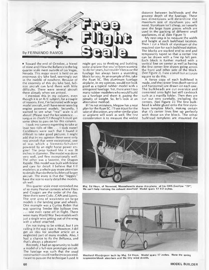
By FERNANDO RAMOS
i*
• Toward the end of October, a friend of mine and I flew the Ballanca to the big quarter scale meet outside of Las Vegas, Nevada. This major event is held on an enormous dry lake bed, seemingly out in the middle of nowhere. Because of the enormity of this dry lake bed, full- size aircraft can land there with little difficulty. There were several aircraft there already when we arrived.
I mention this in my column, even though it is an R/C subject, for a couple of reasons. First, I’m facinated with large model aircraft, and I have never seen big engine powered models. Secondly, I wanted to see what "real” scale is all about! (Please read the last sentence . . . tongue in cheek!!) I thought I could get some ideas to pass on for this column.
I took my camera expecting to take at least two rolls of film . . . I took none! Conditions were such that I found it difficult to take good pictures. I might add that in my opinion there were only two aircraft that were exceptional, one of was which a Siemens-Schukert powered by an eight horse power engine! The prop looked like it was 30 inches in diameter. The model was done very well, and flew exceptionally well. The other was a favorite, the Dragon Rapide. This model was built with finese and care for detail. I believe that F/F modelers as a whole pay more attention to details than do these builders of larger aircraft. The irony is that the "biggies" have the size to easily detail the models, oh well.
might get you to thinking and building some airplane that you’ve been wanting to do for years, but couldn’t because the fuselage has always been a stumbling block for you. As an example of this, take the Ryan SC. This aluminum fuselage airplane, in my opinion, would not look good as a typical rubber model with a stringered fuselage. Yet, there aren’t too many rubber modelers who would build up a fuselage and sheet it, paying the penalty of weight. So, let’s look at an alternative method.
If I’m not mistaken, Megow has a neat plan for the Ryan SC. I’ll use it just for the sake of discussion, any other similar plan or airplane will work as well. The first consideration is to measure the widest
distance between bulkheads and the greatest depth of the fuselage. These two dimensions w ill determ ine the maximum size of styrofoam you will need. Styrofoam isn’t cheap, so I usually save the large foam pieces which are used in the packing of different small appliances, et al. (See Figure 1)
My next step is to measure the width and height at each buldhead location. Then I cut a block of styrofoam of the required size for each bulkhead station. The blocks are stacked end to end and temporarily taped so that a center line can be drawn with a fine tip felt pen. Each block is further marked with a vertical line on center as well as having the first center line drawn going across the front and other side of the block. (See Figure 2). I use a small but accurate square to do this.
A Xerox copy of each bulkhead is made, and the center lines (both vertical and horizontal) are drawn on each one. The bulkheads are cut oversize and cemented onto light but stiff cardstock such as a manilla folder. Then they are cut out very carefully, including the centers. (See Figure 2.) The first bulkhead is white glued onto the first styrofoam template block, making certain that it’s center lines line up perfectly w ith those on the block. The other bulkhead templates are mounted the
This quarter scale meet reminded me of so many Peanut contests where Fikes and Cougars are the order of the day. Here there were Cubs, CAPs and Lazers. The one area of weakness on large models is the landing gear and wheels. One example was a Curtiss Robin that was sporting Trexler like balloon tires . . . one even came off in flight. There were many World War Two models with just a single wire jutting out of the wing with a wheel attached.
I’m not trying to be critical, but I am calling it the way I saw it. However, I did get an idea for another article on a neglected part of many models. Also, I had a chance to fly the Bellanca, and that’s always a pleasure!
Recently, I had an oportunity to build a model of a full-size prototype aircraft. The fuselage was such that the usual construction could not be incorporated. I want to pass on the technique I used. It
Maj. Ed Heyn, of Norwood, Massachusetts shares this photo of his 0 X 5 Swallow "TP ". We can't help noticing the exhaust manifold! Model spans 17-1/2 inches.
Westland Woodpigeon built by Maj. Ed Heyn. Model spans 17 inches. Note the spring suspension/shock absorbers and the tiny wind shields.
60 MODEL BUILDER

The author's method of obtaining a molded balsa fuselage. Styrofoam blocks are carved to shape, covered with balsa, melted out.
same way.The next step is to white glue each
styrofoam block to each other, again keeping the center lines perfectly in line. Care has to be taken, because the blocks, aided by the glue, tend to slide around. You may prefer to simply glue one block to one other and wait until the glue sets up before going on.
By now, you should have a good idea of what's going on. When the whole assembly is thoroughly dry, carefully carve away the foam, followed by sanding to the edge of each bulkhead template. You’ll be able to see the edge of each one easily enough, so you don’t have to worry about over sanding. At this point you can see a slick fuselage emerge. Any irregularities can be sanded smooth for a nice, flowing line.
Depending on the size of the fuselage, pick out some 1/16 thick, quality contest balsa, wide enough to cover half the fuselage,then soak it in ammonia water. Remove any excess H20, and place it evenly on the styrofoam fuselage halfline and tightly wrap it using masking tape. You’ll be amazed at how easily the balsa wraps around. If there are some really unusual compound curves, the balsa will bend easily. If the curves are such that the balsa won’t cooperate, make a cut where it tends to "bubble” up. The balsa will then overlap here. For now, just leave it alone.
When this side has dried out thoroughly, trim the balsa roughly. That is, leave it oversize, then remove it from the styrofoam mold, and repeat with the other side. When the second side has
A D D < " B A L S A
dried, place the first balsa side back on the form. Let one side overlap the other. Tape the two sides in a couple of areas so they can’t move. With a straightedge placed on the top of the model, carefully cut through both layers of balsa. Do the same with the bottom. You should now have two seams that line up pretty well. Maybe a bit of sanding will make for yet a better fit. When you are satisfied with the fit, epoxy the two halves together, and wrap tightly again with masking tape. Use only an epoxy on this step.
After the epoxy has set up well, remove the tape. If there are any bare spots where the balsa wasn't w ide enough, cut and trim some scrap balsa, and epoxy those into place. As we used 1/16 sheet for the fuselage, about half of it can be sanded off. So, at this time,sand away until you get a perfectly smooth, flowing fuselage. Use some vinylspackle compound to fill in any irregularities. Do not apply any dope or sealer of any kind just yet.
Remove the first bulkhead by peeling it off. Scrape, cut or do whatever it takes to expose the styrofoam. The nextstep is a bit gooey, but don’t fret, it won’t last long! Take a solvent like acetone or MEK, and slowly pour it down into the
New Standard NT-1 built to a 22-inch span by Maj. Ed Heyn. Full-size plane was based on the D-29A model, six were sold to the Navy in 1931. Entry for Navy combat.
fuselage. Before long all of the stro- foam will disappear like magic. All that w ill remain are the light cardboard templates, and these can be removed easily with a long probe. At this stage, you should have a pretty light and good looking fuselage. The epoxy glue used to attach the balsa to the foam protects it from the solvent used.
At this point. I’ ll throw in a variation. Let's say that you feel that an occasional bulkhead is desirable. It would be a difficult task to cut one out and install it in place, and have it fit well. However, there is an easier way. Wherever you feel a bulkhead is desireble, take the bulkhead pattern and attach it to 1/16 balsa. Do this instead of using the manilla folder stock. Because of the thickness of the balsa, the strofoam block will have to be trimmed that extra dimension. Everything else is the same. After the foam is dissolved, the balsa bulkheads will be left in place.
Finishing the fuselage can be done in several ways. To keep weight down, I would put several coats of clear dope, followed by sanding between coats. Then I would tissue cover the entire fuselage to get rid of the wood grain. If you really want to get carried away, you can scribe in panel lines using a fine tool, like a small, three-cornered file and a flexible straightedge.
Another consideration I’ve not mentioned before, is that if your design has a canopy with compound curves, take your time and shape it (the foam plug) carefully with the rest of the fuselage. Naturally, sheeting over it is not necessary or practical. However, once the styrofoam has been sheeted and sanded, the foam canopy area can be spackled. (See Figure 3.) This is done for two reasons. One is to build up the area as the balsa sheeting now makes the canopy undersize. And secondly, it
Continued on page 92
MARCH 1984 61
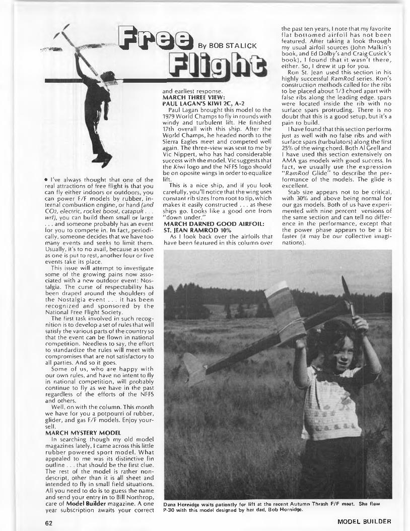
By BOB STALICKA » ' 3 3
• I’ve always thought that one of the real attractions of free flight is that you can fly either indoors or outdoors, you can power F/F models by rubber, internal combustion engine, or hand (and CO2, electric, rocket boost, catapult.. . wrl), you can build them small or large . .. and someone probably has an event for you to compete in. In fact, periodically, someone decides that we have too many events and seeks to limit them. Usually, it’s to no avail, because as soon as one is put to rest, another four or five events take its place.
This issue will attempt to investigate some of the growing pains now associated with a new outdoor event: Nostalgia. The curse of respectability has been draped around the shoulders of the Nostalgia event . . . it has been recognized and sponsored by the National Free Flight Society.
The first task involved in such recognition is to develop a set of rules that will satisfy the various parts of the country so that the event can be flown in national competition. Needless to say, the effort to standardize the rules will meet with compromises that are not satisfactory to all parties. And so it goes.
Some of us, who are happy with our own rules, and have no intent to fly in national competition, will probably continue to fly as we have in the past regardless of the efforts of the NFFS and others.
Well, on with the column. This month we have for you a potpourri of rubber, glider, and gas F/F models. Enjoy yourself.MARCH MYSTERY MODEL
In searching though my old model magazines lately, I came across this little rubber powered sport model. What appealed to me was its distinctive fin outline . . . that should be the first clue. The rest of the model is rather nondescript, other than it is all sheet and intended to fly in small field situations. All you need to do is to guess the name and send your entry in to Bill Northrop, care of Model Builder magazine. A one year subscription awaits your correct
and earliest response.MARCH THREE VIEW:PAUL LACAN'S KIWI 2C, A-2
Paul Lagan brought this model to the 1979 World Champs to fly in rounds with windy and turbulent lift. He finished 17th overall with this ship. After the World Champs, he headed north to the Sierra Eagles meet and competed well again. The three-view was sent to me by Vic Nippert, who has had considerable success with the model. Vic suggests that the Kiwi logo and the NFFS logo should be on oposite wings in order to equalize lift.
This is a nice ship, and if you look carefully, you’ll notice that the wing uses constant rib sizes from root to tip, which makes it easily constructed . . . as these ships go. Looks like a good one from “ down under.”MARCH DARNED GOOD AIRFOIL:ST. JEAN RAMROD 10%
As I look back over the airfoils that have been featured in this column over
the past ten years, I note that my favorite fla t bo ttom ed a ir fo il has not been featured. After taking a look through my usual airfoil sources (John Malkin's book, and Ed Dolby’s and Craig Cusick's book), I found that it wasn’t there, either. So, I drew it up for you.
Ron St. Jean used this section in his highly successful RamRod series. Ron's construction methods called for the ribs to be placed about 1/3 chord apart with false ribs along the leading edge, spars were located inside the rib with no surface spars protruding. There is no doubt that this is a good setup, but it ’s a pain to build.
I have found that this section performs just as well with no false ribs and with surface spars (turbulators) along the first 25% of the wing chord. Both Al Crell and I have used this section extensively on AMA gas models with good success. In fact, we usually use the expression “ RamRod Clide” to describe the performance of the models. The glide is excellent.
Stab size appears not to be critical, with 30% and above being normal for our gas models. Both of us have experimented with nine percent versions of the same section and can tell no difference in the performance, except that the power phase appears to be a bit faster (it may be our collective imaginations).
Dana Hornidge waits patiently for lift at the recent Autum n Thrash F/F meet. She flew P-30 with this model designed by her dad. Bob Hornidge.
62 MODEL BUILDER

Gene Bartel ponders his Junior Phoenix Nostalgia model. Medallion .049 engine.
Note the rounded leading edge (Phillip's entry) which seems to be an im-
ortant feature of this airfoil. If you aven’t tried your hand at using such a
section, try it. Next month. I’ll bring you the nine percent version . . . complete with turbulator locations.1983 WORLD CHAMPS PLANBOOK FROM NFFS
Do you remember the 7979 World Champs Planbook that was sold at Taft? If so, and if you missed out, you will be interested to know that NFFS has a limited number of copies of the 1983 version available on a first-come, first- served basis. Most of the competitors submitted three-views of their designs along with biographies and other pertinent info. Copies are available from NFFS Publications, c/o Fred Terzian, 4558 Moorpark, San Jose, CA 95129. Cost is $12 plus $2 for postage and handling. Fred also has copies of Malkin’s airfoil book (see above) still for sale for $7.50 for NFFS members, and $8.50 for nonmembers plus $2 for postage and handling. This is your chance to knock off two birds (pun intended) with one stone. Order both.THE CASE FOR NOSTALGIA RULES,BY BOB LARSH
Recently, I received a rather lengthy letter from Bob Larsh, who is the Nostalgia rules coordinator for the CIA (Central Indiana Aeromodellers) one of the strongholds of the Nostalgia movement. I have taken the liberty to shorten Bob’s letter to what I believe to be his essential points. Read it, as I believe that it gives some insight into the upcoming free flight debate over the national Nostalgia rules.
"We (the CIA) adopted the San Val- eers’ rules for the most part in 7979, and the first few meets showed that these rules per se would be untenable for us. Some contestants were using late model Super Tigres, Combat .35s, and current Cox .049, .057 and .09 Tee Dees. These motors were perfectly legal according to the rules as they were 'plain bearing.’ We felt that we were just getting into
a horsepower race. Most of the flyers, however, stuck to the spirit o f the Nostalgia concept and used the early glow engines of the period, such as Torp Green Heads, stunt Foxes, Holland Hornets, Wasps, etc.
“ We also fell into the Tee Dee .049 RamRod 250 trap. As manager of the 7980 SAM Champs, I included a combined Nostalgia class as a special event using the 7979 rules. Out of the 30 plus contestants, 77 flew RamRods which went one-two-three with first and second using T.D.s.
"As one could see, we were going to be in a constant rut with the use of modern engines and a contest with nothing but RamRods. We had many complaints and letters of discouragement because of the situation. The class was becoming like another modern AM A event and guys were doing well in
regular AMA meets with these models.“ The CIA decided, for the sake of
keeping Nostalgia alive in the Midwest, that they should adopt more equitable and true Nostalgia flavored rules. The CIA asked for proposals from the M idwest flyers which would be voted on by all who were concerned. Many ideas came forward. We had two rounds of proposals and voting, out o f which came our present rules.
“ The 100 oz. per CID weight rule was overw he lm ing ly voted in as it d iscourages the use of large engines in small models and overpowering them. We apply this to Class A, B and C models only as we felt that it was not necessary for 1/2A. Also, the fact that many of the designs of the early Nostalgia era were lacking in wing area and should be built light to compete with the bigger models of 7955-56. The 100 ounce rule was in
Gene Bartel launches the Junior Phoenix. Model flew well, but later suffered from an instant case of two-piece-wing-in-mid-air.
MARCH 1984 63
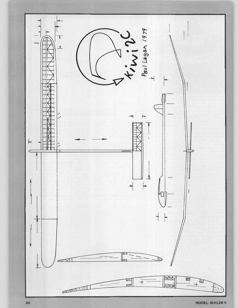
___________________
64 MODEL BUILDER

Frisco Kid, a Nostalgia model. Power is supplied by a Cox Medallion .15. The model is anBill Giffen launches his John Tatone designed excellent performer and an eye pleaser.
effect in the '50s and worked out well. It was the FAI oriented 779 ounce per CID that was imposed in 7959 that drove us all up a wall.
"To establish a true Nostalgia atmosphere, the modelers wanted the late model engines banned to allow the use of early glow motors that they grew up with. The first idea was to use 7956 as the engine cutoff date, but this was modified to 7962 after a study was made to see what engines could be utilized. It was found that the 1962 date would allow the use o f the fo llow ing plain bearing engines: all 0 .5 . Max steel finned engines, many Fox P.B., johnson and Veco P.B., Cox rear intake 1/2As and many others. An in-depth study was made of these engines, and an eligibility list was distributed. (It is available from Bob Larsh.)
"A n o th e r feature that was overwhelmingly voted in was the banning of all Cox front rotor engines. This included Medallions as well as Tee Dees. This rule dealt with the T.D. problem and the possibility of using T.D. pistons
and cylinders on Medallions, plus it knocked out the pow erfu l T.D. ,75s which dominated the contest scene in the early to mid '60s.
"We did make a couple of exceptions. We voted to allow current off the shelf Cox rear intake engines to compete as long as the T.D. part were not used, and to allow the use of late manufacture Fox stunt engines which followed the type manufactured in the mid '50s era.
"The majority of our flyers voted not to scale ABC models up or down unless different sizes were spelled out by the original designer. It was felt that the models should physically remain now as they did in their heyday. We made an exception in 1/2A, however, to deal with the RamRod (o be enlarged up to a maximum equal to the RamRod (250 sq. in. projected, and 263 sq. in. flat). We don’t allow any model to be reduced in size, however. Since we have small fields in which to fly, it is obvious why we couldn’t use the San Valeers' flight rules.
"This should pretty well cover the major changes we chose to make to the
original Southern California rules and why we did it. Another point to consider is that the CIA does allow the modelers to propose rule changes and vote on them. Having been the rules coordinator, I felt that in the interest of the Midwest Nostalgia flyers, I would like to go on record as having made a public explanation o f our rules and the ir virtues, and hope that they will remain intact for the most part. As we voted to allow rules proposals to be submitted only in two-year cycles, we will be using our current rules in 1984. I have arranged to hold events for two different sizes of Nostalgia classes at the 1984 SAM Champs to be held the last week of june at Bong Field. (Rules are available from Bob Larsh.)’’
Thanks for your explanation, Bob. If you intend to fly Nostalgia at the SAM Champs, drop Bob a line along with an SASE fo r copies of the rules. Bob’s address is 45 So. Witcomb Ave., Indianapolis, IN 46241.
By the way, Bob, I checked over your list of acceptable engines and noted that
DARNED GOOD AIRFOIL - St. JEAN RAMROD - 10%
S T A T IO N G 1.25 2.5 5 7.5 10 15 20 25 30 40 50 60 70 80 90 100
UPPER 1 Z 3 3.63 5 6.15 6.92 8.46 9.23 10 10 9.54 9 7.7 6.15 4.61 2.7 0.7
LOW ER 1 0.1 0 0 0 0 0 0 0 0 0 0 0 0 0 0 0
MARCH 1984 65

Go w ith Peclr in 84
B U S Y P E O P L E K IT SY O U H A V E TIM E T O B U ILD TH E S E
CITABRIA STINSON L5
CESSNA ZLIN SOL16 INCH PR O FILE A L L B A LSA FLY ER
O N L Y $6.95D ELU XE P R EFA B K IT IN CLU D ES:
PLA ST IC PRO P and BEARIN G DIE-CUT B A LSA · D ECAL SH EET FORMED LANDING G EA R LIG H T W EIGHT W HEELS SAN D PAPER - 3-VIEW W EIGHTS FO R BALAN CIN G C O R R EC T S IZ E RUBBER MOTOR CONSTRUCTION PLANS and PHO TO S BLD G , and FLYING IN STRU CTIO N S
RUBBER POWER · CATALOG $1.50
M 3 PecA-Po/ymersJ^Z™BOX 2498-MB LA MESA. CA 92041
PEANUT sail MODELS K it. $5 95
MUSTANG
/ ZERO · / PIETENPOL
PIPER CUB ANDRESON
MILES M-18 DRUINE COUGAR GIPSY MOTH
LACEY M-10 GANAGOBIE
Rubber Powered
PRAIRIE BIRD · *KIT $5.95
SPORT MODELSBABY ACE $6.49 ONE NITE 28 $6.95ONE NITE 16 $5.95STRINGLESS $4.95 PECK R.O.G. $1.95
B U M P S CONTROLLED11 and 13 FOOT LONG.K1TS OR READY TO FLY. N O W IN THREE COLORS GRAY. ORANGE and YELLOW LOW PRICES.
No. 25 - $1.50
S Peck-Polymers ΡΗ°Ν(β|Ι9)'«948««Μ I BOX 2498 -MB_________ LA MESA. C A 92041 J
my 432 RamRod with the Greenhead Torp .15 would be acceptable. My 1/2A Spacer with the Wen Mac Roto- matic would not. I suppose that this combination is not a biggie in the national Nostalgia scene.
I should comment that I like the approach that the CIA is using to keep within the spirit of the times.
Well, speaking of spirit, it must be time for the spirit of test flying in the spring weather to hit all of us. Let's do it. ·
H.l.T.............Continued from page 59TAILBOOM
The tailboom is made in a similar fashion as the fuselage. The form for it
can be made from a hardwood tapered dowel turned to the correct size, or it can be made of 1/4-inch steel rod and brown wrapping paper which is shown on the drawing. Phil Klintworth, Paul Crowley, and I worked this method out about 10 years ago, and it works for any length or diameter tailboom.
A little explanation might be in order, so I will try to cover what might not be clear on the drawing. Cut many two- inch wide strips of brown wrapping paper from the end of the roll. Tape them end to end. don’t overlap them, and make a strip 20 to 30 feet long. Tape the end of this strip to a 1/4-inch rod, and roll it up on the rod until it is 1-3/16 inches in diameter. Cut it off at this point. Remove the paper from the rod.
Unroll the roll of brown wrapping paper on a floor area where it will lay flat, and then weight the ends. Take the long, two-inch strip of paper, lay it on the unrolled paper, and mark the length. Draw a perpendicular line across the paper at this point and cut it. Measure the length of the tailboom across the paper on this end (20 inches), and put a mark. Take a chalkline and stretch it diagonally from the 20-inch mark to the other end of the paper and snap it. You now have a diagonal line the full length of the paper.
Cut the paper along this line and scotch tape the wide end squarely to the 1/4-inch rod. Roll the paper onto the rod keeping the edges even. Clamp the rod in a vice and roll the paper tighter by rolling your hands around it from one end to the other till it will tighten no more. Glue the end down, and finish with three coats of clear dope, sanding between coats.
Now that you have the form made, use the same procedure to construct the tail boom as you did on the motor tube starting from thesmallend, and working to the large end.
When gluing the tail boom to the motor tube, make some kind of a simple jig to hold them in place. Keep the top of the motor tube and the top of the tail boom in a straight line. Make sure you have the auto rudder and the DT lines through all the tubing before you glue them together. Leave the lines extra long for now, and cut them to proper length later.
PYLONThe pylon is low and wide, I have
made it this way for three reasons: (1) you must have 3.1 square inches of cross sectional area to the fuselage to satisfy the rules for the event; (2) I like to keep the center of gravity low, and (3) its w idth also makes a solid mounting surface for the wing.
I build the pylon right on the uncovered center section of the wing to assure a perfect fit. Cut two pieces of 1/32 balsa 1-1/2 x 4-9/16, grain running the short direction, and tack glue them with ambroid to the center rib and the adjacent ribs either side of center. Make sure you have a good fit in the center (no gaps).
Cut out parts P-1, P-2, and P-3 making an eggcrate cut on P-1 and P-2 so that they will slip together. Glue the three parts together making sure that you have a good fit when the assembly is laid on the 1/32 sheet you have tack glued to the bottom of the wing. Glue in place and let dry.
Make a paper pattern of the top surface of the pylon, lay it on the 1/32 sheet you have tack glued to the bottom of the wing, and cut off the extra balsa. Cut two pieces of 1/32 balsa, five inches by two inches with the grain of the balsa going the short direction. These are for the sides of the pylon and will haveto be notched to fit around the leading and trailing edges, glue them in placeand let dry.
Take some acetone, loosen the tack glue joints with it, and remove the pylon from the wing. Sand off the extra balsa from the top of the pylon.
Take your pipe form, wrap it with some brown wrapping paper till it is just slightly smaller than the outside diameter of the motor tube. Use glue or some double stick masking tape to secure some medium grit sandpaper to the form. The outside diameter of the sandpaper must be the same diameter as the outside of the motor tube. Draw a center line lengthwise down the center of the sandpaper. Now, take the pylon and run it back and forth the length of the form being careful to keep it centered on the line. Sand slowly, fitting the pylon to the motor tube as you go. Your sanding should end when you reach former P-3. PROP
I have a few ideas on how to carve the prop blades which I would like to explain. Cut your prop blanks to thesize shown on the print. Draw lines across the face of the block as shown on the print. Build a jig like the one shown on the print being sure to drill the holes in the plywood formers in the proper location. Put one of the prop blanks in the jig now and run the 7/32 tubing into the end of it 3/4 of an inch, twisting the tubing as you go. Remove the tubing and the proper blank. Cut a piece of the same size tubing 1-1/2 inches long, slip it into the circular cut you have just made in the block. Take a 3/16 drill and by hand twist it into the tubing, cleaning out the balsa on the insideof the tubing. Remove the tubing and glue the dowel in place. Do the same with the other
66 MODEL BUILDER

All Prices Subject to Change Limited to Quantity on Hand.
Circus IV$ 9 9 . 9 5
with (4) 505 ServosAlso Available with Reversing Switches $109.95 Limited Quantity
Unlimited VIII$ 3 4 9 . 9 5 ™
with (4) 801 Servos(Pattern, Scale, Helicopter Avail, with 401 or 4001 Servos $399.95)
$ 2 1 9 . 9 5
Pattern
(Special on old frequencies only)
with (4) 501 ServosNew Frequencies $234.95
Also Available in AMCustomer Service (702) 732-0022 Orders Only - Toll Free (800) 782-0022
3132 S. Highland Dr., Las Vegas, NV 89109Offer Expires March 31
block.Cut the blocks to the shape of the
front view making sure they are identical. Extend the lines you have drawn on the face of the block down both sides. Now, measure from the bottom of the block up to the leading and trailing edge lines shown on the side view, and transfer them to the block at each station. The next step is an idea of Paul Crowley’s that really works well. Take some 15 or 20-pound monofilament line, and (starting from the hub) glue the monofilament from station to station with ambroid, crossing the points you have established, making sure to maintain the curve of the blade as you go, no straight lines, but a gentle curve as shown. Look at the block from the end, and you can see if the lines form a nice gentle curve. If they don’t, loosen the monofilament with some acetone and make them right. The beauty of this method is that you now have a very distinct line to carve to, and you have the benefit of having the monofilament on the edges to protect the prop from nicks. The blades are then carved from front line to rear line keeping the back surface of the blade flat (no undercamber), and the maximum thickness of the prop blades (3/32 in.) at 25 percent of the chord, measured from the leading edge.
Give the blades a couple of coats of clear dope, and cover with Japanese tissue with the grain of the tissue going across the blade. Wet the tissue slightly
to make it conform to the shape of the blades. A couple more coats of dope and you are finished!
Install the blades in the prop hub, set the pitch, drill a hole through the brass tubing and the dowel in the hub, and secure it with a pin.
I am not going to go into the construction of the wing and tail surfaces as they are pretty basic. You may use mylar hinges in the rudder if you wish to save a little weight, I have built them both ways.
The Montreal stop prop hub in my estimation is the only way to go as you can use any com bination of rubber strands, and you don't have to readjust your prop stop. Build one like I have shown, or purchase one from F.A.I. Model Supply.TRIMMING FOR FLIGHT
I fly a right-right pattern, so sand in about two or three degrees right side thrust, no down thrust at this point. Set the auto rudder straight for power and about 3/16 of an inch to the right for glide. Make some test glides, it should show a tendency to glide right. Adjust the incidence in the stab by installing small squares of IBM or other card stock under the rear of the stab till the plane shows just the slightest tendency to stall, then remove a thickness of card stock. The incidence shown on the p rin t should be very close.
Wind in about 50 hand turns, hook up the AR and DT lines, light the fuse, pull the pin on the Montreal stop, launch
VINTAGE R-C FLANS
9 FT. WING SPANALL RIBS β FULL FORMERS SHOWN ON PLANS 11
PLASTIC ENG.COWLS % 9 .9 0 PR.CLEAR GUN BLISTERS $ 6 .6 0 PR
4 LARGE PLAN SHEETS — P la n s $ 1 6 9 5 6 f t . WING SPAN MODEL P 8 Y -5 A ENGINE COWLS t 6 .5 0 PR. R a n S $ 1 2 . 9 5GUN BLISTERS t 4 .50 PR ADD S2.50 POSTAGE
CATALOG -OVER 50 PLANS $ l 00 DEALERS WRIT E
WORLD © WIDE
SID MORGAN13157 ORMOND,BELLEVILLE ,M IC H .48III u.SA.
gently, and watch the power and glide patterns. They should both be to the right. Keep adding turns 25 to 50 more each flight, and correct your rudder and stab settings till you end up with a tight climbing circle and a glide of 80 to 100 feet in diameter. If you see any stalling tendency in the power pattern, try to correct it by adding a little more right rudder or more side thrust to tighten up the turn. I don't like to use any down thrust in my Coupes as it is a waste of energy, and you cannot afford too much of this with only 10 grams of rubber. Use it if you must, but then only in small amounts. The rubber I use is either eight strands of 1/4-inch Sig, or six strands of six milimeter F.A.I. rubber.
WHEN CONTACTING ADVERTISERS, TELL ’EM MODEL BUILDER SENT YOU!MARCH 1984 67

REPLICA ENGINES PROUDLY P R E S E N T S " J a c k K e e n e r ’s 193 7m m m s a m
.15 c u . i n . d i s p l a c e m e n t · · ·M a d e w i t h 1 9 8 3 A i r c r a f t Q u a l i t y M a t e r i a l s and T e c h n o l o g y ·
100 S e r i a l i z e d E n g i n e s R e a d y ForS h i p m e n t . C o m p l e t e W i t h Plug C o i l , C o n d . & Prop.
$ 1 9 9 . 9 5post - p a i d
REPLICAENGINES
14600 R A M S TA D DR
SAN JOSE, CA 95127
"A N O T H E R G R EAT W IN D E R "
IMPROVED SMOOTHER
List - $64.95 Plus shipping
JOHN MOR RILLS "SIDEWINDER"Precision Built Heavy Duty Winder!
Turn Counter kit - $18.00 $1.00 FOR C A T A L O G
dIM CROCKET REPLICASP 0 BO X 12600
FRESNO. CA 93778
Good luck with your ship, and I hope it does as well for you as it has for me. Hang In There! ·
Datamaster. . . Continued from page 41
to the receiver, a separate power connection and source must be used. In spite of its acceptability as is, I decided that it would be more versatile for my purpose if it had a permanent power supply installed, with charging capabilities. This is a good place to use those low capacity (or otherw ise questionable) batteries which you should no longer fly with, as they will not cause erroneous readings with the Datamaster; either it’ll work or not.
After some study along those lines. I decided to recase the whole unit, adding the batteries, charging plugs, etc.
The results are shown here . . . . Let me stress that while my conversion does make the unit more versatile, as will be explained, it really does not improve on the basic design or features. I chose the case shown, a 3-3/4 x 6-3/4 x 2-inch plastic case for an admittedly impractical reason, being that it is the same type of box that my DigiPace and other equipment I have is encased, and I like things to match!
Such cases are available at all electron ic supply houses (except Radio Shack) and are made by Dakaware, or Keystone. By mail, you can obtain one from Digi-Key Corp., Box 677, Thief River Falls, MN 56701. Credit card orders are accepted on a to ll free phone number (800) 346-5144. The case is Stock Number 700K-ND, at $3.50, the front panel is available in either matching black plastic ( No. 2037K-ND at $1.33) or aluminum ( No. 2046K-ND, at $1.37). I have found the latter to be extremely attractive if rubbed to a brushed finish with fine wet sandpaper in one direction only. After having made all of the holes, and applied all of the lettering, you should paint the panel with clear Super Poxy. The panel on mine was made from a light neutral color material to simplify the photography . . . black on black is murder!
In addition to the Datamaster and Interface, you will need the following:
1 — Toggle switch, DPDT, Ace No. SW005
1 — Noble Switch Guard, Ace No. 50L515
1 — 4.8 Volt, four-cell Ni-Cd battery 1 — Charger plug to match your trans
mitter, or1 — Charger Plug, Deans, Ace No.
19K551 — Knob, Ace No. PLA0071 — Bezel, see text below2 — Deans 3-Pin Female Plugs, Ace
No. 19K20FAs needed — Deans 3-Pin Male Plugs.
No. 19K20M1 — Single Pin Antenna Connector,
Ace No. 50L251 — Ace Hookup Wire Pack, No 50L520
The bezel over the digital display is not an absolute necessity, an opening similar to the one in the Datamaster case could be made, and covered with the same piece of red plastic installed there. However, it does add a touch of class, though not without a minor problem, I couldn’t locate a retail mail order supplier. The bezel is No. 140-1, made by RMF Products Inc, 1275 Paramount Pkwy., Batavia, IL 60510. There are similar ones made by other companies, and you may be able to locate one. But if all else fails, I have some extras and will trade one for your check for $2.50.
If you already have an assembled Datamaster/lnterface, or Datamaster, it will first havetocomeapart.down to the PC boards. If you are starting from scratch, complete the PC boards per the instructions, less the External-Internal switch on the Datamaster, and the wiring on both boards. The only changes made are purely mechanical, involving the relocation of the sub-assemblies, and minor rewiring.
The panel should be prepared per the sketch, and two holes should be made in the Datmaster board according to the dimensions given. The board is supported on the new panel with 4-40 bolts and two 7/16 inch spacers. Clear the foil around the edge of the two new holes and use a nylon or fiber washer under the nut for insulation. Mount the components to the panel. The Interface PC board is attached to the Datamaster board at the upper right corner with two layers of double sided tape. The foil of the boards must not be allowed to touch, and the wiring to the Interface board must be completed before they are joined.
Electrically, we are connecting a battery and charge receptacle to the system, providing switching for the display, and switching between the internal servo driver and external receiver or Interface outputs. We’ll take it bit by bit; all wiring not mentioned here is done per the original Ace instructions.
In the battery circuit, normal R/C procedures are used in that the battery's positive lead in the “ OFF” position of the switch is connected to the charge receptacle. In the “ ON” position, the battery’s positive lead is connected to the Datamaster board. The positive voltage to the Interface goes through
68 MODEL BUILDER

one side of the “ External-Internal” switch and in the interest of saving current, makes contact only when the Interface function is in use. I used a transmitter type charger socket, as they are more readily available and easier to mount than most receiver battery charge plugs . . . and I'm sure you own a transmitter charger! To charge with the latter, a 33-ohm resistor has to be inserted in the positive lead to the battery to adjust the charge rate. If a receiver charger is used, this resistor is not necessary. If you are using a separate non-system charger, a Deans Charge Connector (Ace No. 19K55) is recommended.
Switching of the "External-Internal” function is done by the original switch, remounted as shown. Short pieces of wire must be connected from the holes in the PC board into which the switch was originally mounted, to the upper set of switch terminals only. All other connections from the Interface and to the outgoing plugs are normal, with the exception that the red wire from the receiver plug is not connected. This wire used to bring in the positive voltage from the receiver battery when the Datamaster was to read a pulse from the receiver. Power is now provided at all times from the internal battery.
If you only have one brand of R/C system and will only be working with one type of plugs, you can end the servo/receiver wiring with the proper types. If you have different kinds of systems or wish to make the unit more versatile so that you can help out your friends when required, you can end these wires with Dean's three-pin female connectors, and make up the proper adapter cables with Deans male connectors and whatever is necessary to match the system on the other end. A single pin connector, such as the Ace No. 50L25 may be installed in the Interface input lead so as to be able to disconnect that long wire when the Interface is not in use.
The knobs as furnished don’t match each other. If you want that coordinated look, you’ll have to get a mate for the Interface knob, per the parts list, or obtain a matching pair from Radio Shack. The lettering is rapidly and neatly put on with rub-off lettering, and protected with a coat of Super Poxy. As mentioned, it can be used over rubbed aluminum, in which case it must be sprayed on in order not to distort the lettering. On a colored panel, the Super Poxy should be applied just over the lettering, with a single stroke of a fine haired brush. Subsequent brush strokes will loosen and distort the lettering, so do it all at one shot. Rub-offs are available at all stationery and art supply sores, and the electronic stores carry them with electronic words.
As with the original Datamaster and Interface, there is no adjustment or tuning necessary, merely get it all together, test it, and start yourself on the flight path to better understanding and use of your R/C equipment.
Yet another version of the recased
NO TIME TO BUILD?TRY OUR “ OLD TIM E” F/F-R/C AIRCRAFT
FULLY ASSEMBLED COMPONENTS
“KLO UD KING”R/C REPLICA OF 1938 F/F
IDEAL FOR BEG IN N ERS & EX PERTS
• 7 2 " Span · .29 to 40 Engine Size• 2-3 Channel Operation, or F/F• Quality Built Components of Balsa.Spruce & Ply. «Form ed Spring Steel Landing Gear/Tail Wheel Assembly.(Less Wheels)
FU LLY FRAMED - U N C O V E R E D .......................... $149.95Add $8 00 Shippmg/Handlmg
NEW! NOW IN K IT FORM WITHFUSELAGE SIDES PRE B U IL T ................................... $89.95
This is a full kit All components pre-cutAdd $3.00 Shippmg/Handlmg All A/C Shipped U P S
BEEHIVE R/C MODEL AIRCRAFT CO. P.O. Box 744, Layton, UT 84041
Note UTAH RESIDENTS ADD 5% SA LES TAX
Dealer Inquiries Invited
STOP
Eliminates GLITCH problems associated with long servo leads, - a .
• E lim inates need tor voltage robbing chokes and other devices withleads over 15” long ^
• Modern CMOS IC technology ~~'~~• Uses less than 0.5 m illiamps at 4.8 volts• Power lines are capacitor tillered• Available in 4 versions with connector installed
5 1 0 .95 - S ing le Channel, s ing le servo drive (S ingle) GS-1512.95- S ing le Channel, tw o servo drive (Wye) GS-1 Y $14.95 - Two Channel, tw o independent servo drive (Twin) GS-2517 .9 5 - Two Channel, two servos per channel drive (Twin Wye) GS-2Y
• Overall lead length is approxim ately 6“ to 8”1 * · Modeler must furnish own longer extensions as required
Specify Radio s 1-00 Shipping and Handling on Pre-Paid orders, add ^ ’ 6% for California residents. Mastercharge and Visa.
6175 PALO ALTO DR.. ANAHEIM, CALIF. 92807 (714) 637-2161
EM SlUCT»Ot'C MOWt 5»5T|VS
Datamaster and Interface is shown. This one uses a thumb switch for channel selection. As with the first onedescribed, the only differences are mechanical, and it is shown only to acquaint you with yet another possibility. Well, you don ’t build your airplanes completely according to the plans,do you?
As of this w riting, Datmaster and Interface units are available as follows: 22G20 Datamaster, Kit — $39.95 22G20C Datamaster, Assembled —
$49.9522G21 RF Interface. Kit — $11.95 22G21C RF Interface, Assembled —
$19.9522G20RFC Datamaster w/RF Interface,
Assembled — $69.95 ·
R otorise r..........C o n t in u e d fro m page 4 5
but a bit more difficult to make.)Next, at the end of the main rotor
blade, cut slots at the location shown on the plans, and glue the stabilizer struts in place.
Trim the top of the stab struts at an angle of six degrees to the flat bottom of
the rotor blade. The trailing edge of the stab will be raised about 1/4-inch from the leading edge to achieve this angle. It is not too critical.
Cut out the 1/2x4-inch trim tab on the stabilizer, then attach it to the stab with soft wire (pipe cleaner wire is excellent for this purpose) so it can be bent to various settings.
Glue the stabilizer to the struts.Dope the entire assembly to fuel
proof it. You can use clear dope. or. if you prefer, colored dope to suit your taste.
The balance arm is a 1/4-inch dowel. 24 inches long, w ith some lead or modeling clay on the end. The arm is held on the rotor blade by rubber bands. That makes it easy to remove and store alongside the rotor blade for ease of transport. It also serves to absorb the shock of hard landings, which do occur at times.
Drill a hole in the center of the rotor arm at the location shown. With this as a balance point, add lead strip or modeling clay to the end of the balance arm until the whole assembly balances. You
MARCH 1984 WHEN CONTACTING ADVERTISERS. TELE ’EM MODEL BUILDER SENT YOU! 69
WILLIAMS A Γ Γ Γ ^ ^ Π Ί Ρ T t CBROTHERS
i PILOTSSTANDARD · SPORTSMAN
RACING · MILITARY
W H EELS ►VINTAGE · SMOOTH CONTOUR
BALLOON · GOLDEN AGE
PARTS ►PRATT? & WHITNEY · IE RHONE
VICKERS · SPANDAU · PARABEILUM
SEND $1 FOR FULLY ILLUSTRATED CATALOG _____ u f c U A M iDEPT. MB 181 PAWNEE ST. SAN MARCOS, CALIFORNIA 92069 ____ mos
Twelve page-Fully Illustrated with complete details on . . .
• MUFFLERS• ENGINE MOUNTS• ENGINE TESTING EQUIP. •SCALE ACCESSORIES• SMOKE KITS, ETC.
Send $1.00 for CatalogTATONE PRODUCTS CORP.
1 2 0 9 G e n e v a A v e S a n F r a n c i s c o . C a .9 4 1 1 2 4 1 5 3 3 4 - 7 1 8 9
might also have to add some ballast at the end of either the rotor blade or the motor arm, depending on the grade of balsa and the amount of dope you used. Naturally, balance it with the engine mounted.
Now, let’s make the “ launch pad.” Cut o ff about three feet of an old broomstick handle, and tape a nail to the end, pointed end of the nail sticking up. Blunt the end so you don’t stab yourself with it. Shave the other end of the stick to a point, so you can stick it into soft earth.
Solder a washer on the nail, or alternatively, attach a wheel collar at the point level with the end of the stick. The nail sticks up about an inch from there. The washer or wheel collar serves as a bearing surface.
Construction is now complete. It’s time to make some test flights.FLYING THE ROTORISER
For your first flights, select an open area perferably covered with grass or low growing weeds. Pick a day when the wind is either calm or very light.
Shove the end of the launching pad into the ground far enough so that the
top end is held firmly in place.Fuel up the engine, start it up, and
adjust it to run. Let it run for about thirty seconds, then set the Rotoriser on the launcher w ith the nail sticking up through the hole in the center section. Hold the machine level, using the end of the rotor blade, then let go. The Rotoriser will start rotating, gain speed, and then lift off. Watch it carefully, because it may be slightly out of balance and sway towards you. Get out of the way and let it continue. It will stabilize and climb up until the engine stops, then autorotate down.
The rate of climb will be determined by the angle of the stabilizer and the setting of the trim tab. If you want a fast climb, set the trim tab even with the stabilizer. For slower ascent, bend the trim tab s ligh tly down. W ith some experimentation, you can actually get the machine to lift off and spin slowly up to about ten feet, then wander around until the engine stops. Or, set the trim tab up, and the Rotoriser will virtually disappear overhead . . . but the autorotation coming down is pretty ragged. It’s your choice.
If it so happens that the ground is too hard to stick the launching stick into the turf, you can launch the Rotoriser by hand. But it's a pretty sporty course.
There are two ways. One is to hold the Rotoriser at the center section with the engine running, then launch it upwards with a twisting, clockwise action, then get out from under it, fast!
The other way gives you a bit of leeway, although you still have to be alert. With the engine running, hold the Rotoriser by the end of the rotor blade, then toss it into the air with a spinning action in the same way that you toss a Frisbee. Do it level, or it will circle out and around and come right back towards you.
Obviously, the safest way is to use the
launcher.When the Rotoriser is in powered
flight, the noise is sort of a “ whomp, whomp, whomp” as the blade rotates. It will draw kids to it like a light draws moths.
As I said in the beginning, it's a real fun machine, both for you and your spectators. Kids love it.
At least, kids like me and you! ·
P&F&CT . . . . Continued from page 47
what the author is telling you, but you will learn something new to apply later.
As an example, let’s assume you want to make a copy of an article with a lot of pictures, and the text will send you all through the magazine. When you arrive at your local "instant copy" shop, the only employee is busy on another machine, and recognizing you as the guy who always wants a copy better than the public machine gives, he asks you to come in and run your copies yourself. You go into shock, for this is a formidable machine w ith a lot of knobs, buttons, and gauges, and you are not a reproduction expert . . . not magazine articles, at any rate. The guy who is an expert comes over, looks at your magazine, pushes several buttons, tweaks a knob, shows you where to put your copy, and says, "Push that button for each page of copy!" You do it and get good copies! The next time you come in and he is busy he may show you why he pushed the other buttons and voila, you are now an expert who can be obnoxious when the company you work for gets a similar machine and someone has a problem getting a good copy!
The above things that I have been beating about the bush involve the relationship of science and technology, tempered by witchcraft, which is basically a mixed-up combination of the two. Science can be imagined as a great thermal of general knowledge, fed by a large ground area of many small hotspots of research activity, most of these little local areas having no apparent relation to model aerodynamics. As circulation is produced, generally counter-clockwise on the west coast ana clockwise to the west of the Rockies (a future article will tell you what is general farther east than the Mississippi), the diameter of circulation decreases as the velocity increases until this “ pipe” of knowledge rises to such a height that it is e ither dissipated by fric tion of the atmosphere or it releases its energy and forms a towering cumulus cloud. Ultimately, it completes developing the cumulus cloud, and it becomes a flat- bottomed nimbus. Up to the point where one of these reasons for the therm al’s demise occurs, the combination of all these little hotspots of scientific research in chemistry, physics, electronics, mechanics, therm odynamics, and the common language, mathematics, has resulted in what not only supports your model, but carries it to a greater height! It is not one particular "ground bubble" that has pro-
70 MODEL BUILDER
vided your model’s “ boost” , but all the bubbles together.
Where does techology come in? It comes in when we sample the information contained in this tower of knowledge and use it to improve our model’s performance. Engineering is often confused with science, which is actually comprised of physics, chemistry, and mathematics as far as we are concerned (the other fields mentioned above are really specialized variations of the three). We are not concerned with the sciences involving the flora and fauna of this earth, except, possibly, the use of medical science when we stick our hand in a prop, or the effect of different vegetation on the formation of thermals . . . maybe we should inculde all sciences, after all?
Witchcraft? That is how this crazy hobby got started. Leonardo da Vinci was considered somewhat of a witch when he made model gliders. From the excellent articles about Maxwell Bassett in Model Aviation it is certainly apparent that his early gas models were designed by omen and random theory, and some of his designs are strong Texaco contenders today! Taibi, Struck, Lanzo . . . a lot of the great early designers started off by conjecture, but they were not averse to the use of science to help them win all those trophies.
This article started off to be a complete discussion of the properties of air, necessary to the future articles concerned with aerodynamics, but I got carried away on my soapbox and used up too much space. However, we do have enough space left to return to the problem of why the model w ithout washout pranged in the other direction when we made a turn. Let’s look at what actually happens.
The left portion of the illustration shows a wing with no dihedral at all! It has an aspect ratio, which is the span divided by the chord, that is lower than should be used on most free flight or R/C designs. You do see it in C/L combat circles, however, but you see all sorts of weird things there. Incidently, aspect ratio is also the span squared divided by the area. This is handy to remember.
With this "flat” wing you can see that the two wing sections 2-1 and 4-3 are exactly the same with the relative wind coming from the direction shown. In other words the incidence, or angle at which the wing meets the approaching air, is the same for both tips. If you had taken the P&F&CT course on airfoils, you would know that the lift on both wings is the same and the turn will continue to the right. In fact, it probably will continue to do so if you turn the rudder back to neutral! You may have to command "le ft" for a bit to get it going straight. If the model is in free flight, you have a problem.
In the right part of the figure you have the same wing with considerable dihedral, again in right turn. Look at the section 6-5. It is at negative incidence, which means more right turn. Look at section 8-7. It is at positive incidence,
B IG EBIG “ E" is now predrilled for the EVRA, the 2.3 ZENOAH, or the 22 QUADRA.
SpecificationsWing span ............84Length ................. 70“Airfoil ................... SymmetricalW eight...................15 lbs (ready to fly)Power.................... EVRA. ZENOAH or QUADRA enginesPlease specify which engine is being used when ordering your kJt.Features: · firewall pudrWed tor evra. zenoah. or• Easy to build... 20 hours from box to sanding QUADRA engine* (Please specify)• All hardwood and plywood precut to size · Great ground handling with BIG “E" extra long• Fuselage sides preformed to full length, wtth fuselage and landing gear location
stringers and vertical braces glued in place · Precovered (hard cover) foam wing and turtle deck• Unique wing attachment mokes alignment · Rys the full pattern with power lo spare
and installation super easy · Includes oil hardware, except tall wheel assembly
ONLY$22495
pus $10 00 shipping and handling
(O S only)
and tires
INTRODUCTORY OFFER - BIG “E” and E & L ZENOAH engine
D*U* $1500 shipping0 * T m and handling (U S only)
NOW AVAILABLE!The NEW E & L ZENOAH Engine- It’s Precision, Powerful, and has Very Low Vibration!E & L updated features Include balancing, increased compression ratio, modified muffler. Improved timing, and It comes wtth throttle linkage Installed.
Specifications:• 228 CIO. 2-cycle, piston ported ignition gas engine• Roller bearing wrist pin and pinned piston ring• Smooth! Much less vibration than a balanced QUADRA• Powerful! Turns an 18-10 prop at 7S00 RPM• Double ball bearing crankshaft• Solid-state ignition (no points)• W eighi-4 lbs. 2 oz• Easy hand starting
$14495plus $5 00 $rvpp<ng
ondhondkng (U-Sonty)
Ports for ZENOAH engine• Spnng recoil
starter $39.95e DuoJ stock
muffler $24.95e Zenoah ruol 7-ooit
nub $18.95• 30 id test lord
mount* $ 200 each
* * -
EVRA OwnersUpdate NOW Available!
Ermine Modifications Include e increased power e Easy hand starting
(turns 18-8 prop at 7200 RPM) · Full-circle nng conversion e Balanced for reduced vibration e Improved timing • Balanced crankshaft and flywheel e Optimized reed vafve
All this for ONLY $45.00 p»usS5.00ihipp«ng
Ports for EVRA engine• Motor Mount with
Lord Mounts $19O0• Twin Stock Muffler
$24.95• Pud Hub $14 95• Lord Mounts $ ΐ.5 0 ·α
(20 ib test)
E & L Manufacturing8631 East Laredo Lane, Scottsdale, Arizona 85253 (602) 941-0633
MASTERCARD
— Jwhich means still more right turn. The model should viciously go to the right, yet, it pranged the other direction! “ Vas ist los?” as one of von Richthofen's green cadets would no doubt have questioned!
If you remember, the model in question was dead-stick. A model in glide is trimmed for minimum sink rate. If you had taken the P&F&CT course on trimming models you would instantly have realized that the model was trimmed to the maximum overall lift-to-drag ratio. (If you look carefully at Chickum’s tracks in the logo, you will see theequation for L/Dmax!) You would also realize that this means the mode! is flying very close to a stall at maximum lift. Both of the above courses would have told you that if section 8-7 was near the stall in straight flight, and its incidence was increased in the right turn . . . it would stall, and the left wing would lose almost as much lift as if it had been cut off! Ergo, the left prang when told to go right!
So what effect does washout have that cures this malady? This is answered in both the above courses and a third, the course on stability. The course on the theory of lift (Kutta-Joukowski Circular Theory, to be precise, according to
CUSTOM TUNED EN GIN ES COMPETITION A C C E S S O R IE S
S P E C I A L I S T S I N P I N E T U N E D C O X T E E D E E A N D R E E D V A L V E E N G I N E S .
T H R O T T L E D V E R S I O N S A V A I L A B L E .
C U S T O M P A R T S E O R A L L C O X E N G I N E S .
C O M P L E T E I N V E N T O R Y O E I N D I V I D U A L S T O C K P A R T S E O R A L L C U R R E N T T . D . & M E D A L L I O N
E N G I N E S . M A N Y P A R T S E O R C O L L E C T O R S . O L D T I M E R & N O S T A L G I A E L V E R S .
C U S T O M T U N I N G E O R A L L E N G I N E S .H A R D C H R O M I N G .
O T H E R C O M P E T I T I O N A C C E S S O R I E S .
E O R D E T A I L E D R R O C I I U R E , S E N D 7S t T O :
K U S T O M E R A E T S M A N S I I I P P .O . B O X 2 69 9
L A C U N A H I L L S , C A 92654
T E L E P H O N E : ( 7 I t ) 830-5162
Sylvestor) is a clincher! The whole secret lies in thedelayofatipstall. If only a portion of the inner wing panel stalls first, lift is gradually lost and the nose drops before the tip stalls and drops on that side. Once the nose drops just a little, everything goes back to the high lift routine and the problem doesn’t occur! If the tip stalls first, the high pressure on the bottom of the wing forces air over the tip onto the wing top
MARCH 1984 WHEN CONTACTING ADVERTISERS, TELL ’EM MODEL BUILDER SENT YOU! 71

BUZZ WALTZ R/C DESIGNS255 N. EL CIELO, SUITE 476
PALM SPRINGS, CA 92262
SUN R ISE 254055 in. span; 550 In.** are A c h . R / B * . /
/ $44.95
B E G IN -A IR 40 T R A IN E R72 in. span, 760 ln2 area
4 ch. R/C
κ
$44.95
$25.95
XV E LE R O78 in. span. 635 in2 area2 ch. R/C
B EG IN A IR T R A IN E R54 In. span, 540 In2 area 3-4 ch. R/C
$39.95
DIRECT SALES ONLY619-325-5494 r
surface and ZAP goes the lift on the whole panel. The washout, by decreasing the tip incidence, forces some portion of the mid-panel to stall before the tip does. Too, you don’t really lose much lift during normal flight due to the washout, because tip efficiency is poor anyway. Why the washout on both wings? Because you might want to make a left turn, someday!
This is something to remember when you are setting up your ailerons. Select your horns so that you have about twice as much up aileron throw as down, for a down aileron can initiate tip stall, too!
See, we did pull some information of value out of that thermal tower of knowledge! This was a bit of technology that we extracted from the scientific
S ch lu e te r F ree Flight M odels3 5 0 8 P o inse ttia Ave M a n h a tta n B e a ch , Ca. 9 0 2 6 6
eΘ
PACIFIC ACE
DealerInquiriesInvited
BLACK BU LLET
PARTIAL KITS (p la n s & p r in te d w o o d )PACIFIC ACE o r BLACK BULLET 2 0 " . 13 2 5 - 3 0 ' M 7 0 - 4 0 ';> 6 .6 5 -A D O 12.00 SHIPPING FOR EACH I TO 3 K IT O R O E R -C A RES AOO · · ; . TAX
research of Kutta-Joukowski, National Advisory Committee for Aeronautics (now NASA), Prandtl, and the dozens of activities that have made wind tunnel studies. If you will just nibble at the bullet a bit (you don’t have to bite it) and request some of the P&F&CT samples from our BigThermal. . . you can eat the whole thing!
See you in the chicken house, y'hear?Alfred Lehmberg, 2646 Bolker Drive,
Port Hueneme, CA 93041. ·
R/C Autos . . Continued from page 53and, yes, we did have the bumper installed.
By now the RC500 was starting to get some respect. I will freely admit to a certain amount of favoritism shown toward Delta, but then it defin ite ly earned this through total honesty with me and everybody else racing Delta products, as well as Delta's cars and accessories being absolutely top-notch. Expensive, yes; top-r.otch, ditto. So, Associated not only had to show me, via the RC500 chassis, that it had a top-line race car, it had to measure up to very high standards as well.
About this time. Delta had made up a bunch of lightweight parts for the Eagle. Ken called me about them and asked if I wanted a set for my car. In a very “ loose” conversation, I mentioned that, yes, I wanted the parts, and that possibly they would help me beat Gary Kyes, a world- class racer who regularly pretty much kills the DRT on race day. Please realize up front that I was joking with Ken and have long accepted the fact that given equal race cars, Gary will always beat me unless he breaks. And if he breaks, I still didn’t out out drive him, so it isn’t much of a victory.
With light parts on the way, I stripped my Eagle down. But Friday came and no new parts. With a busy weekend ahead, I could thrash the Eagle back together, race it on Sunday, and then take it all back apart when the parts came on Monday. Or, I could just race the RC500. It didn’t take me long to decide; for the first time in years I was going to race something other than a Delta car. The car worked super, qualified very high that day, ran second only to Kyes in the A Main . . . and Gary broke! First time out
with the car, and I had taken my first A Main win of ’83, all previous finishes being a second place (yes. with Gary winning).
The situation was simply too good to pass up. Monday morning I called Delta and left a message: “ Got good news and bad news. Good news is I beat Kyes; bad news is I used an RC500 to do it!”
Don’t you think I got a quick call-back on that little missive? It was all in fun!
For its next outing, we did something to the RC500 that was really outrageous; we lent the car to my brother-in-law Kent to race, and he had never driven or controlled any kind of R/C vehicle!! Do you remember how many times you crashed when learning to race? Right, we’re talking crashing big-time; Kent’s very first try with the car was our regularly scheduled practice session on race day. Kent hit everything on the track plus most other cars at least once each. About halfway through race day he was starting to get the hang of it a little, actually punching for full-throttle in several spots. We had this one straightaway that was of decent length, but it had a very shallow bend to the left midway through. Kent came out of a corner, nailed it down the straight. . . and failed to drift left! He drove the 500 flat-out directly over one of our plow-discs, and the plow-discs that we use are not the shallow ones you might have seen at other tracks, instead, they have quite a rise to them . . . about six inches! The car went a good twenty feet high, coming down sideways and tumbling clear to the far end of the track! It was great, all were hoping for an encore. At the end of its tumbling routine (which seemed to go on forever) the car landed upside down, and a corner marshal flipped it right side up just like it was a normal, everyday, simple roll-over! And Kent drove the car away, finishing the heat race .. . We loved it!
That's not the end of the story, however. While nothing broke on the car, every time Kent ran it, the car would come back in fairly badly tweaked. We finally figured out that the heavy-duty bashing was shifting the radio tray in relation to the pan, and with these two components bolted together, a super hard knock would get things out of alignment, yet normal vibrations and shakes weren’t enough to let all settle back into alignment.
Normally this is not any problem, of course. Kent definitely over-stressed the chassis; we had not up to this point seen any signs of crash-induced tweaks, nor have we since. But, if you hammer your RC500 rather viciously some race day, my suggestion is to first loosen all five bolts holding to tray to the pan and then to retighten them. Only after doing this should you check the tweak, readjusting if necessary.
Shortly after Kent’s demolition derby race day, Josh decided to get back into racing. After hearing me praise Delta products for years, he really wanted an Eagle to race, but as we only have one, he was convinced to at least give the RC500 a try. Now, to be totally honest.
72 MODEL BUILDER

Adjustable. I 8 scale varilok boll differential
1:8 SCALE RACING. IT'S A GAS!Team Associated's gas-powered, 1 8 scale
radio-controlled cars are the ultimate in model car competition
With on unbeatable combination of power, speed and performance, gas R/C car racing has grown to be a truly international sport.
Associated cars have played a major role in the history of 1:8 scale competition Our legendary RC1, a simple, flat pan-chassied car won both the Rood and Oval US National Championships immediately following its introduction in 1971 After several years of testing and development we next introduced the amazing RC100, which won it all in R/C car racing's first World Championships
Always a dominant force in the world of R/C racing, Team Associated's RC300 continued our winning tradition, setting records all the way in Florida's classic 24 hour Enduro
Our secret to success is simple We do our talking on the track, offering model car racing enthusiasts competition tested and proven cars and components
We build race cars to stand up to world class competition, and win.
In the development, testing and prototype stages for over 2 years, the RC500 is the final result of Team Associated's joint British/American effort
The RC500 is a true racing ca r, with outhentic race cor suspension geometry and fully adjustable springs, shocks and sway bars.
You set the ride height. You select the stabilizer bars to suit your track. You even fine- tune the coil-over shocks.
Every option is there for you to dial-in your RC500 the same way racing mechanics set-up a modern, full-scale Formula car perfectly balanced for optimum performance
Porsche 917-30/KL
INDEPENDENT SUSPENSION. A NEW ERA.Our new RC500 is the most unique and
revolutionary race car we have ever built, because it is designed around a chassis using 4 wheel independent suspension
The retined tear suspension geometry of the RC500 rides on adjustable competition coil-over shocks and features simple sway bar tuning
And to make sure you get your RC500 set-up right we've included a comprehensive assembly and suspension tuning manual Together with our simple, step-by-step assembly photos even the novice can build the RC500 and become an expert on subjects like understeer/oversteer, roll rotes, spring rates, caster and camber Special sections also cover advanced engine tuning, radio installation and driving techniques
Exclusive cross over (rant shock layout provides optimum suspension travel and rebound
THE RC500. ANOTHER WINNER.For all the pride and satisfaction there is in
building and driving the sophisticated RC500, there is still nothing quite like the thrill of victory
Like all Associated race cars your RC500 is above all designed and engineered to win. Each component must meet our strict, competition tolerances and are manufactured of the highest quality materials.
Already prototypes of the RC500 have won several prestigious British and American nationol titles, proving the versatility of the basic chassis in several different body classes.
Your RC500 meets all specifications for competition in the Americas (R O A R ), Europe (EFRA) and Asia (JMRCA) using internationally recognized standards for fuel capacity and dimensions
Take up the ultimate challenge with your driving skills ond RC500 Join the thousands of RC car racing enthusiasts of ROAR (Radio Operated Auto Racers) and get into the high- powered excitement of gas cor competition
TEAM ASSOCIATEDAssociated Electrics 1928 Eosl Edinger A ve. Sanlu And. CA 92705 (714) 547-4986
Send for Free 1/8 Catalog
MARCH 1984 WHEN CONTACTING ADVERTISERS, TELL 'EM MODEL BUILDER SENT YOU1 73

• 6 CHANNEL RECEIVER*• 4 MIDGET SERVOS (NES-1A)• 500 MAH SQ. BATT (SANYO)• AILERON EXTENSION• MINI SWITCH HARNESS
No v a kELECTRONICS
Futaba/compatible plugs. Matches all modern TX. Plug-in crystal included. S p e c ify F re q u e n c y . A d d S2.50 U P S Calif, res ide n ts , a d d 6%. A llo w 3 -4 w e e k s to r
che cks . S e n d 9’Λ x 1 V /i SAS E fo r fre e b rochu re .
2709-C Orange Avenue, Santa Ana, CA 92707, (714) 549-3741
TAKE IT OFF WITH S P E E D S T I XDISPOSABLE SANDING TOOLS
USE WET OR DRY 3 SANDING GRADES 100 — 120 - 180
A * $4.85
B * $2.95
C * $3.75
REGULAR SPEED STIX9 STIX (1/4-3/8-1/2 diameter)
MINI SPEED STIX6 STIX (1/8-3/16-1/4 diameter)
NEW! FLAT STIX6 Wedge STIX 13/4-1/2-1/4 w idth)
ORDER TODAY!! POSTPAID!!(DEALER INQUIRIES INVITED)
PRECISION SANDING TOOLS 2930 SKYVIEW AVENUE
PUEBLO. CO 81008 Evenings call (303) 542-6200
Josh had not previously enjoyed much success in car racing, never completely coming to grips with the art of smoothly and consistently cranking off the laps. Also, he didn’t have the best of cars previously . . . or they weren’t set up properly for him, same thing.
The RC500 simply changed all of that from his first lap on. The car would do exactly what he wanted whether it was being stable down the straight or instantly turning in at the corners. He was (is) still rough at times, but no longer is he held back by inferior equipment. More than just a few times I have seen him turn genuinely competitive laps, even when pushed hard by much more experienced racers. At one of the last races of the year, he even did well enough to qualify the RC500 into the A Main, duly noted by club president Dave Clark as actually qualifying higher than I did by one point. Uh, duly noting something in our club means broadcasting the info over the PA system, by the way.. . .
The only problem of note Josh has had with the car is an inconsistent brake.
Well, that’s a little misleading as the brake is actually very consistent in that it always takes a few laps to get the thing to work properly. Evidently, the brake likes to be warm before coming in strongly, and as Josh runs a very light brake, during warm-up laps he almost has no brake at all which further complicates getting it heated. As a result of overshooting the corners, his timing was thrown off. As a temporary fix, we have just resorted to cranking in more brake with transmitter trim during warm-up, and then Josh resets the trim to a premarked position while waiting for the start. This is not a totally acceptable situation, but I am not sure what to do about it. At least the brakes do work consistently and we// once up to temp.
As this is written, our 500 has been fitted with all the current modifications recommended by Associated and sold as after market kits. These mods are incorporated into the new 500 car kits. The modifications include the lightweight differential assembly, a ’glass bracket for the brake actuation arm, Associated’s own excellent shocks, the new silicone
O rings for same, the latest brake assembly with two steel rotors, snap rings on suspension pivot pins, a full complement of titanium pivot pins, lower rear suspension A arms that eliminate the extreme coning wear pattern on the rear tires, the trick-o (and Eag/e-inspired) front anti-roll bar, new long-wearing front tires, the really super “ mellow yellow’’ (medium) rear tires, and the outboard mounting kit for the rear shocks. I ran the list only to bring all of you up to date on our own car. My understanding is that nearly all of these items are now supplied with kit cars; two exceptions, for example, would probably be the titanium pins and the 30 weight oil used in the rear shocks, which in turn are used in conjunction with the very light .038 coil-over springs.
Add-on stuff supplied by Delta included several excellent, or just plain handy, accessory items. These were: Super Body Posts, a molded nylon bumper, an antenna mount, hardened steel wing tubes, molded rear body mounts, and a very important piece . . . the Delta slide-valve carb complete with Delta paper element air cleaner.
With the motor being such an important part of any 1/8 car, I really wish there was more to say about the latest- version K&B .21 we are using in the RC500, but you can’t say much (enough, actually) about a motor that fires up in the morning and simply runs well race after race with a consistency and reliability factor that all of us would have killed for just a few years ago. When I started racing, the K&B .21 was the only motor to use, but a couple of years later they were faced with very serious competition first from OPS and then from Picco. K&B lost their dominance in the sport, but in my opinion they now are offering a .21 that can compete heads-up with any motor presently available, plus offer an attractive price along with exellent parts availability.
The radio system is also important, but again we haven’t given it much thought during the season because the Kraft K- Line “ staple gun” radio has always worked. To be honest, I cannot understand how any radio can be reliable in an R/C car, but the Kraft system is super in this regard as well as offering all of the handy features like servo reversing, endpoint adjustments on both throttle and steering servos, a thumb wheel for instantly variable rate trim on the steering servo, separate trim adjustments for the high and low positions of the throttle servo, an easily-held, well-balanced transmitter, and super smooth throttle trigger. Yes, I know the exponential wasn’t mentioned, but only because I don’t find it to be handy at all; we have yet to find a situation where it helps us go faster. While there are some interesting new radios coming fo r R/C car racing, as I write this the Kraft system is the best all-around package available.
Next month we'll do the Eagle and then wrap it up with an overview of how the cars differ, how they are alike.
Dan Rutherford, 4705 237th PI. S.E..
74 MODEL BUILDER

Bothell, WA 98021.
Four-stroke . . Continued from page 13to climb, and climb, and climb! Very impressive! A smooth p ilo t, Helmut enjoyed low level aerobatics and frequently brought the CAP 20L across the field inverted only inches from the runway, then took it all the way to the tree line on the west side of the field to pull up at the last minute. Sooner or later, it was bound to happen, and he finally threaded it through some tree limbs, resulting in deep gouges in the wing and stab leading edges. Fortunately, it wasn’t serious damage, and after a few hours of repair work in Dave Brown's workshop, Helmut had the CAP ready to fly again on Sunday.
Four-strokes are great, and I’m sure they're here to stay. Will they take the place of screaming two-strokes? Not completely. I'm sure. Four-strokes have a distinctive sound and low RPM performance which is well suited to many light aircraft type scale models and most sport models. I can honestly say that I've never had a more pleasurable flying experience than my 1/4-scale Clip Wing Cub with the Gemini Twin engine. The sound and flight performance is the most realistic I’ve been able to achieve. There are those who will argue that the four-stroke sound is not well suited to WW-II models such as the P-51, P-47, or P-40, and I probably have to agree with them. But, as I’m not really a WW-II figher fan, and my favorite planes are light aircraft and home-builts, it’s four- strokes forever for me!
Hamilton Hawks and World Engines; Thank You . . . I’ll see you next year! ·
Electronics . . Continued from page 48
with the results reported in the July ’82, issue. It turned out that the Low Battery LED indicator in the transmitter was coming on much too early, calling for a battery replacement long before the critical value .was reached. The combination of buying and installing Ni-Cds and disregarding or disconnecting the LED would cure the problem.
No, there is absolutely no reason why you can’t install Ni-Cds in your transmitter, and an eight cell, 9.6-volt pack would be ample for both. However, do not be tempted to purchase the no-tab cells, and simply drop them into the cases furnished for the alkalines. The spring contacts are poor and undependable at best, and enough corrosion could develop to completely stop the flow of current, which (naturally) is going to happen while you are in the air.
Soldered-in cells are the only way to go, and I recommend the Ace R/C Transmitter Ni-Cd Conversion Kit, No. 38K9. at £24.95. It includes two 4.8-volt battery packs. Deans charge connectors, an overnight rate charger, and instructions. I think that it is extremely interesting and indicative of Ace’s policy that the price has not changed since 1981, but even so, we all like to save a dollar or two when we can. In this case,if
DU-BRO FUEL TANKS
CAP FITS OVER-------------------------MACHINED SMOOTH NECK OF TANK PREVENTS TANK FROM SPLITTING FORMS A POSITIVE LEAKPROOF SEAL
-SINGLE OR DOUBLE VENT SYSTEM
PROTRUDING FRONT · PROTECTS FUEL LINES FROM BEING CRIMPED
-EXTRA LONG CONNECTION TUBE ON CLUNK FUEL PICK UP
The DU-BRO FUEL TANKS come complete with all tank hardware, soft brass tubing, and positive flow clunk fuel pick-up Available in 8 sizes from 2 oz to 16 07 capacity
CATNO. DESCRIPTION PRICE
402 (S-21 2 oz S Q U A R E FU E L T A N K 2.15404 (S -4) 4 c z S O U A R E FU E L T A N K 2.35406 (S -6) 6 oz S O U A R E FU E L T A N K 2.45408 (S-8) 8 oz S O U A R E FU E L T A N K 2.55410 (S -10) 10 OZ S O U A R E FU E L TA N K 2.65412 (S -1 2 | 12 oz S Q U A R E FU E L TA N K 2.80414 lS -1 4 1 14 oz S Q U A R E FU E L TA N K 3.00416 (S - 16) 16 oz S Q U A R E FU E L TA N K 3.25
D U - B R O P R O D U C T S480 Bonner Road, Wauconda, ILL. 60084
MARCH 1984 WHEN C O N I AC t INC. ADVERTISERS. TEll 'EM MODEL BUILDER SENT YOU! 75

LEFT or MIGHT HAND.
VORTEX TIPS AVAIL·
2 ?o 3 WEEK DELIVERY
EPOXY RESIN CONTINUOUS FILAMENT• 5 25x4.6x3.7x3. · 10x8.10x7.11x6 · · GIANT SIZES
2 *4 .7 x 8 5 $4.85 38LAOE $14.86 I8X 8 .I8X I0 $34.96• 8 χ4 .8 χ 6 .8 « β · 12.6x8 M ilita ry 20X8.20X10 $38.95
9x4.Bx6.9x7 $7.96 4 BLADE $ 2 4 9 5 22X8.22X10 $49.96• tOx4.Κ)χβ.Ι0χβ. · PITCH GAUGE · |/2A and 9 iam » it« j
11x6.11x7.12x4, wp to 12 in $29.85 ttra ipM tip and>2*6 riQht hand only
D**l«ra Invited1 *3 0 3 '4 6 9 -3 9 2 8 tor M.C./VtSA ACOD•r moll CMh.Check or M.O. toN)· Cmorold tt. Sroomfl«M,Co. 80020
P.A.W. DIESELSEngland's Finest
.049 to .29. New low low prices. Send $1.00 for list.
Eric Clutton, R T4 , Box 1109C, Edmond, Oklahoma 73034
you think that you can live with only one charger for your two transmitters you could get just one kit as mentioned, and order the other set of batteries and connector separately. Along with hundreds of other interesting and necessary items,they are listed in Ace’s $2.00 catalog.FM - FUTABA/KRAFT COMBINATION
I recently received a thought provoking letter from Joe Utasi, in Cincinnati, Ohio. For those of you who are thinking, “ Now, where did I hear that name before?’’ Joe is the designer and manufacturer of the interesting Jomar Products electronic accessories, which include the only twin engine sync system available, a lightweight airborne coupler, and an auxiliary accessory con- toller.
" / fly a Futaba 6IN FM system on 53.2 MHz, and I really like the feel that the sticks provide. I ’m concerned that interference might total out my now budget breaking Nosen 310, and I wonder if I can use the new Kraft Super Receiver with it, (I don’t know all the model numbers, but I’m sure you know what I mean.) I know that it's an FM system, and that it ’s eight channels. I figure the last two channels just won't exist at the receiver. As long as there is an appropriate ‘reset’ interval between pulse trains, the receiver doesn’t care how many channels it receives, right? And what about FM? Is there any standard for the amount of frquency deviation used? I’d really like the security of the Kraft receiver, but I don’t want to give up my Futaba transmitter. ( I don’t want to go broke on the new PCM system either!.) Can I do it???
Joe, to begin with, the receiver you have in mind is known officially as the Kraft KPR8FD. I assume the "F” designates it as being FM, as there is also one named KPR8 D. The 8FD works extremely well with the companion FM
module equipped Kraft transmitter, I have flown the combination extensively, first in an old test plane I keep just for such purposes, and eventually in my CAP-20 (MB, January ‘84). To the best of my knowledge, this FM system is the only one u tiliz ing Narrow Band FM techniques, having a frequency swing of about 3.5 KHz. At this stage of the FM game, all of the manufacturers are somewhat reluctant to release technical in fo rm a tion or schematics of the ir equipment, in an effort to stay ahead of the competition. One has to assume then, with no advertising claims to the contrary, that all other FM systems now on the market are some form of what we can call Wide Band FM, using the above as a data point. As far as I know, there are no standards on band width, other than the ones imposed by FCC regulations. And if history means anything, nor will there be, unless dictated by some component such as is the case with 455 KHz IFs, which are that particular frequency simply because of the availability of IF transformer of that frequency.
So, since the J Series, as advanced as it was when it first appeared, was introduced prio r to the new frequency requirements, I am almost certain that it has a wider frequency swing than the newer Kraft system. The question, which I can't really answer, is whether the KPR8FD receiver, designed to work with a very narrow signal, will have a wide enough bandpass for the J’s signal to be effective. I don't have all of the necessary components to do any testing of the two at this time, but will try to borrow enough from my friends to do so. I will let you know of any results. This FM business is creating some problems for us technicians, as you can’t look at a transmitter signal with a simple scope demodulator such as you can with AM, the signal strength meters don't respond to FM, and who is setup to measure frequency deviation?
As a matter of possible interest, I have heard from a pretty reliable source that Kraft Systems will soon have available an FM module for the Futaba G transmitter, which will enable it to work with the 8FD receiver. This should be good news for the thousands of owners of that particular transm itter who w ill also be
looking for the same features you are. I would guess that if the demand warrants it, Kraft would also consider sim ilar modules for the Futaba J and similar poplar module equipped transmitters. DIODE PROTECTED AIRBORNE BATTERY PACKS
Joe’s letter goes on to say:"Next topic is airborne battery sys
tems. After considerable thought and brow wrinkling, I just couldn’t justify the redundant battery setups on the market. Not that they don’t do their jobs well, but I subscribe to the school that says, ‘The fewer the parts, the less the odds of failure.' I think that ProLine had the right idea with the parallel diodes accross each cell. In the event that a battery ‘opens' in flight, the diode conducts and you land with safety. I had a ProLine, and while the idea was good, the receiver didn't like to work too well at 3.0 volts. My solution is simply to use five cells! The advantage is that if one should ‘open’ there is still 4.2 volts left to run the system (4.8.-.6 = 4.2). In the meantime when everything is working, you have six volts available to power the servos, which really makes them move quickly and with authority . . . I don’t see any problem with this small added voltage on the servos or receiver. If anything, the receiver front end likes the extra voltage, and the added voltage on the servo signal lines gives added noise immunity (higher logic levels). What do you think? I'm sure I’m not the first to consider doing this, and it might have enough merit for others to consider it also. . .’ ’
Now, about the diode protected packs. I have different ideas on the subject, backed up by experience with thousands of Ni-Cd cells during my years with Orbit Electronics back when Ni-Cds were not even as good as they are today. In theory, the ideas you and ProLine share sound great, but did you ever wonder why none of the other R/C manufacturers around the world ever did the same thing? I firmly believe that it is because they found out the same thing we at Orbit did . . . that Ni-Cds rarely fail by an open circuit in R/C use. Almost all (and while I don’t have any exact figures, I would estimate at least 99%) of the failures are caused by an
76 MODEL BUILDER

internal short, which a parallel diode would not help. My library includes information from a number of Ni-Cd manufacturerers, and all discussions of cell failure found there attribute open circuits to high temperatures, high drain rates, and high charge rates, all leading to venting and loss of electrolyte. These are not conditions normally found in R/C system applications, though it sounds like a much higher percentage of those cells being used for electric power might fail in an open mode.
Then too, some receivers definitely do not take kindly to voltages much above 4.8 volts, some to the point where the higher "surface charge” initially produced by a Ni-Cd pack immediately after charge will cause them to operate erra tica lly . Some of these receiver designs are admittedly older, but are still seen at the flying fields; some are newer, but do not use internal voltage regulation, sometimes the case with the less expensive systems. The better designs, which include some form of voltage regulation, many of which operate at all times at less than three-cell voltage, should accept your idea without any problem.
You have started me thingking, but the only thing I can come up with that matches the simplicity of the diodes is a five-volt, fixed regulator. It would work well with five cells, and at just slightly over four volts on four cells, though we'd lose the three-cell capability of some receivers. Until we see something entirely new in power circuitry, it looks like you are stuck with a redundant battery supply.
Such things do exist already. At the 1983 Nuremberg Show (MB, June ’83), I was shown some very interesting features of the Brand Elektronik “ Microprop” PCM (Pulse Code Modulation) systems. It has an airborne system which will work on as few as two cells, with some form of converter to provide higher voltages. Interestingly enough, when the airborne battery drops to four volts, the throttle warns you by going to low. However, you are not stuck there, you can push a button on the transmitter which restores full use of the airborne controls, including the throttle, for ten seconds so you can land normally. If it takes you longer than 90 seconds to get back on the ground, the low throttle condition will occur again, though you can start the whole cycle over with the transmitter button for another 10 seconds of total control. I really believe I could get myself back down on the ground in 10 seconds if something was telling me I had to ! . .. It would be nice to have such a feature on some of the systems available here in the States, wouldn't it? I expect that at Toledo '84, we are due to see more really new and original features and ideas than we have in the last few years.
Anyway Joe, thanks for the letter, and your thoughts on some interesting subjects. I know you’ll keep thinking about the battery business, and will come up with some "Jomar” solution.
Giant R/C Scale Plan Designs:SOTWTTH TAHOIO 14 Μ ι 77 V m I24 00pp U.S.A.IOPVVITH TABlOlO r . = I 44 Ip ·» I t · 00 p p U S A.AT -4 TTXAN J.4‘ c l 101 Spon 127.00 p.p. U.S.A.FOKKia'orr a.r * r u-tpo· 121.00*.» u4.a.F4U CORSAir J’A* * «' W Ip·» 127 00p p. U.S.A.CURTISS “Ψ·¥Γ 2Y.· = I «4 Ιρο» 127 OOp.p U.S.AW NAICAT 2% - I »♦ Spon 127 OOp.p U S A
Fiberglass Cow lings 4 Canopies are available Send a Stamp for the dotailed Brochures on our G iant Scale Accessories
(Our Plans aro sent Post-Paid w ith in the U.S.A.)
Nick Ziroli29 Edgar D r iv ·. Smithtown, N .Y . 117·7 U .S .A .
When you do, I expect to be the first to hear about it, so I can pass it along to our readers.WIRE PUSHROD RECEIVER ANTENNA
Our resident glider guider, Bill Forrey, received the following letter from distant, fellow C.C. Larry Peters, in Clayton, New Jersey:
"/ am working on a two-meter Sagitta. After building the fuselage, I came to a crude reality . . . how was I going to get the antenna through the Sagitta fuse? I tried, and wound up trying to punch holes anywhere, finally messed up the antenna. I read at one time about attaching the receiver antenna to a wire control surface, like a cable . . . in this case I soldered a nine-inch pigtail off the receiver to the rudder control surface, I have about 37 inches of antenna (cable included). Will this work? I don’t want to mess up my new Airtronics system. . . . "
Well, isn’t that clever. . . it’s the first time I’d heard about this, but there is no reason why it shouldn’t work, though I have one comment and a suggestion. The former has to do with your mention of antenna length, which should be as close as possible to the original, though I doubt if one inch more or lesss is going to change anything. A good solder connection must be made between the two sections, the added piece can be either flexible or solid wire. Plastic fittings should be used on both ends, this is definitely no place for any noisy metal-to-metal connections.
The suggestion is for a comparison range check with the other non-antenna pushrod in and out of the airplane. A nearby metallic object, especially one of similar diameter and length as the antenna will sometimes shield or reflect the signal, neither being desireable. I would establish a maximum antenna off or down distance without the other pushrod, then install it and compare the distance obtained, looking especially for any deviation when the other pushrod is directly between the receiver and transmitter antennas, and when it is directly in back of the receiver antenna. Any reduction is cause for concern, and if any significant amount occurs, you should consider changing the nonantenna pushrod to a non-metallictype. This is probably the best idea anyway, as
POWER TO SOAR TO NEW HEIGHTS
LEISURE LT500.10 cu. in equivalent g lo w engine d is placement For tw o-m ete r sailplanes, o r sport scale a ircraft.
KELLER 250.24 cu. in. equivalent g low engine d is placement. Flies any .19 to 23 pow ered plane For 100-ineh sailplanes, and sport scale aircraft. Manufactured fo r Leisure by K e lle r M otoren o f W est Germany
KELLER 50/240..16 cu. in. equivalent g low engine dis placement. The standard by w h ich a ll o th e r e le c tric m o to rs are com pared. O nly 0.36 eu. in equivalent g lo w displacem ent, but p u lls lik e a 30 ! Fo r F.3E c o m p e t it io n sailplanes, o r lO -si/e pa ttern scale planes
Discover exciting electric flight tor yourself. Send a self-addressed, stamped envelope for our latest catalog and technical bulletins.
Leisure11 D eerspring .-Irv ineC a lifo rn ia 9 2 ~ l- t
any range reduction might occur only when you are low and far away, inbound, with the worst possible transmitter to receiver antenna angles. Please let us know how it works out, we’d all like to know.TWELVE-VOLT CLOW PLUG SUPPLY . . . UPDATED
In last month’s column, I answered a letter from Joe Clark, down south of us in La Mesa, California, about driving a glow plug directly from a 12-volt battery, through resistors. Since then, while looking through some old issues of MB for one of those things, "I know I saw here somewhere” , I came into another different and interesting solution to the problem. It involves the use of two, 12- volt, dual filam ent automotive light
WHEN CONTACTING ADVERTISERS, TELL 'EM MODEL BUILDER SENT YOU!MARCH 1984 77
Can you really afford to use less than the best battery packs ma)
SR aerospace grade battery packs give you
• 3 Times the fly ing time
• The ulim ate in re liab ility
• 80 Packs to choose from for transmitters, receivers, and e lectric powered cars and planes
• Send a self-addressed, stamped business size envelope for fu ll details
ΒΔ' *F«-es -»sc° BOX 2Θ7 B C llP O m NEW YORK 11713
C O R P O R A
BUILD YOUR OWN ROCKET
MOTORS!WE CAN SHOW YOU HOW!
•4 0 POUNDS THRUST!
• 50C EACH!• With .t m ck tuinblei and som e sim ple hand tools
w e ll show you how lo build YOUR OWN rocket engines in youi own garage oi workshop for 1/5 to 1/10 the cost of the com m ercially marketed motois
• INTERESTED7 Just send us S2 00 and we II m ail you our brochure along w ith a WORKING SAM PLE ol an electric igniter that YOU CAN MAKE YO URSELF (torn m aterials you II hnd around the house
TELL YOUR FRIENOS ABOUT US! Were the 00 IT YOURSELF ROCKET people
Write to Department MB 4. The Tetellite Corporation 11620 Kitching St.. Sunnymead. CA 92388
bulbs, being used as resistors, and which, totaling up to four elements, can be switched to provide different values of resistance and thus different glow plug currents. Start with the two heaviest filaments in parallel, and add the others one at a time for a hotter glow.
If you mount the bulbs so they are visible, they will serve a dual purpose, the cheery glow will let you know that the plug, battery, and all connections are doing their job. The basic schematic is shown, along with one using a Radio Shack No. 275-1533 DPDT Center-Off switch, wired to provide "OFF" while at center, “ LOW” in one position and “ HIGH” in the other.
That’ll teach Joe Clark to write a letter to this column. He probably expected a
simple answer like “ 10 Ohms’’ , but instead he got so many suggestions and things to try he's probably scared off for good!MB ELECTRONICS & ELECTRIC INDEX
I finally kept one of my 1983 New Year’s resolutions, I completed an index of ten tears of electronic and electric coverage from the pages of Model Builder magazine. No, I’m not usually so slow that it takes me eleven months to get something done, but in this case I had to wait for the December '83 issue to appear.
Anyway, my “ MB Electronics Index” covers everything written in the last ten years about electronic and electric items and products; it includes the name of the article,cross-indexed by subject; issue, page, and author. I initially did this to save myself time when I am researching answers to your questions, but I had enough local requests for copies that I decided to have my local friendly printer run off a batch and make them available to whomever shares my interest in the mysterious electron. Copies are available, postpaid, for $5.00. Your letters, on this or for general column information, are welcome at: 231 Cottage PI., Costa Mesa, CA 92627.NEXT MONTH IN ELECTRONICS CORNER
FM (Frequency Modulation) R/C is here to stay! The time has come to speak about it here in this column, and I intend to do so next month. Not with complicated circuits, wiggles and squiggles, and all manner of complicated talk about discriminators (FM detectors) and that kind of stuff. I w ill attempt to describe the basic differences, what it means to you the flyer, and what to look for when you read the ads.. .FM for the non-technicians, in other words. Maybe we'll call it “ FM forUg/y Stik flyers” , or something like that, the intent being to make it unerstandable, and if they can understand it, anyone can.
Space permitting, though maybe it’ll have to wait until the following month, I'll attempt to give the same treatment to d o ub le convers ion rece ivers. BE THERE! ·
78
Hannan.........Continued from page 57
wing tip vanes with different angles and dihedral; even open paper cones at the tips; all to no avail. It was very frustrating, but I will start earlier next year and maybe give things a better chance!”
Thank you George for sharing your experience, which should be encouraging to the rest of us. There are indeed times when certain models can be most exasperating . . .
George was also kind enough to tell us about a full-size, man-carrying, rubber- powered machine he has seen, and we will try to obtain more information to publish.FRED WILLIAMS AND JESSE DAVIDSON
We regret to report the passing of two fine people. During the latter part of 1983, Fred W illiams, eldest of the Williams brothers, died following a long illness. Fred had been a devoted craftsman for most of his life, having produced furniture, musical instruments, and numerous inventions as well as having been a pioneer in plastics fabrication. Although not a builder of model aircraft, Fred constructed many miniatures of other types, some of which have been featured in this column. His final project was an intricately detailed, antique musical workshop, which may be placed on display in a northern California museum.
During October, 1983, we lost Jesse Davidson, renowned aviation enthusiast and writer. Jesse was a walking encyclopedia of aviation history, a pilot, researcher, and photographer. He was also Al Capp’s uncle, and witness to the birth of Al’s famous “ Lil' Abner” comic strip. Davidson is perhaps best known to model builders as a former editor of Flying Aces magazine, a publication which helped launch thousands of youngsters into the hobby. Most recently, Jesse had served as a consultant to Time/Life, drawing upon his comprehensive photograph collection to assist in their production of Flying The Mail.FLYING WINGS
Another Northrop Flying Wing Contest is history. The weather was great, support was excellent, and the variety of entries outstanding. A traditional attraction of this annual meet is its relaxed atmosphere, which may help explain an unusually large turnout of spectators. The contestants were unhurried and helped each other freely . . . and with some of the far-out designs, plenty of help was needed. Right Bill Northrop? (I was the helper,not the helpee. wen)
On a more sober note, we reflected upon the absence of one of the event's originators. Jack Headley, who had passed away earlier in the year. According to Carl Hatrak, Jack had been Vice-Commissioner for the Northrop model club during 1965-66 when Carl first proposed the event.
Since that time the rules have been altered slightly, but the friendly spirit of
MODEL BUILDER

MicroHarkThe Small Tool Specialists
s i
ORDER EARLY!SALE ENDS
MAR. 31,1984
DREMEL M ODEL # 3 8 0 1 VARIABLE SPEED M 0 T 0 -T 0 0 L S E T
with 40 accessories. Speeds from 5,000 to 28,000 RPM, ball bearings
List Price $94 95 Sale Price $60.50
DREMEL M ODEL # 2 7 0 1 CONSTANTSPEED
TO O LSETwith 30 accessories. Bronze bearings ltem#38270
Price $71.95 Price $42.50
PRECISION D R ILL PRESS ATTACHM ENTlor Dremel Moto-Tools Item #38268 List Price $33.95
Sale Price $22.50
[HI■ p * nyt,
1 ■ ·Γm 1Cj/
O-i
A PIECE A LU M IN U M C C LAM P SETto 2" capacity.
Item #21113 List Price $7.95„ Sale Price $5.50
V 'TW IN GRIP, THIRD H AN D
List Price $11.95 Item #21120 Sale Price $7.50
V T V DREMELW D ISC IBELT SANDER
5"disc, Γ χ 30" belt, 45°tilting table
Item #38101 List Price $119.95 Sale Price $74.50
FREE BONUS! '.SI?
Surgical-quality Stainless Steel Tweezer yours FREE with any order over $50 00 from this ad!
STAINLESS STEEL, SELF-CLOSING TWEEZERwith heat-resistant grips Ust Price 54 50Item #19110 sale Price $2.50
5-P IEC E TWEEZER SETof nickel-plated steel Item #19111 List Price $10.95
Sale Price $7.50
JEW ELER S SCREW DRIVER SETwith 4 flat blades. 2 Phillips Item #28106 List Price $6 95
Sale Price $4.50
12-PIECEJEW ELER S NEEDLE FILE SETMedium cut. for wood or metal Item #33108 List Price $17 95
Sale Price $12.50
PRECISIO N JEW ELER S VISE1 wide x V h ~ capacity. Fits bench up to 1W" thickItem #21136 List Price $9.95
Sale Price $6.50
DREM EL 4 " TILTING TABLE SAWwith mitre gauge Item #38273List Price $129.95 Sale Price $79.50
X-ACTO 15-PIECE KNIFE A TOOL SETwith wood storage box ltem#34101
List Price $27 95 Sale Price $17.95
X-ACTO 27-P IEC E KNIFE A TOOL SETwith wood storage box ltem#34103 List Price $38 95
Sale Price $27.50
6-PIECE PRECISIO N CARVING SETHardened and polished tool steel. 4’/«"longltem#25105 List Price $24 95
Sale Price S17.50
20-P IEC E D R ILL B IT SETNo 61 to 80. with plastic index Item #26111 List Price $19 95
Sale Price $12.50
DOUBLE END P IN VISE4Vi" long. Vi" capacity Item #21104 $ . List Prii
Sa le P riiPrice S3 95
Sale Price $2.50
SW IVEL HEAD P IN VISE2 double end collets.3 W" long, Vi" capacity Item #21105
List Price S4.95 Sale Price $3.50
JEW ELER 'S H AND VISEPolished steel. 4Vi"long,'/«"capacityItem #21102
J?:List Price $11 95 Sale Price $6.50 .
JEW ELER S SPIRAL P U SH DRILL STEEL CHUCK7” long, .039"capacity. Item #26101
List Price $6.95 Sale Price $4.50
DREMEL VARIABLE SPEED M O TO-FLEXTOOLSpeeds from 7,500 to 25.000RPM, ball bearing handpiece.
Item #38111 List Price $109.95 Sale Price $65.50
S A V ET IM E !
ORDER TOLL-FREE 100%AGUARAWTEED1with VISA, MASTER CARD. AMERICAN EXPRESSFor COD, add $2.00 per order. Cash payment required upon delivery. No checks.
800-225-1066 (in NJ. 201-464-6764)(in NJ, 201-464-6764)
DREMEL SCROLL SAW /SANDER15" throat, tilt table
Item #38115 List Price $99.95 Sale Price $64.50
MICRO-MARK · Box 5112 KB— RUSH ORDER COUPON — —
24 East Main St. - Clinton, NJ 08809□ YESI Please send me the items indicated
0ΤΥ.
F R E E !Our big. new MICRO-MARK Miniature Tools Catalog
($1.00 value)SENTFREE with every order!
ITEM # PRICE EA.
SUBTOTALAD010%. OR SS MAXIMUM SHIPPING
COD — ADD $2.00 PER ORDER NJ RES. A00 6% SALES TAX
FINAL TOTAL
TOTALTotal enclosed $ · - in check ormoney order payable to MICROeMARK. (Sorry, no COOs)
Charge it ($15.00 minimum only):□ MASTER CARO □ VISA □ AMERICAN EXPRESS
_Exp Date _Acct. # _
Signature.
NAME___
Π Send me your big. new MICRO-MARK TOOLS CATALOG absolutely FREE with my order
□ My order subtotal is $50 00 or more Send me my FREE Surgical Quality Stainless Steel Tweezer.
ADDRESS.
CITY_____ -S T A T E ____ ZIP -NO-RISK CUSTOMER GUARANTEE: You must be 100% delighted or return your order within 14 days for a full refund of the purchase price
C MICROeMARK 1983 — — _ _ _ _ _ _ _ _
MARCH 1984 WHEN CONTACTING ADVERTISERS, TELL'EM MODEL BUILDER SENT YOU! 79

Γ § 0 I F F - P A K + + * * S 6 n i6 e * * * * ^I H L nc c ir.M tn rn o
/I
I ^ I
DESIGNED FOR
SPORT & FUN FLY
SPECIFICATIONSWing Area.. . . 540 sq. in.Span.............................60"Length......................... 43"
I Weight..............3-4 Vi lbs.Engine........ 25-.45 cu. in Deluxe Kit 564.95
°3^10............. 3-4 channel Spinner, Fuel Tank, FuelFEATURES Line, Pushrods, Control
• Machined Balsa & Horns. Hinges, Clevises,Plywood Couplers, Hardware.
•Positive Positioning ._ Construction Basic Kit $57.95■ «Semi Symmetrical Airfoil Spinner, Hardware.
VISA/MASTERCARD 4517 Morning Wind Place
Ft. Wayne. IN 46804 (2191 432-4324 after 6:00 p i
I
Wing S p a n --781“Wing A re · -564 Sq"
y ' J V £ < W l
The SENSOAR gliderA HOBBY HORN Exclusive!! A HOBBY HORN Kit! The SENSOAR Clider kit is · high quality kit with Machine cut t sanded parts. Select quality balsa and spruce. Detailed plans, and written instructions. For THERM AL or SLOPE or 05 E L E C TR IC POWER.
V A L U E P R I C E D a t $ 1 6 . 0 0
P i IV S e m i - K i t * Combined w ith f u l l s t r i p w o o d
a n d p l a n . ( N o w m e t . W i r e . W i n d o w , e t c . M a t . )
( N o t e . T h e s e m a y b e p u r c h a s e d fust as s e m i
k i t s . o r w i t h p l a n s - - w r i t e o r c a l l f o r p r i c e s . )1936 Buccaneer-84” $51; 1938 Clipper MK l-7 2 “ --$391937 Dallair* S p ts 'e r -108"-$61; 1940 R anger-46"- $271939 M e rc u ry -72"— $56; 1935 Miss A m erica -84"-- $59 1941 Playboy J r . -54"— $29; 1941 Playboy S r-8 0 ’ -$461938 Power House-84"— $43; 1940 Sailplane-78"--$741940 So Long-50"--$28; 1938 Trenton Terror-72”- $321939 Z ip p e r-5 4 " -$ 4 8 ; 1939 Korda Wakefield-44"- $17
M I D W A Y M O D E L £ o . S e m i - k i t s C o m b i n e d w / s t r i p1936 F lyin g Quaker-84"-$49; l937Quoker Flash-67"$381937 Long Cabln-78"-$42; 1937 A ir C hlef-61"------- $40
S T R U C K ' S 1 3< * o 74" S pa n . 835 S q . in .
n m a i Ι · Ι ΐ ΐ Α Ρ $ΕΜ Ι' Χ Ι Τ (P ,an ,n c L ) 533 00 I l C W I I I I C l Combo (F u ll) K it $63.00
S C A L E P L A N S a n d D R A W I N G SS -5 0 H E IN K E L H E -1 00 D . 62", .60s $10.00
$2.00 P P /ls t Class Λ co py w ill be sent
fre e --w h e n requested- w ith an o rd e r.________
SH IP P IN G A N I) H A N D L IN G : U p to $8.00 add $1.50.$8.01 to $20.00 add $2.25. $20.01 to $45.00 add $3.00. $45.01 to $70.00 add $3.50. and o ve r $70.00 Add $4.00. C A Addressees ndd 61 tax. Send M O . Vl»a/MC< f + E x p .) o r C heck (allow up to 30 days for check c lea ra n ce.)
HCOD=Kxuct Charges ♦ $1.50 H d l. (C a s h O n ly )f A ll UPS1
H O B B Y HORN ••hobby specialties**
15173 Moran S treet ( B 1 P .O . Box 2212
W estminster. Ca 92683 (714) 893-831 (714) 895 1203
the affair has remained unchanged, a fact which may account for the many regular entrants. Some of their entries are also regular, being dusted off only once per year for this contest! Certain designs have been a bit too consistent: For example the perpetually winning ways of Bill Warner’s Insect. . . Rogallo- wing models led to them being banned
in 1975. And for this year’s event, it was decreed that my Stringless Wonder be excluded, perhaps an indirect form of flattery?
On an historical note, a small review of this design may be in order: The original “ Stringless” , complete with tail, is illustrated in one of our photos. It was entered as a gag in a Palomar College kite contest in San Marcos, California, during 1970, as part of a team effort with Ken Hannan and the late Russ Barrera. At first, the meet organizers were reluctant to allow entry of “ a kite without a string” , and a meeting of the judges was convened. In what seemed a quite generous decision, they concluded that the entry was indeed a kite, but that it simply "made its own wind” via the rubber-driven propeller on its nose!
Actually, it was a marginal performer at best, so after the contest it was extensively redesigned. After placing third in class at the 1970 Northrop Wing Contest, it was published in American Aircraft Modeler as a Tenderfoot project.
In 1971, the late Jack Lueken flew an enlarged, gas powered " Wonder” to second place in the Northrop meet, and by 1974 the Walton brothers were competing with CO2 powered variations. Bob Peck won first place in the 1975 Northrop meet with his “ Wonder” , and his daughter Jill placed fourth with hers. Perhaps this helped boost kit sales for Peck-Polymers?
During 1977, the Northrop Wing event was conducted as part of the California Nationals at Riverside, and Stringless Wonders were flown in the gas class by both Jim McDermoth and Jack Lueken, while the rubber event was won by another Wonder, which disappeared over a mountain in the process.
Upon winning the 1981 rubber event of the Wing meet, more than a few grumbles were heard from other con
testants, centering upon the "hole” in the middle of the wing. To some, this seemed to render the aft portion of the design too much like a tail to constitute a true flying wing. Thus, the hole was covered for the 1982 contest, and although the model still flew, its performance was only mediocre and it did not place. With the announcement of the Stringless Wonder ban for 1983, the model was presented to Contest Director Carl Hatrak as a small memento of the retirement.
So that is the conclusion of our little saga, except to mention that a replacement has been constructed and flown in the 1983 meet, and may be debugged in time for ‘84!
A recent feature of the Northrop Wing event is a provision for proxy participants, and it has been proven to be a pratical proposition by Daniel Walton, of Kansas. His Dyke Delta Peanut constructed from Ken Johnson’s Model Builder plans was safely mailed to California and placed first in the scale category.ATTENTION PUBLISHERS
Building and Flying Indoor Model Airplanes was a good seller, with 8,000 copies sold, but it is now out of print. Author Ron Williams is seeking someone to republish this classicvolume,and anyone interested should contact Ron at: 1364 Lexington Ave., New York, N.Y. 10028.SOARING
Sailplanes continue as a poplar facet of modeling, and for those of you into them we heartily suggest reading the November, 1983 issue of SOARING magazine. This is the annual directory edition, which features hundreds of craft known to be existing in the United States. Each is depicted in a photogragh and described. Further, many of the descriptions reference earlier issues of the magazine containing additional information and sometimes three-view drawings, so valuable to buildersof scale models.
As we find it difficult to stay apace with every phase of aviation, we look upon this directory as an efficient way to catch up on developments in the world of silent flight. Of course, some of the silence has been modified now, by the ever-growing numbers of motorgliders included, but these too lend themselves to interpretation in model form.
A few gems of informtion we noted in this publication:
1. Many vintage types, such as primary gliders still exist, with some in museums and others privately owned.
2. The many countries producing high performance craft is remarkable, as is the quantity manufactured, especially when the cost of them is considered.
3. Remember the Rubik’s Cube puzzle? Well it seems that the inventor's father is a sailplane designer!
4. Are you interested in exotic materials and advaned technology? This is the place to find it in action. For Instance. consider the Schleicher AS-W 22: spanning an astonishing 78.9 feet with an aspect ratio of 37, this supership
80 MODEL BUILDER

is constructed of carbon fiber, glass fiber, Kevlar, and resin. Its underwing tubes collect high pressure air which is forced out of hundreds of tiny holes on the wing’s upper surfaces. There’s those leaky wings again!
Our thanks to former Soaring editor, Richard Miller for loaning us his directory. Evidently this publication is limited in circulation to members of the Soaring Society of America, and a few libraries, so to see it you may need to contact your friendly neighborhood glider-guider. Hint: Many of 'em are model builders! SPEAKING OF INDOOR
Mario Alberto Battagion sent us a report of modeling activities in Argentina. Mario explained that indoor models were first flown in his country on an organized basis during 1942. During 1945-1952, a series of contests were sponsored by the Spanish Embassy, culminating in flight durations well over six minutes.
In 1980, an Argentine team competed for the first time in a World Championship at West Baden, Indiana, and managed to place 9th among 12 teams, in class F1-D. One of its members, Marcos Molo, also placed second in the Pioneer Peanut Scale category, appropriately enough with a Franco-Brazillian Santos- Dumont canard. As a result of experience gained at West Baden, Easy Band Peanut events were added to the 1981 Argentine Nationals. By 1983, their Nationals categories included F1-D, Easy B, Peanut, Indoor Hand-Launched Glider, and P-25 (similar to the U.S. A-6). Peanut Scale was particularly well- supported, and we noted that several of the entries were based upon Model Builder plans.
For 1984 it is proposed to include some additional classes, including “ Modeio de Interiores Promotional" for beginners. Towed Indoor Gliders, and types similar to the U.S. Bostonians or French Saint-Formule.AND IN CZECHOSLOVAKIA
There is also plenty of indoor competition, according to Lubomir Koutny. During the Brno International of 1983, elevated temperatures caused many problems with the heat-senseitive rubber motors. These were described as being "A lfa Romeo” brand, which leaves us a bit puzzled . ..
The site was "Pavilon Z” , which sounds to be a wonderful circular structure about 250 feet in diameter, having a cupola about 120 feet high at its center. Entrants represented Poland, Denmark, Yugoslavia, Rumania, and East Germany as well as Czechoslovakia. In addition to the F1-D Microfilm class. Peanut Scale was flown, and the duration times recorded are impressive indeed, ranging from 64 seconds to 131 seconds! And as is usual for Peanut contests everywhere, the variety of entries was great, including an Albatross Dll, a Vickers biplane, a Yak-55, a Farman 190, a Heinkel seaplane, and the winning R.V. Ill shown in one our photos.
Realistic demonstration flights were also made by a CO2 powered, radio-
C l m ^ c A l o . 4 GOODIES
Φ α / ig a i a Φ ο ν
(818) 764-1490
1 3 4 0 0 -7 6 S o tico y S i r · · ! N o rth H o lly w o o d C o lif 9160S
NEW GLOW HEAD ADAPTERS FOR
§1.
2 CH ., 2 Servos3 CH ., 3 Servos4 CH., 4 Servos
$99.95114.95
95
■* MADE •0 IN1 U.S.A.
SPECIAL 810 R/C SYSTEM Dry Tx Rx Nicads CH-4 Servos Charger
129.95 Ship -S5.50 CASH
HEAVY DUTY 4-IN. SANDER Adjustable table. lOdiscs $3.00 Miter guide $1.00cash $27 . 95 Ship S 3.50
COX 049 , 09 and 15 ENGINES
Screw-on heads re p la c e COX glow h eads. P e rm it use o f re g u la r glow p lu g s . Saves many d o l la r s ! Eng ine com pression not a f f e c t e d .
049/051 09 15RETA IL S2 .7 5 $ 3 .75 $ 3 .9 5
CASH $ 2 .19 $ 2 .98
CRAFT-AIRS3 .1 5
ίό η / ύ τ
CREDIT CARDS 5% MORE. 20 ' DEPOSIT FOR C0D‘ s CATALOG $ 1 .0 0 U .S . , $ 2 .00 FOREIGN.
CASH$14.95For Ship S 3.2-CH. 2-METER Radio COMPETITION SAILPLANES25.00
OR 4 MORECALIF. RESIDENTS ADD SALES TAX.
controlled Avro 504, featuring a tiny, homemade guidance system.
Turning to outdoor models, Lubomir reports that more than 40 rubber and CO2 powered scale models were flown during the Drnec Memorial event held at an airfield near Brno. Unfortunately, windy conditions resulted in some damaged models, but among those successfully flown were a Firefly, an Me- 109E, an SE-5a, and an Me-110 twin, which managed an over 60-second flight.
Lubomir sent numerous other photos which we will try to feature in future columns.NEW FUN EVENT
Genial "Captain Ed” Toner has proposed a new free flight class which he describes as being of a low pressure nature, but which derives its power from a high-pressure source . .. CO2! Ed feels that interest remains high in duration events, but in the light of disappearing sites, there is need for models that can compete in limited-size fields or indoors. His answer is drawn from both scale and old timer concepts: Category I would be limited to small versions of free flight non-scale models such as reduced old timer designs (a), or more recent types (b), to be powered by CO2 engines. And what could be more appropriate than a Brown CO2 engine powered model of a model which was originally powered by a Brown Junior ignition engine?
Category 11 would be for scale models. Existing Peanuts could be converted to CO2, but the class would be limited to models of 18 inch span, tip to tip. Bonus points would be alloted to the smaller models, by way of a handicap. Ed proposes a 30-point bonus for 13-inch span,· 10 points for a 15inch span, and no bonus points for an 18-incher. (We would anticipate mixed reactions to this unusual stipulation).
World War I isn't Quite Over Yet! “ E IN D E C K E R ” E -Ill S39.95
N Y tesKienis add 7 ’ · P ie·»· In d u d · $2.00 Pottag· 6 Handling
55 Wingspon / For .35 to .45 Engines Boiso & Plywood Construction
M o ra n e “ S A U L N IE R ” NBeautiful new production a its o t ofd favorites You " like the rugged construction, tit o f lt»e d ie cu t part» Both nave a h i*!o*v o· con*es! «m $ Easy to Ouitd superb in High!·
3-4 Channel R/C '"d *1· 1700 *» “ «· *Daa/ar inquiriat inv/m d NY residents »>1 t . $ 4 3 . 9 5
Nick Ziroli Models29 Edgar Drive, Sm ithtown, N .Y . 11787
CO2 tank capacity would be limited to three cubic centimeters, except for twins, which would be allowed six. Multi-engine types would be allowed three cc’s per engine.
For scoring, Ed proposes one point per second airborne time with a ihree minute maximum, and three official flights per model. Extra points would be accumulated for adherance to scale (both Categories I and II), but models out-of-scale by more than 10% would be p roh ib ited . R ise-o ff-ground starts would earn 15 bonus points as contrasted to hand-launched flights. Ed feels the rules could be flexible enough to accommodate Flying Aces Club design handicaps if desired, but suggests testing them in present form to determine modeler reactions.
Oh yes, Captain Toner is also soliciting a suitable name for his concept. . . ideas anyone?PINK SPITFIRE POSTSCRIPT
In response to the many modelers who wrote in asking where they could obtain the Bentom rubber-powered Spitfire. Mustang, Zero, or Messer-
WHEN CONTACTING ADVERTISERS, TELL ’EM MOD El BUILDER SENT YOU1MARCH 1984 81

ZENOAH G-38 Q U AR TZ
G - 3 8 - 2 . 2 8 - 3 8 C CMagneto ignition. Smooth running - more powerful and best of all easiest starting. Light and compact. High quality. Inexpensive.Retail..............................................$149.95Dealers: write for more information.
(513) 793-5900
W O R L D E N G I N E S
8960 Rossash Ave., Cincinnati, Ohio 45236
schmitt models mentioned last month . . . and to satisfy those who wanted to know, but didn’t write . . . we will now inform you. These all foam cuties can be purchased d irec tly from C alifo rn ia Model Imports, P.O. Box 1695, Carden Grove, CA 92642.SICN—OFF TIME
Paul Forrette passes along this tip for model builders: “ When you lose something in your shop, look in the last place first; you’ll save a lot of time.” ·
Bostonian . . . . Continued from page 49
the straight and diagonal bottom caps cementing them to the edges. Now thread the spar through the root and tip ribs from one end to the other. (Hope you didn’t forget to cut the hole for the spar in the root and tip ribs.)
Now cement all the sliced top caps in place. When the wing is dry, remove it from the plan, and sand the leading and trailing edge to the correct contour. Cut the wing just on the outside of the root ribs and carefully trim the free ends of the leading and trailing edges and the spar so that the wings can be cemented together again with the tips one inch higher than the center section to obtain the proper dihedral angle.
Cover both sides of the wings with Japanese tissue.
The fuselage is a standard box structure where both sides of the frame are assembled directlv over the plans and then removed and separated for the
NEW R/C BOOKLET
A n sw e rs th e q u e s tio n s m o s t o fte n asked by th o s e w h o w a n t to g e t s ta rte d in Fl/C f ly in g : P LU S , it in
tro d u c e s yo u to th e be s t a irp la n e to s ta r t
w ith , th e G O LD E N F A LC O N !
To receive your copySEND $2.00 TO
ST. CROIX OF PARK FALLS, LTD.P.O. Box 279P - Park Falls, Wl 54552
installation of the cross members. Add the formers and sheet the top of the cowl. Fill in the first inch and a half of the bottom of the fuselage with 1/16 sheet similarly to the way the sides are made.
The nose block is made from two pieces of 1/4-inch sheet balsa. The back piece is made to fit snuggly in the nose of the fuselage frame and the forward piece is sanded to match the external contour of the nose. The nose block is removable so that the rubber motor can be stretched for winding. Use a commercially available six-inch diameter propeller and a plastic thrust button.
Bend the wire landing gear wire and install it in tne fuselage. Wheel pants are not required, but they look good and might even lower the wheel drag a little.
Cover the fuselage w ith Japanese tissue. Water shrink all the tissue covering. I’m using an old “ Easy-off” oven cleaner pump sprayer to rain a light fog of water onto my tissue. This sprayer is adjustable. (Volunteer to clean your mother’s oven if she’ll let you keep the used sprayer, and you'll make points . . . unless, of course, your mother is insulted because she’s a perfect housekeeper.)
Set the top wing temporarily in place, and carve the cabin top to fit.
Now give everything a light coat of dope. Give the fuselage one more coat than the rest of the airplane.
Make the V struts out of hard balsa sticks or out of model railroad basswood. They should be sanded to a streamlined cross-section.
Cement the top wing in place on the fuselage. Cement the cabin top in place at the front of the wing. Now, cut the windshield out of thin plastic to the pattern shown, and cement it in place. Add the side windows. Cement the vertical tail in place on the top of the fuselage. Cement the V struts to the top wing at the third rib in counting the tip rib as one.
Cement the bottom wings in place on the sides of the fuselage and to the struts. Slit the fuselage tissue where the horizontal tail penetrates it and insert the tail. Cement only thetrailingedgeof the tail to the fuselage structure at this time so that the leading edge can be moved up or down for flight adjustments.
Install a motor and start the test flight program. ·
Vintage Day . . Continued from page 25
certainly keeps things moving. . .baulky petrol motors were a rarity . . . and the uncluttered starting procedure of the diesels must certainly account largely for their popularity.
The radios used were appropriately simple, leaving the bells-and-whistles variety to the aspiring T.O.C. brigade. A surprisingly large number were still flying on 27 MHz, of which some encountered the expected interference, yet there were few crack-ups attributable to radio failure.
The occasional nylon-bag-of-balsa was seen being forlornly retrieved, but their fate was more likely the result of pilot error than anything else. Flying standards varied from the smooth and polished, to the rather erratic . . . but remember, we’re dealing largely with weekend fliers, many of whom have neither the time nor local facilities for lots of practice.
The biggest surprise was the sparse representation of the modelling trade. A few specialist old-time kit manufaturers were peddling their wares, and Britain’s two leading private engine dealers were doing a brisk business.
So for a real treat, US O/T enthusiasts please note: next August, take a cut- price trans-Atlantic flight, drive two hours from London airport and wham! Brita in ’s largest gathering of O /T modelers w ill again be “ fly ing for fun” . ·
Plug Sparks . . Continued from page 30
by Dave Hewitt of Portland, Oregon, that appeared in the 1953 Zaic Year Book. The original model was built likea feather weighing only four ounces with motor! No wonder the model held the 1/2A Gas record!MORE NOSTALGIA
Photo No. 9 taken by Harry Murphy shows Ralph Turner, Avon, Ohio, the SAM 39 newsletter editor with a model called “ The K id " as featured in the January 1946 issue of Model Airplane News. The model, originally designed by Art Horak, is a dead ringer tor the Scientific Humdinger (or vice versa).
Regardless, this cabin model is a very good flyer with an O.S. .15 for power. From the rear view, one could guess the model was a small Brooklyn Dodger. Model did place third in Nostalgia and fifth in Class A. Not too shabby!FREE PLUG DEPARTMENT
Just received a notice from Russ James, 4840 Easy Leisure, Fresno, CA 93727, informing me that heand his wife, Ann, have started the A-J Free Flight Service. This will be devoted to free flight strictly and will be able to furnish just about any item that is used in free flight. Now don’t say we didn't tell you! TRENTON TERROR REVISITED
Received several photos from James
82 MODEL BUILDER
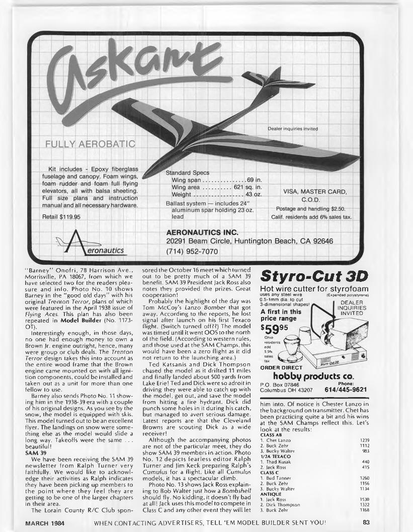
Dealer Inquiries invited
AEROBATICFULLY
Kit includes - Epoxy fiberglass fuselage and canopy. Foam wings, foam rudder and foam full flying elevators, all with balsa sheeting.
Standard Specs
Weightinstructionallast system — includes 24 aluminum spar holding 23c lead
manual and all necessary hardware.
Retail $119.95
e ro n a u tic s
VISA, MASTER CARD. C.O.D.
Postage and handling $2.50. Calif, residents add 6% sales tax.
AERONAUTICS INC.20291 Beam Circle, Huntington Beach, CA 92646 (714) 952-7070
‘ 'Barney” O nofri, 78 Harrison Ave., Morrisville, PA 18067, from which we have selected two for the readers pleasure and info. Photo No. 10 shows Barney in the “ good old days" with his original Trenton Terror, plans of which were featured in the April 1938 issue of Flying Aces. This plan has also been repeated in Model Builder (No. 1173- OT).
Interestingly enough, in those days, no one had enough money to own a Brown Jr. engine outright, hence, many were group or club deals. The Trenton Terror design takes this into account as the entire wood frame that the Brown engine came mounted on with all ignition components, could be installed and taken out as a unit for more than one fellow to use.
Barney also sends Photo No. 11 showing him in the 1938-39 era with a couple of his original designs. As you see by the snow, the model is equipped with skis. This model turned out to bean excellent flyer. The landings on snow were something else as the model would slide a long way. Takeoffs were the same .. . beautiful!SAM 39
We have been receiving the SAM 39 newsletter from Ralph Turner very faithfully. We would like to acknowledge their activities as Ralph indicates they have been picking up members to the point where they feel they are getting to be one of the larger chapters in their area.
The Lorain County R/C Club spon
sored the October 16 meet which turned out to be pretty much of a SAM 39 benefit. SAM 39 President Jack Ross also notes they provided the prizes. Great cooperation!
Probably the highlight of the day was Tom McCoy’s Lanzo Bomber that got away. According to the reports, he lost signal after launch on his first Texaco flight. (Switch turned off??) The model was timed until it went OOS to the north of the field. (According to western rules, and those used at the SAM Champs, this would have been a zero flight as it did not return to the launching area.)
Ted Katsanis and Dick Thompson chased the model as it drifted 11 miles and finally landed about 500 yards from Lake Erie! Ted and Dick were so adroit in driving they were able to catch up with the model, get out, and save the model from hitting a fire hydrant. Dick did
Cunch some holes in it during his catch, ut managed to avert serious damage.
Latest reports are that the Cleveland Browns are scouting Dick as a wide receiver!
Although the accompanying photos are not of the particular meet, they do show SAM 39 members in action. Photo No. 12 depicts fearless ed ito r Ralph Turner and Jim Keck preparing Ralph’s Cumulus for a flight. Like all Cumulus models, it has a spectacular climb.
Photo No. 13 shows Jack Ross explaining to Bob Walter just how a Bombshell should fly. No kidding, it doesn't fly bad at all! Jack uses this model to compete in Class C and any other event they will let
S tyro -C u t 3 DHot wire cutter fo r styrofoamuses any steel wire (Expanded polystyrene)
DEALERINQUIRIESINVITED
0.5-1mm dia to cut 3-dimensional shapes!
A first in this price range
*5995Ohio residentsadd5.5%
O R D E R D IR E C T
hobby products co.Ρ.Ο. Box 07846 phone:Columbus OH 43207 614/445-9621
him into. Of notice is Chester Lanzo in the background on transmitter. Chet has been practicing quite a bit and his wins at the SAM Champs reflect this. Let’s look at the results:CUSS AB1. Chet Lanzo 12392. Buck Zehr 11123. Bucky Walter 9831/2A TEXACO1. Thad Kusak 4402. Jack Ross 415CUSS C1. Bud Tanner 12602. Buck Zehr 11563. Bucky W alter 1134ANTIQUE1. lack Ross 15302. Dick Thompson 13223. Buck Zehr 1168
MARCH 1984 WHEN CONTACTING ADVERTISERS. TELL ‘EM MODEL BUILDER SENT YOU! 83

Soldering Tools
Model 1200
Model 900
Model 300
Model 1200 delivers 100 watts, heats instantly. Two tips included. Model 900 delivers 60 watts. And Model 300 delivers 30 watts. Great for all soldering jobs. Send 25 cents for catalog and price list. K & S Engineering, 6917 W. 59th St., Chicago, Illinois 60638. Telephone: 312/586-8503.
ATTENTION % SC A LER SE P O X Y G L A S S C O W L S FOR:
N O S E N P IC A S ID M O R G A N . B A LS A U S A P L A TT. C O N C E P Tf l e e t h o s t e t l e r . r c m t - c r a f t . s h c b c r p i t t s '/> a v.S C A LE. S U P E R CU B. F O K K E R D 7. B O E IN G P 12 P 26. F4B2. F4 B 4 S P A R R O W H A W K . G E E B E E M O D V . M A C B R IE N S TU R B U LEN T. C H R IS TE N EA G LE. B R IS IG H E L L A S S T A R D U S TE R II. V> S C A L E J 3 -B I B ABY. F L Y B A B Y A IR C A M P E R P IL O T J U N G M A N N I 3 5 S C A L E h O T H E R S
W H E E L P A N T S FOR :CITA B R IA . S T A R D U S T E R II. P IU S . S K Y B O LT. L IB E R T Y S POR T. C H R IS T E N E A G L E P 6 E H A W K . S TE A R M A N . S T IN S O N S R-9. M U L L IG A N b O T H E R S
BRAZED b HEAT-TREATED W IRE GEARS b CABANES LARGE SCALE PLANS AVAILABLE
Please send $1.00 for complete list We supply Modelers with fiberglass parts fo r your plans— Write or call us:
T a D FIBERGLASS SPECIALTIES30925 BLOCK. GARDEN CITY, Ml 48135
PHONE (313) 421-6358
TEXACO1. Chet Lanzo 19:302. Bucky Walter 16:363. Buck Zehr 10:45
It is just a shame we don’t have room to acknowledge the rest of the fellows who flew, as the results show a rather monotonous series of wins by a few of the SAM 39 boys. Anyway, fellows, look at it this way, you had fun, otherwise you would have never been there! ORWICK ENGINES
All of a sudden we have Orwick engines coming out of our ears. The latest announcement from Klause and McCollum, P.O. Box 3255, Laguna Hills, CA 92653, indicate that all Orwick backorders should be cleaned up by the end of December.
Also received a nice note from Bert Streigler. 5831 McKnight, Houston, TX 77035, who runs R/C Hobby Supply, and says that he is importing Orwick engines from Dunham Engineering of England. According to George Aldrich who has received one of the first Orwick .64 engines in this country, the engine is a faithful copy of the original. It ought to be, George lent his original engine for copying.
This makes two excellent Orwick .64 engines to choose from. However, according to Aldrich. Dunham expects to also produce other models of the Orwick line such as the .73, .32, and .23 ignition series. Great stuff!
As if that wasn’t enough, at the recent Region 2 Collectogether at Stockton, California, Bill Daniels has finally come out with his version of the Orwick, but it is modified to show the name " Daniels" on the case. Other than that, the engine pretty well is in the Orwick tradition . . . neatly made.
The competition promises to be rather stiff as Bill Daniels is asking better than $300 for his engine, while Joe Klause is selling his at $250, while Bert Streigler is figuring on retailing his at $200. In most cases the above figures include postage, but not sales tax where applicable. Looks like the modeler has broken the sonic barrier on old model engines .. . that have been astronomically priced. Go gettum fellows!!FORSTER .99
George Aldrich. 12822 Tarrytown, San Antonio, TX 78233, reports he is no longer associated with M&G. According to Les Payne, M&G has decided to hone their own piston and cylinder assemblies. This leaves George with a few assemblies that he can fix up in his inimitable way. If you have a Forster .99 that has a good lower end, but needs a good top end, George can fix you up with a real honking Forster .99! Try George, you’d be surprised!MORE ENGINES
Just received the neatest letter from Herb Wahl, Box 61, Forksville, PA 18616, wherein he states that he has almost completed the run of 900 Commemorative Ohlsson Gold Seal engines. As of November 15, he was working on No. 730. He says he has further plans for this motor but must defer to the demand that has piled up from the Brown Jr. and Hurleman engines.
In that line. Herb says he will immediately start his building of the aforementioned engines for 1984 plus the overhaul of badly needed engines. Herb, who operates under the name of Herbs Model Motors, puts out an impressive list of parts for Brown Jr., Hurleman, Brownie .29, and Ohlsson Gold Seal engines. You gotta write him to be a believer!!
Herb also stocks ignition components such as condensers, spark coils, spark plugs, gaskets, and even SAE 70 wt. oil. So, don’t ask where there is a good source for engine parts fellows!! You can rejuvenate that old turkey of yours and have some real fun again.
Almost forgot to mention prices. Engines (com plete) are as fo llow s: Hurlemann .48, $250; Hurleman Twin, $480; Brown Jr. Special, $225; Brown Jr. Custom, $250; Brown Jr. Classic, $290.
The first Brown Jr. (Special) has no choke nut on the intake while the most expensive Brown (Classic) features a 24 karat gold cylinder. How about that?? To order engines, a $50 deposit is required to get you on the list. Engines are made and shipped in strict rotation of the numbers assigned.SAM CHAMPS SITE
Just received a letter from John Lange of Stone Park, Illino is, wherein he describes the Bong Recreational Area as the remains of an unfinished 10,000 ft. strip that was levelled and gravelled, but not paved.
Between the taxi strips, ways, and interconnecting roads, grass grows knee high. Most chasing must be done on the roads if one is to keep up with his model. The knee high grass makes it easy to lose hand launched gliders, .020 Replica models, and any other of the small type airplanes. You have to keep your eyes on them, men!
John says there is no 72 MHz interference problem s at Bong. He has monitored the field and finds that 75.64 (green and white) has a pager service on this frequency at Reeseville-Columbus, Wisconsin. This can be heard on his car radio backup so be a little careful here.
The field will cost each contestant 75<t per day to come aboard as the Wisconsin Department of Natural Resources has taken over. Lange also reminds the contestants to come prepared with rubber boots if that area has heavy rainfall in the spring. Bong can get “ soft" from continual rainfall.
In addition, Karl Spielmaker,1984 Sam Championship Contest Manager writes to say the contest will definitely be held on June 25 through 28. The following events are to be held:FREE FLIGHT30 second Antique Class A Cabin Gas Class B Cabin Gas Class C Cabin Gas Class A Pylon Gas Class B Pylon Gas Class C Pylon Gas SPECIAL FREE FLIGHT Compressed Air Twin Pusher jimmy Allen Ohlsson 23 Power
Rubber Slick Rubber Cabin Gas Scale .020 Replica Hand Launched Glider Rubber Scale Fuel A llotment
EVENTSSlag Engine Power Commercial Rubber Nostalgia (.02-.089) Nostalgia (.09- .65)
84 MODEL BUILDER

R ADIO CONTROL EVENTS1/2A Texaco Texaco True Antique Glow Antique Class A Glow
Class B Glow Class C Glow Class A Ignition Class B Ignition Class C Ignition
Trophies will be given to fifth place in all standard free flight and R/C events. All special events will have awards to third place.SAM F/F CHAMPION
In the past few months, there have been some inquiries as to the exact winner of the O /T F/F Sweepstakes Trophy given at the La Junta SAM Champs. Jim Adams, “ SAM Speaks" newsletter editor, was the first to spot the discrepancy in the results. While it is not genera lly know n, the Hand Launched Glider event counts in the Sweepstakes Trophy points, having been voted as a “ basic event” several years ago.
The announced winner, Sal Taibi, was most gracious in his letter of congratulations to John Bortnak, sometimes called the "Canadian F/F Tornado” . John is a dedicated modeler who flew in from Calgary, Alberta, in his Cessna Skyhawk, fully loaded with models. Being unable to rent a car, John Lange kindly took him out to the field utilizing his station wagon.
Bortnak was in the Royal Navy and flew Fairey Swordfish airplanes (known as String Bags) and Spitfires off small aircraft carriers during WW-II and Korea. He built models when we was young, and after his time in the service he was a hot competitor in Canadian and Northwest US free flight contests.
Then he raised a family, making his m illion or so in the meantime. He recently decided to retire and resume modeling again. He built fifteen models in less than six months. Whew!!
The amazing thing (according to Lange) is that Bortnak is good at everything from Hand Launched Glider, Rubber Power, Scale, Towline Glider, and Free Flight Gas. He looks like a 30 year old, lifts weights, jogs five miles every day. He is unbeatable in hand launched glider as his arms are like two Gorilla winches, and his legs are like two motor bikes. He can bench press 440 pounds and do squats with 500 pounds, yet his gliders show all the dainty warp adjustments and daubs of clay.
Lange sez he expected him to be a basket case from heat prostration, but his physical condition prevented that. He chased planes two and half miles several times, swam in the lake to get his Brooklyn Dodger, and lost that event after two maxes because he was unable to start the water soaked engine and ignition system. Beating Taibi (to Bortnak) would have been better than a basement full of trophies.
As a beginner, John B. took two firsts, and two other places. Not bad for a Rip Van Winkle who hasn’ t flown in 20 years!AUSTRALIA
Received a nice photo (No. 14) from Colin Borthwick, 52 Chapel Hill Road, Queensland 4069, Australia, showing his
AC/DC AUTO CHARGERN o . 4 0 0 5 B
$69.95
Astro Flight, Inc.13311 Beach Ave. Venice. California 90291 (213) 821-6242
THIS DELUXE HEAVY DUTY AC/DC AUTO CHARGES IS JUST PERFECT FOR SAFE, RELIABLE. FAST CHARGING OF THE NICAD BATTERY IN YOUR PLANE. BOAT OR CAR. IT HAS ALL THESE FEATURES YOU ASKED FOR:• Has adjustable rate - zero to six
amps.• Charges 4. 5. 6. 7. or 8 cells.• Charges 250 mahr up to 1.8 ahr
cells.• Works from 1 lOv house current.• Works from 12v auto battery or gel
cell.• Has equalizer circuit with pilot
light.• Has jacks for external voltmeter.• Use on boats, cars, planes.• Use on transmitter and receiver• Use for motor break in.
latest handiwork, a Megow Quaker Flash. Colin reports with a Saito .30 engine in the model, it is one of the nicest and smoothest flyers he has ever had. That’s what its all about isn’t it?? READERS WRITE
Photo No. 15 shows John Kenny, Jr., 204 North Stone St., Greenwood, MS 38930, with his first O.S. .60 four-cycle powered Powerhouse. This is the first R/C O/T model that John has built, and he is quite enthusiasticabout the model.
As can be seen, he enjoys a good field to fly from, but he dins old timer flyers are far and few between in the Deep South. Anyone out there who is interested??GOOD STORY
Received the darnedest letter which included Photo No. 16 from Harry A lbright. Jr., 5226 Woodland Drive, Harrisburg, PA 17109, about his experiences with his Mercury. Here's what Harry has to say:
"/ built about four of the Scientific Mercury kits back in the forties, and all flew well (free flight), but it is the last one that is the best. Powered by a Herb Wahl Brown lr., the model has rudder and elevator only (radio control this time).
"On the third flight of the day, I let it go not realizing the antenna wire had broken loose. The model went straight away like a bird until it was out of sight.
"I could hear the motor but couldn't see it. Finally the motor quit. ‘Please come back baby!’ After an interminable length of time (about ten minutes), here the model comes back on a straight line about five hundred feet away directly to the field
"Everyone went nuts as this was absolutely unbelievable. The model continued on over some trees, across a meadow, and ended up in the woods bordering the area. Picking up the
model after some searching, I found the only damage was a broken propeller. Wow!
" Everyone thought this was great and said to do it again. No way!!! I was glad to get it back. I figure someone up there loves me, and it's no use stretching your luck."WRAPUP
On that note, we'll wrap it up. Beside this columnist is running out of time to prepare and pack up for the Australian Nats held over the New Years holiday. We’ll have a report and photos on the Old Timer explosion in Australia. It'ssimply great! ·
Soaring........ Continued from page 34
bubble is relatively short in length, therefore contributing little drag to the airfoil. However, in the Reynolds number regime of an R/C sailplane, a laminar separation bubble can extend over a large portion of the a irfo il's upper surface. This long bubble causes a drastic increase in drag which the program cannot account fo r in its calculations. In using the program to design arifoils, this lim itation of the program must be realized by the designer; if it is not, the theoretical section characteristics are opimistic in this low Reynolds number regime.
" The S1120-106-83 and S1144-108-83 (SI 144 and S1120)are preliminary airfoils that were designed in the summer of 1983. Since that time I have designed some airfoils that should prove to be better in the 'real world' than the S1120 and SI 144. As mentioned in Bill Forrey's column, I have built a wing utilizing the SI 144. This wing has been adapted to my Sagitta sailplane. To date, I have not flown this sailplane in com petition where its performance can be evaluated relative to other R/C sailplanes. I can
WHEN CONTACTING ADVERTISERS, TELL'EM MODEL BUILDER SENT YOU!MARCH 1984 85

MODEL IGNITION ENGINES G ACCESSORIES
P R <
77 Products now has N 6 K M E 8 m iniature spark plugs, designed specifically for Model Ignition Engines.
Threads and Hex size same as M odern G lo w Plugs price is $ 5 .0 0 each, total postage is $1.50 regardless of quantity. W ill fit m ost original Ignition Engines and all M odern Ignition Conversions.
CA TA L OG A V A IL A B L E. $2.00
(213) 329 0273 17119 SO. HARVARD BLVD., GARDENA. CA. 90247
A sport .40 a irp lane tha t looks like the real th ing ! Patterned fro m the venerable T-34, th is plane is designed fo r so lid and p red ic tab le flig h t characte ristics w ith good ground handling and slow land ing speed. Perfect fo r e ither a low winged a ile ron tra iner or an advanced fu n -fly machine. Balsa sheeted foam w ing , lite p ly/balsa fuselage and ta il, vacuum fo rm ed canopy and cow l.
5 0 K 2 2 2 —Ace S port T 34
com plete cata log, a ll Ace items are available at you r dealer. Add $1.00 handling fee if you must order d ire c t.
A C I l/C . BwcT]$59.95 Box 51 ID , H igginsville , M o. 64037 (816)584-7121
safely say, its performance is as good as, if not belter than, the Sagitta with the modified E205.
“ At the expense of confusing the modeler, there has been an ongoing debate: 'Thick vs. Thin,' referring to airfoil sectional thickness ratio. The fact is plain and simple. Relatively speaking, thick airfoils give us a wide drag bucket with high drag. Conversely, thin airfoils give us a narrow drag bucket with low drag.
“ For F3B type competition, low drag near a lift coefficient of 0.1 is desired for1 the speed task. Whereas, high lift is desired for launching and soaring. In itia lly , these conditions may seem impossible to meet; but, there is a solution. The low drag is achieved by using a thin airfoil while the high lift is achieved by flapping this airfoil. Ralf Decker used this combination on his R/C sailplane to win the 1983 World Champs. Decker’s Quabeck airfoil was included in Bill Forrey’s Ianuary 1984 column.
“ My airfoil nomenclature is as follows: the first four digits are unique to each individual airfoil, larger numbers being later designs; the next three digits indicate the sectional thickness raio times WOO; and the last two digits designate the year of design (T9**).
" The S209T-T0T-83, I highly recommend for use on a precision-duration or cross-country type R/C sailplane. This airfoil is based on the Airtronics Aquila airfoil. Because of its flat-bottom con
tour, the Aquila airfoil performs poorly at low angles of attack; hence, the Aquila suffers from poor penetration due to the increased drag. The S209T has a drag bucket that extends much lower than the drag bucket of the Aquila airfoil. This extension improves the penetration. The S2091 contour might be said to have ‘Phillips Entry.' At five degrees negative flap deflection, the drag bucket of the S209T lowers to about a lift coefficient of 0.25. The high lift capability of the S209T is equal to that of the Aquila airfoil. A short mean chord of about nine inches could be used as this airfoil was designed for low Reynolds numbers and high aspect ratio wings.
"I have written a report, titled ‘The Design o f A irfo ils at Low Reynolds Numbers,’ which will be published in the next issue of Soartech. (You may subscribe to Soartech by writing to the Tidewater Model Soaring Society, H.A. (Herk) Stokely, 1504 Horseshoe Circle, Virginia Beach, VA 23451,804/428-8064.) In the report, I described the cause of poor airfoil performance, namely, laminar and turbulent separation. I then compare the theoretical section characteristics predicted by the Eppler computer program with the experimental data ofAlthaus. Based on these comparisons, I designed several airfoils applicable to R/C sailplanes. Also, I discussed how the theoretical section characteristics should be interpreted, i.e„ when one can believe the theory.
“ I have planned further research in
the design of low Reynolds number airfoils . . . R/C sailplane airfoils . . . using the Eppler computer program. If you would like to receive the section characteristics, coordinates, and description o f some more new airfoils (approximately 3-4), send $1 to cover the cost of postage and copying. Mailing of these new airfoils will be within the upcoming four months. School keeps my busy!
“ I would appreciate any questions you may have regarding airfoils. Write them down and send them to me.
"I believe, if you choose to use one of my airfoil designs, you will be pleasantly surprised. ”
Those of you wishing to w rite to Michael Selig may feel free to do so. His address is 715 S. Randolph, Apt. 21, Champaign, IL 61820. If your phone bill isn’t high enough for you yet, you might try calling Michael at the fo llow ing number: (217) 351-4187. Remember that Illinois is in the Central time zone, and that most people don’t appreciate telephone calls late at night.IN CLOSING. . .
Man, another column is finished and I have only covered half the things I wanted to cover. Where does all the space go to?
Next month, if none of my plans change (they shouldn’t) I want to discuss with you the art of mold making. We will go over the steps necessary to manufacture that favorite fuselage design you’ve been kicking around in the back of your mind for years. So for now, get some sketch paper out of your desk drawer and get that design roughed out. I’ll show you how to make a dozen fuselages from that sketch . . . all identical, all as strong as you please, and as many as you desire! ·
Pattern........ Continued from page 35
the new systems on the market which have upgraded RF links are worthwhile in my opinion. Why? Because almost every crash I have had was due to interference of some kind.
The added advantage of not worrying about being “ shot down” is just too great an advantage to ignore. Also, I still recommend the use of some kind of transmitter support to simplify learning to fly all stick axes simultaneously .. . single stick flyers excepted . . . as they hold the box steady anyway.
What about gadgets? FAI flying is not going to be fun for you if you have to flip a switch or hit a button for every maneuver. Therfore, I suggest you learn to fly the sticks. Why? Because the mind is the best computer in the world, and once it’s trained to do those “ tough” rolling and snapping maneuvers, you can progress to really involved stuff with reinforced confidence. Dual rates and some exponential setups are a great help in establishing a good “ feel,” but all those buttons and switches! I'm convinced that the design criteria on some of the latest systems is “ if it doesn’t confuse, it won’t sell” .
86 MODEL BUILDER
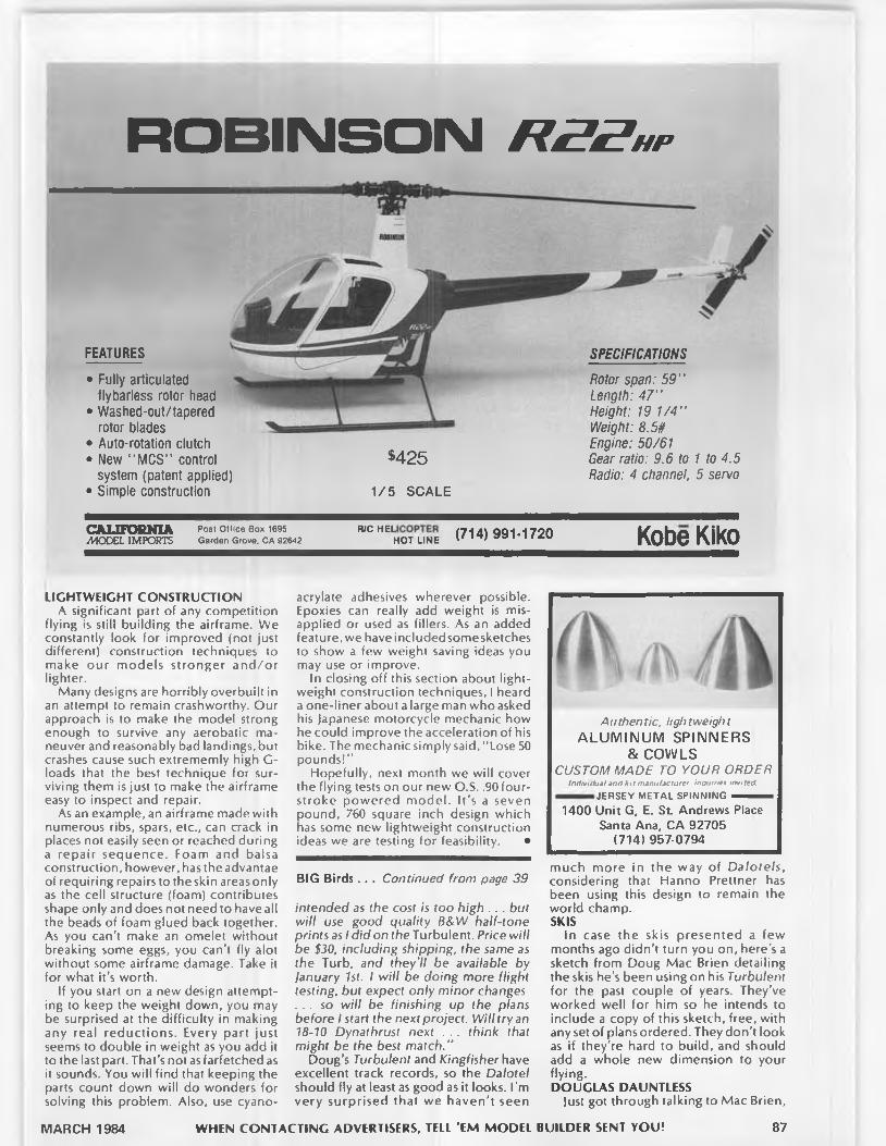
R O B IN S O N R B Z h p
FEATURES
• Fully articulated flybarless rotor head
• Washed-out/tapered rotor blades
• Auto-rotation clutch• New “ MCS" control
system (patent applied)• Simple construction
$425
1/5 SCALE
SPECIFICATIONS
Rotor span: 5 9 "Length: 4 7 "Height: 19 1 /4 "Weight: 8.5#Engine: 50/61Gear ratio: 9.6 to 1 to 4.5Radio: 4 channel. 5 servo
CALIFORNIA/MODEL IMPORTS
Post O ffice Box 1695 Garden Grove. CA 92642 RycHELhotune (?14) 991 -1720 Kobe Kiko
LIGHTWEIGHT CONSTRUCTIONA significant part of any competition
flying is still building the airframe. We constantly look for improved (not just different) construction techniques to make our models stronger and/or lighter.
Many designs are horribly overbuilt in an attempt to remain crashworthy. Our approach is to make the model strong enough to survive any aerobatic maneuver and reasonably bad landings, but crashes cause such extrememly high G- loads that the best technique for surviving them is just to make the airframe easy to inspect and repair.
As an example, an airframe made with numerous ribs, spars, etc., can crack in places not easily seen or reached during a repair sequence. Foam and balsa construction, however, has the advantae of requiring repairs to theskin areasonly as the cell structure (foam) contributes shape only and does not need to have all the beads of foam glued back together. As you can’t make an omelet without breaking some eggs, you can’t fly alot without some airframe damage. Take it for what it's worth.
If you start on a new design attempting to keep the weight down, you may be surprised at the difficulty in making any real reductions. Every part just seems to double in weight as you add it to the last part. That’s not as farfetched as it sounds. You will find that keeping the parts count down will do wonders for solving this problem. Also, use cyano
acrylate adhesives wherever possible. Epoxies can really add weight is misapplied or used as fillers. As an added feature, we have included some sketches to show a few weight saving ideas you may use or improve.
In closing off this section about lightweight construction techniques, I heard a one-liner about a large man who asked his Japanese motorcycle mechanic how he could improve the acceleration of his bike. The mechanic simply said. “ Lose 50 pounds!”
Hopefully, next month we will cover the flying tests on our new O.S. .90 four- stroke powered model. I t ’s a seven pound, 760 square inch design which has some new lightweight construction ideas we are testing for feasibility. ·
BIG Birds.. . Continued from page 39
intended as the cost is too high .. . but will use good quality B&W half-tone prints as / did on the Turbulent. Price will be $30, including shipping, the same as the Turb, and they’ll be available by january 1st. I will be doing more flight testing, but expect only minor changes . . . so will be finishing up the plans before I start the next project. Will try an 18-10 Dynathrust next . . . think that might be the best match.’’
Doug’s Turbulent and Kingfisher have excellent track records, so the Dalotel should fly at least as good as it looks. I’m very surprised that we haven’t seen
Authentic, lightweight ALUMINUM SPINNERS
& COWLSCUSTOM MADE TO YOUR ORDER
I n d i v i d u a l a n d k i t m a n u f a c t u r e r i n Q u t r t e s i n v i t e d
JERSEY METAL SPINNING — — 1400 Unit G, E. St Andrews Place
Santa Ana, CA 92705 (714) 957-0794
much more in the way of Dalotels, considering that Hanno Prettner has been using this design to remain the world champ.SKIS
In case the skis presented a few months ago didn’t turn you on, here’s a sketch from Doug Mac Brien detailing the skis he’s been using on his Turbulent for the past couple of years. They’ve worked well for him so he intends to include a copy of this sketch, free, with any set of plans ordered. They don't look as if they're hard to build, and should add a whole new dimension to your flying.DOUGLAS DAUNTLESS
Just got through talking to Mac Brien,
87MARCH 1984 WHEN CONTACTING ADVERTISERS, TELL ’EM MODEL BUILDER SENT YOU!
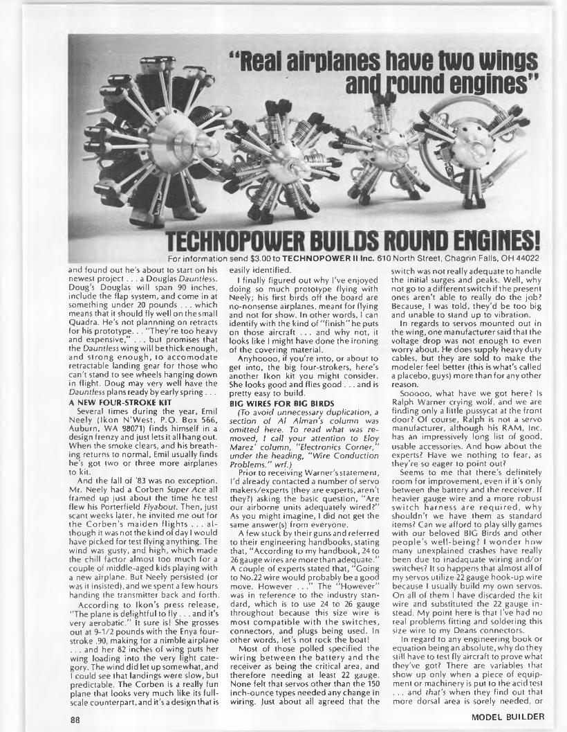
For information send $3.00 to TECHNOPOWER II Inc. 610 North Street, Chagrin Falls, OH 44022and found out he's about to start on his newest project. . . a Douglas Dauntless. Doug's Douglas will span 90 inches, include the flap system, and come in at something under 20 pounds . . . which means that it should fly well on thesmall Quadra. He’s not plannning on retracts for his prototype... "They’re too heavy and expensive,” . . . but promises that the Dauntless wing will bethickenough, and strong enough, to accomodate retractable landing gear for those who can’t stand to see wheels hanging down in flight. Doug may very well have the Dauntless plans ready by early spring . .. A NEW FOUR-STROKE KIT
Several times during the year, Emil Neely (Ikon N’West, P.O. Box 566, Auburn, WA 98071) finds himself in a design frenzy and just lets it all hang out. When the smoke clears, and his breathing returns to normal, Emil usually finds he’s got two or three more airplanes to kit.
And the fall of ’83 was no exception. Mr. Neely had a Corben Super Ace all framed up just about the time he test flew his Porterfield Flyabout. Then, just scant weeks later, he invited me out for the Corben's maiden flights . . . although it was not the kind of day I would have picked for test flying anything. The wind was gusty, and high, which made the chill factor almost too much for a couple of middle-aged kids playing with a new airplane. But Neely persisted (or was it insisted), and we spent a few hours handing the transmitter back and forth.
According to Ikon’s press release, “ The plane is delightful to fly . . . and it’s very aerobatic." It sure is! She grosses out at 9-1/2 pounds with the Enya four- stroke .90, making for a nimble airplane . . . and her 82 inches of wing puts her wing loading into the very light category. The wind did let up somewhat, and I could see that landings were slow, but predictable. The Corben is a really fun plane that looks very much like its full- scale counterpart, and it's a design that is
easily identified.I finally figured out why I've enjoyed
doing so much prototype flying with Neely; his first birds off the board are no-nonsense airplanes, meant for flying and not for show. In other words, I can identify with the kind of "finish” he puts on those aircraft . . . and why not, it looks like I might have done the ironing of the covering material.
Anyhoooo, if you're into, or about to get into, the big four-strokers, here's another Ikon kit you might consider. She looks good and flies good . . . and is pretty easy to build.BIG WIRES FOR BIG BIRDS
(To avoid unnecessary duplication, a section of Al Alman’s column was omitted here. To read what was removed, I call your attention to Eloy Marez’ column, "Electronics Corner," under the heading, "Wire Conduction Problems." wrf.)
Prior to receiving Warner’s statement. I’d already contacted a number of servo makers/experts (they are experts, aren't they?) asking the basic question, "Are our airborne units adequately wired?” As you might imagine, I did not get the same answer(s) from everyone.
A few stuck by their guns and referred to their engineering handbooks, stating that, “ According to my handbook, 24 to 26 gauge wires are more than adequate." A couple of experts stated that, "Going to No.22 wire would probably be a good move. However .. .” The "However” was in reference to the industry standard, which is to use 24 to 26 gauge throughout because this size wire is most compatible with the switches, connectors, and plugs being used. In other words, let’s not rock the boat!
Most of those polled specified the w iring between the battery and the receiver as being the critical area, and therefore needing at least 22 gauge. None felt that servos other than the 150 inch-ounce types needed any change in wiring. Just about all agreed that the
switch was not really adequate to handle the initial surges and peaks. Well, why not go to a different switch if the present ones aren’t able to really do the job? Because, I was told, they’d be too big and unable to stand up to vibration.
In regards to servos mounted out in the wing, one manufacturer said that the voltage drop was not enough to even worry about. He does supply heavy duty cables, but they are sold to make the modeler feel better (this is what’s called a placebo, guys) more than for any other reason.
Sooooo, what have we got here? Is Ralph Warner crying wolf, and we are finding only a little pussycat at the front door? Of course, Ralph is not a servo manufacturer, although his RAM, Inc. has an impressively long list of good, usable accessories. And how about the experts? Have we nothing to fear, as they’re so eager to point out?
Seems to me that there’s definitely room for improvement, even if it ’s only between the battery and the receiver. If heavier gauge wire and a more robust switch harness are requ ired , why shouldn’t we have them as standard items? Can we afford to play silly games with our beloved BIG Birds and other people ’s well-being? I wonder how many unexplained crashes have really been due to inadequate wiring and/or switches? It so happens that almost all of my servos utilize 22 gauge hook-up wire because I usually build my own servos. On all of them I have discarded the kit wire and substituted the 22 gauge instead. My point here is that I’ve had no real problems fitting and soldering this size wire to my Deans connectors.
In regard to any engineering book or equation being an absolute, why do they still have to test fly aircraft to prove what they’ve got? There are variables that show up only when a piece of equipment or machinery is put to the acid test . . . and that's when they find out that more dorsal area is sorely needed, or
88 MODEL BUILDER

that certain fairings won’t hack it, etc. I, for one, think we deserve the best radio gear, instead of a watered-down compromises. And most of the guys I've talked to would fork out the extra bucks for a radio that would be better insurance against glitches, funnies, burnouts . . . and crashes.TARTAN TWIN MUFFLER
PK Products (P.O. Box 6226, Hayward, CA 94540) has another goodie, this time it’s a cast aluminum muffler for the Tartan Twin. It allows access to the needle valves even with the engine running, and provides a “ significant” increase in rpm over the stock muffler. Also, guys, these mufflers are fitted with pipes that are directed down and back from the engine . . . as in full-sized aircraft. According to Paul Kinney, the price is $39.95 plus $1.50 for postage and handling. Extension tubing is included so you can get that exhaust outside the cowl.
Paul also mentioned that PK now has a Super Starter to fit the Tartin Twin. This should be a boon to Tartin Twin owners as I’ve heard that this engine has been known to start backwards.TIP OF THE MONTH
Mae West must have liked BIG Birds . . . why else would she have said, “ Too much of a good thing is wonderful!”
Al Alman, 605 168th Street, East, Box 95, Spanaway, WA 98387.
Now that we're into the build ing season, how about some pix of what’s do in ’ in your workshop? And don ’t forget about fly-in’s and such; let's get the word out!
BE SAFE . . . PLEASE! ·
Choppers . . . . Continued from page 43
roll. Right-left cyclic and tail rotor are very closely related!
3) Keep the helicopter within a ten- foot circle. This will keep you from running all over the parking lot, and it will also make you concentrate harder to keep the helicopter in one spot. If it leaves the ten-foot circle, pick it up and bring it back to the center, and try again.
4) Make each hop a definite learning attempt. If the helicopter leaves the circle, don’t walk around it and try to fly / slide it back to the center. Pick it up and center it by hand . . . take a minute or two to gather your concentration, and very slowly get the helicopter light on the skids. Once it reaches an inch or two, try to keep it over your spot. If the hop lasts five seconds, and the ship is still in the circle, go ahead and reposition yourself behind the helicopter (providing it is still pointing into the wind) and start over again.
5) Don’t stand too close or too far away. Generally six to eight feet behind the ship is good, and slightly off to the left or right . . . whatever feels more comfortable to you. See Figure 1.
6) Concentrate your attention aroundthe main shaft. If you stare at the nose ortail, you'll never see what's happeningwith cyclic until it’s too late. By looking at the main part of the fuselage, you can
B E E C H C R A F T SKIPPER: Quarter-Scale. 90" wingspan, 1,200 sq. in. area, .90 or larger engines. Plans, $18.50 O ther plans:BEECHCRAFT BARON MODEL 58: 2’ z Scale 85 wingspan-1000 sq in (3) 3 x6 sheets S15 00 Beechcralt Fm Insignia $2 00 BEECHCRAFT BONANZA A36: 24» Scale-86 wingspan-1300 sq in (3)3x6*? sheets $17 50 A dd $2.00 postage inside U.S. & Canada Include $2.00 fo r plan ro lled In tube Overseas orders add $10.00 postage A labam a residents add 6% sales tax
BUD CADDELL1525 Badham Dr.. Dept M. Birmingham. AL 35216
205 822-4312______________ DEALER INQUIRIES INVITED
see altitude and cyclic changes clearly. Movements of the nose (for tail rotor correction) can easily be picked up with peripheral vision.
7) Practice, practice, practice; but don’t fly until you crash. This type of practice I am referring to is frequency of practice, not quantity of practice. To give you an example from full-size, we always liked the student to fly five days a week, then take Saturday and Sunday off and think about it over the weekend. Some students couldn’t fly five days a week for time or money reasons, and it was apparent that they took longer to learn how to fly the thing.
Three days a week was the very minimum that we liked to see, but there was an occasional student who flew only on the weekends. This was really a problem becaused he simply forgot more over the week that he didn’t fly. When the next weekend came, most of the time was spent reviewing things he had learned the week before, with only 15 minutes left out of a one-hour period to work on new progression. We (instructors) would always tell the student that it was going to be nearly impossible to learn to fly only on the weekends, but most would only agree with us once they had flown 15 or 20 hours, and found out that they had hit a plateau that they could not pass through.
Quite simply, the same goes for learning how to hover models, too. Fly frequently, but not too much at one shot. Don’t try to fly any more than three tankfuls at a time. The first tank will warm you up and let you relearn what you forgot since last time. The second tank is the “ workhorse” , where you’ll learn the most on that particular day. The third tank will still be good, but by the end of it, you’ll be fairly well fatigued. The forth tank is asking for a crash. You won’t learn enough to make the risk worthwhile, and a tipover only takes a second of mental lapse.
Try to fly a tank or two every evening that you can. On weekends, a maximum of three fights in the early morning and three flights during late afternoon will be best.LONG HOVERS
When you can hover at will, set it down and pick it up with complete con-
NEW !FR O M
" “ "S S lo r
$9.95easv^npJ Une ,lyin9 jsthe Y· inexpensive wav into
WaTkTr°,df lln9' andJ'm h a „ er S ,am°us models have been responsible for getting
Whin* 3 4 S 6 * *p f k'dS in,° 'be bobby. n Z hlKP~?°wer P'anes, devel-a il ihby he lale Jim Walker, are the easiest and safest way
' f arn C/L flying. No messyVconfab T L nmn9 pr°Ps to dis-ron, ?9 «k'u S or paren,s Just a regular fishing rod or bamboopole provides the power to perform loops, wing-overs and inverted flight. Develops basic aerobatic skills and simple modeling techniques quietly and safely
When you're ready for powered flight, try the Fire- baby II (19-1/2 in. w ing) or the Jr. Fireball (24 in. wing). Both of these dynamite models use any standard .049 engine.
See your dealer and ASK FOR T H E A M E R IC A N JUNIORS!American Junior Heritage Models, Inc.P.O. Box 505 Donald, OR 97020 (503) 370-7558If not available, order direct Check, money order. Visa/Master- Card. please AddS2.00for handling and postage.
trol, then it’s time to jump to a new level of novice flying.
You’ll find that you won’t get fatigued nearly as much; the three-tank limit won’t apply anymore. And if you can only make it out on weekends, you'll see that you don’t forget (or regress) nearly as much from week to week as you did when you were first learning.
At this point, try to actively maneuver to improve your hovering skills. Walk the dog” , which meansslowly hover forward and walk behind the ship, keeping your six to eight-foot distance.
Practice 90-degree turns with the tail rotor, at first keeping yourself oriented by staying behind the helicopter. (Later, you can make these 90-degree tail rotor turns and fly by looking at the side of the
WHEN CONTACTING ADVERTISERS, TELL 'EM MODEL BUILDER SENT YOU!MARCH 1984

G e t E l e c t r i f i e d — <u TOtUAvtef
ΓΝ
Geist — World-Leading, German high technology
electric components• Geist Samarium Cobalt motors
and flight systems (with slip-on rings for more power durationl)
• Geist Electronic Speed Controls• Geist Fiberglass Folding Props• Geist Electronic On/Off Switches• Geist Battery Chargers• Geist "Hot Dog" and
"Hot River" AircraftContact Wllshlre for all electric
^flight components!C ata lo g s - Sailplane $2.50
Electric . $2.50
w i l s h i r e m o d e l c e n t e r12836 Santa Monica Blvd.· Santa Monica, C A ·
■■ 90403 · Phone 1213) 828-9362RC Sailplane and Electric Power specialists for the U.S.A.
[ V a a # p a r a s o lI rOClOr 1/4 SCALE KIT
COMPOSITE MODEL OF THE 1914 MORANE-SAULNIER & THE 1915 PFALZ E III. BEAUTIFULLY DETAILED. VERY EASY TO FLY AT LOW AIR SPEED W ITHOUT ANY PREVIOUS EXPERIENCE 76'/UN WINGSPAN. 6.8 LBS.. USING .45 ENGINES AND UP
CO M PLETE KIT. LESS WHEELS. ENGINE ft PROP S 145 .00 + SHIP(contain» tome 540 pert» and » »w> detailed construction memel)
PROCTOR. P.O. BOX 1333, LA JO LLA. CA. 92038 For add itiona l in form ation, ca ll (619)278-9000 . or
write. For a com plete 40 page cata log, send S 2.00.
ship.) Then, stand in one spot and hover the helicopter around you in a circle, turning with the ship as it slowly hovers around you. (Figure 2.)
Practice your hovering until you feel tota lly confident . . . almost bored. Then, in combination with the exercise shown in Figure 2, it’s time for forward flight.FORWARD FLIGHT CONDITIONS
Contrary to some opinions, forward flight is not something you automatically do. You don’t hover one day, and fly around the next. No offense to Andy in his letter, but you don’t " bite the bullet and go." Forward flight is something you sneak up on, so the interface between hovering and actual forward flight is almost unnoticeable.
Transition to forward flight also puts you back as a "beginner", but on a higher level. What I am indirectly telling you in the last sentence is that you must have nearly perfectly calm conditions when you practice these exercises which lead to forward flight.
No doubt at the end of your earlier hovering practice you’ll be able to fly in
some wind with little problem. Resist the temptation to do these circles in wind because it only takes one gust to swing the tail around, and in an instant you’ll lose orientation and roll it up in a ball. (Also known as the dying chicken routine . ..) All of this means that your practice sessions will go back to early morning or late afternoon, when calm conditions are most prevalent. FORWARD FLIGHT BEFORE EFFECTIVE TRANSLATIONAL U R
Refer back to Figure 2. This is where it all starts. Hover at the “ start” point and stabilize. Then give very slight forward cyclic to move the helicopter forward. The main thing that turns the helicopter around you is the tail rotor. The right and left cyclic only serves to control the six-foot distance between you and the machine. It may take you 20seconds to a minute to complete these first circles. Notice that this is really hover practice, which you probably already feel confident with.
Always start from a hover and end with a hover. This is the number one rule for transitioning to forward flight. Many accomplished fixed-wing pilots would have no trouble at all with a helicopter in forward flight, it’s just getting it back down on the ground in one piece that becomes a problem. Therefore, your ability to hover consistently becomes very important at the end of the approach from forward flight.
Given that the six-foot circle around you is perfectly comfortable, increase the radius of the circle from six feet to 10 to 15 feet in positions two, three, and four. The start/stop point in all of these forward flight exercises will always be at the same point. Do these 10-foot circles imperceptibly faster than the six-foot circles until you feel perfectly comfortable with them. Always start and stop at a hover.
Now increase the radius of the circle
P O R T E R F IE L D4 CYCLE POWERED 8 0 “ WINGSPAN
SEND 51.00 FOR CO M PLETE CA TA LO G OF FIN E KITS
Ikon N'WSTP.O Box 566 Auburn. WA 98071
(206) 941-8248
to 30 feet. The speed of the circle will again imperceptibly increase, enough that all of the circles stay constant. By this I mean that if the six-foot circles took 20 seconds to complete, the 30-foot circles ought to take the same 20 seconds. At position three, your altitude should be slightly higher now .. . about 10 feet. Position two will be climbing slightly, and position four will be descending slightly. At about the 50 to 75-foot circle size, things will start to change:
1) The acceleration into the circle and deceleration at the end of the circle will be more predominant. That is, a touch more forward cyclic will be needed to accelerate, and more aft cyclic will be needed to decelerate when returning to a hover. The throttle/collective changes at this point will still be fairly small. This is because you still should have forward speed below effective translational lift (ETL).. . say three to five mph. But as you come back into a hover, you will need a touch of throttle to keep a four-foot hover after descending from the 10-15 feet in position three and four.
2) As the circle size increases, more cyclic and less tail rotor will have to be used to turn the helicopter around you. In full-blown forward flight, which we’ll get to in a few paragraphs, it is all cyclic that is used for the circle, and tail rotor will only be used to correct for torque changes, mainly at the termination of the approach. At the six-foot circle we looked at earlier, it was all tail rotor, so the 50 to 75-foot circle requires the most coordination of roll and tail rotor for a smooth turn.
3) The 50 to 75-foot circle size will start to make the helicopter feel "slimey," again, similar to the "greased pig” feel it had when you were still trying to nail it in a hover! This is because the helicopter is farther away from you now than it has ever been, and visual clues to the he licop te r’s movement won’t get any better. Which means it will have to move more in any given axis before you can detect and correct it.
4) As long as you stay smooth and slow, the tail rotor torque changes will never be a problem at the bottom of an approach. It is only when you push yourself too much and get too fast that you’ll get into trouble. Keep all movements
90 MODEL BUILDER
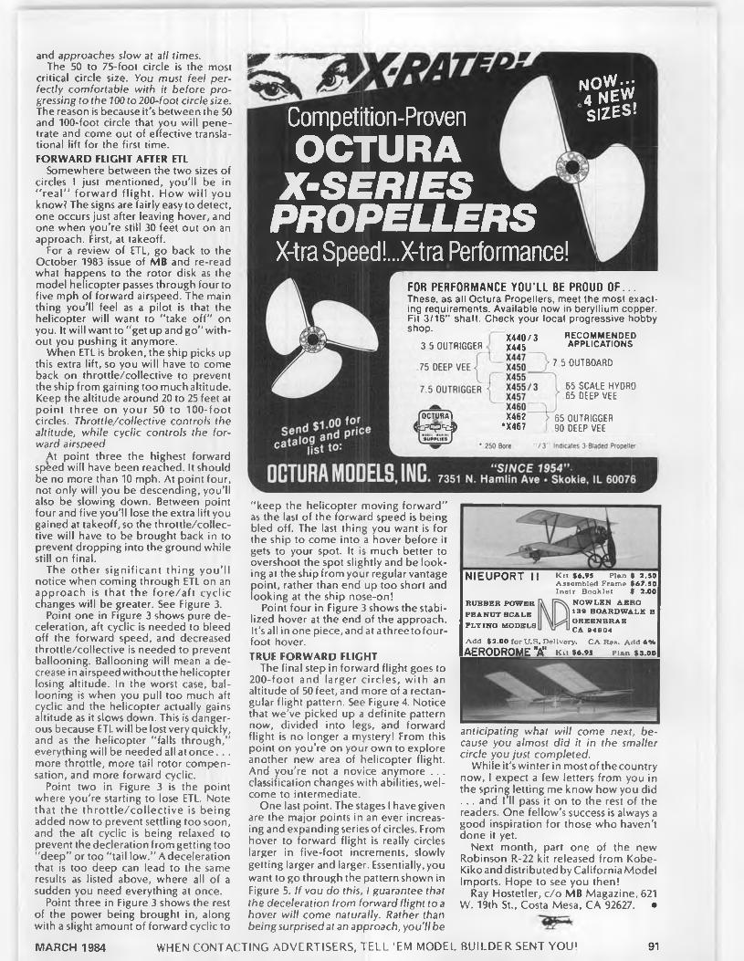
and approaches slow at all times.The 50 to 75-foot circle is the most
critical circle size. You must feel perfectly comfortable with it before progressing to the 100 to 200-foot circle size. The reason is because it's between the 50 and 100-foot circle that you will penetrate and come out of effective translational lift for the first time.FORWARD FLIGHT AFTER ETL
Somewhere between the two sizes of circles I just mentioned, you'll be in “ real” forward flight. How w ill you know? The signs are fairly easy to detect, one occurs just after leaving hover, and one when you're still 30 feet out on an approach. First, at takeoff.
For a review of ETL, go back to the October 1983 issue of MB and re-read what happens to the rotor disk as the model helicopter passes through four to five mph of forward airspeed. The main thing you’ll feel as a pilot is that the helicopter will want to “ take off” on you. It will want to “ get up and go” without you pushing it anymore.
When ETL is broken, the ship picks up this extra lift, so you will have to come back on throttle/collective to prevent the ship from gaining too much altitude. Keep the altitude around 20 to 25 feet at point three on your 50 to 100-foot circles. Throttle/collective controls the altitude, while cyclic controls the forward airspeed
At point three the highest forward speed will have been reached. It should be no more than 10 mph. At point four, not only will you be descending, you'll also be slowing down. Between point four and five you'll lose the extra lift you gained at takeoff, so the throttle/collective will have to be brought back in to prevent dropping into the ground while still on final.
The other significant thing you’ ll notice when coming through ETL on an approach is that the fo re /a ft cyclic changes will be greater. See Figure 3.
Point one in Figure 3 shows pure deceleration, aft cyclic is needed to bleed off the forward speed, and decreased throttle/collective is needed to prevent ballooning. Ballooning will mean a decrease in airspeed without the helicopter losing altitude. In the worst case, ballooning is when you pull too much aft cyclic and the helicopter actually gains altitude as it slows down. This is dangerous because ETL will be lost very quickly, and as the helicopter “ falls through," everything will be needed all at once.. . more throttle, more tail rotor compensation, and more forward cyclic.
Point two in Figure 3 is the point where you’re starting to lose ETL. Note that the th ro ttle /co llec tive is being added now to prevent settling too soon, and the aft cyclic is being relaxed to prevent the decleration from getting too “ deep” or too “ tail low.” A deceleration that is too deep can lead to the same results as listed above, where all of a sudden you need everything at once.
Point three in Figure 3 shows the rest of the power being brought in, along with a slight amount of forward cyclic to
Competition-ProvenO C T U R A
X - S E R I E S P R O P E L L E R SX-tra Speed!...X-tra Performance!
N O W · · ;4 N E WSIZES!
RECOMMENDED APPLICATIONS
7 5 OUTBOARD
FOR PERFORM ANCE Y O U ’ LL BE PROUD O F . . . These, as all Octura Propellers, meet the most exacting requirements. Available now in beryllium copper. Fit 3/16” shaft. Check your local progressive hobby shop.
X440/33 5 OUTRIGGER X445
X44775 DEEP VEE <! X450
X4557.5 OUTRIGGER i X455/3
X457 X460
fOCTURAl X462 > 65 OUTRIGGERΡ φ ' ΐ # *X467 go DEEP VEE
65 SCALE HYDRO 65 DEEP VEE
"keep the helicopter moving forward” as the last of the forward speed is being bled off. The last thing you want is for the ship to come into a hover before it gets to your spot. It is much better to overshoot the spot slightly and be looking at the ship from your regular vantage point, rather than end up too short and iooking at the ship nose-on!
Point four in Figure 3 shows the stabilized hover at the end of the approach. It’s all inone piece, and at athreeto four- foot hover.TRUE FORWARD FLIGHT
The final step in forward flight goes to 200-foo t and larger circles, with an altitude of 50 feet, and more of a rectangular flight pattern. See Figure 4. Notice that we’ve picked up a definite pattern now, divided into legs, and forward flight is no longer a mystery! From this point on you’re on your own to explore another new area of helicopter flight. And you’re not a novice anymore . . . classification changes with abilities, welcome to intermediate.
One last point. The stages I have given are the major points in an ever increasing and expanding series of circles. From hover to forward flight is really circles larger in five-foot increments, slowly getting larger and larger. Essentially,you want to go through the pattern shown in Figure 5. If you do this, I guarantee that the deceleration from forward flight to a hover will come naturally. Rather than being surprised at an approach, you'll be
NIEUPORT II Kit $6.95 Plan $ 2.SO Assembled Frame $67.50 Instr. Booklet $ 2.00
N O W LB N A E R O 13Θ BOARD W A LK B O R E E N B R A E CA 9 4 9 0 4
Add $2.00 for U.S. Delivery. CA Res. Add 6 *AERODROME "A" k h $6.95 pun $3.00
R U BBER PO W ER P E A N U T SC A L E F L Y IN G M ODELS
anticipating what will come next, because you almost did it in the smaller circle you just completed.
While it's winter in most of the country now, I expect a few letters from you in the spring letting me know how you did . . . and I'll pass it on to the rest of the readers. One fellow's success is always a good inspiration for those who haven't done it yet.
Next month, part one of the new Robinson R-22 kit released from Kobe- Kiko and distributed by California Model Imports. Hope to see you then!
Ray Hostetler, c/o MB Magazine, 621 W. 19th St., Costa Mesa, CA 92627. ·
WHEN CONTACTING ADVERTISERS, TELL ’EM MODEL BUILDER SENT YOU1MARCH 1984 91

DALOTEL - TIPORARE - C .A .P .217 5 0 8 2 5
C O M P E T IT IV E A IR FR A M ES for
P A T T E R N FLY ER S K IT S OR A IR FR A M ES
B U IL T T O O R D E R W R ITE O R C A L L
FOR IN F O R M A T IO N
AMA or FAIOUR DESIGNS ARE IN THE WINNERS CIRCLE
1978 - 1983D IC K H A N S O N M O D E LS
5269 L U C K Y C L O V E R LA N E M U R R A Y . U T A H 84107 P H O N E (801) 261-1402
F/F Scale . . . . Continued from page 61smooths out the styrofoam. When the spackle has dried, the canopy can be sanded to conform nicely to the rest of the fuselage.
Next, the canopy is carefully cut and removed from the fuselage. Add 1/8 or 3/6 balsa to the area shown on the drawing. This is done, of course, to have overlapping material to attach the canopy to the fuselage. The use of a bit more spackle to cover the seams might be in order. I then follow up with a couple coats of epoxy resin, sanding between coats, to give a very smooth, hard surface. The canopy is now ready for vacuum forming. All of this may seem like a lot of work, but end results will definitely be worth it, plus, it gives you a chance to build a fuselage differently for a change of pace.
A variation of this technique was mentioned in this column a couple of years ago. As an example of what I’m talking about, let's use the Focke-Wulf Sfosser. This airplane has a stringered fuselage with the usual amount of metal sheeting around the cockpit, and all metal from the firewall forward. On a rubber model, having stringers only to the firewall doesn’t look bad at all. However, having stringers foreward of the firewall looks downright poor, in my opinion. The usual alternative is to sheet between the stringers. Forget that! I refuse to do this on a model. Beside being time consuming, with so many glue joints, it is difficult, if not impossible, to get totally smooth contours.
My solution is fairly easy. I carve the cowl out of a piece of styrofoam, using two templates, one at the rear and the other at the front. I carve it 1/16 undersize all around to compensate for the sheeting. The sheeting is treated as mentioned before with the fuselage. After the balsa has been fitted, epoxied, and sanded, the styrofoam is dissolved. Believe me, this is not difficult to do, and looks so much better than the alternative method.
Hope this will hold you until next
R/C Boats. . . Continued from page 55was unbelievable. It was rather obvious that the props I had weren’t going to work, the leaves were going to be there awhile, and the noise could get me arrested for disturbing the peace. My son, Paul and I packed things up and went home.
I purchased an Octura X455 prop the next time I was at the hobby shop. To the back of the tuned pipe, I attached a muffling device made from an aluminum film can. (I would recommend the Prather Products muffler that attaches to the end of tuned pipes.) The boat was readied for another trip to the pond. Then the weather turned sour. We had three staight weekends of wet. windy, miserable days. The only reason I went out the fourth weekend was because I had to get something done in time to meet the deadline for submitting this article.
The second time we had the boat out proved to be a real eye opener. I have not run a .60 powered boat of my own in about ten years. I’ve never owned a fast .60 Deep Vee. The first time I gave the boat full throttle, I was amazed at how quickly it accelerated. It became immediately apparent that I’d have to reset the strut angle because the bow was riding much too high. The boat was brought in, and the strut was adjusted to where it was parallel with the bottom of the hull. With this setting, the boat was rather “ struck down", but I had an oportunity to run it around for awhile. I was most impressed by the speed. I have no way of knowing h’ow fast the boat was going. However, it was considerably faster than the .21 deep vees I am accustomed to running. The boat was overly sensitive to rudder, so it was brought in for a linkage adjustment. While making those adjustments, the wind really began kicking up the pond. It was obvious that any further runs would be at reduced speeds, so we again headed for home without completely "dialing in” the hull.
We were out the following day to get some running shots. I had to promise Paul breakfast at McDonald’s to get him out of the sack that morning. I managed to get the photos taken, but the boat was still “ glued in” and over steering was a
problem. I made another strut adjustment, and when I reached for the starting belt, I found that had separated. Sure I had a backup staring belt. Only problem was it lay on my workshop bench. So much for further testing.
I am confident that I’ll get the Challenger running strong after a few more oportunities to get out to the pond. Tuning a hull for lop performance lakes lime. I have no doubt that the Challenger is capable of being most competitive in the .60 Deep Vee class. It appears that the K&B .67 Marine is capable of turning even larger props than the X-455/3 and the X-457. I have attached a transom mounted skid fin that helped improve the cornering on my .21 Vees.
When the 1984 racing season gets started, I’m going to have a new boat and engine ready for the clock to count down the start. I’m looking forward to seeing what’s going to happen when I try my hand at racing a "big bore” boat.
Jerry Dunlap, 119 Crestwood Dr. S.W..Tacoma. WA 98498. ·
E lectric........ Continued from page 23
impressed at how trouble free a Keller is if you try one.
The Technical Bulletin No. 2 from Leisure is a gem of information. I’m sure that Leisure will send you one if you give them an SASE. It has all the details on what motor, prop, charger, radio, and kit to use for three classes of planes, 05 Old Timer, 05 Open Class Sailplane, 05 Golden Age, and school yard scale. It really puts all the information in front of you with a minimum of head scratching.
Speaking of Golden Age and scale, another bulletin from Leisure covers all the parameters necessary to convert full-scale to realistic electric scale. Roland comes up with some very interesting conclusions. It turns out that the geared 05 systems are just about perfect power scale for the golden age type planes. As an example, the Taylorcraft was powered by a 65 hp engine, and spans 36 feet. Scaled to 1-3/4 inches to the foot, you get a 63-inch span, and .08 hp with a 10-1/2-inch prop. This is just right for the LT50 with 3:1 gearing. The LT50 system represents about 42% of the total flying weight, this compares very closely to the real aircraft, in which the engine plus fuel is 38% of the weight.
The bulletin is very interesting reading; it turns out that 1/8 to 1/ 6-scale (depending on the plane) is ideal for the LT50 geared systems for realistic scale flight. This sounds right to me as I fly a full-scale Taylorcraft on floats, and I am continually impressed by how similar it is to the electrics in its power to weight
erformance (it has an 85 hp engine to andle floats better). Electrics fly very
much like full-scale light planes. I'm sure Roland would include this bulletin too for an SASE.
And, yet another bulletin! This one has tips on how to get the maximum performance from your electric sailplane, and how to get the worst performance.
92 MODEL BUILDER
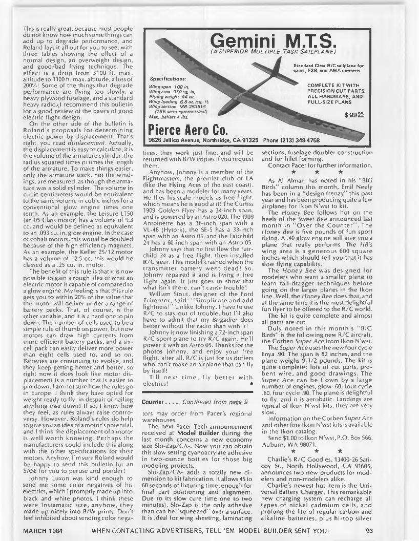
Gemini M.T.S.(A s u p e r io r Mu l t ip l e Ta s k Sa il p l a n e )
Standard Class R/C sailplane for sport, F3B, and AMA contests
Specifications:Wing span 100 in.Wing area 930 sq. in.Flying weigh t 44 oz.Wing loading 6.8oz./sq ft Wing section MB-253515
(15% semi *symmetrical)Max. ballast 4 lbs.
Pierce Aero Co.9626 Jellico Avenue, Northridge, CA 91325 Phone (213) 349-4758
COMPLETE K IT WITH PRECISION C U T PARTS, A LL HARDWARE, AND FULL-SIZE PLANS
$99 t§
This is really great, because most people do not know how much some things can add up to degrade performance, and Roland lays it all out for you to see, with three tables showing the effect of a normal design, an overweight design, and good/bad flying technique. The effect is a drop from 3100 ft. max. altitude to 1100 ft. max. altitude, a lossof 200%! Some of the things that degrade performance are flying too slowly, a heavy plywood fuselage, and a standard heavy radio.\.l recommend this bulletin for a good review of the basics of good electric flight design.
On the other side of the bulletin is Roland’s proposals for determ ining electric power by displacement. That’s right, you read displacement. Actually, the displacement is easy to calculate, it is the volume of the armature cylinder, the radius squared times pi times the length of the armature. To make things easier, only the armature stack, not the windings, are measured, as though the armature was a solid cylinder. The volume in cubic centimeters would be equivalent to the same volume in cubic inches fora conventional glow engine times one tenth. As an example, the Leisure LT50 (an 05 Class motor) has a volume of 9.3 cc, and would be defined as equivalent to an .093 cu. in. glow engine. In the case of cobalt motors, this would be doubled because of the high efficiency magnets. As an example, the Keller 25/12 motor has a volume of 12.5 cc, this would be classed as a .25 cu. in. motor.
The benefit of this rule is that it is now possible to gain a rough idea of what an electric motor is capable of compared to a glow engine. My feeling is that this rule gets you to within 20% of the value that the motor will deliver under a range of battery packs. That, of course, is the other variable, and it is a hard one to pin down. The number of cells used to be a simple rule of thumb on power, but now motors can draw high currents from more efficient battery packs, and a sixcell pack can easily deliver more power than eight cells used to, and so on. Batteries are continuing to evolve, and they keep getting better and better, so right now it does look like motor displacement is a number that is easier to pin down. I am not sure how the rules go in Europe, I think they have opted for weight ready to fly, in despair of nailing anything else down! If so, I know how they feel, as rules always raise controversy. However, Roland’s rules do help to give you an idea ofamotor’spotential, and I think the displacement of a motor is well worth knowing. Perhaps the manufacturers could include this along with the other specifications for their motors. Anyhow, I'm sure Roland would be happy to send this bulletin for an SASE for you to peruse and ponder!
Johnny Luxon was kind enough to send me some color negatives of his electrics, which I promptly made up into black and white photos. I think these were Instamatic size, anyhow, they made up nicely into B/W prints. Don’t feel inhibited about sending color nega
tives, they work just fine, and will be returned with B/W copies if you request them.
Anyhow, )ohnny is a member of the Flightmasters, the premier club of LA (like the Flying Aces of the east coast), and has been a modeler for many years. He flies his scale models as free flight, which means he is good at it! The Curtiss 1909 Golden Flyer has a 34-inch span, and is powered by an Astro 020. The 1909 Antoinette has a 36-inch span with a VL-48 (Hytork), the SE-5 has a 33-inch span with an Astro 05. and the Fairchild 24 has a 60-inch span with an Astro 05.
Johnny says that he first flew the Fair- child 24 as a free flight, then installed R/C gear. This model crashed when the transmitter battery went dead! So, Johnny repaired it and is flying it free flight again. It just goes to show that what isn't there, can’t cause trouble!
William Stout, designer of the Ford Trimotor, said: “ Simplicate and add lightness!" Unlike Johnny, I have to use R/C to stay out of trouble, but I’ll also have to admit that my Brigadier does better without the radio than with it!
Johnny is now finishing a 72-inch span R/C sport plane to try R/C again. He'll power it with an Astro 05. Thanks for the photos Johnny, and enjoy your free flight, after all, R/C is just for us duffers who can’t make an airplane that can fly by itself!
T ill next tim e , fly be tte r w ith electrics! ·
Counter. . . . Continued from page 9
tors may order from Pacer’s regional warehouses.
The next Pacer Tech announcement received at Model Builder during the last month concerns a new economy size Slo-Zap/CA-. Now you can obtain this slow setting cyanoacrylate adhesive in two-ounce bottles for those big modeling projects.
Slo-Zap/CA- adds a totally new dimension to kit fabrication. It allows45 to 60 seconds of fixturing time, enough for final part positioning and alignment. Due to its slow cure time one to two minutes), Slo-Zap is the only adhesive than can be "squeezed” over a surface. It is ideal for wing sheeting, laminating
sections, fuselage doubler construction and for fillet forming.
Contact Pacer for further information. ★ ★ ★
As Al Alman has noted in his "BIG Birds" column this month, Emil Neely has been in a “ design frenzy” this past year and has been producing quite a few airplanes for Ikon N’wst to kit.
The Honey Bee follows hot on the heels of the Sweet Bee announced last month in "O ver the C ounter” . The Honey Bee is five pounds of fun sport flying. A .40 glow engine will give you a plane that really performs. The HB’s wing area is a generous 600 square inches which should tell you that it has slow flying capability.
The Honey Bee was designed for modelers who want a smaller plane to learn tail-dragger techniques before going on the larger planes in the Ikon line. Well, the Honey Bee does that, and at the same time it is the most delightful fun flyer to be offered to the R/C world.
The kit is quite complete and almost all parts are cut.
Duly noted in this m onth’s "BIG Birds" is the following new R/C aircraft, the Corben Super Ace from Ikon N’wst.
The Super Ace uses the new four cycle Enya .90. The span is 82 inches, and the plane weighs 9-1/2 pdunds. The kit is quite complete: lots of cut parts, prebent wire, and good drawings. The Super Ace can be flown by a large number of engines, glow .60, four cycle .60, four cycle .90. The plane is delightful to fly, and it is aerobatic. Landings are typical of Ikon N’wst kits, they are very slow.
Information on the Corben Super Ace and other fine Ikon N’wst kits is available in the Ikon catalog.
Send $1.00 to Ikon N’wst, P.O. Box 566, Auburn, WA 98071.
★ ★ ★Charlie’s R/C Goodies, 13400-26 Sati-
coy St., North Hollywood, CA 91605, announces two new products for modelers and non-modelers alike.
Charlie's newest hot item is the Universal Battery Charger. This remarkable new charging system can recharge all types of nickel cadmium cells, and prolong the life of regular carbon and alkaline batteries, plus h i-top silver
WHEN CONTACTING ADVERTISERS, TE L L ’EM MODEL BUILDER SENT YOU!MARCH 1984 93

JOHN POND Old T im e P lan Service
The largest selection of plans in the world at the most reasonable prices. Each list $1.00
All 4 for $3.00No. 14 OLD TIMER F/F GAS No. 14 OLD TIMER RUBBER/TOW LINE No. 14 OLD TIMER FLYING SCALE A through K No. 14 OLD TIMER FLYING SCALE L through ZNew plans prices effective Dec. I983 to Dec. 1984
P. O. Box 3215 ____■San Jose, Calif. 95156 Phone (408) 292-3382
FAI RUBBERSIZES: 1/4", 3/16", 1/8", 3/32"
1/16". 1 mm thick (. 042).BOX ED: 16 ounces o f rubber per box.PRICE: $12.50 per box, ppdin U.S.A. (California residents 6% sales tax)
Coupe deVille S23.95 plus UPS Finished Prop.Very Very completeSend 504 for 1984/1985 catalog
_ F . A . I . M o d e l S u p p l yj| - ^X^y>y>^^cOCOOOC<XXiOOOOOC«>OOOC>OOOC>OC
P O BO X3957 TORRANCE. CA 90510
oxide, button cells (watch and camera types), as well as six and nine volt square batteries. It drastically cuts your cost of battery purchases. Charges up to 11 cells at one time . . . meter and test button to show battery condition. Will pay for itself in 90 days!
Item number two is a combo. Four 500 mah AA penlite Ni-Cd cells come with their own charger at a price below cost of cells alone. Portable package provides unlimited power for your flashlights, model airplanes, toys, cameras, flash units and hundreds of other items. Switchable for 120 or 240V.
For special prices and/or additional information on these or other Charlie’s R/C Goodies, send one dollar to the above address for the complete brochure.
★ ★ ★Kitronics of Ontario Canada, is pleased
to announce the availability of two new products, a sound signaling beeper called the Retrieve-lt and a light flashing device called Brite-Lites.
The Retrieve-lt is a compact device, weighing less than an ounce, which can be interfaced with any receiver. The loud beeping noise emitted from the Retrieve-lt can be an invaluable aid to the finding of a plane lost in tall grass, wheat fields and corn fields, or in any difficult to see place. As the Retrieve-lt is interfaced with you receiver, it can be actuated by your transmitter; when your transmitter is on the beeper is off, so no
sound is made while you’re flying. Also, because of this interface the Retrieve-lt can be used for range checking; simply turning your transmitter on and off, as you walk away from your plane, should cause the beeper to also go off and on indicating that your radio gear is working. The Retrieve-lt can also be used to detect if someone else is on your frequency .. . simply turn on your receiver and the beeper, if no sound is heard either someone is on your frequency or your battery is not functioning. As the Retrieve-lt uses its own battery supply and consumes such little power, you could lose your plane one day and still locate it days later by sound ranging.
The Brite-Lite device also weighs less than an ounce, and it can flash one or several lamps. The flashing rate can be set and changed by the owner from a fast rate to simulate a rotating beacon to a slow rate simulating a strobe. Several lamps are available from Kitronics including red and green LEDs and various incandescent lamps from a two millimeter diameter wheat bulb, to a six millimeter diameter miniature bulb, and a 10 m illim eter diameter lamp. The power requirements to flash these lamps will be determined by the number and type of lamps you use. Typical battery requirements range from three volts to 18 volts.
Either of the products, the Retrieve-lt or the Brite-Lites, are available inkit form or fully assembled. The printed circuit board is of high quality epoxy-glass construction with tinned copper foils
The devices are available from your local hobby store or d irec tly from Kitronics, 90 Wildwood Road, Georgetown, Ontario, Canada L7G 4S8. Write for prices and/or additional information.
★ ★ ★The need for an easy handling, su
perior aerobatic, quick building, modern looking, sport biplane has now been filled. The Bel-Air .60 is the sport/ exhibition biplane designed to give you the greatest value for your hard earned dollars. Initial sales have ben fantastic, well above the manufacturers expectations.
All parts in the Bel-Air .60 kit are jig- machine cut. Clean and accurate parts
assist you in building a real showstopper. There is a very minimum amount of parts in the kit to allow you to build the Bel- Air .60 in the very least amount of time of any biplane of the market.
The Bel-Air .60 has fully summetrical wing sections. This gives you the greatest potential for aerobatic performance, either upright or inverted. This ship is cap&ble of very slow, close-in flight right up yo the most rigorous aerobatic schedule you can muster.
Pertinent stats on this model are: wingspan 52 inches; wing area, 935 square inches; fuselage length, 46 inches; weight range, six to 7.5 pounds; engine requirement, any .60.
Contact Northeast Aerodynamics, 568 Main St., Haverhill, MA 01830, for prices or aditional information.
★ ★ ★The New Micro-Mark catalog features
over 550 small hand tools for hobbyists and craftsmen! Famous-name brands like X-Acto and Dremel, plus, hundreds of new and unusual tools not found in local hobby shops or hardware stores. Toll-free ordering 24 hours a day,service with charge cards. Valuable hobby knife free with first purchase!
If you enjoy model railroading, ship modeling, jewelry making, car modeling doll house construction, metalsmithing, toy m aking, decoy carving, clock making, woodworking, or gunsmithing, you’ll love this catalog! For your copy, send $1 plus name and address to: Micro-Mark Catalog, P.O. Box 5112, 24 East Main St., Clinton, NJ 08809.
★ ★ ★Scale Model Research, providers of
high quality color photographs of full- size aircraft for scale modelers for many years, has changed ownership recently. SMR is now under the guidance of Bob Banka, a modeler who will continue the fine service that has been an SMR trademark for many years.
Dale Willoughby, founder and principal photographer of SMR, will continue to travel worldwide in his search for more interesting aircraft to expand the range of SMR Foto Paaks.
Currently, there are more than 575 d iffe rent Foto Paaks, over 300 scale three-views from aviation and modeling magazines, more than 120 Koku-fan scale three-views from world-renown K. Hashimoto, and many drawings of Russian aircraft from Polish aviation artist Zdzislaw Szajewski.
For any scale documentation need, contact Bob Banka, Scale Model Research, 418-B East Oceanfront, Newport Beach, CA 92661. Send $1 for catalog.
★ ★ ★Wing-lt Model Products has recently
released an ingenious lit t le product which simplifies and beautifies R/C aircraft landing gear. Introducing the ‘Quick-On’ Wheel Thrust Bearing, a small plastic device which slips over the axle of your model’s landing gear to act as the inside wheel collar. It eliminates the frustration of soldering washers or fastening wheel collars, and it adds a trim, sleek appearance in the process.
94 MODEL BUILDER

Peter West burg’s
SCALE VIEWS
SUPER-ACCURATE AIRCRAFT DRAWINGS. USE FOR SCALE DOCUMENTATION AND/OR FOR DEVELOPING MODEL CONSTRUCTION PLANS. ALL DRAWINGS ARE
28 x 40 INCHES BORDER- TO-BORDER, AND ARE SCALED AS LISTED BELOW.
1/24th scale: 'k" = 1 ft. Shts $ Czech Avia B-534 2 8 Waco ATO Taperwing 2 8Douglas 0-35/B-7 1 4 Davis D-1K 2 8Douglas XO-36-XB-7 1 4 Douglas 0-25C 3 12 1/10 scale: 1.2" 1 ft. Shts S
Douglas 0-31A/0-31B 3 12 Berliner/Joyce P-16 4 161/ 12th scale: 1" = 1 ft. Douglas 0-38/0-38B 2 8 Curtiss BFC-2 Goshawk 4 16Boeing F4B-4/-3 4 16 Douglas 0-43A 3 12 Curtiss F9C-2 Sparrowhawk 4 16Boeing P-12E 3 12 Douglas 0-31C/Y10-43 3 12 Curtiss P-6E Hawk 4 16Curtiss A-8 Shrike 3 12 Douglas 0-46A 3 12 Fiat CR-32 3 12Curtiss Gulfhawk IA 2 8 Fokker D-17 3 12 Great Lakes Trainer 4 16Curtiss N2C-2 Fledgling 4 16 General Western Meteor 1 4 Hawker Fury Mk I 4 16Curtiss 0-1B/A-3 Falcon 3 12 Grumman F2F-1 3 12 Hawker High Speed Fury 3 12Curtiss P-1B Hawk 3 12 Grumman F3F-2 3 12 Hawker Persian Fury 3 12Curtiss XP/YP-23 3 12 Stearman 4E Mailplane 2 8 Monocoupe 90A 2 8Curtiss SBC-4 Helldiver 4 16 Travel Air 2000 2 8 Swedish Sparmann P-1 2 8
ORDERING INSTRUCTIONSPrice includes 3rd or 4th Class mail. F o r A irm ail or ders. Master Card o r Visa orders add 5% , include cardFirst Class in U .S ., add 2 5 % o f total order. F o r O ver- num ber, expiration date, and signature. Send pay-seas Airm ail (includes Canada and M exico), add 5 0 % m ent to M O D E L B U IL D E R , P.O. B ox 10335, Costaof total order. Rem it by International M oney O rder Mesa, C A 92627. Phone (714) 645 8830or U .S . funds drawn on a U .S . bank fo r overseas or-
C A L IF O R N IA R E S ID E N TS A D D 6% S A L E S T A X
MARCH 1984 WHEN CONTACTING ADVERTISERS. TELL ’EM MODEL BUILDER SENT YOU! 95

FU
LL
-SIZ
E
PL
AN
S S
ER
VIC
E---------M O D E L 0
B U I L D E RA ll Full S im plans purchased from MODEL BUILDER
Magarine include a reprint of the construction article, if building instructions were part o f the article.
S E N D T O : M O D E L B U IL D E R P LA N S S E R V IC E BOX 10335, COSTA M E S A C A L IF O R N IA 92627 0132
NEW ORDERING INSTRUCTIONSPrice includes 3rd or 4th Class mail. For A irm ail or First Class in U.S., add 25% o f to u l order. For Overseas Airmail (includes Canada and Mexico), add 50% of total order. Remit by International Money Order or U.S. funds on Overseas orders Postage paid for APO and FPO orders. Master Card or VISA accepted. Include card number, expiration date, and signature Add 5% to credit card orders M in im um ordar. S5.0C
C A L IF O R N IA RESIOENTS AOO 6*. SALES T A X
No. 3841 FA B R E H Y D R A V IO N S15.00RC Standoff Scale 191 Ocanard seaplane for .10 glow. 69 in. span. F. Reynolds.
No. 384-0.T . C L O U D C R U IS ER S6.00Parasol wing O /T from July '37 M AN , 72" span, looks scale-like. Harry Moyer.
No. 3842 H A N G -IN -T H E R E $4.00Couped'Hiver FF model. Features rolled balsa fuse, folding prop. By E. Schick.
No. 2841 B IT T Y -B IP E $5.00A small, but exciting R/C sport biplane for .10 to .20 glow. By "D o c" Edwards.
No. 2842 V O L T S W A G O N S5.50A 54" span, 430 sq" area, 05 electric powered. sport R/C plane. Woody Woodward.
No. 284-O T T H E D IA M O N D $4.00Rubber O /T with diamond fuse, 150 sq. in. wing, from Oct. '37 A T . Roy Wriston.
No. 2843 TH E C R A C K E R JA C K $4.00F/F Rub. or C 0 2 Scale, high wing home- built; 26" span. 86" area. Walt Mooney.
No. 1841 SU N R ISE 2540 $9.00Mild-mannered, low-wing, R/C trainer for .25 to .40 glow engines. By Buzz Waltz.
No. 1842 O H M -Y -G O S H $5.00Sporty 05 electric Pylon racer. Wing area is 300 sq. in., span, 38 in. Dave Katagiri.
No. 184-OT 1/2A B R IG ID IE R $5.00An 1/2A Tex. version of the Berkeley kit scaled to 82% for R/C. By Jim Reynolds.
No. 12831 N IE U P O R T 11-C 59 00WW-I triplane for Standoff R/C scale, 4- channel, two-inch scale. By FrankHoffer.
No. 12832 F A S T E D D IE $5.0005 Electric pylon/aerobatic plane in 29, 34, 38-in spans; 3-ch R/C. By Bob Stiff.
No. 1283-O.T. K A R A S U $2.00Rubber powered, 19th century antique from Japan;21 "span. By Danny Sheelds.
No. 12833 V E R V IL L E A IR C O A C H $2.50 F/F Rubber Scale Golden Age high wing monoplane; 26 in span. By Walt Mooney.
No. 11831 H A W K ER F U R Y $12.50Classic British biplane in 1/4 scale, for Quadra or equiv. power. Don Prentice.
No. 11832 F L Y IN G F L E A $4.50R/C scale model of original HM-14 'Pou de Ciel'. Span 44". By Randy Wrisley.
No. 1183-0.T . A R U P F L Y IN G W ING $2.00 Flying scale rubber powered model from Sept. '36 M .A.N . By Gordon Englehart.
No. 10831 RUSS. M ISSILE B O A T $6.00Missile-firing, scale Russian attack boat, O SA class. 2 or 3-ch. By Walt Musciano.
No. 10832 C IT A B R IA $5.00Semi-scale Citabria for 05 electrics. Span: 54 in., 2,3, or 4-ch. R/C. By Stan Wilson.
The ‘Quick-On’ Wheel Thrust Bearing is available in four sizes to fit 1/8, 5/32, 3/16 and 1/4-inch axle rods. Write to Wing-lt Model Products, 151 Magnolia Lindenhurst, IL 60046 for further infor- mation. * * *
When contacting manufacturers featured in “ Over the Counter,” tell them you saw it in Model Builder! ·
Hydravion . . . . Continued from page 19
is a matter of common-sense judgement. You may find that you have all the lines taut with the model supported by the fuselage, but when you set it on its floats, some of the lines go slack. It is a flexible model. (Sounds like an entertaining challenge, wrf)
Supporting the assembled model for rigging and o ther work presents a
Eroblem. I clamped the fuselage lightly etween two scraps of plywood in a
bench vise. Grooves in the boards to match the upper and lower fuselage tubes hold the model securely and prevent flattening of the tubes. If your vise will rotate on its base, the model can be swung around to any convenient working angle.
As I live on a lake, I have little need to transport the plane and therefore built it in one piece. It did fit all assembled into our smallish Volvo station wagon when I
took it to a model show, however. (My Hydravion placed first in the Seaplane Division of the 1983 Northwest Model Exposition at Puyallup, Washington last February.)
If your flying water is not w ith in walking distance, and you don't have a station wagon, van, or truck, you can revise the design to make the wing demountable, but connecting all that rigging and aligning the model at the shore will be a sizable chore (a shore chore for sure). (Boo-o-o.)
One bit of the historical data on the Hydravion indicates that the airplane may have been steered on the water by turning the nose float. At any rate, I chose to do that on the model, and it steers very well at all taxi speeds (with the rear water fin, but not without it). Actually, this is the second airplane I’ve built with a steerable nose float. The first one was an aerobatic seaplane of my own design (like a tricycle-geared land- plane), which also steered well on the water. The Hydravion model nose float steering is a cinch, as it is accomplished by a torque tube through the front vertical member of the fuselage. The rigging to the steerable nose float stays tight when the float turns, as the upper ends of these lines terminate essentially at the center of rotation.
The short, wide, flat-bottom floats are the same shape as the original ones. In
spite of their unusual shape by modern standards, they are very e ffic ien t at producing lots of lift at low speeds. Their main disadvantage is rough riding on waves. They would impose serious rough-water stresses on an airplane planning at high velocity. As the floats are way forward and way aft, the Hydravion cannot “ rotate” for takeoff. Fore and aft floats leave the water at the same time. Therefore, we must provide sufficient incidence in the wing and foreplanes to permit the airplane to fly level off the water. It takes off with a very short run with the .10 powerplant.
One thing you will notice in operating with these strange flat-bottomed floats is the lack of a distinct "hump” speed where they start to plane. Completely flat-bottom floats rise out gradually from 100% static buoyancy to full planing.
As this is not a construction article for the beginner, I won't explain how to glue stick A to stick B, but some construction and materials hints are in order where these are different from conventional model practice.
I chose to make the floats, the ribs, and the radio and servo compartment out of Aerolite, made by Aerolite Products Inc., 1325 Millersport Hwy., Buffalo, NY 14221. I highly recommend this material if you haven't used it yet. It is a very light, foam-core, plastic-faced sheet stock available in various thickness. The Aerolite is ideal for floats as it is completely waterproof, light, strong, and requires no finish.
You can use the optional laminated wood wing ribs shown on the plan instead of Aerolite ribs and be a little more true to scale, but they would take longer and be heavier. If you go the Aerolite ribs route, note that I designed them so they have the same arc top and bottom and can be cut from a circular sheet of Aerolite by the hot wire method with a single cut per rib (see photos). Aerolite sheet material requires d ifferent construction methods than balsa wood. It is similar to paper-faced foam board, but lighter. It is fuel and water proof, and doesn’t need any finishing . . . if you are satisfied with the snow white color. Read and follow the instructions for use which you will get when you buy the material.
There are a few additional tricks in working with Aerolite, as illustrated in the photos. I use chiefly cyanoacrylate in building with Aerolite. Zap and Zap-A- Gap adhesives work very well w ith almost no dissolving of the foam core. The Zip Kicker instant setting spray saves a lot of time, but I still use baking soda sometimes. If you have a gap or a depression at a joint in Aerolite or balsa construction, fill it with dry baking soda, level it off and drop a drop of thin cyanoacrylate on the soda. It will penetrate to the bottom and set instantly, making a very hard, strong, adherent patch which can be sanded beautifully. In patching Aerolite with sodium bicarbonate and cyanoacrylate adhesive, there is the added advantage of the matching white color which needs no
96 MODEL BUILDER

Ace R/C, Inc............................................. 86Aeronautics, Inc...................................... 83American Junior H e ritag e ....................89Associated E le c tr ics ........................... 73Astro Flight, Inc....................................... 85Beehive R/C Model Aircraft Co.......... 69Byron Originals ..................... Cover 2, 1Bud Caddell P lans................................. 89California Model Im ports ......................87Campbell's Custom K its ........................66Charlie's R/C Goodies ..........................81Circus H obb ies.......................................67Eric C lu tto n .............................................76Jim Crocket Replicas ........................... 68Du-Bro Products ................................... 75E&L M anufacturing............................... 71Electronic Model System s....................69F A.I Model S up p ly ............................... 94Dick H a n so n ......................................... 92Hobby H o rn .............................................80Hobby Products Co................................ 83Hunt Products......................................... 99
INDEX TO ADVERTISERS
Indoor Model Supply ..........................100Jersey Metal Spinning ..........................87K&B M anufacturing.............................. 100K&S E ng ineering ................................... 84Kustom Kraftsm anship..........................71Leisure E le c tro n ics ................................77Micro M ark ...............................................79Midway Model Co................................. 99Model Rectifier C orp.................. Cover 4Walt M ooney...........................................98Sid Morgan Vintage P la n s ....................67Novak E le c tro n ics ............................... 74Nowlen A e ro ...........................................91Octura Models ....................................... 91Peck Polymers .......................................66Pierce A e r o ............................................ 93John Pond O /T P la n s ......................... 94Precision Sanding T o o ls ......................74Proctor E nterprises............................... 90Prop Shop, T h e ....................................... 76
Replica E ng in es ..................................... 68Satellite City ........................................... 3Schlueter Free F lig h t........................... 72Sig Manufacturing Co.. Inc...................4,5SR Batteries........................................... 78St. Croix of Park F a lls ............................82Tatone Products..................................... 70T&D F iberglass....................................... 84Technopower II. Inc............................. 88Teleflight R esearch............................. 78Uber Skiver .................................Cover 3Buzz W a ltz ............................................... 72Westburg D raw ings............................... 95Williams B rothers................................. 70Wilshire Model Center ..........................90Wolff-Pak ............................................. 80World Engines ..................................... 82N ickZ iro li ..........................................77.8177 P rod uc ts ............................................. 86HOUSE ADSModeler's C h o ice ................................. 98
O l A Q Q I P I P H A H Q IM P O R TA N T IN S TR U C TIO N S : Noncommercial I I I (personal items) rate is 25 cents per word,
with a minimum of $3.00. Commercial rateis40 cents per word, with a minimum of $5.00. No advertising agency discounts allowed. Name and address free, phone number counts as two words, abbreviations count as whole words and will be spelled out. All ads are payable with order, and may be for any consecutive insertion period specified. Send ad payment to:M O D EL B U ILD E R , Classified Ads, P.O. Box 10335. Costa Mesa, CA 92627-0132. ____
FREE FLIGHT SPECIALISTS, 1984 catalog $2 CHE Hobbies. 10900 Easlwood Ave. Inglewood. CA 90304, (213) 674-1756
WANTED — OLD MODEL ignition engines cars, elc Paying top dollar ΒΊΙ Simpson 7413 Via Lorado Rancho Palos Verdes. CA 90274(213) 377-3532
SCRAPBOOK OF SCALE, by Bill Hannan. Twelve three-views, photos, philosophy, and whimsey Autographed if desired Postpaid. $9 95 W C Hannan. Box A. Escondido. CA 92025
LIST YOUR RADIO EQUIPMENT for sale No fee for listing Escrow available Send SASE for details Radio Equipment Exchange. Box 561. Park Forest, IL 60466
NATS WINNING Bellanca Aircruiser. Senior Indoor and Outdoor Rubber Scale. Plans $1.50. Send SASE for list, David Aronstein, 50 Pasture Lane. Poughkeepsie. NY 12603.
COMPUTER CONTROL OF R/C SERVOS - Control up to six servos with your Timex TS-1000/1500 or TRS-80 Personal Computer Perfect for winter projects, robotics, model actuation experiment1 Software and application notes included Write for free information or send $10 00 for plans, or $39 95 for complete kit. Satisfaction guaranteed. Fratello MicroElectronics, Department B ! . P.O. Box 4007, Hampton, VA 23664
INTERESTED IN JETEX flying, plans, fuel, and engines7 Would you be interested in a newsletter circulation connecting all of us together7 I know location of $2,000 of fuel, wicks, and kits. Send SASE for reply Roger L Wathen. 3242 N DeQuincy, Indianapolis. IN 46218. phone (317) 547-5963
FIFTY CENTS brings list of new/used model motors, accessories, balsa kits Motor trade- ins wanted T Crouss. 100 Smyrna, West Springfield. MA 01089
WANTED: Pin-down clamps as shown on page 24 of Bill Hannan's 1980 edition of Peanut Power. Arsene Fauquef. 5643 Hartley. Lincoln. NE 68507
PLANS ENLARGED — Blueprints to nine feet from your plan or book page. SASE for prices Scale Plans and Photo Service. 3209 Madison A ve . Greensboro NC 27403
WILL PAY AT LEAST $300 tor any complete, original Elf Also want other vintage ignition model engines and parts Woody Bartelt, 5600 Portage Road. Kalamazoo. Ml 49002; (616) 385-3696
RAZOR BLADES, single edge industrial first quality — extra sharp l00/$4.25;200/$8.00 300/51 1 75: 500/$19.25. 1000/S37 50 Postpaid in U S Cobble's Gifts. Postbox 2, Deal, NJ 07723, (201) 922-9898
PLANS Mini Paagan by Denny Davis. Nostalgia. Third Payload at 1983 Nats' Postpaid $400. Stephen Landy 44 Chaplin Road. Newton Centre, MA 02159.
GRUMMAN F7F-3 TIGERCAT plan, 1/24- scale free flight, rubber, or COz Postpaid $4 50 SASE for complete list David Diels PO Box 101. Woodville. OH 43469
FORSTER IGNITION ENGINES, English and Chinese diesels, parts, and supplies Visa. Mastercard Send SASE to M&G Engines. P.O. Box 6026 Denver, CO 80206
PAW DIESELS — England's most popular diesels now available, 049 to .29. throttled and standard, at low prices Throw away those plugs and batteries Use a self-contained diesel using half the fuel of an equivalent glow motor Send $1 for list Eric Clutton. 3816 De Soto Ave . Fort Meyers. FL 33905
SCALE DOCUMENTATION - Photo packs, three-views, cutaways for 800 aircraft Giant, Precision. Fun Scale plans. Eighteen page catalog. $3 Scale Plans and Photo Service. 3209 Madison Ave.. Greensboro. NC 27403
INDIVIDUALS. TEACHERS, youth groups, and libraries I have the following model aviation magazines for sale: MAN, MB. AM. A AM. FM. A T. MA No complete set more than $5 except AM. AT MB Send large SASE Roger L Wathen 3242 N DeQuincy. Indianapolis. IN 46218 (317) 547-5963
P-30 CONTEST MODEL PLANS Two-minute flights possible Builds last and easy. $3 75 postpaid P-30 Werks. 1715 Knoltwood. Apt P-4. Kalamazoo. Ml 49007
ANTIQUE IGNITION ENGINE PARTS Excellent reproductions of original timers, points, tanks, etc Send $1 for information and price list. Micro Model Engineering, 5600 Portage Road Kalamazoo. Ml 49002
C/5COLUocQΩ<
NAMEAttach old label here r Attach old label here
, C/5 I CO
MOVING? SEND NOTIFICATION FIRST! » ώ ^ ' ? £ ,Ε:τ3Ε,“·takes effect. For prompt service, old label M U S T be attached. Post o ff ic e w ill n o t fo rw a rd copies unless you pay extra postage. D up lica te issues canno t be sent.
M O D EL B U IL D E R , Box 10335, Costa Mesa, CA 92627
NAM E ____________________________A D D R ESS
Q_ jO
C IT Y I S T A T E Z IPA ttach old label here
LUcc
8 1< ig 8 A D D R ES S .
V A ttach old label here LU ώ5? 9- C ITY _ S T A TE/Z/P .
MARCH 1984 WHEN CONTACTING ADVERTISERS. TELL 'EM MODEL BUILDER SENT YOU! 97

THE MODELERS' CHOICE□ $25.00 For one year subscription Subscription copies mailed in envelopes, add $3.00
(—-] $32.00 Outside U. S including Mexico and Canada in protective envelope ,add $3.00.Outside U. S .. One year subscription only.
Please enter my subscription: DNew Π RenewalM O D E L SB U I L D E R
City Zip-Country_____________
M/C or VISA # _
Expiration Date. Signature_____
■ * 1
• SUPERIOR COIIORIAL CONTENT
• HIGHER EDITORIAL TO ADVERTISING RATIO
• THE Γ INC ST A M ) MOST COMT1.1Tt CONSTRUCTION ARTICLES
• PLAN SERVICE
• UT TO THE MINUTE ARTICLES ON NEW TROOUCTS AND TRODUCT REVIEWS
• CONTEST ANO SHOW COVERAGE
. Add 5%
M A IL TO :
Prices subject to change without notice. (714 ) 645-8830
: ‘- ^ M O D E L S ' B U I L D E R
P.0. BOX 10335, COSTA MESA, CA 92627
YES-SIR, YES-8IR, THREE BAOS FULL4 . ™ A v a i l a b l e IAS
3 / i / n e . n u m b e r , o r P x -tc e . /WALT JI00NEY NOW OFFERS 4-BAGS OF PEANUT SCALE PLANS
ALL WELL TESTEO OESlGNS, AT ONLY fS.OO EACH EACH BAG FEATURES FOURTEEN PEANUT PLANS,ONE OTHER, PLUS PHOTOS ANO INFORMATION
SEND ίΐ.Ο Ο FOR COMPLETE LISTING ANO SAMPLE PLAN TO:WALT MOONEY, 2912 CABRILLO MESA OR
SAN OIEGO, CALIFORNIA 92123 +
finishing. Don’t use viscous type gapfilling cyanoacrylates with baking soda. They don’t penetrate the dry powder.
I used a technique in building the Aerolite floats which doesn’t show on the photo of the float construction, because both the skin and the foam core of the Aerolite are white. This technique, which is included in the plan, is to strip parallel strips of the inner skin off the Aerolite where it is to be curved. The literature from the Aerolite company recommends stripping the entire inner skin off in areas to be curved. This works, but the resulting structure is considerably weakened by the loss of the inner skin. If you carefully razor blade cut through just the inner skin in areas to be curved (not through the foam core) in strips parallel to the bend and about 3/16 wide, then peel every other strip off, the material will bend smoothly, yet it will retain better strength and stiffness.
Micafilm, by Coverite is an excellent covering material for the Hydravion model, as it is very light, yet very strong. It is easily applied, and requires no finishing. Use the white Micafilm and don’t apply any finish to it.
I used a Cannon Super-Micro RC system, which is ideal because of its very small size and weight. (Less than four ounces total flight weight, including receiver, battery and four servos.) If you use larger RC gear, you will have to
enlarge the RC compartment, and you may seriously increase the wing loading. At least use a small battery pack if you must use standard miniature servos.
The motor I used is an O.S. Max .10. It is plenty. Don’t use a larger engine. Pusher props are a little hard to find, but they are available in this size range. If you can't find a suitable prop, carve your own. It is an interesting challenge. We old timers carved all our own “ gas model” props back in the 1930s. Manufactured props were nonexistent. Actually, the prop on my Hydravion is a nylon pusher prop of the proper diameter which orig ina lly had too much
itch. I lowered the pitch by carefullyeating each blade at the root and
reducing the blade angle by hand while the nylon was soft. On a small engine, this is a good technique, but don’t do it on large nylon props. It may weaken the blade roots.
The fuel tank is a Sullivan R-2 (two- ounce, round). I put a band of .001 thick brass shim stock around it for looks, and made two clamping rings to support the tank and mount it to the fuselage tube. If you lack thin brass, wrap aluminum foil around the tank, but leave the ends bare. Being able to see fuel level through the translucent plastic is a handy feature of an external tank. This tank location is non-scale. The 1910 Hydravion had the tank suspended by rigging above the
fuselage halfway between the fin and the pilot. Model engines don’t run well with the tank that far away, but the original, seven-cylinder, 50 hp Gnome Rotary didn’t mind.
My motor mount was machined from nylon. If you lack power tools, start with a commercial radial mount to fit your engine and mount it to the fuselage tubes by binding, bracing, and gluing a plywood disk to the fuselage, then bolting the motor mount to this “ firewall’ ’.
To join the fuselage tubes, I used silver solder to make up fittings of thin wall brass tubing as these could be polished to give a classy, antique look. Without silver soldering equipment, you can bend some landing gear spring wire into 90-degree angles and epoxy them inside the tube joints without external joint fittings. I used 5/16 fiberglass arrow shaft tubing for the fuselage. Aluminum tubing would do. I prefer the fiberglass tubing because it is non-conductiveand won’t interfere with the receiving antenna pattern. (Heaven knows, you've already got enough steel wire rigging to worry about! wrf) Arrow shaft tubing is available from archery shops and some model shops.
The scale control poles and the curved handle bar (the "stick” ) are attached to theelevatorand rudderssothey move in pitch and yaw like the original plane’s controls. I also put on operating pedals connected to the RC w ing-warping control system.
The pilot was built up from a commercial plastic model pilot bust with helmet and goggles, and an assortment of do ll parts (lightened as much as possible) and doll clothes. He is bolted to the fuselage through his seat. My pilot looks realistic, but he is too stiff to be moved by the controls as though he was flying the airplane. His hands and feet are therefore moved off the stick and pedals for flight. By building a light profile pilot with loosely-hinged joints, you could let the controls move him, and also reduce weight and drag, but at the expense of appearance. To my eye, cartoon-type, two-dimensional pilot simulations spoil the appearance of an otherwise classic antique "aeroplane” model. Snoopy on his RC Sopwith dog house was an exception, as Snoopy is a cartoon character.
The gimbaled arrangement of the elevator (top foreplane) is unique. The whole surface rotates in pitch about a horizontal shaft and rotates in yaw about the vertical front tube of the fuselage by the elevator and rudder servos, respectively. The forward air rudders are attached to this movable elevator, as are the control poles and pilot’s handlebar. To yaw left, the pilot pulls the handlebar to the right. To pitch up, he pulls the handlebar down.
Photos of the full-scale aircraft reveal that the Hydravion model taxied and flew well, I had to make four changes, all of which have been incorporated in the plans. One of the changes was to add a couple more rigging lines to keep the
98 WHEN CONTACTING ADVERTISERS, T E L L ‘EM MODEL BUILDER SENT YOU! MODEL BUILDER

Ψ “ SERIES 5 0 ” Old Timer R/C1939
AIR TRAILS SPORTSTER P 0
Ή Ι$ 39 .951938
POWERHOUSE • $ 3 9 .9 5
50" SPAN 380 SQ. IN. 32-38 OZ.'3 CHANNEL, .09 TO .15 POWER
"S E R IE S 50" K its are Full K its wltn Machine C u t 6 Sanded P arts. Formed Landing C ea r. Partial R/C H ardw are, Oetailed Full Size Plans, and P rinted Assem bly In stru ctio n s. [2 o r 3 C h R /C Cear R eqd. 1
C O M IN G : 54" Q u ak er. 48" F ly b a b y ; 48" Miss America 48" Cleveland V ik in g ; 50" Cleveland C lo ud ste r.
STRUCKS 1940 3 * !NEW RULER
74" Span. 835 S q . in .
Partial Kit $33.00
.29 to .36 ( .9 0 ) Clow MC " or "D " Ignition
In addition to the Just Released New R u le r, the following partial k its are also available.Th e 1936 F L Y IN G Q U A K E R (M eguw 's) 84" 521.50Th e 1937 Q U A K E R F L A S H (M egow 's) 67"span $17.50 T h e 1937 "L O N G " C A B IN . 78" span 520.00T h e 1937 A IR C H IE F (Id e a l's ) . 61" span $20.00
Partial k its are R ib . T i p . and Form er k its , i ney feature Machine C u t and Sanded P arts. Full Size Construction Plans, and build in g notes. Th e y meet SAM FF and R /C requirem ents.
C O M IN G : 120" K G -2 ; 84" Miss Delcw are. 96" Lanzo RB
j® M5w*ms m mm,_____________ P O B o* #9 . M idw ay C ity . Ca 9?655
At yo u r Dealer or add 52.00 per o rde r for U P S . C a . Res " add 61 for Ta x
rder )
m
stabilizer from twisting in the air, others were a larger front float, and the central aft water rudder. A fourth change was a shift of the balance point.
Canards do fly d ifferently, as do antique planes in general. The first real flight of the model was somewhat of a white knuckles affair, but not too bad. She took off and gained some altitude while I tried to learn to fly it. It required quite a bit of up elevator and tended to dive in the turns. No sign of stalling however. Turning it was an experience. The wing warping wasn’t doing much. The rudder alone was (and is) much more effective in turning it than wing warping alone. A combination of wing warping and rudder flies it very well.
The tendency to dive more in a turn than an ordinary airplane, is, I suspect, due to the fact that the elevator yaws with the forward rudders, reducing the effective elevator span when a rudder command is given, thereby reducing the forward lift and letting the nose drop. That is the way Fabre built it originally, but there is some indication in the historical data that in a later revision he fixed the elevator in yaw and yawed only the rudders. If so, I expect he made the change to eliminate the tendency to dive in turns that I notice in my RC model.
Back to the first high test-flight of the model. (I had made some earlier test hops up to about six feet off the water.) After I found our how to steer it and to give it enough elevator control, it was fun to fly. After flying most of the tank out, making overhead passes for the benefit of the photographer (my son Greg), I brought her in for a beautiful
three-point landing, taxied it back to the beach, and shut off the engine. A very successful test flight, but with enough challenge to prevent boredom.
The next day I removed the pilot to lighten the plane and reduce drag and also to move the CG back farther (an inch behind the position shown on the plan). I flew it again. This time the CG was too far aft for comfort, making it harder to control and less predictable. The nose didn't want to drop in a glide for one thing. On the first landing I carelessly mushed it in flat from about eight foot altitude at a fairly high sink rate. With no damage and the engine still running, I taxied it close to the dock where I was standing to visually check the fuel level in the translucent tank. I then taxied back out and took off again. After a few more minutes of flying, I brought it in for a good landing, taxied
FLY BABY 1-B21 WING SPAN
FREE FLIGHT TELCO CO, POWERED•CO-101 LONGSTER *14.95
•CO-103 1940 PORTERFIELD *17.95SEE YOUR DEALER FIRST. OR ORDER DIRECT,ADD *1.00 FOR POSTAGE & HANDLING
DEALER INOUIRIES INVITED
Hunt Models POB. 21B Dassel, MN 55325
back to the beach, and shut off the engine.
Test program was complete, and the airplane was still in one piece. Conclusions: (1) Don’t fly with the CG very far from the position on the plan. (2) The O.S. Max .10 is plenty of powerfor it. The plane climbs well and accelerates well. You won’t need a very low idle rpm, however. The plane will land at 1/3 throttle. With all this rigging the drag is huge, and the glide ratio is only about four to one. (3) Shes flies slowly and realistically at about 25 mph. Assuming a maximum lift coefficient of 0.7 for this old, bird-type airfoil, my calculations show a stall speed for the airplane of about 15 mph. (4) The wing warping isn’t very effective, probably for the same reason that the ailerons on some planes haven’t worked well. The adverse drag and yaw caused by the down-warped wing combined with the righting effect of the dihedral results in little net roll and yaw from warping the wings. By flying with wing warping plus rudder to correct the adverse yaw, it works very well. (5) The airframe is light, but fairly strong and resilient. It stands up well under hard landingsand handlingabuse. I'm always snagging a rigging line or two when I’m trying to work with it, but have never damaged it. (6) It doesn’t like wind or waves. To play safe, don’t fly when there is over a two mph breeze or over one-inch-high ripples. (7) It isn’t a high performance airplane, nor an aerobatic
HYDRAVION 1/8-Scale RC Model 1910 OriginalDESIGNED BY TYPE AIRCRAFT WINGSPAN WING CHORD TOTAL WING AREA WING LOCATION AIRFOILWING PLANFORM DIHEDRAL, EACH TIP O.A. FUSELAGE LENGTH RADIO COMPARTMENT
SIZESTABILIZER SPAN STABILIZER CHORD STAB. PLUSELEV. AREA STAB. AIRFOIL SECTION STABILIZER LOCATION VERTICAL FIN HEIGHT VERTICAL FIN WIDTH REC. ENGINE SIZE FUEL TANK SIZE LANDING GEAR REC. NO. OF CHANNELS CONTROL FUNCTIONS
MATERIALS IN CONSTRUCTION
WEIGHT READY TO FLY WING LOADING TOTAL SURFACE
LOADING
Francis D. ReynoldsSport Scale69 inches7.1 inches483 square inchesRearSingle-surface cambered Rectangular5.0 inches38.7 inches
14.7 x 1.4 x 1.4 inches (max) 25 inches5.35 inches 230 square inches Single-surface cambered At front below Elev.14.8 inches 6.6 inches 10cubic inch
2 ounces3 Flat-bottom Floats FourRudder, elevator, wing
warping, throttle Aerolite, aluminum, fiber
glass tubing, spruce, Micafilm, Kevlar, plywood, balsa, stainless steel
40 oz. (plus 2oz. fuel) 11.9oz./sq. ft.
8.1 oz./sq. ft.
Henri Fabre First seaplane 14 meters1.25 meters17.25 square meters RearSameSame1.20 meters 7.73 meters
Not applicable5.1 meters1.01 meters9.5 square meters SameAt front below elevator 3.22 meters1.2 meters50-hp Gnome rotary Unknown3 Flat-bottom Floats Not applicable
SameAsh, mahogany, cotton
canvas, iron, leather, bungee cord, wicker (seat)
450 kilograms 26 kg/sq. meter
16.8 kg/sq meter
MARCH 1984 99

IINDOOR MODEL SUPPLY
ENDURANCE RUBBER MODELSTHE EASY B 3 I M S G l i d e r * <2 So t
1/8 ox $4.95
THE SLOWPOKE So t ie
W *ighl 2 Penny» $ 4 .9 5 Ptatttc Prop
THE TIME MACHINE PENNY 1/8 02. s PLANE 18* Span \
13" MINIATURE SCALE AIRCRAFT KITS ea $6.95 OUTSTANDING DETAILS. 3-VIEWS & HISTORY
.045" Strip Wood. Light Sheet. Hardware & Prop.Heat Transfers. Japanese Tissue
PLASTIC CYLINDERS in ALCO and HEATH ALCO SPORT 1929 ZIPPY SPORT A.R.V. WATERMAN RACER 1921 HEATH PARASOL 1928
AERONCA K 1937 Span 16" Length 9" INDOOR MODEL AIRPLANES by Lew Gitlow 48 pgs. 100 illust. (reprint) ♦ FREE PLAN. $3.95 PEANUT POWER by Hannan. 80 pgs $8.95INDOOR BALSA PACK $6 95 P-NUT PACK $6.95JAPANESE TISSUE 10 Ige 5 col. ro ll............$5.95CONDENSER PAPER 2/$2.50 MICROLITE $3.25 RUBBER LUBE $150 BALSA CEMENT $1.50THRUST BEARINGS. Mini Dual or Dual.......$1.00PIRELLI RUBBER 020 to .090" & .125........ $2.356:1 WINDER $3.95 16:1 MARK 1 $11.95P-NUT CO-2 ENGINE $34.95 CHARGER $8 95 P-NUT PROP PACK 4 props, shafts, w 4p . $2.95 SCALE CYLINDERS 5 pack. 3/8 4 1/2" $1.00I M S. P-NUT PLANS ALL 5. 10 sheets $15.00ADD 10% POSTAGE-MINIMUM POSTAGE $1.50
1983-4 CATALOG 18 ILLUST. PGS. $1.50 iBOX C, GARBERVILLE, CA 95440
airplane. It is an antique flying machine.I will close with a bit of philosophy. If
you want high performance and effortless flying, neither this airplane nor any other early antique airplane scale model is what you want. The charm of these ancient fly ing machines is in the ir whimsical appearance, the challenges they offer in both building and flying, and the wonderful fact that they flew origingally at all, and w ill fly as RC models. Have some challenging and educational fun. Get out of the rut and get your feet wet.
Dear Jake........ Continued from page 6
row boat.Reverse Cuban 8 — Same group inter
cepted and sent back by US Coast Guard.
Incidence — One half of a coincidence.Camber — Airfoil curvature.Undercamber — Airfoil curvature in
Australia.Dihedral — Two ’hedrals.Loop — Circular maneuver in a vertical
plane.Square Loop — Same maneuver per
formed by a nerd.
fo r TOP PERFORMANCEK&B ENGINES
16 Airplane - 4 Marine KAB puElS ΚΑΘ GLOW PLUGS
7 Bienfls 4 cnoices
“ M atched F in ish System ’’ fo r BEST APPEARANCE
k&b fiberglass cloth κ&θ m cro-Banoons fillerK&B SUPER POXV R£SiN K&B SUPER POX'1 ThisNER
K&B SUPER POXV PRIMER K&B SUPER POXV PAifgTK&B MIXING CUPS
< 3 DKAB M AN UFA CTUR IN G
12152 Woodruff AvenueDowney. California 90241
Scale fidelity — Accuracy of the weighing device in your bathroom.
Overnight charging — Putting a motel room on your Master Card.
Dethermalize — Take off long johns.Bellcrank — Used to start helicopters
prior to the 1930’s.Butt joint — One kind of Siamese twin.Pylon — Penalty in football.
Cloud Cruiser. . Continued from page 30
your model transport can’t handle a six- foot wing.
Top and bottom 1/4-square spars with 1/16 webbing would greatly improve wing strength w ithout adding much weight.FLYING
Balance is mentioned . . . move the battery box back and forth to balance . . . but nothing is specified. With symmetrical tail surfaces, one-third of the wing chord back from the leading edge, is a good place to start . . . and remain.
Dihedral is specified at 3-1/2 inches per panel with a Baby Cyclone, and 4-1/2 inches for a Brown. With R/C, three inches per panel should do fine. If you’re going to mess it up with ailerons (like strip-style a la Health Parasol) drop the dihedral to a cosmetic one inch, but don’t tell me about it!
Anyone know the whereabouts of Harry Moyer? ·
Workbench . . . .Continued from page 6
Frank Macey, Oregon City, Oregon BIG MODELS, BIG WIRES
This is really Eloy’s department, but we wanted to make doubly sure that you absorb his words on this subject, as brought to our attention by Ralph Warner, of Radio Controlled Models, Inc., Chicago Illinois. Of course, we’re referring to the Electronics Corner Column by Eloy Marez.
There, Ralph, two mentions in the same issue!CAMOUFLAGE CONT.
Here are four more authentic World War II scale color formulas for use with Pettit “ Hobbypoxy” epoxy paints. These are camouflage colors used on German Luftwaffe day fighters in operation from 1940 to 1945.
For the period 1940 to 1944, Messer- schmitt Bf109-F and -G models,and Focke Wulf FW190-A models, had a factory-applied “ splinter” camouflage pattern on upper surfaces using 74 GRAY GREEN and 75 GRAY VIOLET, with undersurfaces and sides of fuselage painted 76 LIGHT BLUE. On Bf109s the fuselage mottle pattern was done in 02 RLM GRAY, 70 BLACK GREEN, and 74 GRAY GREEN, while on FW190s, the mottle was a combination of 02 RLM GRAY and 74 GRAY GREEN. (Formulas for 02 RLM GRAY and 70 BLACK GREEN were published earlier.)
In 1944-1945, factory finishes switched to a "defensive” camouflage scheme of 82 DARK GREEN and 75 GRAY VIOLET, with 76 LIGHT BLUE on undersurfaces and fuselage sides. Bf109-G and -K models, and FW190-D models, were finished in this scheme. Mottleon Bf 109s was still 02/70/74, while FW109-D mottle was changed to 82 DARK GREEN and/or 75 GRAY VIOLET.
It must be noted that field-applied modifications were made to suit local conditions. We are presenting only factory standard colors. Here are the formulas:
GRAY GREEN 74: Six Parts H81 Black, Two Parts H70 Gray, One Part H33 Stinson Green, and One Part H47 Bright Yellow.
GRAY VIOLET 75: Two Parts H81 Black One Part H70 Gray, One Part H65 Bright Red, and One Part H10 White.
LIGHT BLUE 76: To a Half Pint of H10 White add: Three Teaspoons H70 Gray, Two Teaspoons H26 Light Blue, Two Teaspoons H81 Black, and Two Teaspoons H33 Stinson Green.
DARK GREEN 82: Four Parts H81 Black, Four Parts H33 Stinson Green, Three Parts H65 Bright Red, and Two Parts H49 Cub Yellow.
Be sure to mix the above formulas 1:1 with H05 Flat Hardener for an authentic matte finish.
The reference used for these colors is The Official Monogram Painting Guide To German A ircraft 7935-7945, published by Monogram Aviation Publications, 625 Edgebrook Drive, Boylston, MA 01505.FUBAR
A recent letter from Ernie Currington, Kirkland, Quebec, Canada did indeed log our memory. Seeing the FU-BAR Mystery Model in Bob Stalick’s December ’83 Free Flight column (we already have our winner), Ernie commented that he had never actually seen any definition of FU-BAR in any of the model mags. He then summed up a few famous initials which, I’m pretty certain, were originated during World War II. If I’m wrong, please be specific about any alternate origin in your letters.
SNAFU: Situation Normal All Fouled Up.
TARFU: Things Are Really Fouled Up.FUBAR: Fouled Up Beyond All Recog
nition.We also appreciate Ernie’s "letters to
hom e" defin itions of these m ilitary status reports. ·
100 MODEL BUILDER

IN THE BES' IT’S U b e r
CIRCLES,s k iv e r
A PRECISION INSTRUMENT FOR THE DISCRIMINATING MODELER
• Safe, Rear Draw-Bar Clutch• Precision, Instrument-Quality Materials• Strong-Holding Advanced Collet Design• Non-Rolling Hex Cross-Section• Deeply Knurled, Non-Slip Grip• Long-Life, Stainless,
Surgical Steel Blades
See y o u r dealer, o r o rde r d ire c t. Dealer inqu iries are inv ited .A ll d ire c t orders sent postpa id in U.S. C a lifo rn ia residents add 6% sales tax .
20
NEW PRICES AS OF N O V EM BE R 1. 1983 Availab le in seven satin anodized handle colors: silver, blue, red, green, gold, b lack, & v io le t. Com plete set in f it te d ha rdw ood case; includes uber Skiver, together w ith tw o vials con ta in ing fo u r No. 11, and one each o f Nos. 10, 12, 15,and 2 0 ............ $16 .95Ind iv id ua l handles (specify co lo r) $6 .95V ia l o f 6 blades (N o. 10, 11, or 15) $3 .00
(N o. 12 o r 20) $4 .00
MODEL B PR O D U C TS621 West Nineteenth St., Costa Mesa, California 92627
JER i

STEERING SERVO SAVEI
SEMI-PNEUMATIC RUBBER LIKE TIRE
COIL SPRING REAR SUSPENSION
FORWARD & REVERSE THREE STEP SPEED CONTROLLER DOUBLE WISHBONE
FRONT SUSPENSION
SUPERBLY BALANCED SLOPING I MAIN FRAME CHASSI S DESIGNED FOR
UNPARALLELED ROAD HANDLING
CASTER ANGLE ADJUSTABLE FRONT ARMNYLON
SUSPENSION ARM
NEW FROM THE GROUND UPInstead of just adjusting,
improving, and modifying our off-road designs, we started from scratch to create the Subaru Brat. We set out to design a whole new breed of off-road with features that would substantially improve performance.
SENSATIONAL "SOUP UP" CAPABILITYFirst we wanted it to be really
simple to assemble, yet tremendously rugged. It had to perform for the novice, yet have the ability to be instantly “ souped-up" to really compete in off-road racing. We also wanted to extend the running time on a single charge using the standard RS380SE motor that
comes in the kit. What’s more, we were excited too, about developing a new suspension system.
PRICE BREAKTHROUGHAnd then we added a final crite
ria . . . price. It had to sell for substantially less than our highest performance off-roads. No one has ever done all this before. The Subaru Brat does it now. Out of a list of challenging demands a new breed was born. See it at your dealer. Features of the Amazing 1/10 scale Subaru Brat k i t . ..• Sealed gear box keeps dirt out• A soup-up capability that allows
for ball bearings to be added, as well as the new hi-torque RS540 black motor. Also accepts a vari
ety of tires to meet different road surfaces
• Quick access battery compartment for quick battery change, and easy charging.
• 4-wheel independent suspension adjusts to the road surface without changing castor or.camber. Tires grip and hold
• Newly designed hex-type, universal joints for added reliability (Pat. Applied)
• Rugged lightweight main frame chassis(2 channel radio required. Not included.)
MRC© ★ ★TAMIYA
Model Rectifier Corp.,2500 Woodbridge Ave., Edison. NJ 08817
Assembles taster...“soups-up”easier...runs longer