CADS RC v9 Tutorial
519
Comprehensive Tutorial on Using CADS RC v9 CADS RC v9 Tutorial
-
Upload
khangminh22 -
Category
Documents
-
view
2 -
download
0
Transcript of CADS RC v9 Tutorial

Comprehensive Tutorial on Using CADS RC v9
CADS RC v9 Tutorial
Contents
ii CADS RC v9 Tutorial
Copyright © 2007 Computer and Design Services Limited
First Published April 2007
Second Edition September 2007
Additions
3.6.19 Try It! Using the Lap Bar CADS RC Snap to Add Flight Steel to a Staircase
5.2.5 Try It! Multiple Pitch Range on Plan for Stair Flight Distribution Steel
5.3.4 Try It! Linear Taper of Curved Bars
5.5.2 Drawing a Retaining Wall
9.3.1 Try It Formatting the Schedule
Section 12 Tools
Section 13 Detailers
Section 14 Range Tools
Last Page
iii
Copyright © 2007 Computer and Design Services Limited
CADS RC v9 Tutorial
Contents Introduction......................................................................................................viii
Icon Guidance in the Tutorial........................................................................................ ix Commands, Menu Options and Other Terms................................................................ x
1: Introduction to CADS RC Commands...........................................................1 1.0 Overview..................................................................................................................1 1.1 Bar Organization......................................................................................................2 1.2 Try It! Examine a CADS RC Drawing ......................................................................3 1.3 Creating Bars and Ranges ......................................................................................4 1.4 What is a Bar Set?...................................................................................................5 1.5 Concepts of New Mark, Add View and New Set .....................................................6 1.6 Bar Views ................................................................................................................8 1.7 Bar Alignments ......................................................................................................10 1.8 Bar Styles ..............................................................................................................11
Hints & Tips – the Change Bar Style Command......................................................11 1.9 Be Consistent! .......................................................................................................12 1.10 Key points – Introduction to CADS RC Commands ............................................13
2: CADS RC Drawings ......................................................................................14 2.0 Introduction............................................................................................................14 2.1 Drawing Sheets .....................................................................................................15 2.2 Creating a New AutoCAD file and Adding a Drawing Sheet .................................16 2.3 Managing Drawing Scales.....................................................................................20 2.4 Restrictions on Detailing with CADS RC ...............................................................21 2.5 Configuring and Saving the Title Block Settings....................................................22 2.6 Key points – CADS RC Drawings..........................................................................23
2.7 Command List – CADS RC Drawings................................................................23 3: General Arrangement Drawings and Drawing Reinforcement..................24
3.0 General Arrangement Drawings ............................................................................24 3.1 CADS RC Outlines ................................................................................................25 3.2 Dynamic Blocks (AutoCAD 2006 or higher only)...................................................26
Hints & Tips – Loading CADS RC Palettes..............................................................26 Hints & Tips – Switching on Dynamic Input .............................................................27 Hints & Tips – Editing Dynamic Block Dimensions ..................................................28
3.3 CADS RC Snaps – How to Use These in Detailing...............................................29 3.4 Setting a Drawing Sheet Current...........................................................................30 3.5 Creating and Setting the Current Member.............................................................31
Hints & Tips – Make the Draw Bar Dialog Default to a Member ..............................31 3.6 Bar Drawing Dialog................................................................................................32

Contents
iv CADS RC v9 Tutorial
Copyright © 2007 Computer and Design Services Limited
Hints & Tips – Disable the Offset Prompt ................................................................43 Hints & Tips – Set Object Snaps on the Range Prompts.........................................44 Hints & Tips – Preset Centre to Centre Spacing......................................................44 Hints & Tips – Save Configuration Changes Permanently ......................................44 Hints & Tips – Lining up Bar Labels with Others......................................................44
3.7 Key points - General Arrangement Drawings ... ....................................................52 3.8 Command List - General Arrangement Drawings ... ..........................................52
4: Over Stock Length (OSL) and Creating Special Bars................................53 4.0 Over Stock Length Overview.................................................................................53 4.1 Set Over Stock Length ..........................................................................................53 4.2 Switching Off the Over Stock Length Option .........................................................53 4.3 Over Stock Length Restrictions .............................................................................54 4.4 Over Stock Length Dialog......................................................................................55 4.5 Over Stock Length Configuration Dialog ...............................................................57 4.6 Overview of Creating Special Bars........................................................................59 4.7 Key points - OSL and Creating Special Bars.........................................................62
4.8 Command List - OSL and Creating Special Bars...............................................62 5: Range Types and Bar Runs .........................................................................63
5.0 Introduction............................................................................................................63 5.1 Single Group Ranges ............................................................................................65
Hints & Tips – Disable Range Offset Prompts .........................................................66 Hints & Tips - Adding Radial Range Construction Lines..........................................82 Hints & Tips – Radial Range Detailer ......................................................................82
5.2 Multiple Group Ranges with either Fixed or Multiple Centres ...............................86 5.3 Tapered Ranges..................................................................................................105
Hints & Tips – Detailing Tapered Ranges..............................................................105 Hints & Tips – Define Shortest Bar First for Tapered Ranges ...............................105 Hints & Tips – Varying Taper, Polyline Not Closed................................................117
5.4 Bar Runs..............................................................................................................123 Hints & Tips – Run to Path Along a Curved Polyline .............................................123 Hints & Tips – Resetting the Number of Bars ........................................................125
5.5 OSL Groups and Ranges ....................................................................................127 5.6 Key points – Range Types and Bar Runs ...........................................................134
5.7 Command List – Range Types and Bar Runs .................................................135 6: Labelling Commands .................................................................................136
6.0 Introduction..........................................................................................................136 6.1 Add New Label ....................................................................................................137 6.2 Label an Existing Bar...........................................................................................139 6.3 Formatting Bar Labels .........................................................................................140
Hints & Tips - Placing a Circle Around the Bar Mark .............................................142

Contents
v CADS RC v9 Tutorial
Copyright © 2007 Computer and Design Services Limited
Hints & Tips – Showing Configuration Changes ....................................................142 6.4 Tick and Tag........................................................................................................143
Hints & Tips – Alternative Ways of Distinguishing Bars.........................................143 6.5 Tick and Tag to a Line .........................................................................................144 6.6 Tick and Tag Configuration .................................................................................145 6.7 Adding Bar References .......................................................................................146 6.8 Masking Bar Labels .............................................................................................147 6.9 Toggle Hidden Multipliers ....................................................................................148 6.10 Next Bar Mark....................................................................................................149 6.11 Leaders..............................................................................................................159 6.12 Key points – Labelling Commands ....................................................................167
6.13 Command List – Labelling Commands ..........................................................168 7: Edit and Modify Commands.......................................................................169
7.0 Introduction..........................................................................................................169 7.1 Double Click Editing ............................................................................................170
Hints & Tips – Switching on Hyperlinks to Enable Double Click Editing ................170 7.2 Bar Editing: Single and Multiple Selection...........................................................171
Hints & Tips – Warning on Editing Multiple Bars ...................................................174 Hints & Tips – Use Multiple Bar Edit to Modify a Whole Drawing ..........................174
7.3 Edit Range...........................................................................................................180 Hints & Tips – Add Missing Bar Leg Dimensions to Tapered Ranges...................190
7.4 Redraw Bar..........................................................................................................198 7.5 Stretch Bar/Range ...............................................................................................201 7.6 Using AutoCAD Commands to Modify a Drawing ...............................................206
Hints & Tips – Copy and Paste ..............................................................................208 7.7 AutoCAD Commands You Cannot Use on Reinforcement Entities.....................217 7.8 Explode Over Stock Length (OSL) Group ...........................................................217 7.9 Assign Bars to Members .....................................................................................217
Hints & Tips – Quick Way to Check Member Assignment .....................................219 7.10 Assign Bars to Drawing Sheets .........................................................................220
Hints & Tips - Quick Way to Check Drawing Sheet Assignment ...........................220 7.11 Assign Bars to Release .....................................................................................221 7.12 Change View to Set...........................................................................................228 7.13 Change Set to View...........................................................................................230
Hints & Tips –Take Care When Using Change Set to View ..................................230 7.14 Change Bar Style ..............................................................................................233 7.15 Change Bar View...............................................................................................234
Hints & Tips – Missing Bar Views ..........................................................................234 7.16 Add Entity to View .............................................................................................236 7.17 Add Text to View ...............................................................................................238 7.18 Key points - Edit and Modify Commands ..........................................................239
Contents
vi CADS RC v9 Tutorial
Copyright © 2007 Computer and Design Services Limited
7.19 Command List - Edit and Modify Commands ................................................240 8: Checking Drawings (Utilities) ....................................................................241
8.0 Introduction..........................................................................................................241 8.1 Drawing Audit ......................................................................................................242
Hints & Tips – Resetting Reinforcement Entities to the Original Colors ................243 8.2 Check Database..................................................................................................245
Hints & Tips – Switching off Bar Label Selection in the Check Database Command...............................................................................................................................247
8.3 Match Bars ..........................................................................................................250 Hints & Tips – Applying Tolerance to Match Bars..................................................250
8.4 Compact Bars......................................................................................................252 8.5 Select Bars ..........................................................................................................256 8.6 Highlight Bars ......................................................................................................259 8.7 Toggle Sketch Drawing Mode .............................................................................260 8.8 Check Dimensions...............................................................................................261 8.9 Save As V8.4 Drawing.........................................................................................263 8.10 Key points - Checking Drawings........................................................................264
8.11 Command List - Checking Drawings..............................................................265 9: Interacting with the Schedule ....................................................................266
9.0 Introduction..........................................................................................................266 9.1 Navigating around the Schedule .........................................................................267 9.2 Formatted versus Free-Form Schedule Views ....................................................271 9.3 Formatting the Schedule .....................................................................................272 9.4 Manipulating the Formatted Schedule.................................................................276 9.5 Printing Schedules & Reports..............................................................................280 9.6 Creating Custom Reports using the Free-Form View..........................................286 9.7 Schedule Menu Options ......................................................................................291 9.8 Schedule Configuration .......................................................................................292 9.9 Key points – Interacting with the Schedule..........................................................293
9.10 Command List – Interacting with the Schedule..............................................293 10: Place Schedule .........................................................................................294
10.0 Introduction........................................................................................................294 10.1 Place Schedule on Drawing ..............................................................................295 10.2 Place Bar Labels List on Drawing......................................................................297 10.3 Refresh List On Drawing ...................................................................................298 10.5 Key points – Place Schedule.............................................................................302
10.6 Command List – Place Schedule...................................................................302 11: Issuing and Revisions..............................................................................303
11.0 Introduction........................................................................................................303 11.1 Issue Drawing Sheet .........................................................................................304
Contents
vii CADS RC v9 Tutorial
Copyright © 2007 Computer and Design Services Limited
11.2 Un-Issue Drawing Sheet....................................................................................307 11.3 Place Revision Table.........................................................................................308 11.4 Delete Revision History .....................................................................................309 11.6 Issuing the Schedule Sheet Only ......................................................................314 11.7 Key points – Issuing and Revisions...................................................................318
11.8 Command List – Issuing and Revisions.........................................................318 12: Tools ..........................................................................................................319
12.0 Introduction........................................................................................................319 12.1 Special Bar Creator ...........................................................................................320 12.2 Cross Section Detailer.......................................................................................323 12.3 Trim Openings ...................................................................................................336 12.4 Draw Lap Dog Leg Bar ......................................................................................344 12.5 Outlines .............................................................................................................348 12.6 Tools & Symbols................................................................................................352
12.7 Command List - Tools....................................................................................355 13: Detailers.....................................................................................................356
13.0 Introduction........................................................................................................356 13.1 Beam Detailer....................................................................................................357 13.2 Column Detailer.................................................................................................372 13.3 Pad Footing Detailer..........................................................................................386 13.4 Pile Cap Detailer................................................................................................391 13.5 Pad Base Detailer..............................................................................................407 13.6 Stair Flight Detailer ............................................................................................420 13.7 Octagonal Pad Base Detailer ............................................................................435
13.8 Command List - Detailers ..............................................................................442 14: Range Tools ..............................................................................................443
14.0 Introduction........................................................................................................443 14.1 Circular Bar Arrangement..................................................................................444 14.2 Area Detailer......................................................................................................453 14.3 Split Range........................................................................................................463 14.4 Change Range Type .........................................................................................471 14.5 Share Range Line..............................................................................................477 14.6 Show All Bars in Range.....................................................................................479 14.7 Radial Bar Detailer ............................................................................................482
14.8 Command List – Range Tools .......................................................................488 Index of Try It! Examples ...............................................................................489
Index of Figures ..............................................................................................492

viii
Copyright © 2007 Computer and Design Services Limited
CADS RC v9 Tutorial
Introduction
This tutorial will give you the basic knowledge you need to detail reinforcement using the latest release of the CADS RC program, CADS RC v9.
To gain the most benefit, you’ll need to have:
• A basic knowledge of AutoCAD 2005 or higher • Reinforced concrete detailing knowledge • Experience to produce reinforcement drawings and their respective Schedules.
The tutorial will guide you in how to use the CADS RC commands. The examples and other drawings used here have already been installed on your computer.
Each command is first introduced and explained concisely. You will often be given related detailing information and shown how these commands can be used when detailing.
Sometimes you may be shown hints and tips to help you use commands more efficiently. These might show you how to reduce time spent on repetitive tasks or how to speed things up to get particular results quickly. We want to help you improve your productivity as you become more familiar with the program. Some of these tips may relate to using AutoCAD as well as to using CADS RC.
Reading about commands is useful and necessary. However, the best way to develop and build your understanding of what CADS RC can do is to practice, to use the commands with real examples. Every so often we’ll invite you to Try It!, to work through examples showing how you might apply these commands in everyday use. These examples will often relate to particular drawings or screen shots so that you can compare what is in this Tutorial with what you see on your screen. Work through these examples to make sure you understand how the commands work and how best to use them to make your detailing fast and efficient.
We show the Key points at the end of each chapter, together with a reference list of any commands introduced. These key points will remind you of what you have learned and will help to reinforce your understanding of what’s important. As you get more familiar with using CADS RC v9 you’ll be able to glance at these key points to remind yourself quickly of what is important about particular groups of commands.
These are the supported AutoCAD Platforms for CADS RC v9:
• AutoCAD 2005, 2006, 2007 • Autodesk Architectural Desktop 2005, 2006, 2007 • Autodesk Civil 3D 2006, 2007 • Autodesk Building Systems 2006, 2007 • Autodesk Map 3D 2006, 2007
Throughout this document:
• CADS refers to Computer and Design Services Limited • CAD refers to Computer Aided Drafting.
This training document is one of a series produced by Computer and Design Services of Arrowsmith Court, Station Approach, Broadstone, Dorset BH18 8AX.

Introduction
ix CADS RC v9 Tutorial
Copyright © 2007 Computer and Design Services Limited
Icon Guidance in the Tutorial We’ve made liberal use of icons throughout this Tutorial in order to help you find different sections easily and quickly.
These icons mark the different sections in each chapter:
This shows where a new Concept is introduced.
This shows a Command Explanation, a section explaining what the command does, how to use it and how it can be applied when detailing. It may also be used to clarify the use of dialogs.
This shows the start of a section of Hints & Tips, advice to help you get the best out of CADS RC v9.
The mouse icon is an invitation to Try It! Many of these exercise sections will include sample drawings on which you can work through the commands shown.
This shows Key Points, sections to reinforce your understanding of the commands you’ve just read about and tried as exercises.
The paperclip marks the Command Reference List at the end of each chapter. You can use these lists to remind yourself of the commands learnt and where to find them.
Introduction
x CADS RC v9 Tutorial
Copyright © 2007 Computer and Design Services Limited
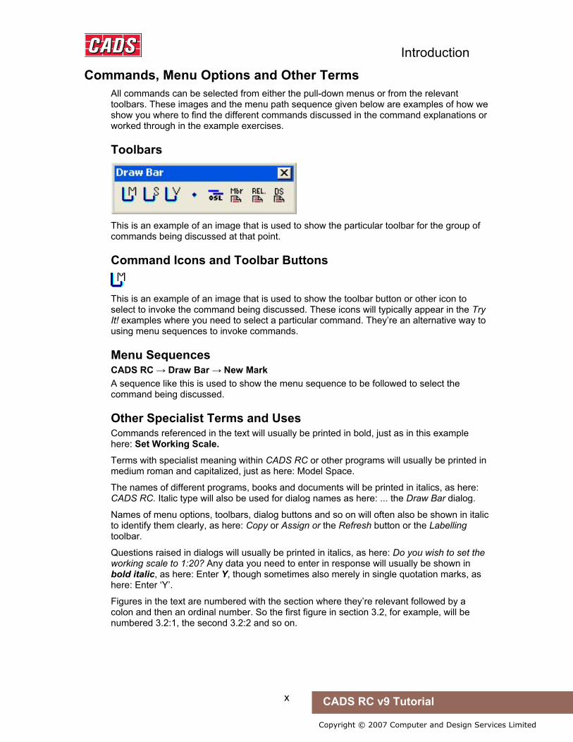
Commands, Menu Options and Other Terms All commands can be selected from either the pull-down menus or from the relevant toolbars. These images and the menu path sequence given below are examples of how we show you where to find the different commands discussed in the command explanations or worked through in the example exercises.
Toolbars
This is an example of an image that is used to show the particular toolbar for the group of commands being discussed at that point.
Command Icons and Toolbar Buttons
This is an example of an image that is used to show the toolbar button or other icon to select to invoke the command being discussed. These icons will typically appear in the Try It! examples where you need to select a particular command. They’re an alternative way to using menu sequences to invoke commands.
Menu Sequences CADS RC → Draw Bar → New Mark A sequence like this is used to show the menu sequence to be followed to select the command being discussed.
Other Specialist Terms and Uses Commands referenced in the text will usually be printed in bold, just as in this example here: Set Working Scale.
Terms with specialist meaning within CADS RC or other programs will usually be printed in medium roman and capitalized, just as here: Model Space.
The names of different programs, books and documents will be printed in italics, as here: CADS RC. Italic type will also be used for dialog names as here: ... the Draw Bar dialog.
Names of menu options, toolbars, dialog buttons and so on will often also be shown in italic to identify them clearly, as here: Copy or Assign or the Refresh button or the Labelling toolbar.
Questions raised in dialogs will usually be printed in italics, as here: Do you wish to set the working scale to 1:20? Any data you need to enter in response will usually be shown in bold italic, as here: Enter Y, though sometimes also merely in single quotation marks, as here: Enter ‘Y’.
Figures in the text are numbered with the section where they’re relevant followed by a colon and then an ordinal number. So the first figure in section 3.2, for example, will be numbered 3.2:1, the second 3.2:2 and so on.

1
Copyright © 2007 Computer and Design Services Limited
CADS RC v9 Tutorial
1: Introduction to CADS RC Commands
1.0 Overview
1.0 Overview When you manually detail reinforced concrete the scheduling operation is usually performed before the drawing is complete. When you use CADS RC, however, the schedule is created while the reinforcement is being detailed. This means that when the CADS RC drawing is completed then the schedule is also complete.
Very few commands are required to draw a bar and you will quickly become familiar with these. There is little else you need to complete a drawing although you will also come to learn CADS RC’s speed-drawing options, options that can make your detailing more efficient.
The vast majority of the remaining CADS RC commands fall into one of two categories:
• commands required for editing (either to handle missing information or for using speed-drawing techniques)
• commands required for configuring the CADS RC package to your office requirements.
The drawing commands are by far the easiest and you will learn these first. You will then learn the editing commands and, lastly, the commands you can use to tailor the software to your own needs.
Two additional products are supplied with CADS RC, namely CADS Scale and CADS Viewport Manager (usually referred to as CADS VPM). CADS VPM is the recommended scaling program to use with CADS RC v9. Try It! examples will show you how to scale drawings using CADS VPM, CADS Scale and AutoCAD.
Introduction to CADS RC Commands
2 CADS RC v9 Tutorial
Copyright © 2007 Computer and Design Services Limited
1.1 Bar Organization
1.1 Bar Organization The use of CADS RC commands to place graphics and text on the drawing ensures that all graphics and text relating to a Bar Mark are both linked together and linked to a line in the Schedule.
Consider the graphics that are needed to detail a bar:
• There may be several views of the bar • There may be Range Lines, each with end-of-range markers • There may be Ticks and Tags to show where bars start and end • There will be a Bar Label • There may be Bar Mark References
Introduction to CADS RC Commands
3 CADS RC v9 Tutorial
Copyright © 2007 Computer and Design Services Limited
1.2 Try It! Examine a CADS RC Drawing
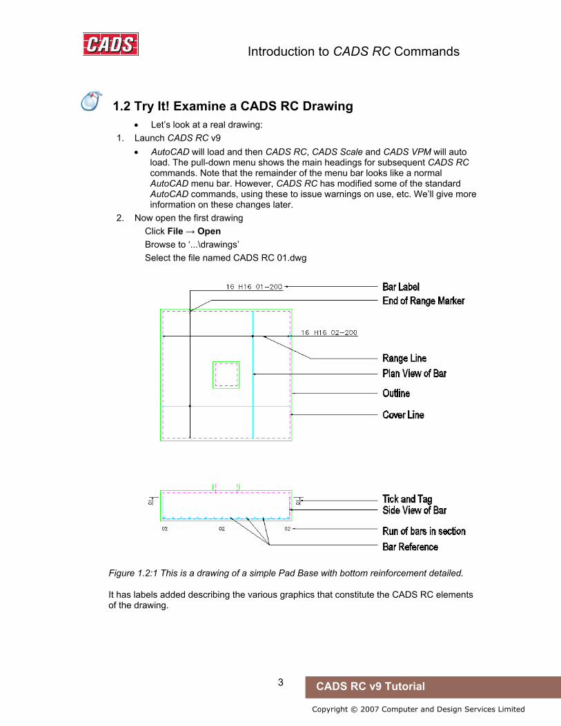
• Let’s look at a real drawing: 1. Launch CADS RC v9
• AutoCAD will load and then CADS RC, CADS Scale and CADS VPM will auto load. The pull-down menu shows the main headings for subsequent CADS RC commands. Note that the remainder of the menu bar looks like a normal AutoCAD menu bar. However, CADS RC has modified some of the standard AutoCAD commands, using these to issue warnings on use, etc. We’ll give more information on these changes later.
2. Now open the first drawing Click File → Open Browse to ‘...\drawings’ Select the file named CADS RC 01.dwg
Figure 1.2:1 This is a drawing of a simple Pad Base with bottom reinforcement detailed.
It has labels added describing the various graphics that constitute the CADS RC elements of the drawing.
1.2 Try It! Examine a CADS RC Drawing

Introduction to CADS RC Commands
4 CADS RC v9 Tutorial
Copyright © 2007 Computer and Design Services Limited
1.3 Creating Bars and Ranges
1.3 Creating Bars and Ranges There are two basic commands for adding bars to your drawing, namely Draw Bar and Draw Range.
The Draw Bar command allows you to draw a single view of a bar in any orientation. An example of this is the Shape Code 21 bar shown on the Pad Base section in figure 1.2:1 above.
The Draw Range command allows you to draw a view of a bar with a Range Line attached or to draw a run of bars in section. An example of this is the Plan View of the same Shape Code 21 bar drawn on the Pad Base plan in figure 1.4:1 with the Range Line and End Range markers.
Introduction to CADS RC Commands
5 CADS RC v9 Tutorial
Copyright © 2007 Computer and Design Services Limited
1.4 What is a Bar Set?
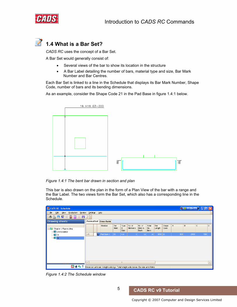
1.4 What is a Bar Set? CADS RC uses the concept of a Bar Set.
A Bar Set would generally consist of:
• Several views of the bar to show its location in the structure • A Bar Label detailing the number of bars, material type and size, Bar Mark
Number and Bar Centres.
Each Bar Set is linked to a line in the Schedule that displays its Bar Mark Number, Shape Code, number of bars and its bending dimensions.
As an example, consider the Shape Code 21 in the Pad Base in figure 1.4:1 below.
Figure 1.4:1 The bent bar drawn in section and plan
This bar is also drawn on the plan in the form of a Plan View of the bar with a range and the Bar Label. The two views form the Bar Set, which also has a corresponding line in the Schedule.
Figure 1.4:2 The Schedule window

Introduction to CADS RC Commands
6 CADS RC v9 Tutorial
Copyright © 2007 Computer and Design Services Limited
1.5 Concepts of New Mark, Add View and New Set
Before you start using CADS RC you need to understand the relationship between New Mark, Add View and New Set. These are found in the Draw Bar and Draw Range menu bars and toolbars.
A Bar Set, as you now know, contains all the information needed to draw the graphics for one instance of a bar on the drawing and its corresponding line in the Schedule.
The actual graphics showing the bar is called the Bar View. Bar Views can be Plan, Elevation or Section Views. You will see later that each Bar Mark may contain one or more Bar Sets.
Both the Draw Bar and Draw Range commands are used in conjunction with any of the following sub-commands:
• New Mark • Add View • New Set
These three sub-commands control the input of data to the Schedule and determine how the bars are linked together.
As a drawing is developed it is quite common to show the same bar in different views on the drawing. If a new line were added to the Schedule each time one of these views was drawn there would be too many lines in the Schedule. A mechanism is therefore required to update an existing line in the Schedule with the missing dimensions, number of bars etc.
This is achieved by the correct use of New Mark, Add View and New Set options.
1.5.1 New Mark The New Mark sub-command instructs CADS RC that the Bar View (and Range Line) to be drawn is the first set of a New Bar Mark and allocates the set the next available Bar Mark Number. This will also add a new line to the Schedule for this Bar Set. The New Mark function is the equivalent of the first set of a Bar Mark.
1.5.2 Add View The Add View sub-command instructs CADS RC that the Bar View (and Range Line) to be drawn is another view of an existing Bar Set already on the drawing. This will not add a new line to the Schedule but may update the line already present in the Schedule for this Bar Set.
1.5.3 New Set The New Set sub-command instructs CADS RC that the Bar View (and Range Line) to be drawn is the first of a new Bar Set but uses a Bar Mark already in use. This command allows the detailer to reuse the same Bar Mark in various locations within the structure. It can be considered as a Repeat Bar Mark Number command. This will also add a new line to the Schedule for this Bar Set.
Note: a number of lines in the Bend List with the same Bar Mark can be combined into one line showing the total number of bars if required provided that they are all associated with the same Drawing Sheet and Release Code. (There’s more on Drawing Sheets and Release Codes later.)
1.5 Concepts of New Mark, Add View and New Set

Introduction to CADS RC Commands
7 CADS RC v9 Tutorial
Copyright © 2007 Computer and Design Services Limited
Figure 1.5:1 Illustrates a simple Pad Base with Bar Mark 01 shown within two ranges.
The graphics could be placed using four simple steps on the plan and the section. The relationship between the Mark, Sets and the Views is shown on the family tree diagram above. The circled numbers on these diagrams refer to the order of working while the different commands so used are described further below.
1. Draw Bar – New Mark is used to place the Side View of the bar in the section. This allocates a new Bar Mark to the reinforcement plus a line in the Schedule.
2. Draw Range – Add View is used to place the bar plus the Range Line in the plan. This updates any missing data in the existing line in the Schedule. Items 1 and 2 are linked together as Set One of Bar Mark 01.
3. Draw Range – New Set is used to place a second instance of Bar Mark 01 in the plan and shows a bar plus its Range Line. The New Set command repeats the Bar Mark Number and allocates a line in the Schedule. Item 3 shows in Set Two of Bar Mark 01 in figure 1.4:1 above.
4. Draw Bar – Add View is used to place the Side View of the bar in the section. All the information for Set Two of Bar Mark 01 is already present in the Schedule and so this view of the bar indicates its placing position in the structure.
Introduction to CADS RC Commands
8 CADS RC v9 Tutorial
Copyright © 2007 Computer and Design Services Limited
1.6 Bar Views
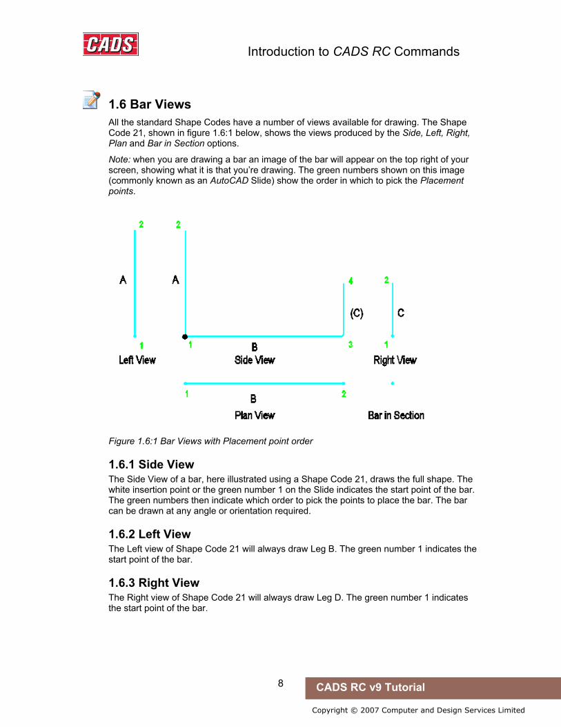
1.6 Bar Views All the standard Shape Codes have a number of views available for drawing. The Shape Code 21, shown in figure 1.6:1 below, shows the views produced by the Side, Left, Right, Plan and Bar in Section options.
Note: when you are drawing a bar an image of the bar will appear on the top right of your screen, showing what it is that you’re drawing. The green numbers shown on this image (commonly known as an AutoCAD Slide) show the order in which to pick the Placement points.
Figure 1.6:1 Bar Views with Placement point order
1.6.1 Side View The Side View of a bar, here illustrated using a Shape Code 21, draws the full shape. The white insertion point or the green number 1 on the Slide indicates the start point of the bar. The green numbers then indicate which order to pick the points to place the bar. The bar can be drawn at any angle or orientation required.
1.6.2 Left View The Left view of Shape Code 21 will always draw Leg B. The green number 1 indicates the start point of the bar.
1.6.3 Right View The Right view of Shape Code 21 will always draw Leg D. The green number 1 indicates the start point of the bar.

Introduction to CADS RC Commands
9 CADS RC v9 Tutorial
Copyright © 2007 Computer and Design Services Limited
1.6.4 Plan View The Plan view of Shape Code 21 will always draw Leg C. The green number 1 indicates the start point of the bar.
1.6.5 Bar in Section The Bar in Section view will always draw as either a solid donut or a circle depending on the Bar Style chosen.
Introduction to CADS RC Commands
10 CADS RC v9 Tutorial
Copyright © 2007 Computer and Design Services Limited
1.7 Bar Alignments
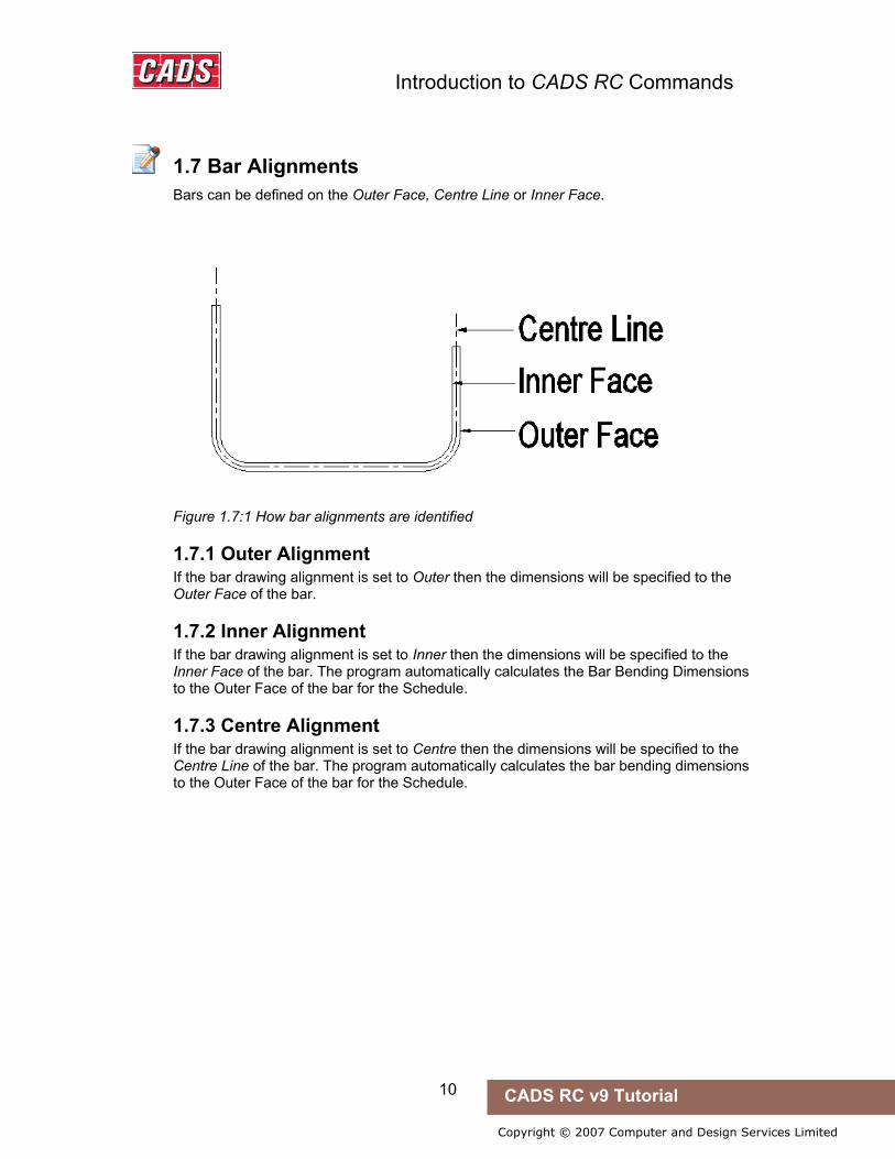
1.7 Bar Alignments Bars can be defined on the Outer Face, Centre Line or Inner Face.
Figure 1.7:1 How bar alignments are identified
1.7.1 Outer Alignment If the bar drawing alignment is set to Outer then the dimensions will be specified to the Outer Face of the bar.
1.7.2 Inner Alignment If the bar drawing alignment is set to Inner then the dimensions will be specified to the Inner Face of the bar. The program automatically calculates the Bar Bending Dimensions to the Outer Face of the bar for the Schedule.
1.7.3 Centre Alignment If the bar drawing alignment is set to Centre then the dimensions will be specified to the Centre Line of the bar. The program automatically calculates the bar bending dimensions to the Outer Face of the bar for the Schedule.

Introduction to CADS RC Commands
11 CADS RC v9 Tutorial
Copyright © 2007 Computer and Design Services Limited
1.8 Bar Styles
1.8 Bar Styles Bars can be drawn in three styles to cater for detailing at different scales as necessary.
Figure 1.8:1 The different bar styles available
1.8.1 Centre Style This will draw the centreline only of the bar. The color of the layer on which the bar is placed will dictate the line thickness when plotted.
1.8.2 Centre Style Showing True Diameter This will draw the centreline only of the bar but uses a polyline with the width set to the diameter of the bar. Select CADS RC → Configuration → Bar Configuration to configure this.
1.8.3 Profile Style This will draw the full profile of the bar as a pair of parallel lines. The distance between the lines as drawn will be the actual diameter of the bar.
Hints & Tips – the Change Bar Style Command
A drawing can have a combination of bar styles and bars can be changed from one style to another using the Change Bar Style command. The command can be accessed through CADS RC → Editing → Change Bar Style.
Hints & Tips – the Change Bar Style Command

Introduction to CADS RC Commands
12 CADS RC v9 Tutorial
Copyright © 2007 Computer and Design Services Limited
1.9 Be Consistent!
1.9 Be Consistent! It is good practice to develop a consistent drawing method. This is particularly important when detailing with a CAD Reinforced Concrete software package as you have the ability to perform massive edits very easily.
Consider the extreme case of a bridge that has its span changed late in the detailing stage – being able to use a command such as Stretch and have the outline, bars and Schedule update automatically is very powerful and a facility that would appeal to all detailers. However, to minimise problems, it’s important that the original detail be produced in a standard manner.
Always draw bars and ranges in a consistent direction: • Either top to bottom or bottom to top • Either left to right or right to left
Any bars that are stretched remotely (that is, not within the Stretch Window) will be extended or trimmed from the insertion point so if all the bars were drawn consistently from left to right and top to bottom they would all stretch in the same direction. Remember that if you stretch the section of a Member the bars in the other views will update as well.
Good drawing practice needs to be followed consistently over the whole office as different detailers may work on the same drawing over a period of time.

Introduction to CADS RC Commands
13 CADS RC v9 Tutorial
Copyright © 2007 Computer and Design Services Limited
1.10 Key points – Introduction to CADS RC Commands
1.10 Key points – Introduction to CADS RC Commands • A Bar Mark Number can have several Bar Sets associated with it. • A Bar Set can have several Bar Views associated with it, including Bar Views,
Ranges, Bar Labels, Bar Mark References, and Ticks and Tags. • Each Bar Set has its own Bar Label and one line in the Schedule. • Bar Sets of the same Bar Mark Number and Member Title can be combined
together prior to printing the Schedule. • Develop a consistent approach to placing bars and ranges on the drawing.

14
Copyright © 2007 Computer and Design Services Limited
CADS RC v9 Tutorial
2: CADS RC Drawings
2.0 Introduction
Before starting to detail reinforcement you need to set-up an AutoCAD drawing. You can add reinforcement to a new drawing or to an existing one. This chapter explains how to create new drawings, how to set the working scale of the drawing, and how to set up existing drawings. It also explains the concept of Drawing Sheets, something newly introduced in CADS RC v9.
2.0 Introduction

CADS RC Drawings
15 CADS RC v9 Tutorial
Copyright © 2007 Computer and Design Services Limited
2.1 Drawing Sheets
Drawing Sheets allow you to produce several drawings together with their associated Schedules from within a single AutoCAD DWG file. Whole structures can be detailed in one AutoCAD DWG file and split between several Drawing Sheets. Each Drawing Sheet and associated Schedule can be issued and tracked independently.
A Drawing Sheet can either be an AutoCAD Layout or a specific area of Model Space. Reinforcement can be assigned to specific Drawing Sheets as you detail or at a later time.
2.1 Drawing Sheets
CADS RC Drawings
16 CADS RC v9 Tutorial
Copyright © 2007 Computer and Design Services Limited
2.2 Creating a New AutoCAD file and Adding a Drawing Sheet
There are several ways to create a Drawing Sheet. Users of CADS VPM and CADS Scale can configure Drawing Sheets to be created automatically as part of the process of setting up a drawing. Other users can also ensure Drawing Sheets are created as part of their own drawing setup procedure. Instructions on configuring your own Title Blocks to both trigger Drawing Sheet creation and to map to the Schedule headers and footers can be found later in this chapter.
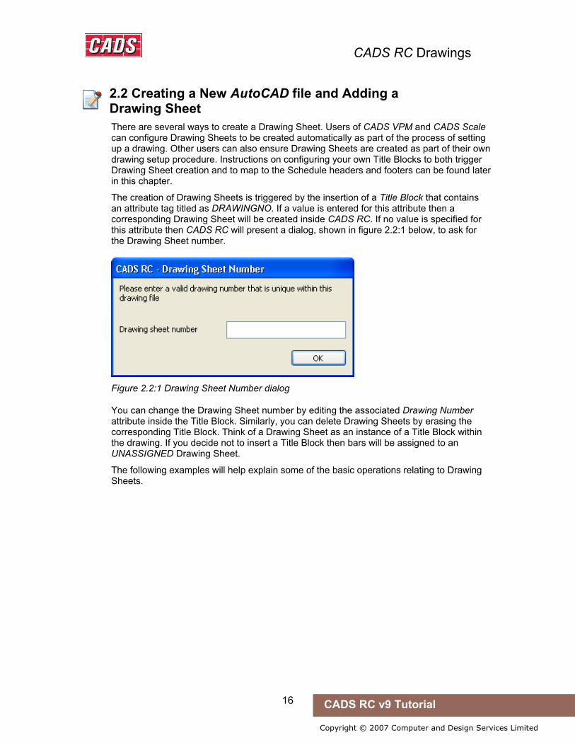
The creation of Drawing Sheets is triggered by the insertion of a Title Block that contains an attribute tag titled as DRAWINGNO. If a value is entered for this attribute then a corresponding Drawing Sheet will be created inside CADS RC. If no value is specified for this attribute then CADS RC will present a dialog, shown in figure 2.2:1 below, to ask for the Drawing Sheet number.
Figure 2.2:1 Drawing Sheet Number dialog
You can change the Drawing Sheet number by editing the associated Drawing Number attribute inside the Title Block. Similarly, you can delete Drawing Sheets by erasing the corresponding Title Block. Think of a Drawing Sheet as an instance of a Title Block within the drawing. If you decide not to insert a Title Block then bars will be assigned to an UNASSIGNED Drawing Sheet.
The following examples will help explain some of the basic operations relating to Drawing Sheets.
2.2 Creating a New AutoCAD file and Adding a Drawing Sheet
CADS RC Drawings
17 CADS RC v9 Tutorial
Copyright © 2007 Computer and Design Services Limited
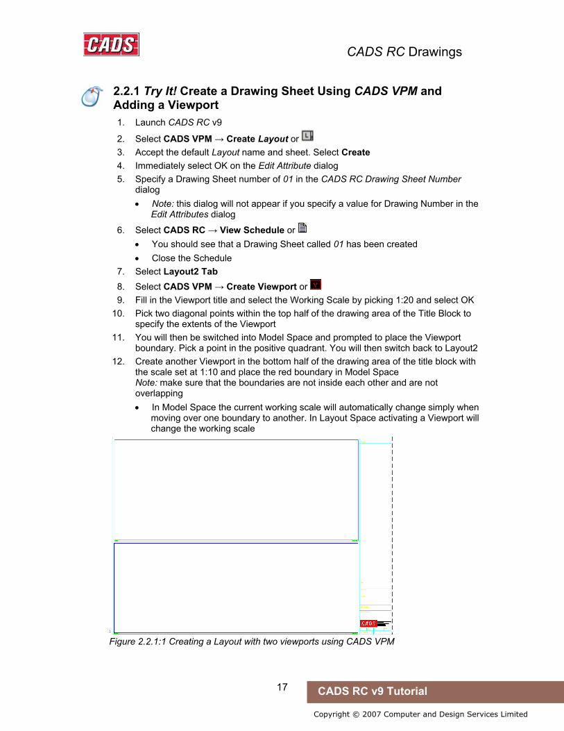
2.2.1 Try It! Create a Drawing Sheet Using CADS VPM and Add a Viewport
1. Launch CADS RC v9
2. Select CADS VPM → Create Layout or 3. Accept the default Layout name and sheet. Select Create 4. Immediately select OK on the Edit Attribute dialog 5. Specify a Drawing Sheet number of 01 in the CADS RC Drawing Sheet Number
dialog • Note: this dialog will not appear if you specify a value for Drawing Number in the
Edit Attributes dialog
6. Select CADS RC → View Schedule or • You should see that a Drawing Sheet called 01 has been created • Close the Schedule
7. Select Layout2 Tab 8. Select CADS VPM → Create Viewport or 9. Fill in the Viewport title and select the Working Scale by picking 1:20 and select OK
10. Pick two diagonal points within the top half of the drawing area of the Title Block to specify the extents of the Viewport
11. You will then be switched into Model Space and prompted to place the Viewport boundary. Pick a point in the positive quadrant. You will then switch back to Layout2
12. Create another Viewport in the bottom half of the drawing area of the title block with the scale set at 1:10 and place the red boundary in Model Space Note: make sure that the boundaries are not inside each other and are not overlapping • In Model Space the current working scale will automatically change simply when
moving over one boundary to another. In Layout Space activating a Viewport will change the working scale
Figure 2.2.1:1 Creating a Layout with two viewports using CADS VPM
2.2.1 Try It! Create a Drawing Sheet Using CADS VPM and Adding a Viewport

CADS RC Drawings
18 CADS RC v9 Tutorial
Copyright © 2007 Computer and Design Services Limited
2.2.2 Try It! Create a Layout Space Drawing Sheet Using CADS Scale and Adding a Viewport
1. Launch CADS RC v9
2. Select CADS Scale → Drawing Setup or 3. In the ‘Apply Setup To:’ option, select Layout1
Select Standard A2 Setup. Select OK 4. Select Modify on the Page Setup Manager dialog and set the Paper Size to ISO
A2(594.00 x 420.00 MM), select OK and then select Close 5. Select a scale of 1:20 in the Setup Scale dialog. Select OK 6. Select OK on the Edit Attributes dialog 7. Specify a Drawing Sheet number of 01 in the CADS RC Drawing Sheet Number
dialog • Note: this dialog will not appear if you specify a value for Drawing Number in the
Edit Attributes dialog.
8. Select CADS RC → View Schedule or 9. You should see that a Drawing Sheet called 01 has been created
10. Close the Schedule
11. Select CADS Scale → Create Scale Area or • This automatically switches you to Layout Space
12. Pick two diagonal points within the Title Block to indicate the extents of the Scale Area (approx the top half of the drawing area)
13. Pick a scale of 1:20 in the Enter Scale of Area dialog and select OK 14. Create another Scale Area at 1:10 in the remaining area inside the Title Block
• Note: the Scale Area with the current working scale is highlighted in magenta 15. To change the working scale to 1:20 select CADS Scale → Set Working Scale or
16. Pick the border of the 1:20 Scale Area. This will set the working scale to 1:20
Figure 2.2.2:1 Creating a Layout with two viewports using CADS Scale
2.2.2 Try It! Create a Layout Space Drawing Sheet Using CADS Scale and Adding a Viewport

CADS RC Drawings
19 CADS RC v9 Tutorial
Copyright © 2007 Computer and Design Services Limited
2.2.3 Try It! Create a Model Space Drawing Sheet Using CADS Scale and Define Model Space Scale Areas
1. Launch CADS RC v9
2. Select CADS Scale → Drawing Setup or 3. In the ‘Apply Setup To:’ option, select Layout1
Select Standard A2 Setup. Select OK 4. Select a scale of 1:20 in the Setup Scale dialog. Select OK 5. Select OK on the Edit Attributes dialog 6. Specify a Drawing Sheet number of 01 in the CADS RC Drawing Sheet Number
dialog • Note: this dialog will not appear if you specify a value for Drawing Number in the
Edit Attributes dialog
7. Select CADS RC → View Schedule or 8. You should see that a Drawing Sheet called 01 has been created 9. Close the Schedule
10. Select CADS Scale → Create Scale Area or 11. Pick two diagonal points in the top half of the title drawing to indicate the extents of
the Scale Area 12. Pick a scale of 1:20 in the Enter Scale of Area dialog and select OK 13. Create another Scale Area at 1:10 and answer Yes to Do you wish to set the
working scale to 1:10? Note: Unless the Scale Areas are of the same scale do not overlap them or place them inside each other
14. Select CADS Scale → Set Working Scale or 15. Pick the border of the 1:20 Scale Area. This will set the working scale to 1:20
2.2.4 Try It! Create a Layout Space Drawing Sheet Using AutoCAD
1. Launch CADS RC v9 2. Make Layout1 active by selecting the tab 3. Right click on the Layout1 and select Page Setup Manager…. Select Modify.
Select ISO A2 (594.00 x 420.00 MM) paper size. Select OK and Close 4. Select Insert → Block or type Insert 5. Browse to the ‘...\cads\AutoCAD 200*\CADS RC 9.00\CADS Scale blocks folder’ and
select ‘A2CADS.dwg’. Select Open and then OK 6. Specify a Drawing Sheet number of 01 in the CADS RC Drawing Sheet Number
dialog 7. Select OK on the Drawing Sheet Number dialog
8. Select CADS RC → View Schedule or • You should see that a Drawing Sheet called Sheet 1 has been created
2.2.3 Try It! Create a Model Space Drawing Sheet Using CADS Scale and Define Model Space Scale Areas
2.2.4 Try It! Create a Layout Space Drawing Sheet Using AutoCAD

CADS RC Drawings
20 CADS RC v9 Tutorial
Copyright © 2007 Computer and Design Services Limited
2.3 Managing Drawing Scales
CADS RC relies on the AutoCAD Dimscale variable being set to display the scale of the Viewport in which the detail is being placed. CADS RC will read the Dimscale value and will automatically scale any blocks inserted whilst detailing to the correct size. The Dimscale can be set using CADS VPM, CADS Scale or set manually inside AutoCAD.
If using CADS VPM you will change the current working scale, and hence the Dimscale, simply by moving from one Viewport boundary to another.
If using CADS Scale, using the Set Working Scale command will change the current working scale and hence the Dimscale.
If you are using AutoCAD, you will need to create manually a different Dimension Style for each Working Scale on the drawing. The value that needs to be set is on the Fit Tab → Scale for Dimension Features → Use Overall Scale of: menu option. You can then make a particular Dimension Style current to change the Current Working Scale.
2.3 Managing Drawing Scales

CADS RC Drawings
21 CADS RC v9 Tutorial
Copyright © 2007 Computer and Design Services Limited
2.4 Restrictions on Detailing with CADS RC
• Work within the positive quadrant of the AutoCAD drawing. Both X and Y co-ordinates are positive.
• Keep your details as close to the origin as possible (0,0). This keeps the co-ordinates small and reduces AutoCAD’s calculation time.
• Always work with the UCS (User Co-ordinates System) set to World. • Always work with the View set to Plan World. • Do not use Z values on any of the entities within General Arrangement drawings.
2.4 Restrictions on Detailing with CADS RC

CADS RC Drawings
22 CADS RC v9 Tutorial
Copyright © 2007 Computer and Design Services Limited
2.5 Configuring and Saving the Title Block Settings
Please consult the CADS RC Customisation & Configuration Guide for information on configuring and saving the Title Block settings for future drawing sessions.
You can configure CADS RC to work with any number of Title Blocks regardless of whether they use consistent attribute naming. You can use the same method to migrate any Title Blocks that are embedded in an AutoCAD DWT file.
2.5 Configuring and Saving the Title Block Settings
CADS RC Drawings
23 CADS RC v9 Tutorial
Copyright © 2007 Computer and Design Services Limited
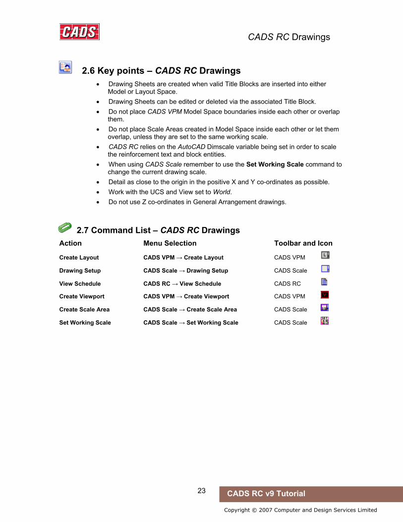
2.6 Key points – CADS RC Drawings
• Drawing Sheets are created when valid Title Blocks are inserted into either Model or Layout Space.
• Drawing Sheets can be edited or deleted via the associated Title Block. • Do not place CADS VPM Model Space boundaries inside each other or overlap
them. • Do not place Scale Areas created in Model Space inside each other or let them
overlap, unless they are set to the same working scale. • CADS RC relies on the AutoCAD Dimscale variable being set in order to scale
the reinforcement text and block entities. • When using CADS Scale remember to use the Set Working Scale command to
change the current drawing scale. • Detail as close to the origin in the positive X and Y co-ordinates as possible. • Work with the UCS and View set to World. • Do not use Z co-ordinates in General Arrangement drawings.
2.7 Command List – CADS RC Drawings
Action Menu Selection Toolbar and Icon
Create Layout CADS VPM → Create Layout CADS VPM
Drawing Setup CADS Scale → Drawing Setup CADS Scale
View Schedule CADS RC → View Schedule CADS RC
Create Viewport CADS VPM → Create Viewport CADS VPM
Create Scale Area CADS Scale → Create Scale Area CADS Scale
Set Working Scale CADS Scale → Set Working Scale CADS Scale
2.6 Key points – CADS RC Drawings
2.7 Command List – CADS RC Drawings

24
Copyright © 2007 Computer and Design Services Limited
CADS RC v9 Tutorial
3: General Arrangement Drawings and Drawing Reinforcement
3.0 General Arrangement Drawings
Reinforcement can be added to any type of General Arrangement drawing that can be generated using standard AutoCAD commands. This can be an existing drawing or one prepared from scratch by the detailer. CADS RC includes a number of General Arrangement tools to speed up the process and these are described in this chapter.
3.0 General Arrangement Drawings
General Arrangement Drawings & Drawing Reinforcement
25 CADS RC v9 Tutorial
Copyright © 2007 Computer and Design Services Limited
3.1 CADS RC Outlines
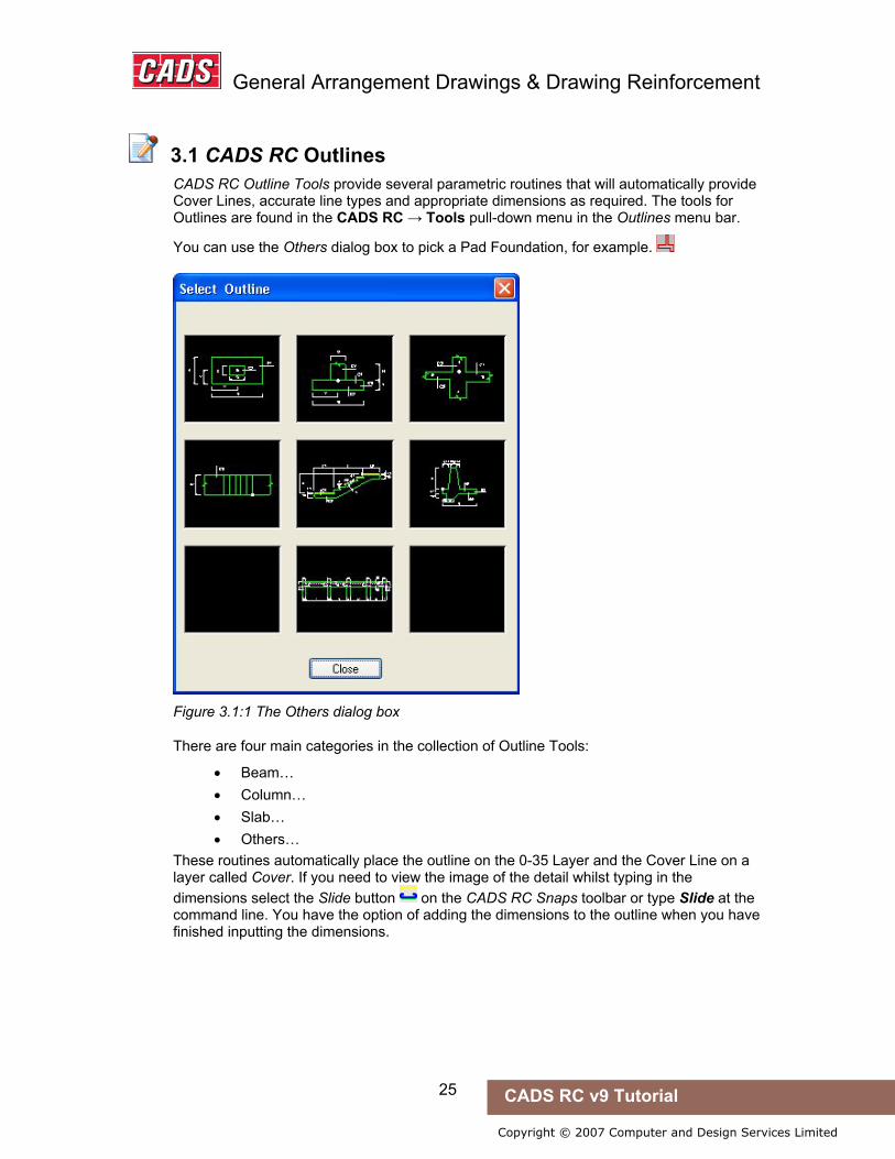
CADS RC Outline Tools provide several parametric routines that will automatically provide Cover Lines, accurate line types and appropriate dimensions as required. The tools for Outlines are found in the CADS RC → Tools pull-down menu in the Outlines menu bar.
You can use the Others dialog box to pick a Pad Foundation, for example.
Figure 3.1:1 The Others dialog box
There are four main categories in the collection of Outline Tools:
• Beam… • Column… • Slab… • Others…
These routines automatically place the outline on the 0-35 Layer and the Cover Line on a layer called Cover. If you need to view the image of the detail whilst typing in the dimensions select the Slide button on the CADS RC Snaps toolbar or type Slide at the command line. You have the option of adding the dimensions to the outline when you have finished inputting the dimensions.
3.1 CADS RC Outlines

General Arrangement Drawings & Drawing Reinforcement
26 CADS RC v9 Tutorial
Copyright © 2007 Computer and Design Services Limited
3.2 Dynamic Blocks (AutoCAD 2006 or higher only)
CADS RC ships with several tool palettes, which contain various Dynamic Block Outlines in both Imperial and Metric measures that can be dragged and dropped on to your drawing and then stretched to the correct size using Grips. Many of these support alternatives views of the structure. For instance, the Pad Base Plan & Elevation Outlines can be switched to show either the Plan or Elevation View.
Figure 3.2:1 Selection of Tool Palettes
Hints & Tips – Loading CADS RC Palettes
If the CADS RC Palettes do not show up on your Tool Palette they can be loaded manually as follows:
1. Right click on the Icon at the bottom of the Tool Palette 2. Select Customise Palettes 3. Right click in the Palettes area and select Import 4. Browse to the \Program Files\Common Files\CADS Shared\CADS Outlines\Exported
Palettes & Groups\Imperial or Metric directory 5. Pick the required *.xtp file 6. Repeat the procedure until all the required XTP files are loaded
3.2 Dynamic Blocks (AutoCAD 2006 or higher only)
Hints & Tips – Loading CADS RC Palettes
General Arrangement Drawings & Drawing Reinforcement
27 CADS RC v9 Tutorial
Copyright © 2007 Computer and Design Services Limited
Hints & Tips – Switching on Dynamic Input
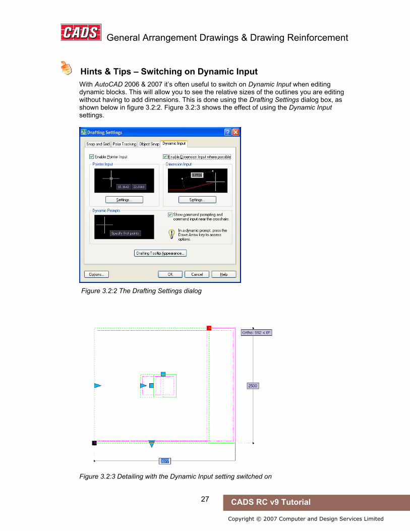
With AutoCAD 2006 & 2007 it’s often useful to switch on Dynamic Input when editing dynamic blocks. This will allow you to see the relative sizes of the outlines you are editing without having to add dimensions. This is done using the Drafting Settings dialog box, as shown below in figure 3.2:2. Figure 3.2:3 shows the effect of using the Dynamic Input settings.
Figure 3.2:2 The Drafting Settings dialog
Figure 3.2:3 Detailing with the Dynamic Input setting switched on
Hints & Tips – Switching on Dynamic Input
General Arrangement Drawings & Drawing Reinforcement
28 CADS RC v9 Tutorial
Copyright © 2007 Computer and Design Services Limited
Hints & Tips – Editing Dynamic Block Dimensions
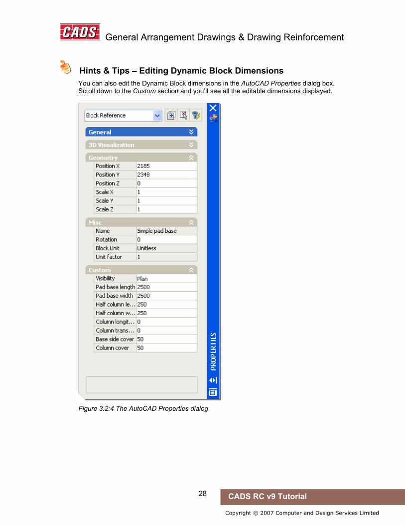
You can also edit the Dynamic Block dimensions in the AutoCAD Properties dialog box. Scroll down to the Custom section and you’ll see all the editable dimensions displayed.
Figure 3.2:4 The AutoCAD Properties dialog
Hints & Tips – Editing Dynamic Block Dimensions
General Arrangement Drawings & Drawing Reinforcement
29 CADS RC v9 Tutorial
Copyright © 2007 Computer and Design Services Limited
3.3 CADS RC Snaps – How to Use These in Detailing
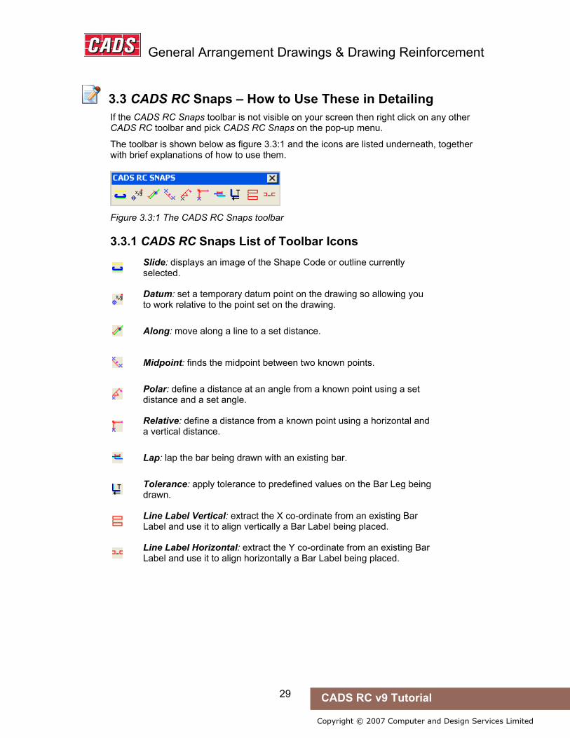
If the CADS RC Snaps toolbar is not visible on your screen then right click on any other CADS RC toolbar and pick CADS RC Snaps on the pop-up menu.
The toolbar is shown below as figure 3.3:1 and the icons are listed underneath, together with brief explanations of how to use them.
Figure 3.3:1 The CADS RC Snaps toolbar
3.3.1 CADS RC Snaps List of Toolbar Icons
Slide: displays an image of the Shape Code or outline currently selected.
Datum: set a temporary datum point on the drawing so allowing you to work relative to the point set on the drawing.
Along: move along a line to a set distance.
Midpoint: finds the midpoint between two known points.
Polar: define a distance at an angle from a known point using a set distance and a set angle.
Relative: define a distance from a known point using a horizontal and a vertical distance.
Lap: lap the bar being drawn with an existing bar.
Tolerance: apply tolerance to predefined values on the Bar Leg being drawn.
Line Label Vertical: extract the X co-ordinate from an existing Bar Label and use it to align vertically a Bar Label being placed.
Line Label Horizontal: extract the Y co-ordinate from an existing Bar Label and use it to align horizontally a Bar Label being placed.
3.3 CADS RC Snaps – How to Use These in Detailing

General Arrangement Drawings & Drawing Reinforcement
30 CADS RC v9 Tutorial
Copyright © 2007 Computer and Design Services Limited
3.4 Setting a Drawing Sheet Current
If you have several layouts in your AutoCAD drawing file you can use the Set Drawing Sheet command to ensure that the reinforcement is correctly assigned to a particular Drawing Sheet. The Schedule will automatically sort the reinforcement into Drawing Sheets. Later in this tutorial you will go through the commands used to assign reinforcement to a Drawing Sheet after it has been drawn and checking that reinforcement has been correctly assigned to a Drawing Sheet.
Figure 3.4:1 The Set Current Drawing Sheet dialog
3.4 Setting a Drawing Sheet Current

General Arrangement Drawings & Drawing Reinforcement
31 CADS RC v9 Tutorial
Copyright © 2007 Computer and Design Services Limited
3.5 Creating and Setting the Current Member
Members can be used as a way of grouping and categorising bars.
If you wish to produce a duplicate of a specific detail without drawing it then you will need to use the Member Quantity option.
Figure 3.5:1 The Members dialog
Hints & Tips – Make the Draw Bar Dialog Default to a Member
To make the Draw Bar dialog default to a specific Member you can simply highlight the required Member within the list and click the Make Current button.
3.5 Creating and Setting the Current Member
Hints & Tips – Make the Draw Bar Dialog Default to a Member

General Arrangement Drawings & Drawing Reinforcement
32 CADS RC v9 Tutorial
Copyright © 2007 Computer and Design Services Limited
3.6 Bar Drawing Dialog
The CADS RC Bar Drawing dialog is the main tool for the selection and input of bar bending data. You should try to input as much data as you can into this dialog box, as this will cut down the number of AutoCAD command line prompts needed and so speed up your detailing.
Figure 3.6:1 The Bar Drawing dialog. The number labels added show the different sections and these are described below. The item labels on the dialog are shown below in bold italic.
3.6.1 Shape Code Use this section to set the Shape Code required either by scrolling through the Shape Codes, or by typing in the required Shape Code Number. You can manually create your own Special Bars by typing in a unique number into this area and then selecting the 99 radio button. The Shape Codes available will change depending on the Bar Description file configuration. The use of the 99 radio button and the availability of particular Shape Codes at different times are both described more fully later.
3.6 Bar Drawing Dialog

General Arrangement Drawings & Drawing Reinforcement
33 CADS RC v9 Tutorial
Copyright © 2007 Computer and Design Services Limited
3.6.2 Graphics Style Use this section to set the required View, Alignment and Bar Style.
3.6.3 Bar Label Data Input as much information as feasible, such as the centres and notes, in this section before drawing the bar in order to reduce the number of command line prompts needed later. Multi: enter a numerical value here when you want to multiply the number of bars detailed. You can use this for Top and Bottom bars, Near-Face and Far-Face, or Bundle bars. The Label Multiplier also allows hidden multipliers in the Bar Label and so lets you multiply the number of bars in the Bar Label for take-off purposes. You can do this by entering multipliers in the form 2*2. See the Help System for further information. Type and Size: the Types and sizes of steel available will depend on the detailing standard selected from CADS RC → Configuration → Change Detailing Standard. Notes: use this option to add up to four extra lines of text to the Bar Label.
3.6.4 Assign Bar to… Make entries here to show the current Member, Release and Drawing Sheet values. You can change these using the drop down menus. Pick the Browse button to access the Create/Set Current dialogs for each option.
3.6.5 Dimension Data Select the First Bar button to input the bar dimensions by hand. If you attempt to type in dimensions that are below the minimum or above the maximum configured Bar Leg lengths CADS RC will issue a warning and auto-correct the dimensions.
3.6.6 Couplers Use the Couplers button to attach a variety of manufacturer’s couplers and threaded ends to the reinforcement.
3.6.7 Extract Data The Extract Data button opens a dialog through which you select data to be copied from another Bar Set and then automatically added to the Bar Set being created.
3.6.8 Sketch Bar Shape Code The Set Sketch Bar button opens the Sketch Bar dialog box. You would normally use a sketch bar where you are unable to draw the true length of the bar or to draw the Left, Right or Plan Views of a User-Defined 99 bar.
3.6.9 Other Tick the Un-Scheduled Bar box if you do not want the bar being drawn to show up on the Schedule. You could also use this option to show continuation steel, which is being lapped in the current area but has previously been detailed on another drawing.
3.6.10 Suppress c/c Display and Suppress Label Multiply Ticking the Suppress c/c display option prevents the centres from being displayed on the Bar Label. Ticking the Suppress Label Multiply box will change the Bar Label format if a Multiplier has been added in the Bar Label data area, a feature discussed at 3.6.3 above.
General Arrangement Drawings & Drawing Reinforcement
34 CADS RC v9 Tutorial
Copyright © 2007 Computer and Design Services Limited
For instance, the Bar Label might ordinarily show 12 x 5 T20-05-200; if the Suppress Label Multiplier is selected it would show 60 T20 -05-200.
Click OK to exit the dialog once you have entered all the required data. On the top right of the screen an image of the Shape Code is displayed with the insertion point indicated as a white donut. The order in which to pick the Bar Legs is indicated numerically. The bar can be inserted at any angle and in any rotation.
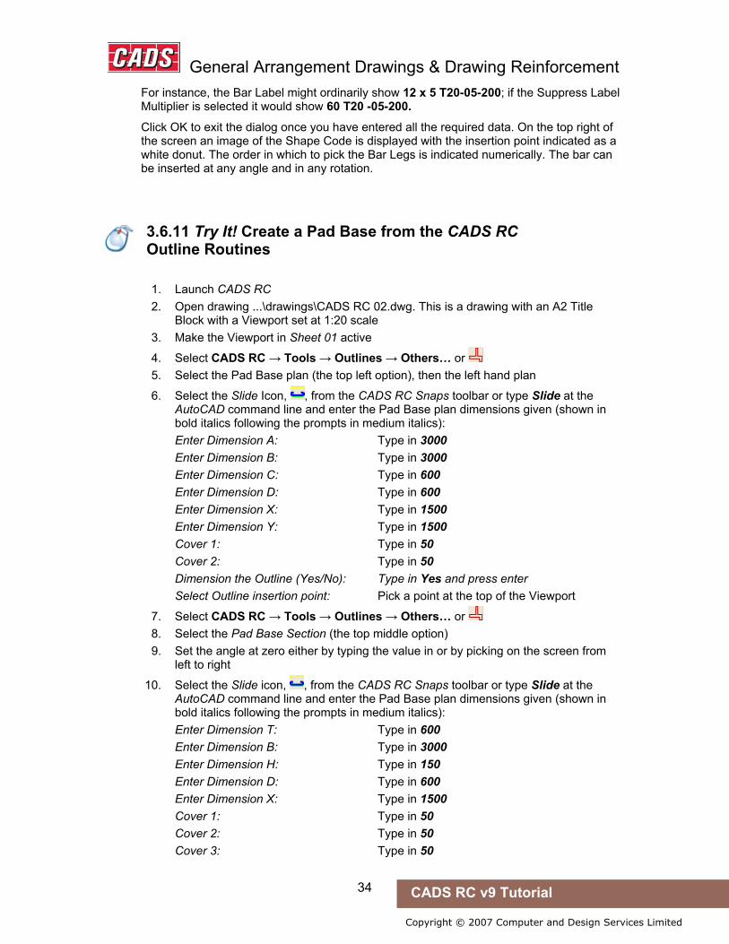
3.6.11 Try It! Create a Pad Base from the CADS RC Outline Routines
1. Launch CADS RC 2. Open drawing ...\drawings\CADS RC 02.dwg. This is a drawing with an A2 Title
Block with a Viewport set at 1:20 scale 3. Make the Viewport in Sheet 01 active
4. Select CADS RC → Tools → Outlines → Others… or 5. Select the Pad Base plan (the top left option), then the left hand plan
6. Select the Slide Icon, , from the CADS RC Snaps toolbar or type Slide at the AutoCAD command line and enter the Pad Base plan dimensions given (shown in bold italics following the prompts in medium italics): Enter Dimension A: Type in 3000 Enter Dimension B: Type in 3000 Enter Dimension C: Type in 600 Enter Dimension D: Type in 600 Enter Dimension X: Type in 1500 Enter Dimension Y: Type in 1500 Cover 1: Type in 50 Cover 2: Type in 50 Dimension the Outline (Yes/No): Type in Yes and press enter Select Outline insertion point: Pick a point at the top of the Viewport
7. Select CADS RC → Tools → Outlines → Others… or 8. Select the Pad Base Section (the top middle option) 9. Set the angle at zero either by typing the value in or by picking on the screen from
left to right
10. Select the Slide icon, , from the CADS RC Snaps toolbar or type Slide at the AutoCAD command line and enter the Pad Base plan dimensions given (shown in bold italics following the prompts in medium italics): Enter Dimension T: Type in 600 Enter Dimension B: Type in 3000 Enter Dimension H: Type in 150 Enter Dimension D: Type in 600 Enter Dimension X: Type in 1500 Cover 1: Type in 50 Cover 2: Type in 50 Cover 3: Type in 50
3.6.11 Try It! Create a Pad Base from the CADS RC Outline Routines

General Arrangement Drawings & Drawing Reinforcement
35 CADS RC v9 Tutorial
Copyright © 2007 Computer and Design Services Limited
Cover 4: Type in 50 Dimension the Outline (Yes/No): Type in Yes and press enter Select Outline insertion point: Line the section up with the Plan View and place it below
Figure 3.6.11:1 Pad Base Plan and Section created with CADS RC Outline Routines

General Arrangement Drawings & Drawing Reinforcement
36 CADS RC v9 Tutorial
Copyright © 2007 Computer and Design Services Limited
3.6.12 Try It! Create a Pad Base Outline Using CADS RC Dynamic Blocks (AutoCAD 2006 or higher only)
1. Launch CADS RC 2. Open drawing ...\drawings\CADS RC 03.dwg. This is a drawing with an A2 Title
Block with a Viewport set at 1:20 scale 3. Make the Viewport in Sheet 01 active 4. Launch the Tool Palettes and select Foundation Outlines
If the CADS RC Tool Palettes are not present refer to the Hints & Tips following section 3.2 above on how to load them.
Figure 3.6.12:1 CADS RC Pad Base Tool Palette
5. Drag and drop the Pad Base with Column Plan & Elevation into the Viewport. It currently shows the Plan View of the Pad Base
6. Click on the plan to activate the Grips. Pick the top right Grip and stretch to the right. Change the length to 3000
7. Pick the top right Grip point again and press the Tab key on the keyboard until the Width field is active. Change the width to 3000
8. Copy the Pad Base plan below itself 9. Click on the Pad Base plan to activate the Grips, select the Visibility Arrow (indicated
on the diagram below), and select the Elevation option 10. Move the elevation nearer to the Plan View
Figure 3.6.12:2 Pad Base Dynamic Block
3.6.12 Try It! Create a Pad Base Outline Using CADS RC Dynamic Blocks (AutoCAD 2006 or higher only)

General Arrangement Drawings & Drawing Reinforcement
37 CADS RC v9 Tutorial
Copyright © 2007 Computer and Design Services Limited
3.6.13 Try It! Create a Member Title and Set the Current Drawing Sheet
1. Launch CADS RC 2. Open drawing ...\drawings\CADS RC 04.dwg. This is a drawing with an A2 Title
Block with a Viewport set at 1:20 scale 3. Make the Viewport in Sheet 01 active
4. Select CADS RC → Draw Bar → Set Member or . Type in the Member Title as Pad Base 1, set the description to 3000 x 3000 x 600 Pad Base and set the quantity to 2. The quantity entered will multiply the total number of bars allocated to the Pad Base Member Title
5. Select Make Current and select OK. The line color will change to green to indicate that this is the current Member and that all reinforcement drawn will be assigned to this Member
Figure 3.6.13:1 CADS RC Members dialog
6. Select CADS RC → Draw Bar → Set Drawing Sheet or . Drawing Number 01 is already highlighted so click the Make Current button. The line color will change to green to indicate that it is now current. The Drawing Title will automatically be picked up from the Drawing Title block. You can configure CADS RC to read Title Block attribute information automatically
3.6.13 Try It! Create a Member Title and Set the Current Drawing Sheet

General Arrangement Drawings & Drawing Reinforcement
38 CADS RC v9 Tutorial
Copyright © 2007 Computer and Design Services Limited
Figure 3.6.13:2 Set Current Drawing Sheet screen

General Arrangement Drawings & Drawing Reinforcement
39 CADS RC v9 Tutorial
Copyright © 2007 Computer and Design Services Limited
3.6.14 Try It! Add two U Bars to the Pad Base Section
• In this example you will add two Side Views of Shape Code 21 to the Pad Base Section using the New Mark and New Set sub options under Draw Bar.
1. Launch CADS RC 2. Open drawing ...\drawings\CADS RC 05.dwg 3. Select 1:20 as the working scale 4. Switch to Model Space and zoom in on the Pad Base detail
5. Select CADS RC → Draw Bar → New Mark or 6. Input the data as shown in figure 3.6.14:1 below
• Note: You can choose to input the Bar Centres now, that is, when you add a Range of the bar. CADS RC defaults to 0 mm which will not be displayed on the Bar Label. Showing the Bar Centres is optional and you may not want to do this
Figure 3.6.14:1 The Bar Drawing dialog; see 3.6 for more explanation
7. Select the First Bar button and input Dimensions B, C and D as shown in figure 3.6.14:2 below. You do not have to input the dimensions in the First Bar dialog as they can be picked or specified directly on the screen whilst drawing the bar. Select OK twice
3.6.14 Try It! Add two U Bars to the Pad Base Section

General Arrangement Drawings & Drawing Reinforcement
40 CADS RC v9 Tutorial
Copyright © 2007 Computer and Design Services Limited
Figure 3.6.14:2 CADS RC Dimension Entry dialog
8. Pick the points to place the bar, as indicated in figure 3.6.14:3 below. The insertion point of the bar is on the Intersection of the Cover Lines at the top left. You can simply pick in the direction of points 2, 3 and 4 with Ortho switched ON, as you will already have input the length of these legs. If no dimensions have been specified you could use Direct Distance Entry to input the lengths, Relative Co-ordinates, Relative Polar Co-ordinates or Object Snaps
Figure 3.6.14:3 Insertion point and placing order Shape Code 21
9. Answer No to the prompt to place the Bar Label (Call Off). You will add the Bar Label to the Range Line later
10. Select CADS RC → Draw Bar → New Set or 11. Select Continue with New Set 12. Select the bar drawn in the left side of the section 13. All the data in this dialog box, other than Notes, is already set-up correctly and this
includes the Bar View. Type in Side Bars and select OK 14. Place the bar on the right hand side of the Pad Base with the Insertion point on the
top right (point 5) and Leg B (point 6) along the top face of the structure 15. Answer No to Label Bar?
16. Select CADS RC → View Schedule or

General Arrangement Drawings & Drawing Reinforcement
41 CADS RC v9 Tutorial
Copyright © 2007 Computer and Design Services Limited
Figure 3.6.14:4 The CADS RC Schedule dialog
3.6.15 Try It! Add the Ranges to the Pad Base Plan
• In the appropriate places in this working example you should enter the values shown in bold italics following the prompts given in medium italics.
1. Launch CADS RC 2. Open drawing ...\drawings\CADS RC 06.dwg 3. Set the Working Scale at 1:20 4. Switch to Model Space and zoom in on the Pad Base plan and section
5. Select CADS RC → Draw Range → Add View or 6. Pick the Shape Code 21 on the left side of the section, indicated by point 1 7. Select the Single Indicator Range Style 8. Set the Bar View to Left and select OK 9. Pick the points as indicated on figure 3.6.15:1 below starting with point 2, to place
the Bar View and the Range Line. The range offsets should be set to 0.0. Set the Centre Spacing at 200 and answer Yes to placing the Bar Label
Figure 3.6.15:1 Single Indicator Range Placing Order
3.6.15 Try It! Add the Ranges to the Pad Base Plan

General Arrangement Drawings & Drawing Reinforcement
42 CADS RC v9 Tutorial
Copyright © 2007 Computer and Design Services Limited
Left View Outer start point: Pick as indicated by point 2 Enter Outer Dimension: Pick as indicated by point 3 Start of bar range / enter Slope / True Len / Line: Pick as indicated by point 4 Offset first bar from start <0>: Press Enter Pick End of range: Pick as indicated by point 5 Offset last bar from end <0>: Press Enter Range length to 1836 Centre spacing or <Number of bars>: Type in 200(for 200 mm) and press enter Range options: 16 bars at < 200 > / Average c/c = 193.3 / Run out / Numeric: Press ENTER to continue or (A)verage/(R)un Out/(N)umeric: Press Enter to accept Label bar <No>? or J to Justify: Type in yes and press enter Pick point: Pick the position of the Bar Label above the Plan View, as indicated by point 6
10. Repeat the CADS RC → Draw Range → Add View or command and add the range of the right hand Shape Code 21 (shown by point 7) to the Plan View, as shown in figure 3.6.15:2 below
Figure 3.6.15:2 Second Single Indicator Range Placing Order
• If you have set the Range Offsets and Snaps and preset the Range Centres as suggested in the Hints & Tips at the end of this example then the time taken to place the range will have been reduced.
11. Select CADS RC → View Schedule or . Note that the number of bars allocated to each line has updated. Close the Schedule and the drawing
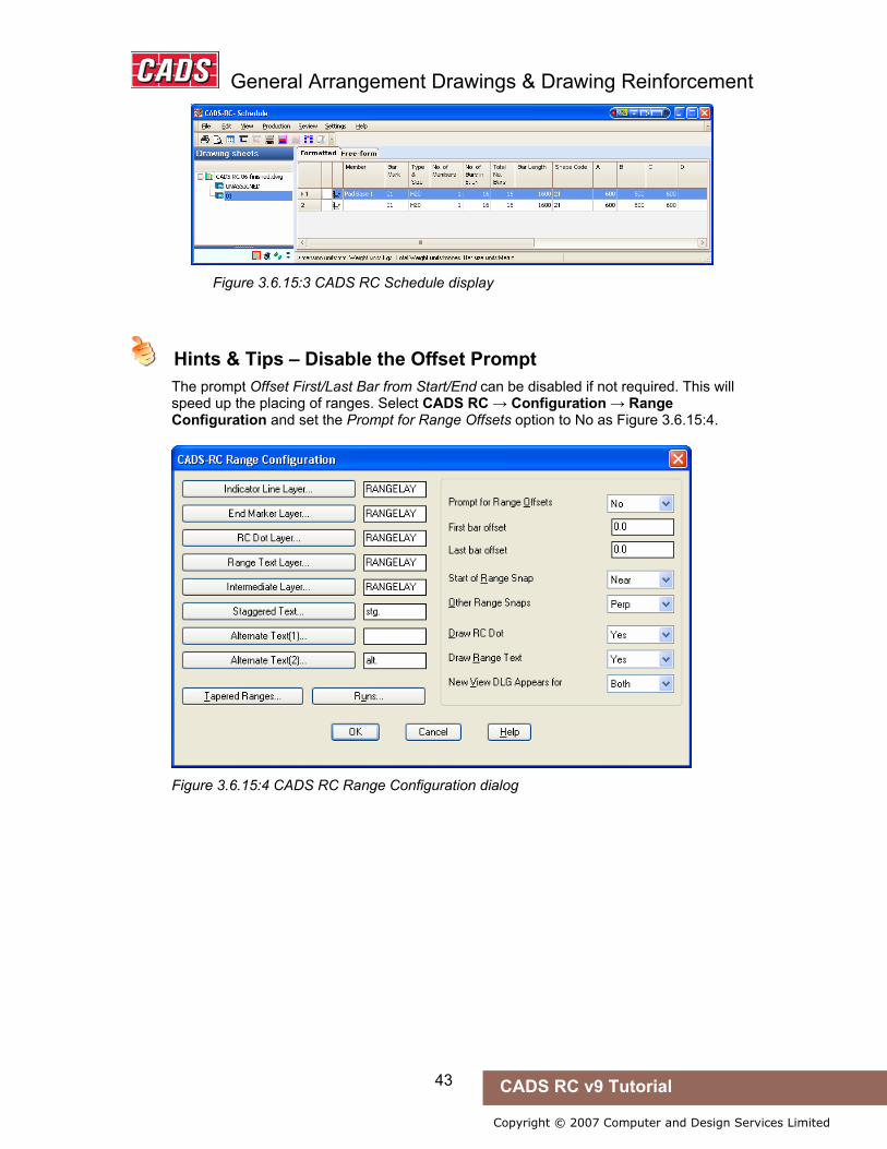
General Arrangement Drawings & Drawing Reinforcement
43 CADS RC v9 Tutorial
Copyright © 2007 Computer and Design Services Limited
Figure 3.6.15:3 CADS RC Schedule display
Hints & Tips – Disable the Offset Prompt
The prompt Offset First/Last Bar from Start/End can be disabled if not required. This will speed up the placing of ranges. Select CADS RC → Configuration → Range Configuration and set the Prompt for Range Offsets option to No as Figure 3.6.15:4.
Figure 3.6.15:4 CADS RC Range Configuration dialog
Hints & Tips – Set Object Snaps on the Range Prompts
Hints & Tips – Disable the Offset Prompt
General Arrangement Drawings & Drawing Reinforcement
44 CADS RC v9 Tutorial
Copyright © 2007 Computer and Design Services Limited
Object Snaps can be set on the Start / End of Range prompts. These will override the current Osnap settings and then reset them once the command has finished. Select CADS RC → Configuration → Range Configuration; set the Start Snap to Near and the Other Snaps to Perp as Figure 3.6.15:4
Hints & Tips – Preset Centre to Centre Spacing
You can preset the centre-to-centre spacing for the range in the Draw Bar dialog. This will suppress the Bar Spacing prompt when drawing the range.
Hints & Tips – Save Configuration Changes Permanently
If you want to save any configuration changes permanently for all new drawings select CADS RC → Configuration → Configuration Centre → Miscellaneous Configuration and pick Write Prototype Settings. This creates a unique *.INI (initialization) file on your computer. Every time you start a new drawing inside CADS RC this file is read and the configuration is set accordingly.
Hints & Tips – Lining up Bar Labels with Others
For lining up Bar Labels (Call Outs) with other Bar Labels, you can use these CADS RC Snaps:
Line Label Vertical
Line Label Horizontal
Hints & Tips – Set Object Snaps on the Range Prompts
Hints & Tips – Preset Centre to Centre Spacing
Hints & Tips – Save Configuration Changes Permanently
Hints & Tips – Lining up Bar Labels with Others
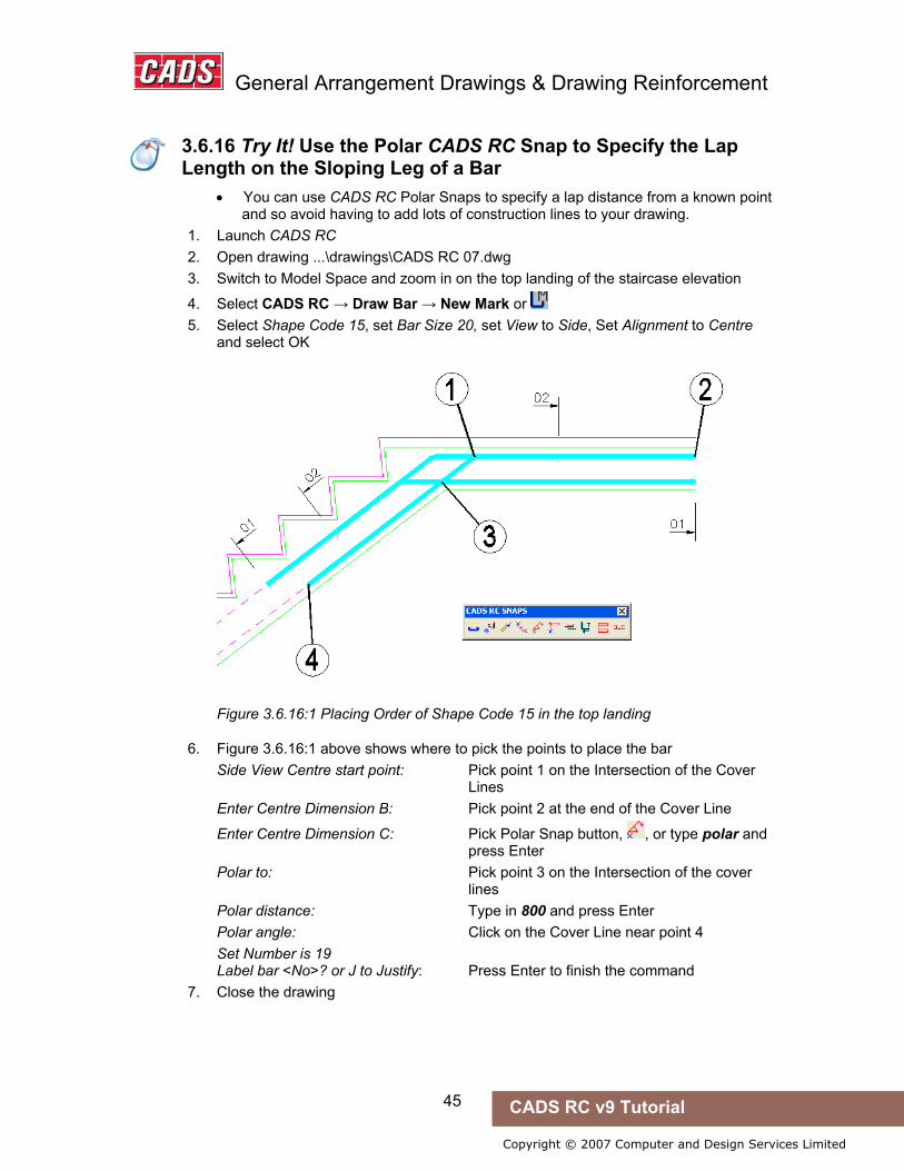
General Arrangement Drawings & Drawing Reinforcement
45 CADS RC v9 Tutorial
Copyright © 2007 Computer and Design Services Limited
3.6.16 Try It! Use the Polar CADS RC Snap to Specify the Lap Length on the Sloping Leg of a Bar
• You can use CADS RC Polar Snaps to specify a lap distance from a known point and so avoid having to add lots of construction lines to your drawing.
1. Launch CADS RC 2. Open drawing ...\drawings\CADS RC 07.dwg 3. Switch to Model Space and zoom in on the top landing of the staircase elevation
4. Select CADS RC → Draw Bar → New Mark or 5. Select Shape Code 15, set Bar Size 20, set View to Side, Set Alignment to Centre
and select OK
Figure 3.6.16:1 Placing Order of Shape Code 15 in the top landing
6. Figure 3.6.16:1 above shows where to pick the points to place the bar Side View Centre start point: Pick point 1 on the Intersection of the Cover Lines Enter Centre Dimension B: Pick point 2 at the end of the Cover Line
Enter Centre Dimension C: Pick Polar Snap button, , or type polar and press Enter Polar to: Pick point 3 on the Intersection of the cover lines Polar distance: Type in 800 and press Enter Polar angle: Click on the Cover Line near point 4 Set Number is 19 Label bar <No>? or J to Justify: Press Enter to finish the command
7. Close the drawing
3.6.16 Try It! Use the Polar CADS RC Snap to Specify the Lap Length on the Sloping Leg of a Bar
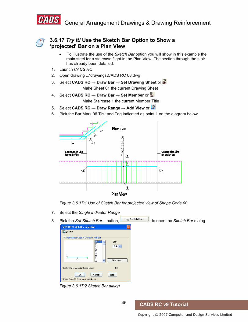
General Arrangement Drawings & Drawing Reinforcement
46 CADS RC v9 Tutorial
Copyright © 2007 Computer and Design Services Limited
3.6.17 Try It! Use the Sketch Bar Option to Show a ‘projected’ Bar on a Plan View
• To illustrate the use of the Sketch Bar option you will show in this example the main steel for a staircase flight in the Plan View. The section through the stair has already been detailed.
1. Launch CADS RC 2. Open drawing ...\drawings\CADS RC 08.dwg
3. Select CADS RC → Draw Bar → Set Drawing Sheet or Make Sheet 01 the current Drawing Sheet
4. Select CADS RC → Draw Bar → Set Member or Make Staircase 1 the current Member Title
5. Select CADS RC → Draw Range → Add View or 6. Pick the Bar Mark 06 Tick and Tag indicated as point 1 on the diagram below
Figure 3.6.17:1 Use of Sketch Bar for projected view of Shape Code 00
7. Select the Single Indicator Range
8. Pick the Set Sketch Bar... button, , to open the Sketch Bar dialog
Figure 3.6.17:2 Sketch Bar dialog
3.6.17 Try It! Use the Sketch Bar Option to Show a ‘projected’ Bar on a Plan View

General Arrangement Drawings & Drawing Reinforcement
47 CADS RC v9 Tutorial
Copyright © 2007 Computer and Design Services Limited
9. Select the Activate option, , and then pick Shape Code 00 on the list. Select OK
10. Set the Bar Centres c/c at 200 and select OK 11. Place the Sketch Bar View and the Range Line picking points 2 to 6 shown in figure
3.6.17:1 above Side View Centre start point: Pick point 2 on the magenta construction line Enter Centre Dimension B: Pick point 3 on the magenta construction line Setting Start Snap(s) Near Start of bar range / enter Slope / True Len / Line: Pick point 4 on the Cover Line Offset First bar from start <0>: Press enter Setting Other Snap(s) Perp. Pick End of range: Pick point 5 on the Cover Line Offset Last bar from end <0>: Press Enter Range length 1020 Range options: 7 bars at < 200 > / Average c/c = 170.0 / Run out / Numeric: Press ENTER to continue or (A)verage/(R)un Out/(N) umeric: Set Number is 1 Label bar <No>? or J to Justify: Type Y and press Enter Pick point: Pick point 6 below the Plan View • Note that you do not have to use a Sketch Bar with the cranked bars (Shape
Code 15), as CADS RC will correctly calculate the Projected Length of the Plan View.
12. Select CADS RC → View Schedule to review Bar Data and then close the Schedule and the drawing.
3.6.18 Try It! Use the Multiplier Field and Lap Bar CADS RC Snap to Detail Top and Bottom Steel Efficiently
1. Launch CADS RC 2. Open drawing ...\drawings\CADS RC 09.dwg 3. Switch to Model Space and zoom in on the Pad Base elevation
4. Select CADS RC → Draw Bar → Set Drawing Sheet or Make 01 the current Drawing Sheet
5. Select CADS RC → Draw Bar → New Mark or 6. Select Shape Code 00, set Bar Size 16, set View to Side, Set Alignment to Centre,
type 2 in the Multi field and set Centres to 200 and select OK 7. Place the Straight Bar as indicated in the diagram below using the CADS RC Lap
Bar Snap. Set the Lap Type at 35d
3.6.18 Try It! Use the Multiplier Field and Lap Bar CADS RC Snap to Detail Top and Bottom Steel Efficiently
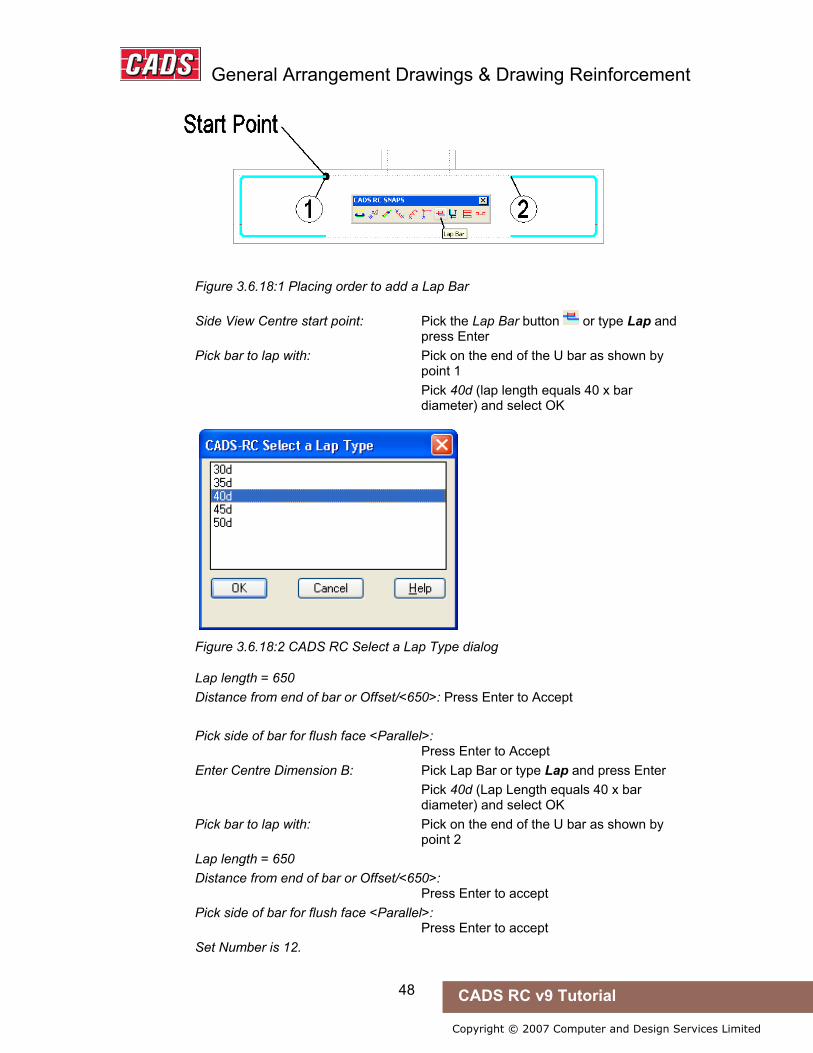
General Arrangement Drawings & Drawing Reinforcement
48 CADS RC v9 Tutorial
Copyright © 2007 Computer and Design Services Limited
Figure 3.6.18:1 Placing order to add a Lap Bar
Side View Centre start point: Pick the Lap Bar button or type Lap and press Enter Pick bar to lap with: Pick on the end of the U bar as shown by point 1 Pick 40d (lap length equals 40 x bar diameter) and select OK
Figure 3.6.18:2 CADS RC Select a Lap Type dialog
Lap length = 650 Distance from end of bar or Offset/<650>: Press Enter to Accept
Pick side of bar for flush face <Parallel>: Press Enter to Accept Enter Centre Dimension B: Pick Lap Bar or type Lap and press Enter Pick 40d (Lap Length equals 40 x bar diameter) and select OK Pick bar to lap with: Pick on the end of the U bar as shown by point 2 Lap length = 650 Distance from end of bar or Offset/<650>: Press Enter to accept Pick side of bar for flush face <Parallel>: Press Enter to accept Set Number is 12.

General Arrangement Drawings & Drawing Reinforcement
49 CADS RC v9 Tutorial
Copyright © 2007 Computer and Design Services Limited
Label bar <No>? or J to Justify: Press Enter to accept
Figure 3.6.18:3 Placing order to add lap bar and range to the Plan View
8. Select CADS RC → Draw Range → Add View or and pick the Straight Bar in the elevation you have just drawn, point 3. Choose a Single Indicator Range.
9. Place the Straight Bar as indicated in figure 3.6.18:3 above using the CADS RC Snap Line Label Horizontal to line up the Bar Labels. Note that construction lines have already been added to ease the placement of the bar. Side View Centre start point: Pick point 4 on the construction line Enter Centre Dimension B: Pick point 5 on the construction line Setting Start Snap(s) Near Start of bar range / enter Slope / True Len / Line: Pick point 6 on the Cover Line Setting Other Snap(s) Perp. Pick End of range: Pick point 7 on the Cover Line Range length 2900.0. Range options : 16 bars at < 200 > / Average c/c = 193.3 / Run out / Numeric : Press ENTER to continue or (A)verage/(R)un Out/(N) umeric: Press Enter Set Number is 13
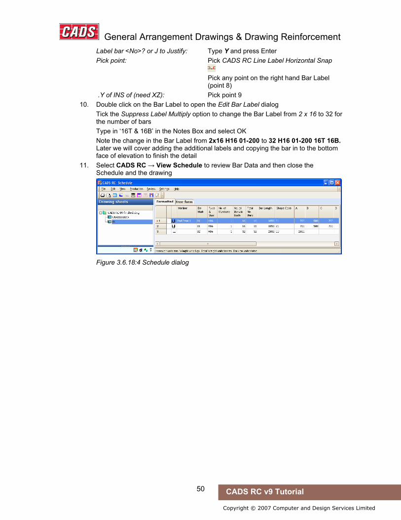
General Arrangement Drawings & Drawing Reinforcement
50 CADS RC v9 Tutorial
Copyright © 2007 Computer and Design Services Limited
Label bar <No>? or J to Justify: Type Y and press Enter Pick point: Pick CADS RC Line Label Horizontal Snap Pick any point on the right hand Bar Label (point 8) .Y of INS of (need XZ): Pick point 9
10. Double click on the Bar Label to open the Edit Bar Label dialog Tick the Suppress Label Multiply option to change the Bar Label from 2 x 16 to 32 for the number of bars Type in ‘16T & 16B’ in the Notes Box and select OK Note the change in the Bar Label from 2x16 H16 01-200 to 32 H16 01-200 16T 16B. Later we will cover adding the additional labels and copying the bar in to the bottom face of elevation to finish the detail
11. Select CADS RC → View Schedule to review Bar Data and then close the Schedule and the drawing
Figure 3.6.18:4 Schedule dialog
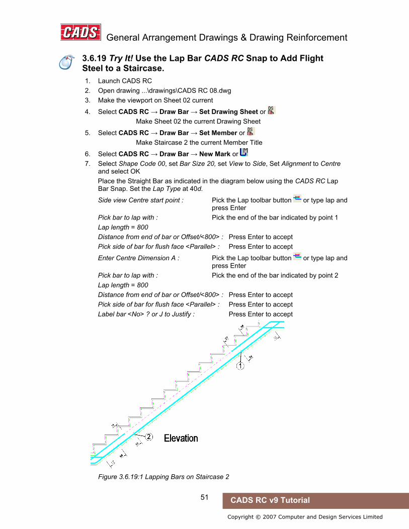
General Arrangement Drawings & Drawing Reinforcement
51 CADS RC v9 Tutorial
Copyright © 2007 Computer and Design Services Limited
3.6.19 Try It! Use the Multiplier Field and Lap Bar CADS RC Snap to Detail Top and Bottom Steel Efficiently
1. Launch CADS RC 2. Open drawing ...\drawings\CADS RC 08.dwg 3. Make the viewport on Sheet 02 current
4. Select CADS RC → Draw Bar → Set Drawing Sheet or Make Sheet 02 the current Drawing Sheet
5. Select CADS RC → Draw Bar → Set Member or Make Staircase 2 the current Member Title
6. Select CADS RC → Draw Bar → New Mark or 7. Select Shape Code 00, set Bar Size 20, set View to Side, Set Alignment to Centre
and select OK Place the Straight Bar as indicated in the diagram below using the CADS RC Lap
Bar Snap. Set the Lap Type at 40d.
Side view Centre start point : Pick the Lap toolbar button or type lap and press Enter Pick bar to lap with : Pick the end of the bar indicated by point 1 Lap length = 800 Distance from end of bar or Offset/<800> : Press Enter to accept Pick side of bar for flush face <Parallel> : Press Enter to accept
Enter Centre Dimension A : Pick the Lap toolbar button or type lap and press Enter Pick bar to lap with : Pick the end of the bar indicated by point 2 Lap length = 800 Distance from end of bar or Offset/<800> : Press Enter to accept Pick side of bar for flush face <Parallel> : Press Enter to accept Label bar <No> ? or J to Justify : Press Enter to accept
Figure 3.6.19:1 Lapping Bars on Staircase 2
3.6.19 Try It! Use the Lap Bar CADS RC Snap to Add Flight Steel to a Staircase.

General Arrangement Drawings & Drawing Reinforcement
52 CADS RC v9 Tutorial
Copyright © 2007 Computer and Design Services Limited
3.7 Key points - General Arrangement Drawings ...
• Reinforcement can be placed on outlines created by lines, polyline, blocks and xrefs.
• Switch on Dynamic Input when working with Dynamic Blocks in order to show the dimensions of the entity.
• You can use CADS RC Snaps in conjunction with CADS RC functions to speed up the drawing process.
• Input as much information into the Draw Bar dialog as possible to speed up the drawing process by minimising the need for command prompts later.
• Switch off the Range Offset prompts and preset the Range Snaps in the Range Configuration to reduce the number of command prompts.
• Reduce the number of Ranges that need detailing by using the Multiplier option in the Draw Bar dialog.
• Use a Sketch Bar to show a Projected View (not true length) of a bar. • Save changes to the CADS RC configuration by selecting the Save Settings
option in the Configuration Centre. This will affect all new drawings.
3.8 Command List - General Arrangement Drawings ...
Action Menu Selection Toolbar and Icon
Create Pad Base Outline CADS RC→Tools→Outlines→Others Outlines
CADS RC Snaps CADS RC Snaps
Set Member CADS RC→Draw Bar→Set Member Draw Bar
Set Drawing Sheet CADS RC→Draw Bar→Set Drawing Sheet Draw Bar
Draw Bar→New Mark CADS RC→Draw Bar→New Mark Draw Bar
Draw Bar→New Set CADS RC→Draw Bar→New Set Draw Bar
Draw Range→Add View CADS RC→Draw Range→Add View Draw Range
Sketch Bar CADS RC→Draw Bar→Add View Draw Bar
AutoCAD 2006 / 2007 only
Insert Dynamic Block Insert→Block Insert
Set Dynamic Input Tools→Draft Settings, Dynamic Input
3.7 Key points - General Arrangement Drawings ...
3.8 Command List - General Arrangement Drawings ...

53
Copyright © 2007 Computer and Design Services Limited
CADS RC v9 Tutorial
4: Over Stock Length (OSL) and Creating Special Bars
4.0 Over Stock Length Overview
When detailing reinforcement there is an optimum length of bar that can be detailed and safely handled on site. The OSL (Over Stock Length) feature in CADS RC allows you to specify this as the stock bar length. Once this has been set, if you then attempt to draw a bar that is longer CADS RC will automatically offer to splice the bars across the structure. The splice position and lengths are based on rules that you set in the Over Stock Length dialog box. Once OSL bars have been drawn they are grouped together as a single entity. Any changes made will affect all the bars in the group.
4.1 Set Over Stock Length
You use this command to define the Over Stock Length that can be detailed before the OSL functionality is invoked.
4.2 Switching Off the Over Stock Length Option
The OSL feature can be switched off by selecting CADS RC → Configuration → Configuration Centre → Global/General Configuration.
• Set the Top Field to OverStockLength • In the Middle Field select UseOverStockLength • In the Lower Field type in No and then pick Assign to CFG • Answer Yes to Apply the Changes?
4.0 Over Stock Length Overview
4.1 Set Over Stock Length
4.2 Switching Off the Over Stock Length Option
Over Stock Length and Creating Special Bars
54 CADS RC v9 Tutorial
Copyright © 2007 Computer and Design Services Limited
4.3 Over Stock Length Restrictions
The Over Stock feature has the following limitations:
• OSL supports only the following shapes: i. Straight Bar ii. Straight Bar with Hooks iii. U Bar and L Bar
• OSL Supports only the following Range Types: iv. Single Indicator Range v. Double Indicator Range vi. Double Indicator Tapered Range
For U and L shapes, only the second leg of the bar shape is allowed to stretch beyond the Stock Length.
Couplers cannot be added to OSL bars. You can add couplers to an Exploded OSL Group - see Chapter 7, Edit and Modify commands, for further information.
The Add View or Set and Range View commands are not supported for Over Stock Length bars. You can use the Add View and New Set commands if you Explode an OSL Group - see Chapter 7, Edit and Modify commands, for further information.
If the difference between the first and last bar is more than the Stock Length of a Double Indicator tapered range, the bars will not be spliced as Over Stock bars.
4.3 Over Stock Length Restrictions

Over Stock Length and Creating Special Bars
55 CADS RC v9 Tutorial
Copyright © 2007 Computer and Design Services Limited
4.4 Over Stock Length Dialog
This dialog will only appear if you attempt to draw a bar longer than the configured Over Stock Length.
Figure 4.4:1 The Invoke Over Stock Length Feature dialog
If you answer No to the question shown in figure 4.4:1 then CADS RC will attempt to draw the bar. If you attempt to draw a bar over the default maximum Stock Length then CADS RC will ask you specify the length again. If the bar to be drawn is under this length CADS RC will draw the bar. CADS RC ships with the default Stock Length set to 20m but you can, of course, configure this to your particular needs.
If you select Cancel on this dialog box, CADS RC exits the drawing routine and returns you to the AutoCAD command prompt.
If you answer Yes CADS RC displays the Over Stock Length dialog, as shown below.
Figure 4.4:2 The Over Stock Length dialog. The number labels added show the different sections and these are described below. The item labels on the dialog are shown below in bold italic.
4.4 Over Stock Length Dialog
Over Stock Length and Creating Special Bars
56 CADS RC v9 Tutorial
Copyright © 2007 Computer and Design Services Limited
4.4.1 Lap Position Options Option 1: The first and intermediate bars are drawn to the Stock Length. The last bar is the Run-Out Bar. Option 2: The first and last bars have equal leg lengths. The intermediate bars are drawn to the Stock Length. Option 3: The first, intermediate and last bars are all drawn to the Stock Length. The penultimate bar is used as the Run-Out Bar. Option 4: The Splice Bar Location is defined by selecting Splice Lines, which have already been drawn. If the length of the bar between the Splice Lines exceeds the Stock Length the OSL routine will automatically offer a Splice point or allow you to pick additional Splice Lines.
4.4.2 Stagger Lap Position This will only work with Option 1 of the lap positions. This option calculates and adjusts the first and last bar lengths such that if mirroring places the alternate bars the lap distance is staggered by the given value.
4.4.3 Stock and Lap Length The Stock Length displayed is the length set by the Set Stock Length command.
The lap length displayed is the default distance set by CADS RC. You can invoke the Lap Calculator to work out the correct splice distance for the diameter of bars you are detailing.
4.4.4 Group Bar Label Edit This has exactly the same options as the Draw Bar dialog at 3.6 except that you can choose the Shape Code and the Bar View Drawn but you cannot add Notes - see the Configuration option for this. Use the Member option to check that the current Member is set correctly.
4.4.5 First and Last Bar Dimensions You can input missing dimensions in End Dim 1 and End Dim 2 if you select a Shape Code in the Group Bar Label Edit area that has more than one leg.
4.4.6 Suppress As with the Draw Bar dialog box discussed in section 3.6 you can use the Suppress C/C Display to stop dimensions showing on the Bar Labels and the Suppress Label Multiplier option to change the Number of Bars Displayed to show the actual number of bars rather than the calculation, such as from, say, 2x3 to 6.

Over Stock Length and Creating Special Bars
57 CADS RC v9 Tutorial
Copyright © 2007 Computer and Design Services Limited
4.5 Over Stock Length Configuration Dialog
How you enable the settings in the Configuration dialog heavily influences the detailing style of the OSL range.
Figure 4.5:1 The OSL Configuration dialog. Item labels are described below.
4.5.1 Stock and Lap Lengths Use this option to fix Lap Lengths to Bar Diameters.
4.5.2 Display Method The left hand option will place a Bar Label on each individual bar drawn.
The right hand option will stack all the Bar Labels in one location pointing to the first bar in the OSL group.
4.5.3 Label Placing and Bar Notes The most efficient choice in Label Placing is On bar distance. This allows you to set the distance in plotted inches that the Bar Label is placed away from the bar.
In the Bar Notes sub-section you can choose from any of the standard options or you can type in your own data in any field.
4.5 Over Stock Length Configuration Dialog
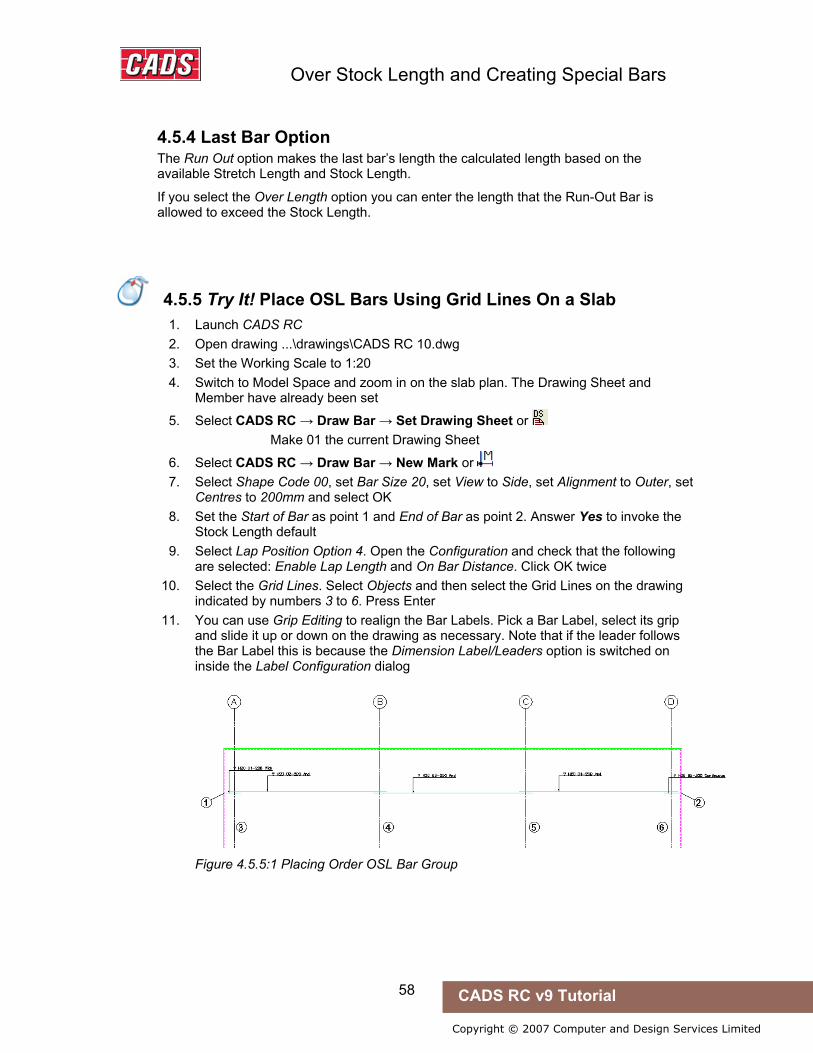
Over Stock Length and Creating Special Bars
58 CADS RC v9 Tutorial
Copyright © 2007 Computer and Design Services Limited
4.5.4 Last Bar Option The Run Out option makes the last bar’s length the calculated length based on the available Stretch Length and Stock Length.
If you select the Over Length option you can enter the length that the Run-Out Bar is allowed to exceed the Stock Length.
4.5.5 Try It! Place OSL Bars Using Splice Lines On a Slab
1. Launch CADS RC 2. Open drawing ...\drawings\CADS RC 10.dwg 3. Set the Working Scale to 1:20 4. Switch to Model Space and zoom in on the slab plan. The Drawing Sheet and
Member have already been set
5. Select CADS RC → Draw Bar → Set Drawing Sheet or Make 01 the current Drawing Sheet
6. Select CADS RC → Draw Bar → New Mark or 7. Select Shape Code 00, set Bar Size 20, set View to Side, set Alignment to Outer, set
Centres to 200mm and select OK 8. Set the Start of Bar as point 1 and End of Bar as point 2. Answer Yes to invoke the
Stock Length default 9. Select Lap Position Option 4. Open the Configuration and check that the following
are selected: Enable Lap Length and On Bar Distance. Click OK twice 10. Select the Grid Lines. Select Objects and then select the Grid Lines on the drawing
indicated by numbers 3 to 6. Press Enter 11. You can use Grip Editing to realign the Bar Labels. Pick a Bar Label, select its grip
and slide it up or down on the drawing as necessary. Note that if the leader follows the Bar Label this is because the Dimension Label/Leaders option is switched on inside the Label Configuration dialog
Figure 4.5.5:1 Placing Order OSL Bar Group
4.5.5 Try It! Place OSL Bars Using Grid Lines On a Slab

Over Stock Length and Creating Special Bars
59 CADS RC v9 Tutorial
Copyright © 2007 Computer and Design Services Limited
4.6 Overview of Creating Special Bars
There are two methods of creating special bars in CADS RC: • Create a quick special bar inside the Draw Bar dialog. • Use the Special Bar Creator see Section 12.1 for details on how to use the
function and section 4.6.2 for a Try It! example. This is available in the Tools sub menu but has restricted input options compared to the previous method. However, you may find this approach easier to use for very simple bars.
If you are trying to create a complex bar with curved sections or oversized radii, it’s worth contacting the CADS RC Support for advice and to discuss the issues involved.
All the special bars you create are saved inside the drawing where they were created or used and in a file called specials.spl. This file is stored in the \cads\cads-rc\params folder. However, CADS RC can be configured to read a file of a different name or one in a different folder location if necessary.
Use the Try It! examples below to create a special bar with a cranked leg. Example 4.6.1 shows you how to create such a bar using the Draw Bar dialog box and example 4.6.2 lets you create the same bar using the Special Bar Creator.
4.6.1 Try It! Create a Special Bar With a Cranked Leg Using the Draw Bar Dialog
1. Launch CADS RC 2. Open drawing ...\drawings\CADS RC 11.dwg 3. Set the Working Scale to 1:20 4. Switch to Model Space and zoom in on the sketch of the bar. The Drawing Sheet
and Member have already been set
5. Select CADS RC → Draw Bar → New Mark or 6. In the Shape Code Number input field enter SP01 and then select the 99 radio
button. Answer Yes to create the special bar called SP01. It will now appear on the Shape Code List, although no image exists for it yet
7. Pick the First Bar button and change the Slide Name from Special.SLD to SP01.SLD 8. Change the length calculation to read {length=A+B+D+E-(0.5*barrad+bardia);}.
Select OK 9. Set the Bar Size to 20. Select OK
10. Answer Yes to Draw Shape SP01? 11. Answer No to Create a Slide for SP01? 12. Answer Yes to Allow Individual Dimension Selection?:
Select point 1 as the Centre Start point Select point 2, enter B as the next dimension letter and press enter Select point 3, enter D as the next dimension letter and press Enter Select point 4, enter E as the next dimension letter and press Enter Select point 5 and press Enter to quit
11. Enter No to Label Bar?
4.6 Overview of Creating Special Bars
4.6.1 Try It! Create a Special Bar With a Cranked Leg Using the Draw Bar Dialog

Over Stock Length and Creating Special Bars
60 CADS RC v9 Tutorial
Copyright © 2007 Computer and Design Services Limited
12. Create the slide image next. To do this use AutoCAD Move to relocate the bar on the dimension letters below by selecting point 6 as the Base point of Displacement and point 7 as the Second point
13. Zoom into the bar as close as you can get while still being able to see the dimension letters and lines
14. Type in MSLIDE at the AutoCAD command prompt. Browse to the \CADS\AutoCAD 200x\CADS RC 9.00\CADS-RC\params folder and type in SP01 as the filename and select Save • Note: In the path “... AutoCAD200x\...” above, x denotes the last digit in your
version of AutoCAD, such as AutoCAD2005 or 2006 and so on
Figure 4.6.1:1 Creating a Shape Code 99
15. Test the shape by selecting the CADS RC → Draw Bar → New Mark or . The image of your bar should now appear in the Shape Code window. We will later attach this diagram to the Schedule
Figure 4.6.1:2 Shape Code SP01 appears in the list of shapes
Note the following points: • You cannot amend the angle of the slope. • You will need to add the H Dimension manually by editing the bar. Refer to
Chapter 7, Edit and Modify commands, for more information.
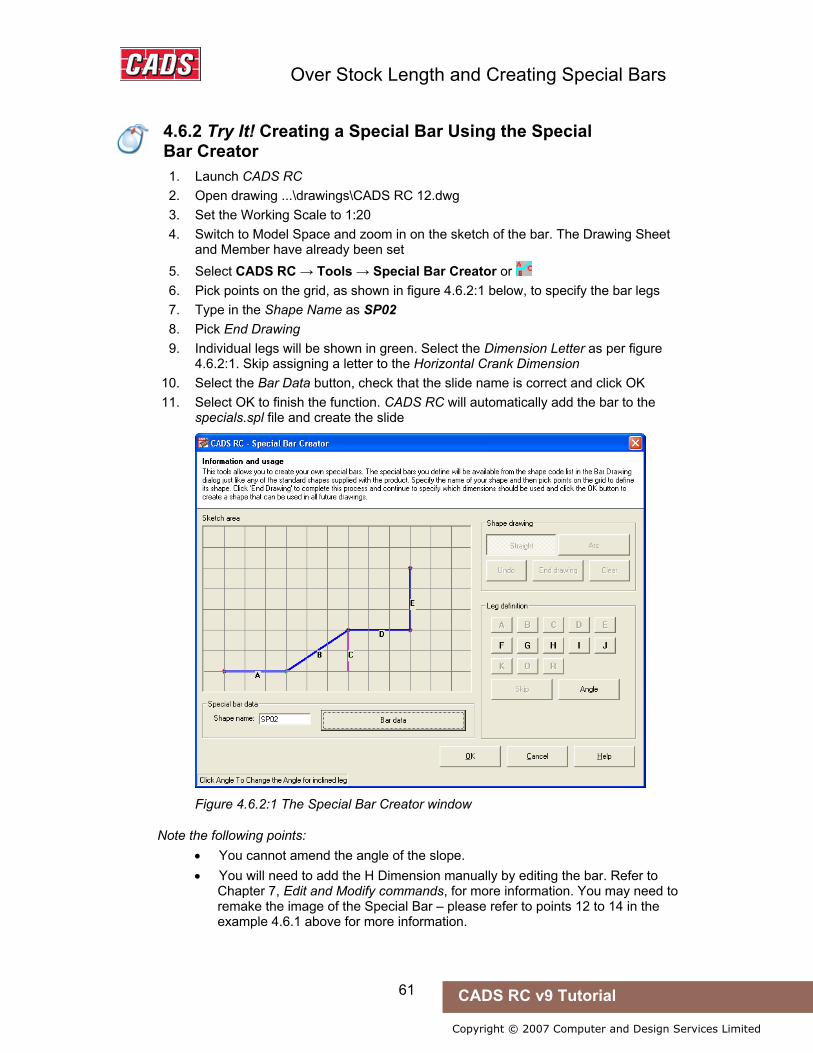
Over Stock Length and Creating Special Bars
61 CADS RC v9 Tutorial
Copyright © 2007 Computer and Design Services Limited
4.6.2 Try It! Creating a Special Bar Using the Special Bar Creator
1. Launch CADS RC 2. Open drawing ...\drawings\CADS RC 12.dwg 3. Set the Working Scale to 1:20 4. Switch to Model Space and zoom in on the sketch of the bar. The Drawing Sheet
and Member have already been set 5. Select CADS RC → Tools → Special Bar Creator or 6. Pick points on the grid, as shown in figure 4.6.2:1 below, to specify the bar legs 7. Type in the Shape Name as SP02 8. Pick End Drawing 9. Individual legs will be shown in green. Select the Dimension Letter as per figure
4.6.2:1. Skip assigning a letter to the Horizontal Crank Dimension 10. Select the Bar Data button, check that the slide name is correct and click OK 11. Select OK to finish the function. CADS RC will automatically add the bar to the
specials.spl file and create the slide
Figure 4.6.2:1 The Special Bar Creator window
Note the following points: • You cannot amend the angle of the slope. • You will need to add the H Dimension manually by editing the bar. Refer to
Chapter 7, Edit and Modify commands, for more information. You may need to remake the image of the Special Bar – please refer to points 12 to 14 in the example 4.6.1 above for more information.
4.6.2 Try It! Creating a Special Bar Using the Special Bar Creator
Over Stock Length and Creating Special Bars
62 CADS RC v9 Tutorial
Copyright © 2007 Computer and Design Services Limited
4.7 Key points - OSL and Creating Special Bars
• Use OSL (Over Stock Length) utilities to quickly add reinforcement to a drawing where spliced bars are grouped together as a single entity.
• Use the OSL Splice options to produce different bar layouts. • Create special Shape Codes using either the Special Bar Creator or inside the
Draw Bar dialog. • All special Shape Codes are stored in a file specials.spl unless you configure
this otherwise.
4.8 Command List - OSL and Creating Special Bars
Action Menu Selection Toolbar and Icon
Set Over Stock Length CADS RC → Draw Bar → Set OSL Draw Bar
Draw Range → New Mark CADS RC → Draw Range → New Mark Draw Range
Special Bar Creator CADS RC → Tools → Special Bar Creator Misc Tools
4.7 Key points - OSL and Creating Special Bars
4.8 Command List - OSL and Creating Special Bars

Range Types and Bar Runs
63 CADS RC v9 Tutorial
Copyright © 2007 Computer and Design Services Limited
5: Range Types and Bar Runs
5.0 Introduction
CADS RC provides a number of Range (ladder) types and runs of bars for use on different structure types.
You opened the Range dialog in the previous section when adding Single Indicator Ranges to the Pad Base and the Slab (see Section 3.6.15).
As you work through this section you’ll get practice using examples of all the Range types, drawing them in typical structures and picking up detailing hints to increase your productivity.
Figure 5.0:1 CADS RC’s Range Type Selection window
5.0 Introduction

Range Types and Bar Runs
64 CADS RC v9 Tutorial
Copyright © 2007 Computer and Design Services Limited
Figure 5.0:2 The Tapered Range Type Selection window
Figure 5.0:3 The Run Type Selection window

Range Types and Bar Runs
65 CADS RC v9 Tutorial
Copyright © 2007 Computer and Design Services Limited
5.1 Single Group Ranges
The Single Group Range types typically show one or two Bar Views with one Range Group.
The text below takes you through typical input for the Single Group Ranges. It explains all the sub-options and their consequences. Prompts and other screen displays are shown in italic and values that you might enter are shown in bold italic. The instruction “Press Enter” simply means that you should press the Enter or Return key. As usual, commands are often – though not always - shown in bold roman (but sometimes in medium italic). Comments and explanations about what’s happening or what you should do are set off with bullets and indented, as with the immediately following paragraph.
• Normally you would select the Draw Range command and then either New Mark, Add View or New Set. You would then select the Range Type from the Range dialog. The Bar dialog then loads and this lets you select the Shape Code, Type and Size and the Bar View, Style and Alignment.
• The typical Bar View is drawn first and then description elements of the Range can be selected from the following prompt:
Start of Bar Range / Enter Slope / True Len / Line: • If Slope is selected then enter the angle of the slope of the Range. The
distance selected for the Range should be the projected length - the system will work out the true length and the correct number of bars.
• If True Length is selected then enter the true numeric length of the Range. The points picked on the screen will show the projected length of the Range.
• If Line is selected then select an AutoCAD line on the screen that is the length of the Range Line. The points picked for the start and the end of the Range will show the projected length.
• If a point is selected this will specify the start point of the Range.
Offset First Bar from Start <0>: • After you’ve selected the start point of the Range a prompt to Offset First Bar
from Start is shown. If you enter a distance the start of the Range will be moved appropriately from the point selected. Hence if you do not show Cover Lines you can work directly from the outline and use this offset option to enter the necessary cover distance. You could also use this offset to move the start of the bar range half a bar diameter from the Range start point. The same prompt for offset, this time from the end, appears after the last point of the Range has been selected.
Pick end of Range: • Select the end of the Range.
Offset Last bar from end <0>: • If required, enter the distance to offset the end of the Range from the point
selected.
Range Length 4023.9. Centre Spacing or <Number of Bars>: 200
• The selected length of the Range is displayed. If an angle has been set then both the true Range length and the projected Range length will be displayed.
5.1 Single Group Ranges
Range Types and Bar Runs
66 CADS RC v9 Tutorial
Copyright © 2007 Computer and Design Services Limited
• You will now be given an option of entering the centre spacing or else pressing Enter and typing in the number of bars required. However, if you have already set the Bar Centres in the Draw Bar dialog box this prompt will not appear.
Range options : 22 bars at < 200 > / Average c/c = 191.6 / Run out / Numeric : Press ENTER to continue or (A)verage/(R)un Out/(N)umeric:
• This prompt shows the numbers of bars that can be placed at the centres previously entered. You have three options (A, R or N) that will variously affect either the Bar Label or the Bar Placement.
Average: if you type A then the Bar Label will display the actual centres.
Numeric: if you type N then the centres will not be shown on the Bar Label.
Run Out: if you type R then when you draw the bars in section they will be placed at 200 mm centres, with the last pair closer together.
If you simply press Enter at the prompt the Bar Label will show the appropriate number of bars at the selected distances (here, for example, 41 bars at 200 mm centres). This is the option you will select most of the time.
Set Number is 1. Label bar <No>? or J to Justify:
• Enter either Y (yes) or N (no) to show whether or not you want to place the Bar Label.
• The default value for the Bar Label is for it to align to the start of the text (to the left). However, if you want it to align with the end of the text (right) then enter J to Justify.
• If you prefer, you can simply select a point on the screen without answering the question about placing the Bar Label. If you do this you will need to add a leader manually.
Pick point: • Select the point on the screen where the label is to be placed. CADS RC will
automatically add a leader if the Bar Label is in alignment with the Range Line.
Hints & Tips – Disable Range Offset Prompts
You can disable the Range Offset prompt if required. Use the CADS RC → Configuration → Configuration Centre → Range Configuration menu selection and set the query Prompt for Range Offsets to No.
Using this same dialog box, you can set Object Snaps for the start and Other Range Snaps. Set the Start of Range Snap to Near and the Other Range Snaps to Perp.
Following this section there are brief explanations of each of the Single Group Ranges as well as examples of some typical applications. You can work through these to ensure you that you understand how to use these various features. Be aware that the example drawings do not have the offset prompt switched off.
Hints & Tips – Disable Range Offset Prompts
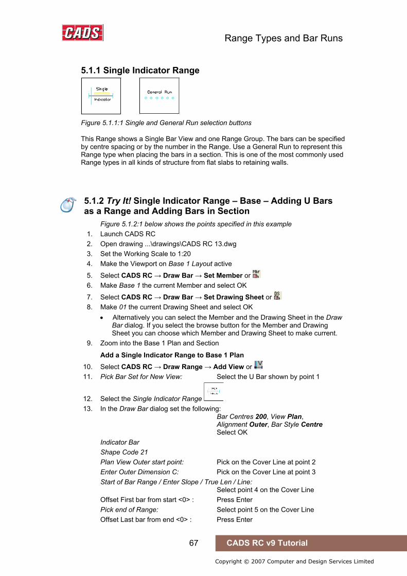
Range Types and Bar Runs
67 CADS RC v9 Tutorial
Copyright © 2007 Computer and Design Services Limited
5.1.1 Single Indicator Range
Figure 5.1.1:1 Single and General Run selection buttons
This Range shows a Single Bar View and one Range Group. The bars can be specified by centre spacing or by the number in the Range. Use a General Run to represent this Range type when placing the bars in a section. This is one of the most commonly used Range types in all kinds of structure from flat slabs to retaining walls.
5.1.2 Try It! Single Indicator Range – Base – Adding U Bars as a Range and Adding Bars in Section
Figure 5.1.2:1 below shows the points specified in this example 1. Launch CADS RC 2. Open drawing ...\drawings\CADS RC 13.dwg 3. Set the Working Scale to 1:20 4. Make the Viewport on Base 1 Layout active
5. Select CADS RC → Draw Bar → Set Member or 6. Make Base 1 the current Member and select OK
7. Select CADS RC → Draw Bar → Set Drawing Sheet or 8. Make 01 the current Drawing Sheet and select OK
• Alternatively you can select the Member and the Drawing Sheet in the Draw Bar dialog. If you select the browse button for the Member and Drawing Sheet you can choose which Member and Drawing Sheet to make current.
9. Zoom into the Base 1 Plan and Section
Add a Single Indicator Range to Base 1 Plan 10. Select CADS RC → Draw Range → Add View or 11. Pick Bar Set for New View: Select the U Bar shown by point 1
12. Select the Single Indicator Range 13. In the Draw Bar dialog set the following:
Bar Centres 200, View Plan, Alignment Outer, Bar Style Centre Select OK Indicator Bar Shape Code 21 Plan View Outer start point: Pick on the Cover Line at point 2 Enter Outer Dimension C: Pick on the Cover Line at point 3 Start of Bar Range / Enter Slope / True Len / Line: Select point 4 on the Cover Line Offset First bar from start <0> : Press Enter Pick end of Range: Select point 5 on the Cover Line Offset Last bar from end <0> : Press Enter
5.1.2 Try It! Single Indicator Range – Base – Adding U Bars as a Range and Adding Bars in Section

Range Types and Bar Runs
68 CADS RC v9 Tutorial
Copyright © 2007 Computer and Design Services Limited
Range length 2900.0 Range options : 16 bars at < 200 > / Average c/c = 193.3 / Run out / Numeric : Press ENTER to continue or (A)verage/(R)un Out/(N)umeric : Press Enter Set Number is 1. Label bar <No> ? or J to Justify: Enter Y (Yes) and press Enter Pick point: Select near point 6
5.1.2:1 Adding Single Indicator Range to a Pad Base
Now Add the Bar Run in Base 2 Section 14. Select CADS RC → Draw Bar → Set Member or 15. Make Base 2 the current Member and select OK 16. Zoom into the Base 2 Plan and Section
17. Select CADS RC → Draw Range → Add View 18. Pick Bar Set for New View: Select the Plan View of the U Bar, point 7
19. Select the General Run 20. Select OK in the Draw Bar dialog
The Bar View is already set to Section and the centres are set from drawing the Range in the Plan View
21. Start of Bar Range or ENTER to Select Bar Leg: Press Enter to select the bar leg • If a point had been selected at this prompt, this would have shown the start
of the Range. CADS RC would then prompt for the end of the Range. It
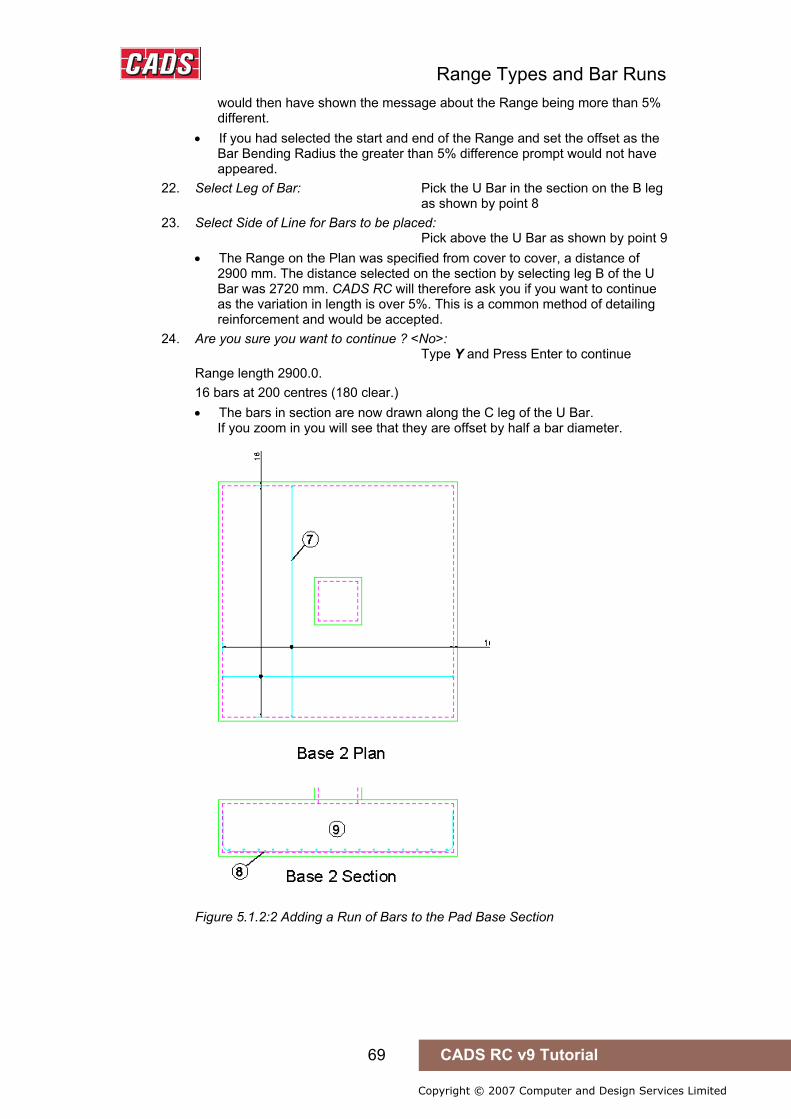
Range Types and Bar Runs
69 CADS RC v9 Tutorial
Copyright © 2007 Computer and Design Services Limited
would then have shown the message about the Range being more than 5% different.
• If you had selected the start and end of the Range and set the offset as the Bar Bending Radius the greater than 5% difference prompt would not have appeared.
22. Select Leg of Bar: Pick the U Bar in the section on the B leg as shown by point 8
23. Select Side of Line for Bars to be placed: Pick above the U Bar as shown by point 9 • The Range on the Plan was specified from cover to cover, a distance of
2900 mm. The distance selected on the section by selecting leg B of the U Bar was 2720 mm. CADS RC will therefore ask you if you want to continue as the variation in length is over 5%. This is a common method of detailing reinforcement and would be accepted.
24. Are you sure you want to continue ? <No>: Type Y and Press Enter to continue Range length 2900.0. 16 bars at 200 centres (180 clear.) • The bars in section are now drawn along the C leg of the U Bar.
If you zoom in you will see that they are offset by half a bar diameter.
Figure 5.1.2:2 Adding a Run of Bars to the Pad Base Section
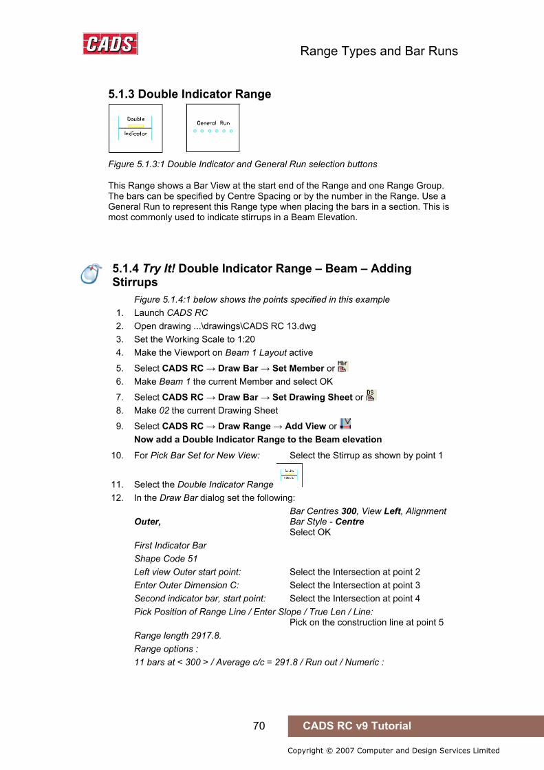
Range Types and Bar Runs
70 CADS RC v9 Tutorial
Copyright © 2007 Computer and Design Services Limited
5.1.3 Double Indicator Range
Figure 5.1.3:1 Double Indicator and General Run selection buttons
This Range shows a Bar View at the start end of the Range and one Range Group. The bars can be specified by Centre Spacing or by the number in the Range. Use a General Run to represent this Range type when placing the bars in a section. This is most commonly used to indicate stirrups in a Beam Elevation.
5.1.4 Try It! Double Indicator Range – Beam – Adding Stirrups
Figure 5.1.4:1 below shows the points specified in this example 1. Launch CADS RC 2. Open drawing ...\drawings\CADS RC 13.dwg 3. Set the Working Scale to 1:20 4. Make the Viewport on Beam 1 Layout active
5. Select CADS RC → Draw Bar → Set Member or 6. Make Beam 1 the current Member and select OK
7. Select CADS RC → Draw Bar → Set Drawing Sheet or 8. Make 02 the current Drawing Sheet
9. Select CADS RC → Draw Range → Add View or Now add a Double Indicator Range to the Beam elevation
10. For Pick Bar Set for New View: Select the Stirrup as shown by point 1
11. Select the Double Indicator Range 12. In the Draw Bar dialog set the following:
Bar Centres 300, View Left, Alignment Outer, Bar Style - Centre Select OK First Indicator Bar Shape Code 51 Left view Outer start point: Select the Intersection at point 2 Enter Outer Dimension C: Select the Intersection at point 3 Second indicator bar, start point: Select the Intersection at point 4 Pick Position of Range Line / Enter Slope / True Len / Line: Pick on the construction line at point 5 Range length 2917.8. Range options : 11 bars at < 300 > / Average c/c = 291.8 / Run out / Numeric :
5.1.4 Try It! Double Indicator Range – Beam – Adding Stirrups

Range Types and Bar Runs
71 CADS RC v9 Tutorial
Copyright © 2007 Computer and Design Services Limited
Press ENTER to continue or (A)verage/(R)un Out/(N)umeric: Press enter to accept Set Number is 17. Label bar <No> ? or J to Justify: Type Y and press enter Pick point: Pick near point 6 to position the Bar Label
Figure 5.1.4:1 Adding a Double Indicator Range to the Beam Elevation
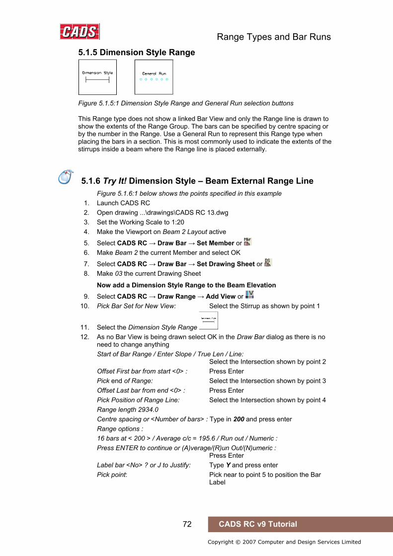
Range Types and Bar Runs
72 CADS RC v9 Tutorial
Copyright © 2007 Computer and Design Services Limited
5.1.5 Dimension Style Range
Figure 5.1.5:1 Dimension Style Range and General Run selection buttons
This Range type does not show a linked Bar View and only the Range line is drawn to show the extents of the Range Group. The bars can be specified by centre spacing or by the number in the Range. Use a General Run to represent this Range type when placing the bars in a section. This is most commonly used to indicate the extents of the stirrups inside a beam where the Range line is placed externally.
5.1.6 Try It! Dimension Style – Beam External Range Line
Figure 5.1.6:1 below shows the points specified in this example 1. Launch CADS RC 2. Open drawing ...\drawings\CADS RC 13.dwg 3. Set the Working Scale to 1:20 4. Make the Viewport on Beam 2 Layout active
5. Select CADS RC → Draw Bar → Set Member or 6. Make Beam 2 the current Member and select OK
7. Select CADS RC → Draw Bar → Set Drawing Sheet or 8. Make 03 the current Drawing Sheet
Now add a Dimension Style Range to the Beam Elevation 9. Select CADS RC → Draw Range → Add View or
10. Pick Bar Set for New View: Select the Stirrup as shown by point 1
11. Select the Dimension Style Range 12. As no Bar View is being drawn select OK in the Draw Bar dialog as there is no
need to change anything Start of Bar Range / Enter Slope / True Len / Line: Select the Intersection shown by point 2 Offset First bar from start <0> : Press Enter Pick end of Range: Select the Intersection shown by point 3 Offset Last bar from end <0> : Press Enter Pick Position of Range Line: Select the Intersection shown by point 4 Range length 2934.0 Centre spacing or <Number of bars> : Type in 200 and press enter Range options : 16 bars at < 200 > / Average c/c = 195.6 / Run out / Numeric : Press ENTER to continue or (A)verage/(R)un Out/(N)umeric : Press Enter Label bar <No> ? or J to Justify: Type Y and press enter Pick point: Pick near to point 5 to position the Bar Label
5.1.6 Try It! Dimension Style – Beam External Range Line

Range Types and Bar Runs
73 CADS RC v9 Tutorial
Copyright © 2007 Computer and Design Services Limited
Figure 5.1.6:1 Adding a Dimension Style Range to the Beam Elevation

Range Types and Bar Runs
74 CADS RC v9 Tutorial
Copyright © 2007 Computer and Design Services Limited
5.1.7 Alternate Range
Figure 5.1.7:1 Alternate Range selection buttons
This Range shows two Bar Views that have different Bar Marks within one Range Group. The bars can be specified by centre spacing or by the number in the Range. Use an Alternate Run to represent this Range type when placing the bars in a section. This type of Range is most commonly used in flat slabs.
5.1.8 Try It! Alternate Range - Slab
Figure 5.1.8:1 below shows the points specified in this example 1. Launch CADS RC 2. Open drawing ...\drawings\CADS RC 13.dwg 3. Set the Working Scale to 1:20 4. Make the Viewport on Slab 1 Layout active
5. Select CADS RC → Draw Bar → Set Member or 6. Make Slab 1 the current Member and select OK
7. Select CADS RC → Draw Bar → Set Drawing Sheet or 8. Make 04 the current Drawing Sheet
Adding an Alternate Range to the Slab 1 Plan 9. Select CADS RC → Draw Range → New Mark or
10. Select the Alternate Range 11. For the first Alternate Bar select: Shape Code 21, Type H, Size 20,
View Plan, Alignment Outer, Style Centre Pick the First Bar button Set Legs A and C to 450 and select OK twice First Indicator Bar. Shape Code 21. Plan View Outer start point: Select the Intersection shown by point 1 Enter Outer Dimension C: Select the Intersection shown by point 2 For the Second Alternate Bar select: Shape Code 00, Type H, Size 25, View Plan, Alignment Outer, Style Centre Select OK Second Indicator Bar Shape Code 00 Plan View Outer start point: Select the Intersection shown by point 3 Enter Outer Dimension A: Select the Intersection shown by point 4
12. Setting Start Snap(s) Near. Start of Bar Range / Enter Slope / True Len / Line: Pick on Cover Line as shown by point 5 Offset First bar from start <0> : Type 30 and press enter Setting Other Snap(s) Perp. Pick end of Range: Pick on Cover Line as shown by point 6 Offset Last bar from end <0> : Type 30 and press enter
5.1.8 Try It! Alternate Range - Slab

Range Types and Bar Runs
75 CADS RC v9 Tutorial
Copyright © 2007 Computer and Design Services Limited
Range length 9900.. Centre Spacing or <Number of bars>: Type 200 and press enter Range options: 51 bars at < 200 > / Average c/c = 198 / Run out / Numeric : Press ENTER to continue or (A)verage/(R)un Out/(N)umeric: Press enter to accept. Set Number is 21. Label bar <No> ? or J to Justify: Type Y and press Enter to place the Bar Label for the First Alternate Bar Pick point: Pick to right of slab as shown by point 7 Set Number is 22. Label bar <No> ? or J to Justify: Type Y and press enter Pick point: Pick to right of slab as shown by point 7 You may like to try the Bar Label alignment tool built-in to the Alternate Range
Pick Bar Label Location: Pick directly on top of the first Alternate Bar Label Rotation angle: Pick to the right to set the angle to 0 degrees. Pick Side of Label: Pick below the leader to place the second Alternate Bar Label
Figure 5.1.8:1 Adding an Alternate Range to a Floor Slab
Range Types and Bar Runs
76 CADS RC v9 Tutorial
Copyright © 2007 Computer and Design Services Limited
Adding the Alternate Bar Run to the Slab 1 Section 13. Select CADS RC → Draw Range → Add View or 14. Pick Bar Set for New View: Select the U Bar as shown by point 8
15. Select the Alternate Bar Run Existing Range of this bar - will calculate centres to existing length
16. Pick Bar Set for Alternate New View: Select the Straight Bar shown by point 9 Pick OK to exit from Draw Bar dialog First Bar Shape Code 21 Pick OK to exit from Draw Bar Dialog Second Bar Shape Code 00 Start of Bar Range or ENTER to select bar leg: Select the Intersection shown by point 10 Offset First bar from start <30> : Press Enter to accept Pick end of Range: Select the Intersection shown by point 11 Offset Last bar from end <30> : Press Enter to accept Select side of line for bars to be placed: Pick above the Cover Line as shown by point 12 Range Length 9900 • The bars in section are now drawn on the Cover Line. Zoom in and you will
see the variation in bar diameter between the first and second Alternate Bars.

Range Types and Bar Runs
77 CADS RC v9 Tutorial
Copyright © 2007 Computer and Design Services Limited
5.1.9 Staggered Range
Figure 5.1.9:1 Staggered Range selection buttons
This Range shows two Bar Views of the same Bar Mark and one Range Group. The bars can either be shown as a staggered offset or alternate reversed. The bars can be specified by centre spacing or by the number in the Range. Use a General Run to represent this Range type when placing the bars in a section. This format is most commonly used in flat slabs or anywhere the Bar Laps need to be staggered in the structure.
5.1.10 Try It! Staggered Range – Slab
Figure 5.1.10:1 below shows the points specified in this example 1. Launch CADS RC 2. Open drawing ...\drawings\CADS RC 13.dwg 3. Set the Working Scale to 1:20 4. Make the Viewport on Slab 2 Layout active
5. Select CADS RC → Draw Bar → Set Member or 6. Make Slab 2 it the current Member and select OK
7. Select CADS RC → Draw Bar → Set Drawing Sheet or 8. Make 05 the current Drawing Sheet
Add a Staggered Range to the Base 2 Plan (bars reversed) 9. Select CADS RC → Draw Range → New Mark or
10. Select the Staggered Range 11. In the Draw Bar dialog select: Shape Code 00, Type H, Size 16,
Centres 200, View Side, Alignment Outer, Style Centre Select the First Bar button. Select OK First Indicator Bar Shape Code 00 Side View Outer start point: Select the Intersection shown by point 1 Enter Outer Dimension C: Select the Intersection shown by point 2 Reverse bar (Yes/No) <No>?: Press Enter Enter offset (stagger) to start of second indicator bar: Select the Intersection shown by point 3 Specify second point: Select the Intersection shown by point 4 Setting Start Snap(s) Near. Start of Bar Range / Enter Slope / True Len / Line: Select the Intersection shown by point 5 Offset First bar from start <30>: Type 30 and press enter Setting Other Snap(s) Perp. Pick end of Range: Select the Intersection shown by point 6 Offset Last bar from end <30>: Type 30 and press enter
5.1.10 Try It! Staggered Range – Slab

Range Types and Bar Runs
78 CADS RC v9 Tutorial
Copyright © 2007 Computer and Design Services Limited
Range length 9810.0. Range options: 51 bars at < 200 > / Average c/c = 196.2 / Run out / Numeric Press ENTER to continue or (A)verage/(R)un Out/(N)umeric: Press Enter to accept Indicate position of second bar: Select close to point 7 Label bar <No>? or J to Justify: Type Y and press enter Pick point: Pick near to point 8 to position the Bar Label
Figure 5.1.10:1 Adding a Staggered Range to a Floor Slab
Add the Bar Run to the Slab 2 Section 12. Select CADS RC → Draw Range → Add View or 13. Pick Bar Set for New View: Select the Bar View as shown by point 9
14. Select the General Run 15. Pick OK on the Draw Bar Dialog
Existing Range of this bar - will calculate centres to existing length Shape Code 00 Start of Bar Range or ENTER to select bar leg: Select the Intersection shown by point 10 Offset First bar from end <0>: Type 30 and press enter Pick end of Range: Select the Intersection shown by point 11 Offset Last bar from end <0>: Type 30 and press enter
Range Types and Bar Runs
79 CADS RC v9 Tutorial
Copyright © 2007 Computer and Design Services Limited
Select side of line for bars to be placed: Select above the Cover Line, point 12 Range length 9810.0. 51 bars at 200 centres (184 clear.) • The bars in section are drawn along the section Cover Line. • Note: you can offset the bars from each other and you would normally use
this option for Straight Bars.

Range Types and Bar Runs
80 CADS RC v9 Tutorial
Copyright © 2007 Computer and Design Services Limited
5.1.11 Radial Range
Figure 5.1.11:1 Radial Range selection buttons
This Range shows a Single Bar View attached to a Radial Range Group. The bars can be specified by centre spacing either on the inner or outer Cover Line or the position of the Range Line or by the number of bars in the Range. Use the Run to Path to represent this Range type when placing the bars in a section. This Range is most commonly used to detail circular tank bottoms or sump tanks with sloping sides.
5.1.12 Try It! Radial Range – Circular Sump Tank
Figure 5.1.12:1 below shows the points specified in this example 1. Launch CADS RC 2. Open drawing ...\drawings\CADS RC 14.dwg 3. Set the Working scale to 1:20 4. Make the Viewport on Sump Tank 1 Layout active
• This drawing has already had construction lines added to make placing the bars easier. The Hints & Tips sections after this example explain how to produce the construction lines.
5. Select CADS RC → Draw Bar → Set Member or 6. Make Sump Tank 1 the current Member and select OK
7. Select CADS RC → Draw Bar → Set Drawing Sheet or 8. Make 01 the current Drawing Sheet
Adding a crank bar to the Sump Tank Section 9. Select CADS RC → Draw Bar → New Mark or
10. In the Draw Bar dialog select: Shape Code 15, Type H, Size 20, Centres 200, View Side, Alignment
Centre, Style Centre and select OK Shape Code 15 Side View Centre start point: Select the Intersection shown by point 1 Enter Centre Dimension C: Select the Intersection shown by point 2 Enter Centre Dimension A: Select the Intersection shown by point 3 Set Number is 2 Label bar <No> ? or J to Justify: Press enter to accept
5.1.12 Try It! Radial Range – Circular Sump Tank
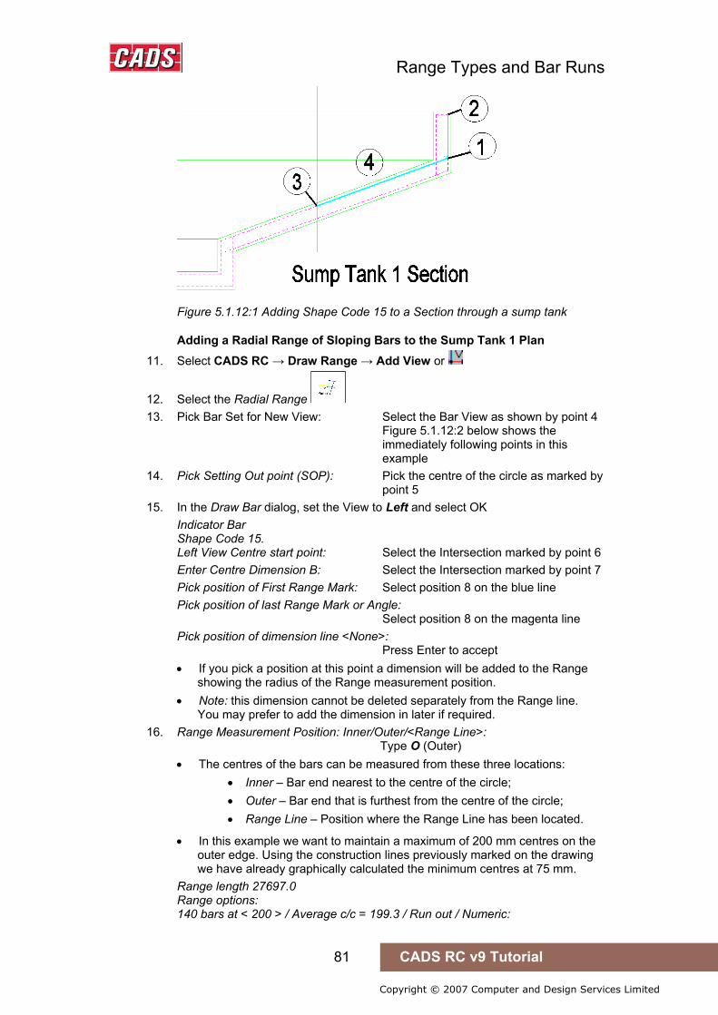
Range Types and Bar Runs
81 CADS RC v9 Tutorial
Copyright © 2007 Computer and Design Services Limited
Figure 5.1.12:1 Adding Shape Code 15 to a Section through a sump tank
Adding a Radial Range of Sloping Bars to the Sump Tank 1 Plan 11. Select CADS RC → Draw Range → Add View or
12. Select the Radial Range 13. Pick Bar Set for New View: Select the Bar View as shown by point 4
Figure 5.1.12:2 below shows the immediately following points in this example
14. Pick Setting Out point (SOP): Pick the centre of the circle as marked by point 5
15. In the Draw Bar dialog, set the View to Left and select OK Indicator Bar Shape Code 15. Left View Centre start point: Select the Intersection marked by point 6 Enter Centre Dimension B: Select the Intersection marked by point 7 Pick position of First Range Mark: Select position 8 on the blue line Pick position of last Range Mark or Angle: Select position 8 on the magenta line Pick position of dimension line <None>: Press Enter to accept • If you pick a position at this point a dimension will be added to the Range
showing the radius of the Range measurement position. • Note: this dimension cannot be deleted separately from the Range line.
You may prefer to add the dimension in later if required. 16. Range Measurement Position: Inner/Outer/<Range Line>:
Type O (Outer) • The centres of the bars can be measured from these three locations:
• Inner – Bar end nearest to the centre of the circle; • Outer – Bar end that is furthest from the centre of the circle; • Range Line – Position where the Range Line has been located.
• In this example we want to maintain a maximum of 200 mm centres on the outer edge. Using the construction lines previously marked on the drawing we have already graphically calculated the minimum centres at 75 mm.
Range length 27697.0 Range options: 140 bars at < 200 > / Average c/c = 199.3 / Run out / Numeric:
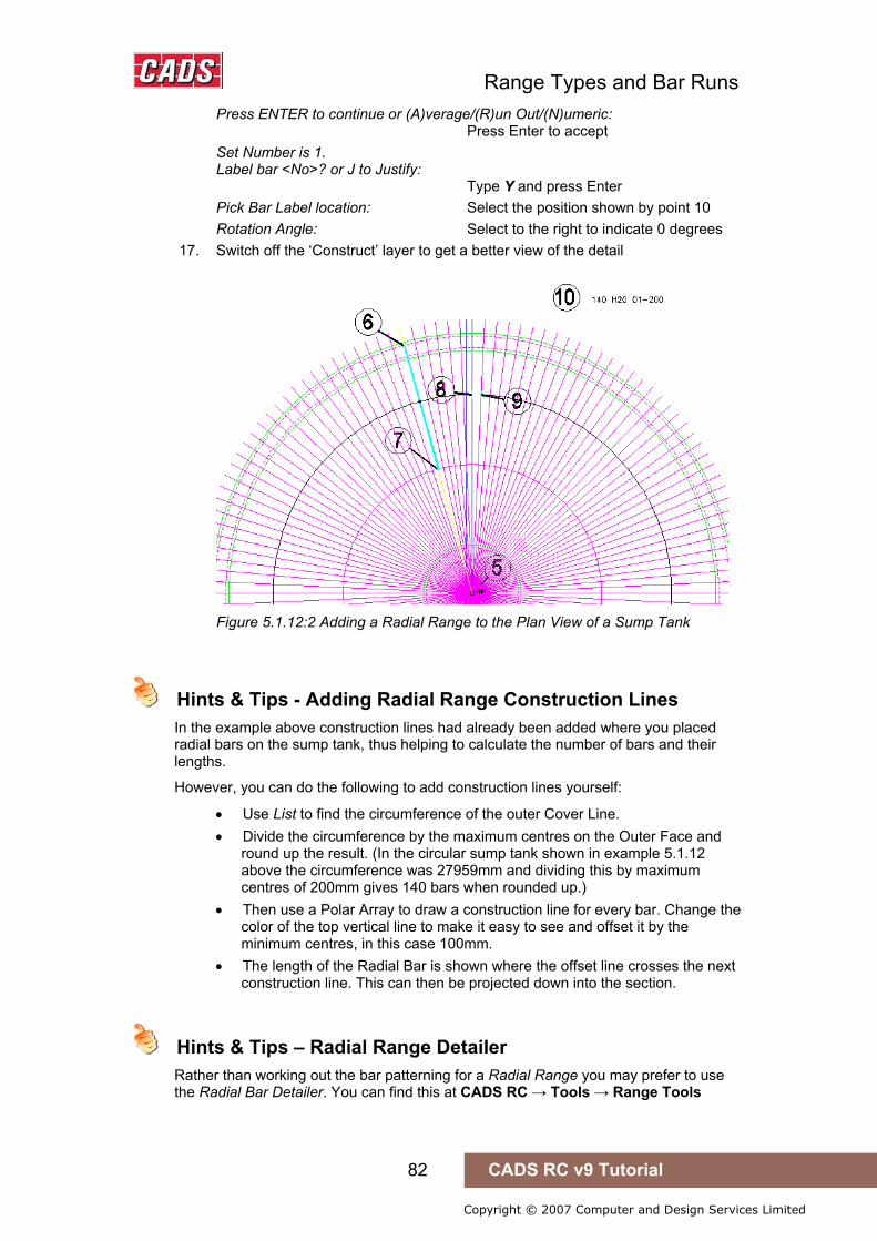
Range Types and Bar Runs
82 CADS RC v9 Tutorial
Copyright © 2007 Computer and Design Services Limited
Press ENTER to continue or (A)verage/(R)un Out/(N)umeric: Press Enter to accept Set Number is 1. Label bar <No>? or J to Justify: Type Y and press Enter Pick Bar Label location: Select the position shown by point 10 Rotation Angle: Select to the right to indicate 0 degrees
17. Switch off the ‘Construct’ layer to get a better view of the detail
Figure 5.1.12:2 Adding a Radial Range to the Plan View of a Sump Tank
Hints & Tips - Adding Radial Range Construction Lines
In the example above construction lines had already been added where you placed radial bars on the sump tank, thus helping to calculate the number of bars and their lengths.
However, you can do the following to add construction lines yourself:
• Use List to find the circumference of the outer Cover Line. • Divide the circumference by the maximum centres on the Outer Face and
round up the result. (In the circular sump tank shown in example 5.1.12 above the circumference was 27959mm and dividing this by maximum centres of 200mm gives 140 bars when rounded up.)
• Then use a Polar Array to draw a construction line for every bar. Change the color of the top vertical line to make it easy to see and offset it by the minimum centres, in this case 100mm.
• The length of the Radial Bar is shown where the offset line crosses the next construction line. This can then be projected down into the section.
Hints & Tips – Radial Range Detailer
Rather than working out the bar patterning for a Radial Range you may prefer to use the Radial Bar Detailer. You can find this at CADS RC → Tools → Range Tools
Hints & Tips - Adding Radial Range Construction Lines
Hints & Tips – Radial Range Detailer

Range Types and Bar Runs
83 CADS RC v9 Tutorial
Copyright © 2007 Computer and Design Services Limited
5.1.13 Alternate Radial Range
Figure 5.1.13:1 Alternate Radial Range selection buttons
This Range shows two Bar Views that have different Bar Marks attached to a Radial Range Group. The bars can be specified by centre spacing either on the inner or outer Cover Line or by the position of the Range Line or by the number of bars in the Range. Use the Alternate Run to Path to represent this Range type when placing the bars in a section. This option is most commonly used to detail circular tank bottoms or the likes of sump tanks with sloping sides.
5.1.14 Try It! Alternate Radial Range – Circular Sump Tank
Figure 5.1.14:1 below shows the points specified in this example 1. Launch CADS RC 2. Open drawing ...\drawings\CADS RC 14.dwg 3. Set the Working Scale to 1:20 4. Make the Viewport on Sump Tank 2 Layout active
• This drawing has already had construction lines added to make placing the bars easier. The Hints & Tips section above explains how to produce the construction lines yourself.
5. Select CADS RC → Draw Bar → Set Member or 6. Make Sump Tank 2 the current Member and select OK
7. Select CADS RC → Draw Bar → Set Drawing Sheet or 8. Make 02 the current Drawing Sheet
Add the both Crank bars to the Sump Tank 2 Section 9. Select CADS RC → Draw Bar → New Mark or
10. In the Draw Bar dialog select Shape Code 15, Type H, Centres 200, Size 20, View Side, Alignment Centre, Style Centre and select OK
Shape Code 15 Side View Centre start point: Select the Intersection shown by point 1 Enter Centre Dimension B: Select the Intersection shown by point 2 Enter Centre Dimension C: Select the Intersection shown by point 3 Label bar <No>? or J to Justify: Press Enter to accept
11. Select CADS RC → Draw Bar → New Mark or 12. In the Draw Bar dialog select: Shape Code 15, Type H, Centres 200,
Size 20, View Side, Alignment Centre, Style Centre and select OK
13. Shape Code 15 Side View Centre start point: Select the Intersection shown by point 4 Enter Centre Dimension B: Select the Intersection shown by point 5 Enter Centre Dimension C: Select the Intersection shown by point 6 Set Number is 10. Label bar <No>? or J to Justify: Press enter to accept
5.1.14 Try It! Alternate Radial Range – Circular Sump Tank

Range Types and Bar Runs
84 CADS RC v9 Tutorial
Copyright © 2007 Computer and Design Services Limited
Figure 5.1.14:1 Adding two Shape Code 15’s as different Bar Marks
Add the Alternate Range to Sump Tank 2 Plan 14. Select CADS RC → Draw Range → Add View or
15. Select the Alternate Radial Range 16. Pick Bar Set for New View: Select the Bar View as shown by point 7 17. Pick Bar Set for Alternate New View:
Select the Bar View as shown by point 8 Figure 5.1.14:2 below shows where to pick the following points to place the bar:
18. Pick Setting Out point (SOP): Select the centre of the circle, point 9 19. In the Draw Bar dialog, set the View to Left and select OK
First Indicator Bar Shape Code 15 Left view Centre start point: Select the Intersection shown by point 10 Enter Centre Dimension B: Select the Intersection shown by point 11 In the Draw Bar dialog, set the View to Left and select OK Second Indicator Bar Shape Code 15 Left View Centre start point: Select the Intersection shown by point 12 Enter Centre Dimension B: Select the Intersection shown by point 13 Pick position of first Range Mark: Select position 14 on the blue line Pick position of last Range Mark or Angle: Select position 15 on the magenta line Pick position of dimension line <None>: Press enter to accept Pick position of alternate dimension line <None>: Press enter to accept Range measurement position Inner/Outer/<Range Line>: Type in ‘O’ and press Enter Range length 27759.3. Range options : 140 bars at < 200 > / Average c/c = 199.7 / Run out / Numeric: Press ENTER to continue or (A)verage/(R)un Out/(N)umeric: Press enter to accept Set Number is 9 Label bar <No>? or J to Justify: Type Y and press enter Pick Bar Label location: Select the position shown by point 16 Rotation angle: Pick to the right Set Number is 10
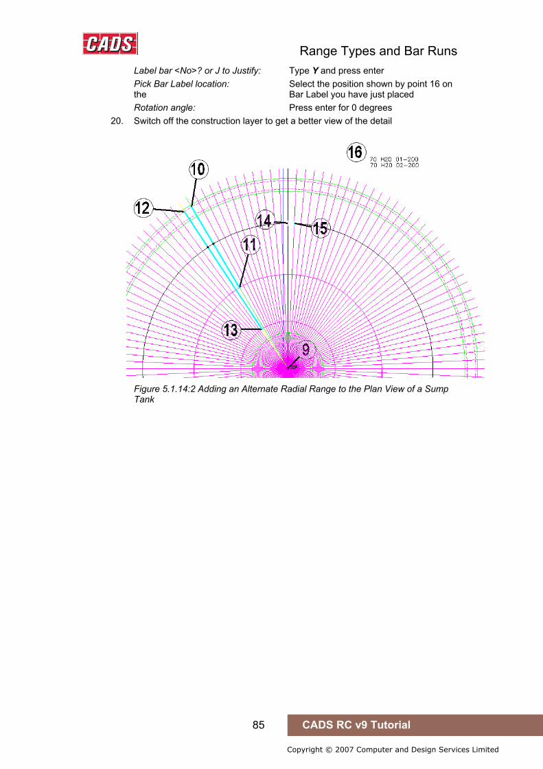
Range Types and Bar Runs
85 CADS RC v9 Tutorial
Copyright © 2007 Computer and Design Services Limited
Label bar <No>? or J to Justify: Type Y and press enter Pick Bar Label location: Select the position shown by point 16 on the Bar Label you have just placed Rotation angle: Press enter for 0 degrees
20. Switch off the construction layer to get a better view of the detail
Figure 5.1.14:2 Adding an Alternate Radial Range to the Plan View of a Sump Tank
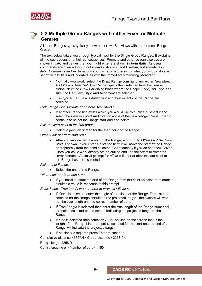
Range Types and Bar Runs
86 CADS RC v9 Tutorial
Copyright © 2007 Computer and Design Services Limited
5.2 Multiple Group Ranges with either Fixed or Multiple Centres
All these Ranges types typically show one or two Bar Views with one or more Range Groups.
The text below takes you through typical input for the Single Group Ranges. It explains all the sub-options and their consequences. Prompts and other screen displays are shown in italic and values that you might enter are shown in bold italic. As usual, commands are often – though not always - shown in bold roman, but sometimes in italic. Comments and explanations about what’s happening or what you should do are set off with bullets and indented, as with the immediately following paragraph.
• Normally you would select the Draw Range command and either New Mark, Add View or New Set. The Range type is then selected from the Range dialog. Next the Draw Bar dialog loads where the Shape Code, Bar Type and size, the Bar View, Style and Alignment are selected.
• The typical Bar View is drawn first and then extents of the Range are selected.
Pick 'Range Line' for data or enter to <continue>: • If another Range line exists which you would like to duplicate, select it and
select the insertion point and rotation angle of the new Range. Press Enter to continue to select the Range start and end points.
Pick the start point of the first group: • Select a point on screen for the start point of the Range.
Offset First bar from start <0>: • After you’ve selected the start of the Range, a prompt to Offset First Bar from
Start is shown. If you enter a distance here it will move the start of the Range appropriately from the point selected. Consequently if you do not show Cover Lines you could work directly off the outline and use the offset to enter the cover distance. A similar prompt for offset will appear after the last point of the Range has been selected.
Pick end of Range: • Select the end of the Range.
Offset Last bar from end <0>: • If you need to offset the end of the Range from the point selected then enter
a suitable value in response to this prompt. Enter Slope / True Len / Line / or enter to proceed <Enter>:
• If Slope is selected, enter the angle of the slope of the Range. The distance selected for the Range should be the projected length - the system will work out the true length and the correct number of bars.
• If True Length is selected then enter the true length of the Range numerical, the points selected on the screen indicating the projected length of the Range.
• If Line is selected then select an AutoCAD line on the screen that is the length of the Range Line - the points selected for the start and the end of the Range will indicate the projected length.
• If no slope is required press Enter to continue Cumulative distance <5657.4> Group distance <2258.0> Range length 2258.0. Centre spacing or <Number of bars> : 150
5.2 Multiple Group Ranges with either Fixed or Multiple Centres
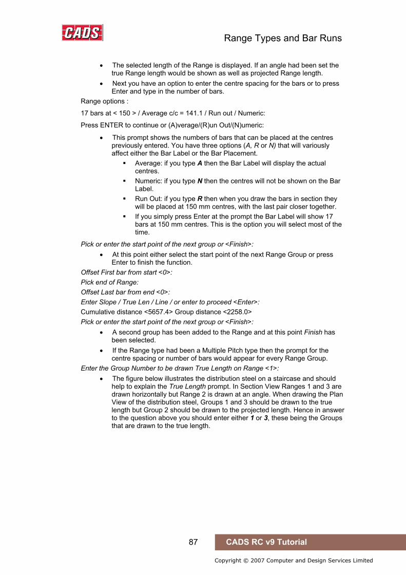
Range Types and Bar Runs
87 CADS RC v9 Tutorial
Copyright © 2007 Computer and Design Services Limited
• The selected length of the Range is displayed. If an angle had been set the true Range length would be shown as well as projected Range length.
• Next you have an option to enter the centre spacing for the bars or to press Enter and type in the number of bars.
Range options :
17 bars at < 150 > / Average c/c = 141.1 / Run out / Numeric:
Press ENTER to continue or (A)verage/(R)un Out/(N)umeric:
• This prompt shows the numbers of bars that can be placed at the centres previously entered. You have three options (A, R or N) that will variously affect either the Bar Label or the Bar Placement.
Average: if you type A then the Bar Label will display the actual centres.
Numeric: if you type N then the centres will not be shown on the Bar Label.
Run Out: if you type R then when you draw the bars in section they will be placed at 150 mm centres, with the last pair closer together.
If you simply press Enter at the prompt the Bar Label will show 17 bars at 150 mm centres. This is the option you will select most of the time.
Pick or enter the start point of the next group or <Finish>: • At this point either select the start point of the next Range Group or press
Enter to finish the function. Offset First bar from start <0>: Pick end of Range: Offset Last bar from end <0>: Enter Slope / True Len / Line / or enter to proceed <Enter>: Cumulative distance <5657.4> Group distance <2258.0> Pick or enter the start point of the next group or <Finish>:
• A second group has been added to the Range and at this point Finish has been selected.
• If the Range type had been a Multiple Pitch type then the prompt for the centre spacing or number of bars would appear for every Range Group.
Enter the Group Number to be drawn True Length on Range <1>: • The figure below illustrates the distribution steel on a staircase and should
help to explain the True Length prompt. In Section View Ranges 1 and 3 are drawn horizontally but Range 2 is drawn at an angle. When drawing the Plan View of the distribution steel, Groups 1 and 3 should be drawn to the true length but Group 2 should be drawn to the projected length. Hence in answer to the question above you should enter either 1 or 3, these being the Groups that are drawn to the true length.
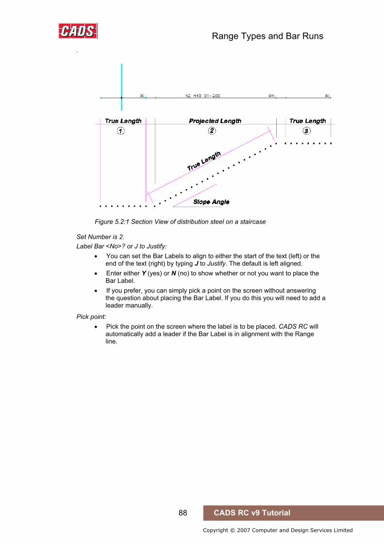
Range Types and Bar Runs
88 CADS RC v9 Tutorial
Copyright © 2007 Computer and Design Services Limited
.
Figure 5.2:1 Section View of distribution steel on a staircase
Set Number is 2. Label Bar <No>? or J to Justify:
• You can set the Bar Labels to align to either the start of the text (left) or the end of the text (right) by typing J to Justify. The default is left aligned.
• Enter either Y (yes) or N (no) to show whether or not you want to place the Bar Label.
• If you prefer, you can simply pick a point on the screen without answering the question about placing the Bar Label. If you do this you will need to add a leader manually.
Pick point: • Pick the point on the screen where the label is to be placed. CADS RC will
automatically add a leader if the Bar Label is in alignment with the Range line.

Range Types and Bar Runs
89 CADS RC v9 Tutorial
Copyright © 2007 Computer and Design Services Limited
5.2.1 Single Fixed Pitch Range
Figure 5.2.1:1 Single Fixed Pitch Range selection buttons
This Range shows a Single Bar View and one or more Range Groups that have the same centres throughout. The bars can be specified by centre spacing or by the number in the Range. Once drawn the number of bars in each Range Group is clearly shown on the Range line. Use a Single Fixed Pitch Run to represent this Range type when placing the bars in a section. This form is most commonly used where holes or beam strips have been introduced into a structure and standard centres maintained on either side. This Range will also support changes of angle and could be used to define the distribution steel in a staircase.
5.2.2 Try It! Single Fixed Pitch - Slab
Figure 5.2.2:1 below shows where to select the points to place the bar 1. Launch CADS RC 2. Open drawing ...\drawings\CADS RC 15.dwg 3. Set the Working Scale to 1:20 4. Make the Viewport on Slab 1 Layout active
5. Select CADS RC → Draw Bar → Set Member or 6. Make Slab 1 the current Member and select OK
7. Select CADS RC → Draw Bar → Set Drawing Sheet or 8. Make 01 the current Drawing Sheet
Add a Single Fixed Pitch Range to the Base 1 Plan 9. Select CADS RC → Draw Range → New Mark or
10. Select the Single Fixed Pitch 11. In the Draw Bar dialog select: Shape Code 00, Type H, Size 20,
View Side, Alignment Outer, Style Centre Select OK Indicator Bar Shape Code 00 Side View Outer start point: Pick on Cover Line as shown by point 1 Enter Outer Dimension B: Pick on Cover Line as shown by point 2 Pick ‘Range Line' for data or enter to <continue>: Press Enter to continue If another Range Line has already been drawn with the same layout as you need then you can select it and CADS RC will apply its length properties to the current Range.
5.2.2 Try It! Single Fixed Pitch - Slab

Range Types and Bar Runs
90 CADS RC v9 Tutorial
Copyright © 2007 Computer and Design Services Limited
Figure 5.2.2:1 Adding a Single Fixed Pitch Range to a Floor Slab
12. Setting Start Snap(s) Near. Pick the start point of the First Group: Pick on Cover Line as shown by point 3
Offset First bar from start <0>: Type 30 and Press Enter Setting Other Snap(s) Perp. Pick end of Range: Pick on Cover Line as shown by point 4
Offset Last bar from end <0>: Type 30 and Press Enter Enter Slope / True Len / Line / or enter to proceed <Enter>: Press Enter to proceed Cumulative distance <1840> Group distance <1840> Range length 1840 Centre spacing or <Number of bars>: Type in 200 and press Enter Range options: 11 bars at < 200 > / Average c/c = 184 / Run out / Numeric : Press ENTER to continue or (A)verage/(R)un Out/(N)umeric: Press Enter to continue Setting Other Snap(s) Perp Pick or enter the start point of the next group or <Finish>: Pick on Cover Line at point 5 as shown
Offset First bar from start <30>: Press Enter Setting Other Snap(s) Perp Pick end of Range: Pick on Cover Line at point 6 as shown Offset Last bar from end <30>: Press Enter Enter Slope / True Len / Line / or enter to proceed <Enter>: Press Enter to continue Cumulative distance <9840.0> Group distance <4840.0> Setting Other Snap(s) Perp

Range Types and Bar Runs
91 CADS RC v9 Tutorial
Copyright © 2007 Computer and Design Services Limited
Pick or enter the start point of the next group or <Finish>: Press Enter to finish Enter the Group Number to be drawn True Length on Range <1>: Press Enter to accept Range 1 Label bar <No>? or J to Justify: Type Y and press Enter Pick point: Position Bar Label as marked by point 7
Add a Single Fixed Pitch Bar Run to the Base 1 Section 12. Select CADS RC → Draw Range → Add View or
Pick Bar Set for New View: Select the Bar View on the plan, point 8
13. Select the Alternate Radial Range 14. Pick Bar Set for New View: Select the Bar View on the plan, point 8
Figure 5.2.2:2 below shows where to select the remaining points to place the bar: Select OK to close the Draw Bar dialog. The view is already set to section Existing Range of this bar - will calculate centres to existing length Shape Code 00 Pick start point <Normal Input>: Pick on the Intersection shown as point 9 Rotation <Original>: Press Enter to Set Rotation at 0 degrees, or Pick to the right to set the direction. Select side of line for bars to be placed: Pick above the section, shown by point 10 Set Number is 8 • Note that the bar run automatically lines up with the slab opening.
Figure 5.2.2:2 Adding a Single Fixed Pitch Run of Bars in Section to the Slab Section

Range Types and Bar Runs
92 CADS RC v9 Tutorial
Copyright © 2007 Computer and Design Services Limited
5.2.3 Single Multiple Fixed Pitch Range
Figure 5.2.3:1 Single Multiple Fixed Pitch Range selection buttons
This Range shows a Single Bar View and one or more Range Groups that can have different centres for each Group. The bars can be specified by centre spacing or by the number in the Range. Once drawn the number of bars and the centre spacing in each Range Group is clearly shown on the Range Line. Use a Single Multiple Pitch Run to represent this Range type when placing the bars in a section. This format is most commonly used where shear strips need to be introduced in beams and slabs. This Range will also support changes of angle.
5.2.4 Try It! Single Multiple Pitch - Beam
figure 5.2.4:1 below shows the points specified in this example 1. Launch CADS RC 2. Open drawing ...\drawings\CADS RC 15.dwg 3. Set the Working Scale at 1:20 4. Make the Viewport on Beam 1 Layout active
5. Select CADS RC → Draw Bar → Set Member or 6. Make Beam 1 the current Member and select OK
7. Select CADS RC → Draw Bar → Set Drawing Sheet or 8. Make 02 the current Drawing Sheet
Add a Single Multiple Pitch Range to the Beam 1 Elevation 9. Select CADS RC → Draw Range → Add View or
10. Select the Single Multiple Pitch Range 11. Pick Bar Set for New View: Pick the link on the Section A-A as shown
by point 1 In the Draw Bar dialog change the view to Left and select OK Indicator Bar Shape Code 51 Left view Outer start point: Pick on Cover Line as shown by point 2 Enter Outer Dimension C: Pick on Cover Line as shown by point 3 Pick 'Range Line' for data or enter to <continue>: Press enter to continue Setting Start Snap(s) Near. Pick the start point of the first group: Pick on Cover Line as shown by point 4 Offset First bar from start <0>: Press enter
5.2.4 Try It! Single Multiple Pitch - Beam
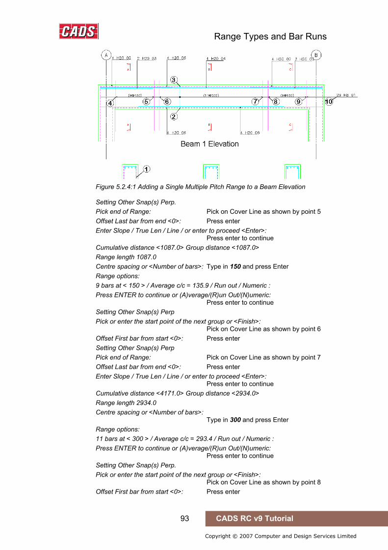
Range Types and Bar Runs
93 CADS RC v9 Tutorial
Copyright © 2007 Computer and Design Services Limited
Figure 5.2.4:1 Adding a Single Multiple Pitch Range to a Beam Elevation
Setting Other Snap(s) Perp. Pick end of Range: Pick on Cover Line as shown by point 5 Offset Last bar from end <0>: Press enter Enter Slope / True Len / Line / or enter to proceed <Enter>: Press enter to continue Cumulative distance <1087.0> Group distance <1087.0> Range length 1087.0 Centre spacing or <Number of bars>: Type in 150 and press Enter Range options: 9 bars at < 150 > / Average c/c = 135.9 / Run out / Numeric : Press ENTER to continue or (A)verage/(R)un Out/(N)umeric: Press enter to continue Setting Other Snap(s) Perp Pick or enter the start point of the next group or <Finish>: Pick on Cover Line as shown by point 6 Offset First bar from start <0>: Press enter Setting Other Snap(s) Perp Pick end of Range: Pick on Cover Line as shown by point 7 Offset Last bar from end <0>: Press enter Enter Slope / True Len / Line / or enter to proceed <Enter>: Press enter to continue Cumulative distance <4171.0> Group distance <2934.0> Range length 2934.0 Centre spacing or <Number of bars>: Type in 300 and press Enter Range options: 11 bars at < 300 > / Average c/c = 293.4 / Run out / Numeric : Press ENTER to continue or (A)verage/(R)un Out/(N)umeric: Press enter to continue Setting Other Snap(s) Perp. Pick or enter the start point of the next group or <Finish>: Pick on Cover Line as shown by point 8 Offset First bar from start <0>: Press enter

Range Types and Bar Runs
94 CADS RC v9 Tutorial
Copyright © 2007 Computer and Design Services Limited
Setting Other Snap(s) Perp. Pick end of Range: Pick on Cover Line as shown by point 9 Offset Last bar from end <0>: Press enter Enter Slope / True Len / Line / or enter to proceed <Enter>: Press enter to continue Cumulative distance <5404.0> Group distance <1087.0> Range length 1087.0 Centre spacing or <Number of bars>: Type in 150 and press Enter Range options: 9 bars at < 150 > / Average c/c = 135.9 / Run out / Numeric : Press ENTER to continue or (A)verage/(R)un Out/(N)umeric: Press enter to continue Setting Other Snap(s) Perp Pick or enter the start point of the next group or <Finish>: Press enter to finish Enter the group number to be drawn true length on Range <1>: Press enter to accept Group 1 Label bar <No>? or J to Justify: Type Y and press enter Pick point: Pick to the left of the beam, point 10
5.2.5 Try It! Single Multiple Pitch – Stair Flight
figure 5.2.5:1 below shows the points specified in this example 1. Launch CADS RC 2. Open drawing ...\drawings\CADS RC 15.dwg 3. Set the Working Scale at 1:20 4. Make the Viewport on Stair 1 Layout active
5. Select CADS RC → Draw Bar → Set Member or 6. Make Stair 1 the current Member and select OK
7. Select CADS RC → Draw Bar → Set Drawing Sheet or 8. Make 03 the current Drawing Sheet
Add a Single Fixed Pitch Bar Run to the Stair 1 Elevation 9. Select CADS RC → Draw Range → New Mark or
10. Select the Bar Run option
11. Select the Single Fixed Pitch Bar Run 11. In the Draw Bar dialog select: Shape Code 00, Type H, Size 12,
Style Centre Select OK
Indicator Bar Shape Code 00. Pick 'range line' for data or Enter to <continue> : Press enter to continue Pick the start point of the first group : Pick on the bar at point 1 Offset First bar from start <0> : Press enter to accept Pick End of range : Pick on the bar at point 2
5.2.5 Try It! Single Fixed Pitch – Stair Flight

Range Types and Bar Runs
95 CADS RC v9 Tutorial
Copyright © 2007 Computer and Design Services Limited
Offset Last bar from end <0> : Press enter to accept
Figure 5.2.5:1 Adding Fixed Pitch Bar Run to Stair Elevation
Enter True len / Line / or Enter to proceed <Enter> : Press enter to proceed Cumulative distance <1502.5> Group distance <1502.5> Range length 1502.5. Centre spacing or <Number of bars> : Type in 200 and press enter Range options : 9 bars at < 200 > / Average c/c = 187.8 / Run out / Numeric : Press ENTER to continue or (A)verage/(R)un Out/(N)umeric : Press enter to continue Pick or enter the start point of the next group or <Finish> : Pick on bar at point 3 Offset First bar from start <0> : Press enter to accept Pick End of range : Pick on the bar at point 4 Offset Last bar from end <0> : Press enter to accept Enter True len / Line / or Enter to proceed <Enter> : Press enter to accept Cumulative distance <5832.2> Group distance <4320.8> Pick or enter the start point of the next group or <Finish> : Pick on bar at point 5 Offset First bar from start <0> : Press enter to accept Pick End of range : Pick on the bar at point 6 Offset Last bar from end <0> : Press enter to accept Enter True len / Line / or Enter to proceed <Enter> : Press enter to accept Cumulative distance <6887.7> Group distance <974.2> Pick or enter the start point of the next group or <Finish> : Press enter to accept Select side of line for bars to be placed : Pick above the landing at point 7 Enter the group number to be drawn true length on range <1> : Press enter Set Number is 17. Label bar <No> ? or J to Justify : Press enter to accept
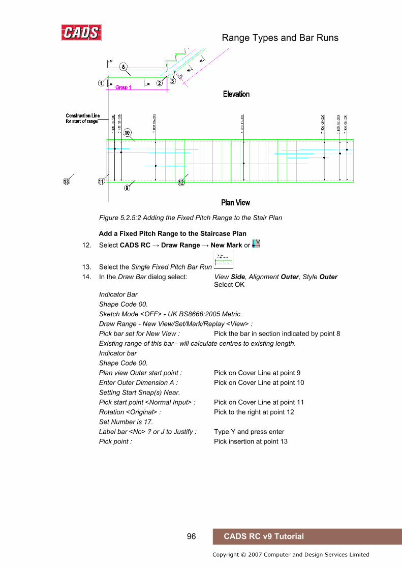
Range Types and Bar Runs
96 CADS RC v9 Tutorial
Copyright © 2007 Computer and Design Services Limited
Figure 5.2.5:2 Adding the Fixed Pitch Range to the Stair Plan
Add a Fixed Pitch Range to the Staircase Plan 12. Select CADS RC → Draw Range → New Mark or
13. Select the Single Fixed Pitch Bar Run 14. In the Draw Bar dialog select: View Side, Alignment Outer, Style Outer
Select OK Indicator Bar Shape Code 00. Sketch Mode <OFF> - UK BS8666:2005 Metric. Draw Range - New View/Set/Mark/Replay <View> : Pick bar set for New View : Pick the bar in section indicated by point 8 Existing range of this bar - will calculate centres to existing length. Indicator bar Shape Code 00. Plan view Outer start point : Pick on Cover Line at point 9 Enter Outer Dimension A : Pick on Cover Line at point 10 Setting Start Snap(s) Near. Pick start point <Normal Input> : Pick on Cover Line at point 11 Rotation <Original> : Pick to the right at point 12 Set Number is 17. Label bar <No> ? or J to Justify : Type Y and press enter Pick point : Pick insertion at point 13
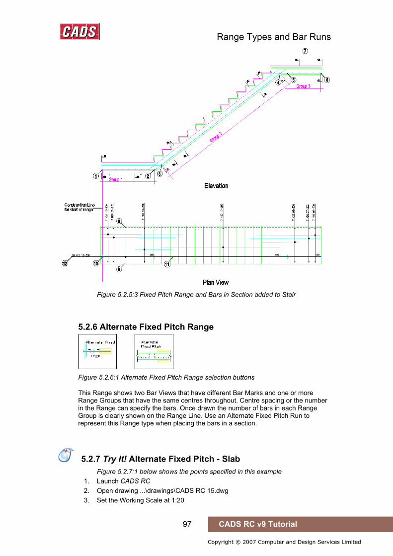
Range Types and Bar Runs
97 CADS RC v9 Tutorial
Copyright © 2007 Computer and Design Services Limited
Figure 5.2.5:3 Fixed Pitch Range and Bars in Section added to Stair
5.2.6 Alternate Fixed Pitch Range
Figure 5.2.6:1 Alternate Fixed Pitch Range selection buttons
This Range shows two Bar Views that have different Bar Marks and one or more Range Groups that have the same centres throughout. Centre spacing or the number in the Range can specify the bars. Once drawn the number of bars in each Range Group is clearly shown on the Range Line. Use an Alternate Fixed Pitch Run to represent this Range type when placing the bars in a section.
5.2.7 Try It! Alternate Fixed Pitch - Slab
Figure 5.2.7:1 below shows the points specified in this example 1. Launch CADS RC 2. Open drawing ...\drawings\CADS RC 15.dwg 3. Set the Working Scale at 1:20
5.2.7 Try It! Alternate Fixed Pitch - Slab
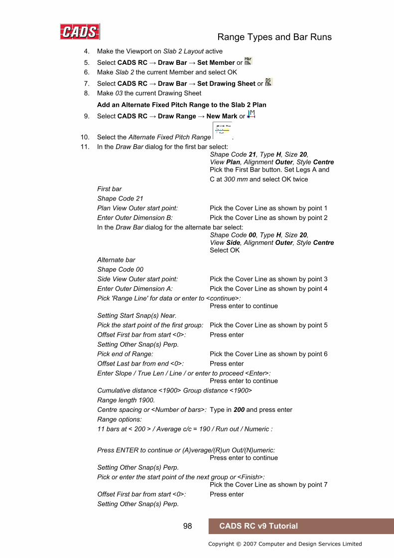
Range Types and Bar Runs
98 CADS RC v9 Tutorial
Copyright © 2007 Computer and Design Services Limited
4. Make the Viewport on Slab 2 Layout active
5. Select CADS RC → Draw Bar → Set Member or 6. Make Slab 2 the current Member and select OK
7. Select CADS RC → Draw Bar → Set Drawing Sheet or 8. Make 03 the current Drawing Sheet
Add an Alternate Fixed Pitch Range to the Slab 2 Plan 9. Select CADS RC → Draw Range → New Mark or
10. Select the Alternate Fixed Pitch Range . 11. In the Draw Bar dialog for the first bar select:
Shape Code 21, Type H, Size 20, View Plan, Alignment Outer, Style Centre Pick the First Bar button. Set Legs A and
C at 300 mm and select OK twice First bar Shape Code 21 Plan View Outer start point: Pick the Cover Line as shown by point 1 Enter Outer Dimension B: Pick the Cover Line as shown by point 2 In the Draw Bar dialog for the alternate bar select: Shape Code 00, Type H, Size 20, View Side, Alignment Outer, Style Centre Select OK Alternate bar Shape Code 00 Side View Outer start point: Pick the Cover Line as shown by point 3 Enter Outer Dimension A: Pick the Cover Line as shown by point 4 Pick 'Range Line' for data or enter to <continue>: Press enter to continue Setting Start Snap(s) Near. Pick the start point of the first group: Pick the Cover Line as shown by point 5 Offset First bar from start <0>: Press enter Setting Other Snap(s) Perp. Pick end of Range: Pick the Cover Line as shown by point 6 Offset Last bar from end <0>: Press enter Enter Slope / True Len / Line / or enter to proceed <Enter>: Press enter to continue Cumulative distance <1900> Group distance <1900> Range length 1900. Centre spacing or <Number of bars>: Type in 200 and press enter Range options: 11 bars at < 200 > / Average c/c = 190 / Run out / Numeric :
Press ENTER to continue or (A)verage/(R)un Out/(N)umeric: Press enter to continue Setting Other Snap(s) Perp. Pick or enter the start point of the next group or <Finish>: Pick the Cover Line as shown by point 7 Offset First bar from start <0>: Press enter Setting Other Snap(s) Perp.

Range Types and Bar Runs
99 CADS RC v9 Tutorial
Copyright © 2007 Computer and Design Services Limited
Pick end of Range: Pick the Cover Line as shown by point 8 Offset Last bar from end <0>: Press enter Enter Slope / True Len / Line / or enter to proceed <Enter>: Press enter to continue
Figure 5.2.7:1 Adding an Alternate Fixed Pitch Range to a Floor Slab
Cumulative distance <9900.0> Group distance <4900.0> Previous group ended with First bar Current group - First Bar = 13, Alternate Bar = 13, Total = 26. Swap the order of these bars <No>: Press enter for No Setting Other Snap(s) Perp. Pick or enter the start point of the next group or <Finish>: Press enter to finish Enter the group number to be drawn true length on Range <1>: Press enter for group No1 Set Number is 10. Label bar <No>? or J to Justify: Type Y and press enter Pick point: Set Number is 11. Label bar <No>? or J to Justify: Type Y and press enter to place the Bar Label for the first alternate bar Pick point: Pick a point on the right of slab, point 9 Set Number is 11. Label bar <No>? or J to Justify: Type Y and press enter
• The Alternate Range has a built in Bar Label alignment tool which you may like to try out.
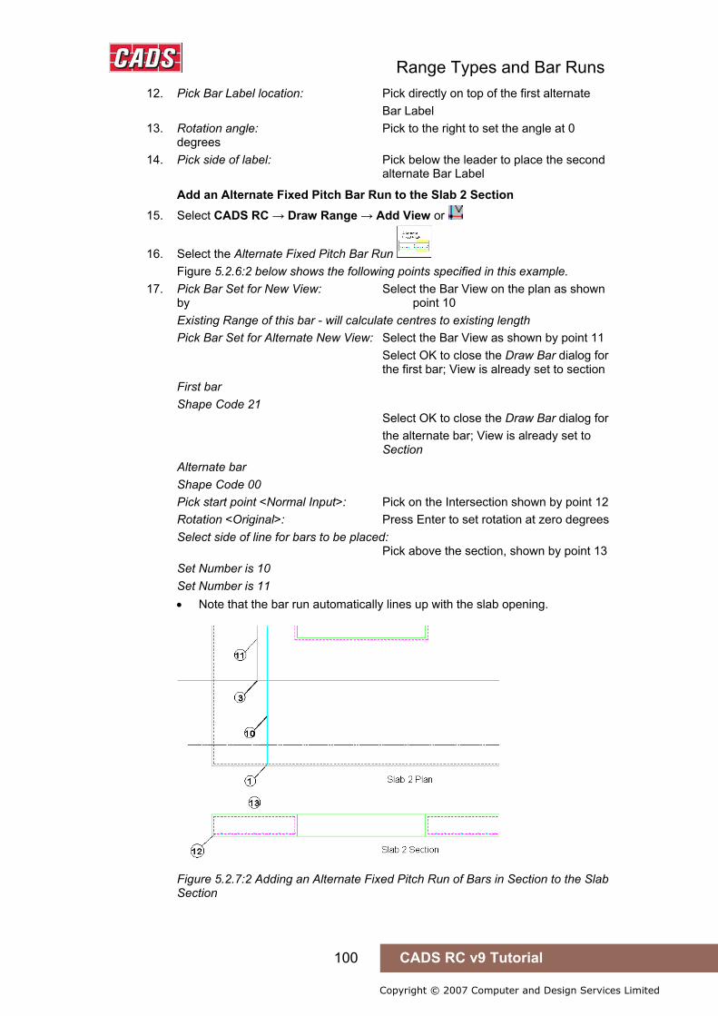
Range Types and Bar Runs
100 CADS RC v9 Tutorial
Copyright © 2007 Computer and Design Services Limited
12. Pick Bar Label location: Pick directly on top of the first alternate Bar Label
13. Rotation angle: Pick to the right to set the angle at 0 degrees
14. Pick side of label: Pick below the leader to place the second alternate Bar Label
Add an Alternate Fixed Pitch Bar Run to the Slab 2 Section 15. Select CADS RC → Draw Range → Add View or
16. Select the Alternate Fixed Pitch Bar Run Figure 5.2.6:2 below shows the following points specified in this example.
17. Pick Bar Set for New View: Select the Bar View on the plan as shown by point 10 Existing Range of this bar - will calculate centres to existing length Pick Bar Set for Alternate New View: Select the Bar View as shown by point 11 Select OK to close the Draw Bar dialog for the first bar; View is already set to section First bar Shape Code 21 Select OK to close the Draw Bar dialog for the alternate bar; View is already set to Section Alternate bar Shape Code 00 Pick start point <Normal Input>: Pick on the Intersection shown by point 12 Rotation <Original>: Press Enter to set rotation at zero degrees Select side of line for bars to be placed: Pick above the section, shown by point 13 Set Number is 10 Set Number is 11 • Note that the bar run automatically lines up with the slab opening.
Figure 5.2.7:2 Adding an Alternate Fixed Pitch Run of Bars in Section to the Slab Section

Range Types and Bar Runs
101 CADS RC v9 Tutorial
Copyright © 2007 Computer and Design Services Limited
5.2.8 Alternate Multiple Pitch Range
Figure 5.2.8:1 Alternate Multiple Pitch Range selection buttons
This Range shows two Bar Views that have different Bar Marks and one or more Range Groups that have different centres for each group. The bars can be specified by centre spacing or by the number in the Range. The number and centre spacing of the bars in each Range Group is clearly shown on the Range Line once the bars have been drawn.
Use an Alternate Multiple Pitch Run to represent this Range type when placing the bars in a section.
The functionality of the Alternate Fixed and Multiple Pitch Ranges is the same except that the Multiple Pitch Range will prompt for the bar spacing for every Range Group.
5.2.9 Staggered Fixed Pitch Range
Figure 5.2.9:1 Staggered Fixed Pitch Range selection buttons
This Range shows two Bar Views of the same Bar Mark and one or more Range Groups that have the same centres throughout. The bars can either be shown as a staggered offset or alternate reversed. The bars can be specified by centre spacing or by the number in the Range. Once the bars have been drawn their number in each Range Group is clearly shown on the Range Line. Use a Staggered Fixed Pitch Run to represent this Range type when placing the bars in a section.
5.2.9 Try It! Staggered Fixed Pitch - Slab
Figure 5.2.10:1 below shows the points specified in this example 1. Launch CADS RC 2. Open drawing ...\drawings\CADS RC 15.dwg 3. Set the Working Scale at 1:20 4. Make the Viewport on Slab 3 Layout active
5.2.10 Try It! Staggered Fixed Pitch - Slab
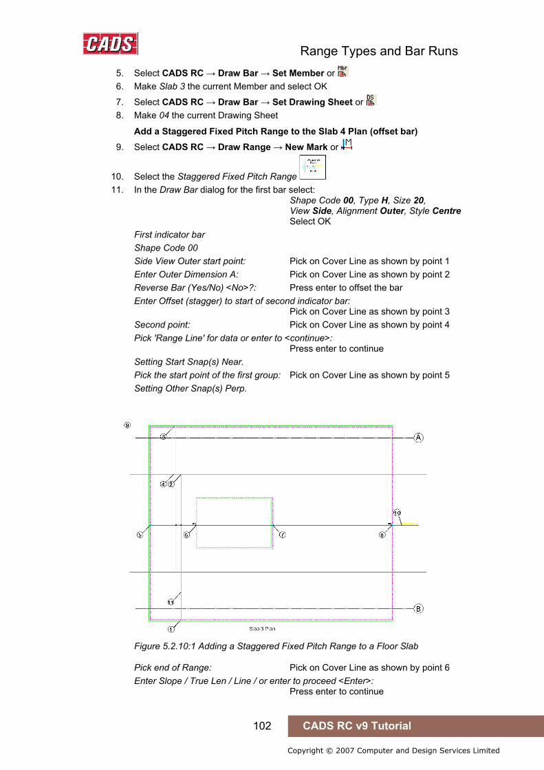
Range Types and Bar Runs
102 CADS RC v9 Tutorial
Copyright © 2007 Computer and Design Services Limited
5. Select CADS RC → Draw Bar → Set Member or 6. Make Slab 3 the current Member and select OK
7. Select CADS RC → Draw Bar → Set Drawing Sheet or 8. Make 04 the current Drawing Sheet
Add a Staggered Fixed Pitch Range to the Slab 4 Plan (offset bar) 9. Select CADS RC → Draw Range → New Mark or
10. Select the Staggered Fixed Pitch Range 11. In the Draw Bar dialog for the first bar select:
Shape Code 00, Type H, Size 20, View Side, Alignment Outer, Style Centre Select OK First indicator bar Shape Code 00 Side View Outer start point: Pick on Cover Line as shown by point 1 Enter Outer Dimension A: Pick on Cover Line as shown by point 2 Reverse Bar (Yes/No) <No>?: Press enter to offset the bar Enter Offset (stagger) to start of second indicator bar: Pick on Cover Line as shown by point 3 Second point: Pick on Cover Line as shown by point 4 Pick 'Range Line' for data or enter to <continue>: Press enter to continue Setting Start Snap(s) Near. Pick the start point of the first group: Pick on Cover Line as shown by point 5 Setting Other Snap(s) Perp.
Figure 5.2.10:1 Adding a Staggered Fixed Pitch Range to a Floor Slab
Pick end of Range: Pick on Cover Line as shown by point 6 Enter Slope / True Len / Line / or enter to proceed <Enter>: Press enter to continue
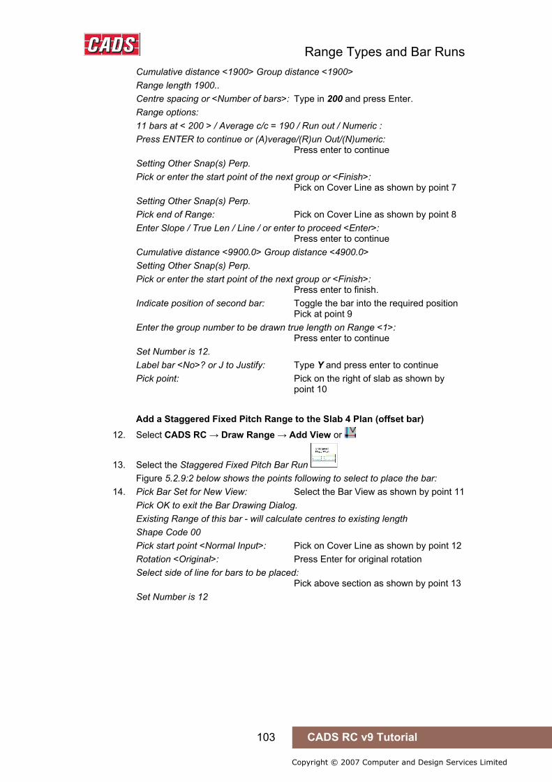
Range Types and Bar Runs
103 CADS RC v9 Tutorial
Copyright © 2007 Computer and Design Services Limited
Cumulative distance <1900> Group distance <1900> Range length 1900.. Centre spacing or <Number of bars>: Type in 200 and press Enter. Range options: 11 bars at < 200 > / Average c/c = 190 / Run out / Numeric : Press ENTER to continue or (A)verage/(R)un Out/(N)umeric: Press enter to continue Setting Other Snap(s) Perp. Pick or enter the start point of the next group or <Finish>: Pick on Cover Line as shown by point 7 Setting Other Snap(s) Perp. Pick end of Range: Pick on Cover Line as shown by point 8 Enter Slope / True Len / Line / or enter to proceed <Enter>: Press enter to continue Cumulative distance <9900.0> Group distance <4900.0> Setting Other Snap(s) Perp. Pick or enter the start point of the next group or <Finish>: Press enter to finish. Indicate position of second bar: Toggle the bar into the required position Pick at point 9 Enter the group number to be drawn true length on Range <1>: Press enter to continue Set Number is 12. Label bar <No>? or J to Justify: Type Y and press enter to continue Pick point: Pick on the right of slab as shown by point 10
Add a Staggered Fixed Pitch Range to the Slab 4 Plan (offset bar) 12. Select CADS RC → Draw Range → Add View or
13. Select the Staggered Fixed Pitch Bar Run Figure 5.2.9:2 below shows the points following to select to place the bar:
14. Pick Bar Set for New View: Select the Bar View as shown by point 11 Pick OK to exit the Bar Drawing Dialog. Existing Range of this bar - will calculate centres to existing length Shape Code 00 Pick start point <Normal Input>: Pick on Cover Line as shown by point 12 Rotation <Original>: Press Enter for original rotation Select side of line for bars to be placed: Pick above section as shown by point 13 Set Number is 12

Range Types and Bar Runs
104 CADS RC v9 Tutorial
Copyright © 2007 Computer and Design Services Limited
Figure 5.2.10:2 Adding a Staggered Fixed Pitch Run of Bars in Section to a Floor Slab
5.2.11 Staggered Multiple Pitch Ranges
Figure 5.2.11:1 Staggered Multiple Pitch Range selection buttons
This Range shows two Bar Views of the same Bar Mark and one or more Range Groups that can have different centres for each group. The bars can either be shown as a Staggered Offset or Alternate Reversed. The bars can be specified by centre spacing or by the number in the Range. Once the bars have been drawn their number and the Centre Spacing in each Range Group is clearly shown on the Range Line. Use a Staggered Multiple Pitch Run to represent this Range type when placing the bars in a section.
The functionality of the Staggered Fixed and Multiple Pitch Ranges is the same except that the Multiple Pitch Range will prompt for the bar spacing for every Range Group.
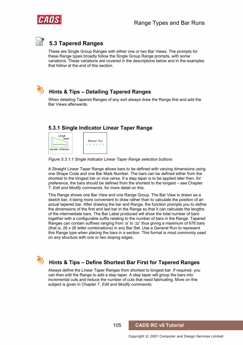
Range Types and Bar Runs
105 CADS RC v9 Tutorial
Copyright © 2007 Computer and Design Services Limited
5.3 Tapered Ranges
These are Single Group Ranges with either one or two Bar Views. The prompts for these Range types broadly follow the Single Group Range prompts, with some variations. These variations are covered in the descriptions below and in the examples that follow at the end of this section.
Hints & Tips – Detailing Tapered Ranges
When detailing Tapered Ranges of any sort always draw the Range first and add the Bar Views afterwards.
5.3.1 Single Indicator Linear Taper Range
Figure 5.3.1:1 Single Indicator Linear Taper Range selection buttons
A Straight Linear Taper Range allows bars to be defined with varying dimensions using one Shape Code and one Bar Mark Number. The bars can be defined either from the shortest to the longest bar or vice versa. If a step taper is to be applied later then, for preference, the bars should be defined from the shortest to the longest – see Chapter 7, Edit and Modify commands, for more detail on this.
This Range shows one Bar View and one Range Group. The Bar View is drawn as a sketch bar, it being more convenient to draw rather than to calculate the position of an actual tapered bar. After drawing the bar and Range, the function prompts you to define the dimensions of the first and last bar in the Range so that it can calculate the lengths of the intermediate bars. The Bar Label produced will show the total number of bars together with a configurable suffix relating to the number of bars in the Range. Tapered Ranges can contain suffixes ranging from ‘a’ to ‘zz’ thus giving a maximum of 676 bars (that is, 26 x 26 letter combinations) in any Bar Set. Use a General Run to represent this Range type when placing the bars in a section. This format is most commonly used on any structure with one or two sloping edges.
Hints & Tips – Define Shortest Bar First for Tapered Ranges
Always define the Linear Taper Ranges from shortest to longest bar. If required, you can then edit the Range to add a step taper. A step taper will group the bars into incremental cuts and reduce the number of cuts that need fabricating. More on this subject is given in Chapter 7, Edit and Modify commands.
5.3 Tapered Ranges
Hints & Tips – Detailing Tapered Ranges
Hints & Tips – Define Shortest Bar First for Tapered Ranges
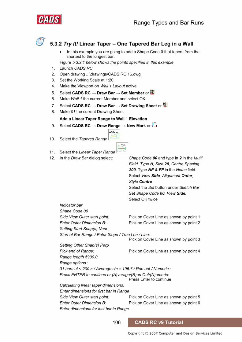
Range Types and Bar Runs
106 CADS RC v9 Tutorial
Copyright © 2007 Computer and Design Services Limited
5.3.2 Try It! Linear Taper – One Tapered Bar Leg in a Wall
• In this example you are going to add a Shape Code 0 that tapers from the shortest to the longest bar.
Figure 5.3.2:1 below shows the points specified in this example 1. Launch CADS RC 2. Open drawing ...\drawings\CADS RC 16.dwg 3. Set the Working Scale at 1:20 4. Make the Viewport on Wall 1 Layout active
5. Select CADS RC → Draw Bar → Set Member or 6. Make Wall 1 the current Member and select OK
7. Select CADS RC → Draw Bar → Set Drawing Sheet or 8. Make 01 the current Drawing Sheet
Add a Linear Taper Range to Wall 1 Elevation 9. Select CADS RC → Draw Range → New Mark or
10. Select the Tapered Range
11. Select the Linear Taper Range 12. In the Draw Bar dialog select: Shape Code 00 and type in 2 in the Multi
Field, Type H, Size 20, Centre Spacing 200. Type NF & FF in the Notes field. Select View Side, Alignment Outer, Style Centre Select the Set button under Sketch Bar Set Shape Code 00, View Side. Select OK twice
Indicator bar Shape Code 00 Side View Outer start point: Pick on Cover Line as shown by point 1 Enter Outer Dimension B: Pick on Cover Line as shown by point 2 Setting Start Snap(s) Near. Start of Bar Range / Enter Slope / True Len / Line: Pick on Cover Line as shown by point 3 Setting Other Snap(s) Perp Pick end of Range: Pick on Cover Line as shown by point 4 Range length 5900.0 Range options : 31 bars at < 200 > / Average c/c = 196.7 / Run out / Numeric : Press ENTER to continue or (A)verage/(R)un Out/(N)umeric: Press Enter to continue Calculating linear taper dimensions. Enter dimensions for first bar in Range Side View Outer start point: Pick on Cover Line as shown by point 5 Enter Outer Dimension B: Pick on Cover Line as shown by point 6 Enter dimensions for last bar in Range.
5.3.2 Try It! Linear Taper – One Tapered Bar Leg in a Wall
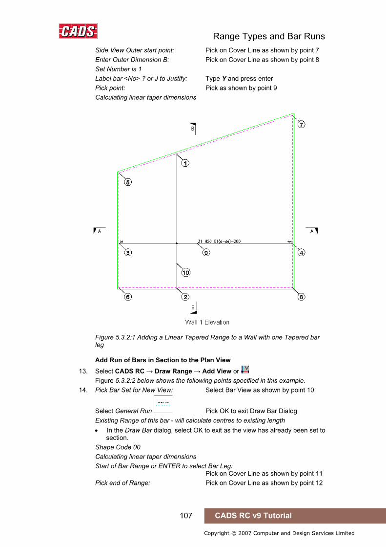
Range Types and Bar Runs
107 CADS RC v9 Tutorial
Copyright © 2007 Computer and Design Services Limited
Side View Outer start point: Pick on Cover Line as shown by point 7 Enter Outer Dimension B: Pick on Cover Line as shown by point 8 Set Number is 1 Label bar <No> ? or J to Justify: Type Y and press enter Pick point: Pick as shown by point 9 Calculating linear taper dimensions
Figure 5.3.2:1 Adding a Linear Tapered Range to a Wall with one Tapered bar leg
Add Run of Bars in Section to the Plan View 13. Select CADS RC → Draw Range → Add View or
Figure 5.3.2:2 below shows the following points specified in this example. 14. Pick Bar Set for New View: Select Bar View as shown by point 10
Select General Run Pick OK to exit Draw Bar Dialog Existing Range of this bar - will calculate centres to existing length • In the Draw Bar dialog, select OK to exit as the view has already been set to
section. Shape Code 00 Calculating linear taper dimensions Start of Bar Range or ENTER to select Bar Leg: Pick on Cover Line as shown by point 11 Pick end of Range: Pick on Cover Line as shown by point 12
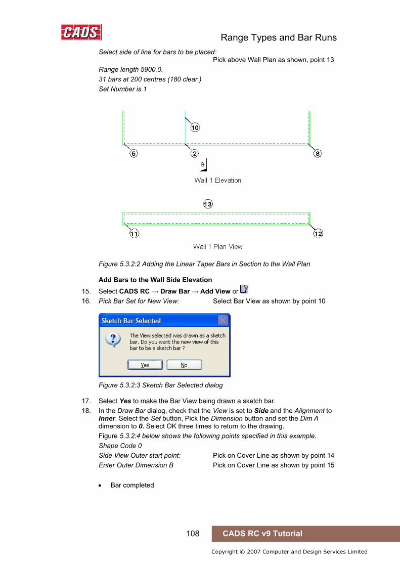
Range Types and Bar Runs
108 CADS RC v9 Tutorial
Copyright © 2007 Computer and Design Services Limited
Select side of line for bars to be placed: Pick above Wall Plan as shown, point 13 Range length 5900.0. 31 bars at 200 centres (180 clear.) Set Number is 1
Figure 5.3.2:2 Adding the Linear Taper Bars in Section to the Wall Plan
Add Bars to the Wall Side Elevation 15. Select CADS RC → Draw Bar → Add View or 16. Pick Bar Set for New View: Select Bar View as shown by point 10
Figure 5.3.2:3 Sketch Bar Selected dialog
17. Select Yes to make the Bar View being drawn a sketch bar. 18. In the Draw Bar dialog, check that the View is set to Side and the Alignment to
Inner. Select the Set button, Pick the Dimension button and set the Dim A dimension to 0. Select OK three times to return to the drawing. Figure 5.3.2:4 below shows the following points specified in this example. Shape Code 0 Side View Outer start point: Pick on Cover Line as shown by point 14 Enter Outer Dimension B Pick on Cover Line as shown by point 15 • Bar completed

Range Types and Bar Runs
109 CADS RC v9 Tutorial
Copyright © 2007 Computer and Design Services Limited
Figure 5.3.2:4 Adding Sketch Bar Views of the Linear Taper to the Wall Section
• Now repeat the exercise and draw the sketch bar on the right hand side.
19. Select CADS RC → Draw Bar → Add View or 20. Pick Bar Set for New View: Pick Bar View as shown by point 16
Figure 5.3.2:5 Sketch Bar Selected dialog
21. Pick Yes to make the Bar View being drawn a sketch bar 22. In the Draw Bar dialog set the alignment to Outer and then pick OK as the rest of
the sketch bar properties have been extracted from the bar selected. Shape Code 00 Side View Outer start point: Pick on Cover Line as shown by point 17 Enter Outer Dimension B: Pick on Cover Line as shown by point 18 • Bar completed
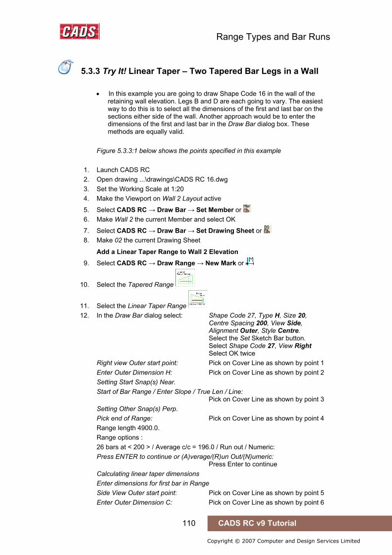
Range Types and Bar Runs
110 CADS RC v9 Tutorial
Copyright © 2007 Computer and Design Services Limited
5.3.3 Try It! Linear Taper – Two Tapered Bar Legs in a Wall
• In this example you are going to draw Shape Code 16 in the wall of the
retaining wall elevation. Legs B and D are each going to vary. The easiest way to do this is to select all the dimensions of the first and last bar on the sections either side of the wall. Another approach would be to enter the dimensions of the first and last bar in the Draw Bar dialog box. These methods are equally valid.
Figure 5.3.3:1 below shows the points specified in this example
1. Launch CADS RC 2. Open drawing ...\drawings\CADS RC 16.dwg 3. Set the Working Scale at 1:20 4. Make the Viewport on Wall 2 Layout active
5. Select CADS RC → Draw Bar → Set Member or 6. Make Wall 2 the current Member and select OK
7. Select CADS RC → Draw Bar → Set Drawing Sheet or 8. Make 02 the current Drawing Sheet
Add a Linear Taper Range to Wall 2 Elevation 9. Select CADS RC → Draw Range → New Mark or
10. Select the Tapered Range
11. Select the Linear Taper Range 12. In the Draw Bar dialog select: Shape Code 27, Type H, Size 20,
Centre Spacing 200, View Side, Alignment Outer, Style Centre. Select the Set Sketch Bar button. Select Shape Code 27, View Right Select OK twice Right view Outer start point: Pick on Cover Line as shown by point 1 Enter Outer Dimension H: Pick on Cover Line as shown by point 2 Setting Start Snap(s) Near. Start of Bar Range / Enter Slope / True Len / Line: Pick on Cover Line as shown by point 3 Setting Other Snap(s) Perp. Pick end of Range: Pick on Cover Line as shown by point 4 Range length 4900.0. Range options : 26 bars at < 200 > / Average c/c = 196.0 / Run out / Numeric: Press ENTER to continue or (A)verage/(R)un Out/(N)umeric: Press Enter to continue Calculating linear taper dimensions Enter dimensions for first bar in Range Side View Outer start point: Pick on Cover Line as shown by point 5 Enter Outer Dimension C: Pick on Cover Line as shown by point 6
5.3.3 Try It! Linear Taper – Two Tapered Bar Legs in a Wall
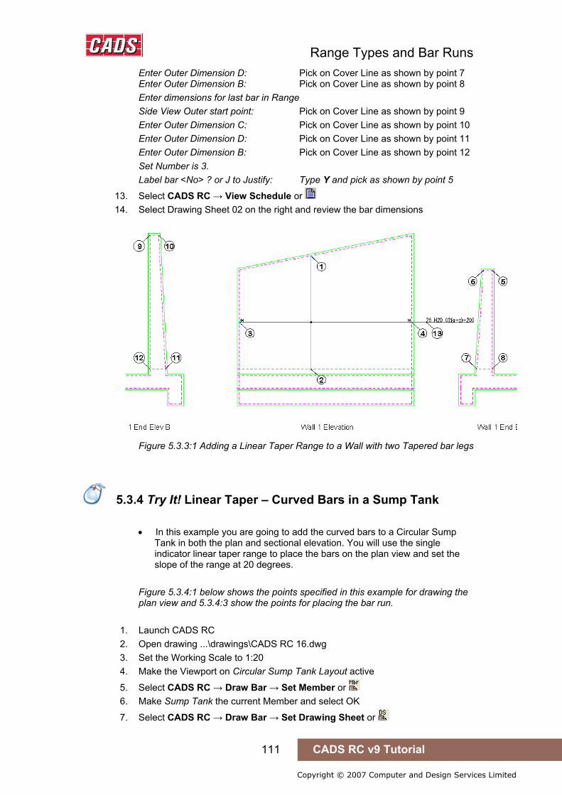
Range Types and Bar Runs
111 CADS RC v9 Tutorial
Copyright © 2007 Computer and Design Services Limited
Enter Outer Dimension D: Pick on Cover Line as shown by point 7 Enter Outer Dimension B: Pick on Cover Line as shown by point 8 Enter dimensions for last bar in Range Side View Outer start point: Pick on Cover Line as shown by point 9 Enter Outer Dimension C: Pick on Cover Line as shown by point 10 Enter Outer Dimension D: Pick on Cover Line as shown by point 11 Enter Outer Dimension B: Pick on Cover Line as shown by point 12 Set Number is 3. Label bar <No> ? or J to Justify: Type Y and pick as shown by point 5
13. Select CADS RC → View Schedule or 14. Select Drawing Sheet 02 on the right and review the bar dimensions
Figure 5.3.3:1 Adding a Linear Taper Range to a Wall with two Tapered bar legs
5.3.4 Try It! Linear Taper – Curved Bars in a Sump Tank
• In this example you are going to add the curved bars to a Circular Sump
Tank in both the plan and sectional elevation. You will use the single indicator linear taper range to place the bars on the plan view and set the slope of the range at 20 degrees.
Figure 5.3.4:1 below shows the points specified in this example for drawing the plan view and 5.3.4:3 show the points for placing the bar run.
1. Launch CADS RC 2. Open drawing ...\drawings\CADS RC 16.dwg 3. Set the Working Scale to 1:20 4. Make the Viewport on Circular Sump Tank Layout active
5. Select CADS RC → Draw Bar → Set Member or 6. Make Sump Tank the current Member and select OK
7. Select CADS RC → Draw Bar → Set Drawing Sheet or
5.3.4 Try It! Linear Taper – Curved Bars in a Sump Tank
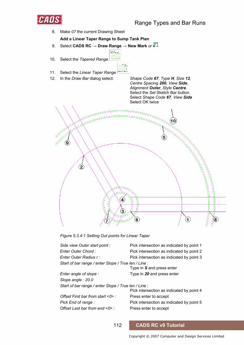
Range Types and Bar Runs
112 CADS RC v9 Tutorial
Copyright © 2007 Computer and Design Services Limited
8. Make 07 the current Drawing Sheet
Add a Linear Taper Range to Sump Tank Plan 9. Select CADS RC → Draw Range → New Mark or
10. Select the Tapered Range
11. Select the Linear Taper Range 12. In the Draw Bar dialog select: Shape Code 67, Type H, Size 12,
Centre Spacing 200, View Side, Alignment Outer, Style Centre. Select the Set Sketch Bar button. Select Shape Code 67, View Side Select OK twice
Figure 5.3.4:1 Setting Out points for Linear Taper
Side view Outer start point : Pick intersection as indicated by point 1 Enter Outer Chord : Pick intersection as indicated by point 2 Enter Outer Radius r : Pick intersection as indicated by point 3 Start of bar range / enter Slope / True len / Line : Type in S and press enter Enter angle of slope : Type in 20 and press enter Slope angle : 20.0 Start of bar range / enter Slope / True len / Line : Pick intersection as indicated by point 4 Offset First bar from start <0> : Press enter to accept Pick End of range : Pick intersection as indicated by point 5 Offset Last bar from end <0> : Press enter to accept
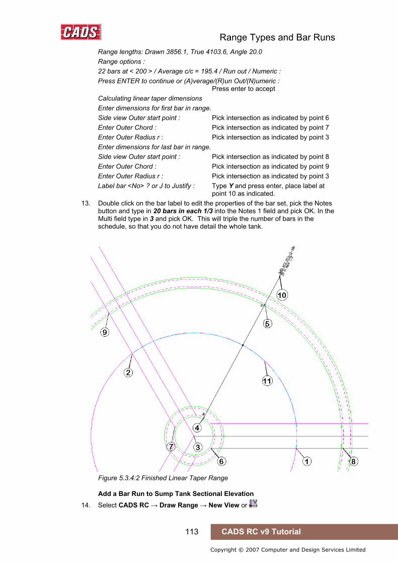
Range Types and Bar Runs
113 CADS RC v9 Tutorial
Copyright © 2007 Computer and Design Services Limited
Range lengths: Drawn 3856.1, True 4103.6, Angle 20.0 Range options : 22 bars at < 200 > / Average c/c = 195.4 / Run out / Numeric : Press ENTER to continue or (A)verage/(R)un Out/(N)umeric : Press enter to accept Calculating linear taper dimensions Enter dimensions for first bar in range. Side view Outer start point : Pick intersection as indicated by point 6 Enter Outer Chord : Pick intersection as indicated by point 7 Enter Outer Radius r : Pick intersection as indicated by point 3 Enter dimensions for last bar in range. Side view Outer start point : Pick intersection as indicated by point 8 Enter Outer Chord : Pick intersection as indicated by point 9 Enter Outer Radius r : Pick intersection as indicated by point 3 Label bar <No> ? or J to Justify : Type Y and press enter, place label at point 10 as indicated.
13. Double click on the bar label to edit the properties of the bar set, pick the Notes button and type in 20 bars in each 1/3 into the Notes 1 field and pick OK. In the Multi field type in 3 and pick OK. This will triple the number of bars in the schedule, so that you do not have detail the whole tank.
Figure 5.3.4:2 Finished Linear Taper Range
Add a Bar Run to Sump Tank Sectional Elevation 14. Select CADS RC → Draw Range → New View or

Range Types and Bar Runs
114 CADS RC v9 Tutorial
Copyright © 2007 Computer and Design Services Limited
Pick bar set for New View : Pick the bar indicated by point 11 15. In the Draw Bar dialog: Pick the OK button as all fields are
correctly set. Existing range of this bar - will calculate centres to existing length. Shape Code 67. Calculating linear taper dimensions Start of bar range or ENTER to select bar leg : Pick intersection as indicated by point 12 Offset First bar from start <0> : Press enter to accept Pick End of range : Pick intersection as indicated by point 13 Offset Last bar from end <0> : Press enter to accept Select side of line for bars to be placed : Pick as indicated by point 14 Range has already been specified, the distance you have picked is greater than
5% different. Are you sure you want to continue ? <No> : Type Y and press enter.
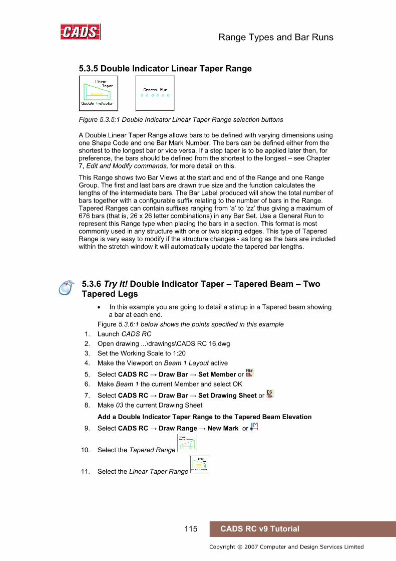
Range Types and Bar Runs
115 CADS RC v9 Tutorial
Copyright © 2007 Computer and Design Services Limited
5.3.5 Double Indicator Linear Taper Range
Figure 5.3.5:1 Double Indicator Linear Taper Range selection buttons
A Double Linear Taper Range allows bars to be defined with varying dimensions using one Shape Code and one Bar Mark Number. The bars can be defined either from the shortest to the longest bar or vice versa. If a step taper is to be applied later then, for preference, the bars should be defined from the shortest to the longest – see Chapter 7, Edit and Modify commands, for more detail on this.
This Range shows two Bar Views at the start and end of the Range and one Range Group. The first and last bars are drawn true size and the function calculates the lengths of the intermediate bars. The Bar Label produced will show the total number of bars together with a configurable suffix relating to the number of bars in the Range. Tapered Ranges can contain suffixes ranging from ‘a’ to ‘zz’ thus giving a maximum of 676 bars (that is, 26 x 26 letter combinations) in any Bar Set. Use a General Run to represent this Range type when placing the bars in a section. This format is most commonly used in any structure with one or two sloping edges. This type of Tapered Range is very easy to modify if the structure changes - as long as the bars are included within the stretch window it will automatically update the tapered bar lengths.
5.3.5 Try It! Double Indicator Taper – Tapered Beam – Two Tapered Legs
• In this example you are going to detail a stirrup in a Tapered beam showing a bar at each end.
Figure 5.3.6:1 below shows the points specified in this example 1. Launch CADS RC 2. Open drawing ...\drawings\CADS RC 16.dwg 3. Set the Working Scale to 1:20 4. Make the Viewport on Beam 1 Layout active
5. Select CADS RC → Draw Bar → Set Member or 6. Make Beam 1 the current Member and select OK
7. Select CADS RC → Draw Bar → Set Drawing Sheet or 8. Make 03 the current Drawing Sheet
Add a Double Indicator Taper Range to the Tapered Beam Elevation 9. Select CADS RC → Draw Range → New Mark or
10. Select the Tapered Range
11. Select the Linear Taper Range
5.3.6 Try It! Double Indicator Taper – Tapered Beam – Two Tapered Legs
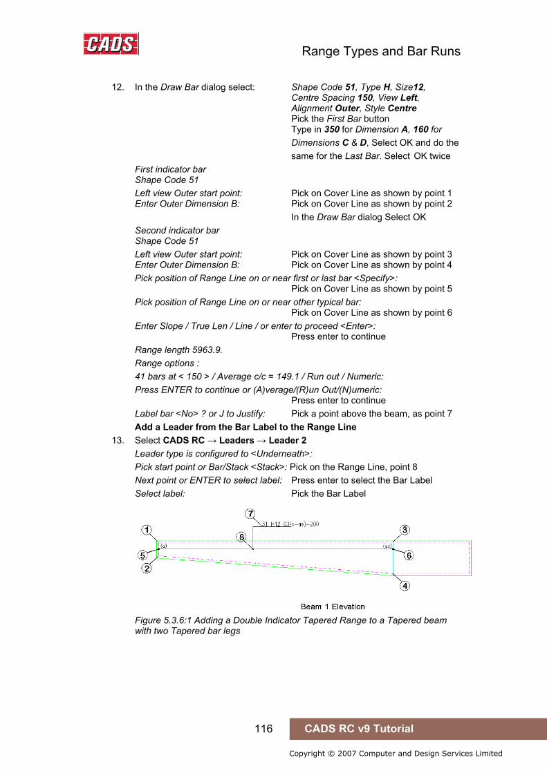
Range Types and Bar Runs
116 CADS RC v9 Tutorial
Copyright © 2007 Computer and Design Services Limited
12. In the Draw Bar dialog select: Shape Code 51, Type H, Size12, Centre Spacing 150, View Left, Alignment Outer, Style Centre Pick the First Bar button Type in 350 for Dimension A, 160 for
Dimensions C & D, Select OK and do the same for the Last Bar. Select OK twice
First indicator bar Shape Code 51 Left view Outer start point: Pick on Cover Line as shown by point 1 Enter Outer Dimension B: Pick on Cover Line as shown by point 2 In the Draw Bar dialog Select OK Second indicator bar Shape Code 51 Left view Outer start point: Pick on Cover Line as shown by point 3 Enter Outer Dimension B: Pick on Cover Line as shown by point 4 Pick position of Range Line on or near first or last bar <Specify>: Pick on Cover Line as shown by point 5 Pick position of Range Line on or near other typical bar: Pick on Cover Line as shown by point 6 Enter Slope / True Len / Line / or enter to proceed <Enter>: Press enter to continue Range length 5963.9. Range options : 41 bars at < 150 > / Average c/c = 149.1 / Run out / Numeric: Press ENTER to continue or (A)verage/(R)un Out/(N)umeric: Press enter to continue Label bar <No> ? or J to Justify: Pick a point above the beam, as point 7 Add a Leader from the Bar Label to the Range Line
13. Select CADS RC → Leaders → Leader 2 Leader type is configured to <Underneath>: Pick start point or Bar/Stack <Stack>: Pick on the Range Line, point 8 Next point or ENTER to select label: Press enter to select the Bar Label Select label: Pick the Bar Label
Figure 5.3.6:1 Adding a Double Indicator Tapered Range to a Tapered beam with two Tapered bar legs

Range Types and Bar Runs
117 CADS RC v9 Tutorial
Copyright © 2007 Computer and Design Services Limited
5.3.7 Varying Taper Range
Figure 5.3.7:1 Varying Taper Range selection buttons
A Varying Taper Range calculates the length of bars based on a closed polyline boundary, circle or ellipse. This Range shows one Bar View and one Range Group. The Bar View is automatically drawn as a sketch bar, something easier and more convenient than calculating the position of an actual tapered bar. After the bar and Range have been drawn the function prompts for the boundary to be selected. It will then generate temporary markers at the points where the bars have been calculated, clearing these later. The Bar Label produced will show the total number of bars together with a configurable suffix relating to the number of bars in the Range. Tapered Ranges can contain suffixes ranging from ‘a’ to ‘zz’ thus giving a maximum of 676 bars (that is, 26 x 26 letter combinations) in any Bar Set. Use a General Run to represent this Range type when placing the bars in a section. This function is most commonly used for any structure where the boundary to be reinforced is non-linear.
Hints & Tips – Varying Taper, Polyline Not Closed
If the function reports that the boundary is not a closed polyline then abort the command and use the AutoCAD Explode command to break the outline apart. Use Polyline Edit to rejoin the lines.
If there is a curve in the boundary, select it last when creating the boundary using the polyline edit command.
If the internal space is clear then rather than tracing the outline of the Varying Taper you should use the AutoCAD Boundary command to create it.
5.3.8 Try It! Varying Taper – Curved Balcony
• In this example you are going to add some main steel to a curved balcony, A closed polyline on the cover layer has already been formed.
Figure 5.3.8:1 below shows the points specified in this example 1. Launch CADS RC 2. Open drawing ...\drawings\CADS RC 16.dwg 3. Set the Working Scale to 1:20 4. Make the Viewport on Slab 1 Layout active
5. Select CADS RC → Draw Bar → Set Member or 6. Make Slab 1 the current Member and select OK
7. Select CADS RC → Draw Bar → Set Drawing Sheet or 8. Make 04 the current Drawing Sheet
Add a Varying Taper Range to the Slab 1 curved balcony with one tapered leg
9. Select CADS RC → Draw Range → New Mark or
Hints & Tips – Varying Taper, Polyline Not Closed
5.3.8 Try It! Varying Taper – Curved Balcony
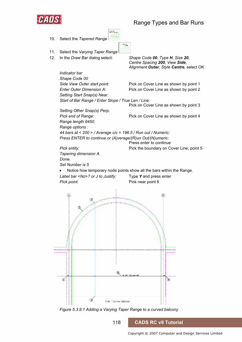
Range Types and Bar Runs
118 CADS RC v9 Tutorial
Copyright © 2007 Computer and Design Services Limited
10. Select the Tapered Range
11. Select the Varying Taper Range 12. In the Draw Bar dialog select: Shape Code 00, Type H, Size 20,
Centre Spacing 200, View Side, Alignment Outer, Style Centre, select OK Indicator bar Shape Code 00 Side View Outer start point: Pick on Cover Line as shown by point 1 Enter Outer Dimension A: Pick on Cover Line as shown by point 2 Setting Start Snap(s) Near. Start of Bar Range / Enter Slope / True Len / Line: Pick on Cover Line as shown by point 3 Setting Other Snap(s) Perp. Pick end of Range: Pick on Cover Line as shown by point 4 Range length 8450. Range options : 44 bars at < 200 > / Average c/c = 196.5 / Run out / Numeric: Press ENTER to continue or (A)verage/(R)un Out/(N)umeric: Press enter to continue Pick entity: Pick the boundary on Cover Line, point 5 Tapering dimension A. Done. Set Number is 5 • Notice how temporary node points show all the bars within the Range. Label bar <No>? or J to Justify: Type Y and press enter Pick point: Pick near point 6
Figure 5.3.8:1 Adding a Varying Taper Range to a curved balcony

Range Types and Bar Runs
119 CADS RC v9 Tutorial
Copyright © 2007 Computer and Design Services Limited
5.3.9 Try It! Add a Varying Taper Range to the Slab 1 Curved Balcony With Two Tapered Legs
• In this example you are going to draw a Shape Code 21 with varying B and D Legs and a constant C Leg. However, in order to ensure that CADS RC prompts to apply the Varying Taper to more than one leg you will also need to add in any dimension needed into the D Leg field.
Figure 5.3.9:2 below shows the points specified in this example 1. Launch CADS RC 2. Open drawing ...\drawings\CADS RC 16.dwg 3. Set the Working scale to 1:20 4. Make the Viewport on Slab 2 Layout active
5. Select CADS RC → Draw Bar → Set Member or 6. Make Slab 2 the current Member and select OK
7. Select CADS RC → Draw Bar → Set Drawing Sheet or 8. Make 05 the current Drawing Sheet
9. Select CADS RC → Draw Range → New Mark or
10. Select the Tapered Range
11. Select the Varying Taper Range 12. In the Draw Bar dialog select: Shape Code 21, Type H, Size 20, Centre
Spacing 200, View Left, Alignment Outer, Style Centre. Select the First and Last Bar buttons and enter a dimension of 300 for Leg B. Select the Set button under Sketch
Bar, choose Shape Code 21, View Left Select the Dimensions button, type 300 into the Leg C field and select OK three times to return to the drawing
Indicator bar Shape Code 21 Left view Outer start point: Pick on Cover Line as shown by point 1 Enter Outer Dimension B: Pick on Cover Line as shown by point 2 Setting Start Snap(s) Near. Start of Bar Range / Enter Slope / True Len / Line: Pick on Cover Line as shown by point 3 Setting Other Snap(s) Perp. Pick end of Range: Pick on Cover Line as shown by point 4 Range length 8450.0. Range options : 44 bars at < 200 > / Average c/c = 196.5 / Run out / Numeric: Press ENTER to continue or (A)verage/(R)un Out/(N)umeric: Press enter to continue Pick entity: Pick the boundary on the Cover Line, point 5
5.3.9 Try It! Add a Varying Taper Range to the Slab 1 Curved Balcony With Two Tapered Legs

Range Types and Bar Runs
120 CADS RC v9 Tutorial
Copyright © 2007 Computer and Design Services Limited
• Path Range can only taper one dimension at a time. Enter dimension to be tapered (A C ) <A>: Press enter to accept Leg A Tapering dimension A
5.3.9:1 CADS RC Tapered Range dialog
Answer yes to apply the dimensions to another bar leg Done Enter dimension to be tapered (A C ) <C>: Type in C and press enter Adjusting dimension Cy Set Number is 8 • Notice how temporary node points show all the bars within the Range. Label bar <No> ? or J to Justify: Type Y and press enter Pick point: Pick near point 6
Figure 5.3.9:2 Adding a Varying Tapered Range to a Curved Balcony with two Tapered bar legs
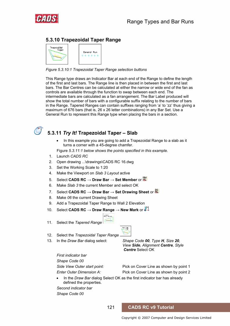
Range Types and Bar Runs
121 CADS RC v9 Tutorial
Copyright © 2007 Computer and Design Services Limited
5.3.10 Trapezoidal Taper Range
Figure 5.3.10:1 Trapezoidal Taper Range selection buttons
This Range type draws an Indicator Bar at each end of the Range to define the length of the first and last bars. The Range line is then placed in between the first and last bars. The Bar Centres can be calculated at either the narrow or wide end of the fan as controls are available through the function to swap between each end. The intermediate bars are calculated as a fan arrangement. The Bar Label produced will show the total number of bars with a configurable suffix relating to the number of bars in the Range. Tapered Ranges can contain suffixes ranging from ‘a’ to ‘zz’ thus giving a maximum of 676 bars (that is, 26 x 26 letter combinations) in any Bar Set. Use a General Run to represent this Range type when placing the bars in a section.
5.3.11 Try It! Trapezoidal Taper – Slab
• In this example you are going to add a Trapezoidal Range to a slab as it turns a corner with a 45-degree chamfer.
Figure 5.3.11:1 below shows the points specified in this example. 1. Launch CADS RC 2. Open drawing ...\drawings\CADS RC 16.dwg 3. Set the Working Scale to 1:20 4. Make the Viewport on Slab 3 Layout active
5. Select CADS RC → Draw Bar → Set Member or 6. Make Slab 3 the current Member and select OK
7. Select CADS RC → Draw Bar → Set Drawing Sheet or 8. Make 06 the current Drawing Sheet 9. Add a Trapezoidal Taper Range to Wall 2 Elevation
10. Select CADS RC → Draw Range → New Mark or
11. Select the Tapered Range
12. Select the Trapezoidal Taper Range 13. In the Draw Bar dialog select: Shape Code 00, Type H, Size 20,
View Side, Alignment Centre, Style Centre Select OK First indicator bar Shape Code 00 Side View Outer start point: Pick on Cover Line as shown by point 1 Enter Outer Dimension A: Pick on Cover Line as shown by point 2 • In the Draw Bar dialog Select OK as the first indicator bar has already
defined the properties. Second indicator bar Shape Code 00
5.3.11 Try It! Trapezoidal Taper – Slab

Range Types and Bar Runs
122 CADS RC v9 Tutorial
Copyright © 2007 Computer and Design Services Limited
Side View Outer start point: Pick on Cover Line as shown by point 3 Enter Outer Dimension A: Pick on Cover Line as shown by point 4 Pick position of Range Line on or near first or last bar <Specify>: Pick on Cover Line as shown by point 5 Pick position of Range Line on or near other typical bar: Pick on Cover Line as shown by point 6 Press 'C' to calc bar numbers along shown line or <ENTER> to swap line: Press enter to swap • Note: by defining the bars from the narrow end to the wide end the
calculation line will be shown as the narrow end and you will be defining the minimum centres. If you wish you can press Enter to move the calculation line to the other end of the bars and you could then calculate the number of bars based on the maximum centres. However, be aware that CADS RC does not check the minimum or maximum centres at the opposite end to test for clashing or for centres being too far apart.
Press 'C' to calc bar numbers along shown line or <ENTER> to swap line: Press enter to swap Press 'C' to calc bar numbers along shown line or <ENTER> to swap line: Type C and press Enter Enter Slope / True Len / Line / or enter to proceed <Enter>: Press enter to continue Range length 3041.4. Centre spacing or <Number of bars> : Type in 100 and press enter Range options : 32 bars at < 100 > / Average c/c = 98.1 / Run out / Numeric: Press ENTER to continue or (A)verage/(R)un Out/(N)umeric: Press enter to accept Set Number is 6 Label bar <No> ? or J to Justify: Type in Y and press enter Pick point: Place label on the Range Line as shown in the figure 5.3.10:1 below. • Note: When the Range is complete CADS RC displays a series of node
points which indicate the bar spacing. These will disappear when you zoom or regenerate the drawing. You can use these points to check the distance between the bars.
Figure 5.3.11:1 Adding a Trapezoidal Taper Range to a Floor Slab
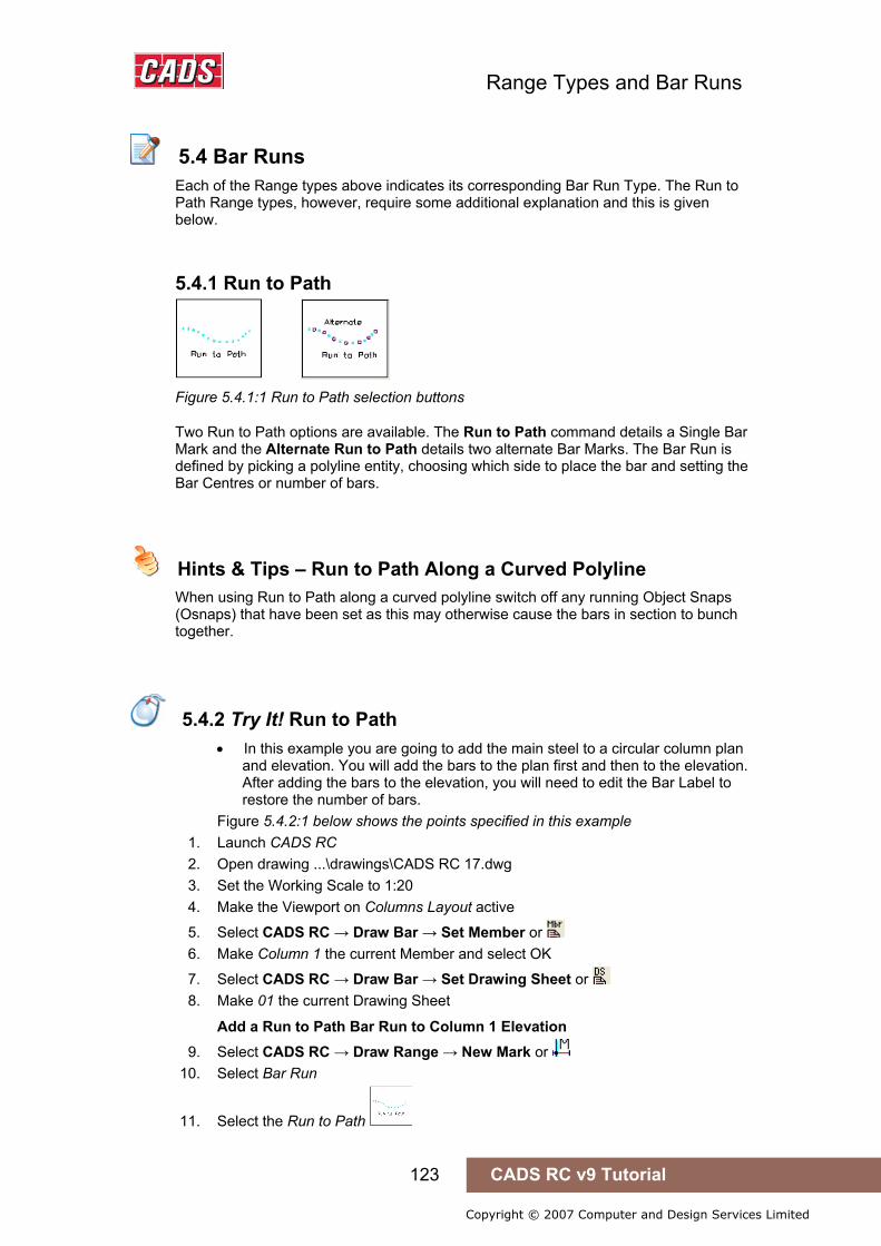
Range Types and Bar Runs
123 CADS RC v9 Tutorial
Copyright © 2007 Computer and Design Services Limited
5.4 Bar Runs
Each of the Range types above indicates its corresponding Bar Run Type. The Run to Path Range types, however, require some additional explanation and this is given below.
5.4.1 Run to Path
Figure 5.4.1:1 Run to Path selection buttons
Two Run to Path options are available. The Run to Path command details a Single Bar Mark and the Alternate Run to Path details two alternate Bar Marks. The Bar Run is defined by picking a polyline entity, choosing which side to place the bar and setting the Bar Centres or number of bars.
Hints & Tips – Run to Path Along a Curved Polyline
When using Run to Path along a curved polyline switch off any running Object Snaps (Osnaps) that have been set as this may otherwise cause the bars in section to bunch together.
5.4.2 Try It! Run to Path
• In this example you are going to add the main steel to a circular column plan and elevation. You will add the bars to the plan first and then to the elevation. After adding the bars to the elevation, you will need to edit the Bar Label to restore the number of bars.
Figure 5.4.2:1 below shows the points specified in this example 1. Launch CADS RC 2. Open drawing ...\drawings\CADS RC 17.dwg 3. Set the Working Scale to 1:20 4. Make the Viewport on Columns Layout active
5. Select CADS RC → Draw Bar → Set Member or 6. Make Column 1 the current Member and select OK
7. Select CADS RC → Draw Bar → Set Drawing Sheet or 8. Make 01 the current Drawing Sheet
Add a Run to Path Bar Run to Column 1 Elevation 9. Select CADS RC → Draw Range → New Mark or
10. Select Bar Run
11. Select the Run to Path
5.4 Bar Runs
Hints & Tips – Run to Path Along a Curved Polyline
5.4.2 Try It! Run to Path
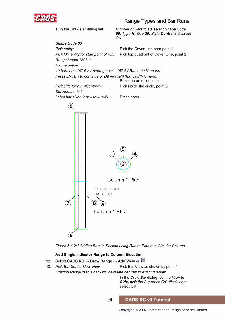
Range Types and Bar Runs
124 CADS RC v9 Tutorial
Copyright © 2007 Computer and Design Services Limited
a. In the Draw Bar dialog set: Number of Bars to 10, select Shape Code 00, Type H, Size 20, Style Centre and select OK
Shape Code 00 Pick entity: Pick the Cover Line near point 1 Pick ON entity for start point of run: Pick top quadrant of Cover Line, point 2 Range length 1508.0. Range options : 10 bars at < 167.6 > / Average c/c = 167.6 / Run out / Numeric: Press ENTER to continue or (A)verage/(R)un Out/(N)umeric: Press enter to continue Pick side for run <Centred>: Pick inside the circle, point 3 Set Number is 3 Label bar <No> ? or J to Justify: Press enter
Figure 5.4.2:1 Adding Bars in Section using Run to Path to a Circular Column
Add Single Indicator Range to Column Elevation 12. Select CADS RC → Draw Range → Add View or 13. Pick Bar Set for New View: Pick Bar View as shown by point 4
Existing Range of this bar - will calculate centres to existing length In the Draw Bar dialog, set the View to Side, pick the Suppress C/C display and select OK
Range Types and Bar Runs
125 CADS RC v9 Tutorial
Copyright © 2007 Computer and Design Services Limited
Indicator bar Shape Code 00 Side View Outer start point: Pick on Cover Line as shown by point 5 Enter Outer Dimension B: Pick on Cover Line as shown by point 6 Setting Start Snap(s) Near Start of Bar Range / Enter Slope / True Len / Line: Pick on Cover Line as shown by point 7 Setting Other Snap(s) Perp Pick end of Range: Pick on Cover Line as shown by point 8 Range length 500.0 Label bar <No> ? or J to Justify: Type Y and press enter Pick point: Place label near point 9
Hints & Tips – Resetting the Number of Bars
If the number of bars in the Bar Label updates to show the wrong number, double pick the Bar Label, type in the number of bars (for instance, 10 in this case) and select OK. Chapter 7, Edit and Modify commands, give more information on editing bar and range data.
5.4.3 Try It! Alternate Run to Path
Figure 5.4.3:1 below shows the points specified in this example 1. Launch CADS RC 2. Open drawing ...\drawings\CADS RC 17.dwg 3. Set the Working Scale at 1:20 4. Make the Viewport on Wall 1 Layout active
5. Select CADS RC → Draw Bar → Set Member or . 6. Make Wall 1 the current Member and select OK.
7. Select CADS RC → Draw Bar → Set Drawing Sheet or 8. Make 02 the current Drawing Sheet
Add a Run to Path Bar Run to Column 1 Elevation 9. Select CADS RC → Draw Range → New Mark or
10. Select Bar Run
11. Select the Alternate Run to Path 12. In the Draw Bar dialog for the first bar select:
Shape Code 00, Type H, Size 20 Select OK First bar: Shape Code 00
13. In the Draw Bar dialog for the first bar select: Shape Code 00, Type H, Size 40 Select OK
Hints & Tips – Resetting the Number of Bars
5.4.3 Try It! Alternate Run to Path
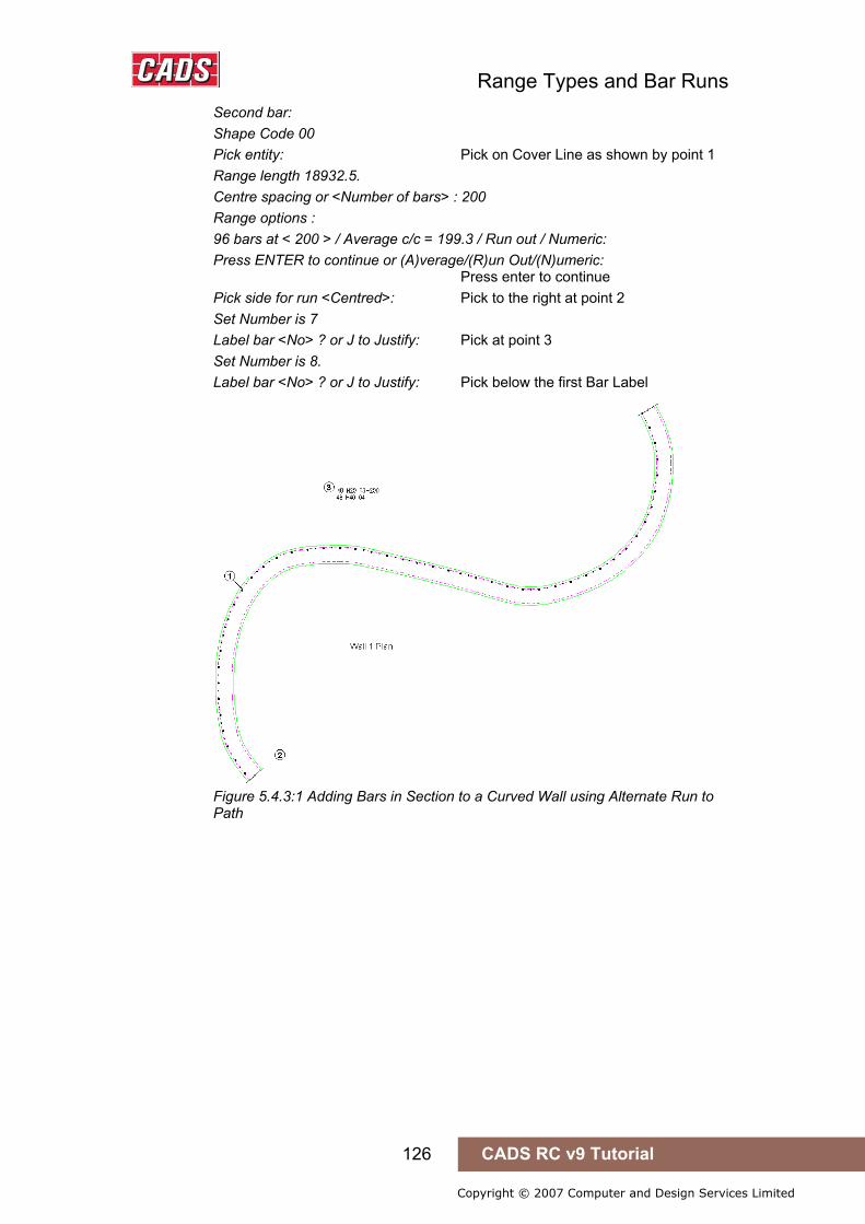
Range Types and Bar Runs
126 CADS RC v9 Tutorial
Copyright © 2007 Computer and Design Services Limited
Second bar: Shape Code 00 Pick entity: Pick on Cover Line as shown by point 1 Range length 18932.5. Centre spacing or <Number of bars> : 200 Range options : 96 bars at < 200 > / Average c/c = 199.3 / Run out / Numeric: Press ENTER to continue or (A)verage/(R)un Out/(N)umeric: Press enter to continue Pick side for run <Centred>: Pick to the right at point 2 Set Number is 7 Label bar <No> ? or J to Justify: Pick at point 3 Set Number is 8. Label bar <No> ? or J to Justify: Pick below the first Bar Label
Figure 5.4.3:1 Adding Bars in Section to a Curved Wall using Alternate Run to Path

Range Types and Bar Runs
127 CADS RC v9 Tutorial
Copyright © 2007 Computer and Design Services Limited
5.5 OSL Groups and Ranges
The only Range types that are supported are Single Indicator, Double Indicator and Double Indicator Taper. The OSL dialog box will be displayed if the length of the bar is over the Stock Length. In the Configuration dialog an additional prompt is available which will place Range Lines for each of the OSL bars in the group: this marked in red in figure 5.5:1 below.
Figure 5.5:1 CADS RC Over Stock Length Configuration dialog
5.5.1 Try It! Adding OSL Bars and Ranges to a Floor Slab
Figure 5.5.1:3 below shows the points specified in this example. 1. Launch CADS RC 2. Open drawing ...\drawings\CADS RC 17.dwg 3. Set the Working Scale to 1:50 4. Make the Viewport on Slab 1 Layout active
5. Select CADS RC → Draw Bar → Set Member or 6. Make Slab 1 the current Member and select OK
7. Select CADS RC → Draw Bar → Set Drawing Sheet or 8. Make 03 the current Drawing Sheet
9. Select CADS RC → Draw Bar →Set Over Stock Length or Enter the value for Over Stock Length <12000.0> : Type in 9000 and press Enter
10. Select CADS RC → Draw Range → New Mark or
11. Select the Single Indicator Range
5.5 OSL Groups and Ranges
5.5.1 Try It! Adding OSL Bars and Ranges to a Floor Slab

Range Types and Bar Runs
128 CADS RC v9 Tutorial
Copyright © 2007 Computer and Design Services Limited
12. In the Draw Bar dialog for the first bar select: Shape Code 00, Type H, Size 20, Centres 200, View Side, Alignment Outer, Style Centre and select OK Indicator bar Shape Code 00 Side View Outer start point: Pick on Cover Line as shown by point 1 Enter Outer Dimension A: Pick on Cover Line as shown by point 2
Figure 5.5.1:1 Invoke OSL Feature dialog
13. Answer Yes to the Invoke OSL?
Figure 5.5.1:2 CADS RC Over Stock Length Configuration dialog
14. In the OSL Configuration dialog choose Option 4 with the Splice Lines. Select Configuration and ensure that the dialog is set-up as shown in figure 5.5.1:2.
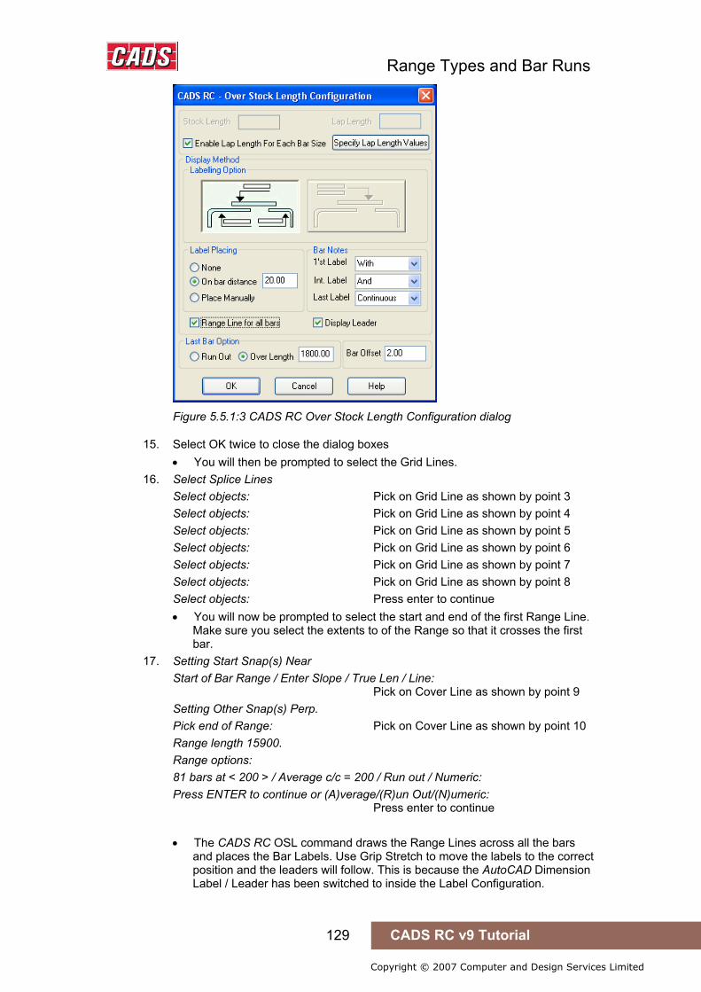
Range Types and Bar Runs
129 CADS RC v9 Tutorial
Copyright © 2007 Computer and Design Services Limited
Figure 5.5.1:3 CADS RC Over Stock Length Configuration dialog
15. Select OK twice to close the dialog boxes • You will then be prompted to select the Grid Lines.
16. Select Splice Lines Select objects: Pick on Grid Line as shown by point 3 Select objects: Pick on Grid Line as shown by point 4 Select objects: Pick on Grid Line as shown by point 5 Select objects: Pick on Grid Line as shown by point 6 Select objects: Pick on Grid Line as shown by point 7 Select objects: Pick on Grid Line as shown by point 8 Select objects: Press enter to continue • You will now be prompted to select the start and end of the first Range Line.
Make sure you select the extents to of the Range so that it crosses the first bar.
17. Setting Start Snap(s) Near Start of Bar Range / Enter Slope / True Len / Line: Pick on Cover Line as shown by point 9 Setting Other Snap(s) Perp. Pick end of Range: Pick on Cover Line as shown by point 10 Range length 15900. Range options: 81 bars at < 200 > / Average c/c = 200 / Run out / Numeric: Press ENTER to continue or (A)verage/(R)un Out/(N)umeric: Press enter to continue • The CADS RC OSL command draws the Range Lines across all the bars
and places the Bar Labels. Use Grip Stretch to move the labels to the correct position and the leaders will follow. This is because the AutoCAD Dimension Label / Leader has been switched to inside the Label Configuration.

Range Types and Bar Runs
130 CADS RC v9 Tutorial
Copyright © 2007 Computer and Design Services Limited
Figure 5.5.1:4 Adding OSL Bars and Ranges to a Floor Slab
5.5.2 Try It! Draw a Retaining Wall
Figures 5.5.2:1, 5.5.2:2 and 5.5.2:3 below show the finished retaining wall details specified in this example.
1. Launch CADS RC 2. Open drawing ...\drawings\Retaining Wall.dwg 3. Set the Working Scale to 1:20 4. Make the Viewport on Retaining Wall (02) Layout active
5. Select CADS RC → Draw Bar → Set Member or 6. Make Retaining Wall the current Member and select OK
7. Select CADS RC → Draw Bar → Set Drawing Sheet or 8. Make 02 the current Drawing Sheet
The purpose of this Try It! is to detail a concrete retaining wall, add all the labelling and take advantage of the multiplier field in the draw bar dialog box. Using the finished details below as a guide add the reinforcement to the retaining wall plan, section and elevation. This will demonstrate a sufficient level of understanding and knowledge to detail simple reinforced structures.
5.5.2 Try It! Drawing a Retaining Wall

Range Types and Bar Runs
131 CADS RC v9 Tutorial
Copyright © 2007 Computer and Design Services Limited
Figure 5.5.2:1 Section A-A
Figure 5.5.2:2 Retaining Wall Plan View
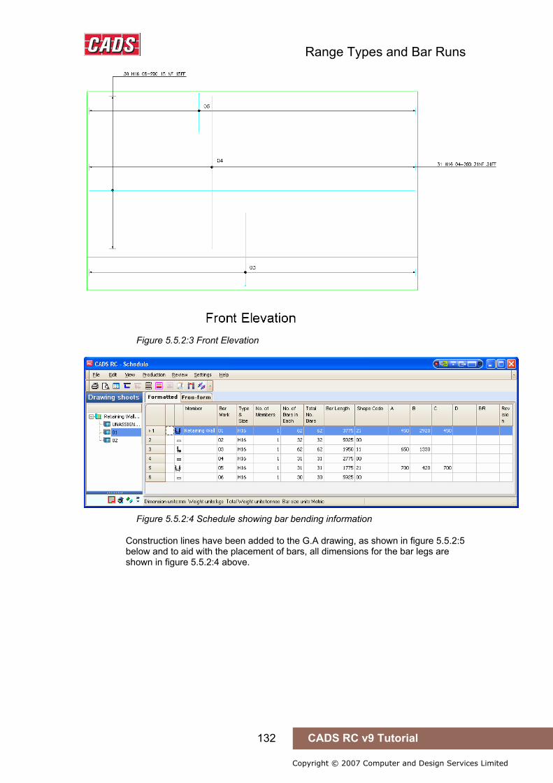
Range Types and Bar Runs
132 CADS RC v9 Tutorial
Copyright © 2007 Computer and Design Services Limited
Figure 5.5.2:3 Front Elevation
Figure 5.5.2:4 Schedule showing bar bending information
Construction lines have been added to the G.A drawing, as shown in figure 5.5.2:5 below and to aid with the placement of bars, all dimensions for the bar legs are shown in figure 5.5.2:4 above.

Range Types and Bar Runs
133 CADS RC v9 Tutorial
Copyright © 2007 Computer and Design Services Limited
Figure 5.5.2:4 Retaining Wall Outlines
Range Types and Bar Runs
134 CADS RC v9 Tutorial
Copyright © 2007 Computer and Design Services Limited
5.6 Key points – Range Types and Bar Runs
• Ranges can be roughly broken up into five groups: Single Group Ranges Multiple Group Ranges Radial Ranges Tapered Ranges Bar Runs
• Use the Range Configuration to switch off the Range offset prompt and set the Start and Other Range Snaps.
• Bar Runs can be quickly placed on the bar leg by picking the leg when prompted to start the Range.
• Use the Multi field in the Draw Bar dialog to multiply the number of bars drawn, for example the top and bottom faces.
• In the Staggered Ranges the bars can be either offset or reversed. • Use setting out construction lines for calculating the length of radial bars
graphically. • With Alternate Ranges draw the bars in the full side view of the bar or
manually input the dimensions before drawing the Range. Editing is limited on this Range type.
• You can use the Slope/True Length/Line option inside the Range command Set An Angle when drawing a Plan View.
• When detailing Tapered Ranges always start with the Range and not the individual Bar Views.
• When detailing a Tapered Range start with the shortest bar first as this will allow you to apply a step taper.
• You can taper more than one leg on a bar. • Varying Taper Range will only work with a closed polyline boundary. If the
function fails to recognise the boundary, explode it and recreate it with the Polyline Edit command.
• If you need to have more than one leg tapered when using the Varying Taper command remember to add a dimension for the additional leg in the Sketch Bar dialog.
• Sketch bars can be used to show a projected view of a bar. • The spacing on a Trapezoidal Taper can be calculated on the short or long
edge. • Use the Multiple Group Ranges to detail around holes and to adjust to show
changes of angle in a structure. • Range Offsets can be preset to a required distance in the Range
Configuration. This could be half a bar diameter to give automatic offsets from the start and end of Range if the offsets are disabled.
• Range Offsets can be disabled in the Range Configuration. • Object Snaps can be added to the Start and Other Range Snaps in the
Range Configuration. • Over Stock Length (OSL) bars can only be detailed with Double Indicator
Taper Ranges and Single and Double Indicator Ranges.
5.6 Key points – Range Types and Bar Runs
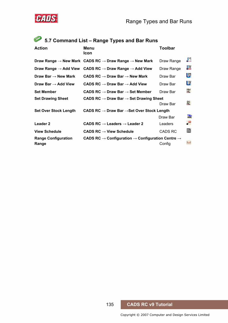
Range Types and Bar Runs
135 CADS RC v9 Tutorial
Copyright © 2007 Computer and Design Services Limited
5.7 Command List – Range Types and Bar Runs
Action Menu Toolbar Icon
Draw Range → New Mark CADS RC → Draw Range → New Mark Draw Range
Draw Range → Add View CADS RC → Draw Range → Add View Draw Range
Draw Bar → New Mark CADS RC → Draw Bar → New Mark Draw Bar
Draw Bar → Add View CADS RC → Draw Bar → Add View Draw Bar
Set Member CADS RC → Draw Bar → Set Member Draw Bar
Set Drawing Sheet CADS RC → Draw Bar → Set Drawing Sheet Draw Bar
Set Over Stock Length CADS RC → Draw Bar →Set Over Stock Length Draw Bar
Leader 2 CADS RC → Leaders → Leader 2 Leaders
View Schedule CADS RC → View Schedule CADS RC
Range Configuration CADS RC → Configuration → Configuration Centre → Range Config
5.7 Command List – Range Types and Bar Runs

Labeling Commands
136 CADS RC v9 Tutorial
Copyright © 2007 Computer and Design Services Limited
6: Labelling Commands
6.0 Introduction
Each Bar Set on the drawing requires a Bar Label (call off) to be complete. CADS RC is designed to allow a user to add only one Bar Label per Bar Set. Additional labels such as bar references, which show either the bar length or the Bar Mark, and Ticks and Tags (end of bar indicators) can be added. You can Mask the Bar Label text, that is, leave a clear space around the text either individually or for the whole drawing if it becomes congested.
The tools for adding text to the Bars Set are found on the CADS RC pull down menu under Labelling.
6.0 Introduction
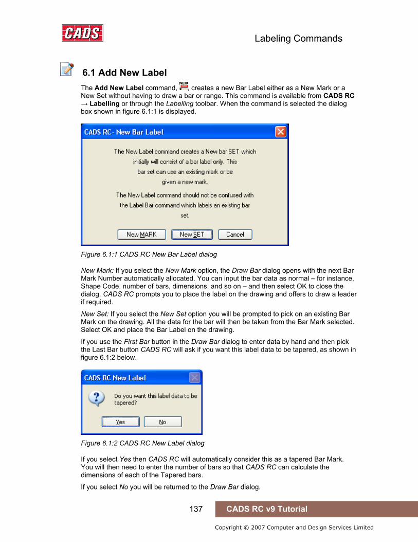
Labeling Commands
137 CADS RC v9 Tutorial
Copyright © 2007 Computer and Design Services Limited
6.1 Add New Label
The Add New Label command, , creates a new Bar Label either as a New Mark or a New Set without having to draw a bar or range. This command is available from CADS RC → Labelling or through the Labelling toolbar. When the command is selected the dialog box shown in figure 6.1:1 is displayed.
Figure 6.1:1 CADS RC New Bar Label dialog
New Mark: If you select the New Mark option, the Draw Bar dialog opens with the next Bar Mark Number automatically allocated. You can input the bar data as normal – for instance, Shape Code, number of bars, dimensions, and so on – and then select OK to close the dialog. CADS RC prompts you to place the label on the drawing and offers to draw a leader if required.
New Set: If you select the New Set option you will be prompted to pick on an existing Bar Mark on the drawing. All the data for the bar will then be taken from the Bar Mark selected. Select OK and place the Bar Label on the drawing.
If you use the First Bar button in the Draw Bar dialog to enter data by hand and then pick the Last Bar button CADS RC will ask if you want this label data to be tapered, as shown in figure 6.1:2 below.
Figure 6.1:2 CADS RC New Label dialog
If you select Yes then CADS RC will automatically consider this as a tapered Bar Mark. You will then need to enter the number of bars so that CADS RC can calculate the dimensions of each of the Tapered bars.
If you select No you will be returned to the Draw Bar dialog.
6.1 Add New Label

Labeling Commands
138 CADS RC v9 Tutorial
Copyright © 2007 Computer and Design Services Limited
This command is very useful if you simply want to add stock steel to the drawing or perhaps add a Bar Label to an existing range. If you have already detailed the top steel, for instance, you can then use the New Label command to add the bottom steel rather than having to detail the whole range again. However, note that if you choose to edit the range you will need to edit the Bar Label separately as the two are not automatically linked. There are better techniques to produce two labels on one Range Line and these are covered later in Chapter 7, Edit and Modify commands.

Labeling Commands
139 CADS RC v9 Tutorial
Copyright © 2007 Computer and Design Services Limited
6.2 Label an Existing Bar
The Label an Existing Bar command, , will add a Bar Label to an existing set of bars on a drawing that has not already been labelled. This command is accessible through CADS RC → Labelling or from the Labelling toolbar. If the set has already been labelled then CADS RC will report, Bar Set already labelled and abort the command. Only one Bar Label can be shown per Bar Set on the drawing.
The command will prompt you to select a bar or to press Enter for a multiple selection of Bar Sets, thus: Pick bar/label to edit or <ENTER> for multiple selection:
6.2.1 Labelling an Individual Bar If you pick a single Bar Label you will be prompted for the Bar Label location and rotation and then for the start point of the leader on the bar or range.
Pick Bar Label location: Rotation angle: Pick point on bar:
6.2.2 Placing a Selection of Bar Labels If you press Enter to invoke the Selection then you can pick several bars. The command cycles through the bars asking of each:
Link label to bar/range with leader (Yes/No/Always) <Yes>: • If you answer Yes you are then asked to pick the start point of a leader to
become part of the Bar Set.
In each case the leader drawn is either going to be Leader 1 or the Leader for the current Dimension Style depending on whether the Dimension Label/Leader option is switched Off or On inside the Label Configuration dialog.
6.2 Label an Existing Bar
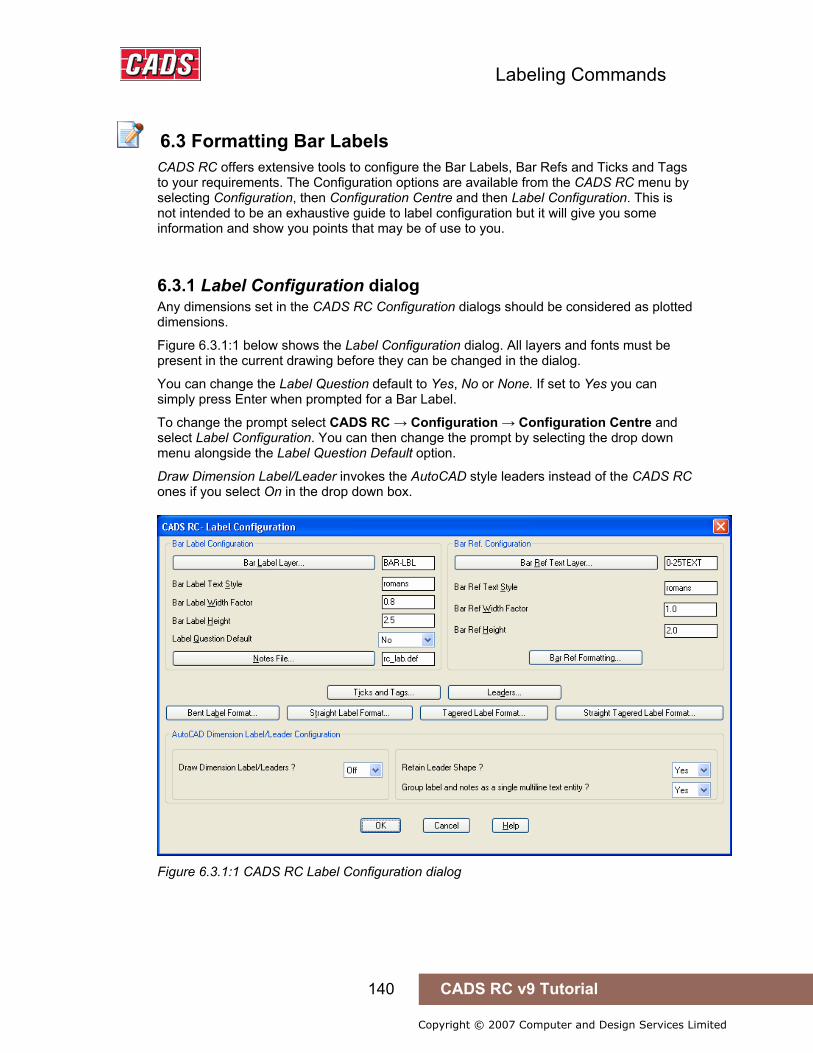
Labeling Commands
140 CADS RC v9 Tutorial
Copyright © 2007 Computer and Design Services Limited
6.3 Formatting Bar Labels
CADS RC offers extensive tools to configure the Bar Labels, Bar Refs and Ticks and Tags to your requirements. The Configuration options are available from the CADS RC menu by selecting Configuration, then Configuration Centre and then Label Configuration. This is not intended to be an exhaustive guide to label configuration but it will give you some information and show you points that may be of use to you.
6.3.1 Label Configuration dialog Any dimensions set in the CADS RC Configuration dialogs should be considered as plotted dimensions.
Figure 6.3.1:1 below shows the Label Configuration dialog. All layers and fonts must be present in the current drawing before they can be changed in the dialog.
You can change the Label Question default to Yes, No or None. If set to Yes you can simply press Enter when prompted for a Bar Label.
To change the prompt select CADS RC → Configuration → Configuration Centre and select Label Configuration. You can then change the prompt by selecting the drop down menu alongside the Label Question Default option.
Draw Dimension Label/Leader invokes the AutoCAD style leaders instead of the CADS RC ones if you select On in the drop down box.
Figure 6.3.1:1 CADS RC Label Configuration dialog
6.3 Formatting Bar Labels
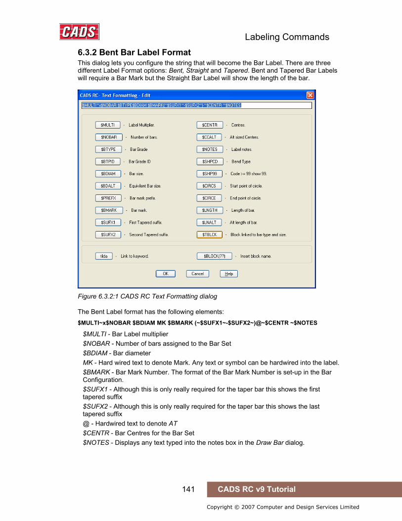
Labeling Commands
141 CADS RC v9 Tutorial
Copyright © 2007 Computer and Design Services Limited
6.3.2 Bent Bar Label Format This dialog lets you configure the string that will become the Bar Label. There are three different Label Format options: Bent, Straight and Tapered. Bent and Tapered Bar Labels will require a Bar Mark but the Straight Bar Label will show the length of the bar.
Figure 6.3.2:1 CADS RC Text Formatting dialog
The Bent Label format has the following elements: $MULTI~x$NOBAR $BDIAM MK $BMARK (~$SUFX1~-$SUFX2~)@~$CENTR ~$NOTES
$MULTI - Bar Label multiplier $NOBAR - Number of bars assigned to the Bar Set $BDIAM - Bar diameter MK - Hard wired text to denote Mark. Any text or symbol can be hardwired into the label. $BMARK - Bar Mark Number. The format of the Bar Mark Number is set-up in the Bar Configuration. $SUFX1 - Although this is only really required for the taper bar this shows the first tapered suffix $SUFX2 - Although this is only really required for the taper bar this shows the last tapered suffix @ - Hardwired text to denote AT $CENTR - Bar Centres for the Bar Set $NOTES - Displays any text typed into the notes box in the Draw Bar dialog.
Labeling Commands
142 CADS RC v9 Tutorial
Copyright © 2007 Computer and Design Services Limited
6.3.3 Straight Bar Label Format $MULTI~x$NOBAR $BDIAM X $LNGTH (~$SUFX1~-$SUFX2~)@~$CENTR ~$NOTES
The Straight Bar Label Format only varies in that the MK and $BMARK are replaced with $LNGTH, which shows the total length of the bar.
You can move, delete from or add to the keywords in the Bar Label format to create your own style of Bar Label.
6.3.4 Bar Mark Format To access the Bar Mark Format dialog, open the Bar Configuration dialog from the Configuration Centre and select the Bar Marking button.
The Bent Label Format is displayed as $PREFX$BDIAM$BMARK which will show as Prefix, Bar Diameter and then the Bar Mark.
The Straight Label Format is displayed as $PREFXS$BMARK which will show the Prefix and the Bar Mark.
By default the program is shipped not to show Bar Marks for Straight Bars.
Hints & Tips - Placing a Circle Around the Bar Mark
You can configure CADS RC to show a circle around the Bar Mark. Do this by preceding $BMARK with $CIRCS and following it by $CIRCE (Circle Start and Circle End) as shown below. CADS RC will draw a circle large enough to enclose the Bar Mark Number.
$CIRCS$BMARK$CIRCE
Hints & Tips – Showing Configuration Changes
You can update any changes to the label configuration by using the Redraw Bar command, accessible from the CADS RC → Editing pull-down menu.
Hints & Tips - Placing a Circle Around the Bar Mark
Hints & Tips – Showing Configuration Changes
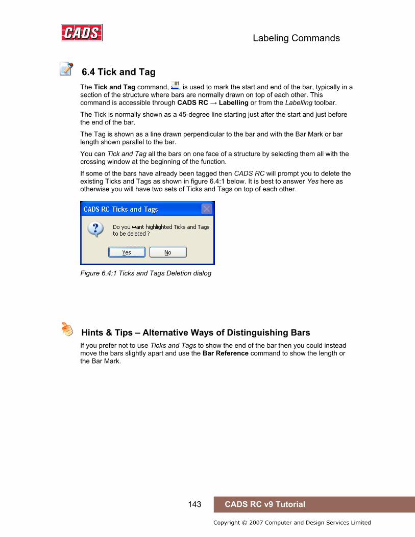
Labeling Commands
143 CADS RC v9 Tutorial
Copyright © 2007 Computer and Design Services Limited
6.4 Tick and Tag
The Tick and Tag command, , is used to mark the start and end of the bar, typically in a section of the structure where bars are normally drawn on top of each other. This command is accessible through CADS RC → Labelling or from the Labelling toolbar.
The Tick is normally shown as a 45-degree line starting just after the start and just before the end of the bar.
The Tag is shown as a line drawn perpendicular to the bar and with the Bar Mark or bar length shown parallel to the bar.
You can Tick and Tag all the bars on one face of a structure by selecting them all with the crossing window at the beginning of the function.
If some of the bars have already been tagged then CADS RC will prompt you to delete the existing Ticks and Tags as shown in figure 6.4:1 below. It is best to answer Yes here as otherwise you will have two sets of Ticks and Tags on top of each other.
Figure 6.4:1 Ticks and Tags Deletion dialog
Hints & Tips – Alternative Ways of Distinguishing Bars
If you prefer not to use Ticks and Tags to show the end of the bar then you could instead move the bars slightly apart and use the Bar Reference command to show the length or the Bar Mark.
6.4 Tick and Tag
Hints & Tips – Alternative Ways of Distinguishing Bars

Labeling Commands
144 CADS RC v9 Tutorial
Copyright © 2007 Computer and Design Services Limited
6.5 Tick and Tag to a Line
The Tick and Tag to a Line command, , gives the same result as the standard Tick and Tag command but allows you to specify a line on which to align the tags. You can invoke this command through CADS RC → Labelling or from the Labelling toolbar. The command is very useful anywhere that you need to align tags to each other, for instance on sloping sections such as staircases or circular sump tanks.
Figure 6.5:1 Ticks and Tags added to Straight Bars
6.5 Tick and Tag to a Line
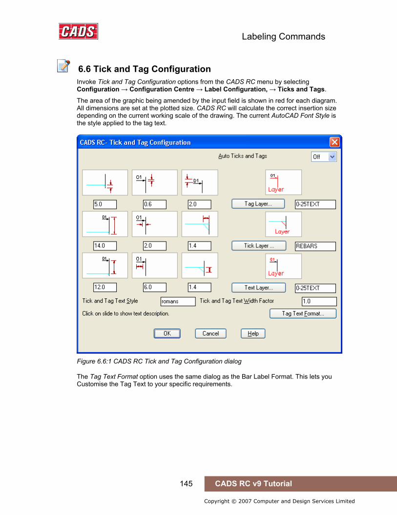
Labeling Commands
145 CADS RC v9 Tutorial
Copyright © 2007 Computer and Design Services Limited
6.6 Tick and Tag Configuration
Invoke Tick and Tag Configuration options from the CADS RC menu by selecting Configuration → Configuration Centre → Label Configuration, → Ticks and Tags.
The area of the graphic being amended by the input field is shown in red for each diagram. All dimensions are set at the plotted size. CADS RC will calculate the correct insertion size depending on the current working scale of the drawing. The current AutoCAD Font Style is the style applied to the tag text.
Figure 6.6:1 CADS RC Tick and Tag Configuration dialog
The Tag Text Format option uses the same dialog as the Bar Label Format. This lets you Customise the Tag Text to your specific requirements.
6.6 Tick and Tag Configuration

Labeling Commands
146 CADS RC v9 Tutorial
Copyright © 2007 Computer and Design Services Limited
6.7 Adding Bar References
The Add Bar Reference command, , generates text and allows you to add this to the drawing to show, for instance, the Bar Mark Number for bent bars or the bar length for Straight Bars. This command is accessible through CADS RC → Labelling or from the Labelling toolbar. You can configure the reference text to show different information.
You can use the Add Bar Reference command to add information in respect of individual bars, runs of bars or multiple sets of bars. The Bar Refs are linked as Views to the Bar Set and any change in the Bar Mark Number or bar length will automatically be shown in the Bar Reference. You can use AutoCAD Move to reposition the Bar Refs. You can use the Bar Refs when prompted to pick a Bar Set when detailing a New Set or Add View.
The command will prompt you to select a bar or to press Enter for a multiple selection of Bar Sets, thus: Pick bar of required Bar Mark or ENTER for selection:
6.7.1 Placing an Individual Bar Reference If you pick a bar on the drawing you are then prompted to pick an insertion point.
Pick insertion point for bar reference Angle/Reset/<point>: Pick insertion point for bar reference Angle/Reset/<point>:
Once you have finished placing Bar Refs press Enter to finish and exit the command.
6.7.2 Placing a Selection of Bar References If you press Enter to invoke the Selection you will be initially prompted for the angle of the text and then asked to select the bars either individually or by using a window.
Please set angle of bar Reference text Reset/Angle <0.00>: Select bar dots to be referenced Reset: Select objects: Specify opposite corner: 5 found Select objects: Press Enter to continue • Next you are prompted for a reference line and this dictates the insertion point
on the bar refs. Start of reference line: Pick a point End of reference line: Pick a point
Press Enter to finish and exit the command when you have finished selecting objects.
Figure 6.7.2:1 Bar Refs added to a Run of Bars in Section
6.7 Adding Bar References
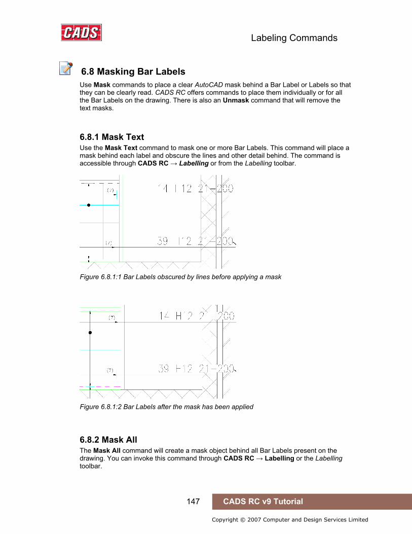
Labeling Commands
147 CADS RC v9 Tutorial
Copyright © 2007 Computer and Design Services Limited
6.8 Masking Bar Labels
Use Mask commands to place a clear AutoCAD mask behind a Bar Label or Labels so that they can be clearly read. CADS RC offers commands to place them individually or for all the Bar Labels on the drawing. There is also an Unmask command that will remove the text masks.
6.8.1 Mask Text Use the Mask Text command to mask one or more Bar Labels. This command will place a mask behind each label and obscure the lines and other detail behind. The command is accessible through CADS RC → Labelling or from the Labelling toolbar.
Figure 6.8.1:1 Bar Labels obscured by lines before applying a mask
Figure 6.8.1:2 Bar Labels after the mask has been applied
6.8.2 Mask All The Mask All command will create a mask object behind all Bar Labels present on the drawing. You can invoke this command through CADS RC → Labelling or the Labelling toolbar.
6.8 Masking Bar Labels

Labeling Commands
148 CADS RC v9 Tutorial
Copyright © 2007 Computer and Design Services Limited
6.8.3 Unmask All The Unmask All command removes any mask objects that are on the drawing. This command is accessible through CADS RC → Labelling or the Labelling toolbar.
6.9 Toggle Hidden Multipliers
6.9.1 Apply Hidden Multipliers Inside the Draw Bar dialog Hidden Multipliers can be added to the Multi field inside the Draw Bar dialog box so that bars can be multiplied inside the Schedule without the additional numbers appearing on the Bar Label. The second number added to the multiplier field will not be displayed on the Bar Label unless the Hidden Multiplier toggle is switched off.
If you had ten bars and set the Multi field to 5*4, for example, the Bar Label would then show 5 x 10 bars and the Schedule would show a total of 200 for that Bar Set.
If Suppress Label Multiply were applied in the Draw Bar dialog the number of bars on the label would show instead as 50.
If you reversed the Multi field to 4*5 the Bar Label would show either 4 x 10 or 40 bars depending on whether the Suppress Label Multiply field was selected. The Schedule would still show 200 bars.
This feature is useful for detailing bundled bars.
6.9.2 Toggling the Hidden Multiplier If you use this toggle to display the hidden multiplier the Bar Label described in the example above would change from 50 bars to 4 x 50 bars to show the true number detailed. You can invoke the Toggle Hidden Multiplier command through CADS RC → Labelling or from the Labelling toolbar, .
6.9 Toggle Hidden Multipliers
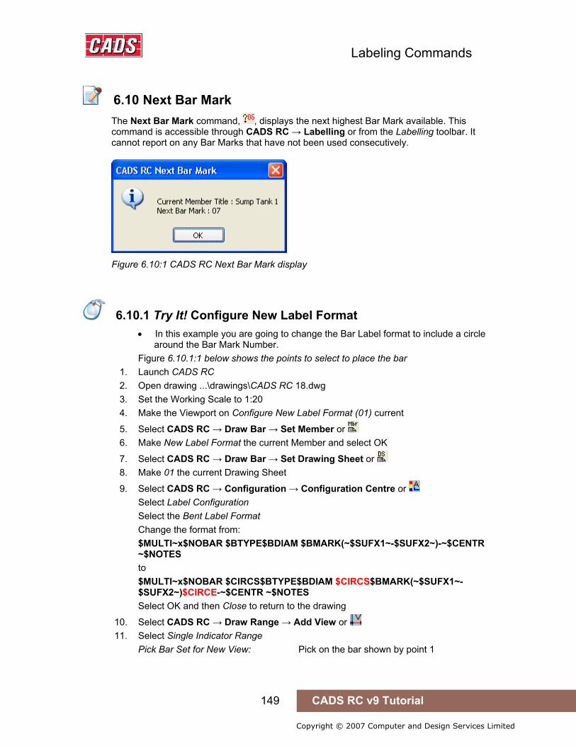
Labeling Commands
149 CADS RC v9 Tutorial
Copyright © 2007 Computer and Design Services Limited
6.10 Next Bar Mark
The Next Bar Mark command, , displays the next highest Bar Mark available. This command is accessible through CADS RC → Labelling or from the Labelling toolbar. It cannot report on any Bar Marks that have not been used consecutively.
Figure 6.10:1 CADS RC Next Bar Mark display
6.10.1 Try It! Configure New Label Format
• In this example you are going to change the Bar Label format to include a circle around the Bar Mark Number.
Figure 6.10.1:1 below shows the points to select to place the bar 1. Launch CADS RC 2. Open drawing ...\drawings\CADS RC 18.dwg 3. Set the Working Scale to 1:20 4. Make the Viewport on Configure New Label Format (01) current
5. Select CADS RC → Draw Bar → Set Member or 6. Make New Label Format the current Member and select OK
7. Select CADS RC → Draw Bar → Set Drawing Sheet or 8. Make 01 the current Drawing Sheet
9. Select CADS RC → Configuration → Configuration Centre or Select Label Configuration Select the Bent Label Format Change the format from: $MULTI~x$NOBAR $BTYPE$BDIAM $BMARK(~$SUFX1~-$SUFX2~)-~$CENTR ~$NOTES to $MULTI~x$NOBAR $CIRCS$BTYPE$BDIAM $CIRCS$BMARK(~$SUFX1~-$SUFX2~)$CIRCE-~$CENTR ~$NOTES Select OK and then Close to return to the drawing
10. Select CADS RC → Draw Range → Add View or 11. Select Single Indicator Range
Pick Bar Set for New View: Pick on the bar shown by point 1
6.10 Next Bar Mark
6.10.1 Try It! Configure New Label Format

Labeling Commands
150 CADS RC v9 Tutorial
Copyright © 2007 Computer and Design Services Limited
In the Draw Bar dialog set the View to Plan and the Centres to 200 Indicator bar Shape Code 3c. Plan View Outer start point: Pick on the Cover Line shown by point 2 Enter Outer Dimension O: Switch Ortho On. Pick to the right at point 3 Setting Start Snap(s) Near. Start of bar range / Enter Slope / True Len / Line: Pick on the Cover Line shown by point 4 Setting Other Snap(s) Perp. Pick End of range: Pick on the Cover Line shown by point 5 Range length 1020.0. Range options: 8 bars at < 150 > / Average c/c = 145.7 / Run out / Numeric: Press ENTER to continue or (A)verage/(R)un Out/(N)umeric: Press enter to continue Set Number is 2. Label bar <No>? or J to Justify: Type Y and press enter
Pick point: Pick on the construction line at point 6 • The Bar Label now shows the circle around the Bar Mark
Figure 6.10.1:1 Bar Label for cranked bars showing new format
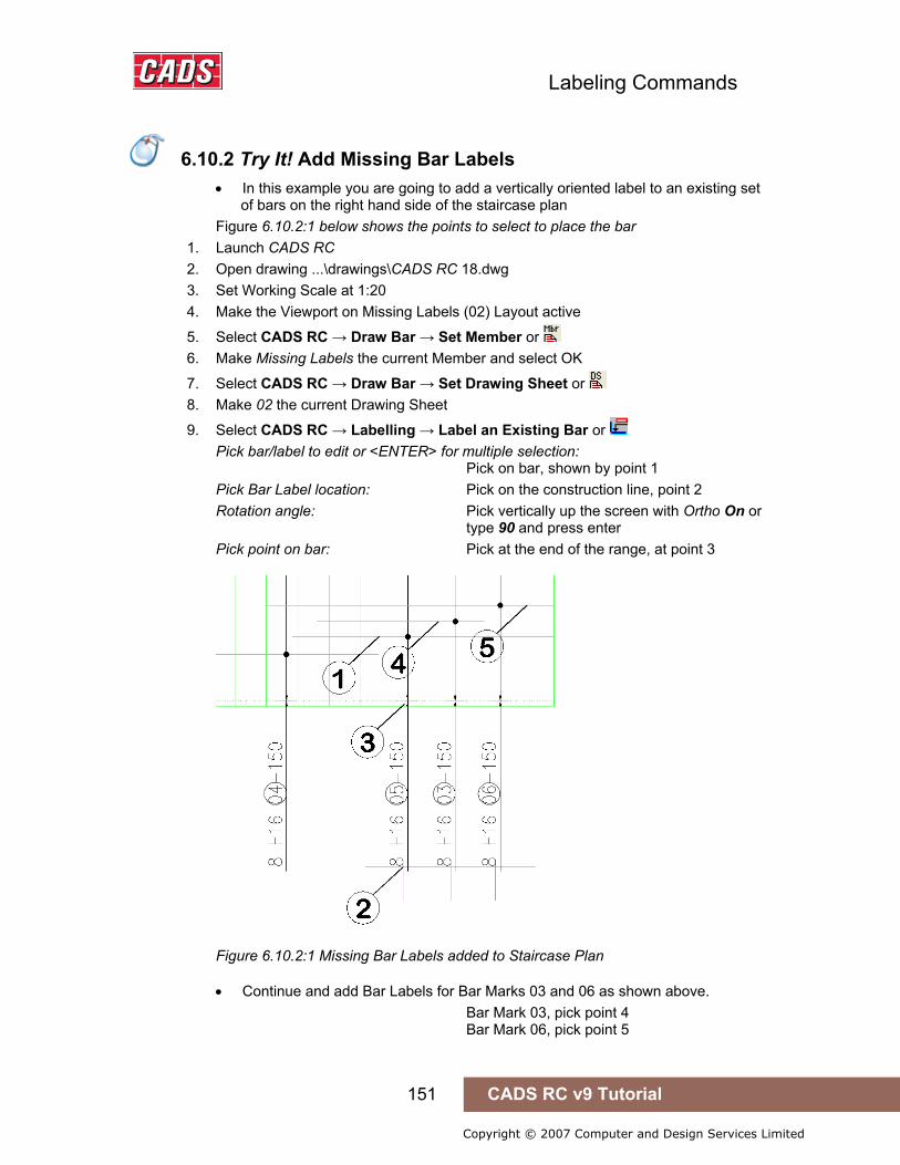
Labeling Commands
151 CADS RC v9 Tutorial
Copyright © 2007 Computer and Design Services Limited
6.10.2 Try It! Add Missing Bar Labels
• In this example you are going to add a vertically oriented label to an existing set of bars on the right hand side of the staircase plan
Figure 6.10.2:1 below shows the points to select to place the bar 1. Launch CADS RC 2. Open drawing ...\drawings\CADS RC 18.dwg 3. Set Working Scale at 1:20 4. Make the Viewport on Missing Labels (02) Layout active
5. Select CADS RC → Draw Bar → Set Member or 6. Make Missing Labels the current Member and select OK
7. Select CADS RC → Draw Bar → Set Drawing Sheet or 8. Make 02 the current Drawing Sheet
9. Select CADS RC → Labelling → Label an Existing Bar or Pick bar/label to edit or <ENTER> for multiple selection: Pick on bar, shown by point 1 Pick Bar Label location: Pick on the construction line, point 2 Rotation angle: Pick vertically up the screen with Ortho On or type 90 and press enter Pick point on bar: Pick at the end of the range, at point 3
Figure 6.10.2:1 Missing Bar Labels added to Staircase Plan
• Continue and add Bar Labels for Bar Marks 03 and 06 as shown above. Bar Mark 03, pick point 4 Bar Mark 06, pick point 5
6.10.2 Try It! Add Missing Bar Labels
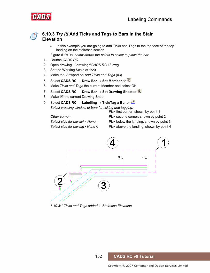
Labeling Commands
152 CADS RC v9 Tutorial
Copyright © 2007 Computer and Design Services Limited
6.10.3 Try It! Add Ticks and Tags to Bars in Section
• In this example you are going to add Ticks and Tags to the top face of the top landing on the staircase section.
Figure 6.10.3:1 below shows the points to select to place the bar 1. Launch CADS RC 2. Open drawing ...\drawings\CADS RC 18.dwg 3. Set the Working Scale at 1:20 4. Make the Viewport on Add Ticks and Tags (03)
5. Select CADS RC → Draw Bar → Set Member or 6. Make Ticks and Tags the current Member and select OK
7. Select CADS RC → Draw Bar → Set Drawing Sheet or 8. Make 03 the current Drawing Sheet
9. Select CADS RC → Labelling → Tick/Tag a Bar or Select crossing window of bars for ticking and tagging: Pick first corner, shown by point 1 Other corner: Pick second corner, shown by point 2 Select side for bar-tick <None>: Pick below the landing, shown by point 3 Select side for bar-tag <None>: Pick above the landing, shown by point 4
6.10.3:1 Ticks and Tags added to Staircase Elevation
6.10.3 Try It! Add Ticks and Tags to Bars in the Stair Elevation
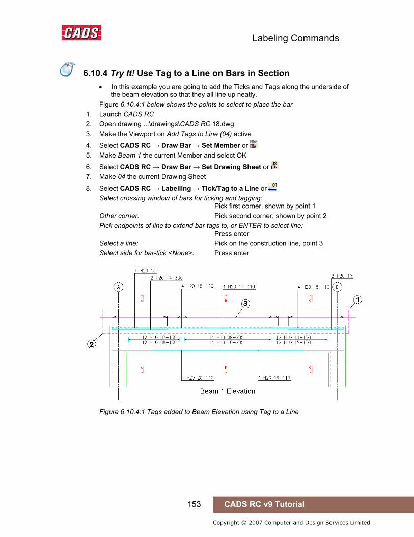
Labeling Commands
153 CADS RC v9 Tutorial
Copyright © 2007 Computer and Design Services Limited
6.10.4 Try It! Add Tag to a Line to Bars in Section
• In this example you are going to add the Ticks and Tags along the underside of the beam elevation so that they all line up neatly.
Figure 6.10.4:1 below shows the points to select to place the bar 1. Launch CADS RC 2. Open drawing ...\drawings\CADS RC 18.dwg 3. Make the Viewport on Add Tags to Line (04) active
4. Select CADS RC → Draw Bar → Set Member or 5. Make Beam 1 the current Member and select OK
6. Select CADS RC → Draw Bar → Set Drawing Sheet or 7. Make 04 the current Drawing Sheet
8. Select CADS RC → Labelling → Tick/Tag to a Line or Select crossing window of bars for ticking and tagging: Pick first corner, shown by point 1 Other corner: Pick second corner, shown by point 2 Pick endpoints of line to extend bar tags to, or ENTER to select line: Press enter Select a line: Pick on the construction line, point 3 Select side for bar-tick <None>: Press enter
Figure 6.10.4:1 Tags added to Beam Elevation using Tag to a Line
6.10.4 Try It! Use Tag to a Line on Bars in Section

Labeling Commands
154 CADS RC v9 Tutorial
Copyright © 2007 Computer and Design Services Limited
6.10.5 Try It! Add Bar References
Figure 6.10.5:1 below shows the points to select to place the bar 1. Launch CADS RC 2. Open drawing ...\drawings\CADS RC 18.dwg 3. Set the Working Scale at 1:20 4. Make the Viewport on Bar References Layout active
5. Select CADS RC → Draw Bar → Set Member or 6. Make Stair 4 the current Member and select OK
7. Select CADS RC → Draw Bar → Set Drawing Sheet or 8. Make 02 the current Drawing Sheet
Add Bar References using the Selection Method 9. Select CADS RC → Labelling → Add Bar Reference or
Pick bar of required Bar Mark or ENTER for selection: Press enter for Selection Please set angle of bar Reference text Reset/Angle <0.00>: Press enter to set angle of text to 0 Select bar dots to be referenced Reset: Select objects: Pick bar in section as shown by point 1 Select objects: Pick bar in section as shown by point 2 Select objects: Pick bar in section as shown by point 3 Select objects: Pick bar in section as shown by point 4 Pick insertion point for bar reference Angle/Reset/<point>: Press Enter to finish
Figure 6.10.5:1 Bar References added to Staircase Elevation
6.10.5 Try It! Add Bar References
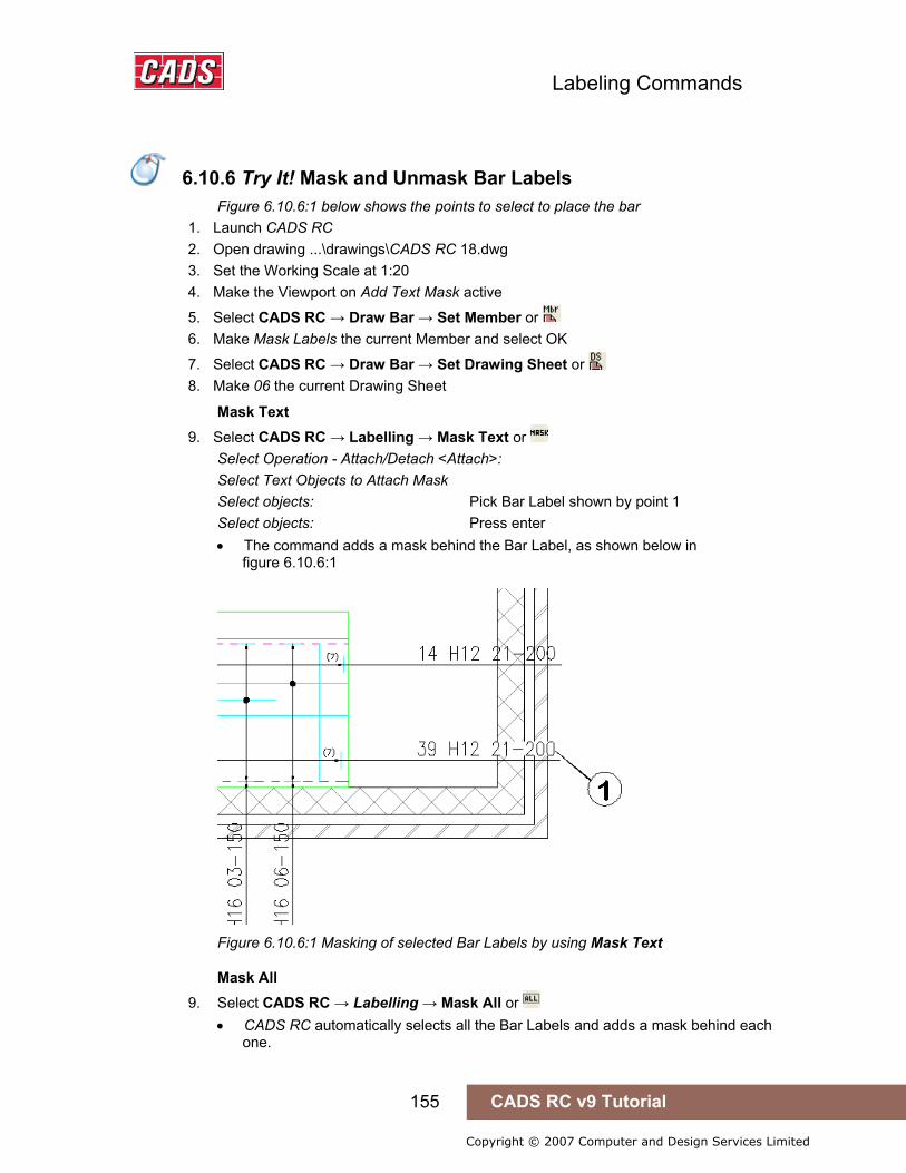
Labeling Commands
155 CADS RC v9 Tutorial
Copyright © 2007 Computer and Design Services Limited
6.10.6 Try It! Mask and Unmask Bar Labels
Figure 6.10.6:1 below shows the points to select to place the bar 1. Launch CADS RC 2. Open drawing ...\drawings\CADS RC 18.dwg 3. Set the Working Scale at 1:20 4. Make the Viewport on Add Text Mask active
5. Select CADS RC → Draw Bar → Set Member or 6. Make Mask Labels the current Member and select OK
7. Select CADS RC → Draw Bar → Set Drawing Sheet or 8. Make 06 the current Drawing Sheet
Mask Text 9. Select CADS RC → Labelling → Mask Text or
Select Operation - Attach/Detach <Attach>: Select Text Objects to Attach Mask Select objects: Pick Bar Label shown by point 1 Select objects: Press enter • The command adds a mask behind the Bar Label, as shown below in
figure 6.10.6:1
Figure 6.10.6:1 Masking of selected Bar Labels by using Mask Text
Mask All 9. Select CADS RC → Labelling → Mask All or
• CADS RC automatically selects all the Bar Labels and adds a mask behind each one.
6.10.6 Try It! Mask and Unmask Bar Labels

Labeling Commands
156 CADS RC v9 Tutorial
Copyright © 2007 Computer and Design Services Limited
Figure 6.10.6:2 Mask All applies a mask to all Bar Labels in a drawing
Unmask All 10. Select CADS RC → Labelling → Unmask All or
• CADS RC automatically selects all the Bar Labels and removes any masks that are present behind them.
Figure 6.10.6:3 All the Bar Labels have now been unmasked using Unmask All
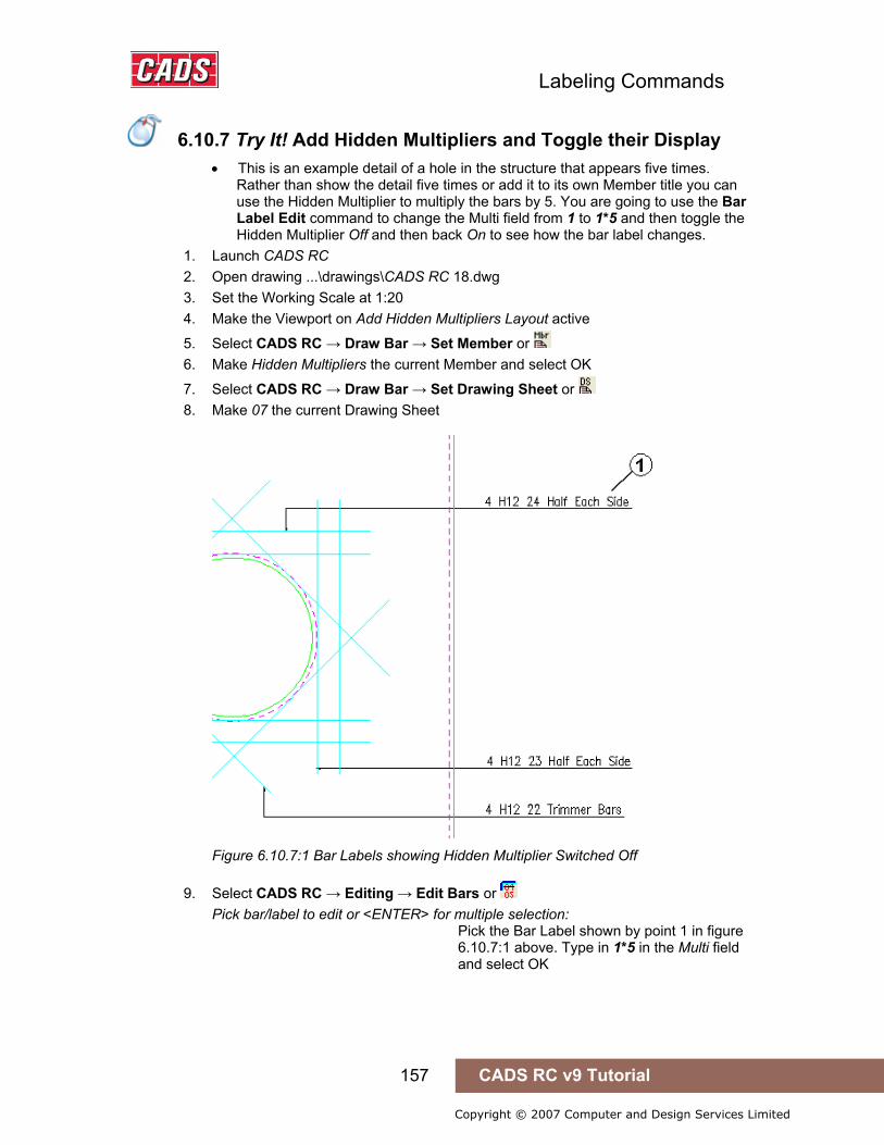
Labeling Commands
157 CADS RC v9 Tutorial
Copyright © 2007 Computer and Design Services Limited
6.10.7 Try It! Add Hidden Multipliers and Toggle their Display
• This is an example detail of a hole in the structure that appears five times. Rather than show the detail five times or add it to its own Member title you can use the Hidden Multiplier to multiply the bars by 5. You are going to use the Bar Label Edit command to change the Multi field from 1 to 1*5 and then toggle the Hidden Multiplier Off and then back On to see how the bar label changes.
1. Launch CADS RC 2. Open drawing ...\drawings\CADS RC 18.dwg 3. Set the Working Scale at 1:20 4. Make the Viewport on Add Hidden Multipliers Layout active
5. Select CADS RC → Draw Bar → Set Member or 6. Make Hidden Multipliers the current Member and select OK
7. Select CADS RC → Draw Bar → Set Drawing Sheet or 8. Make 07 the current Drawing Sheet
Figure 6.10.7:1 Bar Labels showing Hidden Multiplier Switched Off
9. Select CADS RC → Editing → Edit Bars or Pick bar/label to edit or <ENTER> for multiple selection: Pick the Bar Label shown by point 1 in figure 6.10.7:1 above. Type in 1*5 in the Multi field and select OK
6.10.7 Try It! Add Hidden Multipliers and Toggle their Display
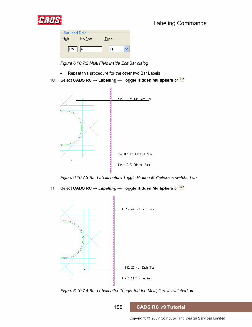
Labeling Commands
158 CADS RC v9 Tutorial
Copyright © 2007 Computer and Design Services Limited
Figure 6.10.7:2 Multi Field inside Edit Bar dialog
• Repeat this procedure for the other two Bar Labels.
10. Select CADS RC → Labelling → Toggle Hidden Multipliers or
Figure 6.10.7:3 Bar Labels before Toggle Hidden Multipliers is switched on
11. Select CADS RC → Labelling → Toggle Hidden Multipliers or
Figure 6.10.7:4 Bar Labels after Toggle Hidden Multipliers is switched on

Labeling Commands
159 CADS RC v9 Tutorial
Copyright © 2007 Computer and Design Services Limited
6.11 Leaders
CADS RC supports three different leaders of its own as well as the AutoCAD Dimension Style leaders. You can use the Label Configuration dialog to set whether to use CADS RC or AutoCAD leaders. To use CADS RC leaders set the option Draw Dimension Label/Leaders to Off. To use AutoCAD leaders set this option to On. See figure 6.11.2:1 below where the section is shown in red. There are advantages to using the AutoCAD leaders: for example, when you move the text the leader will follow while in the case of Bar Labels then text, together with associated notes, can be drawn as multi-liner text.
6.11.1 CADS RC Leaders There are three types of CADS RC leaders that can be used while labelling.
• Leader 1 – default configuration shows an arrowhead with a leader line • Leader 2 – default configuration shows a dot with a leader line • Leader 3 – default configuration shows a leader line only
All the leaders can be configured to draw underneath the label or to draw to the start or end of the label. There are also options to automatically locate a Bar Label from a known bar and to stack the leaders for labels that are drawn in columns.
6.11.1.1 CADS RC Leader Configuration The Configuration options are available from the CADS RC menu by selecting Configuration → Configuration Centre → Label Configuration and Leaders….
Configuration for each of the CADS RC Leader Types is available in this dialog.
Generally speaking you can change the block inserted at the end of the leader (leader arrow file), its layer and size and whether the leader is placed underneath or in the centre of the text.
Figure 6.11.1.1:1 CADS RC Leader Configuration dialog
6.11 Leaders

Labeling Commands
160 CADS RC v9 Tutorial
Copyright © 2007 Computer and Design Services Limited
If you wish to create your own arrowhead, draw it at full size in Model Space and make sure that the tip of the arrow is placed at 0,0.
6.11.2 AutoCAD Leaders If you wish to use AutoCAD Dimension leaders with CADS RC you need to switch them on inside the Label Configuration dialog. This is accessed through CADS RC → Configuration → Configuration Centre. The configuration of the Dimension leaders is carried out through the AutoCAD Dimension Style dialog.
Do not use both AutoCAD and CADS RC leaders on one drawing but stick to one or the other throughout a drawing file.
Figure 6.11.2:1 Label Configuration dialog with leader selection options marked
6.11.2.1 Draw Dimension Label/Leaders? If this option is set to On then when you place a leader on the drawing the AutoCAD Dimension leader will be used. The current Dimension Style will determine the style of the leader. If the option is set to Off then CADS RC leaders will be used.
6.11.2.2 Retain Leader Shape? If this option is set to Yes and Draw Dimension Label/Leaders option is switched on then the leader will automatically follow the label when the text associated with the leader is moved.
6.11.2.3 Group Label and Notes as a Single Multiline Text Entity? If this option is set to Yes and Draw Dimension Label/Leaders is switched on the Bar Label and its associated notes will become a Multiline Text (Mtext) entity. If it’s set to No the labels will be treated as Single Line Text entities (Dtext).

Labeling Commands
161 CADS RC v9 Tutorial
Copyright © 2007 Computer and Design Services Limited
6.11.2.4 Changing the Style of the AutoCAD Dimension Leaders CADS RC will have created three additional Dimension Styles on your drawing. Each of these styles relates to one of the three leader styles available within CADS RC.
If you wish to change the properties of the leaders you will have to edit each one in turn inside the Dimension Style Manager dialog, shown in figure 6.11.2.4:1 below. A change to the leader set-up is best carried out in your AutoCAD template drawing.
Figure 6.11.2.4:1 The Dimension Style Manager dialog

Labeling Commands
162 CADS RC v9 Tutorial
Copyright © 2007 Computer and Design Services Limited
6.11.3 Try It! Add CADS RC Leaders to a Drawing
• In this example you are going to use all the options available within the CADS RC leader command.
Figure 6.11.3:1 below shows the points to select 1. Launch CADS RC 2. Open drawing ...\drawings\CADS RC 19.dwg 3. Set the Working Scale at 1:20 4. Make the Viewport on CADS RC Leaders the active Layout
5. Select CADS RC → Draw Bar → Set Member or 6. Make CADS RC the current Member and select OK
7. Select CADS RC → Draw Bar → Set Drawing Sheet or 8. Make 01 the current Drawing Sheet
Leader 1 • Adding Leader 1 between the Range Line and Bar Label
8. Select CADS RC → Leaders → Leader Option 1 or Leader type is configured to <Underneath>:- Pick start point or Bar/Stack <Stack>: Pick the point at the end of the Range Line as shown by point 1 Next point or ENTER to select label: Press Enter to select a label Select label: Pick the label shown by point 2
Figure 6.11.3:1 Adding leaders 1 & 2 to the drawing
Leader 2 • Adding Leader 2 between the Range Line and Bar Label
9. Select CADS RC → Leaders → Leader Option 2 or Leader type is configured to <Underneath>:- Pick start point or Bar/Stack <Stack>: Pick the point on the bar shown by point 3 Next point or ENTER to select label: Press Enter Select label: Pick the label shown by point 4
6.11.3 Try It! Add CADS RC Leaders to a Drawing

Labeling Commands
163 CADS RC v9 Tutorial
Copyright © 2007 Computer and Design Services Limited
Leader 2 Bar Option • Using the Leader 2 to locate a Bar Label Figure 6.11.3:2 below shows the points to select
10. Select CADS RC → Leaders → Leader Option 2 or Leader type is configured to <Underneath>:- Pick start point or Bar/Stack <Stack>: Type B and press Enter Pick bar: Pick the bar shown by point 5 Pick point on bar: Pick start point of the leader, point 6
Figure 6.11.3:2 Locating the Bar Label using the CADS RC leader command
Leader 2 Stack Option • Using Leader 2 Stack option Figure 6.11.3:3 below shows the points to select
11. Select CADS RC → Leaders → Leader Option 2 or Leader type is configured to <Underneath>:- Pick start point or Bar/Stack <Stack>: Type S and press Enter Select leader: Pick the Leader shown by point 7 Select label: Pick the label shown by point 8 • Repeat the function for the label above.
Figure 6.11.3:3 Stacking CADS RC leaders from one start point

Labeling Commands
164 CADS RC v9 Tutorial
Copyright © 2007 Computer and Design Services Limited
6.11.4 Try It! Add AutoCAD Dimension Style Leaders to a Drawing
• In this example you are going to switch on the AutoCAD leaders inside CADS RC, change the leader 1 arrowhead style and the leader color. Then place some leaders that show the configuration changes.
Figure 6.11.4:2 below shows the points to select 1. Launch CADS RC 2. Open drawing ...\drawings\CADS RC 20.dwg 3. Set the Working Scale at 1:20 4. Make the Viewport on AutoCAD Leaders (01) the active Layout
5. Select CADS RC → Draw Bar → Set Member or 6. Make AutoCAD Leaders the current Member and select OK
7. Select CADS RC → Draw Bar → Set Drawing Sheet or 8. Make 01 the current Drawing Sheet
Configure AutoCAD Dimension Leaders 9. Select CADS RC → Configuration → Configuration Centre – Label Config
10. Switch on the Draw Dimension Label/Leaders. Set Retain Leader Shape and the Group Label and Notes options to Yes
11. Select OK and Close to return to the drawing
12. Select Format → Dimension Style or 13. Pick LEADER1 on the list of styles and then select MODIFY 14. Select the Lines and Arrows tab 15. Change the Dimension Line color to Red and the Leader Arrowhead type to Box
Filled • Note: In AutoCAD 2006 & 2007 the Dimension Line color appears on the Lines
tab. The Leader Arrowhead appears on the Symbols and Arrows tab. 16. Select OK and then Close
6.11.4 Try It! Add AutoCAD Dimension Style Leaders to a Drawing
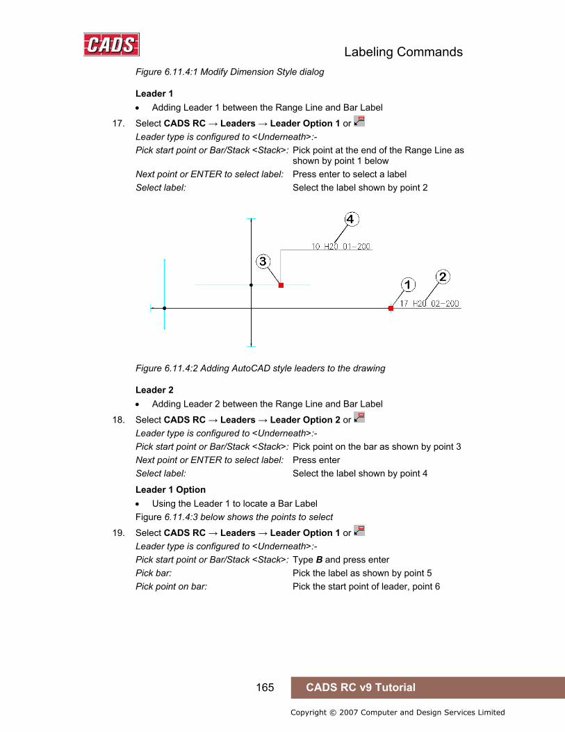
Labeling Commands
165 CADS RC v9 Tutorial
Copyright © 2007 Computer and Design Services Limited
Figure 6.11.4:1 Modify Dimension Style dialog
Leader 1 • Adding Leader 1 between the Range Line and Bar Label
17. Select CADS RC → Leaders → Leader Option 1 or Leader type is configured to <Underneath>:- Pick start point or Bar/Stack <Stack>: Pick point at the end of the Range Line as shown by point 1 below Next point or ENTER to select label: Press enter to select a label Select label: Select the label shown by point 2
Figure 6.11.4:2 Adding AutoCAD style leaders to the drawing
Leader 2 • Adding Leader 2 between the Range Line and Bar Label
18. Select CADS RC → Leaders → Leader Option 2 or Leader type is configured to <Underneath>:- Pick start point or Bar/Stack <Stack>: Pick point on the bar as shown by point 3 Next point or ENTER to select label: Press enter Select label: Select the label shown by point 4
Leader 1 Option • Using the Leader 1 to locate a Bar Label Figure 6.11.4:3 below shows the points to select
19. Select CADS RC → Leaders → Leader Option 1 or Leader type is configured to <Underneath>:- Pick start point or Bar/Stack <Stack>: Type B and press enter Pick bar: Pick the label as shown by point 5 Pick point on bar: Pick the start point of leader, point 6
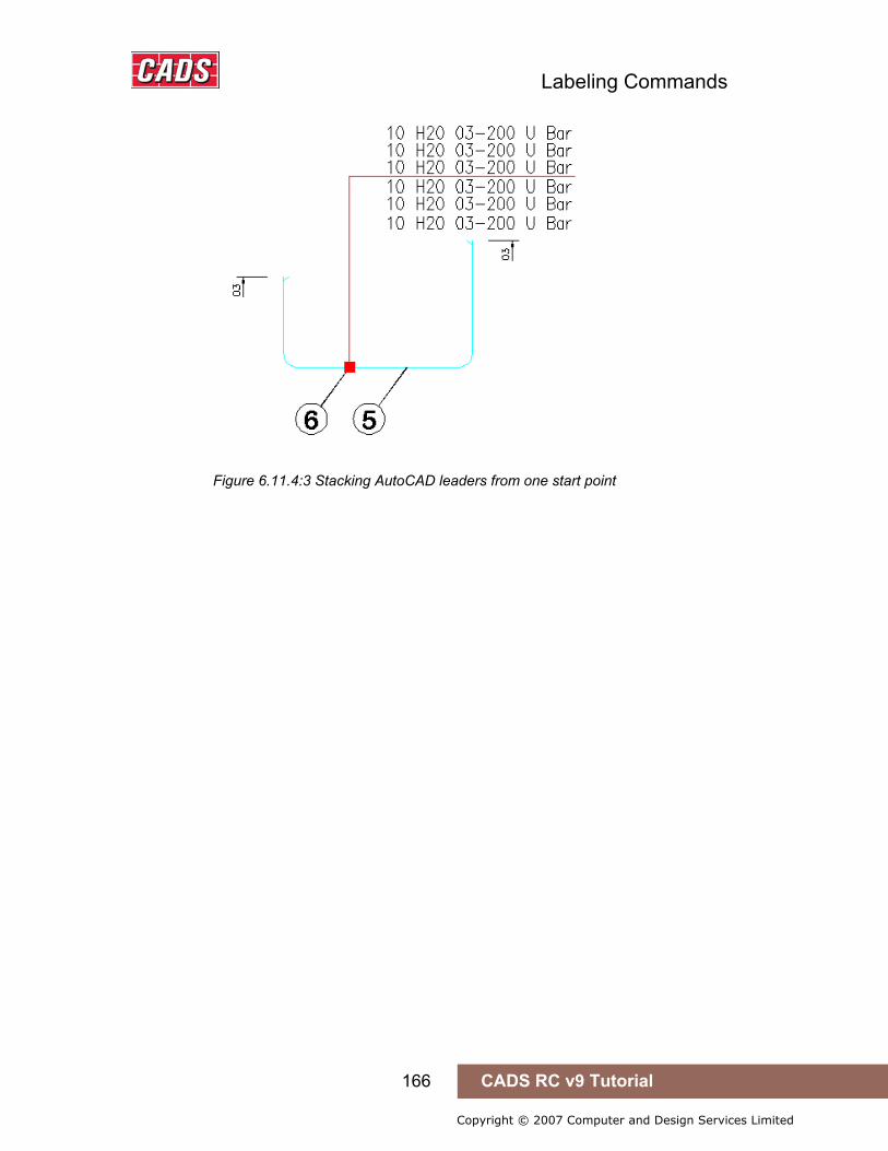
Labeling Commands
166 CADS RC v9 Tutorial
Copyright © 2007 Computer and Design Services Limited
Figure 6.11.4:3 Stacking AutoCAD leaders from one start point

Labeling Commands
167 CADS RC v9 Tutorial
Copyright © 2007 Computer and Design Services Limited
6.12 Key points – Labelling Commands
• Use the New Label command to add another Bar Label to a Range Line, to indicate top and bottom steel for instance.
• Use New Label to populate a tabulated table. • All CADS RC labels can be formatted to your individual or company
requirements • Use Label an Existing Bar to add missing Bar Labels to previously drawn Bar
Sets. • Ticks and Tags can be used to indicate the start and end of bars. • Use Bar References to indicate the Bar Marks or the bar lengths of bars in
section. • Use Mask Text to prevent Bar Labels becoming obscured in congested
drawings. • You can use either CADS RC or AutoCAD leaders on a drawing. Do not use
both on one drawing. • AutoCAD leaders will automatically update if their associated text is moved on
the drawing. • Use the Bar Option in the Leader commands to locate missing Bar Labels.
6.12 Key points – Labelling Commands
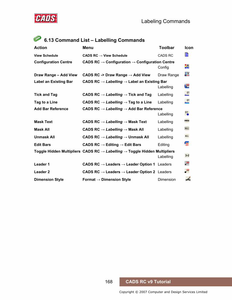
Labeling Commands
168 CADS RC v9 Tutorial
Copyright © 2007 Computer and Design Services Limited
6.13 Command List – Labelling Commands
Action Menu Toolbar Icon
View Schedule CADS RC → View Schedule CADS RC
Configuration Centre CADS RC → Configuration → Configuration Centre Config
Draw Range – Add View CADS RC -> Draw Range → Add View Draw Range
Label an Existing Bar CADS RC → Labelling → Label an Existing Bar Labelling
Tick and Tag CADS RC → Labelling → Tick and Tag Labelling
Tag to a Line CADS RC → Labelling → Tag to a Line Labelling
Add Bar Reference CADS RC → Labelling → Add Bar Reference Labelling
Mask Text CADS RC → Labelling → Mask Text Labelling
Mask All CADS RC → Labelling → Mask All Labelling
Unmask All CADS RC → Labelling → Unmask All Labelling
Edit Bars CADS RC → Editing → Edit Bars Editing
Toggle Hidden Multipliers CADS RC → Labelling → Toggle Hidden Multipliers Labelling
Leader 1 CADS RC → Leaders → Leader Option 1 Leaders
Leader 2 CADS RC → Leaders → Leader Option 2 Leaders
Dimension Style Format → Dimension Style Dimension
6.13 Command List – Labelling Commands
Edit and Modify Commands
169 CADS RC v9 Tutorial
Copyright © 2007 Computer and Design Services Limited
7: Edit and Modify Commands
7.0 Introduction
CADS RC has an extensive range of editing tools that allow you to change the properties of bars, ranges and their labels.
You can also use some of the AutoCAD Modify commands to alter CADS RC entities. There are some restrictions, however, and these are discussed later in this chapter.
7.0 Introduction

Edit and Modify Commands
170 CADS RC v9 Tutorial
Copyright © 2007 Computer and Design Services Limited
7.1 Double Click Editing
The easiest way to edit the properties of bars and ranges is to use the Double Click Edit feature. With this enabled you can simply double click on a CADS RC entity to display the relevant editing dialog box. If a bar or any of the labels are selected then the Edit Bar Label Data dialog will be displayed. If a range or bar run is selected the Edit Range dialog will be displayed.
7.1.1 Enabling Double Click Editing CADS RC has a toggle option built in to switch Double Click Editing On and Off. This is accessed through CADS RC → Configuration → Double Click Edit Toggle.
Hints & Tips – Switching on Hyperlinks to Enable Double Click Editing
You might find that even if you’ve enabled the Double Click Edit feature it doesn’t work! If this happens, check that the Display hyperlink cursor, tooltip, and shortcut menu is switched on inside the AutoCAD Options dialog under the User Preferences Tab.
Figure 7.1.1:1 Hyperlink Option in the Options dialog
When double clicking on Bar Labels pick the beginning of the label. If you select a different point you may display the AutoCAD Text Edit dialog instead.
7.1 Double Click Editing
Hints & Tips – Switching on Hyperlinks to Enable Double Click Editing
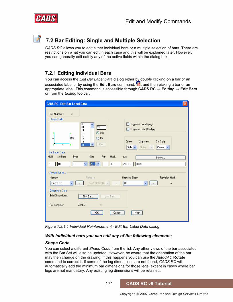
Edit and Modify Commands
171 CADS RC v9 Tutorial
Copyright © 2007 Computer and Design Services Limited
7.2 Bar Editing: Single and Multiple Selection
CADS RC allows you to edit either individual bars or a multiple selection of bars. There are restrictions on what you can edit in each case and this will be explained later. However, you can generally edit safely any of the active fields within the dialog box.
7.2.1 Editing Individual Bars You can access the Edit Bar Label Data dialog either by double clicking on a bar or an associated label or by using the Edit Bars command, , and then picking a bar or an appropriate label. This command is accessible through CADS RC → Editing → Edit Bars or from the Editing toolbar.
Figure 7.2.1:1 Individual Reinforcement - Edit Bar Label Data dialog
With individual bars you can edit any of the following elements: Shape Code You can select a different Shape Code from the list. Any other views of the bar associated with the Bar Set will also be updated. However, be aware that the orientation of the bar may then change on the drawing. If this happens you can use the AutoCAD Rotate command to correct it. If some of the leg dimensions are not found, CADS RC will automatically add the minimum bar dimensions for those legs, except in cases where bar legs are not mandatory. Any existing leg dimensions will be retained.
7.2 Bar Editing: Single and Multiple Selection
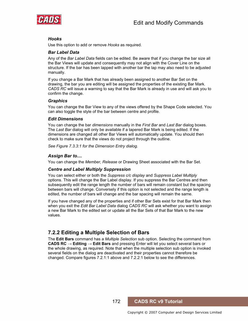
Edit and Modify Commands
172 CADS RC v9 Tutorial
Copyright © 2007 Computer and Design Services Limited
Hooks Use this option to add or remove Hooks as required.
Bar Label Data Any of the Bar Label Data fields can be edited. Be aware that if you change the bar size all the Bar Views will update and consequently may not align with the Cover Line on the structure. If the bar has been lapped with another bar the lap may also need to be adjusted manually.
If you change a Bar Mark that has already been assigned to another Bar Set on the drawing, the bar you are editing will be assigned the properties of the existing Bar Mark. CADS RC will issue a warning to say that the Bar Mark is already in use and will ask you to confirm the change.
Graphics You can change the Bar View to any of the views offered by the Shape Code selected. You can also toggle the style of the bar between centre and profile.
Edit Dimensions You can change the bar dimensions manually in the First Bar and Last Bar dialog boxes. The Last Bar dialog will only be available if a tapered Bar Mark is being edited. If the dimensions are changed all other Bar Views will automatically update. You should then check to make sure that the views do not project through the outline.
See Figure 7.3.3:1 for the Dimension Entry dialog.
Assign Bar to.... You can change the Member, Release or Drawing Sheet associated with the Bar Set.
Centre and Label Multiply Suppression You can select either or both the Suppress c/c display and Suppress Label Multiply options. This will change the Bar Label display. If you suppress the Bar Centres and then subsequently edit the range length the number of bars will remain constant but the spacing between bars will change. Conversely if this option is not selected and the range length is edited, the number of bars will change and the bar spacing will remain the same.
If you have changed any of the properties and if other Bar Sets exist for that Bar Mark then when you exit the Edit Bar Label Data dialog CADS RC will ask whether you want to assign a new Bar Mark to the edited set or update all the Bar Sets of that Bar Mark to the new values.
7.2.2 Editing a Multiple Selection of Bars The Edit Bars command has a Multiple Selection sub option. Selecting the command from CADS RC → Editing → Edit Bars and pressing Enter will let you select several bars or the whole drawing, as required. Note that when the multiple selection sub option is invoked several fields on the dialog are deactivated and their properties cannot therefore be changed. Compare figures 7.2.1:1 above and 7.2.2:1 below to see the differences.
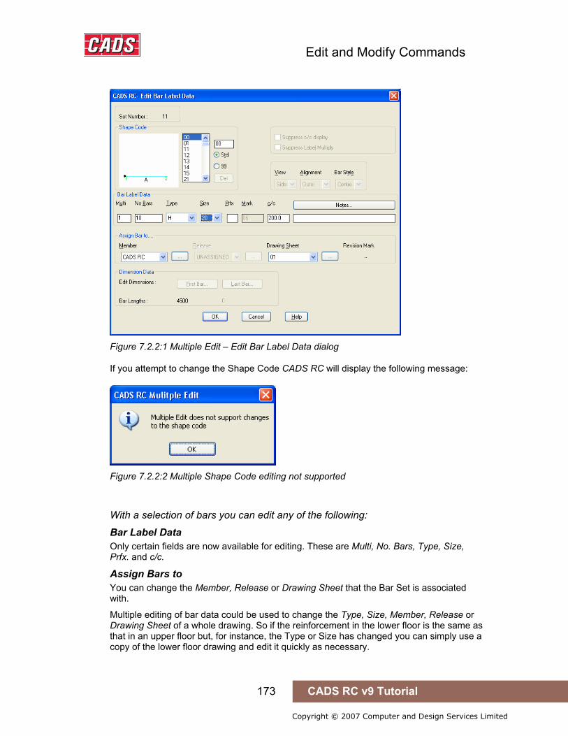
Edit and Modify Commands
173 CADS RC v9 Tutorial
Copyright © 2007 Computer and Design Services Limited
Figure 7.2.2:1 Multiple Edit – Edit Bar Label Data dialog
If you attempt to change the Shape Code CADS RC will display the following message:
Figure 7.2.2:2 Multiple Shape Code editing not supported
With a selection of bars you can edit any of the following:
Bar Label Data Only certain fields are now available for editing. These are Multi, No. Bars, Type, Size, Prfx. and c/c.
Assign Bars to You can change the Member, Release or Drawing Sheet that the Bar Set is associated with.
Multiple editing of bar data could be used to change the Type, Size, Member, Release or Drawing Sheet of a whole drawing. So if the reinforcement in the lower floor is the same as that in an upper floor but, for instance, the Type or Size has changed you can simply use a copy of the lower floor drawing and edit it quickly as necessary.

Edit and Modify Commands
174 CADS RC v9 Tutorial
Copyright © 2007 Computer and Design Services Limited
Hints & Tips – Warning on Editing Multiple Bars
If you pick a selection of bars with different Types or bar sizes CADS RC will warn you that the existing Types and bar sizes will be overwritten with the new ones selected in the Edit Bar Label Data dialog. If the Type or Size fields are not edited the bars will retain their original data.
Figure 7.2.2:3 Multiple Edit Bars Warning
Hints & Tips – Use Multiple Bar Edit to Modify a Whole Drawing
You can use the Multiple Selection Option from the Edit Bars command to change the Type and bar diameter for a whole drawing.
7.2.3 Restrictions on Bar Label Edit According to the Type of Range Alternate Ranges of all Types Do not change the Bar Centres in the Edit Bar Data dialog for this Range type as it cannot communicate with the alternate bar. Instead, use Edit Range to change the centres.
Varying Taper Range You cannot edit the bar dimensions for the first and last bar - use Edit Range to edit individual bars.
Trapezoidal Taper Once drawn, the bars assigned to this range type cannot be edited.
Hints & Tips – Warning on Editing Multiple Bars
Hints & Tips – Use Multiple Bar Edit to Modify a Whole Drawing

Edit and Modify Commands
175 CADS RC v9 Tutorial
Copyright © 2007 Computer and Design Services Limited
7.2.4 Try It! Use Edit Bars to Change the Properties of a Single Bar
• Using the Edit Bars command you are going to change the bar diameter and the B and D leg dimensions of the Bar Mark 1001. This bar has another set associated with it but as you are changing the bar diameter CADS RC will automatically assign another Bar Mark and not warn that other sets exist.
1. Launch CADS RC 2. Open drawing ...\drawings\CADS RC 21.dwg 3. Set the Working Scale at 1:10 4. Make the Viewport on Edit Single Bar (01) current
5. Select CADS RC → Draw Bar → Set Member or 6. Make Edit Single Bar the current Member and select OK
7. Select CADS RC → Draw Bar → Set Drawing Sheet or 8. Make 01 the current Drawing Sheet
9. Select CADS RC → Editing → Edit Bars or or double click the bar as marked by point 1 in figure 7.2.4:1 below
Figure 7.2.4:1 Editing the properties of Shape Code 21
10. In the Edit Bar Label Data dialog box change the Bar Diameter to 25 11. Select the First Bar… button
Change Leg A to 1000 Change Leg C to 500
12. Select OK twice to return to the drawing 13. Pick Yes to Create New Bark when the Change Bar Mark dialog is displayed
7.2.4 Try It! Use Edit Bars to Change the Properties of a Single Bar
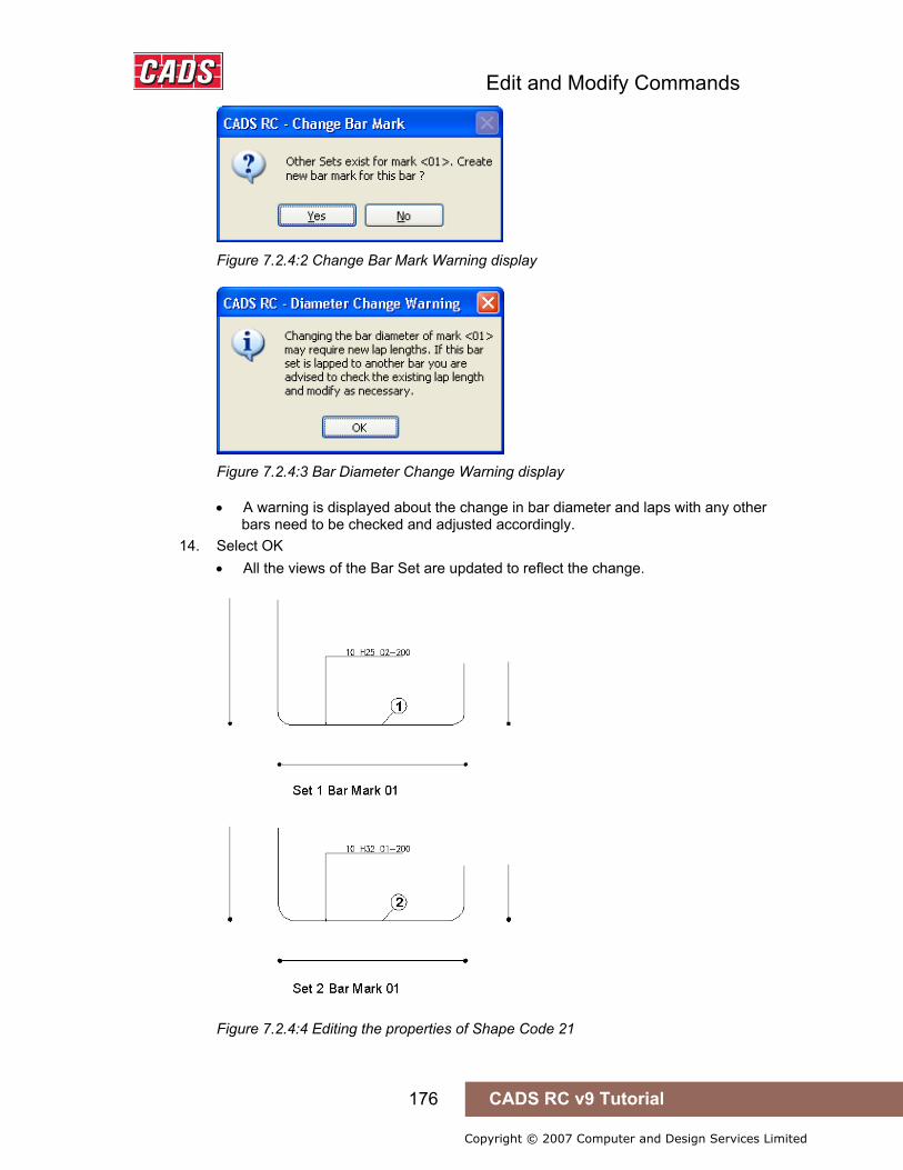
Edit and Modify Commands
176 CADS RC v9 Tutorial
Copyright © 2007 Computer and Design Services Limited
Figure 7.2.4:2 Change Bar Mark Warning display
Figure 7.2.4:3 Bar Diameter Change Warning display
• A warning is displayed about the change in bar diameter and laps with any other bars need to be checked and adjusted accordingly.
14. Select OK • All the views of the Bar Set are updated to reflect the change.
Figure 7.2.4:4 Editing the properties of Shape Code 21

Edit and Modify Commands
177 CADS RC v9 Tutorial
Copyright © 2007 Computer and Design Services Limited
15. Select CADS RC → Editing → Edit Bars or or double click the bar as marked by point 2 in figure 7.2.4:4 above • Using the Edit Bars command you are going to change the bar style of the
selected bar to Profile and change the Bar Mark Number to 02 to let it inherit the properties of the bar we have just changed.
16. In the Edit Bar Label Data dialog box change the Bar Style to Profile and type in 02 as the Bar Mark Number
17. Select OK to return to the drawing
Figure 7.2.4:5 Bar Mark Change Warning dialog
• The warning points out that Bar Mark 02 has already been assigned. If you select Yes the bar being edited will inherit the properties of Bar Mark 02.
18. Select Yes • The second set of bars update to reflect the properties of Bar Mark 02 and the
Side View changes to a profile bar style.
Figure 7.2.4:6 Editing the properties of Shape Code 21
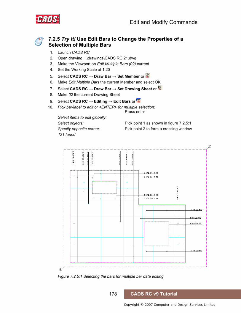
Edit and Modify Commands
178 CADS RC v9 Tutorial
Copyright © 2007 Computer and Design Services Limited
7.2.5 Try It! Use Edit Bars to Change the Properties of a Selection of Multiple Bars
1. Launch CADS RC 2. Open drawing ...\drawings\CADS RC 21.dwg 3. Make the Viewport on Edit Multiple Bars (02) current 4. Set the Working Scale at 1:20
5. Select CADS RC → Draw Bar → Set Member or 6. Make Edit Multiple Bars the current Member and select OK
7. Select CADS RC → Draw Bar → Set Drawing Sheet or 8. Make 02 the current Drawing Sheet
9. Select CADS RC → Editing → Edit Bars or 10. Pick bar/label to edit or <ENTER> for multiple selection:
Press enter Select items to edit globally: Select objects: Pick point 1 as shown in figure 7.2.5:1 Specify opposite corner: Pick point 2 to form a crossing window 121 found
Figure 7.2.5:1 Selecting the bars for multiple bar data editing
7.2.5 Try It! Use Edit Bars to Change the Properties of a Selection of Multiple Bars
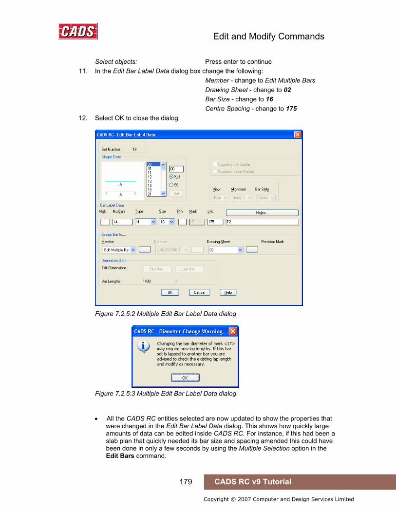
Edit and Modify Commands
179 CADS RC v9 Tutorial
Copyright © 2007 Computer and Design Services Limited
Select objects: Press enter to continue 11. In the Edit Bar Label Data dialog box change the following:
Member - change to Edit Multiple Bars Drawing Sheet - change to 02 Bar Size - change to 16 Centre Spacing - change to 175
12. Select OK to close the dialog
Figure 7.2.5:2 Multiple Edit Bar Label Data dialog
Figure 7.2.5:3 Multiple Edit Bar Label Data dialog
• All the CADS RC entities selected are now updated to show the properties that
were changed in the Edit Bar Label Data dialog. This shows how quickly large amounts of data can be edited inside CADS RC. For instance, if this had been a slab plan that quickly needed its bar size and spacing amended this could have been done in only a few seconds by using the Multiple Selection option in the Edit Bars command.

Edit and Modify Commands
180 CADS RC v9 Tutorial
Copyright © 2007 Computer and Design Services Limited
7.3 Edit Range
The editing options offered by the Edit Range dialog will vary according to the type of range selected for modifying. Broadly speaking you can split the ranges into the following groups:
• Single Group • Multiple Group • Radial • Tapered
7.3.1 Edit Range Dialog You can either double click on the Range Line or select the Edit Range dialog through the menu sequence CADS RC → Editing → Edit Range or by clicking on the toolbar button
. The initial Edit Range dialog is the same for all the range types.
Figure 7.3.1:1 Edit Range dialog
The function buttons available are:
Edit Range… This button opens the Edit Range dialog. The functionality varies for each of the Range Groups but basically the dialog allows you to edit the Bar Centres, range length, and so on. You cannot, however, edit any of the properties of a Trapezoidal Tapered Range bar – to achieve this you would need to delete and redraw it with changed properties.
More information on variations in the Edit Range dialog is given later in this chapter.
Adjust Ends… The Adjust Ends button lets you rotate the range end markers away from the perpendicular to the Range Line, giving what is called the skew angle. This feature is useful when drawing ranges that align with a sloping edge but where you need to calculate the bars either vertically or horizontally. When you select this option you are prompted to define the new angle of the range end marker by picking two points on the screen. The range will be regenerated with the markers shown at the new skewed angle, the number of bars recalculated and the Bar Label amended.
This option is not available for Double Indicator, Dimension Style, Radial, Double Indicator Taper, Varying or Trapezoidal Range routines.
7.3 Edit Range

Edit and Modify Commands
181 CADS RC v9 Tutorial
Copyright © 2007 Computer and Design Services Limited
Figure 7.3.1:2 Range End Marker perpendicular to Range Line
Figure 7.3.1:3 Range End Marker skewed to Vertical Alignment
Information… This button displays details about the type of range and information on the Shape Code(s) associated with it.
Figure 7.3.1:4 Range Information dialog
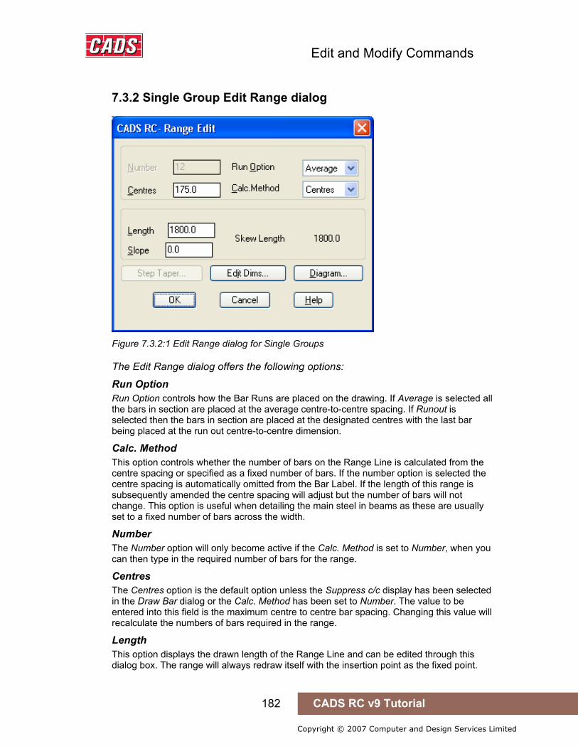
Edit and Modify Commands
182 CADS RC v9 Tutorial
Copyright © 2007 Computer and Design Services Limited
7.3.2 Single Group Edit Range dialog
Figure 7.3.2:1 Edit Range dialog for Single Groups
The Edit Range dialog offers the following options:
Run Option Run Option controls how the Bar Runs are placed on the drawing. If Average is selected all the bars in section are placed at the average centre-to-centre spacing. If Runout is selected then the bars in section are placed at the designated centres with the last bar being placed at the run out centre-to-centre dimension.
Calc. Method This option controls whether the number of bars on the Range Line is calculated from the centre spacing or specified as a fixed number of bars. If the number option is selected the centre spacing is automatically omitted from the Bar Label. If the length of this range is subsequently amended the centre spacing will adjust but the number of bars will not change. This option is useful when detailing the main steel in beams as these are usually set to a fixed number of bars across the width.
Number The Number option will only become active if the Calc. Method is set to Number, when you can then type in the required number of bars for the range.
Centres The Centres option is the default option unless the Suppress c/c display has been selected in the Draw Bar dialog or the Calc. Method has been set to Number. The value to be entered into this field is the maximum centre to centre bar spacing. Changing this value will recalculate the numbers of bars required in the range.
Length This option displays the drawn length of the Range Line and can be edited through this dialog box. The range will always redraw itself with the insertion point as the fixed point.

Edit and Modify Commands
183 CADS RC v9 Tutorial
Copyright © 2007 Computer and Design Services Limited
Hence if you want to change the range length and move the insertion point it would be best to use the Stretch Bar/Range command or else to edit as two separate operations. The skew length, and not the length (from which it might differ), is used to calculate the number of bars in the range.
Slope This field will display any angle of slope that might have been set when the range was placed. If the range picked was drawn as a foreshortened view, then the slope angle it represents will be reported as a value other than zero. Entering a slope value of 0.1 will always set the skew length to that of the length. This allows ranges to have the end markers skewed but have the bar number calculation still based on the drawn Range Line length.
Skew Length If a bar range has had the end markers adjusted to produce a skew range, then the Skew Length is shown here. If the skew length is reported as being the same as the length, then the range has not been skewed.
7.3.3 Edit Dims The Edit Dims button displays exactly the same Dimension Entry dialog as that accessed through the Edit Bar Data dialog. See figure 7.3.3:1 below.
Figure 7.3.3:1 Dimension Entry dialog

Edit and Modify Commands
184 CADS RC v9 Tutorial
Copyright © 2007 Computer and Design Services Limited
7.3.4 Diagram The Skew Help display shows the way the slope and skewed ranges are calculated.
Figure 7.3.4:1 Skew Help display
7.3.5 Multiple Group Edit Range Dialog
Figure 7.3.5:1 Multiple Group Edit Range dialog
The Multiple Range Edit Group List dialog displays the currently defined groups for the Range Line in the form of a spreadsheet. You can double click on one of the groups to access the Edit dialog box rather than having to highlight the group and then pick Edit. To access the Edit, Copy, Move or Delete options highlight the group on the list and then pick the appropriate command button from the dialog.
This dialog has the following options:
Create The Create option allows you to add a new group to the Range. When you have entered the data you can indicate where the group should be inserted by specifying its Group Number. The dialog box is always displayed with all the fields set to zero. If you want to

Edit and Modify Commands
185 CADS RC v9 Tutorial
Copyright © 2007 Computer and Design Services Limited
duplicate some data from another group it’s better to use the Copy option and then edit the newly created group by changing the contents of some of the fields.
Figure 7.3.5:2 Create Multiple Range Group dialog
Edit The Edit option will display the Multiple Range Edit dialog for the group highlighted in the group list. A scaled diagram is displayed to show your changes and the position of the group being edited. The options are similar to the Single Group Range Edit dialog (see figure 7.3.2:1 above) except that you can type in the distance between Range Groups and swap the bar order for an Alternate Range.
Figure 7.3.5:3 Edit Multiple Range Group dialog

Edit and Modify Commands
186 CADS RC v9 Tutorial
Copyright © 2007 Computer and Design Services Limited
Copy The Copy option will duplicate the currently highlighted group in the group list to another position you specify in the Group Number field. You can then edit the newly created group by double clicking on it in the spreadsheet and changing its values as necessary.
Figure 7.3.5:4 Copy Multiple Range Group dialog
Move The Move option will move the currently highlighted group to the position that you specify in the Group Number field.
Figure 7.3.5:5 Move Multiple Range Group dialog
Delete The Delete option will remove the group currently highlighted in the group list.
Figure 7.3.5:6 Delete Multiple Range Group dialog

Edit and Modify Commands
187 CADS RC v9 Tutorial
Copyright © 2007 Computer and Design Services Limited
7.3.6 Radial Range Edit Dialog
Figure 7.3.6:1 Radial Range Edit dialog
The editing options for Radial Ranges are restricted. You can amend the centres, the run out and the calculation method but you cannot edit the range length. However, you can apply a slope to the range length and this is useful when detailing spiral ramps and silos.

Edit and Modify Commands
188 CADS RC v9 Tutorial
Copyright © 2007 Computer and Design Services Limited
7.3.7 Tapered Range Edit Dialog
Figure 7.3.7:1 Tapered Range Edit dialog
All editing options for the Single Indicator Range are also available for the Tapered Range. In addition you can apply a step increment to a Tapered Range and you can edit individual bars in the taper and change their dimensions.
Step Taper The Step Taper option allows you to group tapered bars according to a step increment length that rationalises the number of cut bars within the range. You can only apply a step taper to a range if it has been detailed from the shortest to the longest bar. If a step increment is applied to a range of bars, the length of any bars that lap with the range must be increased by the step length. You can apply the step to start at the shortest bar, which keeps all the bars within the outline, or to start at the longest bar. In the dialog below a step increment has been applied to the range and the cut bars have reduced from (a-ab) to (a-j).
Figure 7.3.7:2 Step Taper dialog before Step Increment applied
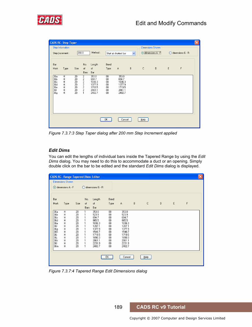
Edit and Modify Commands
189 CADS RC v9 Tutorial
Copyright © 2007 Computer and Design Services Limited
Figure 7.3.7:3 Step Taper dialog after 200 mm Step Increment applied
Edit Dims You can edit the lengths of individual bars inside the Tapered Range by using the Edit Dims dialog. You may need to do this to accommodate a duct or an opening. Simply double click on the bar to be edited and the standard Edit Dims dialog is displayed.
Figure 7.3.7:4 Tapered Range Edit Dimensions dialog
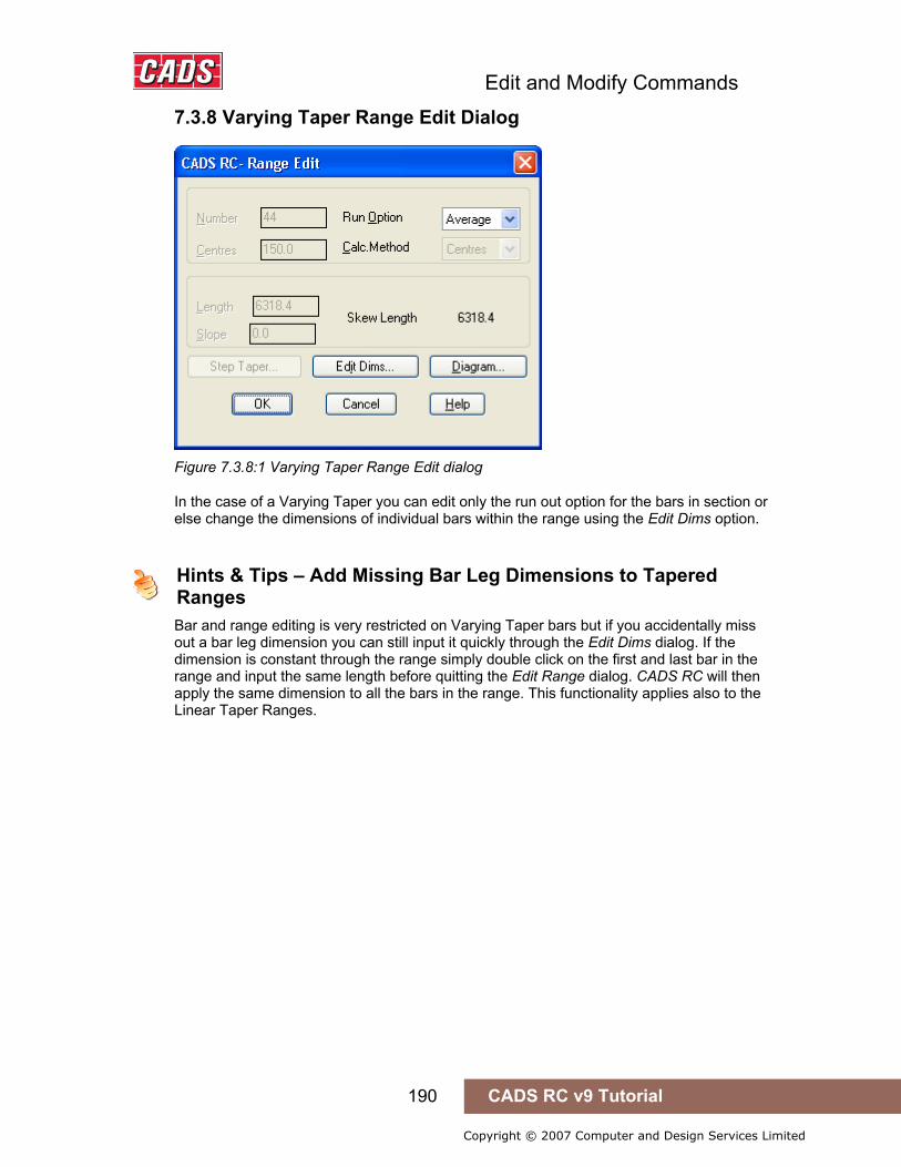
Edit and Modify Commands
190 CADS RC v9 Tutorial
Copyright © 2007 Computer and Design Services Limited
7.3.8 Varying Taper Range Edit Dialog
Figure 7.3.8:1 Varying Taper Range Edit dialog
In the case of a Varying Taper you can edit only the run out option for the bars in section or else change the dimensions of individual bars within the range using the Edit Dims option.
Hints & Tips – Add Missing Bar Leg Dimensions to Tapered Ranges
Bar and range editing is very restricted on Varying Taper bars but if you accidentally miss out a bar leg dimension you can still input it quickly through the Edit Dims dialog. If the dimension is constant through the range simply double click on the first and last bar in the range and input the same length before quitting the Edit Range dialog. CADS RC will then apply the same dimension to all the bars in the range. This functionality applies also to the Linear Taper Ranges.
Hints & Tips – Add Missing Bar Leg Dimensions to Tapered Ranges

Edit and Modify Commands
191 CADS RC v9 Tutorial
Copyright © 2007 Computer and Design Services Limited
7.3.9 Try It! Use Edit Range to Change the Properties of the Single Indicator Range
1. Launch CADS RC 2. Open drawing ...\drawings\CADS RC 21.dwg 3. Set the Working Scale at 1:20 4. Make the Viewport on Range Edit Single Indicator (03) current
5. Select CADS RC → Draw Bar → Set Member or 6. Make Range Edit Single Indicator the current Member and select OK
7. Select CADS RC → Draw Bar → Set Drawing Sheet or 8. Make 03 the current Drawing Sheet
9. Select CADS RC → Editing → Edit Range or or double click on the Range Line as indicated by point 1 on figure 7.3.9:1 below
Figure 7.3.9:1 Using Edit Range to edit the range length
10. Select Edit Range and then change the following in the Edit Range dialog: Centres - change to 150 mm Run Option - change to Run Out Length - change to 3500 mm
11. Select OK twice to return to the drawing • The drawing will automatically update to reflect the changes made in the dialog.
The bars in section are now placed at 150 centres instead of 200 centres. The Range Line has extended beyond the outline of the structure in both the plan and section views because you changed the length. However, generally when you want to change the length of a range it is best to use the Stretch Bar/Range command as this will update the outline as well as the CADS RC entities.
7.3.9 Try It! Use Edit Range to Change the Properties of the Single Indicator Range

Edit and Modify Commands
192 CADS RC v9 Tutorial
Copyright © 2007 Computer and Design Services Limited
7.3.10 Try It! Use Edit Range to Change the Properties of the Multiple Group Range
• This exercise will take you through introducing a new opening into the multiple group range using the Edit Range function. Currently the range has two groups so you are going to copy Group 2 to position 3 and then edit both groups to the correct length.
1. Launch CADS RC 2. Open drawing ...\drawings\CADS RC 21.dwg 3. Set the Working Scale at 1:20 4. Make the Viewport on Edit Range Multiple Group (04) Layout current
5. Select CADS RC → Draw Bar → Set Member or 6. Make Range Edit m mo Multiple Group the current Member and select OK
7. Select CADS RC → Draw Bar → Set Drawing Sheet or 8. Make 04 the current Drawing Sheet
9. Select CADS RC → Editing → Edit Range or or double click on the Range Line as shown by point 1 in figure 7.3.10:1 below
Figure 7.3.10:1 Using Edit Range to add a Range Group
10. Select Edit Range 11. Highlight Group 2 and select Copy… 12. Type in 3 for the Group Position to Copy to
7.3.10 Try It! Use Edit Range to Change the Properties of the Multiple Group Range
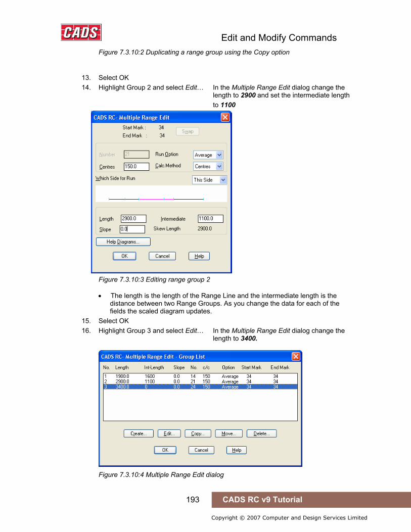
Edit and Modify Commands
193 CADS RC v9 Tutorial
Copyright © 2007 Computer and Design Services Limited
Figure 7.3.10:2 Duplicating a range group using the Copy option
13. Select OK 14. Highlight Group 2 and select Edit… In the Multiple Range Edit dialog change the
length to 2900 and set the intermediate length to 1100
Figure 7.3.10:3 Editing range group 2
• The length is the length of the Range Line and the intermediate length is the distance between two Range Groups. As you change the data for each of the fields the scaled diagram updates.
15. Select OK 16. Highlight Group 3 and select Edit… In the Multiple Range Edit dialog change the
length to 3400.
Figure 7.3.10:4 Multiple Range Edit dialog
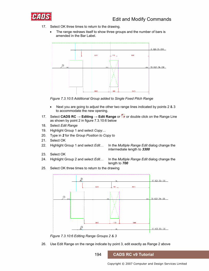
Edit and Modify Commands
194 CADS RC v9 Tutorial
Copyright © 2007 Computer and Design Services Limited
17. Select OK three times to return to the drawing. • The range redraws itself to show three groups and the number of bars is
amended in the Bar Label.
Figure 7.3.10:5 Additional Group added to Single Fixed Pitch Range
• Next you are going to adjust the other two range lines indicated by points 2 & 3 to accommodate the new opening.
17. Select CADS RC → Editing → Edit Range or or double click on the Range Line as shown by point 2 in figure 7.3.10:6 below
18. Select Edit Range 19. Highlight Group 1 and select Copy… 20. Type in 2 for the Group Position to Copy to 21. Select OK 22. Highlight Group 1 and select Edit… In the Multiple Range Edit dialog change the
intermediate length to 3300 23. Select OK 24. Highlight Group 2 and select Edit… In the Multiple Range Edit dialog change the
length to 700 25. Select OK three times to return to the drawing
Figure 7.3.10:6 Editing Range Groups 2 & 3
26. Use Edit Range on the range indicate by point 3, edit exactly as Range 2 above
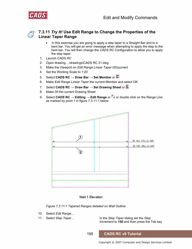
Edit and Modify Commands
195 CADS RC v9 Tutorial
Copyright © 2007 Computer and Design Services Limited
7.3.11 Try It! Use Edit Range to Change the Properties of the Linear Taper Range
• In this exercise you are going to apply a step taper to a Straight Bar and to a bent bar. You will get an error message when attempting to apply the step to the bent bar. You will then change the CADS RC Configuration to allow you to apply the step taper.
1. Launch CADS RC 2. Open drawing ...\drawings\CADS RC 21.dwg 3. Make the Viewport on Edit Range Linear Taper (05)current 4. Set the Working Scale to 1:20
5. Select CADS RC → Draw Bar → Set Member or 6. Make Edit Range Linear Taper the current Member and select OK
7. Select CADS RC → Draw Bar → Set Drawing Sheet or 8. Make 05 the current Drawing Sheet
9. Select CADS RC → Editing → Edit Range or or double click on the Range Line as marked by point 1 in figure 7.3.11:1 below
Figure 7.3.11:1 Tapered Ranges detailed on Wall Outline
10. Select Edit Range… 11. Select Step Taper… In the Step Taper dialog set the Step
Increment to 150 and then press the Tab key
7.3.11 Try It! Use Edit Range to Change the Properties of the Linear Taper Range
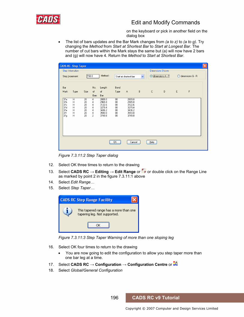
Edit and Modify Commands
196 CADS RC v9 Tutorial
Copyright © 2007 Computer and Design Services Limited
on the keyboard or pick in another field on the dialog box • The list of bars updates and the Bar Mark changes from (a to z) to (a to g). Try
changing the Method from Start at Shortest Bar to Start at Longest Bar. The number of cut bars within the Mark stays the same but (a) will now have 2 bars and (g) will now have 4. Return the Method to Start at Shortest Bar.
Figure 7.3.11:2 Step Taper dialog
12. Select OK three times to return to the drawing
13. Select CADS RC → Editing → Edit Range or or double click on the Range Line as marked by point 2 in the figure 7.3.11:1 above
14. Select Edit Range… 15. Select Step Taper…
Figure 7.3.11:3 Step Taper Warning of more than one sloping leg
16. Select OK four times to return to the drawing • You are now going to edit the configuration to allow you step taper more than
one bar leg at a time.
17. Select CADS RC → Configuration → Configuration Centre or 18. Select Global/General Configuration

Edit and Modify Commands
197 CADS RC v9 Tutorial
Copyright © 2007 Computer and Design Services Limited
Figure 7.3.11:4 Global Configuration dialog
19. In the Global Configuration dialog set the top field to Range using the drop down menu. In the middle field scroll to the bottom of the list and highlight RestrictStepMoreThan1TapLeg. In the lower input field type in No
20. Pick Assign to CFG 21. Select OK 22. Select Yes to apply the change that has just been made 23. Select Close
24. Select CADS RC → Editing → Edit Range or or double click on the Range Line as indicated by point 2 in the figure 7.3.11:1 above
25. Select Edit Range… 26. Select Step Taper… Enter a step increment of 150 27. Select OK three times to return to the drawing
• Both ranges now show the bars as (a) to (g).
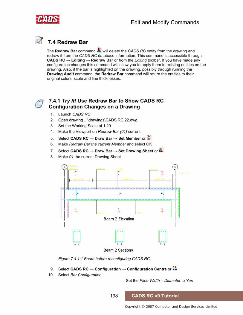
Edit and Modify Commands
198 CADS RC v9 Tutorial
Copyright © 2007 Computer and Design Services Limited
7.4 Redraw Bar
The Redraw Bar command will delete the CADS RC entity from the drawing and redraw it from the CADS RC database information. This command is accessible through CADS RC → Editing → Redraw Bar or from the Editing toolbar. If you have made any configuration changes this command will allow you to apply them to existing entities on the drawing. Also, if the bar is highlighted on the drawing, possibly through running the Drawing Audit command, the Redraw Bar command will return the entities to their original colors, scale and line thicknesses.
7.4.1 Try It! Use Redraw Bar to Show CADS RC Configuration Changes on a Drawing
1. Launch CADS RC 2. Open drawing ...\drawings\CADS RC 22.dwg 3. Set the Working Scale at 1:20 4. Make the Viewport on Redraw Bar (01) current
5. Select CADS RC → Draw Bar → Set Member or 6. Make Redraw Bar the current Member and select OK
7. Select CADS RC → Draw Bar → Set Drawing Sheet or 8. Make 01 the current Drawing Sheet
Figure 7.4.1:1 Beam before reconfiguring CADS RC
9. Select CADS RC → Configuration → Configuration Centre or 10. Select Bar Configuration
Set the Pline Width = Diameter to Yes
7.4 Redraw Bar
7.4.1 Try It! Use Redraw Bar to Show CADS RC Configuration Changes on a Drawing
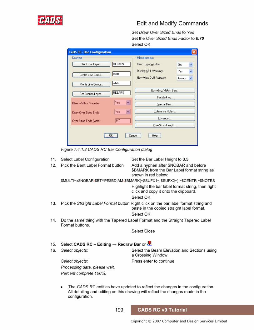
Edit and Modify Commands
199 CADS RC v9 Tutorial
Copyright © 2007 Computer and Design Services Limited
Set Draw Over Sized Ends to Yes Set the Over Sized Ends Factor to 0.70
Select OK
Figure 7.4.1:2 CADS RC Bar Configuration dialog
11. Select Label Configuration Set the Bar Label Height to 3.5 12. Pick the Bent Label Format button Add a hyphen after $NOBAR and before
$BMARK from the Bar Label format string as shown in red below: $MULTI~x$NOBAR-$BTYPE$BDIAM-$BMARK(~$SUFX1~-$SUFX2~)-~$CENTR ~$NOTES Highlight the bar label format string, then right click and copy it onto the clipboard. Select OK
13. Pick the Straight Label Format button Right click on the bar label format string and paste in the copied straight label format. Select OK
14. Do the same thing with the Tapered Label Format and the Straight Tapered Label Format buttons. Select Close
15. Select CADS RC – Editing → Redraw Bar or 16. Select objects: Select the Beam Elevation and Sections using
a Crossing Window. Select objects: Press enter to continue Processing data, please wait. Percent complete 100%.
• The CADS RC entities have updated to reflect the changes in the configuration. All detailing and editing on this drawing will reflect the changes made in the configuration.
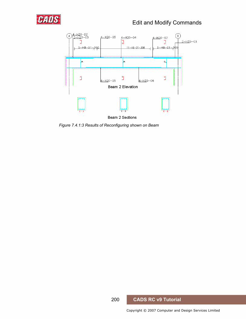
Edit and Modify Commands
200 CADS RC v9 Tutorial
Copyright © 2007 Computer and Design Services Limited
Figure 7.4.1:3 Results of Reconfiguring shown on Beam

Edit and Modify Commands
201 CADS RC v9 Tutorial
Copyright © 2007 Computer and Design Services Limited
7.5 Stretch Bar/Range
You cannot use the AutoCAD Stretch command on CADS RC entities as it cannot communicate with the CADS RC database and hence the Schedule. A CADS RC Stretch Bar/Range command, , has been specifically written for this purpose, and this will also stretch AutoCAD entities. This function has the capability of retaining or changing the Bar Marks of any entities selected for stretching.
This command is accessible from CADS RC → Editing → Stretch Bar/Range or through the Editing toolbar.
The command prompts as follows:
Check for other sets and re-assign Bar Marks/Stock? <Yes>:
• If you type S for Stock the dialog shown in figure 7.5:1 below is displayed. This allows you to amend the Maximum Stock Length value and if you then attempt to stretch the bar(s) over this value CADS RC will automatically invoke the Over Stock Length feature discussed earlier in Section 4.4. Select OK to return to the command.
Figure 7.5:1 Stock Length Defaults dialog
Check for other sets and re-assign Bar Marks/Stock? <Yes>:
• The function can either retain or change the Bar Marks of the entities selected for stretching. If you answer No to whether you want to change the Bar Marks then any other sets of that Bar Mark on the drawing will be modified as well to reflect the new dimensions. If you answer Yes to that same question then new Bar Mark Numbers will be allocated to the stretched bars.
Select object to be stretched or crossing window:
• You are then prompted to use the crossing window to select the part of the drawing to be stretched and then distance and angle of the stretch. As the crossing window has been preset you can pick in any direction.
7.5 Stretch Bar/Range
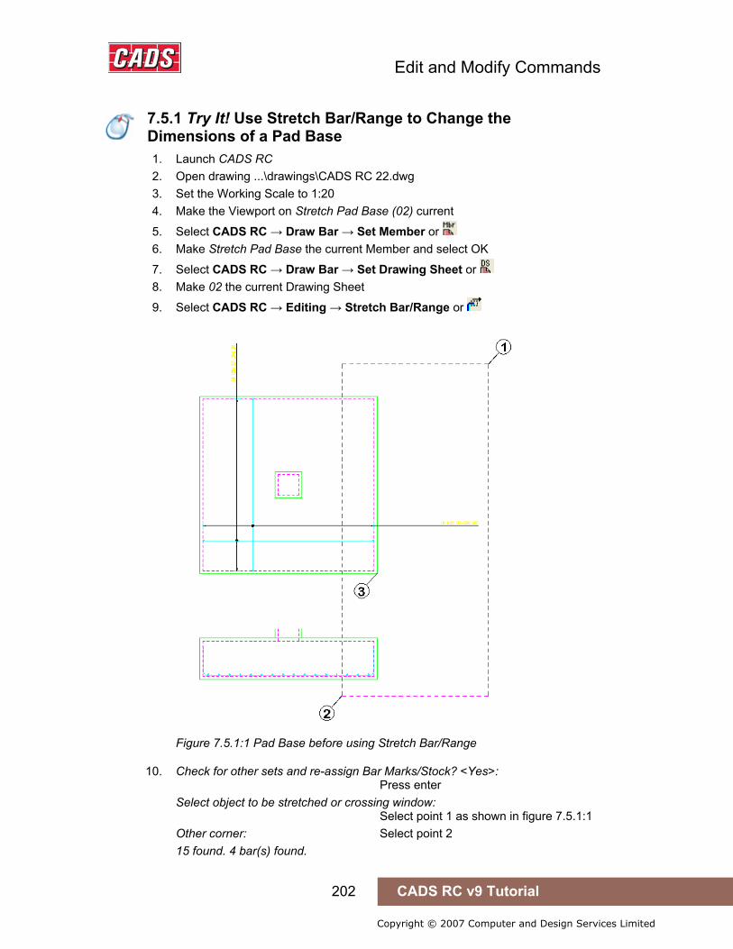
Edit and Modify Commands
202 CADS RC v9 Tutorial
Copyright © 2007 Computer and Design Services Limited
7.5.1 Try It! Use Stretch Bar/Range to Change the Dimensions of a Pad Base
1. Launch CADS RC 2. Open drawing ...\drawings\CADS RC 22.dwg 3. Set the Working Scale to 1:20 4. Make the Viewport on Stretch Pad Base (02) current
5. Select CADS RC → Draw Bar → Set Member or 6. Make Stretch Pad Base the current Member and select OK
7. Select CADS RC → Draw Bar → Set Drawing Sheet or 8. Make 02 the current Drawing Sheet
9. Select CADS RC → Editing → Stretch Bar/Range or
Figure 7.5.1:1 Pad Base before using Stretch Bar/Range
10. Check for other sets and re-assign Bar Marks/Stock? <Yes>: Press enter Select object to be stretched or crossing window: Select point 1 as shown in figure 7.5.1:1 Other corner: Select point 2 15 found. 4 bar(s) found.
7.5.1 Try It! Use Stretch Bar/Range to Change the Dimensions of a Pad Base
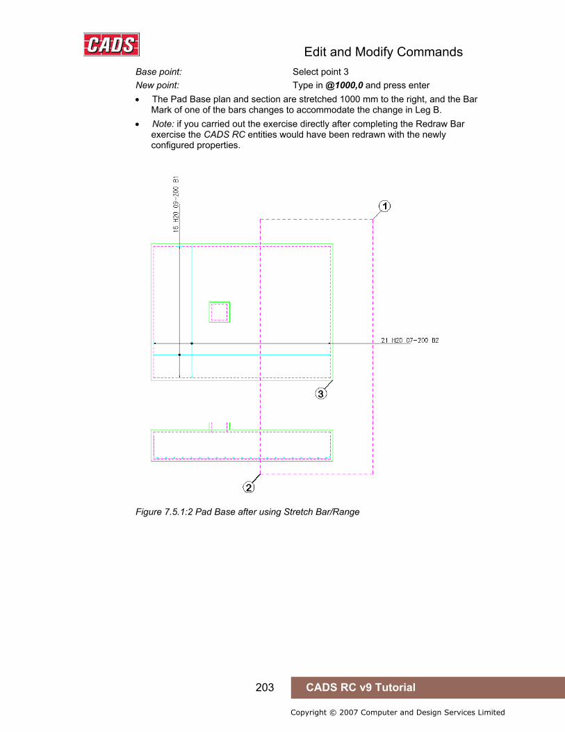
Edit and Modify Commands
203 CADS RC v9 Tutorial
Copyright © 2007 Computer and Design Services Limited
Base point: Select point 3 New point: Type in @1000,0 and press enter • The Pad Base plan and section are stretched 1000 mm to the right, and the Bar
Mark of one of the bars changes to accommodate the change in Leg B. • Note: if you carried out the exercise directly after completing the Redraw Bar
exercise the CADS RC entities would have been redrawn with the newly configured properties.
Figure 7.5.1:2 Pad Base after using Stretch Bar/Range
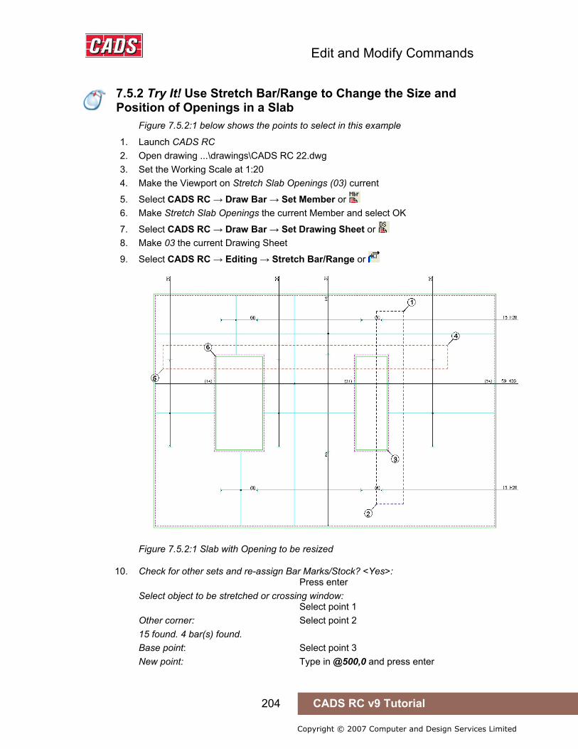
Edit and Modify Commands
204 CADS RC v9 Tutorial
Copyright © 2007 Computer and Design Services Limited
7.5.2 Try It! Use Stretch Bar/Range to Change the Size and Position of Openings in a Slab
Figure 7.5.2:1 below shows the points to select in this example
1. Launch CADS RC 2. Open drawing ...\drawings\CADS RC 22.dwg 3. Set the Working Scale at 1:20 4. Make the Viewport on Stretch Slab Openings (03) current
5. Select CADS RC → Draw Bar → Set Member or 6. Make Stretch Slab Openings the current Member and select OK
7. Select CADS RC → Draw Bar → Set Drawing Sheet or 8. Make 03 the current Drawing Sheet
9. Select CADS RC → Editing → Stretch Bar/Range or
Figure 7.5.2:1 Slab with Opening to be resized
10. Check for other sets and re-assign Bar Marks/Stock? <Yes>: Press enter Select object to be stretched or crossing window: Select point 1 Other corner: Select point 2 15 found. 4 bar(s) found. Base point: Select point 3 New point: Type in @500,0 and press enter
7.5.2 Try It! Use Stretch Bar/Range to Change the Size and Position of Openings in a Slab
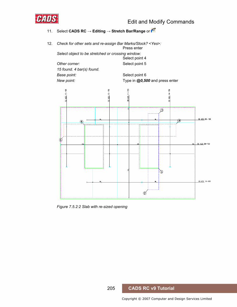
Edit and Modify Commands
205 CADS RC v9 Tutorial
Copyright © 2007 Computer and Design Services Limited
11. Select CADS RC → Editing → Stretch Bar/Range or
12. Check for other sets and re-assign Bar Marks/Stock? <Yes>: Press enter Select object to be stretched or crossing window: Select point 4 Other corner: Select point 5 15 found. 4 bar(s) found. Base point: Select point 6 New point: Type in @0,500 and press enter
Figure 7.5.2:2 Slab with re-sized opening

Edit and Modify Commands
206 CADS RC v9 Tutorial
Copyright © 2007 Computer and Design Services Limited
7.6 Using AutoCAD Commands to Modify a Drawing
7.6.1 Copy and Array You can use the AutoCAD commands Copy and Array to produce duplicate CADS RC entities in exactly the same way as in standard AutoCAD. While using these commands you will be prompted to choose to add the CADS RC entities as either a Copy Bar Set or Copy Bar View by the dialog shown below as figure 7.6.1:1. The Copy Bar Set option will duplicate the Entities and add another line to the Schedule, which increases the number of bars on the detail. The Copy Bar View just duplicates the entities but does not increase the number of bars on the Schedule.
Figure 7.6.1:1 CADS RC Copy Bar View or Set Confirmation
The Cancel option will abort the Copy or Array command.
7.6.2 Mirror You can use the AutoCAD Mirror command to produce reflected copies of CADS RC entities on your details.
If you decide to delete the original CADS RC entities (source objects) a warning message will be displayed as shown in figure 7.6.2:1 below. This warning points out that if there are any other graphics linked to the Bar View that have not been selected for mirroring CADS RC will not be able to delete them.
Figure 7.6.2:1 CADS RC Mirror Warning
7.6 Using AutoCAD Commands to Modify a Drawing
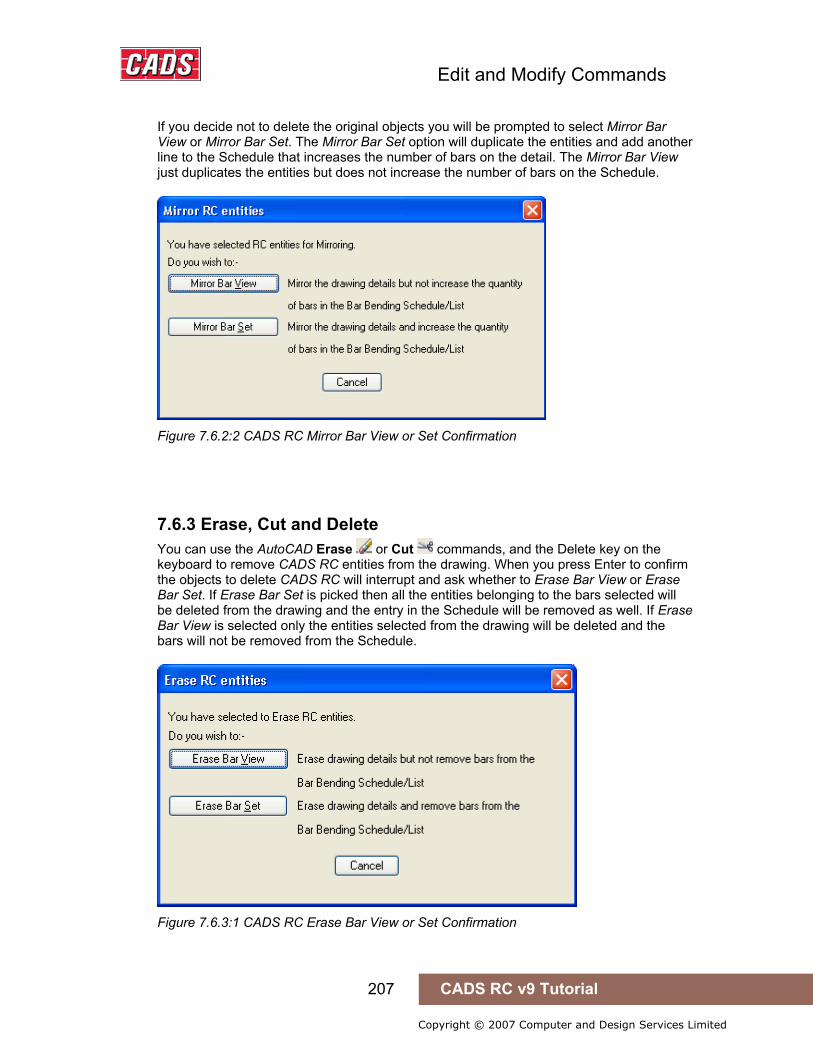
Edit and Modify Commands
207 CADS RC v9 Tutorial
Copyright © 2007 Computer and Design Services Limited
If you decide not to delete the original objects you will be prompted to select Mirror Bar View or Mirror Bar Set. The Mirror Bar Set option will duplicate the entities and add another line to the Schedule that increases the number of bars on the detail. The Mirror Bar View just duplicates the entities but does not increase the number of bars on the Schedule.
Figure 7.6.2:2 CADS RC Mirror Bar View or Set Confirmation
7.6.3 Erase, Cut and Delete You can use the AutoCAD Erase or Cut commands, and the Delete key on the keyboard to remove CADS RC entities from the drawing. When you press Enter to confirm the objects to delete CADS RC will interrupt and ask whether to Erase Bar View or Erase Bar Set. If Erase Bar Set is picked then all the entities belonging to the bars selected will be deleted from the drawing and the entry in the Schedule will be removed as well. If Erase Bar View is selected only the entities selected from the drawing will be deleted and the bars will not be removed from the Schedule.
Figure 7.6.3:1 CADS RC Erase Bar View or Set Confirmation

Edit and Modify Commands
208 CADS RC v9 Tutorial
Copyright © 2007 Computer and Design Services Limited
7.6.4 Copy and Paste You can use Copy and Paste from the Edit pull down menu to place objects on the clipboard. These can then be pasted into the same drawing or into a different drawing.
When using Copy and Paste to copy entities from one drawing to another ensure both drawings are at the same working scale. The Paste command will add the bars as the next available Bar Marks on the drawing.
Hints & Tips – Copy and Paste
When copying and pasting details from one drawing to another make sure that the working scales are the same. If required, you can then rescale the detail once it has been inserted.
7.6.5 Export and Insert a Block If you want to save a CADS RC detail for later use you can create an AutoCAD Wblock. Create the detail in exactly the same way as you would with AutoCAD either by selecting Export from the File pull down menu and then changing the files to DWG type or else by typing Wblock at the command line. When you import the detail to the existing drawing, or to a new one, using the Insert Block command make sure that the Explode option is selected in the dialog so that CADS RC can assign the next available bars marks to the detail.
Note: You cannot edit the Wblock drawing to change the CADS RC entities as you have no access to the CADS RC database. If you need to amend a library detail then import it to a drawing, edit it, and then export it again as a Wblock.
Hints & Tips – Copy and Paste
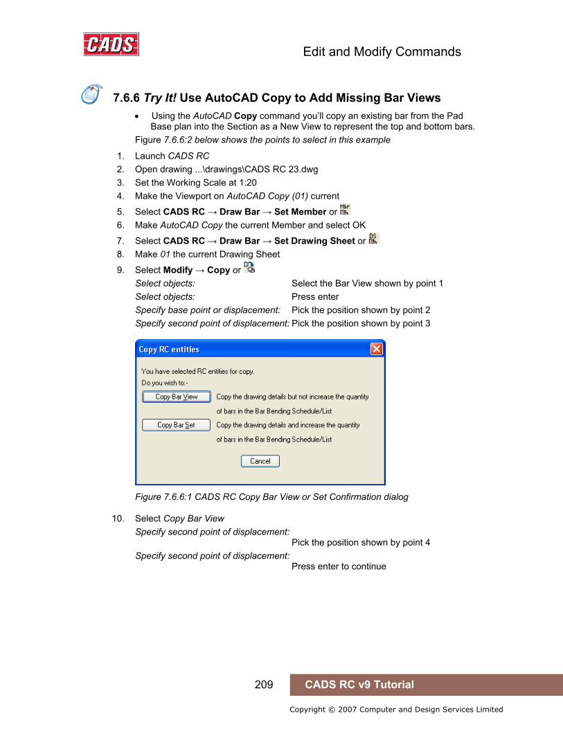
Edit and Modify Commands
209 CADS RC v9 Tutorial
Copyright © 2007 Computer and Design Services Limited
7.6.6 Try It! Use AutoCAD Copy to Add Missing Bar Views
• Using the AutoCAD Copy command you’ll copy an existing bar from the Pad Base plan into the Section as a New View to represent the top and bottom bars.
Figure 7.6.6:2 below shows the points to select in this example
1. Launch CADS RC 2. Open drawing ...\drawings\CADS RC 23.dwg 3. Set the Working Scale at 1:20 4. Make the Viewport on AutoCAD Copy (01) current
5. Select CADS RC → Draw Bar → Set Member or 6. Make AutoCAD Copy the current Member and select OK
7. Select CADS RC → Draw Bar → Set Drawing Sheet or 8. Make 01 the current Drawing Sheet
9. Select Modify → Copy or Select objects: Select the Bar View shown by point 1 Select objects: Press enter Specify base point or displacement: Pick the position shown by point 2 Specify second point of displacement: Pick the position shown by point 3
Figure 7.6.6:1 CADS RC Copy Bar View or Set Confirmation dialog
10. Select Copy Bar View Specify second point of displacement: Pick the position shown by point 4 Specify second point of displacement: Press enter to continue
7.6.6 Try It! Use AutoCAD Copy to Add Missing Bar Views

Edit and Modify Commands
210 CADS RC v9 Tutorial
Copyright © 2007 Computer and Design Services Limited
Figure 7.6.6:2 Using AutoCAD Copy to duplicate Bar Views
• Using AutoCAD Copy to duplicate the bars where the same view is required is faster than drawing the bar using the Draw Bar routine.
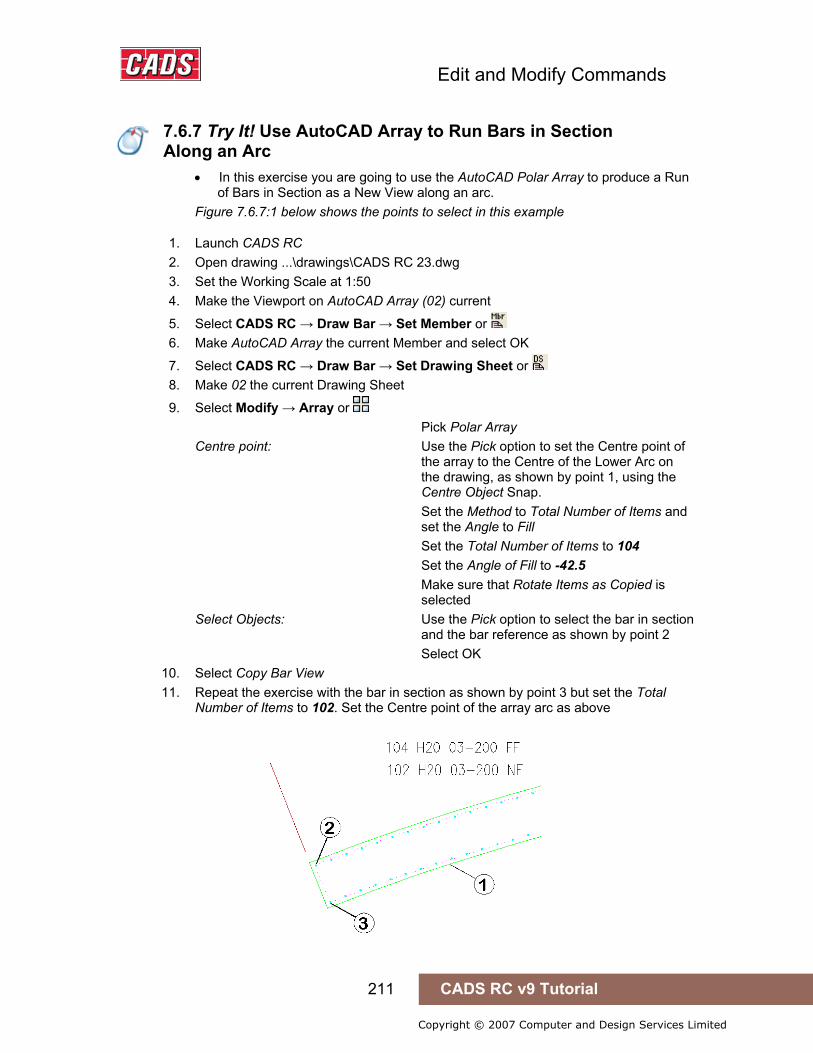
Edit and Modify Commands
211 CADS RC v9 Tutorial
Copyright © 2007 Computer and Design Services Limited
7.6.7 Try It! Use AutoCAD Array to Run Bars in Section Along an Arc
• In this exercise you are going to use the AutoCAD Polar Array to produce a Run of Bars in Section as a New View along an arc.
Figure 7.6.7:1 below shows the points to select in this example
1. Launch CADS RC 2. Open drawing ...\drawings\CADS RC 23.dwg 3. Set the Working Scale at 1:50 4. Make the Viewport on AutoCAD Array (02) current
5. Select CADS RC → Draw Bar → Set Member or 6. Make AutoCAD Array the current Member and select OK
7. Select CADS RC → Draw Bar → Set Drawing Sheet or 8. Make 02 the current Drawing Sheet
9. Select Modify → Array or Pick Polar Array Centre point: Use the Pick option to set the Centre point of the array to the Centre of the Lower Arc on the drawing, as shown by point 1, using the Centre Object Snap. Set the Method to Total Number of Items and set the Angle to Fill Set the Total Number of Items to 104 Set the Angle of Fill to -42.5 Make sure that Rotate Items as Copied is selected Select Objects: Use the Pick option to select the bar in section and the bar reference as shown by point 2 Select OK
10. Select Copy Bar View 11. Repeat the exercise with the bar in section as shown by point 3 but set the Total
Number of Items to 102. Set the Centre point of the array arc as above
7.6.7 Try It! Use AutoCAD Array to Run Bars in Section Along an Arc
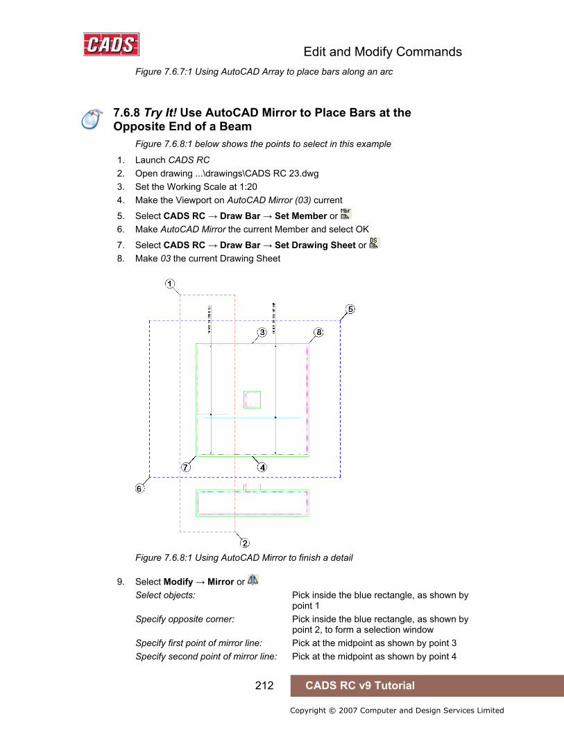
Edit and Modify Commands
212 CADS RC v9 Tutorial
Copyright © 2007 Computer and Design Services Limited
Figure 7.6.7:1 Using AutoCAD Array to place bars along an arc
7.6.8 Try It! Use AutoCAD Mirror to Place Bars at the Opposite End of a Beam
Figure 7.6.8:1 below shows the points to select in this example
1. Launch CADS RC 2. Open drawing ...\drawings\CADS RC 23.dwg 3. Set the Working Scale at 1:20 4. Make the Viewport on AutoCAD Mirror (03) current
5. Select CADS RC → Draw Bar → Set Member or 6. Make AutoCAD Mirror the current Member and select OK
7. Select CADS RC → Draw Bar → Set Drawing Sheet or 8. Make 03 the current Drawing Sheet
Figure 7.6.8:1 Using AutoCAD Mirror to finish a detail
9. Select Modify → Mirror or Select objects: Pick inside the blue rectangle, as shown by point 1 Specify opposite corner: Pick inside the blue rectangle, as shown by point 2, to form a selection window Specify first point of mirror line: Pick at the midpoint as shown by point 3 Specify second point of mirror line: Pick at the midpoint as shown by point 4
7.6.8 Try It! Use AutoCAD Mirror to Place Bars at the Opposite End of a Beam

Edit and Modify Commands
213 CADS RC v9 Tutorial
Copyright © 2007 Computer and Design Services Limited
Delete source objects? [Yes/No] <N>: Press Enter to continue Pick Mirror Bar Set • This has reflected the left hand Bar Set to the right in the plan and the section.
You will need to move the Bar Label to the correct side of the leader line. • Next you are going to mirror all the bars and the ranges on the plan at 45
degrees to produce the second layer of reinforcement. You will then adjust leg B of the U bar to fit inside the first layer of reinforcement.
10. Select Modify → Mirror command 11. Select objects: Pick inside the orange rectangle, as shown by
point 5 Specify opposite corner: Pick inside the blue rectangle, as shown by point 6, to form a selection window Specify first point of mirror line: Pick at the endpoint marked as point 7 Specify second point of mirror line: Pick at the endpoint marked as point 8 • Hold the Shift Key down on the keyboard and select the Pad Base and Column
Outlines to remove them from the AutoCAD selection set. Delete source objects? [Yes/No] <N>: Press enter to continue Pick Mirror Bar Set
12. Move the Bar Labels above the leader line
Figure 7.6.8:2 Completed detail using AutoCAD Mirror
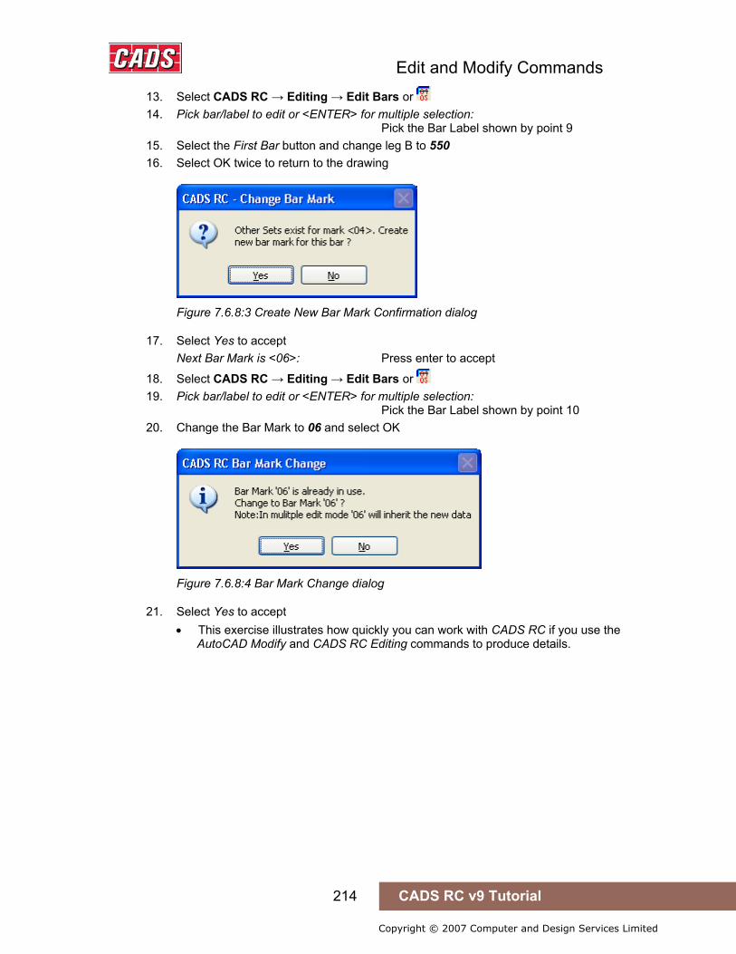
Edit and Modify Commands
214 CADS RC v9 Tutorial
Copyright © 2007 Computer and Design Services Limited
13. Select CADS RC → Editing → Edit Bars or 14. Pick bar/label to edit or <ENTER> for multiple selection:
Pick the Bar Label shown by point 9 15. Select the First Bar button and change leg B to 550 16. Select OK twice to return to the drawing
Figure 7.6.8:3 Create New Bar Mark Confirmation dialog
17. Select Yes to accept Next Bar Mark is <06>: Press enter to accept
18. Select CADS RC → Editing → Edit Bars or 19. Pick bar/label to edit or <ENTER> for multiple selection:
Pick the Bar Label shown by point 10 20. Change the Bar Mark to 06 and select OK
Figure 7.6.8:4 Bar Mark Change dialog
21. Select Yes to accept • This exercise illustrates how quickly you can work with CADS RC if you use the
AutoCAD Modify and CADS RC Editing commands to produce details.
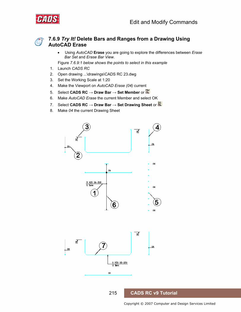
Edit and Modify Commands
215 CADS RC v9 Tutorial
Copyright © 2007 Computer and Design Services Limited
7.6.9 Try It! Delete Bars and Ranges from a Drawing Using AutoCAD Erase
• Using AutoCAD Erase you are going to explore the differences between Erase Bar Set and Erase Bar View.
Figure 7.6.9:1 below shows the points to select in this example 1. Launch CADS RC 2. Open drawing ...\drawings\CADS RC 23.dwg 3. Set the Working Scale at 1:20 4. Make the Viewport on AutoCAD Erase (04) current
5. Select CADS RC → Draw Bar → Set Member or 6. Make AutoCAD Erase the current Member and select OK
7. Select CADS RC → Draw Bar → Set Drawing Sheet or 8. Make 04 the current Drawing Sheet
7.6.9 Try It! Delete Bars and Ranges from a Drawing Using AutoCAD Erase

Edit and Modify Commands
216 CADS RC v9 Tutorial
Copyright © 2007 Computer and Design Services Limited
Figure 7.6.9:1 Using Erase Bar View and Set
9. Select Modify → Erase or 10. Select Objects: Pick the leader as shown by point 1
Select Objects: Press enter 11. Choose Erase Bar View
• Note that only the leader line has been deleted and not the arrowhead. You need to select both for deletion
12. Select Modify → Erase or 13. Pick the Bar Reference as shown by point 2
Select Objects: Press enter Select Erase Bar View • Note that only the Bar Reference is deleted
14. Select Modify → Erase or 15. Pick the Tag as shown by point 3
Select Objects: Press enter Select Erase Bar View • Note that the Ticks and Tags at each end of the bar are deleted
16. Select Modify → Erase or 17. Pick the Bar View as shown by point 4
Select Objects: Press enter Select Erase Bar View • Note that the Bar View and its Bar Reference are deleted
18. Select Modify → Erase or 19. Pick the Bar In Section as shown by point 5
Select Objects: Press enter Select Erase Bar View • Note that the whole Bar Run and the associated Bar References are deleted
20. Select Modify → Erase or 21. Pick the Bar In Section as shown by point 6
Select Objects: Press enter Select Erase Bar View • Note that the range line and associated end markers are deleted from the
drawing
22. Select Modify → Erase or 23. Pick the Bar In Section as shown by point 7
Select Objects: Press enter Select Erase Bar Set • Note that all the entities associated with the bar set are deleted from the drawing
Edit and Modify Commands
217 CADS RC v9 Tutorial
Copyright © 2007 Computer and Design Services Limited
7.7 AutoCAD Commands You Cannot Use on Reinforcement Entities
The following AutoCAD commands won’t work with CADS RC entities:
• Stretch • Offset • Scale • Lengthen • Trim, Extend • Break • Explode
You can however, Explode or Break CADS RC entities, but this will destroy the link to the CADS RC database and the bars may no longer appear on the Schedule.
7.8 Explode Over Stock Length (OSL) Group
An OSL Group of Bars and/or Ranges can be exploded into individual sets if required. Take care to use the CADS RC Explode OSL Group command and not the AutoCAD Explode command. You cannot currently add Views to an OSL group and so you will need to explode the Group in order to add Views. Once exploded the Bar Sets will no longer behave as an OSL group.
7.9 Assign Bars to Members
Throughout this tutorial we’ve encouraged you always to set the default Member before you start detailing. However, after the bar has been drawn you can always change the Member to which it has been assigned by using the Assign Bars to Member command,
.
This command is available from the Editing toolbar or through CADS RC → Editing → Assign Bars to Member. You can use this command to quickly assign multiple bars to a Member.
Select the Member from the drop down list and then use the Pick button to select the bars to be assigned. After you’ve made your selection you must use the Apply button on this dialog window as otherwise the assignment or reassignment will not be made and the changes will be lost. Having the Apply button on the dialog means that you can easily and quickly make several sets of changes without having to reload the command each time.
7.7 AutoCAD Commands You Cannot Use on Reinforcement Entities
7.8 Explode Over Stock Length (OSL) Group
7.9 Assign Bars to Members
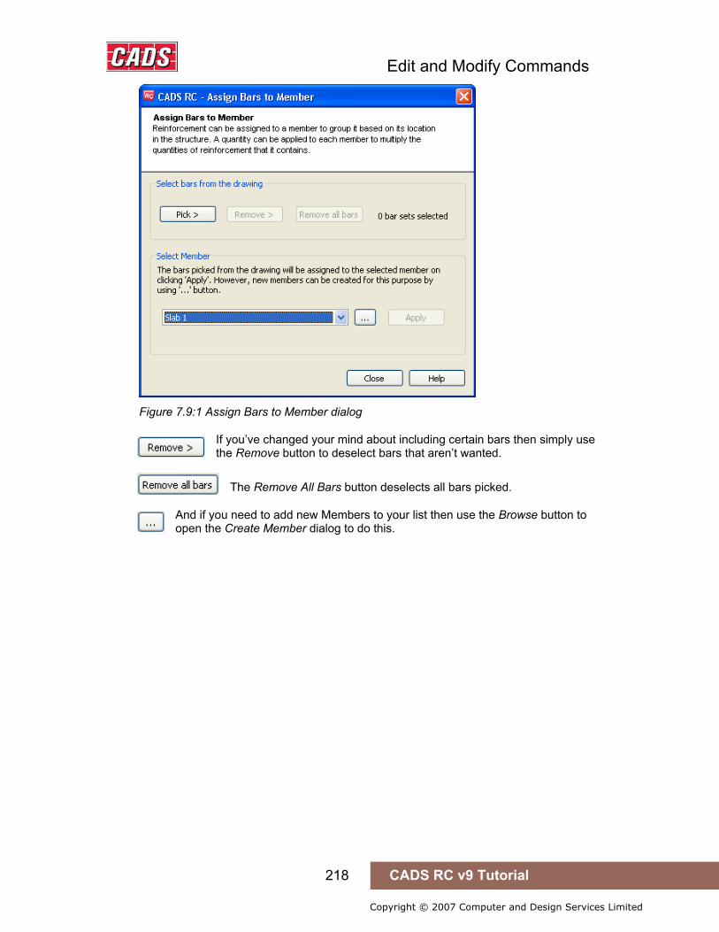
Edit and Modify Commands
218 CADS RC v9 Tutorial
Copyright © 2007 Computer and Design Services Limited
Figure 7.9:1 Assign Bars to Member dialog
If you’ve changed your mind about including certain bars then simply use the Remove button to deselect bars that aren’t wanted.
The Remove All Bars button deselects all bars picked.
And if you need to add new Members to your list then use the Browse button to open the Create Member dialog to do this.

Edit and Modify Commands
219 CADS RC v9 Tutorial
Copyright © 2007 Computer and Design Services Limited
Hints & Tips – Quick Way to Check Member Assignment
You can use the Assign Bars to Member command to view and check quickly that the bars on the drawing are assigned to the correct Member. Switch to Model Space and do a Zoom Extents on the drawing. Select the Assign Bars to Member command. Choose each Member on the drop down list in turn and select the Pick option. CADS RC will highlight in magenta (color 6) all the bars currently assigned to that selected Member.
Hints & Tips – Quick Way to Check Member Assignment
Try It! See the Examples at 7.11.1 and 7.11.2 for Practice on Assigning Bars to Members

Edit and Modify Commands
220 CADS RC v9 Tutorial
Copyright © 2007 Computer and Design Services Limited
7.10 Assign Bars to Drawing Sheets
Throughout this tutorial we’ve encouraged you always to set the default Drawing Sheets before you start detailing. However, after the bar has been drawn you can always change the Drawing Sheet to which it has been assigned by using the Assign Bars to Drawing Sheet command, .
This command is available from the Editing toolbar or through CADS RC → Editing → Assign Bars to Drawing Sheet. You can use this command to quickly assign multiple bars to a Drawing Sheet.
Figure 7.10:1 Assign Bars to Drawing Sheet dialog
If you’ve changed your mind about including certain bars then simply use the Remove button to deselect bars that aren’t wanted.
The Remove All Bars button deselects all bars picked.
Hints & Tips - Quick Way to Check Drawing Sheet Assignment
You can use the Assign Bars to Drawing Sheet command to view and check quickly that the bars on the drawing are assigned to the correct Drawing Sheet. Switch to Model Space and do a Zoom Extents on the Drawing. Select the Assign Bars to Drawing Sheet command. Choose each Drawing Sheet on the drop down list in turn and select the Pick option. CADS RC will highlight in magenta (color 6) all the bars currently assigned to that selected Drawing Sheet.
7.10 Assign Bars to Drawing Sheets
Hints & Tips - Quick Way to Check Drawing Sheet Assignment
Edit and Modify Commands
221 CADS RC v9 Tutorial
Copyright © 2007 Computer and Design Services Limited
7.11 Assign Bars to Release
The creation of Releases and of Assigning Bars to Releases is covered in the Section on Production, Chapter 10.
7.11.1 Try It! Copy and Paste a Detail from one Drawing Sheet to Another and Assign the Drawing Sheet and Member
• Using the standard Windows method of Copy to the clipboard and Paste from the clipboard you are going to duplicate a CADS RC detail. The copy and paste functionality could be used to duplicate details from one open drawing to another.
Figure 7.11.1:1 below shows the points to select in this example
1. Launch CADS RC 2. Open drawing ...\drawings\CADS RC 23.dwg 3. Set the Working Scale at 1:20 4. Make the Viewport on AutoCAD Copy Clip (05) current
5. Select CADS RC → Draw Bar → Set Member command 6. Make AutoCAD Copy Clip the current Member and select OK
7. Select CADS RC → Draw Bar → Set Drawing Sheet or 8. Make 05 the current Drawing Sheet
9. Select Edit → Copy with Base point or Specify base point: Pick the endpoint shown by point 1 Select objects: Pick in space, as shown by point 2, to create a crossing window Specify opposite corner: Pick in space as shown by point 3 Select objects: Press enter to continue • The slab has now been placed on the Windows clipboard
10. Make the Viewport on AutoCAD Paste (06) current
11. Select Edit → Paste command Specify insertion point: Pick the insertion point shown by point 4 • The slab is pasted into the Viewport. If bent bars are present CADS RC will
automatically assign them the next available Bar Marks.
7.11 Assign Bars to Release
7.11.1 Try It! Copy and Paste a Detail from one Drawing Sheet to Another and Assign the Drawing Sheet and Member
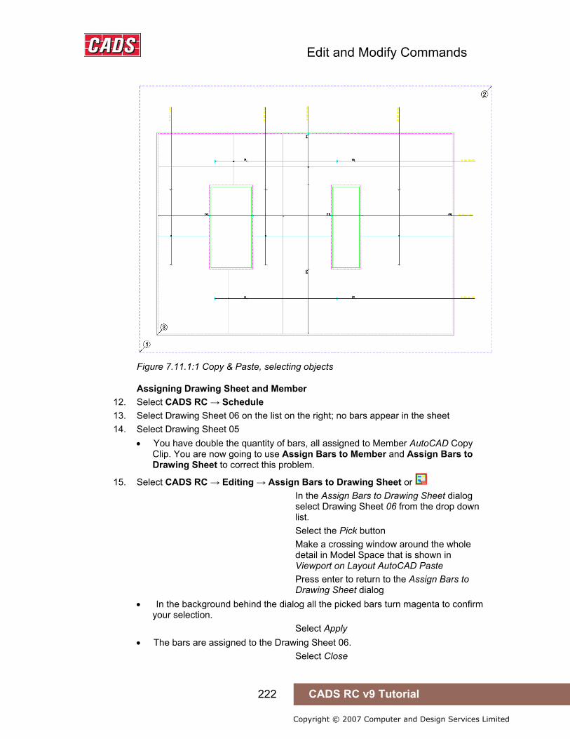
Edit and Modify Commands
222 CADS RC v9 Tutorial
Copyright © 2007 Computer and Design Services Limited
Figure 7.11.1:1 Copy & Paste, selecting objects
Assigning Drawing Sheet and Member 12. Select CADS RC → Schedule 13. Select Drawing Sheet 06 on the list on the right; no bars appear in the sheet 14. Select Drawing Sheet 05
• You have double the quantity of bars, all assigned to Member AutoCAD Copy Clip. You are now going to use Assign Bars to Member and Assign Bars to Drawing Sheet to correct this problem.
15. Select CADS RC → Editing → Assign Bars to Drawing Sheet or In the Assign Bars to Drawing Sheet dialog select Drawing Sheet 06 from the drop down list. Select the Pick button Make a crossing window around the whole detail in Model Space that is shown in Viewport on Layout AutoCAD Paste Press enter to return to the Assign Bars to Drawing Sheet dialog • In the background behind the dialog all the picked bars turn magenta to confirm
your selection. Select Apply • The bars are assigned to the Drawing Sheet 06. Select Close
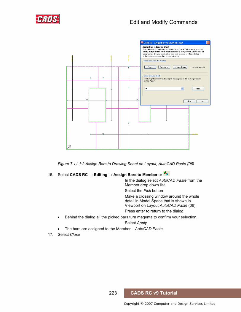
Edit and Modify Commands
223 CADS RC v9 Tutorial
Copyright © 2007 Computer and Design Services Limited
Figure 7.11.1:2 Assign Bars to Drawing Sheet on Layout, AutoCAD Paste (06)
16. Select CADS RC → Editing → Assign Bars to Member or In the dialog select AutoCAD Paste from the Member drop down list Select the Pick button Make a crossing window around the whole detail in Model Space that is shown in Viewport on Layout AutoCAD Paste (06) Press enter to return to the dialog • Behind the dialog all the picked bars turn magenta to confirm your selection. Select Apply • The bars are assigned to the Member – AutoCAD Paste.
17. Select Close

Edit and Modify Commands
224 CADS RC v9 Tutorial
Copyright © 2007 Computer and Design Services Limited
7.11.2 Try It! Export and Import a Wblock to a Drawing, Assigning Drawing Sheet and Member
Figure 7.11.2:2 below shows the points to select in this example
1. Launch CADS RC 2. Open drawing ...\drawings\CADS RC 23.dwg 3. Set the Working Scale at 1:20 4. Make the Viewport on AutoCAD Export Wblock (07) current
5. Select CADS RC → Draw Bar → Set Member or 6. Make AutoCAD Import Wblock the current Member and select OK
7. Select CADS RC → Draw Bar → Set Drawing Sheet or 8. Make 08 the current Drawing Sheet 9. Type Wblock and press enter
Figure 7.11.2:1 Wblock dialog
10. Select the Pick point button Wblock Insertion base point: Select point 1 • In the Wblock dialog make sure that the Retain radio button is selected. This
prevents AutoCAD from deleting the objects that have selected for export as a Wblock.
7.11.2 Try It! Export and Import a Wblock to a Drawing, Assigning Drawing Sheet and Member

Edit and Modify Commands
225 CADS RC v9 Tutorial
Copyright © 2007 Computer and Design Services Limited
Figure 7.11.2:2 Selecting objects to save as a Wblock
11. Click the Select Objects button Select objects: Select point 2 Specify opposite corner: Select point 3 Select objects: Press enter Specify the File name and path by selecting the Browse button
Figure 7.11.2:3 Specifying Path and Filename of Wblock
• Use a suitable folder such as the one currently holding your tutorial drawings. Type in the file name as ‘Pad Base’.
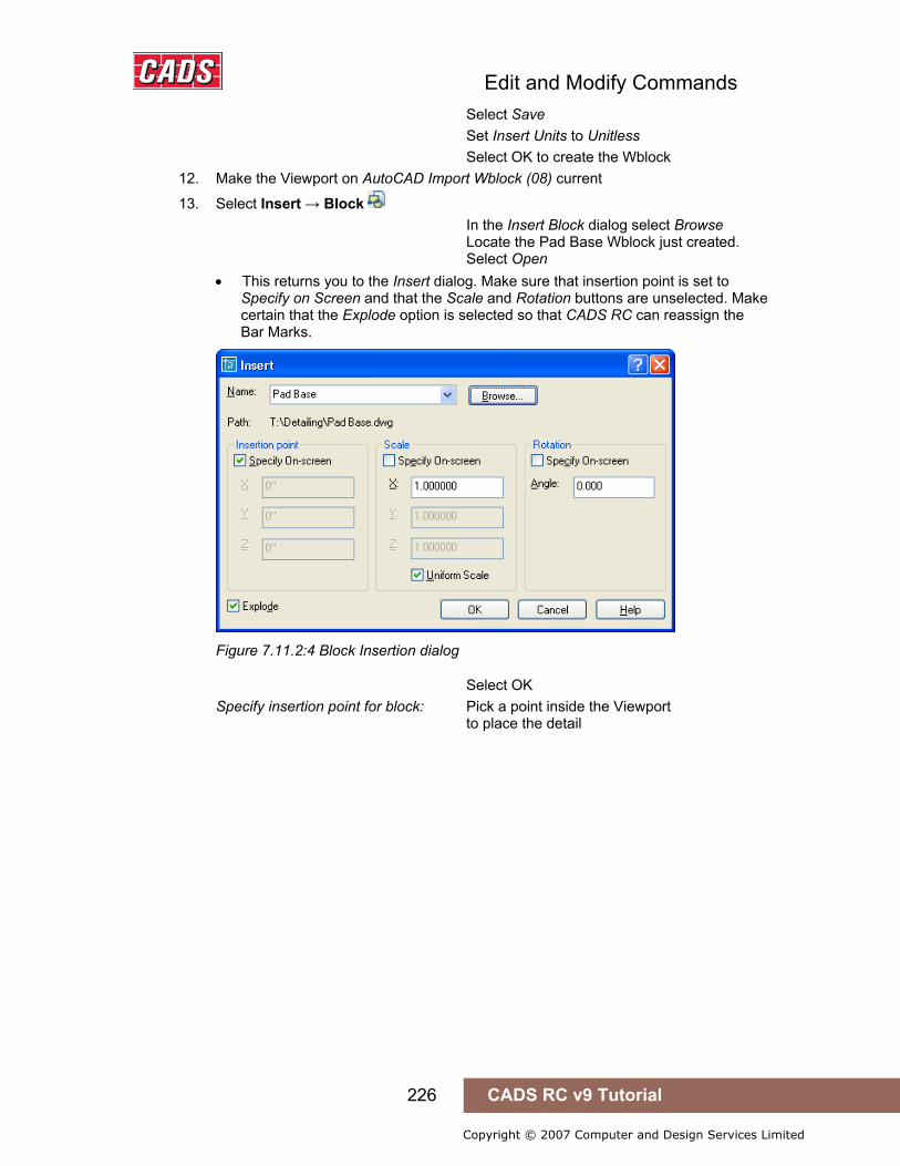
Edit and Modify Commands
226 CADS RC v9 Tutorial
Copyright © 2007 Computer and Design Services Limited
Select Save Set Insert Units to Unitless Select OK to create the Wblock
12. Make the Viewport on AutoCAD Import Wblock (08) current
13. Select Insert → Block In the Insert Block dialog select Browse Locate the Pad Base Wblock just created. Select Open • This returns you to the Insert dialog. Make sure that insertion point is set to
Specify on Screen and that the Scale and Rotation buttons are unselected. Make certain that the Explode option is selected so that CADS RC can reassign the Bar Marks.
Figure 7.11.2:4 Block Insertion dialog
Select OK Specify insertion point for block: Pick a point inside the Viewport to place the detail
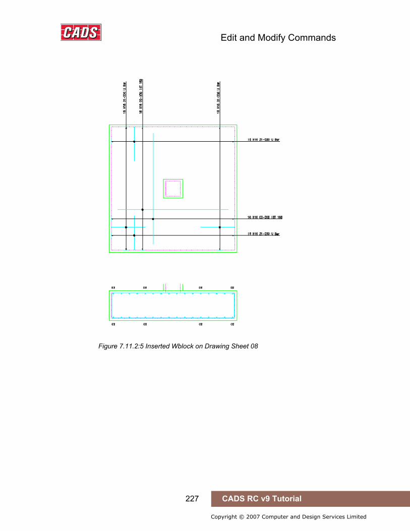
Edit and Modify Commands
227 CADS RC v9 Tutorial
Copyright © 2007 Computer and Design Services Limited
Figure 7.11.2:5 Inserted Wblock on Drawing Sheet 08

Edit and Modify Commands
228 CADS RC v9 Tutorial
Copyright © 2007 Computer and Design Services Limited
7.12 Change View to Set
The Change View to Set command, , will separate the Bar View / Bar Label from an existing Bar Set and make it a Bar Set in its own right. The Schedule will update to show another instance of the Bar Set.
This command is available from the Editing toolbar or through CADS RC → Editing → Change View to Set.
7.12.1 Try It! Change View to Set
• In this exercise you are going to make the bottom Straight Bar in the section a set on its own so that you can change its bar diameter without affecting the top steel. Start by changing the multi setting and the notes in the Straight Bar range.
Figure 7.12.1:1 below shows the points to select in this example
1. Launch CADS RC 2. Open drawing ...\drawings\CADS RC 24.dwg 3. Set Working Scale at 1:20 4. Make the Viewport on Change View to Set (01) current
5. Select CADS RC → Draw Bar → Set Member or 6. Make Change View to Set the current Member and select OK
7. Select CADS RC → Draw Bar → Set Drawing Sheet or 8. Make 01 the current Drawing Sheet
9. Select Editing → Edit Bars or Select Objects: Pick the Bar Label shown by point 1 Set the Multi Field to 1 Change the Notes to read T Select OK Use Grips to shorten the leader
10. Select Editing → Change View to Set or Pick required View for new SET: Pick the Bar View shown by point 2 Set Number is 15 Label bar <No>? or J to Justify: Type Y and press enter Pick Bar Label location: Position as shown by point 3 and rotate to 90 degrees
7.12 Change View to Set
7.12.1 Try It! Change View to Set

Edit and Modify Commands
229 CADS RC v9 Tutorial
Copyright © 2007 Computer and Design Services Limited
Figure 7.12.1:1 Selecting Bar Views to change to a Bar Set
11. Select CADS–RC → Editing → Edit Bars or Select Objects: Pick the Bar Label shown by point 3 Set the Bar Size to 20 Change the Notes to read B Select OK
12. Answer Yes to Create New Mark? and select OK on the Warning about the Laps • This is a quick way of editing the drawing to change the bottom steel when the
multi option has been used. Remember that if Edit This Outline as the Bottom Straight Steel has no Range in the Plan View the number of bars will not update and you will need to do this manually. Also note that the ticks and tags updated automatically to the new bar mark number.
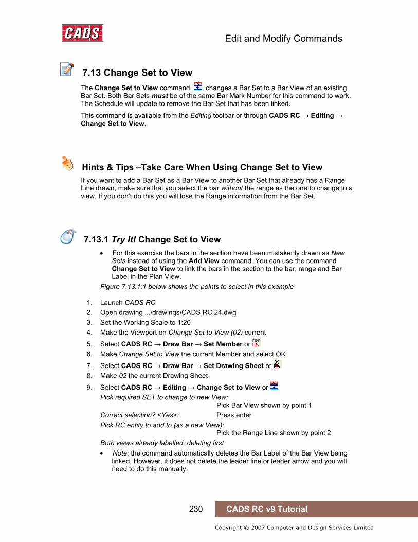
Edit and Modify Commands
230 CADS RC v9 Tutorial
Copyright © 2007 Computer and Design Services Limited
7.13 Change Set to View
The Change Set to View command, , changes a Bar Set to a Bar View of an existing Bar Set. Both Bar Sets must be of the same Bar Mark Number for this command to work. The Schedule will update to remove the Bar Set that has been linked.
This command is available from the Editing toolbar or through CADS RC → Editing → Change Set to View.
Hints & Tips –Take Care When Using Change Set to View
If you want to add a Bar Set as a Bar View to another Bar Set that already has a Range Line drawn, make sure that you select the bar without the range as the one to change to a view. If you don’t do this you will lose the Range information from the Bar Set.
7.13.1 Try It! Change Set to View
• For this exercise the bars in the section have been mistakenly drawn as New Sets instead of using the Add View command. You can use the command Change Set to View to link the bars in the section to the bar, range and Bar Label in the Plan View.
Figure 7.13.1:1 below shows the points to select in this example
1. Launch CADS RC 2. Open drawing ...\drawings\CADS RC 24.dwg 3. Set the Working Scale to 1:20 4. Make the Viewport on Change Set to View (02) current
5. Select CADS RC → Draw Bar → Set Member or 6. Make Change Set to View the current Member and select OK
7. Select CADS RC → Draw Bar → Set Drawing Sheet or 8. Make 02 the current Drawing Sheet
9. Select CADS RC → Editing → Change Set to View or Pick required SET to change to new View: Pick Bar View shown by point 1 Correct selection? <Yes>: Press enter Pick RC entity to add to (as a new View): Pick the Range Line shown by point 2 Both views already labelled, deleting first • Note: the command automatically deletes the Bar Label of the Bar View being
linked. However, it does not delete the leader line or leader arrow and you will need to do this manually.
7.13 Change Set to View
Hints & Tips –Take Care When Using Change Set to View
7.13.1 Try It! Change Set to View
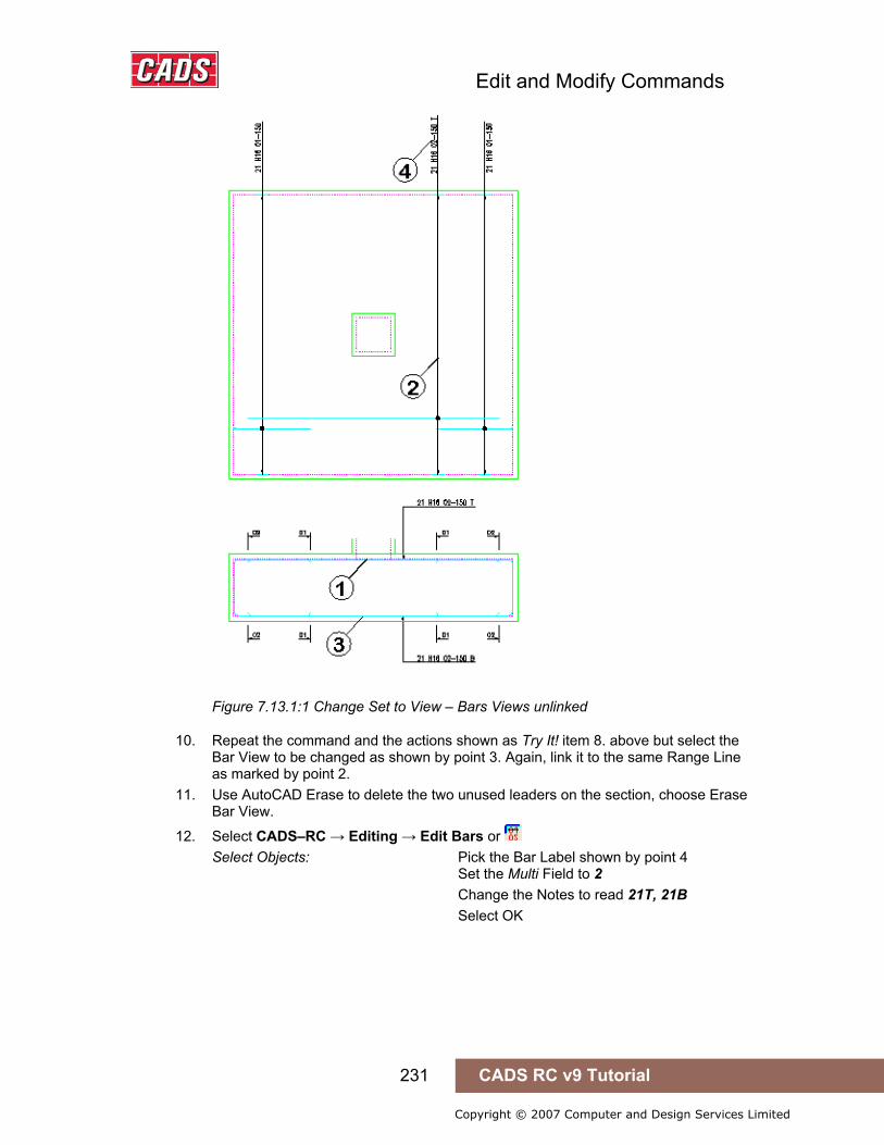
Edit and Modify Commands
231 CADS RC v9 Tutorial
Copyright © 2007 Computer and Design Services Limited
Figure 7.13.1:1 Change Set to View – Bars Views unlinked
10. Repeat the command and the actions shown as Try It! item 8. above but select the Bar View to be changed as shown by point 3. Again, link it to the same Range Line as marked by point 2.
11. Use AutoCAD Erase to delete the two unused leaders on the section, choose Erase Bar View.
12. Select CADS–RC → Editing → Edit Bars or Select Objects: Pick the Bar Label shown by point 4 Set the Multi Field to 2 Change the Notes to read 21T, 21B Select OK

Edit and Modify Commands
232 CADS RC v9 Tutorial
Copyright © 2007 Computer and Design Services Limited
Figure 7.13.1:2 Change Set to View – Bars Views Linked

Edit and Modify Commands
233 CADS RC v9 Tutorial
Copyright © 2007 Computer and Design Services Limited
7.14 Change Bar Style
The Change Bar Style command is used to toggle the display of the bar from Centre Line to Profile or vice versa. You can select one or more bars to change at the same time and the selection can be a mixture of Centre Line and Profile bars.
This command is accessible from the Editing toolbar or through CADS RC → Editing → Change Bar Style.
7.14 Change Bar Style
Try It! See the Example at 7.15.1 for Practice on Changing Bar Styles
Edit and Modify Commands
234 CADS RC v9 Tutorial
Copyright © 2007 Computer and Design Services Limited
7.15 Change Bar View
The Change Bar View command, , is used to change the current view of a selected bar. For instance, you might copy a Bar View from a Section View of the structure to an Elevation View of the structure and want to change it to a Right View. You can work through all the available views of the bar by pressing Enter on the keyboard. When the bar you want shows then press Esc to select it and to exit the command.
This command is accessible from the Editing toolbar or through CADS RC → Editing → Change Bar View.
Hints & Tips – Missing Bar Views
If the required view is not shown when you work through the views with the Change Bar View command it means that all the dimension data has not been entered for the bar. Use the Esc key on the keyboard to Exit the command, double click the bar to display the Edit Bar Data dialog and select Edit Dims. Type in the missing data and then try the Change Bar View command again.
7.15.1 Try It! Change Bar View and Bar Style
Figure 7.15.1:1 below shows the points to select in this example
1. Launch CADS RC 2. Open drawing ...\drawings\CADS RC 24.dwg 3. Set the Working Scale at 1:20 4. Make the Viewport on Change Bar View & Style (03) current
5. Select CADS RC → Draw Bar → Set Member or 6. Make Change Bar View & Style the current Member and select OK
7. Select CADS RC → Draw Bar → Set Drawing Sheet or 8. Make 03 the current Drawing Sheet
9. Select CADS RC → Editing → Change Bar Style or Select bars to be toggled: Select objects: Make a crossing box as shown by point 1 Specify opposite corner: Select point 2 Select objects: Press enter • The Side View of the bar is redrawn in Profile Style
10. Select CADS RC → Editing → Change Bar View or Select bars to be toggled: Select objects: Make a crossing box as shown by point 3 Specify opposite corner: Select point 4 Select objects: Press enter
7.15 Change Bar View
Hints & Tips – Missing Bar Views
7.15.1 Try It! Change Bar View and Bar Style

Edit and Modify Commands
235 CADS RC v9 Tutorial
Copyright © 2007 Computer and Design Services Limited
Enter view or <ENTER> to toggle: Press enter to work through the views offered and press the Esc key to select and exit when you’ve reached the view you want
Figure 7.15.1:1 Change Bar View and Bar Style
7.16 Add Entity to View
Edit and Modify Commands
236 CADS RC v9 Tutorial
Copyright © 2007 Computer and Design Services Limited
The Add Entity to View command can be used to add AutoCAD graphics entities – such as lines, polylines, arcs, circles and so on - to a Bar Set. This command is accessible through CADS RC → Editing → Add Entity to View. You might use this command to create custom Range Lines to attach to the Bar View or perhaps to add a missing dot between the Range Line and the Bar View.
Once you have selected the entities to attach to the Bar View CADS RC will prompt:
Calculate centres from added entity <No>:
If you answer Yes to this prompt you will be asked to reselect the entity to act as the Range Line and then to type in the centre spacing or the number of bars. Note that the Add Entity to View command will not prompt you to add a Bar Label, something which the Draw Range command would do if a Bar Label were not present for the Bar Set.
7.16.1 Try It! Add Entity to View
Figure 7.16.1:1 below shows the points to select in this example
1. Launch CADS RC 2. Open drawing ...\drawings\CADS RC 24.dwg 3. Set the Working Scale at 1:20 4. Make the Viewport on Add Entity to View (04) current
5. Select CADS RC → Draw Bar → Set Member or 6. Make Add Entity to View the current Member and select OK
7. Select CADS RC → Draw Bar → Set Drawing Sheet or 8. Make 04 the current Drawing Sheet 9. Select CADS RC → Editing → Add Entity to View
Pick Bar View to add entities to: Pick the bar as shown by point 1 Select objects: Select the line shown by point 2 Select objects: Select the polyline shown by point 3 Select objects: Select the line shown by point 4 Select objects: Select the line shown by point 5 Select objects: Press enter Calculate centres from added entity <No>: Type in Y and press enter Pick entity to calculate centres from: Pick on the polyline as shown by point 6 Range length 11489.5. Centre spacing or <Number of bars>: 200 Range options: 59 bars at < 200 > / Average c/c = 198.1 / Run out / Numeric: Press ENTER to continue or (A)verage/(R)un Out/(N)umeric: Press ENTER to continue or (A)verage/(R)un Out/(N)umeric: Press enter to continue • The Bar Label updates to show the correct number of bars and the Bar Centres.
7.16 Add Entity to View
7.16.1 Try It! Add Entity to View

Edit and Modify Commands
237 CADS RC v9 Tutorial
Copyright © 2007 Computer and Design Services Limited
Figure 7.16.1:1 Create a Custom Range Line using Add Entity to View

Edit and Modify Commands
238 CADS RC v9 Tutorial
Copyright © 2007 Computer and Design Services Limited
7.17 Add Text to View
The Add Text to View command can be used to attach additional text to a Bar Set. You will be prompted first to select the relevant Bar View and then to type in the text you want to add. There is a limit of 132 characters and the text you enter will automatically be formatted to match the Bar Label for font, height and layer.
This command is accessible through CADS RC → Editing → Add Text to View
7.17.1 Try It! Add Text to View
Figure 7.17.1:1 below shows the points to select in this example
1. Launch CADS RC 2. Open drawing ...\drawings\CADS RC 24.dwg 3. Set the Working Scale at 1:20 4. Make the Viewport on Add Text to View (05) current
5. Select CADS RC → Draw Bar → Set Member or 6. Make Add Text to View the current Member and select OK
7. Select CADS RC → Draw Bar → Set Drawing Sheet or 8. Make 05 the current Drawing Sheet 9. Select CADS RC → Editing → Add Text to View
Pick Bar View to add text to: Pick bar as shown by point 1 Enter text (no more than 132 characters): Type in, Oversized Radii bars to be bent on Site and press Enter Pick Bar Label location: Pick point 2 Rotation angle: Press enter for default rotation of 0 degrees.
Figure 7.17.1:1 Attach Annotation to a Bar Set using Add Text to View command
7.17 Add Text to View
7.17.1 Try It! Add Text to View
Edit and Modify Commands
239 CADS RC v9 Tutorial
Copyright © 2007 Computer and Design Services Limited
7.18 Key points - Edit and Modify Commands
• For speed, use the Double Click Editing feature to edit CADS RC Entities. If you select a Bar View it will display the Edit Bar Data dialog while if you select a range it will display the Edit Range dialog.
• The Edit Range dialog will vary depending on the type of range selected as some range types have restrictions on the type of data that can be edited.
• The Edit Bars command has a multiple selection option. This can be useful for changing globally properties such as steel Type, bar size and the like, within a whole drawing.
• Use the Edit Bars command to change properties such as Type, size, Shape Code, notes and so on relating to a bar.
• Use the Edit Range command to change the range properties such as range length, multiple groups, step increments on taper ranges, skewed range end markers, and more.
• You can apply a step taper to a Tapered Range that has more than one leg. • Missing tapering dimensions for the Varying Taper can be added through the
Edit Range dialog. • Use the Redraw Bar command to refresh configuration changes made to an
existing drawing. • If you need to stretch CADS RC entities then use the Reinforcement Stretch
Bar/Range command. Do not use the AutoCAD Stretch command. • Use the AutoCAD Copy, Mirror and Array commands to rapidly duplicate CADS
RC entities and then edit them to your requirements. • You cannot use the following AutoCAD Modify commands on CADS RC entities:
Stretch, Offset, Scale, Lengthen, Trim, Extend, Break, Explode. • You can create custom Range Lines using the Add Entity to View command. • You can work through the available Bar Views using the Change Bar View
command. • You can change the style of multiple bars between Profile and Centre Line by
using the Change Bar Style command. • Use Windows Copy and Paste to duplicate details between open drawings. • Make AutoCAD Wblocks to create CADS RC library details.
7.18 Key points - Edit and Modify Commands
Edit and Modify Commands
240 CADS RC v9 Tutorial
Copyright © 2007 Computer and Design Services Limited
7.19 Command List - Edit and Modify Commands
Action Menu Toolbar Icon CADS RC Commands
Set Member CADS RC → Draw Bar → Set Member Draw Bar
Set Drawing Sheet CADS RC → Draw Bar → Set Drawing Sheet Draw Bar
Edit Bars CADS RC → Editing → Edit Bars Editing
Edit Range CADS RC → Editing → Edit Range Editing
Configuration Centre CADS RC → Configuration → Configuration Centre Config
Redraw Bar CADS RC – Editing → Redraw Bar Editing
Stretch Bar/Range CADS RC → Editing → Stretch Bar/Range Editing
Assign Bars to Drawing Sheet CADS RC → Editing → Assign Bars to Drawing Sheet Editing
Assign Bars to Member CADS RC → Editing → Assign Bars to Member
Editing
Change View to Set CADS RC → Editing → Change View to Set Editing
Change Set to View CADS RC → Editing → Change Set to View Editing
Change Bar Style CADS RC → Editing → Change Bar Style Editing
Change Bar View CADS RC → Editing → Change Bar View Editing
Add Entity to View CADS RC → Editing → Add Entity to View
Add Text to View CADS RC → Editing → Add Text to View
AutoCAD Commands
Copy Modify → Copy
Array Modify → Array
Mirror Modify → Mirror
Erase Modify → Erase
Copy with Base point Edit → Copy with Base point
Paste Edit → Paste
Export File → Export
Block Insert → Block
7.19 Command List - Edit and Modify Commands

Checking Drawings
241 CADS RC v9 Tutorial
Copyright © 2007 Computer and Design Services Limited
8: Checking Drawings (Utilities)
8.0 Introduction
CADS RC comes with a number of utilities that allow you check and interrogate the CADS RC entities on your drawing:
• Use the Drawing Audit command to make sure all Bar Sets are complete and labelled
• Use the Check Database command to ensure that all CADS RC entities are linked correctly to the Schedule
• The Match Bars command will check all Bar Marks on the drawing and give those that are identical the same Mark Number
• The Compact Bars command will ensure that Bar Marks are sequential
You can also create AutoCAD selection sets of bars based on specific, selectable criteria.
8.0 Introduction

Checking Drawings
242 CADS RC v9 Tutorial
Copyright © 2007 Computer and Design Services Limited
8.1 Drawing Audit
Use the Drawing Audit command to make sure that all the Bar Sets on the drawing are complete and labelled. This command is accessible through CADS RC → Utilities → Drawing Audit. If a Bar Set is incomplete or unlabelled you can either highlight it on the drawing or add it to an AutoCAD selection set for interrogation. After running the command a display reports the audit results.
Figure 8.1:1 Drawing Audit report display
Incomplete Bar Sets If you tick this option CADS RC will report the number of Bar Sets with incomplete bar bending data or where the number of bars is incomplete. In addition it will highlight such sets on the drawing by colouring the bars magenta. When you then add the missing data the Bar Sets will be redrawn in the correct colors.
If you do not tick the highlight option CADS RC will still report the number of incomplete bars but will add them instead to the AutoCAD Selection set which you can then manipulate using the Move command to reposition the bars for interrogation.
Unlabelled Bar Sets CADS RC will also report the number of Bar Sets lacking a Bar Label. If you tick the option then CADS RC will highlight any unlabelled Bar Sets in magenta. When the Bar Label is added to the Bar Set it will be redrawn in the correct color.
If you do not tick the highlight option then CADS RC will add any unlabelled bars to the AutoCAD Selection set which you can then manipulate using the Move command to reposition the bars for interrogation.
Bar to be purged from the Schedule You can also use the Drawing Audit command is to clean up the Schedule. If all the views of a Bar Set have been erased using the Erase Bar View command then the Bar Set will still appear in the Schedule. Drawing Audit will purge these bars from the CADS RC database and the Schedule.
8.1 Drawing Audit

Checking Drawings
243 CADS RC v9 Tutorial
Copyright © 2007 Computer and Design Services Limited
Hints & Tips – Resetting Rebar Entities to the Original Colors
If you want to return the CADS RC entities to their original colors without first adding missing data then use the Redraw Bar command. This is accessible as CADS RC → Editing → Redraw Bar.
8.1.1 Try It! Drawing Audit
• In this exercise you are going to run the Drawing Audit to see if any of the bars are incomplete or unlabelled. This function checks the whole drawing but in this example only the bars in the Drawing Audit (01) layout will show any errors.
1. Launch CADS RC 2. Open drawing ...\drawings\CADS RC 25.dwg 3. Set the Working Scale at 1:20 4. Make the Viewport on Drawing Audit (01) Layout active
5. Select CADS RC → Draw Bar → Set Member or 6. Make Drawing Audit the current Member and select OK 7. Select CADS RC → Draw Bar → Set Drawing Sheet 8. Make Drawing Sheet 01 current
9. Select CADS RC → Utilities → Drawing Audit or • The command checks the drawing and reports, as shown in 8.1.1:1 below, that
there are five incomplete and two unlabelled Bar Sets. Make sure that the highlight options are ticked so that the command highlights the bars on the drawing and places them in the AutoCAD previous selection set. In some cases, such as Bars in Section, CADS RC cannot highlight the bars so you will need to move the incomplete and unlabelled bars off the drawing for closer inspection.
Figure 8.1.1:1 Drawing Audit report display
10. Select Modify → Move or Select objects: Type in P for previous selection set Select objects: Press enter to continue
Hints & Tips – Resetting Reinforcement Entities to the Original Colors
8.1.1 Try It! Drawing Audit

Checking Drawings
244 CADS RC v9 Tutorial
Copyright © 2007 Computer and Design Services Limited
Select objects: Specify base point or displacement: Select point 1 as marked on figure 8.1.1:2 Specify second point of displacement or <use first point as displacement>: Type @10000<90 and press Enter
Figure 8.1.1:2 Bars highlighted by the Drawing Audit command
11. Select the Model tab and zoom into the bars that you have just moved and that have been marked as incomplete or unlabelled. • You can inspect the bar data by double clicking on each bar and checking the
bar numbers or the bar dimensions. As you add the missing dimensions or numbers of bars, the edited bars will be redrawn in their original colors.
• The remaining bars need their Bar Labels added. 12. Select CADS RC → Editing → Edit Bars
Select the trimmer bars one by one and set the number of bars to 4 Select the Shape Code 21s and set the C legs to 900
13. Select CADS RC → Labelling → Label an Existing Bar, pick the highlighted bar and place the label on the leader
14. Select CADS RC → Utilities → Drawing Audit or • You will probably find that one Bar Set does not have a Bar Label so tick the
highlight options and add the missing Bar Label. If you have found incomplete or unlabelled bars it is worth running the command a second time after you have added the missing bar data as CADS RC may pick up more errors.
15. Select Modify → Move or Select objects: Make a window around the bars, ranges and labels that you moved earlier. Move them
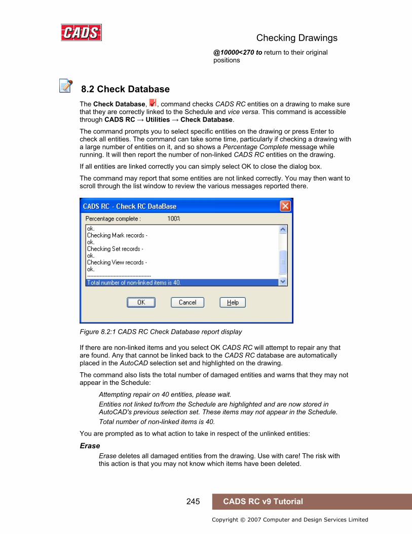
Checking Drawings
245 CADS RC v9 Tutorial
Copyright © 2007 Computer and Design Services Limited
@10000<270 to return to their original positions
8.2 Check Database
The Check Database, , command checks CADS RC entities on a drawing to make sure that they are correctly linked to the Schedule and vice versa. This command is accessible through CADS RC → Utilities → Check Database.
The command prompts you to select specific entities on the drawing or press Enter to check all entities. The command can take some time, particularly if checking a drawing with a large number of entities on it, and so shows a Percentage Complete message while running. It will then report the number of non-linked CADS RC entities on the drawing.
If all entities are linked correctly you can simply select OK to close the dialog box.
The command may report that some entities are not linked correctly. You may then want to scroll through the list window to review the various messages reported there.
Figure 8.2:1 CADS RC Check Database report display
If there are non-linked items and you select OK CADS RC will attempt to repair any that are found. Any that cannot be linked back to the CADS RC database are automatically placed in the AutoCAD selection set and highlighted on the drawing.
The command also lists the total number of damaged entities and warns that they may not appear in the Schedule:
Attempting repair on 40 entities, please wait. Entities not linked to/from the Schedule are highlighted and are now stored in AutoCAD's previous selection set. These items may not appear in the Schedule. Total number of non-linked items is 40.
You are prompted as to what action to take in respect of the unlinked entities:
Erase Erase deletes all damaged entities from the drawing. Use with care! The risk with this action is that you may not know which items have been deleted.
8.2 Check Database
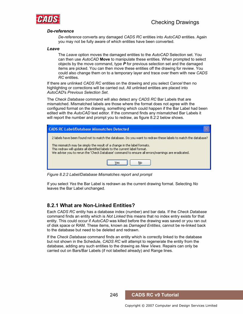
Checking Drawings
246 CADS RC v9 Tutorial
Copyright © 2007 Computer and Design Services Limited
De-reference De-reference converts any damaged CADS RC entities into AutoCAD entities. Again you may not be fully aware of which entities have been converted.
Leave The Leave option moves the damaged entities to the AutoCAD Selection set. You can then use AutoCAD Move to manipulate these entities. When prompted to select objects by the move command, type P for previous selection set and the damaged items are picked. You can then move these entities off the drawing for review. You could also change them on to a temporary layer and trace over them with new CADS RC entities.
If there are unlinked CADS RC entities on the drawing and you select Cancel then no highlighting or corrections will be carried out. All unlinked entities are placed into AutoCAD's Previous Selection Set.
The Check Database command will also detect any CADS RC Bar Labels that are mismatched. Mismatched labels are those where the format does not agree with the configured format on the drawing, something which could happen if the Bar Label had been edited with the AutoCAD text editor. If the command finds any mismatched Bar Labels it will report the number and prompt you to redraw, as figure 8.2:2 below shows.
Figure 8.2:2 Label/Database Mismatches report and prompt
If you select Yes the Bar Label is redrawn as the current drawing format. Selecting No leaves the Bar Label unchanged.
8.2.1 What are Non-Linked Entities? Each CADS RC entity has a database index (number) and bar data. If the Check Database command finds an entity which is Not Linked this means that no index entry exists for that entity. This could occur if AutoCAD was killed before the drawing was saved or you ran out of disk space or RAM. These items, known as Damaged Entities, cannot be re-linked back to the database but need to be deleted and redrawn.
If the Check Database command finds an entity which is correctly linked to the database but not shown in the Schedule, CADS RC will attempt to regenerate the entity from the database, adding any such entities to the drawing as New Views. Repairs can only be carried out on Bars/Bar Labels (if not labelled already) and Range lines.

Checking Drawings
247 CADS RC v9 Tutorial
Copyright © 2007 Computer and Design Services Limited
Hints & Tips – Switching off Bar Label Selection in the Check Database Command
If the Check Database command does not correctly select unlinked entities when the Leave option is selected, you should check and change the configuration through CADS RC → Configuration → Configuration Centre → Global/General Configuration. Set the top field to Miscellaneous and highlight CheckForLabelMismatches in the middle field. In the lower field type in Off and select Assign to CFG. Select OK twice and select Close to return to the drawing. See figure 8.2:3 below.
Run the Check Database command again and confirm that when you select Leave CADS RC creates a selection set of the unlinked bars.
Figure 8.2.1:1 CADS RC’s Global Configuration Centre
Hints & Tips – Switching off Bar Label Selection in the Check Database Command
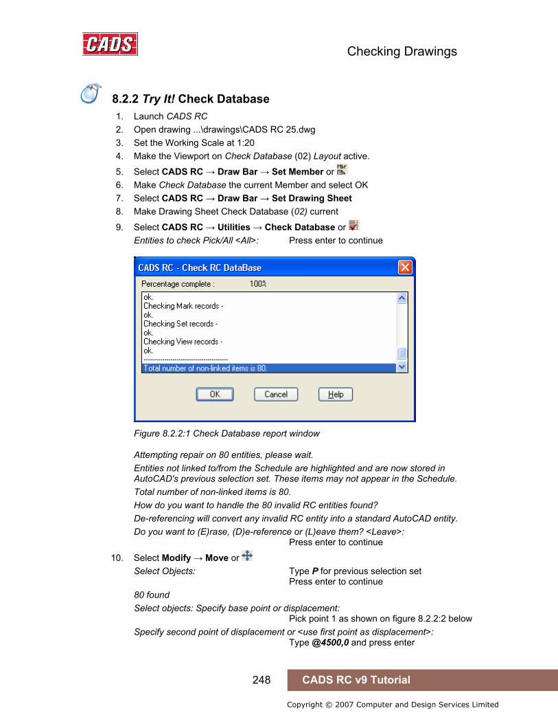
Checking Drawings
248 CADS RC v9 Tutorial
Copyright © 2007 Computer and Design Services Limited
8.2.2 Try It! Check Database
1. Launch CADS RC 2. Open drawing ...\drawings\CADS RC 25.dwg 3. Set the Working Scale at 1:20 4. Make the Viewport on Check Database (02) Layout active.
5. Select CADS RC → Draw Bar → Set Member or 6. Make Check Database the current Member and select OK 7. Select CADS RC → Draw Bar → Set Drawing Sheet 8. Make Drawing Sheet Check Database (02) current
9. Select CADS RC → Utilities → Check Database or Entities to check Pick/All <All>: Press enter to continue
Figure 8.2.2:1 Check Database report window
Attempting repair on 80 entities, please wait. Entities not linked to/from the Schedule are highlighted and are now stored in AutoCAD's previous selection set. These items may not appear in the Schedule. Total number of non-linked items is 80. How do you want to handle the 80 invalid RC entities found? De-referencing will convert any invalid RC entity into a standard AutoCAD entity. Do you want to (E)rase, (D)e-reference or (L)eave them? <Leave>: Press enter to continue
10. Select Modify → Move or Select Objects: Type P for previous selection set Press enter to continue 80 found Select objects: Specify base point or displacement: Pick point 1 as shown on figure 8.2.2:2 below Specify second point of displacement or <use first point as displacement>: Type @4500,0 and press enter
8.2.2 Try It! Check Database

Checking Drawings
249 CADS RC v9 Tutorial
Copyright © 2007 Computer and Design Services Limited
Figure 8.2.2:2 Damaged CADS RC Entities identified by the Check Database command
• All the CADS RC entities moved to the right are damaged and need to be redrawn. This damaged detail has been manufactured for this tutorial as it is rare that the problem occurs.
• If you find that you frequently get unlinked and damaged CADS RC entities you need to contact your local CADS RC support department. They will need to know which versions of AutoCAD and CADS RC you have installed and to see a sample drawing which illustrates what is going wrong. You can find out how to contact the support department by checking CADS RC → Help → About.
Checking Drawings
250 CADS RC v9 Tutorial
Copyright © 2007 Computer and Design Services Limited
8.3 Match Bars
The Match Bars command, , searches the drawing for identical bars which have been detailed with different Bar Mark Numbers. The command is accessible through CADS RC → Utilities → Match Bars. You are given the option to suppress questions and accept defaults.
If you answer No to the prompt Suppress Questions and Accept Defaults, each time the command finds an identical bar you are asked if you want to make them the same Mark and which Mark Number to change to.
If you answer Yes to Suppress Questions and Accept Defaults, CADS RC will assume that all bars are to be matched and assign the lowest Bar Mark Number.
Hints & Tips – Applying Tolerance to Match Bars
The Match Bars command can be configured to match Straight Bars within a set distance of another bar. This is known as the Straight Length Tolerance. This tolerance is configured through CADS RC → Configuration → Configuration Centre → Bar Configuration → Rounding/Match Bars. Straight bars with a difference in bar length less than or equal to the entered Straight Length Tolerance will be offered for Bar Mark matching.
8.3.1 Try It! Match Bars
• This example will show how you might run Match Bars. The two Pad Bases shown in figure 8.3.1:1 below are detailed with Shape Code 21 and have exactly the same dimensions, bar size, and so on. They should therefore all have the same Bar Mark Number. However, they have been copied and pasted from another drawing and CADS RC has assigned new Bar Mark Numbers for each Bar Set. The Match Bars routine will assign the same Bar Mark to each Bar Set.
1. Launch CADS RC 2. Open drawing ...\drawings\CADS RC 25.dwg 3. Set the Working Scale at 1:20 4. Make the Viewport on Match Bars (03) Layout active
5. Select CADS RC → Draw Bar → Set Member or 6. Make Match Bars the current Member and select OK 7. Select CADS RC → Draw Bar → Set Drawing Sheet 8. Make Drawing Sheet 03 current
• Normally you would answer Yes to the prompt about suppressing questions and accepting defaults but here you should answer No. This will let you see for yourself exactly what the command does and how you can override any of the defaults if you want to retain a particular Bar Mark. The command will check the entire drawing although in this example we are primarily interested in what happens to Bar Marks 801 to 804.
8.3 Match Bars
Hints & Tips – Applying Tolerance to Match Bars
8.3.1 Try It! Match Bars

Checking Drawings
251 CADS RC v9 Tutorial
Copyright © 2007 Computer and Design Services Limited
Figure 8.3.1:1 Running the Match Bars command
9. Select CADS RC → Utilities → Match Bars or Suppress questions and accept defaults <No>: Press enter Searching drawing for similar bar marks, please wait. Bar marks <13> and <17> are the same. Do you wish to combine them to make one mark? <Yes>: Press enter Enter the mark that you want to keep from 13/17 <13>: Bar marks <13> and <20> are the same. Do you wish to combine them to make one mark? <Yes>: Press enter Enter the mark that you want to keep from 13/20 <13>: Bar marks <13> and <23> are the same. Do you wish to combine them to make one mark? <Yes>: Press enter Enter the mark that you want to keep from 13/23 <13>: Bar marks <14> and <16> are the same. Do you wish to combine them to make one mark? <Yes>: Press enter Enter the mark that you want to keep from 14/16 <14>: Bar marks <14> and <19> are the same. Do you wish to combine them to make one mark? <Yes>: Press enter Enter the mark that you want to keep from 14/19 <14>: Bar marks <14> and <21> are the same. Do you wish to combine them to make one mark? <Yes>: Press enter Enter the mark that you want to keep from 14/21 <14>: Bar marks <15> and <18> are the same.

Checking Drawings
252 CADS RC v9 Tutorial
Copyright © 2007 Computer and Design Services Limited
Do you wish to combine them to make one mark? <Yes>: Press enter Enter the mark that you want to keep from 15/18 <15>: Bar marks <15> and <22> are the same. Do you wish to combine them to make one mark? <Yes>: Press enter Enter the mark that you want to keep from 15/22 <15>: Bar marks <15> and <24> are the same. Do you wish to combine them to make one mark? <Yes>: Press enter Enter the mark that you want to keep from 15/24 <15>: 9 similar bar marks found and modified. • Zoom around the Viewport to check that all the Bar Labels now show Bar Marks
13 to 15 instead of 13 to 24. • You may see slightly different Bar Marks appearing at the command line - simply
press Enter to accept the defaults.
8.4 Compact Bars
The Compact Bar Marks command, , checks through all Bar Marks on a drawing and reassigns Bar Mark Numbers so that they are sequential. The command is accessible through CADS RC → Utilities → Compact Bar Marks.
Using this command together with the Match Bars command ensures the most efficient use of Bar Marks on a drawing.
8.4.1 Try It! Compact Bars
• In this exercise you are going to run the Compact Bars routine to make Bar Mark Numbers sequential.
1. Launch CADS RC 2. Open drawing ...\drawings\CADS RC 25.dwg 3. Set the Working Scale at 1:20 4. Make the Viewport on Compact Bars (04) Layout active
5. Select CADS RC → Draw Bar → Set Member or 6. Make Compact Bars the current Member and select OK 7. Select CADS RC → Draw Bar → Set Drawing Sheet 8. Make Drawing Sheet 04 current
9. Select CADS RC → View Schedule or 10. Select the 04 Drawing Sheet
8.4 Compact Bars
8.4.1 Try It! Compact Bars
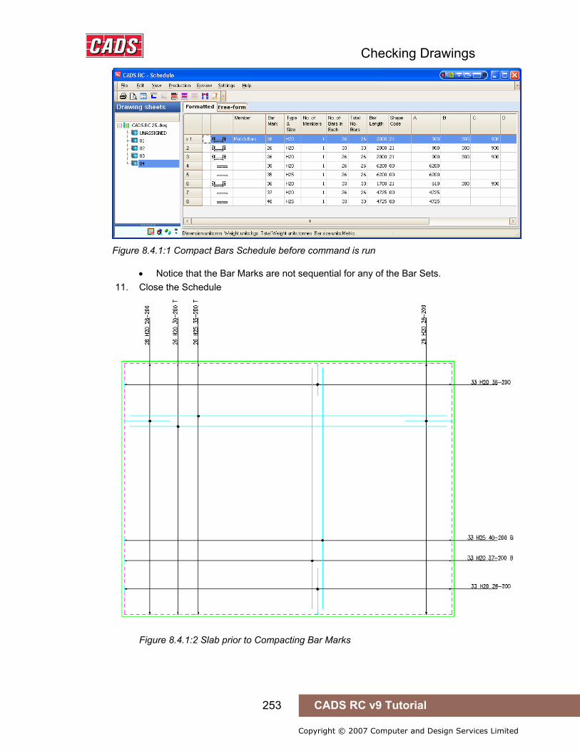
Checking Drawings
253 CADS RC v9 Tutorial
Copyright © 2007 Computer and Design Services Limited
Figure 8.4.1:1 Compact Bars Schedule before command is run
• Notice that the Bar Marks are not sequential for any of the Bar Sets. 11. Close the Schedule
Figure 8.4.1:2 Slab prior to Compacting Bar Marks

Checking Drawings
254 CADS RC v9 Tutorial
Copyright © 2007 Computer and Design Services Limited
12. Select CADS RC → Utilities → Compact Bar Marks or
Figure 8.4.1:3 Compact gaps? dialog
13. Compact gaps where Bar Marks have been deleted: Select Yes
Figure 8.4.1:4 Drawing after Compact Bars have been run
14. Select CADS RC → View Schedule or
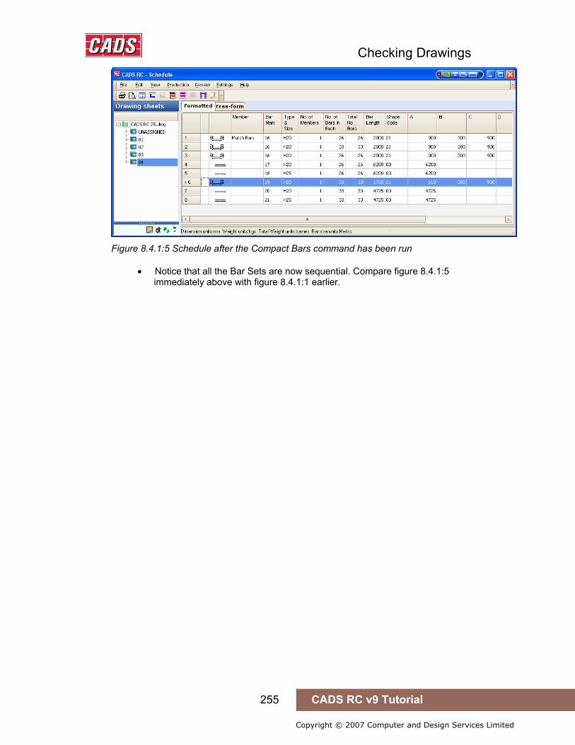
Checking Drawings
255 CADS RC v9 Tutorial
Copyright © 2007 Computer and Design Services Limited
Figure 8.4.1:5 Schedule after the Compact Bars command has been run
• Notice that all the Bar Sets are now sequential. Compare figure 8.4.1:5 immediately above with figure 8.4.1:1 earlier.
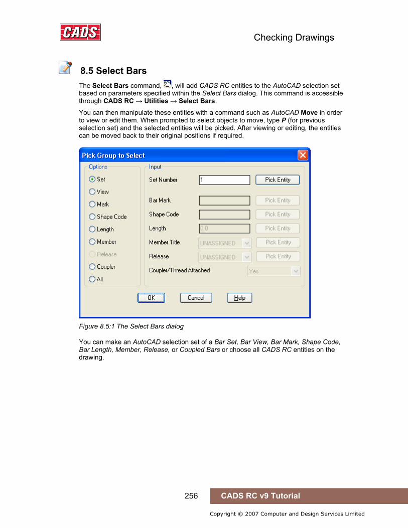
Checking Drawings
256 CADS RC v9 Tutorial
Copyright © 2007 Computer and Design Services Limited
8.5 Select Bars
The Select Bars command, , will add CADS RC entities to the AutoCAD selection set based on parameters specified within the Select Bars dialog. This command is accessible through CADS RC → Utilities → Select Bars.
You can then manipulate these entities with a command such as AutoCAD Move in order to view or edit them. When prompted to select objects to move, type P (for previous selection set) and the selected entities will be picked. After viewing or editing, the entities can be moved back to their original positions if required.
Figure 8.5:1 The Select Bars dialog
You can make an AutoCAD selection set of a Bar Set, Bar View, Bar Mark, Shape Code, Bar Length, Member, Release, or Coupled Bars or choose all CADS RC entities on the drawing.
8.5 Select Bars
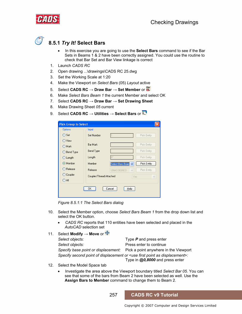
Checking Drawings
257 CADS RC v9 Tutorial
Copyright © 2007 Computer and Design Services Limited
8.5.1 Try It! Select Bars
• In this exercise you are going to use the Select Bars command to see if the Bar Sets in Beams 1 & 2 have been correctly assigned. You could use the routine to check that Bar Set and Bar View linkage is correct
1. Launch CADS RC 2. Open drawing ...\drawings\CADS RC 25.dwg 3. Set the Working Scale at 1:20 4. Make the Viewport on Select Bars (05) Layout active
5. Select CADS RC → Draw Bar → Set Member or 6. Make Select Bars Beam 1 the current Member and select OK 7. Select CADS RC → Draw Bar → Set Drawing Sheet 8. Make Drawing Sheet 05 current
9. Select CADS RC → Utilities → Select Bars or
Figure 8.5.1:1 The Select Bars dialog
10. Select the Member option, choose Select Bars Beam 1 from the drop down list and select the OK button. • CADS RC reports that 110 entities have been selected and placed in the
AutoCAD selection set
11. Select Modify → Move or Select objects: Type P and press enter Select objects: Press enter to continue Specify base point or displacement: Pick a point anywhere in the Viewport Specify second point of displacement or <use first point as displacement>: Type in @0,8000 and press enter
12. Select the Model Space tab • Investigate the area above the Viewport boundary titled Select Bar 05. You can
see that some of the bars from Beam 2 have been selected as well. Use the Assign Bars to Member command to change them to Beam 2.
8.5.1 Try It! Select Bars

Checking Drawings
258 CADS RC v9 Tutorial
Copyright © 2007 Computer and Design Services Limited
13. Select CADS RC → Editing → Assign Bars to Member or
Figure 8.5.1:2 Assign Bars to Member dialog
14. Set the select Member field to Select Bars Beam 2 15. Select the Pick button and make a crossing window around the bottom bars as
shown in figure 8.5.1:3 below Select Objects: Press enter to return to the dialog
Figure 8.5.1:3 Selecting bars to Assign to a Member
16. Pick Apply in the Assign Bars to Member dialog and then Close 17. Select all the RC Entities above the Viewport boundary and move them back into
their original position.

Checking Drawings
259 CADS RC v9 Tutorial
Copyright © 2007 Computer and Design Services Limited
8.6 Highlight Bars
The Highlight Bars command, , will highlight CADS RC entities on the drawing based on the parameters selected through the Pick Group to Highlight dialog. This command is accessible through CADS RC → Utilities → Highlight Bars
Figure 8.6:1 Highlight Bars dialog
You can choose to highlight a Bar Set, Bar View, Bar Mark, Shape Code, Bar Length, Member, Release, or Coupled Bars or choose all CADS RC entities on the drawing. The CADS RC entities selected are then immediately highlighted on the drawing once OK has been selected.
You are then prompted to Unhighlight the Entities. If you select Yes the entities will return to their original configured colors. If you select No the entities will remain highlighted in magenta. You can later use the Redraw Bar command, accessible through CADS RC → Editing → Redraw Bar, to return them to their correct colors.
Figure 8.6:2 The Unhighlight dialog of the Highlight Bars command
8.6 Highlight Bars

Checking Drawings
260 CADS RC v9 Tutorial
Copyright © 2007 Computer and Design Services Limited
8.7 Toggle Sketch Drawing Mode
The Toggle Sketch Drawing Mode command, , opens a dialog box with an option to set Sketch Mode ON or OFF by marking a tick box.
This command is accessible through CADS RC → Utilities Toggle → Sketch Drawing Mode
Figure 8.7:1 CADS RC Set Sketch Mode dialog
If Sketch Mode is ticked ON then Bar Labels are treated as intelligent CADS RC entities. However, Bar Views, Range Lines, bar references and other such entities are drawn instead as AutoCAD entities. This means if the bar data is edited the views and ranges will not update.
If Sketch Mode is turned OFF by unticking the box then all CADS RC entities are linked to each other and any editing will dynamically update all associated views of a Bar Set.
You should leave Sketch Mode switched OFF, selecting it only if there is a particular reason to have all CADS RC entities other than Bar Labels handled as AutoCAD entities.
8.7 Toggle Sketch Drawing Mode

Checking Drawings
261 CADS RC v9 Tutorial
Copyright © 2007 Computer and Design Services Limited
8.8 Check Dimensions
The Check Dimensions command, , will check all the dimensions on a drawing whether in Model or Layout Space to see if the dimension text has been manually edited to a different value. The command will ignore additional text which has been appended to the dimension.
This command is accessible through CADS RC → Utilities → Check Dimensions
When you initially select the command the dialog shown in figure 8.8:1 below is displayed.
Figure 8.8:1 Check Dimensions dialog
If you select the Check Dims button CADS RC searches the drawing, checks all the dimensions in Model and Layout Space and reports back how many dimensions have been modified.
Figure 8.8:2 The Check Dimensions report window
If the check box Put Found Dimensions into the Group is ticked then the dimension entities found will be put into AutoCAD group as specified in the text box. This group name can be changed, as described below, using the Configure button offered in the dialog.
If you select Yes the command will let you navigate around the drawing and show you which dimensions have been manually edited.
You can use the Highlight dialog box, shown in figure 8.8:3 below, to easily identify the edited dimensions. They will appear in a blue box on the drawing. You can then choose to leave them alone or edit them. When finished select the Close button.
8.8 Check Dimensions
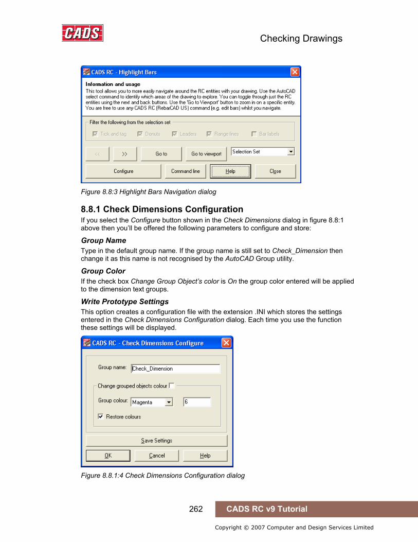
Checking Drawings
262 CADS RC v9 Tutorial
Copyright © 2007 Computer and Design Services Limited
Figure 8.8:3 Highlight Bars Navigation dialog
8.8.1 Check Dimensions Configuration If you select the Configure button shown in the Check Dimensions dialog in figure 8.8:1 above then you’ll be offered the following parameters to configure and store:
Group Name Type in the default group name. If the group name is still set to Check_Dimension then change it as this name is not recognised by the AutoCAD Group utility.
Group Color If the check box Change Group Object’s color is On the group color entered will be applied to the dimension text groups.
Write Prototype Settings This option creates a configuration file with the extension .INI which stores the settings entered in the Check Dimensions Configuration dialog. Each time you use the function these settings will be displayed.
Figure 8.8.1:4 Check Dimensions Configuration dialog

Checking Drawings
263 CADS RC v9 Tutorial
Copyright © 2007 Computer and Design Services Limited
8.9 Save As V8.4 Drawing
Use this command to save your current CADS RC V9 drawings in the earlier CADS RC V8.40 format.
This command is accessible through CADS RC → Utilities → Save as V8.4 Drawing
Note: if you save a V9 drawing in V8 format the following data will be lost:
• Drawing Sheet, Release and Member Information • Issuing and Revision Information
8.9 Save As V8.4 Drawing
Checking Drawings
264 CADS RC v9 Tutorial
Copyright © 2007 Computer and Design Services Limited
8.10 Key points - Checking Drawings
• When you have finished detailing run the following commands: i. Check Database ii. Drawing Audit iii. Match Bars iv. Compact Bars
• This ensures that all the CADS RC entities on the drawing are correctly linked to the database and Schedule. Running Match Bars and Compact Bars ensures the most efficient use of Bar Marks on the drawing.
• Use Drawing Audit to tidy up the Schedule if bars are present that have been deleted from the drawing.
• Check Database will detect Bar Labels that have been manually edited and offer to redraw them.
• Use Select Bars to create AutoCAD selection sets of CADS RC entities based on defined parameters such as Member, Release, Mark and the like.
• Use Check Dimensions to highlight which dimensions have had their associated text manually overridden.
• V9 drawings can be saved to V8.4 format, with certain limitations.
8.10 Key points - Checking Drawings
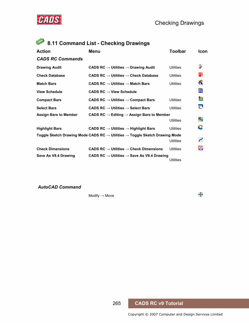
Checking Drawings
265 CADS RC v9 Tutorial
Copyright © 2007 Computer and Design Services Limited
8.11 Command List - Checking Drawings
Action Menu Toolbar Icon CADS RC Commands
Drawing Audit CADS RC → Utilities → Drawing Audit Utilities
Check Database CADS RC → Utilities → Check Database Utilities
Match Bars CADS RC → Utilities → Match Bars Utilities
View Schedule CADS RC → View Schedule
Compact Bars CADS RC → Utilities → Compact Bars Utilities
Select Bars CADS RC → Utilities → Select Bars Utilities
Assign Bars to Member CADS RC → Editing → Assign Bars to Member Utilities
Highlight Bars CADS RC → Utilities → Highlight Bars Utilities
Toggle Sketch Drawing Mode CADS RC → Utilities → Toggle Sketch Drawing Mode Utilities
Check Dimensions CADS RC → Utilities → Check Dimensions Utilities
Save As V8.4 Drawing CADS RC → Utilities → Save As V8.4 Drawing Utilities
AutoCAD Command
Modify → Move
8.11 Command List - Checking Drawings
Interacting with the Schedule
266 CADS RC v9 Tutorial
Copyright © 2007 Computer and Design Services Limited
9: Interacting with the Schedule
9.0 Introduction
The Schedule viewer is designed to give you maximum freedom to organise and view your bar data to your own requirements. The View Schedule command can be accessed from the CADS RC pull down menu or by selecting on the CADS RC toolbar.
9.0 Introduction

Interacting with the Schedule
267 CADS RC v9 Tutorial
Copyright © 2007 Computer and Design Services Limited
9.1 Navigating around the Schedule
There are three main areas to the Schedule dialog. These are shown in figure 9.1:1 below.
Navigation Area The Navigation Area shows a tree view of the available Drawing Sheets, Releases or Members depending on which option is selected in the Mode Area.
Data Area The Data Area displays bar bending data relevant to the selection made in the Navigation Area. There are two tabs, Formatted and Free-Form, and these will be described later.
Mode Area This area has three icon buttons, Drawing Sheets, Releases and Members, used to select what displays in the Navigation Area and, hence, what class of bar bending data will be shown in the Data Area.
Figure 9.1:1 Schedule dialog
When you open the Schedule the Navigation Area will show a list of all the currently created Drawing Sheets. If you select a particular Drawing Sheet the Data Area will adjust its output to show just the bars assigned to that Drawing Sheet.
9.1 Navigating around the Schedule

Interacting with the Schedule
268 CADS RC v9 Tutorial
Copyright © 2007 Computer and Design Services Limited
Figure 9.1:2 Selecting a Drawing Sheet will change the Data View
If you want to see data on Members then select the Members icon in the Mode Area, shown in figure 9.1:3 below. This will change the Navigation Area to display a tree view of Members and selecting a particular Member will show its data in the Data Area.
Figure 9.1:3 Mode Area of the Schedule Viewer
Figure 9.1:4 Members displayed in Free-Form Data display
Similarly, if you want to see data on Releases then select the Releases icon in the Mode Area. This will change the Navigation Area to display a tree view of Releases. Further information on Releases is given later in this chapter.
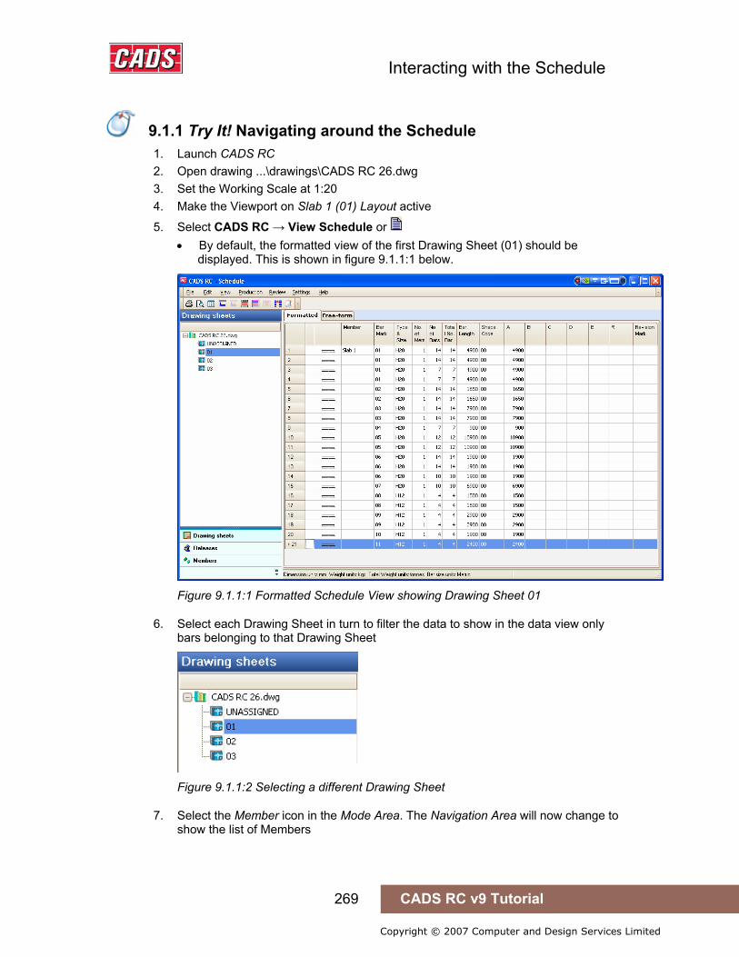
Interacting with the Schedule
269 CADS RC v9 Tutorial
Copyright © 2007 Computer and Design Services Limited
9.1.1 Try It! Navigating around the Schedule
1. Launch CADS RC 2. Open drawing ...\drawings\CADS RC 26.dwg 3. Set the Working Scale at 1:20 4. Make the Viewport on Slab 1 (01) Layout active
5. Select CADS RC → View Schedule or • By default, the formatted view of the first Drawing Sheet (01) should be
displayed. This is shown in figure 9.1.1:1 below.
Figure 9.1.1:1 Formatted Schedule View showing Drawing Sheet 01
6. Select each Drawing Sheet in turn to filter the data to show in the data view only bars belonging to that Drawing Sheet
Figure 9.1.1:2 Selecting a different Drawing Sheet
7. Select the Member icon in the Mode Area. The Navigation Area will now change to show the list of Members
9.1.1 Try It! Navigating around the Schedule
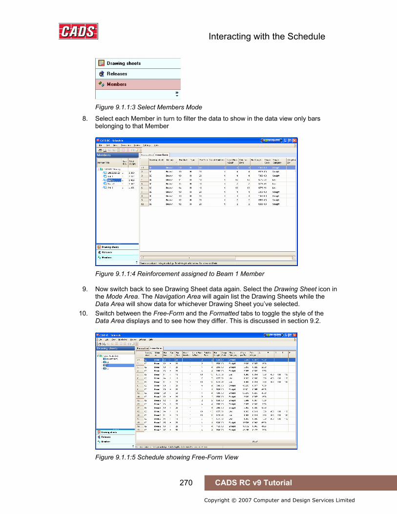
Interacting with the Schedule
270 CADS RC v9 Tutorial
Copyright © 2007 Computer and Design Services Limited
Figure 9.1.1:3 Select Members Mode
8. Select each Member in turn to filter the data to show in the data view only bars belonging to that Member
Figure 9.1.1:4 Reinforcement assigned to Beam 1 Member
9. Now switch back to see Drawing Sheet data again. Select the Drawing Sheet icon in the Mode Area. The Navigation Area will again list the Drawing Sheets while the Data Area will show data for whichever Drawing Sheet you’ve selected.
10. Switch between the Free-Form and the Formatted tabs to toggle the style of the Data Area displays and to see how they differ. This is discussed in section 9.2.
Figure 9.1.1:5 Schedule showing Free-Form View
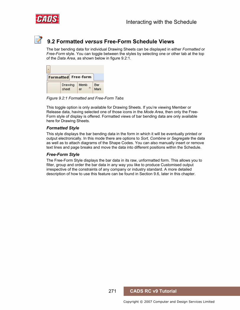
Interacting with the Schedule
271 CADS RC v9 Tutorial
Copyright © 2007 Computer and Design Services Limited
9.2 Formatted versus Free-Form Schedule Views
The bar bending data for individual Drawing Sheets can be displayed in either Formatted or Free-Form style. You can toggle between the styles by selecting one or other tab at the top of the Data Area, as shown below in figure 9.2:1.
Figure 9.2:1 Formatted and Free-Form Tabs
This toggle option is only available for Drawing Sheets. If you’re viewing Member or Release data, having selected one of those icons in the Mode Area, then only the Free-Form style of display is offered. Formatted views of bar bending data are only available here for Drawing Sheets.
Formatted Style This style displays the bar bending data in the form in which it will be eventually printed or output electronically. In this mode there are options to Sort, Combine or Segregate the data as well as to attach diagrams of the Shape Codes. You can also manually insert or remove text lines and page breaks and move the data into different positions within the Schedule.
Free-Form Style The Free-Form Style displays the bar data in its raw, unformatted form. This allows you to filter, group and order the bar data in any way you like to produce Customised output irrespective of the constraints of any company or industry standard. A more detailed description of how to use this feature can be found in Section 9.6, later in this chapter.
9.2 Formatted versus Free-Form Schedule Views
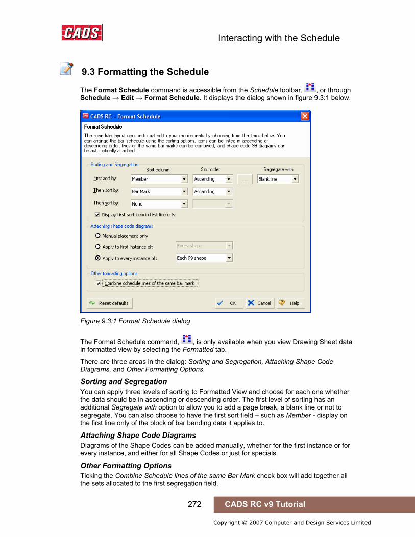
Interacting with the Schedule
272 CADS RC v9 Tutorial
Copyright © 2007 Computer and Design Services Limited
9.3 Formatting the Schedule
The Format Schedule command is accessible from the Schedule toolbar, , or through Schedule → Edit → Format Schedule. It displays the dialog shown in figure 9.3:1 below.
Figure 9.3:1 Format Schedule dialog
The Format Schedule command, , is only available when you view Drawing Sheet data in formatted view by selecting the Formatted tab.
There are three areas in the dialog: Sorting and Segregation, Attaching Shape Code Diagrams, and Other Formatting Options.
Sorting and Segregation You can apply three levels of sorting to Formatted View and choose for each one whether the data should be in ascending or descending order. The first level of sorting has an additional Segregate with option to allow you to add a page break, a blank line or not to segregate. You can also choose to have the first sort field – such as Member - display on the first line only of the block of bar bending data it applies to.
Attaching Shape Code Diagrams Diagrams of the Shape Codes can be added manually, whether for the first instance or for every instance, and either for all Shape Codes or just for specials.
Other Formatting Options Ticking the Combine Schedule lines of the same Bar Mark check box will add together all the sets allocated to the first segregation field.
9.3 Formatting the Schedule

Interacting with the Schedule
273 CADS RC v9 Tutorial
Copyright © 2007 Computer and Design Services Limited
9.3.1 Try It! Formatting the Schedule
In this Try It! you will format the schedule ready for printing. This will include changing the display order of the member titles, sorting and combining.
1. Launch CADS RC 2. Open drawing ...\drawings\CADS RC 26.dwg 3. Set the Working Scale at 1:20 4. Make the Viewport on Slab 1 (01) Layout active
5. Select CADS RC → View Schedule or • By default, the formatted view of the first Drawing Sheet (01) should be
displayed. This is shown in figure 9.3.1:1 below.
Figure 9.3.1:1 Schedule ready for formatting
6. Select Edit → Format Schedule or In the Sorting and Segregation section on the ‘First Sort by:’ line, set the ‘Sort Order’ to Custom and then pick the Browse button as shown below in figure 9.3.1:2.
Figure 9.3.1:2 Sorting and Segregation options
9.3.1 Try It! Formatting the Schedule

Interacting with the Schedule
274 CADS RC v9 Tutorial
Copyright © 2007 Computer and Design Services Limited
In the Arranger members dialog change the order of the member titles as shown below in figure 9.3.1:3 and then pick Ok to return to the Formatting dialog.
Figure 9.3.1:3 Arrange members dialog
In the Format Schedule dialog box pick the Combine schedule lines of the same bar mark, as shown in figure 9.3.1:4 below and then pick OK to return the main schedule view.
Figure 9.3.1:4 Format Schedule dialog
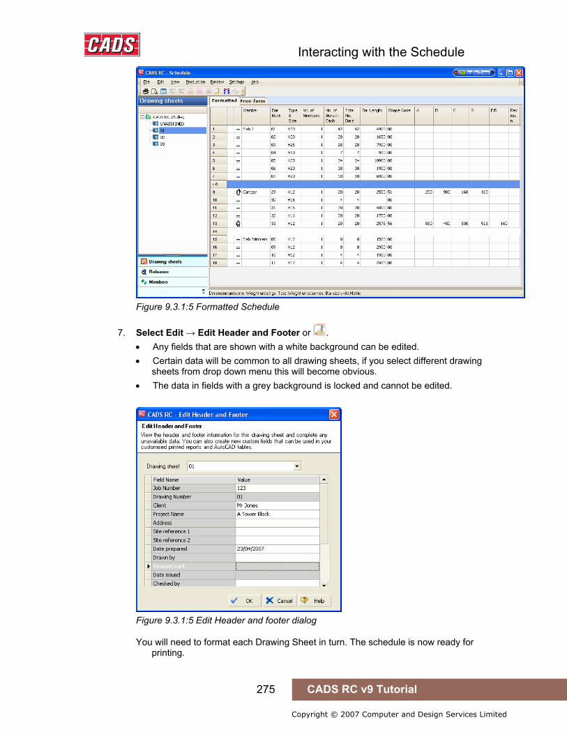
Interacting with the Schedule
275 CADS RC v9 Tutorial
Copyright © 2007 Computer and Design Services Limited
Figure 9.3.1:5 Formatted Schedule
7. Select Edit → Edit Header and Footer or . • Any fields that are shown with a white background can be edited. • Certain data will be common to all drawing sheets, if you select different drawing
sheets from drop down menu this will become obvious. • The data in fields with a grey background is locked and cannot be edited.
Figure 9.3.1:5 Edit Header and footer dialog
You will need to format each Drawing Sheet in turn. The schedule is now ready for printing.
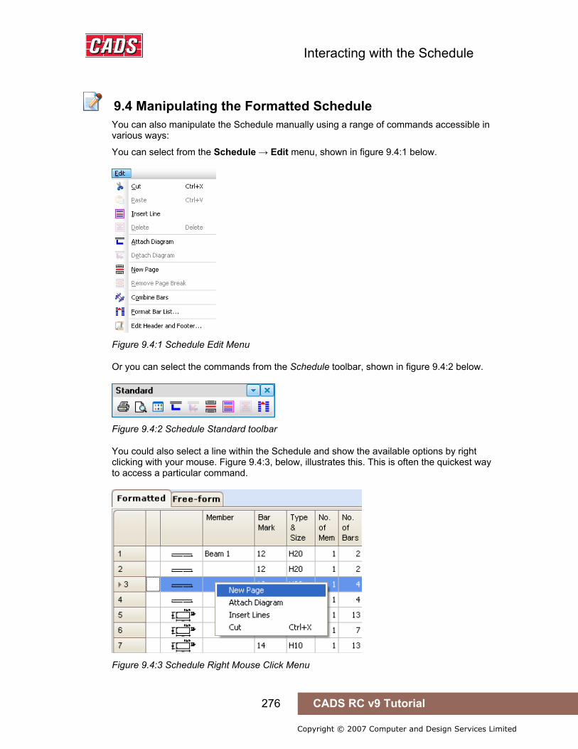
Interacting with the Schedule
276 CADS RC v9 Tutorial
Copyright © 2007 Computer and Design Services Limited
9.4 Manipulating the Formatted Schedule
You can also manipulate the Schedule manually using a range of commands accessible in various ways:
You can select from the Schedule → Edit menu, shown in figure 9.4:1 below.
Figure 9.4:1 Schedule Edit Menu
Or you can select the commands from the Schedule toolbar, shown in figure 9.4:2 below.
Figure 9.4:2 Schedule Standard toolbar
You could also select a line within the Schedule and show the available options by right clicking with your mouse. Figure 9.4:3, below, illustrates this. This is often the quickest way to access a particular command.
Figure 9.4:3 Schedule Right Mouse Click Menu
9.4 Manipulating the Formatted Schedule

Interacting with the Schedule
277 CADS RC v9 Tutorial
Copyright © 2007 Computer and Design Services Limited
9.4.1 Schedule Edit Menu Options The Schedule Edit menu offers commands useful for manipulating the Schedule in various ways. As mentioned earlier, many of these are also available on the Schedule Standard toolbar or from a menu brought up by right clicking on a line of data within the Schedule. There’s also an additional command to add text to a blank line, and this is described at the end of the list. Note that these options are available only in the Formatted Schedule view.
Cut This uses the standard Windows Cut command and, with Paste, lets you move selected bar data from one location to another within the Schedule. You can highlight a single line by clicking on it with your left mouse button or highlight a continuous block of lines by clicking on the first, holding down the keyboard Shift key and then clicking on the last line. And if you want to select a number of lines in different places then keep the keyboard Ctrl key pressed while making your selection.
Hint: it’s sometimes quicker to select a large block using click/Shift-click and then unselect a few unwanted lines individually using Ctrl-click.
The lines you select will be highlighted in green and you can then Cut these by, for instance, right clicking to show the menu and selecting Cut or by using the toolbar or the Schedule → Edit menu described earlier.
Figure 9.4.1:1 Bar Data marked to be moved in the Formatted Schedule
Paste This also uses a standard Windows command, Paste. After you’ve Cut selected lines click in the location in the Schedule where the line or lines should go. Select Paste, using any of the three approaches described earlier, to move the lines to the new position.
Insert line Use this option to insert blank lines into the Schedule view, positioned above the line of bar data selected when the command is invoked. You can then leave the line blank or add text to it as described in the paragraph on Attaching Text to a Blank Line at the end of this list of Schedule Edit menu options.
Delete Use the Delete option to remove lines from the Schedule. Lines can be deleted individually or as a group selected in the same manner as explained above in the description of the Cut option.
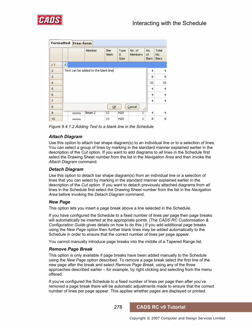
Interacting with the Schedule
278 CADS RC v9 Tutorial
Copyright © 2007 Computer and Design Services Limited
Figure 9.4.1:2 Adding Text to a blank line in the Schedule
Attach Diagram Use this option to attach bar shape diagram(s) to an individual line or to a selection of lines. You can select a group of lines by marking in the standard manner explained earlier in the description of the Cut option. If you want to add diagrams to all lines in the Schedule first select the Drawing Sheet number from the list in the Navigation Area and then invoke the Attach Diagram command.
Detach Diagram Use this option to detach bar shape diagram(s) from an individual line or a selection of lines that you can select by marking in the standard manner explained earlier in the description of the Cut option. If you want to detach previously attached diagrams from all lines in the Schedule first select the Drawing Sheet number from the list in the Navigation Area before invoking the Detach Diagram command.
New Page This option lets you insert a page break above a line selected in the Schedule.
If you have configured the Schedule to a fixed number of lines per page then page breaks will automatically be inserted at the appropriate points. (The CADS RC Customisation & Configuration Guide gives details on how to do this.) If you add additional page breaks using the New Page option then further blank lines may be added automatically to the Schedule in order to ensure that the correct number of lines per page appear.
You cannot manually introduce page breaks into the middle of a Tapered Range list.
Remove Page Break This option is only available if page breaks have been added manually to the Schedule using the New Page option described. To remove a page break select the first line of the new page after the break and select Remove Page Break, using any of the three approaches described earlier – for example, by right clicking and selecting from the menu offered.
If you’ve configured the Schedule to a fixed number of lines per page then after you’ve removed a page break there will be automatic adjustments made to ensure that the correct number of lines per page appear. This applies whether pages are displayed or printed.
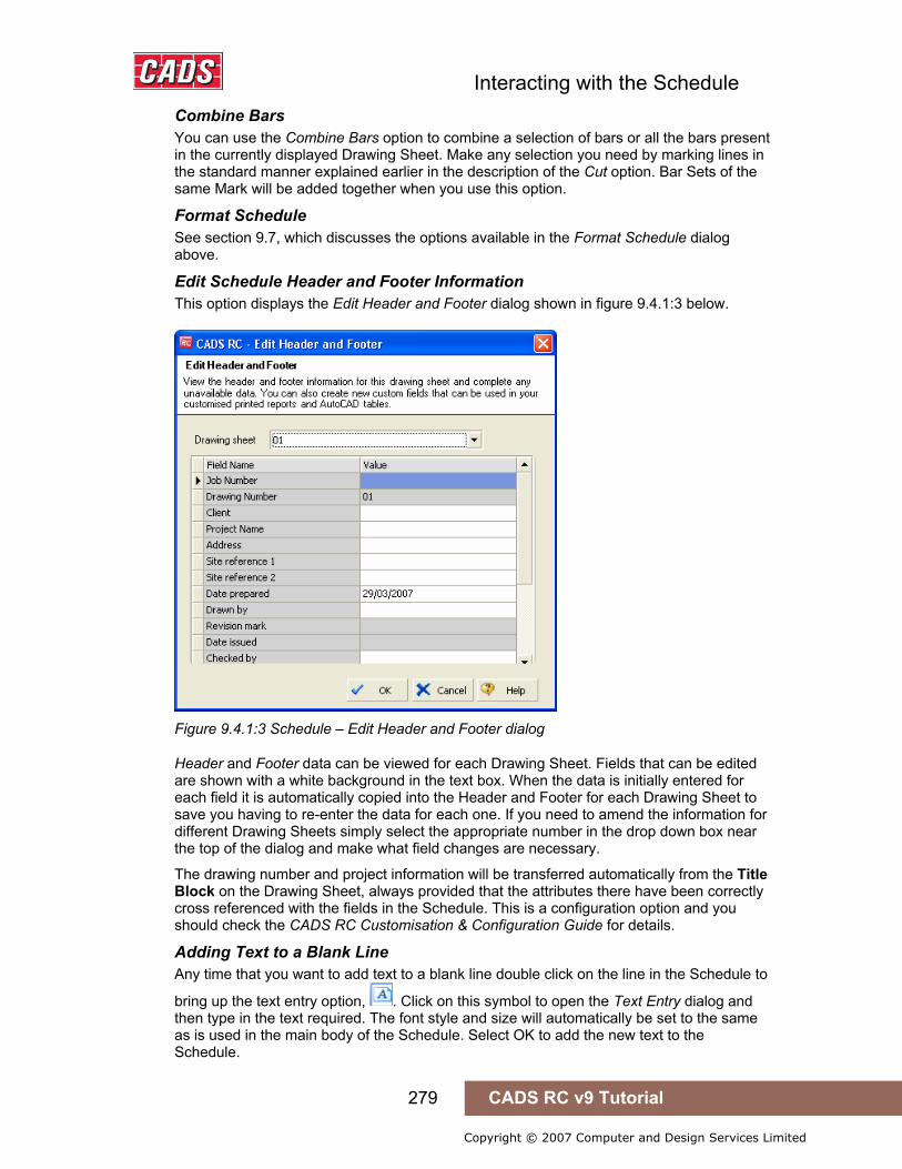
Interacting with the Schedule
279 CADS RC v9 Tutorial
Copyright © 2007 Computer and Design Services Limited
Combine Bars You can use the Combine Bars option to combine a selection of bars or all the bars present in the currently displayed Drawing Sheet. Make any selection you need by marking lines in the standard manner explained earlier in the description of the Cut option. Bar Sets of the same Mark will be added together when you use this option.
Format Schedule See section 9.7, which discusses the options available in the Format Schedule dialog above.
Edit Schedule Header and Footer Information This option displays the Edit Header and Footer dialog shown in figure 9.4.1:3 below.
Figure 9.4.1:3 Schedule – Edit Header and Footer dialog
Header and Footer data can be viewed for each Drawing Sheet. Fields that can be edited are shown with a white background in the text box. When the data is initially entered for each field it is automatically copied into the Header and Footer for each Drawing Sheet to save you having to re-enter the data for each one. If you need to amend the information for different Drawing Sheets simply select the appropriate number in the drop down box near the top of the dialog and make what field changes are necessary.
The drawing number and project information will be transferred automatically from the Title Block on the Drawing Sheet, always provided that the attributes there have been correctly cross referenced with the fields in the Schedule. This is a configuration option and you should check the CADS RC Customisation & Configuration Guide for details.
Adding Text to a Blank Line Any time that you want to add text to a blank line double click on the line in the Schedule to
bring up the text entry option, . Click on this symbol to open the Text Entry dialog and then type in the text required. The font style and size will automatically be set to the same as is used in the main body of the Schedule. Select OK to add the new text to the Schedule.
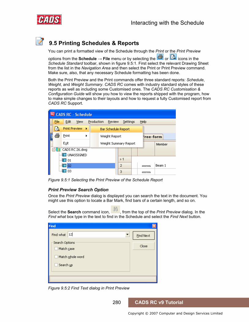
Interacting with the Schedule
280 CADS RC v9 Tutorial
Copyright © 2007 Computer and Design Services Limited
9.5 Printing Schedules & Reports
You can print a formatted view of the Schedule through the Print or the Print Preview
options from the Schedule → File menu or by selecting the or icons in the Schedule Standard toolbar, shown in figure 9.5:1. First select the relevant Drawing Sheet from the list in the Navigation Area and then select the Print or Print Preview command. Make sure, also, that any necessary Schedule formatting has been done.
Both the Print Preview and the Print commands offer three standard reports: Schedule, Weight, and Weight Summary. CADS RC comes with industry standard styles of these reports as well as including some Customised ones. The CADS RC Customisation & Configuration Guide will show you how to view the reports shipped with the program, how to make simple changes to their layouts and how to request a fully Customised report from CADS RC Support.
Figure 9.5:1 Selecting the Print Preview of the Schedule Report
Print Preview Search Option Once the Print Preview dialog is displayed you can search the text in the document. You might use this option to locate a Bar Mark, find bars of a certain length, and so on.
Select the Search command icon, , from the top of the Print Preview dialog. In the Find what box type in the text to find in the Schedule and select the Find Next button.
Figure 9.5:2 Find Text dialog in Print Preview
9.5 Printing Schedules & Reports
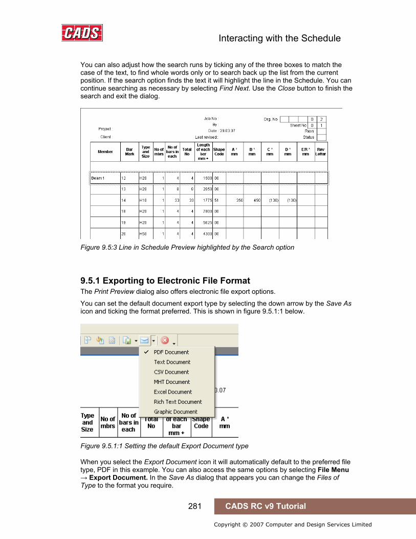
Interacting with the Schedule
281 CADS RC v9 Tutorial
Copyright © 2007 Computer and Design Services Limited
You can also adjust how the search runs by ticking any of the three boxes to match the case of the text, to find whole words only or to search back up the list from the current position. If the search option finds the text it will highlight the line in the Schedule. You can continue searching as necessary by selecting Find Next. Use the Close button to finish the search and exit the dialog.
Figure 9.5:3 Line in Schedule Preview highlighted by the Search option
9.5.1 Exporting to Electronic File Format The Print Preview dialog also offers electronic file export options.
You can set the default document export type by selecting the down arrow by the Save As icon and ticking the format preferred. This is shown in figure 9.5.1:1 below.
Figure 9.5.1:1 Setting the default Export Document type
When you select the Export Document icon it will automatically default to the preferred file type, PDF in this example. You can also access the same options by selecting File Menu → Export Document. In the Save As dialog that appears you can change the Files of Type to the format you require.
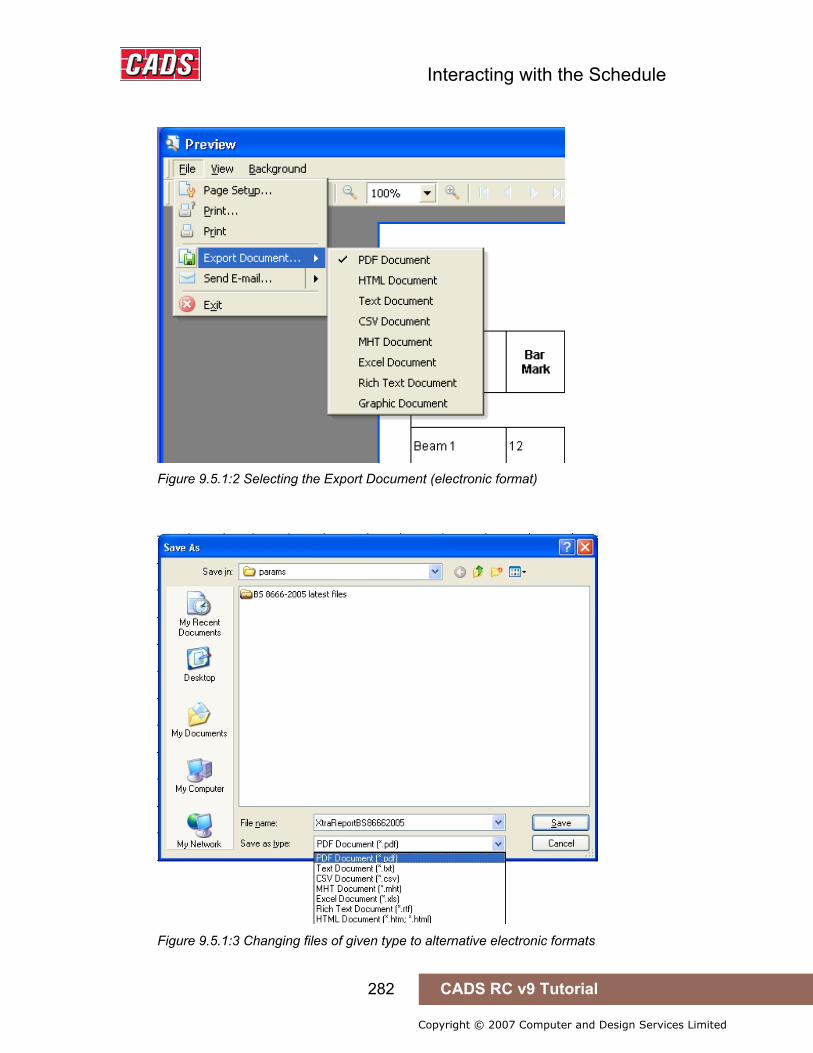
Interacting with the Schedule
282 CADS RC v9 Tutorial
Copyright © 2007 Computer and Design Services Limited
Figure 9.5.1:2 Selecting the Export Document (electronic format)
Figure 9.5.1:3 Changing files of given type to alternative electronic formats
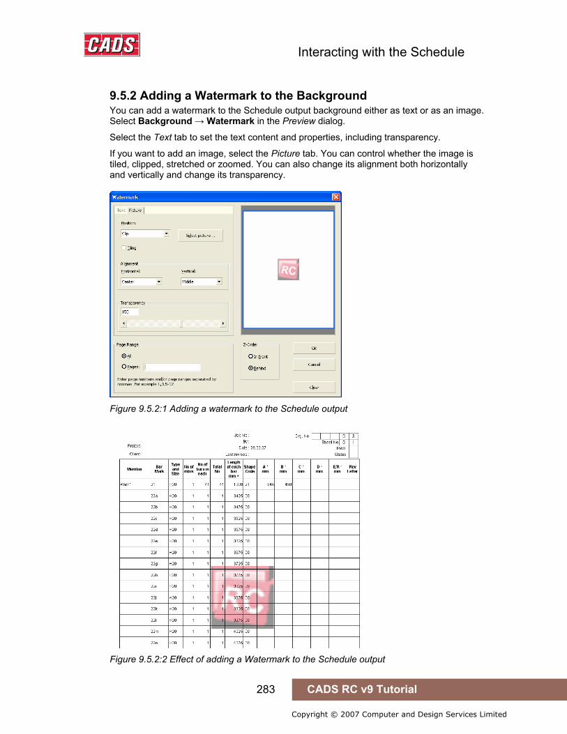
Interacting with the Schedule
283 CADS RC v9 Tutorial
Copyright © 2007 Computer and Design Services Limited
9.5.2 Adding a Watermark to the Background You can add a watermark to the Schedule output background either as text or as an image. Select Background → Watermark in the Preview dialog.
Select the Text tab to set the text content and properties, including transparency.
If you want to add an image, select the Picture tab. You can control whether the image is tiled, clipped, stretched or zoomed. You can also change its alignment both horizontally and vertically and change its transparency.
Figure 9.5.2:1 Adding a watermark to the Schedule output
Figure 9.5.2:2 Effect of adding a Watermark to the Schedule output
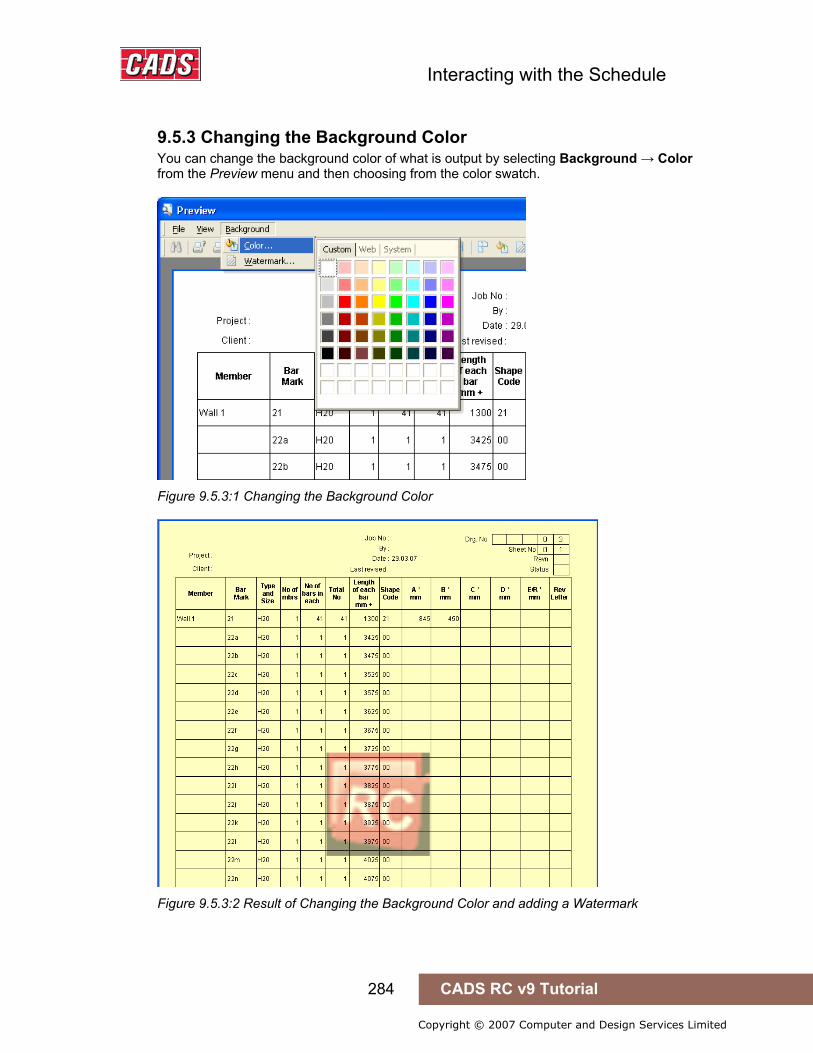
Interacting with the Schedule
284 CADS RC v9 Tutorial
Copyright © 2007 Computer and Design Services Limited
9.5.3 Changing the Background Color You can change the background color of what is output by selecting Background → Color from the Preview menu and then choosing from the color swatch.
Figure 9.5.3:1 Changing the Background Color
Figure 9.5.3:2 Result of Changing the Background Color and adding a Watermark
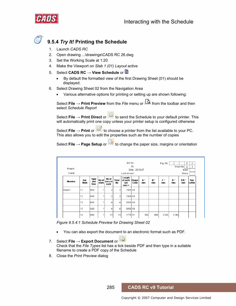
Interacting with the Schedule
285 CADS RC v9 Tutorial
Copyright © 2007 Computer and Design Services Limited
9.5.4 Try It! Printing the Schedule
1. Launch CADS RC 2. Open drawing ...\drawings\CADS RC 26.dwg 3. Set the Working Scale at 1:20 4. Make the Viewport on Slab 1 (01) Layout active
5. Select CADS RC → View Schedule or • By default the formatted view of the first Drawing Sheet (01) should be
displayed. 6. Select Drawing Sheet 02 from the Navigation Area
• Various alternative options for printing or setting up are shown following:
Select File → Print Preview from the File menu or from the toolbar and then select Schedule Report
Select File → Print Direct or to send the Schedule to your default printer. This will automatically print one copy unless your printer setup is configured otherwise
Select File → Print or to choose a printer from the list available to your PC. This also allows you to edit the properties such as the number of copies
Select File → Page Setup or to change the paper size, margins or orientation
Figure 9.5.4:1 Schedule Preview for Drawing Sheet 02
• You can also export the document to an electronic format such as PDF.
7. Select File → Export Document or Check that the File Types list has a tick beside PDF and then type in a suitable filename to create a PDF copy of the Schedule
8. Close the Print Preview dialog
9.6 Creating Custom Reports using the Free-Form View
9.5.4 Try It! Printing the Schedule

Interacting with the Schedule
286 CADS RC v9 Tutorial
Copyright © 2007 Computer and Design Services Limited
You can produce a custom report from the bar bending data using Free-Form view. To access this option open the Schedule, select the Drawing Sheet you want and then select the Free-Form tab in the Data Area, as shown below in figure 9.6:1.
Figure 9.6:1 Free-Form tab
9.6.1 Changing the Bar Data Display Order The bar bending data will initially be displayed in the order in which the bars were created on the drawing. You can change this order through the Schedule column headers – clicking in turn on a particular column header will sort the bar bending data into ascending or descending order.
Figure 9.6.1:1 Changing Data Order by clicking on the field header
9.6 Creating Custom Reports using the Free-Form View
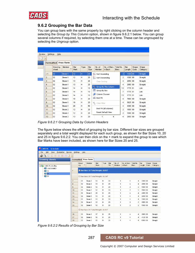
Interacting with the Schedule
287 CADS RC v9 Tutorial
Copyright © 2007 Computer and Design Services Limited
9.6.2 Grouping the Bar Data You can group bars with the same property by right clicking on the column header and selecting the Group by This Column option, shown in figure 9.6.2:1 below. You can group several columns if required, by selecting them one at a time. These can be ungrouped by selecting the Ungroup option.
Figure 9.6.2:1 Grouping Data by Column Headers
The figure below shows the effect of grouping by bar size. Different bar sizes are grouped separately and a total weight displayed for each such group, as shown for Bar Sizes 10, 20 and 25 in figure 9.6.2:2. You can then click on the + mark to expand the group to see which Bar Marks have been included, as shown here for Bar Sizes 20 and 25.
Figure 9.6.2:2 Results of Grouping by Bar Size
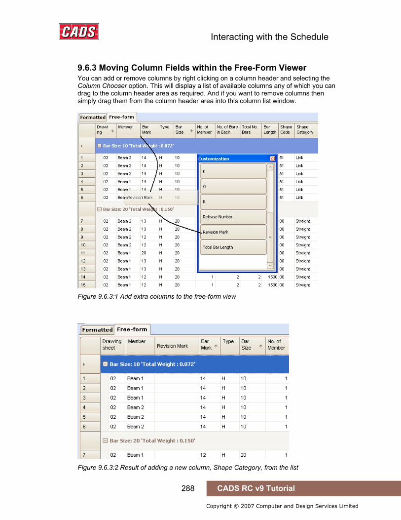
Interacting with the Schedule
288 CADS RC v9 Tutorial
Copyright © 2007 Computer and Design Services Limited
9.6.3 Moving Column Fields within the Free-Form Viewer You can add or remove columns by right clicking on a column header and selecting the Column Chooser option. This will display a list of available columns any of which you can drag to the column header area as required. And if you want to remove columns then simply drag them from the column header area into this column list window.
Figure 9.6.3:1 Add extra columns to the free-form view
Figure 9.6.3:2 Result of adding a new column, Shape Category, from the list

Interacting with the Schedule
289 CADS RC v9 Tutorial
Copyright © 2007 Computer and Design Services Limited
9.6.4 Printing the Free-Form View Once you have prepared the report to show the information wanted in the form you need then select the Print or Print Preview option from the Schedule → File menu.
The sample report in figure 9.6.4:1 below shows a report listing bars of type H Type grouped into bar sizes.
Figure 9.6.4:1 Report showing H Reinforcement grouped into Bar Sizes, ready for printing
The Print Preview option of the Free-Form View will let you see exactly how the report will look when printed. This is shown below in figure 9.6.4:2.
Figure 9.6.4:2 Print Preview of Free-Form View
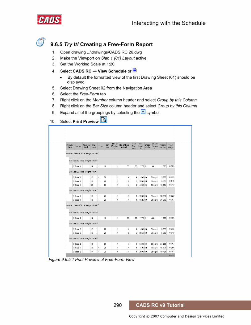
Interacting with the Schedule
290 CADS RC v9 Tutorial
Copyright © 2007 Computer and Design Services Limited
9.6.5 Try It! Creating a Free-Form Report
1. Open drawing ...\drawings\CADS RC 26.dwg 2. Make the Viewport on Slab 1 (01) Layout active 3. Set the Working Scale at 1:20
4. Select CADS RC → View Schedule or • By default the formatted view of the first Drawing Sheet (01) should be
displayed. 5. Select Drawing Sheet 02 from the Navigation Area 6. Select the Free-Form tab 7. Right click on the Member column header and select Group by this Column 8. Right click on the Bar Size column header and select Group by this Column 9. Expand all of the groupings by selecting the symbol
10. Select Print Preview
Figure 9.6.5:1 Print Preview of Free-Form View
9.6.5 Try It! Creating a Free-Form Report

Interacting with the Schedule
291 CADS RC v9 Tutorial
Copyright © 2007 Computer and Design Services Limited
9.7 Schedule Menu Options
9.7.1 File Menu Options Print Preview When you are in Formatted mode, you can view and print these three reports:
• Schedule • Weight • Weight Summary
All the reports are previewed in the template style selected in the Schedule configuration settings. In free-form mode you can print exactly what you have Customised in the free-form Schedule view.
Print This is the standard Windows command, used here to print reports. There’s a description of how to use it in section 9.5.
Exit This closes the Schedule viewer.
9.7.2 Edit Menu Options See section 9.4.1 above for information on the Edit menu options.
9.7.3 View Menu Options Toolbar This is a standard Windows View menu item. You can Customise your toolbars display through this menu option.
Figure 9.7.3:1 Toolbar Customisation dialog
9.7 Schedule Menu Options
Interacting with the Schedule
292 CADS RC v9 Tutorial
Copyright © 2007 Computer and Design Services Limited
Refresh In certain very occasional circumstances the Schedule may not get refreshed automatically. You can, however, force a refresh by selecting this option or by pressing the F5 key. If refresh is used any customisation made in the Free-Form View will be lost.
9.7.4 Production Menu Options Not covered in this Tutorial as this is relevant to RebarCAD only
9.7.5 Review Menu Options See Chapter 11, Issuing and Revisions.
9.7.6 Issue Schedule See Chapter 11, Issuing and Revisions for details concerning Issuing Bar Schedules
9.7.7 Settings Menu Options Configure Clicking on the Configure option will open the Schedule Configure dialog through which you can set default values for the Schedule. This configuration option also lets you adjust settings for display, the revision system, the production output/fabrication system and for the printed reports. Please refer to the CADS RC Customisation & Configuration Guide for more detail.
Load Configuration Selecting Load Configuration will open the Load Configuration dialog box. This lists any configuration files prepared for your project and lets you select whichever you need, optionally using the Browse button to search in other folders. Please refer to the CADS RC Customisation & Configuration Guide for more detail.
9.8 Schedule Configuration
CADS RC ships with the Schedule preconfigured to what is most commonly used. The program includes the CADS RC Customisation & Configuration Guide and this explains what each of the settings does and how they influence the Schedule.
This Tutorial periodically makes reference to relevant Schedule Configuration Items when it seems useful or helpful to do so.
9.8 Schedule Configuration

Interacting with the Schedule
293 CADS RC v9 Tutorial
Copyright © 2007 Computer and Design Services Limited
9.9 Key points – Interacting with the Schedule
• There has to be at least one Drawing Sheet defined before the Schedule dialog box can be opened.
• To make the Bar Draw dialog default to a specific Member set it as current.
• Use the Assign Bars to Members command, , to assign existing bars to a Member.
• You can view information about Members from inside the Schedule. • Use the mode selector buttons in the Mode Area to select whether Drawing
Sheets, Members or Releases are shown in tree view in the Navigation Area. • The Data Area shows bar bending data for a particular Drawing Sheet, Member
or Release depending on what is selected in the Navigation Area. • Formatting options can be applied only to the formatted view and not to the free-
form view. • You can select Formatted View only in Drawing Sheet mode. • The free-form style can be used to produce quick queries and reports. • Select the Free-Form tab to switch to free-form mode. • The Free-Form view does not show combined bars. • Right click on the column headers to see available options such as to sort or
group bars. • Select a bar in the Schedule and use a right mouse click to find available editing
options. • Some manual formatting option that can be carried out inside the Schedule may
result in conflict with the automatic formatting options. This will result in the automatic formatting options being reset.
• Ensure you have the correct Drawing Sheet selected before doing a print. • You can configure the Schedule on a drawing to be by Release or by Drawing
Sheet. • The Preview dialog includes some additional export options. (e.g. PDF, Excel). • The Schedule on drawing will display an ‘INVALID’ message if subsequent edits
are made to the bars being shown. The Schedule can be refreshed by using the Refresh Schedule on Drawing command, .
9.10 Command List – Interacting with the Schedule
Action Menu Toolbar Icon
View Schedule CADS RC → View Schedule… CADS RC
9.9 Key points – Interacting with the Schedule
9.10 Command List – Interacting with the Schedule

Place Schedule
294 CADS RC v9 Tutorial
Copyright © 2007 Computer and Design Services Limited
10: Place Schedule 10.0 Introduction
The Place Schedule on Drawing command will place a copy of the Formatted Schedule View on the drawing either in Layout or Model Space. The Schedule by default is placed by Release. Any manual formatting carried out in the Free-Form View of the Schedule will not be carried over. You can also place a list of the Bar Marks used on the drawing using the Place Schedule on Drawing command.
10.0 Introduction
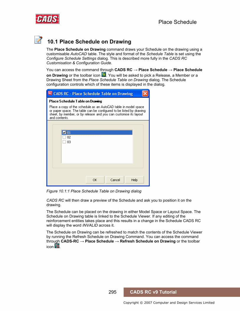
Place Schedule
295 CADS RC v9 Tutorial
Copyright © 2007 Computer and Design Services Limited
10.1 Place Schedule on Drawing
The Place Schedule on Drawing command draws your Schedule on the drawing using a customisable AutoCAD table. The style and format of the Schedule Table is set using the Configure Schedule Settings dialog. This is described more fully in the CADS RC Customisation & Configuration Guide.
You can access the command through CADS RC → Place Schedule → Place Schedule on Drawing or the toolbar icon . You will be asked to pick a Release, a Member or a Drawing Sheet from the Place Schedule Table on Drawing dialog. The Schedule configuration controls which of these items is displayed in the dialog.
Figure 10.1:1 Place Schedule Table on Drawing dialog
CADS RC will then draw a preview of the Schedule and ask you to position it on the drawing.
The Schedule can be placed on the drawing in either Model Space or Layout Space. The Schedule on Drawing table is linked to the Schedule Viewer. If any editing of the reinforcement entities takes place and this results in a change in the Schedule CADS RC will display the word INVALID across it.
The Schedule on Drawing can be refreshed to match the contents of the Schedule Viewer by running the Refresh Schedule on Drawing Command. You can access the command through CADS-RC → Place Schedule → Refresh Schedule on Drawing or the toolbar icon .
10.1 Place Schedule on Drawing

Place Schedule
296 CADS RC v9 Tutorial
Copyright © 2007 Computer and Design Services Limited
Figure 10.1:2 Schedule, Weight Summary and Shape Code Diagrams on Drawing
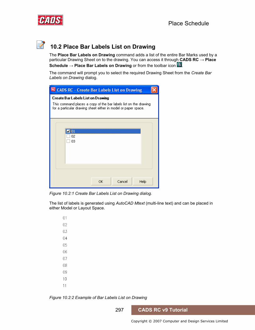
Place Schedule
297 CADS RC v9 Tutorial
Copyright © 2007 Computer and Design Services Limited
10.2 Place Schedule on Drawing
The Place Bar Labels on Drawing command adds a list of the entire Bar Marks used by a particular Drawing Sheet on to the drawing. You can access it through CADS RC → Place Schedule → Place Bar Labels on Drawing or from the toolbar icon .
The command will prompt you to select the required Drawing Sheet from the Create Bar Labels on Drawing dialog.
Figure 10.2:1 Create Bar Labels List on Drawing dialog.
The list of labels is generated using AutoCAD Mtext (multi-line text) and can be placed in either Model or Layout Space.
Figure 10.2:2 Example of Bar Labels List on Drawing
10.2 Place Bar Labels List on Drawing
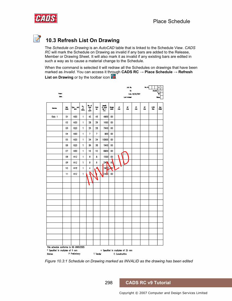
Place Schedule
298 CADS RC v9 Tutorial
Copyright © 2007 Computer and Design Services Limited
10.3 Refresh List On Drawing
The Schedule on Drawing is an AutoCAD table that is linked to the Schedule View. CADS RC will mark the Schedule on Drawing as invalid if any bars are added to the Release, Member or Drawing Sheet. It will also mark it as invalid if any existing bars are edited in such a way as to cause a material change to the Schedule.
When the command is selected it will redraw all the Schedules on drawings that have been marked as Invalid. You can access it through CADS RC → Place Schedule → Refresh List on Drawing or by the toolbar icon .
Figure 10.3:1 Schedule on Drawing marked as INVALID as the drawing has been edited
10.3 Refresh List On Drawing
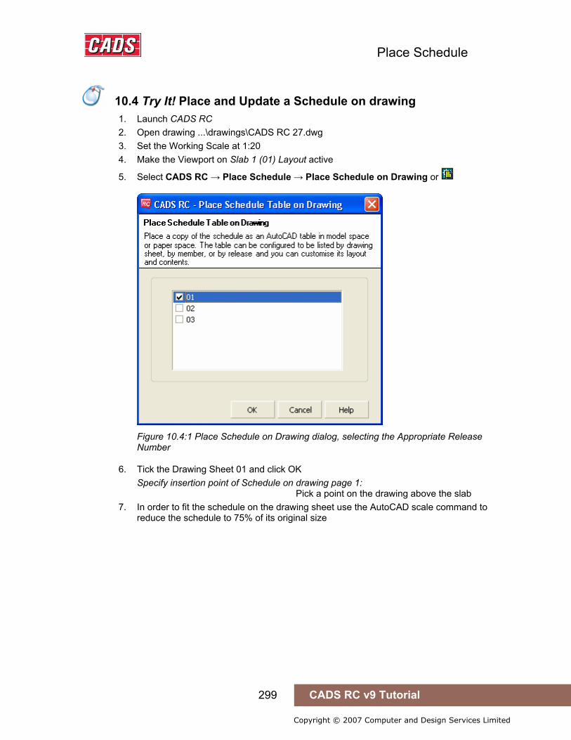
Place Schedule
299 CADS RC v9 Tutorial
Copyright © 2007 Computer and Design Services Limited
10.4 Try It! Place and Update a Schedule on drawing
1. Launch CADS RC 2. Open drawing ...\drawings\CADS RC 27.dwg 3. Set the Working Scale at 1:20 4. Make the Viewport on Slab 1 (01) Layout active
5. Select CADS RC → Place Schedule → Place Schedule on Drawing or
Figure 10.4:1 Place Schedule on Drawing dialog, selecting the Appropriate Release Number
6. Tick the Drawing Sheet 01 and click OK Specify insertion point of Schedule on drawing page 1: Pick a point on the drawing above the slab
7. In order to fit the schedule on the drawing sheet use the AutoCAD scale command to reduce the schedule to 75% of its original size
10.4 Try It! Place and Update a Schedule on drawing
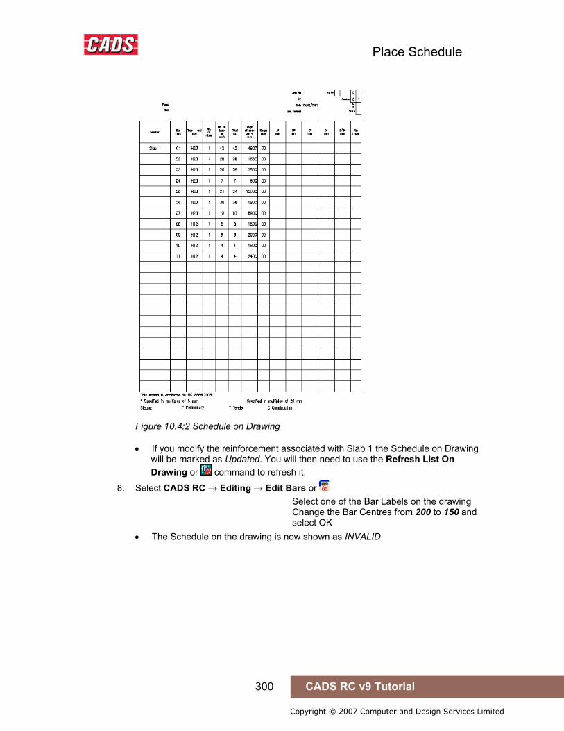
Place Schedule
300 CADS RC v9 Tutorial
Copyright © 2007 Computer and Design Services Limited
Figure 10.4:2 Schedule on Drawing
• If you modify the reinforcement associated with Slab 1 the Schedule on Drawing will be marked as Updated. You will then need to use the Refresh List On Drawing or command to refresh it.
8. Select CADS RC → Editing → Edit Bars or Select one of the Bar Labels on the drawing Change the Bar Centres from 200 to 150 and select OK • The Schedule on the drawing is now shown as INVALID

Place Schedule
301 CADS RC v9 Tutorial
Copyright © 2007 Computer and Design Services Limited
Figure 10.4:3 Schedule on Drawing shown as Invalid after editing Bar Properties
9. Select CADS RC → Place Schedule → Refresh Schedule on Drawing or • The Schedule is redrawn in exactly the same place with updated information.
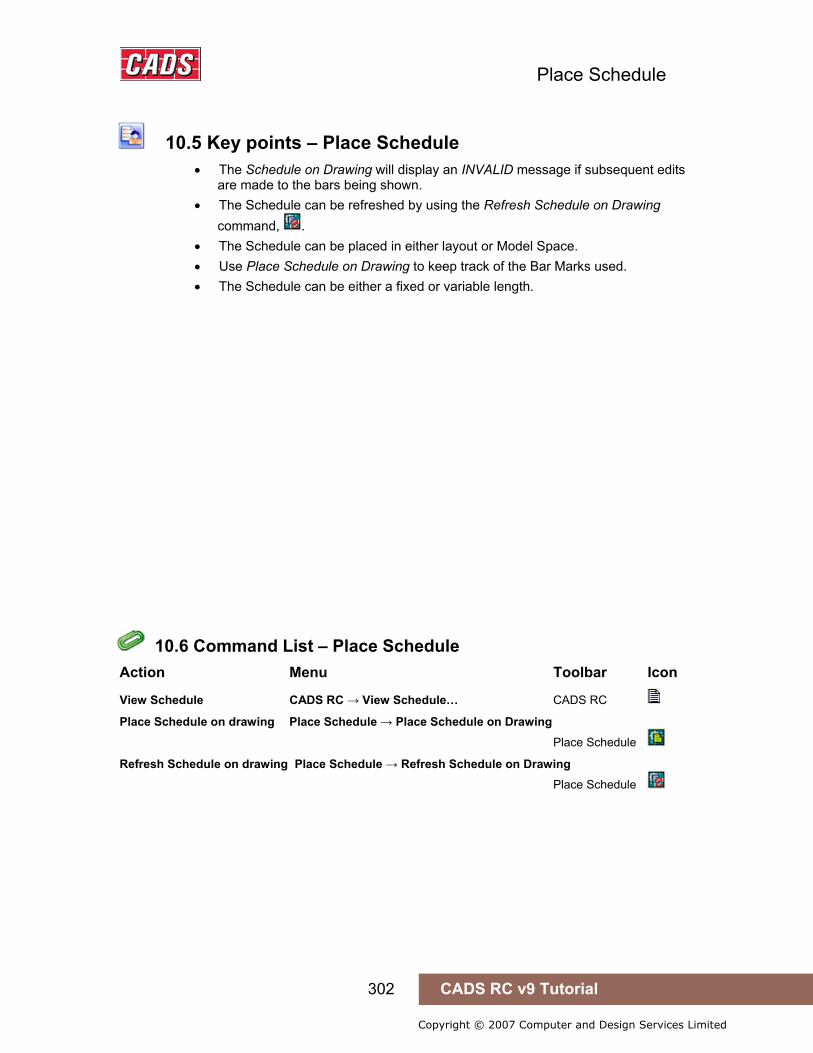
Place Schedule
302 CADS RC v9 Tutorial
Copyright © 2007 Computer and Design Services Limited
10.5 Key points – Place Schedule
• The Schedule on Drawing will display an INVALID message if subsequent edits are made to the bars being shown.
• The Schedule can be refreshed by using the Refresh Schedule on Drawing command, .
• The Schedule can be placed in either layout or Model Space. • Use Place Schedule on Drawing to keep track of the Bar Marks used. • The Schedule can be either a fixed or variable length.
10.6 Command List – Place Schedule
Action Menu Toolbar Icon
View Schedule CADS RC → View Schedule… CADS RC
Place Schedule on drawing Place Schedule → Place Schedule on Drawing Place Schedule
Refresh Schedule on drawing Place Schedule → Refresh Schedule on Drawing Place Schedule
10.5 Key points – Place Schedule
10.6 Command List – Place Schedule
Range Tools
303 CADS RC v9 Tutorial
Copyright © 2007 Computer and Design Services Limited
11: Issuing and Revisions
11.0 Introduction
CADS RC v9 includes a sophisticated issuing and revision system. Once the drawing and Schedule have been completed you can issue them together or individually. Any subsequent editing of the bars will be marked with a revision letter both on the drawing and inside the Schedule.
11.0 Introduction
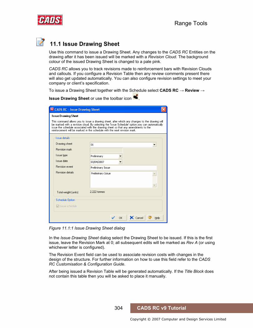
Range Tools
304 CADS RC v9 Tutorial
Copyright © 2007 Computer and Design Services Limited
11.1 Issue Drawing Sheet
Use this command to issue a Drawing Sheet. Any changes to the CADS RC Entities on the drawing after it has been issued will be marked with a Revision Cloud. The background colour of the issued Drawing Sheet is changed to a pale pink.
CADS RC allows you to track revisions made to reinforcement bars with Revision Clouds and callouts. If you configure a Revision Table then any review comments present there will also get updated automatically. You can also configure revision settings to meet your company or client’s specification.
To issue a Drawing Sheet together with the Schedule select CADS RC → Review →
Issue Drawing Sheet or use the toolbar icon .
Figure 11.1:1 Issue Drawing Sheet dialog
In the Issue Drawing Sheet dialog select the Drawing Sheet to be issued. If this is the first issue, leave the Revision Mark at 0; all subsequent edits will be marked as Rev A (or using whichever letter is configured).
The Revision Event field can be used to associate revision costs with changes in the design of the structure. For further information on how to use this field refer to the CADS RC Customisation & Configuration Guide.
After being issued a Revision Table will be generated automatically. If the Title Block does not contain this table then you will be asked to place it manually.
11.1 Issue Drawing Sheet
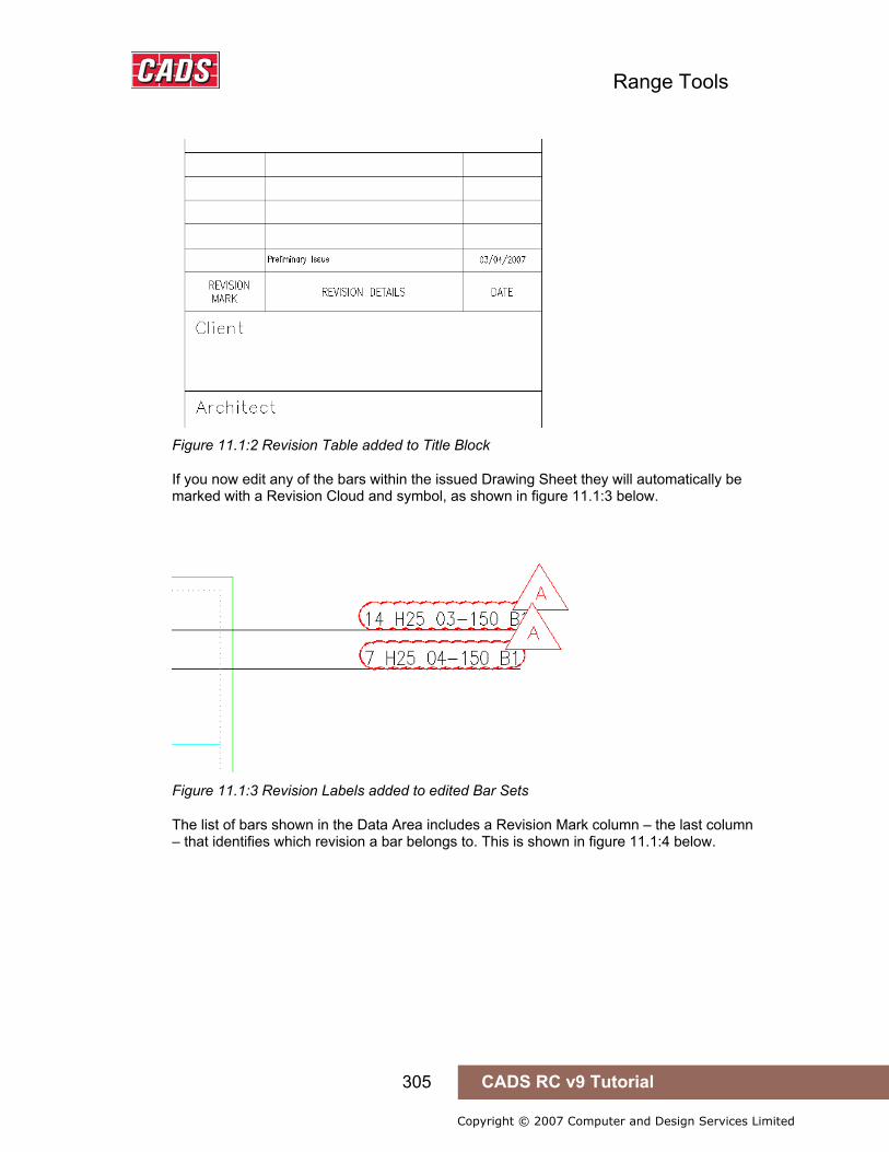
Range Tools
305 CADS RC v9 Tutorial
Copyright © 2007 Computer and Design Services Limited
Figure 11.1:2 Revision Table added to Title Block
If you now edit any of the bars within the issued Drawing Sheet they will automatically be marked with a Revision Cloud and symbol, as shown in figure 11.1:3 below.
Figure 11.1:3 Revision Labels added to edited Bar Sets
The list of bars shown in the Data Area includes a Revision Mark column – the last column – that identifies which revision a bar belongs to. This is shown in figure 11.1:4 below.
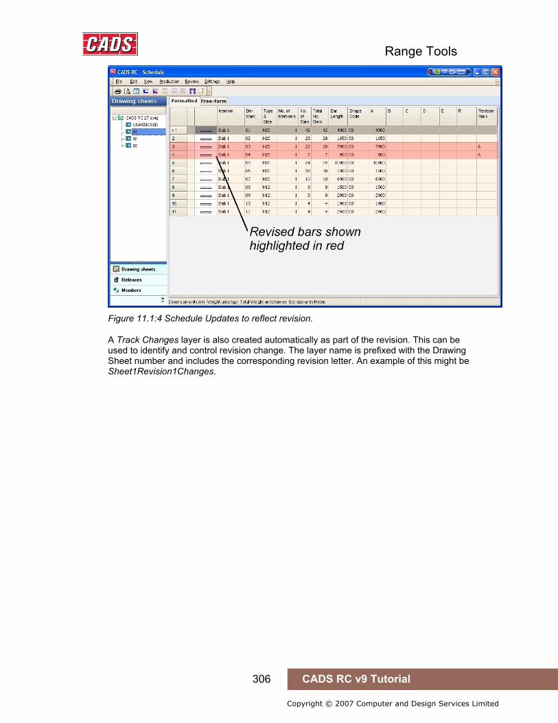
Range Tools
306 CADS RC v9 Tutorial
Copyright © 2007 Computer and Design Services Limited
Figure 11.1:4 Schedule Updates to reflect revision.
A Track Changes layer is also created automatically as part of the revision. This can be used to identify and control revision change. The layer name is prefixed with the Drawing Sheet number and includes the corresponding revision letter. An example of this might be Sheet1Revision1Changes.
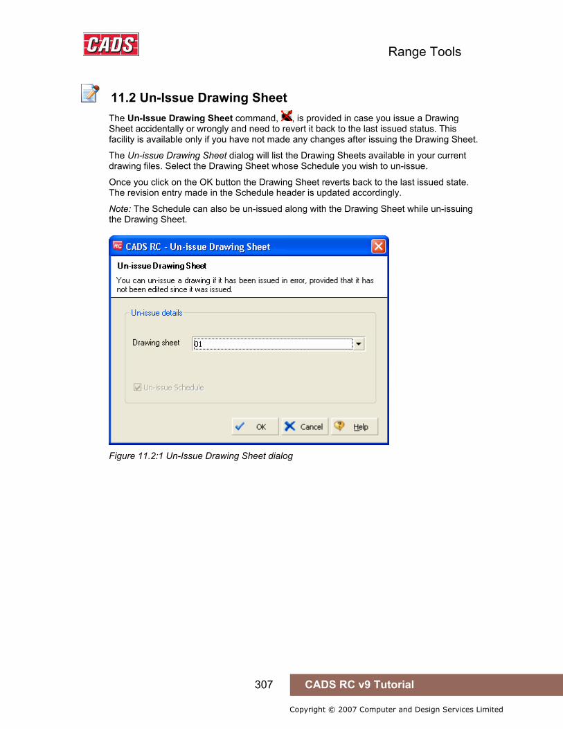
Range Tools
307 CADS RC v9 Tutorial
Copyright © 2007 Computer and Design Services Limited
11.2 Un-Issue Drawing Sheet
The Un-Issue Drawing Sheet command, , is provided in case you issue a Drawing Sheet accidentally or wrongly and need to revert it back to the last issued status. This facility is available only if you have not made any changes after issuing the Drawing Sheet.
The Un-issue Drawing Sheet dialog will list the Drawing Sheets available in your current drawing files. Select the Drawing Sheet whose Schedule you wish to un-issue.
Once you click on the OK button the Drawing Sheet reverts back to the last issued state. The revision entry made in the Schedule header is updated accordingly.
Note: The Schedule can also be un-issued along with the Drawing Sheet while un-issuing the Drawing Sheet.
Figure 11.2:1 Un-Issue Drawing Sheet dialog
11.2 Un-Issue Drawing Sheet
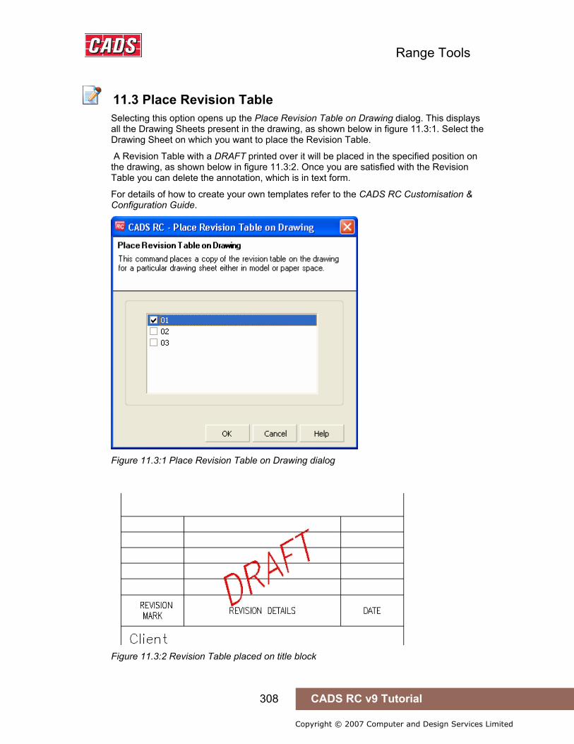
Range Tools
308 CADS RC v9 Tutorial
Copyright © 2007 Computer and Design Services Limited
11.3 Place Revision Table
Selecting this option opens up the Place Revision Table on Drawing dialog. This displays all the Drawing Sheets present in the drawing, as shown below in figure 11.3:1. Select the Drawing Sheet on which you want to place the Revision Table.
A Revision Table with a DRAFT printed over it will be placed in the specified position on the drawing, as shown below in figure 11.3:2. Once you are satisfied with the Revision Table you can delete the annotation, which is in text form.
For details of how to create your own templates refer to the CADS RC Customisation & Configuration Guide.
Figure 11.3:1 Place Revision Table on Drawing dialog
Figure 11.3:2 Revision Table placed on title block
11.3 Place Revision Table
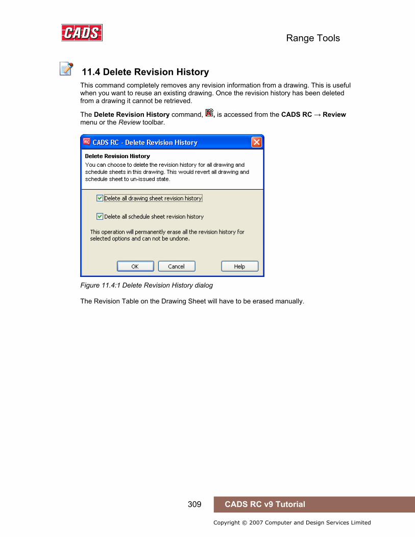
Range Tools
309 CADS RC v9 Tutorial
Copyright © 2007 Computer and Design Services Limited
11.4 Delete Revision History
This command completely removes any revision information from a drawing. This is useful when you want to reuse an existing drawing. Once the revision history has been deleted from a drawing it cannot be retrieved.
The Delete Revision History command, , is accessed from the CADS RC → Review menu or the Review toolbar.
Figure 11.4:1 Delete Revision History dialog
The Revision Table on the Drawing Sheet will have to be erased manually.
11.4 Delete Revision History
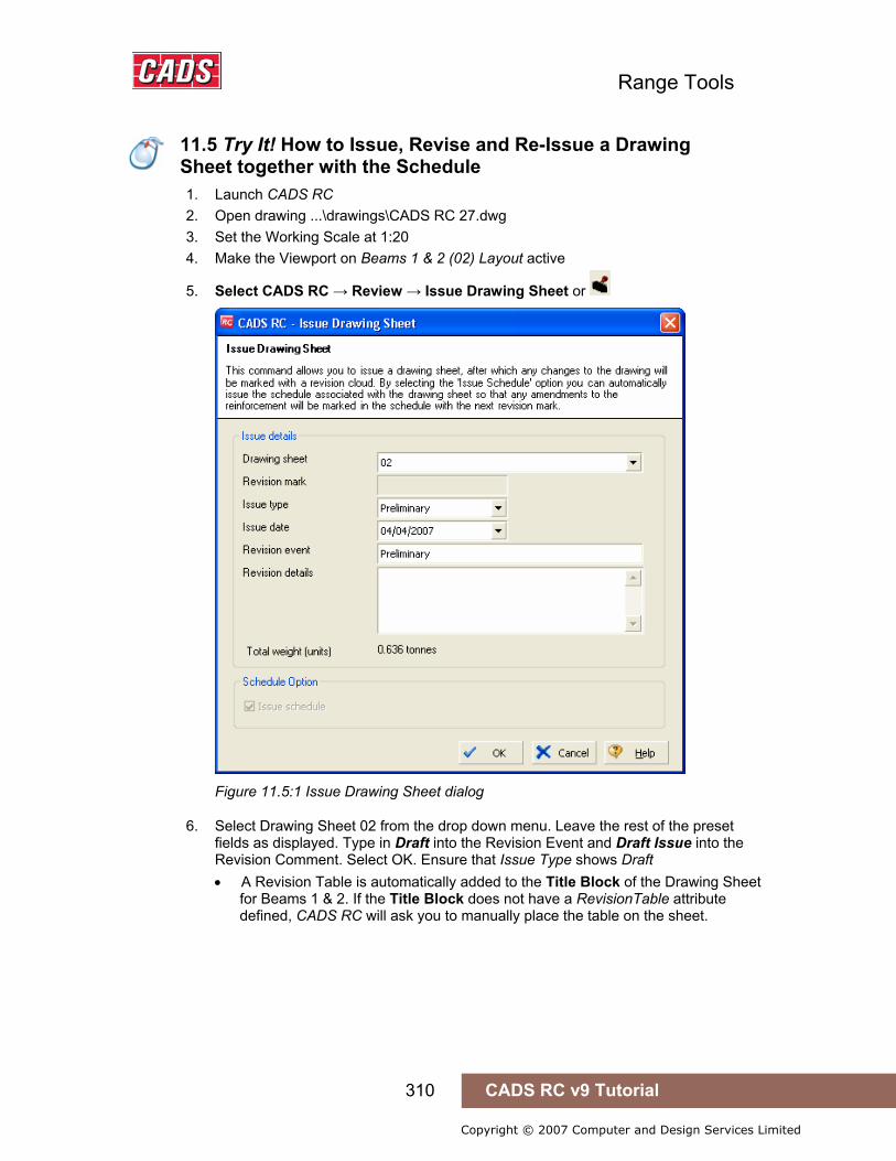
Range Tools
310 CADS RC v9 Tutorial
Copyright © 2007 Computer and Design Services Limited
11.5 Try It! How to Issue, Revise and Re-Issue a Drawing Sheet together with the Schedule
1. Launch CADS RC 2. Open drawing ...\drawings\CADS RC 27.dwg 3. Set the Working Scale at 1:20 4. Make the Viewport on Beams 1 & 2 (02) Layout active
5. Select CADS RC → Review → Issue Drawing Sheet or
Figure 11.5:1 Issue Drawing Sheet dialog
6. Select Drawing Sheet 02 from the drop down menu. Leave the rest of the preset fields as displayed. Type in Draft into the Revision Event and Draft Issue into the Revision Comment. Select OK. Ensure that Issue Type shows Draft • A Revision Table is automatically added to the Title Block of the Drawing Sheet
for Beams 1 & 2. If the Title Block does not have a RevisionTable attribute defined, CADS RC will ask you to manually place the table on the sheet.
11.5 Try It! How to Issue, Revise and Re-Issue a Drawing Sheet together with the Schedule

Range Tools
311 CADS RC v9 Tutorial
Copyright © 2007 Computer and Design Services Limited
Figure 11.5:2 Revision Table added to Drawing Sheet
7. Select CADS RC → Editing → Edit Bars and change the bar size of one of the bars in Beam 1
8. Select OK when the CADS RC revision warning, shown in figure 11.5:3 below, appears
Figure 11.5:3 Revision Warning display
• A Revision Cloud should now appear around the edited Bar Label.
Figure 11.5:4 Revision cloud added to the edited Bar Label.
9. Select CADS RC → View Schedule or 10. Select Drawing Sheet 02
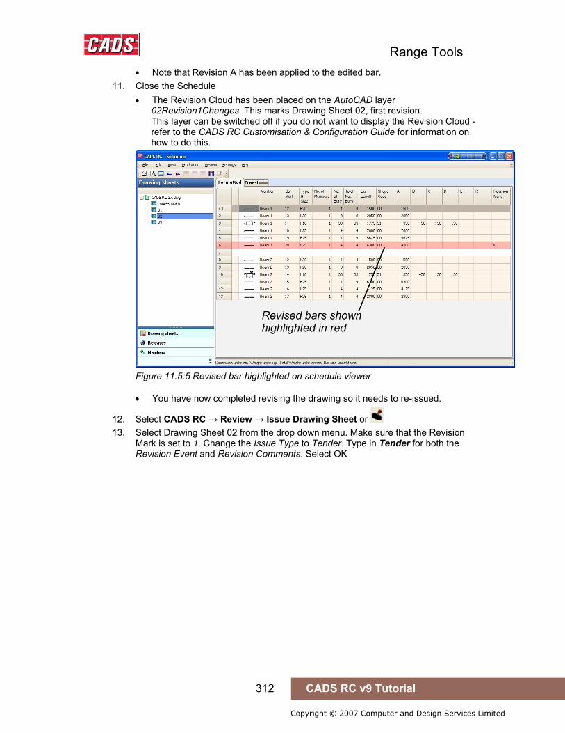
Range Tools
312 CADS RC v9 Tutorial
Copyright © 2007 Computer and Design Services Limited
• Note that Revision A has been applied to the edited bar. 11. Close the Schedule
• The Revision Cloud has been placed on the AutoCAD layer 02Revision1Changes. This marks Drawing Sheet 02, first revision. This layer can be switched off if you do not want to display the Revision Cloud - refer to the CADS RC Customisation & Configuration Guide for information on how to do this.
Figure 11.5:5 Revised bar highlighted on schedule viewer
• You have now completed revising the drawing so it needs to re-issued.
12. Select CADS RC → Review → Issue Drawing Sheet or 13. Select Drawing Sheet 02 from the drop down menu. Make sure that the Revision
Mark is set to 1. Change the Issue Type to Tender. Type in Tender for both the Revision Event and Revision Comments. Select OK

Range Tools
313 CADS RC v9 Tutorial
Copyright © 2007 Computer and Design Services Limited
Figure 11.5:6 Issue Drawing Sheet dialog
• The Revision Table on the Drawing Sheet is automatically updated to show the Revision 1 entry. All subsequent revisions will show 2 as the revision number.
Figure 11.5:7 Revision Table showing Revision A.

Range Tools
314 CADS RC v9 Tutorial
Copyright © 2007 Computer and Design Services Limited
11.6 Issuing the Schedule Sheet Only
We would normally recommend that the Schedule is always issued with the Drawing sheet to keep the revision levels in step with each other. This is the default configuration for CADS RC v9 when it is installed. However, you can configure CADS RC to issue the schedules independently of the Drawing Sheets if required. If the Issue Drawing Sheet command is selected from the CADS RC – Review menu, an additional option has been added which you can tick to say whether you want to Issue the Schedule at the same time. If you wish to Issue the Schedule independently of the Drawing Sheet this must be done from inside the Schedule Viewer using the Review – Issue Schedule command.
11.6.1 Configure CADS RC to allow independent Schedule Issuing The configuration option is accessed from CADS RC – Configuration – Configuration Centre – Configure Schedule Settings or Select the Issuing & Revision Tab and deselect the “Always issue schedule with drawing” option as shown in figure 11.6.1:1 below.
Figure 11.6.1:1 Schedule Configuration dialog
11.6 Issuing the Schedule Sheet Only
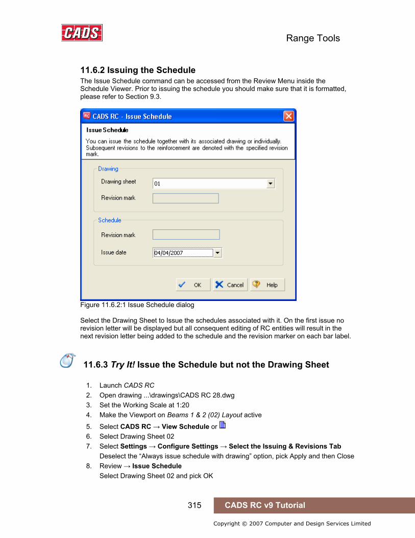
Range Tools
315 CADS RC v9 Tutorial
Copyright © 2007 Computer and Design Services Limited
11.6.2 Issuing the Schedule The Issue Schedule command can be accessed from the Review Menu inside the Schedule Viewer. Prior to issuing the schedule you should make sure that it is formatted, please refer to Section 9.3.
Figure 11.6.2:1 Issue Schedule dialog Select the Drawing Sheet to Issue the schedules associated with it. On the first issue no revision letter will be displayed but all consequent editing of RC entities will result in the next revision letter being added to the schedule and the revision marker on each bar label.
11.6.3 Try It! Issue the Schedule but not the Drawing Sheet
1. Launch CADS RC 2. Open drawing ...\drawings\CADS RC 28.dwg 3. Set the Working Scale at 1:20 4. Make the Viewport on Beams 1 & 2 (02) Layout active
5. Select CADS RC → View Schedule or 6. Select Drawing Sheet 02 7. Select Settings → Configure Settings → Select the Issuing & Revisions Tab
Deselect the “Always issue schedule with drawing” option, pick Apply and then Close 8. Review → Issue Schedule
Select Drawing Sheet 02 and pick OK
11.6.3 Try It! Issue the Schedule but not the Drawing Sheet

Range Tools
316 CADS RC v9 Tutorial
Copyright © 2007 Computer and Design Services Limited
Figure 11.6.3:1 Issue Schedule dialog
9. Select CADS RC → Editing → Edit Bars and change the bar size of one of the bars in Beam 1
10. Select OK when the CADS RC revision warning, shown in figure 11.6.3:2 below, appears
Figure 11.6.3:2 Revision Warning display
• A Revision Cloud should now appear around the edited Bar Label.
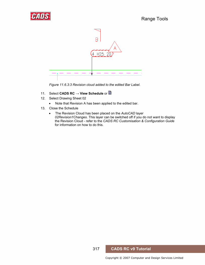
Range Tools
317 CADS RC v9 Tutorial
Copyright © 2007 Computer and Design Services Limited
Figure 11.6.3:3 Revision cloud added to the edited Bar Label.
11. Select CADS RC → View Schedule or 12. Select Drawing Sheet 02
• Note that Revision A has been applied to the edited bar. 13. Close the Schedule
• The Revision Cloud has been placed on the AutoCAD layer 02Revision1Changes. This layer can be switched off if you do not want to display the Revision Cloud - refer to the CADS RC Customisation & Configuration Guide for information on how to do this.

Range Tools
318 CADS RC v9 Tutorial
Copyright © 2007 Computer and Design Services Limited
11.7 Key points – Issuing and Revisions
• You can issue a Schedule with or without its associated Drawing Sheet. • Issuing a Drawing Sheet will ‘lock down’ the Schedule. Any editing of the
drawing will result in Revision Markers being added to the drawing and Schedule.
• A Drawing Sheet can be un-issued if accidentally issued. • If a Revision Table is not automatically placed on the Drawing Sheet use the
Place Revision Table • All the Revision History can be removed from a drawing using the Delete
Revision History command. • Editing Reinforcement Entities on an Issued Drawing Sheet will result in
Revision Clouds being added to the Bar Labels unless already switched off in the Configuration.
11.8 Command List – Issuing and Revisions
Action Menu Toolbar Icon
View Schedule CADS RC → View Schedule… CADS RC
Issue Drawing Sheet CADS RC → Review → Issue Drawing Sheet…
Review
Un-issue Drawing Sheet CADS RC → Review → Un-issue Drawing Sheet… Review
Place Revision Table CADS RC → Review → Place Revision Table Review
Delete Revision History CADS RC → Review → Delete Revision History Review
11.7 Key points – Issuing and Revisions
11.8 Command List – Issuing and Revisions

Range Tools
319 CADS RC v9 Tutorial
Copyright © 2007 Computer and Design Services Limited
12: Tools
12.0 Introduction
The CADS RC productivity tools contain several utility tools that can be used to increase reinforcement detailing efficiency. Common structural elements like beams, columns, slabs etc can be detailed in a few picks. As the name suggests, these tools will greatly enhance your reinforcement detailing productivity. You can also use these tools for quick and approximate estimation as required for bidding and stock ordering purpose.
CADS RC is shipped with the following additional utilities;
Special Bar Creator The special bar creator allows you to create your own shape code 99’s.
Cross Section Detailer The Cross Section Detailer helps to detail cross sections through columns, beams and slabs including the reinforcement bars.
Trim Openings The Trim Openings utility details and labels the reinforcement around either rectangular or circular holes in a structure.
Draw Lap Dog Leg The Draw Lap Dog Leg Bar tool helps with the placing of a cranked bar when lapping with an existing bar on the drawing.
Outlines The CADS RC Outline tools includes a range of parametric shapes which automatically include concrete cover lines, with the correct line types, layers and dimensions, if required. Also included is a Freehand Outline routine which draws a line with a parallel cover line beside.
Tools & Symbols Tools and Symbols dialog contains a number of useful tools that can be used to help with general drafting such as a Grid Generator, grid balloons and line breaks.
The Utilities use the AutoCAD Dimscale variable to size the text and blocks to suit the plotted scale of the drawing regardless of whether you are working in Model Space only or both Model/Layout space. Ensure that Dimscale is set to match the plotted scale of the detail.
If you have access to the CADS-SC software, use the Drawing Set-up Function to load in a Title Block and set the appropriate scale and drawing environment. Alternatively you can use CADS VPM, create Layout function or basic AutoCAD, create Layout as described in Section 2 of this Tutorial.
12.0 Introduction
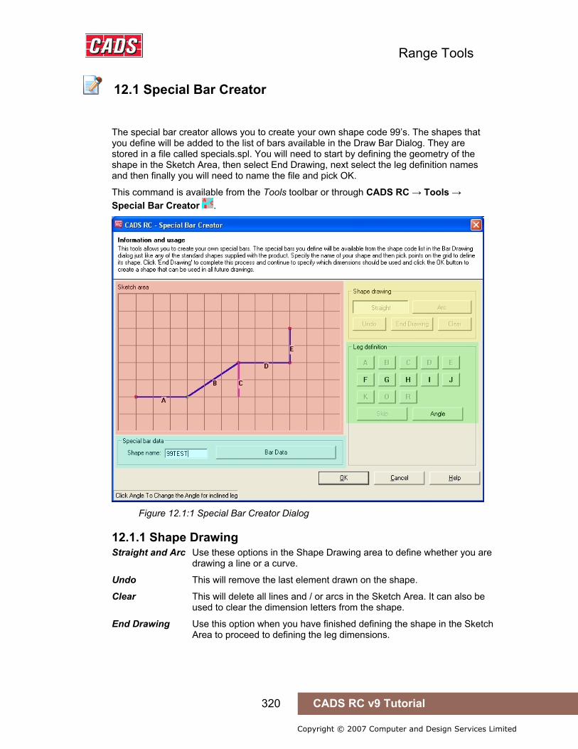
Range Tools
320 CADS RC v9 Tutorial
Copyright © 2007 Computer and Design Services Limited
12.1 Special Bar Creator
The special bar creator allows you to create your own shape code 99’s. The shapes that you define will be added to the list of bars available in the Draw Bar Dialog. They are stored in a file called specials.spl. You will need to start by defining the geometry of the shape in the Sketch Area, then select End Drawing, next select the leg definition names and then finally you will need to name the file and pick OK.
This command is available from the Tools toolbar or through CADS RC → Tools → Special Bar Creator .
Figure 12.1:1 Special Bar Creator Dialog
12.1.1 Shape Drawing Straight and Arc Use these options in the Shape Drawing area to define whether you are drawing a line or a curve.
Undo This will remove the last element drawn on the shape.
Clear This will delete all lines and / or arcs in the Sketch Area. It can also be used to clear the dimension letters from the shape.
End Drawing Use this option when you have finished defining the shape in the Sketch Area to proceed to defining the leg dimensions.
12.1 Special Bar Creator

Range Tools
321 CADS RC v9 Tutorial
Copyright © 2007 Computer and Design Services Limited
12.1.2 Sketch Area Pick points in the sketch area to define the shape of the bar, you can use either straight or curved lines by selecting the options from the Shape Drawing Area. Pick the End Drawing
button to proceed onto dimensioning the shape.
Make the diagram of the shape as large as possible as this will result in the best slide being created to add to the schedule.
12.1.3 Leg Definition Once the End Drawing button has been selected you are guided around the shape to define the leg letter dimensions. The leg to be dimensioned is highlighted in green, either pick the required letter or select Skip if a dimension is not required. You can use the Clear option to remove the dimensions and define them again.
12.1.4 Shape Name Type in a unique name for the shape code 99 that you are creating. If the name has been duplicated the program will inform you and ask you to enter another name.
12.1.5 Bar Data
Figure 12.1.5:1 Special Bar Creator Bar Data dialog
The Bar Data dialog cannot be accessed unless all the information to create the shape code 99 has been entered. The dialog shows all the information that is specific for the bar being created. The length calculation will have appropriate formula for the shape defined. The data in this dialog can be amended if required to include deductions for bends.
When you select OK on the main Special Bar Creator dialog all the information is added to the Specials.spl file. At the same time a slide file and windows meta file is created for displaying in the Draw Bar dialog and the schedule.
12.1.6 Limitations Shapes with inclined legs (except legs that have angled dimensions) and / or arcs can only be used as label only option, as it will not be possible to draw these shapes from RC.

Range Tools
322 CADS RC v9 Tutorial
Copyright © 2007 Computer and Design Services Limited
If required, these shapes can be drawn using polylines manually and RC’s label with appropriate dimensions can be inserted.
12.1.7 Tips on Dimensioning Shape Code 99’s Dimensioning for Straight legs There are two cases for dimensioning straight legs;
Horizontal or Vertical legs
• Only one dimension can be assigned for this case. Inclined legs
There are five possible ways to define the dimensioning;
• Assigning one dimension along leg and other dimensions for both horizontal & vertical projection
• Assigning one dimension along leg and other dimension for horizontal projection. • Assigning one dimension along leg and other dimension for vertical projection. • Assigning the leg dimension only. • Assigning the horizontal and vertical projection
Dimensioning for Arcs • An arc requires any of the two dimensions - Chord length and Radius.
12.1.8 Try It! How to Create a Shape Code 99 using the Special Bar Generator
Refer to 4.6.2 Try It! Creating a Shape Code 99
12.1.8 Try It! How to Create a Shape Code 99 using the Special Bar Generator
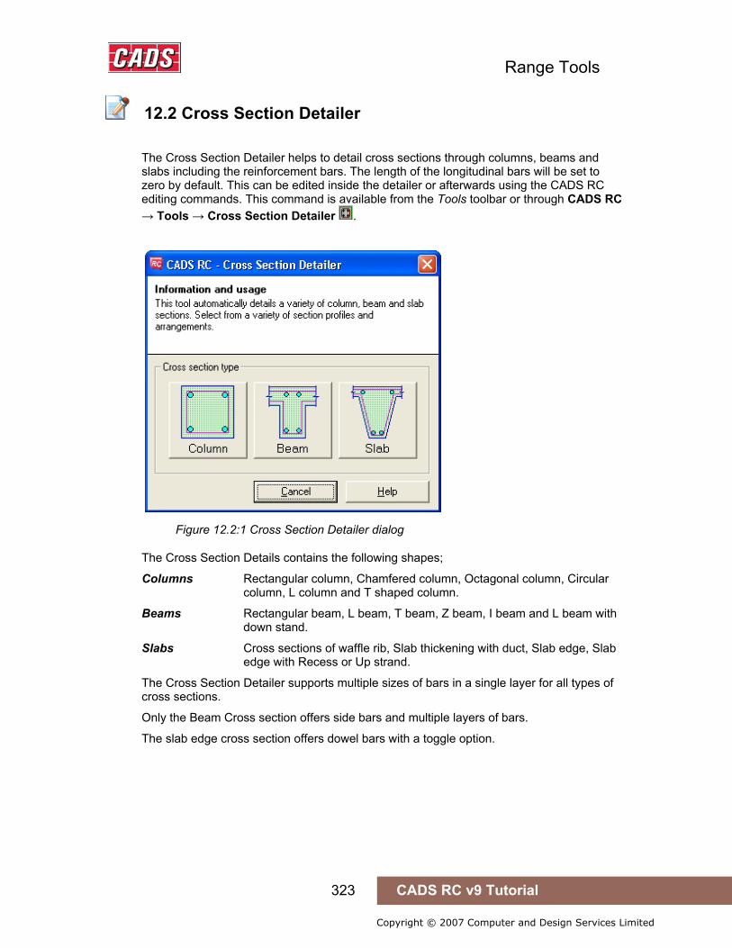
Range Tools
323 CADS RC v9 Tutorial
Copyright © 2007 Computer and Design Services Limited
12.2 Cross Section Detailer
The Cross Section Detailer helps to detail cross sections through columns, beams and slabs including the reinforcement bars. The length of the longitudinal bars will be set to zero by default. This can be edited inside the detailer or afterwards using the CADS RC editing commands. This command is available from the Tools toolbar or through CADS RC → Tools → Cross Section Detailer .
Figure 12.2:1 Cross Section Detailer dialog
The Cross Section Details contains the following shapes;
Columns Rectangular column, Chamfered column, Octagonal column, Circular column, L column and T shaped column.
Beams Rectangular beam, L beam, T beam, Z beam, I beam and L beam with down stand.
Slabs Cross sections of waffle rib, Slab thickening with duct, Slab edge, Slab edge with Recess or Up strand.
The Cross Section Detailer supports multiple sizes of bars in a single layer for all types of cross sections.
Only the Beam Cross section offers side bars and multiple layers of bars.
The slab edge cross section offers dowel bars with a toggle option.
12.2 Cross Section Detailer

Range Tools
324 CADS RC v9 Tutorial
Copyright © 2007 Computer and Design Services Limited
12.2.1 Columns
Figure 12.2.1:1 Column Cross Section dialog
Selecting the Column option from the main dialog invokes the Column Cross Section dialog as shown above in figure 12.2.1:1. This is divided into sub sections;
Outlines and Dimensions The following column types are available;
Rectangular, Chamfered, Octagonal, Circular, L Shaped and T Shaped.
Select the required option and a preview of the section is shown along the input dimension fields. Enter the dimensions for the width, length etc as required.
Select / Edit links Selecting this button invokes the Column Section Detailer Links dialog as shown in figure 12.2.1:2 below.
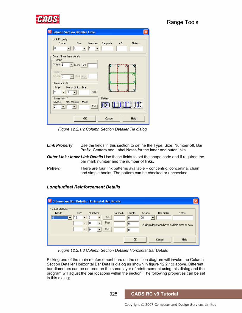
Range Tools
325 CADS RC v9 Tutorial
Copyright © 2007 Computer and Design Services Limited
Figure 12.2.1:2 Column Section Detailer Tie dialog
Link Property Use the fields in this section to define the Type, Size, Number off, Bar Prefix, Centers and Label Notes for the inner and outer links.
Outer Link / Inner Link Details Use these fields to set the shape code and if required the bar mark number and the number of links.
Pattern There are four link patterns available – concentric, concertina, chain and simple hooks. The pattern can be checked or unchecked.
Longitudinal Reinforcement Details
Figure 12.2.1:3 Column Section Detailer Horizontal Bar Details
Picking one of the main reinforcement bars on the section diagram will invoke the Column Section Detailer Horizontal Bar Details dialog as shown in figure 12.2.1:3 above. Different bar diameters can be entered on the same layer of reinforcement using this dialog and the program will adjust the bar locations within the section. The following properties can be set in this dialog;

Range Tools
326 CADS RC v9 Tutorial
Copyright © 2007 Computer and Design Services Limited
Grade Grade of the bars in the layer
Shape Shape code
Bar Prefix Prefix of bar if any
Notes Notes for the bar if any
In order to assign different bar diameters in the same reinforcement layer there are three additional rows of editing fields;
Size Diameter of the bar
Numbers Number of bars of that diameter in the layer
Bar Mark You can type in the Bar Mark Number to be assigned to the bar
Length Type in the required length of the bar, this allows different diameters of bar to have different lengths
Pick You can use the Pick button to link the bars in the section with bars already detailed on the drawing. The new bars will be shown as Views of the selected bars
Figure 12.2.1:4 Typical Column Cross Section Details
Configure Please refer to Section 12.2.4 for details on Configuration
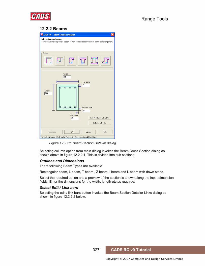
Range Tools
327 CADS RC v9 Tutorial
Copyright © 2007 Computer and Design Services Limited
12.2.2 Beams
Figure 12.2.2:1 Beam Section Detailer dialog
Selecting column option from main dialog invokes the Beam Cross Section dialog as shown above in figure 12.2.2:1. This is divided into sub sections;
Outlines and Dimensions There following Beam Types are available.
Rectangular beam, L beam, T beam , Z beam, I beam and L beam with down stand.
Select the required option and a preview of the section is shown along the input dimension fields. Enter the dimensions for the width, length etc as required.
Select Edit / Link bars Selecting the edit / link bars button invokes the Beam Section Detailer Links dialog as shown in figure 12.2.2:2 below.
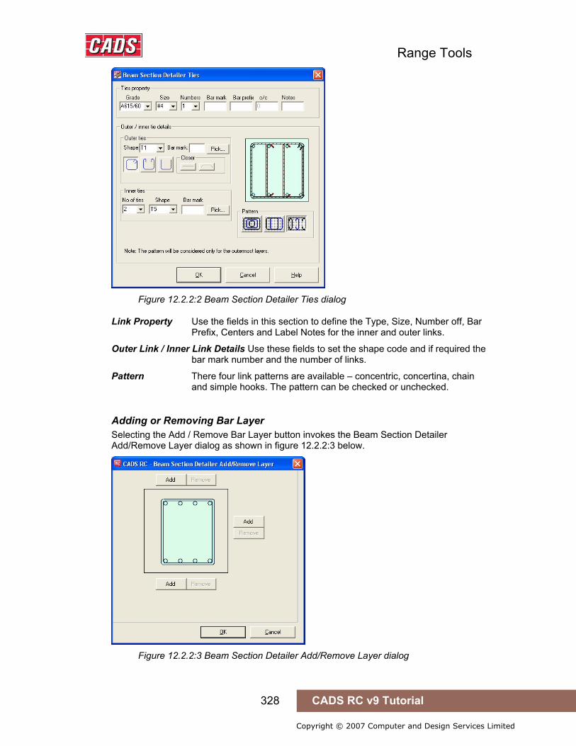
Range Tools
328 CADS RC v9 Tutorial
Copyright © 2007 Computer and Design Services Limited
Figure 12.2.2:2 Beam Section Detailer Ties dialog
Link Property Use the fields in this section to define the Type, Size, Number off, Bar Prefix, Centers and Label Notes for the inner and outer links.
Outer Link / Inner Link Details Use these fields to set the shape code and if required the bar mark number and the number of links.
Pattern There four link patterns are available – concentric, concertina, chain and simple hooks. The pattern can be checked or unchecked.
Adding or Removing Bar Layer Selecting the Add / Remove Bar Layer button invokes the Beam Section Detailer Add/Remove Layer dialog as shown in figure 12.2.2:3 below.
Figure 12.2.2:3 Beam Section Detailer Add/Remove Layer dialog
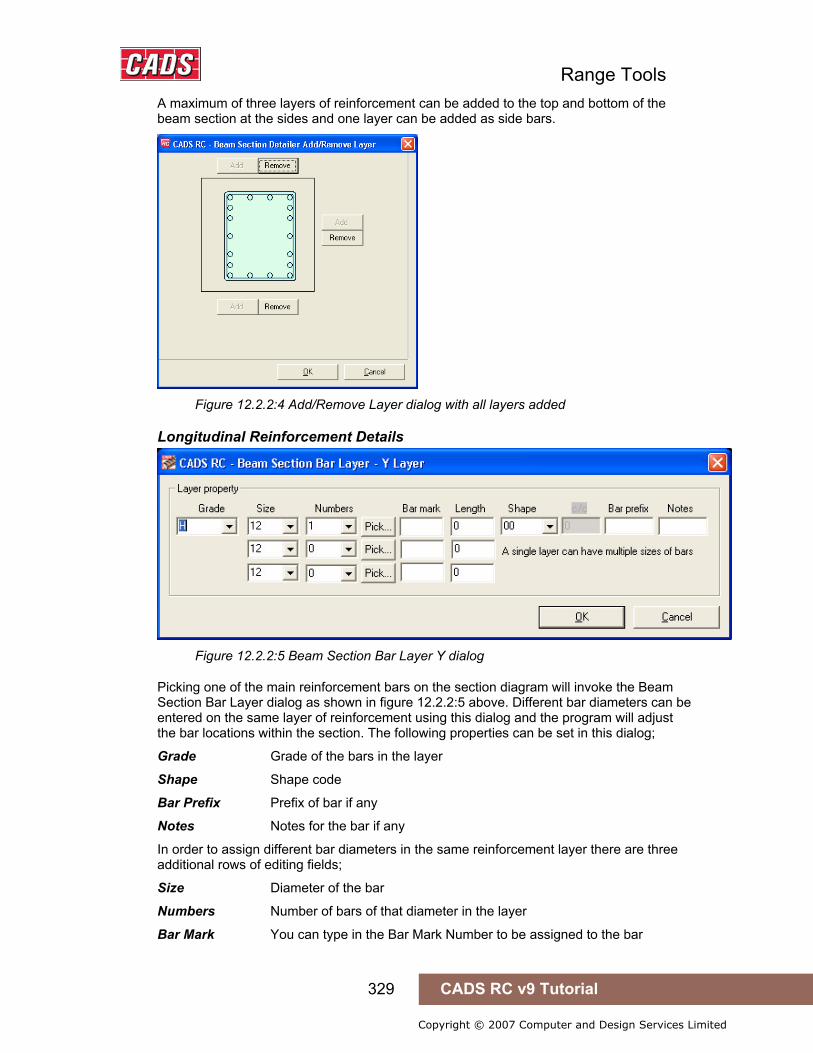
Range Tools
329 CADS RC v9 Tutorial
Copyright © 2007 Computer and Design Services Limited
A maximum of three layers of reinforcement can be added to the top and bottom of the beam section at the sides and one layer can be added as side bars.
Figure 12.2.2:4 Add/Remove Layer dialog with all layers added
Longitudinal Reinforcement Details
Figure 12.2.2:5 Beam Section Bar Layer Y dialog
Picking one of the main reinforcement bars on the section diagram will invoke the Beam Section Bar Layer dialog as shown in figure 12.2.2:5 above. Different bar diameters can be entered on the same layer of reinforcement using this dialog and the program will adjust the bar locations within the section. The following properties can be set in this dialog;
Grade Grade of the bars in the layer
Shape Shape code
Bar Prefix Prefix of bar if any
Notes Notes for the bar if any
In order to assign different bar diameters in the same reinforcement layer there are three additional rows of editing fields;
Size Diameter of the bar
Numbers Number of bars of that diameter in the layer
Bar Mark You can type in the Bar Mark Number to be assigned to the bar

Range Tools
330 CADS RC v9 Tutorial
Copyright © 2007 Computer and Design Services Limited
Length Type in the required length of the bar, this allows different diameters of bar to have different lengths
Pick You can use the Pick button to link the bars in the section with bars already detailed on the drawing. The new bars will be shown as Views of the selected bars
Figure 12.2.2:6 Typical Beam Section Details

Range Tools
331 CADS RC v9 Tutorial
Copyright © 2007 Computer and Design Services Limited
12.2.3 Slab
Figure 12.2.3:1 Slab Section Detailer dialog
Selecting the Column option from the main dialog invokes the Slab Section dialog as shown in figure 12.2.3:1above. This is divided into sub sections;
Outlines and Dimensions There following Slab Section Types are available;
Waffle Rib, Slab Thickening with Duct, Slab Edge, Slab Edge with Recess and Slab Edge with Up stand.
Select the required option and a preview of the section is shown along the input dimension fields. Enter the dimensions for the width, length etc as required.
Select / Edit Link Bars Picking the Select / Edit Links button invokes the Slab Section Detailer Links dialog as shown in figure 12.2.3:2 below.

Range Tools
332 CADS RC v9 Tutorial
Copyright © 2007 Computer and Design Services Limited
Figure 12.2.3:2 Slab Section Detailer Ties dialog
Link Property Use the fields in this section to define the Type, Size, Number off, Bar Prefix, Centers and Label Notes for the inner and outer links.
Outer Link / Inner Link Details Use these fields to set the shape code and if required the bar mark number and the number of links based on the pattern selected.
Pattern There are four link patterns available – concentric, concertina, chain and simple hooks. The pattern can be checked or unchecked.
Longitudinal Reinforcement Bar Details
Figure 12.2.3:3 Slab Section Bar Details
Picking one of the main reinforcement bars on the section diagram will invoke the Beam Section Bar Layer dialog as shown above in figure 12.2.3:3. The following properties can be set in this dialog;
Grade Grade of the bars in the layer
Size Diameter of the bar
Numbers Number of bars of that diameter in the layer
Bar Mark You can type in the Bar Mark Number to be assigned to the bar
C/C Enter the bar centre to centre distance

Range Tools
333 CADS RC v9 Tutorial
Copyright © 2007 Computer and Design Services Limited
Bar Prefix Prefix of bar if any
Notes Notes for the bar if any
12.2.4 Configuration Picking the Configure button invokes the Section Detailer Configuration dialog as shown in figure 12.2.4:1 below.
Figure 12.2.4:1 Section Detailer Configuration dialog
In the Section Detailer Configuration Dialog Box the following options are available
Rotation Use to set the insertion angle of the section on the drawing.
Insert Outline If checked, the section outline will be drawn.
Insert Cover line If checked, the cover line will be drawn.
Unscheduled Bars If checked, the reinforcement bars will be drawn as unscheduled bars.
Length of Bars This is the global edit field for the length of bars. The value entered in this field will become the default value for all the length fields.
12.2.5 Try It! Detailing Cross Sections using the Cross Section Detailer
Figure 12.2.5:1 below shows the points specified in this example 1. Launch CADS RC 2. Open drawing ...\drawings\CADS RC 29.dwg 3. Set the Working Scale at 1:20 4. Make the Viewport on Cross Section Layout active
5. Select CADS RC → Draw Bar → Set Member or 6. Make Cross Section the current Member and select OK
7. Select CADS RC → Draw Bar → Set Drawing Sheet or 8. Make 01 the current Drawing Sheet and select OK
12.2.5 Try It! Detailing Cross Sections using the Detailer
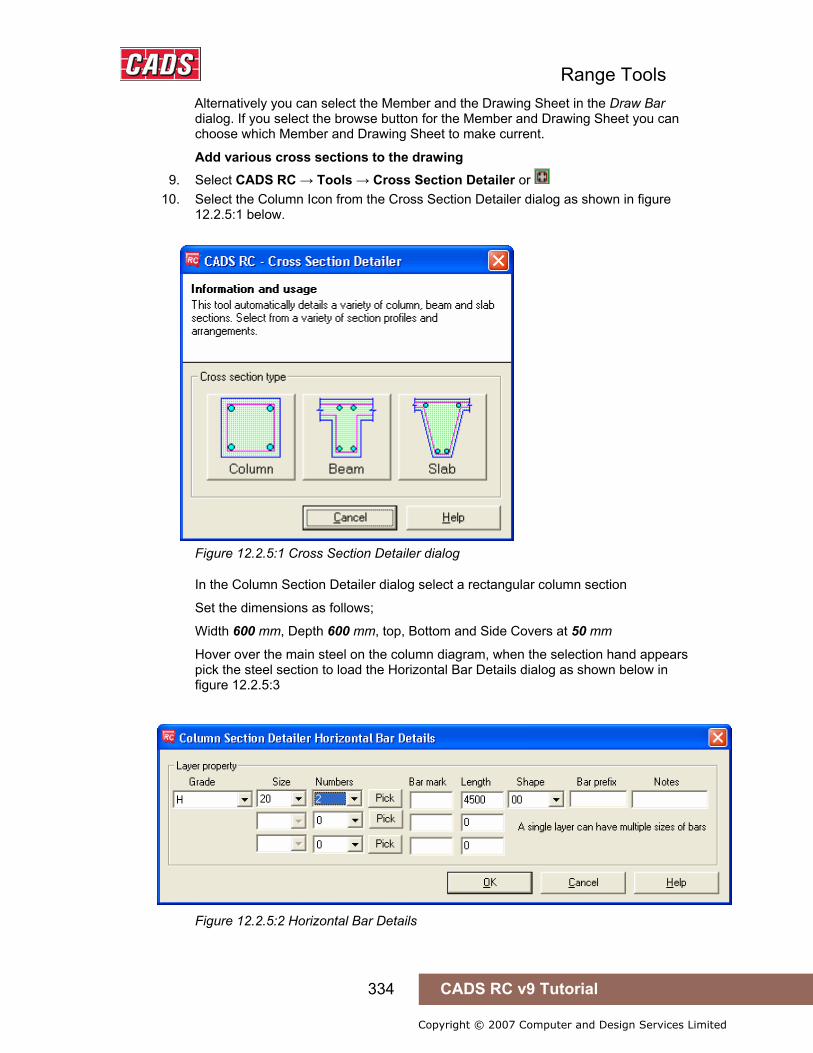
Range Tools
334 CADS RC v9 Tutorial
Copyright © 2007 Computer and Design Services Limited
Alternatively you can select the Member and the Drawing Sheet in the Draw Bar dialog. If you select the browse button for the Member and Drawing Sheet you can choose which Member and Drawing Sheet to make current.
Add various cross sections to the drawing 9. Select CADS RC → Tools → Cross Section Detailer or
10. Select the Column Icon from the Cross Section Detailer dialog as shown in figure 12.2.5:1 below.
Figure 12.2.5:1 Cross Section Detailer dialog
In the Column Section Detailer dialog select a rectangular column section
Set the dimensions as follows;
Width 600 mm, Depth 600 mm, top, Bottom and Side Covers at 50 mm
Hover over the main steel on the column diagram, when the selection hand appears pick the steel section to load the Horizontal Bar Details dialog as shown below in figure 12.2.5:3
Figure 12.2.5:2 Horizontal Bar Details
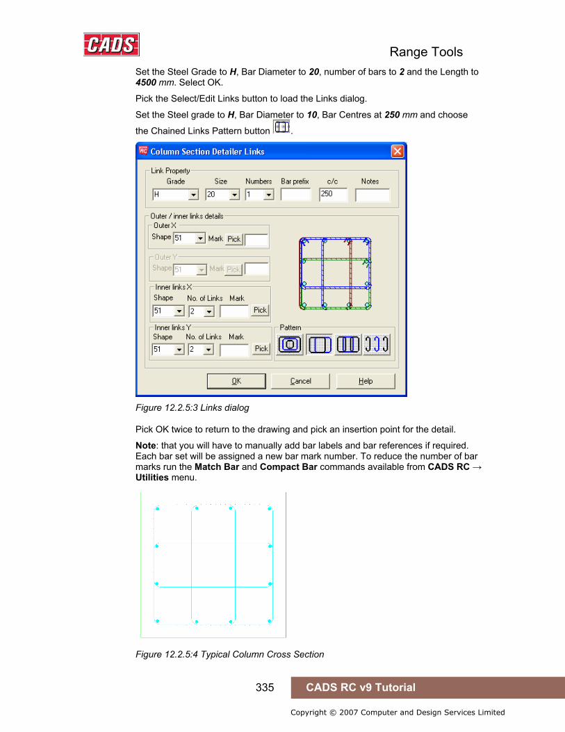
Range Tools
335 CADS RC v9 Tutorial
Copyright © 2007 Computer and Design Services Limited
Set the Steel Grade to H, Bar Diameter to 20, number of bars to 2 and the Length to 4500 mm. Select OK.
Pick the Select/Edit Links button to load the Links dialog.
Set the Steel grade to H, Bar Diameter to 10, Bar Centres at 250 mm and choose
the Chained Links Pattern button .
Figure 12.2.5:3 Links dialog
Pick OK twice to return to the drawing and pick an insertion point for the detail.
Note: that you will have to manually add bar labels and bar references if required. Each bar set will be assigned a new bar mark number. To reduce the number of bar marks run the Match Bar and Compact Bar commands available from CADS RC → Utilities menu.
Figure 12.2.5:4 Typical Column Cross Section
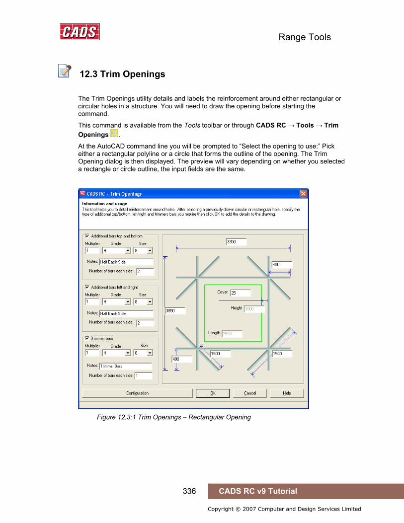
Range Tools
336 CADS RC v9 Tutorial
Copyright © 2007 Computer and Design Services Limited
12.3 Trim Openings
The Trim Openings utility details and labels the reinforcement around either rectangular or circular holes in a structure. You will need to draw the opening before starting the command.
This command is available from the Tools toolbar or through CADS RC → Tools → Trim Openings .
At the AutoCAD command line you will be prompted to “Select the opening to use:” Pick either a rectangular polyline or a circle that forms the outline of the opening. The Trim Opening dialog is then displayed. The preview will vary depending on whether you selected a rectangle or circle outline, the input fields are the same.
Figure 12.3:1 Trim Openings – Rectangular Opening
12.3 Trim Openings
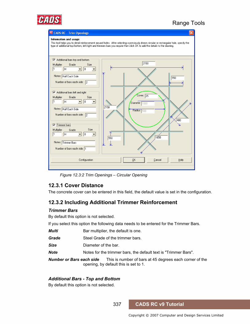
Range Tools
337 CADS RC v9 Tutorial
Copyright © 2007 Computer and Design Services Limited
Figure 12.3:2 Trim Openings – Circular Opening
12.3.1 Cover Distance The concrete cover can be entered in this field, the default value is set in the configuration.
12.3.2 Including Additional Trimmer Reinforcement Trimmer Bars By default this option is not selected.
If you select this option the following data needs to be entered for the Trimmer Bars.
Multi Bar multiplier, the default is one.
Grade Steel Grade of the trimmer bars.
Size Diameter of the bar.
Note Notes for the trimmer bars, the default text is "Trimmer Bars".
Number or Bars each side This is number of bars at 45 degrees each corner of the opening, by default this is set to 1.
Additional Bars - Top and Bottom By default this option is not selected.

Range Tools
338 CADS RC v9 Tutorial
Copyright © 2007 Computer and Design Services Limited
If you select this option the following data needs to be entered for the Top and Bottom Bars.
Multi Bar multiplier, the default is one.
Grade Steel Grade of the trimmer bars.
Size Diameter of the bar.
Note Notes for the top and bottom bars, the default text is "Half Each Side".
Number or Bars each side This is number of bars above and below the opening, by default this is set to 2.
Additional Bars – Left and Right Exactly the same data is entered for the Left and Right Bars as the Top and Bottom Bars.
12.3.3 Bar Lengths Trimmer Bar Lengths There are two different ways the trimmer bar length can be defined as shown in figure 12.3.3:1 below;
1 Overall length
2 Projection from the point where trimmer bar from the other direction intersect.
The values in each field depend on each other and will change automatically.
Figure 12.3.3:1 Trimmer Bar Lengths
Top and Bottom Bar Lengths There are two different ways the top and bottom bar lengths can be defined as shown in figure 12.3.3:2 below;
1 Overall length.
2 Projection from the point where left and right bars meet. This value is kept constant if the hole size is changed.
The values in each field depend on each other and will get changed automatically.
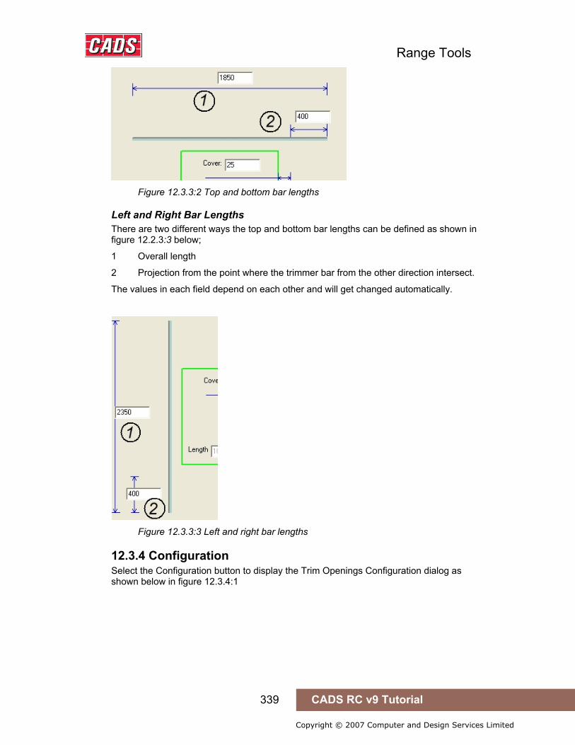
Range Tools
339 CADS RC v9 Tutorial
Copyright © 2007 Computer and Design Services Limited
Figure 12.3.3:2 Top and bottom bar lengths
Left and Right Bar Lengths There are two different ways the top and bottom bar lengths can be defined as shown in figure 12.2.3:3 below;
1 Overall length
2 Projection from the point where the trimmer bar from the other direction intersect.
The values in each field depend on each other and will get changed automatically.
Figure 12.3.3:3 Left and right bar lengths
12.3.4 Configuration Select the Configuration button to display the Trim Openings Configuration dialog as shown below in figure 12.3.4:1

Range Tools
340 CADS RC v9 Tutorial
Copyright © 2007 Computer and Design Services Limited
Figure 12.3.4:1 Trim Openings Configuration dialog
The configuration dialog has the following items for the user to configure.
Named Settings These options are not available in this version of the program
General Configuration
Draw Outline If ticked the opening outline will be drawn
Add bar label If ticked the bar labels will be drawn
Draw number of views If ticked this option will show all the bars for each bar set around the opening. If unticked, only one bar view will be drawn for each bar set around the opening.
Figure 12.3.4:2 Typical Trimmed Opening Details
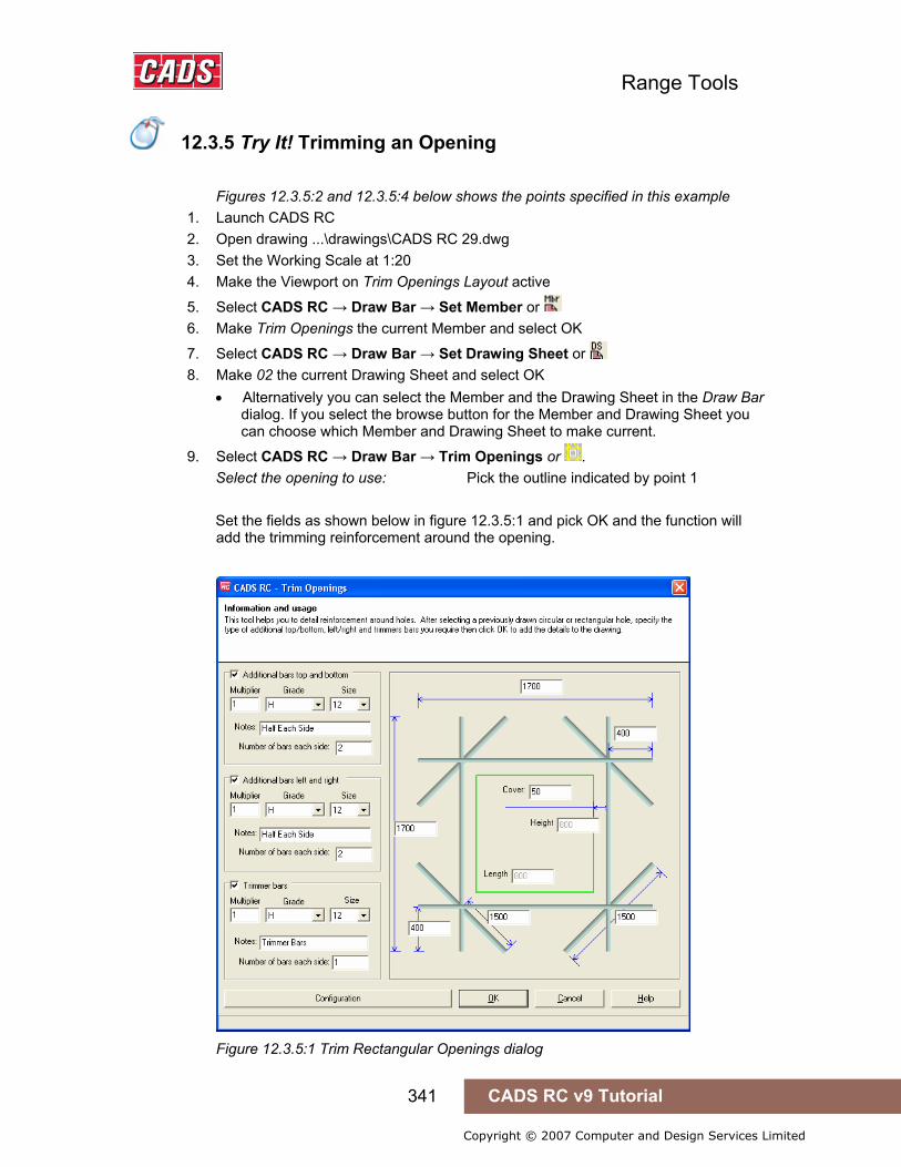
Range Tools
341 CADS RC v9 Tutorial
Copyright © 2007 Computer and Design Services Limited
12.3.5 Try It! Trimming an Opening
Figures 12.3.5:2 and 12.3.5:4 below shows the points specified in this example 1. Launch CADS RC 2. Open drawing ...\drawings\CADS RC 29.dwg 3. Set the Working Scale at 1:20 4. Make the Viewport on Trim Openings Layout active
5. Select CADS RC → Draw Bar → Set Member or 6. Make Trim Openings the current Member and select OK
7. Select CADS RC → Draw Bar → Set Drawing Sheet or 8. Make 02 the current Drawing Sheet and select OK
• Alternatively you can select the Member and the Drawing Sheet in the Draw Bar dialog. If you select the browse button for the Member and Drawing Sheet you can choose which Member and Drawing Sheet to make current.
9. Select CADS RC → Draw Bar → Trim Openings or . Select the opening to use: Pick the outline indicated by point 1 Set the fields as shown below in figure 12.3.5:1 and pick OK and the function will
add the trimming reinforcement around the opening.
Figure 12.3.5:1 Trim Rectangular Openings dialog
12.3.5 Try It! Trimming an Opening
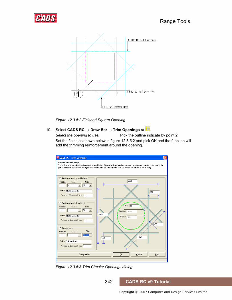
Range Tools
342 CADS RC v9 Tutorial
Copyright © 2007 Computer and Design Services Limited
Figure 12.3.5:2 Finished Square Opening
10. Select CADS RC → Draw Bar → Trim Openings or . Select the opening to use: Pick the outline indicate by point 2 Set the fields as shown below in figure 12.3.5:2 and pick OK and the function will
add the trimming reinforcement around the opening.
Figure 12.3.5:3 Trim Circular Openings dialog
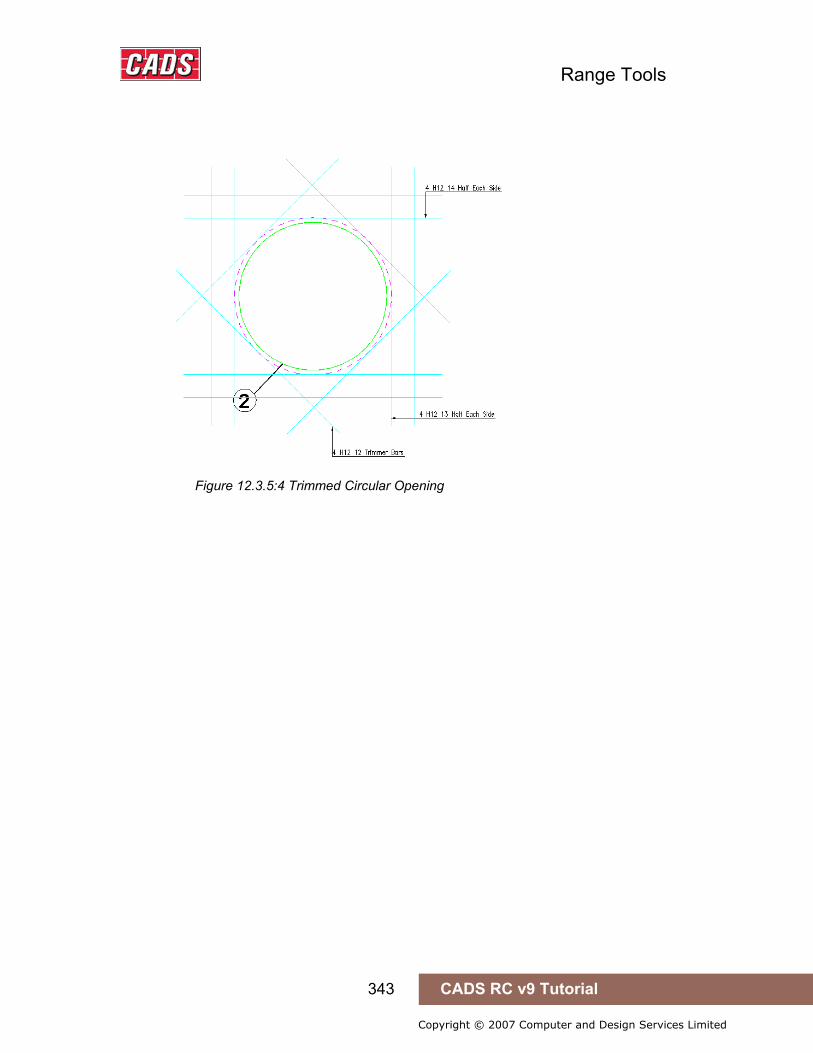
Range Tools
343 CADS RC v9 Tutorial
Copyright © 2007 Computer and Design Services Limited
Figure 12.3.5:4 Trimmed Circular Opening
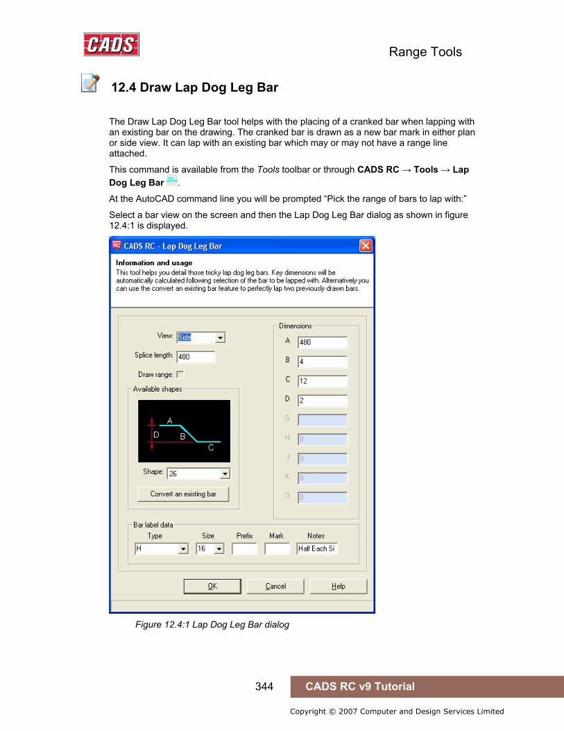
Range Tools
344 CADS RC v9 Tutorial
Copyright © 2007 Computer and Design Services Limited
12.4 Draw Lap Dog Leg Bar
The Draw Lap Dog Leg Bar tool helps with the placing of a cranked bar when lapping with an existing bar on the drawing. The cranked bar is drawn as a new bar mark in either plan or side view. It can lap with an existing bar which may or may not have a range line attached.
This command is available from the Tools toolbar or through CADS RC → Tools → Lap Dog Leg Bar .
At the AutoCAD command line you will be prompted “Pick the range of bars to lap with:”
Select a bar view on the screen and then the Lap Dog Leg Bar dialog as shown in figure 12.4:1 is displayed.
Figure 12.4:1 Lap Dog Leg Bar dialog
12.4 Draw Lap Dog Leg Bar
Range Tools
345 CADS RC v9 Tutorial
Copyright © 2007 Computer and Design Services Limited
The View and Bar Label data fields are updated automatically depending on the shape code picked to lap with on the drawing. There are a number of fields that can be edited to suit your requirements;
Splice Length By default the utility sets the splice length (lap length) at 30d but this can be overridden by typing in a new value.
Shapes Use the drop down menu to select the crank bar shape code. The shapes that are offered will vary according to the Detailing Standard configured inside CADS RC. The appropriate default dimensions are displayed in dimension fields. You will only be able to edit the length of dogleg. The remaining dimensions are automatically calculated based on splice length, bar to lap and lapping bar values.
Convert an Existing Bar You can also convert an existing lapped bar in CADS RC to a lap with dogleg bar. Click the "Convert an existing bar" button in the main dialog box and select an existing bar on the drawing.
Bar Label Data Grade Grade of the dogleg bar. Default value is Grade of bar to lap with.
Size Size of dogleg bar. Default value is Size of bar to lap with.
Prfx Bar mark prefix. Default value is Prfx of bar to lap with.
Mark Bar Mark required. If none, automatic bar mark of CADS RC will be used.
Notes Notes that will get appended to the label
You can now continue by picking the OK button. 12.4.1 Try It Drawing Lap Dog leg Bar
Figure 12.4.1:1 below shows the points specified in this example 1. Launch CADS RC 2. Open drawing ...\drawings\CADS RC 29.dwg 3. Set the Working scale at 1:20 4. Make the Viewport on Draw Lap Dog Leg Layout active
5. Select CADS RC → Draw Bar → Set Member or 6. Make Draw Lap Dog Leg the current Member and select OK
7. Select CADS RC → Draw Bar → Set Drawing Sheet or 8. Make 03 the current Drawing Sheet and select OK
• Alternatively you can select the Member and the Drawing Sheet in the Draw Bar dialog. If you select the browse button for the Member and Drawing Sheet you can choose which Member and Drawing Sheet to make current.
9. Use Zoom Window into the centre of the section where the picking points are shown
12.4.1 Try It! Drawing Lap Dog Leg Bar

Range Tools
346 CADS RC v9 Tutorial
Copyright © 2007 Computer and Design Services Limited
Figure 12.4.1:1 Bars to Lap with
10. Select CADS RC → Tools → Draw Lap Dog Leg Bar or Pick the range of bars to lap with: Pick the bar indicate by point 1
Figure 12.4.1:2 Lap Dog Leg Bar dialog
Set the fields in the Lap Dog Leg dialog as indicated in figure 12.4.1:2. When setting the bar size the lap calculator dialog box will appear accept 40d as the
bar diameter multiplier. Pick OK.

Range Tools
347 CADS RC v9 Tutorial
Copyright © 2007 Computer and Design Services Limited
Pick a point to indicate which end of the bar to lap: Pick on the bar at point 2 Pick a point to indicate which side to place the lap dog leg bar:
Pick above bar at point 3 If the bar to lap with is range bar then the user will also be asked for Pick where to place the range line: If the user not specified the length of dogleg in the main dialog, then in command it
will be asked user to pick a point to calculate dimension of dogleg. Then the dogleg bar is placed according with new bar mark.
Figure 12.4.1:3 Lap Bar drawn
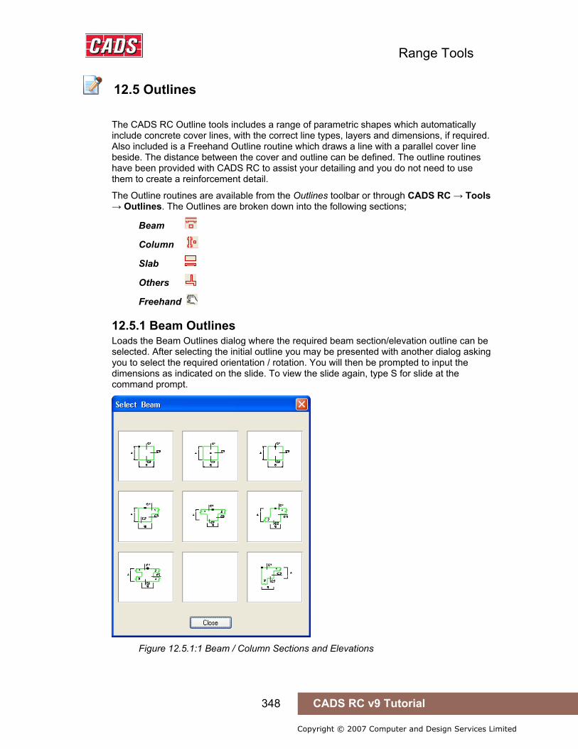
Range Tools
348 CADS RC v9 Tutorial
Copyright © 2007 Computer and Design Services Limited
12.5 Outlines
The CADS RC Outline tools includes a range of parametric shapes which automatically include concrete cover lines, with the correct line types, layers and dimensions, if required. Also included is a Freehand Outline routine which draws a line with a parallel cover line beside. The distance between the cover and outline can be defined. The outline routines have been provided with CADS RC to assist your detailing and you do not need to use them to create a reinforcement detail.
The Outline routines are available from the Outlines toolbar or through CADS RC → Tools → Outlines. The Outlines are broken down into the following sections;
Beam
Column
Slab
Others
Freehand
12.5.1 Beam Outlines Loads the Beam Outlines dialog where the required beam section/elevation outline can be selected. After selecting the initial outline you may be presented with another dialog asking you to select the required orientation / rotation. You will then be prompted to input the dimensions as indicated on the slide. To view the slide again, type S for slide at the command prompt.
Figure 12.5.1:1 Beam / Column Sections and Elevations
12.5 Outlines

Range Tools
349 CADS RC v9 Tutorial
Copyright © 2007 Computer and Design Services Limited
12.4.2 Column Outlines Loads the Column Outlines dialog where the required column section outline can be selected. After selecting the initial outline you may be presented with another dialog asking you to select the required orientation / rotation. You will then be prompted to input the dimensions as indicated on the slide. To view the slide again, type S for slide at the command prompt.
Figure 12.5.2:1 Column Outline dialog
12.4.3 Slab Sections Loads the Slab Outlines dialog where the required slab section outline can be selected. After selecting the initial outline you may be presented with another dialog asking you to select the required orientation / rotation. You will then be prompted to input the dimensions as indicated on the slide. To view the slide again, type S for slide at the command prompt.
Figure 12.5.3:1 Slab Outline dialog
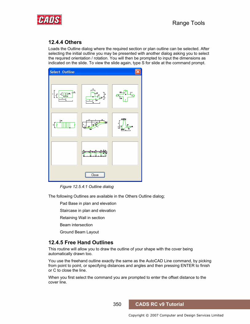
Range Tools
350 CADS RC v9 Tutorial
Copyright © 2007 Computer and Design Services Limited
12.4.4 Others Loads the Outline dialog where the required section or plan outline can be selected. After selecting the initial outline you may be presented with another dialog asking you to select the required orientation / rotation. You will then be prompted to input the dimensions as indicated on the slide. To view the slide again, type S for slide at the command prompt.
Figure 12.5.4:1 Outline dialog
The following Outlines are available in the Others Outline dialog;
Pad Base in plan and elevation
Staircase in plan and elevation
Retaining Wall in section
Beam intersection
Ground Beam Layout
12.4.5 Free Hand Outlines This routine will allow you to draw the outline of your shape with the cover being automatically drawn too.
You use the freehand outline exactly the same as the AutoCAD Line command, by picking from point to point, or specifying distances and angles and then pressing ENTER to finish or C to close the line.
When you first select the command you are prompted to enter the offset distance to the cover line.

Range Tools
351 CADS RC v9 Tutorial
Copyright © 2007 Computer and Design Services Limited
Next you specify the first two points of the line. At this point you are asked to toggle alignment position between the cover line and the outline. If you draw your first line from bottom to top and toggle the alignment to the right you will specify your dimensions on the outline and not the cover. When you move your cursor to the right the pair of lines will move to follow you.
You can then continue specifying the points to form the outline and cover will remain constant, all the corners will be trimmed to suit.
You can press Enter to finish or type C for close to end the command.
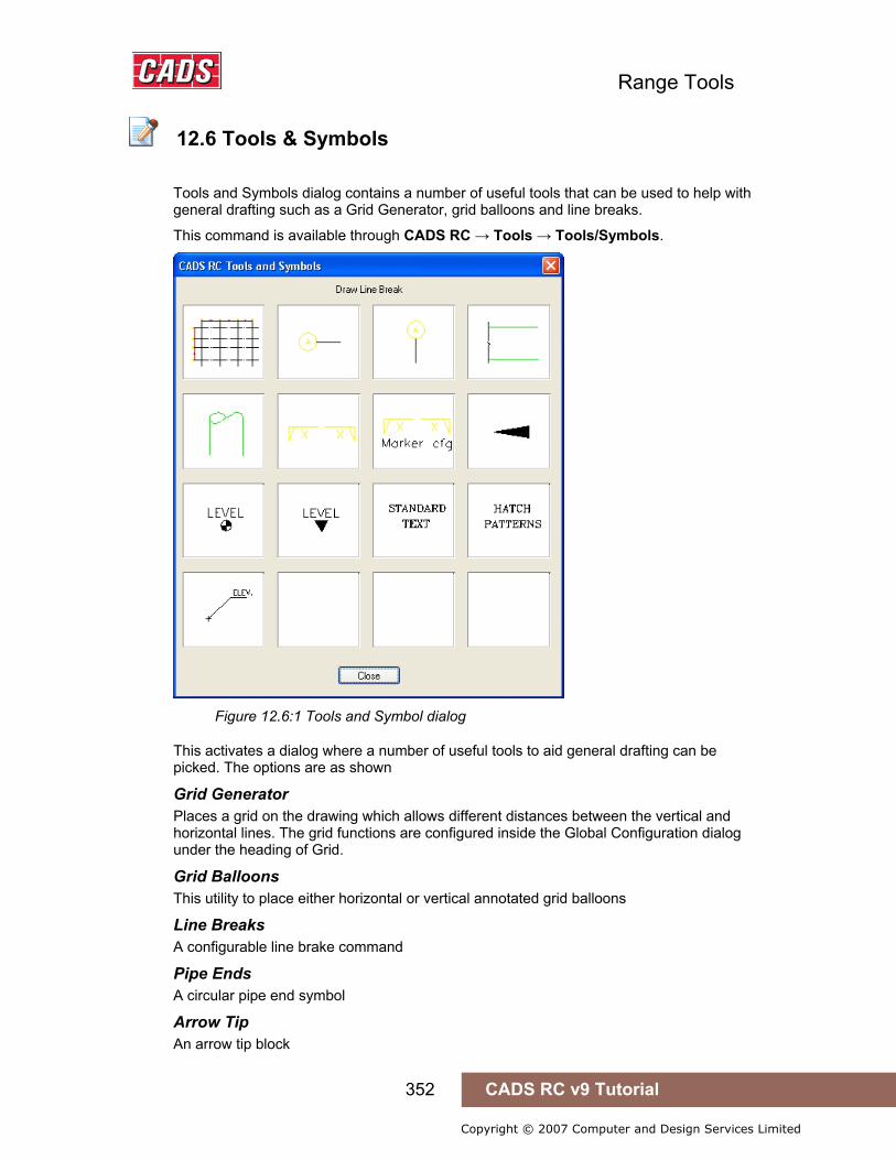
Range Tools
352 CADS RC v9 Tutorial
Copyright © 2007 Computer and Design Services Limited
12.6 Tools & Symbols
Tools and Symbols dialog contains a number of useful tools that can be used to help with general drafting such as a Grid Generator, grid balloons and line breaks.
This command is available through CADS RC → Tools → Tools/Symbols.
Figure 12.6:1 Tools and Symbol dialog
This activates a dialog where a number of useful tools to aid general drafting can be picked. The options are as shown
Grid Generator Places a grid on the drawing which allows different distances between the vertical and horizontal lines. The grid functions are configured inside the Global Configuration dialog under the heading of Grid.
Grid Balloons This utility to place either horizontal or vertical annotated grid balloons
Line Breaks A configurable line brake command
Pipe Ends A circular pipe end symbol
Arrow Tip An arrow tip block
12.6 Tools & Symbols

Range Tools
353 CADS RC v9 Tutorial
Copyright © 2007 Computer and Design Services Limited
Level and Elevation symbols Contains symbols with attributes attached to type in the level height etc
Section Markers and Section Marker Config. You can set the layers and sizes for the section marker symbol and text. The symbol is automatically rescaled according to the working scale of the drawing
Figure 12.6:2 Section Marker Configuration
Standard Text These are blocks which contain annotation text for details, some of them have editable attributes
Figure 12.6:3 Standard Text Types

Range Tools
354 CADS RC v9 Tutorial
Copyright © 2007 Computer and Design Services Limited
Standard Hatch Patterns These include are CADS hatch patterns for Hardcore, Sub-soil, Block & Brick Section, Concrete and Brick Elevations.
Figure 12.6:4 Hatch Pattern dialog

Range Tools
355 CADS RC v9 Tutorial
Copyright © 2007 Computer and Design Services Limited
12.7 Command List - Tools
Action Menu Selection Toolbar and Icon
Special Bar Creator CADS RC→Tools→Special Bar Creator Misc Tools
Cross Section Detailer CADS RC→Tools→Cross Section Detailer Misc Tools
Trim Openings CADS RC→Tools→Trim Openings Misc Tools
Draw Lap Dog Leg Bar CADS RC→Tools→ Draw Lap Dog Leg Bar Misc Tools
Outlines - Beam CADS RC→Tools→ Outlines - Beam Outlines
Outlines - Column CADS RC→Tools→ Outlines -Column Outlines
Outlines - Slab CADS RC→Tools→ Outlines - Slab Outlines
Outlines - Others CADS RC→Tools→ Outlines - Others Outlines
Outlines - Freehand CADS RC→Tools→ Outlines - Freehand Outlines
Tools & Symbols CADS RC→Tools→ Tools & Symbols
12.7 Command List - Tools
Range Tools
356 CADS RC v9 Tutorial
Copyright © 2007 Computer and Design Services Limited
13: Detailers
13.0 Introduction
CADS RC is shipped with the following Detailers;
Beam Detailer Beam Detailer provides an automated method of producing reinforcement drawings for concrete beams. It features Single, End and Interior Span Types.
Column Detailer Column Detailer provides an automated method of producing placing drawings for reinforced concrete columns. It features Rectangular and Circular Column types with or without columns above.
Pad Footing Detailer CADS Pad Footing Detailer (PFD) provides an automated method of producing reinforcement drawings for rectangular reinforced concrete pad footings.
Pile Cap Detailer Pile Cap Detailer provides an automated method of detailing pile cap bar arrangements.
Pad Base Detailer The CADS Pad Base Detailer supports a range of typical base details with reinforcement in a bottom mat, or double (top and bottom) mats.
Stair Flight Detailer CADS Stair Flight Detailer provides an automated method of detailing the reinforcement arrangements for a single flight staircase.
Octagonal Pad Base Detailer Octagonal Pile Cap Detailer provides an automated method of detailing octagonal pile cap bar arrangements.
The CADS RC Detailers provide an automated method of producing reinforcement drawings for standard structural types. You can input the dimensions of the structure and influence the bar arrangements based on standard layouts of rebar. The details are then drawn and scheduled for you. With some of the detailers you can also import design data from the CADS Design Programs.
The Detailers use the AutoCAD Dimscale variable to size the text and blocks to suit the plotted scale of the drawing regardless of whether you are working in Model Space only or both Model/Layout space. Ensure that Dimscale is set to match the plotted scale of the detail.
If you have access to the CADS-SC software, use the Drawing Set-up Function to load in a Title Block and set the appropriate scale and drawing environment. Alternatively you can use CADS VPM, create Layout function or basic AutoCAD, create Layout as described in Section 2 of this Tutorial.
13.0 Introduction

Range Tools
357 CADS RC v9 Tutorial
Copyright © 2007 Computer and Design Services Limited
13.1 Beam Detailer
Beam Detailer provides an automated method of producing reinforcement drawings for concrete beams. It features Single, End and Interior Span Types. You can choose different bar arrangements with percentage span calculations and bar dimensions automatically determined from the entered span data.
The Beam Detailer allows the top and bottom support bars to be curtailed. The amount of curtailment can be specified as either a fixed distance or calculated as a percentage of the clear span between the column faces. For the bottom support reinforcement the curtailment calculation is based on the current beams clear span. For the top support reinforcement the curtailment calculation is based on either the current beams clear span or the adjacent beams clear span whichever is the greater.
This command is available from the Detailers toolbar or through CADS RC → Tools → Detailers → Beam Detailer .
There are four data input dialog boxes which need to be completed before attempting to ask the detailer to draw the beam these consist of;
Beam Type specify either single span, end span or interior span.
Beam Dimensions input the dimensions for span, depth, width etc.
Beam Reinforcement set-up the top, bottom and link reinforcement
13.1.1 Selecting the Beam Type The type of beam span can be selected from the Beam Type Selection dialog. Single Span, End Span or Interior span types can be selected by activating the relevant check box. End spans may be defined as left or right by picking the relevant option from the adjacent pop-down list. At any time during the set-up procedure the beam span type can be altered or checked by picking the Beam Selection Button that is available from the majority of the beam detailer input dialogs.
Figure 13.1.1:1 Beam Detailer Beam Type Selection
13.1 Beam Detailer
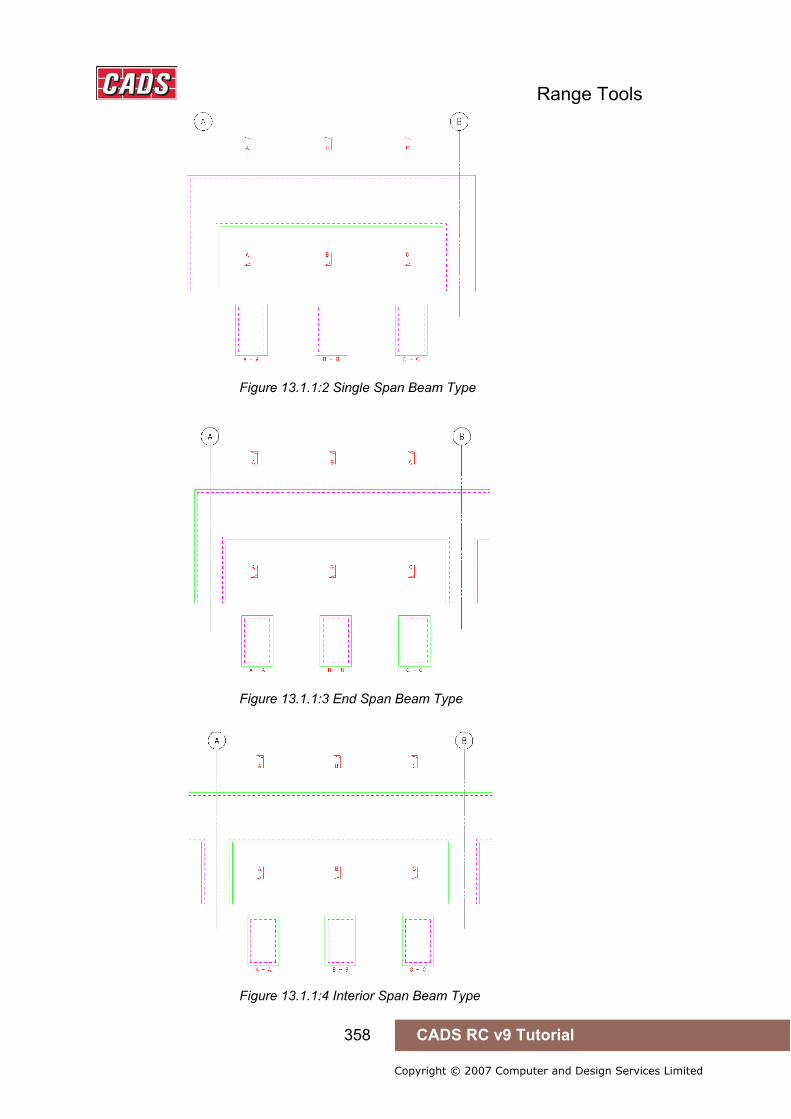
Range Tools
358 CADS RC v9 Tutorial
Copyright © 2007 Computer and Design Services Limited
Figure 13.1.1:2 Single Span Beam Type
Figure 13.1.1:3 End Span Beam Type
Figure 13.1.1:4 Interior Span Beam Type

Range Tools
359 CADS RC v9 Tutorial
Copyright © 2007 Computer and Design Services Limited
13.1.2 Entering the Beam Dimensions The beam dimensions can be amended or checked by picking the Beam Dimensions Button
that is available from most of the beam detailer input dialogs.
Figure 13.1.2:1 Beam Dimensions dialog
The types of beam dimension data that are required are dependent upon the beam span type selected. Therefore some beam dimension fields will not be accessible for certain beam span types. When defining an end or interior beam the BMD program needs the adjacent span data in order to calculate the correct curtailment dimensions for the top support bars.
Figure 13.1.2:2 Beam Detailer Dimensions
Beam Dimension input data is as follows:
Clear Span This is the clear span between column faces of the beam.
Adjacent Left Clear Span Interior and right end span types only and is the clear span between column faces of the beam to the left of the beam to be detailed.

Range Tools
360 CADS RC v9 Tutorial
Copyright © 2007 Computer and Design Services Limited
Adjacent Right Clear Span Interior and left end span types and is the clear span between column faces of the beam to the right of the beam to be detailed.
Left Column Width This is the overall column width at the left end of the beam.
Right Column Width This is the overall column width at the right end of the beam.
Beam Depth This is the overall depth of the beam.
Beam Width This is the overall width of the beam.
Draw Outline When set to Yes the detail produced will include the beam outline, set to No the detail produced will only contain the reinforcing entities that can be placed into an existing general arrangement drawing.
Beam Left End Cover Single and left end span types only, this is the end cover applied to top and bottom bars.
Beam Right End Cover Single and right end span types only, this is the end cover applied to top and bottom bars.
Top Cover To Links This is the cover applied to the beam link leg in the top of the beam.
Bottom Cover To Links This the cover applied to the beam link leg in the bottom of the beam.
Near Face Cover To Links This is the cover applied to the beam link leg in the near face of the beam in elevation.
Far Face Cover To Links This is the cover applied to the beam link leg in the far face of the beam in elevation.
Left Column Grid Ref. This is the grid reference for the left column grid line and is drawn in the centre of the beam when the draw outline is set to yes.
Right Column Grid Ref. This is the grid reference for the right column grid line and is drawn at the centre of the beam when draw outline is set to yes.
13.1.3 Defining the Bar Arrangements The Beam Detailer program divides the beam reinforcement into three zones. These are for the Top, Bottom and Stirrup (Link) Reinforcement.
Picking the beam reinforcement button opens up the reinforcement selection dialog box where the bar grade and bar mark prefix can be defined for the Top Reinforcement and Bottom Reinforcement and the Stirrup reinforcement.
Figure 13.1.3:1 Reinforcement Selection Dialog
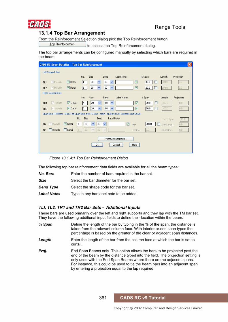
Range Tools
361 CADS RC v9 Tutorial
Copyright © 2007 Computer and Design Services Limited
13.1.4 Top Bar Arrangement From the Reinforcement Selection dialog pick the Top Reinforcement button
to access the Top Reinforcement dialog.
The top bar arrangements can be configured manually by selecting which bars are required in the beam.
Figure 13.1.4:1 Top Bar Reinforcement Dialog
The following top bar reinforcement data fields are available for all the beam types:
No. Bars Enter the number of bars required in the bar set.
Size Select the bar diameter for the bar set.
Bend Type Select the shape code for the bar set.
Label Notes Type in any bar label note to be added.
TLl, TL2, TR1 and TR2 Bar Sets - Additional Inputs These bars are used primarily over the left and right supports and they lap with the TM bar set. They have the following additional input fields to define their location within the beam:
% Span Define the length of the bar by typing in the % of the span, the distance is taken from the relevant column face. With interior or end span types the percentage is based on the greater of the clear or adjacent span distances.
Length Enter the length of the bar from the column face at which the bar is set to curtail.
Proj. End Span Beams only. This option allows the bars to be projected past the end of the beam by the distance typed into the field. The projection setting is only used with the End Span Beams where there are no adjacent spans. For instance, this could be used to tie the beam bars into an adjacent span by entering a projection equal to the lap required.

Range Tools
362 CADS RC v9 Tutorial
Copyright © 2007 Computer and Design Services Limited
TM Bar Set Additional Inputs This bar set is the main span reinforcement in the top of the beam. It has the following inputs to define the location of the bars within the beam:
Lap The TM bars lap with the TL1 and TR1 bars, see Figure 13.1.4:1, enter the lap length required between the two bars.
Length Enter the required bar length which is placed equally about the mid-span.
% Span The TM bar can be placed as a continuous bar over the column into the adjacent beam. The curtailment point of the TM bar in the adjacent span is entered as a percentage of the clear span. The percentage span is based on either the current beams clear span between column faces or the adjacent beams clear span whichever is the greater.
TC Bar Set Additional Inputs This bar set is used only on single span beam types where a continuous top bar is required. The TC Bar uses the following input to define its location within the beam:
Left and Right Proj The TC bar can be projected past the end of the beam by the distance typed into this field. For instance, this could be used to tie the beam bars into an adjacent span by entering a projection equal to the lap required.
Preset Arrangements Alternatively, the bar arrangement can be set by picking the Pre-set Arrangements button
. This displays the Pre-set Arrangements options for the type of beam selected. Pick on the diagram that displays the bar layout you require to set-up the Top Bar Reinforcement dialog. Shown below are the different top bar arrangements that are available depending on the span type selected.
Figure 13.1.4:2 Single Span Top Bar Pre-sets

Range Tools
363 CADS RC v9 Tutorial
Copyright © 2007 Computer and Design Services Limited
Figure 13.1.4:3 End Span Top Bar Pre-sets
Figure 13.1.4:4 Interior Span Top Bar Pre-sets
Six additional sets of bar are available for use in the top of the beams. These bar sets are optional and can be omitted from the beam in order to achieve the desired bar arrangement.
Figure 13.1.4:5 Top Bar Set annotation explained
Detail and Include Options Each of the bar sets has Detail and Include options that determines whether the bar set is to be included in the beam detail or not.
The Detail and Include options can be used in combination. Listed below are the combination options available and an explanation of the effects on the beam being detailed:
Detail option selected
The bar set will be detailed based on the data entered.
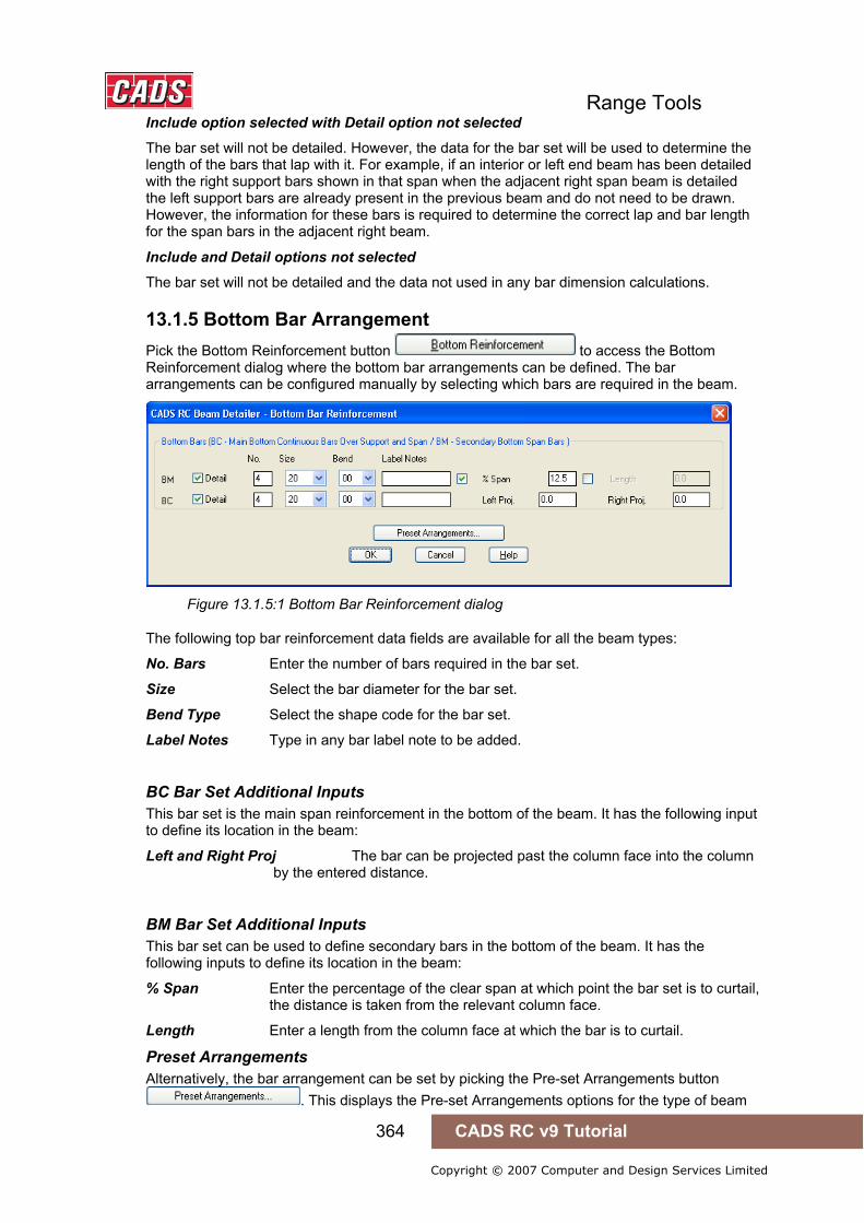
Range Tools
364 CADS RC v9 Tutorial
Copyright © 2007 Computer and Design Services Limited
Include option selected with Detail option not selected
The bar set will not be detailed. However, the data for the bar set will be used to determine the length of the bars that lap with it. For example, if an interior or left end beam has been detailed with the right support bars shown in that span when the adjacent right span beam is detailed the left support bars are already present in the previous beam and do not need to be drawn. However, the information for these bars is required to determine the correct lap and bar length for the span bars in the adjacent right beam.
Include and Detail options not selected
The bar set will not be detailed and the data not used in any bar dimension calculations.
13.1.5 Bottom Bar Arrangement Pick the Bottom Reinforcement button to access the Bottom Reinforcement dialog where the bottom bar arrangements can be defined. The bar arrangements can be configured manually by selecting which bars are required in the beam.
Figure 13.1.5:1 Bottom Bar Reinforcement dialog
The following top bar reinforcement data fields are available for all the beam types:
No. Bars Enter the number of bars required in the bar set.
Size Select the bar diameter for the bar set.
Bend Type Select the shape code for the bar set.
Label Notes Type in any bar label note to be added.
BC Bar Set Additional Inputs This bar set is the main span reinforcement in the bottom of the beam. It has the following input to define its location in the beam:
Left and Right Proj The bar can be projected past the column face into the column by the entered distance.
BM Bar Set Additional Inputs This bar set can be used to define secondary bars in the bottom of the beam. It has the following inputs to define its location in the beam:
% Span Enter the percentage of the clear span at which point the bar set is to curtail, the distance is taken from the relevant column face.
Length Enter a length from the column face at which the bar is to curtail.
Preset Arrangements Alternatively, the bar arrangement can be set by picking the Pre-set Arrangements button
. This displays the Pre-set Arrangements options for the type of beam

Range Tools
365 CADS RC v9 Tutorial
Copyright © 2007 Computer and Design Services Limited
selected. Pick on the diagram that displays the bar layout you require to set-up the Bottom Bar Reinforcement dialog. Shown below are the different bottom bar arrangements that are available depending on the span type selected.
Figure 13.1.5:2 Single Span Bottom Bar Pre-sets
Figure 13.1.5:3 End Span Bottom Bar Pre-sets
Figure 13.1.5:4 Interior Span Bottom Bar Pre-sets
Two bar sets are available for use as the bottom bars for the beam, these bar sets are optional and can be omitted from the beam in order to achieve the desired bar arrangement.
Figure 13.1.5:5 Bottom Bar Sets
Each of the bar sets has a Detail option that determines whether the bar set is to be included in the beam detail or not. Listed below are the outcome of the combinations available when using the Detail option and an explanation of the effects on the beam being detailed.
Detail Options Detail Option Activated The bar set will be detailed based on the information entered for that bar set.
Detail Option Not Activated The bar set will not be detailed and its data will not be used in any bar dimension calculations.

Range Tools
366 CADS RC v9 Tutorial
Copyright © 2007 Computer and Design Services Limited
13.1.6 Stirrup Reinforcement Stirrup Bar Zones The Beam Detailer allows the stirrup (link) bars to be defined as one zone or three zones within the beam span. Pick the Stirrup Reinforcement button to access the Stirrup Reinforcement dialog where the number, length and bar centers of the stirrup zones can be defined.
Figure 13.1.6:1 Stirrup Zone Data Dialog
Stirrup Zone Offset from the Column Face
The distance entered in this field defines the distance from the right and left column faces to the start and end of the stirrup zones.
Figure 13.1.6:2 Beam showing One Stirrup Zone
One Stirrup Zone When one stirrup zone is selected for the beam span the following Span Support Zone data fields are available for input:
Zone Length The zone length is calculated as the Clear Span less the offset from the right and left column faces.
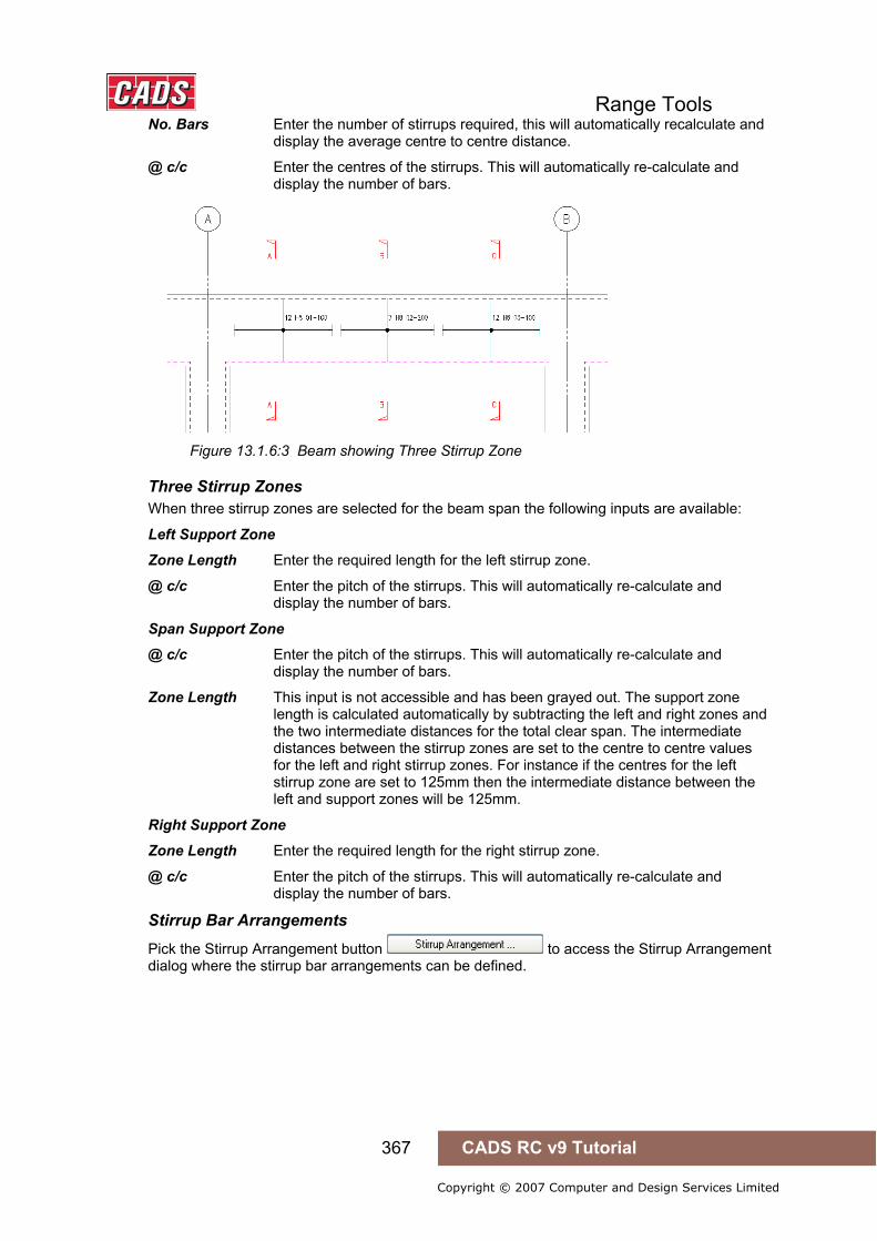
Range Tools
367 CADS RC v9 Tutorial
Copyright © 2007 Computer and Design Services Limited
No. Bars Enter the number of stirrups required, this will automatically recalculate and display the average centre to centre distance.
@ c/c Enter the centres of the stirrups. This will automatically re-calculate and display the number of bars.
Figure 13.1.6:3 Beam showing Three Stirrup Zone
Three Stirrup Zones When three stirrup zones are selected for the beam span the following inputs are available:
Left Support Zone
Zone Length Enter the required length for the left stirrup zone.
@ c/c Enter the pitch of the stirrups. This will automatically re-calculate and display the number of bars.
Span Support Zone
@ c/c Enter the pitch of the stirrups. This will automatically re-calculate and display the number of bars.
Zone Length This input is not accessible and has been grayed out. The support zone length is calculated automatically by subtracting the left and right zones and the two intermediate distances for the total clear span. The intermediate distances between the stirrup zones are set to the centre to centre values for the left and right stirrup zones. For instance if the centres for the left stirrup zone are set to 125mm then the intermediate distance between the left and support zones will be 125mm.
Right Support Zone
Zone Length Enter the required length for the right stirrup zone.
@ c/c Enter the pitch of the stirrups. This will automatically re-calculate and display the number of bars.
Stirrup Bar Arrangements
Pick the Stirrup Arrangement button to access the Stirrup Arrangement dialog where the stirrup bar arrangements can be defined.
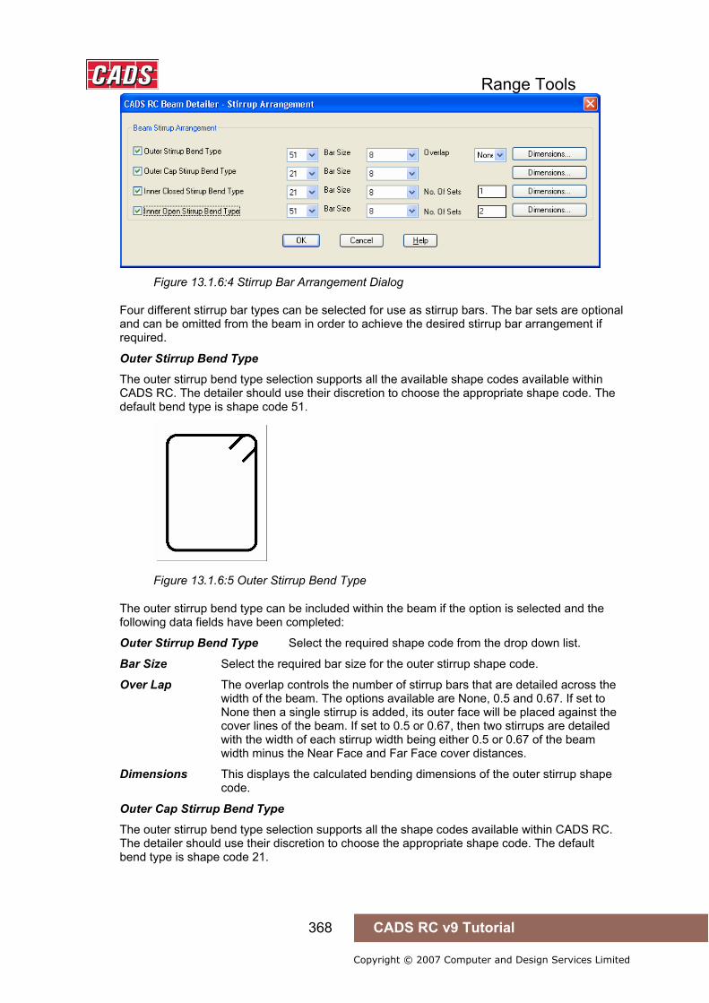
Range Tools
368 CADS RC v9 Tutorial
Copyright © 2007 Computer and Design Services Limited
Figure 13.1.6:4 Stirrup Bar Arrangement Dialog
Four different stirrup bar types can be selected for use as stirrup bars. The bar sets are optional and can be omitted from the beam in order to achieve the desired stirrup bar arrangement if required.
Outer Stirrup Bend Type
The outer stirrup bend type selection supports all the available shape codes available within CADS RC. The detailer should use their discretion to choose the appropriate shape code. The default bend type is shape code 51.
Figure 13.1.6:5 Outer Stirrup Bend Type
The outer stirrup bend type can be included within the beam if the option is selected and the following data fields have been completed:
Outer Stirrup Bend Type Select the required shape code from the drop down list.
Bar Size Select the required bar size for the outer stirrup shape code.
Over Lap The overlap controls the number of stirrup bars that are detailed across the width of the beam. The options available are None, 0.5 and 0.67. If set to None then a single stirrup is added, its outer face will be placed against the cover lines of the beam. If set to 0.5 or 0.67, then two stirrups are detailed with the width of each stirrup width being either 0.5 or 0.67 of the beam width minus the Near Face and Far Face cover distances.
Dimensions This displays the calculated bending dimensions of the outer stirrup shape code.
Outer Cap Stirrup Bend Type
The outer stirrup bend type selection supports all the shape codes available within CADS RC. The detailer should use their discretion to choose the appropriate shape code. The default bend type is shape code 21.
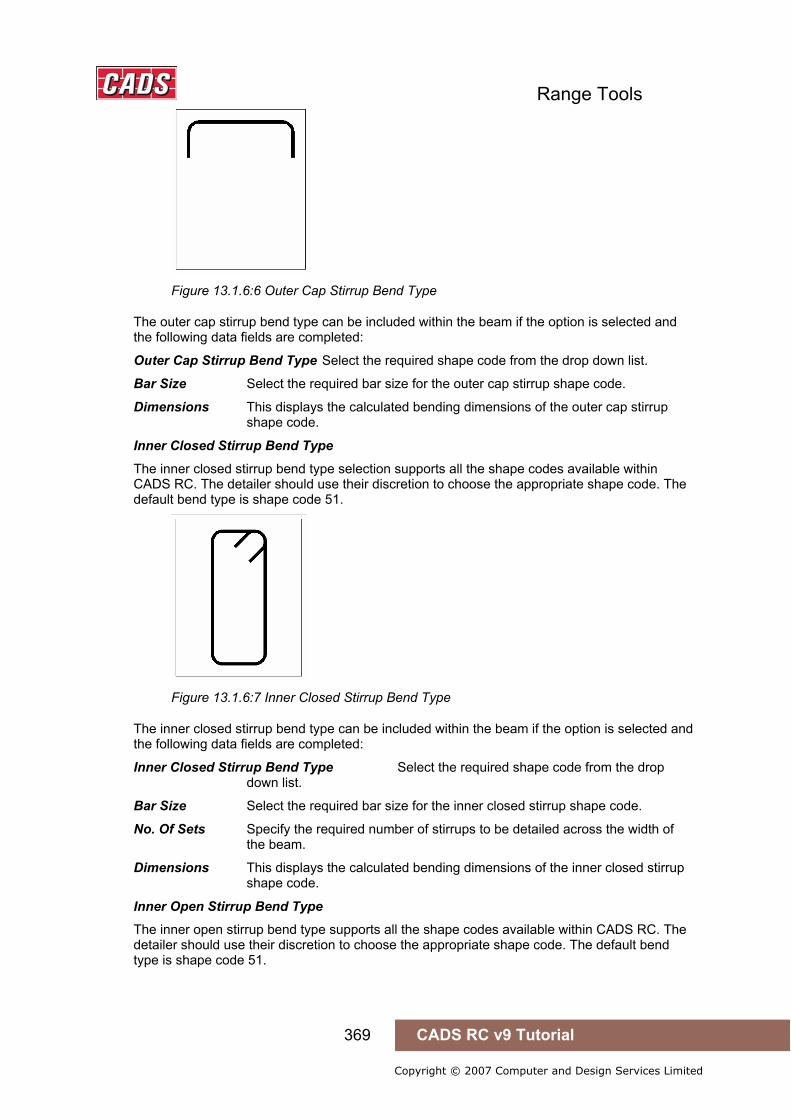
Range Tools
369 CADS RC v9 Tutorial
Copyright © 2007 Computer and Design Services Limited
Figure 13.1.6:6 Outer Cap Stirrup Bend Type
The outer cap stirrup bend type can be included within the beam if the option is selected and the following data fields are completed:
Outer Cap Stirrup Bend Type Select the required shape code from the drop down list.
Bar Size Select the required bar size for the outer cap stirrup shape code.
Dimensions This displays the calculated bending dimensions of the outer cap stirrup shape code.
Inner Closed Stirrup Bend Type
The inner closed stirrup bend type selection supports all the shape codes available within CADS RC. The detailer should use their discretion to choose the appropriate shape code. The default bend type is shape code 51.
Figure 13.1.6:7 Inner Closed Stirrup Bend Type
The inner closed stirrup bend type can be included within the beam if the option is selected and the following data fields are completed:
Inner Closed Stirrup Bend Type Select the required shape code from the drop down list.
Bar Size Select the required bar size for the inner closed stirrup shape code.
No. Of Sets Specify the required number of stirrups to be detailed across the width of the beam.
Dimensions This displays the calculated bending dimensions of the inner closed stirrup shape code.
Inner Open Stirrup Bend Type
The inner open stirrup bend type supports all the shape codes available within CADS RC. The detailer should use their discretion to choose the appropriate shape code. The default bend type is shape code 51.
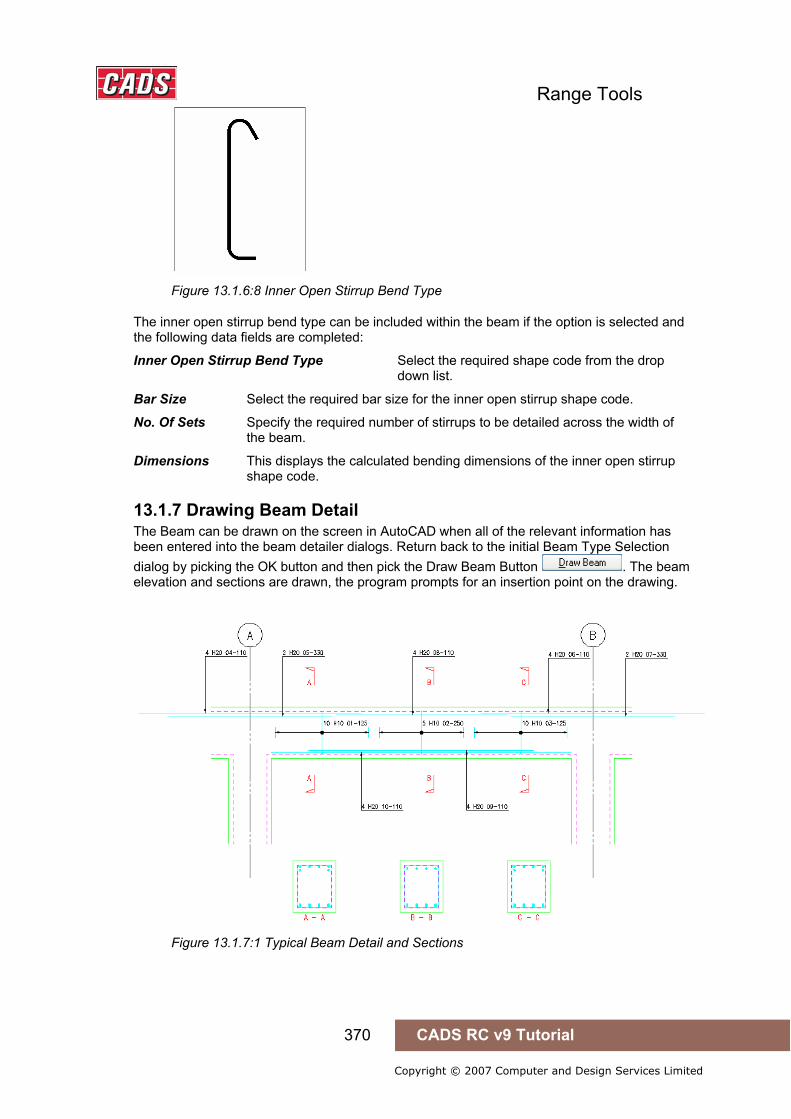
Range Tools
370 CADS RC v9 Tutorial
Copyright © 2007 Computer and Design Services Limited
Figure 13.1.6:8 Inner Open Stirrup Bend Type
The inner open stirrup bend type can be included within the beam if the option is selected and the following data fields are completed:
Inner Open Stirrup Bend Type Select the required shape code from the drop down list.
Bar Size Select the required bar size for the inner open stirrup shape code.
No. Of Sets Specify the required number of stirrups to be detailed across the width of the beam.
Dimensions This displays the calculated bending dimensions of the inner open stirrup shape code.
13.1.7 Drawing Beam Detail The Beam can be drawn on the screen in AutoCAD when all of the relevant information has been entered into the beam detailer dialogs. Return back to the initial Beam Type Selection dialog by picking the OK button and then pick the Draw Beam Button . The beam elevation and sections are drawn, the program prompts for an insertion point on the drawing.
Figure 13.1.7:1 Typical Beam Detail and Sections

Range Tools
371 CADS RC v9 Tutorial
Copyright © 2007 Computer and Design Services Limited
13.1.8 Beam Detailer Configuration File Selection To change the Beam Detailer configuration select the Change CFG button in the Beam Type Selection Dialog. The required configuration file (*.def file) can be selected in order that suitable default data is displayed. By default the program is set to BS 8666:2005.
Figure 13.1.8:1 Beam Detailer Config File
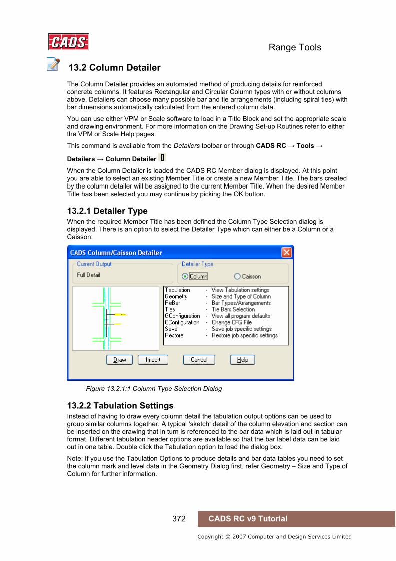
Range Tools
372 CADS RC v9 Tutorial
Copyright © 2007 Computer and Design Services Limited
13.2 Column Detailer
The Column Detailer provides an automated method of producing details for reinforced concrete columns. It features Rectangular and Circular Column types with or without columns above. Detailers can choose many possible bar and tie arrangements (including spiral ties) with bar dimensions automatically calculated from the entered column data.
You can use either VPM or Scale software to load in a Title Block and set the appropriate scale and drawing environment. For more information on the Drawing Set-up Routines refer to either the VPM or Scale Help pages.
This command is available from the Detailers toolbar or through CADS RC → Tools →
Detailers → Column Detailer
When the Column Detailer is loaded the CADS RC Member dialog is displayed. At this point you are able to select an existing Member Title or create a new Member Title. The bars created by the column detailer will be assigned to the current Member Title. When the desired Member Title has been selected you may continue by picking the OK button.
13.2.1 Detailer Type When the required Member Title has been defined the Column Type Selection dialog is displayed. There is an option to select the Detailer Type which can either be a Column or a Caisson.
Figure 13.2.1:1 Column Type Selection Dialog
13.2.2 Tabulation Settings Instead of having to draw every column detail the tabulation output options can be used to group similar columns together. A typical ‘sketch‘ detail of the column elevation and section can be inserted on the drawing that in turn is referenced to the bar data which is laid out in tabular format. Different tabulation header options are available so that the bar label data can be laid out in one table. Double click the Tabulation option to load the dialog box.
Note: If you use the Tabulation Options to produce details and bar data tables you need to set the column mark and level data in the Geometry Dialog first, refer Geometry – Size and Type of Column for further information.
13.2 Column Detailer

Range Tools
373 CADS RC v9 Tutorial
Copyright © 2007 Computer and Design Services Limited
Figure 13.2.2:1 Tabulation Dialog
Tabulation This option switches the tabulation output On or Off. Switch it on to place a bar data table on the drawing.
Required Mode The required mode option allows you to select different table header and sample detail options:
Table Header & Data Line Inserts a new table on the drawing with the header descriptions and bar label data but it does not insert a typical detail.
Figure 13.2.2:2 Table Header and Data Line
Sketch detail, Table header & Data Line Inserts a new table on the drawing with header descriptions and bar label data. It also produces a typical detail of the column and its section with labels that are referenced to the table.
Figure 13.2.2:3 Sketch Detail, Table Header and Data Line
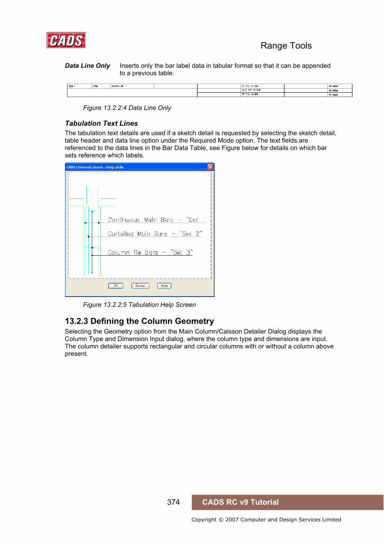
Range Tools
374 CADS RC v9 Tutorial
Copyright © 2007 Computer and Design Services Limited
Data Line Only Inserts only the bar label data in tabular format so that it can be appended to a previous table.
Figure 13.2.2:4 Data Line Only
Tabulation Text Lines The tabulation text details are used if a sketch detail is requested by selecting the sketch detail, table header and data line option under the Required Mode option. The text fields are referenced to the data lines in the Bar Data Table, see Figure below for details on which bar sets reference which labels.
Figure 13.2.2:5 Tabulation Help Screen
13.2.3 Defining the Column Geometry Selecting the Geometry option from the Main Column/Caisson Detailer Dialog displays the Column Type and Dimension Input dialog, where the column type and dimensions are input. The column detailer supports rectangular and circular columns with or without a column above present.
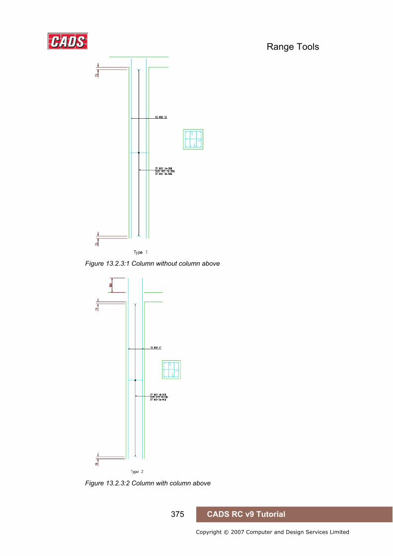
Range Tools
375 CADS RC v9 Tutorial
Copyright © 2007 Computer and Design Services Limited
Figure 13.2.3:1 Column without column above
Figure 13.2.3:2 Column with column above

Range Tools
376 CADS RC v9 Tutorial
Copyright © 2007 Computer and Design Services Limited
The column dimensions can be altered or checked in the Column/Caisson Type and Dimension Input dialog which is available from the majority of the column detailer input dialogs.
The Column Dimension Data is dependent upon the column type selected; therefore some column dimension fields are not accessible for certain column types.
Figure 13.2.3:3 Column Type and Dimension Input dialog
The Column/Caisson Dimension input data is as follows:
Column Mark This option is only used by the detailer if the tabulation option is activated in the Tabulation Settings Dialog. The column mark could be used to define a column type or grid location on the general arrangement drawing. Refer Tabulation in Column Geometry for more information.
Level This option is only used by the detailer if the tabulation option is switched on in the Tabulation Settings Dialog. The level option is used to define the floor level of the column. Refer to Tabulation in Column Geometry for more information.
Column Type Defines the column section type as Rectangular or Circular.
Column Above Choose whether a column is drawn above or not by selecting Yes or No.
Floor to Floor Enter the floor to floor distance.
Top Slab Thickness Enter the thickness of the slab above the column.
Bottom Slab Thickness Enter the thickness of the slab below the column.
Column Diameter If column type is set to circular the column diameter or the caisson diameter is entered here.
Column Dim. (A) If the column type is set to rectangular, the column dim (A) is entered here.
Column Dim. (B) It the column type is set to rectangular, the column dim (B) is entered here.
Cover to Ties Enter the required cover value to the column links.
Draw Outline When set to Yes the detail produced will include the column outline, set to No the detail produced will only contain the reinforcement elements which can be placed into an existing outline drawing.
13.2.4 Defining the Bar Arrangements The Column/Caisson Detailer requires two bar arrangement areas to be defined namely Column/Caisson Main Bars and Column/Caisson Ties (Links). In each area the general
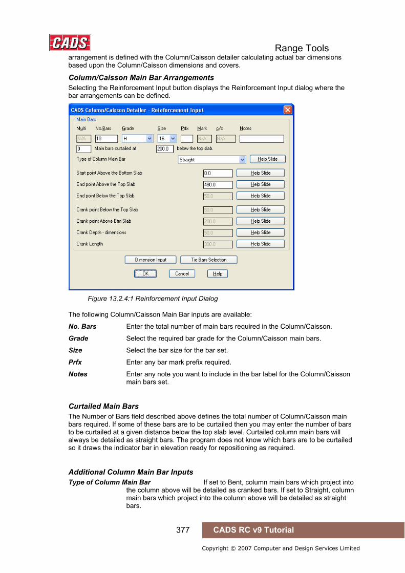
Range Tools
377 CADS RC v9 Tutorial
Copyright © 2007 Computer and Design Services Limited
arrangement is defined with the Column/Caisson detailer calculating actual bar dimensions based upon the Column/Caisson dimensions and covers.
Column/Caisson Main Bar Arrangements Selecting the Reinforcement Input button displays the Reinforcement Input dialog where the bar arrangements can be defined.
Figure 13.2.4:1 Reinforcement Input Dialog
The following Column/Caisson Main Bar inputs are available:
No. Bars Enter the total number of main bars required in the Column/Caisson.
Grade Select the required bar grade for the Column/Caisson main bars.
Size Select the bar size for the bar set.
Prfx Enter any bar mark prefix required.
Notes Enter any note you want to include in the bar label for the Column/Caisson main bars set.
Curtailed Main Bars The Number of Bars field described above defines the total number of Column/Caisson main bars required. If some of these bars are to be curtailed then you may enter the number of bars to be curtailed at a given distance below the top slab level. Curtailed column main bars will always be detailed as straight bars. The program does not know which bars are to be curtailed so it draws the indicator bar in elevation ready for repositioning as required.
Additional Column Main Bar Inputs Type of Column Main Bar If set to Bent, column main bars which project into the column above will be detailed as cranked bars. If set to Straight, column main bars which project into the column above will be detailed as straight bars.
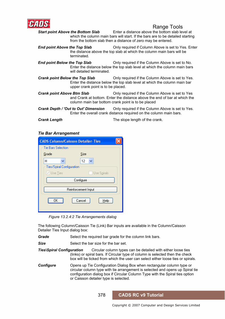
Range Tools
378 CADS RC v9 Tutorial
Copyright © 2007 Computer and Design Services Limited
Start point Above the Bottom Slab Enter a distance above the bottom slab level at which the column main bars will start. If the bars are to be detailed starting from the bottom slab then a distance of zero may be entered.
End point Above the Top Slab Only required if Column Above is set to Yes. Enter the distance above the top slab at which the column main bars will be terminated.
End point Below the Top Slab Only required if the Column Above is set to No. Enter the distance below the top slab level at which the column main bars will detailed terminated.
Crank point Below the Top Slab Only required if the Column Above is set to Yes. Enter the distance below the top slab level at which the column main bar upper crank point is to be placed.
Crank point Above Btm Slab Only required if the Column Above is set to Yes and Crank at bottom. Enter the distance above the end of bar at which the column main bar bottom crank point is to be placed
Crank Depth / 'Out to Out' Dimension Only required if the Column Above is set to Yes. Enter the overall crank distance required on the column main bars.
Crank Length The slope length of the crank.
Tie Bar Arrangement
Figure 13.2.4:2 Tie Arrangements dialog
The following Column/Caisson Tie (Link) Bar inputs are available in the Column/Caisson Detailer Ties Input dialog box:
Grade Select the required bar grade for the column link bars.
Size Select the bar size for the bar set.
Ties\Spiral Configuration Circular column types can be detailed with either loose ties (links) or spiral bars. If Circular type of column is selected then the check box will be ticked from which the user can select either loose ties or spirals.
Configure Opens up Tie Configuration Dialog Box when rectangular column type or circular column type with tie arrangement is selected and opens up Spiral tie configuration dialog box if Circular Column Type with the Spiral ties option or Caisson detailer type is selected.

Range Tools
379 CADS RC v9 Tutorial
Copyright © 2007 Computer and Design Services Limited
Tie Configuration The Tie Configuration Dialog Box will be available from the Configure option in the Column/Caisson Ties input Dialog box when rectangular column type is selected or circular column type with loose tie arrangement is selected.
Figure 13.2.4:3 Main vertical bar tie arrangements dialog
In Tie Configuration Dialog Box the following Tie(Link) bar inputs are available
No. Bars Enter the total number of column link bars required.
Size Select the bar size for the bar set.
Prfx. Enter any bar mark prefix required.
C/C Enter the required column link pitch.
Notes Enter any note you want to include in the bar label for the column link bars set
Top Bar offset Distance to start the ties from the top of the column.
Bottom Bar Offset Distance to start the ties from the bottom of the column.
Extra Top bars If extra links are required at the Top of the column then the number, c/c and any specific label notes required for the bar label of the extra links can be entered in the Extra Top bars input dialog.
Extra Bottom bars If extra links are required at the bottom of the column then the number, c/c and any specific label notes required for the bar label of the extra links can be entered in the extra Bottom bars input dialog.
Default column link arrangements are available for selection by picking the Select button that displays the column tie arrangements options for the number of main vertical bars in use as shown below.
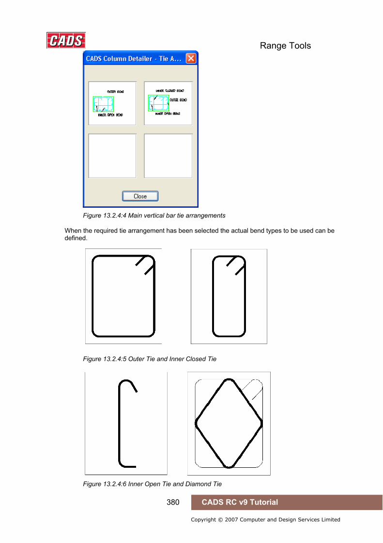
Range Tools
380 CADS RC v9 Tutorial
Copyright © 2007 Computer and Design Services Limited
Figure 13.2.4:4 Main vertical bar tie arrangements
When the required tie arrangement has been selected the actual bend types to be used can be defined.
Figure 13.2.4:5 Outer Tie and Inner Closed Tie
Figure 13.2.4:6 Inner Open Tie and Diamond Tie

Range Tools
381 CADS RC v9 Tutorial
Copyright © 2007 Computer and Design Services Limited
The tie bend types can be defined at Bends Dialog boxes
Outer Tie Bend Type Select Outer Tie Bend Type. The available Ties for rectangular column types are T1 & T2 and for circular column type is T3, RT3 & bT3.
Inner closed bend Type Select inner closed bend types. The available Ties for rectangular column types are T1 & T2.
Inner Open Tie bend type Select inner open Tie bend types. The available ties for rectangular column types are T5, T9 & T12.
Diamond Tie bend type Select the diamond tie bend type. The ties available are T4.
Lap Length for circular tie Input lap length value for circular ties.
For imported details the CADS RC Column Designer determines the tie arrangement and only limited amendments can be made. The program will not draw arrangements with an odd number of bars and if more than sixteen bars are entered the program draws half in the opposite face with an enclosing link ready for the detail to be amended on the drawing as necessary.
When the required tie arrangement has been selected the actual bend types to be used can be defined.
Circular Links and Spirals Configuration
Figure 13.2.4:7 Tie Arrangements dialog
If Circular Column/Caisson Type is selected with the spiral ties, the configure option in the Column/Caisson ties input dialog box opens the spiral tie configuration dialog box.
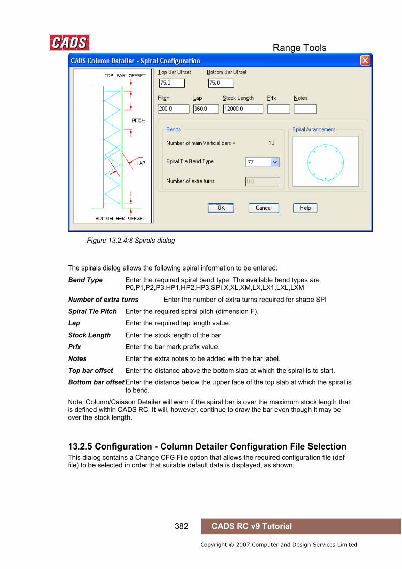
Range Tools
382 CADS RC v9 Tutorial
Copyright © 2007 Computer and Design Services Limited
Figure 13.2.4:8 Spirals dialog
The spirals dialog allows the following spiral information to be entered:
Bend Type Enter the required spiral bend type. The available bend types are P0,P1,P2,P3,HP1,HP2,HP3,SPI,X,XL,XM,LX,LX1,LXL,LXM
Number of extra turns Enter the number of extra turns required for shape SPI
Spiral Tie Pitch Enter the required spiral pitch (dimension F).
Lap Enter the required lap length value.
Stock Length Enter the stock length of the bar
Prfx Enter the bar mark prefix value.
Notes Enter the extra notes to be added with the bar label.
Top bar offset Enter the distance above the bottom slab at which the spiral is to start.
Bottom bar offset Enter the distance below the upper face of the top slab at which the spiral is to bend.
Note: Column/Caisson Detailer will warn if the spiral bar is over the maximum stock length that is defined within CADS RC. It will, however, continue to draw the bar even though it may be over the stock length.
13.2.5 Configuration - Column Detailer Configuration File Selection This dialog contains a Change CFG File option that allows the required configuration file (def file) to be selected in order that suitable default data is displayed, as shown.
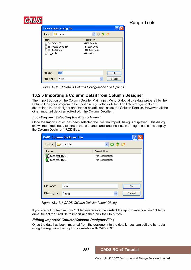
Range Tools
383 CADS RC v9 Tutorial
Copyright © 2007 Computer and Design Services Limited
Figure 13.2.5:1 Default Column Configuration File Options
13.2.6 Importing a Column Detail from Column Designer The Import Button on the Column Detailer Main Input Menu Dialog allows data prepared by the Column Designer program to be used directly by the detailer. The link arrangements are determined in the designer and cannot be adjusted inside the Column Detailer. However, all the other imported data can edited with the Column Detailer.
Locating and Selecting the File to Import Once the Import Option has been selected the Column Import Dialog is displayed. This dialog shows the directories / folders in the left hand panel and the files in the right. It is set to display the Column Designer *.RCD files.
Figure 13.2.6:1 CADS Column Detailer Import Dialog
If you are not in the directory / folder you require then select the appropriate directory/folder or drive. Select the *.rcd file to import and then pick the OK button.
Editing Imported Column/Caisson Designer Files Once the data has been imported from the designer into the detailer you can edit the bar data using the regular editing options available with CADS RC.

Range Tools
384 CADS RC v9 Tutorial
Copyright © 2007 Computer and Design Services Limited
Figure 13.2.6:2 Typical Imported Column Details
13.2.7 Drawing the Column/Caisson Detail When the required Column/Caisson data has been entered the Column/Caisson can be drawn by selecting the Draw button from the Column/Caisson Detailer dialog which can be displayed by picking the OK button from the Geometry or Reinforcement dialogs.
The Column/Caisson Detailer draws the column elevation first and then prompts for its insertion point.
The section is then drawn and its placement requested. Both elevation and section can be relocated after their initial insertion.

Range Tools
385 CADS RC v9 Tutorial
Copyright © 2007 Computer and Design Services Limited
Figure 13.2.7:1 Typical Circular Column Elevations and Sections
Figure 13.2.7:2 Typical Rectangular Column Elevations and Sections
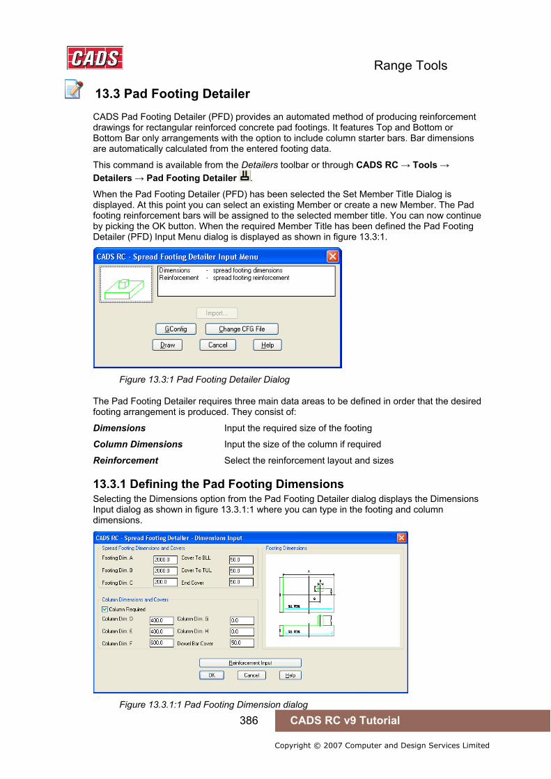
Range Tools
386 CADS RC v9 Tutorial
Copyright © 2007 Computer and Design Services Limited
13.3 Pad Footing Detailer
CADS Pad Footing Detailer (PFD) provides an automated method of producing reinforcement drawings for rectangular reinforced concrete pad footings. It features Top and Bottom or Bottom Bar only arrangements with the option to include column starter bars. Bar dimensions are automatically calculated from the entered footing data.
This command is available from the Detailers toolbar or through CADS RC → Tools → Detailers → Pad Footing Detailer .
When the Pad Footing Detailer (PFD) has been selected the Set Member Title Dialog is displayed. At this point you can select an existing Member or create a new Member. The Pad footing reinforcement bars will be assigned to the selected member title. You can now continue by picking the OK button. When the required Member Title has been defined the Pad Footing Detailer (PFD) Input Menu dialog is displayed as shown in figure 13.3:1.
Figure 13.3:1 Pad Footing Detailer Dialog
The Pad Footing Detailer requires three main data areas to be defined in order that the desired footing arrangement is produced. They consist of:
Dimensions Input the required size of the footing
Column Dimensions Input the size of the column if required
Reinforcement Select the reinforcement layout and sizes
13.3.1 Defining the Pad Footing Dimensions Selecting the Dimensions option from the Pad Footing Detailer dialog displays the Dimensions Input dialog as shown in figure 13.3.1:1 where you can type in the footing and column dimensions.
Figure 13.3.1:1 Pad Footing Dimension dialog
13.3 Pad Footing Detailer

Range Tools
387 CADS RC v9 Tutorial
Copyright © 2007 Computer and Design Services Limited
Spread Footing Dimension and Cover input data is as follows:
Footing Dim. A Overall footing dimension parallel with the bottom lower layer of reinforcement (BLL).
Footing Dim. B Overall footing dimension parallel with the bottom upper layer of reinforcement (BUL).
Footing Dim. C Overall footing depth.
Cover To BLL Enter the concrete cover to the BLL reinforcement.
Cover To TUL Enter the concrete cover to the TUL reinforcement.
End Cover Enter the concrete cover to the end of the reinforcement at the edge of the spread footing.
13.3.2 Defining the Column Dimensions If a column is required the Column required check box needs to be ticked which enables the column data to be input, as shown in figure 13.3.1:1.
Column Dimensions and Covers input data is as follows:
Column Dim. D Overall column dimension parallel with the bottom lower layer of reinforcement (BLL).
Column Dim. E Overall column dimension parallel with the bottom upper layer of reinforcement (BUL).
Column Dim. F Enter the column height.
Column Dim. G Enter the column offset from the centre of the footing parallel with the bottom lower layer of reinforcement (BLL).
Column Dim. H Enter the column offset from the centre of the footing parallel with the bottom upper layer of reinforcement (BUL).
Dowel Bar Cover Enter the concrete cover to the column dowel bars.
13.3.3 Defining the Footing Bar Arrangements The Column Detailer requires two bar arrangement areas to be defined namely the Footing and Column Dowels. In each area the general arrangement is defined with the spread footing detailer calculating actual bar dimensions based upon the footing and column dimensions and covers.
Figure 13.3.3:1 Pad Footing Reinforcement Input dialog

Range Tools
388 CADS RC v9 Tutorial
Copyright © 2007 Computer and Design Services Limited
The following Spread Footing Reinforcement General inputs are available:
Top and Bottom Reinforcement Tick this check box to detail top and bottom reinforcement in the footing.
Bottom Reinforcement Only Tick this check box to detail bottom reinforcement only in the footing.
Bar Grade Select the bar grade to be used for the footing reinforcement.
Prfx Enter any bar mark prefix required for the footing reinforcement, if any.
The following Spread Footing Reinforcement Detailed inputs are available for each layer of footing reinforcement:
Bend Type Select a suitable shape code to be used for the bar set.
Bar Size Select the required bar size.
Bar c/c Enter the required bar pitch.
Label Notes Enter any bar label notes required for the bar set label.
13.3.4 Defining Column Reinforcement The column dowel (starter bars) options are only available if a column option is activated in the Dimensions input.
The following Column Dowel Reinforcement General inputs are available:
Dowel Hook in BLL Only available if the Column Shape Code is set to a bent shape code such as a 37. If activated the column starter bar is detailed with leg or the hook A placed in the lower layer of the bottom reinforcement.
Figure 13.3.4:1 Column Dowel Hook detailed in BLL
Dowel Hook Above BUL Only available if the Column Shape Code is set to a bent shape code such as a 37. If activated the column starter bar is detailed with leg or the hook A placed in the upper layer of the bottom reinforcement.
Figure 13.3.4:2 Column Dowel Hook detailed above BUL

Range Tools
389 CADS RC v9 Tutorial
Copyright © 2007 Computer and Design Services Limited
Bar Grade Select the bar grade to be used for the column dowel reinforcement.
Prfx. Enter any bar mark prefix required for the column dowel reinforcement.
The following Column Dowel (Starter Bar) Reinforcement Detailed inputs are available:
No. Dowels Available if the Num/Spc check box is ticked. Enter the required number of column starter bars.
Bend Type Select the bend type to be used for the column starter bars.
Bar Size Select the required bar size.
Bar c/c Enter the required starter bars pitch to automatically calculate the No. Bars required.
Label Notes Enter any bar label notes required for the column starter bar set label.
Dowel Projection Above Footing Enter the projection required for the column starter bars above the footing top.
Dowel Projection into Footing Only available if the column dowel bend type is set to a straight shape code (shape code 20). Enter the projection required into the footing from the footing top for the starter bars.
13.3.5 Configuration File Selection The Pad Footing Detailer dialog, contains a Change CFG File option that allows the required configuration file (def file) to be selected in order that suitable default data is displayed.
Figure 13.3.5:1 Pad Footing Configuration dialog
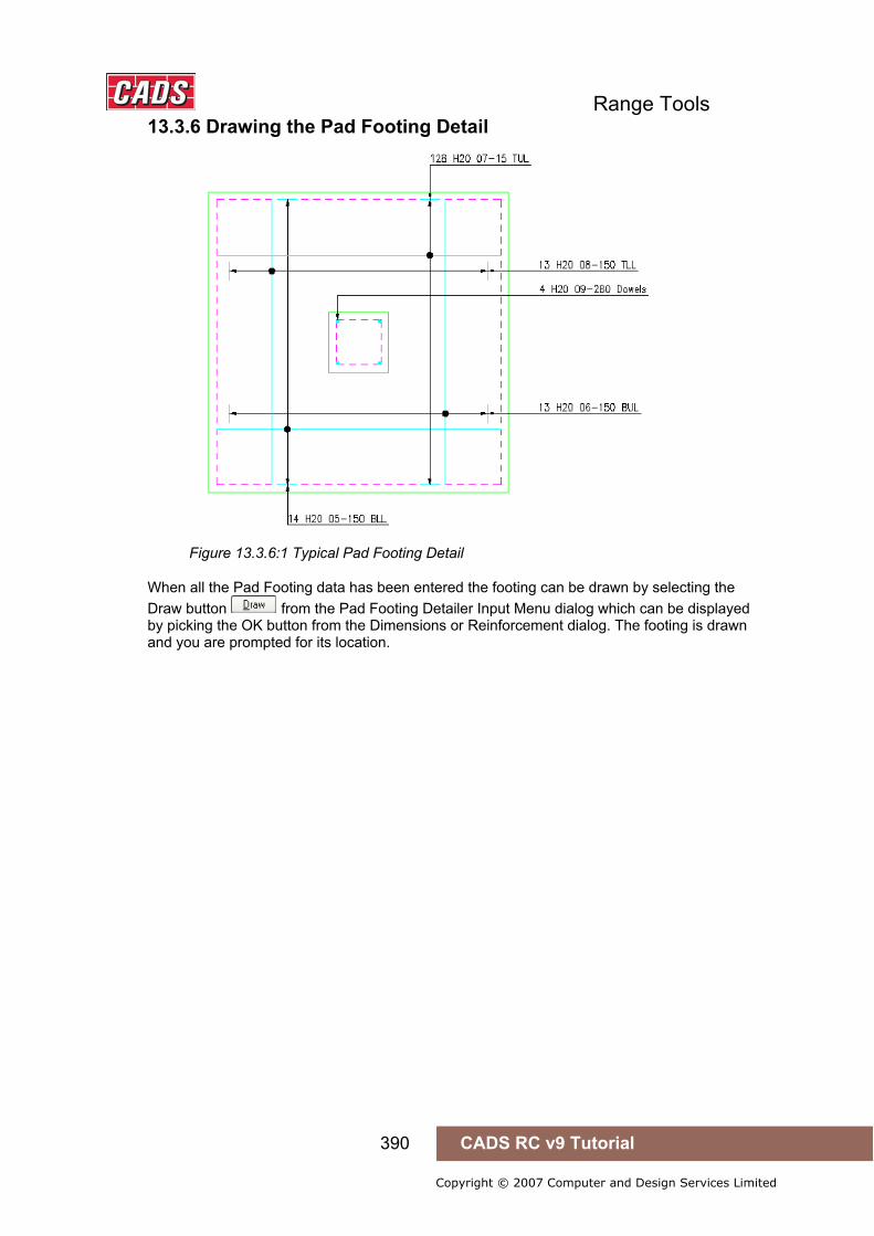
Range Tools
390 CADS RC v9 Tutorial
Copyright © 2007 Computer and Design Services Limited
13.3.6 Drawing the Pad Footing Detail
Figure 13.3.6:1 Typical Pad Footing Detail
When all the Pad Footing data has been entered the footing can be drawn by selecting the Draw button from the Pad Footing Detailer Input Menu dialog which can be displayed by picking the OK button from the Dimensions or Reinforcement dialog. The footing is drawn and you are prompted for its location.
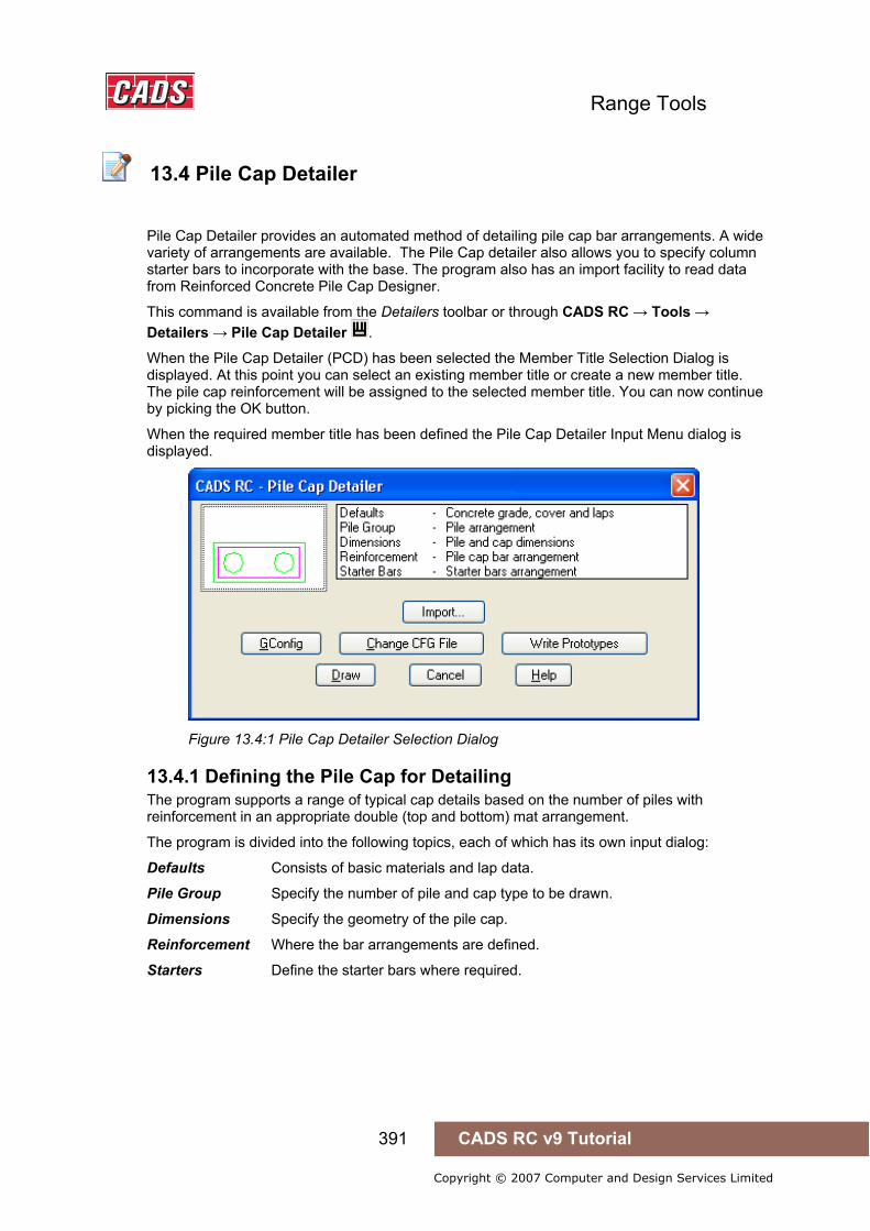
Range Tools
391 CADS RC v9 Tutorial
Copyright © 2007 Computer and Design Services Limited
13.4 Pile Cap Detailer
Pile Cap Detailer provides an automated method of detailing pile cap bar arrangements. A wide variety of arrangements are available. The Pile Cap detailer also allows you to specify column starter bars to incorporate with the base. The program also has an import facility to read data from Reinforced Concrete Pile Cap Designer.
This command is available from the Detailers toolbar or through CADS RC → Tools → Detailers → Pile Cap Detailer .
When the Pile Cap Detailer (PCD) has been selected the Member Title Selection Dialog is displayed. At this point you can select an existing member title or create a new member title. The pile cap reinforcement will be assigned to the selected member title. You can now continue by picking the OK button.
When the required member title has been defined the Pile Cap Detailer Input Menu dialog is displayed.
Figure 13.4:1 Pile Cap Detailer Selection Dialog
13.4.1 Defining the Pile Cap for Detailing The program supports a range of typical cap details based on the number of piles with reinforcement in an appropriate double (top and bottom) mat arrangement.
The program is divided into the following topics, each of which has its own input dialog:
Defaults Consists of basic materials and lap data.
Pile Group Specify the number of pile and cap type to be drawn.
Dimensions Specify the geometry of the pile cap.
Reinforcement Where the bar arrangements are defined.
Starters Define the starter bars where required.
13.4 Pile Cap Detailer
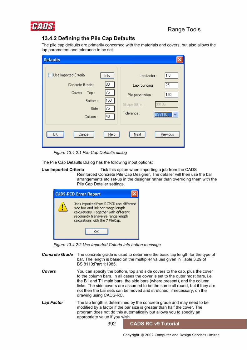
Range Tools
392 CADS RC v9 Tutorial
Copyright © 2007 Computer and Design Services Limited
13.4.2 Defining the Pile Cap Defaults The pile cap defaults are primarily concerned with the materials and covers, but also allows the lap parameters and tolerance to be set.
Figure 13.4.2:1 Pile Cap Defaults dialog
The Pile Cap Defaults Dialog has the following input options:
Use Imported Criteria Tick this option when importing a job from the CADS Reinforced Concrete Pile Cap Designer. The detailer will then use the bar arrangements etc set-up in the designer rather than overriding them with the Pile Cap Detailer settings.
Figure 13.4.2:2 Use Imported Criteria Info button message
Concrete Grade The concrete grade is used to determine the basic lap length for the type of bar. The length is based on the multiplier values given in Table 3.29 of BS 8110:Part 1:1985.
Covers You can specify the bottom, top and side covers to the cap, plus the cover to the column bars. In all cases the cover is set to the outer most bars, i.e. the B1 and T1 main bars, the side bars (where present), and the column links. The side covers are assumed to be the same all round, but if they are not then the bar sets can be moved and stretched, if necessary, on the drawing using CADS-RC.
Lap Factor The lap length is determined by the concrete grade and may need to be modified by a factor if the bar size is greater than half the cover. The program does not do this automatically but allows you to specify an appropriate value if you wish.

Range Tools
393 CADS RC v9 Tutorial
Copyright © 2007 Computer and Design Services Limited
Lap Rounding The lap rounding value simply rounds up the calculated lap length to the next specified increment (e.g. a calculated lap of 444 becomes 450 when a rounding value of 25 is used).
Pile Penetration The side / sectional view of the cap shows the pile penetration within the cap. This field allows you to specify the value. It is used solely for drawing the pile cap outline and does not affect the positioning of the reinforcement. The piles can therefore be shown penetrating inside the reinforcement if required, as shown in Figure13.4.2:3
Shape 99 Ref. The main reinforcing bars are shape code 21 by default, however sometimes the bend radius needs to be larger than the standard shape codes requiring shape code 99 'U bars' to be provided. This field allows you to specify any library shape code you want to use for this shape. For instance the CADS standard library shape code 99106 is used by default.
Tolerance This option allows you to choose whether the BS 8110 Table 3.26 tolerances will be applied to bars, which extend between the covers. Otherwise no tolerance will be applied.
Figure 13.4.2:3 Pile Penetration into the Pile Cap
13.4.3 Selecting the Type of Pile Grouping The Pile Group dialog, as shown in Figure 13.4.3:1, allows you to specify the number of piles required and illustrates the cap type that will be used.
Figure 14.4.3:1 Pile Groups dialog
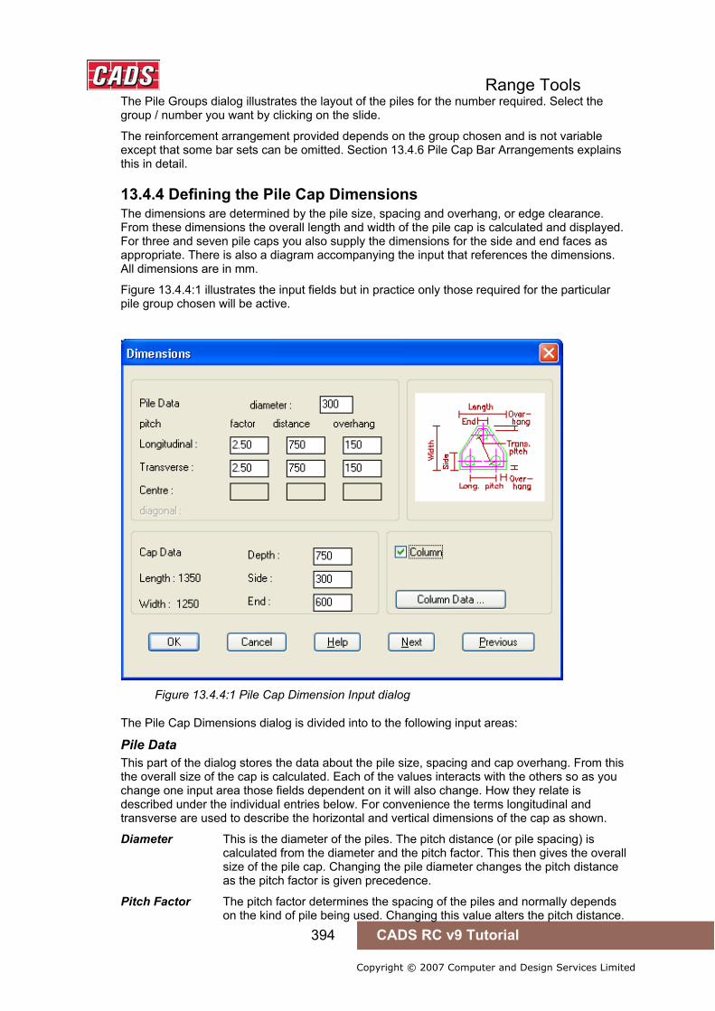
Range Tools
394 CADS RC v9 Tutorial
Copyright © 2007 Computer and Design Services Limited
The Pile Groups dialog illustrates the layout of the piles for the number required. Select the group / number you want by clicking on the slide.
The reinforcement arrangement provided depends on the group chosen and is not variable except that some bar sets can be omitted. Section 13.4.6 Pile Cap Bar Arrangements explains this in detail.
13.4.4 Defining the Pile Cap Dimensions The dimensions are determined by the pile size, spacing and overhang, or edge clearance. From these dimensions the overall length and width of the pile cap is calculated and displayed. For three and seven pile caps you also supply the dimensions for the side and end faces as appropriate. There is also a diagram accompanying the input that references the dimensions. All dimensions are in mm.
Figure 13.4.4:1 illustrates the input fields but in practice only those required for the particular pile group chosen will be active.
Figure 13.4.4:1 Pile Cap Dimension Input dialog
The Pile Cap Dimensions dialog is divided into to the following input areas:
Pile Data This part of the dialog stores the data about the pile size, spacing and cap overhang. From this the overall size of the cap is calculated. Each of the values interacts with the others so as you change one input area those fields dependent on it will also change. How they relate is described under the individual entries below. For convenience the terms longitudinal and transverse are used to describe the horizontal and vertical dimensions of the cap as shown.
Diameter This is the diameter of the piles. The pitch distance (or pile spacing) is calculated from the diameter and the pitch factor. This then gives the overall size of the pile cap. Changing the pile diameter changes the pitch distance as the pitch factor is given precedence.
Pitch Factor The pitch factor determines the spacing of the piles and normally depends on the kind of pile being used. Changing this value alters the pitch distance.

Range Tools
395 CADS RC v9 Tutorial
Copyright © 2007 Computer and Design Services Limited
Pitch Distance This is the distance between the centre of the piles. Changing this value will alter the corresponding pitch factor.
Overhang This is the distance from the face of the pile to the edge of the cap. Altering this value only changes the overall size of the cap.
The above pitch values can be specified for the longitudinal direction for all pile groups. All but the seven pile group has transverse values. The seven pile group uses the same pitch factor for all the pile spacings.
The five and eight pile groups have a further set of centre values for the internal piles. These are always symmetrically placed in the cap. The diagonal values are shown as a check against the pitch factor or distance becoming unacceptably small. The program does not automatically protect against this as changing either the longitudinal or transverse pitches can relieve any problem.
Cap Data This data relates to the overall geometry of the cap. All groups require a cap depth and some also require further side or end dimensions to fully define their shape. The overall widths and length are also shown. The accompanying diagrams will clarify the various terms used.
Depth This specifies the thickness or depth of the cap.
Side The three-pile group requires a dimension for its sides, which are the vertical edges of the pile cap. The seven pile group displays the length of its sides based on the pile data.
End The three-pile cap also requires the length of the horizontal face truncating the ‘triangular’ faces.
Length The longitudinal length is shown as calculated from the pile data. In the case of the seven pile group it is the greatest dimension across the cap.
Width The transverse length is shown as calculated from the pile cap data. In the case of the three pile cap it is the distance over the parallel long and short faces. For the seven pile cap it is the distance over the parallel faces.
Cap dimensions The following diagrams illustrate how the dimensions relate to the dialog fields.
Figure 13.4.4:2 Two and Three Pile Groups

Range Tools
396 CADS RC v9 Tutorial
Copyright © 2007 Computer and Design Services Limited
Figure 13.4.4:3 Four and Five Pile Groups
Figure 13.4.4:4 Six and Seven Pile Groups
Figure 14.4.4:5 Eight and Nine Pile group
13.4.5 Defining the Column Dimensions Although it may not be that usual to have a column springing directly from a pile cap the program does allow you to add one if required. The column must be rectangular and positioned within the cap. Even if you are not detailing a column directly from the cap it may be useful to specify one in order to include starter bars into a beam or other similar detail. The column outline could then be subsequently erased.
To include a column check the Column Option in the Pile Cap Dimension Dialog, see Figure 13.4.4:1, and then select the Column Data Button .
The Column Dimension dialog is divided into the following input fields:
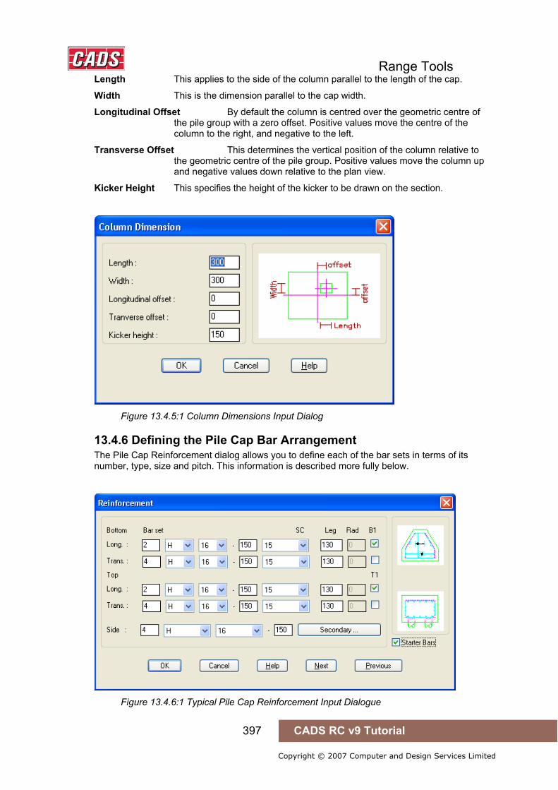
Range Tools
397 CADS RC v9 Tutorial
Copyright © 2007 Computer and Design Services Limited
Length This applies to the side of the column parallel to the length of the cap.
Width This is the dimension parallel to the cap width.
Longitudinal Offset By default the column is centred over the geometric centre of the pile group with a zero offset. Positive values move the centre of the column to the right, and negative to the left.
Transverse Offset This determines the vertical position of the column relative to the geometric centre of the pile group. Positive values move the column up and negative values down relative to the plan view.
Kicker Height This specifies the height of the kicker to be drawn on the section.
Figure 13.4.5:1 Column Dimensions Input Dialog
13.4.6 Defining the Pile Cap Bar Arrangement The Pile Cap Reinforcement dialog allows you to define each of the bar sets in terms of its number, type, size and pitch. This information is described more fully below.
Figure 13.4.6:1 Typical Pile Cap Reinforcement Input Dialogue

Range Tools
398 CADS RC v9 Tutorial
Copyright © 2007 Computer and Design Services Limited
All pile caps contain main reinforcement that is specified using the Pile Cap Reinforcement dialog. The three and seven pile types also have secondary bars that are specified using a sub-dialog that is described later.
The Bar Sets appropriate to the chosen arrangement are listed together with an accompanying diagram that indicates the current bar arrangement. Each bar set requires some basic data, namely the number of bars in the range, bar type, bar size and pitch. If you change the number of bars then the pitch will be recalculated. If you change the pitch then the number of bars is recalculated although for small changes in pitch there may no change in the number.
The cover and bend radius of the perpendicular bars determines the length of the ranges so that the ranges fit within their shoulders as shown below in figure 13.4.6:2.
Figure 13.4.6:2 Range Length
Main Reinforcement Longitudinal and Transverse Reinforcement
All the pile caps contain longitudinal and transverse main bars in the top and bottom of the cap. In addition to general bar data you also have a choice of shape code 38 or 99. Shape 99 is provided so that a non-standard bend radius can be specified for cases where bearing stress at the bend is critical.
For both shapes the bend length can be modified to suit your detail, and the program will warn you if too small a value is entered. For shape code 99 bars you can also specify the inside bend radius. By default the standard radius is offered, but clearly this should be modified otherwise there is no point in using a shape 99.
Figure 13.4.6:2 Typical Pile Cap Bar Sets

Range Tools
399 CADS RC v9 Tutorial
Copyright © 2007 Computer and Design Services Limited
You can also indicate whether the longitudinal or transverse bars are to be placed in the outer layer by picking the appropriate radio button for top and bottom sets.
Figure 13.4.6:3 Bar Layering Options
The three and seven pile groups have their main reinforcement arranged in bands as shown in Figure 13.4.6:4.
Figure 13.4.6:4 Main Reinforcement Bands
Side Bars Deep Pile Caps may require side bars that can have their basic bar data defined. The pile group type and the lap criteria set-up in the Defaults Dialog determine the bar shape and dimensions.
Secondary Reinforcement Access the secondary dialog box from the main reinforcement dialog as shown in figure 13.4.6:1 by picking the secondary button . The three and seven Pile Caps also have secondary reinforcement to fill in areas beyond the main reinforcement bands.

Range Tools
400 CADS RC v9 Tutorial
Copyright © 2007 Computer and Design Services Limited
Figure 13.4.6:5 Typical Secondary Reinforcement dialog
The three pile cap has three sets of secondary reinforcement top and bottom; two either side of the main transverse bars and one in the ‘trapezoidal’ part of the cap alongside the main longitudinal bars. The seven pile cap has two sets of secondary reinforcement they are top and bottom either side of the main transverse band.
Figure 13.4.6:6 Three and Seven Pile, Secondary Reinforcement
Starter Bars If you have specified a column then selecting the starter bars check box in the Main Reinforcement dialog as shown in figure 13.4.6:1 enables you to add starter bars to the pile cap. This dialog is accessed as the ‘Next’ option from the Reinforcement Dialog or from the Main Pile Cap Dialog.
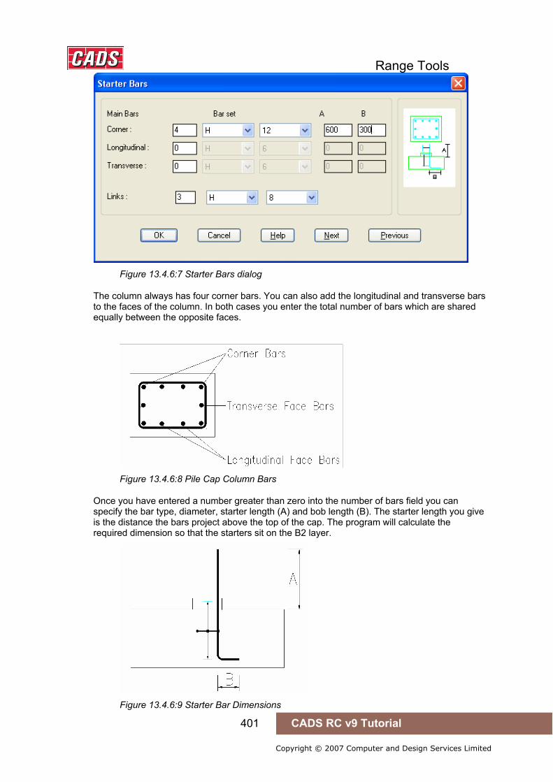
Range Tools
401 CADS RC v9 Tutorial
Copyright © 2007 Computer and Design Services Limited
Figure 13.4.6:7 Starter Bars dialog
The column always has four corner bars. You can also add the longitudinal and transverse bars to the faces of the column. In both cases you enter the total number of bars which are shared equally between the opposite faces.
Figure 13.4.6:8 Pile Cap Column Bars
Once you have entered a number greater than zero into the number of bars field you can specify the bar type, diameter, starter length (A) and bob length (B). The starter length you give is the distance the bars project above the top of the cap. The program will calculate the required dimension so that the starters sit on the B2 layer.
Figure 13.4.6:9 Starter Bar Dimensions

Range Tools
402 CADS RC v9 Tutorial
Copyright © 2007 Computer and Design Services Limited
The links must be specified and are taken between the bottom bend of the starter bars and the kicker.
Figure 13.4.6:10 Typical Starter Detail
13.4.7 Pile Cap Configuration File Selection When the Reinforcement Panel Detailer is loaded the Panel Detailer Input dialog is displayed, as shown in figure 13.4.6:1. This dialog contains a Change CFG File option that allows the required configuration file (def file) to be selected in order that suitable default data is displayed, as shown in Figure 13.4.7:1.
Figure 13.4.7:1 Default Pile Cap Configuration File Options
Should other configuration options be required, then please contact the CADS Support department who will be pleased to advise.
13.4.8 Importing Data from Pile Cap Designer The Import button on the Main Pile Cap Dialog allows data prepared using the CADS Pile Cap Designer to be used directly by this detailer. The design program creates job files with the extension *.PCD. The *.PCD files can be read by the Pile Cap Detailer.

Range Tools
403 CADS RC v9 Tutorial
Copyright © 2007 Computer and Design Services Limited
Locating and Selecting the File to Import Once the Import Option is selected the Select Import File dialog is displayed.
Figure 13.4.8:1 Typical Job / Directory List
Browse to the location of the *.PCD file you wish to import. To make locating the files easier it is advisable for the creator of the designer file and the detailer to agree a standard location. This directory should have the appropriate read write permissions for both users. One suggestion is to write the files to the directory where the project drawing files are located.
Loading the Job File Select the Pile Cap Designer file (*.PCD) you require and the pile cap designer data is transferred into the detailer as if you had manually input the data. You can then edit it as described in the earlier sections of this manual. The Pile Cap Detailer does not, however, make any checks on the suitability of the chosen arrangement.
The CADS Pile Cap Designer uses the number of bars to determine the resistance of the cap to moments and shears, but allows you to specify the nominal centres as well. The bars entered in the Pile Cap Designer should be compatible with the detailer. However, as some of the detailer input options are not necessary at the design stage it may give rise to some minor discrepancies. The detailer will endeavor to preserve the number of bars and modify the centres as necessary. Once the detail has been drawn some minor editing may be required.
13.4.9 Drawing the Pile Cap Detail Once the Pile Cap Dimensions and Bar sets have been defined then the detail is ready to draw. Selecting the Draw Button from the Main Pile Cap Dialog does this. The program will pause for a few moments while it assembles the drawing data and then returns to the AutoCAD drawing editor.
The plan is drawn first and can be moved to an appropriate position on the drawing. The elevation is then drawn and it can be also moved into position. Finally the column section is drawn if it has been selected.
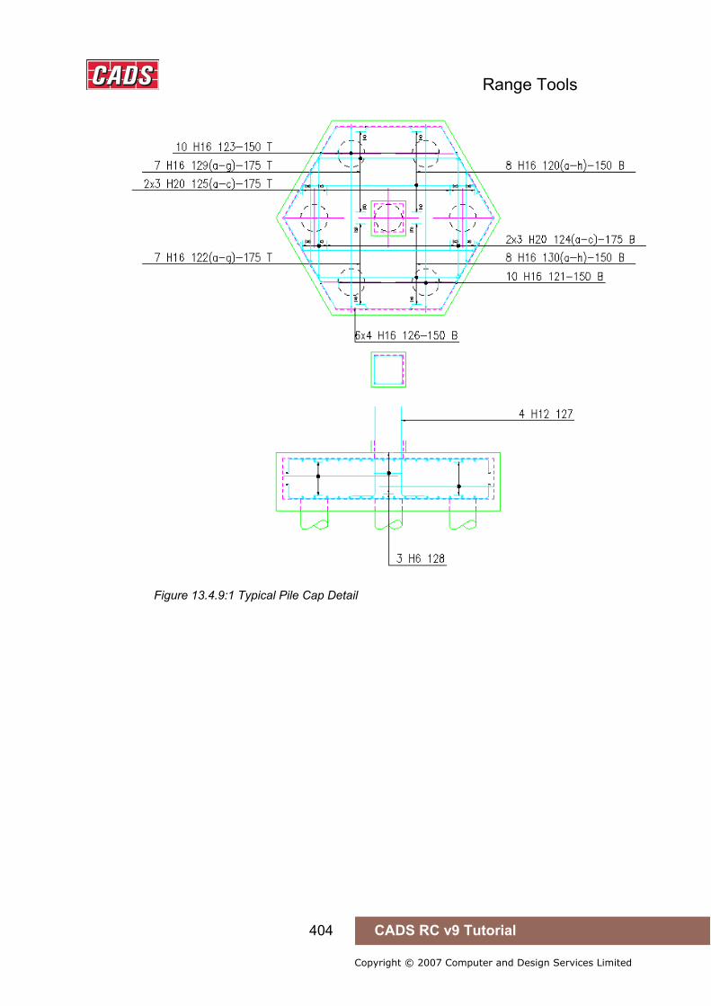
Range Tools
404 CADS RC v9 Tutorial
Copyright © 2007 Computer and Design Services Limited
Figure 13.4.9:1 Typical Pile Cap Detail

Range Tools
405 CADS RC v9 Tutorial
Copyright © 2007 Computer and Design Services Limited
13.4.10 Try It! Using the Pile Cap Detailer
1. Launch CADS RC 2. Open drawing ...\drawings\CADS RC 30.dwg 3. Set the Working Scale at 1:20 4. Make the Viewport on Pile Cap Layout active
5. Select CADS RC → Draw Bar → Set Drawing Sheet or 6. Make 01 the current Drawing Sheet and select OK
• Alternatively you can select the Member and the Drawing Sheet in the Draw Bar dialog. If you select the browse button for the Member and Drawing Sheet you can choose which Member and Drawing Sheet to make current.
7. Select CADS RC → Tools → Detailers → Pile Cap Detailer or Make Pile Cap the current Member and select OK Double Click the Pile Group option in the Pile Cap Detailer main dialog Select the 7 Pile Cap Arrangement as shown in figure 13.4.5:1 below Pick Next
Figure 13.4.5:1 Pile Groups dialog
Set the pile diameter to 350, the Longitudinal factor to 3.00 and the Overhang to 200 as shown in figure 13.4.5:2 below
Pick Next
13.4.10 Try It! Using the Pile Cap Detailer
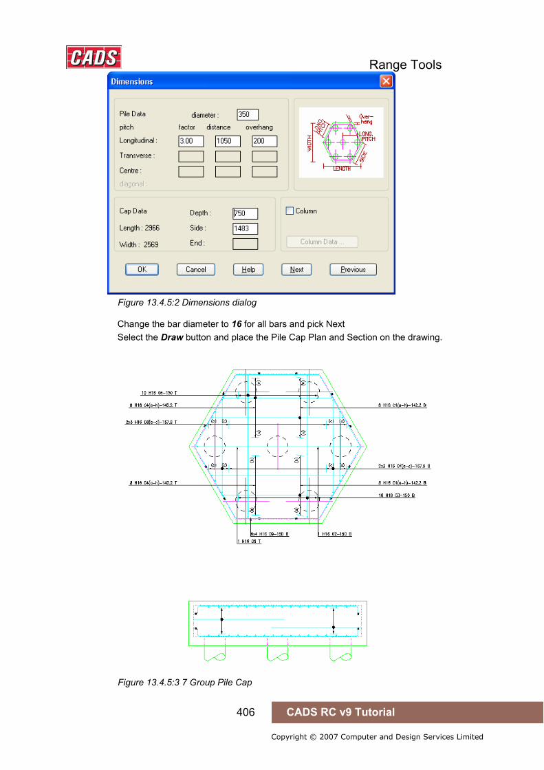
Range Tools
406 CADS RC v9 Tutorial
Copyright © 2007 Computer and Design Services Limited
Figure 13.4.5:2 Dimensions dialog
Change the bar diameter to 16 for all bars and pick Next Select the Draw button and place the Pile Cap Plan and Section on the drawing.
Figure 13.4.5:3 7 Group Pile Cap
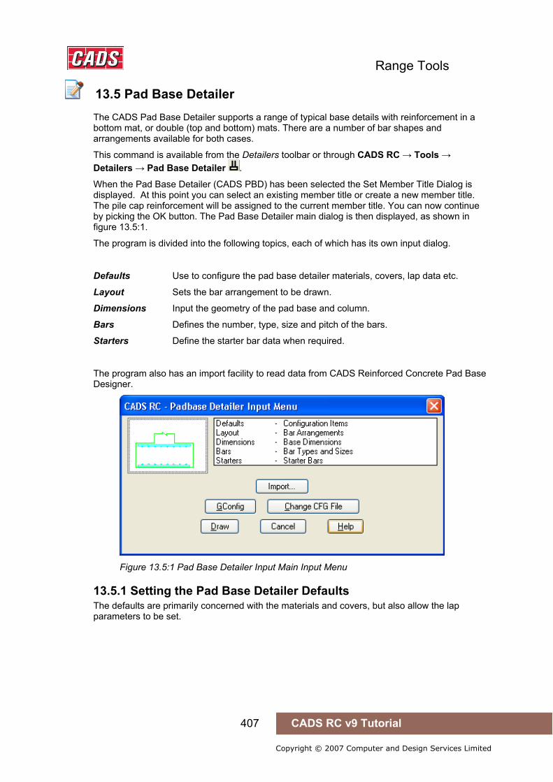
Range Tools
407 CADS RC v9 Tutorial
Copyright © 2007 Computer and Design Services Limited
13.5 Pad Base Detailer
The CADS Pad Base Detailer supports a range of typical base details with reinforcement in a bottom mat, or double (top and bottom) mats. There are a number of bar shapes and arrangements available for both cases.
This command is available from the Detailers toolbar or through CADS RC → Tools → Detailers → Pad Base Detailer .
When the Pad Base Detailer (CADS PBD) has been selected the Set Member Title Dialog is displayed. At this point you can select an existing member title or create a new member title. The pile cap reinforcement will be assigned to the current member title. You can now continue by picking the OK button. The Pad Base Detailer main dialog is then displayed, as shown in figure 13.5:1.
The program is divided into the following topics, each of which has its own input dialog.
Defaults Use to configure the pad base detailer materials, covers, lap data etc.
Layout Sets the bar arrangement to be drawn.
Dimensions Input the geometry of the pad base and column.
Bars Defines the number, type, size and pitch of the bars.
Starters Define the starter bar data when required.
The program also has an import facility to read data from CADS Reinforced Concrete Pad Base Designer.
Figure 13.5:1 Pad Base Detailer Input Main Input Menu
13.5.1 Setting the Pad Base Detailer Defaults The defaults are primarily concerned with the materials and covers, but also allow the lap parameters to be set.
13.5 Pad Base Detailer
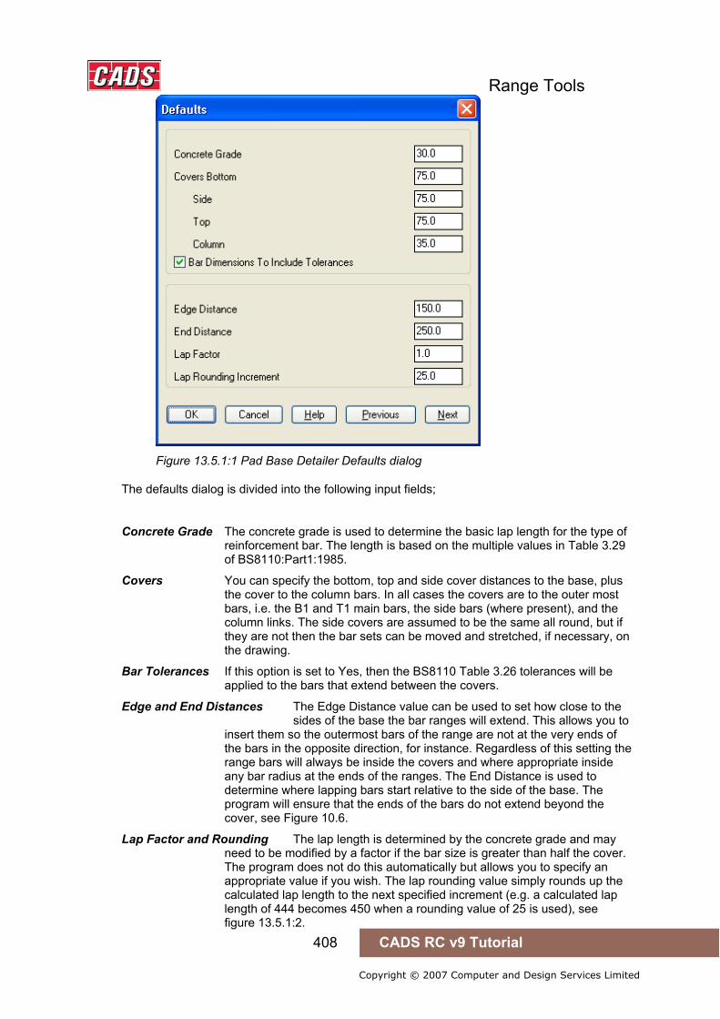
Range Tools
408 CADS RC v9 Tutorial
Copyright © 2007 Computer and Design Services Limited
Figure 13.5.1:1 Pad Base Detailer Defaults dialog
The defaults dialog is divided into the following input fields;
Concrete Grade The concrete grade is used to determine the basic lap length for the type of reinforcement bar. The length is based on the multiple values in Table 3.29 of BS8110:Part1:1985.
Covers You can specify the bottom, top and side cover distances to the base, plus the cover to the column bars. In all cases the covers are to the outer most bars, i.e. the B1 and T1 main bars, the side bars (where present), and the column links. The side covers are assumed to be the same all round, but if they are not then the bar sets can be moved and stretched, if necessary, on the drawing.
Bar Tolerances If this option is set to Yes, then the BS8110 Table 3.26 tolerances will be applied to the bars that extend between the covers.
Edge and End Distances The Edge Distance value can be used to set how close to the sides of the base the bar ranges will extend. This allows you to insert them so the outermost bars of the range are not at the very ends of the bars in the opposite direction, for instance. Regardless of this setting the range bars will always be inside the covers and where appropriate inside any bar radius at the ends of the ranges. The End Distance is used to determine where lapping bars start relative to the side of the base. The program will ensure that the ends of the bars do not extend beyond the cover, see Figure 10.6.
Lap Factor and Rounding The lap length is determined by the concrete grade and may need to be modified by a factor if the bar size is greater than half the cover. The program does not do this automatically but allows you to specify an appropriate value if you wish. The lap rounding value simply rounds up the calculated lap length to the next specified increment (e.g. a calculated lap length of 444 becomes 450 when a rounding value of 25 is used), see figure 13.5.1:2.

Range Tools
409 CADS RC v9 Tutorial
Copyright © 2007 Computer and Design Services Limited
Figure 13.5.1:2 Edge Distance Information
Figure 13.5.1:3 End Distance Information
13.5.2 Choosing the Bar Arrangement Layout Figure 13.5.2:1 shows the Bar Arrangement Layout dialog, which allows you to specify the type of base detail, required.
Figure 13.5.2:1 Tabulated Base Output and Dimensions
Presently only individual bases can be detailed, therefore the following options are ‘grayed out’. It is intended to extend the program to include tabulated details.
• Tabulated Base Output will produce details in tabular form when the box is ticked. • Tabulate Base Dimensions will include the base dimensions in the tabulated output.

Range Tools
410 CADS RC v9 Tutorial
Copyright © 2007 Computer and Design Services Limited
Reinforcement Arrangements The following five items enable you to select a particular bar arrangement. Used in conjunction with each other wide ranges of combinations are available. To avoid confusion over the direction of the bars the following terms are used to describe the bars. Longitudinal Bars run parallel to the length of the base. Transverse Bars are perpendicular to the longitudinal bar and run parallel to the width.
Figure 13.5.2:2 Bar Directions
General Bar Arrangement This option selects the basic bar layout. You can choose an un-reinforced, singly reinforced or doubly reinforced base. Both the reinforced options include various layer arrangements as described below. These options can be selected using the drop down menu to the right of each option.
Un-Reinforced This setting will simply produce a base without reinforcement.
Single 1 This detail is a single mat of reinforcement in the bottom of the base with the longitudinal bars in the B1 Layer, parallel to the base length.
Single 2 This arrangement also has a bottom mat, but with the transverse bars in the B1 Layer, parallel to the base width.
Both the Single Arrangements can have the bar shapes to be used specified under the longitudinal and transverse bar shape fields.
Figure 13.5.2:3 Typical Un-reinforced and Single Bar Arrangements

Range Tools
411 CADS RC v9 Tutorial
Copyright © 2007 Computer and Design Services Limited
Double 1 This bar arrangement provides a reinforcement mat in the top and bottom of the base. The longitudinal bars are placed in the B1 and T1 Layers.
Double 2 This is similar to the Double 1 Arrangement, but with the transverse bars in the B1 and T1 Layers.
Double 3 In this arrangement the top longitudinal bars are placed in layer T1, and the bottom transverse bars in Layer B1.
Double 4 This is the converse of the Double 3 arrangement with the top transverse bars in Layer T1 and bottom longitudinal bars in Layer B1.
Figure 13.5.2:4 Typical Double Bar Arrangements
The Double Arrangements described above can be set out in three ways as described below. They can also have side bars associated with them.
Detailed Bar Arrangement Each of the double General Arrangements can have three further arrangements as follows;
Normal The main bars in each reinforcement mat are shape code 00 and lap in the same layer with shape 21 U bars extending between the top and bottom layers. The ends of the main bars are determined by the end distance specified in the default screen, but will not extend beyond the side cover. The U Bars lap with these main bars by a lap length determined by the smaller bar as modified by the lap factor and rounding.
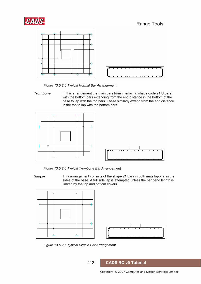
Range Tools
412 CADS RC v9 Tutorial
Copyright © 2007 Computer and Design Services Limited
Figure 13.5.2:5 Typical Normal Bar Arrangement
Trombone In this arrangement the main bars form interlacing shape code 21 U bars with the bottom bars extending from the end distance in the bottom of the base to lap with the top bars. These similarly extend from the end distance in the top to lap with the bottom bars.
Figure 13.5.2:6 Typical Trombone Bar Arrangement
Simple This arrangement consists of the shape 21 bars in both mats lapping in the sides of the base. A full side lap is attempted unless the bar bend length is limited by the top and bottom covers.
Figure 13.5.2:7 Typical Simple Bar Arrangement

Range Tools
413 CADS RC v9 Tutorial
Copyright © 2007 Computer and Design Services Limited
Side Bar Arrangement The Double General Arrangements can also have side bars enclosing them as shown in Figure 13.5.2:8 below.
No Bars No side bars are provided.
11 & 00 This arrangement has shape code 00 bars in the sides lapping with shape 11 corner bars. The end distance is also applied to straight bars.
11 only In this case the shape code 11 corner bars extend along the sides of the base to lap in the middle.
Figure 13.5.2:8 Side Bar Arrangements
Longitudinal Bar Shape The longitudinal bar shape is required when a single general arrangement is selected. You can choose from shapes 20, 35 and 38.
Transverse Bar Shape This is similar to the longitudinal bar shape in a single arrangement.
Figure 13.5.2:9 Single Longitudinal and Transverse Bar Shapes
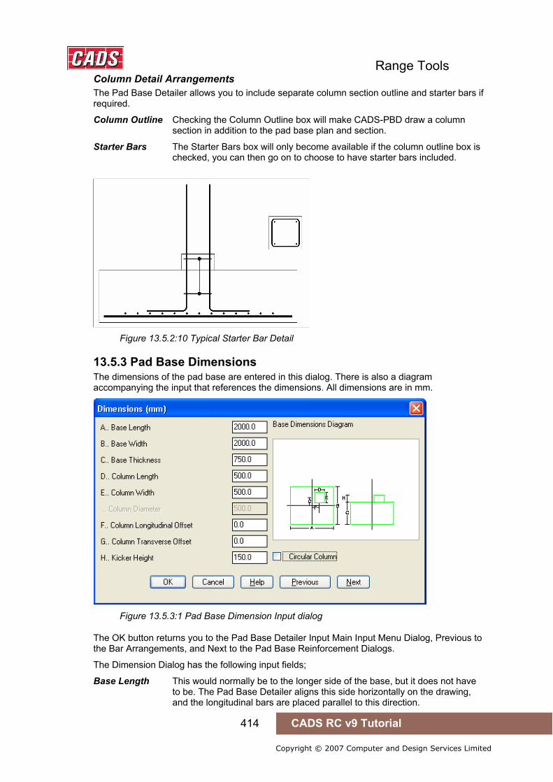
Range Tools
414 CADS RC v9 Tutorial
Copyright © 2007 Computer and Design Services Limited
Column Detail Arrangements The Pad Base Detailer allows you to include separate column section outline and starter bars if required.
Column Outline Checking the Column Outline box will make CADS-PBD draw a column section in addition to the pad base plan and section.
Starter Bars The Starter Bars box will only become available if the column outline box is checked, you can then go on to choose to have starter bars included.
Figure 13.5.2:10 Typical Starter Bar Detail
13.5.3 Pad Base Dimensions The dimensions of the pad base are entered in this dialog. There is also a diagram accompanying the input that references the dimensions. All dimensions are in mm.
Figure 13.5.3:1 Pad Base Dimension Input dialog
The OK button returns you to the Pad Base Detailer Input Main Input Menu Dialog, Previous to the Bar Arrangements, and Next to the Pad Base Reinforcement Dialogs.
The Dimension Dialog has the following input fields;
Base Length This would normally be to the longer side of the base, but it does not have to be. The Pad Base Detailer aligns this side horizontally on the drawing, and the longitudinal bars are placed parallel to this direction.
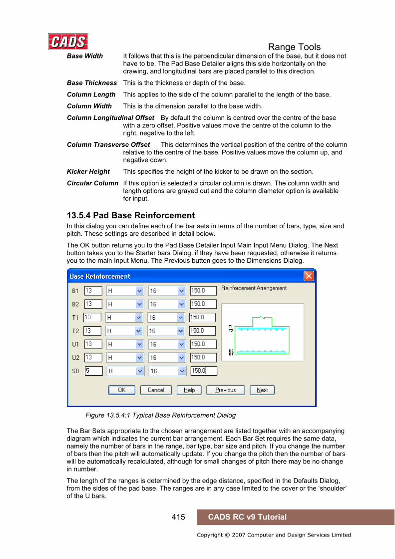
Range Tools
415 CADS RC v9 Tutorial
Copyright © 2007 Computer and Design Services Limited
Base Width It follows that this is the perpendicular dimension of the base, but it does not have to be. The Pad Base Detailer aligns this side horizontally on the drawing, and longitudinal bars are placed parallel to this direction.
Base Thickness This is the thickness or depth of the base.
Column Length This applies to the side of the column parallel to the length of the base.
Column Width This is the dimension parallel to the base width.
Column Longitudinal Offset By default the column is centred over the centre of the base with a zero offset. Positive values move the centre of the column to the right, negative to the left.
Column Transverse Offset This determines the vertical position of the centre of the column relative to the centre of the base. Positive values move the column up, and negative down.
Kicker Height This specifies the height of the kicker to be drawn on the section.
Circular Column If this option is selected a circular column is drawn. The column width and length options are grayed out and the column diameter option is available for input.
13.5.4 Pad Base Reinforcement In this dialog you can define each of the bar sets in terms of the number of bars, type, size and pitch. These settings are described in detail below.
The OK button returns you to the Pad Base Detailer Input Main Input Menu Dialog. The Next button takes you to the Starter bars Dialog, if they have been requested, otherwise it returns you to the main Input Menu. The Previous button goes to the Dimensions Dialog.
Figure 13.5.4:1 Typical Base Reinforcement Dialog
The Bar Sets appropriate to the chosen arrangement are listed together with an accompanying diagram which indicates the current bar arrangement. Each Bar Set requires the same data, namely the number of bars in the range, bar type, bar size and pitch. If you change the number of bars then the pitch will automatically update. If you change the pitch then the number of bars will be automatically recalculated, although for small changes of pitch there may be no change in number.
The length of the ranges is determined by the edge distance, specified in the Defaults Dialog, from the sides of the pad base. The ranges are in any case limited to the cover or the ‘shoulder’ of the U bars.

Range Tools
416 CADS RC v9 Tutorial
Copyright © 2007 Computer and Design Services Limited
Figure 13.5.4:2 Edge Distance and Range Length
The main bar sets are defined by layer and so may be either longitudinal or transverse bars depending on the arrangement chosen, The U Bars, however are defined by direction, i.e. U1 is always longitudinal and U2 transverse.
For clarity the U Bars are illustrated within the main reinforcement mats but they will be drawn lapping alongside the main bars in the appropriate direction. Where chosen the side bars are taken to be the same number, type, size and pitch for all their sets.
13.5.5 Starter Bars Rectangular Column If you have chosen to include starter bars then this dialog allows you to define them.
Figure 13.5.5:1 Starter Bars dialog for the Rectangular Column
The Bar Sets are referred to as C, D, E and F. The Bar Set C is always the four corner bars. You can also add bars along the longitudinal face of the column, Bar Set D, and the transverse face, Bar Set E. In both cases you enter the total number of bars that are shared equally between the opposite faces.
Starter Bars Once you have entered a number greater than zero you can then specify the bar type, diameter, starter length (Leg A) and the bob length (Leg B). The Starter length you give is the distance the bars project above the top of the base. The program will calculate the required dimension so that the starters sit on the B2 Layer.
Link Bars The links, Bar Set F, must also be specified and are taken to range between the bottom bend of the starter bars and the kicker.

Range Tools
417 CADS RC v9 Tutorial
Copyright © 2007 Computer and Design Services Limited
Figure 13.5.5:2 Typical Rectangular Column Starter Bar Detail
Circular Column If you have chosen to include starter bars and ticked the circular column option then this dialog allows you to define them.
Figure 13.5.5:3 Pad Base Starter Bars dialog for the Circular Column
Side Bars Once you have entered a number greater than zero you can then specify the bar type, diameter, starter length (Leg A) and the bob length (Leg B). The Starter length you give is the distance the bars project above the top of the base. The program will calculate the required dimension so that the starters sit on the B2 Layer.
Link Bars The links, Bar Set F, must also be specified and are taken to range between the bottom bend of the starter bars and the kicker. The link in this case is a shape code 9904, circular link, taken from CADS-RC pre programmed library of 99’s.
Figure 13.5.5:4 Typical Circular Column Starter Bar Detail

Range Tools
418 CADS RC v9 Tutorial
Copyright © 2007 Computer and Design Services Limited
13.5.6 Padbase Detailer Configuration File Selection When the Padbase Detailer is loaded the Padbase Detailer Input dialog is displayed, see figure 13.5:1. This dialog contains a Change CFG File option that allows the required configuration file (def file) to be selected in order that suitable default data is displayed, as shown below in figure 13.5.6:1.
Figure 13.5.6:1 Default Pad Base Configuration File Options
Should other configuration options be required, then please contact the CADS Support department who will be pleased to advise.
13.5.7 Importing Design Data The Import button on the Main Pile Cap Dialog allows data prepared using the CADS Pad Base Designer to be used directly by this detailer. The design program creates job files with the extension *.RCB. The *.RCB files can be read by the Pile Cap Detailer.
Locating and Selecting the File to Import Once the Import Option has been selected the Pad Base Import Dialog is displayed. This dialog shows the directories / folders in the left hand panel and the files in the right. It is set to display the Pad Base Designer *.RCB files.
Figure 13.5.7:1 Pad Base Detailer Import File Selection Dialog
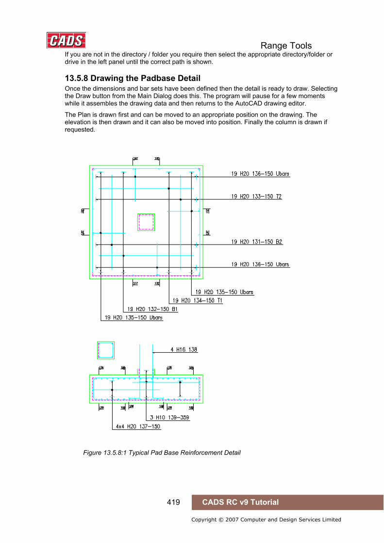
Range Tools
419 CADS RC v9 Tutorial
Copyright © 2007 Computer and Design Services Limited
If you are not in the directory / folder you require then select the appropriate directory/folder or drive in the left panel until the correct path is shown.
13.5.8 Drawing the Padbase Detail Once the dimensions and bar sets have been defined then the detail is ready to draw. Selecting the Draw button from the Main Dialog does this. The program will pause for a few moments while it assembles the drawing data and then returns to the AutoCAD drawing editor.
The Plan is drawn first and can be moved to an appropriate position on the drawing. The elevation is then drawn and it can also be moved into position. Finally the column is drawn if requested.
Figure 13.5.8:1 Typical Pad Base Reinforcement Detail

Range Tools
420 CADS RC v9 Tutorial
Copyright © 2007 Computer and Design Services Limited
13.6 Stair Flight Detailer
CADS Stair Flight Detailer provides an automated method of detailing the reinforcement arrangements for a single flight staircase. The basic detail the program draws is of the form recommended in the “Standard method of Detailing Structural Concrete” published by the Institution of Structural Engineers and the Concrete Society.
This command is available from the Detailers toolbar or through CADS RC → Tools → Detailers → Stair Flight Detailer or .
When the CADS RC Stair Flight Detailer (CADS SFD) has been selected the Member dialog is displayed. At this point you can select an existing member title or create a new member title. The stair flight reinforcement will be assigned to the selected member title. You can now continue by picking the OK button and the Stair Flight Detailer Input Menu dialog is displayed, as shown in figure 13.6:1
The program is divided into the following topics, each of which has its own input dialog:
Defaults which consists of the basic materials and lap data.
Options to define the bar arrangement to be drawn.
Dimensions which specify the geometry of the stair.
Reinforcement where the number, type, size and pitch of the bars are defined.
Figure 13.6:1 Stair Flight Detailer Selection Menu
13.6 Stair Flight Detailer

Range Tools
421 CADS RC v9 Tutorial
Copyright © 2007 Computer and Design Services Limited
13.6.1 Setting the Stair Flight Defaults The input options in the Defaults dialog are primarily concerned with the materials, but also the lap parameters to be set.
Figure 13.6.1:1 Stair Flight Defaults dialog
The defaults dialog is divided into the following input fields:
Concrete Grade The concrete grade is used to determine the basic lap length for the type of bar. The length is based on the multiplier values given in Table 3.29 of BS8110:Part1:1985.
Bar Type, Size and Pitch Staircases frequently have a number of bar sets that use the same type, size and pitch (c/c) of bars. In order to make the reinforcement data easier to define you can specify defaults that the program will use to set-up the bar data. These defaults can also be used to reset all the bar data you wish.
Lap Factor The lap length determined by the concrete grade might need to be modified by a factor if the bar size is greater than half the cover. In order to provide control the program does not do this automatically, but allows you to specify an appropriate value if you wish.
Lap Rounding The lap rounding value simply rounds up the calculated lap length to the next specified increment (e.g. a calculated lap length of 444 becomes 450 when a rounding value of 25 is used).

Range Tools
422 CADS RC v9 Tutorial
Copyright © 2007 Computer and Design Services Limited
13.6.2 Selecting the Stair Flight Options The Options Dialog is divided into three groups. These determine how the stair is to be drawn and the bar setting. This information is described in the following sections.
Figure 13.6.2:1 Typical Options dialog
Orientation This option simply determines which way round the flight will be drawn, i.e. up towards the right or up towards the left. Clicking on the slide of the stair flight will toggle between these options.
Drawings The four options allow you to choose whether to have the elevation and / or plan of the stair reinforced and dimensioned. Select the appropriate check boxes to set-up the combination of your choice. Should you wish the detailer could be used to produce just an outline of the stair, if the reinforcement options are switched off. You may find this easier and quicker to use than the two stair outlines in CADS-RC.
End Options The remaining four options in this group allow you to indicate where the main bars are to be placed and the end conditions of the landing outline.
Flight Bar Inset The flight bars are assumed to run between the line of the structural top face of the lower landing and the structural soffit of the upper landing as shown in Figure 13.6.2:2 below.
Figure 13.6.2:2 Flight Bars between Landings
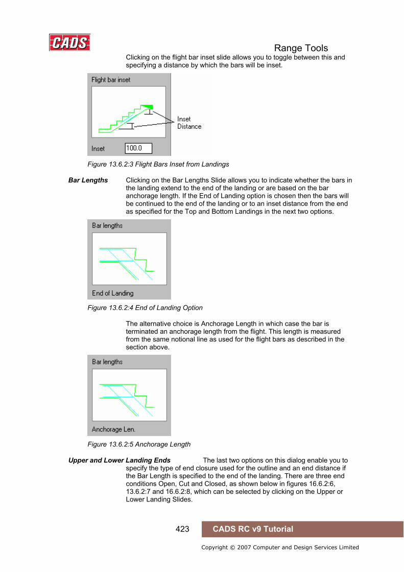
Range Tools
423 CADS RC v9 Tutorial
Copyright © 2007 Computer and Design Services Limited
Clicking on the flight bar inset slide allows you to toggle between this and specifying a distance by which the bars will be inset.
Figure 13.6.2:3 Flight Bars Inset from Landings
Bar Lengths Clicking on the Bar Lengths Slide allows you to indicate whether the bars in the landing extend to the end of the landing or are based on the bar anchorage length. If the End of Landing option is chosen then the bars will be continued to the end of the landing or to an inset distance from the end as specified for the Top and Bottom Landings in the next two options.
Figure 13.6.2:4 End of Landing Option
The alternative choice is Anchorage Length in which case the bar is terminated an anchorage length from the flight. This length is measured from the same notional line as used for the flight bars as described in the section above.
Figure 13.6.2:5 Anchorage Length
Upper and Lower Landing Ends The last two options on this dialog enable you to specify the type of end closure used for the outline and an end distance if the Bar Length is specified to the end of the landing. There are three end conditions Open, Cut and Closed, as shown below in figures 16.6.2:6, 13.6.2:7 and 16.6.2:8, which can be selected by clicking on the Upper or Lower Landing Slides.
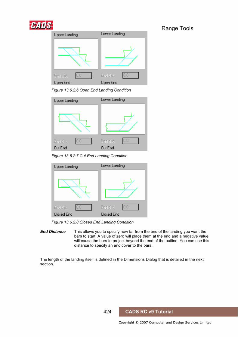
Range Tools
424 CADS RC v9 Tutorial
Copyright © 2007 Computer and Design Services Limited
Figure 13.6.2:6 Open End Landing Condition
Figure 13.6.2:7 Cut End Landing Condition
Figure 13.6.2:8 Closed End Landing Condition
End Distance This allows you to specify how far from the end of the landing you want the bars to start. A value of zero will place them at the end and a negative value will cause the bars to project beyond the end of the outline. You can use this distance to specify an end cover to the bars.
The length of the landing itself is defined in the Dimensions Dialog that is detailed in the next section.
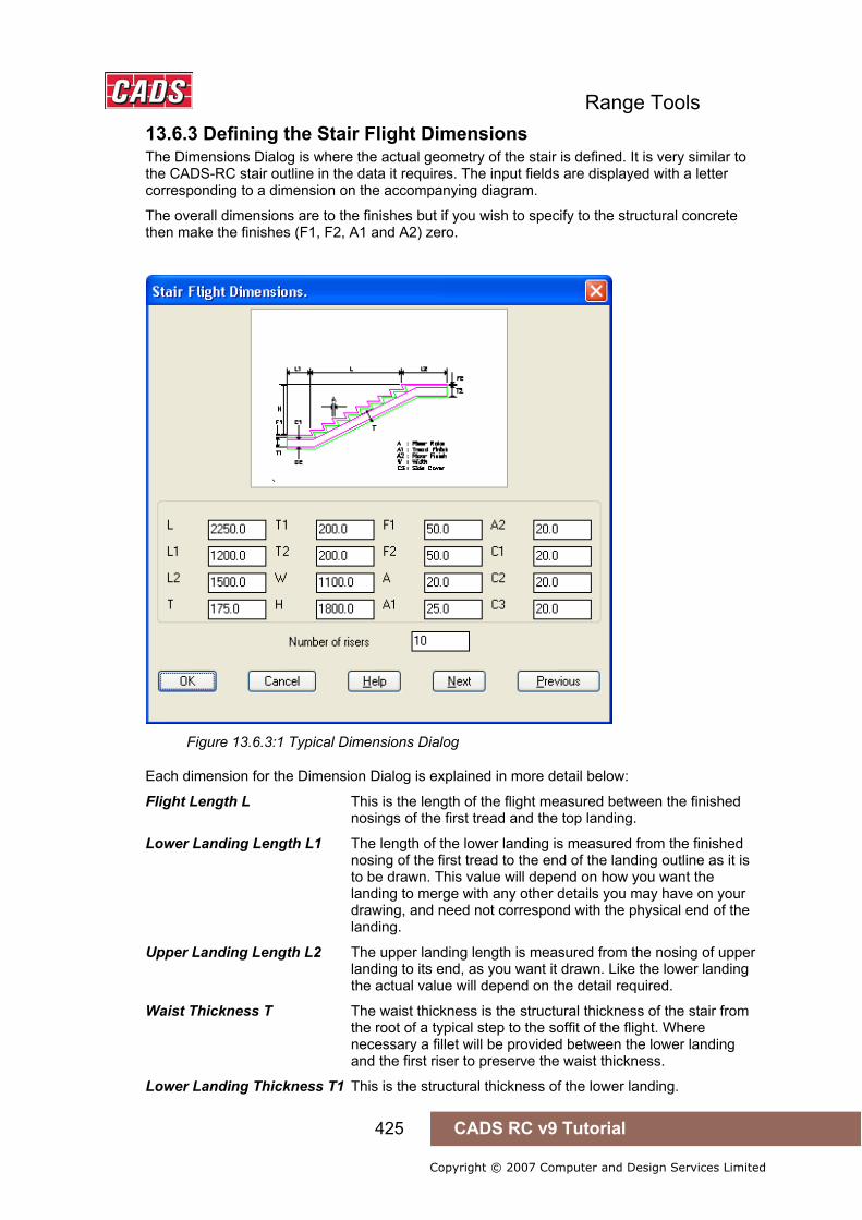
Range Tools
425 CADS RC v9 Tutorial
Copyright © 2007 Computer and Design Services Limited
13.6.3 Defining the Stair Flight Dimensions The Dimensions Dialog is where the actual geometry of the stair is defined. It is very similar to the CADS-RC stair outline in the data it requires. The input fields are displayed with a letter corresponding to a dimension on the accompanying diagram.
The overall dimensions are to the finishes but if you wish to specify to the structural concrete then make the finishes (F1, F2, A1 and A2) zero.
Figure 13.6.3:1 Typical Dimensions Dialog
Each dimension for the Dimension Dialog is explained in more detail below:
Flight Length L This is the length of the flight measured between the finished nosings of the first tread and the top landing.
Lower Landing Length L1 The length of the lower landing is measured from the finished nosing of the first tread to the end of the landing outline as it is to be drawn. This value will depend on how you want the landing to merge with any other details you may have on your drawing, and need not correspond with the physical end of the landing.
Upper Landing Length L2 The upper landing length is measured from the nosing of upper landing to its end, as you want it drawn. Like the lower landing the actual value will depend on the detail required.
Waist Thickness T The waist thickness is the structural thickness of the stair from the root of a typical step to the soffit of the flight. Where necessary a fillet will be provided between the lower landing and the first riser to preserve the waist thickness.
Lower Landing Thickness T1 This is the structural thickness of the lower landing.
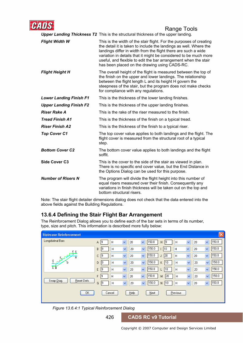
Range Tools
426 CADS RC v9 Tutorial
Copyright © 2007 Computer and Design Services Limited
Upper Landing Thickness T2 This is the structural thickness of the upper landing.
Flight Width W This is the width of the stair flight. For the purposes of creating the detail it is taken to include the landings as well. Where the landings differ in width from the flight there are such a wide variation in details that it might be considered to be much more useful, and flexible to edit the bar arrangement when the stair has been placed on the drawing using CADS-RC.
Flight Height H The overall height of the flight is measured between the top of the finish on the upper and lower landings. The relationship between the flight length L and its height H govern the steepness of the stair, but the program does not make checks for compliance with any regulations.
Lower Landing Finish F1 This is the thickness of the lower landing finishes.
Upper Landing Finish F2 This is the thickness of the upper landing finishes.
Riser Rake A This is the rake of the riser measured to the finish.
Tread Finish A1 This is the thickness of the finish on a typical tread.
Riser Finish A2 This is the thickness of the finish to a typical riser.
Top Cover C1 The top cover value applies to both landings and the flight. The flight cover is measured from the structural root of a typical step.
Bottom Cover C2 The bottom cover value applies to both landings and the flight soffit.
Side Cover C3 This is the cover to the side of the stair as viewed in plan. There is no specific end cover value, but the End Distance in the Options Dialog can be used for this purpose.
Number of Risers N The program will divide the flight height into this number of equal risers measured over their finish. Consequently any variations in finish thickness will be taken out on the top and bottom structural risers.
Note: The stair flight detailer dimensions dialog does not check that the data entered into the above fields against the Building Regulations.
13.6.4 Defining the Stair Flight Bar Arrangement The Reinforcement Dialog allows you to define each of the bar sets in terms of its number, type, size and pitch. This information is described more fully below:
Figure 13.6.4:1 Typical Reinforcement Dialog

Range Tools
427 CADS RC v9 Tutorial
Copyright © 2007 Computer and Design Services Limited
Swap Diagram Button The Swap Diagram button toggles between the diagram of the annotated illustrations of the longitudinal bars and the transverse bars to assist with identifying the bar sets that you can define in the Reinforcement Dialog.
Figure 13.6.4:2 Transverse Bar Diagram
Defining a Typical Bar Set All the bar sets are defined in the same way. They have been laid out like a typical bar label so that entering the data follows a natural flow. Usually you should start at the number field and work across each set until you have entered the pitch.
The program automatically determines the number of bars or the pitch depending on the range length of the bar set. How these range lengths are determined is described for each particular bar set in the next section.
Number of Bars If you change the number of bars then the pitch will be simultaneously recalculated. The calculated pitch will be the average pitch of the bars and may not be a rounded number you would normally use. This can be amended when you reach the pitch input field. This program does not allow a range with less than two bars. A special case is when you enter zero for the number of bars. This tells the program not to draw that bar set and the other input fields for that set are ‘grayed out’.
Type of Bar The program will accept T, R, U, X and S type of reinforcement, although U, X and S are not fully supported by CADS-RC. You can use the drop down list to select the required option.
Size of Bar You can select the diameter of bar from the pop down list.
Bar Pitch This is calculated according to the number of bars whenever that is amended. Otherwise when you change the value of the pitch the number of the bars will be recalculated. In many cases small changes in the pitch will not change the number of bars.
13.6.5 The Stair Flight Bar Sets Explained This section describes each of the bar sets detailed by the program. The anchorage and lap lengths mentioned include the lap factor and any specified rounding. The lap is based on the lesser value of the two bar types and diameter.
The main and secondary longitudinal bars all have the same range extending between the side covers of the flight. The transverse bars are all shape code 00 bars extending between the covers, but with a 40mm end tolerance deduction.

Range Tools
428 CADS RC v9 Tutorial
Copyright © 2007 Computer and Design Services Limited
Lower Landing Main Bottom Bars ‘A’ These are shape code 15 bars which extend either from the inset value at the end of the landing, or an anchorage length from the flight, to lap with the bottom flight bars.
Figure 13.6.5:1 Bar Set ‘A’
Lower Landing Secondary Bars ‘B’ These are shape code 15 bars that run in a similar manner to the bottom landing main bars but lap with the top flight bars. If the top flight bars are omitted then they extend into the flight by an anchorage length. You may wish to alter this position, using CADS-RC, if it does not correspond with the simplified bar curtailments shown in the I Struct E Detailing Manual. In most cases such a change will not be required.
Figure 13.6.5:2 Bar Set ‘B’
Lower Landing Main Top Bars ‘C’ These shape code 15 bars extend from the end inset, or anchorage length from the flight, to lap with the bottom flight bars.
Figure 13.6.5:3 Bar Set ‘C’
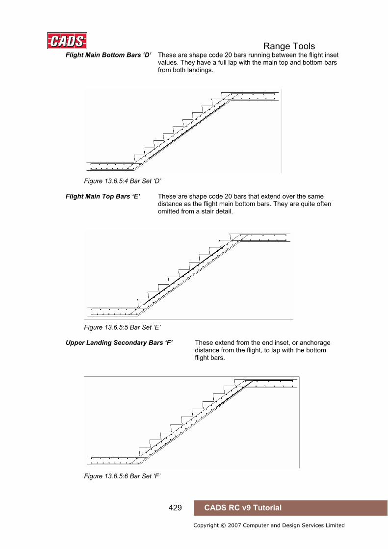
Range Tools
429 CADS RC v9 Tutorial
Copyright © 2007 Computer and Design Services Limited
Flight Main Bottom Bars ‘D’ These are shape code 20 bars running between the flight inset values. They have a full lap with the main top and bottom bars from both landings.
Figure 13.6.5:4 Bar Set ‘D’
Flight Main Top Bars ‘E’ These are shape code 20 bars that extend over the same distance as the flight main bottom bars. They are quite often omitted from a stair detail.
Figure 13.6.5:5 Bar Set ‘E’
Upper Landing Secondary Bars ‘F’ These extend from the end inset, or anchorage distance from the flight, to lap with the bottom flight bars.
Figure 13.6.5:6 Bar Set ‘F’
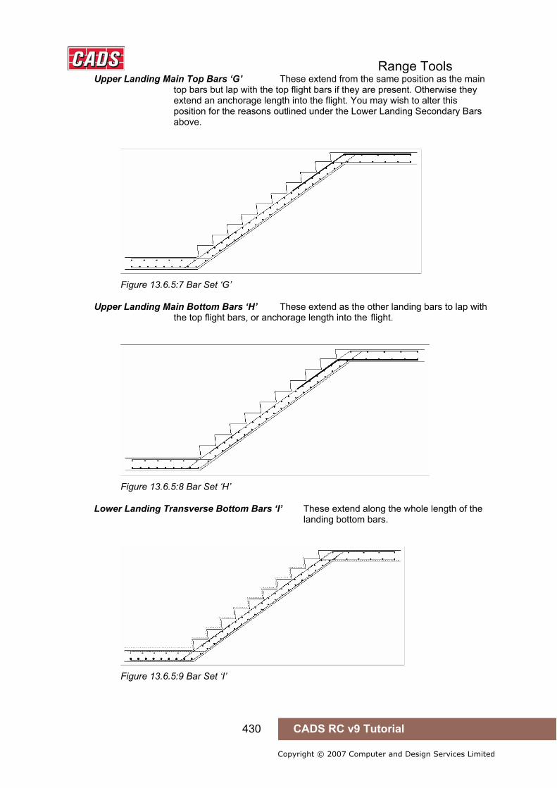
Range Tools
430 CADS RC v9 Tutorial
Copyright © 2007 Computer and Design Services Limited
Upper Landing Main Top Bars ‘G’ These extend from the same position as the main top bars but lap with the top flight bars if they are present. Otherwise they extend an anchorage length into the flight. You may wish to alter this position for the reasons outlined under the Lower Landing Secondary Bars above.
Figure 13.6.5:7 Bar Set ‘G’
Upper Landing Main Bottom Bars ‘H’ These extend as the other landing bars to lap with the top flight bars, or anchorage length into the flight.
Figure 13.6.5:8 Bar Set ‘H’
Lower Landing Transverse Bottom Bars ‘I’ These extend along the whole length of the landing bottom bars.
Figure 13.6.5:9 Bar Set ‘I’
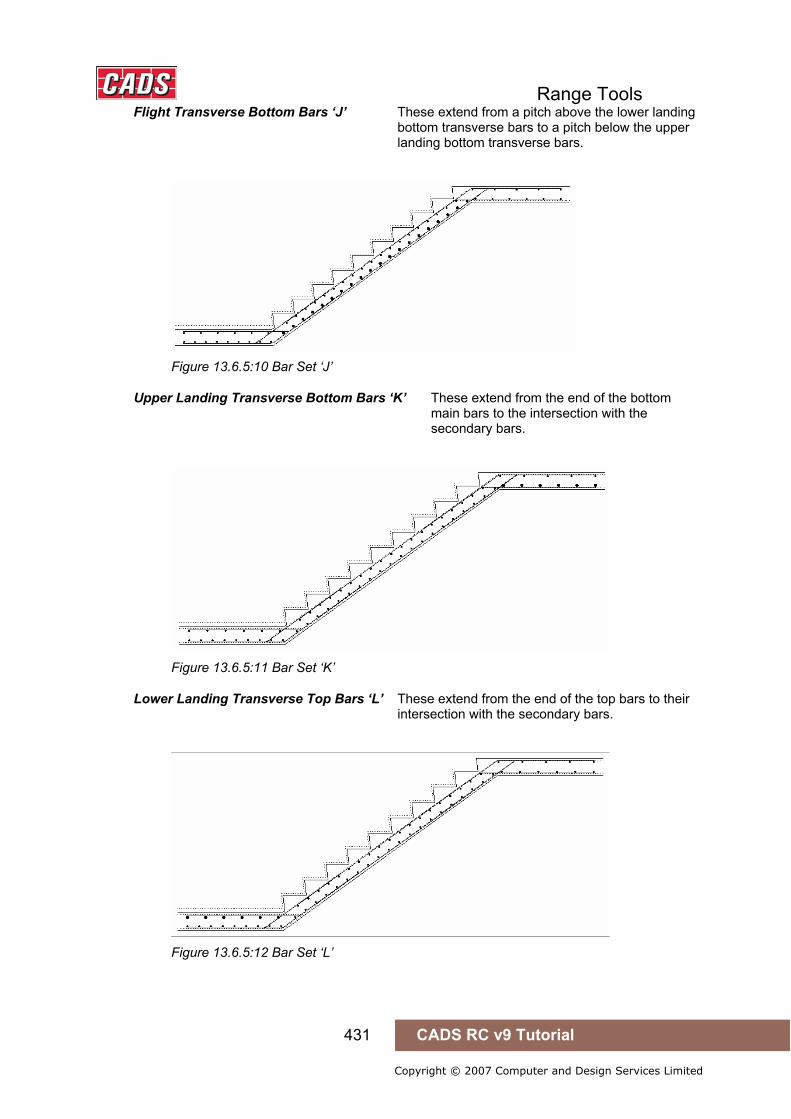
Range Tools
431 CADS RC v9 Tutorial
Copyright © 2007 Computer and Design Services Limited
Flight Transverse Bottom Bars ‘J’ These extend from a pitch above the lower landing bottom transverse bars to a pitch below the upper landing bottom transverse bars.
Figure 13.6.5:10 Bar Set ‘J’
Upper Landing Transverse Bottom Bars ‘K’ These extend from the end of the bottom main bars to the intersection with the secondary bars.
Figure 13.6.5:11 Bar Set ‘K’
Lower Landing Transverse Top Bars ‘L’ These extend from the end of the top bars to their intersection with the secondary bars.
Figure 13.6.5:12 Bar Set ‘L’

Range Tools
432 CADS RC v9 Tutorial
Copyright © 2007 Computer and Design Services Limited
Flight Transverse Top Bars ‘M’ These run between the top transverse bars in the upper and lower landing with each end offset by the pitch value. If the top main flight is omitted and the bars from the landing do not lap then these transverse bars will be split into two sets extending the length of the top bars.
Figure 13.6.5:13 Bar Set ‘M’ Continuous
Figure 13.6.5:14 Bar Set ‘M’ Split
Upper Landing Transverse Top Bars ‘N’ These run along the length of the top bars.
Figure 13.6.5:15 Bar Set ‘N’
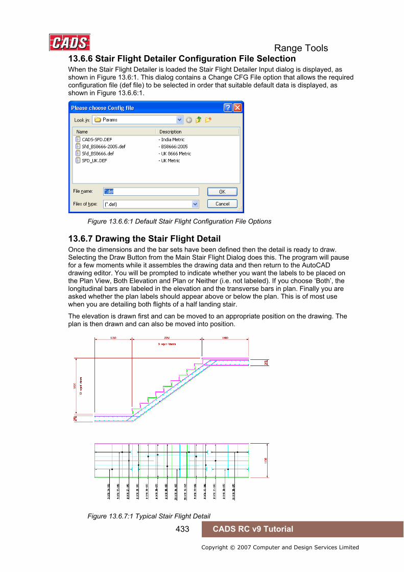
Range Tools
433 CADS RC v9 Tutorial
Copyright © 2007 Computer and Design Services Limited
13.6.6 Stair Flight Detailer Configuration File Selection When the Stair Flight Detailer is loaded the Stair Flight Detailer Input dialog is displayed, as shown in Figure 13.6:1. This dialog contains a Change CFG File option that allows the required configuration file (def file) to be selected in order that suitable default data is displayed, as shown in Figure 13.6.6:1.
Figure 13.6.6:1 Default Stair Flight Configuration File Options
13.6.7 Drawing the Stair Flight Detail Once the dimensions and the bar sets have been defined then the detail is ready to draw. Selecting the Draw Button from the Main Stair Flight Dialog does this. The program will pause for a few moments while it assembles the drawing data and then return to the AutoCAD drawing editor. You will be prompted to indicate whether you want the labels to be placed on the Plan View, Both Elevation and Plan or Neither (i.e. not labeled). If you choose ‘Both’, the longitudinal bars are labeled in the elevation and the transverse bars in plan. Finally you are asked whether the plan labels should appear above or below the plan. This is of most use when you are detailing both flights of a half landing stair.
The elevation is drawn first and can be moved to an appropriate position on the drawing. The plan is then drawn and can also be moved into position.
Figure 13.6.7:1 Typical Stair Flight Detail
Range Tools
434 CADS RC v9 Tutorial
Copyright © 2007 Computer and Design Services Limited
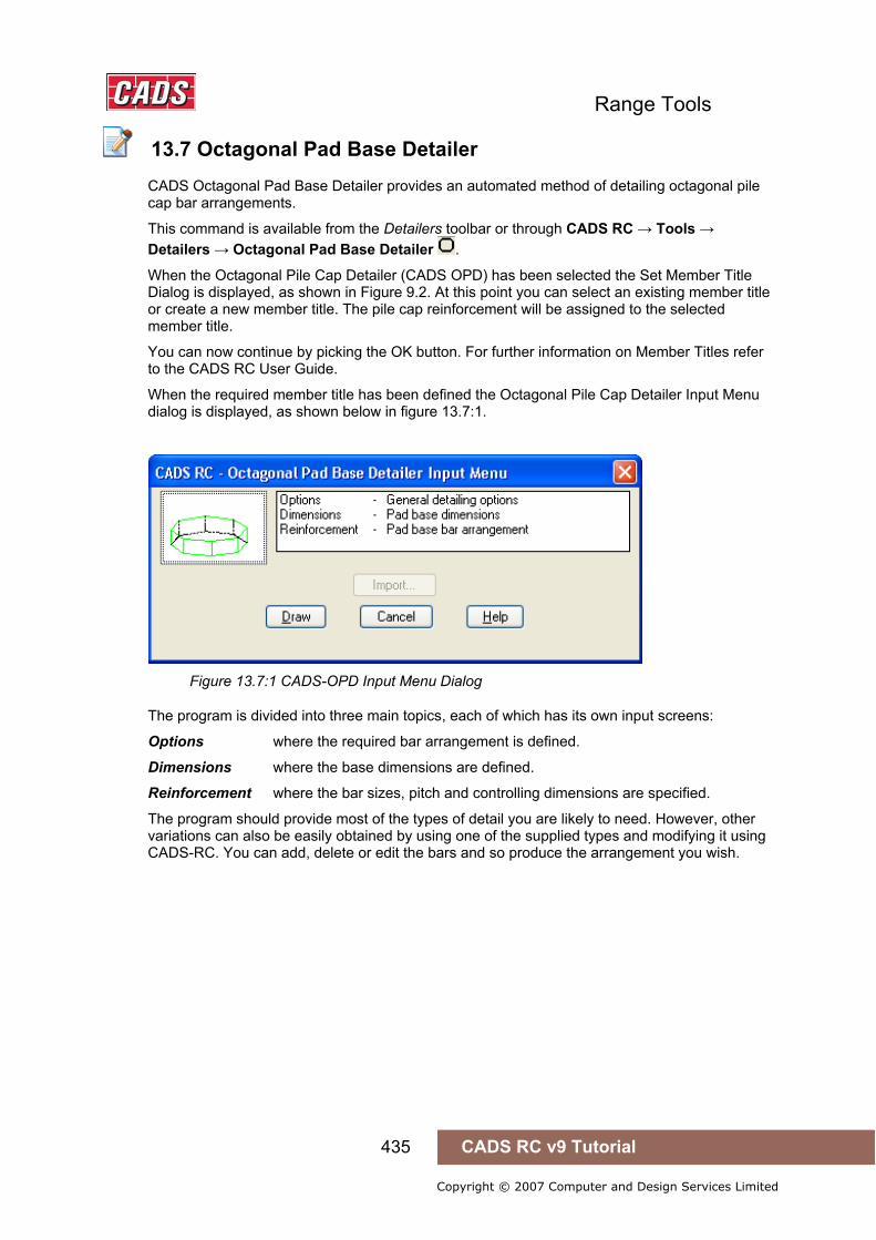
Range Tools
435 CADS RC v9 Tutorial
Copyright © 2007 Computer and Design Services Limited
13.7 Octagonal Pad Base Detailer
CADS Octagonal Pad Base Detailer provides an automated method of detailing octagonal pile cap bar arrangements.
This command is available from the Detailers toolbar or through CADS RC → Tools → Detailers → Octagonal Pad Base Detailer .
When the Octagonal Pile Cap Detailer (CADS OPD) has been selected the Set Member Title Dialog is displayed, as shown in Figure 9.2. At this point you can select an existing member title or create a new member title. The pile cap reinforcement will be assigned to the selected member title.
You can now continue by picking the OK button. For further information on Member Titles refer to the CADS RC User Guide.
When the required member title has been defined the Octagonal Pile Cap Detailer Input Menu dialog is displayed, as shown below in figure 13.7:1.
Figure 13.7:1 CADS-OPD Input Menu Dialog
The program is divided into three main topics, each of which has its own input screens:
Options where the required bar arrangement is defined.
Dimensions where the base dimensions are defined.
Reinforcement where the bar sizes, pitch and controlling dimensions are specified.
The program should provide most of the types of detail you are likely to need. However, other variations can also be easily obtained by using one of the supplied types and modifying it using CADS-RC. You can add, delete or edit the bars and so produce the arrangement you wish.
13.7 Octagonal Pad Base Detailer

Range Tools
436 CADS RC v9 Tutorial
Copyright © 2007 Computer and Design Services Limited
13.7.1 Defining the CADS-OPD General Detailing Options Picking Options from the Main CADS-OPD Dialog displays the Options Dialog, shown in figure 13.7.1:1, where the general reinforcing bar arrangement required is selected.
Figure 13.7.1:1 CADS-OPD Reinforcement Options Dialog
Side Bars The required side bar arrangement can be selected from the drop down list below the side bar slide. There are two options available:
Shape Code 25 This option uses four identical shape code 49 bars lapped to produce a continuous side bar.
Shape Code 15 This option uses eight identical shape code 62 bars lapped to produce a continuous side bar.
Note: The side bars are detailed as being placed inside the main cage bars.
Main Bars The required main bar arrangement for layers B1, B2, T1 and T2 used between parallel faces can be selected from the drop down list below the Main Bar Slide. There are two options available:
Standard 21’s This option details the reinforcement between parallel faces as shape code 21 bars with leg B spanning between the parallel faces.
Alternate 11’s This option details the reinforcement between parallel faces as alternately placed lapped shape code 11 bars.
In both the above cases the area between the non-parallel faces is detailed using the tapering shape code 21 bars with leg B spanning between the non-parallel faces.
Note: Main Bars are detailed to the side cover specified. If you wish to allow tolerances, you are advised to increase the side cover to a value that will produce the tolerance required.
Each layer of main bars (B1, B2, T1 and T2) are detailed with different bar marks to allow different bar types and diameters to be specified for each layer. CADS-RC can be used to rationalise bar marks if required.
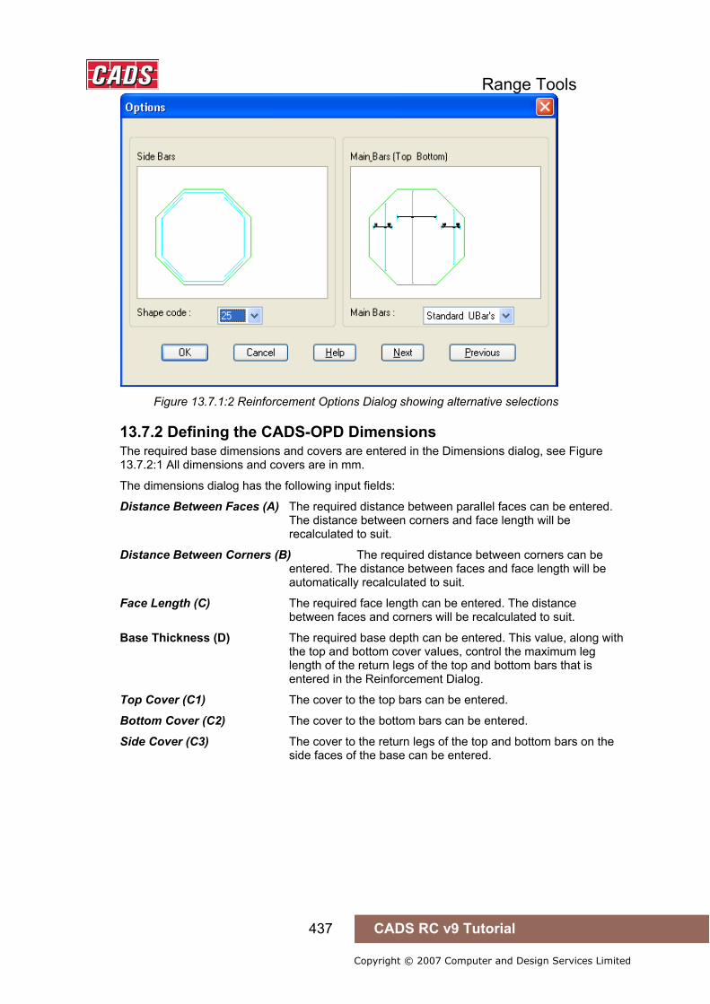
Range Tools
437 CADS RC v9 Tutorial
Copyright © 2007 Computer and Design Services Limited
Figure 13.7.1:2 Reinforcement Options Dialog showing alternative selections
13.7.2 Defining the CADS-OPD Dimensions The required base dimensions and covers are entered in the Dimensions dialog, see Figure 13.7.2:1 All dimensions and covers are in mm.
The dimensions dialog has the following input fields:
Distance Between Faces (A) The required distance between parallel faces can be entered. The distance between corners and face length will be recalculated to suit.
Distance Between Corners (B) The required distance between corners can be entered. The distance between faces and face length will be automatically recalculated to suit.
Face Length (C) The required face length can be entered. The distance between faces and corners will be recalculated to suit.
Base Thickness (D) The required base depth can be entered. This value, along with the top and bottom cover values, control the maximum leg length of the return legs of the top and bottom bars that is entered in the Reinforcement Dialog.
Top Cover (C1) The cover to the top bars can be entered.
Bottom Cover (C2) The cover to the bottom bars can be entered.
Side Cover (C3) The cover to the return legs of the top and bottom bars on the side faces of the base can be entered.
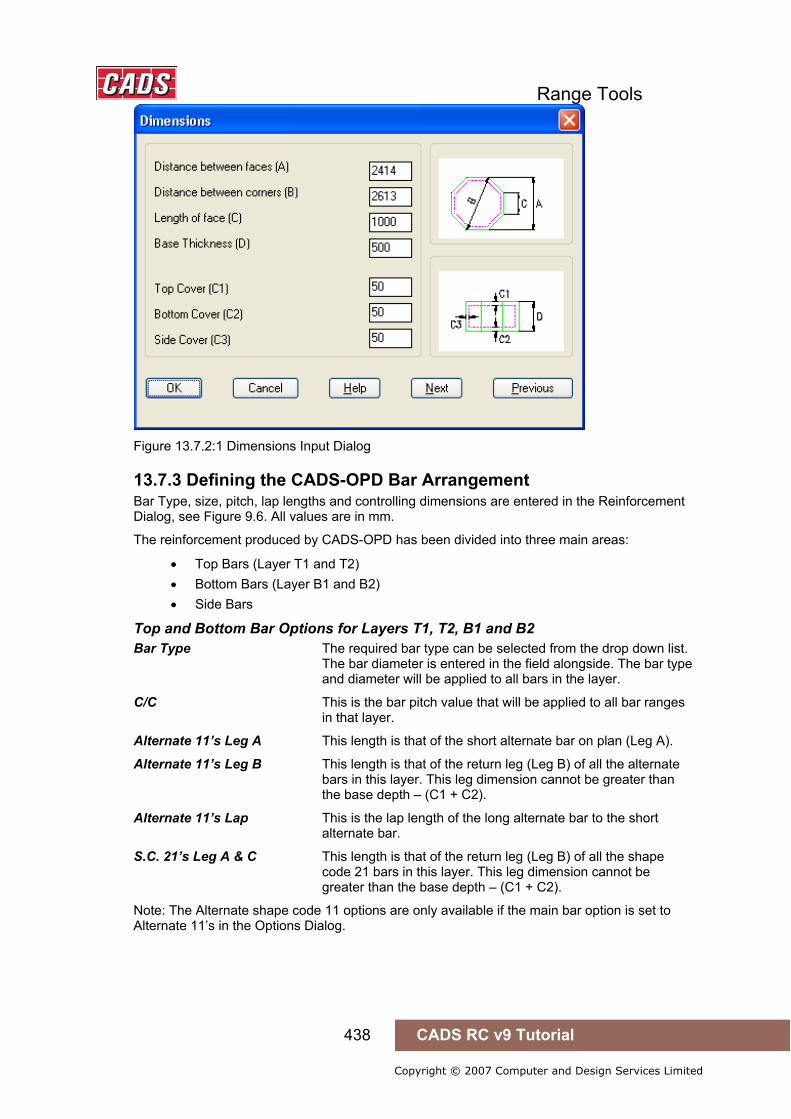
Range Tools
438 CADS RC v9 Tutorial
Copyright © 2007 Computer and Design Services Limited
Figure 13.7.2:1 Dimensions Input Dialog
13.7.3 Defining the CADS-OPD Bar Arrangement Bar Type, size, pitch, lap lengths and controlling dimensions are entered in the Reinforcement Dialog, see Figure 9.6. All values are in mm.
The reinforcement produced by CADS-OPD has been divided into three main areas:
• Top Bars (Layer T1 and T2) • Bottom Bars (Layer B1 and B2) • Side Bars
Top and Bottom Bar Options for Layers T1, T2, B1 and B2 Bar Type The required bar type can be selected from the drop down list. The bar diameter is entered in the field alongside. The bar type and diameter will be applied to all bars in the layer.
C/C This is the bar pitch value that will be applied to all bar ranges in that layer.
Alternate 11’s Leg A This length is that of the short alternate bar on plan (Leg A).
Alternate 11’s Leg B This length is that of the return leg (Leg B) of all the alternate bars in this layer. This leg dimension cannot be greater than the base depth – (C1 + C2).
Alternate 11’s Lap This is the lap length of the long alternate bar to the short alternate bar.
S.C. 21’s Leg A & C This length is that of the return leg (Leg B) of all the shape code 21 bars in this layer. This leg dimension cannot be greater than the base depth – (C1 + C2).
Note: The Alternate shape code 11 options are only available if the main bar option is set to Alternate 11’s in the Options Dialog.

Range Tools
439 CADS RC v9 Tutorial
Copyright © 2007 Computer and Design Services Limited
Figure 13.7.3:1 Reinforcement Input Dialog
Side Bar Options Bar Type The required bar type can be selected from the drop down list. The bar diameter is entered in the field alongside.
Size Enter the required bar diameter.
C/C This is the bar pitch value that will be applied to the side bars.
Lap Enter the required lap distance.
View Options Alternate 37’s Dims Button Displays a slide indicating the dimension options for the alternate 37’s.
S.C. 38 Dims Button Displays a slide indicating the dimension options for the shape code 38 bars.
Side Bars Dims Button Displays a slide indicating the lap length applied to the side bars.

Range Tools
440 CADS RC v9 Tutorial
Copyright © 2007 Computer and Design Services Limited
Figure 13.7.3:2 Alternate 37’s Dimensions Slide
Figure 13.7.3:3 Shape Code 38 Dims Slide
Figure 13.7.3:4 Side Bars Dimensions Slide

Range Tools
441 CADS RC v9 Tutorial
Copyright © 2007 Computer and Design Services Limited
13.7.4 Drawing the Octagonal Pad Base Detail Once all the dimensions and bar data have been defined the detail is ready to be drawn. Selecting the Draw Button from the Main CADS OPD Dialog invokes the detail drawing process. The program will pause for a moment while it assembles the data and then it returns to the AutoCAD drawing editor.
The plan is drawn first and you are prompted to select an insertion point for it on the drawing. The program then draws the section and you are again prompted for an insertion point for it on the drawing. Once this has been selected, the drawing is complete and you are returned to the AutoCAD command prompt.
Figure 13.7.4:1 Typical Octagonal Pile Cap Reinforcement Drawing
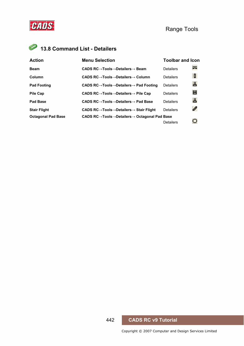
Range Tools
442 CADS RC v9 Tutorial
Copyright © 2007 Computer and Design Services Limited
13.8 Command List - Detailers
Action Menu Selection Toolbar and Icon
Beam CADS RC→Tools→Detailers→ Beam Detailers
Column CADS RC→Tools→Detailers→ Column Detailers
Pad Footing CADS RC→Tools→Detailers→ Pad Footing Detailers
Pile Cap CADS RC→Tools→Detailers→ Pile Cap Detailers
Pad Base CADS RC→Tools→Detailers→ Pad Base Detailers
Stair Flight CADS RC→Tools→Detailers→ Stair Flight Detailers
Octagonal Pad Base CADS RC→Tools→Detailers→ Octagonal Pad Base Detailers
13.8 Command List - Detailers
Range Tools
443 CADS RC v9 Tutorial
Copyright © 2007 Computer and Design Services Limited
14: Range Tools
14.0 Introduction
CADS RC v9 is shipped with the following Range Tools;
Circular Bar Detailer This provides an automated method of detailing circular bar arrangements like those found in circular tanks using lapped stock length bars. Single or multiple rings can be detailed for flat or sloping slabs.
Area Detailer The Area Detailer provides an automated method of detailing irregular outlines with openings with varying bars as individual bars and as part of tapered range.
Split Range This command will split an existing range around an opening and provide additional steel above and below the opening.
Change Range Type The Change Range Type tool allows you to change from one range type to another. The tool will delete the original range line and transfer all the set data to the new range line.
Share Range Line The Share Range Line function allows you to add other bar sets to an existing range line on the drawing. The bar sets that have been added will inherit the range data from the existing range.
Show All Bars The Show All Bars in Range command will add all the bars to a selected range line.
Radial Bar Detailer Radial Bar Detailer calculates the radial steel, typically detailed in circular slabs and tanks.
The Range Tools use the AutoCAD Dimscale variable to size the text and blocks to suit the plotted scale of the drawing regardless of whether you are working in Model Space only or both Model/Layout space. Ensure that Dimscale is set to match the plotted scale of the detail.
If you have access to the CADS-SC software, use the Drawing Set-up Function to load in a Title Block and set the appropriate scale and drawing environment. Alternatively you can use CADS VPM, create Layout function or basic AutoCAD, create Layout as described in Section 2 of this Tutorial.
14.0 Introduction

Range Tools
444 CADS RC v9 Tutorial
Copyright © 2007 Computer and Design Services Limited
14.1 Circular Bar Arrangement
Circular Bar Arrangement provides an automated method of detailing circular bar arrangements like those found in circular tank slabs using lapped stock length bars. Single or multiple rings can be detailed for flat or sloping slabs or tanks.
This command is available from the Detailers toolbar or through CADS RC → Tools → Detailers → Circular Bar Arrangement Detailer .
14.1.1 Circular Bar Arrangement Geometry
Figure 14.1.1:1 Circular Bar Arrangement dialog
The Circular Bar Arrangement Detailer requires two main areas of data to be defined in order that the desired bar arrangement is produced. They consist of:
Geometry Use to define the size and slope of the structure. Also the spacing, laps and start positions of the bars.
Bar Information Use to set the multiplier, steel grade, bar diameter and notes.
Set Member Title Use to set the rebar’s member title.
14.1 Circular Bar Arrangement
Range Tools
445 CADS RC v9 Tutorial
Copyright © 2007 Computer and Design Services Limited
14.1.2 Setting the Member Title To allocate the Circular Bar Arrangement Detailer (CBA) to a Member select the Member title button . This in turn displays the Member dialog. At this point you can select an existing Member Title or create a new member title. The Circular Bar Arrangement reinforcement will be assigned to the selected member title. You can now continue by picking the OK button.
14.1.3 Defining Bar Arrangements The Size Information inputs which define the bar arrangements are as follows:
Multi Enter the required label multiplier to be applied to each bar set.
Grade Select the required bar grade.
Size Select the bar diameter.
Prfx. Enter any bar mark prefixing required.
Notes Enter any note you want to include in the bar labels.
Lap Length Enter the lap length to be used for bars that require lapping.
14.1.4 Defining the Circular Bar Arrangement Geometry The Circular Bar Arrangement Input dialog contains input options for defining the Circular Bar Arrangement geometry required for detailing using the following options:
Outer Radius Enter the radius to the outer concrete cover line. Selecting the pick option allows the outer cover radius to be defined by picking points on the AutoCAD drawing.
Inner Radius Enter the radius to the inner concrete cover line. Selecting the pick option allows the inner cover radius to be defined by picking points on the AutoCAD drawing.
Spacing Enter the bar pitch required, if set to zero then a single ring of reinforcement will be detailed to the Outer Cover Radius value.
Slope Enter the slope angle if the slab slopes towards the centre so the correct number of rings of reinforcement can be calculated.
Angle Enter the included angle that is to be detailed. Selecting the pick option allows the total rotation to be defined by picking an angle on the AutoCAD drawing.
Start Extra Lap Enter any additional lap required, in mm, at the start of the radius bars.
End Extra Lap Enter any additional lap required, in mm, at the end of the radius bars.
Start Position Start Position Indicates the start angle for the reinforcement placement, 90 means that the start position is vertically at the top of the bar arrangement.
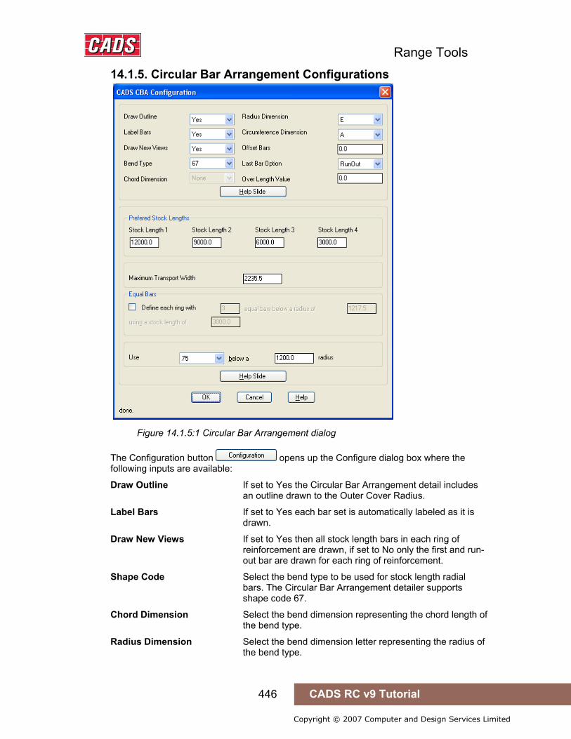
Range Tools
446 CADS RC v9 Tutorial
Copyright © 2007 Computer and Design Services Limited
14.1.5. Circular Bar Arrangement Configurations
Figure 14.1.5:1 Circular Bar Arrangement dialog
The Configuration button opens up the Configure dialog box where the following inputs are available:
Draw Outline If set to Yes the Circular Bar Arrangement detail includes an outline drawn to the Outer Cover Radius.
Label Bars If set to Yes each bar set is automatically labeled as it is drawn.
Draw New Views If set to Yes then all stock length bars in each ring of reinforcement are drawn, if set to No only the first and run- out bar are drawn for each ring of reinforcement.
Shape Code Select the bend type to be used for stock length radial bars. The Circular Bar Arrangement detailer supports shape code 67.
Chord Dimension Select the bend dimension representing the chord length of the bend type.
Radius Dimension Select the bend dimension letter representing the radius of the bend type.

Range Tools
447 CADS RC v9 Tutorial
Copyright © 2007 Computer and Design Services Limited
Circumference Dimension Select the bend dimension letter representing the circumference of the bend type
Offset Bars Enter in plotted mm the distance which lapping bars will offset to show the lap when plotted
Last Bar Options This is applied to the closer bar in the Circular Bar Arrangement detail and has the following options:
Run Out If set to Run-out the closer bar will be detailed to the dimensions required to close the arrangement by lapping onto the last preferred/stock length bar making the bar shorter than the preferred/stock length.
Over Length If set to Over Length the last preferred/stock length bar will be extended to close the Circular Bar Arrangement detail making the bar longer then the preferred/stock length.
Over Length Value Enter the Over length value.
Figure 14.1.5:2 CBA Dimension Help Slide
Preferred Stock Lengths - The options available in this dialog are as follows:
Stock Length 1 Enter the longest choice stock of bar length.
Stock Length 2 Enter the second longest choice of stock bar length.
Stock Length 3 Enter the third longest choice of stock bar length.
Stock Length 4 Enter the fourth longest choice of stock bar length. The circular bar arrangement detailer will use the longest stock bar length until the E dimension becomes greater than the value defined for the Maximum Transport width at which point it will begin to use the next longest stock bar length and so on.

Range Tools
448 CADS RC v9 Tutorial
Copyright © 2007 Computer and Design Services Limited
Figure 14.1.5:3 Equal Bars Help File
Maximum Transport Width Enter the maximum transport dimension value for the bent bars.
Use 75 below 1200 Radius Enter the bend type you wish to detail when the radius is below the entered value. By default shape code 75 is used.
Equal Bars Define each ring with 3 equal bars below a radius of 1200 mm using a stock length of 1200 mm. Enter the values if equal bars are to be detailed for rings below certain radius.
Save Job Settings This button opens up the Save as Dialog box where all the configuration settings can be saved in a specified location.
Restore Job Settings Selecting this button displays the Open dialog box where a predefined project settings file can be selected.
14.1.6 CBA Configuration File Selection When the Circular Bar Arrangement Detailer (CBA) is loaded the Circular Bar Arrangement Detailer Input dialog is displayed. This dialog contains a Change CFG File button
that allows the required configuration file (def file) to be selected in order that suitable default data is displayed. The CBA will automatically select the correct definition file depending on the standard set-up in CADS RC v9.
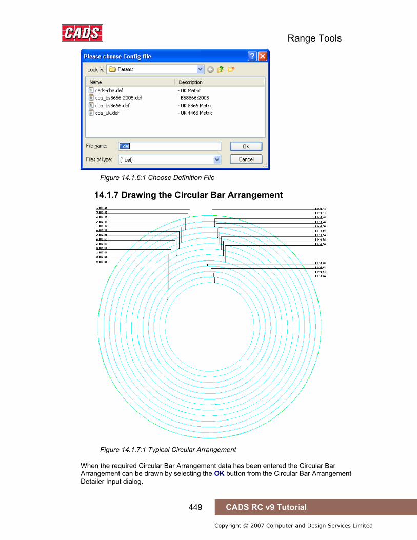
Range Tools
449 CADS RC v9 Tutorial
Copyright © 2007 Computer and Design Services Limited
Figure 14.1.6:1 Choose Definition File
14.1.7 Drawing the Circular Bar Arrangement
Figure 14.1.7:1 Typical Circular Arrangement
When the required Circular Bar Arrangement data has been entered the Circular Bar Arrangement can be drawn by selecting the OK button from the Circular Bar Arrangement Detailer Input dialog.
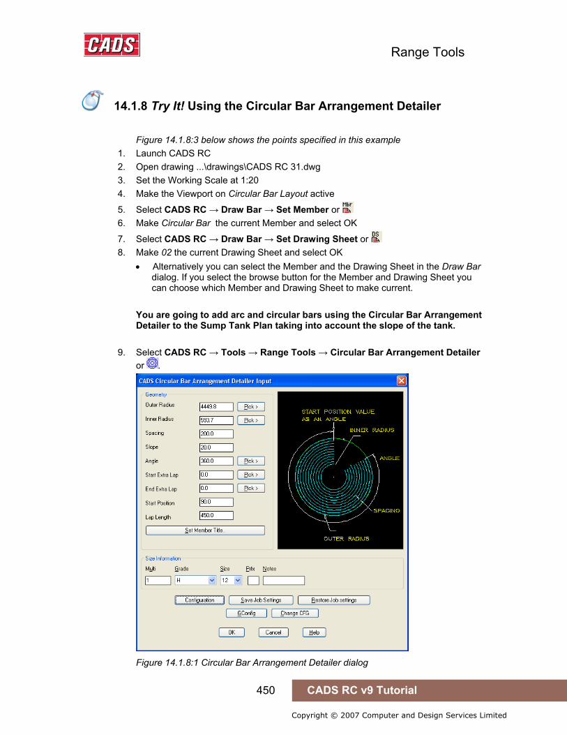
Range Tools
450 CADS RC v9 Tutorial
Copyright © 2007 Computer and Design Services Limited
14.1.8 Try It! Using the Circular Bar Arrangement Detailer
Figure 14.1.8:3 below shows the points specified in this example 1. Launch CADS RC 2. Open drawing ...\drawings\CADS RC 31.dwg 3. Set the Working Scale at 1:20 4. Make the Viewport on Circular Bar Layout active
5. Select CADS RC → Draw Bar → Set Member or 6. Make Circular Bar the current Member and select OK
7. Select CADS RC → Draw Bar → Set Drawing Sheet or 8. Make 02 the current Drawing Sheet and select OK
• Alternatively you can select the Member and the Drawing Sheet in the Draw Bar dialog. If you select the browse button for the Member and Drawing Sheet you can choose which Member and Drawing Sheet to make current.
You are going to add arc and circular bars using the Circular Bar Arrangement Detailer to the Sump Tank Plan taking into account the slope of the tank.
9. Select CADS RC → Tools → Range Tools → Circular Bar Arrangement Detailer or .
Figure 14.1.8:1 Circular Bar Arrangement Detailer dialog
14.1.8 Try It! Using the Circular Bar Arrangement Detailer
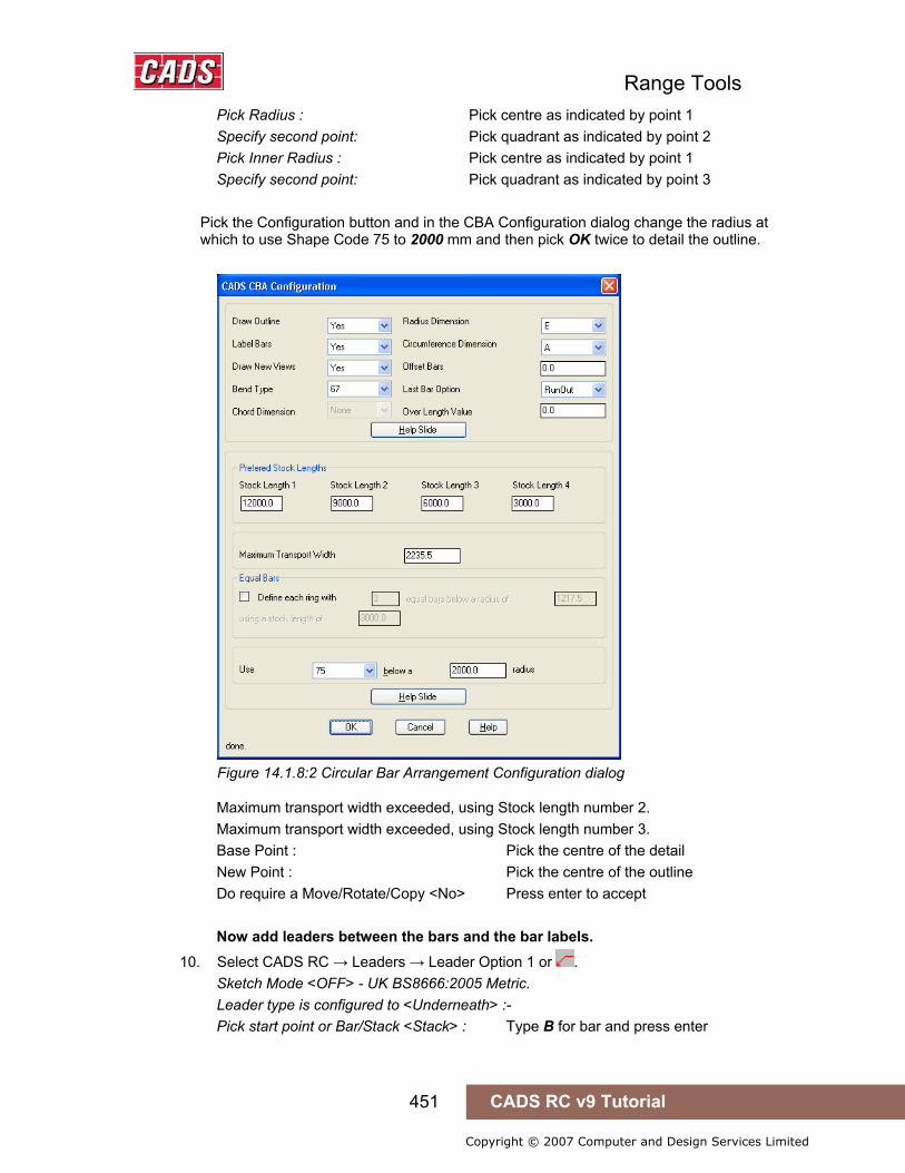
Range Tools
451 CADS RC v9 Tutorial
Copyright © 2007 Computer and Design Services Limited
Pick Radius : Pick centre as indicated by point 1 Specify second point: Pick quadrant as indicated by point 2 Pick Inner Radius : Pick centre as indicated by point 1 Specify second point: Pick quadrant as indicated by point 3 Pick the Configuration button and in the CBA Configuration dialog change the radius at which to use Shape Code 75 to 2000 mm and then pick OK twice to detail the outline.
Figure 14.1.8:2 Circular Bar Arrangement Configuration dialog
Maximum transport width exceeded, using Stock length number 2. Maximum transport width exceeded, using Stock length number 3. Base Point : Pick the centre of the detail New Point : Pick the centre of the outline Do require a Move/Rotate/Copy <No> Press enter to accept Now add leaders between the bars and the bar labels.
10. Select CADS RC → Leaders → Leader Option 1 or . Sketch Mode <OFF> - UK BS8666:2005 Metric. Leader type is configured to <Underneath> :- Pick start point or Bar/Stack <Stack> : Type B for bar and press enter
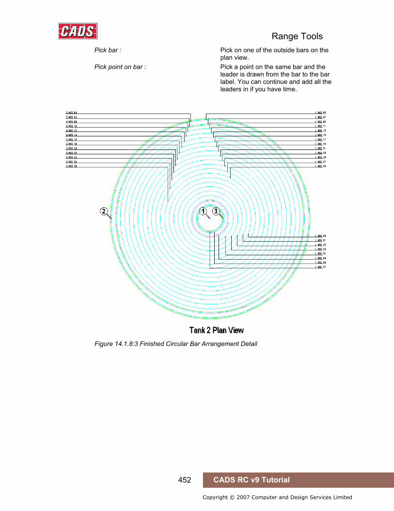
Range Tools
452 CADS RC v9 Tutorial
Copyright © 2007 Computer and Design Services Limited
Pick bar : Pick on one of the outside bars on the plan view. Pick point on bar : Pick a point on the same bar and the leader is drawn from the bar to the bar label. You can continue and add all the leaders in if you have time.
Figure 14.1.8:3 Finished Circular Bar Arrangement Detail
Range Tools
453 CADS RC v9 Tutorial
Copyright © 2007 Computer and Design Services Limited
14.2 Area Detailer
The Area Detailer is used to add reinforcement to irregular polyline outlines with or without openings. The detailer has the ability to detail either single indicator or tapered ranges with either straight, bent or hook bars in one direction at a time. The Area detailer will also support Over Stock Length bars.
This command is available from the Detailers toolbar or through CADS RC → Tools → Detailers → Area Detailer .
14.2.1 Basic Operation Load the Area Detailer tool. At the AutoCAD command line you will be asked;
Select the outer boundary…
Select a Pline object:
Select a polyline or region object that has already been drawn to define the outer boundary of the area to be detailed.
Next, at the AutoCAD command line, you will be asked;
Do you want to select any holes (Yes/No)<Yes>:
Answer yes if you want to pick polyline or region objects that have already been drawn. If you answer No the Area Detailer dialog will be displayed.
Select the opening(s)…
Select polyline/Region<Pick points>:
There are three options to define the openings with the default option as Pick points.
• Select polyline You can select a polyline entity.
• Region You can pick a point inside a closed region.
• Pick You can pick as many points as required to select the area.
After selecting the objects for the openings, press enter and then you will be prompted at the AutoCAD command line;
Pick start point to indicate direction of ranges:
Pick end point to indicate direction of ranges:
Pick points to define the direction of the ranges. The area detailer will support ranges drawn at any angle. However, if the auto-place bar label option is selected in the configuration, they will be placed horizontally and occasionally the leader maybe missed.
After indicating the direction of the ranges the Area Detailer Dialog box is displayed as shown in figure 14.2.1:1.
14.2 Area Detailer

Range Tools
454 CADS RC v9 Tutorial
Copyright © 2007 Computer and Design Services Limited
Figure 14.2.1:1 Area Detailer main dialog
Area Detailer Dialog contains the following fields to be input:
Cover Values Define the cover values for Bar, Range Line & Openings.
Bar Shape Define the shape code to be drawn.
Bar Data Set the steel grade, bar diameter, centres and notes.
14.2.2 Defining Cover Values You can define the cover distances to the Bars, the Range lines and then openings in the Area Detailer main input dialog. You can enter the cover values for each using one of two options;
You can type in a value for the cover distance.
You can pick the cover distance on the drawing by selecting the Pick button.
14.2.3 Defining Bar and Range Data Bar Shape The user can pick the Shape Code to be used by the Area Detailer from the drop down list. (This is country specific and some of them may be disabled.) The user can enter the appropriate hook dimensions when a Non-standard hook bar shape is selected.
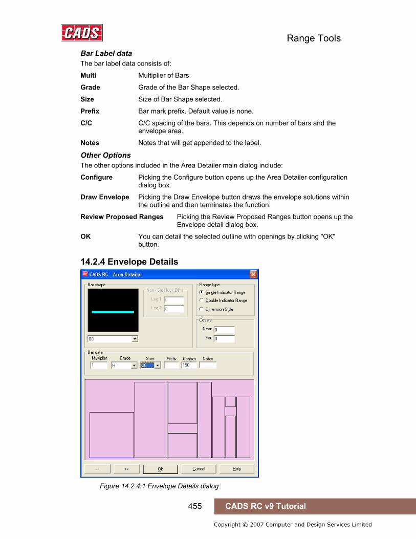
Range Tools
455 CADS RC v9 Tutorial
Copyright © 2007 Computer and Design Services Limited
Bar Label data The bar label data consists of:
Multi Multiplier of Bars.
Grade Grade of the Bar Shape selected.
Size Size of Bar Shape selected.
Prefix Bar mark prefix. Default value is none.
C/C C/C spacing of the bars. This depends on number of bars and the envelope area.
Notes Notes that will get appended to the label.
Other Options The other options included in the Area Detailer main dialog include:
Configure Picking the Configure button opens up the Area Detailer configuration dialog box.
Draw Envelope Picking the Draw Envelope button draws the envelope solutions within the outline and then terminates the function.
Review Proposed Ranges Picking the Review Proposed Ranges button opens up the Envelope detail dialog box.
OK You can detail the selected outline with openings by clicking "OK" button.
14.2.4 Envelope Details
Figure 14.2.4:1 Envelope Details dialog
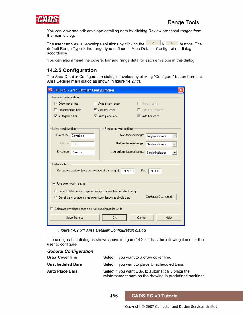
Range Tools
456 CADS RC v9 Tutorial
Copyright © 2007 Computer and Design Services Limited
You can view and edit envelope detailing data by clicking Review proposed ranges from the main dialog.
The user can view all envelope solutions by clicking the & buttons. The default Range Type is the range type defined in Area Detailer Configuration dialog accordingly.
You can also amend the covers, bar and range data for each envelope in this dialog.
14.2.5 Configuration The Area Detailer Configuration dialog is invoked by clicking "Configure" button from the Area Detailer main dialog as shown in figure 14.2.1:1.
Figure 14.2.5:1 Area Detailer Configuration dialog
The configuration dialog as shown above in figure 14.2.5:1 has the following items for the user to configure:
General Configuration Draw Cover line Select if you want to a draw cover line.
Unscheduled Bars Select if you want to place Unscheduled Bars.
Auto Place Bars Select if you want CBA to automatically place the reinforcement bars on the drawing in predefined positions.
Range Tools
457 CADS RC v9 Tutorial
Copyright © 2007 Computer and Design Services Limited
Auto Place Range Select if you want CBA to automatically place Range Lines on the drawing in predefined positions.
Add Bar Label Select if you want to add the bar label to the drawing.
Auto Place Label Select if you want to automatically place the Bar Label on the drawing in redefined positions.
Group Labels Select if you want to Group the Bar Labels together.
Add Bar Reference Select if you want to Add Bar references to the reinforcing bars.
Layer Configuration Cover line Type in the Layer name for the cover line
Outline The layer for the outline is set by the polyline or region selected on the drawing
Envelope Type in layer name for the envelope lines
The defined layer names will be created in the AutoCAD Layer Properties Manager.
Range drawing options Range configuration can be defined based on three major categories of Range envelope types, these are:
• Non-Tapered Range
• Uniform Tapered Range
• Non- Uniform Tapered Range
Non –Tapered Range If the range envelope is Non Tapered range then you can detail these envelopes with the following range types:
• Single Indicator Range
• Double Indicator Range
• Dimension Style
The user can select the required range type from the drop down list.
Uniform Tapered Range If the range envelope is Uniform Tapered range then you can detail those envelopes with the following range types
• Linear Tapered Range
• Linear Double Indicator
• Detail Single Bars
The user can select the required range type from the drop down list.
Non Uniform Tapered Range If the range envelope is Non Uniform Tapered range then you can detail those envelopes with the following range types
• Varying Taper Range
• Detail Single Bars
The user can select the required range type by picking the appropriate option button.

Range Tools
458 CADS RC v9 Tutorial
Copyright © 2007 Computer and Design Services Limited
Distance Factor You can specify the position on the drawing where the range line is drawn by using the "Range Line Position Factor". This value is expressed as a percentage of the distance measured from top to the bottom of the range bar. If the envelope is either linear taper or varying taper then the factor is measured from bottom to top of the first bar of a range.
You can also specify the position on the drawing where the reinforcement bar is drawn by using the "Bar Insertion Point " option. If, 2 is specified then the bar will be drawn where the 3rd reinforcement bar would cross the range line.
14.2.6 Use Over Stock Length
Figure 14.2.6:1 Over Stock Length Configuration
You can choose to allow the Area Detailer to use the Over Stock Length feature available in CADS RC v9 by selecting the “Use over stock feature” option.
Picking the Configure Over Stock feature opens up the Over Stock Configuration dialog as shown in figure 14.2.6:1.
There are also options to use OSL for varying tapered range. Selecting the Do not detail varying tapered range that are beyond stock length option will not detail the varying tapered envelope if the length of the bar exceeds stock length.
Selecting the option detail varying taper range over stock length as single bars will detail the varying taper over stock length envelope as single bars.
Save Settings Select Save Settings if user needs the current program values as the default values.

Range Tools
459 CADS RC v9 Tutorial
Copyright © 2007 Computer and Design Services Limited
14.2.7 Draw Envelope Picking the Draw Envelope button will add the envelope solution to the Polyline / Region Outline on the drawing.
Figure 14.2.7:1 Typical Envelope solution added to the outline
14.2.8 Detail Area Picking the OK button on the main dialog and the detailer will add the reinforcement to the outline.
Typical 14.2.8:1 Typical Outline detailed with the Area Detailer
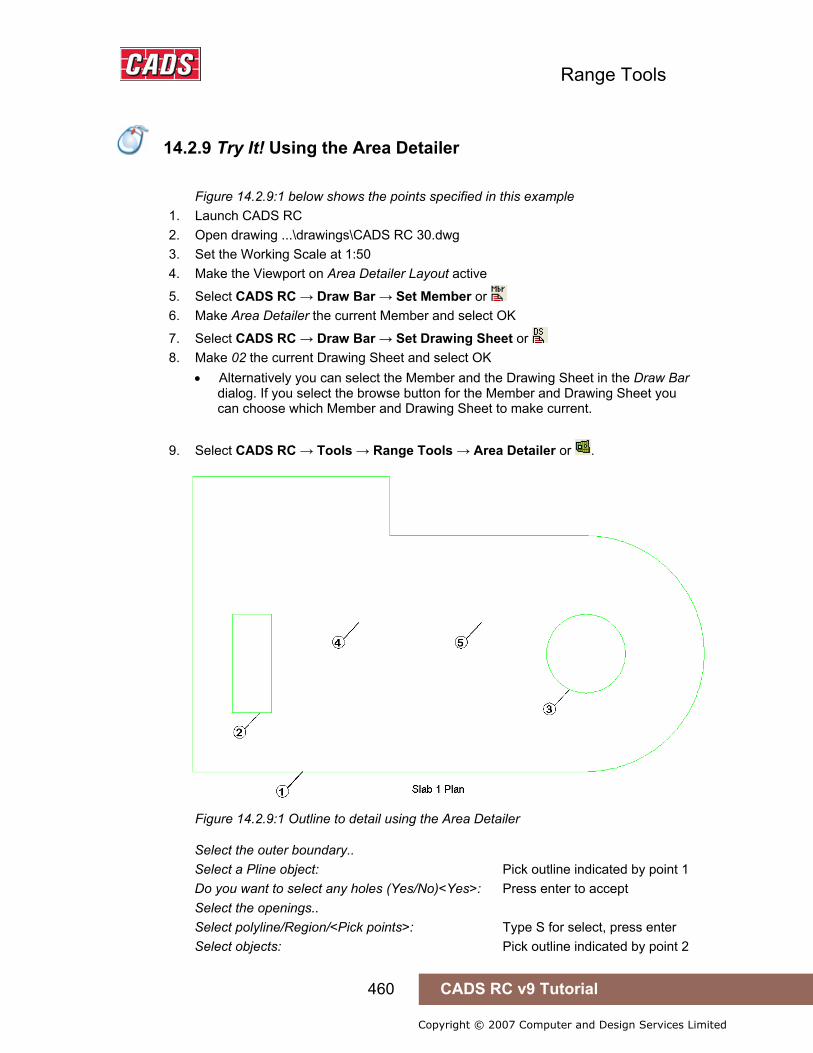
Range Tools
460 CADS RC v9 Tutorial
Copyright © 2007 Computer and Design Services Limited
14.2.9 Try It! Using the Area Detailer
Figure 14.2.9:1 below shows the points specified in this example 1. Launch CADS RC 2. Open drawing ...\drawings\CADS RC 30.dwg 3. Set the Working Scale at 1:50 4. Make the Viewport on Area Detailer Layout active
5. Select CADS RC → Draw Bar → Set Member or 6. Make Area Detailer the current Member and select OK
7. Select CADS RC → Draw Bar → Set Drawing Sheet or 8. Make 02 the current Drawing Sheet and select OK
• Alternatively you can select the Member and the Drawing Sheet in the Draw Bar dialog. If you select the browse button for the Member and Drawing Sheet you can choose which Member and Drawing Sheet to make current.
9. Select CADS RC → Tools → Range Tools → Area Detailer or .
Figure 14.2.9:1 Outline to detail using the Area Detailer
Select the outer boundary.. Select a Pline object: Pick outline indicated by point 1 Do you want to select any holes (Yes/No)<Yes>: Press enter to accept Select the openings.. Select polyline/Region/<Pick points>: Type S for select, press enter Select objects: Pick outline indicated by point 2
14.2.9 Try It! Using the Area Detailer
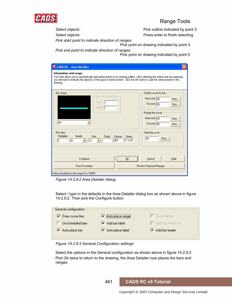
Range Tools
461 CADS RC v9 Tutorial
Copyright © 2007 Computer and Design Services Limited
Select objects: Pick outline indicated by point 3 Select objects: Press enter to finish selecting. Pick start point to indicate direction of ranges: Pick point on drawing indicated by point 4 Pick end point to indicate direction of ranges: Pick point on drawing indicated by point 5
Figure 14.2.9:2 Area Detailer dialog
Select / type in the defaults in the Area Detailer dialog box as shown above in figure
14.2.9:2. Then pick the Configure button.
Figure 14.2.9:3 General Configuration settings
Select the options in the General configuration as shown above in figure 14.2.9:3 Pick Ok twice to return to the drawing, the Area Detailer now places the bars and
ranges.

Range Tools
462 CADS RC v9 Tutorial
Copyright © 2007 Computer and Design Services Limited
Figure 14.2.9:4 Slab detailed using the Area Detailer
Use AutoCAD and CADS RC editing commands to tidy up the drawing/.
Figure 14.2.9:5 Slab after labels have been tidied up

Range Tools
463 CADS RC v9 Tutorial
Copyright © 2007 Computer and Design Services Limited
14.3 Split Range
The Split range tool can be used to break an existing range line around one or more openings within the boundaries of a range area. It will redraw the ranges either side of the opening as well as above and below as shown below in figure 14.3:1.
This command is available from the Detailers toolbar or through CADS RC → Tools → Detailers → Split Range .
Before using this command make sure that the openings are already drawn using either an AutoCAD region or a polyline as shown below in figure 14.3:1.
Figure 14.3:1 Typical Outline, with range and new openings
Figure 14.3:2 Finished Split Range Detail
After picking the command from either the Toolbar or the pull down menu you will be prompted at the AutoCAD command line to select a range which you want to split.
14.3 Split Range

Range Tools
464 CADS RC v9 Tutorial
Copyright © 2007 Computer and Design Services Limited
Select Range line:
Once you have selected the range you will be prompted again.
Select the opening(s)…
Select polyline/Region<Pick points>:
There are three options to define the openings with the default option as Pick points.
• Select polyline You can select a polyline entity.
• Region You can pick a point inside a closed region.
• Pick You can pick as many points as required to select perimeter of the area.
After selecting the objects for opening press Enter and then you will be prompted in the command prompt.
14.3.1 Defining the Split Range Defaults
Figure 14.3.1:1 Split Range dialog
Defining Cover value The user can define the cover value to the openings. There are two options to enter cover values,
• You can enter a value for the cover.
• You can pick the cover distance on the drawing.
Picking the Configure button opens up the Split range configuration dialog box.
Picking the Review Proposed ranges opens up the Envelope detail dialog box.
14.3.2 Envelope Details The User can view and edit envelope detailing data by clicking Review proposed ranges from the main dialog.

Range Tools
465 CADS RC v9 Tutorial
Copyright © 2007 Computer and Design Services Limited
Figure 14.3.2:1 Envelope Detail dialog
The user can view all envelope solutions by picking either the back or forwards
buttons. The default Range Type is the range type defined in Split Range Configuration dialog.
At this point of time the user can also change range type information for each envelope.
14.3.3 Split Range Configuration Split Range configuration dialog is invoked by clicking "Configure" button from Split Range main dialog. Configuration dialog is displayed as shown below.

Range Tools
466 CADS RC v9 Tutorial
Copyright © 2007 Computer and Design Services Limited
Figure 14.3.3:1 Split Range Configuration dialog
The configuration dialog has the following items for user to configure.
General Configuration Draw Cover line Select if you want to a draw cover line.
Unscheduled Bars Select if you want to place Unscheduled Bars.
Auto Place Bars Select if you want CBA to automatically place the reinforcement bars on the drawing in predefined positions.
Auto Place Range Select if you want CBA to automatically place Range Lines on the drawing in predefined positions.
Add Bar Label Select if you want to add the bar label to the drawing.
Auto Place Label Select if you want to automatically place the Bar Label on the drawing in redefined positions.
Group Labels Select if you want to Group the Bar Labels together.
Add Bar Reference Select if you want to Add Bar references to the reinforcing bars.
Layer Configuration Cover line Type in the Layer name for the cover line

Range Tools
467 CADS RC v9 Tutorial
Copyright © 2007 Computer and Design Services Limited
Outline The layer for the outline is set by the polyline or region selected on the drawing
Envelope Type in layer name for the envelope lines
The defined layer names will be created in the AutoCAD Layer Properties Manager.
Range drawing options Range configuration can be defined based on three major categories of Range envelope types, these are:
• Non-Tapered Range
• Uniform Tapered Range
• Non Uniform Tapered Range
Non –Tapered Range If the range envelope is Non Tapered range then you can detail these envelopes with the following range types:
• Single Indicator Range
• Double Indicator Range
• Dimension Style
The user can select the required range type from the drop down list.
Uniform Tapered Range If the range envelope is Uniform Tapered range then you can detail those envelopes with the following range types
• Linear Tapered Range
• Linear Double Indicator
• Detail Single Bars
The user can select the required range type from the drop down list.
Non Uniform Tapered Range If the range envelope is Non Uniform Tapered range then you can detail those envelopes with the following range types
• Varying Taper Range
• Detail Single Bars
The user can select the required range type by picking the appropriate option button.
Distance Factor You can specify the position on the drawing where the range line is drawn by using the "Range Line Position Factor". This value is expressed as a percentage of the distance measured from top to the bottom of the range bar. If the envelope is either linear taper or varying taper then the factor is measured from bottom to top of the first bar of a range.
You can also specify the position on the drawing where the reinforcement bar is drawn by using the "Bar Insertion Point " option. If, 2 is specified then the bar will be drawn where the 3rd reinforcement bar would cross the range line.
Save settings Select save settings if user needs current program values as the default value.
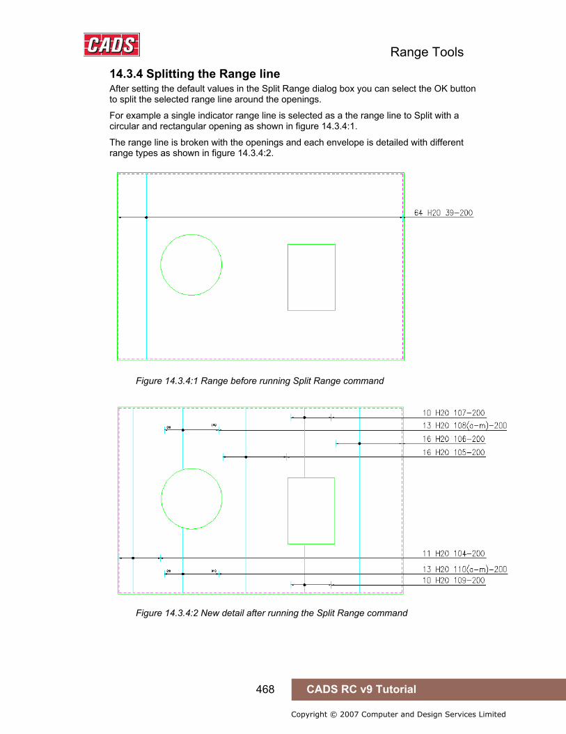
Range Tools
468 CADS RC v9 Tutorial
Copyright © 2007 Computer and Design Services Limited
14.3.4 Splitting the Range line After setting the default values in the Split Range dialog box you can select the OK button to split the selected range line around the openings.
For example a single indicator range line is selected as a the range line to Split with a circular and rectangular opening as shown in figure 14.3.4:1.
The range line is broken with the openings and each envelope is detailed with different range types as shown in figure 14.3.4:2.
Figure 14.3.4:1 Range before running Split Range command
Figure 14.3.4:2 New detail after running the Split Range command
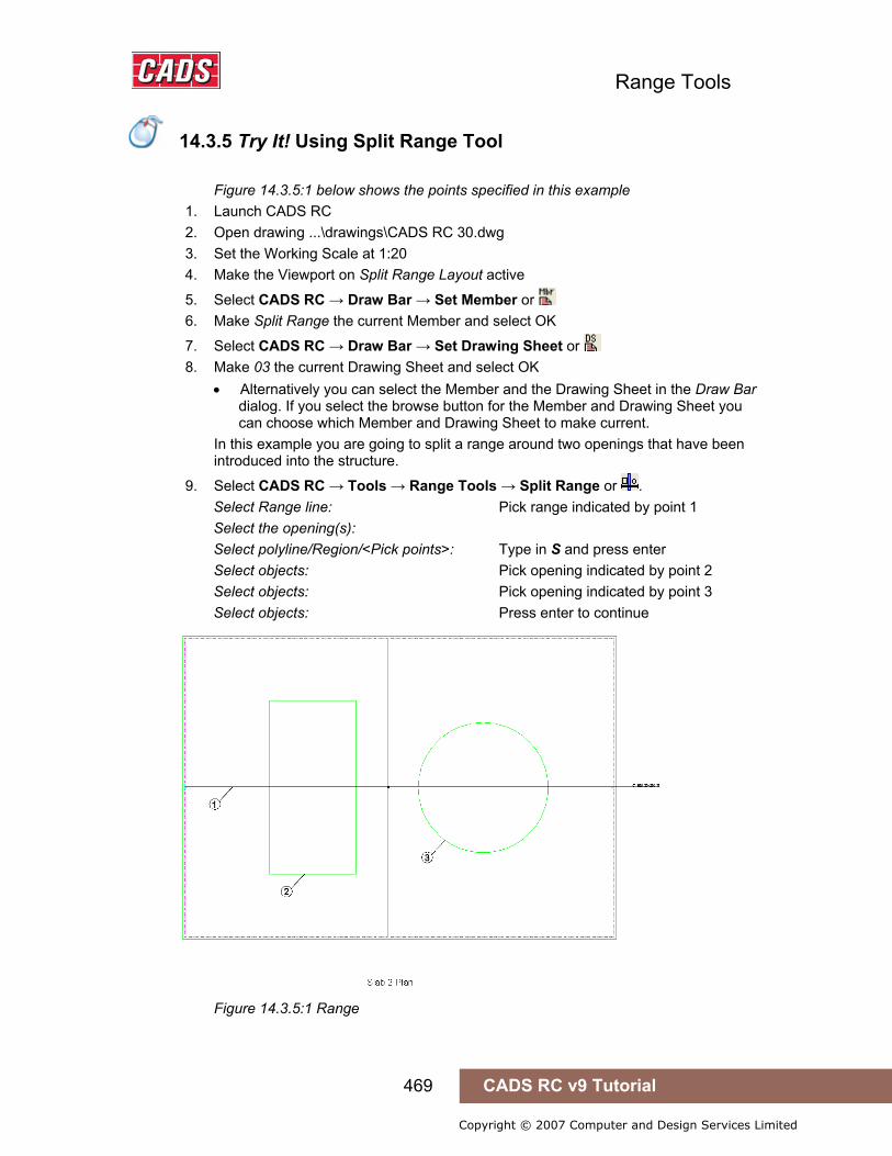
Range Tools
469 CADS RC v9 Tutorial
Copyright © 2007 Computer and Design Services Limited
14.3.5 Try It! Using Split Range Tool
Figure 14.3.5:1 below shows the points specified in this example
1. Launch CADS RC 2. Open drawing ...\drawings\CADS RC 30.dwg 3. Set the Working Scale at 1:20 4. Make the Viewport on Split Range Layout active
5. Select CADS RC → Draw Bar → Set Member or 6. Make Split Range the current Member and select OK
7. Select CADS RC → Draw Bar → Set Drawing Sheet or 8. Make 03 the current Drawing Sheet and select OK
• Alternatively you can select the Member and the Drawing Sheet in the Draw Bar dialog. If you select the browse button for the Member and Drawing Sheet you can choose which Member and Drawing Sheet to make current.
In this example you are going to split a range around two openings that have been introduced into the structure.
9. Select CADS RC → Tools → Range Tools → Split Range or . Select Range line: Pick range indicated by point 1 Select the opening(s): Select polyline/Region/<Pick points>: Type in S and press enter Select objects: Pick opening indicated by point 2 Select objects: Pick opening indicated by point 3 Select objects: Press enter to continue
Figure 14.3.5:1 Range
14.3.5 Try It! Using Split Range Tool
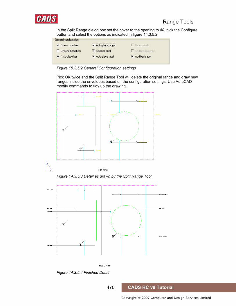
Range Tools
470 CADS RC v9 Tutorial
Copyright © 2007 Computer and Design Services Limited
In the Split Range dialog box set the cover to the opening to 50, pick the Configure button and select the options as indicated in figure 14.3.5:2
Figure 15.3.5:2 General Configuration settings
Pick OK twice and the Split Range Tool will delete the original range and draw new ranges inside the envelopes based on the configuration settings. Use AutoCAD modify commands to tidy up the drawing.
Figure 14.3.5:3 Detail as drawn by the Split Range Tool
Figure 14.3.5:4 Finished Detail

Range Tools
471 CADS RC v9 Tutorial
Copyright © 2007 Computer and Design Services Limited
14.4 Change Range Type
The Change Range Type tool allows you to change from one range type to another. The tool will delete the original range line and transfer all the set data to the new range line.
You can only change the range type to a similar one, for instance if you have selected a single indicator linear taper you can change it to a double indicator linear taper.
Change Range Groups The following lists the Change Range Type Groups;
Single Ranges Single Indicator; Double Indicator; Single Fixed Pitch; Single Multiple Pitch; Dimension Style
Alternate Ranges Alternate; Alternate Fixed Pitch; Alternate Multiple Pitch
Staggered Ranges Staggered; Staggered Fixed Pitch; Staggered Multiple Pitch
Tapered Ranges Linear Taper; Double Indicator; Double Taper
14.4.1 Using Change Range Type Tool This command is available from the Detailers toolbar or through CADS RC → Tools → Detailers → Change Range Type or .
After picking the command from either the Toolbar or the pull down menu you will be prompted at the AutoCAD command line to select the range you want to change.
Select a New Range to Change Once the range has been picked the Change Range Type dialog is displayed as shown below in figure 14.1.1:1. The alternative range types to change to will vary according to the range selected on the drawing.
Figure 14.4.1:1 Change Range Type dialog
14.4 Change Range Type

Range Tools
472 CADS RC v9 Tutorial
Copyright © 2007 Computer and Design Services Limited
Select a New Range to Change Choose the range type to change to from the list of possible range types shown in the dialog box.
Changing Range type The existing range will be changed to the new range type when the OK button is selected in main dialog.
The function will delete the original range and pass the bar set data to the new range type. The change range type tool may require additional input data especially if changing from a single indicator type range to a multiple range. It is at this stage you will be prompted to pick additional points of you want to split the range into groups.
Limitations When range type is changed to a multiple fixed pitch type range, then all groups are given with same centre to centre spacing. You can use the Edit Range function to change the centre spacing for each range group. This is illustrated in the example below.
Figure 14.4.1:2 Single Indicator Range
Use the Change Range Type tool to change the range from a single indicator to a single multiple pitch.
Note: the user has drawn construction lines to make it easier to select the start and end points of the range groups.
Figure 14.4.1:3 Single Indicator changed to a Single Multiple Pitch
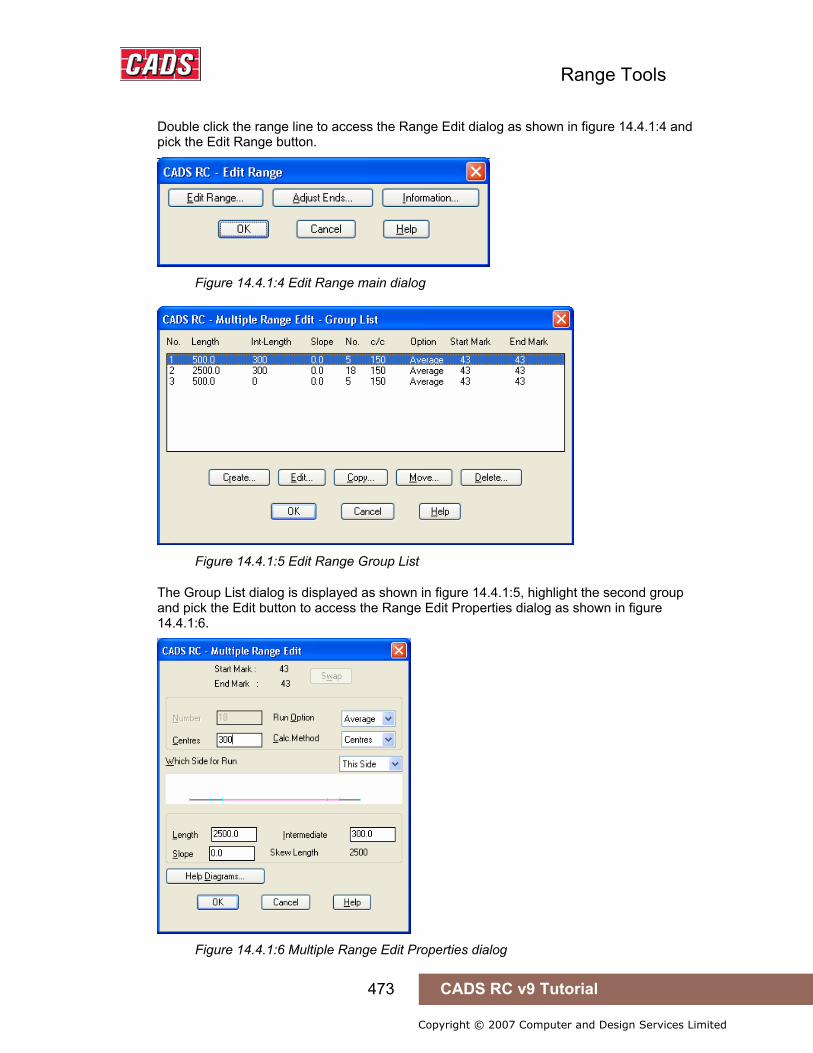
Range Tools
473 CADS RC v9 Tutorial
Copyright © 2007 Computer and Design Services Limited
Double click the range line to access the Range Edit dialog as shown in figure 14.4.1:4 and pick the Edit Range button.
Figure 14.4.1:4 Edit Range main dialog
Figure 14.4.1:5 Edit Range Group List
The Group List dialog is displayed as shown in figure 14.4.1:5, highlight the second group and pick the Edit button to access the Range Edit Properties dialog as shown in figure 14.4.1:6.
Figure 14.4.1:6 Multiple Range Edit Properties dialog

Range Tools
474 CADS RC v9 Tutorial
Copyright © 2007 Computer and Design Services Limited
Change the centres from 150 to 300 and pick OK to exit back the drawing. The range updates as shown in figure 14.4.1:7.
Figure 14.4.1:7 Finished Beam Detail
14.4.2 Try It! Using the Change Range Type Tool
Figure 14.4.2:1 below shows the points specified in this example
1. Launch CADS RC 2. Open drawing ...\drawings\CADS RC 30.dwg 3. Set the Working Scale at 1:20 4. Make the Viewport on Change Range Type Layout active
5. Select CADS RC → Draw Bar → Set Member or 6. Make Change Range Type the current Member and select OK
7. Select CADS RC → Draw Bar → Set Drawing Sheet or 8. Make 04 the current Drawing Sheet and select OK
• Alternatively you can select the Member and the Drawing Sheet in the Draw Bar dialog. If you select the browse button for the Member and Drawing Sheet you can choose which Member and Drawing Sheet to make current.
In this example you are going to change the range from a single indicator range to a single fixed pitch range and then select around the two openings that have been introduced into the structure.
9. Select CADS RC → Tools → Range Tools → Change Range Type or . Select range line: Pick range line as indicate by point 1 In the Change Range Type dialog highlight the Single Fixed Pitch and pick OK You will then be prompted to pick the endpoint of the range. In this case you are going to pick around the openings as indicated below in figure 14.4.2:1
14.4.2 Try It! Using the Change Range Type Tool
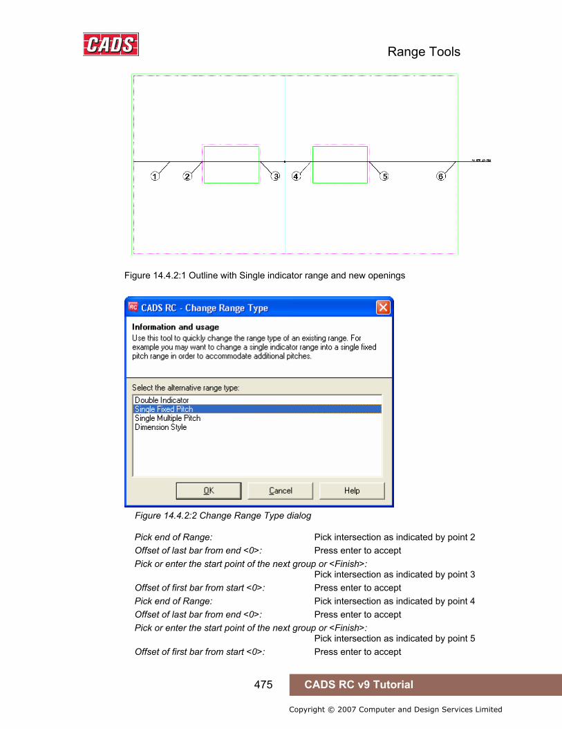
Range Tools
475 CADS RC v9 Tutorial
Copyright © 2007 Computer and Design Services Limited
Figure 14.4.2:1 Outline with Single indicator range and new openings
Figure 14.4.2:2 Change Range Type dialog
Pick end of Range: Pick intersection as indicated by point 2 Offset of last bar from end <0>: Press enter to accept Pick or enter the start point of the next group or <Finish>: Pick intersection as indicated by point 3 Offset of first bar from start <0>: Press enter to accept Pick end of Range: Pick intersection as indicated by point 4 Offset of last bar from end <0>: Press enter to accept Pick or enter the start point of the next group or <Finish>: Pick intersection as indicated by point 5 Offset of first bar from start <0>: Press enter to accept

Range Tools
476 CADS RC v9 Tutorial
Copyright © 2007 Computer and Design Services Limited
Pick end of Range: Pick intersection as indicated by point 6 Offset of last bar from end <0>: Press enter to accept Do you want to change the label position ? (Yes/No)<Yes>: Type N and press enter You will need to manually redraw the leader between the end of the range and the bar label using the Leader Option 1 command.
10. Select CADS RC → Leaders → Leader Option 1 or . Leader type is configured to <Underneath> :- Pick start point or Bar/Stack <Stack> : Pick the end of the range line Next point or ENTER to select label : Press enter Select label : Pick the bar label
Figure 14.4.2:3 Finished Detail using Change Range Type

Range Tools
477 CADS RC v9 Tutorial
Copyright © 2007 Computer and Design Services Limited
14.5 Share Range Line
The Share Range Line function allows you to add other bar sets to an existing range line on the drawing. The bar sets that have been added will inherit the range data from the existing range. Therefore you do not have to keep drawing ranges lines with the same data, you can simply attach a bar to an existing range. There are no dialog boxes for the Share Range Line function, all options will be displayed at the AutoCAD command line.
This command is available from the Detailers toolbar or through CADS RC → Tools → Detailers → Share Range Line or .
14.5.1 Sequence of Operation Before selecting the Share Range Line command, add the reinforcement bars you wish to attach to an existing range across that range as shown in the example in figure 14.5.1:1 below.
Figure 14.5.1:1 Detail showing existing range and bar set to be added.
Once you have selected the Share Range Line function you will be prompted at the AutoCAD command line as follows:
Pick the range line to share:
This may be any range type except a Tapered Range. If valid range is not selected, you will see the following message:
The selected Range or object is not supported.
Do you want to try selecting again (Yes/No)<No>:
Answer Yes to this prompt and the function will ask for the range line to share to be selected again. You can cancel the command if required.
If an appropriate range line is selected, the function will prompt as follows:
Pick bars to share the chosen range line:
Select the bar that you wish to add to the range line.
Do you want to select another bar to share (Yes/No)<Yes>:
If you answer Yes to this prompt you can keep on selecting bars to add to the range line.
14.5 Share Range Line

Range Tools
478 CADS RC v9 Tutorial
Copyright © 2007 Computer and Design Services Limited
If you answer No to this prompt the function will add the range data to the selected bar (s), add a donut between the range line and the bar, as well as adding a bar reference to clearly identify each bar set.
You will then be prompted to:
Pick the position of the label:
Select the position of the bar label for the bars that have been added to the existing range line. You will then be prompted to:
Align Base label to New Label<ON>:
If the existing range line is already labeled and you are happy with the position of the bar labels type in Off to finish the command.
If the existing range has not been labeled press enter to accept the default and pick the new position of the bar label for the existing range.
The Share Range Line command actually reproduces the existing range that was selected and attaches it to the bar set that was selected. So, in fact, CADS RC duplicates the ranges and places one on top of the other.
Figure 14.5.1:2 Finished result of Share Range Line
14.5.2 Editing Shared Range Lines If you stretch the shared range line, the newly drawn range line(s) also gets stretched, as one is drawn on top of the other.
Figure 14.5.2:1 Stretched detail
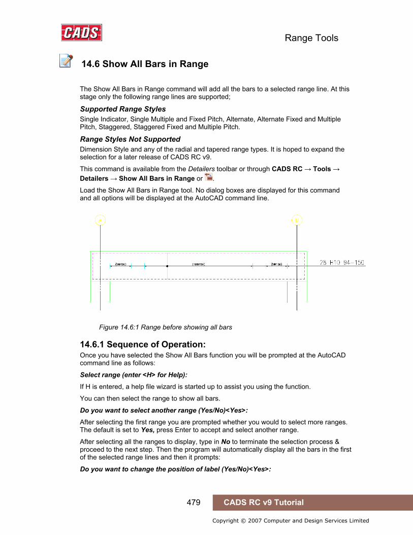
Range Tools
479 CADS RC v9 Tutorial
Copyright © 2007 Computer and Design Services Limited
14.6 Show All Bars in Range
The Show All Bars in Range command will add all the bars to a selected range line. At this stage only the following range lines are supported;
Supported Range Styles Single Indicator, Single Multiple and Fixed Pitch, Alternate, Alternate Fixed and Multiple Pitch, Staggered, Staggered Fixed and Multiple Pitch.
Range Styles Not Supported Dimension Style and any of the radial and tapered range types. It is hoped to expand the selection for a later release of CADS RC v9.
This command is available from the Detailers toolbar or through CADS RC → Tools → Detailers → Show All Bars in Range or .
Load the Show All Bars in Range tool. No dialog boxes are displayed for this command and all options will be displayed at the AutoCAD command line.
Figure 14.6:1 Range before showing all bars
14.6.1 Sequence of Operation: Once you have selected the Show All Bars function you will be prompted at the AutoCAD command line as follows:
Select range (enter <H> for Help):
If H is entered, a help file wizard is started up to assist you using the function.
You can then select the range to show all bars.
Do you want to select another range (Yes/No)<Yes>:
After selecting the first range you are prompted whether you would to select more ranges. The default is set to Yes, press Enter to accept and select another range.
After selecting all the ranges to display, type in No to terminate the selection process & proceed to the next step. Then the program will automatically display all the bars in the first of the selected range lines and then it prompts:
Do you want to change the position of label (Yes/No)<Yes>:
14.6 Show All Bars in Range
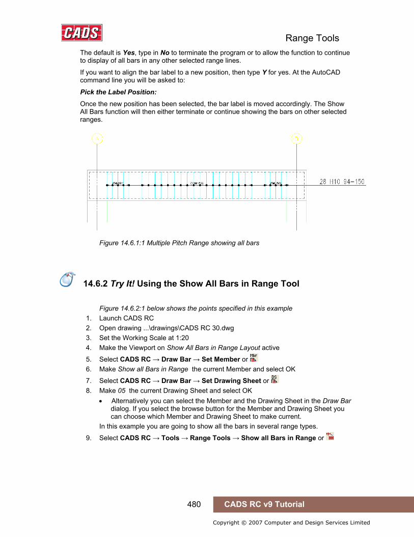
Range Tools
480 CADS RC v9 Tutorial
Copyright © 2007 Computer and Design Services Limited
The default is Yes, type in No to terminate the program or to allow the function to continue to display of all bars in any other selected range lines.
If you want to align the bar label to a new position, then type Y for yes. At the AutoCAD command line you will be asked to:
Pick the Label Position:
Once the new position has been selected, the bar label is moved accordingly. The Show All Bars function will then either terminate or continue showing the bars on other selected ranges.
Figure 14.6.1:1 Multiple Pitch Range showing all bars
14.6.2 Try It! Using the Show All Bars in Range Tool
Figure 14.6.2:1 below shows the points specified in this example 1. Launch CADS RC 2. Open drawing ...\drawings\CADS RC 30.dwg 3. Set the Working Scale at 1:20 4. Make the Viewport on Show All Bars in Range Layout active
5. Select CADS RC → Draw Bar → Set Member or 6. Make Show all Bars in Range the current Member and select OK
7. Select CADS RC → Draw Bar → Set Drawing Sheet or 8. Make 05 the current Drawing Sheet and select OK
• Alternatively you can select the Member and the Drawing Sheet in the Draw Bar dialog. If you select the browse button for the Member and Drawing Sheet you can choose which Member and Drawing Sheet to make current.
In this example you are going to show all the bars in several range types.
9. Select CADS RC → Tools → Range Tools → Show all Bars in Range or
14.6.2 Try It! Using the Show All Bars in Range Tool
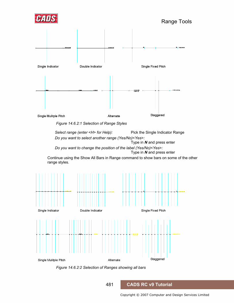
Range Tools
481 CADS RC v9 Tutorial
Copyright © 2007 Computer and Design Services Limited
Figure 14.6.2:1 Selection of Range Styles
Select range (enter <H> for Help): Pick the Single Indicator Range Do you want to select another range (Yes/No)<Yes>: Type in N and press enter Do you want to change the position of the label (Yes/No)<Yes>: Type in N and press enter Continue using the Show All Bars in Range command to show bars on some of the other range styles.
Figure 14.6.2:2 Selection of Ranges showing all bars

Range Tools
482 CADS RC v9 Tutorial
Copyright © 2007 Computer and Design Services Limited
14.7 Radial Bar Detailer
Radial Bar Detailer calculates the radial steel, typically detailed in circular slabs and tanks.
The tool essentially calculates the number of curtailments based on initial input. Once an initial solution has been reached, the detailer may change certain information and the program will provide the real time update to enable the detailer to explore alternative options prior to the tool producing the final detail on the drawing.
The Radial Bar Detailer considers detailing the entire area of the circular slab.
This command is available from the Detailers toolbar or through CADS RC → Tools → Detailers → Radial Bar Detailer or .
14.7.1 Basic operation Once you have selected the Radial Bar Detailer function you will be prompted at the AutoCAD command line as follows:
Figure 14.7.1:1 Tank outline ready for detailing
Do you want to select the inner and outer circles for the radial detail (Yes/No)<Yes>:
Accept the Yes default to select existing circles on the drawing as shown above in figure 14.7.1:1and No to open the Radial Bar Detailer dialog box without selecting any circles.
Select the inner circle for the radial detail:
Select an existing inner circle and the function prompts as follows:
Select the outer circle for the radial detail:
Select an existing outer circle and then the Radial Bar Detailer dialog box is displayed as shown below in figure 14.7.1:2.
14.7 Radial Bar Detailer

Range Tools
483 CADS RC v9 Tutorial
Copyright © 2007 Computer and Design Services Limited
Figure 14.7.1:2 Radial Bar Detailer dialog
Input Details Outer and Inner radii The data for these fields will be updated from the selected circles. You can also edit or input radius details directly in this dialog without selecting the circle.
Outer and Inner Covers Type in the required cover distance in millimeters.
Design Spacing This is the maximum distance between the bars where they intersect with the outer radius.
Minimum Spacing This is the minimum spacing between bars to allow the concrete to be placed.
Solutions The program will display several different solutions based on the input data entered. You can select any one of the solutions from the drop down menu, this will update the main display.
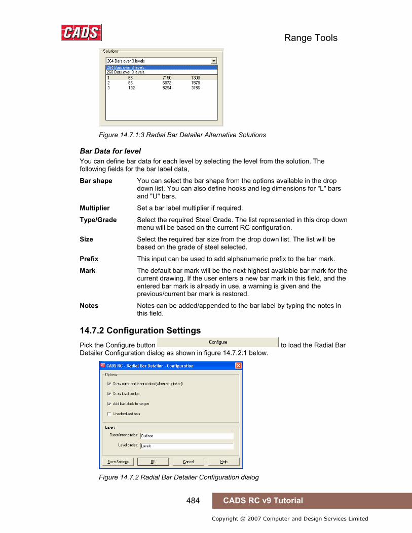
Range Tools
484 CADS RC v9 Tutorial
Copyright © 2007 Computer and Design Services Limited
Figure 14.7.1:3 Radial Bar Detailer Alternative Solutions
Bar Data for level You can define bar data for each level by selecting the level from the solution. The following fields for the bar label data,
Bar shape You can select the bar shape from the options available in the drop down list. You can also define hooks and leg dimensions for "L" bars and "U" bars.
Multiplier Set a bar label multiplier if required.
Type/Grade Select the required Steel Grade. The list represented in this drop down menu will be based on the current RC configuration.
Size Select the required bar size from the drop down list. The list will be based on the grade of steel selected.
Prefix This input can be used to add alphanumeric prefix to the bar mark.
Mark The default bar mark will be the next highest available bar mark for the current drawing. If the user enters a new bar mark in this field, and the entered bar mark is already in use, a warning is given and the previous/current bar mark is restored.
Notes Notes can be added/appended to the bar label by typing the notes in this field.
14.7.2 Configuration Settings Pick the Configure button to load the Radial Bar Detailer Configuration dialog as shown in figure 14.7.2:1 below.
Figure 14.7.2 Radial Bar Detailer Configuration dialog
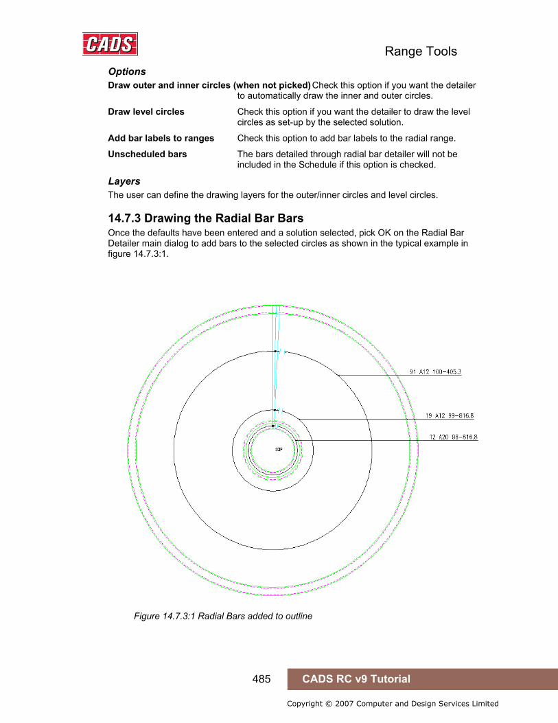
Range Tools
485 CADS RC v9 Tutorial
Copyright © 2007 Computer and Design Services Limited
Options Draw outer and inner circles (when not picked) Check this option if you want the detailer to automatically draw the inner and outer circles.
Draw level circles Check this option if you want the detailer to draw the level circles as set-up by the selected solution.
Add bar labels to ranges Check this option to add bar labels to the radial range.
Unscheduled bars The bars detailed through radial bar detailer will not be included in the Schedule if this option is checked.
Layers The user can define the drawing layers for the outer/inner circles and level circles.
14.7.3 Drawing the Radial Bar Bars Once the defaults have been entered and a solution selected, pick OK on the Radial Bar Detailer main dialog to add bars to the selected circles as shown in the typical example in figure 14.7.3:1.
Figure 14.7.3:1 Radial Bars added to outline

Range Tools
486 CADS RC v9 Tutorial
Copyright © 2007 Computer and Design Services Limited
14.7.4 Try It! Using the Radial Bar Detailer
Figure 14.7.4:2 below shows the points specified in this example 1. Launch CADS RC 2. Open drawing ...\drawings\CADS RC 31.dwg 3. Set the Working Scale at 1:20 4. Make the Viewport on Radial Bar Detailer Layout active
• This drawing has already had construction lines added to make placing the bars easier. The Hints & Tips sections after this example explain how to produce the construction lines.
5. Select CADS RC → Draw Bar → Set Member or 6. Make Radial Bar Detailer the current Member and select OK
7. Select CADS RC → Draw Bar → Set Drawing Sheet or 8. Make 01 the current Drawing Sheet
Using the Radial Bar Detailer to detail the Tank Plan View
It is anticipated, in a future version of this detailer, that you will be able to set the angle of slope for a sump tank. The range of shape codes supported will be extended so that you will be able to detail a circular sump tank with crank bars.
9. Select CADS RC → Tools → Range Tools → Radial Bar Detailer or Do you want to select the inner and outer circles for the radial detail (Yes/No)<Yes>: Press enter to accept Select the inner circle for the radial detail: Pick the circle indicated by point 1 Select the outer circle for the radial detail: Pick the circle indicated by point 2
14.7.4 Try It! Using the Radial Bar Detailer
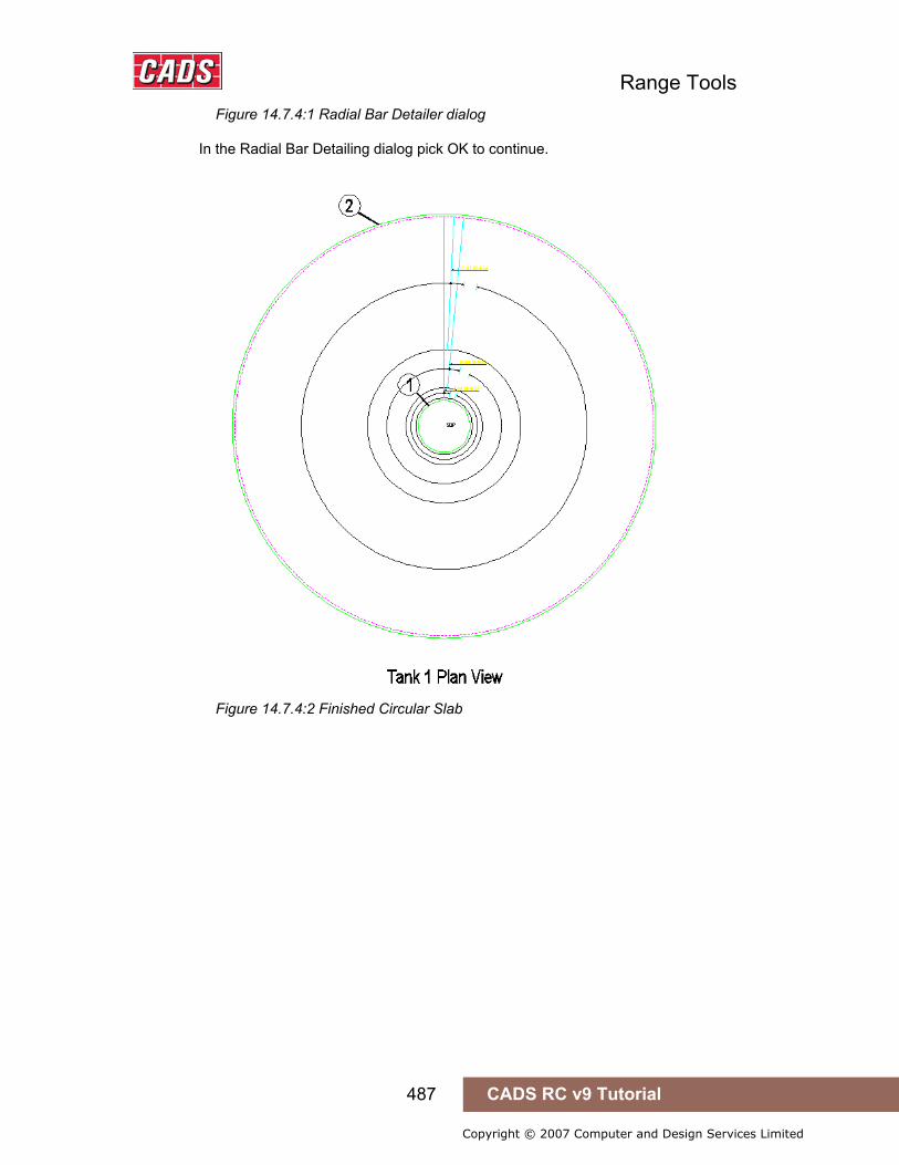
Range Tools
487 CADS RC v9 Tutorial
Copyright © 2007 Computer and Design Services Limited
Figure 14.7.4:1 Radial Bar Detailer dialog
In the Radial Bar Detailing dialog pick OK to continue.
Figure 14.7.4:2 Finished Circular Slab
Range Tools
488 CADS RC v9 Tutorial
Copyright © 2007 Computer and Design Services Limited
14.8 Command List – Range Tools
Action Menu Selection Toolbar and Icon Circular Bar Arrangement CADS RC→Tools→Range Tools→ Circular Bar Arrangement Range Tools
Area Detailer CADS RC→Tools→Range Tools→ Area Detailer Range Tools
Split Range CADS RC→Tools→Range Tools→ Split Range Range Tools
Change Range Type CADS RC→Tools→Range Tools→ Change Range Type Range Tools
Share Range Line CADS RC→Tools→Range Tools→ Share Range Line Range Tools
Show All Bars in Range CADS RC→Tools→Range Tools→ Show All Bars in Range Range Tools
Radial Bar Detailer CADS RC→Tools→Range Tools→ Radial Bar Detailer Range Tools
14.8 Command List – Range Tools
Index of Try It! Examples
489 CADS RC v9 Tutorial
Copyright © 2007 Computer and Design Services Limited
Index of Try It! Examples
1.2 Try It! Examine a CADS RC Drawing ..................................................................................... 3
2.2.1 Try It! Create a Drawing Sheet Using CADS VPM and Add a Viewport ........................ 17
2.2.2 Try It! Create a Layout Space Drawing Sheet Using CADS Scale and Adding a Viewport........................................................................................................................................ 18
2.2.3 Try It! Create a Model Space Drawing Sheet Using CADS Scale and Define Model Space Scale Areas....................................................................................................................... 19
2.2.4 Try It! Create a Layout Space Drawing Sheet Using AutoCAD...................................... 19
3.6.11 Try It! Create a Pad Base from the CADS RC Outline Routines .................................. 34
3.6.12 Try It! Create a Pad Base Outline Using CADS RC Dynamic Blocks (AutoCAD 2006 or higher only).............................................................................................................................. 36
3.6.13 Try It! Create a Member Title and Set the Current Drawing Sheet .............................. 37
3.6.14 Try It! Add two U Bars to the Pad Base Section............................................................ 39
3.6.15 Try It! Add the Ranges to the Pad Base Plan ................................................................ 41
3.6.16 Try It! Use the Polar CADS RC Snap to Specify the Lap Length on the Sloping Leg of a Bar.............................................................................................................................................. 45
3.6.17 Try It! Use the Sketch Bar Option to Show a ‘projected’ Bar on a Plan View ............ 46
3.6.18 Try It! Use the Multiplier Field and Lap Bar CADS RC Snap to Detail Top and Bottom Steel Efficiently ............................................................................................................................ 47
3.6.19 Try It! Use the Multiplier Field and Lap Bar CADS RC Snap to Detail Top and Bottom Steel Efficiently ............................................................................................................................ 51
4.5.5 Try It! Place OSL Bars Using Splice Lines On a Slab..................................................... 58
4.6.1 Try It! Create a Special Bar With a Cranked Leg Using the Draw Bar Dialog .............. 59
4.6.2 Try It! Creating a Special Bar Using the Special Bar Creator ........................................ 61
5.1.2 Try It! Single Indicator Range – Base – Adding U Bars as a Range and Adding Bars in Section.......................................................................................................................................... 67
5.1.4 Try It! Double Indicator Range – Beam – Adding Stirrups............................................. 70
5.1.6 Try It! Dimension Style – Beam External Range Line..................................................... 72
5.1.8 Try It! Alternate Range - Slab ............................................................................................ 74
5.1.10 Try It! Staggered Range – Slab ....................................................................................... 77
5.1.12 Try It! Radial Range – Circular Sump Tank.................................................................... 80
5.1.14 Try It! Alternate Radial Range – Circular Sump Tank................................................... 83
5.2.2 Try It! Single Fixed Pitch - Slab......................................................................................... 89
5.2.4 Try It! Single Multiple Pitch - Beam .................................................................................. 92
5.2.5 Try It! Single Multiple Pitch - Stairflight ........................................................................... 94
5.2.7 Try It! Alternate Fixed Pitch - Slab.................................................................................... 97

Index of Try It! Examples
490 CADS RC v9 Tutorial
Copyright © 2007 Computer and Design Services Limited
5.2.9 Try It! Staggered Fixed Pitch - Slab................................................................................ 101
5.3.2 Try It! Linear Taper – One Tapered Bar Leg in a Wall................................................... 106
5.3.3 Try It! Linear Taper – Two Tapered Bar Legs in a Wall ................................................ 110
5.3.4 Try It! Linear Taper – Curved Bars in a Sump Tank...................................................... 111
5.3.5 Try It! Double Indicator Taper – Tapered Beam – Two Tapered Legs......................... 115
5.3.8 Try It! Varying Taper – Curved Balcony ......................................................................... 117
5.3.9 Try It! Add a Varying Taper Range to the Slab 1 Curved Balcony With Two Tapered Legs ............................................................................................................................................ 119
5.3.11 Try It! Trapezoidal Taper – Slab .................................................................................... 121
5.4.2 Try It! Run to Path ............................................................................................................ 123
5.4.3 Try It! Alternate Run to Path............................................................................................ 125
5.5.1 Try It! Adding OSL Bars and Ranges to a Floor Slab ................................................... 127
5.5.2 Try It! Draw a Retaining Wall ........................................................................................... 130
6.10.1 Try It! Configure New Label Format ............................................................................. 149
6.10.2 Try It! Add Missing Bar Labels...................................................................................... 151
6.10.3 Try It! Add Ticks and Tags to Bars in Section............................................................. 152
6.10.4 Try It! Add Tag to a Line to Bars in Section................................................................. 153
6.10.5 Try It! Add Bar References ............................................................................................ 154
6.10.6 Try It! Mask and Unmask Bar Labels............................................................................ 155
6.10.7 Try It! Add Hidden Multipliers and Toggle their Display ............................................ 157
6.11.3 Try It! Add CADS RC Leaders to a Drawing................................................................. 162
6.11.4 Try It! Add AutoCAD Dimension Style Leaders to a Drawing.................................... 164
7.2.4 Try It! Use Edit Bars to Change the Properties of a Single Bar................................... 175
7.2.5 Try It! Use Edit Bars to Change the Properties of a Selection of Multiple Bars ........ 178
7.3.9 Try It! Use Edit Range to Change the Properties of the Single Indicator Range ....... 191
7.3.10 Try It! Use Edit Range to Change the Properties of the Multiple Group Range....... 192
7.3.11 Try It! Use Edit Range to Change the Properties of the Linear Taper Range .......... 195
7.4.1 Try It! Use Redraw Bar to Show CADS RC Configuration Changes on a Drawing.... 198
7.5.1 Try It! Use Stretch Bar/Range to Change the Dimensions of a Pad Base .................. 202
7.5.2 Try It! Use Stretch Bar/Range to Change the Size and Position of Openings in a Slab..................................................................................................................................................... 204
7.6.6 Try It! Use AutoCAD Copy to Add Missing Bar Views.................................................. 209
7.6.7 Try It! Use AutoCAD Array to Run Bars in Section Along an Arc ............................... 211
7.6.8 Try It! Use AutoCAD Mirror to Place Bars at the Opposite End of a Beam ................ 212
7.6.9 Try It! Delete Bars and Ranges from a Drawing Using AutoCAD Erase..................... 215
7.11.1 Try It! Copy and Paste a Detail from one Drawing Sheet to Another and Assign the Drawing Sheet and Member ..................................................................................................... 221
7.11.2 Try It! Export and Import a Wblock to a Drawing, Assigning Drawing Sheet and

Index of Try It! Examples
491 CADS RC v9 Tutorial
Copyright © 2007 Computer and Design Services Limited
Member ....................................................................................................................................... 224
7.12.1 Try It! Change View to Set ............................................................................................. 228
7.13.1 Try It! Change Set to View ............................................................................................. 230
7.15.1 Try It! Change Bar View and Bar Style ......................................................................... 234
7.16.1 Try It! Add Entity to View ............................................................................................... 236
7.17.1 Try It! Add Text to View.................................................................................................. 238
8.1.1 Try It! Drawing Audit ........................................................................................................ 243
8.2.2 Try It! Check Database..................................................................................................... 248
8.3.1 Try It! Match Bars ............................................................................................................. 250
8.4.1 Try It! Compact Bars ........................................................................................................ 252
8.5.1 Try It! Select Bars ............................................................................................................. 257
9.1.1 Try It! Navigating around the Schedule ......................................................................... 269
9.3.1 Try It! Formatting the Schedule ...................................................................................... 273
9.5.4 Try It! Printing the Schedule............................................................................................ 285
9.6.5 Try It! Creating a Free-Form Report ............................................................................... 290
10.4 Try It! Place and Update a Schedule on drawing ........................................................... 299
11.5 Try It! How to Issue, Revise and Re-Issue a Drawing Sheet together with the Schedule..................................................................................................................................................... 310
11.6.3 Try It! Issue the Schedule but not the Drawing Sheet ................................................ 315
12.1.8 Try It! How to Create a Shape Code 99 using the Special Bar Generator ................ 322
12.2.5 Try It! Detailing Cross Sections using the Cross Section Detailer ........................... 333
12.3.5 Try It! Trimming an Opening ......................................................................................... 341
12.4.1 Try It Drawing Lap Dog leg Bar..................................................................................... 345
13.4.5 Try It! Using the Pile Cap Detailer................................................................................. 405
14.1.8 Try It! Using the Circular Bar Arrangement Detailer................................................... 450
14.2.9 Try It! Using the Area Detailer ....................................................................................... 460
14.3.5 Try It! Using Split Range Tool ....................................................................................... 469
14.4.2 Try It! Using the Change Range Type Tool.................................................................. 474
14.6.2 Try It! Using the Show All Bars in Range Tool ............................................................ 480
14.7.4 Try It! Using theRadial Bar Detailer .............................................................................. 486
Index of Figures
492 CADS RC v9 Tutorial
Copyright © 2007 Computer and Design Services Limited
Index of Figures Figure 1.2:1 This is a drawing of a simple Pad Base with bottom reinforcement detailed.... 3
Figure 1.4:1 The bent bar drawn in section and plan ................................................................ 5
Figure 1.4:2 The Schedule window.............................................................................................. 5
Figure 1.5:1 Illustrates a simple Pad Base with Bar Mark 01 shown within two ranges........ 7
Figure 1.6:1 Bar Views with Placement point order................................................................... 8
Figure 1.7:1 How bar alignments are identified........................................................................ 10
Figure 1.8:1 The different bar styles available ......................................................................... 11
Figure 2.2:1 Drawing Sheet Number dialog .............................................................................. 16
Figure 2.2.1:1 Creating a Layout with two viewports using CADS VPM................................ 17
Figure 2.2.2:1 Creating a Layout with two viewports using CADS Scale .............................. 18
Figure 3.1:1 The Others dialog box ........................................................................................... 25
Figure 3.2:1 Selection of Tool Palettes ..................................................................................... 26
Figure 3.2:2 The Drafting Settings dialog ................................................................................. 27
Figure 3.2:3 Detailing with the Dynamic Input setting switched on....................................... 27
Figure 3.2:4 The AutoCAD Properties dialog ........................................................................... 28
Figure 3.3:1 The CADS RC Snaps toolbar ................................................................................ 29
Figure 3.4:1 The Set Current Drawing Sheet dialog................................................................. 30
Figure 3.5:1 The Members dialog............................................................................................... 31
Figure 3.6:1 The Bar Drawing dialog. The number labels added show the different sections and these are described below. The item labels on the dialog are shown below in bold italic............................................................................................................................................... 32
Figure 3.6.11:1 Pad Base Plan and Section created with CADS RC Outline Routines ........ 35
Figure 3.6.12:1 CADS RC Pad Base Tool Palette ..................................................................... 36
Figure 3.6.12:2 Pad Base Dynamic Block ................................................................................. 36
Figure 3.6.13:1 CADS RC Members dialog ............................................................................... 37
Figure 3.6.13:2 Set Current Drawing Sheet screen.................................................................. 38
Figure 3.6.14:1 The Bar Drawing dialog; see 3.6 for more explanation................................. 39
Figure 3.6.14:2 CADS RC Dimension Entry dialog................................................................... 40
Figure 3.6.14:3 Insertion point and placing order Shape Code 21 ......................................... 40
Figure 3.6.14:4 The CADS RC Schedule dialog........................................................................ 41
Figure 3.6.15:1 Single Indicator Range Placing Order............................................................. 41
Figure 3.6.15:2 Second Single Indicator Range Placing Order .............................................. 42
Figure 3.6.15:3 CADS RC Schedule display ............................................................................. 43
Index of Figures
493 CADS RC v9 Tutorial
Copyright © 2007 Computer and Design Services Limited
Figure 3.6.15:4 CADS RC Range Configuration dialog............................................................ 43
Figure 3.6.16:1 Placing Order of Shape Code 15 in the top landing ...................................... 45
Figure 3.6.17:1 Use of Sketch Bar for projected view of Shape Code 00 .............................. 46
Figure 3.6.18:1 Placing order to add a Lap Bar ........................................................................ 48
Figure 3.6.18:2 CADS RC Select a Lap Type dialog................................................................. 48
Figure 3.6.18:3 Placing order to add lap bar and range to the Plan View.............................. 49
Figure 3.6.18:4 Schedule dialog................................................................................................. 50
Figure 4.4:1 The Invoke Over Stock Length Feature dialog.................................................... 55
Figure 4.4:2 The Over Stock Length dialog. The number labels added show the different sections and these are described below. The item labels on the dialog are shown below in bold italic. ..................................................................................................................................... 55
Figure 4.5:1 The OSL Configuration dialog. Item labels are described below...................... 57
Figure 4.5.5:1 Placing Order OSL Bar Group ........................................................................... 58
Figure 4.6.1:1 Creating a Shape Code 99.................................................................................. 60
Figure 4.6.1:2 Shape Code SP01 appears in the list of shapes .............................................. 60
Figure 4.6.2:1 The Special Bar Creator window ....................................................................... 61
Figure 5.0:1 CADS RC’s Range Type Selection window ......................................................... 63
Figure 5.0:2 The Tapered Range Type Selection window ....................................................... 64
Figure 5.0:3 The Run Type Selection window .......................................................................... 64
Figure 5.1.1:1 Single and General Run selection buttons....................................................... 67
5.1.2:1 Adding Single Indicator Range to a Pad Base ............................................................. 68
Figure 5.1.2:2 Adding a Run of Bars to the Pad Base Section ............................................... 69
Figure 5.1.3:1 Double Indicator and General Run selection buttons ..................................... 70
Figure 5.1.4:1 Adding a Double Indicator Range to the Beam Elevation............................... 71
Figure 5.1.5:1 Dimension Style Range and General Run selection buttons ......................... 72
Figure 5.1.6:1 Adding a Dimension Style Range to the Beam Elevation............................... 73
Figure 5.1.7:1 Alternate Range selection buttons.................................................................... 74
Figure 5.1.8:1 Adding an Alternate Range to a Floor Slab...................................................... 75
Figure 5.1.9:1 Staggered Range selection buttons.................................................................. 77
Figure 5.1.10:1 Adding a Staggered Range to a Floor Slab .................................................... 78
Figure 5.1.11:1 Radial Range selection buttons....................................................................... 80
Figure 5.1.12:1 Adding Shape Code 15 to a Section through a sump tank........................... 81
Figure 5.1.12:2 Adding a Radial Range to the Plan View of a Sump Tank ............................ 82
Figure 5.1.13:1 Alternate Radial Range selection buttons...................................................... 83
Figure 5.1.14:1 Adding two Shape Code 15’s as different Bar Marks.................................... 84
Figure 5.1.14:2 Adding an Alternate Radial Range to the Plan View of a Sump Tank ......... 85
Figure 5.2:1 Section View of distribution steel on a staircase ............................................... 88
Figure 5.2.1:1 Single Fixed Pitch Range selection buttons .................................................... 89
Index of Figures
494 CADS RC v9 Tutorial
Copyright © 2007 Computer and Design Services Limited
Figure 5.2.2:1 Adding a Single Fixed Pitch Range to a Floor Slab......................................... 90
Figure 5.2.2:2 Adding a Single Fixed Pitch Run of Bars in Section to the Slab Section ..... 91
Figure 5.2.3:1 Single Multiple Fixed Pitch Range selection buttons...................................... 92
Figure 5.2.4:1 Adding a Single Multiple Pitch Range to a Beam Elevation ........................... 93
Figure 5.2.5:1 Adding Fixed Pitch Bar Run to Stair Elevation ................................................ 95
Figure 5.2.5:2 Adding the Fixed Pitch Range to the Stair Plan............................................... 96
Figure 5.2.5:3 Fixed Pitch Range and Bars in Section added to Stair ................................... 97
Figure 5.2.6:1 Alternate Fixed Pitch Range selection buttons ............................................... 97
Figure 5.2.7:1 Adding an Alternate Fixed Pitch Range to a Floor Slab.................................. 99
Figure 5.2.7:2 Adding an Alternate Fixed Pitch Run of Bars in Section to the Slab Section..................................................................................................................................................... 100
Figure 5.2.8:1 Alternate Multiple Pitch Range selection buttons ......................................... 101
Figure 5.2.9:1 Staggered Fixed Pitch Range selection buttons ........................................... 101
Figure 5.2.10:1 Adding a Staggered Fixed Pitch Range to a Floor Slab.............................. 102
Figure 5.2.10:2 Adding a Staggered Fixed Pitch Run of Bars in Section to a Floor Slab .. 104
Figure 5.2.11:1 Staggered Multiple Pitch Range selection buttons ..................................... 104
Figure 5.3.1:1 Single Indicator Linear Taper Range selection buttons................................ 105
Figure 5.3.2:1 Adding a Linear Tapered Range to a Wall with one Tapered bar leg .......... 107
Figure 5.3.2:2 Adding the Linear Taper Bars in Section to the Wall Plan............................ 108
Figure 5.3.2:3 Sketch Bar Selected dialog .............................................................................. 108
Figure 5.3.2:4 Adding Sketch Bar Views of the Linear Taper to the Wall Section.............. 109
Figure 5.3.2:5 Sketch Bar Selected dialog .............................................................................. 109
Figure 5.3.3:1 Adding a Linear Taper Range to a Wall with two Tapered bar legs............. 111
Figure 5.3.4:1 Setting Out points for Linear Taper................................................................. 112
Figure 5.3.4:2 Finished Linear Taper Range........................................................................... 113
Figure 5.3.5:1 Double Indicator Linear Taper Range selection buttons .............................. 115
Figure 5.3.6:1 Adding a Double Indicator Tapered Range to a Tapered beam with two Tapered bar legs........................................................................................................................ 116
Figure 5.3.7:1 Varying Taper Range selection buttons ......................................................... 117
Figure 5.3.8:1 Adding a Varying Taper Range to a curved balcony..................................... 118
5.3.9:1 CADS RC Tapered Range dialog ................................................................................. 120
Figure 5.3.9:2 Adding a Varying Tapered Range to a Curved Balcony with two Tapered bar legs.............................................................................................................................................. 120
Figure 5.3.10:1 Trapezoidal Taper Range selection buttons ................................................ 121
Figure 5.3.11:1 Adding a Trapezoidal Taper Range to a Floor Slab..................................... 122
Figure 5.4.1:1 Run to Path selection buttons ......................................................................... 123
Figure 5.4.2:1 Adding Bars in Section using Run to Path to a Circular Column ................ 124
Figure 5.4.3:1 Adding Bars in Section to a Curved Wall using Alternate Run to Path....... 126

Index of Figures
495 CADS RC v9 Tutorial
Copyright © 2007 Computer and Design Services Limited
Figure 5.5:1 CADS RC Over Stock Length Configuration dialog ......................................... 127
Figure 5.5.1:1 Invoke OSL Feature dialog............................................................................... 128
Figure 5.5.1:2 CADS RC Over Stock Length Configuration dialog ...................................... 128
Figure 5.5.1:3 CADS RC Over Stock Length Configuration dialog ...................................... 129
Figure 5.5.1:4 Adding OSL Bars and Ranges to a Floor Slab............................................... 130
Figure 5.5.2:2 Retaining Wall Plan View.................................................................................. 131
Figure 5.5.2:3 Front Elevation .................................................................................................. 132
Figure 5.5.2:4 Schedule showing bar bending information .................................................. 132
Figure 5.5.2:4 Retaining Wall Outlines .................................................................................... 133
Figure 6.1:1 CADS RC New Bar Label dialog ......................................................................... 137
Figure 6.1:2 CADS RC New Label dialog ................................................................................ 137
Figure 6.3.1:1 CADS RC Label Configuration dialog ............................................................. 140
Figure 6.3.2:1 CADS RC Text Formatting dialog .................................................................... 141
Figure 6.4:1 Ticks and Tags Deletion dialog .......................................................................... 143
Figure 6.5:1 Ticks and Tags added to Straight Bars.............................................................. 144
Figure 6.6:1 CADS RC Tick and Tag Configuration dialog ................................................... 145
Figure 6.8.1:1 Bar Labels obscured by lines before applying a mask................................. 147
Figure 6.8.1:2 Bar Labels after the mask has been applied .................................................. 147
Figure 6.10:1 CADS RC Next Bar Mark display ...................................................................... 149
Figure 6.10.1:1 Bar Label for cranked bars showing new format......................................... 150
Figure 6.10.2:1 Missing Bar Labels added to Staircase Plan................................................ 151
6.10.3:1 Ticks and Tags added to Staircase Elevation .......................................................... 152
Figure 6.10.4:1 Tags added to Beam Elevation using Tag to a Line .................................... 153
Figure 6.10.5:1 Bar References added to Staircase Elevation.............................................. 154
Figure 6.10.6:1 Masking of selected Bar Labels by using Mask Text .................................. 155
Figure 6.10.6:2 Mask All applies a mask to all Bar Labels in a drawing.............................. 156
Figure 6.10.6:3 All the Bar Labels have now been unmasked using Unmask All............... 156
Figure 6.10.7:1 Bar Labels showing Hidden Multiplier Switched Off................................... 157
Figure 6.10.7:2 Multi Field inside Edit Bar dialog................................................................... 158
Figure 6.10.7:3 Bar Labels before Toggle Hidden Multipliers is switched on..................... 158
Figure 6.10.7:4 Bar Labels after Toggle Hidden Multipliers is switched on........................ 158
Figure 6.11.1.1:1 CADS RC Leader Configuration dialog...................................................... 159
Figure 6.11.2:1 Label Configuration dialog with leader selection options marked ............ 160
Figure 6.11.2.4:1 The Dimension Style Manager dialog ........................................................ 161
Figure 6.11.3:1 Adding leaders 1 & 2 to the drawing............................................................. 162
Figure 6.11.3:2 Locating the Bar Label using the CADS RC leader command ................... 163
Figure 6.11.3:3 Stacking CADS RC leaders from one start point ......................................... 163

Index of Figures
496 CADS RC v9 Tutorial
Copyright © 2007 Computer and Design Services Limited
Figure 6.11.4:1 Modify Dimension Style dialog ...................................................................... 165
Figure 6.11.4:2 Adding AutoCAD style leaders to the drawing ............................................ 165
Figure 6.11.4:3 Stacking AutoCAD leaders from one start point ......................................... 166
Figure 7.1.1:1 Hyperlink Option in the Options dialog .......................................................... 170
Figure 7.2.1:1 Individual Reinforcement - Edit Bar Label Data dialog ................................. 171
See Figure 7.3.3:1 for the Dimension Entry dialog. ............................................................... 172
Figure 7.2.2:1 Multiple Edit – Edit Bar Label Data dialog ...................................................... 173
Figure 7.2.2:2 Multiple Shape Code editing not supported................................................... 173
Figure 7.2.2:3 Multiple Edit Bars Warning .............................................................................. 174
Figure 7.2.4:1 Editing the properties of Shape Code 21........................................................ 175
Figure 7.2.4:2 Change Bar Mark Warning display.................................................................. 176
Figure 7.2.4:3 Bar Diameter Change Warning display........................................................... 176
Figure 7.2.4:4 Editing the properties of Shape Code 21........................................................ 176
Figure 7.2.4:5 Bar Mark Change Warning dialog.................................................................... 177
Figure 7.2.4:6 Editing the properties of Shape Code 21........................................................ 177
Figure 7.2.5:1 Selecting the bars for multiple bar data editing............................................. 178
Figure 7.2.5:2 Multiple Edit Bar Label Data dialog ................................................................. 179
Figure 7.2.5:3 Multiple Edit Bar Label Data dialog ................................................................. 179
Figure 7.3.1:1 Edit Range dialog .............................................................................................. 180
Figure 7.3.1:2 Range End Marker perpendicular to Range Line........................................... 181
Figure 7.3.1:3 Range End Marker skewed to Vertical Alignment ......................................... 181
Figure 7.3.1:4 Range Information dialog................................................................................. 181
Figure 7.3.2:1 Edit Range dialog for Single Groups .............................................................. 182
Figure 7.3.3:1 Dimension Entry dialog .................................................................................... 183
Figure 7.3.4:1 Skew Help display............................................................................................. 184
Figure 7.3.5:1 Multiple Group Edit Range dialog ................................................................... 184
Figure 7.3.5:2 Create Multiple Range Group dialog ............................................................... 185
Figure 7.3.5:3 Edit Multiple Range Group dialog ................................................................... 185
Figure 7.3.5:4 Copy Multiple Range Group dialog ................................................................. 186
Figure 7.3.5:5 Move Multiple Range Group dialog ................................................................. 186
Figure 7.3.5:6 Delete Multiple Range Group dialog ............................................................... 186
Figure 7.3.6:1 Radial Range Edit dialog .................................................................................. 187
Figure 7.3.7:1 Tapered Range Edit dialog............................................................................... 188
Figure 7.3.7:2 Step Taper dialog before Step Increment applied ......................................... 188
Figure 7.3.7:3 Step Taper dialog after 200 mm Step Increment applied.............................. 189
Figure 7.3.7:4 Tapered Range Edit Dimensions dialog ......................................................... 189
Figure 7.3.8:1 Varying Taper Range Edit dialog..................................................................... 190
Index of Figures
497 CADS RC v9 Tutorial
Copyright © 2007 Computer and Design Services Limited
Figure 7.3.9:1 Using Edit Range to edit the range length...................................................... 191
Figure 7.3.10:1 Using Edit Range to add a Range Group...................................................... 192
Figure 7.3.10:2 Duplicating a range group using the Copy option ...................................... 193
Figure 7.3.10:3 Editing range group 2 ..................................................................................... 193
Figure 7.3.10:4 Multiple Range Edit dialog ............................................................................. 193
Figure 7.3.10:5 Additional Group added to Single Fixed Pitch Range................................. 194
Figure 7.3.10:6 Editing Range Groups 2 & 3........................................................................... 194
Figure 7.3.11:1 Tapered Ranges detailed on Wall Outline .................................................... 195
Figure 7.3.11:2 Step Taper dialog ............................................................................................ 196
Figure 7.3.11:3 Step Taper Warning of more than one sloping leg...................................... 196
Figure 7.3.11:4 Global Configuration dialog........................................................................... 197
Figure 7.4.1:1 Beam before reconfiguring CADS RC............................................................. 198
Figure 7.4.1:2 CADS RC Bar Configuration dialog................................................................. 199
Figure 7.4.1:3 Results of Reconfiguring shown on Beam..................................................... 200
Figure 7.5:1 Stock Length Defaults dialog.............................................................................. 201
Figure 7.5.1:1 Pad Base before using Stretch Bar/Range..................................................... 202
Figure 7.5.1:2 Pad Base after using Stretch Bar/Range ........................................................ 203
Figure 7.5.2:1 Slab with Opening to be resized...................................................................... 204
Figure 7.5.2:2 Slab with re-sized opening............................................................................... 205
Figure 7.6.1:1 CADS RC Copy Bar View or Set Confirmation............................................... 206
Figure 7.6.2:1 CADS RC Mirror Warning ................................................................................. 206
Figure 7.6.2:2 CADS RC Mirror Bar View or Set Confirmation ............................................. 207
Figure 7.6.3:1 CADS RC Erase Bar View or Set Confirmation .............................................. 207
Figure 7.6.6:1 CADS RC Copy Bar View or Set Confirmation dialog ................................... 209
Figure 7.6.6:2 Using AutoCAD Copy to duplicate Bar Views................................................ 210
Figure 7.6.7:1 below shows the points to select in this example......................................... 211
Figure 7.6.7:1 Using AutoCAD Array to place bars along an arc ......................................... 212
Figure 7.6.8:1 Using AutoCAD Mirror to finish a detail ......................................................... 212
Figure 7.6.8:2 Completed detail using AutoCAD Mirror ........................................................ 213
Figure 7.6.8:3 Create New Bar Mark Confirmation dialog ..................................................... 214
Figure 7.6.8:4 Bar Mark Change dialog ................................................................................... 214
Figure 7.6.9:1 Using Erase Bar View and Set ......................................................................... 216
Figure 7.9:1 Assign Bars to Member dialog ........................................................................... 218
Figure 7.10:1 Assign Bars to Drawing Sheet dialog .............................................................. 220
Figure 7.11.1:1 Copy & Paste, selecting objects.................................................................... 222
Figure 7.11.1:2 Assign Bars to Drawing Sheet on Layout, AutoCAD Paste (06) ................ 223
Figure 7.11.2:1 Wblock dialog .................................................................................................. 224

Index of Figures
498 CADS RC v9 Tutorial
Copyright © 2007 Computer and Design Services Limited
Figure 7.11.2:2 Selecting objects to save as a Wblock ......................................................... 225
Figure 7.11.2:3 Specifying Path and Filename of Wblock..................................................... 225
Figure 7.11.2:4 Block Insertion dialog..................................................................................... 226
Figure 7.11.2:5 Inserted Wblock on Drawing Sheet 08.......................................................... 227
Figure 7.12.1:1 below shows the points to select in this example....................................... 228
Figure 7.12.1:1 Selecting Bar Views to change to a Bar Set................................................. 229
Figure 7.13.1:1 below shows the points to select in this example....................................... 230
Figure 7.13.1:1 Change Set to View – Bars Views unlinked.................................................. 231
Figure 7.13.1:2 Change Set to View – Bars Views Linked..................................................... 232
Figure 7.15.1:1 Change Bar View and Bar Style..................................................................... 235
Figure 7.16.1:1 Create a Custom Range Line using Add Entity to View.............................. 237
Figure 7.17.1:1 Attach Annotation to a Bar Set using Add Text to View command ........... 238
Figure 8.1:1 Drawing Audit report display .............................................................................. 242
Figure 8.1.1:1 Drawing Audit report display ........................................................................... 243
Figure 8.1.1:2 Bars highlighted by the Drawing Audit command......................................... 244
Figure 8.2:1 CADS RC Check Database report display ......................................................... 245
Figure 8.2:2 Label/Database Mismatches report and prompt............................................... 246
Figure 8.2.1:1 CADS RC’s Global Configuration Centre........................................................ 247
Figure 8.2.2:1 Check Database report window....................................................................... 248
Figure 8.2.2:2 Damaged CADS RC Entities identified by the Check Database command. 249
Figure 8.3.1:1 Running the Match Bars command................................................................. 251
Figure 8.4.1:1 Compact Bars Schedule before command is run.......................................... 253
Figure 8.4.1:2 Slab prior to Compacting Bar Marks............................................................... 253
Figure 8.4.1:3 Compact gaps? dialog...................................................................................... 254
Figure 8.4.1:4 Drawing after Compact Bars have been run .................................................. 254
Figure 8.4.1:5 Schedule after the Compact Bars command has been run.......................... 255
Figure 8.5:1 The Select Bars dialog......................................................................................... 256
Figure 8.5.1:1 The Select Bars dialog...................................................................................... 257
Figure 8.5.1:2 Assign Bars to Member dialog ........................................................................ 258
Figure 8.5.1:3 Selecting bars to Assign to a Member ............................................................ 258
Figure 8.6:1 Highlight Bars dialog ........................................................................................... 259
Figure 8.6:2 The Unhighlight dialog of the Highlight Bars command.................................. 259
Figure 8.7:1 CADS RC Set Sketch Mode dialog ..................................................................... 260
Figure 8.8:1 Check Dimensions dialog.................................................................................... 261
Figure 8.8:2 The Check Dimensions report window.............................................................. 261
Figure 8.8:3 Highlight Bars Navigation dialog........................................................................ 262
Figure 8.8.1:4 Check Dimensions Configuration dialog........................................................ 262

Index of Figures
499 CADS RC v9 Tutorial
Copyright © 2007 Computer and Design Services Limited
Figure 9.1:1 Schedule dialog.................................................................................................... 267
Figure 9.1:2 Selecting a Drawing Sheet will change the Data View ..................................... 268
Figure 9.1:3 Mode Area of the Schedule Viewer .................................................................... 268
Figure 9.1:4 Members displayed in Free-Form Data display ................................................ 268
Figure 9.1.1:1 Formatted Schedule View showing Drawing Sheet 01.................................. 269
Figure 9.1.1:2 Selecting a different Drawing Sheet................................................................ 269
Figure 9.1.1:3 Select Members Mode....................................................................................... 270
Figure 9.1.1:4 Reinforcement assigned to Beam 1 Member ................................................. 270
Figure 9.1.1:5 Schedule showing Free-Form View................................................................. 270
Figure 9.2:1 Formatted and Free-Form Tabs .......................................................................... 271
Figure 9.3:1 Format Schedule dialog....................................................................................... 272
Figure 9.3.1:1 Schedule ready for formatting ......................................................................... 273
Figure 9.3.1:2 Sorting and Segregation options .................................................................... 273
Figure 9.3.1:3 Arrange members dialog.................................................................................. 274
Figure 9.3.1:4 Format Schedule dialog.................................................................................... 274
Figure 9.3.1:5 Formatted Schedule.......................................................................................... 275
Figure 9.3.1:5 Edit Header and footer dialog .......................................................................... 275
Figure 9.4:1 Schedule Edit Menu ............................................................................................. 276
Figure 9.4:2 Schedule Standard toolbar ................................................................................. 276
Figure 9.4:3 Schedule Right Mouse Click Menu..................................................................... 276
Figure 9.4.1:1 Bar Data marked to be moved in the Formatted Schedule........................... 277
Figure 9.4.1:2 Adding Text to a blank line in the Schedule................................................... 278
Figure 9.4.1:3 Schedule – Edit Header and Footer dialog..................................................... 279
Figure 9.5:1 Selecting the Print Preview of the Schedule Report ........................................ 280
Figure 9.5:2 Find Text dialog in Print Preview........................................................................ 280
Figure 9.5:3 Line in Schedule Preview highlighted by the Search option........................... 281
Figure 9.5.1:1 Setting the default Export Document type ..................................................... 281
Figure 9.5.1:2 Selecting the Export Document (electronic format) ...................................... 282
Figure 9.5.1:3 Changing files of given type to alternative electronic formats .................... 282
Figure 9.5.2:1 Adding a watermark to the Schedule output.................................................. 283
Figure 9.5.2:2 Effect of adding a Watermark to the Schedule output .................................. 283
Figure 9.5.3:1 Changing the Background Color..................................................................... 284
Figure 9.5.3:2 Result of Changing the Background Color and adding a Watermark ......... 284
Figure 9.5.4:1 Schedule Preview for Drawing Sheet 02......................................................... 285
Figure 9.6:1 Free-Form tab ....................................................................................................... 286
Figure 9.6.1:1 Changing Data Order by clicking on the field header ................................... 286
Figure 9.6.2:1 Grouping Data by Column Headers ................................................................ 287
Index of Figures
500 CADS RC v9 Tutorial
Copyright © 2007 Computer and Design Services Limited
Figure 9.6.2:2 Results of Grouping by Bar Size ..................................................................... 287
Figure 9.6.3:1 Add extra columns to the free-form view ....................................................... 288
Figure 9.6.3:2 Result of adding a new column, Shape Category, from the list ................... 288
Figure 9.6.4:1 Report showing H Reinforcement grouped into Bar Sizes, ready for printing..................................................................................................................................................... 289
Figure 9.6.4:2 Print Preview of Free-Form View ..................................................................... 289
Figure 9.6.5:1 Print Preview of Free-Form View ..................................................................... 290
Figure 10.1:1 Place Schedule Table on Drawing dialog ........................................................ 295
Figure 10.1:2 Schedule, Weight Summary and Shape Code Diagrams on Drawing .......... 296
Figure 10.2:1 Create Bar Labels List on Drawing dialog. ...................................................... 297
Figure 10.2:2 Example of Bar Labels List on Drawing........................................................... 297
Figure 10.3:1 Schedule on Drawing marked as INVALID as the drawing has been edited 298
Figure 10.4:1 Place Schedule on Drawing dialog, selecting the Appropriate Release Number ....................................................................................................................................... 299
Figure 10.4:2 Schedule on Drawing......................................................................................... 300
Figure 10.4:3 Schedule on Drawing shown as Invalid after editing Bar Properties ........... 301
Figure 11.1:1 Issue Drawing Sheet dialog .............................................................................. 304
Figure 11.1:2 Revision Table added to Title Block................................................................. 305
Figure 11.1:3 Revision Labels added to edited Bar Sets....................................................... 305
Figure 11.1:4 Schedule Updates to reflect revision. .............................................................. 306
Figure 11.2:1 Un-Issue Drawing Sheet dialog ........................................................................ 307
Figure 11.3:1 Place Revision Table on Drawing dialog ......................................................... 308
Figure 11.3:2 Revision Table placed on title block ................................................................ 308
Figure 11.4:1 Delete Revision History dialog ......................................................................... 309
Figure 11.5:1 Issue Drawing Sheet dialog .............................................................................. 310
Figure 11.5:2 Revision Table added to Drawing Sheet.......................................................... 311
Figure 11.5:3 Revision Warning display.................................................................................. 311
Figure 11.5:4 Revision cloud added to the edited Bar Label. ............................................... 311
Figure 11.5:5 Revised bar highlighted on schedule viewer .................................................. 312
Figure 11.5:6 Issue Drawing Sheet dialog .............................................................................. 313
Figure 11.5:7 Revision Table showing Revision A................................................................. 313
Figure 11.6.1:1 Schedule Configuration dialog ...................................................................... 314
Figure 11.6.3:1 Issue Schedule dialog..................................................................................... 316
Figure 11.6.3:2 Revision Warning display .............................................................................. 316
Figure 11.6.3:3 Revision cloud added to the edited Bar Label. ............................................ 317
Figure 12.1:1 Special Bar Creator Dialog................................................................................ 320
Figure 12.1.5:1 Special Bar Creator Bar Data dialog ............................................................. 321
Figure 12.2:1 Cross Section Detailer dialog ........................................................................... 323

Index of Figures
501 CADS RC v9 Tutorial
Copyright © 2007 Computer and Design Services Limited
Figure 12.2.1:1 Column Cross Section dialog ........................................................................ 324
Figure 12.2.1:2 Column Section Detailer Tie dialog............................................................... 325
Figure 12.2.1:3 Column Section Detailer Horizontal Bar Details .......................................... 325
Figure 12.2.1:4 Typical Column Cross Section Details ......................................................... 326
Figure 12.2.2:1 Beam Section Detailer dialog......................................................................... 327
Figure 12.2.2:2 Beam Section Detailer Ties dialog ................................................................ 328
Figure 12.2.2:3 Beam Section Detailer Add/Remove Layer dialog....................................... 328
Figure 12.2.2:4 Add/Remove Layer dialog with all layers added.......................................... 329
Figure 12.2.2:5 Beam Section Bar Layer Y dialog.................................................................. 329
Figure 12.2.2:6 Typical Beam Section Details ....................................................................... 330
Figure 12.2.3:1 Slab Section Detailer dialog........................................................................... 331
Figure 12.2.3:2 Slab Section Detailer Ties dialog................................................................... 332
Figure 12.2.3:3 Slab Section Bar Details................................................................................. 332
Figure 12.2.4:1 Section Detailer Configuration dialog........................................................... 333
Figure 12.2.5:1 Cross Section Detailer dialog ........................................................................ 334
Figure 12.2.5:2 Horizontal Bar Details ..................................................................................... 334
Figure 12.2.5:3 Links dialog ..................................................................................................... 335
Figure 12.2.5:4 Typical Column Cross Section ...................................................................... 335
Figure 12.3:1 Trim Openings – Rectangular Opening ........................................................... 336
Figure 12.3:2 Trim Openings – Circular Opening................................................................... 337
Figure 12.3.3:1 Trimmer Bar Lengths...................................................................................... 338
Figure 12.3.3:2 Top and bottom bar lengths........................................................................... 339
Figure 12.3.3:3 Left and right bar lengths............................................................................... 339
Figure 12.3.4:1 Trim Openings Configuration dialog............................................................. 340
Figure 12.3.4:2 Typical Trimmed Opening Details ................................................................. 340
Figure 12.3.5:1 Trim Rectangular Openings dialog ............................................................... 341
Figure 12.3.5:2 Finished Square Opening............................................................................... 342
Figure 12.3.5:3 Trim Circular Openings dialog....................................................................... 342
Figure 12.3.5:4 Trimmed Circular Opening............................................................................. 343
Figure 12.4:1 Lap Dog Leg Bar dialog..................................................................................... 344
Figure 12.4.1:1 Bars to Lap with .............................................................................................. 346
Figure 12.4.1:2 Lap Dog Leg Bar dialog.................................................................................. 346
Figure 12.4.1:3 Lap Bar drawn ................................................................................................. 347
Figure 12.5.1:1 Beam / Column Sections and Elevations...................................................... 348
Figure 12.5.2:1 Column Outline dialog.................................................................................... 349
Figure 12.5.3:1 Slab Outline dialog.......................................................................................... 349
Figure 12.5.4:1 Outline dialog .................................................................................................. 350
Index of Figures
502 CADS RC v9 Tutorial
Copyright © 2007 Computer and Design Services Limited
Figure 12.6:1 Tools and Symbol dialog................................................................................... 352
Figure 12.6:2 Section Marker Configuration........................................................................... 353
Figure 12.6:3 Standard Text Types .......................................................................................... 353
Figure 12.6:4 Hatch Pattern dialog .......................................................................................... 354
Figure 13.1.1:1 Beam Detailer Beam Type Selection............................................................. 357
Figure 13.1.1:2 Single Span Beam Type ................................................................................. 358
Figure 13.1.1:3 End Span Beam Type...................................................................................... 358
Figure 13.1.1:4 Interior Span Beam Type................................................................................ 358
Figure 13.1.2:1 Beam Dimensions dialog ............................................................................... 359
Figure 13.1.2:2 Beam Detailer Dimensions............................................................................. 359
Figure 13.1.3:1 Reinforcement Selection Dialog .................................................................... 360
Figure 13.1.4:1 Top Bar Reinforcement Dialog ...................................................................... 361
Figure 13.1.4:2 Single Span Top Bar Pre-sets........................................................................ 362
Figure 13.1.4:3 End Span Top Bar Pre-sets............................................................................ 363
Figure 13.1.4:4 Interior Span Top Bar Pre-sets ...................................................................... 363
Figure 13.1.4:5 Top Bar Set annotation explained................................................................. 363
Figure 13.1.5:1 Bottom Bar Reinforcement dialog................................................................. 364
Figure 13.1.5:2 Single Span Bottom Bar Pre-sets.................................................................. 365
Figure 13.1.5:3 End Span Bottom Bar Pre-sets...................................................................... 365
Figure 13.1.5:4 Interior Span Bottom Bar Pre-sets ................................................................ 365
Figure 13.1.5:5 Bottom Bar Sets .............................................................................................. 365
Figure 13.1.6:1 Stirrup Zone Data Dialog ................................................................................ 366
Figure 13.1.6:2 Beam showing One Stirrup Zone .................................................................. 366
Figure 13.1.6:3 Beam showing Three Stirrup Zone............................................................... 367
Figure 13.1.6:4 Stirrup Bar Arrangement Dialog .................................................................... 368
Figure 13.1.6:5 Outer Stirrup Bend Type................................................................................. 368
Figure 13.1.6:6 Outer Cap Stirrup Bend Type......................................................................... 369
Figure 13.1.6:7 Inner Closed Stirrup Bend Type .................................................................... 369
Figure 13.1.6:8 Inner Open Stirrup Bend Type ....................................................................... 370
Figure 13.1.7:1 Typical Beam Detail and Sections................................................................. 370
Figure 13.1.8:1 Beam Detailer Config File............................................................................... 371
Figure 13.2.1:1 Column Type Selection Dialog ...................................................................... 372
Figure 13.2.2:1 Tabulation Dialog ............................................................................................ 373
Figure 13.2.2:2 Table Header and Data Line ........................................................................... 373
Figure 13.2.2:3 Sketch Detail, Table Header and Data Line .................................................. 373
Figure 13.2.2:4 Data Line Only ................................................................................................. 374
Figure 13.2.2:5 Tabulation Help Screen .................................................................................. 374

Index of Figures
503 CADS RC v9 Tutorial
Copyright © 2007 Computer and Design Services Limited
Figure 13.2.3:1 Column without column above...................................................................... 375
Figure 13.2.3:2 Column with column above ........................................................................... 375
Figure 13.2.3:3 Column Type and Dimension Input dialog ................................................... 376
Figure 13.2.4:1 Reinforcement Input Dialog ........................................................................... 377
Figure 13.2.4:2 Tie Arrangements dialog ................................................................................ 378
Figure 13.2.4:3 Main vertical bar tie arrangements dialog .................................................... 379
Figure 13.2.4:4 Main vertical bar tie arrangements................................................................ 380
Figure 13.2.4:5 Outer Tie and Inner Closed Tie ...................................................................... 380
Figure 13.2.4:6 Inner Open Tie and Diamond Tie ................................................................... 380
Figure 13.2.4:7 Tie Arrangements dialog ................................................................................ 381
Figure 13.2.4:8 Spirals dialog................................................................................................... 382
Figure 13.2.5:1 Default Column Configuration File Options ................................................. 383
Figure 13.2.6:1 CADS Column Detailer Import Dialog ........................................................... 383
Figure 13.2.6:2 Typical Imported Column Details .................................................................. 384
Figure 13.2.7:1 Typical Circular Column Elevations and Sections ...................................... 385
Figure 13.2.7:2 Typical Rectangular Column Elevations and Sections............................... 385
Figure 13.3:1 Pad Footing Detailer Dialog .............................................................................. 386
Figure 13.3.1:1 Pad Footing Dimension dialog ...................................................................... 386
Figure 13.3.3:1 Pad Footing Reinforcement Input dialog...................................................... 387
Figure 13.3.4:1 Column Dowel Hook detailed in BLL ............................................................ 388
Figure 13.3.4:2 Column Dowel Hook detailed above BUL..................................................... 388
Figure 13.3.5:1 Pad Footing Configuration dialog ................................................................. 389
Figure 13.3.6:1 Typical Pad Footing Detail ............................................................................. 390
Figure 13.4:1 Pile Cap Detailer Selection Dialog.................................................................... 391
Figure 13.4.2:1 Pile Cap Defaults dialog ................................................................................. 392
Figure 13.4.2:2 Use Imported Criteria Info button message ................................................. 392
Figure 13.4.2:3 Pile Penetration into the Pile Cap.................................................................. 393
Figure 14.4.3:1 Pile Groups dialog........................................................................................... 393
Figure 13.4.4:1 Pile Cap Dimension Input dialog ................................................................... 394
Figure 13.4.4:2 Two and Three Pile Groups............................................................................ 395
Figure 13.4.4:3 Four and Five Pile Groups ............................................................................. 396
Figure 13.4.4:4 Six and Seven Pile Groups............................................................................. 396
Figure 14.4.4:5 Eight and Nine Pile group .............................................................................. 396
Figure 13.4.5:1 Column Dimensions Input Dialog.................................................................. 397
Figure 13.4.6:1 Typical Pile Cap Reinforcement Input Dialogue .......................................... 397
Figure 13.4.6:2 Range Length .................................................................................................. 398
Figure 13.4.6:2 Typical Pile Cap Bar Sets ............................................................................... 398

Index of Figures
504 CADS RC v9 Tutorial
Copyright © 2007 Computer and Design Services Limited
Figure 13.4.6:3 Bar Layering Options...................................................................................... 399
Figure 13.4.6:4 Main Reinforcement Bands............................................................................ 399
Figure 13.4.6:5 Typical Secondary Reinforcement dialog .................................................... 400
Figure 13.4.6:6 Three and Seven Pile, Secondary Reinforcement ....................................... 400
Figure 13.4.6:7 Starter Bars dialog .......................................................................................... 401
Figure 13.4.6:8 Pile Cap Column Bars..................................................................................... 401
Figure 13.4.6:9 Starter Bar Dimensions .................................................................................. 401
Figure 13.4.6:10 Typical Starter Detail..................................................................................... 402
Figure 13.4.7:1 Default Pile Cap Configuration File Options ................................................ 402
Figure 13.4.8:1 Typical Job / Directory List ............................................................................ 403
Figure 13.4.9:1 Typical Pile Cap Detail .................................................................................... 404
Figure 13.4.5:1 Pile Groups dialog........................................................................................... 405
Figure 13.4.5:2 Dimensions dialog .......................................................................................... 406
Figure 13.4.5:3 7 Group Pile Cap ............................................................................................. 406
Figure 13.5:1 Pad Base Detailer Input Main Input Menu........................................................ 407
Figure 13.5.1:1 Pad Base Detailer Defaults dialog ................................................................. 408
Figure 13.5.1:2 Edge Distance Information............................................................................. 409
Figure 13.5.1:3 End Distance Information............................................................................... 409
Figure 13.5.2:1 Tabulated Base Output and Dimensions...................................................... 409
Figure 13.5.2:2 Bar Directions.................................................................................................. 410
Figure 13.5.2:3 Typical Un-reinforced and Single Bar Arrangements ................................. 410
Figure 13.5.2:4 Typical Double Bar Arrangements ................................................................ 411
Figure 13.5.2:5 Typical Normal Bar Arrangement .................................................................. 412
Figure 13.5.2:6 Typical Trombone Bar Arrangement............................................................. 412
Figure 13.5.2:7 Typical Simple Bar Arrangement................................................................... 412
Figure 13.5.2:8 Side Bar Arrangements .................................................................................. 413
Figure 13.5.2:9 Single Longitudinal and Transverse Bar Shapes ........................................ 413
Figure 13.5.2:10 Typical Starter Bar Detail ............................................................................. 414
Figure 13.5.3:1 Pad Base Dimension Input dialog ................................................................. 414
Figure 13.5.4:1 Typical Base Reinforcement Dialog .............................................................. 415
Figure 13.5.4:2 Edge Distance and Range Length ................................................................. 416
Figure 13.5.5:1 Starter Bars dialog for the Rectangular Column ......................................... 416
Figure 13.5.5:2 Typical Rectangular Column Starter Bar Detail ........................................... 417
Figure 13.5.5:3 Pad Base Starter Bars dialog for the Circular Column ............................... 417
Figure 13.5.5:4 Typical Circular Column Starter Bar Detail .................................................. 417
Figure 13.5.6:1 Default Pad Base Configuration File Options .............................................. 418
Figure 13.5.7:1 Pad Base Detailer Import File Selection Dialog ........................................... 418

Index of Figures
505 CADS RC v9 Tutorial
Copyright © 2007 Computer and Design Services Limited
Figure 13.5.8:1 Typical Pad Base Reinforcement Detail........................................................ 419
Figure 13.6:1 Stair Flight Detailer Selection Menu................................................................. 420
Figure 13.6.1:1 Stair Flight Defaults dialog............................................................................. 421
Figure 13.6.2:1 Typical Options dialog.................................................................................... 422
Figure 13.6.2:2 Flight Bars between Landings ....................................................................... 422
Figure 13.6.2:3 Flight Bars Inset from Landings .................................................................... 423
Figure 13.6.2:4 End of Landing Option.................................................................................... 423
Figure 13.6.2:5 Anchorage Length........................................................................................... 423
Figure 13.6.2:6 Open End Landing Condition ........................................................................ 424
Figure 13.6.2:7 Cut End Landing Condition............................................................................ 424
Figure 13.6.2:8 Closed End Landing Condition...................................................................... 424
Figure 13.6.3:1 Typical Dimensions Dialog ............................................................................ 425
Figure 13.6.4:1 Typical Reinforcement Dialog........................................................................ 426
Figure 13.6.4:2 Transverse Bar Diagram................................................................................ 427
Figure 13.6.5:1 Bar Set ‘A’ ........................................................................................................ 428
Figure 13.6.5:2 Bar Set ‘B’ ........................................................................................................ 428
Figure 13.6.5:3 Bar Set ‘C’ ........................................................................................................ 428
Figure 13.6.5:4 Bar Set ‘D’ ........................................................................................................ 429
Figure 13.6.5:5 Bar Set ‘E’ ........................................................................................................ 429
Figure 13.6.5:6 Bar Set ‘F’......................................................................................................... 429
Figure 13.6.5:7 Bar Set ‘G’ ........................................................................................................ 430
Figure 13.6.5:8 Bar Set ‘H’ ........................................................................................................ 430
Figure 13.6.5:9 Bar Set ‘I’ .......................................................................................................... 430
Figure 13.6.5:10 Bar Set ‘J’....................................................................................................... 431
Figure 13.6.5:11 Bar Set ‘K’ ...................................................................................................... 431
Figure 13.6.5:12 Bar Set ‘L’....................................................................................................... 431
Figure 13.6.5:13 Bar Set ‘M’ Continuous................................................................................. 432
Figure 13.6.5:14 Bar Set ‘M’ Split ............................................................................................. 432
Figure 13.6.5:15 Bar Set ‘N’ ...................................................................................................... 432
Figure 13.6.6:1 Default Stair Flight Configuration File Options............................................ 433
Figure 13.6.7:1 Typical Stair Flight Detail ............................................................................... 433
Figure 13.7:1 CADS-OPD Input Menu Dialog.......................................................................... 435
Figure 13.7.1:1 CADS-OPD Reinforcement Options Dialog .................................................. 436
Figure 13.7.1:2 Reinforcement Options Dialog showing alternative selections................. 437
Figure 13.7.3:1 Reinforcement Input Dialog ........................................................................... 439
Figure 13.7.3:2 Alternate 37’s Dimensions Slide.................................................................... 440
Figure 13.7.3:3 Shape Code 38 Dims Slide ............................................................................. 440
Index of Figures
506 CADS RC v9 Tutorial
Copyright © 2007 Computer and Design Services Limited
Figure 13.7.3:4 Side Bars Dimensions Slide........................................................................... 440
Figure 13.7.4:1 Typical Octagonal Pile Cap Reinforcement Drawing .................................. 441
Figure 14.1.1:1 Circular Bar Arrangement dialog................................................................... 444
Figure 14.1.5:1 Circular Bar Arrangement dialog................................................................... 446
Figure 14.1.5:2 CBA Dimension Help Slide............................................................................. 447
Figure 14.1.5:3 Equal Bars Help File........................................................................................ 448
Figure 14.1.6:1 Choose Definition File .................................................................................... 449
Figure 14.1.7:1 Typical Circular Arrangement........................................................................ 449
Figure 14.1.8:1 Circular Bar Arrangement Detailer dialog .................................................... 450
Figure 14.1.8:2 Circular Bar Arrangement Configuration dialog.......................................... 451
Figure 14.1.8:3 Finished Circular Bar Arrangement Detail ................................................... 452
Figure 14.2.1:1 Area Detailer main dialog ............................................................................... 454
Figure 14.2.4:1 Envelope Details dialog.................................................................................. 455
Figure 14.2.5:1 Area Detailer Configuration dialog................................................................ 456
Figure 14.2.6:1 Over Stock Length Configuration.................................................................. 458
Figure 14.2.7:1 Typical Envelope solution added to the outline .......................................... 459
Typical 14.2.8:1 Typical Outline detailed with the Area Detailer .......................................... 459
Figure 14.2.9:1 Outline to detail using the Area Detailer....................................................... 460
Figure 14.2.9:2 Area Detailer dialog......................................................................................... 461
Figure 14.2.9:3 General Configuration settings ..................................................................... 461
Figure 14.2.9:4 Slab detailed using the Area Detailer............................................................ 462
Figure 14.2.9:5 Slab after labels have been tidied up............................................................ 462
Figure 14.3:1 Typical Outline, with range and new openings............................................... 463
Figure 14.3:2 Finished Split Range Detail ............................................................................... 463
Figure 14.3.1:1 Split Range dialog........................................................................................... 464
Figure 14.3.2:1 Envelope Detail dialog.................................................................................... 465
Figure 14.3.3:1 Split Range Configuration dialog .................................................................. 466
Figure 14.3.4:1 Range before running Split Range command.............................................. 468
Figure 14.3.4:2 New detail after running the Split Range command.................................... 468
Figure 14.3.5:1 Range ............................................................................................................... 469
Figure 15.3.5:2 General Configuration settings ..................................................................... 470
Figure 14.3.5:3 Detail as drawn by the Split Range Tool....................................................... 470
Figure 14.3.5:4 Finished Detail................................................................................................. 470
Figure 14.4.1:1 Change Range Type dialog ............................................................................ 471
Figure 14.4.1:2 Single Indicator Range ................................................................................... 472
Figure 14.4.1:3 Single Indicator changed to a Single Multiple Pitch.................................... 472
Figure 14.4.1:4 Edit Range main dialog................................................................................... 473

Index of Figures
507 CADS RC v9 Tutorial
Copyright © 2007 Computer and Design Services Limited
Figure 14.4.1:5 Edit Range Group List .................................................................................... 473
Figure 14.4.1:6 Multiple Range Edit Properties dialog .......................................................... 473
Figure 14.4.1:7 Finished Beam Detail ...................................................................................... 474
Figure 14.4.2:2 Change Range Type dialog ............................................................................ 475
Figure 14.4.2:3 Finished Detail using Change Range Type .................................................. 476
Figure 14.5.1:1 Detail showing existing range and bar set to be added.............................. 477
Figure 14.5.1:2 Finished result of Share Range Line............................................................. 478
Figure 14.5.2:1 Stretched detail ............................................................................................... 478
Figure 14.6:1 Range before showing all bars ......................................................................... 479
Figure 14.6.1:1 Multiple Pitch Range showing all bars.......................................................... 480
Figure 14.6.2:1 Selection of Range Styles .............................................................................. 481
Figure 14.6.2:2 Selection of Ranges showing all bars........................................................... 481
Figure 14.7.1:1 Tank outline ready for detailing..................................................................... 482
Figure 14.7.1:2 Radial Bar Detailer dialog............................................................................... 483
Figure 14.7.1:3 Radial Bar Detailer Alternative Solutions ..................................................... 484
Figure 14.7.2 Radial Bar Detailer Configuration dialog ......................................................... 484
Figure 14.7.3:1 Radial Bars added to outline.......................................................................... 485
Figure 14.7.4:1 Radial Bar Detailer dialog............................................................................... 487
Figure 14.7.4:2 Finished Circular Slab .................................................................................... 487

Index of Figures
508 CADS RC v9 Tutorial
Copyright © 2007 Computer and Design Services Limited

Computer and Design Services Ltd Arrowsmith Court 10 Station Approach Broadstone, Dorset BH18 8AX
Contact CADS Support: Tel: +44 (0)1202 603733 Fax: +44 (0)1202 690284 Email:[email protected] www.cadsglobal.com/support