A large deflection model for the pull-in analysis of electrostatically actuated microcantilever...
19
This article appeared in a journal published by Elsevier. The attached copy is furnished to the author for internal non-commercial research and education use, including for instruction at the authors institution and sharing with colleagues. Other uses, including reproduction and distribution, or selling or licensing copies, or posting to personal, institutional or third party websites are prohibited. In most cases authors are permitted to post their version of the article (e.g. in Word or Tex form) to their personal website or institutional repository. Authors requiring further information regarding Elsevier’s archiving and manuscript policies are encouraged to visit: http://www.elsevier.com/copyright
Transcript of A large deflection model for the pull-in analysis of electrostatically actuated microcantilever...

This article appeared in a journal published by Elsevier. The attachedcopy is furnished to the author for internal non-commercial researchand education use, including for instruction at the authors institution
and sharing with colleagues.
Other uses, including reproduction and distribution, or selling orlicensing copies, or posting to personal, institutional or third party
websites are prohibited.
In most cases authors are permitted to post their version of thearticle (e.g. in Word or Tex form) to their personal website orinstitutional repository. Authors requiring further information
regarding Elsevier’s archiving and manuscript policies areencouraged to visit:
http://www.elsevier.com/copyright

Author's personal copy
JOURNAL OFSOUND ANDVIBRATION
Journal of Sound and Vibration 322 (2009) 969–986
A large deflection model for the pull-in analysis ofelectrostatically actuated microcantilever beams
S. Chaterjee, G. Pohit�
Department of Mechanical Engineering, Jadavpur University, Kolkata 700032, India
Received 7 August 2008; received in revised form 4 October 2008; accepted 15 November 2008
Handling Editor: L.G. Tham
Available online 19 January 2009
Abstract
A comprehensive model of an electrostatically actuated microcantilever beam separated from the ground plane by
relatively larger gap is formulated accounting for the nonlinearities of the system arising out of electric forces, geometry of
the deflected beam and the inertial terms. Since the gap is relatively large, the electrostatic model is formulated
incorporating higher order correction of electrostatic forces. First static analysis is carried out to match the results
obtained from the proposed model with the results provided by other researchers. It is observed that reduced order model
exhibits good convergence when five or more number of modes is considered for the analysis. Dynamic analysis of the
model is performed with five modes. The study indicates that although electrostatic forces cause softening characteristics
whereas geometric nonlinearity produces stiffening effect on the microstructure, the nonlinearities play a significant role
when pull-in occurs. The consideration of slope and curvature of deformable electrode for modelling the electrostatic
forces for large gap separations predicts more accurate results. For applications in and around pull-in zone, the large
deflection model needs to be considered for effective design.
r 2009 Elsevier Ltd. All rights reserved.
1. Introduction
Electrostatically actuated devices form a broad class of MEMS devices due to their simplicity, as theyrequire few mechanical components and small voltage levels for actuation [1]. Typical MEMS structuresconsist of thin beams with cross-sections in the order of microns and lengths in the order of ten to hundreds ofmicrons. Efficient electrostatic actuation at reasonable actuation voltages is achieved for the size of the devicessuch that the electrostatic gap to beam length is typically of the order of 10�2–10�3. Further reduction in sizeof the devices, and, low actuation voltages operations have been made possible by the development of newmaterials and advancement in fabrication technologies. In such devices, the length of the electrode is typicallyof the order of several micrometers with the gap-length ratio not necessarily small and can be typically of theorder of 10�1–10�2 [2,3] or even larger [4]. For small gap-length ratios, parallel plate approximation of theelectrostatic forces and small deflection assumption for deriving the mechanical model are justified. However,
ARTICLE IN PRESS
www.elsevier.com/locate/jsvi
0022-460X/$ - see front matter r 2009 Elsevier Ltd. All rights reserved.
doi:10.1016/j.jsv.2008.11.046
�Corresponding author. Tel./fax: +91 33 2414 6890.
E-mail address: [email protected] (G. Pohit).

Author's personal copy
for relatively larger gaps, a model involving geometric nonlinearity and a more accurate approximation of theelectrostatic forces needs to be derived. Electrostatically actuated microbeams (e.g., cantilever and fixed–fixedmicrobeams) are used in many MEMS devices such as capacitive MEMS switches and resonant sensors.Microfabricated cantilever beams are widely used in MEMS capacitive type sensors as the sensing element[5–8]. In case of an electrostatically actuated microcantilever, when the applied voltage is increased beyond acritical value, stable equilibrium positions of the beam cease to exist and the elastic beam is pull-in into theground plate. This phenomenon known as static pull-in instability has as well been observed experimentally inRefs. [9,10,19]. In case of applications like microswitches [11,12] or micromirror positioning the transientbehaviour is of great interest. With voltages applied as non-smooth function of time, the kinetic energy andthe dissipation of energy play an important role in defining the dynamic pull-in condition.
The static pull-in voltage depends on the interaction of the nonlinear electrostatic forces and the structuralstiffness of the microcantilever. A further complication arises due to redistribution of electrostatic forcesowing to deformation of the structure thereby modifying the mechanical restoring forces. As a result, couplefield solutions are required. Several approaches have been proposed for the estimation of the static pull-inparameters. From simple lumped models [10,13,14], on one hand, to powerful 3-D numerical simulations[15–17] based on FEM/BEM schemes, on the other hand, have been established to elucidate the pull-inbehaviour. The model in Ref. [10] leads to a simplified expression for the pull-in voltage and is not usable forreal MEMS structure. A closed form expression for the pull-in voltage has been derived by Pamidighantamet al. [13]. Though membrane stiffness due to large deflection has been considered for clamped–clamped beam,the effective stiffness for cantilever case is valid only for small deflections. The approach of Chowdhury et al.[14] is based on a linearized uniform approximate model of the nonlinear electrostatic pressure and the loaddeflection model of a cantilever beam under uniform pressure incorporating fringing field corrections. Theyintroduced a compensation factor to compensate for the errors arising out of non-inclusion of the geometricnonlinearity and the linearization of the electrostatic forces. Computer aided design systems MEMCAD wasdeveloped [15] to simulate electrostatic MEMS. An automated procedure to generate macromodel from a 3-DFEM simulation was presented in Ref. [16]. This procedure may not be suitable for problems involving largedisplacements as the mid-plane stretching effect for the clamped–clamped beams was neglected. Coventor [17]provides a comparison of the pull-in voltage results obtained from the COVENTORWARE (FEA) and theARCHITECT parametric analysis models for various device parameters. FCM, a meshless technique, wasused by Gang and Aluru [18] to simulate linear and nonlinear static behaviour in electrostatic MEMS. Effectof different geometric variables on the static pull-in voltage was presented for both clamped–clamped andcantilever beams. Pull-in voltage results obtained through experimental measurements by Hu et al. [19] werecompared to the analytical model based on small deflection and linearized electrostatic forces. Nayfeh et al.[20] emphasized the efficacy of accounting for the mid-plane stretching of the beam in order to treat largedeflections for clamped–clamped beams. The model successfully highlights the importance of including thedeflection distribution, geometric nonlinearities and mid-plane stretching in the analysis to avoidunderestimation of the stability limits. Generalized DQM has been used by Osterberg et al. [21] to studythe pull-in behaviour of both clamped–clamped and cantilever based MEMS switches. Various effects likefringing field, stress gradient and trapezoidal cross-section were considered.
In addition to the stability of equilibria, transient behaviour of microstructures has also been studied byseveral authors [11,12,22–28]. Behaviour of cantilever microswitches under step voltages was analysed byMcCarthy et al. [11] using finite difference method. The microswitch modelled as a clamped–clampedmicrobeam actuated by step input was studied by Xie et al. [12] using invariant manifold approach. Full-Lagrangian based relaxation and Newton schemes for dynamic analysis of electrostatic MEMS was presentedby Aluru et al. [22]. Static and dynamic pull-in conditions were analytically examined in Ref. [23] using energyanalysis of a lumped parameter model. Under dynamic conditions, reduction in stable voltages was obtainedwhereas the travel range was much extended. Lumped parameter models were used by Nielson et al. [24] foranalytical and numerical analyses of both parallel-plate and torsional actuators. For the ideal case of nodamping, significant decrease in the pull-in voltage was obtained for an applied step voltage. FEM approachwas used [25] to simulate the dynamic behaviour of a clamped–clamped beam type resonator under a suddenlyapplied voltage. It was shown that the system may become unstable before the static pull-in voltage due to thedynamical effects.
ARTICLE IN PRESSS. Chaterjee, G. Pohit / Journal of Sound and Vibration 322 (2009) 969–986970

Author's personal copy
A reduced order model (ROM) was developed by Younis et al. [26] to investigate both static anddynamic pull-in behaviour of a clamped–clamped beam based microdevice. The macromodel uses few linear-undamped mode shapes of a microbeam in its straight position as basis functions in a Galerkin procedure.The model accounts for the mid-plane stretching and the electrostatic force is represented exactly inthe discretization procedure. They observed that numerical results obtained using even number of modesdid not converge. Using five modes for discretization, pull-in time of a pressure sensor was validated withthe experimental results. An elastic cantilever coupled to a plate at the free end was studied by Krylovand Maimon [27] to investigate the static and transient behaviour in the presence of squeeze film damping.A ROM, with three modes used in the discretization procedure, predicted the transient dynamics revealinggood agreement with the experimental data. The Lyapunov exponents had been used by Krylov [28]to indicate dynamic pull-in instability of double clamped microbeam actuated by a suddenly appliedvoltage subjected to nonlinear squeeze film damping. Static analysis results obtained with the ROMwere compared with the numeric solution of the boundary value problem (BVP). The number of modes to beused in the discretization procedure was shown to be dependent on the nonlinear parameter representinggeometric nonlinearity. The transient behaviour obtained with the reduced order and finite differencemodels were in good agreement for an undamped beam. Batra et al. [29] considered the von Karmannonlinearity and the Casimir force to first develop a reduced-order model for a prestressed clamped ellipticelectrostatically actuated microplate and studied vibrations and pull-in instability of the system. However,the effect of inertia forces on pull-in parameters has not been analysed. Electromechanical Models havebeen proposed for narrow microbeam and parallel array of microplates under the influence of electric field[30,31]. A closed-form expression was derived in Ref. [31] to study the modal properties and pull-in instabilityof the array. A study was undertaken in Ref. [32] to determine the exact mode shapes of vibrations thatare inevitably required in the study of the system in the time-domain, as well as the stability of electrostaticexciter/detector. An overview of models for electrostatically devices classifying the theoretical, numericaland experimental works according to the mechanical model used in the analyses has been presented inRef. [33].
In this paper, the static and dynamic pull-in behaviours of wide microcantilevers separated by relativelylarger gaps and acted upon by DC electrostatic forces are studied. The structural geometric nonlinearity due tolarge deformation effect is quite considerable in microstructures because of their low mass and high flexibility.For large gaps between the deformable conductor and the ground plane, slope and curvature of thedeformable electrode also needs to be considered for modelling the electrostatic pressure [34]. Few conclusivestudies, investigating the effect of geometric and inertial nonlinearities on the response of electrically actuatedwide microcantilevers separated by large gaps, exist in the literature. A comprehensive model is derivedaccounting for the nonlinearities of the system due to electric forces, the geometry of the deflected beam, andthe inertial terms. As studied in the earlier works [29–32,35–40] with varying levels of complexity andsophistication, the nonlinear curvature and the von Karman nonlinearity in the axial strain–displacementrelationship are incorporated to account for the geometric nonlinearity of the microcantilever associated withlarge deflection. The compatibility of the electrostatic model, with the large deflection theory being used forthe structural model, has been taken care off by incorporating higher order correction of the electrostaticforces [34]. From the comprehensive model, a ROM is developed to study the effect of nonlinearities on thestatic response and the transient dynamics. An investigation is carried out in detail to ascertain number ofmodes to be employed for ROM analysis to arrive at results within admissible error. Efficacy of the largedeflection model, for behavioural simulations of electrostatic MEMS, with respect to gap-length ratio of thedevices has been demonstrated in this study.
The rest of the paper is organized as follows. In Sections 2 and 3, respectively, the electromechanicalmodel and the related BVP have been described. In Section 4, the ROM has been formulated usingGalerkin method. In Section 5, the BVP governing the static deflection has been numerically solved. Theresults have been validated with the experimental results available in open literature. Further, the ROM withthe correct number of modes has been used to simulate the transient dynamics. The dynamic results havebeen validated with the numerical results available in the literature. Influences of nonlinearities arisingout of electrostatic forces, geometry, and the inertial terms are studied. Conclusions are summarized inSection 6.
ARTICLE IN PRESSS. Chaterjee, G. Pohit / Journal of Sound and Vibration 322 (2009) 969–986 971

Author's personal copy
2. Model description
Fig. 1 illustrates a perfect conductor clamped at one end through dielectric support and suspended over aground plane. The upper electrode is acted upon by attractive electrostatic force which is non-uniformlydistributed along the length due to the redistribution of the charges as the beam deflects. Even at smallvoltages, the tip deflection will be comparable to the air-gap and will be large enough in comparison to theelectrode thickness. The deformable electrodes with thickness much smaller than the characteristic in-planedimension can be treated as 2D plate like bodies [29,31,41]. In this work, the electrostatic force is assumed tobe uniform across the width and the deformable conductor is assumed to undergo cylindrical bendingdeformations and is treated as a wide (width-thickness ratio greater than 5) beam with the effective Young’smodulus equal to the plate modulus [20,42]. Under large rigid-body rotations, structures like cantilever beamsundergo large deformations but small strains, and the beam can be modelled by incorporating the von Karmannonlinearity in the expression for the axial strain [29–32] and consideration of nonlinear curvature [35–40].Fringing fields emanating from the lateral and the top surfaces of the deformable electrode need to beconsidered while modelling the electrostatic field by accounting for finite width and finite thickness [43,44] ofthe beam. For wide beams with beamwidth–airgap ratio greater than 1.5 [43] and width-thickness ratio greaterthan 5 [44], the fringing fields are neglected. For flexible structures, the parallel plate capacitance (PPC) isusually justified by the smallness of the gap-length ratio typically of the order of 10�2–10�3 [45]. The presentwork for relatively larger gaps incorporates the second order corrections (SOC) [34] to formulate theelectrostatic model.
3. Boundary value problem (BVP)
The model (Fig. 1) shows an undamped cantilever beam of length l, width b, thickness h separated from theground plane by an initial gap of d0. When subjected to a driving DC voltage V, the beam undergoes atransverse deflection w(x,t) and an axial extension u(x,t), which are dependent on the position x along thebeam length and time t. Geometric nonlinearity arises from two distinct mechanisms: (1) Green strain relationthat quantifies the extensional deformation of the centroidal plane of the beam, and (2) the nonlinearcurvature of the deflection curve. The axial strain xxx [37] associated with the material located at the neutralaxis is given by
xxx ¼ds� dx
dx¼ 1þ
quðx; tÞ
qx
� �2
þqwðx; tÞ
qx
� �2" #1=2
� 1 (1)
Using the inextensibility condition (i.e., xxx ¼ 0) in Eq. (1), one gets
1þqu
qx
� �2
þqw
qx
� �2
¼ 1 (2)
ARTICLE IN PRESS
Fig. 1. (a) A schematic diagram of an electrostatically actuated microcantilever beam model and (b) a schematic diagram of a deflected
microcantilever beam.
S. Chaterjee, G. Pohit / Journal of Sound and Vibration 322 (2009) 969–986972
Author's personal copy
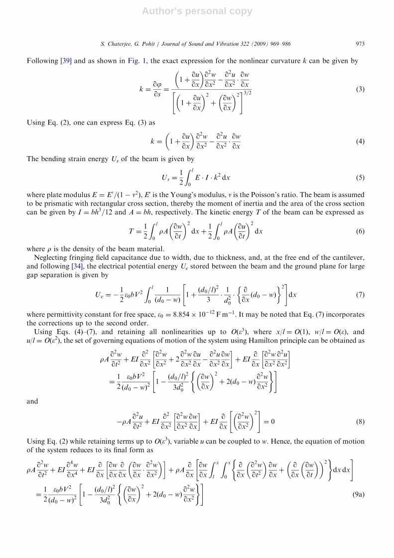
Following [39] and as shown in Fig. 1, the exact expression for the nonlinear curvature k can be given by
k ¼qjqs¼
1þqu
qx
� �q2w
qx2�
q2u
qx2�qw
qx
1þqu
qx
� �2
þqw
qx
� �2" #3=2 (3)
Using Eq. (2), one can express Eq. (3) as
k ¼ 1þqu
qx
� �q2wqx2�
q2uqx2�qw
qx(4)
The bending strain energy Us of the beam is given by
Us ¼1
2
Z l
0
E � I � k2 dx (5)
where plate modulus E ¼ E0=ð1� n2Þ, E0 is the Young’s modulus, n is the Poisson’s ratio. The beam is assumedto be prismatic with rectangular cross section, thereby the moment of inertia and the area of the cross sectioncan be given by I ¼ bh3=12 and A ¼ bh, respectively. The kinetic energy T of the beam can be expressed as
T ¼1
2
Z l
0
rAqw
qt
� �2
dxþ1
2
Z l
0
rAqu
qt
� �2
dx (6)
where r is the density of the beam material.Neglecting fringing field capacitance due to width, due to thickness, and, at the free end of the cantilever,
and following [34], the electrical potential energy Ue stored between the beam and the ground plane for largegap separation is given by
Ue ¼ �1
2�0bV 2
Z l
0
1
ðd0 � wÞ1þðd0=lÞ2
3�1
d20
�qqxðd0 � wÞ
� �2" #
dx (7)
where permittivity constant for free space, �0 ¼ 8:854� 10�12 Fm�1. It may be noted that Eq. (7) incorporatesthe corrections up to the second order.
Using Eqs. (4)–(7), and retaining all nonlinearities up to Oð�3Þ, where x/l ¼ O(1), w/l ¼ O(e), andu/l ¼ O(e2), the set of governing equations of motion of the system using Hamilton principle can be obtained as
rAq2wqt2þ EI
q2
qx2
q2w
qx2þ 2
q2wqx2
qu
qx�
q2u
qx2
qw
qx
� �þ EI
qqx
q2wqx2
q2u
qx2
� �
¼1
2
�0bV2
ðd0 � wÞ21�ðd0=lÞ2
3d20
qw
qx
� �2
þ 2ðd0 � wÞq2wqx2
( )" #
and
�rAq2uqt2þ EI
q2
qx2
q2wqx2
qw
qx
� �þ EI
qqx
q2w
qx2
� �2" #
¼ 0 (8)
Using Eq. (2) while retaining terms up to O(e3), variable u can be coupled to w. Hence, the equation of motionof the system reduces to its final form as
rAq2wqt2þ EI
q4wqx4þ EI
qqx
qw
qx
qqx
qw
qx�q2wqx2
� �� �þ rA
qqx
qw
qx
Z x
l
Z x
0
qqx
q2wqt2
� �qw
qxþ
qqx
qw
qt
� �� �2( )
dxdx
" #
¼1
2
�0bV2
ðd0 � wÞ21�ðd0=lÞ2
3d20
qw
qx
� �2
þ 2ðd0 � wÞq2w
qx2
( )" #(9a)
ARTICLE IN PRESSS. Chaterjee, G. Pohit / Journal of Sound and Vibration 322 (2009) 969–986 973
Author's personal copy
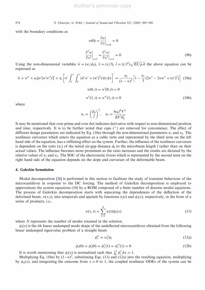
with the boundary conditions as
wð0Þ ¼qw
qx
����x¼0
¼ 0
q2w
qx2
����x¼l
¼q3wqx3
����x¼l
¼ 0 (9b)
Using the non-dimensional variables w ¼ ðw=d0Þ; x ¼ ðx=lÞ; t ¼ ðt=l2ÞffiffiffiffiffiffiffiffiffiffiffiffiffiffiEI=rA
pthe above equation can be
expressed as
€wþ wiv þ a1½w0ðw0w00Þ0�0 þ a1 w0
Z x
1
Z x
0
f €w0w0 þ ð _w0Þ2gdxdx
� �0¼
a2ð1� wÞ2
1�a13f2w00 � 2ww00 þ ðw0Þ2g
h i(10a)
wð0; tÞ ¼ w0ð0; tÞ ¼ 0
w00ð1; tÞ ¼ w000ð1; tÞ ¼ 0 (10b)
where
a1 ¼d0
l
� �2
; a2 ¼6�0l
4V 2
Eh3d30
It may be mentioned that over prime and over dot indicates derivative with respect to non-dimensional positionand time, respectively. It is to be further noted that caps (4) are removed for convenience. The effect ofdifferent design parameters are indicated by Eq. (10a) through the non-dimensional parameters a1 and a2. Thenonlinear curvature which enters the equation as a cubic term and represented by the third term on the lefthand side of the equation, has a stiffening effect on the system. Further, the influence of the nonlinear curvatureis dependent on the ratio (a1) of the initial air-gap distance d0 to the microbeam length l rather than on theiractual values. The influence becomes more prominent as the ratio increases and the results are dictated by therelative values of a1 and a2. The SOC of the electrostatic forces which is represented by the second term on theright hand side of the equation depends on the slope and curvature of the deformable beam.
4. Galerkin formulation
Modal decomposition [26] is performed in this section to facilitate the study of transient behaviour of themicrocantilever in response to the DC forcing. The method of Galerkin decomposition is employed toapproximate the system equations (10) by a ROM composed of a finite number of discrete modal equations.The process of Galerkin decomposition starts with separating the dependences of the deflection of thedeformed beam, w(x,t), into temporals and spatials by functions si(t) and fi(x), respectively, in the form of aseries of products, i.e.,
wðx; tÞ ¼XN
i¼1
siðtÞfiðxÞ (11)
where N represents the number of modes retained in the solution.fi(x) is the ith linear undamped mode shape of the undeflected microcantilever obtained from the following
linear undamped eigenvalue problem of a straight beam
fivi ¼ o2
i fi (12a)
fið0Þ ¼ f0ið0Þ ¼ f00i ð1Þ ¼ f000i ð1Þ ¼ 0 (12b)
It is worth mentioning that fi(x) is normalized such thatR 10 f
2i dx ¼ 1.
Multiplying Eq. (10a) by (1�w)2, substituting Eqs. (11) and (12a) into the resulting equation, multiplyingby fn(x), and integrating the outcome from x ¼ 0 to 1, the coupled nonlinear ODEs of the system can be
ARTICLE IN PRESSS. Chaterjee, G. Pohit / Journal of Sound and Vibration 322 (2009) 969–986974

Author's personal copy
derived as
€sn þ sno2n þ
XN
i¼1
XN
j¼1
XN
k¼1
€sisjsk
Z 1
0
fnfifjfk dx� 2XN
i¼1
XN
j¼1
€sisj
Z 1
0
fnfifj dxþXN
i¼1
XN
j¼1
XN
k¼1
sisjsko2i
Z 1
0
fnfifjfk dx
� 2XN
i¼1
XN
j¼1
sisjo2i
Z 1
0
fnfifj dxþ a1XN
i¼1
XN
j¼1
XN
k¼1
sisjsk
Z 1
0
fnf00i f00j f00k dx
"
þXN
i¼1
XN
j¼1
XN
k¼1
XN
p¼1
XN
q¼1
sisjskspsq
Z 1
0
fnf00i f00j f00kfpfq dx� 2
XN
i¼1
XN
j¼1
XN
k¼1
XN
p¼1
sisjsksp
Z 1
0
fnf00i f00j f00kfp dx
þ 4XN
i¼1
XN
j¼1
XN
k¼1
sisjsk
Z 1
0
fnf0if00j f00k dxþ 4
XN
i¼1
XN
j¼1
XN
k¼1
XN
p¼1
XN
q¼1
sisjskspsq
Z 1
0
fnf0if00j f000k fpfq dx
� 8XN
i¼1
XN
j¼1
XN
k¼1
XN
p¼1
sisjsksp
Z 1
0
fnf0if00j f000k fp dxþ
XN
i¼1
XN
j¼1
XN
k¼1
sisjsko2i
Z 1
0
fnfif0jf0k dx
þXN
i¼1
XN
j¼1
XN
k¼1
XN
p¼1
XN
q¼1
sisjskspsqo2i
Z 1
0
fnfif0jf0kfpfq dx� 2
XN
i¼1
XN
j¼1
XN
k¼1
XN
p¼1
sisjskspo2i
Z 1
0
fnfif0jf0kfp dx
þXN
i¼1
XN
j¼1
XN
k¼1
€sisjsk
Z 1
0
fnbijk dxþXN
i¼1
XN
j¼1
XN
k¼1
XN
p¼1
XN
q¼1
€sisjskspsq
Z 1
0
fnfpfqbijk dx
� 2XN
i¼1
XN
j¼1
XN
k¼1
XN
p¼1
€sisjsksp
Z 1
0
fnfpbijk dxþXN
i¼1
XN
j¼1
XN
k¼1
_si _sjsk
Z 1
0
fnbijk dx
þXN
i¼1
XN
j¼1
XN
k¼1
XN
p¼1
XN
q¼1
_si _sjskspsq
Z 1
0
fnfpfqbijk dx� 2XN
i¼1
XN
j¼1
XN
k¼1
XN
p¼1
_si _sjsksp
Z 1
0
fnfpbijk dx
#
� a2
Z 1
0
fn dx�a13
2XN
i¼1
si
Z 1
0
fnf00i dx� 2
XN
i¼1
XN
j¼1
sisj
Z 1
0
fnfif00j dxþ
XN
i¼1
XN
j¼1
sisj
Z 1
0
fnf0if0j dx
!" #
¼ 0; n ¼ 1; 2; . . . ;N (13)
where bijk ¼ ½f0k
R x
1
R x
0 f0if0j dxdx�0.
It should be noted that the above method of treating the electrostatic force term ensures its exactrepresentation. In the process, the mass matrix of Eq. (13) no longer remains diagonal as obtained in Refs. [27,28].
5. Results
In this section, firstly, the static analysis is carried out by directly solving the BVP. The model is validatedfor the static pull-in voltage and the static pull-in deflection. The convergence of the model obtained throughGalerkin decomposition method is then studied by comparing the results with the static solution of the BVP.The ROM with the correct number of modes is then used to study the dynamic behaviour under an appliedvoltage varying as non-smooth function of time.
5.1. Static analysis
The static deflection equation is obtained by setting all time derivatives in Eq. (10a) to zero. The two-pointBVP was numerically solved for w(x) using the Matlab BVP solver [46]. The numerical procedure implementsa collocation method for the solution of two point BVP. The first step is to express the governing equation as asystem of first order differential equations (collocates). An initial guess is supplied for each variable used todefine the first order differential equations. The guess for an initial mesh is then used by the finite differencecode to obtain accurate numerical solution within an absolute tolerance of 10�6. Fig. 2 reveals the existence oftwo solutions for each value of the gradually applied DC voltage. The pull-in condition is predicted as boththe solutions coalesce at a certain voltage. It has been shown by earlier authors [20,28] that the upper-branchsolution is unstable whereas the lower branch corresponds to the stable equilibrium configurations. Hereafter,
ARTICLE IN PRESSS. Chaterjee, G. Pohit / Journal of Sound and Vibration 322 (2009) 969–986 975

Author's personal copy
in this paper, the lower branch will suffice for the static deflection of the microcantilever. To validate theproposed model the pull-in results are compared with the results obtained in Ref. [19]. Fig. 3 clearly shows thatthe pull-in results of the present work are in better agreement with the experimental results in comparison tothe analytical results of [19] which are based on linearized electrostatic forces. The estimated static pull-involtage (VSPI) is 66.78V using the proposed model compared to 68.5V obtained experimentally in Ref. [19].The pull-in voltage predicted in Ref. [21] for the same system configuration was 66.4V, only after dueconsideration of fringing field and stress gradient effects which have been neglected in this study.
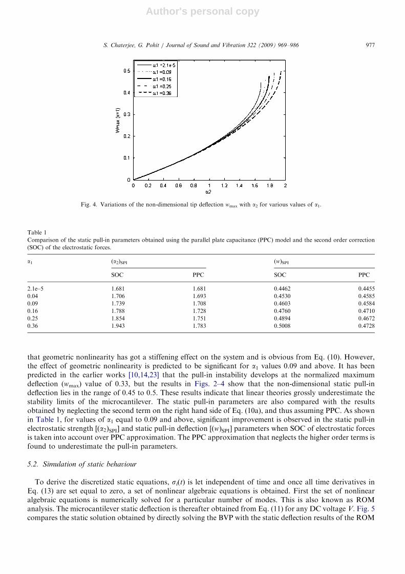
To study the influence of the nonlinear curvature, the microbeam static deflection equation was solved for arange of electrostatic forces ranging from zero to the forcing level where structural instability (pull-in)develops. This procedure was repeated for various values of a1. Fig. 4 shows the variation of the non-dimensional tip deflection wmax with a2 for various values of a1. At low levels of the electrostatic force,represented by a2, the curve is linear but nonlinearity starts showing its effects as a2 increases to higher (41)values. As a1 increases, the value of a2 at which pull-in develops also increases. This is in support of the fact
ARTICLE IN PRESS
Fig. 2. Variation of the non-dimensional tip deflection wmax with voltage V for the beam properties E0 ¼ 155:8e9Pa, b ¼ 5000e� 6m,
h ¼ 57e� 6m, d0 ¼ 92e� 6m, l ¼ 20000e� 6m, n ¼ 0.06 as used in Ref. [19].
Fig. 3. Comparison of end gap results for a1 ¼ 2:1e� 5.
S. Chaterjee, G. Pohit / Journal of Sound and Vibration 322 (2009) 969–986976
Author's personal copy
that geometric nonlinearity has got a stiffening effect on the system and is obvious from Eq. (10). However,the effect of geometric nonlinearity is predicted to be significant for a1 values 0.09 and above. It has beenpredicted in the earlier works [10,14,23] that the pull-in instability develops at the normalized maximumdeflection (wmax) value of 0.33, but the results in Figs. 2–4 show that the non-dimensional static pull-indeflection lies in the range of 0.45 to 0.5. These results indicate that linear theories grossly underestimate thestability limits of the microcantilever. The static pull-in parameters are also compared with the resultsobtained by neglecting the second term on the right hand side of Eq. (10a), and thus assuming PPC. As shownin Table 1, for values of a1 equal to 0.09 and above, significant improvement is observed in the static pull-inelectrostatic strength ½ða2ÞSPI� and static pull-in deflection [ðwÞSPI] parameters when SOC of electrostatic forcesis taken into account over PPC approximation. The PPC approximation that neglects the higher order terms isfound to underestimate the pull-in parameters.
5.2. Simulation of static behaviour
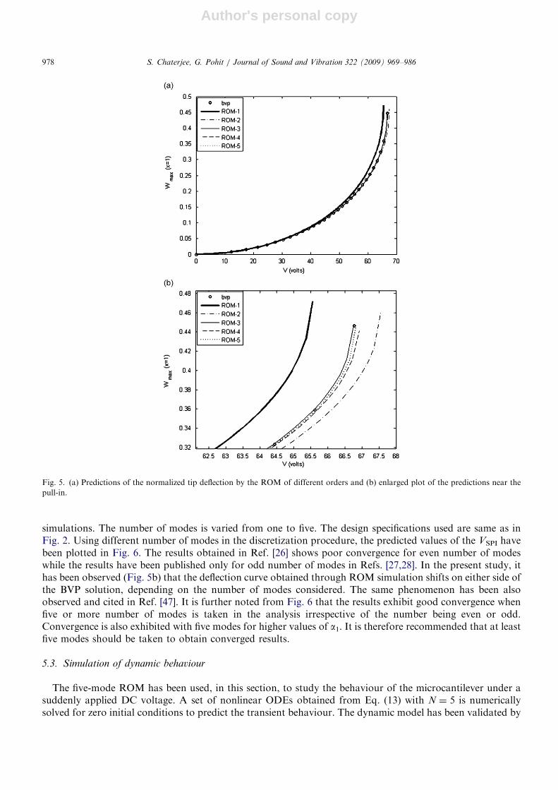
To derive the discretized static equations, si(t) is let independent of time and once all time derivatives inEq. (13) are set equal to zero, a set of nonlinear algebraic equations is obtained. First the set of nonlinearalgebraic equations is numerically solved for a particular number of modes. This is also known as ROManalysis. The microcantilever static deflection is thereafter obtained from Eq. (11) for any DC voltage V. Fig. 5compares the static solution obtained by directly solving the BVP with the static deflection results of the ROM
ARTICLE IN PRESS
Fig. 4. Variations of the non-dimensional tip deflection wmax with a2 for various values of a1.
Table 1
Comparison of the static pull-in parameters obtained using the parallel plate capacitance (PPC) model and the second order correction
(SOC) of the electrostatic forces.
a1 (a2)SPI (w)SPI
SOC PPC SOC PPC
2.1e–5 1.681 1.681 0.4462 0.4455
0.04 1.706 1.693 0.4530 0.4585
0.09 1.739 1.708 0.4603 0.4584
0.16 1.788 1.728 0.4760 0.4710
0.25 1.854 1.751 0.4894 0.4672
0.36 1.943 1.783 0.5008 0.4728
S. Chaterjee, G. Pohit / Journal of Sound and Vibration 322 (2009) 969–986 977
Author's personal copy
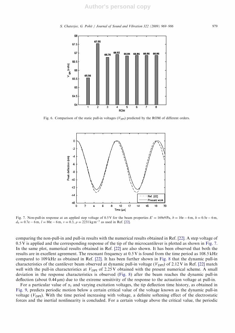
simulations. The number of modes is varied from one to five. The design specifications used are same as inFig. 2. Using different number of modes in the discretization procedure, the predicted values of the VSPI havebeen plotted in Fig. 6. The results obtained in Ref. [26] shows poor convergence for even number of modeswhile the results have been published only for odd number of modes in Refs. [27,28]. In the present study, ithas been observed (Fig. 5b) that the deflection curve obtained through ROM simulation shifts on either side ofthe BVP solution, depending on the number of modes considered. The same phenomenon has been alsoobserved and cited in Ref. [47]. It is further noted from Fig. 6 that the results exhibit good convergence whenfive or more number of modes is taken in the analysis irrespective of the number being even or odd.Convergence is also exhibited with five modes for higher values of a1. It is therefore recommended that at leastfive modes should be taken to obtain converged results.
5.3. Simulation of dynamic behaviour
The five-mode ROM has been used, in this section, to study the behaviour of the microcantilever under asuddenly applied DC voltage. A set of nonlinear ODEs obtained from Eq. (13) with N ¼ 5 is numericallysolved for zero initial conditions to predict the transient behaviour. The dynamic model has been validated by
ARTICLE IN PRESS
Fig. 5. (a) Predictions of the normalized tip deflection by the ROM of different orders and (b) enlarged plot of the predictions near the
pull-in.
S. Chaterjee, G. Pohit / Journal of Sound and Vibration 322 (2009) 969–986978
Author's personal copy
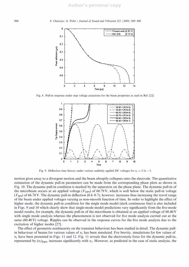
comparing the non-pull-in and pull-in results with the numerical results obtained in Ref. [22]. A step voltage of0.5V is applied and the corresponding response of the tip of the microcantilever is plotted as shown in Fig. 7.In the same plot, numerical results obtained in Ref. [22] are also shown. It has been observed that both theresults are in excellent agreement. The resonant frequency at 0.5V is found from the time period as 108.5 kHzcompared to 109 kHz as obtained in Ref. [22]. It has been further shown in Fig. 8 that the dynamic pull-incharacteristics of the cantilever beam observed at dynamic pull-in voltage (VDPI) of 2.12V in Ref. [22] matchwell with the pull-in characteristics at VDPI of 2.25V obtained with the present numerical scheme. A smalldeviation in the response characteristics is observed (Fig. 8) after the beam reaches the dynamic pull-indeflection (about 0.44 mm) due to the extreme sensitivity of the response to the actuation voltage at pull-in.
For a particular value of a1 and varying excitation voltages, the tip deflection time history, as obtained inFig. 9, predicts periodic motion below a certain critical value of the voltage known as the dynamic pull-involtage (VDPI). With the time period increasing with voltage, a definite softening effect of the electrostaticforces and the inertial nonlinearity is concluded. For a certain voltage above the critical value, the periodic
ARTICLE IN PRESS
Fig. 6. Comparison of the static pull-in voltages (VSPI) predicted by the ROM of different orders.
Fig. 7. Non-pull-in response at an applied step voltage of 0.5V for the beam properties E0 ¼ 169e9Pa, b ¼ 10e� 6m, h ¼ 0:5e� 6m,
d0 ¼ 0:7e� 6m, l ¼ 80e� 6m, n ¼ 0.3, r ¼ 2231kgm�3 as used in Ref. [22].
S. Chaterjee, G. Pohit / Journal of Sound and Vibration 322 (2009) 969–986 979
Author's personal copy
motion gives away to a divergent motion and the beam abruptly collapses onto the electrode. The quantitativeestimation of the dynamic pull-in parameters can be made from the corresponding phase plots as shown inFig. 10. The dynamic pull-in condition is marked by the separatrix on the phase plane. The dynamic pull-in ofthe microbeam occurs at an applied voltage (VDPI) of 60.79V, which is well below the static pull-in voltage(VSPI) of 66.78V. The dynamic pull-in deflection (0.6–0.7), however, increases thus increasing the travel rangeof the beam under applied voltages varying as non-smooth function of time. In order to highlight the effect ofhigher mode, the dynamic pull-in condition for the single mode model (dark continuous line) is also includedin Figs. 9 and 10 which clearly show that single-mode model predictions vary significantly from the five-modemodel results, for example, the dynamic pull-in of the microbeam is obtained at an applied voltage of 60.40Vwith single mode analysis whereas the phenomenon is not observed for five mode analysis carried out at thesame (60.40V) voltage. Ripples can be observed in the response curves for the five mode analysis due to theexcitation of higher modes [27].
The effect of geometric nonlinearity on the transient behaviour has been studied in detail. The dynamic pull-in behaviour of beams for various values of a1 has been simulated. For brevity, simulations for few values ofa1 have been presented in Figs. 11 and 12. Fig. 11 reveals that the electrostatic force for the dynamic pull-in,represented by ða2ÞDPI, increases significantly with a1. However, as predicted in the case of static analysis, the
ARTICLE IN PRESS
Fig. 8. Pull-in response under step voltage actuations for the beam properties as used in Ref. [22].
Fig. 9. Deflection time history under various suddenly applied DC voltages for a1 ¼ 2:1e� 5.
S. Chaterjee, G. Pohit / Journal of Sound and Vibration 322 (2009) 969–986980
Author's personal copy
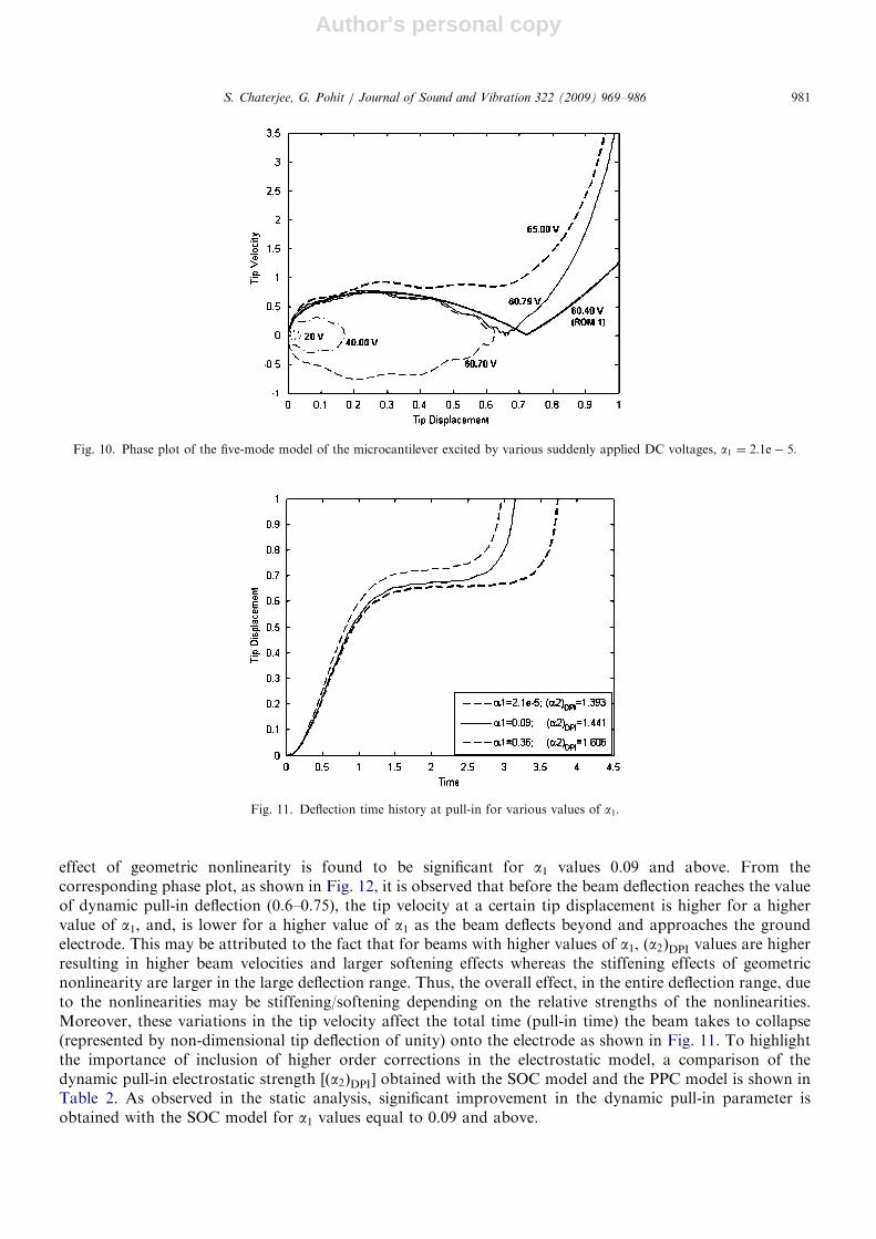
effect of geometric nonlinearity is found to be significant for a1 values 0.09 and above. From thecorresponding phase plot, as shown in Fig. 12, it is observed that before the beam deflection reaches the valueof dynamic pull-in deflection (0.6–0.75), the tip velocity at a certain tip displacement is higher for a highervalue of a1, and, is lower for a higher value of a1 as the beam deflects beyond and approaches the groundelectrode. This may be attributed to the fact that for beams with higher values of a1, ða2ÞDPI values are higherresulting in higher beam velocities and larger softening effects whereas the stiffening effects of geometricnonlinearity are larger in the large deflection range. Thus, the overall effect, in the entire deflection range, dueto the nonlinearities may be stiffening/softening depending on the relative strengths of the nonlinearities.Moreover, these variations in the tip velocity affect the total time (pull-in time) the beam takes to collapse(represented by non-dimensional tip deflection of unity) onto the electrode as shown in Fig. 11. To highlightthe importance of inclusion of higher order corrections in the electrostatic model, a comparison of thedynamic pull-in electrostatic strength [ða2ÞDPI] obtained with the SOC model and the PPC model is shown inTable 2. As observed in the static analysis, significant improvement in the dynamic pull-in parameter isobtained with the SOC model for a1 values equal to 0.09 and above.
ARTICLE IN PRESS
Fig. 10. Phase plot of the five-mode model of the microcantilever excited by various suddenly applied DC voltages, a1 ¼ 2:1e� 5.
Fig. 11. Deflection time history at pull-in for various values of a1.
S. Chaterjee, G. Pohit / Journal of Sound and Vibration 322 (2009) 969–986 981

Author's personal copy
ARTICLE IN PRESS
Fig. 12. Phase plot at pull-in for various values of a1.
Table 2
Comparison of the dynamic pull-in electrostatic strength ((a2)DPI) obtained using the parallel plate capacitance (PPC) model and the
second order correction (SOC) of the electrostatic forces.
a1 (a2)DPI
SOC PPC
2.1e–5 1.393 1.393
0.04 1.414 1.404
0.09 1.441 1.416
0.16 1.480 1.434
0.25 1.534 1.457
0.36 1.606 1.485
Fig. 13. Deflection time history of the microcantilever at representative values of a2 in the vicinity and well below pull-in for various values
of a1.
S. Chaterjee, G. Pohit / Journal of Sound and Vibration 322 (2009) 969–986982

Author's personal copy
In order to understand the impact of geometric nonlinearity for actuation voltages in the vicinity and wellbelow pull-in, three practical cases of transient actuation have been presented in Figs. 13 and 14. For eachcase, the time history and the phase plot have been obtained for beams with various values of a1 actuated bythe electrostatic force of same strength a2. For the representative case well below pull-in (a2 ¼ 0.8), varyinga1 results in no significant variation in the behaviour, and, as shown in Figs. 13 and 14 the curves overlay eachother. In the vicinity of pull-in (a2 ¼ 1.35, 1.62), the overall effects due to the nonlinearities are such that thestiffening effect of geometric nonlinearity is considerable enough. For a2 ¼ 1.35, amplitude (Figs. 13 and 14)and time period (Fig. 13) of the periodic motion decreases with increase in a1. In the representative case ofa2 ¼ 1.62, the pull-in time monotonically decreases with increase in a1 as shown in Fig. 13. This decreasingtrend can be further explained with the help of Fig. 14 which predicts lower tip velocities, almost in the entiredeflection range, for beams with higher values of a1. In Fig. 15, variations of non-dimensional resonantfrequency is plotted against a2 for various values of a1. The softening effects of the electrostatic forces and theinertial terms are further depicted in the figure. As the applied step voltage increases, the structure is softened
ARTICLE IN PRESS
Fig. 14. Phase plot at representative values of a2 in the vicinity and well below pull-in for various values of a1.
Fig. 15. Variations of the non-dimensional resonant frequency with a1 for various values of a2. SOC: second order correction and PPC:
parallel plate capacitance.
S. Chaterjee, G. Pohit / Journal of Sound and Vibration 322 (2009) 969–986 983

Author's personal copy
and the resonance reduces. Moreover, for periodic motions well bellow pull-in (a2 ¼ 0.8), varying a1 results inno significant variation in resonant frequency, whereas, in the vicinity of pull-in the resonant frequency ofstable periodic motion increases significantly with increase in a1. For comparison, resonant frequency plots forvarious values of a1 have also been obtained with the PPC approximation and the plot for a1 value of 0.36 hasbeen shown in Fig. 15. The PPC model predictions of resonant frequencies for higher values of a2 (40.8) arefound to be significantly underestimated.
6. Conclusions
The static and dynamic behaviour of a microcantilever, with relatively large gap to beam-length ratios,under electrostatic actuation is studied herein with special emphasis on the nonlinear effects due to geometry,electric forces, and inertial terms. The deflections near pull-in being large, model derived on the basis of largedeflection assumption effectively predicts the behaviour. In case there is large gap between deformableconductor and ground plane, it is essential to consider higher order corrections of electrostatic forces duringthe formulation of the model. In the present work, it has been shown that results are much improved whenhigher order terms are taken into account during static and dynamic analysis. The numerical results of thestatic analysis are validated with experimental and analytical results available in open literature. According tothe results of static analysis where the voltages are applied gradually, a linear model can appreciably predictthe static behaviour for small electrostatic forces as the deflections are small. For higher strengths ofelectrostatic forces close to pull-in, coupled effects of geometric nonlinearity, and nonlinear electrostatic forceswith higher order correction terms cause deviation from the linearized results while the effects are significantfor initial gap to beam-length ratios of 0.3 and above. Consideration of nonlinearities gives a better estimationof the stability limits which can be advantageously used for design of non-pull-in devices.
A ROM incorporating the correct number of modes provides a compact yet accurate approach to study thebehaviour of microstructures. This approach has been extensively evaluated in the present work and has beeneffectively used to study the transient behaviour of microcantilevers. Results exhibit good convergence for fiveor more number of modes irrespective of the number being even or odd.
The numerical results of the dynamic analysis are validated with other numerical results available in openliterature. According to the results of the transient analysis, nonlinear electrostatic forces and the inertialeffects cause softening of the microstructure whereas geometric nonlinearity has got a stiffening effect on themicrostructure. The overall effect, in the entire deflection range, due to the nonlinearities may be stiffening/softening depending on the relative strengths of the nonlinearities. At and near pull-in, geometric nonlinearityhas got significant effect on the response characteristics for systems with initial gap to beam-length ratios of0.3 and above. For actuations at applied voltages well below the dynamic pull-in voltage, geometricnonlinearity does not play any significant role. Thus, for applications in and around the pull-in zone, the largedeflection model needs to be considered for effective design of microcantilever based microsystems.
References
[1] S. Senturia, Microsystem Design, Norwell, Kluwer, MA, 2001.
[2] P. Decuzzi, A. Granaldi, G. Pascazio, Dynamic response of microcantilever-based sensors in a fluidic chamber, Journal of Applied
Physics 101 (2007) 024303.
[3] J. Teva, G. Abadal, Z.J. Davis, J. Verd, X. Borrise, A. Boisen, F. Perez-Murano, N. Barniol, On the electromechanical modeling of a
resonating nano-cantilever-based transducer, Ultramicroscopy 100 (2004) 225–232.
[4] V. Sazonova, Y. Yaish, H. Ustunel, D. Roundy, T.A. Arias, P.L. McEuen, A tunable carbon nanotube electromechanical oscillator,
Nature 431 (2004) 284–287.
[5] M. Dequesnes, Z. Tang, N.R. Aluru, Static and dynamic analysis of carbon nanotube-based switches, Journal of Engineering
Materials and Technology 126 (2004) 230–237.
[6] J.M. Huang, K.M. Liew, C.H. Wong, S. Rajendran, M.J. Tan, A.Q. Liu, Mechanical design and optimization of capacitive
micromachined switch, Sensors and Actuators A 93 (2001) 273–285.
[7] R. Puers, D. Lapadatu, Electrostatic forces and their effects on capacitive mechanical sensors, Sensors and Actuators A 56 (1996)
203–210.
[8] J. Fricke, C. Obermaiar, Cantilever beam accelerometer based on surface micromachining technology, Journal of Micromechanics and
Microengineering 3 (1993) 100–102.
ARTICLE IN PRESSS. Chaterjee, G. Pohit / Journal of Sound and Vibration 322 (2009) 969–986984

Author's personal copy
[9] G.I. Taylor, The coalescence of closely spaced drops when they are at different electric potentials, Proceedings of Royal Society A 306
(1968) 423–434.
[10] H.C. Nathanson, W.E. Newell, R.A. Wickstrom, J.R. Davis, The resonant gate transistor, IEEE Transactions of Electron Devices
ED-14 (3) (1967) 117–133.
[11] B. McCarthy, G.G. Adams, N.E. McGruer, D. Potter, A dynamic model including contact bounce of an electrostatically actuated
microswitch, Journal of Microelectromechanical Systems 11 (2002) 276–283.
[12] W.C. Xie, H.P. Lee, S.P. Lim, Nonlinear dynamic analysis of MEMS switches by nonlinear modal analysis, Nonlinear Dynamics 31
(2003) 243–256.
[13] S. Pamidighantam, R. Puers, K. Baert, H.A.C. Tilmans, Pull-in voltage analysis of electrostatically actuated beam structures with
fixed–fixed and fixed-free end conditions, Journal of Micromechanics and Microengineering 12 (2002) 458–464.
[14] S. Chowdhury, M. Ahmadi, W.C. Miller, A closed-form model for the pull-in voltage of electrostatically actuated cantilever beams,
Journal of Micromechanics and Microengineering 15 (2005) 756–763.
[15] S.D. Senturia, R.M. Harris, B.P. Johnson, S. Kim, K. Nabors, M.A. Shulman, J.K. White, A computer-aided design system for
microelectromechanical systems (MEMCAD), Journal of Microelectromechanical Systems 1 (1992) 3–13.
[16] L.D. Gabbay, J.E. Mehner, S.D. Senturia, Computer-aided generation of nonlinear reduced-order dynamic macromodels I: non-
stress-stiffened case, Journal of Microelectromechanical Systems 9 (2000) 262–269.
[17] Coventor Inc., Pull-in Voltage Analysis of Electrostatically-Actuated Beams verifying Accuracy of Coventor Behavioural Models
/http://www.coventor.com/media/fem_comparisons/pullin_voltage.pdfS.
[18] G. Li, N.R. Aluru, Linear, non-linear and mixed-regime analysis of electrostatic MEMS, Sensors and Actuators A 91 (2001) 278–291.
[19] Y.C. Hu, C.M. Chang, S.C. Huang, Some design considerations on the electrostatically actuated microstructures, Sensors and
Actuators A 112 (2004) 155–161.
[20] E.M. Abdel-Rahman, M.I. Younis, A.H. Nayfeh, Characterization of the mechanical behaviour of an electrically actuated
microbeam, Journal of Micromechanics and Microengineering 12 (2002) 759–766.
[21] H. Sadeghian, G. Rezazadeh, P.M. Osterberg, Application of the generalized differential quadrature method to the study of pull-in
phenomena of MEMS switches, Journal of Microelectromechanical Systems 16 (2007) 1334–1340.
[22] S.K. De, N.R. Aluru, Full-Lagrangian schemes for dynamic analysis of electrostatic MEMS, Journal of Microelectromechanical
Systems 13 (2004) 737–758.
[23] A. Fargas-Marques, J. Casals-Terre, A.M. Shkel, Resonant pull-in condition in parallel-plate electrostatic actuators, Journal of
Microelectromechanical Systems 16 (2007) 1044–1053.
[24] G.N. Nielson, G. Barbastathis, Dynamic pull-in of parallel-plate and torsional electrostatic MEMS actuators, Journal of
Microelectromechanical Systems 15 (2006) 811–821.
[25] V. Rochus, D.J. Rixen, J.C. Golinval, Electrostatic coupling of MEMS structures: transient simulations and dynamic pull-in,
Nonlinear Analysis 63 (2005) e1619–e1633.
[26] M.I. Younis, E.M. Abdel-Rahman, A.H. Nayfeh, A reduced-order model for electrically actuated microbeam-based MEMS, Journal
of Microelectromechanical Systems 12 (2003) 672–680.
[27] S. Krylov, R. Maimon, Pull-in dynamics of an elastic beam actuated by continuously distributed electrostatic force, Journal of
Vibration and Acoustics 126 (2004) 332–342.
[28] S. Krylov, Lyapunov exponents as a criterion for the dynamic pull-in instability of electrostatically actuated microstructures,
International Journal of Non-Linear Mechanics 42 (2007) 626–642.
[29] R.C. Batra, M. Porfiri, D. Spinello, Vibrations and pull-in instabilities of microelectromechanical von Karman elliptic plates
incorporating the Casimir force, Journal of Sound and Vibration 315 (2008) 939–960.
[30] R.C. Batra, M. Porfiri, D. Spinello, Vibrations of narrow microbeams predeformed by an electric field, Journal of Sound and Vibration
309 (2008) 600–612.
[31] M. Porfiri, Vibrations of parallel arrays of electrostatically actuated microplates, Journal of Sound and Vibration 315 (2008)
1071–1085.
[32] P.A. Hassanpour, W.L. Cleghorn, E. Esmailzadeh, J.K. Mills, Vibration analysis of micro-machined beam-type resonators, Journal
of Sound and Vibration 308 (2007) 287–301.
[33] R.C. Batra, M. Porfiri, D. Spinello, Review of modeling electrostatically actuated microelectromechanical systems, Smart Materials
and Structures 16 (2007) R23–R31.
[34] S. Krylov, S. Seretensky, Higher order correction of electrostatic pressure and its influence on the pull-in behaviour of
microstructures, Journal of Micromechanics and Microengineering 16 (2006) 1382–1396.
[35] H. Wagner, Large-amplitude free vibrations of a beam, Journal of Applied Mechanics 32 (1965) 887–892.
[36] J. Liua, D.T. Martin, K. Kadirvel, T. Nishida, L. Cattafesta, M. Sheplak, B.P. Mann, Nonlinear model and system identification of a
capacitive dual-backplate MEMS microphone, Journal of Sound and Vibration 309 (2008) 276–292.
[37] S.R. Hsieh, S.W. Shaw, C. Pierre, Normal modes for large amplitude vibration of a cantilever beam, International Journal of Solids
and Structures 31 (1994) 1981–2014.
[38] S.N. Mahmoodi, N. Jalili, Non-linear vibrations and frequency response analysis of piezoelectrically driven microcantilevers,
International Journal of Nonlinear Mechanics 42 (2007) 577–587.
[39] D.H. Hodges, Proper definition of curvature in nonlinear beam kinematics, American Institute of Aeronautics and Astronautics
Journal 22 (1984) 1825–1827.
[40] A.H. Nayfeh, C. Chin, S.A. Nayfeh, Nonlinear normal modes of a cantilever beam, Journal of Vibration and Acoustics 117 (1995)
477–481.
ARTICLE IN PRESSS. Chaterjee, G. Pohit / Journal of Sound and Vibration 322 (2009) 969–986 985

Author's personal copy
[41] R.C. Batra, M. Porfiri, D. Spinello, Reduced-order models for microelectromechanical rectangular and circular plates incorporating
the Casimir force, International Journal of Solids and Structures 45 (2008) 3558–3583.
[42] P.M. Osterberg, Electrostatically Actuated Microelectromechanical Test Structures for Material Property Measurements, Ph.D.
Thesis, Massachusetts Institute of Technology, 1995.
[43] J.M. Rabaey, Digital Integrated Circuits, Prentice-Hall, Englewood Cliffs, NJ, 1996, pp. 438–445.
[44] R.C. Batra, M. Porfiri, D. Spinello, Electromechanical model of electrically actuated narrow microbeams, Journal of
Microelectromechanical Systems 15 (2006) 1175–1189.
[45] J.A. Pelesko, D.H. Bernstein, Modeling MEMS and NEMS, Chapman&Hall/CRC Press, London/New York/Washington, DC, 2003
(Chapter 7).
[46] L.F. Shampine, M.W. Reichelt, J. Kierzenka, Solving boundary value problems for ordinary differential equations in MATLAB with
bvp4 /http://www.mathworks.comS.
[47] G. Pohit, A.K. Mallik, C. Venkatesan, Free out of plane vibration of a rotating beam with nonlinear elastomeric constraints, Journal
of Sound and Vibration 220 (1999) 1–25.
ARTICLE IN PRESSS. Chaterjee, G. Pohit / Journal of Sound and Vibration 322 (2009) 969–986986