A corrosion resistant cerium oxide based coating on aluminum alloy 2024 prepared by brush plating
7
Applied Surface Science 257 (2011) 2806–2812 Contents lists available at ScienceDirect Applied Surface Science journal homepage: www.elsevier.com/locate/apsusc A corrosion resistant cerium oxide based coating on aluminum alloy 2024 prepared by brush plating Junlei Tang, Zhongzhi Han, Yu Zuo ∗ , Yuming Tang School of Materials Science and Engineering, Beijing University of Chemical Technology, Beijing 100029, China article info Article history: Received 15 March 2010 Received in revised form 8 October 2010 Accepted 18 October 2010 Available online 23 October 2010 Keywords: Cerium oxide based coating Aluminum alloy Brush plating Corrosion resistance abstract Cerium oxide based coatings were prepared on AA2024 Al alloy by brush plating. The characteristic of this technology is that hydrogen peroxide, which usually causes the plating solution to be unstable, is not necessary in the plating electrolyte. The coating showed laminated structures and good adhesive strength with the substrate. X-ray diffraction and X-ray photoelectron spectroscopy analysis showed that the coatings were composed of Ce(III) and Ce(IV) oxides. The brush plated coatings on Al alloys improved corrosion resistance. The influence of plating parameters on structure and corrosion resistance of the cerium oxide based coating was studied. © 2010 Elsevier B.V. All rights reserved. 1. Introduction Cerium compounds have been used for protection of aluminum alloys against corrosion for decades. Since Hinton et al. [1] reported the inhibitive effects of rare earth compounds on aluminum alloys, there have been many studies on preparation and properties of rare earth conversion coatings [2–7]. The deposition of rare earth con- version coatings on aluminum alloys and other metals is considered as an effective method to replace chromate conversion coatings which have been prohibited in many fields for their toxicity. How- ever, most of the reported methods to prepare cerium oxide based coatings were based on electrodeposition or chemical conversion processes. The electrodeposition process is difficult to be applied on large surface areas. The chemical conversion processes are usu- ally complex and H 2 O 2 is often used in the solution as oxidizer [8–14] both in chemical and electrodepositing processes. Creus et al. [14–17] reported that the addition of H 2 O 2 is essential for preparing completely covered coatings in aqueous baths because the reduction of dissolved oxygen in the bath cannot provide suffi- cient pH increase at the surface for the formation of colloidal cerium hydroxide particles. In freshly prepared solution, the deposition rate is faster due to the reduction of H 2 O 2 , producing hydroxyl ions at the interface area. Zhitomirsky and Petric [8] reported that the role of H 2 O 2 as a precursor was to prevent the formation of a non- stoichiometric cerium oxide coating by oxidizing Ce(III) into Ce(IV), the latter being more easily hydrolyzed. Moreover, this precursor ∗ Corresponding author. Tel.: +86 10 64423795; fax: +86 10 64423795. E-mail address: [email protected] (Y. Zuo). was shown to enhance the adherence and uniformity of the oxide coatings. The addition of hydrogen peroxide leads to the formation of sufficient hydroxyl ions and O 2 during the cathodic reaction (Eq. (1)). The self decomposition reaction of hydrogen peroxide may also happen as Eq. (2). The hydroxyl ions also can be produced by reduction of oxygen which comes from hydrogen peroxide (Eq. (3)). H 2 O 2 + 2e − → 2OH − (1) 2H 2 O + H 2 O 2 → 2H 3 O + + O 2 + 2e − (2) 2H 2 O + O 2 + 4e − → 4OH − (3) The formation of hydroxyl ions at the cathode leads to local increase in pH near the alloy surface, which promotes the forma- tion of Ce(OH) 3 precipitate or/and the formation of soluble ionic complexes such as Ce(OH) 2 2+ (Eqs. (4) and (5)). Ce(OH) 2 2+ appears preferentially when H 2 O 2 is added in the solution [14]. Ce 3+ + 3OH − → Ce(OH) 3 (4) 2Ce(OH) 3 → Ce 2 O 3 ·3H 2 O (5) 2Ce 3+ + H 2 O 2 + 2OH − → 2Ce(OH) 2 2+ (6) 2Ce(OH) 2 2+ + 2OH − → Ce(OH) 4 (7) Ce(OH) 4 → CeO 2 ·2H 2 O (8) It is generally believed [18,19] that Ce(III) is oxidized into Ce(IV) in the solution because of the presence of an oxidizing agent. Depo- sition of Ce(IV) species is more favorable because K sp of Ce(OH) 4 is 4.0 × 10 −51 , markedly smaller than K sp of Ce(OH) 3 which is 1.5 × 10 −20 . Deposition of Ce(IV) species occurs at lower pH values 0169-4332/$ – see front matter © 2010 Elsevier B.V. All rights reserved. doi:10.1016/j.apsusc.2010.10.065
Transcript of A corrosion resistant cerium oxide based coating on aluminum alloy 2024 prepared by brush plating

Ap
JS
a
ARRAA
KCABC
1
attevawecpoa[eptchrarst
0d
Applied Surface Science 257 (2011) 2806–2812
Contents lists available at ScienceDirect
Applied Surface Science
journa l homepage: www.e lsev ier .com/ locate /apsusc
corrosion resistant cerium oxide based coating on aluminum alloy 2024repared by brush plating
unlei Tang, Zhongzhi Han, Yu Zuo ∗, Yuming Tangchool of Materials Science and Engineering, Beijing University of Chemical Technology, Beijing 100029, China
r t i c l e i n f o
rticle history:eceived 15 March 2010eceived in revised form 8 October 2010
a b s t r a c t
Cerium oxide based coatings were prepared on AA2024 Al alloy by brush plating. The characteristic ofthis technology is that hydrogen peroxide, which usually causes the plating solution to be unstable, isnot necessary in the plating electrolyte. The coating showed laminated structures and good adhesive
ccepted 18 October 2010vailable online 23 October 2010
eywords:erium oxide based coatingluminum alloy
strength with the substrate. X-ray diffraction and X-ray photoelectron spectroscopy analysis showedthat the coatings were composed of Ce(III) and Ce(IV) oxides. The brush plated coatings on Al alloysimproved corrosion resistance. The influence of plating parameters on structure and corrosion resistanceof the cerium oxide based coating was studied.
© 2010 Elsevier B.V. All rights reserved.
rush platingorrosion resistance
. Introduction
Cerium compounds have been used for protection of aluminumlloys against corrosion for decades. Since Hinton et al. [1] reportedhe inhibitive effects of rare earth compounds on aluminum alloys,here have been many studies on preparation and properties of rarearth conversion coatings [2–7]. The deposition of rare earth con-ersion coatings on aluminum alloys and other metals is considereds an effective method to replace chromate conversion coatingshich have been prohibited in many fields for their toxicity. How-
ver, most of the reported methods to prepare cerium oxide basedoatings were based on electrodeposition or chemical conversionrocesses. The electrodeposition process is difficult to be appliedn large surface areas. The chemical conversion processes are usu-lly complex and H2O2 is often used in the solution as oxidizer8–14] both in chemical and electrodepositing processes. Creust al. [14–17] reported that the addition of H2O2 is essential forreparing completely covered coatings in aqueous baths becausehe reduction of dissolved oxygen in the bath cannot provide suffi-ient pH increase at the surface for the formation of colloidal ceriumydroxide particles. In freshly prepared solution, the depositionate is faster due to the reduction of H2O2, producing hydroxyl ions
t the interface area. Zhitomirsky and Petric [8] reported that theole of H2O2 as a precursor was to prevent the formation of a non-toichiometric cerium oxide coating by oxidizing Ce(III) into Ce(IV),he latter being more easily hydrolyzed. Moreover, this precursor∗ Corresponding author. Tel.: +86 10 64423795; fax: +86 10 64423795.E-mail address: [email protected] (Y. Zuo).
169-4332/$ – see front matter © 2010 Elsevier B.V. All rights reserved.oi:10.1016/j.apsusc.2010.10.065
was shown to enhance the adherence and uniformity of the oxidecoatings. The addition of hydrogen peroxide leads to the formationof sufficient hydroxyl ions and O2 during the cathodic reaction (Eq.(1)). The self decomposition reaction of hydrogen peroxide mayalso happen as Eq. (2). The hydroxyl ions also can be produced byreduction of oxygen which comes from hydrogen peroxide (Eq. (3)).
H2O2 + 2e− → 2OH− (1)
2H2O + H2O2 → 2H3O+ + O2 + 2e− (2)
2H2O + O2 + 4e− → 4OH− (3)
The formation of hydroxyl ions at the cathode leads to localincrease in pH near the alloy surface, which promotes the forma-tion of Ce(OH)3 precipitate or/and the formation of soluble ioniccomplexes such as Ce(OH)2
2+ (Eqs. (4) and (5)). Ce(OH)22+ appears
preferentially when H2O2 is added in the solution [14].
Ce3+ + 3OH− → Ce(OH)3 (4)
2Ce(OH)3 → Ce2O3·3H2O (5)
2Ce3+ + H2O2 + 2OH− → 2Ce(OH)22+ (6)
2Ce(OH)22+ + 2OH− → Ce(OH)4 (7)
Ce(OH)4 → CeO2·2H2O (8)
It is generally believed [18,19] that Ce(III) is oxidized into Ce(IV)in the solution because of the presence of an oxidizing agent. Depo-sition of Ce(IV) species is more favorable because Ksp of Ce(OH)4is 4.0 × 10−51, markedly smaller than Ksp of Ce(OH)3 which is1.5 × 10−20. Deposition of Ce(IV) species occurs at lower pH values

J. Tang et al. / Applied Surface Science 257 (2011) 2806–2812 2807
Table 1The step-by-step procedure for brush plating on AA2024 Al alloy.
Step Operation Solution pH Polarity Voltage (V) Time (s)
1 Electroclean Cleaning solution 11 Positive 10 15
tE
pHcpgias
2
2
wC0
2
fi1
eicwtfs
2
mXcPtdfpuT
3.1. Coating characterization
Fig. 2 shows SEM images of brush plated cerium oxide basedcoating on Al alloy. The coating is smooth and dense, but
2 Rinse Deionized water3 Cathodic activation Activating solution4 Rinse Deionized water5 Plating Brush plating solution
han Ce(OH)3. Thus, Eq. (7) may happen preferentially compared toq. (4).
However, the addition of hydrogen peroxide results in ceriumrecipitates and solution instability. Deposition solutions with2O2 are also difficult to recycle. In this study, a cerium oxide basedoating was deposited on aluminum alloy 2024 by brush. The brushlated cerium oxide based coatings on aluminum alloy showedood corrosion resistance. H2O2 is not necessary in the brush plat-ng solution. The influence of the plating parameters on structurend corrosion resistance of the cerium oxide based coatings wastudied.
. Experimental
.1. Materials
The testing material was rolled Al alloy 2024 (heat treatment T3)ith thickness of 3 mm. The Al alloy composition was as follows:u 1.9–2.7%, Mg 1.3–1.8%, Fe 0.9–1.3%, Si 0.1–0.25%, Ni 0.9–1.2%, Zn.10%, Ti 0.04–0.1%, Al% Bal.
.2. Brush plating conditions
AA2024 Al alloy plates with the size of 400 mm × 200 mm werenished on both sides with Al2O3 based abrasive papers up to000#. The brush plating conditions are shown in Table 1.
The solutions used are as follows:
Cleaning solution: Na2CO3 40 g/L, NaOH 25 g/L, Na3PO4 40 g/L andNaCl 25 g/L.Activating solution: HCl 25 g/L and NaCl 140 g/L.Brush plating solution: Ce(NO3)3·6H2O 20–60 g/L, NaF 0.1–0.3 g/L.The temperature of plating solution is 20 ◦C.
Fig. 1 shows the illustration of the brush-plating apparatus. Thelectrolyte was supplied automatically to the anode by a pump dur-ng brush plating at a rate of 200 ml/min. The Al alloy specimen wasonnected to the cathode of the power supply and a graphite anoderapped with absorbent membrane was connected to the anode of
he power supply. The plating solution was pumped continuouslyrom the reservoir to the anode through a tube when brush platingtarted. Then the coating was deposited on the specimen surface.
.3. Testing methods
The coating surface was observed with scanning electronicicroscopy (SEM). Energy dispersive X-ray spectroscopy (EDS) and-ray photoelectron spectroscopy (XPS) were used to analyze theomposition of the coatings. The specimens were plated with at film by PVD prior to SEM and EDS analysis. The coating struc-ure was studied with X-ray diffraction (XRD), by a 2500VB2+PC
iffractometer (Japan) using CuK� radiation which was filtered andocused with a Göbel mirror. Because the coatings were thin, theeaks of alloy substrate in the diffraction patterns were deductedsing MDI Jade5.0 software (Materials Data Inc, Liverpool, CA).he coating thickness was measured by SEM observation of cross70.5 Positive 10 1073–4 Positive 6–7 180
sections. The adhesive strength of the coating to the matrix wasmeasured according to ASTM D 3359 – 90 (ASTM Standard TestMethod for Coating Adhesion by Tape Test) TEST METHOD B –Cross-Cut Tape Test. An ultraviolet spectrophotometer (UV3010,Hitachi) was used to measure the cerium concentration in platingsolution with a scanning range of 800–200 nm and a sweep speed of300 nm/min. The baseline was determined using deionized water.
Corrosion behavior of the coatings was studied using polar-ization scans and electrochemical impedance spectroscopy (EIS).The test electrolyte was 1 M NaCl in deionized water. The neutralsalt spray test was evaluated following the Standard GB5938-86“the corrosion resistance test of metal-plate and chemical pro-cessing coating on light industry products – Neutral salt sprayingtest”. The NaCl concentration was 5 wt.%. The pH of NaCl solu-tion was 6.5–7.2, and the temperature in salt-fog cabinet (FQY015,Shanghai Laboratory Instrument Works Co., Ltd.) was maintainedat 35 ± 1 ◦C. The samples for electrochemical tests were sealed withepoxy resin, leaving an area of 0.5 cm × 0.5 cm exposed to the solu-tion. A saturated calomel electrode (SCE) was used as the referenceelectrode, and the counter electrode was platinum. Electrochemi-cal impedance spectroscopy (EIS) measurements were performedwith a Model 5210 lock in amplifier connected to the cell via aModel 273A potentiostat, at the open circuit potential with a 10 mVperturbation and the frequency range was from 100 kHz to 10 mHz.All the reagents used were of analytic grade, and the solutions wereopen to the air.
3. Results and discussion
Fig. 1. Illustration of the brush-plating apparatus: (1) anode connection; (2) elec-trode handle; (3) carbon anode; (4) absorbent membrane; (5) Al alloy specimen;(6) solution recycle; (7) the solution feed tube; (8) cathode connection; (9) solutionreservoir; (10) specimen holder.
2808 J. Tang et al. / Applied Surface Science 257 (2011) 2806–2812
F g/L): (A ck.
mirs
csvsthtTcowi[c
ig. 2. SEM images of the cerium oxide based coatings (V = 7 V, Ce(NO3)3·6H2O = 20, (d) magnified image of area B, (e) the edges of the cracks, (f) cross section of a cra
ud-cracks are seen. The mud-cracks, which are common for coat-ngs formed from hydroxide gels, have been reported by manyesearchers as the result of dehydration process of cerium conver-ion coatings [8,11,20,21].
Fig. 2b shows surface morphology of the cerium oxide basedoating on which two areas are seen. Fig. 2c and d respectivelyhows magnified image of area A and area B. Area A consisted ofery fine grains less than 20–30 nm and area B consisted of scalytructure. The morphology of the cerium oxide based coating nearhe mud-cracks is shown in Fig. 2e and f. It is seen that the cracksave very sharp and smooth edges (Fig. 2e) and the dense struc-ure was covered by the scaly structure in some areas (Fig. 2f).he ratio of the two structures is related to the concentration oferium salt in brush plating solution. Fig. 3 shows the morphol-
gy of cerium oxide based coatings deposited in plating solutionsith different Ce(NO)3 concentrations. The scaly structure areancreased with increasing Ce(NO)3 concentration. Chang and Chen22] have reported the preparation of CeO2 nanoparticles from pre-ipitation of Ce(OH)3 which was obtained by adding alkaline into
a) micro cracks, (b) morphology of the coating surface, (c) magnified image of area
Ce3+ solution. The morphology difference between CeO2 particlesobtained at different preparation temperatures was attributed tothe structure of initial Ce(OH)3 precipitates. The initial precipitatesobtained at 90 ◦C were needle-like and a few hundreds nanometerslong, but those obtained at 0 ◦C were sphere-like with diameters of7–25 nm. The observed structures of cerium oxide in Fig. 2 havesimilar sizes to the reported Ce(OH)3 precipitates. It is suggestedthat similar to temperature, cerium ion concentration in the plat-ing bath may also affect the formation rate and the structure ofCe(OH)3 precipitates. The formation rate of Ce(OH)3 may be shownas Eq. (9):
−dcA
dt= Ae−Ea/RT cn
A (9)
In the equation −dcA/dt is the reaction rate, cA is Ce3+ concentrationat random time of reaction, k is the reaction rate constant, n is theoverall reaction order which is larger than 1 in this precipitationreaction, A is the pre-exponential factor, Ea is activation energy, Ris mol gas constant and T the Kelvin temperature.

J. Tang et al. / Applied Surface Science 257 (2011) 2806–2812 2809
Fc4
twci
TT
ig. 3. SEM images of the cerium oxide based coatings under different Ce(NO)3 con-entrations in plating bath (V = 6.5 V): (a) Ce(NO3)3·6H2O 20 g/L, (b) Ce(NO3)3·6H2O0 g/L, (c) Ce(NO3)3·6H2O 60 g/L.
It is clear that the precipitation reaction rate increases with the
emperature or cerium ion concentration. At higher reaction ratehich is caused by the higher cerium ion concentration, the pre-ipitated Ce(OH)3 grows faster and more scaly structure is formedn brush plating process.
able 2he adhesive strength of the coatings under different plating conditions.
Cerium salt (g/L) Brush plating voltage (V) Level
20 6 4B6.5 4B7 4B
20 6.5 4B40 3B60 3B
Fig. 4. Cross section of the brush plated cerium oxide based coatings, etched in20 wt.% sulphuric acid for 3 s to make gain boundaries clearly.
The adhesion test results are shown in Table 2, where 4B indi-cates good adhesion according to ASTM Standard Test Methodfor Coating Adhesion by Tape Test. The coatings showed goodadhesive strength under most of the plating conditions. However,when Ce(NO)3 concentration was higher than 20 g/L the adhesivestrength decreased. The decrease may be due to the area ratioof the scaly structure in the coating. According to Figs. 2 and 3,the adhesion of coatings decreased with decreasing area fractionof the scaly structure. The scaly structure is less dense than thefine grained structure, which may decrease the cohesive of coat-ing. Fig. 3b shows that some scaly surface has flaked off and thestructures with fine gains under the scaly surface were exposed.When Ce(NO)3 concentration in the plating solution reached 60 g/L(Fig. 3c), the coating was almost all scaly, which may decrease bothadhesion at the coating–substrate interface and the cohesion of thecoating.
An SEM image of a cross section of the coating is shown in Fig. 4.The thickness of the coating was 3–4 �m and the coating consistsof laminated layers. Each layer contains many columnar structures.During brush plating, the anode moves across the surface severaltimes and the growth of the coating is discontinuous, which causedthe laminated structure.
The composition analysis of the cerium oxide based coating wascarried out by EDS (brush plate voltage of 7 V, cerium salt concen-tration of 20 g/L), and the element contents (at.%) were C 26.19%,O 52.78%, Al 5.23%, Ce 15.80%. The results indicate that the brushplated cerium oxide based coating on Al alloy is mainly composedof Ce, O, Al and C.
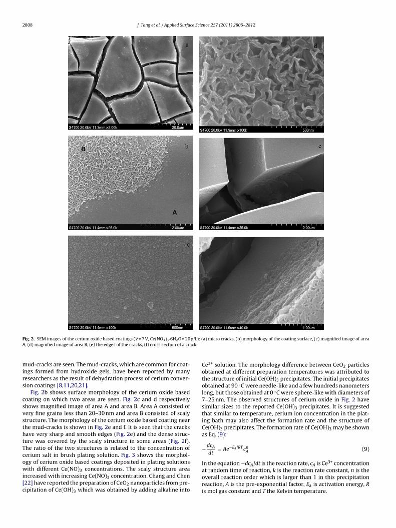
XPS analysis was carried out to further understand the bond-ing states of the elements in the coatings. Fig. 5a shows the widescan XPS spectra on surface of the cerium deposition coating. Thesurface composition of the coating includes mainly Ce, O and C. Alpeaks of the matrix were not observed, indicating that there is noaluminum or its compounds present on the coating surface. Theraw peak of Ce3d5/2 from 878 to 892 eV should be the overlappedresult of Ce(IV) and Ce(III). Fig. 5b shows the deconvolution of thepeaks for Ce3d5/2. The relative contents of Ce(IV) and Ce(III) couldbe calculated from the area ratio of Ce(IV)/Ce(III) which is 0.44. Theintensity ratio (molar ratio) of Ce(IV)3d5/2 peak to Ce(III)3d5/2 peakis equal to the area ratio because they have the same sensitivity fac-tor. It means that at the cerium oxide based coating surface about69.5% of cerium was present as Ce(III).
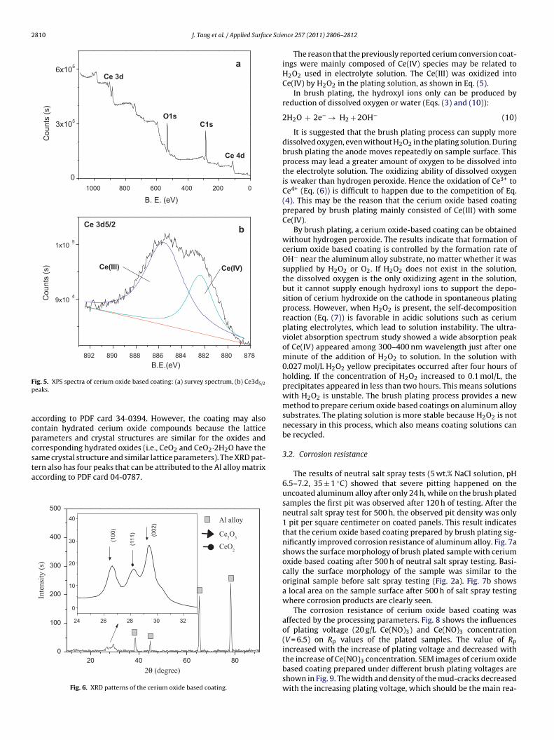
Fig. 6 shows XRD patterns of the brush plated cerium oxide
based coating. The diffraction peaks at 2� = 24.426◦ and 2� = 29.435◦could be related to planes (1 0 0) and (0 0 2) reflection of Ce2O3according to XRD PDF 44-1086. There is a “shoulder” on the leftof (0 0 2) peak, which may be from the (1 1 1) reflection of CeO2
2810 J. Tang et al. / Applied Surface Scie
02004006008001000
0
3x10⁵
6x10⁵
Cou
nts
(s)
B. E. (eV)
C1sO1s
Ce 3d
Ce 4d
a
878880882884886888890892
9x10⁴
1x10⁵
Ce(IV)
Cou
nts
(s)
B.E.(eV)
Ce(III)
Ce 3d5/2b
Fp
acpcsta
ig. 5. XPS spectra of cerium oxide based coating: (a) survey spectrum, (b) Ce3d5/2
eaks.
ccording to PDF card 34-0394. However, the coating may alsoontain hydrated cerium oxide compounds because the latticearameters and crystal structures are similar for the oxides andorresponding hydrated oxides (i.e., CeO2 and CeO2·2H2O have the
ame crystal structure and similar lattice parameters). The XRD pat-ern also has four peaks that can be attributed to the Al alloy matrixccording to PDF card 04-0787.806040200
100
200
300
400
500
3230282624
0
10
20
30
40
(100
)
(111
) (002
)
Inte
nsity
(s)
2θ (degree)
Al alloy
Ce2O
3
CeO2
Fig. 6. XRD patterns of the cerium oxide based coating.
nce 257 (2011) 2806–2812
The reason that the previously reported cerium conversion coat-ings were mainly composed of Ce(IV) species may be related toH2O2 used in electrolyte solution. The Ce(III) was oxidized intoCe(IV) by H2O2 in the plating solution, as shown in Eq. (5).
In brush plating, the hydroxyl ions only can be produced byreduction of dissolved oxygen or water (Eqs. (3) and (10)):
2H2O + 2e− → H2 + 2OH− (10)
It is suggested that the brush plating process can supply moredissolved oxygen, even without H2O2 in the plating solution. Duringbrush plating the anode moves repeatedly on sample surface. Thisprocess may lead a greater amount of oxygen to be dissolved intothe electrolyte solution. The oxidizing ability of dissolved oxygenis weaker than hydrogen peroxide. Hence the oxidation of Ce3+ toCe4+ (Eq. (6)) is difficult to happen due to the competition of Eq.(4). This may be the reason that the cerium oxide based coatingprepared by brush plating mainly consisted of Ce(III) with someCe(IV).
By brush plating, a cerium oxide-based coating can be obtainedwithout hydrogen peroxide. The results indicate that formation ofcerium oxide based coating is controlled by the formation rate ofOH− near the aluminum alloy substrate, no matter whether it wassupplied by H2O2 or O2. If H2O2 does not exist in the solution,the dissolved oxygen is the only oxidizing agent in the solution,but it cannot supply enough hydroxyl ions to support the depo-sition of cerium hydroxide on the cathode in spontaneous platingprocess. However, when H2O2 is present, the self-decompositionreaction (Eq. (7)) is favorable in acidic solutions such as ceriumplating electrolytes, which lead to solution instability. The ultra-violet absorption spectrum study showed a wide absorption peakof Ce(IV) appeared among 300–400 nm wavelength just after oneminute of the addition of H2O2 to solution. In the solution with0.027 mol/L H2O2 yellow precipitates occurred after four hours ofholding. If the concentration of H2O2 increased to 0.1 mol/L, theprecipitates appeared in less than two hours. This means solutionswith H2O2 is unstable. The brush plating process provides a newmethod to prepare cerium oxide based coatings on aluminum alloysubstrates. The plating solution is more stable because H2O2 is notnecessary in this process, which also means coating solutions canbe recycled.
3.2. Corrosion resistance
The results of neutral salt spray tests (5 wt.% NaCl solution, pH6.5–7.2, 35 ± 1 ◦C) showed that severe pitting happened on theuncoated aluminum alloy after only 24 h, while on the brush platedsamples the first pit was observed after 120 h of testing. After theneutral salt spray test for 500 h, the observed pit density was only1 pit per square centimeter on coated panels. This result indicatesthat the cerium oxide based coating prepared by brush plating sig-nificantly improved corrosion resistance of aluminum alloy. Fig. 7ashows the surface morphology of brush plated sample with ceriumoxide based coating after 500 h of neutral salt spray testing. Basi-cally the surface morphology of the sample was similar to theoriginal sample before salt spray testing (Fig. 2a). Fig. 7b showsa local area on the sample surface after 500 h of salt spray testingwhere corrosion products are clearly seen.
The corrosion resistance of cerium oxide based coating wasaffected by the processing parameters. Fig. 8 shows the influencesof plating voltage (20 g/L Ce(NO)3) and Ce(NO)3 concentration(V = 6.5) on Rp values of the plated samples. The value of Rp
increased with the increase of plating voltage and decreased withthe increase of Ce(NO)3 concentration. SEM images of cerium oxidebased coating prepared under different brush plating voltages areshown in Fig. 9. The width and density of the mud-cracks decreasedwith the increasing plating voltage, which should be the main rea-

J. Tang et al. / Applied Surface Science 257 (2011) 2806–2812 2811
F(s
suCictttc
Fa
ig. 7. The SEM morphology of brush plated cerium oxide based coating sampleV = 7 V, Ce(NO)3·6H2O 20 g/L) after neutral salt spray test for 500 h: (a) the intacturface, (b) local corrosion of coating.
on for the increased Rp and the improved corrosion resistancender higher plating voltages. The decreased Rp with the increasede(NO)3 concentration may relate to the scaly structure in the coat-
ng which increased with increasing Ce(NO)3 concentration. Theoating density and adhesion were deteriorated as the regions ofhe scaly structure increased in coating, resulting in corrosion resis-
ance of the coating to decrease. Therefore, corrosion resistance ofhe cerium oxide based coating was remarkably influenced by theoating structure.20 40 602.0x10 4
4.0x10 4
6.0x10 4
8.0x10 4
1.0x10 5
Plating Voltage (V)
Rp
cm2 )
Ce(NO)3 Concentration (g/L)
7.06.56.0
ig. 8. The Rp variations of the plated samples with plating voltage (Ce(NO)3 20 g/L)nd Ce(NO)3 concentration (V = 6.5).
Fig. 9. The SEM images of cerium oxide based coating prepared under differentbrush plating voltages (Ce(NO)3 20 g/L): (a) 6 V, (b) 6.5 V, (c) 7 V.
4. Conclusions
Cerium oxide based coatings were prepared on Al alloy 2024 bybrush plating. For 3 min of brush plating time, the obtained ceriumoxide based coating was about 3–4 �m in thickness. The coatingshowed good adhesive strength to the substrate, although therewere many mud-cracks on the coating surface. The coating mainlyconsisted of cerium oxide and showed laminated structures whichmay be attributed to the brush plating process. XPS and XRD resultsshowed the coating was mainly composed of Ce(III).
The brush plated cerium oxide based coatings improved the cor-rosion resistance of the Al alloy. For AA2024, severe pitting occurred
after 24 h of salt spray testing, while for brush plated panels onlya few pits were observed after 500 h of testing. The RP value of thecoating increased with plating voltage and decreased with Ce(NO)3concentration.
2 ce Scie
cpi
R
[[[
[[
[[[
812 J. Tang et al. / Applied Surfa
The brush plating process provides a new method to prepareerium oxide based coatings on aluminum alloy substrates. In thisrocess, the frequently used oxidizing agent H2O2 is not necessary
n the electrolyte, thus the plating solution is more stable.
eferences
[1] B.R.W. Hinton, D.R. Arnott, N.E. Ryan, Metals Forum 7 (1984) 211.[2] M. Dabala, L. Armelao, A. Buchberger, I. Calliari, Appl. Surf. Sci. 172 (2001) 312.[3] W.G. Fahrenholtz, M.J. O’Keefe, H.F. Zhou, J.T. Grant, Surf. Coat. Technol. 155
(2002) 208.
[4] A. Decroly, J.-P. Petitjean, Surf. Coat. Technol. 194 (2005) 1.[5] F.H. Scholes, C. Soste, A.E. Hughes, S.G. Hardin, P.R. Curtis, Appl. Surf. Sci. 253(2006) 1770.[6] M. Bethencourt, F.J. Botana, M.J. Cano, M. Marcos, Appl. Surf. Sci. 238 (2004)
278.[7] M. Dabala, E. Ramous, M. Magrini, Mater. Corros. 55 (2004) 381.
[[[[[
nce 257 (2011) 2806–2812
[8] I. Zhitomirsky, A. Petric, Ceram. Int. 27 (2001) 149.[9] P. Stefanov, G. Atanasova, D. Stoychev, Ts. Marinova, Surf. Coat. Technol.
180/181 (2004) 446.10] Y. Zhou, J.A. Switzer, J. Alloys Compd. 237 (1996) 1.11] I. Zhitomirsky, A. Petric, Mater. Lett. 40 (1999) 263.12] M. Balasubramaniam, C.A. Melendres, A.N. Mansour, Thin Solid Films 347
(1999) 178.13] H.B. Zhang, Y. Zuo, Appl. Surf. Sci. 254 (2008) 4930.14] J. Creus, F. Brezault, C. Rebere, M. Gadouleau, Surf. Coat. Technol. 200 (2006)
4636.15] B.F. Rivera, B.Y. Johnson, M.J. O’Keefe, et al., Surf. Coat. Technol. 176 (2004) 349.16] M. Dabalà, K. Brunelli, E. Napolitani, et al., Surf. Coat. Technol. 172 (2003) 227.17] P. Campestrini, H. Terryn, A. Hovestad, J.H.W. de Wit, Surf. Coat. Technol. 176
(2004) 365.18] F.H. Scholes, C. Soste, A.E. Hughes, Appl. Surf. Sci. 253 (2006) 1770.19] P. Yu, S.A. Hayes, T.J. O’Keefe, J. Electrochem. Soc. 153 (2006) C74.20] L. Arurault, P. Monsang, J. Salley, R.S. Bes, Thin Solid Films 466 (2004) 75.21] Y. Hamlaoui, F. Pedrazaa, C. Remazeilles, Mater. Chem. Phys. 113 (2009) 650.22] H.Y. Chang, H.I. Chen, J. Cryst. Growth 283 (2005) 457.