A cooperative framework for path loss calibration and indoor mobile positioning
7
A Cooperative Framework for Path Loss Calibration and Indoor Mobile Positioning Francescantonio Della Rosa, Tommi Paakki, Helena Lepp¨ akoski and Jari Nurmi Tampere University of Technology, Department of Computer Systems Tampere, Finland Email: name.surname@tut.fi Abstract—In this paper, we propose a solution for avoiding extensive time consuming path loss calibrations when performing RSS-to-distance conversions for indoor mobile positioning with heterogeneous mobiles. By exploiting RSS measurements and ad- hoc link communications we prove the concept of cooperative calibration and demonstrate it in a WLAN 802.11 network. Moreover the results obtained in the cooperative calibration phase will be applied to the cooperative mobile positioning algorithm developed in previous works. Index Terms—Cooperation, Path Loss, WLAN, Non-Linear- Least-Square (NLLS) I. I NTRODUCTION Indoor positioning systems are based on the information obtained from fixed reference points with known coordinates, such as deployed Wireless Local Area Network (WLAN) Access Points (APs) providing wireless connectivity to the users [1]. Techniques based on Received Signal Strength (RSS) [2] can be used to estimate the position of a Mobile Station (MS) in a defined area [2]. In wireless positioning the power- based approach exploits the signal attenuation and distance- dependent properties of radio waves propagation using con- ventional or customized path-loss models in order to provide direct relations between the measured RSS and the distance between the Transmitter (Tx) and the Receiver (Rx) [3]. Due to the intrinsic complexity of the indoor environment, the accuracy of measurements is highly dependent on the wireless channel conditions. Several error sources may cause huge signal fluctuations detected at terminal level, severely affecting the final location estimation. These sources include multipath, shadowing, presence of humans and objects, signal blocking, overlapping channels, walls, noise and sensitivity of the wireless cards embedded in the MSs [1]-[4]. Hence it is not straightforward to relate accurately RSS values and Tx-Rx distances in an indoor scenario by using conventional theoretical path-loss models; a path-loss model should strictly reflect both the specific environment in which the experiment is taking place and also the MS hardware characteristics. For these reasons, exhaustive calibrations are needed in order to provide empirical path-loss models [1][3] for the desired device and environment. However the calibration of the RSS is a time consuming approach [3] to be performed for a great number of mobiles. Since different vendors use different chipsets with different Radio Frequency (RF) characteristics (such as accuracy, range of power and sensitivity), more Fig. 1. The Cooperative Framework complications rise up when performing indoor positioning applications [1][3][4][5] working on a wide range of hetero- geneous devices. In order to overcome the aforementioned drawbacks, we propose in this paper to combine the RSS measured at AP- MS links (long range) with the RSS measurements detected among neighboring mobiles (short range) connected in ad-hoc mode (Fig. 1) [1]. The basic idea is to apply a data-fusion algorithm within a group of heterogeneous wireless devices with different wireless cards to provide practical path-loss model calibrations by exploiting the RSS measured from ad- hoc links. Moreover the results obtained in the cooperative calibration phase will be applied to the cooperative mobile po- sitioning algorithm developed in [1]. The RSS measurements of MS-MS links are considered more reliable than the ones between APs-MSs, as the distance in the former is usually shorter and therefore less interferences or obstructions affect the signal path specially if in Line of Sight (LoS) conditions. The overall cooperative algorithm is based on two phases: in the first phase the cooperative calibration of a group of mobiles is performed by providing on-the-fly path loss corrections based on the estimated distance and measurements among neighboring mobiles; in the second phase cooperative position- ing is performed [1]. Results comparison of position estimates for cooperative and non cooperative case are computed using a Non- Linear Least Square (NLLS)[1][6][7] algorithm, serving as data-fusion to combine RSS measurements from APs-MSs links and RSS measurements from MS-MS links. 978-1-4244-7157-7/10/$26.00 ©2010 IEEE 86
-
Upload
independent -
Category
Documents
-
view
0 -
download
0
Transcript of A cooperative framework for path loss calibration and indoor mobile positioning
A Cooperative Framework for Path Loss Calibrationand Indoor Mobile Positioning
Francescantonio Della Rosa, Tommi Paakki, Helena Leppakoski and Jari NurmiTampere University of Technology, Department of Computer Systems
Tampere, FinlandEmail: [email protected]
Abstract—In this paper, we propose a solution for avoidingextensive time consuming path loss calibrations when performingRSS-to-distance conversions for indoor mobile positioning withheterogeneous mobiles. By exploiting RSS measurements and ad-hoc link communications we prove the concept of cooperativecalibration and demonstrate it in a WLAN 802.11 network.Moreover the results obtained in the cooperative calibration phasewill be applied to the cooperative mobile positioning algorithmdeveloped in previous works.
Index Terms—Cooperation, Path Loss, WLAN, Non-Linear-Least-Square (NLLS)
I. INTRODUCTION
Indoor positioning systems are based on the informationobtained from fixed reference points with known coordinates,such as deployed Wireless Local Area Network (WLAN)Access Points (APs) providing wireless connectivity to theusers [1]. Techniques based on Received Signal Strength (RSS)[2] can be used to estimate the position of a Mobile Station(MS) in a defined area [2]. In wireless positioning the power-based approach exploits the signal attenuation and distance-dependent properties of radio waves propagation using con-ventional or customized path-loss models in order to providedirect relations between the measured RSS and the distancebetween the Transmitter (Tx) and the Receiver (Rx) [3].
Due to the intrinsic complexity of the indoor environment,the accuracy of measurements is highly dependent on thewireless channel conditions. Several error sources may causehuge signal fluctuations detected at terminal level, severelyaffecting the final location estimation. These sources includemultipath, shadowing, presence of humans and objects, signalblocking, overlapping channels, walls, noise and sensitivityof the wireless cards embedded in the MSs [1]-[4]. Henceit is not straightforward to relate accurately RSS values andTx-Rx distances in an indoor scenario by using conventionaltheoretical path-loss models; a path-loss model should strictlyreflect both the specific environment in which the experimentis taking place and also the MS hardware characteristics.For these reasons, exhaustive calibrations are needed in orderto provide empirical path-loss models [1][3] for the desireddevice and environment. However the calibration of the RSSis a time consuming approach [3] to be performed for agreat number of mobiles. Since different vendors use differentchipsets with different Radio Frequency (RF) characteristics(such as accuracy, range of power and sensitivity), more
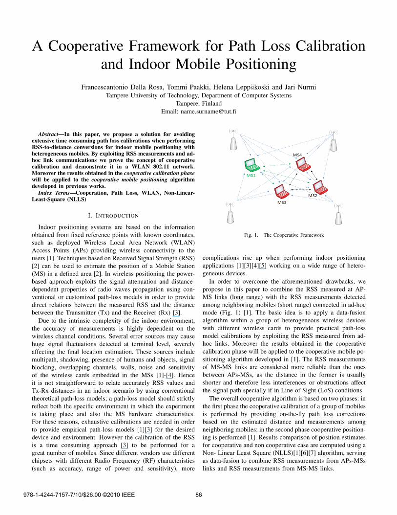
Fig. 1. The Cooperative Framework
complications rise up when performing indoor positioningapplications [1][3][4][5] working on a wide range of hetero-geneous devices.
In order to overcome the aforementioned drawbacks, wepropose in this paper to combine the RSS measured at AP-MS links (long range) with the RSS measurements detectedamong neighboring mobiles (short range) connected in ad-hocmode (Fig. 1) [1]. The basic idea is to apply a data-fusionalgorithm within a group of heterogeneous wireless deviceswith different wireless cards to provide practical path-lossmodel calibrations by exploiting the RSS measured from ad-hoc links. Moreover the results obtained in the cooperativecalibration phase will be applied to the cooperative mobile po-sitioning algorithm developed in [1]. The RSS measurementsof MS-MS links are considered more reliable than the onesbetween APs-MSs, as the distance in the former is usuallyshorter and therefore less interferences or obstructions affectthe signal path specially if in Line of Sight (LoS) conditions.
The overall cooperative algorithm is based on two phases: inthe first phase the cooperative calibration of a group of mobilesis performed by providing on-the-fly path loss correctionsbased on the estimated distance and measurements amongneighboring mobiles; in the second phase cooperative position-ing is performed [1]. Results comparison of position estimatesfor cooperative and non cooperative case are computed using aNon- Linear Least Square (NLLS)[1][6][7] algorithm, servingas data-fusion to combine RSS measurements from APs-MSslinks and RSS measurements from MS-MS links.
978-1-4244-7157-7/10/$26.00 ©2010 IEEE 86

The paper is organized as follows: section II describespositioning techniques, section III describes the conventionaland the cooperative calibration, section IV describes the coop-erative positioning algorithm, section V describes results andanalysis, section VI conclusions and future work.
II. POSITIONING TECHNIQUES
Several different radio navigation methods, based on differ-ent measurements and operation principles, have been used inpractical positioning applications [8]. The following measure-ments can be used for WLAN based positioning:• Angle Of Arrival (AOA):
AOA utilizes multi-array antennas which are used toestimate the line of arrival of the signal. The positionof the MS can be located at the intersection of the linesif more than one AOA measurements is performed. Re-flections and non-line-of-sight (NLOS) conditions distortthe direction of arrival of the signals, deteriorating theaccuracy of AOA positioning.
• Time Of Arrival (TOA):TOA information from the MS to a station with knowncoordinates (navigation satellites, base stations of wire-less communication networks, etc.) or vice versa can beestimated if both entities are precisely synchronized intime. To estimate the position of the MS, TOAs to atleast three stations in different locations are required formultilateration.
• Time Difference Of Arrival (TDOA):TDOA is based on estimating the difference in the arrivaltimes of the signals coming from two different trans-mitters to the receiver. Geometrically a particular TDOAvalue defines a hyperbola between the two receivers onwhich the MS may be located. The position of the MScan be estimated at the intersection of the hyperbolas ifmore than one TDOA measurements is performed. Oneof the benefits of this technique is that it does not requireknowledge of the absolute time of the transmission, i.e.,the receiver time does not need to be synchronized withthe transmitter, but the transmitters need to be synchro-nized with each other.
• Received Signal Strength:In RSS based positioning, the MS location is estimatedusing models that relate the strength of the received radiosignal either to the distance between the MS and thesignal emitter or to the MS location directly. Typicallyat least some parameters in the applied models aredetermined experimentally to adapt the model to theapplication environment. RSS based positioning methodscan be divided into three main categories: cell identifierbased, pathloss-based, and fingerprinting.
For consumer market positioning applications, the RSS ob-servables are considered to be more easily available than AOAor TOA, as the RSS can be passively listened from the accesspoints of the infrastructure WLAN, without adding any extraload to the network. According to IEEE 802.11 standard,the infrastructure access points periodically transmit beacon
frames, which contain information for network identification,broadcasting network capabilities, and for other control andmanagement purposes [9]. The MS can sweep from channel tochannel and record information from any beacon it receives.This process is performed regularly to determine the accesspoint with the best link quality. This allows the MS todetermine the cell identifiers and signal strengths of all APsvisible for the MS. In many mobile devices, such as mobilephones, PDAs and laptop computers, this information is easilyavailable through Application Programming Interfaces (API)of standard WLAN services.
A. Cell ID based positioning
In cell identifier method, the MS scans the available WLANchannels. As the position estimate it reports the position ofthe AP from which it received the strongest signal. In cellidentifier method, a MS needs prior information about thelocations of APs and their unique Media Access Control(MAC) addresses. Therefore, the system set-up for positioningis relatively easy. Granularity of the position estimate isdetermined by the distances between MS and AP. Because ofthe coarse granularity of the estimate and noise introduced bythe environment, this method is applicable only in scenarioswhere rather coarse accuracy is sufficient.
B. Fingerprinting
Fingerprinting approaches are based on experimental mod-els that relate the measured RSS values directly to the mea-surement position. These models are generated from off-linecollected data from several locations that sufficiently coverthe area where positioning is needed. Compared to other RSSbased methods, fingerprinting algorithms are considered to bemore robust against signal propagation errors such as multi-path or attenuations generated by walls and other structures;fingerprinting actually makes use of these location dependenterror characteristics of radio signals. In estimation phase, newmeasurement vectors are related with the information stored infingerprint database. A known disadvantage in fingerprintingapproaches is the fact that the collection of the data forfingerprint database is laborious and time consuming.
C. Pathloss-Based positioning
Path loss models of radio signals are used to translateRSS measurements to distances between the MS and APs.After the distances are estimated from RSS measurements,multilateration methods are used to estimate the position ofthe MS. To obtain a unique solution, the MS needs to measureRSS to at least three distinct APs. As in cell ID based methods,the MS needs prior information about the MAC addressesand locations of APs, which is easily acquired, at least whencompared with fingerprint databases. In indoor environments,multipath and attenuation caused by walls, other structures,and even people complicate the modeling of signal propaga-tion. Because of this, the positioning errors in pathloss-basedpositioning are typically larger than in fingerprinting [10]. On
87
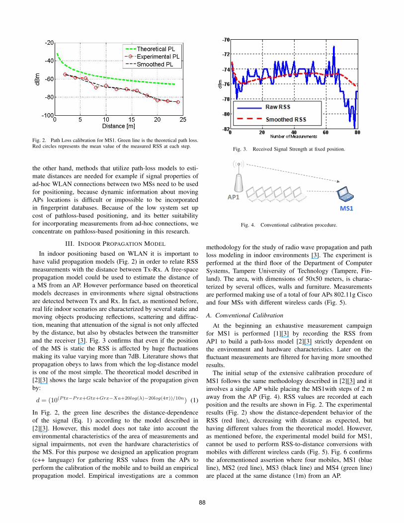
Fig. 2. Path Loss calibration for MS1. Green line is the theoretical path loss.Red circles represents the mean value of the measured RSS at each step.
the other hand, methods that utilize path-loss models to esti-mate distances are needed for example if signal properties ofad-hoc WLAN connections between two MSs need to be usedfor positioning, because dynamic information about movingAPs locations is difficult or impossible to be incorporatedin fingerprint databases. Because of the low system set upcost of pathloss-based positioning, and its better suitabilityfor incorporating measurements from ad-hoc connections, weconcentrate on pathloss-based positioning in this research.
III. INDOOR PROPAGATION MODEL
In indoor positioning based on WLAN it is important tohave valid propagation models (Fig. 2) in order to relate RSSmeasurements with the distance between Tx-Rx. A free-spacepropagation model could be used to estimate the distance ofa MS from an AP. However performance based on theoreticalmodels decreases in environments where signal obstructionsare detected between Tx and Rx. In fact, as mentioned before,real life indoor scenarios are characterized by several static andmoving objects producing reflections, scattering and diffrac-tion, meaning that attenuation of the signal is not only affectedby the distance, but also by obstacles between the transmitterand the receiver [3]. Fig. 3 confirms that even if the positionof the MS is static the RSS is affected by huge fluctuationsmaking its value varying more than 7dB. Literature shows thatpropagation obeys to laws from which the log-distance modelis one of the most simple. The theoretical model described in[2][3] shows the large scale behavior of the propagation givenby:
d = (10(Ptx−Prx+Gtx+Grx−Xa+20log(λ)−20log(4π))/10n) (1)
In Fig. 2, the green line describes the distance-dependenceof the signal (Eq. 1) according to the model described in[2][3]. However, this model does not take into account theenvironmental characteristics of the area of measurements andsignal impairments, not even the hardware characteristics ofthe MS. For this purpose we designed an application program(c++ language) for gathering RSS values from the APs toperform the calibration of the mobile and to build an empiricalpropagation model. Empirical investigations are a common
Fig. 3. Received Signal Strength at fixed position.
Fig. 4. Conventional calibration procedure.
methodology for the study of radio wave propagation and pathloss modeling in indoor environments [3]. The experiment isperformed at the third floor of the Department of ComputerSystems, Tampere University of Technology (Tampere, Fin-land). The area, with dimensions of 50x50 meters, is charac-terized by several offices, walls and furniture. Measurementsare performed making use of a total of four APs 802.11g Ciscoand four MSs with different wireless cards (Fig. 5).
A. Conventional Calibration
At the beginning an exhaustive measurement campaignfor MS1 is performed [1][3] by recording the RSS fromAP1 to build a path-loss model [2][3] strictly dependent onthe environment and hardware characteristics. Later on thefluctuant measurements are filtered for having more smoothedresults.
The initial setup of the extensive calibration procedure ofMS1 follows the same methodology described in [2][3] and itinvolves a single AP while placing the MS1with steps of 2 maway from the AP (Fig. 4). RSS values are recorded at eachposition and the results are shown in Fig. 2. The experimentalresults (Fig. 2) show the distance-dependent behavior of theRSS (red line), decreasing with distance as expected, buthaving different values from the theoretical model. However,as mentioned before, the experimental model build for MS1,cannot be used to perform RSS-to-distance conversions withmobiles with different wireless cards (Fig. 5). Fig. 6 confirmsthe aforementioned assertion where four mobiles, MS1 (blueline), MS2 (red line), MS3 (black line) and MS4 (green line)are placed at the same distance (1m) from an AP.
88

Fig. 5. MSs with different wireless cards.
Fig. 6. RSS measured at 1 m for MS1 (blue line), MS2 (red line), MS3(black line) and MS4 (green line).
Due to the different hardware and RF characteristics of theembedded wireless cards, the RSS recorded at terminal levelare not the same. Same behavior has been observed when thefour MSs have been placed at 22m faraway from the AP (Fig.7). It is observed that e.g. between MS1 and MS2 there is adifference of 25dB.
Once one MS is well calibrated following the time consum-ing procedure described before, the others can perform thecooperative calibration procedure shown in Fig. 8 and Fig. 9according to the proposed protocol of communications.
B. Cooperative Calibration
In order to perform the proposed cooperative calibration weassume two MSs, MS1 and MS2, in an area covered by oneaccess point (e.g. AP1). MS1 is the one already extensivelycalibrated. MS2 needs to be calibrated and it enters theregion covered by AP1. MS2 starts measuring the RSS valuesfrom the AP1. When MS2 detects MS1, it opens an ad-hocconnection for exchanging data with the MS1. MS2 recognizesthe MS1 to be well-calibrated for the area and requests forthe correction parameters from MS1. MS1 accepts/denies therequests with basic ack/nack messages respectively.
The corresponding ack is received by the MS2, after whichMS2 sends its measured RSS power from the AP1. When MS1receives the RSS measurements from the MS2 it also records
Fig. 7. RSS measured at 22 m for MS1 (blue line), MS2 (red line), MS3(black line) and MS4 (green line).
Fig. 8. The proposed protocol.
Fig. 9. Cooperative calibration.
RSS from ad-hoc connection. At this point it can solve thecorrection factor for MS2 path-loss model applied to its ownempirical model. (e.g. 25 dB as in Fig. 6). The correctionfactor is then sent to MS2, where it is applied. At this point
89

the ad-hoc connection is either terminated, or it can be used forfurther path-loss model refining of MS2 with more iterations ofthe procedure. An example of the proposed procedure for thecooperative calibration is explained below, and is illustrated inFig. 8 and Fig. 9:• MS1 and MS2 are placed at distance d1(e.g. 22) and d2
(e.g. 24m) from AP1 respectively and they measure theRSS from AP1.
• MS2 sends the recorded RSS to MS1 via ad-hoc connec-tion.
• MS1 measures also the RSS of the ad-hoc link with MS2and estimates the distance between them (e.g. 2m).
• MS1 is able to estimate the distance d1 from AP1 andthe distance d3 from MS2 (e.g. 2m).
• The distance d2 of MS2 from AP1 should not exceedd1+d3, and should not exceed the radius of d3 estimatedfrom ad-hoc RSS by MS1.
• MS1 calculates and sends the correction factor to beapplied to the path-loss model for MS2.
• MS2 can estimate the distance from AP1 with the newcorrected parameter.
Same procedure applies to any other mobile entering thecalibration area. It is worth mentioning that after the coop-erative calibration phase, any calibrated mobile can continueto cooperate for calibrating other MSs. At this point onceMSs are calibrated, they can perform the positioning algorithmdescribed in [1].
IV. COOPERATIVE POSITIONING ALGORITHM
Fig.10 shows the data-fusion algorithm for positioningwhich can be used after the MSs are calibrated. First RSSmeasured from APs are used to estimate the position of theMSs by using the Least Squares (LS) algorithm [1]. Theobtained estimates are the needed initial guesses for the NLLSalgorithm when used in the non-cooperative case (conventionaltechnique) [1]. Details regarding the positioning algorithm canbe found in [1][6]. To enhance the positioning accuracy (b),RSS from the ad-hoc MS-MS links are used to estimate therelative distances between the MSs and NLLS is used as data-fusion algorithm to combine all the measurements. A KalmanFilter (KF) is used to have smoothed measurements. Somenotations need to be defined:
x[j] =[x[j]y[j]
]T(2)
x[i] =[x(i)y(i)
]T(3)
d(i)[j]k =
√{x(i) − x[j]
}T {x(i) − x[j]
}(4)
d(i)(j)k =
√{x(i) − x(j)
}T {x(i) − x(j)
}(5)
x[j] represents the coordinates of APj ; x(i) are the estimatedcoordinates of MSi; d
(i)[j]k are the estimated distances between
Fig. 10. Non cooperative (a) and cooperative (b) positioning [1] .
APj and MSi at iteration k of the optimization routineof the NLLS when considering RSS from APs; d
(i)(j)k are
the estimated distances between MSj and MSi at iterationk when considering RSS from ad-hoc links. The objectivefunction of the NLLS to be minimized in order to determinethe location of the MSs is described as [1]:
I(x(i)) =n∑i=1
N∑j=1
{JT
(x(i))}2
+n∑i=1
N∑j=1,j 6=i
{JP
(x(i))}2
(6)n is the total number of MSs and N is the total number of
APs. The functions J (·) can be defined as:
JT
(x(i))
= d(i)[j] − dk(i)[j]
(7)
JP
(x(i))
= d(i)(j) − dk(i)(j)
(8)
V. RESULTS AND ANALYSIS
The accurate and time consuming calibration of MS1 (whichis our reference MS for calibrating the other MSs) is confirmedby the test results shown in Fig. 13. By placing the calibratedMS1 at 22m of distance from AP1 and recording the RSS,we are able to estimate its distance from AP1 being closeto 22m. As mentioned before, when applying the path-lossmodel of MS1 (which at 22 m has a RSS value in averageequal to -85dBm as shown in Fig. 11) to the measurementsof MS2 (average value -62dBm) the estimated distance (Fig.13) is close to 7m. This confirms that the path loss modelcannot be applied as it is (without any correction). After havingperformed the cooperative calibration proposed in sec. III,MS1 can calculate the correction parameter to be applied forMS2. While Fig. 12 shows the corrected model for MS2, Fig.13 (red line) shows the obtained results for the cooperativecalibration of MS2, where the estimated distance is close tothe real one (24m).
As mentioned before, once MS2 is calibrated it can calibratealso other incoming MSs by following the same proceduredescribed before for its own cooperative calibration phase, andit can send the correction parameter to be applied. Resultsare shown in Fig. 14 and Fig. 15 where after the cooperative
90

Fig. 11. RSS for MS1 (real distance = 22m) and MS2 (real distance = 24m).
Fig. 12. Pathloss calibration of MS2 calibrated by MS1.
calibration between MS2 and MS4, MS2 can calculate thecorrection parameter for MS4. Fig. 14 shows the correctedmodel for MS4, Fig. 15 (red line) shows the obtained resultsfor the cooperative calibration of MS4, where the estimateddistance is between 22m and 24m.
Before introducing the numerical results of the cooperativepositioning algorithm [1], it has to be highlighted that sincethe power fluctuations introduce large estimation errors, therecorded RSS measurements have been pre-filtered with a KF.The performance of the data fusion is evaluated by calculatingthe Root Mean Square Error (RMSE), which is defined as:
RMSE =√
(Xreal − Xest)2 + (Yreal − Yest)2 (9)
where [Xreal, Yreal] and [Xest, Yest] are respectively thereal and the estimated coordinates of the MSs. The resultis obtained by positioning the two MSs at a distance of 2m from each other. Fig. 16 shows the map of the mea-surement area with the estimated positions of MS1. Thecoordinates of the exact positions of the APs and the MSsutilized in the experiment are as follows: AP1(0,0), AP2(-26,22), AP3(20,22), AP4(6.6,13), MS1(-10,21), MS2(-8,21).It is observed that cooperative NLLS gives better results with
Fig. 13. Estimated distance for MS1 and MS2.
Fig. 14. Path loss calibration of MS4 with MS2.
Fig. 15. Estimated distance for MS2 (real distance= 23m) and MS4 (realdistance 24m).
respect to the non-cooperative NLLS algorithm. In Fig. 17the Cumulative Distribution Function (CDF) of the RMSE isshown and it proves that cooperation among mobiles enhancesthe localization accuracy.
Table 1 shows the RMSE of the estimated positions for bothcooperative and non-cooperative case with gains going up to38% in our scenario.
91

Fig. 16. Estimated positions with and without cooperation.
Fig. 17. CDF of RMSE with and without cooperation.
TABLE IRMSE WITH AND WITHOUT COOPERATION.
- Without Cooperation With Cooperation gainMS1 14.0m 10.4m 26%MS2 19.3m 12.1m 38%
VI. CONCLUSION
The method proposed in this paper avoids to repeat theconventional calibration procedure for several mobiles, evenif they have different wireless cards, by exploiting the RSSconstraint coming from ad-hoc connections between MS1 (thealready well calibrated MS) and the not calibrated MSs con-nected in ad-hoc mode. In particular, our aim has been to provethe concept of cooperative calibration in a WLAN 802.11network. Moreover cooperation among calibrated mobiles canenhance the localization accuracy in adverse indoor scenarios.The numerical results show that for the specific scenario
assumed, that the cooperative technique can enhance thelocalization accuracy with gains in the range of [26%, 38%].The future work will be mainly focused on implementing areal-time platform, and investigate error propagations in multi-hop cooperative calibrations.
ACKNOWLEDGMENT
The research leading to these results has received fund-ing from the European Community’s Seventh FrameworkProgramme (FP7/2007-2013) under the GRAMMAR project,grant agreement n. 227890.
REFERENCES
[1] F. Della Rosa, S.A. Wardana, C.L.F. Mayorga, G. Simone, M.C.N. Ray-nal, J. Figueiras, S. Frattasi, Experimental Activity on Cooperative MobilePositioning in Indoor Environments, 2nd IEEE Workshop on AdvancedExperimental Activities on Wireless Networks and Systems (EXPON-WIRELESS), Helsinki, Finland, June, 2007.
[2] A. Kotanen, M. Hannikainen, H. Leppakoski, T.D. Hamalainen, Position-ing with IEEE 802.11b Wireless LAN, Proceedings on Personal, Indoorand Mobile Radio Communications, (PIMRC) 2003.
[3] A. Bose, Chuan Heng Foh, A practical pathloss model for indoor wifipositioning enhancement, 6th International Conference on Information,Communications & Signal Processing, 2007.
[4] K. Kaemarungsi, Distribution of WLAN Received Signal Strength Indica-tion for Indoor Location Determination, 1st International Symposium onWireless Pervasive Computing, 2006.
[5] A. Shahid, P. Nobles, A Novel Indoor Location Sensing Mechanism forIEEE 802.11 b/g Wireless LAN, 4th Workshop on Positioning, Navigationand Communication (WPNC’07). Hannover, Germany.
[6] C.L.F. Mayorga, F. Della Rosa, S.A. Wardana, G. Simone, M.C.N. Ray-nal, J. Figueiras, S. Frattasi, Cooperative Positioning Techniques for Mo-bile Localization in 4G Cellular Networks, IEEE International Conferenceon Pervasive Services (ICPS), Instanbul, Turkey, July, 2007.
[7] A.H. Sayed,H. Tarighat, N. Khajehnouri, Network-Based Wireless Loca-tion: Challenges Faced in Developing Techniques for Accurate WirelessLocation Information, IEEE Signal Processing Magazine, vol. 22, no. 4,pp. 24-40, July, 2005.
[8] J. Syrjarinne, Studies on Modern Techniques for Personal Position-ing,PhD thesis, Tampere University of Technology, 2001.
[9] M. Wallbaum, S. Diepolder Benchmarking wireless LAN location sys-tems,In Proc. Second IEEE International Workshop on Mobile Commerceand Services WMCS’05 (July 2005), IEEE, pp. 42-51.
[10] P. Bahl, V.N. Padmanabhan Radar: An in-building RF-based userlocation and tracking system,In Proc. IEEE INFOCOM 2000 Conferenceon Computer Communications (March 2000), vol. 2, IEEE, pp. 775-785.
92