Indoor Positioning Using Ultrasound and Radio Combination
12
Indoor Positioning Using Ultrasound and Radio Combination Gintautas Salcius, Evaldas Povilaitis, Algimantas Tacilauskas Centre of Real Time Computer Systems, Kaunas University of Technology Studentu St. 50, Kaunas, Lithuania [email protected], [email protected], [email protected] ABSTRACT The paper introduces a method of indoor positioning using a combination of ultrasound and radio frequency. This method allows for a more effective usage of radio frequency as it is employed for both object identification and time synchronization by calculating ultrasound propagation time, as well as object positioning using radio signal strength values. Application of this method forms the basis of positioning system that can estimate the position of mobile and stationary objects when an object has been detected by at least two ultrasound listeners, while the systems that are in usage today require for the object to be detected by at least three listeners. Experiments on an object that was detected by only two ultrasonic listeners resulted in a mean error of 34.1 cm, whereas consistent positioning would not have been possible when limited only to ultrasound technology. The aforementioned mean error is also a few times lower than the one resulting from positioning when only radio frequency is used. KEYWORDS Indoor positioning, Ultrasound, RF, Fingerprinting, RSSI. 1 INTRODUCTION Following the rapid development of technology, more and more innovative solutions are being brought into our daily lives and homes. In order to develop cutting-edge, smart house management solutions, a precise object (people, devices, things, etc.) positioning and identification system is required. There are several reasons for that: achieving maximum system precision; applying technologies that would compensate their weaknesses with the strengths of other technologies; creating a more universal, adjustable and user-friendly system. At present, commonly used technologies for indoor positioning include Infrared, Ultrasonic, computer vision, ZigBee, RFID, UWB and WLAN [1]. GPS technology is not on the list because it is not suitable for indoor usage. Of existing technologies, position estimation using ultrasound is appealing for its high accuracy rate (up to centimeters or even millimeters) and inexpensive equipment. However, when employed alone, ultrasound technology does not solve all problems that may arise: objects are not always in the line of sight, not to mention difficulties in identifying multiple mobile objects, time synchronization and such. These problems are effectively solved by combining ultrasound with other technologies. This paper proposes a method that combines best features of ultrasound and RF technologies for effective indoor positioning. With the application of the suggested method, the potential of the active ultrasound positioning system is realized. In the proposed case, a beacon device sending out ultrasonic and RF signals is attached to a mobile object. The beacon does not perform any additional calculations, resulting in reduced power consumption and extended battery life. Mobile object positioning using ultrasound is done by calculating the distance between active (beacon) and passive (listener) devices. Different 3D positioning methods can be employed when the distance between devices is known. Adding RF technology solves three problems arising from ultrasound usage: time synchronization is ensured when calculating ultrasound time of ISBN:978-0-9891305-8-5 ©2014 SDIWC 109
Transcript of Indoor Positioning Using Ultrasound and Radio Combination

Indoor Positioning Using Ultrasound and Radio Combination
Gintautas Salcius, Evaldas Povilaitis, Algimantas Tacilauskas Centre of Real Time Computer Systems, Kaunas University of Technology
Studentu St. 50, Kaunas, Lithuania [email protected], [email protected], [email protected]
ABSTRACT The paper introduces a method of indoor positioning using a combination of ultrasound and radio frequency. This method allows for a more effective usage of radio frequency as it is employed for both object identification and time synchronization by calculating ultrasound propagation time, as well as object positioning using radio signal strength values. Application of this method forms the basis of positioning system that can estimate the position of mobile and stationary objects when an object has been detected by at least two ultrasound listeners, while the systems that are in usage today require for the object to be detected by at least three listeners. Experiments on an object that was detected by only two ultrasonic listeners resulted in a mean error of 34.1 cm, whereas consistent positioning would not have been possible when limited only to ultrasound technology. The aforementioned mean error is also a few times lower than the one resulting from positioning when only radio frequency is used. KEYWORDS Indoor positioning, Ultrasound, RF, Fingerprinting, RSSI. 1 INTRODUCTION Following the rapid development of technology, more and more innovative solutions are being brought into our daily lives and homes. In order to develop cutting-edge, smart house management solutions, a precise object (people, devices, things, etc.) positioning and identification system is required. There are several reasons for that: achieving maximum system precision; applying technologies that
would compensate their weaknesses with the strengths of other technologies; creating a more universal, adjustable and user-friendly system. At present, commonly used technologies for indoor positioning include Infrared, Ultrasonic, computer vision, ZigBee, RFID, UWB and WLAN [1]. GPS technology is not on the list because it is not suitable for indoor usage. Of existing technologies, position estimation using ultrasound is appealing for its high accuracy rate (up to centimeters or even millimeters) and inexpensive equipment. However, when employed alone, ultrasound technology does not solve all problems that may arise: objects are not always in the line of sight, not to mention difficulties in identifying multiple mobile objects, time synchronization and such. These problems are effectively solved by combining ultrasound with other technologies. This paper proposes a method that combines best features of ultrasound and RF technologies for effective indoor positioning. With the application of the suggested method, the potential of the active ultrasound positioning system is realized. In the proposed case, a beacon device sending out ultrasonic and RF signals is attached to a mobile object. The beacon does not perform any additional calculations, resulting in reduced power consumption and extended battery life. Mobile object positioning using ultrasound is done by calculating the distance between active (beacon) and passive (listener) devices. Different 3D positioning methods can be employed when the distance between devices is known. Adding RF technology solves three problems arising from ultrasound usage: time synchronization is ensured when calculating ultrasound time of
ISBN:978-0-9891305-8-5 ©2014 SDIWC 109
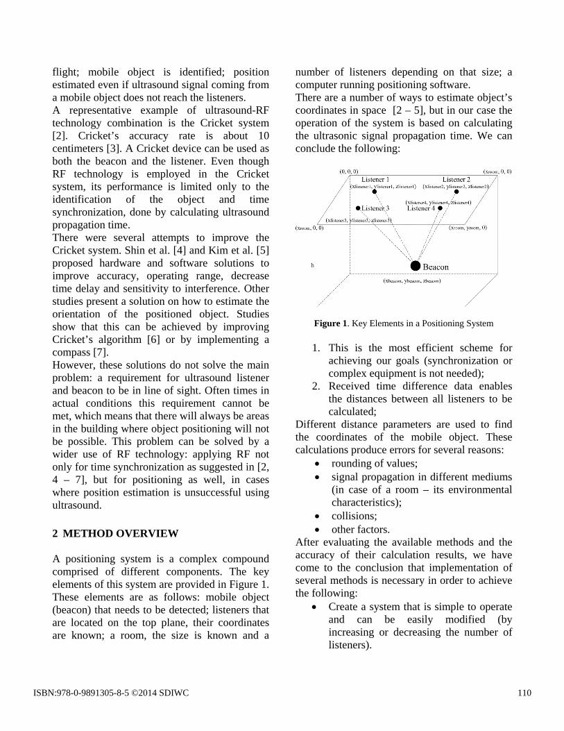
flight; mobile object is identified; position estimated even if ultrasound signal coming from a mobile object does not reach the listeners. A representative example of ultrasound-RF technology combination is the Cricket system [2]. Cricket’s accuracy rate is about 10 centimeters [3]. A Cricket device can be used as both the beacon and the listener. Even though RF technology is employed in the Cricket system, its performance is limited only to the identification of the object and time synchronization, done by calculating ultrasound propagation time. There were several attempts to improve the Cricket system. Shin et al. [4] and Kim et al. [5] proposed hardware and software solutions to improve accuracy, operating range, decrease time delay and sensitivity to interference. Other studies present a solution on how to estimate the orientation of the positioned object. Studies show that this can be achieved by improving Cricket’s algorithm [6] or by implementing a compass [7]. However, these solutions do not solve the main problem: a requirement for ultrasound listener and beacon to be in line of sight. Often times in actual conditions this requirement cannot be met, which means that there will always be areas in the building where object positioning will not be possible. This problem can be solved by a wider use of RF technology: applying RF not only for time synchronization as suggested in [2, 4 – 7], but for positioning as well, in cases where position estimation is unsuccessful using ultrasound. 2 METHOD OVERVIEW A positioning system is a complex compound comprised of different components. The key elements of this system are provided in Figure 1. These elements are as follows: mobile object (beacon) that needs to be detected; listeners that are located on the top plane, their coordinates are known; a room, the size is known and a
number of listeners depending on that size; a computer running positioning software. There are a number of ways to estimate object’s coordinates in space [2 – 5], but in our case the operation of the system is based on calculating the ultrasonic signal propagation time. We can conclude the following:
Figure 1. Key Elements in a Positioning System
1. This is the most efficient scheme for achieving our goals (synchronization or complex equipment is not needed);
2. Received time difference data enables the distances between all listeners to be calculated;
Different distance parameters are used to find the coordinates of the mobile object. These calculations produce errors for several reasons:
• rounding of values; • signal propagation in different mediums
(in case of a room – its environmental characteristics);
• collisions; • other factors.
After evaluating the available methods and the accuracy of their calculation results, we have come to the conclusion that implementation of several methods is necessary in order to achieve the following:
• Create a system that is simple to operate and can be easily modified (by increasing or decreasing the number of listeners).
ISBN:978-0-9891305-8-5 ©2014 SDIWC 110

• Combine radio frequency and ultrasound technologies for successful coordinate estimation in unfavorable circumstances.
• Achieve the maximum possible accuracy in coordinate estimation.
In that case the positioning algorithm was that the system would adapt to varying listener numbers on its own. Listener numbers can vary for the following reasons:
• room size; • signal sent by the beacon does not reach
the listener. These factors were put into consideration when the following positioning methods were chosen:
1. trilateration method; [8] 2. matrix method; [8] 3. two points method (supplemented with
RSSI technology) [9]. The position estimation algorithm was created using these methods. The steps of this algorithm are presented in Figure 2.
Figure 2. Visualization of the position estimation algorithm
This algorithm is used to calculate the coordinates of a mobile object, and is comprised of the following steps:
1. Distance between the mobile object and all of the listeners is determined by calculating the signal propagation time.
2. The number of listeners that detected the mobile object is determined.
3. Position estimation method is chosen according to the determined number of listeners.
4. Estimated coordinates returned. According to known data the coordinates of a moving object are calculated by estimating the distances between each of the listeners and their coordinates on the coordinate plane. Position estimation method is chosen according to the number of listeners that are being used. These methods have different mathematical expressions. The first part of the formula for the first two methods is the same:
21
222 r)()()( =−+−+− iii zzyyxx
(i = 1, 2, …, n), r – distance between the listener and the mobile object.
(1)
Derivation of this formula (different for each method) can be used to estimate the coordinates of the moving object. 2.1 Position Estimation Using Trilateration
Method This method requires for at least three listeners to “see” the moving object in space.
Figure 3. Position Estimation Using Circles Method
The sequence in which those listeners detect the object is not important: the object can be detected by the first, second and third listeners
ISBN:978-0-9891305-8-5 ©2014 SDIWC 111

or the second, third and fourth. What is important is for the arrangement of points to be maintained, as shown in Figure 3. Standard formulas are used to estimate the coordinates of the mobile object on a plane. Those formulas can be found in [8]. 2.2 Position Estimation Using Matrix Method The same conditions apply for this case as well: distances to all listeners and their coordinates on a plane are known. But in this case at least four listeners detecting the moving object are required for position estimation (Figure 4).
Figure 4. Position Estimation Using Matrix Method
There is an additional requirement: at least one of the listeners detecting the object must be placed at a different height from all the other listeners. The number of listeners is not limited as long as it is not less than four (>4). This method is realized by implementing standard formulas [8]. 3 POSITION ESTIMATION USING TWO
POINTS AND RSSI METHOD In cases when successful positioning is impossible using ultrasound, a method implementing both RF technology and ultrasound has been proposed. There are several methods that can be implemented for position estimation using radio
frequency but the most efficient one for indoor positioning is the fingerprinting method. However, in order to apply this method successfully, initial information on signal propagation of every radio device is required. This information can be gathered experimentally (signal strength is measured in various indoor areas and entered into a database) or mathematically (signal propagation model is created and signal strength in specified room areas is estimated on a computer according to that model). Determining signal strength experimentally is time-consuming, so in case of fingerprinting it was decided to use signal propagation models. 3.1 Prediction of Radio Signal Propagation Using theoretical signal propagation models based on empirical measurements is a relatively simple way to estimate indoor RF propagation. These models do not require a lot of the initial parameters and can be calculated quite fast compared to the deterministic models that are based on signal propagation and diffraction theories (Geometrical Optics and Uniform Theory of Diffraction formulations) [10]. Early empirical methods were derived from the Free Space Propagation model. This model is based on gathering measurement data under actual conditions and then using it to estimate unknown coefficient values. More complex models were created later on, and they included a significant number of additional parameters affecting signal propagation. Therefore, their results were far more accurate. These models were chosen for further investigation on their application possibilities when radio beacons are used for positioning. Path-loss prediction is commonly expressed in the following way [11]:
∑∑ ==++=
Q
q
P
pn qFAFpWAF
dddBdPL
110
)()()log(10])[( (2)
PL(d) stands for received signal strength in the distance d between the beacon and the listener.
ISBN:978-0-9891305-8-5 ©2014 SDIWC 112

d0 is distance between the beacon and a spot where the initial signal strength has been measured. Usually d0 is equal to 1 m, in such case only propagation effects are included in (2). p and q are the number of walls and floors between the beacon and the listener, respectively. The empirical parameters n, WAF (p) and FAF (q) are respectively the path-loss exponent, wall attenuation factor and floor attenuation factor. This model does not include signal propagation effects, such as attenuation from traveled distance, angle of incidence with walls and so on. This may lead to lower accuracy in calculation results in certain areas of the building. These deficiencies were well noted when creating the New Empirical Model which is written in the following way [12]:
∑ ∑= =++−+
++−=
P
p
Q
qqp
bpn
bp
nbpbp
n
qFAFpWAFddUdd
dd
ddUdddBdPL
1 1
00
)cos()(
)cos()()(])log(
)[log()()log(10])[(
2
11
θθ
(3)
PL(d) is the loss of signal strength at a point of distance d from the beacon, d0 – distance between the beacon and a spot where the initial signal strength has been measured, dbp is the distance of the breakpoint from the beacon, n1 is the first path-loss exponent (in front of the breakpoint), n2 – the second path-loss exponent (behind the breakpoint), U is the unit step function, p – the number of walls in signal propagation path, q - the number of floors in signal propagation path, WAF – wall attenuation factor, FAF – floor attenuation factor, θp – signal angle of incidence with walls, θq – signal angle of incidence with floors. WAF(p) and FAF(q) are the attenuation factor values for the signal when it is moving perpendicular to walls or floors, θp and θq are angles of incidence between, respectively, the p-th wall and q-th floor and a straight line connecting the beacon and the listener.
3.2 Positioning Using RSSI and Propagation Models
Before object positioning can take place, a detailed building plan is required along with a signal propagation model for each RF listener. These models are created in accordance with the previously described RF signal propagation formula (3). Once the aforementioned data is prepared, object positioning can take place. Object positioning algorithm idea is based on Euclidean distance calculation [9]. Algorithm is executed in the following order: 1. All of the RF listeners connected to the
system send the following information on every detected beacon to the server: • Received signal strength indicator –
RSSI, • Listener identifier – ID, • Listener packet identifier – PID, used
for correct time synchronization. 2. Positioning is performed only for those
beacons that were last detected (i.e., their transmitted radio packet was last received) in a specified amount of time by at least two listeners.
3. In order to reduce the amount of calculations, the probable location of the beacon is estimated using signal propagation models (instead of analyzing the entire plan of the building) by excluding all the areas where the beacon could not be located. To do so, information from all of the listeners is used to determine if the beacon was detected by the listener or not. In order to estimate the likely location of the beacon, the coverage area of each of the listeners is compared. Coverage area of the listeners is determined by using their signal propagation models.
4. In order to determine the actual position of the positioned object, the Euclidean distance between the measured and calculated values is calculated using the following formula:
ISBN:978-0-9891305-8-5 ©2014 SDIWC 113

∑=
−=n
iii pqd
1
2)( (4)
qi – signal strength index measured by the i-th listener, pi – value of the i-th listener found in its signal propagation model, n – number of listeners used in the positioning system. The number of Euclidean distances estimated depends on the number of signal propagation models created and values calculated in them.
5. The minimum Euclidean distance is found and the corresponding row and column indexes values are saved.
6. The position is estimated in meters according to the row index and column index. Coordinates x and y are calculated in the following way:
cnax ⋅= (5)
where a stands for the length of the room in meters, n – number of columns in RSSI values’ file, c – column index.
rmby ⋅= (6)
where b stands for the width of the room in meters, m – number of rows in RSSI values’ file, r – row index. 3.3 Position Correction Using RF Positioning Position estimation using radio frequency is not as accurate as ultrasound positioning. However, it can be very useful when the positioning algorithm determines more than one likely position using ultrasound, i.e., when a system of equations with several possible solutions is formed.
Figure 5. Position Estimation Using Two Points Method
When we have only two points (listeners) we can estimate two area points where the mobile object is likely located (Figure 5). In such case the accurate position cannot be determined. Nonetheless, by employing RSSI the accurate position can be estimated by using coordinates of several possible locations. Calculations are done using the following formulas:
ace −= (7)
where a is the x-coordinate of the first listener, c – x-coordinate of the second listener, e – x-coordinates difference.
bdf −= (8)
where b is the y-coordinate of the first listener, d – y-coordinate of the second listener, f – y-coordinates difference.
22 fep +=
(9)
where p is the distance between the centers of two circles.
psrpk
⋅−+= 2
)( 222
(10)
where k is the distance between the center of one of the circles and the line connecting the points of intersection, r
ISBN:978-0-9891305-8-5 ©2014 SDIWC 114

and s – distance between both points and the mobile object.
We can estimate the distance between two known points by using formulas given above. The coordinates of those points are used in order to do so. All the estimated values are needed for finding the x and y coordinates of the mobile object. Formulas are given below:
221 // krpfpkeax −⋅+⋅+= (11)
22
1 // krpepkfby −⋅−⋅+= (12)
or
222 // krpfpkeax −⋅−⋅+= (13)
22
2 // krpepkfby −⋅+⋅+= (14)
Incorrect coordinates can be dismissed by taking into consideration the estimated position calculated with the help of RF positioning. This is done by following the steps outlined below:
1. The distance between coordinates found by the RF positioning and coordinates of all likely spots found by the ultrasound positioning algorithm is calculated.
2. The coordinates that have the smallest distance between them are chosen.
The closest coordinates estimated by ultrasound positioning is then presented as the actual position of the mobile object. 4 POSITIONING SYSTEM ELEMENTS
AND THEIR APPLICATION The general structure of the positioning system is given in Figure 6. It is comprised of the following elements: • Server running positioning software. The
server receives data packets sent from the listeners, processes this data and estimates
the position of the beacon. It can then send this information to other systems.
• Local area network connecting the listeners and the server into a single network using a TCP/IP protocol.
Figure 6. Positioning System Structure
• Listeners that can receive ultrasonic and radio signals from a mobile beacon. Additionally, each listener calculates the time of flight of the ultrasonic signal (the time it takes for the ultrasonic signal to reach the listener) and sends this information to the positioning server.
• A beacon that is usually attached to a mobile object minimizing the possibility of various obstacles interfering with ultrasound and radio signals.
The beacon sends out a data packet (its structure is given in Figure 7) via radio frequency. Additionally, it sends out an ultrasound signal.
Figure 7. Beacon Data Packet Structure Beacon data packet contains the basic information required for registering the ultrasonic propagation time and identifying the object. Beacon ID identifies both the beacon and the mobile object. Packet ID is used for correct time synchronization. With each data packet and ultrasonic signal sent, packet ID is increased by
ISBN:978-0-9891305-8-5 ©2014 SDIWC 115

one. Beacon temperature readings are required for further operations when the ultrasound time of flight is calculated by the server. Data packets sent by the beacon are received by the listener which processes the information and creates a new data packet by supplementing the old one and then sending it to the server. Listener data packet structure is given in Figure 8.
Figure 8. Listener Data Packet Structure
Listener ID identifies the listener. It is used by the server to determine which listener sent the data packet so it can associate known listener coordinates with the actual listener. Both beacon and listener temperature readings are used in further calculations when the ultrasound propagation distance is estimated by the server. BID (beacon ID), PID (beacon packet ID) and BT (beacon temperature) contained in the listener data packet are the same as the ones received from the beacon. When data is received from the beacon (a RF packet is received), the received signal strength indicator (RSSI) is measured for that packet as well. This value is then logged in the packet bound for the positioning server. The last measurement in the data packet is dt – ultrasound time of flight which is used for estimating the position of the object. As mentioned earlier, the main task of the beacon is to send out a radio data packet and an ultrasound signal. A detailed chart on the operation of the beacon is given in the following diagram (Figure 9).
Figure 9. Beacon Operation Chart
Time intervals between packets can be configured. For objects that move (for example, people) this time interval needs to be quite short (less than 1 s) in order to maintain accuracy. For stationary or rarely moved objects time interval can be prolonged to decrease beacon energy consumption. In either case, energy consumption will be relatively low because the beacon will not perform any additional calculations nor will it process large amounts of data. This means that beacon performance can rely solely on batteries or an accumulator. Before the ultrasonic signal and RF packet is sent, the beacon checks if the radio channel is idle. It reduces the number of possible collisions in case there are several mobile objects in the room. The principle of operation for listeners is more complex. Not only does the listener have to receive the ultrasonic and radio signals from the beacon, but it also has to calculate the ultrasonic signal time of flight. Ultrasound time of flight measurements are used by the server in estimating listener’s position using ultrasound. Listener operation chart is given in Figure 10.
ISBN:978-0-9891305-8-5 ©2014 SDIWC 116
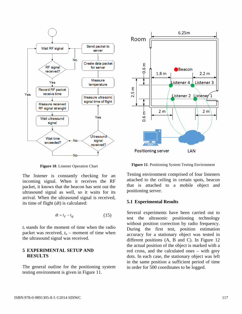
Figure 10. Listener Operation Chart
The listener is constantly checking for an incoming signal. When it receives the RF packet, it knows that the beacon has sent out the ultrasound signal as well, so it waits for its arrival. When the ultrasound signal is received, its time of flight (dt) is calculated:
utrtdt −= (15) tr stands for the moment of time when the radio packet was received, tu – moment of time when the ultrasound signal was received. 5 EXPERIMENTAL SETUP AND
RESULTS
The general outline for the positioning system testing environment is given in Figure 11.
Figure 11. Positioning System Testing Environment
Testing environment comprised of four listeners attached to the ceiling in certain spots, beacon that is attached to a mobile object and positioning server. 5.1 Experimental Results Several experiments have been carried out to test the ultrasonic positioning technology without position correction by radio frequency. During the first test, position estimation accuracy for a stationary object was tested in different positions (A, B and C). In Figure 12 the actual position of the object is marked with a red cross, and the calculated ones – with grey dots. In each case, the stationary object was left in the same position a sufficient period of time in order for 500 coordinates to be logged.
ISBN:978-0-9891305-8-5 ©2014 SDIWC 117
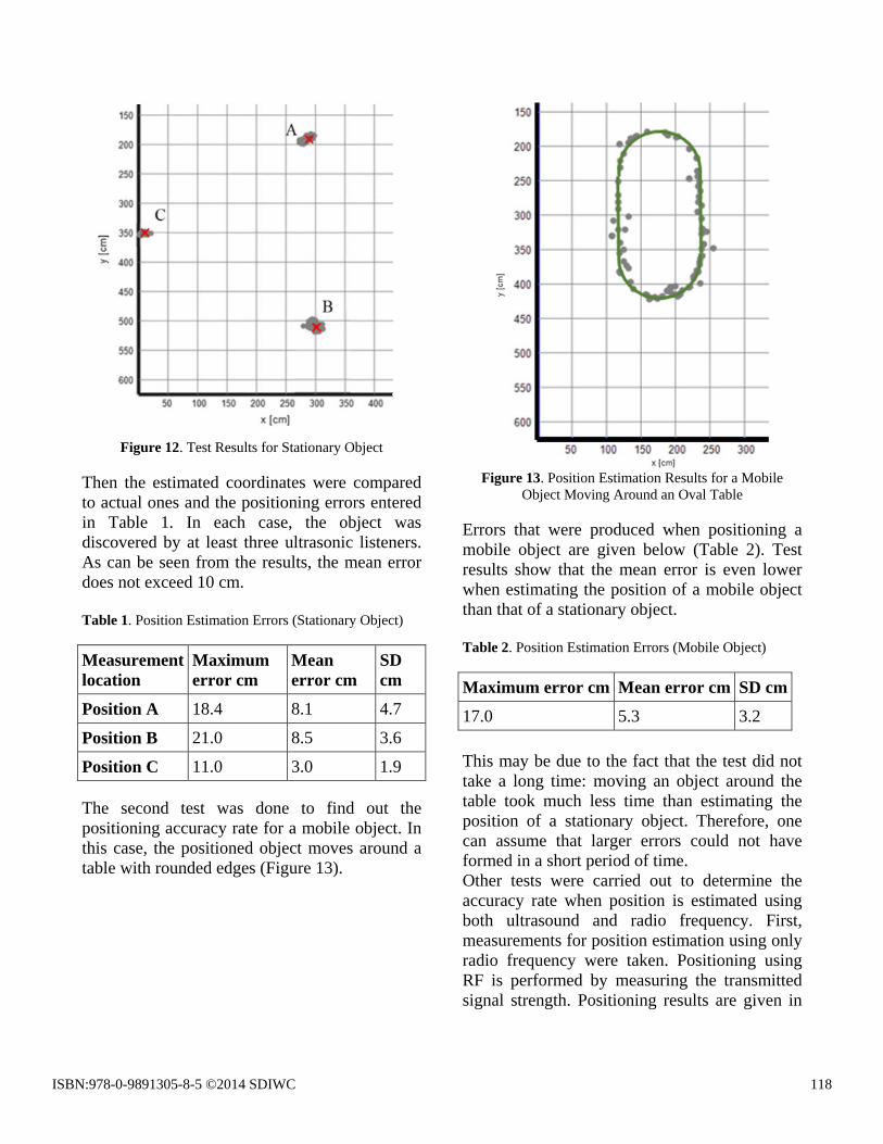
Figure 12. Test Results for Stationary Object
Then the estimated coordinates were compared to actual ones and the positioning errors entered in Table 1. In each case, the object was discovered by at least three ultrasonic listeners. As can be seen from the results, the mean error does not exceed 10 cm. Table 1. Position Estimation Errors (Stationary Object)
Measurement location
Maximum error cm
Mean error cm
SD cm
Position A 18.4 8.1 4.7
Position B 21.0 8.5 3.6
Position C 11.0 3.0 1.9
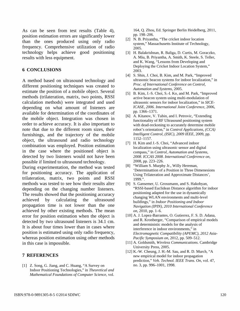
The second test was done to find out the positioning accuracy rate for a mobile object. In this case, the positioned object moves around a table with rounded edges (Figure 13).
Figure 13. Position Estimation Results for a Mobile
Object Moving Around an Oval Table
Errors that were produced when positioning a mobile object are given below (Table 2). Test results show that the mean error is even lower when estimating the position of a mobile object than that of a stationary object. Table 2. Position Estimation Errors (Mobile Object)
Maximum error cm Mean error cm SD cm
17.0 5.3 3.2 This may be due to the fact that the test did not take a long time: moving an object around the table took much less time than estimating the position of a stationary object. Therefore, one can assume that larger errors could not have formed in a short period of time. Other tests were carried out to determine the accuracy rate when position is estimated using both ultrasound and radio frequency. First, measurements for position estimation using only radio frequency were taken. Positioning using RF is performed by measuring the transmitted signal strength. Positioning results are given in
ISBN:978-0-9891305-8-5 ©2014 SDIWC 118

Figure 14 (the actual position of the object is marked by a red cross).
Figure 14. Position Estimation Results Using Radio Frequency
As can be seen from the test results, when limited only to radio technology position estimation produced much larger errors than when positioning was performed using ultrasound technology. Table 3. Position Estimation Errors When Radio Frequency Is Used
Maximum error cm Mean error cm SD cm
249.6 144.3 66.8 It is clear from the results in Table 3 that position estimation produced much larger errors when radio frequency was used. However, radio frequency has its own advantages: it does not require the line of sight zone between the beacon and the listener, whereas the ultrasound technology is limited by this requirement. In the case of ultrasound, even the smallest obstacles in ultrasonic signal’s path may prevent it from reaching the listener. Generally, position estimation using radio frequency is impractical because it cannot produce accurate results. Nevertheless, this method is very useful when an ultrasound beacon is detected by an insufficient number of listeners.
Figure 15. Position Estimation Results Using Ultrasound
and Radio Frequency In the case where the beacon is detected by two listeners, accurate positioning by measuring ultrasound time of flight is impossible because a system of equations with several solutions is formed. But if we add the approximate position estimated by using radio frequency into this equation, we can dismiss faulty solutions and calculate the value that is closest to the actual position of the object. Position estimation results in a case of ultrasound beacon being detected only by two listeners are shown in Figure 15. Position estimation accuracy for a stationary object was tested in different positions (A, B and C) Estimation results differ from the actual positions (marked by a red cross) by 52.5 cm at most, and the mean error is 34.1 cm. Table 4. Position Estimation Errors Using Ultrasound and Radio Frequency
Measurement location
Maximum error cm
Mean error cm
SD cm
Position A 52.5 34.1 43.6
Position B 49.3 32.7 21.5
Position C 52.2 25.8 12.7
ISBN:978-0-9891305-8-5 ©2014 SDIWC 119
As can be seen from test results (Table 4), position estimation errors are significantly lower than the ones produced using only radio frequency. Comprehensive utilization of radio technology helps achieve good positioning results with less equipment. 6 CONCLUSIONS A method based on ultrasound technology and different positioning techniques was created to estimate the position of a mobile object. Several methods (trilateration, matrix, two points, RSSI calculation methods) were integrated and used depending on what amount of listeners are available for determination of the coordinates of the mobile object. Integration was chosen in order to achieve accuracy. It is also important to note that due to the different room sizes, their furnishings, and the trajectory of the mobile object, the ultrasound and radio technology combination was employed. Position estimation in the case where the positioned object is detected by two listeners would not have been possible if limited to ultrasound technology. During experimentation, the method was tested for positioning accuracy. The application of trilateration, matrix, two points and RSSI methods was tested to see how their results alter depending on the changing number listeners. The results showed that the positioning accuracy achieved by calculating the ultrasound propagation time is not lower than the one achieved by other existing methods. The mean error for position estimation when the object is detected by two ultrasound listeners is 34.1 cm. It is about four times lower than in cases where position is estimated using only radio frequency, whereas position estimation using other methods in this case is impossible. 7 REFERENCES [1] Z. Song, G. Jiang, and C. Huang, “A Survey on
Indoor Positioning Technologies,” in Theoretical and Mathematical Foundations of Computer Science, vol.
164, Q. Zhou, Ed. Springer Berlin Heidelberg, 2011, pp. 198–206.
[2] N. B. Priyantha, “The cricket indoor location system,” Massachusetts Institute of Technology, 2005.
[3] H. Balakrishnan, R. Baliga, D. Curtis, M. Goraczko, A. Miu, B. Priyantha, A. Smith, K. Steele, S. Teller, and K. Wang, “Lessons from Developing and Deploying the Cricket Indoor Location System,” 2003.
[4] S. Shin, J. Choi, B. Kim, and M. Park, “Improved ultrasonic beacon systems for indoor localization,” in Proc. of International Conference on Control, Automation and Systems, 2005.
[5] B. Kim, J.-S. Choi, S.-I. Ko, and M. Park, “Improved active beacon system using multi-modulation of ultrasonic sensors for indoor localization,” in SICE-ICASE, 2006. International Joint Conference, 2006, pp. 1366–1371.
[6] A. Kitanov, V. Tubin, and I. Petrovic, “Extending functionality of RF Ultrasound positioning system with dead-reckoning to accurately determine mobile robot’s orientation,” in Control Applications, (CCA) Intelligent Control, (ISIC), 2009 IEEE, 2009, pp. 1152–1157.
[7] H. Kim and J.-S. Choi, “Advanced indoor localization using ultrasonic sensor and digital compass,” in Control, Automation and Systems, 2008. ICCAS 2008. International Conference on, 2008, pp. 223–226.
[8] “William S. Murphy Jr., Willy Hereman, ‘Determinattion of a Position in Three Dimenesions Using Trilateration and Approximate Distances’, 1999.”.
[9] S. Gansemer, U. Grossmann, and S. Hakobyan, “RSSI-based Euclidean Distance algorithm for indoor positioning adapted for the use in dynamically changing WLAN environments and multi-level buildings,” in Indoor Positioning and Indoor Navigation (IPIN), 2010 International Conference on, 2010, pp. 1–6.
[10] A. J. Lopez-Barrantes, O. Gutierrez, F. S. D. Adana, and R. Kronberger, “Comparison of empirical models and deterministic models for the analysis of interference in indoor environments,” in Electromagnetic Compatibility (APEMC), 2012 Asia-Pacific Symposium on, 2012, pp. 509–512.
[11] A. Goldsmith, Wireless Communications. Cambridge University Press, 2005.
[12] K.-W. Cheung, J. H.-M. Sau, and R. D. Murch, “A new empirical model for indoor propagation prediction,” Veh. Technol. IEEE Trans. On, vol. 47, no. 3, pp. 996–1001, 1998.
ISBN:978-0-9891305-8-5 ©2014 SDIWC 120