A comparison of two distributed large-volume measurement systems: The mobile spatial co-ordinate...
11
A comparison of two distributed large-volume measurement systems: the mobile spatial co-ordinate measuring system and the indoor global positioning system D A Maisano, J Jamshidi*, F Franceschini, P G Maropoulos, L Mastrogiacomo, A R Mileham, and G W Owen Department of Mechanical Engineering, The University of Bath, Bath, UK The manuscript was received on 23 June 2008 and was accepted after revision for publication on 18 December 2008. DOI: 10.1243/09544054JEM1271 Abstract: Advances in the area of industrial metrology have generated new technologies that are capable of measuring components with complex geometry and large dimensions. However, no standard or best-practice guides are available for the majority of such systems. Therefore, these new systems require appropriate testing and verification in order for the users to understand their full potential prior to their deployment in a real manufacturing environment. This is a crucial stage, especially when more than one system can be used for a specific mea- surement task. In this paper, two relatively new large-volume measurement systems, the mobile spatial co-ordinate measuring system (MScMS) and the indoor global positioning sys- tem (iGPS), are reviewed. These two systems utilize different technologies: the MScMS is based on ultrasound and radiofrequency signal transmission and the iGPS uses laser technology. Both systems have components with small dimensions that are distributed around the measuring area to form a network of sensors allowing rapid dimensional measurements to be performed in relation to large-size objects, with typical dimensions of several decametres. The portability, reconfigurability, and ease of installation make these systems attractive for many industries that manufacture large-scale products. In this paper, the major technical aspects of the two systems are briefly described and compared. Initial results of the tests performed to establish the repeatability and reproducibility of these systems are also presented. Keywords: dimensional measurement, large-scale metrology, mobile measuring system, distance measurements, indoor GPS, metrological performance 1 INTRODUCTION Metrology, the science of dimensional measurement, is an integral part of all manufacturing industries, regardless of the scale of their products. The con- ventional applications of measurement are the inspection of finished components, control of man- ufacturing and assembly processes, and verification of jigs and fixtures. The capabilities of new mea- surement systems and the improvement of their relevant control systems and computer programs have opened up new application areas for metrology. Examples of these are metrology for assisting the manufacturing and assembly processes, continued jig and fixture monitoring, and tracking of production systems and elements within a factory. Large-volume metrology deals with the measure- ment of large machines and structures, in which the linear dimensions range from tens to hundreds of metres [1]. There is an increasing trend for accu- rate measurement of length; in particular, three- dimensional co-ordinate metrology at scales from 5 to 100 m has become a routine requirement in industries such as aircraft and ship construction. Recent advances across a broad range of technologies have led to some innovative measurement solutions such as laser interferometry (IFM), the absolute dis- tance meter (ADM), and very high-density charge *Corresponding author: Department of Mechanical Engineer- ing, The University of Bath, Bath BA2 7AY, UK. email: [email protected] JEM1271 Ó IMechE 2009 Proc. IMechE Vol. 223 Part B: J. Engineering Manufacture SPECIAL ISSUE PAPER 511
-
Upload
independent -
Category
Documents
-
view
0 -
download
0
Transcript of A comparison of two distributed large-volume measurement systems: The mobile spatial co-ordinate...
A comparison of two distributed large-volumemeasurement systems: the mobile spatialco-ordinate measuring system and the indoorglobal positioning systemD A Maisano, J Jamshidi*, F Franceschini, P G Maropoulos, L Mastrogiacomo, A R Mileham, and G W Owen
Department of Mechanical Engineering, The University of Bath, Bath, UK
The manuscript was received on 23 June 2008 and was accepted after revision for publication on 18 December 2008.
DOI: 10.1243/09544054JEM1271
Abstract: Advances in the area of industrial metrology have generated new technologies thatare capable of measuring components with complex geometry and large dimensions. However,no standard or best-practice guides are available for the majority of such systems. Therefore,these new systems require appropriate testing and verification in order for the users tounderstand their full potential prior to their deployment in a real manufacturing environment.This is a crucial stage, especially when more than one system can be used for a specific mea-surement task. In this paper, two relatively new large-volume measurement systems, themobile spatial co-ordinate measuring system (MScMS) and the indoor global positioning sys-tem (iGPS), are reviewed. These two systems utilize different technologies: the MScMS is basedon ultrasound and radiofrequency signal transmission and the iGPS uses laser technology. Bothsystems have components with small dimensions that are distributed around the measuringarea to form a network of sensors allowing rapid dimensional measurements to be performed inrelation to large-size objects, with typical dimensions of several decametres. The portability,reconfigurability, and ease of installation make these systems attractive for many industriesthat manufacture large-scale products. In this paper, the major technical aspects of the twosystems are briefly described and compared. Initial results of the tests performed to establishthe repeatability and reproducibility of these systems are also presented.
Keywords: dimensional measurement, large-scale metrology, mobile measuring system,distance measurements, indoor GPS, metrological performance
1 INTRODUCTION
Metrology, the science of dimensional measurement,is an integral part of all manufacturing industries,regardless of the scale of their products. The con-ventional applications of measurement are theinspection of finished components, control of man-ufacturing and assembly processes, and verificationof jigs and fixtures. The capabilities of new mea-surement systems and the improvement of theirrelevant control systems and computer programshave opened up new application areas for metrology.
Examples of these are metrology for assisting themanufacturing and assembly processes, continuedjig and fixture monitoring, and tracking of productionsystems and elements within a factory.
Large-volume metrology deals with the measure-ment of large machines and structures, in whichthe linear dimensions range from tens to hundredsof metres [1]. There is an increasing trend for accu-rate measurement of length; in particular, three-dimensional co-ordinate metrology at scales from 5to 100m has become a routine requirement inindustries such as aircraft and ship construction.Recent advances across a broad range of technologieshave led to some innovative measurement solutionssuch as laser interferometry (IFM), the absolute dis-tance meter (ADM), and very high-density charge
*Corresponding author: Department of Mechanical Engineer-
ing, The University of Bath, Bath BA2 7AY, UK. email:
JEM1271 � IMechE 2009 Proc. IMechE Vol. 223 Part B: J. Engineering Manufacture
SPECIAL ISSUE PAPER 511
coupled device (CCD) cameras that were previouslydifficult or impossible to implement [2]. The mea-surement systems digitize a component by contact ornon-contact techniques, depending on their tech-nology, which makes them more suitable for specificapplications. Figure 1 shows a classification schemeof large-volume measurement systems for variousapplications. In this paper, the measurement systemsare classified into centralized and distributed sys-tems. A centralized system (e.g. a laser tracker) isessentially a stand-alone unit that can work inde-pendently to digitize the spatial co-ordinates of apoint on the object surface. In some cases, a numberof centralized systems can be simultaneously usedwith the aim of improving measurement accuracy.On the other hand, a distributed system needs a ser-ies of measuring stations that work co-operatively tocollect information for determining co-ordinates ofa point from the object’s geometry. In general, theindividual stations associated with a distributed sys-tem cannot measure the co-ordinates of a pointindependently. The co-ordinates of the desiredpoints can be captured by combining the measure-ment information from different stations.
Owing to their topology and the light weight ofeach of their peripheral devices, distributed mea-surement systems are portable and can easily betransferred to the measurand.
This paper introduces and compares two recentmeasurement systems for large-volume objects:the mobile spatial co-ordinate measuring system
(MScMS) and the indoor global positioning system(iGPS). The MScMS is a new prototype systemfor dimensional measurement, developed at theIndustrial Metrology and Quality Laboratory ofDISPEA – Politecnico di Torino [3]. Based on adistributed sensor network structure, the MScMScan accomplish rapid dimensional measurementsof large-size objects, in a wide range of indooroperating environments. It consists of distributedwireless devices that communicate with each otherthrough radiofrequency (RF) and ultrasound (US)transceivers.
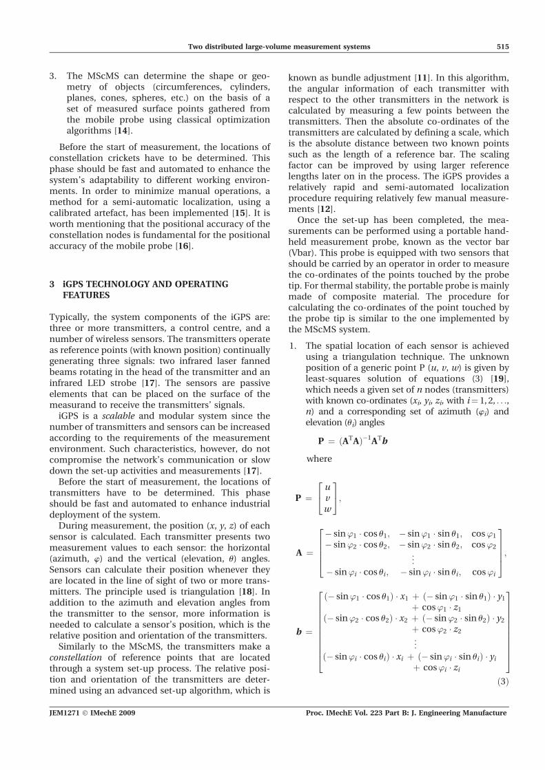
The iGPS is a modular, large-volume tracking sys-tem enabling factory-wide localization of objectswith metrological accuracy, applicable in manu-facturing and assembly environments. The systemcomponents of iGPS are a number of transmitters, acontrol centre, sensors, and receivers [4]. The trans-mitters use laser and infrared light to determine therelative angles from the transmitters to the sensors.The sensors, used for measuring the workpiece, havephotodiodes inside their modules that can sense thetransmitted laser and infrared light signals (Fig. 3).
The other distributed contact measurement systemshown in Fig. 1 is the 3rd Tech HiBall, a systemcomposed of a number of infrared LEDs, arrangedaround the measuring area, which can be viewed byan optical sensor probe measuring the object surface[5]. The probe is able to locate itself, measuring theangles from the LEDs and performing a triangulation.This type of distributed system can potentially be
Fig. 1 Classification of large-volume measuring systems
Proc. IMechE Vol. 223 Part B: J. Engineering Manufacture JEM1271 � IMechE 2009
512 D A Maisano, J Jamshidi, F Franceschini, P G Maropoulos, L Mastrogiacomo, A R Mileham, and G W Owen
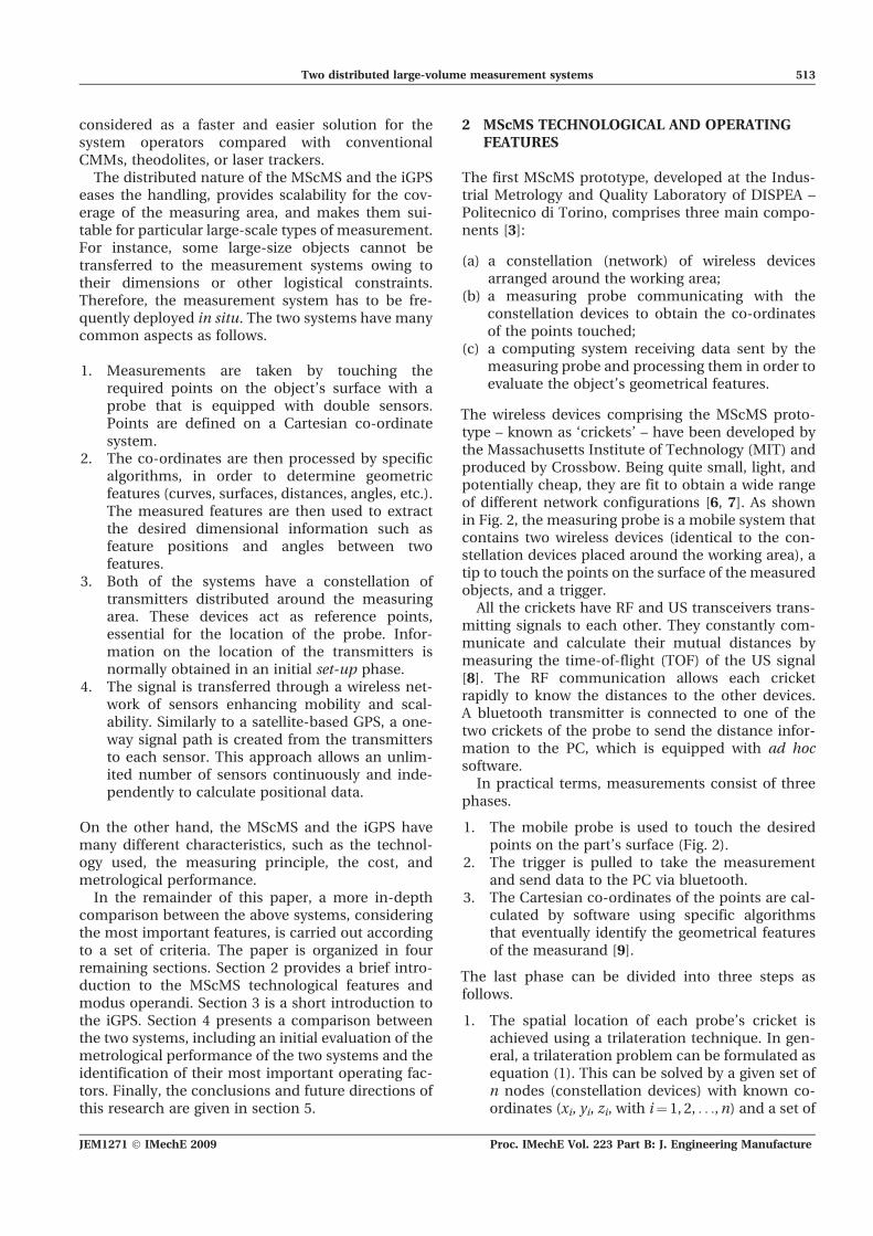
considered as a faster and easier solution for thesystem operators compared with conventionalCMMs, theodolites, or laser trackers.
The distributed nature of the MScMS and the iGPSeases the handling, provides scalability for the cov-erage of the measuring area, and makes them sui-table for particular large-scale types of measurement.For instance, some large-size objects cannot betransferred to the measurement systems owing totheir dimensions or other logistical constraints.Therefore, the measurement system has to be fre-quently deployed in situ. The two systems have manycommon aspects as follows.
1. Measurements are taken by touching therequired points on the object’s surface with aprobe that is equipped with double sensors.Points are defined on a Cartesian co-ordinatesystem.
2. The co-ordinates are then processed by specificalgorithms, in order to determine geometricfeatures (curves, surfaces, distances, angles, etc.).The measured features are then used to extractthe desired dimensional information such asfeature positions and angles between twofeatures.
3. Both of the systems have a constellation oftransmitters distributed around the measuringarea. These devices act as reference points,essential for the location of the probe. Infor-mation on the location of the transmitters isnormally obtained in an initial set-up phase.
4. The signal is transferred through a wireless net-work of sensors enhancing mobility and scal-ability. Similarly to a satellite-based GPS, a one-way signal path is created from the transmittersto each sensor. This approach allows an unlim-ited number of sensors continuously and inde-pendently to calculate positional data.
On the other hand, the MScMS and the iGPS havemany different characteristics, such as the technol-ogy used, the measuring principle, the cost, andmetrological performance.
In the remainder of this paper, a more in-depthcomparison between the above systems, consideringthe most important features, is carried out accordingto a set of criteria. The paper is organized in fourremaining sections. Section 2 provides a brief intro-duction to the MScMS technological features andmodus operandi. Section 3 is a short introduction tothe iGPS. Section 4 presents a comparison betweenthe two systems, including an initial evaluation of themetrological performance of the two systems and theidentification of their most important operating fac-tors. Finally, the conclusions and future directions ofthis research are given in section 5.
2 MScMS TECHNOLOGICAL AND OPERATINGFEATURES
The first MScMS prototype, developed at the Indus-trial Metrology and Quality Laboratory of DISPEA –Politecnico di Torino, comprises three main compo-nents [3]:
(a) a constellation (network) of wireless devicesarranged around the working area;
(b) a measuring probe communicating with theconstellation devices to obtain the co-ordinatesof the points touched;
(c) a computing system receiving data sent by themeasuring probe and processing them in order toevaluate the object’s geometrical features.
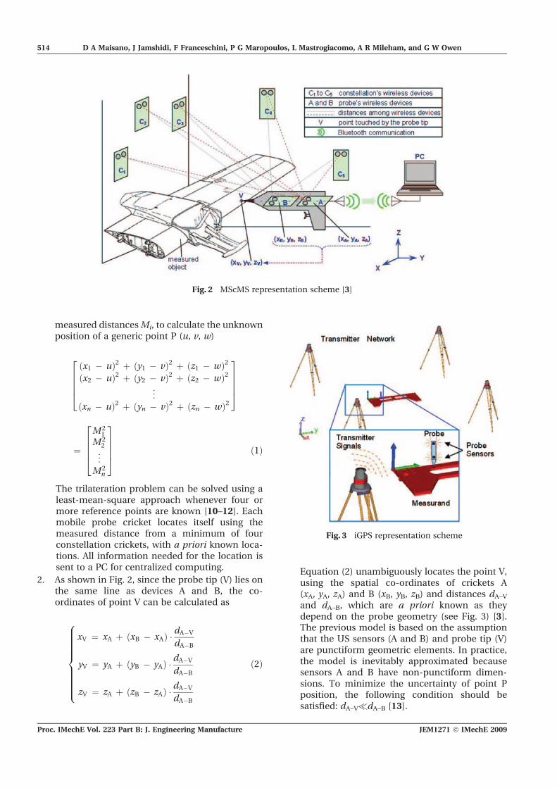
The wireless devices comprising the MScMS proto-type – known as ‘crickets’ – have been developed bythe Massachusetts Institute of Technology (MIT) andproduced by Crossbow. Being quite small, light, andpotentially cheap, they are fit to obtain a wide rangeof different network configurations [6, 7]. As shownin Fig. 2, the measuring probe is a mobile system thatcontains two wireless devices (identical to the con-stellation devices placed around the working area), atip to touch the points on the surface of the measuredobjects, and a trigger.
All the crickets have RF and US transceivers trans-mitting signals to each other. They constantly com-municate and calculate their mutual distances bymeasuring the time-of-flight (TOF) of the US signal[8]. The RF communication allows each cricketrapidly to know the distances to the other devices.A bluetooth transmitter is connected to one of thetwo crickets of the probe to send the distance infor-mation to the PC, which is equipped with ad hocsoftware.
In practical terms, measurements consist of threephases.
1. The mobile probe is used to touch the desiredpoints on the part’s surface (Fig. 2).
2. The trigger is pulled to take the measurementand send data to the PC via bluetooth.
3. The Cartesian co-ordinates of the points are cal-culated by software using specific algorithmsthat eventually identify the geometrical featuresof the measurand [9].
The last phase can be divided into three steps asfollows.
1. The spatial location of each probe’s cricket isachieved using a trilateration technique. In gen-eral, a trilateration problem can be formulated asequation (1). This can be solved by a given set ofn nodes (constellation devices) with known co-ordinates (xi, yi, zi, with i¼ 1, 2, . . .,n) and a set of
JEM1271 � IMechE 2009 Proc. IMechE Vol. 223 Part B: J. Engineering Manufacture
Two distributed large-volume measurement systems 513
measured distancesMi, to calculate the unknownposition of a generic point P (u, v, w)
ðx1 � uÞ2 þ ðy1 � vÞ2 þ ðz1 � wÞ2ðx2 � uÞ2 þ ðy2 � vÞ2 þ ðz2 � wÞ2
..
.
ðxn � uÞ2 þ ðyn � vÞ2 þ ðzn � wÞ2
26664
37775
¼M2
1
M22
..
.
M2n
26664
37775 ð1Þ
The trilateration problem can be solved using aleast-mean-square approach whenever four ormore reference points are known [10–12]. Eachmobile probe cricket locates itself using themeasured distance from a minimum of fourconstellation crickets, with a priori known loca-tions. All information needed for the location issent to a PC for centralized computing.
2. As shown in Fig. 2, since the probe tip (V) lies onthe same line as devices A and B, the co-ordinates of point V can be calculated as
xV ¼ xA þ ðxB � xAÞ � dA�V
dA�B
yV ¼ yA þ ðyB � yAÞ � dA�V
dA�B
zV ¼ zA þ ðzB � zAÞ � dA�V
dA�B
8>>>>>>>><>>>>>>>>:
ð2Þ
Equation (2) unambiguously locates the point V,using the spatial co-ordinates of crickets A(xA, yA, zA) and B (xB, yB, zB) and distances dA–Vand dA–B, which are a priori known as theydepend on the probe geometry (see Fig. 3) [3].The previous model is based on the assumptionthat the US sensors (A and B) and probe tip (V)are punctiform geometric elements. In practice,the model is inevitably approximated becausesensors A and B have non-punctiform dimen-sions. To minimize the uncertainty of point Pposition, the following condition should besatisfied: dA–V�dA–B [13].
Fig. 2 MScMS representation scheme [3]
Fig. 3 iGPS representation scheme
Proc. IMechE Vol. 223 Part B: J. Engineering Manufacture JEM1271 � IMechE 2009
514 D A Maisano, J Jamshidi, F Franceschini, P G Maropoulos, L Mastrogiacomo, A R Mileham, and G W Owen
3. The MScMS can determine the shape or geo-metry of objects (circumferences, cylinders,planes, cones, spheres, etc.) on the basis of aset of measured surface points gathered fromthe mobile probe using classical optimizationalgorithms [14].
Before the start of measurement, the locations ofconstellation crickets have to be determined. Thisphase should be fast and automated to enhance thesystem’s adaptability to different working environ-ments. In order to minimize manual operations, amethod for a semi-automatic localization, using acalibrated artefact, has been implemented [15]. It isworth mentioning that the positional accuracy of theconstellation nodes is fundamental for the positionalaccuracy of the mobile probe [16].
3 iGPS TECHNOLOGY AND OPERATINGFEATURES
Typically, the system components of the iGPS are:three or more transmitters, a control centre, and anumber of wireless sensors. The transmitters operateas reference points (with known position) continuallygenerating three signals: two infrared laser fannedbeams rotating in the head of the transmitter and aninfrared LED strobe [17]. The sensors are passiveelements that can be placed on the surface of themeasurand to receive the transmitters’ signals.
iGPS is a scalable and modular system since thenumber of transmitters and sensors can be increasedaccording to the requirements of the measurementenvironment. Such characteristics, however, do notcompromise the network’s communication or slowdown the set-up activities and measurements [17].
Before the start of measurement, the locations oftransmitters have to be determined. This phaseshould be fast and automated to enhance industrialdeployment of the system.
During measurement, the position (x, y, z) of eachsensor is calculated. Each transmitter presents twomeasurement values to each sensor: the horizontal(azimuth, w) and the vertical (elevation, u) angles.Sensors can calculate their position whenever theyare located in the line of sight of two or more trans-mitters. The principle used is triangulation [18]. Inaddition to the azimuth and elevation angles fromthe transmitter to the sensor, more information isneeded to calculate a sensor’s position, which is therelative position and orientation of the transmitters.
Similarly to the MScMS, the transmitters make aconstellation of reference points that are locatedthrough a system set-up process. The relative posi-tion and orientation of the transmitters are deter-mined using an advanced set-up algorithm, which is
known as bundle adjustment [11]. In this algorithm,the angular information of each transmitter withrespect to the other transmitters in the network iscalculated by measuring a few points between thetransmitters. Then the absolute co-ordinates of thetransmitters are calculated by defining a scale, whichis the absolute distance between two known pointssuch as the length of a reference bar. The scalingfactor can be improved by using larger referencelengths later on in the process. The iGPS provides arelatively rapid and semi-automated localizationprocedure requiring relatively few manual measure-ments [12].
Once the set-up has been completed, the mea-surements can be performed using a portable hand-held measurement probe, known as the vector bar(Vbar). This probe is equipped with two sensors thatshould be carried by an operator in order to measurethe co-ordinates of the points touched by the probetip. For thermal stability, the portable probe is mainlymade of composite material. The procedure forcalculating the co-ordinates of the point touched bythe probe tip is similar to the one implemented bythe MScMS system.
1. The spatial location of each sensor is achievedusing a triangulation technique. The unknownposition of a generic point P (u, v, w) is given byleast-squares solution of equations (3) [19],which needs a given set of n nodes (transmitters)with known co-ordinates (xi, yi, zi, with i¼ 1, 2, . . .,n) and a corresponding set of azimuth (wi) andelevation (ui) angles
P ¼ ðATAÞ�1ATb
where
P ¼uvw
24
35;
A ¼� sin’1 � cos u1; � sin’1 � sin u1; cos’1
� sin’2 � cos u2; � sin’2 � sin u2; cos’2
..
.
� sin’i � cos ui; � sin’i � sin ui; cos’i
26664
37775;
b ¼
� sin’1 � cos u1ð Þ � x1 þ � sin’1 � sin u1ð Þ � y1þ cos’1 � z1
� sin’2 � cos u2ð Þ � x2 þ � sin’2 � sin u2ð Þ � y2þ cos’2 � z2...
� sin’i � cos uið Þ � xi þ � sin’i � sin uið Þ � yiþ cos’i � zi
26666666664
37777777775
ð3Þ
JEM1271 � IMechE 2009 Proc. IMechE Vol. 223 Part B: J. Engineering Manufacture
Two distributed large-volume measurement systems 515
For unique determination of the relative locationof a point in three-dimensional space, at leasttwo transmitters are needed [11, 12]. All infor-mation needed for location calculation is sent toa computer for processing.
2. In a similar way to the MScMS, the location of apoint touched by the probe tip can be calculatedby equation (2) using the obtained co-ordinatesof points A (xA, yA, zA) and B (xB, yB, zB), which arein effect the centre-points of the sensors, and thegeometrical features of the probe (distances dA–Vand dA–B).
For the experimental work described in this paper, aniGPS system equipped with four transmitters wasused.
4 SYSTEM COMPARISON
In this section, the MScMS and the iGPS systems arecompared, and some of the most important simila-rities and differences between the two systems arediscussed. A summary of the comparison is given inTable 1. In the following paragraphs, some of theitems are individually analysed in order to emphasizethe most interesting similarities and differencesbetween the two systems.
4.1 Number of constellation devices
For both the MScMS and the iGPS, the number ofconstellation devices is strictly related to their com-munication range and the measurement volume. Inthe case of the MScMS, some tests show that thecoverage of an indoor working volume is achievableusing about one network device per square metre,depending on the workshop layout [3]. Compara-tively, since the communication range of the trans-mitters of the iGPS is much larger, the transmitters’density within the measuring volume does not haveto be as high (approximately one device per 100m2).
Furthermore, it is important to note that thenumber of constellation devices ‘seen’ by the sensorshas a strong influence on the positioning accuracy.This particular aspect was studied through explora-tory tests combined with simulation.
With regard to the iGPS, 30 points, with a prioriknown positions, were measured (repeating themeasurement 150 times per point), while the numberof iGPS transmitters for the desired points wasdeliberately changed from 2 to 4 transmitters [20].The co-ordinate positional errors (residuals) weredetermined by considering the difference betweenthe ‘true’ co-ordinate position and the co-ordinateposition of the points, as calculated by triangulation.
Table 1 Comparison of results between the MScMS and the iGPS
Technical feature MScMS iGPS
Measured variables Distances among constellationdevices and probe sensors
Two angles among each coupleof sensor and transmitter
Localization technique duringmeasurements
Trilateration Triangulation
Transmitter’s communicationrange
About 6–8m Up to 40m
Approximate number ofconstellation devices
1 per m2 1 per 100m2
Sample rate About three points per second About 30 points per second
Sensitivity to environmentalconditions
Temperature, humidity, vibrations Temperature, light, vibrations, reflection
Localization of constellationdevices
Semi-automated procedure Semi-automated procedure
System diagnostics Diagnostic function to filterwrong measurements and tocorrect parameters
Use of fixed sensors todetermine whether measurementsystem is going out of tolerance
System calibration check Automatic calculation of thespeed of sound duringmeasurements
Real-time adjustments of scale
Metrological performance Repeatability s� 5mmReproducibility s� 8mm
Repeatability s� 0.06mmReproducibility s� 0.16mm
Working volume size Scalable Scalable
Estimated cost for a typicalsystem
e10k e150k for typical system withfour transmitters
Proc. IMechE Vol. 223 Part B: J. Engineering Manufacture JEM1271 � IMechE 2009
516 D A Maisano, J Jamshidi, F Franceschini, P G Maropoulos, L Mastrogiacomo, A R Mileham, and G W Owen
The co-ordinate positional errors relating to all30 points showed a normally distributed pattern.
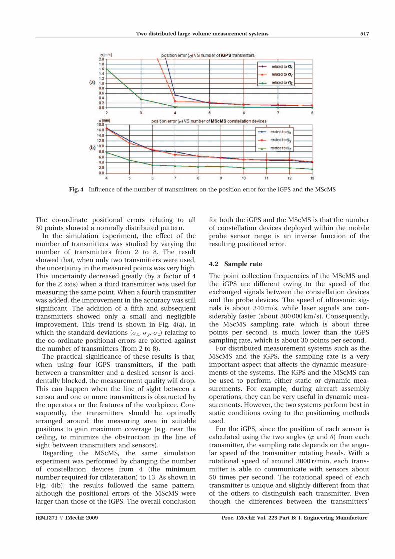
In the simulation experiment, the effect of thenumber of transmitters was studied by varying thenumber of transmitters from 2 to 8. The resultshowed that, when only two transmitters were used,the uncertainty in the measured points was very high.This uncertainty decreased greatly (by a factor of 4for the Z axis) when a third transmitter was used formeasuring the same point. When a fourth transmitterwas added, the improvement in the accuracy was stillsignificant. The addition of a fifth and subsequenttransmitters showed only a small and negligibleimprovement. This trend is shown in Fig. 4(a), inwhich the standard deviations (sx, sy, sz) relating tothe co-ordinate positional errors are plotted againstthe number of transmitters (from 2 to 8).
The practical significance of these results is that,when using four iGPS transmitters, if the pathbetween a transmitter and a desired sensor is acci-dentally blocked, the measurement quality will drop.This can happen when the line of sight between asensor and one or more transmitters is obstructed bythe operators or the features of the workpiece. Con-sequently, the transmitters should be optimallyarranged around the measuring area in suitablepositions to gain maximum coverage (e.g. near theceiling, to minimize the obstruction in the line ofsight between transmitters and sensors).
Regarding the MScMS, the same simulationexperiment was performed by changing the numberof constellation devices from 4 (the minimumnumber required for trilateration) to 13. As shown inFig. 4(b), the results followed the same pattern,although the positional errors of the MScMS werelarger than those of the iGPS. The overall conclusion
for both the iGPS and the MScMS is that the numberof constellation devices deployed within the mobileprobe sensor range is an inverse function of theresulting positional error.
4.2 Sample rate
The point collection frequencies of the MScMS andthe iGPS are different owing to the speed of theexchanged signals between the constellation devicesand the probe devices. The speed of ultrasonic sig-nals is about 340m/s, while laser signals are con-siderably faster (about 300 000 km/s). Consequently,the MScMS sampling rate, which is about threepoints per second, is much lower than the iGPSsampling rate, which is about 30 points per second.
For distributed measurement systems such as theMScMS and the iGPS, the sampling rate is a veryimportant aspect that affects the dynamic measure-ments of the systems. The iGPS and the MScMS canbe used to perform either static or dynamic mea-surements. For example, during aircraft assemblyoperations, they can be very useful in dynamic mea-surements. However, the two systems perform best instatic conditions owing to the positioning methodsused.
For the iGPS, since the position of each sensor iscalculated using the two angles (w and u) from eachtransmitter, the sampling rate depends on the angu-lar speed of the transmitter rotating heads. With arotational speed of around 3000 r/min, each trans-mitter is able to communicate with sensors about50 times per second. The rotational speed of eachtransmitter is unique and slightly different from thatof the others to distinguish each transmitter. Eventhough the differences between the transmitters’
Fig. 4 Influence of the number of transmitters on the position error for the iGPS and the MScMS
JEM1271 � IMechE 2009 Proc. IMechE Vol. 223 Part B: J. Engineering Manufacture
Two distributed large-volume measurement systems 517
sampling rates are small, it is impossible to receiveconcurrent data from all transmitters. The inevitabledifference in data streaming is in the range of a fewhundredths of a second. This effect does not createany problem for static measurements; however, itwill affect the dynamic measurement.
For dynamic measurements, the sensors are mov-ing over time t. For any sensor, the position duringthe time period t4–t1, is calculated by triangulatingdata collected at very close but different instants [9].Even if the difference consists of a few tenths of asecond, it produces a location error. Therefore, thefaster the sensor moves, the larger the error becomes.However, for applications such as initial positioningof large structures, where accuracy is not critical, theiGPS system can provide flexible solutions.
Regarding the MScMS, this aspect is similar butmore apparent owing to the lower sampling rate. Theonly difference is that the position of a sensor is cal-culated by trilateration of the distances from theconstellation devices, which are not concurrent.Therefore, the location error is larger for dynamicmeasurements.
In this paper, the experiments for the evaluation ofthe systems were performed in static conditions.
4.3 Localization of the constellation devices
Both the MScMS and the iGPS give the opportunityof freely arranging the constellation devices aroundthe desired working area, based on workpiecedimensions and geometry. Whenever the systems aremoved, i.e. when the position of the constellationdevices is changed, a new localization should beperformed. It is evident that this step should becompleted before measurement, as it has a strongeffect on the measurement accuracy. For this pur-pose, the MScMS and the iGPS provide two differentsemi-automated localization procedures, bothrequiring several manual measurements. Thesemeasurements should be taken in different positionswithin the measurement area while using a calibratedartefact equipped with four cricket transmitters [3].For the iGPS, the procedure is similar, but a referencebar equipped with two sensors with a priori knowndistance should be used.
4.4 System calibration check
Another activity to make the MScMS suitable formeasurement is the system calibration check. Itis well known that the speed of sound changeswith air conditions in terms of temperature andhumidity, which can exhibit both temporal and spa-tial variations within large working volumes. As aconsequence, the speed of sound should often bemeasured and updated in the calculations. In order
to verify this value in real time, an optimizationprocedure is implemented.
A similar procedure is applied for the iGPS, using areference bar to compensate for the effects of envir-onmental conditions. Such effects can originate fromchanges in the magnetic field, reflection, and airtemperature and humidity, which can, for instance,affect the laser direction. What became clear from thetests is that the absolute uncertainty of the iGPS isdirectly related to the quality of the scale bar mea-surement and its initial calibration. The procedurecan be fully automated using two fixed sensors,which are tied to the extremities of an interferometricscale bar. The implementation of autocalibrationminimizes downtime as the system can self-calibratecontinuously and in real time.
4.5 Metrological performance
A prototype MScMS and a standard iGPS were testedfor the purpose of evaluating their main metrologicalperformance. Regarding the MScMS, 21 constellationdevices were arranged around a measuring area ofabout 24m2. In the case of the iGPS, four transmitterswere distributed around a measuring area of about60m2. Two preliminary tests were performed.
4.5.1 Repeatability test
Repeatability is defined as ‘the closeness of theagreement between the results of successive mea-surements of the same measurand, carried out underthe same conditions of measurement’ [21, 22]. Apoint within the working volume was measuredrepeatedly about 150 times. During these measure-ments, the probe was left in a fixed position, for boththe MScMS and the iGPS. The test was repeated for30 different points in different areas of the workingvolume. For each point, the residuals between thesingle measurements and their average valueswere calculated [20]. The residuals showed a nor-mally distributed pattern. The repeatability indicatorwas given by the standard deviations (sx, sy, sz)related to each Cartesian co-ordinate residual asshown in Table 2.
4.5.2 Reproducibility test
Reproducibility is defined as ‘the closeness of theagreement between the results of successive mea-surements of the same measurand, carried out underchanged conditions of measurement’ [21, 22]. Thistest is similar to the previous one, the only differencebeing that the probe is repositioned in differentorientations before each single point measurement.Hence, each point is approached from a differentprobe direction. Reproducibility gives a preliminaryindication of the current accuracy of the system,
Proc. IMechE Vol. 223 Part B: J. Engineering Manufacture JEM1271 � IMechE 2009
518 D A Maisano, J Jamshidi, F Franceschini, P G Maropoulos, L Mastrogiacomo, A R Mileham, and G W Owen
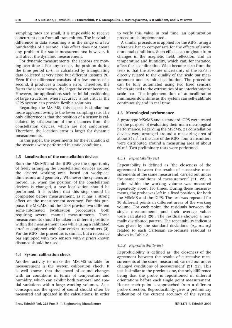
whereas repeatability gives a preliminary indicationof the potential accuracy of the system [23]. This wasbased on compensating for the most important cau-ses of systematic errors. Table 2 shows the standarddeviations related to each Cartesian co-ordinate. Asexpected, the standard deviations for the reproduci-bility tests were higher than those of the repeatabilitytests. The results of these preliminary tests are sum-marized in Table 2.
In general, for both the MScMS and the iGPS, thesz value was lower than the sx and sy values for bothrepeatability and reproducibility. This was due to thegeometric configuration of the constellation devices,which were mounted on tripods set more or less atthe same height. Therefore, they could be consideredas approximately placed on a horizontal plane (XY)perpendicular to the vertical (Z) axis [16].
The US transceivers, which were used to calculatethe distances between sensor devices, were respon-sible for the low accuracy of the MScMS comparedwith the iGPS [3, 11]. The US speed may have chan-ged with changes in the environmental conditions,depending on time and position. Furthermore, USsignals may have been diffracted and reflected byobstacles interposed between two devices. This hada negative effect on the measurement accuracy;however, it could have been limited by the use ofcompensation control tools [24].
4.6 Working volume size
The MScMS and the iGPS comprise separate, multipledevices that can be easily moved and arranged aroundthe measuring area according to requirements. Thesesystems are scalable and modular, since the numberof constellation devices can be increased dependingon the size and peculiarities of the workpiece and themeasurement environment. Such characteristics,however, do not compromise the network commu-nication or slow down the support activities such asconstellation location and measurements.
4.7 System diagnostics
The MScMS software provides some diagnostic toolsto control the activities and assist in the detection ofabnormal functions. First, it gives the opportunity ofviewing (directly from the measuring page or during
network localization) the distance data exchangedamong the wireless devices. Second, during mea-surement activities, it allows a graphic display of theprobe’s range of vision, which is the set of networkdevices with which it can communicate. This helpsthe operator to check whether the probe is in theoptimal position to perform the measurement, forexample when it communicates with at least fourconstellation devices.
As mentioned above, the MScMS is sensitive toexternal factors, such as the environmental condi-tions of the measuring area (temperature, humidity,presence of obstacles among distributed devices).However, wrong distance measurements, like thoseaffected by US reflection, diffraction, or other mea-suring accidents among cricket devices, can beindirectly detected and rejected. For this purpose, theMScMS is equipped with an effective diagnostic testable to discriminate measurements that have goodform but are at a wrong distance. This test is based onanalysis of the residuals related to the error functionoptimized during the trilateration process [9, 15].
For filtering bad measurement data due to externalfactors such as light, temperature, or vibrations, theiGPS also provides diagnostic controls. The reliabilityof measurements increases dramatically by usingmultiple fixed sensors which are placed at a prioriknown positions. With these sensors, the system canperform an automatic initial set-up continually tocorrect the measurement field and determine whetherthe system is conforming to the desired tolerance [4].
4.8 Cost
Cost is a point in favour of the MScMS, since its maincomponents, including cricket devices, supports andbooms, adapters, etc., have an individual cost of a fewtens of euros. This reduces the overall cost of thesystem to about e10k. On the other hand, the cost ofthe iGPS, even for the most economical and simpleconfiguration, is much higher (around e150k).
5 CONCLUSIONS
This paper firstly gives a brief review of two state-of-the-art, large-volume measurement systems, theMScMS and the iGPS. The two systems are compared
Table 2 Comparison between the MScMS and iGPS metrological performances
Mean standard deviation (mm)Repeatability test Reproducibility test
sx sy sz sx sy sz
MScMS 4.8 5.1 3.5 7.3 7.8 4.1iGPS 0.06 0.06 0.04 0.16 0.16 0.08
JEM1271 � IMechE 2009 Proc. IMechE Vol. 223 Part B: J. Engineering Manufacture
Two distributed large-volume measurement systems 519
in order to highlight the pros and cons of eachsystem, based on initial experimental results andavailable information from the literature.
In terms of measurement procedure, the MScMSand the iGPS are similar as they are multitransmitter,multisensor measurement networks. However, theypresent many differences on account of their differ-ent technological features. The technological differ-ences affect several factors within the systems,including system presetting, start-up, and measure-ment execution. It can be concluded that thesesystems can easily coexist, since each system issuitable for specific applications. The metrologicalperformance of the iGPS is superior to that of theMScMS; however, the overall cost of the MScMS ismore attractive in applications that do not requirea high level of accuracy. It is also shown that, with theexisting state of their technology, the MScMS and theiGPS may not be completely suitable for dynamicmeasurements. However, by predicting the directionof movement and by using error compensationmethods, this limitation may be resolved, and theiGPS can potentially be utilized for rough positioningand/or slow dynamic measurements. Both of thesesystems are lightweight and easily adaptable to dif-ferent working environments, and they can be rapidlyinstalled and used. Prior to performing measure-ments, the constellation devices are freely distributedaround the working area and semi-automaticallylocated in a few minutes.
Future work will consist of trials and studies toidentify the best layout for the positioning of MScMSand iGPS constellation devices and other compo-nents. Research will also be carried out to optimizethe number of sensors for achieving the desiredaccuracies for dimensional measurement. Further-more, the dynamic performance of the systems willbe investigated in more detail.
ACKNOWLEDGEMENTS
The authors would like to acknowledge the support ofPolitecnico di Torino – DISPEA (Dipartimento diSistemi di Produzione ed Economia dell’Azienda)and of the IdMRC of the University of Bath, EPSRCGrant EP/E00184X/1. The authors also wish to thankMr Ben Hughes from NPL, UK, for his valuabletechnical input.
REFERENCES
1 Puttock, M. J. Large-scale metrology. Ann. CIRP, 1978,21(1), 351–356.
2 Estler, W. T., Edmundson, K. L., Peggs, G. N., andParker, D. H. Large-scale metrology – an update. Ann.CIRP – Mfg Technol., 2002, 51(2), 587–609.
3 Franceschini, F., Galetto, M., Maisano, D., andMastrogiacomo, L. Mobile Spatial coordinate Measur-
ing System (MScMS) – introduction to the system, 2008,
23 pp.4 Kang, S. and Tesar, D. A noble 6-DOF measurement
tool with indoor GPS for metrology and calibration of
modular reconfigurable robots. IEEE ICM International
Conference on Mechatronics, Istanbul, Turkey.5 Welch, G., Bishop, G., Vicci, L., Brumback, S., and
Keller, K. High-performance wide-area optical tracking
– the HiBall tracking system. Presence: Teleoperators and
Virtual Environ., 2001, 10(1), 1–21.6 Priyantha, N. B., Chakraborty, A., and Balakrishnan,
H. The cricket location-support system. Proceedings of
6th ACM MOBICOM, Boston, Massachusetts, 2000.7 Balakrishnan, H., Baliga, R., Curtis, D., Goraczko, M.,
Miu, A., Priyantha, N. B., Smith, A., Steele, K., Teller,
S., and Wang, K. Lessons from developing and deploy-
ing the cricket indoor location system, Preprint, 2003.8 Gustafsson, F. and Gunnarsson, F. Positioning using
time difference of arrival measurements. In Proceedings
of IEEE International Conference on Acoustics, speech,
and signal processing (ICASSP 2003), Hong Kong, vol. 6,
pp. 553–556.9 Moore, D., Leonard, J., Rus, D., and Teller, S. S. Robust
distributed network localization with noisy range mea-
surements. In Proceedings of SenSys 2004, Baltimore,
Maryland, pp. 50–61.10 Savvides, A., Han, C., and Strivastava, M. B. Dynamic
fine-grained localization in ad hoc networks of sensors.
Proceedings of ACM/IEEE 7th Annual International
Conference on Mobile computing and networking
(MobiCom’01), 2001, pp. 166–179.11 Chen, M., Cheng, F., and Gudavalli, R. Precision and
accuracy in an indoor localization system. Technical
report CS294-1/2, University of California, Berkeley,
California.12 Akcan, H., Kriakov, V., Bro€nnimann, H., and Delis, A.
GPSFree node localization in mobile wireless sensor
networks. In Proceedings of MobiDE’06, Chicago,
Illinois, pp. 35–42.13 Zakrzewski, J. Error and uncertainty reduction –
challenge for a measuring systems designer. Measmt
Sci. Rev., 2003, 3(1), 31–34.14 Overmars, M. H. Designing the computational geo-
metry algorithms library CGAL. Proceedings of WACG
’96, Lecture notes in computer science, 1997, vol. 1148,
pp. 53–58 (Springer-Verlag).15 Franceschini, F., Galetto, M., Maisano, D., and
Mastrogiacomo, L. A review of localization algorithms
for distributed wireless sensor networks in manu-
facturing. Int. J. Comput. Integrated Mfg, Special Issue:
Wireless Mfg, 2008, 19 pp.16 Patwari, N., Ash, J., Kyperountas, S., Hero III, A.,
Moses, R., and Correal, N. Locating the nodes –
cooperative localization in wireless sensor networks.
IEEE Signal Processing Mag., 2005, 22(4), 54–69.17 Product literature, ARC Second company website
<http://arcsecond.com>, 2004.18 Niculescu, D. and Nath, B. Ad hoc positioning system
(APS) using AOA. In Proceedings of IEEE Annual Joint
Proc. IMechE Vol. 223 Part B: J. Engineering Manufacture JEM1271 � IMechE 2009
520 D A Maisano, J Jamshidi, F Franceschini, P G Maropoulos, L Mastrogiacomo, A R Mileham, and G W Owen
Conference IEEE Computer and CommunicationsSocieties (INFOCOM’03), 2003, pp. 1734–1743.
19 Dogancay, K. and Ibal, G. 3D passive bearings-onlyemitter localization using crude angle-of-arrival mea-surements. Proceedings of SimTecT 2005, Melbourne,Australia, 9–12 May 2005.
20 Maisano, D., Jamshidi, J., Franceschini, F., Maropoulos,P., Mastrogiacomo, L., Mileham, A., and Owen, G.Indoor GPS: system functionality and initial performanceevaluation. Int. J. Mfg Res.
21 Guide to the expression of uncertainty in measurement.International Organization for Standardization, Geneva,Switzerland, 2004.
22 International vocabulary of basic and general terms inmetrology. International Organization for Standardiza-tion, Geneva, Switzerland, 2004.
23 Franceschini, F., Galetto, M., and Maisano, D.Management by measurement: designing key indicatorsand performance measurement systems, 2007 (SpringerVerlag, Berlin).
24 Martin, J. M., Jime�nez, A. R., Seco, F., Calderon, L.,Pons, J. L., and Ceres, R. Estimating the 3D-positionfrom time delay data of US-waves: experimental
analysis and new processing algorithm. Sensors andActuators, 2002, 101(3), 311–321.
25 Performance evaluation of laser-based spherical coor-dinate measurement systems. ANSI/ASME B89.4.19-2006, 2006.
26 Bohn, D. A. Environmental effects on the speed ofsound. J. Audio Engng Soc., 1988, 36(4).
27 Cross, N. R., Dotson, J. R., Flank, D. R., Peggs, G. N.,Cox, M. G., Forbes, A. B., Corta, R., O’Donnell, J., andPrieto, E. A large reference artefact for CMM verifica-tion. National Physical Laboratory report CLM 6, May1998, 45 pp.
28 Franceschini, F., Galetto, M., Maisano, D., andMastrogiacomo, L. On-line diagnostics tools in theMobile Spatial coordinate Measuring System (MScMS).7th ENBIS Conference, Dortmund, Germany, 24–26September 2007.
29 Geometrical Product Specifications (GPS) – acceptanceand reverification tests for coordinate measuringmachines (CMM). ISO 10360, Part 2, 2001.
30 Metris, <http://www.metris.com/large_volume_tracking_positioning/>, 2008.
JEM1271 � IMechE 2009 Proc. IMechE Vol. 223 Part B: J. Engineering Manufacture
Two distributed large-volume measurement systems 521